pico table clean type
TRANSCRIPT
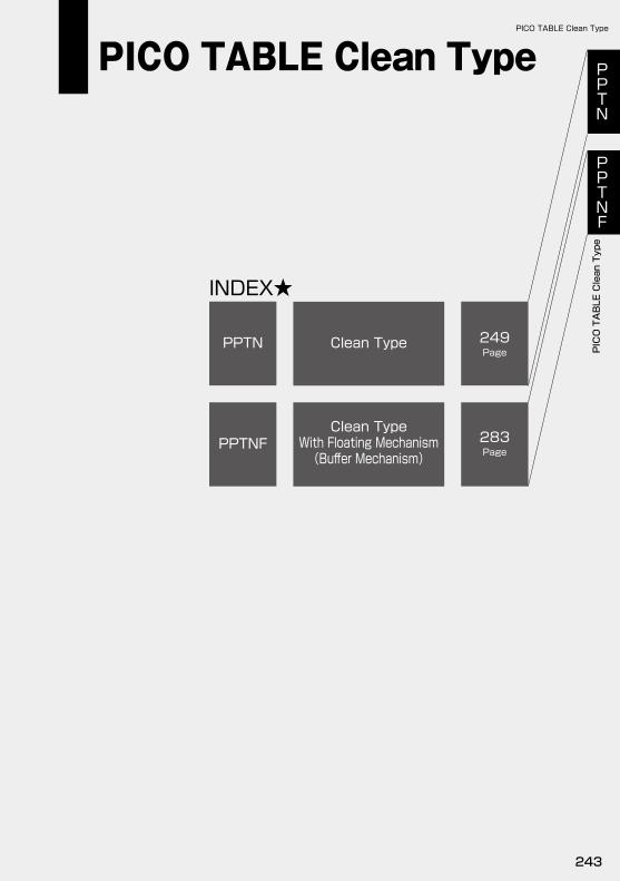
INDEX★
PPTN Clean Type 249Page
PPTNFClean Type
With Floating Mechanism(Buffer Mechanism)
283Page
PPTN
PPTNF
PICO TABLE Clean Type
PICO TABLE Clean Type
PICO TABLE Clean Type
243
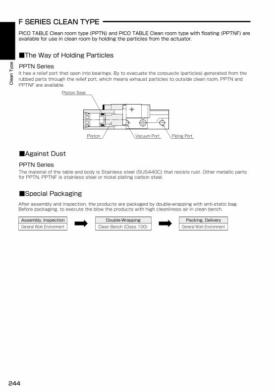
F SERIES CLEAN TYPEPICO TABLE Clean room type (PPTN) and PICO TABLE Clean room type with floating (PPTNF) areavailable for use in clean room by holding the particles from the actuator.
■The Way of Holding Particles
PPTN Series
■Special Packaging
■Against Dust
PPTN Series
After assembly and inspection, the products are packaged by double-wrapping with anti-static bag.Before packaging, to execute the blow the products with high cleanliness air in clean bench.
Assembly, InspectionGeneral Work Environment
Packing, DeliveryGeneral Work EnvironmentClean Bench (Class 100)
Double-Wrapping
Piston Vacuum Port Piping Port
Piston Seal
It has a relief port that open into bearings. By to evacuate the corpuscle (particles) generated from therubbed parts through the relief port, which means exhaust particles to outside clean room, PPTN andPPTNF are available.
The material of the table and body is Stainless steel (SUS440C) that resists rust. Other metallic partsfor PPTN, PPTNF is stainless steel or nickel plating carbon steel.
Clean Type
244
Clean Type
Clean Type
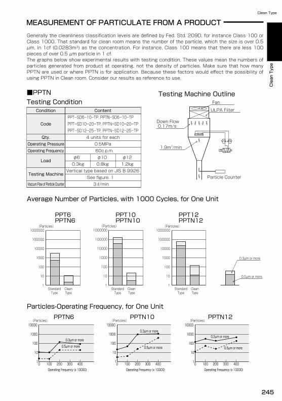
Average Number of Particles, with 1000 Cycles, for One Unit
MEASUREMENT OF PARTICULATE FROM A PRODUCT
Testing ConditionTesting Machine Outline
0.3kg
Condition
Code
Qty.Operating PressureOperating Frequency
Load
Testing Machine
Vaccum Flow of Particle Counter
Content
PPT-SD12-25-TP, PPTN-SD12-25-TP
PPT-SD6-10-TP, PPTN-SD6-10-TPPPT-SD10-20-TP, PPTN-SD10-20-TP
3 /min
4 units for each0.5MPa60c.p.m.
φ121.2kg
Vertical type based on JIS B 9926See figure. 1
φ100.8kg
φ6
Down Flow 0.17m/s
Fan
ULPA Filter
1.9m3/min
Particle Counter
PPT12PPT6 PPT10PPTN6 PPTN10 PPTN12
(Particles)1000000
1000
100
10
1
10000
100000
StandardType
CleanType
StandardType
CleanType
StandardType
CleanType
(Particles)1000000
1000
100
10
1
10000
100000
(Particles)1000000
1000
100
10
1
10000
100000
0.3μm or more
0.5μm or more
Particles-Operating Frequency, for One UnitPPTN12PPTN6 PPTN10
(Particles)(Particles) (Particles)
0.3μm or more
0.5μm or more
0.3μm or more0.3μm or more
0.5μm or more
10000
1000
100
10
1
0.5μm or more
0 100 200 300 4000 100 200 300 4001
10
100
1000
10000
0 100 200 300 400Operating Frequency (x 10000) Operating Frequency (x 10000) Operating Frequency (x 10000)
1
10
100
1000
10000
■PPTN
Generally the cleanliness classification levels are defined by Fed. Std. 209D, for instance Class 100 or Class 1000. That standard for clean room means the number of the particle, which the size is over 0.5 μm, in 1cf (0.0283m3) as the concentration. For instance, Class 100 means that there are less 100 pieces of over 0.5 μm particle in 1 cf.The graphs below show experimental results with testing condition. These values mean the numbers of particles generated from product at operating, not the density of particles. Make sure that how many PPTN are used or where PPTN is for application. Because these factors would effect the possibility of using PPTN in Clean room. Consider our results as reference to use.
Clean Type
Clean Type
Clean Type
245
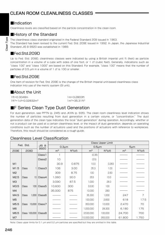
■Indication
■Fed.Std.209E
CLEAN ROOM CLEANLINESS CLASSES
■About the Unit
Cleanliness Level Classification
■F Series Clean Type Dust Generation
Note: Class upper limits for 0.1 μm and 0.2 μm particles are specified but they are omitted in this table.
10,000,000
3,530,000
1,000,000
353,000
100,000
35,300
10,000
3,530
1,000
353
35.3
100
10.0
(3.5)
(0.35)
283,000 61,800
24,700
6,180
2,470
618
247
1,750
700
175
70
17.5
7
100,000
28,300
10,000
2,830
1,000
283
100
28.3
10.0
2.83
1.00
0.283
M1
M2
M2.5
875
300
87.5
30.0
8.75
3.00
0.875
M3.5
M4
M4.5
M5
M5.5
M6
M6.5
M7
Class M1.5
Class1
M3
10,600
35,000
3,090
1,060
309
106
30.9
10
1m30.3μm 0.5μm
Class Upper Limit
ft3(cf) m3 ft3(cf)5μm
m3 ft3(cf)
Fed. Std.
209E9920
209D
JIS B
Class2
Class31
Class 10
Class 100
Class 1,000
Class 10,000
Class 100,000
Class4
Class5
Class6
Class7
Class8
For dust generation, see PPTN (p. 245) and JKXN (p. 935). The clean room cleanliness level indication shows the number of particles resulting from dust generation in a certain volume, or “concentration.” The dust generation data of the clean type indicates the local “dust generation” during operation. Accordingly, whether or not a product can be used at a certain cleanliness level, or the impact of dust generation, depends on operating conditions such as the number of actuators used and the positions of actuators with reference to workpieces. Therefore, this result should be considered as a rough guide.
■History of the StandardThe cleanliness class standard originated in the Federal Standard 209 issued in 1963.The Standard has been revised to the current Fed. Std. 209E issued in 1992. In Japan, the Japanese Industrial Standard JIS B 9920 was established in 1989.
Cleanliness levels are classified based on the particle concentration in the clean room.
■Fed.Std.209DUp to Fed. Std. 209D, cleanliness classes were indicated by using a British imperial unit ft (feet) as particle concentration in a volume of a cube with sides of one foot, or 1 cf (cubic feet). Generally, indications such as “class 100” and “class 1000” are based on this Standard. For example, “class 100” means that the number of particles of 0.5 μm in a volume of 1 cf is 100 or smaller.
One item of revision for Fed. Std. 209E is the change of the British imperial unit-based cleanliness class indication into use of the metric system (SI unit).
1ft=0.3048m 1m=3.2803ft1ft3=1cf=0.02832m3 1m3=35.31ft3
Clean Type
246
Clean Type
Clean Type
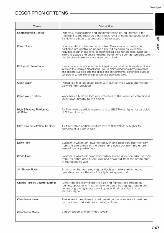
DESCRIPTION OF TERMS
Cleanliness Level The level of cleanliness rated based on the numbers of particlesby the sizes that exist in a certain volume.
Small chamber for removing particulate matters attached tooperators and clothes by forcibly blowing them off.
Description
Portable simplified clean room with curtain-type walls and verticalblowing filter provided.
Clean Booth
Planning, organization and implementation of requirements formaintaining the required cleanliness level of confined space or theinside or surface of a product or other object.
Contamination Control
Clean Room Space under contamination control. Space in which airborneparticles are controlled under a limited cleanliness level, therequired cleanliness level is maintained also for objects suppliedinto the space and environmental conditions such as temperature,humidity and pressure are also controlled.
Biological Clean Room Space under contamination control against microbial contamination. Spacein which the required cleanliness level is maintained for airborne microbesand objects supplied into the space and environmental conditions such astemperature, humidity and pressure are also controlled.
Ultra Low Penetration Air Filter Air filter with a particle capture rate of 99.9995% or higher forparticles of 0.1 μm in size.
Optical Particle Counter Method A method of determining the size and number of particles byrunning specimens in a thin flow across a strong light beam andconverting the light scattered by individual particles into anelectric signal.
Down Flow System in which air flows vertically in one direction into the roomfrom the entire area of the ceiling and flows out from the entirearea of the opposite floor.
Cross Flow System in which air flows horizontally in one direction into the roomfrom the entire area of one wall and flows out from the entire areaof the opposite wall.
Clean Work Station Work bench built so that air controlled to the specified cleanlinesslevel flows directly to the object.
Cleanliness Class Classification of cleanliness levels.
Air filter with a particle capture rate of 99.97% or higher for particlesof 0.3 μm in size.
High Efficiency ParticulateAir Filter
Terms
Air Shower Booth
Clean Type
Clean Type
Clean Type
247

248
PPTNPICO TABLE Clean Type
PPTN
PICO TABLE Clean Type
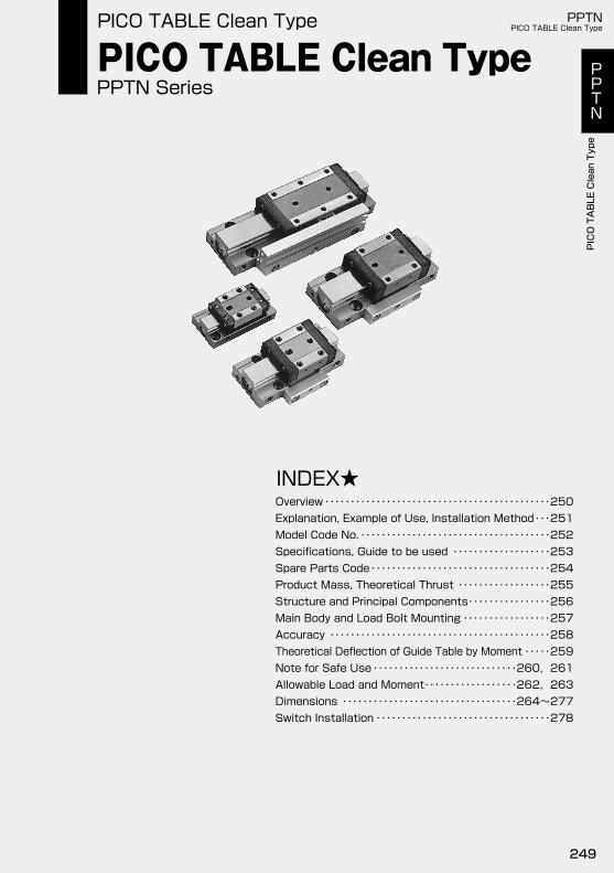
PPTN Series
INDEX★
Explanation, Example of Use, Installation MethodModel Code No.Specifications, Guide to be used
Structure and Principal ComponentsMain Body and Load Bolt MountingAccuracyTheoretical Deflection of Guide Table by Moment
Product Mass, Theoretical Thrust
Dimensions
Overview・・・・・・・・・・・・・・・・・・・・・・・・・・・・・・・・・・・・・・・・・・・・250・・・251
・・・・・・・・・・・・・・・・・・・・・・・・・・・・・・・・・・・・・252・・・・・・・・・・・・・・・・・・・253
・・・・・・・・・・・・・・・・・・・・・・・・・・・・・・・・・・・254
・・・・・・・・・・・・・・・・256・・・・・・・・・・・・・・・・・257
・・・・・・・・・・・・・・・・・・・・・・・・・・・・・・・・・・・・・・・・・・・258
・・・・・・・・・・・・・・・・・・・・・・・・・・・・260,261・・・・・259
・・・・・・・・・・・・・・・・・・262,263・・・・・・・・・・・・・・・・・・・・・・・・・・・・・・・・・・264~277
・・・・・・・・・・・・・・・・・・・・・・・・・・・・・・・・・・278
・・・・・・・・・・・・・・・・・・255
Allowable Load and MomentNote for Safe Use
Switch Installation
Spare Parts Code
PICO TABLE Clean TypePICO TABLE Clean Type PPTN
PICO TABLE Clean Type
PPTN
PICO TABLE Clean Type
249
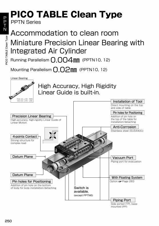
PPTN Series
Accommodation to clean roomMiniature Precision Linear Bearing withIntegrated Air Cylinder
Mounting Parallelism 0.02㎜ (PPTN10, 12)Running Parallelism 0.004㎜ (PPTN10, 12)
Linear Bearing
High Accuracy, High RigidityLinear Guide is built-in.
THK CO., LTD RSRIKO CO., LTD LWL
Datum Plane
4-points Contact
Precision Linear Bearing
(except PPTN6)
Switch isavailable.
Vacuum Port
Piping Port
With Floating System
Anti-Corrosion
Installation of Tool
High-accuracy, high-rigidity Linear Guide of Linear Motion.
Pin holes for PositioningAddition of pin hole on the bottomof body for body installation/detaching
Strong structure forcomplex load
Direct mounting on the topand side of table
Pin holes for PositioningAddition of pin hole onthe top of the table forinstallation/detaching
Stainless steel (SUS440C)
Piping port for evacuation
Option Page 283
Side ported (TP), basemounted (PP)
PICO TABLE Clean Type
Datum Plane
PPTN
PICO TABLE Clean Type
250
PPTNPICO TABLE Clean Type
PPTN
PICO TABLE Clean Type
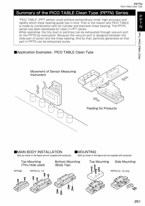
Summary of the PICO TABLE Clean Type (PPTN) Series"PICO TABLE" (PPT series) could achieve extraordinary small, high accuracy andrigidity which linear bearing guide has in kind. That is the reason why PICO TABLEis made by combination with air cylinder and precision linear bearing. The PPTNseries has been developed for clean in PPT series.While operating, the tiny dust or particles can be exhausted through vacuum porton the PPTN by evacuation. Because the vacuum port is designed between theslide part of piston and the linear bearing. And by that, particles generated at thatpart in PPTN can be exhausted surely.
■Application Examples : PICO TABLE Clean Type
Feeding for Products
Movement of Sensor MeasuringInstrument
■MAIN BODY INSTALLATION(Bolt as shown in the figure are not supplied with products)
■MOUNTING(Bolt as shown in the figure are not supplied with products)
Top Mounting(Thru Hole used)
Bottom Mounting(Body Tap)
Top Mounting Side Mounting
PPTN6 PPTN10, 12 PPTN10, 12 only
PPTN
PICO TABLE Clean Type
PPTNPICO TABLE Clean Type
PPTN
PICO TABLE Clean Type
251

Piping
Bore Size
Type
Stroke
Floating Mechanism Type PPTNF Series283 Page
PICO TABLE Standard TypePPT Series35 Page
Model Code Example
PPTNS-SD10-10-TP-RB12LA
Series Name
Clean Type
Magnet and Switch Rail
SwitchVacuum Plate
Magnet
Switch Rail
No Code None
Magnet and Switch RailThe figure shows TP
S
φ6
φ1212
610 φ10
BasicSD
1mLA 3m
No Code
121
2
2-Piping Ports
2-Piping Ports Vacuum Port
Hole for Vacuum
2-O rings
Vacuum Port
Cable Length
Number of Switches
A magnet and switch rail isrequired when mountigswitches. For PPTN6,10 and 12, S is available.
TP Side Ported Base MountedPP
Not available to shift the port position each other.
5
Unit:㎜
10 25PPTN6PPTN10
ModelStandard Stroke
PPTN12
2015
Attachment : Two O-ring
By arranging the base, the airfittings can be mountedanywhere on it.
The surface roughness of thebase for O-ring should be 1.6umRa(6.3umRy) at the maximum.
Vaccum port should be installed onthe position which leads to hole forvaccum of bottom of the body.
Install the air fittingsto the ports directly.
RB・・・・Straight Outlet Cable
Direction Of Cable OutletRC・・・・Angle Outlet Cable
No Code
RC1RB1
RB2RC2RB4RC4RB5RC5
DC12~24V2 Wires
Reed SwitchDC12~24V2 Wires
Reed SwitchDC12~24V2 Wires SolidState SwitchDC5~24V3 Wires SolidState Switch
NoneStraightAngleStraightAngleStraightAngleStraightAngle
WithIndicatorLightWithoutIndicatorLightWith
IndicatorLightWith
IndicatorLight
For details Page 1066, 1067
PPTN
PICO TABLE Clean Type
252
PPTNPICO TABLE Clean Type
PPTN
PICO TABLE Clean Type
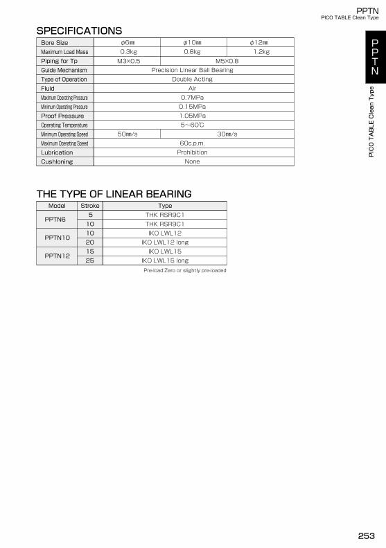
SPECIFICATIONS
Double ActingAir
1.05MPa5~60℃
60c.p.m.50㎜/s 30㎜/s
Prohibition
0.7MPa
Precision Linear Ball BearingM5×0.8M3×0.5
None
0.15MPa
0.3kgφ6㎜
1.2kgφ12㎜
0.8kgφ10㎜
THE TYPE OF LINEAR BEARINGModel
PPTN6
PPTN12
Type
PPTN10
Stroke
25
510102015
IKO LWL15 long
THK RSR9C1
IKO LWL12 longIKO LWL15
IKO LWL12THK RSR9C1
Pre-load:Zero or slightly pre-loaded
Bore SizeMaximum Load MassPiping for TpGuide MechanismType of OperationFluidMaximum Operating PressureMinimum Operating PressureProof PressureOperating TemperatureMinimum Operating SpeedMaximum Operating SpeedLubricationCushloning
PPTN
PICO TABLE Clean Type
PPTNPICO TABLE Clean Type
PPTN
PICO TABLE Clean Type
253

OPTIONAL PARTS CODES
Name
RB1(PPT)
Reed Switch(2 Wires, without Indicator Light)Angle Outlet Cable
RB1LA(PPT) RC1LA(PPT)
Reed Switch(2 Wires, with Indicator Light)
RB2LA(PPT)
Content
PARTS CODENote
RC1(PPT)PARTS CODENote
RB2(PPT)
Straight Outlet Cable
with fixture
Angle Outlet CableStraight Outlet Cable
Cable Length:3m
Cable Length:1m
with fixture
Cable Length:3m
RC2LA(PPT)
Cable Length:1m
RC2(PPT)
Cable Length:3m
Cable Length:1m
with fixture
Cable Length:3m
Cable Length:1m
with fixture
Screw, nut
BE(PPT)
Switch Fixture
Straight Outlet Cable
Cable Length:3m
Cable Length:1m
with fixture
RC5LA(PPT)
RC5(PPT)
Cable Length:3m
Cable Length:1m
with fixture
Angle Outlet CableSolid State Switch(3 Wires, with Indicator Light)
RB5(PPT)
RB5LA(PPT)
with fixture
Angle Outlet CableStraight Outlet Cable
Cable Length:3m
Cable Length:1m
Cable Length:3m
Cable Length:1m
with fixture
RB4(PPT)
RB4LA(PPT)
RC4(PPT)
RC4LA(PPT)
Solid State Switch(2 Wires, with Indicator Light)
Switch RailMagnetRepair Parts Kit
Before mounting, applyanaerodic adhesive tothe screws.
RK(PPT)
with fixing boltswith fixing bolts
HS(PPT)
RJ(PPTN(Stroke)-(Piping))
Ex) In case PPTN10 20stroke TP Piping Switch Rail : RJ(PPTN10-20-TP)Note: For Only PPTN10,12
O-ring for Base Mounted
Fill in □ as bore size.
For details Page 256
Fill in □ as bore size
HC(PPT□)
CSφ1, IDφ10
For all size
10 O-rings
●RB,RC SwitchConventional RG1,RG2 switchescan be replaced to RB,RC switch
Comparison with Old TypeOld type
RG1
RG2
Equivalent Current TypeRB1, RC1RB2, RC2RB4, RC4RB5, RC5
PPTN
PICO TABLE Clean Type
254
PPTNPICO TABLE Clean Type
PPTN
PICO TABLE Clean Type
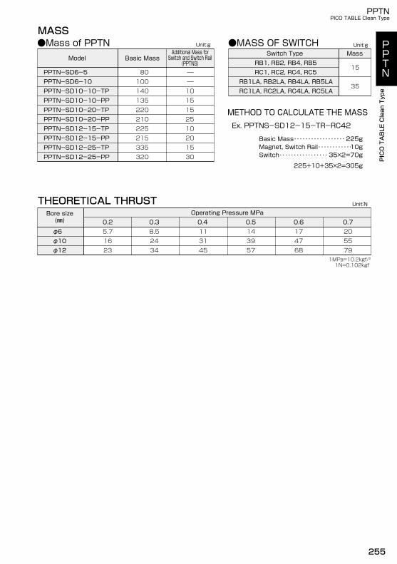
1MPa=10.2kgf/21N=0.102kgf
Unit:g
MASS
Model
PPTN-SD6-5
PPTN-SD10-10-TPPPTN-SD10-10-PP
30
101515251020
PPTN-SD6-10
PPTN-SD12-25-PP
PPTN-SD10-20-TPPPTN-SD10-20-PPPPTN-SD12-15-TPPPTN-SD12-15-PPPPTN-SD12-25-TP 15
320335215225210220135140100 80
Basic Mass
●Mass of PPTNAdditional Mass forSwitch and Switch Rail
(PPTNS)
●MASS OF SWITCH
15
Switch Type Mass
RC1LA, RC2LA, RC4LA, RC5LA
Unit:g
RB1LA, RB2LA, RB4LA, RB5LARC1, RC2, RC4, RC5RB1, RB2, RB4, RB5
35
METHOD TO CALCULATE THE MASSEx. PPTNS-SD12-15-TR-RC42
225+10+35×2=305g
Basic Mass・・・・・・・・・・・・・・・・・・
Switch・・・・・・・・・・・・・・・・・Magnet, Switch Rail・・・・・・・・・・・・
225g
35×2=70g10g
THEORETICAL THRUSTBore size(㎜)
φ12
φ6
Operating Pressure MPaUnit:N
φ108.5
0.7
165.7
23
0.2 0.3 0.4 0.5 0.6
2434
20
795531
45
113957
144768
17
PPTN
PICO TABLE Clean Type
PPTNPICO TABLE Clean Type
PPTN
PICO TABLE Clean Type
255
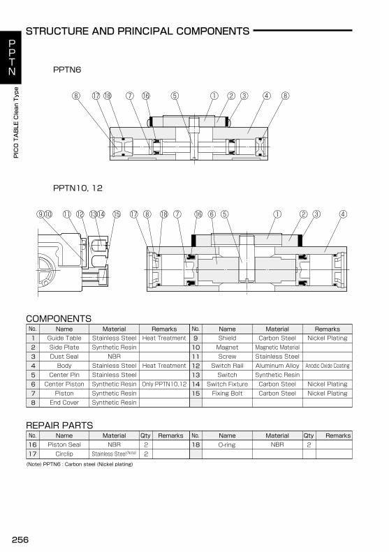
PPTN6
STRUCTURE AND PRINCIPAL COMPONENTS
COMPONENTS
REPAIR PARTS
3
6
2
RemarksName MaterialName Material Remarks1
4
15
5
78
91011121314
1716
RemarksName MaterialName Remarks18
Material Qty22
2Qty
O-ring
No.
No. No.
No.
(Note) PPTN6 : Carbon steel (Nickel plating)
PPTN10, 12
Guide TableSide PlateDust SealBody
Center PinCenter PistonPistonEnd Cover
Piston SealCirclip
Stainless SteelSynthetic Resin
NBRStainless SteelStainless SteelSynthetic ResinSynthetic ResinSynthetic Resin
NBRStainless Steel(Note)
Heat Treatment
Heat Treatment
Only PPTN10,12
ShieldMagnetScrew
Switch RailSwitch
Switch FixtureFixing Bolt
Carbon SteelMagnetic MaterialStainless SteelAluminum AlloySynthetic ResinCarbon SteelCarbon Steel
NBR
Nickel Plating
Anodic Oxide Coating
Nickel PlatingNickel Plating
PPTN
PICO TABLE Clean Type
256
PPTNPICO TABLE Clean Type
PPTN
PICO TABLE Clean Type
LφD
H
L
H
φD
L
φD
H
L
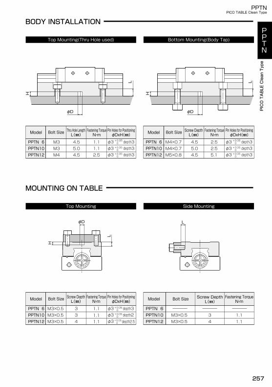
BODY INSTALLATION
Top Mounting(Thru Hole used) Bottom Mounting(Body Tap)
Model
PPTN12PPTN10PPTN 6
M4M3M3
2.51.11.1
4.55.04.5
PPTN12PPTN10PPTN 6
M5×0.8M4×0.7
5.12.5
4.55.0
M4×0.7 2.54.5
M3×0.5M3×0.5M3×0.5 1.1
1.11.1 1.1
1.1433
Model
PPTN12PPTN10PPTN 6
Bolt Size
M3×0.5M3×0.5
Fastening TorqueN・m
43
Side MountingTop Mounting
MOUNTING ON TABLE
Screw DepthL(㎜)
Bolt Size Thru Hole LengthL(㎜)
Fastening TorqueN・m
depth3depth3depth3
φ3φ3φ3
Pin Holes for PositioningφDxH(㎜) Model Bolt Size Screw Depth
L(㎜)Fastening TorqueN・m
Pin Holes for PositioningφDxH(㎜)
+0.05 0
+0.05 0+0.05 0
depth3depth3depth3
φ3φ3φ3
+0.05 0
+0.05 0+0.05 0
Model
PPTN12PPTN10PPTN 6
Bolt Size Screw DepthL(㎜)
Fastening TorqueN・m
depth3depth2
φ3φ3φ3
Pin Holes for PositioningφDxH(㎜)
+0.05 0
+0.05 0
+0.05 0 depth2.5
PPTN
PICO TABLE Clean Type
PPTNPICO TABLE Clean Type
PPTN
PICO TABLE Clean Type
257
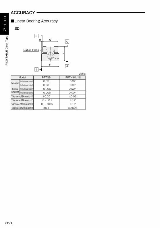
ACCURACY
■Linear Bearing Accuracy
SD
Datum Plane
DG
E
H
F A
C
B
±0.02
0.020.020.0040.004
±0.2±0.025
±0.2
PPTN10, 12
0~-0.20~-0.05±0.1
±0.050.0050.0050.030.03PPTN6
Plane C with respect to plane A
Plane D with respect to plane B
Plane C with respect to plane A
Plane D with respect to plane B
Model
Tolerance of Dimension ETolerance of Dimension FTolerance of Dimension GTolerance of Dimension H
RunningParallelism
Parallelism
Unit:㎜
PPTN
PICO TABLE Clean Type
258
PPTNPICO TABLE Clean Type
PPTN
PICO TABLE Clean Type
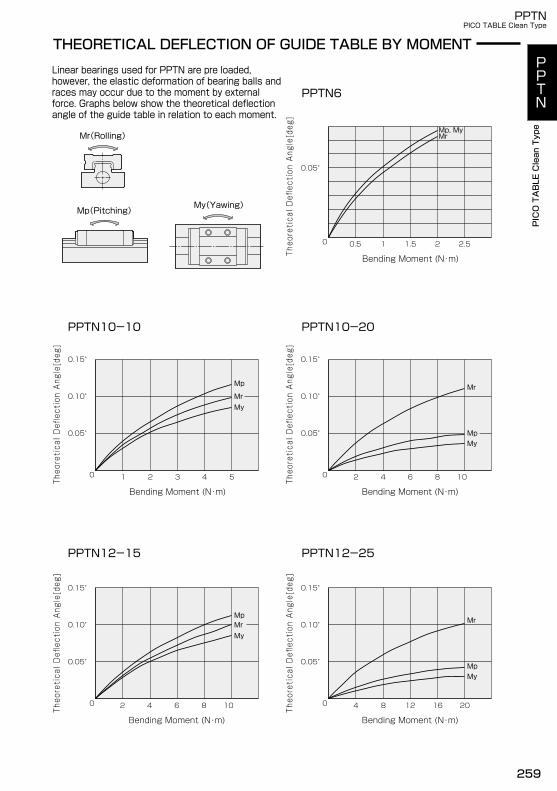
Linear bearings used for PPTN are pre loaded,however, the elastic deformation of bearing balls andraces may occur due to the moment by externalforce. Graphs below show the theoretical deflectionangle of the guide table in relation to each moment.
THEORETICAL DEFLECTION OF GUIDE TABLE BY MOMENT
PPTN6
Mr(Rolling)
My(Yawing)Mp(Pitching)
Mp, MyMr
0.05゜
0 0.5 1 1.5 2 2.5
Bending Moment (N・m)
PPTN10-10
Mp
MrMy
0.05゜
0.10゜
0.15゜
0
Bending Moment (N・m)
1 2 3 4 5
PPTN10-20
0.05゜
0.10゜
0.15゜
0
Bending Moment (N・m)
2 4 6 8 10
Mp
Mr
My
My
MpMr
0.05゜
0.10゜
0.15゜
0
Bending Moment (N・m)
2 4 6 8 10
PPTN12-15 PPTN12-25
0.05゜
0.10゜
0.15゜
0
Bending Moment (N・m)
4 8 12 16 20
My
Mr
Mp
Theoretical Deflection Angle[deg]
Theoretical Deflection Angle[deg]
Theoretical Deflection Angle[deg]
Theoretical Deflection Angle[deg]
Theoretical Deflection Angle[deg]
PPTN
PICO TABLE Clean Type
PPTNPICO TABLE Clean Type
PPTN
PICO TABLE Clean Type
259

A
B B
AR0.2 or less
R0.2 or less
BA
θ
θ
PRECAUTIONS FOR DESIGN AND USE
Caution
Moment by Thrust of Cylinder at Offset Pushing
As the following figure, if cylinder will push work or so atthe offset point in the middle of stroke, a large momentwill be generated by the thrust of cylinder itself.Static moment rating Page 263
Mounting Surface Accuracy
①At the top, side of table and the bottom of body, the surfaces of PICO TABLE are ground up accurately. Stable and smooth movement highly accuracy can be obtained by proper installation to mounting surface machined high accurately. An irregular mounting surface or incorrect mounting may result in inaccurate movement, instability or poor service life. Datum plane (body and guide table) Page 258
②It is recommended to make relief at the corner of mating reference mounting surfaces. Besides, corner radius shown in the following figure can also be used. If the corner profile is curved smoothly, compared to the chamfer profile of the body and guide table, it may not closely contact its reference surface.
③Check the reference mounting corner to an exact right angle between the mounting surface and the surface against which body or table is pressed. If the angle is not right-engled, they cannot contact the surface properly.
④When designing a reference surface, carefully examine the height and thickness of the section. If a reference section is too thin, precision may deteriorate, as a thin ridge lacks rigidity against lateral load due to the movement of the body or guide table and the force exerted by the lateral mounting bolts.
Rigidity of Mounting Base (Fixed Part)
If the method of fixing the body and the rigidity of themounting base are not correct, high rigidity and thehigh accuracy PICO TABLE has in kind could not beeffectire.Consider it for design about also the rigidity ofdevices itself such as an attachment base.
Pushing Point
Pitching Moment
Moment
Cylinder Thrust
L
Cylinder Thrust
Moment
Pushing Point
Yawing Moment
L
PPTN
PICO TABLE Clean Type
260
PPTNPICO TABLE Clean Type
PPTN
PICO TABLE Clean Type
Lubrication
Fluorine grease is applied on ball rolling surfacesbefore dispatch the unit. According to operation, timeand condition for use, grease would be deterioratedand this cause the bearing to shorten its life becauseof wear on rolling surfaces.Although the grease feeding interval depends on theservice conditions and environment, as a rule, feedingshould be performed every 100km of travel undernormal usage or one month. Feed on raceway of thebody as for Fluorine grease after wiping off old greasecompletely. The chemical change and poor performance byfeeding the different grease would cause defectiveoperation and the breakdown.
Anticorrosive
The material of body and guide table is martensitestainless steal (SUS440C). That parts should not betreated with anticorrosive oil for use in clean room. Bythat, the surface of the each parts may cause a bit ofrust according to the condition which the actuator isoperated, for instance, use by hand or in environmentor the period for use. However, the linear guide andcylinder inside actuator are applied with fluorinegrease for smooth operation.
Feeling of Linear Guide Rolling
When the table is moved by hand without air pressure,discontinuous feeling of rolling balls on strangefeeling of rolling resistance do not effect itsperformance.
Magnetization of Table and Body
Martensite stainless steel, as material of table andbody, must be magnetized easily by contactingmagnet and magnetic thing. Once that steel ismagnetized, it keeps this state.Note that there is a possibility that the switch mightnot work correctly by this magnetization.
Pin Hole of Table and Body for Positioning
Excessive load or transformation of raceway due topress-fitting the pin into the pin hole would cause thebreakdown. Moreover, to press-fit would cause thecrack and damage because of hardness of material byheat treated at the pin hole part.Confirm the clearance between pin and pin hole.
PPTN
PICO TABLE Clean Type
PPTNPICO TABLE Clean Type
PPTN
PICO TABLE Clean Type
261
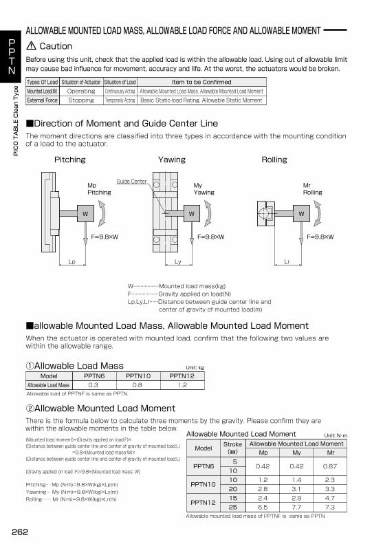
ALLOWABLE MOUNTED LOAD MASS, ALLOWABLE LOAD FORCE AND ALLOWABLE MOMENT
The moment directions are classified into three types in accordance with the mounting condition of a load to the actuator.
Pitching Yawing Rolling
■Direction of Moment and Guide Center Line
CautionBefore using this unit, check that the applied load is within the allowable load. Using out of allowable limitmay cause bad influence for movement, accuracy and life. At the worst, the actuators would be broken.
OperatingStopping
Situation of Actuator Situation of LoadContinuously ActingTemporarily Acting
Types Of LoadMounted Load(W)External Force Basic Static-load Rating, Allowable Static Moment
Allowable Mounted Load Mass, Allowable Mounted Load MomentItem to be Confirmed
WW
MrRolling
F=9.8×W
MpPitching
F=9.8×W F=9.8×W
MyYawing
Guide Center
LrLyLp
W
W・・・・・・・・・・・・・・・・・・Mounted load mass(kg)F・・・・・・・・・・・・・・・・・・・Gravity applied on load(N)Lp,Ly,Lr・・・・・・Distance between guide center line and center of gravity of mounted load(m)
■allowable Mounted Load Mass, Allowable Mounted Load MomentWhen the actuator is operated with mounted load, confirm that the following two values are within the allowable range.
①Allowable Load Mass Unit: kg
Allowable load of PPTNF is same as PPTN.
Allowable mounted load mass of PPTNF is same as PPTN
Allowable Load MassModel
0.3 1.2PPTN6 PPTN12PPTN10
0.8
②Allowable Mounted Load MomentThere is the formula below to calculate three moments by the gravity. Please confirm they arewithin the allowable moments in the table below.(Mounted load moment)=(Gravity applied on load:F)×(Distance between guide center line and center of gravity of mounted load:L) =9.8×(Mounted load mass:W)×(Distance between guide center line and center of gravity of mounted load:L)
(Gravity applied on load: F)=9.8×(Mounted load mass: W)
Pitching… Mp (N・m)=9.8×W(kg)×Lp(m)Yawning… My (N・m)=9.8×W(kg)×Ly(m)Rolling…… Mr (N・m)=9.8×W(kg)×Lr(m)
Allowable Mounted Load Moment Unit: N・m
ModelStroke(㎜)
Allowable Mounted Load MomentMp My Mr
25
510102015
7.3
0.87
PPTN12
PPTN6
PPTN102.33.34.72.4
2.81.2
0.42
6.52.93.11.4
0.42
7.7
PPTN
PICO TABLE Clean Type
262
PPTNPICO TABLE Clean Type
PPTN
PICO TABLE Clean Type
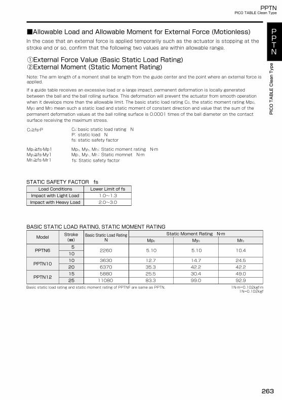
■Allowable Load and Allowable Moment for External Force (Motionless)
Note: The arm length of a moment shall be length from the guide center and the point where an external force isapplied.
①External Force Value (Basic Static Load Rating)②External Moment (Static Moment Rating)
In the case that an external force is applied temporarily such as the actuator is stopping at thestroke end or so, confirm that the following two values are within allowable range.
fs: Static safety factor
C0≧fs・P basic static load rating Nstatic load Nstatic safety factor
STATIC SAFETY FACTOR fs
1.0~1.3Lower Limit of fs
Impact with Heavy Load
Load ConditionsImpact with Light Load
2.0~3.0
BASIC STATIC LOAD RATING, STATIC MOMENT RATING
PPTN12
Model
PPTN6
PPTN10
25
510102015
Basic Static Load RatingN
Static Moment Rating N・mMr0Mp0 My0
92.9
42.249.0
10.4
1108025.535.3
5.10
83.3
14.7
30.442.2
5.10
99.0
24.512.7
2260
6370 5880
3630
Stroke(㎜)
C0:P:fs:
Mp0, My0, Mr0:Mp1, My1, Mr1:
Mp0≧fs・Mp1My0≧fs・My1Mr0≧fs・Mr1
If a guide table receives an excessive load or a large impact, permanent deformation is locally generatedbetween the ball and the ball rolling surface. This deformation will prevent the actuator from smooth operationwhen it develops more than the allowable limit. The basic static load rating C0, the static moment rating Mp0,My0 and Mr0 mean such a static load and static moment of constant direction and value that the sum of thepermanent deformation values at the ball rolling surface is 0.0001 times of the ball diameter on the contactsurface receiving the maximum stress.
1N・m=0.102kgf・m1N=0.102kgf
Basic static load rating and static moment rating of PPTNF are same as PPTN.
Static moment rating N・mStatic momnet N・m
PPTN
PICO TABLE Clean Type
PPTNPICO TABLE Clean Type
PPTN
PICO TABLE Clean Type
263
PPTN-SD6-5
20.5
D
B
B D - Datum plane
C
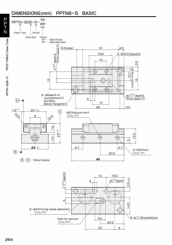
DIMENSIONS(mm) PPTN6-5 BASIC
PPTN-SD6-5-TPPP
Piping TP・・・・・Side Ported PP・・・・・Base Mounted
StrokeClean Type
Bore Size
5(Stroke) 4.531
19.8
10
1.5±0.1 20 0-0.05
C0.59
C0.5
23 0-0.2
7.8
7.8 17±0.05
M3(Vacuum port)(Only TP)
20.52-M3(Port)(Only TP)
5
12.5
9.7 5.7
45
9.2
14.5
4-M3×0.5depth3
Hole for vacuum
5
2-φ11.8counterbore
825
2-φ6depth of counterbore3.3 φ3.3thru M4×0.7length4.5
3.5
(Only PP)
2-φ9.5(O-ring inside diameter)(Only PP)
16
3.5
38
14
15
depth3
(From plane C)
0+0.05
3
depth3 0+0.05φ3
(From plane C)4
depth3 0+0.05φ3de
pth3
0+0.05
3
4
10 15.5
±0.05
3.5
(Location of hole φ3)
±0.1
10
PPTN
PICO TABLE Clean Type
264
PPTNPICO TABLE Clean Type
PPTN
PICO TABLE Clean Type
PPTN-SD6-10
14D
B
B D - Datum plane
C
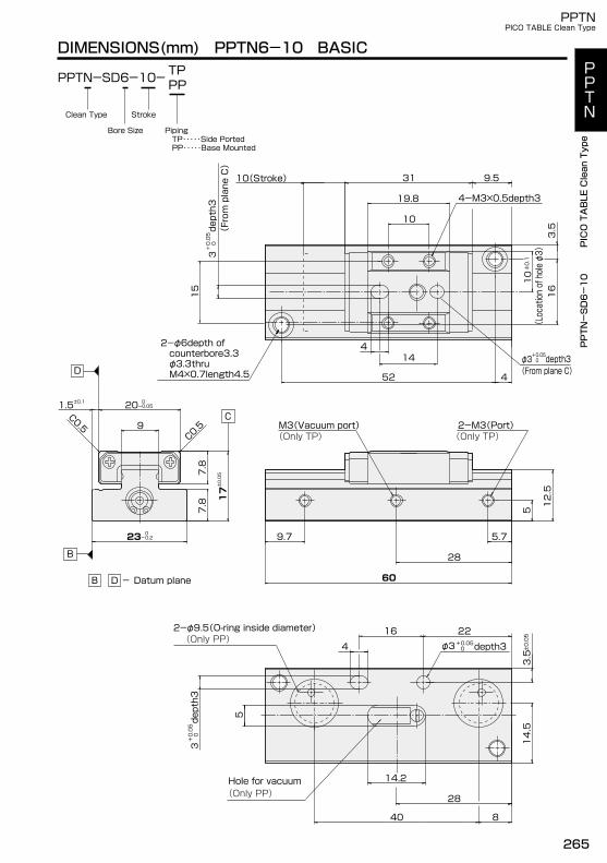
DIMENSIONS(mm) PPTN6-10 BASIC
PPTN-SD6-10-
9.510(Stroke) 31
19.8
10
C0.5C0.5
1.5±0.1 20 0-0.05
7.8
23 0 -0.2
9
17±0.05
7.8
2-M3(Port)(Only TP)
28
M3(Vacuum port)(Only TP)
5
12.5
5.79.7
60
28
14.2
14.5
3.5
5
TPPP
φ3
Hole for vacuum
2-φ9.5(O-ring inside diameter)
3.5
4-M3×0.5depth3
2-φ6depth of counterbore3.3 φ3.3thru M4×0.7length4.5
16
15
52
4
4
(Only PP)
(Only PP)4
16 22
840
depth3
(From plane C)
0+0.05
3
(Location of hole φ3)
±0.1
10
depth3 0+0.05φ3
(From plane C)
depth3
0+0.05
3
depth3 0+0.05
±0.05
Piping TP・・・・・Side Ported PP・・・・・Base Mounted
StrokeClean Type
Bore Size
PPTN
PICO TABLE Clean Type
PPTNPICO TABLE Clean Type
PPTN
PICO TABLE Clean Type
265

DC
B
B D - Datum plane
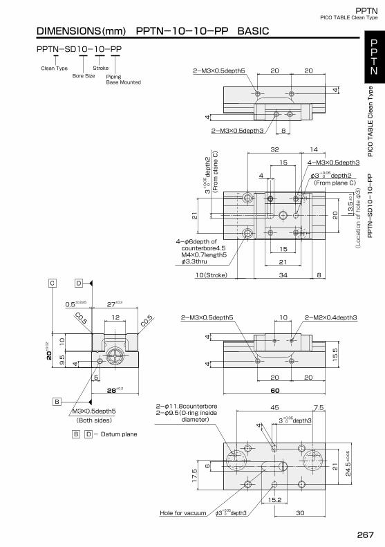
DIMENSIONS(mm) PPTN10-10-TP BASIC
PPTN-SD10-10-TP
4
4
2-M3×0.5depth3
2-M3×0.5depth5 20 20
8
20
10(Stroke) 834
21
15
2-M2×0.4depth3M3(Vacuum port) 10
54
15.5
30
5.5
2-M5(Port)
66
60
C0.5C0.5
0.5±0.025
0.5
7.5
6.5
27±0.2
M3×0.5depth5(Both sides)
4
10
9.5
12
5
28±0.2
20±0.02
4
±0.05
24.5
depth3 0+0.05φ3 30
depth3 0+0.053
21
1628
±0.1
13.5
4-M3×0.5depth3
depth2 0+0.05φ3de
pth2
(From plane C)
0+0.05
3
14
15
4
4-φ6depth of counterbore4.5 M4×0.7length5 φ3.3thru
32
21
(From plane C)
(Location of hole φ3)
PPTN-SD10-10-TP
PipingBase Mounted
StrokeClean Type
Bore Size
PPTN
PICO TABLE Clean Type
266
PPTNPICO TABLE Clean Type
PPTN
PICO TABLE Clean Type
B
B D - Datum plane
M3×0.5depth5(Both sides)
C D
4
4
2-M3×0.5depth3
2-M3×0.5depth5 20 20
8
20
10(Stroke) 834
21
15
20 20
60
2-M3×0.5depth5
4
2-M2×0.4depth310
4
15.5
C0.5
C0.5
0.5±0.025 27±0.2
4
10
9.520±0.02
12
5
28±0.2
2-φ11.8counterbore2-φ9.5(O-ring inside diameter)
6
30
15.2
4
depth3 0+0.05φ3Hole for vacuum
±0.05
24.5
depth3 0+0.053
21
7.545
17.5
±0.1
13.5
4-M3×0.5depth3
depth2 0+0.05φ3de
pth2
(From plane C)
0+0.05
3
14
15
4-φ6depth of counterbore4.5 M4×0.7length5 φ3.3thru
32
4
21
(From plane C)
(Location of hole φ3)
PPTN-SD10-10-PP
DIMENSIONS(mm) PPTN-10-10-PP BASIC
PPTN-SD10-10-PP
PipingBase Mounted
StrokeClean TypeBore Size
PPTN
PICO TABLE Clean Type
PPTNPICO TABLE Clean Type
PPTN
PICO TABLE Clean Type
267

DC
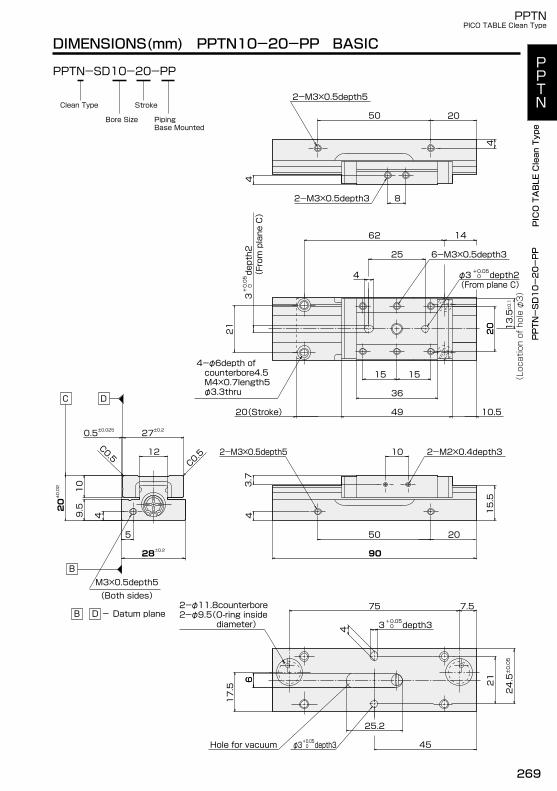
DIMENSIONS(mm) PPTN10-20-TP BASIC
PPTN-SD10-20-TP
50 20
4
4
2-M3×0.5depth3
2-M3×0.5depth5
8
20
10.520(Stroke) 49
36
1515
M3(Vacuum port)
2-M5(Port)
45
90
2-M2×0.4depth310
53.7
15.5
5.566
C0.5
C0.5
0.5±0.025
0.5
7.5
6.5
27±0.2
4
10
9.520±0.02
12
5
28±0.2
4
1658
depth3 0+0.053
depth3 0+0.05φ3
21
45
±0.05
24.5
14
depth2 0+0.05φ3
±0.1
13.5
62
25depth2
(From plane C)
0+0.05
3
4
21
6-M3×0.5depth3
4-φ6depth of counterbore4.5 φ3.3thru M4×0.7length5
20
(From plane C)
(Location of hole φ3)
PPTN-SD10-20-TP
B
B D - Datum plane
M3×0.5depth5(Both sides)
PipingBase Mounted
StrokeClean Type
Bore Size
PPTN
PICO TABLE Clean Type
268
PPTNPICO TABLE Clean Type
PPTN
PICO TABLE Clean Type
PPTN-SD10-20-PP
DC
DIMENSIONS(mm) PPTN10-20-PP BASIC
PPTN-SD10-20-PP
50
4
4
2-M3×0.5depth3
2-M3×0.5depth5
8
10.5
20
20(Stroke) 49
36
1515
2-M3×0.5depth5
50 20
90
2-M2×0.4depth310
3.7
15.5
2-φ11.8counterbore2-φ9.5(O-ring inside diameter)
25.2
45
6
C0.5
C0.5
0.5±0.025 27±0.2
4
10
9.520±0.02
12
5
28±0.2
4
20
Hole for vacuum depth3 0+0.05φ3
4
17.5
6
7.575
depth3 0+0.053
21
±0.05
24.5
14
depth2 0+0.05φ3
±0.1
13.5
62
25depth2
(From plane C)
0+0.05
3
4-φ6depth of counterbore4.5 M4×0.7length5 φ3.3thru
6-M3×0.5depth3
21
4
20
(From plane C)
(Location of hole φ3)
B
B D - Datum plane
M3×0.5depth5(Both sides)
PipingBase Mounted
StrokeClean Type
Bore Size
PPTN
PICO TABLE Clean Type
PPTNPICO TABLE Clean Type
PPTN
PICO TABLE Clean Type
269
B
B D - Datum plane
M3×0.5depth5(Both sides)
DC
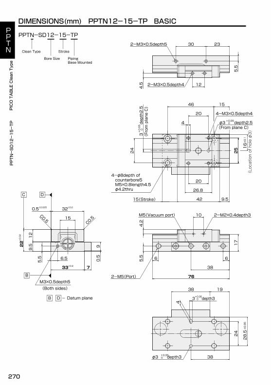
DIMENSIONS(mm) PPTN12-15-TP BASIC
PPTN-SD12-15-TP2-M3×0.5depth5
2-M3×0.5depth4
30 23
12
4.5
5.5
25
26.8
20
42 9.515(Stroke)
2-M2×0.4depth3M5(Vacuum port)
2-M5(Port)
17
4.2
5.5
10
66
38
76
C0.5
C0.5
0.5±0.025
0.5
9
7
32±0.2
22±0.02
5.5
15
33±0.2
6.5
12
9.5
4
±0.05
28.5
1938
depth3 0+0.05φ3 38
24
depth3 0+0.053
±0.1
16
depth2.5 0+0.05φ3
.4-M3×0.5depth4
.depth2.5
(From plane C)
0+0.05
3
15
4
20
4-φ8depth of counterbore5 M5×0.8length4.5 φ4.2thru
46
25
24
(From plane C)
(Location of hole φ3)
PPTN-SD12-15-TP
PipingBase Mounted
StrokeClean Type
Bore Size
PPTN
PICO TABLE Clean Type
270
PPTNPICO TABLE Clean Type
PPTN
PICO TABLE Clean Type
DC
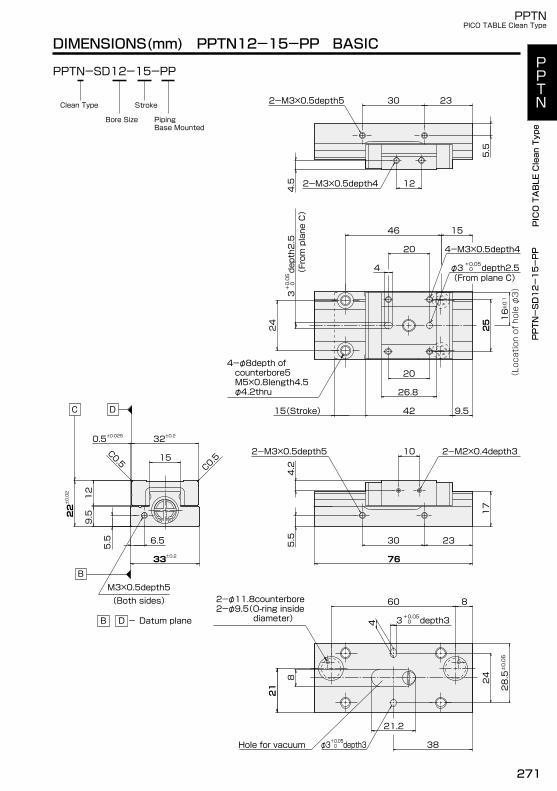
DIMENSIONS(mm) PPTN12-15-PP BASIC
PPTN-SD12-15-PP
2-M3×0.5depth5
2-M3×0.5depth4
30 23
12
4.5
5.5
25
26.8
20
9.54215(Stroke)
2-M3×0.5depth5
76
30 23
2-M2×0.4depth3
4.2
5.5
10
21
2-φ11.8counterbore2-φ9.5(O-ring inside diameter)
38
21.2
C0.5
C0.5
0.5±0.025 32±0.2
12
9.522±0.02
5.5
15
33±0.2
6.5
17
4
8
21
860
Hole for vacuum depth3 0+0.05φ3
24
depth3 0+0.053
±0.05
28.5
depth2.5
(From plane C)
0+0.05
3
15
20
4
4-M3×0.5depth4
depth2.5 0+0.05φ3
±0.1
16
24
25
46
4-φ8depth of counterbore5 M5×0.8length4.5 φ4.2thru
(From plane C)
(Location of hole φ3)
PPTN-SD12-15-PP
B
B D - Datum plane
M3×0.5depth5(Both sides)
PipingBase Mounted
StrokeClean Type
Bore Size
PPTN
PICO TABLE Clean Type
PPTNPICO TABLE Clean Type
PPTN
PICO TABLE Clean Type
271
DC
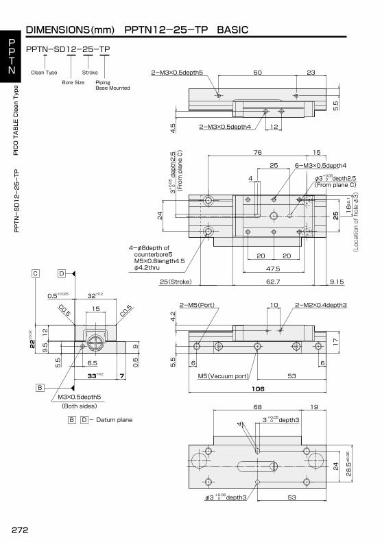
DIMENSIONS(mm) PPTN12-25-TP BASIC
PPTN-SD12-25-TP
2-M3×0.5depth4
2-M3×0.5depth5 60
12
4.5
5.5
6-M3×0.5depth4
25
2020
47.5
9.1562.725(Stroke)
M5(Vacuum port)
2-M2×0.4depth32-M5(Port) 10
106
53
66
17
4.2
5.5
22±0.02
C0.5
C0.5
0.5±0.025
0.5
9
7
32±0.2
12
9.5
5.5
15
6.5
33±0.2
23
4
1968
depth3 0+0.05φ3 53
24 ±
0.05
28.5
depth3 0+0.053
depth2.5 0+0.05φ3
15
4-φ8depth of counterbore5 M5×0.8length4.5 φ4.2thru
7624
25depth2.5
0+0.05
34
±0.1
16
25
(From plane C)(From plane C)
(Location of hole φ3)
PPTN-SD12-25-TP
B
B D - Datum plane
M3×0.5depth5(Both sides)
PipingBase Mounted
StrokeClean Type
Bore Size
PPTN
PICO TABLE Clean Type
272
PPTNPICO TABLE Clean Type
PPTN
PICO TABLE Clean Type
DC
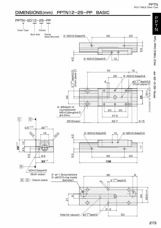
DIMENSIONS(mm) PPTN12-25-PP BASIC
PPTN-SD12-25-PP
2-M3×0.5depth4
2-M3×0.5depth5 60
12
4.5
5.5
25
2020
47.5
9.1562.725(Stroke)
6-M3×0.5depth4
2-M3×0.5depth5
106
60 23
2-M2×0.4depth310
17
4.2
5.5
2-φ11.8counterbore2-φ9.5(O-ring inside diameter)
21
53
31.2
C0.5
C0.5
0.5±0.025 32±0.2
22±0.02
12
9.5
5.5
15
6.5
33±0.2
23
4
depth3 0+0.05φ3Hole for vacuum
8
890
24
±0.05
28.5
depth3 0+0.053
depth2.5 0+0.05φ3
15
±0.1
16
4
76
4-φ8depth of counterbore5 M5×0.8length4.5 φ4.2thru
25
24
25
depth2.5
0+0.05
3
(From plane C)
(From plane C)
(Location of hole φ3)
PPTN-SD12-25-PP
B
B D - Datum plane
M3×0.5depth5(Both sides)
PipingBase Mounted
StrokeClean Type
Bore Size
PPTN
PICO TABLE Clean Type
PPTNPICO TABLE Clean Type
PPTN
PICO TABLE Clean Type
273
DC
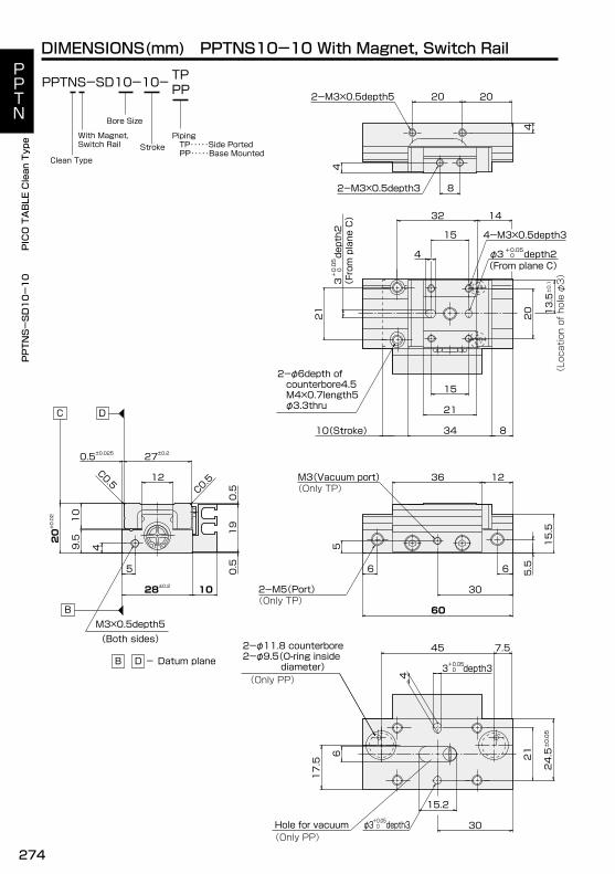
DIMENSIONS(mm) PPTNS10-10 With Magnet, Switch RailTPPPPPTNS-SD10-10-
With Magnet, Switch Rail
4
4
2-M3×0.5depth3
2-M3×0.5depth5 20
8
2-φ6depth of counterbore4.5 M4×0.7length5 φ3.3thru
20
10(Stroke) 834
21
15
M3(Vacuum port)(Only TP)
1236
5 15.5
30
5.5
2-M5(Port)(Only TP)
66
60
6
30
15.2
2-φ11.8 counterbore2-φ9.5(O-ring inside diameter)
0.5±0.025
C0.5
C0.5
27±0.2
10
19
0.5
0.5
4
10
9.520±0.02
12
5
28±0.2
20
4
Hole for vacuum depth3 0+0.05φ3
17.5
±0.05
24.5
depth3 0+0.053
21
7.545
(Only PP)
(Only PP)
±0.1
13.5
.4-M3×0.5depth3
depth2 0+0.05φ3de
pth2
(From plane C)
0+0.05
3
14
15
4
32
21
(From plane C)
(Location of hole φ3)
PPTNS-SD10-10
B
B D - Datum plane
M3×0.5depth5(Both sides)
Piping TP・・・・・Side Ported PP・・・・・Base Mounted
Stroke
Clean Type
Bore Size
PPTN
PICO TABLE Clean Type
274
PPTNPICO TABLE Clean Type
PPTN
PICO TABLE Clean Type
DC
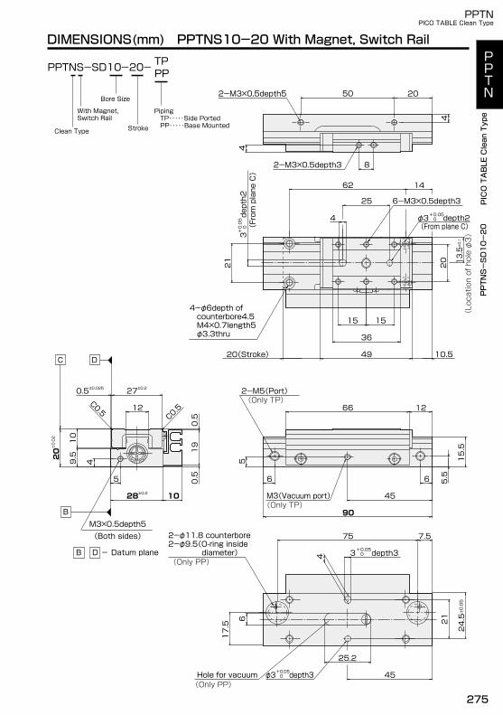
DIMENSIONS(mm) PPTNS10-20 With Magnet, Switch RailTPPPPPTNS-SD10-20-
2-M3×0.5depth5
2-M3×0.5depth3 8
50
4
4
10.520(Stroke)
1515
36
49
1266
M3(Vacuum port)(Only TP)
(Only TP)
45
5 15.5
2-M5(Port)
5.566
90
6
45
25.2
C0.5
C0.5
0.5±0.025 27±0.2
0.5
0.5
19
420±0.02 10
9.5
12
1028±0.2
5
20
14
depth2 0+0.05φ3
±0.1
13.5
62
25
depth2
(From plane C)
0+0.05
3
4
20
21
6-M3×0.5depth3
4-φ6depth of counterbore4.5 M4×0.7length5 φ3.3thru
(From plane C)
(Location of hole φ3)
4
depth3 0+0.05φ3
7.5
depth3 0+0.053
75
17.5 21 ±
0.05
24.5
Hole for vacuum
2-φ11.8 counterbore2-φ9.5(O-ring inside diameter)
(Only PP)
(Only PP)
PPTNS-SD10-20
B
B D - Datum plane
M3×0.5depth5(Both sides)
With Magnet, Switch Rail
Piping TP・・・・・Side Ported PP・・・・・Base MountedStrokeClean Type
Bore Size
PPTN
PICO TABLE Clean Type
PPTNPICO TABLE Clean Type
PPTN
PICO TABLE Clean Type
275
DC
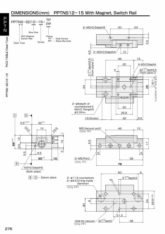
DIMENSIONS(mm) PPTNS12-15 With Magnet, Switch RailTPPPPPTNS-SD12-15-
2-M3×0.5depth5
2-M3×0.5depth4
30
12
4.5
5.5
25
26.8
20
9.542
M5(Vacuum port)(Only TP)
1546
38
5.5
17
2-M5(Port)(Only TP)
66
76
2-φ11.8 counterbore2-φ9.5(O-ring inside diameter)(Only PP)
21
38
21.2
C0.5
C0.5
0.5±0.025 32±0.2
19
21
12
9.522±0.02
5.5
15
1033±0.2
6.5
15(Stroke)
23
4
depth3 0+0.053
860
8
21
Hole for vacuum depth3 0+0.05φ3
24
±0.05
28.5
(Only PP)
4-M3×0.5depth4
depth2.5 0+0.05φ3
2-φ6depth of counterbore4.5 M4×0.7length5 φ3.3thru
±0.1
16
depth2.5
0+0.05
3
15
4
20
46
25
24
(From plane C)
(From plane C)
(Location of hole φ3)
PPTNS-SD12-15
B
B D - Datum plane
M3×0.5depth5(Both sides)
Piping TP・・・・・Side Ported PP・・・・・Base MountedStrokeClean Type
Bore Size
With Magnet, Switch Rail
PPTN
PICO TABLE Clean Type
276
PPTNPICO TABLE Clean Type
PPTN
PICO TABLE Clean Type
M5(Vacuum Port)(Only TP)
DC
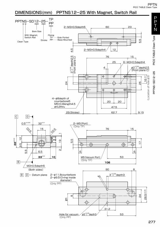
DIMENSIONS(mm) PPTNS12-25 With Magnet, Switch RailTPPPPPTNS-SD12-25-
2-M3×0.5depth4
2-M3×0.5depth5 60
12
4.5
5.5
25
25(Stroke) 62.7 9.15
47.5
20 20
2-M5(Port)(Only TP)
1576
5.5
17
53
66
106
2-φ11.8counterbore2-φ9.5(O-ring inside diameter)(Only PP)
21
53
31.2
C0.5
C0.5
0.5±0.025 32±0.2
219
1
22±0.02
12
9.5
5.5
15
6.5
1033±0.2
23
depth2.5 0+0.05φ3
6-M3×0.5depth4
15
4-φ8depth of counterbore5 M5×0.8length4.5 φ4.2thru
76
24
25
depth2.5
0+0.05
34
±0.1
16
(From plane C)
(From plane C)
(Location of hole φ3)
4
depth3 0+0.05φ3
890
depth3 0+0.053
8
21 24
±0.05
28.5
Hole for vacuum(Only PP)
PPTNS-SD12-25
B
B D - Datum plane
M3×0.5depth5(Both sides)
With Magnet, Switch Rail
Piping TP・・・・・Side Ported PP・・・・・Base MountedStroke
Clean Type
Bore Size
PPTN
PICO TABLE Clean Type
PPTNPICO TABLE Clean Type
PPTN
PICO TABLE Clean Type
277

INSTALLATION OF SWITCH
■Switch Setting Position
Unit: mm
ModelA
Switch Setting PositionB
On Hold Distance( )
Hysteresis(c)
RB1, RC1, RB2, RC2 Switch
PPTN12-25PPTN12-15PPTN10-20PPTN10-10
Explanation of hysteresis and on hold distance. Page1084
B
A
5.5
313
PPTN10-10PPTN10-20PPTN12-15PPTN12-25
RB(RC)4, 5 Switch
B
Unit: mm
2.5 1
A
40.5
133320.5
15.5
1113.513.5
113118.538.5
6 1
■Installataion Of Switch
Nut
Fixing Screw M2.5
Switch
Assemble the fixing screw with a nut to theswitch.Insert the switch into the groove.After setting the position, fasten the screwby a screwdriver.Fastening torgue of fixing screw must be 0.1 N・m.
ModelSwitch Setting Position On Hold
Distance( )
Hysteresis(c)
PPTN
PICO TABLE Clean Type
278

279
■MEMO■PPTN
PICO TABLE Clean Type

■MEMO■
280

281
■MEMO■

■MEMO■
282