environment clean room specification
TRANSCRIPT

Support guide
LEF (Drive side)
Vacuum suctionfrom the vacuumport minimizesexternal particlegeneration fromthe ball screw andguide.
Vacuum suctionfrom the vacuumport minimizesexternal particlegeneration fromthe ball screw andguide.
* Port locations can be selected.
Vacuum portVacuum port
Vacuumsuction
Vacuumsuction
After installing the actuator on the drive side, perform the alignment of the support guide. However, when the mounting flatness exceeds 0.1, install a floating mechanism separately on the workpiece installation surface (table).
Application example
A support guide is designed to support workpieces with significant overhang.¡�As the dimensions are the same as the LEF series body, installation is simple and contributes to a reduction in
installation and assembly labor.¡�The standard equipped seal bands prevent grease from splashing and external foreign matter from entering.
Caution
ISO Class 4*1 (ISO14644-1) Built-in vacuum piping Possible to mount the main body without removing the external cover etc. Body-integrated linear guide specification*1 Changes depending on the suction flow rate.
High Rigidity Slider TypeBall Screw Drive/Series 11-LEJS
Slider TypeBall Screw Drive/Series 11-LEFS
Support Guide/Series 11-LEFG
Environment Clean Room Specification
TypeStep Motor (Servo/24 VDC) Servo Motor (24 VDC)
Type
Type
AC Servo Motor
AC Servo Motor
Page 505
Page 513
Page 524
Page 518
500
LE
FS
LE
FB
LE
LL
EJS
LE
JBL
EM
LE
YL
EY
GL
ES
LE
SH
LE
PY
LE
PS
LE
RL
EH
LEY-
X511
-LEF
S11
-LEJ
S25
A-
LEC
YMLE
CYU
LECS
S-T
LA
T3
Moto
rless
LEC
S
LE
C
Air cleaning system
Clean gas filter
Supply rate 28.3 L/min Vacuum suction from vacuum port
Laser dust monitor(Suction flow rate 28.3 L/min)
Clean bench (ISO Class 5 equivalent)
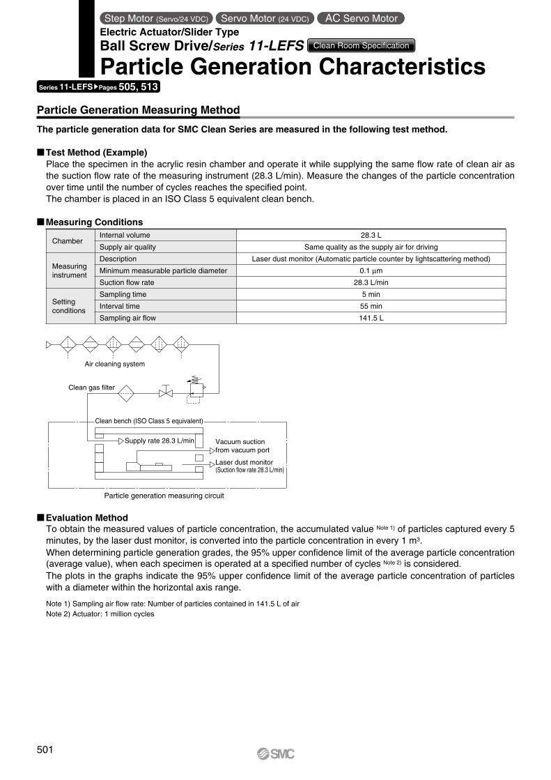
Particle Generation Measuring Method
Particle generation measuring circuit
The particle generation data for SMC Clean Series are measured in the following test method.
Measuring Conditions
Test Method (Example)Place the specimen in the acrylic resin chamber and operate it while supplying the same flow rate of clean air as the suction flow rate of the measuring instrument (28.3 L/min). Measure the changes of the particle concentration over time until the number of cycles reaches the specified point.The chamber is placed in an ISO Class 5 equivalent clean bench.
Evaluation MethodTo obtain the measured values of particle concentration, the accumulated value Note 1) of particles captured every 5 minutes, by the laser dust monitor, is converted into the particle concentration in every 1 m3.When determining particle generation grades, the 95% upper confidence limit of the average particle concentration (average value), when each specimen is operated at a specified number of cycles Note 2) is considered.The plots in the graphs indicate the 95% upper confidence limit of the average particle concentration of particles with a diameter within the horizontal axis range.
Note 1) Sampling air flow rate: Number of particles contained in 141.5 L of airNote 2) Actuator: 1 million cycles
ChamberInternal volume 28.3 L
Supply air quality Same quality as the supply air for driving
Measuring instrument
Description Laser dust monitor (Automatic particle counter by lightscattering method)
Minimum measurable particle diameter 0.1 μm
Suction flow rate 28.3 L/min
Setting conditions
Sampling time 5 min
Interval time 55 min
Sampling air flow 141.5 L
Series 11-LEFSsPages 505, 513
Step Motor (Servo/24 VDC) Servo Motor (24 VDC) AC Servo MotorElectric Actuator/Slider TypeBall Screw Drive/Series 11-LEFS Clean Room Specification
Particle Generation Characteristics
501
ISO Class 6 upper limit
ISO Class 4 upper limit
ISO Class 5 upper limit
Suction flow rate: 0 L/min
Suction flow rate:10 L/min
Suction flow rate: 30 L/min
Particle diameter [µm]
1
10
10000000
1000000
100000
10000
1000
100
0 0.1 0.60.50.40.30.2
Par
ticle
con
cent
ratio
n [p
artic
les/
m3 ]
ISO Class 6 upper limit
ISO Class 4 upper limit
ISO Class 5 upper limit
Suction flow rate: 0 L/min
Suction flow rate: 20 L/min
Suction flow rate: 30 L/min
Particle diameter [µm]
1
10
10000000
1000000
100000
10000
1000
100
0 0.1 0.60.50.40.30.2
Par
ticle
con
cent
ratio
n [p
artic
les/
m3 ]
ISO Class 6 upper limit
ISO Class 4 upper limit
ISO Class 5 upper limit
Suction flow rate: 0 L/min
Suction flow rate: 20 L/min
Suction flow rate: 30 L/min
Particle diameter [µm]
1
10
10000000
1000000
100000
10000
1000
100
0 0.1 0.60.50.40.30.2
Par
ticle
con
cent
ratio
n [p
artic
les/
m3 ]
ISO Class 6 upper limit
Suction flow rate: 50 L/min
ISO Class 4 upper limit
ISO Class 5 upper limitSuction flow rate: 0 L/min
Suction flow rate: 40 L/min
Suction flow rate: 20 L/min
Particle diameter [µm]
1
10
10000000
1000000
100000
10000
1000
100
0 0.1 0.60.50.40.30.2
Par
ticle
con
cent
ratio
n [p
artic
les/
m3 ]
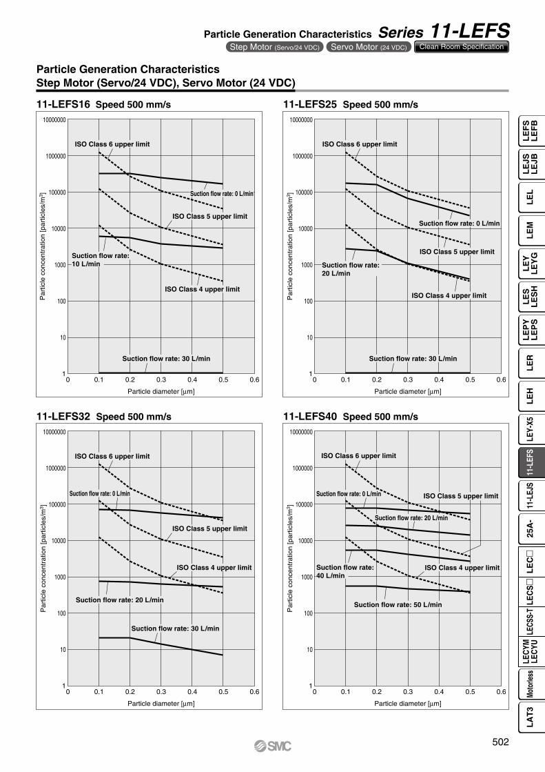
Particle Generation CharacteristicsStep Motor (Servo/24 VDC), Servo Motor (24 VDC)
11-LEFS16 Speed 500 mm/s 11-LEFS25 Speed 500 mm/s
11-LEFS32 Speed 500 mm/s 11-LEFS40 Speed 500 mm/s
502
Particle Generation Characteristics Series 11-LEFSStep Motor (Servo/24 VDC) Servo Motor (24 VDC) Clean Room Specification
LE
FS
LE
FB
LE
LL
EJS
LE
JBL
EM
LE
YL
EY
GL
ES
LE
SH
LE
PY
LE
PS
LE
RL
EH
LEY-
X511
-LEF
S11
-LEJ
S25
A-
LEC
YMLE
CYU
LECS
S-T
LA
T3
Moto
rless
LEC
S
LE
C
ISO Class 6 upper limit
ISO Class 4 upper limit
ISO Class 5 upper limit
Suction flow rate: 0 L/min
Suction flow rate: 30 L/min
Suction flow rate: 50 L/min
Particle diameter [µm]
1
10
10000000
1000000
100000
10000
1000
100
0 0.1 0.60.50.40.30.2
Par
ticle
con
cent
ratio
n [p
artic
les/
m3 ]
ISO Class 6 upper limit
ISO Class 5 upper limit
ISO Class 4 upper limit
Suction flow rate: 0 L/min
Suction flow rate: 60 L/min
Suction flow rate: 30 L/min
Particle diameter [µm]
1
10
10000000
1000000
100000
10000
1000
100
0 0.1 0.60.50.40.30.2
Par
ticle
con
cent
ratio
n [p
artic
les/
m3 ]
ISO Class 6 upper limit
ISO Class 4 upper limit
Suction flow rate: 100 L/min
Suction flow rate:80 L/min
Suction flow rate: 50 L/min
Particle diameter [µm]
1
10
10000000
1000000
100000
10000
1000
100
0 0.1 0.60.50.40.30.2
Par
ticle
con
cent
ratio
n [p
artic
les/
m3 ]
Suction flow rate: 0 L/min
ISO Class 5 upper limit
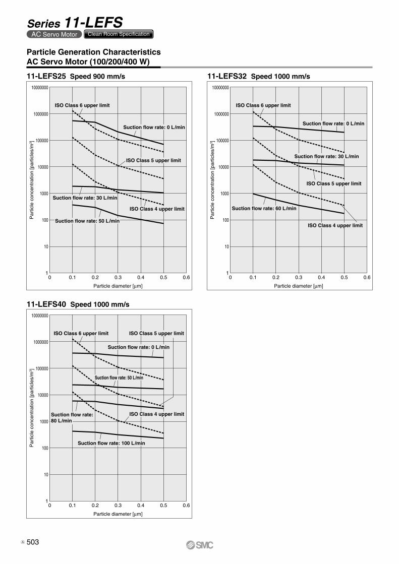
Particle Generation CharacteristicsAC Servo Motor (100/200/400 W)
11-LEFS25 Speed 900 mm/s 11-LEFS32 Speed 1000 mm/s
11-LEFS40 Speed 1000 mm/s
503
Series 11-LEFSAC Servo Motor Clean Room Specification
A

L3
Mep
m
T1
a1 a2
LS
peed
: V [m
m/s
]
Time[s]
T2 T3 T4
100
W
2000
1500
1000
500
00 5 10 15 20
Work load [kg]
Ove
rhan
g: L
3 [m
m]
5000 mm/s2
3000 mm/s2
1000 mm/s2
Wor
k lo
ad: W
[kg]
Speed: V [mm/s]
30
25
20
15
10
5
00 600400 800200 1000 1200
Lead 6: LEFS25B
Lead 12: LEFS25A
Lead 20:LEFS25H
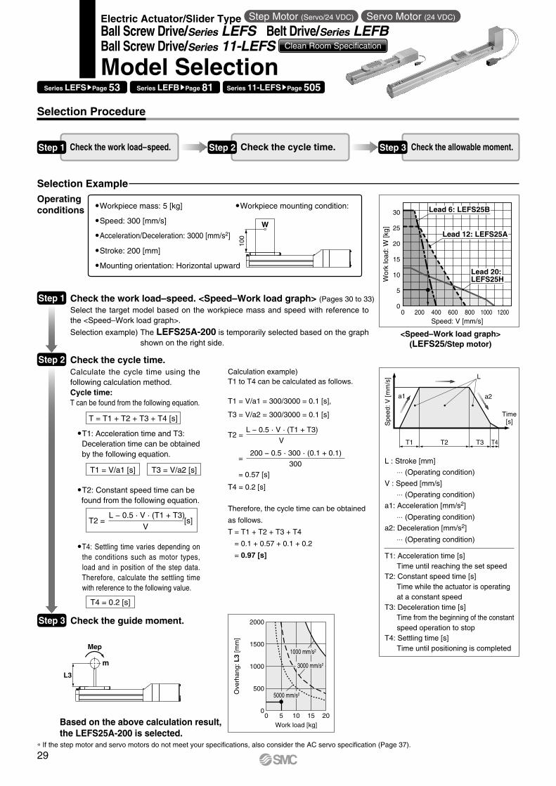
Step 2
Selection Procedure
Selection Example
Step 1 Check the work load–speed. Step 2 Check the cycle time. Step 3 Check the allowable moment.
Workpiece mass: 5 [kg]
Speed: 300 [mm/s]
Acceleration/Deceleration: 3000 [mm/s2]
Stroke: 200 [mm]
Mounting orientation: Horizontal upward
Workpiece mounting condition:
<Speed–Work load graph>(LEFS25/Step motor)
Step 1 Check the work load–speed. <Speed–Work load graph> (Pages 30 to 33)
Select the target model based on the workpiece mass and speed with reference to the <Speed–Work load graph>.
Selection example) The LEFS25A-200 is temporarily selected based on the graph shown on the right side.
Check the cycle time.Calculate the cycle time using the following calculation method.Cycle time:T can be found from the following equation.
T = T1 + T2 + T3 + T4 [s]
T4 = 0.2 [s]
* If the step motor and servo motors do not meet your specifications, also consider the AC servo specification (Page 37).
T1 = V/a1 [s] T3 = V/a2 [s]
T2 = [s]L − 0.5 · V · (T1 + T3)
V
�T4: Settling time varies depending on the conditions such as motor types, load and in position of the step data. Therefore, calculate the settling time with reference to the following value.
T2: Constant speed time can befound from the following equation.
T1: Acceleration time and T3:Deceleration time can be obtainedby the following equation.
Step 3 Check the guide moment.
Based on the above calculation result,the LEFS25A-200 is selected.
L : Stroke [mm]
⋅⋅⋅ (Operating condition)
V : Speed [mm/s]
⋅⋅⋅ (Operating condition)
a1: Acceleration [mm/s2]
⋅⋅⋅ (Operating condition)
a2: Deceleration [mm/s2]
⋅⋅⋅ (Operating condition)
T1: Acceleration time [s]Time until reaching the set speed
T2: Constant speed time [s]Time while the actuator is operating at a constant speed
T3: Deceleration time [s]Time from the beginning of the constantspeed operation to stop
T4: Settling time [s]Time until positioning is completed
Calculation example)T1 to T4 can be calculated as follows.
T1 = V/a1 = 300/3000 = 0.1 [s],
T3 = V/a2 = 300/3000 = 0.1 [s]
T4 = 0.2 [s]
Therefore, the cycle time can be obtained
as follows.
T = T1 + T2 + T3 + T4
= 0.1 + 0.57 + 0.1 + 0.2
= 0.97 [s]
T2 =
=
= 0.57 [s]
L − 0.5 · V · (T1 + T3)
V
200 − 0.5 · 300 · (0.1 + 0.1)
300
Operatingconditions
Series LEFSsPage 53 Series LEFBsPage 81 Series 11-LEFSsPage 505
Electric Actuator/Slider Type Step Motor (Servo/24 VDC) Servo Motor (24 VDC)
Ball Screw Drive/Series LEFS Belt Drive/Series LEFBBall Screw Drive/Series 11-LEFS Clean Room Specification
Model Selection
29
0
2
4
6
8
10
16
14
12
0 100 200 300 400 500 800600 700
Wor
k lo
ad: W
[kg]
Speed: V [mm/s]
Lead B
Lead A
0 100 200 300 400 500 600
Wor
k lo
ad: W
[kg]
Speed: V [mm/s]
0
2
4
6
Lead B
Lead A
0
5
10
15
30
25
20
0 200 400 600 800 1000 1200
Wor
k lo
ad: W
[kg]
Speed: V [mm/s]
Lead B
Lead A
Lead H
0 100 200 300 400 500 600
Wor
k lo
ad: W
[kg]
Speed: V [mm/s]
0
5
10
15
20
Lead B
Lead A
Lead H
0
10
20
30
40
50
0 200 400 600 800 1000 1200
Wor
k lo
ad: W
[kg]
Speed: V [mm/s]
Lead B
Lead A
Lead H
0 100 200 300 400 500 600
Wor
k lo
ad: W
[kg]
Speed: V [mm/s]
0
10
20
30
Lead B
Lead A
Lead H
0
10
20
30
40
50
70
60
0 200 400 600 800 1000 1200
Wor
k lo
ad: W
[kg]
Speed: V [mm/s]
Lead B
Lead A
Lead H
0
10
20
30
0 100 200 300 400 500 600
Wor
k lo
ad: W
[kg]
Speed: V [mm/s]
Lead B
Lead A/Lead H
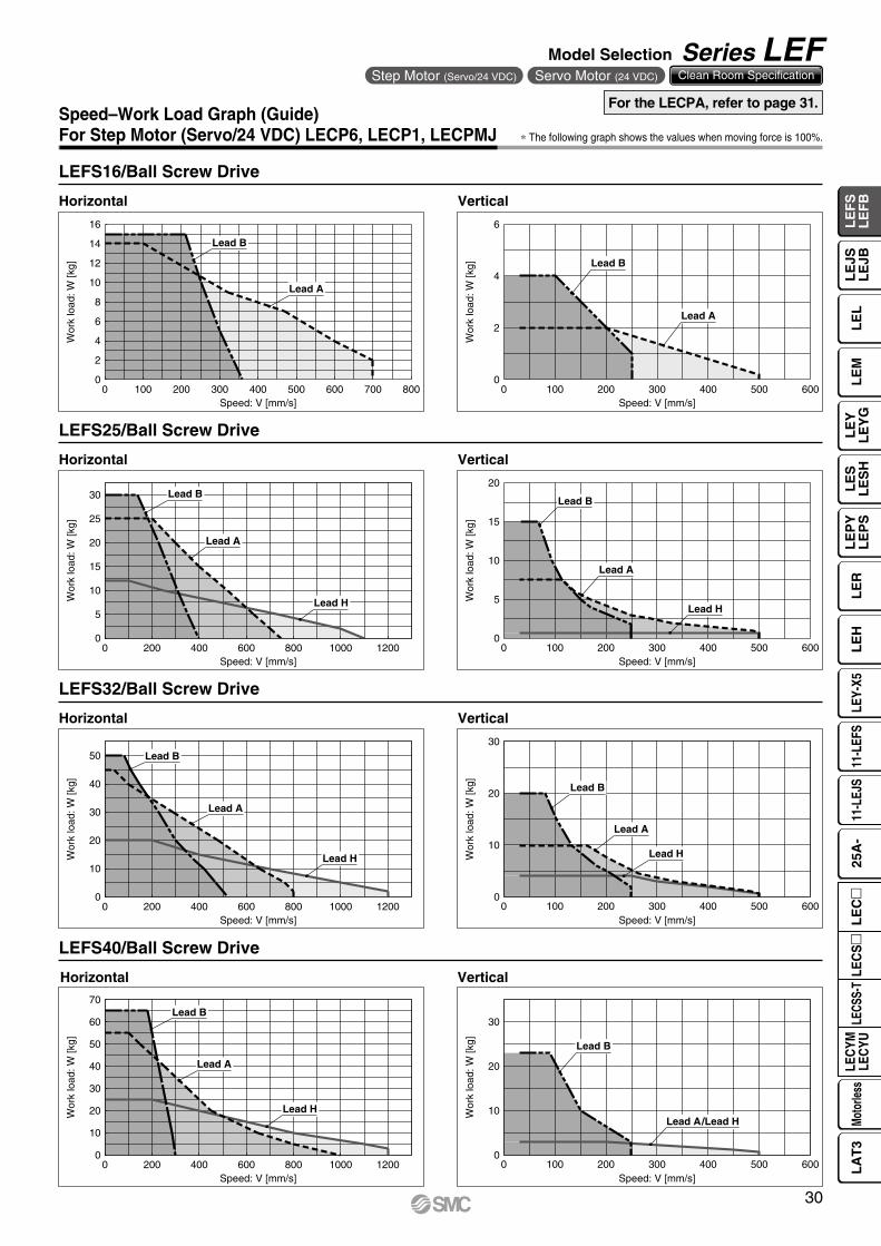
Speed–Work Load Graph (Guide)For Step Motor (Servo/24 VDC) LECP6, LECP1, LECPMJ
LEFS16/Ball Screw Drive
LEFS32/Ball Screw Drive
LEFS25/Ball Screw Drive
∗ The following graph shows the values when moving force is 100%.
Horizontal Vertical
Horizontal Vertical
Horizontal Vertical
Vertical
LEFS40/Ball Screw Drive
Horizontal
For the LECPA, refer to page 31.
30
Model Selection Series LEFStep Motor (Servo/24 VDC) Servo Motor (24 VDC) Clean Room Specification
LE
FS
LE
FB
LE
LL
EJS
LE
JBL
EM
LE
YL
EY
GL
ES
LE
SH
LE
PY
LE
PS
LE
RL
EH
LEY-
X511
-LEF
S11
-LEJ
S25
A-
LEC
YMLE
CYU
LECS
S-T
LA
T3
Moto
rless
LEC
S
LE
C
0
2
4
6
8
10
16
14
12
0 100 200 300 400 500 600 700 800
Wor
k lo
ad: W
[kg]
Speed: V [mm/s]
Lead B
Lead A
0 100 200 300 400 500 600
Wor
k lo
ad: W
[kg]
Speed: V [mm/s]
0
2
4
6
Lead B
Lead A
0
5
10
15
30
25
20
0 200 400 600 800 1000 1200
Wor
k lo
ad: W
[kg]
Speed: V [mm/s]
Lead B
Lead A
Lead H
0 100 200 300 400 500 600
Wor
k lo
ad: W
[kg]
Speed: V [mm/s]
0
5
10
15
20
Lead B
Lead A
Lead H
0
10
20
30
40
50
0 200 400 600 800 1000 1200
Wor
k lo
ad: W
[kg]
Speed: V [mm/s]
Lead B
Lead A
Lead H
0 100 200 300 400 500 600
Wor
k lo
ad: W
[kg]
Speed: V [mm/s]
0
10
20
30
Lead B
Lead A
Lead H
0
10
20
30
40
50
70
60
0 200 400 600 800 1000 1200
Wor
k lo
ad: W
[kg]
Speed: V [mm/s]
Lead B
Lead A
Lead H
0
10
20
30
0 100 200 300 400 500 600
Wor
k lo
ad: W
[kg]
Speed: V [mm/s]
Lead B
Lead A
Lead H
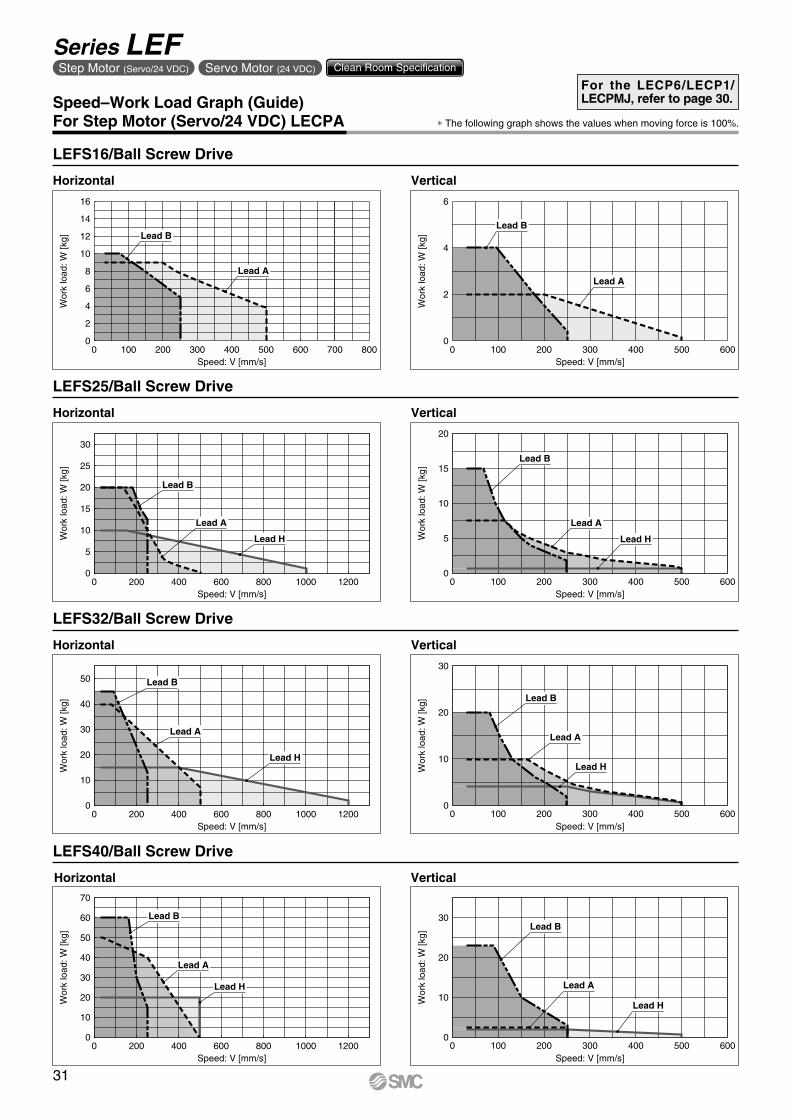
Speed–Work Load Graph (Guide)For Step Motor (Servo/24 VDC) LECPA ∗ The following graph shows the values when moving force is 100%.
LEFS32/Ball Screw Drive
LEFS25/Ball Screw Drive
Horizontal Vertical
Horizontal Vertical
Horizontal Vertical
Vertical
LEFS40/Ball Screw Drive
Horizontal
LEFS16/Ball Screw Drive
For the LECP6/LECP1/LECPMJ, refer to page 30.
31
Series LEFStep Motor (Servo/24 VDC) Servo Motor (24 VDC) Clean Room Specification
Wor
k lo
ad: W
[kg]
Speed: V [mm/s]
0 500 1000 1500 20000
2
4
6
8
10
12
14
16
18
20
LEFB32
LEFB25
LEFB16
Wor
k lo
ad: W
[kg]
Speed: V [mm/s]
0 500 1000 1500 2000
14
12
10
8
6
4
2
0
LEFB32
LEFB25
LEFB16
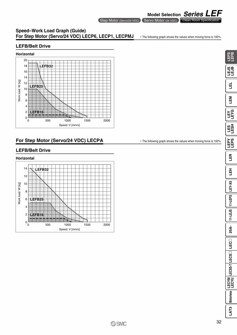
Speed–Work Load Graph (Guide)For Step Motor (Servo/24 VDC) LECP6, LECP1, LECPMJ ∗ The following graph shows the values when moving force is 100%.
∗ The following graph shows the values when moving force is 100%.
LEFB/Belt Drive
LEFB/Belt Drive
Horizontal
Horizontal
For Step Motor (Servo/24 VDC) LECPA
32
Model Selection Series LEFStep Motor (Servo/24 VDC) Servo Motor (24 VDC) Clean Room Specification
LE
FS
LE
FB
LE
LL
EJS
LE
JBL
EM
LE
YL
EY
GL
ES
LE
SH
LE
PY
LE
PS
LE
RL
EH
LEY-
X511
-LEF
S11
-LEJ
S25
A-
LEC
YMLE
CYU
LECS
S-T
LA
T3
Moto
rless
LEC
S
LE
C
Wor
k lo
ad: W
[kg]
Speed: V [mm/s]
0 500 1000 1500 2000
4
2
0
LEFB25
LEFB16
0
2
4
6
8
10
12
0 100 200 300 400 500 600 700 800 900
Wor
k lo
ad: W
[kg]
Speed: V [mm/s]
Lead B
Lead A
Wor
k lo
ad: W
[kg]
Speed: V [mm/s]
0
2
4
6
0 100 200 300 400 500 600 700 800 900
Lead B
Lead A
0
5
10
15
20
0 200 400 600 800 1000 1200
Wor
k lo
ad: W
[kg]
Speed: V [mm/s]
Lead A
Lead B
Lead H Wor
k lo
ad: W
[kg]
Speed: V [mm/s]
0
5
10
0 100 200 300 400 500 600 700 800 900
Lead B
Lead A
Lead H
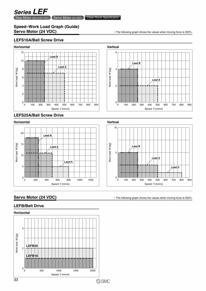
Speed–Work Load Graph (Guide)Servo Motor (24 VDC)
LEFS16A/Ball Screw Drive
LEFS25A/Ball Screw Drive
∗ The following graph shows the values when moving force is 250%.
Horizontal
Horizontal Vertical
Vertical
Servo Motor (24 VDC) ∗ The following graph shows the values when moving force is 250%.
LEFB/Belt Drive
Horizontal
33
Series LEFStep Motor (Servo/24 VDC) Servo Motor (24 VDC) Clean Room Specification
0
200
400
600
800
1000
0
200
400
600
800
1000
0 4 8 12 16 20 24
0 4 8 12 16 20 24
0 4 8 12 16 20 24
0 4 8 12 16 20 24
0
200
400
600
800
1000
0
200
400
600
800
1000
0 10 20 30 40 50
0 10 20 30 40 50
0 10 20 30 40 50 60
0
500
1000
1500
2000
0 2 4 6 8 10 12 14 16
0 2 4 6 8 10 12 14 16
0 2 4 6 8 10 12 14 16
0 2 4 6 8 10 12 14 16
0 2 4 6 8 10 12 14 16
0 2 4 6 8 10 12 14 16
0
500
1000
1500
2000
0
500
1000
1500
2000
0 10 20 30 40 500
500
1000
1500
2000
0 10 20 30 40 50 60
L1
[mm
]
Work load [kg]
L2
[mm
]
Work load [kg]
0
500
1000
1500
2000
0 10 20 30 40 50 60L
3 [m
m]
Work load [kg]
0
500
1000
1500
2000L
3 [m
m]
Work load [kg]
0
500
1000
1500
2000
L3
[mm
]
Work load [kg]
0
500
1000
1500
2000
L3
[mm
]
Work load [kg]
0 4 8 12 16 20 24 0 10 20 30 40 500
500
1000
1500
2000
0 10 20 30 40 50 60
L5
[mm
]
Work load [kg]
0
500
1000
1500
2000
L5
[mm
]
Work load [kg]
0
500
1000
1500
2000
L5
[mm
]
Work load [kg]
0
500
1000
1500
2000
L5
[mm
]
Work load [kg]
L2
[mm
]Work load [kg]
L2
[mm
]
Work load [kg]
L2
[mm
]
Work load [kg]
0
200
400
600
800
1000
0
200
400
600
800
1000
0 4 8 12 16 20 240
200
400
600
800
1000
0
200
400
600
800
1000
0 10 20 30 40 50 0 10 20 30 40 50 60
L6
[mm
]
Work load [kg]
L6
[mm
]
Work load [kg]
L6
[mm
]
Work load [kg]
L6
[mm
]
Work load [kg]
L1
[mm
]
Work load [kg]
L1
[mm
]
Work load [kg]
L1
[mm
]
Work load [kg]
0
500
1000
1500
2000
0 10 20 30 40 500
500
1000
1500
2000
0
500
1000
1500
2000
0
500
1000
1500
2000
0 10 20 30 40 50 60
L4
[mm
]
Work load [kg]
L4
[mm
]
Work load [kg]
L4
[mm
]
Work load [kg]
L4
[mm
]
Work load [kg]
L1
Merm
L2
L3
Mep
m
L4
L5
Mey
m
L6
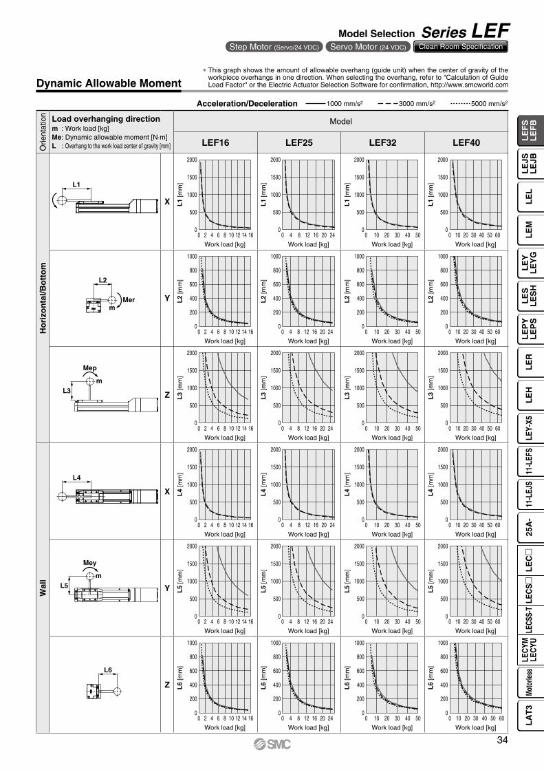
Dynamic Allowable Moment
Acceleration/Deceleration 1000 mm/s2 3000 mm/s2 5000 mm/s2
Orie
ntat
ion Load overhanging direction
m : Work load [kg]Me: Dynamic allowable moment [N·m]L : Overhang to the work load center of gravity [mm]
Model
LEF16 LEF25 LEF32 LEF40
Ho
rizo
nta
l/Bo
tto
m
X
Y
Z
Wal
l
X
Y
Z
* This graph shows the amount of allowable overhang (guide unit) when the center of gravity of the workpiece overhangs in one direction. When selecting the overhang, refer to "Calculation of Guide Load Factor" or the Electric Actuator Selection Software for confirmation, http://www.smcworld.com
34
Model Selection Series LEFStep Motor (Servo/24 VDC) Servo Motor (24 VDC) Clean Room Specification
LE
FS
LE
FB
LE
LL
EJS
LE
JBL
EM
LE
YL
EY
GL
ES
LE
SH
LE
PY
LE
PS
LE
RL
EH
LEY-
X511
-LEF
S11
-LEJ
S25
A-
LEC
YMLE
CYU
LECS
S-T
LA
T3
Moto
rless
LEC
S
LE
C
xy
z
xy
z
x z
y
x
z y
0
0
500
1000
1500
0 15105 20 25 30
L7
[mm
]
Work load [kg]
500
1000
1500
0 15105 20 25 30
L8
[mm
]
Work load [kg]
0
0
500
1000
1500
L7
[mm
]
Work load [kg]
500
1000
1500
0 15105 20
0 15105 20
L8
[mm
]Work load [kg]
0
0
500
1000
1500
0 15105
0 15105
L7
[mm
]
Work load [kg]
500
1000
1500L
8 [m
m]
Work load [kg]
0
0
500
1000
1500
0 21 3 4 5
0 21 3 4 5
L7
[mm
]
Work load [kg]
500
1000
1500
L8
[mm
]
Work load [kg]
Mepm
L7
Meym
L8
0
500
1000
1500
2000
0 10 20 30 40 50 60
L1
[mm
]
Work load [kg]
Lx
0
200
400
600
800
1000
0 10 20 30 40 50 60
L2
[mm
]
Work load [kg]
Ly
0
500
1000
1500
2000
0 10 20 30 40 50 60
L3
[mm
]
Work load [kg]
Lz
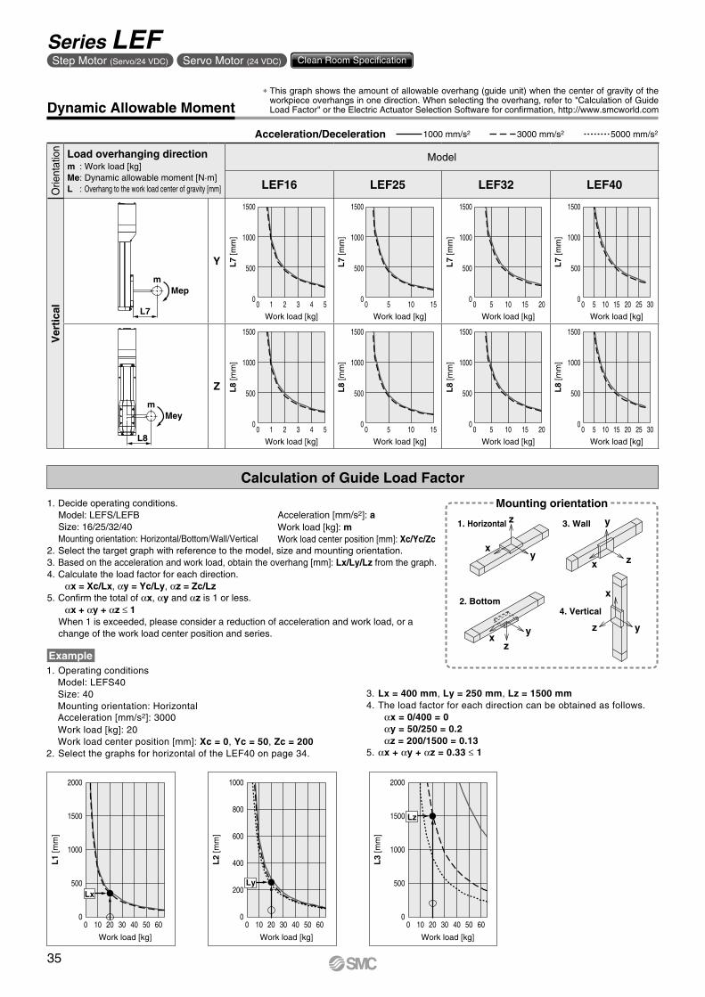
Dynamic Allowable Moment
Orie
ntat
ion Load overhanging direction
m : Work load [kg]Me: Dynamic allowable moment [N·m]L : Overhang to the work load center of gravity [mm]
Model
LEF16 LEF25 LEF32 LEF40
Ver
tica
l
Y
Z
Acceleration/Deceleration 1000 mm/s2 3000 mm/s2 5000 mm/s2
Calculation of Guide Load Factor
1. Operating conditionsModel: LEFS40Size: 40Mounting orientation: HorizontalAcceleration [mm/s2]: 3000Work load [kg]: 20Work load center position [mm]: Xc = 0, Yc = 50, Zc = 200
2. Select the graphs for horizontal of the LEF40 on page 34.
Example
Acceleration [mm/s2]: aWork load [kg]: mWork load center position [mm]: Xc/Yc/Zc
Mounting orientation
1. Horizontal 3. Wall
2. Bottom4. Vertical
1. Decide operating conditions.Model: LEFS/LEFBSize: 16/25/32/40Mounting orientation: Horizontal/Bottom/Wall/Vertical
2. Select the target graph with reference to the model, size and mounting orientation.3. Based on the acceleration and work load, obtain the overhang [mm]: Lx/Ly/Lz from the graph.4. Calculate the load factor for each direction.
αx = Xc/Lx, αy = Yc/Ly, αz = Zc/Lz5. Confirm the total of αx, αy and αz is 1 or less.
αx + αy + αz ≤ 1When 1 is exceeded, please consider a reduction of acceleration and work load, or a change of the work load center position and series.
3. Lx = 400 mm, Ly = 250 mm, Lz = 1500 mm4. The load factor for each direction can be obtained as follows.
αx = 0/400 = 0αy = 50/250 = 0.2αz = 200/1500 = 0.13
5. αx + αy + αz = 0.33 ≤ 1
* This graph shows the amount of allowable overhang (guide unit) when the center of gravity of the workpiece overhangs in one direction. When selecting the overhang, refer to "Calculation of Guide Load Factor" or the Electric Actuator Selection Software for confirmation, http://www.smcworld.com
35
Series LEFStep Motor (Servo/24 VDC) Servo Motor (24 VDC) Clean Room Specification
0
0.05
0.1
0.15
0.2
0.25
0 100 200 300
LEF16
LEF25
LEF32
LEF40Dis
plac
emen
t [m
m]
Overhang distance [mm]
0 100 200 300
Dis
plac
emen
t [m
m]
Overhang distance [mm]
0
0.02
0.04
0.06
0.08
0.1
0.12
LEF16
LEF25
LEF32
LEF40
A side
C side
B side
D side
w
q
0.08
0.06
0.04
0.02
00 100 200 300 400 500
Dis
plac
emen
t [m
m]
Load W [N]
LEF16(L = 20 mm)
LEF25(L = 25 mm)
LEF32(L = 30 mm)
LEF40(L = 37 mm)
WL
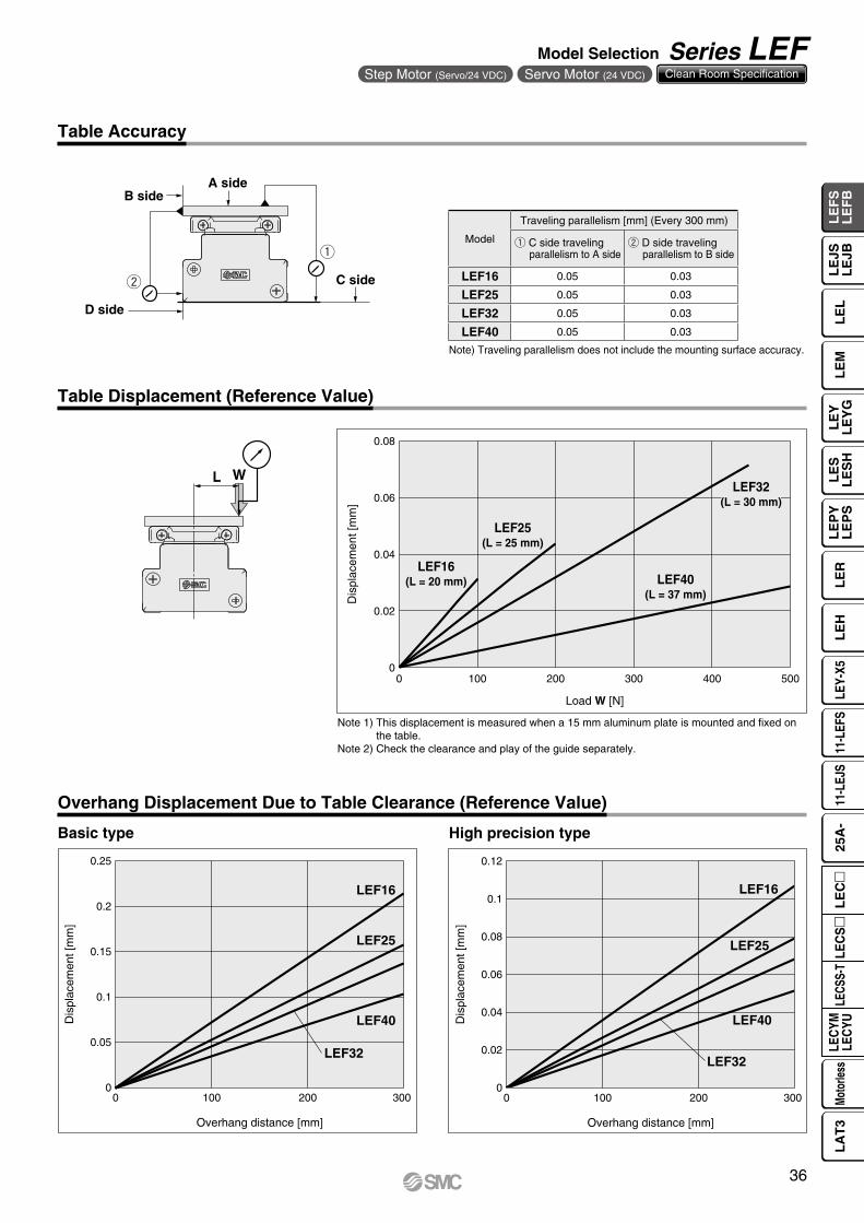
Table Accuracy
Table Displacement (Reference Value)
Note) Traveling parallelism does not include the mounting surface accuracy.
Note 1) This displacement is measured when a 15 mm aluminum plate is mounted and fixed on the table.
Note 2) Check the clearance and play of the guide separately.
Model
Traveling parallelism [mm] (Every 300 mm)
q C side travelingparallelism to A side
w D side travelingparallelism to B side
LEF16 0.05 0.03
LEF25 0.05 0.03
LEF32 0.05 0.03
LEF40 0.05 0.03
Overhang Displacement Due to Table Clearance (Reference Value)
Basic type High precision type
36
Model Selection Series LEFStep Motor (Servo/24 VDC) Servo Motor (24 VDC) Clean Room Specification
LE
FS
LE
FB
LE
LL
EJS
LE
JBL
EM
LE
YL
EY
GL
ES
LE
SH
LE
PY
LE
PS
LE
RL
EH
LEY-
X511
-LEF
S11
-LEJ
S25
A-
LEC
YMLE
CYU
LECS
S-T
LA
T3
Moto
rless
LEC
S
LE
C
L3
Mep
m
T1
a1 a2
LS
peed
: V [m
m/s
]
Time[s]
T2 T3 T4
100
W
1000 mm/s2
3000 mm/s2
5000 mm/s2
0 10 20 30 40 50 60
1500
1000
500
0
Work load [kg]
Ove
rhan
g: L
3 [m
m]
Wor
k lo
ad: W
[kg]
Speed: V [mm/s]0 200 400 600 800 1000
70
60
50
40
30
20
10
0
Lead 10: LEFS40B
Lead 20: LEFS40A
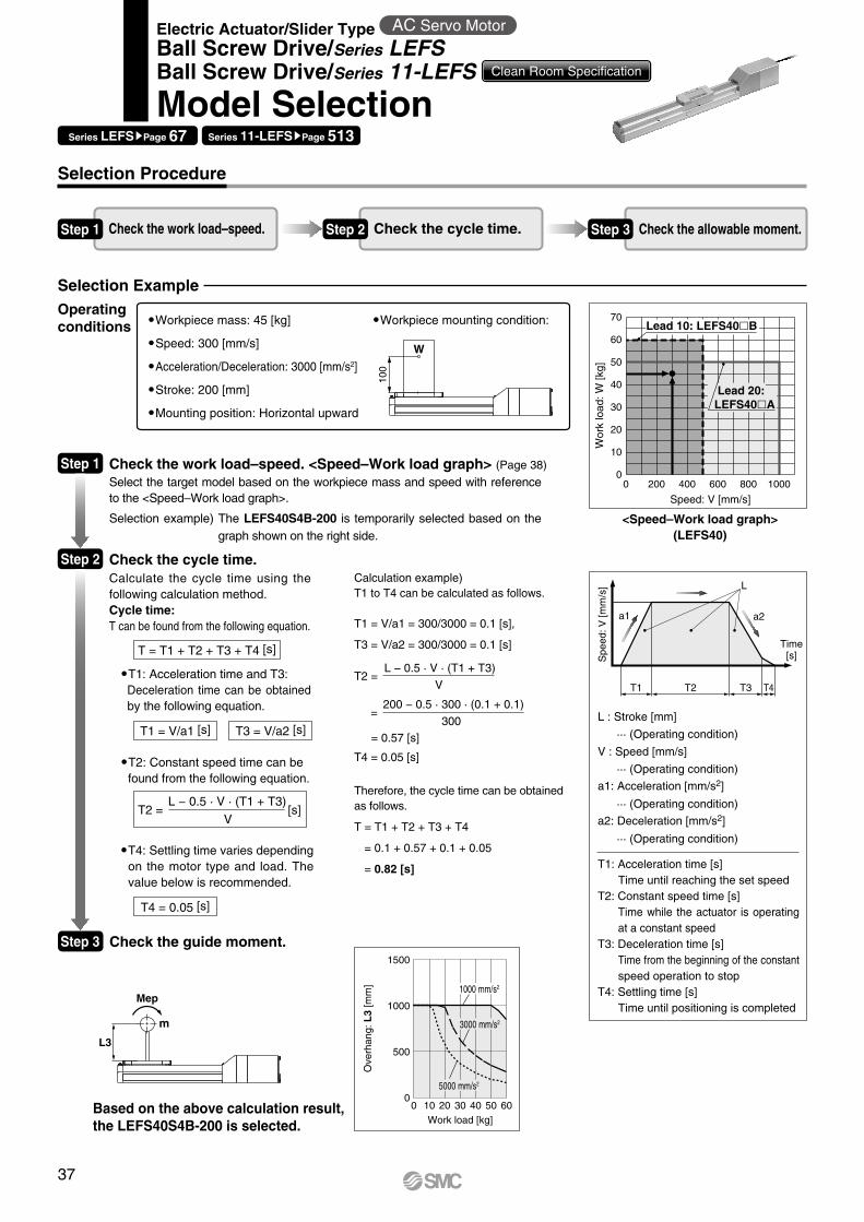
Selection Procedure
Selection Example
Step 1 Check the work load–speed. Step 2 Check the cycle time. Step 3 Check the allowable moment.
Workpiece mass: 45 [kg]
Speed: 300 [mm/s]
Acceleration/Deceleration: 3000 [mm/s2]
Stroke: 200 [mm]
Mounting position: Horizontal upward
Workpiece mounting condition:Operating conditions
<Speed–Work load graph>(LEFS40)
Step 1 Check the work load–speed. <Speed–Work load graph> (Page 38)
Select the target model based on the workpiece mass and speed with reference to the <Speed–Work load graph>.
Selection example) The LEFS40S4B-200 is temporarily selected based on the graph shown on the right side.
Step 2 Check the cycle time.Calculate the cycle time using the following calculation method.Cycle time: T can be found from the following equation.
T = T1 + T2 + T3 + T4 [s]
T4 = 0.05 [s]
T1 = V/a1 [s] T3 = V/a2 [s]
T2 = [s]L − 0.5 · V · (T1 + T3)
V
�T4: Settling time varies depending on the motor type and load. The value below is recommended.
T2: Constant speed time can befound from the following equation.
T1: Acceleration time and T3:Deceleration time can be obtained by the following equation.
Step 3 Check the guide moment.
Based on the above calculation result, the LEFS40S4B-200 is selected.
L : Stroke [mm]
··· (Operating condition)
V : Speed [mm/s]
··· (Operating condition)
a1: Acceleration [mm/s2]
··· (Operating condition)
a2: Deceleration [mm/s2]
··· (Operating condition)
T1: Acceleration time [s]Time until reaching the set speed
T2: Constant speed time [s]Time while the actuator is operating at a constant speed
T3: Deceleration time [s]Time from the beginning of the constant speed operation to stop
T4: Settling time [s]Time until positioning is completed
Calculation example)T1 to T4 can be calculated as follows.
T1 = V/a1 = 300/3000 = 0.1 [s],
T3 = V/a2 = 300/3000 = 0.1 [s]
T4 = 0.05 [s]
Therefore, the cycle time can be obtained as follows.
T = T1 + T2 + T3 + T4
= 0.1 + 0.57 + 0.1 + 0.05
= 0.82 [s]
T2 =
=
= 0.57 [s]
L − 0.5 · V · (T1 + T3)
V
200 − 0.5 · 300 · (0.1 + 0.1)
300
Series LEFSsPage 67 Series 11-LEFSsPage 513
Electric Actuator/Slider Type AC Servo Motor
Ball Screw Drive/Series LEFSBall Screw Drive/Series 11-LEFS Clean Room Specification
Model Selection
37
0
5
10
15
20
25
30
0 200 400 600 800 1000 1200 1400 1600
Wor
k lo
ad [k
g]
Speed [mm/s]
A
Lead 6: LEFS25B Lead 12: LEFS25A
Lead 20: LEFS25H
0
5
10
15
20
0 200 400 600 800 1000 1200 1400 1600
Use a regeneration option.
Wor
k lo
ad [k
g]
Speed [mm/s]
Lead 6: LEFS25B
Lead 12: LEFS25A
Lead 20: LEFS25H
A
0
10
20
30
40
50
60
70
0 200 400 600 800 1000 1200 1400 1600
Wor
k lo
ad [k
g]
Speed [mm/s]
A
Lead 20: LEFS40A
Lead 10:LEFS40B
Lead 30:LEFS40H
0
5
10
15
20
25
30
35
40
0 200 400 600 800 1000 1200 1400 1600
Wor
k lo
ad [k
g]
Speed [mm/s]
AB
Lead 20: LEFS40A
Lead 10: LEFS40B
Lead 30: LEFS40H
0
10
20
30
40
50
60
0 200 400 600 800 1000 1200 1400 1600
Wor
k lo
ad [k
g]
Speed [mm/s]
A
Lead 8: LEFS32B Lead 16: LEFS32A
Lead 24: LEFS32H
0
5
10
15
20
25
30
0 200 400 600 800 1000 1200 1400 1600
Wor
k lo
ad [k
g]
Speed [mm/s]
A
Lead 8: LEFS32B
Lead 16: LEFS32A
Lead 24: LEFS32H
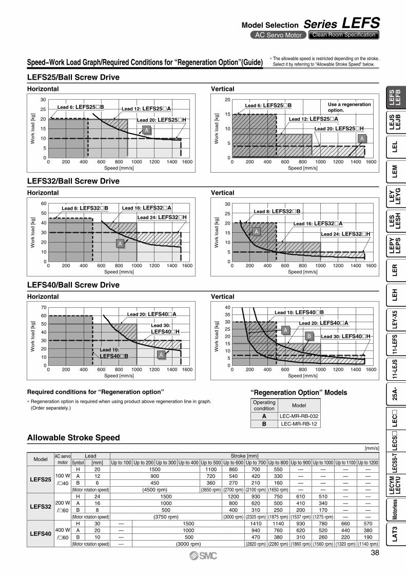
Speed−Work Load Graph/Required Conditions for “Regeneration Option”(Guide)
LEFS25/Ball Screw Drive
LEFS40/Ball Screw Drive
LEFS32/Ball Screw Drive
Horizontal Vertical
Horizontal Vertical
Horizontal Vertical
Allowable Stroke Speed
∗ The allowable speed is restricted depending on the stroke. Select it by referring to “Allowable Stroke Speed” below.
[mm/s]
Required conditions for “Regeneration option”∗ Regeneration option is required when using product above regeneration line in graph.
(Order separately.)
“Regeneration Option” ModelsOperatingcondition
Model
A LEC-MR-RB-032
B LEC-MR-RB-12
ModelAC servo
motorLead Stroke [mm]
Symbol [mm] Up to 100 Up to 200 Up to 300 Up to 400 Up to 500 Up to 600 Up to 700 Up to 800 Up to 900 Up to 1000 Up to 1100 Up to 1200
LEFS25100 W
/l40
H 20 1500 1100 860 700 550 — — — —A 12 900 720 540 420 330 — — — —B 6 450 360 270 210 160 — — — —
(Motor rotation speed) (4500 rpm) (3650 rpm) (2700 rpm) (2100 rpm) (1650 rpm) — — — —
LEFS32200 W
/l60
H 24 1500 1200 930 750 610 510 — —A 16 1000 800 620 500 410 340 — —B 8 500 400 310 250 200 170 — —
(Motor rotation speed) (3750 rpm) (3000 rpm) (2325 rpm) (1875 rpm) (1537 rpm) (1275 rpm) — —
LEFS40400 W
/l60
H 30 — 1500 1410 1140 930 780 660 570A 20 — 1000 940 760 620 520 440 380B 10 — 500 470 380 310 260 220 190
(Motor rotation speed) — (3000 rpm) (2820 rpm) (2280 rpm) (1860 rpm) (1560 rpm) (1320 rpm) (1140 rpm)
38
Model Selection Series LEFSAC Servo Motor Clean Room Specification
LE
FS
LE
FB
LE
LL
EJS
LE
JBL
EM
LE
YL
EY
GL
ES
LE
SH
LE
PY
LE
PS
LE
RL
EH
LEY-
X511
-LEF
S11
-LEJ
S25
A-
LEC
YMLE
CYU
LECS
S-T
LA
T3
Moto
rless
LEC
S
LE
C
0
2500
5000
7500
10000
12500
15000
17500
20000
0 2 4 6 8 10
Work load [kg]
Acc
eler
atio
n/D
ecel
erat
ion
[mm
/s2] Duty ratio: 50%
Duty ratio: 75%
Duty ratio: 100%
Work load [kg]A
ccel
erat
ion/
Dec
eler
atio
n [m
m/s
2]
0
2500
5000
7500
10000
12500
15000
17500
20000
22500
0 1 2 3 4
Duty ratio: 50%
Duty ratio: 75%
Duty ratio: 100%
Work load [kg]
Acc
eler
atio
n/D
ecel
erat
ion
[mm
/s2]
0
2500
5000
7500
10000
12500
15000
17500
20000
0 5 10 15 20
Duty ratio: 50%
Duty ratio: 75%
Duty ratio: 100%
Work load [kg]
Acc
eler
atio
n/D
ecel
erat
ion
[mm
/s2]
0
2500
5000
7500
10000
12500
15000
17500
20000
0 5 10 15
Duty ratio: 50%
Duty ratio: 75%
Duty ratio: 100%
Work load [kg]
Acc
eler
atio
n/D
ecel
erat
ion
[mm
/s2]
0
2500
5000
7500
10000
12500
15000
17500
20000
0 5 10 15 20
Duty ratio: 50%
Duty ratio: 75%
Duty ratio: 100%
Work load [kg]
Acc
eler
atio
n/D
ecel
erat
ion
[mm
/s2]
0
2500
5000
7500
10000
12500
15000
17500
20000
0 2 4 6 8
Duty ratio: 50%
Duty ratio: 75%
Duty ratio: 100%
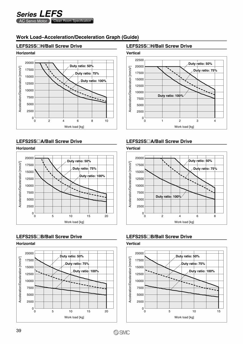
Work Load–Acceleration/Deceleration Graph (Guide)
Horizontal
Horizontal Vertical
LEFS25SlH/Ball Screw Drive
Horizontal Vertical
LEFS25SlA/Ball Screw Drive LEFS25SlA/Ball Screw Drive
LEFS25SlB/Ball Screw Drive LEFS25SlB/Ball Screw Drive
LEFS25SlH/Ball Screw DriveVertical
39
Series LEFSAC Servo Motor Clean Room Specification
Work load [kg]
Acc
eler
atio
n/D
ecel
erat
ion
[mm
/s2]
2500
5000
7500
10000
12500
15000
17500
20000
22500
5 10 15 20 25 300
0
Duty ratio: 50%
Duty ratio: 75%
Duty ratio: 100%
Work load [kg]A
ccel
erat
ion/
Dec
eler
atio
n [m
m/s
2]
0
2500
5000
7500
10000
12500
15000
17500
20000
22500
1 2 3 4 50
Duty ratio: 50%
Duty ratio: 75%
Duty ratio: 100%
0
2500
5000
7500
10000
12500
15000
17500
20000
0 10 20 30 40
Work load [kg]
Acc
eler
atio
n/D
ecel
erat
ion
[mm
/s2 ]
Duty ratio: 50%
Duty ratio: 75%
Duty ratio: 100%
Work load [kg]
Acc
eler
atio
n/D
ecel
erat
ion
[mm
/s2]
0
2500
5000
7500
10000
12500
15000
17500
20000
0 5 10 15 20
Duty ratio: 50%
Duty ratio: 75%
Duty ratio: 100%
Work load [kg]
Acc
eler
atio
n/D
ecel
erat
ion
[mm
/s2]
0
2500
5000
7500
10000
12500
15000
17500
20000
0 10 20 30 40
Duty ratio: 50%
Duty ratio: 75%
Duty ratio: 100%
Work load [kg]
Acc
eler
atio
n/D
ecel
erat
ion
[mm
/s2]
0
2500
5000
7500
10000
12500
15000
17500
20000
0 2 4 6 8 10
Duty ratio: 50%
Duty ratio: 75%
Duty ratio: 100%
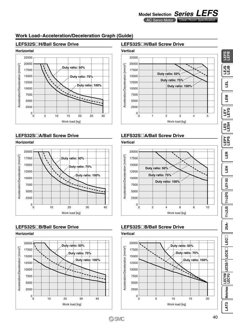
Work Load–Acceleration/Deceleration Graph (Guide)
Horizontal
Horizontal Vertical
LEFS32SlH/Ball Screw Drive
Horizontal Vertical
LEFS32SlA/Ball Screw Drive LEFS32SlA/Ball Screw Drive
LEFS32SlB/Ball Screw Drive LEFS32SlB/Ball Screw Drive
LEFS32SlH/Ball Screw DriveVertical
40
Model Selection Series LEFSAC Servo Motor Clean Room Specification
LE
FS
LE
FB
LE
LL
EJS
LE
JBL
EM
LE
YL
EY
GL
ES
LE
SH
LE
PY
LE
PS
LE
RL
EH
LEY-
X511
-LEF
S11
-LEJ
S25
A-
LEC
YMLE
CYU
LECS
S-T
LA
T3
Moto
rless
LEC
S
LE
C

Work load [kg]
Acc
eler
atio
n/D
ecel
erat
ion
[mm
/s2]
2500
5000
7500
10000
12500
15000
17500
20000
22500
0 5 10 15 20 25 300
Duty ratio: 50%
Duty ratio: 75%
Duty ratio: 100%
Work load [kg]A
ccel
erat
ion/
Dec
eler
atio
n [m
m/s
2]
0
2500
5000
7500
10000
12500
15000
17500
20000
22500
0 1 2 3 4 5 6 7
Duty ratio: 50%
Duty ratio: 75%
Duty ratio: 100%
Work load [kg]
Acc
eler
atio
n/D
ecel
erat
ion
[mm
/s2]
0
2500
5000
7500
10000
12500
15000
17500
20000
22500
0 10 20 30 40 50 60
Duty ratio: 50%
Duty ratio: 75%
Duty ratio: 100%
Work load [kg]
Acc
eler
atio
n/D
ecel
erat
ion
[mm
/s2]
0
2500
5000
7500
10000
12500
15000
17500
20000
22500
0 10 20 30
Duty ratio: 50%
Duty ratio: 75%
Duty ratio: 100%
Work load [kg]
Acc
eler
atio
n/D
ecel
erat
ion
[mm
/s2]
0
7500
10000
12500
15000
17500
20000
22500
0 10 20 30 40 50
2500
5000
Duty ratio: 50%
Duty ratio: 75%
Duty ratio: 100%
Work load [kg]
Acc
eler
atio
n/D
ecel
erat
ion
[mm
/s2]
0
2500
5000
7500
10000
12500
15000
17500
20000
22500
0 5 10 15
Duty ratio: 50%
Duty ratio: 75%
Duty ratio: 100%
Work Load–Acceleration/Deceleration Graph (Guide)
Horizontal
Horizontal Vertical
LEFS40SlH/Ball Screw Drive
Horizontal Vertical
LEFS40SlA/Ball Screw Drive LEFS40SlA/Ball Screw Drive
LEFS40SlB/Ball Screw Drive LEFS40SlB/Ball Screw Drive
LEFS40SlH/Ball Screw DriveVertical
41
Series LEFSAC Servo Motor Clean Room Specification
0 10 20 30 40 50 60Work load [kg]
L1
[mm
]
0
500
1500
1000
0 10 20 30 40Work load [kg]
L1
[mm
]
0
500
1500
1000
0 5 10 15 20Work load [kg]
L1
[mm
]
0
500
1500
1000
0 10 20 30 40 50 60Work load [kg]
L3
[mm
]
0
500
1500
1000
0 10 20 30 40Work load [kg]
L3
[mm
]
0
500
1500
1000
0 5 10 15 20Work load [kg]
L3
[mm
]
0
500
1500
1000
0 10 20 30 40 50 60Work load [kg]
L4
[mm
]
0
500
1500
1000
0 10 20 30 40Work load [kg]
L4
[mm
]
0
500
1500
1000
0 5 10 15 20Work load [kg]
L4
[mm
]
0
500
1500
1000
0 10 20 30 40 50 60Work load [kg]
L5
[mm
]
0
500
1500
1000
0 10 20 30 40Work load [kg]
L5
[mm
]
0
500
1500
1000
0 5 10 15 20Work load [kg]
L5
[mm
]
0
500
1500
1000
0 10 20 30 40 50 60Work load [kg]
L2
[mm
]
0 10 20 30 40Work load [kg]
L2
[mm
]
0 5 10 15 20Work load [kg]
L2
[mm
]
0
600
400
200
1000
800
0
600
400
200
1000
800
0
600
400
200
1000
800
0 10 20 30 40 50 60Work load [kg]
L6
[mm
]
0 10 20 30 40Work load [kg]
L6
[mm
]
0 5 10 15 20Work load [kg]
L6
[mm
]
0
600
400
200
1000
800
0
600
400
200
1000
800
0
600
400
200
1000
800
L1
L3
Mep
m
L5
Mey
m
L4
Merm
L2
L6
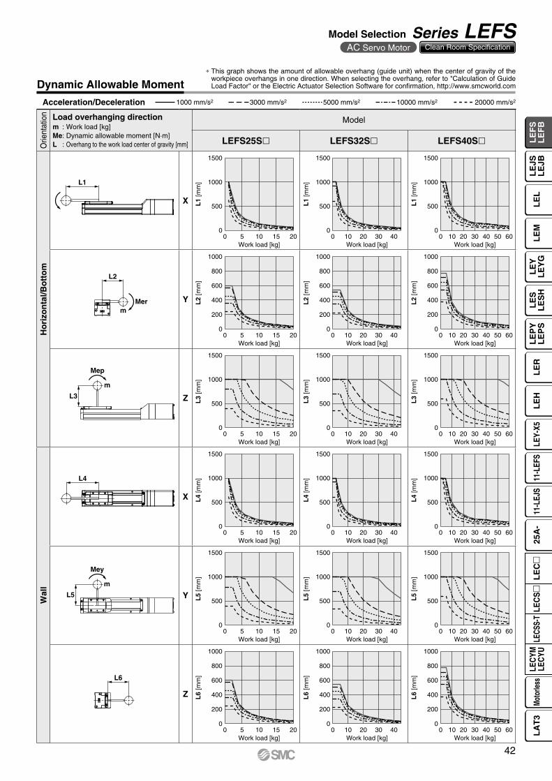
Dynamic Allowable Moment
Acceleration/Deceleration 1000 mm/s2 3000 mm/s2 5000 mm/s2 10000 mm/s2 20000 mm/s2
Orie
ntat
ion Load overhanging direction
m : Work load [kg]Me: Dynamic allowable moment [N·m]L : Overhang to the work load center of gravity [mm]
Model
LEFS25Sl LEFS32Sl LEFS40Sl
Ho
rizo
nta
l/Bo
tto
m
X
Y
Z
Wal
l
X
Y
Z
* This graph shows the amount of allowable overhang (guide unit) when the center of gravity of the workpiece overhangs in one direction. When selecting the overhang, refer to "Calculation of Guide Load Factor" or the Electric Actuator Selection Software for confirmation, http://www.smcworld.com
42
Model Selection Series LEFSAC Servo Motor Clean Room Specification
LE
FS
LE
FB
LE
LL
EJS
LE
JBL
EM
LE
YL
EY
GL
ES
LE
SH
LE
PY
LE
PS
LE
RL
EH
LEY-
X511
-LEF
S11
-LEJ
S25
A-
LEC
YMLE
CYU
LECS
S-T
LA
T3
Moto
rless
LEC
S
LE
C
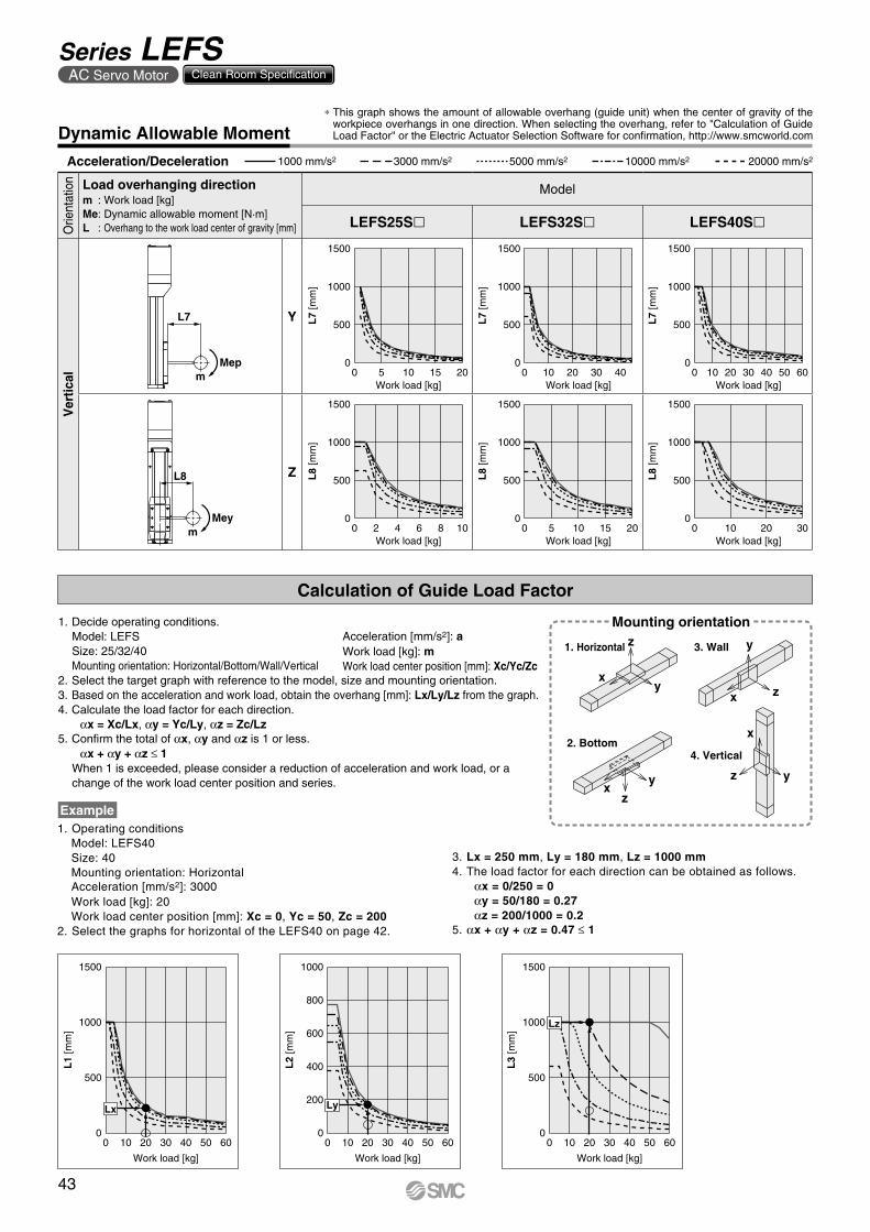
0 10 20 30 40 50 60Work load [kg]
L7
[mm
]
0
500
1500
1000
0 10 20 30 40Work load [kg]
L7
[mm
]
0
500
1500
1000
0 5 10 2015Work load [kg]
L7
[mm
]
0
500
1500
1000
0 10 20 30Work load [kg]
L8
[mm
]
0
500
1500
1000
0 5 10 15 20Work load [kg]
L8
[mm
]
0
500
1500
1000
0 4 62 8 10Work load [kg]
L8
[mm
]
0
500
1500
1000
L7
Mepm
L8
Meym
0 10 20 30 40 50 600
500
1500
1000
Lx
L1
[mm
]
Work load [kg]
0 10 20 30 40 50 600
600
400
200
1000
800
L2
[mm
]
Work load [kg]
Ly
0 10 20 30 40 50 600
500
1500
1000
L3
[mm
]
Work load [kg]
Lz
xy
z
xy
z
x z
y
x
z y
Calculation of Guide Load Factor
Mounting orientation
1. Horizontal 3. Wall
2. Bottom4. Vertical
Acceleration/Deceleration 1000 mm/s2 3000 mm/s2 5000 mm/s2 10000 mm/s2 20000 mm/s2
Dynamic Allowable Moment
Orie
ntat
ion Load overhanging direction
m : Work load [kg]Me: Dynamic allowable moment [N·m]L : Overhang to the work load center of gravity [mm]
Model
LEFS25Sl LEFS32Sl LEFS40Sl
Ver
tical
Y
Z
1. Operating conditionsModel: LEFS40Size: 40Mounting orientation: HorizontalAcceleration [mm/s2]: 3000Work load [kg]: 20Work load center position [mm]: Xc = 0, Yc = 50, Zc = 200
2. Select the graphs for horizontal of the LEFS40 on page 42.
Example
Acceleration [mm/s2]: aWork load [kg]: mWork load center position [mm]: Xc/Yc/Zc
1. Decide operating conditions.Model: LEFSSize: 25/32/40Mounting orientation: Horizontal/Bottom/Wall/Vertical
2. Select the target graph with reference to the model, size and mounting orientation.3. Based on the acceleration and work load, obtain the overhang [mm]: Lx/Ly/Lz from the graph.4. Calculate the load factor for each direction.
αx = Xc/Lx, αy = Yc/Ly, αz = Zc/Lz5. Confirm the total of αx, αy and αz is 1 or less.
αx + αy + αz ≤ 1When 1 is exceeded, please consider a reduction of acceleration and work load, or a change of the work load center position and series.
3. Lx = 250 mm, Ly = 180 mm, Lz = 1000 mm4. The load factor for each direction can be obtained as follows.
αx = 0/250 = 0αy = 50/180 = 0.27αz = 200/1000 = 0.2
5. αx + αy + αz = 0.47 ≤ 1
* This graph shows the amount of allowable overhang (guide unit) when the center of gravity of the workpiece overhangs in one direction. When selecting the overhang, refer to "Calculation of Guide Load Factor" or the Electric Actuator Selection Software for confirmation, http://www.smcworld.com
43
Series LEFSAC Servo Motor Clean Room Specification
0
0.05
0.1
0.15
0.2
0.25
0 100 200 300
LEF16
LEF25
LEF32
LEF40Dis
plac
emen
t [m
m]
Overhang distance [mm]
0 100 200 300
Dis
plac
emen
t [m
m]
Overhang distance [mm]
0
0.02
0.04
0.06
0.08
0.1
0.12
LEF16
LEF25
LEF32
LEF40
w
q
A side
C side
B side
D side
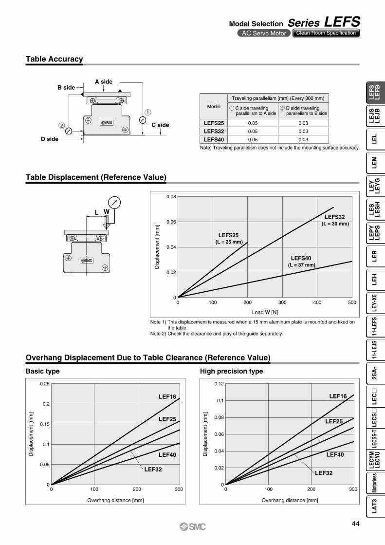
WL
0.08
0.06
0.04
0.02
00 100 200 300 400 500
Dis
plac
emen
t [m
m]
Load W [N]
LEFS25 (L = 25 mm)
LEFS32 (L = 30 mm)
LEFS40 (L = 37 mm)
Table Displacement (Reference Value)
Table Accuracy
Note) Traveling parallelism does not include the mounting surface accuracy.
Note 1) This displacement is measured when a 15 mm aluminum plate is mounted and fixed on the table.
Note 2) Check the clearance and play of the guide separately.
Model
Traveling parallelism [mm] (Every 300 mm)
q C side travelingparallelism to A side
w D side travelingparallelism to B side
LEFS25 0.05 0.03
LEFS32 0.05 0.03
LEFS40 0.05 0.03
Overhang Displacement Due to Table Clearance (Reference Value)
Basic type High precision type
44
Model Selection Series LEFSAC Servo Motor Clean Room Specification
LE
FS
LE
FB
LE
LL
EJS
LE
JBL
EM
LE
YL
EY
GL
ES
LE
SH
LE
PY
LE
PS
LE
RL
EH
LEY-
X511
-LEF
S11
-LEJ
S25
A-
LEC
YMLE
CYU
LECS
S-T
LA
T3
Moto
rless
LEC
S
LE
C
q w
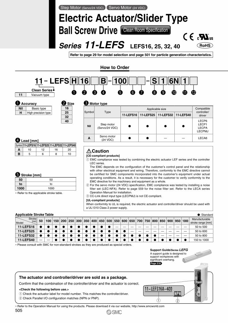
11 LEFS 16 100B 11S 6N
* Refer to the applicable stroke table.
Confirm that the combination of the controller/driver and the actuator is correct.
The actuator and controller/driver are sold as a package.
<Check the following before use.>q Check the actuator label for model number. This matches the controller/driver.w Check Parallel I/O configuration matches (NPN or PNP).
* Refer to the Operation Manual for using the products. Please download it via our website, http://www.smcworld.com
[CE-compliant products]q EMC compliance was tested by combining the electric actuator LEF series and the controller
LEC series. The EMC depends on the configuration of the customer’s control panel and the relationship with other electrical equipment and wiring. Therefore, conformity to the EMC directive cannot be certified for SMC components incorporated into the customer’s equipment under actual operating conditions. As a result, it is necessary for the customer to verify conformity to the EMC directive for the machinery and equipment as a whole.
w For the servo motor (24 VDC) specification, EMC compliance was tested by installing a noise filter set (LEC-NFA). Refer to page 559 for the noise filter set. Refer to the LECA series Operation Manual for installation.
e CC-Link direct input type (LECPMJ) is not CE-compliant.
[UL-compliant products]When conformity to UL is required, the electric actuator and controller/driver should be used with a UL1310 Class 2 power supply.
w e r t uy i o !0 !1 !2Clean Series
e Motor type
r Lead [mm]
t Stroke [mm]
Caution
w Size16253240
Symbol TypeApplicable size Compatible
controller/driver11-LEFS16 11-LEFS25 11-LEFS32 11-LEFS40
NilStep motor
(Servo/24 VDC)V V V V
LECP6LECP1LECPA
LECPMJ
A Servo motor(24 VDC)
V V — — LECA6
50 50
to to
1000 1000
Symbol 11-LEFS16 11-LEFS25 11-LEFS32 11-LEFS40A 10 12 16 20
B 5 6 8 10
11 Vacuum type
Applicable Stroke Table V: StandardStroke
[mm]Model50 100 150 200 250 300 350 400 450 500 550 600 650 700 750 800 850 900 950 1000 Manufacturable
stroke range [mm]
11-LEFS16 V V V V V V V V V V — — — — — — — — — — 50 to 500
11-LEFS25 V V V V V V V V V V V V — — — — — — — — 50 to 600
11-LEFS32 V V V V V V V V V V V V V V V V — — — — 50 to 800
11-LEFS40 — — V V V V V V V V V V V V V V V V V V 150 to 1000
* Please consult with SMC for non-standard strokes as they are produced as special orders.
Support Guide/Series LEFGA support guide is designed to support workpieces with significant overhang.Page 518
Hq
q AccuracyNil Basic typeH High precision type
Step Motor (Servo/24 VDC) Servo Motor (24 VDC)
Electric Actuator/Slider TypeBall Screw Drive Clean Room Specification
Series 11-LEFS LEFS16, 25, 32, 40
How to Order
Refer to page 29 for model selection and page 501 for particle generation characteristics.
505
R: Right
Nil: Left
* Produced upon receipt of order (Robotic cable only)Refer to the specifications Note 2) on pages 507 and 508.
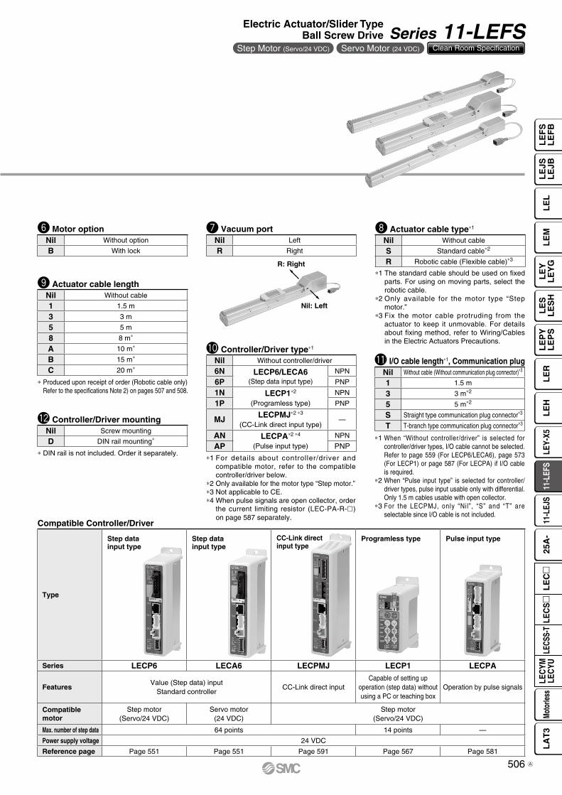
y Motor option
o Actuator cable length
!2 Controller/Driver mounting
* DIN rail is not included. Order it separately.
i Actuator cable type*1u Vacuum port
*1 The standard cable should be used on fixed parts. For using on moving parts, select the robotic cable.
*2 Only available for the motor type “Step motor.”
*3 Fix the motor cable protruding from the actuator to keep it unmovable. For details about fixing method, refer to Wiring/Cables in the Electric Actuators Precautions.
*1 For details about controller/driver and compatible motor, refer to the compatible controller/driver below.
*2 Only available for the motor type “Step motor.”*3 Not applicable to CE.*4 When pulse signals are open collector, order
the current limiting resistor (LEC-PA-R-l) on page 587 separately.
!0 Controller/Driver type*1
Compatible Controller/Driver
Type
Step datainput type
Step datainput type
CC-Link directinput type
Programless type Pulse input type
Series LECP6 LECA6 LECPMJ LECP1 LECPA
FeaturesValue (Step data) input
Standard controllerCC-Link direct input
Capable of setting up operation (step data) without using a PC or teaching box
Operation by pulse signals
Compatible motor
Step motor(Servo/24 VDC)
Servo motor(24 VDC)
Step motor(Servo/24 VDC)
Max. number of step data 64 points 14 points —
Power supply voltage 24 VDC
Reference page Page 551 Page 551 Page 591 Page 567 Page 581
Nil Without controller/driver
6N LECP6/LECA6(Step data input type)
NPN
6P PNP
1N LECP1*2
(Programless type)
NPN
1P PNP
MJ LECPMJ*2 *3
(CC-Link direct input type)—
AN LECPA*2 *4
(Pulse input type)
NPN
AP PNP
Nil Left
R RightNil Without cable
S Standard cable*2
R Robotic cable (Flexible cable)*3
Nil Screw mounting
D DIN rail mounting*
Nil Without option
B With lock
Nil Without cable
1 1.5 m
3 3 m
5 5 m
8 8 m*
A 10 m*
B 15 m*
C 20 m*!1 I/O cable length*1, Communication plug
*1 When “Without controller/driver” is selected for controller/driver types, I/O cable cannot be selected. Refer to page 559 (For LECP6/LECA6), page 573 (For LECP1) or page 587 (For LECPA) if I/O cable is required.
*2 When “Pulse input type” is selected for controller/driver types, pulse input usable only with differential. Only 1.5 m cables usable with open collector.
*3 For the LECPMJ, only “Nil”, “S” and “T” are selectable since I/O cable is not included.
Nil Without cable (Without communication plug connector)*3
1 1.5 m
3 3 m*2
5 5 m*2
S Straight type communication plug connector*3
T T-branch type communication plug connector*3
506
Electric Actuator/Slider TypeBall Screw Drive Series 11-LEFS
Step Motor (Servo/24 VDC) Servo Motor (24 VDC) Clean Room Specification
LE
FS
LE
FB
LE
LL
EJS
LE
JBL
EM
LE
YL
EY
GL
ES
LE
SH
LE
PY
LE
PS
LE
RL
EH
LEY-
X511
-LEF
S11
-LEJ
S25
A-
LEC
YMLE
CYU
LECS
S-T
LA
T3
Moto
rless
LEC
S
LE
C
A
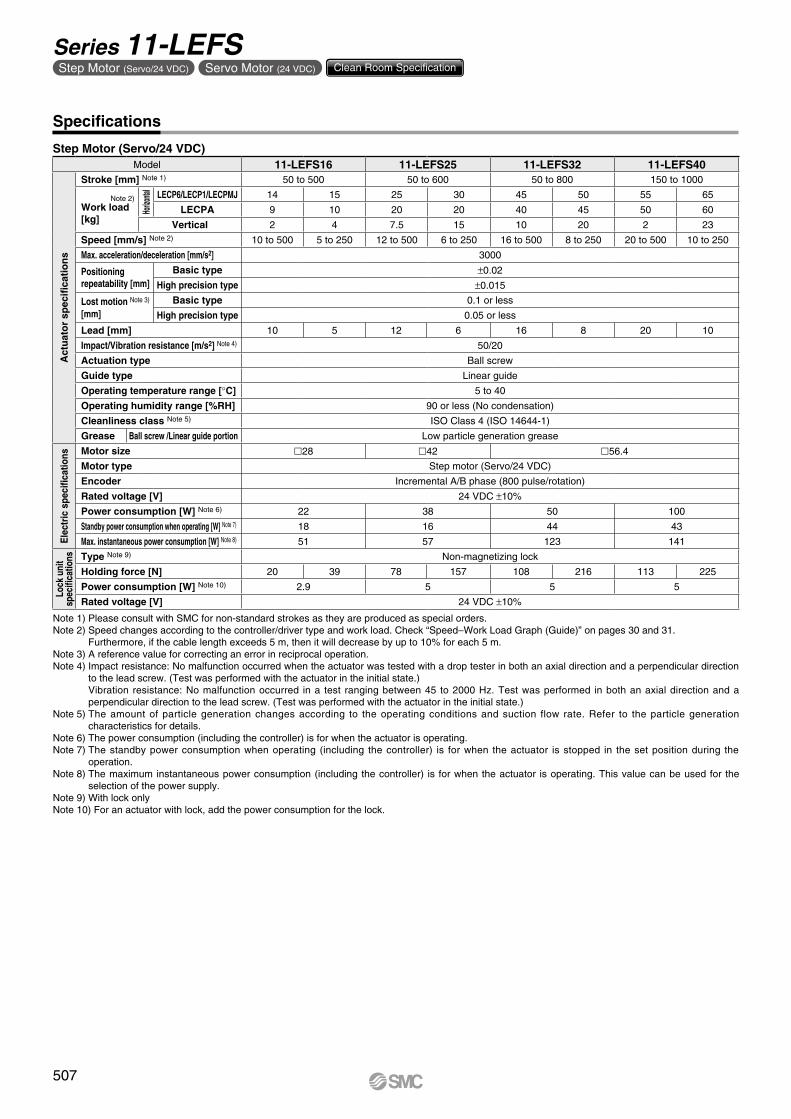
Note 1) Please consult with SMC for non-standard strokes as they are produced as special orders.Note 2) Speed changes according to the controller/driver type and work load. Check “Speed–Work Load Graph (Guide)” on pages 30 and 31. Furthermore, if the cable length exceeds 5 m, then it will decrease by up to 10% for each 5 m.Note 3) A reference value for correcting an error in reciprocal operation.Note 4) Impact resistance: No malfunction occurred when the actuator was tested with a drop tester in both an axial direction and a perpendicular direction
to the lead screw. (Test was performed with the actuator in the initial state.) Vibration resistance: No malfunction occurred in a test ranging between 45 to 2000 Hz. Test was performed in both an axial direction and a
perpendicular direction to the lead screw. (Test was performed with the actuator in the initial state.)Note 5) The amount of particle generation changes according to the operating conditions and suction flow rate. Refer to the particle generation
characteristics for details.Note 6) The power consumption (including the controller) is for when the actuator is operating.Note 7) The standby power consumption when operating (including the controller) is for when the actuator is stopped in the set position during the
operation. Note 8) The maximum instantaneous power consumption (including the controller) is for when the actuator is operating. This value can be used for the
selection of the power supply.Note 9) With lock onlyNote 10) For an actuator with lock, add the power consumption for the lock.
Step Motor (Servo/24 VDC)Model 11-LEFS16 11-LEFS25 11-LEFS32 11-LEFS40
Act
uat
or
spec
ifica
tio
ns
Stroke [mm] Note 1) 50 to 500 50 to 600 50 to 800 150 to 1000
Note 2)Work load [kg]
Horizo
ntal
LECP6/LECP1/LECPMJ 14 15 25 30 45 50 55 65
LECPA 9 10 20 20 40 45 50 60
Vertical 2 4 7.5 15 10 20 2 23
Speed [mm/s] Note 2) 10 to 500 5 to 250 12 to 500 6 to 250 16 to 500 8 to 250 20 to 500 10 to 250
Max. acceleration/deceleration [mm/s2] 3000
Positioning repeatability [mm]
Basic type ±0.02
High precision type ±0.015
Lost motion Note 3)
[mm] Basic type 0.1 or less
High precision type 0.05 or less
Lead [mm] 10 5 12 6 16 8 20 10
Impact/Vibration resistance [m/s2] Note 4) 50/20
Actuation type Ball screw
Guide type Linear guide
Operating temperature range [°C] 5 to 40
Operating humidity range [%RH] 90 or less (No condensation)
Cleanliness class Note 5) ISO Class 4 (ISO 14644-1)
Grease Ball screw /Linear guide portion Low particle generation grease
Ele
ctri
c sp
ecifi
catio
ns Motor size 28 42 56.4
Motor type Step motor (Servo/24 VDC)
Encoder Incremental A/B phase (800 pulse/rotation)
Rated voltage [V] 24 VDC ±10%
Power consumption [W] Note 6) 22 38 50 100
Standby power consumption when operating [W] Note 7) 18 16 44 43
Max. instantaneous power consumption [W] Note 8) 51 57 123 141
Lock
uni
tsp
ecifi
catio
ns Type Note 9) Non-magnetizing lock
Holding force [N] 20 39 78 157 108 216 113 225
Power consumption [W] Note 10) 2.9 5 5 5
Rated voltage [V] 24 VDC ±10%
Specifications
507
Series 11-LEFSStep Motor (Servo/24 VDC) Servo Motor (24 VDC) Clean Room Specification
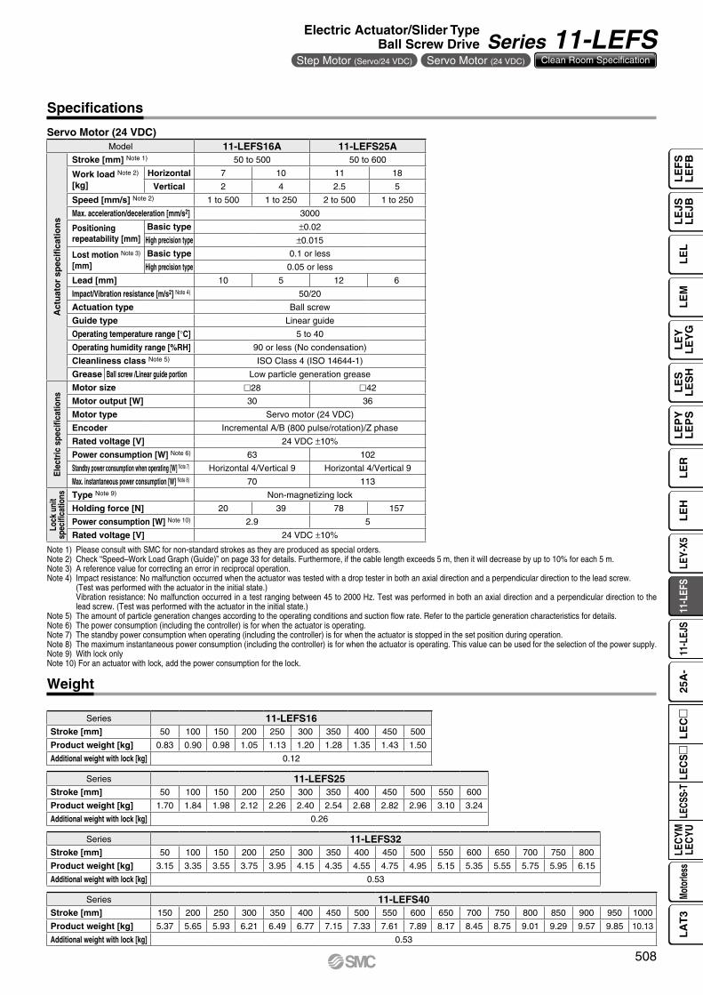
Servo Motor (24 VDC)Model 11-LEFS16A 11-LEFS25A
Act
uat
or
spec
ifica
tio
ns
Stroke [mm] Note 1) 50 to 500 50 to 600
Work load Note 2) [kg]
Horizontal 7 10 11 18
Vertical 2 4 2.5 5
Speed [mm/s] Note 2) 1 to 500 1 to 250 2 to 500 1 to 250
Max. acceleration/deceleration [mm/s2] 3000
Positioning repeatability [mm]
Basic type ±0.02
High precision type ±0.015
Lost motion Note 3) [mm]
Basic type 0.1 or less
High precision type 0.05 or less
Lead [mm] 10 5 12 6
Impact/Vibration resistance [m/s2] Note 4) 50/20
Actuation type Ball screw
Guide type Linear guide
Operating temperature range [°C] 5 to 40
Operating humidity range [%RH] 90 or less (No condensation)
Cleanliness class Note 5) ISO Class 4 (ISO 14644-1)
Grease Ball screw /Linear guide portion Low particle generation grease
Ele
ctri
c sp
ecifi
catio
ns
Motor size 28 42
Motor output [W] 30 36
Motor type Servo motor (24 VDC)
Encoder Incremental A/B (800 pulse/rotation)/Z phase
Rated voltage [V] 24 VDC ±10%
Power consumption [W] Note 6) 63 102
Standby power consumption when operating [W] Note 7) Horizontal 4/Vertical 9 Horizontal 4/Vertical 9
Max. instantaneous power consumption [W] Note 8) 70 113
Lock
uni
tsp
ecifi
catio
ns Type Note 9) Non-magnetizing lock
Holding force [N] 20 39 78 157
Power consumption [W] Note 10) 2.9 5
Rated voltage [V] 24 VDC ±10%
Weight
Series 11-LEFS40Stroke [mm] 150 200 250 300 350 400 450 500 550 600 650 700 750 800 850 900 950 1000
Product weight [kg] 5.37 5.65 5.93 6.21 6.49 6.77 7.15 7.33 7.61 7.89 8.17 8.45 8.75 9.01 9.29 9.57 9.85 10.13
Additional weight with lock [kg] 0.53
Series 11-LEFS32Stroke [mm] 50 100 150 200 250 300 350 400 450 500 550 600 650 700 750 800
Product weight [kg] 3.15 3.35 3.55 3.75 3.95 4.15 4.35 4.55 4.75 4.95 5.15 5.35 5.55 5.75 5.95 6.15
Additional weight with lock [kg] 0.53
Series 11-LEFS25Stroke [mm] 50 100 150 200 250 300 350 400 450 500 550 600
Product weight [kg] 1.70 1.84 1.98 2.12 2.26 2.40 2.54 2.68 2.82 2.96 3.10 3.24
Additional weight with lock [kg] 0.26
Series 11-LEFS16Stroke [mm] 50 100 150 200 250 300 350 400 450 500
Product weight [kg] 0.83 0.90 0.98 1.05 1.13 1.20 1.28 1.35 1.43 1.50
Additional weight with lock [kg] 0.12
Specifications
Note 1) Please consult with SMC for non-standard strokes as they are produced as special orders.Note 2) Check “Speed–Work Load Graph (Guide)” on page 33 for details. Furthermore, if the cable length exceeds 5 m, then it will decrease by up to 10% for each 5 m.Note 3) A reference value for correcting an error in reciprocal operation.Note 4) Impact resistance: No malfunction occurred when the actuator was tested with a drop tester in both an axial direction and a perpendicular direction to the lead screw.
(Test was performed with the actuator in the initial state.) Vibration resistance: No malfunction occurred in a test ranging between 45 to 2000 Hz. Test was performed in both an axial direction and a perpendicular direction to the
lead screw. (Test was performed with the actuator in the initial state.)Note 5) The amount of particle generation changes according to the operating conditions and suction flow rate. Refer to the particle generation characteristics for details.Note 6) The power consumption (including the controller) is for when the actuator is operating.Note 7) The standby power consumption when operating (including the controller) is for when the actuator is stopped in the set position during operation.Note 8) The maximum instantaneous power consumption (including the controller) is for when the actuator is operating. This value can be used for the selection of the power supply.Note 9) With lock onlyNote 10) For an actuator with lock, add the power consumption for the lock.
508
Electric Actuator/Slider TypeBall Screw Drive Series 11-LEFS
Step Motor (Servo/24 VDC) Servo Motor (24 VDC) Clean Room Specification
LE
FS
LE
FB
LE
LL
EJS
LE
JBL
EM
LE
YL
EY
GL
ES
LE
SH
LE
PY
LE
PS
LE
RL
EH
LEY-
X511
-LEF
S11
-LEJ
S25
A-
LEC
YMLE
CYU
LECS
S-T
LA
T3
Moto
rless
LEC
S
LE
C
20
46
27
40
28
24
40
(72)
4 x M4 x 0.7thread depth 6.4
ø3H9depth 3
3H9depth 3
3.5
39.4
F100
D x 100 (= E)
34
B
n x ø3.5
(152)
65
Cable length ≈ 250
2020
15
20Lock cable (ø3.5)
Motor option: With lockStep
motorServomotor
20
15
24
24
4033
65
Cable length ≈ 250
Motor cable (2 x ø5)
L
6.5
9.2
Vacuum port M5 x 0.8 x 5
Body mounting Note 1)
reference plane
6
5.5M4 x 0.7thread depth 7(F.G. terminal)
( )
8
3H9depth 3
+0.025 0
4
( )+0.025 0
( )+0.025 0
(41) [39] 39 [(41)]Stroke
4 [2] 2 [4]
(2.4)7
(37) A (Table traveling distance) Note 2) (110)37
[Origin] Note 4) Origin Note 3)
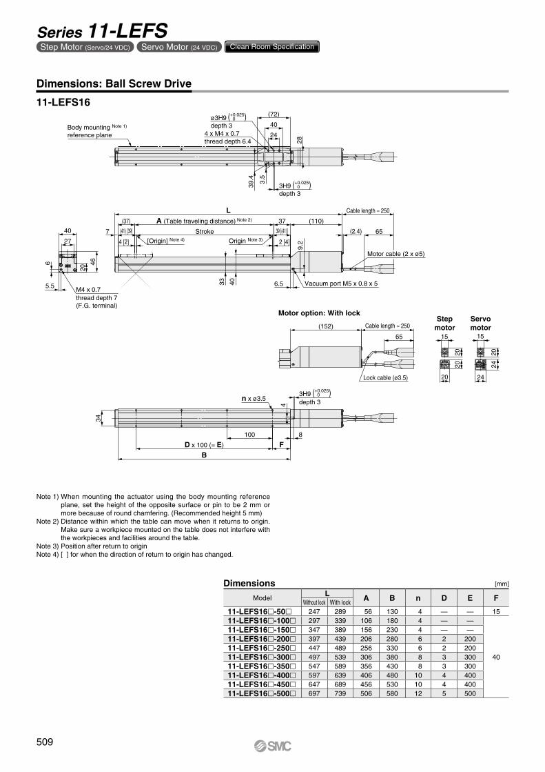
11-LEFS16
Dimensions: Ball Screw Drive
Note 1) When mounting the actuator using the body mounting reference plane, set the height of the opposite surface or pin to be 2 mm or more because of round chamfering. (Recommended height 5 mm)
Note 2) Distance within which the table can move when it returns to origin. Make sure a workpiece mounted on the table does not interfere with the workpieces and facilities around the table.
Note 3) Position after return to originNote 4) [ ] for when the direction of return to origin has changed.
[mm]
ModelL A B n D E F
Without lock With lock11-LEFS16l-50l 247 289 56 130 4 — — 1511-LEFS16l-100l 297 339 106 180 4 — —
40
11-LEFS16l-150l 347 389 156 230 4 — —11-LEFS16l-200l 397 439 206 280 6 2 20011-LEFS16l-250l 447 489 256 330 6 2 20011-LEFS16l-300l 497 539 306 380 8 3 30011-LEFS16l-350l 547 589 356 430 8 3 30011-LEFS16l-400l 597 639 406 480 10 4 40011-LEFS16l-450l 647 689 456 530 10 4 40011-LEFS16l-500l 697 739 506 580 12 5 500
Dimensions
509
Series 11-LEFSStep Motor (Servo/24 VDC) Servo Motor (24 VDC) Clean Room Specification
24
57.5
3858
45
64
(102)
50
38
3H9depth 3
3.5
ø3H9depth 3
4 x M5 x 0.8thread depth 8.5
F120
D x 120 (= E)
B
48
n x ø4.5
(160.5) Cable length ≈ 250
65
2020
15
20Lock cable (ø3.5)
Motor option: With lock Stepmotor
Servomotor
20
15
24
24
4838
.5
Cable length ≈ 250
65
Motor cable (2 x ø5)
L
Vacuum port Rc1/8
34
13.9
Body mounting Note 1)
reference plane
M4 x 0.7thread depth 8(F.G. terminal)
6.5
6
10
4
( )3H9depth 3
+0.025 0
( )+0.025 0
( )+0.025 0
54 [(56)](56) [54] Stroke
4 [2]
(52) A (Table traveling distance) Note 2)
2 [4]
10
52 (115.5)
(2.4)
[Origin] Note 4) Origin Note 3)
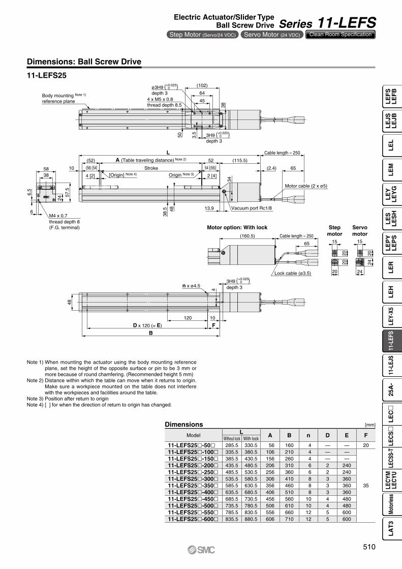
11-LEFS25
Dimensions: Ball Screw Drive
Note 1) When mounting the actuator using the body mounting reference plane, set the height of the opposite surface or pin to be 3 mm or more because of round chamfering. (Recommended height 5 mm)
Note 2) Distance within which the table can move when it returns to origin. Make sure a workpiece mounted on the table does not interfere with the workpieces and facilities around the table.
Note 3) Position after return to originNote 4) [ ] for when the direction of return to origin has changed.
[mm]
ModelL A B n D E F
Without lock With lock11-LEFS25l-50l 285.5 330.5 56 160 4 — — 2011-LEFS25l-100l 335.5 380.5 106 210 4 — —
35
11-LEFS25l-150l 385.5 430.5 156 260 4 — —11-LEFS25l-200l 435.5 480.5 206 310 6 2 24011-LEFS25l-250l 485.5 530.5 256 360 6 2 24011-LEFS25l-300l 535.5 580.5 306 410 8 3 36011-LEFS25l-350l 585.5 630.5 356 460 8 3 36011-LEFS25l-400l 635.5 680.5 406 510 8 3 36011-LEFS25l-450l 685.5 730.5 456 560 10 4 48011-LEFS25l-500l 735.5 780.5 506 610 10 4 48011-LEFS25l-550l 785.5 830.5 556 660 12 5 60011-LEFS25l-600l 835.5 880.5 606 710 12 5 600
Dimensions
510
Electric Actuator/Slider TypeBall Screw Drive Series 11-LEFS
Step Motor (Servo/24 VDC) Servo Motor (24 VDC) Clean Room Specification
LE
FS
LE
FB
LE
LL
EJS
LE
JBL
EM
LE
YL
EY
GL
ES
LE
SH
LE
PY
LE
PS
LE
RL
EH
LEY-
X511
-LEF
S11
-LEJ
S25
A-
LEC
YMLE
CYU
LECS
S-T
LA
T3
Moto
rless
LEC
S
LE
C
6046
.8
65
Cable length ≈ 250
42
70
(122)
44
4 x M6 x 1thread depth 9.9
ø5H9depth 5
5H9depth 5
5.5
60
60
15
150
D x 150 (= E)
B
n x ø5.5
30
79
48
70
65
Cable length ≈ 250(194)
20
20
15
20
Motor cable (2 x ø5)
Lock cable (ø3.5)
Motor option: With lock Stepmotor
L
20
20
14.941
.8Vacuum portRc1/8
Body mounting Note 1)
reference plane
7.5
6.5
M4 x 0.7thread depth 8(F.G. terminal)
15
6
( )5H9depth 5
+0.030 0
( )+0.030 0
( )+0.030 0
(62) 62
(66) [64] 64 [(66)]Stroke
4 [2] 2 [4]
(2.4)10
A (Table traveling distance) Note 2) (142)
[Origin] Note 4) Origin Note 3)
Dimensions: Ball Screw Drive
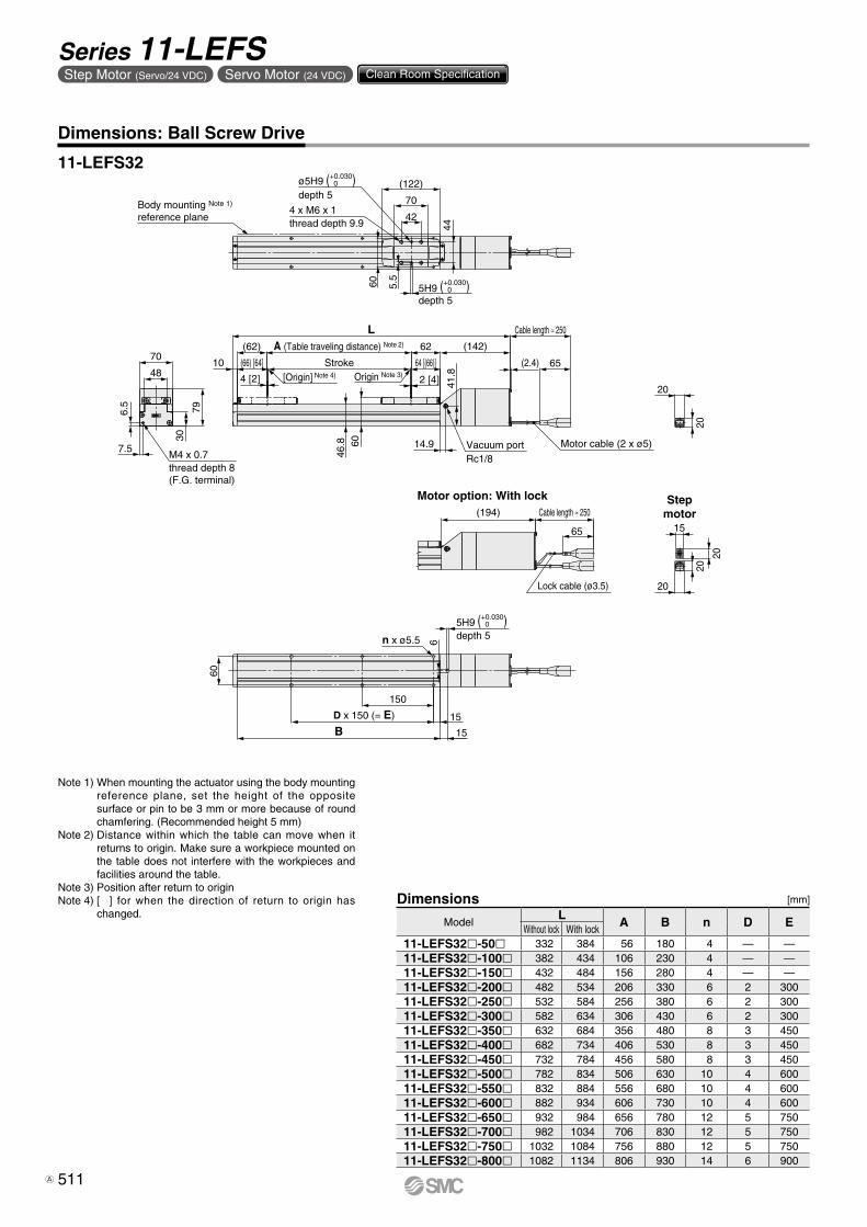
11-LEFS32
Note 1) When mounting the actuator using the body mounting reference plane, set the height of the opposite surface or pin to be 3 mm or more because of round chamfering. (Recommended height 5 mm)
Note 2) Distance within which the table can move when it returns to origin. Make sure a workpiece mounted on the table does not interfere with the workpieces and facilities around the table.
Note 3) Position after return to originNote 4) [ ] for when the direction of return to origin has
changed.[mm]
ModelL A B n D E
Without lock With lock11-LEFS32l-50l 332 384 56 180 4 — —11-LEFS32l-100l 382 434 106 230 4 — —11-LEFS32l-150l 432 484 156 280 4 — —11-LEFS32l-200l 482 534 206 330 6 2 30011-LEFS32l-250l 532 584 256 380 6 2 30011-LEFS32l-300l 582 634 306 430 6 2 30011-LEFS32l-350l 632 684 356 480 8 3 45011-LEFS32l-400l 682 734 406 530 8 3 45011-LEFS32l-450l 732 784 456 580 8 3 45011-LEFS32l-500l 782 834 506 630 10 4 60011-LEFS32l-550l 832 884 556 680 10 4 60011-LEFS32l-600l 882 934 606 730 10 4 60011-LEFS32l-650l 932 984 656 780 12 5 75011-LEFS32l-700l 982 1034 706 830 12 5 75011-LEFS32l-750l 1032 1084 756 880 12 5 75011-LEFS32l-800l 1082 1134 806 930 14 6 900
Dimensions
511
Series 11-LEFSStep Motor (Servo/24 VDC) Servo Motor (24 VDC) Clean Room Specification
A
Body mounting Note 1)
reference plane 60
106
774
58
60
150
B
76
n x ø6.6
15
7
thread depth 8(F.G. terminal)
31
61
90
(68)
8
8
Lock cable (ø3.3)
Motor cable (2 x ø5)
65
Cable length ≈ 250
20
20
20
15
4 x M8 x 1.25thread depth 13
ø6H9depth 7
( )+0.030 0 (170)
6H9depth 7
( )+0.030 0
(214)
M4 x 0.7
D x 150 (= E)
( )6H9depth 6
+0.030 0
Motor option: With lock
20
20
Motor cable (2 x ø5)
Cable length ≈ 250
Stroke
4 [2]
(90) [88]
A (Table traveling distance) Note 2)
2 [4]
88 [(90)] (3.1)
(86)68
53.8
13
L
65
86 (165)
[Origin] Note 4) Origin Note 3)
12.9
48.5
Vacuum portRc1/8
Dimensions: Ball Screw Drive
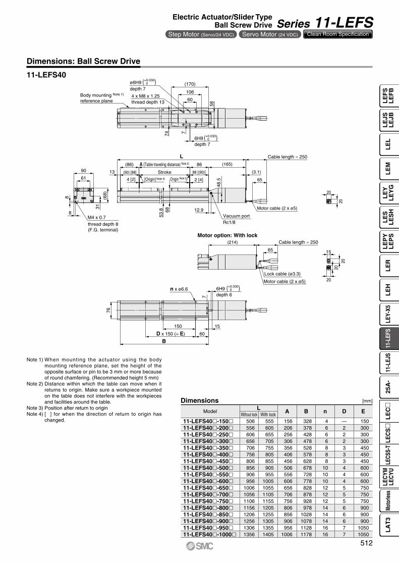
11-LEFS40
Note 1) When mounting the actuator using the body mounting reference plane, set the height of the opposite surface or pin to be 3 mm or more because of round chamfering. (Recommended height 5 mm)
Note 2) Distance within which the table can move when it returns to origin. Make sure a workpiece mounted on the table does not interfere with the workpieces and facilities around the table.
Note 3) Position after return to originNote 4) [ ] for when the direction of return to origin has
changed.
[mm]
ModelL A B n D E
Without lock With lock11-LEFS40l-150l 506 555 156 328 4 — 15011-LEFS40l-200l 556 605 206 378 6 2 30011-LEFS40l-250l 606 655 256 428 6 2 30011-LEFS40l-300l 656 705 306 478 6 2 30011-LEFS40l-350l 706 755 356 528 8 3 45011-LEFS40l-400l 756 805 406 578 8 3 45011-LEFS40l-450l 806 855 456 628 8 3 45011-LEFS40l-500l 856 905 506 678 10 4 60011-LEFS40l-550l 906 955 556 728 10 4 60011-LEFS40l-600l 956 1005 606 778 10 4 60011-LEFS40l-650l 1006 1055 656 828 12 5 75011-LEFS40l-700l 1056 1105 706 878 12 5 75011-LEFS40l-750l 1106 1155 756 928 12 5 75011-LEFS40l-800l 1156 1205 806 978 14 6 90011-LEFS40l-850l 1206 1255 856 1028 14 6 90011-LEFS40l-900l 1256 1305 906 1078 14 6 90011-LEFS40l-950l 1306 1355 956 1128 16 7 105011-LEFS40l-1000l 1356 1405 1006 1178 16 7 1050
Dimensions
512
Electric Actuator/Slider TypeBall Screw Drive Series 11-LEFS
Step Motor (Servo/24 VDC) Servo Motor (24 VDC) Clean Room Specification
LE
FS
LE
FB
LE
LL
EJS
LE
JBL
EM
LE
YL
EY
GL
ES
LE
SH
LE
PY
LE
PS
LE
RL
EH
LEY-
X511
-LEF
S11
-LEJ
S25
A-
LEC
YMLE
CYU
LECS
S-T
LA
T3
Moto
rless
LEC
S
LE
C
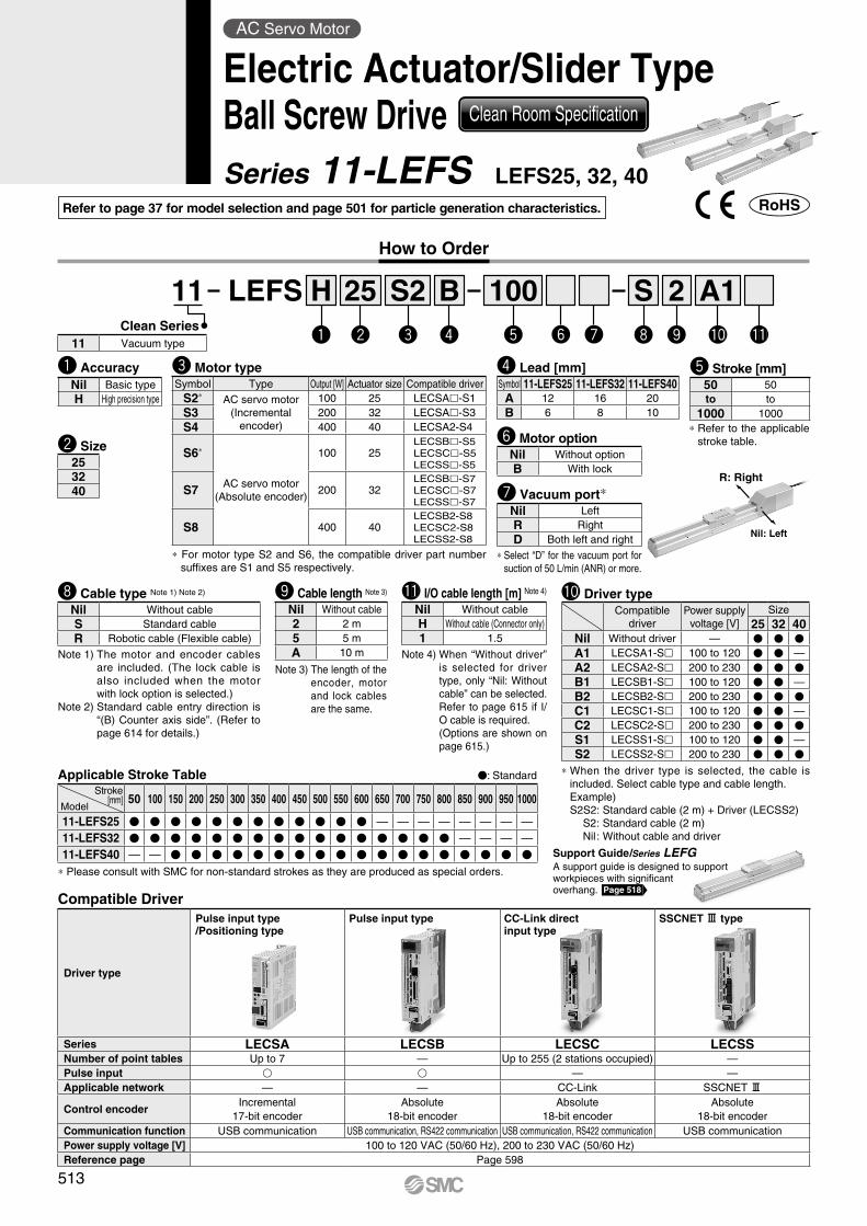
How to Order
Refer to page 37 for model selection and page 501 for particle generation characteristics.
R: Right
Nil: Left
25 100B 2S A1S2w e r t uy i o !0 !1
11 LEFSClean Series
w Size* Refer to the applicable
stroke table.
t Stroke [mm]
Note 1) The motor and encoder cables are included. (The lock cable is also included when the motor with lock option is selected.)
Note 2) Standard cable entry direction is “(B) Counter axis side”. (Refer to page 614 for details.)
i Cable type Note 1) Note 2)
Note 3) The length of the encoder, motor and lock cables are the same.
o Cable length Note 3)
e Motor type
Compatible Driver
* For motor type S2 and S6, the compatible driver part number suffixes are S1 and S5 respectively.
!0 Driver type
* When the driver type is selected, the cable is included. Select cable type and cable length.Example)S2S2: Standard cable (2 m) + Driver (LECSS2)
S2 : Standard cable (2 m)Nil : Without cable and driver
Applicable Stroke Table V: Standard
* Please consult with SMC for non-standard strokes as they are produced as special orders.
Driver type
Pulse input type/Positioning type
Pulse input type CC-Link directinput type
SSCNET # type
Series LECSA LECSB LECSC LECSSNumber of point tables Up to 7 — Up to 255 (2 stations occupied) —Pulse input v v — —Applicable network — — CC-Link SSCNET #
Control encoderIncremental
17-bit encoderAbsolute
18-bit encoderAbsolute
18-bit encoderAbsolute
18-bit encoderCommunication function USB communication USB communication, RS422 communication USB communication, RS422 communication USB communicationPower supply voltage [V] 100 to 120 VAC (50/60 Hz), 200 to 230 VAC (50/60 Hz)Reference page Page 598
Stroke[mm]
Model50 100 150 200 250 300 350 400 450 500 550 600 650 700 750 800 850 900 950 1000
11-LEFS25 V V V V V V V V V V V V — — — — — — — —11-LEFS32 V V V V V V V V V V V V V V V V — — — —11-LEFS40 — — V V V V V V V V V V V V V V V V V V
Compatible driver
Power supply voltage [V]
Size25 32 40
Nil Without driver — V V V
A1 LECSA1-S 100 to 120 V V —A2 LECSA2-S 200 to 230 V V V
B1 LECSB1-S 100 to 120 V V —B2 LECSB2-S 200 to 230 V V V
C1 LECSC1-S 100 to 120 V V —C2 LECSC2-S 200 to 230 V V V
S1 LECSS1-S 100 to 120 V V —S2 LECSS2-S 200 to 230 V V V
Symbol Type Output [W] Actuator size Compatible driverS2* AC servo motor
(Incremental encoder)
100 25 LECSA-S1S3 200 32 LECSA-S3S4 400 40 LECSA2-S4
S6*
AC servo motor(Absolute encoder)
100 25LECSB-S5LECSC-S5LECSS-S5
S7 200 32LECSB-S7LECSC-S7LECSS-S7
S8 400 40LECSB2-S8LECSC2-S8LECSS2-S8
Nil Without cable2 2 m5 5 mA 10 m
Nil Without cableS Standard cableR Robotic cable (Flexible cable)
50 50to to
1000 1000
y Motor optionNil Without optionB With lock
r Lead [mm]Symbol 11-LEFS25 11-LEFS32 11-LEFS40A 12 16 20B 6 8 10
253240 u Vacuum port*
* Select “D” for the vacuum port for suction of 50 L/min (ANR) or more.
Nil LeftR RightD Both left and right
11 Vacuum type
Support Guide/Series LEFG A support guide is designed to support workpieces with significant overhang. Page 518
q AccuracyNil Basic typeH High precision type
!1 I/O cable length [m] Note 4)
Nil Without cableH Without cable (Connector only)1 1.5
Note 4) When “Without driver” is selected for driver type, only “Nil: Without cable” can be selected.Refer to page 615 if I/O cable is required.(Options are shown on page 615.)
Hq
513
AC Servo Motor
Electric Actuator/Slider TypeBall Screw Drive Clean Room Specification
Series 11-LEFS LEFS25, 32, 40

514
Specifications
Note 1) Please consult with SMC for non-standard strokes as they are produced as special orders.
Note 2) For details, refer to “Speed–Work Load Graph (Guide)” on page 38.Note 3) The allowable speed changes according to the stroke.Note 4) A reference value for correcting an error in reciprocal operation.Note 5) Impact resistance: No malfunction occurred when the actuator
was tested with a drop tester in both an axial direction and a perpendicular direction to the lead screw. (Test was performed with the actuator in the initial state.)
Vibration resistance: No malfunction occurred in a test ranging between 45 to 2000 Hz. Test was performed in both an axial direction and a perpendicular direction to the lead screw. (Test
was performed with the actuator in the initial state.)Note 6) The amount of particle generation changes according to the
operating conditions and suction flow rate. Refer to the particle generation characteristics for details.
Note 7) The power consumption (including the driver) is for when the actuator is operating.
Note 8) The standby power consumption when operating (including the driver) is for when the actuator is stopped in the set position during the operation.
Note 9) The maximum instantaneous power consumption (including the driver) is for when the actuator is operating.
Note 10) Only when motor option “With lock” is selected.Note 11) For an actuator with lock, add the power consumption for the lock.
11-LEFS25, 32, 40 AC Servo Motor
Weight
Model 11-LEFS25S26 11-LEFS32S3
7 11-LEFS40S48
Act
uat
or
spec
ifica
tio
ns
Stroke [mm] Note 1) 50 to 600 50 to 800 150 to 1000
Work load [kg] Note 2)Horizontal 20 20 40 45 50 60
Vertical 8 15 10 20 15 30
Note 3)Max. speed [mm/s]
Stroke range
Up to 400 900 450 1000 500 1000 500401 to 500 720 360 1000 500 1000 500501 to 600 540 270 800 400 1000 500601 to 700 — — 620 310 940 470701 to 800 — — 500 250 760 380801 to 900 — — — — 620 310901 to 1000 — — — — 520 260
Max. acceleration/deceleration [mm/s2] 5000 (Refer to pages 39 to 41 for limit according to work load and duty ratio.)
Positioning repeatability [mm]
Basic type ±0.02High precision type ±0.01
Lost motion [mm] Note 4)Basic type 0.1 or less
High precision type 0.05 or lessLead [mm] 12 6 16 8 20 10Impact/Vibration resistance [m/s2] Note 5) 50/20Actuation type Ball screwGuide type Linear guideOperating temperature range [°C] 5 to 40Operating humidity range [%RH] 90 or less (No condensation)
Cleanliness class Note 6)ISO Class 4 (ISO 14644-1)
Class 10 (Fed.Std.209E)Grease Ball screw /Linear guide portion Low particle generation grease
Ele
ctri
c sp
ecifi
cati
on
s Motor output/Size 100 W/40 200 W/60 400 W/60Motor type AC servo motor (100/200 VAC)
EncoderMotor type S2, S3, S4: Incremental 17-bit encoder (Resolution: 131072 p/rev)
Motor type S6, S7, S8: Absolute 18-bit encoder (Resolution: 262144 p/rev)
Power consumption [W] Note 7)
Horizontal 45 65 210Vertical 145 175 230
Standby power consumption when operating [W] Note 8)
Horizontal 2 2 2Vertical 8 8 18
Max. instantaneous power consumption [W] Note 9) 445 725 1275
Lock
uni
t sp
ecifi
catio
ns Type Note 10) Non-magnetizing lockHolding force [N] 131 255 197 385 330 660Power consumption at 20°C [W] Note 11) 6.3 7.9 7.9Rated voltage [V] 24 VDC 0
−10%
Series 11-LEFS25SStroke [mm] 50 100 150 200 250 300 350 400 450 500 550 600
Motortype
S2 2.00 2.14 2.28 2.44 2.56 2.69 2.84 2.99 3.12 3.24 3.40 3.54 S6 2.06 2.20 2.34 2.50 2.62 2.75 2.90 3.05 3.18 3.30 3.46 3.60
Additional weight with lock [kg] S2: 0.2/S6: 0.3
Series 11-LEFS32SStroke [mm] 50 100 150 200 250 300 350 400 450 500 550 600 650 700 750 800
Motortype
S3 3.40 3.60 3.80 4.00 4.20 4.40 4.60 4.80 5.00 5.20 5.40 5.60 5.80 6.00 6.20 6.40S7 3.34 3.54 3.74 3.94 4.14 4.34 4.54 4.74 4.94 5.14 5.34 5.54 5.74 5.94 6.14 6.34
Additional weight with lock [kg] S3: 0.4/S7: 0.7
Series 11-LEFS40SStroke [mm] 150 200 250 300 350 400 450 500 550 600 650 700 750 800 850 900 950 1000
Motortype
S4 5.82 6.10 6.38 6.65 6.95 7.25 7.51 7.80 8.07 8.25 8.63 8.90 9.20 9.45 9.76 10.05 10.32 10.60 S8 5.92 6.20 6.48 6.75 7.05 7.35 7.61 7.90 8.17 8.35 8.73 9.00 9.30 9.55 9.86 10.15 10.42 10.70
Additional weight with lock [kg] S4: 0.7/S8: 0.7
514
Electric Actuator/Slider TypeBall Screw Drive Series 11-LEFS
AC Servo Motor Clean Room Specification
LE
FS
LE
FB
LE
LL
EJS
LE
JBL
EM
LE
YL
EY
GL
ES
LE
SH
LE
PY
LE
PS
LE
RL
EH
LEY-
X511
-LEF
S11
-LEJ
S25
A-
LEC
YMLE
CYU
LECS
S-T
LA
T3
Moto
rless
LEC
S
LE
C
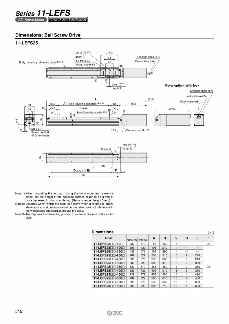
Encoder cable (ø7)
Lock cable (ø4.5)
Motor cable (ø6)
(209)
Motor option: With lock
6
6.5
24
66
38
58
M4 x 0.7thread depth 8(F.G. terminal)
n x ø4.5
4
10
+0.025 03H9 ( )
depth 3
48
BD x 120 (= E)
120
F
3.5
+0.025 0ø3H9 ( )
depth 3
+0.025 03H9 ( )
depth 3
50
(102)
64
38
45
Encoder cable (ø7)
Motor cable (ø6)Body mounting reference plane Note 1)
Encoder Z-phase detecting position Note 3)
4 x M5 x 0.8thread depth 8.5
(56)
(52) A (Table traveling distance) Note 2)
(4)
52
2±1
Stroke (54)
38.5
48
10
(169)
(2.2)L
34
13.9 Vacuum port Rc1/8
11-LEFS25
Dimensions: Ball Screw Drive
Note 1) When mounting the actuator using the body mounting reference plane, set the height of the opposite surface or pin to be 3 mm or more because of round chamfering. (Recommended height 5 mm)
Note 2) Distance within which the table can move when it returns to origin. Make sure a workpiece mounted on the table does not interfere with the workpieces and facilities around the table.
Note 3) The Z-phase first detecting position from the stroke end of the motor side.
[mm]
ModelL A B n D E F
Without lock With lock11-LEFS25ll-50l 339 379 56 160 4 — — 2011-LEFS25ll-100l 389 429 106 210 4 — —
35
11-LEFS25ll-150l 439 479 156 260 4 — —11-LEFS25ll-200l 489 529 206 310 6 2 24011-LEFS25ll-250l 539 579 256 360 6 2 24011-LEFS25ll-300l 589 629 306 410 8 3 36011-LEFS25ll-350l 639 679 356 460 8 3 36011-LEFS25ll-400l 689 729 406 510 8 3 36011-LEFS25ll-450l 739 779 456 560 10 4 48011-LEFS25ll-500l 789 829 506 610 10 4 48011-LEFS25ll-550l 839 879 556 660 12 5 60011-LEFS25ll-600l 889 929 606 710 12 5 600
Dimensions
515
Series 11-LEFSAC Servo Motor Clean Room Specification
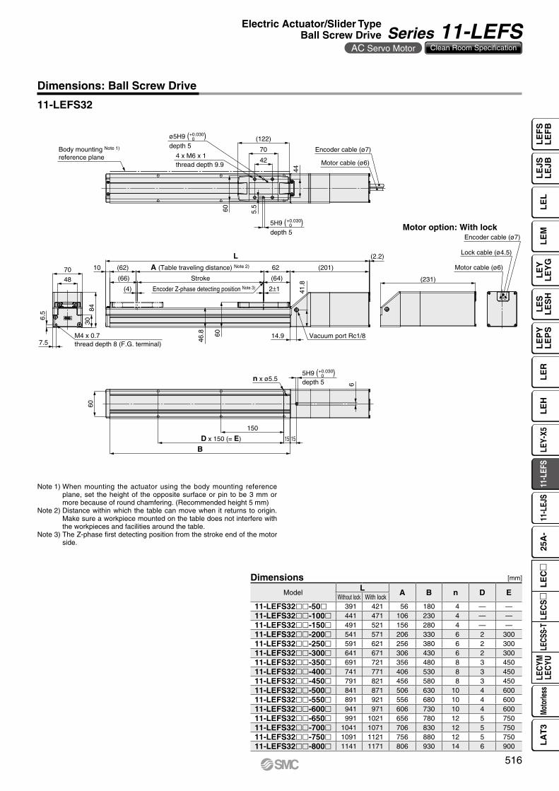
Encoder Z-phase detecting position Note 3)
Lock cable (ø4.5)
Encoder cable (ø7)
Motor cable (ø6)
(231)
Motor option: With lock
6.5
7.5
70
48
3084
M4 x 0.7thread depth 8 (F.G. terminal)
60
n x ø5.5
BD x 150 (= E)
150
15 15
6
+0.030 05H9 ( )
depth 5
60
44
42
5.5
+0.030 05H9 ( )
depth 5
ø5H9 ( )depth 5
+0.030 0
70
(122)
Motor cable (ø6)
Encoder cable (ø7)Body mounting Note 1)
reference plane 4 x M6 x 1thread depth 9.9
(2.2)L
(201)(62)
(66)
A (Table traveling distance) Note 2)
(4)
62
2±1
Stroke
10
(64)
41.8
Vacuum port Rc1/814.960
46.8
Dimensions: Ball Screw Drive
11-LEFS32
Note 1) When mounting the actuator using the body mounting reference plane, set the height of the opposite surface or pin to be 3 mm or more because of round chamfering. (Recommended height 5 mm)
Note 2) Distance within which the table can move when it returns to origin. Make sure a workpiece mounted on the table does not interfere with the workpieces and facilities around the table.
Note 3) The Z-phase first detecting position from the stroke end of the motor side.
[mm]
ModelL A B n D E
Without lock With lock11-LEFS32ll-50l 391 421 56 180 4 — —11-LEFS32ll-100l 441 471 106 230 4 — —11-LEFS32ll-150l 491 521 156 280 4 — —11-LEFS32ll-200l 541 571 206 330 6 2 30011-LEFS32ll-250l 591 621 256 380 6 2 30011-LEFS32ll-300l 641 671 306 430 6 2 30011-LEFS32ll-350l 691 721 356 480 8 3 45011-LEFS32ll-400l 741 771 406 530 8 3 45011-LEFS32ll-450l 791 821 456 580 8 3 45011-LEFS32ll-500l 841 871 506 630 10 4 60011-LEFS32ll-550l 891 921 556 680 10 4 60011-LEFS32ll-600l 941 971 606 730 10 4 60011-LEFS32ll-650l 991 1021 656 780 12 5 75011-LEFS32ll-700l 1041 1071 706 830 12 5 75011-LEFS32ll-750l 1091 1121 756 880 12 5 75011-LEFS32ll-800l 1141 1171 806 930 14 6 900
Dimensions
516
Electric Actuator/Slider TypeBall Screw Drive Series 11-LEFS
AC Servo Motor Clean Room Specification
LE
FS
LE
FB
LE
LL
EJS
LE
JBL
EM
LE
YL
EY
GL
ES
LE
SH
LE
PY
LE
PS
LE
RL
EH
LEY-
X511
-LEF
S11
-LEJ
S25
A-
LEC
YMLE
CYU
LECS
S-T
LA
T3
Moto
rless
LEC
S
LE
C
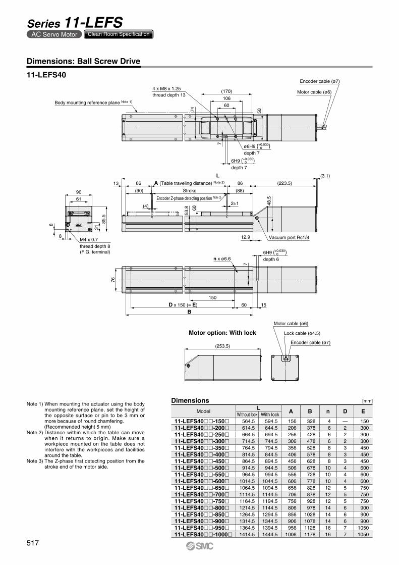
Encoder Z-phase detecting position Note 3)
Lock cable (ø4.5)
Motor cable (ø6)
Encoder cable (ø7)(253.5)
Motor option: With lock
BD x 150 (= E)
150
60 15
76
n x ø6.6
7+0.030 06H9 ( )
depth 6
7
+0.030 06H9 ( )
depth 7
74 58
(170)
106
60
ø6H9 ( )depth 7
+0.030 0
Motor cable (ø6)
Encoder cable (ø7)
Body mounting reference plane Note 1)
4 x M8 x 1.25thread depth 13
8
8
61
90
31
85.5
M4 x 0.7thread depth 8(F.G. terminal)
(3.1)
A (Table traveling distance) Note 2)86 86
(4) 2±1
(90)
13
L
Stroke (88)
(223.5)53
.8 68
12.9
48.5
Vacuum port Rc1/8
Dimensions: Ball Screw Drive
11-LEFS40
Note 1) When mounting the actuator using the body mounting reference plane, set the height of the opposite surface or pin to be 3 mm or more because of round chamfering. (Recommended height 5 mm)
Note 2) Distance within which the table can move when it returns to origin. Make sure a workpiece mounted on the table does not interfere with the workpieces and facilities around the table.
Note 3) The Z-phase first detecting position from the stroke end of the motor side.
[mm]
ModelL A B n D E
Without lock With lock11-LEFS40ll-150l 564.5 594.5 156 328 4 — 15011-LEFS40ll-200l 614.5 644.5 206 378 6 2 30011-LEFS40ll-250l 664.5 694.5 256 428 6 2 30011-LEFS40ll-300l 714.5 744.5 306 478 6 2 30011-LEFS40ll-350l 764.5 794.5 356 528 8 3 45011-LEFS40ll-400l 814.5 844.5 406 578 8 3 45011-LEFS40ll-450l 864.5 894.5 456 628 8 3 45011-LEFS40ll-500l 914.5 944.5 506 678 10 4 60011-LEFS40ll-550l 964.5 994.5 556 728 10 4 60011-LEFS40ll-600l 1014.5 1044.5 606 778 10 4 60011-LEFS40ll-650l 1064.5 1094.5 656 828 12 5 75011-LEFS40ll-700l 1114.5 1144.5 706 878 12 5 75011-LEFS40ll-750l 1164.5 1194.5 756 928 12 5 75011-LEFS40ll-800l 1214.5 1144.5 806 978 14 6 90011-LEFS40ll-850l 1264.5 1294.5 856 1028 14 6 90011-LEFS40ll-900l 1314.5 1344.5 906 1078 14 6 90011-LEFS40ll-950l 1364.5 1394.5 956 1128 16 7 105011-LEFS40ll-1000l 1414.5 1444.5 1006 1178 16 7 1050
Dimensions
517
Series 11-LEFSAC Servo Motor Clean Room Specification