calor 38 - comac cal sro
TRANSCRIPT

CALOR 38 Ver.2.00
Installation and technical conditions
Date of issue 06/01/2022
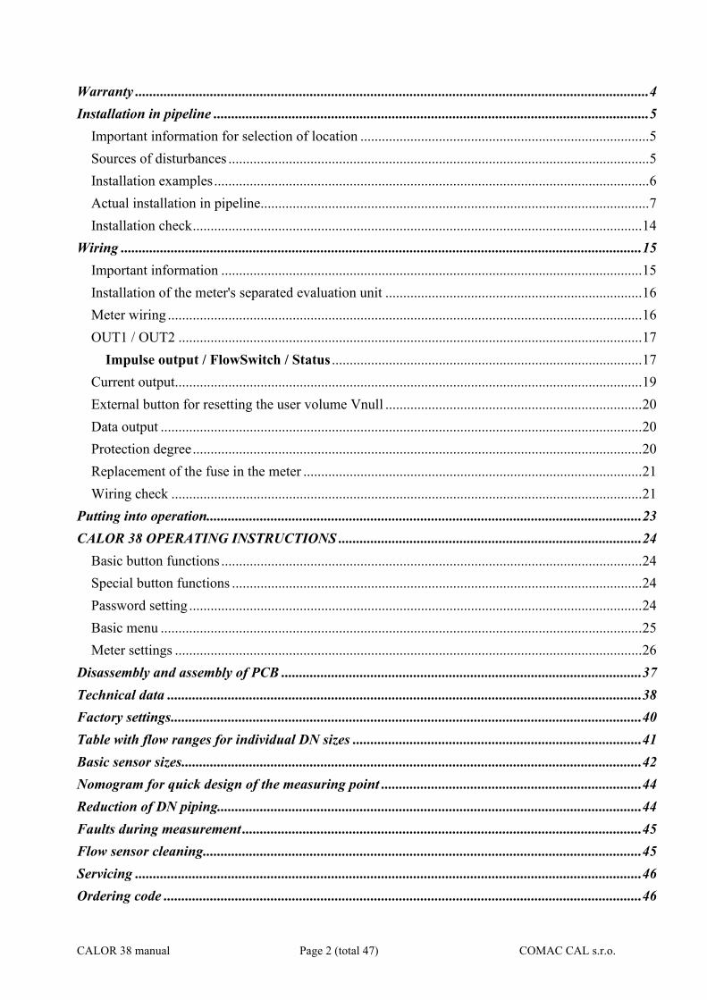
Contents: Description of the device ....................................................................................................................... 4
Scope of delivery ................................................................................................................................ 4
Storage conditions ................................................................................................................................. 4
CALOR 38 manual Page 2 (total 47) COMAC CAL s.r.o.
Warranty ................................................................................................................................................ 4
Installation in pipeline .......................................................................................................................... 5
Important information for selection of location ................................................................................. 5
Sources of disturbances ...................................................................................................................... 5
Installation examples .......................................................................................................................... 6
Actual installation in pipeline............................................................................................................. 7
Installation check .............................................................................................................................. 14
Wiring .................................................................................................................................................. 15
Important information ...................................................................................................................... 15
Installation of the meter's separated evaluation unit ........................................................................ 16
Meter wiring ..................................................................................................................................... 16
OUT1 / OUT2 .................................................................................................................................. 17
Impulse output / FlowSwitch / Status ....................................................................................... 17
Current output................................................................................................................................... 19
External button for resetting the user volume Vnull ........................................................................ 20
Data output ....................................................................................................................................... 20
Protection degree .............................................................................................................................. 20
Replacement of the fuse in the meter ............................................................................................... 21
Wiring check .................................................................................................................................... 21
Putting into operation.......................................................................................................................... 23
CALOR 38 OPERATING INSTRUCTIONS ..................................................................................... 24
Basic button functions ...................................................................................................................... 24
Special button functions ................................................................................................................... 24
Password setting ............................................................................................................................... 24
Basic menu ....................................................................................................................................... 25
Meter settings ................................................................................................................................... 26
Disassembly and assembly of PCB ..................................................................................................... 37
Technical data ..................................................................................................................................... 38
Factory settings .................................................................................................................................... 40
Table with flow ranges for individual DN sizes ................................................................................. 41
Basic sensor sizes ................................................................................................................................. 42
Nomogram for quick design of the measuring point ......................................................................... 44
Reduction of DN piping....................................................................................................................... 44
Faults during measurement ................................................................................................................ 45
Flow sensor cleaning ........................................................................................................................... 45
Servicing .............................................................................................................................................. 46
Ordering code ...................................................................................................................................... 46
CALOR 38 manual Page 3 (total 47) COMAC CAL s.r.o.
Form for returning the meter to COMAC CAL s.r.o. ........................................................................ 47
CALOR 38 manual Page 4 (total 47) COMAC CAL s.r.o.
Description of the device
The CALOR 38 heat meter is based on measurement principle by a well-known Faraday's electromagnetic induction law according to which an electric voltage is induced during the flow of a conductive liquid through the flow meter magnetic field. This is sensed by two electrodes which have direct contact with the measured medium and evaluated in the electronic unit, taking into account the temperature difference of the paired resistance temperature sensors on the supply and return pipes. CALOR 38 induction meters are suitable exclusively for measurement of volumetric flow of electrically conductive liquid substances with a minimum conductivity of 20S/cm (at a lower conductivity, in agreement with the manufacturer). Meters are designed for measurements where the velocity of liquid is in the range of 0.01 ÷ 12 m/s. The best measurement accuracy can be obtained in the range of 1 ÷ 10 m/s.
Scope of delivery The accessories vary according to flow sensor versions and above standard optional features. Threaded construction Electronic evaluation unit with the fixing bracket for wall mounting (not for the compact construction), the flow sensor (in case of the compact construction, the electronic unit is an integral part of the temperature sensor), paired resistance temperature sensors, connecting grounding cable, installation manual. Flanged construction Electronic evaluation unit with the fixing adapter for wall mounting ( not for the compact construction), flow sensor (in case of the compact construction, the electronic unit is an integral part of flow sensor), paired resistance temperature sensors, connecting grounding cable, installation manual. In case of the separated construction, a special cable for connection of the meter (it must not be extended or cut short) is part of the flow sensor.
Storage conditions The temperature during shipment and for storage must be within the range of -10 °C up to 50 °C. Wooden boards installed on the flanges in the factory are used for protection of lining on the flanges during storage and transportation (for PTFE lining). Remove these protective boards just before installing in the pipeline!!! Do not lift the flanged meters by the transducer head or by the connecting box of the separated construction during transportation! Use slings and place them round both process connections for transportation of meters up to DN150 (chains may damage the meter head)! Use only the holes between the flange and sensor body for transportation, lifting and installation of the sensor in piping for DN200 and bigger!!!
Warranty
CALOR 38 manual Page 5 (total 47) COMAC CAL s.r.o.
Unprofessional installation or using the induction meters (devices) may result in a loss of warranty as well as failure to comply with installation or operating conditions according to this manual.
Installation in pipeline
Important information for selection of location !!! In case of the separated construction, the cable must not be extended or cut short !!! Outdoor conditions It is necessary to ensure that the flow sensor is not exposed to weather effects and that the measured medium cannot freeze in the flow sensor as it would damage the measuring tube. In case of outdoor location of the electronic evaluation unit, the manufacturer recommends using a protective box or a roof to avoid direct solar exposure so that the evaluation electronics cannot get overheated.
Sources of disturbances The following items rank among the most frequent sources of disturbances to the steady flow of liquid:
• Abrupt changes in pipe cross-section if not performed as a cone with an angle of 7° (where is the angle made by bevelled walls of the pipe reduction).
• Incorrectly centred sealing, low ID sealing or sealing made of soft elastic materials which are pushed out into the interior pipe cross-section after flanges are tightened.
• Anything interfering in the flow of liquid, for example thermowells, branch pipes, T-pieces, bends, elbows, slide valves, cocks, flap valves, shut-off valves, control valves, butterfly valves and check valves. Pipe outlets from tanks, heat exchangers and filters.
• No intensive magnetic fields in the proximity of the induction flow sensor (detector) must be present.
No sources of disturbances affecting the steady flow must be present in the straight pipeline sections. They must be located in the piping after the flow sensor or at the farthest distance before it. Sources of disturbances may substantially reduce the measuring range and accuracy of the flow meters. Vibration We recommend supporting the connecting pipes on both sides of the meter for partial elimination of vibrations. Levels and range of vibrations must be under 2.2 in the frequency range of 20 ÷ 50 Hz according to IEC 068-2-34. If the pipeline is exposed to excessive vibrations (e.g. from pumps), using compact meters is not recommended. Actual location The flow sensor (detector) must not be at the top position of the pipe which may be airlocked, or in declining or even in horizontal pipelines with open ends in which air may penetrate. Impurities may accumulate during long-term measurement of very low flow rates Q < 0.1 m/s. There must be a sufficient pressure in the place of flow sensor installation so that the expulsion of gas or vapour bubbles from the liquid is avoided. Little bubbles that always occur in liquids may accumulate at any of the electrodes and this may result in incorrect operation of the meter. Gas bubbles are expelled also at an abrupt pressure drop. Therefore, butterfly valves and similar elements should be located after the flow
CALOR 38 manual Page 6 (total 47) COMAC CAL s.r.o.
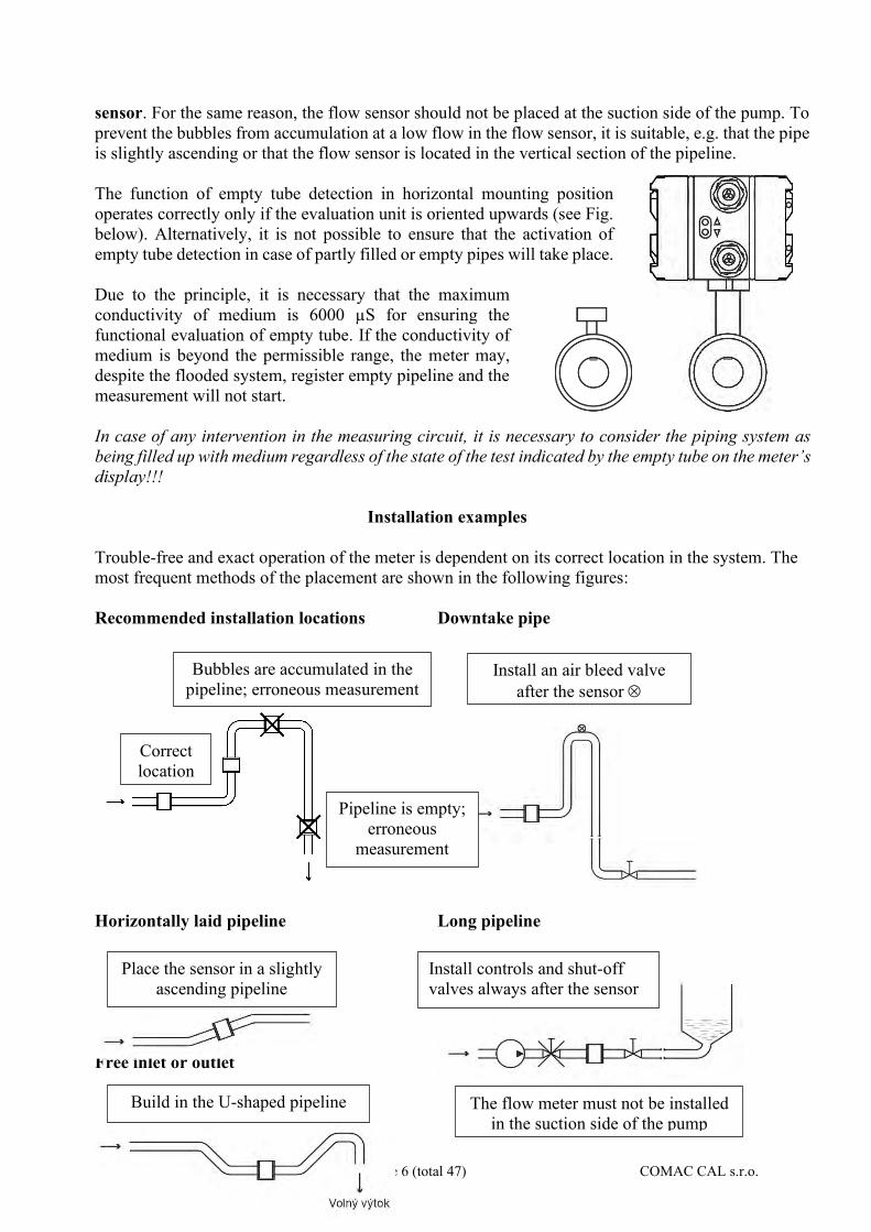
sensor. For the same reason, the flow sensor should not be placed at the suction side of the pump. To prevent the bubbles from accumulation at a low flow in the flow sensor, it is suitable, e.g. that the pipe is slightly ascending or that the flow sensor is located in the vertical section of the pipeline. The function of empty tube detection in horizontal mounting position operates correctly only if the evaluation unit is oriented upwards (see Fig. below). Alternatively, it is not possible to ensure that the activation of empty tube detection in case of partly filled or empty pipes will take place. Due to the principle, it is necessary that the maximum conductivity of medium is 6000 µS for ensuring the functional evaluation of empty tube. If the conductivity of medium is beyond the permissible range, the meter may, despite the flooded system, register empty pipeline and the measurement will not start. In case of any intervention in the measuring circuit, it is necessary to consider the piping system as being filled up with medium regardless of the state of the test indicated by the empty tube on the meter’s display!!!
Installation examples
Trouble-free and exact operation of the meter is dependent on its correct location in the system. The most frequent methods of the placement are shown in the following figures: Recommended installation locations Downtake pipe Horizontally laid pipeline Long pipeline Free inlet or outlet Pumps
Install an air bleed valve after the sensor
Place the sensor in a slightly ascending pipeline
Pipeline is empty; erroneous
measurement
Correct location
Install controls and shut-off valves always after the sensor
Build in the U-shaped pipeline The flow meter must not be installed in the suction side of the pump
Bubbles are accumulated in the pipeline; erroneous measurement
CALOR 38 manual Page 7 (total 47) COMAC CAL s.r.o.
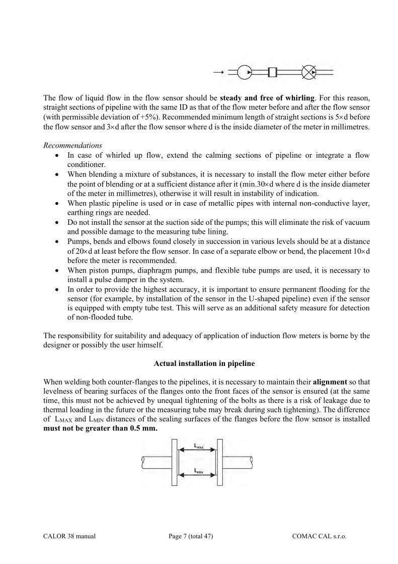
The flow of liquid flow in the flow sensor should be steady and free of whirling. For this reason, straight sections of pipeline with the same ID as that of the flow meter before and after the flow sensor (with permissible deviation of +5%). Recommended minimum length of straight sections is 5d before the flow sensor and 3d after the flow sensor where d is the inside diameter of the meter in millimetres. Recommendations
• In case of whirled up flow, extend the calming sections of pipeline or integrate a flow conditioner.
• When blending a mixture of substances, it is necessary to install the flow meter either before the point of blending or at a sufficient distance after it (min.30d where d is the inside diameter of the meter in millimetres), otherwise it will result in instability of indication.
• When plastic pipeline is used or in case of metallic pipes with internal non-conductive layer, earthing rings are needed.
• Do not install the sensor at the suction side of the pumps; this will eliminate the risk of vacuum and possible damage to the measuring tube lining.
• Pumps, bends and elbows found closely in succession in various levels should be at a distance of 20d at least before the flow sensor. In case of a separate elbow or bend, the placement 10d before the meter is recommended.
• When piston pumps, diaphragm pumps, and flexible tube pumps are used, it is necessary to install a pulse damper in the system.
• In order to provide the highest accuracy, it is important to ensure permanent flooding for the sensor (for example, by installation of the sensor in the U-shaped pipeline) even if the sensor is equipped with empty tube test. This will serve as an additional safety measure for detection of non-flooded tube.
The responsibility for suitability and adequacy of application of induction flow meters is borne by the designer or possibly the user himself.
Actual installation in pipeline
When welding both counter-flanges to the pipelines, it is necessary to maintain their alignment so that levelness of bearing surfaces of the flanges onto the front faces of the sensor is ensured (at the same time, this must not be achieved by unequal tightening of the bolts as there is a risk of leakage due to thermal loading in the future or the measuring tube may break during such tightening). The difference of LMAX and LMIN distances of the sealing surfaces of the flanges before the flow sensor is installed must not be greater than 0.5 mm.
CALOR 38 manual Page 8 (total 47) COMAC CAL s.r.o.
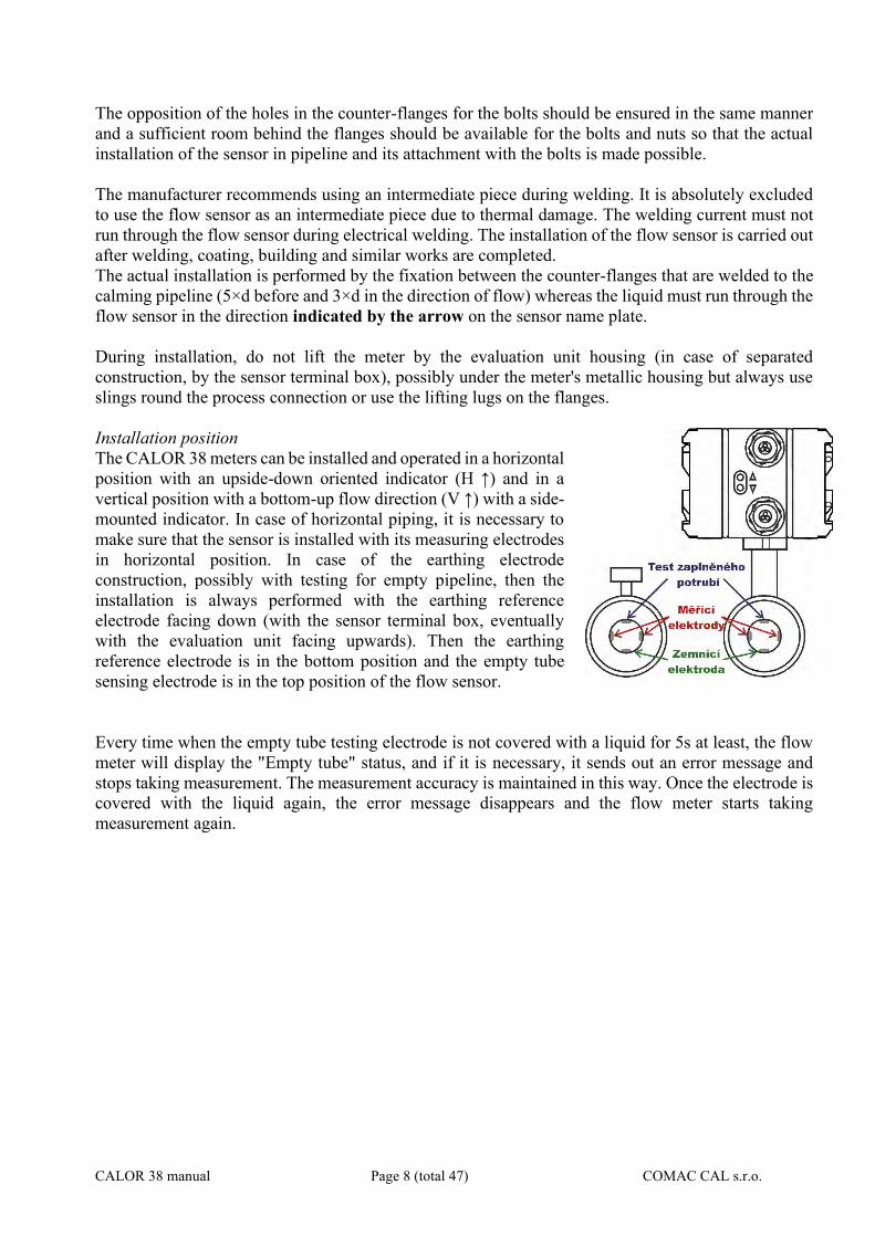
The opposition of the holes in the counter-flanges for the bolts should be ensured in the same manner and a sufficient room behind the flanges should be available for the bolts and nuts so that the actual installation of the sensor in pipeline and its attachment with the bolts is made possible. The manufacturer recommends using an intermediate piece during welding. It is absolutely excluded to use the flow sensor as an intermediate piece due to thermal damage. The welding current must not run through the flow sensor during electrical welding. The installation of the flow sensor is carried out after welding, coating, building and similar works are completed. The actual installation is performed by the fixation between the counter-flanges that are welded to the calming pipeline (5×d before and 3×d in the direction of flow) whereas the liquid must run through the flow sensor in the direction indicated by the arrow on the sensor name plate. During installation, do not lift the meter by the evaluation unit housing (in case of separated construction, by the sensor terminal box), possibly under the meter's metallic housing but always use slings round the process connection or use the lifting lugs on the flanges. Installation position The CALOR 38 meters can be installed and operated in a horizontal position with an upside-down oriented indicator (H ↑) and in a vertical position with a bottom-up flow direction (V ↑) with a side-mounted indicator. In case of horizontal piping, it is necessary to make sure that the sensor is installed with its measuring electrodes in horizontal position. In case of the earthing electrode construction, possibly with testing for empty pipeline, then the installation is always performed with the earthing reference electrode facing down (with the sensor terminal box, eventually with the evaluation unit facing upwards). Then the earthing reference electrode is in the bottom position and the empty tube sensing electrode is in the top position of the flow sensor. Every time when the empty tube testing electrode is not covered with a liquid for 5s at least, the flow meter will display the "Empty tube" status, and if it is necessary, it sends out an error message and stops taking measurement. The measurement accuracy is maintained in this way. Once the electrode is covered with the liquid again, the error message disappears and the flow meter starts taking measurement again.

CALOR 38 manual Page 9 (total 47) COMAC CAL s.r.o.
Measurement error due to incorrect installation position
1) correct installation (evaluation unit is positioned perpendicular upwards) EMPTY TEST – ON EMPTY TEST – OFF
2) Incorrect installation (evaluation unit is positioned diagonally, Empty test - ON)
CALOR 38 manual Page 10 (total 47) COMAC CAL s.r.o.
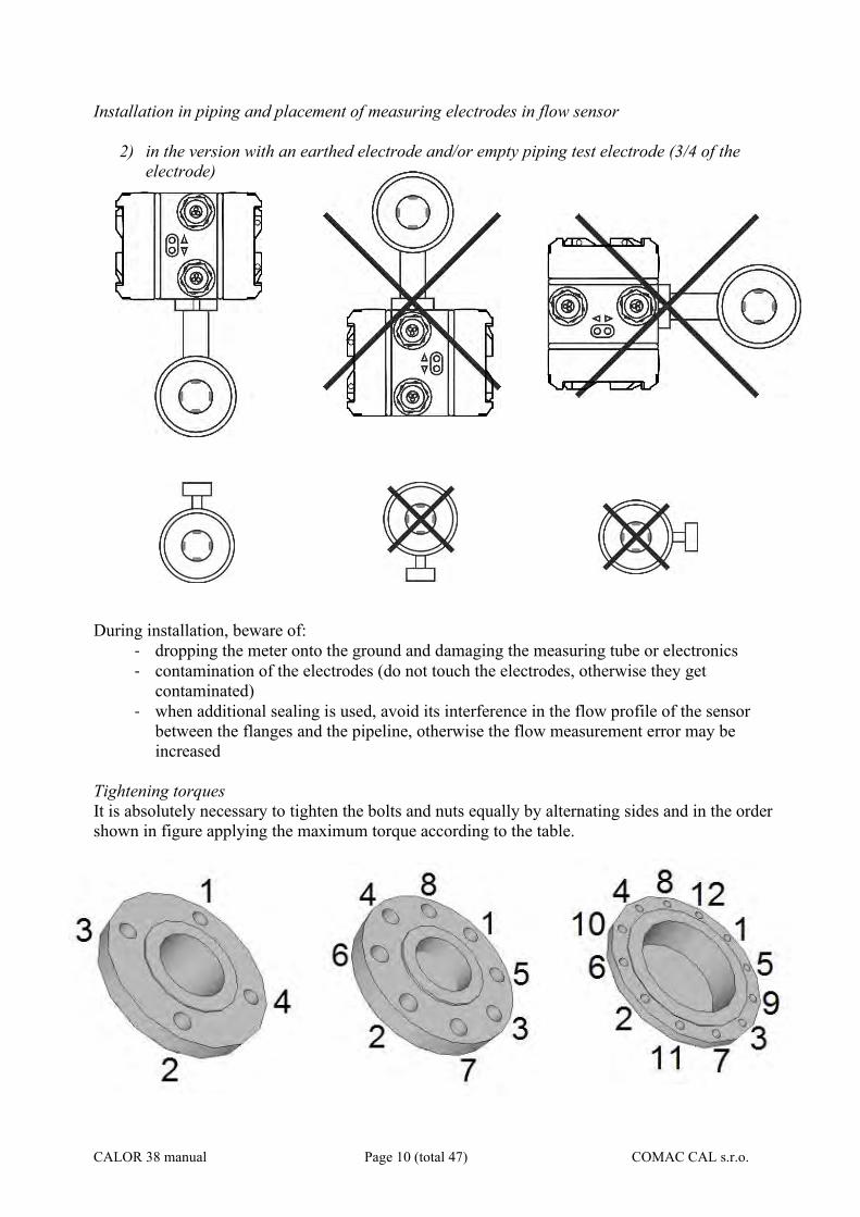
Installation in piping and placement of measuring electrodes in flow sensor
2) in the version with an earthed electrode and/or empty piping test electrode (3/4 of the electrode)
During installation, beware of:
- dropping the meter onto the ground and damaging the measuring tube or electronics - contamination of the electrodes (do not touch the electrodes, otherwise they get
contaminated) - when additional sealing is used, avoid its interference in the flow profile of the sensor
between the flanges and the pipeline, otherwise the flow measurement error may be increased
Tightening torques It is absolutely necessary to tighten the bolts and nuts equally by alternating sides and in the order shown in figure applying the maximum torque according to the table.
CALOR 38 manual Page 11 (total 47) COMAC CAL s.r.o.
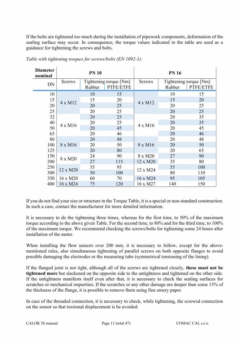
If the bolts are tightened too much during the installation of pipework components, deformation of the sealing surface may occur. In consequence, the torque values indicated in the table are used as a guidance for tightening the screws and bolts. Table with tightening torques for screws/bolts (EN 1092-1):
Diameter nominal PN 10 PN 16
DN Screws Tightening torque [Nm] Screws Tightening torque [Nm] Rubber PTFE/ETFE Rubber PTFE/ETFE
10
4 x M12
10 15
4 x M12
10 15 15 15 20 15 20 20 20 25 20 25 25 20 25 20 25 32
4 x M16
20 25
4 x M16
20 35 40 20 25 20 35 50 20 45 20 45 65 20 46 20 46 80
8 x M16 20 48
8 x M16 20 48
100 20 50 20 50 125 20 80 20 65 150 8 x M20 24 90 8 x M20 27 90 200 27 115 12 x M20 35 80 250 12 x M20 35 95 12 x M24 55 100 300 50 100 80 110 350 16 x M20 60 70 16 x M24 95 105 400 16 x M24 75 120 16 x M27 140 150
If you do not find your size or structure in the Torque Table, it is a special or non-standard construction. In such a case, contact the manufacturer for more detailed information. It is necessary to do the tightening three times, whereas for the first time, to 50% of the maximum torque according to the above given Table. For the second time, to 80% and for the third time, to 100% of the maximum torque. We recommend checking the screws/bolts for tightening some 24 hours after installation of the meter. When installing the flow sensors over 200 mm, it is necessary to follow, except for the above-mentioned rules, also simultaneous tightening of parallel screws on both opposite flanges to avoid possible damaging the electrodes or the measuring tube (symmetrical tensioning of the lining). If the flanged joint is not tight, although all of the screws are tightened closely, these must not be tightened more but slackened on the opposite side to the untightness and tightened on the other side. If the untightness manifests itself even after that, it is necessary to check the sealing surfaces for scratches or mechanical impurities. If the scratches or any other damage are deeper than some 15% of the thickness of the flange, it is possible to remove them using fine emery paper. In case of the threaded connection, it is necessary to check, while tightening, the screwed connection on the sensor so that torsional displacement is be avoided.
CALOR 38 manual Page 12 (total 47) COMAC CAL s.r.o.
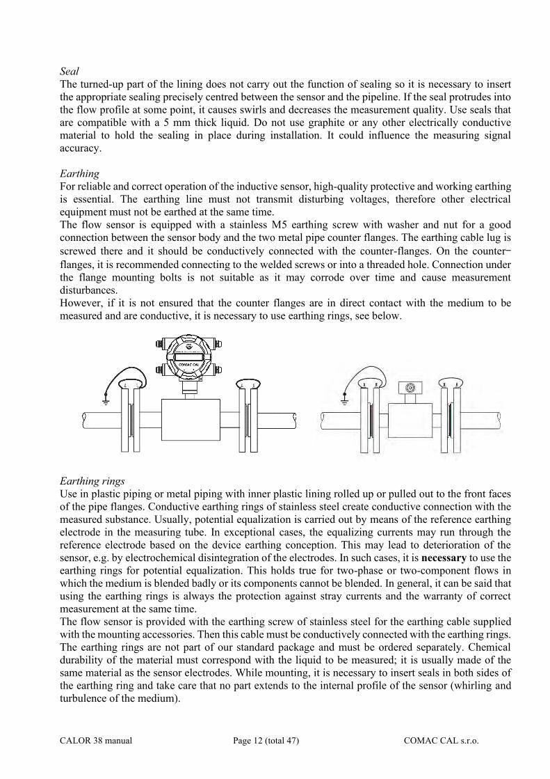
Seal The turned-up part of the lining does not carry out the function of sealing so it is necessary to insert the appropriate sealing precisely centred between the sensor and the pipeline. If the seal protrudes into the flow profile at some point, it causes swirls and decreases the measurement quality. Use seals that are compatible with a 5 mm thick liquid. Do not use graphite or any other electrically conductive material to hold the sealing in place during installation. It could influence the measuring signal accuracy. Earthing For reliable and correct operation of the inductive sensor, high-quality protective and working earthing is essential. The earthing line must not transmit disturbing voltages, therefore other electrical equipment must not be earthed at the same time. The flow sensor is equipped with a stainless M5 earthing screw with washer and nut for a good connection between the sensor body and the two metal pipe counter flanges. The earthing cable lug is screwed there and it should be conductively connected with the counter-flanges. On the counter-flanges, it is recommended connecting to the welded screws or into a threaded hole. Connection under the flange mounting bolts is not suitable as it may corrode over time and cause measurement disturbances. However, if it is not ensured that the counter flanges are in direct contact with the medium to be measured and are conductive, it is necessary to use earthing rings, see below.
Earthing rings Use in plastic piping or metal piping with inner plastic lining rolled up or pulled out to the front faces of the pipe flanges. Conductive earthing rings of stainless steel create conductive connection with the measured substance. Usually, potential equalization is carried out by means of the reference earthing electrode in the measuring tube. In exceptional cases, the equalizing currents may run through the reference electrode based on the device earthing conception. This may lead to deterioration of the sensor, e.g. by electrochemical disintegration of the electrodes. In such cases, it is necessary to use the earthing rings for potential equalization. This holds true for two-phase or two-component flows in which the medium is blended badly or its components cannot be blended. In general, it can be said that using the earthing rings is always the protection against stray currents and the warranty of correct measurement at the same time. The flow sensor is provided with the earthing screw of stainless steel for the earthing cable supplied with the mounting accessories. Then this cable must be conductively connected with the earthing rings. The earthing rings are not part of our standard package and must be ordered separately. Chemical durability of the material must correspond with the liquid to be measured; it is usually made of the same material as the sensor electrodes. While mounting, it is necessary to insert seals in both sides of the earthing ring and take care that no part extends to the internal profile of the sensor (whirling and turbulence of the medium).
CALOR 38 manual Page 13 (total 47) COMAC CAL s.r.o.
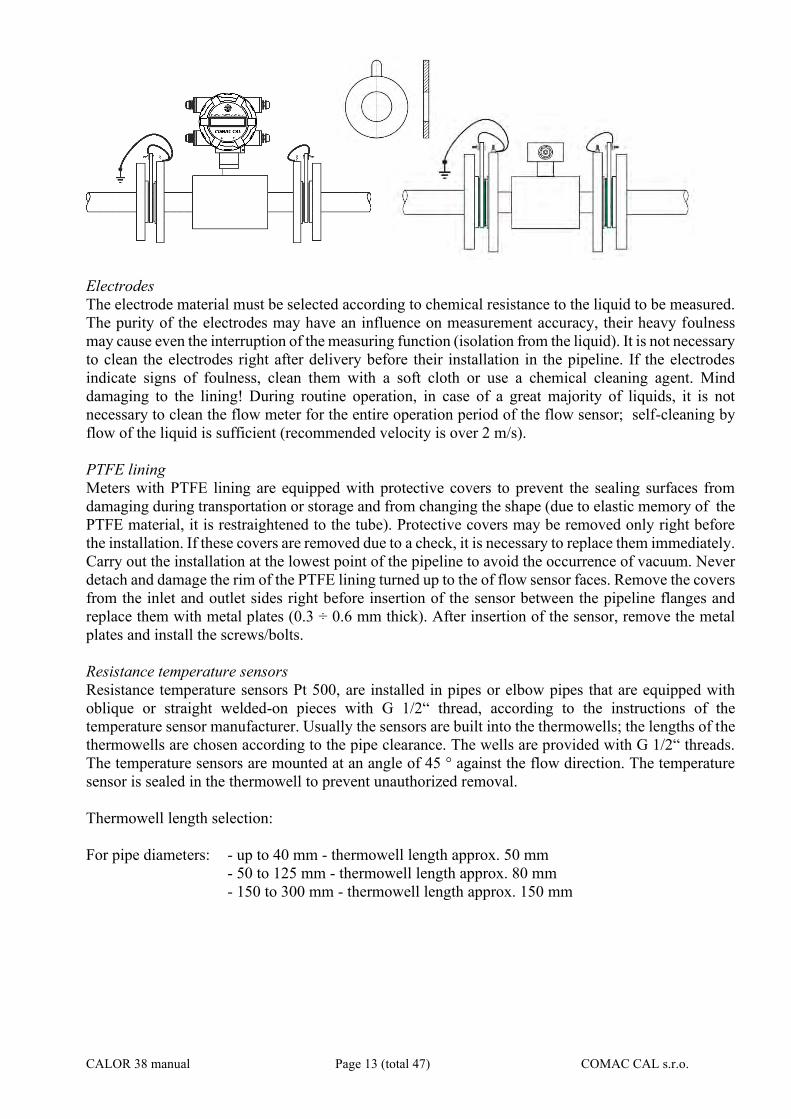
Electrodes The electrode material must be selected according to chemical resistance to the liquid to be measured. The purity of the electrodes may have an influence on measurement accuracy, their heavy foulness may cause even the interruption of the measuring function (isolation from the liquid). It is not necessary to clean the electrodes right after delivery before their installation in the pipeline. If the electrodes indicate signs of foulness, clean them with a soft cloth or use a chemical cleaning agent. Mind damaging to the lining! During routine operation, in case of a great majority of liquids, it is not necessary to clean the flow meter for the entire operation period of the flow sensor; self-cleaning by flow of the liquid is sufficient (recommended velocity is over 2 m/s). PTFE lining Meters with PTFE lining are equipped with protective covers to prevent the sealing surfaces from damaging during transportation or storage and from changing the shape (due to elastic memory of the PTFE material, it is restraightened to the tube). Protective covers may be removed only right before the installation. If these covers are removed due to a check, it is necessary to replace them immediately. Carry out the installation at the lowest point of the pipeline to avoid the occurrence of vacuum. Never detach and damage the rim of the PTFE lining turned up to the of flow sensor faces. Remove the covers from the inlet and outlet sides right before insertion of the sensor between the pipeline flanges and replace them with metal plates (0.3 ÷ 0.6 mm thick). After insertion of the sensor, remove the metal plates and install the screws/bolts. Resistance temperature sensors Resistance temperature sensors Pt 500, are installed in pipes or elbow pipes that are equipped with oblique or straight welded-on pieces with G 1/2“ thread, according to the instructions of the temperature sensor manufacturer. Usually the sensors are built into the thermowells; the lengths of the thermowells are chosen according to the pipe clearance. The wells are provided with G 1/2“ threads. The temperature sensors are mounted at an angle of 45 ° against the flow direction. The temperature sensor is sealed in the thermowell to prevent unauthorized removal. Thermowell length selection: For pipe diameters: - up to 40 mm - thermowell length approx. 50 mm
- 50 to 125 mm - thermowell length approx. 80 mm - 150 to 300 mm - thermowell length approx. 150 mm
CALOR 38 manual Page 14 (total 47) COMAC CAL s.r.o.
Installation check
After installation of the flow sensor in the pipeline, the following must be checked:
- According to the name plate, if there is a relevant meter in the given measuring point (pressure, temperature, dimension, etc.).
- If the direction of the arrow on the device is in agreement with the direction of the flow in the pipeline.
- Correct position of the measuring electrodes (horizontally). - Correct position of the electrode for empty pipeline detection (up). - If all bolts (screws) are tightened properly. - If earthing rings are used, then their correct installation and connection with the sensor. - Accuracy of flow sensor earthing. - Accuracy of execution of the pipeline calming section lengths - If the sensor is protected against vibrations and mechanical damage. - If the name plate (serial number) on the sensor corresponds to the one on the electronics.

CALOR 38 manual Page 15 (total 47) COMAC CAL s.r.o.
Wiring
Workers performing wiring are subject to the requirements of Decree No. 50/1978 Coll. on activities on electrical equipment!!! When the operations described below are performed unprofessionally, the claim on warranty becomes extinct!!! Prior to any opening of the evaluation unit, switch off the power !!! It should be remembered that even in the case of a separate construction, the evaluation electronic unit and the flow sensor form an integral unit which is metrologically verified and uniquely paired. In consequence, make sure that the serial numbers of both parts are always identical!!!
Important information
Flow sensor connecting cable The signal cable of the separated induction flow sensor cannot be led in parallel (even partly) with the cables for power distribution voltage or in the proximity to electric motors, electromagnets, contactors, frequency converters and similar sources of electromagnetic interference. In unavoidable situations, it is necessary to put the cable in an earthed iron tube. Primarily in media with a low conductivity, cable movements and interference may result in distortion of the measured signal. The maximum length of the cable between the sensor and the evaluation unit is 30 metres provided that the conductivity is over 50µS/cm. In case of lower conductivities, it is recommended to use the shortest possible cable length, however, 10m max. In case of the separated constructions, it is possible to interconnect only the sensor and the transducer with the same serial numbers. The special cable for connecting the separate meter version must not be extended or shortened. In case of infringement of these requirements, measurement failures and significant inaccuracies may occur once the meters are connected. If it is possible to expect an increased level of unwanted electromagnetic field, we do not recommend using the separated construction. In places with strong electromagnetic interference (in the proximity of frequency converters, electric motors, transformers, etc.), we recommend putting a line filter before the meter in the power supply circuit. Evaluation unit As standard, the evaluation unit is delivered for mains power supply 230V / 50÷60Hz. It is possible to specify DC power supply (as standard 24V AC/DC). For securing the tightness of the evaluation unit cover, it is necessary to keep the seal intact and clean (replace the damaged seal immediately). If the holes for cable entries are not occupied, it is necessary to do it. The flow meter signal outputs may only be connected to devices where accident protection is provided by a safe low voltage and where generated voltages do not exceed the limits defined for safe low voltage. When powered from the 230V / 50 ÷ 60Hz mains, the meter is powered by a switch mode power supply that may contain beat frequencies in the acoustic spectrum whereas this symptom does not indicate a failure of the meter.
CALOR 38 manual Page 16 (total 47) COMAC CAL s.r.o.
Never make kinks on the cable and on individual conductors and do not let them cross mutually in the terminal board area and always use a separate cable grommet for power supply. Cover the unoccupied grommets with a piece of cable or a plastic plug (securing of tightness).
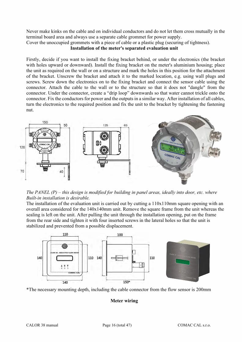
Installation of the meter's separated evaluation unit Firstly, decide if you want to install the fixing bracket behind, or under the electronics (the bracket with holes upward or downward). Install the fixing bracket on the meter's aluminium housing; place the unit as required on the wall or on a structure and mark the holes in this position for the attachment of the bracket. Unscrew the bracket and attach it to the marked location, e.g. using wall plugs and screws. Screw down the electronics on to the fixing bracket and connect the sensor cable using the connector. Attach the cable to the wall or to the structure so that it does not "dangle" from the connector. Under the connector, create a “drip loop” downwards so that water cannot trickle onto the connector. Fix the conductors for power and the outputs in a similar way. After installation of all cables, turn the electronics to the required position and fix the unit to the bracket by tightening the fastening nut.
The PANEL (P) – this design is modified for building in panel areas, ideally into door, etc. where Built-in installation is desirable. The installation of the evaluation unit is carried out by cutting a 110x110mm square opening with an overall area considered for the 140x140mm unit. Remove the square frame from the unit whereas the sealing is left on the unit. After pulling the unit through the installation opening, put on the frame from the rear side and tighten it with four inserted screws in the lateral holes so that the unit is stabilized and prevented from a possible displacement. *The necessary mounting depth, including the cable connector from the flow sensor is 200mm
Meter wiring
CALOR 38 manual Page 17 (total 47) COMAC CAL s.r.o.
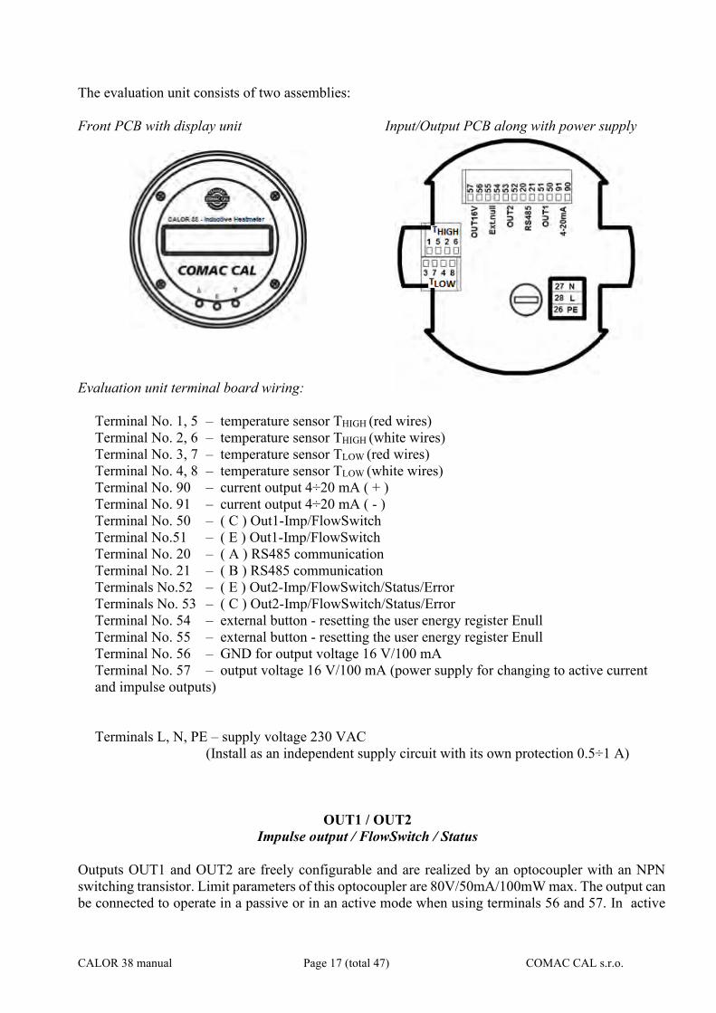
The evaluation unit consists of two assemblies: Front PCB with display unit Input/Output PCB along with power supply
Evaluation unit terminal board wiring:
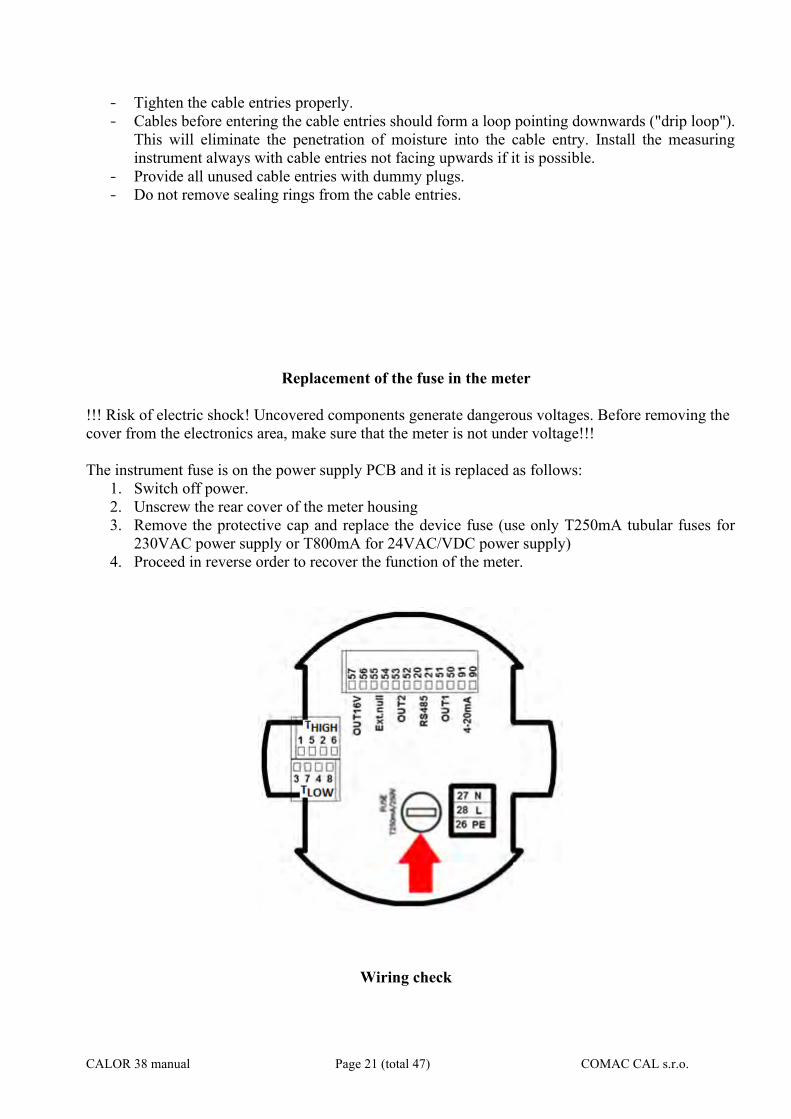
Terminal No. 1, 5 – temperature sensor THIGH (red wires) Terminal No. 2, 6 – temperature sensor THIGH (white wires) Terminal No. 3, 7 – temperature sensor TLOW (red wires) Terminal No. 4, 8 – temperature sensor TLOW (white wires) Terminal No. 90 – current output 4÷20 mA ( + ) Terminal No. 91 – current output 4÷20 mA ( - ) Terminal No. 50 – ( C ) Out1-Imp/FlowSwitch Terminal No.51 – ( E ) Out1-Imp/FlowSwitch Terminal No. 20 – ( A ) RS485 communication Terminal No. 21 – ( B ) RS485 communication Terminals No.52 – ( E ) Out2-Imp/FlowSwitch/Status/Error Terminals No. 53 – ( C ) Out2-Imp/FlowSwitch/Status/Error Terminal No. 54 – external button - resetting the user energy register Enull Terminal No. 55 – external button - resetting the user energy register Enull Terminal No. 56 – GND for output voltage 16 V/100 mA Terminal No. 57 – output voltage 16 V/100 mA (power supply for changing to active current and impulse outputs)
Terminals L, N, PE – supply voltage 230 VAC (Install as an independent supply circuit with its own protection 0.5÷1 A)
OUT1 / OUT2 Impulse output / FlowSwitch / Status
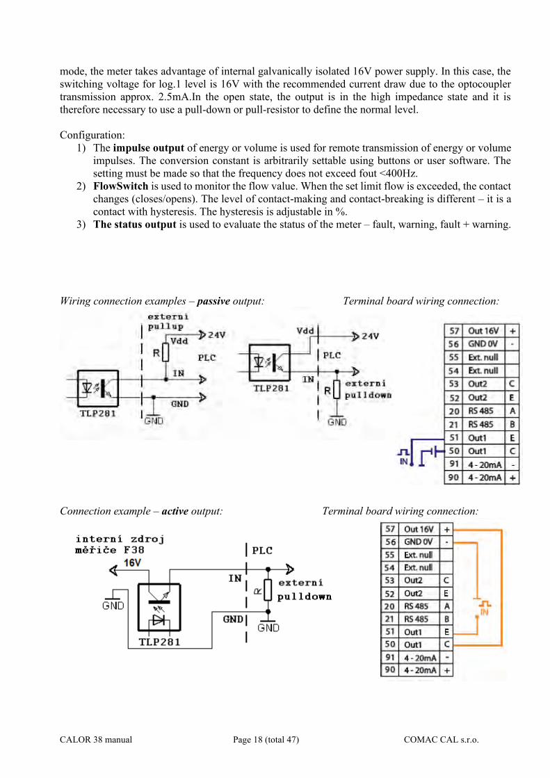
Outputs OUT1 and OUT2 are freely configurable and are realized by an optocoupler with an NPN switching transistor. Limit parameters of this optocoupler are 80V/50mA/100mW max. The output can be connected to operate in a passive or in an active mode when using terminals 56 and 57. In active
CALOR 38 manual Page 18 (total 47) COMAC CAL s.r.o.
mode, the meter takes advantage of internal galvanically isolated 16V power supply. In this case, the switching voltage for log.1 level is 16V with the recommended current draw due to the optocoupler transmission approx. 2.5mA.In the open state, the output is in the high impedance state and it is therefore necessary to use a pull-down or pull-resistor to define the normal level. Configuration:
1) The impulse output of energy or volume is used for remote transmission of energy or volume impulses. The conversion constant is arbitrarily settable using buttons or user software. The setting must be made so that the frequency does not exceed fout <400Hz.
2) FlowSwitch is used to monitor the flow value. When the set limit flow is exceeded, the contact changes (closes/opens). The level of contact-making and contact-breaking is different – it is a contact with hysteresis. The hysteresis is adjustable in %.
3) The status output is used to evaluate the status of the meter – fault, warning, fault + warning. Wiring connection examples – passive output: Terminal board wiring connection:
Connection example – active output: Terminal board wiring connection:

CALOR 38 manual Page 19 (total 47) COMAC CAL s.r.o.
Considering that CTR≈100% and If=2.5mA, it is advisable to select the collector current up to 2.5mA.
Current output
The D/A converter of the CALOR 38 evaluation unit is 16-bit with data recovery performed approximately every second. The converter is isolated from the meter by optocouplers. If the current output is passive, it is necessary to feed the current output from an external power supply. External power supply Ue can be 12 24 V. The loop resistance must not be higher than R = Ue / 0,02 (Ω;V). By default, it is set so that at maximum flow Qmax or power Pmax the loop current is 20mA and at zero or minimum flow/power the loop current is 4mA. The borders can be set by buttons or user software for all flow directions. In case of loss of power for the meter, it is indicated by 0mA current loop output. In case of active current loop, an internal 16V galvanically isolated power supply is used in FLOW38 meter. Current loop wiring connection example: Passive current loop Terminal block wiring connection:
Active current loop Terminal board wiring connection:
CALOR 38 manual Page 20 (total 47) COMAC CAL s.r.o.
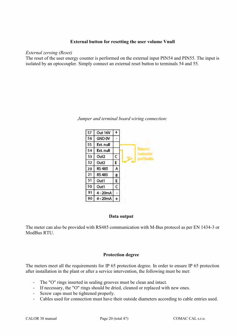
External button for resetting the user volume Vnull
External zeroing (Reset) The reset of the user energy counter is performed on the external input PIN54 and PIN55. The input is isolated by an optocoupler. Simply connect an external reset button to terminals 54 and 55.
Jumper and terminal board wiring connection:
Data output
The meter can also be provided with RS485 communication with M-Bus protocol as per EN 1434-3 or ModBus RTU.
Protection degree
The meters meet all the requirements for IP 65 protection degree. In order to ensure IP 65 protection after installation in the plant or after a service intervention, the following must be met:
- The "O" rings inserted in sealing grooves must be clean and intact. - If necessary, the "O" rings should be dried, cleaned or replaced with new ones. - Screw caps must be tightened properly. - Cables used for connection must have their outside diameters according to cable entries used.
CALOR 38 manual Page 21 (total 47) COMAC CAL s.r.o.
- Tighten the cable entries properly. - Cables before entering the cable entries should form a loop pointing downwards ("drip loop").
This will eliminate the penetration of moisture into the cable entry. Install the measuring instrument always with cable entries not facing upwards if it is possible.
- Provide all unused cable entries with dummy plugs. - Do not remove sealing rings from the cable entries.
Replacement of the fuse in the meter !!! Risk of electric shock! Uncovered components generate dangerous voltages. Before removing the cover from the electronics area, make sure that the meter is not under voltage!!! The instrument fuse is on the power supply PCB and it is replaced as follows:
1. Switch off power. 2. Unscrew the rear cover of the meter housing 3. Remove the protective cap and replace the device fuse (use only T250mA tubular fuses for
230VAC power supply or T800mA for 24VAC/VDC power supply) 4. Proceed in reverse order to recover the function of the meter.
Wiring check
CALOR 38 manual Page 22 (total 47) COMAC CAL s.r.o.
After completion of wiring, check the following:~
- Connecting cables for damage. - If the cables used are suitable for given cable entries. - Cables for pull relief. - Correct tightening of cable entries. - Correct connection of cables to terminals. - Whether the supply voltage corresponds with the nameplate data. - After the meter is closed, tighten the covers properly to the O-rings.
CALOR 38 manual Page 23 (total 47) COMAC CAL s.r.o.
Putting into operation Prior to connection to power supply, check the device installation accuracy in accordance with “Installation in pipeline“ and “Wiring” chapters. If you wish the meter to take measurement as precisely as possible right after powering up, it is a good idea to fill the flow sensor with water, one or two days before its installation, so that all of its electrodes are flooded. Just before the installation, the water is discharged and the sensor is installed into piping. Right after installation, piping is filled with a medium so that the electrodes cannot dry off. If the meter has no electrode for empty tube detection, do not connect the meter to power before filling the system with the fluid to be measured and power off the meter before system discharge. Once the meter is powered up, the green LED on the front glazed panel is lit, confirming the supply voltage on the control PCB and stabilization of parameters of the meter takes place subsequently. The stabilization is indicated on the meter's display. After that period of time, the meter starts measuring. Meter status: It is displayed continuously on the screen as one of the basic menu items and in case of a non-standard state or a failure this is displayed by alternating indication of the status and main menu basic data and the operator is warned by a text. The meter status is divided into 4 basic groups: 1) OK everything is all right 2) Warning – the meter takes measurement but some of the parameters are out of range 3) Error critical error – the meter does not take measurement 4) Empty tube if the EMPTY TUBE TEST function is activated Flow direction: The arrow indicates the direction liquid flow inside the sensor and thus the correct orientation of the meter's sensor for installation in piping. In case of inversely performed installation, it is possible to toggle the direction in electronics between positive/negative and thus avoid incorrect value imaging and reading out . Basic parameter settings The meter or flow meter parameters are set by the manufacturer in accordance with the purchase order. If these values are not indicated in your purchase order, the meter will be set up using the default parameters in accordance with the meter's range. The operator can make modifications by means of three buttons on the meter's panel or through the RS485 interface. Safety rules for operator Any interference with the inductive flow sensor and the evaluation unit itself is illegal on the part of operator and may lead to direct scalding by the medium should the inductive flow sensor is handled incorrectly. Perform electrical connection always after powering off.
CALOR 38 manual Page 24 (total 47) COMAC CAL s.r.o.
CALOR 38 OPERATING INSTRUCTIONS
Basic button functions
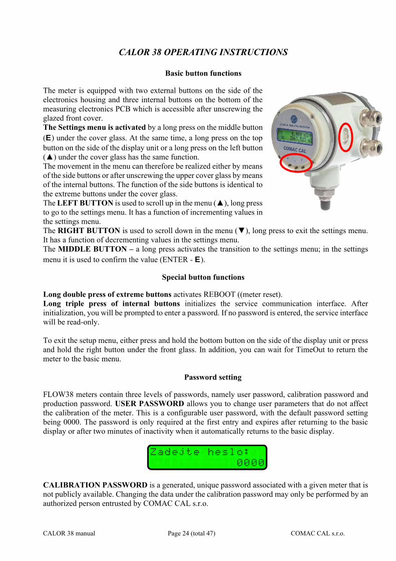
The meter is equipped with two external buttons on the side of the electronics housing and three internal buttons on the bottom of the measuring electronics PCB which is accessible after unscrewing the glazed front cover. The Settings menu is activated by a long press on the middle button (E) under the cover glass. At the same time, a long press on the top button on the side of the display unit or a long press on the left button (▲) under the cover glass has the same function. The movement in the menu can therefore be realized either by means of the side buttons or after unscrewing the upper cover glass by means of the internal buttons. The function of the side buttons is identical to the extreme buttons under the cover glass. The LEFT BUTTON is used to scroll up in the menu (▲), long press to go to the settings menu. It has a function of incrementing values in the settings menu. The RIGHT BUTTON is used to scroll down in the menu (▼), long press to exit the settings menu. It has a function of decrementing values in the settings menu. The MIDDLE BUTTON – a long press activates the transition to the settings menu; in the settings menu it is used to confirm the value (ENTER - E).
Special button functions
Long double press of extreme buttons activates REBOOT ((meter reset). Long triple press of internal buttons initializes the service communication interface. After initialization, you will be prompted to enter a password. If no password is entered, the service interface will be read-only. To exit the setup menu, either press and hold the bottom button on the side of the display unit or press and hold the right button under the front glass. In addition, you can wait for TimeOut to return the meter to the basic menu.
Password setting
FLOW38 meters contain three levels of passwords, namely user password, calibration password and production password. USER PASSWORD allows you to change user parameters that do not affect the calibration of the meter. This is a configurable user password, with the default password setting being 0000. The password is only required at the first entry and expires after returning to the basic display or after two minutes of inactivity when it automatically returns to the basic display.
CALIBRATION PASSWORD is a generated, unique password associated with a given meter that is not publicly available. Changing the data under the calibration password may only be performed by an authorized person entrusted by COMAC CAL s.r.o.
CALOR 38 manual Page 25 (total 47) COMAC CAL s.r.o.
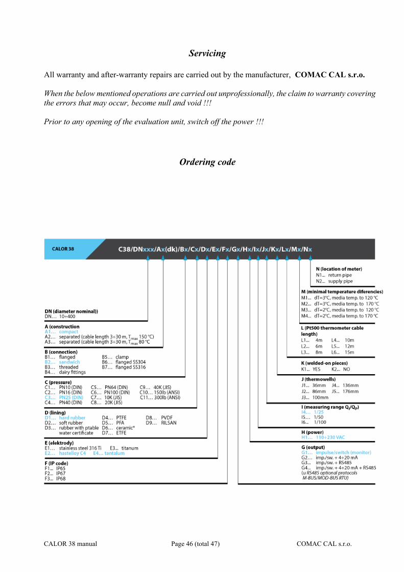
These are the following data: Constant k Constant n1 Temperature constant Tp Temperature constant Tv Empty tube test (only if the sensor supports this function - it is active in the factory setting) Start of measurement Zero calibration Resetting Flow direction Display V Test (calibration and simulation test) Factory settings PRODUCTION PASSWORD is a generated, unique password associated with a given meter, which is not publicly available. Changing the data under the production password may only be performed by an authorized person entrusted by COMAC CAL s.r.o. These are the following data: All constants under the calibration password Serial number Sensor – DN Turning communication on/off
Basic menu
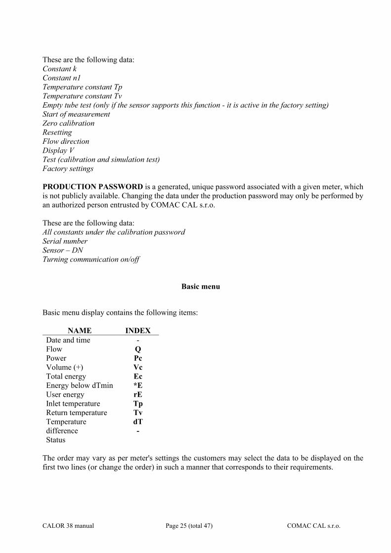
Basic menu display contains the following items:
NAME INDEX Date and time - Flow Q Power Pc Volume (+) Vc Total energy Ec Energy below dTmin *E User energy rE Inlet temperature Tp Return temperature Tv Temperature difference Status
dT -
The order may vary as per meter's settings the customers may select the data to be displayed on the first two lines (or change the order) in such a manner that corresponds to their requirements.
CALOR 38 manual Page 26 (total 47) COMAC CAL s.r.o.
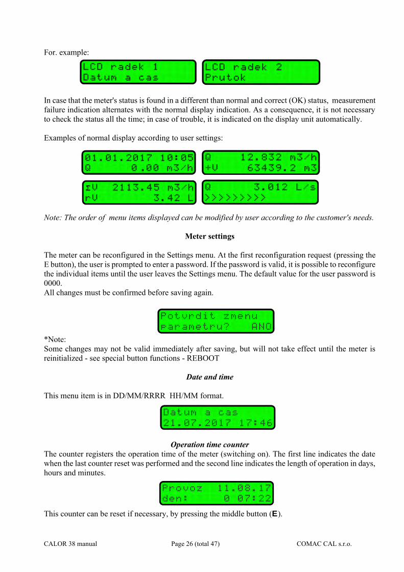
For. example:
In case that the meter's status is found in a different than normal and correct (OK) status, measurement failure indication alternates with the normal display indication. As a consequence, it is not necessary to check the status all the time; in case of trouble, it is indicated on the display unit automatically. Examples of normal display according to user settings:
Note: The order of menu items displayed can be modified by user according to the customer's needs.
Meter settings
The meter can be reconfigured in the Settings menu. At the first reconfiguration request (pressing the E button), the user is prompted to enter a password. If the password is valid, it is possible to reconfigure the individual items until the user leaves the Settings menu. The default value for the user password is 0000. All changes must be confirmed before saving again.
*Note: Some changes may not be valid immediately after saving, but will not take effect until the meter is reinitialized - see special button functions - REBOOT
Date and time
This menu item is in DD/MM/RRRR HH/MM format.
Operation time counter
The counter registers the operation time of the meter (switching on). The first line indicates the date when the last counter reset was performed and the second line indicates the length of operation in days, hours and minutes.
This counter can be reset if necessary, by pressing the middle button (E).
CALOR 38 manual Page 27 (total 47) COMAC CAL s.r.o.
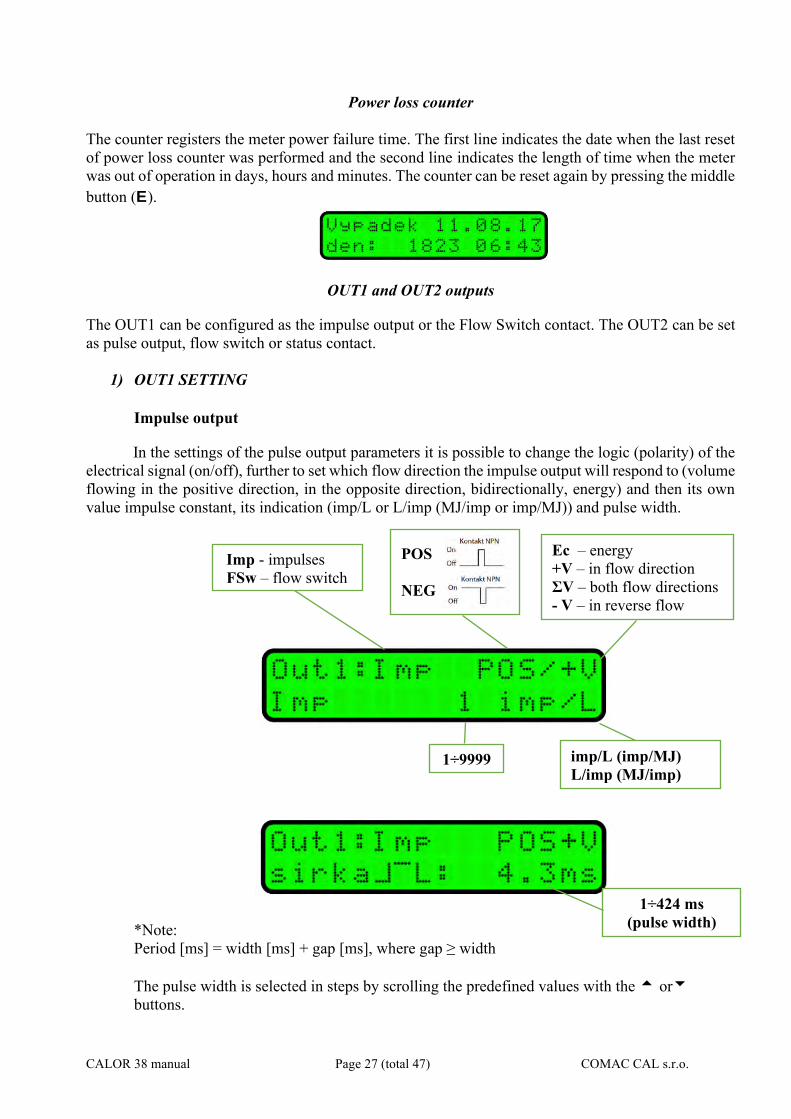
Power loss counter The counter registers the meter power failure time. The first line indicates the date when the last reset of power loss counter was performed and the second line indicates the length of time when the meter was out of operation in days, hours and minutes. The counter can be reset again by pressing the middle button (E).
OUT1 and OUT2 outputs
The OUT1 can be configured as the impulse output or the Flow Switch contact. The OUT2 can be set as pulse output, flow switch or status contact.
1) OUT1 SETTING Impulse output
In the settings of the pulse output parameters it is possible to change the logic (polarity) of the electrical signal (on/off), further to set which flow direction the impulse output will respond to (volume flowing in the positive direction, in the opposite direction, bidirectionally, energy) and then its own value impulse constant, its indication (imp/L or L/imp (MJ/imp or imp/MJ)) and pulse width.
*Note: Period [ms] = width [ms] + gap [ms], where gap ≥ width The pulse width is selected in steps by scrolling the predefined values with the or buttons.
POS
NEG
Ec – energy +V – in flow direction ΣV – both flow directions - V – in reverse flow direction
1÷9999 imp/L (imp/MJ) L/imp (MJ/imp)
1÷424 ms (pulse width)
Imp - impulses FSw – flow switch
CALOR 38 manual Page 28 (total 47) COMAC CAL s.r.o.
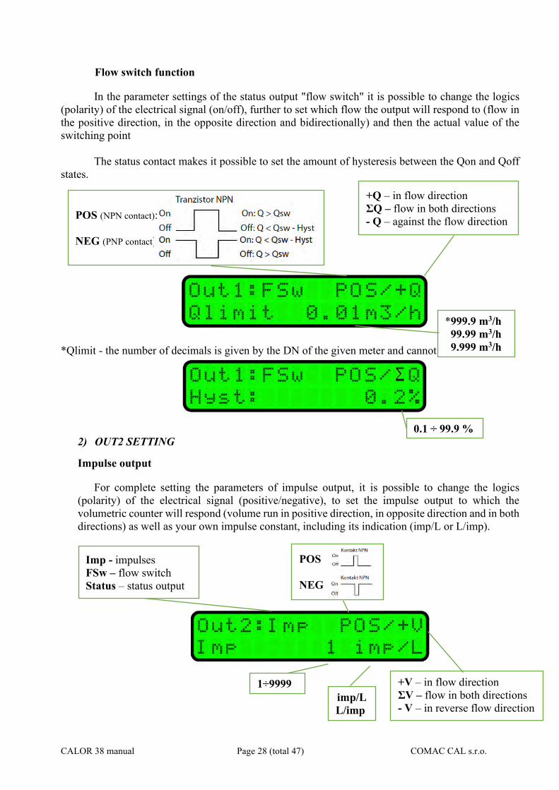
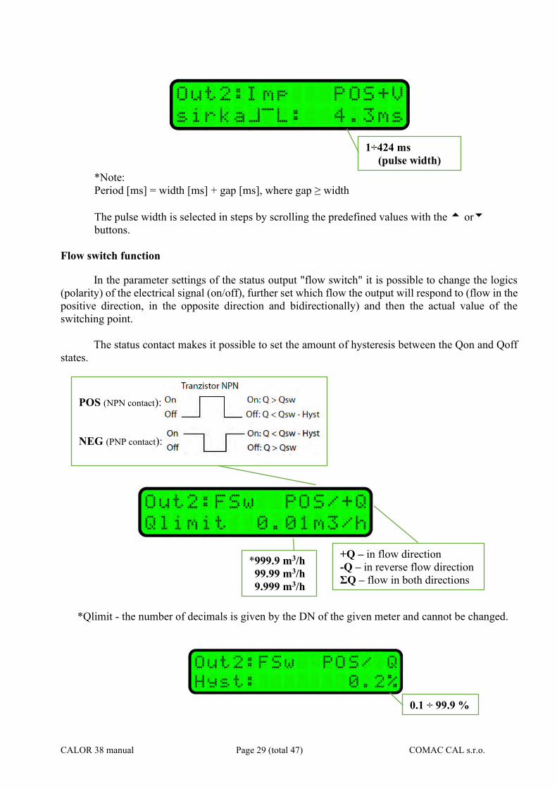
Flow switch function
In the parameter settings of the status output "flow switch" it is possible to change the logics (polarity) of the electrical signal (on/off), further to set which flow the output will respond to (flow in the positive direction, in the opposite direction and bidirectionally) and then the actual value of the switching point
The status contact makes it possible to set the amount of hysteresis between the Qon and Qoff
states.
*Qlimit - the number of decimals is given by the DN of the given meter and cannot be changed.
2) OUT2 SETTING
Impulse output
For complete setting the parameters of impulse output, it is possible to change the logics (polarity) of the electrical signal (positive/negative), to set the impulse output to which the volumetric counter will respond (volume run in positive direction, in opposite direction and in both directions) as well as your own impulse constant, including its indication (imp/L or L/imp).
+Q – in flow direction ΣQ – flow in both directions - Q – against the flow direction
*999.9 m3/h 99.99 m3/h 9.999 m3/h
0.1 ÷ 99.9 %
POS (NPN contact):
NEG (PNP contact):
POS
NEG
+V – in flow direction ΣV – flow in both directions - V – in reverse flow direction
1÷9999 imp/L L/imp
Imp - impulses FSw – flow switch Status – status output
CALOR 38 manual Page 29 (total 47) COMAC CAL s.r.o.
*Note: Period [ms] = width [ms] + gap [ms], where gap ≥ width The pulse width is selected in steps by scrolling the predefined values with the or buttons.
Flow switch function
In the parameter settings of the status output "flow switch" it is possible to change the logics (polarity) of the electrical signal (on/off), further set which flow the output will respond to (flow in the positive direction, in the opposite direction and bidirectionally) and then the actual value of the switching point.
The status contact makes it possible to set the amount of hysteresis between the Qon and Qoff
states.
*Qlimit - the number of decimals is given by the DN of the given meter and cannot be changed.
1÷424 ms (pulse width)
0.1 ÷ 99.9 %
+Q – in flow direction -Q – in reverse flow direction ΣQ – flow in both directions
*999.9 m3/h 99.99 m3/h 9.999 m3/h
POS (NPN contact):
NEG (PNP contact):
CALOR 38 manual Page 30 (total 47) COMAC CAL s.r.o.
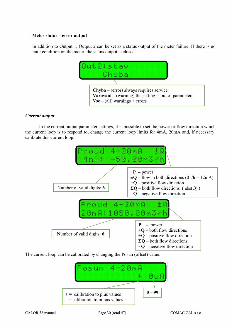
Meter status – error output In addition to Output 1, Output 2 can be set as a status output of the meter failure. If there is no fault condition on the meter, the status output is closed.
Current output
In the current output parameter settings, it is possible to set the power or flow direction which
the current loop is to respond to, change the current loop limits for 4mA, 20mA and, if necessary, calibrate this current loop.
The current loop can be calibrated by changing the Posun (offset) value.
Chyba – (error) always requires service Varovani – (warning) the setting is out of parameters Vse – (all) warnings + errors
P – power ±Q – flow in both directions (0 l/h = 12mA) +Q – positive flow direction ΣQ – both flow directions ( abs(Q) ) - Q – negative flow direction
Number of valid digits: 6
Number of valid digits: 6
+ = calibration to plus values – = calibration to minus values
0 – 99
P – power ±Q – both flow directions +Q – positive flow direction ΣQ – both flow directions - Q – negative flow direction
CALOR 38 manual Page 31 (total 47) COMAC CAL s.r.o.
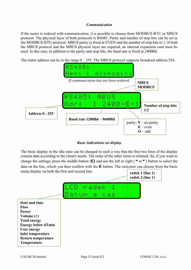
Communication
If the meter is ordered with communication, it is possible to choose from MODBUS-RTU or MBUS protocol. The physical layer of both protocols is RS485. Parity and number of stop bits can be set in the MODBUS-RTU protocol. MBUS parity is fixed at EVEN and the number of stop bits to 1. If both the MBUS protocol and the MBUS physical layer are required, an internal expansion card must be used. In this case, in addition to the parity and stop bits, the baud rate is fixed at 2400Bd. The meter address can be in the range 0 – 255. The MBUS protocol supports broadcast address 254.
If communication has not been ordered.
Basic indications on display
The basic display in the idle state can be changed in such a way that the first two lines of the display contain data according to the client's needs. The order of the other items is retained. So, if you want to change the settings, press the middle button (E) and use the left or right (or) button to select the data on the line, which you then confirm with the E button. The customer can choose from the basic menu display on both the first and second line.
MBUS MODBUS
radek 1 (line 1) radek 2 (line 1)
Date and time Flow Power Volume (+) Total energy Energy below dTmin User energy Inlet temperature Return temperature Temperature difference
Address 0 - 255 Baud rate 1200Bd – 9600Bd
parity: N – no parity E – even
O – odd
Number of stop bits 1/2
CALOR 38 manual Page 32 (total 47) COMAC CAL s.r.o.
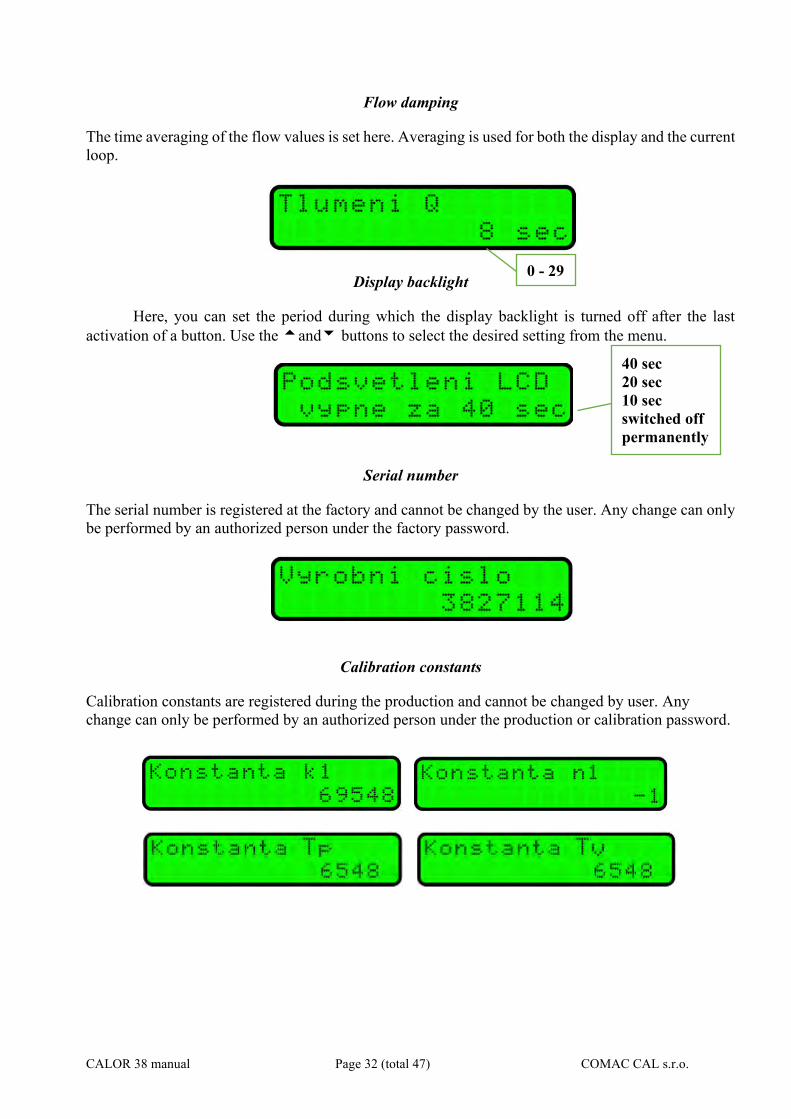
Flow damping
The time averaging of the flow values is set here. Averaging is used for both the display and the current loop.
Display backlight
Here, you can set the period during which the display backlight is turned off after the last activation of a button. Use the and buttons to select the desired setting from the menu.
Serial number
The serial number is registered at the factory and cannot be changed by the user. Any change can only be performed by an authorized person under the factory password.
Calibration constants
Calibration constants are registered during the production and cannot be changed by user. Any change can only be performed by an authorized person under the production or calibration password.
0 - 29
40 sec 20 sec 10 sec switched off permanently
CALOR 38 manual Page 33 (total 47) COMAC CAL s.r.o.
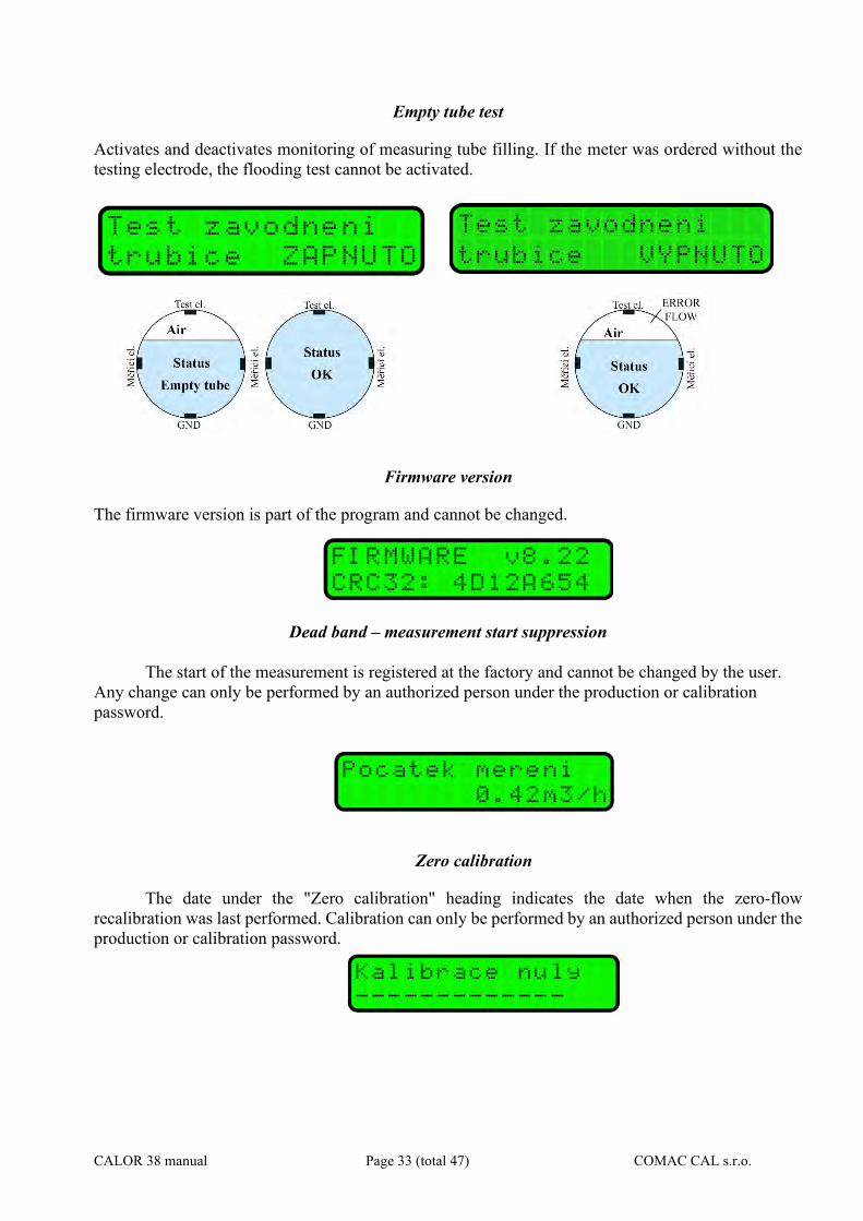
Empty tube test
Activates and deactivates monitoring of measuring tube filling. If the meter was ordered without the testing electrode, the flooding test cannot be activated.
Firmware version
The firmware version is part of the program and cannot be changed.
Dead band – measurement start suppression
The start of the measurement is registered at the factory and cannot be changed by the user.
Any change can only be performed by an authorized person under the production or calibration password.
Zero calibration
The date under the "Zero calibration" heading indicates the date when the zero-flow recalibration was last performed. Calibration can only be performed by an authorized person under the production or calibration password.

CALOR 38 manual Page 34 (total 47) COMAC CAL s.r.o.
Flow rate simulation
The test is used to easily verify the computational algorithms of calorimetric equations. The flow simulation then serves for convenient setting and control of systems in which the calorimeter is installed without the need for actual flow of the medium through the meter and without the necessary installation of the meter in the pipeline. The display shows the test status or the simulated flow, and the current and impulse outputs of the meter also correspond to this data. Such a simulated test or flow is not recorded in the billing registers.
The value of the simulated flow can be set. To turn the simulation on or off, press the E button. In the AUTO mode, the flow value is not displayed. In this mode, the volume and energy values are displayed alternately. The simulation can only be performed under the factory or calibration password.
Language
To change the device language, press E and then select the desired language from the menu.
Counter resetting
The counters can be reset only by an authorized person under the production or calibration
password. The bottom line contains the date of the last meter reset.
Nominal diameter
This parameter is set in the factory and cannot be changed. Only the authorized person under the production password can change the DN.
VYP (OFF) ZAP (ON) AUTO
Number of valid digits: 6
cz – Czech en – English
CALOR 38 manual Page 35 (total 47) COMAC CAL s.r.o.
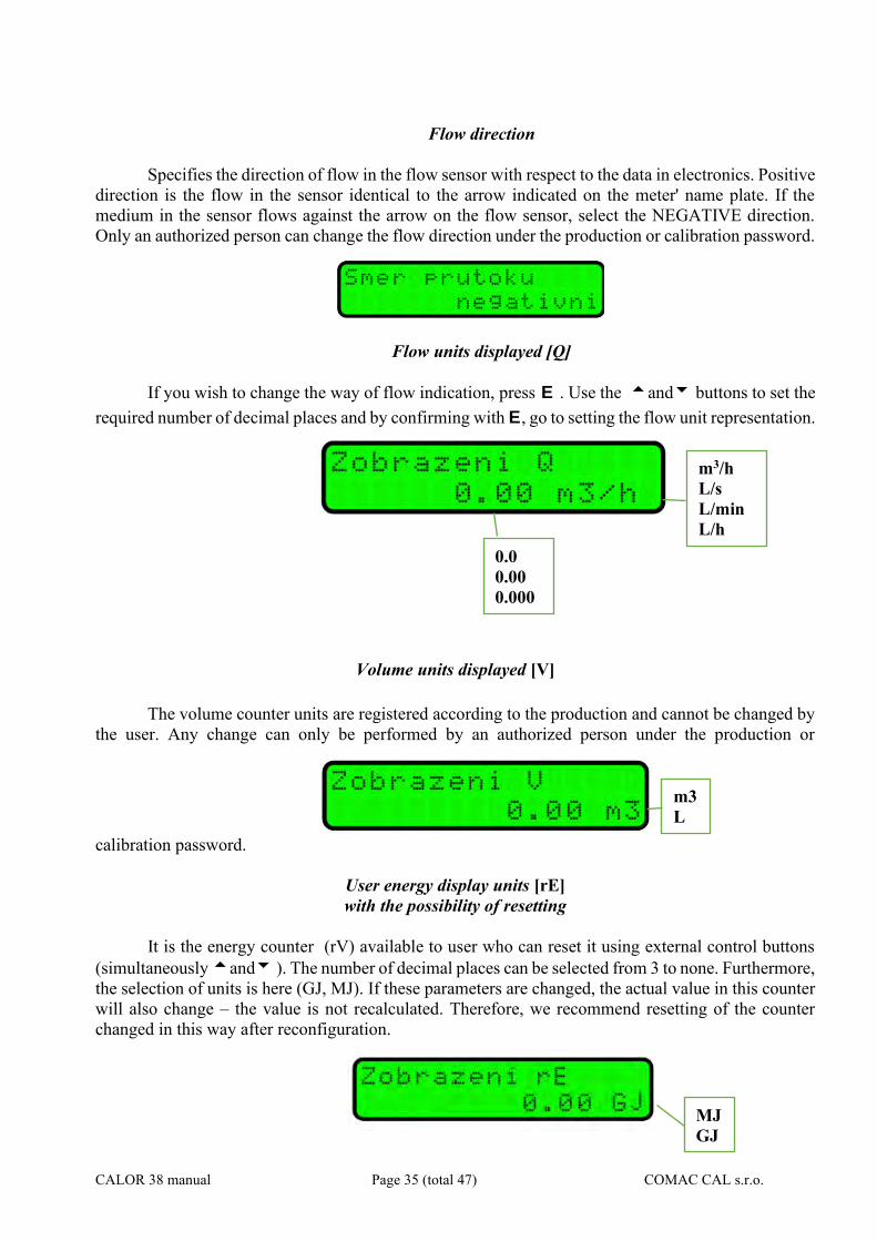
Flow direction
Specifies the direction of flow in the flow sensor with respect to the data in electronics. Positive direction is the flow in the sensor identical to the arrow indicated on the meter' name plate. If the medium in the sensor flows against the arrow on the flow sensor, select the NEGATIVE direction. Only an authorized person can change the flow direction under the production or calibration password.
Flow units displayed [Q]
If you wish to change the way of flow indication, press E . Use the and buttons to set the required number of decimal places and by confirming with E, go to setting the flow unit representation.
Volume units displayed [V] The volume counter units are registered according to the production and cannot be changed by
the user. Any change can only be performed by an authorized person under the production or
calibration password.
User energy display units [rE] with the possibility of resetting
It is the energy counter (rV) available to user who can reset it using external control buttons (simultaneously and ). The number of decimal places can be selected from 3 to none. Furthermore, the selection of units is here (GJ, MJ). If these parameters are changed, the actual value in this counter will also change – the value is not recalculated. Therefore, we recommend resetting of the counter changed in this way after reconfiguration.
m3/h L/s L/min L/h
0.0 0.00 0.000
m3 L
MJ GJ
CALOR 38 manual Page 36 (total 47) COMAC CAL s.r.o.
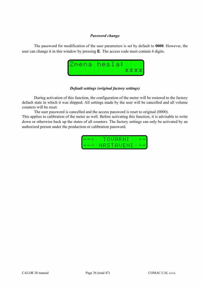
Password change
The password for modification of the user parameters is set by default to 0000. However, the user can change it in this window by pressing E. The access code must contain 4 digits.
Default settings (original factory settings)
During activation of this function, the configuration of the meter will be restored to the factory default state in which it was shipped. All settings made by the user will be cancelled and all volume counters will be reset.
The user password is cancelled and the access password is reset to original (0000). This applies to calibration of the meter as well. Before activating this function, it is advisable to write down or otherwise back up the states of all counters. The factory settings can only be activated by an authorized person under the production or calibration password.
CALOR 38 manual Page 37 (total 47) COMAC CAL s.r.o.
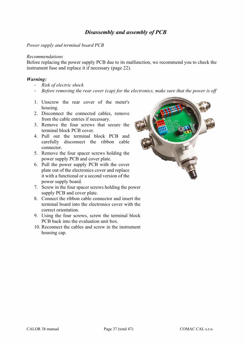
Disassembly and assembly of PCB
Power supply and terminal board PCB Recommendations Before replacing the power supply PCB due to its malfunction, we recommend you to check the instrument fuse and replace it if necessary (page 22). Warning:
- Risk of electric shock - Before removing the rear cover (cap) for the electronics, make sure that the power is off
1. Unscrew the rear cover of the meter's
housing. 2. Disconnect the connected cables, remove
from the cable entries if necessary. 3. Remove the four screws that secure the
terminal block PCB cover. 4. Pull out the terminal block PCB and
carefully disconnect the ribbon cable connector.
5. Remove the four spacer screws holding the power supply PCB and cover plate.
6. Pull the power supply PCB with the cover plate out of the electronics cover and replace it with a functional or a second version of the power supply board.
7. Screw in the four spacer screws holding the power supply PCB and cover plate.
8. Connect the ribbon cable connector and insert the terminal board into the electronics cover with the correct orientation.
9. Using the four screws, screw the terminal block PCB back into the evaluation unit box.
10. Reconnect the cables and screw in the instrument housing cap.
CALOR 38 manual Page 38 (total 47) COMAC CAL s.r.o.
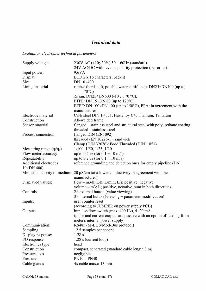
Technical data Evaluation electronics technical parameters Supply voltage: 230V AC (+10;-20%) 50 ÷ 60Hz (standard) 24V AC/DC with reverse polarity protection (per order) Input power: 9.6VA Display: LCD 2 x 16 characters, backlit Size DN 10÷400 Lining material rubber (hard, soft, potable water certificate): DN25÷DN400 (up to
70°C) Rilsan: DN25÷DN600 (-10 … 70 °C), PTFE: DN 15÷DN 80 (up to 120°C),
ETFE: DN 100÷DN 400 (up to 150°C), PFA: in agreement with the manufacturer
Electrode material CrNi steel DIN 1.4571, Hastelloy C4, Titanium, Tantalum Construction All-welded frame Sensor material flanged – stainless steel and structural steel with polyurethane coating threaded – stainless steel Process connection flanged DIN (EN1092) threaded (EN 10226-1), sandwich Clamp (DIN 32676)/ Food Threaded (DIN11851) Measuring range (qi/qp) 1/100, 1/50, 1/25, 1/10 Flow meter accuracy up to 0.5 % (for 0.1 ÷ 10 m/s) Repeatability up to 0.2 % (for 0.1 ÷ 10 m/s) Additional electrodes reference grounding and detection ones for empty pipeline (DN 10÷DN 400) Min. conductivity of medium: 20 μS/cm (at a lower conductivity in agreement with the
manufacturer) Displayed values: flow – m3/h; L/h; L/min; L/s; positive, negative volume – m3; L; positive, negative, sum in both directions Controls 2× external button (value viewing) 3× internal button (viewing + parameter modification) Inputs: user counter reset (according to JUMPER on power supply PCB) Outputs impulse/flow switch (max. 400 Hz), 4÷20 mA (pulse and current outputs are passive with an option of feeding from
meter's internal power supply) Communication: RS485 (M-BUS/Mod-Bus protocol) Sampling: 12.5 samples per second Display response: 1.28 s I/O response: 1.28 s (current loop) Electronics type head Construction compact, separated (standard cable length 3 m) Pressure loss negligible Pressure PN10 – PN40 Cable glands 4x cable max. 13 mm
CALOR 38 manual Page 39 (total 47) COMAC CAL s.r.o.
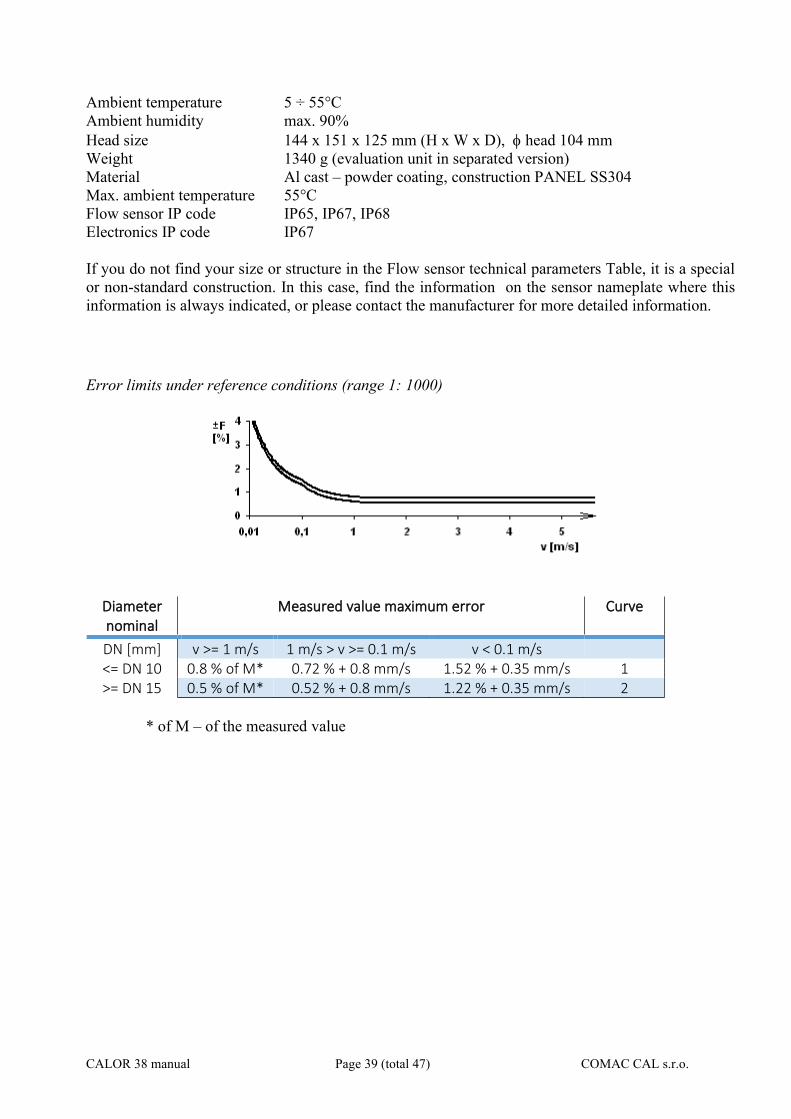
Ambient temperature 5 ÷ 55°C Ambient humidity max. 90% Head size 144 x 151 x 125 mm (H x W x D), head 104 mm Weight 1340 g (evaluation unit in separated version) Material Al cast – powder coating, construction PANEL SS304 Max. ambient temperature 55°C Flow sensor IP code IP65, IP67, IP68 Electronics IP code IP67 If you do not find your size or structure in the Flow sensor technical parameters Table, it is a special or non-standard construction. In this case, find the information on the sensor nameplate where this information is always indicated, or please contact the manufacturer for more detailed information. Error limits under reference conditions (range 1: 1000)
Diameter nominal
Measured value maximum error Curve
DN [mm] v >= 1 m/s 1 m/s > v >= 0.1 m/s v < 0.1 m/s <= DN 10 0.8 % of M* 0.72 % + 0.8 mm/s 1.52 % + 0.35 mm/s 1 >= DN 15 0.5 % of M* 0.52 % + 0.8 mm/s 1.22 % + 0.35 mm/s 2
* of M – of the measured value

CALOR 38 manual Page 40 (total 47) COMAC CAL s.r.o.
Factory settings The current loop is set in such a manner that 4 mA corresponds to zero flow and 20 mA corresponds to its maximum value. The address of the meter is set to 1 by default and communication parameters to 2400Bd,8db,1sb, parity EVEN (Mbus) or 9600Bd,8db,1sb, no parity (Modbus). Access password (PIN) for parameter changing is always set to 0000 and this value will be reset in case of restoring to factory default settings.
Impulse constants and current loop – factory settings
Diameter nominal
Impulse output 4 ÷ 20mA
DN Vout[imp/l] Vout - pulse width [ms] Q[l/h] for 4mA Q[l/h] for 20mA
10 10 4 0 3,400 15 10 4 0 7,600 20 10 4 0 14,200 25 10 4 0 21,000 32 1 4 0 34,000 40 1 4 0 54,000 50 1 4 0 84,000 65 1 4 0 144,000 80 1 4 0 220,000
100 0.1 4 0 340,000 125 0.1 4 0 534,000 150 0.1 4 0 760,000 200 0.1 4 0 1,350,000 300 0.1 4 0 3,052,000 400 0.1 2.5 0 5,400,000
Diameter nominal
Resolution V Resolution Q Resolution E
DN≤15 V [0.001 m3] Q [0.001 m3/h] E [0.001 GJ]
50≥DN>15 V [0.01 m3] Q [0.01 m3/h] E [0.01 GJ]
DN>50 V [0.1 m3] Q [0.1 m3/h] E [0.1 GJ]
CALOR 38 manual Page 41 (total 47) COMAC CAL s.r.o.
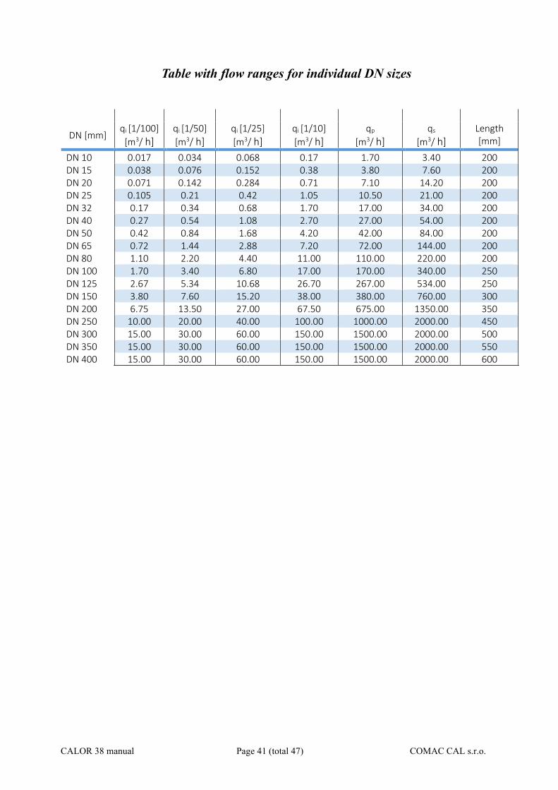
Table with flow ranges for individual DN sizes
DN [mm] qi [1/100]
[m3/ h] qi [1/50]
[m3/ h] qi [1/25]
[m3/ h] qi [1/10]
[m3/ h] qp
[m3/ h] qs
[m3/ h] Length [mm]
DN 10 0.017 0.034 0.068 0.17 1.70 3.40 200 DN 15 0.038 0.076 0.152 0.38 3.80 7.60 200 DN 20 0.071 0.142 0.284 0.71 7.10 14.20 200 DN 25 0.105 0.21 0.42 1.05 10.50 21.00 200 DN 32 0.17 0.34 0.68 1.70 17.00 34.00 200 DN 40 0.27 0.54 1.08 2.70 27.00 54.00 200 DN 50 0.42 0.84 1.68 4.20 42.00 84.00 200 DN 65 0.72 1.44 2.88 7.20 72.00 144.00 200 DN 80 1.10 2.20 4.40 11.00 110.00 220.00 200 DN 100 1.70 3.40 6.80 17.00 170.00 340.00 250 DN 125 2.67 5.34 10.68 26.70 267.00 534.00 250 DN 150 3.80 7.60 15.20 38.00 380.00 760.00 300 DN 200 6.75 13.50 27.00 67.50 675.00 1350.00 350 DN 250 10.00 20.00 40.00 100.00 1000.00 2000.00 450 DN 300 15.00 30.00 60.00 150.00 1500.00 2000.00 500 DN 350 15.00 30.00 60.00 150.00 1500.00 2000.00 550 DN 400 15.00 30.00 60.00 150.00 1500.00 2000.00 600
CALOR 38 manual Page 42 (total 47) COMAC CAL s.r.o.
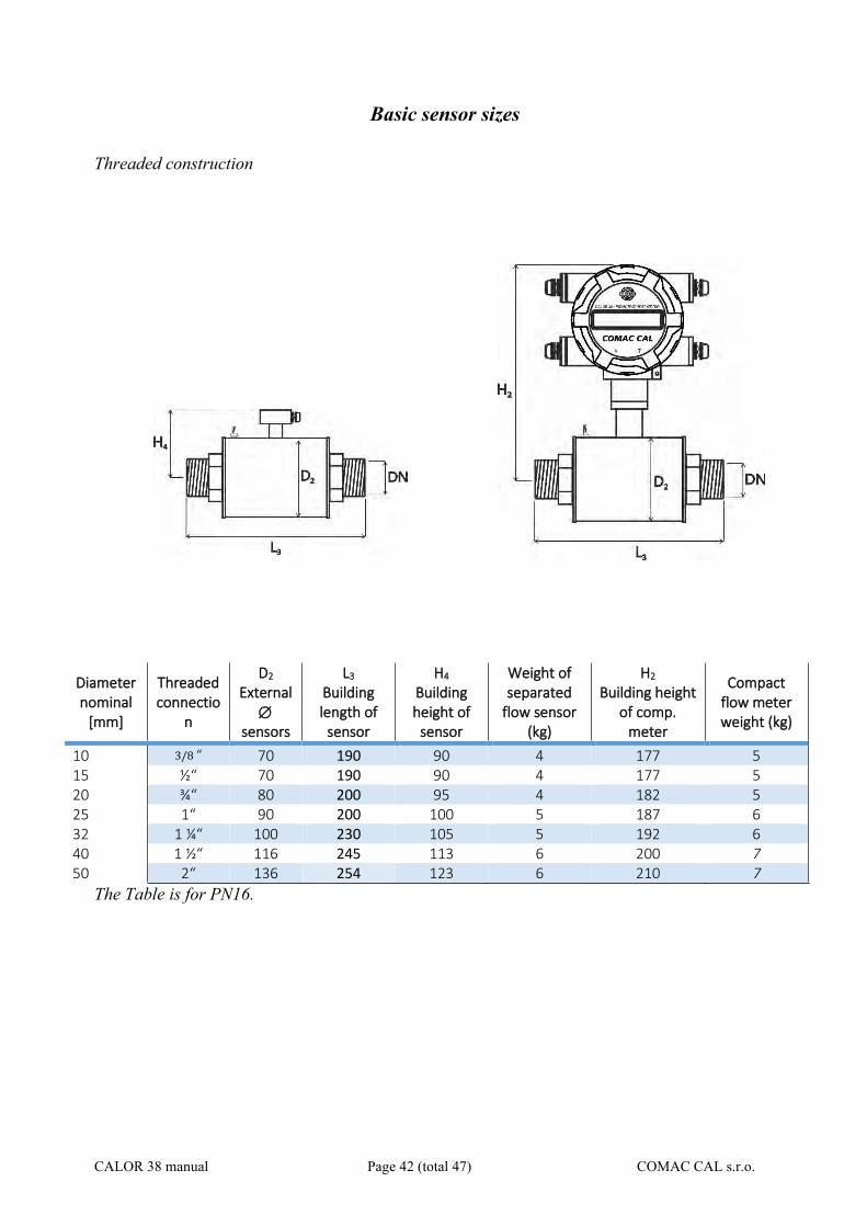
Basic sensor sizes
Threaded construction
Diameter nominal
[mm]
Threaded connectio
n
D2 External
sensors
L3 Building length of
sensor
H4 Building height of
sensor
Weight of separated
flow sensor (kg)
H2 Building height
of comp. meter
Compact flow meter weight (kg)
10 3/8 “ 70 190 90 4 177 5 15 ½“ 70 190 90 4 177 5 20 ¾“ 80 200 95 4 182 5 25 1“ 90 200 100 5 187 6 32 1 ¼“ 100 230 105 5 192 6 40 1 ½“ 116 245 113 6 200 7 50 2“ 136 254 123 6 210 7
The Table is for PN16.
CALOR 38 manual Page 43 (total 47) COMAC CAL s.r.o.
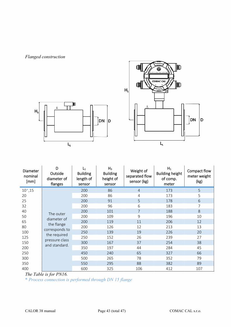
Flanged construction
Diameter nominal
[mm]
D Outside
diameter of flanges
L1 Building length of
sensor
H3 Building height of
sensor
Weight of separated flow
sensor (kg)
H1 Building height
of comp. meter
Compact flow meter weight
(kg)
10*,15
The outer diameter of the flange
corresponds to the required
pressure class and standard.
200 86 4 173 5 20 200 86 4 173 5 25 200 91 5 178 6 32 200 96 6 183 7 40 200 101 7 188 8 50 200 109 9 196 10 65 200 119 11 206 12 80 200 126 12 213 13 100 250 139 19 226 20 125 250 152 26 239 27 150 300 167 37 254 38 200 350 197 44 284 45 250 450 240 65 327 66 300 500 265 78 352 79 350 550 295 88 382 89 400 600 325 106 412 107
The Table is for PN16. * Process connection is performed through DN 15 flange
CALOR 38 manual Page 44 (total 47) COMAC CAL s.r.o.
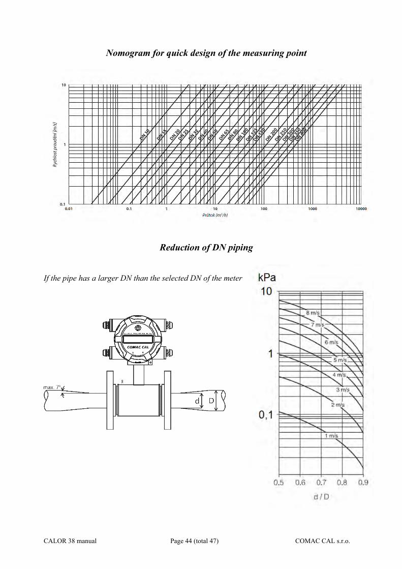
Nomogram for quick design of the measuring point
Reduction of DN piping
If the pipe has a larger DN than the selected DN of the meter
CALOR 38 manual Page 45 (total 47) COMAC CAL s.r.o.
Faults during measurement
Unstable indication and outputs may occur upon: - high proportion of solids - latent non-homogeneities - dislocation of mixing - ongoing chemical reactions within the measured substance - use of diaphragm pumps or piston-type pumps - poor grounding
Flow sensor cleaning
Some measured media contain substances and chemicals that tend to form coatings on the walls of the pipe and thus also on the walls of the measuring tube, which can then affect the accuracy of the measurement. Then the flow sensor must be cleaned from time to time. Ceramic tubes can be cleaned mechanically with a steel brush and then cleaned with dilute hydrochloric acid or a citric acid solution. Acids remove coatings from calcareous deposits or black deposits from iron complexes well. If the contamination has the character of greasy deposits, a solution of caustic soda or potassium must be used for cleaning. For flow sensors with Teflon, plastic and rubber measuring tubes, you cannot use mechanical cleaning with a brush, but use only chemical cleaning or a soft cloth. After cleaning, the tube must be thoroughly rinsed with clean water.
CALOR 38 manual Page 46 (total 47) COMAC CAL s.r.o.
Servicing All warranty and after-warranty repairs are carried out by the manufacturer, COMAC CAL s.r.o. When the below mentioned operations are carried out unprofessionally, the claim to warranty covering the errors that may occur, become null and void !!! Prior to any opening of the evaluation unit, switch off the power !!!
Ordering code
CALOR 38 manual Page 47 (total 47) COMAC CAL s.r.o.
Form for returning the meter to COMAC CAL s.r.o. The meter that you have acquired was made with the highest level of precision and it was tested several times and wet-calibrated. When the meter is used in accordance with this manual, failures can be expected very rarely. If there is any failure, contact our service centre. When returning the device to the manufacturing plant, keep the conditions set forth below.
- Clean the meter from impurities stuck to the sensing element and the measuring tube (eventually to the evaluation unit as well).
- If the meter was operated with poisonous, etching, combustible, or water endangering substances measured, check and flush eventually and neutralize the sensor cavities.
Attach a description of the defect to the shipment. The COMAC CAL s.r.o. will not be able to process your requirement correctly and promptly without the form.