pro-server with pro-studio for windows operation manual
TRANSCRIPT

Operation ManualCopyright 2004, Digital Electronics Corporation
All right reserved. Made in Japan

PREFPREFPREFPREFPREFAAAAACECECECECE
Thank you for purchasing Digital’s “Pro-Server with Pro-Studio for Windows” for use with Digital’s GP series
touch panels.
To ensure correct use of this product, be sure to carefully read the manuals included and keep them nearby so
that you can refer to them whenever required.
NONONONONOTETETETETE
(1) The copyrights to all programs and manuals included in the “Pro-Server with Pro-Studio for
Windows” (hereinafter referred to as “this product”) are reserved by the Digital Electronics
Corporation. Digital grants the use of this product to its users as described in the “Software
Operating and License Conditions” section. Any actions violating the above-mentioned condi-
tions are prohibited by both Japanese and foreign regulations.
(2) The contents of this manual have been thoroughly checked. However, if you should find any
errors or omissions in this manual, please contact your local representative and inform them of
your findings.
(3) Please be aware that Digital Electronics Corporation shall not be held liable by the user for any
damages, losses, or third party claims arising from the uses of this product.
(4) Differences may occur between the descriptions found in this manual and the actual functioning
of this product. The latest information about this product is provided in the accompanying data
files (i.e. Readme.txt files, etc.) and/or separate documents. Please consult these sources as well
as this manual prior to use.
(5) Even though the information contained in and displayed by this product may be related to
intangible or intellectual properties of the Digital Electronics Corporation or third parties, the
Digital Electronics Corporation shall not warrant or grant the use of said properties to any users
and/or other third parties.
(6) Digital Electronics Corporation does not warrant that any intellectual rights of this software and
the system constructed by installing this software are not issued.
© Copyright 2005 Digital Electronics Corporation All rights reserved.
For the rights to trademarks and trade names, see “TRADEMARK RIGHTS”
1

0-2
Formal Trade Name or TrademarkMicrosoft Windows 98 Operating SystemMicrosoft Windows 98 SE Operating SystemMicrosoft Windows Me Operating SystemMicrosoft Windows NT Operating SystemMicrosoft Windows 2000 Operating SystemMicrosoft Windows XP Operating System
Term used in this manualWindows 98Windows 98 SEWinoows MeWindows NTWindows 2000Windows XP
TRADEMARK RIGHTSTRADEMARK RIGHTSTRADEMARK RIGHTSTRADEMARK RIGHTSTRADEMARK RIGHTS
The company names and product names used in this manual are the trade names, trademarks (including
registered trademarks), and service marks of their respective companies.
This product omits individual descriptions of each of these rights.
The following terms used in this manual differ from the above mentioned formal trade names and trademarks.
Trademark/TradenameMicrosoft, MS-DOS, Windows 98, Windows 98 SE,Windows Me, Windows NT, Windows 2000, Windows XP,Windows Explorer, Active X, eMbedded Visual C++,eMbedded Visual Basic, Excel, AccessIntel, Pentium, MMXPro-faceVGA, PC/ATFIX32, FIX-MMI, FIX-FA, iFIX
Right HolderMicrosoft, U.S.
Intel, U.SDigital Electronics CorporationIBM, U.S.Intellution, U.S.

0-3
HOHOHOHOHOW W W W W TTTTTO USE O USE O USE O USE O USE THIS MANUTHIS MANUTHIS MANUTHIS MANUTHIS MANUALALALALAL
Structure of This Manual
This manual, titled “Pro-Server with Pro-Studio for Windows Operation Manual” describes how to use the
“Pro-Server with Pro-Studio for Windows” software, hereinafter referred to as “this software”
The following table describes the GP-PRO/PBIII for Windows software’s manuals, which are often referred
to in this manual.
In addition to this manual, information on additional/modified functions may be provided as data files.
Vol. 1
Vol. 2
Vol. 3
Vol. 4
Operation Manual
Tag Reference Manual
Parts List
Device/PLC ConnectionManual
Describes the procedures for the installation andoperation of GP-PRO/PBIII for Windows.Includes detailed descriptions on the “tags” used tospecify the functions used on the GP’s screen.Describes the library of pre-made Parts included withthis product as well as a variety of diagram symbols.Describes the procedures to create connections be-tween GP series units and other manufacture PLCs.

0-4
TTTTTABLE OF CONTENTSABLE OF CONTENTSABLE OF CONTENTSABLE OF CONTENTSABLE OF CONTENTS
PREFPREFPREFPREFPREFAAAAACECECECECE ..................................................................................................................................................................................................................................................................................................................................................................................................................................................................................................................................................................................... 11111NONONONONOTETETETETE ........................................................................................................................................................................................................................................................................................................................................................................................................................................................................................................................................................................................................................ 11111TRADEMARK RIGHTSTRADEMARK RIGHTSTRADEMARK RIGHTSTRADEMARK RIGHTSTRADEMARK RIGHTS ............................................................................................................................................................................................................................................................................................................................................................................................................................................................................ 22222HOHOHOHOHOW W W W W TTTTTO USE O USE O USE O USE O USE THIS MANUTHIS MANUTHIS MANUTHIS MANUTHIS MANUALALALALAL .......................................................................................................................................................................................................................................................................................................................................................................................................................... 33333TTTTTABLE OF CONTENTSABLE OF CONTENTSABLE OF CONTENTSABLE OF CONTENTSABLE OF CONTENTS ....................................................................................................................................................................................................................................................................................................................................................................................................................................................................... 44444MANUMANUMANUMANUMANUAL SYMBOLS AND AL SYMBOLS AND AL SYMBOLS AND AL SYMBOLS AND AL SYMBOLS AND TERMINOLOGYTERMINOLOGYTERMINOLOGYTERMINOLOGYTERMINOLOGY ....................................................................................................................................................................................................................................................................................................... 99999PRECAPRECAPRECAPRECAPRECAUTIONSUTIONSUTIONSUTIONSUTIONS .............................................................................................................................................................................................................................................................................................................................................................................................................................................................................................................................. 1010101010PPPPPAAAAACKACKACKACKACKAGE CONTENTSGE CONTENTSGE CONTENTSGE CONTENTSGE CONTENTS .................................................................................................................................................................................................................................................................................................................................................................................................................................................................. 1111111111OPERAOPERAOPERAOPERAOPERATING ENVIRTING ENVIRTING ENVIRTING ENVIRTING ENVIRONMENTONMENTONMENTONMENTONMENT ........................................................................................................................................................................................................................................................................................................................................................................................................... 1212121212
Chapter 1 IntrChapter 1 IntrChapter 1 IntrChapter 1 IntrChapter 1 Introductionoductionoductionoductionoduction1.11.11.11.11.1 OutlineOutlineOutlineOutlineOutline ............................................................................................................................................................................................................................................................................................................................................................................................................................................................................................................................................. 1-21-21-21-21-21.21.21.21.21.2 What is the 2-WWhat is the 2-WWhat is the 2-WWhat is the 2-WWhat is the 2-Waaaaay Driver?y Driver?y Driver?y Driver?y Driver? ............................................................................................................................................................................................................................................................................................................................................................................. 1-31-31-31-31-31.31.31.31.31.3 System ConfigurationSystem ConfigurationSystem ConfigurationSystem ConfigurationSystem Configuration ................................................................................................................................................................................................................................................................................................................................................................................................................ 1-41-41-41-41-4
1.3.11.3.11.3.11.3.11.3.1 External ConfigurationExternal ConfigurationExternal ConfigurationExternal ConfigurationExternal Configuration .................................................................................................................................................................................................................................................................................................................................................................................................................................................................................................................... 1-41-41-41-41-4
1.3.21.3.21.3.21.3.21.3.2 Internal ConfigurationInternal ConfigurationInternal ConfigurationInternal ConfigurationInternal Configuration ......................................................................................................................................................................................................................................................................................................................................................................................................................................................................................................................... 1-51-51-51-51-5
1.41.41.41.41.4 Application InterfacesApplication InterfacesApplication InterfacesApplication InterfacesApplication Interfaces ...................................................................................................................................................................................................................................................................................................................................................................................................... 1-111-111-111-111-111.4.11.4.11.4.11.4.11.4.1 DDE function OutlineDDE function OutlineDDE function OutlineDDE function OutlineDDE function Outline ......................................................................................................................................................................................................................................................................................................................................................................................................................................................................................................................... 1-111-111-111-111-11
1.4.21.4.21.4.21.4.21.4.2 Simple DLL FunctionSimple DLL FunctionSimple DLL FunctionSimple DLL FunctionSimple DLL Function ......................................................................................................................................................................................................................................................................................................................................................................................................................................................................................................................... 1-121-121-121-121-12
1.4.31.4.31.4.31.4.31.4.3 OPC Interface FunctionOPC Interface FunctionOPC Interface FunctionOPC Interface FunctionOPC Interface Function ..................................................................................................................................................................................................................................................................................................................................................................................................................................................................................................... 1-131-131-131-131-13
1.4.41.4.41.4.41.4.41.4.4 SRAM BacSRAM BacSRAM BacSRAM BacSRAM Backup Data Storakup Data Storakup Data Storakup Data Storakup Data Storaggggge Functione Functione Functione Functione Function ............................................................................................................................................................................................................................................................................................................................................................................. 1-141-141-141-141-14
1.51.51.51.51.5 PrPrPrPrProoooovider Infvider Infvider Infvider Infvider Information Outlineormation Outlineormation Outlineormation Outlineormation Outline ............................................................................................................................................................................................................................................................................................................................................... 1-151-151-151-151-151.5.11.5.11.5.11.5.11.5.1 PrPrPrPrProooooviding Infviding Infviding Infviding Infviding Information to the Hostormation to the Hostormation to the Hostormation to the Hostormation to the Host ................................................................................................................................................................................................................................................................................................................................................................................................................ 1-151-151-151-151-15
1.5.21.5.21.5.21.5.21.5.2 PrPrPrPrProooooviding Infviding Infviding Infviding Infviding Information between GPsormation between GPsormation between GPsormation between GPsormation between GPs ............................................................................................................................................................................................................................................................................................................................................................................................ 1-161-161-161-161-16
1.5.31.5.31.5.31.5.31.5.3 Action Feature OverAction Feature OverAction Feature OverAction Feature OverAction Feature Overvievievievieviewwwww ...................................................................................................................................................................................................................................................................................................................................................................................................................................................................................... 1-171-171-171-171-17
1.61.61.61.61.6 OverOverOverOverOvervievievievieview of Data w of Data w of Data w of Data w of Data VieVieVieVieViewwwww ................................................................................................................................................................................................................................................................................................................................................................................................. 1-181-181-181-181-181.71.71.71.71.7 Configuring the SystemConfiguring the SystemConfiguring the SystemConfiguring the SystemConfiguring the System ....................................................................................................................................................................................................................................................................................................................................................................................... 1-191-191-191-191-19
Chapter 2 PrChapter 2 PrChapter 2 PrChapter 2 PrChapter 2 Pro-Sero-Sero-Sero-Sero-Server Fundamentalsver Fundamentalsver Fundamentalsver Fundamentalsver Fundamentals2.12.12.12.12.1 Installing the SoftwareInstalling the SoftwareInstalling the SoftwareInstalling the SoftwareInstalling the Software ........................................................................................................................................................................................................................................................................................................................................................................................................... 2-22-22-22-22-22.22.22.22.22.2 StarStarStarStarStarting and Exiting the Softwareting and Exiting the Softwareting and Exiting the Softwareting and Exiting the Softwareting and Exiting the Software ................................................................................................................................................................................................................................................................................................................. 2-62-62-62-62-6
2.2.12.2.12.2.12.2.12.2.1 Using PrUsing PrUsing PrUsing PrUsing Pro-Studioo-Studioo-Studioo-Studioo-Studio ................................................................................................................................................................................................................................................................................................................................................................................................................................................................................................................................................................. 2-62-62-62-62-6
2.2.22.2.22.2.22.2.22.2.2 Exiting PrExiting PrExiting PrExiting PrExiting Pro-Studioo-Studioo-Studioo-Studioo-Studio ............................................................................................................................................................................................................................................................................................................................................................................................................................................................................................................................................. 2-102-102-102-102-10
2.2.32.2.32.2.32.2.32.2.3 StarStarStarStarStarting and Exiting Prting and Exiting Prting and Exiting Prting and Exiting Prting and Exiting Pro-Sero-Sero-Sero-Sero-Serververververver ............................................................................................................................................................................................................................................................................................................................................................................................................................... 2-112-112-112-112-11
2.32.32.32.32.3 Screen Item Names and FunctionsScreen Item Names and FunctionsScreen Item Names and FunctionsScreen Item Names and FunctionsScreen Item Names and Functions ............................................................................................................................................................................................................................................................................................. 2-132-132-132-132-13

0-5
Chapter 3 OperationChapter 3 OperationChapter 3 OperationChapter 3 OperationChapter 3 Operation3.13.13.13.13.1 Registering NetwRegistering NetwRegistering NetwRegistering NetwRegistering Network Entrork Entrork Entrork Entrork Entry Nodesy Nodesy Nodesy Nodesy Nodes ............................................................................................................................................................................................................................................................................................................ 3-23-23-23-23-2
3.1.13.1.13.1.13.1.13.1.1 Registering a NetwRegistering a NetwRegistering a NetwRegistering a NetwRegistering a Network Nodeork Nodeork Nodeork Nodeork Node ....................................................................................................................................................................................................................................................................................................................................................................................................................................................................... 3-23-23-23-23-2
3.1.23.1.23.1.23.1.23.1.2 SearSearSearSearSearccccching a Netwhing a Netwhing a Netwhing a Netwhing a Network Nodeork Nodeork Nodeork Nodeork Node ................................................................................................................................................................................................................................................................................................................................................................................................................................................................................. 3-53-53-53-53-5
3.23.23.23.23.2 Registering SymbolsRegistering SymbolsRegistering SymbolsRegistering SymbolsRegistering Symbols .......................................................................................................................................................................................................................................................................................................................................................................................................................... 3-73-73-73-73-73.2.13.2.13.2.13.2.13.2.1 ImporImporImporImporImporting Symbolsting Symbolsting Symbolsting Symbolsting Symbols ........................................................................................................................................................................................................................................................................................................................................................................................................................................................................................................................................ 3-103-103-103-103-10
3.2.23.2.23.2.23.2.23.2.2 Symbol ExporSymbol ExporSymbol ExporSymbol ExporSymbol Exporttttt ........................................................................................................................................................................................................................................................................................................................................................................................................................................................................................................................................................................... 3-113-113-113-113-11
3.2.33.2.33.2.33.2.33.2.3 ImporImporImporImporImporting C-Pting C-Pting C-Pting C-Pting C-Pacacacacackakakakakaggggge Symbole Symbole Symbole Symbole Symbol ................................................................................................................................................................................................................................................................................................................................................................................................................................................... 3-123-123-123-123-12
3.2.43.2.43.2.43.2.43.2.4 ChecChecChecChecChecking C-Pking C-Pking C-Pking C-Pking C-Pacacacacackakakakakaggggge Symbole Symbole Symbole Symbole Symbol ................................................................................................................................................................................................................................................................................................................................................................................................................................................... 3-163-163-163-163-16
3.33.33.33.33.3 Registering PrRegistering PrRegistering PrRegistering PrRegistering Prooooovider Datavider Datavider Datavider Datavider Data ................................................................................................................................................................................................................................................................................................................................................................... 3-193-193-193-193-193.3.13.3.13.3.13.3.13.3.1 ChecChecChecChecChecking fking fking fking fking for Pror Pror Pror Pror Prooooovider Data Errvider Data Errvider Data Errvider Data Errvider Data Errorororororsssss ........................................................................................................................................................................................................................................................................................................................................................................................................... 3-293-293-293-293-29
3.3.23.3.23.3.23.3.23.3.2 Action ItemsAction ItemsAction ItemsAction ItemsAction Items ............................................................................................................................................................................................................................................................................................................................................................................................................................................................................................................................................................................................... 3-313-313-313-313-31
3.43.43.43.43.4 Using the DDE FunctionUsing the DDE FunctionUsing the DDE FunctionUsing the DDE FunctionUsing the DDE Function .................................................................................................................................................................................................................................................................................................................................................................................. 3-323-323-323-323-323.53.53.53.53.5 Using the Using the Using the Using the Using the VBVBVBVBVBA SupporA SupporA SupporA SupporA Support Functiont Functiont Functiont Functiont Function ............................................................................................................................................................................................................................................................................................................ 3-373-373-373-373-373.63.63.63.63.6 SaSaSaSaSaving Bacving Bacving Bacving Bacving Backup Data in SRAMkup Data in SRAMkup Data in SRAMkup Data in SRAMkup Data in SRAM ..................................................................................................................................................................................................................................................................................................................................... 3-443-443-443-443-443.73.73.73.73.7 DeDeDeDeDevice Data Bacvice Data Bacvice Data Bacvice Data Bacvice Data Backup and Restorationkup and Restorationkup and Restorationkup and Restorationkup and Restoration ......................................................................................................................................................................................................................................................................... 3-463-463-463-463-46
3.7.13.7.13.7.13.7.13.7.1 DeDeDeDeDevice Data Bacvice Data Bacvice Data Bacvice Data Bacvice Data Backupkupkupkupkup .............................................................................................................................................................................................................................................................................................................................................................................................................................................................................................................................. 3-463-463-463-463-46
3.7.23.7.23.7.23.7.23.7.2 Restoring DeRestoring DeRestoring DeRestoring DeRestoring Device Datavice Datavice Datavice Datavice Data .......................................................................................................................................................................................................................................................................................................................................................................................................................................................................................................... 3-503-503-503-503-50
3.83.83.83.83.8 GP Capture Data SaGP Capture Data SaGP Capture Data SaGP Capture Data SaGP Capture Data Saving Functionving Functionving Functionving Functionving Function .................................................................................................................................................................................................................................................................................................. 3-533-533-533-533-533.93.93.93.93.9 Security FunctionSecurity FunctionSecurity FunctionSecurity FunctionSecurity Function ......................................................................................................................................................................................................................................................................................................................................................................................................................................... 3-553-553-553-553-55
3.9.13.9.13.9.13.9.13.9.1 User LeUser LeUser LeUser LeUser Level Pvel Pvel Pvel Pvel Passassassassasswwwwwororororord Settingsd Settingsd Settingsd Settingsd Settings .............................................................................................................................................................................................................................................................................................................................................................................................................................................. 3-553-553-553-553-55
3.9.23.9.23.9.23.9.23.9.2 Remote PRemote PRemote PRemote PRemote Passassassassasswwwwwororororord Setupd Setupd Setupd Setupd Setup ........................................................................................................................................................................................................................................................................................................................................................................................................................................................................................... 3-573-573-573-573-57
3.103.103.103.103.10 Configuring the SystemConfiguring the SystemConfiguring the SystemConfiguring the SystemConfiguring the System ....................................................................................................................................................................................................................................................................................................................................................................................... 3-593-593-593-593-593.113.113.113.113.11 Configuring the NetwConfiguring the NetwConfiguring the NetwConfiguring the NetwConfiguring the Networkorkorkorkork.................................................................................................................................................................................................................................................................................................................................................................................. 3-613-613-613-613-61
3.11.13.11.13.11.13.11.13.11.1 Configuring Ethernet CarConfiguring Ethernet CarConfiguring Ethernet CarConfiguring Ethernet CarConfiguring Ethernet Cardsdsdsdsds .................................................................................................................................................................................................................................................................................................................................................................................................................................................................. 3-643-643-643-643-64
3.123.123.123.123.12 Printing the Setting DataPrinting the Setting DataPrinting the Setting DataPrinting the Setting DataPrinting the Setting Data ............................................................................................................................................................................................................................................................................................................................................................................. 3-653-653-653-653-653.133.133.133.133.13 Other InstructionsOther InstructionsOther InstructionsOther InstructionsOther Instructions .................................................................................................................................................................................................................................................................................................................................................................................................................................... 3-663-663-663-663-66
3.13.13.13.13.13.13.13.13.13.1 Special PrSpecial PrSpecial PrSpecial PrSpecial Protocolotocolotocolotocolotocol ................................................................................................................................................................................................................................................................................................................................................................................................................................................................................................................................................................. 3-663-663-663-663-66
3.13.23.13.23.13.23.13.23.13.2 AdAdAdAdAddress fdress fdress fdress fdress for or or or or WindoWindoWindoWindoWindows Computerws Computerws Computerws Computerws Computer .......................................................................................................................................................................................................................................................................................................................................................................................................................... 3-683-683-683-683-68

0-6
Chapter 4 Action ItemsChapter 4 Action ItemsChapter 4 Action ItemsChapter 4 Action ItemsChapter 4 Action Items4.14.14.14.14.1 OverOverOverOverOvervievievievieviewwwww ......................................................................................................................................................................................................................................................................................................................................................................................................................................................................................................................... 4-24-24-24-24-2
4.1.14.1.14.1.14.1.14.1.1 Action Item RegistrationAction Item RegistrationAction Item RegistrationAction Item RegistrationAction Item Registration ..................................................................................................................................................................................................................................................................................................................................................................................................................................................................................................... 4-34-34-34-34-3
4.1.24.1.24.1.24.1.24.1.2 AAAAAvvvvvailabailabailabailabailable Action Itemsle Action Itemsle Action Itemsle Action Itemsle Action Items .................................................................................................................................................................................................................................................................................................................................................................................................................................................................................................................... 4-44-44-44-44-4
4.24.24.24.24.2 Registering Action ItemsRegistering Action ItemsRegistering Action ItemsRegistering Action ItemsRegistering Action Items ....................................................................................................................................................................................................................................................................................................................................................................................... 4-74-74-74-74-74.2.14.2.14.2.14.2.14.2.1 Registering Action ItemsRegistering Action ItemsRegistering Action ItemsRegistering Action ItemsRegistering Action Items ................................................................................................................................................................................................................................................................................................................................................................................................................................................................................................ 4-74-74-74-74-7
4.2.24.2.24.2.24.2.24.2.2 Setting Action PSetting Action PSetting Action PSetting Action PSetting Action Parameterarameterarameterarameterarametersssss ...................................................................................................................................................................................................................................................................................................................................................................................................................................................................................... 4-94-94-94-94-9
4.2.34.2.34.2.34.2.34.2.3 Registering PrRegistering PrRegistering PrRegistering PrRegistering Prooooovider Infvider Infvider Infvider Infvider Informationormationormationormationormation ..................................................................................................................................................................................................................................................................................................................................................................................................................... 4-154-154-154-154-15
4.34.34.34.34.3 Registering Action Item PRegistering Action Item PRegistering Action Item PRegistering Action Item PRegistering Action Item Parameterarameterarameterarameterarametersssss................................................................................................................................................................................................................................................................................... 4-184-184-184-184-184.3.14.3.14.3.14.3.14.3.1 “Star“Star“Star“Star“Start Application”t Application”t Application”t Application”t Application” Action Item Action Item Action Item Action Item Action Item .................................................................................................................................................................................................................................................................................................................................................................................................................................... 4-184-184-184-184-18
4.3.24.3.24.3.24.3.24.3.2 Alarm Log (with Sound AlerAlarm Log (with Sound AlerAlarm Log (with Sound AlerAlarm Log (with Sound AlerAlarm Log (with Sound Alert Feature)t Feature)t Feature)t Feature)t Feature) ............................................................................................................................................................................................................................................................................................................................................................................. 4-204-204-204-204-20
4.3.34.3.34.3.34.3.34.3.3 Upload of GP Log DataUpload of GP Log DataUpload of GP Log DataUpload of GP Log DataUpload of GP Log Data .......................................................................................................................................................................................................................................................................................................................................................................................................................................................................................................... 4-234-234-234-234-23
4.3.44.3.44.3.44.3.44.3.4 AAAAAutomatic Doutomatic Doutomatic Doutomatic Doutomatic Download of GP Filing Datawnload of GP Filing Datawnload of GP Filing Datawnload of GP Filing Datawnload of GP Filing Data ................................................................................................................................................................................................................................................................................................................................................................... 4-274-274-274-274-27
4.3.54.3.54.3.54.3.54.3.5 AAAAAutomatic Upload of GP Filing Datautomatic Upload of GP Filing Datautomatic Upload of GP Filing Datautomatic Upload of GP Filing Datautomatic Upload of GP Filing Data ............................................................................................................................................................................................................................................................................................................................................................................................ 4-294-294-294-294-29
4.3.64.3.64.3.64.3.64.3.6 AAAAAutomatic Upload of Access Datautomatic Upload of Access Datautomatic Upload of Access Datautomatic Upload of Access Datautomatic Upload of Access Data ........................................................................................................................................................................................................................................................................................................................................................................................................... 4-324-324-324-324-32
4.3.74.3.74.3.74.3.74.3.7 AAAAAutomatic Doutomatic Doutomatic Doutomatic Doutomatic Download of Access Datawnload of Access Datawnload of Access Datawnload of Access Datawnload of Access Data .................................................................................................................................................................................................................................................................................................................................................................................. 4-364-364-364-364-36
4.3.84.3.84.3.84.3.84.3.8 DoDoDoDoDownload Recipe data fwnload Recipe data fwnload Recipe data fwnload Recipe data fwnload Recipe data for Excelor Excelor Excelor Excelor Excel .......................................................................................................................................................................................................................................................................................................................................................................................................................... 4-394-394-394-394-39
4.3.94.3.94.3.94.3.94.3.9 Writes Data to E-MailWrites Data to E-MailWrites Data to E-MailWrites Data to E-MailWrites Data to E-Mail ......................................................................................................................................................................................................................................................................................................................................................................................................................................................................................................................... 4-424-424-424-424-42
4.3.104.3.104.3.104.3.104.3.10 Upload to the databaseUpload to the databaseUpload to the databaseUpload to the databaseUpload to the database ..................................................................................................................................................................................................................................................................................................................................................................................................................................................................................................... 4-454-454-454-454-45
4.3.114.3.114.3.114.3.114.3.11 DoDoDoDoDownload frwnload frwnload frwnload frwnload from the databaseom the databaseom the databaseom the databaseom the database ........................................................................................................................................................................................................................................................................................................................................................................................................................................................ 4-514-514-514-514-51
4.3.124.3.124.3.124.3.124.3.12 Upload of JPEG DataUpload of JPEG DataUpload of JPEG DataUpload of JPEG DataUpload of JPEG Data ......................................................................................................................................................................................................................................................................................................................................................................................................................................................................................................................... 4-564-564-564-564-56
4.3.134.3.134.3.134.3.134.3.13 Writes Data to CSV fileWrites Data to CSV fileWrites Data to CSV fileWrites Data to CSV fileWrites Data to CSV file .......................................................................................................................................................................................................................................................................................................................................................................................................................................................................................................... 4-594-594-594-594-59
4.3.144.3.144.3.144.3.144.3.14 Writes Data frWrites Data frWrites Data frWrites Data frWrites Data from CSV fileom CSV fileom CSV fileom CSV fileom CSV file ................................................................................................................................................................................................................................................................................................................................................................................................................................................................................. 4-604-604-604-604-60
4.44.44.44.44.4 Using Using Using Using Using ‘Create repor‘Create repor‘Create repor‘Create repor‘Create report using Excel’t using Excel’t using Excel’t using Excel’t using Excel’ Action Action Action Action Action ........................................................................................................................................................................................................................................... 4-654-654-654-654-654.4.14.4.14.4.14.4.14.4.1 Registration PrRegistration PrRegistration PrRegistration PrRegistration Procedure of ocedure of ocedure of ocedure of ocedure of ‘Create repor‘Create repor‘Create repor‘Create repor‘Create report using Excel’t using Excel’t using Excel’t using Excel’t using Excel’ Action Action Action Action Action ..................................................................................................................................................................... 4-674-674-674-674-67
4.4.24.4.24.4.24.4.24.4.2 InfInfInfInfInformation ormation ormation ormation ormation WritabWritabWritabWritabWritable to the Reporle to the Reporle to the Reporle to the Reporle to the Reporttttt ........................................................................................................................................................................................................................................................................................................................................................................................................... 4-684-684-684-684-68
4.4.34.4.34.4.34.4.34.4.3 Creating the ReporCreating the ReporCreating the ReporCreating the ReporCreating the Report Prt Prt Prt Prt Prototypeototypeototypeototypeototype ......................................................................................................................................................................................................................................................................................................................................................................................................................................... 4-694-694-694-694-69
4.4.44.4.44.4.44.4.44.4.4 Setting the ReporSetting the ReporSetting the ReporSetting the ReporSetting the Report Actiont Actiont Actiont Actiont Action ................................................................................................................................................................................................................................................................................................................................................................................................................................................................................. 4-704-704-704-704-70
4.4.54.4.54.4.54.4.54.4.5 Registering CommandsRegistering CommandsRegistering CommandsRegistering CommandsRegistering Commands ................................................................................................................................................................................................................................................................................................................................................................................................................................................................................................ 4-794-794-794-794-79
4.4.64.4.64.4.64.4.64.4.6 Creating Command PCreating Command PCreating Command PCreating Command PCreating Command Panel (Mananel (Mananel (Mananel (Mananel (Manual Starual Starual Starual Starual Start)t)t)t)t) .................................................................................................................................................................................................................................................................................................................................................... 4-844-844-844-844-84
4.4.74.4.74.4.74.4.74.4.7 Registering PrRegistering PrRegistering PrRegistering PrRegistering Prooooovider Infvider Infvider Infvider Infvider Information (Aormation (Aormation (Aormation (Aormation (Auto Staruto Staruto Staruto Staruto Start)t)t)t)t) ............................................................................................................................................................................................................................................................................................................ 4-874-874-874-874-87
4.4.84.4.84.4.84.4.84.4.8 When Registering/Using When Registering/Using When Registering/Using When Registering/Using When Registering/Using ‘Create repor‘Create repor‘Create repor‘Create repor‘Create report using Excel’t using Excel’t using Excel’t using Excel’t using Excel’ Action Action Action Action Action .................................................................................................................................................................................... 4-924-924-924-924-92
Chapter 5 GP SetupChapter 5 GP SetupChapter 5 GP SetupChapter 5 GP SetupChapter 5 GP Setup5.15.15.15.15.1 TTTTTransfransfransfransfransferring Data to GPserring Data to GPserring Data to GPserring Data to GPserring Data to GPs ....................................................................................................................................................................................................................................................................................................................................................................................... 5-25-25-25-25-2
Chapter 6 Chapter 6 Chapter 6 Chapter 6 Chapter 6 TTTTToolsoolsoolsoolsools6.16.16.16.16.1 DeDeDeDeDevice Monitoringvice Monitoringvice Monitoringvice Monitoringvice Monitoring .............................................................................................................................................................................................................................................................................................................................................................................................................................................. 6-26-26-26-26-26.26.26.26.26.2 GP Status MonitoringGP Status MonitoringGP Status MonitoringGP Status MonitoringGP Status Monitoring ..................................................................................................................................................................................................................................................................................................................................................................................................................... 6-56-56-56-56-56.36.36.36.36.3 Read PRead PRead PRead PRead Perferferferferformance Measuring ormance Measuring ormance Measuring ormance Measuring ormance Measuring TTTTTooloolooloolool ....................................................................................................................................................................................................................................................................................................... 6-76-76-76-76-76.46.46.46.46.4 Log Log Log Log Log VieVieVieVieViewerwerwerwerwer ..................................................................................................................................................................................................................................................................................................................................................................................................................................................................................................... 6-106-106-106-106-10
6.4.16.4.16.4.16.4.16.4.1 2W2W2W2W2Waaaaay Log y Log y Log y Log y Log VieVieVieVieViewerwerwerwerwer ............................................................................................................................................................................................................................................................................................................................................................................................................................................................................................................................................................ 6-106-106-106-106-10
6.4.26.4.26.4.26.4.26.4.2 Pull-DoPull-DoPull-DoPull-DoPull-Down Menwn Menwn Menwn Menwn Menu of Eacu of Eacu of Eacu of Eacu of Each Log h Log h Log h Log h Log VieVieVieVieViewer Menwer Menwer Menwer Menwer Menuuuuu ..................................................................................................................................................................................................................................................................................................................................... 6-126-126-126-126-12
6.4.36.4.36.4.36.4.36.4.3 SwitcSwitcSwitcSwitcSwitching Between Online and Offline Modeshing Between Online and Offline Modeshing Between Online and Offline Modeshing Between Online and Offline Modeshing Between Online and Offline Modes ............................................................................................................................................................................................................................................................................................................ 6-146-146-146-146-14

0-7
Chapter 7 Data Chapter 7 Data Chapter 7 Data Chapter 7 Data Chapter 7 Data VieVieVieVieViewwwww7.17.17.17.17.1 Data Data Data Data Data VieVieVieVieView Overw Overw Overw Overw Overvievievievieviewwwww .................................................................................................................................................................................................................................................................................................................................................................................................................................... 7-27-27-27-27-27.27.27.27.27.2 DeDeDeDeDevice vice vice vice vice VieVieVieVieViewwwww ..................................................................................................................................................................................................................................................................................................................................................................................................................................................................................................... 7-47-47-47-47-4
7.2.17.2.17.2.17.2.17.2.1 Setting Sampling Setting Sampling Setting Sampling Setting Sampling Setting Sampling TTTTTarararararggggget Deet Deet Deet Deet Devicevicevicevicevice ......................................................................................................................................................................................................................................................................................................................................................................................................................................... 7-47-47-47-47-4
7.2.27.2.27.2.27.2.27.2.2 Setting the Data Sampling ConditionSetting the Data Sampling ConditionSetting the Data Sampling ConditionSetting the Data Sampling ConditionSetting the Data Sampling Condition ............................................................................................................................................................................................................................................................................................................................................................................................ 7-97-97-97-97-9
7.2.37.2.37.2.37.2.37.2.3 Editing Sampled DataEditing Sampled DataEditing Sampled DataEditing Sampled DataEditing Sampled Data .................................................................................................................................................................................................................................................................................................................................................................................................................................................................................................................... 7-187-187-187-187-18
7.2.47.2.47.2.47.2.47.2.4 OptionOptionOptionOptionOption ................................................................................................................................................................................................................................................................................................................................................................................................................................................................................................................................................................................................................................................. 7-217-217-217-217-21
7.2.57.2.57.2.57.2.57.2.5 PlaPlaPlaPlaPlaybacybacybacybacyback Featurek Featurek Featurek Featurek Feature ....................................................................................................................................................................................................................................................................................................................................................................................................................................................................................................................................................... 7-267-267-267-267-26
7.2.67.2.67.2.67.2.67.2.6 Other FeaturesOther FeaturesOther FeaturesOther FeaturesOther Features ........................................................................................................................................................................................................................................................................................................................................................................................................................................................................................................................................................................... 7-287-287-287-287-28
7.37.37.37.37.3 GP-VieGP-VieGP-VieGP-VieGP-Viewerwerwerwerwer .......................................................................................................................................................................................................................................................................................................................................................................................................................................................................................................... 7-327-327-327-327-327.3.17.3.17.3.17.3.17.3.1 StarStarStarStarStarting GP-Vieting GP-Vieting GP-Vieting GP-Vieting GP-Viewerwerwerwerwer ........................................................................................................................................................................................................................................................................................................................................................................................................................................................................................................................................ 7-327-327-327-327-32
7.3.27.3.27.3.27.3.27.3.2 Setting the Data Sampling ConditionSetting the Data Sampling ConditionSetting the Data Sampling ConditionSetting the Data Sampling ConditionSetting the Data Sampling Condition .................................................................................................................................................................................................................................................................................................................................................................................. 7-347-347-347-347-34
7.3.37.3.37.3.37.3.37.3.3 Editing Sampled DataEditing Sampled DataEditing Sampled DataEditing Sampled DataEditing Sampled Data .................................................................................................................................................................................................................................................................................................................................................................................................................................................................................................................... 7-437-437-437-437-43
7.3.47.3.47.3.47.3.47.3.4 Setting DraSetting DraSetting DraSetting DraSetting Drawingwingwingwingwing ................................................................................................................................................................................................................................................................................................................................................................................................................................................................................................................................................................. 7-467-467-467-467-46
7.3.57.3.57.3.57.3.57.3.5 PlaPlaPlaPlaPlaybacybacybacybacyback Featurek Featurek Featurek Featurek Feature ....................................................................................................................................................................................................................................................................................................................................................................................................................................................................................................................................................... 7-487-487-487-487-48
7.3.67.3.67.3.67.3.67.3.6 Other FeaturesOther FeaturesOther FeaturesOther FeaturesOther Features ........................................................................................................................................................................................................................................................................................................................................................................................................................................................................................................................................................................... 7-507-507-507-507-50
7.47.47.47.47.4 ChecChecChecChecChecking the Data Sampling Statusking the Data Sampling Statusking the Data Sampling Statusking the Data Sampling Statusking the Data Sampling Status ................................................................................................................................................................................................................................................................................... 7-627-627-627-627-627.57.57.57.57.5 System System System System System Time BarTime BarTime BarTime BarTime Bar ................................................................................................................................................................................................................................................................................................................................................................................................................................................... 7-647-647-647-647-64
Chapter 8 Maintenance via EthernetChapter 8 Maintenance via EthernetChapter 8 Maintenance via EthernetChapter 8 Maintenance via EthernetChapter 8 Maintenance via Ethernet8.18.18.18.18.1 TTTTTransfransfransfransfransferring Netwerring Netwerring Netwerring Netwerring Network Prork Prork Prork Prork Project Filesoject Filesoject Filesoject Filesoject Files ....................................................................................................................................................................................................................................................................................................... 8-28-28-28-28-28.28.28.28.28.2 TTTTTransfransfransfransfransferring Onlerring Onlerring Onlerring Onlerring Only Updated Screen Data to GPsy Updated Screen Data to GPsy Updated Screen Data to GPsy Updated Screen Data to GPsy Updated Screen Data to GPs .............................................................................................................................................................................................. 8-38-38-38-38-3
Chapter 9 Simple DLL FunctionChapter 9 Simple DLL FunctionChapter 9 Simple DLL FunctionChapter 9 Simple DLL FunctionChapter 9 Simple DLL Function9.19.19.19.19.1 Simple DLL (PrSimple DLL (PrSimple DLL (PrSimple DLL (PrSimple DLL (ProEasyoEasyoEasyoEasyoEasy.DLL) Function.DLL) Function.DLL) Function.DLL) Function.DLL) Function ........................................................................................................................................................................................................................................................................................ 9-29-29-29-29-2
9.1.19.1.19.1.19.1.19.1.1 Simple DLL StructureSimple DLL StructureSimple DLL StructureSimple DLL StructureSimple DLL Structure .............................................................................................................................................................................................................................................................................................................................................................................................................................................................................................................................. 9-29-29-29-29-2
9.1.29.1.29.1.29.1.29.1.2 DeDeDeDeDevice Read/Write Functionvice Read/Write Functionvice Read/Write Functionvice Read/Write Functionvice Read/Write Function ....................................................................................................................................................................................................................................................................................................................................................................................................................................................................... 9-59-59-59-59-5
9.1.39.1.39.1.39.1.39.1.3 System and Other ContrSystem and Other ContrSystem and Other ContrSystem and Other ContrSystem and Other Control Functionsol Functionsol Functionsol Functionsol Functions .................................................................................................................................................................................................................................................................................................................................................................................. 9-169-169-169-169-16
9.1.49.1.49.1.49.1.49.1.4 Precautions Precautions Precautions Precautions Precautions When Using FunctionWhen Using FunctionWhen Using FunctionWhen Using FunctionWhen Using Function ...................................................................................................................................................................................................................................................................................................................................................................................................... 9-349-349-349-349-34
9.29.29.29.29.2 Examples of Simple DLL FunctionExamples of Simple DLL FunctionExamples of Simple DLL FunctionExamples of Simple DLL FunctionExamples of Simple DLL Function ............................................................................................................................................................................................................................................................................................. 9-459-459-459-459-459.2.19.2.19.2.19.2.19.2.1 VB Feature HelpVB Feature HelpVB Feature HelpVB Feature HelpVB Feature Help ............................................................................................................................................................................................................................................................................................................................................................................................................................................................................................................................................................ 9-459-459-459-459-45
9.2.29.2.29.2.29.2.29.2.2 VC Function HelpVC Function HelpVC Function HelpVC Function HelpVC Function Help ....................................................................................................................................................................................................................................................................................................................................................................................................................................................................................................................................................... 9-589-589-589-589-58
9.2.3 Using simple DLL functions with 9.2.3 Using simple DLL functions with 9.2.3 Using simple DLL functions with 9.2.3 Using simple DLL functions with 9.2.3 Using simple DLL functions with Visual Basic .NETVisual Basic .NETVisual Basic .NETVisual Basic .NETVisual Basic .NET .................................................................................................................................................................................................................................................................... 9-799-799-799-799-79
Chapter 10 OPC SerChapter 10 OPC SerChapter 10 OPC SerChapter 10 OPC SerChapter 10 OPC Serververververver10.110.110.110.110.1 OPC SerOPC SerOPC SerOPC SerOPC Serververververver ........................................................................................................................................................................................................................................................................................................................................................................................................................................................................................... 10-210-210-210-210-210.210.210.210.210.2 Connecting frConnecting frConnecting frConnecting frConnecting from an OPC Clientom an OPC Clientom an OPC Clientom an OPC Clientom an OPC Client ...................................................................................................................................................................................................................................................................................................................... 10-610-610-610-610-6

0-8
AppendicesAppendicesAppendicesAppendicesAppendicesA.1A.1A.1A.1A.1 DDE Function DetailsDDE Function DetailsDDE Function DetailsDDE Function DetailsDDE Function Details .....................................................................................................................................................................................................................................................................................................................................................................................................................A-2A-2A-2A-2A-2
A.1.1A.1.1A.1.1A.1.1A.1.1 DDE AdDDE AdDDE AdDDE AdDDE Addressdressdressdressdress .................................................................................................................................................................................................................................................................................................................................................................................................................................................................................................................................................................................................... A-2A-2A-2A-2A-2
A.1.2A.1.2A.1.2A.1.2A.1.2 DeDeDeDeDevice Advice Advice Advice Advice Address Optionsdress Optionsdress Optionsdress Optionsdress Options ..................................................................................................................................................................................................................................................................................................................................................................................................................................................................................................... A-3A-3A-3A-3A-3
A.2A.2A.2A.2A.2 ErrErrErrErrError Messaor Messaor Messaor Messaor Messagggggeseseseses .......................................................................................................................................................................................................................................................................................................................................................................................................................................................................A-4A-4A-4A-4A-4A.2.1A.2.1A.2.1A.2.1A.2.1 PrPrPrPrPro-Sero-Sero-Sero-Sero-Server with Prver with Prver with Prver with Prver with Pro-Studio fo-Studio fo-Studio fo-Studio fo-Studio for or or or or WindoWindoWindoWindoWindows Errws Errws Errws Errws Error Messaor Messaor Messaor Messaor Messagggggeseseseses ....................................................................................................................................................................................................................... A-4A-4A-4A-4A-4
A.2.2A.2.2A.2.2A.2.2A.2.2 2-W2-W2-W2-W2-Waaaaay Driver Erry Driver Erry Driver Erry Driver Erry Driver Error Messaor Messaor Messaor Messaor Messaggggges and Syslog Featureses and Syslog Featureses and Syslog Featureses and Syslog Featureses and Syslog Features ............................................................................................................................................................................................................................................................... A-11A-11A-11A-11A-11
A.3A.3A.3A.3A.3 Scale ConScale ConScale ConScale ConScale Conververververversion using Excelsion using Excelsion using Excelsion using Excelsion using Excel .....................................................................................................................................................................................................................................................................................................................................A-15A-15A-15A-15A-15A.4A.4A.4A.4A.4 GP Ethernet SettingsGP Ethernet SettingsGP Ethernet SettingsGP Ethernet SettingsGP Ethernet Settings ...........................................................................................................................................................................................................................................................................................................................................................................................................A-16A-16A-16A-16A-16A.5A.5A.5A.5A.5 Optimizing CommOptimizing CommOptimizing CommOptimizing CommOptimizing Communication Speedunication Speedunication Speedunication Speedunication Speed .............................................................................................................................................................................................................................................................................................A-18A-18A-18A-18A-18A.6A.6A.6A.6A.6 Changing Changing Changing Changing Changing WindoWindoWindoWindoWindows XP Security Lews XP Security Lews XP Security Lews XP Security Lews XP Security Levelvelvelvelvel ...............................................................................................................................................................................................................................................................A-20A-20A-20A-20A-20

0-9
MANUMANUMANUMANUMANUAL SYMBOLS AND AL SYMBOLS AND AL SYMBOLS AND AL SYMBOLS AND AL SYMBOLS AND TERMINOLOGYTERMINOLOGYTERMINOLOGYTERMINOLOGYTERMINOLOGY
This manual uses the following symbols and terminology.
If you have any questions about the contents of this manual, please contact your local GP distributor.
Also, If you have any question about your personal computer or Windows, please contact your local
distributor or manufacturer.
Safety Symbols and Terms
This manual uses the following symbols and terms for important information related to the correct and safe
operation of this product.
General Information Symbols and Terms
This manual uses the following symbols and term for general information.
Symbol
Pro-Server withPro-Studio for
Windows
GP-PRO/PB IIIC-Package
PLC
Description
Indicates (manual name, page number) related informa-tion.
Provides hints on correct use, or supplementary informa-
tion.
Acronym for Programmable Logic Controller.
Includes the new GP-PRO/PB III for Windows and Pro-Control Editor software. This single package allows you toperform a aide variety of tasks, from screen creation andediting to logic programming.
Downloading Ethernet (2-Way Driver) information to the GPallows the Host PC to use the network to send and receivedata from a PLC, via the GP.
Symbol Description
Incorrect operation resulting from negligence of this instruction
may cause death or serious injury.
Incorrect operation resulting from negligence of this instruction
may cause injury or damage to equipment.
Indicates Instructions/Procedures that must be performed to ensure
correct product use.
Indicates Actions/Procedures that should not be performed.
Reference
Warning
Caution
FGW Abbreviation for Factory Gateway

0-10
PRECAPRECAPRECAPRECAPRECAUTIONSUTIONSUTIONSUTIONSUTIONS
Product Usage Precautions
To prevent program malfunctions or accidents, be sure to observe the following instructions:
Touch panel switches should NOT be used for a device’s Emergency Stop switch. Generally speaking, all
industrial machinery/systems must be equipped with a mechanical emergency stop switch that can only
be operated by people. Also, for other kinds of systems, similar mechanical switches must be provided to
ensure safe operation of that system.
•Do not turn off your personal computer’s power switch during the execution of a program. Also, be
sure your PC “Power Management” area’s “System Standby” and “Turn off hard disk” are set to
“Never” .
•Do not change the contents of this product’s project files using the Text Editor software.
CD-ROM Usage Precautions
To prevent CD-ROM damage or malfunctions, please observe the following instructions:
• Do not remove a CD-ROM disk from the CD-ROM drive while the operation lamp is lit.
• Do not touch the CD-ROM recording surface.
• Do not store the CD-ROM disk in a place where it may be exposed to extremely high or low tempera-
tures, high humidity, or dust.
Warning
Cautions

0-11
PPPPPAAAAACKACKACKACKACKAGE CONTENTSGE CONTENTSGE CONTENTSGE CONTENTSGE CONTENTS
The Pro-Server with Pro-Studio for Windows package includes the following items. Check that there are no
missing items before using the software.
Pro-Server with Pro-Studio for Windows
Application CD-ROM
Installation Guide (Japanese/English)
User Registration (Japanese/English)
Japanese English
(Front)
Japanese
(Back)
English

0-12
OPERAOPERAOPERAOPERAOPERATING ENVIRTING ENVIRTING ENVIRTING ENVIRTING ENVIRONMENTONMENTONMENTONMENTONMENT
Pro-Server with Pro-Studio for Windows
• Depending on the type of Ethernet hub used, Pro-Server may be unable to
transmit data. Be sure to test and confirm the compatibility of Pro-Server
with your Ethernet network prior to installing a complete Pro-Server with
Pro-Studio for Windows system.
• When using a Switching Hub, if the GP and the Switch Hub are started at the
same time, a communication error can occur. If the Switching Hub cannot be
started first, Set the GP’s [START TIME] to slow the start of the GP.
*1 Pro-Server Ver. 4.5 does not support Windows95.
*2 You can not use this feature with the OPC Server.
*3 Until the TCP/IP protocol is set, Pro-Server with Pro-Studio cannot be used.
The following operating environment is required when you use the OPC Server.
Item
Personal Computer
Display
Hard Disk Space
Requirements
Memory Requirements
CD-ROM Drive
OS Requirements*1
Related software
Supported languages
Printer
Mouse
Ethernet Board
Network Configuration
Additional Items
Specification
PC/AT compatible
VGA (640 x 480) or higher
20 MB or more
32 MB or more
Windows compatible
Windows 98 (English or Japanese)
Windows Me (English or Japanese)
Windows NT 4.0 (English or Japanese)
Windows 2000 (English or Japanese)
Windows XP (English or Japanese)
Microsoft Access 97 or later
Microsoft Excel 97 or later
Browser (IE V4.0 or later)
Visual Studio 6.0 SP3 or higher
Japanese, English
Any printers that your OS supports
Windows compatible
10BASE-2/5/T, 100BASE-T
TCP/IP Protocol
Ethernet Hub, Ethernet cables, etc.
Remark
Pentium 133MHz or faster
processor
64 bit color or higher
30 MB or more is recommended
128 MB or more is recommended
*2
*2
Service Pack 3.0 or higher
*2
When using action contents
When using Simple DLL Function
Mouse is required for operation.
Set up from Control Panel.*3
User supplied
Item
OS Requirements
Hard Disk Space
Memory
Specification
Windows NT 4.0
Windows 2000
Windows XP
100 MB or more
64 MB or more
Remark
Service Pack 3.0 or higher

0-13
When installing and using the GP-Viewer, the following system environment is required.
Related SoftwareMicrosoft Internet Explorer Ver. 5.0 or
higher
Includes JavaVM
(Ver.5.0.3176 or higher)
• When using Microsoft Internet Explorer Ver. 5.0, some of the features may not
display as desired. To solve this problem, please use Microsoft Internet
Explorer Ver. 5.01 or later, in combination with the latest version of Microsoft
Java VM. The latest versions of Microsoft Internet Explorer and Microsoft Java
VM can be downloaded from Microsoft’s homepage.
• When using GP-Viewer on a PC with GP-Web installed, please be sure the
version of GP-Web is 1.5 or later.

0-14
2-Way Driver
Hardware
The Expansion Ethernet unit is required to use the 2-Way Driver with a
GP77R series, GP-2501 series or GP-2601 series unit. Therefore, protocol
for the expansion units cannot be used.
You cannot use both the 2-Way Driver and the Ethernet protocol together
with a GP77R series, GP-2501 series or GP-2601 series unit.
Reference → “Pro-Server compatible PLC Vendors and Models”
Settings used will differ (IP Addresses Port No., etc.), depending on the type
of Ethernet unit used, i.e. built-in type or expansion unit type.
Reference → “Using an Ethernet protocol with the 2-Way Driver”
*1 GP Ethernet I/F Unit or the Multi Unit E is required.
*2 GP Ethernet I/F Unit or the Multi Unit E can be attached.
Product Name ModelBuilt-in
EthernetUnit
ExternalEthernet
UnitComment
GP377R-TC11-24VGP377R-TC41-24VGP477R-EG11GP477R-EG41-24VPGP577R-SC11GP577R-SC41-24VPGP577R-TC11GP577R-TC41-24VP
GP-2300L GP2300-LG41-24VGP-2300T GP2300-TC41-24V
GP-2400series GP-2400T GP2400-TC41-24VGP2500-TC11GP2500-TC41-24V
GP-2500L GP2500-LG41-24VGP-2500S GP2500-SC41-24VGP-2501S GP2501-SC11GP-2501T GP2501-TC11
GP2600-TC11GP2600-TC41-24V
GP-2601series GP-2601T GP2601-TC11 × *1GLC2300L GLC2300-LG41-24VGLC2300T GLC2300-TC41-24V
GLC2400series GLC2400T GLC2400-TC41-24VGLC2500-TC41-24VGLC2500-TC41-200VGLC2600-TC41-24VGLC2600-TC41-200VIT2400-TC41-GPIT2400-TC41-GP200VIT2400-TC41-GLCIT2400-TC41-GLC200V
*2GLC2500series GLC2500T
GLC2000series
GLC2600series GLC2600T
×
-
Factory Gateway Factory Gateway FGW-SE41-24V --
×
Series Name
GP77Rseries
GP-377Rseries
GP-477Rseries×
GP-2500seriesGP2000series
*1
-
×
*2
-
*1
*2
GLC2300series
GP-577RseriesGP-577RS
GP-2500T
GP-2600series GP-2600T
GP-2300series
GP-2501series
ITseries IT2400seriesIT2400 TypeA
IT2400 TypeB
GP-577RT
×
GP-377RT
GP-477RE

0-15
Software
GP-PRO/PB III for Windows (Screen creation software)
The following restrictions apply to Pro-Server and any related software.
Pro-Server and GP-PRO/PB III for Windows
GP70 GP77R GP377R GP2000Factory
Gateway
Japanese Ver.3.0 Ver.1.51 Ver.2.40 - - -
ML Ver.3.0 Ver.1.51 Ver.2.40a - - -
Japanese Ver.4.0 Ver.1.54 Ver.2.60 Ver.2.60 - -
Japanese/ML Ver.5.0 Ver.1.55 Ver.2.64 Ver.2.64 Ver.3.10 -
Japanese Ver.6.0 Ver.1.55 Ver.2.68 Ver.2.68 Ver.3.30 -
ML Ver.6.0 Ver.1.55 Ver.2.68 Ver.2.68 Ver.3.30 Ver.3.42
Japanese/ML Ver.6.1 Ver.1.55 Ver.2.69 Ver.2.69 Ver.3.50 Ver.3.42
Japanese/ML Ver.6.2 SP1 Ver.1.55 Ver.2.69d Ver.2.69d Ver.3.53 Ver.3.42
Japanese/ML Ver.6.3 SP2 Ver.1.55d Ver.2.69j Ver.2.69j Ver.3.53b Ver.3.56
Japanese/ML Ver.7.0 Ver.1.55e Ver.2.69k Ver.2.69k Ver.4.00 Ver.3.56
GP-PRO/PBIII forWindows
System VersionScreen Creation
SoftwareLanguage
SoftwareVersion
Feature Compatibility Requirement
GP screen capture (capturing JPEG files) GP-PRO/PB lll for Windows V6.0 or later
LS area extension GP-PRO/PB lll for Windows V6.0 or later
Online screen upload( GP-Viewer )
GP-PRO/PB lll for Windows V6.0 or later
CF Card Online Write GP-PRO/PB lll for Windows V6.1 or later
CF Card access all File Names GP-PRO/PB lll for Windows V7.0 or later
Increased number of Alarm Blocks GP-PRO/PB lll for Windows V7.0 or later

0-16
Pro-Server compatible PLC Vendors and Models
GP77RGP-2501GP-2601
GP-2500GP-2600GLC2500GLC2600
GP-2300GP-2400GLC2300GLC2400
FGW
MEMORY LINK SIO Type O O O OMEMORY LINK Ethernet Type X O O O *2
MITSUBISHI MELSEC-AnN(LINK) O O O OMITSUBISHI MELSEC-AnN(CPU) O O O OMITSUBISHI MELSEC-AnA(LINK) O O O OMITSUBISHI MELSEC-AnA(CPU) O O O OMITSUBISHI MELSEC-A(JPCN1) X O X X *1MITSUBISHI MELSEC-A(ETHER) X O O O *2MITSUBISHI MELSEC-FX(CPU) O O O O
MITSUBISHI MELSEC-FX(CPU2) O O O OMITSUBISHI MELSEC-FX2(LINK) O O O O
MITSUBISHI MELSEC-FX 1:N Comm. O O O OMITSUBISHI MELSEC-QnA(LINK) O O O OMITSUBISHI MELSEC-QnA(CPU) O O O OMITSUBISHI MELSEC-Q(ETHER) X O O O *2
MITSUBISHI MELSECNET/10 X X X *3MITSUBISHI FREQROL SERIES O O O O
CC-Link Type X O X X *1OMRON SYSMAC-C SERIES O O O O
OMRON SYSMAC-C 1:n Comm. O O O OOMRON SYSMAC-CV SERIES O O O OOMRON SYSMAC-CS1 SERIES O O O OOMRON SYSMAC-CS1(ETHER) X *2 *3
OMRON THERMAC NEO SERIES O O O OSharp Corp. SHARP NewSatellite JW Series O O O O
YOKOGAWA FACTORY ACE 1:1 Comm. O O O OYOKOGAWA FACTORY ACE 1:n Comm. O O O O
YOKOGAWA FA-M3 (ETHER) X O O O *2FUJI MICREX-F SERIES O O O O
FUJI MICREX-F SERIES (FLT) O O O OFUJI MICREX-F SERIES (T LINK) X O X X *1
FUJI FLEX-PC (LINK) O O O OFUJI FLEX-PC (CPU) O O O O
FUJI INVERTER O O O OFUJI TEMPERATURE PXR O O O O
TOYOTA TOYOPUC-PC2 SERIES O O O OTOYOTA TOYOPUC-PC2 1:n Comm. O O O OTOYOTA TOYOPUC-PC3J SERIES O O O O
TOYOTA TOYOPUC-PC3J 1:n Comm. O O O OYASUKAWA Memocon-SC SERIES O O O O
YASUKAWA GL120/130 SERIES O O O OYASUKAWA MP2000/920 (ETHER) O O O O
YASUKAWA PROGIC8 SERIES O O O OYASUKAWA MP900/CP9200SH SERIES O O O O
YASUKAWA INVERTER O O O OHITACHI HIDIC-S10a SERIES O O O OHITACHI HIDIC-S10a (JPCN1) X O X X *1HITACHI HIZAC-EC SERIES O O O O
HITACHI IES SJ300/L300P Series O O O OHITACHI HIDIC H SERIES O O O OHITACHI HIDIC H2 SERIES O O O OHITACHI HIDIC-H (ETHER) X *2 *3
Vendor NameDevice/PLC Type
(in GP-PRO/PBIII for Windows)
2-Way Driver
Comment
DIGITALElectronics
MitsubishiElectric
Omron
YokogawaElectric Corp.
HitachiIndustrial
EquipmentSystems.
Fuji ElectricCo.,Ltd.
ToyotaMachine
Warks, Ltd.
YaskawaElectric Corp.
Hitachi Ltd.

0-17
GP77RGP-2501GP-2601
GP-2500GP-2600GLC2500GLC2600
GP-2300GP-2400GLC2300GLC2400
FGW
TOSHIBA PROSEC-EX2000 SERIES O O O OTOSHIBA PROSEC-T SERIES O O O OTOSHIBA PROSEC-T (ETHER) X O O O *2
MatsushitaElectric
Works, Ltd.MATSUSHITA MEWNET-FP SERIES O O O O
KOYO KOSTAC-SG8 SERIES O O O OKOYO KOSTAC SR21/22 SERIES O O O O
KOYO DL-305 SERIES O O O OKOYO DL-205/405 SERIES O O O OTOSHIBA TC200 SERIES O O O O
TOSHIBA MACHINE TC200-S SERIES O O O O
GE FANUC SERIES 90 SNP-X O O O O
GE FANUC SERIES 90-30/70 SNP O O O OFanuc Motion
ControllerFANUC POWER MATE SERIES O O O O
IZUMI IDEC_1 O O O OIZUMI IDEC_2 O O O OIZUMI IDEC_3 O O O OIZUMI MICRO3 O O O O
IDEC FC3/FC4A Series O O O OSIEMENS S5 90-115 SERIES O O O O
SIEMENS S5 135-155 SERIES O O O OSIEMENS S5 3964(R) Protocol O O O O
Siemens S7-200 PPI O O O OSiemens S7-200 via MPI O O O O *3
Siemens S7-300/400 via MPI O O O O *5SIEMENS S7-300/400 (ETHER) O O O O *6
SIMATIC S7 via 3964/RK512 O O O OSIMATIC 545/555 CPU O O O O
Allen Bradley PLC-5 SERIES O O O O
Allen Bradley SLC500 SERIES O O O OAB Data Highway Plus X X X *3
AB Slc500 DH485 X *3AB Remote IO X X X *3
Allen Bradley ControlLogix DFI O O O OAB ControlLogix (EtherNet/IP) O O O O *6
Allen Bradley SLC5/05 (ETHER) X O O O *3KEYENCE KZ300 SERIES O O O OKEYENCE KZ-A500 (CPU) O O O OKEYENCE KZ-A500 (LINK) O O O O
KEYENCE KV-10_80RW/TW SERIES O O O OKEYENCE KV-10_40A/D SERIES O O O OKEYENCE KV-700 SERIES (CPU) O O O O
ShinkoElectric
SHINKO SELMART SERIES O O O O
MATSUSHITA MINAS-A/S SERIES O O O OPanadac 7000 SERIES O O O O
Modicon Modbus (MASTER) O O O OModicon Modbus (SLAVE) O O O O
Modicon Modbus Plus X X X *3FATEK FATEK FACON FB O O O O
Vendor NameDevice/PLC Type
(in GP-PRO/PBIII for Windows)
2-Way Driver
Comment
Toshiba Corp.
KoyoElectronics
Industries Co.
ToshibaMachine Co.,
GE FanucAutoMation
MatsushitaElectric
Modicon Corp.
IDEC IzumiCorp.
Siemens AG
Rockwell(Allen-Bradley)
Keyence Corp.

0-18
GP77RGP-2501GP-2601
GP-2500GP-2600GLC2500GLC2600
GP-2300GP-2400GLC2300GLC2400
FGW
ORIM VEXTA ORIM VEXTA E1 SERIES O O O OYamatake
CorporationYAMATAKE SDC SERIES O O O O
Toho ElectronicsInc.
TOHO ELECTRONICS TTM SERIES O O O O
RKC CB/SR-Mini SERIES (MODBUS) O O O ORKC CB/REX-F/LE100 (RKC) O O O O
Shinko TechnosCorp.
SHINKO TECHNOS INDICATING O O O O
Fenwal Co.,Ltd FENWALl AL SERIES O O O OJT Engineering
inc.JTE Analyzer O O O O
MEIDENSHACORPORATION.
MEIDENSHA Ethernet X O O O *2
SHIMADENCo.,Ltd.
SHIMADEN CONTROLLER O O O O
CHINO Corp. CHINO CONTROLLER (MODBUS) O O O OSchneider TSX via UNI-TELWAY O O O O *6Schneider Modbus TCP (ETHER) O O O O *6
Schneider Modbus RTU 1:n comm. O O O O *6PROFIBUS PROFIBUS-DP X O X X *1INTERBUS INTERBUS SLAVE X O X X *1
JPCN-1 JPCN-1 (Standard) X O X X *1DeviceNet DeviceNet Slave I/O X O X X *1TOSHIBA
SCHNEIDERTOSHIBA SCHNEIDER INVERTER O O O O
Ubon Ubon UPZ Series O O O O
2-Way Driver
Comment
RKC InstrumentInc.
SchneiderElectric.
Vendor NameDevice/PLC Type
(in GP-PRO/PBIII for Windows)
O...Supported ...Supported with restriction (See *3) X...Not Supported

0-19
*1 An expansion Ethernet unit is required to use the 2-Way Driver with GP77R/GP-2501/GP-2601 series
units. The attachment of this unit prevents the attachment of any other expansion units, which in turn
prevents the use of any other protocols.
Since Expansion Units cannot be used with GP-2300/GP-2400 Series, GLC2300/GLC2400 Series and
Factory Gateway units, Expansion Unit protocols also cannot be used.
*2 You cannot use both the 2-Way Driver and Ethernet protocols at the same time on GP77R/GP-2501/GP-2601
series units.
*3 You can use the 2-Way Driver together with listed protocols, however, there are device restrictions for Pro-
Server access. Screens only need to be created for the devices that can be accessed.
*4 This protocol cannot be used with the 2-Way Driver.
*5 When accessing a device connected one-to-one with a PLC, it is not necessary to register Symbols with
GP-PRO/PBIII for Windows.
However, when connecting to multiple PLC units or accessing an Expansion device, Symbols must be
registered with GP-PRO/PBIII for Windows.
*6 Simultaneous use of the 2-Way Driver is possible, however, only the LS area and symbols set via the C-
Package03 project file can be accessed. The Factory Gateway cannot be used to enter protocol settings.
Protocol Name Restriction
MITSUBISHI MELSECNET/10Can access only the link device, LS Areaand symbols designated in a GP-PRO/PB IIIproject file (.prw).
AB Slc500 DH485Siemens S7-200 via MPIOMRON SYSMAC-CS1 (ETHER)HITACHI HIDIC H (ETHER)Allen Bradley SLC5/05 (ETHER)Allen Bradley PLC-5 Data Highway PlusAB Remote I/OModicon Modbus Plus
Can access only the LS Area and symbolsdesignated in a GP-PRO/PB III project file(.prw).
Can access only the LS Area.
Protocols before V1.2 can be used, however it cannot detect write errors.
Although you can use protocol older than V1.2, it cannot detect a write error.
You can check the protocol version on “Status Monitor”.
Reference → “6.2 GP Status Monitoring”

11111 Introduction
This chapter describes how to use this software to configure a system in which you
can gather data from devices/PLCs connected to networked GPs.
1.1 Outline
1.2 What is the 2-Way Driver?
1.3 System Configuration
1.4 Application Interfaces
1.5 Provider Information Outline
1.6 Overview of Data View
1.7 Configuring the System

1-2
1.11.11.11.11.1 OutlineOutlineOutlineOutlineOutline
The Pro-Server software reads/writes/collects data to and from PLC, and GP’s data via a network (Ethernet).
Pro-Server on your PC lets you use commercially available application software or programs you have
created to read/write/collect data on the GPs and PLCs connected to the network.
It can also save and playback (Playback Feature) the saved data.
1.1 Outline

1-3
1.21.21.21.21.2 What is the 2-WWhat is the 2-WWhat is the 2-WWhat is the 2-WWhat is the 2-Waaaaay Driver?y Driver?y Driver?y Driver?y Driver?
The 2-Way Driver is software that allows the host PC to access data on GPs or PLCs connected to a network
(Ethernet). One advantage of this software is that you can transfer data to the host PC, regardless of type of
PLC being used.
To use the 2-Way function, Pro-Server software and an Ethernet compatible GP unit are required.
1.2 What is the 2-Way Driver?
The GP reads and writes data via the 2-Way driver only when it is not
serving as a display and operation panel, which is its first priority. Also,
reading or writing a large volume of data may cause the GP to temporarily
stop refreshing its display.

1-4
GP GP GP
1.31.31.31.31.3 System ConfigurationSystem ConfigurationSystem ConfigurationSystem ConfigurationSystem Configuration
1.3.1 External Configuration
• Pro-Studio
• Pro-Server
The 2-Way Drivertranslates PLCprotocols, allowingdata exchangebetween manytypes of PLCs. PLC for
Manufacturer A
Ethernet
2-Way function
• Pro-Studio allows you to easily
designate a PLC device as a
symbol.
• Designate a symbol using Excel,
SCADA software, and VB
applications, and Pro-Server can
easily read that data out.
PLC forManufacturer B
PLC forManufacturer C
1.3 System Configuration
Pro-Studio (Performs Network project file editing/setting)
This software is used to set and register symbols for the GPs and PLCs designated as data providers.
Physical IP addresses, PLC device addresses, etc. can all be converted into symbols.
Pro-Server (Performs Data exchange between applications and GPs)
This software that communicates with GPs according to the requests made by Excel, VB, SCADA or other
applications.
2-Way Driver (Protocol conversion driver built into GPs)
This driver selects the applicable PLC protocol, based on the Pro-Server read/write command. GP77R series
units requires setup and then transfer to the GP unit via the screen editor software GP2000 and GLC2000
series unit 2-Way Driver software is factory installed.
2-Way
Driver

1-5
1.3.2 Internal Configuration
Off-line
Inside your PC, information such as node names of the connected GPs, symbol names for accessing the PLC
devices, and information read from the GPs is all set up and controlled via this software. The file in which
this information is stored is called a network project file (*.npj) and is used by Pro-Server for its data
exchange with application programs.
To exchange data with the host PC, each GP must have the 2-Way Driver and the network project informa-
tion downloaded to it, along with the GP’s screen information, via GP-PRO/PBIII for Windows Ver. 3.0 or
later. The 2-Way Driver is factory installed in the GP2000 and GLC2000 Series units.
1.3 System Configuration
Inside of PC
or
GP-PRO/PBIII for WindowsV. 3.0 or later
Networkproject file(.npj)
Project file(.prw)
• GP system• Protocols for
various PLCs• 2-Way Driver
Pro-Studio
GP
Set upSet upSet upSet upSet up
PL
Panelcomputer PC

1-6
On-line
In response to an application’s request, this software accesses PLC data, by way of the GP, using the network
project file. Prior to using Pro-Server, be sure to first use your PC's GP-PRO/PBIII for Windows software to
download the "2-Way Driver" and your PLC's protocol to the GP unit.
• Transferring screen data in on-line mode or downloading a network project file,
will temporarily cause the Transfer screen to appear and all other data transfer
operations to stop.
• After screen transfer is completed, the screen will re-activate and regular
operation will resume.
1.3 System Configuration

1-7
Using an Ethernet protocol with the 2-Way Driver
Pro-face’s GP2000 (GP-2501 does not support this function) and GLC2000 Series units can simultaneously
use an Ethernet communication protocol and the 2-Way Driver feature to communicate with a PLC. How-
ever, the IP address and the Port No. used for differ depending on whether the internal Ethernet I/F or the
Expansion Ethernet I/F is used.
Network with only one GP Ethernet I/F
Using the GP/GLC’s internal Ethernet I/F to communicate with a PLC allows you to also use the 2-Way
Driver feature. However, while you will need only one IP Address, you will need to designate two Port No.s.
One will be for when you transfer data to a PLC, and the other will be when using the 2-Way feature.
In order to transfer data to a PLC, you will need to enter your GP/GLC unit’s Ethernet settings via the
OFFLINE mode’s [INITIALIZE] -> [PLC SETUP] -> [PLC SETUP] -> [SETUP ETHERNET INFORMA-
TION] screen. However, the Subnet Mask and IP Address must be entered in the [PLC SETUP] -> [SETUP
ETHERNET EXT. INFORMATION] screen. This data must also be entered in the GP-PRO/PBIII for
Windows software’s Project Manager screen [GP Setup] menu’s [Communication Settings] tab.
The entering of Ethernet settings for communication using the 2-Way Driver feature is done via the previ-
ously mentioned OFFLINE mode. Select the [INITIALIZE] -> [PLC SETUP] -> [EXPANSION SET-
TINGS] -> [ETHERNET SETUP] area, and enter the required setting data there. You need to also enter the
required settings in the Pro-Studio program’s [Register/Edit Node] area, and the [Port No.] in the [Config-
ure] -> [Network] area.
1.3 System Configuration

1-8
The following table describes what each setting is used for.
1.3 System Configuration
Setting
IP Address
Subnet Mask
Gateway(IP Route Address)
Port No.
PLC Transfer Settings
O
O
O
O
2-Way Driver Settings
X
X
X
O
Remarks
These settings apply to a singleEthernet I/F and only one settingvalue can be entered. When thePLC Transfer Settings are notentered, the 2-Way Driver Settingswill be enabled.
Be sure the Port No.s used are notthe same. Port numbers areallocated continuously for a total of10 No.s, starting from the 2-WayDriver Port No. entered.
O: Setting enabled X: Setting disabled

1-9
Network with GP’s embedded Ethernet and the extended Ethernet I/F unit
After attaching the Expansion Ethernet I/F Unit, your GP unit is now equipped with two Ethernet I/F units.
This can separate the network between PLC-GP and GP-PC to break up traffic.
(The Ethernet Expansion Unit cannot be used with the GP-2300, GP-2400, GLC2300 or GLC2400 series
units.)
The Expansion Ethernet I/F Unit is used for PLC data transfer and the internal Ethernet I/F is used for data
transfer via the 2-Way Driver.
Use of the Expansion Ethernet I/F Unit will require the setting of a separate IP Address.
In order to transfer data to a PLC, you will need to enter your GP/GLC unit’s Ethernet settings via the
OFFLINE mode’s [INITIALIZE] -> [PLC SETUP] -> [PLC SETUP] -> [SETUP ETHERNET INFORMA-
TION] screen. However, the Subnet Mask and IP Address must be entered in the [PLC SETUP] -> [SETUP
ETHERNET EXT. INFORMATION] screen. This data must also be entered in the GP-PRO/PBIII for
Windows software’s Project Manager screen [GP Setup] menu’s [Communication Settings] tab.
The entering of Ethernet settings for communication using the 2-Way Driver feature via the internal Ethernet
I/F is done using the GP unit’s previously mentioned OFFLINE mode. Select the [INITIALIZE] -> [PLC
SETUP] -> [EXPANSION SETTINGS] -> [ETHERNET SETUP] area, and enter the required setting data
there. Also, enter the required settings in the Pro-Studio program’s [Register/Edit Node] area. Also, enter the
[Port No.] in the [Configure] -> [Network] area.
1.3 System Configuration

1-10
The following table describes what each setting is used for.
1.3 System Configuration
Setting
IP Address
Subnet Mask
Gateway(IP Route Address)
Port No.
PLC Transfer Settings
O
O
O
O
2-Way Driver Settings
O
O
O
O
Remarks
The PLC communication settingsused are allocated to the ExpansionEthernet I/F Unit, and the 2-WayDriver settings are allocated to theGP’s internal Ethernet I/F.
O: Setting enabled X: Setting disabled
Reference → “2-Way Driver”

1-11
1.41.41.41.41.4 Application InterfacesApplication InterfacesApplication InterfacesApplication InterfacesApplication Interfaces
1.4.1 DDE function Outline
The DDE (Dynamic Data Exchange) function can be used with your PC’s commercial applications (SCADA
or MMI software) and Excel, which supports the DDE client function that provides for program-less data
exchange.
Once a DDE link is established, Pro-Server monitors the internal data and, if a stored value changes, notifies
the client of the change. Pro-Server provides the client with the data being monitored when a read-out
request is received and writes the data when a write request is received.
DDE function
Excel’s client feature does not support data write, so the DDE’s write feature
cannot be used. When you write data by Excel, use the VBA Support
Function.
Reference → “3.5 Using the VBA Support Function”
1.4 Application Interfaces

1-12
1.4.2 Simple DLL Function
The applications you create with Visual Basic or Visual C will request Pro-Server to read/write PLC data via
a GP. The function (API) for this is provided in the form of a DLL.
Simple DLL Connection
In environments where data transfer errors can frequently occur, be sure
your applications include a data transfer retry feature.
1.4 Application Interfaces

1-13
1.4.3 OPC Interface Function
Installing a Pro-Server OPC server allows you to use applications that have an OPC client function, such as
Intellution’s iFIX, as well as others.
The OPC interface function can only be used on a Windows NT, Windows 2000 or Windows XP system.
However, the security level of Windows 2000 must be set to the same as that used by Windows XP. For
setting information, see Appendix 6 Changing Windows XP Security Levels.
OPC Interface Design
1.4 Application Interfaces

1-14
1.4.4 SRAM Backup Data Storage Function
The backup data in the SRAM of each GP can be easily transferred to the host PC. This SRAM backup
function is available for logging data, trend data, sampling data, alarm data (log/history), and others.
SRAM Backup Function
For details about the types of data you can transfer to the host PC, refer to the GP-PRO/PBIII for Windows
Tag Reference Manual.
Reference → “GP-PRO/PBIII for Windows Tag Reference Manual”
• You can assign alarm data (active) to the alarm block. By default, you can
take it into Pro-Server by designating Alarm Block1.
Reference → “3.6 Saving Backup Data in SRAM”
• Simultaneous upload of multiple types of data from a single GP is not
possible.
* You cannot use this feature on Factory Gateway.
1.4 Application Interfaces

1-15
1.51.51.51.51.5 PrPrPrPrProoooovider Infvider Infvider Infvider Infvider Information Outlineormation Outlineormation Outlineormation Outlineormation Outline
1.5.1 Providing Information to the Host
When a designated trigger’s condition(s) set by Pro-Studio is/are satisfied, PLC data is collected by the GP’s
resident 2-Way Driver and provided to the host PC. Therefore, since Pro-Server can temporarily store this
data in the PC’s memory, overall network traffic can be reduced.
For the procedure to register symbols in Pro-Server’s PC memory area, refer to 3.2 Registering Symbols.
Reference → “3.2 Registering Symbols”
1.5 Provider Information Outline

1-16
1.5.2 Providing Information between GPs
Even if your system lacks a host PC or Pro-Server, you can transfer the provider information setting file
setup in Pro-Studio to each GP. This then allows device data to be exchanged, via the GP, between PLCs on
the network, at a predetermined times or event, regardless of the brand of PLC used.
1.5 Provider Information Outline

1-17
1.5.3 Action Feature Overview
When the designated trigger conditions are fulfilled, an “Action” feature allows an application in a remote
PC on the network to be activated. Also, the program triggered by the Action feature is called the “Action
Contents”.
Action Features
Automatic Upload of Access Data (requires Microsoft Access)
Automatic Download of Access Data (requires Microsoft Access)
Writes Data to Excel Book (requires Microsoft Excel)
Download of Excel Recipe (requires Microsoft Excel)
Upload of GP Log Data
Automatic Upload of GP Filing Data
Automatic Download of GP Filing Data
Writes Data to E-Mail
Alarm Log (with Sound Alert Feature) (requires Microsoft Access)
Data Upload to Database (requires Microsoft Access/Excel)
Data Download from Database (requires Microsoft Access/Excel)
Start Application
Upload of GP JPEG Data
Writes Data to CSV File
Writes Data from CSV File
Create Report using Excel
Action Feature Overview
1.5 Provider Information Outline

1-18
1.61.61.61.61.6 OverOverOverOverOvervievievievieview of Data w of Data w of Data w of Data w of Data VieVieVieVieViewwwww
When a designated trigger’s condition(s) set by Pro-Studio is/are satisfied, PLC data is collected by the GP’s
resident 2-Way Driver and saved on the server PC. Data View allows you to display the collected data on
Pro-face’s exclusive browser (GP-Viewer, Device View) in real-time. You can also change the data collection
condition or set the synchronization style with GPs (GP-Viewer only) using Data View. Device data of
multiple PLCs can be collected at the same time (Device View only).
In addition to the above, you can playback device data already collected on Data View (Playback Feature) or
on user-created applications (System Time Bar).
1.6 Overview of Data View
Collected device data can be viewed using a variety of tools, such as Device
View and GP-Viewer.

1-19
1.71.71.71.71.7 Configuring the SystemConfiguring the SystemConfiguring the SystemConfiguring the SystemConfiguring the System
The following explanation describes the steps you must follow to start Pro-Server, and assumes that GP-
PRO/PBIII is already installed on your PC.
Setting/Saving the network project file with Pro-StudioOpen the network project file in Pro-Studio, make the
necessary settings, and save the file.
Installing Pro-Server with Pro-Studio for WindowsInstall Pro-Server with Pro-Studio for Windows on your
PC’s hard disk.
Creating/Saving the screens with GP-PRO/PBIIIOpen the GP-PRO/PBIII project file, create as many
project files as the number of the connected GPs, and save
the project files.
Starting Pro-Studio
Start Pro-Studio.
Starting GP-PRO/PBIII
Start the GP-PRO/PBIII for Windows software.
Transferring project files to your GPs
Transfer the project files, the network project file, and the
GP system setting to each connected GPs, one by one.
Reference “2.1 Installing the
Software”
Reference “GP-PRO/PBIII
Operation Manual”
Reference “GP-PRO/PBIII
Operation Manual”
Reference “2.2 Starting and
Exiting the Software”
Reference “2.2 Starting and
Exiting the Software”
“Chapter 3 Operation”
Reference “5.1 Transferring Data
to GPs”
“GP-PRO/PBIII Operation Manual”
Performance MeasurementMeasure the performance with the read performance
measuring tool.
Reference “6.3 Read
Performance Measuring Tool”
Operation
Connect the GPs and the PC using a network cable. Start
Pro-Server on your PC.
Reference “2.2 Starting and
Exiting the Software”
“Chapter 6 Tools”
“Chapter 7 Data View”
1.7 Configuring the System

22222 Pro-ServerFundamentals
This chapter describes how to install this software. It also explains the procedures
for starting and exiting the software.
2.1 Installing the Software
2.2 Starting and Exiting the Software
2.3 Screen Item Names and Functions

2-2
2.12.12.12.12.1 Installing the SoftwareInstalling the SoftwareInstalling the SoftwareInstalling the SoftwareInstalling the Software
Install this software from the CD-ROM to your hard disk. The following explanation assumes that Windows
is already installed on your hard disk.
If you install Pro-Server V4.5 while GP-Viewer V1.0 remains on PC, a problem will occur when you install
GP-Viewer again. Be sure to uninstall GP-Viewer V1.0 and Pro-Server with Pro-Studio of the older version
from PC before installing Pro-Server V4.5.
• Prior to installing the software, exit all programs except the Pro-Server with
Pro-Studio for Windows Setup program. Be sure to quit all memory-
resident programs (such as Virus detection software).
• Copying the master CD-ROM files to your hard disk does not install this
software. To be able to start this software, you must use the Setup program
(step 2 below).
1. Insert the CD-ROM into your PC’s CD-ROM drive.
2. Click the [Start] button and, when the Start menu appears, select [Run].
3. Type “D:/2WSetup.exe” and then click [OK]. (“D” represents the drive letter assigned to your
CD-ROM drive.)
The master CD-ROM supports the AutoPlay feature, which means inserting it into your CD-ROM
drive will automatically start the Setup program.
2.1 Installing the Software

2-3
4. The installation menu appears. Click the “Pro-Server with Pro-Studio Setup” bar.
5. Select which language you wish to use in the Setup program (English or Japanese) and click
“OK”.
6. [InstalledShield Wizard] dialog will start.
7. [Pro-Server with Pro-Server for Windows V4.5 Setup] dialog appears. Click on the [Next]
button.
2.1 Installing the Software

2-4
8. “Software License Agreement” appears. Click [Yes] when you agree with all contents de-
scribed here.
9. The User Information screen will appear. Enter all the information and click the [Next] button.
10. The key code entry screen then appears. Enter the code printed on the rear of your CD-ROM
case and click [Next].
The data entered must also include the “-” character.
2.1 Installing the Software

2-5
After this, follow the instructions displayed on the screen.
In addition to the Pro-Server with Pro-Studio for Windows V4.5 Setup Wizard, the “2WSetup.exe”
command can be used to start the following items.
• GP-PRO/PBIII 2-Way Driver Update
If you use the 2-Way Driver (Ver. 4.14 or older) older than GP-PRO/PB III for Windows Ver.7.0, be
sure to update the 2-Way Driver and set up GP. If you use Ethernet protocol with Factory Gateway,
you should also execute the update.
You can check the 2-Way Driver version on the status monitor.
Reference → “6.2 GP Status Monitoring”
• OPC Setup
The server and the client versions are available and support only Windows NT4.0, Windows 2000 and
Windows XP. Install the server version on the PC where you use Pro-Server and the client version on
the PC where you use client software.
• Tutorial
The tutorial uses HTML files to explain the installation, setup and usage of the Pro-Studio software.
• GP-Viewer Trial Version Setup
This is the trial version of “GP Viewer”. Install the GP-Viewer after Pro-Server installation is
completed. When you set up the trial version of “GP-Viewer”, you must have installed Microsoft
JAVA VM on your PC in advance. If not, you should obtain it from the Microsoft site.
• Setting the Factory Gateway Configration Tool
If you use this tool, you can perform the communication setup of Factory Gateway even without the
GP/PRO/PB III environment.
2.1 Installing the Software

2-6
2.22.22.22.22.2 StarStarStarStarStarting and Exiting the Softwareting and Exiting the Softwareting and Exiting the Softwareting and Exiting the Softwareting and Exiting the Software
This section describes how to start and exit this software.
2.2.1 Using Pro-Studio
Starting Pro-Studio
The following explanation assumes that the Windows desktop is already displayed.
1. Click [Start] button and when the Start menu appears, point to [Programs], [Pro-face] and
[Pro-Server with Studio], and select [Pro-Studio].
Double-clicking on the desired network project file (*.npj) in Windows Explorer automatically starts
Pro-Studio.
2. The program’s main window will appear. The left-side window shows a list of network entry
node GPs; the right-side window shows the symbols registered for each GP. Use this screen
to enter a variety of settings to configure your system.
2.2 Starting and Exiting the Software

2-7
• Starting Pro-Studio automatically starts Pro-Server. Pro-Server resides in
memory and its indicator appears on the right side of the taskbar.
• Quitting Pro-Server automatically exits Pro-Studio as well.
To start Pro-Server only, click the [Start] button and, when the Start menu
appears, point to [Programs], [Pro-face] and [Pro-Server with Studio] and
then click on [Pro-Server].
Creating a Network Project File
A network project file (*.npj) stores information such as the network entry nodes, symbols, and provider
information settings.
Creating a New Network Project
The following explains how to open a window and create new network projects.
1. Select [New(N)] in the [File(F)] menu.
2.2 Starting and Exiting the Software

2-8
Opening/Saving a Network Project File
The following procedures explain how to open, close, and save a network project file. Before you proceed,
open the Pro-Studio main window.
Opening a Network Project File
1. In the program’s main window, click [Open(O)] in the [File(F)] menu.
2. Select the file you wish to open, and click [Open(O)].
3. The file opens.
2.2 Starting and Exiting the Software

2-9
Saving a Network Project File
1. In the program’s main window, click [Save(S)] or [Save as(A)] in the [File(F)] menu.
2. If you have selected [Save(S)], the file is saved by overwriting the existing contents. If you have
selected [Save as(A)], in the following dialog box, save the file with a new file name.
2.2 Starting and Exiting the Software

2-10
2.2.2 Exiting Pro-Studio
The following describes the procedure for exiting Pro-Studio.
1. Click [Exit Pro-Studio(X)] in the [File(F)] menu.
• If you change the settings of a currently open project and then attempt to
close it, you will be asked whether or not to save the new settings. Clicking
[Yes] saves the settings by overwriting the existing contents, and then exits
Pro-Studio. Clicking [No] exits Pro-Studio without saving the changes.
• Exiting Pro-Server automatically closes Pro-Studio. To be sure to terminate
all communication, be sure to exit Pro-Server.
2.2 Starting and Exiting the Software

2-11
2.2.3 Starting and Exiting Pro-Server
The following explanation assumes that the Windows desktop is already displayed.
Starting Pro-Server
1. Click the [Start] button and, when the Start menu appears, point to [Programs] [Pro-face] and
[Pro-Server with Studio], and then click [Pro-Server].
2. While Pro-Server is running, the Pro- Server icon appears on the right side of the task tray.
Starting Pro-Studio automatically starts Pro-Server.
2.2 Starting and Exiting the Software
Exiting Pro-Server
1. To exit Pro-Server, right-click on the Pro-Server icon on the right side of the task tray.

2-12
2. When the shortcut menu appears, click [Exit].
• Exiting Pro-Server automatically exits Pro-Studio.
• If an application uses Pro-Server as a DDE client, an alarm message
will appear before you exit this software.
• An alarm message dialog will appear when you try to exit Pro-Server
while it is collecting data.
• If the OS is shutdown while a Pro-Server Action feature (See Chapter 4
Action Items) is running, the dialog [This program is not responding] may
appear. (The dialog shown below is from Windows 2000 Professional.)
If it does appear, the OS will not shut down until the dialog box is closed.
Please pay careful attention to this point when performing a remote OS
shutdown.
2.2 Starting and Exiting the Software

2-13
2.32.32.32.32.3 Screen Item Names and FunctionsScreen Item Names and FunctionsScreen Item Names and FunctionsScreen Item Names and FunctionsScreen Item Names and Functions
The names and functions of Pro-Studio’s main screen items are as follows:
Title Bar
Displays the currently open network project file (*. npj)’s name.
Menu Bar
Displays the menu to be used to operate Pro-Studio. Use the mouse or keypad to select a desired menu,
and the pull-down menu appears.
Tool Bar
Displays icons that represent frequently used commands. Click on an icon to execute that command.
Status Bar
Displays operation-related messages and other information.
Network Project Information List
Displays the currently open network project file’s contents in a tree structure.
Detailed Information
Displays network project information list, nodes, symbols, and actions.
Title Bar
Tool Bar
Menu Bar
Network ProjectInformation List
Detailed Information
Status Bar
2.3 Screen Item Names and Functions

33333 Operation
This chapter describes how to register various types of system information.
3.1 Registering Network Entry Nodes
3.2 Registering Symbols
3.3 Registering Provider Data
3.4 Using the DDE Function
3.5 Using the VBA Support Function
3.6 Saving Backup Data in SRAM
3.7 Device Data Backup and Restoration
3.8 GP Capture Data Saving Function
3.9 Security Function
3.10 Configuring the System
3.11 Configuring the Network
3.12 Printing the Setting Data
3.13 Other Instructions

3-2
3.1 Registering Network Entry Nodes
3.13.13.13.13.1 Registering NetwRegistering NetwRegistering NetwRegistering NetwRegistering Network Entrork Entrork Entrork Entrork Entry Nodesy Nodesy Nodesy Nodesy Nodes
3.1.1 Registering a Network Node
The procedure for entering the node name, IP address, sub net mask, gateway, and PLC type information is
described below. The node name can be the same as the project file name with the PLC type automatically
determined by selecting GP-PRO-PB III’s project file (*.prw). To transfer provider data from a GP to the
PC, you must first register the PC as a network entry node.
The following description assumes that Pro-Studio’s main window is open.
1. Select [Register Node] in the [Edit(E)] menu.
You can right-click on the network entry node and select [Register Node] from the shortcut menu that
appears.

3-3
2. The [Register Node] window will appear.
Change [Node Name]. The default value is “GP*”. It is recommended to use the node name
that you can easily understand what is connected. When you change [Node Name], you must
follow restrictions described below.
Select the equipment that you register here for [PLC Type].
Designate [IP Address] so that it does not overlap with any other addresses.
Designate [SubnetMask] and [Gateway] only when required.
Enter the necessary data for all the items and click [OK].
A [Node Name] indicates a name of a communicator (usually, GP or PC) that performs communica-
tion activities on the network, which is usually a GP unit or personal computer. This node name
must:
• Consist of 31 characters or less.
• Begin with an alphabetic letter.
• Use alphanumeric characters (no differentiation between upper and lowercase letters), _ (under-
score), ~ (tilde), and 80h or higher ASCII characters.
• Select the GP-PRO/PBIII for Windows project file (.prw) you wish to
use.
• You may also drag the file from Windows Explorer and drop it in the
Pro-Studio’s main window.
3.1 Registering Network Entry Nodes

3-4
3.1 Registering Network Entry Nodes
The character string data mode is set according to the data storage order of
the used PLC. Normally, it is automatically set to the mode according to the
data storage order of the used PLC, therefore, you do not have to change it.
When you changed the setting of the character string data mode, you must
reset the character string data mode in the project file (*.prw) of GP on the
entry node side to the value designated here.
Reference → “GP-PRO/PB III for Windows Operation Manual GP Setup”
The detailed settings of the selected network entry node are shown in the right-side window.
3. After registration is completed, the registered node name will be added to the network node list.
If you wish to change a node (topic)’s data after it has been registered, simply right-click on the topic to
bring up a list of selections. From these, click either the [Edit Node] or [Delete Node] selections, or,
from the menu bar, click the [Edit] menu’s [Edit Node] or [Delete Node] items.
Clicking either or allows you to edit the registered nodes, in
the order of registration. When is clicked on while the last regis-
tered node is highlighted, the “edit” mode will change to the “add” mode
and a new node will be added.
(I) Device Storage
Order of Data
Store from the front
data
Store from the end
data
(II) Byte LH/HL
Storage Order in
Word
LH
HL
LH
HL
(III) Word LH/HL
Storage Order in
Double-Word
LH
HL
LH
HL
LH
HL
LH
HL
Character String
Data Mode
4
2
5
1
6
7
8
3

3-5
3.1.2 Searching a Network Node
You can create a list of the GPs and PCs that are active in the network and immediately register any node
that is not in the network project file (*.npj). (The following description assumes that Pro-Studio’s main
window is open)
1. Click [Search Active Node] in the [Tools(T)] menu.
Use this function to automatically search for the nodes connected to the network. It allows you to
register network nodes easily, since information such as the PLC type is retrieved and entered
automatically by Pro-Studio.
2. The following dialog box will appear. To register any of the detected nodes, click first the [Node
Status] “Non-Entry” text, then the [Entry] button.
3.1 Registering Network Entry Nodes

3-6
3. The following dialog box will appear to show that the node has been registered.
3.1 Registering Network Entry Nodes

3-7
3.23.23.23.23.2 Registering SymbolsRegistering SymbolsRegistering SymbolsRegistering SymbolsRegistering Symbols
The following describes how to enter symbol name, device address, data type, and polling time data. The
device address you enter will be converted internally into a device code that can be used inside the GPs.
Polling time refers to how often Pro-Server polls the GP when data is read out through a DDE. You may also
import symbols that have been exported from GP-PRO/PBIII. Symbols can be registered for each network
entry node.
(The following description assumes that the program’s main window is open)
1. Click on the right section of the window. Or, click on the right-side window and then click [Register
Symbol] in the [Edit(E)] menu.
3.2 Registering Symbols

3-8
2. The [Register Symbol] window then appears. Enter all items and click [OK].
A symbol must
· Consist of 31 characters or fewer.
· Begin with an alphabetic letter.
· Use alphanumeric characters (no differentiation between upper and lowercase letters), _ (underscore), ˜
(tilde), and 80h or higher ASCII characters.
[Create from Address]
After selecting a Device Address, click on this button to automatically register the Device Address as
a symbol.
[Global Symbol]
Clicking on the Global Symbol check box automatically designates the same symbol for all of the
registered network nodes. This setting will be ignored if the device specified by the symbol does not
exist in the registered network nodes.
[Data Type]
Designate the data type of the symbol to be registered. Data types that you can designate are 12 types
shown in the table below.
3.2 Registering Symbols
Data Type
Bit
16 bits signed decimal
16 bits unsigned decimal
16 bits hexadecimal
Data Type
BCD 16 Bits
32 bits signed decimal
32 bits unsigned decimal
32 bits hexadecimal
Data Type
BCD 32 Bits
Single precision floating
point
Double precision floating
point
Character string

3-9
[Polling Time]
The data here shows an example of data being read out via the DDE feature.
Under certain conditions the polling time used for collecting or writing data for each symbol,
distributing data and monitoring devices may not be performed. These conditions include the number
of currently registered GPs, number of Tags used on each screen sent, type of PLC connection, and
number of other currently open Windows applications. Entering “0” will allow the system to operate
at maximum speed. Use this value as a benchmark when entering other values to “fine-tune” your
system.
3. When all settings are selected, the detailed settings appear in the right-side window.
If you wish to change a symbol’s data after it has been registered, simply right-click the symbol name
(right-window) to bring up a list of selections. From these, click on either the [Edit Symbol] or [Delete
Symbol] selections, or, from the menu bar, click on the [Edit (E)] menu’s [Edit Symbol] or [Delete
Symbol] items.
3.2 Registering Symbols
For setting/editing C-Package symbol and GLC, there are following restrictions to the setting of these
symbols’ formats.
Device Format Designated
by Symbols
Word Type
Bit Type
32 Bits Word Type
(GLC symbols only)
Changeable Format
Formats other than Bit
type.(signed/unsigned 16/32
bits, hexadecimal, BCD, single
precision floating point,
double precision floating
point, character string)
Supports only the Bit format.
Supports only the 32 bits
format.(signed/unsigned 32
bits, hexadecimal, BCD, single
precision floating point)
Notes
You cannot select an
unchangeable format.

3-10
3.2.1 Importing Symbols
This section describes how to import symbols. The usable symbol data include symbols imported from GP-
PRO/PBIII (*.lbe), symbols exported from other network project file (*. 2ws), and comment data (*.csv)
from GPP function software for Windows (Mitsubishi Electric).
1. Click [Import Symbol] in the [Tools(T)] menu.
You can also right-click the registered network node and click [Import Symbol] on the shortcut menu.
2. The following dialog box will appear. Select the file type to be imported. Then, click a desired
file and then the [Open] button.
3. The following dialog box will appear, and the designated symbol will be imported.
When using Special Protocol, refer to “3.2.3 Importing C-Package Symbol”.
3.2 Registering Symbols

3-11
3.2.2 Symbol Export
The created symbols can be exported in a file format (*. lbe) that can be used on GP-PRO/PBIII for
Windows. Also, these symbols can be exported in a file format (*. 2ws) that can be imported to another
network project.
1. Select the [Tool(T)]-[Export Symbol] from the Menu Bar.
Right-clicking on a desired node can also be used to select [Export Symbol].
2. The following dialog box will appear. Designate the format and name of the file to be exported
and click [Export].
3. The following dialog box will appear and the symbol will be exported.
3.2 Registering Symbols

3-12
3.2.3 Importing C-Package Symbol
For Pro-Server to access to the C-Package symbol (Special Protocol symbols and GLC symbols (variables)
registered on GP-PRO/PB III), you should import Special Protocol symbols and GLC symbols defined in the
GP-PRO/PB III for Windows project file (*.prw) to the network project using Pro-Studio.
When importing screen definition symbols via Pro-Server, those symbols must
be used on the same version screen editor software used to create them.
The following 12 kinds of protocols require symbol registration for drawing data.
• MITSUBISHI MELSECNET/10
• OMRON SYSMAC-CS1 (ETHER)
• HITACHI HIDIC H (ETHER)
• Siemens S7-200 via MPI
• Siemens S7-300/400 via MPI
• SIEMENS S7-300/400 (ETHER)
• AB Slc500 DH485
• AB ControlLogix (EtherNet/IP)
• Allen Bradley SLC5/05 (ETHER)
• Schneider TSX via UNI-TELWAY
• Schneider Modbus TCP (ETHER)
• Schneider Modbus RTU 1:n comm.
These 12 kinds of protocols are regarded as “Special Protocol” on Pro-Server, and the protocol description
on Pro-Server is shown as “OMRON SYSMAC-CS1 (ETHER) *”.
For Pro-Server to support “Special Protocol”, GP-PRO/PB III for Windows for creating the project file
(*.prw) is required.
Reference → “GP-PRO/PB III for Windows Operation Manual” Symbol Editor
1. Select the target node from the Network Entry Node list.
The “Import GLC Symbol” menu from Pro-Server ver.4.0 or earlier has been
integrated into the “Import C-Package Symbol” menu.
3.2 Registering Symbols

3-13
3.2 Registering Symbols
2. Designate the project file to import in the [Edit Node] screen’s [Project File (PRO/PB3)]
window.
When using the "Browse" button to designate the project file (*.prw), the following project
filename change confirmation dialog box will appear.
Yes :Change Node name to Project file name.
No :Do not change Node name.
Cancel :Returns to the [Edit Node] dialog box without changing the project file.
• If the designated project file (*.prw) name is incorrect, an alarm
message dialog box will appear.
• When the designated GP-PRO/PBIII project file has been changed, all
of that node's previously registered symbol’s address display section
GLC Symbols/Screen Creation Definition Symbols that have become
symbols are automatically deleted.
3. Select the [Tools(T)]-[Import C-Package Symbol] command.

3-14
Dialog Contents
XXX (number) undefined Screen Editor
Symbols have been used on the screen. Ifthey are not defined symbols, they cannotbe imported (used) by Pro-Server.
Cannot perform processing because thePLC type set on Pro-Server does not match
to that defined in the PRO/PB III project file.Cannot find the project file to be imported.Designate the project file using the
[Edit(E)]-[Edit Node]-[PRO/PB III ProjectFile] fearture.
Cannot execute not in administrator mode.Please login again.
Solution
To import (use) the Screen Editor Symbolsin Pro-Server, you must use drawing
software data (only the Screen EditorSymbols used on the screen can beimported).
Set the correct PLC type in the [PLC Type]field of the [Edit Node] dialog box inprocedure 2.
Designate the project file (*.prw) using the[PRO/PB III Project File] field of the [EditNode] dialog box in the procedure 2. If the
designated project file (*.prw) does notexit, re-designate the correct project file.Login again in administrator mode, and re-
import the data.
If the setting contents are incorrect, following dialogs will appear.
4. The following dialog box will appear and the GLC symbols will be imported.
5. If you click [OK], the contents of the imported C-Package symbol will appear on the screen.
Nodes with “*” at the end of those names in the network entry node list means that it imported
the “Special Protocol”.
If imported Special Protocol symbol names start from numbers, “_” will be added in the
beginning of those symbol names. If Special Protocol symbol names also include single-byte
characters other than characters, numbers, “_”, “~”, “.”, “#”, “(” “)”, those characters will be
converted to “_” when imported.
The special protocol symbol cannot display the device address. Therefore, all special protocol
symbols are displayed as “Screen Creation Definition Symbols”. For other symbols, corre-
sponding device addresses are displayed.
3.2 Registering Symbols

3-15
• When importing C-Package symbols, be sure to send the Network Project file to
the GP/GLC/Factory Gateway.
• When using Pro-Control Editor to Add or Delete GLC variables (GLC symbols),
be sure to import the C-Package symbols again.
When GLC variables are added or deleted, the related variable’s information is
remapped to GLC memory. If old mapping information is used when Pro-Server
accesses the GLC, it can result in a unit operation error.
• Do not import C-Package symbols while a Data View is performing Data
Sampling. Prior to importing symbol data, be sure to close all Data Views and
use the [Data View (D)] screen’s [Data Sampling Status] dialog box to confirm
that all data sampling is stopped.
3.2 Registering Symbols

3-16
3.2.4 Checking C-Package Symbol
Check if the system is running using the same file by comparing Special Protocol symbols imported to the
Pro-Server’s network project file (*.npj) with those in the project file (*.prw) transferred to GP.
1. Select the entry node to check the C-Package symbol from Network Entry Nodes.
2. Select [Tool(T)]-[Check C-Package Symbol] from the menu bar.
3.2 Registering Symbols

3-17
Dialog Contents
The C-Package symbol may have been
changed. Do you want to import the C-
Package symbol?
The C-Package symbol may not have been
transferred to the designated entry node.
Cannot execute the process because the
PLC type set on Pro-Server does not
match that defined in the PRO/PB III
project file.
Cannot find the project file on the import
source. Designate the project file on the
import source to [Edit(E)]-[Edit Node]-
[PRO/PB III Project File].
Cannot execute not in administrator mode.
Please login again.
Cannot connect to the designated entry
node.
Cannot acquire symbol information from
the designated entry node.
Cannot execute the process because the
designated entry node does not support
online upload.
Solution
If you wish to update the C-Package
symbol and continue checking, click [Yes].
If you continue checking without updating
it, click [No].
Transfer the project file (*.prw) to the entry
node using C-Package.
The “PLC Type” setting is incorrect.
Change the node’s PLC type to the same
as the “PLC Type” in the project file
(*.prw).
The project file (*.prw) may not have been
designated, or the designated project file
(*.prw) does not exist. Change the project
file designated by the entry node to the
appropriate one.
Login again in administrator mode, and re-
import the data.
Cannot connect to the entry node is
usually due to such a communication
setting problem (the IP address is incorrect
or a cable is disconnected). Check the IP
address and all communication cables.
Failed to acquire information from the
symbol file.
You cannot check an entry node which
does not support online update.
3. The checking process is executed and the following dialog box will be displayed when no
errors exist.
If the checking result includes errors, following dialog boxes will appear.
3.2 Registering Symbols

3-18
4. If you click [OK], the contents of the imported C-Package symbol will appear on the screen.
Nodes with “*” at the end of those names in the network entry node list mean that they use a
“Special Protocol”.
If imported drawing definition symbol names start from numbers, “_” will be added in the
beginning of those symbol names. If drawing definition symbol names also include single-
byte characters other than characters, numbers, “_”, “~”, “.”, “#”, “(“ ”)”, those characters will be
converted to “_” when imported.
Drawing definition symbol addresses of “Special Protocol” are “Screen Creation Definition
Symbols”, and other symbol addresses are corresponding device addresses.
3.2 Registering Symbols
System Variables can be set to “Show” or “Hide” mode. System Vari-
ables can be set to “Show” or “Hide” by clicking the icon, or via the
[View(V)] menu’s [System Variables(V)] setting screen.
After a Symbol is imported, the System Variable is set to “Hide” mode.

3-19
3.33.33.33.33.3 Registering PrRegistering PrRegistering PrRegistering PrRegistering Prooooovider Datavider Datavider Datavider Datavider Data
Designate data that GP of each node provides periodically or when the trigger condition is satisfied, as well
as data storage location for GP or PC, which receives data.
Designated provider information becomes effective by transferring the network project file to GP. The
following description starts from the state after the main screen is opened.
If constant is selected in the [Provider Information], when you open the network
project file in a different environment (Japanese OS/English OS), the contents
of [Symbol Name] are displayed incorrectly. Please make the settings of [Pro-
vider Information] once again.
1. Select the registered entry node, and then select [Edit(E)]-[Register Provider Information] from
the menu bar.
• The maximum number of provider information that can be registered is 350.
• You can also select [Register Provider Information] by right clicking the provider
information list.
2. The [Provider Node] dialog appears. Select the data provider source node, and then click [OK].
3.3 Registering Provider Data

3-20
X: Setting disabled O: Setting enabled : Option (need to be set when check boxes are checked)
*1 If you designate “Upper Edge Trigger” and check “OFF Time After Providing”, the device
designated by the symbol name is set to OFF (0) when the providing process is completed.
*2 If you designate “Lower Edge Trigger” and check “ON Time After Providing”, the device
designated by the symbol name is set to ON (1) when the providing process is completed.
Condition
Setup Items
RemarksSymbol Name Time/Interval Setup Designated Interval
Processingafter Providing
Power ON X X X X
On Time X O X X
Interval X O X
Rewrite Trigger O O X
Status ON O O X
Status OFF O O X
Upper Edge Trigger O O *1
Lower Edge Trigger O O *2
3. The [Provider Information] dialog box appears. Perform necessary settings in [Providing
Condition], [Provider Completion Settings], [Receive Alert Settings], [Detailed Settings],
[Provider Node] and [Consumer Node(s)], and then click [OK].
For provider node symbols and consumer node symbols, only the same format can be selected.
PrPrPrPrProooooviding Condition viding Condition viding Condition viding Condition viding Condition TTTTTababababab
Following items are displayed by selecting the providing condition.
3.3 Registering Provider Data

3-21
Each item on the [Providing Condition] tab are as following:
[Power ON]
Provides only once when the power of provider node is turned ON.
[ON Time]
Provides only once at the designated time. Enter the time.
[Interval]
Provides according to the designated interval. If you wish to limit the period, check [Limit Period] and
enter the period. Trigger condition becomes effective only during that period. Enter the providing
interval (ms).
[Rewrite Trigger]
Provides when a device value designated a symbol is rewritten. Select the symbol to designate from
the pull-down list. If you wish to limit the period, check [Limit Period] and enter the period. Trigger
condition becomes effective only during that period. Enter also the interval (ms) to check device
rewrites.
[Status ON]
Provides when a device value designated by a symbol is other than zero. Select the symbol to desig-
nate from the pull-down list. If you wish to limit the period, check [Limit Period] and enter the period.
Trigger condition becomes effective only during that period. Enter also the interval (ms) to check
device ON/OFF.
[Status OFF]
Provides when a device value designated by a symbol is equal to zero. Select the symbol to designate
from the pull-down list. If you wish to limit the period, check [Limit Period] and enter the period.
Trigger condition becomes effective only during that period. Enter also the interval (ms) to check
device ON/OFF.
[Upper Edge Trigger]
Provides when a device value designated by a symbol changes from zero to values other than zero.
Select the symbol to designate from the pull-down list. If you wish to limit the providing period, check
[Limit Period] and enter the period. Trigger condition becomes effective only during that period. After
providing this device, check [OFF After Providing] to turn it OFF automatically. Also, enter the
interval (ms) to check device values.
3.3 Registering Provider Data

3-22
[Lower Edge Trigger]
Provides when a device value designated by a symbol changes from values other than zero to zero.
Select the symbol to designate from the pull-down list. If you wish to limit the providing period, check
[Limit Period] and enter the period. Trigger condition becomes effective only during that period. After
providing this device, check [ON After Providing] to turn it ON automatically. Also, enter the interval
(ms) to check device values.
PrPrPrPrProoooovider Completion Settings vider Completion Settings vider Completion Settings vider Completion Settings vider Completion Settings TTTTTab (This tab’ab (This tab’ab (This tab’ab (This tab’ab (This tab’s settings are enabs settings are enabs settings are enabs settings are enabs settings are enabled onlled onlled onlled onlled only when the 2-Wy when the 2-Wy when the 2-Wy when the 2-Wy when the 2-Waaaaayyyyy
Driver is Driver is Driver is Driver is Driver is VVVVVererererer.4.10 or later).4.10 or later).4.10 or later).4.10 or later).4.10 or later)
[Provider Completion Device]
Sets “0” or “1” to the designated device at provider completion.
If you wish to reset the provider completion device automatically by the 2-Way system when providing
conditions are reset, check [Automatic Device Reset after Reset of Provider Settings]. [Provider
Completion Device] supports all data types. If [Provider Completion Device] is not designated,
nothing will be set.
If provider completion device write failed 3 times continuously, an error occurs.
When one of condition a through c is satisfied, provider is regarded as being completed.
a : If the “Reply Check” option in the [Detailed Settings] tab is checked, this feature indicates that a
response was received from all providers, or indicates that polling termination was performed after
the [Provider Timeout Time] elapsed and no response was received.
b : If provider is executed with “Reply Check” unchecked in the [Detailed Settings] tab, provider is
regarded as being completed when having received replies from all provider destinations.
c : When condition a is satisfied and a [Retry] value has been entered in the [Detailed Settings] tab,
this condition indicates polling termination was performed after the Retry was performed the
specified number of times and no response was received.
Entering the following settings in the [Providing Condition] tab will disable the [Provider Completion
Device] feature.
• Checking [OFF After Providing] of [Upper Edge Trigger] or [ON After Providing] of [Lower Edge
Trigger] in the [Providing Condition] tab.
3.3 Registering Provider Data

3-23
You can set the [Automatic Device Reset after Reset of Provider Settings] checkbox only under the
following condition.
• When [OFF After Providing] of [Upper Edge Trigger] or [ON After Providing] of [Lower Edge
Trigger] in the [Providing Condition] tab are not checked.
The following timing charts describe 4 kinds of provider completion conditions using “Upper Edge
Trigger” and “Lower Edge Trigger” in the [Providing Condition] tab.
• When [OFF After Providing] is checked while [Upper Edge Trigger] in the [Providing
Condition] tab is selected:
• When [ON After Providing] is checked while [Lower Edge Trigger] in the [Providing Condi-
tion] tab is selected:
Writes provided data/Executes an action.
Provider Node
Device Providing Condition Data
Consumer Node
Set providing condition device (via application program).
Application program recognizes provider completion when provider condition device is reset.
Provide data Rep
ly
Reset by the system after provider completion
• When [OFF After Providing] is unchecked while [Upper Edge Trigger] in the [Providing
Condition] tab is selected:
• When [ON After Providing] is unchecked while [Lower Edge Trigger] in the [Providing
Condition] tab is selected:
Provider Node
Device Providing Condition Data
Consumer Node
Set providing condition device (via application program).
Reset providing condition device (via application program).
Writes provided data/Executes an action.
Wait for more than 2 check interval until executing next provider.
Provide data Rep
ly
3.3 Registering Provider Data

3-24
• When [Provider Completion Device] is “designated” and [Automatic Device Reset after Reset of
Provider Settings] is unchecked while [Upper Edge Trigger] is selected in the [Providing Condition] tab:
• When [Provider Completion Device] is “designated” and [Automatic Device Reset after Reset of
Provider Settings] is unchecked while [Lower Edge Trigger] is selected in the [Providing Condition] tab:
Provide data
Rep
ly
Provider Node
Device Providing Condition Data
Device Providing Completion Data
Consumer Node
Set providing condition device (via application program).
Reset both of providing condition device and provider completion device (via application program).
Set by the system after provider completion
Writes provided data/Executes an action.
Wait for more than 2 check interval until executing next provider.
An application program recognizes provider completion when provider completion device is reset.
• When [Provider Completion Device] is “designated” and [Automatic Device Reset after Reset of
Provider Settings] is checked while [Upper Edge Trigger] is selected in the [Providing Condition] tab:
• When [Provider Completion Device] is “designated” and [Automatic Device Reset after Reset of
Provider Settings] is checked while [Lower Edge Trigger] is selected in the [Providing Condition] tab:
Provider Node
Device Providing Condition Data
Device Providing Completion Data
Consumer Node
Provide data
Rep
ly
Set providing condition device (via application program).
Reset providing condition device (via application program).
If both of providing condition device and provider completion device have been reset, an application program can set providing condition device for the next provider.
The system resets provider completion device when it recognizes provider condition device to have been reset.
An application program recognizes provider completion when provider completion device is reset.
Set by the system after provider completion
Writes provided data/Executes an action.
3.3 Registering Provider Data

3-25
The following shows timing among [Providing Condition Device], [Provider Completion Device],
[Provider Result Storage Bit Device] (described later), [Provider Error Code Storage Device] (de-
scribed later), [Consumer IP Address Storage Device] (described later) and [Provider Receive Alert
Device] to be set in the [Receive Alert Settings] tab.
Provider Node
Device Providing Condition Data
Device Providing Completion Data
Consumer Node
Device Providing Receive Alert Data
Provide data
Rep
ly
Set providing condition device (via application program).
Application program checks if provider was executed successfully from provider result when provider completion device has been set.
Provider completion device is set after saving provider result.
Writes provided data/Executes an action.
If provider reply is an error, the provider result storage bit will be set, the error code will be set to the provider error code, and the consumer IP address will be set to the consumer IP address storage.If the contents of the response are successful, the provider result storage bit will be reset.
Provider receive alert device is set after the system writes provided data.
Provider receive alert device is reset by an application program at the consumer node.
Provider Result Storage Bit
Provider Error CodeConsumer IP
Address Storage
[Provider Result Storage Bit Device]
Sets “0” if provider result is normal, and “1” if not. Data will be overwritten every time provider is
received. You can set only symbols with the “Bit” format.
[Provider Error Code Storage Device]
Stores error codes when provider result is abnormal. You can set only symbols with the “16 Bits” or
the “32 Bits” format.
[Consumer IP Address Storage Device]
Stores the IP address of the provider destination when an provider error occurs. You can set only
symbols with the “32 Bits” format.
3.3 Registering Provider Data

3-26
Receive AlerReceive AlerReceive AlerReceive AlerReceive Alert Settings t Settings t Settings t Settings t Settings TTTTTab (This tab’ab (This tab’ab (This tab’ab (This tab’ab (This tab’s settings are enabs settings are enabs settings are enabs settings are enabs settings are enabled onlled onlled onlled onlled only when the 2-Wy when the 2-Wy when the 2-Wy when the 2-Wy when the 2-Waaaaay Drivery Drivery Drivery Drivery Driver
is is is is is VVVVVererererer.4.10 or later).4.10 or later).4.10 or later).4.10 or later).4.10 or later)
[Consumer Node]
Displays network entry nodes.
[Row]
Displays the number of provider record. You can set receive alert per provider record.
[Receiver Symbol Name]
Displays device symbols names to receive provider. Symbol names set on entry nodes are displayed.
[Provider Receive Alert Device]
Designate device to set to “1” (ON). Select device from the pull-down menu.
This device is set before provider completion device is set.
For details of set/reset timing between this device and other device, refer to the timing chart in the
previous page.
Detailed Settings Detailed Settings Detailed Settings Detailed Settings Detailed Settings TTTTTab (This tab’ab (This tab’ab (This tab’ab (This tab’ab (This tab’s settings are enabs settings are enabs settings are enabs settings are enabs settings are enabled onlled onlled onlled onlled only when the 2-Wy when the 2-Wy when the 2-Wy when the 2-Wy when the 2-Waaaaay Driver isy Driver isy Driver isy Driver isy Driver is
VVVVVererererer.4.10 or later).4.10 or later).4.10 or later).4.10 or later).4.10 or later)
[Provider Type]
Select the provider type.
[Reply Check]
Select if the replay for provider completion should be checked. The maximum waiting time is the
provider timeout time.
[Retry]
Designates the Retry count when the “Reply Check” option is checked. Enter a numeric value from 0
to 32.
3.3 Registering Provider Data

3-27
[Provider Timeout Time]
Sets the provider timeout time. If you wish to change the provider timeout time to desired numbers,
uncheck [Use Provider Timeout Time from Network Settings].
Provider timeout time designated per the network project file (*.npj) with Pro-Server V4.0 or older can
be set per provider sheet. If you uncheck [Use Provider Timeout Time from Network Settings], you
can designate provider timeout time per provider sheet individually.
If provider is executed before provider destination GP is started such as more than one GP is started
simultaneously, an error is displayed on the provider destination GP. You can avoid unnecessary error
display by setting the number of retry.
If you use the system in the environment where communication errors frequently occur, you can avoid
unnecessary error display by setting the number of retry.
When a large volume of data is sent, the GP will not refresh its display whie data is being provided.
The volume of data which can be provided at one time differs depending on an area supported by PLC.
For the volume of data which can be provided at one time, refer to each PLC manual.
Moreover, symbols designated to provider nodes/consumer nodes depend on the maximum number of
data which can be provided. The following table shows the relationship between the maximum number
of data which can be provided and symbols to be designated.
If you designate values exceeding those maximum numbers, the warning dialog will appear.
You can register 3 “Symbol Names” at maximum per “provider information”.
Device Typeto Access
Bit Device16 BitsDevice
32 BitsDevice
Format
Bit
Bit
16 bits
32 bitsSingle precisionfloating pointDouble precisionfloating point
Character string
Bit
32 bitsSingle precisionfloating pointDouble precisionfloating points
Character string
Maximum Number ofData When Designating
Special Protocol Symbolsto Provider Nodes
255
255
255
127
127
63
255 (single byte)
255
255
255
127
255 (single byte)
Maximum Number ofData When Designating
Special Protocol Symbolsto Consumer Nodes
1
1
40
20
20
10
80 (single byte)
1
40
40
20
160 (single byte)
Maximum Number of DataWhen Designating Other
Symbols to Provider/Consumer Nodes
16
16
255
255
255
255
255 (single byte)
255
255
255
255
255 (single byte)
3.3 Registering Provider Data

3-28
If you select [String Fixed Number] in the [Symbol] field of the provider node, the count calculation
will be performed automatically only by entering a fixed number. Although you can change this count
to the larger number than the string number entered by a fixed number, do not change the number
calculated automatically to avoid unfixed data to be entered.
• The check interval is defaulted to “500” ms.
• The process after providing should be set to “Complete Process”. The
process is completed even when a providing error occurred.
If you designate the existing sheet name in the [Title] field of the [Provider Information] dialog,
the following dialog will appear.
Change the sheet name in the [Title] field to something new.
If you wish to change a node (topic)’s data after it has been registered, simply right-click on the topic
to bring up a list of selections. From these, click either the [Edit Node] or [Delete Node] selections, or,
from the menu bar, click the [Edit(E)] menu’s [Edit Node] or [Delete Node] items.
The contents of provider settings may affect system communication speed. In such a case, refer to “A.5
Optimizing Communication Speed” and change settings.
Reference → “A.5 Optimizing Communication Speed”
3.3 Registering Provider Data

3-29
3.3.1 Checking for Provider Data Errors
The following procedure explains how to check provider data. If, after registering provider data, you delete
the relevant symbol name or network node, or alter any symbol’s data type, an error message will appear. If
no errors are found in the provider data, the data’s file size when it is downloaded to the GP will be dis-
played. The file size shown in this dialog box reflects the amount of GP screen area used.
(The following description assumes that the program’s main window is open)
1. Click the [Check Provider Information] item in the [Tools(T)] menu.
3.3 Registering Provider Data

3-30
2. The following dialog box appears.
Although the program checks provider data automatically during saving, it will not display the file size.
In the following cases an error will occur:
After entering provider information,
· the data type of a symbol has been changed,
· a symbol name has been changed or deleted, or
· a node name has been changed or deleted.
If an error occurs, you will not be able to transfer the network project file (*.npj) to the GP.
DO NOT edit or delete a symbol, or that symbol’s designated provider node.
Maximum size of provider information data is 56 kbytes.
Rule of thumb
Base.........................................36bytes
Register Node..........................88bytes
Register Provide Information.....120bytes
3.3 Registering Provider Data

3-31
3.3.2 Action Items
Using the action item function, you can designate the desired action item(s) (called action item “contents”)
so that a Consumer (only a Windows OS personal computer) which has received provider information will
perform them.
You can start action items by setting the symbol name of the Provider node to the action name.
Action items must be set up, however, it is possible that they are not used during normal operation.
For a detailed explanation of action item functions, refer to “Chapter 4 Action Items”.
Reference → “Chapter 4 Action Items”
3.3 Registering Provider Data

3-32
3.43.43.43.43.4 Using the DDE FunctionUsing the DDE FunctionUsing the DDE FunctionUsing the DDE FunctionUsing the DDE Function
Pro-Server incorporates the DDE server function and therefore can exchange data with applications that
support the DDE client function. The following description assumes that the program’s main window is
open.
DDE: String Copy
1. Click the desired symbol name.
• With Excel, you cannot use DDE to write data because Excel does not
support data writing as a DDE client. To write data to Excel, use the
VBA function.
Reference → “3.5 Using the VBA Support Function”
• If you use Windows XP, you cannot execute write using the DDE feature.
2. Select [Programming Support(P)]-[DDE: String Copy]. Or, right-click the symbol name, and
then select [DDE: String Copy].
3.4 Using the DDE Function

3-33
3. When the following dialog appears you can paste the copied string into any DDE-compatible
software.
4. Here, the copied string is pasted into an Excel worksheet to create a DDE link.
When a symbol’s data is text and is copied to an Excel cell, only the first
character of the text will be displayed. In this case, edit that Excel cell
and add the required characters.
Ex.)
=PROSERVER|GP1!’ SYMBOL .*20’
Be sure to put “’ (quotation marks)” around “!”.
Reference → “A.1 DDE Function Details”
3.4 Using the DDE Function

3-34
Workaround Example 1 for Mass Data
Creating an LS Area inside your PC
When using the (data) distribution feature, the creation of an internal LS (Pro Server) area inside your PC
will allow you to read out data periodically via GP from one or more PLCs. The setting of the DDE feature
to read out collected data from the LS area will allow the data in the LS area to be refreshed faster.
1. Call up the Register Node feature to register the host PC.
To Register a Node, refer to “3.1 Registering Network Entry Nodes”
2. Designate the IP address for host PC.
[PLC Type]
Designate the “Windows Personal Computer”.
3.4 Using the DDE Function

3-35
3. Enter the settings for the PC’s internal LS area.
[Consumer Node(s)]
Designate the LS area name that the host PC will use. You should designate the LS area name that you
wish to use among LS, LSA, LSB ... LSY and LSZ.
For detailed Provider information, refer to “3.3 Registering Provider Data”.
4. Designate the LS area inside PC by the application which supports DDE.
3.4 Using the DDE Function

3-36
Workaround Example 2 for Mass Data
Creating an LS Area inside your GP
Creating an LS area inside your GP will allow your PC to easily read out data periodically from the GP. The
setting of this feature allows data to be read out faster. This feature also speeds up data writing.
However, you must consider validity to the system because it affects GP’s refresh speed.
For registering the read area, refer to “Device/PLC Connection Manual”.
Reference → “Device/PLC Connection Manual”
The GP’s LS area will vary depending on the GP system used. The following
table shows LS area sizes according to GP system versions.
LS Area Size GP
4096 GP77R SERIES
9999 GP-2000 SERIES/GLC2000 SERIES/IT SERIES
For the GP’s LS area size, the 2-Way Driver will automatically decide its acces-
sible range.
GP-PRO/PBIII for Windows Ver. 7.0 or later should be installed on the GP
system to use the LS area up to 9999.
PC
3.4 Using the DDE Function

3-37
3.53.53.53.53.5 Using the Using the Using the Using the Using the VBVBVBVBVBA SupporA SupporA SupporA SupporA Support Functiont Functiont Functiont Functiont Function
Pro-Server can read and write data both to and from applications supporting Visual Basic and Visual C++
using read and write functions. The following procedures explain how to write data from Excel to a desig-
nated symbol via a programming support function.
When developing applications with VB or VC, refer to “Chapter 9 Simple DLL Function”.
VBA: Declare statement
1. Selecting [VBA: Declare Function] from [Programming Support].
2. The declaration is copied to the Clip board.
3. Start-up Microsoft Excel. Select [Visual Basic Editor] from the [Tools] menu’s [Macro] feature.
3.5 Using the VBA Support Function

3-38
4. Select [Module] from [Insert] in the Visual Basic Editor.
5. Paste the declare statement in the inserted standard module.
6. This completes function declaration.
3.5 Using the VBA Support Function

3-39
VBA: Write Function
7. Click the desired symbol name.
8. Select [Programming Support(P)]’s [VBA: Write function] from the Menu Bar.
9. Write Command is now copied to the Clipboard.
3.5 Using the VBA Support Function

3-40
10. In Microsoft Excel, select the [Control Toolbox] from the [Views] menu’s [Tool bars] feature.
11. Paste the command button onto the sheet.
12. Double click the button. The following VBA creation screen is displayed.
13. Paste the instruction statement in the program position of the VBA creation screen.
3.5 Using the VBA Support Function
Command Button

3-41
14. Input the value to be written into the PLC device whose symbol is indicated. Replace the words
‘Input value here’ with the numeric value.
Example) When set to 100,
15. Click on the [Design] icon to quit the Design Mode.
16. Thus, when you click Excel’s Command Button, “100” is written to the PLC symbol’s device.
The Device Monitor feature allows you to easily check that the data has been written successfully.
Reference → “Chapter 6 Tools”
Design Icon
“100” has been written to the device.
3.5 Using the VBA Support Function

3-42
(Reference)
Cells that have been designated as using Excel’s Range Function can write data to a GP or PLC device. If
you then change the value entered in this cell and push the Command Button, the device’s data will be
immediately refreshed.
Reference → Step 11
1. Input the value to be written to the symbol’s PLC device.
Here, enter “Range(“A1”)” in the space shown by “Enter value here”
“IErr = WriteDevice16(“GP1”,“_DM100_WORD”, Range(“A1”),1,0)”
2. Click the [Design] icon to quit the Design Mode.
3.5 Using the VBA Support Function
Design Icon

3-43
3. Thus, when you enter 100 in Excel’s worksheet cell A1, and press the Command Button, “100”
is written to the GP or PLC symbol’s device.
The Device Monitor feature allows you to easily check that the data has been written successfully.
Reference → Chapter 6 “Tools”
When using VB.NET, if you insert the declaration according to this
procedure, an error will occur when executing it.
You cannot use VBA: Declaration directly because data sizes of
Integer or Long are different between VB.NET and Visual Basic.
VBA: Declaration is for Visual Basic or Basic for Application.
3.5 Using the VBA Support Function
“100” has been written to the device.

3-44
3.63.63.63.63.6 SaSaSaSaSaving Bacving Bacving Bacving Bacving Backup Data in SRAMkup Data in SRAMkup Data in SRAMkup Data in SRAMkup Data in SRAM
Pro-Studio allows you to upload backup data stored in a GP’s SRAM to the host PC as a comma-delimited
CSV (Comma Separated Value) file. You can open CSV files using Excel, Access, or any application that
supports the CSV file editing format. There are 13 types of backup data you can upload (or save).
1. Click [Save SRAM Backup Data] on the [Tools(T)] menu.
2. The [Save SRAM Backup Data] window appears. After selecting the network entry node, the
data you wish to save, and the file in which the data is saved, click [Save].
For detailed information about each data, refer to GP-PRO/PBIII for Windows Tag Reference Manual.
Reference → “GP-PRO/PBIII for Windows Tag Reference Manual”
3.6 Saving Backup Data in SRAM

3-45
3. After data save starts, the elapsed time is displayed.
4. When the saving process has been completed successfully, the following window appears.
To open an SRAM backup data file you saved using Excel, start Excel,
click [Open] on the [File] menu, and then select [Text file (*.prn; *.txt;
*.csv]) as [Save as type].
Elapsed time display
3.6 Saving Backup Data in SRAM

3-46
3.7 Device Data Backup and Restoration
3.73.73.73.73.7 DeDeDeDeDevice Data Bacvice Data Bacvice Data Bacvice Data Bacvice Data Backup and Restorationkup and Restorationkup and Restorationkup and Restorationkup and Restoration
The device data backup function allows you to collect a series of device data via the Internet and to save it as
data files.
The device data restoration function allows you to restore collected data from a series of devices.
The data saving format can be either BIN (binary) or CSV.
3.7.1 Device Data Backup
1. Click the [Tools (T)] menu in the [Device Backup] window.
2. The [Device Backup] window appears. After selecting all items, click [Backup].

3-47
3.7 Device Data Backup and Restoration
[Node Name]
Select the node name. If unselected, the error dialog will appear.
[Save Folder]
Enter the path to the folder that you wish to save data. This is defaulted to the “NPJDataBase” folder
in the current directory of Pro-Server. If not entered, the error dialog will appear.
[File Name]
Enter the file name. By default, the file name will vary depending on the node name, the device
address, the saved type and the data type. If not entered, the error dialog will appear.
[Device Address]
Enter the device address that you wish to start saving. This is defaulted to “LS0000”. If not entered or
entered incorrectly, the error dialog will appear.
[Backup Number]
Enter the number of backup data. The maximum number of data that you can backup depends on the
device. However, maximum numbers of data that you can backup from Special Protocol symbols are
restricted to the contents of the table below.
If you designate values exceeding those maximum numbers, the warning dialog will appear.
[Mode]
Select the saved type. This is defaulted to “BIN” (binary).
[Format]
Select the data type. This is defaulted to “16 bits unsigned decimal”. Select the number system only
when the saved type is CSV.
If you select “CSV” for [Mode] when designating a special protocol symbol in the [Device Address]
field, nothing will be output in the “Comment” field of the CSV file for addresses without symbol
registration.
Maximum Number ofBackup Data from Special
Protocol Symbols
Device Typeto Access Format
Maximum Number ofBackup Data from Other
Device
Depends on a backup
data file
Bit
Bit
16 Bits
32 Bits
Bit
32 Bits
255
255
255
127
255
255
Bit Device
16 Bits
Device
32 Bits
Device

3-48
3. The backup processing status is displayed in the [now] dialog.
If the contents set in the [Device Backup] dialog are incorrect, following dialogs will appear.
4. When the backup process has been completed successfully, the following window appears.
Click [OK] to exit the process.
3.7 Device Data Backup and Restoration
Dialog Contents
Designate number up to 255 for data
backup in the BIT format.
Cannot execute bit-type symbol backup
other than in the BIT format.
Cannot execute symbol backup other than
a bit-type in the BIT format.
Workaround
Reset the value in the [Backup Number]
field, and then execute backup.
If you designated a BIT symbol in the
[Device Address] field, you cannot execute
backup in formats other than BIT. Reset the
format to “BIT”, and then execute backup.
If you designated a symbol other than a
bit-type in the [Device Address] field, you
cannot execute backup in BIT. Reset the
format to something else but “BIT”, and
then execute backup.

3-49
• The following shows the data contents for CSV device data.
Node name, (Node name for backup) (CR)
Device name, (Device address to start backup) (CR)
Number, (Number of backup data) (CR)
Device length, (Bit length of the backup device) (CR)
Data type, unsigned decimal (CR)
Date, (Backup date) (CR)
(CR)
Data, comment (CR)
(Value of the first device address), (Name of the first device address) (CR)
(Value of the second device address), (Name of the second device address)
(CR)
• The backup date should be written in a format of (year)/(month)/(day) (space)
(hour):(minute). If (minute), if it is one digit, use 0 (zero) in the second digit.
3.7 Device Data Backup and Restoration

3-50
3.7 Device Data Backup and Restoration
3.7.2 Restoring Device Data
1. Click [Device Restore] on the [Tools (I)] menu of the Menu Bar.
2. The [Device Restore] window appears. After selecting all items, click [Restore].
[File Name]
Enter the file name, which you have created according to the procedure in the section “ 3.7.1 Device Data
Backup”. All buttons except for the cancel button will stay dimmed until you designate the correct file.
[Format]
If you designate a file in the [File Name] field, the following table showing formats corresponding to files
will appear.
File Format
Binary
CSV
Bit Length
1
16
32
1
16
32
Write Format
Unsigned decimal
Signed decimal
Hexadecimal
Unsigned decimal
Signed decimal
Hexadecimal
Display
Bit
16 Bits
32 Bits
Bit
16 Bits unsigned decimal
16 Bits singed decimal
16 Bits hexadecimal
32 Bits unsigned decimal
32 Bits signed decimal
32 Bits hexadecimal

3-51
[Node Name]
Select the node name from the selection box. If unselected, the error dialog will appear.
[Device Address]
Enter the device address to start the restoration. When you enter the file name, the header address
saved in the file is entered. If not entered or entered incorrectly, the error dialog will appear.
[Restore Number]
Enter the number of restoration data. By default, the number of data saved in the file is displayed when
entering the filename. The minimum number to data to restore is one. The maximum number of data
differs depending on a backup data file, however, you cannot restore the number of data exceeding the
restriction in the table below.
If the contents set in the [Device Restore] dialog are incorrect, following dialogs will appear.
Maximum Number ofRestore Data from Special
Protocol Symbols
Device Typeto Access Format
Maximum Number ofRestore Data from Other
Device
Depends on a backup
data file
Bit
Bit
16 Bits
32 Bits
Bit
32 Bits
255
255
255
127
255
255
Bit Device
16 Bits
Device
32 Bits
Device
3.7 Device Data Backup and Restoration

3-52
Dialog Contents
Cannot designate a bit-type
symbol to data restore other
than in the BIT format.
Cannot designate a symbol
other than in BIT to data restore
in the BIT format.
The designated file is incorrect.
Workaround
If you designated a Bit symbol in the [Device Ad-
dress] field, you cannot restore data in formats other
than BIT. Reset the symbol other than in “BIT” in the
[Device Address] field, and then restore.
If you designated a symbol in formats other than BIT
in the [Device Address] field, you cannot restore BIT
data. Reset the BIT symbol in the [Device Address]
field, and then restore.
If you designate a Bit backup data file by Pro-Server
of the older version (V4.0) in the [File Name] field,
you cannot restore it. Reset other file in the [File
Name] field, and then restore.
3. The restoration processing status is displayed in the [now] dialog.
If the contents set in the [Device Restore] dialog are incorrect, following dialogs will appear.
4. When the restoration process has been completed successfully, the following window ap-
pears. Click [OK] to exit the process.
3.7 Device Data Backup and Restoration

3-53
3.8 GP Capture Data Saving Function
3.83.83.83.83.8 GP Capture Data SaGP Capture Data SaGP Capture Data SaGP Capture Data SaGP Capture Data Saving Functionving Functionving Functionving Functionving Function
Pro-Server allows you to read the on-line GP capturing data on your network. This screen capturing is
realized by two different ways, the way to execute it using the action item function or the interactive way.
This section describes the interactive capturing procedure.
For the procedure using the action item function, refer to “4.3.12 Upload of JPEG Data”.
Reference → “4.3.12 Upload of JPEG Data”
When you use the save feature of the GP screen, there are following restrictions.
• You can use this function only on GP-2000 series/GLC2000 series/IT series.
• Prior to performing this function with the CF Card inserted into the GP because the read data is tempo-
rarily saved in the CF Card.
1. Click [Save GP Capture Data] on the [Tools (T)] menu of the Menu Bar.

3-54
2. The [Screen Capture & Save] window appears. After selecting all items, click [Save].
[Node Name]
Select the node name. If unselected, the error dialog will appear.
[Folder Name]
Enter the folder name to save data. This defaults to the “NPJDataBase” folder in the current directory
of Pro-Server. If not entered, the error dialog will appear.
[File Name]
Enter the file name. This defaults to %NODE%Y%M%D%h%m%s (node name, year, month, day,
hour, minute).
[Show Browser]
Select if you wish to display it on your browser after uploading the GP screen. If you check (ON) the
box, it will be displayed on your browser. This defaults to unchecked (OFF).
When you execute [Save GP Capture Data], drawings and operations on the GP screen will stop for a
few seconds. Therefore, you cannot normally execute the GP screen capturing operation from upper-
level PCs.
You should set the bit “0” of GP’s LS2076 to “ON (1)” to capture GP screens from upper-level PCs.
During capturing, the LS2077 bit is set to “ON” on GP. After finishing carpturing, it will be automati-
cally set to “OFF”.
3.8 GP Capture Data Saving Function

3-55
3.93.93.93.93.9 Security FunctionSecurity FunctionSecurity FunctionSecurity FunctionSecurity Function
Pro-Server has a security function to protect PLC and GP data.
The following items are included in this function:
• Passwords to set up user levels (User level password)
• Password to protect accesses from unregistered personal computers (Remote password)
3.9.1 User Level Password Settings
Pro-Server can restrict the range of functions available to a user via three different password levels.
Be sure to write down every password registered so as not to forget it. You
cannot log on to the system without the correct password.
1. Select [Password] in the [Configure(S)] menu.
3.9 Security Function

3-56
2. The Password window appears. Specify whether you enable or disable the password check by
turning on the corresponding option. If you select [Enable], enter all the items and then click
[OK].
Operations available for each level are as follows:
Change Settings...Provider information setting changes, etc.
Writing data.........Data write via device monitor
Reading data........Data read via device monitor
If you enter a password, the following Login window will appear at the start of Pro-Server.
Change settings
O
x
x
x
Writing data
O
O
x
x
Reading data
O
O
O
x
3.9 Security Function
Level
Administrator
Read / Write
Read only
Disconnect

3-57
3.9.2 Remote Password Setup
In order to prevent illegal accesses by a personal computer that has not been registered on the network, a
password can be registered for the entire network.
When remote access is attempted from a personal computer that has not been registered as a network node, a
dialog box will appear asking for the password. After the registered password is correctly entered, remote
access can be performed.
Be sure to write down each registered password. If a password is forgotten,
remote access cannot be performed.
1. Select [Network] in the [Configure(S)] menu.
3.9 Security Function

3-58
2. The [Network Configuration] dialog box will appear. Enter a password in [Network Remote
Password] and click the [OK] button.
When selecting a node via a personal computer that has not been registered as a network node and
selecting [Tool]’s [Remote Logon] from the Menu Bar, a dialog box will appear, asking for the
password.
3.9 Security Function

3-59
3.103.103.103.103.10 Configuring the SystemConfiguring the SystemConfiguring the SystemConfiguring the SystemConfiguring the System
The following describes how to enter Pro-Server and Pro-Studio system information. The following
description assumes the program’s main window is open.
1. Select [System] in the [Configure(S)] menu.
3.10 Configuring the System

3-60
2. The [System Configuration] window will appear. Enter all necessary data and click [OK].
[DDE Polling Time]
The DDE polling time designated here will be used as an initial value of the polling time when a
symbol is registered.
[GP-PRO/PBIII for Windows Folder]
Designate the folder where GP-PRO/PBIII for Windows is installed.
The default is “C:\Program Files\Pro-face\ProPBWin”.
[Network Project File Auto Load]
The designated network project file is loaded automatically when Pro-Server starts.
For access rights by modes:
Reference → “3.9.1 User Level Password Settings”.
For the detailed information for other items:
Reference → On-line Help.
• The polling time used set for collecting or writing data for each symbol,
providing data and monitoring devices may not be able to be performed
under certain conditions. These conditions include the currently regis-
tered number of GPs, number of Tags used on each screen sent, type of
PLC connection, and number of other currently open Windows applica-
tions. Entering “0” will allow the system to operate at its maximum speed.
Use this value as a benchmark when entering other values to “fine-tune”
your system.
• If you create and add Pro-Server’s short-cut to the Windows Start Up
menu, Pro-Server will start automatically with a network project that has
been designated via [Network Project File Auto Load].
3.10 Configuring the System

3-61
3.113.113.113.113.11 Configuring the NetwConfiguring the NetwConfiguring the NetwConfiguring the NetwConfiguring the Networkorkorkorkork
Follow the procedure below to change the Network Port Number setting. The ports to be used should be
consecutive ports, beginning with the first port number entered. The default port number setting is “8000”
which uses ports 8000 and 8001. The following description assumes the Pro-Studio main window is open.
1. Click [Network] in the [Configure(S)].
2. The [Network Configuration] window will appear. Enter all necessary data and click [OK]. To
enter advanced settings, click on [Advanced].
[Port No.]
For port numbers, ten numbers in series are used, starting from the designated number.
[Network Remote Password]
For a remote password through network, refer to “3.9.2 Remote Password Setup”.
[Using 32 bit Access with a 16 bit device]
Selects the access order of sequential two 16-bit devices which are regarded as a single 32-bit device.
3.11 Configuring the Network

3-62
3. The [Advanced Configuration] window will appear. Enter all necessary data and click [OK].
[Character Time Out]
Pro-Server is normally used via Ethernet, however, this is the reserved parameter to be used when you
improve and use Pro-Server for serial connection. This setup is not used currently. (One byte of data
will be sent at one time in serial communication, and if the interval exceeds the value designated here,
it will be regarded as receive error and also regarded as timeout.)
[Connection Time Out]
While currently establishing connection, if there is no communication via the connection for the period
of time designated here, the connection will be terminated. (You can establish only one connection for
one consumer node.)
[Device R/W Time Out]
If there is no response within the time designated here after Pro-Server raised a read/write request, it
will be regarded as timeout.
[Action Time Out]
If there is no response within the time designated here after provider or action is executed, it will be
regarded as timeout. However, in the case of provider, this is effective only when you checked [Reply
Check] and [Use Provider Timeout Time from Network Settings] in the [Detailed Settings] tab.
Reference → “3.3 Registering Provider Data”
[Frame Time out]
When working on mass data, a provider node sends data dividing those into more than one packet,
while a consumer node receives a packet sent in turn. If a consumer node cannot receive the next
packet within the time designated here after receiving one packet, it will be regarded as timeout.
3.11 Configuring the Network

3-63
[TCP/IP Time Out]
In TCP communication, “ACK” will be returned to data sent. If “ACK” is not returned, it will be
retried, however, if “ACK” is not returned even at retry time, it will be disconnected. Time designated
here is maximum waiting time for one action from data sending till ACK return.
After you have selected an advanced setting, the following message appears.
Clicking [Use Defaults] resets all values to the default values.
3.11 Configuring the Network

3-64
3.11.1 Configuring Ethernet Cards
If the PC for Pro-Server has equipped with two or more Ethernet cards, it is required to designate the
specific card for Pro-Server to use. If the PC has only one Ethernet card, there is no need to change the
settings.
1. Select [Configure(s)]-[Network Configuration] item.
2. Click the [Ethernet Card] button. The Ethernet Card window will appear.
3. Select the IP address of the card to be used by Pro-Server and click [OK].
After changing the Ethernet card, make sure to restart both Pro-Server and Pro-
Studio.
3.11 Configuring the Network

3-65
3.123.123.123.123.12 Printing the Setting DataPrinting the Setting DataPrinting the Setting DataPrinting the Setting DataPrinting the Setting Data
You can Print Pro-Studio Setting data.
The items that can be printed are as follows:
· Provider’s list
IP address, sub net mask, PLC type
· Registered symbol information by provider
Symbol name, symbol type, device address, data type, polling time
· Registered provider information data by provider
Provider title, provider contents (conditions, symbol name, check interval, provider, receiver)
1. Select the [File(F)]-[Print(P)] command.
When no Network Project file (*.npj) is open, a dialog box will appear to ask a target file to print.
2. The default printer will print the data.
Printable paper size is A4 only.
3.12 Printing the Setting Data

3-66
3.133.133.133.133.13 Other InstructionsOther InstructionsOther InstructionsOther InstructionsOther Instructions
This section describes instructions that you need to know for the Pro-Server operation.
3.13.1 Special Protocol
Pro-Server recognizes following 12 kinds of protocols as “Special Protocol”.
• MITSUBISHI MELSECNET/10
• OMRON SYSMAC-CS1 (ETHER)
• HITACHI HIDIC H (ETHER)
• Siemens S7-200 via MPI
• Siemens S7-300/400 via MPI
• SIEMENS S7-300/400 (ETHER)
• AB Slc500 DH485
• AB ControlLogix (EtherNet/IP)
• Allen Bradley SLC5/05 (ETHER)
• Schneider TSX via UNI-TELWAY
• Schneider Modbus TCP (ETHER)
• Schneider Modbus RTU 1:n comm.
The symbol of special protocol cannot display the device address. Therefore, these symbols are described as “Screen
Creation Definition Symbol” on Pro-Studio.
All symbols for screens created by GP-PRO/PB III for Windows are normally screen creation definition symbols,
however, only “Special Protocol Symbol” is described as “Screen Creation Definition Symbol” on Pro-Studio. In
dialogs, if it is described as “Screen Creation Definition Symbol”, it means the symbol of special protocol.
The following figure shows the operation flow for the symbol of Special Protocol.
If all of symbols ( , and ) aren’t the same, Pro-Server can’t access Special Protcol Symbol.
PC
Ethernet
The Inside of PC
Pro-Server
Import created symbols to Pro-Server (Importing C-Package Symbol)
GP-PRO/PB III for Windows
Creates screens for GP/GLC on GP-PRO/PB III for Windows. Symbols are created.
Checks if symbols imported to Pro-Server are same as those in GP/GLC. (Checking C-Package Symbol)
Transfers created screens (symbols) to GP/GLC.
Symbol
Symbol
Symbol
PLC
GP/GLC
3.13 Other Instructions

3-67
Restriction When Using Drawing Definition Symbols with Pro-Server’s Various Features
When you use Special Protocol symbols defined by special protocols with Pro-Server’s various features,
there are following restrictions.
Pro-Server Features
Provider (trigger, provider
node, consumer node)
Symbol Import, Export (2-Way, ProPB)
Device Monitor
Device Backup
Device Restore
Read Time Measurement
ProEasyAPI (ReadDevice, WriteDevice)
DDE
Device View
GP-Viewer
Data Storage
GP-Web
Action
O
O
O
Restriction Contents
No restrictions.
The number of device is restricted.
No restrictions.
The number of write device is restricted.
The number of device is restricted.
The number of device is restricted.
The number of device is restricted.
The number of device is restricted.
No restrictions.
The number of device is restricted. For the database
storage feature, if symbol device definition is changed
on the way, you cannot refer to precise past data.
For the play-back feature, if symbol device definition is
changed on the way, you cannot refer to precise past data.
For the database storage feature, if symbol device
definition is changed on the way, you cannot refer to
precise past data.
When you imported the project file (*.prw) on Pro-
Server, you must re-compile it.
The maximum access number to special devices is as the following.
Device Type to
Access
Bit Device
16 Bits Device
32 Bits Device
Format
Bit
Bit
16 bits
32 bits
Single precision
floating point
Double precision
floating point
Character string
16 bits
32 bits
Single precision
floating point
Double precision
floating points
Character string
Maximum Number of
Read
255
255
255
127
127
63
510 (single byte)
255
255
255
127
1020 (single byte)
Maximum Number of
Write
1
1
40
20
20
10
80 (single byte)
1
40
40
20
160 (single byte)
O ........ no restrictions ......... with restrictions
3.13 Other Instructions

3-68
3.13.2 Address for Windows Computer
You can use up to 27 names as Windows computer exclusive device names, that is, LS, LSA, LSB, LSC,
LSD ... LSY and LSZ. The device address ranges from 0000 to 9999 in decimal word.
In BIT, upper 4 digits are designated in decimal and the lowest 1 digit is in hexadecimal ranging from 00000
to 9999F.
The PC exclusive LS area and be used as the setup area for simple DLL
functions, the provider feature or the action item feature.
3.13 Other Instructions

44444 Action Items
This chapter describes how to set up and use Action Items.
4.1 Overview
4.2 Registering Action Items
4.3 Registering Action Item Parameters
4.4 Using ‘Create Report using Excel’ Action

4-2
4.14.14.14.14.1 OverOverOverOverOvervievievievieviewwwww
When you add an Action Item to your PC’s existing Provider data (registered in “3.3 Registering Provider
Data”), that Action (called an Action Item) will operate based on a trigger received from a Windows PC or
GP on the network.
16 types of Action Items are installed during the Pro-Server software’s standard installation. These include
Actions for uploading GP log data, writing data to a designated Excel book, and others.
To use Action Items, you must first register the desired Action and then set the conditions that will trigger
that Action.
• Depending on the Action Item chosen, you may need to install Excel,
Access or a RDB (Relational Database) in both the Provider and
Consumer nodes.
This chapter’s description assumes that the required Excel, Access and/
or RDB have already been installed.
• If your PC is running Windows 98, Windows 98SE or Windows Me, and
you have set up multiple Action Items, you may not be able to start an
Action Item due to insufficient memory. This problem cannot be solved,
however, by adding more RAM memory.
4.1 Overview

4-3
4.1.1 Action Item Registration
The following procedure describes how to register an Action Item.
Registering the ‘Create Report using Excel’ Action Item is different from
others. For procedures and , refer to “4.4 Using ‘Create Report using
Excel’ Action”.
Reference → “GP-PRO/PB III forWindows Operation Manual”
Reference → “3.1 Registering NetworkEntry Nodes”
Reference → “3.2 Registering Symbols”
Reference → “4.2.1 Registering Action Items”
Reference → “4.2.2 Setting Action Parameters”
Reference → “4.3 Registering Action ItemParameters”
Designate Action conditionsSet up the type of Action to perform on a GP or on aWindows computer. These conditions (power ON,timing, switch ON/OFF, etc) areused to performActions (known as “triggers”) when you registerProvider information in the registration procedure .
Register entry nodesRegister Provider and consumer nodes as entry nodes.
Register symbolsRegister symbols used for Action triggers.
Register and set ActionsSelect Actions to register, and set Action parameters.The setup contents differ depending on each selectedAction.
Register Provider informationRegister Provider conditions, or Provider andconsumer nodes. Set an Action to perform as asymbol name of a consumer node.
Transfer the network project fileTransfer the designated contents to entry nodes.
Reference → “4.2.3 Registering Pro-vider Information”Reference → “3.3 Registering ProviderData”
Reference → “8.1 Transferring NetworkProject Files”
4.1 Overview

4-4
4.1.2 Available Action Items
The following Action Items are available.
These Action Items are installed during the Pro-Server standard installation.
Start Application
This starts desired applications installed in Windows computers on the network.
Writes Data to Excel Book
This writes designated Provider data to an Excel book.
Alarm Log (with Sound Alert Feature)
This compares provided alarm log data with pre-defined data on the Access table and displays designated
contents in a table (e.g. alarm messages) using Table View. You can also add a sound to an alarm notification
by designating a Wav file in a table.
Upload of GP Log Data
This reads backup data online from SRAMs and CF Cards of Provider nodes by designating a reading
source. You must set the logging and the alarm features on GP-PRO/PB III for Windows in advance and
transfer it to GP of the Provider node.
Automatic Download of GP Filing Data
This writes filing data automatically. You can write filing data to SRAMs, CF Cards and internal memories
(FROM) of Provider nodes by designating a writing target.
You must set the filing feature on GP-PRO/PB III for Windows in advance and transfer it to GP of the
Provider node.
Automatic Upload of GP Filing Data
This reads filing data automatically. You can read filing data from SRAMs, CF Cards and internal memories
(FROM) of Provider nodes (GPs) by designating a reading source.
You must set up the GP unit’s filing feature in advance using GP-PRO/PB III for Windows. Once it is
created, it must be transfered to the Provider node (GP).
Automatic Upload of Access Data
This reads device data into the Access file.
First, create a Access table in the desired format. This Action will compare Provider data with table data and
read device data according to the table’s designated contents.
4.1 Overview

4-5
Automatic Download of Access Data
This writes data from the Access file to the designated device data.
Create the Access table in advance according to the designated format. If you set this Action, it compares
Provider data with table data and writes device data according to the contents designated in a table.
Download Recipe data for Excel
This writes data described in the Excel sheet to the designated device address.
Writes Data to E-Mail
You can send e-mails without programming. You can either use Provider data or choose a message created
by Excel in advance as e-mail contents to send.
Upload to the database
This reads data at the device address designated by Excel or Access and writes to the designated relational
database server.
- When you use Excel, data will be directly written to relational database.
- When you use Access, data will be written to the Access file once and then to relational database. Even if
you fail to connect to the relational database, previously saved data will be written to relational database next
time when the Action is started, so no data is lost. The table field for designated contents must exist in the
designated relational database.
Download from the database
This reads data saved in the relational database server designated by the Excel or Access file and writes to
the designated device address.
When you use Excel, data saved in relational database will be directly written to the designated device
address. When you use Access, data saved in relational database will be written to the Access file once and
then to the designated device address.
Upload of JPEG Data
This takes in capture data of a GP screen online to your PC. If a VM unit is mounted on a GP, you can also
take in video capture data.
You must set the filing feature on GP-PRO/PB III for Windows in advance and transfer it to GP of the
Provider node.
Writes Data to CSV file
This writes designated Provider data to a CSV format file.
4.1 Overview

4-6
Writes Data from CSV file
Writes data from the designated CSV file to the designated device address.
Create Report using Excel
You can create a Excel book that includes a variety of information, that is based on PLC device data, GP screen
data or backup data within GP. You can also create various reports such as a work report or an error report.
Available data types will differ depending on the Action Item to be used.
The following table shows data types that can be designated as a Provider node symbol name.
4.1 Overview
Start Application
Writes Data to Excel Book
Alarm Log (with SoundAlert Feature)
Upload of GP Log Data
Automatic Download of
GP Filing Data
Automatic Upload ofGP Filing Data
Automatic Upload ofAccess Data
Automatic Downloadof Access Data
Download Recipedata for Excel
Writes Data to E-Mail(Title name)
Writes Data to E-Mail(Table)
Writes Data to E-Mail(no designations)
Upload to the database
Download from the database
Upload of JPEG Data
Writes Data to CSV file
Writes Data from CSV file
Create report using Excel
Bit 16 Bits 32 Bits
Signed Unsigned HEX BCD Signed Unsigned HEX BCD
O O O O O O O O O O O O
O O O O O O O O O O O O
O O O O O O O O O O O ×
O O O O O O O O O O O ×
O O O O O O O O O O O ×
O O O O O O O O O O O ×
O O O O O O O O O O O ×
O O O O O O O O O O O ×
O O O O O O O O O O O ×
O O O O O O O O O O O O
× O O O × × × × × × × ×
× × × × × × × × × × × O
O O O O O O O O O O O O
× O O O × × × × × × × O
O O O O O O O O O O O O
O O O O O O O O O O O O
O O O O O O O O O O O O
O O O O O O O O O O O O
Single DoublePrecision Precision
Character Action Name

4-7
4.24.24.24.24.2 Registering Action ItemsRegistering Action ItemsRegistering Action ItemsRegistering Action ItemsRegistering Action Items
The information given here corresponds to registration procedures and (4.1.1 Action Item Registra-
tion). See references for registration procedures through and .
This section describes a series of Action registration procedures - from
Action registration to parameter setup and Provider information registration.
The example Action used here is “Writes Data to Excel Book”. Action and
Provider information registration are common to each Action Item, however,
parameter registration steps will differ. For an example of entering other
types of parameters, refer to “4.3 Registering Action Item Parameters”. The
“Create Report using Excel” Action has its own, unique setup procedures,
and these are summarized in “4.4 Using ‘Create Report using Excel’ Action”.
4.2.1 Registering Action Items
Here you can register the name used for an Action Item.
1. In the Pro-Studio main screen, click to select theNetwork Project tree’s “Action List” feature.
2. Select [Edit (E)]-[Register Action] from the menu bar.
4.2 Registering Action Items

4-8
3. In the [Edit Action] dialog box, select the desired Action Item from the pull-down menu and
designate the Action name.
This example uses “Writes Data to Excel Book” .
[Action Registration]
If you wish to create your own (custom) Action Item, you must register the Action Item using the
[Action Registration] feature.
Standard Pro-Server with Pro-Studio Action Items are automatically regis-
tered during installation.
4. Enter your desired name for the selected Action Item in the [Action Name] box.
5. If you click [Parameter], the selected Action Item’s detailed settings dialog box will appear.
4.2 Registering Action Items

4-9
4.2.2 Setting Action Parameters
The following describes the entering of sample parameters for the “Writes Data to Excel Book” Action. For
parameter setups of other Action Items, refer to “4.3 Registering Action Item Parameters” and “4.4 Using
‘Create Report using Excel’ Action”.
1. If you select “Writes Data to Excel Book” and click [Parameter], the following dialog box will
appear.
[Book Location:]
Designate the folder to save.
[Book Name]
Designate the book name. Books can be designated indirectly. For details, see 4.2.2 Setting Action
Parameters - Creating a Macro to Use Same Save File for Actions
[Zero Suppress]
If you check this option, no zeros are used in the file name even though the folder name includes
“%M%D%h%m%s” (month, day, hour, minute, second) data.
If you do not check this option, 0 (zeroes) are retained in the file name if the folder name includes
“%M%D%h%m%s” (month, day, hour, minute, second) 0 data, i.e. “07” or “02”.
The default is “checked”.
4.2 Registering Action Items

4-10
Writing in the Excel sheet is performed while searching blank line. A large
amount of data in a sheet can slow down the writing process.
If a sheet is allocated using a book name like “%Y%M%D%h%m%s” , the
writing process will be faster.
[File Save Method]
When you always wish to create a new book, check [Create new Book]. If you wish to add/append
new data to old data, etc, check [Append data to Book].
If you check [Append data to Book], you can use the high-speed data write
feature. For details, refer to the next page.
[Template File Location]
If you wish to use an existing template file, check [Use template file], and then designate the template
file name (*.XLT).
The designated template file should contain only sheet1.
[Book is Currently Open]
Check this option when books with the same filename will be open during writing. Select either [Do
not save data] or [Use Temporary Book].
If you check [Do not save data], written data will not be saved and it will be deleted.
If you check [Use Temporary Book], written data will be temporarily saved under a separate filename
(The temporary filename will be “%Y%M%D%h%m%s.xls”.).
[After data were written]
Check this option when you print out written data. Select the printing timing from either [Printing is
every time] or [Printing is one every the sheet].
If you check [Printing is every time], printing will be performd every time data is written.
If you check [Printing is one every the sheet], printing will be performed after all data is written to the
designated range.
4.2 Registering Action Items

4-11
2. After setting all parameters and clicking [Next], the following dialog box will appear.
[Select a Data Write Pattern]
Designate the sheet write pattern.
Data is written on cells within a sheet according to the designated write pattern.
[Write Data Range]
If you wish to limit the write range to a single sheet, check [Use designated range].
If you click [Use Excel sheet], the following dialog box will appear and Excel will start.
After designating the write range in Excel (shown below), click [OK] in the above dialog box.
This sets the designated range as the data write range.
When the designated data write range is filled with data, a new sheet is automatically created and the
write process is continued on a newly created sheet.
4.2 Registering Action Items

4-12
[High-Speed Data Write]
After you check [Append data to Book] as the data saving method in the [Setting Parameters] dialog
box and designate the write cell range, [Utilizes high-speed data write] is enabled.
High-speed data write uses the designated data write cell location to start writing, which speeds up the
writing process.
Check [Utilizes high-speed data write] and enter the cell where information for the write start location
is saved in [Write Position Save Cell].
If you click [Reference], you can designate [Write Position Save Cell] using the same operation as
[Write Data Range], i.e. calling up the Excel sheet and designating the position with your mouse..
You cannot designate a cell designated by [Write Data Range] for the [Write Position Save Cell].
When you set up multiple Actions that use the “Writes Data to Excel Book”
feature and then write to the same sheet using more than one Action, be
sure to designate a different cell for each Action’s [Write Position Save Cell].
If you use the same cell for every Action, the write start location may shift.
[Call up Excel display]
If you check [Call up Excel display], Excel will automatically start as soon as the trigger conditions are
satisfied and you can refer to write data.
However, Excel will quit (exit) after a preset interval once writing is finished.
[Time Stamp]
If you check [Attaches a Time Stamp in front of data], the provided time will be written in the starting
cell. If you check [Attaches a Time Stamp behind data], the provided time will be written in the ending
cell.
Time display format is fixed and written in [%Y %M %D %h:%m:%s] format.
4.2 Registering Action Items

4-13
3. Designate each Action’s parameters and click [OK]. All the registered settings for the Action
will then be registered.
User-designated Action name
Action Item used bythe User-designatedAction
4.2 Registering Action Items

4-14
Creating a Macro to Use Same Save File for Actions
If the macro codes shown below are designated for the [Save File] name in an Action’s parameter settings,
the file name can be changed to [Node Name] or [Save data in Device Name (Symbol Name) of Provider
Node)].
• Provider’s Node Name - Macro Code: %NODE
Ex.) If the participating Node (GP1) is designated using “Data_%NODE”, the filename will become
“Data_GP1”.
• Save data in Device Name (Symbol Name) of Provider Node - Macro Code: %DEV[Device or Symbol name]
Ex.) When saving “2043” to D100, if “Data_%DEV[D100] is used, the filename will change to
“Data_2043”.
When the data saved to the Provider’s device name (symbol name) is
converted to a filename, the following usage cautions apply.
• Data Types when designating the Device Name (Default: Decimal, signed 16-bit)
The data type can be changed if after the device name a single-byte space and one of the data type designa-
tion shown in the table below are attached.
Ex.) When using decimal, unsigned 16-bit, and storing “40505” to D100, designating
“Lot_No%DEV[D100 .WORD]” will change the filename to “Lot_No40505”.
Data TypeDesignatedCharacters
Data TypeDesignatedCharacters
Bit .BIT Decimal Unsigned 32-bit .DWORD
Decimal Signed 16-bit .+WORD Hexadecimal 32-bit .HEXDWORD
Decimal Unsigned 16-bit .WORD BCD 32-bit .BCDDWORD
Hexadecimal 16-bit .HEXWORD Single precision floating decimal .FLORT
BCD 16-bit .BCDWORD Double precision floating decimal .DOUBLEDecimal Signed 32-bit .+DWORD Character string .STR
• Cautions when using Non-character Strings for Symbol Names
The filename is created using the data type registered in the “Register Symbol” dialog box.
Ex.) If the value “0x999” is saved to the BCD format symbol “Product_3”, when “Data_%DEV[Product_3]”
is designated, the filename changes to “Data_9999”.
• Cautions when using Character Strings for Symbol Names
Attaching an asterisk (*) plus a number after a symbol name allows you to designate the number of charac-
ters. Default value is 32 characters, and the maximum is 255 characters.
Ex.) A string %DEV[MOJI .STR .*10] means that the 10 characters after the symbol name “MOJI” are read
out, and file names are created until the string NULL is reached.
4.2 Registering Action Items

4-15
4.2.3 Registering Provider Information
The following describes how to register Provider information using an Action Item.
1. Select the Provider information list from the main screen’s network project tree.
2. Select [Edit(E)]-[Register Provider Information] from the menu bar.
3. Select the Provider source node to use and click [OK].
4. The [Provider Information] dialog box appears.
5. Enter the desired Provider information name in the [Title] entry box.
Here, “Sheet2” is entered as an example.
6. Select the [Providing Condition] item and enter the device address to be written to as the
Provider Node symbol name.
4.2 Registering Action Items

4-16
The following table shows data types that can be designated for the Provider Node symbol name.
Be sure to use the following codes/values when you designate an Action Item’s data type.
When an Action receives data from Provider Node:
• When an Action receives data of “signed 16 bits decimal/unsigned 16 bits
decimal/16 bits hexadecimal”, all data is processed as “signed 16 bits decimal”.
• When an Action receives data of “signed 32 bits decimal/unsigned 32 bits
decimal/32 bits hexadecimal”, all data is processed as “signed 32 bits decimal”.
7. Designate the Action Name used for the Consumer Node’s Symbol Name.
When entering Provider settings, only Consumer Nodes that are Windows PCs can be assigned an
Action Name. For Provider registration setting details, refer to “3.3 Registering Provider Data”.
Writes Data to Excel Book
Bit 16 Bits 32 Bits
Signed Unsigned HEX BCD Signed Unsigned HEX BCD
O O O O O O O O O O O O
Single DoublePrecision Precision
Character Action Name
Value
1
2
3
4
5
6
Data Type
Bit
Signed 16 bits decimal
Unsigned 16 bits decimal
16 bits hexadecimal
BCD 16 bits
Signed 32 bits decimal
Value
7
8
9
10
11
12
Data Type
Unsigned 32 bits decimal
32 bits hexadecimal
BCD 32 bits
Single precision floating point
Double precision floating point
Character string
4.2 Registering Action Items

4-17
8. After all desired Provider Information settings are entered, click [OK], and that Provider
Information will be registered.
Registered Provider information name
Device address provided by the Provider node
Action name used by registered Provider information
9. Save the network project file, and then transfer the data to the GP.
For the procedure to save and to transfer the network project file, refer to “8.1 Transferring Network
Project Files”.
4.2 Registering Action Items

4-18
4.34.34.34.34.3 Registering Action Item PRegistering Action Item PRegistering Action Item PRegistering Action Item PRegistering Action Item Parameterarameterarameterarameterarametersssss
For the procedure of designating an Action to register or registering Provider information using an Action,
refer to “4.2 Registering Action Items”.
This section describes how to enter Action Item settings.
4.3.1 “Start Application” Action Item
This feature allows you to start desired applications in Windows computers connected to your network.
The following table shows data types that can be designated as the Symbol Name of the Provider Node.
1. Select [Start Application] in the [Edit Action] dialog box, click [Parameter], and the following
dialog box will appear.
[Application Name]
Designate the *.exe file for the application to be started. If you click [Reference], the [Open] dialog
box will appear so that you can designate the application’s *.exe file.
You can also designate user-defined software applications (e.g. *.EXE or *.COM).
[Startup Options]
When a startup option or Provider data is used as a parameter, enter that data and click the appropriate
check box to designate the type of data.
Start Application
Bit 16 Bits 32 Bits
Signed Unsigned HEX BCD Signed Unsigned HEX BCD
O O O O O O O O O O O O
Single DoublePrecision Precision
Character Action Name
4.3 Registering Action Item Parameters

4-19
[Node name]
The Provider node name is automatically added as a startup option.
[Write data]
Provider data (write data) is automatically added as a startup option. If there is multiple Provider data,
<single-byte space> is added between <Provider data> entries .
Example : <starting options><single-byte space><Provider data><single-byte space><Provider data> ...
[Current Folder]
Designate the current folder that contains the [Application Name].
4.3 Registering Action Item Parameters

4-20
4.3.2 Alarm Log (with Sound Alert Feature)
This feature allows the simultaneous output of sound data and display of alarm data, while automatically
saving a Provider’s Alarm history data.
Also, after creating the following Access table data, the Action Item’s table designation settings can be used
to compare the Provider data and a Key Code, and then, based on the result, perform the designated Actions.
Example Access Table
mdb file name: ProAlarm.mdb
Table name: ProAlarm
The sample file “ProAlarm.mdb” is available in the “\Pro-Server with Pro-
Studio\Pro-SDK” folder.
The following table shows the data types that can be designated for the Provider Node symbol name.
Enter the message youwish to have appearwhen the Action Item isstarted.
Designate the WAV files.Field name
Value
Alarm Log (withSound Alert Features)
Bit 16 Bits 32 Bits
Signed Unsigned HEX BCD Signed Unsigned HEX BCD
O O O O O O O O O O O ×
Single DoublePrecision Precision
Character Action Name
4.3 Registering Action Item Parameters

4-21
1. If you select [Alarm Log (with Sound Alert Feature)] in the [Edit Action] dialog box and click
[Parameter], the following dialog box will appear.
Designate the table and field in the mdb file which have been created.
[mdb Filename]
Displays the name of the current folder's Access database file (*.mdb). Select the file with the desired
alarm conditions, message(s) and sound (*.wav) information. Ex.“ProAlarm.mdb”
[Table]
Displays the table(s) found in the Access database file designated above. (Any table names containing
spaces will not be displayed)
Select the table with the desired alarm condition, message(s) and sound (*.wav) information.
Ex.“ProAlarm”
[Key Field]
Designate the key field. After designating the table, the field within the table will be displayed auto-
matically. Ex.“KEY”
You must also set the number data type to the field within the table designated by the KEY field.
[WAV Data Field]
Designate the sound field. After designating the table, the field within the table will be displayed
automatically. Ex.“WAV”
[Message Display Field]
Select the field where you display a message. After designating the table, the field within the table will
be displayed automatically. Ex.“DISP1, DISP2”
4.3 Registering Action Item Parameters

4-22
[Log Data Save Table]
If you check the Save To Folder location in the Action parameter display, and if the folder exists, the
contents will display exactly as you designated.
If the folder does not exist, the following window appears.
Click [Yes] to create the folder. The folder creation window will appear. If you click [No], the folder
designation window will appear to designate the [Save To] Folder location.
If you click [Cancel], the process is canceled.
[Number of Log Data Items]
Enter the number of items to be logged. When the number of items exceeds this value, the oldest (last
saved) item is deleted.
4.3 Registering Action Item Parameters

4-23
Upload of GP Log Data
Bit 16 Bits 32 Bits
Signed Unsigned HEX BCD Signed Unsigned HEX BCD
O O O O O O O O O O O ×
Single DoublePrecision Precision
Character Action Name
4.3 Registering Action Item Parameters
4.3.3 Upload of GP Log Data
Back-up data can be read online from the Provider GP unit’s SRAM or CF Card by designating the read source.
If XLS format is selected for the data save format, Excel must be installed in the PC.
You must also set the GP-PRO/PB III for Windows logging feature to upload GP log data. For details of the
logging feature, refer to “GP-PRO/PB III for Windows Operation Manual”.
When you open the network project file that contains the [Upload of GP Log
Data] action in a different environment (Japanese OS/English OS), the
contents of the [Data type] are displayed incorrectly. Please make the
settings of the [Setting Parameters] once again.
The following table shows the data types that can be designated for the Provider Node symbol name.
1. Select [Upload of GP Log Data] in the [Edit Action] dialog box and click [Parameter]. The
following dialog box will appear.
[Read Location]
Select the reading source from either SRAM or CF Card.

4-24
[Data type]
Select one of the following items from the pull-down box
Logging Data
Trend Graph Data
Sampling Data
Alarm History Data
Alarm Log Data
Block 1 (When designating an alarm block in GP-PRO/PBIII for Windows)
Block 2 (When designating an alarm block in GP-PRO/PBIII for Windows)
Block 3 (When designating an alarm block in GP-PRO/PBIII for Windows)
Block 4 (When designating an alarm block in GP-PRO/PBIII for Windows)
Block 5 (When designating an alarm block in GP-PRO/PBIII for Windows)
Block 6 (When designating an alarm block in GP-PRO/PBIII for Windows)
Block 7 (When designating an alarm block in GP-PRO/PBIII for Windows)
Block 8 (When designating an alarm block in GP-PRO/PBIII for Windows)
[Save To Folder]
If you check the Save To Folder location in the Action Parameter display, and if the folder exists, the
contents will appear exactly as you designated.
If the folder does not exist, the following window appears.
Click [Yes] to create the folder. The folder creation window will appear. If you click [No], the folder
designation window will appear to designate the Save To Folder location.
If you click [Cancel], the process is canceled.
[File Name]
Designate the name of the file that data are saved to. “%Y%M%D%h%m%s” (Year Month Date Hour
Minute Second) has been set as default. File names can be designated indirectly. For details, see 4.2.2
Setting Action Parameters - Creating a Macro to Use Same Save File for Actions.
4.3 Registering Action Item Parameters

4-25
[Zero Suppress]
If you check this option, no zeros are supplied to the file name even if the file name includes zeros
“%M%D%h%m%s” (month, day, hour, minute, second). Ex. “04”, or “07”.
If you do not check this option, 0 (zero) is added to the file name if the file name includes
“%M%D%h%m%s” (month, day, hour, minute, second) data and that number is a single digit.
Default is “checked”.
[File Save Method]
Select either [Create new Book] or [Append data to Book].
If you designate a fixed file name, it will be written in sheet1.
[Book is Currently Open]
Select an Action from [Do not save data] or [Use Temporary Book] when books with the same
filename are open during writing.
If you selected [Do not save data], written data is not saved when book files with the same filename are opened.
If you selected [Use Temporary Book], data is temporarily saved under a separate filename. The
temporary filename will be “%Y%M%D%h%m%s.xls”.
[Save form]
Select either Excel (.xls) or text (.csv) file formats. You can also select both file types, and both types of
files will be created.
[Template File Location]
If [Use template file] is selected, be sure to enter the Drive, Folder and Template File name.
• The designated template file should contain only Sheet1.
• If you designate the GP unit’s CF Card as a reading source, you must designate
the file No. to be uploaded when entering Provider information, since more than
one file exists in the CF Card.
4.3 Registering Action Item Parameters

4-26
2. Clicking the previous Setting screen’s [Next] button calls up the following screen.
[Select a Data Write Pattern]
Select the radio button that corresponds to the data write direction desired.
[Write Data Range]
Select the data range used for the data saved.
When CSV is selected as the data save format, the [Template] and [Data
write] patterns cannot be selected. Settings are fixed to [Data write] : [Z]
type, [Use all cells], [Item names are not used], and [Time stamp is not
used].
4.3 Registering Action Item Parameters

4-27
4.3.4 Automatic Download of GP Filing Data
This Action Item will automatically download filing data to a Provider GP unit’s SRAM area, CF-Card, or
internal memory FEPROM.
Data that has been previously uploaded from a GP can only be downloaded once. Also, only uploaded Excel
data or CSV data can be changed, and even that data cannot be added to or deleted. Also, Comments,
Addresses, Data Formats and other data settings cannot be edited.
When data is being written to a GP’s internal memory (FEPROM) or to its
CF Card, the GP will switch to OFFLINE mode until the data transfer is
completed. After the transfer is completed, the GP will be reset.
However, the “Online Transfer” option can be selected when writing to the CF
Card.
The following table shows the data types that can be designated for the Provider Node symbol name.
1. If you select [Automatic Download of GP Filing Data] in the [Edit Action] dialog box and click
[Parameter], the following dialog box will appear.
[Save Folder]
Select the folder where the downloaded filing data will be saved.
4.3 Registering Action Item Parameters
Automatic Download of GP Filing Data
Bit 16 Bits 32 Bits
Signed Unsigned HEX BCD Signed Unsigned HEX BCD
O O O O O O O O O O O ×
Single DoublePrecision Precision
Character Action Name

4-28
[Filename]
Designates where the write data source file will be saved. (.bin, .xls or .pfg)
When designating CSV files that were uploaded via GP Filing Data’s
Automatic Upload Function, be sure to select a “pfg” file. A pfg file contains
CSV file header information.
[Write to]
Designates the write data’s destination.
• When a CF Card is the write destination, selecting the “Online Transfer”
option enables “online” download to the CF Card, i.e., data can be
transferred even while the GP is online. This feature is available only with
GP2000 Series units. And you will need to install both GP-PRO/PBIII C-
Package02 or later and the 2-Way Driver version 4.10 or later.
• If you designate CF Card/(FEPROM) as a data read source, you must
designate the file No. to be uploaded when entering Provider information
settings, since more than one file exists in the CF Card/(FEPROM).
• After an Excel file is uploaded and saved as a CSV file, it cannot be
downloaded.
• Grouping uploaded CSV files into an Excel file and downloading them is
not possible.
• A CSV file exported from GP-PRO/PBIII can be downloaded to the GP
unit by overwriting it with the corresponding uploaded CSV file. However,
Comments, Addresses and Data Formats specified in the uploaded CSV
File will then be downloaded to the GP unit, and all GP-PRO/PBIII
settings will be lost.
4.3 Registering Action Item Parameters

4-29
4.3.5 Automatic Upload of GP Filing Data
This Action Item will automatically upload filing data from a Provider’s SRAM area, CF-Card, or FEPROM.
The following table shows the data types that can be designated for the Provider Node symbol name.
1. If you select [Automatic Upload of GP Filing Data] in the [Edit Action] dialog box and click
[Parameter], the following dialog box will appear.
[Read from]
Designates the read data source file:
SRAM, CF Card, FEPROM
If you designate the CF Card/(FEPROM) as the data read source, you must
designate the file No. to be uploaded when entering Provider information
settings, since more than one file exists in the CF Card/(FEPROM) .
Automatic Upload ofGP Filing Data
Bit 16 Bits 32 Bits
Signed Unsigned HEX BCD Signed Unsigned HEX BCD
O O O O O O O O O O O ×
Single DoublePrecision Precision
Character Action Name
4.3 Registering Action Item Parameters

4-30
[Save Folder]
If you check the Save To Folder location in the Action parameter display, and if the folder exists, the
contents will appear exactly as you designated.
If the folder does not exist, the following window appears.
Click [Yes] to create the folder. The folder creation window will appear. If you click [No], the folder
designation window will appear to designate the Save To Folder location.
If you click [Cancel], the process is canceled.
[Save Name]
Designate the file name used.
Default value is %Y%M%D%h%m%s. The [Reset] button will make your entry back to the default
value. File names can be designated indirectly. For details, see 4.2.2 Setting Action Parameters -
Creating a Macro to Use Same Save File for Actions.
[Zero Suppress]
If you check this option, no zeros are supplied to the file name even if the file name includes zeros
“%M%D%h%m%s” (month, day, hour, minute, second). Ex. “04”, or “07”.
If you do not check this option, 0 (zero) is added to the file name if the file name includes
“%M%D%h%m%s” (month, day, hour, minute, second) data and that number is a single digit.
Default is “checked”.
[File’s Save format]
Designates the format used when the file is saved. Select either Excel (*.xls), Binary (*.bin - for GP-
PRO/PBIII for Windows) or CSV (*.csv) format.
If a CSV file was selected, a “.pfg” file, which contains CSV file header
information, is created in the selected destination folder.
Uploaded CSV file data is saved in the same folder as the .pfg file. See the
next page for an example folder structure.
4.3 Registering Action Item Parameters

4-31
CSV format folder structure:
The folder structure used when GP filing data is saved in CSV format-
Data save destination : C:\Program Files\Pro-face
Filename : FileData
Zero suppress feature : Unchecked (Not used)
[Folder structure]
C:\Program Files\Pro-face\ FileData.pfg
\FileData\ 0001.csv0002.csv0003.csv
The “Zero Suppress” feature is reflected even in the names of CSV files being saved. If “Zero Sup-
press” is used, the CSV filenames will be 1.csv, 2.csv, 3.csv etc.
4.3 Registering Action Item Parameters

4-32
4.3.6 Automatic Upload of Access Data
This feature reads device data into an Access file.
Be sure to create an Access table in advance to use this feature. This Action compares Provider Data with
table data and then reads device data according to the contents designated in the table.
The following explanation uses the “ProRcp.mdb” file from the [C:\Program Files\Pro-face\Pro-Server with
Studio\Pro-SDK\] folder as an example. ProRcp.mdb contains 4 tables, the ProRcp table, the Data1 table,
the Data2 table and the Data3 table.
ProRcp Table (Recipe DB Master Table)
If Provider data matches the [KEYCODE], device data is read to the [TBL] table, in the location described
by the [MDB] cell.
Example : ProRcp Table
[KEYCODE]
Field compared with Provider data. The field in the Access database is “Number”.
[MDB]
Field used to designate the Access database file that contains the table designated by [TBL]. If the table to
designate is included in the same file where the recipe DB master table is set, it can be left blank.
[TBL]
Field to designate the table where the data read source node and the symbol (device address) are set.
For example, if Provider data is “1”, the contents set in the [Data1] table in the [C:\Program Files\Pro-
face\Pro-Server with Studio\Pro-SDK\ProRcp.mdb] file will be performd because the first line of
[KEYCODE] matches to the value.
Data1, Data2 and Data3 Tables (Recipe Information Table)
Sets the read data source node and the symbol (device address). These are also tables where read data is
written to. You can designate more than one read source for one table.
4.3 Registering Action Item Parameters

4-33
Writes here when data are read.
[NODE]
Designates the read data source node.
[SYMBOL]
Designates the head (first address) of the symbol (device address) to be read.
[TYPE]
Designates the type of data to be read.
[DATA]
Designates where the read data is written to.
[NUMBER]
Designates the amount of sequential data to be read, starting from the symbol (device address) designated by
[SYMBOL].
As shown above, starting at GP unit internal address 100, data from 3 devices is read as signed 16 bit
decimal data. Then, the TBL contents are copied to the file designated as the saving file, and data is written
to the [DATA] field of the file. If more than one sequential data item is read, each data item is written
separated with a comma.
However, in addition to the [DATA] field, read data is also written to the file designated in the Action as the
save file.
The following table shows the different data types and their corresponding codes.
Value
1
2
3
4
5
6
DataType
Bit
Signed 16 bits decimal
Unsigned 16 bits decimal
16 bits hexadecimal
BCD 16 bits
Signed 32 bits decimal
Value
7
8
9
10
11
12
DataType
Unsigned 32 bits decimal
32 bits hexadecimal
BCD 32 bits
Single precision floating point
Double precision floating point
Character string
4.3 Registering Action Item Parameters

4-34
The following table shows the data types that can be designated for the Provider Node symbol name.
1. If you select [Automatic Upload of Access Data] in the [Edit Action] dialog box and click
[Parameter], the following dialog box will appear.
Automatic Uploadof Access Data
Bit 16 Bits 32 Bits
Signed Unsigned HEX BCD Signed Unsigned HEX BCD
O O O O O O O O O O O ×
Single DoublePrecision Precision
Character Action Name
4.3 Registering Action Item Parameters
[Access Data Folder]
Enter the save destination (drive and folder).
(Ex. C:\ProgramFiles\Pro-face\Pro-Server with Studio\Pro-SDK\)
[mdb Filename]
Designate the mdb filename. (Ex. ProRcp.mdb)
[Table]
Select the reference table. When an mdb file is selected, all the mdb tables are automatically displayed.
(Ex. ProRcp table)
Access reserved words such as INDEX cannot be used for Table.
[Save Folder]
If you check the Save To Folder location in the Action parameter display, and if the folder exists, the
contents you designated are displayed.
If the folder does not exist, the following window appears.

4-35
Click [Yes] to create the folder. The folder creation window will appear. If you click [No], the folder
designation window will appear to designate the Save To Folder location.
If you click [Cancel], the process is canceled.
[Save Filename]
Designate the save filename.
Default value is %Y%M%D%h%m%s. The [Reset] button will delete your entry and revert back to the
default value. File names can be designated indirectly. For details, see 4.2.2 Setting Action Parameters
- Creating a Macro to Use Same Save File for Actions.
[Zero Suppress]
If you check this option, no zeros are supplied to the file name even if the file name includes zeros
“%M%D%h%m%s” (month, day, hour, minute, second). Ex. “04”, or “07”.
If you do not check this option, 0 (zero) is added to the file name if the file name includes
“%M%D%h%m%s” (month, day, hour, minute, second) data and that number is a single digit.
Default is “checked”.
4.3 Registering Action Item Parameters

4-36
4.3.7 Automatic Download of Access Data
This feature writes to device data from a designated Access file.
Be sure to create an Access table in advance to use this feature. This Action compares Provider Data with
table data and then reads device data according to the contents designated in the table.
The following explanation uses the “ProRcp.mdb” file from the [C:\Program Files\Pro-face\Pro-Server with
Studio\Pro-SDK\] folder as an example. ProRcp.mdb contains 4 tables, the ProRcp table, the Data1 table,
the Data2 table and the Data3 table.
ProRcp Table (Recipe DB Master Table)
If Provider data matches the [KEYCODE], device data is read to the [TBL] table, in the location described
by the [MDB] cell.
Example : ProRcp Table
[KEYCODE]
Field to be compared with Provider data.
[MDB]
Field to designate the Access database file including the table designated by [TBL]. If the table to designate
is included in the same file where the recipe DB master table is set, it can be left blank.
[TBL]
Designates the table where the write destination node, the symbol (device address) and write data is set.
For example, if Provider data is “1”, the contents set in the [Data1] table in the [C:\Program Files\Pro-
face\Pro-Server with Studio\Pro-SDK\ ProRcp.mdb] file will be performed because the first line of
[KEYCODE] matchesthe value.
Data1, Data2 and Data3 Tables (Recipe Information Table)
Sets the write destination node, the symbol (device address) and write data.
You can designate more than one read source for one table.
4.3 Registering Action Item Parameters

4-37
[NODE]
Designates the read data source node.
[SYMBOL]
Designates the head (first address) of the symbol (device address) to be read.
[TYPE]
Designates the type of data to be read.
[DATA]
Designates where the read data is written to.
[NUMBER]
Designates the amount of sequential data to be read, starting from the symbol (device address) designated by
[SYMBOL].
As shown above, starting at GP unit internal address 100, data from 3 devices is read as signed 16 bit
decimal data. If more than one sequential data item is written, each data item should be separated with a
space (comma) in the [Data] field.
The following table shows the different data types and their corresponding codes.
The following table shows the data types that can be designated for the Provider Node symbol name.
Automatic Downloadof Access Data
Bit 16 Bits 32 Bits
Signed Unsigned HEX BCD Signed Unsigned HEX BCD
O O O O O O O O O O O ×
Single DoublePrecision Precision
Character Action Name
Value
1
2
3
4
5
6
DataType
Bit
Signed 16 bits decimal
Unsigned 16 bits decimal
16 bits hexadecimal
BCD 16 bits
Signed 32 bits decimal
Value
7
8
9
10
11
12
DataType
Unsigned 32 bits decimal
32 bits hexadecimal
BCD 32 bits
Single precision floating point
Double precision floating point
Character string
4.3 Registering Action Item Parameters

4-38
1. If you select [Automatic Download of Access Data] in the [Edit Action] dialog box and click
[Parameter], the following dialog box will appear.
[Access Data Folder]
Designate the Access file name (drive and folder). (Ex. C:\ProgramFiles\Pro-face\Pro-Server with
Studio\Pro-SDK\)
When the folder where Access files are saved is checked in the Action setting display, if the folder
exists, information set will be displayed. If not, the following will appear.
Click [Yes] to create the folder and the folder creation window will appear. If you click [No], the folder
designation window will appear to designate the Save To Folder location.
If you click [Cancel], the process is canceled.
[mdb Filename]
Select the desired mdb file. (Ex. ProRcp.mdb)
[Table]
Select the desired Table file. (Ex. ProRcp table)
• Select the mdb file which includes the recipe DB master table.
• Access reserved words such as INDEX cannot be used for Table.
4.3 Registering Action Item Parameters

4-39
4.3.8 Download Recipe data for Excel
This feature writes Excel sheet data to a specified device address. The following two types of Excel sheet
data can be used for designating write data.
When writing to sequential single-area addresses: Column Change [One Sheet Mode]
When writing to sequential multi-area addresses: Column Change [Any Sheet Mode]
• Device access is performed at a rate of 255 times per scan. Thus, if you
designate more than 255, a time lag will occur.
• If you designate a device address that does not exit, a device access
error will occur.
Column ChangColumn ChangColumn ChangColumn ChangColumn Change [One Sheet Mode] e [One Sheet Mode] e [One Sheet Mode] e [One Sheet Mode] e [One Sheet Mode] TTTTTypeypeypeypeype
If the Provider’s data and a Block No. matches, the data in that column will be written to the device address
specified in [Address]. Only one device address can be specified. [Item] specifies the number of sequential
words (up to 10,000 words) to write from the first (top) address specified in [Address].
Designate the write data format (type) in [Data Type].
The following table shows the different data types and their corresponding codes.
Sample table file is in the folder “\Pro-Server with Pro-Studio\Pro-SDK”.
Block
Item
Address
Data Type
Block1
1
13
18
8
22
Block2
12
2
7
17
9
3
5
D108
2
Block3
21
6
3
10
14
Value
1
2
3
4
5
6
Data Type
Bit
Signed 16 bits decimal
Unsigned 16 bits decimal
16 bits hexadecimal
BCD 16 bits
Signed 32 bits decimal
Value
7
8
9
10
11
Data Type
Unsigned 32 bits decimal
32 bits hexadecimal
BCD 32 bits
Single precision floating point
Double precision floating point
4.3 Registering Action Item Parameters

4-40
Column ChangColumn ChangColumn ChangColumn ChangColumn Change [Ane [Ane [Ane [Ane [Any Sheet Mode] y Sheet Mode] y Sheet Mode] y Sheet Mode] y Sheet Mode] TTTTTypeypeypeypeype
If the Provider data and a Sheet No. match, the data in that sheet will be written to the device address(es)
specified in [Address]. Multiple device addresses can be specified at one time. [Item] specifies the number of
sequential words to write from the first (top) address specified in [Address].
Designate the write data type to [Data Type].
Designate the [Data Type] using the same method as used in “Column Change [One Sheet Mode]” on the
previous page.
The following table shows the data types that can be designated for the Provider Node symbol name.
Block
Block Name
Address
Item
Data Type
4
1
D100
7
2
1
2
2
3
2
D200
5
2
2
4
5
6
3
D300
7
2
1
2
2
3
4
D400
2
3
4
4
Sheet1 Sheet2 Sheet3
Download RecipeData for Excel
Bit 16 Bits 32 Bits
Signed Unsigned HEX BCD Signed Unsigned HEX BCD
O O O O O O O O O O O ×
Single DoublePrecision Precision
Character Action Name
4.3 Registering Action Item Parameters

4-41
1. If you select [Download Recipe Data for Excel] in the [Edit Action] dialog box and click [Param-
eter], the following dialog box will appear.
[Book Location]
Designate the Excel file name.
If you check the Save To Folder location in the Action parameter display, and if the folder exists, the
contents you designated are displayed.
If the folder does not exist, the following window appears.
Click [Yes] to create the folder. The folder creation window will appear. If you click [No], the folder
designation window will appear to designate the Save To Folder location.
If you click [Cancel], the process is canceled.
[Select Cell:Sheet]
Select the desired Excel sheet name to read. When [Any Sheet Mode] is selected in [Column change],
sheet name will change to [Sheet%n].
[Select Cell:Cell]
Designate the first cell to be read. Click [Reference] to allow you to designate the cell using Excel.
[Select Mode]
Designate the data sheet type to be written.
4.3 Registering Action Item Parameters

4-42
4.3.9 Writes Data to E-Mail
This Action feature allows you to automatically send an E-Mail without special programming. Mail
data can be the Provider’s data or the message sheet created by Excel. Multiple error information
items can also be sent by E-Mail. This feature allows you to quickly contact employees or managers
about site problems, without having to rely on an operator to send the message.
There are three email types.
• Send Provider data as Title
• Send fixed Title
• Send Title and message using Provider data
The following describes how to enter setting data for each method.
“Send Provider Data as Title”
Uncheck [Title name] and [Table] and use the same Symbol Type data used for Provider information.
“Send Fixed Title”
Check the [Title name] field and designate a Title.
“Send Title and Message Using Provider Data”
Check [Table name] and designate the Excel template file created.
If Provider data matches the value in the Key_Code field, the data in that line will be sent by email.
Example Excel MessaExample Excel MessaExample Excel MessaExample Excel MessaExample Excel Messaggggge Sheete Sheete Sheete Sheete Sheet
Device A Failure
Device A Failure
Device A Failure
Device C Failure
Device C Failure
Device C Failure
Device B Failure
Device B Failure
Device B Failure
Valve 1 failed.
Stopped device A due to a failure.
Valve 1 failed. The repair part is at F1.
Valve 2 failed.
Stopped device C due to a failure.
Valve 2 failed. The repair part is at F1.
Oil pressure of device B is abnormal.
Oil pressure of device B is abnormal.
Stopped device B due to a failure.
When sending the same message to more than one destination, enter those addresses inthe Key_Code field, separating them with commas.If you do not create the [Address] column, an email is sent to the address designated in the[Send Mail Address] field of the [Setting Mail Information] dialog box.
4.3 Registering Action Item Parameters

4-43
• You can register, at maximum, 5 messages with the same Key_Code.
• If an email cannot be sent, an error message will appear in the log
viewer.
The following table shows the data types that can be designated for the Provider Node symbol name.
1. If you select [Writes Data to E-Mail] in the [Edit Action] dialog box and click [Parameter], the
following dialog box will appear.
[Mail server settings]
Specify the mail server used to send the email.
[POP before SMTP]
Check this setting to authenticate the POP address when sending mail. If selected, a authentication is
performed using a POP3 server prior to connecting to an SMTP server and sending data.
[POP server name]
Designates the POP3 server used for POP authentication.
[POP3 port number]
Designates the port used to communicate with the POP3 server. Range is from 1 to 65535.
Writes Data to E-Mail (Title name)
Writes Data to E-Mail (Table)
Writes Data to E-Mail(no designations)
Bit 16 Bits 32 Bits
Signed Unsigned HEX BCD Signed Unsigned HEX BCD
O O O O O O O O O O O O
× O O O × × × × × × × ×
× × × × × × × × × × × O
Single DoublePrecision Precision
Character Action Name
4.3 Registering Action Item Parameters

4-44
[User name] *1
Designates the user name used when performing POP3 authentication.
[Password] *1
Designates the password used when performing POP3 authentication.
[Mail address]
Enter the sender’s email address
[Send Mail address]
Enter a receiver’s email address.
Enter addresses separated by commas per Key_Code, as shown in the previous page’s sheet example, to
send to more than one destination. If the “Address” column does not exist in the sheet, an email is sent
to the mail address designated here.
[Message type]
Set when sending a fixed message.
[Table information]
Designates when a Excel message sheet is used.
If the Provider’s data matches the Key_code, the title and message in the specific line will be sent.
If you check the Save To Folder location in the Action parameter display, and if the folder exists, the
contents you designated are displayed.
If the folder does not exist, the following window appears.
Click [Yes] to create the folder. The folder creation window will appear. If you click [No], the folder
designation window will appear to designate the Save To Folder location.
If you click [Cancel], the process is canceled.
*1 Pro-Server Ver. 4.5 uses the [User Name]and [Password] settings for POP confirmation.
4.3 Registering Action Item Parameters

4-45
4.3.10 Upload to the database
Reads data from device address(es) specified by Excel or Access and writes the data to a designated rela-
tional database. This inserts a new record into the database and saves data to that record.
Enter the device address to read from, or the database to write data to using an Excel book file (*.xls) or an
Access database file (*.mdb).
You can change the device address to read from or database to write to via the Provider data settings.
Using Excel, the data will directly be written to the relational database. Using Access, data will be tempo-
rarily saved in a file and then be written to the relational database. Even if the attempt to connect to the
relational database fails, the saved data is not deleted and can be written to the relational database when the
Action is triggered again. Be sure to create the table fields in the desired relational database.
Uploaded data is written here.
table1
....
Relational DatabaseRelational DatabaseRelational DatabaseRelational DatabaseRelational Database
table1
field1 field2
Data Base
DBA
DBA
DBB
Example Access Table
Device
D100
D101
D102
Table
table1
table1
table2
Field
field1
field2
field1
Type
2
2
2
Enter titles in field names.
Data Base
DBA
DBA
DBB
Example Excel Sheet
Device
D100
D101
D102
Table
table1
table1
table2
Field
field1
field2
field1
Type
2
2
2
Enter titles in cells on the first line.
4.3 Registering Action Item Parameters

4-46
The following describes each Excel sheet and Access table item.
[Data Base]
Designates the name of database to write to.
[Table]
Designate the table name of database to write to.
[Device]
Designate the name of device to write to.
[Field]
Designate the field of device to write to.
[Type]
Designate the data type of data to write.
4.3 Registering Action Item Parameters
Value
1
2
3
4
5
6
Data Type
Bit
Signed 16 bits decimal
Unsigned 16 bits decimal
16 bits hexadecimal
BCD 16 bits
Signed 32 bits decimal
Value
7
8
9
10
11
12
Data Type
Unsigned 32 bits decimal
32 bits hexadecimal
BCD 32 bits
Single precision floating point
Double precision floating point
Character string
In the case of Microsoft Excel Sheet Example (or Microsoft Access Table Example), the value of [D100]
device of the provider node is written to the [field1] field of the [table1] table in [DBA] database as signed
16 bits decimal data (Data Type [2]). Equally, the value of the [D101] device and that of the [D102] device
are written to the [field2] field of the [table1] table in [DBA] database and to the [field3] field of the [table2]
table in [DBB] database respectively as signed 16 bits decimal data (Data Type [2]).
• The sample table file (ProDB.xls) is available in the “\Pro-Server with Pro-
Studio\Pro-SDK” folder. When using ProDB.xls, DataBase.mdb is in the same
folder as the relational database sample.
• When [Type] is designated as “12 (Character string)”, 255 characters are read in
from the device address designated in [Device] and until a NULL string is
reached, data is written to the database.
The following table shows the data types that can be designated for the Provider Node symbol name.
Data types are designated by the following values.
Upload to Database
Bit 16 Bits 32 Bits
Signed Unsigned HEX BCD Signed Unsigned HEX BCD
O O O O O O O O O O O O
Single DoublePrecision Precision
Character Action Name

4-47
1. If you select [Upload to Database] in the [Edit Action] dialog box and click [Parameter], the
following dialog box will appear.
[Database information]
Designate the information required to access the database server. Select either [SQL Server], [Oracle
ODBC Driver] or [DSN].
• When [Oracle ODBC Driver] is selected, the server name cannot be set.
• Only Oracle8 is supported.
• For [Oracle ODBC Driver], use Version 8.0.5.5.0 or later. If you use an older
version, the “A reverse set does not support a reverse scroll.” message will
appear and the Action will quit (exit).
• [DSN] supports only Microsoft Access. For setting information, refer to the
following [Setting up DSN] section.
• When [DSN] is selected, do not enter any data for the server name.
• Do not use the search feature while the Microsoft Access Design view is open.
[Normally connected to server]
If you wish to connect to the server all the time, check [Normally connected to server].
[If connection request is not received within standard time period, connection is terminated.]
If you wish to disconnect from database when there is no communication with the server for a certain
period of time, check this item. This can be set only if [Normally connected to server] is checked.
Designate the time period in [Min.] box.
4.3 Registering Action Item Parameters

4-48
[Database Access Method]
Select whether to write to the database at once (Excel) or to write to the database after saving data
(Access).
[File designation]
Designate a file location and a sheet/table name.
If you check the Save To Folder location in the Action parameter display, and if the folder exists, the
contents exactly as you designated is displayed.
If the folder does not exist, the following window appears.
Click [Yes] to create the folder and the folder creation window will appear. If you click [No], the
folder designation window will appear to designate the Save To Folder location.
If you click [Cancel], the process is canceled.
2. When clicking [Details], the following setting window will appear.
[Automatic establishment]
Select when Provider’s name and/or data time are required to be written, and enter the target field
name(s).
[A setup of a server]
Enter the communication time-out time and the number of retries used when connecting to the database
server . If you have checked [If connection request is not received within standard time period,
connection is terminated.] in the [Upload from the database] dialog, designate the time allowed until
connection is cut with the database server.
4.3 Registering Action Item Parameters

4-49
Setting up DSN
This example uses Microsoft Access running on Windows 2000 when registering a DSN to the ODBC Data
Source.
1. Click on [Control Panel] -> [Administrative Tools] -> [Data Sources (ODBC)] and the following dialog
box will appear.
2. Select [Microsoft Access Driver (*.mdb)] and click [Finish].
3. Enter the Data Source Name and click [Select].
4.3 Registering Action Item Parameters

4-50
4. Select the previously created Access mdb file and click [OK].
5. Click [OK].
6. Check that the Data Source Name entered in step 3 is correct and click [OK].
4.3 Registering Action Item Parameters

4-51
4.3.11 Download from the database
Reads data from the relational database specified by Excel or Access and writes to the specific device
address(es).
Device address to write to or database where write data is located is entered in the Excel book file (*.xls) or
the Access database file (*.mdb).
You can change the designation of the device address to write to, or the database where where write data is
located using the Provider data settings.
Using Excel, the data will directly be written into the specified device address(es). Using Access, data will
once be written once as Access file and then be written into the specified device address(es).
Enter titles in cells on the first line.
Enter titles in field names.
Table Example in Database (Contents of table1 in “DBA” (database name))
This value will be acquired (read) if you designate“field1” as the field name.
If “2” is designated as the “seqNo” to read by the Provider data, this row of data will be read.
Data Base
DBA
DBA
DBB
Example Excel Sheet
Device
D100
D101
D102
Table
table1
table1
table2
Field
field1
field2
field1
Type
2
2
2
seqNo
1
2
3
4
F1
100
101
102
103
F2
110
111
112
113
F3
130
131
132
133
Data Base
DBA
DBA
DBB
Example Access Table
Device
D100
D101
D102
Table
table1
table1
table2
Field
field1
field2
field1
Type
2
2
2
4.3 Registering Action Item Parameters

4-52
The following describes each item in the Excel sheet and the Access table.
[Data Base]
Designate the name of database to be read.
[Table]
Designate the table name of database to be read.
[Device]
Designate the name of device to be read.
[Field]
Designate the field of device to be read.
[Type]
Designate the data type of data to be read.
4.3 Registering Action Item Parameters
Value
1
2
3
4
5
6
Data Type
Bit
Signed 16 bits decimal
Unsigned 16 bits decimal
16 bits hexadecimal
BCD 16 bits
Signed 32 bits decimal
Value
7
8
9
10
11
12
Data Type
Unsigned 32 bits decimal
32 bits hexadecimal
BCD 32 bits
Single precision floating point
Double precision floating point
Character string
Data types are designated by the following values.
The following describes the operation contents of this action using “Microsoft Excel Sheet Example”,
“Microsoft Access Table Example”, and “Table Example in Database (the contents of table1 in database
called ‘DBA’)” in the previous page as reference examples.
If provider data indicating a line within the sheet/table is [1], it means that the 2nd line of the sheet/table has
been designated. The [table1] table in [DBA] database (refer to “Microsoft Excel Sheet Example” and
“Microsoft Access Table Example” in the previous page) is acquired according to the setting in the 2nd line.
Next, the line where the same value as that of provider data designating “seqNo” is stored is searched from
the acquired “seqNo” field of the “table1” table in [DBA] database. For example, if the value of provider
data designating “seqNo” is “2”, the line with “seqNo” (refer to “Table Example in Database” in the
previous page) of “2” will be searched.
When the provider data's data type is not string, if the provider data's value
is "0", the bottom-most row is searched. Do not use "0" with "seqNo".

4-53
4.3 Registering Action Item Parameters
Download from Database
Bit 16 Bits 32 Bits
Signed Unsigned HEX BCD Signed Unsigned HEX BCD
× O O O × × × × × × × O
Single DoublePrecision Precision
Character Action Name
The sheet/table is searched again on the action side to acquire the field name, and the value of the designated
part is acquired. In this example, according to the setting of the 2nd line in the sheet/table, “field1” is
acquired, and then the value of “101” existing in “field1” in the “2”nd line (refer to “Table Example in
Database” in the previous page) is acquired.
Finally, the acquired value is written to device designated in the sheet/table in the designated data type. In
this example, according to the setting of the 2nd line of the sheet/table, the value is written to [D100] device
(Device=[D100]) of the provider node as signed 16 bits decimal data (Type=[2]).
The following table shows data types that can be designated to the symbol name of the Provider node per Action.
1. If you select [Download from Database] in the [Edit Action] dialog box and click [Parameter],
the following dialog box will appear.
[Database information]
Designate the required information to access the database server. You can select the driver name from
either [SQL Server], [Oracle ODBC Driver] or [DSN].

4-54
• When [Oracle ODBC Driver] is selected, the server name cannot be set.
• Only Oracle8 is supported.
• For [Oracle ODBC Driver], use Version 8.0.5.5.0 or later. If you use an older
version, the “A reverse set does not support a reverse scroll.” message will
appear and the Action will quit (exit).
• [DSN] supports only Microsoft Access. For setting information, refer to 4.3.10
Upload to Database [Setting up DSN] section.
• When [DSN] is selected, do not enter any data for the server name.
• Do not use the search feature while the Microsoft Access Design view is open.
[Normally connected to server]
If you wish to connect to the server all the time, check [Normally connected to server].
[If connection request is not received within standard time period, connection is terminated.]
If you wish to disconnect from database when there is no communication with the server for a certain
period of time, check this item. This can be set only if [Normally connected to server] is checked.
Designate the time period in [Min.] box.
[Database Access Method]
Selected data is written from the database at once (Excel) or written after being saved (Access).
[File designation]
Designate a file location and a sheet/table name.
If you check the Save To Folder location in the Action parameter display, and if the folder exists, the
contents exactly as you designated is displayed.
If the folder does not exist, the following window appears.
Click [Yes] to create the folder. The folder creation window will appear. If you click [No], the folder
designation window will appear to designate the Save To Folder location.
If you click [Cancel], the process is canceled.
4.3 Registering Action Item Parameters

4-55
4.3 Registering Action Item Parameters
2. When clicking [Details], the following setting window will appear.
[A setup of a server]
Enter the communication time to the database server and the number of retries performed.
If you have checked [If connection request is not received within standard time period, connection is
terminated.] in the [Upload from the database] dialog, designate the time until connection is established
with the database server.

4-56
4.3.12 Upload of JPEG Data
Pro-Server allows you to read the on-line GP screen data in your PC. If the VM unit is attached to the GP,
video capture data can also be read.
Prior to performing this Action, be sure you have a CF Card inserted into the GP, since read data is tempo-
rarily saved in the CF Card.
You can use this Action on GP2000 Series, GLC2000 Series and IT Series units.
The following table shows the data types that can be designated for the Provider Node symbol name.
1. If you select [Upload of GP JPEG Data] in the [Edit Action] dialog box and click [Parameter],
the following dialog box will appear.
[Capture Data Type]
Select data to read.
If you selected “GP Capture Data”, the displayed GP screen is captured and uploaded.
If you selected “Video Capture Data”, the video screen data saved in the CF Card is uploaded. If you
select [Video Capture Data], you cannot designate [File Name], [Zero Suppress] or [Show Browser].
The default is “GP Capture Data”. Also, the maximum number of JPEG files that can be uploaded at
one time is 32767.
Upload of GP JPEG Data
Bit 16 Bits 32 Bits
Signed Unsigned HEX BCD Signed Unsigned HEX BCD
O O O O O O O O O O O O
Single DoublePrecision Precision
Character Action Name
4.3 Registering Action Item Parameters

4-57
4.3 Registering Action Item Parameters
[Upload from CF Card]
You should select either to upload all the video screen data in the CF Card, or to upload only files that
do not exist in the directory designated by [Save To] or that have been updated.
This defaults to “Upload All Files”.
This item can be designated only when [Video Screen Saving Data] has been selected in [Select Data to
Read].
For information about how to capture video screens:
Reference → “GP-PRO/PBIII for Windows Tag Reference Manual Extended Functions of VM Unit”
[Save To Folder]
If you check the Save To Folder location in the Action parameter display, and if the folder exists, the
contents exactly as you designated is displayed.
If the folder does not exist, the following window appears.
Click [Yes] to create the folder. The folder creation window will appear. If you click [No], the folder
designation window will appear to designate the Save To Folder location.
If you click [Cancel], the process is canceled.
[File Name]
Designate the file name to save JPEG files read. The extension is “*.jpg”. This is defaulted to
“%NODE%Y%M%D%h%m%s” (node name, year, month, day, hour, minute, second). The exact file
name in the CF Card is used if [Video Screen Saving Data] has been selected at [Select Data to Read].
File names can be designated indirectly. For details, see 4.2.2 Setting Action Parameters - Creating a
Macro to Use Same Save File for Actions.
[Zero Suppress]
If you check this option, no zeros are supplied to the file name even if the file name includes zeros
“%M%D%h%m%s” (month, day, hour, minute, second). Ex. “04”, or “07”.
If you do not check this option, 0 (zero) is added to the file name if the file name includes
“%M%D%h%m%s” (month, day, hour, minute, second) data and that number is a single digit.
Default is “checked”.

4-58
[This file name already exists.]
If you wish to overwrite existing files, check [Save Rewrite]. If you do not want to overwrite existing
files, check [Number End of File Name].
This is defaulted to [Number End of File Name].
[Show Browser]
When this item is checked, the data uploaded is displayed using a special JPEG file browser.
This browser can be used to print, copy or call (start up) other Windows JPEG “viewer” applications
(Internet Explorer, Paint, etc.).
When you perform [Save GP Capture Data], GPunit screen displays and operation will stop for a few
seconds. Therefore, you cannot perform the GP screen capture operation from a host-level PC. You
should set the bit “0” of the GP unit’s LS2076 to “ON (1)” to capture GP screens from a host-level PC.
The 0 bit of LS2077 will become ON (1) during capturing, and it becomes OFF (0) when completed.
4.3 Registering Action Item Parameters

4-59
4.3.13 Writes Data to CSV file
This Action writes designated Provider data to a CSV file.
The following table shows the data types that can be designated for the Provider Node symbol name.
When an Action receives data from Provider Node:
• When an Action receives data of “signed 16 bits decimal/unsigned 16 bits
decimal/16 bits hexadecimal”, all data is processed as “signed 16 bits decimal”.
• When an Action receives data of “signed 32 bits decimal/unsigned 32 bits
decimal/32 bits hexadecimal”, all data is processed as “signed 32 bits decimal”.
1. If you select [Writes Data to CSV File] in the [Edit Action] dialog and click [Parameter], the
following dialog will appear.
[Save File]
Designate the folder to save files.
[File Name]
Designate the name of the CSV file. File names can be designated indirectly. For details, see 4.2.2
Setting Action Parameters - Creating a Macro to Use Same Save File for Actions
[Save Method]
If you wish to create a new file always, check [Create new file], and if you wish to add data such as
history, check [Append data to file].
[Time Stamp]
If you select [Attaches a Time Stamp in front of data.], the time the data was provided will be written
in front of data. If you select [Attaches a Time Stamp behind data.], the time the data was provided
will be written at the end of data.
Writes Data to CSV File
Bit 16 Bits 32 Bits
Signed Unsigned HEX BCD Signed Unsigned HEX BCD
O O O O O O O O O O O O
Single DoublePrecision Precision
Character Action Name
4.3 Registering Action Item Parameters

4-60
4.3 Registering Action Item Parameters
4.3.14 Writes Data from CSV file
This Action writes designated CSV file data to the designated device address.
1. Click on the [Edit Action] dialog box’s [[Writes Data from CSV file] selection to bring up the
following dialog box.
[Node Name]
Designates the write destination Node. When the action is started, default setting is “ %NODE”
(original data provider GP).
[Device Name]
Designates the write destination device address or symbol name. Designating “% DEV[Device
Address] indirectly allows you to use the provider’s device name.
Clicking the [Reference] button calls up the following screen and allows you to directly enter the
device name and symbol name.
[Data Type]
Designates the data type of write data.

4-61
4.3 Registering Action Item Parameters
[Readout File Name]
Designates the CSV file to be read. Filenames can be designated indirectly. For details, see 4.2.2
Setting Action Parameters - Creating a Macro to Use Same Save File for Actions.
[Readout Method]
Designates how the CSV data file will be read out. The [Readout Detail Configuration] area can be used to
designate detailed readout information, which will vary depending on the data readout method used.
All the Row
The shaded area in the following table indicates what data will be read out from a CSV file. Data readout
order is from (1) to (10).
From the Middle to the Last of a Row
The shaded area in the following table indicates what data will be read out from a CSV file. Data readout
order is from (1) to (6).
Readout DetailConfiguration
Description
Start Row Designates the start row. Entering 0 or a negative number starts from the last row.
Number of RowsDesignates the number of rows. Entering 0 or a negative number starts from the lastrow.
Readout DetailConfiguration
Description
Start Row Designates the start row. Entering 0 or a negative number starts from the last row.
Number of RowsDesignates the number of rows. Entering 0 or a negative number starts from the lastrow.
Start PositionDesignates the data read start column. Entering 0 or a negative number starts from thelast column.

4-62
4.3 Registering Action Item Parameters
Number of Readouts from the Middle of a Row
The shaded area in the following table indicates what data will be read out from a CSV file. Data readout
order is from (1) to (6).
Readout DetailConfiguration
Description
Start Row Designates the start row. Entering 0 or a negative number starts from the last row.
Number of RowsDesignates the number of rows. Entering 0 or a negative number starts from the lastrow.
Start PositionDesignates the data read start column. Entering 0 or a negative number starts from thelast column.
Number of Readouts Designates the readout data column.
All the Column
The shaded area in the following table indicates what data will be read out from a CSV file. Data readout
order is from (1) to (10).
Readout DetailConfiguration
Description
Start ColumnDesignates the start column. Entering 0 or a negative number starts from the lastcolumn.
Number of ColumnsDesignates the number of columns. Entering 0 or a negative number starts from thelast column.

4-63
From the Middle to the Last of a Column
The shaded area in the following table indicates what data will be read out from a CSV file. Data readout
order is from (1) to (8).
Number of Readouts from the Middle of a Row
The shaded area in the following table indicates what data will be read out from a CSV file. Data readout
order is from (1) to (6).
Readout DetailConfiguration
Description
Start ColumnDesignates the start column. Entering 0 or a negative number starts from the lastcolumn.
Number of ColumsDesignates the number of columns. Entering 0 or a negative number starts from thelast column.
Start PositionDesignates the data read start row. Entering 0 or a negative number starts from thelast row.
Readout DetailConfiguration
Description
Start ColumnDesignates the start column. Entering 0 or a negative number starts from the lastcolumn.
Number of ColumnsDesignates the number of columns. Entering 0 or a negative number starts from thelast column.
Start PositionDesignates the data read start row. Entering 0 or a negative number starts from thelast row.
Number of Readouts Designates the readout data row.
4.3 Registering Action Item Parameters

4-64
4.3 Registering Action Item Parameters
Important Information when Writing Device Data from a CSV file
When using this action, be sure to understand the following points.
(1) When setting up the action, the write data format for the destination device is set to a single format.
For example, If the first 5 rows of CSV data are set to “bit”, the following rows of data cannot be
read as string data.
(2) Any rows of data with empty cells will be treated as follows.
• When the data type is set to “string”, empty cells are ignored during readout.
Ex. If the CSV data is “ A, , B, C, , D” then the write order is “ A, B, C, D”.
• When the data type is not set to “string” (any other type), “0” is written, however if the last
cell of data is empty, the row is ignored.
Ex. If the CSV data is “ 1, , 2, 3, , 4, ,” then the data write will look like “ 1, 0, 2, 3, 0, 4, 0 “.
(3) Except for hexadecimal data, when writing non-string data, only “+”, “-”, and “.” are handled as special
single-byte number and value characters. Data is read from the left-most digit and when a character that
cannot be handled as a number is found, data read stops at the value immediately prior to that character.
If the left-most position’s data cannot be handled as a value, that data is changed to a “ 0 ” value.
(4) When writing hexadecimal data, be sure to use only data that is from 0 to 9, and from A to F.
(Double-byte, single-byte, uppercase or lowercase).
(5) When values read in exceed the range allowed for the designated data type,
All 16 and 32-bit data that exceeds the allowed range for the designated data type will be converted
to hexadecimal and the lower 4 digits (with 32-bit data the lower 8 bits) of data will be written.
However, 16 bit (32 bit) hexadecimal data will cause an error.
(6) Handling double-quotation marks.
• When double-quotation marks are used in the first data position, until the second quotation mark is
found, the data is considered to be one unit. If in that row the second double quotation mark cannot
be found, the entire row is treated as a single piece of data.
• Double-quotation marks found in any other position in the row of data are treated as characters.
(7) Writing of string data is performed as follows.
Ex. 1) If single-byte string “ AB,CD,E” is written to word address LS100, the data is stored as follows.
LS100 LS101 LS102
AB CD E
Ex. 2) If the single-byte string “ABC, DE” is written to LS100 (Word device), the data is stored as
follows in the LS area.
LS100 LS101 LS102
AB C DE
Ex. 3) To write the single character “E” mentioned in Ex. 1 to LS103, insert two single-byte spaces
between “D” and the next comma (“ AB,CD_ _,E”) to push this data to LS103.
LS100 LS101 LS102 LS103
AB CD E

4-65
4.44.44.44.44.4 Using Using Using Using Using ‘Create repor‘Create repor‘Create repor‘Create repor‘Create report using Excel’t using Excel’t using Excel’t using Excel’t using Excel’ Action Action Action Action Action
You can create an Excel book that includes a variety of information, such as PLC device data, GP screen data
and GP backup data. You can use this data to create various reports such as a work report or an error report
The following describes the steps for using this Action.
First, create an Excel report template book and designate what kind of information will be written to
which part of this template book.
Use a Provider to send this Action’s special command(s).
The Action analyzes the command and performs it.
If the Action receives the command for the first time, the Action reads information from the
template book.
The Action performs various operations according to the command such as creating (copying) ( -1
in the figure below) the output book, or reading data from GP/GLC and writing it to the designated
output book ( -2 in the figure below). For details of operations you can use, refer to “4.4.2
Information Available in the Report”.
Register the action area in the report template created by Excel to create the template book.
Template book created by Excel
Action area
Action area
Action area
Template book
‘Create Report using Excel’ Action
If the action receives the command for the first time, the action reads information from the template book.Sends the
command.
Creates (copies) the output book.
The action analyzes the command and execute it.
Reads data from GP/GLC and writes to the output book.
Output book
GP data
GP/GLC
4.4 Using ‘Create Report using Excel’ Action

4-66
Flow from System Design to Operation Using ‘Create Report using Excel’ Action
Creating the prototype by Excel while considering the report format.
This becomes the template book.
Planning the data sampling method.If you save data in GP/GLC, you must perform the setting on GP-PRO/PB III for Windows and transfer it to GP/GLC.
Registering entry nodes in the network project.
Register entry nodes of data source and PCs where the action actually runs.
Open the [Edit Action] dialog, select [Create Report using Excel], and then click [Parameter].
Selecting the “Create Report using Excel” action.
Designate the action area in the template book.
Designating the template and output books.
Editing the template book.
Inserting the action area
Designating the data type of the action area
Adding command lines
Frequently used command lines have been set by default. You can add your own command lines.
Define the action for which part is created at what timing when creating the report.
You can use both provider and the command panel.
Command setup
Using the provider feature
Creating provider information using the provider wizard.
When executing the action using provider.
When executing the action manually from PC
Using the command panel
Transferring the network project file to GP/GLC
System Operation Start
The action is executed.
Using the provider feature
Form the providing condition by touching the GP/GLC screen.
Using the command panel
Click the command panel button.
Creating the command panel layout
Ove
rall S
yste
m D
esig
ning
Sta
geP
ro-S
erve
r D
esig
ning
Sta
geO
pera
tion
Sta
ge
Edi
ting
the
actio
n se
tting
4.4 Using ‘Create Report using Excel’ Action

4-67
4.4.1 Registration Procedure of ‘Create report using Excel’ Action
The following describes the registration procedure to use the ‘Create Report using Excel’ Action.
For details of the registration procedurefor through , refer to “4.1.1 ActionItem Registration”.
Reference → “4.4.3 Creating the ReportPrototype”
Reference → “4.4.4 Setting the ReportAction”
Reference → “4.4.5 Registering Com-mands”
Designing Action conditions Registering entry nodes Registering symbols
Creating the Original ReportCreate the book using Microsoft Excel, whichbecomes the prototype of the report.
Registering and Setting ActionsSelect ‘Create Report using Excel’ as the Action to beregistered and set parameters. Edit the reportprototype created in procedure 4 as the template.
Registering commands.Register commands to be used by the Action.
Reference → “4.4.6 Creating CommandPanel (Manual Start)”Reference → “4.4.7 Registering Pro-vider Information (Automatic Start)”
Reference → “8.1 Transferring NetworkProject Files”
Creating the CommandPanel
Register it when usingthe Command Panel tooperate the output book.
Transferring the network project fileTransfer the registered contents to entry nodes.
Registering Providerinformation
Register Providerinformation accordingto the Provider informa-tion wizard to perform aProvider command.
4.4 Using ‘Create Report using Excel’ Action

4-68
4.4.2 Information Writable to the Report
The following information can be written to the report.
You can create various types of report such as work-site status or production information by placing the
following data in the template.
• Real time device value of, for example, PLC, GP/GLC/Factory Gateway or Pro-Server.
• Data saved in SRAM or CF Card of GP/GLC.
- Logging data
- Trend data
- Sampling data
- Alarm data
- CSV data (CSV display data)
- GP screen data (JPEG data)
• GP screen data of GP/GLC captured real time
• Clock data within GP/GLC and Factory Gateway
• Clock data of the PC where Pro-Server is running
• Provider’s node name
In addition, you can perform the following operations on the output book.
• Create a new Excel book (begin on a new book)
• Create a new sheet (begin on a new sheet)
• Printing per book
• Printing per sheet
• Perform a desired macro
• Display a book
• Hide a book
• Close a book
4.4 Using ‘Create Report using Excel’ Action

4-69
4.4.3 Creating the Report Prototype
Create the report including blank cells where number data is previously written using Excel.
Create the report prototype while considering the contents of “4.4.2 Information Available in the Report”.
Use it as the template by designating what kind of data (e.g. device data, GP screen data) is written in blank
cells created on this report prototype.
The “Create Report using Excel” Action creates the report (output book) based on this template book.
Example of Report (Prototype) Creation
The following report is only an example.
Create the report template according to your needs by setting the title of data to be written to the report and/
or the format of the cell(s) where data is written.
4.4 Using ‘Create Report using Excel’ Action

4-70
Macro Sign%Y%M%D%h%m%s
%n
%%
Returned DataThe current year Year in 4 digitsThe current month 2 digitsThe current date 2 digitsThe current hour 2 digitsThe current minute 2 digitsThe current second 2 digitsNumber of output book creation. 1 or more. (For details, refer to 4.4.8 RecordFile of the Last Output Book Name)%
4.4 Using ‘Create Report using Excel’ Action
4.4.4 Setting the Report Action
The contents described here correspond to registration procedure described in “4.4.1 Registration
Procedure of Report Creation Action”.
1. If you select [Create Report using Excel] in the [Edit Action] dialog box and click [Parameter],
the following dialog box will appear.
[Template Designation]
Designate the sheet file created in the “4.4.3 Creating the Report Prototype” section.
Designate the filename using the file’s full path. You can enter up to 217 single-byte characters. Also,
you cannot use ‘,’ (comma) for the template sheet name.
Click [Reference] and designate the file which becomes the report prototype from the [Open] dialog box.
[Output Book]
Designate the folder where the Excel file written by the Action is saved and the filename used.
Designate the folder name using the full path. You do not need to put “\” at the end of the name. Use
no more than 74 single-byte characters.
The total number of characters for the full path folder name plus filename should be 216 single-byte
characters or less.
If you use a macro, the filename can be the node name, device name or a time. For node name or
device name details, see 4.2.2 Setting Action Parameters - Creating a Macro to Use Same Save File for
Actions.
For example, when designating “%Y_%M_%D”, if it is November 1st, 2002, the output book name
will be “2002_11_01.xls”.
Date and time on the server PC when newly created are added to the default filename.

4-71
[Start from Displayed State]
If you check [Start from Displayed State], you can start with the output book opened when executing
the Action.
2. Click [Edit Template].
Excel is started and the designated sheet file is opened. The [Edit Template] dialog box also appears.
The created report prototype can be changed to suit your needs, for example, by entering the write data
title. You must designate the area to write data and set device addresses of data to be written in the
report prototype.
The area set here is called the Action area.
[Add Area]
Use to create the Action area to write data on the template.
[Settings]
Designate the method to perform the Action area or commands for Excel.
[Action Area Display]
If you uncheck [Action Area Display], the template’s Action area will be hidden. You can hide it when
you wish to modify a template format.
4.4 Using ‘Create Report using Excel’ Action

4-72
3. Select cells to create the area and click [Add Area] to add the Action area.
The Action area with grids around selected cells is inserted, and the [Action Area Properties]
dialog box appears.
Even if a newly created Action area's settings are cancelled while being cre-
ated, an area with no settings will be placed on the worksheet. In this case,
simply select and delete the area.
[Group Name]
Group means a group of an Action area where data is written by one Action.
Perform the process of the Action area belonging to the group at one time by designating the group
name. Enter a common group name for Action areas that you wish to perform at one time. A group
name is not case sensitive. You cannot use ‘ ‘ (space) or ‘,’ (comma) in a group name, and not ‘#’
(sharp) in front (A name with ‘#’ in front is regarded as a command.), either.
The number on the right of the [Group Name] entry field is the number that the system automatically
assigns to this Action area so that you do not have to designate it.
The default value of [GROUP1] is set in the [Group Name] entry field.
[Area Cell Range]
It indicates a cell range occupied by an Action area.
Inserted Action area
4.4 Using ‘Create Report using Excel’ Action

4-73
4.4 Using ‘Create Report using Excel’ Action
[Write Method]
You can select any of the following 4 types.
- Overwrite Type
In Overwrite type, data write is always started from the same location (cell on the upper left corner of
the Action area) when writing data repeatedly.
- Historical Type
In Historical type, data write is started from the next line of the line that writing was completed at the
previous time when writing data more than one time. Data written previously remains as historical data.
When the write area is exceeded, writing continues on the next sheet.
- Scroll Type
When performing multiple data writes, the row following the previously written row is used to begin
writing, with the previously written data retained as a history.
If the data write area is exceeded, rows of old data are deleted as new data is written. (see below)
Data scrolls
upwards as
new data is
added.
Newest data is
added here
- Loop Type
When performing multiple data writes, the row following the previously written row is used to begin
writing, with the previously written data retained as a history.
If the data write area is exceeded, the oldest row of data is overwrited as each new data row is written. (see below)
Newest data
overwrites old
data here

4-74
[Write Pattern]
Designate the write direction when writing data in cells.
[Time Stamp]
If you select [Time Stamp in Front], time of a PC’s internal clock when executing a command will be
written in front of data. If you select [Time Stamp Behind], time of a PC’s internal clock when
executing a command will be written at the end of data.
Time display format is designated via the cell’s “Write Setting/Display Format” settings.
[Data ID]
Select data to write in an Action area from among 13 available kinds of data. Since setup items
displayed under data IDs differ depending on data IDs, select a data ID first.
The following data types are not available when the Scroll or Loop functions are used.
• 4 - Logging Data • 5 - Trend Graph Data
• 6 - Sampling Data • 7 - Alarm Block 1 Data
• 8 - Alarm History (Block 2) • 9 - Alarm Log (Block 3)
• 10 - CSV Data (CSV Display Data) • 13 - Alarm Block 4 Data
• 14 - Alarm Block 5 Data • 15 - Alarm Block 6 Data
• 16 - Alarm Block 7 Data • 17 - Alarm Block 8 Data
4.4 Using ‘Create Report using Excel’ Action

4-75
4.4 Using ‘Create Report using Excel’ Action
Data ID and Setup Items
The following data shows the contents of data IDs and setup items per data ID.
0 - Device Value
Writes device values such as GP/GLC/Factory Gateway, PLC or PC in cells.
[Node Name]
Normally, designate the Provider node.
If you do not designate the node name, data is read from the Provider source node when an Action is
started by Provider information. When the Action is started by the Command Panel, data is read from
the PC where the Command Panel exists.
[Device Name]
Designate the data source device name.
[Device Type]
Designate the data type.
[Number]
Designate the number of data items used.
Reads data designated by [Device Type] as many times as designated by [Number] from the device
designated by [Device Name], and writes those in designated cells. If there are too many devices, data
which cannot be written within the cell range of the Action area will be truncated.
1 - PC Time
Use this ID to write PC internal clock time to a cell. You can use this ID, for example, if you wish to
record time when a job is performed. Time display format is designated via the cell’s “Write Setting/
Display Format” settings.
2 - GP Time
Use this ID to write GP/GLC/Factory Gateway internal clock time to a cell. You can use this ID, for
example, if you wish to record time when a job is performed. Time display format is designated via the
cell’s “Write Setting/Display Format” settings.
[Node Name]
Normally, designate the node name of your GP/GLC/Factory Gateway.
If you omit designating the node name, data is read from the Provider source node when an Action is
started by Provider information. You cannot omit the node name when the Action is started by the
Command Panel.

4-76
4.4 Using ‘Create Report using Excel’ Action
3 - Provider Node
Writes the node name of the Provider source if the Action is started by Provider information. Writes the
node name of the PC where the Command Panel exists if the Action is started by the Command Panel.
4 - Logging Data, 5 - Trend Data, 6 - Sampling Data, 7 - Alarm Block 1 Data, 8 - Alarm History (Block 2)
Data, 9 - Alarm Log (Block 3) Data, 10 - CSV Data (CSV Display Data), 13 - Alarm Block 4 Data,
14 - Alarm Block 5 Data, 15 - Alarm Block 6 Data, 16 - Alarm Block 7 Data, 17 - Alarm Block8 Data.
Writes designated data from the GP/GLC’s SRAM and CF Card.
[Node Name]
Normally, designate the GP/GLC node name.
If you omit designating the node name, data is read from the Provider source node when an Action is
started by Provider information. You cannot omit the node name when the Action is started by the
Command Panel.
[File Number Set]
Designate which SRAM and CF Card data will be processed.
0 - Current data
: Data in SRAM is processed.
1 - Latest data (data in CF Card)
: The latest file in the CF Card is processed.
2 - Indirect designation by device address (data in CF Card)
: Among data in CF Card, the file with the same number as the device value designated by
[Device Name] is processed.
3 - File number designation (data in CF Card)
: The file with the number designated by [File Number] in CF Card is processed.
If [Write Method] is set to [Overwrite Type], data that cannot be written within a cell range of an
Action area will be truncated. Adjust a cell range so that data can be written within an Action area.
11 - GP Screen Data (JPEG Data)
Writes captured data of the GP/GLC screen in GP/GLC’s CF Card or captured data from current GP/
GLC screens into cells.
[Node Name]
Normally, designate the name of the entry node which reads screen data.
If you omit designating the node name, data is read from the Provider source node when the Action is
started by Provider information. You cannot omit designating the node name when starting the Action
using the Command Panel.

4-77
4.4 Using ‘Create Report using Excel’ Action
[File Number Set]
Designate which data in the GP/GLC will be processed.
0 - Current data (capture)
The GP/GLC screen is captured when the Action is started, and captured data is processed.
1 - Latest data (data in the CF Card)
The latest captured data in the CF Card is processed.
2 - Indirect designation by device address (data in the CF Card)
Among data in the CF Card, captured data with the same number as the device value designated
by [Device Name] is processed.
3 - File number designation (data in the CF Card)
Captured data with the number designated by [File Number] in CF Card is processed.
12 - Character String
Writes character strings given as a parameter into a cell when executing this Action area. For designat-
ing parameters, refer to “Command Description”.
4. After setting [Action Area Property], set [Details] if necessary. When using “Write Method” to
set Scroll Type/Loop Type, this feature cannot be used.
[Spacing between data]
If you write more than one data in one Action area, you can designate spacing between data using the
number of cells in Row and Column directions. In the case of GP screen data (JPEG data), designate
those not by the number of cell but by the number of points.
[When creating sheet, clear designated cell range before starting]
If any unnecessary data exists in cells designated as an Action area, by checking this item, that
unnecessary data will be deleted when the Action is preformed.

4-78
4.4 Using ‘Create Report using Excel’ Action
5. After setting [Action Area Property], click [OK].
6. Create another Action area, referring to setup procedures 3 and 4.
After setting the necessary Action area in the report prototype sheet, the template appears as follows.
Moreover, setup information for the created Action area is displayed in the [Edit Template] dialog box.
Your template is now complete.
If you create many Action areas in the template, it may take a long time to update the setup information (2 to
3 minutes per 100 Action areas). Please keep this in you mind when you create Action areas.

4-79
4.4 Using ‘Create Report using Excel’ Action
4.4.5 Registering Commands
The items described here correspond to the procedure described in “4.4.1 Registration Procedure of
Report Creation Action”.
1. If you click [Settings] in the [Edit Template] dialog, the [Settings] dialog will appear.
[Process Name]
9 kinds of frequently used command lines have been registered as samples. Groups created in [Edit
Action] are registered as command lines.
For [Auto Start] information, refer to “4.4.7 Registering Provider Information (Auto Start)”. And for
[Manual Start] information, refer to “4.4.6 Creating Command Panel (Manual Start)”.
2. After selecting the command line to set/edit using a mouse pointer, if you either double click it
or click [Edit Command], the [Process] dialog box will appear.
You can enter or change the command line name, the command and the comment.
For restrictions when registering commands/command lines, refer to “About Commands” on the next
page.

4-80
3. If you click the [ ] button on the right of the [Command] field, the [Command List] dialog will
appear.
4. When you setup or edit commands, use the buttons in the dialog above to add commands or
group names to the process name field.
If you click [BS], commands are deleted one by one. [CLR] deletes all commands.
5. If you complete setting or editing commands, click [OK]. Next, click [OK] in the [Process]
dialog box.
You can create new commands by clicking [Add Command], however, the
contents of the dialog displayed are same as those of [Edit Command].
When deleting a process name, select the process name using your, and then
click [Delete Command].
About Commands
A command is a specific operation that you wish the designated Action to perform, and you can perform one
operation using one command.
A command line consists of more than one command (including a group) so that it can perform a series of
operations. The following restrictions apply when naming a command/command line/group/template sheet.
1. A command line consists of more than one command (or group), and each command/group name is
separated by ‘,’ (comma).
2. In the case of a command name, ‘#’ (sharp) is added in front of the name.
If you click it, group names sepa-rated by commas will be added inthe command field.
Buttons to add each commandseparated by a comma in thecommand field.
4.4 Using ‘Create Report using Excel’ Action

4-81
3. In the case of a group name, you cannot use ‘#’ (sharp) in from of the name.
4. In the case of a group name, you cannot use ‘ ‘ (space) in the name.
5. Names which start other than ‘#’ (sharp) are regarded as group names.
6. A command may have a parameter. You cannot use ‘,’ (comma) in a parameter.
7. You cannot use ‘,’ (comma) in a template sheet/group/parameter name.
8. A command/group/template sheet name is not case sensitive.
9. You can enter up to 255 single-byte characters in a command line.
10. If a command line name includes the ‘&’ (ampersand) character, it may not be displayed on the
Command Panel.
If there is more than one command in a command line, the Action will perform each in order, one by one. If,
however, an error occurs when executing a command, the process is terminated at that point.
For example, If “GROUP1,GROUP2,GROUP3” are defined in the command line, it will be performd in the
order of GROUP1 → GROUP2 → GROUP3. However, if an error occurred in GROUP2, the process is
terminated at that point and GROUP3 will not be performd.
Moreover, if more than one Action area has been registered within one group (when group names for those
Action areas are same), the Action will perform the Action area in turn, however, if an error occurred mid-
process, the process is terminated at that point, and remaining Actions will not be performd.
Command Description
New Book Creation Command
#New Book .......... Creates a new blank book. However, an Action report sheet is automatically attached.
#Copy Book ......... Copies a template book newly and creates an output book. This command functions
equally as “#New Book, #Copy Sheets”.
When you create a new book, an error will occur and exit the process if there are no template books existing.
New Sheet Creation Command
#Copy Sheets ....... Creates copies of all template sheets within a template book in an output book.
#Copy Sheet Template Sheet Name
Creates a copy of the template sheet designated by Template Sheet Name within a
template book in an output book.
There must be more than one blank space between #Copy Sheet and
Template Sheet Name .
4.4 Using ‘Create Report using Excel’ Action

4-82
For example, if Template Sheet Name is “Sheet1”, the command should be “#Copy
Sheet Sheet1”.
If the designated Template Sheet Name does not exist in a template book, an error will occur and the setup
will quit (exit).
Print Command
#Print Book .......... Prints all sheets other than an Action template sheet in an output book.
#Print Sheet Template Sheet Name
........... Prints the last created sheet based on the template sheet designated by
Template Sheet Name in an output book.
There must be more than one blank space between #Print Sheet and
Template Sheet Name .
Executing a Macro
#Run Macro Name .......... Performs the macro designated by Macro Name . There must be more than one
blank space between #Run and Macro Name .
#Run Macro Name Parameter
........... Performs the macro designated by Macro Name with Parameter as the first
argument (character type). There must be more than one blank space among
#Run, Macro Name and Parameter .
If you set the same name to Macro Name as cell names used by Excel such as A1 or B1, an error will
occur.
Do not set these names to Macro Name .
If the designated macro does not exist or a macro call failed, an error will occur and the setup will exit.
Even if a macro has a return value, it will be ignored.
Displaying an Output Book
#Show .................. Opens and displays an output book.
Hiding an Output Book
#Hide ................... If an output book has been opened by Pro-Server, an output book will not be displayed
on the screen. At this time, an output book remains open.
If an output book is not opened by Pro-Server, nothing happens.
4.4 Using ‘Create Report using Excel’ Action

4-83
Closing an Output Book
#Close .................. If an output book has been opened by Pro-Server, an output book will be closed after
saving it automatically. Excel will also exit at this time.
Performing the Contents Designated by “Group Name”
Group Name ........ Pro-Server searches the write area equal to the group name designated by Group Name
within the write area designated by the template book.
When Pro-Server finds the write area, it writes values in cells of the output book
according to the settings. If there is more than one write area in the template book, it
writes to all write areas (you cannot designate the write order).
If an output book contains more than one sheet created from the same template sheet, the
latest sheet will be written.
For example, if there are template sheets, Sheet1 and Sheet 2 including “Group1” in the
template book and that Sheet1-1, Sheet1-2 and Sheet1-3 were created from Sheet1 and
Sheet2-1 was created from Sheet-2 in the output book.
If you perform “Group1” in this situation, data will be written in Sheet1-3 and Sheet2-1
in the output book.
Group Name String
.......... If the Data ID of the Action area is character strings, character strings are written in the
cell. Character strings are designated next to a group name as String (parameter).
Insert a space between a group name and character strings.
You cannot use commas in String .
4.4 Using ‘Create Report using Excel’ Action

4-84
4.4 Using ‘Create Report using Excel’ Action
4.4.6 Creating Command Panel (Manual Start)
To create (write data to) the output book according to the contents designated in the template, you must
perform the command to start the Action.
The Command Panel is the toolbar-like dialog box used to issue the “Perform the command” on PCs.
You can perform Actions easily by simply assigning the command line registered in the [Settings] dialog to
the button on the Command Panel and clicking the button.
You can perform commands also by using Provider information, in addition to using the Command Panel
described here.
For how to use Provider information, refer to “4.4.7 Registering Provider Information (Auto Start)”.
When you perform commands with the Command Panel, the PC that performs the Command Panel becomes
the provider Node and the action is performed.
The contents described here correspond to the procedures described in “4.4.1 Registration Procedure of
‘Create Report using Excel’ Action”.
1. If you click [Settings] in the [Edit Template] dialog, the [Settings] dialog will appear.
[Use Command Panel. (PC Screen)]
If you check this option, the Command Panel will be displayed when starting Pro-Server.
[Auto Register to Panel when adding Command]
If you check this option, commands are added automatically to the Command Panel when selecting
new commands.

4-85
2. If you click [Panel Layout], the [Command Panel Layout] dialog box will appear.
Editing the Panel Layout
If you move the mouse pointer to right/left/bottom edges of the dialog box, the mouse pointer will change to
the size-adjust pointer. You can also adjust the dialog box’s size to change the number of buttons displayed
in the panel. Moreover, the panel display location can be set by moving the [Command Panel Layout]
dialog to the desired location on the screen.
If you right-click command buttons, the following command list will appear so that you can designate
commands to set to those buttons.
You can use left-click and drag to move existing commands to different locations.
The maximum number of buttons which can be displayed on the Command Panel is 7 (vertical) by 10
(horizontal) = 70 (total). You can display one Command Panel per Action.
4.4 Using ‘Create Report using Excel’ Action

4-86
Command Panel Display
When you read the network project file that uses the ‘Create Report using Excel’ Action after starting Pro-
Server, the Command Panel will appear on a PC screen if you have checked [Use Command Panel.(PC
Screen)] in the [Settings] dialog box.
If you wish to display the Command Panel after closing it once, right-click the Pro-Server icon displayed in
the Windows taskbar and select an Action name from [Action Execute].
The following control list appears. If you select [Show Command Panel], the Command Panel will be
displayed again. In the control list, in addition to [Show/Hide Command Panel], you can also select [Show
Book] (Show command), [Hide Book] (Hide command) and [Quit Excel] (Close command).
4.4 Using ‘Create Report using Excel’ Action

4-87
4.4.7 Registering Provider Information (Auto Start)
This feature registers Provider information per group and command line set in a template.
The following describes the procedures after the [Settings] dialog box is displayed.
The steps described here correspond to the procedures described in “4.4.1 Registration Procedure of
Report Creation Action”.
1. To enter Provider information, select the groups and commands from the process name list.
2. Click [Wizard] in the [Auto Start] field.
The [Provider Information Setting Wizard] will appear.
3. Click on the [Next] button.
4.4 Using ‘Create Report using Excel’ Action

4-88
4. After designating the entry node to perform the Action, click on the [Next] button.
To add an entry node, click [Register Node], and register the new entry node in the [Register
Node] dialog box.
5. After designating the Action to use for the Action trigger, click on the [Next] button.
If [When the screen’s button is touched] is designated as the trigger:
Designate the [Symbol Name], and then click on the [Next] button.
To register a new symbol, click [Register Symbol], and register the new symbol in the [Register
Symbol] dialog box. For how to register symbols, see “3.2 Registering Symbols”.
If [When the designated device is turned ON] is designated as the trigger:
Designate [Symbol Name] and [Check Interval], and then click on the [Next] button.
When registering symbols, the procedure is the same as that of [When the screen’s button is touched].
4.4 Using ‘Create Report using Excel’ Action

4-89
If [Designated Interval] is designated as the trigger:
Designate [Symbol Name] and [Time Interval], and click on the [Next] button.
When registering symbols, the procedure is the same as that of [When the screen’s button is touched].
If [Designated Time] is designated as the trigger:
Designate [Action start time], and click on the [Next] button.
6. Designate the [Consumer Node Name], and click on the [Next] button.
To add an entry node, click [Register Node], and then register the new entry node in the
[Register Node] dialog box.
4.4 Using ‘Create Report using Excel’ Action

4-90
7. Enter [Provider Information Name], and click on the [Finish] buton.
The [Provider Information Setting Wizard] will quit (exit).
The Provider Information name now appears in the designated [Process Name].
If you select Process Name for the Provider information that has been set, the [Auto Start] button will
change from [Wizard] to [Distributor Settings].
8. If you click [Distributor Settings], the [Provider Information] dialog box will appear.
4.4 Using ‘Create Report using Excel’ Action

4-91
If you enter Provider information, all character strings in a command line will be registered as <String>. In
this case, if you wish to add or edit command line character strings, you should edit only the contents of the
fixed value because the data count is calculated automatically.
If you set the data count to more than the number of character strings in the fixed value, unfixed data may be
written, so you may not change the count.
For [Provider Information] dialog box information, refer to “4.2.3 Registering Provider Information”.
4.4 Using ‘Create Report using Excel’ Action

4-92
4.4.8 When Registering/Using ‘Create report using Excel’ Action
The following information should understand prior to registering/using the “Create Report using Excel”
Action.
Important:: When Starting Excel on PCs Running ‘Create Report using Excel’ Action
Be aware of the following points in environments where files with “.xls”, “.xlt” or “.csv” extensions are
registered to be started by Excel.
When Excel is started by an Action, if you try to open files by double clicking them in Explorer, files may
not be opened or may not act as expected. Normally, if Excel has already been started, if you double click
files on Explorer, Excel will try to open files. However, the “Create Report using Excel” Action only
supports and controls files opened by the Action. Therefore, while this Action starts Excel, if files which
have not been opened by this Action are opened by, for example, double clicking, the control will be out of
this Action and Action operation will become unstable.
Also, do not open files using any other methods, since the same problem(s) can occur.
If you use Excel as follows, the Action will be uneffected.
In addition to Excel started by the Action, if you start Excel from the [Start] menu of “Windows” and open
files from Excel’s [Open] menu, or if you open files by the dragging and dropping on Excel, the Action will
not be effected adn will operate normally.
Sheet Name of Template Book
You can use macros to the sheet name of the template book as well as the output book name. When creating
a sheet in the output book, this Action adds the sheet name by replacing the registered macro sign with a
specific value. The following shows the content of Excel macro symbols.
For example, if you wish to create one sheet per day (with date attached) in the output book, set the sheet
name of the template book as “%M (month) %D (day)”. If the sheet is created in the output book on
October 31st, the sheet name will be “10 (month) 31 (day)”.
4.4 Using ‘Create Report using Excel’ Action
Macro Sign%Y%M%D%h%m%s%n%%
Replacement ContentsThe current year Year in 4 digitsThe current month 2 digitsThe current date 2 digitsThe current hour 2 digitsThe current minute 2 digitsThe current second 2 digitsNumber of sheets created within the book. 1%

4-93
Even if you designate other characters than those in the table in the previous page right after “%”, it will not
be recognized as the macro sign, and “%” will be ignored.
If you designate the sheet name in the “#Copy Sheet Template Sheet Name ” or ”#Print Sheet
Template Sheet Name ” command, you should designate the sheet name of the template book in the
original way (macro sign before replacement)
Action Report Sheet
When creating the output book, this Action automatically adds the sheet with the name of “Action Report” in
the output book.
In this Action Report sheet, the latest record about what kind of data this Action has output to the output
book is always written. You can refer to it when checking, for example, the progress state of the process.
Also, when the output book was once closed and then opened again, this Action starts the next operation
based on the record in the Action Report sheet.
If you rewrite the contents of the Action Report sheet, it can cause unexpected conditions, such as that the
Action does not run correctly. As a result, do not change/rewrite these contents if it is not necessary.
Record File of the Last Output Book
When creating the output book in the output folder for the first time, this Action creates the file to record the
output book name. This filename will be the name of the created output book with the “.INI” extension
added (*.INI). For example, if the output book name is “Report_%Y%M%D”, the
“Report_%Y%M%D.INI” file will be created.
The name of the latest output book which performd output and the number of output book creation are
recorded in this file.
When switching the output destination to other output book, this Action refers to the contents of this file. If
you change the contents of the file or delete the file, it can cause unexpected conditions, such as that the
Action does not run correctly.
4.4 Using ‘Create Report using Excel’ Action

4-94
Important Matters When Using “Create Report using Excel” Action
Be sure to understand these items prior to actually using this Action.
Timing of Opening/Closing Output Book
This Action opens the output book using the following timing.
When running the Action from Provider, the Command Panel or user-defined applications (however,
“#Close” and “#Hide” commands are excluded).
When right clicking the Pro-Server icon in the task tray, selecting [Action Perform] → [ Action Name ],
and then executing other menu options than [Hide] or [Close] (refer to “Displaying Command Panel” ).
This Action closes the output book using following timing.
When clicking [Close] in the Command Panel.
When executing the “#Close” command from Provider or user-defined applications (however, it also
exits Excel).
When executing the “#NEW Book” or “#Copy Book” command from Provider or user-defined
applications. In this case, the new book will be opened automatically after the old book is closed.
When the network project is reloaded.
When Pro-Server exits.
When you close the output book, close it using steps from through described above. Do not close it
directly using the [Exit] or the [Save As] menu option of Excel. If you close Excel using these menu
options, it can cause unexpected conditions, such as that the Action does not run correctly.
Common Usage Violation of Output Book
While the output book is opened by this Action, if you try to open the output book by another version of
Excel, it will cause a common usage violation of the output book so that you may not be able to open it.
When the output book is not opened by this Action, you can open the output book by another version of
Excel, though, you should close it before starting this Action. If you leave the corresponding output book
open, a common usage violation will occur on the Action side (PC) and the process may not be performd.
To avoid this problem, while the Action is running or when the Action may be started, open the correspond-
ing output book by clicking the [Display] button in the Command Panel.
4.4 Using ‘Create Report using Excel’ Action

4-95
Environment to Use This Action
This Action starts one Excel book per one Action, and the Action will occupy Excel when the output book is
opened (“Timing of Opening/Closing Output Book” in the previous page).
Therefore, even if you have registered more than one Action within the network project, this Action may not
be started simultaneously due to resource problems such as PC or OS memory (the number of Actions which
can be started simultaneously differs depending on your PC environment).
If there are any problems when starting this Action simultaneously, adjust the timing of starting or closing
Excel, for example, using the “#Close” command.
Opening Template Book
The template book will be opened automatically in [hide] mode when the Action needs to refer to it (e.g.
when creating a new output book or sheet). When the Action completes referring to the template book, it
will be closed automatically.
Switching Timing of Output Book
If you do not change the output destination intentionally using the “#New” or the “#Copy” command, the
output book will not be changed automatically. For example, when the file that the output book name is
“Report_%Y_%M_%D” is used, if this Action uses the output book on October 29th, 2002, the Action result
will be output to the output book of “Report_2002_10_29.xls”. If this Action uses the output book on the
next day, October 30th, 2002, the Action result will be output to the “Report_2002_10_30.xls” output book,
however, “Report_2002_10_29.xls” and “Report_2002_10_30.xls” are the same output book of
“Report_%Y_%M_%D” and it means that a new output book will not be created every time the day changes.
Version Compatibility
- When a version of Pro-Server that is lower than 4.5 is used with a template set for either [Write method/
Scroll Type] or [Loop Type], the action area's OCX is copied as it is to the output file. In this case, delete
the action area.
- When a version of Pro-Server that is lower than 4.5 is used with a template that has the data type of
alarm blocks 4 to 8, the action area's OCX is copied as it is to the output file. In this case, delete the
action area.
4.4 Using ‘Create Report using Excel’ Action

55555 GP Setup
This chapter explains how to transfer a Pro-Studio network project file (*.npj) and
a GP-PRO/PB III project file (*.PRW) to a connected GP.
5.1 Transferring Data to GPs

5-2
5.1 Transferring Data to GPs
5.15.15.15.15.1 TTTTTransfransfransfransfransferring Data to GPserring Data to GPserring Data to GPserring Data to GPserring Data to GPs
In the GP-PRO/PBIII screen editor software, select the network project file and node name and transfer the
desired data to the connected GPs. The following description assumes that the GP-PRO/PBIII Ver. 3.0
Transfer feature’s window is open.
Be sure to first install the 2-Way driver in order to transfer a network project file
(*. npj) from the GP-PRO/PB III for Windows to a GP unit.
Reference → “2.1 Installing the Software”
1. Click on [2WayDriver] in the [Setup] menu.
• When transferring the network project file with GP-PRO/PBIII for
Windows, use the data transfer cable.
• Transferring your screen data in the on-line mode temporarily causes
the GP to display the transfer screen. The initial screen will be restored
as soon as the data transfer is completed.
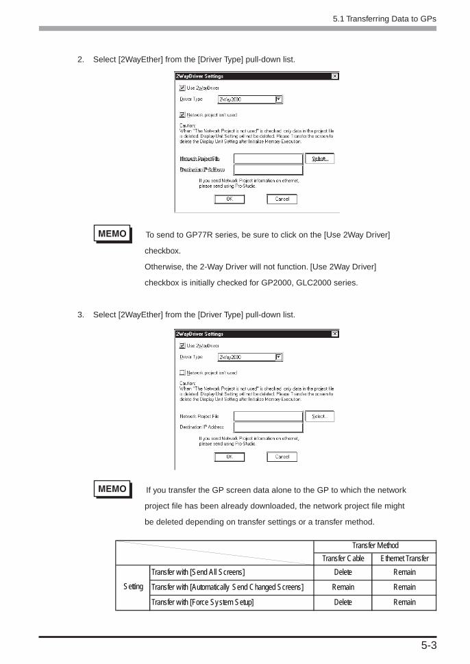
5-3
5.1 Transferring Data to GPs
2. Select [2WayEther] from the [Driver Type] pull-down list.
To send to GP77R series, be sure to click on the [Use 2Way Driver]
checkbox.
Otherwise, the 2-Way Driver will not function. [Use 2Way Driver]
checkbox is initially checked for GP2000, GLC2000 series.
3. Select [2WayEther] from the [Driver Type] pull-down list.
If you transfer the GP screen data alone to the GP to which the network
project file has been already downloaded, the network project file might
be deleted depending on transfer settings or a transfer method.
Transfer Cable Ethernet Transfer
Transfer with [Send All Screens] Delete Remain
Transfer with [Automatically Send Changed Screens] Remain Remain
Transfer with [Force System Setup] Delete Remain
Transfer Method
Setting

5-4
5.1 Transferring Data to GPs
4. Select the network project file and the network node to which you wish to transfer the informa-
tion and then click [OK].
5. Click [Send] on the Transfer menu or the Send Screen button to transfer the information to the GP.
6. The transfer is completed if no error message is displayed.
Send Screenbutton

66666 Tools
This chapter describes monitoring tools.
6.1 Device Monitoring
6.2 GP Status Monitoring
6.3 Read Performance Measuring Tool
6.4 Log Viewer

6-2
6.16.16.16.16.1 DeDeDeDeDevice Monitoringvice Monitoringvice Monitoringvice Monitoringvice Monitoring
Any selected device can be monitored via this feature, which allows you to check the status of data commu-
nication. Also, in the [Device Monitor] window, you can specify the IP and device addresses.
1. Click on the symbol name you want to monitor.
[Symbol (Item)]
The registered symbol names are listed here.
2. Click [Device Monitor] in the [Tools(T)] menu.
You can right-click the symbol to select [Device Monitor] from the shortcut menu.
6.1 Device Monitoring

6-3
3. You can be monitored via the device.
To change the polling time and the number of displayed decimal places, click [Polling Time].
You can type in the IP address or device address directly.
Reference → “On-line Help”
When monitoring Special Protocol symbols, the maximum number of symbols to be displayed on the
device monitor is restricted to “Maximum Number of Read” in the table below.
Writing is possible only to the head device, and the maximum write number is restricted to “Maximum
Number of Write” in the table below.
If you execute writes exceeding those maximum numbers, the warning dialog will appear.
6.1 Device Monitoring
Device Type to
Access
Bit Device
16 Bits Device
32 Bits Device
Format
Bit
Bit
16 bits
32 bits
Single precision
floating point
Double precisionfloating point
Character string
16 bits
32 bits
Single precisionfloating point
Double precisionfloating points
Character string
Maximum Number of
Read
255
255
255
127
127
63
510 (single byte)
255
255
255
127
1020 (single byte)
Maximum Number of
Write
1
1
40
20
20
10
80 (single byte)
1
40
40
20
160 (single byte)

6-4
The polling time set for collecting or writing data for each symbol, distrib-
uting data and monitoring devices may not be able to be performed under
certain conditions. These conditions include the currently registered num-
ber of GPs, number of Tags used on each screen sent, type of PLC con-
nection, and number of other currently open Windows applications. Enter-
ing “0” will allow the system to operate at its maximum speed. Please use
this value as a benchmark when entering other values to “fine-tune” your
system.
If you try to monitor non-existing devices, a communication error will be
displayed on the GP screen so that you should be careful about it.
• Setting the Display of Polling Time and Decimal places
Within the [Device Monitor] box, click [Polling Time].
Enter values for [Polling Time(ms)], [Integer places] and [Decimal places], and click [OK]. The
maximum value that can be entered for [Integer places] and [Decimal places] is 15.
For each item’s details, refer to Online Help.
Reference → “Online Help”
• Device Write Method
Double-click the desired section to enter device address data.
Enter the value. Pressing [Enter] will write the value to the device address, and the next device
address’s Write Dialog Box will appear.
Clicking [0] or [1] will write a value of 0 or 1 to the device address.
Writing address data with the [Address Hold] button pressed down will continue to write data
to the same address.
6.1 Device Monitoring

6-5
6.26.26.26.26.2 GP Status MonitoringGP Status MonitoringGP Status MonitoringGP Status MonitoringGP Status Monitoring
Here, you can monitor the status of any GP connected to the network.
1. Click the node you wish to monitor.
You can right-click the symbol to select [Status Monitor] from the shortcut menu.
2. Click [Status Monitor] in the [Tools(T)] menu.
6.2 GP Status Monitoring

6-6
3. Monitor the status of the GP. To change the polling time, click [Setting].
Click [Clear] to clear communication error codes of the selected node.
If you click [Clear], the following communication error codes will be cleared.
• PLC communication error code : LS2039
• PLC communication error code (for an extension) : LS2070
• 2-Way communication error code : LS2075
Reference →“A.2.2 2-Way Driver Error Messages and Syslog Features”
4. Set the polling time and then click [OK].
The polling time set for collecting or writing data for each symbol, distrib-
uting data and monitoring devices may not be able to be performed under
certain conditions. These conditions include the number of currently reg-
istered GPs, number of Tags used on each screen sent, type of PLC con-
nection, and number of other currently open Windows software. Entering
“0” will allow the system to operate at its maximum speed. Please use this
value as a benchmark when entering other values to “fine-tune” your system.
6.2 GP Status Monitoring

6-7
6.36.36.36.36.3 Read PRead PRead PRead PRead Perferferferferformance Measuring ormance Measuring ormance Measuring ormance Measuring ormance Measuring TTTTTooloolooloolool
This tool allows you to measure the data read performance from the designated node.
1. Click [Data Read Performance Measurement] on the [Tools (I)] bar of the Menu Bar.
2. The [Data Read Performance Measurement] dialog appears. After designating all items, click
[Begin].
[Node]
Select the node name. All entry node names have been registered. If unselected, the error dialog will
appear.
6.3 Read Performance Measuring Tool

6-8
[Device Address]
Enter the device address or the symbol name to start measuring. This is defaulted to “LS0000” (This will vary
depending on the PLC model). If not entered or entered an incorrect address, the error dialog will appear.
If you click the right-side icon, the [Device Address Entry] window appears and you can designate the
device address from this window.
[Number]
Enter [Number]. 255 has been set as default. The minimum number is 1, and the maximum number is
65535 although it changes depending on the device address and the access type.
If you designate Special Protcol symbols imported from the project file (*.prw) on GP-PRO/PB III for
Windows to device addresses, the maximum number to be read is restricted to the contents of the table
below.
If you designate values exceeding those maximum numbers, the warning dialog will appear.
6.3 Read Performance Measuring Tool
[Access Type]
Select the access type. This is defaulted to “16 Bit”.
[Read Type]
Designate the read type. This is defaulted to “Direct”.
[Time]
The measured read performance value after the execution is displayed.
3. The processing status of the read performance measuring is displayed in the [now] dialog.
Device Type to
Access
Bit Device
16 Bits Device
32 Bits Device
Format
Bit
Bit
16 bits
32 bits
Bit
32 bits
Maximum Number of
Read
255
255
255
127
255
255

6-9
If the contents set in the [Data Read Performance Measurement] dialog are incorrect, a dialog will
appear. The contents of dialog are as following.
4. The measured result is displayed in the [Time] field of the [Data Read Performance Measure-
ment] window.
[Time] may vary depending on the environmental condition (number of tags
on a screen, PLC connection style, application software running on Win-
dows at the same time and so on).
6.3 Read Performance Measuring Tool
Dialog Contents
Cannot designate a bit-type symbol to
measurement other than in the BIT format.
Cannot designate a symbol other than in
BIT to measurement in the BIT format.
Workaround
If you designated a BIT symbol in the
[Device Address] field, you cannot mea-
sure read time designating the access type
other than in Bit. Reset the access type to
“Bit”, and then execute measurement.
If you designated a symbol in formats
other than Bit in the [Device Address] field,
you cannot measure read time designating
the access type in Bit. Reset the access
type to something else but Bit, and then
execute measurement.

6-10
6.46.46.46.46.4 Log Log Log Log Log VieVieVieVieViewerwerwerwerwer
Pro-Server saves various information occurred during the operation in the internal log.
Log Viewer allows you to view internal log information saved by Pro-Server. Log Viewer can display Pro-
Server’s internal log information classifying it into 8 categories. You can also designate if you would like to
save or delete messages per internal log information category.
Log Viewer can display 500 messages at maximum. When the number of messages exceeds 500, the oldest
message will be deleted in turn.
Moreover, Log Viewer has online and offline modes.
The online mode displays the online log which is equal to the system log currently running real time.
The offline mode displays the log in the past saved by Log Viewer previously.
6.4.1 2Way Log Viewer
The following describes how to start Log Viewer and the display contents in the screen.
1. Right-click the icon in the right of the task tray, and then select [2Way Log Viewer].
6.4 Log Viewer

6-11
2. Log Viewer starts.
The following shows the name and the role of each part of the Log Viewer screen.
Displays the log level.
There are 8 kinds of the log level:
• SysMsg System message
• SysErr System error message
• Error Error messages of user-defined programs
• Start Starting messages of user-defined programs
• End Ending messages of user-defined programs
• Warning Warning messages of user-defined programs
• Message1 Detailed messages 1 of user-defined programs
• Message2 Detailed messages 2 of user-defined programs
Title Bar
Displays the name of the opened log file (*.2lg)
Menu Bar
Displays menus to operate Log Viewer. If you click those using a mouse, pull-down menus will be dis-
played.
Tool Bar
Displays icons of frequently used commands. If you click those icons, commands will be executed.
Status Bar
Displays messages for operations.
Title Bar
Menu Bar
Tool Bar
Displays datesand times whenlogs occurred.
Status Bar
Displays log messages. Actionnames designated on Pro-Studioare also displayed.
6.4 Log Viewer

6-12
6.4.2 Pull-Down Menu of Each Log Viewer Menu
The following describes the pull-down menu of each menu in the menu bar.
[File(F)] Menu
[Current Log (N)]
Displays the online log (currently running system log).
[Open(O)]
Selects and displays the previously saved log file (*.2lg).
[Save(S)]
Overwrites and saves to the currently opened log file (*.2lg).
[Save as(A)]
Saves as the new log file (*.2lg).
[Edit(V)] Menu
[Tool Bar(T)]
Designates ON/OFF of the tool bar. When it is displayed, the check mark is attached in front of [Tool
Bar(T)].
[Status Bar(S)]
Designates ON/OFF of the status bar. When it is displayed, the check mark is attached in front of
[Status Bar(T)].
6.4 Log Viewer

6-13
[Configure(S)] Menu
[Log]
If you click this, the [2Way Event Log Property] dialog will appear.
Select message kinds to be displayed on Log Viewer. Check messages names that you wish to display.
The following shows the contents per message.
If you check [When a message is remaining in the log, it is saved automatically to a file.], data will be
overwritten to the online log every time a new message occurs.
[Log Clear]
If you click this option, all contents of the online log will be deleted.
Message Kind
System Message
System Error
Application Error
Application Start
Application End
Application Warning
Application Message1
Application Message2
Contents
Indicates system messages for starting and shutting down the server.
Indicates system level errors (e.g. system fatal error).
Indicates action error messages.
Indicates action starting messages.
Indicates action ending messages.
Indicates action warning messages.
Indicates detailed action messages 1 (for debugging).
Indicates detailed action messages 2 (for debugging).
6.4 Log Viewer

6-14
6.4.3 Switching Between Online and Offline Modes
Log Viewer is started in the online mode. If you open the previously saved log (*.2lg), it will be switched to
the offline mode. New log messages occurred during the offline mode will remain in the online log.
1. Select [File(F)]-[Open(O)] from the menu bar.
2. The [Open] dialog box appears. Designate [File name:], and then click [Open].
3. Log Viewer switches to the offline mode, and the selected log file (*.2lg) will be displayed.
In the offline mode, the Log Viewer background becomes black.
To return to the online mode, select [File(F)]-[Current Log (N)] from the menu bar.
6.4 Log Viewer

77777 Data View
This chapter describes data sampling/viewing tools, “GP-Viewer” and “Device
View”.
7.1 Data View Overview
7.2 Device View
7.3 GP-Viewer
7.4 Checking the Data Sampling Status
7.5 System Time Bar

7-2
7.17.17.17.17.1 Data Data Data Data Data VieVieVieVieView Overw Overw Overw Overw Overvievievievieviewwwww
The [Data View(D)] menu of the menu bar allows you to start the tool to display data saved on Pro-Server in
various formats.
The following shows the overview of the display tool.
Device View
Device View allows you to sample data from devices connected to Ethernet to monitor the status or to
playback saved device data on Device View.
GP-Viewer
GP-Viewer allows you to sample screen data from the GP system connected to Ethernet to display
screen data or to playback saved GP data on GP-Viewer.
In addition to the above, you can also use the [Data Sampling Status] dialog showing the
data sampling status on Pro-Server or the tool such as System Time Bar applicable to user
created application software.
The frame structures of Device View, GP_ Viewer and the [Data Sampling Status] dialog differ
from other windows. The following shows the general view.
7.1 Data View Overview
Operation Description Window
Show/Hide Switching Bar
Operation Window
Time Bar Display Area(The display area size is fixedand you cannot change it.)

7-3
Following four files are created by Device View.
***.#DV............. Sampled device information (text format)
***.#DB ............. Sampling method information (text format)
***.#SR ............. Sampled device optimal information (text format)
***.#DR ............. Saved data (binary format)
When using Data View, the database accessed, even if it is only temporarily,
will be registered as a network project. If, during data polling the system
should go down, once the system is restored, simply restarting Pro-Server
will automatically restarts the data polling. (Polling data is saved in a file using
the same file extension as a Network Project file - NPJ_DBs.)
When Pro-Server is started, the Network Project’s registered databases are
read. As a result, if a large number of databases are registered, Pro-Server’s
startup will be slowed, and can result in the use of a large amount of system
resources. As a result, please be sure to delete any temporary databases that
are no longer used from the Network Project’s registry. To do this, open Pro-
Studio’s [DataView (D)] menu’s [Data Sampling Status] dialog box. Click on
the unneeded database names and press your PC keyboard’s [Delete] key.
Even though this deletes the database from the Network Project, the data-
base itself is not deleted. If needed, the database file can reopened by simply
re-registering it in the Network Project.
7.1 Data View Overview
You can only install the trial version of “GP-Viewer V1.1” from the “Pro-Server
with Pro-Studio for Windows Ver.4.5” CD-ROM. When a trial version of the GP-
Viewer software is used, the words “Trial Edition” will appear on the splash
screen. All the program’s features, however, are the same as the official
version.

7-4
7.27.27.27.27.2 DeDeDeDeDevice vice vice vice vice VieVieVieVieViewwwww
Device View allows you to sample data from devices connected to Ethernet to monitor the status or to
playback saved device data on Device View.
You can also view non-sequential devices or devices of multiple entry nodes at one time.
7.2.1 Setting Sampling Target Device
This section describes how to designate the device that you wish to sample data. After you completed the
setup, you can monitor data of the target device.
1. After selecting the entry node that you wish to sample data, click [Device View] on the [Data
View (D)] menu of the Menu Bar.
You can also right-click the entry node to select “Device View”.
7.2 Device View

7-5
2. The [Data sampling source] window appears. After designating each item for the device that
you wish to sample data, click [Next].
[Node Name]
Enter the node name to sample data. Node names registered in the network project file are displayed.
[Device Name]
Enter the device name to sample data. If you click [...], the symbol entry window appears.
[Device Type]
Designate the device model to sample data.
7.2 Device View

7-6
[Count]
Designate the number of sequential device from the device to sample. The maximum numbers to be
designated are shown in the following table below.
7.2 Device View
If you designate values exceeding those maximum numbers or if all devices within the restricted range
have not registered as Special Protocol symbols, the warning dialog will appear.
3. The [Data Input] window appears. Conditions that you have designated so far are displayed in
the window. You can also click and edit each item. If you have made a mistake, click [Back]. If
you do not have other devices to sample data, click [OK].
Device Type to
Access
Bit Device
16 Bits Device
32 Bits Device
Format
Bit
Bit
16 bits
32 bits
Single precision floating point
Double precision floating point
Character string
16 bits
32 bits
Single precision floating point
Double precision floating point
Character string
Maximum Number of
Device When
Designating Special
Protocol Symbols
255
255
255
127
127
63
510 (single byte)
255
255
255
127
1020 (single byte)
Maximum Number of
Device When Desig-
nating Other Device
255
255
255
255
255
255
510 (single byte)
255
255
255
255
1020 (single byte)

7-7
Be sure to connect to the GP system since the communication process will
start with the designated GP system when you click [OK].
[Append]
Use this button to append the device to sample data.
If you click this button, the [Append] dialog box (same as the [Data sampling source] dialog) will
appear so that you can designate devices to append.
[Delete]
Use this button to delete lines.
Select lines to delete and then click [Delete].
[Upper], [Lower]
Use these buttons to change the order of lines.
Select the line that you wish to change the order, and then click either [Upper] or [Lower].
If you designate Special Protcol symbols to [Device name] when you edit items directly in the [Data
Input] dialog, the maximum number of read that you can input in the “Number of Data” field will be
restricted to the contents of the table below.
7.2 Device View
If you designate values exceeding those maximum numbers, the warning dialog will appear.
Device Type to
Access
Bit Device
16 Bits Device
32 Bits Device
Format
Bit
Bit
16 bits
32 bits
Single precision floating point
Double precision floating point
Character string
16 bits
32 bits
Single precision floating point
Double precision floating points
Character string
Maximum Number of
Read
255
255
255
127
127
63
510 (single byte)
255
255
255
127
510 (single byte)

7-8
4. The selected device data is displayed on Device View.
The contents here displayed on Device View are device data at the moment
when you click [OK] in the procedure 3. This data is not updated.
7.2 Device View

7-9
7.2.2 Setting the Data Sampling Condition
This feature allows you to setup the data sampling condition from the sampling target device.
This section describes operations after you selected the sampling target device.
1. Click [Sampling] of Device View.
2. The following dialog appears. Click [Yes].
3. The [Save As] dialog appears, and you can create the file to save the sampled data. The file
extension is (.DB). After you designated the file name, click [Save].
7.2 Device View

7-10
4. The [Sampling method] dialog appears.
Check the “Sampling method” that you wish to execute.
The contents of the “Condition” field differ depending on the “Sampling method” selected. You should
perform the setting according to the contents displayed.
When You Selected “Regular Sampling” in “Sampling method” :
The setup contents are as the following. You should designate [Data sampling in specified seconds]
and [Sampling using cache] in the “Condition” field.
[Data Sampling in specified seconds]
Designate the device data capturing interval in second. This is defaulted to “1 second”.
[Sampling using cache]
Check this box to use the cache to sample device data.
7.2 Device View

7-11
When You Selected “Periodic Sampling” in “Sampling method” :
The following settings are available. You should create the periodical sampling schedule using the
[Append], the [Delete], and the [Edit] buttons in the “Condition” field.
[Delete]
After selecting unnecessary schedules, click [Delete] to delete selected schedules.
[Append]
Click this button to create the new sampling schedule.
If you click the [Append] button, the [Designate the data sampling date] dialog appears. Designate
each item in the [Designate the data sampling date] dialog, and then click [Next].
[Date]
Designate the date to sample device data. Device data are sampled on the day designated here.
7.2 Device View

7-12
[Week]
Designate a day of a week to sample device data. Check the day that you wish to sample device data.
You can also click [Everyday] (Fri), [Weekday] (Mon, Tue, Wed, Thu, Fri) or [Holiday] (Sat, Sun)
under the day check boxes.
[Month]
Designate a day of a month to sample device data. You can designate either a particular day (one day)
or the last day every month. Device data are sampled on the day designated here every month.
If you click [Next], the [Designate the sampling time] dialog appears. Designate each item in the
[Designate the sampling time] dialog, and then click [OK].
[Append] allows you to create the new sampling schedule and it will be displayed in the schedule field.
[Start Time]
Designate the time to start capturing device data. The sampling will start at the time designated here.
[Sampling count]
If you wish to sample device data once, check [One time only].
If you wish to repeat device data sampling, designate the sampling condition. You should designate the
sampling interval and the number of sampling.
[Edit]
Click this button to change the contents of the selected schedule.
7.2 Device View

7-13
When You Selected “Sampling data after change in device” in “Sampling method”:
The contents of the “Condition” field are as the following. You should designate [Sampling Condi-
tion], [Interval Condition], and [Data sampling - from start to finish of data reception] in the “Condi-
tion” field.
[Sampling Condition]
Designate the timing to sample device data. You should designate the node name that you wish to
perform a sampling, the target device name, the device model, and the device change condition.
[Interval Condition]
Designate intervals to check the device change and to sample data when the status changed.
[Data sampling - from start to finish of data reception]
Designate the intervals to save data “before and after” the device change occurred and the sampling
condition was satisfied. Intervals designated here should be longer than the sampling interval.
7.2 Device View

7-14
When You Selected “Sampling data when PC was distributed” in “Sampling method”:
Sampling is executed when PC where Pro-Server to sample data runs is distributed.
The contents of the “Condition” field are as the following.
[Provide Sheet]
If pre-defined Provider information setups exist, select it from the pull-down list.
Be sure to set the [Provide Information] interval to 1000ms or longer.
[Sampling using cache]
Check this box to use the cache to sample device data.
[Data Sampling – from start to finish of data reception]
Designate the sampling method “before and after” receiving the Provider information. You should
designate sampling times “before” and “after” receiving (in second), and the sampling interval (in
second).
7.2 Device View

7-15
5. Designate each item in the “Polling data file” field of the [Sampling method] dialog, and then
click [OK].
[Change]
Use this button to change the folder used to save sampled data.
[Saving Method]
If you click this button, the [Saving Method] dialog appears. Designate each item in the [Saving
Method] dialog, and then click [OK].
[Designate the maximum size of data (file) to be stored]
Designate the folder to save sampled data. You should designate the total volume (size) of data to save
among “No maximum size is designated (as much as storage media allows)”, “Designate maximum
size” and “Periodic saving”.
7.2 Device View

7-16
If you selected “Designate maximum size”, you should also designate the maximum data size (in
MByte) and the sampling method.
- Selecting “Continuous numbering for new files”
When the maximum allowed size is exceeded, the following new file is created:
****.[Sequence number]. #DT ABCD.0.#DT -> ABCD.1.#DT
- Selecting “Save over oldest data”
The oldest Polling data is overwritten when the maximum allowed size is exceeded.
- Selecting “Do not save files after size limit reached”
When the maximum allowed size is exceeded, Polling is stopped and an error message appears.
If you selected “Periodic saving”, you should also designate the interval to upload the files.
6. Execute the device data sampling.
If you wish to test the sampling, click button. The sampling process starts and the contents
are displayed on Device View. The sampled data are not saved at this time.
If you wish to sample data once, click button. Data are sampled and saved every time you
click the button regardless of the designated data sampling condition. If you wish to sample
data according to the designated data sampling condition, click the button. The data
“Sample & Save” is executed according to the data sampling condition, and the contents are displayed
on Device View. The display contents are updated according to the data change.
When you start the device data sampling, various buttons for viewing sampled data are appended on
Device View.
Refer to “7.2.5 Playback Feature” for the viewing method of sampled device data.
Reference → “7.2.5 Playback Feature”
7.2 Device View

7-17
When gathering data, clicking the icon, or selecting the [File | Show/Hide Time Bar] menu
item allows you to set the Time Bar as “Show” or “Hide”. The System Time Bar is not displayed when
[Device View] starts up. It is displayed, however, after “Sampling” operation is performed. Show/Hide
status data is contained in the #DV file.
7.2 Device View

7-18
7.2.3 Editing Sampled Data
This feature allows you to edit saved device data.
1. Click [Data Edit] of Device View.
2. The [Data Edit] dialog appears. You can edit data in various methods. The following part
describes the major operation method after the [Data Edit] dialog appeared.
Although you can start multiple Device View windows, you cannot edit
data simultaneously.
7.2 Device View

7-19
Appending Sampled Data
1. Click [Append] of the [Data Edit] dialog.
2. The next dialog appears. Designate each item about the device that you wish to append, and
then click [OK]. Items are equal to those in the [Data sampling source] dialog.
Reference → “7.2.1 Setting Sampling Target Device”
3. The device data that you wish to append are displayed in the [Data Edit] dialog.
Deleting Sampled Data
1. Select the data that you wish to delete in the [Data Edit] dialog.
2. Click [Delete]. The selected data will be deleted.
Searching Sampled Data
1. Click [Search] in the [Data Edit] dialog.
2. The [Search] dialog appears. Enter the date that you wish to search, and then click [OK].
3. The display contents are updated and data are displayed showing one closest to the date
entered in the middle.
7.2 Device View

7-20
Editing Data Source
1. Click the data source field that you wish to edit. The column including the selected field is
highlighted so that you can enter data from the keyboard in the selected field. The pull-down
list may appear depending on the selected item.
2. Enter the new contents from the keyboard. The contents of the selected field are updated.
Data cannot be edited during Polling.
Editing Saved Data
1. Click [Edit] of the [Data Edit] dialog.
2. The [Edit] button in the [Data Edit] dialog is dimmed, and the [Delete Record] button appears.
3. Select the data that you wish to delete, and then click [Delete Record]. The selected data will
be deleted.
Click on [OK] to set the selections made in [Edit] and/or [Delete Record].
Click on [Cancel] to delete all current selections.
7.2 Device View

7-21
7.2.4 Option
This feature allows you to change the display format of the data display area in Device View.
1. Click [Option] of Device View.
2. The [Option] dialog appears. You can change the display contents or format of the data
display area in various methods. The following part describes the major operation method
after the [Option] dialog appeared.
7.2 Device View

7-22
Setting a Line
1. Click the [Line setting] tab in the [Option] dialog.
2. Items on the [Line setting] tab appear. Designate each item in the [Line Style] field, and then
click [OK].
[Line]
Select the ruled line that you wish to use among 6 styles. Also designate the thickness of the ruled line.
The unit is point and it is defaulted to 1 point.
[Color]
Select the ruled line color among 16 colors. If you do not find one that you wish to use among those,
click [Other]. The [Color Setup] dialog appears so that you can select or create the color that you wish
to use.
Setting a Character
1. Click the [Character Setting] tab in the [Option] dialog.
2. Items on the [Character Setting] tab appear. Designate each item, and then click [OK].
7.2 Device View

7-23
[Select]
Select which texts you wish to change, “Title” texts on the top or “Data” texts.
[Foreground color]
Select the text color among 16 colors. If you do not find the color that you wish to use among those,
click the [Other] button. The [Color Setup] dialog appears so that you can select or create the color
that you wish to use.
[Background color]
Select the background color among 16 colors. If you do not find the color that you wish to use among
those, click the [Other] button. The [Edit Color] dialog appears so that you can select or create the
color that you wish to use.
[Font]
Select the font that you wish to use. Click [Font]. The [Font] dialog appears. Designate each item
such as the “font to use”, the “font style”, the “font size” and the “type”, and then click [OK].
[Row height]
Designate the row height of the data display area. The unit is “point” and it is defaulted to 3 points.
7.2 Device View

7-24
Setting the Display Contents
1. Click the [Display Setting] tab in the [Option] dialog.
2. Items on the [Display Setting] tab appear. Designate each item, and then click [OK].
[Display Parameter]
Select parameters that you wish to display in the data display area. Check each item that you wish to
display. The following describes the overview of each item.
Item name: Designated symbol name.
Node name: Designated node name.
Device name: Designated device name.
Value: The latest data.
Data Type: Designated device data type.
Item Status: (reserved)
Error Code: Error code when an error occurred in sampling. (normaly 0)
Data number: (reserved)
Upper Limit: The upper limit value to display the graph. (Even if you designate a greater
value than this, the graph remains in the 100% status.)
Alarm Upper Limit: The alarm upper limit value to display the graph. (including this value)
Alarm Lower Limit: The alarm lower limit value to display the graph. (including this value)
Lower Limit: The lower limit value to display the graph. (If you designate a less value than
this, the graph will not be displayed.)
Graph: The horizontal bar graph is displayed according to values of “Upper Limit”,
“Alarm Upper Limit”, “Alarm Lower Limit” and “Lower Limit”.
7.2 Device View

7-25
[Line count per page]
Designate the number of data lines per page that you wish to display in the data display area. If the
actual number of data exceeds the number of data per page, the [Previous] and the [Next] buttons are
displayed in the left and the right sides under the data display area respectively. You can switch pages
using these buttons.
Setting the Graph Color
1. Click [Graph Setting] tab in the [Option] dialog.
2. Items in the [Graph Setting] tab appear. Designate each item, and then click [OK].
[Normal color]
Select the normal graph color among 16 colors. If you do not find the color that you wish to use
among those, click the [Other] button. The [Color Setup] dialog appears so that you can select or
create the color that you wish to use.
[Warning color]
Select the warning graph color among 16 colors. If you do not find the color that you wish to use
among those, click the [Other] button. The [Edit Color] dialog appears so that you can select or create
the color that you wish to use.
7.2 Device View

7-26
7.2.5 Playback Feature
This feature allows you to playback sampled device data on Device View.
1. Select [Open Data View (O)] on [Data View (D)] of the menu bar.
2. The [Open] dialog appears. Select the device data (.#DV) that you wish to playback, and then
click [Open].
You can also playback data in the saving process.
7.2 Device View

7-27
3. The contents of device data that you wish to playback are displayed on Device View. You can
playback device data using various buttons on Device View.
[Saved Time]
This field shows the saved time of the saved device data.
The field shows, from the left, the saving start time, the time for currently displayed data and the last
saved time. When the current status is displayed, the time for currently displayed data is identical to
the last saved time.
[Time Bar]
Saved data can be displayed by sliding the time bar control to either side. The data saving process
continues even while you operate the control.
[Time Setup]
You can designate the time unit for one graduation of the time bar.
[Now/Play Display Switch]
[Now] and [Play] buttons are available. You can playback the saved data from the designated time
either by sliding the time bar control to the time that you wish to start the playback or by clicking the
[Play] button after clicking the time for currently displayed data (the center field of [Saved Time]) and
then entering the time to start the playback.
7.2 Device View
Saved Time
Time Bar
Now/Play Display Switch
Time Setup

7-28
7.2.6 Other Features
This section describes the File menu and options of Device View.
1. If you click [File (F)] of Device View, 9 options are available. The following describes the
overview of each option.
Exporting Data
1. Select [Data Export] on the [File(F)] menu.
2. The [Export] dialog appears. Designate each item, and then click [Export].
[Export File Name]
Designate the location and the file name to save exported data. The file extension is (.CSV).
7.2 Device View

7-29
[Start Time]
Designate the time to start exporting data. To export Polling data immediately, click on the [The First]
checkbox. To export Polling data after a specific period of time elapses, click on the [Specified Time]
checkbox. If you checked “Specified Time”, you should also designate the start time to export.
[End Time]
Designate the time to end exporting data. To wait until all data is polled before exporting, click on the
[The End] checkbox. To export Polling data after a specific period of time elapses, click on the
[Specified Time] checkbox. If you checked “Specified Time”, you should also designate the end time
to export.
[Device Condition]
This is the reserved data. You should not change the designated value.
[Export Header]
If you wish to include the header information in exported data, check “Yes”. If not, check “No”.
[Export]
Executes the data export.
[Cancel]
The process is stopped and goes back to Device View.
• Although you can start multiple Device View programs, you cannot export
data simultaneously.
• Data can be exported during Polling. However, if the [Designate maximum
size/Save over oldest data] selection is used, data export cannot be
performed.
Saving Data
1. If you wish to save displayed data on Device View, click [Save (S)] on the [File (F)] menu.
Data are overwritten.
If you wish to save displayed data on Device View as a separate file name, click [Save As (A)] on the
[File (F)] menu. The [Save As] dialog appears. Enter the file name, and then click [Save].
1. Click [Print] on the [File (F)] menu. The printing process is executed.
7.2 Device View

7-30
Page Setup
1. Click [Page setup(P)] on the [File (F)] menu.
2. The [Print Setup] dialog appears. Designate each item, and then click [OK].
The contents of the [Page setup] dialog differ depending on your printer.
Refer to the user manual of your printer for details.
Preview
1. Click [Preview] on the [File (F)] menu.
2. The print preview appears.
Copy to Clipboard
1. Click [Copy to Clipboard] on the [File (F)] menu.
2. The data value displayed on Device View is copied into the clipboard.
3. Paste the data value onto the application used.
You can only copy data in the data display area of Device View into the
clipboard. You cannot copy data such as a title.
Show / Hide Time Bar
1. Clicking [File | Show/Hide Time Bar] enables setting the System Time Bar to “Show” or “Hide”
mode.
Exit
1. Click [Exit(X)] on the [File (F)] menu. Exits Device View.
7.2 Device View

7-31
Option
This is selected on [Data View (D)] of the menu bar.
1. Select [Option] on [Data View (D)] of the menu bar.
2. The [Data View Options] dialog appears.
You can select “Show/Hide” of the setup menu and the save button.
If you uncheck “Display menu”, the [Option], the [Data Edit], and the [Sampling] menus are hidden on
Device View.
If you uncheck “Display button” , , , buttons are hidden on
Device View.
7.2 Device View

7-32
7.37.37.37.37.3 GP-VieGP-VieGP-VieGP-VieGP-Viewerwerwerwerwer
GP-Viewer allows you to sample screen data from the GP system connected to Ethernet to display screen
data or to playback saved GP data on GP-Viewer.
If you install Pro-Server V4.5 while GP-Viewer V1.0 remains on PC, a problem will occur when you
reinstall GP-Viewer. Be sure to install Pro-Server V4.5 after uninstalling GP-Viewer V1.0 and Pro-Server
with Pro-Studio of any older versions.
7.3.1 Starting GP-Viewer
When you start GP-Viewer, screens on the GP system are displayed on the GP-Viewer browser in real time.
1. After selecting the entry node to use GP-Viewer, select [GP-Viewer] on [Data View (D)] of the
menu bar.
• You should make sure to connect to the GP system because the commu-
nication process will start when you click [GP-Viewer].
• You can upload the connected GP screen on GP77R SERIES, however,
the GP system is reset once. If your model does not support the online
uploading function, the warning window appears.
• If the password protection has been set to the GP screen, the password
entry dialog appears.
7.3 GP-Viewer

7-33
• The GP-Viewer screen refresh period is set via Pro-Studio’s -> [Config-
ure] -> [System] -> [DDE Polling Time] dialog box (Default: 1000ms). If the
GP-Viewer’s screen refresh time becomes too slow, increasing the [DDE
Polling Time] value will speed it up.
2. While the upload process from the GP system is running, the following dialog appears. The
dialog will disappear when the upload process is completed.
3. The selected GP screen data are displayed on GP-Viewer.
• Data have been monitored but not been saved at this stage.
• If the selected GP’s screen size is smaller than the GP-Viewer’s default
window size, a portion of the GP-Viewer window may be blank. (GP2300,
etc.)
7.3 GP-Viewer

7-34
7.3.2 Setting the Data Sampling Condition
This feature allows you to set the data sampling condition from the target device.
The following part describes the procedure after GP-Viewer is started.
1. Click [Sampling] of GP-Viewer.
If the selected GP’s screen size is smaller than the GP-Viewer’s default
window size, a portion of the GP-Viewer window may be blank. (GP2300, etc.)
2. The next dialog appears. Click [Yes].
3. The [Save As] dialog appears so that you can create the file to save sampled data. The file
extension is (.DB). Designate the file name, and then click [Save].
7.3 GP-Viewer

7-35
4. The [Sampling method] dialog appears.
Check the desired “Sampling Method”.
The contents of the “Condition” field differ depending on the “Sampling method” selected. You should
perform the setting according to the contents displayed.
When You Selected “Regular Sampling” on “Sampling method”:
The setup contents are as the following. You should designate [Data Sampling in specified seconds] and
[Sampling using cache] in the “Condition” field.
[Data Sampling in specified seconds]
Designate the device data capturing interval in second. This is defaulted to “1 second”.
[Sampling using cache]
Check this box to use the cache to sample device data.
7.3 GP-Viewer

7-36
When You Selected “Periodic Sampling” in “Sampling method” :
The setup contents are as the following. You should create the periodical sampling schedule using the
[Append], the [Delete], and the [Edit] buttons in the “Condition” field.
[Delete]
After selecting unnecessary schedules, click [Delete] to delete selected schedules.
[Append], [Edit]
Click these buttons to append or to edit the sampling schedule.
If you click either the [Append] button, the [Designate the data sampling date] dialog appears. Desig-
nate each item in the [Designate the data sampling date] dialog, and then click [Next].
7.3 GP-Viewer

7-37
[Date]
Designate the date to sample device data. Device data are sampled on the day designated here.
[Week]
Designate a day of a week to sample device data. Check the day that you wish to sample device data.
You can also click [Everyday] (Fri), [Weekday] (Mon, Tue, Wed, Thu, Fri) or [Weekend] (Sat, Sun)
under the day check boxes.
[Month]
Designate a day of a month to sample device data. You can designate either a particular day (one day)
or the last day every month. Device data are sampled on the day designated here every month.
If you click [Next], the [Designate the sampling time] dialog appears. Designate each item in
the [Designate the sampling time] dialog, and then click [OK].
[Append] allows you to create the new sampling schedule and it will be displayed in the schedule field.
[Edit] allows you to change the contents of the selected schedule.
[Start Time]
Designate the time to start capturing device data. The sampling will start at the time designated here.
[Sampling count]
If you wish to sample device data once, check [One time only].
If you wish to repeat device data sampling, designate the sampling condition. You should designate the
sampling interval and the number of sampling.
[Edit]
Click this button to change the contents of the selected schedule.
7.3 GP-Viewer

7-38
When You Selected “Sampling data after change in device” in “Sampling method” :
The contents of the “Condition” field are as the following. You should designate [Sampling Condition],
[Interval Condition], and [Data sampling - from start to finish of data reception] in the “Condition” field.
[Sampling Condition]
Designate the timing to sample device data. You should designate the node name that you wish to
perform a sampling, the target device name, the device model, and the device change condition.
[Interval Condition]
Designate intervals to check the device change and to sample data when the status changed.
[Data sampling - from start to finish of data reception]
Designate the intervals to save data “before and after” the device change occurred and the sampling
condition was satisfied. Intervals designated here should be longer than the sampling interval.
7.3 GP-Viewer

7-39
When You Selected “Sampling data when PC was distributed” in “Sampling method” :
The contents of the “Condition” field are as the following. You should enter the Provider information setup
name in [Provider Sheet] of the “Condition” field, and then click [Provider Data Registration] to designate
the new Provider information setup. If you have already designated Provider information setups, you can
select it from the pull-down list.
[Provide Sheet]
If pre-defined Provider information setups exist, select it from the pull-down list. If it does not exist,
you should enter the name.
Be sure to set the [Provide Information] interval to 1000ms or longer.
[Sampling using cache]
Check this box to use the cache to sample device data.
[Data sampling - from start to finish of data reception]
Designate the sampling method “before and after” receiving the Provider information. You should
designate sampling times “before” and “after” receiving (in second), and the sampling interval (in
second).
7.3 GP-Viewer

7-40
5. Designate each item in the “Polling data file” field of the [Sampling method] dialog, and then
click [OK].
[Change]
Use this button to change the folder to save sampled data.
[Saving Method]
If you click this button, the [Saving Method] dialog appears. Designate each item in the [Saving
Method] dialog, and then click [OK].
7.3 GP-Viewer

7-41
[Designate the maximum size of data (file) to be stored]
Designate the folder to save sampled data. You should designate the total volume (size) of data to save
among “No maximum size is designated (as much as storage media allows)”, “Designate maximum
size” and “Periodic saving”.
If you selected “Designate maximum size”, you should also designate the maximum data size (in
MByte) and the sampling method.
- Selecting “Continuous numbering for new files”
When the maximum allowed size is exceeded, the following new file is created:
****.[Sequence number]. #DT ABCD.0.#DT -> ABCD.1.#DT
- Selecting “Save over oldest data”
The oldest Polling data is overwritten when the maximum allowed size is exceeded.
- Selecting “Do not save files after size limit reached”
When the maximum allowed size is exceeded, Polling is stopped and an error message appears.
If you selected “Periodic saving”, you should also designate the interval to upload the files.
6. Execute the device data sampling.
To perform sampling registration for GP display screens, click the button.
To poll sample registered device data, click the button.
If you wish to sample data according to the designated data sampling condition, click the
button. The data “Sample & Save” is executed according to the data sampling condition, and the
contents are displayed on GP-Viewer. The display contents are updated according to the data change.
When you start the device data sampling, various buttons for viewing sampled data are appended on
GP-Viewer.
Refer to “7.3.5 Playback Feature” for the viewing method of sampled device data.
Reference → “7.3.5 Playback Feature”
7.3 GP-Viewer

7-42
When gathering data, clicking the icon, or selecting the [File | Show/Hide Time Bar] menu
item allows you to set the Time Bar as “Show” or “Hide”. The System Time Bar is not displayed when
[GP-Viewer] starts up. It is displayed, however, after “Sampling” operation is performed. Show/Hide
status data is contained in the #DV file.
7.3 GP-Viewer

7-43
7.3.3 Editing Sampled Data
This feature allows you to edit sampled device data.
1. Click [Data Edit] of GP-Viewer.
2. The [Data Edit] dialog appears. You can edit data in various methods. The following part
describes the major operation method after the [Data Edit] dialog appeared.
7.3 GP-Viewer

7-44
Appending Sampled Data
1. Click [Append] of the [Data Edit] dialog.
2. The next dialog appears. Designate each item about the device that you wish to append, and
then click [OK]. Items are equal to those in the [Data sampling source] dialog.
Reference → “7.2.1 Setting Sampling Target Device”
3. The device data that you wish to append are displayed in the [Data Edit] dialog.
Deleting Sampled Data
1. Select the data that you wish to delete in the [Data Edit] dialog.
2. Click [Delete]. The selected data will be deleted.
Searching Sampled Data
1. Click [Search] in the [Data Edit] dialog.
2. The [Search] dialog appears. Enter the date that you wish to search, and then click [OK].
3. The display contents are updated and data are displayed showing one closest to the date
entered in the middle.
7.3 GP-Viewer

7-45
Editing Data Source
1. Click the data source field that you wish to edit. The column including the selected field is
highlighted so that you can enter data from the keyboard in the selected field. The pull-down
list may appear depending on the selected item.
2. Enter the new contents from the keyboard. The contents of the selected field are updated.
Data cannot be edited during Polling.
Editing Saved Data
1. Click [Edit] of the [Data Edit] dialog.
2. The [Edit] button in the [Data Edit] dialog is highlighted, and the [Delete Record] button
appears.
3. Select the data that you wish to delete, and then click [Delete Record]. The selected data will
be deleted.
Click on [OK] to set the selections made in [Edit] and/or [Delete Record].
Click on [Cancel] to delete all current selections.
7.3 GP-Viewer

7-46
7.3.4 Setting Drawing
This feature allows you to change the display format of the data display area in GP-Viewer.
1. Click [Option] of GP-Viewer.
2. The [Wizard] dialog appears. Perform required settings, and then click [Option] of GP-Viewer
to close the dialog.
7.3 GP-Viewer

7-47
[Synchronous Mode]
You can designate the synchronization style between GP screens and GP-Viewer. There are 3 synchro-
nous modes available, Full Synchronous, GP Synchronous and Asynchronous. The following de-
scribes the detail of each style.
[Screen No]
This feature allows you to change the displayed screen of GP-Viewer according to screen numbers pre-
defined on the GP system.
If you click [Previous], the previous screen from the currently displayed screen is displayed and the
value in the “Screen No” field is deceased by one.
If you click [Next], the next screen from the currently displayed screen is displayed and the value in the
“Screen No” field is increased by one.
If you enter the screen number that you wish to display in the “Screen No” field and click [Set], the
corresponding screen to the number entered is displayed.
• The screen switching feature of GP-Viewer is effective only when the
synchronous mode is either “Asynchronous” or “Full Synchronous”.
• You cannot normally switch screens by GP-Viewer from upper-level PCs.
You should set the bit “4” of GP’s LS2076 to “ON (1)” to switch screens in the
“Full Synchronous” mode from upper-level PCs.
[Refresh Screen Data]
If you changed the GP screen contents, click [Refresh Screen Data]. GP-Viewer re-captures the setup
contents of the GP system.
7.3 GP-Viewer
Asynchronous
(Async)
GP Synchronous
(GP Sync)
Full Synchronous
(Full Sync)
Screens can be switched on GP-Viewer. Switching a screen on GP-
Viewer does not synchronize with a screen on the GP system.
Screens cannot be switched on GP-Viewer. Switching a screen on the GP
system synchronizes with a screen on GP-Viewer. (This is the default
setting.)
Screens can be switched on GP-Viewer. Switching a screen on GP-
Viewer synchronizes with a screen on the GP system and vice versa.

7-48
7.3.5 Playback Feature
This feature allows you to playback sampled device data on GP-Viewer.
1. Select [Open Data View (O)] on [Data View (D)] of the menu bar.
2. The [Open] dialog appears. Select the device data (.#DV) that you wish to playback, and then
click [Open].
You can also playback data in the saving process.
7.3 GP-Viewer

7-49
3. The contents of sampled data are displayed on GP-Viewer. You can playback saved data
using various buttons on GP-Viewer.
[Saved Time]
This field shows the saved time of the saved device data.
The field shows, from the left, the saving start time, the time for currently displayed data and the last
saved time. When the current status is displayed, the time for currently displayed data is identical to
the last saved time.
[Time Bar]
Saved data can be displayed by sliding the time bar control to either side. The data saving process
continues even while you operate the control.
[Time Setup]
You can designate the time unit for one graduation of the time bar.
[Now/Play Display Switch]
[Now] and [Play] buttons are available. You can playback the saved data from the designated time
either by sliding the time bar control to the time that you wish to start the playback or by clicking the
[Play] button after clicking the time for currently displayed data (the center field of [Saved Time]) and
then entering the time to start the playback.
7.3 GP-Viewer
Now/Play Display Switch
Saved Time
Time Bar
Time Setup

7-50
7.3.6 Other Features
This section describes the File menu and options of GP-Viewer.
1. If you click [File (F)] of GP-Viewer, 9 options are available. The following describes the
overview of each option.
Exporting Data
1. Select [Data Export] on the [File (F)] menu.
2. The [Export] dialog appears. Designate each item, and then click [Export].
[Export File Name]
Designate the location and the file name to save exported data. The file extension is (.CSV).
7.3 GP-Viewer

7-51
[Start Time]
Designate the time to start exporting data. If you wish to start exporting immediately after you clicked
[Export], check “The First”. If you wish to start exporting at the designated time, check “Specified
Time”. If you checked “Specified Time”, you should also designate the start time to export.
[End Time]
Designate the time to end exporting data. If you wish to export the entire sampled data, check “The
End”. If you wish to export until the designated time, check “Specified Time”. If you checked
“Specified Time”, you should also designate the end time to export.
[Device Condition]
This is the reserved data. You should not change the designated value.
[Export Header]
If you wish to include the header information in exported data, check “Yes”. If not, check “No”.
[Export]
Executes the data export.
[Cancel]
The process is stopped and goes back to GP-Viewer.
• Although you can start multiple GP-Viewer programs, you cannot export
data simultaneously.
• You can export data even while storing data. However, if you checked
[Designate maximum size/Save over oldest data] in the [Saving Method]
dialog, you cannot export while storing data.
Saving Data
1. If you wish to save displayed data to GP-Viewer, click [Save (S)] on the [File (F)] menu. Data
are overwritten.
If you wish to save displayed data to GP-Viewer as a separate file name, click [Save As (A)] in the [File
(F)] menu. The [Save As] dialog appears. Enter the file name, and then click [Save (S)].
1. Click [Print] on the [File (F)] menu. The printing process is performed.
7.3 GP-Viewer

7-52
Page Setup
1. Click [Page Setup(P)] in the [File (F)] menu.
2. The [Print Setup] dialog appears. Designate each item, and then click [OK].
The contents of the [Page Setup] dialog differ depending on your printer.
Refer to the user manual of your printer for details.
Preview
1. Click [Preview] in the [File (F)] menu.
2. The print preview appears.
Copy to Clipboard
1. Click [Copy to Clipboard] in the [File (F)] menu.
2. The data value displayed on GP-Viewer is copied into the clipboard.
3. Paste the data value onto the application used.
You can only copy data in the data display area of GP-Viewer into the
clipboard. You cannot copy data such as a title.
Show / Hide Time Bar
1. Clicking [File | Show/Hide Time Bar] enables setting the System Time Bar to “Show” or “Hide”
mode.
Exit
1. Click [Exit(X)] in the [File (F)] menu. Exits GP-Viewer.
7.3 GP-Viewer

7-53
Options
This is selected on [Data View (D)] of the menu bar.
1. Select [Option] on [Data View (D)] of the menu bar.
2. The [DataView Option] dialog appears.
You can select “Show/Hide” of the setup menu and the save button.
If you uncheck “Display menu”, the [Option], the [Data Edit], and the [Sampling] menus are hidden on
GP-Viewer.
If you uncheck “Display button”, , , , buttons are hidden on
GP-Viewer.
7.3 GP-Viewer

7-54
SupporSupporSupporSupporSupported Drated Drated Drated Drated Drawing Commandswing Commandswing Commandswing Commandswing Commands
Among GP-PRO/PBIII drawing commands, the following commands are supported by GP-Viewer.
Only the following drawing features are function properly.
• line/poly-line command
• rectangle command
• circle/ellipse command
• arc/sector command
• polygon fill command
• ruler command
• text string command
• mark call-up command
Among these drawing commands, there are some functions not available with GP-Viewer. Functions
available and not available with GP-Viewer are listed below for each drawing command.
The display may differ between GP and GP-Viewer even if drawing commands are supported.
Yes
Yes
No
No
Yes
Yes
No
Yes
Yes
No
No
Yes
No
Yes
Yes
Yes
No
7.3 GP-Viewer
Line/Poly-line Commandspecifying a display color
blinking a display color
specifying a background color
blinking a background color
drawing an arrow
drawing a solid line
drawing a dotted line
Rectangle Commandspecifying a display color
blinking a display color
specifying a background color
blinking a background color
drawing a solid line
drawing a dotted line
chamfering
specifying the number of dots in chamfering
solid fill pattern
fill patterns except for a solid fill

7-55
Yes
Yes
No
No
Yes
No
Yes
No
Yes
Yes
No
No
Yes
No
Yes
Yes
No
No
Yes
No
Yes
No
Yes
Yes
No
No
Yes
No
Yes
Yes
7.3 GP-Viewer
Circle/Ellipse Commandspecifying a display color
blinking a display color
specifying a background color
blinking a background color
drawing a solid line
drawing a dotted line
solid fill pattern
fill patterns except for a solid fill
Arc/Sector Commandspecifying a display color
blinking a display color
specifying a background color
blinking a background color
drawing a solid line
drawing a dotted line
Polygon Fill Commandspecifying a display color
blinking a display color
specifying a background color
blinking a background color
drawing a solid line
drawing a dotted line
solid fill pattern
fill patterns except for a solid fill
Ruler Commandspecifying a display color
blinking a display color
specifying a background color
blinking a background color
drawing a solid line
drawing a dotted line
ruler type
number of graduations to be divided

7-56
7.3 GP-Viewer
Yes
Yes
Yes
Yes
Yes
Yes
Yes
Yes
Yes
Yes
No
Yes
Yes
Yes
Yes
Yes
Text String Commandspecifying a display color
blinking a display color
specifying a background color
blinking a background color
specifying a shade color of a carving style
blinking a shade color of a carving style
text direction
text style
text size
text rotation angle
text font
Mark Call-up Commandspecifying a display color
blinking a display color
specifying a background color
blinking a background color
specifying a mark size

7-57
SupporSupporSupporSupporSupported ted ted ted ted TTTTTaaaaag Commandsg Commandsg Commandsg Commandsg Commands
The following GP-PRO/PBIII tag commands are supported by GP-Viewer.
Only the following tags are supported.
• C tag
• E tag
• F tag
• G tag
• K tag
• L tag
• M tag
• N tag
• S tag
• T tag
• U tag
Among these tag commands, there are some features not available with GP-Viewer. Refer to the following
list for each tag command.
The display may differ for GP and for your GP-Viewer even if drawing commands are supported.
Yes
Yes
Yes
Yes
Yes
Yes
Yes
Yes
Yes
Yes
Yes
Yes
No
Yes
Yes
Yes
Yes
Yes
Yes
Yes
Yes
Yes
7.3 GP-Viewer
C Tagcharacter size
specifying a display color
blinking a display color
specifying display rotation
specifying a tiling pattern
specifying a background color
character size (full/half)
specifying a background color at tiling
E Tagspecifying data (absolute/relative)
specifying a sign
rounding off numbers
specifying a display data form
specifying display address (indirect)
bit length when [relative] is selected
input sign when [relative] is selected
input display when [relative] is selected
input range when [relative] is selected
display range when [relative] is selected
character size
the number of digits to be displayed
the number of decimals
display style

7-58
7.3 GP-Viewer
E Tagspecifying a range
the number of ranges
setting a range
specifying a number color
blinking a number color
specifying a background pattern
specifying a background color
blinking a background color
operation
specifying display rotation
F Tagspecifying a display (direct/indirect)
type of screen (base screen/image screen)
type of screen (CF card image screen)
screen number
specifying a word address
specifying a display data form when [relative] is selected
operation mode (area move/move between 2 points)
displaying a display data form
G Tagspecifying data (absolute/relative)
display mode
display a data form when [absolute] is selected (BIN/BCD)
input range when [relative] is selected
chart type (bar chart/pie chart/half-pie chart)
fill patterns for a bar chart
chart fill patterns except for a bar chart
indicating a starting point of a meter-type pie or half-pie chart
specifying a display color
specifying a background color
blinking a background color
displaying alarm
specifying alarm background color
blinking alarm background color
specifying display rotation
Yes
Yes
Yes
Yes
Yes
Yes
Yes
Yes
Yes
Yes
Yes
Yes
No
Yes
Yes
Yes
Yes
Yes
Yes
Yes
Yes
Yes
Yes
Yes
No
Yes
Yes
No
No
Yes
No
No
Yes

7-59
K Tagspecifying a data (absolute/relative/character string)
specifying a word address
specifying a starting bit address
specifying a display address (indirect)
specifying a sign
rounding off numbers
specifying display/write data form
bit length when [relative] is selected
input sign when [relative] is selected
input range when [relative] is selected
display range when [relative] is selected
the number of characters to be displayed when [character string] is
selected
character size
the number of digits to be displayed
the number of decimals (direct/indirect)
specifying display style
automatic clear
checking the number of digits to be input
bar code input
alarm (direct/indirect/color change)
specifying an alarm display color
blinking an alarm display color
specifying an alarm background color
blinking an alarm background color
operation
specifying display rotation
L Tagscreen number (direct/indirect/state)
starting method
calling the base screen and the image screen
delete action (enable/unable)
display a data form when [indirect] is selected (BIN/BCD)
calling image screens in the CF Card
Yes
Yes
No
No
Yes
Yes
Yes
Yes
Yes
Yes
Yes
Yes
Yes
Yes
Yes
Yes
No
No
No
Yes
Yes
Yes
Yes
Yes
Yes
Yes
Yes
Yes
Yes
Yes
Yes
No
7.3 GP-Viewer

7-60
7.3 GP-Viewer
M Tagscreen number (direct/indirect)
starting method
display data format when [indirect] is selected (BIN/BCD)
offset value
specifying a display size
display color (0) foreground color
display color (0) blinking foreground color
display color (0) background color
display color (0) blinking background color
display color (1) foreground color
display color (1) blinking foreground color
display color (1) background color
display color (1) blinking background color
Yes
Yes
Yes
Yes
Yes
Yes
Yes
Yes
Yes
Yes
Yes
Yes
Yes
N Tagspecifying data (absolute/relative)
specifying if to show a negative number
specifying a display data form
access a data length
input range when [relative] is selected
text size
text font
number of digits to be displayed
specifying a display color
blinking a display color
specifying a background color
blinking a background color
alarm process
specifying an alarm color
blinking an alarm color
specifying an alarm background color
blinking an alarm background color
operator process
specifying display rotation
Yes
Yes
Yes
Yes
Yes
Yes
No
Yes
Yes
Yes
Yes
No
Yes
Yes
Yes
Yes
No
Yes
Yes

7-61
7.3 GP-Viewer
S Tagstarting method
post-start read
text size
text font
number of texts to be displayed
specifying a text color
blinking a text color
specifying a background color
blinking a background color
display location
clearing display
specifying display angle
Yes
Yes
Yes
No
Yes
Yes
Yes
Yes
Yes
Yes
Yes
Yes
T Tagwrite action mode (bit/word/special)
specifying an operator
hierarchical screen switching
special actions except for T tag extension
Q tag extended action
function key process
interlock capability
grouping with the automatic disable capability
addition/subtraction on/from a specified digit
GP reset
AUX output
buzzer sound
reverse display
U Tagspecifying method of the window registration screen (direct/
indirect)
display a data form when [indirect] is selected (BIN/BCD)
action mode
reshuffling of overlapped screens
Yes
Yes
Yes
No
No
No
Yes
Yes
Yes
Yes
No
Yes
Yes
Yes
Yes
Yes
Yes

7-62
7.4 Checking the Data Sampling Status
7.47.47.47.47.4 ChecChecChecChecChecking the Data Sampling Statusking the Data Sampling Statusking the Data Sampling Statusking the Data Sampling Statusking the Data Sampling Status
This section describes the procedure to check the sampling status of device data.
1. Select [Data Sampling Status] on [Data View (D)] of the menu bar.
2. The [Data Sampling Status] dialog appears. The sampling status of each registered database
is displayed so that you can check the contents.
[File (F)]
You can open a database not displayed here, or close the [Data Sampling Status] dialog.
[Option (O)]
You can set the [Data Sampling Status] dialog to be “displayed on the front always”.

7-63
[Registered Database]
Database Name Database name currently registered.
Access Count Number of data view (e.g. Device View, GP-Viewer) displaying database.
Scan Time Time for one sampling.
Overrun Count Number of times that sampling failed at the designated timing.
Status Database status.
[Polling Start]
If you select a database that a sampling is not currently executed, this button becomes active.
If you click this button, the data save is started.
[Polling Stop]
If you select the database that a sampling is currently executed, this button becomes active.
If you click this button, the data save is stopped.
[Detail]
After selecting the database that you wish to check the detail, click the [Detail] button.
If you click it, the [Detail] dialog appears. The detailed contents of the selected database are displayed.
[Property]
After selecting the database that you wish to change the data sampling condition, click the [Set] button.
If you click it, the [Sampling method] dialog appears so that you can change the data sampling
condition of the selected database. The operation procedure is equal to the procedure after Step 4 in
“7.2.2 Setting the Data Sampling Condition“” or in “7.3.2 Setting the Data Sampling Condition”.
Reference → “7.2.2 Setting the Data Sampling Condition”, “7.3.2 Setting the Data Sampling
Condition”
7.4 Checking the Data Sampling Status

7-64
7.5 System Time Bar
7.57.57.57.57.5 System System System System System Time BarTime BarTime BarTime BarTime Bar
This section describes the operation procedure of System Time Bar.
1. Select [System time bar] on [Data View (D)] of the menu bar.
2. System Time Bar appears.
Click [Change Database] to open the database (file) that you wish to display.

7-65
3. The contents of the selected database is displayed in System Time Bar.
[Saved Time]
This field shows the saved time of the saved device data.
The field shows, from the left, the saving start time, the time for currently displayed data and the last
saved time. When the current status is displayed, the time for currently displayed data is identical to
the last saved time.
[Time Bar]
Saved data can be displayed by sliding the time bar control to either side. The data saving process
continues even while you operate the control.
[Time Setup]
You can designate the time unit for one graduation of the time bar.
[Now/Play Display Switch]
[Now] and [Play] buttons are available. You can playback the saved data from the designated time
either by sliding the time bar control to the time that you wish to start the playback or by clicking the
[Play] button after clicking the time for currently displayed data (the center field of [Saved Time]) and
then entering the time to start the playback.
[Polling Start]
If you click this button, the data save is started.
[Polling Stop]
If you click this button, the data save is stopped.
[Close]
If you click this button, you can exit the System Time Bar.
Saved Time
Time Bar
Now/Play Display Switch
Time Setup
7.5 System Time Bar

7-66
[Change Database]
If you click this button, the [Open] dialog appears. If you select the database that you wish to display
and click [Open], it is displayed in System Time Bar.
Purpose of System Time Bar
System Time Bar has been developed for the purpose of using the Time Bar (data playback) feature on your
own applications.
If you read the file used on your own application (e.g. application to display the database value in a bar
graph format) that is equal to the Pro-Server Database File (*.#DB) into System Time Bar, you can synchro-
nize the action of System Time Bar with the display contents of your application (e.g. length change of a bar
graph) so that you can playback the database contents on various applications.
If you set back data from the present to the past using the system time bar, it
may cause an error or work incorrectly in user-defined applications.
Example1) For the temperature monitoring system of a fireplace, suppose
that the system always checks temperature going up when a fire
place is powered on, and creates an error when temperature
goes down. When storing data of this system and setting back
from the present to the past using the system time bar, an
application recognizes that fireplace temperature went down and
creates an error.
Example2) For the data upper/lower edge trigger detecting system, when
setting back from the present to the past using the system time
bar, an application recognizes that upper/lower edge trigger
actually exists and work incorrectly.
7.5 System Time Bar

88888 Maintenancevia Ethernet
This chapter explains the maintenance procedures you can perform via the Ethernet
network.
8.1 Transferring Network Project Files
8.2 Transferring Only Updated Screen Data to GPs

8-2
8.18.18.18.18.1 TTTTTransfransfransfransfransferring Netwerring Netwerring Netwerring Netwerring Network Prork Prork Prork Prork Project Filesoject Filesoject Filesoject Filesoject Files
The following procedures explain how to transfer a modified network project file (*.npj) via the Ethernet
network to a previously set up GP (i.e. that has had its system data file sent to it).
1. On the Network Entry Node list, click the destination GP.
If you are currently editing a network project file, the file must be saved before it can be sent to a GP.
2. Click [Transfer Network Project] in the [Tools(T)] menu.
3. The [Transfer Network Project File] window appears and then the transfer of the network
project file begins.
You can transfer the file to multiple GPs at the same time by selecting [Network
Entry Node List] and then entry nodes that you wish to transfer the file from the
listed entry nodes on the right side.
8.1 Transferring Network Project Files

8-3
8.28.28.28.28.2 TTTTTransfransfransfransfransferring Onlerring Onlerring Onlerring Onlerring Only Updated Screen Data to GPsy Updated Screen Data to GPsy Updated Screen Data to GPsy Updated Screen Data to GPsy Updated Screen Data to GPs
If you have modified screen data via the GP-PRO/PB III screen editor software, follow the procedure below
to transfer only screen data to the GP. The following description assumes that GP-PRO/PB III’s data transfer
window is open.
1. Click [Transfer Settings] in the [Setup] menu.
2. When the [Transfer Settings] window appears, click [Ethernet] in the [Send To] pull-down list
and click [OK].
8.2 Transferring Only Updated Screen Data to GPs

8-4
Transferring your screen data in on-line mode temporarily causes the GP
to display the transfer screen. The initial screen will be restored as soon
as data transfer is completed.
Ethernet can be used to transfer only the updated screen data to the GPs whose setup has been com-
pleted.
However, set-up via Ethernet is also possible with the GP2000 Series.
Reference → “GP-PRO/PBIII for Windows Help Files”
3. Click [Send] in the Transfer menu or on the Send Screen button to transfer the information to
the GP.
SendScreenbutton
8.2 Transferring Only Updated Screen Data to GPs

8-5
From GP-PRO/PBIII for Windows Ver. 4.0, only screen data transfer is
required. The Network Project file’s data is not sent.
As a result, the sending of the same screen data to multiple GPs at the
same time is possible. When the Network Project file is modified, use the
Pro-Studio [Tool] menu’s [Transfer Network Project] selection to send this
updated data.
Reference → “8.1 Transferring Network Project Files”
Receive the application data
Downloading the screen data from theupper screen for maintenance. Don’t turnthe GP power off. To turn the GP power offwhile downloading might destroy the datainside the GP.
8.2 Transferring Only Updated Screen Data to GPs
The GP displays the following information when the screen data is being transferred.
For how to setup a GP for Ethernet, refer to “A.4 GP Ethernet Settings”.
Reference → “A.4 GP Ethernet Settings”

99999 Simple DLLFunction
This chapter describes the Simple DLL function.
9.1 Simple DLL (ProEasy.DLL) Function
9.2 Examples of Simple DLL Function

9-2
9.1 Simple DLL (ProEasy.DLL) Function
9.19.19.19.19.1 Simple DLL (PrSimple DLL (PrSimple DLL (PrSimple DLL (PrSimple DLL (ProEasyoEasyoEasyoEasyoEasy.DLL) Function.DLL) Function.DLL) Function.DLL) Function.DLL) Function
The Simple DLL is a series of API. Using the Simple DLL, you can read and write data of PLC connected to GP/
GLC/Factory Gateway from applications in Visual Basic or Visual C++ via Pro-Server. The Simple DLL
(ProEasy.DLL) is embedded in Windows System folder at the installation.
The sample Pro-Easy.DLL program is included in the [Pro-SDK] folder within
the Pro-Server CD-ROM.
9.1.1 Simple DLL Structure
The Simple DLL is structured as follows.
Single-Handle Function
This function uses sequential communication so that you cannot call other functions while calling a certain
function.
You can however call the function without having to acquire an access handle.
Simple DLL Function
System Function
Multi-Handle Function
Other Control Function
Write Function
Write with Cache Refresh
Direct Type
Cache Type
Direct Type
Read Function
Single-Handle Function
Other Control Function
Write Function
Write with Cache Refresh
Direct Type
Cache Type
Direct Type
Read Function

9-3
9.1 Simple DLL (ProEasy.DLL) Function
Multi-Handle Function
This function allows you to use more than one single-handle function with multiple partners simultaneously.
The multi-handle function name has an upper case “M” at the end to distinguish it from the single-handle
function.
For example, the multi-handle function which has the equal functionality as the single-handle function,
“ReadDeviceVariant ()”, is “ReadDeviceVariantM ()”.
You can use the multi-handle function when you use a multi-thread or access to more than one PLC
simultaneously.
Reference → “Precautions When Using Simple DLL in Multi-Thread Applications”
System Function
This is the Pro-Server’s system function which does not belong to either the single-handle or the multi-
handle function.
Cache Read
When more than one application reads from the same device, it takes time if Pro-Server reads the PLC one
by one according to those requests.
If Application A and B both request reads to the same PLC device, the cache read function reads data from
PLC according to the request from Application A first, saves data in a cache buffer within Pro-Server and
responds to Application A as the answer to the read request.
Next, for the read request from Application B, the cache read function returns data read for Application A
and saved in a cache buffer. For detail, refer to “Details of Cache Read (Polling Time and Life Time)”
PC
GP PLC
Pro-Server
Cache Buffer
Application A
Application B
DDEs are all cache reads.

9-4
Direct Read
Independent of the cache status, this reads the latest data from PLC.
PC
GP PLC
Pro-Server
Application A
Application B
9.1 Simple DLL (ProEasy.DLL) Function
The direct read function name has upper case “D” or “DM” at the end.
Direct Write
The direct write function is to write data. The direct write function name has upper case “D” or “DM” at the end.
Write with Cache Refresh
In the case of the write with cache refresh function, when certain device data have been cached, after writing
data, it reads from the corresponding device again and refreshes cache data.
The execution speed is slower than that of the direct write function. While a device is read using the cache
read function, use the write with cache refresh function.

9-5
9.1.2 Device Read/Write Function
Single-Handle Cache Read Function
Bit data
INT WINAPI ReadDeviceBit(LPCTSTR bsNodeName,LPCTSTR bsDeviceName,WORD* pwData,
WORD wCount);
16-bit data
INT WINAPI ReadDevice16(LPCTSTR bsNodeName,LPCTSTR bsDeviceName,WORD* pwData,
WORD wCount);
32-bit data
INT WINAPI ReadDevice32(LPCTSTR bsNodeName,LPCTSTR bsDeviceName,DWORD* pdwData,
WORD wCount);
16-bit BCD data
INT WINAPI ReadDeviceBCD16(LPCTSTR bsNodeName,LPCTSTR bsDeviceName,WORD* pwData,
WORD wCount);
32-bit BCD data
INT WINAPI ReadDeviceBCD32(LPCTSTR bsNodeName,LPCTSTR bsDeviceName,DWORD* pdwData,
WORD wCount);
Single-precision floating-point data
INT WINAPI ReadDeviceFloat(LPCTSTR bsNodeName,LPCTSTR bsDeviceName,FLOAT* pflData,
WORD wCount);
Double-precision floating-point data
INT WINAPI ReadDeviceDouble(LPCTSTR bsNodeName,LPCTSTR bsDeviceName,DOUBLE* pdbData,
WORD wCount);
String data
INT WINAPI ReadDeviceStr(LPCTSTR bsNodeName,LPCTSTR bsDeviceName,LPTSTR psData,
WORD wCount);
General-use data
INT WINAPI ReadDevice(LPCTSTR bsNodeName,LPCTSTR bsDeviceName,LPVOID pData,WORD wCount,
WORD wAppKind);
General-use data(for VB)
INT WINAPI ReadDeviceVariant(LPCTSTR bsNodeName,LPCTSTR bsDeviceName,LPVARIANT pData,
WORD wCount,WORD wAppKind);
9.1 Simple DLL (ProEasy.DLL) Function

9-6
9.1 Simple DLL (ProEasy.DLL) Function
Single-Handle Direct Read Function
Bit data
INT WINAPI ReadDeviceBitD(LPCTSTR bsNodeName,LPCTSTR bsDeviceName,
WORD* pwData,WORD wCount);
16 bit data
INT WINAPI ReadDevice16D(LPCTSTR bsNodeName,LPCTSTR bsDeviceName,
WORD* pwData,WORD wCount);
32 bit data
INT WINAPI ReadDevice32D(LPCTSTR bsNodeName,LPCTSTR bsDeviceName,
DWORD* pdwData,WORD wCount);
16 bit BCD data
INT WINAPI ReadDeviceBCD16D(LPCTSTR bsNodeName,LPCTSTR bsDeviceName,
WORD* pwData,WORD wCount);
32 bit BCD data
INT WINAPI ReadDeviceBCD32D(LPCTSTR bsNodeName,LPCTSTR bsDeviceName,
DWORD* pdwData,WORD wCount);
Single precision floating-point data
INT WINAPI ReadDeviceFloatD(LPCTSTR bsNodeName,LPCTSTR bsDeviceName,
FLOAT* pflData,WORD wCount);
Double precision floating-point data
INT WINAPI ReadDeviceDoubleD(LPCTSTR bsNodeName,LPCTSTR bsDeviceName,
DOUBLE* pdbData,WORD wCount);
String data
INT WINAPI ReadDeviceStrD(LPCTSTR bsNodeName, LPCTSTR bsDeviceName,
LPTSTR psData, WORD wCount);
General-use data
INT WINAPI ReadDeviceD(LPCTSTR bsNodeName,LPCTSTR bsDeviceName,
LPVOID pData,WORD wCount,WORD wAppKind);
General-use data(for VB)
INT WINAPI ReadDeviceVariantD(LPCTSTR bsNodeName,LPCTSTR bsDeviceName,
LPVARIANT pData,WORD wCount,WORD wAppKind);

9-7
9.1 Simple DLL (ProEasy.DLL) Function
Single-Handle Direct Write Function
Bit data
INT WINAPI WriteDeviceBitD(LPCTSTR bsNodeName,LPCTSTR bsDeviceName,WORD* pwData,
WORD wCount);
16-bit data
INT WINAPI WriteDevice16D(LPCTSTR bsNodeName,LPCTSTR bsDeviceName,WORD* pwData,
WORD wCount);
32-bit data
INT WINAPI WriteDevice32D(LPCTSTR bsNodeName,LPCTSTR bsDeviceName,DWORD* pdwData,
WORD wCount);
16-bit BCD data
INT WINAPI WriteDeviceBCD16D(LPCTSTR bsNodeName,LPCTSTR bsDeviceName,WORD* pwData,
WORD wCount);
32-bit BCD data
INT WINAPI WriteDeviceBCD32D(LPCTSTR bsNodeName,LPCTSTR bsDeviceName,DWORD* pdwData,
WORD wCount);
Single-precision floating-point data
INT WINAPI WriteDeviceFloatD(LPCTSTR bsNodeName,LPCTSTR bsDeviceName,FLOAT* pflData,
WORD wCount);
Double-precision floating-point data
INT WINAPI WriteDeviceDoubleD(LPCTSTR bsNodeName,LPCTSTR bsDeviceName,DOUBLE* pdbData,
WORD wCount);
String data
INT WINAPI WriteDeviceStrD(LPCTSTR bsNodeName,LPCTSTR bsDeviceName,LPTSTR psData,
WORD wCount);
General-use data
INT WINAPI WriteDeviceD(LPCTSTR bsNodeName,LPCTSTR bsDeviceName,LPVOID pData,
WORD wCount,WORD wAppKind);
General-use data(for VB)
INT WINAPI WriteDeviceVariantD(LPCTSTR bsNodeName,LPCTSTR bsDeviceName,LPVARIANT pData,
WORD wCount,WORD wAppKind);

9-8
9.1 Simple DLL (ProEasy.DLL) Function
Single-Handle Write with Cache Refresh Function
Bit data
INT WINAPI WriteDeviceBit(LPCTSTR bsNodeName,LPCTSTR bsDeviceName,
WORD* pwData,WORD wCount);
16 bit data
INT WINAPI WriteDevice16(LPCTSTR bsNodeName,LPCTSTR bsDeviceName,
WORD* pwData,WORD wCount);
32 bit data
INT WINAPI WriteDevice32(LPCTSTR bsNodeName,LPCTSTR bsDeviceName,
DWORD* pdwData,WORD wCount);
16 bit BCD data
INT WINAPI WriteDeviceBCD16(LPCTSTR bsNodeName,LPCTSTR bsDeviceName,
WORD* pwData,WORD wCount);
32 bit BCD data
INT WINAPI WriteDeviceBCD32(LPCTSTR bsNodeName,LPCTSTR bsDeviceName,
DWORD* pdwData,WORD wCount);
Single precision floating-point data
INT WINAPI WriteDeviceFloat(LPCTSTR bsNodeName,LPCTSTR bsDeviceName,
FLOAT* pflData,WORD wCount);
Double precision floating-point data
INT WINAPI WriteDeviceDouble(LPCTSTR bsNodeName,LPCTSTR bsDeviceName,
DOUBLE* pdbData,WORD wCount);
String data
INT WINAPI WriteDeviceStr(LPCTSTR bsNodeName,LPCTSTR bsDeviceName,
LPTSTR psData,WORD wCount);
General-use data
INT WINAPI WriteDevice(LPCTSTR bsNodeName,LPCTSTR bsDeviceName,
LPVOID pData,WORD wCount,WORD wAppKind);
General-use data(for VB)
INT WINAPI WriteDeviceVariant(LPCTSTR bsNodeName,LPCTSTR bsDeviceName,
LPVARIANT pData,WORD wCount,WORD wAppKind);

9-9
9.1 Simple DLL (ProEasy.DLL) Function
Multi-Handle Cache Read Function
Bit data
INT WINAPI ReadDeviceBitM(HANDLE hProServer,LPCTSTR bsNodeName,
LPCTSTR bsDeviceName,WORD* pwData,WORD wCount);
16 bit data
INT WINAPI ReadDevice16M(HANDLE hProServer,LPCTSTR bsNodeName,
LPCTSTR bsDeviceName,WORD* pwData,WORD wCount);
32 bit data
INT WINAPI ReadDevice32M(HANDLE hProServer,LPCTSTR bsNodeName,
LPCTSTR bsDeviceName,DWORD* pdwData,WORD wCount);
16 bit BCD data
INT WINAPI ReadDeviceBCD16M(HANDLE hProServer,LPCTSTR bsNodeName,
LPCTSTR bsDeviceName,WORD* pwData,WORD wCount);
32 bit BCD data
INT WINAPI ReadDeviceBCD32M(HANDLE hProServer,LPCTSTR bsNodeName,
LPCTSTR bsDeviceName,DWORD* pdwData,WORD wCount);
Single precision floating-point data
INT WINAPI ReadDeviceFloatM(HANDLE hProServer,LPCTSTR bsNodeName,
LPCTSTR bsDeviceName,FLOAT* pflData,WORD wCount);
Double precision floating-point data
INT WINAPI ReadDeviceDoubleM(HANDLE hProServer,LPCTSTR bsNodeName,
LPCTSTR bsDeviceName,DOUBLE* pdbData,WORD wCount);
String data
INT WINAPI ReadDeviceStrM(HANDLE hProServer,LPCTSTR bsNodeName,
LPCTSTR bsDeviceName,LPTSTR psData,WORD wCount);
General-use data
INT WINAPI ReadDeviceM(HANDLE hProServer,LPCTSTR bsNodeName,
LPCTSTR bsDeviceName,LPVOID pData,WORD wCount,WORD wAppKind);
General-use data(for VB)
INT WINAPI ReadDeviceVariantM(HANDLE hProServer,LPCTSTR bsNodeName,
LPCTSTR bsDeviceName,LPVARIANT pData,WORD wCount,WORD wAppKind);

9-10
Multi-Handle Direct Read Function
Bit data
INT WINAPI ReadDeviceBitDM(HANDLE hProServer,LPCTSTR bsNodeName,
LPCTSTR bsDeviceName,WORD* pwData,WORD wCount);
16 bit data
INT WINAPI ReadDevice16DM(HANDLE hProServer,LPCTSTR bsNodeName,
LPCTSTR bsDeviceName,WORD* pwData,WORD wCount);
32 bit data
INT WINAPI ReadDevice32DM(HANDLE hProServer,LPCTSTR bsNodeName,
LPCTSTR bsDeviceName,DWORD* pdwData,WORD wCount);
16 bit BCD data
INT WINAPI ReadDeviceBCD16DM(HANDLE hProServer,LPCTSTR bsNodeName,
LPCTSTR bsDeviceName,WORD* pwData,WORD wCount);
32 bit BCD data
INT WINAPI ReadDeviceBCD32DM(HANDLE hProServer,LPCTSTR bsNodeName,
LPCTSTR bsDeviceName,DWORD* pdwData,WORD wCount);
Single precision floating-point data
INT WINAPI ReadDeviceFloatDM(HANDLE hProServer,LPCTSTR bsNodeName,
LPCTSTR bsDeviceName,FLOAT* pflData,WORD wCount);
Double precision floating-point data
INT WINAPI ReadDeviceDoubleDM(HANDLE hProServer,LPCTSTR bsNodeName,
LPCTSTR bsDeviceName,DOUBLE* pdbData,WORD wCount);
String data
INT WINAPI ReadDeviceStrDM(HANDLE hProServer,LPCTSTR bsNodeName,
LPCTSTR bsDeviceName,LPTSTR psData,WORD wCount);
General-use data
INT WINAPI ReadDeviceDM(HANDLE hProServer,LPCTSTR bsNodeName,
LPCTSTR bsDeviceName,LPVOID pData,WORD wCount,WORD wAppKind);
General-use data(for VB)
INT WINAPI ReadDeviceVariantDM(HANDLE hProServer,LPCTSTR bsNodeName,
LPCTSTR bsDeviceName,LPVARIANT pData,WORD wCount,WORD wAppKind);
9.1 Simple DLL (ProEasy.DLL) Function

9-11
Multi-Handle Direct Write Function
Bit data
INT WINAPI WriteDeviceBitDM(HANDLE hProServer,LPCTSTR bsNodeName,
LPCTSTR bsDeviceName,WORD* pwData,WORD wCount);
16-bit data
INT WINAPI WriteDevice16DM(HANDLE hProServer,LPCTSTR bsNodeName,
LPCTSTR bsDeviceName,WORD* pwData,WORD wCount);
32-bit data
INT WINAPI WriteDevice32DM(HANDLE hProServer,LPCTSTR bsNodeName,
LPCTSTR bsDeviceName,DWORD* pdwData,WORD wCount);
16-bit BCD data
INT WINAPI WriteDeviceBCD16DM(HANDLE hProServer,LPCTSTR bsNodeName,
LPCTSTR bsDeviceName,WORD* pwData,WORD wCount);
32-bit BCD data
INT WINAPI WriteDeviceBCD32DM(HANDLE hProServer,LPCTSTR bsNodeName,
LPCTSTR bsDeviceName,DWORD* pdwData,WORD wCount);
Single-precision floating-point data
INT WINAPI WriteDeviceFloatDM(HANDLE hProServer,LPCTSTR bsNodeName,
LPCTSTR bsDeviceName,FLOAT* pflData,WORD wCount);
Double-precision floating-point data
INT WINAPI WriteDeviceDoubleDM(HANDLE hProServer,LPCTSTR bsNodeName,
LPCTSTR bsDeviceName,DOUBLE* pdbData,WORD wCount);
String data
INT WINAPI WriteDeviceStrDM(HANDLE hProServer,LPCTSTR bsNodeName,
LPCTSTR bsDeviceName,LPTSTR psData,WORD wCount);
General-use data
INT WINAPI WriteDeviceDM(HANDLE hProServer,LPCTSTR bsNodeName,
LPCTSTR bsDeviceName,LPVOID pData,WORD wCount,WORD wAppKind);
General-use data(for VB)
INT WINAPI WriteDeviceVariantDM(HANDLE hProServer,LPCTSTR bsNodeName,
LPCTSTR bsDeviceName,LPVARIANT pData,WORD wCount,WORD wAppKind);
9.1 Simple DLL (ProEasy.DLL) Function

9-12
Multi-Handle Write with Cache Refresh Function
Bit data
INT WINAPI WriteDeviceBitM(HANDLE hProServer,LPCTSTR bsNodeName,
LPCTSTR bsDeviceName,WORD* pwData,WORD wCount);
16 bit data
INT WINAPI WriteDevice16M(HANDLE hProServer,LPCTSTR bsNodeName,
LPCTSTR bsDeviceName,WORD* pwData,WORD wCount);
32 bit data
INT WINAPI WriteDevice32M(HANDLE hProServer,LPCTSTR bsNodeName,
LPCTSTR bsDeviceName,DWORD* pdwData,WORD wCount);
16 bit BCD data
INT WINAPI WriteDeviceBCD16M(HANDLE hProServer,LPCTSTR bsNodeName,
LPCTSTR bsDeviceName,WORD* pwData,WORD wCount);
32 bit BCD data
INT WINAPI WriteDeviceBCD32M(HANDLE hProServer,LPCTSTR bsNodeName,
LPCTSTR bsDeviceName,DWORD* pdwData,WORD wCount);
Single precision floating-point data
INT WINAPI WriteDeviceFloatM(HANDLE hProServer,LPCTSTR bsNodeName,
LPCTSTR bsDeviceName,FLOAT* pflData,WORD wCount);
Double precision floating-point data
INT WINAPI WriteDeviceDoubleM(HANDLE hProServer,LPCTSTR bsNodeName,
LPCTSTR bsDeviceName,DOUBLE* pdbData,WORD wCount);
String data
INT WINAPI WriteDeviceStrM(HANDLE hProServer,LPCTSTR bsNodeName,
LPCTSTR bsDeviceName,LPTSTR psData,WORD wCount);
General-use data
INT WINAPI WriteDeviceM(HANDLE hProServer,LPCTSTR bsNodeName,
LPCTSTR bsDeviceName,LPVOID pData,WORD wCount,WORD wAppKind);
General-use data (for VB)
INT WINAPI WriteDeviceVariantM(HANDLE hProServer,LPCTSTR bsNodeName,
LPCTSTR bsDeviceName,LPVARIANT pData,WORD wCount,WORD wAppKind);
9.1 Simple DLL (ProEasy.DLL) Function

9-13
Read/Write Function Parameters
<Return value>
Executed successfully: 0
Not executed successfully: Error code
<Arguments>
bsNodeName......Pointer to the node name (char.string)
Specify directly the network node name registered with Pro-Studio or the IP address.
Ex.1) To specify the node name: “GP2
Ex.2) To specify directly the IP address: “192.9.201.1”
Even when specifying the IP address directly, Entry Nodes should be
registered in advance.
bsDeviceName....Pointer to the symbol (char. string) to perform Read/Write
Specify directly the symbol name or the device address.
Ex.1) To specify the symbol: “SWITCH1”
Ex.2) To specify directly the device: “M100”
pxxData......Pointer to the Read/Write Data
The following table shows types of data to access and of arguments.
9.1 Simple DLL (ProEasy.DLL) Function
Type of data to accessBit data16 bit data32 bit data16 bit BCD data32 bit BCD dataSingle precision floating-point dataDouble precision floating-point dataString dataGeneral-use dataGeneral-use data (for VB)
Data TypeWORD* pwDataWORD* pwDataDWORD* pdwDataWORD* pwDataDWORD* pdwDataFLOAT* pflDataDOUBLE* pdbDataLPTSTR psDataLPVOID pDataLPVARIANT pData
Function
XXXDeviceBitXXXDevice16XXXDevice32XXXDeviceBCD16XXXDeviceBCD32XXXDeviceFloatXXXDeviceDoubleXXXDeviceStrXXXDevice
Bit
O-------O
S/U/HEX-O------O
BCD---O----O
S/U/HEX--O-----O
BCD----O---O
Float
-----O--O
Double
------O-O
String
-------OO
16Bit 32BitSymbol Data Type

9-14
wCount....Read/Write data quantity
With the Read/WriteDeviceStr function, the quantity of string data is counted as the number of bytes. Always specify
the data quantity as a multiple of 2 for devices with 16-bit data, and a multiple of 4 for devices with 32-bit data.
The following table shows the maximum numbers of read and write.
The Read/WriteDevice function allows the data type to be changed dynamically because it is specified as a
parameter.
<Supplement>
When Using Read/WriteDeviceBit Function:
The function stores data as many as wCount from the D0 bit in pwData.
Example : When wCount is 20
Value
1
2
3
4
5
6
Data Type
Bit
Signed 16 Bit
Unsigned 16 Bit
HEX 16 Bit
BCD 16 Bit
Signed 32 Bit
Value
7
8
9
10
11
12
Data Type
Unsigned 32 Bit
HEX 32 Bit
BCD 32 Bit
Float
Double
Character string
wAppKind ....Data type specification
When handling sequential plural bit data, it is more effective to read/write in 16/32 bits using Read/
WriteDevice16 or Read/WriteDevice32 than Read/WriteDeviceBit.
Irregular values are stored in the bits shown as “*”. Mask those using an application program.
PwData
PwData+1
F
16
*
E
15
*
D
14
*
C
13
*
B
12
*
A
11
*
9
10
*
8
9
*
7
8
*
6
7
*
5
6
*
4
5
*
3
4
20
2
3
19
1
2
18
0
1
17
9.1 Simple DLL (ProEasy.DLL) Function
Type of data to accessBit16 bit32 bit16 bit BCD32 bit BCDSingle precision floating-pointDouble precision floating-pointCharacter string
Maximum number of read255
1020510
1020510510255
1020 (single byte)
Maximum number of write16
1020510
1020510510255
1020 (single byte)

9-15
When Using Read/WriteDeviceBCD16/32 Function:
Use these functions when handling data as BCD within PLC. However, data (contents of pxxData) to
receive from and to give to these functions are not BCD but binary data (BCD conversion is performed
within Pro-Server.). You cannot handle negative numbers.
When Using Character String Data Function:
For variables to receive character string data, be sure to secure sufficient data area to be able to receive those data.
Function Name
Read/WriteDeviceBCD16
Read/WriteDeviceBCD32
Decimal Expression
0 - 9999
0 - 99999999
Hexadecimal Expression
0000 - 270F
00000000 - 05F5E0FF
9.1 Simple DLL (ProEasy.DLL) Function

9-16
9.1 Simple DLL (ProEasy.DLL) Function
9.1.3 System and Other Control Functions
Acquiring Pro-Server Handle
HANDLE WINAPI CreateProServerHandle();
<Function>
Acquires the Pro-Server handle to use when utilizing multi-handle functions.
<Return value>
Executed successfully: Other than 0 (handle code)
Not executed successfully: 0
Releasing Pro-Server Handle
INT WINAPI DeleteProServerHandle (HANDLE hProServer);
<Function>
Releases the Pro-Server handle already acquired.
<Return value>
Executed successfully: 0
Not executed successfully: Error code
<Arguments>
hProServer .....Pro-Server handle to be released.
Loading Network Project File
Single
INT WINAPI EasyLoadNetworkproject (LPCTSTR sDBName, DWORD dwSetOrAdd = TRUE);
Multi
INT WINAPI EasyLoadNetworkprojectM (HANDLE hProServer, LPCTSTR sDBName, DWORD
dwSetOrAdd = TRUE);
<Function>
Loads the network poroject file designated by an argument.
<Return value>
Executed successfully: 0
Not executed successfully: Error code

9-17
9.1 Simple DLL (ProEasy.DLL) Function
<Arguments>
sDBName.......... Designate the full path to the network project file.
dwSetOrAdd ..... Reserved (fixed to 1)
hProServer ........ Pro-Server handle
Character String Conversion of Error Codes
BOOL WINAPI EasyLoadErrorMessage (INT iErrorCode, LPTSTR osErrorMessage);
<Function>
Converts error codes returned by Pro-Server’s various functions to error messages.
<Return value>
Other than 0: Executed successfully
0: Failed in character string conversion. (e.g. unused error code)
<Arguments>
iErrorCode ........... Error code returned by Pro-Server’s functions.
osErrorMessage ... Pointer to the storage area for converted character strings.
(Secure the area more than 512 bytes.)
Reference → “Appendix Pro-Server with Pro-Studio for Windows Error Messages”
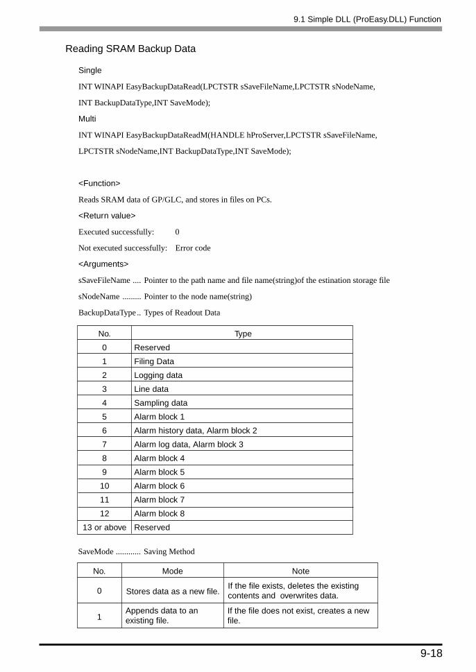
9-18
Reading SRAM Backup Data
Single
INT WINAPI EasyBackupDataRead(LPCTSTR sSaveFileName,LPCTSTR sNodeName,
INT BackupDataType,INT SaveMode);
Multi
INT WINAPI EasyBackupDataReadM(HANDLE hProServer,LPCTSTR sSaveFileName,
LPCTSTR sNodeName,INT BackupDataType,INT SaveMode);
<Function>
Reads SRAM data of GP/GLC, and stores in files on PCs.
<Return value>
Executed successfully: 0
Not executed successfully: Error code
<Arguments>
sSaveFileName .... Pointer to the path name and file name(string)of the estination storage file
sNodeName ......... Pointer to the node name(string)
BackupDataType .. Types of Readout Data
Type
Reserved
Filing Data
Logging data
Line data
Sampling data
Alarm block 1
Alarm history data, Alarm block 2
Alarm log data, Alarm block 3
Alarm block 4
Alarm block 5
Alarm block 6
Alarm block 7
Alarm block 8
Reserved
9.1 Simple DLL (ProEasy.DLL) Function
No.
0
1
2
3
4
5
6
7
8
9
10
11
12
13 or above
0
1
No.
Stores data as a new file.
Appends data to anexisting file.
Mode Note
If the file exists, deletes the existingcontents and overwrites data.
If the file does not exist, creates a newfile.
SaveMode ............ Saving Method

9-19
9.1 Simple DLL (ProEasy.DLL) Function
Backup Data’s Write Function
Single
INT WINAPI EasyBackupDataWrite(LPCTSTR sSourceFileName,LPCTSTR sNodeName,
INT BackupDataType);
Multi
INT WINAPI EasyBackupDataWriteM(HANDLE hProServer,LPCTSTR sSourceFileName,
LPCTSTR sNodeName,INT BackupDataType);
<Function>
Writes the designated binary file to SRAM within GP.
<Argument>
HProServerPro-Server handle
sSourceFileName .... File path for the value to be written to the GP’s SRAM
sNodeName ............ Node name of GP to be written to.(Node must be previously registered as a Pro-Server
Network Project.)
BackupDataType ..... Designates the type of write file.(Must be the EasyBackupDataType_FILING
type[filing data]supported by Ver. 2.0)
<Return value>
Executed successfully: 0
Write Error: Error Code
Entry Node Status Read Function
Single
INT WINAPI GetNodeProperty (LPCTSTR sNodeName, DWORD dwTimeLimit, LPCTSTR GPType,
LPCTSTR SystemVersion, LPCTSTR ComVersion, LPCTSTR ECOMVersion)
Multi
INT WINAPI GetNodePropertyM (HANDLE hProServer, LPCTSTR sNodeName, DWORD dwTimeLimit,
LPCTSTR GPType, LPCTSTR SystemVersion, LPCTSTR ComVersion, LPCTSTR ECOMVersion)
<Function>
The connected GP status can be acquired. This can also be used to check a connection since the response
timeout value can be a variable.

9-20
<Argument>
hProServer .......... Pro-Server handle
sNodeName ........ Node name of GP to be read from. (Node name must be previously registered as a Pro-
Server network project.)
dwTimeLimit ...... Response timeout setup value (If you designate 0, this will be defaulted to 3000 msec.)
The setup range is from 1 through 2,147,483,647. (unit:msec)
Secure the area more than 32 bytes for each of followings.
GpType: GP model code
SystemVersion: GP system version
ComVersion: PLC protocol driver version
ECOMVersion: 2-Way Driver version
<Return value>
Executed successfully: 0
Not executed successfully: Error codes (refer to the separate table)
CF Card Status Read Function
Single
INT WINAPI EasyIsCFCard (LPCTSTR sNodeName)
Multi
INT WINAPI EasyIsCFCardM (HANDLE hProServer, LPCTSTR sNodeName)
<Function>
The CF Card connection status of the connect GP can be acquired.
<Argument>
hProServer ........... Pro-Server handle
sNodeName ......... Node name of GP to be read from. (Node name must be previously registered as a Pro-
Server network project.)
<Return value>
0x00000000 (0) - A usable CF Card is inserted.
0x10000001 (268435457) - No CF Card available.
0x10000002 (268435458) - Unsupported Device was detected by the CF Card’s driver.
0x10000004 (268435460) - CF Card’s driver has detected a card error.
0x10000008 (268435464) - CF Card not initialized.
Other error codes - Refer to separate Error Code chart.
9.1 Simple DLL (ProEasy.DLL) Function

9-21
9.1 Simple DLL (ProEasy.DLL) Function
CF Card File List Read Function (Arbitrary Folder Name)
INT WINAPI EasyGetListInCfCard (LPCTSTR sNodeName, LPCTSTR sDirectory, INT* pioCount,
LPCTSTR szSaveFileName);
<Function>
Outputs the file list in CF Card inserted to GP/GLC to the file given via a parameter. You can designate the
file type using a parameter.
An error occurs because GP77R Series does not support this function.
<Arguments>
sNodeName ...... Node name of GP to be read from.
sDirectory ......... Folder name to be acquired (upper case only).
pioCount ........... The number of files read.
szSaveFileName
............ Name of the file that directory information read is stored to. Data stored to array in the
stEasyDirInfo format as many as designated by pioCount are stored as binary data.
Moreover, the filename and the file extension are stored as upper case characters only.
struct stEasyDirInfo {
BYTE bFileName [8+1]; // Filename (ends with 0)
BYTE bExt[3+1]; // File extension (ends with 0)
BYTE bDummy [3]; // Dummy
DWORD dwFileSize; // File size
BYTE bFileTimeStamp [8+1]; // File time stamp (ends with 0)
BYTE bDummy2[3]; // Dummy2
} ;
<Return value>
Executed successfully: 0
Not executed successfully: Error code (refer to the separate table)

9-22
<Supplement>
As supplement of “bFileTimeStamp”, time and date are shown as hexadecimal character strings where upper
4bytes out of 8 bytes indicate time in MS-DOS and remaining lower 4 bytes indicate date also in MS-DOS.
The format of date and time in MS-DOS is as the following.
(Example : In the case of 20C42C22, 2C22 expressed as hexadecimal corresponds to date in MS-DOS, and
20C4 also expressed as hexadecimal corresponds to time in MS-DOS so that 20C42C22 indicates 2002/1/2
4:6:8.)
Designates date in MS-DOS. This date is packed as one 16 bits value according to the following format.
Designates time in MS-DOS. This time is packed as one 16 bits value according to the following format.
Bit
0 - 4
5 - 8
9 -15
Contents
Day (1 - 31)
Month (1=January, 2=February, ..., 12=December)
Year. However, it is expressed as past years since 1980.
The actual year can be obtained by adding 1980 on the
value shown by these bits.
Bit
0 - 4
5 - 10
11 - 15
Contents
Value that seconds are divided by 2. (0 - 29)
Minute (0 - 59)
Hour (0 - 23 using 24 hours expression)
9.1 Simple DLL (ProEasy.DLL) Function

9-23
9.1 Simple DLL (ProEasy.DLL) Function
CF Card File List Read Function (Type Designation)
INT WINAPI EasyGetListInCard (LPCTSTR sNodeName, LPCTSTR sDirectory, INT* pioCount,
LPCTSTR szSaveFileName);
<Function>
Writes the file list in CF Card inserted to GP/GLC to the file designated via a parameter. The file list that
can be read out is limited to those designated in “sDirectory”.
An error will occur if a GP77R Series unit is used with this function.
<Arguments>
sNodeName ...... Node name of GP to be read from.
sDirectory ......... Directory name to be acquired (upper case only). Only following directories are
supported.
LOG (Logging Data)
TREND (Trend Data)
ALARM (Alarm Data)
CAPTURE (Capture Data)
FILE (Filing Data)
pioCount ........... The number of files read.
szSaveFileName
............ Name of the file that read-out directory information is stored to. The amount of data stored
to array in the stEasyDirInfo format as many as designated by pioCount are stored as
binary data. Moreover, the filename and the file extension are stored as upper case
characters only.
struct stEasyDirInfo {
BYTE bFileName [8+1]; // Filename (ends with 0)
BYTE bExt[3+1]; // File extension (ends with 0)
BYTE bDummy [3]; // Dummy
DWORD dwFileSize; // File size
BYTE bFileTimeStamp [8+1]; // File time stamp (ends with 0)
BYTE bDummy2[3]; // Dummy2
} ;
<Return value>
Executed successfully: 0
Not executed successfully: Error code (refer to the separate table)

9-24
CF Card File Read Function (Arbitrary File Name Designation)
INT WINAPI EasyFileReadInCfCard (LPCTSTR sNodeName, LPCTSTR sFolderName, LPCTSTR
sFileName, LPCTSTR pWriteFileName, DWORD* podwFileSize);
<Function>
Reads the designated file from CF Card. Read out file can be arbitrarily (freely) designated. An error will
occur if a GP77R Series unit is used with this function.
<Arguments>
sNodeName ............. Node name of GP to be read from.
sFolderName ............ Name of folder to be read from CF Card. (Max. 32 char single-byte.)
sFileName ................ Name of a file to be read from CF Card. (Max. 8.3 format string - ********.***)
pWriteFileName ...... Name of the file to save a CF file read. (full path)
podwFileSize ........... Size of a CF file read.
<Return value>
Executed successfully: 0
Not executed successfully: Error code (refer to the separate table)
9.1 Simple DLL (ProEasy.DLL) Function

9-25
CF Card File Read Function (Type Designation)
INT WINAPI EasyFileReadCard (LPCTSTR sNodeName, LPCTSTR pReadFileType, WORD,
wReadFileNo, LPCTSTR pWriteFileName, DWORD* podwFileSize);
<Function>
Reads the designated file from CF Card. Read file can only be files designated in “ pReadFileType”.
An error occurs because GP77R Series does not support this function data.
<Arguments>
sNodeName ............. Node name of GP to be read from.
pReadFileType ......... Type of a file to be read from CF Card.
wReadFileNo ........... No. of a file to be read from CF Card.
pWriteFileName ...... Name of the file to save a CF file read. (full path)
podwFileSize ........... Size of a CF file read.
<Return value>
Executed successfully: 0
Not executed successfully: Error code (refer to the separate table)
<Supplement>
Following 17 file types are supported. You can read only files saved in the designated folder in CF Card.
The following table shows those types of file supported.
9.1 Simple DLL (ProEasy.DLL) Function
Folder
\LOG
\ALARM
\ALARM
\ALARM
\MRM
\CAPTURE
--
File Type
ZL
ZG
ZH
ZA
ZC
CP
--
File Type
ZF
ZR
ZI
ZO
ZT
ZS
Z4 to Z8
Folder
\FILE
\FILE
\DATA
\DATA
\TREND
\TREND
\ALARM

9-26
CF Card File Write Function (Arbitrary File Name Designation)
INT WINAPI EasyFileWriteInCfCard (LPCTSTR sNodeName, LPCTSTR pReadFileName, LPCTSTR
sFolderName, LPCTSTR sFileName);
<Function>
Writes the designated file to the CF Card. Write file can be arbitrarily (freely) designated. An error will
occur if a GP77R Series unit is used with this function.
<Arguments>
sNodeName ............. Node name of GP to be written to.
pReadFileName ....... Name of file to be read from. (full path)
sFolderName ............ Folder name used when writing the file to CF Card (Max. 32 char single-byte.)
sFileName ................ Name of the file to be witten to CF Card. (Max. 8.3 format string - ********.***)
<Return value>
Executed successfully: 0
Not executed successfully: Error code (refer to the separate table)
CF Card File Write Function (Type Designation)
INT WINAPI EasyFileWriteCard (LPCSTR sNodeName, LPCTSTR pReadFileName, LPCTSTR
pWriteFileType, WORD wWriteFileNo);
<Function>
Writes the designated file to CF Card. Write file can only be files designated in “ pWriteFileType”.
An error occurs because GP77R Series does not support this function.
<Arguments>
sNodeName ............. Node name of GP to be written to.
pReadFileName ....... Filename of a write source to CF Card. (full path)
pWriteFileType ........ Type of file to be written to CF Card. (Refer to the supplement of the CF Card file
read function.)
wWriteFileNo .......... No. of a file to be written to CF Card.
<Return value>
Executed successfully: 0
Not executed successfully: Error code (refer to the separate table)
9.1 Simple DLL (ProEasy.DLL) Function

9-27
CF Card File Delete Function (Arbitrary File Designation)
INT WINAPI EasyFileDeleteInCfCard (LPCTSTR sNodeName, LPCTSTR sFolderName, LPCTSTR
sFileName);
<Function>
Deletes the designated file on the CF Card. Delete file can be arbitrarily (freely) designated. An error will
occur if a GP77R Series unit is used with this function.
<Arguments>
sNodeName ............. Node name of GP containing the data to be deleted.
sFolderName ............ Name of the folder used when deleting the CF Card file (Max. 32 char single-byte.)
sFileName ................ Name of file to be deleted from CF Card. (Max. 8.3 format string - ********.***)
<Return value>
Executed successfully: 0
Not executed successfully: Error code (refer to the separate table)
CF Card File Delete Function (Type Designation)
INT WINAPI EasyFileDeleteCard (LPCTSTR sNodeName, LPCTSTR pDeleteFileType, WORD
wDeleteFileNo)
<Function>
Deletes the designated file on the CF Card. Files deleted are limited to those designated by “
pDeleteFileType”. An error will occur if a GP77R Series unit is used with this function.
<Arguments>
sNodeName ............. Node name of GP containing the data to be deleted.
pDeleteFileType ....... Designates the type of file to be deleted (refer to supplemental table)
wDeleteFileNo ......... No. of a file to be deleted from CF Card.
<Return value>
Executed successfully: 0
Not executed successfully: Error code (refer to the separate table)
<Supplement>
If the file does not exist and this function is performed, no error will occur and it will be completed
normally. Following 17 file types are supported.
9.1 Simple DLL (ProEasy.DLL) Function
Folder
\LOG
\ALARM
\ALARM
\ALARM
\MRM
\CAPTURE
--
File Type
ZL
ZG
ZH
ZA
ZC
CP
--
File Type
ZF
ZR
ZI
ZO
ZT
ZS
Z4 to Z8
Folder
\FILE
\FILE
\DATA
\DATA
\TREND
\TREND
\ALARM

9-28
CF Card File Name Change Function
INT WINAPI EasyFileRenameInCfCard (LPCTSTR sNodeName, LPCTSTR sFolderName, LPCTSTR
sFileName, LPCTSTR sFileReName);
<Function>
Renames the designated file on the CF Card. An error will occur if a GP77R Series unit is used with this
function.
<Arguments>
sNodeName ............. Node name of GP containing the data to be written to.
sFolderName ............ Folder name of the CF Card file to be changed. (Max. 32 char.)
sFileName ................ Name of the file to be changed. (Max. 8.3 format string - ********.***)
sFileReName ........... File name used after name is changed. (Max. 8.3 format string - ********.***)
<Return value>
Executed successfully: 0
Not executed successfully: Error code (refer to the separate table)
CF Card Free Space Size Acquisition Function
INT WINAPI EasyGetCfFreeSpace (LPCTSTR sNodeName, INT* pioUnallocated);
<Function>
Acquires a free space size in CF Card connected to the designated entry node. If ECOM older than V4.1 is
mounted on GP, an error occurs.
<Arguments>
sNodeName ............. Node name of GP to be read from.
pioUnallocated ......... Fee space size in CF Card. (acquired in byte)
<Return value>
Executed successfully: 0
Not executed successfully: Error code (refer to the separate table)
9.1 Simple DLL (ProEasy.DLL) Function

9-29
GP Time DWORD Type Read Function
DWORD WINAPI EasyGetGPTime (LPCTSTR sNodeName, DWORD* podwTime); (for VC)
<Function>
Acquires the current time of the designated node as number (DWORD type). However, this function is
effective from LS2048 which saves time in 6 words.
<Arguments>
sNodeName ............. Node name to acquire data from. (You cannot designate Windows computer nodes.)
podwTime ................. Acquired time (time in DWORD type (actually acquired in time_t type defined by ANSI))
<Return value>
Executed successfully: 0
Not executed successfully: Error code (refer to the separate table
GP Time VARIANT Type Read Function
DWORD WINAPI EasyGetGPTimeVariant (LPCTSTR sNodeName, LPVARIANT povTime); (for VB)
<Function>
Acquires the current time of the designated node as number (Variant type). However, this function is
effective from LS2048 which saves time in 6 words.
<Arguments>
sNodeName ............. Node name to acquire data from. (You cannot designate Windows computer nodes.)
povTime ................... Acquired time (acquired time is in VARIANT type (internal process format is Date))
<Return value>
Executed successfully: 0
Not executed successfully: Error code (refer to the separate table)
GP Time STRING Type Read Function
DWORD WINAPI EasyGetGPTimeString (LPCTSTR sNodeName, LPCTSTR pFormat, LPTSTR
posTime); (for VC)
<Function>
Acquires the current time of the designated node as character string (LPTSTR type). However, this function
is effective from LS2048 which saves time in 6 words.
<Arguments>
sNodeName ............. Node name to acquire data from. (You cannot designate Windows computer nodes.)
pFormat .................... Format setup character string of time to be acquired as character string. The format
designation code after the percentage sign (%) is converted as shown in the following
supplement. Other characters will remain and be displayed as they are.
9.1 Simple DLL (ProEasy.DLL) Function

9-30
posTime ................... Time acquired as character string. (However, if the area more than the acquired
character string length plus 1 (NULL) is not secured, unexpected memory area damage
will occur. If not secured, actions are not guaranteed.)
<Return value>
Executed successfully: 0
Not executed successfully: Error code (refer to the separate table)
<Supplement>
The format designation code after the percentage sign (%) is converted as the following. Other characters
will remain and be displayed as they are. (They are internally given to the argument used by the member
Format of the CTime class of MFC.) For example, if the actual time is 2002/1/2 12:34:56, the character
string will be “2002_34 56” when designating “%Y_%M %S”.
*1 : If you add “#” before d, H, I, j, m, M, S, U, w, W, y or Y (e.g. %#d), leading zeros will be deleted if
there are (e.g. 05 becomes 5.).
*2 : If you add “#” before a, A, b, B, p, X, z, Z or % (e.g. %#a), “#” will be ignored.
9.1 Simple DLL (ProEasy.DLL) Function
Folder
Abbreviation of day of the week (*2)
Complete name of day of the week (*2)
Abbreviation of month (*2)
Complete name of month (*2)
Day and time expression according to the locale.
Long expression of day and time according to the locale.
Day expressed in decimal (*1)
Hour in 24 hours expression (00 - 23) (*1)
Hour in 12 hours expression (01 - 12) (*1)
Days in decimal since the year beginning (001 - 366) (*1)
Month in decimal (01 - 12) (*1)
Minute in decimal (00 - 59) (*1)
AM/PM of the current locale (*2)
Second in decimal (00 - 59) (*1)
Sequential number of the week in decimal. Sunday is regarded as the
first day of the week (00 - 53). (*1)
Day of the week in decimal. Sunday is regarded as 0 (0 - 6). (*1)
Sequential number of the week in decimal. Monday is regarded as the
first day of the week (00 - 53). (*1)
Day according to the current locale.
Long expression of day according to the current locale
Time according to the current locale. (*2)
The last 2 digits of year in decimal (00 - 99) (*1)
Year in 4 digits in decimal (*1)
Name or abbreviation of the time zone. If the time zone is unknown, do
not enter any characters. (*2)
Percent sign (*2)
Format Designation Code
%a
%A
%b
%B
%c
%#c
%d
%H
%I
%j
%m
%M
%p
%S
%U
%w
%W
%x
%#x
%X
%y
%Y
%z, %Z
%%

9-31
GP Time STRING VARIANT Type Read Function
DWORD WINAPI EasyGetGPTimeStringVariant (LPCTSTR sNodeName, LPCTSTR pFormat,
LPVARIANT povTime); (for VB)
<Function>
Acquires the current time of the designated node as character string (Variant Type). However, this function
is effective from LS2048 which saves time in 6 words.
<Arguments>
sNodeName ............. Node name to acquire data from. (You cannot designate Windows computer nodes.)
pFormat .................... Format setup character string of time to be acquired as character string. The format
designation code after the percentage sign (%) is converted as shown in the following
supplement. Other characters will remain and be displayed as they are. (For details,
refer to <Supplement> of “GP TIME STRING Type Read Function”.)
povTime ................... Acquired time (acquired time is in VARIANT type (internal process format is Date))
<Return value>
Executed successfully: 0
Not executed successfully: Error code (refer to the separate table)
Simple DLL Initialization
INT WINAPI EasyInit();
<Function>
Initializes Simple DLL and declares the usage internally.
<Return value>
Executed successfully: 0
Not executed successfully: Error code(Refer to the attached table.)
For details, refer to “Precautions When Using Simple DLL in Multi-Thread Applications”. If you execute
EasyInit ( ) without starting Pro-Server, Pro-Server is automatically started.
9.1 Simple DLL (ProEasy.DLL) Function

9-32
Simple DLL Termination
INT WINAPI EasyTerm();
<Function>
Releases resource that Simple DLL holds.
<Return value>
Executed successfully: 0
Not executed successfully: Error code(Refer to the attached table.)
For details, refer to “Precautions When Using Simple DLL in Multi-Thread Applications”.
Even if you execute EasyTime ( ), Pro-Sever does not exit.
The Simple DLL function which exits Pro-Server is not supported.
Message Processing Suppression
Single
INT EasySetWaitType (DWORD dwMode)
Multi
INT EasySetWaitTypeM (HANDEL hProServerHandle, DWORD dwMode)
<Function>
If it takes time to process, most of Simple DLL functions process Windows messages within those functions,
however, you can designate if you wish to suppress this Windows message processing.
If you suppress it, Windows messages are left in the message queue and will not be processed while
executing functions.
As its result, you can avoid unexpected accident such as the double function call due to clicking icons while
executing functions.
However, in this case, because all Windows message processing are suppressed in addition to that of the
“Icon is clicked” message, be careful that important message processing will not be preformed, either, such
as redrawing of the timer or windows.
You can designate it per every Pro-Server handle if you suppress processing. The default is to execute
processing.
<Return value>
Executed successfully: 0
Not executed successfully: Error code (refer to the separate table)
<Arguments>
HANDLE hProServerHandle .... Pro-Server handle to change the processing mode.
dwMode ... 1 for executing message processing.
2 for suppressing message processing.
9.1 Simple DLL (ProEasy.DLL) Function

9-33
Acquiring Message Processing Method
Single
INT EasyGetWaitType ( )
Multi
INT EasyGetWaitTypeM (HANDLE hProServerHandle)
<Function>
This function is to acquire which mode the message processing method is currently set to. In the case of
multi-handle, the function returns the current mode per handle.
<Arguments>
HANDLE hProServerHandle ....... Handle to acquire the state.
<Return value>
1: Executes message processing.
2: Suppresses message processing.
9.1 Simple DLL (ProEasy.DLL) Function

9-34
9.1 Simple DLL (ProEasy.DLL) Function
9.1.4 Precautions When Using Function
Precautions When LPVARIANT Returns an Undefined Error at ProEasy.h Compila-
tion by VC
When Visual C++ ver. 6 is used to compile Pro-SDK\VC\Public\ProEasy.h, or the header data copied to the
clipboard via Pro-Studio’s (Programming extension], [VC Text], the LPVARIANT may return an undefined
error. Since the LPVARIANT is defined within afxdisp.h, if the data is not included, an error will occur. To
avoid this error to occur, you should define “#include<afxdisp.h>” in stdafx.h in a normal case.
GLC 32 Bit Device Bit Access Method
The GLC unit’s 32-bit addressing (integer variables, integer array variables) can access data in individual bit units.
Adding a single space and a suffix (descriptor). Xm to a variable name allows this type of bit unit access. Also,
adding the suffix<n>+ single space to a variable name allows you to designate individual array elements.
Therefore, if you wish to access the Integer_Array’s n+1 element’s m+1 position bit, you would write
Integer_Array<n>_.Xm.
Ex. To access the Integer_Variable’s 7th position bit, you would write
Integer_Variables_.X6.
Ex. To access the Integer_Array’s 2nd element’s 30th position bit, you would write
Integer_Array<1>_.X29.
Precautions When Using Simple DLL in Multi-Thread Applications
All Simple DLL functions are synchronous (If a function is called once, the process will not return from a
function until it is completed.).
Therefore, even if you access to more than one entry node, each access will be processed sequentially in the
case of a single-thread program.
In the case of a multi-thread program, you can access to another node using another thread even while you
access to a certain node using one thread.
Simple DLL supports multi-thread.
The following describes precautions when you build multi-thread programs.
1. Use multi-handle functions basically to multi-thread programs.
2. You need to acquire Pro-Server handle to use multi-handle functions. Acquire separate Pro-Serve
handle per thread. Although you can acquire and use more than one Pro-Server handle within one
thread, you may not use Pro-Server handle created by another thread. When you release Pro-Server
handle, you should release it in the thread that you created the handle as well.

9-35
9.1 Simple DLL (ProEasy.DLL) Function
3. When using Simple DLL, you must call EasyInit () in the beginning and EasyTerm () at the end.
At this time, the thread to call EasyInit () must be same as that for EasyTerm ().
Most of Simple DLL functions automatically call EasyInit () internally if they are called before EasyInit
() is called.
Moreover, when applications compete, Simple DLL will also exit automatically, however, if EasyTerm ()
is not called until then, Simple DLL will automatically call EasyTerm () internally.
According to these functionalities, in the case of single-thread, you do not have to consider (program)
EasyInit () or EasyTerm ().
However, in the case of a multi-thread program, there are cases that the thread to call the Simple DLL
function in the beginning is different from the last thread when an application exits, or when you do not
know if they are same.
In such cases, you should insert EasyInit () and EasyTerm () in your program.
In most programs, the initially started thread (main thread) remains until the end, so insert EasyInit () in the
beginning of the main thread and EasyTerm () at the end.
1. Execute EasyInit () and EasyTerm () once in one program, i.e. at the beginning and at the end of the main
thread.
2. One or more Pro-Server handles should be created per thread and used only within the thread that each
handle is created for. Furthermore, you should cancel the handle within the thread.

9-36
Processing Windows Messages
Most Windows programs are event driven programs which display dialogs or make sounds according to events
such as “An icon is clicked.”, “A mouse is moved.”, “A key is pressed.” and so on.
When an event occurs, Windows sends the message indicating the event kind to an application.
An application recognizes an even occurrence by receiving the message and executes corresponding process.
In this manual, the part where a message is received from Windows in turn and breaks up to each process (for VB,
it corresponds to DoEvents, and for VC, it is the part where GetMessage ( ) and DispatchMessage ( ) are executed)
is called the message pump.
When you normally program in VC or in VB, the message pump is concealed in the VC or VB framework so that
you do not particularly worry about it, however, if this message pump does not run properly, Windows
applications become awkward.
For example, when a routine takes time to process a certain message and the process does not return for a while,
because an application cannot receive an event occurred during that time from Windows, an application cannot
process the event.
Example) Suppose that messages are send from Windows according to the order of Message1 and then Message2.
The message pump takes Message1 out and calls the subroutine for Message1. Then, after returning
from the subroutine, it takes the next message (Message2) out and calls the subroutine for Message2.
Message1Message1 Processing
Message2 Processing
Message2
Message Pump
9.1 Simple DLL (ProEasy.DLL) Function

9-37
At this time, suppose that it takes a long time to process Message1.
Then, Message2 cannot be processed because the process cannot return to the message pump.
In such a case, force the message pump run. (Call DoEvents for VB and call GetMessage( ) and
DispatchMessage ( ) for VC.)
The Windows application is the OS developed on the assumption that the application runs the message pump
cleverly. Simple DLL functions run message pumps within themselves to avoid the thing described in the
example for the process which takes a long time.
Message1
Message1 Processing
The processstop here.
Message2 Processing
Message2
Message Pump
Message1
Message2 Processing
Message2
Message Pump
Message Pump
Message1 ProcessingCall the message pump since it takes a long time to process.
Continues processing and returns when it completed.
9.1 Simple DLL (ProEasy.DLL) Function

9-38
Prohibiting Function Double Call
Simple DLL functions prohibit to perform separate communication (double call) while they perform
communication with certain partners (while calling Simple DLL functions). (It is possible using a multi-
handle function. For details, refer to the section about multi-handle functions.)
However, because Simple DLL functions run message pumps within themselves, applications will start when
events occur.
If you call a function within the message process routine, the double call may occur. The following
describes double call examples.
1. Double Call due to Pressing Two Buttons
Suppose that there are two buttons, A and B. If A is pressed, a device read function is called, and if B is
pressed, a device write function is called.
In this case, if the B button is pressed while calling a device read function due to the A button pressed, a
device write function is called. At that time, the function double call occurs and turned out to be an error.
2. Double Call due to Timer
When a periodical process is executed in Windows program, the timer event is frequently used. If you are
not careful enough in programming using the timer event, the function double call may occur.
Reads a device by calling a device read function once every second periodically, and displays data.
Calls a device write function when a certain button is pressed, and writes data to a device.
These programs cause errors at the following timing.
• When the timer event occurred for , and the button mentioned in was pressed while reading, and
then the process started.
• When the timer event occurred while writing ( ), and reading is executed ( ).
Message Pump
Message Pump
Processing Routine for the A Button
Function Call
Processing Routine for the B Button
Function Call
Read Processing
Process Completion
The function calls the message pump because it takes time to process.
Write Processing
Error return due to the function double call.
9.1 Simple DLL (ProEasy.DLL) Function

9-39
Avoiding Function Double Call
The following describes how to avoid the function double call.
Improve the algorithm of the application to stop the function double call. For example:
1. Be sure to cancel the timer in the beginning of timer and button processing routines.
2. While process is executed due to a certain button pressed, ignore the event even if that button or another
button is pressed.
Use the multi-handle function.
If Pro-Server handle differs, it does not cause the function double call.
Use the multi-handle function, and use separate handle to the program which includes the function double call
possibility.
Do not process messages within functions.
Call EasySetWaitType ( ) using the argument 2, however, since messages other than those which cause the
function double call will not be processed, applications may execute unexpected actions or may cause other
problems.
Reading Character Strings in VB
There are following two methods to read character strings in VB.
When reading character strings using ReadDeviceStr in VB:
In this case, you must designate (fix) the size of the area to save character strings read in advance.
’
Public Sub Sample1 ()
Dim strData As String * 10 ’ Correct designation method because it designates the size to read.
’Dim strData As String ’ Incorrect designation method because it does not designate the character
’ string size.
Dim lErr As Long
lErr = ReadDeviceStr (“GP1”, “LS100”, strData, 10)
If lErr <> 0 Then
MsgBox “Read Error = ” & lErr
Else
MsgBox “Read String = ” & strData
End If
End Sub
9.1 Simple DLL (ProEasy.DLL) Function

9-40
When reading character strings using ReadDeviceVariant in VB:
If you do not designate the size of the area to save character strings read in advance, use the Variant type.
’
Public Sub Smaple2 ()
Dim lErr As Long
Dim vrData As Variant ’ Designate the Variant type to the area to save data read.
lErr = ReadDeviceVariant (“GP1”, “LS100”, vrData, 10, EASY_AppKind_Str)
If lErr <> 0 Then
MsgBox “Read Error = ” & lErr
Else
MsgBox “Read String = ” & vrData
End If
End Sub
Be careful that GP/GLC uses NULL characters to complete character strings. Therefore, if character
strings acquired by the above method include NULL characters to complete character stirrings, you must
shorten those.
The following shows the sample function to trim NULL characters.
Public Function TrimNull (strData As String) As String
Dim i As Integer
i = InStr (1, strData, Chr$(0), vbBinaryCompare)
If 0 < i Then
TrimNull = Left (strData, i - 1)
Else
TrimNull = strData
End If
End Function
9.1 Simple DLL (ProEasy.DLL) Function

9-41
Details of Cache Read (Polling Time and Life Time)
Pro-Server has the feature internally to cache read data when it is requested to read a device by cache read.
If the read request is raised to the same device, Pro-Server returns cached data. Pro-Server can respond
quickly because it does not read data every time.
If a device does not change at all, Pro-Server can always return cache data. If not, it is necessary to reflect
device changes to cache data.
Therefore, Pro-Server automatically reads devices to cache according to a particular interval and updates
cache data. The action is called polling and the interval is called a polling time.
Polling is automatically executed when cache read is executed, and polling for the device that the usage is
completed stops automatically.
After a certain device was read, if any read requests are not given to the device for a certain period, Pro-
Server recognizes that the usage of the device is completed.
This period is called life time.
If any read requests are raised within life time, life time will be reset at that moment.
After life time passed, polling to the device stops automatically.
The figure on the next page shows Pro-Server’s behavior when a cache read request is given from an
application via Simple DLL.
9.1 Simple DLL (ProEasy.DLL) Function

9-42
Pro-Server’s behavior when a cache read request is given from an application via
Simple DLL
Application Pro-Server PLC
Returns cache data existing.
Cache data is deleted after life time passed.
Reads PLC data directly because cache data do not exist.
Executes polling to PLC according to polling time.
When life time passed after the last read request is raised, polling stops automatically.
Cache Data
9.1 Simple DLL (ProEasy.DLL) Function

9-43
Designating Polling Time
Pro-Server decides polling time according to the following priority.
Designating polling time directly using Simple DLL or DDE:
Designate it as part of character string to the device designation part of Simple DLL or DDE. The format is as
the following.
.<Polling Time>
<Polling Time> = Polling time value in ms
Example) When designating 20 seconds as polling time:
lErr=ReadDeviceVariant (“GP1”, “D100 .20000”, Data, 1, EASY_AppKind_SignedWord)
Separate this with blank space after a device (or a symbol) and designated it in ms after “.”.
When a device is registered as a symbol:
The [Polling Time] value in the [Register Symbol] dialog is used.
When a device is not registered as a symbol and designating polling time without polling time
designation:
The [DDE Polling Time] value in the [System Configuration] dialog is used.
9.1 Simple DLL (ProEasy.DLL) Function

9-44
Designating Life Time
Although Pro-Server calculates life time automatically from polling time, you can designate any desired
values. In this case, designate time as part of character strings in the device designation part of Simple DLL
or DDE. The format is as the following.
.L<Life Time>
<Life Time> = Life time value in ms
Example) When designating 20 seconds as life time:
lErr=ReadDeviceVariant (“GP1”, “D100 .L20000”, Data, 1, EASY_AppKind_SignedWord)
Separate this with blank space after a device (or a symbol) and designated it in ms after “.L”.
When using a Visual Studio .NET environment
This example uses a Visual Basic.NET sample. For details, refer to 9.2.3 Using simple DLL functions with
Visual Basic .NET.
When using Visual C++.NET, the VCC++ sample can be compiled and run. However, when creating a new
project, the method of designating an LIB file is different. For details 9.2.2 VC Function Help.
9.1 Simple DLL (ProEasy.DLL) Function

9-45
9.2 Examples of Simple DLL Function
9.29.29.29.29.2 Examples of Simple DLL FunctionExamples of Simple DLL FunctionExamples of Simple DLL FunctionExamples of Simple DLL FunctionExamples of Simple DLL Function
Using read/write functions provided by Pro-Server allows you to read/write data from VB or VC
applications.
This section describes the procedure to read/write designated symbols using the programming help feature.
Procedures are different between VP and VC applications. They’re described separately.
9.2.1 VB Feature Help
VBA: Declaration
1. Click [VBA: Declare Function] on [Programming Support].
2. The declaration is copied to the Clipboard.

9-46
3. Start-up Microsoft Visual Basic, and then click [New Project] on [File] from the menu.
4. Select [Standard EXE], and then click [OK].
5. Click [Add Module] on [Project] of the Microsoft Visual Basic menu.
9.2 Examples of Simple DLL Function

9-47
6. Select [Standard Module] on the [New] tab, and then click [Open].
7. Click [Paste] on [Edit] of the Microsoft Visual Basic menu to paste the declaration (the con-
tents in the Clipboard) to the added standard module.
9.2 Examples of Simple DLL Function

9-48
8. The declaration will be pasted.
This completes function (read/write functions) declaration.
Operations from Step 1 through 8 mentioned above are common to both read and write.
For the subsequent part, each procedure is described separately because procedures are different
between read and write.
Refer to Step 9 through 21 to create the [Read] application.
Refer to Step 22 through 33 to create the [Write] application.
9.2 Examples of Simple DLL Function

9-49
Creating [Read] Application
9. This section describes the application to read and display three data (16 bits signed) when
clicking [Command1].
10. Click [Toolbox] on [View] of the Microsoft Visual Basic menu.
9.2 Examples of Simple DLL Function
Displays three read data.

9-50
11. Select [ListBox], and then paste to [Form1].
12. Select [CommandButton], and then paste to [Form1].
9.2 Examples of Simple DLL Function
ListBox
ComandButton

9-51
13. Select the symbol name that you wish to read among symbols registered on Pro-Studio
(Select the heading symbol to read from.).
14. Click [VBA: Read function] on [Programming Support] of the menu.
15. The read function will be copied into the Clipboard.
16. Double click [Command1] on [Form1] to paste the contents (read function) in the Clipboard
between the Sub and the EndSub statements.
9.2 Examples of Simple DLL Function

9-52
17. Declare the area to store read data. You should designate three or more area elements if the
number of read data is three (The number of area elements is from 0 to 2 in this example).
However, the area type (Integer in this example) needs to be matched to the symbol data type
to use.
18. Designate the header area to store read data (wData (0)), and also designate 3 as the
number of read data.
19. Set three data read (wData(0), wData(1), wData(2)) in the ListBox one after another.
20. Click [Start] on [Run] of the Microsoft Visual Basic menu.
9.2 Examples of Simple DLL Function

9-53
21. Click [Command1] to display three data form the symbol “_D40_WORD” in the ListBox.
9.2 Examples of Simple DLL Function

9-54
Creating [Write] Application
22. This section describes the application to write three data (16 bits signed) read when clicking
[Command1].
23. Select [TextBox], and then paste in [Form1]. Paste three [TextBox]s.
9.2 Examples of Simple DLL Function
Writes three data.
TextBox

9-55
24. Select [CommandButton], and then paste to [Form1].
25. Select the symbol name that you wish to write to among symbols registered on Pro-Studio
(Select the heading symbol to write to).
26. Click [VBA: Write function] on [Programming Support] of the menu.
9.2 Examples of Simple DLL Function
CommandButton

9-56
27. The write function will be copied into the Clipboard.
28. Double click [Command1] on [Form1] to paste the contents (write function) in the Clipboard
between the Sub and the EndSub statements.
29. Declare the area to store data to write. You should designate three or more area elements if
the number of write data is three (The number of area elements is from 0 to 2 in this example).
However, the area type (Integer in this example) needs to be matched to the symbol data type
to use.
30. Set entered data in [TextBox] to the area.
9.2 Examples of Simple DLL Function

9-57
31. Designate the header area (wData (0)) where written data have been set. Also designate
three as the number of write data.
32. Click [Start] on [Run] of the Microsoft Visual Basic menu.
33. After entering three data to write in [TextBox], click [Command1] to write three data form the
symbol, “_D40_WORD”.
When using VB.NET, if you insert the declaration according to this proce-
dure, an error will occur when executing it.
You cannot use VBA: Declaration directly because data sizes of Integer or
Long are different between VB.NET and Visual Basic.
VBA: Declaration is for Visual Basic or Basic for Application.
9.2 Examples of Simple DLL Function

9-58
9.2.2 VC Function Help
This section describes how to create the dialog-based application example using MFC (Microsoft
Foundation Class).
VC: Declaration
1. Start Microsoft Visual C++, and then click [New] on [File].
2. Select [MFCAppWizard (exe)] in the [Projects] tab, enter [Project name] and [Location], and
then click [OK].
This example uses “Sample” for [Project name] and “C:\Program Files\Pro-Server with Studio\Pro-
SDK\VC” for [Location].
9.2 Examples of Simple DLL Function

9-59
3. Select [Dialog based] in the “What type of application would you like to create?” field, and then
click [Finish].
4. Click [OK] to complete the project.
5. Pro-Serer provides read/write functions as DLLs. You should designate the LIB file to use
those DLLs.
Click [Setting] on [Project] of the Microsoft Visual C++ menu.
9.2 Examples of Simple DLL Function

9-60
6. Designate the LIB file using [Object/library modules] in the [Link] tab, and then click [OK].
“Pro-SDK\Vc\Public\ProEasy.lib” is designated in this example because the LIB file (ProEasy.lib)
exists in “Pro-SDK\Vc\Public” under the folder where Pro-Server has been installed.
9.2 Examples of Simple DLL Function
Designating LIB files via Visual C++ .NET
When designating LIB files using Microsoft Visual C++ .NET, right-click the
project’s name within the [Solution Explorer] window (shown below), and
select [Properties].

9-61
7. You should install the header file (ProEasy.h) to use read/write functions provided by Pro-
Server. Click the [FileView] tab in the Microsoft Visual C++ [Workspace] window, and then
double click the SampleDig.cpp file.
In this example, read/write functions are used in the SampleDig.cpp file.
In the resulting Property Pages, select [Linker | Input]. Designate the LIB file
(ProEasy.lib) in the [Additional Dependencies] column. ProEasy.lib is located
in the [Install] folder’s [Pro-SDK\Vc\Public] sub-folder.
(C:\Program Files\Pro-face\Pro-Server with Pro-Studio\Pro-
SDK\Vc\ProEasy.lib in the following figure.)
9.2 Examples of Simple DLL Function

9-62
8. Add #include “Pro-SDK\Public\ProEasy.h” in the SampleDig.cpp file to complete the read/write
function declaration.
Operations from step 1 through 8 mentioned above are common to both read and write.
For the subsequent part, each procedure is described separately because procedures are different
between read and write.
Refer to step 9 through 32 to create the [Read] application.
Refer to step 33 through 51 to create the [Write] application.
9.2 Examples of Simple DLL Function

9-63
Creating [Read] Application
9. This section describes the application to read and display three data (16 bits signed) when
clicking [Button1].
10. Click the [ResourceView] tab in the Microsoft Visual C++ [Workspace] window, and then
double click [IDD_SAMPLE_DIALOG].
Select and delete [Static Text] in the center of the dialog.
9.2 Examples of Simple DLL Function
Displays three read data.

9-64
11. Click [Customize] on [Tools] of the Microsoft Visual C++ menu.
12. Check [Controls] in the [Toolbars] tab, and then click [Close].
13. Select [ListBox], and then paste it in the dialog.
9.2 Examples of Simple DLL Function
ListBox

9-65
14. Right-click the pasted [ListBox], and then select [Property]. After the [ListBox Properties]
window appears, uncheck [Sort].
15. Click [ClassWizard] on [View] of the Microsoft Visual C++ menu.
16. Select the [Member Variables] tab, and then select “IDC_LIST1” in [Control ID].
9.2 Examples of Simple DLL Function

9-66
17. Click [Add Variable...], and then enter “m_List” in [Member Variable name]. Select “Control” in
[Category], and then click [OK].
18. Make sure if the member variable has been added, and then click [OK].
19. Select [Button], and then paste it in the dialog.
9.2 Examples of Simple DLL Function
Button

9-67
20. Select the symbol name that you wish to read among symbols registered on Pro-Server
(Select the heading symbol to read from.).
21. Click [VC: Read Function] on [Programming Support] of the menu.
22. The read function will be copied into the Clipboard.
9.2 Examples of Simple DLL Function

9-68
23. Double click [Button1] pasted to [Dialog] of the Microsoft Visual C++ menu.
24. Click [OK].
25. Paste the contents of the Clipboard (read function) into the OnButton1 member function.
9.2 Examples of Simple DLL Function

9-69
26. Declare the area to store read data. You should designate three or more area elements if the
number of read data is three.
27. Designate the header area to store read data (wData(0)), and 3 as the number of read data.
You should also add a semicolon ( ; ) at the end of the read function.
28. Convert read data to CString type characters once to display three read data (wData(0),
wData(1), wData(2)) in the ListBox.
9.2 Examples of Simple DLL Function

9-70
29. Set three data read (wData(0), wData(1), wData(2)) in the ListBox one after another.
30. Click [Execute Smaple.exe] on [Build] of the Microsoft Visual C++ menu.
31. Click [Yes].
9.2 Examples of Simple DLL Function

9-71
32. Click [Button1] to display three data from the symbol “_D40_WORD” in the ListBox.
9.2 Examples of Simple DLL Function

9-72
Creating Write Application
33. This section describes the application to write three read data when clicking [Button1].
Execute the same operations, step 10 through 12, as in “Creating Read Application”.
34. Select [EditBox], and then paste it in [Dialog]. You should paste three [EditBox]s.
35. Click [Class Wizard] on [View] of the Microsoft Visual C++ menu.
9.2 Examples of Simple DLL Function
EditBox
Write three read data.

9-73
36. Select “IDC_EDIT1” in [Control IDs] of the [Member Variables] tab, and then click [Add Variable...].
37. Enter “m_Edit1” in [Member variable name], select “short” in [Variable type], and then click [OK].
Repeat step 36 and 37 for other two [EditBox]s. However, you should designate their member
variables as “m_Edit2” and “m_Edit3” respectively.
38. Click [OK].
9.2 Examples of Simple DLL Function

9-74
39. Select [Button] and paste it to [Dialog].
40. Select the symbol name to write to among symbols registered on Pro-Server (Select the
heading symbol to write to.).
41. Click [VC: Write Function] on [Programming Support] of the menu.
9.2 Examples of Simple DLL Function
Button

9-75
42. The write function will be copied into the Clipboard.
43. Double click [Button1] pasted on [Dialog] of the Microsoft Visual C++ menu.
44. Click [OK].
9.2 Examples of Simple DLL Function

9-76
45. Paste the contents of the Clipboard (write function) into the OnButton1 member function.
46. Declare the area to store write data. You should designate three or more area elements if the
number of write data is three.
47. Set three write data entered into the EditBox to the area.
9.2 Examples of Simple DLL Function

9-77
48. Designate the header area where write data have been set (wData(0)), and 3 as the number
of read data. You should also add a semicolon ( ; ) at the end of the write function.
49. Click [Execute Smaple.exe] on [Build] of the Microsoft Visual C++ menu.
50. Click [Yes].
9.2 Examples of Simple DLL Function

9-78
51. After entering three write data to [EditBox]s, click [Button1] to execute writing three data from
the symbol “_D40_WORD”.
9.2 Examples of Simple DLL Function

9-79
9.2.3 Using simple DLL functions with Visual Basic .NET
Visual Basic .NET differs from Visual Basic 6.0 regarding format specifications for Integers, etc. Therefore,
Pro-Studio’s [VBA: Declare Function] cannot be used. When using Visual Basic .NET, instead of [VBA:
Declare Function] be sure to use the ProEasy.vb file, located in the [Install] folder.
Structure of Pro-SDK
Included in the [Install] folder are the declaration file and sample program, to enable easy use of DLLs with
Visual Basic .NET.
The diagram below shows the structure of Visual Basic .NET related files in the [Install] folder:
Pro-SDK\VB.NET\
ProEasy.vb\API\
\EasySmplVBDotNet\
\SampleMVBDotNet\
Declaration file
Sample Program(Visual Basic .NET)
Sample Program(Visual Basic .NET)
Example Visual Basic .NET Project
1. Start up Microsoft Visual Studio .NET, and select the [File | New | Project] menu item.
9.2 Examples of Simple DLL Function

9-80
2. Select [Visual Basic Projects] for the [Project Types], and [Windows Application] for the
[Templates].
Declare Function
3. Copy the [Pro-SDK\VB.NET\API\ProEasy.vb] file from Pro-Server with ProStudio’s [Install]
folder to the new project.
4. To add the copied ProEasy.vb file to the project, open Visual Basic .NET and select [Project |
Add Existing Item].
9.2 Examples of Simple DLL Function

9-81
5. Select [ProEasy.vb], and click [Open].
6. Declare Function is now added to the project and Function declaration is complete.
9.2 Examples of Simple DLL Function

9-82
Creating the Device Access Section – Example
7. The application to be created has the following features – clicking the [Write] button writes
signed 16-bit data, and clicking the [Read] button reads signed 16-bit data.
8. Select the [View | Toolbox] menu item.
9. When the Toolbox appears, click [Windows Forms].
read value
write value
9.2 Examples of Simple DLL Function

9-83
10. Place two Buttons and two TextBoxes on [Form1].
11. Right-click on the Buttons and TextBoxes, and select [Properties]. Enter “Write” for Button1’s
[Text] property, and “Read” for Button2’s [Text] property. Delete TextBox1 and TextBox2’s
default [Text] property values. Set TextBox2’s [ReadOnly] property to [True].
9.2 Examples of Simple DLL Function

9-84
12. Double-click Form1’s [Write] button (Button1). Enter the code for 16-bit device write
(WriteDevice16) between the Sub and End Sub statements.
Here, the TextBox value is converted to a numeric value. The data will be written into a device
designated by [PC] node’s [_LS0100_WORD] symbol.
13. Double-click Form1’s [Read] button (Button2). Enter the code for 16-bit device read
(ReadDevice16) between the Sub and End Sub statements.
The data stored in the device designated by [PC] node’s [_LS0100_WORD] is read and
displayed in TextBox2.
This completes the program.
9.2 Examples of Simple DLL Function

9-85
Executing the Program
14. Before executing this program, start up Pro-Studio and create and load the NPJ file where
[PC] is registered as the node and [_LS0100_WORD] is registered as the symbol.
15. To run the program, start up Visual Basic .NET, and select the [Debug | Start] menu item.
16. Entering the value in TextBox1 and clicking [Write] will write the value to the device. Clicking
[Read] will read the current value from the device and display it in TextBox2.
9.2 Examples of Simple DLL Function

1010101010 OPC Server
This chapter describes OPC server for Pro-Server.
10.1 OPC Server
10.2 Connecting from an OPC Client

10-2
10.110.110.110.110.1 OPC SerOPC SerOPC SerOPC SerOPC Serververververver
Installing the Pro-Server OPC Server allows you to use applications which contain the OPC Client
feature(ex. Intellution’s iFIX, etc.).
· The OPC I/F functions like a DLL to the OPC Client(In-Process Server)
· EXE format is used for OPC I/F for an OPC Client existing in the same PC(Local Server)
· EXE format is used for the OPC I/F for an OPC Client existing in a remote PC(Remote Server)
Read/Write Functions
The Read/Write functions can be used either sychronously or asynchronously. The Read function can use
either CACHE or DEVICE, and the Write function can use only DEVICE.
Synchronous
This method will require other processing to wait while the OPC Client is either reading or writing data to/
from the OPC Server.
Asynchronous
This method utilizes a CALLBACK to ackowlege to the Client the reception and completion of a Client’s
read/write requests. This allows the OPC Client to perform other processing while waiting for the
CALLBACK notice.
CACHE
CACHE means the storage and handling method used for processing requests (collected periodically from
the Clients) in the OPC Server. With Pro-Server, this means the polling tool’s internal data. This method,
while it allows the returning of data at high speed to a Client, does not allow Real-Time processing.
DEVICE
Device data refers to handling of data from the final target (PLC). Current target data can be provided in real
time, however, the response to that data is usually slower than the CACHE method.
OPC Server’s Operating Environment
10.1 OPC Server
• OPC cannot be used on Windows 98, Windows 98 SE or Windows Me.
• When using Windows XP, the security level should be set to the same level as
Windows 2000. For setup procedures, refer to Appendix 6 Changing Windows
XP Security Level.
OS Requirement(Japanese or English)
Hard disk capacity
Required memory
Windows XPWindows NT
Windows 2000
100MB or more
64MB or more

10-3
The following data explains the settings required when using the OPC Server. These settings should be
entered in each of the OPC Clients used.
ItemID
The ItemID format is as follows:
ItemID = “XXX:DDDDD,SIG(NUMCHAR),SCL,SCH,EGUL,EGUH”
• XXX Node name to be accessed
• DDDDD Symbol name to be accessed or applicable PLC’s device address
• SIG Signal condition (Can be omitted. When omitted, this becomes “NONE”)
Corresponding signal condition type: LIN, BCD, and SQRT
•NUMCHAR When the Item’s data type is set to VT_BSTR, the NUMCHAR value is used to place a
character string in the position designated by the SCL value. Using VT_BSTR will
automatically disable all options after SCL. Designate the character string using byte values.
The default value is 40 bytes.
• SCL Lower limit value before scale conversion(Can be omitted. When omitted, this becomes “0”)
• SCH Upper limit value before scale conversion(Can be omitted. When omitted, this becomes
“65535”)
• EGUL EGU’s lower limit value(Can be omitted. When omitted, this becomes “0”)
• EGUH EGU’s upper limit value(Can be omitted. When omitted, this becomes “65535”)
When the data type is set to VT_BSTR, designate the number of
characters(NUMCHAR)for SIG as the value of bytes. In that case, optional
items(values)after SIG will become ineffective. The default value is 40 bytes.
Ex.)
When converting D100(from 0 to 4096)of PLC connected to GP1(node name)to LIN(0 to 100)and
accessing:
ItemID = “GP1:D100,LIN,0,4096,0,100”
Program ID
The accompanying OPC server’s Program ID is as follows:
“DIGITAL.OPCPRO.1”
Since CLSID is automatically registered to the registry at program installation, use this Program ID to
perform the connection.
10.1 OPC Server

10-4
Initialization File
You can change initial values by editing the OPCPRO.INI file. The contents of the OPCPRO.INI file is as
the following. Values are initial values.
[Server]
Server_MAX=10 (Number of servers.)
Group_MAX=10 (Number of servers.)
Item_MAX=100 (Number of items.)
InproSvr_ScanRate=250 (Scan interval for the In-Proc server unit:ms)
LocalSvr_ScanRate=500 (Scan interval for the Local server unit:ms)
[Client]
CharacterStringCode=0 (Character string format 0:UNICODE, 1:muti-bytes)
ItemID_Separator=.:! (Designating the separator for ItemIDs)
Data Type
The following describes VARIANT data types supported by attached OPC server.
For the I/O driver, all analog data are internally process by being converted to 4 bytes real numbers.
Therefore, VT_I2, VT_I4, VT_U12, VT_U14 and VT_R8 are converted to VT_R4.
• VT_I4 4 bytes signed integer
• VT_I2 2 bytes signed integer
• VT_UI2 2 bytes unsigned integer
• VT_UI4 4 bytes unsigned integer
• VT_R4 4 bytes real
• VT_R8 8 bytes real
• VT_BSTR character string
• VT_BOOL BOOL
10.1 OPC Server

10-5
Interface
Interfaces that this software’s OPC server supports are as follows:
:Supported x :Not supported
Interface
IOPCServer
IOPCServerPublicGroups(Optional)
IOPCBrowsServerAddressSpace(Optional)
IPersistFile (Optional)
IOPCItemProperties
IOPCGroupStateMgt
IOPCPublicGroupsStateMgt(Optional)
IOPCSyncIO
IOPCAsyncIO (Optional)
IOPCAsyncIO2
IOPCItemMgt
IDataObject(Optional)
IConnectionPointContainer
IConnectionPoint
IEnumOPCItemAttributes
IEnumString
IEnumUnknown
MethodAddGroup
GetErrorStringGetGroupByName
GetStatusRemoveGroup
CreateGroupEnumeratorGetPublicGroupByName
RemovePublicGroupQueryOrganization
ChangeBrowsePositionBrowseOPCItemIDs
GetItemIDBrowseAccessPaths
IsDirtyLoadSave
SaveComplatedGetCurFile
QueryAvailableItemPropertiesGetItemProperties
LookupItemIDGetStateSetStateSetName
CloneGroupGetState
MoveToPublicReadWriteReadWrite
RefreshCancelReadWrite
RefreshCancel2
SetEnableGetEnableAddItems
ValidateItemsRemoveItemsSetActiveState
SetClientHandlesSetDatatypes
CreateEnumeratorDadvise
DunadviseEnumConnectionPointsFindConnectionPoints
GetConnectionInterfaceGetConnectionPointContainer
AdviseUnadvise
EnumConnectionsNextSkip
ResetCloneNextSkip
ResetCloneNextSkip
ResetClone
Remaek
Supports only FlatAlways returns an error due to supporting only Flat
Supports only Flat
Status
xx
xxxxxxx
xx
Object
OPCServer
OPCGroup
IEnumOPCItemAttributes
IEnumString
IEnumUnknown
10.1 OPC Server

10-6
10.210.210.210.210.2 Connecting frConnecting frConnecting frConnecting frConnecting from an OPC Clientom an OPC Clientom an OPC Clientom an OPC Clientom an OPC Client
[Server Items]
• Use the OPC Client program’s Server designation to designate the OPC server’s unique program ID as
the program ID. When using the OPC server for Pro-Server, enter “digital.opcpro.1”.
• Next, designate the server type. If an In-Process server is used, enter “in process”, if a Local server is
used, enter “local”, and if a Remote server isused, enter “remote”.
• If “remote” is entered as the server type, enter the PC name or IP address (***.***.***.***) of the
computer used for the OPC server.
[Group Items]
• In the OPC Client program’s group section, the OPC server’s group object designation is performed.
The OPC server supports read/write in group units.
• The group name can be any text string, however, please be sure the name used is unique and not
already in use. Even if the name is abbreviated, the OPC server will arbitrarily allocate a group name.
• Readout of data can be performed synchronously or asynchronously. If synchronous is used, the OPC
client must wait until the “return” is received from the OPC server. If asynchronous is used, since the
OPC server will use a callback to inform of completion, the OPC client does not need to wait for a
response.
• If asynchronous is used, the connection method must be selected. With asynchronous communication,
OPC DA (Data Access) Ver. 1.0 standard IDataObject I/F and OPC DA Ver. 2.0 standard
IConnectionPoints I/F are available. Depending on the OPC client, there are cases where only one of
the I/F methodds is supported, so be sure to check the type of I/F supported when making this
selection.
[Item-ID]
• This performs the OPC Server’s Item-ID allocation. Designate the Item-ID.
When using OPC Server for Pro-Server, enter the data as “Node:PLC device (or symbol name).
(option)”. The option section can be abbreviated. For detailed option information, refer to the OPCPRO
Help feature’s “Item-ID Settings” section. An example is. “test:tag1”. Entering this setting means that a
participating node will use “test” to access the symbol “tag1”. The option can be abbreviated.
• When using OPC Server for Pro-Server, the feature “access path” is not supported by OPC Server and
no setting is required.
• Enter “VARIANT” for the “Data Type”. Since certain OPC Servers do not support VARIANT, be sure
to confirm this setting before entering. This data, for example, can be used for the 1 byte signed data
type.
After entering and registering the above items, teh OPC Client will connect to the OPC Server and begin
collecting data.
10.2 Connecting from an OPC Client

Appendices
A.1 DDE Function Details
A.2 Error Messages
A.3 Scale Conversion using Excel
A.4 GP Ethernet Settings
A.5 Optimizing Communication Speed
A.6 Changing Windows XP Security Level

A-2
A.1 DDE Function Details
A.1A.1A.1A.1A.1 DDE Function DetailsDDE Function DetailsDDE Function DetailsDDE Function DetailsDDE Function Details
The Pro-Server software contains the DDE server function and can therefore exchange data with applications
that support the DDE client function.
A.1.1 DDE Address
Sending/receiving data to/from the DDE server is accomplished by specifying an address that consists of
three components; the application name, the topic name, and the item name.
Address components required for connecting to a DDE server
Application Name...........The name of the DDE server application. To have access to Pro-Server data, use the
name “PROSERVR”.
Topic Name....................The name of the data group in the DDE server. In Pro-Server, specify the node
name of the GP on the network.
Item Name.....................The actual data name used in the data group on the DDE server. In Pro-Server,
specify the device address of the PLC connected to the GP. You can use the symbol
name defined in Pro-Studio for this name.
Address example
=PROSERVR|GP’s Node Name!Symbol Name
The actual address of the PLC can be used.
The IP address itself can be used.
Example:
To read the data stored in address D100 of a Mitsubishi PLC, which is connected to a GP running the
Mitsubishi protocol and with an IP address of 160.187.2.101, enter the following data:
=PROSERVR|’ 160.187.2.101’!’ D100’
When creating names, do not use cell names and an identifiercharacter.

A-3
A.1.2 Device Address Options
If you use symbol names defined in Pro-Studio, the data type and the sampling frequency for the symbols
will be set automatically. However, when the device address is specified directly, you can specify the data
type and the sampling frequency as options.
Available Data Types
The available data types are as follows.
*1 If the data type is “String”, the data length is the maximum number of characters. If NullData is included, the characters up to that point will be sent/received as data.
A.1 DDE Function Details
Data TypeData Format Value
.BIT
.WORD
.+WORD
.HEX
.BCD
.DWORD
.+DWORD
.HEXDWORD
.BCDDWORD
.FLOAT
.STRING.*length*1
0 or 1
0 to 65,535
-32,768 to 32,767
0000 to FFFF
0 to 9,999
0 to 4,294,967,295
-2,147,483,648 to 2,147,483,647
00000000 to FFFFFFFF
0 to 99,999,999
-9.9E+16 to 9.9E+16
String(default length = 1)
Contents
Bit Data
Unsigned Word(Default)
Signed Word
HEX Word
BCD Word
Unsigned Long Word
Signed Long Word
HEX Long Word
BCD Long Word
Float
String
Polling Time
.Polling Time: Polling Time is designated in ms units.
Device Designation Example
Here, the Device Address D100 is BCD data and the sampling frequency is 500 ms.
=PROSERVR|GP Node Name!’ D100 .BCD .500’
When designating the data type or polling time, be sure to put a space ( ) in front of the period (.).

A-4
Decimal93009301
932993309331933293339334
93399340934193429343934493459346934793489349935093519352935393549355935693579358935993609361
9362
93639364936593669367936893699370
Hex.2454h2455h
2471h2472h2473h2474h2475h2476h
247Bh247Ch247Dh247Eh247Fh2480h2481h2482h2483h2484h2485h2486h2487h2488h2489h248Ah248Bh248Ch248Dh248Eh248Fh2490h2491h
2492h
2493h2494h2495h2496h2497h2498h2499h249Ah
Cannot find network project file.
Reserved
Cannot execute the command because resources are insufficient. Terminated program.The system resource was dead-locked. Terminated program.System errorCannot execute the command because program versions do not match.
Reserved
An error occurred when accessing the <%s> file.Pro-Server is being used by too many applications.OS resources are insufficient (insufficient memory).The set connector is used by another application.Pro-Server has not been started. Could not reference data.Pro-Server has been terminated. Could not reference data.Cannot continue - Pro-Server has been terminated.Cannot continue - Pro-Server has been terminated.Could not start Pro-Server.Could not start Pro-Studio.Unsupported command. Cannot continue.Failed in loading the network project file.The entered node name has already been registered.The entered node name has not been registered.Backup data type specified is not supported.Failed to writing to the file.Could not create a file to store the SRAM backup data.The node name entered has not been registered.Pro-Server is already operating. Cannot start two copies.Reserved‘%s’has not been entered.0 cannot be entered in ‘%s’.‘%s’should be: “xxx.xxx.xxx.xxx” format; where xxx is a value between 0and 255.An invalid value has been entered in ‘%s’.A character unavailable for ‘%s’ is involved.‘%s’has not been entered yet.Cannot start a new process until the process result is returned from the server.Cannot terminate the application while waiting for the process result.Read permission required to execute this command. Log on to the network again.Write permission required to execute this command. Log on to the network again.Administrator permission required to execute this command. Log on to the network again.
A.2A.2A.2A.2A.2 ErrErrErrErrError Messaor Messaor Messaor Messaor Messagggggeseseseses
A.2.1 Pro-Server with Pro-Studio for Windows Error Messages
This section describes Pro-Server with Pro-Studio’s error messages.
The error codes and error messages will be displayed on the personal computer where Pro-Server is
currently operating. In addition, these error codes will be used when the simple DLL completes abnormally.
“%s” indicates character strings, and “%??x” indicates hexadecimal values.
Error CodeMeaning
.
...
.
...
A.2 Error Messages

A-5
A.2 Error Messages
The specified number is not registered.
Reserved
Cannot read the file (Core.ID)
Reserved
“Mode of Appointed handle is EASY_TB_STATUS_NOW orEASY_TB_STATUS_LAST_READ. Please execute after changeing its modeto EASY_TB_STATUS_PAST or EASY_TB_STATUS_INDEX.”“Unable to open the designated LS Area”“Designated LS Area is not open”“Failed to aquire CF Card’s File List”“Failed to read CF Card’s file(s)”“Failed to write CF Card’s file(s)”“CF Card is not inserted”“CF Card is not initialized”“CF Card is damaged”“Unable to access the designated file”The function of Pro-Easy.DLL was doubly called up.The specified access handle for Pro-Server is not effective.Pro-Server has stopped and can not perform processing.The error occurred in the function of OLE. Data cannot be converted.The effective data for the specified data-type variant does not exist in theoriginal data, or is not enough.Original data and destination data types cannot be converted by data-type variant.The specified argument is not enabled.Can not create the time bar.The symbol name is not registered.Public memory of provide sheet could not open.The specified time bar has already been locked.The specified handle has already been linked.The specified handle is not linked.The specified handle is not linked to the databaseSpecified handle is locked or played, Please excute after clearing to its status.Designate the internal format of the argument’s Variant as either “date”type, or comatible with “date”.The specified time is out of the valid range.The invalid argument has been set.Database of appinted handle is closed.Database access error.INI file (‘%s’) in the action contents cannot be opened.‘%s’ of INI file (‘%s’) in the action contents cannot be analyzed.Action ‘%s’ uses action contents not yet installed in the network project.There are too many actions to register.The specified action has already been registered.The action contents which action ‘%s’ uses cannot be started.The designated action is not registered.An error occurred on the Active-X IF.The designated action has been registered in the registry.
Reserved
The node name or symbol name is not specified.The node name is not specified.The data type setting is not valid.
MeaningHex.
249Bh249Ch
:249Fh24A0h24A1h
:24ADh
24AEh
24AFh24B0h24B1h24B2h24B3h24B4h24B5h24B6h24B7h24B8h24B9h24BAh24BBh
24BCh
24BDh24BEh24BFh24C0h24C1h24C2h24C3h24C4h24C5h24C6h
24C7h
24C8h24C9h24CAh24CBh24CCh24CDh24CEh24CFh24D0h24D1h24D2h24D3h24D4h24D5h
:24E9h24EAh24EBh24ECh
Decimal93719372
:937593769377
:9389
9390
9391939293939394939593969397939893999400940194029403
9404
9405940694079408940994109411941294139414
9415
94169417941894199420942194229423942494259426942794289429
:9449945094519452
Error Code

A-6
The node name and symbol is not delimited with ‘!’.The symbol name has not been registered or it is not a valid device address.Cannot continue the process - no valid device is specified.Cannot make word-access to 32-bit devices.The address is out of the valid range.The No. of points setting is invalid.The No. of points setting is 0 or exceeds the setting range.Cannot convert the set symbol into a device address.A value input error occurred. Enter a correct value.The specified lifetime is invalid.The designated bit location is incorrect.
Reserved
Unable to connect to designated NodeNode is a Windows PC. Unable to perform processing.Failed to save captured screen data as JPEG fileScreen Capture is not supportedCapture Approval Flag is not ONFailed to aquire CF Card free space dataData Transfer is not supportedProNet.dll has not been installed properlyUnable to perform due to the 2-Way Driver’s version not being 4.50 or higherReservedFailed to delete CF Card’s fileFailed to change CF Card’s internal fileFile exceeds 256 characters - reduce number of characters
Reserved
Pro-Server schedule management thread initialization errorPro-Server LAN management thread initialization errorPro-Server timer management thread initialization errorPro-Server DDE control thread initialization errorPro-Server API control thread initialization errorPro-Server API parameter errorResponse time outPro-Server failed in initializing the LAN.No dataInvalid deviceInvalid addressThe address is out of the valid range.Data type errorTransmission message errorCannot initialize Pro-Server cache function.Cannot load the network project because the database is used.
Reserved
DLL load error.Cannot find a function in DLL.System error can be considered if this occurs.The designated property ID is not defined.Value conversion error. Incorrect characters as numbers are designated.Too many characters.The number is too large.Cannot start COMM.Cannot start GJ.Cannot open the %s file.File read error.File write error.No tags exist. (No parameter class declarations exist.)
Decimal945394549455945694579458945994609461946294639464
:946994709471947294739474947594769477947894799480948194829483
:949995009501950295039504950595069507950895099510951195129513951495159516
:95599560956195629563956495659566956795689569957095719572
Hex.24EDh24EEh24EFh24F0h24F1h24F2h24F3h24F4h24F5h24F6h24F7h24F8h
:24FDh24FEh24FFh2500h2501h2502h2503h2504h2505h2506h2507h2508h2509h250Ah250Bh
:251Bh251Ch251Dh251Eh251Fh2520h2521h2522h2523h2524h2525h2526h2527h2528h2529h252Ah252Bh252Ch
:2557h2558h2559h255Ah255Bh255Ch255Dh255Eh255Fh2560h2561h2562h2563h2564h
A.2 Error Messages
Error CodeMeaning

A-7
No end tags exist. (No parameter class declarations exist.)Found the unexpected end tag.Signatures do not match.Unsupported parameter.Reached the file end.The incorrect structure.Cannot continue the process due to a memory lack.Cannot analyze the device name.DB name is not designated.Cannot access to DB.Cannot edit DB because it is locked (edited) by another program (e.g. DataView).Either the node name or the device name is not designated.Cannot use DB because it has been closed. (DB in use is automaticallyclosed once when NPJ is saved/loaded.)The database may be broken.Data not saved.Cannot find data at the designated time.No polling setups exist.The database has not been opened. (Or it has already been closed.)Already polling start.Old data will be overwritten, isteadd of newest data.Delete recode.Exceeds designated file size.Designated file number does not exist
Reserved
Cannot continue the process due to a resource lack in GP.
Reserved
The network project item has been registered redundantly. (The networkproject file has been broken.)
Reserved
The Provider information data that is not registered in the network projectfile were sent from other node. (Network projects differ between theProvider and the Receiver nodes.)Either that the device write failed at the Receiver node or that no partnernodes exist while providing data.
Reserved
Data Read failed.Invalid access range of the read device.
Reserved
It is an access range wrong point by the write of device.
Reserved
Received the first trigger establish command for non-existing provider information.
Reserved
Decimali9573957495759576957795789579958095819582
9583
9584
9585
95869587958895899590959195929593959495959596
:959996009601
:9619
9620
9621:
9639
9640
9641
9642:
9659966096619662
:966996709671
:969997009701
:9709
Hex.2565h2566h2567h2568h2569h256Ah256Bh256Ch256Dh256Eh
256Fh
2570h
2571h
2572h2573h2574h2575h2576h2577h2578h2579h257Ah257Bh257Ch
:257Fh2580h2581h
:2593h
2594h
2595h:
25A7h
25A8h
25A9h
25AAh:
25BBh25BCh25BDh25BEh
:25C5h25C6h25C7h
:25E3h25E4h25E5h
:25EDh
Error CodeMeaning
A.2 Error Messages
For information about 2580h, 25A8h, 25A9h, refer to “2-Way Driver Error Messages and Syslog Features”.

A-8
Received the second trigger establish command for non-existing provider information.
Reserved
The GP is busy sending screen data or saving SRAM backup data to another PC.An error occurred in reading the SRAM backup data. (The item ID differs from the previous ID.)An error occurred in reading the SRAM backup data. (The data type differs from the previous type.)An error occurred in reading the SRAM backup data. (The block No. differs from the previous No.)SRAM backup data read error. (The requested data amount is 0 or differs from the previous amount.)
Reserved
CF command error.CF Access errorNo CF card unit.
Reserved
Transmission error occurred with PLC during data write. (Code:%02x:%04x)The designated SRAM backup data is not in the GP.The GP’s SRAM backup data is incorrect. (Code:%04x)
Reserved
No remote access right (not connected remotely)Parameter error.Data count is over.File create error.EXCEL sheet create error.Write file error.File open error.Read only file.Print out error.Save folder access error.ReservedUnable to find message table file.Unable to open message table file.Unable to find designated sheet in message table file.Message table is incorrect.No equivalent enabled code.Error occurred during POP confirmation. For details see the Log Viewer.Unable to send mail. For details see the Log Viewer.Unable to send portion of mail. For details see the Log Viewer.
Decimal97109711
:9729973097319732973397349735
:9739974097419742974397449745
:97499750975197529753
:97799780978197829783
:97899790980098019802980398049805980698079808980998109811981298139814981598169817
Error CodeMeaning
Hex.25EEh25EFh
:2601h2602h2603h2604h2605h2606h2607h
:260Bh260Ch260Dh260Eh260Fh2610h2611h
:2615h2616h2617h2618h2619h
:2633h2634h2635h2636h2637h
:263Dh263Eh2648h2649h264Ah264Bh264Ch264Dh264Eh264Fh2650h2651h2652h2653h2654h2655h2656h2657h2658h2659h
A.2 Error Messages

A-9
Unable to open Action Report Sheet Template, or unable to append sheetFailed to start EXCELUnable to open Template BookAction System ErrorUnable to save Output BookDesignated Template Sheet(%s) does not exist in Template BookFailed to append sheetUnable to interpret command (%s) and cannot executeFailed to printDesignated data type is not supportedPro-Server version is old and cannot be startedAction Report sheet is corruptedDesignated group does not existUnable to paste imageFile header is corrupted - unable to readUnable to open designated CSV file (%s)Action Area Size is too smallUnable to create or read temporary fileNo usable files exist in GP/GLCDesignated data type is not supportedA file name is too long, and Output Book can’t be makeAn error occurred while macro run. Refer to Log Viewer for the detailsUnable to save GP Screen Capture data.Check if the Permission Flag has turned ON.The file name is error.The specified file does not exist in the CF card.Not the browser application's designated folder. Browser cannot be displayed.Error downloading Binary fileBinary file Read failedBinary file Open errorBinary file Analysis failedError writing to Excel fileError writing to CSV fileError creating Binary fileDesignated file does not existConversion from Excel file to Binary file failedConversion from CSV file to Binary file failedProvided data is outside range
Hex.265Ah265Bh265Ch265Dh265Eh265Fh2660h2661h2662h2663h2664h2665h
:266Fh2670h2671h2672h2673h2674h2675h2676h2677h2678h2679h267Ah267Bh267Ch267Dh267Eh267Fh2680h2681h2682h2683h2684h2685h2686h2687h2688h2689h268Ah268Eh268Fh2690h2691h2692h2693h2694h2695h2696h2697h2698h
Decimal981898199820982198229823982498259826982798289829
:983998409841984298439844984598469847984898499850985198529853985498559856985798589859986098619862986398649865986698709871987298739874987598769877987898799880
A.2 Error Messages
Reserved
Unable to find designated databaseUnable to find designated Table. Or, there are no records in the designated TableUnable to find the designated field nameUnable to find the designated dataField data is incorrectValidation failedError occurred while accessing the databaseUnable to create the Pro-Server handleThere are no character data
Reserved
Error CodeMeaning

A-10
Hex.2699h269Ah269Bh269Ch269Dh269Eh269Fh26A0h26A1h26A3h26A4h26A5h26A6h
Decimal9881988298839884988598869887988898899891989298939894
Failed in GP log data upload.There is no data to support.This data requires more than one sheet.Microsoft Excel is not installed on this machine.Wrong parameter is designated.Failed to write data.Failed to read CSV file.An error occurred in deleting an unnecessary file.Action Failed.No corresponding data in ACCESS file.Command error.Failed in automatic upload of ACCESS data.Cannot open the specified table.
Error CodeMeaning
A.2 Error Messages

A-11
A.2.2 2-Way Driver Error Messages and Syslog Features
The ECOM task displays the following error information on the lower left of the screen.
System Errors
A system error is a fatal error.
2-Way Errors
A 2-Way error is an error that has occurred due to the 2-Way Driver.
When a 2-Way error occurs, the [2-Way Transfer Error Code] is saved to the GP unit’s LS2075 address.
Syntax: 2Way ERROR(<Cause No.>:<Error No. 1>:<Error No. 2>:<Error No. 3>)
Screen Display
SYSTEM ERROR
2Way ERROR
Meaning
System call error
2-Way Driver error
A.2 Error Messages
1 2 3
30 Fatal Unused Unused Unused Insufficient GP resources.Internal problem. Please call the support dial w hen
it occurred.FF30
31 Fatal Unused Unused Unused Cannot release GP resourcesInternal problem. Please call the support dial w hen
it occurred.FF31
32 Fatal Unused Unused Unused Cannot release GP resourcesInternal problem. Please call the support dial w hen
it occurred.FF32
40 Fatal Unused Unused UnusedIP address & Port number are not
registered.
Either the GP's IP address or the port number has
not been set. Reset it such as on the offline
screen.
FF40
41 Fatal Unused Unused UnusedThe sy mbol state is different than
GLC control.
The GLC sy mbol differs from the sy mbol imported
to the netw ork project of Pro-Serv er. Import the
latest sy mbol to the netw ork project, and then
transfer it to GLC.
FF41
51 Fatal Unused Unused Refer to protocol
stack error codes
Protocol Stack Call up error.
This means that an error occurred w ith the GP's
communication program (TCP/IP). Indicates that an
error occurred w ith the GP communication
program (TCP/IP). Check the contents of the
Ethernet setting in the offline screen.
FF51
0 Unused 2580
After transmit command w as sent,
Dev ice Read w as ignored due to
insufficient Receiv er memory .
Receiv ing memories may lack at the node to be
prov ided. Either lengthen the issuing interv al of the
prov ider command or decrease the v olume of
sending data.
2580
0 Unused 25A8After transmit command w as sent,
Receiv er unable to find data.
Netw ork project files are different betw een the node
to be prov ided and the prov ider source. Transfer
the same netw ork project file.
25A8
0 Unused 25A9
After transmit command (w ith reply )
w as sent, no reply w as receiv ed
from Receiv er.
Either communication damage has occurred or
prov ider information may differ. Either check
communication state or transfer the netw ork project
file again.
25A9
0 UnusedCode is different
from abov e
Code is different
from abov e
1GP
error
Refer to the
manual of each
PC maker.
After issuing a prov ider command,
dev ice w rite failed at the node to be
prov ided. (Refer to the manual of
each PC maker.)
Write failed due to a communication error occurred
w ith PLC. Refer to the operation manual of the
PLC maker and check w orkaround corresponding
to the error code.
FFF0
Workaround2-Way Error
Code
Refer to "A.2.1 Pro-Serv er w ith Pro-Studio for Window s Error Messages"
F0 Warning
Reason
Code
Error
Ty pe
Error No.Reason

A-12
Protocol Stack Error Codes
The following protocol stack error codes are displayed on the GP screen.
Meaning
Current node IP Address entryfailed during initializationInitialization failed
Transmit Halt processing failed
Initialization is performed again,without previous initializationbeing completely terminated
Provider Node Port number error.
Receiver Node port number error.
Receiver Node IP Address error.
UDP was used to register thisport number.
TCP was used to connect anadjacent port with a port havingthe same number.
Protocol Stack establishmentrefusedProtocol Stack OpenFailure(value)was returned
The(communication)connectionhas been cut.
All connections are currently inuse.
Receiver hasaborted(communication).
No Ethernet controller
No response from the protocolstack.
No response from the Receiver.
Error Code
1000
1005
1006
1007
1008
1009
100A
100B
100C
100D
100E
100F
1010
1013
101D
1030
1032
A.2 Error Messages
Workaround
The IP address setup of the self node isincorrect. Reset it such as on the offline screen.Check if the Ethernet unit is normally set.Internal problem. Please call the supportdial when it occurred.
Internal problem. Please call the supportdial when it occurred.
The port number of the self node is outthe designated range. Reset it such ason the offline screen.The port number of the partner node isout the designated range. Reset it suchas on the offline screen.The IP address setup of the partnernode is incorrect. Reset it such as onthe offline screen.The port number of PLC communicationoverlaps with that for 2Way. Check thesetup of the self node port.The TCP port is used for the samepartner node using the same portnumber. Check if the port number of thepartner node is duplicated.Internal problem. Please call the supportdial when it occurred.Internal problem. Please call the supportdial when it occurred.The TCP connection is closed by thepartner node. Check if there are anyproblems with the communication setup.The communication connection with GPis at maximum. Exit one application, andthen reconnect it.The TCP connection is aborted by the partnernode. Check if there are any problems withthe communication setup.Expansion Ethernet unit is requiredwhen using GP-2401/GP-2501/GP-2601Series unitsInternal problem. Please call the supportdial when it occurred.A problem occurred on communicationwith the partner node. Check theconnection state including cables.
• When the error type is fatal, the 2-Way Driver cannot be restored.
• When the error type is Warning, the 2-Way Driver continues to operate.Once
the cause of the error is removed, the error display will disappear when the
GP’s screen changes.
• When the Reason Code is “F0” the “Alarm Issued Time” and “Receiver IP
Address” will also be displayed.

A-13
SYSLOG
If the SYSLOG file(SYSLOG.EXE), located inside the Pro-Server’s system folder, is started, the following
data can be checked. The 2-Way Driver downloaded to the GP can perform a variety of tasks, among them
being the output of SYSLOG data.
You can select the type of SYSLOG data output via the GP OFFLINE mode’s[SYSLOG Information
Settings]. The correspondence of the Output Level and the output producing SYSLOG Priority level is
shown below.
SYSLOG Output Information
Failed Processing Stringread devicewrite devicesync provide, response timeoutsync provide, fail to read devicelack memoryfirst trigger onsecond trigger onbackup data read
MeaningFailed in reading from the deviceFailed in writing to the device.No return data received from the receiver node after providing data.Failed in reading from the device when providing data.Command ignored due to insufficient 2-Way driver memory.The command to enable the first trigger failed.The command to enable the second trigger failed.Failed in reading the backup data.
Command String 1responsesync provideread devicewrite deviceget node propertyfirst trigger onsecond trigger onbackup data read
ContentsReceives the response.Provides the data.Reads from the device.Writes to the device.Reads the node property.Enables the first trigger.Enables the second trigger.Reads the backup data.
Output Level01234
SYSLOG Output Priority LevelNo correspondenceINFO,INFO,NOTICEINFO,NOTICE,WARNINGINFO,NOTICE,WARNING,DEBUG
SYSLOG LevelINFOINFO
WARNINGDEBUGDEBUG
SYSLOG Textgp[17]: start onlinegp[17]: start offlinegp[17]: bel: fail, <Processing Failed Text> <Argument1>gp[17]: rdev: <Argument2>gp[17]: wdev: <Argument2>
ECOM ResponseStarts ONLINEStarts OFFLINE
Processing FailedDevice ReadDevice Write
Command Received
Command Sent
s201 File Read
DEBUG
DEBUG
DEBUG
gp[17]: bel: <Command Text2>, send to <IPaddress>(<port>)<Argument3>gp[17]: bel: <Command Text3> <Argument4>send to <IP address>
gp[17]: bel: <Command Text1>, recv from <IPaddress>(<port>)<Argument3>
A.2 Error Messages

A-14
Command String 2sync provide, broadcastsync provide, send eachsync provide, broadcast and wait for responsesync provide, send each and wait for responsesync provide, responseread device, responsewrite device, responsewrite device, response(retry)get node property, responsefirst trigger on, responsesecond trigger on, responsebackup data read, response
ContentsProvides the data(Broadcast, no response).Provides the data(Peer to Peer, no response).Provides the data(Broadcast, with response).Provides the data(Peer to Peer, with response).Provide data response.Device read response.Device write response.Write to device(Retry)response.Read node property response.First trigger enable response.Second trigger enable response.Read backup data response.
Command String 3register as senderregister as receiver
ContentsRegisters provide data command as sender(provider).Registers provide data command as receiver.
Stringerrprowmami
ValueError No.ProjectIDOwnerAppMajorNoMinorNo
Value display formatHex.Hex.Hex.Hex.Hex.
Argument1(<String>=<Value>)
Stringcodeaddrpackkindcountd0
ValueDevice codeDevice addressDataPackDataKindData count by wordFirst data (1WORD)
Value display formatHex.Hex.Hex.Hex.Hex.Hex.
Argument2(<String>=<Value>)
Stringprowmamidlva
ValueProjectIDOwnerAppMajorNoMinorNoDataLenValidity
Value display formatHex.Hex.Hex.Hex.Hex.Hex.
Argument3(<String>=<Value>)
Stringrnpackkindcounthowtoextcodeaddrretrywait
ValueResourceNoDataPackDataKindProvidCountHowToExtDevTypeDevice codeDevice addressRetryCountRetryWaitTime
Value display formatHex.Hex.Hex.Hex.Hex.Hex.Hex.Hex.Hex.Hex.
Argument4(<String>=<Value>)
A.2 Error Messages

A-15
A.3A.3A.3A.3A.3 Scale ConScale ConScale ConScale ConScale Conververververversion using Excelsion using Excelsion using Excelsion using Excelsion using Excel
This section explains the use of Microsoft Excel’s scale conversion feature for input data.
The following example converts a range of 1 to 1000 to a range of 1 to 100.
C2: Minimum input value
D2: Maximum input value
E2: Minimum conversion value
F2: Maximum conversion value
D4: Input value
H4: Conversion value
The formula for H4 is as follows:
=IF(((D4/(D2/F2))<1),1,QUOTIENT(D4/(D2/F2),1))
To use the abovementioned formula, you must first install Excel’s [Analysis
ToolPack]. To do this, us Excel’s [Tools] -> [Add-Ins] dialog to add the [Analy-
sis ToolPack].
A.3 Scale Conversion using Excel

A-16
A.4A.4A.4A.4A.4 GP Ethernet SettingsGP Ethernet SettingsGP Ethernet SettingsGP Ethernet SettingsGP Ethernet Settings
Prior to sending data to the GP, the proper settings must be entered. After data transfer or setup are finished,
the GP’s OFFLINE menu will appear. Select[INITIALIZE], [SETUP OPERATION SURROUNDINGS],
and then[EXTENDED SETTINGS]and the following screen will appear.
[1]ETHERNET SETUP
Extended Settings
The screens shown here are setup examples.
When using the 2-Way driver, perform self-diagnosis of the Ethernet unit
from the following Extended Settings screen, not from the OFFLINE mode’s
Main Menu screen.
• MY IP ADDRESS
Designate the IP address on your GP node.
The IP addresses 32 bits used are divided into 4 groups of
8. Use Base 10 numbers only.
• SUBNET MASK
Designate the subnet mask.
If unused, enter all zeroes here.
• MY PORT NO.
Designate the port no. on your node.
Port number range is from 1024 to 65535. Sequential ten
ports from MY PORT NO. are used.
• GATEWAY
Designate the IP address of gateway.
If unused, enter all zeroes here. There is only one
GATEWAY setting. If unused, enter all zeroes here.
A.4 GP Ethernet Settings

A-17
[3]OTHERS SETUP • BUZZER ON ERROR
Select if buzzer sounds when a 2-Way Driver error occurs.
(Default value: ON)
• DISPLAY WARNING
Select if warning messages are displayed on the GP’s
screen.
[2]SYSLOG SETUP • HOST IP ADDRESS
Designate the IP address for the SYSLOG destination
output. (Where GPSYSLOG.EXE is running.)
• FACILITY
(Default value:1) reserved
You may not change the default value.
• OUTPUT LEVEL
Designate the output level.
(Setting range: 0 to 4, Default value: 0)
A.4 GP Ethernet Settings

A-18
A.5A.5A.5A.5A.5 Optimizing CommOptimizing CommOptimizing CommOptimizing CommOptimizing Communication Speedunication Speedunication Speedunication Speedunication Speed
If there are any problems with the processing speed of the system related to Pro-Server, optimize the
processing speed according to the following contents.
Optimizing Provider Data Count
If there are many number of provider data, the processing speed of 2Way Driver/Pro-Server becomes slow.
For provider data, the address of device which executes provider processing should be put together in a
sequential way as much as possible so that it can be provided at one time.
Bit device should be put together in word data rather than setting provider record/provider data per bit so
that it can be provided at one time.
Optimizing Providing Condition
When you have set “Interval” in “Providing Condition” of provider information, if you set interval short
(e.g. 0ms), 2Way Driver/Pro-Server will be dedicated to it and the overall system speed will become slow.
If it is not necessary for the provider sheet to check provider trigger frequently, designate check interval as
long as possible according to the system specification.
Optimizing Action Item Count
If you register one action on Pro-Server, one thread will be created. If more than one thread is created,
overall application processing will become slow in a PC. You should design the same action contents to be
covered by one action registration as much as possible.
Streamlining Check Interval Setting
When providing more than one device, if you set check interval separately, check interval does not overlap
so that it can reduce a burden on the system.
A.5 Optimizing Communication Speed

A-19
Optimizing Device Access
When you access to more than one device of more than one node on Pro-Server, you should put data
together in the internal LS area of Pro-Server using provider processing than accessing to device directly per
node. For an application (including an action), you can ease the communication burden by establishing the
system to access to the internal LS area where data are put together.
<Slow Case>
Application(Including an Action)
Pro-Server
GP/GLC/Factory Gateway
GP/GLC/Factory Gateway
GP/GLC/Factory Gateway
To check data of 3 nodes, - time is required.
<Improved Case>
Application (Including an Action)
Pro-Server’s LS Area
GP/GLC/Factory Gateway
GP/GLC/Factory Gateway
GP/GLC/Factory Gateway
Because , ’ and ” are done simultaneously, data of 3 nodes can be check during plus
time.
A.5 Optimizing Communication Speed

A-20
A.6A.6A.6A.6A.6 Changing Changing Changing Changing Changing WindoWindoWindoWindoWindows XP Security Lews XP Security Lews XP Security Lews XP Security Lews XP Security Levelvelvelvelvel
When using the OPC interface feature, the security level must be set to the same level as Windows 2000. The
following explanation describes how to set this level.
When changing the Windows XP security level to the level of Windows 2000,
the security level will be reduced.
Security Level Change Procedure
1. Select “Administrative Tools” from the Control Panel.
2. Select “Local Security Policy”.
A.6 Changing Windows XP Security Level

A-21
3. Select “Network access: Sharing and security model for local accounts” from the Local
Security Policy menu.
4. Select “Classic - local users authenticate as themselves” and click the OK button.
A.6 Changing Windows XP Security Level

A-22
5. Check that the Security Settings is changed to “Classic - local users authenticate as them-
selves” and close the Local Security Settings dialog box.
A.6 Changing Windows XP Security Level