principles of cable & pipe location - pejuta
TRANSCRIPT

Theory Presentation vLocPro V1.4
Principles of Cable & Pipe Location
A Vivax Customer Support Group Training Presentation

2
Table of Content
• Locator Theory
• Getting to know the vLocPro
• Using a Locator
• EMS Theory
• Accessories
• Batteries Care & Maintenance
• Safety
• Glossary
• Vivax-Metrotech Contact Details

Locator Theory
The Principles of Cable & Pipe Location
4
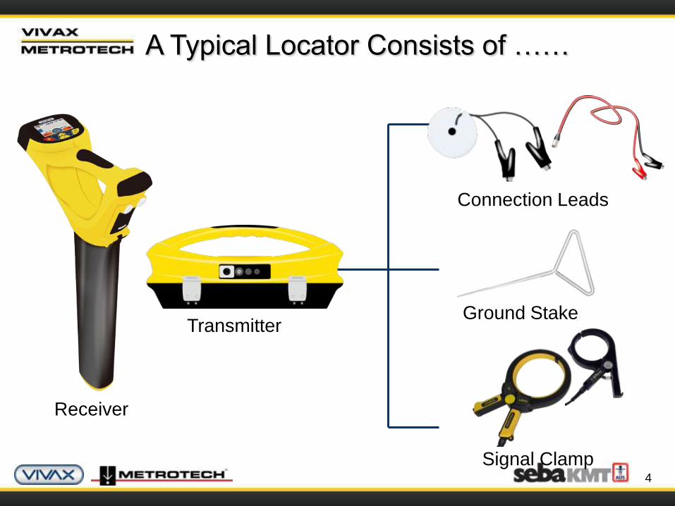
Receiver
Transmitter
Connection Leads
Ground Stake
Signal Clamp
A Typical Locator Consists of ……
5
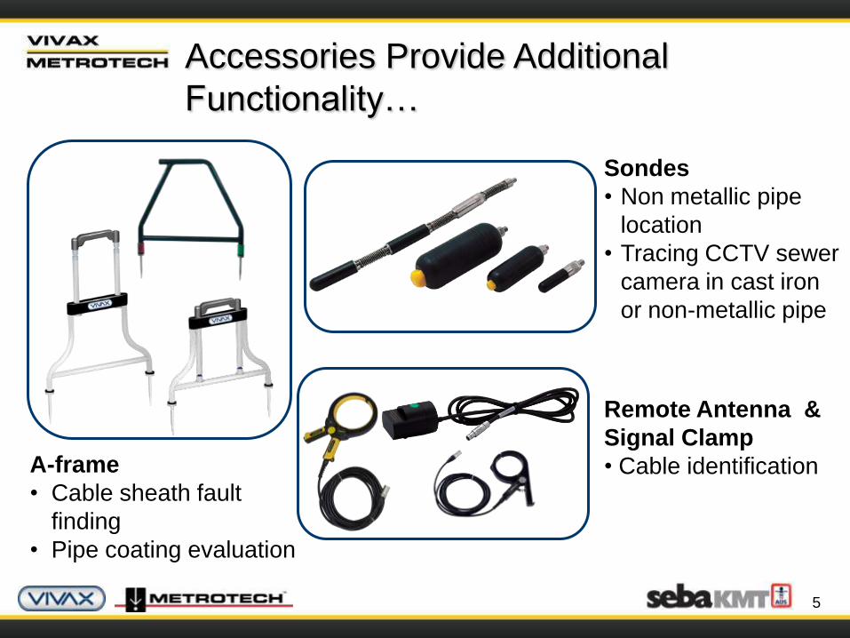
A-frame
• Cable sheath fault
finding
• Pipe coating evaluation
Sondes
• Non metallic pipe
location
• Tracing CCTV sewer
camera in cast iron
or non-metallic pipe
Remote Antenna &
Signal Clamp
• Cable identification
Accessories Provide Additional
Functionality…

6
Loc-10Tx-Power Lead
(12V DC)
• 30ft (10m) lead to
power (NOT charge)
the transmitter from a
vehicle
LPC Separation Filter
• Apply the transmitter
signal to the live
domestic wiring system
onto the service cable
and the supply cable in
the street
vLocPro-Charging
Lead (12V DC)
• 12ft (4m)long lead
to charge the
receiver battery (or
aux battery pack)
while on the move
vLocPro-Aux Battery
(12V DC-Ni-MH)
Loc-10Tx-Battery Tray &
Charger (100-240V AC –
12V DC-Ni-MH)
Accessories Provide Additional
Functionality…
7
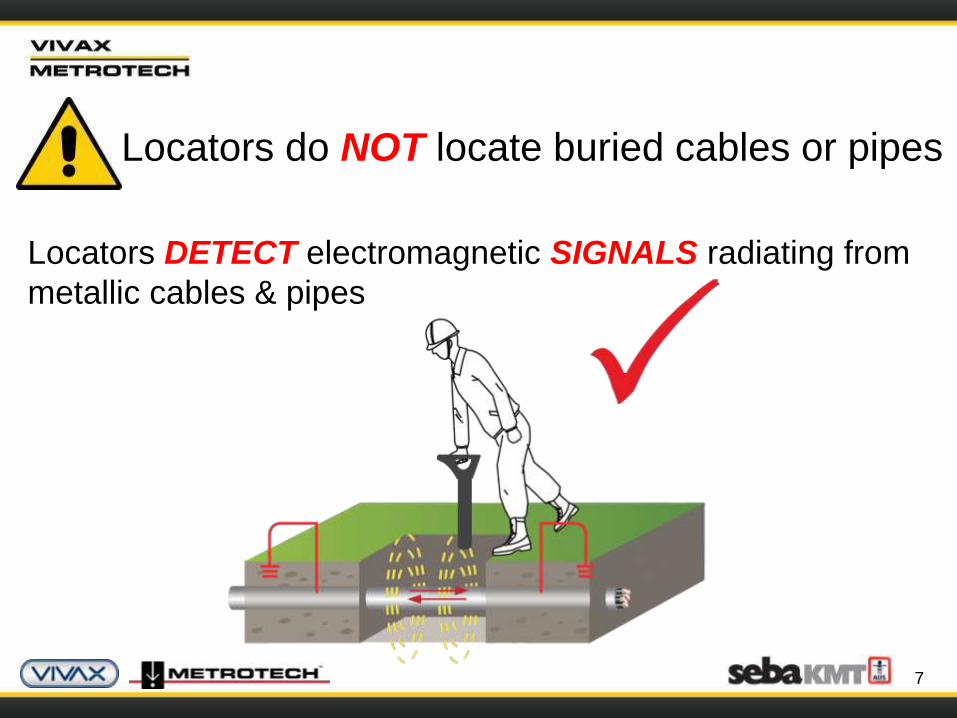
Locators do NOT locate buried cables or pipes
Locators DETECT electromagnetic SIGNALS radiating from
metallic cables & pipes
8
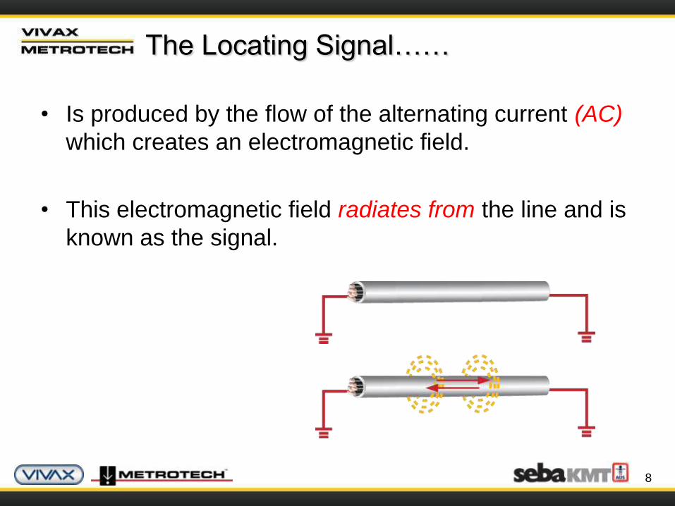
• Is produced by the flow of the alternating current (AC)
which creates an electromagnetic field.
• This electromagnetic field radiates from the line and is
known as the signal.
The Locating Signal……
9
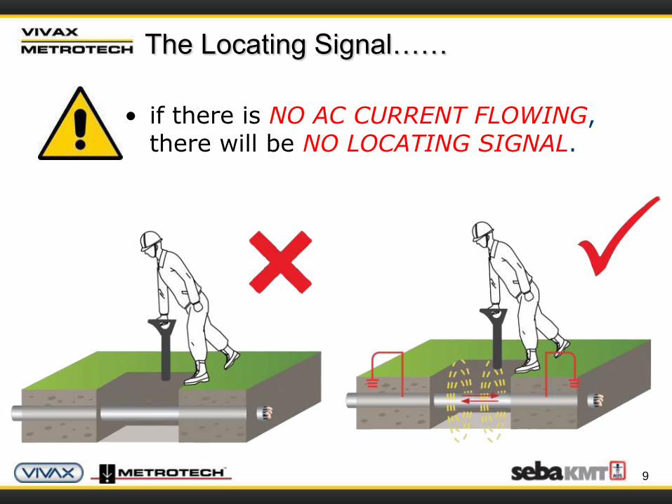
• if there is NO AC CURRENT FLOWING, there will be NO LOCATING SIGNAL.
The Locating Signal……

10
• Signals are created by the current flowing from the
transmitter which travel along the conductor
(line/cable/pipe) and back to the transmitter.
• The current typically uses the ground to complete the
current. The ground stake is used to complete the
circuit through the ground.
The Locating Signal……
11
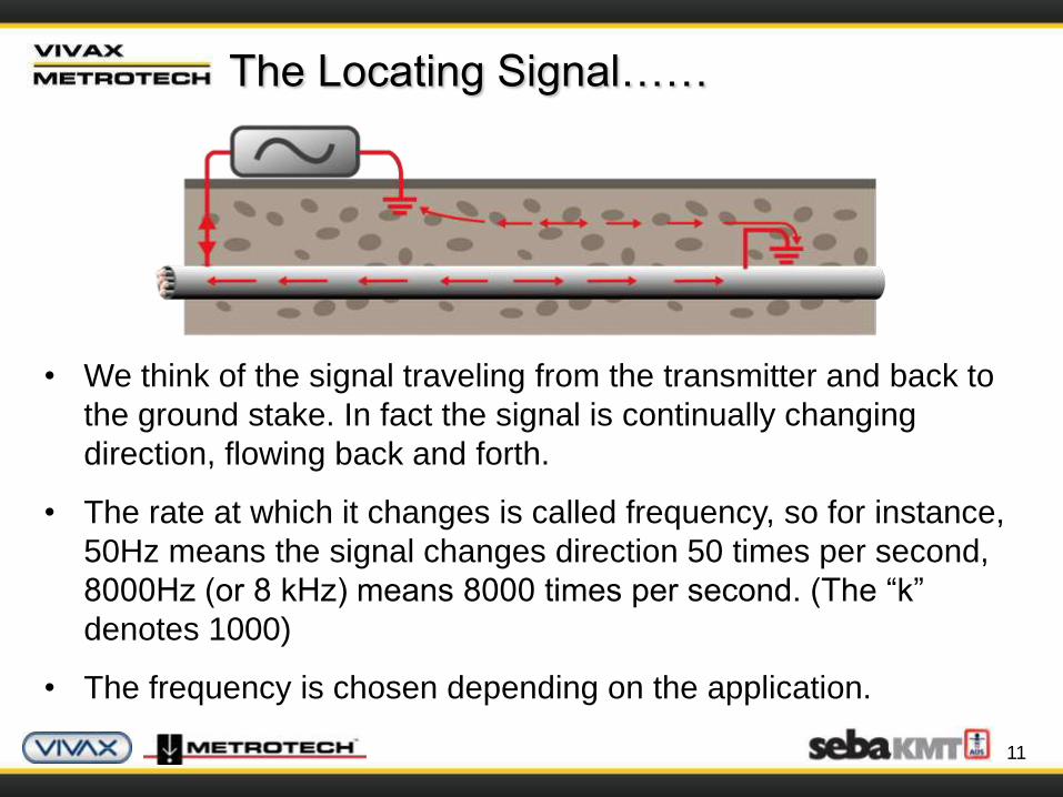
• We think of the signal traveling from the transmitter and back to
the ground stake. In fact the signal is continually changing
direction, flowing back and forth.
• The rate at which it changes is called frequency, so for instance,
50Hz means the signal changes direction 50 times per second,
8000Hz (or 8 kHz) means 8000 times per second. (The “k”
denotes 1000)
• The frequency is chosen depending on the application.
The Locating Signal……
12
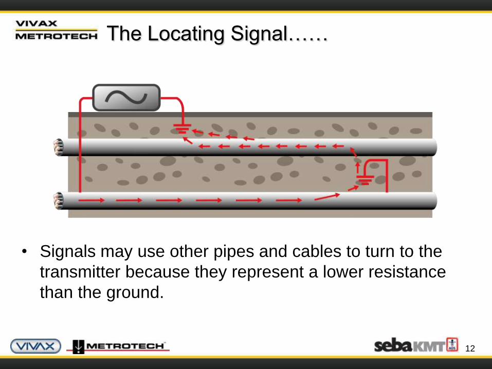
• Signals may use other pipes and cables to turn to the
transmitter because they represent a lower resistance
than the ground.
The Locating Signal……
13
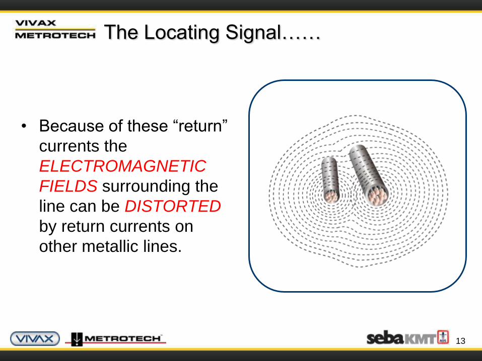
• Because of these “return”
currents the
ELECTROMAGNETIC
FIELDS surrounding the
line can be DISTORTED
by return currents on
other metallic lines.
The Locating Signal……
14
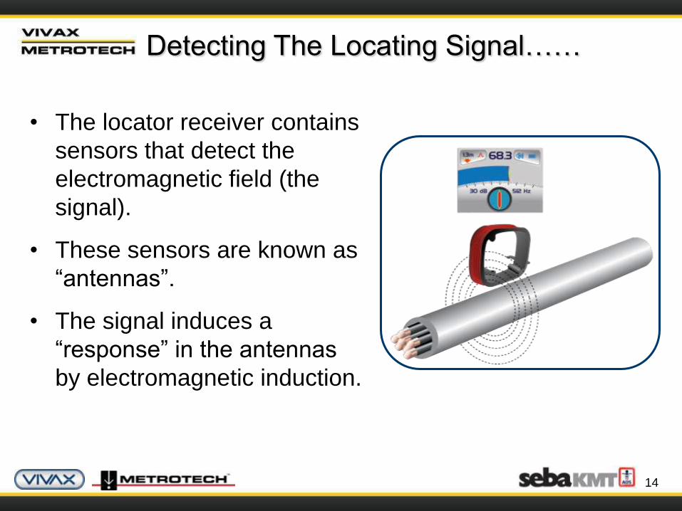
Detecting The Locating Signal……
• The locator receiver contains
sensors that detect the
electromagnetic field (the
signal).
• These sensors are known as
“antennas”.
• The signal induces a
“response” in the antennas
by electromagnetic induction.
15
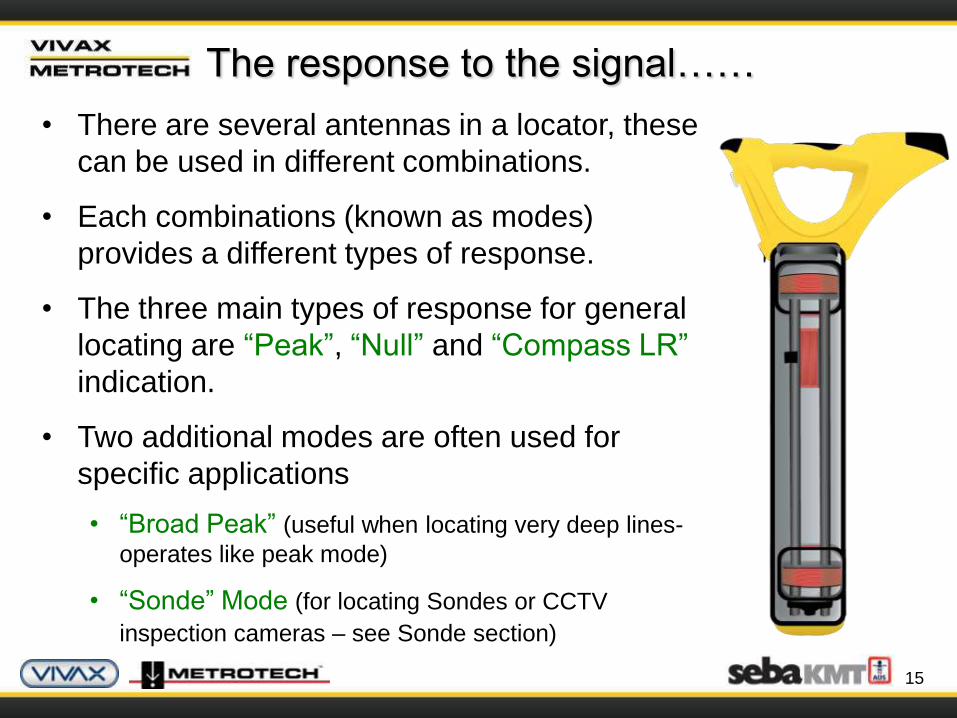
The response to the signal……
• There are several antennas in a locator, these
can be used in different combinations.
• Each combinations (known as modes)
provides a different types of response.
• The three main types of response for general
locating are “Peak”, “Null” and “Compass LR”
indication.
• Two additional modes are often used for
specific applications
• “Broad Peak” (useful when locating very deep lines-
operates like peak mode)
• “Sonde” Mode (for locating Sondes or CCTV
inspection cameras – see Sonde section)
16
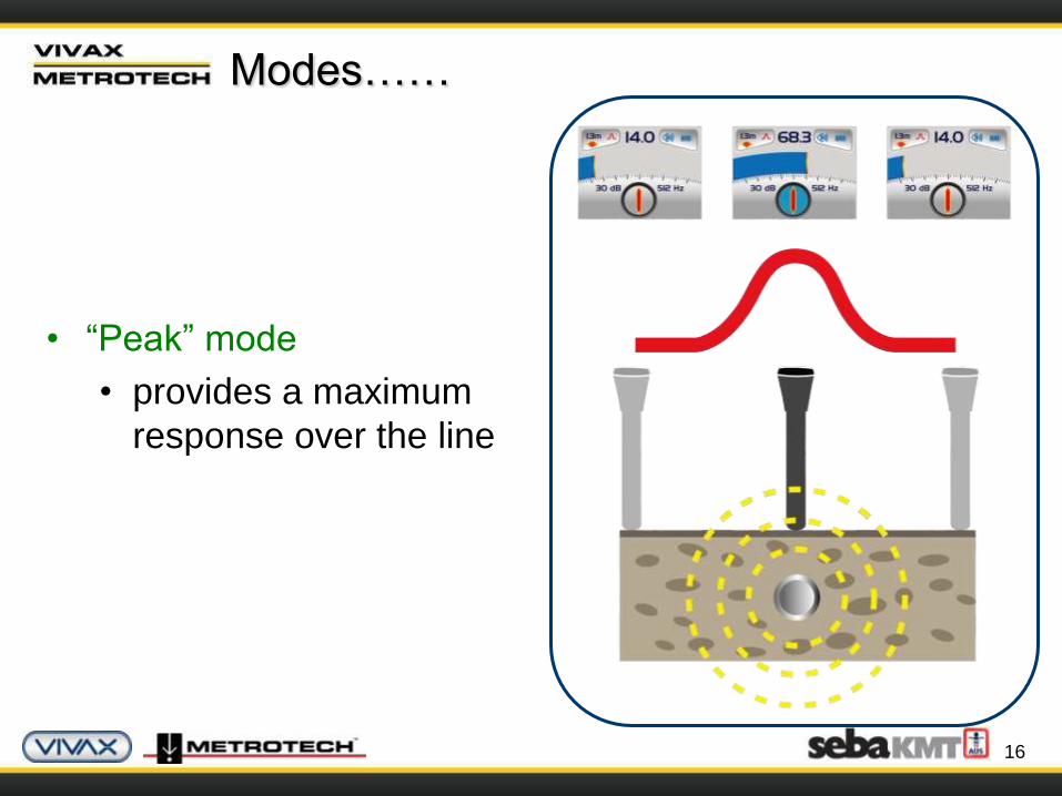
Modes……
• “Peak” mode
• provides a maximum
response over the line

17
• “Null mode”
• provides a minimum
response over the line
Modes……

18
• “Compass LR”
• Provides “direction” & “orientation” to the line
Modes……

19
• Broad Peak
• Provides increased
sensitivity locating for
deep pipes
• But response is broader,
so more difficult to
pinpoint
Modes……
20
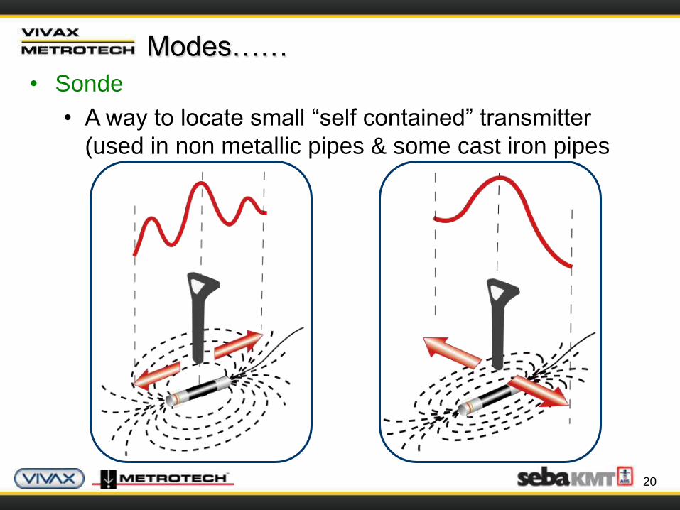
• Sonde
• A way to locate small “self contained” transmitter
(used in non metallic pipes & some cast iron pipes
Modes……

21
Signals used for locating can originate from a
transmitter (active locating), or a variety of other
sources (passive locating)
22
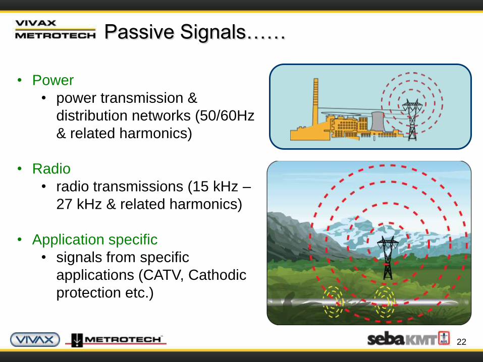
Passive Signals……
• Power
• power transmission &
distribution networks (50/60Hz
& related harmonics)
• Radio
• radio transmissions (15 kHz –
27 kHz & related harmonics)
• Application specific
• signals from specific
applications (CATV, Cathodic
protection etc.)
23
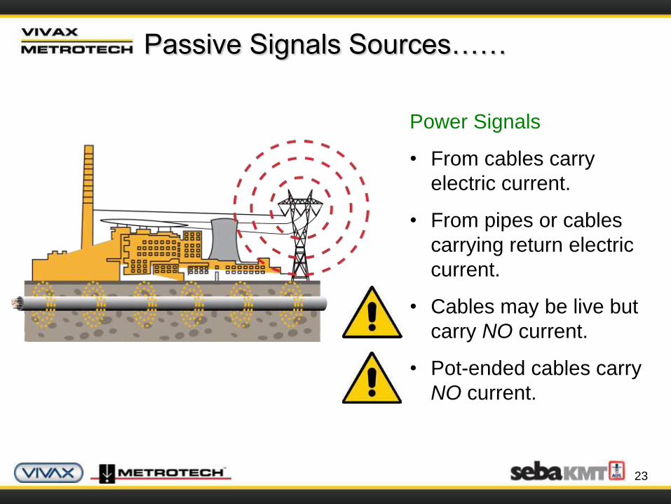
Passive Signals Sources……
Power Signals
• From cables carry
electric current.
• From pipes or cables
carrying return electric
current.
• Cables may be live but
carry NO current.
• Pot-ended cables carry
NO current.
24
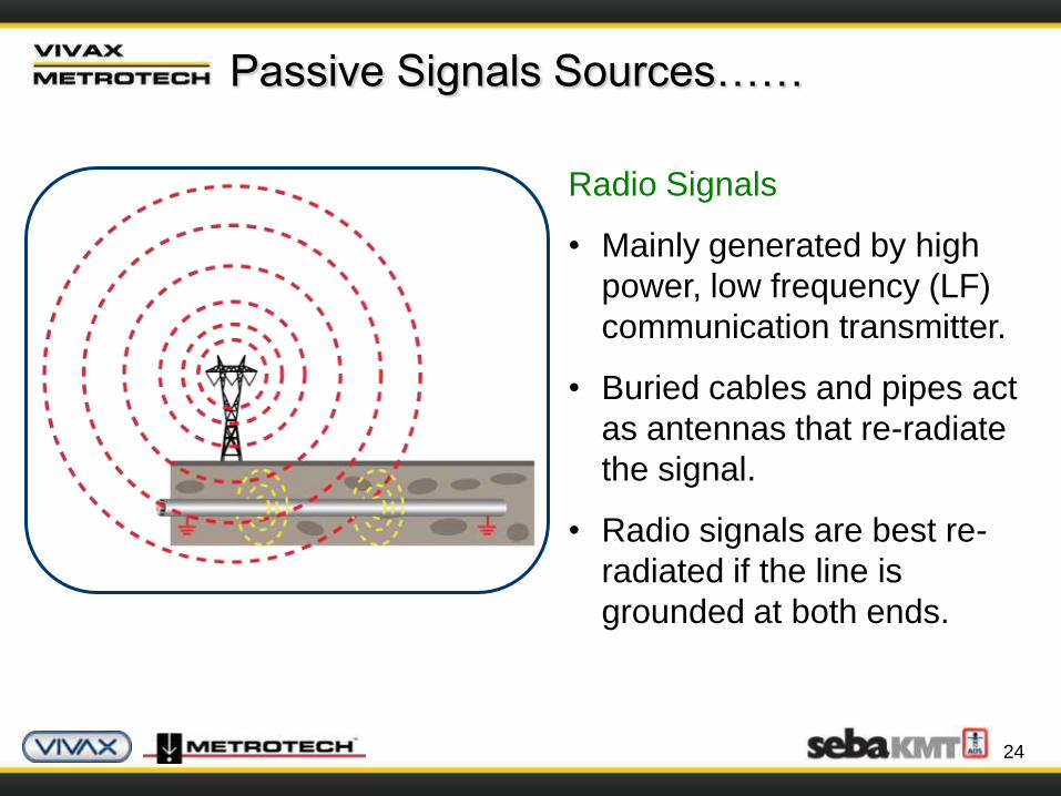
Radio Signals
• Mainly generated by high
power, low frequency (LF)
communication transmitter.
• Buried cables and pipes act
as antennas that re-radiate
the signal.
• Radio signals are best re-
radiated if the line is
grounded at both ends.
Passive Signals Sources……
25
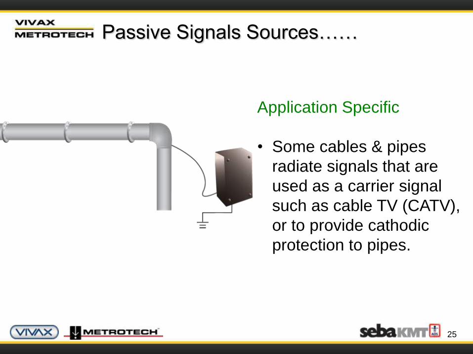
Application Specific
• Some cables & pipes
radiate signals that are
used as a carrier signal
such as cable TV (CATV),
or to provide cathodic
protection to pipes.
Passive Signals Sources……
26
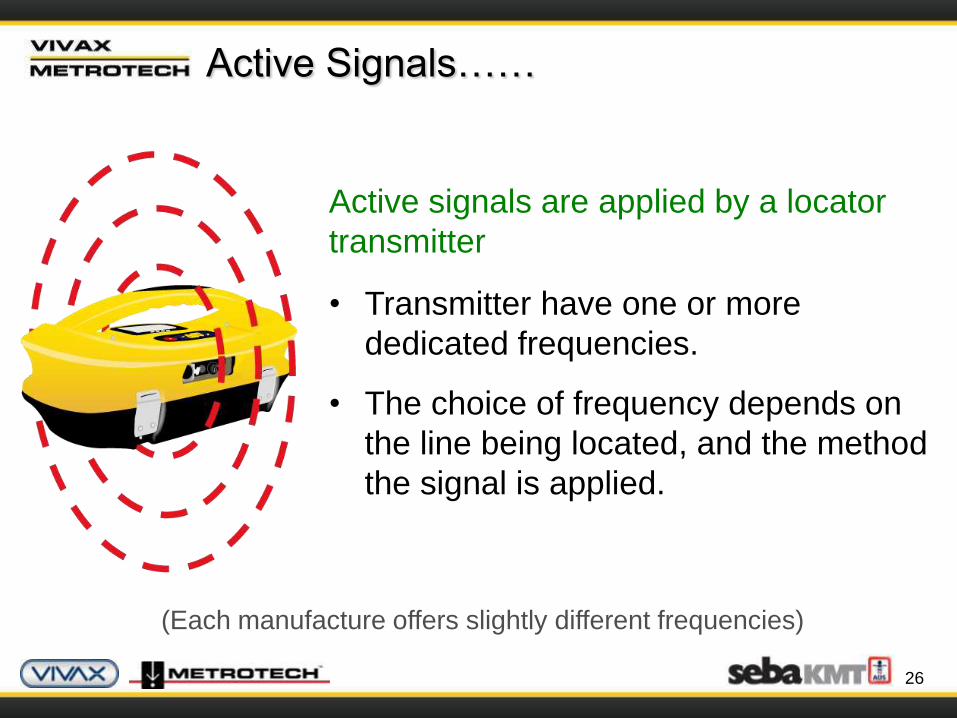
Active Signals……
• Transmitter have one or more
dedicated frequencies.
• The choice of frequency depends on
the line being located, and the method
the signal is applied.
Active signals are applied by a locator
transmitter
(Each manufacture offers slightly different frequencies)
27
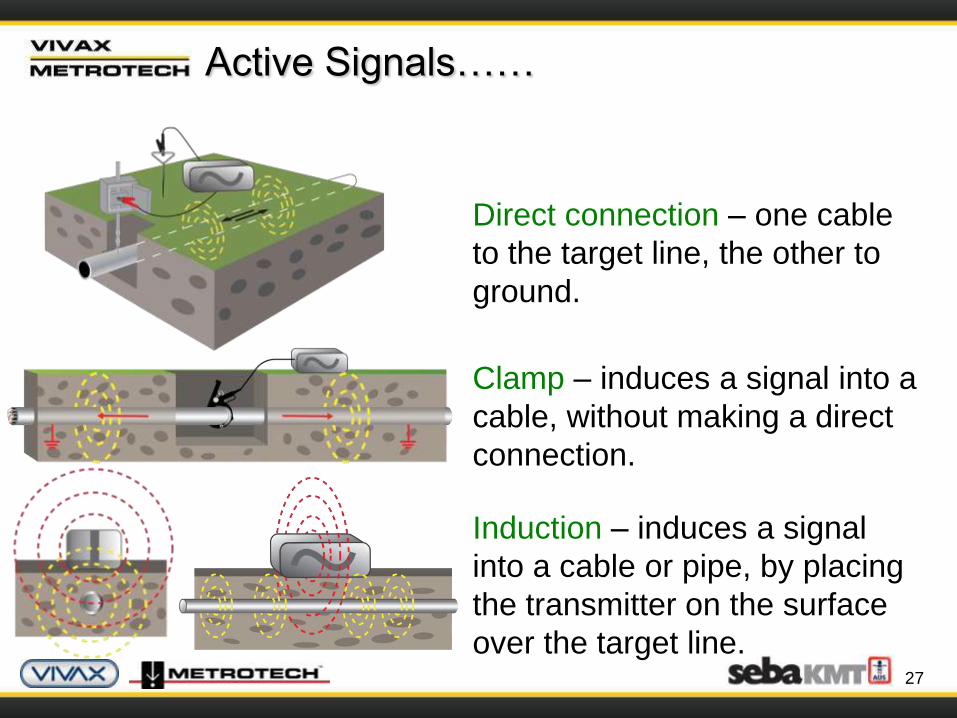
Three ways to apply the signal:
Direct connection – one cable
to the target line, the other to
ground.
Clamp – induces a signal into a
cable, without making a direct
connection.
Induction – induces a signal
into a cable or pipe, by placing
the transmitter on the surface
over the target line.
Active Signals……
28
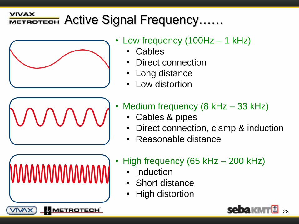
• Low frequency (100Hz – 1 kHz)
• Cables
• Direct connection
• Long distance
• Low distortion
• Medium frequency (8 kHz – 33 kHz)
• Cables & pipes
• Direct connection, clamp & induction
• Reasonable distance
• High frequency (65 kHz – 200 kHz)
• Induction
• Short distance
• High distortion
Active Signal Frequency……
29
Passive verses Active Location…
• Passive Location
• Use to mark the location of unidentified buried
lines before digging (Avoidance)
• Do NOT use to identify or trace “specific” lines
• Active Location
• Use to trace, identify & pinpoint a buried line
• Use to measure the depth of the buried line
• Use to measure the signal current on the buried
line

30
Measuring Depth……
• Depth & signal current can also
be measured using a locator
• Depth is measured to the center
of the signal – in the case of a
large pipe this is considerably
different to the top of the pipe
• Some locators provide
“continuous” depth – this is only
accurate when directly over the
line
31
1.Pushbutton Depth
2.Triangulation Depth – 70% rule
3.Triangulation Depth – 50% rule
The three (3) most common ways of measuring depth are:
Measuring Depth……
32
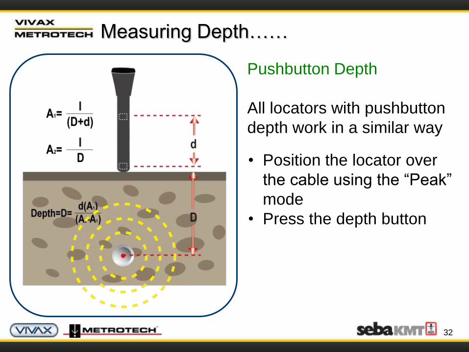
Pushbutton Depth
All locators with pushbutton
depth work in a similar way
• Position the locator over
the cable using the “Peak”
mode
• Press the depth button
Measuring Depth……
33
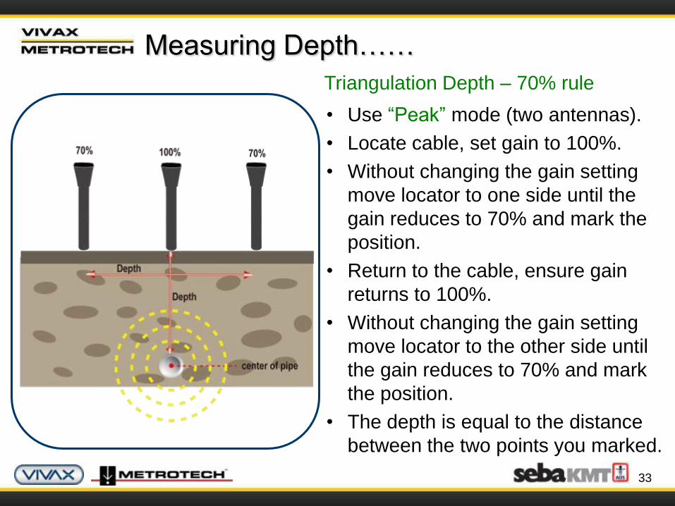
Triangulation Depth – 70% rule
• Use “Peak” mode (two antennas).
• Locate cable, set gain to 100%.
• Without changing the gain setting
move locator to one side until the
gain reduces to 70% and mark the
position.
• Return to the cable, ensure gain
returns to 100%.
• Without changing the gain setting
move locator to the other side until
the gain reduces to 70% and mark
the position.
• The depth is equal to the distance
between the two points you marked.
Measuring Depth……
34
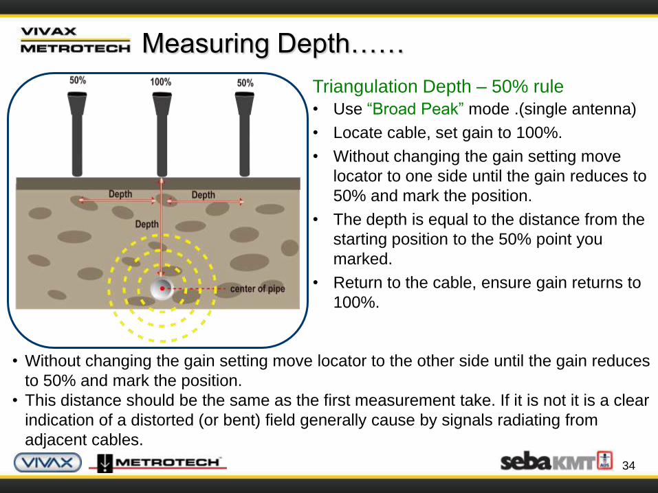
Triangulation Depth – 50% rule
• Use “Broad Peak” mode .(single antenna)
• Locate cable, set gain to 100%.
• Without changing the gain setting move
locator to one side until the gain reduces to
50% and mark the position.
• The depth is equal to the distance from the
starting position to the 50% point you
marked.
• Return to the cable, ensure gain returns to
100%.
• Without changing the gain setting move locator to the other side until the gain reduces
to 50% and mark the position.
• This distance should be the same as the first measurement take. If it is not it is a clear
indication of a distorted (or bent) field generally cause by signals radiating from
adjacent cables.
Measuring Depth……

Getting to Know the vLocPro
The Principles of Cable & Pipe Location
36
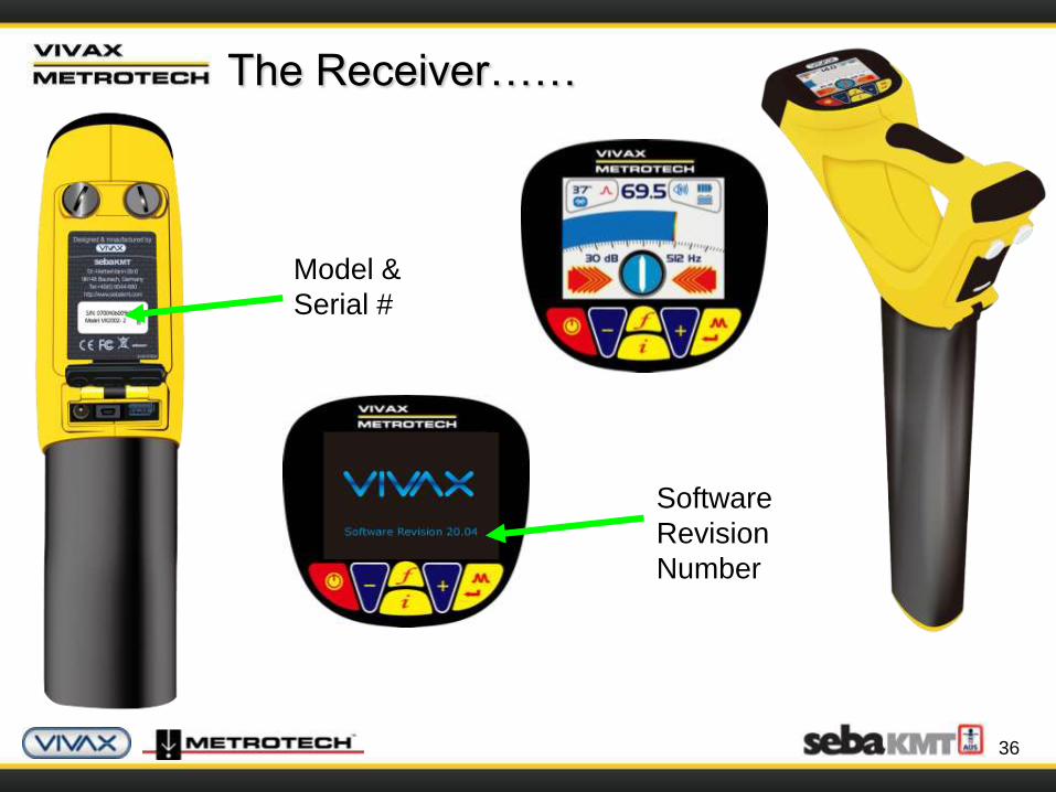
The Receiver……
Model &
Serial #
Software
Revision
Number
37
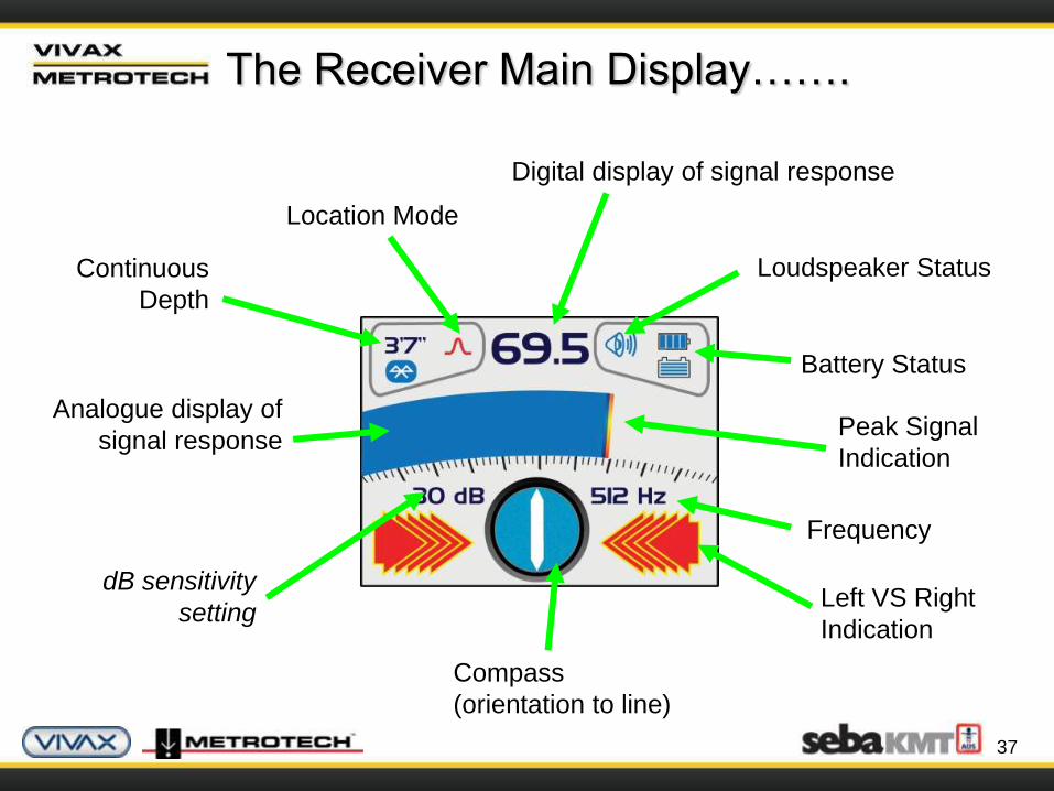
The Receiver Main Display…….
Loudspeaker Status
Battery Status
Peak Signal
Indication
Frequency
Left VS Right
Indication
Compass
(orientation to line)
dB sensitivity
setting
Analogue display of
signal response
Continuous
Depth
Location Mode
Digital display of signal response

38
Receiver Controls…Normal Use…
Frequency Select
Gain Control
(Increase gain)
Location Mode
Select
Information
Depth / Current MeasurementGain Control
(Reduce gain)
On / Off Control
39
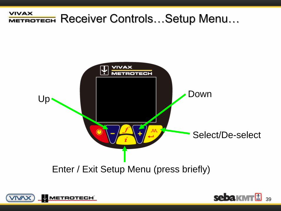
Receiver Controls…Setup Menu…
Down
Select/De-select
Enter / Exit Setup Menu (press briefly)
Up
40
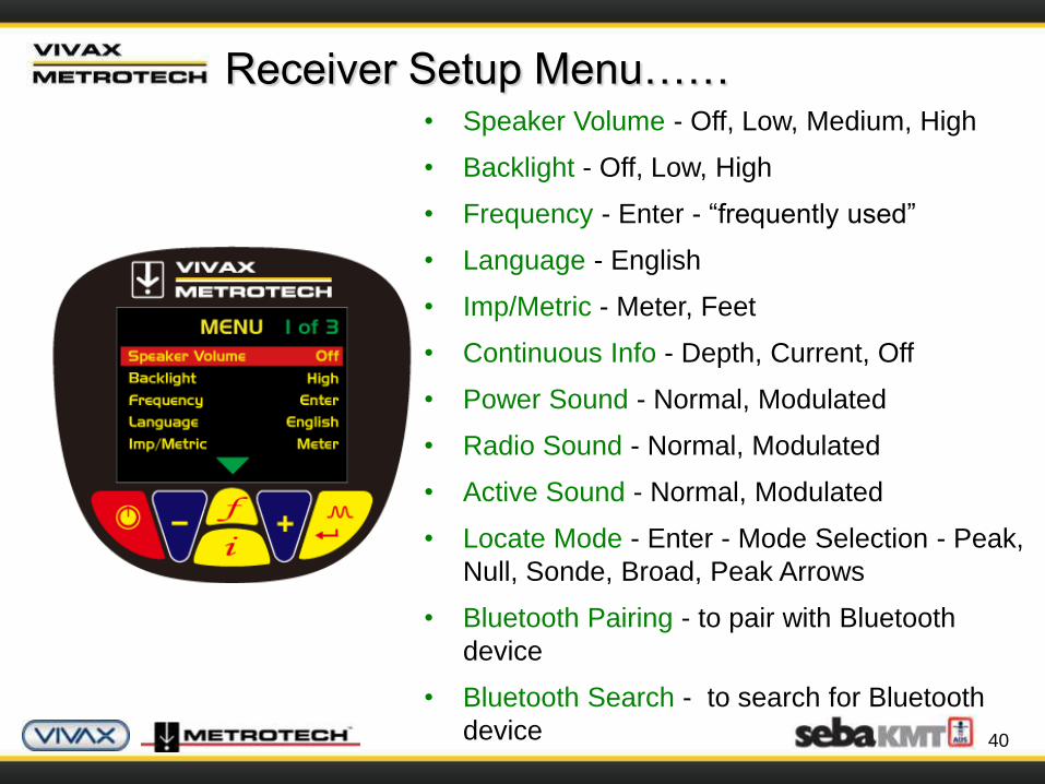
Receiver Setup Menu……• Speaker Volume - Off, Low, Medium, High
• Backlight - Off, Low, High
• Frequency - Enter - “frequently used”
• Language - English
• Imp/Metric - Meter, Feet
• Continuous Info - Depth, Current, Off
• Power Sound - Normal, Modulated
• Radio Sound - Normal, Modulated
• Active Sound - Normal, Modulated
• Locate Mode - Enter - Mode Selection - Peak,
Null, Sonde, Broad, Peak Arrows
• Bluetooth Pairing - to pair with Bluetooth
device
• Bluetooth Search - to search for Bluetooth
device
41
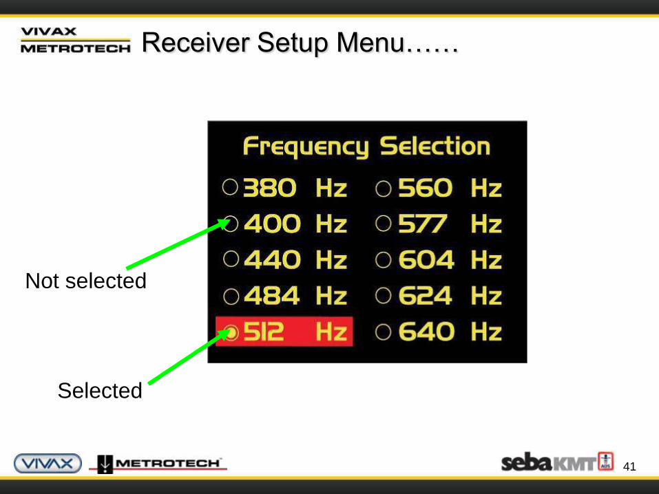
Receiver Setup Menu……
Not selected
Selected
42
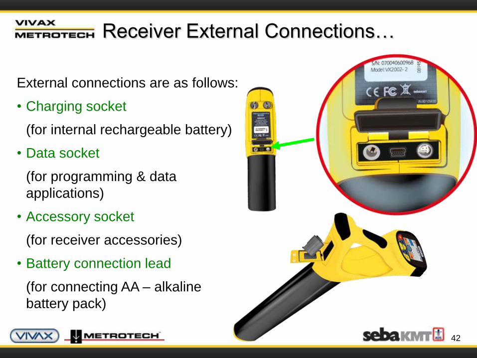
External connections are as follows:
• Charging socket
(for internal rechargeable battery)
• Data socket
(for programming & data
applications)
• Accessory socket
(for receiver accessories)
• Battery connection lead
(for connecting AA – alkaline
battery pack)
Receiver External Connections…
43
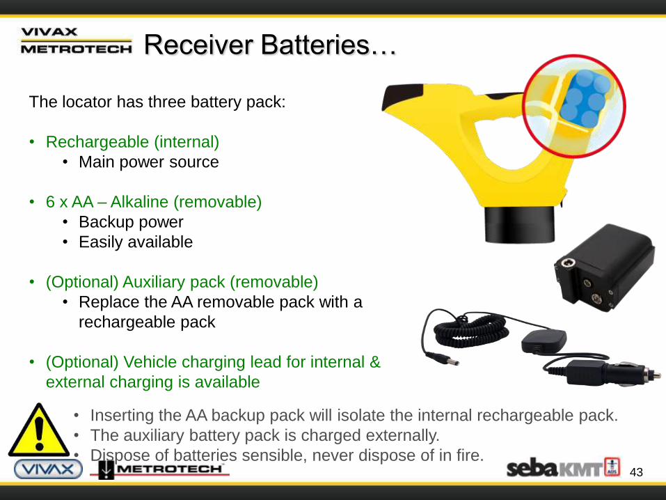
Receiver Batteries…
The locator has three battery pack:
• Rechargeable (internal)
• Main power source
• 6 x AA – Alkaline (removable)
• Backup power
• Easily available
• (Optional) Auxiliary pack (removable)
• Replace the AA removable pack with a
rechargeable pack
• (Optional) Vehicle charging lead for internal &
external charging is available
• Inserting the AA backup pack will isolate the internal rechargeable pack.
• The auxiliary battery pack is charged externally.
• Dispose of batteries sensible, never dispose of in fire.

44
The Transmitter……
Software Revision
Number
Model &
Serial #
labels

45
The Transmitter……
Output Setting
(Step)
Mode Indication
Units
(mAmps, volts,
ohms)
Loudspeaker Level
Digital read out
(mAmps, volts, ohms)
Frequency being
transmittedHigh voltage
warning
Battery
Status
Low power
indicator

46
The Transmitter……
On / Off Control
Output decrease
Frequency select
Information
(Volume, Volts, Ohms)
Output increase
47
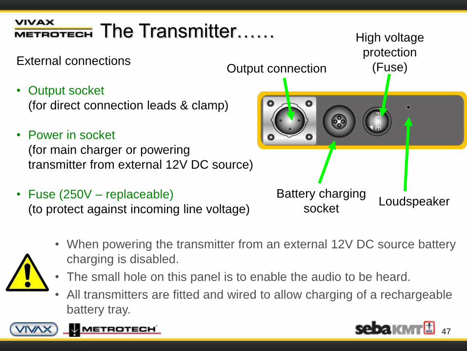
The Transmitter……
External connections
• Output socket
(for direct connection leads & clamp)
• Power in socket
(for main charger or powering
transmitter from external 12V DC source)
• Fuse (250V – replaceable)
(to protect against incoming line voltage)
• When powering the transmitter from an external 12V DC source battery
charging is disabled.
• The small hole on this panel is to enable the audio to be heard.
• All transmitters are fitted and wired to allow charging of a rechargeable
battery tray.
Battery charging
socketLoudspeaker
Output connection
High voltage
protection
(Fuse)
48
The Transmitter……
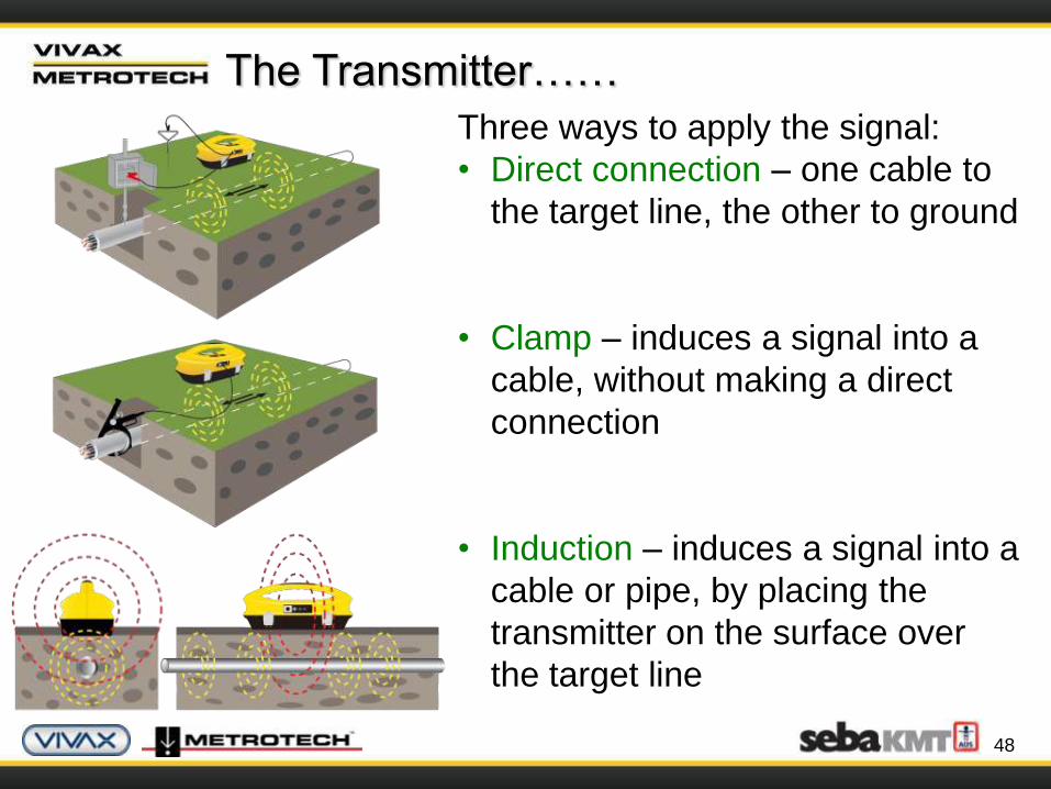
Three ways to apply the signal:
• Direct connection – one cable to
the target line, the other to ground
• Clamp – induces a signal into a
cable, without making a direct
connection
• Induction – induces a signal into a
cable or pipe, by placing the
transmitter on the surface over
the target line
49
The Transmitter……
Three transmitting modes:
• Direct Connection Mode – selects automatically when
plugging in the connection leads
• Signal Clamp Mode – selects automatically when plugging
in the clamp
• Induction Mode – default mode when nothing is plugged in
50
The Transmitter……
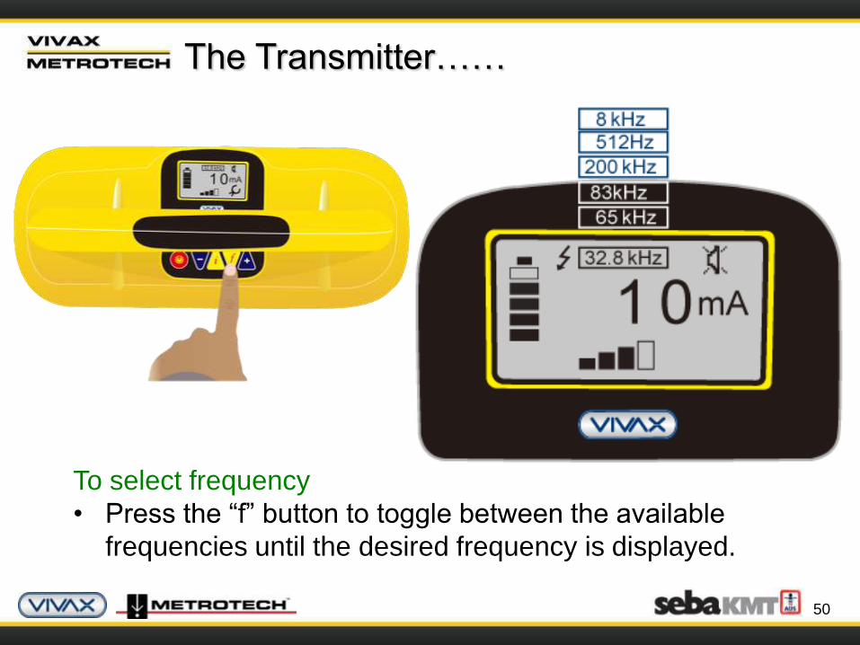
To select frequency
• Press the “f” button to toggle between the available
frequencies until the desired frequency is displayed.
51
The Transmitter……
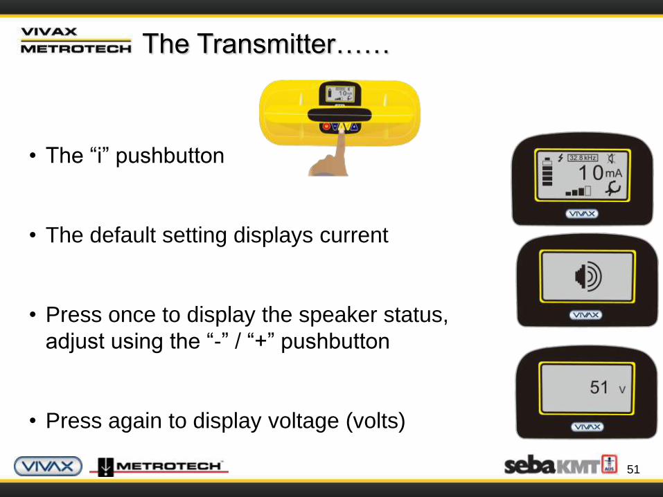
• The “i” pushbutton
• The default setting displays current
• Press once to display the speaker status,
adjust using the “-” / “+” pushbutton
• Press again to display voltage (volts)
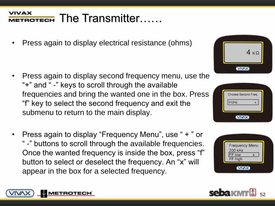
• Press again to display electrical resistance (ohms)
• Press again to display second frequency menu, use the
“+” and “ -” keys to scroll through the available
frequencies and bring the wanted one in the box. Press
“f” key to select the second frequency and exit the
submenu to return to the main display.
• Press again to display “Frequency Menu”, use “ + ” or
“ -” buttons to scroll through the available frequencies.
Once the wanted frequency is inside the box, press “f”
button to select or deselect the frequency. An “x” will
appear in the box for a selected frequency.
52
The Transmitter……

53
The Transmitter……
• Protection
• The transmitter checks the line when
connected, if the line is carrying in
excess of 35V, it will display “High
Voltage” and not allow the transmitter
to operate.
• In addition the transmitter is
protected by a 1.25A / 250V fuse in
the event of excessive voltage or
voltage spikes on the line.
54
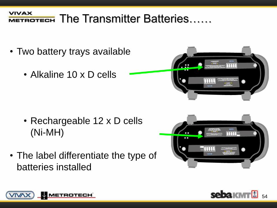
The Transmitter Batteries……
• Two battery trays available
• Alkaline 10 x D cells
• Rechargeable 12 x D cells
(Ni-MH)
• The label differentiate the type of
batteries installed
55
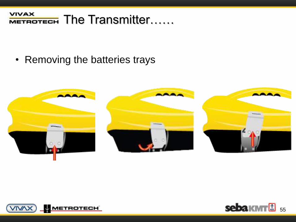
The Transmitter……
• Removing the batteries trays
Using A Locator
The Principles of Cable & Pipe Location
57
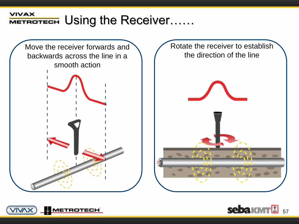
Using the Receiver……
Rotate the receiver to establish
the direction of the lineMove the receiver forwards and
backwards across the line in a
smooth action
58
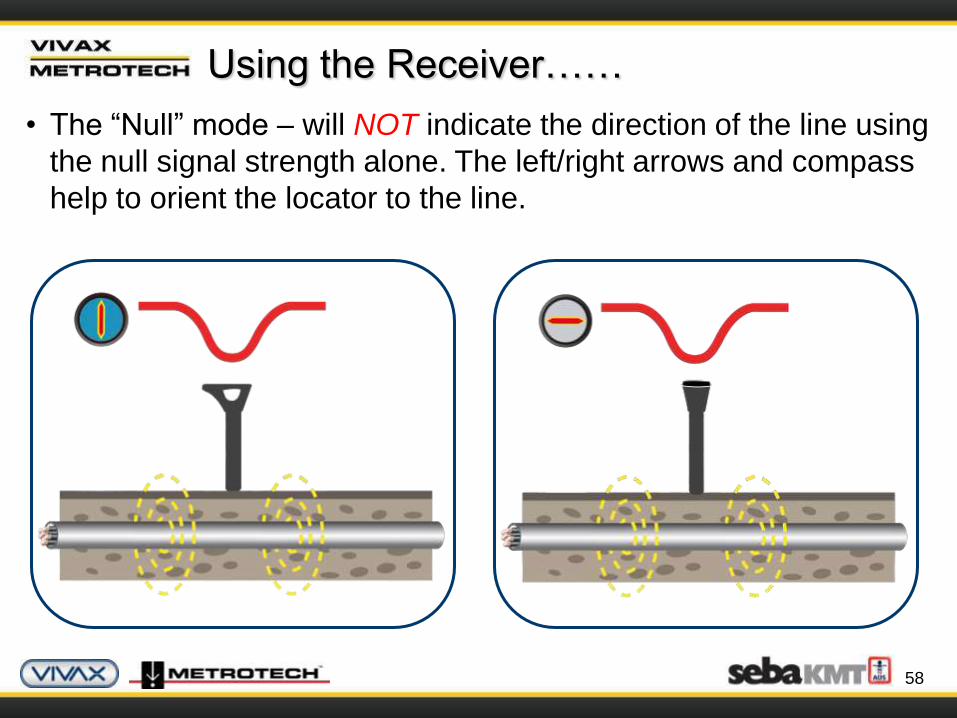
Using the Receiver……
• The “Null” mode – will NOT indicate the direction of the line using
the null signal strength alone. The left/right arrows and compass
help to orient the locator to the line.
59
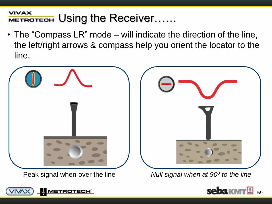
Using the Receiver……
• The “Compass LR” mode – will indicate the direction of the line,
the left/right arrows & compass help you orient the locator to the
line.
Peak signal when over the line Null signal when at 900 to the line

60
Using the Receiver……
Select the locating mode:
• “Peak” mode
• Best for tracing and pinpoint the line in congested areas
• “Null” mode
• Best for following a line if tracing for some distance
(swap to “Peak” mode to pinpoint)
• “Compass LR” mode
• Similar use as “Null” mode (swap to “Peak” mode to
pinpoint)

61
To locate a line an electric current must be
flowing.
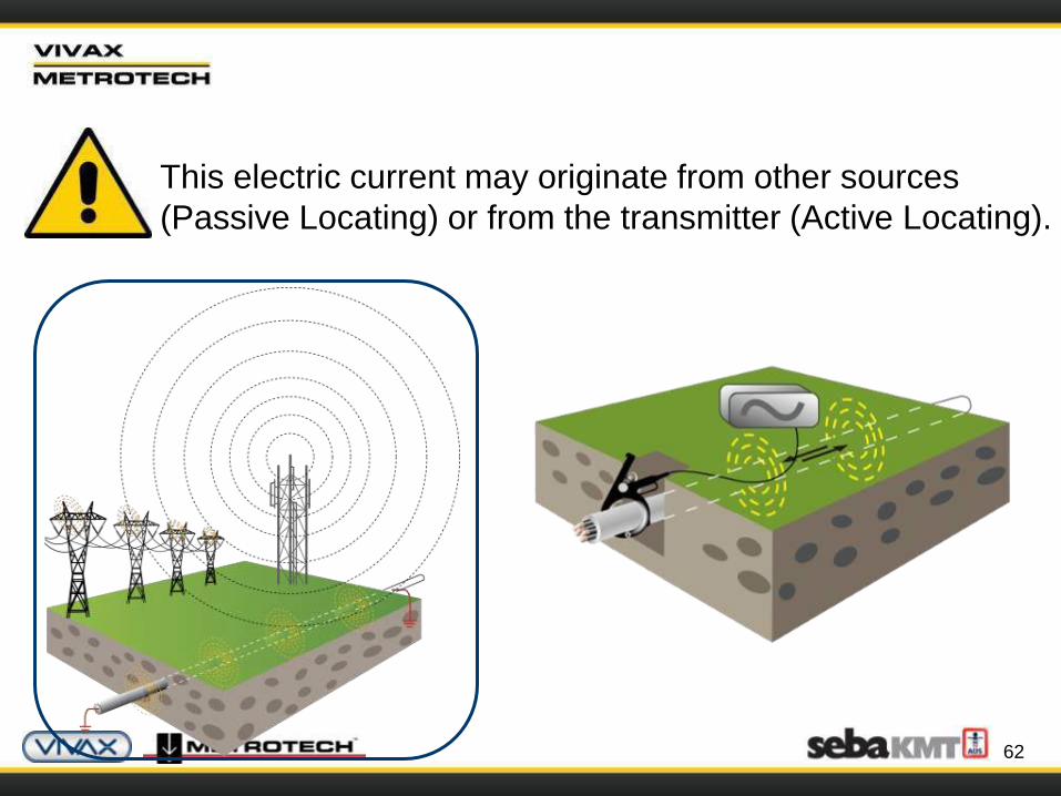
62
This electric current may originate from other sources
(Passive Locating) or from the transmitter (Active Locating).
63
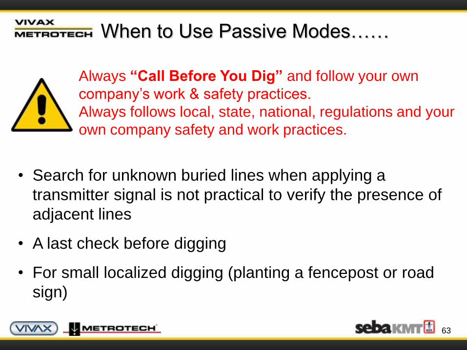
When to Use Passive Modes……
Always “Call Before You Dig” and follow your own
company’s work & safety practices.
Always follows local, state, national, regulations and your
own company safety and work practices.
• Search for unknown buried lines when applying a
transmitter signal is not practical to verify the presence of
adjacent lines
• A last check before digging
• For small localized digging (planting a fencepost or road
sign)
64
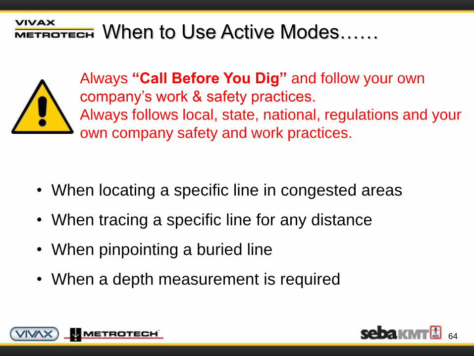
When to Use Active Modes……
Always “Call Before You Dig” and follow your own
company’s work & safety practices.
Always follows local, state, national, regulations and your
own company safety and work practices.
• When locating a specific line in congested areas
• When tracing a specific line for any distance
• When pinpointing a buried line
• When a depth measurement is required

65
Passive Locating……
• Passive locating is generally used to AVOID rather than identify
buried lines.
• Using only the receiver, sweep the area in the search pattern
shown.
• Sweep in “Power” mode, then “Radio” mode.

66
Applying The Transmitter Signal to The
Line……
There are three (3) methods of applying an active signal
to a line:
1. Direct connection (preferred)
2. Using a signal clamp
3. Induction
67
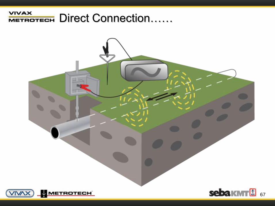
Direct Connection……
68
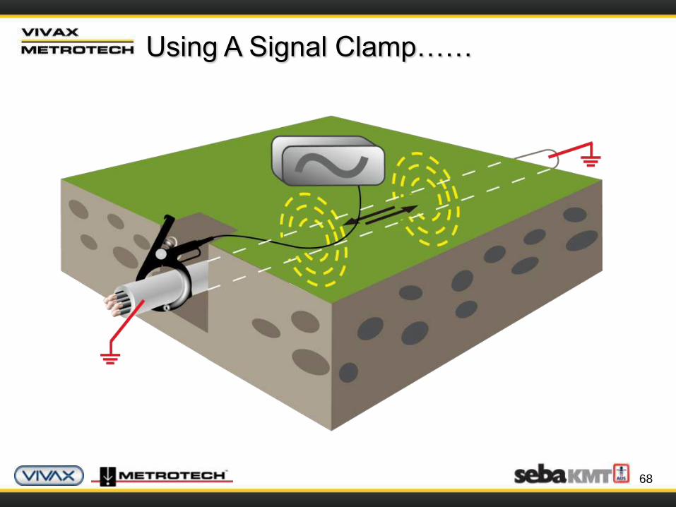
Using A Signal Clamp……
69
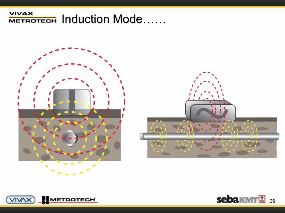
Induction Mode……
70
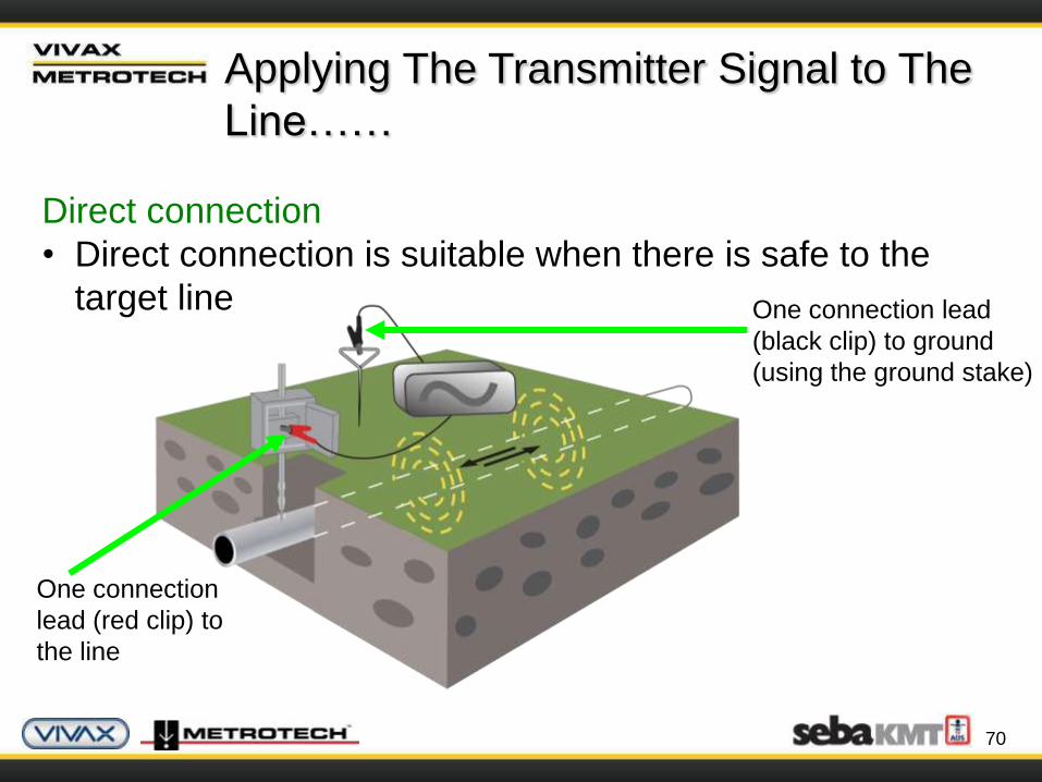
Applying The Transmitter Signal to The
Line……
Direct connection
• Direct connection is suitable when there is safe to the
target line
One connection
lead (red clip) to
the line
One connection lead
(black clip) to ground
(using the ground stake)
71
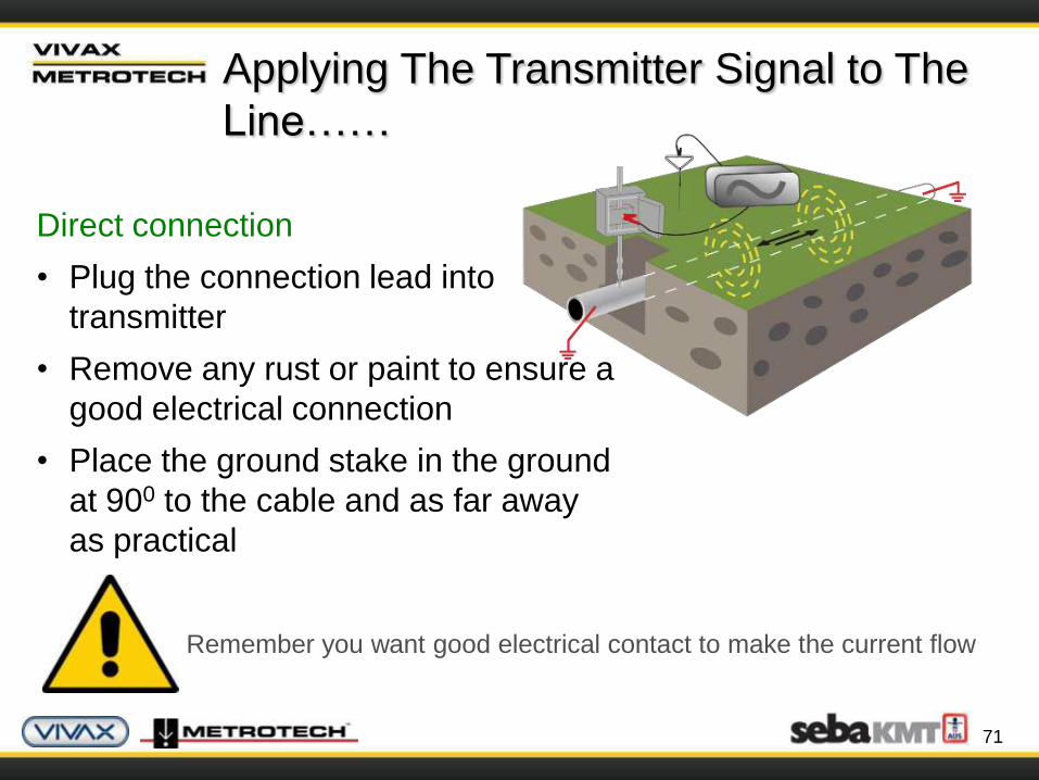
Applying The Transmitter Signal to The
Line……
Direct connection
• Plug the connection lead into
transmitter
• Remove any rust or paint to ensure a
good electrical connection
• Place the ground stake in the ground
at 900 to the cable and as far away
as practical
Remember you want good electrical contact to make the current flow
72
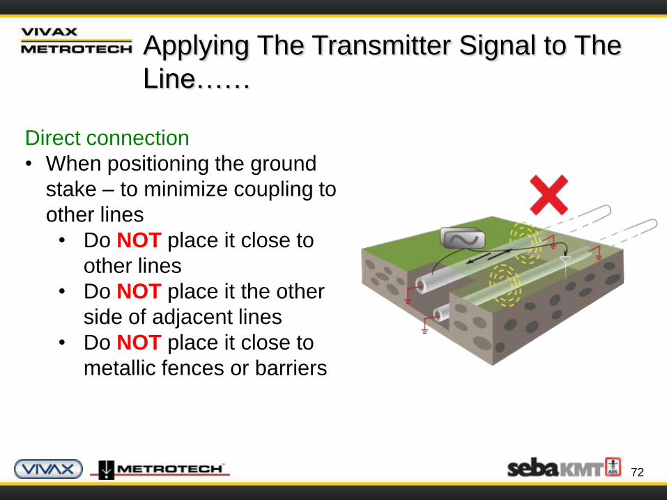
Applying The Transmitter Signal to The
Line……
Direct connection
• When positioning the ground
stake – to minimize coupling to
other lines
• Do NOT place it close to
other lines
• Do NOT place it the other
side of adjacent lines
• Do NOT place it close to
metallic fences or barriers
73
Applying The Transmitter Signal to The
Line……
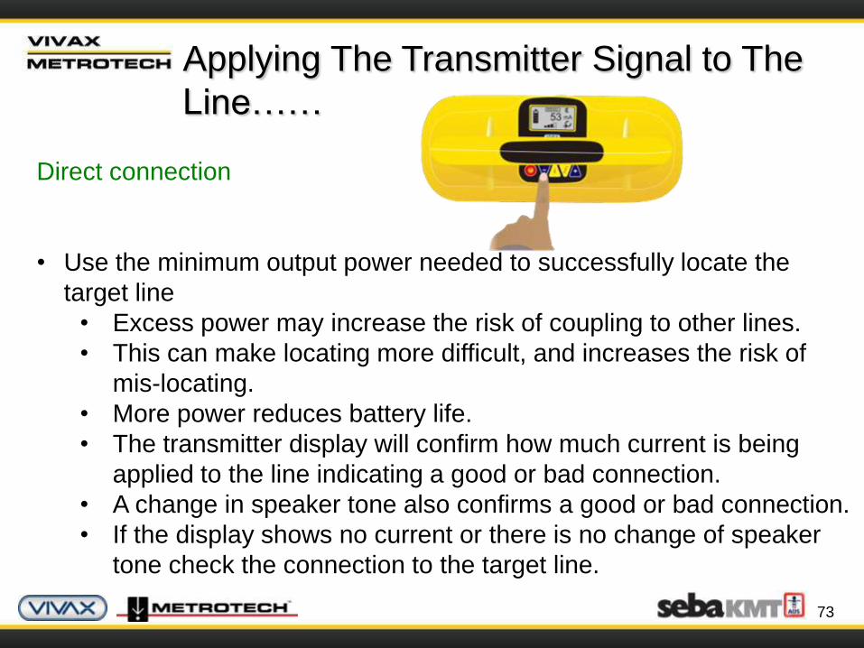
Direct connection
• Use the minimum output power needed to successfully locate the
target line
• Excess power may increase the risk of coupling to other lines.
• This can make locating more difficult, and increases the risk of
mis-locating.
• More power reduces battery life.
• The transmitter display will confirm how much current is being
applied to the line indicating a good or bad connection.
• A change in speaker tone also confirms a good or bad connection.
• If the display shows no current or there is no change of speaker
tone check the connection to the target line.
74
Applying The Transmitter Signal to The
Line……
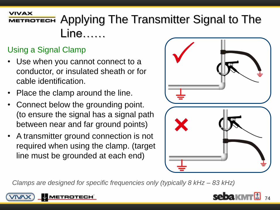
Using a Signal Clamp
• Use when you cannot connect to a
conductor, or insulated sheath or for
cable identification.
• Place the clamp around the line.
• Connect below the grounding point.
(to ensure the signal has a signal path
between near and far ground points)
• A transmitter ground connection is not
required when using the clamp. (target
line must be grounded at each end)
Clamps are designed for specific frequencies only (typically 8 kHz – 83 kHz)
75
Applying The Transmitter Signal to The
Line……
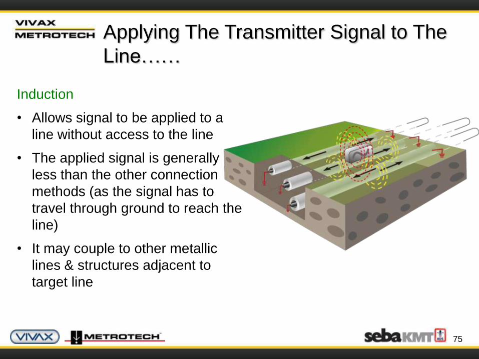
Induction
• Allows signal to be applied to a
line without access to the line
• The applied signal is generally
less than the other connection
methods (as the signal has to
travel through ground to reach the
line)
• It may couple to other metallic
lines & structures adjacent to
target line
76
Applying The Transmitter Signal to The
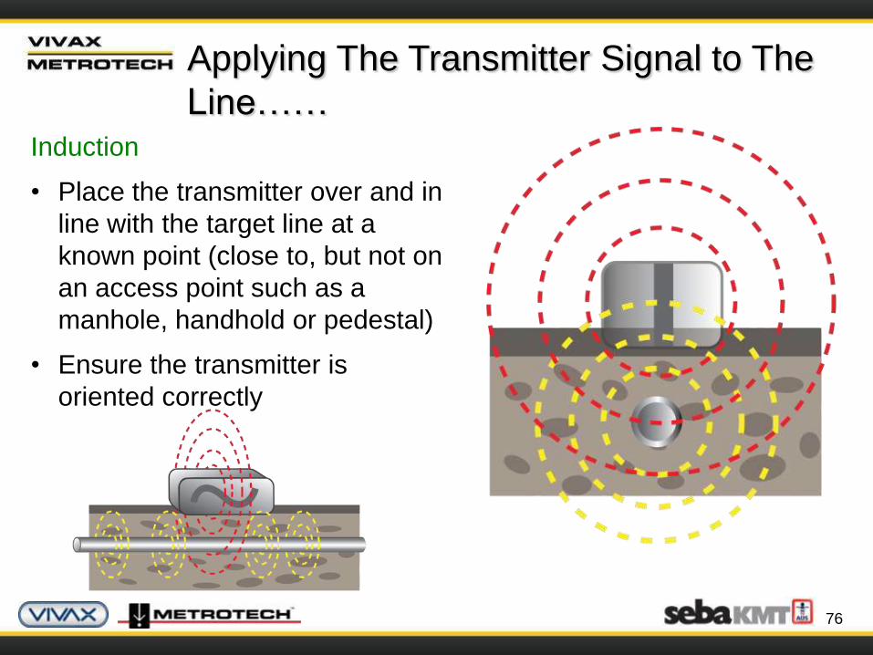
Line……Induction
• Place the transmitter over and in
line with the target line at a
known point (close to, but not on
an access point such as a
manhole, handhold or pedestal)
• Ensure the transmitter is
oriented correctly

77
Applying The Transmitter Signal to The
Line……Induction
• Never locate within 15ft (5m)
of the transmitter (the signal
from the transmitter has an
airborne element which you
will locate)
• Never place on top of a
manhole cover or metal
plate (the signal will not
penetrate to the line and
may in fact damage the
transmitter)
The accuracy of depth readings may be influenced if taken close to a
transmitter on induction
78
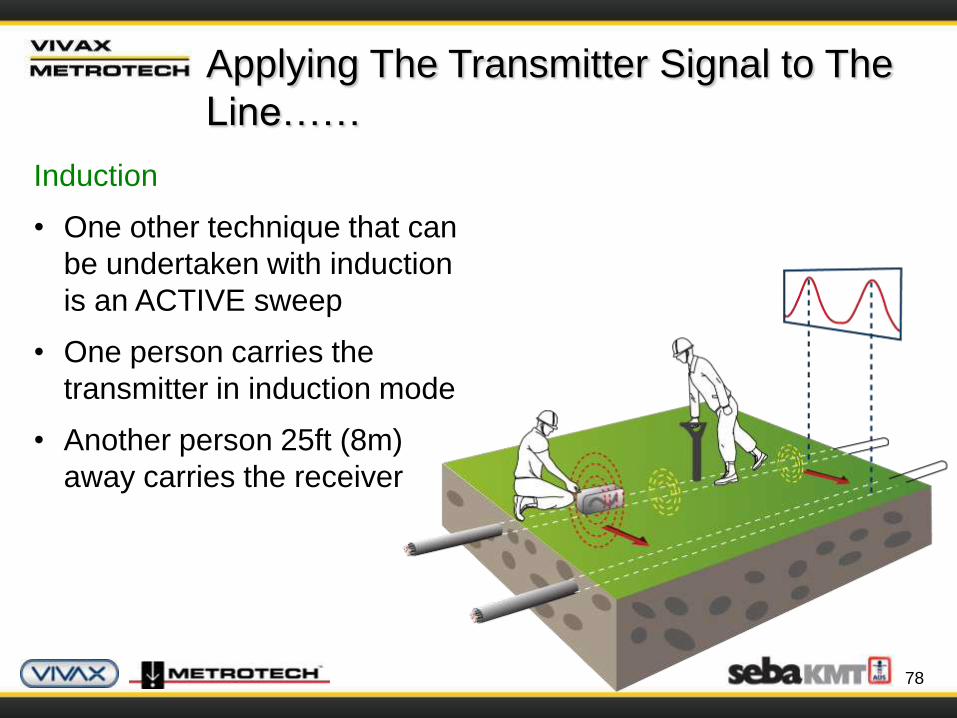
Applying The Transmitter Signal to The
Line……
Induction
• One other technique that can
be undertaken with induction
is an ACTIVE sweep
• One person carries the
transmitter in induction mode
• Another person 25ft (8m)
away carries the receiver

79
Applying The Transmitter Signal to The
Line……
Frequency
• Most transmitters can transmit several different frequencies
• Different manufacturers use different frequencies
• The best frequency for the job will vary depending on the way
the signal is applied (direct connection, signal clamp, induction)
• The distance from the transmitter
• The type of line being located

80
Applying The Transmitter Signal to The
Line……
Frequency
• Low Frequency (100Hz – 1 kHz)
• Cables & insulated pipes & cable identification
• Direct connection
• Long distance
• Less coupling to adjacent lines
81
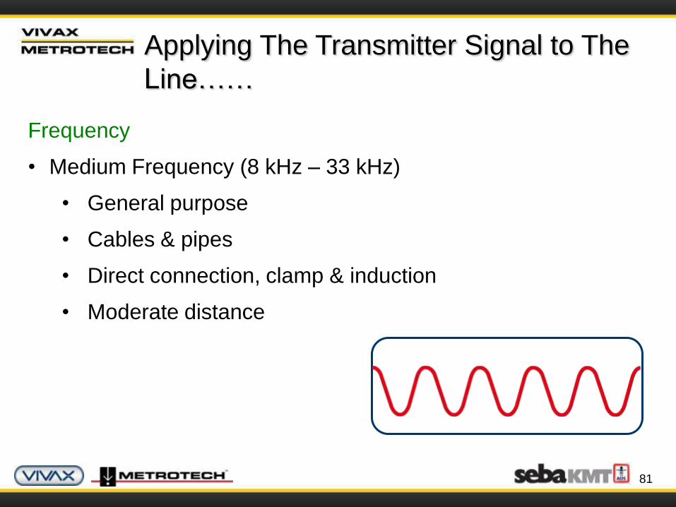
Applying The Transmitter Signal to The
Line……
Frequency
• Medium Frequency (8 kHz – 33 kHz)
• General purpose
• Cables & pipes
• Direct connection, clamp & induction
• Moderate distance
82
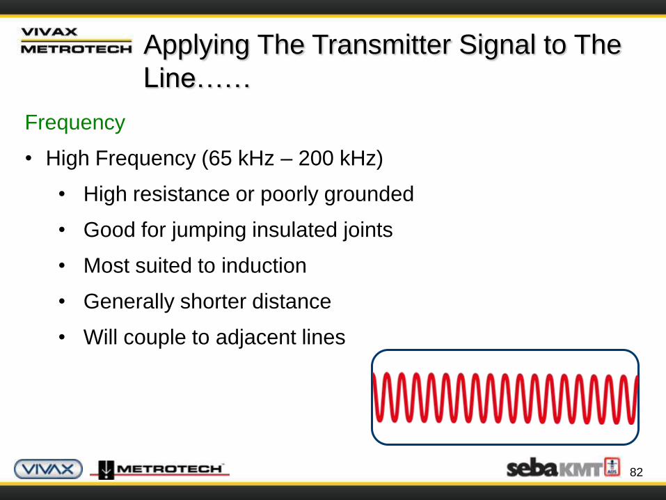
Applying The Transmitter Signal to The
Line……
Frequency
• High Frequency (65 kHz – 200 kHz)
• High resistance or poorly grounded
• Good for jumping insulated joints
• Most suited to induction
• Generally shorter distance
• Will couple to adjacent lines
83
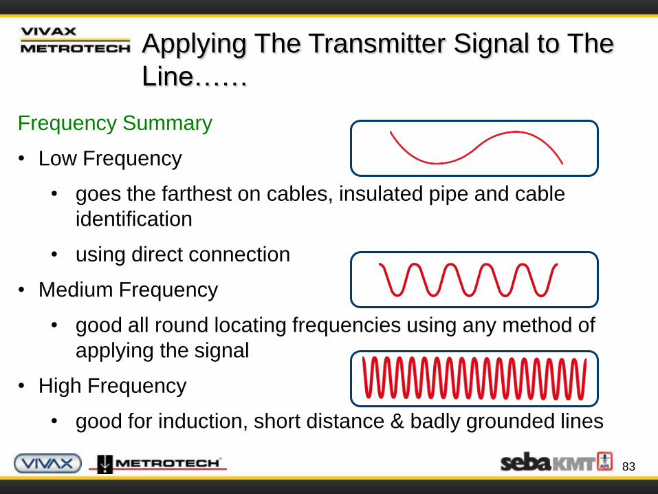
Frequency Summary
• Low Frequency
• goes the farthest on cables, insulated pipe and cable
identification
• using direct connection
• Medium Frequency
• good all round locating frequencies using any method of
applying the signal
• High Frequency
• good for induction, short distance & badly grounded lines
Applying The Transmitter Signal to The
Line……
84
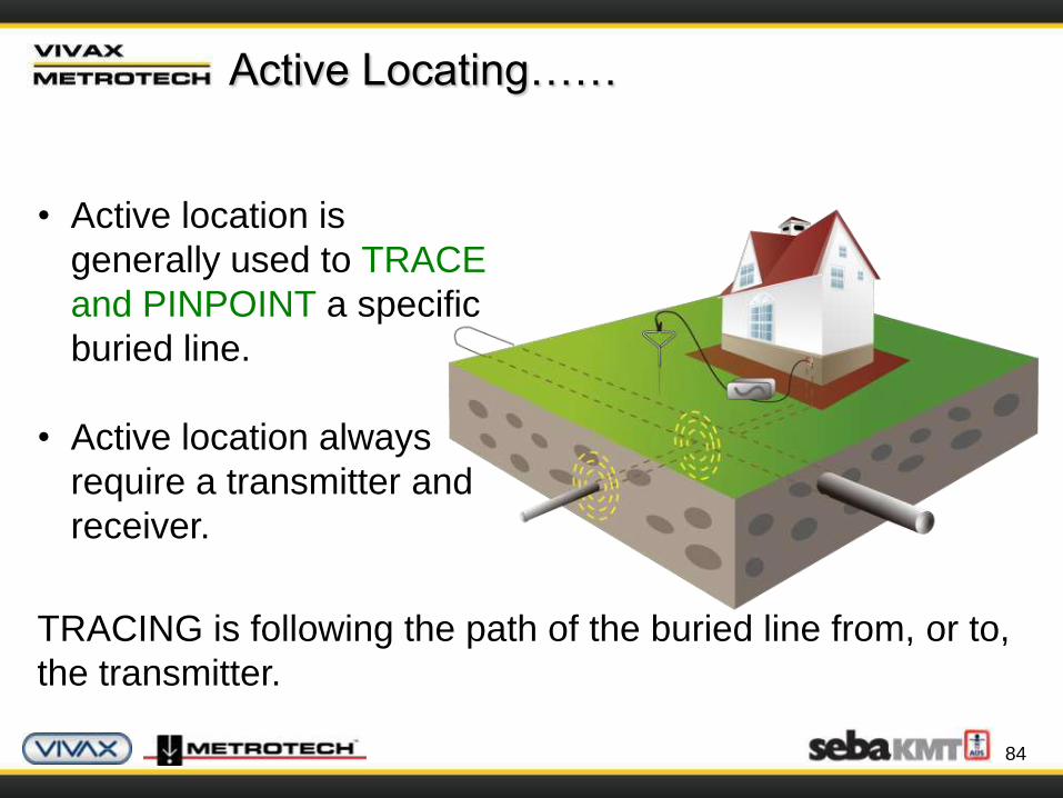
Active Locating……
• Active location is
generally used to TRACE
and PINPOINT a specific
buried line.
• Active location always
require a transmitter and
receiver.
TRACING is following the path of the buried line from, or to,
the transmitter.

85
Active Locating……
Precisely locate the peak
signal
To pinpoint and establish the position and direction of the
line:
Rotate the receiver until the
maximum signal
86
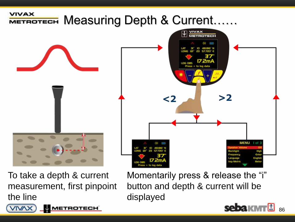
Measuring Depth & Current……
Momentarily press & release the “i”
button and depth & current will be
displayed
To take a depth & current
measurement, first pinpoint
the line
87
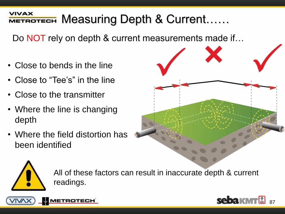
Measuring Depth & Current……
Do NOT rely on depth & current measurements made if…
• Close to bends in the line
• Close to “Tee’s” in the line
• Close to the transmitter
• Where the line is changing
depth
• Where the field distortion has
been identified
All of these factors can result in inaccurate depth & current
readings.
88
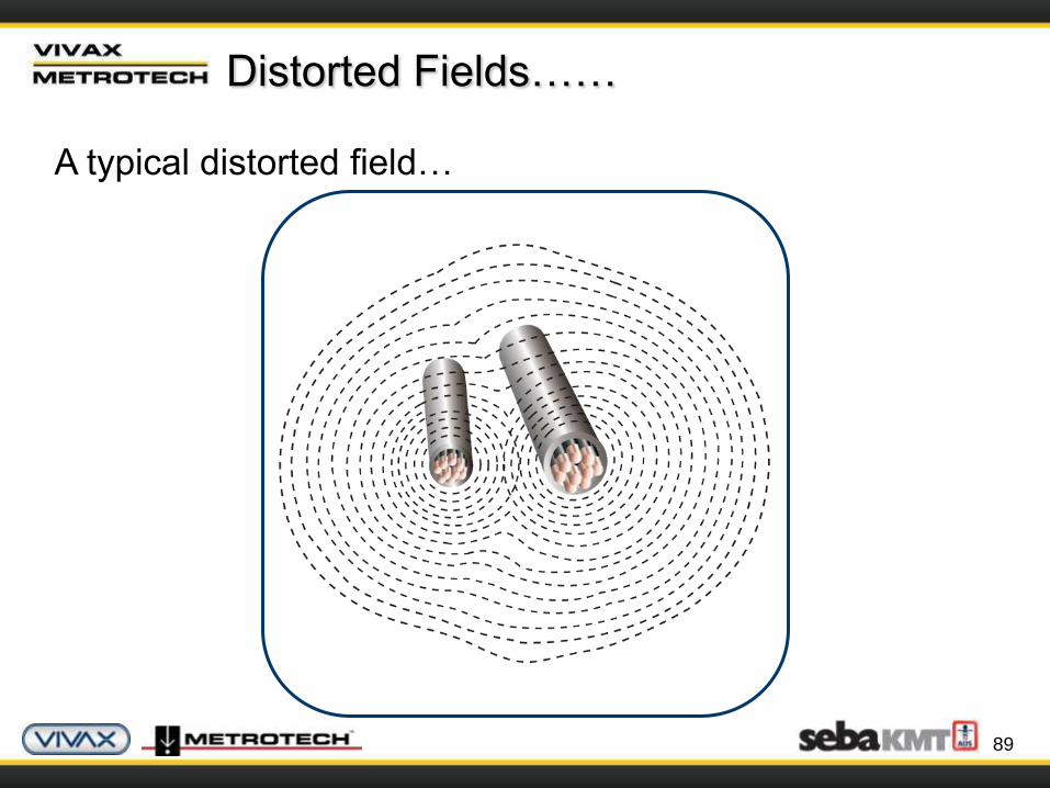
Distorted Fields……
The magnetic field (the signal) radiating from buried lines can
be distorted by the presence of adjacent metallic conductors or
other signals.
This is caused by:
• Signals induced from the target line to other lines
• Commonly bonded structures
• Badly positioned ground (at the transmitter)
The result is that the locator detects signals from more than
one course.
89
Distorted Fields……
A typical distorted field…

90
Identifying A Distorted Fields……
Using “Peak” & “Null” modes to identify a distorted fields
• On a clean undistorted field the
“Peak” and “Null” locate
response will match
• If distortion is present, the peak
and null locate response will no
longer match.
Typically, the greater the distortion,
the further apart these
locate responses will be.

91
Identifying A Distorted Fields……
• Locate the line & measure depth with
the locator resting on the ground
• Lift the receiver off the ground by a
known distance (say) 1ft (30cm)
• Take another depth reading
Using Depth Measurement to identify a vertical
distorted field
The depth reading should have
increase by the distance you raised
the receiver – if significantly different
– the field is distorted.
92
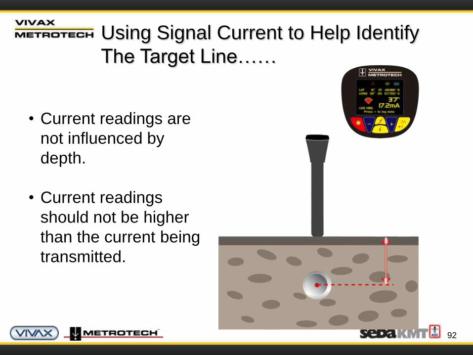
Using Signal Current to Help Identify
The Target Line……
• Current readings are
not influenced by
depth.
• Current readings
should not be higher
than the current being
transmitted.
93
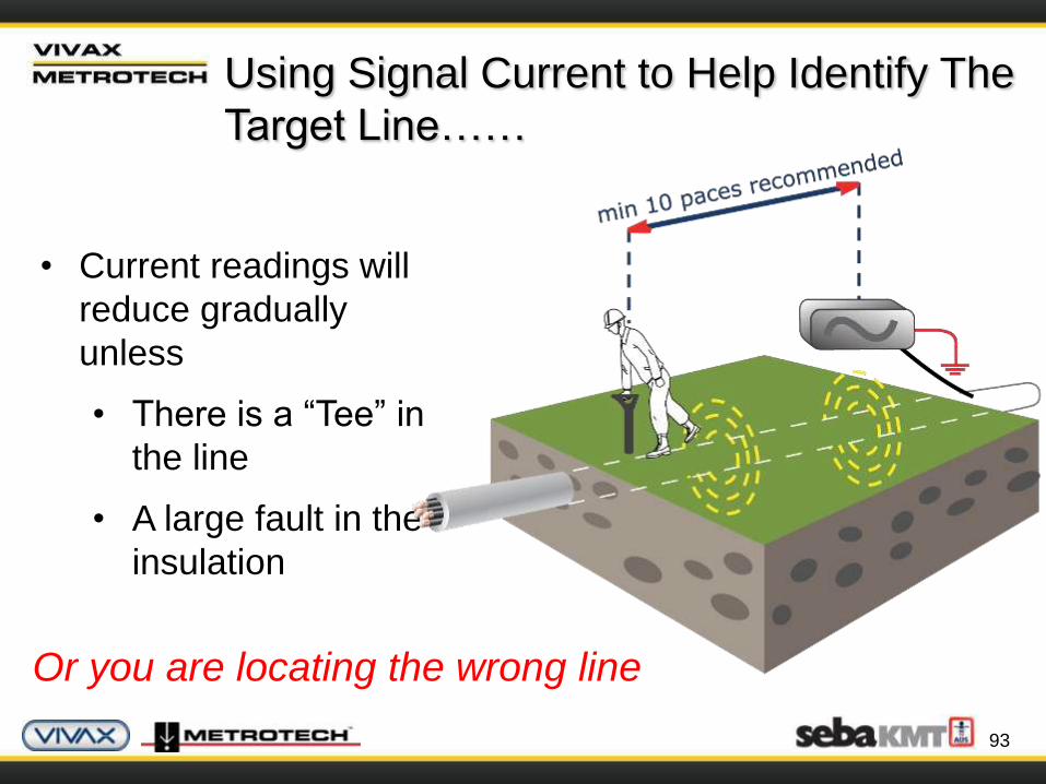
Using Signal Current to Help Identify The
Target Line……
• Current readings will
reduce gradually
unless
• There is a “Tee” in
the line
• A large fault in the
insulation
Or you are locating the wrong line

Passive Electronic
Marker System (EMS)
95
EMS
EMS markers are used to mark below ground points of
interest such as splice joints or buried valves or to mark
the position and route of non metallic services such as
plastic pipes.
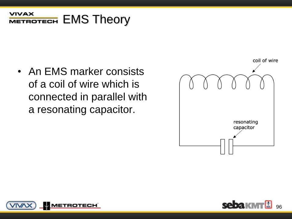
EMS Theory
• An EMS marker consists
of a coil of wire which is
connected in parallel with
a resonating capacitor.
96

EMS Theory
• The coil and capacitor are
chosen so that they have a
particular resonant
frequency.
• When the circuit is hit with
a pulse of electromagnetic
energy the circuit
resonates causing
currents to flow in the
circuit.
97
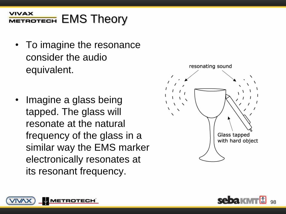
EMS Theory
• To imagine the resonance
consider the audio
equivalent.
• Imagine a glass being
tapped. The glass will
resonate at the natural
frequency of the glass in a
similar way the EMS marker
electronically resonates at
its resonant frequency.
98
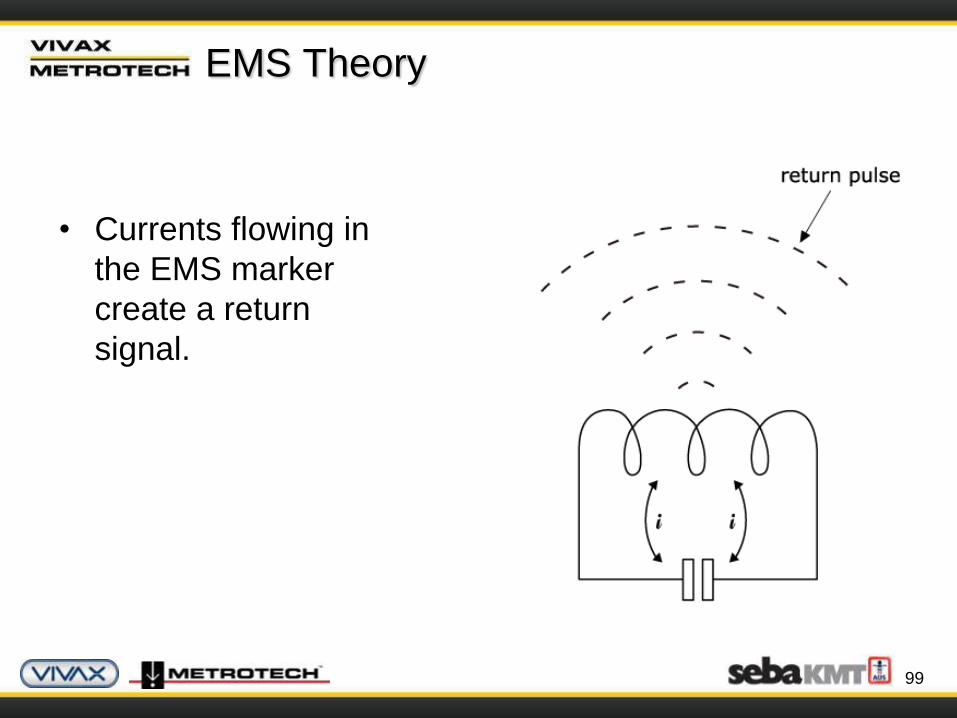
EMS Theory
• Currents flowing in
the EMS marker
create a return
signal.
99
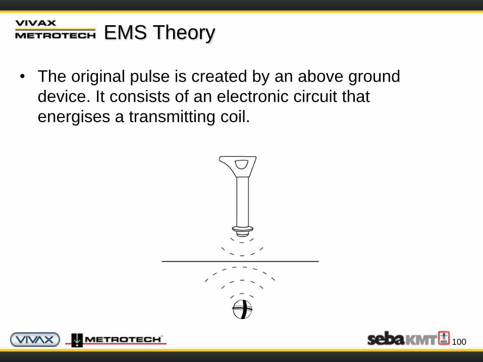
EMS Theory
• The original pulse is created by an above ground
device. It consists of an electronic circuit that
energises a transmitting coil.
100
Vivax vLocML
• The vLocML can detect markers in two modes of
operation:
1. Dedicated
• The locator is dedicated to locating a
predefined marker type.
2. Dual
• The locator is used to locate a cable or
conductive pipe whilst simultaneously search
for a particular marker type.
101
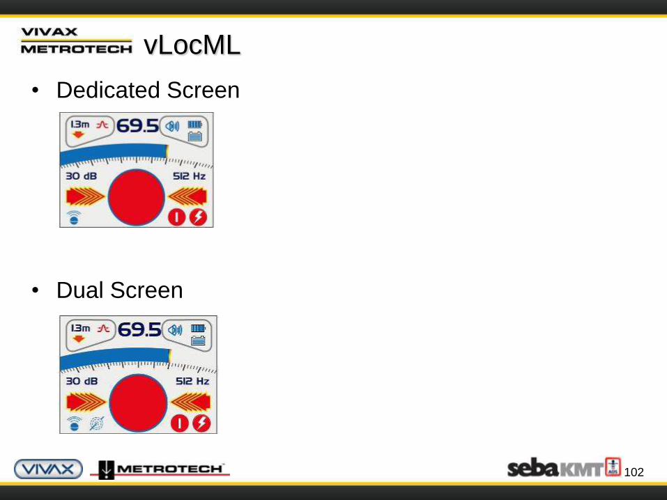
vLocML
• Dedicated Screen
• Dual Screen
102
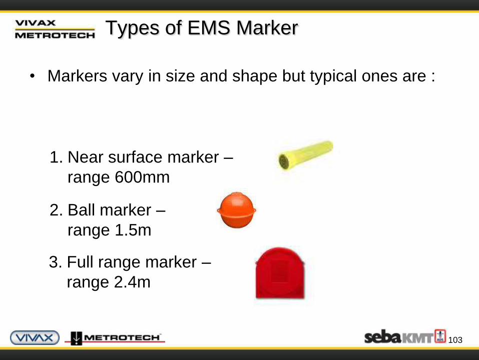
Types of EMS Marker
• Markers vary in size and shape but typical ones are :
103
1. Near surface marker –
range 600mm
2. Ball marker –
range 1.5m
3. Full range marker –
range 2.4m

Types of Marker
• Different frequency
markers are used to
distinguish different
utilities and are
differentiated by
colour.
104

Signal Direction
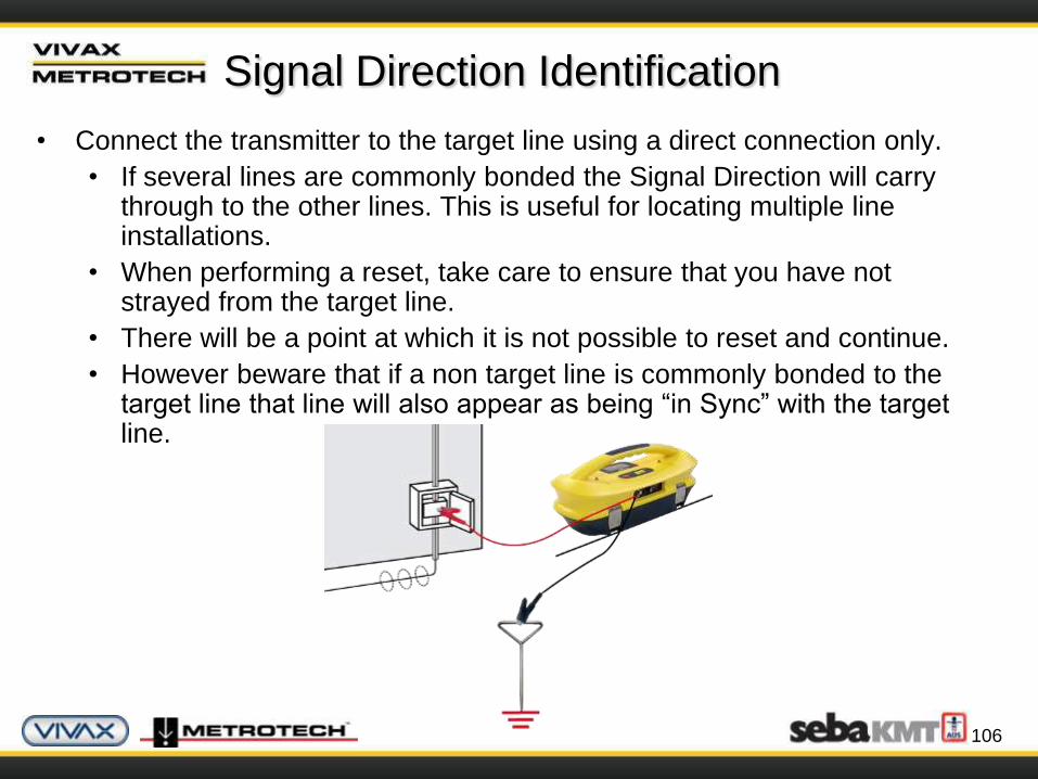
Signal Direction Identification
• Connect the transmitter to the target line using a direct connection only.
• If several lines are commonly bonded the Signal Direction will carry through to the other lines. This is useful for locating multiple line installations.
• When performing a reset, take care to ensure that you have not strayed from the target line.
• There will be a point at which it is not possible to reset and continue.
• However beware that if a non target line is commonly bonded to the target line that line will also appear as being “in Sync” with the target line.
106

Signal Direction Identification
• Turn the transmitter and receiver on and set both to :
• SD-USA – if in North America or any territory where
the power system is 60Hz.
• SD-EUR – if in Europe or any territory where the
power system is 50Hz.
• The receiver may, or may not be flashing the “SD” icon
and compass bezel.
107

Signal Direction Identification
• To synchronize the receiver to the transmitter at the beginning of a survey, pinpoint the line very close to the transmitter.
• Stand facing away from where the transmitter is attached and press “i” pushbutton.
• Press the return pushbutton will synchronize the system, then return the unit to the locate screen.
• The top portion of the bezel surrounding the compass will light and not be flashing indicating the receiver is locked onto the signal.
108
Signal Direction Identification
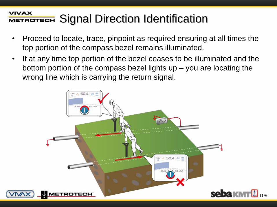
• Proceed to locate, trace, pinpoint as required ensuring at all times the
top portion of the compass bezel remains illuminated.
• If at any time top portion of the bezel ceases to be illuminated and the
bottom portion of the compass bezel lights up – you are locating the
wrong line which is carrying the return signal.
109
Signal Direction Identification
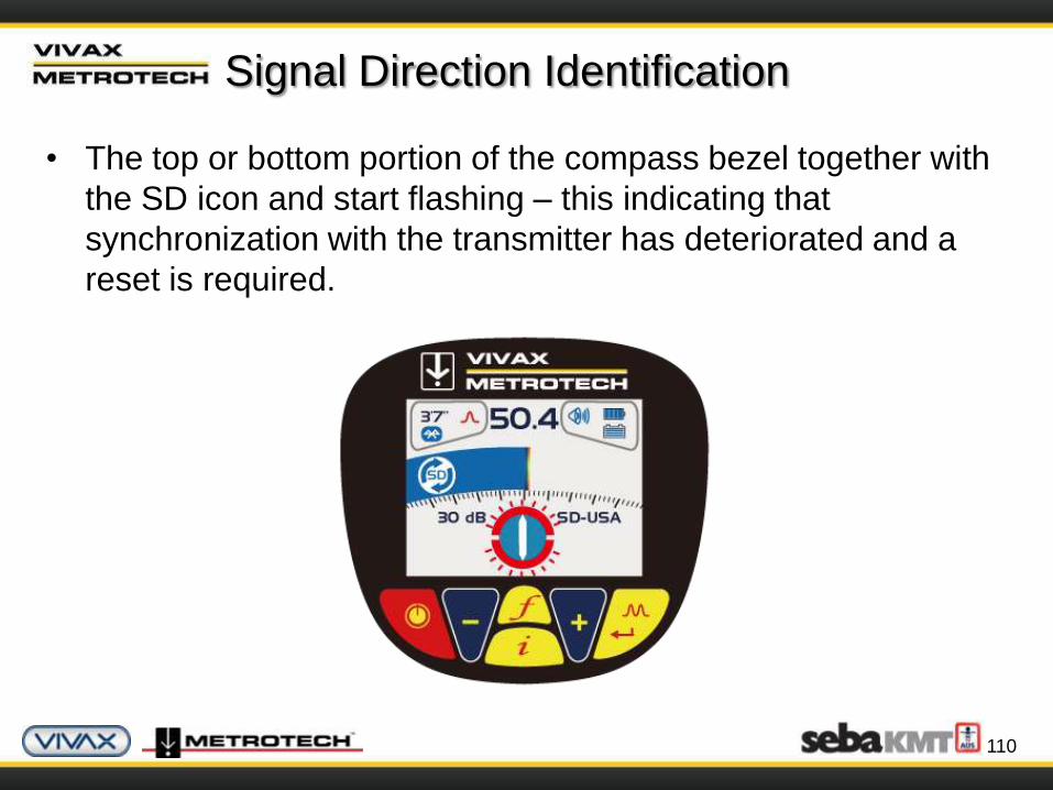
• The top or bottom portion of the compass bezel together with
the SD icon and start flashing – this indicating that
synchronization with the transmitter has deteriorated and a
reset is required.
110

Signal Direction Identification
• Re-trace your line back to a point where a solid signal direction is
obtained.
• Precisely pinpoint the line and stand with your back to the direction of
the transmitter
• Press the “ i ” pushbutton
• Press the enter pushbutton to re-sync with the transmitter signal.
• Continue to locate, pinpoint and trace.
111
Bluetooth GPS
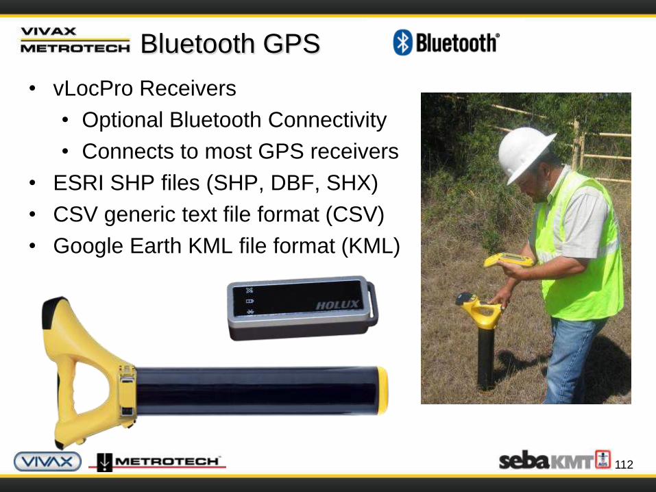
• vLocPro Receivers
• Optional Bluetooth Connectivity
• Connects to most GPS receivers
• ESRI SHP files (SHP, DBF, SHX)
• CSV generic text file format (CSV)
• Google Earth KML file format (KML)
112
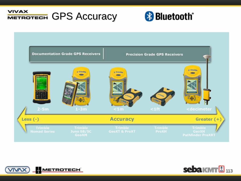
GPS Accuracy
113
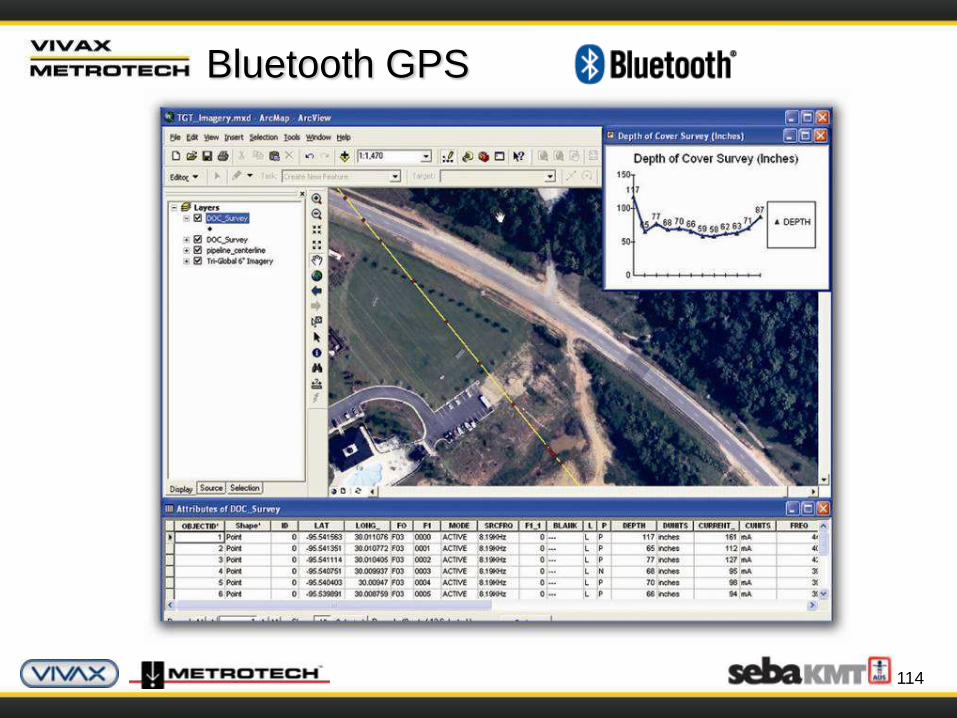
Bluetooth GPS
114
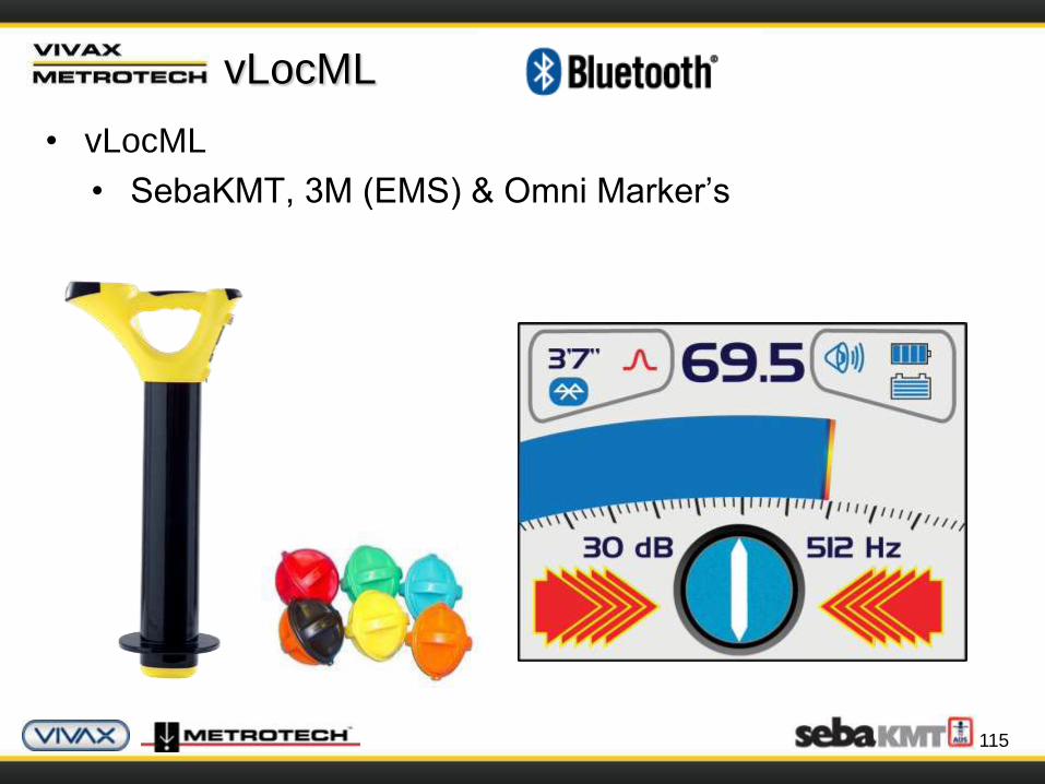
vLocML
• vLocML
• SebaKMT, 3M (EMS) & Omni Marker’s
115

Accessories
The Principles of Cable & Pipe Location
117
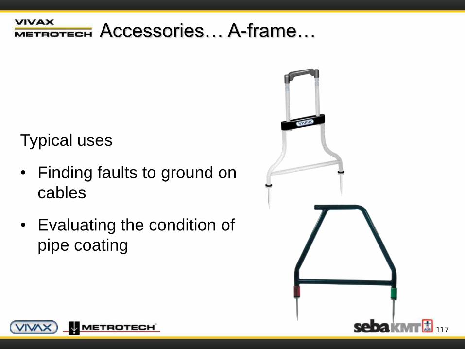
Accessories… A-frame…
Typical uses
• Finding faults to ground on
cables
• Evaluating the condition of
pipe coating

118
Accessories… A-frame…
Cable and Pipeline Faultfinding
The accessory A-frame can be used to detect the position of
cable and pipeline defects where they are in contact with the
ground.
119
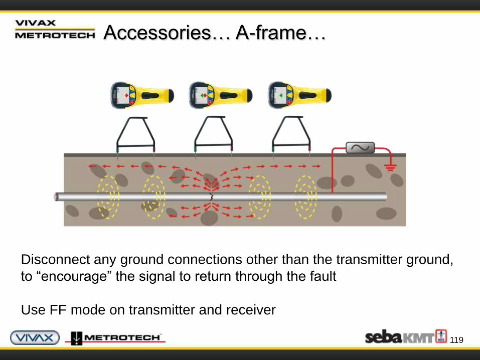
Accessories… A-frame…
Disconnect any ground connections other than the transmitter ground,
to “encourage” the signal to return through the fault
Use FF mode on transmitter and receiver
120
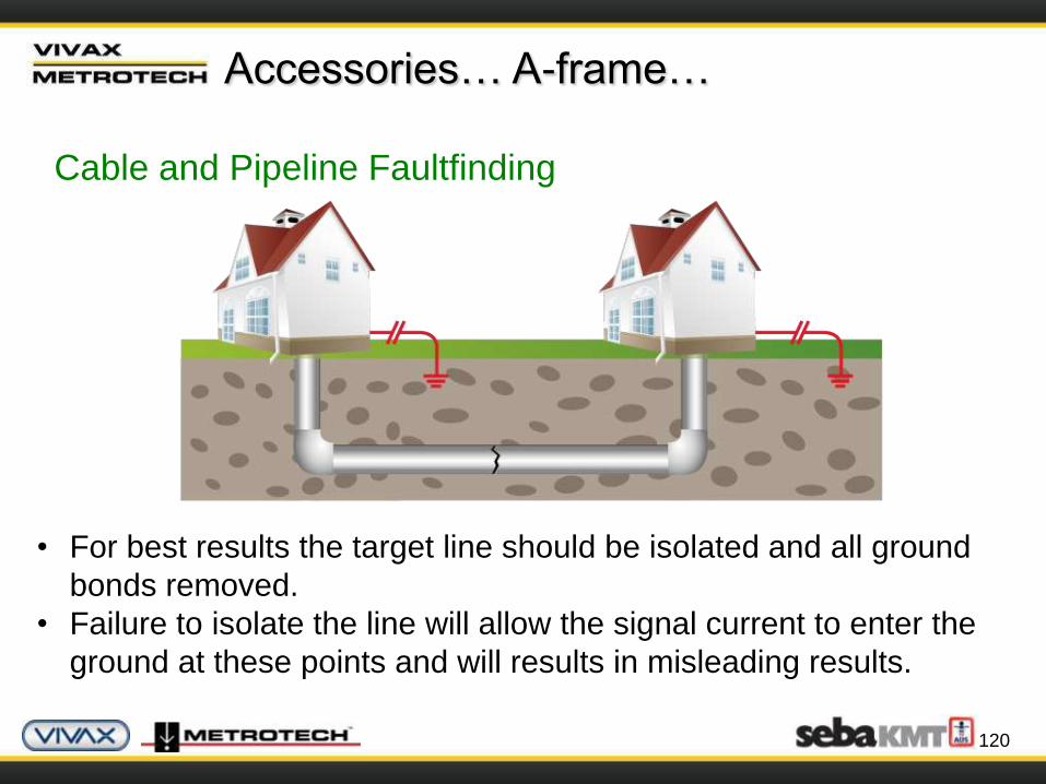
Accessories… A-frame…
Cable and Pipeline Faultfinding
• For best results the target line should be isolated and all ground
bonds removed.
• Failure to isolate the line will allow the signal current to enter the
ground at these points and will results in misleading results.
121
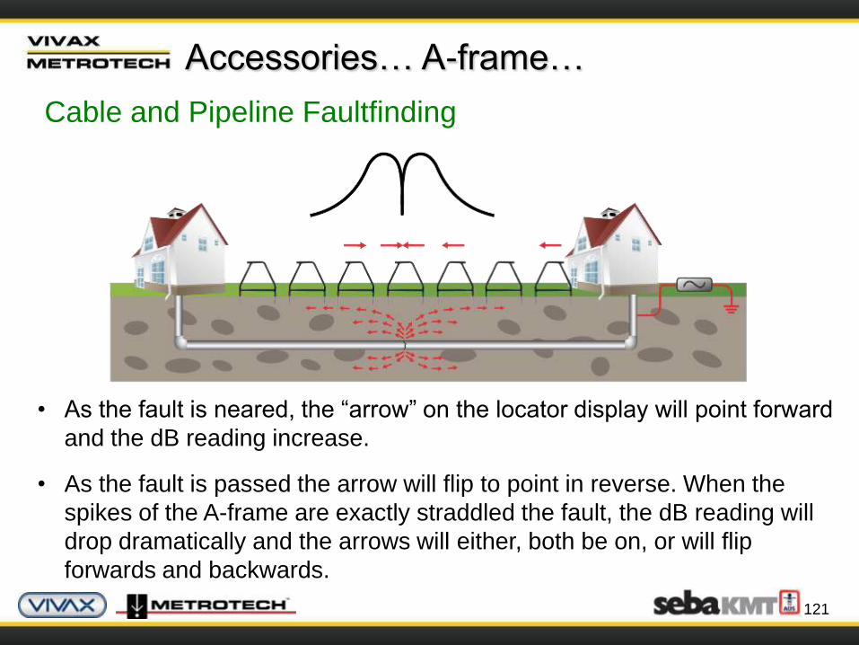
Accessories… A-frame…
Cable and Pipeline Faultfinding
• As the fault is neared, the “arrow” on the locator display will point forward
and the dB reading increase.
• As the fault is passed the arrow will flip to point in reverse. When the
spikes of the A-frame are exactly straddled the fault, the dB reading will
drop dramatically and the arrows will either, both be on, or will flip
forwards and backwards.
122
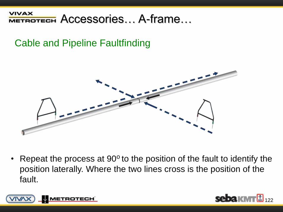
Accessories… A-frame…
Cable and Pipeline Faultfinding
• Repeat the process at 90o to the position of the fault to identify the
position laterally. Where the two lines cross is the position of the
fault.

123
Accessories… A-frame…
Cable and Pipeline Faultfinding
• If it is suspected that there is just one fault on the line, the A-frame can
be used to estimate the magnitude of the fault.
• Position the A-frame approximately one meter from the earth stake. Note
the dB reading which will be similar to the maximum dB reading at the
fault.

124
Accessories… Live Plug Connector…
• Apply the Live Plug Connector
to a normal household power
socket (100V – 250V AC) to
apply the transmitter signal
• The transmitter is protected by
an isolating transformer built
into the accessory
• Use with the receiver or the
remote antenna to detect the
signal as it leaves the premises
125
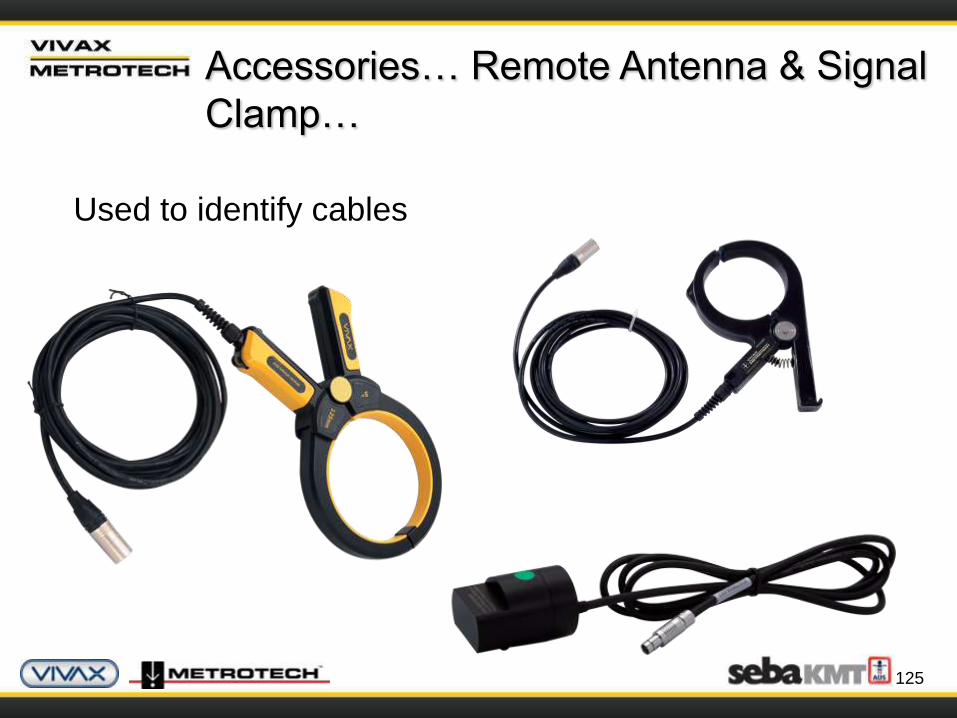
Accessories… Remote Antenna & Signal
Clamp…
Used to identify cables

126
Signal Clamp
• Set transmitter & receiver to 8 kHz / 33 kHz / 65 kHz
• Select the “Peak” mode on the receiver
Remote Antenna
• Place the remote antenna onto the cable
• Locate the cable with the strangest source of your signal
Accessories… Remote Antenna & Signal
Clamp…
127
Accessories… Sondes…
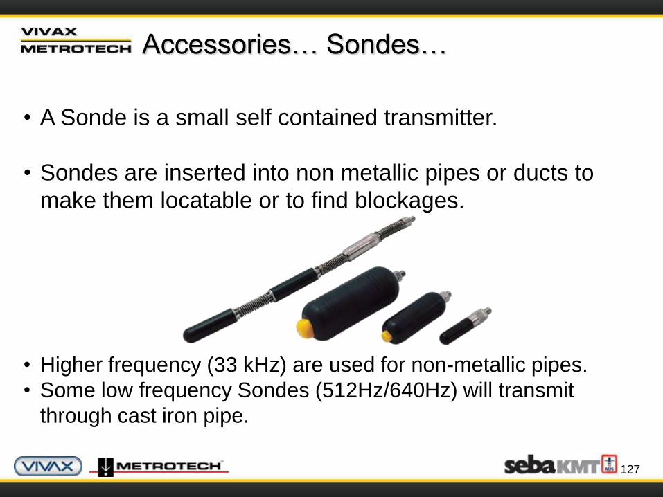
• A Sonde is a small self contained transmitter.
• Sondes are inserted into non metallic pipes or ducts to
make them locatable or to find blockages.
• Higher frequency (33 kHz) are used for non-metallic pipes.
• Some low frequency Sondes (512Hz/640Hz) will transmit
through cast iron pipe.
128
Accessories… Sondes…
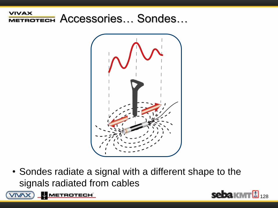
• Sondes radiate a signal with a different shape to the
signals radiated from cables
129
Accessories… Sondes…
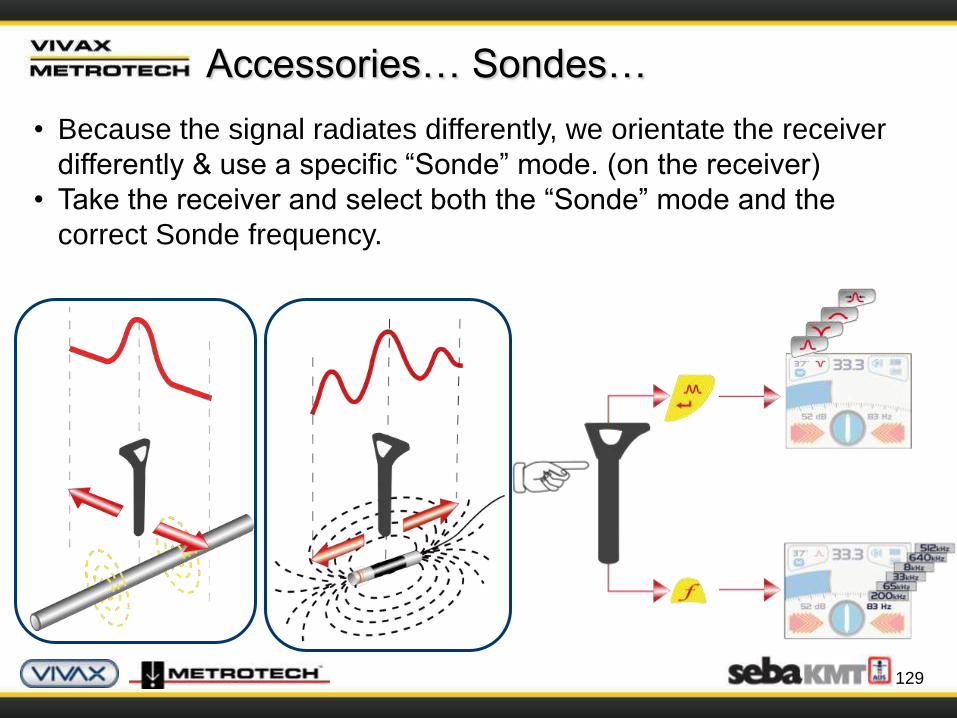
• Because the signal radiates differently, we orientate the receiver
differently & use a specific “Sonde” mode. (on the receiver)
• Take the receiver and select both the “Sonde” mode and the
correct Sonde frequency.

130
Accessories… Sondes…
• The Sonde signal gives three peaks in line with the path of the
Sonde.
• And a single peak across the line of the Sonde.

131
Accessories… Sondes…
• The compass can be used to efficiently
locate the position of a Sonde.
• Position the locator in the approximate
area of the Sonde.
• Rotate the locator so that the compass
is pointing at 12 o’clock.
• Walk forward keeping the compass at
12 o’clock.
• Adjust the gain as the signal strength
increases.
• The position of the Sonde is indicated
by the maximum signal strength.
132
Accessories… Sondes…
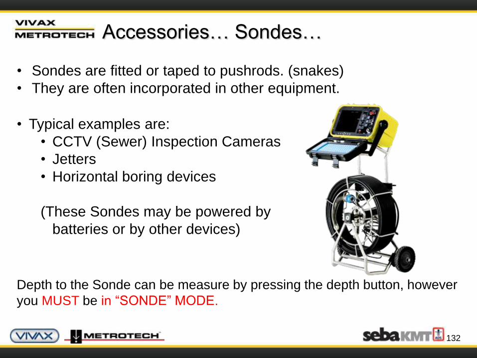
• Typical examples are:
• CCTV (Sewer) Inspection Cameras
• Jetters
• Horizontal boring devices
(These Sondes may be powered by
batteries or by other devices)
Depth to the Sonde can be measure by pressing the depth button, however
you MUST be in “SONDE” MODE.
• Sondes are fitted or taped to pushrods. (snakes)
• They are often incorporated in other equipment.
133
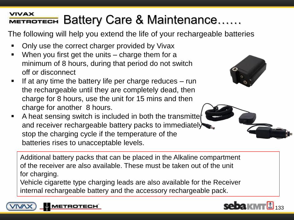
Additional battery packs that can be placed in the Alkaline compartment
of the receiver are also available. These must be taken out of the unit
for charging.
Vehicle cigarette type charging leads are also available for the Receiver
internal rechargeable battery and the accessory rechargeable pack.
Battery Care & Maintenance……The following will help you extend the life of your rechargeable batteries
Only use the correct charger provided by Vivax
When you first get the units – charge them for a
minimum of 8 hours, during that period do not switch
off or disconnect
If at any time the battery life per charge reduces – run
the rechargeable until they are completely dead, then
charge for 8 hours, use the unit for 15 mins and then
charge for another 8 hours.
A heat sensing switch is included in both the transmitter
and receiver rechargeable battery packs to immediately
stop the charging cycle if the temperature of the
batteries rises to unacceptable levels.

134
Safety……
Locators are precision well engineered tools, however the
environment we locate in is not perfect.
Always be aware of the influence of distorted fields
Always take account of visual clues (manholes, pedestals etc)
Always use “as built plans” if available
NEVER use digging machinery over marked out pipes or cables
Do NOT give “depth” information unless authorized by your company
Follow all Federal, State, and company rules and regulations particularly
as regards safety
Dispose of Batteries in line with Federal, State or company regulations
Never submit batteries to extreme heat or fire.
CALL BEFORE YOU DIG - ALWAYS DIG CAREFULLY
135
Glossary……
Active Locate A locate where a transmitter is used to apply a signal to a
buried pipe or cable, the position of which is then located by a
receiver tuned to the same frequency.
Active Signal A signal applied by the locator transmitter to a buried line.
Typical this is a very precise frequency.
Attenuation The reduction of an electromagnetic signal from a pipe or cable.
Clamp (or Coupler) An accessory used to apply the transmitter signal to an
insulated line, removing the need to connect the transmitter
signal directly to a conductor or cable sheath.
Coupling The act of signals transferring to lines to which they were not
originally applied. Coupling can be “direct” where the target
line has an electrical connection to another line, or “induced”
where the signal radiates from the target line to another line
or lines.

136
Glossary……
Display The information visually available on the dot matrix display.
Line A generic term for any buried pipe or cable.
Null A minimum response to a buried line.
Passive Locate A locate where the receiver searches for a wide range of signals that
radiate from buried pipes or cables. These signals come from a
variety of sources in the environment and couple to the buried (&
overhead) lines. Typical examples 50/60Hz and LF/VLF radio.
Passive Signals A wide range of signals that radiate from buried pipes or cables.
These signals come from a variety of sources in the environment
and couple to the buried (& overhead) lines. Typical examples
50/60Hz and LF/VLF radio.
Peak A maximum response to a buried line.
Compass Line direction indicator. (Although visually like a compass, this is the
only relation to a compass.)

137
Glossary……
Pinpoint Using a receiver to identify the exact position of a buried line.
Target Line The buries pipe or cable to be located.
Trace Using a locator to following the path of a buries line.
Response The indication that the receiver gives which is caused by the signals it
is receiving. This can be visual, audio or both. Typically it is displayed
on the locators dot matrix display and audibly from a loudspeaker in
the receiver housing.
Search (sweep) This describes the act of looking for a buried line within a given area.
Sonde A small transmitting coil which may be built into a product such as a
sewer camera or packaged as a small self contained battery powered
transmitter. A receiver tuned to the same frequency can locate the
position of the Sonde and hence whatever it is attached to or in.
Frequently used for locating sewer cameras and the non metallic
pipes.

138
Vivax-Metrotech Contact Details…
Vivax-Metrotech works throughout the world with skilled professionals
experienced in cable and pipe location…
United State of America
Vivax-Metrotech Corporation3251 Olcott Street,
Santa Clara, CA 95054, USA
Website : www.vivax-metrotech.com
Sales & Sales Support:
T/Free : +1-800-446-3392
Tel : +1-408-734-1400
Fax : +1-408-734-1415
Email : [email protected]
Application Support:
T/Free : +1-800-624-6210
Tel : +1-408-454-7159
Fax : +1-408-743-5597
Email : [email protected]
Service & Repairs:
T/Free : +1-800-638-7682
Tel : +1-408-962-9990
Fax : +1-408-734-1799
Email : [email protected]
All Other Department:
T/Free : +1-877-330-1647
Tel : +1-408-734-3880
Fax : +1-408-962-9993
Canada
Vivax Canada Inc.400 Esna Park Drive,
Unit 17, Markham,
Ontario, L3R 3K2, Canada
Tel : +1-289-846-3010
Website : www. vivax-metrotech.com
Email : [email protected]

139
Europe
SebaKMTSeba Dynatronic
Mess-und Ortungstechnik GmbH
Dr.-Herbert-Iann-Str. 6,
96148 Baunach, Germany
Tel : +49-9544-680
Fax : +49-9544-2273
Website : www.sebakmt.com
Email : [email protected]
Vivax-Metrotech Contact Details…
Australasia
SebaKMT AUSUnit 1, 176 South Creek Road,
Cromer NSW 2009, Australia
Tel : +61-2-9972-9244
Fax : +61-2-9972-9433
Website : www.sebakmtaus.com
Email : [email protected]
China
Leidi Utility Supply (Shanghai) Ltd.Rm405 3rd Building No. 641, Tianshan Rd,
Shanghai, China 200336
Tel : +86-21-5187-3880
Fax : +86-21-5168-5880
Website : www.leidi.com
Email : [email protected]
140
The End
The Principles of Cable & Pipe Location