pmsm control with power factor correction: rapid prototyping scenario
TRANSCRIPT
PMSM Control with Power Factor Correction:Rapid Prototyping Scenario
Gionata Cimini, Gianluca Ippoliti, Giuseppe Orlando and Matteo PirroDipartimento di Ingegneria dell’Informazione, Universita Politecnica delle Marche,
Via Brecce Bianche 12, 60131, Ancona, ItalyEmail: {g.cimini,gianluca.ippoliti,giuseppe.orlando,m.pirro}@univpm.it
Abstract—In this paper a system for PMSM control withPower Factor Correction (PFC) has been designed. A robustsensorless cascade speed control scheme for a Permanent MagnetSynchronous Motor (PMSM) drive has been proposed. A DiscreteTime Sliding Mode Control (DTSMC) and a Sliding ModeObserver (SMO) have been considered. An averaged currentcontrol with input voltage feedforward has been implementedfor an AC-DC boost converter to increase Power Factor (PF).The proposed solution has been experimentally tested on acommercial PMSM drive equipped with a control system basedon a microcontroller (MCU) of the Texas Instrument familyC2000TM .
I. INTRODUCTION
Permanent Magnet Synchronous Motors (PMSMs) have animportant role in motion control applications in the low andmedium power range. The desired features of PMSMs are fastdynamical response and high torque to weight ratio [1].
In order to achieve high performance in PMSMs controlthe knowledge of rotor shaft position and speed is needed;for this reason speed and position sensors could be usedsuch as encoder or resolver. Nevertheless, especially for mass-produced motors, several method have been developed in orderto phase out the use of sensors, obtaining rotor position andangular speed from the measurements of electric quantities.Back-EMF-based estimators have been described in [2] andthe Extended Kalman Filter (EKF) approach has been appliedin [3]–[5]. Also the state-space observer and nonlinear reducedorder observer approaches have been proposed as a sensor-less estimation scheme in [6]. An attractive solution to thisproblem is represented by Sliding-Mode Observers (SMOs)[7]–[9]. SMOs present several benefits, such as high state-estimation accuracy, excellent dynamic properties, robustnessto parameter variations, and the ability to handle nonlineardynamical systems.
Akin to its observer counterpart, a nonlinear control strategywidely recognized and successfully applied in recent yearsis the Sliding Mode Control (SMC) [10]–[12]. Indeed, SMCmethods provide robustness to matched uncertainties [6], andare computational simpler with respect to other robust controlapproaches, thus well suited for low-cost DSP implementationwith an appropriate formulation in a sample-data systemcontext [13]–[18]. Therefore, in this paper, a design techniquebased on Discrete Time Sliding Mode Control (DTSMC) [13],
[19] and a SMO for the estimation of rotor position and speedof PMSM drives from measurements of electric quantities [6]have been proposed.
In general, AC motor drives have very poor power factordue to the high number of harmonics in the line current. Powerfactor correction (PFC) method is a good candidate for AC-to-DC switched mode power supply in order to reduce the har-monics in the line current, increase the efficiency and capacityof motor drives in particular for autonomous vehicles [20]–[24], and reduce customers’ utility bills [25], [26]. Thereforethe implementation of a power factor correction technique is arequired feature for a good quality electromechanical system[27]–[29].
There are two general types of PFC methods to obtain aunity power factor: analog and digital PFC techniques. In thepast, due to the absence of fast microprocessors and DSPs,analog PFC methods were the only choice for achieving theunity power factor. Many control strategies using analog cir-cuits have been explored in the past, including average currentcontrol [30], peak current control [31], hysteresis control [32],nonlinear carrier control [33]. With the recent developmentsin the microprocessor and DSP technologies, there is thepossibility to implement complex PFC algorithms using thesefast processors [34]. Several techniques have been employed;a novel DC bus voltage estimation algorithm with inherentcancelation of feedback voltage ripple in [35] and recently apassivity-based method [36], whose use has clear advantagesin terms of considering the system physical structure in thecontrol design procedure.
In this paper a robust sensorless control system for PMSMdrives with DSP-based power factor correction has been im-plemented. Both simulated and real tests have been performed.The paper is organized as follows. The nonlinear state spacemodel of the PMSM dynamics is presented in Subsection II-A.In Subsection II-B details on the considered SM observerand DTSM controller are discussed. Power factor controldetails are discussed in Section III. Results on numerical testson PSIM software platform by Powersim Inc and real testson a commercial DSP-based kit by Texas Instruments arereported in Section IV. The paper ends with comments on theperformance of the proposed solution and with some futureworks proposals.
Revised Personal Version.Online Available Version at http://ieeexplore.ieee.org/xpl/login.jsp?tp=&arnumber=6635693.
II. SYSTEM OVERVIEW
The following subsections provide details as regards themotor dynamics modeling, the motor control and the powerfactor correction implementation.
A. Motor Dynamics
In the (d, q) reference frame, synchronously rotating withthe motor rotor, the electrical equations of motion of apermanent-magnet synchronous motor can be written as [6]:
diddt
= −RLid + ωeiq +
1
Lud (1)
diqdt
= −RLiq − ωeid −
1
Lλ0ωe +
1
Luq (2)
where id and iq are the d−axis and q−axis stator currents,respectively; ud and uq are the d− axis and q − axis statorvoltages, respectively; R is the winding resistance and L =Ld = Lq is the winding inductance on axis d and q; λ0 is theflux linkage of the permanent magnet and ωe is the electricalangular speed of the motor rotor.
The electrical torque τe and the mechanical power P of themotor are given by τe = Ktiq and P = τeωr in which Kt =32λ0Nr is the torque constant with Nr the number of pole pairsand ωr is the mechanical angular speed of the motor rotor. Thedeveloped torque of the motor is proportional to the iq currentbecause of the assumption that there is no reluctance torquein the considered PMSM. The mechanical motion equation ofthe motor is described by:
Jdωrdt
+Bωr = τe − τ`;dθrdt
= ωr (3)
where J is the mechanical inertia of the motor and load, Bis the coefficient of viscous friction, τ` is the load torque andθr denotes the mechanical angular position of the motor rotor.For the electrical angular position/speed and the mechanicalangular position/speed, these relations hold: ωe = Nrωr andθe = Nrθr.
B. Sensorless Control Design
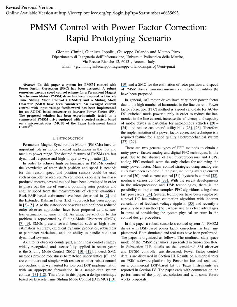
Technical aspects of the proposed solution are given in thefollowing. In particular, the Field Oriented Control (FOC) ofFig. 1, uses a cascade control structure where the inner loopsfor the current control and the outer loop for the speed controlare DTSMCs and the task is to make the speed error ω∗r −ωr to tend to zero as close as possible. The electrical partof the motor model in the stator coordinate frame (α, β) isusually used for sensorless control design, where the phasevoltages and currents are normally measured to estimate themotor speed and position [6]:
diαdt
= −RLiα −
1
Leα +
1
Luα (4)
diβdt
= −RLiβ −
1
Leβ +
1
Luβ . (5)
Assuming the motor speed changes slowly, the model ofthe induced Electromotive Force (EMF) components, eα =
Observer
*au
du
PWM
Inverter
qu
CurrentControl
ai
bi
qi
di
PMSM *bu
*cu
Σ
* 0di =
_ +
Σ Σ
Speed Control
*qi
+ _ _ +
CurrentControl
dq
αβ
dq
αβ
uα αβ
abc
αβ
abc
iβ
iα
uβ
ˆeω eθ
1
rN
*rω
ˆrω
Figure 1. Block scheme of the proposed cascade controller (FOC)
−λ0ωe sin(θe) and eβ = λ0ωe cos(θe) is given by:
eα = −ωeeβ (6)eβ = ωeeα. (7)
As discussed in [6], to filter eα, eβ and to simultaneouslyestimate the rotor position and speed, the following observeris designed by model equations (6) and (7):
˙eα = ωeeβ − l2(eα − eα) (8)˙eβ = ωeeα − l2(eβ − eβ) (9)˙ωe = (eβ − zβ)eα − (eα − zα)eβ (10)
where l2 > 0 is a constant observer gain. To design theDTSMC it is assumed that model parameters differ from thenominal values for unknown but bounded quantities:
Aω = Aω + ∆Aω; Bω = Bω + ∆Bω;
|∆Aω| ≤ ρAω; |∆Bω| ≤ ρBωAi = Ai + ∆Ai; Bi = Bi + ∆Bi;
|∆Ai| ≤ ρAi; |∆Bi| ≤ ρBi. (11)
The following discrete-time sliding surfaces have been de-fined:
sω(k) = (ωe(k)− ω∗e(k)) + λω(ωe(k − 1)− ω∗e(k − 1)) = 0(12)
siq(k) = (iq(k)− i∗q(k)) + λq(iq(k − 1)− i∗q(k − 1)) = 0(13)
sid = id(k) + λdid(k − 1) = 0 (14)
where λω, λq, λd ∈ (−1, 1), ωe(k) is the estimate of ωe(k)provided by the SMO, ω∗e(k) is the given reference valuefor the angular velocity, and i∗q(k) will be defined in thefollowing of this section. Note that the reference (i∗d) of thedirect current component is set to zero. This case correspondsto the motion of the motor in the normal speed range, withoutconsidering possible field weakening operations [6]. Imposinga quasi sliding motion on the surface sω(k) = 0 [13], [19],gives i∗q(k) = ieqq (k)+inq (k), where ieqq (k) and inq (k) are givenby:
ieqq (k) =1
BωKt(ω∗e(k+ 1)− Aωωe(k)−λω(ωe(k)−ω∗e(k)))
(15)
inq (k) =
θω|sω(k)| − ρω
BωKtif |sω(k)| > ρω
−sω(k)− Bωinq (k − 1)
BωKtif |sω(k)| ≤ ρω
(16)
with |θω| ≤ 1, and with
ρω = (|Bω|+ ρBω)ρτ + ρAωωmaxe +KtρBωi
maxq
ρτ being the constant bound of the unknown motor load, i.e.|τ`| ≤ ρτ . Note that ωmaxe and imaxq are the largest speedachievable by the motor and the largest current which can besupplied, respectively, according to its constructive limits.
It can be easily verified that the sliding condition onsiq(k) = 0 is ensured by the control law uq(k) = ueqq (k) +unq (k), where:
ueqq (k) =1
Bi
[i∗q(k)− Aiiq(k)− λq(iq(k)− i∗q(k))
](17)
unq (k) =
θq|siq(k)| − ρq
Biif |siq(k)| > ρq
−siq(k)− Biunq (k − 1)
Biif |siq(k)| ≤ ρq
(18)where |θq| ≤ 1, ρq = ρAii
maxq +ρBiu
maxq +ρ+ωmaxe (imaxd +
λ0
L )Tc, ρ being the bound of ∆i∗q(k) = |i∗q(k + 1)− i∗q(k)|.Finally, the achievement of a quasi sliding motion on
sid(k) = 0 is ensured by the control law:
ueqd (k) = − (Ai + λd)id(k)
Bi(19)
und (k) =
θd|sid(k)| − ρd
Biif |sid(k)| > ρd
−sid(k)− Biund (k − 1)
Biif |sid(k)| ≤ ρd
(20)where |θd| ≤ 1 and ρd = ρAii
maxd +ρBiu
maxd +ωmaxe imaxq Tc.
C. Power Factor Control
Power factor (PF) is defined as the ratio of the real power toapparent power; it is a measure of how efficiently the current isdrawn from the source. Power factor can vary between 0 and 1and when the current and voltage waveforms are in phase andthere are no harmonics except the fundamental one the powerfactor is 1. Achieving a unity PF is equal to make the circuitlook purely resistive (apparent power equals to real power).The 3-phase inverter stage and the motor act as a load to thePFC stage and they represent a non linear load which drawsharmonic currents from the power stage. Harmonics result inreactive power which causes the real power to be less thanapparent power, reducing power factor and resulting in losses.Harmonic current with high Total Harmonic Distortion (THD)can also distort the line voltage. The purpose of power factorcontrol is to drawn a sinusoidal current from the line (withless distortion as possible) in phase with line voltage.
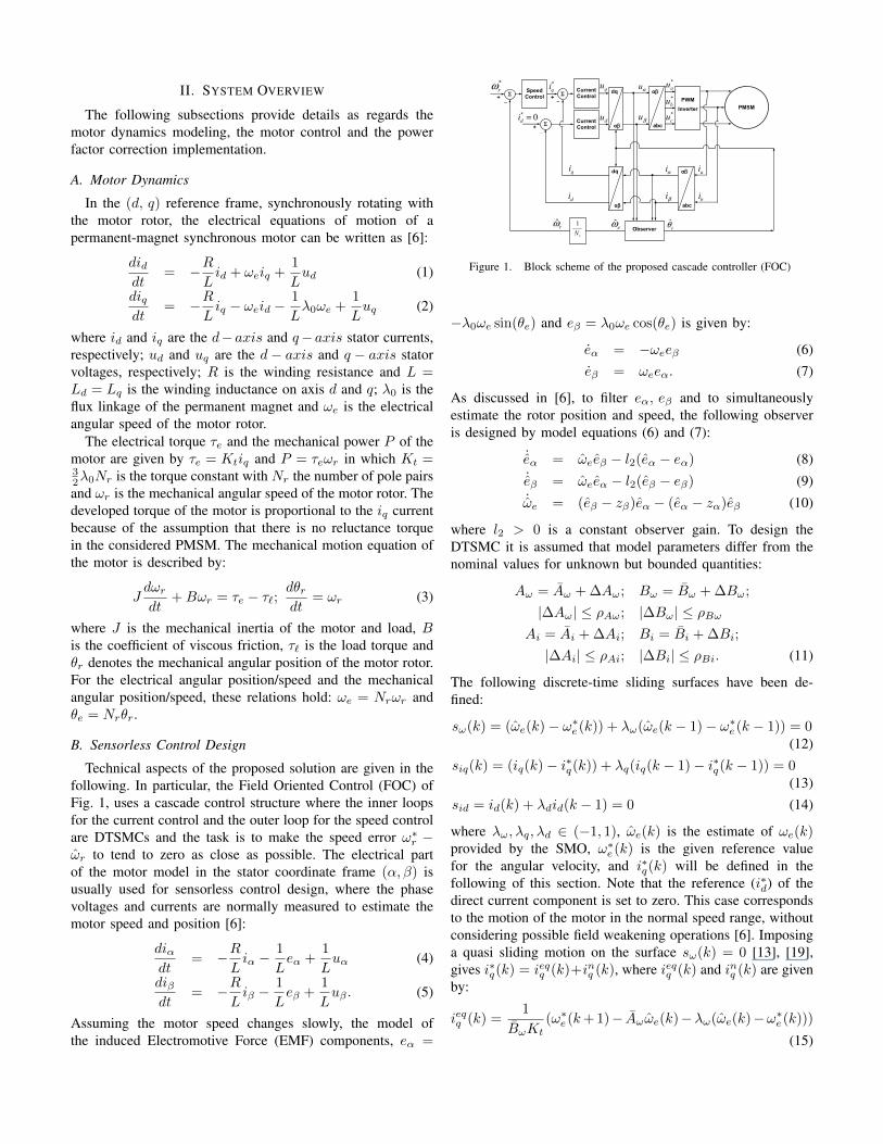
Figure 2. Interleaved boost converter schematic.
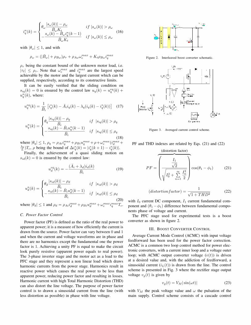
Figure 3. Averaged current control scheme.
PF and THD indexes are related by Eqs. (21) and (22)
PF =
(distortion factor)︷ ︸︸ ︷I1√
2√I20 +
∞∑n=1
I2n2
cos(θ1 − φ1) (21)
(distortionfactor) =1√
1 + THD2(22)
with I0 current DC component, I1 current fundamental com-ponent and (θ1−φ1) difference between fundamental compo-nents phase of voltage and current.
The PFC stage used for experimental tests is a boostconverter as shown in figure 2.
III. BOOST CONVERTER CONTROL
Average Current Mode Control (ACMC) with input voltagefeedforward has been used for the power factor correction.ACMC is a common two loop control method for power elec-tronic converters, with a current inner loop and a voltage outerloop; with ACMC output converter voltage (v(t)) is drivenat a desired value and, with the addiction of feedforward, asinusoidal current (iL(t)) is drawn from the line. The controlscheme is presented in Fig. 3 where the rectifier stage outputvoltage vg(t) is given by
vg(t) = VM | sin(ωt)| (23)
with VM the peak voltage value and ω the pulsation of themain supply. Control scheme consists of a cascade control
with two loops and a feed-forward intermediary state. Boostconverter belongs to variable structure systems, and its dy-namics is fully defined by a switched model. For the designof ACMC compensators, the boost averaged model has beenused:d〈iL(t)〉dt
=1
L(〈vg(t)〉 −RL〈iL(t)〉 − d(t)RDSon
〈iL(t)〉−
d′(t)〈v(t)〉 − d′(t)Rd〈iL(t)〉 − d′(t)Vd)d〈v(t)〉dt
=1
C
(d′(t)〈iL(t)〉 − 1
R〈v(t)〉
)(24)
where 〈v(t)〉Tsand 〈iL(t)〉Ts
are respectively the outputvoltage and the inductor current averaged over one switchingperiod Ts, L, C and R are respectively the inductance, thecapacitance and the boost resistance, d(t) = 1 − d′(t) is theduty-cycle, Vd the diode threshold, Rd the diode resistanceand RDSon
is the mosfet on-resistance.Power factor corrected rectifiers approximate the properties
of ideal rectifier and can be modeled as Loss-Free Resistor(LFR) two port model, [37], [38].
Linear control compensators have been designed with aproportional-integral (PI) structure, with integral anti winduptechnique, based on the transfer function (25) and (27) [39].
A. Voltage loop
In the outer control loop the voltage error (between v(t) andits set point vref2) is the input of compensator Gcv(s) whichgoal is to regulate the DC output voltage at a desired value,driving the signal vcontrol(t) used in the feedforward stage.
Design of the controller is based on perturbation and lin-earization of the LFR model, which results in equivalent ACsmall-signal circuit for the design of the following transferfunction [39]:
v(s)
vcontrol(s)=
PavsCV Vcontrol
(25)
where v(s) and V are respectively Laplace small signal andDC output voltage, vcontrol(s) and Vcontrol are respectivelyLaplace small signal and DC compensator output controlsignal, Pav is the average rectifier power and C is the boostcapacitance.
B. Input voltage feedforward
Input voltage feedforward uses vg(t) measures to producea current reference signal vref1(t) from the output of voltageloop vcontrol(t). Derivation from input voltage vg(t) makes thesignal vr(t) following a sinusoidal waveshape. Feedforwardingcauses the average input current iL(t) to be proportional to theinput voltage vg(t). Multiplier feedforward stage implementsequation
vref1(t) =kvvcontrol(t)vg(t)
V 2M
(26)
where kv is a design constant, vcontrol(t) is the voltagecompensator output control signal, vg(t) is the rectified inputvoltage and VM is the vg(t) peak value.
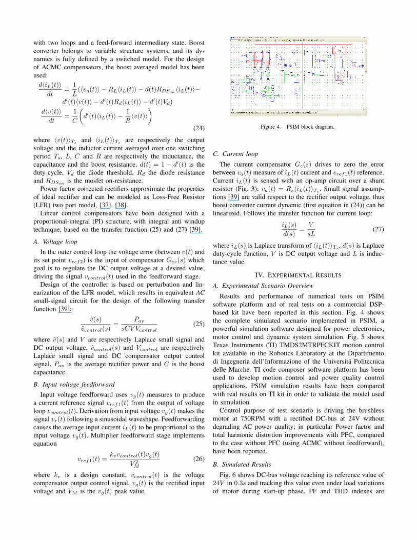
Figure 4. PSIM block diagram.
C. Current loop
The current compensator Gc(s) drives to zero the errorbetween va(t) measure of iL(t) current and vref1(t) reference.Current iL(t) is sensed with an op-amp circuit over a shuntresistor (Fig. 3): va(t) = Rs〈iL(t)〉Ts . Small signal assump-tions [39] are valid respect to the rectifier output voltage, thusboost converter current dynamic (first equation in (24)) can belinearized. Follows the transfer function for current loop:
iL(s)
d(s)=
V
sL(27)
where iL(s) is Laplace transform of 〈iL(t)〉Ts, d(s) is Laplace
duty-cycle function, V is DC output voltage and L is induc-tance value.
IV. EXPERIMENTAL RESULTS
A. Experimental Scenario Overview
Results and performance of numerical tests on PSIMsoftware platform and of real tests on a commercial DSP-based kit have been reported in this section. Fig. 4 showsthe complete simulated scenario implemented in PSIM, apowerful simulation software designed for power electronics,motor control and dynamic system simulation. Fig. 5 showsTexas Instruments (TI) TMDS2MTRPFCKIT motion controlkit available in the Robotics Laboratory at the Dipartimentodi Ingegneria dell’Informazione of the Universita Politecnicadelle Marche. TI code composer software platform has beenused to develop motion control and power quality controlapplications. PSIM simulation results have been comparedwith real results on TI kit in order to validate the model usedin simulation.
Control purpose of test scenario is driving the brushlessmotor at 750RPM with a rectified DC-bus at 24V withoutdegrading AC power quality: in particular Power factor andtotal harmonic distortion improvements with PFC, comparedto the case without PFC (using ACMC without feedforward),have been reported.
B. Simulated Results
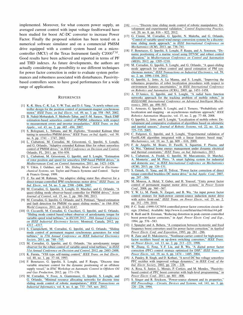
Fig. 6 shows DC-bus voltage reaching its reference value of24V in 0.3s and tracking this value even under load variationsof motor during start-up phase. PF and THD indexes are
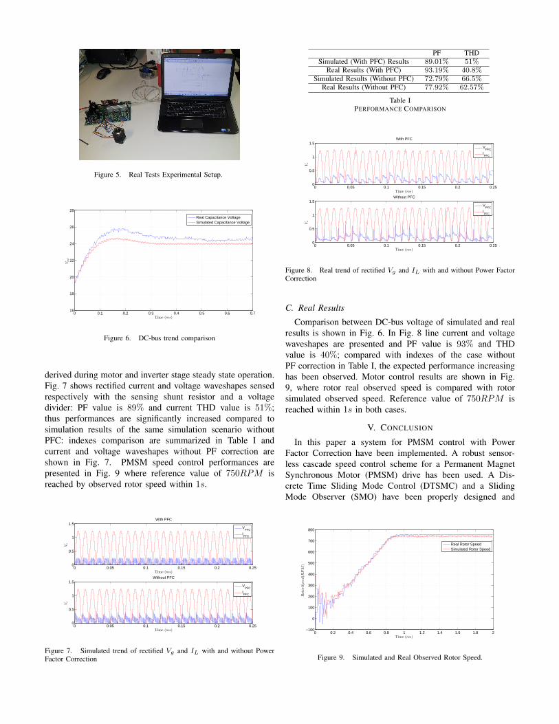
Figure 5. Real Tests Experimental Setup.
0 0.1 0.2 0.3 0.4 0.5 0.6 0.716
18
20
22
24
26
28
Time (ms)
Vout
Real Capacitance VoltageSimulated Capacitance Voltage
Figure 6. DC-bus trend comparison
derived during motor and inverter stage steady state operation.Fig. 7 shows rectified current and voltage waveshapes sensedrespectively with the sensing shunt resistor and a voltagedivider: PF value is 89% and current THD value is 51%;thus performances are significantly increased compared tosimulation results of the same simulation scenario withoutPFC: indexes comparison are summarized in Table I andcurrent and voltage waveshapes without PF correction areshown in Fig. 7. PMSM speed control performances arepresented in Fig. 9 where reference value of 750RPM isreached by observed rotor speed within 1s.
0 0.05 0.1 0.15 0.2 0.250
0.5
1
1.5With PFC
Time (ms)
Vo
VPFC
IPFC
0 0.05 0.1 0.15 0.2 0.250
0.5
1
1.5Without PFC
Time (ms)
Vo
VPFC
IPFC
Figure 7. Simulated trend of rectified Vg and IL with and without PowerFactor Correction
PF THDSimulated (With PFC) Results 89.01% 51%
Real Results (With PFC) 93.19% 40.8%Simulated Results (Without PFC) 72.79% 66.5%
Real Results (Without PFC) 77.92% 62.57%
Table IPERFORMANCE COMPARISON
0 0.05 0.1 0.15 0.2 0.250
0.5
1
1.5With PFC
Time (ms)
Vo
VPFC
IPFC
0 0.05 0.1 0.15 0.2 0.250
0.5
1
1.5Without PFC
Time (ms)
Vo
VPFC
IPFC
Figure 8. Real trend of rectified Vg and IL with and without Power FactorCorrection
C. Real Results
Comparison between DC-bus voltage of simulated and realresults is shown in Fig. 6. In Fig. 8 line current and voltagewaveshapes are presented and PF value is 93% and THDvalue is 40%; compared with indexes of the case withoutPF correction in Table I, the expected performance increasinghas been observed. Motor control results are shown in Fig.9, where rotor real observed speed is compared with rotorsimulated observed speed. Reference value of 750RPM isreached within 1s in both cases.
V. CONCLUSION
In this paper a system for PMSM control with PowerFactor Correction have been implemented. A robust sensor-less cascade speed control scheme for a Permanent MagnetSynchronous Motor (PMSM) drive has been used. A Dis-crete Time Sliding Mode Control (DTSMC) and a SlidingMode Observer (SMO) have been properly designed and
0 0.2 0.4 0.6 0.8 1 1.2 1.4 1.6 1.8 2−100
0
100
200
300
400
500
600
700
800
Time (ms)
RotorS
peed(R
PM
)
Real Rotor SpeedSimulated Rotor Speed
Figure 9. Simulated and Real Observed Rotor Speed.
implemented. Moreover, for what concern power supply, anaveraged current control with input voltage feedforward havebeen studied for boost AC-DC converter to increase PowerFactor. Finally the proposed solution has been tested on anumerical software simulator and on a commercial PMSMdrive equipped with a control system based on a micro-controller (MCU) of the Texas Instrument family C2000TM .Good results have been achieved and reported in terms of PFand THD indexes. As future developments, the authors areactually considering the possibility to use different techniquesfor power factor correction in order to evaluate system perfor-mances and robustness associated with disturbances. Passivity-based controllers seem to have good performances for a widerange of applications.
REFERENCES
[1] K.-K. Shyu, C.-K. Lai, Y.-W. Tsai, and D.-I. Yang, “A newly robust con-troller design for the position control of permanent-magnet synchronousmotor,” IEEE Trans. on Ind. Electr., vol. 49, no. 3, pp. 558 –565, 2002.
[2] B. Nahid-Mobarakeh, F. Meibody-Tabar, and F.-M. Sargos, “Back EMFestimation-based sensorless control of PMSM: robustness with respectto measurement errors and inverter irregularities,” IEEE Trans. on Ind.Applic., vol. 43, no. 2, pp. 485 –494, 2007.
[3] S. Bolognani, L. Tubiana, and M. Zigliotto, “Extended Kalman filtertuning in sensorless PMSM drives,” IEEE Trans. on Ind. Applic., vol. 39,no. 6, pp. 1741 – 1747, 2003.
[4] L. Ciabattoni, M. Corradini, M. Grisostomi, G. Ippoliti, S. Longhi,and G. Orlando, “Adaptive extended Kalman filter for robust sensorlesscontrol of PMSM drives,” in IEEE Conference on Decision and Control,Orlando, FL, 2011, pp. 934–939.
[5] L. Ciabattoni, M. Grisostomi, G. Ippoliti, and S. Longhi, “Estimationof rotor position and speed for sensorless DSP-based PMSM drives,” inMediterranean Conf. on Control Automation, 2011, pp. 1421–1426.
[6] V. Utkin, J. Guldner, and J. Shi, Sliding Mode Control in Electrome-chanical Systems, ser. Taylor and Francis Systems and Control. Taylor& Francis Group, 1999.
[7] Z. Xu and M. Rahman, “An adaptive sliding stator flux observer for adirect-torque-controlled IPM synchronous motor drive,” IEEE Trans. onInd. Electr., vol. 54, no. 5, pp. 2398 –2406, 2007.
[8] M. Corradini, G. Ippoliti, S. Longhi, D. Marchei, and G. Orlando, “Aquasi-sliding mode observer-based controller for PMSM drives,” AsianJournal of Control, vol. 15, no. 2, pp. 380–390, 2013.
[9] M. Corradini, G. Ippoliti, G. Orlando, and S. Pettinari, “Speed estimationand fault detection for PMSM via quasi sliding modes,” in 18th IFACWorld Congress, 2011, pp. 6142–6147.
[10] O. Ciccarelli, M. Corradini, G. Cucchieri, G. Ippoliti, and G. Orlando,“Sliding mode control based robust observer of aerodynamic torque forvariable-speed wind turbines,” in IECON 2012 - 38th Annual Conferenceon IEEE Industrial Electronics Society, Montreal, Canada, 2012, pp.4312 –4317.
[11] S. Ciampichetti, M. Corradini, G. Ippoliti, and G. Orlando, “Slidingmode control of permanent magnet synchronous generators for windturbines,” in 37th Annual Conference on IEEE Industrial ElectronicsSociety, 2011, pp. 740 –745.
[12] M. Corradini, G. Ippoliti, and G. Orlando, “An aerodynamic torqueobserver for the robust control of variable-speed wind turbines,” in IEEE51st Annual Conference on Decision and Control, 2012, pp. 2483–2488.
[13] K. Furuta, “VSS type self-tuning control,” IEEE Trans. on Ind. Electr.,vol. 40, no. 1, pp. 37–44, 1993.
[14] F. Benetazzo, G. Ippoliti, S. Longhi, and P. Raspa, “Discrete timevariable structure control for the dynamic positioning of an offshoresupply vessel,” in IFAC Workshop on Automatic Control in Offshore Oiland Gas Production, 2012, pp. 171–176.
[15] M. Corradini, V. Fossi, A. Giantomassi, G. Ippoliti, S. Longhi, andG. Orlando, “Minimal resource allocating networks for discrete timesliding mode control of robotic manipulators,” IEEE Transactions onIndustrial Informatics, vol. 8, no. 4, pp. 733 –745, nov. 2012.
[16] ——, “Discrete time sliding mode control of robotic manipulators: De-velopment and experimental validation,” Control Engineering Practice,vol. 20, no. 8, pp. 816 – 822, 2012.
[17] G. Cimini, M. Corradini, G. Ippoliti, N. Malerba, and G. Orlando,“Control of variable speed wind energy conversion systems by a discrete-time sliding mode approach,” in IEEE International Conference onMechatronics (ICM), 2013, pp. 736–741.
[18] F. Benetazzo, G. Ippoliti, S. Longhi, P. Raspa, and A. Sorensen, “Dy-namic positioning of a marine vessel using DTVSC and robust controlallocation,” in Mediterranean Conference on Control and Automation(MED), 2012, pp. 1205–1210.
[19] M. Corradini, G. Ippoliti, S. Longhi, and G. Orlando, “A quasi-slidingmode approach for robust control and speed estimation of PM syn-chronous motors,” IEEE Transactions on Industrial Electronics, vol. 59,no. 2, pp. 1096–1104, 2012.
[20] G. Ippoliti, L. Jetto, A. La Manna, and S. Longhi, “Improving therobustness properties of robot localization procedures with respect toenvironment features uncertainties,” in IEEE International Conferenceon Robotics and Automation (ICRA), 2005, pp. 1451–1458.
[21] A. D’Amico, G. Ippoliti, and S. Longhi, “A radial basis functionnetworks approach for the tracking problem of mobile robots,” inIEEE/ASME International Conference on Advanced Intelligent Mecha-tronics, 2001, pp. 498–503.
[22] L. Armesto, G. Ippoliti, S. Longhi, and J. Tornero, “Probabilistic self-localization and mapping - an asynchronous multirate approach,” IEEERobotics Automation Magazine, vol. 15, no. 2, pp. 77–88, 2008.
[23] G. Ippoliti, L. Jetto, and S. Longhi, “Localization of mobile robots: De-velopment and comparative evaluation of algorithms based on odometricand inertial sensors,” Journal of Robotic Systems, vol. 22, no. 12, pp.725–735, 2005.
[24] C. Fulgenzi, G. Ippoliti, and S. Longhi, “Experimental validation ofFastSLAM algorithm integrated with a linear features based map,”Mechatronics, vol. 19, no. 5, pp. 609 – 616, 2009.
[25] F. de Angelis, M. Boaro, D. Fuselli, S. Squartini, F. Piazza, andQ. Wei, “Optimal home energy management under dynamic electricaland thermal constraints,” IEEE Trans. on Ind. Informatics, 2013.
[26] L. Ciabattoni, A. Freddi, G. Ippoliti, M. Marcantonio, D. Marchei,A. Monteriu’, and M. Pirro, “A smart lighting system for industrialand domestic use,” in IEEE International Conference on Mechatronics(ICM), 2013, pp. 126–131.
[27] S. Ozturk, O. Yang, and H. Toliyat, “Power factor correction of directtorque controlled brushless DC motor drive,” in Ind. Applic. Conf., 2007,pp. 297 –304.
[28] M. Moussa, A. Helal, Y. Gaber, and H. Youssef, “Unity power factorcontrol of permanent magnet motor drive system,” in Power SystemConf., 2008, pp. 360 –367.
[29] Y. W. Li, M. Pande, N. Zargari, and B. Wu, “An input power factorcontrol strategy for high-power current-source induction motor drivewith active front-end,” IEEE Trans. on Power Electr., vol. 25, no. 2,pp. 352 –359, 2010.
[30] P. C. Todd. (1999) UC3854 controlled power factor correction circuit de-sign. [Online]. Available: http://www.ti.com/lit/an/slua144/slua144.pdf
[31] R. Redl and B. Erisman, “Reducing distortion in peak-current-controlledboost power-factor correctors,” in Appl. Power Electr. Conf. and Exp.,1994, pp. 576 –583.
[32] J. Spangler and A. Behera, “A comparison between hysteretic and fixedfrequency boost converters used for power factor correction,” in AppliedPower Electr. Conf. and Exposition, 1993, pp. 281 –286.
[33] R. Zane and D. Maksimovic, “Nonlinear-carrier control for high-power-factor rectifiers based on up-down switching converters,” IEEE Trans.on Power Electr., vol. 13, no. 2, pp. 213 –221, 1998.
[34] W. Zhang, G. Feng, Y.-F. Liu, and B. Wu, “A digital power factorcorrection (PFC) control strategy optimized for DSP,” IEEE Trans. onPower Electr., vol. 19, no. 6, pp. 1474 – 1485, 2004.
[35] A. Pandey, B. Singh, and D. Kothari, “A novel DC bus voltage sensorlessPFC rectifier with improved voltage dynamics,” in IEEE Conf. of theInd. Electr. Society, 2002, pp. 226 – 228.
[36] A. Rosa, S. Junior, L. Morais, P. Cortizo, and M. Mendes, “Passivity-based control of PFC boost converter with high-level programming,” inPower Electr. Conf., 2011, pp. 801 –806.
[37] S. Singer and R. Erickson, “Power-source element and its properties,”IEE Proceedings - Circuits, Devices and Systems, vol. 141, no. 3, pp.220 –226, 1994.

[38] S. Singer, “Realization of loss-free resistive elements,” IEEE Trans. onCircuits and Systems, vol. 37, no. 1, pp. 54 –60, 1990.
[39] R. Erickson and D. Maksimovic, Fundamentals of Power Electronics.Springer, 2001.