pick a calculator, any calculator
TRANSCRIPT

FOR ENGINEERS AND ENGINEERING MANAGERS - WORLDWIDE
Pick a calculator, any calculator. More computing power is packed into all machines. Displays are easier to read, and reliability is better. But problems persist. Poor
MARCH 1, 1978
keyboard designs still give false entries. Live N iCd batteries play dead. And complex features of programmables make selection tougher than ever. See p. 40.
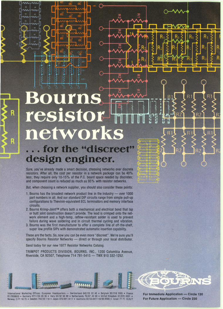
Sure, you've already made a smart decision, choosing networks over discrete resistors. After all, the cost per resistor in a network package can be 40% less; they require only 10-15% of the P.C. board space needed by dlscretes; and component count is reduced as much as 95% with resistor networks.
But, when choosing a network supplier, you should also consider these points:
1. Bourns has the broadest network product line in the industry - over 1000 part numbers in all. And our standard DIP circuits range from simple pull-up configurations to Thevinin-equivalent ECL terminators and memory interface circuits.
2. Bourns Krimp-Joint™ offers both a mechanical and electrical bond that lap or butt joint construction doesn't provide. The lead is crimped onto the network element and a high-temp, reflow-resistant solder is used to prevent failure during wave soldering and in circuit thermal cycling and vibration.
3. Bourns was the first manufacturer to offer a complete line of off-the-shelf, super low profile SIPs with demonstrated automatic insertion capability.
These are the facts. So, now you can be even more "discreet". We're sure you'll specify Bourns Resistor Networks - direct or through your local distributor.
Send today for our new 1977 Resistor Networks Catalog.
TRIMPOT PRODUCTS DIVISION, BOURNS, INC., 1200 Columbia Avenue, Riverside, CA 92507, Telephone 714 781-5415 - TWX 910 332-1252.
International Marketing Offices: European Headquarters - Switzerland 042/23 22 42 • Belgium 02/218 2005 • France 01/2039633 • Germany 0711/24 29 36 • Italy 02132 56 88 • Netherlands 70/87 44 00 • United Kingdom 01/572 6531 • Norway 2/71 18 72 • Sweden 764/20 110 • Japan 075/921 9111 • Australia 02/55-0411 03/95-9566 • Israel 77 71 15/6/7
For Immediate Application - Circle 130 For Future Application - Circle 230
ELECTRONIC
01803
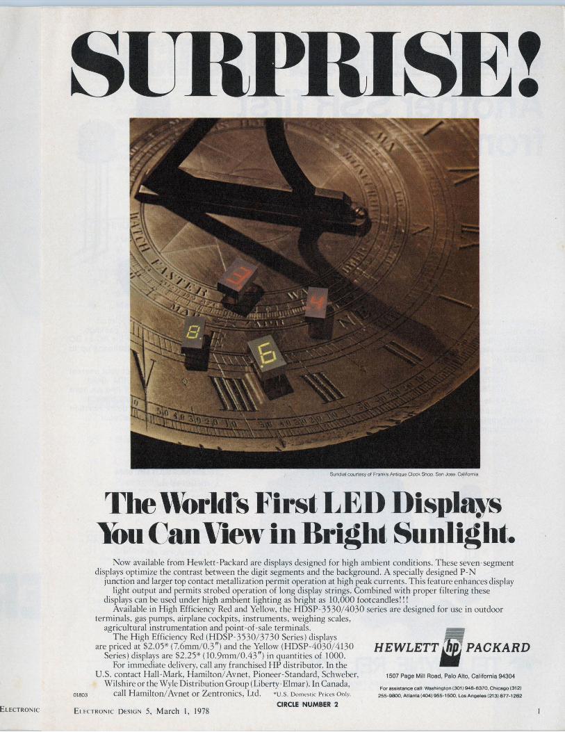
Sundial courtesy of Franks AnllQue Clock Shop, San Jose. Gahfornia
The World's First LED Displays You Can View in Bright Sunlight.
Now avai lable from Hewlett-Packard are displays designed for high ambient conditions. These seven-segment displays optimize the contrast between the digit segments and the background. A specially designed P-N
junction and larger top contact metallization permit operation at high peak currents. This feature enhances display light output and permits strobed operation of long display strings. Combined with proper filtering these
displays can be used under high ambient lighting as bright as 10,000 footcandles! ! ! Available in H igh Efficiency Red and Yellow, the HDSP-3 530/ 4030 series are designed for use in outdoor
terminals, gas pumps, airplane cockpits, instruments , weighing scales, agricultural instrumentation and point -of-sale terminals.
The High Efficiency Red (HDSP-3530/ 3730 Series) displays
' •
are priced at $2.05* (7.6mm/ 0.3") and the Yellow (HDSP-4030/ 4130 Series) displays are $2.25* (10.9mm/ 0.43") in quantities of 1000.
For immediate delivery, call any franchised HP distributor. In the U.S. contact Hall -Mark, Hamilton/ Avnet, Pioneer-Standard, Schweber,
Wilshire or the Wyle Distribution Group (Liberty-El mar). In Canada,
HEWLETT"' PACKARD
call Hamilton/ Avnet or Zentronics , Ltd. •u.s. Domestic Prices Only.
CIRCLE NUMBER 2
1507 Page Mill Road, Palo Alto, California 94304
For assistance call: Washington (301) 948-6370, Chicago (312)
255-9800, Atlanta ( 404) 955-1500. Los Angeles (213) 877-1282
E1.l'CTRON1 c DESIGN 5, March I, 1978
Experience, state relay t milestone wi solid state r MIL-R-28750:
M2t M2t M2t
These SSI reliability re ~ switching a~ support equ1
~ I
2
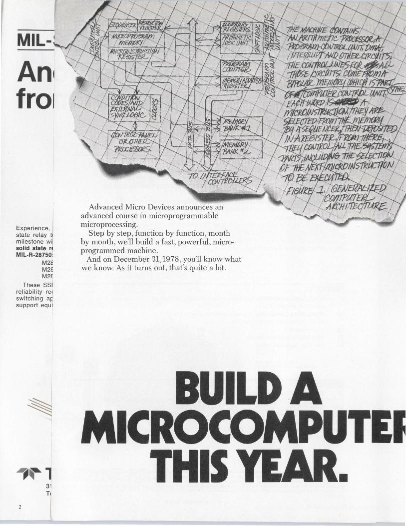
Advanced Micro Devices announces an advanced course in microprogrammable . . m1croprocessmg.
Step by step, function by function, month by month, we'll build a fast, powerful, microprogrammed machine.
And on December 31,1978, you'll know what we know. As it turns out, that's quite a lot.
BUILD A MICROCOMPUTEI
THIS YE •
CHAPTER ONE: COMPUTER ARCHITECTURE. Modern digital processors are built using
one of two techniques: A fixed-instruction MOS processor, such as the 8080A or 8085, or a microprogrammed TTL design. Because of the extremely low cost and small size of the microcomputer built around a fixed-instruction microprocessor, this approach is dominant.
But, not all problems can be solved with an 8080A or 8085. They may not be fast enough. And, applications requiring more than 8 bits of precision, substantial amounts of arithmetic processing, adherence to a predefined instruction set or blazing speed need something more than MOS has to offer. You need microprogramming capability. You need bipolar LSI.
During the year, you'll be meeting several new members of the Arn2900 Family, a series of low-power Schottky LSI devices specifically designed for microprogrammed machines.
Your microcomputer can have instruction execution as short as 100 nanoseconds, multiplication as fast as 4 microseconds and division in just 8 microseconds.
So clear some space. In your office. In your home. In your brain.
BUILD YOUR LIBRARY, TOO. Each of these messages is backed by a ton
of theory and applications information. Send in this coupon, and we'll send you Chapter One and tell you how to get the whole book. 1---------------~-----,
Advanced Micro Devices 901 Thompson Place Sunnyvale, California 94086
I want to build a microcomputer this year. Sign me up.
3/78-ED
Title _________ Mail Stop ___ _
Company ______________ _
Address ______________ _
City State Zip __ _
L---------------------~
Advanced Micro Devices
~ Multiple technologies. One product: excellence.
901 Thompson Place, Sunnyvale, California 94086 Telephone (408) 732-2400
Next month, Chapter Two: Microprogrammed Control.•
6
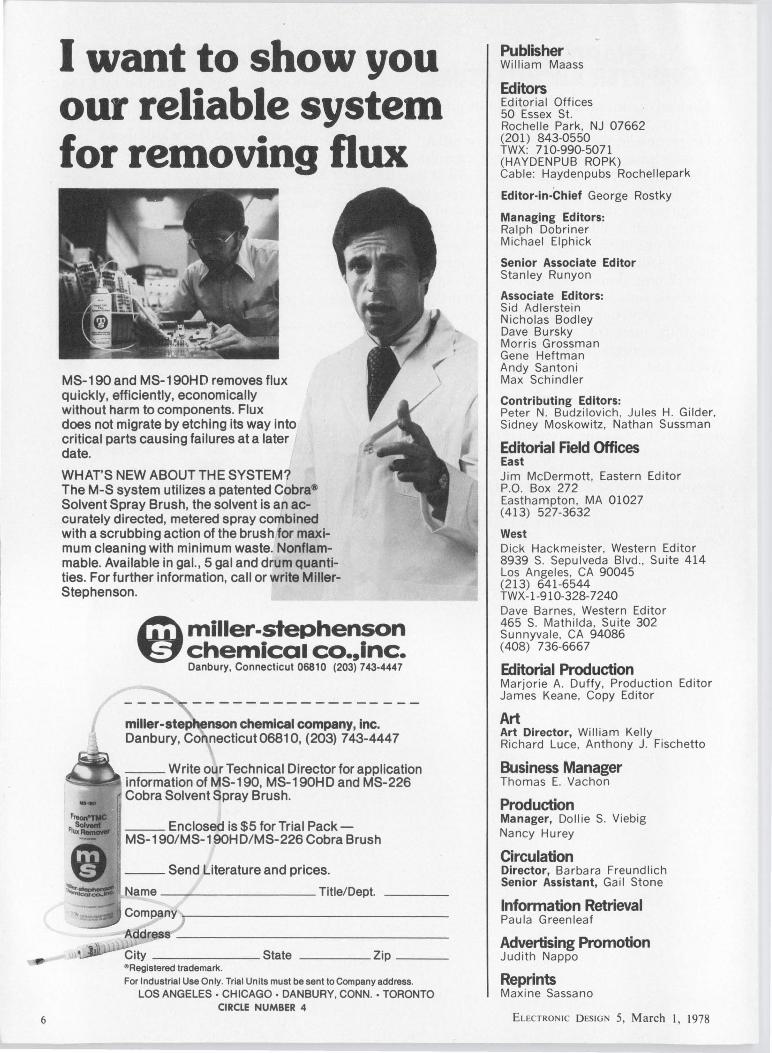
I want to show you our reliable system for removing flux
MS-190 and MS-190H D removes flux quickly, efficiently, economically without harm to components. Flux does not migrate by etching its way into critical parts causing failures at a later date.
WHAT'S NEW ABOUT THE SYSTEM? The M-S system utilizes a patented Cobra® Solvent Spray Brush, the solvent is an accurately directed, metered spray combined with a scrubbing action of the brush for maximum cleaning with minimum waste. Nonflammable. Available in gal., 5 gal and drum quantities. For further information, call or write MillerStephenson.
~ miller-stephenson ~chemical co.,inc.
Danbury, Connecticut 06810 (203) 743-4447
miller-step enson chemical company, inc. Danbury, Connecticut06810, (203) 743-4447
___ Write our Technical Director for application ~--~ information of MS-190, MS-190HD and MS-226
Cobra Solvent Spray Brush.
__ Enclosed is $5 for Trial Pack -MS-190/MS-190H D/MS-226 Cobra Brush
__ Send Literature and prices. __________ Title/Dept.
_______ state _____ Zip __ _ " Registered trademark.
For Industrial Use Only. Trial Units must be sent to Company address.
LOS ANGELES ·CHICAGO· DANBURY. CONN. ·TORONTO CIRCLE NUMBER 4
I
Publisher William Maass
Editors Ed itoria I Offices 50 Essex St. Rochelle Park, NJ 07662 (201) 843-0550 TWX: 710-990-5071 (HAYDENPUB ROPK) Cable: Haydenpubs Rochellepark
Editor-in-Chief George Rostky
Managing Editors: Ralph Dobriner Michael Elphick
Senior Associate Editor Stanley Runyon
Associate Editors: Sid Adlerstein Nicholas Bodley Dave Bursky Morris Grossman Gene Heftman Andy Santoni Max Schindler
Contributing Editors: Peter N. Budzilovich , Jules H. Gilder, Sidney Moskowitz, Nathan Sussman
Editorial Field Offices East Jim McDermott, Eastern Editor P.O. Box 272 Easthampton, MA 01027 (413) 527-3632
West Dick Hackmeister, Western Editor 8939 S. Sepulveda Blvd ., Suite 414 Los Angeles, CA 90045 (213) 641 -6544 TWX-1 -910-328-7240 Dave Barnes, Western Editor 465 S. Mathilda, Suite 302 Sunnyvale, CA 94086 (408) 736-6667
Editorial Production Marjorie A. Duffy, Production Editor James Keane, Copy Editor
Art Art Director, William Kelly Richard Luce, Anthony J. Fischetto
Business Manager Thomas E. Vachon
Production Manager, Dollie S. Viebig Nancy Hurey
Circulation Director, Barbara Freundlich Senior Assistant, Gail Stone
Information Retrieval Paula Greenleaf
Advertising Promotion Judith Nappo
Reprints Maxine Sassano
ELECTRONIC D ESIGN 5, March I, 1978
Aeross the desll Putting the brakes to radar brake control
Your article on automobile radar systems in the U.S. for brake control (ED No. 23, Nov. 8, 1977, p. 30) indicates that noticeable progress has been made in the U.S., butl remember the Japanese reporting approximately this much success at a conference in Detroit around 1972. It appears from your article, though, that the most serious questions raised in 1972 haven't been solved by the approaches you describe, including:
• Inability to determine a real threat. An oak tree or a bridge abutment is a threat. An empty trash can is not, but it has a beautiful radar cross-section.
• Water splash or heavy rainfall problems. Ironically, these bad conditions can occur when braking help might be most needed.
• The braking systems don't know what you're thinking. For example, if you pull out to pass with a car coming on, the systems in your article could brake you just before you turn back into your lane, leaving you in a rather bad position.
• EMI and reliability. The danger from some stray signal is very serious. Likewise, the over-all reliability of the electronics will have to be several orders of magnitude better than anything of this general level of complexity ever built. It will be hard to prove that the units save a life, but rather obvious when it causes a serious accident.
There is nothing wrong with using radar to warn a driver, but taking control raises serious questions. I, for one, would not want the system(s) you describe to control my car.
W.T. Walton 38 Windward Dr. Severna Park, MD 21146
A few changes The article, "Exploit Existing NOV A
Software by Designing computer Systems Around the Micro NOV A" (ED
No. 19, Sept., 13, 1977, p. 54), contained several inaccuracies.
The last two sentences of p. 56 should read: "During a Refresh operation, the CPU specifies a group equivalent to. 1/64 of all the memory locations to be refreshed, but transfers no data. The refresh address is selected by a 6-bit refresh address register placed on the lower six address lines."
Also, Fig. 8a on p. 63 should be corrected as indicated.
Data General Route 9
Daniel Falkoff Design Engineer
Westboro, MA 01581
Misplaced Caption Dept.
Our engineers react positively to design reviews . Our younger engineers, in particular, look forward to these inputs.
Sorry. That's "Massacre of the Barbarians," from the Column of Marcus Aurelius located in Rome.
Electronic Design welcomes the opinions of its readers on the issues raised in the magazine's editorial columns. Address letters to Managing Editor, Electronic Design, 5CI Essex St., Rochelle Park, NJ 07662. Try to keep letters under 200 words. Letters must be signed. Names will be withheld upon request.
ELECTRONIC D ESIGN 5, March I , 1978
OPTRON OPTICALLY COUPLED
ISOLATORS NEW JAN 4N22A SERIES
OFFERS HIGHEST RELIABILITY
You can't buy a more reliable optically coupled isolator than one of OPTRON's new JAN 4N22A series. The popular JAN 4N22A, 4N23A and 4N24A all feature fully qualified JANTX and JANTXV ratings.
These new OPTRON isolators consist of a high efficiency, solution grown gallium arsenide LED and a silicon N-P-N phototransistor in a hermetically sealed 6-pin T0-5 package. Minimum input-to-output isolation voltage for the series is 1000 volts and minimum current transfer ratios range from 25% for the 4N22A to 100% for the 4N24A.
New "A" version OPTRON isolators are a significant improvement over the older 4N22 series since the case is isolated from the sensor and LED to eliminate the need for an insulating spacer in many applications.
OPTRON also offers a new JEDEC registered series of high reliability isolators in a 4-pin T0-18 package. The 3N243 series includes three devices with the same reliability and similar characteristics as the JAN 4N22A T0-5 series, yet in a smaller package.
In addition, OPTRON's complete line of optically coupled isolators includes other immediately available standard devices in high-rel metal cans and low cost DIP and other plastic config-
3N243 urations for almost every application.
Detailed technical information on optically coupled isolators and other OPTRON optoelectronic products ... chips, discrete components, limit switches, reflective transducers, and interrupter assemblies ... is available from your nearest OPTRON sales representative or the factory direct.
@ OPTRON, INC. 1201 Tappan Circle Carrollton, Texas 75006, USA TWX-910-860-5958 2141242-6571
CIRCLE NUMBER 5 7
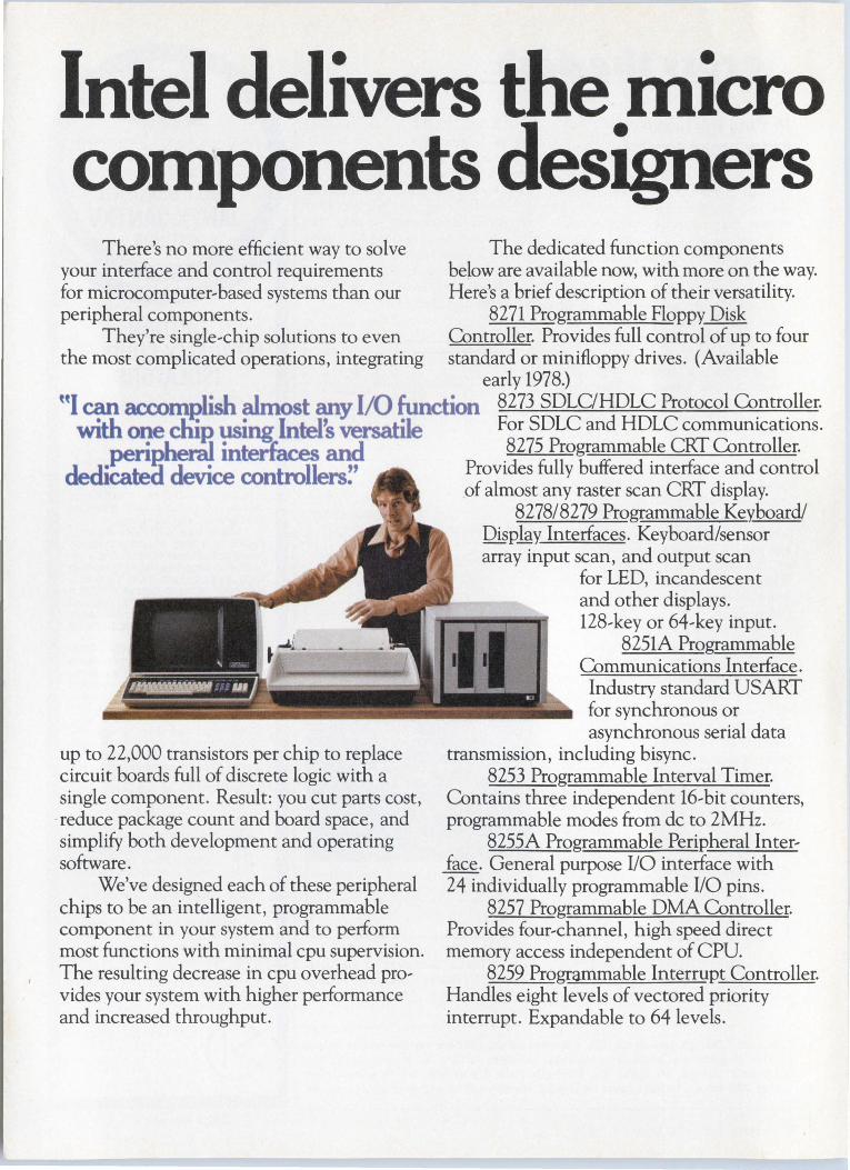
Intel delivers the niicro co01ponents designers
There's no more efficient way to solve your interface and control requirements for microcomputer,based systems than our peripheral components.
They're single,chip solutions to even the most complicated operations, integrating
The dedicated function components below are available now, with more on the way. Here's a brief description of their versatility.
8271 Programmable Floppy Disk O.mtroller. Provides full control of up to four standard or minifloppy drives. (Available
early 1978.) "I can accomplish almost any 1/0 function 8273 SDLC/HDLC Protocol Controller.
with one cliiP. using lntels versatile For SDLC and HDLC communications. . henil inteifaces and 8275 Programmable CRT Controller.
dedi~ device controllers!' Provides fully buffered interface .and control
up to 22,000 transistors per chip to replace circuit boards full of discrete logic with a single component. Result: you cut parts cost, reduce package count and board space, and simplify both development and operating software.
We've designed each of these peripheral chips to be an intelligent, programmable component in your system and to perform most functions with minimal cpu supervision. The resulting decrease in cpu overhead pro, vides your system with higher performance and increased throughput.
of almost any raster scan CRT display. 8278/8279 Programmable Keyboard/
OisP.lay Interfaces. Keyboard/sensor array input scan, and output scan
for LED, incandescent and other displays. 128,key or 64,key input.
8251A Programmable Communications Interface. Industry standard USART for synchronous or asynchronous serial data
transmission, including bisync. 8253 Programmable Interval Timer.
Contains three independent 16,bit counters, programmable modes from de to 2MHz.
8255A Programmable Peripheral Inter, face. General purpose 1/0 interface with 24 individually programmable 1/0 pins.
8257 Programmable OMA Controller. Provides four,channel, high speed direct memory access independent of CPU.
8259 Programmable Interrupt Controller. Handles eight levels of vectored priority interrupt. Expandable to 64 levels.
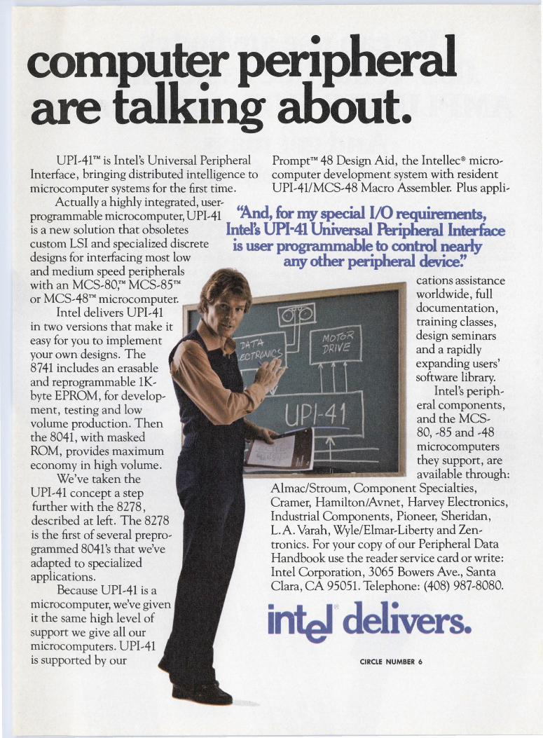
co01puter peripheral are talking al)out.
UPIAl™ is Intel's Universal Peripheral Prompt™ 48 Design Aid, the lntellec® micro, Interface, bringing distributed intelligence to computer development system with resident microcomputer systems for the first time. UPIA 1/MCS,48 Macro Assembler. Plus appli,
Actually a highly integrated, user, programmable microcomputer, UPIAl '!4.Jld, for my special 1/0 requirements, is a new solution that obsoletes Intel~ UPl-41 Universal Peripheral Interface custom LSI and specialized discrete is user p-to control ~ designs for interfacing most low any other pen·pheral devi " and medium speed peripherals ce. with an MCS,so:M MCS,85™ cations assistance or MCSA8™ microcomputer. worldwide, full
Intel delivers UPl,41 documentation, in two versions that make it training classes, easy for you to implement design seminars your own designs. The and a rapidly 8741 includes an erasable expanding users' and reprogrammable lK, software library. byte EPROM, for develop, Intel's periph, ment, testing and low eral components, volume production. Then and the MCS, the 8041, with masked 80, ,s5 and AS ROM, provides maximum microcomputers economy in high volume. they support, are
We've taken the available through: UPIA 1 concept a step Almac/Stroum, Component Specialties, further with the 8278, Cramer, Hamilton/Avnet, Harvey Electronics, described at left. The 8278 Industrial Components, Pioneer, Sheridan, is the first of several prepro, L.A. Varah, Wyle/Elmar,Liberty and Zen, grammed 804 l's that we've tronics. For your copy of our Peripheral Data adapted to specialized Handbook use the reader service card or write: applications. Intel Corporation, 3065 Bowers Ave., Santa
Because UPIAl is a Clara, CA 95051. Telephone: (408) 987,8080. microcomputer, we've given it the same high level of support we give all our microcomputers. up1,41 is supported by our
inter delivers CIRCLE NUMBER 6

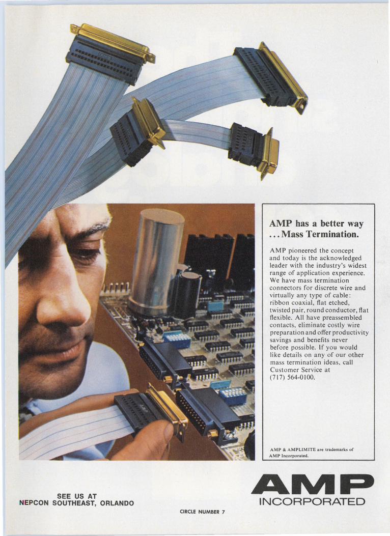
"We can use anybody's .050'' centerline cable with
AMPLIMITE HOF connectors. And get mass
termination efficiency." And there are no exceptions. AMPLIMITE High Density Flexible connectors work with all .050" centerline 28-30 A WG round conductor ribbon cable. You get an axial cable-to-connector interface second to none in strength and ruggedness.
AMPLIMITE HDF connectors provide complete packaging flexibility. They are available in 15-, 25- and 37-position sizes, and have through-cable capability for "daisy chain" applications. They intermate with other D-type connectors, including AMPLIMITEall-plastic right-angle headers. HDF connectors are at work in computer peripherals, modems, instrumentation, industrial controls, and word processing systems. They are completely compatible with transmission specification RS-232.
AMPLIMITE HDF connectors give you another plus. AMP technical assistance and support. It's thorough, complete, professional aid you can call on even during project planning. It can help make sure your design will be efficient and effective right from the start.
There are more advantages with AMPLIMITE HDF connectors: • Probe-ability for convenient circuit
testing with connectors in place . • Compatibility with "dead center" and
"dead edge" designs.
• Matched application tooling assures highest production rates and lowest applied cost.
• Integrated cable strain relief.
For more information on AMPLIMITE HDF connectors, just call Customer Service at (717) 564-0100. Or write AMP Incorporated, Harrisburg, PA 17105.
SEE US AT NEPCON SOUTHEAST, ORLANDO
CIRCLE NUMBER 7
AMP has a better way ... Mass Termination.
AMP pioneered the concept and today is the acknowledged leader with the industry's widest range of application experience. We have mass termination connectors for discrete wire and virtually any type of cable: ribbon coaxial, flat etched, twisted pair, round conductor, flat flexible . All have preassembled contacts, eliminate costly wire preparation and offer productivity savings and benefits never before possible. If you would like details on any of our other mass termination ideas, call Customer Service at (717) 564-0 I 00.
AMP & AMPLIMITE are trademarks of
AMP Incorporated.
AIVIP INCORPORATED

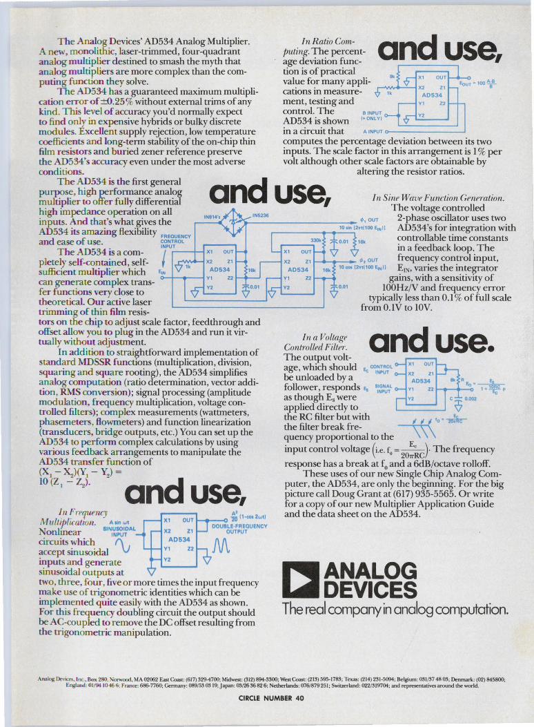
The Analog Devices' AD534 Analog Multiplier. A new, monolithic, laser-trimmed, four-quadrant analog mu ltiplie r destined to smash the myth that analog mu ltipliers are more complex than the computing func tion they solve.
T he AD534 has a guaranteed maximum multiplication error of ±0.25% without external trims of any kind. This level of accuracy you'd normally expect to find onJy in expensive hybrids or bulky discrete modules. Excellent supply rejection, low temperature coefficien ts and long-term stability of the on-chip thin film resistors and buried zener reference preserve the AD534's accuracy even under the most adverse conditions.
Jn Ratio Computing. The percentage deviation func and use, tion is of practical
OUT
...--.~~-X2 Z1 value for many applications in measurement, testing and control. The e INPUT
AD534 is shown c+oNLYJ
AD534 Y1 Z2
Y2
EouT • 100 ABB
in a circuit that A INPUT o----------' computes the percentage deviation between its two inputs. The scale factor in this arrangement is 1 % per volt although other scale factors are obtainable by
altering the resistor ratios. The AD534 is the first general
purpose, high performance analog multiplier to offer fully differential high impedance operation on all inputs. And that's what gives the AD534 its amazing flexibility FREauENcY
and use, In Sine Wave Function Generation. The voltage controlled
.---1N_91 ..... 4··~ '.c~-,._1_N5_236 __________ ~. ouT 2-phase oscillator uses two 10 "" 12.,1100 E,N11 AD534's for integration with
and ease of use. coNTRoL INPUT
T he AD534 is a com- / ....--t--t x1
ple tely self-contained, self- x2 z1 sufficient multiplier which EoN AD534
OUT
I 0------1 Y1 Z2 can generate comp ex trans-fer functions very close to theoretical. Our active laser trimming of thin film resis
Y2
tors on the chip to adjust scale factor, feedthrough and offset allow you to plug in the AD534 and run it virtually without adjustment.
In addition to straightforward implementation of standard MDSSR functions (multiplication, division, squaring and square rooting), the AD534 simplifies analog computation (ratio determination, vector addition, RMS conve rsion); signal processing (amplitude modulation, frequency multiplication, voltage controlled filters); complex measurements (wattmeters, phasemeters , flowmeters) and function linearization (transducers, bridge outputs, etc.) You can set up the AD534 to per form complex calctilations by using va rious feedback arrangements to manipulate the AD534 transfer function of (X1 - ~)(Y1 - Y2) =
10 (Z I - Z2)- and use, J 12 Frrquency
M l l {L ipf icatioJZ. A''" wt
Nonlinear siN,~~~AL circuits which f\ . accept sinusoidal V inputs and generate sinusoidal outputs at
A' OUT ----o 10 (1-cos 2wtl X1
X2 Z1
AD634 V1 Z2
V2
OOUBLE FREOUENCV OUTPUT
M
two, th ree , four, five or more times the input frequency make use of trigonometric identities which can be implemented quite easily with the AD534 as shown. For this frequency doubling circuit the output should be AC-coupled to remove the DC offset resulting from the trigonome tric manipulation.
.-----~.......,.,______, controllable time constants xi ouT in a feedback loop. The x2 z1 ~~,__- ''" ouT frequency control input,
ADSJ4 10 001 12n11oo EtNll ErN, varies the integrator Y1
Y2
Z2
In a Vol Lage Controllrd Filter. The output volt
gains, with a sensitivity of IOOHzN and frequency error
typically less than 0.1 % of full scale from O.IV to IOV.
and use. age, which should •- coNTROL
-.. INPUT
X1 OUT
X2 Z1 be unloaded by a follower, responds Ea 511~PNu~L as though Es were applied directly to
AD634 II< REo•~ Z2 t-<1---0 1 + ~ p Y1
,___v2 __ __, c ~ 0.002
the RC filter but with ti ti ti 10 • ~ the filter break fre- \\\ quency proportional to the input control voltage (i.e. f
0 = ~)· The frequency
207rRC response has a break at f0 and a 6dB/octave rolloff.
These uses of our new Single Chip Analog Computer, the AD534, are only the beginning. For the big picture call Doug Grant at (617) 935-5565. Or write for a copy of our new Multiplier Application Guide and the data sheet on the AD534.
r.ANALOG WDEVICES The real company in analog computation.
Analog De1-ices, l nc. . Box 280. Non.'OOd, MA 02062 East Coast: (617) 3294700; Midwest: (312) 894-3300; West Coast: (213) 595-1783; Texas: (214) 231-5094; Belgium: 031/37 48 03; Denmark : (02) 845800; England : Ol/9l I0 46 6; France: 68&-7760; Germany: 089/53 03 19; Japan: 03126 36 82 6; Netherlands; 076/879251; Switzerland: 022/319704; and representatives around the world.
CIRCLE NUMBER 40
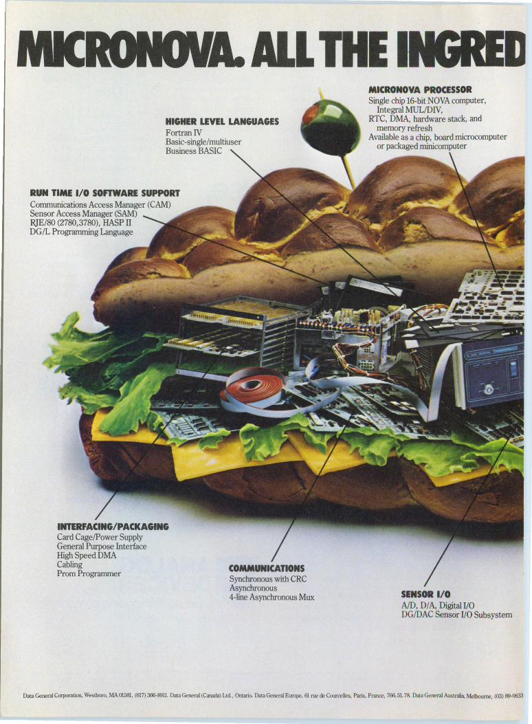
MIC HIGHER LEVEL LANGUAGES FortranN Basic-single/multiuser Business BASIC
RUN TIME 1/0 SOFTWARE SUPPORT Communications Access Manager (CAM) Sensor Access Manager (SAM) RJE/80 (2780,3780), HASP II DG/L Programming Language
Card Cage/Power Supply General Purpose Interface High Speed DMA Cabling Prom Programmer
Synchronous with CRC Asynchronous 4~line Asynchronous Mux
MICRONOYA PROCESSOR Single chip 16-bit NOVA computer,
Integral MUL/DN, RTC, DMA, hardware stack, and
memory refresh
IJ
Available as a chip, board microcomputer or packaged minicomputer
SENSOR 1/0 AID, DIA, Digita!I/O DG/DAC Sensor 1/0 Subsystem
Data General Corporation, Westboro, MA 01581, (617) 366-8911. Data General (Canada) Ltd, Ontario. Data General Europe, 61 rue de Courcelles, Paris, France, 766. 51. 78. Data General Australia, Melbourne, (03) 89-0633
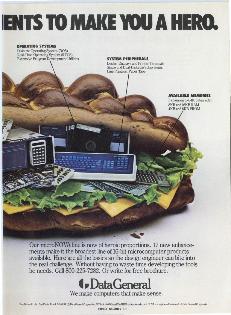
IENTS TO MAKE 10U A HERO. OPERATING SYSTEMS Diskette Operating System (DOS) Real-Time Operating System (RTOS) Extensive Program Development Utilities SYSTEM PERIPHERALS
Dasher Displays and Printer Terminals Single and Dual-Diskette Subsystems Line Printers, Paper Tape
AVAILABLE MEMORIES Expansion to 64K bytes with: 8KB and loKB RAM 4KB and 8KB PROM
Our microNOVA line is now of heroic proportions. 17 new enhancements make it the broadest line of 16-bit microcomputer products available. Here are all the basics so the design engineer can bite into the real challenge. Without having to waste time developing the tools he needs. Call 800-225-7282. Or write for free brochure.
t •Data General We make computers that make sense.
Data General Ltda., Sao Paulo, Brazil, 543-0138. © Data General Corporation, 1978 microNOVA and DASHER are trademarks, and NOVA is a registered trademark ofData General Corporation.
CIRCLE NUMBER 10
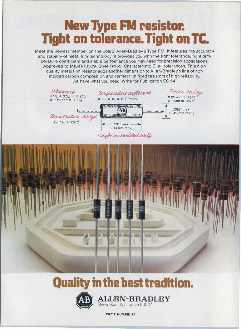
New Type FM resistor. Tight on tolerance. Tight on TC.
Meet the newest member on the board . Allen-Bradley's Type FM . It features the accuracy and stability of metal film technology. It provides you with the tight tolerance , tight tem
perature coefficient and stable performance you may need for precision applications. Approved to MIL-R-10509. Style RN55 , Characteristic E. all tolerances. This high
quality metal film resistor adds another dimension to Allen-Bradley 's line of hotmolded carbon composition and cermet film fixed resistors of high reliability.
We have what you need . Write for Publ ication EC 54.
:!: 1%, :!: 0 .5%, :!: 0 . 25~0 :!: 0 .1% and:!: 0 .05% :!: 25, :!: 15, :!: 10 PPM/°C
PtJWM,~ 0.25 watt at 70° C 0 .1 watt at 125° C
................. .. rI r.· ... .. .. .... .. ... .098" max. ''"' '"''"' " '' ~ i"""""'""'A 1::':::1~1::::::,::J l ~ ~ ;:::=:::::;," 12.49 mm ma> I
- 55oc to + 175oc 1~. 281 " max.--J (7,14 mm max.) - I
~~~
Quality in the best tradition. ,,,,7)J ~~~~~;~s~~~LEY
CIRCLE NUMBER 11
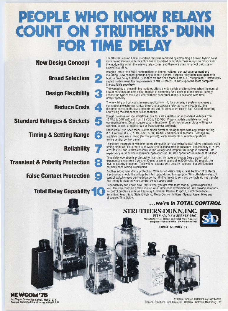
The Struthers-Dunn line of standard tdrs was achieved by combining a proven hybrid solid
New Desl·gn Concept 1 state timing module with the entire line of standard general purpose relays . In most cases the module lits within the existing relay cover , and therefore does not affect unit size or ease of mounting . Imagine, more than 6000 combinations of timing , voltage , contact arrangement and
Broad Selection built-in time delay function. Standard off-the-shelf models are U.L. recognized . Hermetically 2 mounting . New concept permits any standard general purpose relay to be equipped with
sealed models meet the requirements of MIL-R-83726 . It adds up to the most complete line available anywhere. The versatility of these timing modules offers a wide variety of alternatives when the control
Desl"gn flex1"b1"l1"ty 3 circuit must include time delay. Instead of searching tor a timer to fit the circuit, simply choose the type of relay you want with the assurance that ii is available with lime delay capability . The new ldrs will cut costs in many applications . If , for example , a system now uses a
R d Ce C Sts 4 conventional electromechanical timer and a separate relay as many circuits do, the e U 0 designer may substitute a single tdr and cut his component cost in half . Cost of mounting and wiring the component is also reduced.
5 Forget previous voltage limitations . Our ldrs are available for all standard voltages from
Standard Voltages & Sockets 12 VAC to 240 VAC and from 12 voe to 125 voe . Plug-in models available for most common sockets : Octal , square base , miniature or 12 pin rectangular plugs with quick connect , solder , printed circuit or front connect terminals .
6 Standard off-the-shelf models offer seven different timing ranges with adjustable setting:
T·m· & Sett" R n 0.1-1 second, 0.2-2, 1-10, 3-30 , 6-60 , 18-180 and 30 to 300 seconds . Settings are I 1ng 1ng a ge available three ways : Fixed (factory preset) , knob adjustable or remote adjustable
from a central control panel. These ldrs incorporate two time-tested components-electromechanical relays and solid state
Rell"abl"ll"ty 7 timing modules . Thus there is no weak link to cause premature failure . Repeatability of ± 3% at 20 to 25°C and ± 10% accuracy within voltage and temperature range is assured . Life expectancy is 50 million mechanical operations or 500 ,000 operations minimum at full load. Time delay operation is protected for transient voltages as long as 5ms duration with
Transl·ent & Polar"ty Protecti"on 8 exponential slope from o vol!s to 20 microsecond peaks of ± 2000 volts . oc models are I inverse polarity protected . Tdrs will not operate with polarity reversed, but will function normally once wiring is corrected . Another added operational protection . With our on-delay relays , false transfer of contacts
False Contact Pro·teCtl"On 9 is prevented should the voltage be interrupted during timing cycle . With off-delay relays , if control switch closes during delay period , liming resets to zero and contacts do not transfer . Full timing is assured when control switch opens again . Dependability and know-how, that 's what you get from more than 50 years experience. . . 10 You , too , can count on a relay line-up with unmatched diversification . We provide solutions Total Relay Capab1llty to control problems with ten key relay functions: General Purpose , Latch Sequence, Sensitive , Reed , Solid State & Hybrid , Motor Control , Military, Special Assemblies and ,
Las Vegas Convention Center, May 2, 3, 4 See our diversified llne of relays at Booth G31
of course , Time Delay .
. .. we're in TOTAL CONTROL
STRUTHERS-DUNN, INC. PITMAN. NEW JERSEY 08071
Manufaclurt" of Rela)' and Solid S!ale Conlroh Telephone< 609·589 · 7500 TWX,510·686 ·75IO
CIRCLE NUMBER 12
Available Through 140 Stocking Distributors Canada : Struthers-Dunn Relay Div ., Renfrew Electronic Marketing , Ltd.
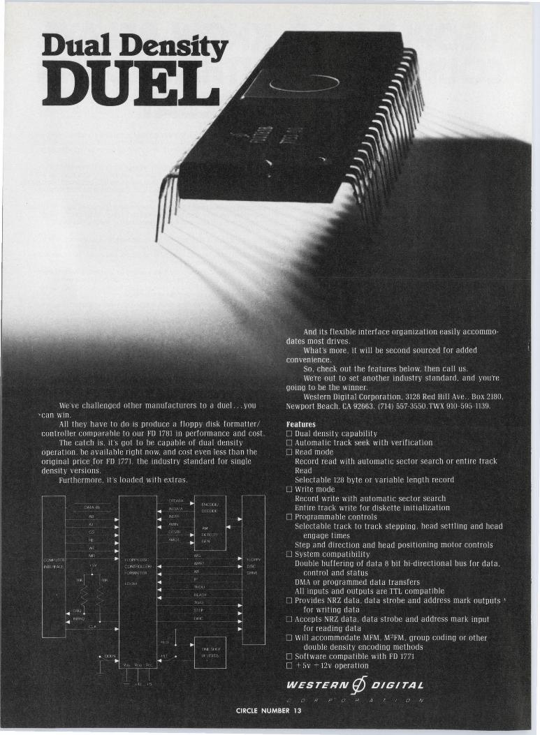
Dual Density
DUEL

Newsseope MARCH l, 1978
Schottky-diode/FET logic bring VLSI into the real world
Gallium arsenide substrates, Schottky-barrier diodes and depletion-mode FET gates will help pave the way for the coming generation of very-largescale integrated circuits. With these elements, entire digital systems will be manufactured on single chips.
"Mainframe central processors of present-day technology are performance-limited by the propagation-delay time that data bits encounter traveling along circuit-board paths and backplane wiring," says Dr. Richard Eden, Rockwell's principal scientist at the firm's Solid State Electronics Dept. in Thousand Oaks, CA. It takes roughly 100 picoseconds for a bit to travel a single inch in any direction.
However, in order to bring a system's logic gates any closer together, the heat generated by its logic gates must be drastically reduced-concentrating the system's volume without reducing its power consumption will only cause it to burn up.
By using GaAs, Schottky-barrier diodes for logic inputs, and (low-power) depletion-mode FETs for gain and inversion, Rockwell has reduced the
ELECTRONIC DESIGN 5, March I, 1978
gates' switching energy (speed X power) from several tens of picojoules to 1/20 of one picojoule, and cut gatepropagation delay to less than 100 ps, Dr. Eden announced at a technical session during the recent International Solid-State Circuits Conference.
At the same time, complete systems made with Schottky-diode/FET logic could be very small: Rockwell's new circuit technique "isn't even intended in systems with more than a single IC package, according to Eden.
Schottky-diode/FET logic uses small (1 micron square), low-capacitance (l0· 1"F) Schottky-barrier diodes to replace active elements at the gates' inputs. This helps reduce the chip's power dissipation to 500 µ. W per gate. Output FETs operate in the depletion mode-normally on-so level shifting is necessary.
The gate's input diodes by themselves provide about 1 V of level shifting. But an additional series diode allows for less-critical output FETs, higher supply voltages, and wider signal excursions (see Fig.)
Rockwell is still several years away
Voo l
The look of very-large-scale integration. This scanning-electron microscope image (left) shows functional logic gates implemented with Schottky-diode FET logic (right).
from a VLSI production line, but Eden already envisions broad application areas where Schottky-diode/FET logic can "overcome the speed and power shortcomings of silicon-gate technology." Computer mainframes, cache memories, and data-communications systems in particular are all likely candidates.
"As data rates need to be increased, present-day methods will become hard-pressed to keep up with the demand for performance," Eden warns. Optical fibers, for example, are capable of much higher data rates than can currently be exploiterl.
"Communications in the 1980s will be increasingly handled by solar-powered earth satellites," Eden predicts. "But high-speed silicon bipolar technology is hindered in space applications because of power budgeting." With GaAs Schottky-diode/FET logic requiring four orders of magnitude less power, VLSI will be well prepared to meet the challenges of outer space.
'Strapping changes modes in 16-bit microprocessor
The 16-bit 8086 microprocessor from Intel Corp. can be configured for small systems or for larger, buffered systems simply by wiring one pin the MN/MX line, to 5 V or ground. As a result, seven pins change their meanings depending on the way the MN/MX line is wired. And with pins having dual capabilities, the 8086 can be housed in a 40-pin package.
In a minimal, small-system configuration, the 8086 requires a clockgenerator chip and digital latches to tie to memories and input/output lines. In the maximum mode, the 8086 ties through a bus controller that generates five of the seven signals not available from the processor after it is switched out of the minimum configuration.
The maximum mode has faster access to memory components-440 ns against 490 ns with no wait states at a 5-MHz clock rate, and 215 ns against 265 ns with no wait states at an 8-MHz clock rate.
The standard maximum clock rate is 5 MHz, with 8-MHz parts available at extra cost. Prices have not yet been set for either version.
The Intel 8086 is built with n-channel, depletion load, silicon-gate technology like that used in the Santa
19
Clara, CA, firm's 2147 4-k static RAM. The processor addresses memory logically as a linear sequence of 8-bit bytes, but speeds access with a 16-bitwide physical path to memory.
Speed is also increased by internal pipelining and overlapped instruction fetch and execution.
The 8086 can use programs written for the 8080, but only after they've been recompiled or translated and reassembled. Intel's 8080-to-8086 translator, the CONV86, converts most source programs, including macros, controls, and source text. But the translator, which runs on the firm's development systems, doesn't support instruction-set dependencies such as timing, size and encoding, nor can it handle self-modifying code or interrupt sequences.
But the 8086 does offer features beyond those of the old 8-bit model. It can address up to 1 Mbyte of memory over a 20-bit bus; handle bit, byte, word, and block operations; and perform floating-point and integer arithmetic. Moreover, the 8086 provides for signed or unsigned arithmetic operations as well as 16-bit multiply and divide.
Incorporating the 8086 into multiprocessor systems is simplified by a locked-exchange or "test-and-set-lock" mechanism. A 1-byte prefix may precede any instruction and cause the processor to assert its bus-lock signal for the duration of the operation caused by that instruction. External hardware should be designed so that other bus masters are disengaged during the period of assertion.
CIRCLE NO. 319
Carter's to blame for energy crisis, says NSPE
The Carter administration is not handling the energy crisis effectively, according to 90% of the engineers surveyed by the National Society of Professional Engineers. Not only that, but almost half the respondents blame the U.S. government for causing the problem.
The responses came from a special energy survey conducted during the NSPE's Winter Meeting in New Orleans, which was attended by 500 elected delegates representing 54 state and territorial regions. The Society sponsored the survey to determine what the nation's leading engineers, representing all major disciplines, con-
20
sider the critical issues in the energy crisis.
Almost everyone surveyed felt that there indeed is an energy crisis. But opinion was almost evenly divided as to the nature of the problem. Production and distribution got 51 % of the vote, while resource shortage garnered 49%.
Who's to blame? The lion's share went to U.S. government policies (48%), while the country's energy consumption habits got most of the rest (38%). Interestingly, only 7% of the respondents blamed foreign energy sources, and just 6% felt the energy industry was the culprit.
As a matter of fact, more than six of every 10 respondents considered the energy industry a more reliable source of information than the U.S. government. And seven of every 10 didn't think the public had been given enough information to form a realistic judgment about the energy crisis.
The economic outlook didn't look very promising to most of the respondents. While 39% felt that by 1985 energy costs would rise by 50%, 43% predicted that by 1985 the energy they consume would cost 100% more than it does today.
Geothermal logger to read temp, pressure, flow rate
An electronic geothermal well-logging tool that simultaneously reads temperature, pressure and flow rate is being developed at Sandia Laboratories, Albuquerque, NM. An early model, which reads only temperature, has been successfully tested recently in a New Mexico geothermal well.
There is great interest in geothermal energy, says Tony Veneruso, supervisor of Sandia's Drilling Technology Div., which conducts tests of the new logging tool. He points to the new power-generating plants being constructed at the Geysers site (north of San Francisco), where geothermal electricity has been produced since the mid-1920s. This site now produces 500 MW of electricity at reasonable rates.
But conventional oil and gas logging tools aren't reliable in the unusual rock formations and high temperatures of geothermal wells, Veneruso adds. Early tests indicate that Sandia's geothermal logging tool will operate for hundreds of hours over a continuous range from room temperature to more than 300 C (575 F). It uses a combination of commercially available hybrid thick-
film circuits and junction field-effect transistors, with JFETs in all active circuit devices.
A 3-in.-long platinum thermometer at the tip of the electronics package provides temperature readings. A magnetic sensor keeps track of well depth by counting the number of steel casing pipes the tool has passed. The entire package, which weighs about 5 lbs in its present form, slips into a 4-ft-long, 1-1/ 2-in.-diameter housing.
We won't forget how to make microwave tubes
Microwave tubes won't disappear in the 1980s and 1990s, thanks to a special program supported by the Air Force, Stanford University, and a number of microwave tube companies.
Tubes are anything but old-fashioned in the microwave field, because solid-state devices do not yet approach their high power and wide bandwidth -particularly at the higher frequencies. Yet university-level teaching and research on microwave tubes dried up in the late 1960s. Worse still, the average age of microwave-tube engineer·s is over 45, and many are close to retirement.
When this situation was recognized, a number of people organized the Air Force Thermionic Engineering Research Program. Stanford University was chosen to provide the teaching because it is near the greatest concentration of tube companies.
Varian, Watkins-Johnson, Litton, Teledyne Microwave, Raytheon, and Hughes are sponsoring one student apiece. Each student receives $4500 from his sponsoring company for schooling, as well as a salary of $10,000 from the Air Force.
The courses combine standard applicable graduate courses with special courses on tubes, the latter taught by Dr. Marvin Chodorow, professor of applied physics and electrical engineering. His lectures are being videotaped, and currently the tapes are air-expressed to the students on the east coast. But, that won't be necessary fo, much longer.
The first transcontinental satellite instructional-TV link will soon provide two-way communication between the Stanford Instructional Television Network in Palo Alto, CA and Varian's plant in Beverly, MA. Interestingly, Dr. Chodorow's lectures on microwave tubes will be carried via microwave tubes.
ELECTRONIC DESIGN 5, March I, 1978

SUPER-FAST LO· VF METOXILITE SILICON RECTIFIERS
Featuring 30 nanoseconds
Reverse Recovery Time
-Types: 1N6073, 74 & 75 (Trr 30ns) PIV: 50, 100 &150V Reverse Current (Max.) : 1µA DC@ 25°C Instantaneous Forward Voltage@ 1.5A:
1.0V @ 100°c Capacitance @ 12V DC (Max.): 24 pF Single Cycle Surge Current: 35A Dimensions (Max.): Body .070" D x .165" L
Leads .029" D x 1.25" L
Types: 1N6079, 80 & 81 (Trr 30ns) PIV: 50, 100 & 150V Reverse Current (Max.): @ 25°C 10µA DC Instantaneous Forward Voltage@ 5.0A:
.BV@ 100°c Capacitance@ 12V DC (Max.) : 230 pF Single Cycle Surge Current: 175A Dimensions (Max.): Body .165" D x .165" L
Leads .038" D x .1.1 O" L
A breakthrough in junction technology makes Super-Fast silicon rectifiers possible. These new high speed silicon rectifiers feature low forward voltage drop at higher operating currents and reverse recovery lime better than 30 nanoseconds. In addition, these devices have extremely low reverse leakage and high surge ratings. SuperFast rectifiers use Semtech's proven Metoxilite non-cavity monolithic high temperature construction. Designed for high frequency applications, such as high speed switching regulators and converter circuits. Semtech's Super-Fast silicon rectifiers are stocked for immediate delivery.
1975 NATIONAL SBA SUBCONTRACTOR OF THE YEAR
E u ·CTRON 1c D1: s1r;N 5, March I, 1978
-Types: 1N6076, 77 & 78 (Trr 30ns) PIV: 50, 100 & 150V Reverse Current (Max.): 5µA DC@ 25°C Instantaneous Forward Voltage@ 3.0A:
1.0V@ 100°c Capacitance@ 12V DC (Max.): 58 pF Single Cycle Surge Current: 75A Dimensions (Max.): Body .11 O" D x .165" L
Leads .038" D x 1.10" L
CIRCLE NUMBER 14
652 Mitchell Road. Newbury Park, California 91320 (805) 498·21 11 • (213) 628·5392 • TWX: 910-336-1264 CHICAGO. (312) 352 3227 • DALLAS: (214) 234 6523 DAYTON (513) 274 8356 • FLORIDA (305) 644-5404 MARYLAND: (301) 937 0070 • NEW YORK/NEW JERSEY: (201) 964 9305 SAN FRANCISCO: (415) 494 0113 • SEATILE: (206) 455 4807 CANADIAN SALES. Avotromcs. Ltd (416) 493·9711 EUROPEAN SALES: Bourns AG Zug. Switzerland (042) 232 242
21

News
With cassettes, video tape recorders have found a new home in the home
After nearly two decades of technical advancements-and false startsvideo tape recorders are finally finding a place in the home. What's brought them home is a packaging technique borrowed from audio recorders-tape cassettes. Consumers are much more interested in video recorders now that they can just pop in a cassette containing 1/2 - in. wide tape instead of having to thread tape carefully by hand through a maze of guideposts.
A fistful of suppliers - all of them Japanese-is now selling home VTRs under more than a dozen brand names.
Unfortunately, videocassettes developed by Sony Corp., Sanyo Electric, Victor Co. of Japan Ltd. (JVC) and Quasar Electronics (both JVC and Quasar are subsidiaries of Matsushita Electric Industrial Co. Ltd. of Osaka) are incompatible with each other. But Sanyo has now introduced a second machine that is compatible with the Sony Betamax system, and Quasar has introduced a JVC-compatible video home system (VHS) recorder. Along with Quasar and JVC, Matsushita is in the VHS camp with a recorder bearing its own Panasonic trade name, and is building VHS recorders for such marketers as GE, Magnavox, and RCA. But with firms like Zenith and Toshiba in the Betamax lineup, Betamax joins VHS in dominating the VCR field .
Playing time increases
The major battle between VHS and Belamax is finding new ways to stretch the playing time-though not the dimensions-of a tape cassette that can cost $25. Sony's original Betamax machine could record and play up to an hour on a cassette, and the first VHS recorder, introduced shortly afterwards by JVC, had a two-hour limit.
Andy Santoni Associate Ed it or
22
Now, four-hour VHS machines and two-hour Betamax recorders are the norm, with a three-hour Betamax expected from Sony this year. In addition, Sony has an optional $100 tape changer that doubles recording time.
In both systems, recording time is increased by eliminating the Guardband spacing between tracks. According to the video recording standard developed by lhe Electronic Industries Association of Japan (EIAJ), the guard band is 63 µm wide and the video track 110 µm wide. So nearly a third of the tape is unused .
The guard band has been eliminated by actually taking advantage of a basic problem of magnetic tape recording: The signal that can be picked up from the tape drops off quickly if the playback head gap is even slightly off parallel with the recorded signal. Since video tape recorders paint and retrace alternate lines with two different heads, each can be slightly off perpendicular to tape travel, yet pick up its own signal properly. If the offset is
Compact, $1000 video recorders using plug-in cassettes are finding a niche in consumers' homes.
in opposite directions, the difference between azimuth angles for the two heads is twice the offset. The offset in VHS is 6°, and in Betamax it is 7°, drastically reducing crosstalk and making guard bands unnecessary.
Azimuth recording, most effective at higher frequencies, is less valuable at lower frequencies. Since chrominance (color) signals are recorded at lower frequencies (688 kHz for Betamax and 629 kHz for VHS) than are luminance (black and white) signals, crosstalk attenuation on a color signal is inadequate even with azimuth recording. Color flicker and color distortion result, which explains why slanted azimuth recording was not used for years after its development.
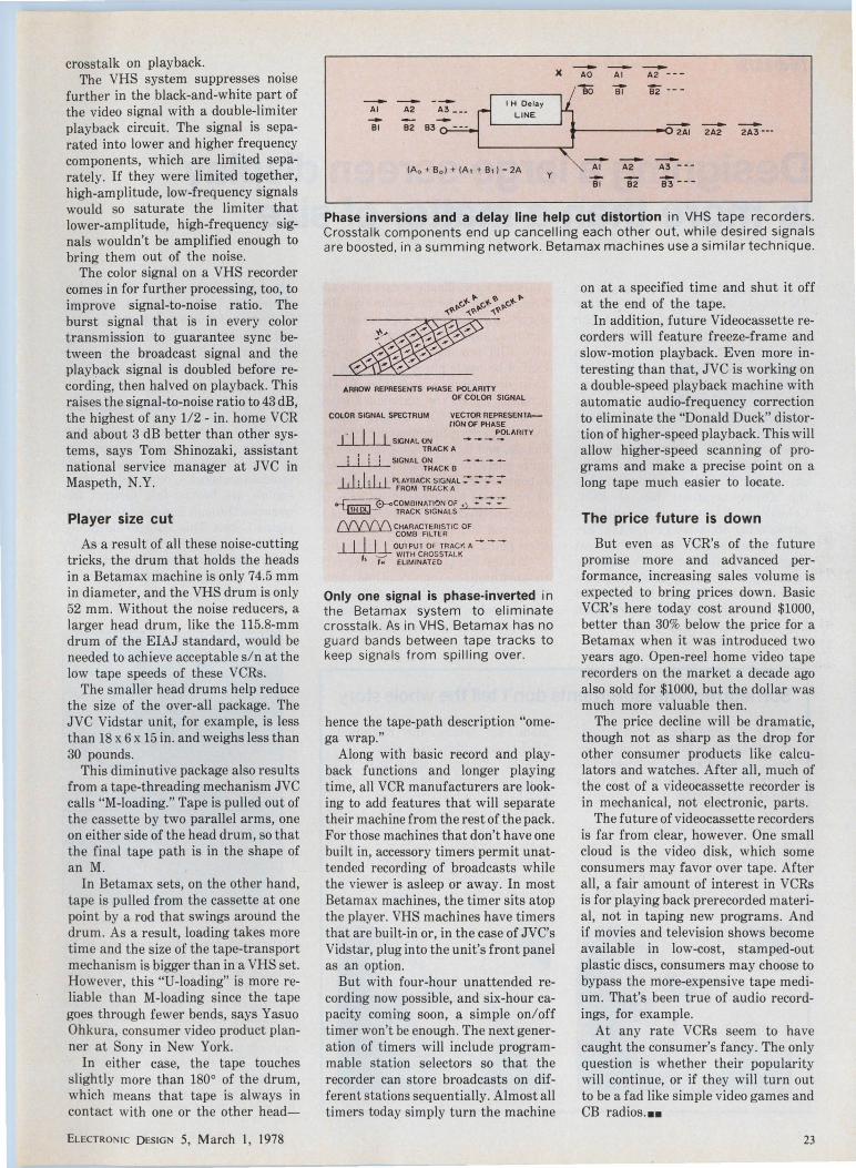
Changing phase cuts noise
To cut crosstalk even in a lower frequency chrominance signal, both Betamax and VHS recorders use phase inversions, though in somewhat different forms. In a VHS machine, the signal fed to one recording head is advanced in-phase by 90° every horizontal picture-scanning line; the signal fed to the other head is delayed by 90° every line.
In playing back through the first head, the signal is delayed by 90° every line, so that signals from the tape that were recorded with this head come out in-phase. Signals from the second channel that appear as crosstalk in the first channel are delayed 180°. All signals are then fed through a one-line delay circuit, then the original and delayed versions of the signal are added. Since each scanning line is about the same as the last, the desired signal component is almost doubled, and the unwanted crosstalk is almost eliminated.
In the Betamax system, signals to one head don't change, while signals to the other get delayed 180° on alternate scans. Again, a delay-line filter cuts
ELECTRONIC DESIGN 5, March I, J 978
crosstalk on playback. The VHS system suppresses noise
further in the black-and-white part of the video signal with a double-limiter playback circuit. The signal is separated into lower and higher frequency components, which are limited separately. If they were limited together, high-amplitude, low-frequency signals would so saturate the limiter that lower-amplitude, high-frequency signals wouldn't be amplified enough to bring them out of the noise.
The color signal on a VHS recorder comes in for further processing, too, to improve signal-to-noise ratio. The burst signal that is in every color transmission to guarantee sync between the broadcast signal and the playback signal is doubled before recording, then halved on playback. This raises the signaHo-noise ratio to 43 dB, the highest of any 1/2 - in. home VCR and about 3 dB better than other systems, says Tom Shinozaki, assistant national service manager at JVC in Maspeth, N.Y.
Player size cut
As a result of all these noise-cutting tricks, the drum that holds the heads in a Betamax machine is only 74.5 mm in diameter, and the VHS drum is only 52 mm. Without the noise reducers, a larger head drum, like the 115.8-mm drum of the EIAJ standard, would be needed to achieve acceptable s/n at the low tape speeds of these VCRs.
The smaller head drums help reduce the size of the over-all package. The JVC Vidstar unit, for example, is less than 18 x 6 x 15 in. and weighs less than 30 pounds.
This diminutive package also results from a tape-threading mechanism JVC calls "M-loading." Tape is pulled out of the cassette by two parallel arms, one on either side of the head drum, so that the final tape path is in the shape of an M.
In Betamax sets, on the other hand, tape is pulled from the cassette at one point by a rod that swings around the drum. As a result, loading takes more time and the size of the tape-transport mechanism is bigger than in a VHS set. However, this "U-loading" is more reliable than M-loading since the tape goes through fewer bends, says Yasuo Ohkura, consumer video product planner at Sony in New York.
In either case, the tape touches slightly more than 180° of the drum, which means that tape is always in contact with one or the other head-
ELECTRONIC DESIGN 5, March I, 1978
)( - - -AO Al A2 ---so - Bi -- -Bl - I H Oetay
Al A2 - LINE
Bl - - -2AI 2A2 2A3-··
- - -(Ao+ Bol + (A1 + B1) =2A Al A2 A3 ---y
Bi 83---82
Phase inversions and a delay line help cut distortion in VHS tape recorders. Crosstalk components end up cancelling each other out. while desired signals are boosted, in a summing network. Beta max machines use a similar technique.
ARROW REPRESENTS PHASE POLARITY
COLOR SIGNAL SPECTRUM
, . I I I I SIGNAL ON
OF COLOR SIGNAL
VECTOR REPRESENTA-flON OF PHASE
POLARITY
TRACK A
l : : l SIGNAL ON THACK B
I I . 11 I ' PLAYBACK SIGNAL - - - -..l.l.ll..Ul.LL FROM TRI.CK A
~COMBINATION OF •l 7 7 7 1H 0L - TRACK SIGNALS .
NVVV\ CHARACTERISTIC OF COMB FILTER
j_JJj_L OUl PUT OF TRACK A - - -
t, I: ~~~~1~fi'cs~n.u<
Only one signal is phase-inverted in the Betamax system to eliminate crosstalk. As in VHS, Betamax has no guard bands between tape tracks to keep signals from spilling over.
hence the tape-path description "omega wrap."
Along with basic record and playback functions and longer playing time, all VCR manufacturers are looking to add features that will separate their machine from the rest of the pack. For those machines that don't have one built in, accessory timers permit unattended recording of broadcasts while the viewer is asleep or away. In most Betamax machines, the timer sits atop the player. VHS machines have timers that are built-in or, in the case of JVC's Vidstar, plug into the unit's front panel as an option.
But with four-hour unattended recording now possible, and six-hour capacity coming soon, a simple on/off timer won't be enough. The next generation of timers will include programmable station selectors so that the recorder can store broadcasts on different stations sequentially. Almost all timers today simply turn the machine
on at a specified time and shut it off at the end of the tape.
In addition, future Videocassette recorders will feature freeze-frame and slow-motion playback. Even more interesting than that, JVC is working on a double-speed playback machine with automatic audio-frequency correction to eliminate the "Donald Duck" distortion of higher-speed playback. This will allow higher-speed scanning of programs and make a precise point on a long tape much easier to locate.
The price future is down
But even as VCR's of the future promise more and advanced performance, increasing sales volume is expected to bring prices down. Basic VCR's here today cost around $1000, better than 30% below the price for a Betamax when it was introduced two years ago. Open-reel home video tape recorders on the market a decade ago also sold for $1000, but the dollar was much more valuable then.
The price decline will be dramatic, though not as sharp as the drop for other consumer products like calculators and watches. After all, much of the cost of a videocassette recorder is in mechanical, not electronic, parts.
The future of videocassette recorders is far from clear, however. One small cloud is the video disk, which some consumers may favor over tape. After all, a fair amount of interest in VCRs is for playing back prerecorded material, not in taping new programs. And if movies and television shows become available in low-cost, stamped-out plastic discs, consumers may choose to bypass the more-expensive tape medium. That's been true of audio recordings, for example.
At any rate VCRs seem to have caught the consumer's fancy. The only question is whether their popularity will continue, or if they will turn out to be a fad like simple video games and CB radios ...
23

News
Designing a large-screen display is more than a matter of size
Making the picture of a large-screen TV display acceptable to the average viewer may be even more difficult than you think. That's the conclusion of researchers at RCA Laboratories in Princeton, NJ. In fact, one aspect of display quality-brightness uniformity-has been analyzed thoroughly enough to determine that the kinds of large-screen TV displays now under development will have to be 200 times better than present television CRTs, says Roger W. Cohen, a group head in the display systems lab at RCA. Cohen's group is studying perception to advise other RCA lab groups that are working not only to develop the best large-screen, direct-view TV displays at the lowest cost, but also to improve aircraft and shipboard displays used by the mi litary. Some of the research has been done for the Navy.
Direct-view displays can be made brighter than the projection-type displays now used for large-screen TV pictures, says Cohen. But the directview CRT now used in television sets cannot be made much larger than the 25 in. now common in console sets. The problem is, all the techniques being investigated as CRT replacementsincluding electroluminescence, gas discharge, and light-emitting diodes-require some form of matrix addressing to control each element in the hundreds of rows and hundreds of columns of display needed to obtain enough resolution. And the brightness at each of these points must be tightly controlled.
"You have to keep the nonuniformity to something less than 1 % in luminance fluctuations," says Cohen, adding that current color televisions have centerto-edge brightness variations that can
Sometimes, measurements don't tell the whole story
24
The eye and brain form a complicated system for interpreting images, so simple measurements like brightness and contrast can't always determine if a picture is good.
Here, the image at the left was made by taking the average brightness of the original, analog image in each pixel, or picture element. The image at the right is
made by taking the minimum brightness within each pixel.
Most observers agree that the left-hand picture looks sharper and has better contrast than the righthand picture, yet the right-hand picture looks more "natural." There is no quantitative method for describing why most observers would choose the right-hand picture to, for example, identify a mugshot.
approach a factor of two. The gradual drop-off in brightness from the center of the screen to the edges isn't noticeable to most observers, Cohen notes, but even small differences from one point to the next wou ld be disturbing.
Pictures break into frequencies
High uniformity is essential because when an observer looks at a scene, the eye and brain break up the picture into spatial frequencies, much as electrical signals are broken into distinct frequencies through Fourier analysis, explains Cohen. This leads to simplified mathematical analysis of images, he notes, and makes it possible to describe display quality quantitatively.
Unfortunately, such an analysis
\ \
25-ln CRT
\ , ' , ~ ,, "/ ~ '--~~--'-~~~"--~~--"--~--' I-~ .---~~~~~~~~~~~~---.
a: Ul ,....---, I
50 -ln MATRIX -ADDRESSED
DISPLAY
POSITION
Matrix-addressed displays have to be better than standard CRTs fo r their images to be perceived just as well. With CRTs, the eye sees the gradual change in brightness as a low spa ti al frequency (that of the sine wave shown by a dotted line), where perception is tolerant to bright ness variations. But the abrupt changes in brightness of a matrix display are seen as high frequency signa ls, where the eye is more sensitive.
ELECTRONIC DESIGN 5, March I, 1978
More muscle for your microprocessor: Now tl1ere's a simpler way
• • to tr191er a trKK, drive a digit, or light up a lamp.
One of our new addressable drivers can control up to eight peripheral devices in any bus-oriented system.
Next time you put a microprocessor to work, it may have more to manipulate than data. Real-world µ.P applications often require the kind of muscle that our new NE590/591 Addressable Peripheral Drivers can provide-simpler and less expensively than the usual combination of discrete power transistors and resistors. Another First From Signetics. Either of these new devices can give you a powerful alternative way to address and drive as many as eiglit different peripherals, using bits extracted directly from a bus. Each of the 8 latched Darlington outputs can drive a 250-mA load current, subject to power dissipation limitations. That's plenty of muscle for turning on (or off) LEDs, SCRs, stepping motors and a host of other commonly used peripheral components.
Most applications can be handled by the 16-pin NE590, which has 8opencollector (current sinking) outputs. The NE591 is an 18-pin version with open-emitter (current sourcing) outputs. Simpler Designs at Lower Costs. A quick parts count and cost evaluation will demonstrate the device's dollar savings. The NE590N costs only $1.95 in
OTHER SIGNETICS DRIVERS
Part No. Description Output Current
NE582 LED digit 400mA drivers ULN2001 Power drivers 500mA series NE5501 High-voltage 500mA series power drivers DS3611 Peripheral 300mA series drivers UDN5711 Peripheral 300mA series drivers
E 1 1-< i ~ 0N 1 c [)1-s 1c, N 5, March I, 1978
No. of
YOUR MICROPROCESSOR
100 quantity, the NE591N, $2.45. You can do the same job with an addressable latch, but you'll need extra driver transistors and resistors that will bring your total parts cost-exclusive of assembly, testing and related expenses-to a considerably higher price.
Use NE590 or NE591 whenever you have multiple high-current peripherals
to drive in any bus-oriented system. You'll simplify your design, improve reliability, reduce component and assembly costs. In short, you'll get more muscle for
your money. Addressable Peripheral
Drivers. Available only from Signetics. Call your nearest distributor
or send the coupon to us today for your data sheet, a sample, or quick attention to any application questions you have.
!ii!IDDliC!i a subsidiary of US. Philips Corporation
SigiellCS Caporation 811 East Arques Avenue
&rrlyvale. Caifoma 94086 ~ 408/739-7700
r-------------------, To: Signetics Information Services, 811 E. Arques Ave. P .O. Box 9052, MS 27, Sunnyvale, CA 94086
Drivers D Send me your NE590/591 Data Sheet
6
7
7
2
2
D Send me a sample of the NE590 for evaluation. D I need data on these other devices shown in the table :
D I have an urgent requirement. Please have an applica-tions specialist phone me at once: ( ) ___ _
Name ___________ Title ______ _
Company _________ Division ____ _ _
Address _________ MS - -------
City --- ------ State ____ Zip _ _ _
(Note: For faster response, clip coupon to letterhead.) ED 31
L-------------------~ CIRCLE NUMBER 15 25

shows that the dissection of images into separate frequencies makes today's matrix-addressed displays inadequate for large-screen viewing. A curve plotting brightness as a function of position across the screen of a matrix-addressed display is a series of straight lines, each at a slightly different level. Using Fourier analysis to break up such a step-function curve into single frequencies yields a large number of high-order terms, and the human eye and brain are very sensitive to these frequencies. Even the small
brightness variations are disturbing. In present CRTs, on the other hand,
the gradual increase then drop-off in brightness from one end of the screen to the other can be plotted as a single, fairly low-frequency sinewave. The eye is relatively insensitive to brightness variations at low spatial frequencies . According to Cohen, the eye's sensitivity to brightness variations ranges from as little as 0.01 % at some frequencies to nearly 100% before the difference is noticeable at other frequencies where the eye is least sensitive.
Another area that can benefit from improved displays is medical imaging: x-rays, ultrasound, and computerized tomography. Here, one unresolved question, is whether the eye can better detect differences when an image is printed in white on a black background or vice versa. Given the same contrast between black and white, the eye sometimes distinguishes shapes better when the picture is displayed in one mode and sometimes in the other, says Cohen. So, which mode is better? No one can say for sure yet. ••
Distributed microprocessing enters the business world
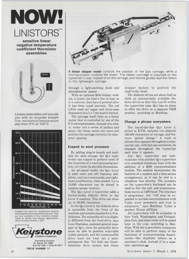
The . first electronic typewriter makes it easier for businesses to move toward distributed processing-decentralized computer power. And the typewriter itself uses distributed microprocessing-a master Z-80 controller and a pair of F-8 chips-to handle drive motors.
In its basic form, the typewriter, developed by the Qyx Division of Exxon Enterprises Inc., Lionville, PA, does far more than a standard office typewriter. Yet it goes for just $1390-not much higher than the nearest comparable mechanical machine (about $900).
The Qyx typewriter has 70% fewer moving parts than electromechanical typewriters, says Dan Matthias, general manager of Qyx. Microprocessors controlling linear motors replace conventional cables, pulleys, and gears.
The Z-80 microprocessor, from Zilog Corp. (another Exxon Enterprises affiliate), Cupertino, CA, handles overall system control and memory operations. A pair of F-8 microprocessors from Fairchild Semiconductor, Mountain View, CA, controls the linear motors that position the carriage and the rotary print head.
The Qyx typewriter can be expanded beyond its basic functions by adding plug-in boards and changing keyboards -without sending the machine back to the factory and without expanding the size of the typewriter itself.
Typewriter built in blocks
The Qyx Level 1 features dual pitch (either 10 or 12 characters to an inch)
26
and proportional spacing (each character takes up only as much space as it needs). The rotary "daisy wheel" print head is coded for type format, so changing print heads automatically resets the typewriter.
The typewriter can even center a line of type automatically and automatically type columns of decimal numbers so that the decimal points line up. Stock phrases and formats can be stored and called up to speed typing repetitive forms.
In addition, the basic typewriter has automatic erase backspace. A lift-off tape, like that used in the IBM Correcting Selectric, pulls an erroneous character off the paper so that a correction can be typed. According to Matthias, Qyx has developed the first daisywheel printer that can position its print head accurately enough for this function. This is accomplished by building the rotor of the linear print head-drive motor into the $25 print head itself and by feeding-back position information
The first electronic typewriter, from the Qyx Division of Exxon Enterprises, distributes computer-aided typing throughout an office while itself taking advantage of multiple processors-three µPs.
ELECTRONIC DESIGN 5, March I, 1978

Now you can specify Spectronics opto couplers for every isolation requirement.
4N25to4N38
Eu:CTRON IC D ES IGN 5, March I, 1978
Spectronics offers industry's broadest choice of optically coupled isolators. Available in popular 6- and 8-pin dual in-line versions, they are completely interchangeable with standard industrial types. The complete Spectronics line includes high-speed, high-gain circuits in IC, phototransistor, photodarlington and photo SCR versions. Check the Spectronics isolator for your application:
D 200VSCR When switching an SCR or TRIAC, specify our 200V SCR rated at 300 mA. The SCS11 C1-11 C3 also features 5000 voe isolation and 11mA IGr· D 1 or 5or10mA Controlled Gain You specify the input current at 1 or 5 or 10 mA, and we'll provide controlled gain. SPX 7110, 7130 and 7150 provide 10-50%, 30-80% and 50-125% CTR at 1 mA. The SPX 7530, 7550 and 7590 have 30-75%; 50-125% and 90-200% CTR at 5 mA'. The SPX 7270-7273 series offers controlled gain at 10mA: 10-50%, 45-90%, 75-150%, 125-250%. o TTL Compatible Choose the SPX 74A1 for TTL interface with guaranteed logic level/compatibility, over the full 0°c to 70°C range. Use it as an ideal transistor coupler for eliminating current loops. Our standard isolation voltage is 4000V rms. D 1 MBIT/SEC For high-speed data transmission,
1 MBITISEC
CIRCLE NUMBER 16
try our 6N135 and 6N136 with up to .8 µ.S rise and fall at 19% CTR, or the 6N138 and 6N139 with up to 1.0, µ.s tPHL at 500% CTR. You can drive them with as little as .5 mA. D 4N25 to 4N38 We provide the industry's standard work horses, off the shelf. Outputs include transistors and darlingtons.
Your critical requirement may be BVc.., le, CTR, T,, TF or isolation. You won't find one coupler to fill all your needs, but one company can. Only Spectronics has all the design choices!
For more details and delivery information, call us today at 214-234-4271. Or write: Commercial Component Division, 830 E. Arapaho Rd., Richardson, Texas 75081 .
1 or 5 or 10mA Controlled Gain
27
NOW!
28
LINISTORS™ sensitive linear
negative temperature coefficient thermistor
assemblies
-•••
Linistor assemblies will provide you with an accurate straight line resistance/temperature plot from 0°C to 1 00°C.
Linistors are ideal for temperature sensing and temperature compensating devices. They are now available in four standard encasements to satisfy most design appl ications . Write for Data Bulletin l -601.
Thermistor Division St. Marys, PA 15857
814/ 781-1591 •Telex 91-4517
CIRCLE NUMBER 17
A linear stepper motor controls the position of the Qyx carriage, while a microprocessor controls the motor. The ribbon cartridge is mounted on the typewriter 's case, instead of on the carriage, and flexible guides lead the ribbon to the lightweight carriage .
through a light-emitting diode and photodetector sensor.
With an optional $850 display module, a typist can read a line of copy as it i~ entered, then have it printed after it has been typed correctly. The red LEDs read out upper and lower-case characters in a 5 X 7 dot matrix format.
The carriage itself rides on a linear motor that is controlled by one of the F-8 microprocessors . Instead of a rotary motor and a series of pulleys and gears, the linear motor can move and position the carriage correctly for character spacing.
Expand to word processor
By adding plug-in boards and modules for data storage, the Qyx typewriter can expand to perform most of the functions of a word-processing system, yet retain its physical dimensions.
An advanced model, the Qyx Level 2, adds store and edit features; add, delete, and move commands; and righth and justification, when needed. Up to 10,000 characters can be stored in random-access memory.
The Qyx Level 3 typewriter adds a buried-media diskette drive to the Level 2 machine. This drive can store up to 60,000 characters.
In the Qyx Level 4, the diskette drive is accessible from the front of the machine and accepts standard 5-1/ 4-in. diskettes . The accessible drive is slightly different from the fixed drive, says Leon Staciokas, assistant general manager at Qyx, since the accessible drive must be able to position removable media precisely and the nonaccessible drive must not wear out a· semipermanent disc. Yet both use linearinduction drive motors and linear
stepper motors to position the read/ write head.
The diskette drives are about half as thick as commercially available diskette drives so that they can fit within the typewriter case. Qyx has no plans to offer the drive as a separate OEM product, according to Matthias.
Change a phrase everywhere
The top-of-the-line Qyx Level 5, priced at $7750, includes two diskette 120,000 characters of storage, and features "global change." A word or phrase that appears throughout a manuscript can, with but one correction, be changed throughout the typescript each time it appears.
Any Qyx typewriter can communicate with another Qyx typewriter over standard telephone lines with the addition of a $500 communications module. The module incorporates the features of a modem and a data-access arrangement, so it can be tied to a telephone line directly. The numbers on the typewriter's keyboard can be used to dial the call, and communications moves at 1200 baud. The interface is proprietary, but "will soon be expanded to include communication with Vydec word processors and even to computers," says Matthias. Vydec is another Exxon affiliate.
All typewriters will be available in New York, Washington, and Philadelphia first, and other cities will be added later in the year, according to Matthias. With the typewriters, companies will be able to perform many of the functions of word-processing departments-like duplicate letters-at a secretary's desk, instead of in a separate operation.••
EL ECTRONIC DESIGN 5, March I, 1978
~SWITCHER' OUTPUT FILTER CAPACITORS
THAT REALLY PUTOUT
equipment designer, Type 6220 capacitors have a symmetrical capacitance tolerance of a tight ±20% instead of the wide asymmetrical tolerance customarily associated with low-voltage electrolytic capacitors. These new capacitors are designed for operation over the wide
If you're working with switchingtype power supplies, you'll want to know about new electrolytic capacitors featuring low equivalent series resistance (for example, 3 mO @
57,000 µF/7.5V) and low internal inductance. Type 6220 EXTRAL YTIC® capacitors are the first of their type to meet the power supply designer's need to know, for worst case design, the maximum and minimum ESR of a capacitor, as well as the need to hold the nominal ESR to a tolerance of ±30% at 20 kHz. To simplify calculations for the
temperature range of - 55°C to +85°C. They are furnished in a 1 %" diameter case with lengths ranging from 2W' to 5%". capacitance values from 2,800 to 67,000 µFare available as standard, and voltage ratings range from 5 to 55 WVDC.
For complete technical data, write for Engineering Bulletin 3459 to: Technical Literature Service, Sprague Electric Company, 347 Marshall Street, North Adams, Mass. 01247.
THE BROAD-LINE PRODUCER OF ELECTRONIC PARTS CIRCLE NUMBER 18
Eu:crnoN 1c DESIGN 5, March I, 1978
4SE 712BRI
SPRAGUE® THE MARK OF RELIABILITY
a General -cable\/
subsidiary
29
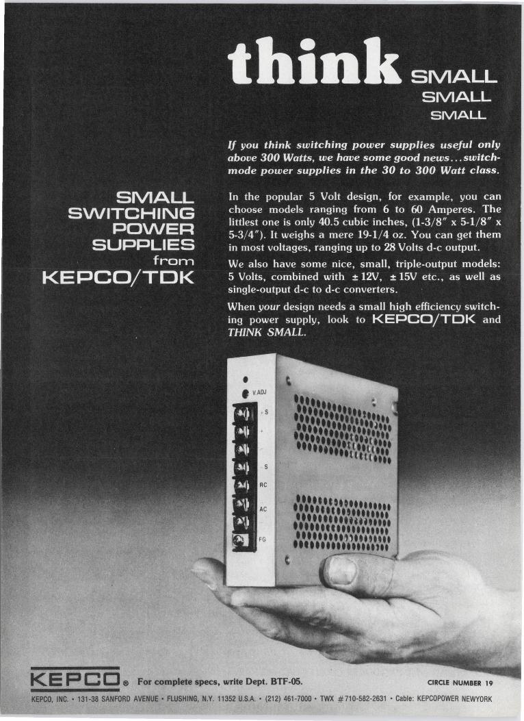
KE P C CJ ® For complete specs. write Dept. BTF-05. CIRCLE NUMBER 19
KEPCO, INC. • 131-38 SANFORD AVENUE• FLUSHING, N.Y. 11352 U.S.A. • (212) 461-7000 ·TWX #710-582-2631 ·Cable: KEPCOPOWER NEWYORK
Washington report John Rhea, Washington Bureau
NASA seeks fifth Shuttle, warns of costly delays
Further delays in deciding on a fifth Space Shuttle orbiting spacecraft will increase its cost to $600-million, a top space agency official told the House Science subcommittee.
President Carter approved four Shuttle spacecraft when he reviewed the fiscal 1979 budget for the National Aeronautics and Space Administration, but deferred a decision on the fifth for another two years. Now, NASA Associate Administrator John F. Yardley says the fifth spacecraft is needed and would cost $365-million if procurement were to begin in fiscal 1979.
The other $235-million will stem from a more inefficient production rate and the higher cost of purchasing smaller quantities of parts from subcontractors, according to Yardley. In the past NASA has estimated the additional cost of waiting for another two years at $100-million to $200-million.
Yardley bases his case on the belief that the Space Shuttle will be used extensively during the 1980s and that five of the reusable spacecraft will be needed in case of unforeseen delays in ground operations or in case one of the craft is lost in an accident. NASA has predicted 560 Shuttle flights during the 1980 to 1991 period, but critics have doubted that the Shuttle will be that popular.
Both the Air Force and NASA plan to launch almost all their satellites from the Shuttle during that period. Under the present plan NASA will get two, the Air Force one, and the two organizations will have to share the fourth orbiter. But if the fifth spacecraft is approved, NASA will be assured of three and the Air Force of two.
U-2 spy plane slated to return
Next year the Air Force plans to reopen production of the U-2, the famous spy plane of the 1950s. A new version of the aircraft, designated the TR-1, will be produced at Lockheed Aircraft Corp.'s "Skunk Works" in Burbank, CA.
Unlike its predecessor, which conducted strategic reconnaissance from high altitudes and thus became obsolete with the development of spy satellites, the new aircraft is intended to support Army and Air Force tactical units under battlefield conditions.
The Pentagon has attempted to keep the program under wraps, but Defense Secretary Harold Brown told the House Armed Services Committee that the aircraft would be able to provide continuous standoff surveillance of a battle area, including such activity as nighttime operations, and even during bad weather. The TR-l's complement of electronic sensors will include long-range, side-looking radar for covering ground targets from outside enemy airspace.
Since Lockheed halted U-2 production more than a decade ago, the company has been experimenting with what has been called a "stealth aircraft" under
ELECTRONI C DESIGN 5, March I, 1978 31
the sponsorship of the Defense Advanced Research Projects Agency. Techniques developed for that aircraft, such as new types of paint and new electronic countermeasures to make the aircraft Jess visible to optical and radar detection, are expected to be adapted for the TR-1.
The Air Force is requesting $10.2-million to begin procurement of the TR-1 next year, but defense officials won't say how many they plan to buy or what they expect the planes to cost.
Laser weapons eyed to protect air bases
The Air Force has become interested in high-energy laser weapons to protect its European bases against enemy cruise missiles.
Studies will be sponsored by the Air Force's Armament Development and Test Center at Eglin Air Force Base, FL, which has asked interested companies to submit proposals. These are expected to be strictly paper studies aimed at figuring out the best ways to protect the bases from 1985 to 1995.
In addition to laser weapons, the studies may also cover guns, surface-to-air missiles and missiles launched by aircraft. The European bases are considered particularly vulnerable to a variety of weapons, including cruise missiles, standoff missiles launched by aircraft, and TV-guided glide bombs.
Computer data entered via voice system
The Defense Mapping Agency is now using a voice-input system to put hydrographic data on ocean-depth measurements into its computer at Suitland, Maryland.
The voice system was developed by the Air Force's Rome (New York) Air Development Center in conjunction with Threshold Technology of Delran, NJ, and is based on the analysis of voice-frequency patterns. Operators at the DMA's Hydrographic Center have trained the system to recognize 14 words and numbers.
As the numbers are read-in for each depth entry, a visual display gives an immediate feedback to allow the operator to correct any errors. Each operator's speech patterns are prerecorded to create an individual speech program, which the system converts into a digital format. This is done by repeating the word to be added to the program 10 times. Speech patterns are averaged out, and a general pattern for each word is established.
Capital Capsules: The National Bureau of Standards is planning a major increase in its program to develop new federal data-processing standards, as required by Public Law 89-306-the so-called Brooks Act named after its sponsor, Rep. Jack Brooks (D-TX). Funding would nearly triple from $6.4-million this year to $21-million in the new budget. The over-all NBS budget would go from $71.5-million to $94.3-million, the largest jump in the organization's history-if Congress approves .... The first of 19 passive tactical reconnaissance systems will be delivered by Litton Industries Amecon Div. (College Park, MD) late next year to the Air Force for installation on RF-4C aircraft. The firm won a $30-million production contract late last year after a successful development program it began in 1971. The reconnaissance system is designed to spot enemy radar systems around surface-to-air missile (SAM) sites. The company previously installed similar passive detection systems on the Navy's E-2C aircraft.
32 ELECTRONIC DESIGN 5, March I, 1978
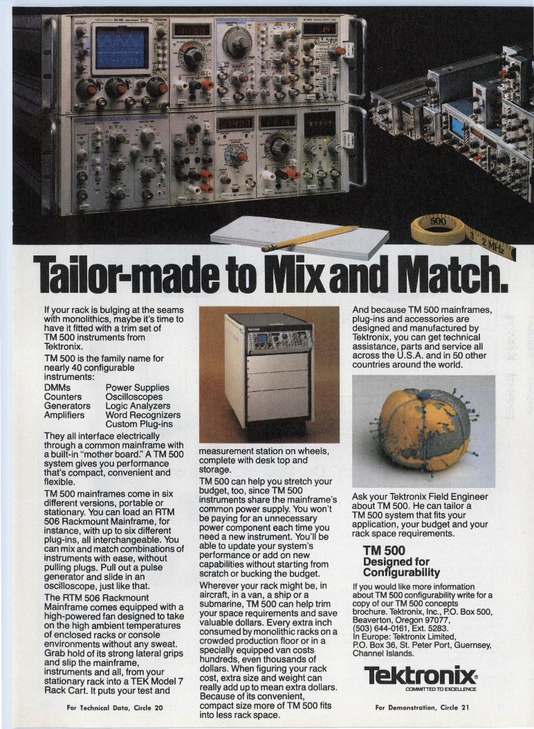
Tailor-made to Mixanll Match. If your rack is bulging at the seams with monolithics, maybe it's time to have it fitted with a trim set of TM 500 instruments from Tektronix. TM 500 is the family name for ~early 40 configurable instruments: DMMs Counters Generators Amplifiers
Power Supplies Oscilloscopes Logic Analyzers Word Recognizers Custom Plug-ins
They all interface electrically through a common mainframe with a built-in "mother board:' A TM 500 system gives you performance that's compact, convenient and flexible. TM 500 mainframes come in six different versions, portable or stationary. You can load an ATM ?06 Rackmount Mainframe, for instance, with up to six different plug-ins, all interchangeable. You can mix and match combinations of instruments with ease, without pulling plugs. Pull out a pulse generator and slide in an oscilloscope, just like that. The ATM 506 Rackmount ~ainframe comes equipped with a high-powered fan designed to take on the high ambient temperatures of enclosed racks or console environments without any sweat. Grab hold of its strong lateral grips and slip the mainframe instruments and all, fro~ your stationary rack into a TEK Model 7 Rack Cart. It puts your test and
For Technical Data, Circle 20
measurement station on wheels complete with desk top and ' storage. TM 500 can help you stretch your budget, too, since TM 500 instruments share the mainframe's common power supply. You won't be paying for an unnecessary power component each time you need a new instrument. You'll be able to update your system's performance or add on new capabilities without starting from scratch or bucking the budget. ~herev~r your rack might be, in aircraft, in a van, a ship or a submarine, TM 500 can help trim your space requirements and save valuable dollars. Every extra inch consumed by monolithic racks on a crowded production floor or in a specially equipped van costs hundreds, even thousands of dollars. When figuring your rack cost, extra size and weight can really add up to mean extra dollars. Because of its convenient, compact size more of TM 500 fits into less rack space.
And because TM 500 mainframes plug-ins and accessories are ' designe:d and manufactured by Tektronix, you can get technical assistance, parts and service all across the U.S.A. and in 50 other countries around the world.
Ask your Tektronix Field Engineer about TM 500. He can tailor a TM 500 system that fits your application, your budget and your rack space requirements.
TMSOO Desi9ned for Conf1gurability
If you would like more information about TM 500 configurability write for a copy of our TM 500 concepts brochure. Tektronix, Inc., P.O. Box 500, Beaverton, Oregon 97077, (503) 644-0161, Ext. 5283. In Europe: Tektronix Limited, P.O. Box 36, St. Peter Port, Guernsey, Channel Islands.
TektronOO For Demonstration, Circle 21
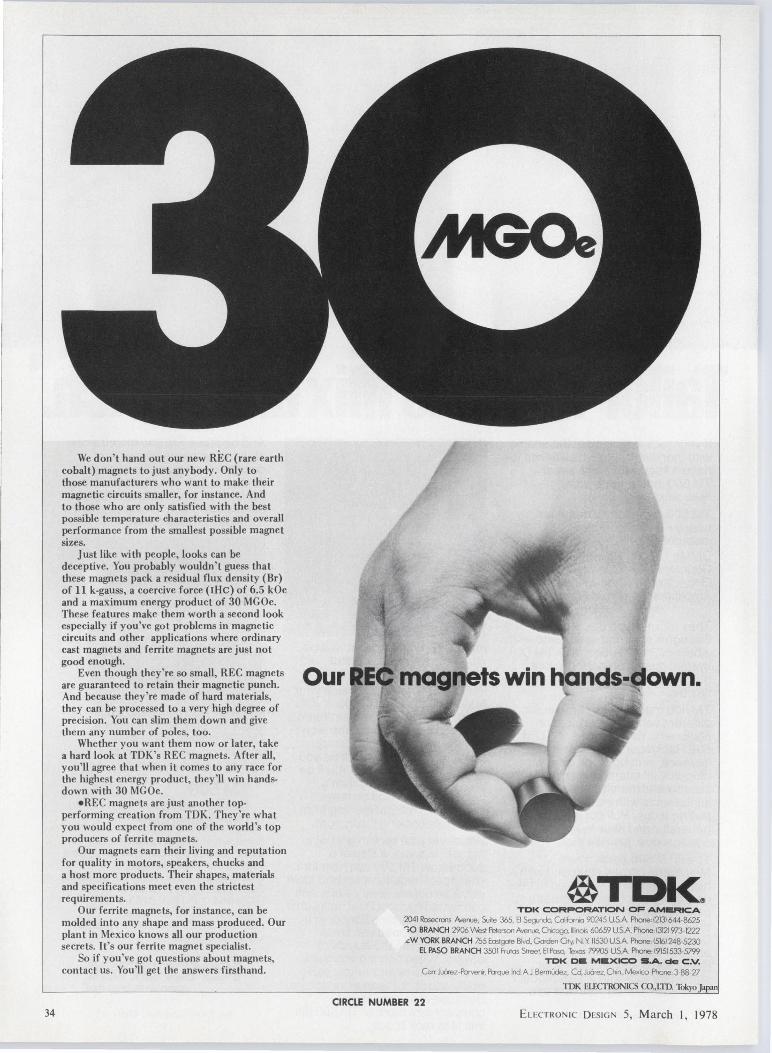
34
We don't hand out our new REC (rare earth cobalt) magnets to just anybody. Only to those manufacturers who want to make their magnetic circuits smaller, for instance. And to those who are only satisfied with the best possible temperature characteristics and overall performance from the smallest possible magnet sizes.
Just like with people, looks can be deceptive. You probably wouldn't guess that these magnets pack a residual flux density (Br) of 11 k-gauss, a coercive force (rHc) of 6.5 kOe and a maximum energy product of 30 MGOe. These features make them worth a second look especially if you've got problems in magnetic circuits and other applications where ordinary cast magnets and ferrite magnets are just not good enough.
Even though they're so small, REC magnets Our are guaranteed to retain their magnetic punch. And because they 're made of hard materials, they can be processed to a very high degree of precision. You can slim them down and give them any number of poles, too.
Whether you want them now or later, take a hard look at TDK's REC magnets. After all, you'll agree that when it comes to any race for the highest energy product, they'll win handsdown with 30 MGOe.
•REC magnets are just another topperforming creation from TDK. They're what you would expect from one of the world's top producers of ferrite magnets.
Our magnets earn their living and reputation for quality in motors, speakers, chucks and a host more products. Their shapes, materials and specifications meet even the strictest requirements.
Our ferrite magnets, for instance, can be molded into any shape and mass produced. Our plant in Mexico knows all our production secrets. It's our ferrite magnet specialist.
So if you've got questions about magnets, con tact us. You 'II get the answers firsthand.
magnets win llands-down.
@TDK~ TDK CORPORATION OF AMERICA
2041 Rosecrons AvertJe, Suite 365, El Seg.indo. Cd1lomo 90245 US.A f'liooe, 12131644-8625 >O BRANCH 2906 West fl.terson Avenue, Cficogo. Illinois 60659 US.A f'liooe, 13121973-1222 .cW YORK BRANCH 755 Eostgote BW. Gorden Oty. N Y 11530 US.A f'liooe, 15161248-5230
El PASO BRANCH 3501 Frutos Street, El Paso Texas 79905 USA f'liooe, 19151533-5799 TDK CE MEXICO S .A. de C .V.
Corr JuOtez-Fbrvem, Porque Ind A.1 BermUdez, Cd. Ju6rez, 0-.n, lv'exoco f'liooe, 3-88-27
TDK ELECTRONICS CO.,LID. Tokyo Japan
CIRCLE NUMBER 22 EL ECTRO NIC D ESI G 5, March I, 1978
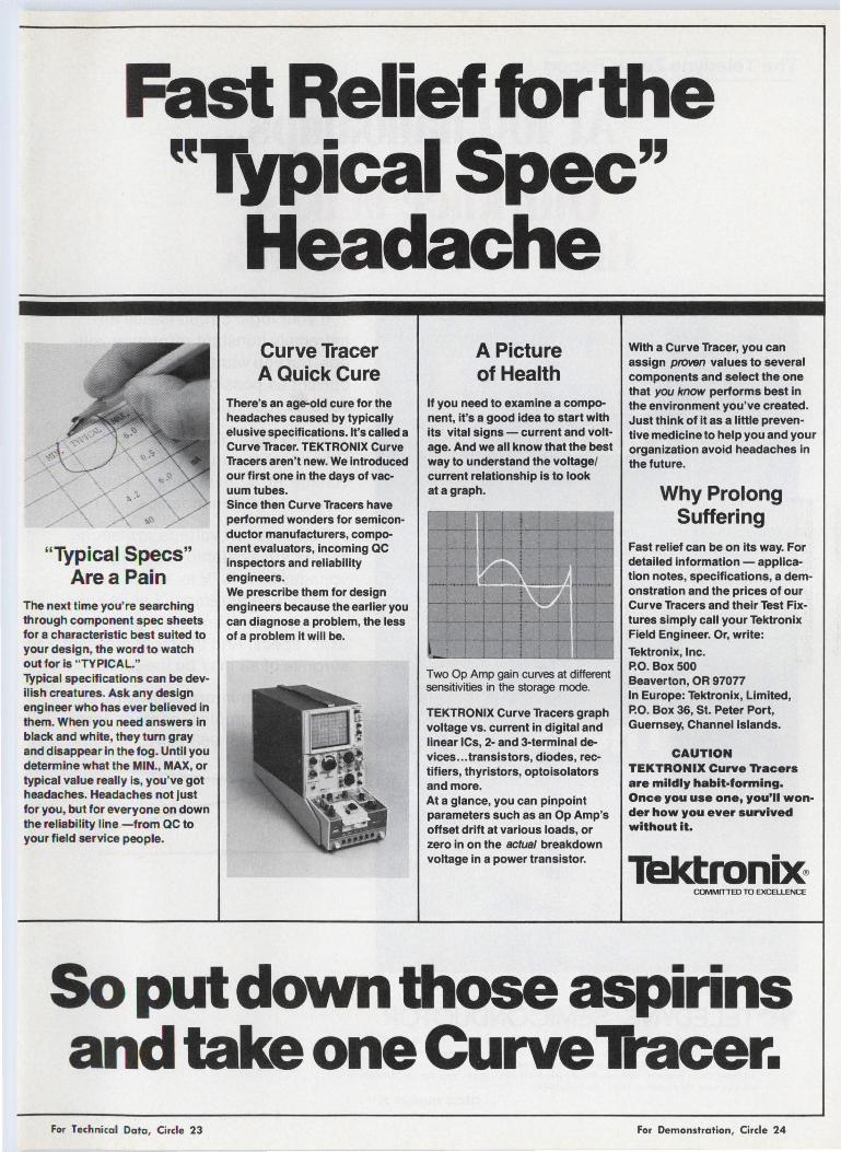
Fast Relief for the "Typical Spec"
Headache
"Typical Specs" Area Pain
The next time you're searching through component spec sheets for a characteristic best suited to your design, the word to watch out for is "TYPICAL." Typical specifications can be devilish creatures. Ask any design engineer who has ever believed in them. When you need answers in black and white, they tum gray and disappear in the fog. Until you determine what the MIN., MAX, or typical value really is, you've got headaches. Headaches not just for you, but for everyone on down the reliability I ine -from QC to your field service people.
Curve Tracer A Quick Cure
There's an age-old cure for the headaches caused by typically elusive specifications. It's called a Curve Tracer. TEKTRONIX Curve Tracers aren't new. We introduced our first one in the days of vacuum tubes. Since then Curve Tracers have performed wonders for semiconductor manufacturers, component evaluators, incoming QC inspectors and reliability engineers. We prescribe them for design engineers because the earlier you can diagnose a problem, the less of a problem it will be.
A Picture of Health
If you need to examine a component, it's a good idea to start with its vital signs - current and voltage. And we all know that the best way to understand the voltage/ current relationship is to look at a graph.
Two Op Amp gain curves at different sensitivities in the storage mode.
TEKTRONIX Curve Tracers graph voltage vs. current in digital and linear ICs, 2- and 3-terminal devices ... transistors, diodes, rectifiers, thyristors, optoisolators and more. At a glance, you can pinpoint parameters such as an Op Amp's offset drift at various loads, or zero in on the actual breakdown voltage in a power transistor.
With a Curve Tracer, you can assign proven values to several components and select the one that you know performs best in the environment you've created. Just think of it as a little preventive medicine to help you and your organization avoid headaches in the future.
Why Prolong Suffering
Fast relief can be on its way. For detailed information - application notes, specifications, a demonstration and the prices of our Curve Tracers and their Test Fixtures simply call your Tektronix Field Engineer. Or, write:
Tektronix, Inc. P.O. Box 500 Beaverton, OR 97077 In Europe: Tektronix, Limited, P.O. Box 36, St. Peter Port, Guernsey, Channel Islands.
CAUTION TEKTRONIX Curve Tracers are mildly habit-forming. Once you use one, you'll won· der how you ever survived without it.
COMMITTED TD EXCELLENCE
So put down those aspirins and take one Curve Tracer.
For Technical Data, Circle 23 For Demonstration, Circle 24
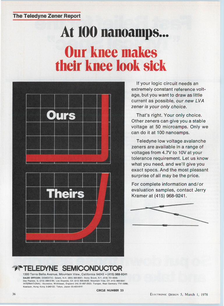
The Teledyne Zener Report
II
~ II
At 100 nanoamps ... Our knee makes
their knee look sick
I:
If your logic circuit needs an extremely constant reference voltage, but you want to draw as little current as possible, our new LVA zener is your only choice.
Ours That's right. Your only choice. Other zeners can give you a stable voltage at 50 microamps. Only we can do it at 100 nanoamps.
II II II II
Theirs
/
II 11 n
-=
-=
-=
-=
~
-===
Teledyne low voltage avalanche zeners are available in a range of voltages from 4.7V to 10V at your tolerance requirement. Let us know what you need, and we'll give you exact specs. And the most pleasant surprise of all may be the price.
For complete information and/ or evaluation samples, contact Jerry Kramer at (415) 968-9241.
_.,~TELEDYNE SEMICONDUCTOR
36
1300 Terra Bella Avenue, Mountain View, Cali fornia 94043 • (415) 968-9241 SALES OFFICES: DOMESTIC : Salem , N.H. (603) 893-9551 ; Stony Brook , N.Y. (516) 751-5640 ;
Des Plaines, IL (312) 299-6196; Los Angeles, CA (213) 826-6639 ; Mountain View, CA (415) 968-9241 INTERNATIONAL : Hounslow, Middlesex, England (44) 01-897-2503; Tiengen, Wesl Germany 7741-5066;
Kowloon. Hong Kong 3-240122; Tokyo, Japan 03-403-8141
CIRCLE NUMBER 25 ELEcTRONIC D ESIGN 5, March I. 1978
Editorial
The typewriter
Charlie's new job as chief engineer brought with it a large corner office. Charlie liked it. He didn't spend an inordinate amount of time at it, but he did take a few hours, with his secretary, to furnish the office more to his tastes and comforts: He got a few plants, pictures and souvenirs and sprinkled them around the place. After all, he would be spending lots of hours there.
But something was lacking, and Charlie couldn't work effectively. Ah-a typewriter. So he sent a requisition for a typewriter, indicating that any old typewriter would do. He didn't object to a good electric, but a 20-year-old manual would be fine. And then came the trouble. The head of the Office Services Department asked if his secretary wasn't suitable. "Oh sure, she's fine," he responded. Then, in the course of the next few days, a small army of people came to ask mysterious questions relating to this typewriter until, finally, Charlie's boss gave him some avuncular advice.
"Charlie," he said, "you aren't entitled to a typewriter. You are Management Code Level 7. You're suppose to be issued a pencil and a pad. Your secretary is supposed to type for you. Nobody above Code 4 ever gets a typewriter."
"But that's ridiculous," Charlie told him. "My handwriting is atrocious. Even I can't read it. And while I certainly use my secretary a lot, I do a lot of my thinking at the typewriter, I make quick notes to myself, to you and to my people on the typewriter. I brew up ideas at the machine. When I have an idea, I want to put it on paper right away, and if I did it in handwriting, we'd need a Sanskrit expert to decipher it. Hell, if we can't manage it through channels, I'll buy my own typewriter."
Well, Charlie won. And for weeks he was the talk of the office, as people would wander by and point with amazement at the executive with the typewritera man at Management Code Level 7, no less.
In time, Charlie hopes to break down a lot of other organizational structures that get in the way of getting things done.
ELECTRONIC DESIGN 5, March I, 1978
GEORGE ROSTKY Editor-in-Chief
37

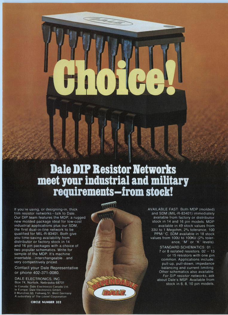

Picking a scientific calculator is getting tougher all the time, despite the fact that the number of calcu-lators to choose from-and manu-facturers-has gone down rapidly over the last three years. But what the fo.dustry has lost in numbers, it has more than gained in calculating features and computing power. Keyboards have been improved. LED and fluorescent-display technologies have been refined. And more computing power has been packed into all machines, with top programmable calculators beginning to take over for computer terminals. Re-
Jim McDermott Eastern Editor
The continuous CMOS memory of the HP-25C retains data stored in its 49-step program memory as well as that in eight addressable registers. Special functions often used, but not preprogrammed in the machine, can be stored.
40
liability has been upgraded-and so has service availability.
Unfortunately, increased machine complexity is making it harder to compare units. And a fast-growing generation of powerful user-programmable calculators is further confusing the picture.
Three years ago, you could get only one hand-held programmable, the $795 HP-65-today there are more than 15 new ones. They range from a $35 Sinclar unit with 36 program steps to a $300 Texas Instruments TI-59 with several hundred program steps to a $750 Hewlett-Packard HP-97 with a 224-step program and
Fifty fully merged program steps of the Tl-57 store up to 150 keystrokes. Eight multi-use, addressable memories store data, calculation results, and intermediate answers. The machine has full editing capabilities.
ELECTRONIC DESIGN 5, March l, 1978
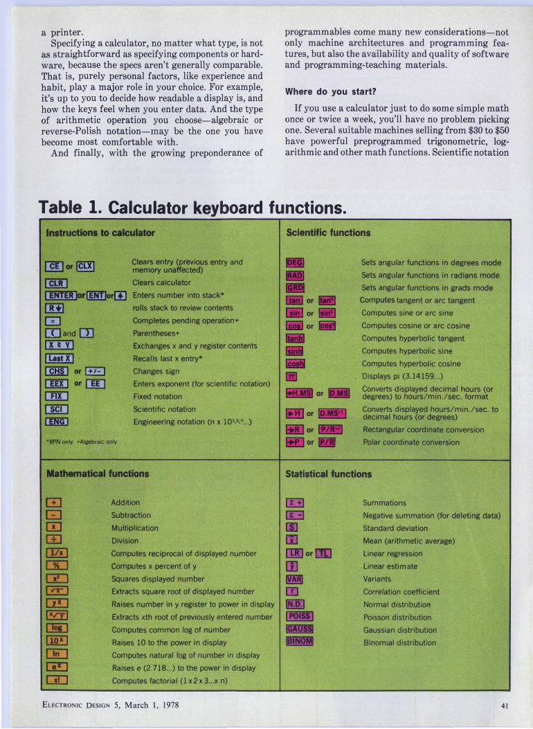
a printer. Specifying a calculator, no matter what type, is not
as straightforward as specifying components or hardware, because the specs aren't generally comparable. That is, purely personal factors, like experience and habit, play a major role in your choice. For example, it's up to you to decide how readable a display is, and how the keys feel when you enter data. And the type of arithmetic operation you choose-algebraic or reverse-Polish notation-may be the one you have become most comfortable with.
And finally, with the growing preponderance of
programmables come many new considerations-not only machine architectures and programming f eatures, but also the availability and quality of software and programming-teaching materials.
Where do you start?
If you use a calculator just to do some simple math once or twice a week, you'll have no problem picking one. Several suitable machines selling from $30 to $50 have powerful preprogrammed trigonometric, logarithmic and other math functions. Scientific notation
Table 1. Calculator keyboard functions. Instructions to calculator
(]!]or~
[§I] I ENTER !orcm!Jor(I] lR+i m OJand[l]
Ix• vi I List x I · [:mil or !+1- ! CmJ or CID cm [ED llrmJ •RPN only +Algebraic only
Clears entry (previous entry and memory unaffected)
Clears calculator
Enters number into stack*
rolls stack to review contents
Completes pending operation+
Parentheses+
Exchanges x and y register contents
Recalls last x entry•
Changes sign
Enters exponent (for scientific notation)
Fixed notation
Scientific notation
Engineering notation (n x lQJ,6,9 •. . )
Mathematical functions
m Addition
c::J Subtraction
m Multiplication
(!] Division
llZ!J Computes reciprocal of displayed number
CD Computes x percent of y
CZJ Squares displayed number
in-! Extracts square root of displayed number
Ci!] Raises number in y register to power in display
[!£f) Extracts xth root of previously entered number
D!iJ Computes common log of number
Cii!l Raises 10 to the power in display
[E] Computes natural log of number in display
Ci!J Raises e (2.718 ... ) to the power in display
CiD Computes factorial ( 1 x 2 x 3 ... x n)
ELECTRONIC DESIGN 5, March I, 1978
Scientific functions
Sets angular functions in degrees mode
Sets angular functions in radians mode
Sets angular functions in grads mode
Computes tangent or arc tangent
Computes sine or arc sine
Computes cosine or arc cosine
Computes hyperbolic tangent
Computes hyperbolic sine
Computes hyperbolic cosine
Displays pi (3.14159 ... )
Converts displayed decimal hours (or degrees) to hours/min./sec. format
Converts displayed hours/min./sec. to decimal hours (or degrees)
Rectangular coordinate conversion
Polar coordinate conversion
Statistical functions
[§1 Summations
Negative summation (for deleting data)
Standard deviation
Mean (arithmetic average)
Linear regression
Linear estimate
Variants
Correlation coefficient
Normal distribution
Poisson distribution
Gaussian distribution
Binomial distribution
41

NORMAL DISCHARGE 04ARACTERISTIC
I ~ OAi--~~-+~~~--~~~-+-~~--.
s
1. A "memory" effect in NiCd rechargeable cells results in an apparent loss of capacity with repetitive chargedischarge cycles. This effect is reversible and can be cured by giving the cell a deep discharge and a recharge.
as well as 12 digits-10 mantissa and 2 exponentare now found in low-cost units.
For once-in-a-while use, get one of the low-cost LED or fluorescent-display units that runs on AA dry cells. Keeping nickel-cadmium batteries recharged when a calculator is idle most of the time is a nuisance. Or buy an LCD model, and forget the batteries for a year.
But if you're going to make serious, professional use of a calculator, you're going to have to look long at several key features:
•The kind of arithmetic programmed into the machine. It may be ordinary algebra, algebra with a
F. a a a a i! s
hierarchy, or reverse-Polish notation. •Keyboard design and accessibility. • Display types and viewability, the number of
digits and special display features. • Care and feeding of batteries. • Power of preprogrammed math, trigonometric,
statistical and other functions. •Use of floating point, scientific and engineering
notations. •Accuracy. • Basic programmable f ea tu res. • Printer applications. • Programmable machine features. • Software and its availability.
Which arithmetic?
You'll probably feel most at home using a calculator with the math system you've grown up with-say, ordinary algebra. But two other math systems, algebra with a hierarchy and reverse-Polish notation, may be better in the long run because they are more efficient (use less keystrokes) and can solve complex problems easier and faster.
Ordinary algebra, the simplest and most straightforward, is found in all scientific calculators except those of Texas Instruments and Hewlett-Packard. Tl's calculators use algebra with a special hierarchy while HP's line incorporates reverse-Polish notation.
Ordinary algebraic operations are, for the most part, executed in the sequence you enter them. For example:
2 + 3 x 4 = 20.
For long strings of calculations, make sure that your machine has at least two levels of nested parentheses, but preferably more-as well as a one or two-register memory. Canon's F-7 calculator, for one, has seven levels of parentheses and two registers.
An algebraic-entry system with hierarchy, together with a pair of parentheses keys, makes up what TI calls its Algebraic Operation System (AOS). Its problem-solving capabilities are comparable to those of HP's reverse-Polish (RPN), but for most problems AOS requires more keystrokes.
If you were brought up on ordinary algebra, AOS may be somewhat confusing at first. Where a calculator using ordinary algebra obeys you and performs the arithmetic in the entering order, an AOS calcu-· lator grabs your key entries, both function and digit, sorts out the data in the order it wants, and performs the calculations in its own sequence. The Tl-59, for example, defies you to set up an equation any other
With a 36-step program capacity, this vest-pocket Sinclair programmable calculator handles frequently used programs in math, physics and engineering. For $35 the machine and a library of 290 programs are supplied.
ELECTRONIC DESIGN 5, March I, 1978

llON ~1 1:. Nllr K: CAl.C'ULATOH
CAaea/x-3000 I 0
'
0 ··:o:; so ~
111111•11 1111••• 1111•11• 1111•1111
1r ,\ Ol!L
Silver-oxide cells provide 700 hours of use for this Casio fx-3000 calculator with a liquid-crystal display. This type display permits packaging the power of a 38-function, 10-digit machine in a slim billfold case.
way than the machine wants it. Computations are always performed in the following order:
1. Special single-function key entries, such as those for trig and log functions, and squares, square roots, reciprocals and conversions.
2. Powers and other roots. 3. Multiplications and divisions. 4. Additions and subtracti<ms.
In other words, if you were to key in the previous equation, the answer wouldn't be 20:
2 + 3 x 4 = 14
With AOS the 3 and 4 are first multiplied, and 2 is then added.
The battle of keystrokes
But is AOS more efficient than RPN? This continuing controversy has been joined by calculator users on both sides. Examples have been created that "prove" one or the other to be more efficient. This, of course, can be done by selecting problems specially suited to one calculator architecture and not the other.
But the pros and cons of the efficiency of one arithmetic system over another become more or less academic, because TI concedes that RPN is somewhat more efficient than AOS architecture. However, Rich-
ELECTRONIC DESIGN S, March I, 1978
ard Cuthbert, applications manager for Tl's professional calculators, points out that the general need for more keystrokes per program by TI machine users is intentional.
"It's intrinsic that you use more space with the AOS architecture,'' Cuthbert says. "But we have deliberately taken this approach to make it easier for the user to program. Our AOS, like higher-level languages in large computers, takes more room than assembly language. But assembly language is a lot tougher for the neophyte. While our approach imposes additional overhead, we have a lot more storage in the machine."
RPN does save a few keystrokes. But there's much more to choosing a calculator language than counting keystrokes. The machine itself should be adaptable to the user's background and needs. A survey of HP and TI users has shown that, by and large, those who have learned to operate programmable machines of one type or another become "addicted" to the machine they learned on. As a matter of fact, over 2000 calculator owners belong to an HP Users Club and 500 to a TI Users Club, both of which are unaffiliated with the manufacturers.
Graduating from an algebraic calculator to an RPN can be a problem because data in the RPN system are entered and manipulated differently. The RPN procedure is a lot like the entry of data into computers.
With algebraic entry, the arithmetic functions of plus, minus, times, or divide by are placed between the numbers of a two-number operation. But with RPN entry the arithmetic function is placed after both members of a two-number operation.
In other words, for problems having two numbers and one arithmetic operator, the first number is keyed in and saved in a stack register by pressing an ENTER key. The second number is keyed in and followed by the arithmetic operator. An expression like (3 X 4) + (5 X 7) would be evaluated in an RPN machine by the following steps:
3 ENTER 4 X (12.00 is displayed),
5 ENTER 7 x (35.00 is displayed)
+ (47.00 is displayed).
While RPN, like AOS, is at first awkward for those accustomed to working with algebraic system entry, users experienced with both AOS and RPN say that with frequent use, they become either as proficient or more proficient at using RPN.
Keyboards are growing
Unfortunately, the amount of keystrokes isn't determined simply by the math language you choose. Because of the abundance of functions preprogrammed into all of today's advanced scientific calculators, keyboards have two, and in some cases, three functions assigned to one key. The more functions per
43
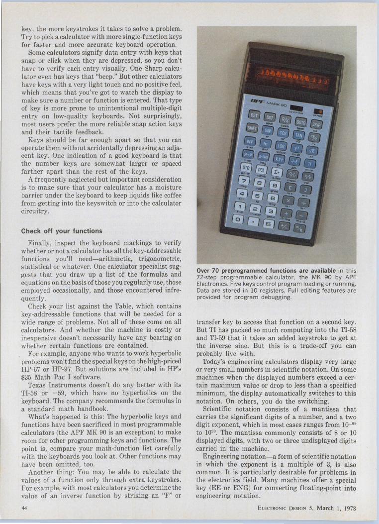
key, the more keystrokes it takes to solve a problem. Try to pick a calculator with more single-function keys for faster and more accurate keyboard operation.
Some calculators signify data entry with keys that snap or click when they are depressed, so you don't have to verify each entry visually. One Sharp calculator even has keys that "beep." But other calculators have keys with a very light touch and no positive feel, which means that you've got to watch the display to make sure a number or function is entered. That type of key is more prone to unintentional multiple-digit entry on low-quality keyboards. Not surprisingly, most users prefer the more reliable snap action keys and their tactile feedback.
Keys should be far enough apart so that you can operate them without accidentally depressing an adjacent key. One indication of a good keyboard is that the number keys are somewhat larger or spaced farther apart than the rest of the keys.
A frequently neglected but important consideration is to make sure that your calculator has a moisture barrier under the keyboard to keep liquids like coffee from getting into the keyswitch or into the calculator circuitry.
Check off your functions
Finally, inspect the keyboard markings to verify whether or not a calculator has all the key-addressable functions you'll need-arithmetic, trigonometric, statistical or whatever. One calculator specialist suggests that you draw up a list of the formulas and equations on the basis of those you regularly use, those employed occasionally, and those encountered infrequently.
Check your list against the Table, which contains key-addressable functions that will be needed for a wide range of problems. Not all of these come on all calculators. And whether the machine is costly or inexpensive doesn't necessarily have any bearing on whether certain functions are contained.
For example, anyone who wants to work hyperbolic problems won't find the special keys on the high-priced HP-67 or HP-97. But solutions are included in HP's $35 Math Pac I software.
Texas Instruments doesn't do any better with its TI-58 or -59, which have no hyperbolics on the keyboard. The company recommends the formulas in a standard math handbook.
What's happened is this: The hyperbolic keys and functions have been sacrificed in most programmable calculators (the APF MK 90 is an exception) to make room for other programming keys and functions. The point is, compare your math-function list carefully with the keyboards you look at. Other functions may have been omitted, too.
Another thing: You may be able to calculate the values of a function only through extra keystrokes. For example, with most calculators you determine the value of an inverse function by striking an "F" or
44
Over 70 preprogrammed functions are available in this 72-step programmable calculator, the MK 90 by APF Electronics. Five keys control program loading or runn ing. Data are stored in 10 registers. Full editing features are provided for program debugging.
transfer key to access that function on a second key. But TI has packed so much computing into the TI-58 and TI-59 that it takes an added keystroke to get at the inverse sine. But this is a trade-off you can probably live with.
Today's engineering calculators display very large or very small numbers in scientific notation. On some machines when the displayed numbers exceed acertain maximum value or drop to less than a specified minimum, the display automatically switches to this notation. On others, you do the switching.
Scientific notation consists of a mantissa that carries the significant digits of a number, and a two digit exponent, which in most cases ranges from 10- 99
to 1099 • The mantissa commonly consists of 8 or 10 displayed digits, with two or three undisplayed digits carried in the machine.
Engineering notation-a form of scientific notation in which the exponent is a multiple of 3, is also common. It is particularly desirable for problems in the electronics field. Many machines offer a special key (EE or ENG) for converting floating-point into engineering notation.
ELECTRONIC DESIGN 5, March I, 1978
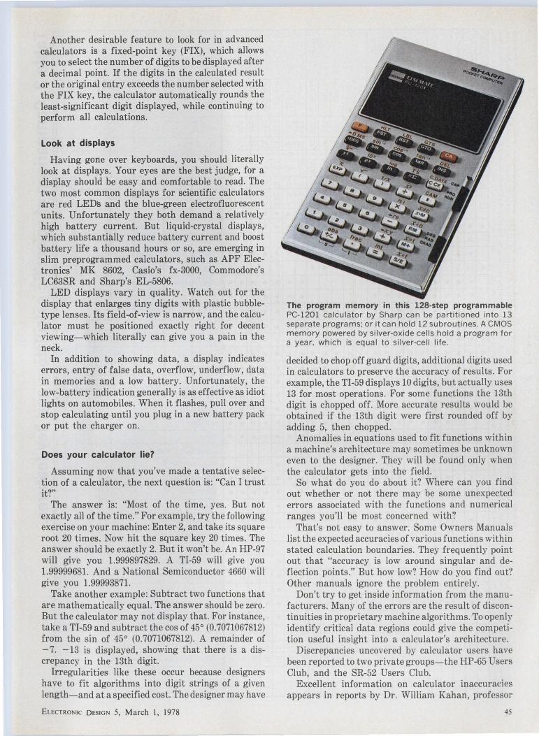
Another desirable feature to look for in advanced calculators is a fixed-point key (FIX), which allows you to select the number of digits to be displayed after a decimal point. If the digits in the calculated result or the original entry exceeds the number selected with the FIX key, the calculator automatically rounds the least-significant digit displayed, while continuing to perform all calculations.
Look at displays
Having gone over keyboards, you -should literally look at displays. Your eyes are the best judge, for a display should be easy and comfortable to read. The .two most common displays for scientific calculators are red LED~ and the blue-green electrofluorescent units. Unfortunately they both demand a relatively high battery current. But liquid-crystal displays, which substantially reduce battery current and boost battery !if e a thousand hours or so, are emerging in slim preprogrammed calculators, such as APF Electronics' MK 8602, Casio's fx-3000, Commodore's LC63SR and Sharp's EL-5806.
LED displays vary in quality. Watch out for the display that enlarges tiny digits with plastic bubbletype lenses. Its field-of-view is narrow, and the calculator must be positioned exactly right for decent viewing-which literally can give you a pain in the neck.
In addition to showing data, a display indicates errors, entry of false data, overflow, underflow, data in memories and a low battery. Unfortunately, the low-battery indication generally is as effective as idiot lights on automobiles. When it flashes, pull over and stop calculating until you plug in a new battery pack or put the charger on.
Does your calculator lie?
Assuming now that you've made a tentative selection of a calculator, the next question is: "Can I trust it?"
The answer is: "Most of the time, yes. But not exactly all of the time." For example, try the following exercise on your machine: Enter 2, and take its square root 20 times. Now hit the square key 20 times. The answer should be exactly 2. But it won't be. An HP-97 will give you 1.999897829. A TI-59 will give you 1.99999681. And a National Semiconductor 4660 will give you 1.99993871.
Take another example: Subtract two functions that are mathematically equal. The answer should be zero. But the calculator may not display that. For instance, take a TI-59 and subtract the cos of 45° (0.7071067812) from the sin of 45° (0.7071067812). A remainder of -7. -13 is displayed, showing that there is a discrepancy in the 13th digit.
Irregularities like these occur because designers have to fit algorithms into digit strings of a given length-and at a specified cost. The designer may have
ELECTRONIC DESIGN 5, March I, 1978
The program memory in this 128-step programmable PC-1201 calculator by Sharp can be partitioned into 13 separate programs; or it can hold 12 subroutines. A CMOS memory powered by silver-oxide cells hold a program for a year, which is equal to silver-cell life.
decided to chop off guard digits, additional digits used in calculators to preserve the accuracy of results. For example, the TI-59 displays 10 digits, but actually uses 13 for most operations. For some functions the 13th digit is chopped off. More accurate results would be obtained if the 13th digit were first rounded off by adding 5, then chopped.
Anomalies in equations used to fit functions within a machine's architecture may sometimes be unknown even to the designer. They will be found only when the calculator gets into the field.
So what do you do about it? Where can you find out whether or not there may be some unexpected errors associated with the functions and numerical ranges you'll be most concerned with?
That's not easy to answer. Some Owners Manuals list the expected accuracies of various functions within stated calculation boundaries. They frequently point out that "accuracy is low around singular and deflection points." But how low? How do you find out? Other manuals ignore the problem entirely.
Don't try to get inside information from the manufacturers. Many of the errors are the result of discontinuities in proprietary machine algorithms. To openly identify critical data regions could give the competition useful insight into a calculator's architecture.
Discrepancies uncovered by calculator users have been reported to two private groups-the HP-65 Users Club, and the SR-52 Users Club.
Excellent information on calculator inaccuracies appears in reports by Dr. William Kahan, professor
45

Table 2. Comparison of scientific calculators and key features. Arithmetic Preprogrammed functions notation
Statistical functions ci u
ell ell c: :;:;
c: c: ell ci QI
al QI 0 QI u QI VI vi c: QI VI c: Iii> QI QI c: 2 ... :;:; 0 VI VI tlO a. ... tlO
>. c: cu u c: lii c: 2 2 ~ "' 0
"' 0 "iii ' > c: "' c: "' VI E c Q. a. c ... > VI
)( ell -- :::J cu iii E c ....... .r::. -~ ~ . :Ci)' 0 ell cu - > cu u 0 QI VI all "C c .s '2 )( ~;;;. .E "C ... ' all 0 Q) cu QI -~ all QI ell ~ 0 tlO tlO ci ~ "' QI QI VI u u ... ...... - c 3: -- "' > c tlO QI QI 0 u "' a. VI c u ~2 QI .!!! ... "iii> "' c: 0 ' QI "C "C VI :r ·i::: )( c ....... ~ "' cu 2 ... "' VI ·- VI QI ...... 0 QI .r::. ~ 0"' :;:; "C .8 :::J Q) x ... u c ti 0 QI ''O :g all u ... .8 tlO VI ....... ~
....... :; a.. 0 ~ u VI "'' iii a. ~ cu "' VI + )( )( E ~ c: )( 0 VI "C c: c: s 'iii> ... ~ >. .... VI > QI .0 cu ........ ' ~ ........ "iii QI QI E 0 cu QI::
QI - c: "' c: :::J ' c u Iii> "' ........ VI ...... ........ -2' :s ·:;; VI c: QI ·i::: -o :::J a E tlO - tlO ·- QI
tic "' c ........ vi "' QI c c ~ "' ... QI VI .0 VI
"' >. u ·5 c: 0 u QI all
VI c VI .0 tlO ....... ~ ... )( c: c QI "C 0 0 ·- lii ~ E QI 0 E;..;: (ii
>. - ~ a. u n "C ' "' ~o E ........ "iii «i 'X QI ........ 0 :::J ~ tlO QI "C VI E ~ QI ·~ 0 c u ........ 3: ~
0 .!!2 :;:; <ii QI "C :;:;
~ c: - 0 QI E~ >. «i "C o "iii VI "§ 2 c VI E QI
List ~
"' E tlO ;;: c: .0 ~ "' £ tlO QI e ~ ~ 8. "' "' > u ... c - "' ·oa E .r::. E l1! - c: ~ QI .2 ... E E E .......
·i::: tlO t;' ·i::: E c "' :::J :.0 ...
~ c: ~VI 0 c. £ ~ c: cu ' '
... QI .Q c: a. "'
QI .8 c "C E "'
"C QI QI QI Calculator Price, "' ro>
~ "' > E "' c E c a. ... E tlD ~ 2 tlD"C (,)
·i::: QI "iii> tlO a. u tlO tlO u :g "' ·u :::J :::J ~ ~ ........ "' ·i::: QI ~ ci 19 0 ;x -c: c u QI "' Qj c: ~ 0 ~ e 0 ...
mfgr. Model $ ~ c: ·i::: >. QI QI QI QI oo .r::. QI r::; g 0 :::J "' 0 ' ~ "' ... "' z LL: w I- I 0 0 0 0 a..u <( u 0:: Cf) c: c 0: u ~ Cf) ~ > Ci5 a.. u :.:::i I- Cii )( )( a.. 0 a..u en
Hewlett- *HP-97 750 55 L RPN 10 10/2 • • • • • • • • • • • • • • • • • • • • • 224 4 26 M 3 Packard *HP-67 450 35 10 10/2 • • • • • • • • • • • • • • • • • • • • • 224 4 26 M
*HP-19C 345 31 8 812 • • • • • • • • • • • • • • • • • • • • 98 4 30 3.4 *HP-29C 195 30 8 812 • • • • • • • • • • • • • • • • • • • • 98 4 30 4 * HP-27 175 30 8 812 • • • • • • • • • • • • • • • • • • • • • • • • • 4 10
*HP-25C 160 30 ~ ~ 8 8/2 • • • • • • • • • • • • • • • • • • • • 49 4 8 4 * HP-25 125 30 L RPN 8 812 • • • • • • • • • • • • • • • • • • • • • • • 49 4 8
Texas *Tl-59 300 45 LAOS 10 10/2 • • • • • • • • • • • • • • • • • 480 9 60 S,M 5 Instr. *Tl-58 125
45 i i 10 10/2 • • • • • • • • • • • • • • • • • 240 9 30 s 5
*Tl-57 80 40 10 10/2 • • • • • • • • • • • • • • • • • 50 9 8
SR-51-Il 60 40 LAOS 10 812 • • • • • • • • • • • • • • • • • • • • • • • • • 9 3
PC-lOOA 200 1fnnterJ.:or Tl -58/ 59) 10 10/2 ..._ NA _. 6 -
Sharp *PC-1201 90 40 F OA 10 10/2 • • • • • • • • • • • • • • • • • • • 128 3 12 4.7 Electronics *EL-5001 5() 39 F 10 10/2 • • • • • • • • • • • • • • • • • • • • • • see
2 2 8.12 note
APF *MK 90 60 45 L 8 8/2 • • • • • • • • • • • • • • • • • • • • • • • • • • • • • 72 4 10 9 Electronics
MK 56 50 45 L 8 8/2 • • • • • • • • • • • • • • • • • • • • • • • • • • • • • 4 10 9
MK 8601 35 38 LX 8 8/2 • • • • • • • 0 • • • • • • • • • • • • • • • • • 2 2
Casio fx-120 30 39 F 10 812 • • • • • • • • • • • • • • • • • • • • • • 6 1
fx-3000 50 39 LX 10 812 • • • • • • • • • • • • • • • • • • • • • • 812 2 1
Canon F-7 80 36 L 8 812 • • • • • • • • • • • • • see note • • • 7 2 10
Nat I Semi. NS108 50 38 LX w 10 812 • • • see • • • • • note • • • • • • • • • • • • • • • 2 1 11
Sinclair Program able 35 19 L OA 8 5/2 • • • • • • • • • 36 l 1 *Programmable calculators (see text) 1. L = LED; F = flourescent; LX = liquid crystal 2. OA =ordinary algebra; AOS ~ hierarchical alegbra ; RPN = reverse- Polish notation 3. Calculator has integral printer. 4. Calculator has CMOS memory for long-term
program storage. 5. Program and data memories can be exchanged. See text 6. Printer has tullialpha-numerical and plotting capability. 7. Can subdivide program memory into 13 programs or 12 subroutines. 8. Calculator has six thumbwheel -accessible programs built in . 9. Converts cartesian to spherical coordinates and inverse. 10. Has cube root instead of n-th root. 11. Has decimal-degree to radian to grad and inverse conversions. 12. Six thumbwheel programs inc lude: (1) Linear and polynomial plots; (2) Statistics; (3) Quadradic equations; (4) Polynomial integration; (5) Complex number algebra and coordinate conversion; (6) Vector algebra and coordinate conversions.
00 I-
°' .r::. u .... "" ~
V')
z Q Vi
"' 0
~ z 0
"' .... ~ -'
u.J
\Q ~

RST 000 76 LBL
E ll ~ i 001 11 A "~•C.t.
002 42 STD • • '-1 1. :;zEE
dJ3 •LE'-£ 003 01 01 06.; s;o.; 004 76 LB L 0,)5 RCL; 005 12 B LL GJ .... 006 42 STD a Jc RCLZ 007 02 02
7.00 hf. 008 91 R/ ::; 00~ 009 76 LBL 5.61<i .Oh 010 1 ·:.
~· c 088 STG:; 0 11 43 RCL li0S R- S 012 01 01 ~. ~e G<CC 013 75
CIC t.UJ ; 014 43 RCL a1 370.; 01 5 02 02 etz K. S
:. . c~ GSSE 0 16 95 01:3 #LSLE 017 42 STD a· . src:; 0 18 03 03 ., 81 5 " "' ' . 1u ....... 019 91 R/ S .;.ac .u 0 20 76 LBL
016 RCL:; 0 21 14 D 5. 0ii ... 022 42 STD
e1:- 023 0 4 04 1.00 •H 024 9 1 R/ S
J1S ST06 025 76 LBL r1 ; RCL3 026 15 E s.cu .... 027 42 STD a2c RClc 028 05 05
J. ilJ ........ 029 91 R/S a21 o;;:o 76 LBL 5 . 0~ .... J2~ Ril; 03 1 16 A'
032 43 F~CL 03:;: 04 04 rn4 ~"
·-·
Thermal-printer tapes show a trace listing of a simple program executed on an HP-97 (left) and a verification listing of program steps (right) produced by a Tl PC-lOOA printer controlled by a Tl-59 in the printer cradle.
of Mathematics and Computer Science at the University of California at Berkeley. Kahan specializes in numerical error analysis and has conducted independent studies and reported them in "Can You Count on Your Calculator?" and "And Now for Something Completely Different, the Texas Instruments SR-52."
One simple way to find out if and where your calculator has errors is to perform a forward-function calculation and then an inverse-calculation with functions and values in the region of suspected inaccuracies. The displayed answer should be identical to the original entry. If not, there is an error in the forward-function or the inverse, or both.
For example, take the cos of 0.05°. Then press the inverse-function (cos- 1) key. The answer probably won't be 0.05. Try the same approach on the sine and tangent functions.
You can use the forward-inverse method on other functions, such as natural logs and antilogs. The natural log of zero, or of a negative number, should indicate ERROR. Make this check in the vicinity of 2, say, from 1.99 to 2.04, and in the vicinity of 1. Use the following table to verify your results:
Number 1.1 1.01 1.001 1.0001
In 9.53101798043247 x 10- 2
9.95033085316808 x 10- 3
9.99500333083532 x 10- 4
9.99950003333083 x 10- 5
ELECTRONIC DESIGN 5, March I, 1978
STEP KEV KEV CODE STEP KEV KEV CODE
! 55 00 32 84
F i HLT F : 12 33 45
55 01 34 RM ! 5
3 F ; HLT F 12 35 45
55!02 36 F 64
5 ! F : HLT F I 12 37 ' ' : x-M: 6 55 06
56 03 38 45
: F ! HLT Fl 12 39 56 07
: 65 02
9 : I x 54 41 + 74
10 i 2 02 42 RM! 3 65 03
11 x 54 43 i ' x 54
12 F ' " F 41 44 RM i 0
13 ' - 45 84
14 56 J 04 46 : I : 45
15 j F x 2 47 : RM I 5 65 ' 05 16 x 48 : 45
17 : RM 0 i 65 ' 00 49 F : 64
18 x l 54 50 ! I : 45
19 i RM i 65J 01 51 i +/- ! 82
20 52 M+ i 7 76 ; 07
21 + : 64
' 01 53 l T 45
22 84 54 44
23 +/- 82 55 ! RM I 6 66 : 06
24 55 05 56 45
25 I RM i 4 65 04 57 84
26 I x 54 58 : I 45
27 I RM! 0 RM i 7 65 : 07
28 84 60 F :-xy F i 74
29 tx-M: 0 55 : 00 61 45
30 : x 54 62 ' ' : x-M· 7 55 07
31 RM i 2 I I I 45
MEMORY LABEL
• 4 t-2•f • 4
5 1 -w'LC 5
0 6
2 Rs 8 2 8
Rp 9 3 9
2. Program lists, like this one for solving series-resonant circuit problems, are found in Sharp's PC-1201 software manual. Each program is supplied with a sample problem and step-by-step directions tor its execution .
1.00001 9.99995000033333 x 10- 6 0.99999 -1.00000500003333 x 10⁻⁵ 0.9999 -1.00005000333358 x 10⁻⁴
0.999 -1.00050033358353 x 10- 3
0.99 -1.00503358535014 x 10- 2
0.9 -1.05360515657826 x 10- 1
Another check is to add mathematically equal functions of opposite sign, or subtract equal functions of the same sign:
tan 89.99° + tan 90.01 ° = ?
sin 45° - cos 45° = ?
The answer should be zero.
Can I count on my battery?
Having determined whether or not your calculator can be trusted, don't forget to check the batteries. Nickel-cadmium rechargeable batteries are the work-
47

horses that power the vast majority of scientific calculators. But they're sensitive to heat and to cold. Not only that, a perfectly good cell may stubbornly resist taking a charge. And continuous overcharge will cut capacity. And continuous deep discharge will do worse.
To get maximum, continuous useful life and dependability from NiCd batteries, you'd better know their properties and characteristics. Unfortunately, calculator manufacturers offer little help. For example, take the following statement from a "Battery Care" section of an otherwise excellent 300-page User Manual. The manual defines the point of battery discharge as follows: "If the calculator fails to turn on you should substitute a charged battery pack, if available, for the one in the calculator."
A typical Ni Cd battery pack consists of two or three AA-sized, sealed cells, each with a nominal voltage of about 1.25 V. Pressure-relief seals are designed into the cells so that when internal pressure builds up, it can be relieved.
Most calculators use what are termed "slow-charge" batteries that are designed to be fully charged in "14 to 16 hours, or overnight." One reason is that these batteries are not harmed by a continuous overcharge. However, a sustained overcharge does lower the discharge voltage.
Note that nickel-cadmium batteries apparently lose capacity from repetitive use patterns. This phenomenon, known as "memory," acts like this: If you charge your battery fully each night, and discharge it by 25% during each working day, after a while the battery develops a memory that makes it think it has only 25% of its original capacity (see Fig. 1): It acts like a battery that is only one-fourth its actual size. So whereas the calculator should normally operate off the battery for, say, four hours, it will now last less than one.
Fortunately, "memory" is only temporary and can be corrected easily: Subject the battery to a deep discharge, then recharge it to restore it to its original performance. One calculator manufacturer suggests that a battery occasionally be discharged by leaving the calculator on until the display digits go out, then recharging it fully. To avoid the situation in the first place, all you have to do is make your charge-discharge patterns random.
Attention: Don't subject the battery to extended deep discharges, such as those caused by neglecting to turn the calculator off for a day or two. Two bad things will happen. First, since the two or three cells in the battery packs don't have identical charge capacities, one usually discharges to 0 V before the others. It is then reverse-charged by the voltage in the other cell or cells, and hydrogen gas is generated internally. The resultant pressure rise may then vent through the pressure-relief seal, with a loss of battery moisture. '--'!
Second, a deeply discharged cell is more likely to short internally than one that is fully charged. That's
48
Advanced programming features plus a battery-operated printer are found in the HP-97. The printer is valuable for editing and debugging, giving printouts that trace each step number, function and results of every step.
because a fully charged cell has sufficient energy to vaporize, or clear, the shorted path. A near-dead cell won't have enough energy to do so.
Nickel-cadmium batteries are designed to live in an ambient of 20 C (68 F) room temperature. Charging them at greater than, or much less than 20 C shortens their !if e. Don't make a practice of charging your calculator batteries in a cold room. Or in a hothouse.
Fully charged NiCd batteries, standing idle at 20 C, lose about 1 % of their charge per day because of chemical self-discharge. So in about a month or so, the battery will have lost about half its capacity, which calls for a recharge.
Hint: To keep idle batteries charged for extended periods, wrap them in a moisture-proof bag and store them in the food-not freezer-compartment of your refrigerator. The ~ 40 F temperature reduces the normal self-discharge to one-fourth, and extends the 50% discharge time to over six months. Caution: Be sure the batteries are warmed to room temperature before recharging.
So far, you've been trying to select a scientific calculator in general. But a new breed-calculators you can program-is fast emerging, and you'd better be ready for them.
The year of the programmables
As 1975 was the year of the preprogrammed scientific calculator-more than 40 kinds were available then-1978 is the year of the programmables. Five out of eight of HP's scientific machines can be programmed, as can three out of five of Tl's new line. Programmables are also appearing from APF Electronics, Casio, Commodore, Sharp and Sinclair.
ELECTRONIC DESIGN 5, March I, 1978
Programmable calculators are "grown-up" preprogrammed machines that tell you, in effect, "Leave the driving to us." They can learn a sequence of keyedin instructions and automatically execute that sequence on command. They store constants and other data. The program sequence, or list, is stored in a program memory while the data are stored in registers that can be accessed by the program.
To teach a programmable calculator a program, you switch to a PRGM or LEARN mode and enter a problem in a sequence of keystrokes dictated by the calculator's program list. The needed software may be prepared by the calculator manufacturer, or you can write it as an original program.
To execute the program, you switch the machine to a RUN mode, key-in initial problem values and let the program take over. You'll save a substantial amount of time when you have to solve similar problems over and over: You can use the same program, instead of going through single-key entry of every step. Great? Sure. But wait.
Turn the calculator off. Then turn it back on and try to run the program. Chances are, you can't, because the program was wiped out when the power went off. Now you have one important yardstick for comparing programmables: In one class of machines, the program must be keyed in again when the power is turned back on. So if your problems involve 100 or 200 program steps, get to work early. Or leave your calculator plugged into the charger and turned on as long as you want to keep the program in. However, when you do so, you'll be trading inconvenience for potential battery trouble.
One way to retain the program is to use low-power CMOS memories, which, with an auxiliary battery, keep the program and its data for months after a calculator is shut off. Such memories are designed into the $160 HP-25C, $195 HP-19C and the $345 printerequipped HP-19C. Sharp's $90 PC-1201 has a standby CMOS memory, powered by two silver-oxide cells, that will hold program information for about a year.
Magnetic cards also keep programs. Machines like the $300 TI-59 come with a magnetic-card handler and can store programs on the cards and read them back at any time. Magnetic cards are also used in the $450 HP-67 and $750 HP-97. In addition, libraries of prerecorded or "canned" programs are available in HP's Engineering Application Pacs .
The newest approach to programs that won't vanish when the machine is turned off is the Solid-State Software ROM modules that plug into the TI-58 and 59. The Master Library module, which corresponds to HP's Standard Pac of magnetic cards for the 67 and 97, has some 5000 program steps that provide 25 different programs in mathematics, geometry, statist ics, engineering conversions, finances and games. Each of the programs can be loaded into the program memory and data registers with a few keystrokes, and run independently. Or the program can be called in by the machine to run as a subroutine
E LECTRON IC D ES IGN 5, March I, 1978
of a larger program. A universal and frequently vexing problem with
programmables is how to debug a program you have written. For most programmables, debugging is a time-consuming operation that requires you to singlestep through the entire program listing, comparing the program step numbers and associated key codes (two-digit numbers that tell which keys were depressed to enter the program) that appear in the display against your master list. If a mistake has been made, you may have to delete or back step, or add steps, moving other portions of the program forward or backward. And you must repeat the single-step check of the program until the listing is correct.
The answer to a programmer's prayer for aid in debugging is found in printers that can be called on to list or trace through a portion of or an entire program. Such printers are incorporated into HP's 19C and 97. And TI has produced a free-standing print/security cradle, the PC-lOOA, in which the SR-52, SR-56, TI-58 and TI-59 can be mounted and locked in place. Locking-in helps solve another problem-theft.
HP's printer machines have a limited alphanumeric capability that identifies the kind of program step entered as well as other functions keyed into the program, for instance, ENT (enter), STOl (store data in register 1), SIN, TAN, etc. TI, however, has taken a giant stride with its $200 PC-lOOA printer, which, when used with the TI-58 and TI-59, can produce full alphanumerics plus 29 other useful symbols.
Not only can users of PC-lOOA list and trace program steps, but program headings and userprompting phrases (up to 20 characters wide) such as "ENTER INDUCTANCE" can be printed. In addition, you can make simple plots of data, such as sine curves, directly from the keyboard or automatically under program control.
Both HP and TI printers use nonimpact, thermal print heads. "Whisper-quiet operation" is claimed for both. After listening for a while, though, you may feel that the sound is more like a stage whisper.
Programmable benchmarks
The power and performance of most programmable calculators generally can be described by the following criteria:
• The number of program steps that can be held. • The number of data registers. • The ability to manipulate program steps to edit
a program. • The presence, or absence, of user-definable
LABEL keys or other keys that identify a program or program segment simply by pressing the defined key.
Comparing some of the lower-cost calculators, you find that Sinclair's 18-key Cambridge Programmable -the world's smallest programmable- has a 36-step program memory. APF's 45-key, $70 MK 90 has 72
49
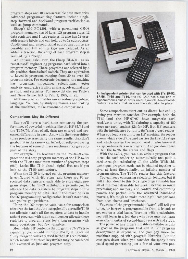
program steps and 10 user-accessible data memories. Advanced program-editing features include singlestep, forward and backward program verification as well as jump commands.
Sharp's $90 PC-1201, with a permanent CMOS program memory, has 40 keys, 128 program steps, 12 data registers and 1 test register. It also has 12 useraddressable labels and can hold up to 12 subroutines. Conditional and unconditional subroutine jumps are possible, and full editing keys are included. As an added attraction, the entry of each program step is verified by a "beep."
An unusual calculator, the Sharp EL-5001, as six "most-used" engineering programs hard-wired into a program memory. These programs are selected by a six-position thumbwheel switch. They are equivalent to keyed-in programs ranging from 30 to over 150 program steps. For electronic designers, the machine has programs, impedance calculations, vector analysis, quadratic stability analysis, polynomial integration, and statistics. For more details, see Table 2 and News Scope, ED 3, Feb. 1, 1978, p. 21.
All these programmables use an ordinary algebraic language. You can, by studying manuals and looking at the machines, make reasonable comparisons.
Comparisons May Be Different
But you'll have a hard time comparing the performance of powerful machines like the HP-67 /97 and the TI-58/59. First of all, data are entered and processed differently in each. And while the two architectures produce essentially the same results, they don't go about it in the same way. In fact, directly comparing the f ea tu res of some of these machines may give only part of the story.
For example, Tl's brochure on the 57/58/59 compares the 224-step program memory of the HP-67/97 with the TI-59's maximu111 number of program steps (960). Looks like TI is ahead, right? But not if you look at the TI-59 architecture.
When the TI-59 is turned on, the program memory is configured with 480 steps, and there are 60 associated data registers, each able to store eight program steps. The TI-59 architecture permits you to allocate the data registers to program steps or the program memory to data. But if the machine is in the 960 program-step configuration, it can't store data, and you've got problems.
Using the 960 steps as your basis for comparison obscures the fact that the exceptionally versatile TI-59 can allocate nearly all the registers to data to handle a short program with many numbers, or allocate those registers to program steps for a long program with many operations, but few variables.
Meanwhile, HP contends that to get the 67 /97's true capability, you should multiply 224 by 3. So-called "fully merged" codes are used in the HP architecture, which means that three keystrokes may be combined and executed as just one program step.
50
An independent printer that can be used with Tl's SR-52, SR-56, Tl-58 and Tl·59, the PC-lOOA has a full line of alphanumerics plus 29 other useful symbols. A worthwhile feature is a lock that secures the calculator in place.
Some comparisons start out as direct, but end up giving you more to consider. For example, both the TI-59 and the HP-67/97 have magnetic card read/write units, with TI claiming a capacity of 480 steps per card, against 224 for HP. But HP counters with the intelligence built into its "smart" card reader. When you load a card into an HP machine, its reader knows which side of the card carries the first 112 steps and which carries the second. And it also knows if a step contains data or a program. And you don't need to tell the 67 /97 the status and flags.
With the 67/97, you can also write a program that turns the card reader on automatically and pulls a card through-calculating all the while. With this technique, program cards can be chained together to give, at least theoretically, an infinite number of program steps. The TI-59's reader has this feature.
You can keep comparing calculator features, but it will all boil down to this: No single programmable has all of the most desirable features. Because so much processing and memory and control and computing powers are packed into the advanced hand-held marvels, it's tough to make meaningful comparisons from spec sheets and brochures.
Veterans of the programmable "wars" will tell you to beg or borrow a programmable from a friend; or get one on a trial basis. Working with a calculator, you will learn in a few days what you may not learn even after months of second-hand research and study.
The power of any programmable calculator is only as good as the programs that run it. But program development is expensive, and you pay more for machines supplied with program libraries. But the cost goes down when you consider the qi.any hours you'd spend generating just a few of your own pro-
ELECTRONIC DESIGN 5, March I, 1978
grams. And with ready-made programs, you can start out immediately.
One good thing about writing your own, however, is that as you develop a personal approach, your storebought programs may not seem as good as they should be. You may want to rewrite them to make them shorter, easier to keep track of, or simply more comfortable to work with.
A major software benchmark when considering a programmable is the quality and depth of the machine's documentation. Check that the Owners Handbook or Owners Manual is comprehensive, and thoroughly describes the programming keys and their functions. And be sure there are plenty of clear sample programs with step-by-step explanations.
With the lower-cost machines, the Owners Manual will usually provide just a few programming examples. One exception is Sharp's PC-1201 programmable. Its instruction manual contains clear descriptions of the programming functions of the machine, along with a good sampling of test programs. But the bonus is a 266-page Application Manual listing 92 programs for math, statistics, electronics, engineering and other problems (See Fig. 2).
Preceding each program listing is its basic formula, a sample problem, and key-by-key directions for executing the program. Also, the program can be stored indefinitely in its special CMOS memory.
Software and documentation for HP and TI machines are ahead of the rest of the competition. And both companies continue to improve and enlarge their sizable libraries and Owners Manuals to capture a larger share of the programmable-calculator market.
In addition to their own software, both companies support in-house User Libraries of programs submitted by calculator owners. In line with this, newsletters from both manufacturers pass on program hints and announcements contributed by subscribers. HP's newsletter is "HP Key Notes" and Tl's is the "PPX Exchange Newsletter."
For the new TI-58 and TI-59 machines, Tl's SolidState Software library modules include the Master Library, which comes with the calculator, and Applied Statistics, Aviation, Marine Navigation, Surveying and Real Estate/Investment. No EE library is available, and at the time of writing there hasn't been any indication that one will be. For TI-programmablecalculator users, another source of software news is the SR-52 Users Club in Dayton, OH, which reports on all TI models.
Software for HP's 67 /97 machines is available in two forms. One is a 40-book series of $10 "User Library Solutions," each containing 10 to 15 programs. Purchased separately they would cost $35 to $45. One book covers electrical engineering. Four books handle mathematics and three more have programs for chemistry, optics and physics. For these calculators, $35 magnetic-card Application Pacs are also available.
One independent source of HP program information and news is the HP Users' Club in Santa Ana, CA.
ELECTRONIC DESIGN 5, March I, 1978
The 2000-member club swaps programming techniques, applications and programs in its newsletter.
What about your old software?
Suppose you already have a programmable and want to step up to a new machine. You ask plaintively, "What do I do with the software that I've already spent a bundle on? Can I transfer my programs, say, from an SR-52 to a TI-59, or from an HP-65 to an HP-67?"
Yes you can. And HP and TI newsletters have tun articles telling how. But an ELECTRONIC DESIGN survey of long-term users of both kinds of machines elicits the following advice: Transfer programs from old libraries directly, and you'll lose efficiency in the translation. The best and quickest approach is to rewrite them according to the new machine's rules.
The thousands of HP and TI programmables now in use have also created a demand for software not available from the manufacturers. To satisfy this demand, calculator-software houses are appearing. One is the International Software Clearinghouse in Estacada, OR, and another is Horizons Technology, Inc., in San Diego ...
Want more information? Readers interested in learning more about the
calculators mentioned in this article and of similar machines available may contact the manufacturers listed below or consult ELECTRONIC DESIGN'S GOLD BOOK. Types of calculators produced are indicated by the letters following the listing: P-preprogrammed; K-key programmable; M-magnetic-card programmable; S-solid-state-module programmable.
For readers who wish to learn more about the activities and services of the private calculator User's Clubs and of the software houses, the addresses are included below. APF Electronics, Inc .. 444 Madison Ave., New York, NY 10022. (212) 758-7550.
P, K. Circle No. 501 Canon, Inc .. 10 Nevada Dr .. Lake Success. NY 11040. (516) 488-6700. P.
. Circle No. 502 Casio, Inc.. 15 Gardner Rd .. Fairfield, NJ 07006. (201) 575-7400. P, K.
Commodore Business Machines. 901 California Ave .. Palo AW~~·~AN;43~ (415) 326-4000. P, K. . Circle No. 504
Hewlett-Packard, 1000 N.E. Circle Blvd .. Corvallis. OR 93770. (503) 757-2000. P, K, _M. Circle No. 505
Kingspoint Corp., 104 Harbor Dr .. Jersey City, NJ 07305. (201) 432-7707. P. . . Circle No. 506
National Semiconductor, 1177 Kern Ave .. Sunnyvale, CA 94086. (408) 732-5000. P., K. Circle No. 507
Sharp Electronics Corp .. P.O. Box 588. Paramus, NJ 07652. (201) 265-5600. P, K. . . Circle No. 508
Sinclair Rad1on1cs, Inc. , 115 E. 57th St., New York, NY 10022. (212) 355-5005. P, K. Circle No. 509
Texas Instruments, P.O. Box 53, MS 5842. Lubbock, TX 79408. (806) 747-3737. P, K, M, S. Circle No. 510
Software clubs and houses: HP Users Club. Richard J. Nelson, 2541 W. Camden Pl. Santa Ana CA 92704
(714) 639-7810. ' • .
SR-52 Users Club. Richard C. Vanderburgh, 9459 Taylorsville Rd. Dayton OH 45424. (513) 255-6502. . .
International Software Clearinghouse. Route 2 Box 965 Estacada OR 97023 (503) 631-2214. ' . • .
Horizons Technology, Inc .. 8333 Clairemont Mesa Blvd. San Diego CA 92111 (714) 292-8331. ' ' .
51
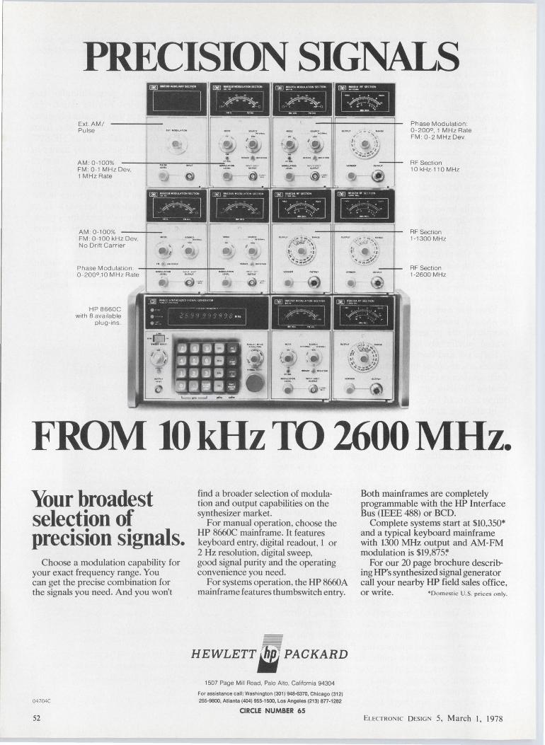
PRECISION SIGNALS !Ml -!llllODUl.ATOOSI(""" ITl>lJ :-:·· -·"~Y"~
' . . ... ' . - _. I
Ext. AM/ Pulse -~ .... - ......... .... ........
Phase Mod ulation: 0 -200°. 1 MHz Rate FM : 0-2 MH z Dev. ·~ ....
-~· -·-·-. •. '• /' ,.,
-' ~ .. _ . . .. .... _
.. ! · \_ > I -' ,, .. ·~:.y
AM : 0 -100% RF Section FM : 0 -1 M H z Dev.
,,_ ...... - ""' --1 M Hz Rate @ :~- @ ·:~
10 kHz-110 MHz
[1¥1] UHJ1w<l0u1AT....,'M.c1,,,,.
[~-~~~ ~~·· l .... I ~~u• " "' ' ~ ' ~
r «-~-- ~~· 1 AM: 0-100% FM : 0 -100 kHz Dev, No Dri ft Carr ier
_ ...... l -·~· ··:~ ...... :~ ..... RF Section 1-1300MHz
Phase Modulation: --1------.-.,--0 -2000.10 M Hz Rate
H P 8660C with 8 available
plug-ins.
\l: ".' ":"" " "'" . • • .. ft,. . · ~ . ..
:·;.]] ::·: .. " . "" "
/,£ • ..... -~
( . '· \ •. . i
fl .: ') 't .., .,.,·:.'l'
RF Section 1-2600 MHz
FROM 10 kHz TO 2600 MHz. Your broadest selection of precision signals.
Choose a modulation capability for your exact frequency range. You can get the precise combination for the signals you need. And you won't
04 704C
52
find a broader selection of modulation and output capabilities on the synthesizer market.
For manual operation, choose the HP 8660C mainframe. It features keyboard entry, digital readout, 1 or 2 Hz resolution, digital sweep, good signal purity and the operating convenience you need.
For systems operation, the HP 8660A mainframe features thumbswitch entry.
HEWLETT. PACKARD
1507 Page Mill Road, Palo Alto, Californ ia 94304
For assistance call : Washington (301) 948·6370, Chicago (312)
255-9800, Atlanta (404) 955-1500, Los Angeles (213) 877-1282
CIRCLE NUMBER 65
Both mainframes are completely programmable with the HP Interface Bus (IEEE 488) or BCD.
Complete systems start at $10,350* and a typical keyboard mainframe with 1300 MHz output and AM-FM modulation is $19,875'."
For our 20 page brochure describing HP's synthesized signal generator call your nearby HP field sales office, Or write. *Do mestic U.S. prices o nly.
Elt:CT RON 1c D ESI G 5, March I, 1978

EL ECTRO 1c D ESIG 5, March I, 1978
IN A MARKET FULL OF DROPOUTS, OUR NEW REGULATORS ARE PHI BETA KAPPA.
Fairchild is introducing two new Linear regulators that are a study in efficiency. Our µA78H05ASC 5-amp positive voltage regulator: And our µA78P05SC 10-amp positive voltage regulator:
They're designed to provide extremely low dropout voltage-typically 2 volts at 5 amps
on the µA78H05ASC and 2.2 volts at 10 amps on the µA78P05SC. And as any student of
regulators knows, dropout like this just isn 't available with monolithic designs.
STRAIGHT 'W' PERFORMANCE.
Since lower dropout voltage provides more efficient power supply designs, these regulators, like all Fairchild voltage regulators, require fewer components than traditional designs. And that reduces design time considerably.
Features include shortcircuit and safe-area protection, thermal shutdown and hermetically sealed T0-3 packages. And all this at the same price you 'd expect to be paying for regulators that graduate at the bottom of their class. In fact, you can start designing in our new regulators for as little as $5.00 in quantities of l 00 (µA78H05ASC).
IF YOU HAVE QUE5nONS, PLEASE RAISE YOUR HAND.
For more details on our new enhanced voltage regulators, or l=AI RC HI L..c:J information on our other Hybrid
products, contact your Fairchild CALL US ON 1• distributor or representative. Or, le for immediate results, call your nearest Fairchild sales office. France: Fcorch1ld Camero & Instrument SA, 121 Ave. d'ltol1e, 750013 - Pons Tel 00331 584 55 66. Telex 0042 200614. ltoly: Foorch1ld Semicondutton S.PA., Vt0 Rosell1no, 12, 20124 Milano. Tel: 02 6887451 Telex 36522. Germany: Foorch1ld Camero & Instrument (Deutschlond) GmbH, 8046 Gorch1ng Hockbruck Do1mlerstr. 15, Munchen. Tel 089 320031 . Telex 52 4831 foord. England : Foorch11d Camero & Instrument (UK) Ltd., 230 High St .. Potter.; Bor. Hertfordshire EN6 58U Tel; 0707 51111. Telex 0051 262835. Sweden : Foorch11d Semiconductor AB. Svortengsgoton 6, S· 11620 Stockholm. Tel: 8·449255. Telex 17759.
CIRCLE NUMBER 165 53
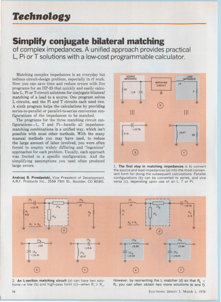
Teehnolog~
Simplify conjugate bilateral matching of complex impedances. A unified approach provides practical L, Pi or T solutions with a low-cost programmable calculator.
Matching complex impedances is an everyday but tedious circuit-design problem, especially in rf work. Now you can save time and reduce errors with five programs for an HP-25 that quickly and easily calculate L, Pi or T-circuit solutions for conjugate bilateral matching of a load to a source. One program solves L circuits, and the Pi and T circuits each need two. A sixth program helps the calculations by providing series-to-parallel or parallel-to-series conversion configurations of the impedances to be matched.
The programs for the three matching circuit configurations-L, T and Pi-handle all impedancematching combinations in a unified way, which isn't possible with most other methods. With the many manual methods you may have used, to reduce the large amount of labor involved, you were often forced to employ widely differing and "ingenious" approaches for each problem. Usually, each approach was limited to a specific configuration. And the simplifying assumptions you used often produced large errors.
Andrzej B. Przedpelski, Vice President of Developmen~. A.R.F. Products Inc .. 2559 75th St .. Boulder, CO 80301.
-jl3.76 I I
R; I 4.13 I
I I
R; > Ro L ':'
j Xb I I
JXa I I I _____ J
':' 0
j6
-j l5.8
JXo
j6.07
2. An L·section matching circuit (a) can have two so lutions-a low (b) and high-pass form (c)-when R; > R
0•
54
SOURCE LOAD IMPEDANCE IMPEDANCE
MATCHING j6 CIRCUIT
50 -j l5
I 2
':'
':'
0 ':'
111 111
F( 0
-jl3.76
3 j6.67 20
':' ':'
CD ©
1. The first step in matching impedances is to convert the source and load impedances (a) into the most convenient form for doing the subsequent calculations. Parallel configurations (b) can be converted to series, and vice versa (c), depending upon use of an L, T or Pi.
R;
2
JX;
j 6
,-------1
JXb I I I
jXa I I I I _____ J
- jl3.76
jXb
~ I
JXa
':' -j 19.24
However, by reorienting the L matcher (d) so that F\, < R;. you can often obtain two more solutions (e and f).
ELECTRONIC DESIGN 5, March I, 1978

Table 1. Parallel/Series/Parallel/Transformations Display Key
Line Code Entry Remarks Registers
00 Ro 01 24 02 RCL 2
02 15 71 (g)x·O
03 13 15 GTO 15 R1 Rp 04 15 22 (g) 1/x
05 24 01 RCL 1
06 15 22 (g) 1 /x R2 Xp 07 15 09 (g)•P
08 15 22 (g) 1/x
09 14 09 (f) .. R R3 As
10 23 03 STO 3 R...s.. 11 74 R/S
12 21 x:y R4
13 23 04 STO 4 Xs
14 74 R/S
15 24 04 RCL 4 Rs
16 24 03 RCL 3
17 15 09 (g) .. P
18 15 22 (g) 1/x Rs 19 14 09 (f) .. R
20 15 22 (g) 1/x
21 23 01 STO 1 RP R7 22 74 R/S
23 21 x:y
24 15 22 (g) 1/x
25 23 02 STO 2 Xp
26 13 00 GTOOO
The HP-25 fits the bill because it has just the amount of memory needed. Although the programs aren't the shortest possible, they have been written so that they can be converted easily for use on an algebraic-type calculator. A calculator without the programming feature also can be used; however, some flexibility is lost and errors will increase.
While the HP-25 programs don't provide the optimum matching solution automatically, they allow you to perform rapid "trials" of the three matchingcircuit configurations with all possible solutions of each.
Your choice of configuration is usually dictated by: • Whether you desire a low or a high-pass circuit. • The effect of including stray and coupled-circuit
reactances as part of the matching circuit's components.
• How much bandwidth the matching circuit should have. Unfortunately, the programs can't work directly with bandwidth: They employ the matching circuit's Q. As a matching network's Q goes up, the circuit's bandwidth goes down. Also, the greater the difference between the real parts of the matched impedances, the less bandwidth the matching circuit will have.
But before you start the calculations, you may have to convert the forms of the load and source impedances into series or parallel forms.
ELECTRONIC DESIGN 5, March I, 1978
Step
1
2
3
Input Output Instructions Data/ Keys Data/Units Units
STORE Ap STO 1
Xp STO 2
0 STO 3
0 STO 4
OR
0 STO 1
0 STO 2
As STO 3
Xs STO 4
CALCULATE R/S Rs or Rp R/S Xs or Xp
RECALL RCL 1 Rp (TO CHECK) RCL 2 Xp
RCL 3 Rs
RCL 4 Xs
--------,
'::"
I I I I
R; I I JXo Ro 50 ;,, I I I 20
-I''~ I iXc I j6.67
I I I_ _J
'::"
0 '::" '::"
R1 >Ro
jXb j24.49
"MINIMUM Q"• 1. 22 JXb -j24.49
j X0
]23.71
JXc
-j6.67T
LDW PASS
T17 l";" -""1
HIGH PASS
jXb - J 1.84
f.~ - j2.16 T 5
- -- -
3. Pi-section matching circuits (a) allow you to choose circuit Q. Wideband matching is obtained with "minimumQ" solutions (b and c); more selective circuits (d and e) are solved with Q = 10.
55

IX;
j l3.76
r---------, I I
i Xc
I I I I I I I
----'
" MINIMUM 0° • 1.03
JXo j6
Ro 2
JXo i Xc
i Xo E-o ~-~ -j8.06
j Xb JXb I 14
© '::'
LOW PASS
JXo JXc
o--i....___~~ - jl4 .83 - j 26
jXb j ll.94
-j4
© Q• 10 HIGH PASS
iXo JXc
~~ I
JX b
'::'-] 65.62
4. T·section matching circuits are equivalent to Pi-sections. but physical considerations, component size. costs and layout may lead you to one type over the other.
The load and source impedances may be physically in either parallel or series form. But to simplify the computations, you will have to calculate series or parallel equivalents, depending upon your choice of matching-circuit configuration (Fig. la):
• For an L or T matching circuit, you work with series forms.
• For a Pi matching circuit, you work with parallel forms.
56
The transformations require four formulas:
R. = ~---1 __ _
1 + ( ~ ) 2
x. = ~ _(_~o._) _2 -
1 + ( ~ ) 2
(1)
(2)
~('----i----o -JS
-J7.14r ~tr -j22
j7.14'::'
~ 1
-]13.39
'::'
~~ r j l7.22
~ r-j25
'::'
5. The load may have no reactive impedance (a) or both source and load may have no reactive im pedance (b). but the programs can handle either case.
l+ ( i-) 2
( ~ )2 (4)
Subscripts "p" denote parallel resistances and reactances and subscripts "s" denote series.
The program that performs these transformations (Table 1) uses polar coordinates, because polars need fewer steps. Parallel values stored in registers [R 1]
and [R2] are transformed to series values and stored in registers [R~J and [R4), or series stored in [R3] and [R4] are transformed to [R1] and [R2]. But before you enter data always remember to clear the two registers not used to enter data.
Note: The program's R/S steps (11, 14 and 22) can be deleted, but then the answers won't be displayed,
ELECTRON IC DESIGN 5, March I, 1978
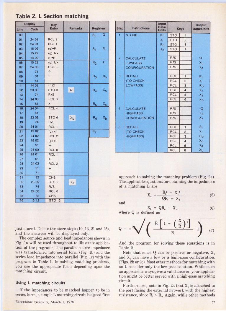
Table 2. L Section matching Display Key
Line Code Entry Remarks Registers
00 Ro Q
01 24 02 RCL 2
02 24 01 RCL 1
03 15 09 (g)•P A1 Ai
04 15 22 (g) 1/x
05 14 09 (f)•R
06 15 22 (g) 1/x R2 xi
07 24 03 RCL 3
08 71
09 01 1 R3 Ro
10 41 -
11 14 02 (f)/X
12 23 00 STO 0 a R4 Xo 13 74 R/S
14 2403 RCL 3
15 61 x ~ Xa 16 24 04 RCL 4
17 41 -
18 2306 STO 6 xb Rs xb 19 74 R/S
20 24 01 RCL 1
21 15 02 (g) x' R7 22 24 02 RCL 2 23 ' 15 02 (g) x' 24 51 + 25 24 00 RCL 0
26 24 01 RCL 1
27 61 x
28 24 02 RCL 2
29 51 -+ 30 71
31 32 CHS
32 23 05 STO 5 Xa 33 74 R/S
34 24 00 RCL 0
35 32 CHS
36 13 12 GTO 12
just stored. Delete the store steps (10, 13, 21 and 25), and the answers will be displayed only .
The complex source and load impedances shown in Fig. la will be used throughout to illustrate application of the programs. The parallel source impedance was transformed into serial form (Fig. lb) and the series load impedance into parallel (Fig. le) with the program in Table 1. In solving matching problems, you use the appropriate form depending upon the matching circuit.
Using L matching circuits
If the impedances to be matched happen to be in series form, a simple L matching circuit is a good first
EL ECTRON IC D ESIG N 5, March I, 1978
Input Output Step Instructions Data/ Keys Data/Units Units
1 STORE Ri STO 1
Xi STO 2
Ao STC 3
Xo STO 4
2 CALCULATE R/S a LO WP ASS R/S xb
CONFIGURATION R/S Xa
3 RECALL RCL 1 Ai (TO CHECK RCL 2 Xi LOWPASS) RCL 3 Ao
RCL 4 Xo RCL 5 Xa RCL 6 Xb
4 CALCULATE R/S -Q
HIGHPASS R/S Xb
CONFIGURATION R/S Xa
5 RECALL RCL 1 Ri
(TO CHECK RCL 2 Xi
HIGHPASS) RCL 3 Ro
RCL 4 Xo
RCL 5 Xa
RCL 6 Xb
approach to solving the matching problem (Fig. 2a). The applicable equations for obtaining the impedances of a 111atching L are
QRi +Xi and
Xb = QRo where Q is defined as
(5)
(6)
(7)
And the program for solving these equations is in Table 2.
Note that since Q can be positive or negative, Xa and Xb can have a low or a high-pass configuration. (Figs. 2b or 2c). Most other methods for matching with an L consider only the low-pass solution. While such an approach always gives a valid answer, your application might be better served with a high-pass matching circuit.
Furthermore, note in Fig. 2a that Xa is attached to the port facing the external network with the highest resistance, since Ri > R0 • Again, while other methods
57
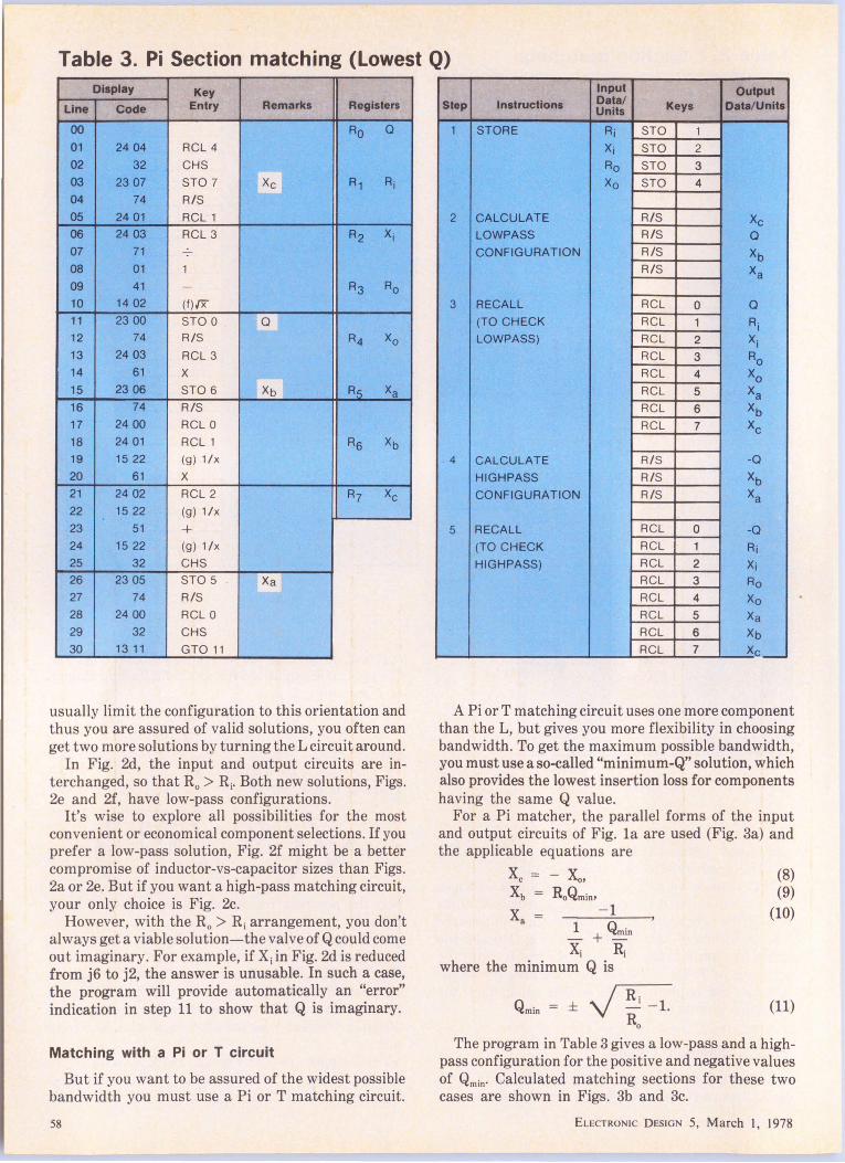
Table 3. Pi Section matching (Lowest Q) Display Key
Line COcle Entry Remark• Registers
00 Ro 0 01 24 04 RCL 4
02 32 CHS
03 23 07 STO 7 Xe R1 Ri 04 74 R/S
05 24 01 RCL1
06 24 03 RCL 3 R2 Xi 07 71
08 01 1
09 41 - R3 Ro 10 14 02 (f){X
11 23 00 STO 0 Q
12 74 R/S R4 Xo 13 24 03 RCL 3
14 61 x
15 23 06 STO 6 Xb R__s_ Xa 16 74 R/S
17 24 00 RCL 0
18 24 01 RCL 1 R5 xb 19 15 22 (g) 1/x
20 61 x
21 24 02 RCL 2 R1 Xe 22 15 22 (g) 1/x
23 51 + 24 15 22 (g) 1/x
25 32 CHS
26 23 05 STO 5 Xa 27 74 R/S
28 24 00 RCL 0
29 32 CHS
30 13 11 GTO 11
usually limit the configuration to this orientation and thus you are assured of valid solutions, you often can get two more solutions by turning the L circuit around.
In Fig. 2d, the input and output circuits are interchanged, so that R0 > Ri. Both new solutions, Figs. 2e and 2f, have low-pass configurations.
It's wise to explore all possibilities for the most convenient or economical component selections. If you pref er a low-pass solution, Fig. 2f might be a better compromise of inductor-vs-capacitor sizes than Figs. 2a or 2e. But if you want a high-pass matching circuit, your only choice is Fig. 2c.
However, with the R0 > Ri arrangement, you don't always get a viable solution-the valve of Q could come out imaginary. For example, if Xi in Fig. 2d is reduced from j6 to j2, the answer is unusable. In such a case, the program will provide automatically an "error" indication in step 11 to show that Q is imaginary.
Matching with a Pi or T circuit
But if you want to be assured of the widest possible bandwidth you must use a Pi or T matching circuit.
58
Input Output Step ln1tructlon1 Data/ Keys Data/Units Units
1 STORE Ri STO 1
Xi STO 2
Ro STO 3
Xo STO 4
2 CALCULATE R/S Xe LOWPASS R/S 0 CONFIGURATION R/S xb
R/S Xa
3 RECALL RCL 0 0 (TO CHECK RCL 1 Ri LOWPASS) RCL 2 xi
RCL 3 Ro RCL 4 XO RCL 5 Xa RCL 6 xb RCL 7 Xe
4 CALCULATE R/S -0
HIGHPASS R/S xb CONFIGURATION R/S Xa
5 RECALL RCL 0 -0 (TO CHECK RCL 1 Ri HIGHPASS) RCL 2 Xi
RCL 3 Ro RCL 4 Xo RCL 5 Xa RCL 6 Xb RCL 7 Xe___.
A Pi or T matching circuit uses one more component than the L, but gives you more flexibility in choosing bandwidth. To get the maximum possible bandwidth, you must use a so-called "minimum-Q" solution, which also provides the lowest insertion loss for components having the same Q value.
For a Pi matcher, the parallel forms of the input and output circuits of Fig. la are used (Fig. 3a) and the applicable equations are
Xe = - Xo, Xb R0Qmi01
- 1 x = a ~ + Qmin Xi Ri
where the minimum Q is
Qmin=±~ Ro
(8) (9)
(10)
(11)
The program in Table 3 gives a low-pass and a highpass configuration for the positive and negative values of Qmin· Calculated matching sections for these two cases are shown in Figs. 3b and 3c.
EL ECTRONIC DESIGN 5, March I, 1978
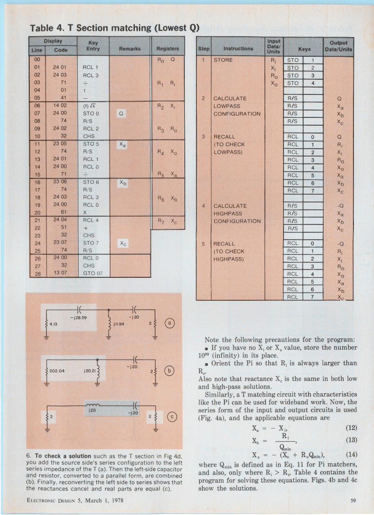
Table 4. T Section matching (Lowest Q) Display Key
Line Code Entry Remarks Registers
00 Ro Q
01 24 01 RCL 1
02 24 03 RCL 3 03 71 R1 Ri 04 01 1 05 41 -
06 14 02 (tJ rx R2 Xi 07 24 00 STO 0 Q
08 74 R/ S
09 24 02 RCL 2 R3 Ro 10 32 CHS
11 23 05 STO 5 Xa 12 74 R/S R4 Xo 13 24 01 RCL 1
14 24 00 RCL 0
15 71 R~ Xa
16 23 06 STO 6 xb 17 74 R/ S
18 24 03 RCL 3 R5 xb 19 24 00 RCL 0
20 61 x 21 24 04 RCL 4 R7 Xe 22 51 + 23 32 CHS
24 23 07 STO 7 Xe
25 74 R/ S
26 24 00 RCL 0
27 32 CHS
28 13 07 GTO 07
r~,, -11 0 3 j ll.94
':"
l"' ~ '"'} I~ -J W '• G
'VV'V'
I~ i' J20
-JW ' • 0
6. To check a solution such as the T section in Fig 4d, you add the source side's series configuration to the left series impedance of the T (a). Then the left-side capacitor and resistor, converted to a paral lel form, are combined (b). Finally, reconverting the left side to series shows that the reactances ca ncel and real parts are equal (c).
ELECTRONIC D ESIGN 5, March I, 1978
Input Output Step Instructions Data/ Keys Data/Units Units
1 STORE Ri STO 1
Xj STO 2
Ro STO 3
Xo STO 4
2 CALCULATE R/S Q
LOWPASS R/S Xa CONFIGURATION R/ S xb
R/ S Xe
3 RECALL RCL 0 Q
(TO CHECK RCL 1 Ri LOWPASS) RCL 2 Xi
RCL 3 Ro RCL 4 Xo RCL 5 Xa RCL 6 xb RCL 7 Xe
4 CALCULATE R/ S -Q
HIGHPASS R/ S Xa
CONFIGURATION R/ S xb R/ S Xe
5 RECALL RCL 0 -Q
(TO CHECK RCL 1 Ri HI GHPASS) RCL 2 Xi
RCL 3 Ro RCL 4 Xo RCL 5 Xa RCL 6 xb RCL 7 Xe .-
Note the following precautions for the program: • If you have no Xi or X 0 value, store the number
1099 (infinity) in its place. • Orient the Pi so that Ri is always larger than
Ro. Also note that reactance Xe is the same in both low and high-pass solutions.
Similarly, a T matching circuit with characteristics like the Pi can be used for wideband work. Now, the series form of the input and output circuits is used (Fig. 4a), and the applicable equations are
- xi, Ri
---, Qmin
Xe - (Xo + Ro~in),
(12)
(13)
(14)
where Qmin is defined as in Eq. 11 for Pi matchers, and also, only where Ri > R0 • Table 4 contains the program for solving these equations. Figs. 4b and 4c show the solutions.
59

Table 5. Pi Section matching (Higher selectivity) Display Key
Line Code Entry Remarks Registers
()() Ro 0 01 24 00 RCL 0 02 24 01 RCL 1 03 71 -;- R1 Ri 04 2402 RCL 2 05 15 22 (Q) 1/x 06 51 + R2 Xi 07 15 22 (g) 1 /x 08 32 CHS 09 23 05 STO 5 Xa R3 Ro 10 74 R/S 11 24 00 RCL 0 12 15 02 (g) x• A4 Xo 13 01 1 14 51 + 15 23 06 STO 6 R5 Xa 16 24 03 RCL 3 17 61 x 18 24 01 RCL 1 R5 xb 19 71 20 01 1 21 41 - R1 Xe 22 14 02 (t)IX
23 23 07 STO 7 24 24 00 RCL 0 25 51 + 26 24 01 RCL1 27 61 x 28 24 06 RCL 6 29 71 30 23 06 STO 6 Xb 31 74 R/S 32 24 07 RCL 7 33 24 03 RCL3 34 71 35 24 04 RCL4 36 15 22 (g) 1/x 37 51 + 38 15 22 (g) 1/x 39 32 CHS 40 23 07 STO 7 Xe 41 74 R/S 42 24 00 RCL 0 43 32 CHS 44 23 00 STO 0 45 13 02 GTO 02
However, additional solutions are possible with Pi and T matching circuits with larger Qs. Where an L matcher has at most four solutions, both Pi and T matchers can have almost unlimited numbers, depending on your choice of Q.
You can design Pi and T circuits for almost any
60
Input Output Step Instructions Data/ Keys Data/Units Units
1 STORE 0 STO 0 Rj STO 1 Xi STO 2 Ro STO 3 Xo STO 4
2 CALCULATE R/S Xa LOWPASS R/S Xb CONFIGURATION R/S Xe
3 RECALL RCL 0 Q
(TO CHECK RCL 1 Ri LOWPASS) RCL 2 xi
RCL 3 Ro RCL 4 Xo RC L 5 Xa RCL 6 xb RCL 7 Xe
4 CALCULATE R/S Xa HIGHPASS R/S xb CONFIGURATION R/S Xe
5 RECALL RCL 0 -Q
(TO CHECK RCL 1 Ri HIGHPASS) RCL 2 Xi
RCL 3 Ro RCL 4 Xo RCL 5 Xa RCL 6 xb RCL 7 Xe
desired selectivity higher than that obtained in the "minimum-Q" calculations. The L matcher's Q, however, is fixed by the input and output impedances.
For a Pi ref er back to Fig. 3a and apply the following equations:
x = a 1 (15)
l+Q2 (16)
x = c 1
(17)
ELECTRONIC DESIGN 5, March I, 1978
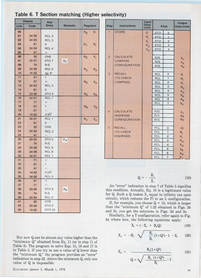
Table 6. T Section matching (Higher selectivity) Display Key
Line Code Entry Remarks Registers
()() Ro a 01 24 ()() RCL 0 02 24 03 RCL 3 03 61 x R1 Ai 04 24 04 RCL 4 05 51 -+ 06 32 CHS R2 xi 07 23 07 STO 7 Xe 08 74 R/S 09 24 ()() RCL 0 R3 Ro 10 15 02 (g ) x2 11 01 1 12 51 -+ R4 Xo 13 24 03 RCL 3 14 61 x 15 23 06 STO 6 R5 Xa 16 24 01 RCL 1 17 71 18 01 1 R5 xb 19 41 -20 14 02 (f)fx
21 24 01 RCL 1 R7 Xe 22 61 x 23 32 CHS 24 24 02 RC L2 25 41 -26 23 05 STO 5 Xa 27 74 R/S 28 24 06 RCL 6 29 24 06 RCL 6 30 24 01 RCL 1 31 71 32 01 1
33 41 -
34 14 02 (f)/X
35 24 ()() RCL 0 36 51 +
37 71 38 23 06 STO 6 Xb 39 74 R/S 40 24 00 RCL 0 41 32 CHS 42 23 00 STO 0 43 13 02 GTO 02
But now Q can be almost any value higher than the "minimum Q" obtained from Eq. 11 (or in step 11 of Table 3). The program to solve Eqs. 15, 16 and 17 is in Table 5. If you try to use a value of Q lower than the "minimum Q," the program provides an "error" indication in step 22. Above the minimum Q, only one value of Q is impossible:
ELECTRONIC DESIGN 5, March I, 1978
Input Output Step Instructions Data/ Keys Date/Units Units
1 STORE a STO _Q_
Ri _s_IQ_ __1_
xi STO 2
Ro STO 3 ~ XO STO 4
2 CALCULATE R/S Xe LOWPASS R/S Xa CONFIGURATION R/ S xb
3 RECALL RCL 0 a (TO CHECK RCL 1 Ai LOWPASS) RCL 2 xi
RCL 3 Ro RCL 4 Xo RCL 5 Xa RCL 6 xb RCL 7 Xe
4 CALCULATE R/S Xe HIGHPASS R/S Xa CONFIGURATION R/S Xb
5 RECALL RCL 0 -Q (TO CHECK RCL 1 Ai HIGHPASS) RCL 2 xi
RCL 3 Ro RCL 4 Xo RCL 5 Xa RCL 6 xb RCL 7 Xe_
Q=-~ X;
(18)
An "error" indication in step 7 of Table 5 signifies this condition. Actually, Eq. 18 is a legitimate value for Q. Such a Q makes Xa equal to infinity (an open circuit), which reduces the Pi to an L configuration.
If, for example, you choose Q = 10, which is larger than the "minimum Q" of 1.22 obtained in Figs. 3b and 3c, you get the solutions in Figs. 3d and 3e.
Similarly, for a T configuration, refer again to Fig. 4a where now, the following equations apply:
Xa
x., = ( - x., + Ro Q)
Ro (l+Q2)-l -~ R;
(19)
(20)
(21)
61
4000 Series MICROTEMP "' thermal cutoff in electric space heater
Guard your products and profits with MICROTEMP®
thermal cutoffs This electric space heater is designed for safety .. . using the low-cost , yet precise 4000 Series M ICROTEM p ~ thermal cutoff. It not only protects those who use the heater, but also the good name of those who make and sell it.
If the heater's thermostat fails - or if the unit overheats for any reason - the MICROTEMP• promptly cuts off the power. Before the appliance can be used again. the fault must be corrected and the MICROTEMP® replaced.
The MICROTEMP® thermal cutoff is available for a w ide range of design applications with cut-
off ratings from 1 36 to 468° F (60 to 240° CJ and operating accuracy within + O - 4°C.
Millions of our Ml CROTEMP~' thermal cutoffs are now protecting hundreds of successful products .
We offer assorted termin at ions, mounting packages, and insulation to suit your design and production needs. Write or call us for your test samples and data.
(ij]!)
62
MICRO DEVICES
I- DIVISION OF EMERSON ELECTRIC CO . ~ 1881 SOUTHTOWN BLVD. - DAYTON OH 45439 513-294-0581
liMliFISDN ~
CIRCLE NUMBER 27
And the program for their solution is in Table 6. As in the case of a Pi, the value of Q can be any
value higher than that obtained in program-step 7 of Table 4 for a "minimum-Q" T.
If you again choose Q = 10, as was done for the Pi, which is larger than the "minimum Q" of 1.03 obtained for the solutions in Figs. 4b and 4c, you get the solutions in Figs. 4d and 4e.
For values of Q smaller than the "minimum Q," the program provides an "error" indication in step 20. Note that for Q = X0 /R0 , Xe becomes zero, and the T configuration becomes a simple L, as was the case with the Pi configuration under the conditions of Eq. 18.
Handling special cases
All sources and loads, however, don't necessarily contain reactive components. When either the input or output impedances, or both, have no capacitance or inductance, the number of possible matching solutions is reduced. Fig. 5a is an example of no reactive component in the output circuit and the four L solutions you can get for it. But if you attempt to obtain Pi and T "minimum-Q" solutions for the matching circuits, they will come out identical to the four L solutions.
For larger Qs (higher selectivity), the number of Pi and T solutions is virtually unlimited. But with no reactances in both the source and load, only two L solutions are obtained (Fig. 5b).
Verify with parallel/series transformations
Finally, you can easily verify that your matching circuit has no errors. You merely use the series/parallel transformations several times and add the resultant reactances. The input and output resistances should become equal, and all reactances should cancel.
As an example, insert Fig. 4d into Fig. 4a and add the series reactances. You get Fig. 6a. Convert either side, say, the left side, to a parallel configuration and combine the two parallel reactances to get Fig. 6b. Now convert the left-side parallel configuration of Fig. 6b to series and you get Fig. 6c, which shows that you have satisfied the conjugate bilateral matching requirements-the reactances cancel and resistances match ...
Bibliography
Charest, C. N., "Impedance Matching Can Be Easy," EDN, Jan. 1, 1969, pp. 48-51.
Henning, H. B., "Impedance Matching by Graphical Techniques," Microwave Journal, June, 1977, pp. 112-114.
Johnson, R. , "Do Complex Impedance Matching in Seven Easy Steps," EDN, March 20, 1974, pp. 73-75.
Nardin, R., "Impedance Matching Made Easy: a 3-Step Uncomplicated Method," Electronic Design, Aug. 16, 1975, pp. 76-78.
Acknowledgement
The author wishes to thank Mr. James R. Jackson for stimulating and constructive discussions on the above subject.
ELECTRONIC DESIGN 5, March I, 1978

Here's yourgolden opportunity to meet our better half.
Our better half. Tl's new H4 Series edge board connector half of a PC board/edgeboard connector system. It's today's best connector value because we made it better in so many ways.
Better functional and dimensional interchangeability, better design and construction, better porosity and wear characteristics, and better price and delivery advantages.
But we've done ourselves even one better. Specifically, our better half uses more gold to
r-----------------------, Texas Instruments Incorporated Mail Station 2-16, Attleboro, MA 02703 I'd like to meet Tl's better half. Please send information on your new H4 Series .156" x. 200" Edge board Connector.
D For an immediate application.
D Please contact me directly. D For reference.
Name _____________ _
I Title _____________ _
I : Company ____________ _
I I Areacode __ Phone Ext ___ _
I I Address Mail Station ___ _
I I City State ___ Zip __ _
I ED L-----------------------~
get more performance and reliability. And yet . there is a substantial cost savings. The reason is our proprietary clad metal technology.
Cladding permits gold to be concentrated only where it is needed-at the contact mating surface -the area critical to contact reliability.
Therefore, significant cost savings can be realized in terms of labor and precious metal consumption. This savings is being passed on to you in the form of a lower price. Or if you prefer, a bigger value.
After all, TI pioneered gold inlay. And we also make extremely high performance connectors. So it was only natural to put them together in our better half.
If you haven't met our better half yet, don't miss out on this truly golden opportunity. Return the coupon above or call Texas Instruments ~ Connector Systems Marketing today. (617) 222-2800, Extension 268 or 269.
TEXAS INSTRUMENTS © 1977 Texas Instruments INCORPORATED
Eu,crnoN 1c DESIGN 5, March I, 1978 63
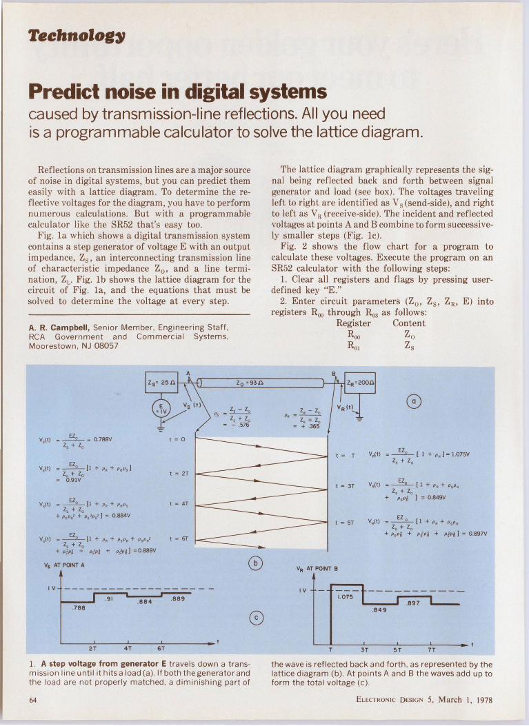
Teehnolog~
Predict noise in digital systems caused by transmission-line reflections. All you need is a programmable calculator to solve the lattice diagram.
Reflections on transmission lines are a major source of noise in digital systems, but you can predict them easily with a lattice diagram. To determine the reflective voltages for the diagram, you have to perform numerous calculations. But with a programmable calculator like the SR52 that's easy too.
Fig. la which shows a digital transmission system contains a step generator of voltage E with an output impedance, Zs , an interconnecting transmission line of characteristic impedance Z0 , and a line termination, ZL. Fig. lb shows the lattice diagram for the circuit of Fig. la, and the equations that must be solved to determine the voltage at every step.
A. R. Campbell, Senior Member, Engineering Staff, RCA Government and Commercial Systems, Moorestown, NJ 08057
V5(t) = ~ = 0.788V t = 0 l 5 + l 0
V5(t) =~[! +PR + PRPs J l 5 +l0 t =2T
= 0.91V
V5(t) -~(l + p , + P, P, t = 4T l 5 + l 0
+ P, P, 2 + P52P.' ) = 0.884V
V,(t) = ~ [l + PR + PsP• + PsP.' t = 6T l 5 + l 0
+ P/ Pa + P/P~ + p~p~ J = o.aa9v
V5 AT POINT A
IV ------------------ -
.9 1 .884 .889
.788
2T 4T ST
lo • 93,n.
Ps = Zs - zo l 5 + l 0
= - .576
1. A step voltage from generator E travels down a transmission line until it hits a load (a). If both the generator and the load are not properly matched , a diminishing part of
64
The lattice diagram graphically represents the signal being reflected back and forth between signal generator and load (see box). The voltages traveling left to right are identified as Vs (send-side), and right to left as V R (receive-side). The incident and reflected voltages at points A and B combine to form successively smaller steps (Fig. le).
Fig. 2 shows the flow chart for a program to calculate these voltages. Execute the program on an SR52 calculator with the following steps:
1. Clear all registers and flags by pressing userdefined key "E."
2. Enter circuit parameters (Z0 , Z8 , ZR, E) into registers R00 through R03 as follows:
PR =lR -lo
l , + l 0 = + .365
Register Content Roo Zo Roi Zs
t = T
t = 3T
t = ST
VR(t) =~ ( 1 + pR )=l.075V l , + l 0
VR(t) = ~ ( 1 + PR + PsPR l 5 + l 0
+ P, Pa 1 = o.a49V
VR(t) = ~ (1 +P R + PsPR l 5 + l 0
+ P, Pa + P/ Pa + P/P~ I = o.B97v
VR AT POINT 8
I V 1.075
.897 .849
T 3T 5T 7T
the wave is reflected back and forth , as represented by the lattice diagram (b). At points A and B the waves add up to form the total voltage (c).
ELECTRONIC DESIGN 5, March I, 1978

E Z0 (1+p1 l
Zs +Zo • ___l_
I+ Ps SUM Ro7
RCL R07
HLT
SET FLAG 3
E Zo(l+f'Bl
Zs +Zo
SUM R11
HLT
NO
NO
NO
Ro6 • PR SUM R 07
YES
YES
RIO • f. pR
SUM R II
RCL R11
HLT
2. The flow chart for calculating a lattice diagram consists of four segments. The user-defined keys determine which
ELECTRONIC DESIGN 5, March I, 1978
HLT
Zs -Zo Ps• ----Ro..
Zs +Zo
P - ZR -zo_ R - Z +z R05
R o
HLT
RESET REGISTERS
RESET FLAGS
H LT
will be executed: clear flags (E) calculate common factors (D), calculate send (A) and receive (8) voltages.
65
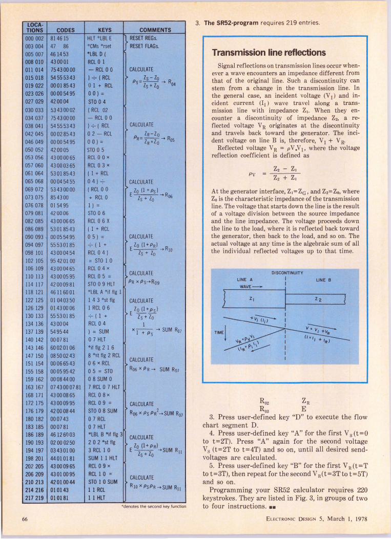
LOCA-TIONS CODES 000 002 8146 15 003 004 47 86 005 007 4614 53 008 010 430001 011 014 75430000 015 018 54555343 019 022 00018543 023 026 00005495 027 029 420004
030 033 53430002 034 037 75430000 038 041 54 55 53 43 042 045 00028543 046 049 000054 95 050 052 420005 053 056 43 00 00 65 057 060 43000365 061 064 53018543 065 068 0004 54 55 069 072 5343 00 00 073 075 85 43 00 076 078 015495 079 081 420006 082 085 43000665 086 089 53018543 090 093 . 000554 95 094 097 55530185 098 IOI 4300 04 54 102 105 95420100 106 109 43 0004 65 110 113 43000595 114 117 42000981 118 121 46116001 122 125 01 040350 126 129 01430006 130 133 55530185 134 136 430004 137 139 549544 140 142 0007 81 143 146 60020106 147 150 08 5002 43 151 154 00066543 155 158 00059542 159 162 00084400 163 167 07 43 00 07 81 168 171 43000865 172 175 43000995 176 179 42000844 180 182 0007 43 183 185 00 07 81 186 189 461261)03 190 193 02000250 194 197 03430100 198 201 44010181 202 205 43000965 206 209 43 010095 210 213 42010044 214 216 010143 217 219 010181
66
KEYS COMMENTS HLT *LBL E ~ RESET REGs. *CMs *rset RESET FLAGs. *LBL D ( RCL 0 1 -RCLOO CALCULATE l -:- ( RCL > Zs- Zo 0 1 + RCL
Ps=zz-+ R04 s + 0
0 0) =
STO 0 4 ( RCL 02 -RCLOO h--( RCL CALCULATE
0 2 - RCL > ZR-Zo 0 0) =
PR=---+ Ros ZR+Zo
STO 0 5 RCL 0 0 x
RCL 0 3 x
( 1 + RCL 04)-:- CALCULATE ( RCL 0 0 :> Zo (1 + Ps) + RCL 0 E z z -+ R06 s + 0
I) = STO 0 6 RCL 0 6 X ( I + RCL 0 5) = CALCULATE
-=-- ( 1 + > E Zo (I+ PR) R RCL 0 4) Zs + lo -+ 10
= STO I 0 RCL 0 4 x
RCL 0 5 = >CALCULATE
STO 0 9 HLT PR x Ps-+Rog
*LBL A *if fig I I 4 3 *st fig CALCULATE I RCL 0 6 Zo(l+p5) -:-- ( 1 + i> E zs+zo RCL 0 4 I ) = SUM x I + P s -+ SUM Ro7
0 7 HLT *ifflg 2 I 6 8 *st fig 2 RCL
CALCULATE 0 6 x RCL > 0 5 = STO Ros x PR-+ SUM Ro7
0 8 SUM 0 7 RCL 0 7 HLT RCL 0 8 x
RCL 0 9 = CALCULATE STO 0 8 SUM Ros x Ps PR
2-+ SUM Ro7
0 1 RCL 0 7 HLT *LBL B *if fig 3 CALCULATE 2 0 2 *st fig
> E Zo ( l + p R)-+ SUM R 3 RCL 1 0 SUM 1 1 HLT
Zs+ Zo 11
RCL 0 9 x
RCL 1 0 = CALCULATE
STO 1 0 SUM > 1 1 RCL R 10 x PsPR-+ SUM R11
1 1 HLT *denotes the second key function
3. The SR52-program requires 219 entries.
Transmission line reflections Signal reflections on transmission lines occur when
ever a wave encounters an impedance different from that of the original line. Such a discontinuity can stem from a change in the transmission line. In the general case, an incident voltage (V 1) and incident current (11) wave travel along a trans-mission line with impedance Z1. When they en-counter a discontinuity of impedance Z2, a reflected voltage V R originates at the discontinuity and travels back toward the generator. The incident voltage on line B is, therefore, V 1 + V R·
Reflected voltage V R = p V .V 1, where the voltage reflection coefficient is defined as
At the generator interface, Z1=Zc, and Z2=Zo, where Z0 is the characteristic impedance of the transmission line. The voltage that starts down the line is the result of a voltage division between the source impedance and the line impedance. The voltage proceeds down the line to the load, where it is reflected back toward the generator, then back to the load, and so on. The actual voltage at any time is the algebraic sum of all the individual reflected voltages up to that time.
DISCONTINUITY
LINE A I LINE B
WAVE-I
1 I Z1 Z2 l
Ro2 ZR Roa E
3. Press user-defined key "D" to execute the flow chart segment D.
4. Press user-defined key "A" for the first Vs (t=O to t=2T). Press "A" again for the second voltage Vs (t=2T to t=4T) and so on, until all desired send-voltages are calculated.
5. Press user-defined key "B" for the first V R (t=T to t=3T), then repeat for the second V R(t=3T to t=5T) and so on.
Programming your SR52 calculator requires 220 keystrokes. They are listed in Fig. 3, in groups of two to four instructions ...
ELECTRONIC DESIGN S, March I, 1978
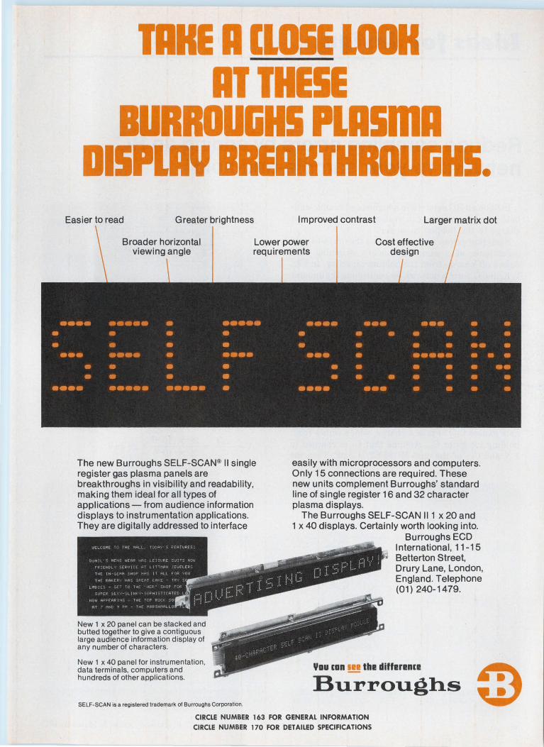
TARE A ELOSE LOOH AT THESE
BURROUliHS PLASmA DISPLAV BREAHTHROUliHS.
Easier to read Greater brightness
The new Burroughs SELF-SCAN® II single register gas plasma panels are breakthroughs in visibility and readability, making them ideal for all types of applications- from audience information displays to instrumentation applications. They are digitally addressed to interface
New 1 x 20 panel can be stacked and butted together to give a contiguous large audience information display of any number of characters.
New 1 x 40 panel for instrumentation, data terminals, computers and hundreds of other applications.
SELF- SCAN is a registered trademark of Burroughs Corporation.
Improved contrast Larger matrix dot
easily with microprocessors and computers. Only 15 connections are required. These new units complement Burroughs' standard line of single register 16 and 32 character plasma displays.
The Burroughs SELF-SCAN 111 x 20 and 1 x 40 displays. Certainly worth looking into.
Burroughs ECO International, 11-15
• Betterton Street, Drury Lane, London, England. Telephone (01) 240-1479.
Yau EDD IH thl! dlffl!rl!Dl:I!
Burroughs CIRCLE NUMBER 163 FOR GENERAL INFORMATION
CIRCLE NUMBER 170 FOR DETAILED SPECIFICATIONS
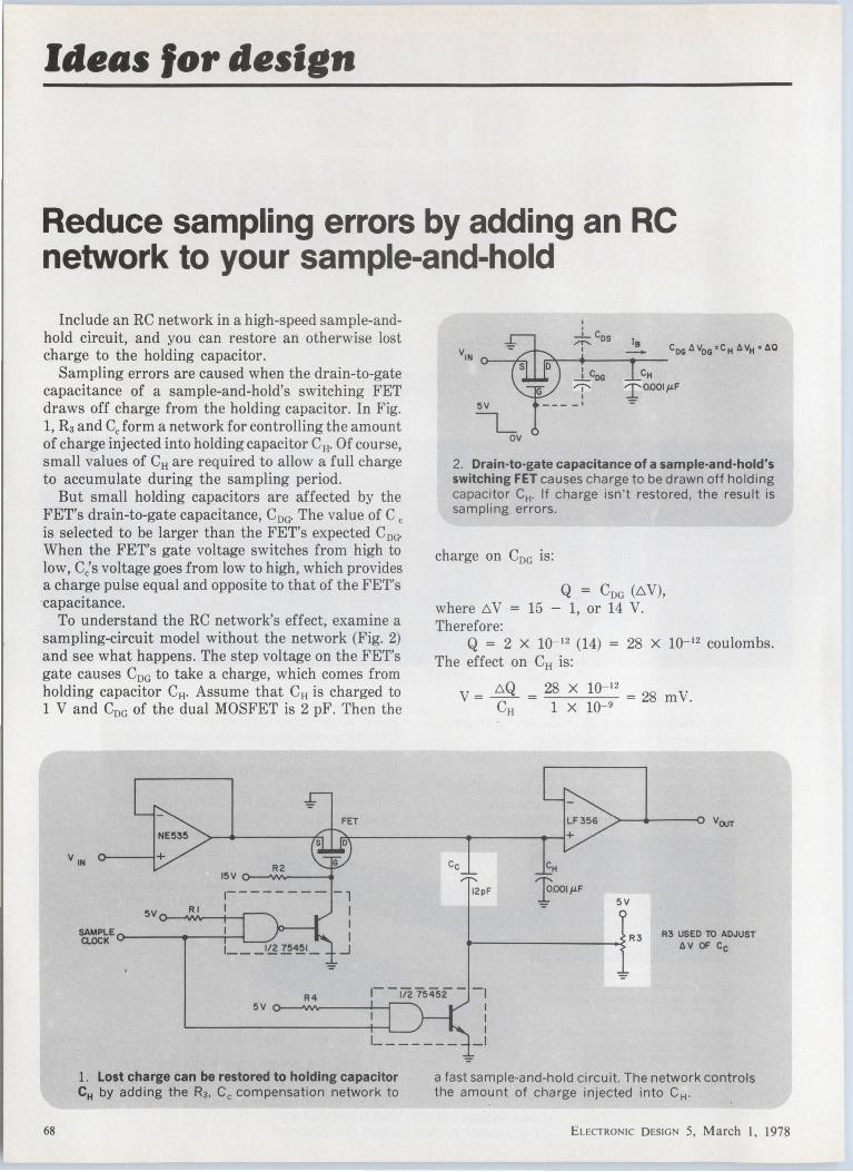
Ideas for design
Reduce sampling errors by adding an RC network to your sample-and-hold
Include an RC network in a high-speed sample-andhold circuit, and you can restore an otherwise lost charge to the holding capacitor.
Sampling errors are caused when the drain-to-gate capacitance of a sample-and-hold's switching FET draws off charge from the holding capacitor. In Fig. 1, R3 and Cc form a network for controlling the amount of charge injected into holding capacitor CH. Of course, small values of CH are required to allow a full charge to accumulate during the sampling period.
But small holding capacitors are affected by the FET's drain-to-gate capacitance, Cnc· The value of Cc is selected to be larger than the FET's expected C0 c;.
When the FET's gate voltage switches from high to low, c;s voltage goes from low to high, which provides a charge pulse equal and opposite to that of the FET's ·capacitance.
To understand the RC network's effect, examine a sampling-circuit model without the network (Fig. 2) and see what happens. The step voltage on the FET's gate causes Cnc to take a charge, which comes from holding capacitor CH. Assume that CH is charged to 1 V and C0 c of the dual MOSFET is 2 pF. Then the
68
V IN
FET
R2
1- - - - - - - - - ,
5V I I 0--JV>h--+---l~ I
I _J
1. Lost charge can be restored to holding capacitor CH by adding the R3, Cc compensation network to
5V
I_ OV
I I
~Cos I
J...coo """ I
--- -·
2. Drain-to-gate capacitance of a sample·and·hold's switching FET causes charge to be drawn off holding capacitor CH. If charge isn't restored, the result is sampling errors .
charge on Cnc is:
Q = CDG (Ci. V), where ei.V = 15 - 1, or 14 V. Therefore:
Q = 2 x 10- 12 (14) = 28 x 10- 12 coulombs. The effect on CH is:
Cc
V = ei.Q = 28 x 10-12
CH 1 X lQ-9 = 28 mV.
>----<---o VOUT
12pF 5V
.----------<R3 R3 USED TO ADJUST
AV OF Cc
a fast sample-and-hold circuit. The network controls the amount of charge injected into CH.
ELECTRONIC DESIGN 5, March I, 1978
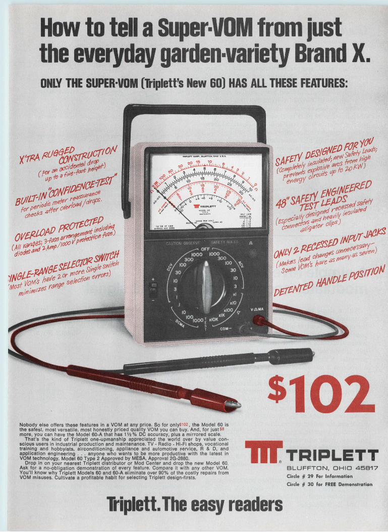
How to tell a SUper·VOM from just the everyday garden-variety Brand X. ONLY THE SUPER·VOM (Triplett's New 60) HAS ALL THESE FEATURES:
Nobody else offers these features in a VOM at any price. So for only$102 , the Model 60 is the safest, most versatile, most honestly priced quality VOM you can buy. And, for just $8 more, you can have the Model 60-A that has 1 Y2 % DC accuracy, plus a mirrored scale.
That's the kind of Triplett one-upmanship appreciated the world over by value conscious users in industrial production and maintenance. TV - Radio - Hi-Fi shops, vocational training and hobbyists, airconditioning, appliance and automotive $ervice, R & D, and application engineering . .. anyone who wants to be more productive with the latest in VOM technology. Model 60 Type 2 Approved by MESA, Approval 2G-2880.
Drop in on your nearest Triplett distributor or Mod Center and drop the new Model 60. Ask for a no-obligation demonstration of every feature. Compare it with any other VOM. You'll know why Triplett Models 60 and 60-A eliminate over 90% of the costly repairs from VOM misuses. Cultivate a profitable habit for selecting Triplett design-firsts.
$102 - TRIPLETT
BLUFFTON, OHIO 45817
Circle # 29 For Information
Circle # 30 for FREE Demonstration
Triplett. The easy readers
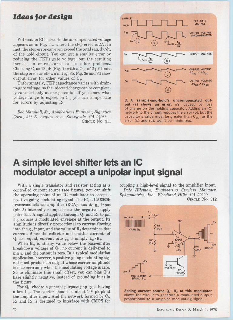
Ideas for design
Without an RC network, the uncompensated voltage appears as in Fig. 3a, where the step error is /':,. V. In fact, the step error can even exceed the total sag, dv/dt; of the hold circuit. You can get a smaller error by reducing the FET's gate voltage, but the resulting increase in on-resistance causes other problems. Choosing Cc as 12 pF (Fig. 1) with a CnG of 2 pF limits the step error as shown in Fig. 3b. Fig. 3c and 3d show output error for other values of Cc.
Unfortunately, FET capacitance varies with drainto-gate voltage, so the injected charge can be completely canceled only at one potential. If you know what voltage range to expect on CH? you can compensate for errors by adjusting R3.
Bob Marshall, Jr., A pplications Engineer, Signetics Corp., 811 E. Arques Ave., Sunnyvale, CA 94086.
CIRCLE No. 311
SAG I dv/dt • ....!...
CH
©
FET GATE lt'OLTAGE
OUTPUT VOLTAGE UNCOMPENSATED
OUTPUT VOLTAGE
OUTPUT VOLTAGE llQDG < llOcc
OUTPUT VOLTAGE dQDG >110cc
3 . A sample·and·hold's uncompensated out· put (a) shows an error, t::.V, caused by loss of charge on the holding capacitor. Adding an RC network to the circuit reduces the error (b), but the capacitor's value must be greater than CoG • or the error (c) and (d), won't be minimized.
A simple level shifter lets an IC modulator accept a unipolar input signal
With a single transistor and resistor acting as a controlled current source (see figure), you can shift the operating point of an IC modulator to accept a positive-going modulating signal. The IC, a CA3080E transconductance amplifier (RCA), has its &n input (pin 5) internally clamped near the negative-supply potential. A signal applied through Qi and R3 to pin 5 produces a modulated envelope at the output. Its amplitude is directly proportional to current flowing into the gm input, and the value of R3 determines that current. Since the collector and emitter currents of Qi are equal, current into gm is simply Em/R3.
When Em is at any value below the base-emitter breakdown voltage of Qi, no current is delivered to pin 5, and the output is zero. In a typical modulation application, however, a positive-going modulating signal must produce an output whose carrier amplitude is near zero only when the modulating voltage is zero. So to eliminate this small offset, you can bias Qi's base slightly negative, instead of grounding it as in the figure.
For Q1, choose a general purpose pnp type having a low Icbo· The carrier should be about 1-V pk-pk at the amplifier input. And the network formed by C1, R1 and R2 is designed to interface with CMOS for
70
coupling a high-level signal to the amplifier input. Dale Hileman, Engineering Services Manager,
Sphygmetrics, Inc. , Woodland Hills, CA 90290. CIRCLE No. 312
Cl ,____] 0.1 µ.F ..
CARRIER
MODULATING SIGNAL Em
Adding current source Qi, R3 to this modulator allows the circuit to generate a modulated output proportional to a unipolar modulating signal.
E LECTRONIC D ESIGN 5, March I, 1978

<714) 835·2751. <L A.J (213) 933·7256 • Sunnyvale. CA (408) 733-2424 • G11thersbur1. MO (301) 840·9490 •Houston. (713> 932·1130 • lrvina. TX (214) 296-4444 DATEL !UK> LTD-TEL. ANDOVER (0264) 51055 • OATEL SYSTEMS SARL 620·06·74 • DATELEK SYSTEMS GmbH (089) 77 60 95
• CIRCLE NUMBIR 31
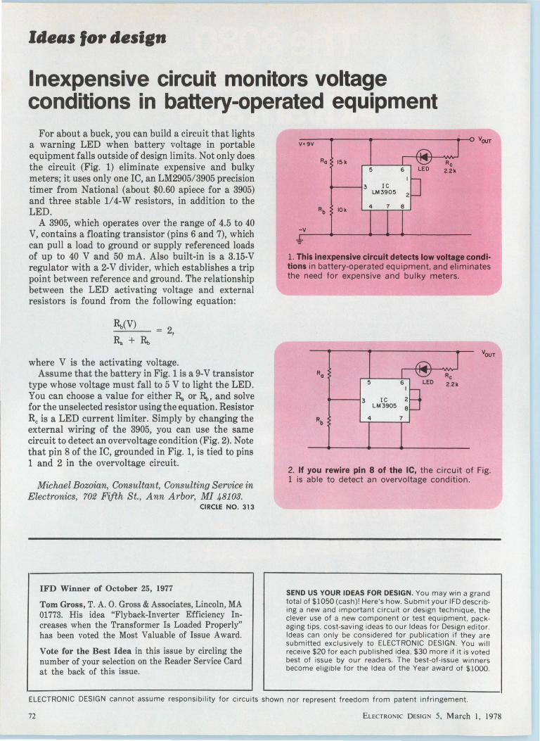
Ideas for design
Inexpensive circuit monitors voltage conditions in battery-operated equipment
For about a buck, you can build a circuit that lights a warning LED when battery voltage in portable equipment falls outside of design limits. Not only does the circuit (Fig. 1) eliminate expensive and bulky meters; it uses only one IC, an LM2905/3905 precision timer from National (about $0.60 apiece for a 3905) and three stable 1/4-W resistors, in addition to the LED.
A 3905, which operates over the range of 4.5 to 40 V, contains a floating transistor (pins 6 and 7), which can pull a load to ground or supply referenced loads of up to 40 V and 50 mA. Also built-in is a 3.15-V regulator with a 2-V divider, which establishes a trip point between reference and ground. The relationship between the LED activating voltage and external resistors is found from the following equation:
= 2,
where V is the activating voltage. Assume that the battery in Fig. 1 is a 9-V transistor
type whose voltage must fall to 5 V to light the LED. You can choose a value for either R,. or R.i. and solve for the unselected resistor using the equation. Resistor Re is a LED current limiter. Simply by changing the external wiring of the 3905, you can use the same circuit to detect an overvoltage condition (Fig. 2). Note that pin 8 of the IC, grounded in Fig. 1, is tied to pins 1 and 2 in the overvoltage circuit.
Michael Bozoian, Consultant, Consulting Service in Electronics, 702 Fifth St., Ann Arbor, MI 48103.
CIRCLE NO. 313
IFD Winner of October 25, 1977
Tom Gross, T. A. 0. Gross & Associates, Lincoln, MA 01773. His idea "Flyback-Inverter Efficiency Increases when the Transformer Is Loaded Properly" has been voted the Most Valuable of Issue Award.
Vote for the Best Idea in this issue by circling the number of your selection on the Reader Service Card at the back of this issue.
Ra 15k
-----13
-v
5 6
IC LM3905 2
4 8
LED Re 2.2k
1. This Inexpensive circuit detects low voltage conditions in battery-operated equ ipment, and eliminates the need for expensive and bulky meters.
5 6 I
----13 IC 2 LM3905 8
4 7
Re LED 2.2k
2. If you rewire pin 8 of the IC, the circu it of Fig. 1 is able to detect an overvoltage condition .
SEND US YOUR IDEAS FOR DESIGN. You may win a grand total of $1050 (cash)! Here's how. Submit your IFD describing a new and important circuit or design technique. the clever use of a new component or test equipment, packaging tips. cost-saving ideas to our Ideas for Design editor. Ideas can only be considered for publication if they are submitted exclusively to ELECTRONIC DESIGN. You will receive $20 for each published idea . $30 more if it is voted best of issue by our readers. The best-of-issue winners become eligible for the Idea of the Year award of $1000.
ELECTRONIC DESIGN cannot assume responsibility for circuits shown nor represent freedom from patent infringement.
72 ELECTRONIC DESIGN 5, March I, 1978
Portable Weather Station
Oceanographer's Probe
Geophysical Monitor Event-triggered recording to save tape,
batteries and for fast computer data-spotting
Traffic or Noise Level Logger
Accepts analog or digital (event counter) inputs
\Jo outside power needed, runs on internal batteries Log your
Analog Data on Digital Tape
Cassettes ...
Biomedical Data Recorder
Optional 5 mV differential amplifier for low level detectors.
Pollution and Environmental
Logger Crystal CMOS clock
can command different scan periods
DATEL'S Dl:2 DATA LOGGER An Important New Tool -· Choose Datel's DL-2 Cassette Data Logger for .Jnattended standby recording of multi -channel , slowly-varying analog samples. The DL -2 samples up to 64 high level or low level analog channels , digitizes them to 12-bit binary coding and records them on a cassette at 5 samples per second. Also recorded are a one year calendar clock with one second resolution produced by an internal CMOS crystal oscillator. And external digital samples (up to 36 bits) may be recorded at any time. Analog scans are started automatically from a preset front panel scan timer with intervals from one second up to 30 hours.
The all -CMOS electronics of the DL-2 and steppermotor transport consume only one watt while recording and microwatts while powered -down between scans. A set of batteries in the front cover will power the DL-2 for a year or longer, recording up to 120,000 samples.
Or external +12VDC or AC power may be used.
The DL-2 features a high-quality instrumentation amplifier (down to ±5mV full scale input) and weatherproof housing and connectors suitable for -1 0°C to +60°C environments . (-40° C optional)
A companion DL-2R Cassette Reader offers a convenient playback front end to a minicomputer, microprocessor, TTY, CRT terminal or modem telephone coupler.
1020 Turnpike Street, Canton, MA 02021 TEL (617) 828-8000 TWX: 710-348-0135
Santa Ana 17 14) 835·2751 (l A I (213) 933 7256 • Sunnyvale CA (408) 733-2424 • Gaithersburg . MD (301) 840-9490 •Houston. (7 13) 932· 1130 •Irving. TX (214) 256·4444 OVER SEAS DA TEL !UK) LTD - TEL ANDOVE R (0264) 51055 • DA TEL SYSTEMS SARL 620·06·74 • DATE LEK SYSTEMSGmbH (089) 77·60·95
CIRCLE NUMBER 32

International teehnolog~
Multiplexer does big job with simple components
A new multiplexer with a pulse repetition rate of 5 Gbit/s is made of simple components-yet it can be used in high-capacity fiber-optic communications systems in place of complex optical multiplexing techniques currently being developed.
In the multiplexer, developed at the Chalmers University of Technology in Goteborg, Sweden, an oscillator drives a step-recovery diode to produce a lowduty-cycle pulse train. The pulse train is then passed through a power divider and split into a number of microstrip lines, each of which can be individually switched on and off by p-i-n diodes. The switched outputs are passed through microstrip delay lines, then combined by an OR gate (a passive circuit that is the inverse of the power divider).
The delay lines are adjusted so that the delay for the nth channel is tn -(n -1) t;n where tPis the period of the input-pulse train. The output is a train of evenly spaced pulses with a pulserepetition frequency equal to n times the input PRF.
Multiplexers have been constructed
AMPL
showing a 5-Gbit/s output PRF and signal-to-distortion ratio of 12 dB. But the Chalmers developers believe that 10-Gbit/s can be achieved and the signal-to-distortion ratio improved using attenuators ahead of the p-i-n diodes.
Backward laser radiation is detectable and usable The backwards-emitted light of a
semiconductor is useful as a signal for the AGC circuitry that stabilizes a laser's output power. But commercial laser diodes are usually packaged so that the backwards-emitted laser light can't be detected by an axially positioned fiber. Now a simple technique, developed by R. Bosch GmbH Geschafts bereich Fernsehanlagen in Darmstadt, W. German, allows the backward laser radiation to be picked up and fed to the AGC system.
A 45° face is formed at the end of a fiber, which is positioned with its axis perpendicular to the laser light, and its sloping end facing away from the laser.
74
A 10% coupling efficiency, adequate for AGC applications, can be achieved by cutting a plastic fiber with a blade. The coupling efficiency of silica fibers
has not yet been measured. But careful polishing of the end faces may achieve coupling efficiencies of 70 to 90%.
Fiber-optic microphone has wide dynamic range
Optical fibers have been used almost exclusively for data-communications applications. But a fiber-optic microphone with a wide dynamic range has been demonstrated at London's University College.
The microphone is the result of investigations of the interaction between coherent light propagating along a fiber and acoustic waves incident on it. In a fiber, small changes in the refractive index phase-modulate light being sent through it. An acoustic wave striking the fiber causes pressure variations that then modulate its refractive index. Because optical wavelengths are small, appreciable phase shifts can be caused by low levels of acoustic power.
Typically, the pressure sensitivity of a single-mode silica or glass fiber is 6 X 10⁻⁵ rad/Nm2 where N is in Newtons. In experiments, a fiber 1 km long, wound to occupy a volume of only 10 cm3, detected a pressure change of 10- 6
Nim with 1 mW optical power at the detector converting phase modulation to audio signals. This is some 26 dB below the weakest sound that can be perceived by the human ear. The linear dynamic range is about 180 dB for a 1-m length of optical fiber.
The microphone's sensitivity is increased by increasing the optical power carried by the fiber. With 1 W of optical power, the limit for currently available fibers, acoustic powers below the threshold of hearing can be detected by only 30 m of fiber.
Inverter problem solved Size and weight problems of the
isolating transformer used in high power inverters is said to have been overcome by the use of high-frequency transformers in a technique developed by ERA Ltd. in England.
ELECTRONIC DESIGN 5, March I, 1978

complC!!te, 12-Bit Microcircuit Data Acquisition
System
121110 9
< ~ a :i MUX
ADDRESS OUT
• z
~ 48
6 8 19 16151413
>Im' lo < ~a l! 5 C3 a: a: a: a: ~ a: -' MUX a: ADDRESS IN
HDAS-16& HDAS-8
20
I~
Datel has it ...
rlrllr 41 4442 431817
8 ~8 ~~8 * -~ : · ~ ~ ~
:.'\D•\JEL Ill SYSTEMS.INC. DATA ACQUISITION SYSTEM
HDAS-18
MAOE IN USA
..,,. 16 Channels, Single-Ended (HDAS-16)
..,,. 8 Channels, Differential (HDAS-8)
Datel's HDAS-the first complete 12-bit data acquisition system in a single, miniature package. Using thin-film hybrid fabrication , it challenges modular data acquisition systems on performance and price . Its excellent performance and reliability are also available in versions for full MIL-Spec operation over - 55to + 125C. The HDAS 62-pin package measures only 2.3 x 1.4 x 0.24 inches (58 x 36 x 6 mm) .
..,,. 12 Bits Resolution
..,,. 50kHz Throughput Rate
..,,. Internal Instrumentation Amplifier
..,,. Three-State Data Outputs
..,,. Military and Commercial Temperature Range available
..,,. 62-pin Miniature Package
..,,. Priced at $295.00* (1-9) ·u.SA domestic prices only
1020 TURNPIKE STREET. CANTON . MASS. 02021 TEL (617)828-8000 / TWX : 710-348-0135 / TELEX : 924461
Santa Ana (714 )835-2751, (L.A ) (213)933-7256 • Sunnyvale. CA (408) 733-2424 • Gaithersburg. MD (301 )840-9490 • Houston . (713)932-1130 • Irv ing. TX (214) 256-4444 OVERSEAS: DATEL (UK) LTD - TEL: ANDOVER (0264 ) 51055 • DATE L SYSTEMS SARL 620-06-74 • DATELEK SYSTEMS G rnbH (089) 77-60-95
CIRCLE NUMBER 33 Eu CTIWNIC DES IGN 5, Ma rch I, 1978 75

76
r/IA~~~ 8-8 (JJf"1/ 78 -PoNA further particulars and free entrance cards
on request: International Trade Shows
All electronic components+ measuring instruments, material and products + equipment and methods specific to the manufacture and installation o electronic components.
Appealing? Ret Service Card forur~ fthe Reader or see in ormati NEPCON ~e~:s~ 5066 at
0
~he 28 • March 2. ow February
ZIH VALE~~~DCRIATIDI H PALADllC
THDUllAID RCLE (IOSl-41Z-21~AKS, CA 91318
CIRCLE NUMBER 35
1350 Avenue of the Americas, New York, N.Y. 10019
(212) 582.4960- Tx 237757 Pren Ur
Test WI h t Confld ence
Auto and Wlnd:"atlc Coll M' ngTestS
icro-Pro . tatlon ce11orC ontroll d 8 -Coils
:r~'1~1~RES
• TEST RATES 1000 TO
READY-TO PE PARTS :PPllCATlo"N~ PACKAGE HA R HOUR UTOMATIC - QUICK NDlES 90%
GO/ NO-GO CY~~:NGE TE~: ~l~~lu:~~DING TEST - FUUY
CABLE ~ANUFACTURERS OF STRO~~~~ESS TESTE~~SULATION TESTERS OPES ... COIL & ... MEGOHMMETER
& BATTERY TES~~~OING TESTERS S
SLAUGHT ~ ... HAILEY STS .. COMPANY e 8 ' 405·223-4n3 ARDMORE OK I LAHOMA
TWX1 91().8 7
3401
CIRCLE NUMBER 36 30-6972 ELECTRONIC D ESIGN 5 M , arch I, 1978
New produets
Schottky power diodes run at high junction temperatures
International Rectifier, 233 Kansas Street, El Segundo, CA 90245. Bob Del Vecchio (213) 322-3331. P & A: See text.
Pushing the operating temperatures up and reducing the reverse currents, International Rectifier's families of extended-range Schottky diodes pack more punch into power-supply designs. The diodes can operate at up to 175 C -a 25-C increase over available devices. As a result, you get either more current-handling capability or less heat-sink area.
Typical of the new devices is the 75HQ family, 75-A diodes with reversevoltage capabilities of 30 or 45 V. Reverse currents for the diodes range from 15 mA at a junction temperature of 100 C to 150 mA at a Ti of 150 C. The maximum forward voltage drop for the diodes is as high as 0.9 V at 25 C and a forward current of 150 A (peak), and as low as 0. 7 4 V at 175 C and 150 A (peak).
The Schottky diodes, since they operate at junction temperatures up to 175 C, permit the ambient temperature of
ELECTRONIC DESIGN S, March I, 1978
the power supply they are used in to rise-typically from 40 to 70 C. Or, ratings can be kept the same but the heat-sink area reduced-by 20 to 40%, according to estimates.
Not only are the 75HQ diodes able to handle the high continuous currents, but they are also sturdy. The maximum peak one-cycle nonrepetitive surge current is 1000 A and the maximum 12t for fusing is 4150 A2S for 5 to 8.3 ms and 2275 A 2S for 1.5 ms.
Housed in stud-mount D0-203AB cases (formerly called D0-5), the diodes have a case-to-sink thermal resistance of 0.25 C/W. Mounting torque for the 1-oz devices is 30 lb-in., maximum. All diodes have an operating junction temperature range of -65 to 175 c.
Also available is a 30-A series of high-temperature diodes, the 30HQ family. Reverse currents are less than half those of the 75HQ devices and forward-voltage drops are about the same as the 75HQ units.
Compared to other high-current
Schottky diodes, the 75HQ series offers 80% less reverse leakage current than its closest competitor, the MBR75 made by Motorola (Phoenix, AZ). The lower leakage minimizes the problem of thermal runaway-one of the major causes of Schottky diode failures.
Another competing diode series, the SD51, is available from TRW (Lawndale, CA). Every diode in this group also handles 75-A loads, but has higher reverse currents and a lower maximum operating junction temperature.
Prices for International Rectifier's 30HQ and 75HQ diodes start at $4.48 for the 30-A, 30-V device and range up to $7.08 for the 75-A, 45-V diode, both in 100-unit quantities. Delivery of samples is from stock, and production quantities require four weeks.
International Rectifier CIRCLE NO. 302
Motorola CIRCLE NO. 303
TRW CIRCLE NO. 304
Speedy power transistors take high voltage General Semiconductor Industries, P.O. Box 3078, Tempe, AZ 85281. Jim Williams (602) 968-3101. $4 .95 to $6.00 (100 qty); stock.
Models XGSR7530, XGSR7535 and XGSR7540 feature a V CEO of 300, 350 and 400 V. Each is both current-gain and saturation-voltage rated at 7.5 A. Peak collector current is 15 A. Collector saturation voltage is typically 0.3 V and switching speed is less than 1 µs . Packaging is the T0-3 metal case.
CIRCLE NO. 305
Bridge rectifiers rate 27.5 A, 3-phase Electronic Devices, 21 Gray Oaks Ave., Yonkers, NY 10710. Dennis Dean (914) 965-4400. Free samples.
A line of 3-phase, full-wave bridge rectifiers is rated at 27.5 A. Peak reverse voltage ratings are 50, 100, 200, 400, 600, 800 and 1000 V. Maximum surge current is 300 A. The bridges are 1.5 X 2 X 0.406 in. and can be mounted on a heat sink or chassis.
CIRCLE NO. 306
77

ICs & SEMICONDUCTORS
Bipolar a/d converter delivers 10-bit output
~ = til:~~ ~~
15ZT4ilillB9'ou""'' A067110 BIT AOC WITH AUTOMATIC J.$TATE OUTI'\ll'I
FOA SINnl F UNE CONTAOt.
Anal,og Devices, Route 1 Industrial Park, P. 0. Box 280, Norwood, MA 02062. Jeff Riskin (617) 329-4700. Stock.
Built using FL technology, the AD571 is a complete, 10-bit analog/ digital converter. On a single chip is ad/a converter, voltage reference, clock, comparator, successive approximation register and output buffer. The AD571 performs a complete conversion to 10-bit accuracy ± 1/2 LSB with no missing codes in 25 µs. There are three versions available; the J suffix for fully guaranteed 10-bit performance at 25 C (9 bits from 0 to 70 C), the K suffix for a full 10 bits over 0 to 70 C, or the S suffix for -55to+125 C operation. The guaranteed full-scale temperature coefficients of 88, 44, and 40 ppm for each version, respectively, are the total TC errors of all the components in the
. circuit. CIRCLE NO. 307
Transistors switch 1 A and are MIL qualified Silicon Transistor, Katrina Rd., Chelmsford, MA 01824. Bill Schramm (617} 256-3321. $3.381$4.30; bonded stock.
JAN-2N3740 and JAN-2N3741 silicon power transistors are qualified to MIL-S-19500/441A. They are rated for a V CEO of 60 and 80 V, respectively, and continuous collector current of 1 A. The de gain is 30 to 100 at an le of 250 mA, and the collector-emitter saturation voltage is specified at 0.6 V at 1 A. The devices are in T0-66 cases.
CI RCLE NO. 308
78
High-speed op amp has 15-MHz bandwidth Texas Ins trumenti;, P. 0. Box 5012, MIS 308 (Attn: LM318), Dallas, TX 75222. Dale Pippenger (214) 238-3527. $1.64 to $10.08 (100 qty); stock.
The LM318 high-speed operational amplifier has a typical small-signal bandwidth of 15 MHz and a slew rate of 50 VI µs min. The op amp has internal unity-gain frequency compensation. External compensation may be added for optimum performance. Supply voltage can range from ±5 V to ±20 v.
CIRCLE NO. 309
Three-terminal regulator adjusts from -1.2 to -37V National Semiconductor, 2900 Semiconductor Dr., Santa Clara, CA 95051. Dave Whetstone (408) 737-5856. $2.80 to $13.60 (100 qty); stock to 4 wks.
Negative three-terminal adjustable regulators, the LM137 series, are 1.5-A devices. The regulators have internal current limiting, thermal shutdown and safe-area compensation. The output voltage shifts 0.2% max when a 10-W pulse is applied for 10 ms. Ripple rejection is 75 dB and rms output noise is 0.003% of the output voltage up to 10 kHz. The series covers output voltage from -1.2 to -37 Vin T0-3, T0-5, T0-220 and T0-202 cases.
CIRCLE NO. 310
Dual op-amps have high input impedance RCA Solid State, Route 202, Somerville, NJ 08876. (201) 685-6423. $0.55 (chip) to $1. 73 (100 qty); stock.
The CA3240 and CA3240A dual op amps have gate-protected MOSFET transistors in the input circuit for high input impedance (1.5 x 10¹² n), low input current (10 pA at ± 15 V) and high-speed. The op amps have, respectively: max input offset voltages of 15 mV and 5 mV, input offset currents of 30 pA and 20 pA and max input currents of 50 pA and 40 pA. The de supply voltage can range from 4 to 36 V and the common-mode input voltage can swing to 0.5 V below the negative supply rail. Package options are 8-lead or 14-lead plastic DIPs.
CIRCLE NO. 320
Programmable circuit multiplexes 8 lines
Raytheon Semiconductor, 350 Ellis St., Mountain View, CA 94040. (415) 968-9211. $4.25 (100 qty); stock.
The field programmable multiplexer (PMUX), Type 29693, contains four 8-line-to-1-line multiplexers with common select and input lines and 10 electrically programmable inputs. The 20-pin device has 10 buffered inputs and four outputs. The 10 input lines form a matrix with 32-bit lines. At each junction of the horizontal inputs with the vertical bit lines, there is a diodefuse combination connecting the two. The bit lines are then routed to four one-of-eight multiplexers controlled by three "select" inputs. The select lines determine which multiplexer inputs are connected to the three-state output drivers.
CIRCLE NO. 321
64-k ROM features 200-ns access time
Mostek, 1215 W. Crosby Rd., Carrollton, TX 75006. Derrell Coker (214) 242-0444. See text; 6 wks.
The MK 36000 64-k ROM operates at a 200-ns access time and requires only 200-m W active power (max) and 25-m W standby power. The device operates from a single +5-V power supply with 10% tolerance. Other system features include full TTL-compatible inputs and outputs. The three-state output can drive two TTL loads and 100 pF. The price for the plastic package is $49.00 in 500 quantity with a $1000 refundable masking charge.
CIRCLE NO. 322
ELECTRONIC DESIGN 5, March I, 1978
Don't waste money and ruin PROMs. Move up to
a first-rate programmer.
What defines a tirstrate programmer? A first-rate programmer is easy to use, safe (U.L. listed}, reliab le , backed with a long-term warranty, and flexible enough to hand le advances in PROM technology, a combination you get only with a Pro-Log programmer.
Our systems take the mistakes out ot programming. Our Series 90 PROM Programmer walks you through tile programming process so tllere's less chance for misprogramming . Separate sockets for master and copy PROMs make it impossible to accidentally destroy a valuable master.
Vendor-approved programming, lull portability, free 2-year warranty. Using vendor-approved PROM personality modules , Pro-Log's field-proven programmers prog ram every major MOS and bipolar PROM . They also program generic PROM families and do gang programming.
E1 t l T RONI C D ESIG 5, March I, 1978
They weigh less than 20 pounds so they go where you need them. And they're backed by the longest warranty in the industry, 2 full years parts and labor.
Microprocessors at your fingertips.
CIRCLE NUMBER 38
A first-rate programmer is economical, too. A complete Series 90 consists of a master control unit, a PROM personality module, and options. An M900 master control unit costs only $1,800. An M920 PROM Duplicator master control unit costs only $1, 145. Single PROM personality modules cost from $325 to $450. Generic modules start at $350. Gang modules which program 8 PROMs simultaneously are $895. All modules come U.L. listed and fit both the M900 and the M920. Options include CMOS RAM buffer (to 4K bytes), RS-232 (terminal or modem) interface, TTY, parallel interfaces, paper tape reader,
U.L. listed erase light, checksum option, and Auto-baud .*
Find out what else a truly first-rate programmer has to otter. Call or write for a free pamphlet giving you comparison checkpoints. Pro-Log Corporation, 2411 Garden Road, Monterey, CA 93940. Phone (408) 372-4593 .
•Trademark. Pro-Log Corporation.
79
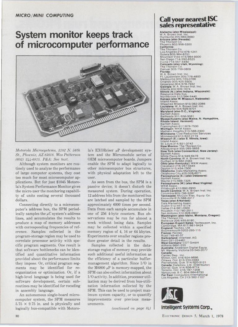
MICRO/ MINI COMPUTING
System monitor keeps track of microcomputer performance
Motorola Microsystems, 3102 N. 56th St., Phoenix, AZ 85018. Wes Patterson (602) 244-6815. P&A: See text.
Although system monitors are routinely used to analyze the performance of large computer systems, they cost too much for most microcomputer applications. But for just $1045 Motorola's System Performance Monitor gives the micro user the monitor ing capability of units costing several thousand dollars.
Connecting directly to a microcomputer's address bus, the SPM periodically samples the µC system's address lines, and accumulates the results to produce a map of memory addresses with corresponding frequencies of reference. Samples collected in the program-storage region may be used to correlate processor activity with specific program segments. One result is that software bottlenecks can be identified and quantitative information provided about the performance limits they impose. Or, critical program segments may be identified for reorganization or optimization. Or, if a high-level language is being used for software development, certain subroutines may be identified for recoding in assembly language.
An autonomous single-board microcomputer system, the SPM measures 5.75 X 9.75 in. and is physically and logically bus-compatible with Motoro-
80
la's EXORciser µP development system and the Micromodule series of OEM microcomputer boards. Jumpers enable the SPM to adapt logically to other microcomputer bus structures, with physical adaptation left to the user.
As seen from the bus, the SPM is a passive device; it doesn't disturb the measured system. During operation, 12 address bits from the monitored bus are latched and sampled by the SPM approximately 6000 times per second. Data from each sample accumulate in one of 256 4-byte counters. Bus observations may be run for almost a week without losing data. Samples may be collected within a specified memory region of 4, 16 or 64 kbytes. Experiments over smaller regions produce greater detail in the results.
Samples collected in the datastorage region of memory may provide such additional useful information as the efficiency of a particular buffermanagement algorithm. Since 1/0 in the M6800 µP is memory-mapped, the SPM can also collect information about 1/0 activity. In addition, processor utilization may be derived from bus-utilization information collected by the SPM. This can be used to project maximum system capacity, or to quantify improvements over previous measurements.
(continued on page 84)
Call your nearest ISC sales representative Alabama (also Mississippi) : W. A . Brown Inst. Inc . Huntsville 205/ 883-8660 Arizona (also Nevada): The T horson Co. Phoenix 602 / 956-5300 Californ ia : T h e T horson Co. Los Angeles 213/476-124 1 Goleta 805/ 964-8751 Mountain View 415/964-9300 San Diego 7 14 /292-8525 lrvi ne 714/55 7-4460 Colorado (also Utah, Wyoming) : The Thorson Co. Denver303/ 759-0809 Florida : W. A . Brown Inst. Inc Ft . Lauderdale 305/ 776-4800 Melbourne 305/723-0766 Orlando 305 / 425-5505 Valparaiso 904/ 678-7932 Georgia: W. A . Brown Inst. Inc. Atlanta 404/ 939-1674 Illinois (N.) (also Indiana , Wisconsin) : Resource Data Sys. Northbrook 312/564-5440 Kansas (also W. M issouri, Nebraska): In land A ssoc. Shawnee M ission 913/362-2366 Lou isiana: W. A . B row n Inst. Inc . M andeville 504/626-9 701 Maryland (also D .C. , Virginia): Bartlett Assoc . Bethesda 301 / 656-3061 Massachusetts (also Maine, N. Hampshire, Rhode Island , Vermont) : Bartlett Assoc . Framingham 617 / 879-7530 M ichigan : WKM Assoc M adison Heig h ts 313 / 588-2300 Minnesota: Cost Reduction Serv ices Minneapoli!! 612 / 822-2 119 M issou ri (E .J (also S. I llinois, Iowa): Inland Assoc . St . Louis314/ 821-37'42 New Mexico: T he Thorson Co. Albuquerque 505/ 265-5655 New York (also Connecticut , New Jersey): Bartlett Assoc . White Plains 914/ 949-64 76 North Carolina: W. A . B rown Inst. Inc. Durham 919/682-2383 Ohio (also Kentucky): W KM Assoc . Cleveland 216/ 267-0445 Dayton 513/ 434-7500 Oklahoma: Data Marketin g A ssoc. Oklahoma City 405/528-6071 Pennsylvania (E .J (also Delaware) : Bartlett Assoc . Wayne 215/ 688-7325 Pennsylvania (W.J (also West Virginia) : WKM Assoc . Pittsburgh 412/892-2953 South Carolina : W. A. B rown Inst. Inc. Columbia 803/798-3 297 Tennessee: McCoin Elec. Equip. Co. Knoxville 615/ 588-2417 Texas (also Arkansas) : Data M arketi ng Assoc . Austin 512/ 451-5174 Dal las 214/ 661-0300 H ousto n 713 / 780-2511 San Anto nio 5 12 / 828 -0937 Wash ington (also Idaho, Montana , Oregon): The Thorson Co. Bellevue 206/ 455-9180 European Export Sales: Tec hexport. Inc . Cambridge . MA 617 / 661-9424 England: Techex . Ltd. Bournemouth 0202-293-115 France: Peritec Rueil 749-40-37 Switzerland : lntertest. AG Bern 031-224481 West Germany: COT GmbH Altheim 6691-255 Au stralia : Anderson Digital Equip. Mt. Waverly, V ictoria 03-543-2077 Canada: Cantec Rep .. Inc. Milton . Ont. 416/ 624-9696 Ottawa. Ont. 613/ 255-0363 Pierrefonds, Que . 514/620-3121 Canada: Datamex . Ltd . (D ist ri butor) Dorval . Que. 514 / 636-9774 Toronto , Ont. 416/ 787-1208 Vancouver. B .C . 604/684-6750 Fa r East: Computers International Los Angeles . CA 213/ 382-1107
• lntelllgent Systems Corp.a
faECTRON 1c DESIG 5, March l, 1978
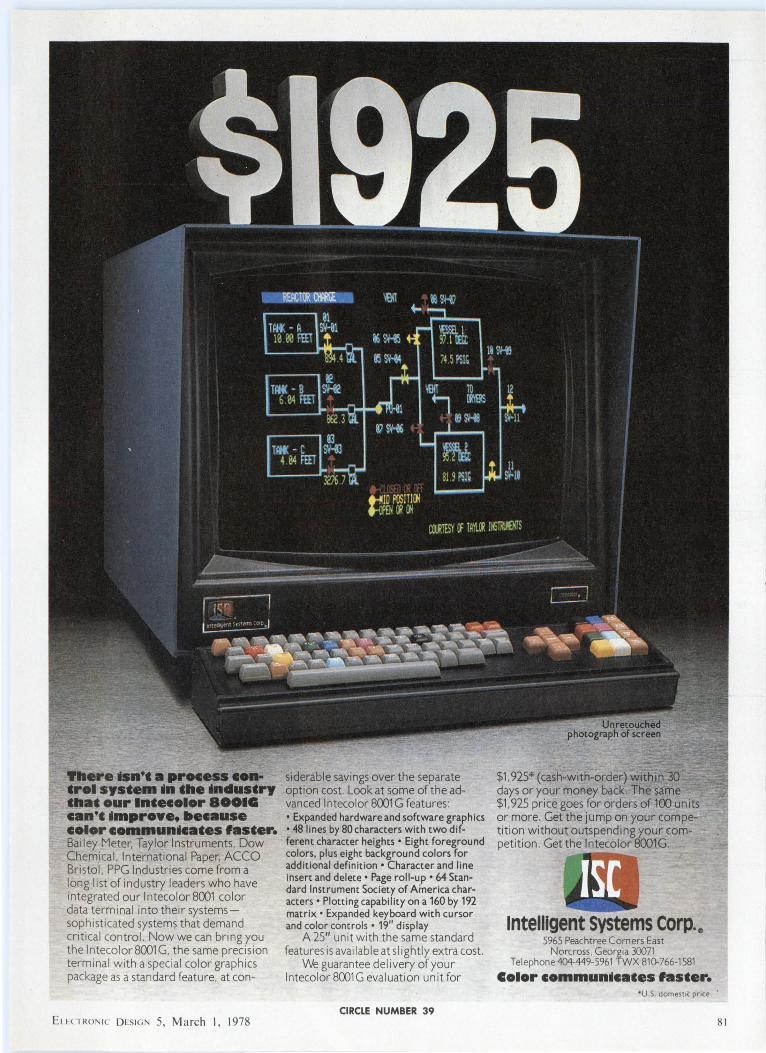
There mn'• •process ..... •rol sys•em ~n •he mdus•ry •hm our lmecolor 800IG can•• ~mprove. because color commun~ca•es fas•er. Bailey Meter, Taylor Instruments , Dow Chemica l, International Paper, ACCO Bristol, PPG Industri es come from a long list of industry leaders who have integrated our lntecolor 8001 color data termi nal into their systemssophisticated systems that demand critical control. Now we can bring you the lntecolor8001G, the same precision terminal with a special color graph ics package as a standard feature, at con-
E1 1 CTRON 1c DcSIG 5, March I, 1978
siderable savings over the separate option cost. Look at some of the advanced lntecolor 8001 G features : • Expanded hardware and software graphics • 48 lines by 80 characters with two different character heights • Eight foreground colors, plus eight background colors for additional definition • Character and line insert and delete• Page roll-up • 64 Standard Instrument Society of America characters • Plotting capability on a 160 by 192 matrix• Expanded keyboard with cursor and color controls • 19" display
A 25" unit with the same standard features is available at slightly extra cost.
We guarantee delivery of your lntecolor 8001 G evaluat ion unit for
CIRCLE NUMBER 39
$1 . 925* (cash-with-order) within 30 days or your money back. The same $1 , 925 price goes for orders of 100 units or more. Get the jump on your competit ion without outspending your rnmpetit ion . Get the lntecolor 800lG.
Intelligent Systems corp.4P 5965 Peachtree Corners East
Norcross. Georgia 30071 Telephone 404-449-5961TWX81(}-766-1581
Color commun~ca•es fas•er. •u.s. domestic price.
81
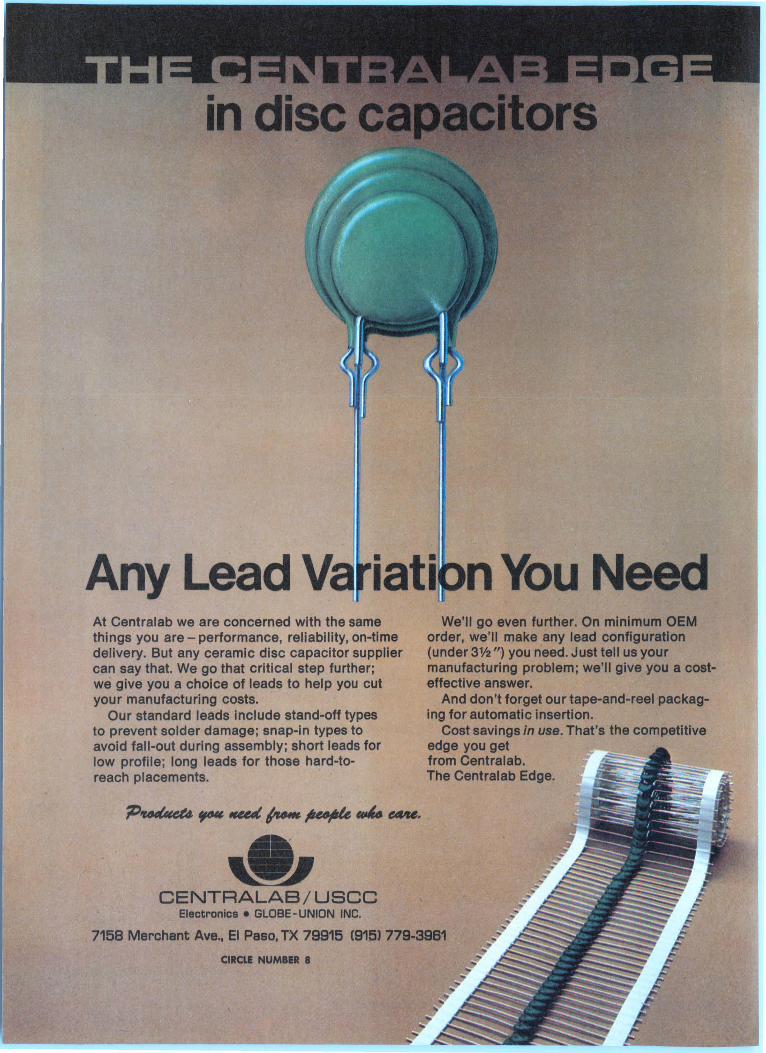
iati n You Need At Centralab we are concerned with the same things you are - performance, reliability, on-time delivery. But any ceramic disc capacitor supplier can say that. We go that critical step further; we give you a choice of leads to help you cut your manufacturing costs.
Our standard leads include stand-off types to prevent solder damage; snap-in types to avoid fall-out during assembly; short leads for low profile; long leads for those hard-toreach placements.
-~ CENTRALAB/USCC Electronics • GLOBE- UNION INC.
We'll go even further. On minimum OEM order, we'll make any lead configuration (under 3V2n) you need. Just tell us your manufacturing problem; we'll give you a costeffective answer.
And don't forget our tape-and-reel packaging for automatic insertion.
Cost savings in use. That's the competitive edge you get from Centralab. The Centralab Edge.
7158 Merchant Ave., El Paso, TX 79915 C915l 779-3961
CIRCLE NUMBER 8
PMI
monoli c 10-bit DACS.
Good news! Two new ten-bit digital-to-analog converters from the folks who know how to make them monolithically. And each is completely "complete'.' Includes internal reference and output op amp. They are fast {1.5 µsec settling time), with voltage outputs, yet consume only
350mW (max) over the entire military temp range (-55°C to +125°C).
DAC-05: Sign-magnitude coding (sign-plus-ten-bits).
DAC-06: Two's complement coding.
Both DACs are available now specified over the full temp range. Off the shelf to MIL STD-883A
Level B. Reliability is enhanced by 100% burn-in, hermetic packaging for all parts, PMI's famous
triple passivation, low noise process and no laser trimming.
Data sheets are ready. Parts are on the shelf. Write, wire or phone. Precision PiM I
Monolithics, Inc., 1500 Space Park Drive, Santa Clara, CA 95050.
( 408) 246-9222. TWX: 910-338-0528. ®
CIRCLE NUMBER 9
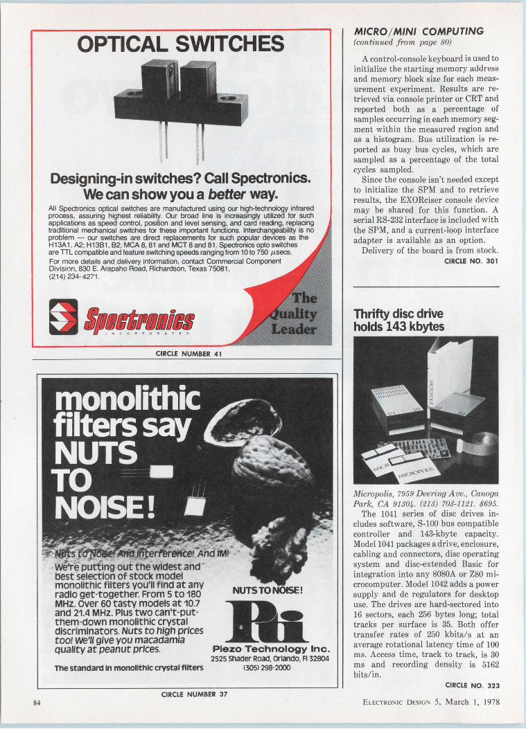
84
OPTICAL SWITCHES
Designing-in switches? Call Spectronics. We can show you a better way.
All Spectronics optical switches are manufactured using our high-technology infrared process, assuring highest reliability. Our broad line is increasingly utilized for such applications as speed control, position and level sensing, and card reading, replacing traditional mechanical switches for these important functions. Interchangeability is no problem - our switches are direct replacements for such popular devices as the H13A1 , A2. ; H1381 , 82; MCA 8, 81 and MCT 8 and 81. Spectronics opto switches are TTL compatible and feature switching speeds ranging from 1 Oto 750 µsecs. For more details and delivery information, contact Commercial Component Division , 830 E. Arapaho Road, Richardson, Texas 75081, (214) 234-4271.
CIRCLE NUMBER 41
~ . y~~-
- ~ - ~ t.~r.fs ta· . . _ e~r~eiAnd tM! ~. : - weT~ putting out the widest and -
!lest selection of stock model monolithic filters you'll find at any radio get-together. From s to 180 MHz. over 60 tasty models at 10.1 and 21.4 MHz. Plus two can't-putthem-down monolithic crystal discriminators. Nuts to high prices too! we'll give you macadamia quality at peanut prices.
The standard In monollthlc crystal filters
NUTS TO NOISE!
Plezo Technology Inc. 2525 Shader Road, or1ando, Fl 32804
(3051 298-2000
CIRCLE NUMBER 37
MICRO/ MINI COMPUTING (continued from page 80)
A control-console keyboard is used to initialize the starting memory address and memory block size for each measurement experiment. Results are retrieved via console printer or CRT and reported both as a percentage of samples occurring in each memory segment within the measured region and as a histogram. Bus utilization is reported as busy bus cycles, which are sampled as a percentage of the total cycles sampled.
Since the console isn't needed except to initialize the SPM and to retrieve results, the EXORciser console device may be shared for this function. A serial RS-232 interface is included with the SPM, and a current-loop interface adapter is available as an option.
Delivery of the board is from stock.
Thrifty disc drive holds 143 kbytes
CIRCLE NO. 301
Micropolis, 7959 Deering Ave., Canoga Park, CA 91304 . (213} 703-1121. $695.
The 1041 series of disc drives includes software, S-100 bus compatible controller and 143-kbyte capacity. Model 1041 packages a drive, enclosure, cabling and connectors, disc operating system and disc-extended Basic for integration into any 8080A or Z80 microcomputer. Model 1042 adds a power supply and de regulators for desktop use. The drives are hard-sectored into 16 sectors, each 256 bytes long; total tracks per surface is 35. Both offer transfer rates of 250 kbits/s at an average rotational latency time of 100 ms. Access time, track to track, is 30 ms and recording density is 5162 bits/in.
CIRCLE NO. 323
ELECTRONIC DESIGN 5, March I, 1978

Full-function computer fits on desk top
IBM, P.O. Box C-1645, Atlanta, GA 30801. Bill Shaffer (404} 231-3201. $9875 to $32,925.
The IBM 5110 is a desktop computer that houses a central processing unit, a typewriter-like keyboard with a 10-key calculator pad and a 1024-character display screen. Main memory holds 16 k, 32 k, 48 k or 64 kbytes of data, depending on the unit selected. The computer is available in two models. Offering either magnetic tape or diskette storage, the Model 1 stores 204 kbytes per tape cartridge or 1.2 Mbytes on a single diskette. The Model 2 allows diskette storage only. Up to two IBM 5114 diskette units, each housing a maximum of two diskette drives, can be attached to the 5110 for an on-line diskette capacity of 4.8 Mbytes.
CIRCLE NO. 324
Memory module contains more than 1 Mbyte EMM Commercial Memory Products, 12621 Chadron Ave., Hawthorne, CA !HMSO (213) 644-9881 . $0.10/bit
The Megabyte Module memory is configured as 1,114,112 X 8 (8,912,896 bits), which is 524,288 bits in excess of 1 Mbyte. The additional 64-kbyte capacity allows the use of various error checking methods while maintaining a 1-Mbyte capacity for data. The memory is a random-access, two-wire, 1-1/2D core memory, packaged on a single pluggable PC card. An available chassis can take up to four modules, two 110 cards, and a power supply within 17-1/2 in. of vertical rack space. The memory module operates at 2 µs in the read/restore and clear/write modes with an access time of 1.2 µs.
CIRCLE NO. 325
ELECTRONIC DESIGN 5, March I, 1978
You probably already have a lot of good reasons for moving your plant or expanding your operation. And they're all great reasons for moving to Palm coast lndustrlal Park. LOCATION - Florida's growing Northeast coast just one hour south of Jacksonville. SAVINCS - Lower state and local taxes, including a total tax on industrial property of 10.BB?mills. Lower housing and labor cost, too.
LABOR - A population of 725,000 within a reasonable
commuting distance. TRANSPORTATION - 1·95 and
us 1 cross the property with available access to air, rail and
trucking. CORPORATE COMMITMENTIIT community Development
corporation is ready to assist you in every step of your move. LIFESTYLE - The bright,
warm Florida climate. There's even more good reasons. Write us and we'll
send you all the details, or call Dave Irving toll free at
1·800·874·1828 (in ~lorida 1·904·445·341 i collectl.
ITT community Development corp ration
I I I I
-----P~l{RtC•o1f _____ _ 1nol AL PARK '""" I
For more Information wrtte Mr. David Irving, ITT community Development Corporation, Executive Offlees, Palm coast, R. 32037 or cal tOll free at 1-800-874-1828 Un AOrlda 1-904-445-3411 COiiect>.
PLEASE SEND ME MORE CREAT REASONS FOR MOVINC TO PALM COAST. I Pll'( company Is engaged In o manufacturing, o distribution, o other, and we are o moving, o expanding.
NAME nru ____ _ I COMPANY NAME _____________________ ~
I ADDRESS ---------------- CITY ____ ZIP __
I I I I I
~---------------------~ CIRCLE NUMBER 42 85

MICRO/ MINI COMPUTING
Low-end computer uses PDP-8 processor Di,gital Equipment, Maynard, MA 01754. Joe Nahil (603) 884-5101. .$12,600; 8 wks.
The Datasystem 308 uses a PDP-8 video data processor and is for data processing that requires a single termi-
nal. A typical system consists of a video date processor with 32 kbytes of memory, dual floppy-disc file system, and a minidesk. The 308 uses the COS-310 operating system whose program includes DIBOL, a business-oriented language. COS-310 files and the DIBOL language permit the user to transfer programs and data to larger systems by appropriate media.
CIRCLE NO. 326
Standard Grigsby§ rotary switches have printed circuit
and solderless terminals that will not bend or twist
our exclusive rigid construction provides you with savings by eliminating costly assembly operations
"YES" - Save the valuable time wasted on straightening the P.C. terminals of rotary switches!
Our exclusive printed circuit "T' terminals are ruggedly designed to allow EASY insertion of our rotary switches into any P.C. board pattern.
If you wire your rotary switches with wire-wrap or other solderless techniques, try a terminal that won't bend or twist .. . Standard Grigsby's NEW solderless "T' terminal.
Send for Free "Yes" button and literature.
IJj standard grigsby, im!.
86
920 Rathbone Avenue • Aurora, Illinois 60507 (312) 844-4300
CIRCLE NUMBER 43
Bulk magnetic eraser is hand held
Printcraft Systems, 11-17 Beach St., New York, NY 10013. Don Hubbinett (212) 966-0001. $22.50.
The UL-approved hand-held bulk tape/ card eraser electronically restores magnetic cards, cassettes, discs and reel-to-reel recording tapes to "like new" blank recording condition. The process can be performed off line in quantity for either general reuse or for information security. The eraser guards against one program from running into a previously recorded program should a stop code be missed.
CIRCLE NO. 327
Personal computer usesZ80 CPU
Realistic Con trols, 404 W. 35 S t., Davenport, IA 52086. (800) 553-1863. $2495.
REX, a total microcomputer system, is fully assembled with a Z80 CPU, 24-k RAM, video output, keyboard, microfloppy-disc drive, cabinet, power supply and optional extended-disc Basic and ANSI Fortran IV. The system includes an S-100 motherboard, up to 64 k of RAM (24 k standard), bootstrap and monitor PROM and power-fail and vectored-interrupt circuitry.
CIRCLE NO. 328
ELECTRON IC DESIG 5, March 1, 1978

Intel delivers a better 22-pin 4K RAM fur people who are never quite satisfied.
For some people "good enough" is never quite good enough. In 1972 we introduced the industry's first 22-pin 4K RAM, the 2107. But we weren't content to stop there. So we follo ed with the 2107A. Then in 1975 the 2107B. Now, introducing the 2107C. Compare it with any 4K dynamic RAM. The results are sure to put a smile on your face.
The 2107C delivers a new standard of performance. Access time: 150 ns. Power consumption: 40% lower than the TMS 4060 or our own 2107B. Current spikes: significantly lower than competitor's parts means less system noise with the
2107C. Supply tolerance: ±10% in all· power supplies gives you the widest system operating margins available anywh re.
Best of all , the 2107C is already in volume production and available in both hermetic and plastic packages. Plan now to upgrade your systems now using our 2107B or any of its second sources. For a 2101c-1 2101c-2 2101c complimentary Maximum Access lime 150 ns 200 ns 250 ns P2107C evalu- Maximum Read/Write Cycle 380 ns 400 ns 430 ns ation sample Maximum loo Average 35 mA 33 mA 30 mA and data sheet, Power Supply Tolerance ±10% ±10% ±10%
contact your Intel sales office. To order, contact Almac/Stroum, Component Specialties, Cramer, Hamilton/Avnet, Harvey Electronics, Industrial Components, Pioneer, Sheridan, Wyle/ Elmar, Wyle/Liberty, L.A. Varah, Zentronics. Or write us. Intel Corporation, 3065 Bowers Avenue, Santa Clara, CA 95051. · In Europe, Telex 24814, Brussels.
n Jap~, Telex 28426, Tokyo.
COMPONENTS
Solid-state chopper comes in T0-5 case
Solid State Electronics, 15321 Rayen St., Sepulveda, CA 91343. Ed Politi (213) 894-2271. $89 (100 qty); 1 to 3 wks.
The NS8000A is a transformerisolated solid-state chopper built with stabilized integrated silicon semiconductors in a T0-5 type enclosure. The max chopped current is 10 mA and the total device dissipation in free air is 0.5 W (2 W at 25-C case temp). The chopping frequency (limited by an internal transformer) ranges from 50 kHz to 1.5 MHz.
CIRCLE NO. 329
Large indicator lights are attention grabbers
Industri,al Devices, 7 Hudson Ave., Edgewater, NJ 07020. (201) 224-4 700. Free samples.
Large attention-getting panel indicator lights, Omni-Glow 2600, have built-in, round metal bezels that retain a lens. High dome-shaped, or lowprofile flat or rounded lenses can be used. The indicators fit into a 7/8-in. diameter panel opening or in a keyed D-mounting hole. Either snap-fit or speednut mounting may be used. Lamps for the indicators are either standard or high-brightness neons or rugged wire-lead incandescents.
CIRCLE NO. 330
THERMISTORS
Low-profile heat sink fits T0-3 and T0-66
Aavid Engineering, 30 Cook Court, Laconia, NH 03246. (603) 524-4443. Free samples.
Heat sinks that feature a universal hole pattern, part numbers 5060 and 5061, also accommodate T0-3 and T0-66 case-style devices. The heat sinks are 0.375-in. high and fit PC boards spaced 0.5-in. between board centers. Both types come with black anodized finish.
CIRCLE NO. 331
VICTORY SELECTIVITY
Select ivity, not just a word but a reality at VECO. SensiChips~ thick films, beads and probes in a wide variety of sizes and resistances. Try us, you'll like VECO quality and prices.
Rogan knobs look better and are built better,
88
~ ~ VICTORY ENGINEERING CORP. V1c1ory Rd . Spnngheld, N J 07061
TWX 710·983·4430 Tel 201-379-5900
CIRCLE NUMBER 45
and we'll prove it with a free sample. After you receive our catalog, send us a note outlining your specific requirement and the quantity involved.
Or furnish us with our cqmpetitor's part number and we will cross-reference it.
Our samples and quotation will be returned promptly.
3455 Woodhead Drive, Northbrook, Illinois 60062 (312) 498-2300
CIRCLE NUMBER 46
CIRCLE NUMBER 47 ~
Intel delivers the only 16-pin 4K RAM that~ sure to keep you smiling.
You may or may not think of your memory system as a masterpiece. But one thing is certain, once you've reached volume production you're going to be reluctant to make major changes. That's why it is so frustrating to find that a supplier has painted you into a comer by deciding to stop delivering the part you want. Or by trying to switch you to a newer, non-compatible part.
Smile. Our 2104A 16-pin 4K RAM is the answer. It's a direct replacement for both the older 4096 metal gate and newer 4027 silicon gate parts. The 2104A keeps your production line moving without expensive re-design. Plug it in
and you're ready to go. The 2104A is best for your new
- designs, too. We've been delivering this part Ut volume since July, 1976. So you 8" Intel to deliver the quantity
Delivery is not the only reason to specify the 2104A. There's not a 16-pin 4K RAM anywhere with lower power consumption. And because the 2104A has significantly lower current spikes than other 16-pin 4K Maximum Maximum Maximum RAMs, there's less sys- Access Read/Write loo tern noise. What it all lime Cycle Allerage
2104A-1 150 ns 320 ns 35 mA means is that when you 2104A-2 200 ns 320 ns 32 mA design your next system, 2104A-3 250 ns 375 ns 30 mA it makes sense to design 2104A-4 300 ns 42? ns 30 mA it using our 2104A. 2104A 350 ns 500 ns 30 mA
You can order the 2104A from distributor stock. Contact: Almac/Stroum, Component Specialties, Cramer, Hamilton/ Avnet, Harvey Electronics, Industrial Components, Pioneer, Sheridan, Wyle/Elmar, Wyle/Liberty, L.A. Varah, Zentronics. Or write Intel Corp., 3065 Bowers Ave., Santa Clara, CA 95051.
IqEur pe. Tel~)~J Brussels. In Japan JtYlllJlj•p~·'j

90
As you can plainly see, our new air variable capacitor is nearly as small as many sub-miniature ceramic trimmers. It also features the same mounting configuration which means you can use it in many of the same applications
But small size isn't the only reason for buying our new Micro T'" capacitor. Because it's air variable, it offers you
great stability. Q is t 1000 at 100 MHz. T 1s + =45 PPM/°C. And it's available in maximum capacities of 3, 6.5, 12.7, and 19.0 pF in either vertical or horizontal tuning PC and stripline mounting versions. What's more, it gives you all this for a very small price.
E. F. Johnson Company /Dept. E.D., Waseca, MN 56093 D Please send me technical D Please send me samples.
information on sub-miniature You can call me at air variable capacitors.
Name·~~~~~~~~~~~~~~~~~~~~~~~
Firm~~~~~~~~~~~~~~~~~~~~~~~~
Address.~~~~~~~~~~~~~~~~~~~~~~~
City ____________ State _______ _
Zip~~~~~~~~~~
For fast service, contact your local Johnson Distributor.
00:JOHNSON CIRCLE NUMBER 48
COMPONENTS
Thermistor in glass bulb is indirectly heated Fenwall E lectronics, 63 Fountain St. , Framingham, MA 01701. (61 7) 872-8841 .
Thermistor K365 has a heating element and thermistor bead enclosed in a glass bulb. It is unaffected by changes in ambient conditions. When power is applied directly to the thermistor bead, temperature increases 1 C/0.015 W. Power of 0.04 mW to the heater indirectly heats the thermistor bead 1 C and changes the thermistor resistance, typically, from 50 to 15 k!l
CIRCLE NO. 332
RCD networks save board space TRW Capacitors, 301 West "O" St., Ogallal,a, NE 6.91 53. (308) 284-3611. 8 to 10 wks.
Resistor-capacitor-diode (RCD) networks save both circuit-board space and design time. The networks come packaged in axial-lead molded-plastic cases. Diodes have reverse-breakdown voltages of 1000 V with less than 50 mA of leakage current and max forwardvoltages of 1.1Vat1 A. Resistors, rated from 1/ 4 to 1/2 W, have values from 100 to 800 n. And metallized-Mylar capacitors have voltage ratings from 100 to 400 V and capacitances from 0.22 µF to 1 µF.
CIRCLE NO. 333
Slim DPM features 3-1/2 digit display Fairchi ld Ins truments & Con trols, 1725 Technology Dr., San Jose, CA 95110. John Hatch (415) 962-2521. $33.
Model 30 3-1/2-digit DPM is a flat pack that operates on only 0.75 W at 5 V de. With the display blanked, power is reduced to 0.05 W. The meter is available in a full-scale range of ± 1.999 V with a resolution of 0.0005%. Higher ranges are obtained by the use of external resistor-divider networks. Accuracy is ±0.1 % of reading, ± 1 digit. The display is 0.5 in. high. The unit fits NEMA and DIN standard 0.44 X 3.59-in. panel cuts.
CIRCLE NO. 334
E LECTRONIC DESIGN 5, March I, 1978
MODULES & SUBASSEMBLIES Dual line amp has equalizer option
Analog interface board handles many functions
Cassette transport has accurate speed MFE, Keewaydin Dr., Salem, NH 03079. Jim Saret (603) 893-1921. $560; 4 to 6 wks.
The Model 450B digital-cassette transport has a speed-control system that provides long-term speed accuracy at the heads without the use of a prerecorded digital clock track. The transport is fully ANSl/ECMA compatible, allowing full interchange of cassette tapes with any other compatible system. Two data tracks are available allowing data storage up to 5.9 Mbits (720 kbytes) per cassette. Read/write speeds from 10 to 40 in/s are available providing data transfer rates up to 32 kbits/s using the bi-phase level encoding standard. Search speeds up to 80 in/s can be used.
Plantronics Kentrox, 14335 N. W. Science Park Dr. , Portland, OR 97229. (503) 643-1681. $155 (amplifier), $47 (equalizer); stock.
Vector Graphic, 790 Hampshire Rd., Westlake Village, CA 91361. Lore Harp (805) 497-6853. $115; stock.
The Model 3300 dual line amplifier takes an optional line-amplitude equalizer that provides transmit and receive equalization in four-wire applications with DIP switches to select equalization. The amplifier has a power regulator and 70-dB power-supplynoise rejection. Simplex leads are provided. A switch selects 150, 600 and 1200-0 input and output impedances. A visual indication of gain is provided.
The multifunction analog interface board interfaces a µP with potentiometers, joysticks or voltage sources. An 8-bit digital port with latch strobe is used as a keyboard-input port. Tonepulse generators also can be used to produce sounds for games or keyboard audio feedback. Also included are four aid inputs, MWRITE logic and poweron jump capability for computers lacking a front panel.
CIRCLE NO. 335
Pancake Resolvers Custom-designed for complex applications.
Our special-design resolvers are today performing on missiles, aircraft, submarines, radar and satellite systems.
Our pancakes, in sizes 16 through 134 and in single and dual speed configurations, are among the most reliable and accurate resolvers available. As are our standard resolvers.
We deal in difficult, custom applications, using engineer-to-engineer contact with detailed technical interchanges to assure smooth production, delivery and absolute performance.
As a result , American Electronics, Inc. has been, for over 15 years, one of the leading suppliers of custom resolvers.
Call or write for our free data package with complete 20-page technical work on resolvers, including outline and performance details.
AEI AMERICAN ELECTRONICS, INC. ® ELECTRO-MECHANICAL INSTRUMENTS DIVISION
1600 VALENCIA DRIVE, FULLERTON, CA 92631 TELEPHONE (714) 871-3020
CIRCLE NUMBER 49 ELECTRONIC D ESIGN 5, March I, 1978
CIRCLE NO. 336 CIRCLE NO. 337
-----------------• I I I I I I I I I I I
I I I I I Solid state electronic MICRO-BUZZER from
CITIZEN : High reliability, competitively I I priced with immediate delivery. I I A complete range: SMB 1.5, 6, 12, 24, voe I
RMB 3, 6, 12, 24, voe I IMB (Intermittent) 6, 12, voe
: ~~z!1A~ ~Na-me ________ :
I CORPORATION I 1710 - 22nd St. Company I
I Santa Monica, Address CA 90404 I
I Toll Free (800) 421-6516 ""'c""it-y ------s=1-,a1-.---- I I In Calif. (213) 829-3541
TWX : (910) 343-6450 Zip Phone I
·-----------------CIRCLE NUMBER 50 91
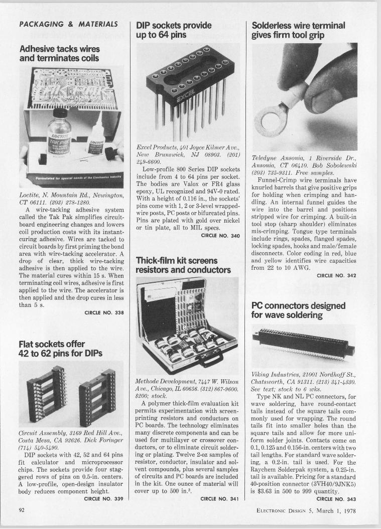
PACKAGING & MATERIALS
Adhesive tacks wires and terminates coils
Loctite, N Mountain Rd., Neioington, CT 06111. (203) 278-1280.
A wire-tacking adhesive system called the Tak Pak simplifies circuitboard engineering changes and lowers coil production costs with its instantcuring adhesive. Wires are tacked to circuit boards by first priming the bond area with wire-tacking accelerator. A drop of clear, thick wire-tacking adhesive is then applied to the wire. The material cures within 15 s. When terminating coil wires, adhesive is first applied to the wire. The accelerator is then applied and the drop cures in less than 5 s.
CIRCLE NO. 338
Flat sockets offer 42 to 62 pins for DIPs
Oi,rcuit Assembly, 3169 Red Hill Ave., Costa Mesa, CA 92626. Dick Foringer (714) 540-5490.
DIP sockets with 42, 52 and 64 pins fit calculator and microprocessor chips. The sockets provide four staggered rows of pins on 0.5-in. centers. A low-profile, open-design insulator body reduces component height.
CIRCLE NO. 339
92
DIP sockets provide up to 64 pins
Excel Products, 401 Joyce Kilmer Ave., New Brunswick, NJ 08903. (201) 249-6600.
Low-profile 800 Series DIP sockets include from 4 to 64 pins per socket. The bodies are Valox or FR4 glass epoxy, UL recognized and 94V-O rated. With a height of 0.116 in., the sockets' pins come with 1, 2 or 3-level wrappedwire posts, PC posts or bifurcated pins. Pins are plated with gold over nickel or tin plate, all to MIL specs.
CIRCLE NO. 340
Thick-film kit screens resistors and conductors
Methode Development, 744 7 W Wilson Ave., Chicago, IL 60656. (312) 867-9600. $200; stock.
A polymer thick-film evaluation kit permits experimentation with screenprinting resistors and conductors on PC boards. The technology eliminates many discrete components and can be used for multilayer or crossover conductors, or to eliminate circuit soldering or plating. Twelve 2-oz samples of resistor, conductor, insulator and solvent compounds, plus several samples of circuits and PC boards are included in the kit. One ounce of material will cover up to 500 in.2 •
CIRCLE NO. 341
Solderless wire terminal gives firm tool grip
Teledyne Ansonia, 1 Riverside Dr., Ansonia, CT 06410. Bob Sobolewski (203) 735-9311. Free samples.
Funnel-Crimp wire terminals have knurled barrels that give positive grips for holding when crimping and handling. An internal funnel guides the wire into the barrel and positions stripped wire for crimping. A built-in tool stop (sharp shoulder) eliminates mis-crimping. Tongue type terminals include rings, spades, flanged spades, locking spades, hooks and male/female disconnects. Color coding in red, blue and yellow identifies wire capacities from 22 to 10 A WG.
CIRCLE NO. 342
PC connectors designed for wave soldering
Viking Industries, 21001 Nordhoff St., Chatsworth, CA 91311. (213) 341-4330. See text; stock to 6 wks.
Type NK and NL PC connectors, for wave soldering, have round-contact tails instead of the square tails commonly used for wrapping. The round tails fit into smaller holes than the square tails and allow for more uniform solder joints. Contacts come on 0.1, 0.125 and 0.156-in. centers with two tail lengths. For standard wave soldering, a 0.2-in. tail is used. For the Raychem Solderpak system, a 0.25-in. tail is available. Pricing for a standard 40-position connector (3VH40/9JNK5) is $3.63 in 500 to 999 quantity.
CIRCLE NO. 343
ELECTRONIC DESIGN 5, March I, 1978
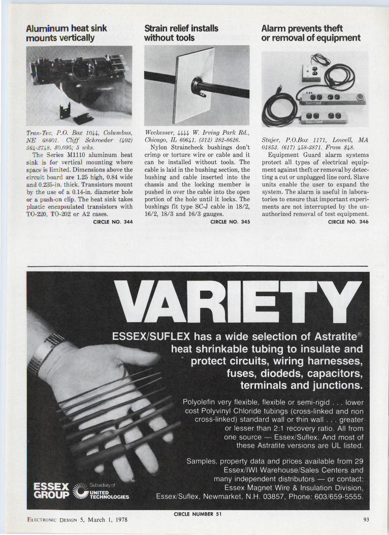
Aluminum heat sink mounts vertically
Tran-Tee, P.O. Box 1044, Columbus, .NE 68601 . ClijJ Schroeder (402) 564 -274 . 0.095; 5 wks.
The Series MlllO aluminum heat sink is for vertical mounting where space is limited. Dimensions above the circuit board are 1.25 high, 0.84 wide a nd 0.235-in. thick. Transistors mount by the use of a 0.14-in. diameter hole or a push-on clip. The heat sink takes plastic encapsulated transistors with T0-220, T0-202 or A2 cases.
CIRCLE NO. 344
ELECTRONI C DESIGN 5, March I, 1978
Strain relief installs without tools
Weckesser, 4444 W. Irving Park Rd., Chicago, IL 60641. (312) 282-8626.
Nylon Straincheck bushings don't crimp or torture wire or cable and it can be installed without tools. The cable is laid in the bushing section, the bushing and cable inserted into the chassis and the locking member is pushed in over the cable into the open portion of the hole until it locks. The bushings fit type SC-J cable in 18/2, 16/2, 18/3 and 16/3 gauges.
CIRCLE NO. 345
CIRCLE NUMBER 51
Alarm prevents theft or removal of equipment
•
Stajer, PO.Box 1171, Lowell, MA 01853. (617) 458-3871. Prom $48.
Equipment Guard alarm systems protect all types of electrical equipment against theft or removal by detecting a cut or unplugged line cord. Slave units enable the user to expand the system. The alarm is useful in laboratories to ensure that important experiments are not interrupted by the unauthorized removal of test equipment.
CIRCLE NO. 346
93
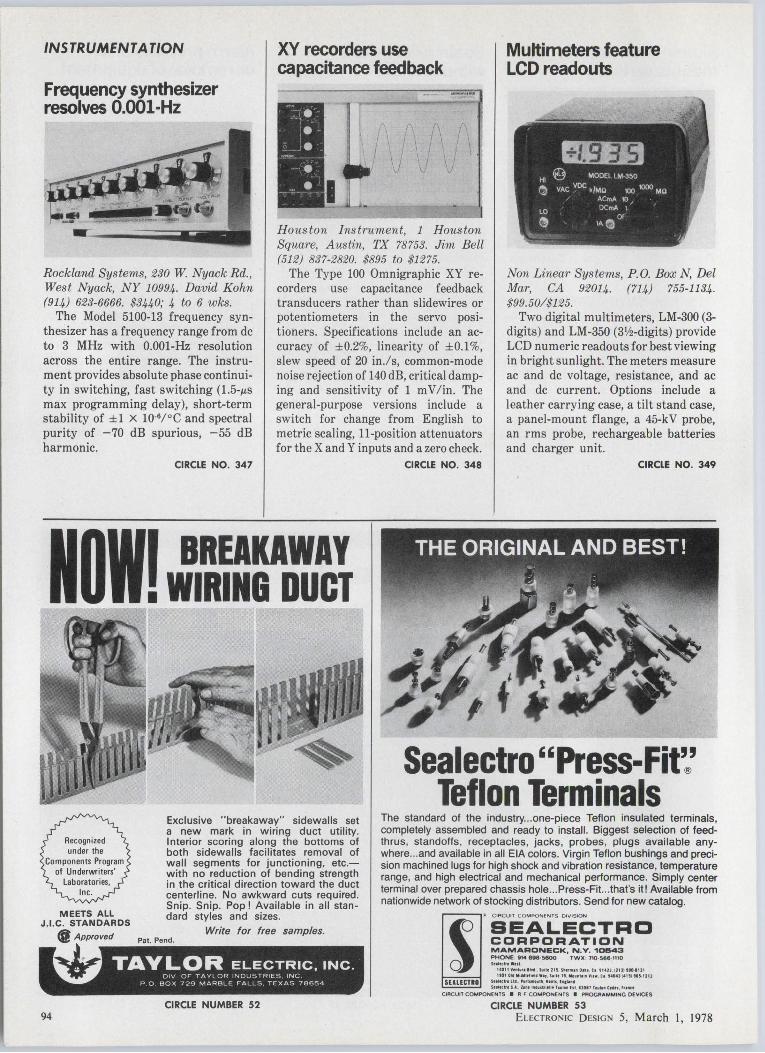
INSTRUMENTATION
Frequency synthesizer resolves 0.001-Hz
Rockland Systems, 230 W. Nyack Rd. , West Nyack, NY 10994. David Kohn (914) 623-6666. $3440; 4 to 6 wks.
The Model 5100-13 frequency synthesizer has a frequency range from de to 3 MHz with 0.001-Hz resolution across the entire range. The instrument provides absolute phase continuity in switching, fast switching (1.5-µs max programming delay), short-term stability of ±1 X l0·6/°C and spectral purity of -70 dB spurious, -55 dB harmonic.
CIRCLE NO. 347
XV recorders use capacitance feedback
Houston Instrument, 1 Houston Square, Austin, TX 78753. Jim Bell (512) 837-2820. $895 to $1275.
The Type 100 Omnigraphic XY recorders use capacitance feedback transducers rather than slidewires or potentiometers in the servo positioners. Specifications include an accuracy of ±0.2%, linearity of ±0.1 %, slew speed of 20 in.ls, common-mode noise rejection of 140 dB, critical damping and sensitivity of 1 m V /in. The general-purpose versions include a switch for change from English to metric scaling, 11-position attenuators for the X and Y inputs and a zero check.
CIRCLE NO. 348
Multimeters feature LCD readouts
Non Linear Systems, P.O. Box N, Del Mar, CA 92014. (714) 755-1134. $99.50/$125.
Two digital multimeters, LM-300 (3-digits) and LM-350 (3V2-digits) provide LCD numeric readouts for best viewing in bright sunlight. The meters measure ac and de voltage, resistance, and ac and de current. Options include a leather carrying case, a tilt stand case, a panel-mount flange, a 45-kV probe, an rms probe, rechargeable batteries and charger unit.
CIRCLE NO. 349
Noll BREAKAWAY I WIRING DUCT
MEETS ALL J.l.C. STANDARDS
@Approved
Exclusive "breakaway" sidewalls set a new mark in wiring duct utility. Interior scoring along the bottoms of both sidewalls facilitates removal of wall segments for junctioning, etc.with no reduction of bending strength in the critical direction toward the duct centerline. No awkward cuts required. Snip. Snip. Pop! Available in all standard styles and sizes.
Write for free samples. Pat. Pend.
~ TAYLOR ELECTRIC , INC. DIV OF TAYLOR INDUSTRIES INC
P 0 BOX 729 MARBLE FALLS TEXAS 78654
CIRCLE NUMBER 52 94
Sealectro ''Press-Fit~ Teflon Terminals
The standard of the industry ... one-piece Teflon insulated terminals, completely assembled and ready to install. Biggest selection of feedthrus, standoffs, receptacles, jacks, probes, plugs available anywhere ... and available in all EIA colors. Virgin Teflon bushings and precision machined lugs for high shock and vibration resistance, temperature range, and high electrical and mechanical performance. Simply center terminal over prepared chassis hole ... Press-Fit ... that's it! Available from nationwide network of stocking distributors. Send for new catalog.
,.----, ,. CIRCUIT COMPONENTS DIVISION
SEALECTRD CORPORATION MAMARONECK, N.V. 101543 PHONE 9M 898·S800 TWX 7IO·S6«Mt10 SUIKtllWnt
1<&011'IHl~r•11•4 , S111l1 2\S, 5-n111111 OIU t1 '1•U.1 21l l HO Ill\ Ito! oi. lll ollflfhf" •••• h•ll 11, 11111~\1 111 'i'it•. ( I too !•ISi HS-1212
lt1l«lrlllt , Put•••ll'. Mants , h1t.a' Sultclr1Sl . Z.ntlnhUi1tll•h1IHhl llHlf1o11ltnt•"' · " 1111ct
CIRCUIT COMPONENTS • R F COMPONENTS • PROGRAMMING OEVtCES
CIRCLE NUMBER 53 ELECTRONIC DESIGN 5, March l, 1978
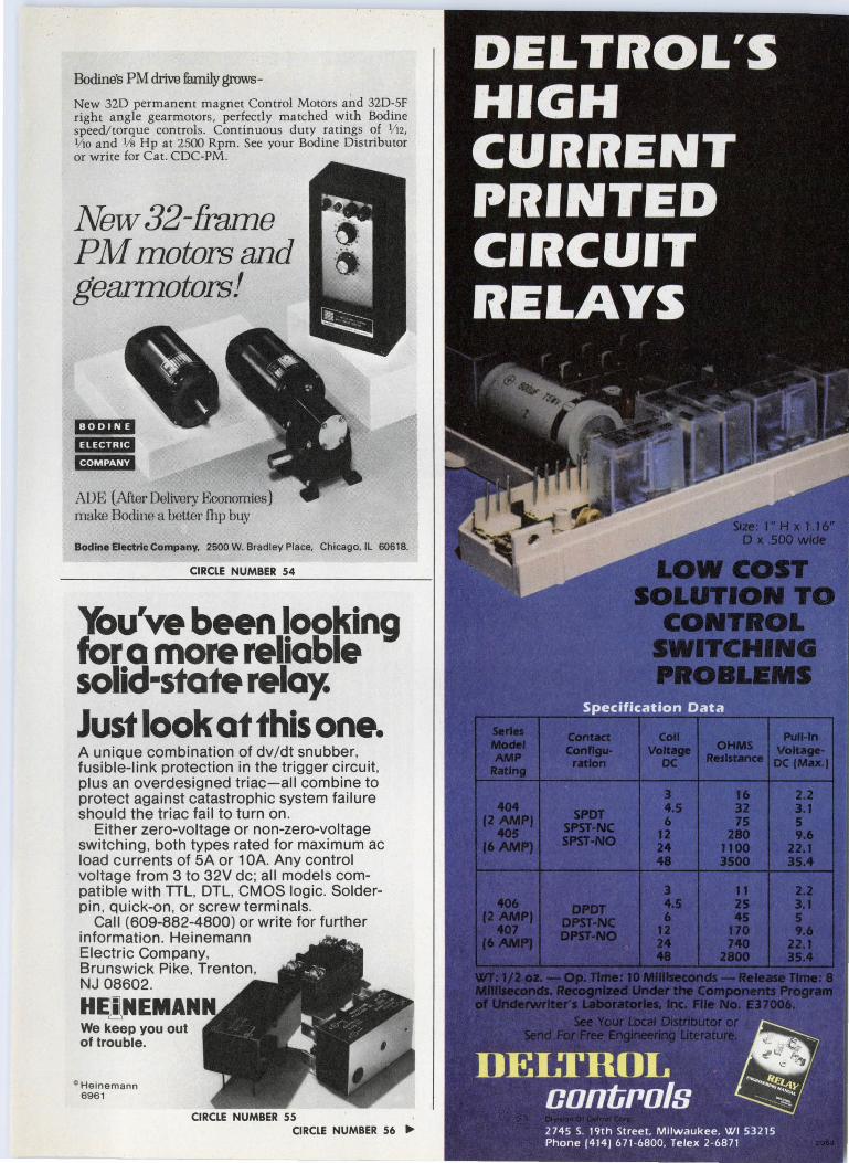
Bodine's PM drive family grows-
New 32D permanent magnet Control Motors and 320-SF right angle gearmotors, perfectly matched with Bodine speed/torque controls. Continuous duty ratings of 1/ 121
l/ 10 and 1/s Hp at 2500 Rpm. See your Bodine Distributor or write for Cat. CDC-PM.
New 32-frame PM motors and gearmotors!
ADE (After Delivery Economies) make Bodine a better fhp buy
Bodine Electric Company, 2500 W. Bradley Place, Chicago, IL 60618.
CIRCLE NUMBER 54
You've been looking for a more reliable solid·state relay. Just look at this one. A unique combination of dv/dt snubber, fusible-link protection in the trigger circuit, plus an overdesigned triac-all combine to protect against catastrophic system failure should the triac fail to turn on.
Either zero-voltage or non-zero-voltage switching, both types rated for maximum ac load currents of SA or 1 OA. Any control voltage from 3 to 32V de; all models compatible with TTL, DTL, CMOS logic. Solderpin, quick-on, or screw terminals.
Call (609-882-4800) or write for further information. Heinemann Electric Company, Brunswick Pike, Trenton, NJ 08602.
HE!lNEMANN We keep you out of trouble.
0 Heinemann 6961
CIRCLE NUMBER 55 CIRCLE NUMBER 56 ...
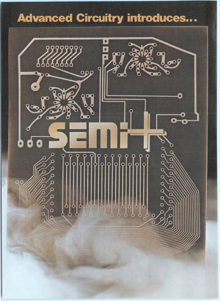
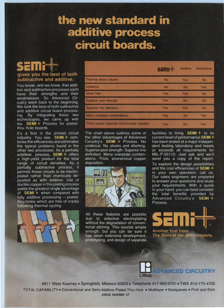
Sim;+ Additive Subtractive
Thermal shock failures No Yes No
No No Yes
Yes Yes No
Superior peel strength Yes No No
Superior line definition Yes Yes No
Many overplate combinations Yes No Yes
A CED CIRCUITRY Litton
4811 West Kearney • Springfield, Missouri 65803 • Telephone 417-862-0751 • TWX 910-775-4 705
TOTAL CAPABILITY• Conventional and Semi-Additive Plated-Thru-Hole •Multilayer• Backpanels •Print and Etch CIRCLE NUMBER 57

DAT A PROCESSING
Dumb terminal is CRT/printer combo
Lear Siegler/EID, 714 N. Brookhurst St., Anaheim, CA 92803. John Pagliaro (BOO) 854-3805. $3890.
The Dumb Connection peripheral package (ADM-3A video terminal, the Model 210 ballistic printer and interconnecting cable) gives the user the flexibility of both a video terminal and a 180-char/s receive-only serial printer. The ADM-3A has 59 data entry keys, a 24-line, 12-in. screen and 1920 char. Switches offer a choice of eleven baud rates (975 to 19,200 baud) and an RS-232 or 20-mA current-loop interface. The Model 210 prints bidirectionally at rates of 75 lines/min for 132 characters or 120 lines/min for 80-char lines.
CIRCLE NO. 356
Data modems operate at 2400 bits/s
Racal-Milgo, 8600 N. W. 41 St., Miami, FL 33166. R. Nathanson (305) 592-8600. $1092 to $1275; 2 wks.
The 24-LSI Mark II modem operates at 2400 bits/sand provides pushbutton test features. Included are internal error test, receive test, and analog and digital loopback tests. Nine LEDs provide continuous indication of key EIA interface signals and modem status. The modems are compatible with ICC 2200/24 and 24-LSI modems, and Western Electric 201B and 201C data sets. The modems allow full-duplex operation over four-wire point-to-point and multipoint dedicated lines, and direct operation over two-wire dial-up lines.
CIRCLE NO. 357 98
Paper-tape reader/punch is whisper-quiet Data Specialties, 3455 Commercial, Northbrook, IL 60062. (312) 564-1800. $2335; 6 wks.
The SRP-3075 whisper-quiet papertape reader/punch with parallel or serial interface punches at speeds up to 75 char/s, and reads up to 300 char/s. The unit punches Mylar, Mylar laminates, oiled, unoiled, rolled and folded tapes without readjustment or modification.
CIRCLE NO. 358
Data terminal uses gas-discharge display
Computerwise, 4006 E. 137 Terrace, Grandview, MO 64030. (816) 765-3330. $995; stock.
The Transactor III data terminal includes a single-line 32-char gas-discharge display and a 53-key TTY-style keyboard. The terminal connects to any computer with an RS-232 or 20-mA current-loop interface or to a communications line through a modem. Switches select the operating mode, including 110 to 9600 baud speeds, full or half duplex, even/odd/no parity, and the station address. The standard unit supports ASCII-coded data. EBCDIC is available as an option.
CIRCLE NO. 359
Video display divides into separate areas Human Designed Systems, 3700 Market St., Philadelphia, PA 19104. (215) 382-5000. $1260 (50 qty).
The Concept 100 CRT terminal handles several different functions simultaneously by allowing the user to divide the display memory into any number of separate rectangular "windows," which can be treated as separate displays. The terminal handles forms control, text editing, line-drawing graphics, multiple pages of display memory and multiple character sets. Up to 19 user-programmable function keys are provided.
CIRCLE NO. 360
Video terminal displays 1920 char/page
Datamedia, 7300 N. Crescent Blvd., Pennsauken, NJ 08110. Bob Sullivan (609) 665-2382. $1520 (100 qty).
The Elite 3025A is a buffered TTYcompatible CRT terminal with a singlepage video memory that displays 1920 alphanumeric characters in a 24-line, 80-char format. Operating modes include local edit, batch, batch modified and transparent. The terminal is asynchronous and compatible with 103 and 202-type modems. Fifteen baud rates, up to 9600, are keyboard selectable.
CIRCLE NO. 361
Small plasma display mounts on desk
..... •
Pichler Associates, 410 Great Rd. , Littleton, MA 01460. Pete Martin (617) 486-8948. $1450; stock to 12 wks.
The DP A64 alphanumeric plasma display is a small desk-mountable, PROM-operated unit that is easy to read in high ambient light over a 120° viewing angle. Plug-compatible with most minicomputers and modems through a 20-mA current-loop or RS232C interface, the UL-listed unit handles up to 9600 baud. A self-refreshing RAM buffers up to 128 char. Changing the PROM produces code and character-font changes. The unit displays up to four 16-char lines of 0.3-in. high 5 X 7 dot matrix characters. The DP A64 measures 6.5 X 7.5 x 8.5 !Il.
CIRCLE NO. 362 ELECTRONIC DESIGN 5, March I, 1978
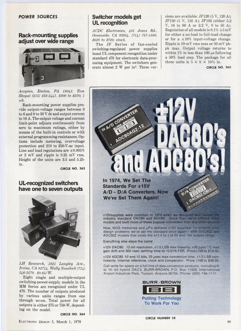
POWER SOURCES
Rack-mounting supplies adjust over wide range
A copian, Easton, PA 18042. Tom Skopal (215) 258-5441 . $300 to $370; 1 wk.
Rack-mounting power supplies provide output-voltage ranges between 0 to 6 and 0 to 50 V de and output current to 16 A. The output voltage and current limit-point adjusts continuously from zero to maximum ratings, either by means of the built-in controls or with external programming resistances. Options include metering, overvoltage protection and 210 to 250-V-ac input. Line and load regulations are ±0.005% or 2 m V and ripple is 0.25 m V rms. Height of the units are 3.5 and 5.25-in.
CIRCLE NO. 363
UL-recognized switchers have one to seven outputs
LH Research, 1821 Langley A ve., Irvine, CA 92714. Wally Nuss lock (714) 546-5279. $0.65/W.
Eight single and multiple-output switching-power-supply models in the MM Series are recognized under UL 478. The number of outputs produced by var ious units ranges from one through seven. Total power for a ll outputs is either 375 or 750-W, depending on the model.
CIRCLE NO. 364
ELECTRON IC D ES IGN 5, March I, 1978
Switcher models get UL recognition ACDC Electronics, 401 Jones Rd., Oceanside, CA 92054. (714) 757-1880. $620 to $720; stock.
The JF Series of fan-cool ed switching-regulated power supplies boast UL component recognition under standard 478 for electronic data-processing equipment. The switchers generate almost 2 W per in3• Three ver-
sions are available: JF120 (5 V, 120 A); J F150 (5 V, 150 A); J F102 (either 5.2 V, 16 to 80 A or 2.2 V, 0 to 50 A). Regulation of all models is 0.1 % ±5 m V for either a no-load to full-load change or for a ±10% input-voltage change. Ripple is 10-m V rms max or 50-m V pkpk max. Output voltage returns to within 1 % in less than 100 µs fo llowing a 50% load step. The package for all three units is 5 X 8 X 101/2 in.
CIRCLE NO. 365
±15Vsupplies were common ltl ) industry standard DAC80 an<! models and built more of these popular~Wi!M
Now, MOS memories and µP's demand .t1:2V sr.ipp Ill design problems we've set the standard once ag81n- • Wfffi ADCBOZ models that cover the ±11 .4 to ±16.0V and +SV supply
Everything else stays the same:
±12V DAC80: 12-bit resolution , ±1 /2 LSB max linearity, .:30 ppm/°C max gain drift and 300 nsec settling time to +0.01% FSA. Price:(100's) $19.50.
±12V ADC80: 10 and 12 bits, 25 µsec max conversion time, ±1/2 LSB nonlinearity, internal reference, clock and comparator. Price: (100's) $49.50.
Ca ll -write for specs on a ful l line of data conversion products, inc luding 8-to 16- bit hybrid DAC's . BURR-BROWN, P.O. Box 11400, International Airport Industrial Park, Tucson, Arizona 85734, Phone: (602) 746-1 11 1.
BURR-BROWN
IEIEll Putting Technology
To Work For You
CIRCLE NUMBER 58 99

New literature
1/20 and 1/10 hp motors Specifications and schematics on a
series of motors and gear motors with input horsepower ranging from 1/50 to 1/10 are shown in a brochure. Molon Motor & Coil, Rolling Meadows, IL
CIRCLE NO. 366
Circuit breakers Photographs, dimensional drawings,
delay curves, specifications of a snapaction magnetic circuit breaker are given in a four-page bulletin. Airpax Electronics, Cambridge, MD
CIRCLE NO. 367
Industrial control µC The IP300 industrial-control-micro
computer system is described in a brochure. The publication discusses operational advantages, hardware features and system software of the IP300. The pamphlet contains a configuration summary listing standard systems, options, and both digital and analog 1/0 modules. Digital Equipment Corp., Communication Services, Northboro, MA
CIRCLE NO. 368
Silicon photodetectors A 24-page electro-optic-components
catalog reviews the physical and electrical properties of silicon photodetectors, providing basic information on structure, response, sensitivity limits, temperature effects and equivalent operating circuits. Centronic, Mountainside, NJ
CIRCLE NO. 369
100
PC board laminates Copper-clad laminates for printed
circuit boards are described in a foldout brochure. The illustrated six-page brochure contains a comprehensive, easy-to-read table that lists applications and technical specifications for each of the many laminate grades and compositions available. Westinghouse Electric, Micarta Div., Hampton, SC
CIRCLE NO. 370
Op amps Data sheets on 18 operational
amplifiers and 22 fast analog-function modules plus a microcomputer are included in a 92-page catalog. A selection guide indexes op-amp modules by slewing rate, by gain-bandwidth at XlOO, and by settling time to 0.1 %. Optical Electronics, Tucson, AZ
CIRCLE NO. 371
Pressure transducers Two bulletins describe 0 to 5-V-dc
isolated-output signal, bonded straingauge pressure transducers. Teledyne Taber, North Tonawanda, NY
CIRCLE NO. 372
UL standards "Catalog of Standards for Safety" is
an easy and quick reference guide to UL's 396 published standards. Underwriters Laboratories, Northbrook, IL
CIRCLE NO. 373
Magnetics
The use of custom magnetics in modern circuits and application information on wideband, rectifier, and pulse transformers and inductors are discussed in a 14-page booklet. Polyphase Instrument, Bridgeport, PA
CIRCLE NO. 374
GP and power relays Specifications, characteristics, wir
ing diagrams and dimensional drawings for more than 1200 stock and special relays are included, as well as socket information, in a 56-page catalog. A relay selection chart guides the user to the proper relay class which fits his particular requirements. Magnecraft, Chicago, IL
CIRCLE NO. 375
Signal processors A brochure describing the new
SPS-61 and SPS-81 programmable digital signal processors features a unique set of comparisons that clearly explain the difference between array processing and real-time signal processing. Signal Processing Systems, Waltham MA
CIRCLE NO. 376
Semiconductors "Integrated Circuits Reference Book
1978," Vol. 1: Analog Circuits ($29.50) and Vol. 2: Digital Circuits ($29.50) lists details of all ICs, with a PRO ELECTRON type number, which are available on the market. It is an upto-date reference source of ICs made in Western Europe. "Semiconductor Reference Book 1978" ($35.00) is a revised and updated Fifth Edition listing the technical characteristics of every semiconductor device made in Western Europe with a PRO ELECTRON type number, which is on the market. Both books include an explanation of the PRO ELECTRON code, a list of the symbols used and a glossary in English, French and German. Scholium International, Flushing, NY
CIRCLE NO. 377
Rf coaxial connectors A 36-page catalog features the SMA
series of rf coaxial connectors. ITT Cannon Electric, Santa Ana, CA
CIRCLE NO. 378
Digital cassette recorders Descriptions, specifications and ap
plication information on low-power recorders for data logging, data loggers with crystal-controlled clocks, universal readers, incremental and continuous read/write cassette systems, OEM incremental transports and ANSI-compatible high-speed continuous recorders are covered in 16 illustrated pages. Block diagrams, outline drawings and timing sequences are also included. Memodyne, Newton Upper Falls, MA
CIRCLE NO. 379
Connectors Cinch Nu-Lok environment-resis
tant coaxial cable connectors that meet MIL-C-25516 are fully described in a 16-page catalog. TRW Cinch Connectors, Elk Grove Village, IL
CIRCLE NO. 380
EL ECTRONIC DESIGN 5, March I, 1978

Bulletin board Raytheon Data Systems Co. has doubled the main memory of its PTS-100 programmable terminal systems and increased the number of operator stations those systems can support.
CIRCLE NO. 381
Longer shelf life, high reliability, and no degradation in power output over operating life are among the advantages of a new hard seal construction technique now being offered on Hughes Aircraft Co.'s line ofheliumneon lasers.
CIRCLE NO. 382
Intel's Microcomputer Components Div.'s 6-MHz 8748 single-chip microcomputer, which was priced at $275 in single-unit quantity and $150 in 100-unit quantity, is now priced at $75 and $48, respectively.
CIRCLE NO. 383
Blank cards for programming Hewlett-Packard's HP-67 and 97 calculators are now available at a reduced price-$195 (1000 qty).
CIRCLE NO. 384
Data General has added comprepensive data communications capabilities to its microNOVA family, giving users the ability to implement asynchronous and synchronous protocols and run Data General's RJE80 (IBM 2780/ 3780) and IBM HASP II emulation packages on a microcomputer system.
CIRCLE NO. 385
Elco's Series 6307, 6064, 6007 and 6308 card-edge connectors are now U.L. approved.
CIRCLE NO. 386
Opcoa's OP· 004 series stud-mount GaP LED panel lamps come with 6-in. insulated leads and provide a variety of indicator functions in equipment requiring LEDs with long lead lengths. The typical luminous intensity at a forward current of 15 mA is 2 med with viewing angles of 60° and 120°. These units come in red, green, and yellow.
CIRCLE NO. 387
ELECTRON IC D ESIGN 5, March I, 1978
Rockwell MOS/LSI Touch Tone detection can
get you into more products. CRC-8030, Rockwell's MOS/LSI digital Touch Tone®detector, can open up new markets for your products by providing a low cost, high performance solution for dual tone multi-frequency (DTMF) detection.
A product of Collins high-technologytelecommunications experience coupled with Rockwell's extensive MOS/ LSI production capability, CRC-8030 has been in quantity production for over a year. Besides traditional telephony systems, it can be used in a growing number of applications including computer signaling and control systems.
CRC-8030reducescosts versus conventional systems (in some cases as much as one fifth the cost) and offers the size and reliability benefits of MOS/ LSI. You get: detection in 22-39 MS; on-chip oscillator operating at 3 .579545 MHz color burst crystal frequency; binary or 2-of-8 coded outputs; operation with single or dual power supply.
The CRC-8030 performs the key critical functions of DTMF detection. To implement a complete DTMF receiver, a number of front-end band-split filters are available. And, if you need DTMF-to-dial pulse conversion, use the CRC-8030 in conjunction with Rockwell's MOS/LSI Binary-to-Dial Pulse Dialer, the CRC-8001.
For more information on telecommunications devices and applications services, contact your nearest Hamilton/ Avnet distributor. Or use the coupon below.
Touch Tone is a registe,..ed trademark of AT & T.
Microelectronic Devices Rockwell International
Get the full story.
P.O. Box 3669, Anaheim, CA 92803 Attn: Marketing Services D/727 RCSS · (714) 632-3698
I want information on D CRC·8030 D CRC-8001 D Send it by mail D Have a salesman call me.
ED-3/1
Name Title ___________ _
Company _________________________ ~
Address ______________ City __________ _
State _______ Zip Code ____ Telephone ________ _
'!' Rockwell International . .. where science gets down to business
IOI
Applieation notes
Power supplies
Power-supply decoupling, preloading and input-transient-suppression methods are treated tutorially in the latest issue of WATTS UP. The 12-page journal includes descriptions of significant new ac/dc and de/de power supplies, plus recent technical literature. Semiconductor Circuits, Haverhill, MA
CIRCLE NO. 388
Capacitance-type switching
A capacitance-switching technique that employs standard microcircuits is described in a 16-page designer's guide. Included are curves and nomographs. American Microsystems, Santa Clara, (;A
CIRCLE NO. 389
Spectrum analyzers The advantages and potential that
can be obtained by interfacing a spectrum analyzer to the computational power and analysis of a computer are discussed in a four-page application note. Marconi Instruments, Northvale, NJ
CIRCLE NO. 390
Soldering problems "Common Production Soldering
Problems: Causes and Cures" details the problems encountered in hand, dip or wave soldering. For each problem a complete visual description is provided for quick identification. Multicore Solders, Westbury, NY
CIRCLE NO. 39 1
V /f and f/v converters Twenty-five applications on both v/f
and f/v converters are given in an application note. Teledyne Semi
. conductor, Mountain View, CA CIRCLE NO. 392
Microcircuit packaging An "Encyclopedia of Hybrid Micro
circuit Packaging," a 74-page booklet, contains nearly 300 subjects, from "A.I.D." to "zymurgy," and 170 illustrations. Qualified persons in the hybrid-microcircuit industry may obtain complimentary copies of the encyclopedia. Isotronics, New Bedford, MA
CIRCLE NO. 393
X-Y recorder The most important features re
quired in a full-capability X-Y recorder are described in a 4-page data sheet. Using the Model 7015B X-Y recorder as an example, the brochure discusses the importance of the internal time base, matched input filters, remote pen lift, TTL-level remote control, autogrip chart hold and paper-alignment guides as well as construction features and product support. Hewlett-Packard, Palo Alto, CA
CIRCLE NO. 394
odds•on choice NEW!
102
There's no need to gamble with selectlvlty that stays put when you specify Murata piezoelectric ceramic filters. Whether your appllcatlon Is AM, TV, FM-stereo or CB, we have Just the 455 KHz, 10.7 MHz or 4.5 MHz filter to do the Job. What's more, we have a variety of ladder type configurations specifically designed for critical communlca· - -=---=------ tlons requirements. Write for
R complete technical and appllca·
.... '. ._.a._ tlon Information to: Murata Cor·
.. _IAll.,j_., ___ -~!..~ poratlon of America, 1148
CORPORATION OF AMERICA
Franklin Road, S.E., Marietta, Georgia 30067. Phone: 404· 952-9777. first In ceramics
CIRCLE NUMBER 59
From ·
CAPllOL - k-
MODEL MLA LEVER SWITCH A panel-mount switch with one-piece molded cam and handle. It extends only 15/s" beh in d panel. Extremel y smooth operation with positive detent action.
COMPLETE SPECIFICATIONS IN NEW BROCHURE
CAPlrOL The Capitol Machine &SwitchCo. 87 Newtown Road, Danbury, CT06810 203- 7 44-3300
CIRCLE NUMBER 60 ELECTRONIC D ESIGN 5, March I, 1978
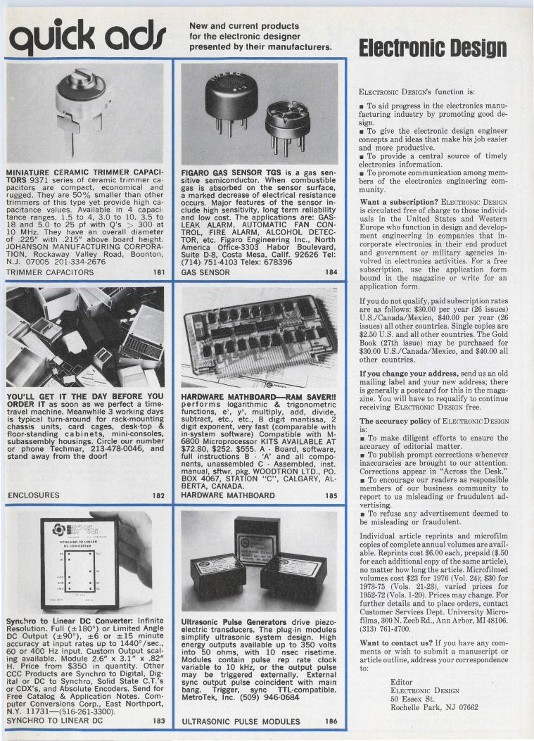
quickod1
MINIATURE CERAMIC TRIMMER CAPACI· TORS 9371 series of ceramic trimmer ca pacitors are compact, economical and rugged. They' are 50% smaller than other trimmers of this type yet provide high ca pacitance values. Available in 4 capacitance ranges, 1.5 to 4, 3 .0 to 10, 3 .5 to 18 and 5.0 to 25 pf with Q's > 300 at 10 MHz. They have an overall diameter of .225" with .215" above board height. JOHANSON MANUFACTURING CORPORATION , Rockaway Valley Road, Boonton, N.J. 07005 201-334-2676 TRIMMER CAPACITORS 181
~
YOU'LL GET IT THE DAY BEFORE YOU ORDER IT as soon as we perfect a time· travel machine. Meanwhile 3 working days is typical turn-around for rack-mounting chassis units, card cages, desk-top & floor-standing cabinets, mini-consoles, subassembly housings. Circle our number or phone Techmar, 213·478·0046, and stand away from the door!
ENCLOSURES
'hi"""'" ,,~ ~ .~ -.-u! ... _
l'NCH•O TO LtNlAI DCCONVlllU .. D.,,. " . . ..
•II" •
.... 11 • • JO• ..... . . ,,
182
Syne;~ro to Linear DC Converter: Infinite Resolution. Full (± 180°) or Limited Angle DC Output (±90°), ±6 or ± 15 minute accuracy at input rates up to 1440° /sec., 60 or 400 Hz input. Custom Output scaling available. Module 2.6" x 3 .1" x .82" H. Price from $350 in quantity. Other CCC Products are Synchro to Digital, Digital or DC to Synchro, Solid State C.T.'s or CDX's, and Absolute Encoders. Send for Free Catalog & Application Notes. Computer Conversions Corp., East Northport, N.Y. 11731-(516-261-3300). SYNCHRO TO LINEAR DC 183
New and current products for the electronic designer presented by their manufacturers.
FIGARO GAS SENSOR TGS is a gas sen· sitive semiconductor. When combustible gas is absorbed on the sensor surface, a marked decrease of electrical resistance occurs. Major features of the sensor in· elude high sensitivity, long term reliability and low cost. The applications are: GAS· LEAK ALARM, AUTOMATIC FAN CON· TROL, FIRE ALARM, ALCOHOL DETEC· TOR, etc. Figaro Engineering Inc., North America Office-3303 Habor Boulevard, Suite D·8, Costa Mesa, Calif. 92626 Tel: (714) 751-4103 Telex: 678396 GAS SENSOR 184
HARDWARE MATHBOARD-RAM SAYER!! performs logarithmic & trigonometric functions, e', y\ multiply, add, divide, subtract, etc., etc., 8 digit mantissa, 2 digit exponent, very fast (comparable with in-system software) Compatible with M-6800 Microprocessor KITS AVAILABLE AT $72.80, $252. $555. A · Board, software, full instructions B · 'A' and all compo· nents, unassembled C · Assembled, inst. manual, sftwr. pkg. WOODTRON LTD., PO. BOX 4067, STATION "C", CALGARY, AL· BERTA, CANADA. HARDWARE MATHBOARD 185
Ultrasonic Pulse Generators drive piezo· electric transducers. The plug-in modules simplify ultrasonic system design. High energy outputs available up to 350 volts into 50 ohms, with 10 nsec risetime. Modules contain pulse rep rate clock variable to 10 kHz, or the output pulse may be triggered externally. External sync output pulse coincident with main bang. Trigger, sync TIL-compatible. MetroTek, Inc. (509) 946·0684
ULTRASONIC PULSE MODULES 186
Electronic oesiun ELECTRONIC DESIGNS function is:
• To aid progress in the electronics manufacturing industry by promoting good design. • To give the electronic design engineer concepts and ideas that make his job easier and more productive. • To provide a central source of timely electronics information. • To promote communication among members of the electronics engineering community.
Want a subscription? ELECTRONIC DESIGN is circulated free of charge to those individuals in the United States and Western Europe who function in design and development engineering in companies that in· corporate electronics in their end product and government or military agencies in· volved in electronics activities. For a free subscription, use the application form bound in the magazine or write for an application form.
If you do not qualify, paid subscription rates are as follows: $30.00 per year (26 issues) U.S./Canada/Mexico, $40.00 per year (26 issues) all other countries. Single copies are $2.50 U.S. and all other countries. The Gold Book (27th issue) may be purchased for $30.00 U.S./Canada/Mexico, and $40.00 all other countries.
If you change your address, send us an old mailing label and your new address; there is generally a postcard for this in the magazine. You will have to requalify to continue receiving ELECTRONIC DESIGN free.
The accuracy policy of ELECTRONIC DESIGN is: • To make diligent efforts to ensure the accuracy of editorial matter. • To publish prompt corrections whenever inaccuracies are brought to our attention. Corrections appear in "Across the Desk." • To encourage our readers as responsible members of our business community to report to us misleading or fraudulent ad· vertising. • To refuse any advertisement deemed to be misleading or fraudulent.
Individual article reprints and microfilm copies of complete annual volumes are available. Reprints cost $6.00 each, prepaid ($.50 for each additional copy of the same article), no matter how long the article. Microfilmed volumes cost $23 for 1976 (Vol. 24); $30 for 1973-75 (Vols. 21-23), varied prices for 1952-72 (Vols. 1-20). Prices may change. For further details and to place orders, contact Customer Services Dept. University Micro· films, 300 N. Zeeb Rd., Ann Arbor, MI 48106. (313) 761-4700.
Want to contact us? If you have any com· ments or wish to submit a manuscript or article outline, address your correspondence to:
Editor ELECTRONIC DESIGN 50 Essex St. Rochelle Park, NJ 07662
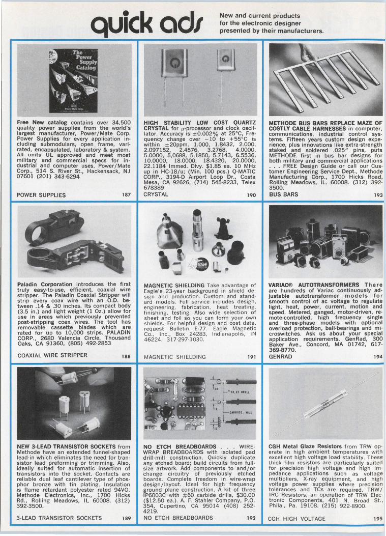
quick ad1 New and current products for the electronic designer presented by their manufacturers.
Free New catalog contains over 34,500 quality power supplies from the world 's largest manufacturer, Power/Mate· Corp. Power Supplies for every application including submodulars, open frame, vari rated, encapsulated, laboratory & system. All units UL approved and meet most military and commercial specs for industrial and computer uses. Power/Mate Corp., 514 S. River St., Hackensack, NJ 07601 (201) 343-6294
POWER SUPPLIES 187
Paladin Corporation introduces the first truly easy-to-use, efficient, coaxial wire stripper. The Paladin Coaxial Stripper will strip every coax wire with an O.D. be· tween .14 & .30 inches. Its compact body (3 .5 in.) and light weight (1 Oz.) allow for use in areas which previously prevented post-stripping coax wires. The tool has removable cassette blades which are rated for up to 10,000 strips. PALADIN CORP., 2680 Valencia Circle, Thousand Oaks, CA 91360, (805) 492-2853
COAXIAL WIRE STRIPPER 188
NEW 3-LEAD TRANSISTOR SOCKETS from Methode have an extended funnel -shaped lead-in which eliminates the need for transistor lead preforming or trimming. Also, ideally suited for automatic insertion of transistors into the socket. Contacts are reliable dual leaf cantilever type of phosphor bronze with tin plating. Insulation is flame retardant polyester rated 94VO. Methode Electronics, Inc., 1700 Hicks Rd., Rolling Meadows, IL 60008. (312) 392-3500.
3-LEAD TRANSISTOR SOCKETS 189
HIGH STABILITY LOW COST QUARTZ CRYSTAL for µ.-processor and clock oscil lator. Accuracy is ±0.002% at 25°C, Frequency change over -10 to + 55°C is within ±20ppm. 1.000, 1.8432, 2.000, 2.097152, 2.4576, 3.2768, 4 .0000, 5.0000, 5,0688, 5.1850, 5.7143, 6.5536, 10.0000, 18.0000, 18.4320, 20.0000, 22.1184 lmmed. Dlvy. $1.85 ea. 10 MHz up in HC-18/u; (Min. 100 pcs.) Q·MATIC CORP., 3194-D Airport Loop Dr., Costa Mesa, CA 92626, (714) 545-8233, Telex 678389 CRYSTAL 190
MAGNETIC SHIELDING Take advantage of Eagle 's 23-year background in shield de· sign and production . Custom and stand · ard models. Full service includes design, engineering, fabrication. heat treating, finishing, testing. Also wide selection of sheet and foil so you can form your own shields . For helpful design and cost data, request Bulletin E·77. Eagle Magnetic Co., Inc., Box 24283 , Indianapolis, IN 46224 , 317·297-1030.
MAGNETIC SHIELDING 191
..L ?.r---· t--"' H . II ORILL
_._ i ....... r.--11 Ll CUllDE MSS
~·---! ,.
NO ETCH BREADBOARDS . . . WIREWRAP BREADBOARDS with isolated pad drill-mill construction . Quickly duplicate any etched board ; build circuits from fullsize artwork. Add components to and/or change circuitry of previously etched boards. Complete freedom in wire-wrap design/layout. Ideal for high frequency ground plane construction . A kit of three IP6003C with # 60 carbide drills, $30.00 ($12.50 ea.) . A. F. Stahler Company, P.O. 354, Cupertino, CA 95014 (408) 252-4219. NO ETCH BREADBOARDS 192
METHODE BUS BARS REPLACE MAZE OF COSTLY CABLE HARNESSES in computer, communications, industrial control systems. Fifteen years custom design experience, plus innovations like extra-strength staked and soldered .025" pins, puts METHODE first in bus bar designs for both military and commercial applications . . . FREE Design Guide or call our Customer Engineering Service Dept., Methode Manufacturing Corp., 1700 Hicks Road, Rolling Meadows, IL. 60008. (312) 392· 3500. BUS BARS 193
VARIAC® AUTOTRANSFORMERS There are hundreds of Variac continuously ad· ju stable autotransformer mode Is for smooth control of ac voltage to regulate light, heat, power, current, motion and speed. Metered, ganged, motor-driven, remote-controlled, high frequency single and three-phase models with optional overload protection, ball-bearings and microswitches. Ask us about your special application requirements. GenRad, 300 Baker Ave., Concord, MA 01742, 617· 369-8770. GEN RAD 194
CGH Metal Glaze Resistors from TRW op· erate in high ambient temperatures with excellent high voltage load stability. These thick film resistors are particularly suited for precision high voltage and high im· pedance applications such as voltage multipliers, X-ray equipment, and high voltage power supplies where precision tolerances and TCs are required. TRW I I RC Resistors, an operation of TRW Elec· tronic Components, 401 N. Broad St., Phila ., Pa. 19108. (215) 922-8900.
CGH HIGH VOLTAGE 195
MINl/BUS:ID BY ROGERS, low-cost, low· inductance, high capacitance printed cir· cuit board bus bars for noise reducing voltage distribution, are available in a variety of ready-to-ship designs. Prototype kits are also available from stock. Call or write Mini/Bus product specialist for a complete list. Rogers Corporation, Chandler, AZ 85224. Phone: (602) 963-4584. (EUROPE: Mektron NV, Gent, Belgium; JAPAN: Nippon Mektron, Tokyo.)
BUS BARS 196
UNIVERSAL JUNCTION UNIT . . . for three devices, RS232C or current loop.
... Six switches provide all 63 interconnects that are possible between three 1-0 devices. LED's indicate data flow. . . . . . . Designed to provide circuit com· patibility and easy data routing between different manufacturer's devices. . . . ... $350 (1-4) from DIGITAL LABORA· TORIES, 600 Pleasant St., Watertown, MA 02172 (617) 924-1680
3 PORT RS232 & 20 MA LOOP 197
FAST, RELIABLE DISCHARGE PRINTER DC-1606B/DC-2106D prints 16 or 21 column alphanumerics in a 5 x 7 dot matrix format. Its MTBF is 5.5 million lines on a 2.25" paper costing less than a half a cent a foot. 3.8" H x 5.4" W x 5.5" D, it is as low as $99 in 100 quan· tity. Interface electronics and power supply available. HYCOM, 16841 Armstrong Ave, Irvine, CA 92714 714/557-5252.
DISCHARGE PRINTER 200
.,DDRMEYER
DORMEYER COACH'S NEW 12-PAGE CAT· ALOG ON COMMERCIAL USE TRANS· FORMERS offers quick reference application help. A wide variety of channel frame and bracket mount open coil 120/30 VAC transformers; Universal Mount control units with 5, 10, 12, 20, 40 and 55 VA ratings are described. Electrical data, load curves and mounting data is given on these U/L and CSA listed or recognized transformers. Dormeyer Industries, Dept. QA 3418 N. Milwaukee Avenue, Chicago, IL 60641, (312) 283-4000. TRANSFORMER CATALOG 201
TIMECO INC. tltftooH••
MAIUFICTUR£RS Of PRECISION ~-COlfllCllll[YJC[.$
!~ -~~ 1~-- ~
! •I• ••• _____ .. -.. _
Free 16 Page Catalog from Timeco, Inc. describes line of Time Delay Relays and other timing devices. Included are On Delay, Off Delay, Interval (one-shot) and Repeat Cycle units. Units are available for DC Voltage from 12 to 120 and AC from 12 to 220. Also AC/DC units as well as 50 Cycles. Time Ranges from .02 Seconds to 16 Minutes. All Units are Guaranteed for 1 Year and over 150,000 are in service.
TIME DELAY RELAY CATALOG 202
Free 1978 Catalog of Recorder Products. Complete description of all Memodyne incremental and continuous digital cassette recorders, data loggers, transports, universal readers and high speed record · ing system with illustrations, block dia· grams, mechanical dimensions and timing sequences are contained in this new catalog. Accessories, supplies, cassettes and a price list are also included. Write for your free copy! Memodyne Corpora· tion, 385 Elliot Street, Newton Upper Falls, MA 02164 (617) 527-6600 FREE RECORDER CATALOG 203
Electronic Design Advertising Sales Staff
Susan G. Apolant Sales Coordinator
Rochelle Park, NJ 07662 Robert W. Gascoigne Thomas P. Barth Stan Tessler Constance McKinley 50 Essex St. (201) 843-0550 TWX: 710-990-5071 (HAYDENPUB ROPK)
Philadelphia Thomas P. Barth (201) 843-0550
Boston 02178 Gene Pritchard P.O. Box 379 Belmont, MA 02178 (617) 489-2340
Chicago 60611 Thomas P. Kavooras Berry Conner, Jr. 200 East Ontario (312) 337-0588
Cleveland Thomas P. Kavooras (312) 337-0588
Los Angeles 90045 Stanley I. Ehrenclou Burt Underwood 8939 Sepulveda Blvd . (213) 641-6544
Texas Burt Underwood (213) 641-6544
San Francisco Robert A. Lukas 465 S. Mathilda, Suite 302 Sunnyvale, CA 94086 (408) 736-6667
England Constance McKinley
50 Essex St. Rochelle Park, N.J. 07662 Phone: (201) 843-0550
Europe Sanders, W. J. M.
Raadhuisstraat 24 Graft-De Ryp, Holland Phone: 02997-1303 Telegrams: Eu radtea m-Amsterdam Telex: 13039-SIPAS
G. Nebut Promotion Presse Internationale 7 ter Cour des Petites Ecuries 75010 Paris, France Telephone: 5231917, 1918, 1919
Dieter Wollenberg Erikastrasse 8 D-8011 Baldham/Muenchen Germany Telephone: 0 8106/4541
Tokyo Haruki Hirayama
EMS, Inc. 5th Floor, Lila Bldg. , 4-9-8 Roppongi Minato-ku, Tokyo, Japan Phone: 402-4556 Cable: EMSINCPERIOD, Tokyo
~ABP •-•w
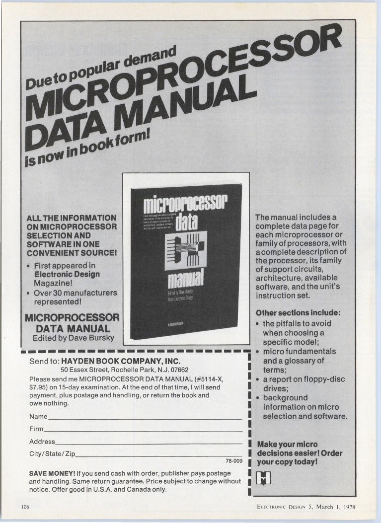
ALL THE INFORMATION ON MICROPROCESSOR SELECTION AND SOFTWARE IN ONE CONVENIENT SOURCE!
• First appeared in Electronic Design Magazine!
• Over 30 manufacturers represented!
MICROPROCESSOR DATA MANUAL
Edited by Dave Bursky
------------------------Send to: HAYDEN BOOK COMPANY, INC. I 50 Essex Street, Rochelle Park, N.J. 07662 I
Please send me MICROPROCESSOR DATA MANUAL (#5114-X, I $7.95) on 15-day examination. At the end of that time, I will send I payment, plus postage and handl ing, or return the book and I owe nothing. I
Firm ___________________ _
I I I
The manual includes a complete data page for each microprocessor or family of processors, with a complete description of the processor, its family of support circuits, architecture, available software, and the unit's instruction set.
Other sections include: • the pitfalls to avoid
when choosing a specific model;
• micro fundamentals and a glossary of terms;
• a report on floppy-disc drives;
• background information on micro selection and software.
Address _ _________________ _ I Make your micro City/State/Zip_______ _ _ ________ I decisions easier! Order
106
1a-oos I your copy today!
SAVE MONEY! If you send cash with order, publisher pays postage and handling. Same return guarantee. Price subject to change without notice. Offer good in U.S.A. and Canada only.
: [JJ ·-------------------
Eu:CTRO 1c D ES IGN 5, March I, 1978
Electronic Design recruitment and classified ads
PLACE YOUR AD AT ONLY $55 PER COLUMN INCH IN
Eleclronlc Design - GET A REPEAT AD FREE!
With our 2 for 1 plan, your net cost in Electronic Design is only $27.50 per column inch, lowest among all the national newspapers and electronics media . You get a total of 165,418 exposures to EDEM engineers and engineering managers (not counting 11 ,668 more among general or corporate managers) at only 33¢ per thousand! You can 't beat the price. You can't beat the coverage and you can't beat the quality.
YOU REACH ENGINEERS WITH TITLES LIKE THESE: • Chief Engineer • Development Engineer • Design Engineer • Project Engineer • Electronic Engineer • Engineer-Supervisor • Section Leader • Staff Engineer • Systems Engineer • Test Engineer • Standards Engineer • Master Engineer
EleclronlcDeslgn RECRUITMENT ADVERTISING RATES 15% commission to recognized agencies supplying offset film negatives. 2% 10 days , net 30 days. Four column makeup. Column width 1-314" x 10". SPACE DIMENSIONS COST
One column inch 2 col. in. 1 /1 6 page (1 /4 col.) 118 page (1 /2 col.) 1/4 page (1 col.)
1 /2 page (2 cols.)
Wide Deep 1-314" x 1" 1-314" x 2" 1-314" x 2-112" 1-3/4" x 5" 1-3/4" x 10" Vert. 3-1 /2" x 5" Hor. 3-1 /2" x 10" Vert. 7" x 5" Hor.
$55. $110. $130. $275. $550.
$1100.
3/4 page (3 cols.) 5-1/4" x 10" $1650. 1 page 7" x 10" $2200. NOTE: EACH RECRUITMENT AD YOU PLACE WILL BE REPEATED FREE OF CHARGE!
LATE CLOSING DATES Electronic Design is mailed every two weeks. Because of its timeliness. personnel recruitment · dvertising closes only two weeks before each issue's mailing date.
Issue Date
Mar.15 Mar. 29 Apr. 12 Apr. 26 May 10 May 24 June 7
Recruitment Closing Date Malling Date
Feb. 17 Mar. 3 Mar. 3 Mar. 17 Mar. 17 Mar. 31 Mar. 31 Apr. 14 Apr. 14 Apr. 28 Apr. 28 May 12 May 12 May 26
HOW TO PLACE YOUR AD
CALL THE RECRUITMENT HOT LINE 201·843·0550
Camera-ready film (right reading negatives, emulsion side down) or cameraready mechanicals must be received by deadline. Or. if you wish us to set your ad (typesetting is free) simply pick up the phone and call our RECRUITMENT HOT LINE - (201) 843-0550. Ask for:
Constance McKinley RECRUITMENT ADVERTISING MANAGER
ELECTRONIC DESIGN 50 Essex Street. Rochelle Park. New Jersey 07662
ELECTRICAL ENGINEERS ANALOG
Engineers to design test stands and associated electrical/electronic controls and data acquistion systems. Experience in solid state closed loop analog control systems.
DIGITAL Engineers to design the hardware. and software of digital computer based equipment used in the testing of high speed rotating machinery and mechanical actuating equipment. Experience in Assembly and Fortran programming of mini-computers is required .
ANALOG/DIGITAL Engineers to design control circuits for turbine systems and other high speed machinery. Must have experience in both analog and digital control circuit design .
Sundstrand Corporation 's Advanced Technology Group designs, manufactures and markets a variety of aircraft accessory products. Sundstrand offers an excellent benefits package including an extensive medical and dental plan. We are located in Rockford, Illinois, providing for easy access to Chicago and to the recreational areas of southern Wisconsin .
Send resumes to:
Eu CTRON 1c D ESIG 5, March I, 1978
SUNDSTRAND CORPORATION Peter L. Arthurs 4751 Harrison Avenue Rockford, IL 61101
An Equal Opportuni ty Employer. M/ F
107
108
MANAGER APPLICATIO!'WS El'WGll'WEERll'WG
to 825,000
Our cltcnl Is a leader in the commercial electronics field and one of the most dynamic and successful among the 1000 lnrA"est Industrial corporations.
They seek n marketing minded multi-project, state of the art cn~lncer to direct an application engineering group. This is an exceptional career opportunity for a BSEE to broaden an en~l nccrlng career through association with sales markellng and project manugemcnt responstbllfllcs.
Our client Is un cquul opportunity cmploycr-'.\t / F uncl pnys all employment expenses. Reply In conrtclcncc to P . Lu11tn~cr.
'~f'J. W. Willard Associates, Inc. (agency!
One Lincoln Center Syracuse, New York 13202 (315) 422·5111
POWER SUPPLY ENGINEERS
Junior and Senior Level Relocation to Dallas, Texas Area
Heavy experience with DC to DC, linear, and high frequency switchers. Openings on all levels with a rapidly
... growing high technology company. Send resume or contact
REACOR, INC. 718 Lingco Drive, Richardson, Tex. 75081
or call (214) 231-7218
SYSTEMS PROGRAMMERS
• Assembler Language • New Systems development • Business applications • Requires 1-4 years ' experience
with major operating systems • Competitive salaries. benefits • Maryland countryside location
Principals only, please. All inquiries confidential.
Mr. W.T. Myers Director of Personnel Management Executive Plaza IV Hunt Valley , Maryland 21031 301 /667-9211
An Equal Opportunity Employer M/ F
ln*ESIQMt: DISPLAY DATA CORPORATION
HOW TO PLACE YOUR AD
CALL THE RECRUITMENT HOT LINE 201 ·843·0550
. '
"' SYSTEMS ENGINEERING: FIRST IN TRUE 32-BIT MINIS
FIRST IN REAL TIME SOLUTIONS FIRST IN CAREER OPPORTUNITY
ALLIN FORT LAUDERDALE We're putting more bytes to work in a real time environment than anyone else 1n the industry. For almost 2 decades. we've bred a family of pacesetting systems. culminating in the first true 32-bit super m1n1 . not a bridge-the-gap system from 16 bit architecture. but a true 32-bit machine with richer instruction sets and larger directly addressable memory.
This kind of presence means opportunity is here . now . along with the resources to really make a name for yourself . If being on the cutting edge of technology. surrounded by year round warmth and swaying palms sounds inviting. consider the many ways available for you to grow at Systems Engineering.
We welcome the professional who 1s highly motivated in the direction of creativity. fresh conceptuahzation. and imaginative problem-solving in state-of-the-art design and software development of small to medium real time systems
I
~ CONTRACT ADMINISTRATOR Senior Level . With Program ~ Management Capability. We require experience , ability and effectiveness ~ at all levels of management in negotiating , drafting . enforcing , and ~ administering fixed-price government and industrial contracts and ~ knowledge of ASPR , and computer systems . Background is essential in ~ either legal , business , or engineering areas. Some travel.
PROJECT ENGINEERS BSEE andexperiencewithjobcosting of custom computer systems.
PROJECT LEADER BSEE and minimum of four years experience as Group Leader involved in job costing for custom computer systems.
MICROPROGRAM MER Minimum of one year design experience in FIRMWARE design. Work involves state-of-the-art advanced concepts .
SENIOR ENGINEERS (DIGIT AL) Four years experience 1n LOGIC DESIGN. Microprocessor or CPU experience highly desirable. Work involves Custom Systems Group.
SOFTWARE TECHNICAL INSTRUCTOR Twoormoreyears teaching computer software courses in industry or academia. Must have knowledge of ASSEMBLY and FORTRAN language.
~l~!~u~~k~~~~~ ~ 12t~Wla~~u~!Y ~o~!~!i~!'!~J s~~s~ background in FORTRAN. Real Time and inter-CPU COMMUNICATIONS and Data Base experience preferred.
~!~f~~r~~x~~r:!~ ~o~ JR~a1!i~~o~ ~n~ ~~pl~~l~:~r~;~e~~: Assemblers and FORTRAN required .
MTS PROGRAMMER (CUSTOMER SERVICE) Minimum of three years in ASSEMBLY and FORTRAN LANGUAGE. Programming background in Real -time and applications environments. Customer contact experience desired . Some travel.
TECHNICIANS DIGITAL 1/ 0 and CPU experience desirable. Will work closely with digital design engineers. Two years experience in troubleshooting .. and testing preferred.
DESIGNER Three to ten years experience 1n electro-mechanical design for a computer manufacturer.
SYSTEMS offers top start1nq salaries. relocation to beautiful Fort Lauderdale , a full-range benefits program including dental insurance. savings/ retirement plan and 100% tuition refund. and the opportunity to work and advance your career in a stable and stimulating professional environment. For immediate and confidential cons1derat1on. please forward resume or detailed letter of information, including current annual compensation to:
MR. FRED BRILLANTE, Dept. ED
ENGINEERING LABORATORIES
8901 W..t Sunrise Blvd., Fort LauderUle, Floria 33313 EQual °""""""''Y Employe< ..... / femolo
Constance McKinley RECRUITMENT ADVERTISING MANAGER
l!LECTRONIC DESIGN 50 EHex Street, Rochelle Park, New Jersey 07662
faEcTRo 1c DESIG 5, March I, 1978
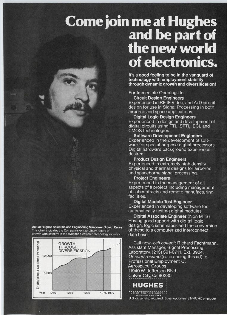

have a gripe?
let ;iis know
about it!
110
We'll help you put pressure on any company that makes promises in its ads .. . then fails to deliver.
Electronic Design refuses to run advertisements deemed to be misleading or fraudulent.
ACCURACY is everybody's business. So if you have a gripe about a misstatement or inaccuracy in either editorial or advertising material in Electronic Design ... tell us about it. We'll do everything we can to find out what happened and see that it's corrected . Notify ...
George Rostky Editor-in-Chief
Electronic Design 50 Essex Street
Rochelle Park, New Jersey 07662
How Much Are You Worth? INCOME ~OUTGO
In most parts of the country the climate has not been good this winter but the climate has never been betterfor Engineers, Technical , Scientific and Manufacturing people desiring a change. Do you want more money, better location or better growth potential?
If you are looking for a change, look to IPA to assist you . One hundred and thirty-five agencies with offices from coast to coast are at your disposal.
All positions are Employer Fee Paid . No cost to you ever'
If you are looking for more than your present position offers, send your resume. salary requirements, position objectives and relocation preference to:
Inter-City Personnel Associates, Inc. P.O. Box 1296 Charlotte, N.C. 28231
'The buck doesn't stop here: it starts here"
Research Engineers Leading Southwest research and development organization has immediate openings for:
Senior Instrumentation Engineer - MSEE plus 5 yrs . experience in design and development of analog and digital solid state circuitry and systems . Desirable prior experience should include project supervision , minicomputer interface design , microprocessors and instrumentation development.
Senior Electronics Engineer - MSEE or Ph .D. plus 5 yrs . experience in digital communication systems design and testing. Assignments will involve point-of-sale terminal polling strategies and equipment, simulation of digital communication network and systems and error rate prediction .
Senior Electronics Engineer - BSEE plus 7 yrs. experience in automatic test equipment using minicomputers and microprocessors. Assignments will include development of automatic test equipment for machinery and electronics.
Electronic Engineers - BSEE plus education background or experience in microprocessors systems design , automatic test equipment or digital communications. Wide variety of challenging project assignment.
Electrical Engineer - BSEE plus 3-5 years experience with electrical power equipment in offshore/ underwater environments.
All positions located in sunny San Antonio. Salary based on qualifications. Excellent benefits . Send resume. with references, in complete confidence to:
Director of Personnel
Southwest Research Institute P.O. Drawer 28510
San Antonio, Texas 78284
EL ECT RO NIC D ESIGN 5, March I , 1978
EFFORTLESS ... If you 're ready to move on with
your career, it can be a lot
easier than you expect.
We are the members of
who work extensively with elec
tronics industry leaders. The
companies we service have
many openings and pay for us
to search you out.
Send your resume to the office
nearest you . Then sit back and
relax while we do the work.
BURTON PERSONNEL SERVICE 300 Walker Bu ilding
120 Boylston Street
Boston, Massachusetts 02116
(61 7) 482-1950
ANDERSON-TAYLOR P.O. Box 21
Exton. Pennsylvania 19341
(21 5) 363-1600
PETER A. KECHIK & ASSOCIATES. INC. 1420 Renaissance Drive
Park Ridge. Ill inois 60068
(312) 298-1148
STAFF DYNAMICS. U.E. 26 Six th Street
Stamford . Connecticut 06905
(203) 324-6191
CAREER SPECIALISTS. INC. 4b00 El Camino Rea l, Su ite 206
Los Altos. California 94022
(415) 941-3200
BRENTWOOD PERSONNEL ASSOCIATES Electronics Division
1280 Route 46
Parsippany , New Jersey 07054
(201) 335-8700
190 associates internationally
r----------------------------~ I I I I I
Power Supply Designers
I Explore the rewards and satisfaction of working on new and : exciting communications and experimental satellite programs.
I
I I I I I
GOES - NASA's Weather/ Environmental Satellite Program
GM S-2 - Japan's Newest Weather Satellite Program
SBS - Privately Owned U.S. Commercial System
ANIK-C - Canada's Latest National Communications System
Join the Hughes team of Space & Co mmun icat ions Enginee rs who are designing high voltage (5 to IO KV), space qua li fied high efficiency power supplies for T WTs. Operations with mult iple co llector T WTs (as loads) present interesti ng des ign challenges.
Experience with series a nd switching regula to rs, T WM converters a nd DC- DC converters a nd BS o r MS in EE are des ired .
For immediate co nsiderat io n please ca ll (co ll ect): Mr. G. Kema nis, Asst. Mgr. Co mmunicat ions La bs, a t (2 13) 648-873 1 or send yo ur res ume to: Professio na l Employment , Dept. 4 1-20, P.O. Box 929 19. Los Ange les , CA 90009.
r------------------1 I I
l HUGHES: t t
L------------------~ HUGHES AIRCRAFT COMPANY
·----------------------------· Engineering Specialists "A Professional Approach to Your Career Growth"
Are you at a career impasse? Are your abilities being stretched to the fullest? If not , take a positive approach and tal k to the specia lists at Gray Kimball Associates. Our nationwide roster of blue-chip c lients have come to re ly on us in rec ruiting topechelon engineering talent . All fees/ expenses paid by our c lients.
Challenging posi tions available nationwide include:
RF Engineers Digital/ Analog Signal Processing Engineers Phase Lock Loop . Microprocessors Spread Spectrum Analysis Display Systems Secure Communication EW System$
Software Engrs/ Reliability/ Programmers Maintainability Real-Time Mini-Computer Engineers
Now is the time to arrange a confidential interview with
Lou Basso (516) 799-5400
• GR:1~ y~~B;~~n ~S~QCl~TES INC. 660 Sway, Massapequa, N.Y. 11758
Our clients are equal opportunity em pl oyers
ENGINEERS SYSTEMS ANALYSTS/
PROGRAMMERS Nat1onw1de Profess ional Fee Pa id Pos1-t1ons Salary Range to 35K Call Collect o r sen d resume to K. Schargus o r S Nemser fo r immediate attention .
Software/ Hardware Analog/ Digital Weapon Systems Microprocessors Sonar/Radar Instrumentat ion Electro optics Test Engineering Electronic Design Mechanical Design
AMERICAN PERSONNEL SERVICE 240 Slate Street
New London, Conn. 06320 203-442-0395
r KEEP
Electronic Design's
GOLD BOOK HANDY When
You Call \. ~
ELi:cTRONic D ESIGN 5, March t. 1978 111
semi CU.STOM
CMOS LSI • Reduce Your Circuit to a Single
Chip with One of Our 14 Master· slices.
• Fast Turn Around - Prototypes in 4 to 6 Weeks.
• Development Cost - As Low As $ 2, 150.
• Quantities from 200 to 200,000 Pieces with Volume Prices as Low as $1.50 Each.
Call
Orhan Tozun or Joe Puhich (408) 735-9370
Or Send for New Brochure:
International Microcircuits, Inc. 3004 Lawrence Expressway Santa Clara, CA. 95051
CIRCLE NUMBER 61
HEWLETT-PACKARD Model YourC011 Model
~~ ~:C2~!~1:i::!11 ~~~Ci~P611 p1r sm ~ ~~ ~~~~~~~~H~~ltfH~;r HP 92 Bond Tr•d•r-F1n.nce-Pnnter 496 95 HP 2SC Sc1ent 11t11ns memory HP 25 Sc1ent.-prog11mm1bl1 99.SO HP 27 Comb Bus.-Sc11nce-S111. HP 90 R/E-Bus-fin ·200 yr c1l1nd1r 234 95 HP 91 Pnn1er Sc11nt· HP 45 specs HP 21 Sc11n1. slide rule 63 95 HP 10 hind held P1r-mem., small HP user hb.sohll boolr.1 l4Cl)euh 9.50 HP 22 RIC Busin111-fin1nc1
HPeccessonH 1td1scountpnce1
Your Cost S596.95
15495 127 95 138.95 25995 139.95 .....
Berween 211na end 3131171, buy one HP-67 or 97, gel S105 worth ol software frH . Buy one HP·l9C or Z9C. get S37 50 of software frH We 1111n HP t11nct11sed d11ler Eich unit comes complete with ch1rger, benenes, CHt, manu1ls Ont v11r gu111nt1t by Hewlttt·P1ct1rd Wt will beat 1nv dt1I. Try us
"'''' TEXASL~~!RUMENTS~ Tl 59 960 prog sttp-100 mt ms S214 95 PC JOOApnnterlorTISS.51-56-52 146.95 Model Your Cost
~~140A~~11~~:· ~~:~dl~;:.~:;theses ~: ~ ~~.~c:.::~.~l~~·,!~l~;l:~·:~:~:. ':~:~ SR 51-2 Super Shdt Rule-Conv, 48 95 Tl 1750 Thin, will. LCD 2M Hrs, mtm. 17.95 D1t1 Chp pencd thin , LCD 1000 H11 2195 MBA 8 u11ness·Fin1nc1·St1t1 6U5 Tll&l:lln11an1Rtpll'(ctlcs 25.95 L1ttl1 Prol lort.1d1Sy1.lup 12 95 Tl 2550-3 8us1ness·M1morv 25 95 Da11-M1n 18111 Pron t duc. 21 .95 Tl 5040 Pnnte1·D11pl1v·Memorv '8 95 Tl 5015 P11n111·G,.nd Tot1l·P1rc1n1 64.95 Tl 5050M AC-DC printer. memory 83 95 Tl 5100 Dtsk·D1grt1I, mtm -p11c1nt 43 95 Tl 1050 Mtm pe1ctnl-1qu111 rool 1295 Tl 1025 Memory-Ptrctnl·+ I- 10.95 llbrtntslorT1591ndTl5B 29.00 TI01g1111Watchts5 1unc1. trom 9.95
~: ~: :::: :;:: :~p~~=s=~ ~ ~ ~:~·~::.w~Jt.~lO.~a'd:i,~~!~~~ ·AH styles 9.9Sup
We1r11Tllr1nch111dd11l1r1ndc1rryTl1ccesson111t d11countpnc11 Wt wtll bt1l 1ny dt1I Try us All Tl ctlculators 111 gu1r1n1eed by TlltH •n11rum1nts, Inc.
SPECIALS Mod ti Nortlco #185D1cta11n11 unit Norelco #BID1c111Jnqunrt Norelco #l86T11nscnb1ng unit Norelco #NT·lntwdict1ting unit Norelco #97d1Ctal111gor t11nsc No11lca #9Bd1C1at1ngortran1c. NortlcoM1mC11stttt1 Cr11g#2625elect.noteboat Cr11g #2706Ad1c1111ngf1tan1c SonylCV-120tColorTnnitron12" SonylCV-1512 Colorl11n1tron15" SonvKV·IS4JR Color Rematt1S" SonvKV·l14lR Colo1 Remo11 17" SonvKV·1921Color l nn1tron 19" Sonv KV-1941R Colar Rtmolt 19" SonvKV-2101Colorlnmtran21"
YourCost Model Your Cost 99.95 Sony KV-214\R Color Rtmott 21" 619.95
~:~:= ~:~h8~~:Reco rder :~:~ 164 00 Rc:AStltct1vi11on 819.95 29100 3M dryphotocopym1ch1nt #l49 7995
~ ~ rcB~~~c~~~~~~·:.::1~: 1ch 11~:~ 149.00 A11n comput TV g1m1f27 wa r g1mes 1" .95 119.95 Phont Mllt-Codt APhone· 309 95 Record A tall-Ans SV'ttms ctM us 359 95 Chnsmaster II, compul 199.95
:,,;; ~:.T~n,~~~d~t~Ct~~'.?1~ 199.95 449.95 Unittta, tlc. pnnt ctlu. e1llu1 529 95 Atan p1nb1H TV 111mt 74.95 559.95
Wo .. .,,-,,-,,-,_.-,,,-,.-~-,-m-,.h-C-,.-,,-,_-.-m-.,-,4-,.-,~-C-ommod0<0-APF-Un111ta- Canon- C1110-Sh1rp-Panason1c- S1nyo-81tly--JVCHV G~n-Kosmos-Victor-S1ncl11r-Pt1rlcord1r-M1dta al1nn-3MMic1om1-Uovds- 801het---ftockwtll-Sentry Sifts- Walton Gvm
112
tqu1pt --JICA--Ztn1th-Sony-A111t-Phont M111-R1cord A C1ll·Cod1 A Phone ind manv more Over 20,000 um1s. !Try COFFEE PLUS 11 SI 79 per ont pound can by tht c111 al 24 cans. F1t1qht prtp11d. Good stll t r I
Pnces 111 lob LA. Goods s11b1tC1 10 1vadao~1ty Ast for our t1mou1 e1t1log. Wew1Ubeat1nypncts1flhecompet1t1onh11thegood1on h1nd
AddS3.00lor1h1ppmgh1ndheldc1lcul1tors CA rt11dentsadd 6%11lt1 t1a.
CIRCLE NUMBER 62
Advertiser's inde#
AFS Precision Tools ......... . ..... . 104 AMP, Incorporated . . ......... . . . .. 10, 11 Advanced Micro Devices ............. 4,5 Allen Bradley Co............. . . . .... 16 American Electronics ................. 91 Analog Devices, Inc .. . . .. .... . . . .. 12, 13
Bodine Co., The . . . . . . . . . . . . . . . . . . . . . 95 Bourns, Inc., Trimpot Products
Di vision ... . .......... .. . . ... Cover II Burr-Brown Research Corporation . . . . . 99 Burroughs Corporation ............... 67
Capitol Machine & Switch Co., Inc., The........ . ........... ... . . 102
Centralab/ USCC. ... . . . ....... . .. . . . 82 Citizen America Corporation .......... 91 Computer Conversions Corp .. . . . . . . . 103 Continenta l Specialties Corpor-
ation. . . . . . . . . . . . . . . . . . . . . . . Cover Ill
Dale Electronics, Inc . . . . . . . . . . . . . . 38,39 Data General Corporation ......... 14, I 5 Data 1/ 0 Corporation ....... . ....... 18 Datel Systems, Inc . . . . . .. . . .. . .. 71 ,73,75 Deltrol Controls . . . . . . . . . . . . . . . . . . . . . 95 Digital Laboratories.... . . .. . . ... . . . . 105 Dormeyer Industries, Inc .. . .. .. . . ... 105
Eagle Magnetics, Inc................ 104 *Electronic Design ................ 95,96 Essex Group, Sub . of United Tech-
nologies. . . . . . . . . . . . . . . . . . . . . . . . . . . 93
Fa irchild Semiconductor, Components Group........................... . 53
Fairchild Systems Technology, A Division of Fairchild Ca mera a nd Instrument Corpor-ation .......................... 16A-B
Figaro Engineering, Inc..... .. .... ... 103
Gen Rad ...................... . .. . . 104 *Gold Book, The. . . . . . . . . . . . . . . . . . . . 97
Hayden Book Co........... . . . . . . . . 106 Heinem ann Electric Company ........ . 95 Hewlett-Packard . . . . .. . . . .. . . .. .... . 1,52 Hycom............ . ............... 105
ITT Community Development Corp ... 85 Intel Corpo ration .............. . .... 8,9 Intel Memory Systems . . . .. .... . .. . 87,89 Intelligent Systems, Inc........... . 80,8 1 International Microcircuits, Inc . .. . ... 11 2
Jo hanson Manufacturing Corp.. .. . . . . 103 Johnson Company, E.F ......... . ... . 90
Kepco, Inc......................... . 30 Keystone Carbon Company ...... . .. .. 28
Litton Advanced Circuitry. . . . . . . . . 96,97
*Mektron .... . ........ . ....... . . . . .. 16
Memodyne Corporation .. ... . . . . . . .. 105 Methode Manufacturing Co.... . .... . 104 MetroTek , Inc..... . . . . . . . . . . . . . . . . . 103 Micro Devices Div. of
Emerson Electronic . . . . . . . . . . . . . . . . 62 Miller-Stephenson Chemical Co., The . . . 6 Murata..... . ....... ... ... .. . . ..... 102
Olympia Sales Company, Inc .. . .... . 112 Optron, Inc . . . . . . . . . . . . . . . . . . . . . . . . . . 7
Paladin Corporation ... .. ... . .. . .. 76,104 *Philips Electronic Components and
Materia ls . . . . . . . . . . . . . . . . . . . . . . . . . 93 Piezo Technology, Inc ....... . .... . ... 84 Power / Mate Corp... . ... . . . . . . . . . . . 104 Precision Mono lithics, Incorporated . . . . 83 Pro-Log Corporation . .. ..... .. ....... 79
Q-M atic Corporation .. . ... ... .. .. ... 104
RCA Solid State Division ...... Cover IV Rockwell Internationa l. . . ....... .. .. IOI Roga n Corporation . . . . . . . . . . . . . . . . . . 88 Rogers Corpora tion .. . ... . ... . ...... 105
Sa lon Interna tiona l des Composants Electroniques. . . . . . . . . . . . . . . . . . . . . . 76
Sea lectro Corporation . . . . . . . . . . . . . . . . 94 Semtech Corporation . . . . . . . . . . . . . . . . . 21 •sfernice. . . . . . . . . . . . . . . . . . . . . . . . . . . . 92 Signeti cs Corporation...... . . . . . . . . . . 25 Slaughter Co . . . . . . . . . . . . . . . . . . . . . . . . 76 Spectronics, Incorporated .......... 27,84 Sprague Electric Compa ny ..... .. .. . .. 29 Standard Grigsby, Inc ........ . . . .. . .. 86 Struthers-Dunn , Inc.. . . . . . . . . . . . . . . . . 17
TDK Electronics ... ...... . .... . .. . ... 34 TRW/ IRC Resistors, an operation of
TRW Electronic Components ...... 104 Tay lor Industries, Inc ...... . ......... 94 Tech mar Omniclosure.. . ... .. .. . .... 103 Tektronix, Inc. . . . . . . . . . . . . . . . . . . . 33,35 Teledyne Relays, A Teledyne
Company.............. . ........... 2 Teledyne Semiconductor .... . . . . . . . . . . 36 Texas Instruments, Incorporated ....... 63 Timeco, Inc. . . . . . . . . . . . . . . . . . . . . . . . 105 Triplett Corporation .. . . . . . . . . . . . . . . . 69
Victory Engineering Corp.. . . . . . . . . . . . 88
Western Digita l Corporation . . . . ... . . . 18 Woodtron, Ltd . . . . . . . . . . . . . . . . . . . . . 103
• Advertisers in non-U .S. edition
RECRUITMENT
Display Data. . . . . . . . . . . . . . . . . . . . . . . 108 Gray, Kimball Associates .. . .... . .... 111 Hughes..... . . . . . . . . . . . . . . . . . . . 109, 111 Intercity.. . . . . . . . . . . . . . . . . . . . . . . . . . 110 Natio na l Personnel Associates... . . . .. 111 So uthwest Resea rch Institute. . . . . . . . . 110 Sunstra nd . . . . . . . . . . . . . . . . . . . . . . . . . . I 07 Systems Engineering Labs...... . . . . . I08
E LECTRONI C DESIG N 5, March I, 1978
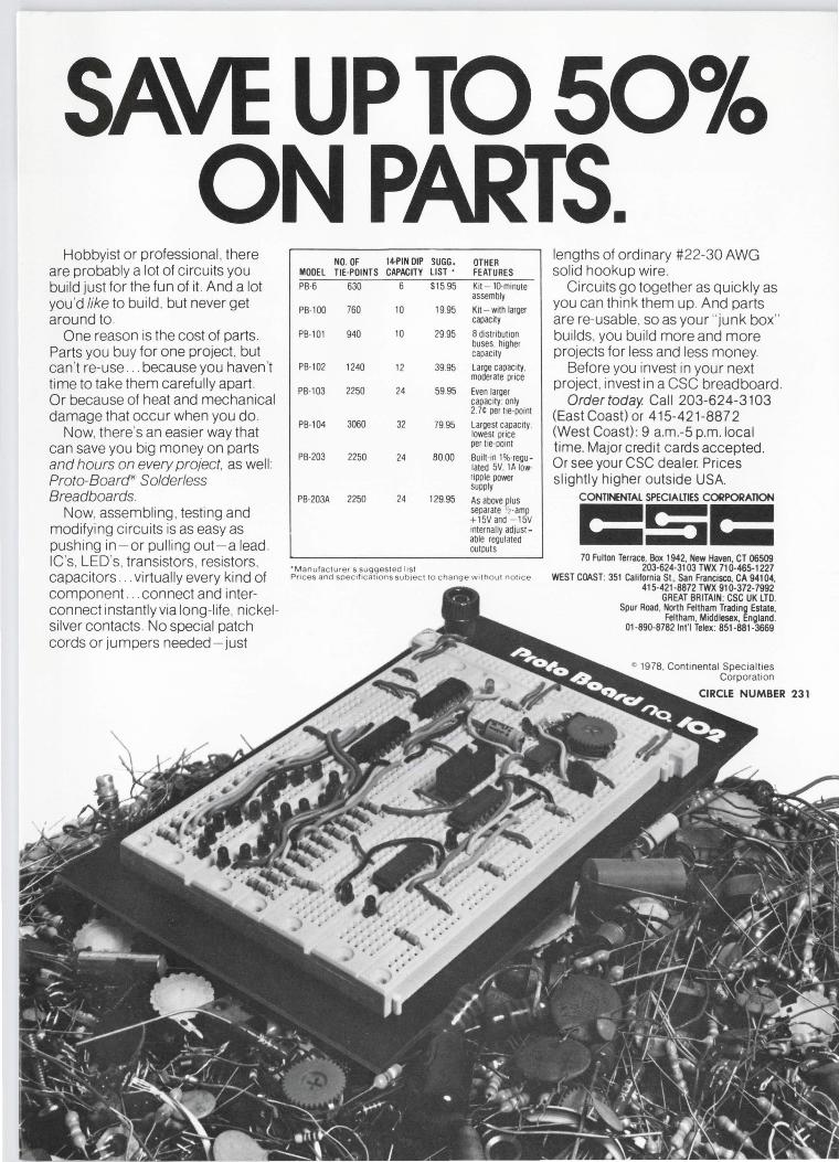
Hobbyist or professional , there are probably a lot of circuits you build just for the fun of it. And a lot you 'd like to build , but never get around to.
One reason is the cost of parts. Parts you buy for one project, but can 't re-use ... because you haven't time to take them carefully apart. Or because of heat and mechanical damage that occur when you do.
Now, there's an easier way that can save you big money on parts and hours on every project, as well : Proto-Board" Solderless Breadboards.
Now, assembling , testing and modifying circuits is as easy as pushing in - or pulling out-a lead . IC's, LED's, transistors , resistors, capacitors ... virtually every kind of component .. connect and interconnect instantly via long-life, nickelsilver contacts. No special patch cords or jumpers needed - just
NO. OF 14-PIN OIP SUGG. OTHER MOOEL TIE-POINTS CAPACITY LIST • FEATURES PB-6 630 6 $15.95 Kit - 10-minute
assembly
PB-100 760 10 19.95 Kit - with larger capacity
PB-101 940 10 29.95 8 distr ibut ion buses. higher capacity
PB-102 1240 12 39.95 Large capacity. moderate price
PB-103 2250 24 59.95 Even larger capacity: only 2.7t per tie-point
PB-104 3060 32 79.95 Largest capacity: lowest price per tie-point
PB-203 2250 24 80.00 Bu ilt-in 1%-regu-lated 5V. 1 A low-ripple pawer supply
PB-203A 2250 24 129.95 As above plus separate '2 -amp +1 5Vand - 15V internally adjust -able regulated outputs
·Manufacturers suggested list Pri ces and soec1f1cat1ons sub1ect 10 c hang e without notice
lengths of ordinary #22-30 AWG solid hookup wire .
Circuits go together as quickly as you can think them up. And parts are re-usable, so as your " junk box" builds, you build more and more projects for less and less money.
Before you invest in your next project, invest in a CSC breadboard .
Ordertoday. Call 203-624-3103 (East Coast) or 415-421-887 2 (West Coast): 9 a.m.-5 p.m. local time. Major credit cards accepted. Or see your CSC dealer. Prices slightly higher outside USA.
CONTINENTAL SPECIALTIES CORPORATION =$= 70 Fulton Terrace, Box 1942, New Haven, CT 06509 203-624-3103 TWX 710-465-1227
WEST COAST: 351 California St., San Francisco, CA 94104, 415-421 -8872 TWX 910-372-7992
GREAT BRITAIN: CSC UK LTD. Spur Road , North Feltham Trading Estate,
Feltham, Middlesex, England. 01 -890-8782 lnt'I Telex : 851-881 -3669
., 1978, Continental Special1ies Corporat ion
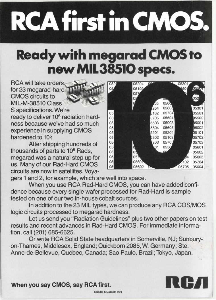
Ready with megarad CMOS to new MIL38510 specs.
RCA will take orders ~iPfri[.'l" '."-for 23 megarad-hard CMOS circuits to MIL-M-38510 Class·-* S specifications. We're ready to deliver 106 radiation hardness because we've had so much experience in supplying CMOS hardened to 10~
After shipping hundreds of thousands of parts to 105 Rads, megarad was a natural step up for us. Many of our Rad-Hard CMOS circuits are now in satellites. Voyagers 1 and 2, for example, which are well into space.
05704 05604
When you use RCA Rad-Hard CMOS, you can have added confidence because every single wafer processed for Rad-Hard is sample tested on one of our two in-house cobalt sources.
In addition to the 23 MIL types, we can produce any RCA COS/MOS logic circuits processed to megarad hardness.
Let us send you "Radiation Guidelines" plus two other papers on test results and recent advances in Rad-Hard CMOS. For immediate information, call (201) 685-6625.
Or write RCA Solid State headquarters in Somerville, NJ; Sunt>uryon-Thames, Middlesex, England; Quickborn 2085, W. Germany; Ste. Anne-de-Bellevue, Quebec, Canada; Sao Paulo, Brazil; Tokyo, Japan.
When you say CMOS, say RCA first. RCll CIRCLE NUMBER 232