peel test of spinnable carbon nanotube webs
TRANSCRIPT
Peel test of spinnable carbon nanotube webs
Noman Khandoker a,b,n, Stephen C. Hawkins c,d, Raafat Ibrahim a, Chi P. Huynh b
a Department of Mechanical and Aerospace Engineering, Monash University, Clayton, Victoria, Australiab CSIRO Material Science and Engineering (CMSE), Bayview Avenue, Clayton, Victoria, Australiac School of Mechanical and Aerospace Engineering, Queen's University Belfast, United Kingdomd Department of Materials Engineering, Monash University, Clayton, Victoria, Australia
H I G H L I G H T S
� Peel tests of carbon nanotube webs have been conducted.� Van der Waals energy between carbon nanotubes has been measured.� The effect of nanotube orientation on Van der Waals energy has been determined.� Experimental result validity is established by analytical calculations from literature.� It is shown that energy for crossed nanotubes is lower than that for parallel nanotubes.
a r t i c l e i n f o
Article history:Received 3 October 2013Accepted 12 February 2014Available online 21 February 2014
Keywords:Carbon nanotubePeel testVan der Waals energy
a b s t r a c t
This paper presents results of peel tests with spinnable carbon nanotube webs. Peel tests were performedto study the effect of orientation angles on interface energies between nanotubes. In absence of anybinding agent the interface energy represents the Van Der Waals energies between the interactingnanotubes. Therefore, the effect of the orientations on Van Der Waals energies between carbon nanotubesis obtained through the peel test. It is shown that the energy for crossed nanotubes at 901 angle is lowerthan the energy for parallel nanotubes at 01 angle. This experimental observation was validated byhypothetical theoretical calculations.
& 2014 Elsevier B.V. All rights reserved.
1. Introduction
Since their discovery carbon nanotubes (CNTs) represent aprominent example of carbon nanomaterial. They have stimulatedintense study for potential applications ranging from single nano-tube based electronics to elevator cables to orbit, from bio-sensorsto composites for aerospace and automotive structure [1]. Individualcarbon nanotubes (Single Wall Nanotubes (SWNT) and Multi-WallNanotubes (MWNT)) are hollow cylinders of seamlessly foldedgraphite sheets and a lot of them are required to be assembled tomake a macroscopic useful item. Carbon nanotube yarn is such amacroscopic item containing trillions of them. But such applicationswhich aimed at exploiting individual nanotube strength succeededneither as pure bulk material nor as composites [2,3]. CNT yarn isproduced by spinning nanotubes from highly oriented drawable
CNT forests [4]. In these drawable forests CNTs tend to interconnecttogether resulting into nanotube bundles as a consequence of theVan der Waals interaction forces. These inherently weak inter-tubeinteractions obstruct the utilisation of the individual strength ofCNTs at macroscopic scales by allowing slippage of nanotubeswithin a bundle before large macroscopic stresses are reached.Hence, it points out the need of better understanding the char-acteristics of inter-tube interactions in order to harness and manip-ulate the individual nanotube strength in macroscale structures.
The experimental work on quantitatively evaluating nanotubeinteractions is very limited, which is quite obvious due to technicalchallenges associated with the nanoscale mechanical manipulationof nanostructures. The innovations and progresses in Atomic ForceMicroscope (AFM) techniques, in-situ Scanning Electron Micro-scope (SEM) and Transmission Electron Microscope (TEM) experi-mental techniques enabled such nanoscale studies to be conducted.However, theoretical studies on carbon nanotube interactions arequite large. Table 1 summarises the results from recent studieson interaction behaviours of carbon nanotubes. However, in theseexperimental studies the types of specimen materials and the
Contents lists available at ScienceDirect
journal homepage: www.elsevier.com/locate/physe
Physica E
http://dx.doi.org/10.1016/j.physe.2014.02.0071386-9477 & 2014 Elsevier B.V. All rights reserved.
n Corresponding author at: Monash University, Department of Mechanical andAerospace Engineering, Clayton Campus, Clayton, Victoria 3800, Australia.Tel.: þ61 3 990 510 88.
E-mail address: [email protected] (N. Khandoker).
Physica E 60 (2014) 160–165
experimental conditions are wide-ranging. Hence, the obtainedresults are quite scattered. Moreover, no experimental studies oninteractions of nanotubes at different orientation angles have beenreported in the current literature.
The macroscale interaction experiments presented in thispaper are conducted with carbon nanotube webs. Carbon nano-tube web is a network of spinnable CNTs that can be densified intostrong sheets which are as thin as 50 nm [5]. In such solid stateprocessing of CNT web and yarn, peeling mechanism is thepremier functional detachment technique of CNT bundles fromthe nanotube forests. Structural models of the zipping unzippingprocesses of CNTs from the spinnable forests (through shreddedcheese like interconnections in a tree model [6] or super alignedCNT pulling model [7]) rely on the peeling mechanism. Hence, themacroscale CNT network interaction behaviour is studied with thewell established peel test technique [8,9].
The objective of this paper is to experimentally investigate theinteraction behaviour of spinnable CNTs at different orientationangles in macroscale without any physical or chemical bondingbetween them. The effect of the orientation angle on the interac-tion behaviour such as interface fracture energy of the spinnableCNT network is studied.
2. Experimental setup
2.1. Sample preparation
The carbon nanotube webs used in this study are prepared fromspinnable MWNTs grown as a forest on silicon wafer by thechemical vapour decomposition (CVD) process. This used semicon-ductor grade Si substrates, with a thermal oxide layer of thickness50 nm and an iron catalyst coating of 2.5 nm deposited by e-beamevaporation. A 44 mm inner diameter quartz reactor was fed withan acetylene concentration of 2.4% in helium (25 sccm in 1000 sccmHe) with a running time of 10 min and temperature of 680 1C. Moredetails of this process are published elsewhere [26]. The verticallyaligned MWNTs in the forest can be drawn into a web of CNTswhich is the major assessment indicator for the spinnabilityproperty of carbon nanotubes [27]. The web was initiated withthe sharp edge of a scalpel plunged down into the forest and thenby pulling it away perpendicular to the nanotube growth direction.The CNTs from the forest string out behind the scalpel and holdtogether without any presence of binding agent.
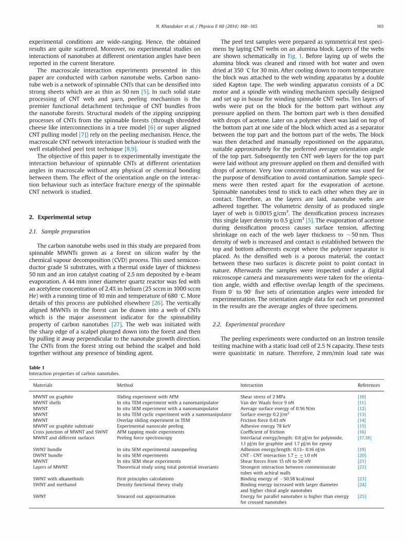
The peel test samples were prepared as symmetrical test speci-mens by laying CNT webs on an alumina block. Layers of the websare shown schematically in Fig. 1. Before laying up of webs thealumina block was cleaned and rinsed with hot water and ovendried at 350 1C for 30 min. After cooling down to room temperaturethe block was attached to the web winding apparatus by a doublesided Kapton tape. The web winding apparatus consists of a DCmotor and a spindle with winding mechanism specially designedand set up in house for winding spinnable CNT webs. Ten layers ofwebs were put on the block for the bottom part without anypressure applied on them. The bottom part web is then densifiedwith drops of acetone. Later on a polymer sheet was laid on top ofthe bottom part at one side of the block which acted as a separatorbetween the top part and the bottom part of the webs. The blockwas then detached and manually repositioned on the apparatus,suitable approximately for the preferred average orientation angleof the top part. Subsequently ten CNT web layers for the top partwere laid without any pressure applied on them and densified withdrops of acetone. Very low concentration of acetone was used forthe purpose of densification to avoid contamination. Sample speci-mens were then rested apart for the evaporation of acetone.Spinnable nanotubes tend to stick to each other when they are incontact. Therefore, as the layers are laid, nanotube webs areadhered together. The volumetric density of as produced singlelayer of web is 0.0015 g/cm3. The densification process increasesthis single layer density to 0.5 g/cm3 [5]. The evaporation of acetoneduring densification process causes surface tension, affectingshrinkage on each of the web layer thickness to �50 nm. Thusdensity of web is increased and contact is established between thetop and bottom adherents except where the polymer separator isplaced. As the densified web is a porous material, the contactbetween these two surfaces is discrete point to point contact innature. Afterwards the samples were inspected under a digitalmicroscope camera and measurements were taken for the orienta-tion angle, width and effective overlap length of the specimens.From 01 to 901 five sets of orientation angles were intended forexperimentation. The orientation angle data for each set presentedin the results are the average angles of three specimens.
2.2. Experimental procedure
The peeling experiments were conducted on an Instron tensiletesting machine with a static load cell of 2.5 N capacity. These testswere quasistatic in nature. Therefore, 2 mm/min load rate was
Table 1Interaction properties of carbon nanotubes.
Materials Method Interaction References
MWNT on graphite Sliding experiment with AFM Shear stress of 2 MPa [10]MWNT shells In situ TEM experiment with a nanomanipulator Van der Waals force 9 nN [11]MWNT In situ SEM experiment with a nanomanipulator Average surface energy of 0.56 N/m [12]MWNT In situ TEM cyclic experiment with a nanomanipulator Surface energy 0.2 J/m2 [13]MWNT Overlap sliding experiment in TEM Friction force 0.43 nN [14]MWNT on graphite substrate Experimental nanoscale peeling Adhesive energy 78 keV [15]Cross junction of MWNT and SWNT AFM tapping mode experiments Coefficient of friction [16]MWNT and different surfaces Peeling force spectroscopy Interfacial energy/length: 0.6 pJ/m for polyimide,
1.1 pJ/m for graphite and 1.7 pJ/m for epoxy[17,18]
SWNT bundle In situ SEM experimental nanopeeling Adhesion energy/length: 0.13– 0.16 nJ/m [19]DWNT bundle In situ SEM experiments CNT�CNT interaction 1.7771.0 nN [20]MWNT In situ SEM shear experiments Shear forces from 15 nN to 50 nN [21]Layers of MWNT Theoretical study using total potential invariants Strongest interaction between commensurate
tubes with achiral walls[22]
SWNT with alkanethiols First principles calculations Binding energy of �50.58 kcal/mol [23]SWNT and methanol Density functional theory study Binding energy increased with larger diameter
and higher chiral angle nanotubes[24]
SWNT Smeared out approximation Energy for parallel nanotubes is higher than energyfor crossed nanotubes
[25]
N. Khandoker et al. / Physica E 60 (2014) 160–165 161
applied in the tests. The specimen was placed on a flat surface andthe peel arm was attached to the cross head of the Instronmachine. Displacement control method was used to apply theload on the specimen. The load displacement response from thetest was recorded automatically to the computer interfaced to theInstron machine. The video of whole test was digitally recordedwith bookmarks for the debonding of the effective over lap sectionof the specimens. The test was manually stopped as soon as thecross head displacement caused the interface to debond up to theeffective overlap length. Later the video was synchronised with therecorded load displacement data and image frames were extractedto be processed for the peel angle data.
3. LEFM analysis of peel test
The peel test can be analysed in terms of energy principles ofLinear Elastic Fracture Mechanics (LEFM) theory. The debonding ofthe interface between the nanotube webs initiates when workdone in breaking is exactly compensated by the gain in surfaceenergy of the system. If UT is the total energy and a is the cracklength, then the interfacial fracture will occur if
dUT
da¼ 0 ð1Þ
Using this criterion Kendall [8] deduced the surface energybetween the top and bottom adherents in a peel test as follows:
G¼ Fð1� cos θÞ ð2Þwhere F is the peel force per unit width and θ is the peel angle. Thissurface energy is the interfacial fracture energy including energiesdissipated due to all modes of mechanical deformations. Correctionfactors considerations regarding the dissipated energies are dis-cussed in the next section. However, the interface fracture occurringin peel test is mixed mode in nature. In mixed mode fracturemechanics analysis the degree of mode mixity is expressed by means
of phase angle which is defined as follows:
φ¼ tan �1
ffiffiffiffiffiffiGII
GI
sð3Þ
where GI and GII are mode-I and mode-II components of energyrelease rate respectively. The total energy release rate thus can begiven by
G¼ GIþGII ð4ÞFor the peel test geometry Thouless and Jensen [28] expressed themode -I and mode-II energies as follows:
GI ¼6M2
0
Et3; GII ¼
F202Et
ð5Þ
F0 ¼ F cos θ; M0 ¼
ffiffiffiffiffiffiffiffiffiffiffiffiffiffiffiffiffiffiffiffiffiffiffiffiffiffiffiffiffiffiffiffiffiffiffiffiffiffiffiffiffiffiffiffiffiffiffiffiffiffiffiffiffiffiffiffiffiffiffiffiffiEt3
6F2 sin 2θ
2EtþFð1� cos θÞ
" #vuut ð6Þ
F0 and M0 are shown in Fig. 1. E and t are the modulus ofelasticity and thickness of the adhered CNT web, respectively,whose values can be found from the article by Zhang et al. [5]. Inpeel test geometry interfacial fracture can be assumed to propa-gate when the total energy release rate G is equal to the modedependent work of separation energy Gf which depends on themixed mode fracture criterion. De Lorenzis and Zavarise [29]proposed the following mixed mode fracture criterion for peeltest:
GI
GIfþ GII
GIIf¼ 1 ð7Þ
where GIf and GIIf denote the fracture energies in pure mode-I andpure mode-II conditions respectively. This mixed mode criterionrepresents the fracture envelop as a straight line on the coordi-nates of mode-I and mode-II fracture energies which can bedetermined from Eq. (5). The peel angle and the peel force areobtained from the recorded data of the experiments described in
Effective overlap length Polymer separator
Orientation angle 0 degree
Orientation angle 90 degree
Orientation angle degree
Fig. 1. Symmetric peel test specimen. (a) Schematic 3D view of peel test specimen and (b) Different peel test specimens used in the study.
N. Khandoker et al. / Physica E 60 (2014) 160–165162
Section 2. Hence, the pure mode energies are determined from theintercepts on the respective coordinate axis. The obtained resultsare presented and discussed in the following section.
4. Results and discussions
4.1. Interface failure mode
The failure modes of the specimens were observed during theprogress of the peel tests. The debonding was initiated through thepolymer separation between the adhered nanotube webs. In all ofthe tests the interface debonded along the bond line leaving thetop and bottom adhered intact. Therefore, these peel tests data canbe used to calculate interface failure energy.
4.2. Interface failure energy
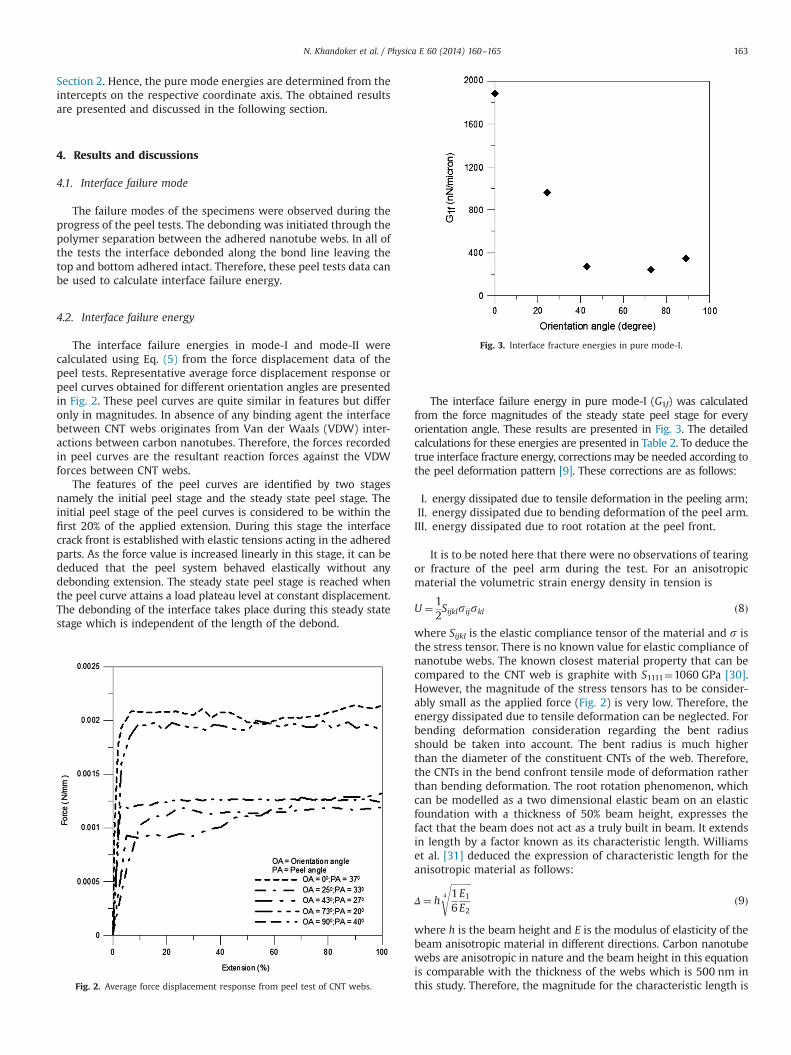
The interface failure energies in mode-I and mode-II werecalculated using Eq. (5) from the force displacement data of thepeel tests. Representative average force displacement response orpeel curves obtained for different orientation angles are presentedin Fig. 2. These peel curves are quite similar in features but differonly in magnitudes. In absence of any binding agent the interfacebetween CNT webs originates from Van der Waals (VDW) inter-actions between carbon nanotubes. Therefore, the forces recordedin peel curves are the resultant reaction forces against the VDWforces between CNT webs.
The features of the peel curves are identified by two stagesnamely the initial peel stage and the steady state peel stage. Theinitial peel stage of the peel curves is considered to be within thefirst 20% of the applied extension. During this stage the interfacecrack front is established with elastic tensions acting in the adheredparts. As the force value is increased linearly in this stage, it can bededuced that the peel system behaved elastically without anydebonding extension. The steady state peel stage is reached whenthe peel curve attains a load plateau level at constant displacement.The debonding of the interface takes place during this steady statestage which is independent of the length of the debond.
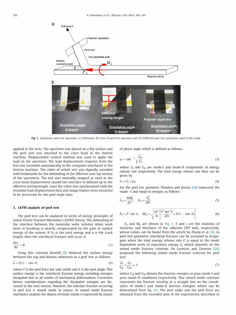
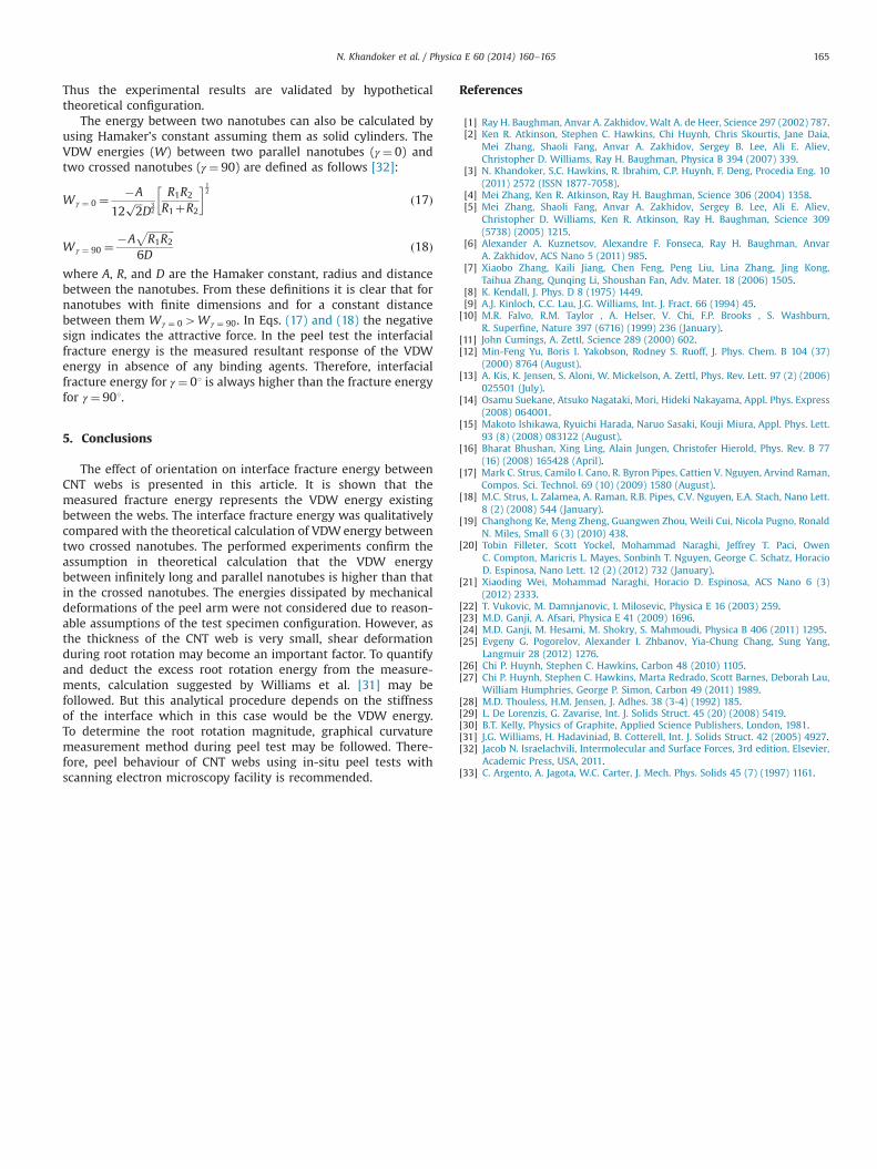
The interface failure energy in pure mode-I (G1f) was calculatedfrom the force magnitudes of the steady state peel stage for everyorientation angle. These results are presented in Fig. 3. The detailedcalculations for these energies are presented in Table 2. To deduce thetrue interface fracture energy, corrections may be needed according tothe peel deformation pattern [9]. These corrections are as follows:
I. energy dissipated due to tensile deformation in the peeling arm;II. energy dissipated due to bending deformation of the peel arm.III. energy dissipated due to root rotation at the peel front.
It is to be noted here that there were no observations of tearingor fracture of the peel arm during the test. For an anisotropicmaterial the volumetric strain energy density in tension is
U ¼ 12Sijklsijskl ð8Þ
where Sijkl is the elastic compliance tensor of the material and s isthe stress tensor. There is no known value for elastic compliance ofnanotube webs. The known closest material property that can becompared to the CNT web is graphite with S1111¼1060 GPa [30].However, the magnitude of the stress tensors has to be consider-ably small as the applied force (Fig. 2) is very low. Therefore, theenergy dissipated due to tensile deformation can be neglected. Forbending deformation consideration regarding the bent radiusshould be taken into account. The bent radius is much higherthan the diameter of the constituent CNTs of the web. Therefore,the CNTs in the bend confront tensile mode of deformation ratherthan bending deformation. The root rotation phenomenon, whichcan be modelled as a two dimensional elastic beam on an elasticfoundation with a thickness of 50% beam height, expresses thefact that the beam does not act as a truly built in beam. It extendsin length by a factor known as its characteristic length. Williamset al. [31] deduced the expression of characteristic length for theanisotropic material as follows:
Δ¼ h
ffiffiffiffiffiffiffiffiffi16E1E2
4
sð9Þ
where h is the beam height and E is the modulus of elasticity of thebeam anisotropic material in different directions. Carbon nanotubewebs are anisotropic in nature and the beam height in this equationis comparable with the thickness of the webs which is 500 nm inthis study. Therefore, the magnitude for the characteristic length isFig. 2. Average force displacement response from peel test of CNT webs.
Fig. 3. Interface fracture energies in pure mode-I.
N. Khandoker et al. / Physica E 60 (2014) 160–165 163
extremely low. Therefore, energy dissipated for the root rotation isnot considered in the present study.
The variation in the pure mode energy is originated from thevariation of Van Der Waals forces. Van der Waals force is generatedby instantaneous polarisation of atoms and molecules caused byquantum mechanical effect [32]. By using interaction potential w,which is a function of separation distance s between the particles,the Van der Waals force f can be calculated for a pair of atoms orsmall molecules as follows:
wðsÞ ¼ � Cs6
ð10Þ
f ¼ �∇w ð11Þwhere C is a material dependent interaction constant. The negativesign signifies the attractive nature of the force. The total Van derWaals force between macroscopic bodies can be derived from Eq.(11) considering the total volumes of bodies as follows:
Fvdw ¼ �ρ1ρ2
ZV1
ZV2
∇wdV1dV2 ð12Þ
where ρi and Vi represent the number density and volume of bodyi¼ 1 and 2. Eq. (12) does not have an analytical solution except infew special cases. Therefore, the integral has to be evaluated bynumerical procedure. To reduce the computational complexity thevolume integrals can be converted to surface integrals [33] by usingthe divergence theorem and assuming a vector field J such that
∇J ¼ �w ð13ÞBy combining Eqs. (12) and (13) the following surface formula-
tion of the total Van der Waals force is obtained:
Fvdw ¼ ρ1ρ2
ZS1
ZS2ðJn1Þn2dS1dS2 ð14Þ
where ρi; Si;ni represent the atomic number density, boundarysurface and outward pointing unit normal of surface i ¼1 and2 respectively. If x is a vector from a point on body 2 to a point onbody 1, then the distance s between these points becomess¼ ðxUxÞ1=2and the expression for function J from Eq. (13) becomesas follows:
J ¼ C Ux
3ðxUxÞ3ð15Þ
The integration in Eq. (14) goes over all points on each surface.The orientation angle of the peel test geometry used in this studycontrols the magnitude of the vector x in Eq. (15). Thus if x islower then J is higher and vice versa. When J is high inmagnitude, total VWD force becomes higher and vice versa. Inthe case of parallel nanotubes x is lower but for crossednanotubes x is higher. Thus peel force for 01 orientation is highestand for other orientation angles it decreases accordingly. Hence,the interfacial energy values differ in magnitudes for differentorientation angles.
4.3. Qualitative comparison of peel force
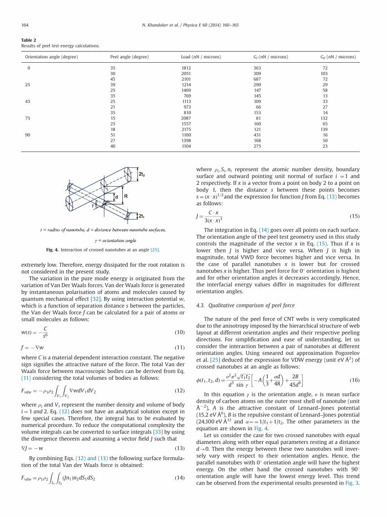
The nature of the peel force of CNT webs is very complicateddue to the anisotropy imposed by the hierarchical structure of weblayout at different orientation angles and their respective peelingdirections. For simplification and ease of understanding, let usconsider the interaction between a pair of nanotubes at differentorientation angles. Using smeared out approximation Pogorelovet al. [25] deduced the expression for VDW energy (unit eV Å2) ofcrossed nanotubes at an angle as follows:
ϕðt1; t2; dÞ ¼υ2π2
ffiffiffiffiffiffiffiffiffit1t2
p
d3 sin γ�A
13þαd48
� �þ 2B
45d6
� �ð16Þ
In this equation γ is the orientation angle, υ is mean surfacedensity of carbon atoms on the outer most shell of nanotube (unitÅ�2), A is the attractive constant of Lennard–Jones potential(15.2 eV Å6), B is the repulsive constant of Lennard–Jones potential(24,100 eV Å12 and α¼¼1/t1þ1/t2. The other parameters in theequation are shown in Fig. 4.
Let us consider the case for two crossed nanotubes with equaldiameters along with other equal parameters resting at a distanced-0. Then the energy between these two nanotubes will inver-sely vary with respect to their orientation angles. Hence, theparallel nanotubes with 01 orientation angle will have the highestenergy. On the other hand the crossed nanotubes with 901orientation angle will have the lowest energy level. This trendcan be observed from the experimental results presented in Fig. 3.
Table 2Results of peel test energy calculations.
Orientation angle (degree) Peel angle (degree) Load (nN / microns) GI (nN / microns) GII (nN / microns)
0 35 1812 363 7230 2051 309 10345 2101 687 72
25 39 1214 290 2925 1469 147 5835 769 145 13
43 25 1113 109 3321 973 66 2735 810 153 14
73 15 2087 81 13225 1557 160 6518 2175 121 139
90 51 1100 431 1627 1398 168 5040 1104 275 23
Fig. 4. Interaction of crossed nanotubes at an angle [25].
N. Khandoker et al. / Physica E 60 (2014) 160–165164
Thus the experimental results are validated by hypotheticaltheoretical configuration.
The energy between two nanotubes can also be calculated byusing Hamaker’s constant assuming them as solid cylinders. TheVDW energies (W) between two parallel nanotubes (γ ¼ 0) andtwo crossed nanotubes (γ ¼ 90) are defined as follows [32]:
W γ ¼ 0 ¼�A
12ffiffiffi2
pD
32
R1R2
R1þR2
� �12
ð17Þ
W γ ¼ 90 ¼�A
ffiffiffiffiffiffiffiffiffiffiffiR1R2
p6D
ð18Þ
where A, R, and D are the Hamaker constant, radius and distancebetween the nanotubes. From these definitions it is clear that fornanotubes with finite dimensions and for a constant distancebetween them Wγ ¼ 04W γ ¼ 90. In Eqs. (17) and (18) the negativesign indicates the attractive force. In the peel test the interfacialfracture energy is the measured resultant response of the VDWenergy in absence of any binding agents. Therefore, interfacialfracture energy for γ ¼ 01 is always higher than the fracture energyfor γ ¼ 901.
5. Conclusions
The effect of orientation on interface fracture energy betweenCNT webs is presented in this article. It is shown that themeasured fracture energy represents the VDW energy existingbetween the webs. The interface fracture energy was qualitativelycompared with the theoretical calculation of VDW energy betweentwo crossed nanotubes. The performed experiments confirm theassumption in theoretical calculation that the VDW energybetween infinitely long and parallel nanotubes is higher than thatin the crossed nanotubes. The energies dissipated by mechanicaldeformations of the peel arm were not considered due to reason-able assumptions of the test specimen configuration. However, asthe thickness of the CNT web is very small, shear deformationduring root rotation may become an important factor. To quantifyand deduct the excess root rotation energy from the measure-ments, calculation suggested by Williams et al. [31] may befollowed. But this analytical procedure depends on the stiffnessof the interface which in this case would be the VDW energy.To determine the root rotation magnitude, graphical curvaturemeasurement method during peel test may be followed. There-fore, peel behaviour of CNT webs using in-situ peel tests withscanning electron microscopy facility is recommended.
References
[1] Ray H. Baughman, Anvar A. Zakhidov, Walt A. de Heer, Science 297 (2002) 787.[2] Ken R. Atkinson, Stephen C. Hawkins, Chi Huynh, Chris Skourtis, Jane Daia,
Mei Zhang, Shaoli Fang, Anvar A. Zakhidov, Sergey B. Lee, Ali E. Aliev,Christopher D. Williams, Ray H. Baughman, Physica B 394 (2007) 339.
[3] N. Khandoker, S.C. Hawkins, R. Ibrahim, C.P. Huynh, F. Deng, Procedia Eng. 10(2011) 2572 (ISSN 1877-7058).
[4] Mei Zhang, Ken R. Atkinson, Ray H. Baughman, Science 306 (2004) 1358.[5] Mei Zhang, Shaoli Fang, Anvar A. Zakhidov, Sergey B. Lee, Ali E. Aliev,
Christopher D. Williams, Ken R. Atkinson, Ray H. Baughman, Science 309(5738) (2005) 1215.
[6] Alexander A. Kuznetsov, Alexandre F. Fonseca, Ray H. Baughman, AnvarA. Zakhidov, ACS Nano 5 (2011) 985.
[7] Xiaobo Zhang, Kaili Jiang, Chen Feng, Peng Liu, Lina Zhang, Jing Kong,Taihua Zhang, Qunqing Li, Shoushan Fan, Adv. Mater. 18 (2006) 1505.
[8] K. Kendall, J. Phys. D 8 (1975) 1449.[9] A.J. Kinloch, C.C. Lau, J.G. Williams, Int. J. Fract. 66 (1994) 45.[10] M.R. Falvo, R.M. Taylor , A. Helser, V. Chi, F.P. Brooks , S. Washburn,
R. Superfine, Nature 397 (6716) (1999) 236 (January).[11] John Cumings, A. Zettl, Science 289 (2000) 602.[12] Min-Feng Yu, Boris I. Yakobson, Rodney S. Ruoff, J. Phys. Chem. B 104 (37)
(2000) 8764 (August).[13] A. Kis, K. Jensen, S. Aloni, W. Mickelson, A. Zettl, Phys. Rev. Lett. 97 (2) (2006)
025501 (July).[14] Osamu Suekane, Atsuko Nagataki, Mori, Hideki Nakayama, Appl. Phys. Express
(2008) 064001.[15] Makoto Ishikawa, Ryuichi Harada, Naruo Sasaki, Kouji Miura, Appl. Phys. Lett.
93 (8) (2008) 083122 (August).[16] Bharat Bhushan, Xing Ling, Alain Jungen, Christofer Hierold, Phys. Rev. B 77
(16) (2008) 165428 (April).[17] Mark C. Strus, Camilo I. Cano, R. Byron Pipes, Cattien V. Nguyen, Arvind Raman,
Compos. Sci. Technol. 69 (10) (2009) 1580 (August).[18] M.C. Strus, L. Zalamea, A. Raman, R.B. Pipes, C.V. Nguyen, E.A. Stach, Nano Lett.
8 (2) (2008) 544 (January).[19] Changhong Ke, Meng Zheng, Guangwen Zhou, Weili Cui, Nicola Pugno, Ronald
N. Miles, Small 6 (3) (2010) 438.[20] Tobin Filleter, Scott Yockel, Mohammad Naraghi, Jeffrey T. Paci, Owen
C. Compton, Maricris L. Mayes, Sonbinh T. Nguyen, George C. Schatz, HoracioD. Espinosa, Nano Lett. 12 (2) (2012) 732 (January).
[21] Xiaoding Wei, Mohammad Naraghi, Horacio D. Espinosa, ACS Nano 6 (3)(2012) 2333.
[22] T. Vukovic, M. Damnjanovic, I. Milosevic, Physica E 16 (2003) 259.[23] M.D. Ganji, A. Afsari, Physica E 41 (2009) 1696.[24] M.D. Ganji, M. Hesami, M. Shokry, S. Mahmoudi, Physica B 406 (2011) 1295.[25] Evgeny G. Pogorelov, Alexander I. Zhbanov, Yia-Chung Chang, Sung Yang,
Langmuir 28 (2012) 1276.[26] Chi P. Huynh, Stephen C. Hawkins, Carbon 48 (2010) 1105.[27] Chi P. Huynh, Stephen C. Hawkins, Marta Redrado, Scott Barnes, Deborah Lau,
William Humphries, George P. Simon, Carbon 49 (2011) 1989.[28] M.D. Thouless, H.M. Jensen, J. Adhes. 38 (3-4) (1992) 185.[29] L. De Lorenzis, G. Zavarise, Int. J. Solids Struct. 45 (20) (2008) 5419.[30] B.T. Kelly, Physics of Graphite, Applied Science Publishers, London, 1981.[31] J.G. Williams, H. Hadaviniad, B. Cotterell, Int. J. Solids Struct. 42 (2005) 4927.[32] Jacob N. Israelachvili, Intermolecular and Surface Forces, 3rd edition, Elsevier,
Academic Press, USA, 2011.[33] C. Argento, A. Jagota, W.C. Carter, J. Mech. Phys. Solids 45 (7) (1997) 1161.
N. Khandoker et al. / Physica E 60 (2014) 160–165 165