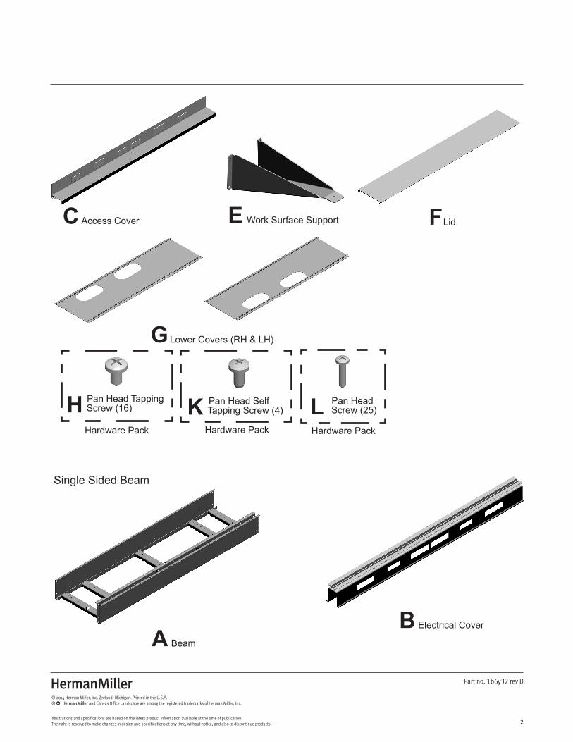
parts included: - herman miller
TRANSCRIPT
Z
1
Part no. 1b6y32 rev D.
© 2014 Herman Miller, Inc. Zeeland, Michigan. Printed in the U.S.A.® Y, Z and Canvas Office Landscape are among the registered trademarks of Herman Miller, Inc.
Illustrations and specifications are based on the latest product information available at the time of publication. The right is reserved to make changes in design and specifications at any time, without notice, and also to discontinue products.
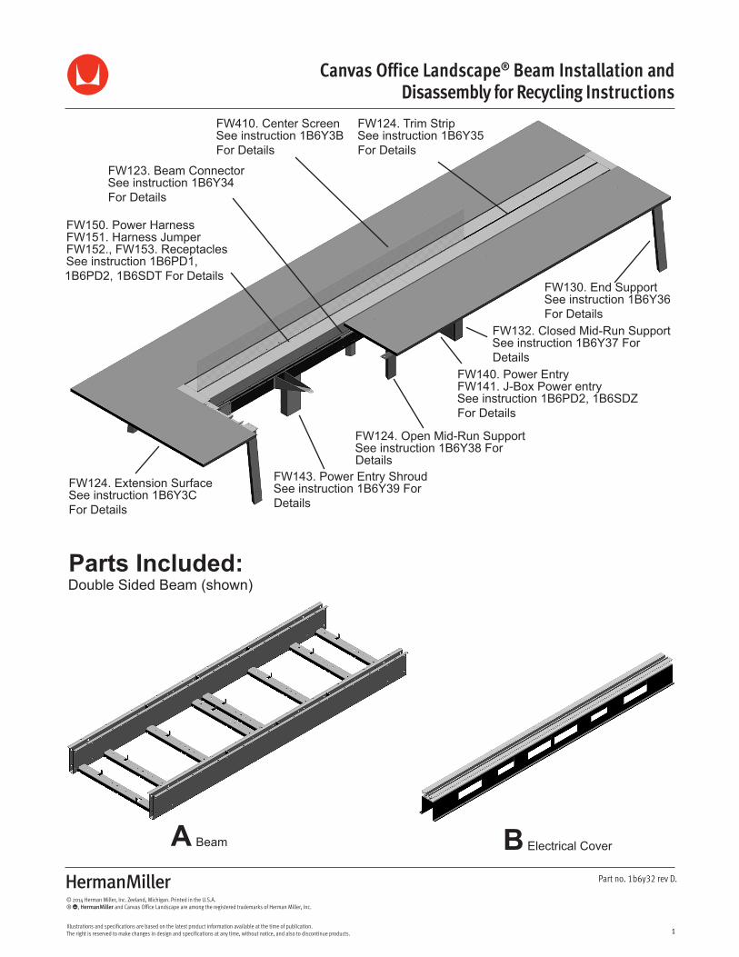
Y Canvas Office Landscape® Beam Installation and Disassembly for Recycling Instructions
FW124. Trim StripSee instruction 1B6Y35For Details
FW130. End SupportSee instruction 1B6Y36For Details
FW132. Closed Mid-Run SupportSee instruction 1B6Y37 ForDetails
FW140. Power EntryFW141. J-Box Power entrySee instruction 1B6PD2, 1B6SDZFor Details
FW124. Open Mid-Run SupportSee instruction 1B6Y38 ForDetails
FW143. Power Entry ShroudSee instruction 1B6Y39 ForDetails
FW123. Beam ConnectorSee instruction 1B6Y34For Details
FW150. Power HarnessFW151. Harness JumperFW152., FW153. ReceptaclesSee instruction 1B6PD1,1B6PD2, 1B6SDT For Details
FW124. Extension SurfaceSee instruction 1B6Y3CFor Details
FW410. Center ScreenSee instruction 1B6Y3BFor Details
Parts Included:
Beam Electrical CoverA B
Double Sided Beam (shown)
Z
2
Part no. 1b6y32 rev D.
© 2014 Herman Miller, Inc. Zeeland, Michigan. Printed in the U.S.A.® Y, Z and Canvas Office Landscape are among the registered trademarks of Herman Miller, Inc.
Illustrations and specifications are based on the latest product information available at the time of publication. The right is reserved to make changes in design and specifications at any time, without notice, and also to discontinue products.
Hardware Pack
Lower Covers (RH & LH)
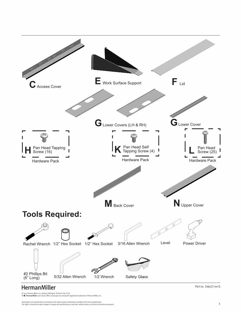
LidWork Surface SupportAccess Cover
G
FEC
Hardware Pack Hardware Pack
Pan Head Tapping Screw (16)
Pan Head SelfTapping Screw (4)
Pan Head Screw (25)H K L
BeamA
Single Sided Beam
Electrical CoverB
Z
3
Part no. 1b6y32 rev D.
© 2014 Herman Miller, Inc. Zeeland, Michigan. Printed in the U.S.A.® Y, Z and Canvas Office Landscape are among the registered trademarks of Herman Miller, Inc.
Illustrations and specifications are based on the latest product information available at the time of publication. The right is reserved to make changes in design and specifications at any time, without notice, and also to discontinue products.
Access CoverC
Hardware Pack
Lower Covers (LH & RH) Lower Cover
LidWork Surface Support
Back Cover Upper Cover
G G
FE
M N
Hardware Pack
Pan Head SelfTapping Screw (4)
Pan Head Screw (25)K L
Hardware Pack
Pan Head Tapping Screw (16)H
Tools Required:
Power Driver
#2 Phillips Bit(6” Long)
Rachet Wrench 1/2” Hex Socket 1/2” Hex Socket
1/2 Wrench
Level3/16 Allen Wrench
5/32 Allen Wrench Safety Glass
Z
4
Part no. 1b6y32 rev D.
© 2014 Herman Miller, Inc. Zeeland, Michigan. Printed in the U.S.A.® Y, Z and Canvas Office Landscape are among the registered trademarks of Herman Miller, Inc.
Illustrations and specifications are based on the latest product information available at the time of publication. The right is reserved to make changes in design and specifications at any time, without notice, and also to discontinue products.
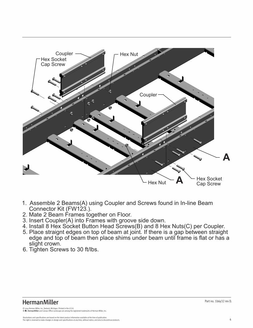
1. Assemble 2 Beams(A) using Coupler and Screws found in In-line Beam Connector Kit (FW123.).2. Mate 2 Beam Frames together on Floor. 3. Insert Coupler(A) into Frames with groove side down. 4. Install 8 Hex Socket Button Head Screws(B) and 8 Hex Nuts(C) per Coupler.5. Place straignt edges on top of beam at joint. If there is a gap between straight edge and top of beam then place shims under beam until frame is flat or has a slight crown.6. Tighten Screws to 30 ft/lbs.
Coupler
Coupler
Hex SocketCap Screw
Hex SocketCap Screw
Hex Nut
Hex Nut
A
A
Z
5
Part no. 1b6y32 rev D.
© 2014 Herman Miller, Inc. Zeeland, Michigan. Printed in the U.S.A.® Y, Z and Canvas Office Landscape are among the registered trademarks of Herman Miller, Inc.
Illustrations and specifications are based on the latest product information available at the time of publication. The right is reserved to make changes in design and specifications at any time, without notice, and also to discontinue products.
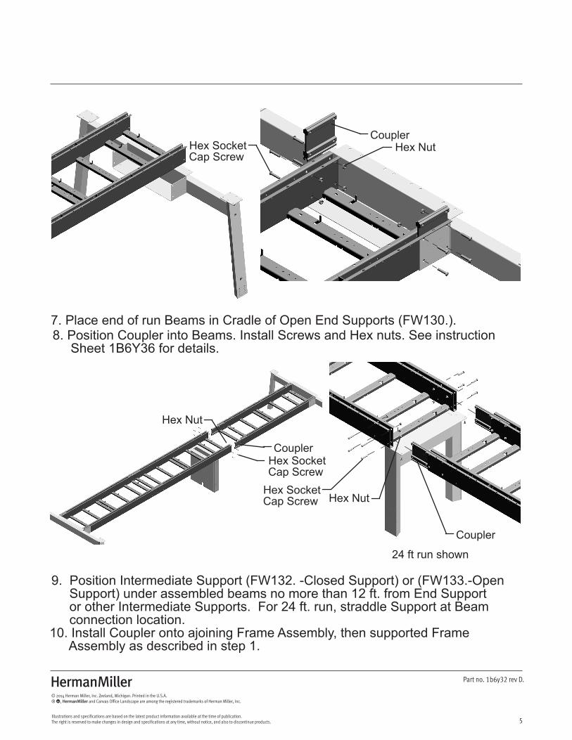
7. Place end of run Beams in Cradle of Open End Supports (FW130.).8. Position Coupler into Beams. Install Screws and Hex nuts. See instruction Sheet 1B6Y36 for details.
CouplerHex SocketCap Screw
Hex Nut
24 ft run shown
Coupler
Coupler
Hex SocketCap Screw
Hex SocketCap Screw Hex Nut
Hex Nut
9. Position Intermediate Support (FW132. -Closed Support) or (FW133.-Open Support) under assembled beams no more than 12 ft. from End Support or other Intermediate Supports. For 24 ft. run, straddle Support at Beam connection location.10. Install Coupler onto ajoining Frame Assembly, then supported Frame Assembly as described in step 1.
Z
6
Part no. 1b6y32 rev D.
© 2014 Herman Miller, Inc. Zeeland, Michigan. Printed in the U.S.A.® Y, Z and Canvas Office Landscape are among the registered trademarks of Herman Miller, Inc.
Illustrations and specifications are based on the latest product information available at the time of publication. The right is reserved to make changes in design and specifications at any time, without notice, and also to discontinue products.
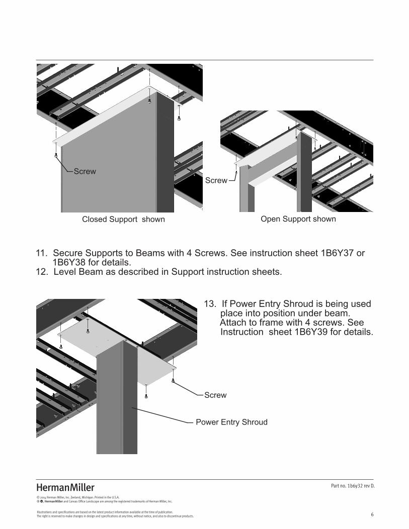
11. Secure Supports to Beams with 4 Screws. See instruction sheet 1B6Y37 or 1B6Y38 for details.12. Level Beam as described in Support instruction sheets.
Closed Support shown Open Support shown
ScrewScrew
13. If Power Entry Shroud is being used place into position under beam. Attach to frame with 4 screws. See Instruction sheet 1B6Y39 for details.
Screw
Power Entry Shroud
Z
7
Part no. 1b6y32 rev D.
© 2014 Herman Miller, Inc. Zeeland, Michigan. Printed in the U.S.A.® Y, Z and Canvas Office Landscape are among the registered trademarks of Herman Miller, Inc.
Illustrations and specifications are based on the latest product information available at the time of publication. The right is reserved to make changes in design and specifications at any time, without notice, and also to discontinue products.
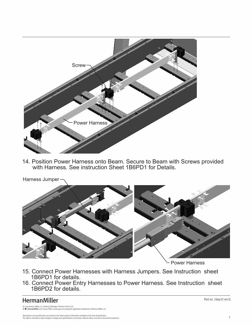
14. Position Power Harness onto Beam. Secure to Beam with Screws provided with Harness. See instruction Sheet 1B6PD1 for Details.
Power Harness
Screw
15. Connect Power Harnesses with Harness Jumpers. See Instruction sheet 1B6PD1 for details.16. Connect Power Entry Harnesses to Power Harness. See Instruction sheet 1B6PD2 for details.
Harness Jumper
Power Harness
Z
8
Part no. 1b6y32 rev D.
© 2014 Herman Miller, Inc. Zeeland, Michigan. Printed in the U.S.A.® Y, Z and Canvas Office Landscape are among the registered trademarks of Herman Miller, Inc.
Illustrations and specifications are based on the latest product information available at the time of publication. The right is reserved to make changes in design and specifications at any time, without notice, and also to discontinue products.
Receptacle
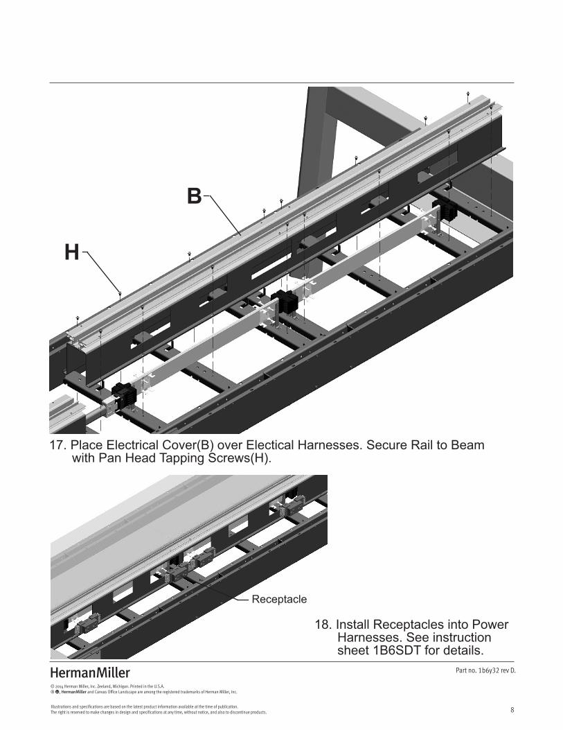
18. Install Receptacles into Power Harnesses. See instruction sheet 1B6SDT for details.
17. Place Electrical Cover(B) over Electical Harnesses. Secure Rail to Beam with Pan Head Tapping Screws(H).
B
H
Z
9
Part no. 1b6y32 rev D.
© 2014 Herman Miller, Inc. Zeeland, Michigan. Printed in the U.S.A.® Y, Z and Canvas Office Landscape are among the registered trademarks of Herman Miller, Inc.
Illustrations and specifications are based on the latest product information available at the time of publication. The right is reserved to make changes in design and specifications at any time, without notice, and also to discontinue products.
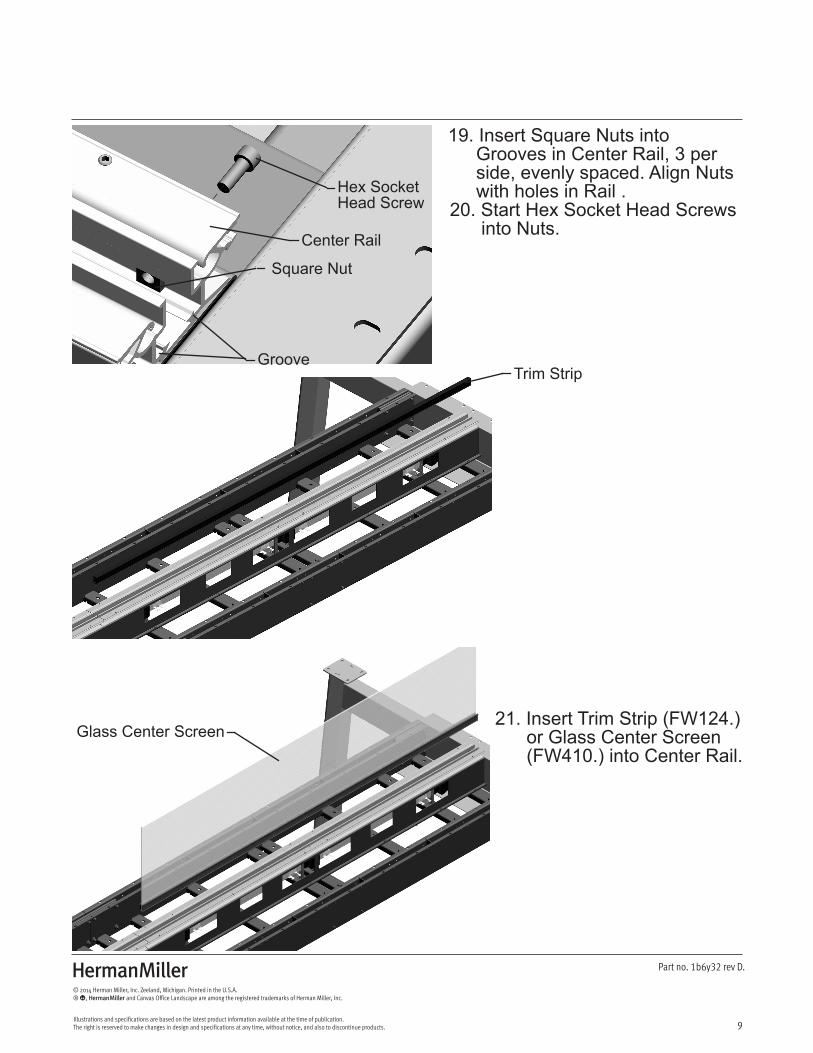
19. Insert Square Nuts into Grooves in Center Rail, 3 per side, evenly spaced. Align Nuts with holes in Rail .20. Start Hex Socket Head Screws into Nuts.
Hex SocketHead Screw
Square Nut
Trim Strip
Glass Center Screen 21. Insert Trim Strip (FW124.) or Glass Center Screen (FW410.) into Center Rail.
Center Rail
Groove
Z
10
Part no. 1b6y32 rev D.
© 2014 Herman Miller, Inc. Zeeland, Michigan. Printed in the U.S.A.® Y, Z and Canvas Office Landscape are among the registered trademarks of Herman Miller, Inc.
Illustrations and specifications are based on the latest product information available at the time of publication. The right is reserved to make changes in design and specifications at any time, without notice, and also to discontinue products.
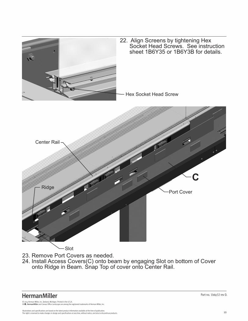
22. Align Screens by tightening Hex Socket Head Screws. See instruction sheet 1B6Y35 or 1B6Y3B for details.
Hex Socket Head Screw
23. Remove Port Covers as needed.24. Install Access Covers(C) onto beam by engaging Slot on bottom of Cover onto Ridge in Beam. Snap Top of cover onto Center Rail.
Port Cover
Slot
Ridge
Center Rail
C
Z
11
Part no. 1b6y32 rev D.
© 2014 Herman Miller, Inc. Zeeland, Michigan. Printed in the U.S.A.® Y, Z and Canvas Office Landscape are among the registered trademarks of Herman Miller, Inc.
Illustrations and specifications are based on the latest product information available at the time of publication. The right is reserved to make changes in design and specifications at any time, without notice, and also to discontinue products.
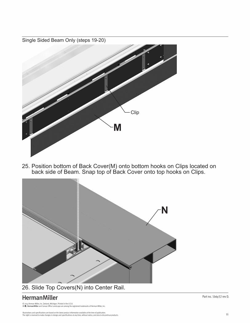
25. Position bottom of Back Cover(M) onto bottom hooks on Clips located on back side of Beam. Snap top of Back Cover onto top hooks on Clips.
26. Slide Top Covers(N) into Center Rail.
N
M
Single Sided Beam Only (steps 19-20)
Clip
Z
12
Part no. 1b6y32 rev D.
© 2014 Herman Miller, Inc. Zeeland, Michigan. Printed in the U.S.A.® Y, Z and Canvas Office Landscape are among the registered trademarks of Herman Miller, Inc.
Illustrations and specifications are based on the latest product information available at the time of publication. The right is reserved to make changes in design and specifications at any time, without notice, and also to discontinue products.
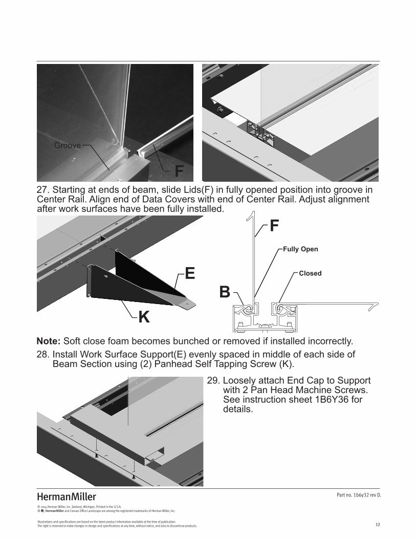
28. Install Work Surface Support(E) evenly spaced in middle of each side of Beam Section using (2) Panhead Self Tapping Screw (K).
29. Loosely attach End Cap to Support with 2 Pan Head Machine Screws. See instruction sheet 1B6Y36 for details.
EB
F
K
27. Starting at ends of beam, slide Lids(F) in fully opened position into groove in Center Rail. Align end of Data Covers with end of Center Rail. Adjust alignment after work surfaces have been fully installed.
F
Groove
Fully Open
Closed
Note: Soft close foam becomes bunched or removed if installed incorrectly.
Z
13
Part no. 1b6y32 rev D.
© 2014 Herman Miller, Inc. Zeeland, Michigan. Printed in the U.S.A.® Y, Z and Canvas Office Landscape are among the registered trademarks of Herman Miller, Inc.
Illustrations and specifications are based on the latest product information available at the time of publication. The right is reserved to make changes in design and specifications at any time, without notice, and also to discontinue products.
Pan Head Screw
Pan Head Screw
Ganging Plate
Set Screw
1/2” Gap
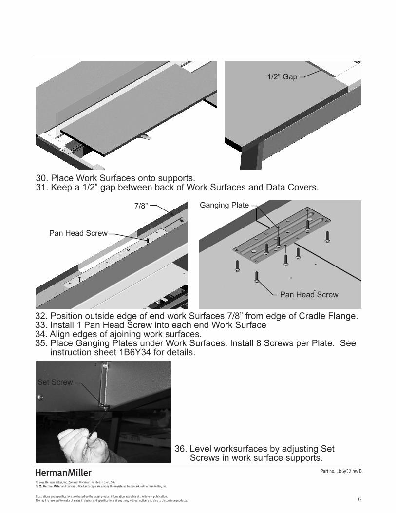
32. Position outside edge of end work Surfaces 7/8” from edge of Cradle Flange.33. Install 1 Pan Head Screw into each end Work Surface34. Align edges of ajoining work surfaces.35. Place Ganging Plates under Work Surfaces. Install 8 Screws per Plate. See instruction sheet 1B6Y34 for details.
30. Place Work Surfaces onto supports.31. Keep a 1/2” gap between back of Work Surfaces and Data Covers.
7/8”
36. Level worksurfaces by adjusting Set Screws in work surface supports.
Z
14
Part no. 1b6y32 rev D.
© 2014 Herman Miller, Inc. Zeeland, Michigan. Printed in the U.S.A.® Y, Z and Canvas Office Landscape are among the registered trademarks of Herman Miller, Inc.
Illustrations and specifications are based on the latest product information available at the time of publication. The right is reserved to make changes in design and specifications at any time, without notice, and also to discontinue products.
L
L
L
Pan Head Screw
Tighten
Pan Head Screw
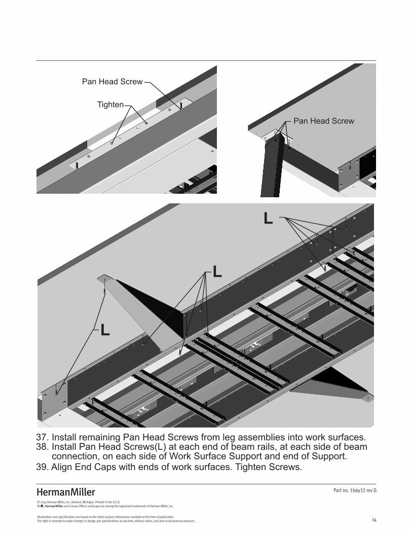
37. Install remaining Pan Head Screws from leg assemblies into work surfaces. 38. Install Pan Head Screws(L) at each end of beam rails, at each side of beam connection, on each side of Work Surface Support and end of Support.39. Align End Caps with ends of work surfaces. Tighten Screws.
Z
15
Part no. 1b6y32 rev D.
© 2014 Herman Miller, Inc. Zeeland, Michigan. Printed in the U.S.A.® Y, Z and Canvas Office Landscape are among the registered trademarks of Herman Miller, Inc.
Illustrations and specifications are based on the latest product information available at the time of publication. The right is reserved to make changes in design and specifications at any time, without notice, and also to discontinue products.
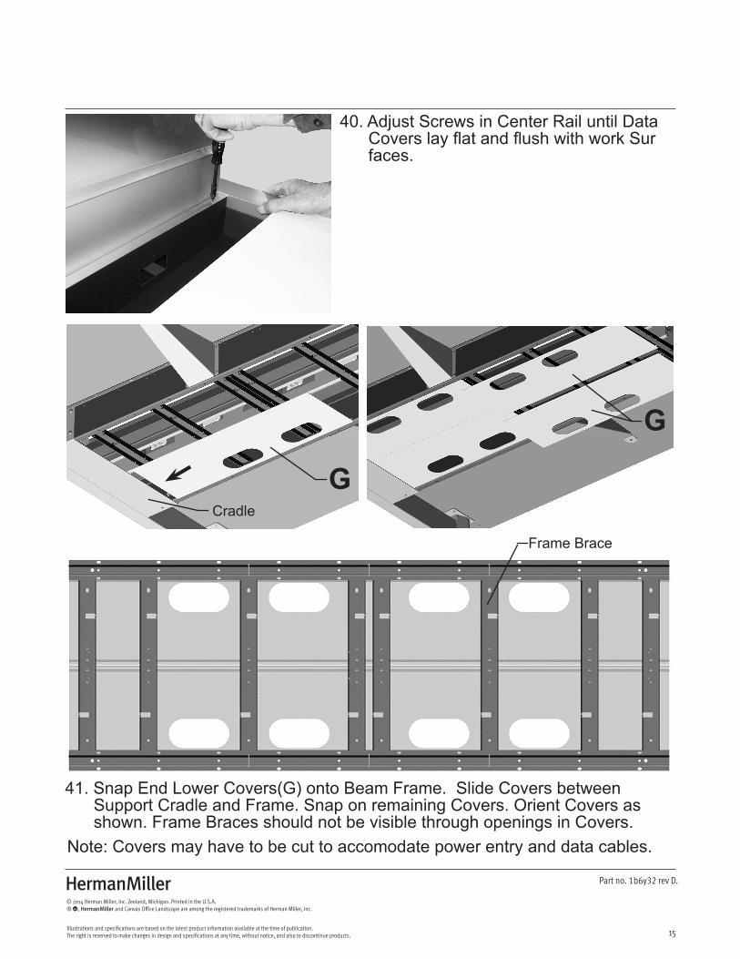
40. Adjust Screws in Center Rail until Data Covers lay flat and flush with work Sur faces.
41. Snap End Lower Covers(G) onto Beam Frame. Slide Covers between Support Cradle and Frame. Snap on remaining Covers. Orient Covers as shown. Frame Braces should not be visible through openings in Covers.Note: Covers may have to be cut to accomodate power entry and data cables.
G
G
Frame Brace
Cradle
Z
16
Part no. 1b6y32 rev D.
© 2014 Herman Miller, Inc. Zeeland, Michigan. Printed in the U.S.A.® Y, Z and Canvas Office Landscape are among the registered trademarks of Herman Miller, Inc.
Illustrations and specifications are based on the latest product information available at the time of publication. The right is reserved to make changes in design and specifications at any time, without notice, and also to discontinue products.
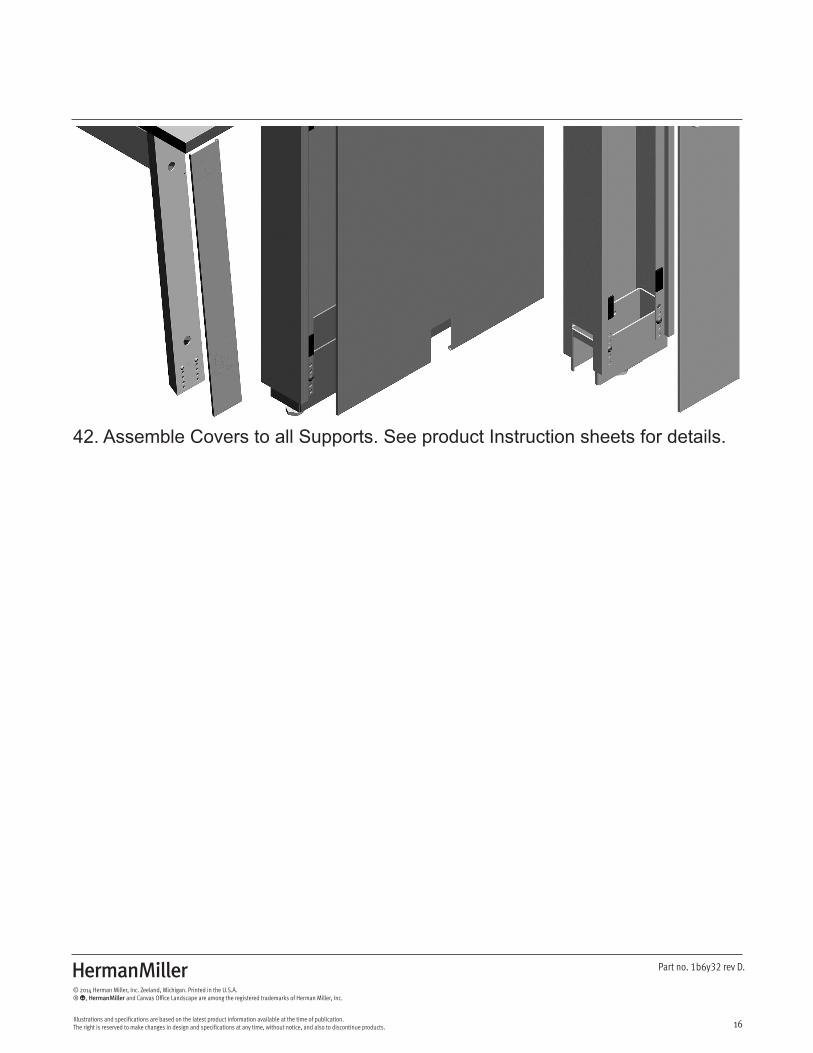
42. Assemble Covers to all Supports. See product Instruction sheets for details.
Z
17
Part no. 1b6y32 rev D.
© 2014 Herman Miller, Inc. Zeeland, Michigan. Printed in the U.S.A.® Y, Z and Canvas Office Landscape are among the registered trademarks of Herman Miller, Inc.
Illustrations and specifications are based on the latest product information available at the time of publication. The right is reserved to make changes in design and specifications at any time, without notice, and also to discontinue products.
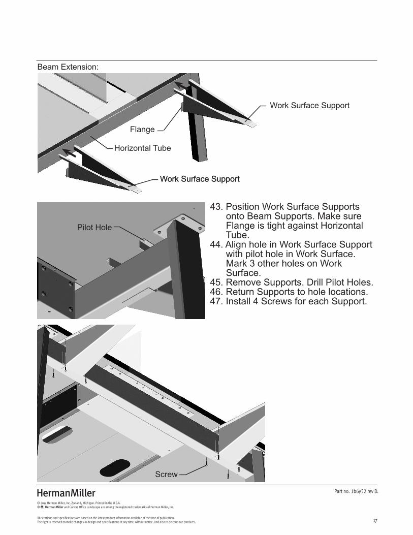
Beam Extension:
43. Position Work Surface Supports onto Beam Supports. Make sure Flange is tight against Horizontal Tube.44. Align hole in Work Surface Support with pilot hole in Work Surface. Mark 3 other holes on Work Surface.45. Remove Supports. Drill Pilot Holes.46. Return Supports to hole locations.47. Install 4 Screws for each Support.
Screw
Pilot Hole
Work Surface SupportWork Surface Support
Work Surface Support
Flange
Horizontal Tube
Z
18
Part no. 1b6y32 rev D.
© 2014 Herman Miller, Inc. Zeeland, Michigan. Printed in the U.S.A.® Y, Z and Canvas Office Landscape are among the registered trademarks of Herman Miller, Inc.
Illustrations and specifications are based on the latest product information available at the time of publication. The right is reserved to make changes in design and specifications at any time, without notice, and also to discontinue products.
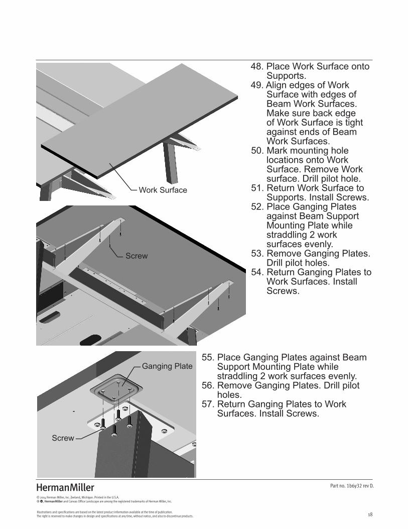
48. Place Work Surface onto Supports.49. Align edges of Work Surface with edges of Beam Work Surfaces. Make sure back edge of Work Surface is tight against ends of Beam Work Surfaces.50. Mark mounting hole locations onto Work Surface. Remove Work surface. Drill pilot hole.51. Return Work Surface to Supports. Install Screws.52. Place Ganging Plates against Beam Support Mounting Plate while straddling 2 work surfaces evenly.53. Remove Ganging Plates. Drill pilot holes.54. Return Ganging Plates to Work Surfaces. Install Screws.
55. Place Ganging Plates against Beam Support Mounting Plate while straddling 2 work surfaces evenly.56. Remove Ganging Plates. Drill pilot holes.57. Return Ganging Plates to Work Surfaces. Install Screws.
Screw
Screw
Work Surface
Ganging Plate

Z
19
Part no. 1b6y32 rev D.
© 2014 Herman Miller, Inc. Zeeland, Michigan. Printed in the U.S.A.® Y, Z and Canvas Office Landscape are among the registered trademarks of Herman Miller, Inc.
Illustrations and specifications are based on the latest product information available at the time of publication. The right is reserved to make changes in design and specifications at any time, without notice, and also to discontinue products.
Disassembly and Recycling:Materials Identification and Segregation:Where possible, plastic components are marked with ASTM recycling codes. Use these codes to identify material type for recycling. Non-marked components should be treated as mixed plastic. Ferrous metals can be identified using a small magnet for recycling. Non-ferrous metals should be separated and recycled separately.
To disassemble product, reverse steps 57 through 1 and also do the following: