overlapped-subcarrier multiplexing for wdm passive optical networks: experimental verification and...
TRANSCRIPT
This article has been accepted for publication in a future issue of this journal, but has not been fully edited. Content may change prior to final publication
Copyright (c) 2011 IEEE. Personal use is permitted. For any other purposes, permission must be obtained from the IEEE by emailing [email protected]
1
1 Abstract— An innovative overlapped-subcarrier multiplexing
(O-SCM) technique is proposed for single-feeder wavelength-division multiplexed (WDM) passive optical networks (PONs). Allowing a certain amount of spectral overlap between the uplink and the downlink maximizes the spectrum usage of bandwidth-limited reflective semiconductor optical amplifier (RSOA)-based optical network units (ONUs), while reducing the effect of Rayleigh backscattering. In this paper, we report successful experimental demonstrations up to 2.5 Gb/s symmetrical bit rates over a ~20 km bidirectional PON, using a ~2 GHz bandwidth RSOA. Moreover, we mathematically address the major design issues and tradeoffs. Our simulation results show good agreement with the experiment.
Index Terms— Fiber-to-the-home (FTTH), passive optical networks (PONs), reflective semiconductor optical amplifiers (RSOAs), subcarrier multiplexing (SCM), wavelength-division multiplexing (WDM).
I. INTRODUCTION
ANDWIDTH demand in access networks is exponentially increasing and is expected to continuously grow over the
next decades [1]-[3]. According to the Cisco Visual Networking Index [4], the total global Internet Protocol (IP) traffic will quadruple from 2009 to 2014. This will drive the peak data rates per user to 1 Gb/s or even more in the near future, and will force much more symmetry in traffic in fiber-to-the-home (FTTH) access networks. Today’s passive optical network (PON)-based access networks operate on a time-division multiple-access (TDMA) basis, and therefore cannot cope with such bandwidth demand explosion. In gigabit-capable PON (GPON) standards, a 2.5 Gb/s line rate is shared between 32 subscribers, compared to only 1.25 Gb/s for symmetric GPON operation and Ethernet PON (EPON) standards. This limits the peak user bit rate to less than 100 Mb/s, forcing network operators and service providers to
Manuscript received August 24, 2011; revised November 5, 2011 and November 24, 2011.
The authors are with the Photonics Systems Group, Electrical and Computer Engineering Department, McGill University, Montreal, QC H3A 2A7, Canada (e-mail : [email protected]).
Z. El-Sahn is also with the department of Electrical Engineering, Alexandria University, Alexandria 21544, Egypt.
re-think upgrading their networks. 10G-PON recent standards can help increase the lifetime of legacy systems in a cost-effective way by re-using the existing optical distribution network (ODN) infrastructure [5], [6]. However, because of their TDMA nature, the bit rates will still be limited to only sub-gigabit per second per user. Further scaling (higher than 10 Gb/s) using TDMA will be difficult to achieve because of both technological and economical issues.
In this dilemma, wavelength-division multiplexing (WDM) is considered a natural choice for next generation access as proposed in the literature by several research groups [7]-[16], and as discussed by the Full Service Access Network (FSAN) standardization group [17]. Full connectivity can be achieved in WDM by assigning a dedicated wavelength to each optical network unit (ONU), i.e., user. Incorporating WDM in access networks provides higher bandwidth and better security than time-division multiplexed (TDM) PONs which operate in a single-wavelength broadcast-and-select mode. Despite the advantages of WDM technology, cost still remains the main issue for access networks [7], [8]. In order to avoid the costs and inventory complexities associated with having distinct WDM transceivers, wavelength-independent colorless ONUs will be required for next generation WDM PON deployments [9]-[11]. Due to their low fabrication cost, small form factor, ease of integration, and ability to achieve both amplification and modulation, reflective semiconductor optical amplifiers (RSOAs) have been widely used as colorless ONUs [11].
From an architectural perspective, it is desirable for future PONs to re-use current single-feeder PON infrastructures to justify the installation costs and maximize savings in operational expenses. Another favorable design constraint would be to achieve full-duplex communication using the same wavelength through data remodulation techniques [18], [19]. However, in a single-feeder PON, the performance is severely degraded by Rayleigh backscattering when the same wavelength is used for both uplink and downlink [20]. Recently, great interest has been shown in radio frequency (RF) subcarrier multiplexing (SCM) as a way to mitigate the degradation caused by Rayleigh backscattering and back-reflections in such WDM PON systems [12]-[15].
Previous work on SCM-based bidirectional WDM PONs has focused on sub-gigabit per second asymmetrical bit rates due to the bandwidth limitation of current generation RSOAs. The subcarrier frequency and the bit rates were carefully
Overlapped-Subcarrier Multiplexing for WDM Passive Optical Networks: Experimental Verification and Mathematical Analysis
Ziad A. El-Sahn, Member, IEEE, Jonathan M. Buset, and David V. Plant, Fellow, IEEE, Fellow, OSA
B
This article has been accepted for publication in a future issue of this journal, but has not been fully edited. Content may change prior to final publication
Copyright (c) 2011 IEEE. Personal use is permitted. For any other purposes, permission must be obtained from the IEEE by emailing [email protected]
2
chosen to separate both uplink and downlink traffics and to accommodate them within the modulation bandwidth of the RSOA [14], [15]. Recently, a novel overlapped-SCM (O-SCM) architecture that allows a certain amount of overlap between uplink and downlink frequency spectra was reported in [16], in an attempt to reduce that guard band (between uplink and downlink), maximize the spectrum usage of the RSOA and permit higher symmetrical bit rates. We have demonstrated the feasibility of our proposal at a modest 1.5 Gb/s bit rate.
In this paper, we report a more realistic system using a less expensive and more compact optical line terminal (OLT) transmitter, and better RF mixers for SCM operation. Unlike [16], an electro-absorption modulated laser (EML) is used for downlink transmission. For simplicity and cost effectiveness, on-off keying (OOK) intensity modulation with direct detection is considered for both uplink and downlink. We initially demonstrate the system at a symmetrical bit rate of 1.5 Gb/s for proof-of-concept and comparison with [16], we then focus on experimental demonstrations at 2.5 Gb/s using only the EML-based transmitter. Error-free operation is achieved for both bit rates over a bidirectional single-feeder WDM PON with fully O-SCM using a ~2 GHz bandwidth-limited RSOA, without forward error correcting (FEC) codes or any electronic equalization. Note that when up-converted, the uplink spectrum covers frequencies up to 3 GHz and 5 GHz for the 1.5 Gb/s and 2.5 Gb/s demonstrations, respectively. Through the power budget optimization, we also show that the OLT launch power levels comply with the 10G-PON standards [21]. The design of both ONU and OLT with simple low-cost optics and electronics makes this O-SCM architecture attractive for next generation PONs.
Furthermore, the performance limitations of the proposed system are addressed through a mathematical model that accounts for the RF mixers and the RSOA performance. The model also presents some design guidelines and can be used to predict the amount of overlap that can be tolerated for optimum O-SCM operation. Moreover, we discuss possible improvements and implementation issues including the use of FEC and digital signal processing (DSP) to increase the link margin and therefore, to extend the PON reach and/or increase the overall capacity.
The rest of this paper is organized as follows; Section II is devoted to a general description of the network architecture of the proposed WDM PON with O-SCM. The principle of operation is included with highlights on the performance limitations. In Section III, we present our experimental results and discussions. The power budget analysis and the associated design constraints are also considered. The mathematical model of the proposed system is described in Section IV, supported by simulations and important design guidelines. The paper is finally summarized and concluded in Section V.
II. PROPOSED WDM PON WITH OVERLAPPED-SCM
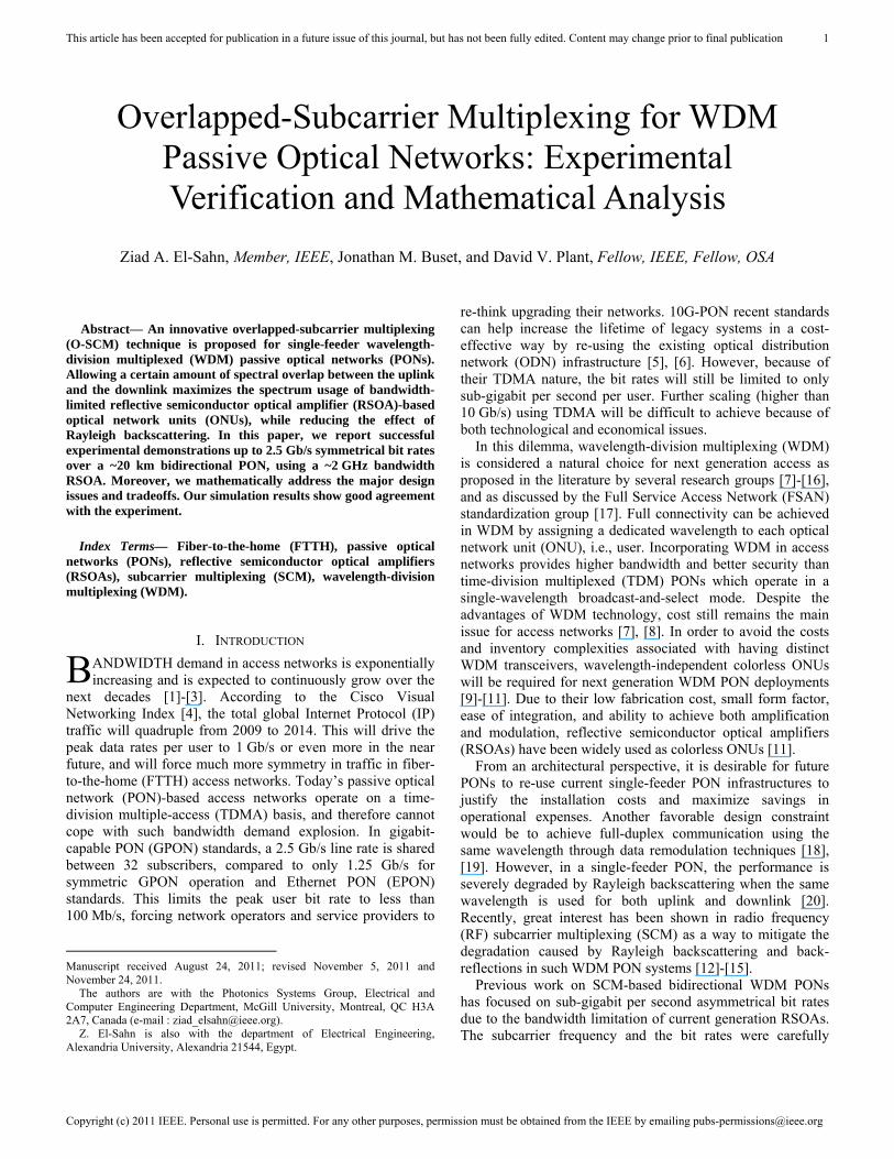
The architecture of the O-SCM WDM PON is based on an existing single-feeder topology connecting the OLT to the ONUs through an arrayed waveguide grating (AWG)-based remote node (RN) as shown in Fig. 1. The O-SCM technique enables full-duplex communications while partially reducing the effect of Rayleigh backscattering as in conventional SCM systems. The insets in Fig. 1 show the electrical RF spectra of a typical 100% O-SCM system illustrating the frequency overlap between the uplink and downlink spectra. Because of that overlap, it is expected that the ability of the O-SCM to reduce the effect of Rayleigh backscattering will not be as good as for conventional SCM systems, but better than simple baseband transmission. In the proposed O-SCM system, the downlink is kept at baseband, whereas the uplink is sent over an RF subcarrier using fully O-SCM (i.e., 100% O-SCM), where the subcarrier frequency fsc is equal to the bit rate Rb. Note that if needed, partially O-SCM with Rb < fsc < 2Rb can also be used to reduce the amount of crosstalk due to the overlap. At the ONU, a fraction of the downlink power is detected by a p-i-n photodiode (PD) and the remaining portion is used to seed a gain saturated RSOA for efficient re-modulation. The extinction ratio (ER) of the uplink is set higher than that of the downlink to facilitate data erasure and re-modulation [19]. Part of the up-converted uplink spectrum overlaps with the residual downlink that is highly suppressed due to the gain squeezing and high pass filtering effect of the saturated RSOA. At the OLT side, the uplink is recovered after down-conversion as the residual downlink acts as additive high frequency noise that is suppressed by a low pass filter (LPF).
Fig. 1. Architecture of the proposed WDM PON with overlapped-SCM (AMP: amplifier, BPF: 50 GHz band pass filter, DC: direct current, DFB: distributedfeedback, DL: downlink, EDFA: erbium-doped fiber amplifier, EML: electro-absorption modulated laser, fsc: subcarrier frequency, LPF: low pass filter,MZM: Mach-Zehnder modulator, PD: photodiode, PC: polarization controller, Rb: bit rate, RF: radio frequency, UL: uplink, VOA: variable optical attenuator).
This article has been accepted for publication in a future issue of this journal, but has not been fully edited. Content may change prior to final publication
Copyright (c) 2011 IEEE. Personal use is permitted. For any other purposes, permission must be obtained from the IEEE by emailing [email protected]
3
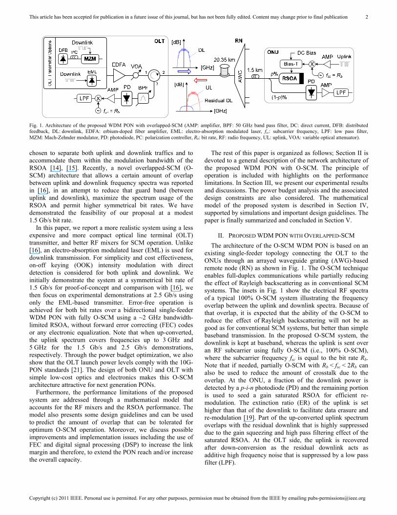
Fig. 2 shows the measured electrical power spectral density (PSD) for the uplink before and after down-conversion for a proof-of-concept fully O-SCM system at 1.5 Gb/s. The upper subplots show the individual PSD of both the uplink and the residual downlink, whereas the lower subplots show the total PSD. In both cases it can be noticed that the total PSD closely resembles that of the uplink, which confirms that the downlink is highly erased by the saturated RSOA. In the OLT down-conversion circuitry, the residual downlink is further suppressed as it is shifted from baseband to 1.5 GHz and then low pass filtered (4th order Bessel-Thomson 933 MHz LPF), while the uplink is brought from the 1.5 GHz RF subcarrier back to baseband.
A. Principle of Operation of the O-SCM System
The key aspect to understand how the proposed O-SCM system works is to recognize that the overlap is actually between the up-converted uplink and the residual downlink (and not the downlink). This implies that the RSOA must be operated in saturation mode which is also necessary for the data remodulation to take place. As the RSOA is further driven into saturation, the downlink signal is efficiently erased and highly suppressed allowing for a 100% overlap.
From a design perspective, it is important to carefully select the p% coupling ratio of the 1×2 ONU coupler to guarantee that enough power goes to the downlink receiver while having sufficient power to saturate the RSOA. There is no advantage to having the downlink power exceed the required sensitivity. On the other hand, it is desirable that the RSOA input power be higher than its input saturation power for more efficient data erasure and remodulation. However, driving the RSOA more into saturation would cause the RSOA gain to drop to zero and the output power to saturate, thus affecting the performance of the uplink. Taking the above factors into consideration, there exists an optimum p% that maximizes the power budget by minimizing the required OLT launch power for error-free operation. The other important design parameter would be the selection of the ER for both downlink and uplink, as previously discussed.
B. Performance Limitations of the O-SCM System
For a certain bit rate, the performance of the O-SCM technique is bounded by the percentage of overlap from one side and the modulation bandwidth of the RSOA from the other side. Decreasing the subcarrier frequency from twice the bit rate (zero overlap) to exactly the bit rate (full overlap), induces more crosstalk between the up-converted uplink and the residual downlink. The RF mixers further degrade the performance as they have a tendency to cut lower frequencies in their pass bands. Whereas, moving to higher subcarrier frequencies, the performance is primarily limited by the modulation bandwidth of the RSOA. It is clear that there exists an optimum operating point that trades off the amount of overlap versus the modulation bandwidth of the RSOA. In Section IV, we introduce a mathematical model that is used for system analysis and optimization.
At high bit rates compared to the RSOA bandwidth, it is much easier to allow a 100% overlap than going to higher subcarrier frequencies. This can be achieved by deeply saturating the RSOA (if the power budget permits) so that the downlink is highly erased, or by decreasing/increasing the ER of the downlink/uplink. In addition, FEC or DSP techniques can be used to increase the link margin [22]-[24].
Our solution appears to be attractive for network operators, as it exploits the existing PON infrastructure while employing low-cost optics and mature WDM technology, combined with inexpensive electronics to achieve SCM and possibly DSP for higher bit rates. For field deployments, athermal AWGs, polarization independent EMLs and RSOAs are commercially available at very competitive pricing, making our solution a potentially cost-effective upgrade for existing PONs.
III. EXPERIMENTAL RESULTS AND DISCUSSIONS
The experimental setup for the O-SCM WDM PON is shown in Fig. 1. In our demonstrations, we focus on the 100% O-SCM technique where fsc = Rb, due to its potential for higher symmetrical bit rates compared to conventional SCM. Two possible OLT transmitter configurations are considered for the experiment. The first consists of a distributed feedback (DFB) laser that is externally modulated, and serves only as a reference transmitter to demonstrate the proof of concept. A polarization controller (PC) is inserted after the DFB to control the input polarization to a Mach-Zehnder modulator (MZM). The laser output power was set to 8 dBm, and the wavelength was tuned to 1550.08 nm. Whereas, the bias of the MZM was adjusted so that the ER < 2.5 dB.
The second configuration for the OLT transmitter is a more practical one that employs a polarization independent EML. The laser driving current was set to 50 mA (corresponding to 4 dBm of laser output power), and the temperature to 22.5 oC to tune its wavelength to 1549.36 nm (a different AWG was used in that experiment). The EML was driven with a pseudo random binary sequence (PRBS) data with a 1 V peak-to-peak voltage and a -250 mV offset so that the downlink ER was kept at 2.4 dB. Note that for both transmitters, the ER has been optimized to facilitate data erasure and to guarantee reliable downlink transmission at the same time [19]. Under these
Fig. 2. RF power spectral density (PSD) for uplink before and after down-conversion for a proof-of-concept 1.5 Gb/s fully O-SCM system, wherefsc = 1.5 GHz.
This article has been accepted for publication in a future issue of this journal, but has not been fully edited. Content may change prior to final publication
Copyright (c) 2011 IEEE. Personal use is permitted. For any other purposes, permission must be obtained from the IEEE by emailing [email protected]
4
conditions, the EML output power was 2.8 dBm. Increasing the laser current up to 100 mA, the OLT launch power (measured at the output of port 2 of the circulator) can reach 6.5 dBm. According to next generation PON standards, the OLT launch power may exceed 10 dBm and an erbium-doped fiber amplifier (EDFA) is recommended to be used with the EML [21].
For a cost-effective implementation, it is more desirable to have low-cost EMLs with a shared EDFA at the OLT, rather than having standalone high-power transmitters without any external amplification. In a practical situation, the EDFA may also be used to compensate for the insertion losses of the AWG that will combine the EML transmitters, and to provide more link margin. In our experiment, an EDFA and a variable optical attenuator (VOA) were used to control the launched power for the bit error rate (BER) measurements.
At the ONU side, an RSOA (SOA-RL-OEC-1550 from CIP) with a ~2 GHz modulation bandwidth was directly modulated with an up-converted PRBS using 100% O-SCM where fsc = Rb. An electrical RF amplifier and a bias-T were used to drive the RSOA (3.35 V DC with a 4 V peak-to-peak PRBS) so that the ER is significantly higher than 2.5 dB to enable data remodulation. Throughout the experiment, a baseband non-return-to-zero (NRZ) 215-1 PRBS and an up-converted NRZ 223-1 PRBS were used for downlink and uplink traffics, respectively.
The same PD, RF amplifier and LPF (933 MHz for 1.5 Gb/s operation and 1.775 GHz for 2.5 Gb/s) were used at both ONU and OLT receivers. Different sets of RF mixers were used to test the system performance at different bit rates. The Mini-Circuits Inc. ZX05-C42MH and the Marki Microwave Inc. M10208MP frequency mixers were used for the 1.5 Gb/s and 2.5 Gb/s operations, respectively. The electrical RF amplifier at the receiver is identical to the one used to drive the RSOA (for the measurements with EML). For the optical distribution network (ODN), standard single mode fiber (SMF-28e+) 20.35 km feeder, 1.5 km distribution drop fiber (DDF), and a 100 GHz AWG were used.
A. Experimental Proof of Concept
The feasibility of our proposed O-SCM system was first studied with the aforementioned proof of concept transmitter at a symmetrical bit rate of 1.5 Gb/s using a 1.5 GHz RF subcarrier for SCM. For instance, a non-optimal 90/10 coupler was used at the ONU side as in [16]. This preliminary selection was mainly biased towards favoring the uplink performance which is more difficult to design.
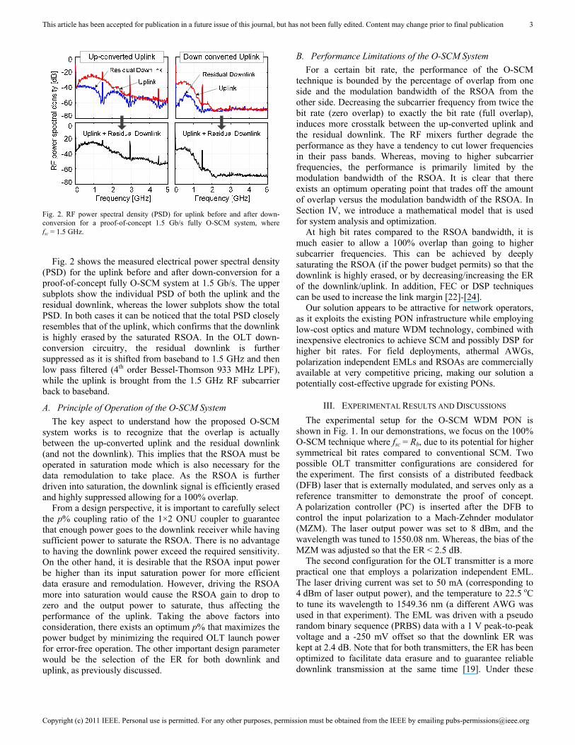
The BER performance versus the OLT launch power is shown in Fig. 3, for a reference back-to-back configuration as well as over a 20 km reach PON with 20.35 km feeder and 1.5 km DDF. Error-free operation (BER < 10-10) is achieved for both downlink and uplink with O-SCM, despite a ~5 dB penalty from the back-to-back configuration to the 20 km feeder case. The penalty is mainly due to chromatic dispersion and some residual Rayleigh backscattering (which is due to the frequency overlap compared to traditional SCM) and back-reflections. The performance of the uplink without any SCM techniques is also measured for sake of comparison; the BER
is highly degraded by Rayleigh backscattering and error-free operation cannot be achieved over the 20 km reach PON. An illustrative inset of the PSD for both the uplink and the residual downlink shows that the actual upstream spectrum covers up to 3 GHz, which is higher than the modulation bandwidth of the RSOA. However, a big portion of the energy contents of the uplink are still within the modulation bandwidth of the RSOA (compared to conventional SCM), and therefore error-free operation can be achieved. In that case, the 100% overlap helped accommodate part of the up-converted uplink within the modulation bandwidth of the RSOA. This overlap was enabled by the saturated RSOA that highly suppressed the downlink signal as explained in Fig. 2. Eye diagrams measured at 5 dBm of OLT launch power are also illustrated as insets of Fig. 3, where error-free operation is achieved for both directions. From the other side, we expect performance degradation when conventional SCM is used, because in that case the up-converted uplink will extend from 1.5 to 4.5 GHz assuming no guard band. This was already demonstrated at 1 Gb/s in [16], where we concluded that for higher bit rates the O-SCM technique will definitely outperform conventional SCM.
The 8 dB difference in the required launch power (for error-free operation) between the uplink and downlink is due to the use of the 90/10 coupler. In [16], we have shown through power budget calculations that the optimum would be to use a 70/30 coupler so that only -2 dBm of OLT launch power is needed for uplink/downlink error-free operation. Note that FEC codes with a BER threshold of 10-3 can provide additional gain (see Fig. 3) for the power budget.
B. Performance of the Proposed WDM PON with O-SCM
Recall that for cost effectiveness a polarization independent
Fig. 3. Performance at 1.5 Gb/s using a DFB + MZM at the OLT transmitter and a 90/10 coupler at the ONU side (back-to-back: 0 km fiber between OLT and ONU, 20 km reach: 20.35 km feeder + 1.5 km DDF).
This article has been accepted for publication in a future issue of this journal, but has not been fully edited. Content may change prior to final publication
Copyright (c) 2011 IEEE. Personal use is permitted. For any other purposes, permission must be obtained from the IEEE by emailing [email protected]
5
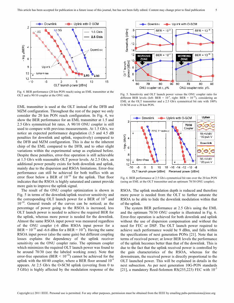
EML transmitter is used at the OLT instead of the DFB and MZM configuration. Throughout the rest of the paper we only consider the 20 km PON reach configuration. In Fig. 4, we show the BER performance for an EML transmitter at 1.5 and 2.5 Gb/s symmetrical bit rates. A 90/10 ONU coupler is still used to compare with previous measurements. At 1.5 Gb/s, we notice an expected performance degradation (1.5 and 4.5 dB penalties for downlink and uplink, respectively) compared to the DFB and MZM configuration. This is due to the inherent chirp of the EML compared to the DFB, and to other slight variations within the experimental setup as explained before. Despite these penalties, error-free operation is still achievable at 1.5 Gb/s with reasonable OLT power levels. At 2.5 Gb/s, an additional power penalty exists for both downlink and uplink, mainly due to the dispersion and RSOA limitations. Error-free performance can still be achieved for both traffics with an error floor below a BER of 10-10 for the uplink. That floor indicates that the RSOA is highly saturated and cannot provide more gain to improve the uplink signal.
The result of the ONU coupler optimization is shown in Fig. 5 in terms of the downlink/uplink receiver sensitivity and the corresponding OLT launch power for a BER of 10-9 and 10-10. General trends of the curves can be noticed; as the percentage of power going to the RSOA is increased, less OLT launch power is needed to achieve the required BER for the uplink, whereas more power is needed for the downlink. Almost the same RSOA input power was measured regardless of the ONU coupler (-6 dBm RSOA input power for a BER = 10-10 and -6.6 dBm for a BER = 10-9). Having the same RSOA input power (also the same gain) but different coupling losses explains the dependency of the uplink receiver sensitivity on the ONU coupler ratio. The optimum coupler which minimizes the required OLT launch power was found to be around 70/30 (see the labeled working zone). Note that error-free operation (BER < 10-10) cannot be achieved for the uplink with the 60/40 coupler, where a BER floor around 10-9 appears. At 2.5 Gb/s the O-SCM uplink (covering from 0 to 5 GHz) is highly affected by the modulation response of the
RSOA. The uplink modulation depth is reduced and therefore more power is needed from the OLT to further saturate the RSOA to be able to hide the downlink modulation within that of the uplink.
The system BER performance at 2.5 Gb/s using the EML and the optimum 70/30 ONU coupler is illustrated in Fig. 6. Error-free operation is achieved for both downlink and uplink without the use of dispersion compensation and without the need for FEC or DSP. The OLT launch power required to achieve such performance would be 9 dBm, and falls within the specifications of next generation PONs [21]. Note that in terms of received power; at lower BER levels the performance of the uplink becomes better than that of the downlink. This is due to the fact that the uplink received power is controlled by the gain characteristics of the RSOA, whereas for the downstream, the received power is directly proportional to the OLT launched power. This will be explained in details in the next subsection. As per next generation 10G-PON standards [21], a mandatory Reed-Solomon RS(255,223) FEC with 10-3
Fig. 4. BER performance (20 km PON reach) using an EML transmitter at theOLT and a 90/10 coupler at the ONU side.
Fig. 5. Sensitivity and OLT launch power versus the ONU coupler ratio fordifferent BER levels (left: BER = 10-9, right: BER = 10-10), considering anEML at the OLT transmitter and a 2.5 Gb/s symmetrical bit rate with 100%O-SCM over a 20 km PON.
Fig. 6. BER performance at 2.5 Gb/s symmetrical bit rate over the 20 km PON(using an EML at the OLT transmitter and an optimum 70/30 ONU coupler).
This article has been accepted for publication in a future issue of this journal, but has not been fully edited. Content may change prior to final publication
Copyright (c) 2011 IEEE. Personal use is permitted. For any other purposes, permission must be obtained from the IEEE by emailing [email protected]
6
FEC threshold would provide 6 dB of coding gain in terms of reducing the launched power to 3 dBm. Such coding gain is translated to a more relaxed power budget, so that more users can be supported on a TDMA basis and/or the PON reach may be extended. Electrical eye diagrams for both uplink and downlink directions (measured at 10-10 BER) are also shown as insets of the same figure.
C. Power Budget Analysis and Constraints
The power budget is an important design parameter and is mainly determined from the PON physical architecture. It allows FTTH operators and providers to select the appropriate ONU and OLT transceivers for their PON, and therefore, to determine the maximum PON capacity and/or reach. In our proposed WDM PON with O-SCM shown in Fig. 1, the design of the uplink is more challenging than the downlink as it experiences twice the ODN losses and is further affected by the gain characteristics of the RSOA.
Starting with the downlink power budget; the downlink received power can be expressed as a function of the OLT launch power PTx_OLT as follows:
_ _ _ % , (1)
where LODN is the total losses within the ODN and LONU_(1-p)% is the coupling ratio to the ONU receiver. The ODN losses include the feeder losses LFeeder, the AWG insertion losses LAWG and the DDF losses LDDF, and is given by
. (2)
For the uplink direction, the RSOA is initially seeded with p% of the downlink signal as follows;
_ _ _ %.
Note that the RSOA input power (seed light) depends linearly on the OLT launch power. Therefore, the RSOA gain GRSOA is also a function of the OLT launch power. Assuming that the insertion losses of the OLT circulator and BPF are LOLT_circulator and LBPF, respectively, the uplink received power can be
expressed by the following equation:
2 2 %
_ , (3)
where LONU_p% is the coupling loss of the ONU coupler to the RSOA-based colorless transmitter.
From Fig. 6, the relation between the received power and the OLT launch power can be directly extracted. It can be seen that for the downlink, the relation is linear as confirmed by (1), whereas for the uplink it is shaped by the gain of the RSOA as described by (3).
For the proposed O-SCM to work properly and in order to minimize the OLT transmitted power the following two inequalities should be satisfied:
_ and _ . (4)
Here SDL and SUL denote the receiver sensitivities for downlink and uplink, respectively. The optimum p% can be found by substituting (1) and (3) in (4), subject to the following RSOA gain saturation constraint;
_ _ % _ _ , (5)
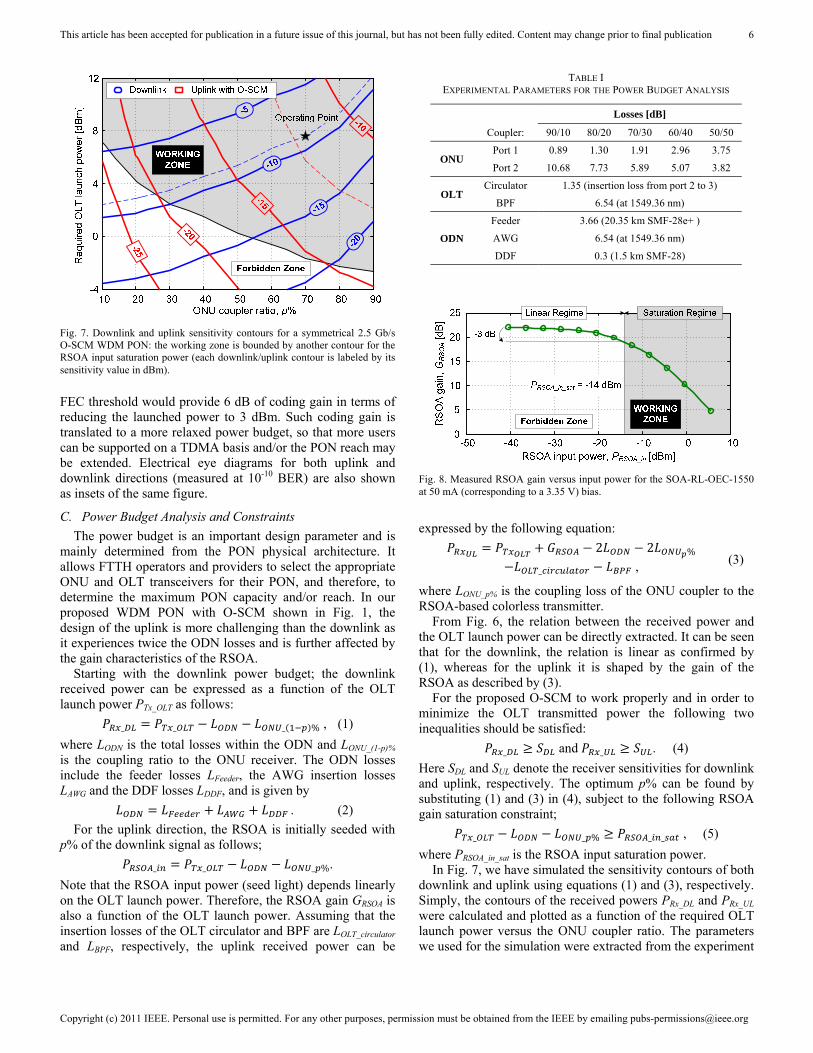
where PRSOA_in_sat is the RSOA input saturation power. In Fig. 7, we have simulated the sensitivity contours of both
downlink and uplink using equations (1) and (3), respectively. Simply, the contours of the received powers PRx_DL and PRx_UL were calculated and plotted as a function of the required OLT launch power versus the ONU coupler ratio. The parameters we used for the simulation were extracted from the experiment
TABLE I EXPERIMENTAL PARAMETERS FOR THE POWER BUDGET ANALYSIS
Losses [dB]
Coupler: 90/10 80/20 70/30 60/40 50/50
ONU Port 1 0.89 1.30 1.91 2.96 3.75
Port 2 10.68 7.73 5.89 5.07 3.82
OLT Circulator 1.35 (insertion loss from port 2 to 3)
BPF 6.54 (at 1549.36 nm)
ODN
Feeder 3.66 (20.35 km SMF-28e+ )
AWG 6.54 (at 1549.36 nm)
DDF 0.3 (1.5 km SMF-28)
Fig. 7. Downlink and uplink sensitivity contours for a symmetrical 2.5 Gb/sO-SCM WDM PON: the working zone is bounded by another contour for theRSOA input saturation power (each downlink/uplink contour is labeled by itssensitivity value in dBm).
Fig. 8. Measured RSOA gain versus input power for the SOA-RL-OEC-1550 at 50 mA (corresponding to a 3.35 V) bias.
This article has been accepted for publication in a future issue of this journal, but has not been fully edited. Content may change prior to final publication
Copyright (c) 2011 IEEE. Personal use is permitted. For any other purposes, permission must be obtained from the IEEE by emailing [email protected]
7
and are listed in Table I. Moreover, the RSOA gain versus input power was experimentally characterized and used for the analysis. Fig. 8 shows the measured gain characteristics for the SOA-RL-OEC-1550 when biased with 50 mA (corresponding to the 3.35 V DC bias used in the experiment). The RSOA input saturation power (measured at the point where the gain drops by 3 dB) was found to be -14 dBm and was used through (5) to draw the contour separating the working zone from the forbidden zone in Fig. 7 corresponding to the same zones in Fig. 8.
General trends in Fig. 7 can be noticed and are similar to the ones in Fig. 5. The downlink contours are uniformly spaced, whereas the uplink contours do not follow the same trend; this can be confirmed by (1) and (3). As expected, higher OLT launch powers are required for higher sensitivity (received power) levels. Note that the same contours can be mapped to optical signal-to-noise ratio (OSNR) or BER values instead of the required sensitivities.
These simulated contours in Fig. 7 serve as a design tool for the proposed O-SCM WDM PON. Knowing a target BER or OSNR, i.e., a sensitivity for both uplink and downlink, the optimum ONU coupler that minimizes the required OLT transmitted power is simply the intersection of both contours within the working zone. For validation purpose, we plot the contours of SDL = -8.94 dBm and SUL = -11.72 dBm (dashed lines in Fig. 7), which are extracted from our experimental results in Fig. 6. The simulation confirms our experimental findings that the optimum coupler would be a 70/30 coupler while having ~7.5 dBm of transmitted power (9 dBm through measurements). In a real situation, this 1.5 dB difference in OLT power is normally tolerated through an extra design link margin (typically > 3 dB) that accounts for implementation losses and other impairments.
IV. MATHEMATICAL MODEL AND DESIGN GUIDELINES
In this section we address some design guidelines other than the power budget previously discussed. We develop a design tool to evaluate the performance of the proposed O-SCM system through a simple mathematical model based on a linear time invariant (LTI) system approach. Further, the optimum amount of overlap that can be tolerated at a certain bit rate (for a given hardware) is predicted using a mean squared error (MSE) criteria. For the purpose of this study, the model considers only the major limiting components, namely, the RSOA and the RF mixers. The other components are carefully chosen so that their impairments are marginal to the O-SCM system, and therefore, their effect is simply neglected. For example, the bandwidth of the receiver PD and RF amplifiers
used in our 2.5 Gb/s experiment (see Fig. 1) were 10 GHz, and thus were considered to have a flat response over the operating frequency range. The O-SCM system limitations were already discussed qualitatively in Section II. It was found that the O-SCM performance is limited by the RSOA from one side and by the overlap and RF mixers from the other side. In this section we mathematically confirm the same using numerical simulations.
Before we go through the mathematical derivations, it is important to note that in a conventional SCM system with no overlap, RF mixers are simply modeled by ideal frequency multipliers. No filtering is considered in that case, because the electrical signals are always accommodated within the mixers intermediate frequency (IF) and RF stages. On the other hand, in an O-SCM system, the baseband and RF signals exhibit filtering at both the IF and RF stages of the mixer. Therefore, these filtering effects cannot be neglected, and hence are considered in our model.
A. Mathematical Model of the Proposed O-SCM System
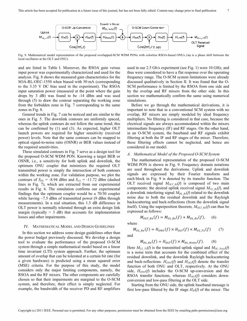
The mathematical representation of the proposed O-SCM WDM PON is shown in Fig. 9. Frequency domain notations are used throughout the derivations. Uplink and downlink signals are expressed by their Fourier transform and each block in Fig. 9 is denoted by its transfer function. The OLT received signal MOLT_Rx(f) is composed of two main components: the desired uplink received signal MUL_Rx(f), and a downlink interfering signal MDL_Rx(f) related to the downlink noise due to both the residual downlink and the Rayleigh backscattering and back-reflections (from the downlink signal itself). Using the superposition theorem, MOLT_Rx(f) can thus be expressed as follows:
_ _ _ , (6)
where
_ _ (7)
and
_ _ . (8)
Here MUL_Tx(f) is the transmitted uplink signal and MDL_Noise(f) is a noise term that accounts for the combined effect of the residual downlink, and the downlink Rayleigh backscattering and back-reflections. HONU(f) and HOLT(f) denote the transfer function of both ONU and OLT, respectively. At the ONU side, HONU(f) includes the O-SCM up-conversion and the RSOA transfer functions, whereas HOLT(f) considers down-conversion and low-pass filtering at the OLT side.
Starting from the ONU side, the uplink baseband message is first low-pass filtered by the IF stage HIF(f) of the mixer. The
Fig. 9. Mathematical model representation of the proposed overlapped-SCM WDM PONs with colorless RSOA-based ONUs (∆φ is a phase shift between thelocal oscillators at the OLT and ONU).
This article has been accepted for publication in a future issue of this journal, but has not been fully edited. Content may change prior to final publication
Copyright (c) 2011 IEEE. Personal use is permitted. For any other purposes, permission must be obtained from the IEEE by emailing [email protected]
8
resultant signal is then mixed with a local oscillator and up-converted to an RF subcarrier frequency fsc (the multiplication with the local oscillator is translated to a frequency shift in frequency domain). Before the signal exits the mixer, it is band-pass filtered by the RF stage HRF(f) of that mixer. The up-converted electrical signal then drives the RSOA. The DC component needed to bias the RSOA (through the bias-T in Fig. 1) is neglected in this analysis. Such DC component does not impact the results as it is simply filtered out by the AC-coupled components at the OLT receiver. At the output of the RSOA the signal is the sum of an up-converted uplink signal filtered by the RSOA modulation response HRSOA(f), and the residual downlink (which is not erased by the RSOA).
At the OLT side, the signal is down-converted. At the input of the mixer, the RF stage filters the incoming signal before down-conversion and low-pass filtering by the IF stage. An additional low-pass filter HLPF(f) is used at the output to remove out-of-band noise. Thus, equations (7) and (8) result in (9) and (10), respectively, through simple manipulations. We have neglected high frequency terms around ±2fsc as they are simply filtered out by the LPF when fsc ≥ Rb (band of interest for SCM and O-SCM). The impact of the negative frequency-shifted terms in (9) and (10) becomes important for smaller
values of fsc. At a subcarrier frequency around the bit rate for a ~100% O-SCM system, the tails of these negative frequency-shifted spectra impacts positive frequencies (spectra), and thus the system performance. In other words, the composite filter (which is the sum of negative and positive frequency-shifted terms) determines the system performance. Note that the uplink signal is filtered twice by the IF stage of the mixers and once by the LPF at the OLT as per (9), whereas the RSOA and the RF stage of the mixers affect the up-converted uplink signal. In other words, HIF(f) and HLPF(f) impact the signal at frequencies up to Rb, whereas HRSOA(f) and HRF(f) affect the up-converted uplink around fsc ± Rb.
Under normal operating conditions where the RSOA is highly saturated, the residual downlink is too small so that MDL_Rx(f) can be neglected, when compared to MUL_Rx(f). In our experiment we have measured a 20 dB suppression of the downlink noise MDL_Noise(f) compared to the desired uplink signal MUL_Tx(f). We have used that value for the simulation in Fig. 10 to account for the real noise coming from the residual downlink and the Rayleigh backscattering. From (10) we note that even if the downlink noise is not highly suppressed the O-SCM down-conversion circuitry will up-convert it after being filtered by HRF(f) so that MDL_Noise(f) will not highly interfere with the useful uplink MUL_Tx(f) at the receiver side. The IF stage of the mixer and the LPF will further suppress the downlink noise so that we can always neglect MDL_Rx(f) with respect to MUL_Rx(f).
B. Optimum Performance and Design Guidelines
Recall that at a certain bit rate Rb, the optimum performance is achieved with a certain amount of overlap that corresponds to an optimum fsc. That optimum is calculated numerically by substituting (9) and (10) in (6) and then comparing MOLT_Rx(f) to MUL_Tx(f). The MSE is then calculated for the different fsc values. Finally the optimum fsc at a given bit rate is selected according to the minimum MSE.
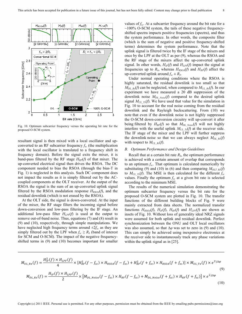
The results of the numerical simulation demonstrating the optimum subcarrier frequency versus the bit rate for the proposed O-SCM system are plotted in Fig. 10. The transfer functions of the different building blocks of Fig. 9 were mainly extracted from data sheets. The normalized transfer functions HRSOA(f), HIF(f), HRF(f) and HLPF(f) are shown as insets of Fig. 10. Without loss of generality ideal NRZ signals were assumed for both uplink and residual downlink. Perfect synchronization between the ONU and OLT local oscillators was also assumed, so that ∆φ was set to zero in (9) and (10). This can simply be achieved using inexpensive electronics at the receiver side to instantaneously track any phase variations within the uplink signal as in [25].
_ 4 _∓ ∆
_ 2 _ _∓ ∆
(9)
(10)
[50
dB/d
iv]
Sub
carr
ier
freq
uenc
y [G
Hz]
f sc
= 2
Rb
f sc=
Rb
[20
dB/d
iv]
Fig. 10. Optimum subcarrier frequency versus the operating bit rate for theproposed O-SCM system.
This article has been accepted for publication in a future issue of this journal, but has not been fully edited. Content may change prior to final publication
Copyright (c) 2011 IEEE. Personal use is permitted. For any other purposes, permission must be obtained from the IEEE by emailing [email protected]
9
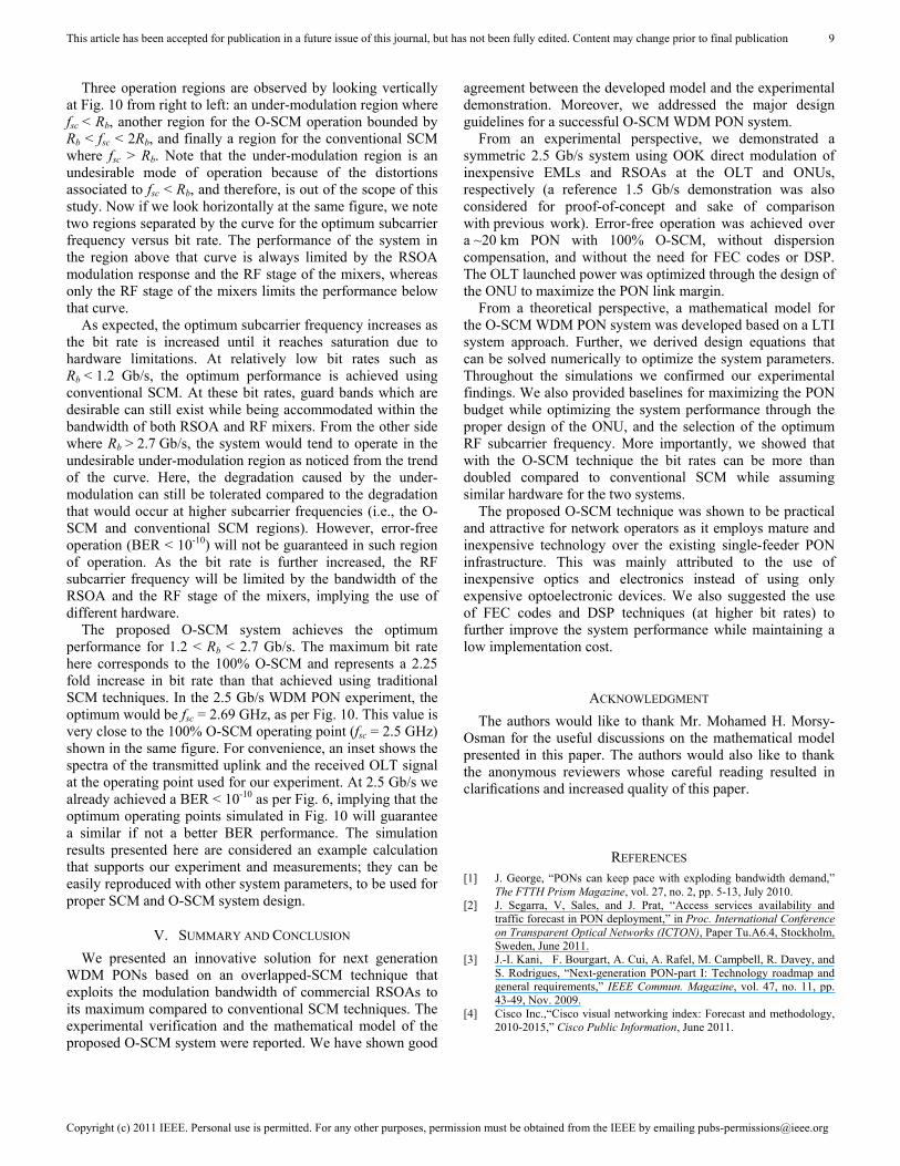
Three operation regions are observed by looking vertically at Fig. 10 from right to left: an under-modulation region where fsc < Rb, another region for the O-SCM operation bounded by Rb < fsc < 2Rb, and finally a region for the conventional SCM where fsc > Rb. Note that the under-modulation region is an undesirable mode of operation because of the distortions associated to fsc < Rb, and therefore, is out of the scope of this study. Now if we look horizontally at the same figure, we note two regions separated by the curve for the optimum subcarrier frequency versus bit rate. The performance of the system in the region above that curve is always limited by the RSOA modulation response and the RF stage of the mixers, whereas only the RF stage of the mixers limits the performance below that curve.
As expected, the optimum subcarrier frequency increases as the bit rate is increased until it reaches saturation due to hardware limitations. At relatively low bit rates such as Rb < 1.2 Gb/s, the optimum performance is achieved using conventional SCM. At these bit rates, guard bands which are desirable can still exist while being accommodated within the bandwidth of both RSOA and RF mixers. From the other side where Rb > 2.7 Gb/s, the system would tend to operate in the undesirable under-modulation region as noticed from the trend of the curve. Here, the degradation caused by the under-modulation can still be tolerated compared to the degradation that would occur at higher subcarrier frequencies (i.e., the O-SCM and conventional SCM regions). However, error-free operation (BER < 10-10) will not be guaranteed in such region of operation. As the bit rate is further increased, the RF subcarrier frequency will be limited by the bandwidth of the RSOA and the RF stage of the mixers, implying the use of different hardware.
The proposed O-SCM system achieves the optimum performance for 1.2 < Rb < 2.7 Gb/s. The maximum bit rate here corresponds to the 100% O-SCM and represents a 2.25 fold increase in bit rate than that achieved using traditional SCM techniques. In the 2.5 Gb/s WDM PON experiment, the optimum would be fsc = 2.69 GHz, as per Fig. 10. This value is very close to the 100% O-SCM operating point (fsc = 2.5 GHz) shown in the same figure. For convenience, an inset shows the spectra of the transmitted uplink and the received OLT signal at the operating point used for our experiment. At 2.5 Gb/s we already achieved a BER < 10-10 as per Fig. 6, implying that the optimum operating points simulated in Fig. 10 will guarantee a similar if not a better BER performance. The simulation results presented here are considered an example calculation that supports our experiment and measurements; they can be easily reproduced with other system parameters, to be used for proper SCM and O-SCM system design.
V. SUMMARY AND CONCLUSION
We presented an innovative solution for next generation WDM PONs based on an overlapped-SCM technique that exploits the modulation bandwidth of commercial RSOAs to its maximum compared to conventional SCM techniques. The experimental verification and the mathematical model of the proposed O-SCM system were reported. We have shown good
agreement between the developed model and the experimental demonstration. Moreover, we addressed the major design guidelines for a successful O-SCM WDM PON system.
From an experimental perspective, we demonstrated a symmetric 2.5 Gb/s system using OOK direct modulation of inexpensive EMLs and RSOAs at the OLT and ONUs, respectively (a reference 1.5 Gb/s demonstration was also considered for proof-of-concept and sake of comparison with previous work). Error-free operation was achieved over a ~20 km PON with 100% O-SCM, without dispersion compensation, and without the need for FEC codes or DSP. The OLT launched power was optimized through the design of the ONU to maximize the PON link margin.
From a theoretical perspective, a mathematical model for the O-SCM WDM PON system was developed based on a LTI system approach. Further, we derived design equations that can be solved numerically to optimize the system parameters. Throughout the simulations we confirmed our experimental findings. We also provided baselines for maximizing the PON budget while optimizing the system performance through the proper design of the ONU, and the selection of the optimum RF subcarrier frequency. More importantly, we showed that with the O-SCM technique the bit rates can be more than doubled compared to conventional SCM while assuming similar hardware for the two systems.
The proposed O-SCM technique was shown to be practical and attractive for network operators as it employs mature and inexpensive technology over the existing single-feeder PON infrastructure. This was mainly attributed to the use of inexpensive optics and electronics instead of using only expensive optoelectronic devices. We also suggested the use of FEC codes and DSP techniques (at higher bit rates) to further improve the system performance while maintaining a low implementation cost.
ACKNOWLEDGMENT
The authors would like to thank Mr. Mohamed H. Morsy-Osman for the useful discussions on the mathematical model presented in this paper. The authors would also like to thank the anonymous reviewers whose careful reading resulted in clarifications and increased quality of this paper.
REFERENCES [1] J. George, “PONs can keep pace with exploding bandwidth demand,”
The FTTH Prism Magazine, vol. 27, no. 2, pp. 5-13, July 2010. [2] J. Segarra, V, Sales, and J. Prat, “Access services availability and
traffic forecast in PON deployment,” in Proc. International Conference on Transparent Optical Networks (ICTON), Paper Tu.A6.4, Stockholm, Sweden, June 2011.
[3] J.-I. Kani, F. Bourgart, A. Cui, A. Rafel, M. Campbell, R. Davey, and S. Rodrigues, “Next-generation PON-part I: Technology roadmap and general requirements,” IEEE Commun. Magazine, vol. 47, no. 11, pp. 43-49, Nov. 2009.
[4] Cisco Inc.,“Cisco visual networking index: Forecast and methodology, 2010-2015,” Cisco Public Information, June 2011.

This article has been accepted for publication in a future issue of this journal, but has not been fully edited. Content may change prior to final publication
Copyright (c) 2011 IEEE. Personal use is permitted. For any other purposes, permission must be obtained from the IEEE by emailing [email protected]
10
[5] IEEE 802.3av Task Force, “10 Gb/s Ethernet passive optical network,” Sep. 2009.
[6] “10-Gigabit-capable passive optical networks (XG-PON): General requirements,” ITU-T Recommendation G.987.1, Jan. 2010.
[7] K. Grobe, and J.-P. Elbers, “PON in adolescence: From TDMA to WDM-PON,” IEEE Commun. Magazine, vol. 46, no. 1, pp. 26-34, Jan. 2008.
[8] A. Banerjee, Y. Park, F. Clarke, H. Song, S. Yang, G. Kramer, K. Kim, and B. Mukherjee, “Wavelength-division-multiplexed passive optical network (WDM-PON) technologies for broadband access: A review [Invited],” J. Optic Net., vol. 4, no. 11, pp. 737-758, Nov. 2005.
[9] K. Iwatsuki, and J.-I. Kani, “Applications and technical issues of wavelength-division multiplexing passive optical networks with colorless optical network units [Invited],” IEEE/OSA J. Optical Commun. and Networking, vol. 1, no. 4, pp. C17-C24, Sep. 2009.
[10] F. Payoux, P. Chanclou, and G. Naveena, “WDM-PON with colorless ONUs,” in Proc. Optical Fiber Communications (OFC), Paper OTuG5, Anaheim, California, USA, Mar. 2007.
[11] C. Arellano, C. Bock, and J. Prat, “RSOA-based optical network units for WDM-PON,” in Proc. Optical Fiber Communications (OFC), Paper OTuC1, Anaheim, California, USA, Mar. 2006.
[12] T.-H. Cheng, Z. Xu, X. Cheng, Y.-K. Yeo, Y. J. Wen, W.-D. Zhong, and Y. Wang, “Subcarrier modulation in wavelength-reuse WDM passive optical networks (Invited Paper),” in Proc. ACP 2010 Asia Communications and Photonics Conference and Exhibition, pp. 401-402, Shanghai, China, Dec. 2010.
[13] Z. Xu, Y. J. Wen, W.-D. Zhong, T. H. Cheng, M. Attygalle, X. Cheng, Y.-K. Yeo, Y. Wang, C. Lu, “Characteristics of subcarrier modulation and its application in WDM-PONs,” IEEE J. Lightw, Technol., vol. 27, no. 12, pp. 2069-2076, June 2009.
[14] J.-M. Kang, and S.-K. Han, “A novel hybrid WDM/SCM-PON sharing wavelength for up- and down-link using reflective semiconductor optical amplifier,” IEEE Photon. Technol. Lett., vol. 18, no. 3, pp. 502-504, Feb. 2006.
[15] J. M. Fàbrega, E. T. López, J. A. Lázaro, M. Zuhdi, and J. Prat, “Demonstration of a full duplex PON featuring 2.5 Gbps sub carrier multiplexing downstream and 1.25 Gbps upstream with colourless ONU and simple optics,” in Proc. European Conference on Optical Communication (ECOC), Paper We.1.F.6, Brussels, Belgium, Sep. 2008.
[16] Z. A. El-Sahn, J. M. Buset, and D. V. Plant, “Bidirectional WDM PON enabled by reflective ONUs and a novel overlapped-subcarrier multiplexing technique,” in Proc. Optical Fiber Communications (OFC), Paper OMP7, Los Angeles, California, USA, Mar. 2011.
[17] Full Service Access Network, “Next generation PON task group (NG-PON),” http://fsanweb.com/
[18] H. Takesue, and T. Sugie, “Wavelength channel data rewrite using saturated SOA modulator for WDM networks with centralized light sources,” IEEE J. Lightw, Technol., vol. 21, no. 11, pp. 2546-2556, Nov. 2003.
[19] F. Payoux, P. Chanclou, T. Soret, N. Genay, and R Brenot, “Demonstration of a RSOA-based wavelength remodulation scheme in 1.25 Gbit/s bidirectional hybrid WDM-TDM PON,” in Proc. Optical Fiber Communications (OFC), Paper OTuC4, Anaheim, California, USA, Mar. 2006.
[20] C. Arellano, K.-D. Langer, and J. Prat, “Reflections and multiple Rayleigh backscattering in WDM single-fiber loopback access networks,” IEEE J. Lightw, Technol., vol. 27, no. 1, pp. 12-18, Jan. 2009.
[21] “10-Gigabit-capable passive optical networks (XG-PON): Physical media dependent (PMD) layer specification,” ITU-T Recommendation G.987.2, Oct. 2010.
[22] K. Y. Cho, A. Agata, Y. Takushima, and Y. C. Chung, “Performance of forward-error correction code in 10 Gb/s RSOA-based WDM PON,” IEEE Photon. Technol. Lett., vol. 22, no. 1, pp. 57-59, Jan. 2010.
[23] K. Y. Cho, B. S. Choi, Y. Takushima, and Y. C. Chung, “25.78-Gb/s operation of RSOA for next-generation optical access networks,” IEEE Photon. Technol. Lett., vol. 23, no. 8, pp. 495-497, Apr. 2011.
[24] A. Agata, and Y. Horiuchi, “RSOA-based 10G WDM PON using FEC and MLSE equalizers,” in Proc. Optical Fiber Communications (OFC), Paper OWG3, San Diego, California, USA, Mar. 2010.
[25] Z. A. El-Sahn, B. J. Shastri, J. M. Buset, and D. V. Plant, “A robust overlapped-SCM WDM PON with a standalone burst-mode OLT receiver,” in Proc. IEEE Photonics Conference (IPC), Paper TuE6, pp. 226-227, Arlington, Virginia, USA, Oct. 2011.
Ziad A. El-Sahn (S’98–M’10) received the B.S. and M.S. degrees in electrical engineering from Alexandria University, Alexandria, Egypt, in 2002 and 2005, respectively. In 2010, he received the Ph.D. degree from the Center of Optics, Photonics and Lasers (COPL), Department of Electrical and Computer Engineering, Laval University, Quebec City, QC, Canada.
In 2002, he joined the Department of Electrical Engineering, Alexandria University, where he was a Teaching and Research Assistant for three years and was then promoted to a Lecturer Assistant in 2005. From 2005 to 2009 he was a research assistant with the COPL, Laval University. Dr. El-Sahn is currently a Postdoctoral Fellow at McGill University, Montreal, QC, Canada. His research interests include fiber-to-the-home access technology, passive optical networks, wavelength-division multiplexing, optical code-division multiple-access, media-access-control layer protocols, computer networks, and mobile communications.
Jonathan M. Buset was born in Thunder Bay, Ontario, Canada in 1983.
In 2006 he received a B.Sc.E. (Hons.) degree in Engineering Physics from the Faculty of Applied Science at Queen’s University in Kingston, Ontario, Canada. In 2008 he received a M.Sc. degree from the Department of Physics at McGill University in Montréal, Quebec, Canada for investigations in optically manipulating GaAs nuclear spins in quantum Hall systems.
He is currently a Ph.D. candidate at the Department of Electrical and Computer Engineering at McGill University as a member of the Photonics Systems Group. His research interests include wavelength-division multiplexed passive optical networks (WDM PONs), electronic equalization and digital signal processing.
Mr. Buset is a recipient of the prestigious Les Vadasz Engineering Fellowship (2008) from McGill University.
David V. Plant (S’85–M’89–SM’05–F’07) received a Ph.D. in electrical
engineering from Brown University in 1989. From 1989 to 1993, he was a Research Engineer with the Department of
Electrical and Computer Engineering at UCLA. He has been a Professor in the Department of Electrical and Computer Engineering at McGill University since 1993, and was department Chair from 2006 to 2011. Dr. Plant currently holds a James McGill Professorship and a Bell Canada/NSERC Industrial Research Chair. Dr. Plant has published over 285 journal and conference papers, two book chapters, and has one licensed patent. He has received five teaching awards, the IEEE Photonics Society Distinguished Lectureship, the NSERC Synergy Award for Innovation, and the IEEE Microwave Theory and Techniques Society Microwave Prize. He was the recipient of the R.A. Fessenden Medal and the Outstanding Educator Award, both from IEEE Canada. He is a Fellow of the IEEE, the OSA, the Engineering Institute of Canada, and the Canadian Academy of Engineering.