time multiplexing and parallelization in multifocal multiphoton microscopy
TRANSCRIPT

1192 J. Opt. Soc. Am. A/Vol. 17, No. 7 /July 2000 A. Egner and S. W. Hell
Time multiplexing and parallelization inmultifocal multiphoton microscopy
Alexander Egner and Stefan W. Hell
High Resolution Optical Microscopy Group, Max-Planck-Institute for Biophysical Chemistry,D-37070 Gottingen, Germany
Received September 2, 1999; accepted February 23, 2000
We investigate the imaging properties of high-aperture multifocal multiphoton microscopy on the basis of dif-fraction theory. Particular emphasis is placed on the relationship between the sectioning property and thedistance between individual foci. Our results establish a relationship between the degree of parallelizationand the axial resolution for both two- and three-photon excitation. In addition, we show quantitatively that ifa matrix of temporal delays is inserted between the individual foci, it is, for the first time to our knowledge,possible to solve the classical conflict between the light budget and the sectioning property in three-dimensional microscopy and to provide a virtually unlimited density of foci at best axial resolution. © 2000Optical Society of America [S0740-3232(00)01906-2]
OCIS codes: 180.6900, 350.5730, 320.7080, 350.2950, 180.1790, 190.4180.
1. INTRODUCTIONMultifocal multiphoton microscopy (MMM)1 has recentlybeen introduced as a fast and efficient mode of three-dimensional (3D) fluorescence microscopy. In MMM arapidly scanned array of high-aperture foci nonlinearlyexcites the fluorescence molecules in the sample.2–5 Thestrength of MMM is to deliver 3D imaging in real time,directly to the eye if desired, while largely retaining thesectioning capabilities of its nonparallelized, single-beamcounterpart.6 Owing to its versatility in life cell imaging,MMM is expected to contribute significantly to the grow-ing popularity of nonlinear imaging modes in microscopy.
Parallelized real-time 3D microscopy has been tradi-tionally accomplished by disk scanning confocal micros-copy with the use of an array of pinholes arranged in aNipkow-type pattern.7–9 The pinhole array providesboth the light for linear excitation and confocal spatial fil-tering upon detection. The image is formed on a CCDcamera or an equivalent detector. Unfortunately, like allparallelized 3D microscopes, this arrangement needs tocompromise between, on the one hand, confocality andhigh axial resolution and, on the other, degree of parallel-ization and brightness.10,11 The conflict stems from thefact that while reducing the distance between the pin-holes increases the light budget, the same measure alsoleads to a cross-talk between adjacent confocal channels.For example, fluorescence that is generated by the illumi-nation cone of one pinhole may also enter other pinholes.
The cross-talk is best understood by considering thatthe excitation is performed through an array of illumina-tion point spread functions (I-PSF’s) that coincides withan array of detection PSF’s (D-PSF’s). Whereas the mainmaximum of the corresponding I-PSF’s and D-PSF’s maybe perfectly colocalized in the focal plane, the axially dis-placed lobes of the I-PSF may overlap with those of theD-PSF of an adjacent pinhole. But, also, the individualI-PSF’s and D-PSF’s can overlap among themselves, sothat regions with reinforced excitation or detection are
0740-3232/2000/071192-10$15.00 ©
generated. For example, in the case of coherent illumi-nation, at a given axial distance from the focal plane, thesidelobes of the adjacent I-PSF’s may constructively inter-fere with each other, so that increased excitation andbleaching will occur in the region of constructive interfer-ence. As this is a classical problem in parallelized 3D mi-croscopy, considerable research effort has been devoted toit.11
MMM does not require backimaging on a pinhole arraybecause the nonlinear absorption automatically restrictsthe fluorescence emission to the focal plane. Hence thereare no confocal detection channels that could overlap.The overlap of the I-PSF’s may also be present in theMMM but is fortunately ameliorated by the fact that theexcitation scales with the cube or the square of the inten-sity. Nevertheless, its presence has to be taken seriouslyin a proper system design, especially when the highestpossible density of foci is needed, as has also been recog-nized experimentally.2 A high focal density may becomepractically relevant when the fluorescence photon flux ofa reduced area has to be maximized.
Another innovative, highly parallelized microscope isthe programmable array microscope,12,13 which illumi-nates the sample and detects the image by means of aprogrammable, movable micromirror device. An elabo-rate sequence of patterns allows the selection of regions ofinterest as well as of the degree of confocality. The pro-grammable array microscope is versatile and particularlyfast in spectroscopic 3D analysis of a fluorescent sample.However, if used as a highly parallelized confocal system,the cross-talk between the channels has to be considered.
The conflict between light budget and sectioning hasalso stimulated the introduction of self-correlating aper-ture microscopy,14 whereby a disk with a very dense andrandom pattern of pinholes is utilized. Maximizing thedensity of pinholes maximizes the light throughput andalso the cross-talk. In fact, in self-correlating aperturemicroscopy the cross-talk is fortunately so strong that it
2000 Optical Society of America

A. Egner and S. W. Hell Vol. 17, No. 7 /July 2000 /J. Opt. Soc. Am. A 1193
corresponds to an image of a conventional microscope.Scanning with such a disk gives an image consisting of abright confocal section added to a very bright conven-tional image. Therefore, after having also recorded aconventional image, one can readily obtain the desiredconfocal section by subtraction of the images.
Sectioning microscopy by fringe pattern projection issimilar.15 After the acquisition of three images with spa-tially shifted fringe patterns, one is able to calculate thesectioned image by proper subtraction. While these mi-croscopes excel by their ability to use a conventional lightsource rather than a (mode-locked) laser, they obtain thesectioned image only after subtraction of two or three im-ages. These images must be taken from the same placeunder identical conditions. This makes them amenableto noise that is inherently connected with the limitednumber of fluorescence photons available and image mis-allocation. Hence these microscopes will develop theirfull potential not only, but primarily, with bright, non-bleaching, and nonmoving specimens. Owing to its in-herent sectioning ability and to the generally lower totalphotodamage associated with near-infrared (NIR) light,MMM is expected to be superior for fast 3D fluorescenceimaging of live cells.
The aim of this paper is twofold. First, we will workout the effective PSF of MMM, with particular emphasison the relationship between the degree of parallelizationand the sectioning strength. In doing so, we provide thetheoretical framework for the design of multifocal multi-photon microscopes. Second, we will show that MMMhas a unique potential to solve the hitherto unsettledcross-talk resolution conflict. MMM has the potential toallow 3D imaging with a virtually infinite degree of par-allelization at an uncompromised axial resolution.
2. MULTIFOCAL MULTIPHOTONMICROSCOPYMultiphoton excitation microscopy is usually carried outwith a mode-locked Ti:sapphire laser providing a train ofpicosecond or subpicosecond NIR pulses at an 80-MHzrate. The 2–3 NIR photons are absorbed in a singlequantum event. The invention of MMM was triggerednot only by the general demand for fast high-resolutionmicroscopy but also by the insight that in multiphoton
microscopy the signal is normally limited by nonlinear op-tical processes. As has been demonstrated in theliterature,16,17 in multiphoton excitation microscopy it isusually more important to keep the maximum focal pulseintensity below a certain threshold rather than minimiz-ing the time-averaged power. For 100–200-fs pulses themaximum allowable focal intensity is reportedly approxi-mately 100–300 GW/cm2.18 When focusing with a high-numerical-aperture (high-NA) lens, this focal peak inten-sity is already achieved with 5–15 mW of time-averagedpower. This amounts to only approximately 1% of the to-tal time-averaged power of a Ti:sapphire laser, so thatmost of the laser light is usually dumped without beingused. In consequence, it is sensible to split up the beaminto N beamlets, each sharply focused at the sample, witheach beamlet leading to the maximum allowable focal in-tensity. In consequence, MMM increases the total fluo-rescence yield by a factor of N. Alternatively, the in-crease in excitation efficiency can be used for decreasingthe image acquisition time by the same factor.
A. SetupIn the initial MMM setup1 (Fig. 1), the laser beam is di-vided by means of an array of microlenses into typicallyN 5 6 3 6 hexagonally arranged beamlets overfilling theback aperture of the objective lens. Thus the beams pro-duce an array of high-resolution I-PSF’s at the focalplane. By positioning the microlenses on a fast rotatingspiral, the focal plane is completely raster scanned by thefoci. Typically, 375 complete scans per second areachieved, and up to typically 3–4000 frames per secondcan be anticipated by further increasing the speed of ro-tation. Alternatively, the array can be scanned by usinggalvanometric beam deflection.2 The axial scan is accom-plished by moving the sample axially as in standard laserscanning microscopes. The fluorescence is imaged onto aCCD camera as in a conventional epifluorescence micro-scope. The sensitivity and the readout time of the CCDcamera technically determines the speed of imaging.The distance between the foci can be adapted by varyingthe magnification of the intermediate optics and is typi-cally between 5 and 10 mm. As we will show in our cal-culations, at this distance the effect of the overlap of theI-PSF’s is largely negligible.
Fig. 1. Principal optical arrangement of a multifocal multiphoton excitation microscope (unfolded). An array of microlenses producesan array of beamlets, in turn producing an array of high-aperture foci in the focal plane inside the specimen. A temporal delay mask(TMX) placed in front of the microlens array ensures that the pulses associated with different foci pass the focal plane at different timepoints. We refer to this method as time-multiplexed MMM.
1194 J. Opt. Soc. Am. A/Vol. 17, No. 7 /July 2000 A. Egner and S. W. Hell
B. Point-Spread FunctionThe excitation PSF of MMM for the p-photon excitationcase is described by the 2p-th power ( p 5 1, 2, 3,...) ofthe focal amplitude:
Hexc 5 @h~x, y, z ! ^ g~x, y, z !#2p. (1)
h(x, y, z) denotes the amplitude PSF of the lens,19 whichis the field generated by a single beamlet:
h~x, y, z ! 5 AE0
a
Acos~u! sin~u!J0(kAx2 1 y2 sin~u!)
3 exp@ikz cos~u!#du. (2)
A is proportional to the beam intensity, J0 is the zero-order Bessel function of the first kind, and u is the polaraperture angle and a is its maximum. The wave numberis given by k 5 2pn/l0 , where l0 denotes the vacuumwavelength and n is the index of refraction of the mediumin the focal region. The symbol ^ denotes the convolu-tion operation. The function
g~x, y, z ! 5 (n51
N
d ~x 2 xn!d ~ y 2 yn!d ~z ! (3)
is the grating function describing the coordinates of thearray that is usually confined to the focal plane. d isDirac’s delta function. The effective PSF takes into ac-count the lateral scanning procedure and the conven-tional imaging onto the CCD camera. It is given by
Heff ~x, y, z ! 5 @h~«x, «y, «z !#2Iz~z !, (4)
where
Iz~z ! 5 EEdxdy@h~x, y, z ! ^ g~x, y, z !#2p (5)
denotes the z response of the microscope and «5 lex /lem is the ratio between the excitation and emis-sion wavelengths. The z response is equivalent to the re-sponse of an infinitely thin fluorescence layer whenscanned along the optic axis.
The lateral resolution is determined by the first factorin Eq. (4), which is the PSF of a conventional epifluores-cence microscope and is given by the lateral extent of theintensity PSF of the lens at the fluorescence wavelength.As this wavelength is shorter than the NIR wavelength,the lateral resolution of MMM is slightly better than thatof a standard two-photon beam-scanning system. In thelimiting case of a sufficiently sparse grating, say xi
2 xi 2 1 @ lAN, yi 2 yi 2 1 @ lAN, the interference ef-fects between the foci are negligible, and Eq. (5) can berewritten as
Iz~z ! 5 EEdxdy$@h~x, y, z !#2p^ g~x, y, z !%
5 NEEdxdy@h~x, y, z !#2p. (6)
In this case the multifocal multiphoton microscope hasthe same z response as that of a single-beam two-photonexcitation microscope, with the only difference being thatit is brighter by a factor corresponding to the number ofbeamlets. If the grating function is dense, the interfer-
ence of the amplitudes of different foci results in a differ-ent z response and hence in a different axial resolutionand sectioning strength. In general, one can expect theaxial resolution to be poorer than in the previous case.
Another useful measure of the sectioning strength of a3D microscope is the sea response
Isea~z ! 5 E2z
`
Iz~z8!dz8. (7)
The sea response describes the signal generated by a fluo-rescent half-space that is moved along the optic axis.Strictly speaking, the sea response does not give informa-tion different from that supplied by the z response, but itvisually emphasizes contributions of weak focal lobes indense specimens. The behavior of the z response and thesea response as a function of the density of the gratingwill be of primary concern in our paper.
C. Parameters of the CalculationFor our calculations we have chosen an objective lens ofNA 5 1.35 (oil immersion, n 5 1.518), which is typicalfor high-NA 3D microscopy. We also elected p 5 2 and 3to stand for two- and three-photon excitation, respec-tively. For this set of conditions, the diameter of the Airy
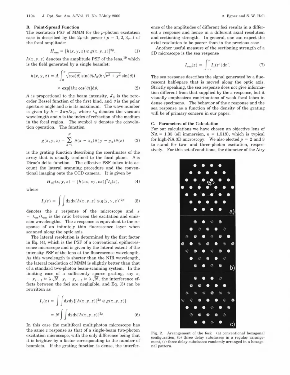
Fig. 2. Arrangement of the foci: (a) conventional hexagonalconfiguration, (b) three delay subclasses in a regular arrange-ment, (c) three delay subclasses randomly arranged in a hexago-nal pattern.

A. Egner and S. W. Hell Vol. 17, No. 7 /July 2000 /J. Opt. Soc. Am. A 1195
disk of the I-PSF is approximately 0.8l0 . As the micro-lens array is illuminated by the same wave front, it is rea-sonable to assume that the beamlets are mutually coher-ent and have the same initial phase.
Furthermore, we started from a hexagonal arrange-ment of N 5 37 high-aperture foci in the focal plane,which also corresponds to the design of our initial multi-focal microscope. If the distance between closest neigh-bors is denoted as s, the maximum distance of a focusfrom the center of the array is given by 3s [Fig. 2(a)]. Toevaluate the integrals (5) and (6) efficiently, we had to re-strict the integration area in a reasonable manner. Inthe case of two-photon excitation ( p 5 2), we have se-lected the area of integration so that a disk ;2.5 timesthe area of the radius of the outermost Airy disk was stillincluded [Fig. 2(a)]:
Iz~z ! [ E23s22l0
3s12l0 E23s22l0
3s12l0
Hexc~x, y, z !dxdy. (8)
We confirmed that when the integration area was en-larged to 3s 1 8l0 , the upper bound for the relative sys-tematic deviation was 0.4%; usually, it was significantlylower. The calculation of the sea response is complicatedby asymptotic behavior of the z response. When calculat-ing the integral Isea , one has to delimit the integrationrange along the optic axis. We found that a range of240l0z < < 40l0 was sufficiently large. This was sub-
stantiated by the fact that, for interfocal distances largerthan l0 , when the distance was increased to zmax5 100l0 , the relative change of the sea response was be-low 1%. Hence we calculated that
Isea~z ! > E2z
40l0
Iz~z8!dz8. (9)
3. RESULTSIn the following we shall present numerical results of thez response and the sea response revealing the relation-ship between the sectioning strength and the degree ofparallelization. We will consider both the two- andthree-photon excitation fluorescence modes, which are inpractice the relevant excitation modes in microscopy.
A. ResponseFigure 3 displays the two-photon excitation z response Izas a function of the interfocal distance s in the range of0 < s < 13l0 . For the limiting case of s → 0, the z re-sponse approaches the unparallelized, single-lens casefeaturing a FWHM of 0.83l0 , which we shall denote asFWHM1. For a spacing narrower than the wavelength(0.1l0 < s < l0), interference between the 3D amplitudePSF’s broadens the z response and degrades the axialresolution. For slightly larger distances, say for s
Fig. 3. Properties of the two-photon excitation response to an infinitely thin fluorescence plane, Iz , calculated for a numerical apertureof NA 5 1.35, oil immersion; normalized to unity. (a) Linear scale plot of Iz for interfocal distances of s 5 0l0 (curve 1), s 5 5l0 (curve2), and s 5 10l0 (curve 3), (b) 2D plot showing the intensity of Iz in gray values as a function of the interfocal distance s and the axialcoordinate z, (c) semilogarithmic plot of the data in (a), (d) semilogarithmic plot of the data in (b).

1196 J. Opt. Soc. Am. A/Vol. 17, No. 7 /July 2000 A. Egner and S. W. Hell
Fig. 4. Squared focal intensities I2(x, y) for different axial coordinates z. In each plane the gray values are normalized to unity, so thatthe image brightness does not reflect the absolute brightness in the particular plane, which, however, can be inferred from the curves inthe rectangular plots showing I2(x,0).
> 3l0 , the interference becomes less pronounced, and theaxial width of the z response rapidly approaches FWHM1.At a typical wavelength of l0 5 800 nm, the distance ofs 5 3.2 mm leads to a FWHM of 0.78l0 , which is close toFWHM1. In Fig. 3(a) we compare the single-beam re-sponse Iz(s 5 0) with Iz(s 5 5l0) and Iz(s5 10l0). We find that the two MMM curves differ fromthe first curve by only a shoulder smaller than 3.5% and1%, respectively. The calculations reveal that interfocaldistances of a few micrometers are sufficient to obtain ahigh axial resolution in MMM. This is confirmed by theexperiment: In the initial setup the interfocal distancefor a NA 5 1.35 oil lens was set to s 5 5.6 mm > 7l0 .
To provide a better understanding of the physical phe-nomena, we have highlighted the weak regions by dis-playing the data of Fig. 3(b) on a semilogarithmic plot[Fig. 3(d)]. We find line-shaped regions of locally in-
creased squared intensity that are parabolically driftingaway from the optic axis. These lines are due to the par-tial constructive interference that typically occurs whenperiodic structures are illuminated with coherent planewaves. The coherent illumination of a periodic structure,such as a microlens array, results in repeated gradualself-imaging of the foci in characteristic planes perpen-dicular to the optic axis.20,21 This is known as the Talboteffect, and the corresponding planes are known as theTalbot and fractional Talbot planes.22 Whereas in Talbotplanes the initial grating pattern is reproduced, in frac-tional Talbot planes the multiplicity of the pattern is al-tered. In some planes the pattern may be shifted or evenrotated, thus resulting in aesthetically appealing orna-ments.
Figure 4 displays the calculated pattern of the squaredintensity in the focal plane z 5 0 and the (fractional) Tal-

A. Egner and S. W. Hell Vol. 17, No. 7 /July 2000 /J. Opt. Soc. Am. A 1197
bot planes at 3.2l0 , 5.1l0 , 10.4l0 , 16.4l0 , and 25.7l0for an s 5 5l0 grating. For the sake of better visualiza-tion, we have normalized the Talbot planes to equalbrightness. Fortunately, the squared intensity in theTalbot planes is much weaker than that at the focal planebecause the field is blurred with increasing distance zfrom the focus. This is due to the strong defocusingcaused by the large aperture angle of ;120°. (Strictlyspeaking, Talbot self-reproduction occurs with finite ar-rays only when low focusing angles are involved.)
The strength of the squared intensity is shown in theintensity profiles beneath the focal patterns. The high-est local squared intensity (11% of the initial value) isfound at the ‘‘full’’ Talbot planes, as is the case at z5 10.4l0 . In planes with higher multiplicity, such asthe one at z 5 3.2l0 , the squared intensity is lower.Nevertheless, these planes can also contribute to thebackground because of their multiplicity. In fact, thesmall peaks found in the semilogarithmically displayed zresponse [Fig. 3(c)] can be associated with contributionsfrom individual Talbot planes.
B. Fluorescence Sea ResponseThe z responses in Fig. 3 suggest that for two-photon ex-citation an interfocal distance of s > 5l0 almost excludes
interference effects between the foci. Hence the two-photon-based MMM should display almost the same axialresolution as that of a single-beam two-photon micro-scope. While this is certainly true for the separation ofstacked layers, this may not be true when imagingdensely fluorescent media. In this case minute contribu-tions from throughout the sample may add to a significantbackground that is superimposed on the sectioned image.The strength of this effect can be investigated by tracingthe axial response of a fluorescence sea. Therefore thetwo-photon sea response Isea(z) has been calculated fol-lowing relation (9) as a function of the interfocal distance0 < s < 13l0 (Fig. 5).
Figure 5(b) shows Isea(z) as a two-dimensional contourplot featuring the 50% line as the vertical line in the cen-ter. The width of the sea response can be inferred fromthe density of the contour lines. In Fig. 5(a) we compareIsea(s 5 5l0) and Isea(s 5 10l0) with the response Isea(s5 0) found for a single beam. The calculations showthat the first two curves differ from the latter by a shoul-der of approximately 20% and 12%, respectively. Thisshoulder is a consequence of the summation of small two-photon excited fluorescence in the uniform sea of fluoro-phores. Figures 6(a) and 6(b) show, respectively, theFWHM of the z response and the distance between the
Fig. 6. Sectioning in two-photon MMM as a function of the interfocal distance s: (a) FWHM of the z response and (b) the d20% –80%threshold value of the sea response, normalized to their single-beam counterparts.
Fig. 5. (a) Normalized two-photon fluorescence sea response Isea for interfocal distances s 5 0l0 (curve 1), s 5 5l0 (curve 2), and s5 10l0 (curve 3) and (b) contour plot showing Isea as a function of s and the axial coordinate z.

1198 J. Opt. Soc. Am. A/Vol. 17, No. 7 /July 2000 A. Egner and S. W. Hell
Fig. 7. Sectioning in three-photon MMM; as in Fig. 5. Plots in (a) are shown for interfocal distances s 5 0l0 (curve 1), s 5 2.5l0(curve 2), and s 5 5l0 (curve 3).
20% and 80% values of the sea response, which we denoteas ]20% –80% , as a function of the interfocal distance s . Itis evident that a fluorescence sea is an artificial objectthat represents the worst-case situation. Nevertheless,Figs. 5 and 6 indicate that the interfocal distance shouldideally not be smaller than 7l0 in two-photon imaging ofdense fluorescence objects or objects with a vast amountof unbound fluorophore.
It is now interesting to investigate the axial resolutionperformance of MMM in the three-photon excitationmode. As the fluorescence scales with the cube of the in-tensity, we can expect that the effect of the various Talbotplanes is further reduced. This is also found in the cal-culations, the results of which are shown in Fig. 7. Infact, Fig. 7 is the three-photon counterpart to the two-photon data of Fig. 5. Whereas Fig. 7(b) shows the three-photon MMM sea response as a contour plot, Fig. 7(b)compares Isea(s 5 2.5l0) and Isea(s 5 5l0) with thesingle-beam response Isea(s 5 0). The comparison re-veals that for interfocal distance large than 3l0 , that is,2.5–3 mm, three-photon MMM can be carried out withoutcompromising the axial resolution.
C. Time-Multiplexed Multifocal MultiphotonMicroscopyThe results presented in Subsections 3.A and 3.B disclosethat for two- and three-photon MMM of high NA, the in-terfocal distance s should preferably not be smaller than7l0 and 3l0 , respectively. For most applications thisdistance or slightly larger distances are just adequate.In fact, moving the foci closer is usually not desired be-cause of the concomitant decrease in the field of view.For example, with a typical array of 6 3 6 foci, the inter-focal distance of s 5 7l0 is accompanied with a field ofview of 42 mm in diameter. Nevertheless, it might be de-sirable to decrease the interfocal distance because ahigher density of foci would result in a higher total exci-tation rate. Hence the total fluorescent flux from the il-luminated region would be increased. This measure mayeven become necessary when a particular region has to beimaged at high speed.
To maintain the axial resolution at small interfocal dis-tances, we have to prevent interference from taking place.As MMM relies on excitation with laser pulses of ul-trashort (picosecond or subpicosecond) duration that areapproximately 13 ns apart, we can define a straightfor-ward way to avoid focal overlap. As has also been inde-pendently recognized by Buist et al.,2 the introduction ofa temporal delay between the beamlets ensures that lightpulses of neighboring foci pass the focal region at differ-ent time points. Interference will not occur because thebeamlets simply do not meet each other. Of course, thismeasure has no influence on the total illumination effi-ciency because multiplexing the arrival times of thepulses at the sample has no influence on the total numberof excitation pulses.
The temporal delay is chosen such that it is slightlylarger than the pulse duration. For 100-fs pulses, tem-poral delays of ti > 2t ' 200 fs are already sufficient forthe desired time-multiplexing effect. A possible methodto realize such an optical delay is to place cylinders oftransparent optical material of varying thickness di infront of the lenses. In the case of a glass cylinder withthe refractive index n, a temporal delay ti is achieved by aglass thickness of di 5 tic/(n 2 1) with respect to a non-delayed pulse. The constant c denotes the speed of lightin air, and the index i 5 0, 1,..., imax 5 1/(2 ft)' 62,500. Hence a delay of i 3 100 fs is achieved by a
glass thickness of di 5 i 3 60 mm. The large number ofpotential time delays, imax , is a direct consequence of thedisparity between the pulse duration and the time gap 1/fbetween the pulses. For practical reasons one is prob-ably limited to a maximum glass thickness of a few milli-meters, so that imax 5 100 might be a more realisticvalue. Nevertheless, as N ! imax , we would be able totime-multiplex virtually all the lenses so that only onepulse resides in the sample at a given time point. We re-fer to this microscopy method as time-multiplexed MMM.
In most cases it will be sufficient to time-multiplexneighboring pulses that would otherwise overlap in thefocus. Hence one has to balance the grating distance swith respect to the number i of time-multiplexed foci. It

A. Egner and S. W. Hell Vol. 17, No. 7 /July 2000 /J. Opt. Soc. Am. A 1199
Fig. 8. (a) Sea response Isea and (b) z response Iz for different grating configurations: s 5 5l0 , regular (curves a); s 5 5l0 , with anoptical delay as in Fig. 2(b) and three regular subclasses (curves b); s 5 8.6l0 , regular arrangement (curves c).
Fig. 9. (a) Enlargement of the upper edge of the sea response Isea and (b) the corresponding part of the z response Iz for different focalconfigurations: s 5 5l0 , regular (curves a); s 5 5l0 , three regular subclasses with seffective 5 8.6l0 (curves b); s 5 5l0 , two randomsubclasses (curves r2); s 5 5l0 , three random subclasses (curves r3); s 5 5l0 , four random subclasses (curves r4). Note that the ran-domness leads to a smoother decline in the z response.
is therefore interesting to investigate the effect of a finitenumber i on the axial resolution, in particular in border-line cases, e.g., with three different pulse arrival times(i 5 2). Figure 8 compares the sea response Isea for (a)s 5 5l0 with that for (b) s 5 5l0 with three-channel timemultiplexing (TMX) (i 5 2) and that for a larger interfo-cal distance [(c) s 5 8.6l0]. The delay lines in case (b)are arranged in such a way that the neighboring beamletsare time multiplexed, as sketched in Fig. 2(b).
The effect of this setting is twofold. First, the interfo-cal distance is increased to an effective s of 8.6l0 , andsecond, the foci are divided into three interfering sub-groups. The numerical results in Fig. 8 reveal that, de-spite the same effective distance s, the two-photon excita-tion fluorescence sea and z response of the time-multiplexed case (b) is superior to that of case (c). Theexplanation is that in (b) the number of foci in the inter-fering subgroup is N/3.
The periodic arrangement of an optical delay maskwith a finite delay (i ! N), as shown in Fig. 2(b), stillproduces Talbot planes, although of considerably reducedsquared intensity. Therefore one is tempted to askwhether it would be more helpful to arrange the delaymask in random order, as sketched in Fig. 2(c). Figures9(a) and 9(b) show an enlargement of the part sensitive tothe interfocal distance of the two-photon excitation fluo-rescence sea and z response, respectively. Figure 9
shows them for the cases without TMX (curves a), withregular TMX, as in Fig. 2(b) and (curves b), and for ran-dom TMX, arranged in three different patterns that aredenoted as curves r2, r3, and r4, referring to two, three,and four different phase delays (i 5 1, 2, 3), respectively.The computations confirms that the cross-talk decreasesrapidly with increasing i. In addition, increasing themultiplicity by 1(i → i 1 1) is more effective for smallvalues of i than for larger values, as expected. We alsofind that for an equal number of foci in the same sub-group, a random pattern is not very different from its pe-riodic counterpart. However, the random arrangementeffectively prevents the formation of well-defined Talbotplanes, so that the responses show a largely monotonicdecline in fluorescence intensity.
4. DISCUSSION, OUTLOOK, ANDCONCLUSIONWe have investigated the axial resolution of a multipho-ton multifocal microscope as a function of the degree ofparallelization. Our study is highly relevant to its opti-cal design, in particular with respect to the right choice ofthe distance between individual foci in the focal plane.For two-photon excitation at high-aperture angles (NA5 1.35 oil, a 5 63°), we could establish a minimum in-tercocal distance of s > 7l0 . Hence, in properly de-

1200 J. Opt. Soc. Am. A/Vol. 17, No. 7 /July 2000 A. Egner and S. W. Hell
signed MMM, the interfocal distance should be approxi-mately 5–6 mm. For smaller interfocal distancesinterference between individual foci occurs in the region afew micrometers above and below the focal plane, result-ing in a gradually decreased sectioning strength. If theimages are bright enough, this can be adequately compen-sated by subtraction of a background. For large interfo-cal distances the axial resolution is largely that of asingle-beam two-photon excitation microscope, whoseaxial resolution is given by the squared intensity PSF ofthe objective lens.
In the case of three-photon excitation, the cubic nonlin-earity leads to a stronger suppression of the weak inter-ference contributions. Lower interfocal distances s> 3l0 , typically 2.4 mm, are sufficient for obtaining asectioning strength similar to that of a single beam.Thus three-photon and higher orders of excitation allowfor an even higher degree of parallelization as comparedwith that from the two-photon case. The cubic order ofexcitation requires careful adjustment of the beam inten-sity to the upper allowable intensity values, which are ofthe order of 100–300 GW/cm2. This is required becauselow intensity levels yield poor signals. In conclusion,MMM provides a good solution for this problem because itallows the dense distribution of multiple foci with safe in-tensity levels, thus leading to a multiple increase inbrightness.
Although MMM does not require confocal pinholes forsectioning, it can be combined with a confocal pinholedisk. Confocalization adds complexity to the microscope,such as the requirement to align the microlens array andthe pinhole array and also the necessity for compensatingfor the longitudinal chromatic aberration between theNIR light and the fluorescence. Another technical chal-lenge is the requirement to place the dichroic mirror be-tween the pinhole array and the microlenses, unless aspatially remote but perfectly synchronized pinhole diskis used. In mathematical terms, however, confocaliza-tion means that the squared or cubic illumination inten-sity PSF array would be multiplied by an array of detec-tion PSFs calculated at the emission wavelength. Thiswould result in an additional suppression of out-of-focussignal and therefore to a further improvement of the axialresolution. Another effect is that the foci can be movedsignificantly closer than the previous 3l0 or 7l0 simplybecause the multiplication with a detection PSF is, in firstapproximation, similar to an increase of the order of exci-tation.
We have shown that a high degree of parallelization isaccomplished by time-multiplexing the pulses through anoptical delay mask. Although our initial calculations as-sumed a pulse length of t 5 100 fs, that is, the pulselength of the laser system now available to us, focal pulselengths on the order of 10 fs have been demonstrated.23
With such short pulses a glass thickness of di 5 i3 6 mm is sufficient for an effective delay. Significantly,it would technically allow us a total number of imax5 1000 time-delayed illumination channels. We notethat the interfocal cross-talk can be reduced to a lesser ex-tent by phase multiplexing of the different beamlets or bythe use of different polarization states.
The concept of time-multiplexed pulse excitation opens
up the prospect of very fast 3D imaging at the highestpossible resolution. In fact, any confocal microscope us-ing pulses for excitation can be time multiplexed, irre-spective of whether it relies on first, second, third, orhigher order of excitation. For example, time-multiplexed multifocal single-photon confocal microscopywill eliminate the interference between the individual ex-citation foci. With the decreasing costs of pulsed lasersystems, time-multiplexing confocal microscopes might beattractive in the future. TMX of the nanosecond dura-tion fluorescence pulse is conceivable but is technicallycomplex because it may require a time-gated detectorwith a fast readout. However, TMX of coherent nonlin-ear processes, such as multifocal second and third har-monics as well as coherent anti-Stokes Raman scatteringimaging, will be attractive because it would significantlyreduce the coherent cross-talk between the signal beams.
Significantly, the concept of time-multiplexed MMMsolves the classical conflict between brightness and sec-tioning strength and should for the first time allow 3D im-aging at a virtually unlimited degree of parallelization.However, the most fascinating option is to position thetime-multiplexed foci so close that one does not requirescanning. In that case the whole-field sectioned image isobtained just by illumination.
Address correspondence to the authors at the locationon the title page or by e-mail, [email protected] [email protected].
REFERENCES1. J. Bewersdorf, R. Pick, and S. W. Hell, ‘‘Multifocal multi-
photon microscopy,’’ Opt. Lett. 23, 655–657 (1998).2. A. H. Buist, M. Muller, and G. J. Brakenhoff, ‘‘Real-time
two-photon microscopy,’’ J. Microsc. (Oxford) 192, 217–226(1998).
3. M. Straub and S. W. Hell, ‘‘Multifocal multiphoton micros-copy: a fast and efficient tool for 3-D fluorescence imag-ing,’’ Bioimages 6, 177–185 (1998).
4. M. Straub and S. W. Hell, ‘‘Fluorescence lifetime three-dimensional microscopy with picosecond precision using amultifocal multiphoton microscope,’’ Appl. Phys. Lett. 73,1769–1771 (1998).
5. K. Fujita, O. Nakamura, T. Kaneko, S. Kawata, M. Oya-mada, and T. Takamatsu, ‘‘Real-time imaging of two-photon-induced fluorescence with a microlens-array scan-ner and a regenerative amplifier,’’ J. Microsc. (Oxford) 194,528–531 (1999).
6. W. Denk, J. H. Strickler, and W. W. Webb, ‘‘Two-photon la-ser scanning fluorescence microscopy,’’ Science 248, 73–76(1990).
7. M. Petran, M. Hadravsky, M. D. Egger, and R. Galambos,‘‘Tandem-scanning reflected-light microscope,’’ J. Opt. Soc.Am. 58, 661–664 (1968).
8. G. Q. Xiao, T. R. Corle, and G. S. Kino, ‘‘Real-time confocalscanning optical microscope,’’ Appl. Phys. Lett. 53, 716–718(1988).
9. A. Ichihara, T. Tanaami, K. Isozaki, Y. Sugiyama, Y.Kosugi, K. Mikuriya, M. Abe, and I. Uemura, ‘‘High-speedconfocal fluorescence microscopy using a Nipkow scannerwith microlenses for 3D-imaging of single fluorescent mol-ecule in real time,’’ Bioimages 4, 52–62 (1996).
10. C. J. R. Sheppard and T. Wilson, ‘‘The theory of the direct-view confocal microscope,’’ J. Microsc. (Oxford) 124, 107–117 (1981).
11. E. M. McCabe, D. T. Fewer, A. C. Ottewill, S. J. Hewlett,

A. Egner and S. W. Hell Vol. 17, No. 7 /July 2000 /J. Opt. Soc. Am. A 1201
and J. Hegarty, ‘‘Direct-view microscopy: optical section-ing strength for finite-sized, multiple-pinhole arrays,’’ J.Microsc. (Oxford) 184, 95–105 (1996).
12. Q. S. Hanley, P. J. Verveer, and T. M. Jovin, ‘‘Optical sec-tioning fluorescence spectroscopy in a programmable arraymicroscope,’’ Appl. Spectrosc. 52, 783–789 (1998).
13. P. J. Verveer, Q. S. Hanley, P. W. Verbeek, L. J. van Vliet,and T. M. Jovin, ‘‘Theory of confocal fluorescence imaging inthe programmable array microscope (PAM),’’ J. Microsc.(Oxford) 189, 192–198 (1998).
14. T. Wilson, R. Juskaitis, M. Neil, and M. Kozubek, ‘‘Confocalmicroscopy by aperture correlation,’’ Opt. Lett. 21, 1879–1881 (1996).
15. M. A. A. Neil, R. Juskaitis, and T. Wilson, ‘‘Real time 3Dfluorescence microscopy by two beam interference illumina-tion,’’ Opt. Commun. 153, 1–4 (1998).
16. J. Bewersdorf and S. W. Hell, ‘‘Picosecond pulsed two-photon imaging with repetition rates of 200 and 400 MHz,’’J. Microsc. (Oxford) 191, 28–38 (1998).
17. S. W. Hell, M. Booth, S. Wilms, J. C. M. Schnetter, A. K.Kirsch, D. J. Arndt-Jovin, and T. M. Jovin, ‘‘Two-photon
near- and far-field fluorescence microscopy with con-tinuous-wave excitation,’’ Opt. Lett. 23, 1238–1240 (1998).
18. K. Konig, T. W. Becker, P. Fischer, I. Reimann, and K.-J.Halbhuber, ‘‘Pulse-length dependence of cellular responseto intense near-infrared laser pulses in multiphoton micro-scopes,’’ Opt. Lett. 24, 113–115 (1999).
19. M. Born and E. Wolf, Principles of Optics (Pergamon, Ox-ford, UK, 1993).
20. J. T. Winthrop and C. R. Worthington, ‘‘Theory of Fresnelimages. I. Plane periodic objects in monochromaticlight,’’ J. Opt. Soc. Am. 55, 373–381 (1965).
21. W. D. Montgomery, ‘‘Self-imaging objects of infinite aper-ture,’’ J. Opt. Soc. Am. 57, 772–778 (1967).
22. E. Bonet, P. Andres, J. C. Barreiro, and A. Pons, ‘‘Self-imaging properties of a periodic microlens array: versatilearray illuminator realization,’’ Opt. Commun. 106, 39–44(1994).
23. M. Muller, J. Squier, R. Wolleschensky, U. Simon, and G. J.Brakenhoff, ‘‘Dispersion-precompensation of 15 femtosec-ond optical pulses for high-numerical-aperture objectives,’’J. Microsc. (Oxford) 191, 141–158 (1998).