optical character recognition using template matching & structured...
TRANSCRIPT
Optical Character Recognition using TemplateMatching & Structured
AnalysisDesai Ami S.
Assi. Prof. in Vivekanand college for BCA,[email protected]
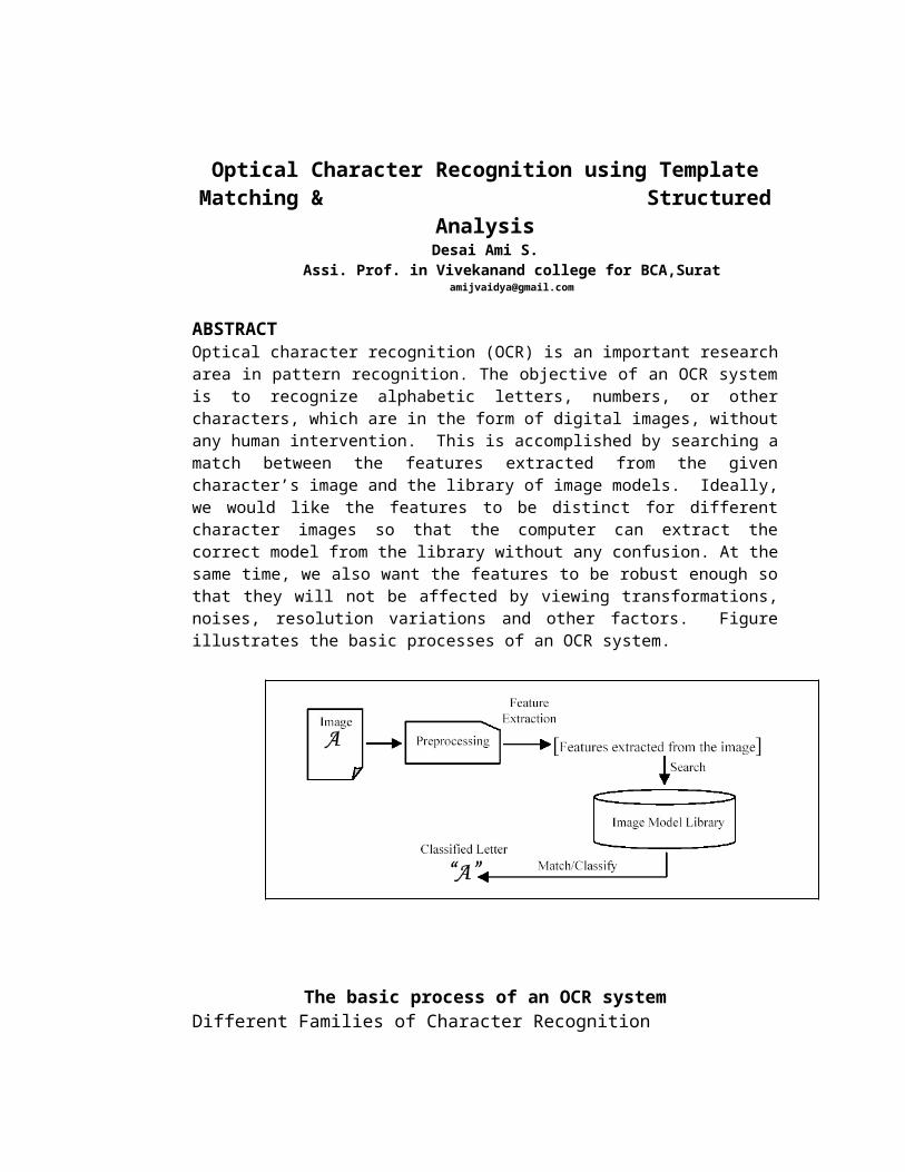
ABSTRACTOptical character recognition (OCR) is an important researcharea in pattern recognition. The objective of an OCR systemis to recognize alphabetic letters, numbers, or othercharacters, which are in the form of digital images, withoutany human intervention. This is accomplished by searching amatch between the features extracted from the givencharacter’s image and the library of image models. Ideally,we would like the features to be distinct for differentcharacter images so that the computer can extract thecorrect model from the library without any confusion. At thesame time, we also want the features to be robust enough sothat they will not be affected by viewing transformations,noises, resolution variations and other factors. Figureillustrates the basic processes of an OCR system.
The basic process of an OCR systemDifferent Families of Character Recognition
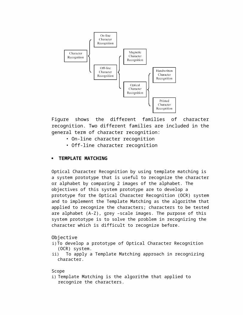
Figure shows the different families of characterrecognition. Two different families are included in thegeneral term of character recognition:
• On-line character recognition • Off-line character recognition
TEMPLATE MATCHING
Optical Character Recognition by using template matching is a system prototype that is useful to recognize the characteror alphabet by comparing 2 images of the alphabet. The objectives of this system prototype are to develop a prototype for the Optical Character Recognition (OCR) systemand to implement the Template Matching as the algorithm thatapplied to recognize the characters; characters to be testedare alphabet (A-Z), grey –scale images. The purpose of this system prototype is to solve the problem in recognizing the character which is difficult to recognize before.
Objectivei)To develop a prototype of Optical Character Recognition
(OCR) system.ii) To apply a Template Matching approach in recognizing
character.
Scopei) Template Matching is the algorithm that applied to
recognize the characters.
ii) Characters to be tested are alphabet (A - Z).iii) Grey-scale images were used with Times New Roman font
type.iv) Using bitmap image formatv) Using 240 x 240 image sizeWORKFLOW OF THE TEMPLATE MATCHINGALGORITM
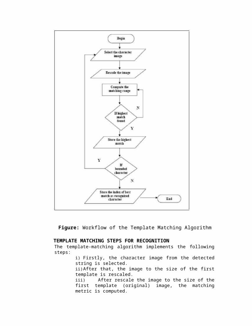
Figure: Workflow of the Template Matching Algorithm
TEMPLATE MATCHING STEPS FOR RECOGNITIONThe template-matching algorithm implements the followingsteps:
i) Firstly, the character image from the detectedstring is selected.ii)After that, the image to the size of the firsttemplate is rescaled.iii) After rescale the image to the size of thefirst template (original) image, the matchingmetric is computed.
iv)Then the highest match found is stored. Ifthe image is not match repeat again the thirdstep.v) The index of the best match is stored as therecognized character.
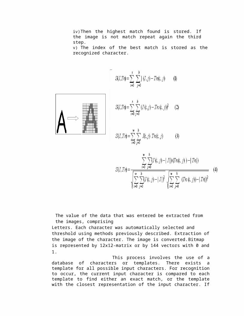
The value of the data that was entered be extracted from the images, comprising
Letters. Each character was automatically selected and threshold using methods previously described. Extraction ofthe image of the character. The image is converted.Bitmap is represented by 12x12-matrix or by 144 vectors with 0 and1. This process involves the use of adatabase of characters or templates. There exists atemplate for all possible input characters. For recognitionto occur, the current input character is compared to eachtemplate to find either an exact match, or the templatewith the closest representation of the input character. If
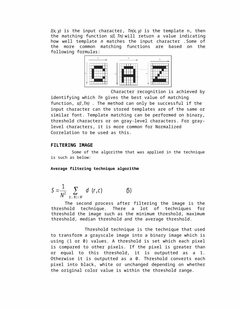
I(x, y) is the input character, Tn(x, y) is the template n, thenthe matching function s(I, Tn) will return a value indicatinghow well template n matches the input character .Some ofthe more common matching functions are based on thefollowing formulas:
Character recognition is achieved byidentifying which Tn gives the best value of matching function, s(I ,Tn) . The method can only be successful if the input character can the stored templates are of the same orsimilar font. Template matching can be performed on binary,threshold characters or on gray-level characters. For gray-level characters, it is more common for Normalized Correlation to be used as this. FILTERING IMAGE Some of the algorithm that was applied in the techniqueis such as below:
Average filtering technique algorithm
)5(),(1)0,(
2 Wr
crdN
S
The second process after filtering the image is thethreshold technique. There a lot of techniques forthreshold the image such as the minimum threshold, maximumthreshold, median threshold and the average threshold.
Threshold technique is the technique that usedto transform a grayscale image into a binary image which isusing (1 or 0) values. A threshold is set which each pixelis compared to other pixels. If the pixel is greater thanor equal to this threshold, it is outputted as a 1.Otherwise it is outputted as a 0. Threshold converts eachpixel into black, white or unchanged depending on whetherthe original color value is within the threshold range.
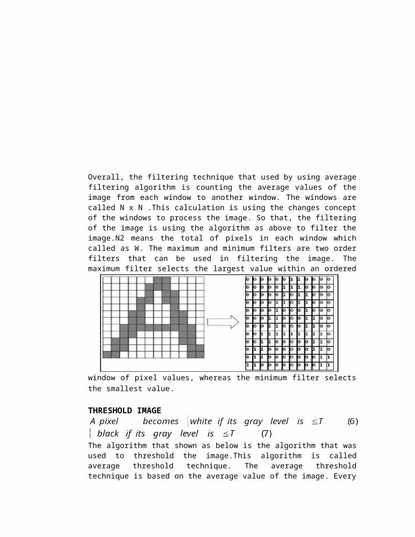
Overall, the filtering technique that used by using averagefiltering algorithm is counting the average values of theimage from each window to another window. The windows arecalled N x N .This calculation is using the changes conceptof the windows to process the image. So that, the filteringof the image is using the algorithm as above to filter theimage.N2 means the total of pixels in each window whichcalled as W. The maximum and minimum filters are two orderfilters that can be used in filtering the image. Themaximum filter selects the largest value within an ordered
window of pixel values, whereas the minimum filter selectsthe smallest value.
THRESHOLD IMAGE
The algorithm that shown as below is the algorithm that wasused to threshold the image.This algorithm is calledaverage threshold technique. The average thresholdtechnique is based on the average value of the image. Every
point is the pixels value of the image. The value of eachpoint is added and it divided by the number of points thatis counted for each image. This is important to get thethreshold value of the image which is 0 and 1.
Other techniques for threshold the image are Maximumthreshold, Minimum threshold and Median threshold. All ofthem also have their own algorithm. Maximum thresholdtechnique is based on the maximum value of the image, whilethe minimum threshold technique is based on the minimumvalue among all of the pixels in the image.
)11(
)10()09(
ittnt
itti
i
iyxifx
yxify
x
y
Maximum and Minimum threshold technique algorithm.Median technique is the threshold techniqueThat counts the median value of the pixel in theimage.
)12(......21 nxxx x in the algorithm above is refers to the value ofthe image and it will be count until getting themedian value among all the pixels in the image.
Following is an Example of using template matching forGujarati Script
CHARACTERISTICS OF GUJARATI LANGUAGE SCRIPT Gujarati is a
phonetic language in western India. Gujarati scriptis written fromleft toright, with each characterrepresenting a syllable. Gujarati script has 12vowels, which are called Swar and 34 consonants,which arc called Vyanjan. These are shown in Figure 2and Figure 3 respectively. Gujarati consists of aspecial symbol called
Figure 1
a ai e E U a[ a] ai[ ai] a> a:

Figure 2 Vowels of Gujarati scriptk K g F D gc C j z T q D Q Nt Y d F n p f b B m y r l L S P s h L Figure 3 Consonants of Gujarati scriptsa ai e E U a[ a] ai[ ai] a> a:Figure 4 Special symbols of Gujrati scripts
i ( ) & * [ ] i[ i] >:
Figure 5 Symbols for consonants without the vowels sounds
kT^ k| kl ³N RÀy ¹y OT^ Oq H
Maatra, corresponding to each vowel, which are attached toconsonants to modify their sound. Maatras corresponding toeach vowel is shown in Figure 4. First, Vowel does nothave corresponding maatra but is basic sound for theconsonants. Maatras are placed at the top, at bottom rightor at bottom part of the consonant. They can be attachedat different positions for different consonants. They canoccur in different shapes depending on the consonant towhich it is attached. In Gujarati each consonant actuallyis a combination of its pure form, called hrasivakshar andthe vowel sound phonetically. Visually also each consonantis a combination of its corresponding brasivaksharani thevowel maatra corresponding to vowel, ie, (excluding someexceptions). Each hrasivakshar'vs, obtained by placing belowthe consonant. When we want to use consonants without thevowel sound we have to use hraswaksharas Figure 5.
A character is said to be simple if it is a consonantalone or with a maatra (Figure 2and3). A charact er is saidto be conjunct if it is a half consonant along with otherconsonant shown in Figure 4). It can be seen that shape ofsome of the consonants is changed while in case of some itis retained.All the vyanjans, maatras and hrasivakshar as together roughlyprovide basic orthographic units, which are referred asglyphs that are combined together in different ways torepresent all the frequently used syllables.RECOGNITION TECHNIQUE
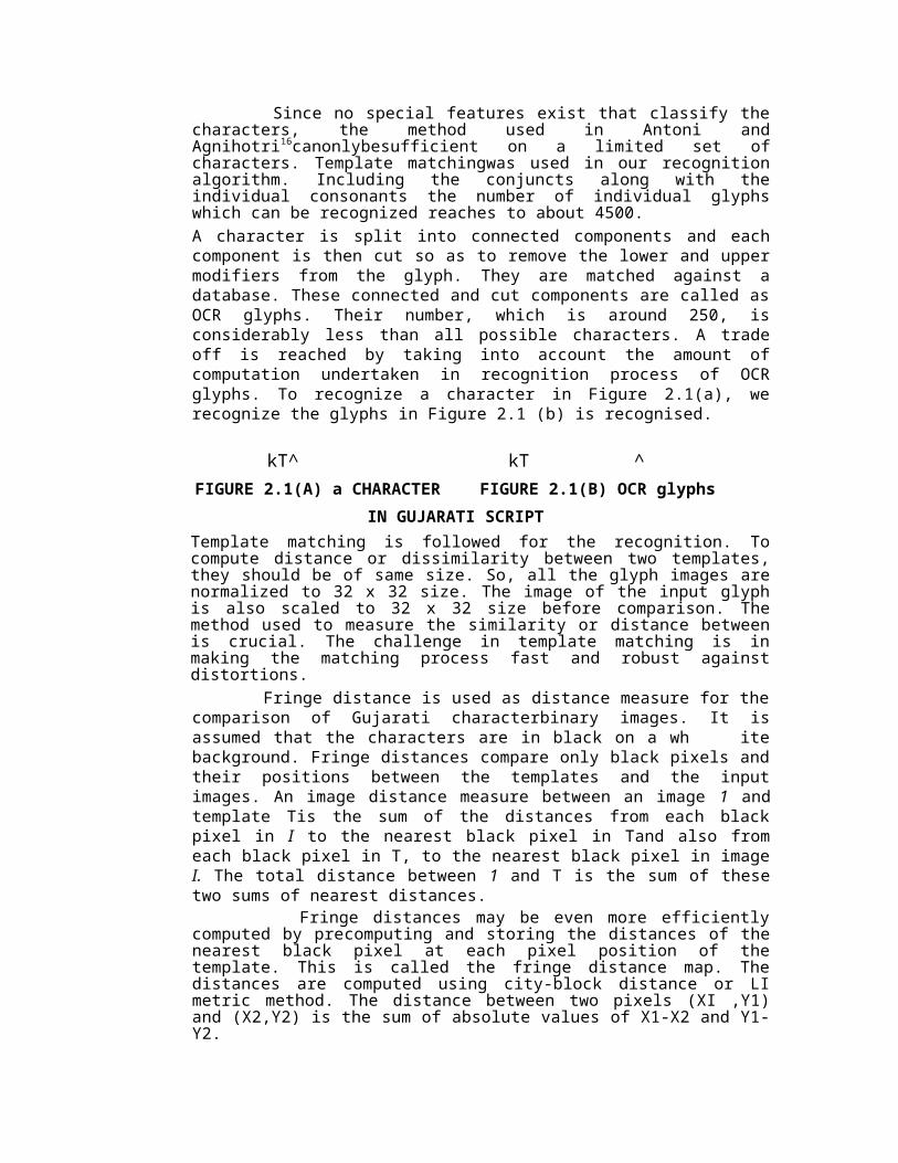
Since no special features exist that classify thecharacters, the method used in Antoni andAgnihotri16canonlybesufficient on a limited set ofcharacters. Template matchingwas used in our recognitionalgorithm. Including the conjuncts along with theindividual consonants the number of individual glyphswhich can be recognized reaches to about 4500.A character is split into connected components and eachcomponent is then cut so as to remove the lower and uppermodifiers from the glyph. They are matched against adatabase. These connected and cut components are called asOCR glyphs. Their number, which is around 250, isconsiderably less than all possible characters. A tradeoff is reached by taking into account the amount ofcomputation undertaken in recognition process of OCRglyphs. To recognize a character in Figure 2.1(a), werecognize the glyphs in Figure 2.1 (b) is recognised.
kT^ kT ^FIGURE 2.1(A) a CHARACTER FIGURE 2.1(B) OCR glyphs
IN GUJARATI SCRIPTTemplate matching is followed for the recognition. Tocompute distance or dissimilarity between two templates,they should be of same size. So, all the glyph images arenormalized to 32 x 32 size. The image of the input glyphis also scaled to 32 x 32 size before comparison. Themethod used to measure the similarity or distance betweenis crucial. The challenge in template matching is inmaking the matching process fast and robust againstdistortions. Fringe distance is used as distance measure for thecomparison of Gujarati characterbinary images. It isassumed that the characters are in black on a wh itebackground. Fringe distances compare only black pixels andtheir positions between the templates and the inputimages. An image distance measure between an image 1 andtemplate Tis the sum of the distances from each blackpixel in I to the nearest black pixel in Tand also fromeach black pixel in T, to the nearest black pixel in imageI. The total distance between 1 and T is the sum of thesetwo sums of nearest distances.
Fringe distances may be even more efficientlycomputed by precomputing and storing the distances of thenearest black pixel at each pixel position of thetemplate. This is called the fringe distance map. Thedistances are computed using city-block distance or LImetric method. The distance between two pixels (XI ,Y1)and (X2,Y2) is the sum of absolute values of X1-X2 and Y1-Y2.
When input is compared to a template, the fringedistance map of the input character is computed andsuperimposed upon the template. The distance form a blackpixel in die template to the closest black pixel in theinput is already stored at the pixel underneath it nosearch for the nearest pixel is needed. The distancebetween the input and the template is the sum of thevalues in the template fringe distance map correspondingto the black pixels in the input character. Similarly thedistance between the template and the input character isthe sum of the values in the input fringe distance mapcorresponding to the black pixels in the template. Fringedistance is the sum of these two distances.
A character, with the minimum fringe distance, issaid to be recognized by the template. A numerical code isassigned to each of the 250 templates and the numbercorresponding to the recognized template is output.RECOGNITION ALGORITHM IMPLEMENTATIONFlow chart given in Figure 7 depicts recognitionalgorithm The image is filtered using low pass filterbefore binarization operation.
Binarization.Optimal thresholding method is used from the methods reported. An optimal threshold is calculated using following algorithm.i) Assuming no knowledge about the exact location ofobjects, as a first approximation it is considered thatthe four corners of the image contain background pixelsonly and the remainder contains object pixels.ii) At step t, compute and \\?Q as the mean background groundand object gray-level, respectively, where segmentationinto background and objects at step /is defined by thethreshold value T determined in the previous step.

Figure 2.2(b) is the result of binarization on the scanned image of Figure 2.2(a).Äyipirn&> vitivrNaY< an[ Äyipirni> vitivrNn[ ligti t_vi[.aY<SiA#in&> vitivrN, aY<SiA#in) n)(t, aY<SiA#in&> aiyi[jnBirtmi> Äyipirn[ ligt&> kiydik)y vitivrN.ApFi<Rmk n)(t, upBi[ktin&> rxN, pyi<vrNn&> rxN.n)(tn[ lgt&> vitivrN; udir)krN, King)krN an[ v](VkrN
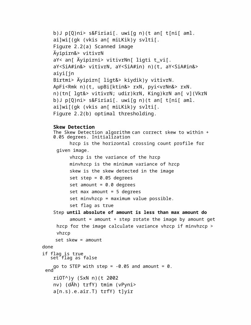
b)J p[Q)ni> s&Firiai[. uwi[g n)(t an[ t[ni[ aml. ai]wi[(gk (vkis an[ miLKik)y svlti[.Figure 2.2(a) Scanned imageÄyipirn&> vitivrNaY< an[ Äyipirni> vitivrNn[ ligti t_vi[.aY<SiA#in&> vitivrN, aY<SiA#in) n)(t, aY<SiA#in&> aiyi[jnBirtmi> Äyipirn[ ligt&> kiydik)y vitivrN.ApFi<Rmk n)(t, upBi[ktin&> rxN, pyi<vrNn&> rxN.n)(tn[ lgt&> vitivrN; udir)krN, King)krN an[ v](VkrNb)J p[Q)ni> s&Firiai[. uwi[g n)(t an[ t[ni[ aml. ai]wi[(gk (vkis an[ miLKik)y svlti[.Figure 2.2(b) optimal thresholding.
Skew DetectionThe Skew Detection algorithm can correct skew to within + 0.05 degrees. Initialization
hzcp is the horizontal crossing count profile for given image.
vhzcp is the variance of the hzcp minvhzcp is the minimum variance of hzcp skew is the skew detected in the image set step = 0.05 degrees set amount = 0.0 degrees set max amount = 5 degrees set minvhzcp = maximum value possible. set flag as true
Step until absolute of amount is less than max amount do amount = amount + step rotate the image by amount get
hzcp for the image calculate variance vhzcp if minvhzcp >vhzcpset skew = amount
doneif flag is true
set flag as falsego to STEP with step = -0.05 and amount = 0.
endriOT^)y (SxN n)(t 2002nv) (dÃh) trfY) tmim (vPyni> a[n.s).e.air.T) trfY) t]yir
an&sir j$r) s&Firi-vFiri kr), tmim (vPyni> a¿yik|m t]yir
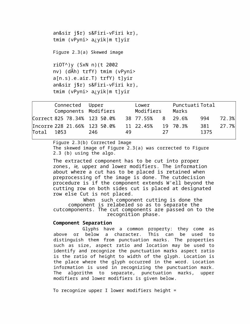
Figure 2.3(a) Skewed image
riOT^)y (SxN n)(t 2002nv) (dÃh) trfY) tmim (vPyni> a[n.s).e.air.T) trfY) t]yir an&sir j$r) s&Firi-vFiri kr), tmim (vPyni> a¿yik|m t]yir
Connected Upper Lower Punctuati TotalComponents Modifiers Modifiers Marks
Correct 825 78.34% 123 50.0% 38 77.55% 8 29.6% 994 72.3%Incorre 228 21.66% 123 50.0% 11 22.45% 19 70.3% 381 27.7%Total 1053 246 49 27 1375
Figure 2.3(b) Corrected ImageThe skewed image of Figure 2.3(a) was corrected to Figure 2.3 (b) using the algo.The extracted component has to be cut into proper zones, ie, upper and lower modifiers. The information about where a cut has to be placed is retained when preprocessing of the image is done. The cutdecision procedure is if the component extends W'ell beyond thecutting row on both sides cut is placed at designated row else Cut is not placed. When such component cutting is done the
component is relabeled so as to separate thecutcomponents. The cut components are passed on to the
recognition phase.Component Separation
Glyphs have a common property: they come asabove or below a character. This can be used todistinguish them from punctuation marks. The propertiessuch as size, aspect ratio and location may be used toidentify and recognize the punctuation marks aspect ratiois the ratio of height to width of the glyph. Location isthe place where the glyph occurred in the word. Locationinformation is used in recognizing the punctuation mark.The algorithm to separate, punctuation marks, uppermodifiers and lower modifiers is given below.
To recognize upper I lower modifiers height =
height of the glyph width = width of the glyph by = bottom coordinate of the glyph ty = top coordinate of the glyphrx = right co-ordinate of the glyph
lx = left co-ordinate of the glyph
Structural approach of OCRThe variation of shape of handwritten characters is solarge that is very difficult to create templates forthem. A so-called structure analysis method has beenapplied to handwritten character recognition.
Structure can be broken into two parts, it can bedescribed parts and relationship between them. Sowe can find out each character easily.
Characters can be represented by structuralfeatures with high tolerance to distortions andstyle variations. This type of representation mayalso encode some knowledge about the structure ofthe object or may provide some knowledge as towhat sort of components make up that object.
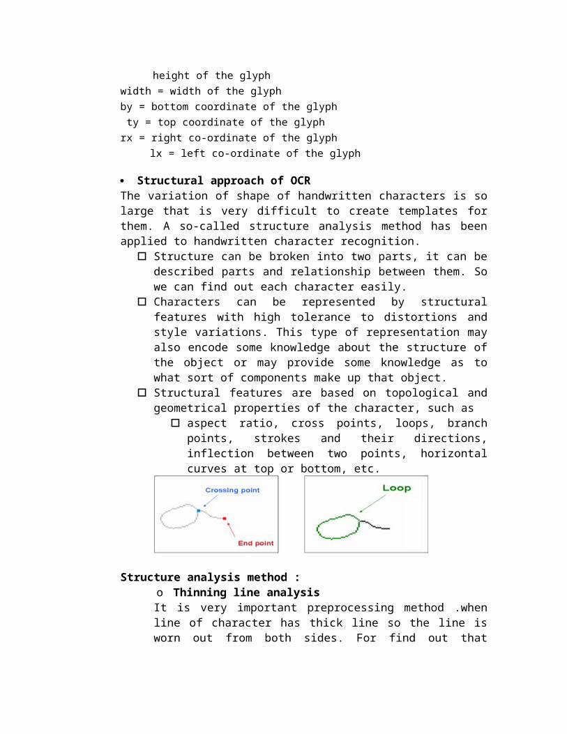
Structural features are based on topological andgeometrical properties of the character, such as
aspect ratio, cross points, loops, branchpoints, strokes and their directions,inflection between two points, horizontalcurves at top or bottom, etc.
Structure analysis method :o Thinning line analysisIt is very important preprocessing method .whenline of character has thick line so the line isworn out from both sides. For find out that
character some constraints are line is not brokenand not shortened.Thinning process has again two sub step
1. detect simple and local segment2. code that character using coding
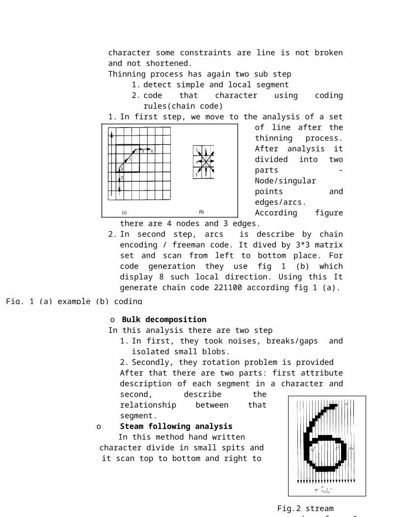
rules(chain code)1. In first step, we move to the analysis of a set
of line after thethinning process.After analysis itdivided into twoparts -Node/singularpoints andedges/arcs.According figure
there are 4 nodes and 3 edges.2. In second step, arcs is describe by chain
encoding / freeman code. It dived by 3*3 matrixset and scan from left to bottom place. Forcode generation they use fig 1 (b) whichdisplay 8 such local direction. Using this Itgenerate chain code 221100 according fig 1 (a).
o Bulk decompositionIn this analysis there are two step
1. In first, they took noises, breaks/gaps andisolated small blobs.
2. Secondly, they rotation problem is provided After that there are two parts: first attributedescription of each segment in a character andsecond, describe therelationship between thatsegment.
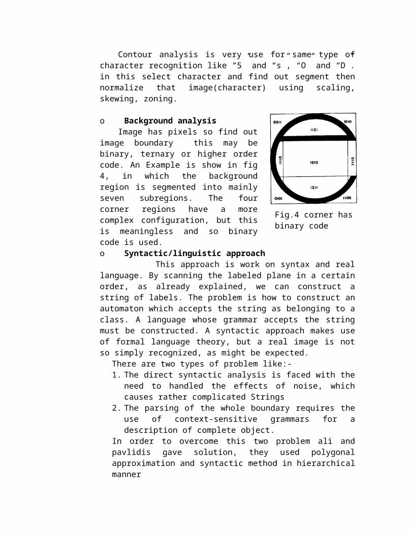
o Steam following analysisIn this method hand written
character divide in small spits andit scan top to bottom and right to
Fig. 1 (a) example (b) coding
Fig.2 stream scanning of no. 6

left. According figure character 6 divide into twopart p1 and p2. where b is a black component. Andoverlap spit is declare as D. component D and d is
merge one b component which is denoted by U
o VectorizationThis analysis is higher than thin and bulk
segmentation analysis. Connected line are separated,a segmented bulk is represented by a line and therelationships between the vectorized line aredescribed as a graph.
This analysis is based on what is referred to as aLAG (line adjacency graph) which is work on lengthencoding. LAG compressed is called C-LAG.
According to fig.3 (a) it split in segment thendisplay graph notation in fig 3 (b) and it displaycompressed LAG in fig 3 (c). In fig b J displayjunction and p is projection if degree of junctionis (1,1) ,where one segment is connected above andbelow are mapped into single node. Junction nodesare connected by more than one path. This path isdivide by segment. Then its follow on thinning lineanalysis and recognition character.
o Contour following analysis
Fig 3 Vectorized method
Contour analysis is very use for same type ofcharacter recognition like “5” and “s”, “O” and “D”.in this select character and find out segment thennormalize that image(character) using scaling,skewing, zoning.
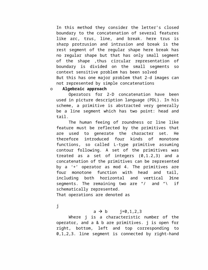
o Background analysisImage has pixels so find out
image boundary this may bebinary, ternary or higher ordercode. An Example is show in fig4, in which the backgroundregion is segmented into mainlyseven subregions. The fourcorner regions have a morecomplex configuration, but thisis meaningless and so binarycode is used.o Syntactic/linguistic approach This approach is work on syntax and reallanguage. By scanning the labeled plane in a certainorder, as already explained, we can construct astring of labels. The problem is how to construct anautomaton which accepts the string as belonging to aclass. A language whose grammar accepts the stringmust be constructed. A syntactic approach makes useof formal language theory, but a real image is notso simply recognized, as might be expected.
There are two types of problem like:- 1. The direct syntactic analysis is faced with the
need to handled the effects of noise, whichcauses rather complicated Strings
2. The parsing of the whole boundary requires theuse of context-sensitive grammars for adescription of complete object.
In order to overcome this two problem ali andpavlidis gave solution, they used polygonalapproximation and syntactic method in hierarchicalmanner
Fig.4 corner has binary code
In this method they consider the letter’s closedboundary to the concatenation of several featureslike arc, trus, line, and break. here trus issharp protrusion and intrusion and break is therest segment of the regular shape here break hasno regular shape but that has only small segmentof the shape ,thus circular representation ofboundary is divided on the small segments socontext sensitive problem has been solvedBut this has one major problem that 2-d images cannot represented by simple concatenations
o Algebraic approachOperators for 2-D concatenation have been
used in picture description language (PDL). In hisscheme, a primitive is abstracted very generallybe a line segment which has two point: head andtail.
The human feeing of roundness or line likefeature must be reflected by the primitives thatare used to generate the character set. Hetherefore introduced four kinds of monotonefunctions, so called L-type primitive assumingcontour following. A set of the primitives wastreated as a set of integers (0,1.2,3) and aconcatenation of the primitives can be representedby a ‘+’ operator as mod 4. The primitives arefour monotone function with head and tail,including both horizontal and vertical linesegments. The remaining two are “/” and “\” ifschematically represented.That operations are denoted as j
a b j=0,1,2,3Where j is a characteristic number of the
operator, and a & b are primitives. j is open forright, bottom, left and top corresponding to0,1,2,3. line segment is connected by right-hand
system, then they are represent sequence of theprimitive, is called primitive sequence.
As per some experiment, prepare 134000characters dataset is prepare for 220 subjects forvariety of writing styles then rate of result isrecognition, rejection and error were respectively98.7%,1.0% and 0.3%.
Example Devnagari script is different from Roman script inseveral ways. This script has two-dimensionalcompositions of symbols: core characters in the middlestrip, optional modifiers above and/or below corecharacters. Two characters may be in shadow of eachother. While line segments (strokes) are thepredominant features for English, most of thecharacters in Devnagari script is formed by curves,holes, and also strokes. In Devnagari language scripts,the concept of uppercase, the lower-case characters isabsent. However the alphabet itself contains morenumber of symbols than that of English. Devnagariscript has around 13 vowels and 36 consonants resultingin a total of 49 basic characters as shown in Figure1a. Vowels occur either in isolation or in combinationwith consonants. Apart from vowels and consonantscharacters called basic characters, there are compoundcharacters in Devnagari script alphabet system, whichare formed by combining two or more basic characters(shown in Figure 1b). The shape of compound characteris usually more complex than the constituent basiccharacters. Coupled to this in Devnagari script thereis a practice of having more than twelve forms each for36 consonants , giving rise to modified shapes which,depending on whether the vowel modifier is placed tothe left, right, top or bottom of the consonants asshown in Figure 1c. They are called modifiedcharacters. The net result is that there are several
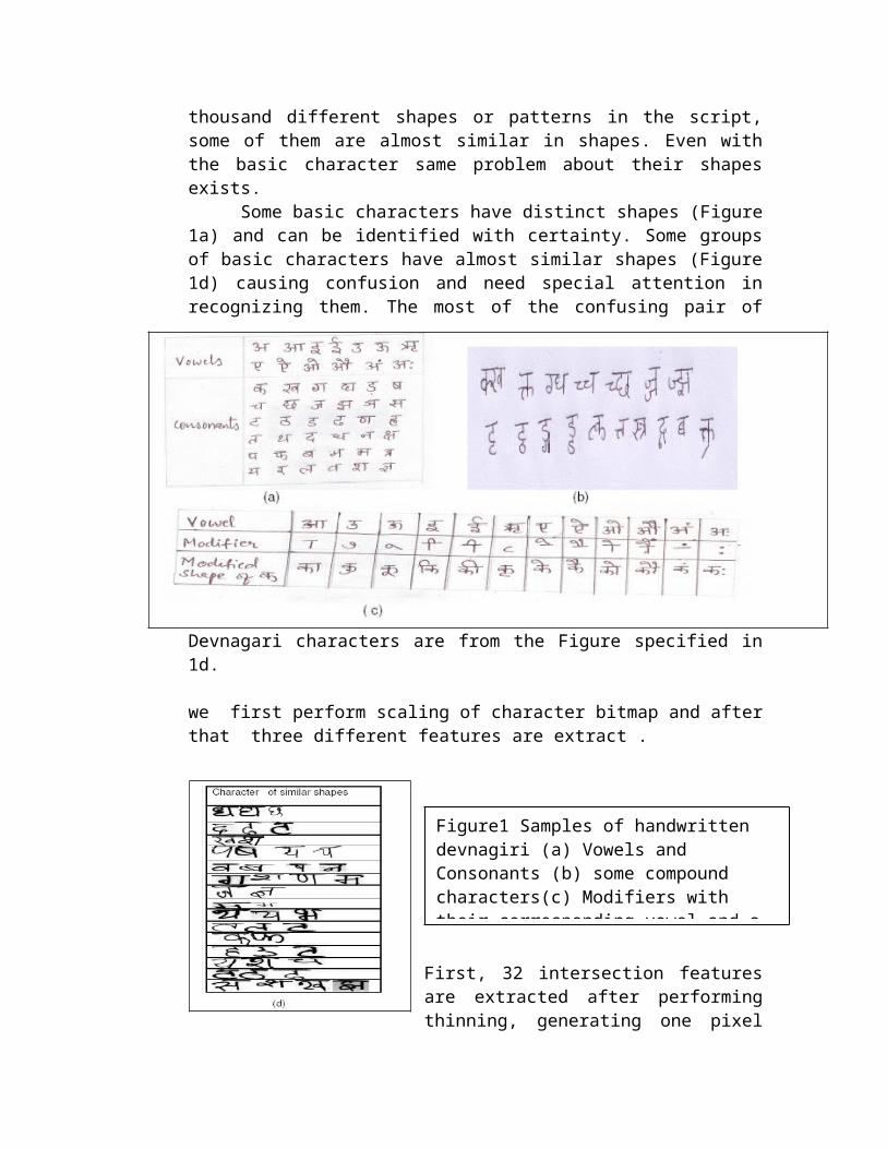
thousand different shapes or patterns in the script,some of them are almost similar in shapes. Even withthe basic character same problem about their shapesexists.
Some basic characters have distinct shapes (Figure1a) and can be identified with certainty. Some groupsof basic characters have almost similar shapes (Figure1d) causing confusion and need special attention inrecognizing them. The most of the confusing pair of
Devnagari characters are from the Figure specified in1d.
we first perform scaling of character bitmap and afterthat three different features are extract .
First, 32 intersection featuresare extracted after performingthinning, generating one pixel
Figure1 Samples of handwritten devnagiri (a) Vowels and Consonants (b) some compound characters(c) Modifiers with their corresponding vowel and a
wide skeleton of character image and segmenting theimage into 16 segments. Second, 16 shadow features are extracted from eightoctants of the character image. Third, 200 chain code histogram features are obtainedby first detecting the contour points of originalscaled character image, and dividing the contour imageinto 25 segments. For each segment chain code histogramfeatures are obtained.We followed some stepsA.. Conversion of Handwritten Character to BitmappedBinary ImagesIn images, background is not always of same contrastvalue. For this, we designed the Dynamic ThresholdValue Identification algorithm. The goal of thisalgorithm is to distinguish between image pixels thatbelong to text and those that belong to the background.The algorithm mentioned below is applied on gray scaleimages:-
a) Take the threshold to be 128(Mid value of 0 to255).
b) Take all the pixels with grayscale value above128 as background and all those with valuebelow 128 as foreground.
c) Find the mean grayscale values of backgroundpixels and foreground pixels.
d) Find the average of both mean values and makethis the new threshold.
e) Go back to step (b) and continue this processof refining the threshold till the change ofthe threshold from one iteration to nextbecomes less than 2%.
B. Scaling of the binary character images
Each character image is first enclosed in a tightfit rectangular boundary. The portion of the imageoutside this boundary is discarded. The selectedportion of the character image is then scaled to thesize 100 × 100 pixel using affine transformation. Forsmoothing the contours of the character images and alsofor filling in some holes, we perform somemorphological operations like closing and dilation onthe character image.
C. Feature ExtractionIn the following we give a brief description of
the three feature sets used in our proposed multipleclassifier system. Shadow features are extracted fromscaled bitmapped character image. Chain code histogramfeatures are extracted by chain coding the contourpoints of the scaled character bitmapped image.Intersection features are extracted from scaled,thinned one pixel wide skeleton of character image.Shadow Features of character—
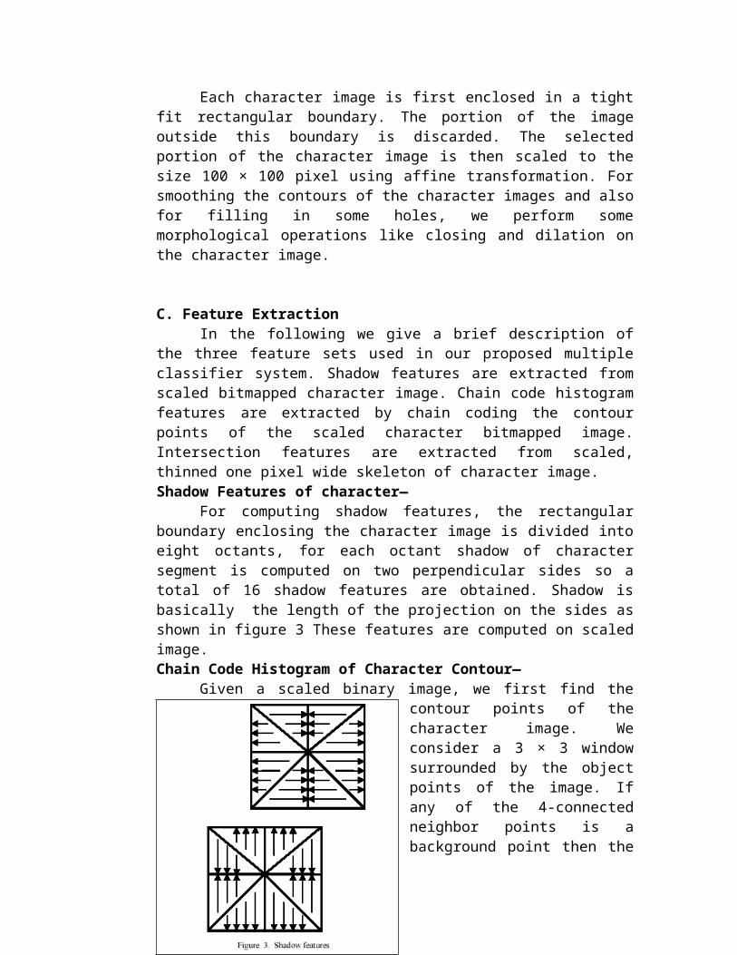
For computing shadow features, the rectangularboundary enclosing the character image is divided intoeight octants, for each octant shadow of charactersegment is computed on two perpendicular sides so atotal of 16 shadow features are obtained. Shadow isbasically the length of the projection on the sides asshown in figure 3 These features are computed on scaledimage.Chain Code Histogram of Character Contour—
Given a scaled binary image, we first find thecontour points of thecharacter image. Weconsider a 3 × 3 windowsurrounded by the objectpoints of the image. Ifany of the 4-connectedneighbor points is abackground point then the
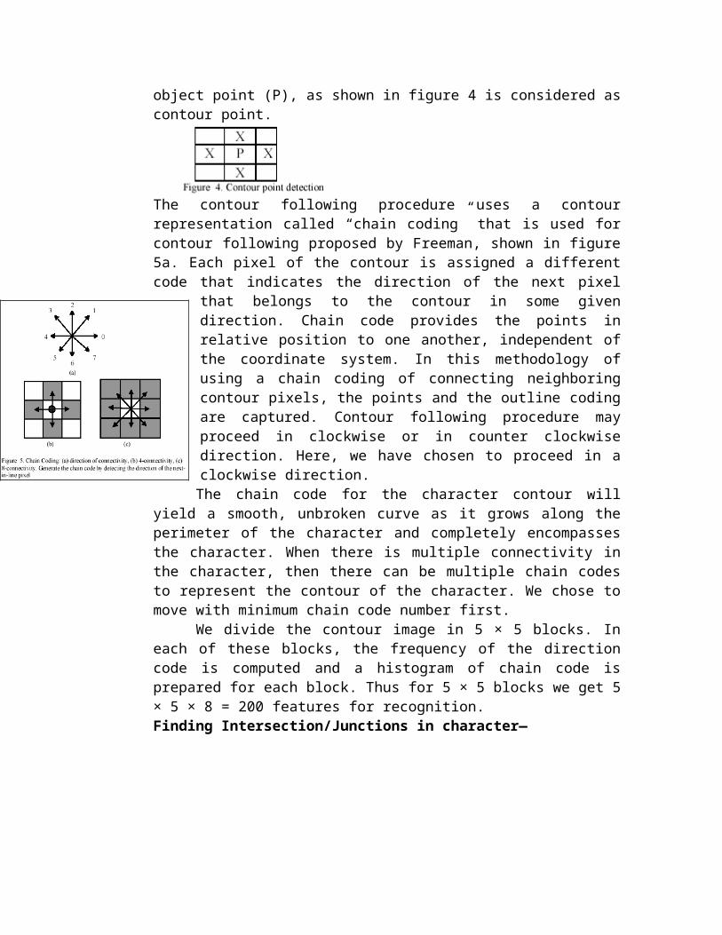
object point (P), as shown in figure 4 is considered ascontour point.
The contour following procedure uses a contourrepresentation called “chain coding” that is used forcontour following proposed by Freeman, shown in figure5a. Each pixel of the contour is assigned a differentcode that indicates the direction of the next pixel
that belongs to the contour in some givendirection. Chain code provides the points inrelative position to one another, independent ofthe coordinate system. In this methodology ofusing a chain coding of connecting neighboringcontour pixels, the points and the outline codingare captured. Contour following procedure mayproceed in clockwise or in counter clockwisedirection. Here, we have chosen to proceed in aclockwise direction.The chain code for the character contour will
yield a smooth, unbroken curve as it grows along theperimeter of the character and completely encompassesthe character. When there is multiple connectivity inthe character, then there can be multiple chain codesto represent the contour of the character. We chose tomove with minimum chain code number first.
We divide the contour image in 5 × 5 blocks. Ineach of these blocks, the frequency of the directioncode is computed and a histogram of chain code isprepared for each block. Thus for 5 × 5 blocks we get 5× 5 × 8 = 200 features for recognition.Finding Intersection/Junctions in character—
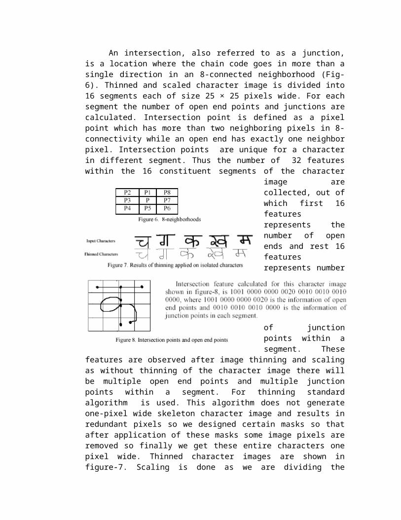
An intersection, also referred to as a junction,is a location where the chain code goes in more than asingle direction in an 8-connected neighborhood (Fig-6). Thinned and scaled character image is divided into16 segments each of size 25 × 25 pixels wide. For eachsegment the number of open end points and junctions arecalculated. Intersection point is defined as a pixelpoint which has more than two neighboring pixels in 8-connectivity while an open end has exactly one neighborpixel. Intersection points are unique for a characterin different segment. Thus the number of 32 featureswithin the 16 constituent segments of the character
image arecollected, out ofwhich first 16featuresrepresents thenumber of openends and rest 16featuresrepresents number
of junctionpoints within asegment. These
features are observed after image thinning and scalingas without thinning of the character image there willbe multiple open end points and multiple junctionpoints within a segment. For thinning standardalgorithm is used. This algorithm does not generateone-pixel wide skeleton character image and results inredundant pixels so we designed certain masks so thatafter application of these masks some image pixels areremoved so finally we get these entire characters onepixel wide. Thinned character images are shown infigure-7. Scaling is done as we are dividing the

character image into fixed size segments which is notpossible without fixing image size.
Straight Lines Fitting for Character—A straight line y=ai+bix is uniquely defined by
two parameters: the slope bi and the intercept ai .Given a thinned and scaled binary image, we segmentedit into 16 segments. For each segment image a straightline was fitted using LMS method of line fitting andcalculated ai and bi as follows :-
Intercept feature can be used directly but using slopefeature directly has a drawback related to thecontinuity of the representation. Straight line withslopes approaching +. And -. Has a very similar orientation but obviously, would berepresented with extremely different values, so we usedtwo features f1 and f2 based on slope, where :
So total calculated line fitting based features are 48for a 16 segmented image out of which 16 are a ivalues, 16 are f1 values and 16 are f2 values.III. DEVNAGARI CHARACTER RECOGNITIONWe used the same MLP with 3 layers including one hiddenlayer for four different feature sets consisting of 32intersection features, 16 shadow features, 48 linefitting based features and 200 chain code histogramfeatures. The experimental results obtained while usingthese features for recognition of handwritten Devnagaricharacters is presented in the next section. At thisstage all characters are non- compound, singlecharacters so no segmentation is required
The classifier is trained with standard Backpropagation. It minimizes the sum of squared errors forthe training samples by conducting a gradient descentsearch in the weight space. As activation function weused sigmoid function. Learning rate and momentum termare set to 0.8 and 0.7 respectively. As activationfunction we used the sigmoid function. Numbers ofneurons in input layer of MLPs are 32, 16, 48 or 200,for intersection features, shadow features, linefitting features and chain code histogram featuresrespectively. Number of neurons in Hidden layer is notfixed, we experimented on the values between 20-70 toget optimal result and finally it was set to 20, 30,40and 70 for intersection features, shadow features, linefitting features and chain code histogram featuresrespectively. The output layer contained one node foreach class., so the number of neurons in output layeris 49. And classification was accomplished by a simplemaximum response strategy.A. Classifier CombinationThe ultimate goal of designing pattern recognitionsystem is to achieve the best possible classificationperformance. This objective traditionally led to thedevelopment of different classification scheme for anypattern recognition problem to be solved. The result ofan experimental assessment to the different designwould then be the basis for choosing one of theclassifiers as the final solution to the problem. Ithad been observed in such design studies, that althoughone of the designs would yield the best performance,the sets of patterns misclassified by the differentclassifiers would not necessarily overlap. Thissuggested that different classifier designs potentiallyoffered complementary information about the pattern tobe classified which could be harnessed to improve theperformance of the selected classifier. So instead ofrelying on a single decision making scheme we cancombine classifiers.

Combination of individual classifier outputs overcomesdeficiencies of features and trainability of singleclassifiers. Outputs from several classifiers can becombined to produce a more accurate result. Classifiercombination takes two forms: combination of likeclassifiers trained on different data sets andcombination of dissimilar classifiers. We have foursimilar Neural networks classifiers as discussed above,which are trained on 32 intersection features, 16shadow features, 48 line fitting features and 200 chaincode features respectively. The outputs are confidencesassociated with each class. As these outputs can not becompared directly, we used an aggregation function forcombining the results of all four classifiers. Ourstrategy is based on weighted majority voting scheme asdescribed below.
ConclusionsWe have described the stream of research anddevelopment of OCR system, which has two largertributaries, have grown to a concrete OCR technologyand are merging to become a wide stream whichconstitutes an essential part of pattern recognitiontechnology. We described many method, some of which are some whatrelated to each other and so of which are more or lessindependent. The important point is that we should makethese method more precise in the sense of an exactscience, not a mere accumulation of empiricalknowledge. The above statement is very much related toa shape model in which we need to establish an exactand flexible mathematical model of shape including anoise model which can be independent of the shape, butis intrinsically related to a given shape. The abovetwo statements might have the relation of “Chick andegg”,but is necessary to attack both of these problemsat the same time in order to establish a shaperecognition technology on scientific ground. Based on
these efforts, we will be able to make a machine whichwill approach human performance on shape recognition.It is clear and real that, in order to make such amachine. Some combination of the method so far shouldbe brought together. Multiple approaches andcomplementary algorithms will be integrated.Performance of each method and models of characterswill be known by the reading machine. On the otherhand, a new method is still naturally expected andbecause of the rapid development of modern computertechnology. We can expand our creative space to a moresophisticated method. Which incorporates humanexpertise and the direct use of multilevel images.
The R & D of OCR is also moving toward “wordrecognition” using contextual knowledge such as addressand names. In fact such development, of postal addressand name reading machines is already such a trend. Thisnecessarily leads the R & D of OCR to documentanalysis. In which characters constitute one component.Thus the R & D of OCR will expand its applications to atotal document reader, posing the greatest challenge toresearchers in this field.
Reference1. J. R. Ullman,Pattern Recognition Techniques.
London.Butterworth,19732. T.Sakai and M. Nagao,Character and Figures
Recognition Machine. Tokiyo,19673. T. Pavlidis, Structural Pattern Recognition. New
york: Springer 19774. D. Marr and E. Hildreth “Theory of edge detection “
Proc Roy Soc “Loan B, Vol 207 pp 187-217,19805. Yamazaki and T. lijima, “ Sampling of a character
image”.J of Trans of Electorn.Commun.Eng Japan,Vol51-C No.9,pp 428-429 Sept 1968