operating manual hydra m (w)vac
TRANSCRIPT

TDP062e.doc Rev. 02.06.2014 Page 1 / 21
Perrot REGNERBAU CALW GmbH Industriestraße 19‐29 / D‐75382 Althengstett / Germany Phone: 0049‐7051‐162‐0 / Fax: 0049‐7051‐162–133
E‐mail: [email protected] / E‐mail Technical Department: [email protected]
Operating Manual
Pop‐up Sprinkler
Hydra M (W)VAC
PERROT

TDP062e.doc Rev. 02.06.2014 Page 2 / 21
Perrot REGNERBAU CALW GmbH Industriestraße 19‐29 / D‐75382 Althengstett / Germany Phone: 0049‐7051‐162‐0 / Fax: 0049‐7051‐162–133
E‐mail: [email protected] / E‐mail Technical Department: [email protected]
Contents
1 SAFETY ................................................................................................................................................... 3
1.1 HOW INSTRUCTIONS ARE MARKED IN THIS MANUAL ............................................................................................. 3 1.2 HAZARDS OF IGNORING SAFETY INSTRUCTIONS ................................................................................................... 3
2 DESCRIPTION ......................................................................................................................................... 4
3 INSTALLATION ....................................................................................................................................... 5
4 SPECIAL TOOLS ....................................................................................................................................... 5
5 COMMISSIONING / PREPARING FOR WINTER ......................................................................................... 6
5.1 COMMISSIONING ......................................................................................................................................... 6 5.2 PREPARING FOR WINTER ................................................................................................................................ 7
6 SETTING IRRIGATION SECTOR ................................................................................................................. 7
7 REPLACING THE NOZZLE ....................................................................................................................... 10
7.1 ADJUSTING THE INLET NOZZLE ....................................................................................................................... 12 7.2 FITTING THE SPRINKLER INSERT ...................................................................................................................... 13
8 VALVE INSERT REMOVAL / INSTALLATION ............................................................................................ 14
8.1 TAKING OUT THE VALVE ............................................................................................................................... 14 8.2 TAKING OUT THE COARSE FILTER – ONLY IF SEEN TO BE DIRTY .............................................................................. 15 8.3 FITTING COARSE FILTER ................................................................................................................................ 16 8.4 FITTING THE VALVE ..................................................................................................................................... 16 8.5 FITTING THE SPRINKLER INSERT ...................................................................................................................... 17
9 CONTROL UNIT REMOVAL / INSTALLATION .......................................................................................... 18
9.1 TAKING OUT THE CONTROL UNIT .................................................................................................................... 18 9.2 FITTING THE CONTROL UNIT .......................................................................................................................... 19
10 REMOVAL / FITTING OF MANUAL OPENING AND PRESSURE REGULATING INSERTS ........................... 19
10.1 REMOVAL OF MANUAL OPENING AND PRESSURE REGULATING INSERTS .................................................................. 19 10.2 FITTING MANUAL OPENING AND PRESSURE REGULATING INSERTS ......................................................................... 20
11 MAINTENANCE ................................................................................................................................. 20
12 TROUBLESHOOTING ......................................................................................................................... 21
12.1 MALFUNCTIONS ......................................................................................................................................... 21

TDP062e.doc Rev. 02.06.2014 Page 3 / 21
Perrot REGNERBAU CALW GmbH Industriestraße 19‐29 / D‐75382 Althengstett / Germany Phone: 0049‐7051‐162‐0 / Fax: 0049‐7051‐162–133
E‐mail: [email protected] / E‐mail Technical Department: [email protected]
1 Safety
This operating & safety manual contains fundamental advice to be heeded during installation and operation. It is therefore imperative that the fitter and relevant engineer/ operator read this manual thoroughly prior to commissioning and operation. Please follow both the general safety instructions specified in this ‘safety’ section and the specific safety warnings included in other sections.
1.1 How instructions are marked in this manual Safety instructions that, if ignored, could endanger human life or limb are marked with the general "danger" symbol:
"Warning" is printed next to instructions that, if ignored, could be hazardous to the sprinkler and its operation.
1.2 Hazards of ignoring safety instructions Failing to heed the safety instructions may result in danger to life and limb, harm to the environment and/or damage to the device. Failing to heed the safety instructions may lead to the loss of any right to claim compensation.

TDP062e.doc Rev. 02.06.2014 Page 4 / 21
Perrot REGNERBAU CALW GmbH Industriestraße 19‐29 / D‐75382 Althengstett / Germany Phone: 0049‐7051‐162‐0 / Fax: 0049‐7051‐162–133
E‐mail: [email protected] / E‐mail Technical Department: [email protected]
2 Description
View from above
Left stop position adjuster screw
Right stop position adjuster screw
Plug for decoder control
Direction of nozzle opening
Pressure regulator screw Manual opening
Housing cover
Guide housing
Protective housing
Side view
Guide groove for lid dismantling

TDP062e.doc Rev. 02.06.2014 Page 5 / 21
Perrot REGNERBAU CALW GmbH Industriestraße 19‐29 / D‐75382 Althengstett / Germany Phone: 0049‐7051‐162‐0 / Fax: 0049‐7051‐162–133
E‐mail: [email protected] / E‐mail Technical Department: [email protected]
3 Installation
Thoroughly flush the pipeline before installing the sprinkler Seal connecting thread with Teflon tape.
Note: Part‐circle sprinklers must be set up in such a way that the ‘ ’ mark is aligned in a straight line from the left side of the irrigation sector.
4 Special tools
Key for coarse filter Hydra M+S Disassembly of coarse filter
RT14930
Retainer for sprinkler head Hydra L/M/S
Changing nozzle
RT14031
Flushing equipment Hydra M Flushing pipes
RT14934
Wrench for changing nozzles Changing nozzles
ZB98276
Retaining ring lifter Disassembly of valve
RT17839
Retaining ring collet Assembly of valve
RT17844
Alignment Left side of irrigation sector

TDP062e.doc Rev. 02.06.2014 Page 6 / 21
Perrot REGNERBAU CALW GmbH Industriestraße 19‐29 / D‐75382 Althengstett / Germany Phone: 0049‐7051‐162‐0 / Fax: 0049‐7051‐162–133
E‐mail: [email protected] / E‐mail Technical Department: [email protected]
5 Commissioning / Preparing for winter
5.1 Commissioning
a) Check electrical function: Before opening water supply to the sprinkler, activate coil via the control module. The sound of a ‘click’ on the coil lets you determine if the sprinkler’s electrical function is working correctly (the click is caused by the rotor being activated).
b) Make sure that ‘Manual opening’ is set to AUTO (turn screw for ‘Manual opening’ round to the left as far as it will go). On this setting, whenever it is not switched on the sprinkler is guaranteed to close following the supply of water.
c) Slowly open water supply to the valve until operating pressure is present. The sprinkler may briefly open but should then close automatically after no more than 30 seconds.
d) Once the water supply is open and the maximum operating pressure has been reached, check sprinkler and connection for leaks.
e) Check sprinkler is working flawlessly: Open sprinkler using ‘Manual opening’ by turning the screw for ‘Manual opening’ to the position between AUTO and OFF (approx. 1 revolution). Sprinkler head rises and begins to rotate. Do not stand facing the nozzle opening! Set desired output pressure by turning the ‘Pressure regulator screw’ to the right (‐) as far as it will go (minimum pressure). The output pressure is now set to approximately 3 bar. If you turn the ‘Pressure regulator screw’ one complete revolution to the left (+), the output pressure will go up by 1 bar.
f) Close ‘Manual opening’ and put in the AUTO position (see point 5b). Sprinkler should stop the throughflow of water within 30 seconds.
g) Perform steps e) and f) again repeatedly until this functions are flawlessly. h) Check again that the sprinkler is working correctly by starting it electrically from the
control module.

TDP062e.doc Rev. 02.06.2014 Page 7 / 21
Perrot REGNERBAU CALW GmbH Industriestraße 19‐29 / D‐75382 Althengstett / Germany Phone: 0049‐7051‐162‐0 / Fax: 0049‐7051‐162–133
E‐mail: [email protected] / E‐mail Technical Department: [email protected]
5.2 Preparing for winter Before the onset of any winter frosts, the sprinkler needs to be emptied. To do this, a
powerful compressor needs to be attached to the pipeline network. Then open the valve on the sprinkler and keep it opens until nothing but air comes out of the nozzle.
Electrically activate the solenoid several times so that any residual water is pushed out of the coil cavity. During winter time it is recommended to activate the solenoid for about 1 minute 2 times per week.
This model does not have a discharge valve and can therefore not be emptied the traditional way by gravity.
6 Setting irrigation sector
(Part‐circle sprinklers only)
Set the left side stop position using: Left stop position can be adjusted by +/‐ 90°
Note: One complete revolution of the adjuster screw adjusts the sector stop position by 60°

TDP062e.doc Rev. 02.06.2014 Page 8 / 21
Perrot REGNERBAU CALW GmbH Industriestraße 19‐29 / D‐75382 Althengstett / Germany Phone: 0049‐7051‐162‐0 / Fax: 0049‐7051‐162–133
E‐mail: [email protected] / E‐mail Technical Department: [email protected]
Set right side stop position using: Right stop position can be set to a watering sector of 30° to 330°.
Note: The sprinkler has a factory setting of 180°

TDP062e.doc Rev. 02.06.2014 Page 9 / 21
Perrot REGNERBAU CALW GmbH Industriestraße 19‐29 / D‐75382 Althengstett / Germany Phone: 0049‐7051‐162‐0 / Fax: 0049‐7051‐162–133
E‐mail: [email protected] / E‐mail Technical Department: [email protected]
Note: In order to speed up the setting of the irrigation sector, the sprinkler head can be manually turned forward with the rotating direction. . DO NOT TURN BACK!
Right stop position
the factory setting of the right sector stop is according this sketch
Left stop position

TDP062e.doc Rev. 02.06.2014 Page 10 / 21
Perrot REGNERBAU CALW GmbH Industriestraße 19‐29 / D‐75382 Althengstett / Germany Phone: 0049‐7051‐162‐0 / Fax: 0049‐7051‐162–133
E‐mail: [email protected] / E‐mail Technical Department: [email protected]
7 Replacing the nozzle
Ensure sprinkler is not under pressure. Using a big screwdriver, unclip the lid Using a screwdriver, remove white retaining ring.
Pull sprinkler insert out of the housing Push down the flange and secure the head with the retainer
Retaining ring
Retaining ring
Guide groove for lid dismantling

TDP062e.doc Rev. 02.06.2014 Page 11 / 21
Perrot REGNERBAU CALW GmbH Industriestraße 19‐29 / D‐75382 Althengstett / Germany Phone: 0049‐7051‐162‐0 / Fax: 0049‐7051‐162–133
E‐mail: [email protected] / E‐mail Technical Department: [email protected]
Take off sprinkler head cover by levering the cover up at the notch using a small
screwdriver. Rotate nozzle to the left using pliers and then pull out. Optionally the sprinkler can be assembled with a tail nozzle. This nozzle can be
refitted or/and also closed with a corresponding plug. Put O‐ring over the new nozzle
and, reversing the procedure, re‐install in the sprinkler head.
Fit cover into sprinkler head’s snap‐in connection by first pushing it as far as it will go against the side opposite the nozzle and then snapping it completely into place on the nozzle side.
O‐Ring
Nozzle

TDP062e.doc Rev. 02.06.2014 Page 12 / 21
Perrot REGNERBAU CALW GmbH Industriestraße 19‐29 / D‐75382 Althengstett / Germany Phone: 0049‐7051‐162‐0 / Fax: 0049‐7051‐162–133
E‐mail: [email protected] / E‐mail Technical Department: [email protected]
7.1 Adjusting the inlet nozzle The recommended rotational speed is maintained by correctly adjusting the inlet nozzle. Adjust as follows: Take off inlet nozzle and filter together by using a screwdriver to lever up the inlet
nozzle at the notch. Snap inlet nozzle back onto the sprinkler module so that the elongated rib is pointing
to the nozzle diameter being used.
Note: If you want a higher rotational speed, the rib must be pointing to a smaller diameter than that of the nozzle actually being used.
View from above
Inlet nozzle
Turbine
Sprinkler insert
Rib
Rib
Strainer
Inlet nozzle
White for Hydra XS 4
Black for Hydra S + Hydra XS 5+6
Red for Hydra M
TDP062e.doc Rev. 02.06.2014 Page 13 / 21
Perrot REGNERBAU CALW GmbH Industriestraße 19‐29 / D‐75382 Althengstett / Germany Phone: 0049‐7051‐162‐0 / Fax: 0049‐7051‐162–133
E‐mail: [email protected] / E‐mail Technical Department: [email protected]
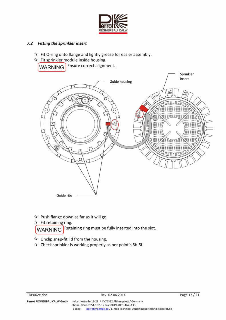
7.2 Fitting the sprinkler insert Fit O‐ring onto flange and lightly grease for easier assembly. Fit sprinkler module inside housing.
Ensure correct alignment.
Push flange down as far as it will go. Fit retaining ring.
Retaining ring must be fully inserted into the slot.
Unclip snap‐fit lid from the housing. Check sprinkler is working properly as per point’s 5b‐5f.
Guide ribs
Guide housing
Sprinkler insert

TDP062e.doc Rev. 02.06.2014 Page 14 / 21
Perrot REGNERBAU CALW GmbH Industriestraße 19‐29 / D‐75382 Althengstett / Germany Phone: 0049‐7051‐162‐0 / Fax: 0049‐7051‐162–133
E‐mail: [email protected] / E‐mail Technical Department: [email protected]
8 Valve insert removal / installation
Ensure sprinkler is not under pressure. Using a big screwdriver, unclip the lid Using a screwdriver, remove white retaining ring
Pull sprinkler insert out of the housing
8.1 Taking out the valve Take off retaining ring by help of retaining ring lifter (see chapter 4). Screw valve lifter / coarse filter wrench onto valve insert’s studs and manually
tighten. Pull out valve insert complete with valve lifter and unscrew. Valve insert is now held
on hollow screw by O‐ring only.
Retaining ring
Hollow screw
Retaining ring

TDP062e.doc Rev. 02.06.2014 Page 15 / 21
Perrot REGNERBAU CALW GmbH Industriestraße 19‐29 / D‐75382 Althengstett / Germany Phone: 0049‐7051‐162‐0 / Fax: 0049‐7051‐162–133
E‐mail: [email protected] / E‐mail Technical Department: [email protected]
8.2 Taking out the coarse filter – only if seen to be dirty Insert valve lifter / coarse filter wrench into the filter’s slots, turn and pull out. Insert flushing equipment and fix with retaining ring. Flush sprinkler / pipes thoroughly

TDP062e.doc Rev. 02.06.2014 Page 16 / 21
Perrot REGNERBAU CALW GmbH Industriestraße 19‐29 / D‐75382 Althengstett / Germany Phone: 0049‐7051‐162‐0 / Fax: 0049‐7051‐162–133
E‐mail: [email protected] / E‐mail Technical Department: [email protected]
8.3 Fitting coarse filter
Take off flushing equipment. Ensure that thread and O‐ring are clean. Lightly smear O‐ring with acid‐free grease. Put coarse filter in place and manually tighten using coarse filter wrench.
8.4 Fitting the valve
Before fitting the valve, check the valve insert – especially around the valve seat – for any dirt or damage!
Screw cleaned or new valve insert onto the valve lifter again and fit into the sprinkler
housing. Ensure it is fitted in the correct position!
Hollow screw Entry for hollow screw

TDP062e.doc Rev. 02.06.2014 Page 17 / 21
Perrot REGNERBAU CALW GmbH Industriestraße 19‐29 / D‐75382 Althengstett / Germany Phone: 0049‐7051‐162‐0 / Fax: 0049‐7051‐162–133
E‐mail: [email protected] / E‐mail Technical Department: [email protected]
Insert retaining ring by help of retaining ring collet (see chapter 4). Retaining ring must be fully inserted into the slots!
8.5 Fitting the sprinkler insert Fit O‐ring onto flange and lightly grease for easier assembly. Install sprinkler insert inside housing.
Ensure it is fitted correctly aligned!
Guide rib
Guide housing
Sprinkler insert
Retaining ring

TDP062e.doc Rev. 02.06.2014 Page 18 / 21
Perrot REGNERBAU CALW GmbH Industriestraße 19‐29 / D‐75382 Althengstett / Germany Phone: 0049‐7051‐162‐0 / Fax: 0049‐7051‐162–133
E‐mail: [email protected] / E‐mail Technical Department: [email protected]
Push flange down as far as it will go. Fit retaining ring.
Retaining ring must be fully inserted into the slot.
Clip in snap‐fit lid. Check sprinkler is working properly as per points 5b ‐ 5e.
9 Control unit removal / installation
Ensure sprinkler is not under pressure. 9.1 Taking out the control unit Using a big screwdriver, unclip the lid Unclip control unit from protective casing and lift up. Twist out coil. When replacing the control unit, cut off the hoses as close as possible to the unit’s
nozzle.
Control unit
Sprinkler

TDP062e.doc Rev. 02.06.2014 Page 19 / 21
Perrot REGNERBAU CALW GmbH Industriestraße 19‐29 / D‐75382 Althengstett / Germany Phone: 0049‐7051‐162‐0 / Fax: 0049‐7051‐162–133
E‐mail: [email protected] / E‐mail Technical Department: [email protected]
9.2 Fitting the control unit When buying a replacement, the control unit is supplied with plug‐and‐socket
connections. Push hoses into plug‐in nozzles as far as they will go and ensure that the mounting ring springs back. Please ensure that the hoses are fitted in the correct position. Otherwise the sprinkler will not work.
Screw in coil. Clip control unit into protective casing. Using a big screwdriver, clip off the snap‐fit lid. Check sprinkler is working properly as per points 5b – 5f.
10 Removal / fitting of manual opening and pressure regulating inserts
Ensure sprinkler is not under pressure. 10.1 Removal of manual opening and pressure regulating inserts Using a big screwdriver, unclip the snap fit lid from the housing. Unclip control unit from protective casing and lift up. Using an SW19 flat spanner, twist out manual opening and pressure regulator
screws.
Coil
Control unit

TDP062e.doc Rev. 02.06.2014 Page 20 / 21
Perrot REGNERBAU CALW GmbH Industriestraße 19‐29 / D‐75382 Althengstett / Germany Phone: 0049‐7051‐162‐0 / Fax: 0049‐7051‐162–133
E‐mail: [email protected] / E‐mail Technical Department: [email protected]
10.2 Fitting manual opening and pressure regulating inserts Set manual opening to Auto and pressure regulator into the minus (‐) position (turn
to the left as far as it will go) and screw in using an SW19 flat spanner. Clip control unit into protective casing. Unclip the snap fit lid from the housing. Check sprinkler is working properly as per points 5b – 5f. Set manual opening / pressure regulator screws to desired position.
11 Maintenance Cut sprinkler housing free of any overgrowing grass. It makes sense to do this work
with the cut off tool before starting up the system in spring.

TDP062e.doc Rev. 02.06.2014 Page 21 / 21
Perrot REGNERBAU CALW GmbH Industriestraße 19‐29 / D‐75382 Althengstett / Germany Phone: 0049‐7051‐162‐0 / Fax: 0049‐7051‐162–133
E‐mail: [email protected] / E‐mail Technical Department: [email protected]
12 Troubleshooting
12.1 Malfunctions
Problem Cause Remedy
Valve opens/closes only with manual opening, but not on any electric signal
Screw for ‘Manual opening’ is set to OFF
Turn screw to the left as far as it will go
Core is jammed in the coil Take out coil and clean core
No / inadequate power supply Establish 24V AC power supply
Coil defective Check coil resistance (should be ca. 35 ohms) and replace if necessary
Overflow channel from coil clogged
Clean channel
Valve fails to open even with manual opening
Control water hole or relief hole clogged
Clean control water / relief hole
Feeder pipeline under no / insufficient pressure
Establish pressure supply
Valve fails to close
Coil seat dirty Clean coil seat
Bits of dirt between valve seat and sealing plate
Clean valve seat and sealing plate
Diaphragm defective Take out valve and replace diaphragm
Insufficient drop in pressure at the valve
Tighten ‘pressure regulator screw’
Control water filter dirty Clean control water filter
Valve fails to close completely
Screw for ‚Manual opening’ is not tightened
Tighten Screw for ‚Manual opening’
Bits of dirt between valve seat and sealing plate
Clean valve seat and sealing plate
Pressure regulating insert damaged
Exchange pressure regulating insert
O‐ring at coarse filter damaged Exchange O‐ring and seal with teflon tape
Rotary speed too low/ too high or does not rotate at all
Inlet nozzle incorrectly set (see chapter 7)
Set inlet nozzle to correct nozzle diameter
Turbine blocked by stones or bits of dirt
Clean turbine
Inlet nozzle or filter have worked loose
Clip parts together again
Output pressure at sprinkler nozzle too low or casting range too short
Stones and bits of dirt are hindering an unimpeded flow‐through of water
Clean valve and flush sprinkler
Pressure regulator in minus (‐) position
Turn pressure regulator screw to the left towards (+)
Subject to change without prior notice.