nov 1. 2 1984 - bitsavers.org
TRANSCRIPT

!/"
NOV 1. 2 1984
Novembe-r 1984
This manual •xplains the inst•llation p-roc•dure for BASEWAY and specifies the VAX/VMS p•ram•t•rs th•t 4hould be set or ~~Justed to optimize performance of BASEWAY. The Release N•Jtes provide additional information about BASEWAY.
BASEWAY
So,tware Installation Guide/Release Notes
SUPERSESSION/UPDATE INFORMATION: This is a new document ror this release.
\..f ::RATING SYSTEM- AND -VERSION: VAX/VMS V3. 5
SOFTWARE VERSION: BASEWAY Version 1.0
ORDER NUMBER:
Digi~al Equipment Corporation Manufacturing Field Application Center
24730 Crestvie~ Court FaTmington Hills, Michigan 49018

The in,~rmation in this document is subJ•ct to change ~ithout notice and should not be construed as a commitment b~ Digital Equipment Co~po~ation. ~~.,.,.. Digital E~uipment Corporation assumes no responsibilit~ for any errors ~· that may appear in this document. ·
No responsibilit~ is assumed for the us• or reliabilit~ of softwar& on e~uipment that is·nat supplied bq Digit•l Equipment Corporation or its a~filiated comp•nies.
The so't••r• described in this document is furnished under a license and may be used o~ copied onl~ in accord•nce ~ith the terms of such license. In addition, 'h• following copyright notic• must be included:
Cop~right C 1964 b~ Digit•l Equipment Corporation
The follo"'ing a-re tTadam.arks of Digital Equipment Corporation:
•
AU..-IN-1 DIGITAL DEC .PDP DECUS · UNIBUS COMPUTER.LABS COMTEX
.DDT DEC COMM ASSIST-11 VAX DECnet Fl'1S
DATATRIEVE DECstjstem-10
·DECtape DIDOL EDUSYSTEM FLIP CHIP FOCAi.. INDAC LAB-8 DECSYSTEM-20 RTS-9 VMS IAS
TRAX MASS BUS OMNIBUS OS/B PHA RSTS RSX TYPESET-a TYPESET-11 TMS-11 ITPS-10 SBI FDT

1. 0 2.0 3.0 4.0 5.0 6.0
CHAPTER l
1. 1 1. :? 1. 3 1. 3. 1 1. 4
CHAPTER 2
2. 1
,~ 2.2
"' 2.3 2. 3. 1 2. 3. 2 2. 3.2. 1 2.·3. 2. 2 2. 3. 2. 3 . 2.3. 3 2. 4 2.5 2. 5. 1 2.6 2. 7 2.B
CHAPTER 3
3. 1 3. 1. 1 3. 1.2 3.2 3.2. 1 3.2.2 3.2.3
CONTENTS
Manual ObJectives . . . 5 Audience............ . 5 Pre-requisites . . . . . . 5 St'ructure of This Document . . . 5 Associated Documents .. ·. . . . . . 6 Disposition OT Softw~-r• Perform•nce Reports <SPRs> 7
OVERVIEW OF BASEWAY
What Is BASEWA~? . . Ha-rdware Requi-rements Software Requirements . . . . .
Optional SoTtware ... DATATRIEVE Access . . .
INSTALLING· THE SOFTWARE
Backing Up the S~stem Disk Before So9tware
1-1 1-3 1-3 1-3 1-4
Insta~lation . . . . . . . . 2-1 Contents of the Distribu~ion Kit 2~1 Instal l•tion Procedure . . . . . . . 2-3
Preliminary Req~ire~ents ~ 2-3 Instructions for Installation 2-3 STEP 1: Log In to the S~stem M•n•ger's Account. 2-3 STEP 2: Invoke VMSINSTAL . . . . . . . . . . . . 2~4 STEP 3: Insert the First Installation Kit Volume 2-3 Error Conditions . . . . . . . . . . 2-7
Backup Procedure A~te'r Installation 2-7 BASEWAV Directorv Structu-res . . . . 2-B
Application Director~ Structure 2-8 S~stemwide BASEWAY Logical Names 2-B GTouptalide BASEWAY Logical Name . 2-9 Complete List of Inst•llad Files . . . 2-9
SETTING UP USER APPLICATIONS
Defining Applications .. . Invoking DEFINEAPP.COM .... . Stai-ting Up the Application .. .
De.Pining Accounts ..... Ma~age'r Account . . . . . . . . User Account . . . . ..... . Login Command File .. .
3-1 3-2
. 3-4 .. 3-5
3-5 3-5 3-6

•
Contents
3.2.4 3.3 3.4 3.4. 1 3. 4. 2 3. 4. 3
CHAPTER 4
4. 1 4.2 4.3 4.4
APPENDIX A
Example Accounts ..... . Sta~tup Param•t•~ Fil• ...... . Modi~~ing_the Menu Facilit~
AU..-IN-1 M•nu Suppo~t BASEWAY M•nu Suppo~t . . . Madi~~ing ~-~~o~d Options and Their
REL.EASE NOTES
FMS StaTtup R•qui~•m•nts . . . . S~st•m Audit File .... SuppoTting Multiple Applications . Using th• P?tnt Function . . . . . .
SAMPLE INSTAU.ATION PROCEDURE
•
. 3-i
. 3-9 . . 3-'?
3-10 3-10
Functions 3-10
. . . ~-1 .. 4-1
. 4-3
. 4-3

PREFACE
1. 0 Manual ObJectives
The BAS£WAY SoftU1arc Installatign Guide/R1lease Notes manual shows how to install BASEWAY on VAX/VMS and pl'ovides additional information about defining an application and tailol'ing the pl'oduct ror speci.Pic user applications.
2.0 Audience
This manual is intended ror those individuals who must s~t up and maintajn the VAX/VMS 09erating system. and BASEWAY so .Ptwar e.
3. 0 Prerequisites
Readers .of this manual should hav.e a solid understanding ...._, VAX/VMS opel'ations and administration, and VAX applicati?n
-~.Ptware. In addition, a knowledge or the specific requirem~nts of the installation site is essential.
4.0 Structure o~ This Document
This manual is ol'ganized as .PolloU11:
Chapter 1: Gives an ovel'view o.P the BASEWAY system.
Chapteiinstallation procedure.
~: Des er ib es prerequisites,
the· and
BASEWAY the
distribution kit, actual installation
Chapter 3: Describes the steps involved in de.Pining an application on BASEWAY.
Chapter 4: Contains Release Notes which you should read before installing BASEWAY. This chapter includes info~mation not included elsewhere in the documentation set, changes made late in the development cycle, softwar.e er'T'oT-s.. an.d documentation omissions.
Pre.Pace

P'T'e.Pac1
App•ndix A: Sho~s a sampl• installation p'T'ocedu,.e.
5.0 Associated Documents
Fu,.ther in~o,.mation on va'T'ious topics cove,.ed in this manual ma~ be ~ound in th• ~ollo~ing manuals:
o p£Cntt VMS Su1t1m Man191r'1·9uidt
<o,.der numbe,. AA-HSO~B-TE>.
o ~ fLOOR QA!EWAY Installation 9uid1/R1l1a11 Nat12
Co'T'der number XX-123~~01>
o BASEWAV Sustem Programmer's Guide
<ord•'T' number XX-12346-01)
o BASiWAY U11r'1 Manual iI!Jl Utiliti11 Quidt
0
<o,.der number X~-12347-01>
PB09RAMMABL£ ·9u i d1/R1l1ase
DEVICE Not-11
<orde,. number 12365-XX>
sueeoRT In1tallation
o ~ ALL-IN-1 Installatign 9uid•/Rel1as1 Note1
o ~ DATA~IEYE Installation Guide/Release Nqte;
o VAX FMS In,tallation Quid! !JlSI. Relra1e Notes
<order numae~ AA-L3~1A-TE>
o ~ FMS Utilitia1 ReT1r~nc1 Manual
Corder numbe,. AA-~320A-TE>
o VAX PL/I In$tallation Guide
Co,.de,. numbe,. AA-~179A-TE>
o ~ So~tware Installation Guide
<o~d•r number AA-M54SA-TE>
•

,t
'-'
o VAX/VMS Command Lanefutqe Us1r'1 9uidt
Co~dtr number AA-D023B-TE>
o .VAX/VMS System Manager's Qui(e
<ord•r number AA-H547A-TE>
6.0 Disposition or Soft~are Pe~formance Reports <SPRs>
Questions, p~oblems, and enhancements to Digital software should be report1d on a Soft111are Performance Report (SPR> form and mailed to the appropriate Digital office. Only one p~oblem shou~d be described concisely on •ach SPR foTm. Please include all pr~grams and data in machine-readable Parm and referenc• the SPR ~orm number on the materials .
. .

•

CHAPTER 1
OVERVIEW OF BASEWAY
1. 1 What Is BASEWAV?
BASEWAV is a tool to de~ine, monitor, and control programmable devices and support variou~ user •PPlications. It can work together with Digital's SHOP FLOOR GATEWAY product which provides the actual communications inter~ace to shop ~loor devices. Up to ~our gateways per s~stem are permitted. The gat•ways are PDP-11/~4s or PDP~11/44s (run memory-onl~ RSX-11S operating system>.
1-1

Ove~vie~ o~ SASEWAY
+-----+ VAX/7x x BASEWAY
+----I I
: • I .
. I I
... ----- + IPDP-11/xx f SHOP FLOOR : tQ.ATEWAV +-------+
+----_.,.i--VAXi7xx BASEWAV ·-----·
+-------+ +-----+ +------+ I . VAX/7xx
BASEWAY VAX/7xx r BASEWAY :
VAX/7xx I BASEWAY :
+------+ +--- - -- -+ +-------~
+---------------------·+ +-------+ f PDP-11/ xx lSHOP FLOOR
OATEWAY +--~-- +
+----------+ I VAX/7xx I BASEWAV +-..._.---·---+
I .,
+--------+ f PDP-11 / x x I ISHOP FLOOR: IOATEWAY +------+
+---------+ .... t VAX/7xx I BASEWAY +1o-------------+
+------+ • I .
+-----+ f PDP 11/xx : ISHOP FLOOR: :QATEWAY +------+
+-------·~· -: VAX/7xx : BASEWAY +------+
1--- --- • ·------: ---~-------1-----------------1 maximum I configu~ation I sup~o~ted +--.-- . -+· ...... ----+ +-
: PDP-11/ xx : lSHOP FLOOR: : GATEWAY fm- ·-- --+
: PDP-11 /xx I IPDP-11/xx : :SHOP FLOORI fS~OP FLOORI IQATEWAV I GATEWAY +-----+
+-----+ : PDP-11 l xx I : SHOP Fl.OOR : f QATEWAY +------+
Figu~• 1. Sample VAX-To-PDP S~stem Con~igu~ations
•
1-2

Overview of BASEWAY
\,/: ::! Hardware Requirements
-VAX 11/750 or 11/790 <memory size dependent upon application>
PDP-11/24 Cor PDP-11/44) 512KB minimum
Hardware to support DECnet links bet~een the VAX and PDP 11/~4, including the automatic boot module ror the 11/24.
Console terminal
1. 3 Sortware Requirements
VAX DECnet, Version 3.0
VAX FMS, ·Version ~- 1
VAX/VMS, Version 3.5
No database for user data or app l; cations . other than that necessary to deTine the network is provided.
In addition, VAX PL/I, Ver~ion 2.0, is required if any additional p~ogrammable device types are to be added during tailoring.
1. 3. 1 Optional Software
The following are optional soTtware products, but are suggested ~or program development:
+ VAX CDD, Version 2.2
+ VAX DATATRIEVE, Version 2. 1
\...r. 1-3
. _________ __J
Ov.eT'vie.., o.P BASEWAV
+ VAX DBMS
+ VAX TDMS, Ve,..sion 1. 0
+ VAX ACMS, ve,.sion 1. 0
+ VAX AU.-IN-1, va,..sion 1. 1
1.4 DATATRIEVE Acc:•ss
I~ DATATRIEVE is install•d, DATATRIEVE d•.Pinitions may be added o~ alte,.ed fo,. BASEWAV tailo,..ing. Du,.ing installation, domain and rec:o,..d definitions a,.• placed· in th• CDDSTOP. BSL'SLIB dic:tiona-ry. Th•se definitions ma~ be used •s d•si-red.
I, VAX DATATRIEVE is installed on the ta,..gat s~stem, the BASEWAV installation pT'oc:adu,.. ~ill pl~c• dom•in and ,...co,.d definitions ro,. each of th• BASEWAY database ril•s in the CDD$TCP.BSLSLIB dic:tiona,.y. ihese m•CJ be used as necessa",-,, to c:,.eate custom repo-rts of the BASEWAV daf initions. Ha~eva,., the ~o,.mat and contents of each of these · database riles are subJect to c:nang• in futu,.• ve,..sions of BAS.CwAV.
1-4
~
'-' .. ·
CHAPTER ~
INSTALLING THE SOFTWARE
The svst•m manager should b• p~ocess as d•scribed herein ,or updates.
familiar with the use in installing
installation upgrades and
Depending on the mass storage device and the s~stem ·load, the installation of BASEWAY may take from 15 to 30 minutes.
2. 1 Backing Up the S4:1stem Disk Before. Software Installation
·It i» rec.ommended that the system disk be backed up pT"ioT" · -eo "" stallation. The pT"ocedur-e rOT" doing the backup is described in the
?~x Software Installation Quide.
2.2 Contents of the Distribution ~it
The BASEWAY installation kit A 1 l .P i l es re q u i ,.. e d to i.n st a 11 contained on ~he distribution.
is distributed on magnetic tape. and tailor the BASEWAY s~~tem are
Each volume is labeled with an external seT"ial numheT" corresponding to BASEWAY's product number and a unique volume label.
Volume Label
BSLOlO
Medium
1600 bpi magnetic tape
2-1
Contents
BASEWAY installation command procedures and so.Pt"91are

Installing the So~twara
NO.TE: Be su'T'e ·to check that the dist'T'ibution kit you receive contains eve'T'~thing listed in the bill o~ mate'T'ials enclosed with it. """
2-2

Installing the Softwar•
'-'2.3 Installation Procedure
......,
2. 3. 1 Preliminary Requirements
NOTE: BASEWAY requires VAX/VMS Version 3. 5 or later.
o approximately 9000 blocks CBASEWAY peak usage> ~uring installation
,o ap pro x-imate l 'J 8000 b 1 oc ks C BASEWAY net usage> a .PteT' installation
o previous ins ta l lat ion of DECnet < v. 3. 0 > and FMS < v. 2. 1).
2.3.2 Instructions ror Installation
Messages aT'e printed at your terminal duT'ing the installation procedure. Most are simple "Yes" or "No" questions which require either a Y or N response.
Proceed as follows at the console. terminal <user input is shown .; ri· uppe1"case 1 ette-rs >:
2'. :;·. d.". l 57e:;:· l: t..og !n to the -s·'J stem Manager ·~s Ace ou-nt -1. Log in under a privileged sy.stem manage-r's account .. as shown
in the following ex amp le:
er Use-rname: SYSTEM er Passt110-rd: , er
2. Now set up the prope-r group and user number and set the default directorv to SYSUPD as follows:
$SET UIC [1,4] S SET DEFAULT SYS$UPDATE
Installing the Soft~•~•
:?. 3. :?. :? STEP :?: Invoke VMSINSTAL
When you invok• VMSINSTAL, it checks the ,ollowing:
o A-re ~ou logged in to the sqstem manage~'s account?
It is recommend•d that you install laq•~•d soft~are ,rom th• sqstem manager's account. Ho~eve-r, an~ account with the nec•ssa-r~ ~rivil•g•s is acc•ptabl•.
o Do you have adequate account quotas 'or installing la~e,.ed pro-ducts'?
As long as the quotas listed in. Section ~.3. 1 are met, ~ou can continue with the installation.
o Is DECnet up and running'?
You should stop DECnet bef~-r• installing BASE'WAY. Although the installation will succeed, problems can occur if someone ti-ies to access any 'il• associated ~ith BASEWAY <including the sqstem HELP ,iles> during the installation.
Use-rs should be asked to log out be.Po-re BASEWAY is in~tallad. Although the installation ma~ succ9ed, problems can occ:u,. i il· som•one ti-ies to use BASEWAY u.h i le the ,..,,,,,. inst~llation is in pr~gress.
I~ anq or these conditions are noted, VMSINSTAL will give ~ou an opportunit~ to stop the installation procedure <see belo\11).
I
To invoke VMSINSTAL, ente,. the ~ollo~ing:
~ IVMSINSTAL BSLnnn ddn:
The VMSINSTAL command procedure takes two parameters:
1. product name--.Por BASEWAY the nam• al\lf•CJS beg ins 1»ith 11 BSL 11
and ends with a 3-digit ve,.sion number. For example, Version 1. 6 u.ou l d b • denoted as BSLO 16. ·Here i na-f ter, this document ~ill re~er to the version number as Vn.n.
~- device name-device names h·ave the ,o,.m ddn:, \lfher·e dd is the devic• code and n is the unit numbe,.. For example, the rirst floppy diskette drive u.ould be called "DYO: ".

Inst•lling the So~tware
NOTE: It is not necessary to use the console drive 'or installing BASEWAY. However, i, 'JOU do use it, be su-re to replace antJ media you may have • .Pound in the d-r i ve U1hen the installation is complete.
VAX/VMS So,tware Product Installation P-rocedu"re
It is dd-mmm-19yy at hh:mm Ent•~ a question mark <?> at any time 'or help
'· * Ar• you satis,ied with the backup o, your system disk CYESJ? Y
I9 you '••l that there are conditions which may adversel~ affect the installation, enter N and the installation will stop. Ir you wish to continue, enter Y Cor press RETURN>.
- 2. 3. 2. 3 STEP 3: Insert the First Installation Kit Volume -
Please mount the first volume o, the set on ddn:.
Insert the ·H-rst .volume o.P the distribution kit and type nyu when you a-re ready to continue.
* Are you ready? Y
The BASEWAY installation procedure now assumes control. The procedure checks to see that there is adequate disk space to build the product. I.P not, it issues an error message and teT'minates. Otherwise, the pT'ocedure processes the fi~st volume of the backup save set.
NOTE: I~ the SVSQEN pa~ameters MOUNTMSQ or DISMOUMSG at you~ site have been set to 1, you will receive a message from OPCOM each "time a disk, tape, or .Ploppy diskette is mounted or dismounted. These messages a~• no~mall~ disabled, but i.P they have been activated and you a~e installing from a console terminal, they will appea~ T-rom 1 to 30 seconds a.Pter each mount or dismount. ·
%MOUNT-I-MOUNTED, BSLnnn mounted on ddn:
. The .Pol lowing p~oducts will be installed:
BS1. Vn.n
Beg inn in g · inst a 11 at ion o, BSL Vn. n at h h : mm
2-5

Instal 1 i ng th• Soiltwa-r•.
XVMSINSTM.-I-RESTOREJ R•storing prod~ct saveset A ...
Previous logjcal name assignm•nt replaced
At this· point, i.P you need to exit .Prom the installation p~ocadure, ~ou must press CTRL/Y.
NOTE: I.P ~ou p-ress CTRL/Y, th• installation procedure deletes all 'iles it has created up ta that p~int and exits.
BSLSTART. COM, th• sta,-tup ca...,..nd pT9ocedure, is used to set up the environ•ent ,o,. the BASEWAY Application Bus. During installation, it •llill be placed in th• CSYSMQRJ. di,.ecto,.~ o.P the sqstam ,.oot on , which this installation is being perfo,.med. SYSSMANAGER: SYSTARTUP. COMf qou,. s~st•• sta,.tup proc•dure, should be modi.Pied to invoke this p-roc•du,.• •h•n the s~st•m boots. How•v•,., it •ill not be necessar~ to ,.•boot the s~stem aft•r th• installation, since this p,.ocedure is invoked as part of the installation.
XVMSINSTAL-I-MOVEFILES, Files ~ill now be mov•d to their target di-r•cto-ries ...
N•xt, an Installation Ve-ri.Pication p,.oc•dur• <IVP> runs· tests to check that th• installation procedu~• ..as succass.Pul.
Installation V•ri~ication P,.ocedu-re <IVP> starting
The installation veri~ication of BASEWAY Application Bus suc:cess~ul ..
Successrul installation or BSL Vn.n at hh:~m
vn.n \
was · "'111111
BASEWAY im•ges and lib,.ari•s are nou. successrull1:1 installed. You may· now install mo-re products, o,. ~ou can end the installation p,-ocedu,..a. To end the installation procedu,.e, type "EXIT" (or press RETURN>.
Ent•r the p,..oducts to b• installed .Prom the next dist~ibution volume set. * P~oducts CEXITJ: EXIT
VMSINSTAL procedure done at hh:mm
I~ ~ou ,.•moved an~ media rrom the console drive beTo,..e beginning, you can ,..eplace it now.

~
Inst•lling the So,t~are
WARNINQ: VMSINSTAL deletes or changes entries in the logical me tables during the installation. Therefore, if you are going to
_.Jntinue using the system manager's account, you should log out and log in again to restore those tables.
2. 3.3 Error Conditions
If the installation procedure or IVP fail for any reason, the ~ollowing messages are displayed:
kVMSINSTAL-E-BSLFAIL1 The installation of BSL Vn. n has railed. %VMSINSTAL-E-IVPFAIL1 The IVP for BSL Vn.n has railed.
An error during the installation can be caused by one or more of the following conditions:
0 insufricient disk space to comp l_ete the installation
0 ·insufficient system virtual page count parameter
0 insufficient process paging file quota
0 insufficient process 111orking set quota
0 i ns.uf f i c: i ent s~stem maximum working set
0 insufficient system global pages
When you are notified that one of these conditions exists, you should take the appropriate action as described in the message.
To change a system parameter, or to increase an authorized quota value, you may need to contact you~ installation system manager.
2.4 Backup Procedure After Installation
Arter installing BASEWAY you should back up the system save. the original for rutu~e reference. See the ~ Installation 9uide for information on the proper procedure.
2-7
disk and So~tware
Installing th• So~t~a,.e
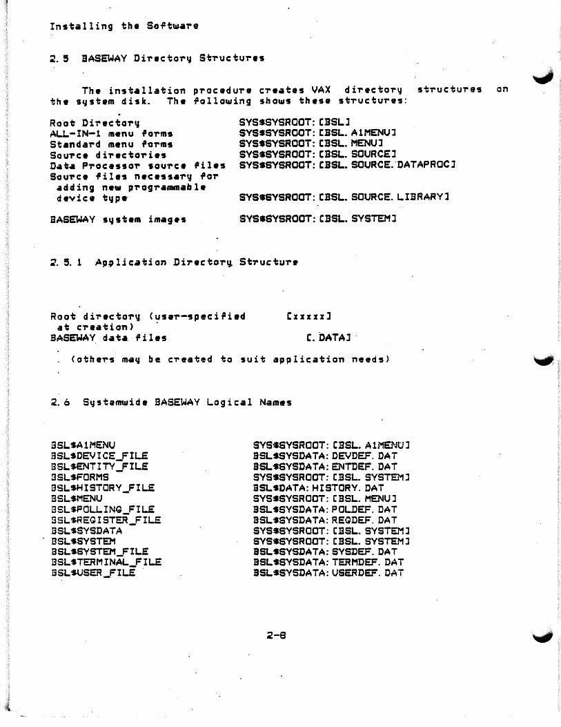
~- 9 SASEWAY DiTacto,.~ StTuctu,.es
The installation pTocedu,.e cTeates VAX directo,.y st,.uctures on the s~stam disk. The following shows these stTuc:tu,.es:
Ro·ot Di,. ec to,.q AU.-IN-1 m•nu fo,.ms Standa,.d menu fo,.ms SouTce di,.ecto,.ies D•t• P,.ocesso,. sou,.c• ,il•s Sou,.c• files necessa,.v fa,.
adding n•w p,.og,.afllftlable d ev i c: a t \J p •·
BASEWAY s~stem images
SYSSSYSROOT:CBSLJ SYSSSYSROOT:CBSL.A1MENUJ SYSSSYSROOT:CBSL.MENUl SYSSSYSROOT:CBSL.SOURCEJ SYSSSYSROOT:CBSL.SOURCE."DATAPROCJ
SYSSSYSROOT:CBSL.SOURCE.LIBRARYl
SYSSSYSROOT:CBSL.SYSTEMJ
R~ot directo,.y C~sa,.-speci,ied at c:,.eation>
Cxxxxxl
BASEWAV dat•. files C. DATAl ·
<othe~s ma~ be c~eated to suit appli~ation needs)
2.6 St:1stemt11ide BASEWAY Logical Names
BS1.SA1MENU BSL$DEVICE_FILE: BSL$ENTITY_FIL.E BSL$FORMS BSLSHISTORY_FIL.E BSLSMENU ESLSPOLLING_FILE ESLSREGIST'ER_FILS: BSLSSYSDATA BSLSSYSTEM BSLSSYSTEM_Fil.£ BSLSTERMINAL_FILE I3SLSUSER_FIL£ .
SYSSSVSROOT: CBS1..A1MENuJ SSL$SVSDATA:DEVDEF.DAT BSL~SYSDATA:ENTDEF.DAT SYSSSYSROOT: CBSL. SYSTEMJ SSLSDATA:HISTORY.DAT SYSSSYSROOT: CBSL.MENUJ SSLSSYSDATA:POLDEF.DAT BSLSSYSDATA:REGDEF.DAT SYSSSYSRCOT: CBSL.SYSTEMJ SYS•SYSROOT: CBSL.SYSTCMJ BSLSSYSDATA:SYSDEF.DAT SSLSSYSDATA:TERMDEF. DAT BSLSSYSDATA:USERDEF.DAT
2-e

·Inst•l ling th• So.Ptwar•
'-.,.,2. 7 Qroup~ide BASEWAY Logical Name
"BSLSDATA" is a groupwide BASEWAY logical n•m• which is created by EVENT_PROC when it is initiat•d. Logical n•m•s that are based on this <such as BSLSHISTORY_FILE> and which are created by the command ~ile SVSSMANAQER:BSLSTART.COM, mav not be referenced until an application is running.
Oth•r group logical nam•s ~hich •~• speci.Pic to your application ma~ be created b~ editing the EVENT_PROC startup command file.
2.9 Complete List o.P Installed. Files
Filename
SYSSSYSROOT: CSYSMGRJ
BSLSTART.COM
SYS$SYSROOT:CSYSLIBJ
BSLDEF.BAS BSLDEF.FOR BSLDEF.H BSLDEF.LIB BSLDEF.PAS BSLDEF.PLI BSLDEF.REG BSLLIB.OLB BSLPLI. TLB BSLSHR.EXE BSLSHRBLD.COM
SYS$SYSROOT:CSYSMSGJ
BSU1SQ.EXE SFQMSQ.EXE
Purpose
BASEWAY star.tup command .Pi le
VAX BASIC de.Pinitions .Por BASEWAY routines VAX FORTRAN definitions .Por BASEWAY routines VAX C deTinitions .Por BASEWAY routines VAX COBOL deTinitions .Po~ BASEWAY routines VAX PASCAL definitions for BASEWAY routines VAX PLI de.Pinitions for BASEWAY ~outines VAX BLISS-32 definitions for BASEWAY routines ObJect libra~~ containing BASEWAY ~outines Text library containing all BASEWAY derinitions Sharable image containing BASEWAY ~outines Command file to relink BSLSHR.EXE sharable image
Image .Pile containing BASEWAY messages Image file containing SHOP FLOOR QATEWAY messages
SYSSSYSROOT: CBSL.A1MENUJ
AlMENU.FLB EDTADDR.COM EDTAPPL.COM EDTDEVICE.COM EDTQATE.COM
.EDTSET.COM EDTTERM.COM
Standard .Po~m libra~y fo~ ALL-IN-1 menu support Command .Pile to run EDTADDR image from ALL-IN-1 Command file to run EDTAPPL image from ALL-IN-1 Command ~ile to run EDTDEVICE image .Prom ALL-IN-1
-Command .Pile to ru.n EDTQATE image .Prom ALL-IN-1 Command fil• to run EDTSET image from ALL-IN-1 Command file to run EDTTERM image rrom ALL-IN-1
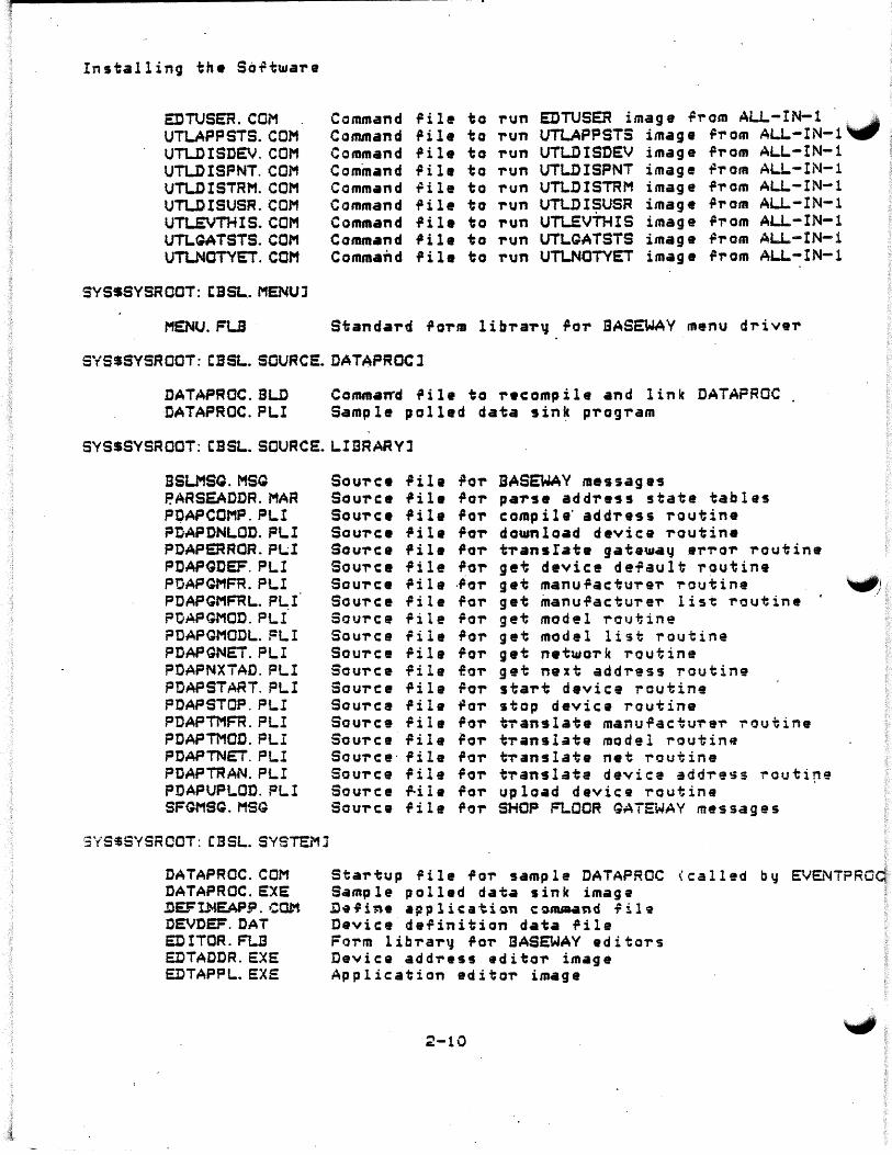
Installing the So~tware
EDTUSEn.COM UTLAPPSTS.COM UTLDISDEV. COM UTLDISPNT. COM UTUJISTRM.COM UTUJISUSR.COM UTLEVTHIS.COM UTl.QATSTS.CCM UTLNOTYET.COM
SYSSSYSROOT: CBSL.MENUJ
MENU.FU
Command ilile to run EDTUSER image r,.om AL~-IN-1 """"" Command i1il• to 1'Un UTLAPPSTS image il,. om ALL.- I N-1 Command .Pile to -run UTLDISDEV image .P,.om ALL-IN-1 Command .Pi 1 e to 1'Un UTLDISPNT image r,.om ALl..-IN-1 Commi1nd ~ile to -run UTLDISTRM image r,.om ALl..-IN-1 Command i1ile to -run UTLDISUSR image i1,. om ALI..-IN-1 Command .Pile to -run UTLEVTHIS image .p,. om AU...-IN-1 Command .Pi 1 a to ,.un UTLGATSTS image r1'om AU.-IN-1 Command file to -run UTLNOTYET image .Prom A~-IN-1
Standa1'd .Po1'm lib,.a-r~ i1o,. SASEWAY menu drive,.
SYSSSYSROOT: CBSL.SOURCE.DATAPROCl
DATAPROC.BLD ·DATAPROC. PL.I
Comma~d .Pile to ,..compile and link DATAPROC Sample polled data sin~ p1'og,.am
SYSSSVSROOT: CBSL.SOURCE.LIBRARYl
BSU1SQ.MSQ P.ARSEADDR.MAR PQAPCOMP.PLI PDAPDNLOD.PLI PDAPERRCR.PL.;I PDAPGDEF. PLI POAPQMFR.PLI POAPGMFRL.. P~I ?OAPGMOD.PLI ?DAPGMODL.FLI PDAPGNET.PLI PDAPNXiAD. PLI PDAPSTART. PLI POAPSTOP.PLI PDAPTMFR.PL.I PDAPTMOD.FLI POAPTNET. PL.I POAPTRAN.PL! POAPUPLOD.PLI SFGMSQ.MSQ
3YS$SYSRCOT: CBSL.SYSTEMj
DATAPROC.COM DATAPROC.EXE .DEF I.1'4E.4P9. ,:OM DEVDEF.DAT e:DITOR.FLB EDTADDR.EXE EDTAPPL.EXE
Sou,.ee .Pill .Po-r BASEWAY messages Sou-rc:e .Pile .Po-r pa-rse add"ress 5tate tables 50U1'C:9 .Pil• .Po-r compile· add1'ess routine SOU1'C:9 .Pil• .Po-r dot.11nload device -routine Sou-rc:e i'il• fOT' trans I ate gate~ay 91''rOT' 1'outine Sou,.c:e .Pile rOT' get devic:e de-rault routine SOU1'C:9 .Pile -~01' get man u ra c: tu,. e-r T'outine ""1#) 90U1'C:e .Pi 1 e ro-r get inanu.Pac:tu,.e-r list T'outine Sou-rce rile .Po,. get model T'oui;ine Sou-rc:e file ilo,. get model list T'outine Sourc:e .Pile ra-r get netwo1'k ,.outine Sou,.c:e .Pile -eo,. get ne:ct add-ress routine Sou,.c:e file .Po-r sta,.t device routine SOU1'C:8 .Pile .Po,. stop device routine 90U1'C:9 .Pi 1 e ro,.. tTanslate manu.Pac:tu,.e-r i-outine Sou,. c: e .Pile ~o,.. t-rans late model routine Sou,. c e · .Pile ro-r t1'ans late net T'outine Sou,.ce .Pile ro-r t-ranslate device addi-ess T'Outi~'H~ Sou-rc:e ~ile .Poi- upload device T'autine SOU1'C:9 .Pile i1o,. SHOP FLOOR QATEWAY messages
Stai-tup ~ile fo1' sample DATAPROC \called by EVENTPRCq Sample polled data sink image ~•fine appli,atiGn conuaand fil9 Device definition data .Pile Form lib1'a-r~ .Po,. BASEWAY edito,.s Device address editor image Application edito,. image
2-10
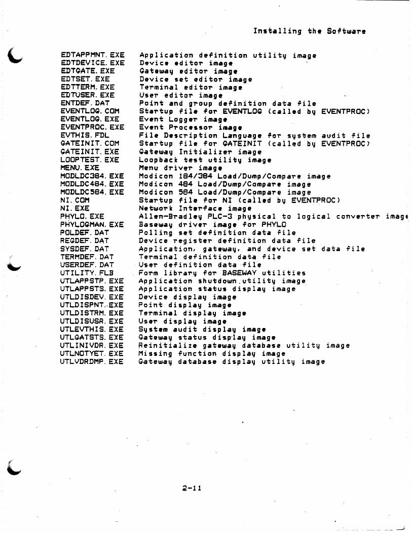
EDTAPPMNT.EXE EDTDEVICE.EXE EDTQATE.EXE EDTSET.EXE EDTTERM.EXE EDTVSER.ElE ENTDEF.DAT EVENTLOQ.COM EVENTLOQ.EXE EVENTPROC.EXE EVTHIS.FDL GATEINIT.COM QATEINIT.EXE LOOPTEST.EXE MENO.EXE MODLDC384.EXE MODLDC484.EXE MODLDC584.EXE NI.COM NI. EXE PHYLO.EXE PHYLOQMAN.EXE POLDEF.DAT REGDEF.DAT SYSDEF.DAT TERMDEF.DAT USERDEF.DAT UTILITY. FLB UTLAPPSTP.EXE UTLAPPSTS.EXE UTLDISDEV. EXE UTLDISPNT .. EXE UTLDISTRM.EXE
·uTLDISUSR.EXE UTLEVTHIS.EXE UTLGATSTS.EXE UTLINIVDR.EXE UTLNOTYET. EXE UTLVDRDMP. EXE
Inst•lling the Software
Application de~inition utility image Device editor image Gatawa~ editoT image Device set editoT im•ge Terminal editor image Use~ editor image Point and group definition data ~ile Startup file foT EVENTLOQ <called bq EVENTPROC> Ev•nt Logger image Event Processor image File Description Language for system audit ~ile Startup file fo~ QATEINIT <called by EVENTPROC} Qateway Initializer image Loopback test utility im•ge Menu driver image Modicon 184/384 Load/Dump/CompaTe image Modicon 484 Load/Dump/Compare image Modicon 594 Load/Dump/CompaTe image Star_tup file fo-r NI <cal l•d by EVENTPROC) Net~o-rk Int•-rfac• image Allen-Bradley PLC-3 physical to logical converter image Baseway d~ive-r image fo-r PHYLO Polling set definition data 'ile Device ~egiste~ definition data rile Application, gatewaCJ, and device set data -File Terminal definition dat~ ri~e
·User definition data ·fil~ Form libTary fo-r BASEWAY utilities Application shutdown.utilit" image_ Application status display image Device displa~ image Point display image Terminal displa~ image Use-r display image System audit displa~ image Gatew.y status d isp·lay image Reinitialize gatewa~ database utilitq image Missing function displaq image Gateway database displa~ utility image
2-11

Installing the So~twaTe
..
2-12
CHAPTER 3
SETTING UP USER APPLICATIONS
After your BASEWAY system has ~een installed, you may derine your user applications.
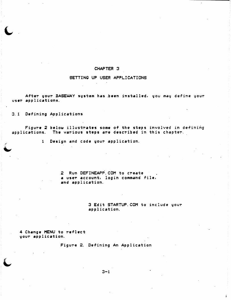
3. 1 De~ining Applications
Figure ~ below illustrates some of the steps involved in de~ining applications. The various steps are described in this chapter.
1 Design and code your application.
2 Run DEFINEAPP.COM to create a user account, login command rile, and application.
4 Change MENU to reflect vour application.
3 Edit STARTUP.COM to include your application.
Figure 2. Defining An Application
3-1

Setting Up User Applications
3. 1. 1 Invoking DEFINEAPP.COM
To create an application, you m~st invoke the ~ommand 9ile DEFINEAPP. COM. This rile de.Pi.nes .the pa-ramete-r~ needed to get a ne"" application running on the system.
DECnet must be up be.Po-re you invoke DEFINEAPP and start your application.
For in,orm•tion •bout de.Pining accounts. see Section 3.2e
The·?ollo•ing is a sample da.Pinition o.P Application Number "0003". It is a continuati~n of the installation dialog which sta-rted in Section 2.3.~.
CAUTION: Make ever~ •?~ort to t~p• accurately ~h•n -responding to the p~omptt in this command procedure.
S SET DEF SSLSSYSTEM s <tDEFINEAPP
** SASEWAV Application Con.Piguration Procedure ** This procedure will de~in• the parameter9 needed to get a new applicati4n ~unning an this s~stem.
Yau may re9pond ta any questiori or prompt ~ith a "?" i~ help is needed.
* App lic:ation name ·? FIELO_TEST
* CONFIRMATION: Is 11 FIELD_TEST 11 the correct name "? YES
Creating application FI~_TEST ...
Application numbe-r 0003 created ...
* G-roup number ro-r application C11-377J .. ? 100
* Disk i1or data dii-ectoT'~ < i.P not _DRAO: > ·7 ci-
*Root directory Cir not APP0003> ? TESTAPP
Creating di-rector'J _DRAO: CTESTAPPJ ...
Creating dii-ector~ ___ DRAO: CTESTAPP.DATAJ ...
Creating Database riles ...
3-2
"'1JI)

Setting Up User Applications.
~ Cr•ating BSLSSVSTEM:APP0003.COl'1 ...
Creating ~DRAO:CTESTAPPJSTARTUP.COM ...
- Applic•tion FIELD_TEST con~i9ured.
You should invoke th• proc•dure BSLtSYSTEM:APP0003.COM to start this new application .
•
3-3
Setting Up User Application~
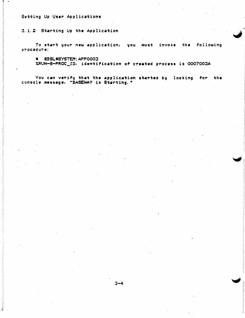
3. 1.~ Starting Up the Application
To start ~ou'r new application, you must invoke the Following p'roc.edu-re:
S i13SLtSYSTEM:APP0003 XRUN-S-PROC~ID, identi,ication o~ c~eated process is 0007003A
You c: an v e-r i 'y that th• a pp 1.i c: at i on st.art• d b CJ l o o le in g I or th• c:on~ole message, "BASEWAY·is St.arting. •
3-4
Setting Up User Applic•tions
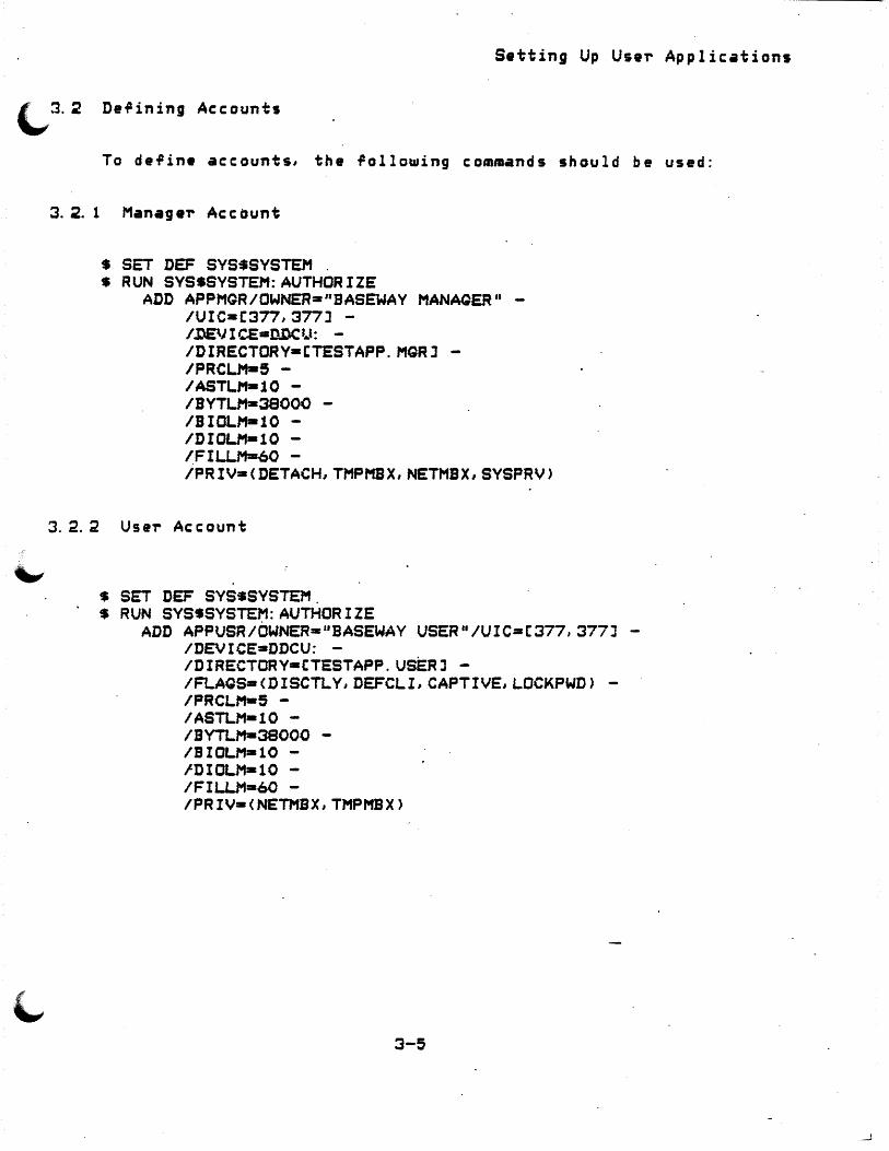
Derining Accounts
To derine accounts, the rollowing commands should be used:
3.2. 1 Manager Account
$ SET DEF SVS$SVSTEM S RUN SYSSSYSTEM:AUTHORIZE
ADD APPMQR/OWNER=-"BASEWAV MANAQER" -/UIC=C377,377J -/IJE\J I CE•Ill.\C l.,l: -
/DIRECTORY•CTESTAPP.MGRJ -/PRCU1•5 -/ASTLM-10 -/BYTLM-38000 -/BIOLM•10 -/DIOUt•lO -/FILLM-60 -/PRIV•<DETACH,TMPMSX,NETMBX,SYSPRV>
3.2.2 User Account

Setting Up Use,. Applications
3.2.3 L~gin Command Fila
To facilitate menu usage, the manager should set up a login command file fa~ users.
Nat• the flags, "DISCTLY DEFCL.I CAPTIVE", shown in the example used in S•c•ion 3.~~ Thes• flags insu~• that the user cannot log into this account ~ithout •xecuting the login command file. This login command fil• shou14 invoke the BASEWAY MENU p~ogram, and should log out when MENU exits.
S! Login command file S! S IF FSMODE<> .EGS. 0 BATCH• THEN SEXIT S SET TERM/ING S SET TERM/NOBRO/FORM/NOWRAP S ASSIGN/USER 'FSLCGICAL<"TT">' SYSSINPUT • ASSIGN/USER 'FSLCO.ICAL< "TT,.) I TT s RUN SSLSSYSTEM:MENU S LCQ/DRIEF
The "SET TERM" commands t11ill set up the user's te,.minal to ~1Jppo~t. VAX FMS, and UJil 1 support anq local p-rinte-r that might be c"nner.t-.d. · The 11 ASSIQN/USER 11 comman-d9 al low th• MENU prog.,.am to b-.· ·~ ~un from a command file.

•
S•tting Up UseT Applications
<.,.,3.2.4 Example Accounts
UAF:>SHOW APPUSR
Username: APPUSR Account: BASEWAY
Owner: BASEWAV USER . UIC: C 100, 200J
CLI: DCL LQICMD: SYSSMANAOER:SYLOQIN.COM Default Devic•: DRA1: Default Dir•ctory: CAPPUSRJ Login Flags: DISCTLY DEFCLI P~imary days: Mon Tue Wed Secondary daCJs: No hourly restrictions ?RIO: 4 BYTLM: PRCLM: 5 PBYTLM: ASTLM: 10 WSDEFAULT: ENGLM: 60 WSGUOTA: TGELM: 10 WSEXTENT: MAX.JOBS: 0 MAXACCT.JOBS: P'T" l v l l e g es :
TMPMBX NETMBX.
UAF)·SHOW APPMGR
LOCKPWD CAPTIVE Thu Fri
Sat Sun
38000 BI OLM: 0 DI OLM:
150 FILLM: 200 SHRFILLM:
1000 CPU: no 0 PQFLGUOTA:
1· Us eT'name: . APPMQR Owner: BASEWA"'t' MANAGER UIC: C100,200J
10 10 60 .o
1 ini it 10000
"" count: BASEWAY __ I: · DCL LQICMD: SYSSMANAQE~:SYLOQIN.COM Default Device: DRAl: De~ault Directory: CAPPMGRJ'. Login Flags: P~imary days: Mon Tue Wed Thu Fri Secondary days: No hourly restrictions PRIO: 4 BYTLM: PRCLM: 5 PBVTU1: ASTLM: 10 WSDEFAULT: ENGLM: 60 WSGUOTA: TQELM: 10 WSEXTENT: MAX~OBS: 0 MAXACCT~OBS: P'T'ivileges:
38000 0
150 200
1000 0
DETACH TMPMBX NETMBX SVSPRV
·Sat Sun
BIOU1: DIOU1: FILU1: SHRFILLM: CPU: no PQFLGUOTA:
3-7
10 10 60
0 . limit 10000

Setting Up User A~plic:ations
3.3 Startup Parameter File
D~ring the staTtup process, a 0 Startup Parameter File" is used to control th• startup functions of th• BASEWAV system. This allows netu logical na•as and subprocesses to be added ~ithout modi~ying portions of the c:ode itself.
The commands in the startup conuNnd. file· a-re organized into seve'ral groups, or sets. The orde'r in ~hic:h these sets a-r.a included is fix•d since such things as logical na••s must be defined before subprocesses are created, e~c. ·
The lollowing exa•pl• tho•~ how commands ar• processed by the Event PTocesso'r in its initialization phase:
3-8

S•tting Up User Applications
l,, BASEWAY startup parameters
SET APPLICATION ID TO 0003
"-'
SET LOGICAL NAME BSLSDATA TO DRAO: CAPP0003.DATAJ CREATE MAILBOX NAME BSLSMBX PORT 010 CREATE BASEWAY GLOBAL SECTION -DCL @SSLSSYSTEM:EVENTLCQ.COM DCL @BSLSSYSTEM:NI.COM DCL @SSLSSYSTEM:GATEINIT.COM
;-----_._,---~--~------_,_---------.-.----~--------: Inae~t appli~atian-speciric logical names HERE ;-------~--------------------~~------~------
;-------------------.----------------~~--------~--------; Set application-specific flags HERE ; -~-------~-----------------~----------~--~~--'milt-
;---------.-------------.__ _________________________________ _ } Run application-specific images HERE .. ~---.----------------------~------------~---------~~~-
u~L eBSLSSYSTEM:DATAPROC.COM ..
3.4 Modifying the Menu Facility
BASEWAY allows the menu to be changed to re,lect your application. You ma~ wish to modi'y individual screens or menu 9low within the screens.
Two versions o' menu suppo'rt are .p'rovided with the system: ALL-IN-1 and MENU. Both are d~iven bv FMS screens. To change the menus, you can edit the -forms .Pound in the MENU fo-rm libra-r'd in eit_her the BSLSAlMENU or BSLSMENU directories. Refer to the FMS User's Reference Manual for mo're detailed information regarding editing of -rorms.
WARNING: The menu fo'rms released as pa~t of the initial disti-ibution o.P BASEWAY are subJect to change in subsequent releases. Thus, any modifications made to these forms are liable to be lost .
•
3-9

.Setting Up Us•r Applications
FoT' this T'eason, it is suggested that. 11ou CT'eata yo·u,.. tailoT'ed menu in the application diT'ec:toT'q that u.as CT'eatad 1a1ith DEFINEAPP.COM.
3.4. 1 ALL-IN-1 Menu SuppoT't
The us•~ ••~ want to inco~po~ata th• menu st~uctu~• into his o~ heT' own veT'sion of ALL-IN-1. The useT's of the BASEW"AY s~stam must be inc lud ad in th• AU.-IN-1 us•T' datab•s• and th es• useT's must- have th• BSLtAlMENU: MENU i1oT'm libT'a-ry dei1ined in their pT'o.Pilas.
3.4., BASE'~AY Menu SuppoT't
The MENU pi-ogT'am is distributed roi-suppoT't. It is invoked b" each user, ESLSMENU:MENU farm librai-.,.
s~stems without ALL-IN-1 and T"e.PeT'ences roT'ms in the
·3.4.3 Modif~ing ~eywoT'd Options and Th•i,.. Func~ions
To modif~ a keyword option, rind th• keqwoT'd definition SCT'een 111'1 ic:h contains the ke~u.o'rd .,au wi-sh to modirq. Modi.P.tJ the named data item ~o do the appT'opT'iata ,unction:
..
3-10

Setting Up User Applications
(..... Nam•d Data Commands
MENU ALL-IN-1
+-----------~~---------+-------------------~--+ Displa~ Screen lMENU$FORM~frmnam FORM .Prmnam
+--------------------+--------------.,...._'--~ Run Program fMENUSIMAQE•rilespec <no equivalent>
or fMENUSCOMMAND•filespecl COMMAND rilespec
Leave Program +--------------~~----+----------------------+ lMENU$EXIT EXIT +-~------------------+--------.---------------+
The MENU .Plow is driven from the contents of the Named Data area o~ each menu screen. The named data area must use the following syntax conventions:
MENUSFORM•<rorm)· £, MENU$LIB•<rilespec.>J MENU$IMAQE=<f ilespec> MENU$COMMAND•( riles p e c)· MENU$EXIT
u;h eT'e:
is a valid VAX FMS form name \ . is ~valid VAX/VMS file spe~irica~ion
•
3-11

Setting Up U••~ Applications
"'·
3-1~
.·
CHAPTER 4
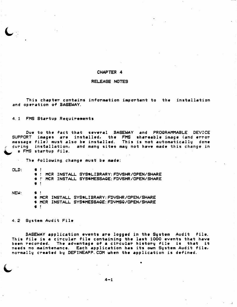
RELEASE NOTES
This chapt•r contains info~m•tion impo~tant to the installation and operation of BASEWAY.
4. 1 FMS Startup Requirements
Due to the ,act that several BASEWAY and PROQRAMMABLE DEVICE SUPPORT images are installed, the FMS sha~eable image <and error message 'ile> must also be installed. This is not automatically done
f during installation, and manCJ sites· mav not hav• made th is change in \_,. e FMS startup rile.
The follo-..ing. change must· be made:
OLD: t S MCR INSTALL. SYS.LIBRARY:FDVSHR/OPEN/SHARE $ >· MCR INSTALL SYSSMESSAGE: FDVSHR/OPEN/SHARE
• NEW: t
t MCR INSTALL SYSSLIBRARY:FDVSHR/OPEN/SHARE t MCR INSTALL SYSSMESSAQE:FDVMSQ/OPEN/SHARE ..
4.2 System Audit File
BASEWAY application events are logged in the S~stem Audit file. This file is a circular file containing the last 1000 events that have been recorded. The advantage of a circula~ hista~v file is that it needs no maintenance. Each application has its a-..n S~stem Audit file, normally created by DEFINEAPP.COM when the application is defined .
•
4-1

Release Not•s
Events a~e recorded in th• System BSLSl.CG_EVENT 'ervica, as de~cribed System Programmtr's Guide.
Audit lile b~ calling the in Section 4.21 of the SASEWAY
Some applications ma~ log events so rapidly th•t 1000 events are onl~ a small snapshot, and critical •vents are lost after onl~ a few hours. Installations requiring a larg•r event lile may create one ~ith the follo•ing saquenc• of st•ps:
1. Run BSLSSVSTEM:UTLAPPSTP to shut do•n the application.
2. Cr•ate a File Description Language lile for the histor~ ~ile:
$ ANALYZE/RMS/FDL/OUT-SYSAUD.FDL BSLSHISTORY_FILE
3. Edit the FDL file, and chang• th• MAX_RECORD_NUMBER parameter ta an• more suited to qaur application:
$EDIT/EDT SYSAUD.FDL 1 IDENT 31-AUG-1984 17:06:2S VAX-11 FDL Edita~
*F'MAX_RECORD_NUMBER' *6/1000/~000/
13 MAX_RECORD_NUMB~ 5000 *EXIT DRA1:C~ONKUSJSYSAUD.FDL;2 2~ lin•s
4. Cr~~ta a new Sc,st11m Audit file ..
• CREATE/FDL-SVSAUD.FDL
5. Restart ~our application.
Or course, since a ne~ ~ile has been created, all o~ the cuTTent audit tTail h•s been lost.
On startup, the Event Logger pTocass CEVENT_LCQ) checks the rirst record of the System Audit ril• to ••• ir it contains a valid header. I~ not, it preextends the event histor~ file to its maximum length. I~ there are ·more than 10000 records, there ~ill be a considerable dela~ berore the "BASEWAY is running" message appears on the console termina 1 sc,..een.
4-:?
R•l•ase Notes
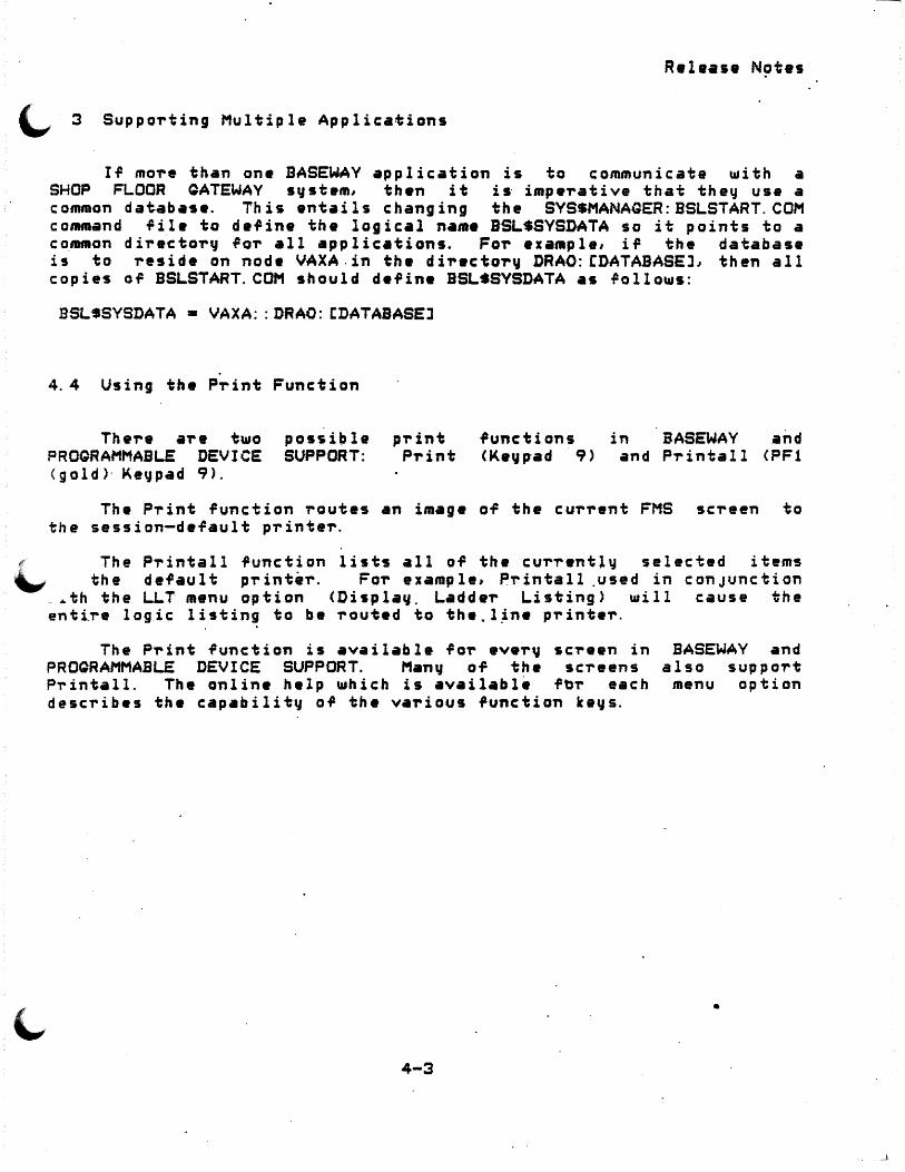
~ 3 Supporting Multiple Applications
IT more than one BASEWAY application is to communicate with a SHOP FLOOR QATEWAY syst•m, th•n it is· imp•rative that the" use a common database. This entails changing the SYSSMANAGER:BSLSTART.COM command fil• to d•fine the logical name BSL$SVSDATA so it points to a co.mmon directol'y .Por all applications. Fol' •xample, iT the database is to reside on node VAXA.in th• directory DRAO:CDATABASEJ, then all copies o.P BSLSTART.COM should de.Pine BSL$SYSDATA as Tallows:
BSLSSYSDATA • VAXA: :DRAO: CDATABASEJ
4.4 Using the Print Function
Th ere ar • two PROQRAMMABLE DEVICE <gold>· Ke':fpad 9>.
possible SUPPORT:
p-rint Pl' int
.Punctions <Kegp-ad 9)
in BASEWAY and and Printall <PF1
The Print function routes an image of the cu-rrent FMS screen to the session-default printer.
~ The Printall function lists all of the currently selected items "" the default pi-inter. For example, P-rintall .used in conJunction
_.th the LLT menu option <Display, Ladde-r Listing) will cause the entire lo~ic listing to be routed to the.l~n• printer.
. . The Print .Punction is available for ever~ screen in
PROQRAMMABLE DEVICE SUPPORT. Man~ of the screens Printall. The online help which is available ft>T' each describes th• capahilit~ of the val'ious function k•vs.
4-3
BASEWAY and also support
menu option
•

APPENDIX A
SAl'!PLE INSTAU..ATION PROCEDURE
$ SET UIC C1,4l $ SET DEFAULT SYSSUPDATE s eVMSINSTAL BSLOlO MSAO:
VAX/VMS Soi'tt11are P"roduct Inst•llatian P"roc:.edu-r&
It is 1-JUN-1984 at 12:0,. Enter a question mark <?> at anq time TOr help.
* Are you satis~ied •ith the backup OT ~our sqstem disk CYESJ~ YES
·Please mount the ~irst volume of the set on MSAO:. * A-re you ready·? YES
/.MOUNT-I-MOUNTED, BSL010 mounted on _MSAO:
The rollowing p-roducts w11I be installed:
BSL Vl.O
Beginning installation OT BSL Vl.O at 1~:07
~VMSINSTAL-I-RESTORE~ Resto-ring p-roduct s•v•set A ...
P~eviou~ logical name assignment replaced
BSLSTART.COM, tna sta-rtup command p-rocadu-r•, is used to set up the environment i1o-r the BASEWAY Application a·us. Du-ring installation it will be plac•d in the CSYSMGRJ dir•cto-r~ o~ the s~stem root on which _this installation is being· pe-r-Fo-rmed. SVS•MANAQER: S"'t'STARTVP. COM, you-r system sta-rtup p-rocadure, should be modi~ied to invoke this pT'ocedu-re when the system boots. Haw•v•-r, it will not be necessar~ to reboot the s~stem afte-r the installation, since this pToceduTe
A-1

S~MPLE INSTALLATION PROCEDURE
'-.,,· · invoked as pa,-t o.P the installation.
/;VMSINSTAL-I-MOVEFILES, Files u.ill nou. i>e moved to their ta,-get di,-ectories ...
InstaJlatjon VeriFicatio~ Procedure <lVP> startj~g
The installation verification of BASEWAY Application Bus vl.0 was successful.
Successful install•tion of BSL Vl.0 at 12:3:?
Enter the products to be installed .P,-om the next distribution volume set. * Products CEXITJ: EXIT
VMSINSTAL p,-ocedure done at 12:35
A-2

Ac counts de.Pining m•naga-r de-flining useT'
Application sta"rting up steps in d•fining
BASEWAY c:onf igu~ations oil definition of
an . .
optional softwa"re ,o,.. overvi•• of . . . . . required hard-are .POT' required so.PtwaT'e ,o,.. speci.P~ing device nam• specif~·ing product name
DATATRIEVE ilCCISS to
DEFINEAPP.COM DirectoT'~ stT'ucturas
application BASEWAY .....
D i s t-r i b u t i on k i t . . . . . ·oo\:umentation
associated ~ith product
ErroT' conditions ..... Event pi-ocassoi-
oT'der of c:omm•nd pi-ocessing
FMS use in menu suppoT't
Installtiition
INDEX
3-4 3-1
1-2 1-1 1-3 .1-1 1-3 1-3 2-4 2-4
1-4 3-2 2-e 2-e 2-e 2-1
6
2-7
3--9
3-4;
c: hang in g q, u o ta s ii OT' . . . . 2-7 changing s~stem paT'ameteT's ror 2-7 conditions checked in ~-4 exiting iii-om the . 2-6 Fai 1 ui-e
geneT'al reasons ,or 2-7 ~ailui-e of . . . . 2-7 inade~uate disk space ~or 2-~ messaga9 du"ring . . . . . 2-~ praliminar~ requirements
DECnet . . . . . . . . 2-3
Index-1
~.

I ~
disk space FMS PL/I VAX/VMS
steps to fol low in . . stopping . time . user input involved in
Installation pr~c•dur• sample . .
Installation Ve-rification Pi-ocedure see IVP
Installed files IVP
fai lui-e of .
Keyword options modifying ..
Logical name tables see VMSINSTAL
Logical names gi-oupwide s 4J s t e mw i d e .
Login command file .
nu ALL-IN-1 MENU. pr.ogi-am modification of suppo-rt pi-ovided
MENU p-rog-ram see Menu
Release notes
SHOP FLOOR GATEWAY
.• ~
Softwa-re Pei-formance Reports see .SPRs
SP Rs submitting
Startup parameter file S•~ stem backup
after installation . before installation
VMSINSTAL.
2-3 2-3 2-3 2-3 2-3 2-5 2-1 2-3
A-1
2-9 2-6 2-7
3-10
2-7·
2-9 2-8 3-6
·3-10 3~10 3-9 3-9
4-1
1-1
7 3-8
2-7 2.;..1
invoking 2-4 logical name table changes . 2-7 pa!amete-r~ . . 2-4
Index-2
to 3-10

.1-· ""'1

-.~ ·-


Novemb •r. 1984
This manual describ_es BASEWAY c.oncepts and ~eat.ures. SubT'outine descriptions, syntax in-fo-rmation, and otheT' re~~~ence mateT'ial are also included.
BASEWAY
System Programmer's Quide
SvPE?.SESSION/UPDATE INFORMATION: This is a ne~ document ~or this T'elease.
I OPERATING SYSTEM AND V~RSIDN: VAX/VMS V3. 5 .\..,-
SOFTWARE VERSION.: BASEWAY Ver iii on 1. 0
ORDER NUMBER:
Digital Equipment Corporation Manu~acturing Field Application Center
24730 Crestview Court Fa-rm in g ton Hi l l s, Mi c h i g a_n 480 18
Th~ info,..mation in this document is subJect without notic:e · and should not be const-rued as a bq Digtt•l Equipment Co,..po,..ation. Digital Cor?oration assumes no responsibilitq for an~ ma~ appea-r in this document.
to change commitment
Eq,uipment errors that
No responsibilitq is assumed ror.th• usa o-r reliabilit~ OT so~t~r• on equipment th•t is not supplied b~ Digital Equipment Co-rpo-ration or its affiliat•d companies.
The so,twa-re da~c-rib•d in this docu••nt is fu-rnishad · und•r a license and may be used or copied only in accordance ~ith the terms o, such licens•. In addition, th• follo~ing
c~p~right notice must be includ•d:
Copqright C 1964 b~ Digital Equipment Cor~oration
The rollo\ding Co,.por~tion:
DIGITAL DEC PDP OECUS UNIBUS COMPUTER LABS COMTEX DDT DEC COMM ASSIST-11 VAX DECnet DATATRIEVE
t-rademarks
DECs~stem-10 DECi:ape . DIBOL F.DUSYSTCM FLIP CHIP FOCAL INDAC LAB-9 DECSVSTEM-20 RiS-e VMS IAS ~AX
of Digital
MASSBUS OMNIBUS OS/B PHA . RSTS RSX TYPESEi-8 n·PESET-11 TMS-11 ITPS-10 SBI PDT
. .
1. 0 2.0 3.0 4.0 5. 0
CHAPTER 1
1. 1 1. 2 1. 2. 1 1. 2. 1. 1 1. 2. 1. ;!. 1. 2. 1. 3 1. 2. 2 1. 2. 3 1. 2. 4 1. 2. 4. 1 1. 2. 4. 2 1. &!. 5 1. 3 1. 4 1. 5 1. 5. l 1. 6 1. 7 1. 9 1. 9 1. 10 1. 11 1. 12
1. 12. 1 1. 12. 2 1. 13 1. 13. 1 1. 13. 2 1. 13. 3 1. 14 1. 14. 1 1. 14. 2
CHAPTER 2
2. 1 2. 1. 1 2. 1. 1. l
CONTENTS
Manual ObJectives ..... . Audience .......... . PT"eT"eq_uisites . . . . .. StT"uctuT"e of This Document Associated Documents ...
INTRODUCTION TO BASEWAY
OveT"view . . . . . . . . Facilities ...... .
PT"ogT"ammable Device Access . PT"ogT"ammable Device Definition . Shop FlooT" Data·Definition. PT"ogT"amming InteT"face . . . Messaging/NetwoT"king . Application Cont-rol .. . Session Cont-rol ..... . Use-r Definition ... . Te-rminal Definition Aud i t Tr a i 1 . . .
Functions . . . . . . App 1 i c: at ions . . . . . Access to BASEWAY P-rocesses
Inte-rp-rocess Messages - .. . Data Files ........ . BASEWAY. P-roc ess•s . . . . . Event PT"ocesso-r <EVENT_PROC> Event LoggeT" <EVENT_LOQ) . . Netwo-rk Inte-rface <NET_INTER> Gateway Initialization (QATE_INIT>
Contents
..
UseT" Application P-rocesses and Data ProcessoT" <DATA_PROC > . • . • • .
Disposition of Poll•d Data .... Polled Data
Message Data Types . . . Atomic . . . . St-ring . . . . . Miscellaneous ...
Message DescT"ipto-r PT"ototype ScalaT"~ StT"ing DescriptoT" <DSC_K_CLASS_MSGS> Example. DATA_PROC ......... .
INiERPROCESS MESSAGES
Ove,.vi ew . . . . . . . . . . Message Code . . . . FoT"mat of Message Code
9 9 9 9
10
1-1 1-2. 1-2 1-2 1-3 1-4 1-4 1-5 1-5 1-5 1-6 1-6 1-6 1-7 1-8 1-8
1-10 1-1;? 1-13 1-13 1-13 1-14
1-14 1-14 1-16 1-16 1-16 1-17 1-17 1-17 1-18 1-19
.. 2-1 2-3 2-3
'· :!:_'(
Cont ants
:?. 1. :? 2. 1. 3 2. 1. 4 2.2 2. 3 2.4 :?. s 2.6 :?. 1 :?. e 2.9 :?. 10 2. 11 :?. 1:? 2. 13 2. 14 2. lS
CHAPTER 3
3. 0. 1
3. 0. :? 3.0.3 3.0.4 3.0. s 3. 0. 6 3.0.7 3. 0. l3 . 3. 1
CHAPTER 4
4. 1 4. 2
4. 3 4.4
4. s
4.6
4. 7
4. 9
4.9
Sou?ce •nd D•stination NAX . . . . . . :?-3 . :?-3 Source and Destination NAU . . . .
M•ssage-Specific Data Do.Qene-ric I/O Request . Do Qene?ic I/O Response Oat•~·~ Loopback . . .
.. 2-4 .... 2-S
Qet Qatawa~ Status . . . . . Oet N•t~o?k Status fa? Qat•~·~ . . . . . . Get Polled Device Statistics· . . . . ... Log Event . . . . . . . . R•load VDR . . . . . . . .
-Reset Net~ark Coun~~ ... Set Oateway Tim• . . . . . . . . . . . . . Shutdown Application .. . St•rt Polling on a Device .. . Stop Qatewa~ . . . . . Stop Polling on a Devic•
INTRODUCTION TO SUBROUTINE DESCRIPTIONS
Te.sting Retu-rn· Status Cod•s in High-Level Languages . . . . Compiling and Linking a VAX PL/I P-rogram Conrp~ling and Linking a VAX BLISS-3:? P-rog,..am Compiling and Linking a VAX FORTRAN P-rogram Compiling and Linking a VAX BASIC P,..og,..am Comp·i 1 ing ··and Linking a VAX c P-rog-ram Compiling and Linking a VAX COBOL PT'ogT'am-Compiling and Linking a VAX PASCAL P-rog,..am
How To Use P-roc:adu-re Desc:,..iptions in This Manual
SEl..£CTED BASEWAY SUBROUTINES
2-c 2-7 2-9
. 2-'1
. 2-49 2-10 2-10 ~-11 2-11 2-12 2-12 2-13 2-13
3-;? 3-2 3-3 3-3 3-3 3-4 3-4 3-4 3-5·
Overview . . . . . . . . . . . . . . . . . . . . 4-1 BSLSACCESS_OEVICE - Acc:ess a p,..og-rammable Device <PDA> . . . . . . . . . . . . . . . . . . 4-2 BSL$ACCESS_PO~T - Access Anothe-r Po,..t . . . . . 4-4 BSLSAU.CCATE_OEVICE - Allocate a p,..ogT'ammable Device <PDA> . . . . . . . . . . . . . . . . . . 4-6 BSL$COMPARE_DEVICE - Compare P,..og,..ammable Device Logic <PDA> . . . . . . . . . . . . . . . . 4-8 BSL$COMPILE_DEVICE_ADDRESS - P,..ec:ompile an Address <PDA> . . . . . . . . . . . . . . . 4-10 BSLSCREATE_MESSAGE - Create an Inte,..;:,.roc es s Me5sage . . . . . . . . . . . . . . . . . . 4-1;? BSLSCREATE NAMED PORT - Create a Pe-rmanent Message Po;"t .. -. . . . . . . . 4-14 BSLSCREATE_PORT - C-reate a Tempo,..ary Message Po,..t 4-16
"""" . /
.4. 10
4. 11
4. 12 4. 13
4. 14
4 .. 15 4. 16
4. 17 4. 18
4. 19
4. 20 4.~1
4. 22
4. 23
4.24 4.25 4. 26
4.~7 4.28
4 . .29
4.30
4. 31
4. 3;?
APPENDIX A
A. 1 A.2
APPENDIX B
B. 1 B.2
Contents
BSLSCVT_MX_OX - General Data Type ConveTsion Routine . . . . . . . . . . . . . . . . 4-18 BSL$DATA_TVPE - Find Data Type· roT a P~ogrammable Device Add~ess CPDA > . . . . . . . . . . . . . . BSLSDEACCESS_DEVICE - Deaccess a PTogTammable "BSLSDEALLOCATE_DEVICE - Deallocate a P~ogrammable Device CPDA> . . . . . . . . . . . . . . . . BSL$DELETE_MESSAGE - Delete an InterpTocess Message . . . . . . . . . . . . . . . . . BSLSDELETE_PORT ·- Delete a Message Port BSLSDOWNLOAD_DEVICE - Download Logic to a PTogTammable Device <PDA> ..... BSLSGET _DATA_INFO - Get Data .Information . BSL$QET_DEVICE_ATTRIBUTES - Qet Device AttTibutes <PDA) . . . . . . . . . . . . · . . · · · · · · BSLSGET_SESSION_INFO - Retrieve Cu~rent Session In-formation . . . . . . . . . . . . . . . . . . BSLSGET_SYSTEM_INFO - Qet System Attributes BSLSLOQ_EVENT - Log a Sqstem Event in History Fi le . . . . . . . . . . .· . . . . . . . . BSLSREAD_DEVICE_DATA - Read Data f~om a PTog~ammable Device <PDA> ..... BSLSREAD_DEVICE_STATUS - Read Status In~o rrom a P'rog-rammab"le Device <PDA> . . . . . . . . . ~·SL$RECEIVE_MESSAOE - Read a Mess•ge ~rom a Port
JSLSSEND_MESSAGE - Send a Message ta a Port BSLSSET_DEVICE_ATTRIBUTES - Change Current Device Attributes <PDA> ............... . BSLSSLEEP - Sleep fol" Speci.Pied Time InteT"val BS'~$START_DEVICE - Start a Prog'rammable Device <PDA > . . . . • • . . . . . . . . . . BSL$STOP_DEVICE - Stop a P,-ogramm•ble Device <PDA > . . . . . . . . . . · · · BSLSUPLOAD_DEVICE - Upload Logic .PT"om a PT"ogrammable Device <PDA> .... BSLSWRITE_DEVICE_DATA - Write Data To a Prog~ammable Device <PDA> .... BSLSWRITE_VERIFV_DEVICE_DATA - W,-ite Data To a
BASEWAY SUBROUTINE CALI..S
BASEWAY Language-Indepen~ent Notation PTocedure Pa~ameter Notation for SASEWAY Calls
SHOP FLOOR GATEWAY
Featu,..es . Components
4-20 4-22
4-25 "4-26
4-27 4-29
4-31
4-36 4-39
4-4;?
4-44
4-47 4-49 4-51
4-53 4-57
4-58
4-60 .
4-62
4-64
4-67
A-1 . A-2
B-1 B-2
Contents
B.3 B.4 B.4. 1 B.4.2 B. 5 i3. o
APPENDIX C
c. 1 C.2 c. 2. 1 C.2.2 c. 3
Fune ti ons . . . . . . . Device Access Suppo-rtad
Direct Access . . . . Qene-ric Access ... .
Eq,uipment Access ... . T~pes of Data Capable of Being Polled
DEVICE INTERFACE MODULES CDIMs>
Ov • .,.,, i •• · . . . . . . . . . . . . . . . . . DIM - PD Ac.cess ·serve-r Data St-ructures
L±n• Acc:ass Blocks <L.ABs·> .... . Lin• Cont-rol Blocks <LCBs> . · .... .
DIM-Se-rve-r P-rotocol and Conside-rations . Initialization P-rocedu-r• Considerations Cancellation P-rocedur• Considerations
B-~ B-3
. B-3 .... B-3
B-3 .... a-3
C-1 C-5 C-6 c-e
.. C-9 C-1;? c-1;:
c. 3. 1 C.3.2 C.3. 3 c. 3. 4
Direct Access Se~vica P-rocessing Considerations Qane-ric Access Servic• P-rocessing
C-14
·conside-rations ......... . C.4 DIM - Utility Mac-ros a~d Sub-routines C.4. 1 Code-Gena-rating Macros .... C. 4. 1. 1 ASDIM$ . . . . . . . . . . C. 4. 1. ~ DTINIS . . . . . . . . . C. 4. 1. 3 DTFNC$ . . . . . . . . . . . C.4. 1.4 DTMDL$ . . . . . .. C.4. 1. 3 DTMNF$ . . . . .. C. 4. 1. 6 ERTBL$ . . . . . . C.4.2 DIM Subroutines ....... . C. 4. 2. l -~GENFC . . . . . C.4. 2. ~ SPDDON .. C. 5 . E.tam~l a DI~
APPENDIX D
D. 1 D.2 D. 3 D.4 D. 5 D. 5. 1 D. 5. 2 D. 5. 2. 1 D. 5. 3 • D. 5.4 D. 5. ~ D. 5.6 D. 5.7 D. 5.8 D. 6
ADDING NEW DEVICE SUPPORT
Ove-rvi ew . . . . . . . . . . . U~e~ul Reading Mate-rial Ha~dwa~e I Softwa~e Environmen~ SHO? Ft.OCR GATEWAY Task5 . . . . \~ATEWAY Ini i; ia l i zati on . . . . .
Nett11ork Inte-r_face <NETINT> .. GATEWAY Event p,..ocessor <GATEVPi PD Data P,..oc1nsing ..... . GATEWAY Task Watcher <TS~WCH> Device Set WatcheT CBUSWCH> Direct Acces~ SeTve-r <DIRSRV>· Gene-ric Acee•s SeTve,. <GENSRV> Polling Server <POLSRV> ... Adding a New Device to ·a GATEWAY
Adding A New Device to BASEWAY
C--1i C-20 c-20 c-20 c-20 c-;:1 c-21 C-22 c-22 "' --\..-,..,, C-24 C-26 C-27
D-1 D-l D-1 D-3 D-4 D-4 D-5 D-5 D-6 D--6 D-6 D-7 D-7 D-9 o-e
\tttfl,
~

Contents
(..,APPENDIX E GLOSSARY
'\._, ..

Cant ants

PREFACE
1. 0 Manual ObJectives
The BASEHAY System Programmer's Guide is intended to describe BASEWAY procedures and includes syntax inform•tion, error messages, and other reference information.
2.0 Au"dience
The intended audience far this manual is application programmers who have a basic knowledge of VAX/VMS and database concepts.
3. 0 Prerequisites
The raader of this manual should have an understanding o.P the VAX/VMS operating s~stem and an in-depth knowledge of at lea~t one high-level programming language. ·
l,, 0 Structure of T·h is Document
This manual is organ~zed as follo~s:
Chapter 1: Describes the functions, app ~ ications, and organization of the BASEWAY system.
Chapter ~: Describes the pu~pose and 9o~mat o~ inte~p~ocess
m'!ssag es.
Chapter 3: Introduces the system procedure descriptions detailed in Chapter 4.
Chapter 4: Describes selected BASEWAV subroutines.
Appendix A: Summarizes procedure parameter notation ~or BASEWAY calls.
Appendix B: Explains the purpose, c•pabili~ies, and st~uctu~e o~ .the SHOP FLOOR GATEWAY.
Appendix C: Provides a detailed desc~iption o~ the use o~ Device Inte~face Modules <DIMs> including an example DIM.

P1'efac e
Appendix D: supp_a-rt.
Qiv•~ inlo-rmatian relevant ta adding new devi:e
Appendix E: Glossary.
5.0 Assaciat•d Documents
Fu-rthe,. info,.mation on va-rious topics covered in this manual ma~ be found in the 'ollo~ing manuals:
o RSX-11M/M-Plu1 Executive R1~t1'1nc1 Manyal
o RSX-11M/M-Plu1 Guide 1g_ W-riiinq !Jl 1LQ. D,.ive~
o RSX-11M/M-Plu1 Sustem Management Quid9
·<o-rde-r numbe-r AA-L679B-TC>
o RSX-11M/M-Plu1 !.i.1l£. Buildt-r Manual
<o-rder numb•-r AA-L6SOA-TC>
a ·~ ALL-IN-1 Applicatiqn P1'og-ramme1''s Refe-renc~ Ouide
< o-rde1' numbe-r AA-N324A-TEi ·
o BASEWAY Installation GuideiRelea5e Nqtes
Corder numbe-r XX-12~4~-01)
o BASEWAY Use1''s Manual i.!lJ!. Utilitie2 Guide
Carde-r numbe-r XX-1~346-01)
o SHOP FLOOR GATEWAY Installation Guide/Ralaase Not!!s
Co-rder numba-r XX-12355-01)
o PROGRAMMABLE DEVICE SUPPORT In5tallation Guida/R~lease -Notes
Ca~d•-r numbe-r XX-12363-01)
o PROGRAMMABLE DEVICE SUPPORT Ust1''s Manya! and Utilitie-s Guide
<o-rd•~ numbe~ XX-12367-01>

o VAX DATATRIEVE UseT''t Ouide
(oT'd~T' number AA-K079A-TE·>
o ~ FMS E2J:.m D-rivei- Re.Pei-ence Manual
Co"rd•i- numbeT' AA-L319A-TE>
o, ~ FMS Language InteT'face Manual
<order number AA-N209A-TE>
o ~ FMS Utilities Re-Ference Manual
Co"rdei- numbe"r AA-L320A-TE>
o VAX LINKER Re~eT'ence Manual
(o"rd•"r riumbeT' AA-D019C-TE>
o ~ PL/I Encyclopedic Re.PeT'ence
Co"rdtT' numbeT' AA-H932A-TE>
o ~PL/I User's Guide
\oT'deT' numDeT' A~-~51~-iEJ
o. ~Run-Time bib-rai-u User's Guide
(oT'deT' numbeT' AA-L8~4A-TE>
o ~Utilities Re-Ference Manual
o VAX/VMS Command Language User's Guide
Corder number AA-D02~B-TE>
o VAX/VMS System SeT'vices RefeT'ence Manual
CoT'deT' numbeT'.AA-D018C-TE>
P·T'efac e

CHAPTER 1
INTRODUCTION TO SASEWAY
1. 1 Overview
The BASEWAY system provides tools for the development and control of complex manufacturing applications where accurate and timely communication with shop floor devices is vital. These tools can· r~duce application development and maintenance time by replacing significant amounts of application control and programmable device-specific communications code.
The BASEWAY product works together with DIQITAL's SHOP FLOOR ,. QATEWAY. produc't. While BASEWAY provides a·pplication program ..._, mmunications and control -Functions, the SHOP FLOOR GATEWA'V provides
... 1 e actual c ommun i cations interface to ~hop r l oor devices.
Programmable devices are discrete processors that are used in shop floo~ control and data acquisition applications. These d~vices include programmable controllers, numerical controlleT's, robots, ba-r code scanners, and many others. Each of the devices involved ~ith an application is defined to BASEWAY and identi~ied by a unique device riame.
Because programmable device access subroutines allow the user ·to ~rite an application program in a device-independent fashion, the p~ogram is not tied to a prog~ammable device or vendor. It can therefore be upgTaded, usually by a simple rede~inition of the programmable device to BASEWAY. See Appendix B 'or a discussion of the GATEWAY and Appendix D for inf~Tmation about adding new device s1Jpport.
A wide ra"ge of manufacturing applications can be c ontTo 11 ed with BASEWAY, including inventorv ~ ontro L and quality control.
1-1
developed and pa,..t tracking,

Int~oduction to BASEWAV
BASEWAY
SHOP Ft.OCR QATEWAY
+------- --+ VAX p,.ocessor
+--------+
+-------+ : PD~-11 I Ip,. oc •s sor: .. ----+
<max. o.P 4, can suppo-rt up to 4 use,. applications>
-~-~------~----------------------~------------~--. I I
I I
I I ' . I I •
+----+ +--+-·+----+. +---+ +--~ +----+ +----+ +----· :P,.ogi-. I l Pi-og-r. I :P,.og,.. I
I I I :Pi-og,.. I IP,.og,.. l IP,.ogi-. I :Device i iDevice: fDevic:e i
: p,.ogr. I iD•vic:e:
I P~og-r. I i Devfc:e: :Devicei iDevic:e: :Devicei
+----+ +--+-··+----+ +---+
+.-.----~----------------~+ Shop Floor Equipment
+------------------~---+
Figure 1. . .
1. 2 Facilities
+---+ +---+ ·+---+. I I
:·
+----+-
+-----------------------.-.---+ Shop. Floo,. .E~uipment +----------------------+
BASEWAY data st,.uctui-es, when used b~ an application prog~am to \...access devices, can determine device status and read and w,.ita data to
d~vices.
.. .., .!. . i=.. 1. 1 P~ogi-ammable Device Definition -
Pi-ogi-ammable devices a~e defined inte,.actively using the BASEWAY conTigui-ation edit~T. Att,.ibutes assigned to each pTogi-ammable device include:
o name
1-:?

Introduction to BASEWAY
~ description or ~omments
o manufacturer name and model number
o communications network address
o memory size
o physical location
o device typ• and status
o date OT installation
These-assigned attributes are checked for validity ~hen the devic:e is de.Pined. Up to 2000 programmable devices may be defined.
1.2:1.2 Shop Floor Data Definition
Individual pieces of data in a programmable device a!"e defined interactively with the BASEWAY configuration editor. Such data items !~!"e te"rmed "known points". An~ addi-ess in a p'rog"rammable device may be read oi- written when "refei-i-ed to by add"ress, but known points ma~ be "refe~red to by point name.
\...,.. When kn~wn points are deTined to the BASEWAY system, various ~ttributes are assigned to that data. Attributes assigned to each known p"rogrammable'device add"ress include:
o address of data
o format of data
o associated equipment name
o name of each data point
o minimum sample time
o unit desc"riptions
o destination application and process· name
Several data Pormats are supported. These inc 1 u de:
o status conditions <single bit values)
1-3

Introduction to BASEWAY
o 12 bit BCD values
o 16-bit BCD values
o 16-bit signed bina-r~ values
Known points ma" be da-rin•d as monito,.•d, controlled, or both. Monito're<J points a-re sampled a:t use-r-~pecified inte-rvals btJ the SHOP FLOOR GATEWAY. Controlled points are kno~n points that a-re written to bq application p-rog,.ams.
1.2. 1.3 p,.ogramming Inta-r~aca
The SASEWAY p-rog-ram•ing interfaca is the means b~ ~hich applications p-rograms communicate ~ith •ach other and ~ith sh~p f loo-r devices. The p-rogramming inte-rfaca pe,.mits application p-rog-rams to inte,.act ~ith shop flao"r devices in a vari~ty of ~a~s:
o Qene,.t~ Acc•ss allo~s an application prog-ram ·to parfo-rm primitive functions through device-independent routines. Th•s• .Punct.ions include -reading and usriting into devic:e addresses, starting and stopping davices, an~ getting device att,. i b ute s.
o Polled Access permits the SHOP FLOOR GATEWAY to periodically sample device data and send a message to an application p,.og,.am when data ·changes. ··
l. 2.2 MessagingiNet~o,.king
BASEWAV software designe-rs ma~ divide complex syst~ms into ~unc:tionally sapa-rate subsystems called "applications". Up to fou-r o~ these appl·ications may be de.Pined to BASEWAV. These may reside on a 2ingle VAX CP~T' on separate C?Us c:on.Pigu,.ed in a DECnet netwo'T'k. A global database contains all p-rog-rammable device de~initions, and programs in each application can access a device simultaneouslq. The p~oduct ~an concu"r-rentl~ suppo,.t up to fou,. gateways.
P~og,.ams communicate ~ith each otne~ tn,.ough a messaging ~ac:ility. Through 11 named me-ssage po,.ts 11
, a p-rogT'am c:an communicate ~ith anothe1" prog-ram~ even if the~ .are not on the same CPU.
1-4

Introduction to BASEWAY
(.,1 2. 3 Application Control
The Application ·Control facility provides a controlled environment far application startup and shutdown. During application staT'tup, a script file is executed. This .Pile mal:J c'T'eate logical names and mailboxes, start application programs, or per.Parm DCL commands. An application progr•m may be monitored or unmonitored. I.P a monitored application program fails, th• BASEWAV Application Control racility lags the •vent and begins an orderly shutdown 0¥ all other application processes.
1. 2.4 Session Control
The BASEWAY Session Control facility allows a user at a VTlOO or vT200 series terminal to select from a menu of options and move from one application program to another. Each menu item may invoke another menu screen, an application program, or a command file. A sample menu
·structure is provided with the product. This structure may be customized on .a site-speciric basis by using the VAX FMS Fo'rms Editor. Uger-written application programs may be added to the menu structure.
1. 2. 4. 1 User Definition -
(r Each user is defined to BASEWAY. A demographic data, user-customization application-speci~ic data. The speci,ic defined for each user include:
o user name
o user's VMS user name
o nickname
o address
o telephone number
o title or position
o dep•rtment
o deTault line p~inter device
o pass~ord for user verification
1-5
user derinition contains data, privileges, and attributes t·hat may be

Int~oduction to BASEWAY
o initial menu ~orm and 'orm librar~
o privilege masks
1.~4.2 Terminal De,inition -
Each te,.minal device is defined to BASEWAY. A t•,.minal definition contains p,.ivileges and application-specific data. lf both a terminal definition and a user definition exist for the current session, th• terminal det1inition oveT',.ide9 the user definition. The attrib~t•s that- ma~ be de~ined fo,. each te,.minal include:
o terminal device name
o · ph~sical locatio~
o d~fault line p,.inter device
a initial menu ~orm and ~orm library
o p,.ivilege masks
1.2. 5 Audit Trail
The BASEWAY· Audit Trail rec:o,.ds system event-; about us~,. logins, task selection, prog-rammable device events, and otheT" ev9ni;s. An associated report racility can be used to view the in~ormation, providing specific: information about .use,.~ and devices.
1. 3 Function9
The BASEWAY sy~tem consists'-3~ a g,.oup o., detached processes that· ai"e initially created when an application system is "sta.-.ted".
are: The processes that are normally active and running on the system
Event P~ocesso-r <EVENT_PROC> Event Logger <EVENT_LOO> Nett11or k Intei-1lac e <NET _INTER> Qateway Initializer <OATE_INIT> UseT" Application P,-ocesses
<sample Data ?,-ocesso,. <DATA_PROC> included in basic system>
1-6
Int~oduction to BASEWAY
I A set of subroutines in the system libra~y performs all of the "-" cessary overhead OT sending messages. These routines assign mailbox
_.iannels, format interprocess messages, and send appropriate data.
1. 4 Applications
Up to four <4> applications, running on from one to four VAX processors, are supported. Each application is assigned a unique VAX/VMS group number, and all user programs running in the same application are assigned to the same group. Applications are defined by unique names .
. . .
1-7

Introduction to BASEWAY
1. 5 Access to BASEWAV Proce9S89
1. ~- 1 Interprocess Massages
G_enerallfl; the p-rogi-ams running· unde-r the BASEWAY communicate among each other via m.ailboxes. D.ata is t-ransmitted in data packets, also i-efe'r'red to as 11 inta'rprocass messages. 11 A more complete •xplanation of in••~procass messages, including their formats, is given in Chapte-r 2.
+---------+ sou-rca proc~ss :-- • --->: destination process:
+--~------+ CALI. BSLSWRITE_MAILBCX CALL BSLSREAD_MAILBOX
Figu-re 2. Interprocess Messages Bet~een Programs
. .
1-8

Introduction to BASEWAY
Ir the· programs are not running under the same application, the~ n still use the same mechanism to communicate ~ith each othe~. The
.SEWAY net~ork interface programs· handle all routing of the messages.
Application 'A'
+----------------~-+ I Source p,.ocess
+-----~---~--------+ BSLSWRITE_MAILBOX
v +---~------,_------+
NET_INTER :--+------------------+
x x x x x x x x x x x
Application 'B'
+~------------------+ Destination Process:
+------------------------+ .....
BSLSREAD_MAILBOX x +-------------------+
DECnet--~I NET_INTER +-------------------+
Figui"e 3. Interprocess Message Communication Bet~een Applications
FiguTe· 4.
BASEWAY
+--------------------------+ I · App 1 i c: at ion 'A' +------------------------+
A BSLSWRITE_MAILBOX BSLSREAD_MAILBOX
x x x
SHOP FLOOR GATEWAY
x +------------------~-+ x Destination iask l x +-------------------+ x x x
·"' SRDMBX SWRMBX
v DECnet V +-----~----------+ x +~---------~---~--+
NET_INTER :-------->x NET INT +----------------+ x +------------------+
Interprocess Message Communication Bet~een Application and Gate~ay
1-9

Int~oduction to BASEWAY
1.6 Data Files
VAX-RMS data 'iles a~e used to maintain conriguration and histor~ data for the SASEWAY. These riles must b• present at all times. They are:
BSLSHISTORY_FIU:
BSLtSYSTEM_FILs:
BSLSOEVICE_FILE
BSL$POLLING_FILE
BSL$REQISTER_FIL.E
BSL·iENTITY _FIL.E
B SL·iTER MI NAL_F I 1..E . .
BSL$USER_FIL£
Circula"r rile containing a chronological hi si:O"r'j o.P .BASEWAY events.
Ind•x•d file con~aining de.Pini~ions of all applications, d•vic• sets, and gata~a~s.
Indexed file containing all programmable devic• definitions.
Indexed file describing sets o.P registers on a p~ogrammable device that a~e to be collect•d together.
Indexed file describing all polled registers .Por •ach of the programmable devices.
Indexed fil• containing definitions o~ all of the t~~es o.P data that are collected 'rom programmable device5.
Index•d 'ile containing menu inTormation 'or a pa~ticula~ terminal .
Indexed file containing session cont~ol in+ormation +or a particular user.
1-10

+-----+ :SYSDEF : +-------+
·"'-
v +------+ IDEVDEF : +----+
·"
v +----+ IPOLDEF I +-----+
\ \
v v +------+ +------+ :REGDEF :---~: ENTDEF I +----+ +------+
Introduction to BASEWAY
+------+ : HISTORVf +-----+
+---------+ I TERMDEF : +---------+
+-------+ : USERDEF i +-------+
Figu~e 5. BASEWAY Data Files
·.
1-11
Int~oduction to BASEWAV
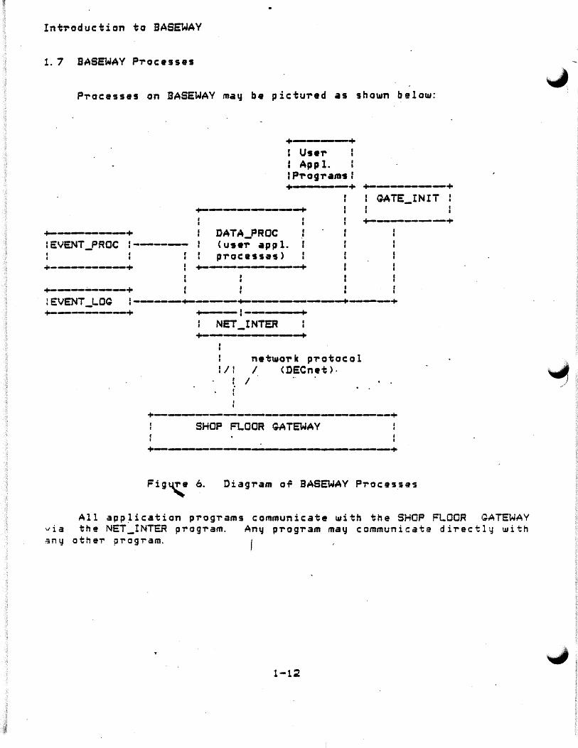
1. 7 SASEWAY Processes
Processes on BASEWAV may be pictured as shown below:
+-----+
+---+ I Us•,.. : App 1. IP-rograms: +-- - -+ +------+
+--------+ r I
DATA_PROC ' .•
: QATE_INIT :
+------+ IEVENT_PROC :------ < us•-r ap p 1.
pracassas> I I
+------+ +----------+
I I
+--------+
~EVENT _LOQ :----+----+--------+---+ +--------+ ..P---·1-----·· ...
NET_INTER +-------+
net~o-rk p~otocal I I I I <DECnet>·
f I . I I
. .
+--------~-------~-------------+ SHOP FLOOR GATEWAY
+-------~---~ .. --------.__,--+
Fig4'," 6. Diagram oil SASEWAY Proc:esse$
All app~ic:atian programs communicate ~ith the SHOP FLOOR GATEWAY via the NET_INTER p~ogram. Any progr3m may communicate di~ectly ~ith any otheT pTogTam.
1-12

Introduction to BASEWAY
'--1.9 Event Processor <EVENT_PROC>
All other BASEWAY processes run as subprocesses to the Event P"rocessor. EVENT_PROC is driven at system startu·p time b.y a command ~ile which tells it how to start up the other processes, as well as c r eat in g var i o u s group l o g i cal names, g l ob al sec t i on s, etc . I t i s also responsible 9o~ r•po~ting and handling signi~icant exte~nal events, such as a link failure with a GATEWAY system and PD t~meout.
The Event Processor is responsible ~or the ~ollowing ~unctions:
o $Ubprocess termination notice
o gateway event reporting
o establishing group logical names for application-specific databases
o establishing group-accessible application-~peci~ic databases.
global sections
Event Logger <EVENT_LOQ)
The EVENT_LOG process receives s~stem events messages from othe~ p'T'ocesses through its process mailbox and logs them to various ope-rator tel"!minals, the system event log file, the VAX ope-rator 's console, or the console OT the SHOP FLOOR GATEWAY .
. \ .,. This process is always running on BASEWAY. l.-CLj S +, 1 ( reetrd Cil~~(Jt/1 1-i!'f';
can ehonce +hi-> --;.,,·2-e J
1. 10 Network Inte1'Tac e <NET _INTER)
The prima-ry function of this proce9s is the routing and delive-ry of inte-rp-rocess mail messages. The process receives messages r-rom its mailbox or ove-r a logical link from a gateway. It then sends the mess~ges to another process's mailbox or to the Net~ork Interfa~e via a g a t e Ula y .
"Tttis \<;. flt~+ +ha+ ~--' ru:k t"t!tH'le-;;; •
{\f-he.- rotr-b ~ fJ(JT c:UG -- fir u!iV a~r·I. k'!>.
1-13

Int~oduction to BASEWAV
1. 11 Qatet11at1 Initialization CQATE_INIT>
This process continuous!~ monito,.s the activity or the SHOP FLOOR GATE1..iAV s•~stams and responds to signi.Pic:ant gateway e·vents.
This proce~s cont,.ols the. se~uenca a~ •vents which occu,. when a gate~a~ is booted (downline s~stem loaded>. It exchanges various messages ~ith the TSXWCH and QATEVP tasks in the SFQ to start variQus gatewa~ tasks runni~g and lqad th• polling database.
1. 12 Use,. Appl ic:atian Processes and Data p,.ocesso,. <DATA_PROC >
-These p,.oc:esses receive most of the data that is sent from the gateway as a result o.P device polling. The~ are responsiole for f~rmatting the data and notif~ing an application data processor ~hen the d~ta arrives. An •xample DATA_PROC is included with the basic ~·J stem. NMcl orie -pee- apphccction ; N<r<Lded ~y ~!"' aw1. ll~;flJ u.ufoma+ic
-Pc.. r-cH1'fl-9 .. l. 12. J Oi spat'ii:it'n of Poi lead Data
DATA_FROC acts rather like a "sink" ror polled data. In .Pact,
..j"-.
man•1~. dti~-feren; polled. data receive,.~ ma1
y. be i-un as pari; o.P an . ~ ·3-PP lea ion. r-or exampL&1 one proca-s2 cou d T-ecaive quality data, ~ ·.3notnei- eq,uipment rault data, etc.
1-14

· App 1 ication
Introductjon to BASEWAY
Cdata analyzed, archived, or otherwise handled)
·''
+----: -----+ +-------+ +--------+ : DATA_PROC : DATA_PROC I" : OAiA_PROC :
+-----------------+ +~----------+ +----------+ \ I I
\ I I +--\---- !--------------/--+ NET_INTER
+-----~---------------~---+
+---:---+ SHOP FLOOR GATEWAY l NETINT
+---------------+ (--------~ualiried data ro~
Shop FlooT Equipment +------:-~-----+ I GATEVP
+--------.----+ .....
(------:--raw data polled rTOm progTammable device
+----:~--+
: POLSRV f .. +------------~--+
. Figure 7. Polled Data ReceiveTS ror One Applicatio~
1-15
Introduction to BASEWAV
1. 12.2 Polled Data
Application programs running on BASEWAY normally send interprocess messages to th• SHOP FLOOR GATEWAY, although these messages ma~ ol"iginate from a task in the gateu.ay . itself. - <See Chapter 2 ~o,. additional in~arm•tian on inte,.process messages. )
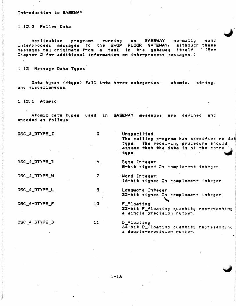
1. 13 Message Data T~pes
Data typ•s (dtyp•> Fall into thre• catagories: and misc el laneaus.
atomic:,
1. 13. 1 AtoCPiC
Atomic da-ta t'dp•s used in BASEWAV messages a-re defined and encoded as follows=
DSC_K_DTYPE_Z 0
. DSC_K_DT'iPE_B
DSC_K_DT'VPE_W 7
osc _K_DTYPE_L 8
DSC_K-DTYPE_F 10
DSC _K_DTYPE_D 11
Un s p • c i 1' i ad . , The calling program has specified no da~ t 'd p •. Th • rec • iv in g · pro c e d ur e s h o u l d
.assume that the data is oT the coTT~ ·_.-, ··type. ~
Byte Integer. 8-bit signed 2s complement intege~-
· Wo,.d In tag er~
1-16
16-bit signed 2s complement intege~.
LongU10,.d Integer. 32-bit signed 2s complement intege~-
' F _Floating. 32-bit F_~loating ~uantity rep~esenting a single-p~ecision numbe~.
D_Floating. 64-bit D_Tloating ~uantity rep~asen~i~g a double-pTacision numbe~.

Introduction to BASEWAY
~ 13.2 String
String data type·s used in BASEWAY messaiges are derined and encoded as .Pollows:
DSC_K_DTVPE_T 14
DSC _ii\_DTYPE_ V 1
1. 13. 3 Miscellaneous
Character-Coded Text. A single S-bit character <atomic data type> or a sequence o~ 0 to 65536 8-bit characters <string data type).
Bit. An align•d bit string. A string of 0 to 65 536 cont i g u o us b i ts. Th e f i rs t bit is bit 0 of the .Pirst byte and the last bit is any bit in the last byte. Remaining bits in the last byte must be zero on read and are cleared on ul'r i te.
l,,- Miscellaneous data types used in BASEWAY messages are defined and .. 1coded as rollows:
DSC_K_DTVPE_DSC 24
1. 14 Message Descriptor P-rotot~pe
Desc-riptor. This data type allows a descriptor to be a data type; thus, levels of desc-riptors are allowed.
Each class of· desc:-ripto-rs consists o.P at least one longwoT'd in the following format:
31 0 +-+-+-+-+-+-+-+-+-+-+-+-+-+-+-+-+-+-+-+-+-+-+-+-+-+-+-+-+-+-+-+
CLASS I DTVPE LENGTH
·-----~-------------~------------------------------------------+ Symbol DescTiption
1-17

IntToduction to BASEWAY
DSC_W_LENOTH (Q, 15: O:>
osc_s_DTYPE (q,;?3: 16)-
DSC_B_CLASS (Q,31::?4>·
A on•-woTd ~iel~ speci~ic to the descTiptor class, typicall'I a 16-bit (unsigned> length.
A one-byte d•ta typa code.
A on•-b~te descriptoT class code.
' -1. 14. 1 ScalaT, String Desc-riptor .<DSC_K_CLASS_MSQS)
A singl• descTiptor ~arm is used ~or scalar data and ~ixed-length st1' ing s.
31 0 +-+-+-+-+-+-+-~+-+-+-+-+-+-+-+-+-+-+-+-+-+-+-+-+-+-+-+-+-+-+
CLASS DTVPE L.ENOTH +-+-+-+-+-+-+-+-+o-+-+-+-"+-+-+-+-+-+-+-+-+-+-+-+-+-+-+-+-+-+-+-+
Data Id en ti f1 i er +-+-+-+-+-+-+-+-+-+-+-+-+-+-+--P-+-+-+-+- .. _ ts-+-+-+-+-+-+-+-+-+-+
. On• OT more b~tes of info-rm•tion +-+-+-+-+-+-+-+-+-+-+-+-+-+-+-+-+-+-+-+-+-+-+-+-+-+-+-+-+-+-+-+
DSC_W_LENQTH
DSC_B_OTYPE
DSC_B_CLASS
DSC_L_DATAID
DSC_R_DATA
Length of data in bytes, unles= the OSC_B_DT'fPE ~ield con~ains the value 1 Cbit). Length of data item is in bits ~OT bit.
A one-byte data t~pe code.
192 s DSC_K_CLASS_MSGS
A longword containing the data identifier value. This value uniquely names the described data field.
Start of the data field.
1-19
~' I

Introduction to BASEWAY
( ... /- 14.2 Example DATA_PROC
An example DATA_PROC is included in Ve-rs ion 1. 0 o.P BASEWAY and is sta~ted by a default startup ~ile. It logs an event th~ough the Event Logger each time a polled data message is received. Ir polled datp is to be used as part or the application, this example may be use~ul as a
·starting point fo-r creating your own polled data receiyer process. The source ror this example is in BSLSROOT: CSCURCE.DATAPROCJ.
1-19

Int~oductian to BASEWAY
1-20
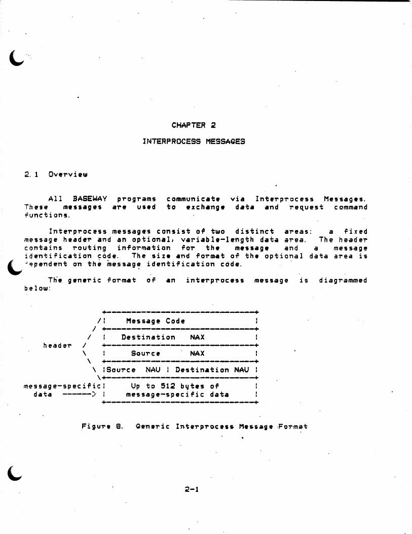
~····.
2. 1 Ove'rvi aw
CHAPTER 2
Ir.fTERPRDCESS MESSAGES
All BASEWAY prog,.ams These messages a're us•d functions.
communicate to exch•ng•
via Inte'rp'rocess Messages. d•ta and request command
Inte'rp'rocess messages consist of t~o distinct areas: message heade'r and an optional, variable-length data area.
a .Pixed The header
contains 'routing info'rmation ro'r the messag• and a messag• identiTication code. The size and fo'rmat of the optional data area is
~,~pendent on th& messag~ identification code.
Tne generic fo'rmat of an interprocess message is diagrammed below:
+--------------------------------+ /I Message C~de
I +-----~---------~---~----~-----+ I Destination NAX
neade'r I +-----------:-------------------+ \ Source · NAX \ +------------------~----------+
\ :sou'rce NAU : Destination NAU : \+-------------~-----~--------+
message-specific: data ------)·
Up to 512 b~tes of message-specific data
+----~--------------~--------------+
.Figu-re B. Qene-ric: Inte-rp-roc:ess Message ·Fo-rmat
2-1
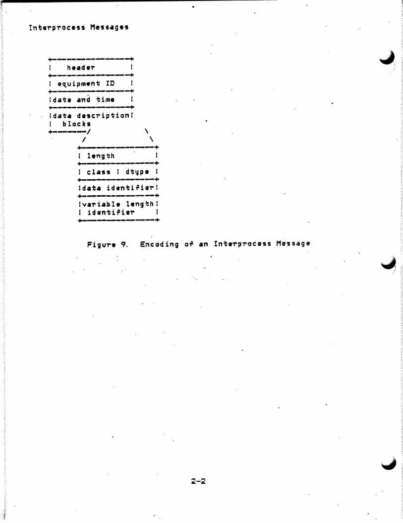
+---------.. head.,.
+--------..... : equipment ID +---------+ ldate and time +-----------+ ldata desc,.iptionl I blocks +-------/ \
I \ +--------+ +-------+ : class : dt~p• : +-.._,___ ---------+ ldata identi~iai-: +---------+ lvai-iabla length: I idanti~iei-
+-------+
Figura 9. Encoding of an Interprocess Message
~ ·'

Interprocess Messages
1. 1 Message Code
A message code is a ~ord ~hich indicates consent or action to be taken as a result of the messag•. Messag• codes l--32767 are reserved for Digital Equipment CoT-poration.
2. 1. l. 1 Form•t of Massage Cod• -
15 14 13 12 11 10 a 7 6 5 4 1 0 +---+---+---+---+---+---+---+---+---+---+---+---+---+---+---+
+---+---------------------------------------~----------------+
Bits o--14 Sit 15
identify message code o, if Digital Equipment message 1, if user message
2. 1.2 Source and Destination NAX
Each application, device set, and gatewa1J is assigned· a ~ .1.i,-bit integ.eT numbeT at de-finitio.n time. This number i.s ~- ute messages and transactions between ·~•tems. ·
2. 1. 3 SouTc e and ·Destination NAU
unique used to
Each program in an application can have ~ Network Addressable Un i t <NAU > as soc i ate d w i th i t. An NAU, a l on g w i th a NA X, ind i c ates a uni~ue process in ·a netwoTk.
There are two t~pes of NAUs: -temporar~ and peTmanent. Temporary NAUs are in the range -1 to -127, and are assigned by calling the BSLSCREATE PORT routine. Permanent NAUs are created by assigning logical n;mes and creating mailboxes in the EVENT_PROC startup fil,. Permanent NAUs are in the range 1 to·127:
1--63 64--127
R~served for Digital Equipment Available to user
2-3

Inte~p~ocess Messages
2. 1.4 Message-Speciric Data
The message-speci~ic data contains in~o~mation related to the individual message. Th~ following sections ~ill define the message-specific d~ta fo~mats fo~ each message code.
2-4

Do Generic I/O Request
Message rormat:
+---------------~----------------+ Standard Message Header <4 t11ords)
+----------~--------------------+ Sequence Nuntbttr +-~-----_._,-------------------+
Device logical ID +~----------------~-----------~+
Status Retu-rn +-----------------~-------------+
+-~-------_._..--~----~--------+ Data Count
+-------------------------~-------+ Device Data Bur~er
<Optional, 256 bytes max) +--------------------------~--+
<16 words)
Massage Codes: MSG_GENERIC_READ MSG~GENERIC_WRITE MSQ_GENERIC_WRITEVFY MSG_GENERIC_STARTDEV MSG_GENERIC_STOPDEV MSG_GENERIC_READDEVSTAT MSG_GENERIC_LOGONDEV MSG_GENERIC_LOGOFFDEV MSG_GENERIC_STARTUPLOAD MSG_GENERIC_ENDUPLOAD MSQ_GENERIC_STARTDOWNLOAD MSG_GENERIC_ENDDOWNLOAD
Sent to: This kind of message is routed to GENSRV. GENSRV to rormat and execute the re~uest.
It causes
Sequence Number - may be ~et by the requesting program. The GENSRV device request always returns a -rttsponse message. The response will contain the sequen~e number of its command, making this 9ield 1_isable as a synchTonization aid o-r "sanitv check. 11
Device Logical ID - an unsigned wo-rd value that is uniquely associated with each programmable device defined.
;?-5
.i
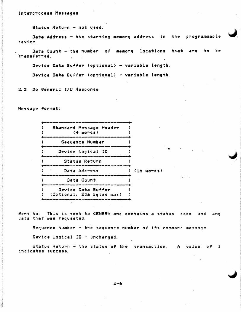
Status R"eturn - not used.
Data Address - the starting memor~ address in the programmable device.
Data Count - the number o~ memor~ locations that a,.e to be ·t,. an 1 f er,..e d.
variable length.
Device Data Buffer (optio~al> variable length.
2. :3 Do Gftna'r i c I/O Resp on ~e
Message rormat:
+----------------------,_.__+ Standard-Message H•ader
C4 u.ords> +----~------.__.__,-~---+
Sequence Numbe'r +-~----------~---~-.--------+
Device logical ·rD
Status Retu'rn . . ~-------~~--------------------+
Data Addr-ess ..;.-.------------------...------~----+
Data Count +-----------~----~-~----------+
Device Data Bu~~er <Optional, 256 b~tas max)
+-------------~----------~----+
<16 wordsi
Sent to: This is 5ent to GENSRV and contains a status code and any data that was requested.
Sequence Numbe,. - the sequence numbe,. oF its command message.
Device Logical ID 1Jnc hanged.
Status Return ~ the status of the tTansaction. indicates success.
;?-6
A value or 1
.J I
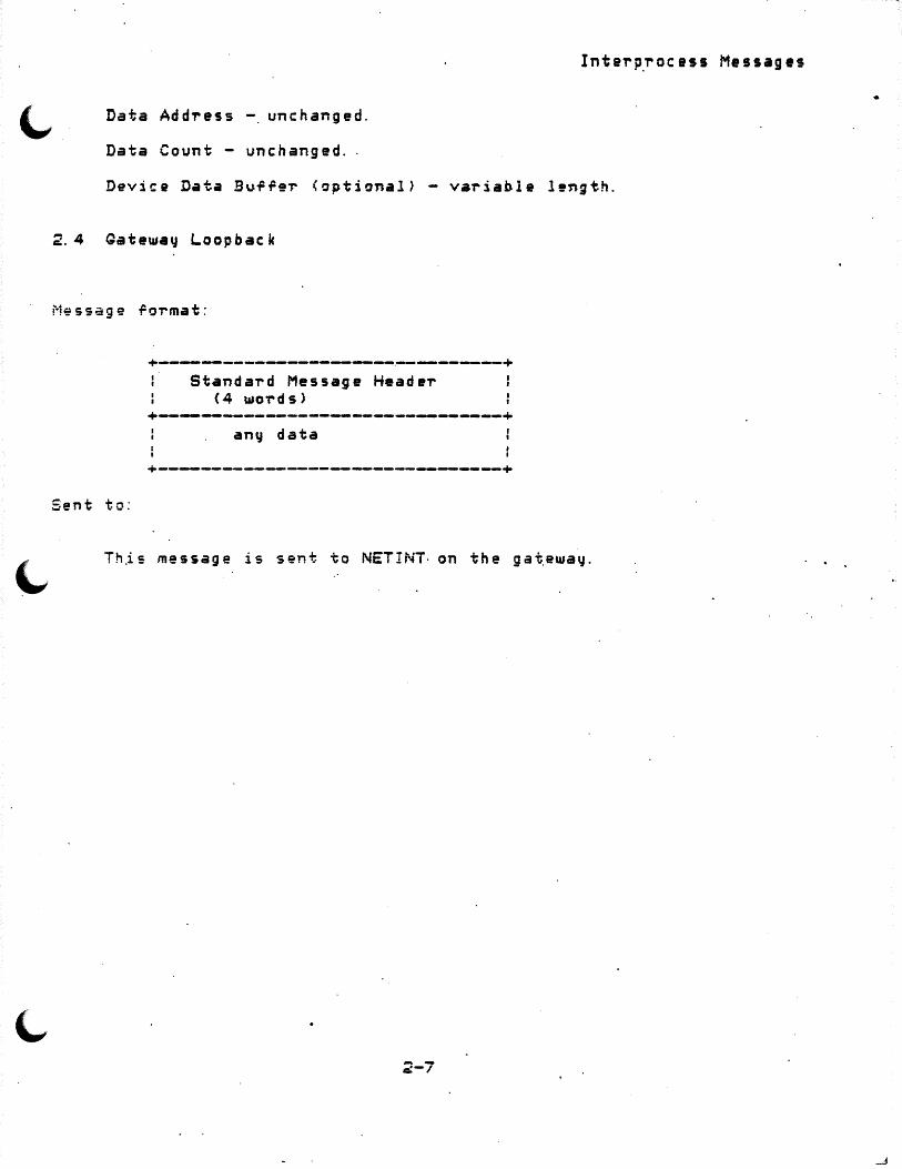
Data Add~ess -. unchanged.
Data Count - unchanged ..
2.4 Gateway Loopback
Message .Po-rmat:
Sent to:
+---------------------------~--------+ Standa~d Message Heade~
(4 wo~ds>
+----...----------------------------+ anv data
+--------------------------------+
Inter~rocess Messages
Th.is message is sent to NETINT· on the gat.eway.
2-7
. .

Inte,.p-ro·cass Mass•ges.
2. 5 Qat Gateway Status
Message -ro,-mat:
:standard Message Heade-r <4 wo-rds>I +-------~--------~--------+
Status flags
Task .Plags
Er-ro,. ;: lags ~--------- ~,.__._,.. ____________ -+
Boot time
+---------------------- ----------+ VDR Load time
+----·---· ---------+ I · Qateway Counts Reset time
Net message~ sent ... .. ---------~.-----------~-~
Net messagas received +-~~-------.--.---.--,---~----+
Net messages ~ueued .. __ ___, _________ ~---------~--+ Net messages lost
+---------~--...------------:;....~..:....-+ VDR Blocks us9d
+----.-------~---------.-------,__------+ VDR size
+-~------------------~---~~~-+ VDR map c:ount
+------------------------.__-+ +--------~.-.-------------------+
Cu,.~ent Device Sets +-----._,----------------~--.-.--,~-+
Potential Device Sets +----------~-----~--------------------+
Gateway Node name +----------~--------~--.__ ____ ,___,__.,.
SASEWAY Node name ..... ------------~-~---------+ BASEWAY ID
+------~~-------.--.----------+ Message burfeT block allocated :
+--~--------.--------------------+ Message bu~fe~ block used
+-~-----------------------------+
2-8

(.,Sent to:
This is sent to QATEVP.
2.6 Get Network Status for Qateway
Message format:
Sent to:
+--------~----------------------~+ Standard Message Header
<4 wo-rds>
+---------._.----~----------------+
Int•rprocess Messages
This message is sent to NETINT on the SHOP FLOOR GATEWAY.
2. 7 G~t Polled Device Statistics
.. ssage rormat:
Sent to:
+--------------------------------+ : · Standard Message Header ( 4 word·s)
+----~--------~-----------------+
This message is ~outed to POLSRV.
2-9

2. S Log. Even.t
Message floi-mao;:
Se-n-t ta:
+ - • ._._ __________ _.._ __ _,_~--+
Standard Messag• He~d•r < 4 u.o-rd s ) +-----+-------+
f event flag I •~•nt code +-------~----+-~--~---~-------+
+-__,----~----.---~-~--+
This is swnt ta EVEMT_LOO to initiate event lagging.
2.ct Reload VDR
Message .Pormat:
Sent to:
Standard Message Header ( 4 l»Or d S)
+-~--~------------~--~-----+
This is sent to QAiEVP .
•
:?-10
~-

(.,2. 10 Reset Network Counts
Message rormat:
Sent to:
+----_,_ __________ ...; __ .__ _________ +
Standard Message Header ( 4 \1101" d s)
+----~--...------------~~-------.-.+
This message is sent to NETINT.
2. 11 Set QateUJay Time
Message rormat:
Sent to:
+--------------------------------+ Standard Message Heade-·r
C4 words)
+------------~----------------~-+ YeaT' <since 1900)
+-----------~--~~-------------------+ Month
+-----------~----------------------+ Da"
+-------------------+ Hour
+----------~------------------+ Minute
+----------------------------+ Second
+----------------------------+
This message is sent to TS~WCH and causes it to set the RSX-115 system time to t~e time specified by the message.
2-11

Interproces9 Me~sages
~. 12 Shutdown Applicati~n
Message rOT'mai;:
Sent i.to:
+-----~-------~-----~~-+ .S~andard Message Header
<4 u.ords>
This is noT"mally s•nt to EVENT_PROC to .~~ect system shutdo~n.
2. 13 StaT"t Polling on a Device
ii~ssage roT'mat:
+~--------~---._,_~--------+ StandaT"d M~ssage HeadeT'
( 4 IJJO,. d S )
: I I
+----------.--~----~-.----------+ device id t
I .. I +-----.--_..,,_ __ ._,----~---------+
This message goas to ?OLSRV .
•

(.,.,2. 14 Stop Gateway
M~ssage .format:
Sent to:
+---------------------~----~------+ Standard Message Header
<4 u.oi-ds>
+-------~-----------------.-..--~--+
This is sent to TSKWCH .
.2. 15 Stop Polling on a Device
Message .Pormat:
+--------------------~---------+ Standard Mes~age Header
"<4 words) +---------------~----------------+
device i.d.
+------~------------------------+
Sent to:
This message is routed to POLSRV.
2-13
Interprocess Messa~es

Inte~process M•9sages
~ ,/
•
2-14

CHAPTER 3
INTRODUCTION TO SUBROUTINE DESCRIPTIONS
Each high-lev•l language supported by VAX/VMS provides some mechanism for calling an ext•rnal procedure and pa~sing arguments to that pT'ocedure. The actual mechanism and terminology used, however, vaT'~ ~T'om one language to another. Since it is not possible to describe the wa~s in ~hich each high-level language calls s~stem s2rvices.. for specific information, it is recommended that you re.Per ~o the appropriate high-level language user's guide.
VAX/VMS system services are external procedures that accept arguments. There are th-ree ways to pass arguments to· Se:Jstem services:
0 b y i mm e d i at e· v a l u e. passed (a n~mbe-r
valu•i.
·The argument is thi actual value t6 be or a symbolic representation of a numeric
o by addT'ess (also called "by T'eference 11 >. The argument is the address of an area OT' field that contains the value. An argument pas~ed by address is usually exp-ressed as a refe+ence name OT' label associated with an area OT' ~ield. <In fact, one common error is to pass a numeric value without indicating that it is. passed by value; i9 the compiler assumes the numeT'ic value is an addT'ess, a run-time "access violationu er-ro-r occurs when, for example, the image t-ries to a c c es s v i T' tu a l ad d res s 0 or 1. >
o by descriptor. This argument is also an addi-ess, but or a special data stT'uctuT'e called a character string descripto-r.
A descT'iption of each service is given in Pai-t II of the VAX/VMS Se-rvices Reference Manual and indicates ho~ each argument is to be passed. Phrases such as "an address" and "address o.P a character st-ring descriptor" identify address and descriptor a-rguments, i-espectively. Words like "indicator, 11 "number," 11 value1" OT' 11 mask 11
indicate an argument passed ~y immediate value.
3-1

Introduction to Subroutine Desc~iptians
Some se~vices also require se~vice-specific data stTu~ture~ that indicate ilunctions to be·pe~.Pol'lmed or hold in.Po-rmation ta be returned. ~ You can use this infoTmation and in.Po~mation from ~our programming language manual~ to define such an item list.
3. 0. 1 Testing Return Status Codes in High-Leval Languages
When a service r•turns control to ~our program, it places a return status value in the general Tegister RO. The value in the lour-order word indicates either that the service completed successfull~ or that some specific eTro~ prevented the service .Prom performing some or all of its functions. After ~ach call to a system service, you must check to see whether it completed successfully. You can also test for spaciili~ error conditions.
Each language provides some mechanism far testing the return status. Often you need onl~ check the lo~-ordeT bit, ~or example, ulith a test i'o-r··TRUE· Csucc•ss or infaTmational -returni or FAl...SE <error o~ ~arning return>.
To check the entire valu• ror a specii'ic return condition, each language provides a ~aq ror your program to dete~mine the values associated ~ith speci~ic symbolically d•?ined codes. You should a l Ula y s us e th e s e s y nri> ·o l i c · n am• s \II h • n " o u ...,,. i t e t e st s r o -r s p e c i f i c co.nd i ti ans.
The .Poll ou. i 'n g The~e procedures biJ entr1~ name.
chap~~-r describes select~d BASEWAY procedu~es. are presented by categar~ and in alphabetical oTde-r
BASEWAY subroutine-s ma'J be inclu·ded in a user program by LIN~ing with the library, BSLSLIBRARY.
3. 0.2 Compiling and Linking a VAX PL/I Program
The text librar~ BSL.DEF.PLI contains a variety o~ codes and routine definitions for BASEWAY. It includes most or the de~initions that you will need .PoT writing your own PL/I application programs. BSLDEF.PLI r.:an be round in the directo-ry BSL$LIBRARY.
The .Pallou.in.g commands uaill compile and link a VAX PL/I program:
5 PLI MYTEST $LINK MYTEST,SYS$LIBRARY:BSU...IB/LIB
·~ ./
Int~oduction to Subroutine Descriptions
l,..3. 0. 3 Compiling and Linking a VAX BLISS-3~ Program
The include file BSLDEF.REG contains a vaT'iety of codes and routine defi~itions for BASEWAY. It includes most tif the definitions th a t y o u w i 1 l n e e d f or ·WT' i t in g y o u T' own a p p l i c a t i on p -r o gr ams .. BSLDEF.REG can be ~ound in the directory BSLSLIBRARY.
The following commands will compile and link a VAX BLISS-3~ pT' og-ram:
·$ BLISS MYTEST $LINK MYTEST,SYSSLIBRARV:BSLLIB/LIB
. 3. 0.4 Compiling and Linking a VAX FORTRAN Program
The text library BSLDEF.FOR contains a variety o.P codes and routine definitions for BASEWAV. It includes most of the definitions that you will need foT' writing your own FORTRAN application programs. BSLDEF.FOR can be found in the directo-r~ BSLSLIBRARY.
The following commands will compile and link a VAX FORTRAN µr-ogT"am:
i $ FORTRAN MYTEST ~ ~INK. MYTEST,SYS$LIBRARY:BSLLIB/LIB
3.0. 5 Compiling and Linking a VAX BASIC P-rog~am
The include ~ile BSLDEF.BAS contains a vaT'iety of codes and routine de~initions foT' BASEWAY. It includes most of the de~initions that you will need fo-r w-riting you~ o~n BASIC application p-rog~ams. BSLDEF.BAS can be found in the directo-ry BSLSLIBRARY.
The following commands will compile and link a VAX BASIC prog-ram:
$ BASIC MYTEST $LINK MYTEST,SYS$LIBRARY:BSLLIB/LIB
3-3

Introduction. to Subroutin• De~c:~iption•
3.0.6 Compiling a~d Linking a VAX C Program
The include ~ile BSLDEF.H contains a variety of codes and routine definitions for BASEWAY. It includes most of the deTinitions that ~ou will need 'or w-riting 1.J·ou-r own C appiication programs. BSLDEF. H c:an be found in the director" BSL$LIBRARY.
Th• .Poll.outing comm.nds U._ill c:ompil• •nd link a VAX C program:
.. CC MYTEST $LINK MYTEST.SYS$LIBRARY~BSLLIB/LIB
3. 0.7 Compiling and Linking a VAX COBOL Program
The cop~ ~ile BSLDEF.LIB contains a variety of codes and routine deTinitions for BASEWAV. It includ•s most o~ th• de~initions that you will need. i1or utriting ~our own COBOL .application programs. BSLDEF. LIB can be found in the direc·tor" BSL$LIBRARV.
The following comm•nds will compil• and link a VAX COBOL p-rogram:
$ COBOL MYTEST $LIN~ MYTEST,SYSSLIBRARY:BSU..IB/LIB
3:0.8 Compiling and Linking a.VAX PASCAL P~ogram
The definition Tile 5SLDEF. PAS contains a varietu o~ cod~s and ~outine definitions far BASEWAY. It'include5 most oi the definitions that you U1ill ·need .Po,. Ul,..iting •lour own Pascal application p-rog-rams. ESLDEF.PAS can be Pound in the diracto,.~ BSL~LIBRARY.
The fallowing commands U1ill compile and link a VAX PASCAL pi- ogram:
·~ PASCAL BSLDEF/ENVIRONMENT $ PASCAL MYTEST $ LINK MYTEST, BSLDEF.· SYS$LIBRARY: BSLLIB/LIB
3-4

Introduction to Subroutine Descriptions
(..., 3. 1 How To Use Procedure Descriptions in This Manual
Each procedure description consists of the following categories. Certain pi-ocedui-es have an additional 11 Notes 11 section.
NOTE: All of the procedures described in this document i-eturn a completion status condition code as a function r•turn value.
Ca 11 in g Format :
This sect i rm sholas tt,e erctT·y nEtme Etnd a general i n .. d ro-r·mc.·t rcn"' calling the procedure ri-om a high-level language, with all arguments listed in positional order. Spaces between arguments are present for readability and are not part of the statement syntax.
Ar g u men t s :
This section _describes each or the arguments in detaiL with any special argument-passing requirements.
along
Return Status:
This section lists the possible error return status codes the procedures, with an explanation of the returT'l condition .
. returns are. ··listed in alphabetical or·der. All statt.:s codes seve~e ei-ro~s, unl~ss ~ther-wise indicated.
Usage Restr-ictions:
rrom The are
This section notes any user pr-ivileges that are required, and any spec·ial conditions that must be established prio'l' to calling this procedure.
Notes:
\.,.This optional section contains a detailed usage desc~iption ~he procedure, as well as references to related information.
3-5
of

Int~oduetion to Sub~outine Oasc~iptions
3-6

CHAPTER 4
SELECTED BASEWAY SUBROUTINES
4. 1 Ove-rview
This chapte-r contains descriptions of various BASEWAY sub-routines that are userul in suppoT'ting interp-rocess messages and the r~ading
-and w~iting of ~~co1ds.
NOTE: Sub-routines specific to prog-rammable devi~e access are denot~d by the lett~rs FDA.
4-1

Selected BASEWAV Subroutines
4. 2 BSL~ACCESS_DEVICE Ac~ess a Programmable Device <FDA>
ESLSACCESS_DEVICE
The Acca9s P~ogrammabl• Device procedure provides a means of establishing an access path to a specified programmable device and setting • .da.Pault pT"ogrammab le device n•m•. No data is retuT"nad by this call.
I~ a programmable device n•m• is not speci~iad, then the last used programmable device name is used. If a handle is not speci~ied, a de~ault handle is used.
Note that an implicit BSLSACCESS call is performed b~ all or the otheT" BSL routines.
Ca 11 in g F o,..ma t:
BSL·IACCESS_DEVICE < Chand laJ, CdeviceJ >
Arguments: ,._
hanale.
Opt'ional addi-ess o.P a longword to .be used as an i:ntei-nal context ~ identi,ie,... A programmer ma~ choose to keep sev~ral handle~, each ~ith a dir~ei-ent context. This parameteT" must be initializad to O bero-r-.· being speciried ro-r th~ .P.i-rst· time in a call, and not modiTied the~eaTte,-. Ir this par3meter is not sp~ci,ied, the s~stem will supply a default context identifier.
devica
Optional address o~ a character string desc~iptoT pointing to tha text ~tring naming ;ha programmable device. This programmable device name sti-ing must correspond exactly to· tha name o~ the davice requested. I~ this pa,-ameter is not 5peci~iedJ the last referenced programmable device is used.
4-;?

S•lected BASEWAY Subroutines
Return Status:
(.... LS_NORMAL
Service successfully completed.
BSL.$_NOSYSTEM
The programmable device does not have a valid device set associated with it.
BSLS_PDEVDE~LT
The caller did not s~eci9y a programmable device name, not have a deTault name set.
BSL$_NOPDEV
and did
The programmable device that ~as specified does not exist.
'
4-3

Select·ed SASEWAY Subroui:ines
4. 3 BSLtACCESS_PORT Access Another Port.
ESL$ACCESS_PORT
The Access Port procedure ~ill find the Port value ~or a particular named port currently running on an application, device set, oi- g at at11a11.
This port value directlv and uniquel11 identifies a message port somewhere in the s~stem.
Ca 11 ing Format:
BSL$ACCESSJ'ORT < pori:, Cs11stemJ, port_name,
Arguments:
port
Address of a longword i:o receive th• port value. Po~t values are 32-bit values that uniquel., identif11 the message port.
pc1't_name
Add~ess or a character string de~criptor po1n~1ng to the text st'T"ing containing a valid message poi-t name. Thes-e names are unique ti an application or gate\lla~.
4-4
'·

Selected BASEWAY Subroutines
I Retu-rn Status:
"1f LS_NDBSL
A BASEWAY application is not currently running in this UIC group.
BSLS_NORMAL
Service successfully completed.
sss_INSFARQ
Not enough arguments were passed to the routine. • BSLS_NOBSL
No BASEWAY application is running.
BSLS_NOPORT
If the port is local to the current application, th@n the specified po-rt name does not exist .. I.P the po-rt is remote, then the problem may be with the Network Intei-face port.
BSLS_NOS't'STEM
The application ... device set, or gateway does not exist.

Selected BASEWAY Subroutines
4. 4 BSLSALLOCATE_DEVICE - Allocate • Programmable Device <FDA>
BSLSALLOCATE_OEVICE
The Allocate PTogrammable Device procedure provides a means a~ requesting axc:lusiv'! access to a programmable device. Thi·s call is often used prior to dawnlin• lo•d a device and during complicated diagnostic: functions, where it· is imp•rative i;hat no other process access the device. If• progTammable device name is spe·cified, then the current default programmable davica name is set to tha speciried name on co~pletion of this call.
Calling Fo,..mat:
BSLSALLOCATE_DEVICE < Ch•ndlel, Cdevice], C.Plagsl
Arguments:
handle
Optional address of a longword to be used as an internal context identifie,...· A programme,. may c:hoose to keep seve-ral handles, each with a diffe+ent· c:antext. This · paramete-r must . be initialized to 0 i:aroi-e bein.g specii=ied for the .PiT"st time in a · .. ··-' call, and not modiried the-rea~tvT. .Ir this parameta-r is not ~ speciFied; the·system will supply a default context identifie~.
device
flags
Optional address a~ a character st~ing descTiptor poin~1ng to the text st-ring naming the p-rogi-ammable devic•. ihis programmable device name st,.ing must car-respond exactly to the name or the device. req,•Jested. If this pa'T'ameter is not speci~ied, the last refe-renc:ed programmable device is used.
Optional add-ress o~ a wo-rd containing flags. Ir the rirst bit is set in this rlag word, then any automatic data collection (polling>· or this device is stopped while the device is allocated. If clear, then data collection continues bµt all othe'T' access is denied.
4-6

Selected BASEWAY Subroutines
<.,Return Status:
jLS_NOBSL
A BASEWAY appljcation is not currently running in this UIC group.
BSLS_NORMAL
Servi~e success.Pully completed.
ESLS_NOSYSiEM
The programmable device does not have a valid device set associated u.ith it .
. BSLS_OWNATTACHED
The programmable device that ~as specified is currentl~ allocated by this process's parent process, and there.Pore.. can be considered allocated to this process.
BSL$_PDEVDEFLT
The· calle,.- did not specify a programmable device name .. not have a default name set.
l,, i=iSL$_NOPDEV . .
and did
.Th~.pr~g~ammable devi~e that was specified· does not exist.
BSLS_ATTACHED
The programmable device is currently allocated .to process.
4-i
another
•

Selected BASEWAY Subroutines
4. ~ BSL$CCMPARE_DEVICE - Compare Programmable Devica Logic <PDA>
BSLSCOMPARE_DEVICE
The Compare Device Logic procedure will compare t~o programmable device logic files and report an~ dirferances to the caller.
Not all pragramm•bl• devices support the compare 'unction.
Calling Format:
BSLSCOMPARE __ DEVICE < ChandleJ, Cdevic•J, filename >
A~guments:
handle
Option~l address of a long~ord to be used as an internal .context identifier. A programmer m•y choose to keep several handles, each with a different context. T~is parameter must be initialized to 0 berore being speciried for ·the ~irst time in a call, and not modified thareart•r. I' this par.a~eter is not ~pecified, the s~stem will supp1~ a def~ult context identi~i~r.
d~vice
Optional address o~ a character string descriptor poin~1ng to the text st~ing naming the programmable device. This p~ogrammable device name string must co~respond exactly to the name o~ the device re~uested. Ir this parameter is not speciried, tne last referenced programmable device is used.
~ilename
Address of a character string de~c~iptor pointing to a VAX/VMS ~ile containing a programmable device logic dump ~or a similar programmable device.
4-8

Selected BASEWAY Subroutines
.Retui-n Status:
(.,. LS COMPFAIL - .
The compare .Pailed due to one or more differences in the logic ~ile and the programmable device's memory.
ESLS_NOBSL
A BASEWAY application is not curr•ntl~ running in this UIC group.
BSLS_t40RMAL
Service success~ully completed.
ESLS_NOSYSTEM
The programmable device does not have a valid device set associated with it.
ESL$_NOTSUPPORTED
The programmable device does not support this function.
fiSL$_PDEVDEFL.T
T·he caller did not speci.Py a p·rogrammable de·.,rice ·name,· and did not have a default nama set:
BSL$_NOPDEV
The programmable d~vice that was specified does not exist.
BSL$_ATTACHED
The programmable device is currently allocated to p-roc ess.
4-9
another

seiectad BASEWAV Subroutines
4. 6 BSL•COMPILE_DEVICE_ADDRESS P~ecompile an Addre9s CPDA>
BSL·$COMP lLE_DEV ICE_ADDRESS
The Compile Address procedure allows a caller to translate a characte,- string containing a valid programmable device address into an internal 9ormat. This internal ~orm•t may be substituted ~or the ~haracte,- string davica addrass in othar BSL calls.
Precompiling addresses that are to be used over and over can save ~ substantial amount of overhead, as the address st~ing does not have to be par~ed each time.
C-alling Fo,-mat:
BSL$COMPILE_DEVICE_ADDRESS < ChandleJ, Cdevicej, address, compiled >
Arguments:
handle
Optional addre~s o~ a long~ord to be used as an inte,.nal context identi~ier. A programmer may choo~e to keep several n~ndles, each .with a. di'P.Per-.nt . .'conte'f·.t.· This pa'1"am·et'!l-r .m•.1!-t: be initialized to 0 oeroi-e being spec{ried ro;- the -rirst time in a call, and not modi-tied therreafter. Ii= thi5 pa-ramete-r is not s;;eciri·ed, the system will supply a de-flault context identi-rieT'.
Optional addT'ess OT a characte-r st-ring desc-ripto-r poin~1ng to the text ~t-ring ·naming the pT'og-rammable device. This programmable device name st~ing must coT'-respond· exactly to the name of the device re~uested. Ir this paramete-r is not speciried, the iast reTeT'enced pT'og-rammable device is used.
addr!?ss
Address 0¥ a character string desci-iptoT' pointing to the text string containing a valid p-rog;-ammable device address.
4-10
(...,compiled
. . Address of a descriptor the compiled address. bytes 1 ong.
Return Status:
BSLS_NORMAL
Selected BASEWAY Subroutines
pointing to a characteT string to receive The characte~ string must be at least 33
Service successfully completed.
BSL$_NOSYSTEM
The pTogrammable device does not have a valid device set associated with it.
ESLS_NDTSUPPORTED
The programmable device does not support this function.
BSLS_PDEVDEFLT
The ~aller did not specify a programmable device name, ~nd did not have a de~ault name set.
~ ESL$_NOPDEV
The programmabl·e device that ~as specified does not exist.
BSLS_BADADDR
The a~dress speci,ied in the "ADDRESS" parameter has an illegal syntax or is outside of the range or valid addresses ro~ this programmable device.
4-11
Selected BASEWAY Subroutine5
4. 7 BSL$CREATE~~ESSAGE - Create an Interprocess Message
ESLSCREATE_MESSAGE
The Creata Message procedure allocates space for an interprocess message, optionally sets some deTault message att~ibutas, and returns a pointer to the message.
Me$sages that are created using this procedure snculd only be deleted ~ith the BSLSDELETE_MESSAQE procedure.
Calling Foi-mat:
BSL$CREATE_MESSAGE painter, CsizeJ, Cc:odeJ, Cd est_port J, C sou,.c: e_p ort j
Arguments:
~ode
Address of a long~ord ta receive the address of the data portio~ o-+: the message.
Optional a~dres$ nf a word containing· t~~ siie o~ the data portion of the allocated message. Valid values are in the ~ange o~ 0 to 8000 bytes. Ir no size parameter is specir1ed, then the default maximum size of 8000 b~tes is used.
C?tional add~~ss of a ~a~d containing the messag~ c~de tc be assigned to this message. I~ no code is speci~i~d! then a code must be speciri~d in the BSLSSEND_MESSAGE procerlu~~ call.
: ~ st_p o:rt
tJ p t i on a 1 , a d d r e s s n ~ a l on g tu or d. c on ta i n i n g t h e port that this message is to be sent to. soeciried, then a d·estination port must be ESLSSEND_MESSAGE procedure call.
#
port v~lue a~ the If no dest_port is sp~ciried in the
~\

Selected BASEWAY Subroutines
(..,SOUT'C e_p OT't
Optional address of a lang~ord containing the port value of the port that this message is to be sent from.
R.:tu,.-n Status:
ESL$_NORMAL
Service successfully com~l•ted.
sss_INSFARG
Not enough a1'guments were ·passed to the routine.
BSLS_BADMSGSIZE
The interprocess message size that was specified is outside o~ the range or 0 to 8000 bytes.
4-13
S.el1cted BASEWAY Subroutines
4.9 BSLSCREATE_NAMED_PORT - Create a Permanent· Message Fort
BSLSCREATE_NAMED~PORT
The Create Named Port procedur• allocat•s a permanent message port, associates an applic~tionwide name ~ith it, and assigns it to the calling procass. Interprocess m••s•ges 11'41~ then be read from and written to this port.
Message ports CT'eated ~ith this procedure should be deleted via the BSL$DELETE_PORT procedure.
Calling Format:
BSLSCREATE NAMED PORT . - - port, name, CsizeJ, Cq,ueuadJ,
CidJ, >
;~r g ument s:
size
4ddr•ss a~ a longword to r•c•ive the port vajua. 32-bit values that uniquel~ identi¥y the-~essage
- . :-or.,, po-rt.
Address o~ a character string descrip~or pointing to a text stT'ing containing the name to associate with this po~t: Name$ must be alphanume'T'ic: symbols, and can be no mo'T'e than 32 characters in length.
Optional addT'~ss of a ~o~d containing the maximum size of a me~sage that can be received through this po~t. Valid values are in the range of 0 to 9000 b~tes. I~ no size parameter is ~pecified, then the de~ault maximum size a~ 9000 bytes is used.
4-14
~i

Sel•cted BASEWAY Subroutinas
{.,,,queued .
Opt1onal address of a word messages that can be ~ueued maximum is specified, then a
containing the maximum number of to this poT't at any one time. I.P no default value of 10 is assumed.
id
Optional address of a word containing a numeric identifier for this port. Ports that a"re to· receive polled dat.a messages .Prom a gatewa~ mu5t be a~signed a unique ID number b~ the system manager, and use this number each time this port name is created.
Return Status:
BSL$_NCBSL
A BASEWAY application is not currently running in this VIC group.
BSLS_NORMAL
Service success.Pully completed.
sss_INSFARG
Not .enough arguments UJ-ere passed ~o the routine.
L$_BADMSGSIZE
The interprocess message size that was specified is outside of the range of 0 to SOOO b~tes.
BSLS_NOBSL
No BASEWAY application is running.
BSLS_PORTEXISTS
A port with this name or ID alread~ exists.
BSL$_TOOMANY?ORTS
More than 127 Damed ports a~e cu"r~ently in use by application.
4-15
this
Selected BASEWAY Subroutines
4. 9 BSLtCREATE_PORT - Create. a Temp orar" Message Port
ESL$CREATE_PORT
The Create Port procedur• allocates a temporar~ message port and assigns it to t~e callin~ process. Interprocess messages ma~ then be read From and written to this port.
Message ports created with this procedure should be deleted via the BSLSDEi.ETE_PORT' pT"ocedure.
Calling Format:
BSLSCREA TE_PCRT port, Csi1eJ, CqueuadJ, >
Arguments:
port
size
Address of a longword to receive the port value. Port values are 32-bit values th•t uniquely identi~y the message port.
Optiona·1 address o~ a u.o-r.d containing the ma:dmt;ra size of\ a mes3age that can be raceived through this poT"t. Valid values a~e in the range of 0 to 9000 bytes. IF no si~e pa~ameter is speci~ied, then the de~ault maximum size of 8000 bytes is used.
Optional add~ess of a wo~d containing the maximum numbe~ of me5sages that can b~ queued to this port at any one time. I~ no maximum is specified, ~hen a default value of 10 is assumed.
4-16

'-"' Raturn Status:
·.L$_NOBSL
A BASEWAY application is not currently running in this UIC group.
BSLS_NORMAL
Service successfully co~pleted.
sss_INSFARG
Not enough arguments were passed to the routine.
BSLS_BADMSGSIZE
The interprocess m•ssage si1e that was specified is outside of the range o; 0 to eooo b~tes.
ESL$_NOBSL
No BASEWAY application is running.
B SL$ ~NONALI
'-' .
More ._than J27 ~emporary ports are currently in use by this a pp 1 i ·cation.
4-17
Selected BASEWAY Subroutines
4. 10 BSL$CVT_MX_DX - General Data T~pe ConveT"sion Routine
· BSL$CVT _MX~DX
The Convert Messag~ D•sc,.ipta~. to Data DescTiptor pToc~dur9 converti a data item described by a BASEWAY message descriptor to a VAX standard data descriptor.
Calling Format:
A,. g ument s:
sT"c:_desc
Ad d,. es s o .P a BASEWA Y me s sag e d es c r i p to,.. Th e ~ .e d ~ s c,. i p t o,.. s a r e used to identi~y pieces o.P .data being sent in interprocass mess•ges.
dest_desc
AddT"ess o.P a VAX descriptor pointing to a piace- a~ data. An~
data c:onvei-sions nec:essa-ry "to convei-t the sour:e data into the ._· £,··/.·1 d~stination data are ~e,..formed,-a~d the T"esulting ~ata is copi~d ~
to ~he ~emory pointed to by"the destination de~criptor.
dest_len
Addres5 o.P a wo~d to T"eceive the length of the data i~em. T'eturned '~om the dest_desc parameter for convenienc9.
4-19
-· . ! n i '3

l,~eturn Status:
.-$_NORMAL
Service success~ully completed.
4-19
S•l•ct•d BASEWAY Subroutines

Se l ec tad BASEWAY 'Subroutines
4. 11 BSLSDATA_TYPE - Find Data Tqp• for a Programmable Device.Address ... ~; <PDA> ~
ESLSOATA_TYPE
Progra~mable devices contain a ~id• variet~ or data formats dat• sizes. The Dat• i~pe proc•dure ch•cks the validity programmable device address and returns the physical data t~pe at this add,.ess.
Calling Format:
BSLSOATA_TYPE < ChandleJ, CdeviceJ, address, t~p~
A-rguments:
handle
and or a
found
Optional addr•ss or a longword to be used as an intarnal contaxt identifier. A programm•r may choose to keep. several handles, each ~ith a di,ferant cont•xt. This parameter must be initialized to 0 beTore being speci~ied for the ~i-rst time in a eall, and not modified tfl•i-•arter. Ir this paT'amete-r is not A s p e c i .P i • d , t.h e s 1' s t em uli l l s u p p ·1 y a d e T au l t c: on t e x t i d en t i r i '! r . "1111.
di?vice
Optional addTess of a character 3tring descripto~ pointing ~o the te~t stTin~ naming the prog~ammable device. This p~ogTammabl~ device name string must correspond exactly to the name o~ ·~he
device re~uested. Ir this parameter is not speci~ied, the last re~aranced progT'ammable devica is used.
Add~~ss· OT a character string descriptor pointing to tha string containing a valid pTcgrammable device add~es:.
4-20

S•lvcted BASEWAY Sub~outines
Address of a word to receive the type OT data referred to by the specified add-ress:
R~t1.;-rn Status:
BSL$_NORMAL
BSLSK_TYPE_BIT BSLS"'_TYPE_BYTE BSLSK_TYPE_WORD BSL $"'_ TYPI;_LONQ
Service successfully completed.
BSLS_NOSYSTEM
Bit data B'Jte data Wo'T'd data LongllloT'd data
1ne programmable device does not have a valid device set a~~ociated with it .
. t:. :.=·&-·$ _NOTSUPPORTED
The programmable device does not support this function.
'-..,.. ·-::L$_PDEVDEFLT
The calle'T' did not =p~cify a progT'ammable device name1 not have a default name set .
.i3SL$_NOPDEV
and did
The p'T'og'T'ammable device that bias speci·fied does not exist.
BSLS_BADADDR
The address speci~ied in the "ADDRESS" paramete-r has an illegal syntax or is outside of the T'ange o9 valid addrasses for this programmable device.
4-21
_ _j

Selected BASEWAV Subroutines
4. 12 BSL$0EACCESS_OEVIC~ - D•access a Programmable
Devi c e < ? DA >
BSL·SDEACCESS _DEV I CE
The.D•acca~s Programmable Device procedure provides a means of disassociating an access path ~ith a speci¥ied programmable device, and clearing the default programmable device n•m•. No data is ~eturned b~ thi~ call.
Ca 11 ing Format:
5SLSDEACCESS __ DEVICE < Chandlel >
handl•
Option-al ad·dress o-r a longuio-rd to be used as an inte-rnal context· identi.Pie-r. A p-rogrammer may choa·sa to keep several handles, each U1ith a di.P¥ei-ent ·c:on.,text. This pa-rame~9,- must be initialized to 0 be¥o-re being specified ·.Poi- the first time in a. call: and not modified the'reafte'r. ·If this parameter is not sp;rcific-d! t~r& ~11~t•m lSill S'>~?Tlh1 a derault tonte:.c·t iden-tirier.
R:?t:_1_-rn S·catus:
2'3L$_NORMAL
Service succass9ully completed.
BSLS_POEVOEFLT
The calle~ did not spaci¥y a p~ogrammable device name, not have ~ dePault name set.
I: SL$ _NO? C·EV
and did
The prog~ammable device that was specified does not axist.
Selected BASEWAY Subroutines
,_./''· 13 BSL$DEALLOCATE_liEVICE - Deallocate a Programmah le Device < PDA.>
The Deallocate Programmable Device procedure provides a means of ~~leasing an allocated ~rogrammable· device so that other users can ~~ress it, and so that automatic data collection can resume. I~ a r: Y c g r a iii:n a b l e d e v i c e ,, am.: i -; s p e c i f i e d , th en t h ~ : ;; 1"' r en t d e .P a u l t il~og~ammable devic£ nam@ is set to the speci~ied name on compl~tion of t ;-. i = r: .:: 1 .l
BEL$DEALLOCATE-< ChandleJ .. CdeviceJ >
:·, : g 11 men t s :
Op~ional add1"'ess of~ lo~gwcrd to be ~sed as an i"ternal context i d ?- r. 't i ~ i er. . A 'p-r cg r :3 mm er may ch o o s e to k e e p : •:? ".,1 :.?. ,.. .:, 1 hand 1 e s, :•~.-.-11 with a di+:feren·!; context. This paramet1=-r' 11wst be. in~~i~lizad ~c 0 ~~~are.being specified ~or the first .time in a cr:1 l, and n·:.-::: !l'"d:idi-Fi;l'd ·th~n~a.Pter. Ir this 1:>a·r·:meter is not s p e c i ~ i e d J t h e s y s t en~ HJ i l l s u p p l y a d e r a 'J l t i: on t e ~ t i d en t i f i er ..
Optional addTess of a character string descriptor pointing to the t2~t string naming the programmable device. device nama string must correspond exactly to ~evic~ requested. I~ this parameter is not refe~enc~d ~~ogrammable devi:e is used.
This programmable the ~ame of the
speciried, the last
.J
Selac:ted BASEWAY Subroutines
Return Status:
DSL$_NOBSL
A BASEWAY application is not c:urrently running in this UIC gi-oup.
BSL'S_NORMAL
Service successfully completed.
BSLS_NOSYSTEM
The programmable device doe9 not have a valid device set associat•d ~ith it.
ESLS_OWNATTACHED
The programmable device that was specified is currently allocated by this proc:ass 's parent process, and thererore, is not d-eal located.
ESL~ NOTATTACHED - .
The programmable device th•t ~as specified in the deallocate operation is not currently allocated bq th• calling process.
BSL$_PDEVOEFLT
The. caller did not _specirt1 a programmable device name,. -and did not have a default name set.
SSLi_NOFOEV
The programmable device that· ~as specified does not exist.
;,

Sel•ct•d BASEWAY Subroutines
~4. 14 ·BSL$DELETE_MESSAGE Delete an Interprocess Message
BSLSDELETE_MESSAGE
The Delete Message procedure interprocess.message occupies.
Calling Format:
BSLSDELETE_MESSAGE pointer
A·rguments:
pointer
deallocates space that an
Add-res; o.P a longU1ord to receive. the addT'ess or the data portion o r th e me s sag e.
R~turn Status:
BSL$_NORMAL
..._, Se~vice successrully completed.
4-25

Selected BAS~wAY Subroutines
4. 13 BSLSDEl...ETE_PORT - Delet• a Message Port
ESLSDEL.E:TE_PORT
The Delete ~a~t procedu~• fre•s up a message port that ~as
assigned to the calling process.
Cal 1 ing Format:
BSLSDELETE_PORT < port
AT'guments:
port
Addres! o~ a longword to receive the port value. Port values are 3~-bit values that uni~uel~ identif~ the message port.
Return Status:·
BSLS_NCBSL
A BASEWAY application is not currently running in this UIC group. 1~ I
IJSL$_NORMAL
Sa~vice successrully completed.
'.-38$ _INSF ARG
Not enough arguments were passed to the-routine.
' :SSL·S_NOFORT
The speci~ied po~t doe~ not exist, o~ is not assigned to th~ calling process.
4-26

S•l•cted BASEWAY Subroutines
BSLSDOWNLOAD_DEVICE - Download Logic to <PDA>
BSL$DOWNLOAD_DEVICE
a P'T'ogrammable Device
The Download p,..ogrammable Device p'T'ocedure prov1aes a means of loading a VAX/VMS file containing device logic into a programmable device.
Not all programmable devices suppo'T't this function.
~::a 1 ling Format:
BSL$DOWNLOAD __ DEVICE ( ChandleJ, [deviceJ, filename
Arguments:
h.andle
Optional address o~ a longword to be used as an internal context identi~ier. A programmer may choose to keep sevel'al·handles, each with a di.P-fel'ent context.. This ·pa,..amete·r- must be in~tialized to 0 before being· specified fol' the rirst time in·a call, and not modified theT'eafte-r. If th is paramete,.. is not specified, the system will supply a de~ault context.identirier.
device
Optional add,..ess of a characteT' st,..ing descripto~ pointing to the text stT'ing naming the programmable device. This programmable device name stl'ing must coT'respond exactly to the name o~ the device T'equested. If this parameter is not speci~ied, the last ~e~erenced programmable device is ~sed.
-rilename
AddT'ess o~ a tha,..acter string descriptor containing a VAX/VMS. ~ilename o~ a ~ile that contains prog'T'ammable dexice logic for a similar device.
4-2i

S~lactad BASEWAY Subroutines
Retui-n Status:
I3 SL$ _NOB SL
A BASEWAY application is not cu,.i-ently -running in ·tni; UIC .9T"O•Jp.
ESLS_NOSYSTEM
The pi-ogi-ammable device does not have a valid device set associated with it.
ESLS_NOTSUPPORTED .
The p,.og,.ammable device does not suppoi-t thi~ function.
BSLS_PDEVOEF1.T
The calle,. did not spaciFy a pi-ogi-ammable device n~me, and did net have a derault Mame set.
GSLS_NCFDEV
Th~ programm~ble ~~vic3 i5 curTently allocat~d pr-oc:~ss.
.4-29
..,,,,\

Selected BASEWAY Subroutines
~· ""'t. 17 BSL$QET_DATA_!NFO - Get Data In.Po"rmation
BSL$GET_DATA_INFO
The Get Data Inro'rmation procedu're p'rovides inrormatjon about a piece or data known to BASE'wAY. Information available includes ~ata type, n.:une, internal identifie-r, etc.
c~lling Format:
ESL$GET_DATA_INFO CidJ, C:nameJ, item_list)
,<:,-;"' g umen ts:
Optional address of a long~o'rd containing the data identifier value.
Optional address or a character string descripto~ pointing to the name o~ this piece of data. Either the ID or the NAME parameter must be specified.
?m_l is t Address o~ a list of item descriptors that des·cribe specific· attributes that are requested, and point to the buffers to receive the information.
Raturn Status:
ESL$_NORMAL
Service successfully completed.
by ·eithe-r a name or an ID does not . . ex is 1.·.
Neither the name or ID was speci,ied
!3 :~L $_TR LINC
Use~-speciried bufrer to receive the data was too small.
4-29·
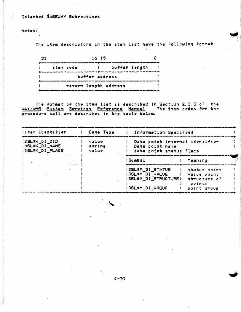
Selected BASEWAY Subroutines
Notes:
The item ·descriptors in the item list have the rollowing ~ormat:
31 lb 13 0
it•m code buff•~ length +---- -----~...-,.-,------+~------~-----__.--+
retu~n length add~ess
The ~a-rmat a~ .the item list is d•scribed in Section ~.3.3 or the ~cJAXiVf15 Sg~h·nr $~vit!'5 ·R9P.-r!'ntt Manual. The itii'm tod'es r~ th!' p~acedure call are de~cribed in the table below.
litem Identiflier
!ESLSK_OI_OID :aSLSK_DI_NAME : .i3 SL $1i<._D I _FLAQS
Data T~p e
value st-ring value
In~o-rmation Speci~ied
Data point internal identiriar Data point name data point status rlags
+---------~---...--~--+-------------~~-~~ ·· I S41mbol :. Mea~ing j +----.----~------------+-------------~--~~~ : BSLSM_DI_STATtJS f BSL$M_DI_VALUE
'IBSLSM_DI_STRUCTURE:
I BSL SM_O I _GROUP
4-30
status point valutt point s t-r u c ·~ 1J r a o ~ points
point gr•Jup
(
i
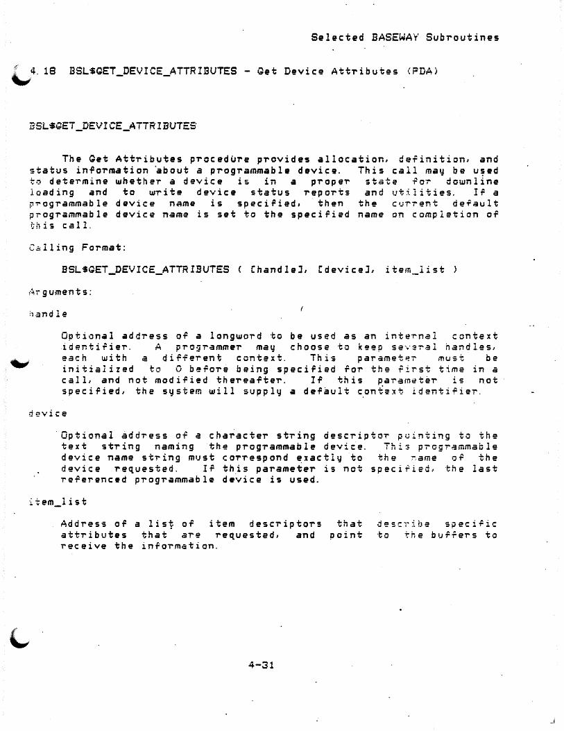
Selected BASEWAY Subroutines
'-'4. 18 BSL$GET_DEVICE_ATTRIBUTES - Get Device Attributes <FDA)
BSL$GEi_DEVICE_ATTRIBUTE5
The Get Attributes procedure provides allocation, deiinition, and status in~ormation ~bout a programmable device. This call may be u~ed to determine whether a device is in a proper state ~or downline loading and to write device status reports and utilities. I~ a p~ogrammable device name is speciried, 'then the current default programmable device name is set to the speciried name on completion o~
t:his call.
C.=illing Format:
BSL$GET_DEVICE_ATTRI.SUTES C ChandleJ, l:deviceJ, item __ list
~·~ r g um en t s :
h-and 1 e
Optional address o~ a longword to be used as an internal context identi~ier. A pro~rammer may choose to k~ep sev~ral handles, each with a different context. This parametP.~ must be initialized to 0 before being speciFied for the first time in a calL and not modi.Pied the'T'ea.Pter. Ir this parameter is not speciried, the system will supply a derault context identirier.
device
·optional address of a character string descriptor puinting to the text st'T'ing naming the programmable device. Thi$ p~ogrammable device name string must co'T'respond ~xactly to the ~ame o~ the device requested. If this parameter is not specified, the last referenced programmable device is used.
:i.tem_list
Address or a lis~ of item descriptors attributes that are requested, and receive the information.
4-31
that point
d~scribe specific to the buffers to

Selected BASEWAY Subroutine2
R::tu-rn Status:
E3L$_NOESL ~
A SASEWAY application is not currently running in this UIC group.
ESL$_NORMAL.
Service succ9ssrully completed .
.BSLS_NOSYSTEM
The programmable device do•~ not have a valid device set a5sociat•d with it.
2::L·$_PDEVOEFL T
The caller did not speci~y a programmable device na1ne and did not have a de~aul~ name set.
·The programmable devic~ that ~as speciPied does not axist.
4-3~

Sel•ct•d BASEWAY Subroutines
,;fr'
'-'Notes:
The item descriptors in the item list have the ~ollowing ~ormat:
31 16 15 0 +-----------.-----~----+------..... --------------+
item code bu~.Per length +--------------------+--------------------+
bu.P-Fei- add-ress +-----------------------------------------+
return length address +---------~-----~----~--------------------+
The rormat or the item list is desc-ribed in Section 2. 3. 3 o~ the VAX/VMS System Services Re,erence Manual. The item codes for the procedure call a~e described in the table below.
4-33
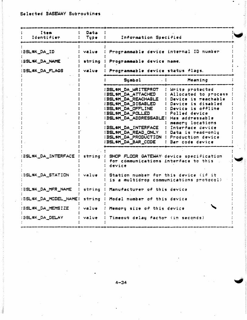
S~lected BASEWAY Subroutines
I tea Identi.Pier
Data Type In.PoT"mation Speci.Pied
~--.--~~~---~--+-~----~-+---------------------------------------------------+
: .BSLSi.<._DA_ID
tBSL.~_DA_NAME
lBSLSl'._DA_FLAQS
:ESL$K_OA_INTERFACE
iBSL$~_DA_STATION
1BSLSK_OA_MFR_NAME
iESLS~_DA_MODEL_NAME
i BSLSl'._DA_DELAY
I
' ,. ' I I
value
st-ring
value
P'rog,-ammable device inteT"nal ID number
P-re9-raaua•bl• d•'li c. nant.e. I
' Pi-og,..ammabl• device status .Plags.
+------~-----.-i.._...._~~---...,,_----~-------~--+ Sqmb.ol I
- I Meaning +••• --------~---~------....-_._,------------+
BSL$M_DA_WRITEPROT SSL $M_DA_A TT ACHED BSLSM_DA_REACHADL.E BSLSM_DA_DISABLED BSLSM_DA_OFFLINE BSLSM_DA_POLLED BSLSM_DA_ADDRESSABLE
:BSLSM_DA_INTERFACE IBSLSM_DA_R~D_ONLY lBSLSM_DA_PRODUCTION IBSLSM_DA_SAR_CODE
' Writ~ protectad Allocated to p~oC&$~ Device is reachable Device is disabled Device is o.P.Pline Polled device Has addressable memor•~ location9 In·f;er.Pace device Data is read-only Production device Ba-r code device
+ ---~-------:---+-~-~-------------~-----+
st'ring ·: SHOP FLOOR GATEWAY· device s·peciPication lor c~mmun~cations inte-r,ace to this device
value Station numbei"' ~or this device ( i ~ it is a multi drop communications p-rotocol)
sti-ing Manufacturer o.P this device
st,-ing I Model number o.P this device
value Memor~ size o~ this device
value Timeout dela~ ~actor \in sec~ndsi
+----------------~---+---------..--.~------------~----------------------------+
4-34

S•lected BASEWAY SubToutines
'-":·--------------------+--------+-------------------------------------------+ , . I I I I I · I
.&SL$_~_DA_LOCATION ' stTing l Location desc~iption stTing
iESL$K_DA_DESCRIPTICN stTing
:BSL$K_DA_CONTRACTOR stTing
:BSLSK_DA_NET_NAME 1t~ing
iBSL$~_DA_DEVICE_SET stTing
:BSL$K_DA_GATEWAY stTing
I
Device. d&scTiption stTing
ContTacto~ desc~iption stTing
Communications Network name
Device set associated with this device
Gateway cu~rently communicating with this device
+-~-------------------+----~---+--------------~-------------------------~-----+
4-35

Sel1ct1d BASEWAY Subroutin•s
4. 19 BSLSGET_SESSION_INFO - Retrieve Cur-rent Session In~o-rmation
BSL$GET_SESSION_INFO
Th• G•t Seision Information procedure provides in~ormation about the cu-rrent ta-rminal session. Inform•ti~n available includes cu-r-rent privilege~, default menu forms, de~ault p-rinte-rs, etc.
· This procedure m•y. onl~ be called in the context OT an interactive process.
Calling Format:
BSLSQET_SESSION_INFC item_list
A-r-guments:
item_list
Address 0¥ a list o9 item descriptors att-ribute~ that are r•que~ted, and receive ~ne inTormation.
Ri?t•J-rn Status:
fiSL·$ _NCESL
that point
desc-ribe speciric to the bu~~ers to
A BASEWAY application is not cu-rrently running in this UIC group.
ESL$_NORMAL
Service succ9ssrully completed.
4-36

Selected BASEWAY Subroutines
The item descriptors in the item list have the ~allowing ~ormat:
31 16 1~ 0 +----------------~----+--------------.--------+
item code burfer length +---~---------------+---------------------+
burrer address +---.---"-----------~----------------------+
return length address +~---------~--------------------------------+
The ~ormat of the item list is described in Section 2.3. 3 or the VAX/VMS System Services RefeTence Manual. The item codes foT the p~ocedvre call are described in the table below.
4-37
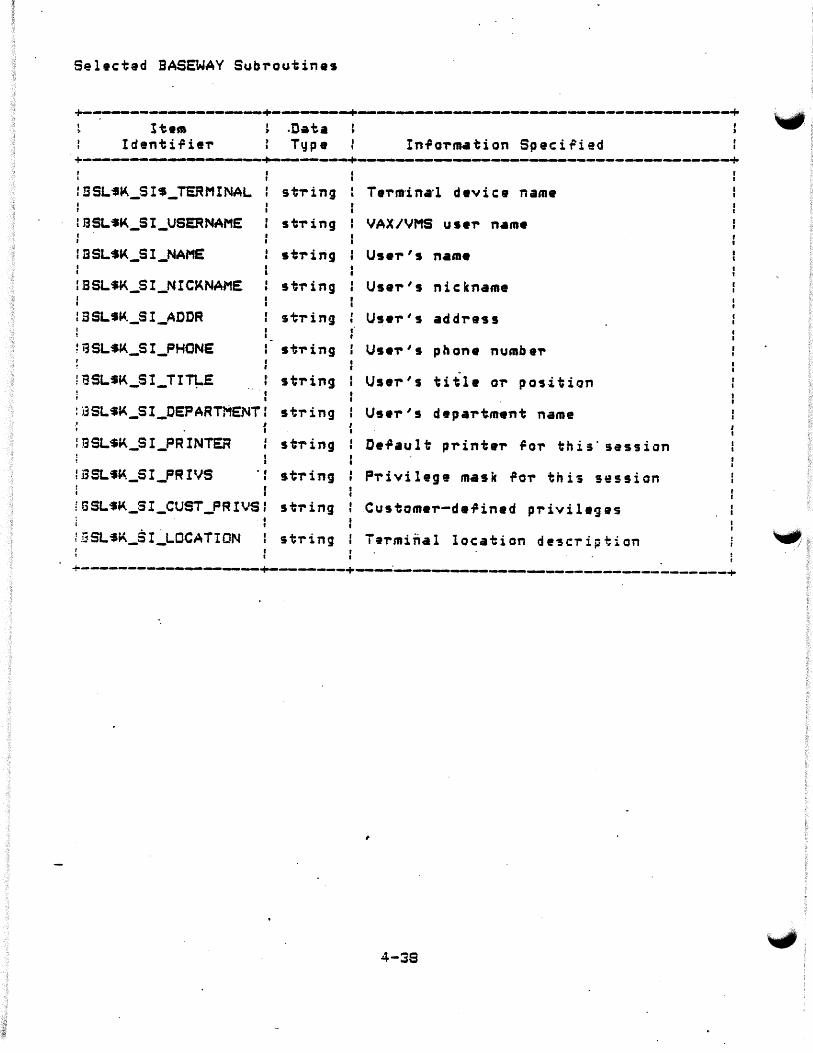
Sel•cted BASEWAY Subroutines
+---------~~----~+---,_,_--~ ________ ,__ _______ _.._ ____ ~---------------~-.+ ltwm
Identirier Information SpeciFied ·+-.-.-.------.-~----~---+.----~~-~------.-------------~._... ______ ..._ _____ _._~ SSLSa.<._SI~_TERMINAL st-ring
SSLSK_SI_USERNAME st-ring
BSL•a.<._SI_NAME string
BSL$K_SI_NIC~NAME string
: BSLSli<._SI_ADDR string
: i3SLS~_S I_PHONE st-ring
l i3SLSK_SI_TI11-E string
:BSL$K_SI_OEPARTMENT: string
:GSL$~_SI_PRINTER : string • I
lBSL,f-(_SI_PRIVS . : st-ring I I
fuSLSK_SI_CUST_PRIVS: string
iBSL$~_SI_LOCAT!ON string
Term·inarl davic:e name
VAX/VMS user n•m•
Use,-'s nickname
User's address
User's phone numbe,.
User's title or position
User's depar~ment name
P-rivilege mask ror this session
Customer-de~ined privileges
ierminal location de~cTiption
+---------~----_... ..... .___._ ___ ,_ __ +------·--------------...-------------~-----------+
4-39
~ I

Select•d BASEWAY Subroutines
\..; 4. 20 BSLSGET _SYSTEM_! NFO - G_e t System At t'I' i Ii u te s
BSL$GET_SYSTEM_INFO
The Get System Information procedure provides de.Pinition status information about an application, device set, or a gateway.
and
The system may be selected b~ specifying either a NAX or a system name. I-f neithei- are specified, then the curT'ent ap,plication 's .att-ributes are T"eturned. Ir a system name of '*' i~ speciried, then a wildcaT'd lookup is performed, and each successive call returns another system until the status code BSL$_NOSYSTEM is r•turned.
Ca 11 in g Format:
BSLSGET SYSTEM_INFO < CnaxJ, CnameJ, item_list>
A-:-guments:
name
Optional address o~ a word that contains a system internal identifie-r.
Optional address of a character string descriptor pointing to the t e x. t s t -r i n g n am i n g th e a p p l i c at i on , d ev i c e s e t , or g a t e wa y .
i ·~em_! i st
Add-ress of .a list of item desc-riptq-rs attributes ·that are r-equested, and receive the inrormation.
4-39
that point
describe speciric to the bu~Te~s ~o
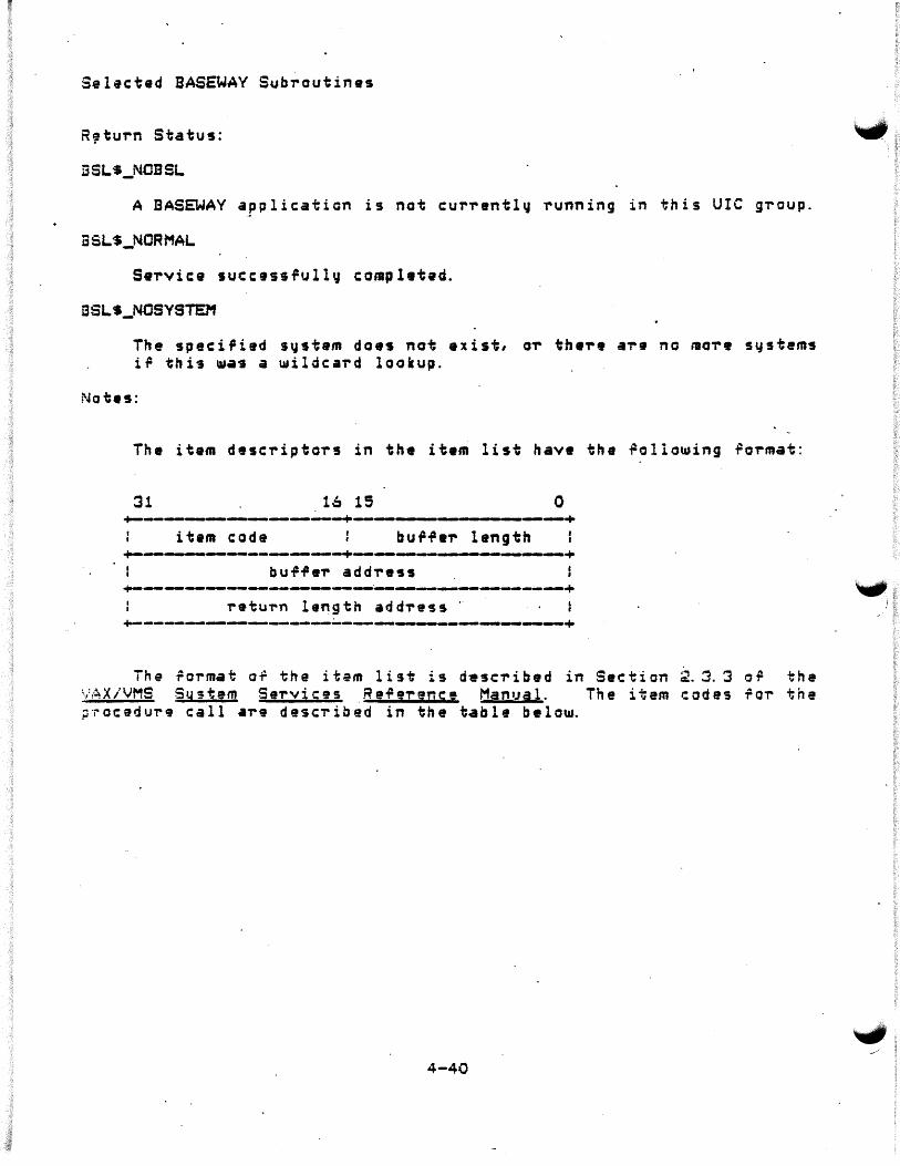
Selacted BASEWAY Subroutines
ESL$_NOBSL
A BASEWAY application is not c:uri-ently running in this UIC gi-oup.
BSL'S_NORMAL
i3SLS_NOSYSTEM
The speciPied system does not exist, o~ th•,.• a,-e no mo,.e systems ir this ~•s a wildcard lookup.
The item desci-iptors in the item list have the ~allowing roi-mat:
16 13 0
+---------+----------,--+ item c:ode bu 9.Pa,. length +----~--------------+---------,__----------+ bu.P.Pe,. add,.ess +-----------------------_,__. _ __, ______ .__ ______ +
retui-n length add,.ess ·· +-----.-----_._ ____ ._ ____ ~------------~--------+
The ~ormat of the itam list is d9sci-ibed in Section 2. 3. 3 0¥ the ;.,:,~X/VMS System SeT'ViC9S .. Re.Pe-rence MantJal. The item codes rOT" the ~~ocedure call are descT"ibed in the table belo~
4-40

Selected BASEWAY Subroutines
A'
:~, ·,&.---------------------+--------+--------------------------------------+ ~ Item : Data : . . l
IdentiTier Type In~o~mation Specified +--------------------+--------+--------------------------------------+ :BSL$1o<._AI ID value -~ BSL'S~._AI_NAME st1"ing
iBSLSK _AI _FLAGS value
r I
System internal identifier number I I
I I
System name I • I I
Sy stem stcttus .Plags +---~----....--..-.--------+----------------+
S4'mbol Meaning +----------------------+----------------+ f BSL$M_AI_APPLICATION :aSL$M_AI_DEVICE5£T f BSLSM_AI_GATEWAY
:BSL$M_AI_REACHABLE
Application Devic~ Set SHOP FLOOR GATEWAY sy s·bam Reachable
+-------~-------~----+----------------+
iBSL$K_AI_DESCRIPTION: string : system description
~--------------------+--~------+---~-------------------------~-------+
4-41
,l

Selected BASEWAY Subroutine~
4. 21 BSLSLOQ_EVENT - Log a S~stem Event in Histo'T'q File
ESL'SLOG_E'iENT
Th• Leg Ever.t procedur• is • user-callable ro~tinc to ~rite •n cntr~ to the system audit racilitq. This p'T'ocedu'T'e accepts a fo'T'matted ASCII text st'T'ing. rT"om the call•'T' and sends a message to the EVENT_LOQ pT"ocess. Oep•nding on speci-Fied flags, the text st-ring maCI be logged in the S~stem Audit rile, t11~itten to OPER terminals, or both.
Calling Format:
BSLSLOG_EVENT C code, flags, text >
Arguments:
.:ode
~lags
Address o.P a. longt11o'T'd containing a bit usk o.P event codes -foithis event. The following event codes ma~ be p~esent in any combination:
BSLSM_eT_sysTEM BSL·sM_ET _~:cfqFIG BSL'SM_ET_NETWOR~ ·asL-sM_ET _GAT~wAY BSLSM_ET_PD
.SSL-SM_ET _lJSER BSL$M_ET _DATA BSLSM_ET_APFL
9~ st.em-re lated event - ~:an H gurati wn •"'·•n"t - Net.U1or k event - SHOP· FLOOR GATEWAY event - P~ogTammable Device event - Use~-related event - Data exception event - Application-~peciric event ·
Address or a long~ord containing rlags ror this event. ~allowing rlags may be pT"e~ent:
6SL$M_EF_FILE - A•Jdit event in file BSL$M_EF_OPER - P~int event on OPER terminals
4 ·-~c:
The .

Sel•ct•d BASEWAY Subroutines
Address of a descriptoT pointing to a characteT string containing an event description. This character string may be up to 1~0 b~tes in length, and may contain an~ printable characters. If multiple lines aTe desiTed, embedded caTTiage return/linefeeds may be included.
Return Status:
BSL$_NOBSL
A BASEWAY application is not cuTrently running in this UIC group.
ESLS_NORMAL
Normal successlul completion.
BSL$_NOPORT
The Event LoggeT message port CEVENT_LOG> does not exist in the cuTrent application.
4-43

Selec:ted BASEWAY Subroutines
4. ~ BSLSREAD_DEVICE_DATA - Read Data from a Programmable Device ~ <PDA> -...,
BSLSREAD_OEVICE_DATA
The Read Data procedure allows a caller to peT"form a logical data read ,,..cun an" address of • programmable d•vic:•. If a programmable d•vi~•·nam• is sp•'i~i~d, t~wn th• tui-,.•n~·d•r~ult·progTam&able devi~• nam• is set ta the sp•ciri•d name on completion of this call.
Galling FoT"mat:
BSLSREAD_DEVICE_OATA < ChandleJ, Cdevic:•J, address, count, buf.Pe-r >
Ai~ g ument s:
Optional address OT a longword to be used as an internal context identifier. A pT"ogrammer m•'l choose to keep several handles, eac:h t11ith a different context. This paramete,.. must be initiali:ad to 0 befor• being specified for the first time in a call, and ·not modified· the,.eafter. If . th is parameteT' is not ""11; specified,_ the Stjs.tem U1ill suppl" a de-fault con.t~xt identiT=ier. ../
dt?vice
Optional addTess of a characteT st~ing descT"iptoT pointing to the text st,.ing naming the progTammabla device. This progTammaole device name stTing must corTe~pond exactly to the name o~ the device req,uestad. I~ this paTametar is not spec:iried, the las·t re~eTenced pTogrammable device is used.
addT'9SS
AddT"ass or a chaTacter string descriptor pointing to the text st~ing containing a valid prog,.ammable device address.
4-44

Selected BASEWAY Sub~outines
Address or a word that contains the amount or data to be read. For example, ir the address specified re.Pers to individual bits, or coils, then the count is the number of bits. I~ the address specified refers to a 16-bit word, then the count is the number or words. Upon completion o.P this call, this parameter is updated to re.Pleet the amount o.P data that is actually returned i n th e b u .P .Per·.
iJ 1_1 r r eT
Address. o.P· a bur.Per. where the programmable device data should be stored. ·rt is up to the caller to insure that this bur.Per is large enough to contain the resulting data.
Re tuT'n Status:
BSLS_NOBSL
A BASEWAY application is not currently running in this UIC group.
l3SL$_NORMAL
Service successfully completed .
.....,. "'L$_NOSYSTEM
The programmable device does n~t have a valid device set associated with it.
BSL$_NOTSUPPORTED
The programmable device does not support this function.
BSLS_PDEVDEFLT
The caller did not.speci.Py -a programmable device name and did not have a default name set.
ESLS_NOPDEV
Th~ p~ogrammable device that was specified does not exist.
BSL$_ATTACHED
The programmable device is currently allocated to process.
. BSL$_BADADDR
4-45
another
_ _;

Selected BASEWAV Subroutin•s
The add,-ess spaeiried in the "ADDRESS" paramete,- has an illegal SCJntax, o,. i~ outside o-r the range o~ valid add,-esses ~or this ·"'1/1 prog,-ammable device .
•
4-46
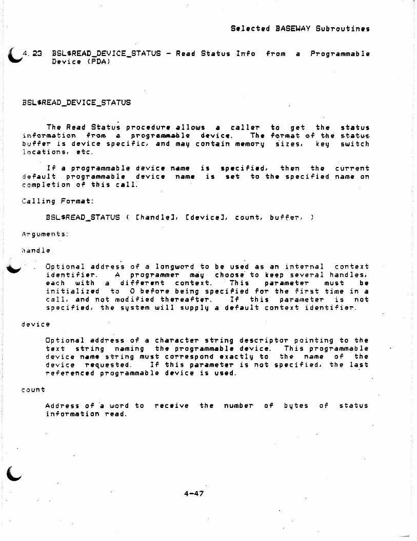
Se.lected BASEWAY Subroutines
BSL$READ_DEVICE_STAiUS - Read Status -In·.Po Device CPDA>
.Prom a PT'ogrammable
BSL$READ_DEVICE_STATUS
The Read Status procedure allows a caller to get the status in~~~~ati~n f~om a p~o9~a1DAaol~ d•vic•. The fo~~at ~f tne statu$ b1J.P.Per is device specific, and may contain memoT'y sizes, keCJ switch locations, etc.
If a programmable device name is d~.Pault progT'ammable device name is completion o.P this calL
specified, then the curT'ent set to the speciried name on
Calling Format:
BSL$READ_STATUS ChandleJ, CdeviceJ, count, buffei',
ilandle
"". Optional address OT a longword to be used as an internal context identi,ier. A programmer may choos~ to keep several handles, each ~ith a diffe~ent context. This paramet~r must be initialized to 0 be.Pore being speci.Pied .Por the ~irst time in a i:alL and not modified therea.PteT'. If tl:lis parameter is not speci.Pied, the system will supply a default context identifier.
device
count
Optional address of a chaT'acteT stTing ~es~riptor pointing to the text stTing naming the progTammahle device. This progTammable device n•me stTing must correspond exactly to the name or ·the device Tequested. Ir this paTameteT' is not specified, the last ~e~e~enced programmable device is used.
Address of ·a word to receive the number of bytes or status information read.
4-47

Selected·BASEWAY Subroutines
Address of a buffer ~here the programmable device statu~ data should be stored. It is up to the caller ta insure that this bu~~er is large enough to contain the resulting data.
Retu"rn Status:
BSLS_NOBSL
A BASEWAY application is not cu-rr•ntl" running in this UIC group.
ESLS_NORMAL
Service successfully compl,ted.
BSLS_NOSYSTEM
The programmable device does not have a valid device set associated ~ith it.
BSL•_NOTSUPPORTED
The programmable device do•s not support this function ..
aSLS_PDEVDEFLT
The c:all~n· did not spec:ii=·" a prcigrammable -device name, ~ot ~ave a deT~ult n~m• set.
ESL$_NOPDEV
~nd did
The programmable device that ~as specified does not exist.
BSLS_ATTACHED
ihe programmable device is currently allocated to p,.oc es~.
4-48
another
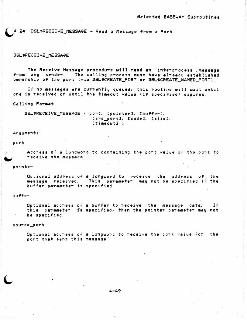
Selected BASEWAY Subroutin•s
(.,A 24· BSL$RECEIVE_MESSAGE - Read a Message -l'retm a Port
BSLSRECEIVE_MESSAGE
The Receive Message procedure will read an interprocess . message ~~om any sender. The calling process must have already established ownership o~ the port <via BSL$CREATE_PORT or BSLSCREAiE_NAMED_PORT>.
Ir no messages are currently queued, this routine will wait until one is received or until the timeout value (if speci~ied) expires.
Ca 11 in g Format :
BSL$RECEIVE_MESSAQE ( port, CpointerJ, CbufferJ, Csrc_poT'tJ, .Ccode:J, CsizeJ, l:timeoutJ >
i=~r g ument s:
port
Addi-~ss o.P a longword to conta.ining the po-rt value o-F the ,po'T"t to ~ receive the m~ssage.
pointer
Optional address o~ a longword to receive the address o~ the message received: This parameter may not be speciried i~ the buffer parameteT' is specified.
Optional address of a bu~~er to receive the message data. I~ this paramete"I' fs speci.Pied, then the pointe"I' parameteT' may not be speci.Pied.
source_p ort
Optional add'T"ess of a longword to receive the po'T"t v~lue ror the po~t that sent this message.
4-49
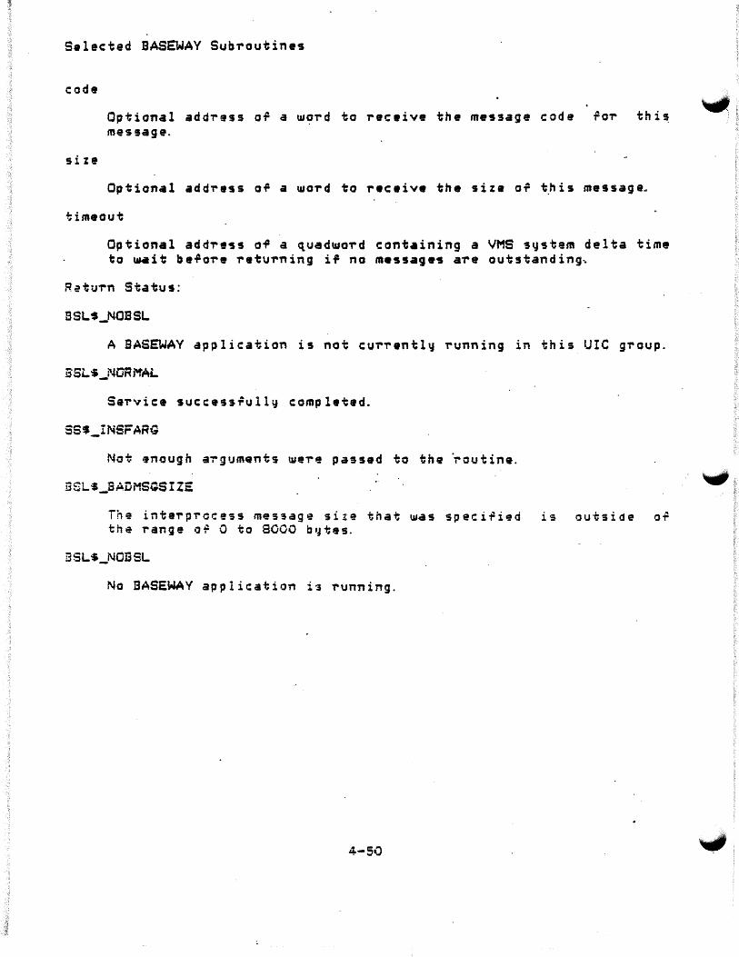
Selected BASEWAY Sub1"outines
code
size
Optional address or a word to receive the me~sage code ror this message.
Optional address o~ a word to receive the size or this message~
timeout
Optional add1"ess of a ~uadward containing a VMS system delta time to ld41it before returning if no messag•s are outstanding~
R~tu1"n Status:
BSL$_NOBSL
A BASEWAY application is not currently running in this UIC group.
Service successrully compl•ted.
SS$_INSFARG
Not 9nough a~guments we1"e passed to the ~outine.
BSL$_BADMSGSIZE
The inte1"process messag~ size that was specified is outside of the range o~ 0 to 8000 b~tas.
BSLS_NQESL
No BASEWAY application is running.
4-50

S•lected BASEWAY Subroutines
~4.25 BSL$SEND_MESSAQE - Send a Message to a Port
BSL$SEND_MESSAGE
The Send Message procedure ~ill s~nd an interprocess message to any port in the system. _The destination port value must have already he en ·found b~ cal 1 ing the BSL$ACCESS_PORT procedure.
The Send Message procedure may be passed either a pointer to. a message (created with BSL$CREATE_MESSAGE or BSL$RECEIVE_MESSAGE), or a buffer containing data to be sent.
Calling Format:
BSL$SEND_MESSAGE
:; o u r c e _p or t
Csource_portJ, Cdest_portJ, C p o int er J, Cb u ff ei- J, Cc ode J, CsizeJ )
Optional add~ess of a longword to containing a port value for a poT't that a ·resp.onse ·should be returned to. Ii! no response is requested, then no source port parameter need be supplied.
dest_po-rt
Optional address of a longword to containing the port value of the port that this message is to be sent to. This parameter is required unless a pointer to a message that already contains a destination port is passed.
pointer
Optional address o.P a longword that contains the address o~ a message to be sent. This parameter may not be speci~ied i~ the
- bu.Prer parameter is specified .
.)
Optional add~ess of a buffe~ parameter is speci.Pied, then paTameters aTe mandatoTy.
o-F data to the code,
4-51
be sent. dest_p ort,
I~ and
this size

Selected BASEWAY Subroutines
code
size
Optional add~egs o~ a wo~d that contains the message code fo-r th i 1 message.
Optional add-ress of a ~o~d containing the siz• o.P this message.
Return. Status:
BSL$_NOBSL
A 5ASEWAY application is not cu~r•ntly running in this UIC group.
SSL·S_NORMAL
Se~vice successiully completed.
SS$_INSFARQ
Not enough a~gyments were passed t~ the routine .
.6SLS_l3ADMSOSIZE
The inte-rprocass message siz'e that u.as specified is outside o.P the range o~ 0 to 8000 byt·~·
No BASEWAY application is ~unning.
4-5;?
...,,,, _)

\..,.4. 26 BSL$SET_DEVICE_ATTRIBUTES -<PDA>
Change
S•lect•d BASEWAY SubT'outines
cu,..T'ent Device Att"ributes
BSLSSET_DEVICE_A~TRIBUTES
The Sat AttT'ibutes pT'oceduT'e pT'ovides a method or setting definition and status inroT'mation roT' a speciried pT'ogTammable device. This call may be used in writing system status utilities. Ir a prog"rammable device name is speciried, then the cuT'rent de~ault programmable device ·name is set to the speciried name on completion or this call.
Calling Fa-rmat:
BSL$SET DEVICE_ATTRIBUTES < C:handleJ, CdeviceJ, item_list
handle
Optional address ol a longword to be used as an internal context identirie,... .A. programme,.. may choose to keep sev~ral handles, each with a di.P.Per~nt context. Thi·s pararpeter must be initi~lized to 0 berore being speciried ror the ~irst time in a calL and not modi~ied theT'earter. · Ir this p-arameter is not speciried, the system will supply a de~ault context identifie,...
aevice·
Optional address of a character st~ing descripto~ pointing to the text st,..ing naming the programmable device. This p~ogrammabl~ device name st~ing must coT'respond exactly to the name o.P the device ~equested. If this p~T'ameter is not speciried, the last re.Perenced programmable device is used.
item_list
Address or a list of item descriptors that attributes that are requested, and point receive the information.
4-53
des~ribe speci~ic to the buffers to

Sel•cted B~SEWAV Sub~outines
Retu..-n Status:
BSLS_NCBSL
A BASEWAY application is not currently rµnning in this UIC group.
BSL$_NCRMAL
S•rvice succ•sslull~ completed.
BSLS_NOSYSTEM
Th• p~og~ammable device does not have • valid device set associated ~ith it.
t3SLS_POEVDEFL.T
The caller did not speci~~ a p~ogrammable device name, and did not hav• a de,ault name set.
ESL$_NCPDEV
•
4-54

Selected BASEWAY Subroutines
The item 4escripto~s in the item list have the 'allowing ,o,..mat:
31 16 15 0
+---------------------+-----------------------+ I . I item code buffeT' length +---_._ __ _,_, _____ ~-----+--------------~---+
bu.PfeT' add-ress +----~-----~--------~------~--------------+
-retuT'n length address +----------~-------------------------------+
The ,o,..mat ·of the item list is descT'ibed in Section 2.3.3 of the VAX/VMS Sustem Se-rvices Refe-rence Manual. The item codes ~Oi' the procedu"re call are.desc-ribed in the table below.
4-55
_ _J
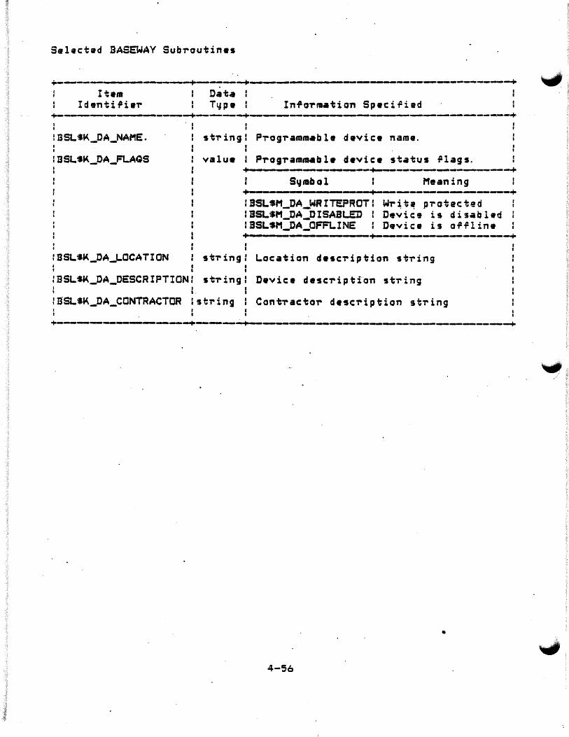
Selected BASEWAY Subroutines
.-.~---- -----------.-+--------+-------~------------------------------------+ Item
I d en t i 9 i .,. Data I Typ• I InfoTmation SpaciTied
~ ----- ----------+...._,----.--+-------.~----- ---- __ ._...__._._--..-.-~--~ !BSLSK_DA_NAME.
: BSLSK_DA_FLAQS
. I I
I st'ring I P"rog'rammable device name. I
valu• I Program.a.bl• d•vic• st~tus ~lags.
+- - ------~~--~------.-.------_,_-+ s-.nabol Meaning +---------- a I ----------------------+ IBSL•M_DA_WRITEPROTI WT~~~ p'rotacted
:BSL$M_DA_DISABL.ED Device is disabled i IBSLSM_DA_OFF1..INE Device is OTfline •+-·------···------------·------+------------..----~-----+
st'ring ~ocation desc"ription string
:BSL•a.<._OA_DESCRIPTION: stT"ing Device description stTing I ..
:SSLS&i<._DA_CONTRACTOR lstring ContT"actor description st'ring
•
4-56

Selected BASEWAY Subroutines
BSLSSLEEP - Sleep for Speci~ied Time Interval
BSLSSl:-EE?
This procedure will suspend the process execution ror the speciried amount of time. This procedure ma~ be useful ror dynamic terminal displa~s, where the program must pause ~or n seconds between ,...~rT·esh&s.
The specified time interval is expected ta be a valid ASCII delta time, as specified in the description of the SYS$BINTIM system service ca 11.
Calling Format:
BSL$SLEEP <ascii_time)
A'l"guments:
~scii_time
Address of a descripto~ pointing to a character string containing a valid VAX/VMS delta time.
Return Status:
BSL$_NORMAL
Service successfully completes.
4-57

Selected BASEWAY Subroutin•s
4.~9 SSLSSTART_OEVICE - Start a Programmable Device CPDA>
BSL$START_DEVICE
Th• Start Devjc• procedure provid•s a programmable d•vice that is currentl~ stopped. a~t•r downlin• loading a n•~ programmable device maintenance, et~.
means of starting ·a This may be necessary
program, performing
Some programmable devic•s, such as bar ae-rfo'rm this function. In those cases,
code readers, may not an e'rro-r status return OT
BSLS_NOTSUPPORTED is retu'rned.
Calling Format:
SSLSSTART_DEVICE < ChandleJ, Cdevic•l >
Arguments:
handle
Optional addre95 OT a long~ord to be used as an internal context identifier. A programme-r. may choose to keep .several handles, each with a di .P;te,.ent conte~t·. Th is parameteT' must be """" initiali:ed to 0 before bein~ specified for the ¥irst time in a calL and not modi.Pied the,.eafter. If this parame·te,- is not specified, the sy~tem ~ill supply a default context identi~ier.
Optional add~e~s o~ a characte,. 9t'ring descripto~ pointing to the taxt string naming the p~ogrammable device. This p~ogrammabla device name st~ing must co~~espond exactly to the name ot the device requested. If this pa~ameter is not speciried, the last ~efe-renced programmable device is used.

Selected BASEWAY Subroutines
(.,,.Return Status:
JL$_NOBSL
~
A BASEWAY appl~cation is not currently run~ing in this UIC group.
BSL$_NORMAL
Service successrully completed.
ESLS_NOSVS.TEM
The programmable device does not have a valid device set associated with it.
BSL$_NOTSUPPORTED
The programmable device does n~t support this function.
BSL$_PDEVDEFLT
The caller did not specify a programmable device name, not have a default name set.
BSLS_NOPDEV
and did
The programmabl.e device ~ha·t. was specified does· not exist.
~SL$_NOTSUPPORTED
The programmable d&vice that was specified does not support this op er a t i. on.
ESL$_ATTACHED
The programmable device is currently alloca~ed to . process.
'
4-59
anothe-r
. .

Selected BASEWAY Subroutines
4. ~9 BSL$STOP_OEVICE - Stop a Programmable Devic:e <POA>
BSLSSTOP DEVICE . -The Stop Device pToceduTe pr~vides a means o~ stopping a
programmabl• controll•r. Thi~ ma~ be n•cessary 'OT downline loading a new programm•ble device program, maint•n•nca, ate.
Some programmable devic:es, such as bar perform tnis function. In thosa casas, BSLS_NOTSUPPORTED is T"eturned.
Calling Format:
BSLiSTOP_DEvICE < ChandleJ, CdeviceJ ),
:4·" g ument s:
h'3ndle
cod• readers, ma~ not an error status return of
Optionar~address· 01'! a longword to be used as an interna1 c:ontP.xt id~nti,iar. A programmer ma~ choose to keep several handl•s, each •.11ith a d·irferent context. This. · pa-rameteT" must be initialized .·i;:J O be.Pore being. speciried ror the ~irst time in ·a """"" call, and not modi~ied thereafter. Ir this parameter is not 3p~cified, the syst~m will suppl~ a default context identifier.
Optional addre~s of a charac~e~ st~ing descriptor pointing to the te~t 5t~ing naming the programmable device. ihis p~ogrammable device name stTing must co-rrespond exactly to the name o~ the device requested. I~ this pa-ramete~ is not speci~ied, the last referenced programmable device is used.
4-60
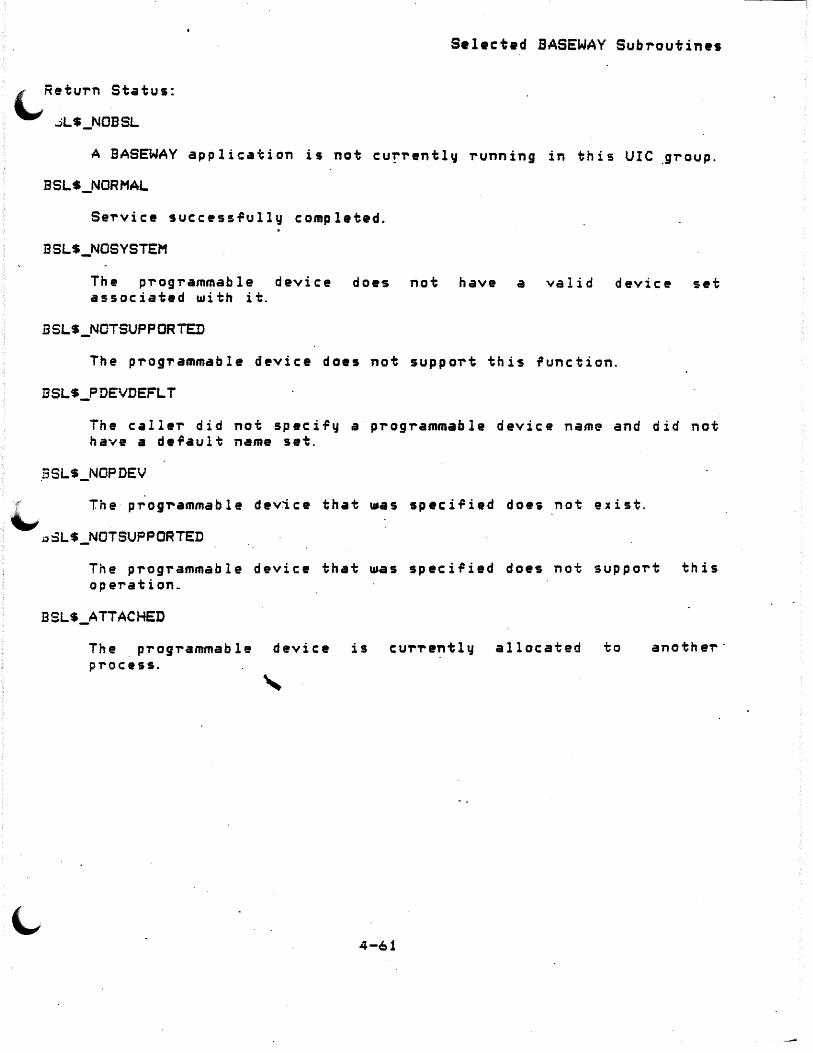
i RetuT'n Status:
""' .:iLS_NOBSL
·l,
A BASEWAY application is not cur-rently 'running in this UIC .gT'oup.
BSLS_NORMAL
Se'rvice succ•ssfully completed.
ESLS_NOSYSTEM
The pT'ogT'ammable device does not have a valid device set associated with it.
BSLS_NOTSUPPORTED
The pT'og-rammable device does not suppoT't this ,unction.
ESLS_PDEVDEFLT
The calleT' did not specify a pT'ogT'ammable device name and did not have a default name set.
BSLS_NOPDEV
The pT'og~ammable device that ~as specified does not exist.
~sLS_NOTSUPPORTED
The pT'ogT'ammable device that ~as specified does not suppoT't this opeT'ation_
BSLS_ATTACHED
The pT'ogT'ammable device is CUT'T'ently allocated to anotheT'· pT'ocess.
4-61

Selected BASEwAY Subroutin•s
4. 30 BSLSUPLOAD_DEVICE - Upload Logic frona a Programmable Device "'1/1., <PDA>
BSLSUPLOAD~DEVICE
The Upload Progranamabl• Device proc•dure provides a means of loading programmable device logic from • device into a VAX/VMS fila.
Not all programm.ble devices suppo-rt this function.
Ca 11 i ng Fo'rmat:
BSL~UPLCAD __ DEVICE < ChandleJ, CdeviceJ, filename
A·I" gument s:
handle
Optional address 0¥ a longword to b• us~d as an internal conta~t identifier. A programmer may choose to keep several handles,
· •ach with a dii=ferent context. This parameter must be initialized to 0 before being specified fo-r the fi~st time in a call, and not modified the'T'eaft.e'r. Ii' this parame.ter is not specified, the ·~~stem ~ill su~pl~ a default co~text identilier.
d~vice
Optional address of a character string descriptor pointing to the text' st-ring naming the p-rogrammable device. This prog-rammable device name st~ing must co-r~espond exactly to the name o~ the device requested. Ir this pa-ramete-r is not speci~ied, the last re¥e'T'enc:ad programmable device is used.
~ilename
Add~9$S OT a characte~ string descriptor containing a VAX/VMS ~ilename or a ~ile th•t is to contain the prog~ammable device logic ror this device.
4-6~

Selected BASEWAY Subroutin•s
Return Status:
\.... .. ;L$_NOBSL
A BASEWAY application is not c·urrently running in this UIC group.
BSLS_NORMAL
Service successfully completed.
BSLS_NOSYSTEM
The programmable device does not have a valid device set associated with it.
BSLS_NOTSUPPORTED
The programmable device does not support this function.
BSLS_PDEVDEFLT
The caller did not speci-Fy a p-rogrammable device name and did not ha~e a default name set.
BSLS_NOPDEV
The programmable device that was specified does not exist .
......,. -~LS_A·TTACHED The programmable device is currently allocated to process.
4-63
another·

Selected BASEWAY Subroutin•s
4. 31 BSLSWRITE_OEVICE_DATA - Writ• Data To a Programmable Device tJ <POA > .
BSLSWRITE_DEVICE_OATA
Th• Writ• Data procadur• allo~s a caller to ~rite data to an~ addre9s o' a prograRlftlabla d•vic•. If a programm•ble device name is specified, then th• current default programmable device name is set to the specified name on completion o.;: this call.
Calling Format:
BSLSWRITE_DEVICE_DATA < Ch•ndlaJ, Cdavic•J, addr•ss, count, buf.Per >
handle
Optional address of a long~ord to be used as an inte,..nal context identifier. A programme,.. ma~ choose to keep several handles, each· ~ith a diffe'rent context. This pa,.amete,.. must be initialized to 0 before being speciried for the rirst time in a """' call, and not modified thereaf~~,... If this parameter is not $pec{fied, the s~stem ~ill supply a default conte~t identifier. . . . .
device
Optional address o-F a· cha-racter string descripto-r pointing to the text sti-ing naming the ?rog'rammable device. This p~og-rammable device name. string must co'r-respond exactly to the name o.P the device requested. If this parameter is not speci~iedJ the last ~eTerenced p~og'rammable device is us•d.
Address o~ a charactar st-ring descriptor pointing to the text st,.ing containing a valid prog~ammable device ad~res$ .
•
4-64

~ count
Addres• or a word that contains the •mount or data to be written. For example, ir the address specified rerers to individual bits, or coils, then count is the number of bits to write. I~ the address speciried refers to 16-bit words, then count is the number of words to write.
Address of a burfer where the programm•ble device data is stored. It is up to the caller to,insure t~at this buffer contains enough data to rulfill the write request.
Retui-n Status:
ESLS_NOBSL
A ~ASEWAY application is not currently running in this UlC group.
BSL$_NCRMAL
Servic~ successfully completed.
BSL$_NOSYSTEM
Th e · . pro gr a mm ab 1 e d e vi c· e d o es · not have a v a l i d. d e vi c: e set associated with it.
BSLS_NOTSUPPORTED
The programmable device does not support this function.
BSLS_PDEVDEFLT
The caller did not specify a progi-ammable device name and did not have a default name set.
BSLS_NOPDEV
The programmable device that was specified does not exist.
BSL$_ATTACHED
The programmable device is currently allocated to process.
BSL$_BADADDR
another
The address s·peciried in the "ADDRESS" paramete-r has an illegal syntax, o~ is outside of the ~ange of valid add~esses Tor this
4-65
Selactad BASEWAY Sub~outinas
4-66
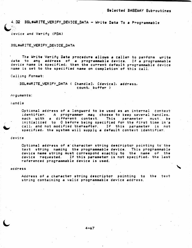
Select•d BASEWAY Subroutines
Write Data To a Programmable
Device and Veri~y <PDA>
BSLSWRITE_VERIFY_DEVICE_DATA
The Writ• Veriry D•ta procedure allows a c:all•r to perrorm write data to any •ddress of a programmable device. I~ a programmable device name is speci~ied, then the current de~ault programmable device name is set to the speciPied name on completion'of this ~all.
Calling Format:
·BSLSWRITE_VERIFY_DATA
l:.r-guments:
handle
C:handleJ, Cdevic:eJ, address, count, bu ilf er >
Optional address of a long~ord to be used as an internal context i d en t i ,C i er . A p T' o gramme r ma y c: h o o s e to k e e p s. ever a l h an d l e s , each with a dir~erent context. This parameter must. be i·niti'alized to 0 before being speciried for th~ .Pirst time in ·a call, and not modified theTeafter. If this parameter is not specified, the system will supp~y a default context identifier.
device
Optional addTess of a·cnaracter string descriptor pointing to· tne text string naming the progi-ammable device. This programmable device name st~ing must cor'respond exactly to the name OT the device requested. If this parameter is not speciried, the last referenced programmable device is used. ·
address
AddTess of a cha~acte'r st-ring desc~iptor pointing to the text string containing a valid progi-ammable device address.
4-67

Selected BASEWAY Subroutines
count
Addr-.ss of a word that contains the amount of data to be u.ritten. For example, i~ the address specified rerers to individual bits, or coils, then count is the number of bits to wr1~e. I~ the address specif'"ied refers to 16-bit u.oT'ds, then count is the number of U1ards to U1rite.
Address oil a bui=fer U1he-r• the programmable d•vice data is stored. It is up to the caller to insure that this buffer contains enough data to ~ul~ill the U1rit• rvqu•st.
R01turn Status:
ESL~_NOBSL
A BASEWAY application is not currently running in this UIC group.
BSLS_NORMAL
Service s4ccessfull~ completed.
ESLt_NOSYSTEM
.The programmab~e device does not have a valid device set associated u.ith· it.
ESLS_NOTSUPPORT.ED
The programmable device does not support this ~unction.
BSL$_PDEVDEFLT
The caller did not spacifq a prog~ammable device name and did not have a default name sat.
ESL-S_NOPDEV
The programmable device that was speci~ied doe~ not elist.
BSL$_Ai7ACHED
The p-rogrammable device i$ currently allocated to process.
BSL$_l3ADADDR
another
The address speci,ied in the "ADDRESS" paramete~ has an illagal syntax, o~ is outside OT the range of valid add~esses ror this
4-68

Selactad BASEWAY Subroutin•s
programmable device.
4-69

Selactad BASEWAY Subroutines
4-iO

APPENDIX A
BASEWAY SUBROUTINE CALLS
A. 1 BASEWAY Language-Independent Notation
BASEWAY routines are invo·ked according to rules specified in the VAX Procedure Calling and Condition H•ndling St•ndard <Appendix C of the~ Run-Time Libraru Refrrence Manual>. The complete notation for describing VAX calls is documented in.Appendix Co~ the~ Guide !.g, Creating Modular Libraru Procrdures.
BASEWAY routines can be invoked as subroutines or as functions:
As·a subroutine:
CALL isLSxxx Cparameter1,pa~ameter2, ...
As a runction:
VMS_stat. ~lc.v = BSLSxxx Cparameter1,parameter2, ... )
The access t~pe, d•ta type, passing mechanism, and parameter rorm are described in the following prescribed order:
<parameter-name>.<access type><dat~ type>.<passing mec~anism~<parameter form)
A-1
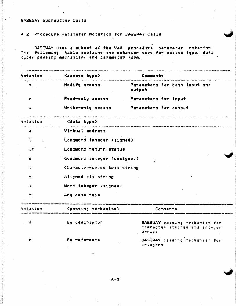
BASEWAV Subroutine Calls
A. 2 Proc~dur• Parameter Notation ,o,. SASEWAY Calls
BASEWAV uses a subset o-F the VAX procedu-re pa-rame_tei- notation. The 'allowing table explains the notatian used for access type, data t~p,, passing mechanism, and pa-rametar form.
.;J,
·---~--- -. ----------~------- . --------------------------------------~_..., Notation <access t~pe) Comm•nts
m Modi.P'J acces•
R•ad-onl~ access
Writ•-onl~ acc•ss
Parameters fo-r both input and output
Parameters for input
Param•ters for output
-----·-------------------------------------------·------------------·-----------Notation -------------------~-----~- __________ ._._._.__.__ ____ ~-----------..__.--
Virtual address
1 L.ongword int•g•r Csig~ed)
le L.ongwor.d return st"atus
Guadword integer (unsigned>
Chai-actar-coded taxt string
v Aligned bit string
Word integer (signed)
x
_.._,.._ ____________ -.-... ________ . _____________________ ~----~--~---------------~--Notation <;rass ing mechanism::· Comments -~-----------------------__,----~--~-------~-------------------------~------
d Bq desc::riptor
T' a" refeT'enc:e
A-2
BASEWAV passing mechanism ror c:hai-acte~ stTings and integer aT'ra Ids
BASEWAY passing mechanism ~o~ integeT's

BASEWAY Subroutine Calls
------------------------------------~--------------_._.,_,_--~----~-.-------------
a
x1
'-'"
Array reference or descriptor
Fixed-length or d~namic string descriptor
A-3
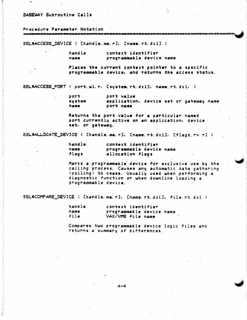
BASEWAY Sub'ro·u.ti ne Ca 11 s·
P~ocedu're Pa'rameta~ Notation · . .
------------------------=------------------=-==~---==-=:=:==-========-=--==="""-BSLSACCESS_OEVICE < Chandle.ma.rJ, Cname.rt. dx1J
handle name
context identi,ie,. p'rog,.amm•ble device name
Plac•s the cu,.,.•nt context pointe,. ta a specific p,.og,.ammable device, and retu'rns the access status.
BSLSACCESS_PORT ( po'rt.wl.r, Csqste•.rt. dxlJ, name.rt. dxl,
po,.t va.lu• application, device set or gateway name po,.t na••
Retu'rns the po,.t value fa,. a pa,.ticular named po'rt cur'rantly active on an application, device set, O'r gate..,a~.
BSLSALI..OCATE_DEVICE < Chandle.'1141-.rJ, Cname.rt. dx1J, C'lags.rv. rJ
handle name i' 1 ag s
context identiFie,. p'rog'ramm•bl• device name allocation i'lags
Marks a prog-rammabla· device .Po,. exclusive use by the calling process. Causes any automatic data gathering <polling) to cease. Usually used when perro-rming a diagnostic 'unction or ~h•n downline loading a p~og~ammable device.
BSLSCOMPARE_OEVICE ( Chand 1 e. m•. r J, Cname. rt. d x l J, rile. rt. d x 1.
handle name r i 1 e
context identirie,. prog~ammab le device nam.e VAX/VMS .Pile name
Compares t~o prog-rammable device logic files and ~etu-rns a summary o~ di~~e~ences.
A-4

BASEWAY Subroutine Calls
PT'oc:edure Parameter Notation ~,-=~===-----........ =-=-= .... -=--=-------==----==..-...----===--=== .... ====--·-=-===
BSLSCOMPILE_DEVICE_ADDRESS < Chandle.ma.r], Cnama.rt. dx1J, address.rt. dx1, comp i led. rt. d x 1 >
handle nam• address compiled
context identifier programmable device name address in .programmable device precompiled address string
Parses an address for this programmable device, and returns the pracompiled address string. Th is .string rf-ci<rr,f ~. '' is nonprintable, but maCJ be used in other r/)0 re- <Zf11 . /0 ttrrfJ
/II , I L(}115 calls in place o-F the add-ress string. ,,,~0,ca TT' J-UJ fitr1~· :JD
BSLSCREATE_MESSAQE pointer. wa. r, Csize. r•. rJ, [code. rw. rJ, Cdest_port. rl. rJ, Csourc:e_port. rl. rJ· )
pointer size code dest_port source_p oT't
address of message size of data buffer in bytes message code port value po,..t value
fttkO S .{;Jt •./. , IJfl tJ'-''':J
( u~,flJ f fan ' fa~;f~r affl~ »
f//C'. /1
Allocates space ~o,.. an interpT'ocess message, and returns a pointer to the data aT'ea or this message.
3LSCREATE_NAMED PORT ·( port. wl. 'r1 name. rt. dxl, Csize. rw. rJ, Cqueu-ed. rw. rJ, Cid. rw. i-J,
port name size queued
id
po-rt value name given to this port maximum bur~ei- that can be received maximum numbeT' o.P messages .that can be queued to this poT't. identi.Pication numbei- (64-127)
Allacates a pe,..manent message port, associates the given name ~ith it, and assigns it to the calling process.
A-5

BASEWAV Sub-routine Calls
P-ra·cedu-re Pa-ramete,. Notation . .. .. Jf1 -
---------------------------------------------------=-=-=-==-=-===-===---=-=-=-=~. • I . .
ESLSCREATE_PORT < poi-t. 1.111. ,.., Csize. i-w. rJ, Cq_ueued. rw. rJ,
pol't size queued
po-rt value maximum buffe..- that c:an be received m•ximum numbe"r of messages that can be queued to this po..-t
Allocates a tempo..-ar~ message port and assigns it to the calling process.
BSLSCVT_MX_DX < src_desc.rx. dxl, d•st_desc.~x. dxl, dest_len.w~.r
si-c_dasc . dest_desc dast_l en
add..-ess of m•ssaga desci-iptor add..-ess OT VAX data desc,..ipto..size of resulting value
Converts data dasci-ibed b~ si-c_desc'riptor into the data type desc:-ribed b'd dest_desc:, and copies the resulting value to the spaca described by dest_desc.
BSLSDAiA_TYPE C Chand le. ma. rJ, Cname. rt. dx.1J, add,....s. rt. dx1, type >
handle name ad·d-ress ty.pe
context identifier p-rog-rammable device name st•~ting memo~q lqc~tion addr~ss data tqpe at this address
Pa..-~e9 ~n add-ress ~or this prog-ramm•ble device, and r~turns the type code ~or the data at this add,..ess:
BSLS~_DT_BIT 1-bit a..- coil add-re9s BSLt~_DT_BVTE Byte data at this address BSLS~_DT_WORD - 16-bit wo~d data BSLS~_DT_LCNG - 3~-bit long~o..-d data
3SLSDEACCESS_DE'JICE < Chandle. ma.rl >
handle context identi~ier
Clea~~ any p-rog-rammable device conta~t previously a9sociated ~ith this handle.

BASEWAV Subroutine Calls
Procedure Parameter Notation
<..... '~------------~----... --------------------------========-=--===-=-·-----= BSLSDEALLOCATE_DEVICE < Chandle.ma.rJ, (name.rt. dx1J >
nan en: e name
con~ex~ iarn~i~ie-r programmable device name
F~ees a previously allocated programmable device, and causes normal data-gathering ~unctipns to resume i~
possible.
BSLSDELETE_MESSAQE < pointer.ma.r .>
pointer . address of message
Releases space occupied bg this m•ssage.
BSLSDELETE_PORT < port.ml.r >
port port value
Releases a message port that was assigned to the calling p-racess.
'--1 'LSDOWNLCAD_DEVICE < Chand le. ma. ,.J, (name: rt. d x 1 J, H le. rt. d x 1
handle name ~ile
context identifier programmable device name VAX/VMS file name
Loads a VAX/VMS ~ile containing device logic into a programmable device.
A-7

BASEWAY Subroutine Calls
BSLSQEi _DATA_INFO <Cid. T' 1. i- l. Cname. rt. d x 1 J, i tam_! i st. ra. r)
id nam• itam_list
data identifier code data point name pointar to aTTa~ of item descTiptors
Returns s•lect•d inform•tion about the data point to the calling program.
BSLs.GET_DEVICE_ATTRIBUTES
handle n••• itam_list
Chand la. IN. i- J, Cname. ,.t. d :c 1J1 i tem_l.i st. ra. r
context identifier programm•bla device .name pointer to arra~ of item descriptors
RetuTns selected generic attributes or the progi-ammable device to the caller.
BSLSQET_SESSION_INFO < item_list.ra.r >
itam_list point•,. to aTTa~ of item descriptors
Returns in,o+mat~on about the currant terminal session to the ealle~.
A-8
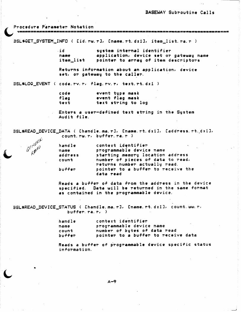
BASEWAY Subroutine Calls
.. PT'oc:edure ParameteT' Notation ~ ~-==-=-=-=i•-----====-==--=s=-....... ====-=--==....__...----===---====m========·==-==
BSL$GET_SYSTEM_INFO < Cid.rw.T'J, (name.rt. dxlJ, item_list.ra.r
ESLSLOG_EVENT
. id name itam_list
system internal identifier application, device set or gateway name pointeT' to array of item descriptors
Returns information about an application, device set, or gatewav to the caller.
code. rv. r, flag. rv. r, text. rt. dxl
code .Plag text
ev•nt type mask event .Plag mask text string to log
Enters a user-defined text string in the System Audit file.
BSLSREAD_DEVICE_DATA < Chand le. ma. rJ, C:name. rt. d x 1 J, Cad dress. rt._d x 1 J, count.rw.r, buffer.ra.r >
handle name address coun·t
buf-Fer
context id~ntifier programmable dev~ce name Jtarting memor~ locat·ion address number of pieces of data to read, returns number actually read. pointer to a buffer to receive the data read
Reads a buffeT' of data from the address in the device specified. Data uiill be returned in the same format as contained in the progT'ammable device.
BSLSREAD_DEVICE_STATUS Chandle.ma.rJ, [name.rt. dx!J, count.ww~r,
•
buffer. ra. r, >
handle name count buffer
context identif ieT' prog~ammable device name numbeT' of bytes of data read pointeT' to a buffer to receive data
Reads a buffer of ~T'OgT'ammable device specific status information .
A-9
_ _J

BASEWAV Subroutine Calls
PTocedure Para~eter Notation ~ .... ~ =-=-----·--•--------=-----m--•••-------•••mw•--=----•=--=-==-=-~=-=-==-=-====~
BSLSRECEIVE_MESSAGE C poT't.rl.r, Cpointer.ra.rJ, Cbu~fer.rx.rl, Cs-rc_po-rt. u.l. rl, Ccode. un11. rJ, Csize. \11t11. rJ,. c t i me 0 u t. ,. tt.. ,. J )
poT't pointe-r b u ff e-r src_poT't cod• Sil• timeout·
port value address of m•ssage data buffer port value m•ss•g• code size of data bufTeT' in bqtas VAX/VMS bina-r~ delta time
Reads an intaT'p-rocass message sent to tha specified poT't. If no nt•ssagas a-re pending, u.ill U1ait until timeout value expi,.es. Message m•y be refei-T'ed to by pointeT' or data bu1'1'eT'.
JSLSSEND_MESSAGE < Csrc_poT't. rl. rJ., Cdast_port. rl. rJ, Cpointe,.., ra. rJ, Cbu.Piler. rx. ,.J, Ccode. rw. rJ, Csize. rw. rJ
s,.c_port dast_po,.t pointeT' buff er ·code size
port value port valu• ad~T'ess of mes~ag• data buffer· mes s·ag e·· code si·ze of data buffer in ~ytes
Sends an interprocess message to the speci~ied port. Message may be re~erred to b~ pointer o-r data bu~fer.
ESL$SET_OEVICE_ATTRIBUTES
handle name item_Iist
Chandle. ma. -rJ1 Cname. rt. dxlJJ itam_list. ra. -r-
context identi.Pier programmable device name pointaT' to arT'a~ OT item descriptors
Allows the calling pT'ocess to set a generic attribute, such as the station number, o.P a progT'ammable device.
A-10
""" -·'
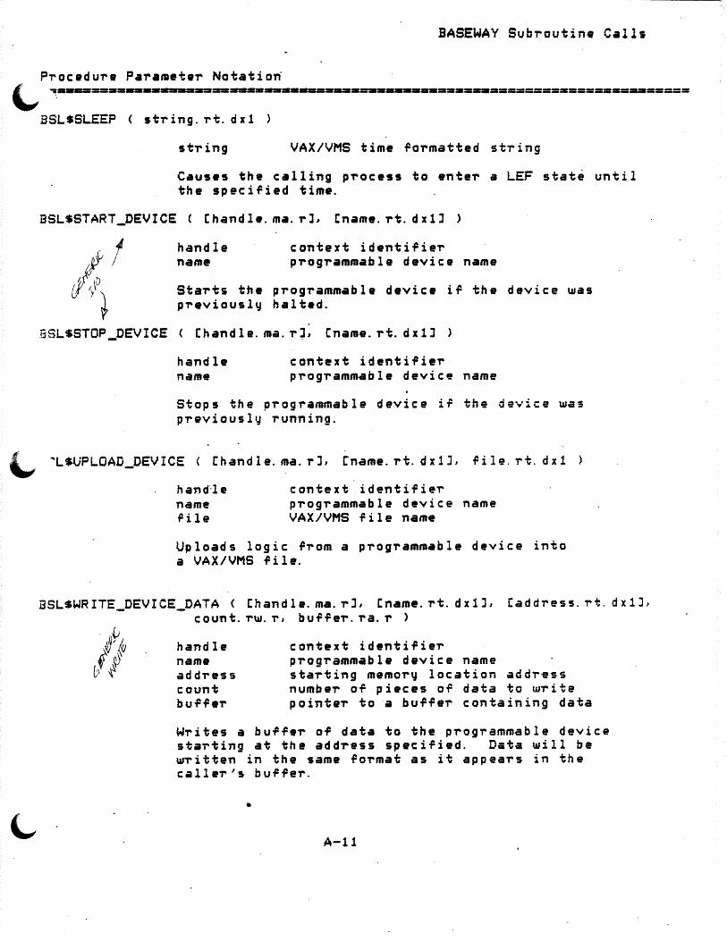
BASEWAY Subroutine Calls
Pi-ocedure Parameter Notatiori ~ ~-----=·--•--------ma--==--..,..------·=------••--•=•••=---===•========-=•===
BSL$SLEEP <string.rt. dx1 >
stT'ing VAX/VMS time rormatted string
Causes the calling process to enter a LEF stat~ until the specified time.
BSL$START_DEVICE C Chandle.ma.rJ, [name.rt. dx1J
handle name
context identifier programmable device name
Starts the programmable device ir the device was previously halted.
BSLSSTOP_DEVICE < Ehandle.ma.r~, Cname.rt. dxlJ
handle name
context identifier progT'ammable device name
Stops the programmable device if the device was previously running.
l,. ""L$UPLOAD_DEVICE < Chand 1 e. ma. r J, Cname. rt. d x 1 J, rile. i-t. d x 1
hand·-1 e name rile
context identifier programmable device name VAX/VMS file name
Uploads logic .Prom a programmable device into a VAX/VMS .Pile.
BSLSWRITE_DEVICE_DATA < Chand le. ma. rJ, [name. rt. dxlJ, Caddress. -rt. dx1J} count.rw.r, buf~eT'.ra.r >
handle name address count buffer
context identifie~ programmable device name staTting memory location addr~ss number of pieces of data to write point&T' to a buffer containing data
Writes a buffeT of data to the prog-rammable device starting at the address specified. Data will be wTitten in the same format as it appears in the caller's buffer .
•
A-11

BASEWAY Sub-routine Calls
P~ocedure Paramete-r Notation -=---=--=------=----=--------------~--·=--=-mm--=---=---=-a=m--====--=-=•-=-===-==~, BSLSWRITE_VERIFY_DEVICE_DATA < Chandle.ma.rJ, Cnama.r-t. dx1J,
Cadd-ress. i-t. dx1J, count. T"t». ,-, bu.P.Pe-r. ra. r >
handle name actdr•ss count buf .Per
context identi.Pier progTammabl• device name starting ••morv location addr•ss number o~ piac•s a.P data to •rite pointer to a bu.PfeT containing data
Writes a buffer of data to the p-rog-rammabla device starting at the address specified and ve-ri.Pies· that it ••s mritten corTectlg. Data ~ill be written in th• same .PoTm•t as it appeaTs in the calla-r's bu~.PeT.
A-12
~ I

APPENDIX. B
SHOP FLOOR QATEWAY
SHOP FLOOR GATEWAY allows a PDP-11 processor to act as a f~ont-end processor for communicating ~ith shop floor programmable d::vices. A manufacturing application built on BASEWAY can use SHOP FLOOR GATEWAY to read and write to p~ogrammable devices on the shop r l OOT'.
The QATEWAV provides the actual communications interface to shop floor devices; BASEWAY provides application program communications and control runctions. The GATEWAY offloads the automatic aata-gathering and qualification processing from the VAX processor. All necessary protocol and data conversion are also perfor~ed by the i;r:, TEWA Y.
~ GATEWAY software is downline loaded into a PDP-11 processor at s~artup using the VAX DECnet downline system load fac~lity.
Information pertinent to adding new device support is given in Appendix D of this manual.
D. 1 Features
Tne GATEWAY supports the BASEWAY programmable device access routines. These allow application programs to interact with shop rloor devices in a variety or ~a~s:
o Generic Access allows an application prog~am to perform
0
primitive functions through device-independent routines. Thes• functions include reading and writing into device addresses, starting and stopping devices, and getting device attributes.
Polled Access permits the periodically and send a when data changes.
B-1
QATEWAY to sample device data message to an application p~og~am
•
SHOP FLOOR QATEWAY
B.2 Components
TBe Net~ark InterTace component allo~s the QATEWAY to participate in the BASEWAY messaging architecture.
The Event Pi-ocessor perTarms p-rogi-ammab le devic:• data. into a application pi-agi-am.
data conversions to form•t easil~ useable
c onvei-t b!J an
The Qeneric Serv•r responds to g•n•ric device access and helps provide a generic interface to programmable conti-ollers.
The Palled Serve~ scans the pragramm•ble device point definitions and pe,..iodicall~ collects data rram pragi-ammabla devices .
.a. :J Functions
The SFQ performs the rallowing ~unctions:
o receives davice-spacific commands, acts upon them, and returns data and/or status.
o polls programmable d•vic:es as speciried in a polling database, performs certain.preprocessing m~nipulation or the polled data, and transmits ·the polled data to BASEWAY.. """"
o detects PD communicatio~ fault5 and ~otifies BASEWAY OT their oc c urr•nc: e.
o peTlorms self-diagnostic checks as ~ell as diagnostic checks. of pTog~ammable device9.
o sel~-initializes Following a bootstrap ope~ation and runs ~ithout direct operator inte~vention.
o accept'! polling con-ftigu~ation data r-rom BASEWAY ·on stai-tup and keeps a copy of the n1ast polled" data in th• palling database.
B-2

SHOP FLOOR QATEWAY
(.... B. 4 . Device Access Suppor1:e.d
Several different methods of communicating with a programmable device are supported.
B.4. 1 Direct Access
Direct access allows an application program anywhere in the network to perform logical "GIO" functions directly to the communications port. <NOTE: "GIO" functions are the RSX-11S executive directives for performing i/o to a device driver or device interface software. This permits application programs to perform device-5pecific functions that are not supported by other a~cess methods.
B.4.2 Generic Access
Generic access allows ~pplications programs to read registers, w~ite status bits, and perform other control functions. No knowledge of the protocols is required.
~ 5 Equipment Access
Equipment access allows the automatic gathering of predefined data. This data is collected in either a polled or unpolled manner. Once collected, the data is rela~ed to a~ application p~ogram.
B. 6 Types of Data Capable of Being·Polled
o Co i l s, o-r . b i t s
o Reg i st er s ,. c on ta i n i n g - bits - words
BCD - ASCII strings
B-3
•


APPENDIX C
DEVICE INTERFACE MODULES <DIMs>
C. 1 Ove'T'v i ew
Device Inte'T'~ace Modules CDIMs> contain the device-speci~ic routines to handle the actual p'T'og"rammable device communications. The ~ou'T' main "routines in a DIM and the tasks which call them a'T'e summa"rized in the table below:
+----------------------+-------~----------------+ ROUTINE CALLED BY
+-------------------+-.--------------------+ l i/o cancellation t DIRSRV, GENSRV, POLSRV : +--~---------------------+------------------------~-+ : access I ilo : DIRSRV, QENSRV, POLSRV I : initialization +----------------------+-----------------------+ l direct access re~uestf DIRSRV : p'T'ocessing +------------------------+-----------~---------------+ : gene"ric access : QENSRV, POLSRV : request processing +~---------------------+----~---------------------+
The se"rvers call the desired DIM routines by invoking the macro DIMDO$. This mac"ro sea"rches the Device Vecto'T' Table, D$VECT ~o,. the DIM ent~y table add"ress associated ~ith the inte"rface device type. The serve~ then uses the add~ess contained in that DIM entTy table at
·the offset of the "routine. The DIM sets up and executes the necessa"ry functions "requi~ed to pe"rfo"rm the desired "request.
The PD acce~s se"rvers and the DlMs pass info~mation through two data st~uctu~es: t~e Line Access Block <LAB> and the Line Cont~ol Block <LCB>. The LABs are used to maintain info"rmation related to the inte~face lines. The LCBs contain the context of se"rv~ce "request to and from the DIM. These st"ructu'T'es a"re desc"ribed in more detail in a later section.
C-1
•
Device Intar~ace Modules
Ea~h PD server task has an active LAB ~or each de~ined PD .j_ inte~~ace. When se~vice requests are ~•ceived the LCBs are queued to the cor~e9ponding LAB. The LCBs a~e dequeued as the requests are p~ocessed. The ~allowing ~igures illust~ata this interaction between the se~vers and the DIMs.
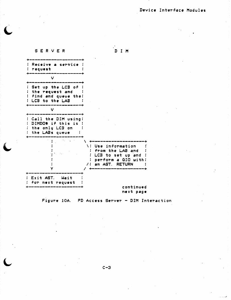
S E R V E R
+----------------~--+ f Receive a service : : request +---~--------~--------+
v +-------------------+
Set up the LCB or : the request and rind and queue the: LCB to the LAB
+-------------------+ v +-------------------+
Call the DIM using I DIMDO$ ir this is : the only LCB on the LABs queue
+-------------------+
., I
Device Interface Modules
D I M
\ +-------------------+ .. I \I Use information
rT"om the LAB- and LCB to set up ·and perform a GIO with:
/.I an AST. RETURN y
I +-------------------+ +---------------------+ f Exit AST. Wait : ror next request +-------------------+ continued
next page
Figure lOA. PD Access Server - DIM Interaction
C-3
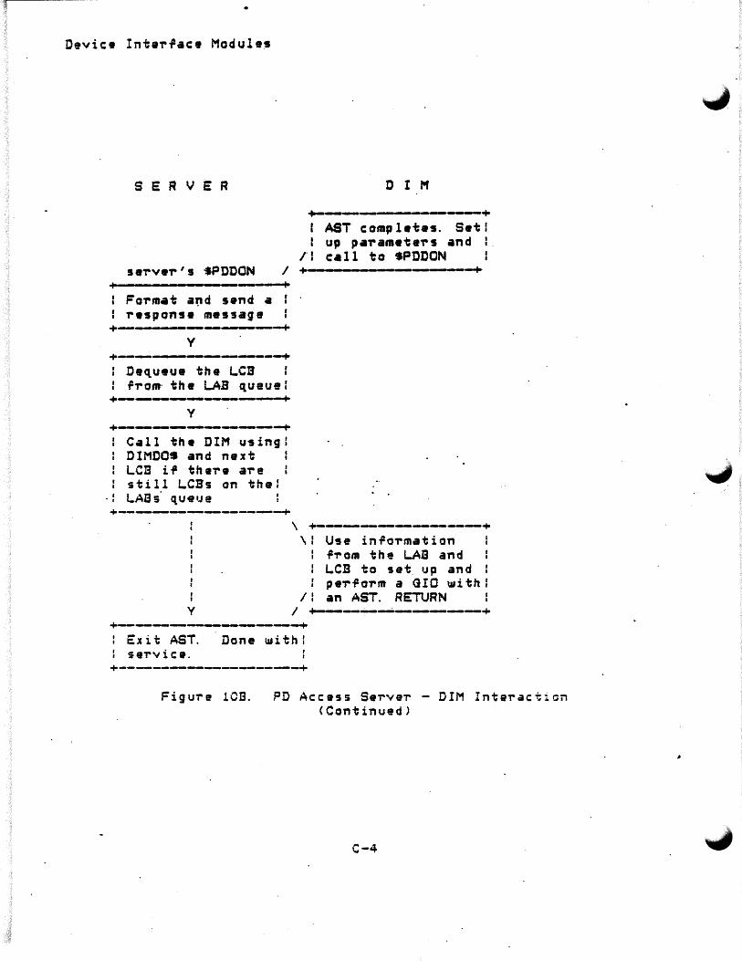
Device Inta,.~ace Modules
SERVER D I M
+-------+ AST comp! etas. Set I
l up pa-ramete-rs and I rl e•ll to •PDDON I
se'rve-r's •PDDON I +--- --- ----+ Fo'rmat a~d s•nd a -response message
+--------------------+ y
+----------+ : De~ueue the LCB : r-rom· the LAB queue: +----------+
y
+-----------------+ Call the DIM u9ingl OIMDOS and next LCB i~ the're a're still LCBs on the:
·: LAas· ~u~rne +--------~~--~---+
y
\ +-----------------+ \f U9e inro'rm•tion
.Pi- om the LAB and LCB to set. up and pe-r~orm a GIO ~ithl
1: an AST. RETURN I +-----------+
+-------------------._,-+ : Exit AST. I seTvice.
Done withl
+--.-.-~-------~-----------+
Figui-e 1CI3. PD Access Sei-veT - DIM Intei-action <Continued)
C-4
Device Inter~ace Modules
\..,C.2 DIM - PD Access Server Data StTuctuTes
The PD Access Servers use two data st-ructures to pass information to and from the DIMs. They are the Line Access Block CLAB> and the Line ContT'ol Block <LCB>. These sti-uctu-res a-re passed to the DIMs in the following manne-r. The add-ress or the LCB ~s passed to the DIM in R5; the add-ress of the LAB associated ~ith this LCB is contained in th·at LCB.
In the description of the data st-ructu-re layouts that follow, the locatio~s in the data structu-re are referred to by their symbolic offsets as defined in the co-r-responding mac-ro as shown. Then, the usage of the location is given below using a special notation:
symbol <n> .Pf Desc-ription ...
symbol - symbolic offset from macro definition
•
n - length of field in b~tes
.Pr - data .Po,-ma t, 11 BU" bi nar'J unsigned va 1 ue "BS" - binai-~ <signed) value 11 BM" b i t map p e d < i . e . .· r l a g s > "C" - coded "A 0
- ASCII
C-5

. Devic• Interface Module9
C.~. 1 Line Access Blocks <LABs)
The Line Access Blocks contain PD interface line-related information required b~ the Access server5 and the OIMs. Most o~ this in~o-rmation is copied ri-om tha Inter-race Definition ·Blocks < IBs> in VDR as the servers are started. The LAB OTf5ets are de~ined in the macro L.ABS of MACROLIB and defined as follows:
.. _ __.__ ___________________ ~ ~--·-------__,__________________ ----+
L.. Ft.AO
+--------------·------------------·----+• L.. L.CBH
L.. L.CBT
L.. IBVP +-----------------~-----~--~
L.. DEV +----------- I • W ------~-----~--+ • ·' L.. UNIT
+--------------· -----·---------------L.. POLL unused +------.------------. - .__~
I . I L.. NREG
L.. NEMR +--..-.-~._._ _____ ,__ __________________ -+ L. TERR ·
+-.--.---------------...----------------+ L.ERRL
+--.------------------------~-+
:_.FLAG<2>
L. LCBH<2>
BU The l.ogical unit assigned ta this line b':f the ~erver
:· BM The status rlag .Por the LAB 's usage Bit 0 - LF.USD This block is used
Por an interface line Bit 1 - LF.ONL This block is
associated with an ac~essible line/port
Bit 2 - LF.PND An operation is pending on this line <i.e., there is an LCB ~ueued to it>
Bit 3 - LF.POL A polling c~cle is in progress for this operation
Bit 4 - LF.DED Dead poll flag BU The ~ueue head pointer o~ the pending
LCB list
C-6
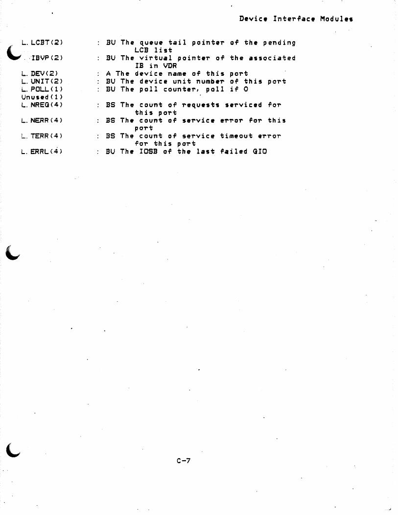
L.LCBT<2>
~. IBVPC2l
L. DEV<2> L.UNIT<2> L. POLI..< 1) •Jn used< 1 > L. NRE<H4>
L.NERR\4)
L. TERR<4>
L. ERRL\4)
Device Interface Module•
BU The queue tail pointer of the pending LCB list
BU The virtual pointe'r OT the associated IB in VDR
A The device name OT this port BU The device unit number of this port BU The poll counter, poll iT 0
BS The count OT requests se'rviced .Po-r this port
BS The count of service 9'r'rOr .Poi- this port
BS The count OT service timeout e'rror .Por this po-rt
BU The IOSB of the last .Pai led <UO
C-7

Device Inte~~ace Modules
C. 2.2 Line Cant~ol Blocks <LCBs>
The context o~ the access service request is passed to the OIMs through the Line Cont~ol Blocks. The Line Access Blocks are derined in the mac~o LCB• OT the libra~q MACROLIB and de~ined as ~allows:
+--~------------------------~-----+ + . C. IOSB +
+--------~-------~---------+ C.LCI3P +-_. ____________________ _,_ ___ --~---+ C.LAB
P--·-_._._~--~--~--.-----+ C.PBVP
+---------------+ C. SBVP
C.DBVP +------~-----------._._----------~-+
C.DBOS I I.
+----~----,__-----------~----+ C.Fl.AQ
•+----------·----------------------------·-+ C.STN +---------------------·---------------+ C.· SLAV
C.EXTN CS wards>
C.M~FR
..._.___,_,-----~--------------~---+ C. MODL
C. TRY
+-------~---------------------------+ C.SAVE < 16 wa~d s i
+------------------------------..-...-----+ C. SRVS
+~----------------------------------+ C. MADR +-------------------------------------+ C. MPNT +----~--------_._--------------+
C.MLEN +------~-------------------,_.---+
c-e
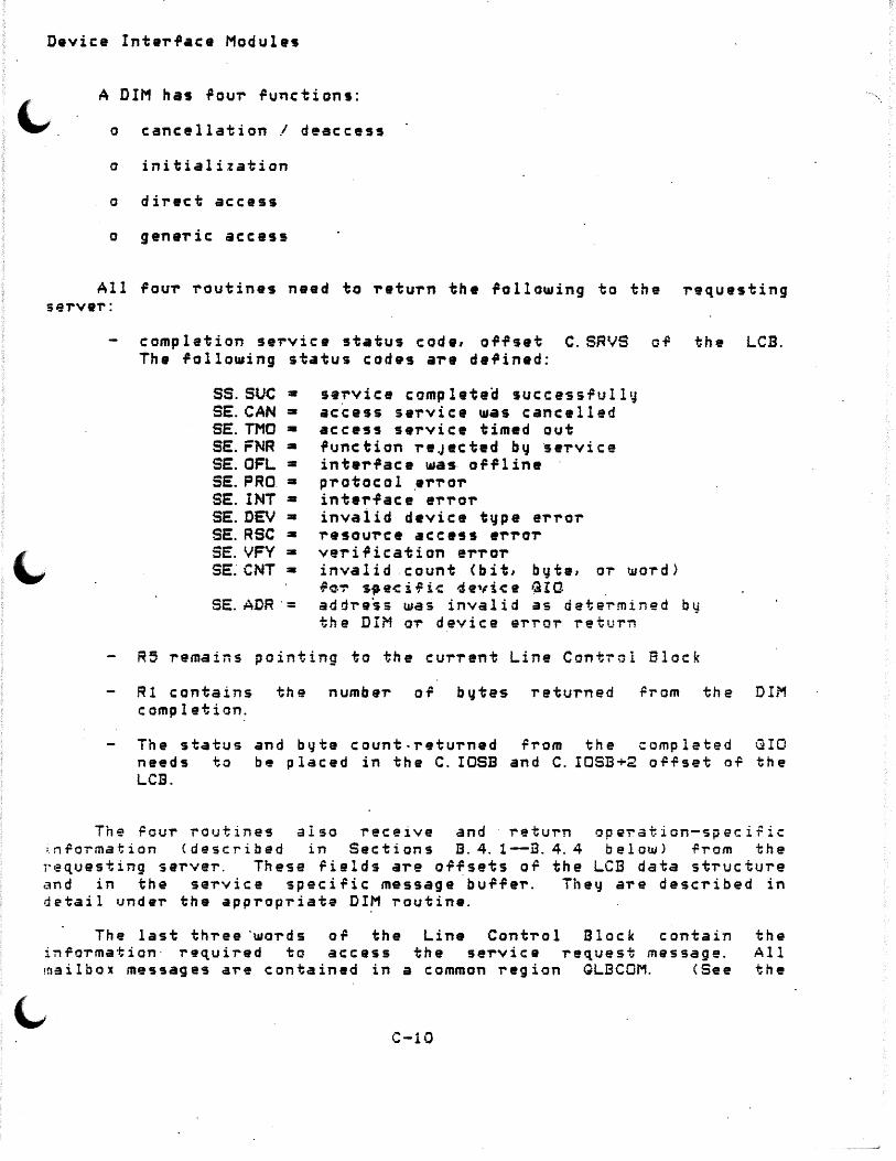
Device InteTface Module•
A DIM has ~ouT ~unctions:
o cancellation I deaccess
o initialization
o direct access
o geneTic: access
All fouT routines need to t'etuTn the following to the requesting servel':
completion service status code, offset C.SRVS of the LCB. The following status codes are defined:
ss.suc = SE.CAN=SE. THO • SE.FNR = SE.OFL = SE.PRO.• SE. INT = SE.DEV• SE.RSC• SE. VFY =SE.· CNT =
SE.ADR·=
service completea successfully access set'vice was cancelled access service timed out function reJeeted b~ ~eTvice interface wa~ orflina pi-otoc:ol eri-oT intel'face eTTOT invaiid device tvpe eTror i-esource access eTTor verification ei-ror invalid .count (bit, byte, or word) f~~ s9e~ifi~ devi~e GIC address was invalid as determined by the DIM or device error return
R5 remains pointing to the cui-rent Line Control Block
R1 contains the number of bytes returned ~rom the DIM completion.
The status and byte count-returned from the completed QIO needs to be placed in the C. IOSB and C. IOSl3+2 o.P.rset o.P the LCB.
The rour routines also receive and return operation-speciric i.n.Pormation <described in Sections B. 4. 1--:a. 4. 4 below) .Prom the requesting server. These fields ai-e offsets of the LCB data stTucture and in the sei-vice specific message buffer. They are described in detail under the appropriate DIM routine.
The last thTee ·woi-ds of the Line Conti-ol Block contain the i~foi-mation· required to access the service request message. All mailbox messages a-re contained in a common region GLECQM. <See the
c-10

C. IOSB <4> C. L.CBP<2>
C. LABC2)
C.FLAQ<2> C.PBVP<2> C.SBVP<2> C.DBVP<2> C. STN<2> C. SLAV<2> C. EXTN<16> C.MNFR<2> C.MODL<2> C. TRYC2)
C.SAVEC32>
C. SRVS<2>
C MADR<2>
C.MPNT<2>
C . .MLEN<2>
BU -BU
BU
BM BU BU BU BU BU BU BU BU BU
BU
BU
BU
Device InteT~ace Modules
i/o status block The pointer to the next ~CB of a
LAB request queue The pointer to the LAB that this · LCB is to service The block usage and status ,lag The programmable device block VP The polling set block VP The data definition block VP The device station address The d•vice slave station address The extended address The manufacturer code The model c:ode The number of attempts to try the
service before reJ•cting A user area to save i/o context far
· ASTs _ The generic service status code o'
· th e r • s u l t of th • s erv i c e The mapped address of the message bur,er.
This word is used ror storing the address of the message buffer. This bur~er-c:orresponds.to the mapping parameters in C.BPNT and C.BLEN. This address ~s only valid if the buffer is currently ·mapped.
BS The block offs•t into the global bu~¥er region o, the 1H·ss.age buffer. This is one of the parameters required to map the message buffer.
BS The length of the message bu,fer in J~ ~ord blocks. This is one of the parmeters requi~•d to map the mailbox message buffer.
The actual rormat of the request messages depend on the server and the· i-equest.
C. 3 DIM-Server PTotocol and Considerations
The device access servers DIRSRV, GENSRV, and POLSRV pass information to and receive information from the DIMs through two data structu'res. These data structures are th• Line Control Block <LCB> and the L.ine Ac:c:ess Block <LAB> desc:'ribed above. Befo-re a seT've-r · enteT's the device interface module1 it places the add-ress of the LCB in RS. The address of the LAB associated ~ith the request is stored at l o c at i on C. LAB < R 5 >.
C-9

'-'
Device Inte-r~ace Module~
C. 3. 1 Initialization P-rocedu-re Conside-rations
This module performs any operations that may be necessary to initialize access to a device's interface so,tware. An initialization -request is pe-rformed by the servers be-tlore any device i-eq,u.ests . are acepted. Th•s• rout~nes should be svnchronous and use GIOWs where necessar1J.
The LCD associated with this requ•st does not have a globa1 message buf.Per associated ~ith it. Th• initialization routine should pas~ the rollo~ing to the routine SPDDON:
f. RS• address o.P the LCB passed to the DIM U1:ith the .Pollowing fields containing:
o C.SRVS • Qeneric status of the initiali:ation routine
o C. IOSB • I/O status block o.P an·y GIO function that may have been pe-r~ormed.
2. R1 ~ 0 aince the-re is no data to be retu-rned.
· l,, C. 3. 2 Cane• ll at ion PT' oc ad UT' e Cons id e"!"at ions
The cancellation service routine allows the access servers to deaccess the communication software of the initialized inte~~aces.
This is necessary if the servers need to update or recon~igure the device network. The serve-rs per.Po-rm a IO.KILL QIO runction on each inter~ace prior to calling the associated DIM cancellation service routine. The cancellation routine perorms all device speci~ic operations required to deacess the inte-r~ace.
As with the initialization routine, the LCB associated with the · request does not have a message bUTTe~. The cancellation routine should pass the ~allowing to the routine $PDDON:
1. R 5 =- add T' es s o .P the LCB p as s e d to th e ·DIM w i th th e f o 11 ow i n g ~ields containing:
o C.SRVS =Generic status or the initialization routine
o C. IOSB = I/O status block or any GIO ;:unction that may. have been P.errormed or .Pilled with· zeros.
c-12
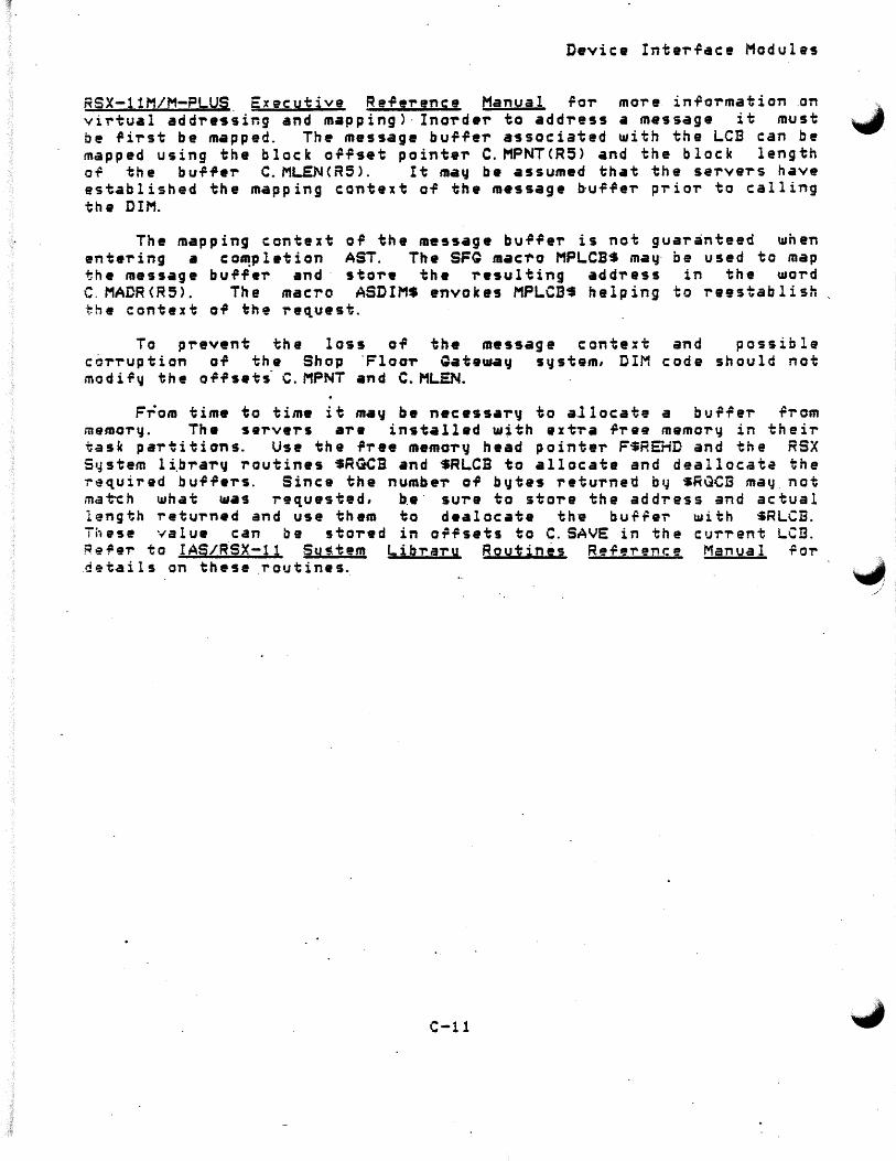
Device InterTace Modules
RSX-llM/M-PLUS. Executive Re.P1rence Manual ror more inrormation .on . •. virtual addre~sir.g and mapping>· Inorder to address• message it must """' be rirst be mapped. The message burrer associated with the LCB can be mapped using the block or.Pset pointer C.MPNTCR5> and the block length of the bu.P~er C.ML.E:N<R5>. It may be assumed that the servers have established the mapping context of the message ~u.P.Per prior to calling the DIM.
The mapping context or the message buffer is not guaranteed ~hen entering a co~pletion AST. The SFQ mac1'o MPLCB$ may- be used to map the message buffer and· store the resulting address in the word C. MADR<R5>. The macro ASDIMS •nvokes MPLCB~ helping to reestablish the context of the request.
To prevent the loss of the message context and possible corruption of the Shop 'Floor Gateway s~stem, DIM code should not modify the offsets- C.MPNT and C.MLEN.
From time to time it ma~ be necess•ry to allocate a bu~~er rrom memory. The servers are installed w;th ext~a ~ree memory in thei~ task partitions. Use the free memor~ head pointer FSREHD and the RSX S•,Jstem li.brary routines SRGCB and SRLCB to allocate and deallocate the r~quired buffers. Since the number of bytes returned by sR~CB may. not mat-ch what t11as requested, b.e · sure ta store the address and actual length return•d and use them to dealocate thv bu~~·~ with $RLCB. Th~se value can be stored in offsets to C. SAVE in the current LCB. Re~er to IAS/RSX-11 Su~tem Libraru Routinjs Reference Manual ~or .details on these routines.
c-11
~ I _,/
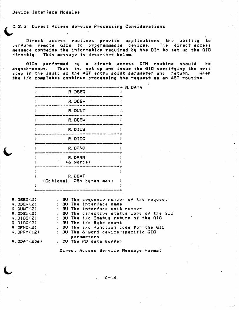
Device Inter~ace Modules
~C.3.3 Direct Access Se~vice Processing Conside,..ations
Direct access routines provide applications the ability to perform remote GIDs to pr~grammable devices. The direct access message contains the information re~uired b~ the DIM to set up the GIO directly. This message is described below.
<lIOs pe,...Po-rmed b'4 .a di-r•ct acc•ss DIM -routine should · be asynchronous. That is, set up and issue the GIO speci.PtJing the next st•p in the lGgic as the AST ent~~ point pa~a••t•~ and ~•tu~n. When the i/o compl•tes continue p-rocessing the ,..equest as an AST routine.
+-------------------+ M. DATA R.DS.EQ
+--~~--------------------· R.DDEV · +--------------------~-----~--+
A.DUNT I ,. +--~~-----------------~~---------+
R.DDSW +------------~----------.-.__------+
R.DIOS +~-~-----~--------------~--------+
R.DIOC +---.-------------...----~--------+
R.DFNC +-----------------------------+ ..
I
R.DPRM <-6· Words·>
. I I
+---~-------------------------+
R.DDAT <Optional, 256 bytes max>
~---~----------~-----------------+
R. DSEG<2> BU The sequence number o.P the request R. DDEV<2> nu The intar.Pace name R. DUNT<2> BU The inter.Pace unit number R.DDSW<2> BU The diT'ective status UJO'T' d or the (UO R. DIOS<2> BU The i/o Status retu-rn o.P the QIO R. DIOC\2) BU The i/o Byte count R. DFNC<2> EU The i/o .Punction code .p OT' the G!O R. DPRM< 12) BU The 6-wo'T'd device-~pecific GIO
pal'ameters R. DDAT(256> BU The PD data b u-F.PeT'
Direct Access Service Message Forma~
C-14
_.J

Device InteTface Modules
2 . Rl • 0 since theTe is no data to be returned.
. .
C-13

Device Interface Modules
Sat up LCB, re~uest me~sage buffer and registe~s and call •PDDON to complete the reque~t
Exit the AST routine.
C-16

Device Inter.Pace Modules·
The direct access service message contains the follow1ng -Fields ~'. for the OIM's use:
R.DFNC, the GIO function to be peT"formed
R.DPRM, an arra~ of six words providing 4evice-spec:ific: GIO parameter requirements issu• a GIO to that ~evic:e.
the nec:essar" for the DIM to
The following o~fsets in the direct access format Line Control Block need to be updated.
C. SRVS, DIM completion · seT"vic: e status c: ode
R. DDSW, the dirac:tive status UIOT"d oft the GlO invocation
R. DIOS, the stat.us retuT"n OT the GIO
R. DIOC, b'jt• count returned from the GIO completion
R. DDAT, buffer aT"ea holding data ~rom a read GIO .Punction
The .Pollowing steps ma~ be used as a guide to coding the direct se~vice routine9: . .
Th11 lo.gic: .Plow o-F a t'Jpic:al di~ect se-rvice i-outine. would be as follows:
Validate .Punc:tion c:ode and •valuate devi.ce dependent parameteT"s in the R.DPRM of-rset of the LCB .. ·same ~a,..amete~s
ma~ need to be pT"ovided at the DIM level. The$e ~ould inc:lude addT"esses of data buffeT"s, DIM overwT"itten timeouts, or size parameters.
Fo~m•t and invoke the GIO specifying a completion AST routine.
Test the directive status woT"d of the GIO invocation, if successful, return to server, i4l unsuccess.Pul, set the offsets n.ecessarq fo~ the calling server, CALL •PDDON, and ~etu~n to the sei-ver.
Restore stack, set R5 as LCB pointer CAST parameteT"), and remap the message buffer.
Evaluate the i/o status block of the i-esulting aIO function. and deteT"imine the corresponding geneT"ic status value. RetT"~ if the function i.P ~as 3 timeout.
C-15

~ R. QBOF< 1)
'-' GCNT<2J /\.GDAT(256>
BU Bit ofl set rield <device ~pecific in its usage and interpretation
BU The data count BU The PD data burrer
Generic Access Service Message Format
R.GSEG is not currently beeing used and should not be modiried by the DIM. R.GDIP is used by the server to determine which LAB it should queue the request to, it too should not be modified by the DIM. R.GSTS is the generic completion code o~ the request. The sever's $PDDON copie• the value that the DIM places in C.SRVS(R5> in R.GDID or tne· message.
The values in the Pields ~CODE, R.QCNT and bu~fe~s R.GADR, R.GDAT are used b~ tne DIM to perform the runction. The value of M.CODE defines the function to be performed. Valid codes are defined in t.h~ macro MXCOD• OT MACROLJB. The are:
MG.RED Perform generic read from the device MQ.WRT Perrorm generic ~rite to the device MG.WTV Perform generic write to the device a~d MO.RDS'PeT~orm read OT device status -.. MG.SRD StaTt the device MO.SPD Stop the device MG.LON Log on to the device MG. LOF Log oi=.P the ·d evi i: e M~.SUL Start the operation of uploading of devi:2
·.tn9ffi01'1.J .
MG.EUL End the ope~ation or uploading of devic~ MG.SDL Start the ope~ation of down loading of memo-ry MG.EDL End the operation of down loading of device
memorq
memory device
IT the i=unction requires an address in the device, it is passed in the buf~er starting at o~fset R.GADR. The contents o~ this bu~fer is an internal BASEWAY address, that is, it was c:Teated by ·the BASEWAY device add-ress t~an~l~to-r. Both the translator and DIM code must interperate this buffer in the same wa~.
The R.GATY offset in the message determines the type of add~ess contained in the buf.Pe-r. Current .address types are bit, ph•Jsic:aL and 1 o g i c a·l. R. GB OF i s us~ d r o-r d e vi r.: e s p e c i f i c b i t o -r f s e t d e t e ·rm in a·~ i on.
The R.GCNT field contains the numbe~ of data types to ope-rate on. I r P.. GADR c on ta i n s a b i t ad d r es s, R. 1~C NT i s in t e -rm s o .P b i ·i; s. I f! R.GADR is a ~ord registe-r add~e~s, R.GCNT is the number or words to
-C-18

Device Interfa~• Modules
C. 3.4 Qeneric: Access Service P,.ocessing Considerations
Generic access routi~e p,.ovida applications ~it~ a method o~ accessing devices generically. That is, an application may req•Jest to issue a read from a device and not need to provide the device specific information requi~ed to do the GIO. This implies that the generic access module OT a DIM has the logic to translate • generic re~uest code in to a se,.ies of steps required to set up, execute, and evaluate completion status in device-specific terms.
As with the other servers, the context of the re~uest is passed to the DIM ~ith RS containing the address of a line control blo~k. The LCB points to a gen•ric request message. The information that is p~ovided by a generic requ~st message is sho~n in the figure below. These offsets are defined in the macro QENMSS of MACROLIB.
+---~~-----~-----.__---------+ M.CODE
Standard message header +---------:------,---•+ M. DATA
R.QSEG
R. QDID -+-~---------~-----------.__.---+
R.GSTS
R.QADR (15 UIO"rdS)
+--.----------~--------~---~--+ R. GDOF R.GATY
~------------~----------.-+ R.QCNT
+--------------------------•+ R.DDAT
<Optional, 256 bvtes max)
~-------------,____ +
M.CODE(2) R. QSEG<2> .~. ~J;Dt,2)
R.GSTS<2> R. QADR<30>
R. GATY ( 1)
BU The generic function code of the ~eauest EU The sequence ~umber of the ~e,uest BU The de~i~• l~gical identific~tion BU The generic service status return code BU The PD data address in internal BASEWAV
'9oTmat C The address t~pe:
0 = Bit address 2 = Phvsical address 4 = Logical add~ess
C-17

Device Interfac• Modules
C.4 DIM - Utility Macros and Subroutines
~ . -· 4. 1 Code-Gene,.-ating Macros
The ~ollawing macros are de~ined in the DIM library ~or and coding cla,.-it~. The~ are quit• help~ul in writing Interface Modules. The rollot11ing is a list· o~ these macros. ,
ASDIMS - Pop AST parameter <address of LCB into RS>, save 'registers RO-R~, restore mapping context o~ m•ssage buffer associated with
DTlNIS DTFNCS DTMDLS DTMFR$
the LCB. Ini'tialize device/.Punction tables. Create a runction branch table entry.
- C,.-eate a device modal ;able entry. - Create a device manufacturer table
entry. ERTBLS Creata a device-speciric status to gene'ric
statu return translation table entr~. MPLCSS - Ma~ the message buffer associated with
the c uT"rent LCB.
C.4. 1. 1 ASDIMS -
utilitv Device
Form: ASDIM$
~ vokes the macros ASTSV$ and MPLCB$. ASTSV$ saves registers RO-RS ~unile it pops the AST pa·rameter o.Pt: the stack· and puts it ·in RS. pops the AST parameter, the address of the LCB associated with the AST. MPLCB$ This macro pops an AST parameter off the· stack and sto~es it in R5, saves the original contents o~ RO-R5 on the stack, remaps the cont
C. 4. 1. 2 Fo,.m:
DTINI$ -DTINI$ <manufacturer table label~
Initializes the PSECTS.fo~ the manufacture, .. MDL, and function branch, .. FNC table~.
C-20
.. MFR, the model,
-"-.
•
Device InteT".Pace Module5
use.
The actual processing o.P the geneT"ic request is accomplished b~ t~aversing through .Punction branch tablas. These tables aT"e made up o~ entr~ points o~ routines, when called in the sequence o.P the table, will perfoT"m the · T'unction associ.ated U1ith that table. The ~unction b~anch table table is deteT"mined by ManufactuT"er/model/~unction tables.
For each ·manu.PactuT"eT" supported b'd the· DIM, there is a tab le of models associated ~ith it. Each model is associated with a table ~hich pairs the generic-function and addressing t~pe· <R.QAiY in the gen•ric: message) with the beginning address o.P the propel" ~unction b~anch table. The macros DTINIS, DTFNCS, DTMDL$, and DTMFR$ descT"ibed in se~tion C.4. 1 aT"e used to build these tahles. The subl"outine SGENFC ma~ be used to determine the function branch table .Por the c:u-r'rent request.
The following steps should prove to be useful in designing and ~riting • gen•~ic access T"outine fol" a device interface module. The ~irst step should be to anal~ze what steps aT'e 'requi~ed to peT'foT'm all the suppoT"ted runction fol" devices that a're to use the DIM. Keeping in mind the following items.
Because the seT"vice must suppo'rt multiple inter~aces at the same time, DIM code must be reentT"ant. .. Use the C.SAVE bu.PfeT' int~• LCB ~o maintain the contex~ of
· th.e C:UT'T"ent GIO. These pa'rametaT's ma~ be needed ir a retr'-' .Po+ a timeout condition is d~sired.
GIOs should be done with a completion AST T'outine.
TT'anslate device specific i/o status codes <success and e'rrOT") into gene~ic se'rvice status values. This is the onl'l waq that tne serve'rs will be able to determine succes or -Fa l i U'r9.
Deallocate anq r~ee memo'!"~ buffe~s tha~ may have been allocate duT'ing the pT"ocessing of the .Punction.
Call SPDDON with the requiT"ed pa'rameteT"s when teT'minating a function. SPDDON must be called whether the ~unction was propeT'ly peT"fo~med O'r not.
Refe,.. to the sample DIM TC'r a more d•tailed example o~ how to constT"uct the geneT"ic rautine .
C-19
~ I
_j

Device Inter~ace Modules
C. 4. 1. 5 -o-rm:
DTMNF$ -DTMFRS tn~g-r
m.Pgr = BASEWAY manu.Pactu-re-r code o-r 0
Creates an ant-r~ into the manufacturer table. The table entry ;onsists o.P the manu~acturer code in the ~i-rst word and the curr•nt ad.d,..e5$ o.P the PESECT .. MDL in the second wo-rd. This 1.uill become the ~ir~t add-ress o.P the next model table built using the DTMDL~ matro. A null paramat•r will generate a zaro w~rd and ta-rminate the cur~ent .itanuPact::.rr~-r table. The trlanuractu-rer table is built in the ?SECT .. MFR.
C. 4. 1. 6 ERTBLS -F~rm: ERTBLS d~ver-r, gener-r
deve-r-r = The d•vice speciPic e-r-ro-r code ratu~ned by the drivar or ACP.
gene-rr =The generic status.code that the devica ar-ro-r is to b• translated to
Creates an antry into the generic error message tabl~ t-ran$l~tion t~ble. The ent~y is in the ~orm o' the device-~pgcific i/o status -~de is in the ~i~st word and th~ generic status me~sage is in the
=ci:7::id :»o-rd.
- --t_.-c:;~
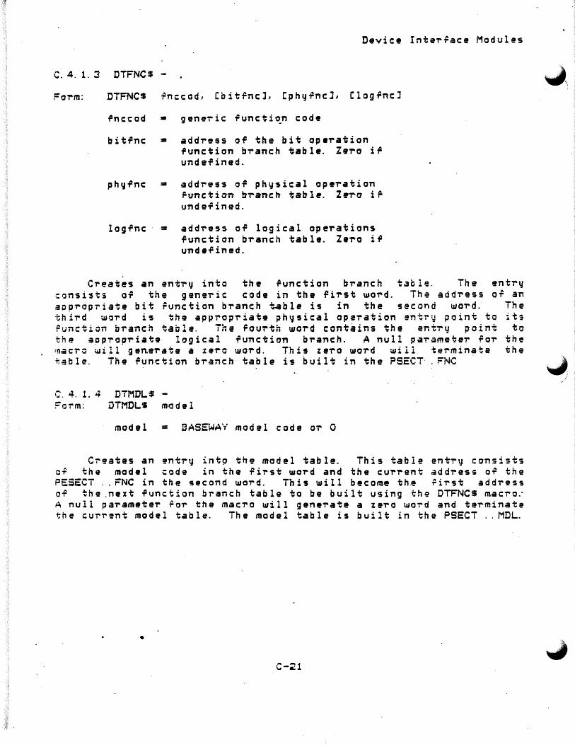
Device Inter~ace Modules
C.4. 1. 3 DTFNC$ -
Foi-m: DTFNCS .Pnc:cod.· Cbit.PncL Cphr.J.PncJ, ClogfncJ
rnccod • gene'ric functi~n code
bitfnc • addi-ess of the bit ope-ration .Punction b-ranch table. Zero i.P undefined.
ph~fnc • addi-ess of physical ope-ration runctian bi-anch table. Z•-ra i ~ undefined.
logfnc = add~ess of logical ope-rations function b-ranch table. Zei-o i.P undefined.
Creates an enti-y into the function bi-anch table. The enti-y consists of the genei-ic code in the rii-st woi-d. The addi-ess o~ an aopi-op~iate bit runction branch table is in the second woi-d. The third word is the appropriate ph~sical operation entr~ point to its Function branch taole. Tne Fourth word contains the entry point to the approp-riate logical function branch. A null parametei- ~o-r the ~aero ~ill gene-rate a ze-ro wci-rd. Thi5 ze-ro word ~iii terminate the table. The function branch table is built in the ?SECT· .FNC
C. 4. 1. 4 DiMDL$ -Form: DTMDLS model
model = BASEWAY model code oi- 0
Creates an entry intp the model table. This table er.t~y consists o~ the model code in the ~irst ~ord and the ~urrent address o~ the PESECT .. FNC in the second word. This will become th~ ~irst address of the .next -r1Jnc:tion branch tab le to be built using the :OTFNC$ macro.· A null parameter ~or the mac~o ~ill gene~ate a zei-o wo~d and terminate the cur'T'ent model table. The model table is built in the PSECT .. MDL .
•
C-;?1
/

Device Interlace Modules
'-'C.4.2. 1 $0ENFC 7
' .. , Subroutine SQENFC - GENERIC FUNCTION TABLE LOOKUP l'!ODULE
The purpose or this module is to perrorm table lookup opeTations deteTmining the pTopeT ~unction ~Tanch table used to execute the geneTic function i/o Tequest. The addTess of the function bTanch table is then passed back to the calling Toutin~
The associated tabl•s ar• defined in the follo~ing >'ltifnTleT":
Manu~actuTeT table
+----...------------~-----+ M•nufactuTeT code
:----~~--------------------: AddTass of fiTst entTy entT~ in the associated
model tabl• .+---------------------------~---+
0
0
0
0 +---~---------~~-------------+
Model table
+----------------------------+ Model NumbeT
:~----------------------------: AddTess of rirst runction
in the associated generic runction table
+----------------------------+ 0
0
0
+---------------------------+ 0
+----------------------------+
C-24

Device Inter~ace Modules
-.C. 4.~ DIM Sub~outines
The 9ollowing are utility subroutines that are used by DIMs.
SGENFC SPDDON
- Find function b~anch table - Server DIM completion routine
The following pages describe these routines in detail .
•
C-23
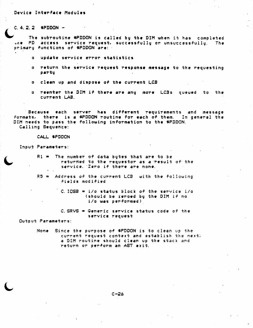
Device Inte-rl•c• Modules
l ,C.4.~.~ SPDDON -
"-" The subToutine $PDDON is called by the DIM when it has completed .. ,1e PD access se-rvice request, success-fully or unsu-ccess.Pully. ihe pl"'ima-ry runctions oi= $PDDON ·a-re: ·
o update se-rvice er-ror statistics
o return the service request response message to the requesting part~
o clean up and dispose of th• cur-rent LCB
o reenter the DIM if there are any more LCBs queued to the cur-rent LAB.
Because each server has different requirements and message rormats, there is a :SPDDON routine for each of them. In genei-al the DIM needs to pass the following information to the $PDDON.
Calling Sequence:
CALL SPDDON
Inpu~ Paramete-rs:
Rl a The number of data bytes that are to be retu-rn·ed to the req,uestor as a ·result o-F· the sa-rvice. ·zei-o i.P the-re are none.
RS = Address OT the cui-i-ent LCB with the -Following helds modified
C. I OSB = i Io status b l o c k or th e s er v i c e i I o (should be zeroed b~ the DIM i~ no i/o was pe-r.Po-rmed)
C.SRVS • Qene-ric service status code or the service request
Output Paramete~s:
None Since the purpose OT $PDDON is to clean up the cur~ent ~equest context and establish the next~ a DIM routi~e should clea~ up the stack a~d return or pe~Torm an AST exit.
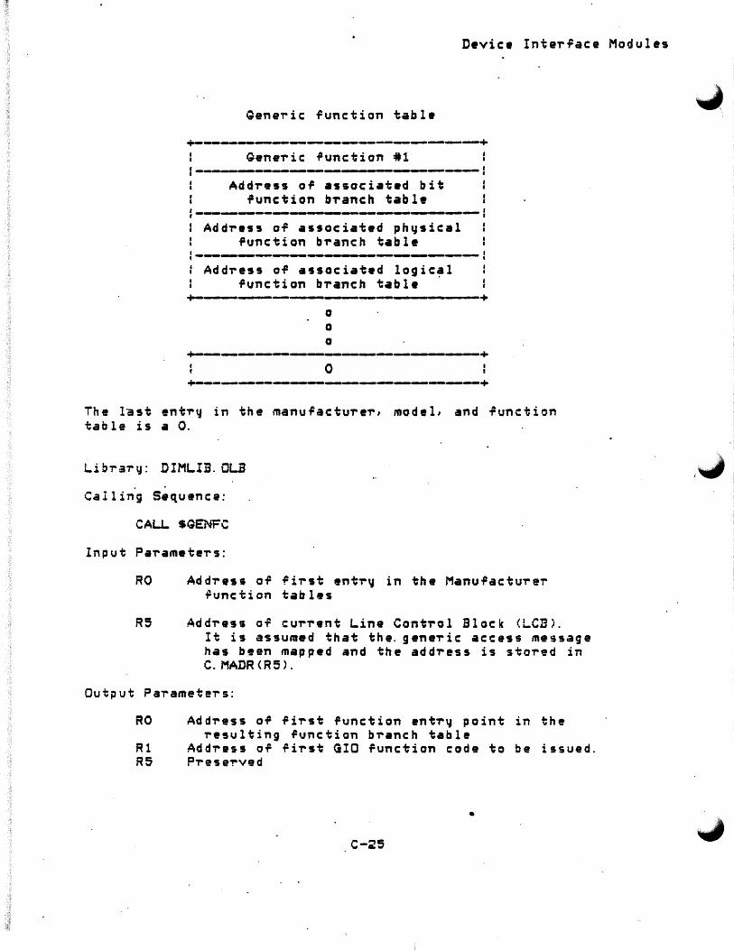
Device Inte~race Modules
Qene~ic function table +---_._--_.-....., _______ ..._ ___________ +
Qene~ic function •1
1---------------------------1 Add~ess or associatad bit
function b~anch table
: Add~ess of associated physical function b~anch table
: -----~--------- ---...-------: Add~ess of associated logical : function b~anch table ·
•+-------------------------------+ 0
0
0
+--------~----------------+ 0
+-------------.__-----------+ The last entr~ in the manufactui-e~, model, and function table is a 0.
Library: DIMLIB.OLB ,.J . .
Calling S•quenca:
CALL SGENFC
Input Pai-amete~s:
RO Add~ess of f i~st ent~~ in the Manufactu~er ilunction tables
R5 Add~ess of cu~~•nt Line Cont~ol Block <LCBL It is a-ssumed that the. genei-ic access message has been mapped and the add~ess is sto~ed in C. MADR <R5 >.
Output Pa,.amete,.s:
RO Add~ess of fi~st function ent~~ point in the ~esulting function b~anch table
Rl Add~ess of fi~st GIO function code to be issued. R5 P~esei-ved
•
C-25

Device Inter,ace Modules
{...c. 5 Example DIM
;+
C op yr i ·g h t C C > l 984 Digital Equipment Co'rp., Maynard, Mass.
This software is furnished under a license and mau be used and copied onl~ in accordance with the terms o~ such license and with the inclusion of the above copyright notice. This software or an~ other copies thereof mav not be provided or otherwise made available to an~ other person. No title to and ownership of the software is hereby ti-ans fe-rred·.
The inform•tion in this soft~are is subJect to change without notice and should not be construed as • commitment by Digital Equipment Corporation.
DIGITAL assumes no responsibilit~ for the use or reliability o~ its so~twa-r~ on equipment which is not supplied by DIGITAL.
Sub-routine $xxDIM - SAMPLE DEVICE INTERFACE MODULE
The .tx D•vjce lnterrace Module CDIM> js p1'ovided as ·a temp late for use-rs UJho UJish to urri te their own DIM· to suppoT-t pi-ogi-ammable devices other than those already suppoi-ted b~
the SHOP FLOOR GATEWAY. . .
This template shows simple and concrete examples foi- writing DIMs. Explanations and code comments guide the novice th-rough the concepts and Teatures or DIMs. For the novice, the temp.late builds a simple terminal server which per.Poi-ms familiar TTy -reads and \llr·i tes, For the mo-re advanced codei-, examples a-re given ror actual PLC servers. Additionally, coding features and important points a-re highlighted ~or added and imp"roved functionalit~.
Generally, the template consists of desc-riptoi- tables and roui- functional modules.
The descriptor tables define pa"rameters like the manufacturer of the device accessed by the DIM, the model number of the device, the functions performed b~ the device, and the possible functions for generic service.
The first module is the i/o cancellation module. This module is responsible foi- pei-foi-ming a disconnect operation fi-om the DIM-supported pi-ogrammable device. This operation may not be necessary foi- a particular device type such as a terminal se~ver.
C-27

Device Interface Modules
;·
The second module is the i/o initialization module. This moG'u1e c:an:Cains :.Cne cod'e ,..equil"ea· :Co c:annec:t to ~ne app-rop-r-iate a·evice driver and/or ACP be.Pore a·c:cessing the c:ommunic:.ations inte-rilac:e < s).
The third module is the Direct Access Service module. This module c:ont•ins the code l"equired to pe,.form remote GIOs to the xx inte-r.Pac •·
Th• ~ourth module is th• Qeneric Access Service module. This module c:ont•ins the code requir•d to perform generic: operations to xx device~.
NOTE: Before a Device access server can access a DIM, the following must be done:
2> Assemble the module DIM source and insert into the obJect librar~ SFQSL!BRARY:DIMLIB.
3> Make an entr~ ~or this module in the device vector tabla DSVECT <DEVVEC.MAC) by adding the ~allowing line:
DEFDIM xx ; Ad d x x sup p or t
4> Reass~mble and insert D~VECT into the obJect libra~y SFGSLIBRARV:DIMLIB.
5> Relink the Device access se~v•~s and move tha re~ulting images to SFGSSVSTEM with the ~allowing VMS DCL commands:
S SET DEFAULT SFG$ROOT: CSOURCE.POLSRVJ S TKB @POLSRV. 4™.B • COPY POLSRV. Tsx-sFGSSYSTEM: S SET DEFAULT SFGSROOT: CSOURCE.GENSRVJ S TI<.B @GENSRV. 4™.B t COPY QENSRV. TSX SFGSSYSTEM: S SET DEFAULT SFGSROOT: CSOURCE.DIRSRVJ $ T~B iDIRSRV. 4™.B $ COPY DIRSRV. TSX SFGSSYSTEM:
Libra~y: DIMLIB.OLB
Language: PDP-11 Mac~o
.: -Creation date:
Modi~ication nisto~y: •
C-29

Device Inte~~ace Modules
-~ C-29

Device Inte~raca Modules
. PAQE
.SBTTL Mac~o declarations and definitions
.MCAL.L LAB$, LCBS, GENMSS, DIRMSS, ASDIM$, SAVRGS
.MCALL.. RESRQS, DTMDLS Gross, QATE?~, ASTX$S, SRVSC$
.MCAU. DEvCDS, MXCODS, TBSIZS, DTI1FRS, DTFNCS, DTINIS
.MCAU. ERTBLS, GIOWSS
QATEPS GENMS$ DEVCDS SRVSC$ OIRMSS MXCODS. LABS LCBS
Gata~•~ parameters D•'~n• Q•n•ric Access message u~~sets D•~ica names and model codes G•n•ric service status codes De~in• Dir•ct Acces3 mes~age oPfsets Define mailbox message codes De,ine Lina Acc•ss Block <LAB> offsets DePine Line Control Block <LCB) o~~sets
. .
C-30

Device Interface Modules
.PAGE
.SBTTL Data de~initions
;=•==--=--------=--==·=·-====··-===-=-=-===---===·=-============ Device-specific i\o function table·
;m•----=••----••==------•••=••••===••==•--=••=-=-=•=--============== Valid direct service GIO functions for the DIM-supported devices. xx.WRT, etc. are previously defined symbols. The following table is defined for validating GIO runctions sent For direct servicing.
;-------~~------------------------------------.-----....... -----------~--~--x xVGIO:
. WORD IO. WLB
. WORD IO. WRT
. WORD IO. BWT
. WORD IO. RLB
. WORD IO. RED
. WORD IO. BRD
. WORD IO. DAG
. WORD IO. STP
. WORD IO. STR
Logical write function Write function · Bit w~ite function Read function Read function Bit read function Diagnostic read stop device sta~t device ,.._
xxNBRG = <.-xxVGI0>/2 Number or entries in table
:•=====·===·=====================~============================= Generic error message.code table
.i·===========·===================================================
Creation of the· erroT" table a5sociating IOSB er1'or with geneT"i_c e1'ror
Entry num~
one
+-----~-----~-----------+ i/o status e-rro~
:---.---~---------------: .: generic error code +----------------------+
·----------------~-----------------------~--------------~---------# •
IOERR: ERTBL$ ERTBL$ ERTBL$ ERTBL$ ERTBL$ ER TB LS ERTBLS ERTBL$
IS.SUC,SS. sue IS.TMO,SE. TMO IE.TMO,SE.TMO IE.SRE,SE.PRO IE. OFL SE. OFL IE.DNR,SE. TMO IE.ABO, SE. CAN IE.BCC .. SE.TMO
·110 success,ully complet.ed Successful, but timeout
·; Timeout Send repl~ message eT"ror Orf line DZ.timeout Function canceled Block check. error
C-31

Device Inta~laca M4dul•~
.TBSIZS IOERR, IOERCT End o~ I/O •~~o~ table
""'
C-3~

. Device Interface Modules
. PAQE ' ,! •• ..;..~------------:US••=•=========-------==-=--=--=-=·==========-== ~ .SBTTL Manufacturer/model function tables
~
l,
The m•nuracturer, model, and function tables a~e defined h~re and used td process generic func~ions requested by. the user to the supported equipment. Each manufacturer may have several models; each model may support several generic functions. Those models ~hich use identical functions tables may sha+e the same table.
Manufacturer/model name9 and codes are defined in the mac~o DEVCD$. · For this example the ·manuracturer will have the c o d e MF. x x x and w i 11 h ave 3 mode l s, MD. x .x A, MD. x x B, and MD. x xD. Assume that MD. x xA and MD. x xB are similar d ev i c:es and use the s•m• logic to perform their runctions.
·----------.-.----~---.---~_._-~ ___________ _._ ______________ ~-.----, . .
DTINIS xxTBL Initialize manufacturer table
DTMFR$ MF. xxx Start table .Por man.P. XXX
DTMDL$ DTMDL$
DTFNC$ DTFNC$ DTFNC$ DTFNC$ DTFNC$ DTFNCS DTFNC$ DTFNC$ DTFNCS DTFNC$
DTMDL$
DTFNCS DTFNC$ DTFNCS DTFNCS DTFNC$ DTFNC$ DTFNC$ DTFNC$ OTFNCS DTFNC$
MD. x xA MD. xxB
Make entries .Por modules MD. xx A and MD. x xB. Note that they share the same function table
MG. RED, BlTRD, PHYRD, LGCRD _; Read -routines MG.WRT,BITWR,PHYWR,LGCWR Write routines MG.WTV,BITWV,PHYWV,LGCWV i Write vei-ify routines MG.RDS,RDSTA Status MG.SRD,START Start device MG.SPD,STOP Stop device MG.SUL,UPREG Upline load request MG.EUL,UPEND End upline load MG.SDL,DNREG Downline load request MG.EDL,DNEND End downline load
MD. x xC Define the functions for the model MD. XXC
MG.RED,CBITRD,PHYRD,CLGCRD MG.WRT,CBITWR,PHYWR,CLGCWR MG.WTV,CBITWV,PHYWV,CLGCWV MG.RDS,RDSTA Status
Read routines W-rite 'T'Outines W'rit~ verif~ routines
MG.SRD,START Start device MG.SPO,STOP Stop device MG.SUL,UFRE~ vpline load request MG.EUL,UPEND End upline load MG.SDL,DNREG Downline load request MG.EDL,DNEND End downline load
C-33

Device InteT~ace Module~
DTFNCS
DTMDLS OTMFRS
r Te-rminate the model t.able Te-rminata manu~acturer table
C-34
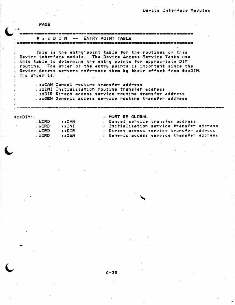
D•vice Inter~ace Modules
. PAQE
' ·+ "" . . :==-===-=•=-=-s======r=========--===----==--====--================== • x x D I M ENTRY POINT TABLE
This is the entry· point table ~or the routines o~ this Device interface module. The Device Access Service Tasks use this table to determine the entry points for appropriate DIM routine. The order of the entry points is important since the Device Access servers reference them by their offset from $xxDIM. The oT"deT" is:
xxCAN Cancel routine transfer address xxINI Initialization routine transfer address xxDlR Direct access service routine transfe~ add~ess xxQEN Qeneric access service routine transfer address
;------------~--~--------------------------_.-.-------------------------~------------
$x xDIM:: . WORD . WORD . WORD . WORD
xxCAN xxINI xxDIR xxGEN
; MUST BE GLOBAL Cancel service trans~er address Initialization service trans~er address Direct access service trans~er address Generic access service trans~er address
C-35

Device Interface Modules
.: +
.PAQE
. SBTTL . x xCAN cancellation se~vic• routine
x x C A N SERVICE CANCELI..ATION SEJ;VICE ROUTINE
This module performs th• necassarq actions re~uired to deacce9s the device's net~orking inter~ace.
The follot11ing GIO function c:ode is device specific. Depending on the tqpe of device, a different t~pe of GIO function may need to be used, or the deaccess GIO function or GIO invocation ma~ not be needed at all for ~our particular device.
Input: R5 •
C.L.AB
Address of Lin• Control Block <LCS> containing the context of the cancel request. Offsets are:
= Address of the Line Access Block <LAB> of the interface to perform the cancel r•quest on
Input to SPDDON: Rl • 0 since there is not data to be returned to anq
one R5 •Address o~ the current LCB·with o~fsets:
C. I OSB = I I 0 status b l o c le o ~ th e i I o d ea«: c :.s s op er at ion< s >
C.SRVS = Service status code sent back to se~vg~s SS.SUC fo,. success~ul completion othe~ codes th,e se-rve-r may expect are locatad in the macro SRVSC$ .
. EFFECT:
;-----.___~--~--~----~--~------~-------------------~--
C-36
~ I
./.
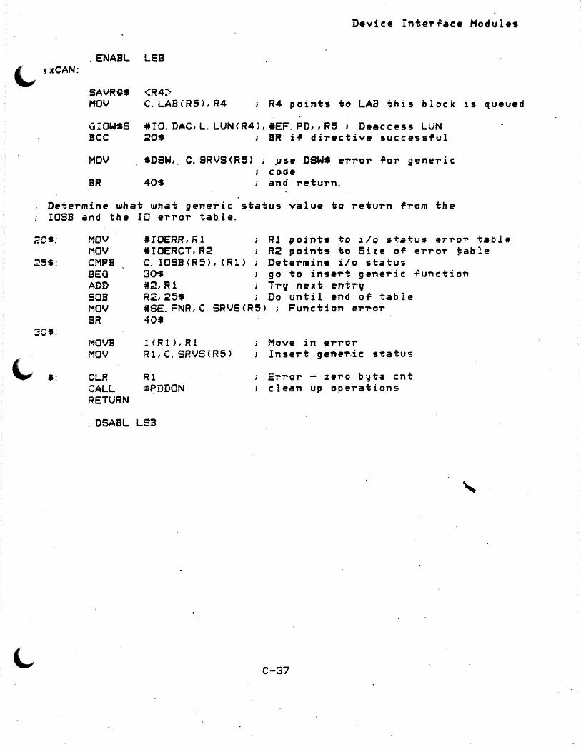
D•vice Inter~ac• Modules
. ENABL LSB \..,. uCAN:
SAVRG$ <R4)· MOV C.LABCR5),R4 ; R4 points to LAB this block is queued
QIOW•S #IO.DAC,L.LUN<R4),#EF.PD,,R5; Deaccess LUN BCC 20$ ; BR if directive successful
MOV SDSW, C.SRVS<R5> ; pse DSW$ er~or 9or generic code
BR 40$ ; and return.
Determine what what generic status value to return from the IOSB and the IO error tahle.
20S;
25$:
30$:
$:
MOV MOV CMPB BEG ADD SOB MOV BR
MOVB MOV
CLR CALL RETURN
#I DERR, R 1 R l p o j n ts to i Io s tat u !; error t.a b l P.
#IOERCT,R2 R2 point9 to Size OT er~or table C. IOSB<R5), <Rl) Determine i/o status 30S go to insert generic function *2,R1 Try n•Jt ent~y R2,25S Do until end or table #S£.FNR,C.SRVSCR5>; Function error 40$
1CR1),R1 Rl.· C. SRVS ( R5 >
Rl SPDDON
; . Move in error Insert gene~ic status
Error - zero b~te cnt clean up operations
. DSABL LSB
C-37

Device Inter~ace Modules
. PACE
.SBTTL . xxINI - initialization service routine ;+
; =------=-===--=======··======-=··===--====--====-======-==========--=== x x I N I SERVICE INITIALIZATION ROUTINE
This module per~orms the nec•~•~ry actions ·re~uired to initialize access to an xx int•rfac• line
Input: R5 • Address o' Line Control Block <LCB> containing
initializaton r•quest parameters: C.L.AB • Address Line Access Block CLAD> to per~orm
initialization
Output.to PDDON~:
Rl • 0 since there is no data to be r•turned
R5 • Add-ress of LCB used in this .opera't1on passing back the aff9ets containing follo~ing information:
C. IOSB •
C~ SRVS = I/O status block o~ th• i/o deaccess
op ei-at ion C s > Service status code •ent back to 5ervers
SS. SUC -For s·uccess~ul comp.leti.on otheicodes the server ma~ expect are located in the macro SRVSC$ .
. ; ------------------------~----.------------_,_----~----------------...-------
C-38
"" I

. ENABL LSB
xx INI; SAVRGS <Rl, R2, R4)· MOV C.LAB<R5>,R4·
D•vic• Inter~ace Modules
-save and restore registers get LAB for this block·
Issue access GIO
GIOWSS BCC MOV
BR
#IO.ACW,L.LUN<R4i,#EF.PD,,R5 20$ ; BR if directive successful SDSW,· C.SRVS<R5>; use DSWS error ¥or generic
code ; and return.
Determine what what generic status value to return Tram the IOSB and the IO error table.
20$:
25$:
"" J$:
40$:
MOV MOV
C.MPB BEG ADD SOB MOV BR
· MOVB MOV
CLR CALL. RE SR GS RETURN . DSABL
#IOERR,R1 #IOERCT,R2
Rl points to i/o status error table R2 points to Size of error table
C. IOSB <R5), C Rl) D•t•rmine i/o statu!t 30$ go to insert generic function #2,Rl Tr~ next entry ~2,25$ . Do until end ~f table #SE.FNR,C. SRV~<R5> ;·Function error 40$
1<R1J,R1 R L C. SRVS C R 5 >
Rl $PDDON <.R4, R~, R i; ..
LSB
'
Move in e-rror Insert generic status
Error - zero byte count clean up operations save and restore registers
C-39

Device Inte~face Modules
. PAOE
. SBTTL . xxDIR ; +
;=========--=--~==--============-=-========-·====-============ X X D I R DIRECT ACCESS SERVICE PROCESSING ROUTINES
This module provides th• actions req,uir•d to pe~~orm a direct access GIO. as defined in the dir•~t access service request m•ssag 11.
This direct access service routine performs the follo~ing:
l> Validates the GIO function code sent ~ith the GIQ ;. function code table <xxVGIO>
i,
~) Validates the device dependent paramwte~s sent in the service request message sta~ting at R.DPRM
3> Sets up the directiv• GIO function \ilith the GIO completion AST parameter set to ~xxOAST
4) Dwterntines ir GIO U1•s invok•d succ:e$si1ully. If ;he GIO UUIS unsuccessfully disp~tched, sets prope~ status codes and calls SPDDON to clean up b•fo~e-returning to server.
5> Saves registers and restores mapping.context o~ the mailbox message with the ASDIMS mac~o
6) Depending· on th~ ~YP• of device s~pport~d, checks foT time outs OT' bloc:k check etT'-rors, than rat-ries the tJ!O th@ numbeT' o~ times indicated in the C. TRY o~r~et of the LCE.
7> Determines success or 'ailure of the i/o completion, sets up the rollowing ofrsets in the LCB and request .message.
C.SRVS - generic status message code dgtaT'mined ,,..om i/o eT'ror to the generic status rou~ine
R. DIOS i/o status From C. IOSB R. DIOC - i/o byta count rrom C. IOSB+2
8 > De t er mi n e s i r a i- ea d u1a s i n v o k e d , i r so , s en d s th e b '.J t e count in R1 to ·PDDON. RS still must point ~o the beginning of the cuTT'ent LCB.
9) Calls SPDDON
10> Restores register$ in the follo~ing oT'der with the RESRGS macro: <RO,R1,R2,R3,R4,R5~
C-40
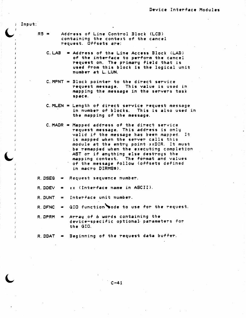
Input:
R5 =
Device Interrace Modules
Address of Line Control Block <LCB> containing the context of the cancel request. Orf sets are:
C.LAB =Address of the Line Access Block <LAB> of the interface to perform the cancel request on. The primar~ rield th~t is used from this block is the logical unit number at 1.. LUN.
C.MPNT =Block pointer to the direct service request me9sage. Th is value is used in mapping the message in the servers task space.
C.MLEN =Length of direct service request message in number of blocks. This is also used· in the mapping OT the message.
C.MADR =Mapped address OT the direct service request message. This add,-ess is only valid if the mtrssage has been mapped. It is mapped when the server calls this module at the entry point ·xxDIR. It must be· remap~ed when the executing completion AST or ir anything else destroys the mapping context. The format and values of the message follow toffsets defined in macro DIRMS$).
R.DSEG = Request sequence numbe"r.
R.DDEV = xx <Interface name in ASCII>.
R.DUNT = Inter~ace unit number.
R. DFNC = GI 0 fun ct i on·'-o d e to use r or th e -re q iJ est.
R.DPRM = ArTay or 6 words containing the device-specific optional· paTameteT"s for the GIO.
R.DDAT = Beginning o~ the request data bufrer.
C-41
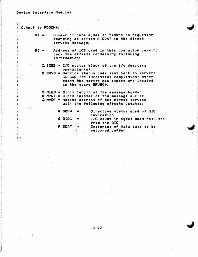
Devic:•. Inte,..~ac• Modules
Output to PDDONS:
Rl • Numbe-r o~ data bytes to -retu-rn to ~equestor sta~ting at offset R.ODAT in the direct se-rvi c: e message.
Add?ess of ~CB usad in this ope,.ation passing back the offsets cont~ining 9ollo~ing info~mation:
C. IOSB • I/O status block of the i/o deaccess op .,. at i on < s >.
C~SRVS •Service status cod• sent back to serve,.s SS.SUC for successful completion> othe,. codes the se-rve,. ma~ expect are located in the mac'ro SRVSCS.
C. Ml.EN • Block lengt.h o~ the message bu.Pfer. C.MPNT •Block pointe,- of th• message buf~er. C.MADR •Mapped address o~ the direct service
~ith the follo~ing offsets updated:
R.DDSW ·•
R.DIOC •
R.DDAT =-
Dir•ctive status ~ord of GIO invocation. I/O count in b~tes that resulted from the <iIO. Begi~ning of data data to be retu~ned b uf ~e-r.
C-42
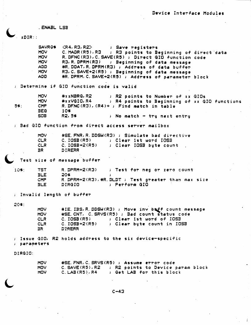
~
Device Inte-r~ace Modules
. ENABL LSB
xDIR::
<R4,R3,R2~ ; Save -registe-rs SAVRG$ MOV MOV MOV ADD MOV ADD
C.MADR<R5>,R3 ; R3 points to Beginning of di~ect "data R.DFNCCR3>,C.SAVECR5>; Di-rect GIO function code R3,R.DPRM<R3) ; Beginning of data message #R. DDAT, R.-DPRM<R3> ; Add-ress of data buffe-r R3,C.SAVE+2<R5>; Beginning of data message #R.DPRM,C.SAVE+2<R5>; Address of pa-ramete-r block
Determine if GIO function cod~ is valid
MOV #xxNBRG,R2 i R2 points to Numbei- of xx GI Os MOV #xxVGIO,R4 i R4 points to Beginning OT xx GIO
5$: CMP R.DFNCCR3>, CR4>+; Find mate h in table BEG 10$ SOB R2,5$ ; No match - t-r\j next en ti-tJ
Bad GIO function f-rom di'rect access S9T'VeT' mailbox
MOV #SE.FNR,R. DDSW<R3> j Simulate bad di-rective CLR C. IOSB CR5 > Clea-r 1st UIO'rd IOSB CLR C. IOSB+2 CR5 > Clea-r IOSB byte count BR DH~ERR
Test size ai= me5sage buffe-r
10$: TST R.DPRM+2<R3> i Test fo'r neg or Z e'l'O count BLE 20$ CMP R. DPRM+2<R3>,#R.DLDT; Test g-reateT' than max size BLE DIRGIO i Perfo-rm GIO
Invalid length of buffeT'
20$: MOV MOV CLR CLR jj~
#IE. IBS, R. DDSW<R3> ; Move inv b._(/ count message #SE.CNT, C.SRVS<RS> ; Bad count status code C. IOSB<R5) Clea,.. 1st wo'rd of IOSB C. IOSB+2<R5> ; Clear b-~te count in IOSB u·z~E-n~
Issue GIO, R~ holds addT'ess to the six device-speci~ic pa'ra'!'ete-rs
DIRGIO:
MOV #SE.FNR,C. SRVSCR5> ; Assume e'r'l'O'r code MOV C. SAVE<R5), R2 R.2 points to Device pa-ram block MOV C.LAB<R5~,R4 Get LAB for this block
C-43
functions

Device InteT~ace Modules
MOV L.LUN<R4>,R4 ; N••d spac• on GIO line
GIO$S C. SAVE<R5>, R4,,, R5, #x xDAST, <<R2>, 2<R:?>, 4 <R2>, 6 CR2>, 9. <R~>, 10. CR2 >:>
MOV ~DSW,R.DDSW<R3>; S~ve directive status word a·PL DIREND
Set up status codes befoTe ~•tuTn~ng ~ith GIO 'ailure R3 points to start o~· data area
DIRERR: MOV CLR CLR CALI..
C. IOSBCR5>,R.OIOS<R3> ; Save i/o status R.DIOC<R3> Z•To i/o.b~te count Rl Rl points to numbe~ of bytes read SPDDON ~ Clean ':JP
; End of.Direct a~cess service processing
DIREND: RESRQ$ <R2,R3,R4> RETURN . DSABL LSB
C-44
"" )

Device Inter~ace Modules
. ENABL LSB
x xDAST:
;-~----------------~-----------------------------------------------
This is the i/o completion AST routine for a Direct service request. It is responsible ror evaluating the completion o~ the i/o operation, setting up the parameters required by SPDDON, and calling SPDDON ~o return the request and clean up .Por the next request.
Inputs:
CSP> = AST parameter, the IOSB of the GIO ~unction. Th i s address a 1 so po int s to th e o .P .P s et C. I OSB of the LCB associated with the GIO.
AST parameter is popped ~rom stack and all registers a-re preserved
;-----------~------------------------------------~---------------
ASDIM$ Pop AST parameter (address of -request'~ LAB> and put into R5·and save registers
; · RO:-R5 on the stack. Remap the message buffer referenced by the LCB <map C.MLEN<R5) blocks starting at block C.MPNTCR5)) and store the resulting address in C. MADR < R 5 >.
Determine ir there .has been a ti~• out or block check
10$:
CMPB BEG CMPB BNE DEC BLE CALL BR
C. IOSB\RS), #IE. TMO ; Test ~or time out condition 10$ · ; Yes, decrement count and ret~~ C. I OSB < R 5 )., # IE. B CC ; Test b 1 o c k c h e c k c on d i t i on 20$ No, detei-mine status and condition C. TRVCR5) Number or ret~ies 20$ Done t~~ing - continue DIRGIO Retry direct service GIO 100$ Go to end or AST
Determine gene~ic messageierror response
20$: MOV MOV MOV
C. MADR <R5), R3 ~HOERR, Rl #IOERCT,R:?
R3 points to Beginning or data Rl points to Erro~ table entry point R2 points to Number of entries in ei-'ror table
C-45
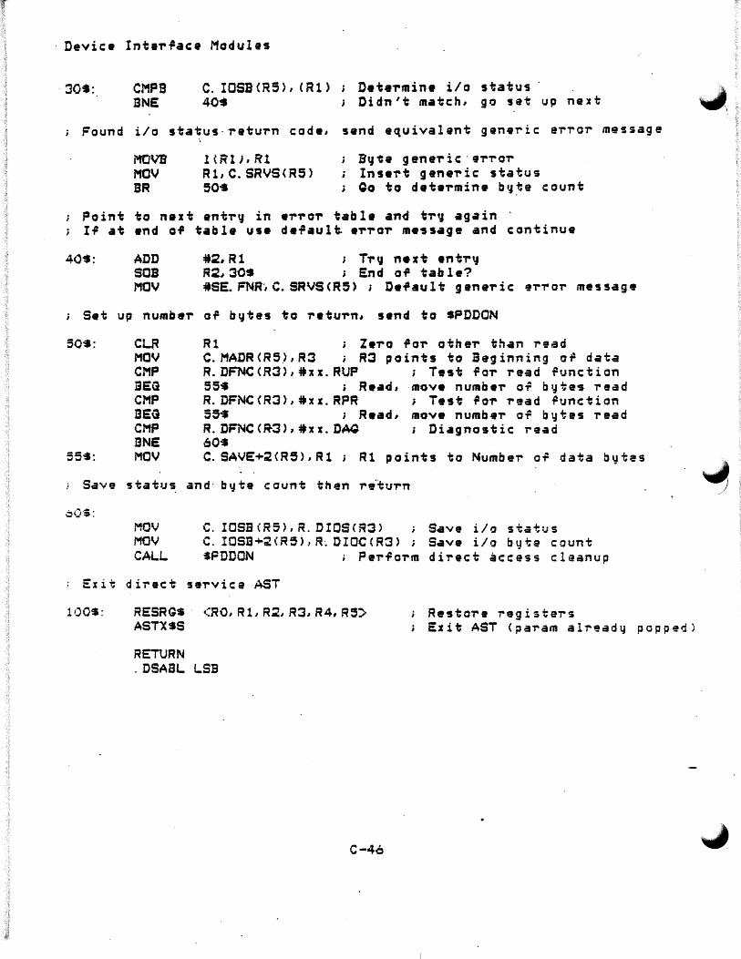
Device IntaT~ace Modules
· 30S: CMPB BNE
c. IOSB <R5) I ( Rl> 40•
DeteTmin·• i/o status · Di d n ' t m• t c h, g o s et up n e :x t
Found i/o status·raturn code, send equivalent generic error message
i'tOVB MOV BR
HR'lJ,Rl R1,C.SRVS<R5> 50•
B~~· gene,.ic·e,.,.or Insert genei-ic status Qo to deteTmin• by~e count
Point to next ant,.~ in erTo,. tabla and tr~ again I? at end of table use de~aul~ eTro,. message and continue
40$: ADD SOB MOV
#2,R1 ; T,.~ n•xt entT~ R2~30S ; End of table? #SE. FNR·, C. SRVS CR5 > ; Dei'au 1 t gene,. ic ei-T' oi- message
j Set up numbei- of bytes to return, send to SPDDON
50$:
55-S:
c~ MOV CMP BEG CMP BEG CMP BNE MOV
Rl ; Zero for otheT than read C. MADR <R5.>, R3 ; R3 points to Beginning or data R.DFNCCR3),#xx.RUP ; Test foi- read function 55$ s Read, ·move numbe,. of b~te5 ,.ead R.DFNCCR3),#x1.RPR ; Test foT read ~unction 55• ; Read, move numbei- o~ bytes read R.DFNC<~3),#xx.DAQ ; Diagnostic read 60-S C. SAVE+2CR5>,Rl ; Rl points to Number of data bytes
; Save $tatus and· byte caunt then riturn
MOV MOV CALL
C. ICSB <RS>, R. DIOSCR3> Save i/o status C. IOSB+2(R5>,R~DIOCCR3> Save i/o byte count tPDDON ; PerfoTm direct access cleanup
Exit direct service AST
100$: RESRGS · <RO,Rl,R~,R3,R4,R3~ AST:XSS
RETURN . DSASL LSB
C-4o
Restore registei-s Exit AST (pa,.am alrgady popped)
.,,
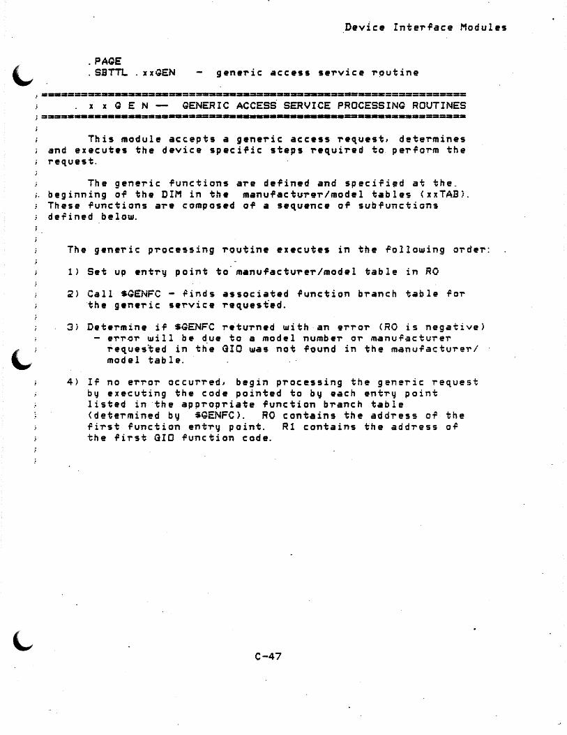
.PAQE
.SBTTL. xxGEN
Device Interface Modules
generic access service r~utine
~===========------=======-====-==··--=-=----------====-==·============ x x Q E N -- GENERIC ACCESS SERVICE PROCESSING ROUTINES
;=•=•=====------=====-=·===--------------------------==-========== This module accepts a generic access request, determines
and executes the device specific steps required to perform the request.
The generic functions are defined and specifi•d at the_ ;. beginning of the DIM in the manufacturer/model table~ <xxTABi.
These functions are composed of a sequence of subfunctions defined below.
The generic processing routine executes in the following order:
1> Set up entr~ paint to· m•nufacturer/model table in RO
2> Call SQENFC - ~inds associated function branch table for the generic service reques~ed.
3) Determine if SGENFC returned with·an error <RO is negative) - err~r will be due to a model number or manuf~cturer
~eques~ed in t~e GIO was not found in the manufactu~eT/ · model table.
4> If no e~~or occurred, begin processing the generic request by executing the code pointed to by each entTy point listed in ·the appropriate function branch table <determined by $GENFC>. RO contains the address of the first function entry point. R1 contains the address o~ the rirst GIO function code.
C-47

Device InteT"face Modules
INPUT:
R5 =r Add-ress o~ the Line Control Block <LCB> containing the contex~ of a generic access service request. Applicable offsets aT"e:
C.L.AB
C.STN C.SLAV C.EXTN C.MNFR C.MODL C.MLEN C.MPNT C.MADR
----a
a
:a
=r -
Addre~s Line Access Block <LAB> of the interface that the device is located on. Station address of the device Slave station address of device Extended addTess ManufactuT• code of the device Model c~de of the device
Block length of the message buf~er. Block ·pointeT of the m•ssage bu~feT'.
Address of the beginn;ng of the mailbox m•ssage c:ontaining i;he ,-eq_~est. Also the addT"ess ilor the response .. The incoming message is ,ormatted as f~llows:
R.Q.ADR =- Data Addr•ss of the pi-ogT'ammable devic:•
R.QCNT =- Count of data to use in i/o R.ODAT - Optional device data buf~er or up
to :?~6 b y.tes. Use of buf~er is dependent on the request <read OT"
ul'r i i;e >
In-formation passed th,-ough 'tne associated LAB is:
L.LUN a Logical Unit Number CLUN> to use in per~orming i/o on the device inteT'.Pace.
C-49
,.
~ )
.-/

Output to PDDON$:
Rl =
R5 •
Number or data bytes to retu~n to ~equesto~ starting at ofrset R.GDAT in the direct service message.
Address of LCB used in this operation passing back the o~rsets containing rallowing information:
C. IOSB = I/O status block o~ the i/o deaccess operationCs>.
C.SRVS =Service status code sent back to servers SS.SUC for successful completion> other codes the serve~ may expect are located in the mac~o SRVSC$.
C.MLEN =Block length or the message bu;fer. C.MPNT =Block pointer of the message buf~er. C.MADR =Mapped address of the di~ect s~~vice
with the rollowing ~ffsets updated:
R. GDAT = Beginning of data data to be · returned buffer. ,...,
C-49

C. SAVE \llil l be used in' the fallo-...ing \lla4'. The p,.ogT"amm&,.. may use them in any ~ay that makes life easy.
C.SAVE C.SAVE+2 C.SAVE+4 C.SAVE+6 C. SAVE+e •. C. SAVE+10. C. SAVE+12.
C. SAVE+14.
C. SAVE+la. C. SAVE+.1S. C. SAVE+:?O. C. SAVE+30.
= Address of cu,..,..ent GIC .Punction = Ad~Tess of data buffeT •Count Cbits,byte5 o,.. ~o,..ds> requested •Address.of PD •ddress buffer Callocated> • Sub.Punction code • Current completion AST address • Assigned when new buffer allocated
<pr~vious buffer addr) a Temporar~ storage for computed b~te count
<bi't .Punctions> • Actual length o~ addre~s bu~Ter • Actual length of buffer 1 = Actual length of buffer 2 • Error exit branch .
C::? J C12J
; --------------~-----~~-~-----------------~----~----Function .branch tables
;-.._,-----------~.----:-i..._,-~------~---------------------
; Read LGCRD:
CLGCRD:
. . T'eg ls v.91'"
. WORD
. WORD
. WORD
. WORD
. WORD
. WORD
. WORD
. WORD
. WORD
. WORD
. WORD
. WORD
. WORD
. WORD
. WORD
. WORD
. WORD
ftJncti on
l IO. RL.B LCBINI CNVBYT BYTCH~ GENG IO GENEND
GIOEXM CLNUP ASTEXT
1 IO. RLB LCBINI ALABUF CNVBYT I3YTCH~
GENG IO
ent,-'l point·s Logical Read o~ Register Issue one GIO ~unction Logic-al read Initial register setup Convert registeT"s to bytes Validate byte count. Issue requested GIO ~unction End gene~ic ~unction th~ next wo,-d contains the next Jump a~ter enter~ng the AST Test fa,.. successrul QIO Success clean up, call FDDON Exit AST
Logical Read o~ Registar ~OT' ;· XXC devices
Issue one GIO function logical T"ead Initial registeT" setup
·Allocate address burTe~ Conve,-t registers to bytes Validate byte count Issue requested GIO ~unction
C-50
"""\

. WORD GENEND
\._, . WORD GIOEXM . WORD CLNUP
·.WORD ASTEXT
W-rite registe-r gene-ric
LGCWR: . WORD 1 . WORD IO.WLB . WORD LCBINI . WORD CNVBYT . WORD BYTCHK . WORD GENG IO . WORD GENEND
. WORD GIOEXM
. WORD CLNUP
. WORD ASTEXT
"" GCWR: . WORD 1 . WORD IO.WLB . WORD LCBINI . WORD ALABUF
.. WORD CNVBYT . WORD BYTCHK . WORD GENG IO . WORD GENE ND
. WORD GIOEXM
. WORD CLNUP
. WORD ASTEXT
function
Device Inter~ace Modules
End generic ~unction the next word contains the next Jump after entering the AST Test for successful GIO Success clean up, call PDDON Exit AST
en t-ry points
; ·One <UO operation Logical W"r i te Initial -registe"r setup
-Conve"rt registe"r cnt to bytes Validate byte count Issue requested GIO -Function End generic .Punction word contains the next Jump af te-r entering the AST Test f o"r successful GIO Success clean up, call PDDON Exit AST
One .GIO ope-ration Logical W"rite Initial register setup Allocate address bu.P.Per
... C~nve"rt register cnt to bytes Validate byte count Issue ,..equested GIO -function End generic function wo-rd contains the next JUmp afte"r. entering ·the AST Test f OT' successful GIO Success clean upr call PDDON Exit AST
Write/verify registeT' generic function ent-ry points
LGCWV:
·~
. WORD
. WORD
. WORD
. WORD
2 IO. WLB IO.RLB L.CBINI
Write/ve"rir~ register gen rnc Two functions performed Logical w-rite Logical "read Initial Tegiste-r setup
C-51
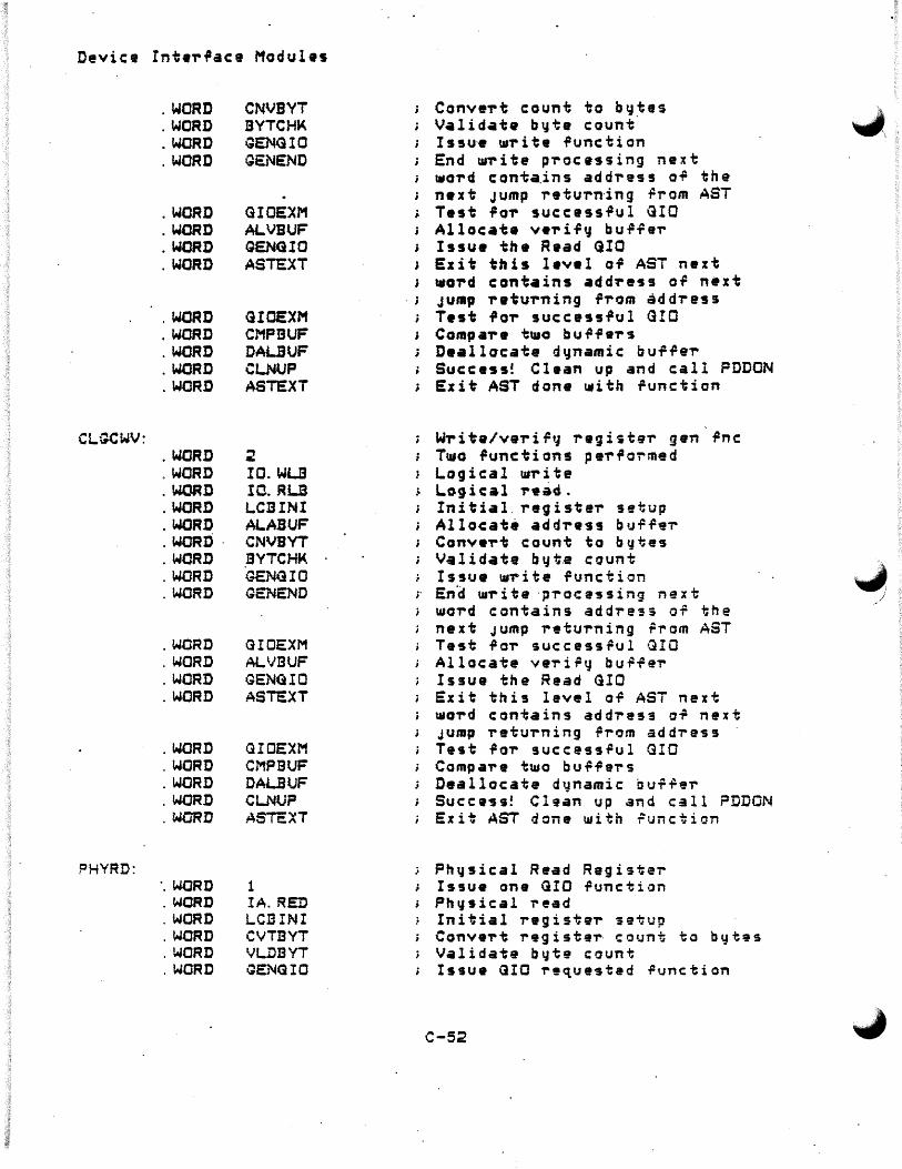
Device Int•T'1'ace Modules
. WORD CNVBVT ConveT't count i:o by_tes
~~ . WORD BYTCH~ Validate byte count . WORD GENG IO Issu·e UST' it 9 function . WORD GS:NEND End t11-r i te p,-ocessing next
1110,-d conta.ins add,-ess o.P the naxt Jump return-ing rrom AST
. WORD GIOEXM Test 1'0-r suc:c:ass.Pul QIO
. WORD ALVBUF Allocate v•ri.Py bu .P-t: e,.
. WORD GENG IO Issua th• Raad OIO
. WORD ASTc:XT Exit this leval a.P AST next tdGT'd c:ontains add~ess o.P next
. ; JUIRp ,-etuT'ning .P-rom add,.ess . WORD GIOEXM Test ilo-r succ:ess.Pul GIO . WORD CMPBUF Comp a,.• t1110 bu .p.p .,. s . WORD DAUUF Da.allocate dynamic buf.Pei-. WORD CLNUP Succ: es s! Clean up and call PDDON . WORD ASTEXT Exit AST done t11ith i&unctian
CL.GCWV: w,. i te/ver i r'J regi»te-r gen .Pnc: . WORD :? Tuto functions peT'.Pormed . WORD IO.WU Logical t11r i te . WORD IO.RL.B L.09ical ,...ad . . WORD LCD IN I Initial. registe-r setup . WORD ALABUF Allocate add-ress bu .p .P-eT' . WORD· CNVBYT Conv•T't count to b"tes . WORD BYTCHf.C. Validate byi;.e count
..A . WORD GENG IO Issue UIT' it e -Function . WORD GENENO ;- En'd t11-r i te · pT'oc es sing next /
·' UIOT'd contains add-ress of the next JUmp returning ~rom AST
. WORD GIOEXM Test .PoT' succ:ess.Pul •JIO
. WORD ALVBUF Allocate ve-ri.PtJ bu~feT'
. WORD GENG IO Issue the Read G!O
. WORD ASTEXT Exit this level o.P AST next UIO'rd contains address o-r next JUIDP i-etuT'ning ~T'Om addT'ess
. WORD GIOEXM Test .Po-r success.Pul GIO
. WORD CMPBUF CompaT'e t1.110 bu .P.PeT' s
. WORD DAUUF Deallocate dt.Jnamic iJ u-r~eT'
. WORD CLNU? Sue c: e-s s! Clean up and call ?DDON
. WORD ASTE:XT Exit AST done with .;eunction
PHYRD: Physical Read Register ·.WORD 1 Issue one GIO .Punc:tion . WORD IA. RED Phtjsic:al -read . WORD LCBINI Initial registeT' setup . WORD CVTBYT Conve-rt reg i steT'· count to b~t95 . WORD VLDBYT Validate byte count . WORD GENG IO Issue GIO T'eq,ue-sted Function
C-52 ~
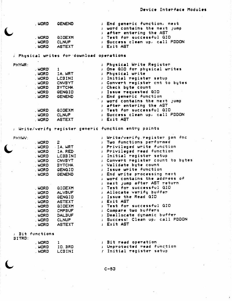
'-' . WORD QENEND
. WORD GIOEXM
. WORD CLNUP
. WORD ASTEXT
D•vic• Inter~ace Modules
End g•neric ~unction, next word contains the next Jump after entering the AST Test for successrul GIO Success clean up, call PDDON Exit AST
; Physical U1rites for ·download operations
PHYWR: .. WORD' . WORD . WORD . WORD . WORD . WORD . WORD
. WORD
. WORD
. WORD
1 IA.WRT LCBINI CNVBYT BYTCHK GENG IO GENEND
GIOEXM CLNUP AS TEXT
Physical Write Register One GIO for physical writes Physical U1rite Initial register setup Convert regi~te~ cnt to bytes Check bgte count Issue requested GIO End generic function word contains the next Jump after entering the AST Test for succ•ssful GIO Success clean up, call FDDON Exit AST
Write/v~rif~ register generic function entry points
PHYWV: 2
'-.,' . WORD . WORD . WORD . WORD . WORD . WORD . WORD . WORD
· IA.WRT IA. RED· LCBBINI CNVBYT BYTCHK GENG IO GENEND
Write/verif~.register gen rnc Two functions performed Privileged write function Privileged ·read .Punc.tion Initial registe~ setup
. WORD
. WORD
. WORD
. WORD
. WORD
. WORD
. WORD
. WO~D
. WORD
.: Bit functions BITRD:
. WORD
. WORD
. WORD
GIDEXM ALVBUF G~NGIO ASTEXT GIOEXM CMPBUF DALBUF CLNUP ASTEXT
l IO. BRD LCBINI
Conve~t ~egiste~ count to bytes Validate byte count Issue w~ite funct·ion End write processing next wo~d.contains the add~ess of next Jump after AST return Test for successful GIO Allocate ve~ify bur.Per Issue the Read GIO Exit AST Test fo~ successful GIO Compare two buffers Deall~cate dynamic buffe~ Success! Clean up, call PDDON Exit AST
Bit ~•ad ope~ation Unp~otected read f~n~tion
; Initial ~egister setup
C-53
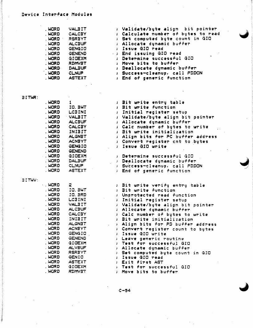
Device Intar~aca Modulas
i3 ITWR:
5 !TWV:
. WORD
. WORD
. WORD
. WORD
. WORD
. WORD
. WORD
. WORD
. WORD , • WORD . WORD
. WORD
. WORD
. WORD
. WORD
. WORD
. WORD
. WORD
. WORD
. WORD
. WORD
. WORD .. WORD
.·woRD
. WORD
. WORD
·.WORD . WORD . WORD . WORD . WORD . WORD . WORD . WORD . WORD . WORD . WORD . WORD . WORD . WORD . WORD . WORD . WORD . WORD . WORD
VAL.eIT CAl.CBY RSRBYT ALCBUF GENG IO GENEND GIOEXM RDMVBT DALBUF CLNUP ASTEXT
1 IO. l3WT LC13INI
· VAL.BIT Al.CBUF CAl.CBY INIBIT Al.GNBT ACNBYT GENG.IO QENEND GIOEXM DALBUF CLNUP ASTEXT
2 IO.BWT IO.BRD LC13INI VAL.BIT Al.C:BUF CAl.CBY INIBIT ALGNBT AC NB YT GENG IO GEN END GIOEXM ALVBUF RSRBYT GEN IO ASTEXT GIOE:XM R'DMVBI
Validat•/byte align bit pointer Calculate number o~ bytes to r~ad Set computed b~te count in GIC Allocate dynamic bu~~er Issue CUO read End issuing GIO read Determine success~ul GIO Move bits to buffer D•allocat• dynamic burr•~ Succ•ss-claanup, call PODON End of gene-ric function
Bit Ul,-ite en tr" table Bit \d'r i te ilunc:tion Initia-1 register setup Validate/b1Jt• align bit pointer Allocate dgnamic bu-f~~r Cale: number of br.Jte~ to u.-r it e Bit w-r i ta initialization Align bits ilor PC bu-r.Per addre9s Convert reg.i ste,- cnt to .. b" te s Issue GIO w,-ite
Det.e-rmine suc:cassrul GIO Deallocate dynamic bu.P~er s u ·c c es s-c 1 CJ an •J p , call FD DON End of g ene-r i c ~unction
Bit w-r i te ve-ri.Pq en t-ry table Bit u.-r i ta ~unction Unp,.otected read i=1Jnction Initial reg i st eT' setup Validate/b1:1te align bit pointe-r Alloc:at• dqnamir. bur~.,..
C•lc: numbe,. o.P bytes to Ul'rite Bit t11-r it e initialization Align bits .Po-r PD bu .P .Pei- address Convert registe,. C:O•Jn·f; to bt-ltes Issue GIO w-rite Leave g ene-r i c: routine T•st .p O'r suc:c:essful GIO Alloc:ate dynamic bu-t~9,.. Set computed byte C·~unt in QIO Issue GIO r•ad Exit first AST Test f o,- succ:ess.P1;l G!O Move bits to buf'~er
C-54
.IA ."./
.,,j
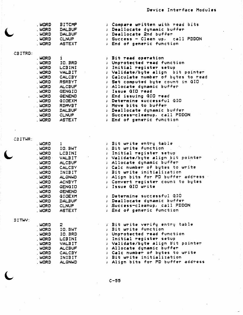
. WORD BITCMP
~ . WORD DALBUF . WORD DALBUF . WORD CLNUP . WORD ASTEXT
CB ITRD: . WORD 1 . WORD IO. BRD . WORD LCBINI . WORD VALI3IT . WORD CALCBY . WORD RSRBYT . WORD ALCBUF . WORD GENG IO . WORD GENEND . WORD GIOEXM . WORD RDMVBT . WORD DALBUF . WORD CLNUP . WORD ASTE>:T
CE ITWR: . WORD 1 . WORD IO.BWT i.
. WORD LCBINI
. WORD· VALBIT
. WORD ALCBUF
. WORD CALCBV
. WORD INIBIT
. WORD ALGNWD
. WORD AC NB YT
. WORD GENG IO
. WORD GENEND
. WORD GIOEXM
. WORD DALBUF
. WORD CLNUP
. WORD ASTEXT
BITWV: . WORD 2 . WORD IO.BWT . WORD IO.BRO . WORD LCBINI . WOR~ VALBIT . WORD ALCBUF . WORD CALCBY . WORD INIBIT . WORD ALGNWD
Device Interface Modules
Compare written with read bits Deallocate d~namic buT~er Deallocate 2nd buffer Success - Clean up, i:all PDDON End of generic function
Bit read operation Unprotected read function Initial register setup Validate/byte align bit pointe~ Calculate number of bytas to read Set computed byte count in GIO Allocate dynamic bu~rer Issue QIO read End issuing GIO read Determine successful GIO Move bits to buffer Deallocate d~namic bu~rer Success-cleanup, call PDDON End ol generic function
Bit U1rite ent-ry table Bit urr i te function Initial -register setup· Validate/byte align .bit pointer Allocate dynamic buffe,.. Cale numbeT' or bytes to UIT" it e Bit write initialization Align bits for PD bu.P.Pe'!" add-ress Convert -reg i st e-r count to bytes Issue GIO 111-r it e
Dete-rmine successful GIO Deallocate dynamic buf-ter .Sue c ass-cleanup, call PD DON End of geneT'ic function
Bit UJrite ve~ i -Fy entry table Bit Ul"r it e -Function Unp1'otected "read -Function Initial T'eg i steT' setup Validate/byte align ti it pointer Allocate dynamic buf-FeT' Cale numbe-r of bytes to w1'ite Bit U1-r it e initialization Align bits for PD burf e-r add-ress
c-ss

Devic:• Interface Module~
. WORD
. WORD
. WORD
. WORD
. WORD·
. WORD ·.WORD . .WOP.I.\ . WORD . WORD . WORD . WORD . WORD . WORD . WORD
AC NB VT GENG IO GENEND GIOEXM ALVJ3UF RS"RBYT GEN IO A£1'£Xl' GIOEXM RDMVBT BITCMP DALSUF DALBUF CLNUP ASTEXT
~ Read status of PD
RDSTA;
-.STAR'T:
STOP:
. WORD
. WORD
. WORD
. WORD
. WORD
. WORD
. WORD
. WORD
. WORD
. WORD
. WORD
. WORD
. WORD
. WORD
. WORD
. WORD
. WORD
. WORD
. WORD
. WORD
. WORD
. WORD
. WORD
1 IO.DAQ LCBINI' SETSTS GENG IO GENEND
'3IOEXM CLNUP ASTEXT
l IO. STR LCBINI STRSTP GENG IO GENEND
GIOEXM CLNUP ASTEXT
1 IO. STP LCBINI STRSTP GENG IQ
f Convert registei- count to b•.Ji:es Issue <HO u.-r i te Leave generic routine Test 'or succ:ess,ui GIO Allocate d~namic: ~u•9er Set computed b~te count in GlO Issue GIO read
... .Es i '; f i~ ~.'; -P..£l' T•st for successful GIO
; Mov9 bits to buffer Campa~• ~ritten ~ith read bits Deallocate d~namic buf9eiDeallocate 2nd buf9er Success! Clean up,:all $PODON
r End of generic function
One status GIO function Diagnostic: read Initial setup entTy
> Set up status GIO stuff Issue GIO r•quested runction End gene-ric _i2unction .. next wo-rd cont•ins the next Jump a,te-r entering the AST Test i2oT succ:ess~ul GIO
. ; su·c.c: •-s s c:.l ean up, ca 11 PDDON Exit AST
Ona status GIO runction Star~ the device Initial setup ent'r~ Set up a sta~t/~top ope~ation Issue GIO requested ~unction End generic: ~unction, next word contains the next Jump after entering the AST Test fo-r successful G!O Succ:e~s clean up, call P:ODON Exit AST
; One status GIO function ; . St op th -. d ev i c: e
Initial setup entTy ~ Set up a sta~t/stop operation
Issue GIO ~•quested ~unction
C-56
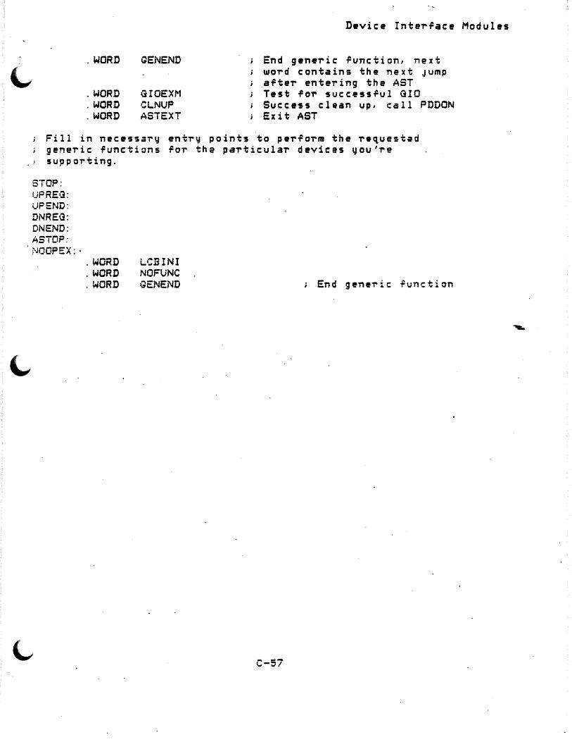
"" . WORD GENEND
. WORD GIOEXM
. WORD CLNUP
. WORD AST EXT
D•vice Inter~ace Modules
End generic runction, next word contains the next Jump .after entering the AST Test for successful GIO Success clean up, call PDDON Exit AST
Fill in necessa~y entry points to perform the re~uested generic functions for the particular devices you're supporting.
STOP: UP REG: UPEND: DNREG: DNEND: ASTOF:
. NOOPEX: · . WORD . WORD . WORD
LCBINI NO FU NC GENEND End generic ~unction
C-57

Device InteT~ace Modules
• :ic :tGEN:
.. ~ -~--------~----._,__..., ____________________ ---:---------------------------------·$QENFC uses the ent-ry point in manu.Pact.u,..e-r./model tables to dete-rmine the gene-ric function to be p-rocessed and rgturns the ant-rq point ~unction branch table
Input: RO poi.nts to enti-" in manu.Pac:tuTeT table RS points to LCB
Output: RO points to ~unction branch tabl• .Por reques~ed ~unction Rl points to GIO function to be u~ed nex~ <Rl < RO> R5 points to LCB
$GENFC uses the ~nt-ry point in manu.Pac:tu,..e-r/model ·to dete'T'mine the gene-ric function to be p-rocessed and retu,..ns the ent-ry point ¥unction b-ranch table
SAVRGS MOV CALL
CMP l3EtJ TST BNE MOV
JMP
<R5,R4,RJ,R~,Rl,RO~; S•v• registe-rs #xxTBL, RO RO iroints to Man.P/madel tab le ~QENFC De~a-rmine -function b~anch
ta.bl a
#-L RO 10$ RO 5$ #NOPEX,RO
i<RO>+
Fu.nc ti on e-r,.- o,.- '? Yes, end gen e'r i c ,.. ai q ~Jest Ir ze,.o, no-op -Function P~ocess spec·i,ied ~unction NO-OP ~unction for device
Jump. to first sub ~unction
MOV #S~ FNR,C. SRVSCR5.> ; Gene-ric 'unction ~rror code JMP GENERR ; End gene~ic pT"oce~sin~ ~o,..
Gene"ric Function Ent~y Poi~ts
:-----------------------------------------.-.-----~-------------------._,-.-
;_c.!3 INI:
Initialize the ~ields in the LCB and otheT"s so that th~ processing maq begin.
MOV #GENEnR, C.SAVE+30. CR5> GENERR i's th~ de.Pauli: ; er-ro-r routine ~o,. now
C-58

'-' CLR CLR CLR
MOV
MOV MOV
CLR MOV ADD .JMP
C. SAVE+16. <R5 > C. SAVE+18. <R5> C.SAVE+20. <R5>
C.MADR<RS>, R3
Device Interrace Modules
Clear allocate bufrer lengths to indicate that nothing ·has been allocated ~et
R3 points to Start g.eneric -request· message
R1, C.SAVE<RS> Address of current GIO Tune R.QCNT<R3>, C.SAVE+4<R5>; Save Count of data
; requested C. SAVE+8. < R5 > i C 1 ear sub function P.3~·:. SAVE+2(R5) .~ Copy beginning of message data #R.GDAT,C.SAVE+2<RS); Address OT data bufTeT @\RO>+ ; Goto next entry in table
;-------------~-~--------------~---------~----------~-~--------.-~
ALABUF:
For model MD. X~C, allocate memorv within task image ~or extended addre~s. This is ~ecessar~ since the driver assumes
; that the address bUTTer is in the task space. Since it is in the mapped message bu~~er it is not available to the driver.
CNVBYT:
SAVRGS
MQV MOV CALL BCC
; Error MOV CLR CLR RE SR GS .JMP
MOV MOV MOV ADD . REPT MOV . ENDR RESRG$ ~MP
•
#XTL. ADR, FU #F$REHD,RO SRGCB 1$
allocating bufTer
Save registers, SRGCB-destroys RO, Rl, Sc R2 Set burfer size RO points to Tree memo~~ listhead Allocate ne~ block Clear? - it made it
#SE.RSC,C. SRVSCRS>; Resource error C. IOSB<R5) Clear 1st word of IOSB C. IOSB+2<R5> Clear byte count in IOSE C::Ro:~.. -; Restore registers <!C. SAVE+30. CR5) Go to erro-r routine
RO,C.SAVE+6(R5> R1, C. SAVE+16. CR5) C.MADR<RS>,Rl #R.QADR,Rl (XTLADR/2)· <.R 1 > +, < R 0 ) +
<RO:> @CRO>+
Address of address buffer ; Save length ~or deallocation Rl points to Start of Generic data Address of extended add~ess to move Move the extended address into ta s k image s? a c e Restore registers Goto next entry in table
C-59
___ J

Device Interface Modules
s~itch register count to bvta count ~OT R/W register
ASL JMP
C.SAVE.+4<R5> i<RO>+
Shi'~ # ~ords to b~tes oi data Go to next e~tr~ in table
;-----~~--~~--------------~---,__--__.__,__ _______________________ ~
BYTCHK:
Compare bqte count re~uest•d •ith cuTrent bqte count for message buffer.
MOV MOV
SUB BL.E
CMP BLS: MOV
CMP BLT JMP
MOV JMP
C.MADR<RS>,Rl M. DLEN <R1> IR 1
#R.QDAT,R1 50$
Rl, #R.QLDT 20$ #R.QUJT, Rl
Rl,C.SAVE+4\R5> 30$ iCRO>+
Rl points to Start o~ QeneTic data Rl points to previous returned b-1Jte count Actual data b~tas Need more than zero
is it bigger than the m•x i/o transaction ror this device? Use the smaller o~ the two.
Compare to re~uestad Need >• 0 Oo to n•xt table ent~~
#SE.CNT, C. SRVS<R5> ~ Bad count requested. @C. SAVE+30. C.~5) ; Qo·· to. error rou.tine
~--------~~-----------~--~--~------------~------------~-------------~
ALCBUF:
Allocate dqnamic bu~~e~ area
10$:
SAVRGS <RO::·
MOV SUB CMP
MOV CALL BCS
G$CBYN, R! #R. GDAi, Rl Rl, #R.~GLDT
1tJ$ #R. KGLDT .. R 1
#F-:SREHD,RO $RGCB 30$
Save registers
make actual Compare burfer size with allowed ror u10 maxlmum Ta k e th e s ma 11 a r ·~ ~ ·!; h ~ tu; o Set bu.P.Pei- size
RO points to f~ee memoi-~ listhead Allocate new block S•tr - it didn't allocate
MOV C. SAVE+2. <R5>, C. SAVE+l;?. <RS> ; Save old ; buf-fei- address
C-60
~-_./

MOV
MOV MOV RESRQS .JMP
D•vice InterTace Modules
C. SAVE+18. <RS>,· C. SAVE+~O. <RS> ; Save old bur.Per length
RO,C.SAVE+2<R5>; Move in new buffer address R L C. SAVE+ 18. { R 5 > ; Se t a c tu a l l en g th <RO> Restore registers i<RO>+ Qo to next entr~
30$: ; Error allocating buf.Per MOV #SE .. RSC, C. SRVSCR5> ; Resource error RESRQ$ <RO> ; Restore registers .JMP @C~SAVE+30<R~> ; N•sted AST level error
.; --------------------------------~----,__----~__._,_,_..... ___ ... ______ _ VALBIT:
Validation and possible word points to byte adJustment OT bit pointer Device XXC needs to be word aligned others byte
l,. 10$:
20•:
MOV CMPB BGT
C.MADR<RS>,R2 :it16. , R. GBOF C R2 > 10$
; R2 points to Start generic data Check ror valid bit o~rset Less than okay
MOV #SE.ADR, C.SRVS<R5); Generic error, reJect run~tion because or address
'-1MP \!C. ·SAVE+30. < R5 > ; Flag e-rror and return
CMP BEG
CMPB BGT SUB INC
.JMP
C. MODL < R 5 > , #MD. XX C ; I s. th i s a XX C fun c t i on? 2o·s Yes, le•ve cas UJOT'd C'l.igl"led
#8. I <R2 j 20$ #8. I <R2) C.SAVE+6<R5>
@<RO>+
Pointing to second bg-te Fits in ri~st byte Point to bit ~ithin byte Move addr up 1 byte
Go to next ent~~ in table
;-----------------------------------~----------------------------
INIBI'T:
Initial register ~etup for bit alignment operations When exiting, R2 = bit orfset negated ro'I" right shift
MOV C.MADR<R5>,R3 ; R3 points to StaTt generic data MOV R.GBOF<R3>,R2 ; Minus bit offset NEG R2 i Shift to the right ADD R. GBOF<R3>,C.SAVE+4(R5>; Add due to bit of~set MOV C.SAVE+2\R5>, R4; Addi-ess of buT.PeT' MOV #-16., C. SAVE+28. <R5> ; Possible shifts plus one ADD R. GADR+30. <R3), C. SAVE+28. <R5> ; Setup alignment
•
C-61

D~vice Inter~ace Modules
numb.,. ~MP @<RO>+ Qo to next table entT'~
!~~--------~------------------~-------------:------------..... ~----------ALGNET: .
Bit alignment ror bit write oparations R2 • bit offset into word <negated for right shi~t ope~ation>
10$:
SAVRQS CLR MOV ADD
MOV INC MOV SAVRGS MOV ASHC MOV MOV MOV INC COM CMP BLT
C::RO.:> Rl C.MADRtR3>,R3 ~R.QDAT .. R3
Save registars Clear low order second ~agister R3 points to Beginning or message data Beginning o~ message data
C.SAVE+6<R5), <R4>+; Move PC addre~s to buTrer C.SAVE+6<R5> Point to next word in FC <R3)+,RO Rl points to Bit data <R:J)· S~v• pointar to data C.MADR<R5>,R3 R3 points to Beginning or message data C. SAVE+;?S. <RJ), RO ; Shi.Pt double word needed bits Rl, <R4> Sto,.a sat bits in out b1.J~Ter CR4)+, ;?<R4> . Set up clear 1.11ord 2 waT'ds a111a4J C.SAVE+6<R5), <R4>+; Move next PC addT'ess in buf~9r C.SAVE+6(R5> ; Ready ~o~ next PC address <R4> ; Reset mask ro~ bits cleared C. SAVE+4(R5L R. GCNTCR3> ; Shirting ri-rst 1.uord 30-t ; · No, into bit op eT'at ion
We ar~ on fir~t wo~d, save the bits not requesting chang~
.30$:
SAVRG'$ r1ov ASH COM BIC RESRGS
ASHC MOVB i'10VI3 MOVB ADD SUB RESRGS BGT
<RO::.· #-L RO
; Save ~or next sni~t
R. G130F\R3i .. RO RO
; Set mask to all on~s Shift bit pointe~ amount·
RO .. CR4)
R2 .. RO '.R4>,RO -3 < R4 » < R4) R0,-3(R4) #2:R4 ; #16. :c. SAVE+4(R5) <R3) 10$
Save mask bits set to ls Save lo~ order bits Restore ~OT' next shi~~
Setup 'o~ next shi~t Swap low ~ith high ordaT next word Move high ordeT' to next word Move low cl~ar to -high prev. byt~ Point to next addr~s; ; Decrease number of blts l@~t RestoT'e pointer to da~a not done yet
W@ ar@ on last ~or~ Save bits in high OT'der that did not request updating
MOV #-L RO Set up save mask
C-62

l.,
~·
Device Inter.Pace Modules
MOV #16. I R1 Numb el" or possible ·Shifts +1 ADD C.SAVE+4<RS> .. Rl SubtT'act numbeT' shirted ASH Rl, RO Shift mask TOT' 10\1.C order byte MOV RO,R1 Rl TOT' high OT'd el" SWAB Rl Save m.ask TOT' high byte SUB #6,R4 Point back to set UIOT' d BICB RO, < R4 > Save cleaT bits BICB RO, 1CR4> Save set bits BICB Rl,4CR4> Save high OTdeT set bits BICB Rl, 5<R4> Save high OTdeT clear bits MOV C. SAVE+14. <R5>,C.SAVE+4CR5> i StoT'e numb eT' o.P
: bytes to write MOV c. MADR ( R 5 ) I R 3 i R3 points to Beginning IJ .p message MOV R. GADR<R3i,C.SAVE+6CR5> ; Reset PC add-ress RE SR GS <RO:> Restore register ~MP @<RO>+ ; Qo to next entT't.J in table
;------------------------------------------_._--------------------~-
ALGNWD:
Bit alignment within woT'd .Por XXC wTite bit opeT'ations R2 = bit offset into woT'd Cnega~ed foT' right shi't operation>
10$:
SAVRG$ (RO:::· Save -registers CLR Rl Cleal" low o,.. d el" second i'egisteT' MOV C.MADR<R5>,R3 R3 points to Beginning 0 .p message ADD #R.GDAT,R3 Beginning o.P. message data
CMF #16., C. SAVE+4(R5) ; 'Test TOT' ·one 11.10T'd byte count BGE 10$ Ir within one woT'd okay MOV #SE. CNT,C. SRVS<R5> ; Move in invalid count eT'roT'
RESRG$ ~MP
MOV MOV ASHC MOV MOV COM
<RO)· @C.SAVE+30<R5>
<R3>+,RO C. MADR < R 5 ) , R 3 c. SAVE+29. <RS) I RO R 1, < R4 > <R4)+, <R4> <R4)+
to sTvc sts RestoT'e Tegiste-rs ErT'oT' Toute out
Rl points to Bit data R3 points to Beginning of message ;Shift double word needed bits Sto-re set bits in out buTfer Set up clear woT'd Reset mask foT' bits cleared
We ~re on fi-rst woT'd1 save the bits not -requesting change First and onl~ foT' now
MOV ASH COM BIC
#-L RO R. GBOF CR3 »RO RO RO,-<R4j
; Set mask to all one: Shift bit pointeT' amount
Saved mask bits zeroed Save low order bits
•
C-63
data
data
data

Oevic:e Interface Modules
We are on last word Save bits in high order· that did not i-equest updating·
MOV ASH BIC BIC
#-1,RO C.SAVE+4(R5>,RO RO, <R4> RO,-<R4>
Set up save mask Shift m•sk S•v• c:l•ar bits Save set bits
Force a on• word entr~< ACP accepts only one word GIO>
40S:
CALCBY:
MOV RESRQS ~MP
M,C.SAVE+4<R~> <RO> @<RO>+
Store number byte5 to write Restore register Qo to next entr~ in table
Calc:ulata number of b"tes .Pro.m bits sent down for G!O ope,-ation
10$:
20-S:
30$:
MOV MOV ADD AOD ASH
CMP BEG ASL
c. MADR <R5) I R3 R. QBOFCR3> .. Rl C.SAVE+4<R5>,Rl #7, Rl" #-3,Rl
R3 points to Beginnin~ o~ message Bit pointer into byte Number of bits ~orking with Force a round up to the next byta Divide by 9
M. CODE<R:J) ~#MO. RED i Bit ·raad? 20.. Ves1 no addr in data R 1 ; Doub le,. due to mas k in g spa c e
CMP C. MODL<R5>, #MD. XXC ; Is th is XXC function"? BNE 30$. Go on ADD #1,Rl Inc to next bqte BIC #1,Rl Force even
MOV ~MP
RL C. SAVE+14 .. <R5> ; Number or bytes to un•ite i<RO>+ Go to next table ent~y
i ____ ...._ ______ __.~~---_,_--~...,___,_..._ ______________ ~---------.-.--
RSRBYT:
; Place the calculated byte count into GIO pa~ameters
MOV C. SAVE+14. <RS>, C. SAVE+4CR5> ; Calculated numbe-r o.P ; paramete~~ sent
~MP ~<RO>+ ; Go to next table entry
;-------------------------------------~----.-----------~------------
C-64
data

Device Inter~ace Modules
i: SETSTS.:
~ Set up device status operation
MOV CMP BNE MOV MOV
BR 10$:
MOV
20$: ADD .JMP
# 10. , C. SAVE +4 ( R 5 ) 10 b y ta s a x p e c t e d C. MODL < R 5 ) , #MD. XX C ; I s th i s a XX C ,.. e q u e st 10$ ; Bypass byte count change #18., C. SA\.'E+4CR5> ; 18 bytes for XXC C. SAVE+8. <RS>, C. SAVE<R5> ; Move in status
.Punction 20$ ; Need sub~unctian ~et
C .. SAVE<R5>, C. SAVE+S. <R5> ; Qet addT"ess o~ ; functions
#2, C. SAVE+S. <RS>; Point ta sub.Punction @<RO>+ Qo ta next table entry
;-~------~---------~-----------------------------------~----------
STRSTP:
; Set up start stop opeT"ation
CLR JMP
C.SAVE+4<R5> @<RO>+
There is no data to b~transferred Qo to nex~ table entry
GENG IO:
GIO's parameters ~ere initially set up in the LCBINI function routine parameters are stoT"ed in C. SAVEU > thT"u C. SAVE CS) .Por easy retT"ieval in case of timeouts OT" blo~k check retries.
The QIO paT"ameters ~or the GIO a~e
MOV C.LABCR5>,R4 R4 points to LAB .p OT' this device MOV L. LUN < R4 > .• R4 R4 points to Logical unit number MOV R5,R3 Copy LCB beginning ADD #C.SAVE,R3 R3 points ta Beginning o.P !>aved MOV #GENAST, -.., rte. Get addT"ess of completion AST MOV RO .. C. SAVE+10. <R5> Save next en tr 1' OT -Function
bi- tbl ADD #2.· C. SAVE+lO. CR~> Point to next entT"y beyond ...
data
·GI 0$S @ ( R 3 ) I R 4, I I R 5 .. R 2, <2 ( R 3) ' 4 ( R 3) I C .. STN ( R 5 ) I 6 ( R 3), t~S. ( R 3 ) I TMOUT:::-
MOV MOV BMI
C. MADR < R 5 ; , R 3 $DSW .. C. SRVS<R5> 50$
R3 points to Beginning of generic data Generic status message Take eT"T"Or route if directive
•
C-65

Device Inte-r~ace Modules
.,..,.0,. JMP @<RO>+ Qo to n•xt table ent-rlJ point
~0-t:
JMP @C. SAVE+30. < R5 > Send 9'r'r O'r and exit
GENAST:
Qene-ric seT"vice AST -reentT"y point and T"•coveT"~ -routine
1 O'S·:
15•:
ASDIMS S•v• registeT"s.R5-RO, R3 points to LAB o~ opeT"ation, and message buffeT" pointed to bg C.MPNTCR5> and C.MLEN<RS> is ~•m•pped and the add-ress o~ message h•adeT is placed in C.MADR<R3>
MOV #AST~R, C.SAVE+30. <RS>; Derault e'r-ror· routine ; is no~ AST type
; D•teT"mina i~ there has been a time out or block check
CMPB BEG
·CMPB BNE
DEC BLE
C. IOSB<R5>,#IE.TMO ; Test roT" time out condition 10-s ; Y•s, dee count and -retT"~ . C. IOSB<RS>,#IE.BCC 15'$
C. iRY< R5) 15'$
; TiJst block ch~ick condition· No; determine status and condition
Numbe,.. o, retTi.es Done t'r~ing - continue
.: Re - i ;sue GIO
.MOV MOV MOV ADD MOV
MOV MOV
BMI
MOV
.JMP
c. LA.i3< R5) I R4 L..LUN<R4LR4 R5,R3 #C. SAVE.,R3 #GENAST, R.2
c. MADR ( Rs ) I R 3 $0SW,C. SRVS<R5>
R4 points to LAB fo~ this device R4 points to ~ogical unit numbe~ Copy LCB beginning
i.R~ points to Beginning o~ saved data
R3 points to Beginning o~ generic data Retu'rn $DSW e'rT"O'r code
Finished gene~ic ~e~uest
C. SAVE+lO. <R5)., RO ; Resto~e pointe~ to 'unction b'ranch table
~CRO>+ G~ to n~xt function branch entry
C-66
~
~ ... /

D•vice Inter~ace Module~
\,...,' DSW
JS:
e,..-ror
""
CLR .JMP
Rl a!C. SAVE+30. < R5)
Fo-r otheT' than -read runctions t•k• exit -route
;------~ ...... -----------~---~~---.----------_.------~--------~.--,--QIOEXM:
DeteT"mine RSX i/o e-rT"oT' then send the gene-ric eT'T'O'r code, if successful then continue ~ith next step in function b-ranch table
20•: Qene-ric &T'T'OT' message area CLR
MOV MOV
C. SRVS<R5> ~nOERR, Rt #lCERCT,R2
R1 point• to i/o statu~ -.r~o~ tabl-. R~ points to Size .of ei-To-r table
29S:
30$:
3SS:
CMPB BEG ADD SOB MOV BR
MOVB MOV CMP BNE .JMP
CLR .JMP
C. IOSB CR5>, CR1 > Dete'rmine i/o status 30S go to inseT"t generic function #2,Rl Trv next entT'~ R2,29S Do until end of table #SE. INT, C. SRVSCR5> ; Function ei-,.-o,.- ,..eturned 35-S
l<Rl>,Rl RL C. SRVS<R5> R1,SE.SUC 35..S @<RO>+
Rl @C. SAVE+30. <R5>
Byte.status ei-T"o'r Inseit gene-ric status Was it s~ccessful?
E-r-ro-r - clea-r byte cnt End gene'ric function
.i -~-----~-----~--------------------------~----~------.----------.-
RDMVBT:
; Align bits to send back upstai'rs fo-r -requested read bit ; ope~ation. Send bit st-ring ~o'rmat OT only bits -request
beginning with bit offset into wo-rd
<RO> Save registeT"s
..
SAVRG$ MOV MOVB NEQ MOV MOV MOV
C.MADR<R5>,R3 R3 ROints to Beginning of message data
10$:
R.QBOF<R3>,R2 Bit pointeT' within wo~d R~ For right shifts C. SAVE+4<R5>, C. SAVE+14. CR5> ; Copy bytes read in C.SAVE+2CR5>,R3; Allocated buffe-r ,..ead into C. SAVE+12. <R5>, R4; Retu'rn buffe,..
C-67
•
_J

MOV <R3>+,R1 Fi,.st wo,.d in lo"' O'rde-r registe,.. MOV <R3» RO Move into high o,.d er rtig i ste-r ASHC R2,RO Shift to the right MOV RL <R4)+ Move low o,.dar to message b l.J rr e-r SUB ~2.· C. SAVE+14. <R5) .• Dei:'rea se bvt•~ l!!.Pt to snii1t BOT 10$ Not done, shirt again
MOV # .. "CO, RO Set ·up mask MOV C. MADR < R 5 >, R 3 R3 points to Beginning oi1 message data MOV R. QCNT CR3) IR~ Save bit count BIC #"'C15. ,R~ Mask out all but UIO'r d BEG ~O'S
ASH R~., RO Shi rt 111.a s k ed bits BIC RO,-<R4> S•ve bi ts not requested
20$: RESRQ$ <:RO)· Resto-r• registe,-s .JMP i<RO>+
BITCMP:
; Bit ~omparisan .Po,.. W'rite/ve-ri.Py bit ope-ration
SAVnG$ MOV r10V ADD MClJ SUB .3.:~e:
<RO::· c. MADR <R5 j I R3 R. Q.CNT<R3>, R2. #R.GDAT~R3 C. SAVE+12. ( R 5) I R4 #8. ,R2
S.ave T'egister-; R3 points to Beginning of message data Numbe,. of bits w-ritten R~· points to Start o~ input bits ; .~4 points· to Bits read in ilrom PC Decrease numbe~ o~ bits le~t More bytes to go
We are on tha last byte to compare
30-S:
l'10V ASH BICB BICB CMPB :SNE TST BGT
:Jt-L RO R21RO RO, <R3> RO, < R4) <R3), CR4)
R2
RESRG$ <RO:> '-1MP ~<RO>+
Set up mask ;. To the left
Clsa-r input Clsa-r read in Compa-re current b~te Bits not the ~ame? Done? No, g 0 t 0 n e :t t b IJ t e
Restore register Go to next table ent~y
MOV .JMP
#SE. VFY,C. SRVS<RS> ; Verification e-rror t!C. SAVE+30. <R5> ; End of gene,.·ic .Punci;ion
~~~-------------------------~-----------~------------------------
C-69
"""

Device InteT~ace Modules
~C.MPBUF:
Routine to c~mpare buffeT ~Titten and buffei- i-ead back
10$:
30$:
MOV MOV ADD MOV
CMPB BNE SOB JMP
MOV MOV MOV .JMP
C.SAVE+4<R5>,R1 C. MADR <RS» R3 #R.QDAT,R3 C.SAVE+~<R5>,R2
<R~)+, <R3>+ 30S Rl, 10$ @<RO>+
R1 points to Number of bytes to compare R3 points to Start generic data
-; W-r it e buff e-r R2 points to Beginning of read buffei-
Test cv-rrent byte and inc ET'T'O'r in data Move th~u buff e~ areas Qo to next table entTy
#SE. VFY,C. SRVS<R5> ; VeT'irication e-rror C.MADR<R5>,R3 ; R3 points to StaT't generic data #SE.VFY,R. QSTSCR3>; Gene-ric erT'oT' @C. SAVE+30._ <RS> ; End genei-ic function
·' ---------------------------------------~~-------.....,---------.-----------.---
DALBUF:
Deallocate tempo-ra-ry woTk buffeT'
10$:
TST ·BEG
.. SAVRG$ MDV
MOV MOV CALL MOV
MOV
CLR RE SR GS
JMP
C. SAV.E+l 9. < R5 > 10$
<:RO, R 1:, .. #F$REHD,RO
c. SAVE+ 1 e. < R s > , R 1 C. SAVE+2. < R5 >, R2 SRLCB
Get length ~f dealloc buffer Noth in g ·to d ea 11 o c ate
Save registers AddTess of free memoTy listhead ; Size of block to be released ; Address of block released Release it
C. SAVE+12. <R5>, C. SAVE+2. <RS> ; Re-store old bu.Pfe,.. area
C. SAVE+20. <R5L C. SAVE+18. <R5) ; RestoT"e old
C. SAVE+20. <RS> <Rl,RO:>
@<RO>+
buff ei- 1 eng th · MaT'k second buffeT" deallocated RestoT'e registeTs
; Go to next ent~y
;---------~-~--~--------------------------------~--------~----~--
DALXTA:
Deallocate memory used roT stoT"ing addT"ess buffers ~ithin task image space.
C-69

Devic• InteTfac• Modules
TST BEG
SAVRQS MOV
MOV MOV CALI.. CLR RESRQS
C. SAVE+16. <R5> :!OS
<RO, R 1;. .. #FtREHD,RO
c. SAVE+16. <R5) IR 1 C.SAVE+o. <R,>,R2; $RLCD C. SAVE+lo. <R' > <R1, RO>
Was memor~ allocated fo,- a ext•nded addr•ss function ?
Save i-egister~ Address of fi-ee memo'rg listhead ; Siz• of block to ba released Addr•ss of block ,.elaased R•l••S• it MaTi it de•llocat•d R•sto~• registers
@<RO>+ ; Qo to nex~ entr~
; --~---------------. ·---------------------~-
.CLNUP:
Succass9ull~ completed i-equested generic function Seif up status. returns and r•gistaTs then call PDDON
NOFUNC:
MOV · MOV
MOV MOV CALI. .JMP
C.MADRCR,>,R3 ; R3 p-oints to Beginning of gene-ric data C.LAB<R5>,R4 ; R4 points to Associated LAB #SS.SUC,C.SRVS<R'>; Q•n•Tic status C.SAVE+4<R,>,Rl Save b~t• .count tPDDON PeTform cleanup ope'rat~ons @<RO>+ Finish exit AST
; .• ~OP- ~•Jr.tc:ti~n r~utir.re r~,. d9vic:9s n~i: s1.J9p.o-rtin9' :all g.er.?e-ri!:: runc:tions
Cl..R i'fOV CAW. .JMP
Rl ; Z•~o numbe~ o~ b~tes #SS.SUC,C.SRVS<R5) ; Qene~ic success message $PDDON a<RO>+ O•n•~ic ope~ation doesn't
~o~ cu~~ent device
;~~------------..... ---------------------------~----------------~----GENERR:
AST~R:
MOV SR
:It, RO
~-Cl..R RO
C-70

Device Inter~ace Modules
{ ; Erro,.., clean up T'outine. Clean up any allocate bu-Ffers. · CleaT' any ~ data being sent back and eitheT' T'eturn or exit AST depending
~
on which entT~ point taken
MOV ADD
SAVRGS MOV
C.MADR<R5i,R3 #R.GDAT,R3
<RO:'-.. #F$REHD,RO
R3 points to Beginning o9 gene,..ic data Point to address o~ data
Deallocate pT'imar~ bufreT'
TST BEG
MOV MOV CALL
C. SAVE+lS. <R5> 10$
Was memor~ allocated roT' the primary buffer ?
c. SAVE+ 1 e. ( R 5 i I R 1 .i s i z e 0 r b l 0 c k t 0 b e i' e l 9 as e d C. SAVE+2. CR5), R2 ; Address of block rel.eased $RLCB ; Release it
Deallocate secondaT'~ bu-rfer
TST C. SAVE+2v. (R 5) Was memorr~ allocated f OT' the BEG 20$ se~ondaT"y burfer ·?
MOV C. SAVE+20. <R5),R1 ; Size or block to· be'rereased MOV C. SAVE+12. \R5L R2 i Address of block !'el eased CALL $R~CB Release it
j Deallocate extended address buffer
20$:
30$:
50$:
TST BEG
MOV MOV CALL
RESRG$
CLR CALL TST BEG .JMP
.Jl'TP
C. SAVE+16. <R5 i 30$
Was memoT"y allocated fo~ a PLC3 extended address -runction ?
C. SAVE+ 1 6. < R 5 ) , R 1 ; Si z e o .P b l o c k to b e re l ea s e d C. SAVE+6. <R5), R~ ; Address of block rel~ased $RLCB . ; Release it
<RO:>
Rl $PDDON RO 50'$ GENE ND
ASTE Xi
Zero byte count - so function is bypassed Determine how ~• get out o.P here
Retu~n to caller
Return -From AST
C-71

Device. Inte~face Modules
GENEND:
; E.xit at non-completion AST l•vel
RESRGS <RO,Rl,R~,R3,R4,R5>; Resto~• registers RETURN ; Retu~n to call•~
;-------~,__----------~~----~-----------------------
ASTE:XT:
; Exit inte~mediate AST
RESRQS <RO,R1,R~,R3,R4,R'>; Resto~• r•giste~s ASTXSS ; Exit AST
. DSABL l.SB
C-7:?
APPENDIX D
ADDING NEW DEVICE SUPPORT
D. 1 Overview
The information presented in this Appendix is useful to those individuals ~ho are adding ne~ device support.
D. 2 Useful Reading Ma~erial
The l,' ad d l. t i on following publication ·ma~
of new devic·e· support: be us.eful plartning the
o fil:iQE. FLOOR GATEWAY Installation Ouide/Release Notes
0 Use~'s Guide to 1h.!. Communication Software
Allen-Bradley <13/NETi
Highwau Netwo-r k
{.1770-843, available f'rom Allen-B-radlet,Ji useful if the U$er is w~1-;1ng a DIM fo-r unsuppo-rted Allen-BT'adle1~ de"¥·ices, or anothe~ utility)
D. 3 Hardware i So~tware Environment
·The GATEWAY system i; implemented on PDP-11 se~ies processors, each containing a minimum of 512K bytes oP memory. A maximum o~ Four gateways are supported.· The processors are connected to a VAX via a DECnet link and to programmable device networks via asynchronous serial lines. ·
The GATEWAY system uses the RSX-11S operating system. This operating system features minimal overhead while p~oviding a real-time multitasking.environment.
D-1
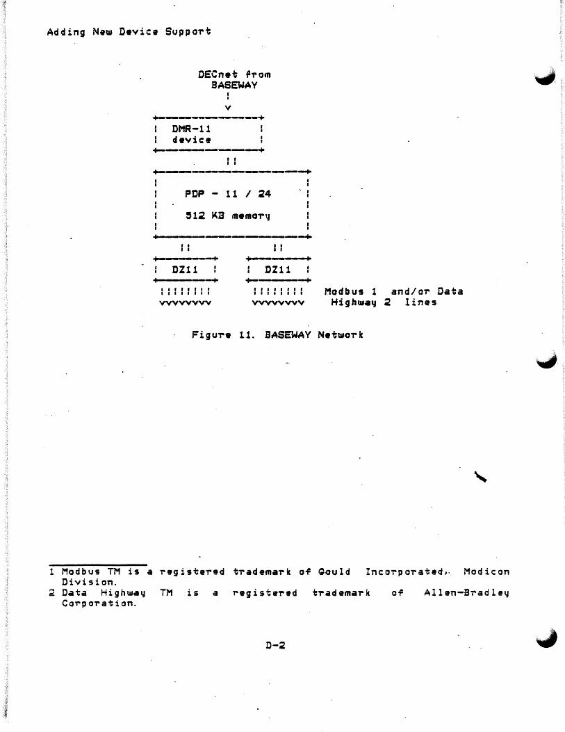
Adding Ne~ Device Suppo,.t
DECnet i',.om BASEWAY
v +-------+
DMR-11 device
+-------+ I I I t
+----------+-PDP - 11 I 24
~12 KB menao,.~
I I
' I I
I • I I
I • ·------------------------+ I I
It
---+ DZ11
.. -- --+
;. . ' I I
DZ11 . ;.
+-----+ I t I I I I I f I I I I I I I I
vvvvvvvv f I I I I I I I I I I I I I I I
vvvvvvvv Modbus 1 and/o-r Data Highw.a~ 2 lines
Figu~• 11. SASEWAY Netwo,.k
1 Modbus TM is a ,..egiste-red t,.adema-rk o-f' Qould Inc:o-rpo,.ated,. Modicon Division.
2 Data Highwa~ TM is a ,.egiste"red t-rademark Carp oration.
D-2
of Allen-Bradley
.J.
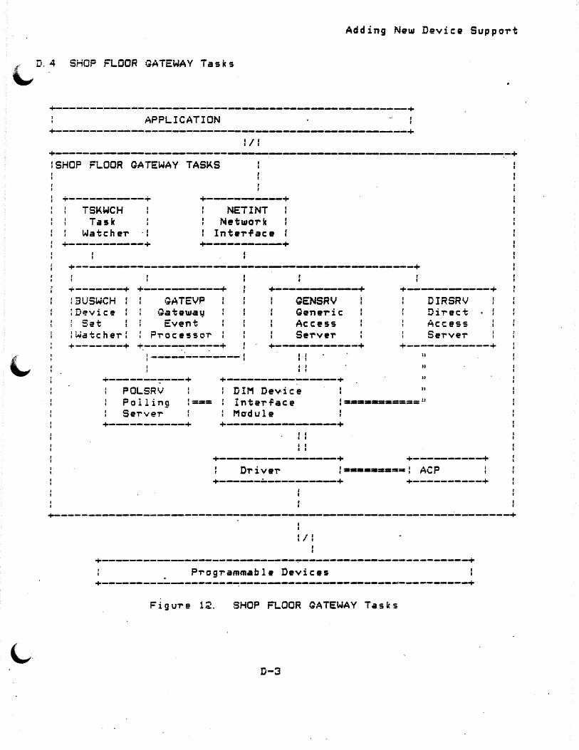
Adding Ne~ Device Suppo-rt
r D. 4 SHOP FLOOR t~ATEWAV Tasks '-' .
+----------------------------------------------~----------+ APPLICATION
+-----------------~--~-----------~---------------------+ :/:
+---------------------------~----~----------~--------------.-+ lSHOP FLOOR GATEWAY TASKS
+------------+ TSKWCH
Task Watche-r . I
I
+-----------+
+-----------+ NET INT
Netwo-r k Inte-rface
+-------+ +------.--.----------------~-------~~---------+
+-------+ +-----------+ ~------------+ +----,_,_------+ iBUSWCH f :Device f ; Set ' I :watchei-:
GATEVP Gateway
Event P-rocessoT'
QENSRV Generic Access Se-rveT'
DIRSRV Di -rec·t Access Se-rveT'
l ' • I
+-------+ +-----------+ +----.-.-------+ +-----------+ : -----·-------- I I
I I
I I I I
+-.-..-----~----+ +---------------+ ii
u
u
n POLSRV Polling SeT've-r
DIM Device : ==== : Inte-r~ac.e
: Madule l=·-·-==-====11
+-----------+ +~-----...._---------+ I I I I
I I I I
+-~---.----------~+ +--------+ D~ive-r :a•=•m====l ACP
+------~----------+ +-------~--+
+-------------------------------------------------------------~--------+
I I:
+---------------------------------~-------------------~-----+ Programmable Devices
+----------------~----~~--------------------~----------+
Figu-re 12. SHOP FLOOR GATEWAY Tasks
D-3
Adding Ne~ Device Support
D. 5 QATEWAY Initialization
A S~stem Startup is pe,.ro,.med when the QATEWAY system is rirst pouse,.ed ·on, and tne,.earter t11heneve,. ·a compl•t• .GATEWAY restart is r-.quested. - .~nitiall1:11 DECnet dou.nline loads the GATEWAY S'JStem and prog,.ams.
Aft•,. th• ope,.ating syst•• is initialiied and ce,.tain tasks that pe~fo,.m s~stam and application initialization have been do~nloaded and co•9latad, a copy of the Task W.tch•,. task is do~nline task-loaded from BASEWAY. The Task W.tche-r task then requests the netwo,.k intar~ace, c,.•ates the inte,.tasi m•ilboxas, and sta,.ts the othe-r tasks running.
Initialization Or the QATEWAV tabl•s is perro,.med arter ev•,.11thing is in re•diness. The OATEWAY Initialize-r on the application traverses . the required databases and .sends message-s containing the polling pa-ra~•t•,.s to tha QATEWAY Event Pracessa,.. GATEVP builds the memor~-resident polling tables from these messages and enables the Palling .Interrace.
D. 5. 1 Network Inte"rrac• <NETINT>
The Net1110,.k Interface task allows tasks to c_ommunicate rega,..dless o.P DECnet limitations or runct-i.·onality. In addition, it pe"r.Po-rms the ~.'·.,·, r ~ 11 o us i n g a c t i .on s : · ··
0 except ro~ ce,..tain control messages, ~out~s incoming inte,.p-racess messages to the p,..ape,. destination ti-anspa-rently;
o maintains ~ueues ro,.. outgoing messages;
o optimizes message t,..ar~ic ave,. DECnet;
o communicates di'l'ectly t11ith othe,. Net111ork intar~ace tasks on othe-r p,.ocesso,..s as requi"red.
D-4

Adding New Device Support
-D. 5.2 QATEWAV Event Proc9ssor <GATEVP>
~. The GATEWAY Event Processor subs~stem is responsible for
controlling the operation of the GATEWAY system. The GATEVP task resides in every GATEWAX system, and is controlled and monitored b~ the TS~WCH task.
On GATEWAY initialization, the GATEWAY Event Processor receives configuration messages from BASEWAY ~hich are used to set up VDR database. This database is used bv the Polling Interface to determine the polling requirements and status of the svstem.
Its activities include:
o sending raw PO data to BASEWAY a.Pter quali.P.ication and preprocessing, depending on register definition;
o accepting messages from BASEWAY ta· load PD definitions in VDRi
o returning a status report to BASEWAY on comma-nd.;
o interacting with the Network Inter.Pace and various s~stem management functions on the SFQ;
5. 2. 1 PD Data Processing. -
The GATEVP task performs preprocessing of data be~ore
includes:
PD the
register message
qualification and reaches BASEWAY.
any This
o analyzing whether a status bit or data changed berore sending it to BASEWAY.
o determining ~hether to process trigger b~ffers;
o converting PD register data from BCD to binary numbers;
Data to be sent is Pirst 'ormatted into polled data messages: Next, depending ·an the type of T'egister .being processed1 one or more data packets are packed into the message for transmission. The process which GATEVP sends a data message to is part OT that data's dei=inition (the derault. is DATA_?ROC>. One· da.ta packet is defined -ror each ea~h status Qr maintenance bit, trigger bufTer, or data count ~egister. Each poll~d data mess~ge has a header containing the equipment logical ID and a time-date stamp. Each data packet is identified with data id@ntifier code.
D-5

Adding New Devica Suppo~t
D. 5. 3 GATEWAY Ta5k Wateher <TSKWCH>
The Task Watcher task:
o monitors the status o~ each ta4k in the GATEWAY system, and in~orms the application ~hen problem5 occur;
o handles system startup and shutdown.
The Task Watcher task runs continuousl~ on the GATEWAY.
D. 3. 4 Devic:e Set Watcher .(BUSWCH>
The Device Set Watcher task accessibilit~ o~ device sets ~or the initially determining what device s•ts GATEWAY. It is also responsible ~or activit~·~ith these events.
D. 5. 5 Direct Acces~ Server <DIRSRV>
monitors and controls the QATEWAY.~ It is resp o·ns ib le fl or are current!~ attached to the sqnchronizing the access server
The Direct A~cess Sarver task p~ovides a direct driver inter~ace ~ to a programmable de~ice, b~passing the protocol-handling ~eatures o~ ~he PD ~upport Ancillary Control Processes <ACP~>. In addition1 the task
o does no~ add d~vice-~peciric p'rotocol to me~=ages s9nt to programmable davices <allowing user application prog'rams on BASEWAY to do protocol ~~r special situations);
o pe,.~orms simple i;~an-sactions on the. device networks.
The Direct Access Server is use~ul when a vendor-"Supplied so~tuaar• p'rogram e:ti~ts to do downline loads, upline dumps, ate. For example, in Modbus TM applications the standard Modicon sortwa're on BAS~AY does all o~ the pTotocol and retr~ processi~g and uses the D i rec t Ac c: es s Server to pro c es s one Mo d b us TI1 pa c k et at a ·t i me.
D-6

Adding New Device Support
I::. 5. 6 Generic· Access SeT'ver ( QENSRV)
The progT'ammable device Generic Access Server is T'esponsible Tor ::: ~ r .P c,.. mi n g an y g en er i c. i I o t o a p r o g -r amma b l e. d e vi c e . I t p e -r f o 'T' ms ~~gister- read/write functions, coil read/write, unprotected memory access, etc. Thus, application programs running on BASEWAY may read and write to programmable devices without· regard to protoeols, unique d~vice architectures, addressing schemes, and other such matters. The 0~neric Access SeTver task:
o accesses devices via simple· requests such as 11 read regis·ter, .. " WT' i t e c o i 1 s, " et c . ;
o handles protocol, retries, device support AC?s.
etc. , in conJunction with the
The request and T'eply messages have the same general ~ormat
~~gardless of the make OT' model of device.
~. 5.7 Polling Serve~ CPOLSRV>
Th~ Progi-ammab·le Device Polling subsqstem is implemented hy the ,-~·~LSRV task. I·t is responsible for systematicall.y "polling" each PD
i. d informing the r~st t>.P the system whenever polled data changes.· ~ .e Polling Serve~ task i$ driven bg ·tables ~hich a~e initiall~ built
.: n th e a p p l i ca t i on and : a ·re l o ad e d into tab l e s in th e GATEWAY b y th e Event Proc~ssoi- task. Polling is done for each device specified in the table, with a given set o~ sets ol data definitions being polled . .j·t; speci~ied intervals. In gene-ral, data i1rom the scan5 is sent back to BASEWAY only if a point value changes.
The POLSRV task is also a highly data-driven program. It scans ~h~ data structures in the Virtual Data Region, pausing at speci~ic PD polling set blocks to poll selected PD data. Whether a PD is p~lled
depends on a number of 'lags and status bits in the VDR data structures, and whether polling a PD generates any further processing depends on the previous contents of the T'egisters and the data type.
D-7
Adding New Device Suppo'rt
D. 5.9 Adding a New Device to a GATEWAY
The ~allowing steps may be used .as a guide to adding a new device to the SHOP FLOOR GATEWAY:
1. Decide i-11 a te'rminal d'rive,- can be used. I~ it cannot, you must ~'rita a device d'riv•,. and ACP <optional> to communicate ~ith ·the neut p'rog'ramnaaale device.
2. Edit SFQ$ROOT:CSOURCE.DIMJDEVCOD.MAC, and add the neut device manu~actu,_.,. and model codes.
3. C'reate a new Device Inte'ri1ace Module <DIM> i1o'r the new devic• Csee Appendix C>.
4. Edit SFQ$ROOT:CSOURCE.DIMJDEVVEC.MAC to include the new DIM.
5. Relink DIRSRV, GENSRV, and POLSRV to inc:o,-po,-ate the net11 DIM.
6. Cop~ DIRSRV.TSX,. GENSRV. TSK, and POLSRV. TSK to SFG'SSYSTEM.
7. Modi'y SFGSSYSTEJ~:SFGVMR.CMD to load the d'rive'r and install the ACP. .
S. Invoke SFQ'SSVSTE't:GATEWAY.COM.
See the §l:f.QE. fLOOR GATgWAV Soi1twa're Installation Guide !.!J.9_ Release Notes ¥0~ help with system tailorin9.
D. 6 Adding A Neu.s Device to BASEWAY
The rolloU1ing steps can. be used to add a neu.s device to BASEWAY:
1. Update the ·module BASE_DEVICE_TYPE_DEFS in BSLtDEFS library to rei1lect the new manu~actu,-9,-, device, net~o,.k, etc.
2. Recompil-. PDAPQMOD. PLI, UARBFMOD. PLI BSLSLil3RARY.
BSLSROOT: CSOURCE.LIBRARVJPDAPGMFR.PLI, PDAPTMFR.PLI, PDAPTMOD. PLI, UARBFMFR.PLI, and
and inse'rt the resulting obJect ~iles in
3. I~ the device u.ill support uploading, downloading, and comparing, then CTeat• subroutin•s fo,- each runction and add refeT~nces to the~e subroutines in BSLSROOT: CSOURCE. LIBRARYJPDAPDNLOD.PLI, PDAPUPLOD.PL!, and PDAPCOMP. PLI.
D-8
Adding New Device Support
IT the device will not support these ~unctions, then modi~y PDAPDNLOD, PDAPUPLOD, and PDAPCOMP to return a PDAPS_NOTSUPPORTED status condition.
4. If the device will suppoi-t stai-t and stop functions, then m~di~y PDAPSTART and PDAPSTOP to send appropi-iate -requests to the SHOP FLOOR GATEWAY. Ir the device will .not support these runctions, then modiry PDAPSTART and PDAPSTOP to return a PDAP_SNOTSUPPORTED status condition.
5. If •ny device-specific errors need to be parsed, modify PDAPERROR to parse it.
6. Add commands to PDAPTRAN to translate ASCII addresses to "internal addresses" that the QATEWAY DIM recognizes.
7. Add code to PDAPNXTAD to rind the next valid internal address ro-r this device.
8. Modiry BSLSROOT: CSOURCE.UTILITY.EDTBASLINJEDTDEVDEF.PLI to reflect new device parameters and network. Relink EDTBASLIN.
D-9

Adding Ne~ Device Suppa~t
D-10

APPENDIX E
The rollowing terminology u"deT~tanding vaTious concvpts ·::~stem.
GLOSSARY
is and
intended to aid the user in te~minologv used in the BASEWAY
~ddress - address in a programmable· device (device-dependent).
~· ,:~i)Olicat:i1Jn - set ·o.P pl'ograms performing a ·single ~unction. An ,, . ~ p l i c a t i on may b e d e .P i n e d t o run on up to 4 VAX p 'T' o c e·s s or s, b u t c an ~ .ly b~ active on a single processor. processors·via DECnet.
:3.~SEW,~Y node - VAX/VMS p-rocessor which loads and initializes the GATEWAY and receives data from the SHOP FLOOR GATEWAY.
compiled addreS$ ;:i~vice.
an internal represe~tation of a programmable
aata identifier - a unique internal identirier that is assigned to a ~ata item at de.Pi"ition time.
d~ta item - represents a unique piece of data associated with a shop floor device. Data items may be gathered automaticall~ from a SHOP FLOOR GATEWAY, or may be upd~ted· via a callable subroutine interface. Each data item has a value associated with it.
d~ta. na~e - a unique name assigned by a user to a data item.
E-1

Glossary
device - See Pi-ogrammable Device. device set a collection o-F ~~ .... _.\ .. p~ogrammabl• devices that a~• connected to a SHOP FLOOR GATEWAY. Up ~, to .Pour d e v i c: e s et s ma l.l b e a t tac h e d to a s i n-g l e g a t e u.a y . A l th o u g h a da.vice set can be de~1ned ror up to 4 gateways, it can onl~ be active on a single gateway.
e~uipment - a polling unit, not necess•,.il~ physical equipment.
gateway Cdata coll9ctor, SHOP FLOOR QATEWAY, or SFG> a PDP-11 p~ocessor dedicat9d to th' task o~ communicating with shop ~loor devices. Acts as a 11 gatew.aq 11 bettueen the shop -Floa,. devices and· an application. May be up to 4 p .,. BASEWAY. ·
host node - a VAX/VMS processor t11hich loads, initializes, and receives data ~rom the SHOP FLOOR GATEWAY.
:nterproces~ communication - me~sage-passing racilitie: which allow ·two proc:esse-s to communicate·. A message is c,.eai;ed and then the data to be sent is sto,.ed in it. The message is then sent to the destination by calling the SEND p,.ocedu,.e, specifying a destination ~ o,.t.
~~te,.process me$sage - a message sen~ from one ··;-:iesa massages ha··.,·~ a stand.a,.d haade,. asso-ciatad
·-. .,._. With th ~t1L
anothel' .
iine - one o~ the c~ree set3 o~ S lines on a single collecto,.. -Each ·jet of 8 lines Cu"l1THtcts to 8 Allen-B,.adle'-' Data Higi11.11ay T;·1, 8 Modicon .. 1Qdbus TM netwo-rks, o-r i;arminal suppo-rt drive·rs, -Fo"I' bar.-code cscanne~ ·~'~vic:es.
~assage code - a unique message identi,ie,. in the range 1--32767.
~~ssa;e po-rt - a value of type PORT repre~ents a !yst~m-maintained
message queue. PORT values are unique in that they 3~~ v~lid anijwher~ ::i th~ netwo'1'k (including in othe~ applications). Thi..!s, t'T'ansmi~sion
~~ messages between two p~ocesses is completely t~=nsparent. Once c!rritten, programs can oe di-;ti-iouted and i-edisti"ibuted among tne ~~twol'k nodes ~ith no changes.
n~med mes;sage poTts names can be given to m~ssage poi"ts ~o ~acilitate communication between JObs. Names exist as systemwide o,. groupwide logical n~mes equating the po~t name with a port identi~i:~.
E-2
Glossar'J
. NAU (netwoTk addTessable unit> an internal numeric id•ntifieT ~ . ~sociated with a particula~ data stream within a system. Normally, a ~ ocess has a single NAU allocated to it, but may have more. Up to
127 permanently assigned NAUs and 1~7 temporaTy NAUs are available.
NAX - an internal numeric identifieT associated with a system. A$signed at svste~ definition time.
network - a series of systems in a DECn•t environment.
node - a processoT\ that is connected to otheT p"rocessors via DECnet.
polling set - each machine may have an unlimited number o~ polling s et s, ea c h c hara c t eT i z e d b y a po 11 in g f Teque n c 'l ( . 1 sec on d s--30 minutes), a starting Tegister address, and the number o~ consecutive ~egisters to be polled.·
process - a single program running on an application. VAX/VMS processes and RSX-115 tasks.
Equivalent to
r progrjm~able devices - up to 32·or 64 statioris on each Modicon Modbus '-" ~ or Allen~BTadley Data Highway TM line,. or terminal support driver · .Jr bar code scanners. ·
register - data register OT' status register. byte, woT'd, longwoT'd, OT st-ring.
.Ma " b e b i t ( o T' c: o i 1 ) ,
shop .Ploo-r entity -·physical o-r logical entity in the shop . .Ploor that is re~eT'enced by a unique name. Each has a unique number assigned to it at de.Pinition time.· Examples are- machines, conve'joT's, departments, ~ork cells, maintenance cT'ibs, and stations.
system - a~ application, device set, uni q,ue name.
E-3
OT gateway. Re~eT'enced by a

•
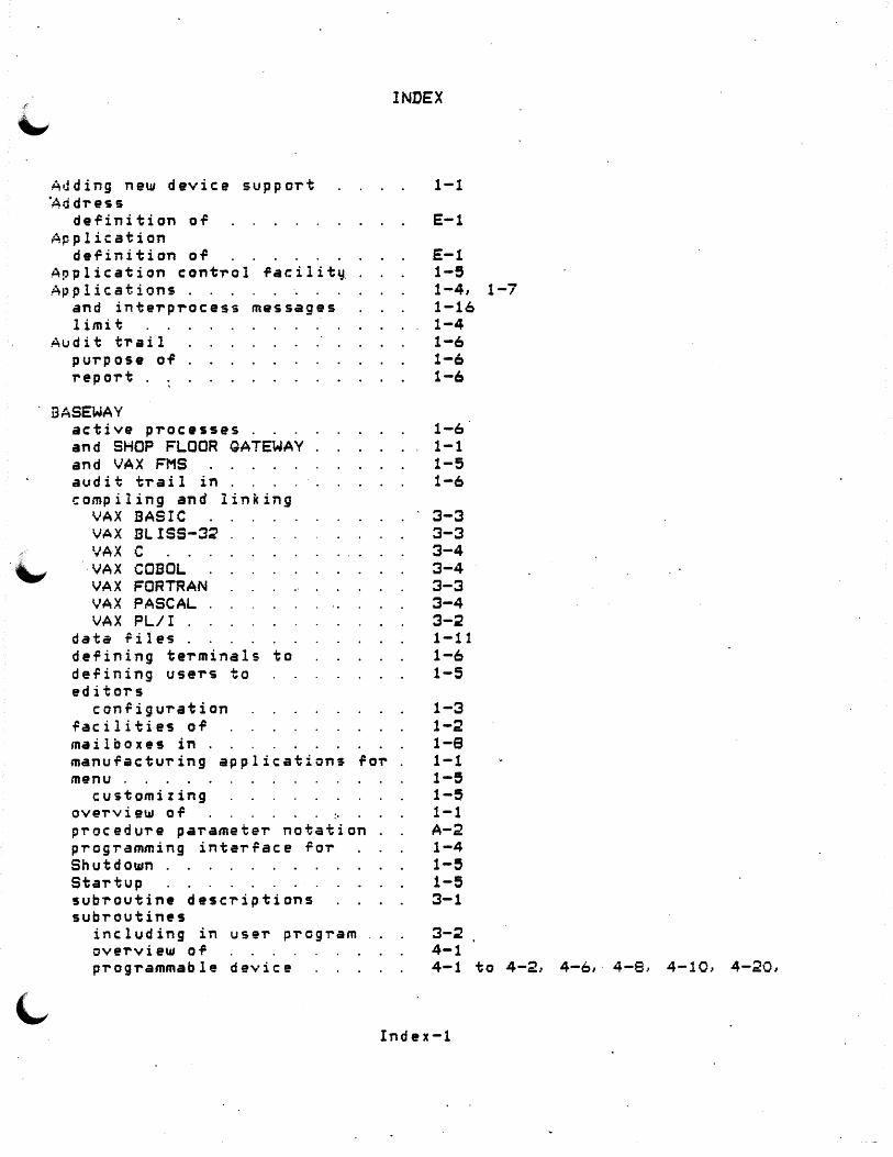
Adding new device support ·Address
definition of Application
definition of Application control facilitv Applications.
and interprocess messages limit
Audit trail purpose of report .
BASEWAY active processes . and SHOP FLOOR GATEWAY and VAX FMS audit trail in compiling and linking
VAX BASIC VAX BLISS-32 VAX C
. VAX COBOL VAX FORTRAN VAX PASCAL VAX PL/I .
data .Pile~ . defining terminals to de~ining users to editOT'S
configuration ~acilities of mailboxes in . manufacturing applications for m11nu .
customizing overview of ~
procedure parameter notation programming interface for Shut d ot11n . StaT'tup subroutine descriptions subT'outines
including in user program ove'T'view of p'T'ogrammable device
INDEX
1-1
E-1
E-1 1-5 1-4, 1-7 1-16 1-4 1-6 1-6 1-6
1-6 1-1 1-5 1-6
3-3 3-3 3-4 3-4 3-3 3-4 3-;? 1-11 1-6 1-5
1-3 1-2 1-8 1-1 1-5 1-5 1-1 A-2 1-4 1-5 1-5 3-1
3-2 4-1 4-1 to 4-2, 4-6,· 4-8, 4-10, 4-20,
Index-1

~ules lor invoking· sq stem .PtJnc ti ons tasks·
Comp.i led add-ress de.Pinition'of
Data .Pormats message specific .
Data identii'ier definition oil
Data item definition of
Data nam• definition or
Data types . atomic: . misc: el l·aneous st-ring .
DATA_PROC example- oT' . polled data handling with
D~vice InteT"Tace Module~ see DIMs . .
iJ-!vice set deTinition OT
D~vice Set Wat~her D.:vice support
4-Z? to 4-~3, 4-27.. 4-31, 4-44, 4-47, 4-53, 4-591 4-60, 4-6~~
4-641 4-67 A-1 1-6 1-12
E-1
2-4
E-1
E-1
E-1· i-16 1-16 1-16 1-10 1-14 1-19 1-14
c-1 £-2 D-6
ove~view OT D-1 OIMs . C-1
cancellation ~unction c-12 code-generating macros C-~O direct acce~s Function C-14 direct acce~s service message ~ormat C-14 example C-27 ~unctions o.P . C-9 generic access C-17 generic access service message rormat C-17 initialization ~unction c-12 main routines in . server inte~action with
I:Hrect access servi~e mes~age rormat .
Do Generic I/O Request . DoctJmentation
C-1 c-1 B-3, C-~, C-14, D-6 C-14 :?-5
ass~ciated with product 10 ror additional device support D-1
•
Index-2
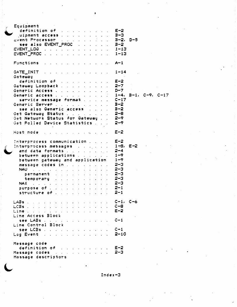
Equipment de-*1inition o-*1
.uipment access i=.vent P'T"ocessoi-
see also EVENT_PROC EVENT_LOG EVENT _PROC .
Fi;nctions
·~ATE_INIT
GdtewatJ definition or
Gateway Loopback Genei-ic Access . Genei-ic access .
se'T"vic:e message ro'rmat Generic: Serve'r .
see also Qene'ric access Get Gateway Status G~t NetwoTk Status ro-r Gateway . ~et Polled Device Statistics
l-ktst node
Intei-process communication r Int&rprDc&s~ mess~g~s \....r and data foi-mat; .
· betwe~n applications between gateway and application message codes in NAU
pei-manent tempo'T"ary
NAX pui-pose or . s t-r u c: t ur e o of •
LABs LCBs Line Line Access Block
see LABs . Line Cont'T"ol Block
see LCBs Log Event
Message code definition o.P
Message codes Message desc'T"iptors
E-2 B-3 B-2, B-2 1-.13 1-13
A-1
1-14
E-2 2-7 D-7 1-4, C-17 B-2 B-2 2-8 2-9 :?-9
E-2
E-2 l~,
:?-4 1-9 1-9 2-3 2-3 2-3 2-3 2-3 2-1 2-1
C-L c-e E-2
C-1
C-1 2-10
E-2 2-3
Index-3
D-5
B-1, C-9, C-17
E-:!
C-6
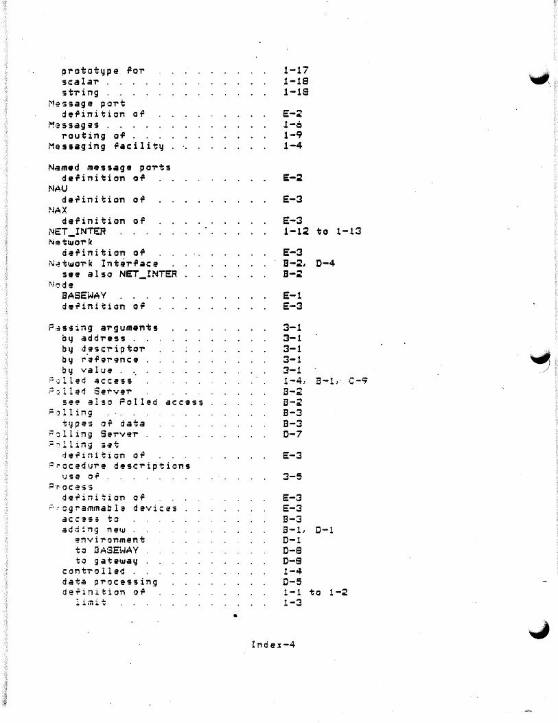
prototype For scalar st-ring
Message port de.Pinition o.P
~;~ s sag es routing o.P
Messaging .Pacilit~
Nam•d message po-rts de.Pinition o.P
NAU de~inition oil
NAX de.Pinition o.P
NET_INTE:R Na tu.OT' k
di1~inition o.P N~twcT'k IntaT'.Pace
see also NET_INTER :\:1' de
BASEWAY d'.Pinition o.P
F~s~ing arguments i:Jy addi-e~s
by desci-iptoiby r·a.Perence by valu@
~:.:;lled acc:e'Ss ;::,lle'1 Se'!'"v9i-
se~ also ?oll9d access := ::J l l i Mg
ti.Jpes of data ;:~ 11 ing Servei-:=01 ling set
ti'!.Pinition oi1 ~~ccedure d~sc-riptions
1;se of P·r· OC ~'i S
de~ini1:ion o.P r· ;· o g r- a mm ab 1 ~ d e vi c e s
adding ne•.JJ ~nvironment
to l3 ASEi~A Y ·to g at ewa~
conti"'olled data processing def in i t: ion o .P
limit
•
1-17 1-19 1-18
E-2 . .1-c 1-9 1-4
E-2
E-3
E-3 1-12 to 1-13
E-3 B-2., 0-4 B-2
E-1 E-3
3-1 3-1 3-1 3-1 :3-1 1-4.. B-1.·· C-~ B-;? B-2 B-3 B-3 D-7
E-3
3-5
E-3 E-3 B-3 B-L D-1 D-1 D-9 D-9 1-4 D-5 1-1 to 1-2 1-3
Index-4

direct access to . ~ generic access to
known points in data .Po-rmats.
monitored programmable devices
known points in
R~gister
de.Pinition o.P R~load VDR . Reset Network Counts R~turn status codes
testing
s~ssion control .Pacility s.;:t Gateu.ay Time SFG
s e·e SHOP FLOOR GATEWAY 3HOP FLOOR GATEWAY .
and PDP-11 proces>or components or de.Pinition o.P features o.P .Punctions o.P . initialization or limit' sampling data by .
-· : , u t d o um A p p l i ca .t i o·n . Start Polling on a Device Stop Gateway . Stop Polling on a Device ~.ubr-o•;tine cal ls ;;,~stem
definition of
T . .;isk WatcheiT~rminals
definition o.P e.Prect on user definition
definition o.P
VMS-RMS riles
B-3 B-3
1-3 1-4
1-3
E-3 ~-10
2-11
3-2
1-5 2-11
E-2 D-1 B-1 B-~ 1-3 B-1 B-1 to B-2 D-4 . 1-4 1-4 2-12· 2-12 2-13 2-13 A-1
E-3
D-6
1-6 1-6
1-5
1-10
Index-5

lr~ -------~
·!nde~-6
•
~ _)