nordsec 2004
TRANSCRIPT
Helsinki University of Technology
Publications in Telecommunications Software and Multimedia
Teknillisen korkeakoulun tietoliikenneohjelmistojen ja multimedian julkaisuja
Espoo 2004 TML-A10
NORDSEC 2004
Proceedings of the Ninth Nordic Workshop on Secure IT Systems
– Encouraging Co-operation
November 4-5, 2004, Espoo, Finland
Sanna Liimatainen, Teemupekka Virtanen (eds.)
In cooperation with
Helsinki University of TechnologyDepartment of Computer Science and EngineeringTelecommunications Software and Multimedia Laboratory
Teknillinen korkeakouluTietotekniikan osastoTietoliikenneohjelmistojen ja multimedian laboratorio
Distribution:
Helsinki University of Technology
Telecommunications Software and Multimedia Laboratory
P.O.Box 5400
FIN-02015 HUT
FINLAND
URL: http://www.tml.hut.fi/
c©The authors
ISBN 951-22-7348-9
ISSN 1456-7911
Otamedia Oy
Espoo 2004
TABLE OF CONTENTS
PrefaceProgramme Committee and Organizing CommitteeProgramme
Daniel Cvrcek Dynamics of Reputation 1G. Navarro, J. Garcia, J. A. Ortega-Ruiz Chained and DelegableAuthorization Tokens 8Pentti Tarvainen Survey of the Survivability of IT Systems 15Martin Boldt, Bengt Carlsson, Andreas Jacobsson Exploring SpywareEffects 23
Marco Giunti Security Properties for Intrusion Detection 31Karin Sallhammar, Svein J. Knapskog Using Game Theory in StochasticModels for Quantifying Security 39Jussipekka Leiwo A Technique for Modeling and Analysis of CommonCriteria Security Environments and Security Objectives 45
Sandro Grech, Jani Nikkanen A Security Analysis of Wi-Fi ProtectedAccessTM 53
Marko Schuba, Volker Gerstenberger, Paul Lahaije Internet ID - FlexibleRe-use of Mobile Phone Authentication Security for Service Access 58
Geir M. Køien Principles for Cellular Access Security 65Sven Laur, Helger Lipmaa On Private Similarity Search Protocols 73Ragni R. Arnesen, Jerker Danielsson, Bjørn Nordlund Carnival -An Application Framework for Enforcement of Privacy Policies 78Gergely Toth, Zoltan Hornak, Ferenc Vajda Measuring AnonymityRevisited 85
Anand S. Gajparia, Chris J. Mitchell, Chan Yeob Yeun The LocationInformation Preference Authority: Supporting User Privacy in LocationBased Services 91
Lillian Krakmo, Marie Elisabeth Gaup Moe An Attack on the StreamCipher Whiteout 97
Kaarle Ritvanen, Kaisa Nyberg Upgrade of Bluetooth Encryption andKey Replay Attack 105
J. Garcia, F. Autrel, J. Borrell, Y. Bouzida, S. Castillo, F. Cuppens,G. Navarro Preventing Coordinated Attacks via Alert Correlation 110Jarmo Molsa Mitigating DoS Attacks against the DNS with DynamicTTL Values 118
Emmanuel Guiton A Distributed Defence Mechanism againstLow-Bandwidth TCP SYN Flooding Attacks 125


PREFACE
It is my pleasure to welcome the participants of NordSec 2004 to Espoo.This is the ninth Nordsec conference and the second time it is arrangedhere. November is the darkest time of year and we all appreciate the lightthis conference brings to us.
Over the years there has been some variations in the focus of these con-ferences. We have defined this conference’s focus as an easily accessiblemiddle level scientific conference, targeted to post-graduate students. Wehave tried to create a simple, well organized conference, targeted to meetthe needs of post-graduates and academics. Keeping the conference onbudget does not imply any skimping on the academic quality of the papersor the review and publication process.
We are very happy with the content provided to the conference by theparticipants. There were 49 papers submitted out of which 19 papers wereselected which means 39reviewed blindly by at least two members of theprogram committee. I like to thank the committee members and otherreviewers for their work. The scientific community needs people who notonly write but read and review, too.
Security is a very large discipline, to which almost any subject can beincluded into. In this conference we are studying solutions to one specificarea. We try to improve security of information systems or improve securityusing information technology. We should keep in mind that outside thisarea are many other methods with which we together form the big picture.But as information technology becomes more important in the world, sodoes our work. Our area increases but in the same time it diffuses withother disciplines. As information technology becomes more common andthe level of connectivity in our world expands, the need for security growsalso. We can see this from different indicators, weather we are looking atnational policies, RFC requirements or readers letters to newspapers, theneed for security is there.
Now, let’s start the conference. The authors and participants create aconference. We thank all the authors for the papers in this volume and theparticipants for their active participation.
Teemupekka Virtanen

PROGRAMME COMMITTEE
Teemupekka Virtanen, Program chair Helsinki University of TechnologyMads Dam, Program co-chair SICS & Royal Institute of Technology
Tuomas Aura Mads DamMicrosoft Research SICS & Royal Institute of Technology
Ulfar Erlingsson Pasi EronenMicrosoft Research Nokia Research Center
Simone Fischer-Huebner Viiveke FakKarlstad University Norwegian University of Science
and Technology
Dieter Gollman Marko HeleniusMicrosoft Research Tampere University of Technology
Erland Jonsson Hannu KariChalmers University of Technology Helsinki University of Technology
Svein J. Knapskog Kaisa NybergNorwegian University of Science Nokia Research Centerand Technology
Jussipekka Leiwo Helger LipmaaNanyang Technological University Helsinki University of Technology
Christer Magnusson Pekka NikanderStockholm University/RIT Ericsson Finland
Hanne Riis Nahid ShahmehriTechnical University of Denmark Linkopings universitet
Camillo Sars Teemupekka VirtanenF-Secure Inc. Helsinki University of Technology
Antti Yla-Jaaski Louise YngstromHelsinki University of Technology Stockholm University/RIT
Additional Reviewers
Fredrik Bjorck, Leong Peng Chor, Claudiu Duma, Almut Herzog, Jesper Kampfeldt, SvenLaur, Adrian Leung, Leonardo Martucci, Valtteri Niemi, Robin Sharp, and Eduard Tur-can.
Organizing Committee
Ursula Holmstrom, Helsinki University of TechnologyAnsa Laakkonen, Helsinki University of TechnologySanna Liimatainen, Helsinki University of Technology


PROGRAMME
Wednesday, 3 November 200417:00-20:00 Registration (doors close at 20:00)17:00-23:00 Welcome Reception and Sauna, Computer Science Building,
HUT, Espoo
Thursday, 4 November 20049:00-9:45 Registration9:45-10:00 Welcome10:00-11:00 Session I
Daniel Cvrcek Dynamics of ReputationG. Navarro, J. Garcia, J. A. Ortega-Ruiz Chained and Delegable AuthorizationTokens
11:00-11:30 Coffee Break11:30-12:30 Session II
Pentti Tarvainen Survey of the Survivability of IT SystemsMartin Boldt, Bengt Carlsson, Andreas Jacobsson Exploring Spyware Effects
12:30-13:30 Lunch13:30-15:00 Session III
Marco Giunti Security Properties for Intrusion DetectionKarin Sallhammar, Svein J. Knapskog Using Game Theory in Stochastic Modelsfor Quantifying SecurityJussipekka Leiwo A Technique for Modeling and Analysis of Common CriteriaSecurity Environments and Security Objectives
15:00-15:30 Coffee Break15:30-17:00 Session IV
Sandro Grech, Jani Nikkanen A Security Analysis of Wi-Fi Protected AccessTM
Marko Schuba, Volker Gerstenberger, Paul Lahaije Internet ID - Flexible Re-useof Mobile Phone Authentication Security for Service Access
Geir M. Køien Principles for Cellular Access Security19:00 Conference Dinner, Haikaranpesa
Friday, 5 November 20049:00-10:00 Keynote speach: Urho Ilmonen, Director, Chief Security Officer, Nokia Oyj.
Security Requirements in Real Life10:00-10:30 Session V
Sven Laur, Helger Lipmaa On Private Similarity Search Protocols10:30-11:00 Coffee Break11:00-12:30 Session VI
Ragni R. Arnesen, Jerker Danielsson, Bjørn Nordlund Carnival - An ApplicationFramework for Enforcement of Privacy PoliciesGergely Toth, Zoltan Hornak, Ferenc Vajda Measuring Anonymity RevisitedAnand S. Gajparia, Chris J. Mitchell, Chan Yeob Yeun The Location InformationPreference Authority: Supporting User Privacy in Location Based Services
12:30-13:30 Lunch13:30-14:30 Session VII
Lillian Krakmo, Marie Elisabeth Gaup Moe An Attack on the Stream CipherWhiteoutKaarle Ritvanen, Kaisa Nyberg Upgrade of Bluetooth Encryption and Key ReplayAttack
14:30-15:00 Coffee Break15:00-16:30 Session VIII
J. Garcia, F. Autrel, J. Borrell, Y. Bouzida, S. Castillo, F. Cuppens, G. NavarroPreventing Coordinated Attacks via Alert CorrelationJarmo Molsa Mitigating DoS Attacks against the DNS with Dynamic TTL ValuesEmmanuel Guiton A Distributed Defence Mechanism against Low-BandwidthTCP SYN Flooding Attacks

This page is blank.
Dynamics of ReputationDaniel Cvrcek
University of CambridgeComputer Laboratory
15 JJ Thomson Avenue, CB3 0FD Cambridge, UKEmail: [email protected]
Abstract— To enforce security without user enrollment, trust(or reputation) systems were proposed to use experience ascrucial information to support cooperation as well as for securityenforcement mechanisms. However, use of trust introduces verydifficult problems that still discourage from exploitation of trustfor security mechanisms. The ability to change trust quickly andreact effectively to changes in environment and user behaviouris profound for usability of mechanisms built on top of trust.Dempster-Shafer theory was proposed as a suitable theoreticalmodel for trust computation. Here, we define general require-ments for reputation dynamics and demonstrate that Dempster-Shafer theory properties are not as good as is widely thought.On the contrary, simple formulae work.
Index Terms— Reputation, trust, security, Dempster-Shafertheory, Dirac impulse, Sybil attack, combining evidence.
I. INTRODUCTION
Many large-scale systems span a number of administrativedomains. They imply economic and technology reasons ham-pering system-wide user enrollment and also prevent effectiveglobal infrastructure for flexible centralised administration tobe established. Current security mechanisms, based on identity,cannot be used in such systems yet cooperation betweendiverse, autonomous entities is needed. The identity of entitiesmay be unknown in such systems because pseudonymity,or even anonymity, is becoming a fundamental property ofinformation systems [1], [2], [3]. The only information that canbe used for any security decision is (partial) information aboutan principal’s previous behaviour. Such systems are calledtrust-based systems [4], [5], [6], [7] or reputation systems tocharacterise their nature.
Each user may deploy tens or hundreds of pseudonymsand each pseudonym may be connected to transactions spreadacross the system. These facts imply the possibility of exis-tence of a number of distinct trust values which are valid forone physical identity. We cannot, and do not even want to,prevent this due to preserving certain level of privacy. On theother side, we need to capture a user’s behaviour as accuratelyas possible. Each system incorporating reputation/trust is basedon two paradigms.
• local trustworthiness evaluation allows any entity (prin-cipal) to make use of behavioural evidence and determinethe trustworthiness of other entities,
The work is funded by the SECURE project (IST-2001-32486), a part ofthe EU FET Global Computing initiative.
• distribution of trust makes it possible to inform otherentities about these local results of trust evaluations.
There are systems not supporting mechanisms for trustpropagation. Such systems cause high independence of trust-worthiness of a digital identity in different parts of the system.It is a challenging task to find the limits of such systemswith respect to privacy properties that may allow the existenceof many digital identities of a principal. However, it seemsobvious that such systems will be much more vulnerableto distributed attacks [8] as the ability to spread knowledgeabout malicious identities or ongoing attacks is limited. Whenwe enhance trust-based model with indirect evidence (i.e.evidence observed by someone else) we may get a system withsome small subspaces (trust domains) of partially mutuallydependent trust values.
The next section briefly summarises some of the secu-rity requirements that make reputation systems distinct fromidentity-based systems. Section III describes the Dempster-Shafer theory of observation. Section IV contains experimentalresults gained with the use of Dempster combination rule andthe arithmetic mean. The results are compared with statedsecurity requirements.
II. BACKGROUND
This paper focuses on the local use of trust computations.We believe that one of the most important properties of trust isits dynamics. A theoretical system model should allow ratherprecise parametrisation of trust value behaviour.
Any computation is based on a set of observations. The sizeof the set varies with time, not only during the initial phase ofsystem deployment. It is significant that the number of relevantobservations, implemented systems can store, is usually notdefined with respect to security requirements but rather withfeasibility requirements in mind. This fact is definitely notgood for security but capabilities, such as memory size orcomputational power, are decisive.
In this context, there is another contradiction regarding theimportance of old and new observations. While new observa-tions are most important for immediate reaction on securitythreats imposed by a particular entity, old observations aresignificant for long-time cooperation. There may be frequentsituations when a principal behaves correctly for a long timeperiod but could then be attacked by a Trojan-Horse that
NORDSEC 2004 1
dramatically changes his behaviour for a short time. Long-term experience may allow faster renewal of the originaltrustworthiness after the attack is over.
The value of old observations is also important for theeconomics of security [1]. Emphasis on old observations mayprevent easy, fast, and therefore cheap Sybil attacks. It meansthat there will be quite often a case when old observations aremore important than newer ones. From an attacker’s viewpoint,the long-term record is expensive to create, especially whentrust transitivity (recommendations from other potentially cor-rupted principals) is weakened.
The last important requirement for trust computations is dif-ferent sensitivity to positive and negative changes in behaviour.It is important for a model to allow radical negative changes oftrust value in response to serious negative observations. Anal-ysis of this requirement indicates that it is closely related tothe difference between old and recent observations discussedabove. This observation about long-term and short-term trustis akin to human perceptions of trust.
Summarising these requirements on trust dynamics:1) the reaction to most recent evidence should be indepen-
dent of the total amount of evidence:• there should be independence between security re-
quirements and the computational potential of par-ticular devices;
• speed and degree of reaction should be specifiedindependently on the number of observations, sincethis cannot often be estimated in advance.
2) the value of trust is proportional to the content (size) ofthe evidence set:
• emphasis is given to the stability of the trust value,i.e. short excesses are not so important;
• an alternative meaning of trust values can be derivedfrom the economic cost of evidence set creation.
3) the actual trust value is kept in a range which allowsmaximum sensitivity to changes:
• it is very hard to express the weight of a trust valuethat has not changed for a long time, regardless ofobservations being gathered.
4) positive/negative changes of trust are not symmetric:• negative changes – it may be necessary to react
quickly in case of attacks;• positive changes – long-term positive observations
should be retained.You can see that e.g. items 1) and 2) are contradicting each
other. It is therefore not clear, whether we can find a singlefunction that would satisfy both these requirements or whethertwo functions must be used and their results combined. Wepropose to use the latter approach based on Dirac impulsesand control theory.
A. Trust and Access Rights
Eventually, trust and risk become inputs for access control.A sufficient trustworthiness is what allows a principal to accessdata or use functionality of a system. Trust consists of two
parts: an information (or certainty) value and a confidencevalue (proper trust). The information value expresses theamount of evidence/observations that were gathered and usedfor the trust value computation.
When you run an information system you distinguish be-tween insiders and outsiders. An insider is a user that youpersonally know; you know his identity. He may be youremployee so there is a contract that obliges you to payhim a salary and he (the principal) must abide your rulesas stated in his contract. The principal is assigned a useraccount and a group that is associated with privileges in theinformation system. Recommendation systems or trust-basedsystems may enhance your ability to control access of insidersas well as for outsiders. You can punish the employee andyou can revoke access rights from outsiders. The strength ofreputation systems is that it is not necessary to enroll usersinto information system. It may lead to higher privacy but italso implies risks of forged identities.
With a reputation system you can either set parameters fortrust evaluation in advance or you can let the system to evolveand adapt to changes. The latter requires some measurementmechanisms – risk analysis. The idea is to perform risk analy-sis (measuring security of system) continuously. However, youdo not repeat the same computations all over again but contextsspecifying subsets of evidence used for runs of risk analysisare changing. However, the amount of possible contexts maybe so huge that it is impossible to evaluate risk for all of them.The system then may randomly select new ones and if thereis a distributed system in place, interesting contexts (securitythreats) can be spread throughout the system1.
B. Trust and Reputation
Many papers confuse the notions of trust and reputation.The use of the words seems to distinguish two groups ofpeople working towards the same target – trust-driven securitymechanisms. The first group comes from the area of ubiquitouscomputing and distributed system architecture for global com-puting is their concern. Here, the reasoning about trust is ratherabstract [4], [5], [6], [7]. The second group is more applicationoriented, concerned with peer-to-peer systems. They tend tosee trust as a new, interesting idea on how to enrich securitymechanisms. The terminology is different for basically thesame concept; while the former use trust-based system todescribe the architecture, the latter define reputation systemsto design mechanisms.
We believe that trust is a relation one-to-many while reputa-tion expresses view of many parties on one user/agent. Trustis my subjective view of my communication partner whilereputation is aggregated trust of many users. However, thisdistinction is not important for local processing that is targetedby this paper so we may use the notions interchangeably.
1The idea comes from immunology, when antibodies are created randomly,antibodies reacting to ”self cells” are filtered out and the rest is set off intoblood. When a reaction is encountered, antibodies of a given type are beingproduced in large amount to expunge ”non-self cell”.
2 NORDSEC 2004
III. A THEORY FOR TRUST COMPUTATION
Dempster-Shafer theory is perhaps the one most preferredfor trust computation in ubiquitous and global computing. [9]presents an intuitive way of behaviour modelling by exploitingthe theory of observation. A similar model is also used in thework of Jøsang et al [10], [11], [12].
We now give only a brief overview of basic terms. Themore detailed description can be found in [9]. The authorsstart with a set H = h1, ..., hn of mutually exclusive andexhaustive hypotheses. They also assume a finite set O ofobservations and there must be a hypothesis hi such that itsencoding (probability) µhi
(ob) > 0 for each ob ∈ O. There isalso defined an evidence space over H and O to be a tuple(H,O, µh1
, ..., µhn).
What we need is to obtain a normalised value of observationencoding. This can be perceived as a level of the evidencecontribution to a hypothesis. The authors use a simple methodto compute it.
ω(ob, h) =µh(ob)
∑
h′∈Hµh′(ob)
(1)
The function ω(ob, h) expresses probability of a hypothesish to happen as a consequence of an observation ob. Theevidence is viewed as a function mapping a prior probability(before new evidence is encountered) of the hypothesis to aposterior probability. That is,
µi+1(h) = µi(h) ⊕ ω(ob, h) (2)
where the operator ⊕ combines two probability distributionson H. The operator is defined by the following equation, whereH is a subset of hypotheses from H we are interested in.
(µ1 ⊕ µ2)(H) =
∑
h∈H µ1(h)µ2(h)∑
h∈Hµ1(h)µ2(h)
(3)
Let us assume that the subset H ⊆ H contains all thehypotheses expressing positive behaviour, i.e. that a given userwill behave the way that is desirable. The value obtained from(3) is then called trust.
A. Computation of Trust
We saw how a hypothesis probability evolves by addingnormalised encodings of new observations in the previous sec-tion. However, all observations had the same weight regardlessof their context – time, or any other information that mayinfluence their value.
Zhong and Bhargava described two basic ways of computingtrust in [13]. They introduced new mapping functions forposterior probabilities. Four particular function instances weredefined and tested on several different types of users.
Trust update and trust analysis functions were defined.A trust update algorithm maintains current trust state andcombines it with a new observation:
TS1 = f1(ob1), TSi+1 = fi(TSi, obi+1), (4)
A trust analysis function, on the other hand, stores asequence of observations and uses them to compute new trustvalues. The practical implementation uses a sliding window(of size n in eqs. (5), (6) ) to determine which observationsshould be used in computations.
TS1,n = fi(ob1, .., obk), 1 ≤ k ≤ n − 1 (5)
TSk,n = fn(obk−n+1, ..., obk), k ≥ n (6)
where TSk,n represents the trust state evaluated from theinteraction sequence of length n starting from obk (the latestobservation).
The important issue is that both approaches conform to thecombination rule (3) as defined above. It is realised by fi
being substituted by (3). The only difference is the number ofsummands in (3).
IV. PRACTICAL TESTS
We have used simple scenarios for practical tests. As thefirst set of evidence we collected a set of e-mail messages withtheir SpamAssassin scoring. The second set contained a subsetof emails with explicit user marking on whether the messageis a spam or not (this set was much smaller – it containedunder a dozen of events compared with several hundred emailmessages). Trust values are to express the probability ofsenders to be spammers or proper users. All experiments wereperformed on a basic set of over 500 messages from about 230domains.
A. Dempster Combination Rule
We chose two subsets of messages received from particulardomains and applied the Dempster combination rule on them.The result were discouraging as even simple tests demon-strated some negative properties.
During the setup, one has to define evidence encodingfunctions. We have used simple linear function inside of totaltrust/distrust boundaries (Vtrust, Vdistrust).
ω =
0.01, if score < Vtrust;0.99, if score > Vdistrust;0.98 Vdistrust−score
Vdistrust−Vtrust
+ 0.01 otherwise.
The domain of score is a superset of all values s ∈Vdistrust, Vtrust.
The graphs on fig. 1 demonstrate the results of trust com-putations for two e-mail domains with highest number ofmessages: fit.vutbr.cz (university) and yahoo.com. ParametersVtrust and Vdistrust are set manually to test thresholds wheretrustworthiness will change. Particular values are in the leg-ends inside the graphs.
Authentic messages from yahoo.com are completed with aset of non-spam messages (from index 43) to test the timenecessary for the change of trust values when a sudden changein behaviour occurs. Evidence encoding of the observations iscreated according to the rules above.
NORDSEC 2004 3

0
0.2
0.4
0.6
0.8
1
10 20 30 40 50 60 70 80
’-10 – 4’
’-11 – 4’
’-12 – 4’
’-13 – 4’
a) domain yahoo.com
0
0.2
0.4
0.6
0.8
1
10 20 30 40 50 60 70 80
’0 – 7’
’0 – 8’
’0 – 5’
’0 – 6’
b) domain fit.vutbr.cz
Fig. 1. Dynamics of trust with Dempster combination rule
ev. encoding – ω no of evidence0.51 1150.52 580.53 390,55 230.60 12
TABLE ISPEED OF SATURATION ON 99 % TRUSTWORTHINESS
Even so, we can find two unpleasant properties. Trustvalues usually (unless Vtrust, Vdistrust are carefully set fora particular evidence set) saturate at zero or hundred-percenttrustworthiness. This situation is more thoroughly analysed intable I showing number of observations with a given encodingneeded to saturate trust. Clearly, the Dempster combinationrule works reasonably well in situations with a small amountof evidence and when two-value logic is of interest (e.g. whenone needs to say whether a suspect is guilty or not). Neither ofthese assumptions is true in access control systems. We hopeto have a large amount of evidence and we need a trust valueallowing for fine-tuning of access control policies.
Concerning the reaction to a set of spam messages, fig. 2demonstrates that the reaction is strongly dependent on thetotal amount of evidence. In fact, the delay between the attackdetection (change in evidence encoding) and correspondingchange of trust value can easily reach the time or numberof observations related to the particular user/agent before theattack (the attack started with message indexed 51).
B. Improving Demspter Combination Rule
This property, saturation, is inherent to Dempster combina-tion rule. We tried to solve this problem using an accumulator
0
0.2
0.4
0.6
0.8
1
0 20 40 60 80 100 120 140 160
’evidence’
’trust value’
Fig. 2. Attack reaction delay with Dempster-rule
for a surplus trust. We were motivated by an analogy with thehuman perception of trust. Imagine you have known someonefor quite some time. Unfortunately it happens that he makes amistake that costs him some trust. However, this lost is usuallyshort-term and after some time your long-term (accumulated)trust outweighs.
This effect may be modelled by setting a maximum and/orminimum level of trust Tmax, Tmin. We then create an ac-cumulator Taccum of trust representing the effect of evidencethat would cause trust to rise/drop below the stated boundaries.
Using (3) we obtain the following equation when one outof two hypothesis is being selected – h1 expresses trust andh2 distrust.
(µi−1 ⊕ µi)(h1) = µi−1(h1)µi(h1)µi−1(h1)µi(h1)+µi−1(h2)µi(h2)
= (7)
=∏
k=1..iωi(h1)
∏
k=1..iωi(h1)+
∏
k=1..iωi(h2)
(8)
The limiting condition (for high boundary) is
(µ1 ⊕ µ2)(h1) = Tmax =
µ1(h1)µ2(h1)Taccum
µ1(h1)µ2(h1)Taccum
+ µ1(h2)µ2(h2)(9)
and
Taccum =(1 − Tmax)µ1(h1)µ2(h1)
Tmax + µ1(h2)µ2(h2)(10)
The accumulator is empty when Taccum ≤ 1. We havealso defined the speed at which the accumulated trust can bereleased when the trust value changes rapidly. The accumulatorhas a positive influence on trust dynamics, giving instantresponse to attacks and controlled stability for long-termvalues (see fig. 3). Unfortunately, the saturation is a profoundproperty of Dempster-Shafer theory which was created to givedefinitive answer yes or no (good or bad).
0
0.2
0.4
0.6
0.8
1
0 20 40 60 80 100
’evidence’
’faster accum’
’slower accum’
Fig. 3. Possible setting of reaction
C. Arithmetic Mean
The requirements described in section 2 led to the design ofa second set of tests. Here, we returned to the simplest possiblefunctions2. Beside this, we applied and tested dynamic update
2Although we used arithmetic mean as the simplest possible function, wehave found that the consensus operator for dogmatic beliefs is computed in avery similar way, as described in [10].
4 NORDSEC 2004
of most of system parameters. The goal of this section isto demonstrate improvement in trust dynamics (stability andreaction to attacks) as a couple of refinements is applied.
The experiment settings that have to be made manually arevery simple. We must state:
1) intervals within which the encoding function is mono-tonous – SpamAssassin scoring is monotonous on thewhole domain of input values thus only one interval isidentified;
2) whether the encoding function is decreasing or increas-ing function for all identified intervals;
3) and define evidence sources – we have two sources here– explicit marking spam/non-spam and SpamAssassinscoring.
a) Evidence Normalising: The following figure (fig. 4)shows three examples of encodings according to how theevidence is being normalised. When there is no explicit spammarking we obtain an evidence encoding with a very lowaverage value in virtue of a much longer numerical intervalrepresenting non-spam messages. The dotted line demonstratesthe influence of explicit marking (spam/non-spam). In thiscase, we got a better mid-value (0.5) but there is still a clearlyvisible impact of one, single, very low value of evidence onthe whole aggregate.
The final experiment was to increase the sensitivity ofthe trust value in intervals with more evidence pieces. Wehave created five bands on each side from uncertainty (thegap between the lowest score of the marked spam and thehighest score of marked non-spam). The boundaries of thebands were dynamically adjusted to contain approximately thesame number of messages. Linear functions were used withinthe bands. This led to improved sensitivity of trust value asdemonstrated by its increase towards 0.7, where 1 is absolutetrust.
0
0.2
0.4
0.6
0.8
1
20 40 60 80 100 120 140 160 180 200
’linear’
’mid-value’
’bands’
Fig. 4. Evolution with dynamic adjustment
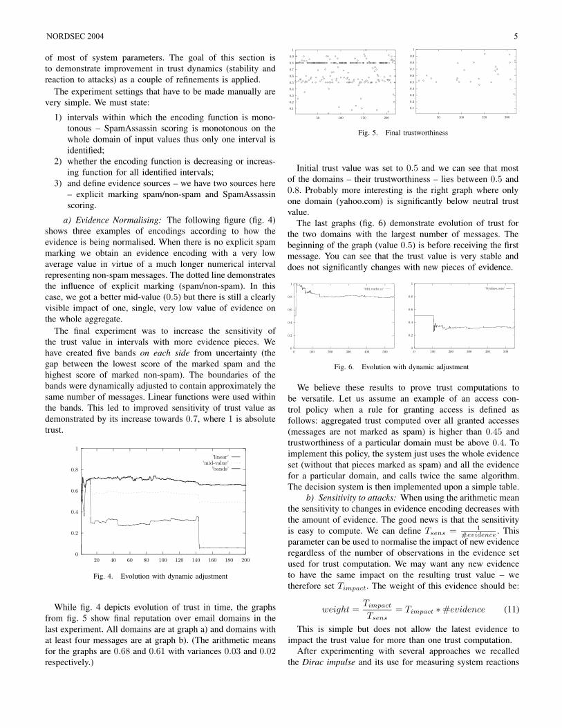
While fig. 4 depicts evolution of trust in time, the graphsfrom fig. 5 show final reputation over email domains in thelast experiment. All domains are at graph a) and domains withat least four messages are at graph b). (The arithmetic meansfor the graphs are 0.68 and 0.61 with variances 0.03 and 0.02respectively.)
0.1
0.2
0.3
0.4
0.5
0.6
0.7
0.8
0.9
1
50 100 150 200
0.1
0.2
0.3
0.4
0.5
0.6
0.7
0.8
0.9
1
50 100 150 200
Fig. 5. Final trustworthiness
Initial trust value was set to 0.5 and we can see that mostof the domains – their trustworthiness – lies between 0.5 and0.8. Probably more interesting is the right graph where onlyone domain (yahoo.com) is significantly below neutral trustvalue.
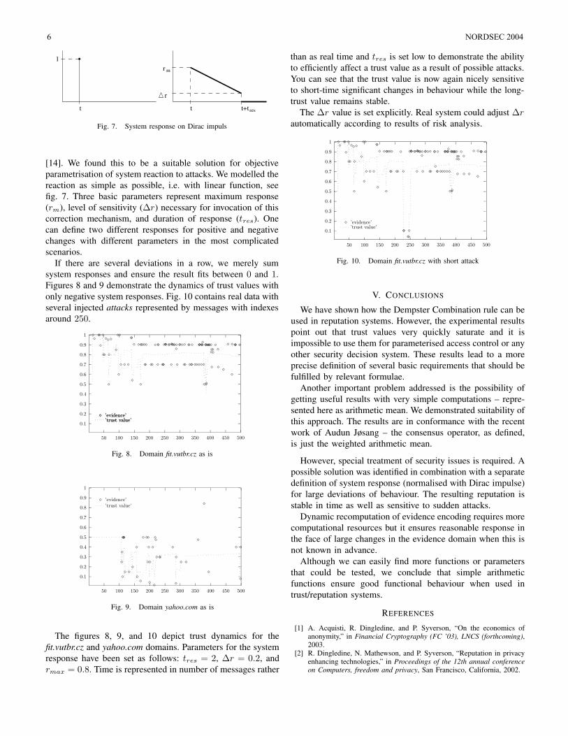
The last graphs (fig. 6) demonstrate evolution of trust forthe two domains with the largest number of messages. Thebeginning of the graph (value 0.5) is before receiving the firstmessage. You can see that the trust value is very stable anddoes not significantly changes with new pieces of evidence.
0
0.2
0.4
0.6
0.8
1
0 100 200 300 400 500
’@fit.vutbr.cz’
0
0.2
0.4
0.6
0.8
1
0 100 200 300 400 500
’@yahoo.com’
Fig. 6. Evolution with dynamic adjustment
We believe these results to prove trust computations tobe versatile. Let us assume an example of an access con-trol policy when a rule for granting access is defined asfollows: aggregated trust computed over all granted accesses(messages are not marked as spam) is higher than 0.45 andtrustworthiness of a particular domain must be above 0.4. Toimplement this policy, the system just uses the whole evidenceset (without that pieces marked as spam) and all the evidencefor a particular domain, and calls twice the same algorithm.The decision system is then implemented upon a simple table.
b) Sensitivity to attacks: When using the arithmetic meanthe sensitivity to changes in evidence encoding decreases withthe amount of evidence. The good news is that the sensitivityis easy to compute. We can define Tsens = 1
#evidence. This
parameter can be used to normalise the impact of new evidenceregardless of the number of observations in the evidence setused for trust computation. We may want any new evidenceto have the same impact on the resulting trust value – wetherefore set Timpact. The weight of this evidence should be:
weight =Timpact
Tsens
= Timpact ∗ #evidence (11)
This is simple but does not allow the latest evidence toimpact the trust value for more than one trust computation.
After experimenting with several approaches we recalledthe Dirac impulse and its use for measuring system reactions
NORDSEC 2004 5
t
1
r
r m
rest+tt
Fig. 7. System response on Dirac impuls
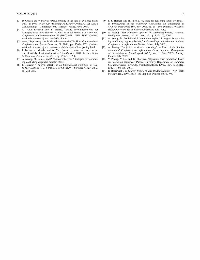
[14]. We found this to be a suitable solution for objectiveparametrisation of system reaction to attacks. We modelled thereaction as simple as possible, i.e. with linear function, seefig. 7. Three basic parameters represent maximum response(rm), level of sensitivity (∆r) necessary for invocation of thiscorrection mechanism, and duration of response (tres). Onecan define two different responses for positive and negativechanges with different parameters in the most complicatedscenarios.
If there are several deviations in a row, we merely sumsystem responses and ensure the result fits between 0 and 1.Figures 8 and 9 demonstrate the dynamics of trust values withonly negative system responses. Fig. 10 contains real data withseveral injected attacks represented by messages with indexesaround 250.
0.1
0.2
0.3
0.4
0.5
0.6
0.7
0.8
0.9
1
50 100 150 200 250 300 350 400 450 500
’evidence’
’trust value’
’evidence’
’trust value’
Fig. 8. Domain fit.vutbr.cz as is
0.1
0.2
0.3
0.4
0.5
0.6
0.7
0.8
0.9
1
50 100 150 200 250 300 350 400 450 500
’evidence’
’trust value’
Fig. 9. Domain yahoo.com as is
The figures 8, 9, and 10 depict trust dynamics for thefit.vutbr.cz and yahoo.com domains. Parameters for the systemresponse have been set as follows: tres = 2, ∆r = 0.2, andrmax = 0.8. Time is represented in number of messages rather
than as real time and tres is set low to demonstrate the abilityto efficiently affect a trust value as a result of possible attacks.You can see that the trust value is now again nicely sensitiveto short-time significant changes in behaviour while the long-trust value remains stable.
The ∆r value is set explicitly. Real system could adjust ∆r
automatically according to results of risk analysis.
0.1
0.2
0.3
0.4
0.5
0.6
0.7
0.8
0.9
1
50 100 150 200 250 300 350 400 450 500
’evidence’
’trust value’
Fig. 10. Domain fit.vutbr.cz with short attack
V. CONCLUSIONS
We have shown how the Dempster Combination rule can beused in reputation systems. However, the experimental resultspoint out that trust values very quickly saturate and it isimpossible to use them for parameterised access control or anyother security decision system. These results lead to a moreprecise definition of several basic requirements that should befulfilled by relevant formulae.
Another important problem addressed is the possibility ofgetting useful results with very simple computations – repre-sented here as arithmetic mean. We demonstrated suitability ofthis approach. The results are in conformance with the recentwork of Audun Jøsang – the consensus operator, as defined,is just the weighted arithmetic mean.
However, special treatment of security issues is required. Apossible solution was identified in combination with a separatedefinition of system response (normalised with Dirac impulse)for large deviations of behaviour. The resulting reputation isstable in time as well as sensitive to sudden attacks.
Dynamic recomputation of evidence encoding requires morecomputational resources but it ensures reasonable response inthe face of large changes in the evidence domain when this isnot known in advance.
Although we can easily find more functions or parametersthat could be tested, we conclude that simple arithmeticfunctions ensure good functional behaviour when used intrust/reputation systems.
REFERENCES
[1] A. Acquisti, R. Dingledine, and P. Syverson, “On the economics ofanonymity,” in Financial Cryptography (FC ’03), LNCS (forthcoming),2003.
[2] R. Dingledine, N. Mathewson, and P. Syverson, “Reputation in privacyenhancing technologies,” in Proceedings of the 12th annual conferenceon Computers, freedom and privacy, San Francisco, California, 2002.
6 NORDSEC 2004
[3] D. Cvrcek and V. Matyas, “Pseudonymity in the light of evidence-basedtrust,” in Proc. of the 12th Workshop on Security Protocols, ser. LNCS(forthcoming). Cambridge, UK: Springer-Verlag, April 2004.
[4] A. Abdul-Rahman and S. Hailes, “Using recommendations formanaging trust in distributed systems,” in IEEE Malaysia InternationalConference on Communication ’97 (MICC’97). IEEE, 1997. [Online].Available: citeseer.nj.nec.com/360414.html
[5] ——, “Supporting trust in virtual communities,” in Hawaii InternationalConference on System Sciences 33, 2000, pp. 1769–1777. [Online].Available: citeseer.nj.nec.com/article/abdul-rahman00supporting.html
[6] J. Bacon, K. Moody, and W. Yao, “Access control and trust in theuse of widely distributed services,” Middleware 2001, Lecture Notesin Computer Science, no. 2218, pp. 295–310, 2001.
[7] A. Jøsang, M. Daniel, and P. Vannoorenberghe, “Strategies forf combin-ing conflicting dogmatic beliefs,” 2003.
[8] J. Douceur, “The sybil attack,” in 1st International Workshop on Peer-to-Peer Systems (IPTPS’02), ser. LNCS 2429. Springer-Verlag, 2002,pp. 251–260.
[9] J. Y. Helpern and R. Pucella, “A logic for reasoning about evidence,”in Proceedings of the Nineteenth Conference on Uncertainty inArtificial Intelligence (UAI’03), 2003, pp. 297–304. [Online]. Available:http://www.cs.cornell.edu/riccardo/abstracts.html#uai03
[10] A. Jøsang, “The consensus operator for combining beliefs,” ArtificialIntelligence Journal, vol. 141, no. 1–2, pp. 157–170, 2002.
[11] A. Jøsang, M. Daniel, and P. Vannoorenberghe, “Strategies for combin-ing conflicting dogmatic beliefs,” in Proceedings of the 6th InternationalConference on Information Fusion, Cairns, July 2003.
[12] A. Jøsang, “Subjective evidential reasoning,” in Proc. of the 9th In-ternational Conference on Information Processing and Managementof Uncertainty in Knowledge-Based Systems (IPMU 2002), Annecy,France, July, 2002.
[13] Y. Zhong, Y. Lu, and B. Bhargava, “Dynamic trust production basedon interaction sequence,” Purdue University, Department of ComputerSciences, Purdue University, West Lafayette, IN 47907, USA, Tech. Rep.CSD-TR 03-006, 2003.
[14] R. Bracewell, The Fourier Transform and Its Applications. New-York:McGraw-Hill, 1999, ch. 5. The Impulse Symbol, pp. 69–97.
NORDSEC 2004 7
Chained and Delegable Authorization TokensG. Navarro, J. Garcia, J. A. Ortega-Ruiz
Dept. Informatica, Universitat Autonoma de Barcelona,Edifici Q, 08193 Bellaterra - Spain
Email: gnavarro,jgarcia,[email protected]
Abstract— In this paper we present an overview of an accesscontrol system based on tokens and delegable hash chains.This system takes advantage of hash chains in a similar wayas the micropayment systems. On the other hand it uses anauthorization infrastructure which allows to delegate authorityand permissions by means of authorization certificates anddelegation. The system is named CADAT (Chained and DelegableAuthorization Tokens). We also describe one of the applicationsof CADAT, which is used as a token based access control for asecure mobile agent platform.
Index Terms— Access Control, Authorization, Delegation, HashChains.
I. INTRODUCTION
The access control and protection of computerized system isan active field of research, development and application. Latelythere have been proposals for models, techniques and novelsystems about access control in distributed systems. Normallythey tend to look for the design of more flexible, scalable, anduser-friendly systems while keeping a high degree of security.
Delegation, for example, introduces a lot of flexibilityto a system, where the permission can be transfered ordelegated between the users of the systems. Some of thefirst systems introducing delegation of authorization and therequired infrastructure where KeyNote [1] and SPKI/SDSI(Simple Public Key Infrastructure/Simple Distributed SecureInfrastructure)[2]. Some authors refer to these systems astrust-management.
Another interesting field in access control is the use ofaccess tokens. In these systems a user receives a token orticket, which allows her to access a given resource or service.Token-based access control has been successfully used inseveral scenarios. For instance, Kerberos [3] is a popularsystem which makes use of access tickets.
An application, somehow similar to access tokens, are themicropayments. A micropayment system allows the paymentof small amounts of money. Although micropayment systemshave been around for a considerable time and have receivedsome critics, they are still an interesting research field [4].As a proof of concept, just consider companies that haveappeared lately offering micropayment based systems, such asPeppercoin (http://www.peppercoin.com) or Bitpass(http://www.bitpass.com). One of the most interestingissues of the micropayment systems has been the introductionof hash chains to represent the transactions [5], [6], [7]. Theuse of hash chains allows to make the issuing of micropaymentmore flexible, since it substitutes computationally expensive
cryptographic operations by simpler operations (hash func-tions).
There have been recently some propositions to use autho-rization infrastructures to implement micropayment systems.One of these proposals [8], introduces a model for usingdelegation in micropayment systems.
In this paper we present a token-based access controlsystem. This system presents some advantages from micro-payment systems and the delegation of authorizations. Ourproposed system is called CADAT (Chained and DelegableAuthorization Tokens). In CADAT the authorization tokensare constructed from a hash chain, which makes it faster andefficient to issue and verify tokens. Furthermore, we introducethe possibility to delegate token chains between users of thesystem in several ways, which adds flexibility to the system.CADAT is implemented by using SPKI/SDSI (Simple PublicKey Infrastructure / Simple Distributed Secure Infrastructure),which provides the main framework to express authorizationsand delegations. We also describe the application of CADATas a token-based access control system in an specific scenario,a secure mobile agent application.
In Section II we introduce the main bases of the CADATsystem. Section III introduces the SPKI/SDSI framework inrelation to CADAT. In Section IV we show how to encodethe hash chain based permissions into SPKI/SDSI certificates,providing the necessary modifications to SPKI/SDSI. Next, weshow the main functionality of CADAT through an examplein Section V. And in Section VI we discuss the applicationof CADAT in mobile agent systems. Finally, Section VIIsummarizes our conclusions and further work.
II. HASH CHAINS AND DELEGATION
In this section we show how we can use delegation andhash chains together. It is based on the model and notation of[8]. We have simplified the model a little bit to make it morereadable. The main idea is to consider the elements of a hashchain as permissions or authorizations.
We adopt the following notation and definitions:² KA: public key of the user A.² sKA: private key of the user A.² msKA
: digital signature of message m, signed by userA with the private key sKA.
² (|KB , p|)KAa direct delegation, where the user A, del-
egates permissions p to the user B. This relation can beestablished by means of an authorization certificate. Atthe moment we denote such a certificate as |KB , p|sKA
.
8 NORDSEC 2004
² h(m): one-way cryptographic hash function applied tom.
² [hn(m), hn¡1(m), . . . , h1(m), h0(m)]: hash chain con-structed from the initial message m (the seed of the hashchain). Normally, m may include information such assome random value (or nonce) to ensure its uniqueness.
² P: set of all the permissions managed by the system.There is an partial ordering in the set (¹) determined bythe inclusion of one permission into another. For instance,x ¹ y, intuitively means that if a user holds permissiony she also holds permission x. There is a least upperbound defined by the intersection (∧) of permissions, anda greatest lower bound defined by the union of (∨). Theorder relation and the set of permissions form a lattice.
² PH: subset of permissions (PH ⊆ P), where eachpermissions is expressed as an element of a hash chain.The order relation between elements of PH is defined as:given x, y ∈ PH, x ¹ y in relation to principal P , if andonly if P , knowing y, can easily determine some x andi, such that hi(x) = y[8]. It means that principal P canfind x and i without having to invert the hash function.
Following with these notation we can express the reductionrules of SPKI/SDSI [2], given the set of permissions PH, inthe following way:
(|KB , x|)KA; y ¹ x
(|KB , y|)KA
(1)
(|KC , x|)KB; (|KB , y|)KA
(|KC , x ∧ y|)KA
(2)
The use of hash chain elements as permissions has severaladvantages, such as the possibility to issue specific permissionswithout having to issue any kind of certificate. We can alsodelegate (or transfer) parts of the hash chain to other principals.
To show the use of hash chains with delegation, we considerthe following example. There are three users Alice, Bob andCarol, with their own public keys KA, KB , KC . We assumethat Alice is some authorization authority. Alice generatesthe following hash chain from the initial seed m: [h5(m),h4(m), h3(m),h2(m),h1(m)], where each element of thechain corresponds to an specific permission.
Alice can issue the following certificate:
|KB , h5(m)|sKA(3)
With this certificate, Alice delegates h5(m) to Bob, whonow, holds the permission h5(m). If Alice wants to delegatepermission h4(m) to Bob, there is no need for Alice to issueanother certificate. Alice just has to make public the valueh4(m). Once it is public, Bob becomes automatically theholder of the permission h4(m). Bob is in the position ofdemonstrating that he holds such a permission because ofcertificate (3). In a same way, Alice can make public thesuccessive permission, for instance, h3(m).
In a more general formulation, if Bob has a certificate,which directly grants him the permission hi(m), and Alicemakes public the value hj(m), where i > j, Bob becomes theholder of permissions hi(m), . . . , hj(m). Given the reduction
rule (1), we have that (|KB , hi(m)|)sKA, and hj(m) ¹ hi(m),
so (|KB , hj(m)|)sKA.
Another important issue is the introduction of delegation.Bob could delegate part of the permissions to another prin-cipal. Following with the example, Bob is in possession ofh5(m), h4(m) and h3(m). He can delegate the last permissionto Carol by issuing the following certificate:
|KC , h3(m)|sKB(4)
Bob delegates h3(m) to Carol. If Alice makes public thevalue h2(m), Carol can demonstrate that she is in possessionof such permission, because of the certificates (3) and (4). It isimportant to note that in no case, Carol can demonstrate sheholds permissions h5(m) and h4(m). She can only receivepermission of the chain which have and index lower or equalto h3(m).
We have seen how hash chains have important advantageswhen combining them with authorization or trust managementsystems. In the following section we show how this model canbe implemented by using SPKI/SDSI. In [9], the authors showhow to implement a similar system in KeyNote.
III. SPKI/SDSI AUTHORIZATION CERTIFICATES
SPKI/SDSI (Simple Public Key Infrastructure/Simple Dis-tributed Secure Infrastructure), is a certificate-based autho-rization infrastructure, which can express authorizations andits delegation by means of authorization certificates. It alsoprovides a distributed name system based on local names, bymeans of name certificates.
In SPKI/SDSI each principal has a pair of cryptographickeys, and its represented by its public key. In other words, wecan say that in SPKI/SDSI each principal is its public key,and it is represented by the key or a hash of the key. An au-thorization certificate binds a public key with an authorizationor permission. This way we can avoid the indirection presentin traditional PKIs, where there is a binding between a publickey and a global identifier (or distinguished name) and anotherone between the identifier and the authorization (permissionor attribute). We can denote an authorization certificate as:
(I, S, tag, p, V ) (5)
Where:
² I: issuer. The principal granting the authorization.² S: subject. The principal receiving the authorization.² tag: authorization tag. The specific authorization being
granted by the certificate.² p: delegation bit. If it is active, the subject of the
certificate can further delegate the authorization (or asubset) to another principal.
² V : validity specification. It includes the validity timerange (not-after and not-before) of the certificate andother possible conditions (currently online tests for re-vocation, revalidation and one-time revalidation).
² Comment: although we do not show it in the notation,the certificates include a field of arbitrary information.
NORDSEC 2004 9
As one can see, the authorization certificates of SPKI/SDSIallows us to easily express the authorization certificates com-mented in Section II. For instance, certificate |KB , p|sKA
can be expressed in SPKI/SDSI, for a given validity time V
as: (KA,KB , p, 1, V ). Note that the delegation bit is active,so KB can further delegate the authorization, KA could avoidthis by setting the delegation bit to 0 if needed.
IV. HASH CHAINS AS SPKI/SDSI AUTHORIZATIONS
As we have seen permissions are expressed in SPKI/SDSI asthe element tag. The format used by SPKI/SDSI to representall the information is S-expression. In order to make it easyto process the authorizations, we include the index of thehash chain component , and an identifier of the chain in theauthorization tag. This way a permission p ∈ PH will havethe following format:
p = (cid, i, hi(m)) (6)
Where i is the index of the element in the chain and cid
is the identifier of the whole hash chain. All the elements ofthe same hash chain have the same cid, which is a randombit string big enough to ensure its uniqueness. The seed, m
includes additional information such as the public key of theprincipal that generated the chain, etc. The hash on m alsoincludes i and cid in each step, making it more difficult toforge it. We do not get into details on how is the concreteinformation in m and how is the hash exactly computed, tokeep the notation more readable, and because it may dependin the specific application of the permission. The reader mayrefer to [5], [6], [7] for specific ways to build such a hashchain.
SPKI/SDSI provides a certificate chain discovery algorithmto find authorization proofs in delegation networks [10]. Thisalgorithm is based on basic intersection operations to providecertificate reduction rules. In [2] the intersection of the tagelement is determined by the operation AIntersect.
In order to represent the authorization (6) in a SPKI/SDSItag, we consider two alternatives. These alternatives are basedon the need of verifying the hash of the permission in thetag intersection operation. When we have to intersect twopermissions with the hash elements hi(m) and hj(m), if i ≥ j
the resulting tag will be the hi(m). The intersection operationcan also verify that (hj)x(m) = hi(m) for some x. Thisverification allows to immediately dismiss forged or erroneouspermissions. If the verification is not carried by the intersectionoperation, it is important to note that the verification has to bedone afterwards to validate an authorization proof.
A. Tag intersection without hash verificationIn this case we can encode the permissions by using
existing SPKI/SDSI structures. For example, a straightforwardrepresentation of the a permission like (6) in SPKI/SDSI S-expression format can be:
(tag(h-chain-id |123456789|)(h-chain-index (* range numeric ge 7)))(h-val (hash
md5 |899b786bf7dfad58aa3844f2489aa5bf|))
Where h-chain-id is the identifier of the hash chain,h-chain-index is the index of the element in the hash chainand h-val is the value of the hash itself. The most importantelement is the index, which is expressed as a numeric rangethat will intersect with a range greater or equal to 7 in thiscase.
The only problem of the previous example is that if weinclude the value h7(m) in the tag, the intersection operationwill not properly work. What we do is to introduce a littlemodification. The value h-val has to be treated in a differentway. Thus, we put the h-val as the comment of the certificate.The certificate may look something like this:(cert(issuer
(hashmd5 |1ac461a2e12a77ad54c67128b5060f28|))
(subject(hashmd5 |b0a746de2d5f6038e49a87c9c826bf4e|))
(tag(h-chain-id |123456789|)(h-chain-index (* range numeric ge 7)))
(comment(h-val
(hashmd5 |899b786bf7dfad58aa3844f2489aa5bf|)))
(not-after "2004-01-01_00:00:00")(not-before "2005-01-01_00:00:00")
)
This allows us to use the SPKI/SDSI decision engine di-rectly, without any lose of information. The main disadvantageof this approach is that in order to verify an authorizationproof, the verifier needs to do an additional operation: verifythe integrity of the hash chain (or subchain).
B. Tag intersection with hash verification
In this case, it is necessary to redefine the tag intersectionoperation for authorizations corresponding to elements of ahash chain. To do this we introduce a new kind of tag, the<tag-hash-auth>. The BNF definition of this new tag,according to the SPKI/SDSI tag definition [11] is given inFigure 1.
<tag>:: <tag-star> | "(" "tag" <tag-expr> ")";<tag-star>:: "(" "tag" "(*)" ")" ;<tag-expr>:: <simple-tag> | <tag-set> |
<tag-string> | <tag-hash-auth>;<tag-hash-auth>:: "(" "hash-auth" <chain-id>
<chain-index> <hash>")";<chain-index>:: "(" "chain-index" <decimal> ")";<chain-id>:: "(" "chain-id" <byte-string> ")";
Fig. 1. Definitionn of <tag-hash-auth>.
We also introduce a new intersection operation: HCAInter-sect (Hash Chained Authorization Intersection). The intersec-tion of two tags representing permissions of PH will resultin the tag with the greatest hash chain index, if the hash chainidentifier is the same and we can verify the hash values. Forexample, given the following tags:(tag(hash-auth
(hchain-id |lksjfSDFIsdfkj0sndKIShfoMSKJSD|)(hchain-index 14)(hash md5 |899b786bf7dfad58aa3844f2489aa5bf|)))
10 NORDSEC 2004
(tag(hash-auth(hchain-id |lksjfSDFIsdfkj0sndKIShfoMSKJSD|)(hchain-index 15)(hash md5 |d52885e0c4bc097f6ba3b4622e147c30|)))
Its intersection (HCAIntersect) will be equal to the secondtag, because the identifier is equal and the index of the secondtag is greater that the first one. And we can verify the hashvalue of the tag. Note that the MD5 of the first value is equalto the second one.
We show the algorithm used by HCAIntersect with hashverification (HCAIntersect full algorithm).
Algorithm 1: HCAIntersect full algorithminput : p = (idp, i, h
i(m)p), q = (idq, j, hj(m)q), such
that p, q ∈ PH
output: r such that r = HCAIntersect(p, q)
beginif idp 6= idq then r ← NULL ;if i ≥ j then
if verifyHashSubChain(p,q) then r ← p ;else r ← NULL ;
endelse
if verifyHashSubChain(q,p) then r ← q ;else r ← NULL ;
endend
Algorithm 2: verifyHashSubChain functioninput : p = (idp, i, h
i(mp)), q = (idq, j, hj(mq)),
where i ≥ j
output: res = true if hi(m) and hj(m) belong to thesame hash chain, res = false otherwise
beginres← false ;aux← hj(mp) ;for x ∈ [(j − 1)..i] do
if aux = hi(mq) then res← true;aux← h(aux) ;
endend
The implementation of the hash chain elements as autho-rizations and the HCAIntersect algorithms, has been done inJava using the JSDSI [12] library. JSDSI is an open sourceimplementation of SPKI/SDSI in Java, which has lately beenunder active development. The implementation of the newtag and the algorithm just represented a few modificationsof JSDSI.
V. APPLICATION TO ACCESS TOKENS: CADAT
The main motivation for the design of CADAT is itsapplication as a token based access control system. In thissection we show the basic functionality of CADAT throughan example. We consider an scenario where news agenciesallow access to the news databases to their clients. The access
is controlled by tokens, that is, each time a user accesses (orreads) a new he needs to issue a token (depending on the casea given new may require several tokens).
For example the headquarters for the news agency Acme-News wants to issue 9 access tokens (note that normallytoken chains will be much larger) to the user Alice, so shecan access all the agencies worldwide (AcmeNews-SudAfrica,AcmeNews-India, . . . ). To do that, AcmeNews issues a con-tract to Alice authorizing her to use 10 access tokens acme(the first token is not used as an access token) for a givenvalidity specification V0. This contract is represented as anSPKI/SDSI authorization certificate.
(AcmeNews,Alice, authstar, p = true, V0) (7)
Where authstar corresponds to: (acmeID, 10, ∗). This is a<tag-hash-auth>, with the hash value equal to “*”. Itstands for an especial tag symbol used in SPKI/SDSI, whichintersects with any kind of character string.
We denote this first certificate aschain-contract-cert or chain contract certificate,because it establishes a contract which allows Alice todemonstrate that she has been authorized by AcmeNews touse 9 tokens acmeID.
Now, Alice can generate the hash chain with 10 elements:
[(acmeID, 1, h1(m)), (acmeID, 2, h2(m)), . . . ,(acmeID, 10, h10(m))]
(8)
The initial message or seed m will normally include informa-tion from the certificate (7), or specific information shared byAcmeNews and Alice.
Suppose that Alice goes to the AcmeNews-Antartida agencyto look for news regarding the habits of the Aptenodytesforsteri1. To do that, Alice, establishes and initial contractwith AcmeNews-Antartida with the following authorizationcertificate:
(Alice,AcmeNews−Antartida, auth10, p = true, V1) (9)
Where auth10 = (acmeID, 10, h10(m)). This certificate isdenoted as a token-contract-cert or token contract certificate.It allows Alice to establish against AcmeNews-Antartida thatshe is in the position of spending 10 tokens acme. The agencyAcmeNews-Antartida can verify such a claim by means ofthe certificates (7) and (9) by using the SPKI/SDSI decisionengine.
Once, the token-contract-cert has been issued, Alice canbegin to spend tokens to access the resources of AcmeNews-Antartida. For example, Alice can send the value auth9 =(acmeID, 9, h9(m)) and auth8 = (acmeID, 8, h8(m)).AcmeNews-Antartida can verify that h(h9(m)) = h10(m) andthat h(h8(m)) = h9(m), and together with the certificates (7)and (9) can allow the requested access to Alice. By making theelements of the chain public, Alice has implicitly delegated thetokens to AcmeNews-Antartida based on the initial contracttoken-contract-cert (9).
1Also known as emperor penguin.
NORDSEC 2004 11
A. Delegation of token-contract-cert
Imagine now, that AcmeNews-Antartida decides to trans-fer the initial contract with Alice, token-contract-cert (9)to AcmeNews-Zoology because Alice needs to access somerecords of the zoology department. To do that AcmeNews-Antartida, issues a new token-contract-cert to AcmeNews-Zoology with the last token that it has received from Alice:
(AcmeNews−Antardtida,AcmeNewsZoology, auth8,
p = true, V2)(10)
AcmeNews-Zoology can verify together with the token-contract-cert (9) and the chain-contract-cert (7), that Aliceis properly authorized to spend 7 tokens acme. Now Aliceissues the next token auth7, which is accepted by AcmeNews-Zoology, who can make all the pertinent verifications.
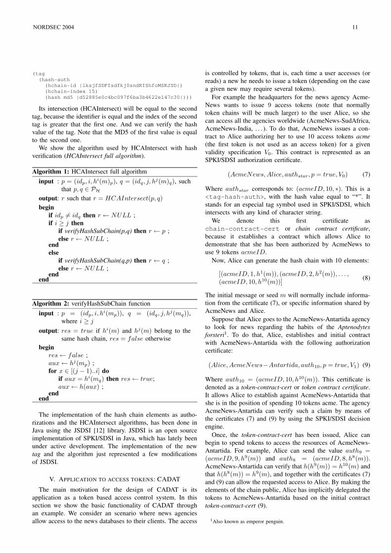
By means of the token-contract-cert (10), AcmeNews-Antartida has been able to delegate part of its initial contractwith Alice to AcmeNews-Zoology. Normally this delegationcan be transparent to Alice, allowing AcmeNews to easilysubcontract services.
Figure 2 shows both token-contract-certs issued, and thetokens delivered by Alice.
token-contract-cert(9)
token-contract-cert(10)
auth_9
auth_8
auth_7
Alice
AcmeNewsAntartida
AcmeNewsZoology
Fig. 2. token-contract-cert delegation example.
B. Delegation of chain-contract-cert
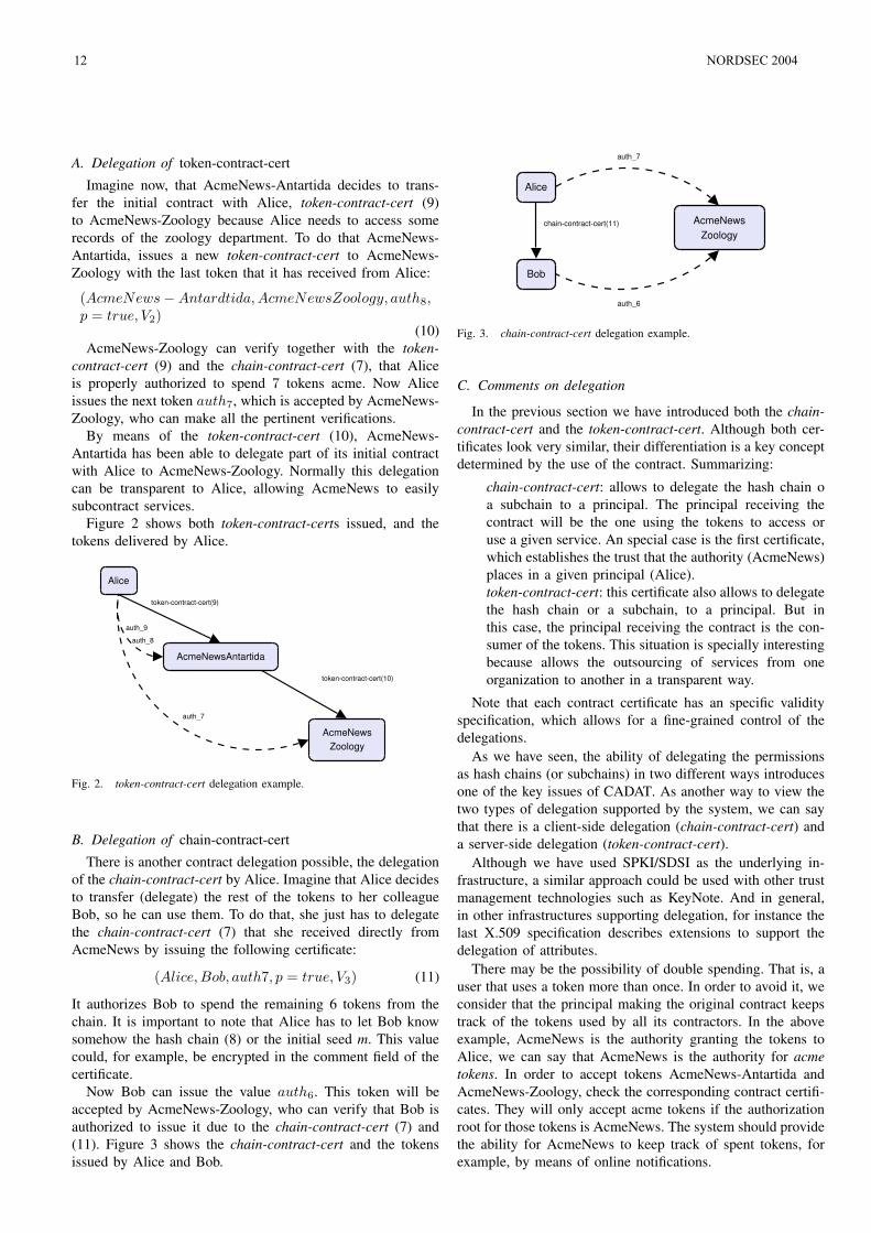
There is another contract delegation possible, the delegationof the chain-contract-cert by Alice. Imagine that Alice decidesto transfer (delegate) the rest of the tokens to her colleagueBob, so he can use them. To do that, she just has to delegatethe chain-contract-cert (7) that she received directly fromAcmeNews by issuing the following certificate:
(Alice,Bob, auth7, p = true, V3) (11)
It authorizes Bob to spend the remaining 6 tokens from thechain. It is important to note that Alice has to let Bob knowsomehow the hash chain (8) or the initial seed m. This valuecould, for example, be encrypted in the comment field of thecertificate.
Now Bob can issue the value auth6. This token will beaccepted by AcmeNews-Zoology, who can verify that Bob isauthorized to issue it due to the chain-contract-cert (7) and(11). Figure 3 shows the chain-contract-cert and the tokensissued by Alice and Bob.
chain-contract-cert(11)
auth_7
Alice
AcmeNewsZoology
Bob
auth_6
Fig. 3. chain-contract-cert delegation example.
C. Comments on delegation
In the previous section we have introduced both the chain-contract-cert and the token-contract-cert. Although both cer-tificates look very similar, their differentiation is a key conceptdetermined by the use of the contract. Summarizing:
² chain-contract-cert: allows to delegate the hash chain oa subchain to a principal. The principal receiving thecontract will be the one using the tokens to access oruse a given service. An special case is the first certificate,which establishes the trust that the authority (AcmeNews)places in a given principal (Alice).
² token-contract-cert: this certificate also allows to delegatethe hash chain or a subchain, to a principal. But inthis case, the principal receiving the contract is the con-sumer of the tokens. This situation is specially interestingbecause allows the outsourcing of services from oneorganization to another in a transparent way.
Note that each contract certificate has an specific validityspecification, which allows for a fine-grained control of thedelegations.
As we have seen, the ability of delegating the permissionsas hash chains (or subchains) in two different ways introducesone of the key issues of CADAT. As another way to view thetwo types of delegation supported by the system, we can saythat there is a client-side delegation (chain-contract-cert) anda server-side delegation (token-contract-cert).
Although we have used SPKI/SDSI as the underlying in-frastructure, a similar approach could be used with other trustmanagement technologies such as KeyNote. And in general,in other infrastructures supporting delegation, for instance thelast X.509 specification describes extensions to support thedelegation of attributes.
There may be the possibility of double spending. That is, auser that uses a token more than once. In order to avoid it, weconsider that the principal making the original contract keepstrack of the tokens used by all its contractors. In the aboveexample, AcmeNews is the authority granting the tokens toAlice, we can say that AcmeNews is the authority for acmetokens. In order to accept tokens AcmeNews-Antartida andAcmeNews-Zoology, check the corresponding contract certifi-cates. They will only accept acme tokens if the authorizationroot for those tokens is AcmeNews. The system should providethe ability for AcmeNews to keep track of spent tokens, forexample, by means of online notifications.
12 NORDSEC 2004
VI. APPLICATION OF CADAT
CADAT attempts to be a generic system, which can beapplied in several scenarios. Given its nature, it can beeasily used as a micropayment system, introducing the abilityto delegate payment tokens. In [8], the authors describe amicropayment system implemented in KeyNote that makes useof what we call delegation of token-contract-cert, but does notuses the chain-contract-cert delegation. CADAT can be seenas an extension of this system.
But the CADAT system can also be used as a generic tokenbased system. One of the current implementations of CADATis as a token-based access control in a secure mobile agentplatform. Access control in mobile agent systems involveslots of security problems. One of them is the fact that ifmobile agents are able to perform digital signatures, eithertheir private key is visible to the underlying platform, or theagent has to use a third party cryptographic proxy.
There are some alternatives as [13], which allows to delegateauthorizations to a hash of the agent’s code, but presents someconstraints in the system. We have implemented CADAT ontop of a secure mobile agent system, which at the same timemakes use of the JADE (Java Agent Development Framework)framework[14], which supports the main FIPA (Foundationfor Intelligent Agents)[15] specifications. JADE is a popularopen source generic agent platform developed in Java, whichlacks support for mobility and security. The implementation isdone within the MARISM-A project, which attempts to bringmobility and several security solutions to the JADE platform.The mobility implemented in top of JADE is described in [16],and some existing security solutions in [17]. In the context ofMARISM-A, CADAT provides a token based authorizationmechanism specially interesting for mobile agents.
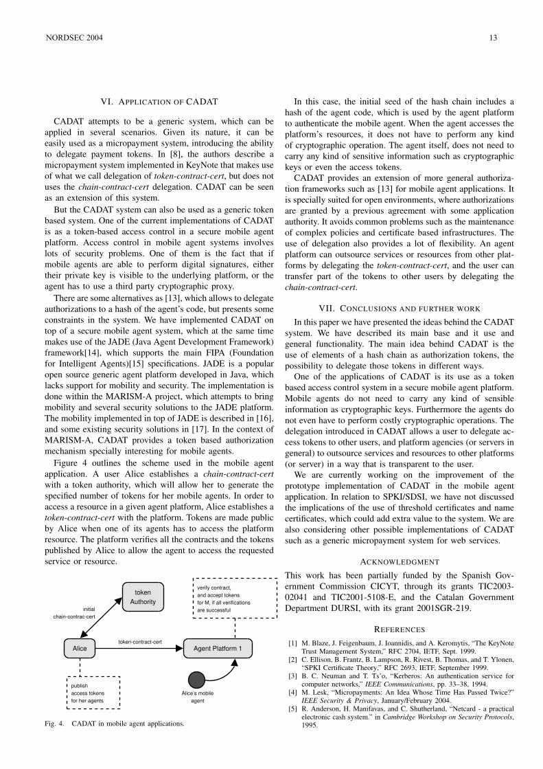
Figure 4 outlines the scheme used in the mobile agentapplication. A user Alice establishes a chain-contract-certwith a token authority, which will allow her to generate thespecified number of tokens for her mobile agents. In order toaccess a resource in a given agent platform, Alice establishes atoken-contract-cert with the platform. Tokens are made publicby Alice when one of its agents has to access the platformresource. The platform verifies all the contracts and the tokenspublished by Alice to allow the agent to access the requestedservice or resource.
Alice
Alice’s mobileagent
Agent Platform 1token-contract-cert
tokenAuthority
initialchain-contrac-cert
publishaccess tokensfor her agents
verify contract,and accept tokensfor M, if all verificationsare successful
Fig. 4. CADAT in mobile agent applications.
In this case, the initial seed of the hash chain includes ahash of the agent code, which is used by the agent platformto authenticate the mobile agent. When the agent accesses theplatform’s resources, it does not have to perform any kindof cryptographic operation. The agent itself, does not need tocarry any kind of sensitive information such as cryptographickeys or even the access tokens.
CADAT provides an extension of more general authoriza-tion frameworks such as [13] for mobile agent applications. Itis specially suited for open environments, where authorizationsare granted by a previous agreement with some applicationauthority. It avoids common problems such as the maintenanceof complex policies and certificate based infrastructures. Theuse of delegation also provides a lot of flexibility. An agentplatform can outsource services or resources from other plat-forms by delegating the token-contract-cert, and the user cantransfer part of the tokens to other users by delegating thechain-contract-cert.
VII. CONCLUSIONS AND FURTHER WORK
In this paper we have presented the ideas behind the CADATsystem. We have described its main base and it use andgeneral functionality. The main idea behind CADAT is theuse of elements of a hash chain as authorization tokens, thepossibility to delegate those tokens in different ways.
One of the applications of CADAT is its use as a tokenbased access control system in a secure mobile agent platform.Mobile agents do not need to carry any kind of sensibleinformation as cryptographic keys. Furthermore the agents donot even have to perform costly cryptographic operations. Thedelegation introduced in CADAT allows a user to delegate ac-cess tokens to other users, and platform agencies (or servers ingeneral) to outsource services and resources to other platforms(or server) in a way that is transparent to the user.
We are currently working on the improvement of theprototype implementation of CADAT in the mobile agentapplication. In relation to SPKI/SDSI, we have not discussedthe implications of the use of threshold certificates and namecertificates, which could add extra value to the system. We arealso considering other possible implementations of CADATsuch as a generic micropayment system for web services.
ACKNOWLEDGMENT
This work has been partially funded by the Spanish Gov-ernment Commission CICYT, through its grants TIC2003-02041 and TIC2001-5108-E, and the Catalan GovernmentDepartment DURSI, with its grant 2001SGR-219.
REFERENCES
[1] M. Blaze, J. Feigenbaum, J. Ioannidis, and A. Keromytis, “The KeyNoteTrust Management System,” RFC 2704, IETF, Sept. 1999.
[2] C. Ellison, B. Frantz, B. Lampson, R. Rivest, B. Thomas, and T. Ylonen,“SPKI Certificate Theory,” RFC 2693, IETF, September 1999.
[3] B. C. Neuman and T. Ts’o, “Kerberos: An authentication service forcomputer networks,” IEEE Communications, pp. 33–38, 1994.
[4] M. Lesk, “Micropayments: An Idea Whose Time Has Passed Twice?”IEEE Security & Privacy, January/February 2004.
[5] R. Anderson, H. Manifavas, and C. Shutherland, “Netcard - a practicalelectronic cash system.” in Cambridge Workshop on Security Protocols,1995.
NORDSEC 2004 13
[6] T. P. Pedersen, “Electronic payments of small amounts,” in Proc. 4thInternational Security Protocols Conference, 1996, pp. 59–68.
[7] R. L. Rivest and A. Shamir, “PayWord and MicroMint: Two simplemicropayment schemes,” in Proc. 4th International Security ProtocolsConference, 1996, pp. 69–87.
[8] S. Foley, “Using trust management to support transferable hash-basedmicropayments,” in Financial Cryptography 2003, 2003, pp. 1–14.
[9] S. Foley and T. B. Quillinan, “Using trust management to supportmicropayments,” in Annual Conference on Information Technology andTelecommunications, Oct. 2002.
[10] D. Clarke, J. Elien, C. Ellison, M. Fredette, A. Morcos, and R. Rivest,“Certificate chain discovery in SPKI/SDSI,” Journal of Computer Secu-rity, vol. 9, no. 4, pp. 285–322, Jan. 2001.
[11] C. Ellison, B. Frantz, B. Lampson, R. Rivest, B. Thomas, and T. Ylonen,“Simple Public Key Certificate,” Internet Draft, July 2000.
[12] “JSDSI: A Java implementation of the SPKI/SDSI standard,”http://jsdsi.sourceforge.net.
[13] G. Navarro, S. Robles, and J. Borrell, “Role-based access control for e-commerce sea-of-data applications,” in Information Security Conference2002, ser. Lecture Notes in Computer Science, vol. 2433. SpringerVerlag, September/October 2002, pp. 102–116.
[14] “JADE, Java Agent DEvelopemnt Framework,”http://jade.tilab.com, telecom Italia Lab.
[15] “Foundation for Intelligent Physical Agents,”http://www.fipa.org, fIPA Specifications.
[16] J. Ametller, S. Robles, and J. Borrell, “Agent Migration over FIPAACL Messages,” in Mobile Agents for Telecommunication Applications(MATA), ser. Lecture Notes in Computer Science, vol. 2881. SpringerVerlag, October 2003, pp. 210–219.
[17] J. Ametller, S. Robles, and J. Ortega-Ruiz, “Self-protected mobileagents,” in 3rd International Conference on Autonomous Agents andMulti Agents Systems. ACM Press, 2004.
14 NORDSEC 2004
Abstract— Failure of IT systems often causes a major loss of
service. Thus their dependability has become an important issue. Recent facets of the dependability of IT systems, such as reliability, availability, safety, security, confidentiality, integrity, and maintainability do not address the needs of IT systems because they do not include the notion of a degraded service as an explicit requirement. The concept termed survivability is a precise notion of the forms of services that are acceptable in a system, the circumstances under which each form is most useful, and the fraction of time that is acceptable in degraded services. In this paper survivability is discussed as a necessary new facet of dependability. The contribution of this paper is to give system architects the latest knowledge on survivability in order to help them develop survivable IT systems. Definitions of dependability and survivability are presented and discussed. In addition, the key properties and survivability requirements, and the role of fault tolerance in survivable systems are discussed. Furthermore, survivability implementation techniques and examples of survivability architectures are introduced and discussed. Finally, software architecture design and analyzing methods and frameworks relevant to survivability are discussed.
Index Terms—Dependability, reliability, security, survivability
I. INTRODUCTION ODERN society faces a substantial, and generally acknowledged, risk of IT systems failure or compromise
with potentially serious consequences. Sectors such as energy, financial services, telecommunications, healthcare, and defense are potential application areas of such systems [4], [5], [6], [8], [12]. Despite the best efforts of security professionals, no amount of system hardening can assure that a system that is connected to an unbounded network, such as the Internet, will not be vulnerable to attack. From point of view of a system architect’s practical work, it is important to know what survivability really means and how it can be applied to IT systems. Survivability, and the survivability requirements, of an IT system must be taken into account at the system architecture design phase. Survivability in IT systems is a relatively new research area. The precise definition of survivability is still being
Manuscript received October 4, 2004. This research work was conducted in the Moose project under the ITEA cluster projects of the EUREKA network, and financially supported by Tekes (the National Technology Agency of Finland).
P. Tarvainen is with VTT Electronics, VTT, the Technical Research Centre of Finland, P.O. Box 1100, FIN-90571 Oulu, Finland, [email protected].
debated, with a number of definitions proposed. Most commonly, survivability is defined as “the ability of a system to fulfill its mission, in a timely manner, in the presence of attacks, failures or accident” [8], [9], [10], [11], [18], [19]. The term system is used in the broadest possible sense, including networks and large-scale systems of systems. The term mission refers to a set of abstract requirements or goals.
Survivability is a necessary new branch of dependability [1], [2], [3], [5], [8], [9], [10], [11], [18]. It addresses explicit requirements for restricted modes of operation that preserve critical essential services in adverse operational environments. A survivable system is one that satisfies its survivability specification of essential services and adverse environments. Essential services are defined as the functions of the system that must be maintained when the environment is hostile or failures or accidents are detected that threaten the system. The discipline of survivability can help ensure that IT systems can deliver essential services and maintain such essential properties as performance, security, reliability, availability and modifiability despite the presence of intrusions. Unlike the traditional security measures that require central control or administration, survivability is intended to address unbounded network environments.
Survivability requirements can vary substantially, depending on the scope of the system, the criticality and the consequences of failure and interruption of service. The definition and analysis of survivability requirements is a critical first step in achieving system survivability [8]. Survivability must address not only software function requirements but also requirements for software usage, development, operation and evolution.
Survivability architectures offer an approach to tolerating faults in which the continued service element of fault tolerance differs from normal service. By introducing this type of fault tolerance, progress can be made towards meeting the survivability goals of IT systems.
The rest of the paper is organized as follows: definitions of dependability and survivability are presented and discussed in Section II,. In Section III key properties and survivability requirements, and the role of fault tolerance in survivable systems are discussed. Techniques for implementing survivability are discussed in Section IV and examples of survivability architectures are introduced. Software architecture design and analyzing methods and frameworks that take survivability into account are introduced in Section V, and, Section VI contains the concluding remarks.
Survey of the Survivability of IT Systems Pentti Tarvainen
VTT Technical Research Centre of Finland P.O. Box 1100, FIN-90571 Oulu, Finland
email: [email protected]
M
NORDSEC 2004 15
II. DEFINITIONS RELATED TO SURVIVABILITY A definition of dependability and different definitions of
survivability based on recent research work are discussed in this section; unofficial and common definitions of survivability are also introduced and discussed.
A. Definition of Dependability Dependability is the system property that integrates such
attributes as reliability, availability, safety, confidentiality, integrity, maintainability and survivability [32]. The dependability of a computing system is its ability to deliver a service that can justifiably be trusted. The service delivered by a system is the behavior of a system as it is perceived by its user(s). A user is another system, physical or human, that interacts with the former at the service interface. The function of a system is what the system is intended to do, and is described by the functional specification. The correct service is delivered when the service implements the system function.
B. Definitions of Survivability Software quality is depicted in IEEE 1061 [30] and
represents the degree to which the software possesses a desired combination of quality attributes. Another standard, ISO/IEC 9126-1 [31], defines the software quality model for external and internal quality. Based on this model, there are six categories of characteristics - functionality, reliability, usability, efficiency, maintainability and portability - which are further divided into sub-characteristics. Either of these standards does not define survivability.
A preliminary scoping of the general survivability problem was suggested by a 1993 report, “Survivable Computer-Communication Systems: The Problem and Working Group Recommendations” [25], written for the U.S. Army Research Laboratory (ARL). The report outlines a comprehensive multifunctional set of realistic computer-communication survivability requirements and makes related recommendations applicable to U.S. Army and defense systems [22].
The precise definition of survivability is still being debated, with a number of definitions proposed as described in Table I. The definitions in the table are listed in chronological order, based on the year the definition was published. Also the
respective references are also denoted in the table. Based on Table I, survivability in respect of IT systems is a relatively new research area and the content of the definition of survivability depends on the domain.
In the context of software engineering, Deutsch [2] has offered the first definition shown in the table. This definition is not sufficient for all needs [18]. If it were applied to IT systems in this form, the user of the system could not be sure which functions had been selected as “essential functions” nor under what circumstances (i.e., after what damage) these functions would be provided.
The Institute for Telecommunications Services, a part of the U.S. Department of Commerce, has created an extensive glossary of telecommunications terms in Federal Standard 1037C [53]. The glossary contains a definition of survivability for telecommunications systems (the second definition in Table I). This definition seeks a framework for defining a service after some form of damage and relates closely to the goal of defining survivability for IT systems [1], [18]. Furthermore, this definition includes the notion of a degraded or different service and requires that it be defined. Specifically on IT systems survivability, Ellison et al. [3] introduce the third definition of survivability shown in Table I. While this definition is a good beginning, it does not have the precision needed to permit a clear determination of whether a given system should be considered to be survivable [1], [18]. The first problem is that much is implied by the phrases “essential services”, “attacks and failures” and “timely manner”. If nothing further is defined, it is not possible for the architect of a system to determine whether a specific design is adequate to meet the needs of the user community. More importantly, if a phrase such as “essential service” is not precisely defined, it might be the case for any specific system that the determination of what constitutes an essential service is left to the system’s developers rather than being defined carefully by application experts. A second problem with a definition of this form is that it provides no testable criterion for the term being defined. Essential services are defined as the functions of the system that must be maintained when the environment is hostile, or failures or accidents that threaten the system are detected.
Most commonly [8], [9], [10], [11], [18], [19], survivability
TABLE I DEFINITIONS OF SURVIVABILITY
Definition Year Domain Ref. 1. Survivability is the degree to which essential functions are still available even though
some part of the system is down. 1988 IT systems in general [2]
2. Survivability is a property of a system, subsystem, equipment, process or procedure that provides a defined degree of assurance that the named entity will continue to function during and after a natural or man-made disturbance. Note: Survivability must be qualified by specifying the range of conditions over which the entity will survive the minimum acceptable level or post-disturbance functionality and the maximum acceptable outage duration.
1996 Telecommunication Systems [54]
3. Survivability is the ability of a network computing system to provide essential services in the presence of attacks and failures and recover full services in a timely manner.
1997 Network Computing Systems [3]
4. Survivability is the capability of a system to fulfill its mission, in a timely manner, in the presence of attacks, failures or accidents.
1999
Critical and Defense Systems [8],[9], [10],[11], [18],[19]
5. Survivability is the ability [of a system] to continue to provide service, possibly degraded or different, in a given operating environment when various events cause major damage to the system or its operating environment.
2000 Critical and Defense Systems [1], [20]
16 NORDSEC 2004
is defined as the fourth definition in Table I. The term system, consisting of software and hardware, is used in the broadest possible sense, including networks and large-scale systems of systems. The term mission refers to a set of very high-level (i.e., abstract) requirements or goals. Missions are not limited to military settings since any successful organization or project must have a vision of its objectives, whether expressed implicitly or as an official mission statement. The terms attack, failure, and accident are meant to include all potentially damaging events, but these terms do not partition these events into mutually exclusive or even distinguishable sets. Attacks are potentially damaging events orchestrated by an intelligent adversary. Attacks include intrusions, probes and denials of service. Failures are included with accidents as part of survivability. Failures are potentially damaging events caused by deficiencies in the system or in an external element on which the system depends. Failures may be due to software design errors, hardware degradation, human errors or corrupted data. Accidents describe a broad range of randomly occurring and potentially damaging events, such as natural disasters. It is important to recognize that it is the mission fulfillment that must survive, not any particular subsystem or system component.
The fifth definition of survivability [1], [20] in Table I suggests a number of key points regarding the notion of survivability:
Survivability is a system property, relating the level of service provided to the level of damage present in the system and operating environment [7],
A system must be capable of providing different levels of service. In a system free of damage, the level of service should equate with full functionality. Different levels of service will correspond to varying subsets of functionality, where some functions that a system performs are obviously more critical than others [1], [18], and
The events that cause major damage can range from failures to attacks to accidents. It is often difficult to immediately determine the cause of the damage, e.g. whether the damage is the result of an intentional security attack or a random failure [3]. More important is the effect of the event in terms of damage to the system and operating environment — the amount of damage is central to the level of service that a survivable system can and should provide [7].
III. REQUIREMENTS AND KEY PROPERTIES OF SURVIVABLE SYSTEMS
In this section the key properties and requirements, and the role of fault tolerance in survivable systems are defined and discussed. The key properties of survivable systems are as follows [8]:
Firstly, central to the delivery of essential services is the ability of a system to maintain essential properties, i.e. specified levels of integrity, confidentiality, performance and other quality attributes. Thus it is important to define the minimum levels of quality attributes that must be associated with essential services.
Secondly, quality attributes are so important that definitions
of survivability are often expressed in terms of maintaining a balance among multiple quality attributes, such as performance, security, reliability, availability, modifiability and affordability. Quality attributes represent broad categories of related requirements, so a quality attribute may contain other quality attributes. For example, the security attribute traditionally includes the three attributes of confidentiality, integrity and availability.
Thirdly, the ability to deliver essential services and maintain the associated essential properties must be sustained, even if a significant portion of the system is incapacitated. This ability should not be dependent upon the survival of a specific information resource, computation or communication link.
Fourthly, key to the concept of survivability is identifying the essential services, and the essential properties that support them, within an operational system. There are typically many services that can be temporarily suspended when a system is dealing with an attack or other extraordinary environmental condition. Such a suspension can help isolate areas affected by an intrusion and free system resources to deal with the intrusion’s effects. The overall function of a system should adapt to the situation to preserve essential services. If an essential service is lost, it can be replaced by another service that supports mission fulfillment in a different but equivalent way. However, the identification and protection of essential services is an important part of a practical approach to building and analyzing survivable systems.
The survivability requirements of survivable systems can vary substantially, depending on the scope of the system, and the criticality and consequences of failure and interruption of service [8]. The definition and analysis of survivability requirements is a critical first step in achieving system survivability. Survivability must address not only the requirements for software functionality but also the requirements for software usage, development, operation and evolution. Five types of requirements definitions are relevant to survivable systems [8]: (1) System/Survivability Requirements, (2) Usage/Intrusion Requirements, (3) Development Requirements, (4) Operations Requirements and (5) Evolution Requirements.
Fault tolerance enables systems to continue to provide service in spite of the presence of faults. Fault tolerance consists of four phases: (1) error detection, (2) damage assessment, (3) state restoration and (4) continued service. Survivability is a dependability property; it is not synonymous with fault tolerance [1]. Fault tolerance is a mechanism that can be used to achieve certain dependability properties. In terms of dependability, it makes sense to refer to a system as reliable, available, secure, safe and survivable, or some combination, using the appropriate official definition(s). Describing a system as fault tolerant is really a statement about the system’s design, not its dependability. While fault tolerance is a mechanism by which some facets of dependability might be achieved, it is not the only mechanism. Other techniques, such as fault avoidance, can also be used. In similar ways, fault elimination and fault forecasting can be used as mechanisms to improve a system’s dependability.
NORDSEC 2004 17
IV. IMPLEMENTATION TECHNIQUES FOR SURVIVABILITY This section discusses implementation techniques related to
the survivability of IT systems. In addition, examples of survivability architectures of IT systems are introduced and discussed
A. Survivability and Security It is important to recognize the relationship between
survivability and security. An application may employ security mechanisms, such as passwords and encryption, and may still be very fragile [17]. For instance, it may fail when a server or a network link dies. On the other hand, a survivable application must be able to survive some malicious attacks. Therefore, survivability must involve security. There are two aspects of survivability [17]: (1) survival by protection and (2) survival by adaptation.
Security mechanisms like access control and encryption attempt to ensure survivability by protecting applications from harmful, accidental or malicious changes in the environment [17]. The application could also survive by adapting itself to the changing conditions. These two aspects may not be mutually exclusive; as part of survival by adaptation, an application may utilize security mechanisms. For example, it may start using access control or increase the key length when it perceives the threat of an intrusion. Most current applications fail rather than adapt when QoS assumptions turn out to be too optimistic. The problem is made worse by the fact that survivability mechanisms are complicated, have little to do with an application’s functionality, and developers only have limited tool support for incorporating them.
Furthermore, based on [17], the general notion of survival by adaptation results from years of experience in designing, implementing and deploying wide-area distributed systems, and is based on the ARMD (Adaptive, Redundant, Monitored, and Diversified) principles. These principles are not independent, and they need to be organized in a meaningful way to lead to survivability. For instance, being adaptive generally means that the adaptation is driven by some kind of monitoring. However, monitoring could be used without any kind of adaptation at all. Similarly, redundancy and diversity could very well be used without any adaptation, but in the context of adaptation they often define or broaden the scope of adaptation. Not all adaptive behaviors lead to survivability. For instance, shutting an application down on an exception indicating a change in the environment does not add anything to the survivability of the application. In fact, such an adaptation facilitates a whole class of denial of service attacks, whereas survivability is about continuing to provide useful service despite environmental changes.
Survival by adaptation typically involves monitoring and changing the Quality of Service (QoS) available to applications [17]. An application’s design always makes some assumptions about the QoS provided by the environment for bandwidth, reliability, security services, etc. When these assumptions are violated, the application should try to adapt rather than fail. Most current applications, however, fail rather than adapt when QoS assumptions turn out to be too optimistic. The problem is made worse by the fact that
survivability mechanisms are complicated, have little to do with an application’s functionality, and developers only have limited tool support for incorporating them.
One important technique for improving system dependability and survivability is to provide mechanisms for a system to adapt at run time in order to accommodate varying resources, system errors and changing requirements [52]. For such self-repairing systems, one of the difficult problems is determining when a change is needed, and knowing what kind of adaptation is required. Based on [52], the challenge is to engineer things so that the system adapts appropriately at run time. There are two problems with this [52]. First, information must be got out of the running system. This can be done by employing low-level monitoring mechanisms that cover various aspects of the executing system. The second problem is to translate architectural repairs into actual system changes. This can be solved by writing table-driven translators that can interpret architectural repair operators in terms of the lower level system modifications.
B. Survivability Architectures Survivability architecture is a system architecture that is
designed specifically to deal with certain non-local faults [50]. A significant difficulty arises when the various concepts involved in survivability architectures have to be evaluated because experimentation with real systems is precluded. One approach to dealing with this problem is to use operational models that can be built and studied in the laboratory using a developed experimentation system [50].
1) Survivability Architecture: Block, Evade, React (SABER). Paper [33] proposes a survivability architecture called SABER. SABER blocks, evades and reacts to a variety of attacks by using several security and survivability mechanisms in an automated and coordinated fashion. SABER integrates several different technologies in an attempt to provide a unified framework for responding to the wide range of attacks malicious insiders and outsiders can launch. Most commercial responses to the diverse array of vulnerabilities have been to apply several discrete solutions [33]: (1) utilization of network-based firewalls [34], [35], (2) deployment of network-based and host-based intrusion detection systems [36], [42] and (3) manual installation and deployment of patches [37], [38].
At present, SABER is in the prototyping stages, with several interesting open research topics. It currently makes use of the following reaction and protection mechanisms [33]: (1) a network Denial-of-Service (DoS) resistant and Secure Overlay Services (SOS) architecture [39], (2) Manuscript intrusion and anomaly detection tools, [43], [44], placed within service contexts to detect malicious activity as well as stealthy “scans and probes”, (3) a process migration system [40] that can be used to move a service to a new location that is not (currently) targeted by an attacker, (4) an automated software-patching system [41] that dynamically fixes certain classes of software-based attacks, such as buffer overflows, and (5) a high-level coordination and control infrastructure to correlate and coordinate the information and control flow.
2) Intrusion Tolerant Distributed Object System (ITDOS): Intrusion Tolerant Distributed Object System (ITDOS)
18 NORDSEC 2004
architecture [47] discusses some of the challenging technical issues related to intrusion tolerance in heterogeneous middleware systems. The intrusion tolerant systems provide integrity and availability services in the face of successful attacks from an adversary.
Middleware is one area in which a system can provide intrusion tolerance [47]. Middleware is a very useful category of software that removes much of the tedium of distributed systems programming and shields programmers from having to deal with the numerous kinds of heterogeneity inherent in a distributed system [48]. Distributed object middleware is considered the most general kind of middleware, and CORBA [49] is a widely adopted standard for distributed object middleware. Middleware provides an ideal platform for intrusion tolerance extensions because it allows a variety of applications to be built that can transparently take advantage of the intrusion tolerance properties of the middleware, eliminating the need for custom solutions for each application [47].
3) Middleware Architecture for Secure and Survivable Mobile C4I Systems: An overview of a middleware-based mobile C4I (Command, Control, Communications, Computers, & Intelligence) architecture is discussed in [51]. The architecture is an outgrowth of work on a mobile distributed operating system that attempts to deal with various shortcomings in the Mobile Internet Protocol (Mobile IP) for military use. The architecture provides a foundation for balanced treatment of the complex, and frequently conflicting, dependability requirements (i.e. security, survivability, etc.) of military tactical systems.
The survivability architecture presented in [51] is controversial in that the Session Layer performs the primary communications function of a mobile “hand-off”, instead of relying exclusively on the Network Layer to perform this function. This approach is defended on the basis that where tactical survivability is paramount, a mobile “hand-off” must be carefully controlled by the Session Layer, even if not specifically performed by that layer. The popular private sector approaches (e.g. Mobile IP) attempt to provide a “virtually stationary” environment by use of address mappings, which, except for performance impact, completely
hide motion effects in the Network Layer. Such mobile networking approaches are unsuitable for military mobile C4I use, unless they are modified or designed to carefully coordinate their resource-management facilities with the survivability mechanisms of the Session Layer [51]. The mobile C4I architecture is a part of an evolving paradigm for C4I survivability called the Plan-Based Survivability, which seems to be able to solve many open problems with current survivability technology, and which has already been partly demonstrated by a working prototype. In effect, Plan-Based Survivability is a “superstructure” for unifying a diverse hierarchy of C4I defenses, both physical and informational.
C. Summary Table II summarizes the features of the survivable
architectures mentioned above. As a conclusion, the maturity of the architectures is insufficient for practical utilization in a system architect’s work, but they will help to understand and solve the problem of survivable systems. The technical approaches of the architectures heavily depend on the system domain.
V. DESIGN OF SURVIVABILITY In this section the available design and analysis methods
and models, as well as frameworks relevant for the survivability of IT systems, are introduced and discussed.
A. Architecture Tradeoff Analysis Method (ATAM) Paper [8] outlines an approach that addresses how to
evaluate the ability of a system to deliver essential functions in an environment that includes intrusion scenarios. The general approach to survivability and security is consistent with the ATAM [14]. ATAM is a method for evaluating architecture-level designs that consider such multiple quality attributes as modifiability, performance, reliability and security to gain insight as to whether the fully fleshed out incarnation of the architecture will meet its requirements [14]. The method identifies tradeoff points between these attributes, facilitates communication between stakeholders (such as user, developer, customer, maintainer) from the perspective of each attribute, clarifies and refines the requirements, and provides a
TABLE II
FEATURES OF SURVIVABILITY ARCHITECTURES Feature SABER ITDOS C4I
Security Mechanism
Integrates several security and survivability mechanisms
Symmetric Encryption Session Keys “Plan-Based Survivability”, Mobile IP and Ad Hoc network protocols for military use
Reaction/Protection Mechanism
Process Migration System, Network Denial-of-Service (DoS), Secure Overlay Services (SOS), An automated software-patching system
Distributed Object Middleware, CORBA
“Plan-Based Survivability”
Intrusion Detection Network- and host-based intrusion detection, Anomaly-, registry- and file-based detection, Surveillance detection
Fault Tolerant Multicast Protocol + CORBA
“Plan-Based Survivability”
Domain Network Systems Heterogeneous Distributed Middleware Systems
Mobile Military Tactical Systems
Maturity Prototype Prototype Prototype Publishing Year 2003 2002 1999 Reference [33] [47] [51]
NORDSEC 2004 19
framework for an ongoing, concurrent process of system design and analysis.
B. The Survivable Network Analysis Method (SNA) A four-step SNA method [23] has been developed for
analyzing survivability in distributed systems. SNA is a practical engineering process that enables systematic assessment of the survivability properties of proposed and existing systems, and modifications to existing systems. The analysis can be carried out at the lifecycle, requirements or architecture level. Based on [23], although the SNA method is developed for use with large-scale distributed-network systems, it is equally applicable to other architectures, including host-based and real-time systems. SNA’s scenario-based approach is a generalization of the operation sequence and usage scenario methods.
C. The Willow Survivability Architecture The Willow Architecture [13] is designed to enhance the survivability of IT systems and is a comprehensive approach to survivability in distributed applications. Based on [13], survivability is achieved in a deployed system using a unique combination of (1) fault avoidance by disabling vulnerable network elements intentionally when a threat is detected or predicted, (2) fault elimination by replacing system software elements when faults are discovered, and (3) fault tolerance by reconfiguring the system if non-maskable damage occurs.
D. Open Implementation Toolkit for Building Survivable Applications (QuO) In [17] Pal, Loyall, Schertz and Zinky consider two aspects
of survivability - namely, survival by adaptation and survival by protection. They show how the Quality Objects (QuO) distributed adaptive middleware framework enables the introduction of these aspects of survivability in a flexible and systematic manner. Furthermore, they also describe a toolkit for developing adaptive applications and demonstrate how more survivable applications can be built using the toolkit.
E. A Survivability Framework for Wireless Access Networks Based on [21], a Survivability Framework for Wireless
Access Networks consists of four layers, with survivability strategies possible in each layer. The four layers are termed access, access link level, transport and intelligent. The logical layers are independent of the physical implementation of the network. Each of the four layers is characterized by network functions, network components and communication links. This framework includes metrics for quantifying network survivability, possible survivability strategies, and restoration techniques for each layer.
F. An Architectural Framework and Algorithms for Engineering Dynamic Real-Time Distributed Systems In [24] Ravindran presents a resource management
architecture for engineering dynamic real-time, military, computer-based, Command and Control (C2) systems using commercial off-the-self technologies. In the proposed architecture a real-time system application is developed in a general-purpose programming language and system description language is used to specify the architectural-level description of the system. An abstract model that is constructed from the language specification is dynamically augmented by the System Description Language Runtime System to produce a dynamic Intermediate Representation (IR). The dynamic IR characterizes the state of the system and is used by a recourse management element to deliver the desired application QoS. The middleware techniques achieve the timeliness and survivability requirements through runtime monitoring and failure detection, diagnosis and dynamic recourse allocation.
G. Easel Modeling and Simulation Language Easel [15] is a modeling and simulation programming
language primarily intended for the research, analysis and depiction of unbounded systems, survivable architectures and emergent algorithms in applications, including Internet security, ad hoc communication networks, electric power and cooperation among autonomous vehicles. Easel is a notation
TABLE III
FEATURES OF THE SURVIVABILITY METHODS, MODELS, AND FRAMEWORKS Method Type of Method Survivability Approach Domain Maturity Level Ref.
ATAM Design and Analysis Method
Intrusion Scenarios, Quality attributes
Not limited High, widely used [8], [14]
SNA Design and Analysis Method
Scenarios Large-Scale Distributed-Network Systems
High, based on ATAM
[23]
Willow Modeling tool Fault Avoidance, Fault Elimination, Fault Tolerance
Critical Distributed Applications
Medium [13]
QuO Modeling tool Quality Objects, Adaptation, Protection
Middleware Applications Medium [17]
Survivability Framework for WANs
Modeling tool Metrics, Restoration Techniques Wireless Access Networks Low [21]
Architectural Framework
Modeling tool System Description Language, Runtime Monitoring, Failure Detection, Dynamic Recourse Allocation
Military C2 Systems High [24]
Easel Modeling and Simulation Language
Discrete Event Simulations Models Unbounded Systems, Ad Hoc Networks
Medium [15]
20 NORDSEC 2004
for describing abstract models of anything, a translator run-time system for running discrete event simulations from those models. An example of the use of Easel in network survivability analysis is presented in [16].
H. Summary Table III summarizes the features of the survivability
methods, models and frameworks described above. As a conclusion, the survivability approaches vary depending on the system domain. From the point of view of the system architect’s practical work, there is a remarkable lack of suitable and mature methods. Only two (ATAM and SNA) design and analysis methods are available. The rest of the methods are modeling or simulation tools.
VI. CONCLUSION Survivability is a new branch of dependability that
addresses the explicit requirements for restricted modes of operation that preserve essential services in adverse operational environments. A survivable system is one that satisfies its survivability specification of essential services and adverse environments. In addition, survivability must address not only the requirements for software functionality but also the requirements for software usage, development, operation and evolution. Furthermore, survivability is a dependability property; it is not synonymous with fault tolerance. Fault tolerance is a mechanism that can be used to achieve certain dependability properties. In terms of dependability, it makes sense to refer to a system as reliable, available, secure, safe, and survivable, or some combination, using the appropriate definition(s). Describing a system as fault tolerant is really a statement about the system’s design, not its dependability.
Survivability in respect of IT systems is a relatively new research area and the definition of survivability is still being debated. Two of the five definitions of survivability in Table I mention "essential services", and three of them mention the "degree of degraded or different” service to be provided by the survivable system, so these could represent points of agreement for a unified survivability definition. However, definition three mentions that full services will be recovered, whereas the other definitions only mention mission fulfillment, not full service recovery.
Security attacks are a major concern for IT systems. In some discussions survivability is viewed as synonymous with secure operation. A survivable application must be able to survive some malicious attacks, so survivability must involve security. There are at least two aspects of survivability: survival by protection and survival by adaptation. Security mechanisms like access control and encryption attempt to ensure survivability by protecting applications from harmful, accidental or malicious changes in the environment. Survival by adaptation typically involves monitoring and changing the QoS available to applications.
The maturity of the survivable architectures is insufficient for practical utilization in a system architect’s work, but they will help to understand and solve the problem of survivable systems. Furthermore, there is a remarkable lack of suitable
and mature methods, models and frameworks for practical use.
REFERENCES [1] J. C. Knight and K. J. Sullivan, “On the Definition of Survivability”,
University of Virginia, Department of Computer Science, Technical Report CS-TR-33-00, 2000.
[2] M. S. Deutsch and R. R. Willis, “Software Quality Engineering: A Total Technical and Management Approach”, Englewood Cliffs, NJ: Prentice-Hall, 1988.
[3] R. J. Ellison, D. A. Fisher, R. C. Linger, H. F. Lipson, T. Longstaff and N. R. Mead, “Survivable Network Systems: An Emerging Discipline”, Technical Report CMU/SEI-97-TR-013, Software Engineering Institute, Carnegie Mellon University, 1997.
[4] The Information Survivability Workshops of CERT Coordination Center, Software Engineering Institute, Carnegie Mellon University. Available at: http://www.cert.org/research/isw.html, 13.02.2004.
[5] R. C. Linger and A. P. Moore, “Foundations for Survivable System Development: Service Traces, Intrusion Traces and Evaluation Models”, Technical Report, CMU/SEI-2001-TR-029, Software Engineering Institute, Carnegie Mellon University, 2001. Available at: http://www. cert.org/archive/pdf/01tr029.pdf, 13.02.2004.
[6] K. Sullivan, J. Knight, X. Du and S. Geist, “Information Survivability Control Systems”, Proceedings of the 21st International Conference on Software Engineering, Los Angeles, California, pp. 184-192, 1999.
[7] M. C. Elder, “Fault Tolerance in Critical Information Systems”, Dissertation, Faculty of the School of Engineering and Applied Science, University of Virginia, 2001.
[8] R. J. Ellison, D. A. Fisher, R. C. Linger, H. F. Lipson, T. A. Longstaff and N. R. Mead, “An Approach to Survivable Systems”, Technical Report, CERT Coordination Center, Software Engineering Institute, Carnegie Mellon University, 1999.
[9] I. Byon, “Survivability of the U.S. Electric Power Industry”, Master's Thesis, Carnegie Mellon University, Information Networking Institute, 2000.
[10] J. Caldera, “Survivability Requirements for the U.S. Health Care Industry”, Master's Thesis, Carnegie Mellon University, Information Networking Institute, 2000.
[11] R. J. Ellison, D. A. Fisher, R., C. Linger, H. F. Lipson, T. A. Longstaff and N. R. Mead “Survivability: Protecting Your Critical Systems”, CERT Coordination Center Software Engineering Institute, IEEE Internet Computing, pp. 55-63, 1999.
[12] R. J. Ellison, L.C. Linger, T. Longstaff, and N. R. Mead “Survivable Network System Analysis: A Case Study”, IEEE Software, Vol. 16, Issue: 4, pp. 70-77, 1999.
[13] J. Knight, D. Heimbigner, A. L. Wolf, A. Carzaniga, J. Hill, P. Devanbu and M. Gertz, “The Willow Architecture: Comprehensive Survivability for Large-Scale Distributed Applications”, Technical Report CU-CS-926-01, Department of Computer Science, University of Colorado, Boulder, Colorado, 2001.
[14] R. Kazman, M. Klein, M. Barbacci, T. Longstaff, H. Lipson and S., J. Carriere, “The Architecture Tradeoff Analysis Method”, Proceedings of the IEEE International Conference on Engineering of Complex Computer Systems, IEEE Computer Society, 1998.
[15] WWW-pages of CERT Coordination Center, Software Engineering Institute, Carnegie Mellon University. Available at: http://www.cert.org/ easel/, 13.02.2004.
[16] A. M. Christie, “Network Survivability Analysis Using Easel”, Technical Report, CMU/SEI-2002-TR-039, ESC-TR-2002-039, Software Engineering Institute, Carnegie Mellon University, 2002.
[17] P. P. Pal, J. P. Loyall, R. E. Schantz, J. A. Zinky and F. Webber, “Open implementation toolkit for building survivable applications”, DARPA Information Survivability Conference and Exposition, Proceedings, Volume: 2, pp. 197 – 210, 2000.
[18] J. C. Knight, E. A. Strunk and K. J. Sullivan, “Towards a Rigorous Definition of Information System Survivability”, DARPA Information Survivability Conference and Exposition, Washington DC, 2003.
[19] M. A. Hiltunen, R. D. Schlichting, C.A. Ugarte and G. T. Wong, “Survivability through Customization and Adaptability: The Cactus
NORDSEC 2004 21
Approach”, DARPA Information Survivability Conference and Exposition, pp. 294-307, 2000.
[20] J. C. Knight, K. J. Sullivan, M. C. Elder and C. Wang, “Survivability Architectures: Issues and Approaches”, DARPA Information Survivability Conference and Exposition, January 2000.
[21] D. Tipper, T. Dahlberg and H. Shin, “Providing Fault Tolerance in Wireless Access Networks”, IEEE Communications Magazine, Vol. 40 Issue: 1, pp. 58-64, 2002.
[22] P. G. Neumann, “Practical Architectures for Survivable Systems and Networks”, Technical Report supported by the U.S. Army Research Laboratory (ARL), Computer Science Laboratory, SRI International, 2000.
[23] N. R. Mead, R. J. Ellison, R. C. Linger, T. Longstaff and J. McHugh, “Survivable Network Analysis Method”, Technical Report, CMU/SEI-2000-TR-013, ESC-2000-TR-013, Software Engineering Institute, Carnegie Mellon University, 2000.
[24] B. Ravindran, “Engineering Dynamic Real-Time Distributed Systems: Architecture, System Description Language, and Middleware”, IEEE Transactions on Software Engineering, Vol. 28 Issue: 1, pp. 30-56, 2002.
[25] A. Barnes, A. Hollway and P. G. Neumann, “Survivable Computer-Communication Systems: The Problem and Working Group Recommendations”, Technical report VAL-CE-TR-92-22 (revision 1), U.S. Army Research Laboratory, AMSRL-SL-E, White Sands Missile Range, NM 88002-5513, 1993.
[26] R. Kazman, G. Abowd, L. Bass and P. Clements, “Scenario-Based Analysis of Software Architecture”, IEEE Software, Vol. 13, Issue: 6, pp. 47-55, 1996.
[27] M. Klein, T. Ralya, B. Pollak, R. Obenza and H. M. Gonzales “A Practitioner’s Handbook for Real-Time Analysis”, Boston, MA, Kluwer Academic, 1993.
[28] B. Boehm, “A Spiral Model of Software Development and Enhancement”, ACM Software Eng. Notes 11, 4, pp. 22-42, 1986.
[29] M. Matinlassi, E. Niemelä and L. Dobrica, “Quality-driven architecture design and quality analysis method. A revolutionary initiation approach to product line architecture”, VTT Electronics, Espoo, VTT Publications: 456, 2002. ISBN 951-38-5967-3, 951-38-5968-1
[30] IEEE Standard 1061- 1998, “Standard for a Software Quality Metrics Methodology”, New York: The Institute of Electrical and Electronics Engineers, 1998.
[31] ISO/IEC 2001 - International Organization for Standardization and International Electrotechnical Commission. “Software engineering - Product quality - Part 1: Quality model”. ISO/IEC 9126-1:2001(E)
[32] A. Avizienis, J.-C. Laprie and B. Randell, “Fundamental Concepts of Dependability”, Technical report CS-TR-739, at University of Newcastle, 2001.
[33] A. D. Keromytis, J. Parekh, P. N. Gross, G. Kaiser, V. Misra, J. Nieh, D. Rubenstein and S. Stolfo, “A Holistic Approach to Service Survivability”, Technical Report CUCS-021-03, Department of Computer Science, Columbia University, 2003.
[34] P. Thompson, “Web services – beyond HTTP tunneling”. In W3C Workshop on Web Services, 2001.
[35] D. Moore, G. M. Voelker and S. Savage, “Inferring internet Denial-of-Service activity”. In Proceedings of the 10th Usenix Security Symposium, pp. 9-22, 2001.
[36] D. Newman, J. Snyder and R. Thayer, “Crying wolf: False alarms hide attacks”, Network World, June 2002. Available at: http://www. nwfusion.com/techinsider/2002/0624security1.html. 13.02.2004
[37] “Microsoft Security Tool Kit: Installing and Securing a New Windows 2000 System”. Microsoft TechNet. Available at: http://www.microsoft. com/technet/security/tools/tools/w2knew.asp, 13.02.2004
[38] “RedHat 9 Security Advisories”. Available at: https://rhn.redhat.com/ errata/rh9-errata-security.html, 13.02.2004
[39] A. D. Keromytis, V. Misra and D. Rubenstein, “SOS: Secure Overlay Services”. In Proceedings of ACM SIGCOMM, Pp. 61-72, 2002.
[40] S. Osman, D. Subhraveti, G. Su and J. Nieh, “The design and implementation of Zap: A system for migrating computing environments”. In Proceedings of the Fifth Symposium on Operating Systems Design and Implementation (OSDI), pp. 361–376, 2002.
[41] S. Sidiroglou and A. D. Keromytis, “A Network Worm Vaccine Architecture”. In Proceedings of the IEEE Workshop on Enterprise Technologies: Infrastructure for Collaborative Enterprises (WET-ICE), Workshop on Enterprise Security, 2003.
[42] M. V. Mahoney and P. K. Chan, “Learning non-stationary models of normal network traffic for detecting novel attacks”. In Proceedings of the eighth ACM SIGKDD international conference on Knowledge discovery and data mining, pp. 376–385, ACM Press, 2002.
[43] D. L. Cook, W. G. Morein, A. D. Keromytis, V. Misra and D. Rubenstein, “WebSOS: Protecting Web Servers from DDoS Attacks”. In Proceedings of the IEEE International Conference on Networks (ICON), 2003.
[44] S. Hershkop, R. Ferster, L. H. Bui, K. Wang, and S. J. Stolfo., “Host-based anomaly detection by wrapping file system accesses”, Technical report, Columbia University, Department of Computer Science, 2003.
[45] P. Pal, M. Atighetchi, F. Webber, R. Schantz and C. Jones, “Reflections on Evaluating survivability: The APOD Experiments”, The 2nd IEEE International Symposium on Network Computing and Applications (NCA-03), 2003.
[46] P. Pal, F. Webber, J. Zinky, R. Shapiro and J. Megquire, “Using QDL to specify QoS aware distributed (QuO) application configuration”, IEEE Int'l Symp. Object-Oriented Real-Time Distributed Comp., 2000.
[47] D. Sames, B. Matt, B. Niebuhr, G. Tally, B. Whitmore and D. Bakken, “Developing a Heterogeneous Intrusion Tolerant CORBA System”, International Conference on Dependable Systems and Networks (DSN'02), 2002.
[48] D. Bakken, “Middleware”, Chapter in Encyclopedia of Distributed Computing, Urban, J., Dasgupta, P., eds., Kluwer Academic Publishers, 2001.
[49] “The Common Object Request Broker: Architecture and specification”, OMG, Revision 2.5, 2001.
[50] J. C. Knight, K. J. Sullivan, M. C. Elder and C. Wang, “Survivability architectures: issues and approaches”, DARPA Information Survivability Conference and Exposition, Proceedings, Volume: 2, pp. 157 -171, 2000.
[51] R. Browne, J. Valente and S. Hariri, “An advanced middleware architecture for secure and survivable mobile C4I systems”, Military Communications Conference Proceedings, MILCOM 1999, IEEE, Volume: 1, pp. 506 -513, 1999.
[52] R. de Lemos, C. Gacek and A. Romanovsky, (Eds.), “Architecting Dependable Systems”, Series: Lecture Notes in Computer Science, Vol. 2677, XII, 309 p., 2003, ISBN: 3-540-40727-8.
[53] “Federal Standard 1037C”, U.S. Department of Commerce, National Telecommunications and Information Administration, Institute for Telecommunications Services, 1996. Available at: http://www.its. bldrdoc.gov/fs-1037/dir-001/_0065.htm, 09.03.2004.
22 NORDSEC 2004
Exploring Spyware Effects
Martin Boldt, Bengt Carlsson & Andreas JacobssonSchool of Engineering, Blekinge Institute of Technology, S-372 25 Ronneby, SWEDEN
martin.boldt;bengt.carlsson;[email protected]
Abstract -- In this paper, we discuss various types of spywareprograms, their behaviour, how they typically infect comput-ers, and the propagation of new varieties of spyware pro-grams. In two experiments, we investigate the occurrence andimpact of spyware programs found in popular P2P applica-tions. Based on the findings from the empirical investigations,we try to lift the perspective to a more general view on spy-ware deriving from the theory of (virtual) network effects. Ina model, we categorize in what ways spyware might decreasethe utility of belonging to a large virtual network. Here, thebaseline is that spyware programs intrude systems and net-works, but since they profit from user data they also intrudeuser privacy. In the model, the intrusions are classified asmoderate, severe or disastrous. We found that spyware hasthe potential to overthrow the positive aspects of belonging toa large network, and network owners should therefore bevery careful about permitting such programs in applicationsand on networks.
Index Terms -- Malware, network effects, P2P, spyware.
I. INTRODUCTION
uring recent years, the world has seen the introductionof peer-to-peer (P2P) systems. P2P technology pro-
vides several beneficial solutions like, e.g., file-sharing,grid computing, web services, groupware and instant mes-saging (IM) [7]. P2P refers to a technology which enablestwo peers or more to collaborate in a network of equals [7][10]. This may be done by using information and commu-nication systems that are not depending on central coordi-nation. P2P technology was first widely deployed andpopularized by file-sharing applications such as KaZaa andIM tools like ICQ.
Even though there are several benefits with belonging toa large virtual network such as a P2P file-sharing network,the rising occurrence of malicious software (malware) mayseriously impact the positive utility of using P2P applica-tions. Usually, only the positive effects that increase utilityare emphasized when discussing participation in large net-works [5]. One example is the theory of virtual network1
effects. Network effects are usually described as when the
value of a product to one user depends on how many otherusers there are [11]. Often, utility of the system is propor-tional to the aggregate amount of resources that the partici-pants are willing to put together. On informationtechnologies, users generally benefit from utilising a popu-lar format, system or application [11]. Typically, technolo-gies subject to strong network effects tend to exhibit longlead times until a critical mass of users is obtained [5].Then, explosive growth is followed. From the perspectiveof a network owner, a large network may help to create astrategic advantage useful for competition and growth pur-poses [1]. From the perspective of a network user, thelarger the network is, the more valuable it will be to partic-ipants and users [1].
There are two kinds of feedback from network effects:positive and negative [11]. Positive feedback can beexplained in that when a person joins a network, the net-work gets bigger and better, to everyone’s benefit. How-ever, large networks may also be exposed to negativefeedback, which bring about significant risks and severeconsequences for all of the network nodes. Therefore, neg-ative feedback may decrease the utility of belonging to thatnetwork. To large networks, such as P2P file-sharing net-works, there could be numerous examples of applications(e.g., malware), which contribute in creating negativeeffects that impact network utility. However, in this paper,we focus on one of these applications, namely spyware.
There are many different kinds of spyware, and hun-dreds of such programs exist throughout the Internet today[9]. Spyware programming is a relatively new computingphenomenon. Although there is no precise definition, theterm “spyware” is typically used to refer to a category ofsoftware that, from a user’s perspective, covertly gathersinformation about a computer’s use and relays that infor-mation back to a third party. In this paper, we use the termspyware in conformity with this common usage. However,
D
1 A virtual network describes a network of users bound together by a certain standard or technology, and where the exchange of information is the foundation for any information transaction. One example is the Inter-net.
NORDSEC 2004 23
in II, we look into and discuss some of the current views onthe concept of spyware.
Even though most people are aware of spyware, itseems that the research community has spent limited efforton understanding the nature and extent of the spywareproblem. However, so far there have been some initialresearch attempts (see for example [4] [9] [17]) of whichthis paper is an additional effort. On the other hand, mostnetwork practitioners and experts agree that spyware is areal problem with increasingly negative effects. One exam-ple of this view is derived from the Emerging InternetThreats Survey 2003 [3], which states that one in threecompanies have detected spyware on their systems, while60% consider spyware to be a growing and future threat.Also, 70% of the companies consider that file-sharing overP2P networks is creating an open door into their organisa-tion. Another example is an investigation made by Earth-link (one of the major American ISPs) [13]. Earthlink set tomeasure the occurrence of spyware on more than 2 millioncomputers connected to their network. A total number of12.1 million different spyware types were detected. Out ofthese, Trojan horses and system monitors approached 700000 instances, and the remaining 11.4 million instanceswere classified as adware. Also, experts suggest that spy-ware infect up to 90% of all Internet-connected computers[13].
In summary, spyware is a problem that should be takenseriously, because it may have the potential to threaten theutility of belonging to a large virtual network. In this paper,we focus on exploring the effects of spyware programs thatare bundled with several P2P applications. The aim is toinvestigate the implications on system capacity, networkbandwidth, security and privacy. Besides introducingresults from empirical investigations, we also discuss thenetwork effects of spyware.
The paper is organised as follows. First, we give anintroduction to spyware, in which we discuss the variouskinds of spyware programs, their behaviour, how they typi-cally infect computers, and the proliferation of new variet-ies of spyware. Next, we investigate the occurrence andimpact of spyware programs found in popular P2P applica-tions. In IV, we discuss the findings from the experimentsand also try to lift the perspective to a more general viewon spyware deriving from the theory of virtual networkeffects. In the end, conclusions are presented.
II. ON SPYWARE
A. The Background of SpywareAs stated by [9], spyware exists because information
has value. The idea with spyware is simply to fetch infor-mation. If a software developer can get revenue from
advertisers, the owner can afford to make the softwareavailable for free. The developer is paid, and the user getsfree, quality software. Usually, the developer provides twoversions of the software, one for which the user has to paya fee in order to receive, and one version that is freewaresupported by advertising. In these cases, free software typi-cally includes programs set to display advertisements andoffers to the users (that is; adware). Therefore, the user canchoose between the free software with the slight inconve-nience of either pop-up ads or banners, or to pay for soft-ware free of advertising. So, users pay to use the softwareeither with their money or with their time.
This method of including rather benign adware whendeveloping and distributing free software was commonuntil marketers noted three separate trends that pushed thedevelopment of adware into a different direction. Thebackground was that:
--standard banner ads on the Internet were not deliver-ing as well as expected (1% click-trough was consideredgood) [15],
--targeted Internet advertising typically performed muchbetter [14], and
--while office hours were dead-time for traditionaladvertising (radio, TV, etc.), many analyses showed a sur-prisingly high degree of personal Internet usage duringoffice hours [14].
The conclusion was that targeted Internet advertisingwas a whole new opportunity for the marketing of productsand services. All that was required was a method for moni-toring users’ behaviour. So, once the adware was monitor-ing users’ Internet usage and sending user details back tothe advertiser, banners more suited to the users’ prefer-ences and personality was sent to the users in return. Theaddition of monitoring functionality turned adware intospyware, and the means to target advertising to interestedparties accelerated [15]. In reality, the data collected byspyware is often sent back to the marketing company,resulting in display of specific advertisements, pop-up ads,and installing toolbars showed when users visit specificweb sites. In this sense, spyware programs became technol-ogies used to fetch valuable customer information.
B. The Operations of SpywareThe usual method for a spyware is to run secretly in the
background of the users’ computers [6]. The reason for thisconcealing of processes is commonly argued as that itwould hardly be acceptable if, e.g., free file-sharing soft-ware kept stopping to ask the user if he or she was ready tofetch a new banner or a pop-up window [15]. Therefore,the client/server routine of spyware is normally executed inthe background. In practice, there would be nothing wrongwith spyware running in the background provided that theusers know that it is happening, what data is being trans-
24 NORDSEC 2004
mitted, and that they have agreed to the process as part ofthe conditions for obtaining the freeware. However, mostusers are unaware of that they have software on their com-puters that tracks and reports on their Internet usage. Typi-cally, a spyware program covertly gathers user informationand spreads it without the user’s knowledge of it. Onceinstalled, the spyware monitors, e.g., user activity on theInternet and transmits that information in the backgroundto third parties, such as advertising companies. In reality,spyware run constantly, even when their carrier program,e.g., a file-sharing tool, has been terminated.
A more or less legal grey area is exploited by the spy-ware actors, since they in most program licenses specifythat information may be gathered for corporate purposes.However, the usual model is to collect more informationthan have been asked for [15]. Besides this, most licenseagreements are formulated in such a way that they areextensively hard for users to understand.
C. The Types of SpywareThere are many different kinds of spyware. For
instance, one of the leading anti-spyware tools, PestPatrol,has a record of over 1400 instances of spyware publishedon their web site [8]. In order to make the spyware domainmore graspable, we present the following classes of spy-ware. This classification is in conformity with a recentlypublished study on measurement and analysis of spyware[9], although when presented here, the order of spywaretypes ranges from minimum to maximum user impact:
--Cookies and web bugs: Cookies are small pieces ofstate stored on individual clients’ on behalf of web servers.Cookies can only be retrieved by the web site that initiallystored them. However, because many sites use the sameadvertisement provider, these providers can potentiallytrack the behaviour of users across many Internet sites.Web bugs are usually described as invisible images embed-ded on Internet pages used for locating a connectionbetween an end user and a specific web site. They arerelated to cookies in that advertisement networks oftenmake contracts with web sites to place such bugs on theirpages. Cookies and web bugs are purely passive forms ofspyware, they contain no code of their own. Instead theyrely on existing web browser functions.
--Adware: Adware is a more benign form of spybot (seebelow). Adware is a category of software that displaysadvertisements tuned to the user’s current activity.Although most “genuine” adware programs only displaycommercial content, some hybrids are involved in report-ing the aggregate or anonymised user behaviour to a thirdparty, as described in A.
--Tracks: A “track” is a generic name for informationrecorded by an operating system or application aboutactions that the user has performed. Examples of tracks
include lists of recently visited web sites, web searches,web form input, lists of recently opened files, and pro-grams maintained by operating systems. Although a trackis typically not harmful on its own, tracks can be mined bymalicious programs, and in the wrong context it can tell agreat deal about a user.
--Browser hijackers: Hijackers attempt to change auser’s Internet browser settings to modify their start page,search functionality, or other browser settings. Hijackers,which predominantly affect Windows operating systems,may use one of several mechanisms to achieve their goal:install a browser extension (called a “browser helperobject”), modify Windows registry entries, or directlymanipulate and/or replace browser preference files.Browser hijackers are also known to replace content onweb sites with such promoted by the spyware authors [12].
--Spybots: Spybots are the prototypes of spyware. Aspybot monitors a user’s behaviour, collects logs of activityand transmits them to third parties. Examples of collectedinformation include fields typed in web forms, lists of e-mail addresses to be harvested as spam targets, and lists ofvisited URLs. A spybot may be installed as a browserhelper object, it may exist as a DLL on the host computer,or it may run as a separate program launched whenever thehost operating system boots.
--System monitors: System monitors record variousactions on computer systems. This ability makes thempowerful administration tools for compiling system diag-nostics. However, if misused system monitors become seri-ous threats to user privacy. Keyloggers are a group ofsystem monitors commonly involved in spyware activities.Keyloggers were originally designed to record all key-strokes of users in order to find passwords, credit cardnumbers, and other sensitive information.
--Malware: Malware is a set of instructions that run on acomputer and make the system do something that anattacker wants it to do [12]. Malware refers to a variety ofmalicious software that includes viruses, worms, and Tro-jan horses. Spyware is one form of malware, but as will bediscussed later on, spyware may also include instructionsfor downloading and installing, e.g., a virus.
Spyware succeeds because some of today’s desktopoperating systems make spyware simple to build and install[9]. Many instances of spyware have the ability to self-update, or automatically download new versions of them-selves to the local host. Self-updating allows spywareauthors to introduce new functions over time, but it mayalso be used to evade anti-spyware tools by avoiding spe-cific signatures contained within the tools’ signature data-bases using polymorphic techniques.
NORDSEC 2004 25
D. On the Implications of SpywareSpyware may occupy resources of the computer that it
infects or alter the functions of existing applications on theaffected computer to the benefit of a third party. In thatsense, spyware poses several risks. One commonly arguedis that spyware compromises a user’s privacy by transmit-ting information about that user’s behaviour [4]. Even so, aspyware can also detract from the usability and stability ofthe computing environment of the user [9]. In addition, aspyware has the ability to introduce new security vulnera-bilities to the infected host by downloading softwareupdates [6]. Due to that spyware is widespread, such vul-nerabilities put numerous amounts of computers at risk.
To summarize, the occurrence of spyware programsraise a real and growing threat to Internet usage in manyaspects, and to other interested parties than only to endusers. Four categories frequently argued on this topic are[3] [6] [15]:
--Consumption of system capacity: Spyware is oftendesigned to be secretly loaded at system startup, and topartly run hidden in the background. Due to that it is notunusual for users to have many different instances of spy-ware running covertly simultaneously, the cumulativeeffect on the system’s processing capacity can be dramatic.
--Consumption of bandwidth: The continual data trafficwith gathering of new pop-ups and banner ads, and deliv-ery of user data can have an imperative and costly effect onboth private and corporate bandwidth.
--Security issues: Spyware covertly transmits user infor-mation back to the advertisement server, implying thatsince this is done in a covert manner, there is no way to becertain of exactly what data is being transmitted. Eventhough spyware, in its purest form, is a threat to privacyrather than security, some spyware programs have begun toact like Trojan horses. Most security experts would agreethat the existence of spyware is incompatible with the con-cept of a secure system.
--Privacy issues: The fact that spyware operates withgathering and transmitting user information secretly in thebackground, and/or displays ads and commercial offersthat the user did not by him-/herself chose to view, makes ithighly privacy-invasive. Also, spyware enables for thespreading of e-mail addresses that may result in the receiv-ing of unsolicited commercial e-mail (so called spam).
III. EXPERIMENTS
We have developed a method for identifying and analys-ing spyware components and their behaviour on their hostsystems. This method has been used in several experiments(see, e.g., [4] [17]). In this section, we present the method
applied in two experiments. Thereafter, a compilation ofthe experiment results is given.
A. MethodThe method is tightly coupled with our security labora-
tory. Mainly because our experiment method is based onstate preservation of computer systems, which can be pro-vided due to the computer architecture of the security labo-ratory2. By storing the initial baseline state of a system it islater possible to conclude what changes occurred withregards to this baseline. In practice, this means that westore the state of a base system before installing any appli-cation carrying spyware components. Afterwards, it is pos-sible to conclude any changes between the two. By alsocapturing all network data sent and binding that traffic tothe corresponding program, we can correlate network datato specific programs. It is also possible to include measure-ments of, e.g., CPU and network utilization during theexperiments.
By using this method, all systems that are measuredconsist of identical hardware and network setups. There-fore, operating systems and their applications are bitwiseidentical for all subjects in the experiment sample. Thissuffices for the generation of reliable results. In order to besure that the results are derived from a certain spyware, weincluded a “clean” reference computer in the experiment.
Since file-sharing tools are notoriously known for bun-dling spyware, we used such applications in both of theexperiments. In this context, it should be pointed out thatno file-sharing activity took place in terms of sharing ordownloading any content on the P2P networks. Our exami-nation was limited to software versions released betweenJanuary and May 2004, and as such, our observations andresults might not hold for other versions. Also, we used anInternet surfing program that automatically simulated auser visiting 100 preconfigured Internet sites. This was anattempt to trigger any spyware to either leak this informa-tion to third parties or to hijack the web sessions. In orderto identify and locate the spyware programs, several anti-spyware tools were used3.
1) Experiment 1: In the first experiment, we investi-gated the occurrence and operations of five popular file-sharing tools4. More specifically, we examined spywareprograms that were bundled with the file-sharing tools, thecontent and format of network data caused by spywareinvolved in Internet communication, and the extent of net-
2 Throughout the experiments, we used 2.8Ghz Pentium 4 computers with 512MB primary memory.
3 For a detailed list of the programs used, see http://www.ipd.bth.se/aja/SpywEffects_Ref.pdf
4 The file-sharing tools were the standard (free) versions of BearShare, iMesh, KaZaa, LimeWire, and Morpheus.
26 NORDSEC 2004
work traffic generated by such programs. Even thoughthere may be numerous components bundled with theinstallation of file-sharing tools, it was primarily the pro-grams engaged in Internet communication that were ofinterest to us. There are two reasons for this. First, withoutthis delimitation, the experiment data would be too com-prehensive to grasp. Second, for spyware programs to leakuser data, they must be involved in communication overthe Internet.
2) Experiment 2: In the second experiment, we set toexplore the effects in terms of resource usage that spywarebring about on a local system. A major problem introducedwhen setting up such an investigation involve how tochoose the experiment sample. What we wanted was a pro-gram instance that was free of spyware and anotherinstance (of the same program) that included spyware.Unfortunately it is almost impossible to remove only thespyware components and still have a working version ofthe original program since such components are verytightly coupled with the original program. We came to anacceptable solution by selecting KaZaa and KaZaa LiteK++ as the two subjects in the experiment sample. KaZaaLite K++ is an instance of KaZaa where all spyware com-ponents have been removed by an independent group thatreverse-engineered the original KaZaa program, carefullyexcluding or disabling all bundled components not solelyused for file-sharing purposes. By using these two KaZaaversions, it was possible to subtract the resource utilizationof KaZaa Lite K++ from the utilization of the originalKaZaa and thereby receive a measurement of resourcesused by the spyware programs.
B. Results and Analysis1) Experiment 1: A detailed list of the identified spy-
ware programs is presented in TABLE I After having anal-ysed the captured data, we concluded that all file-sharingtools contained spyware.
The two main carriers of spyware were iMesh andKaZaa (they included ten respectively eight programseach). The rates for the remaining file-sharing tools werefive for Morpheus, four for LimeWire, and two for Bear-Share. In addition to these findings, we also discovered thatall file-sharing tools contained spyware that were involvedin Internet communication.
As can be seen in TABLE I, the retrieved spyware com-ponents were divided into “Adware” and “Spybot” basedon their operations. We also included a category called“Download” because some of the components allowed forfurther software and/or updates to be downloaded andinstalled. In this category, examples such as hijackers andmalware potentially could be included by the spyware dis-tributors. In addition, all programs involved in any form ofInternet communication were specified in a category called“Internet”. Finally, the category entitled “Host” specifies
which file-sharing tool that carried what spyware5. In thecases where our empirical results could confirm the viewshared by anti-spyware tools, the markers in the table aredeclared with bolded capitol letters.
When analysing the outgoing network communicationfrom the spyware components, we discovered that most ofthis traffic was not sent in clear text. This means that thetransactions between the spyware components and theircorresponding servers were either obfuscated or encrypted.This is also an explanation to why we were able to onlyidentify two genuine spybot components. Since most traf-fic was sent in non-clear text, we could not really measurethe extent to which such traffic was broadcasted. However,we did manage to identify some network traffic sent to spy-ware servers on the Internet that included, e.g., web sitesvisited, zip codes, country, and information about programsand operating system versions on the local host. In exam-ple, one of the spybot programs (ShopAtHomeSelect) thatwas found bundled with the iMesh file-sharing tool trans-mitted Internet browsing history records to several invokedservers on the Internet. The Internet records that weretransmitted could be correlated to the web sites included inour preconfigured web surfing program.
2) Experiment 2: A compilation of the results from theresource utilization measurement can be seen in TABLE II
5 B is for BearShare, I for iMesh, K is for KaZaa, L for LimeWire, and M for Morpheus.
TABLE IIDENTIFIED SPYWARE PROGRAMS
Name Host Adware Spybot Download InternetBroadcastPC M x x x XKeenValue K x x X XMorpehus M X x X X
BargainBuddy I, K x x xTopMoxie L, M x x x
Cydoor I, K x x XGator I, K X x X
SaveNow B X X XBonziBuddy L x x
Web3000 I x xShopAtHomeSelect I X X X
WebHancer K x xBrilliantDigital K x X XMoneyMaker L, M X X X
Claria I, K x XiMesh I x X
WeatherCast B x XCasinoOnNet L x
MyBar I, K, M xNew.Net I X X
FavoriteMan I x
NORDSEC 2004 27
The measurements indicate that if KaZaa was installed, therates for consumption of both system capacity (categories1-4) and network bandwidth (categories 5-7) were signifi-cantly higher. This can be explained in that the spywareprograms included in KaZaa affected both consumption ofsystem capacity and network bandwidth. The high amountof network traffic was due to that the spyware componentsinvoked numerous spyware servers on the Internet for thegathering of ads, pop-ups and banners. The accumulatedlocal storage of collected commercial messages can havenoticeable consequences on hard drive size, which also wasthe case for KaZaa.
In TABLE II, the measurements for the reference sub-ject is subtracted from the file-sharing tools. The columnentitled “Alteration” is represented by the differencebetween KaZaa and KaZaa Lite K++, that is; the spywareresource usage. Interestingly, three computer resourceswere significantly affected by the installation of spyware.In the first category of TABLE II, the occurrence of spy-ware had a measurable effect on CPU usage, KaZaa used32 times more CPU capacity than KaZaa Lite K++. In cate-gory two, a significant difference was measured where theinstallation of KaZaa resulted in a ten times, or 65MB,increase of RAM usage. Finally, spyware programs had animperative effect on the amount of network traffic gener-ated by the file-sharing tools. More specifically, there was a48 times augmentation of network traffic due to the spy-ware programs bundled with KaZaa. So, in contrast toKaZaa, installing a clean file-sharing tool (i.e., KaZaa LiteK++) caused marginal impact to system consumption andnetwork bandwidth. However, due to the occurrence ofspyware in file-sharing tools (see TABLE I), users withseveral such applications installed will, as a result of aggre-gate spyware activity, suffer from a continuos system andnetwork degrading.
IV. DISCUSSION
Based on the findings in III, we can conclude that spy-ware programs exist, that they engage themselves in Inter-net communication, that they transmit user data, and thattheir existence have a negative impact on system and net-work capacity. Since we also can conclude that spywareprograms are bundled with highly popular file-sharingtools6, we can make out that spyware in accumulation mayhave a negative impact on networks and systems. In fact,the occurrence of spyware might decrease the overall util-ity of belonging to a large network such as a P2P file-shar-ing network. Thus, it might be relevant to elaborate on thetheory of negative network effects to see whether spywareprograms can threaten a large network.
In a model (TABLE III), we specify in what ways spy-ware might decrease the utility of belonging to a large vir-tual network. The baseline is that spyware programsintrude systems and networks, but since they profit fromuser data they also intrude user privacy. In the model, theintrusions are classified as moderate, severe and disastrous.
On user effects, some P2P providers include spyware inorder to maximise profitability. Spyware may collect userdata (such as e-mail addresses for spam distribution, surfrecords for personalised advertisement exposure, etc.) forcommercial purposes. At present, spyware programs assuch are rather benign, but cause problems to user privacy.In general, privacy is the right of individuals to control thecollection and use of information about themselves [16].This means that users should be able to decide for them-selves, when, how, and to what extent information aboutthem is communicated to others. Even though the user dataexemplified in this category may not be that sensitive, spy-ware programs ignore user rights, and must therefore beconsidered privacy-invasive.
A more troublesome concern is the distribution of per-sonal data, such as personal details (name, gender, hobby,etc.), e-mail conversation, and chat records. This may bethe result of spyware techniques intended not only for com-mercial purposes, but also motivated by malicious inten-tions. Although, such spyware programs may not be thatwide-spread today, a technological platform for these kindsof operations is available. This mean that although theprobability of being infected by such a spyware is very low,the consequences may be devastating.
A third view would be if the spyware program updateson the servers were replaced with, e.g., keyloggers. Ineffect, harmful software could be distributed to vast groupsof P2P tool users with the purpose of transmitting person-ally critical information such as financial data, private
TABLE IIRESOURCE UTILISATION MEASUREMENTS
KaZaa Lite K++
KaZaa Alteration
1. CPU usage (in%) 0.015 0.48 0.472. RAM usage (in%) 1.4 14 12.63. Addition of new files 50 780 7304. Change in hard disk size (in MB)
8.6 46 37.4
5. Amount of network traffic (in MB)
0.6 29 28.4
6. No. of programs involved in Internet communication
1 11 10
7. No. of corresponding serv-ers
60 349 289
8. No. of spyware programs installed
0 8 8
6 As an example, there are more than 350 million downloaded instances of KaZaa [2].
28 NORDSEC 2004
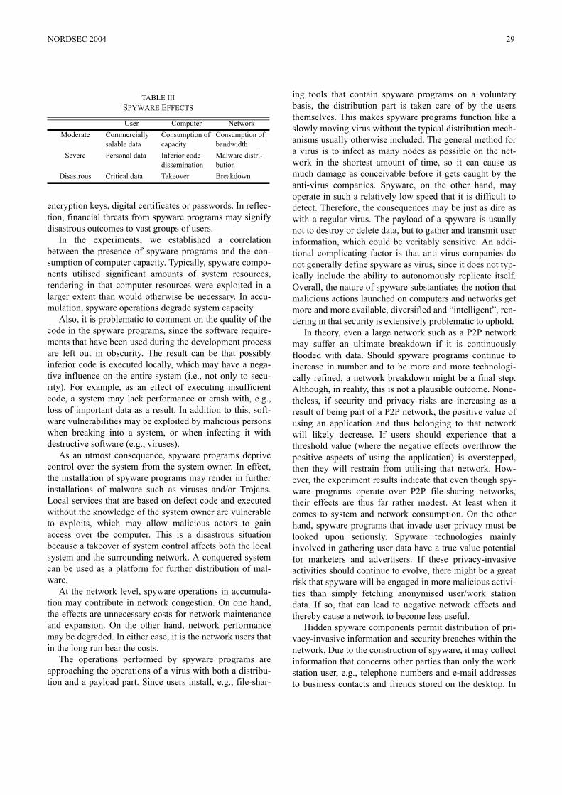
encryption keys, digital certificates or passwords. In reflec-tion, financial threats from spyware programs may signifydisastrous outcomes to vast groups of users.
In the experiments, we established a correlationbetween the presence of spyware programs and the con-sumption of computer capacity. Typically, spyware compo-nents utilised significant amounts of system resources,rendering in that computer resources were exploited in alarger extent than would otherwise be necessary. In accu-mulation, spyware operations degrade system capacity.
Also, it is problematic to comment on the quality of thecode in the spyware programs, since the software require-ments that have been used during the development processare left out in obscurity. The result can be that possiblyinferior code is executed locally, which may have a nega-tive influence on the entire system (i.e., not only to secu-rity). For example, as an effect of executing insufficientcode, a system may lack performance or crash with, e.g.,loss of important data as a result. In addition to this, soft-ware vulnerabilities may be exploited by malicious personswhen breaking into a system, or when infecting it withdestructive software (e.g., viruses).
As an utmost consequence, spyware programs deprivecontrol over the system from the system owner. In effect,the installation of spyware programs may render in furtherinstallations of malware such as viruses and/or Trojans.Local services that are based on defect code and executedwithout the knowledge of the system owner are vulnerableto exploits, which may allow malicious actors to gainaccess over the computer. This is a disastrous situationbecause a takeover of system control affects both the localsystem and the surrounding network. A conquered systemcan be used as a platform for further distribution of mal-ware.
At the network level, spyware operations in accumula-tion may contribute in network congestion. On one hand,the effects are unnecessary costs for network maintenanceand expansion. On the other hand, network performancemay be degraded. In either case, it is the network users thatin the long run bear the costs.
The operations performed by spyware programs areapproaching the operations of a virus with both a distribu-tion and a payload part. Since users install, e.g., file-shar-
ing tools that contain spyware programs on a voluntarybasis, the distribution part is taken care of by the usersthemselves. This makes spyware programs function like aslowly moving virus without the typical distribution mech-anisms usually otherwise included. The general method fora virus is to infect as many nodes as possible on the net-work in the shortest amount of time, so it can cause asmuch damage as conceivable before it gets caught by theanti-virus companies. Spyware, on the other hand, mayoperate in such a relatively low speed that it is difficult todetect. Therefore, the consequences may be just as dire aswith a regular virus. The payload of a spyware is usuallynot to destroy or delete data, but to gather and transmit userinformation, which could be veritably sensitive. An addi-tional complicating factor is that anti-virus companies donot generally define spyware as virus, since it does not typ-ically include the ability to autonomously replicate itself.Overall, the nature of spyware substantiates the notion thatmalicious actions launched on computers and networks getmore and more available, diversified and “intelligent”, ren-dering in that security is extensively problematic to uphold.
In theory, even a large network such as a P2P networkmay suffer an ultimate breakdown if it is continuouslyflooded with data. Should spyware programs continue toincrease in number and to be more and more technologi-cally refined, a network breakdown might be a final step.Although, in reality, this is not a plausible outcome. None-theless, if security and privacy risks are increasing as aresult of being part of a P2P network, the positive value ofusing an application and thus belonging to that networkwill likely decrease. If users should experience that athreshold value (where the negative effects overthrow thepositive aspects of using the application) is overstepped,then they will restrain from utilising that network. How-ever, the experiment results indicate that even though spy-ware programs operate over P2P file-sharing networks,their effects are thus far rather modest. At least when itcomes to system and network consumption. On the otherhand, spyware programs that invade user privacy must belooked upon seriously. Spyware technologies mainlyinvolved in gathering user data have a true value potentialfor marketers and advertisers. If these privacy-invasiveactivities should continue to evolve, there might be a greatrisk that spyware will be engaged in more malicious activi-ties than simply fetching anonymised user/work stationdata. If so, that can lead to negative network effects andthereby cause a network to become less useful.
Hidden spyware components permit distribution of pri-vacy-invasive information and security breaches within thenetwork. Due to the construction of spyware, it may collectinformation that concerns other parties than only the workstation user, e.g., telephone numbers and e-mail addressesto business contacts and friends stored on the desktop. In
TABLE IIISPYWARE EFFECTS
User Computer NetworkModerate Commercially
salable dataConsumption of capacity
Consumption of bandwidth
Severe Personal data Inferior code dissemination
Malware distri-bution
Disastrous Critical data Takeover Breakdown
NORDSEC 2004 29
the context that spyware usually is designed with the pur-pose of conveying commercial information to as manyusers as possible, not only the local user may be exposed tonegative feedback of spyware. As well, the business con-tacts and friends may be the subjects of network contami-nation, e.g., receiving vast amounts of spam or otherunsolicited content.
With the continuos escalation of spyware programs andthe refinement of spyware technologies, network availabil-ity may be degraded to such an extent that ordinary trans-actions are overthrown by obscure malware traffic. Adisastrous situation may occur where a network is seriouslyoverloaded by malware distributed by computerised sys-tems that are controlled by malicious actors. In conclusion,spyware activity may persuade users to abandon networks.
V. CONCLUSIONS
Based on the discussions of spyware and on the findingsfrom the two experiments, we can conclude that spywarehave a negative effect on computer security and user pri-vacy. We have also found that a subsequent development ofspyware technologies in combination with a continuosincrease in spyware distribution will affect system and net-work capacity. A disastrous situation may occur if a net-work is seriously overloaded by different types of spywaredistributed by computerised systems that are controlled bymalicious actors. Then, the risk is a network breakdown.However, a more plausible outcome may be that users willabandon the network before that happens. In effect, spy-ware has the potential to overthrow the positive aspects ofbelonging to a large network, and network owners shouldtherefore be very careful about permitting such programsin applications and on networks.
REFERENCES
[1] S.-Y. Choi, D.O. Stahl, and A.B. Winston, “The Economics of Elec-tronic Commerce”, Macmillan Technical Publishing, Indianapolis IN,1997.[2] C|Net Download.com., http://www.download.com/, 2004-06-29.[3] “Emerging Internet Threats Survey 2003”, commissioned by Web-sense International Ltd., February, 2003. http://www.websense.com/com-pany/news/research/Emerging_Threats_2003_EMEA-de.pdf, 2004-06-29.[4] A. Jacobsson, M. Boldt, and B. Carlsson, “Privacy-Invasive Softwarein File-Sharing Tools”, in Proceedings of the 18th IFIP World ComputerCongress, Toulouse France, 2004.[5] M.L. Katz, and C. Shapiro, “Systems Competition and NetworkEffects”, in Journal of Economic Perspectives 8:93-115, 1994.[6] M. McCardle, “How Spyware Fits into Defence in Depth”, SANSReading Room, SANS Institute, 2003. http://www.sans.org/rr/papers/index.php?id=905, 2004-06-29.[7] A. Oram, “Peer-To-Peer: Harnessing the Benefits of a DisruptiveTechnology”, United States of America: O’Reilly & Associates Inc.,2001.
[8] PestPatrol, http://research.pestpatrol.com/Lists/NewPests(PestCounts).asp, 2004-06-29.[9] S. Sariou, S.D. Gribble, and H.M. Levy, “Measurement and Analysisof Spyware in a University Environment”, in Proceedings of the ACM/USENIX Symposium on Networked Systems Design and Implementation(NSDI), San Francisco CA, 2004.[10] D. Schoder, and K. Fischbach, “Peer-to-Peer (P2P) Computing”, inProceedings of the 36th IEEE Hawaii International Conference on SystemSciences (HICSS’03), IEEE Computer Society Press, Los Alamitos CA,2003.[11] C. Shapiro, and H. Varian, “Information Rules”, HBS Press, BostonMA, 1999. [12] E. Skoudis,“Malware - Fighting Malicious Code”, Prentice HallPTR, Upper Saddle River NJ, 2004.[13] “Spyaudit”, commissioned by Earthlink Inc., http://www. earth-link.net/spyaudit/press/, 2004-06-29.[14] J. Sterne, and A. Priore, “E-Mail Marketing - Using E-Mail to ReachYour Target Audience and Build Customer Relationships”, John Wiley &Sons Inc., New York NY, 2000.[15] K. Townsend, “Spyware, Adware, and Peer-to-Peer Networks: TheHidden Threat to Corporate Security” (technical white paper), PestPatrol,2003., http://www.pestpatrol.com/Whitepapers/PDFs/SpywareAdwareP2P.pdf, 2004-06-29.[16] A. Westin, “Privacy and Freedom”, Atheneum, New York NY, 1968.[17] J. Wieslander, M. Boldt, and B. Carlsson, “Investigating Spyware onthe Internet”, in Proceedings of the Seventh Nordic Workshop on SecureIT Systems, Gjövik Norway, 2003.
30 NORDSEC 2004
Security properties for Intrusion DetectionMarco Giunti
Dipartimento di InformaticaUniversita Ca’ Foscari di Venezia
Abstract— We study security properties for real systems whereclassic access control policies are too strict; to prevent bothdirect and indirect accesses, our properties are then expressed asinformation flow properties. Particularly, we deal with mandatoryintegrity policies rather than secrecy policies. We argue theseproperties may help in discovering potential intrusions in asystem, interpreting an intrusion as a sequence of actions whichbreak the mandatory security policy of the system.
Index Terms— Information flow, intrusion detection, accesscontrol, process algebras, formal methods, UNIX.
I. I NTRODUCTION
Intrusion Detection
The Intrusion Detection (ID) problem consists in discov-ering intrusions in a system and is typically related to theanalysis of system logs, oraudit trail. We immediately noticethe absence, in the ID literature, of a formal and cleardefinition of “intrusion”; the generic idea is that an intrusionis something bad happened in the system, but no generaldefinition for undesired behaviour is provided. For instance,in most Intrusion Detection Systems (IDS) (the tools whichperform the log analysis), a non-root modification of thepassword file is considered an intrusion, but, for the best ofour knowledge, there are no models explaining which generalproperty is unsatisfied when overwriting the password file.
Starting from the 80’s, when the Intrusion Detection prob-lem was proposed [1], [2], two main ID approaches to au-dit trail analysis have been followed. Briefly, system logsanalysis may follow ananomaly detectionapproach or amisuse detectionapproach. Anomaly based Intrusion DetectionSystems (IDS), i.e. the tools that perform the analysis, tryto detect intrusions statistically using metrics which definethe “correct” behaviour of the system, considering anyk-deviation from the correct metric as an intrusion, for somek [3], [4]. Misuse Intrusion Detection Systems, instead, checklogs looking for a sequence of actions that match a systemrelated attack signature; basically an attack signature is asequence of steps which a malicious user may perform tocompromise the security of the system, where a system may belocal [5], [6] or distributed [7], [8]. Current work in the misusedetection area is most turned towards the formal definition ofa language for signatures and the specification of algorithmsfor log auditing [9], [10], [11], [12].
Trying to formalize the intrusion detection problem, wenote that none of these approaches is formal enough to tacklethe ID problem. We do not want to rely on the anomalydetection approach for a formal definition of intrusion, since
it’s hard to demonstrate that statistically non-relevant attackscannot be dangerous. For instance, the famoussendmailbugin BSD UNIX 4.2 [13], [5] gave rise to a public root shellafter the execution by a standard user of three common usedUNIX programs (cp, chmod and mail itself). We think thatshould be hard to discover these kind of attacks in a statisticalapproach, assuming no knowledge of the vulnerability. On theother hand, misuse approach security is based on the “perfectknowledge” of all possible attacks, that is, the definition ofan intrusion setI is crucial. Then a system is secure if doesnot contain a log tracet ∈ I. Here the main drawback wenotice is that intrusions not yet known, or known in somedifferent variant, cannot be discovered. Both these definitionsof security appear thus to be unsound; in other words, statinga system is secure does not imply that the system does notcontain intrusions.
A recent approach known as themodel-based analysis[14], propose to analyze all the possible security-related be-haviours of a system specified as an abstract model in ahigh level specification language. To express concurrency andnon-determinism, a process algebra such Hoare’s CSP [15]or Milner’s CCS [16] may be used. The behaviours maybe analyzed using automated verification techniques such asmodel checking. The authors of [14] propose to analyze all thestates of the system for deciding if a bad event, for instance anoverwriting of the password file, is happened in the system.This basically can be done by labeling as unsafe the stateswhere the password file is overwritten and then by queryingfor the reachability of such states. More complex scenarios canbe expressed by labeling entire execution sequences throughtemporal logical formulas.
An interesting point of this approach is that a completelog analysis is performed; that is, all possible executions areconsidered for detecting a possible intrusion. On the otherhand, a general definition of security for the system is notprovided: it is not clear to us which general property isunsatisfied when an unsafe state is reached.
As in [14], we analyze an abstract model of the systemexpressed in a process algebra; while we adopted a similarmodel, we moved from temporal logics based analysis toinformation flow properties study. Actually, we argue thatintrusion detection is simply a special case of access control;given a mandatory security policy for the system, for instancethe Biba policy [17], roughly synthesized as ”no write up - noread down“, then an intrusion is the sequence of steps whichbreaks the policy. Our approach consists in checking infor-mation flows of the system deciding throughnon-interference
NORDSEC 2004 31
properties if intrusions may happen in the system; the use ofnon-interference assure that both direct and indirect flows arechecked. In this way, we don’t assumea priori the knowledgeof possible attacks; moreover, we can potentially find unknownattacks and generate patterns to be used as abstract signaturesfor misuse Intrusion Detection Systems.
A Non-Interference Property
In general, in a system, information is typically protectedvia some access control policy, limiting accesses of entities(such as users or processes) to data. There are different levelsof flexibility of access control policies depending on thepossibility for one entity to change the access rights of itsown data. Here we will considermandatorypolicies in whichentities have no control on the access rights; historically [18]these strong mandatory security policies have been designedto avoid internal attacks performed by the so calledTrojanHorse programs, i.e., malicious software that, once executedby a user, modifies the access rights of the data belonging tosuch a user. Unfortunately, even when direct access to data isforbidden by (strong) security policies, it might be the casethat data areindirectly leaked by Trojan Horses which mightexploit some observable system side-effects like, e.g., the CPUload or, more in general, the space/time availability of sharedresources.
The necessity of controlling information flow as a whole(both direct and indirect) motivated Goguen and Meseguerin introducing the notion ofNon-interference[19]. Non-Interference formalizes the absence of information flow withindeterministic systems. Given a system in whichconfidential(i.e., high level) andpublic (i.e., low level) information maycoexist,non-interferencerequires that confidential inputs neveraffect the outputs on the public interface of the system, i.e.,never interfere with the low level users. If such a propertyholds, one can conclude that no information flow is everpossible from high to low level.
A possibilistic security property can be regarded as anextension of non-interference to non-deterministic systems.Starting from Sutherland [20], various such extensions havebeen proposed, e.g., [21], [22], [23]. All of these propertiesdepend on the notion of behaviour that may possibly beobserved of a system, i.e., the semantics model that is chosento describe the system. Most of these properties are basedon traces, i.e., the behaviour of systems that may possiblybe observed is modeled through the set of their executionsequences.
In [24], Focardi and Gorrieri express the concept of non-interference in theSecurity Process Algebra(SPA) language,in terms of bisimulation semantics. In particular they intro-duce the notion ofBisimulation-based non Deducibility onCompositions(BNDC): a systemE is BNDC if what a lowlevel user sees of the system is not modified (in the senseof the bisimulation semantics) by composing any high levelprocessΠ with E. The main advantage ofBNDC with respectto trace-based properties is that it is powerful enough todetect information flows due to the possibility, for a highlevel malicious process, to block or unblock a system. In
particular, in [24], it is shown that a malicious process maybuild a channel from high to low, by suitably blocking andunblocking some system services accessible by low level users.The system used to build this covert channel turns out to besecure for trace-based properties. This motivates the use ofmore discriminating equivalences such as bisimulation.
In this paper we focus on integrity policies, i.e. policieswhich care about improper modification of data, rather thansecrecy policies, i.e., policies which prevent unauthorizeddisclosure of data. In the literature, the standard integritypolicy is known as the Biba model [17] and maybe roughlysummarized through the rules “no read down“, “no write up“.The Biba policy is then the dual of the standard secrecy policy[18]; it follows that to express the Biba integrity policy as annon-interference property, we may say that a system is secureif no information can flow from low to high. By exchangingin the definition ofBNDC the low level with the high level,we obtain a new property namedBisimulation-based NonModifiability on Compositions(BNMC for short); we introducethis property in Section IV.BNMC thus can be used to detectwhether a system satisfies the Biba policy, with respect to bothdirect and indirect accesses.
Unfortunately, theBNMC property does not help us toomuch in the analysis of real systems as UNIX-like operatingsystems or MS Windows OSs, since in these systems it ispractically infeasible that no information flows from low tohigh. As a matter of fact in real systems, by default or bycommon practice, processes with root rights (that is, processeswhich have an high security level [18]) often have readaccess to low resources; in such case, expecting the systemis BNMC is hopeless. On the other hand, we want to beable to distinguish the observable behaviour of systems whereinformation flows from low to high, and thus we cannot usethe BNMC property.
To this aim, we introduce a new security property that takescare of different types of accesses; in other words we may saythat this information flow property takes into account differenttypes of “modifiability”, where for modifiability we intend aviolation of the Biba’s standard integrity policy.
We illustrate this new property with an example; we modela sample system into a CCS-like language namedread/writeSecurity Process Algebra(SPArw, for short), a SPA [24]extension which we present in Section II. The set of visibleactions of SPArw is partitioned in two levels as in [24], but,differently from SPA, each of these sets is in turn partitionedinto read and write subsets; we indicate withLr, Lw the sets oflow read and low write actions, respectively, such thatLc = Lc
for eachc ∈ r, w; analogously, we indicate withH r, Hw thesets containing high read and high write actions, respectively,such thatHc = Hc for both read and write capabilities.Moreover,L = Lr∪Lw, i.e. the setL contains all low actions.
As an example, consider the process
P4= wannareadlw.readhr.0 |
writehw.0
where wannareadlw ∈ Lw, readhr ∈ H r, writehw ∈Hw. Basically,P waits for read and write requests but to read
32 NORDSEC 2004
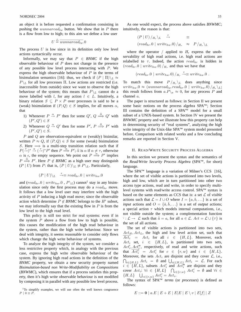
an object it is before requested a confirmation consisting inpushing thewannareadlw button. We show that inP thereis a flow from low to high; to this aim we define a low user
U4= wannareadlw.0
The processU is low since in its definition only low levelactions syntactically occur.
Informally, we may say thatP ∈ BNMC if the highobservable behaviour ofP does not change in the presenceof any possible low level process interacting withP . Weexpress the high observable behaviour ofP in the terms ofbisimulation semantics [16]: thus, we check if(P | Π)\L ≈P\L for all low processesΠ. Low actions are restricted (i.e.inaccessible from outside) since we want to observe the highbehaviour of the system; this means thatP\L cannot do amove labelled withl, for any action l ∈ L. Intuitively, abinary relationS ⊆ P × P over processes is said to be a(weak) bisimulation if(P,Q) ∈ S implies, for all movesα,that
1) WheneverPα→ P ′ then for someQ′, Q
bα=⇒ Q′ with(P ′, Q′) ∈ S
2) WheneverQα→ Q′ then for someP ′, P
bα=⇒ P ′ with(P ′, Q′) ∈ S.
P and Q are observation-equivalent or (weakly) bisimilar,written P ≈ Q, if (P, Q) ∈ S for some (weak) bisimulationS . Here =⇒ is a multi-step transition relation such that ifP ( τ→)∗ α→ ( τ→)∗P ′ thenP
α=⇒ P ′; α is α if α 6= τ , otherwiseα is ε, the empty sequence. We point outP
α=⇒ P ′ impliesP
bα=⇒ P ′. HereP 6∈ BNMC as a high user may distinguish(P | U ) from P : that is,(P | U)\L 6≈ P\L. Particularly,
(P | U)\Lτ→≡ readhr.0 | writehw.0
and (readhr.0 | writehw.0 , P\L) cannot1 stay in any bisim-ulation since only the first process may do areadhr move.It follows that a low level user may interfere with the highactivity of P inducing a high read move; since the observableaction which determineP 6∈ BNMC belongs to theH r subset,we may informally say that the existing flow inP is from thelow level to the high read level.
This policy is still too strict for real systems: even if inthe systemP above a flow from low to high is possible,this causes the modification of the high read behaviour inthe system, rather than the high write behaviour. Since wedeal with integrity, it seems reasonable to consider only flowswhich change the high write behaviour of systems.
To analyze the high integrity of the system, we consider aless restrictive property which, in analogy with the previouscase, express the high write observable behaviour of thesystem. By ignoring high read actions in the definition of theBNMC property, we obtain a new security property namedBisimulation-based non Write-Modifiability on Compositions(BNWMC), which ensures that if a process satisfies this prop-erty, then it’s high write observable behaviour is not modifiedby composing it in parallel with any possible low level process.
1To simplify examples, we will use often the well known congruenceP | 0 ≡ P .
As one would expect, the process above satisfiesBNWMC;intuitively, the reason is that:
(P | U) /Hr\Lτ→ ≡
(readhr.0 | writehw.0) /Hr ≈ P /Hr\L
where the operator/ applied to Hr express the unob-servability of high read actions, i.e. high read actions arerelabelled to τ . Indeed, the actionreadhr is hidden in(readhr.0 | writehw.0) /Hr and thus we have that
(readhr.0 | writehw.0) /Hr
τ→≡ writehw.0 .
To match this move P /Hr\L does anything sincewritehw.0 ≈ (wannareadlw.readhr.0 | writehw.0) /Hr\L;this result follows froma.P\a ≈ 0, for any processP andchannela.
The paper is structured as follows: in Section II we presentsome basic notions on the process algebra SPArw; SectionIII contains the definition of a SPArw model for a smallsubset of a UNIX-based system. In Section IV we present theBNWMCproperty and we illustrate how this property can helpin determining security of “real systems”, analyzing the highwrite integrity of the Unix-like SPArw system model presentedbefore. Comparison with related works and a few concludingremarks are reported in Section V.
II. READ/WRITE SECURITY PROCESSALGEBRA
In this section we present the syntax and the semantics ofthe Read/Write Security Process Algebra(SPArw, for short)language.
The SPArw language is a variation of Milner’s CCS [16],where the set of visible actions is partitioned into two levels,high and low, which are in turn partitioned into other twoaccess type actions, read and write, in order to specify multi-level systems with read/write access control. SPArw syntax isbased on the same elements as CCS that is: a setL of visibleactions such thatL = I ∪O whereI = a, b, . . . is a set ofinput actions andO = a, b, . . . is a set ofoutput actions;a special actionτ which models internal computations, i.e.,not visible outside the system; a complementation function· : L → L such thata = a, for all a ∈ L. Act = L ∪ τ isthe set of allactions.
The set of visible actions is partitioned into two sets,ActH ,ActL, the high and low level action set, such thatAct i = Act i for all i ∈ H, L. Moreover, eachAct i set, i ∈ H,L, is partitioned into two sets,Act r
i,Actwi , respectively, of read and write actions, such
that Actci = Actc
i for c ∈ r, w and i ∈ H,L.Moreover, the setsAct i are disjoint and they coverL, i.e.,⋂
i∈H,L Act i = ∅ and⋃
i∈H,LAct i = L. For eachi ∈ H, L, subsetsAct r
i and Actwi are disjoint and they
cover Act i: ∀i ∈ H, L ⋂c∈r,w Actc
i = ∅ and ∀i ∈H, L ⋃
c∈r,wActci = Act i.
The syntax of SPArw terms (or processes) is defined asfollows:
E ::= 0 | a.E | E + E | E|E | E \ v | E[f ] | Z
NORDSEC 2004 33
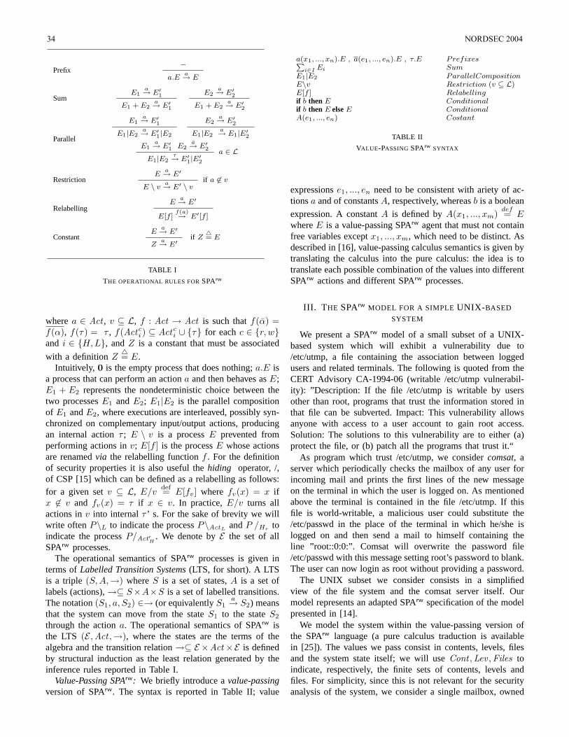
Prefix−
a.Ea→ E
SumE1
a→ E′1E1 + E2
a→ E′1
E2a→ E′2
E1 + E2a→ E′2
Parallel
E1a→ E′1
E1|E2a→ E′1|E2
E2a→ E′2
E1|E2a→ E1|E′2
E1a→ E′1 E2
a→ E′2E1|E2
τ→ E′1|E′2a ∈ L
RestrictionE
a→ E′
E \ va→ E′ \ v
if a 6∈ v
RelabellingE
a→ E′
E[f ]f(a)→ E′[f ]
ConstantE
a→ E′
Za→ E′
if Z4= E
TABLE I
THE OPERATIONAL RULES FORSPArw
wherea ∈ Act , v ⊆ L, f : Act → Act is such thatf(α) =f(α), f(τ) = τ , f(Actc
i ) ⊆ Actci ∪ τ for eachc ∈ r, w
and i ∈ H, L, andZ is a constant that must be associated
with a definitionZ4= E.
Intuitively, 0 is the empty process that does nothing;a.E isa process that can perform an actiona and then behaves asE;E1 + E2 represents the nondeterministic choice between thetwo processesE1 andE2; E1|E2 is the parallel compositionof E1 andE2, where executions are interleaved, possibly syn-chronized on complementary input/output actions, producingan internal actionτ ; E \ v is a processE prevented fromperforming actions inv; E[f ] is the processE whose actionsare renamedvia the relabelling functionf . For the definitionof security properties it is also useful thehiding operator, /,of CSP [15] which can be defined as a relabelling as follows:for a given setv ⊆ L, E/v
def= E[fv] where fv(x) = x ifx 6∈ v and fv(x) = τ if x ∈ v. In practice,E/v turns allactions inv into internalτ ’ s. For the sake of brevity we willwrite oftenP\L to indicate the processP\ActL
andP /Hr toindicate the processP/Act r
H. We denote byE the set of all
SPArw processes.The operational semantics of SPArw processes is given in
terms ofLabelled Transition Systems(LTS, for short). A LTSis a triple (S, A,→) whereS is a set of states,A is a set oflabels (actions),→⊆ S×A×S is a set of labelled transitions.The notation(S1, a, S2) ∈→ (or equivalentlyS1
a→ S2) meansthat the system can move from the stateS1 to the stateS2
through the actiona. The operational semantics of SPArw isthe LTS (E ,Act ,→), where the states are the terms of thealgebra and the transition relation→⊆ E ×Act ×E is definedby structural induction as the least relation generated by theinference rules reported in Table I.
Value-Passing SPArw: We briefly introduce avalue-passingversion of SPArw. The syntax is reported in Table II; value
a(x1, ..., xn).E , a(e1, ..., en).E , τ.E PrefixesPi∈I Ei Sum
E1|E2 ParallelCompositionE\v Restriction (v ⊆ L)E[f ] Relabellingif b then E Conditionalif b then E elseE ConditionalA(e1, ..., en) Costant
TABLE II
VALUE-PASSING SPArw SYNTAX
expressionse1, ..., en need to be consistent with ariety of ac-tionsa and of constantsA, respectively, whereasb is a boolean
expression. A constantA is defined byA(x1, ..., xm)def= E
whereE is a value-passing SPArw agent that must not containfree variables exceptx1, ..., xm, which need to be distinct. Asdescribed in [16], value-passing calculus semantics is given bytranslating the calculus into the pure calculus: the idea is totranslate each possible combination of the values into differentSPArw actions and different SPArw processes.
III. T HE SPArw MODEL FOR A SIMPLEUNIX- BASED
SYSTEM
We present a SPArw model of a small subset of a UNIX-based system which will exhibit a vulnerability due to/etc/utmp, a file containing the association between loggedusers and related terminals. The following is quoted from theCERT Advisory CA-1994-06 (writable /etc/utmp vulnerabil-ity): ”Description: If the file /etc/utmp is writable by usersother than root, programs that trust the information stored inthat file can be subverted. Impact: This vulnerability allowsanyone with access to a user account to gain root access.Solution: The solutions to this vulnerability are to either (a)protect the file, or (b) patch all the programs that trust it.“
As program which trust /etc/utmp, we considercomsat, aserver which periodically checks the mailbox of any user forincoming mail and prints the first lines of the new messageon the terminal in which the user is logged on. As mentionedabove the terminal is contained in the file /etc/utmp. If thisfile is world-writable, a malicious user could substitute the/etc/passwd in the place of the terminal in which he/she islogged on and then send a mail to himself containing theline ”root::0:0:”. Comsat will overwrite the password file/etc/passwd with this message setting root’s password to blank.The user can now login as root without providing a password.
The UNIX subset we consider consists in a simplifiedview of the file system and the comsat server itself. Ourmodel represents an adapted SPArw specification of the modelpresented in [14].
We model the system within the value-passing version ofthe SPArw language (a pure calculus traduction is availablein [25]). The values we pass consist in contents, levels, filesand the system state itself; we will useCont ,Lev ,Files toindicate, respectively, the finite sets of contents, levels andfiles. For simplicity, since this is not relevant for the securityanalysis of the system, we consider a single mailbox, owned
34 NORDSEC 2004
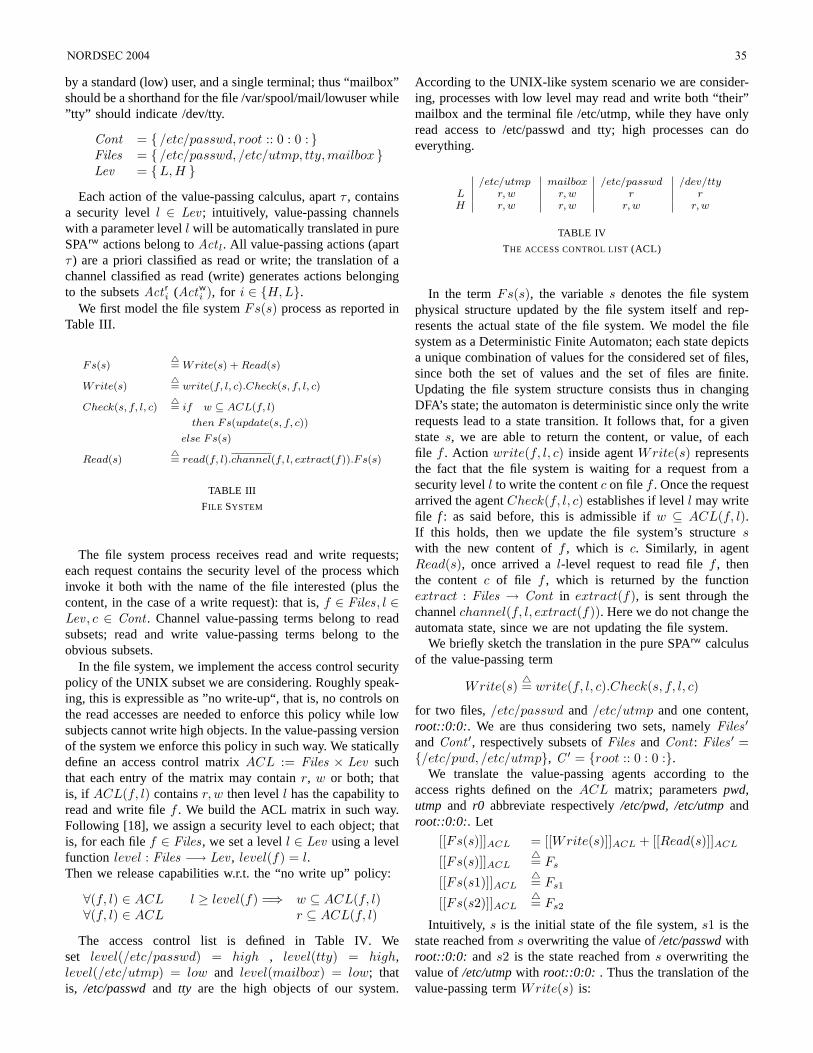
by a standard (low) user, and a single terminal; thus “mailbox”should be a shorthand for the file /var/spool/mail/lowuser while”tty” should indicate /dev/tty.
Cont = /etc/passwd, root :: 0 : 0 : Files = /etc/passwd, /etc/utmp, tty, mailbox Lev = L, H
Each action of the value-passing calculus, apartτ , containsa security levell ∈ Lev ; intuitively, value-passing channelswith a parameter levell will be automatically translated in pureSPArw actions belong toAct l. All value-passing actions (apartτ ) are a priori classified as read or write; the translation of achannel classified as read (write) generates actions belongingto the subsetsAct r
i (Actwi ), for i ∈ H, L.
We first model the file systemFs(s) process as reported inTable III.
Fs(s)4= Write(s) + Read(s)
Write(s)4= write(f, l, c).Check(s, f, l, c)
Check(s, f, l, c)4= if w ⊆ ACL(f, l)
then Fs(update(s, f, c))
else Fs(s)
Read(s)4= read(f, l).channel(f, l, extract(f)).F s(s)
TABLE III
FILE SYSTEM
The file system process receives read and write requests;each request contains the security level of the process whichinvoke it both with the name of the file interested (plus thecontent, in the case of a write request): that is,f ∈ Files, l ∈Lev , c ∈ Cont . Channel value-passing terms belong to readsubsets; read and write value-passing terms belong to theobvious subsets.
In the file system, we implement the access control securitypolicy of the UNIX subset we are considering. Roughly speak-ing, this is expressible as ”no write-up“, that is, no controls onthe read accesses are needed to enforce this policy while lowsubjects cannot write high objects. In the value-passing versionof the system we enforce this policy in such way. We staticallydefine an access control matrixACL := Files × Lev suchthat each entry of the matrix may containr, w or both; thatis, if ACL(f, l) containsr, w then levell has the capability toread and write filef . We build the ACL matrix in such way.Following [18], we assign a security level to each object; thatis, for each filef ∈ Files, we set a levell ∈ Lev using a levelfunction level : Files −→ Lev , level(f) = l.Then we release capabilities w.r.t. the “no write up” policy:
∀(f, l) ∈ ACL l ≥ level(f) =⇒ w ⊆ ACL(f, l)∀(f, l) ∈ ACL r ⊆ ACL(f, l)
The access control list is defined in Table IV. Weset level(/etc/passwd) = high , level(tty) = high,level(/etc/utmp) = low and level(mailbox) = low; thatis, /etc/passwdand tty are the high objects of our system.
According to the UNIX-like system scenario we are consider-ing, processes with low level may read and write both “their”mailbox and the terminal file /etc/utmp, while they have onlyread access to /etc/passwd and tty; high processes can doeverything.
/etc/utmp mailbox /etc/passwd /dev/ttyL r, w r, w r rH r, w r, w r, w r, w
TABLE IV
THE ACCESS CONTROL LIST(ACL)
In the termFs(s), the variables denotes the file systemphysical structure updated by the file system itself and rep-resents the actual state of the file system. We model the filesystem as a Deterministic Finite Automaton; each state depictsa unique combination of values for the considered set of files,since both the set of values and the set of files are finite.Updating the file system structure consists thus in changingDFA’s state; the automaton is deterministic since only the writerequests lead to a state transition. It follows that, for a givenstates, we are able to return the content, or value, of eachfile f . Action write(f, l, c) inside agentWrite(s) representsthe fact that the file system is waiting for a request from asecurity levell to write the contentc on filef . Once the requestarrived the agentCheck(f, l, c) establishes if levell may writefile f : as said before, this is admissible ifw ⊆ ACL(f, l).If this holds, then we update the file system’s structureswith the new content off , which is c. Similarly, in agentRead(s), once arrived al-level request to read filef , thenthe contentc of file f , which is returned by the functionextract : Files → Cont in extract(f), is sent through thechannelchannel(f, l, extract(f)). Here we do not change theautomata state, since we are not updating the file system.
We briefly sketch the translation in the pure SPArw calculusof the value-passing term
Write(s)4= write(f, l, c).Check(s, f, l, c)
for two files, /etc/passwd and /etc/utmp and one content,root::0:0:. We are thus considering two sets, namelyFiles ′
andCont ′, respectively subsets ofFiles andCont : Files ′ =/etc/pwd, /etc/utmp, C ′ = root :: 0 : 0 :.
We translate the value-passing agents according to theaccess rights defined on theACL matrix; parameterspwd,utmp and r0 abbreviate respectively/etc/pwd, /etc/utmpandroot::0:0:. Let
[[Fs(s)]]ACL = [[Write(s)]]ACL + [[Read(s)]]ACL
[[Fs(s)]]ACL4= Fs
[[Fs(s1)]]ACL4= Fs1
[[Fs(s2)]]ACL4= Fs2
Intuitively, s is the initial state of the file system,s1 is thestate reached froms overwriting the value of/etc/passwdwithroot::0:0: and s2 is the state reached froms overwriting thevalue of/etc/utmpwith root::0:0: . Thus the translation of thevalue-passing termWrite(s) is:
NORDSEC 2004 35
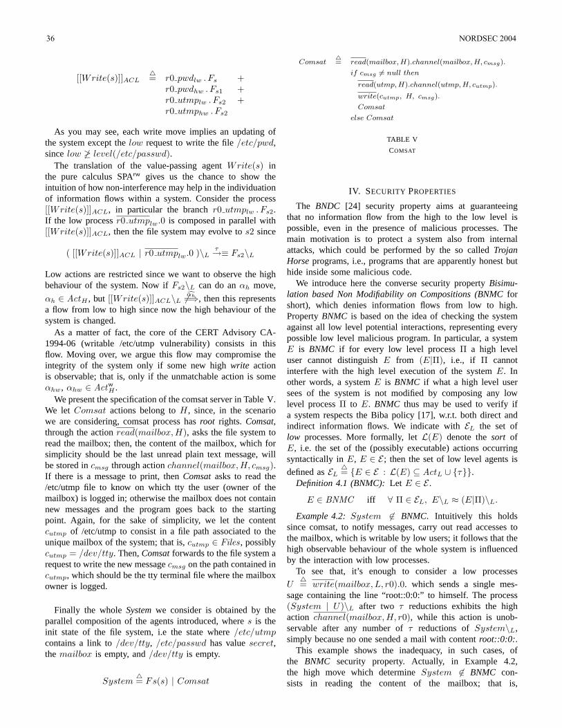
[[Write(s)]]ACL4= r0 pwdlw . Fs +
r0 pwdhw . Fs1 +r0 utmplw . Fs2 +r0 utmphw . Fs2
As you may see, each write move implies an updating ofthe system except thelow request to write the file/etc/pwd,sincelow 6≥ level(/etc/passwd).
The translation of the value-passing agentWrite(s) inthe pure calculus SPArw gives us the chance to show theintuition of how non-interference may help in the individuationof information flows within a system. Consider the process[[Write(s)]]ACL, in particular the branchr0 utmplw . Fs2.If the low processr0 utmplw.0 is composed in parallel with[[Write(s)]]ACL, then the file system may evolve tos2 since
( [[Write(s)]]ACL | r0 utmplw.0 )\Lτ→≡ Fs2\L
Low actions are restricted since we want to observe the highbehaviour of the system. Now ifFs2\L can do anαh move,
αh ∈ ActH , but [[Write(s)]]ACL\L 6 cαh=⇒, then this representsa flow from low to high since now the high behaviour of thesystem is changed.
As a matter of fact, the core of the CERT Advisory CA-1994-06 (writable /etc/utmp vulnerability) consists in thisflow. Moving over, we argue this flow may compromise theintegrity of the system only if some new highwrite actionis observable; that is, only if the unmatchable action is someαhw, αhw ∈ Actw
H .We present the specification of the comsat server in Table V.
We let Comsat actions belong toH, since, in the scenariowe are considering, comsat process hasroot rights. Comsat,through the actionread(mailbox, H), asks the file system toread the mailbox; then, the content of the mailbox, which forsimplicity should be the last unread plain text message, willbe stored incmsg through actionchannel(mailbox, H, cmsg).If there is a message to print, thenComsatasks to read the/etc/utmp file to know on which tty the user (owner of themailbox) is logged in; otherwise the mailbox does not containnew messages and the program goes back to the startingpoint. Again, for the sake of simplicity, we let the contentcutmp of /etc/utmp to consist in a file path associated to theunique mailbox of the system; that is,cutmp ∈ Files, possiblycutmp = /dev/tty. Then,Comsatforwards to the file system arequest to write the new messagecmsg on the path contained incutmp, which should be the tty terminal file where the mailboxowner is logged.
Finally the wholeSystemwe consider is obtained by theparallel composition of the agents introduced, wheres is theinit state of the file system, i.e the state where/etc/utmpcontains a link to/dev/tty, /etc/passwd has valuesecret,the mailbox is empty, and/dev/tty is empty.
System4= Fs(s) | Comsat
Comsat4= read(mailbox, H).channel(mailbox, H, cmsg).
if cmsg 6= null then
read(utmp, H).channel(utmp, H, cutmp).
write(cutmp, H, cmsg).
Comsat
else Comsat
TABLE V
COMSAT
IV. SECURITY PROPERTIES
The BNDC [24] security property aims at guaranteeingthat no information flow from the high to the low level ispossible, even in the presence of malicious processes. Themain motivation is to protect a system also from internalattacks, which could be performed by the so calledTrojanHorseprograms, i.e., programs that are apparently honest buthide inside some malicious code.
We introduce here the converse security propertyBisimu-lation based Non Modifiability on Compositions (BNMCforshort), which denies information flows from low to high.PropertyBNMC is based on the idea of checking the systemagainst all low level potential interactions, representing everypossible low level malicious program. In particular, a systemE is BNMC if for every low level processΠ a high leveluser cannot distinguishE from (E|Π), i.e., if Π cannotinterfere with the high level execution of the systemE. Inother words, a systemE is BNMC if what a high level usersees of the system is not modified by composing any lowlevel processΠ to E. BNMC thus may be used to verify ifa system respects the Biba policy [17], w.r.t. both direct andindirect information flows. We indicate withEL the set oflow processes. More formally, letL(E) denote thesort ofE, i.e. the set of the (possibly executable) actions occurringsyntactically inE, E ∈ E ; then the set of low level agents is
defined asEL4= E ∈ E : L(E) ⊆ ActL ∪ τ.
Definition 4.1 (BNMC):Let E ∈ E .
E ∈ BNMC iff ∀ Π ∈ EL, E\L ≈ (E|Π)\L.
Example 4.2:System 6∈ BNMC. Intuitively this holdssince comsat, to notify messages, carry out read accesses tothe mailbox, which is writable by low users; it follows that thehigh observable behaviour of the whole system is influencedby the interaction with low processes.
To see that, it’s enough to consider a low processes
U4= write(mailbox, L, r0).0. which sends a single mes-
sage containing the line “root::0:0:” to himself. The process(System | U)\L after two τ reductions exhibits the highaction channel(mailbox, H, r0), while this action is unob-servable after any number ofτ reductions ofSystem\L,simply because no one sended a mail with contentroot::0:0:.
This example shows the inadequacy, in such cases, ofthe BNMC security property. Actually, in Example 4.2,the high move which determineSystem 6∈ BNMC con-sists in reading the content of the mailbox; that is,
36 NORDSEC 2004
channel(mailbox,H, r0) ∈ Act rH . As a matter of fact, we ob-
serve thatBNMC is too strong for the security analysis of realsystems and thus do not help very much. For instance, if com-sat specification was consisting only in checking the contentof the mailbox, this system would be also considered unsafe.
To capture this situations that are very likely in real systems,we introduce a security property weaker thanBNMC calledBisimulation-based non Write-Modifiability on Compositions(BNWMC for short). A systemE is BNWMC if for everylow level processΠ a high level user cannot distinguish thewrite behaviour ofE from the one of(E|Π), i.e., if Π cannotinterfere with the high level write execution of the systemE.In other words, a systemE is BNWMC if what a high leveluser sees of the system with respect to write actions is notmodified by composing any low level processΠ to E.
Definition 4.3 (BNWMC):Let E ∈ E .
E ∈ BNWMC iff ∀ Π ∈ EL, E /Hr\L ≈ (E /Hr | Π)\L
The following result is immediate:Proposition 4.4:BNMC ⊂ BNWMC
Proof: To demonstrateBNMC ⊆ BNWMC is enoughto say that (weak) bisimilarity is preserved by relabelling [16].Let E ∈ E . Thus E ∈ BNMC implies ∀ Π ∈ EL, E\L ≈(E|Π)\L. Since bisimulation is closed under relabelling weobtain that∀ Π ∈ EL, E\L /Hr
≈ (E | Π)\L /Hr. From
L ∩ Hr = ∅ we have that for allE ∈ E holds E\L /Hr=
E /Hr\L and we are done. The example of the introduction
proves that the inclusion is strict; that is,P 6∈ BNMCwhile P ∈ BNWMC , whereP
4= wannareadlw.readhr.0 |
writehw.0
Example 4.5:We want to establish, once we have weak-ened our notion of security, if intrusions are possible in thissystem; we obtain that the processSystem does not satisfyBNWMC. To show this, we consider a low user which writeboth the file /etc/utmp and the mailbox.
U4= write(utmp,L, pwd).U ′
U ′ 4= write(mailbox, L, r0).0
Here (System /Hr | U)\L can do an internal move inwhich the user overwrites the file /etc/utmp with the content“/etc/passwd”:
( System /Hr | U )\Lτ→
( ( Fpwd | Comsat ) /Hr | U ′ )\L .
We indicate with the processFpwd the agent reached fromFs(s) after the updating of /etc/utmp.
After another internal move the user sends the mail withcontent “root::0:0:” ; we denote byFcmp the compromisedfile system agent reached from the stateFpwd by updating themailbox with the new message.
( ( Fpwd | Comsat ) /Hr | U ′ )\Lτ→≡
( Fcmp | Comsat ) /Hr\L
Now (Fcmp | Comsat) /Hr\L performs aτ transition inwhich comsat asks to read /etc/utmp; then, comsat receives the
content of the mailbox through another internal transition. Weremark that, differently from Example 4.2, the channel sendingthe content of the mailbox is now unobservable, since highread actions are hidden. Then, analogously, comsat throughtwo internal transitions asks the content of the terminal fileand receives the bogus content “/etc/passwd”.
(Fcmp | Comsat) /Hr\Lτ=⇒
(Fcmp | write(pwd, H, r0).Comsat) /Hr\L
Intuitively, the file system state is still represented by theprocessFcmp since read requests do not determine an updatingof the file system. Now we have that
(Fcmp | write(pwd, H, r0).Comsat) /Hr\Lwrite(pwd,H,r0)−→
while this action is unobservable after any number ofτreductions ofSystem /Hr\L, sinceutmp was not containingthe valuepwd in the init state.
Applying our technique, we have thus found that the UNIX-like system model introduced is flawed, since a low user ofthe system may indirectly break the “no write up” mandatorysystem’s security policy obtaining that the high password fileis overwritten. Using a security property less discriminatingthan BNMC gave us the possibility to individuate the coreof the intrusion. That is, by checking if the system satisfiestheBNWMCproperty we individuate the action which exactlycause the security policy to be broken.
V. FINAL REMARKS AND RELATED WORK
We have studied the Intrusion Detection problem on realsystems governed by a mandatory security policy. Our thesisis that intrusion detection is a special case of access control,where an intrusion is the sequence of steps which breaks thesecurity policy of the system. We have proposed a new securityproperty namedBNWMCwhich characterizes the security ofCCS-like models of real systems w.r.t. the integrity of data.
We point out thatBNDCverification techniques [26] can beused to prove both that a system isBNMCand that isBNWMC.
To the best of our knowledge, few works rely on a formalmodel expressed in a process algebra to analyze intrusionswithin a system, and none of these analyze information flows.
Ramakrishnan and Sekar’s works [14], [27] without doubtinspired us. In [14], [27], the authors define security proper-ties trough an intentions model which captures the intendedoutcome of executing every program: the system model hasvulnerabilities if it contains path to unsafe states for whichthere exists no corresponding path in the intentions model.Their implementation find vulnerabilities as violations of in-variant properties: for instance, they query the model checkerto check the reachability of.write([etc,passwd],), a statewhere a process writes /etc/passwd. Path properties can beencoded in temporal logic. The analysis may be extended toinfinite systems, but in this case a bounded-depth search needto be performed in order to ensure termination. In [27] theinfinity condition is handled in the model checker by usingterm constraints and by abstracting the sequences to finite
NORDSEC 2004 37
(possibly repeating) segments of a certain kinds; moreover,the language is extended with object-oriented capabilities.
Rohrmair and Lowe [28] model a small network scenariousing the CSP process algebra and consider the problemto discover attack strategies which blind network IntrusionDetection Systems. Their model consists in a signature basedIDS process protecting a host, which is the target of the attack.The Intrusion Detection System is considered to be perfectand therefore knows all vulnerabilities that could be used tocause a security branch in the system. Quoting the authors: “Inpractice this is impossible because many vulnerabilities are notrevealed yet. We have to make this assumption to generalizeall current existing IDSs”. Once the CSP model is defined,they check through a model checker if the set of all the tracesof the model is a subset of the set of valid traces. The validtraces are defined as the traces of the specification processS,which should capture the intended behaviour of the model.For instance ifalert is the action raised by processIDS inthe presence of an attack andfail is a target action meaning
that the target is compromised, thenS4= alert.fail.S indicate
that the IDS should have a log-entry once a successful attackis performed. Now ifS vT Model does not hold, wherevT
is the CSP refinement on traces, then (at least) a new attackwhich eludes the IDS is discovered.
ACKNOWLEDGMENTS
We are grateful to Sabina Rossi for precious comments andsuggestions. Discussions on information flow with RiccardoFocardi, which revised the preliminary work [25], have helpedus to improve the paper. Michele Bugliesi gave us fruitfuladvises about the interpretation of the intrusion detectionproblem. The author was partially supported by EU-FETproject ‘MyThS’ IST-2001-32617.
REFERENCES
[1] J. P. Anderson, “Computer security threat monitoring and surveillance,”Fort Washington, Pennsylvania, Tech. Rep. 79F296400, April 1980.
[2] D. E. Denning, “An Intrusion-Detection model,”IEEE Trans. on Soft-ware Engineering, vol. SE-13, no. 2, pp. 222–232, 1987.
[3] T. F. Lunt, “IDES: An intelligent system for detecting intruders,” inProceedings of the Computer Security, Treat and CountermeasuresSymposium (Rome, Italy), November 1990.
[4] T. Lunt and D. Anderson, “Software requirements specification: Next-generation Intrusion Detection expert system,” SRI International, Com-puter Science Laboratory, Tech. Rep., 1994.
[5] K. Ilgun, R. A. Kemmerer, and P. A. Porras, “State transition analysis:A rule-based Intrusion Detection approach,”IEEE Transactions onSoftware Engineering, vol. 21, pp. 1–22, March 1995.
[6] S. Kumar, “Classification and Detection of computer Intrusions,” Ph.D.dissertation, Purdue University - COAST Laboratory ,West Lafayette,IN, USA, 1995.
[7] A. Mounji, “Languages and tools for rule-based distributed IntrusionDetection,” Ph.D. dissertation, Facult es Universitaires, Notre-Dame dela Paix, Namur (Belgium), Institut d’informatique, September 1997.
[8] P. Ning, S. Jajodia, and X. S. Wang, “Abstraction-based intrusion de-tection in distributed environments,”ACM Transactions on Informationand System Security (TISSEC), vol. 4, no. 4, pp. 407–452, 2001.
[9] S. T. Eckmann and G. Vigna, “STATL: An attack language for state-based Intrusion Detection,” Reliable Software Group Department of CS- University of California - Santa Barbara, Tech. Rep., 2000.
[10] F. Cuppens and R. Ortalo, “Lambda: A language to model a databasefor detection of attacks,” inProc. of Third International Workshop onRecent Advances in Intrusion Detection (RAID’2000), 2000.
[11] M. Roger and J. Goubault-Larrecq, “Log auditing through modelchecking,” in Proc. of 14th IEEE Computer Security FoundationsWorkshop (CSFW’01), Cape Breton, Nova Scotia, Canada, June 2001.IEEE Comp. Soc. Press, 2001, pp. 220–236. [Online]. Available:citeseer.nj.nec.com/roger01log.html
[12] J.-P. Pouzol and M. Ducasse, “Formal specification of intrusion signa-tures and detection rules,” inProc. of 15th IEEE Computer SecurityFoundations Workshop (CSFW’02), 2002.
[13] M. Bishop, “Security problems with the unix operating system,” Depart-ment of Computer Sciences, Purdue University, Tech. Rep., 1983.
[14] C. Ramakrishnan and R. Sekar, “Model-based vulnerability analysis ofcomputer systems,” inProc. of the 2nd Int. Workshop on Verification,Model Checking and Abstract Interpretation (VMCAI’98), 1998.
[15] C. Hoare,Communicating Sequential Processes, ser. International Seriesin Computer Science. Prentice Hall, 1985.
[16] R. Milner, Communication and Concurrency. Prentice-Hall, 1989.[17] K. Biba, “Integrity considerations for secure computer systems,” MITRE
Corporation, Tech. Rep. ESD-TR-76-372, 1977.[18] D. E. Bell and L. J. L. Padula, “Secure computer systems: Unified
exposition and multics interpretation,” MITRE MTR-2997, TechnicalReport ESD-TR-75-306, 1975.
[19] J. A. Goguen and J. Meseguer, “Security Policies and Security Models,”in Proc. of the IEEE Symposium on Security and Privacy (SSP’82).IEEE Computer Society Press, 1982, pp. 11–20.
[20] D. Sutherland, “A Model of Information,” inProc. of the 9th NationalComputer Security Conference, 1986, pp. 175–183.
[21] S. N. Foley, “A Universal Theory of Information Flow,” inProc. of theIEEE Symposium on Security and Privacy (SSP’87). IEEE ComputerSociety Press, 1987, pp. 116–122.
[22] D. McCullough, “Specifications for Multi-Level Security and a Hook-Up Property,” inProc. of the IEEE Symposium on Security and Privacy(SSP’87). IEEE Computer Society Press, 1987, pp. 161–166.
[23] J. McLean, “Security Models,”Encyclopedia of Software Engineering,1994.
[24] R. Focardi and R. Gorrieri, “Classification of Security Properties (PartI: Information Flow),” in Proc. of Foundations of Security Analysis andDesign (FOSAD’01), ser. LNCS, R. Focardi and R. Gorrieri, Eds., vol.2171. Springer-Verlag, 2001, pp. 331–396.
[25] M. Giunti, “Modelli Formali per Intrusion Detection,” Master’s thesis,Dipartimento di Informatica, Universita Ca’ Foscari di Venezia, 2002.
[26] A. Bossi, R. Focardi, C. Piazza, and S. Rossi, “Verifying PersistentSecurity Properties,”Computer Languages, Systems and Structures,vol. 30, no. 3-4, pp. 234–258, 2004.
[27] C. Ramakrishnan and R. Sekar, “Model-based analysis of configurationvulnerabilities,” Journal of Computer Security (JCS), vol. 1/2, no. 10,pp. 189–209, 2002.
[28] G. Rohrmair and G. Lowe, “Using CSP to detect insertion and evasionpossibilities within the intrusion detection area,” inProc. of BCSWorkshop on Formal Aspects of Security (BCS ’02)., 2002.
38 NORDSEC 2004
Using Game Theory in StochasticModels for Quantifying Security
Karin Sallhammar and Svein J. KnapskogCentre for Quantifiable Quality of Service in Communication Systems
Norwegian University of Science and Technology,Trondheim, Norway
sallhamm, [email protected]
Abstract— In this paper, game theory is suggested as a methodfor modelling and computing the probabilities of expected be-haviour of attackers in a quantitative stochastic model of security.The stochastic model presented her is very simple, modelling apenetration attempt as a series of intentional state changes thatlead an ICT system from an assumed secure state to a state whereone or more of the systems security aspects are compromised.The game situation models the actions of the attacker underthe condition that at each intermediate stage of the attack, theattempt may be detected and measures taken by the systemowner to bring the system back to the originating secure state.Assumptions are made for the possible rewards for the playersof the game, allowing the calculation of the mean time to firstsecurity breach (MTFSB) for the system. An example of thepossible use of the model is provided by calculating the MTFSBfor a root privilege attack on a UNIX system.
Index Terms— Computer security, quantification, stochasticanalysis, attack models, game theory
I. INTRODUCTION
The security of operating computer systems has traditionallyonly been expressed in a qualitative manner. However, to beable to offer a security dimension to QoS architectures, itis important to find quantitative measures of security. In thedependability community, methods for quantifying reliability,availability and safety, are well-known and effective. By usingstate space modelling methods, operational measures for thesystem, such as mean time between failures (MTBF), meantime to failure (MTTF) or mean time to first failure (MTFF),can be computed. During the past decade, some researchon applying the dependability paradigm to security has beenperformed, using an analogy between system failure andsecurity breach, aiming and attempting to quantify securityby calculating measures such as mean time to security com-promise.
However, in contrast to failures, attacks may not alwaysbe well characterized by models of a random nature. Mostattackers will act with an intent and consider the possibleconsequences; satisfaction, profit and status versus effort andrisk of the actions before they act. This paper uses a gametheoretic approach to model the expected behavior of attackersfor use in stochastic modelling techniques.
The gain of using a game theoretic approach in a securityrelated context is twofold. Firstly, we believe it can provide
a more accurate model of the attackers’ expected behav-ior, which can be used to assign more realistic transitionsprobabilities in the stochastic models. Secondly, it may alsohelp administrators to find the optimal defense strategies ofa system and to calculate the expected loss associated withdifferent defense strategies. This work is a demonstration ofthe former application.
In order to keep the focus on the game theoretic model,issues relating to model parametrization is ignored. Thereforeonly guessed values are used to demonstrate how the modelcan be used to obtain quantitative measures.
II. RELATED WORK
There are several papers on quantification of security. In [7],a first step towards operational measures of computer securityis discussed. The authors point to the lack of quantitative mea-sures for determining operational security and relate securityassessment to the dependability domain. Quantitative measuressuch as mean effort to security breach (MESB) are definedand discussed. [12] presents a quantitative model to measureknown Unix security vulnerabilities using a privilege graph,which is transformed into a Markov chain. The model allowsfor the characterization of operational security expressed asmean effort to security failure as proposed by [7]. Further, in[10], [16] and [2] traditional stochastic modelling techniquesare used to capture attacker behavior and the system’s responseto attacks and intrusions. A quantitative security analysis iscarried out for the steady state behavior of the system.
Game theory in a security related context has also beenutilized in previous papers. In [1], a model for attacker andintrusion detection system (IDS) behavior within a two-person,nonzero-sum, noncooperative game framework is suggested.The possible use of game theory for development of decisionand control algorithms is investigated. In [9], a game theoreticmethod for analysing the security of computer networks ispresented. The interactions between an attacker and the admin-istrator are modelled as a two-player stochastic game for whichbest-response strategies (Nash Equilibrium) are computed. In[8] a preliminary framework for modelling attacker intent,objectives and strategies (AIOS) is presented. To infer AIOSa game theoretic approach is used and models for differentthreat environments are suggested.
NORDSEC 2004 39
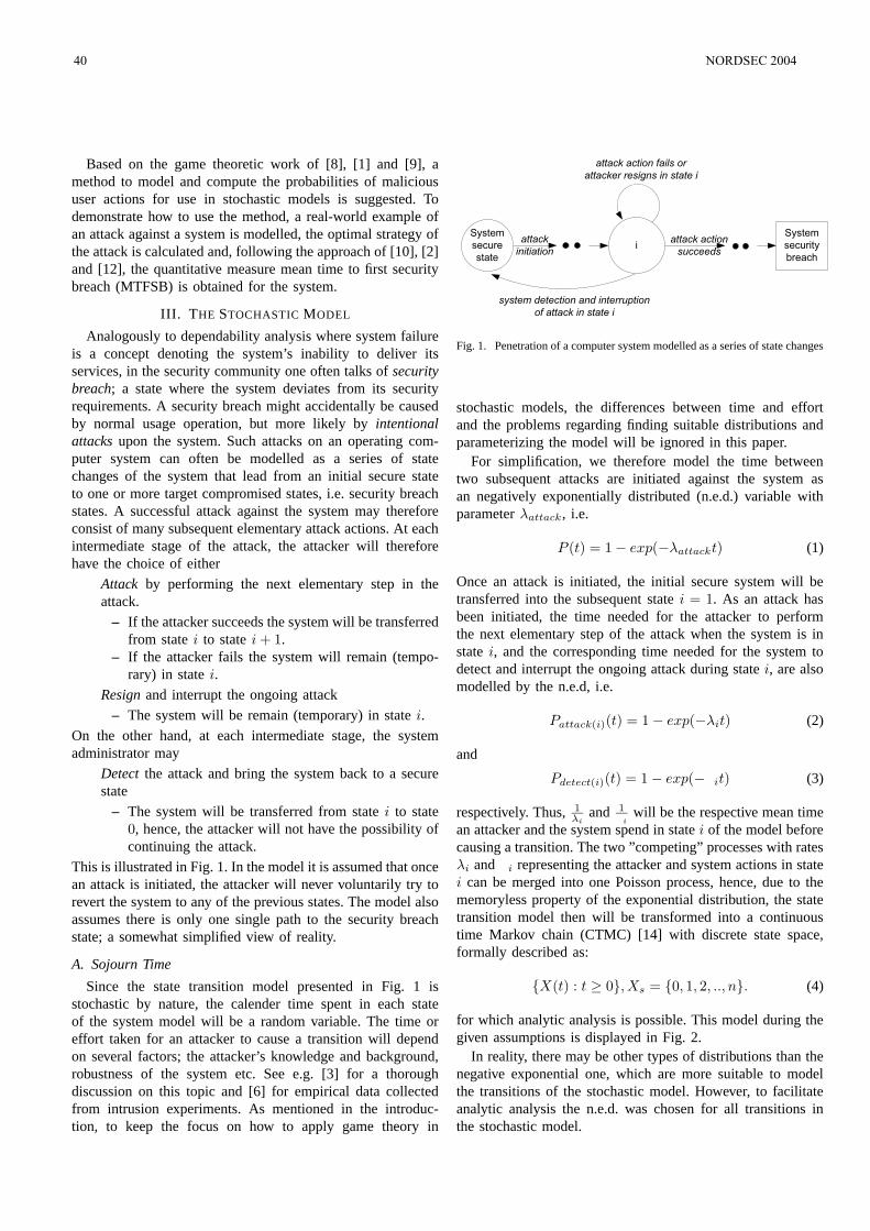
Based on the game theoretic work of [8], [1] and [9], amethod to model and compute the probabilities of malicioususer actions for use in stochastic models is suggested. Todemonstrate how to use the method, a real-world example ofan attack against a system is modelled, the optimal strategy ofthe attack is calculated and, following the approach of [10], [2]and [12], the quantitative measure mean time to first securitybreach (MTFSB) is obtained for the system.
III. THE STOCHASTIC MODEL
Analogously to dependability analysis where system failureis a concept denoting the system’s inability to deliver itsservices, in the security community one often talks of securitybreach; a state where the system deviates from its securityrequirements. A security breach might accidentally be causedby normal usage operation, but more likely by intentionalattacks upon the system. Such attacks on an operating com-puter system can often be modelled as a series of statechanges of the system that lead from an initial secure stateto one or more target compromised states, i.e. security breachstates. A successful attack against the system may thereforeconsist of many subsequent elementary attack actions. At eachintermediate stage of the attack, the attacker will thereforehave the choice of either
² Attack by performing the next elementary step in theattack.
– If the attacker succeeds the system will be transferredfrom state i to state i + 1.
– If the attacker fails the system will remain (tempo-rary) in state i.
² Resign and interrupt the ongoing attack
– The system will be remain (temporary) in state i.
On the other hand, at each intermediate stage, the systemadministrator may
² Detect the attack and bring the system back to a securestate
– The system will be transferred from state i to state0, hence, the attacker will not have the possibility ofcontinuing the attack.
This is illustrated in Fig. 1. In the model it is assumed that oncean attack is initiated, the attacker will never voluntarily try torevert the system to any of the previous states. The model alsoassumes there is only one single path to the security breachstate; a somewhat simplified view of reality.
A. Sojourn Time
Since the state transition model presented in Fig. 1 isstochastic by nature, the calender time spent in each stateof the system model will be a random variable. The time oreffort taken for an attacker to cause a transition will dependon several factors; the attacker’s knowledge and background,robustness of the system etc. See e.g. [3] for a thoroughdiscussion on this topic and [6] for empirical data collectedfrom intrusion experiments. As mentioned in the introduc-tion, to keep the focus on how to apply game theory in
attack action fails or
attacker resigns in state i
attack action
succeeds
system detection and interruption
of attack in state i
iattack
initiation
System
secure
state
System
security
breach
Fig. 1. Penetration of a computer system modelled as a series of state changes
stochastic models, the differences between time and effortand the problems regarding finding suitable distributions andparameterizing the model will be ignored in this paper.
For simplification, we therefore model the time betweentwo subsequent attacks are initiated against the system asan negatively exponentially distributed (n.e.d.) variable withparameter λattack, i.e.
P (t) = 1− exp(−λattackt) (1)
Once an attack is initiated, the initial secure system will betransferred into the subsequent state i = 1. As an attack hasbeen initiated, the time needed for the attacker to performthe next elementary step of the attack when the system is instate i, and the corresponding time needed for the system todetect and interrupt the ongoing attack during state i, are alsomodelled by the n.e.d, i.e.
Pattack(i)(t) = 1− exp(−λit) (2)
and
Pdetect(i)(t) = 1− exp(−¹it) (3)
respectively. Thus, 1λi
and 1¹i
will be the respective mean timean attacker and the system spend in state i of the model beforecausing a transition. The two ”competing” processes with ratesλi and ¹i representing the attacker and system actions in statei can be merged into one Poisson process, hence, due to thememoryless property of the exponential distribution, the statetransition model then will be transformed into a continuoustime Markov chain (CTMC) [14] with discrete state space,formally described as:
X(t) : t ≥ 0, Xs = 0, 1, 2, .., n. (4)
for which analytic analysis is possible. This model during thegiven assumptions is displayed in Fig. 2.
In reality, there may be other types of distributions than thenegative exponential one, which are more suitable to modelthe transitions of the stochastic model. However, to facilitateanalytic analysis the n.e.d. was chosen for all transitions inthe stochastic model.
40 NORDSEC 2004
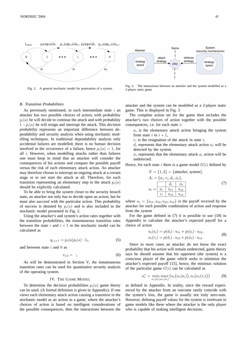
pi-1(a)pi-1(s)i-1 pn-1(a)pn-1(s)
n-1pi(a)pi(s)
ip1(a)p1(s)
1
µnµiµ1
attack
i0 1 n
Fig. 2. A general stochastic model for penetration of a system.
B. Transition Probabilities
As previously mentioned, in each intermediate state i anattacker has two possible choices of action; with probabilitypi(a) he will decide to continue the attack and with probability1−pi(a) he will resign and interrupt the attack. This decisionprobability represents an important difference between de-pendability and security analysis when using stochastic mod-elling techniques. In traditional dependability analysis onlyaccidental failures are modelled; there is no human decisioninvolved in the occurrence of a failure, hence pi(a) = 1, forall i. However, when modelling attacks rather than failuresone must keep in mind that an attacker will consider theconsequences of his actions and compare the possible payoffversus the risk of each elementary attack action. An attackermay therefore choose to interrupt an ongoing attack at a certainstage or to not start the attack at all. Therefore, for eachtransition representing an elementary step in the attack pi(a)should be explicitly calculated.
To be able to bring the system closer to the security breachstate, an attacker not only has to decide upon an action, but hemust also succeed with the particular action. This probabilityof success is denoted by pi(s) and is also included in thestochastic model presented in Fig. 2.
Using the attacker’s and system’s action rates together withthe transition probabilities, the instantaneous transition ratesbetween the state i and i + 1 in the stochastic model can becalculated as
qi,i+1 = pi(a)pi(s) · λi, (5)
and between state i and 0 as
vi,0 = ¹i (6)
As will be demonstrated in Section V, the instantaneoustransition rates can be used for quantitative security analysisof the operating system.
IV. THE GAME MODEL
To determine the decision probabilities pi(a) game theorycan be used. (A formal definition is given in Appendix). If oneviews each elementary attack action causing a transition in thestochastic model as an action in a game, where the attacker’schoices of action is based on intelligent considerations ofthe possible consequences, then the interactions between the
strategy
space
Game
attack
strategy
defense
strategy
System
(security mechanisms)Attacker
strategy
spaceplay
Fig. 3. The interactions between an attacker and the system modelled as a2-player static game
attacker and the system can be modelled as a 2-player staticgame. This is displayed in Fig. 3
The complete action set for the game then includes theattacker’s two choices of action together with the possibleconsequences, i.e. for each state i:
² ai is the elementary attack action bringing the systemfrom state i to i + 1,
² ri is the resignation of the attack in state i,² di represents that the elementary attack action ai will be
detected by the system.² φi represents that the elementary attack ai action will be
undetected.
Hence, for each state i there is a game model G(i) defined by
N = 1, 2 = attacker, system,
Ai = ai, ri, di, φi,
ui =
di φi
ai ui1 ui2
ri ui3 ui4
(7)
where ui = ui1, ui2, ui3, ui4 is the payoff received by theattacker for each possible combination of action and responsefrom the system
For the game defined in (7) it is possible to use (18) inAppendix to calculate the attacker’s expected payoff for achoice of action
ui(ai) = p(di) · ui1 + p(φi) · ui2,
ui(ri) = p(di) · ui3 + p(φi) · ui4.(8)
Since in most cases an attacker do not know the exactprobability that his action will remain undetected, game theorysays he should assume that his opponent (the system) is aconscious player of the game which seeks to minimize theattacker’s expected payoff [15], hence, the minimax solutionof the particular game G(i) can be calculated as
α∗i = min
αi(di)maxαi(ai)
ui
(
αi(ai))
, ui
(
αi(ri))
(9)
as defined in Appendix. In reality, since the reward experi-enced by the attacker from an outcome rarely coincide withthe system’s loss, the game is usually not truly zero-sum.However, defining payoff values for the system is irrelevant ingame models like these where the attacker is the only playerwho is capable of making intelligent decisions.
NORDSEC 2004 41
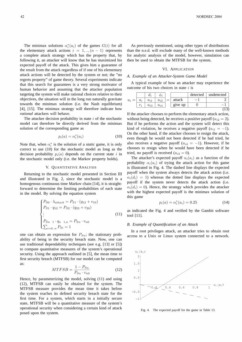
The minimax solutions α∗i (ai) of the games G(i) for all
the elementary attack actions i = 1, .., (n − 1) representsa complete attack strategy which has the property that, byfollowing it, an attacker will know that he has maximized hisexpected payoff of the attack. This gives him a guarantee ofthe result from the attack regardless of if one of his elementaryattack actions will be detected by the system or not; the ”noregrets property” of game theory. Several experiments indicatethat this search for guarantees is a very strong motivator ofhuman behavior and assuming that the attacker populationtargeting the system will make rational choices relative to theirobjectives, the situation will in the long run naturally gravitatetowards the minimax solution (i.e. the Nash equilibrium)[4], [15]. The minimax strategy will therefore indicate howrational attackers will behave.
The attacker decision probability in state i of the stochasticmodel can therefore be directly derived from the minimaxsolution of the corresponding game as
pi(a) = α∗i (ai) (10)
Note that, when α∗i is the solution of a static game, it is only
correct to use (10) for the stochastic model as long as thedecision probability pi(a) depends on the current state i inthe stochastic model only (i.e. the Markov property holds).
V. QUANTITATIVE ANALYSIS
Returning to the stochastic model presented in Section IIIand illustrated in Fig. 2, since the stochastic model is ahomogenous continuous time Markov chain [14], it is straight-forward to determine the limiting probabilities of each statein the model. By solving the equation system
PS0 · λattack = PS1 · (q12 + v10)
PS1 · q12 = PS2 · (q23 + v20)...
PSn¡1 · qn¡1,n = PSn · vn0∑
i=0..n PSi = 1
(11)
one can obtain an expression for PSn; the stationary prob-ability of being in the security breach state. Now, one canuse traditional dependability techniques (see e.g. [13] or [5])to compute quantitative measures of the system’s operationalsecurity. Using the approach outlined in [5], the mean time tofirst security breach (MTFSB) for our model can be computedas:
MTFSB =1− PSn
PSn · vn0(12)
Hence, by parameterizing the model, solving (11) and using(12), MTFSB can easily be obtained for the system. TheMTFSB measure provides the mean time it takes beforethe system reaches its defined security breach state for thefirst time. For a system, which starts in a initially securestate, MTFSB will be a quantitative measure of the system’soperational security when considering a certain kind of attackposed upon the system.
As previously mentioned, using other types of distributionsthan the n.e.d. will exclude many of the well-known methodsfor analytic analysis of the model, however, simulation canthen be used to obtain the MTFSB for the system.
VI. APPLICATION
A. Example of an Attacker-System Game Model
A typical example of how an attacker may experience theoutcome of his two choices in state i is
ui =
di φi
ai ui1 ui2
ri ui3 ui4
=
detected undetectedattack −1 2give up 0 −1
(13)If the attacker chooses to perform the elementary attack action,without being detected, he receives a positive payoff (ui2 = 2).But if he performs the action and the system will detect thiskind of violation, he receives a negative payoff (ui1 = −1).On the other hand, if the attacker chooses to resign the attack,even though he would not been detected if he had tried, healso receives a negative payoff (ui4 = −1). However, if hechooses to resign when he would have been detected if hetried, no payoff is received (ui3 = 0).
The attacker’s expected payoff ui(ai) as a function of theprobability αi(ai) of trying the attack action for this gameis illustrated in Fig. 4. The dashed line displays the expectedpayoff when the system always detects the attack action (i.e.αi(di) = 1) whereas the dotted line displays the expectedpayoff if the system never detects the attack action (i.e.αi(di) = 0). Hence, the strategy which provides the attackerwith the highest expected payoff is the minimax solution ofthis game
pi(a) = α∗i (ai) = 0.25 (14)
as indicated the Fig. 4 and verified by the Gambit softwaretool [11].
B. Example of Quantification of an Attack
In a root privileges attack, an attacker tries to obtain rootaccess to a Unix or Linux system connected to a network.
0.2 0.4 0.6 0.8 1
i
ai
-1
-0.5
0.5
1
1.5
2
uiai
Fig. 4. The expected payoff for the game in Table 13.
42 NORDSEC 2004
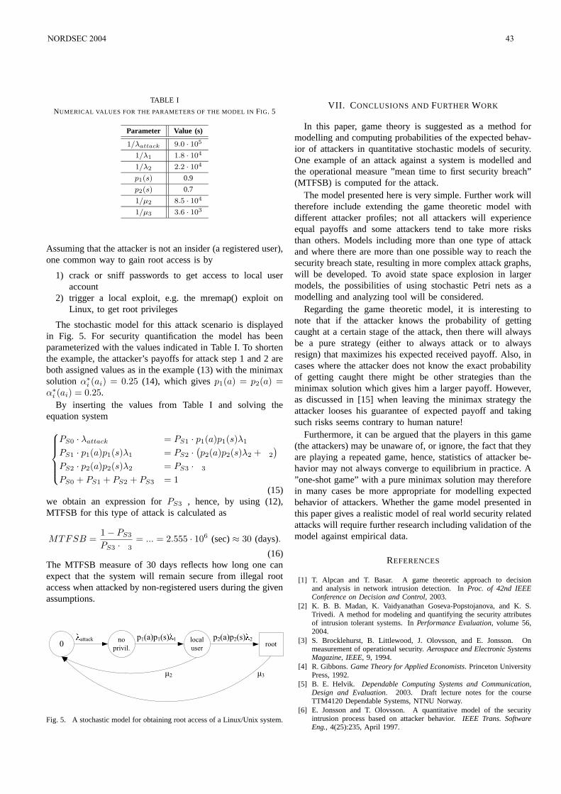
TABLE I
NUMERICAL VALUES FOR THE PARAMETERS OF THE MODEL IN FIG. 5
Parameter Value (s)
1/λattack 9.0 · 105
1/λ1 1.8 · 104
1/λ2 2.2 · 104
p1(s) 0.9
p2(s) 0.7
1/µ2 8.5 · 104
1/µ3 3.6 · 103
Assuming that the attacker is not an insider (a registered user),one common way to gain root access is by
1) crack or sniff passwords to get access to local useraccount
2) trigger a local exploit, e.g. the mremap() exploit onLinux, to get root privileges
The stochastic model for this attack scenario is displayedin Fig. 5. For security quantification the model has beenparameterized with the values indicated in Table I. To shortenthe example, the attacker’s payoffs for attack step 1 and 2 areboth assigned values as in the example (13) with the minimaxsolution α∗
i (ai) = 0.25 (14), which gives p1(a) = p2(a) =α∗
i (ai) = 0.25.By inserting the values from Table I and solving the
equation system
PS0 · λattack = PS1 · p1(a)p1(s)λ1
PS1 · p1(a)p1(s)λ1 = PS2 ·(
p2(a)p2(s)λ2 + ¹2
)
PS2 · p2(a)p2(s)λ2 = PS3 · ¹3
PS0 + PS1 + PS2 + PS3 = 1(15)
we obtain an expression for PS3 , hence, by using (12),MTFSB for this type of attack is calculated as
MTFSB =1− PS3
PS3 · ¹3= ... = 2.555 · 106 (sec) ≈ 30 (days).
(16)The MTFSB measure of 30 days reflects how long one canexpect that the system will remain secure from illegal rootaccess when attacked by non-registered users during the givenassumptions.
µ3µ2
p2(a)p2(s) 2p1(a)p1(s) 1 attack local
user0
no
privil.root
Fig. 5. A stochastic model for obtaining root access of a Linux/Unix system.
VII. CONCLUSIONS AND FURTHER WORK
In this paper, game theory is suggested as a method formodelling and computing probabilities of the expected behav-ior of attackers in quantitative stochastic models of security.One example of an attack against a system is modelled andthe operational measure ”mean time to first security breach”(MTFSB) is computed for the attack.
The model presented here is very simple. Further work willtherefore include extending the game theoretic model withdifferent attacker profiles; not all attackers will experienceequal payoffs and some attackers tend to take more risksthan others. Models including more than one type of attackand where there are more than one possible way to reach thesecurity breach state, resulting in more complex attack graphs,will be developed. To avoid state space explosion in largermodels, the possibilities of using stochastic Petri nets as amodelling and analyzing tool will be considered.
Regarding the game theoretic model, it is interesting tonote that if the attacker knows the probability of gettingcaught at a certain stage of the attack, then there will alwaysbe a pure strategy (either to always attack or to alwaysresign) that maximizes his expected received payoff. Also, incases where the attacker does not know the exact probabilityof getting caught there might be other strategies than theminimax solution which gives him a larger payoff. However,as discussed in [15] when leaving the minimax strategy theattacker looses his guarantee of expected payoff and takingsuch risks seems contrary to human nature!
Furthermore, it can be argued that the players in this game(the attackers) may be unaware of, or ignore, the fact that theyare playing a repeated game, hence, statistics of attacker be-havior may not always converge to equilibrium in practice. A”one-shot game” with a pure minimax solution may thereforein many cases be more appropriate for modelling expectedbehavior of attackers. Whether the game model presented inthis paper gives a realistic model of real world security relatedattacks will require further research including validation of themodel against empirical data.
REFERENCES
[1] T. Alpcan and T. Basar. A game theoretic approach to decisionand analysis in network intrusion detection. In Proc. of 42nd IEEEConference on Decision and Control, 2003.
[2] K. B. B. Madan, K. Vaidyanathan Goseva-Popstojanova, and K. S.Trivedi. A method for modeling and quantifying the security attributesof intrusion tolerant systems. In Performance Evaluation, volume 56,2004.
[3] S. Brocklehurst, B. Littlewood, J. Olovsson, and E. Jonsson. Onmeasurement of operational security. Aerospace and Electronic SystemsMagazine, IEEE, 9, 1994.
[4] R. Gibbons. Game Theory for Applied Economists. Princeton UniversityPress, 1992.
[5] B. E. Helvik. Dependable Computing Systems and Communication,Design and Evaluation. 2003. Draft lecture notes for the courseTTM4120 Dependable Systems, NTNU Norway.
[6] E. Jonsson and T. Olovsson. A quantitative model of the securityintrusion process based on attacker behavior. IEEE Trans. SoftwareEng., 4(25):235, April 1997.
NORDSEC 2004 43
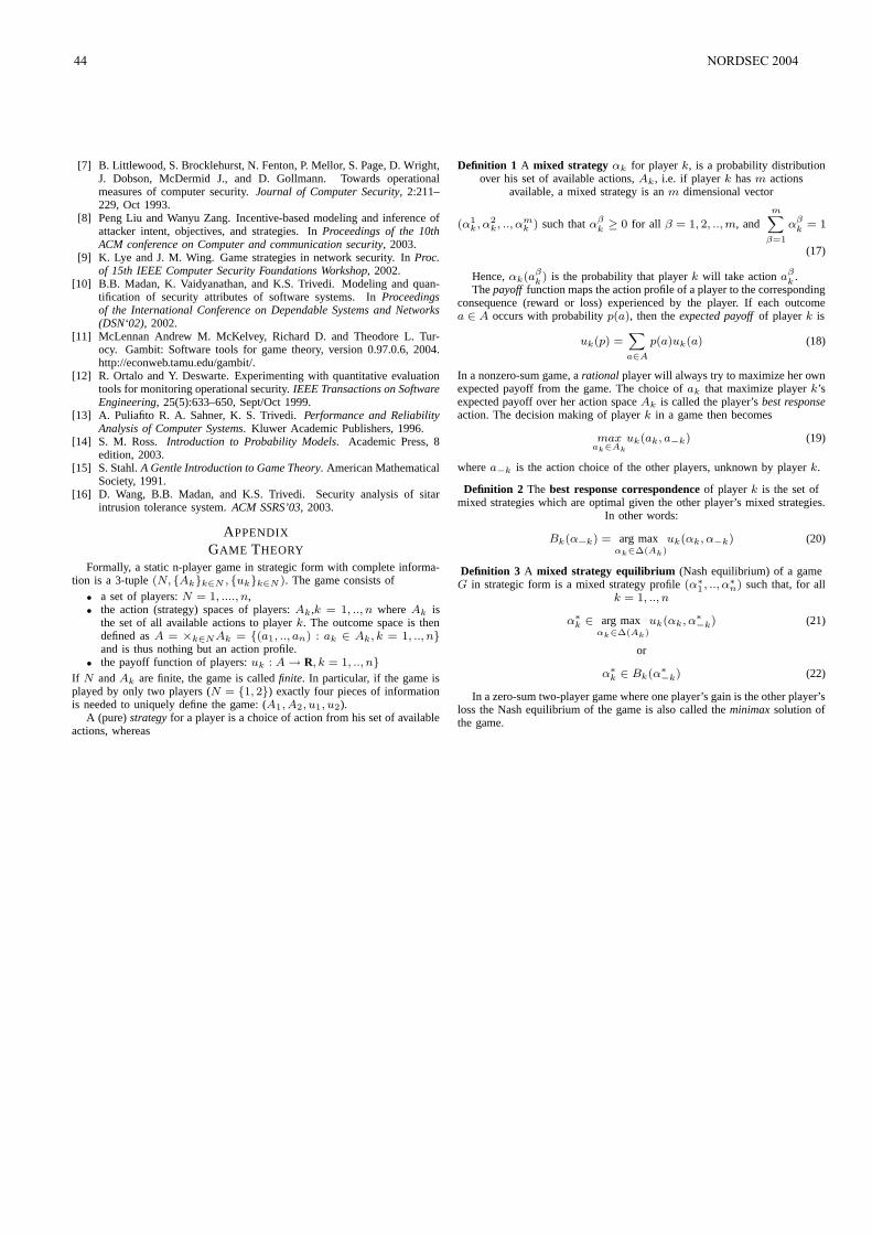
[7] B. Littlewood, S. Brocklehurst, N. Fenton, P. Mellor, S. Page, D. Wright,J. Dobson, McDermid J., and D. Gollmann. Towards operationalmeasures of computer security. Journal of Computer Security, 2:211–229, Oct 1993.
[8] Peng Liu and Wanyu Zang. Incentive-based modeling and inference ofattacker intent, objectives, and strategies. In Proceedings of the 10thACM conference on Computer and communication security, 2003.
[9] K. Lye and J. M. Wing. Game strategies in network security. In Proc.of 15th IEEE Computer Security Foundations Workshop, 2002.
[10] B.B. Madan, K. Vaidyanathan, and K.S. Trivedi. Modeling and quan-tification of security attributes of software systems. In Proceedingsof the International Conference on Dependable Systems and Networks(DSN‘02), 2002.
[11] McLennan Andrew M. McKelvey, Richard D. and Theodore L. Tur-ocy. Gambit: Software tools for game theory, version 0.97.0.6, 2004.http://econweb.tamu.edu/gambit/.
[12] R. Ortalo and Y. Deswarte. Experimenting with quantitative evaluationtools for monitoring operational security. IEEE Transactions on SoftwareEngineering, 25(5):633–650, Sept/Oct 1999.
[13] A. Puliafito R. A. Sahner, K. S. Trivedi. Performance and ReliabilityAnalysis of Computer Systems. Kluwer Academic Publishers, 1996.
[14] S. M. Ross. Introduction to Probability Models. Academic Press, 8edition, 2003.
[15] S. Stahl. A Gentle Introduction to Game Theory. American MathematicalSociety, 1991.
[16] D. Wang, B.B. Madan, and K.S. Trivedi. Security analysis of sitarintrusion tolerance system. ACM SSRS’03, 2003.
APPENDIX
GAME THEORY
Formally, a static n-player game in strategic form with complete informa-tion is a 3-tuple (N, Akk∈N , ukk∈N ). The game consists of
• a set of players: N = 1, ...., n,• the action (strategy) spaces of players: Ak ,k = 1, .., n where Ak is
the set of all available actions to player k. The outcome space is thendefined as A = ×k∈NAk = (a1, .., an) : ak ∈ Ak, k = 1, .., nand is thus nothing but an action profile.
• the payoff function of players: uk : A → R, k = 1, .., n
If N and Ak are finite, the game is called finite. In particular, if the game isplayed by only two players (N = 1, 2) exactly four pieces of informationis needed to uniquely define the game: (A1, A2, u1, u2).
A (pure) strategy for a player is a choice of action from his set of availableactions, whereas
Definition 1 A mixed strategy αk for player k, is a probability distributionover his set of available actions, Ak , i.e. if player k has m actions
available, a mixed strategy is an m dimensional vector
(α1k, α2k, .., α
mk ) such that α
βk≥ 0 for all β = 1, 2, .., m, and
m∑
β=1
αβk
= 1
(17)
Hence, αk(aβk) is the probability that player k will take action a
βk
.The payoff function maps the action profile of a player to the corresponding
consequence (reward or loss) experienced by the player. If each outcomea ∈ A occurs with probability p(a), then the expected payoff of player k is
uk(p) =∑
a∈A
p(a)uk(a) (18)
In a nonzero-sum game, a rational player will always try to maximize her ownexpected payoff from the game. The choice of ak that maximize player k’sexpected payoff over her action space Ak is called the player’s best responseaction. The decision making of player k in a game then becomes
max
ak∈Ak
uk(ak, a−k) (19)
where a−k is the action choice of the other players, unknown by player k.
Definition 2 The best response correspondence of player k is the set ofmixed strategies which are optimal given the other player’s mixed strategies.
In other words:
Bk(α−k) = arg maxαk∈∆(Ak)
uk(αk, α−k) (20)
Definition 3 A mixed strategy equilibrium (Nash equilibrium) of a gameG in strategic form is a mixed strategy profile (α∗
1, .., α∗n) such that, for all
k = 1, .., n
α∗
k ∈ arg maxαk∈∆(Ak)
uk(αk, α∗
−k) (21)
or
α∗
k ∈ Bk(α∗
−k) (22)
In a zero-sum two-player game where one player’s gain is the other player’sloss the Nash equilibrium of the game is also called the minimax solution ofthe game.
44 NORDSEC 2004
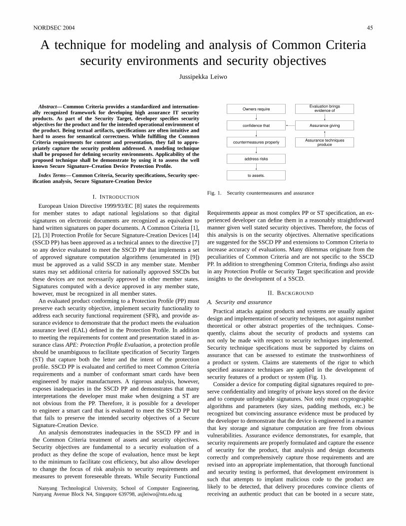
A technique for modeling and analysis of Common Criteriasecurity environments and security objectives
Jussipekka Leiwo
Abstract— Common Criteria provides a standardized and internation-ally recognized framework for developing high assurance ITsecurityproducts. As part of the Security Target, developer specifies securityobjectives for the product and for the intended operationalenvironment ofthe product. Being textual artifacts, specifications are often intuitive andhard to assess for semantical correctness. While fulfillingthe CommonCriteria requirements for content and presentation, they fail to appro-priately capture the security problem addressed. A modeling techniqueshall be proposed for defining security environments. Applicability of theproposed technique shall be demonstrate by using it to assess the wellknown Secure Signature–Creation Device Protection Profile.
Index Terms— Common Criteria, Security specifications, Security spec-ification analysis, Secure Signature-Creation Device
I. I NTRODUCTION
European Union Directive 1999/93/EC [8] states the requirementsfor member states to adapt national legislations so that digitalsignatures on electronic documents are recognized as equivalent tohand written signatures on paper documents. A Common Criteria [1],[2], [3] Protection Profile for Secure Signature-Creation Devices [14](SSCD PP) has been approved as a technical annex to the directive [7]so any device evaluated to meet the SSCD PP that implements a setof approved signature computation algorithms (enumerated in [9])must be approved as a valid SSCD in any member state. Memberstates may set additional criteria for nationally approved SSCDs butthese devices are not necessarily approved in other member states.Signatures computed with a device approved in any member state,however, must be recognized in all member states.
An evaluated product conforming to a Protection Profile (PP) mustpreserve each security objective, implement security functionality toaddress each security functional requirement (SFR), and provide as-surance evidence to demonstrate that the product meets the evaluationassurance level (EAL) defined in the Protection Profile. In additionto meeting the requirements for content and presentation stated in as-surance classAPE: Protection Profile Evaluation, a protection profileshould be unambiguous to facilitate specification of Security Targets(ST) that capture both the letter and the intent of the protectionprofile. SSCD PP is evaluated and certified to meet Common Criteriarequirements and a number of conformant smart cards have beenengineered by major manufacturers. A rigorous analysis, however,exposes inadequacies in the SSCD PP and demonstrates that manyinterpretations the developer must make when designing a ST arenot obvious from the PP. Therefore, it is possible for a developerto engineer a smart card that is evaluated to meet the SSCD PP butthat fails to preserve the intended security objectives of a SecureSignature-Creation Device.
An analysis demonstrates inadequacies in the SSCD PP and inthe Common Criteria treatment of assets and security objectives.Security objectives are fundamental to a security evaluation of aproduct as they define the scope of evaluation, hence must be keptto the minimum to facilitate cost efficiency, but also allow developerto change the focus of risk analysis to security requirements andmeasures to prevent foreseeable threats. While Security Functional
Nanyang Technological University, School of Computer Engineering,Nanyang Avenue Block N4, Singapore 639798, [email protected]
Owners require
confidence that
countermeasures properly
address risks
to assets.
Evaluation bringsevidence of
Assurance giving
Assurance techniquesproduce
Fig. 1. Security countermeasures and assurance
Requirements appear as most complex PP or ST specification, an ex-perienced developer can define them in a reasonably straightforwardmanner given well stated security objectives. Therefore, the focus ofthis analysis is on the security objectives. Alternative specificationsare suggested for the SSCD PP and extensions to Common Criteria toincrease accuracy of evaluations. Many dilemmas originate from thepeculiarities of Common Criteria and are not specific to the SSCDPP. In addition to strengthening Common Criteria, findings also assistin any Protection Profile or Security Target specification and provideinsights to the development of a SSCD.
II. BACKGROUND
A. Security and assurance
Practical attacks against products and systems are usually againstdesign and implementation of security techniques, not against numbertheoretical or other abstract properties of the techniques. Conse-quently, claims about the security of products and systems cannot only be made with respect to security techniques implemented.Security technique specifications must be supported by claims onassurance that can be assessed to estimate the trustworthiness ofa product or system. Claims are statements of the rigor to whichspecified assurance techniques are applied in the development ofsecurity features of a product or system (Fig. 1).
Consider a device for computing digital signatures required to pre-serve confidentiality and integrity of private keys stored on the deviceand to compute unforgeable signatures. Not only must cryptographicalgorithms and parameters (key sizes, padding methods, etc.) berecognized but convincing assurance evidence must be produced bythe developer to demonstrate that the device is engineered in a mannerthat key storage and signature computation are free from obviousvulnerabilities. Assurance evidence demonstrates, for example, thatsecurity requirements are properly formulated and capture the essenceof security for the product, that analysis and design documentscorrectly and comprehensively capture those requirements and arerevised into an appropriate implementation, that thorough functionaland security testing is performed, that development environment issuch that attempts to implant malicious code to the product arelikely to be detected, that delivery procedures convince clients ofreceiving an authentic product that can be booted in a secure state,
NORDSEC 2004 45
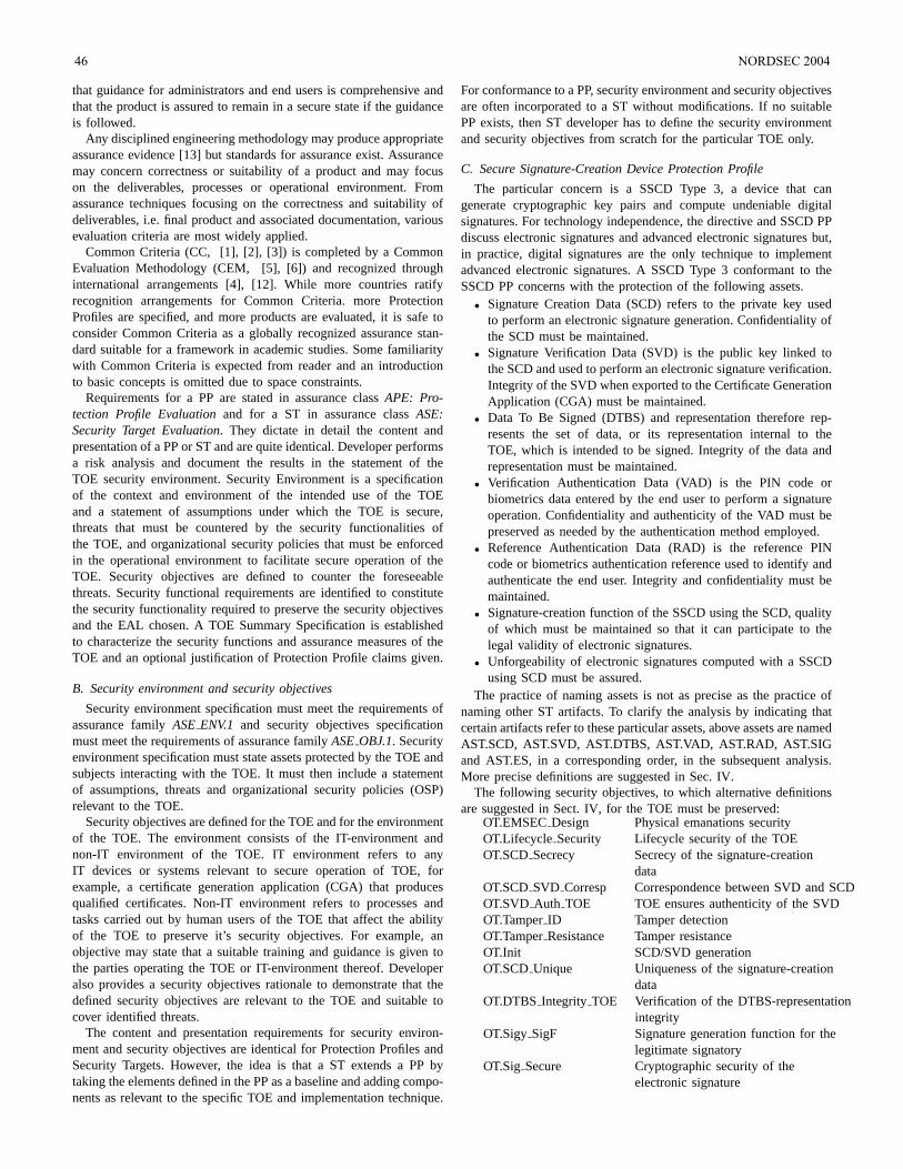
that guidance for administrators and end users is comprehensive andthat the product is assured to remain in a secure state if the guidanceis followed.
Any disciplined engineering methodology may produce appropriateassurance evidence [13] but standards for assurance exist. Assurancemay concern correctness or suitability of a product and may focuson the deliverables, processes or operational environment. Fromassurance techniques focusing on the correctness and suitability ofdeliverables, i.e. final product and associated documentation, variousevaluation criteria are most widely applied.
Common Criteria (CC, [1], [2], [3]) is completed by a CommonEvaluation Methodology (CEM, [5], [6]) and recognized throughinternational arrangements [4], [12]. While more countries ratifyrecognition arrangements for Common Criteria. more ProtectionProfiles are specified, and more products are evaluated, it is safe toconsider Common Criteria as a globally recognized assurance stan-dard suitable for a framework in academic studies. Some familiaritywith Common Criteria is expected from reader and an introductionto basic concepts is omitted due to space constraints.
Requirements for a PP are stated in assurance classAPE: Pro-tection Profile Evaluationand for a ST in assurance classASE:Security Target Evaluation. They dictate in detail the content andpresentation of a PP or ST and are quite identical. Developer performsa risk analysis and document the results in the statement of theTOE security environment. Security Environment is a specificationof the context and environment of the intended use of the TOEand a statement of assumptions under which the TOE is secure,threats that must be countered by the security functionalities ofthe TOE, and organizational security policies that must be enforcedin the operational environment to facilitate secure operation of theTOE. Security objectives are defined to counter the foreseeablethreats. Security functional requirements are identified to constitutethe security functionality required to preserve the security objectivesand the EAL chosen. A TOE Summary Specification is establishedto characterize the security functions and assurance measures of theTOE and an optional justification of Protection Profile claims given.
B. Security environment and security objectives
Security environment specification must meet the requirements ofassurance familyASEENV.1 and security objectives specificationmust meet the requirements of assurance familyASEOBJ.1. Securityenvironment specification must state assets protected by the TOE andsubjects interacting with the TOE. It must then include a statementof assumptions, threats and organizational security policies (OSP)relevant to the TOE.
Security objectives are defined for the TOE and for the environmentof the TOE. The environment consists of the IT-environment andnon-IT environment of the TOE. IT environment refers to anyIT devices or systems relevant to secure operation of TOE, forexample, a certificate generation application (CGA) that producesqualified certificates. Non-IT environment refers to processes andtasks carried out by human users of the TOE that affect the abilityof the TOE to preserve it’s security objectives. For example, anobjective may state that a suitable training and guidance is given tothe parties operating the TOE or IT-environment thereof. Developeralso provides a security objectives rationale to demonstrate that thedefined security objectives are relevant to the TOE and suitable tocover identified threats.
The content and presentation requirements for security environ-ment and security objectives are identical for Protection Profiles andSecurity Targets. However, the idea is that a ST extends a PP bytaking the elements defined in the PP as a baseline and adding compo-nents as relevant to the specific TOE and implementation technique.
For conformance to a PP, security environment and security objectivesare often incorporated to a ST without modifications. If no suitablePP exists, then ST developer has to define the security environmentand security objectives from scratch for the particular TOE only.
C. Secure Signature-Creation Device Protection Profile
The particular concern is a SSCD Type 3, a device that cangenerate cryptographic key pairs and compute undeniable digitalsignatures. For technology independence, the directive and SSCD PPdiscuss electronic signatures and advanced electronic signatures but,in practice, digital signatures are the only technique to implementadvanced electronic signatures. A SSCD Type 3 conformant to theSSCD PP concerns with the protection of the following assets.
• Signature Creation Data (SCD) refers to the private key usedto perform an electronic signature generation. Confidentiality ofthe SCD must be maintained.
• Signature Verification Data (SVD) is the public key linked tothe SCD and used to perform an electronic signature verification.Integrity of the SVD when exported to the Certificate GenerationApplication (CGA) must be maintained.
• Data To Be Signed (DTBS) and representation therefore rep-resents the set of data, or its representation internal to theTOE, which is intended to be signed. Integrity of the data andrepresentation must be maintained.
• Verification Authentication Data (VAD) is the PIN code orbiometrics data entered by the end user to perform a signatureoperation. Confidentiality and authenticity of the VAD must bepreserved as needed by the authentication method employed.
• Reference Authentication Data (RAD) is the reference PINcode or biometrics authentication reference used to identify andauthenticate the end user. Integrity and confidentiality must bemaintained.
• Signature-creation function of the SSCD using the SCD, qualityof which must be maintained so that it can participate to thelegal validity of electronic signatures.
• Unforgeability of electronic signatures computed with a SSCDusing SCD must be assured.
The practice of naming assets is not as precise as the practice ofnaming other ST artifacts. To clarify the analysis by indicating thatcertain artifacts refer to these particular assets, above assets are namedAST.SCD, AST.SVD, AST.DTBS, AST.VAD, AST.RAD, AST.SIGand AST.ES, in a corresponding order, in the subsequent analysis.More precise definitions are suggested in Sec. IV.
The following security objectives, to which alternative definitionsare suggested in Sect. IV, for the TOE must be preserved:
OT.EMSECDesign Physical emanations securityOT.Lifecycle Security Lifecycle security of the TOEOT.SCDSecrecy Secrecy of the signature-creation
dataOT.SCDSVD Corresp Correspondence between SVD and SCDOT.SVD Auth TOE TOE ensures authenticity of the SVDOT.TamperID Tamper detectionOT.TamperResistance Tamper resistanceOT.Init SCD/SVD generationOT.SCDUnique Uniqueness of the signature-creation
dataOT.DTBS Integrity TOE Verification of the DTBS-representation
integrityOT.Sigy SigF Signature generation function for the
legitimate signatoryOT.Sig Secure Cryptographic security of the
electronic signature
46 NORDSEC 2004
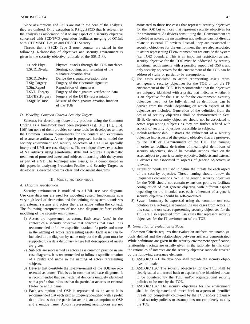
Since assumptions and OSPs are not in the core of the analysis,they are omitted. Only exception is P.SigySSCD that is relevant tothe analysis as association of it to any aspect of a security objectiveconcerned with SCD/SVD generation facilitates merging of OT.Initwith OT.EMSECDesign and OT.SCDSecrecy.
Threats that a SSCD Type 3 must counter are stated in thefollowing. Relationship of objectives and security environment isgiven in the security objective rationale of the SSCD PP.
T.Hack Phys Physical attacks through the TOE interfacesT.SCD Divulg Storing, copying, and releasing of the
signature-creation dataT.SCD Derive Derive the signature-creation dataT.Sig Forgery Forgery of the electronic signatureT.Sig Repud Repudiation of signaturesT.SVD Forgery Forgery of the signature-verification dataT.DTBS Forgery Forgery of the DTBS-representationT.SigF Misuse Misuse of the signature-creation function
of the TOE
D. Modeling Common Criteria Security Targets
Schemes for developing trustworthy products using the CommonCriteria as a framework have been proposed (e.g. [10], [11], [15],[16]) but none of them provides concrete tools for developers to meetthe Common Criteria requirements for the content and expressionof assurance artifacts. A technique is proposed herein to model thesecurity environment and security objectives of a TOE as speciallyinterpreted UML use case diagrams. The technique allows expressionof ST artifacts using semiformal style and requires a systematictreatment of protected assets and subjects interacting with the systemas part of a ST. The technique also assists, as is demonstrated inthis paper, in analyzing Protection Profiles and Security Targets asdeveloper is directed towards clear and consistent diagrams.
III. M ODELING TECHNIQUE
A. Diagram specification
Security environment is modeled as a UML use case diagram.Use case diagrams are used for modeling system functionality at avery high level of abstraction and for defining the system boundariesand external systems and actors that area active within the context.The following interpretations of use case diagram artifacts enablemodeling of the security environment:
1) Assets are represented as actors. Each asset ’acts’ in thecontext of a security objective that concerns that asset. It isrecommended to follow a specific notation of a prefix and namein the naming of actors representing assets. Each asset can beincluded in the diagram by name only but the diagram must besupported by a data dictionary where full descriptions of assetsare given.
2) Subjects are represented as actors as is common practice in usecase diagrams. It is recommended to follow a specific notationof a prefix and name in the naming of actors representingsubjects.
3) Devices that constitute the IT-environment of the TOE are rep-resented as actors. This is as in common use case diagrams. Itis recommended that each external device is uniquely identifiedwith a prefix that indicates that the particular actor is an externalIT-device and a name.
4) Each assumption and OSP is represented as an actor. It isrecommended that each item is uniquely identified with a prefixthat indicates that the particular actor is an assumption or OSPand a unique name. Actors representing assumptions are not
associated to those use cases that represent security objectivesfor the TOE but to those that represent security objectives forthe environment. As devices constituting the IT-environment aremodeled as actors, the assumptions and policies can not directlyrelate to external IT devices. Instead, they are associated tosecurity objectives for the environment that are also associatedto actors representing IT-environment but are outside the system(i.e. TOE) boundary. This is an important restriction as eachsecurity objective for the TOE must be addressed by securityfunctional requirements with a possible support of OSP’s andonly security objectives for the environment of the TOE can beaddressed (fully or partially) by assumptions.
5) Use cases associated to actors representing assets repre-sent generic security objectives for the TOE or for the IT-environment of the TOE. It is recommended that the objectivesare uniquely identified with a prefix that indicates whether itis an objective for the TOE or for the environment. Securityobjectives need not be fully defined as definitions can bederived from the model depending on which aspects of theobjective are included. Generation of the definition from thedesign of security objectives shall be demonstrated in Sect.III-B. Generic security objectives should not be associated toactors representing subjects as they are further refined withaspects of security objectives accessible to subjects.
6) Includes-relationship illustrates the refinement of a securityobjective into aspects of the generic objective that are preservedby the TOE or IT-environment of the TOE. The naming,in order to facilitate derivation of meaningful definitions ofsecurity objectives, should be possible actions taken on theasset subject to generic security objective. Subjects and externalIT-devices are associated to aspects of generic objectives asrelevant.
7) Extension points are used to define the threats for each aspectof the security objective. Threat naming should follow theuniqueness conventions. While the generic security objectivesfor the TOE should not contain extensions points to facilitateconfiguration of that generic objective with different aspectsdepending on the intended use, each refinement of a genericsecurity objective should be self-contained.
8) System boundary is expressed using the common use casenotation as a rectangle separating the use cases from actors. Inthis case, the use cases representing security objectives for theTOE are also separated from use cases that represent securityobjectives for the IT environment of the TOE.
B. Generation of evaluation artifacts
Common Criteria requires that evaluation artifacts are unambigu-ously defined and the relationships between artifacts demonstrated.While definitions are given in the security environment specification,relationship tracings are usually given in the rationale. In this case,the rationales of interests are the security objective rationale coveredby the following assurance elements:
1) ASEOBJ.1.2DThe developer shall provide the security objec-tives rationale.
2) ASEOBJ.1.2CThe security objectives for the TOE shall beclearly stated and traced back to aspects of the identified threatsto be countered by the TOE and/or organizational securitypolicies to be met by the TOE.
3) ASEOBJ.1.3C The security objectives for the environmentshall be clearly stated and traced back to aspects of identifiedthreats not completely countered by the TOE and/or organiza-tional security policies or assumptions not completely met bythe TOE.
NORDSEC 2004 47
4) ASEOBJ.1.4CThe security objectives rationale shall demon-strate that the stated security objectives are suitable to counterthe identified threats to security.
5) ASEOBJ.1.5CThe security objectives rationale shall demon-strate that the stated security objectives are suitable to cover allof the identified organizational security policies and assump-tions.
In practice this means that the relationship of security objectivesto threats, assumptions and OSP’s must be demonstrated. A cross-tabulation is a common way to demonstrate the relationship and, afterdemonstrating the derivation of a definition for security objectives weshall demonstrate ho the use case for the security environment canbe used for deriving the tracings for the rationale.
1) Definitions of security objectives:Assuming that exists asuitable definitions for assets in the data dictionary, definitions forsecurity objective can be derived by concatenating the asset definitionwith the names of all the included aspects (named in a suitablemanner) of the security objective (and the aspects related to thoseaspects) included in the diagram separated by suitable key words.
2) Derivation of tracings for rationale:One of the advantages ofthe proposed technique is that it facilitates semi-formal modeling ofthe definition of security. While the formality of assurance evidencefor evaluated products increases from informal to semi-formal andformal once the evaluation assurance level increases, the assurancerequirements for ST remain unchanged independently of the claimedevaluation assurance level. While bringing the modeling aspects tothe security environment (and further to the entire ST) it is possibleto subject ST to the same increase in rigor of modeling that thedevelopment assurance artifacts, namely the security policy model,high-level design and low-level design, as well as their correspon-dence evidence, and gain further assurance of appropriateness ofdesign artifacts relative to the ST definitions. This is also likely tosimplify the ST authoring. A significant portion of a ST consists ofthe rationale demonstrating appropriateness and correspondence ofspecifications.
While the semiformal model of security environment and securityobjectives acts as a tracing tool between security environment andsecurity objectives, especially from security objectives to securityenvironment, the inverse direction is not as obvious from the diagram(several threats, assumptions and policies may be relevant to morethan one security objective, each security objective possibly beingexpressed in a separate diagram) so it may be, depending on therequirements of the national scheme, necessary to generate moreunambiguous mappings from the security environment diagram. Suchtracings are often expressed as a matrix of objectives and securityenvironment artifacts. Such tracing matrix can be produced from thediagram in a straightforward manner:
1) Each security objective for the TOE and each security objectivefor the IT environment of the TOE is included as a row in amatrix.
2) Each threat, assumption and OSP is included in the column ofthe matrix.
3) For each aspect of each security objective for the TOE, anindication is included in the corresponding node in the matrixis the threat is relevant to that aspect.
4) For each security objective for the IT environment of the TOE,an indication is included in the corresponding node if thatthreat, assumption or OSP is relevant to that objective.
C. A Modeling exercise
OT.EMSECDesign (Fig. 2) must be preserved during generationof SCD/SVD pairs (ASP.KEYGEN) and during computation of
AST.SCD
OT.EMSEC_Design
ASP.KEYGEN
T.Hack_Phys:
T.Sig_Forgery: loc
P.Sigy_SSCD:
ASP.SIGN
T.Hack_Phys:
T.Sig_Forgery:
OSP.LEGAL
T.Sig_Repud:
EXT.CGA
AST.ES
EXT.SCA
AST.EMSEC_Data
<<include>>
<<include>><<include>>
Fig. 2. OT.EMSECDesign
AST.SCDAST.SIGAST.SVD AST.RAD AST.ES
OT.Lifecycle_Security
Initialization
T.Sig_Repud:
Personalization
T.Sig_Forgery:
T.SVD_Forgery:
Regeneration
T.SigForgery:
Operation
T.Sig_Repud:
T.SigF_Misuse:
EXT.SCA EXT.CGA
<<include>>
<<include>>
<<include>>
<<include>>
EXT.INIT
Fig. 3. OT.Lifecycle-Security
digital signatures (ASP.SIGN). Since it appears that asset AST.ESis related to OT.EMSECDesign, aspect ASP.LEGAL (”preserv-ing the legal validity of electronic signatures”) is included. Thishelps to differentiate threats against technical device (T.HackPhysand T.SigForgery) from threats against the PKI infrastructure(T.Sig Repud). Asset AST.EMSECData is created to represent theelectromagnetic emanations generated during computation. The em-anations must be such that no information about the AST.SCD canbe deduced by recording and analyzing them. Radiation, however,is not a property of the key but the computation device and, whilethe inability of an attacker to correlate emanations protects SCD, theactual asset is non-correlation of electromagnetic emanations.
OT.Lifecycle Security (Fig. 3) concerns with AST.SCD but se-curity objectives rationale indicates that only T.SigForgery andT.SigRepud are relevant. On the other hand, the objective by def-inition concerns with initialization, personalization, operation andre-generation of the TOE. Initialization concerns with downloadingthe TOE to the smart card and configuring the file structure orequivalent. Personalization concerns with generation of SVD/SCDpair and RAD and with export of SVD to the CGA. Operational phaseconcerns with all aspects of signature function, and regeneration withsecure destruction of SCD and generation of a new SVD/SCD pair.An additional threat concerned with residual information could beconsidered but it is assumed that T.SigForgery definition is extendedto cover reconstruction of AST.SCD from any residual information.T.SigRepud may be considered relevant to aspect ”initialization” asinappropriate initialization may facilitate repudiation of signatures.Remote trusted IT product EXT.INIT representing the facility ini-tializing the TOE (prior to personalization) is included to align theenvironment of the TOE with the security objective definition.
48 NORDSEC 2004
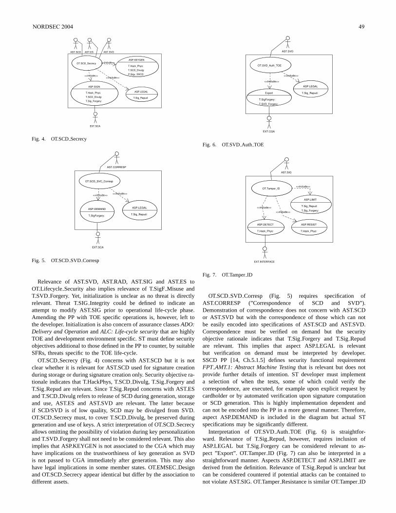
OT.SCD_Secrecy
ASP.SIGN
T.Hack_Phys:
T.SCD_Divulg:
T.Sig_Forgery:
ASP.KEYGEN
T.Hack_Phys:
T.SCD_Divulg:
P.Sigy_SSCD:
EXT.SCA
ASP.LEGAL
T.Sig_Repud:
AST.SCD AST.ES AST.SVD
<<include>>
<<include>><<include>>
Fig. 4. OT.SCDSecrecy
OT.SCD_SVC_Corresp
ASP.DEMAND
T.SIgForgery:
EXT.SCA
ASP.LEGAL
T.Sig_Repud:
AST.CORRESP
<<include>><<include>>
Fig. 5. OT.SCDSVD Corresp
Relevance of AST.SVD, AST.RAD, AST.SIG and AST.ES toOT.Lifecycle Security also implies relevance of T.SigFMisuse andT.SVD Forgery. Yet, initialization is unclear as no threat is directlyrelevant. Threat T.SIGIntegrity could be defined to indicate anattempt to modify AST.SIG prior to operational life-cycle phase.Amending the PP with TOE specific operations is, however, left tothe developer. Initialization is also concern of assurance classesADO:Delivery and OperationandALC: Life-cycle securitythat are highlyTOE and development environment specific. ST must define securityobjectives additional to those defined in the PP to counter, by suitableSFRs, threats specific to the TOE life-cycle.
OT.SCDSecrecy (Fig. 4) concerns with AST.SCD but it is notclear whether it is relevant for AST.SCD used for signature creationduring storage or during signature creation only. Security objective ra-tionale indicates that T.HackPhys, T.SCDDivulg, T.Sig Forgery andT.Sig Repud are relevant. Since T.SigRepud concerns with AST.ESand T.SCDDivulg refers to release of SCD during generation, storageand use, AST.ES and AST.SVD are relevant. The latter becauseif SCD/SVD is of low quality, SCD may be divulged from SVD.OT.SCDSecrecy must, to cover T.SCDDivulg, be preserved duringgeneration and use of keys. A strict interpretation of OT.SCDSecrecyallows omitting the possibility of violation during key personalizationand T.SVDForgery shall not need to be considered relevant. This alsoimplies that ASP.KEYGEN is not associated to the CGA which mayhave implications on the trustworthiness of key generation as SVDis not passed to CGA immediately after generation. This may alsohave legal implications in some member states. OT.EMSECDesignand OT.SCDSecrecy appear identical but differ by the association todifferent assets.
OT.SVD_Auth_TOE
Export
T.SigForgery:
T.SVD_Forgery:
EXT.CGA
ASP.LEGAL
T.Sig_Repud:
AST.SVD
<<include>>
<<include>>
Fig. 6. OT.SVDAuth TOE
OT.Tamper_ID
ASP.DETECT
T.Hack_Phys:
ASP.LIMIT
T.Sig_Repud:
T.Sig_Forgery:
AST.SIG
<<include>>
<<include>>
ASP.RESIST
T.Hack_Phys:
<<include>>
EXT.INTERFACE
Fig. 7. OT.TamperID
OT.SCDSVD Corresp (Fig. 5) requires specification ofAST.CORRESP (”Correspondence of SCD and SVD”).Demonstration of correspondence does not concern with AST.SCDor AST.SVD but with the correspondence of those which can notbe easily encoded into specifications of AST.SCD and AST.SVD.Correspondence must be verified on demand but the securityobjective rationale indicates that T.SigForgery and T.SigRepudare relevant. This implies that aspect ASP.LEGAL is relevantbut verification on demand must be interpreted by developer.SSCD PP [14, Ch.5.1.5] defines security functional requirementFPT AMT.1: Abstract Machine Testingthat is relevant but does notprovide further details of intention. ST developer must implementa selection of when the tests, some of which could verify thecorrespondence, are executed, for example upon explicit requestbycardholder or by automated verification upon signature computationor SCD generation. This is highly implementation dependent andcan not be encoded into the PP in a more general manner. Therefore,aspect ASP.DEMAND is included in the diagram but actual STspecifications may be significantly different.
Interpretation of OT.SVDAuth TOE (Fig. 6) is straightfor-ward. Relevance of T.SigRepud, however, requires inclusion ofASP.LEGAL but T.SigForgery can be considered relevant to as-pect ”Export”. OT.TamperID (Fig. 7) can also be interpreted in astraightforward manner. Aspects ASP.DETECT and ASP.LIMIT arederived from the definition. Relevance of T.SigRepud is unclear butcan be considered countered if potential attacks can be contained tonot violate AST.SIG. OT.TamperResistance is similar OT.TamperID
NORDSEC 2004 49
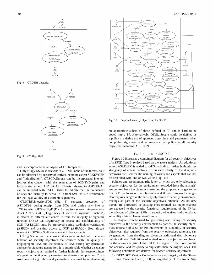
OT.DTBS_Integrity_TOE
Receipt from SCA
T.DTBS_Forgery:
T.SigF_Misuse:
AST.DTBS
<<include>>
Internal Transfer
T.Sig_Repud:
<<include>>
EXT.SCA
Fig. 8. OT.DTBSIntegrity
OT.Sigy_SigF
ASP.ID
T.Sig_Repud:
T.SigF_Misuse:
AST.SCD
<<include>>ASP.ACC
T.Sig_Repud:
T.SigF_Misuse: loc
<<include>>
EXT.SCA
AST.SIG_AC
Fig. 9. OT.SigySigF
and is incorporated as an aspect of OT.TamperID.Only P.SigySSCD is relevant to OT.INIT, none of the threats, so it
can be addressed by security objectives including aspect SP.KEYGENand ”Initialization”. OT.SCDUnique can be incorporated into ob-jectives that concern with the generation of SCD/SVD pairs andincorporates aspect ASP.LEGAL. Threats relevant to ASP.LEGALcan be amended with T.SCDDerive to indicate that the uniquenessof keys and inability to derive SCD from SVD as is a requirementfor the legal validity of electronic signatures.
OT.DTBS Integrity TOE (Fig. 8) concerns protection ofAST.DTBS during receipt from SCA and during any internalTOE transfer. OT.SigySigF (Fig. 9) requires several interpretations.Asset AST.SIGAC (”Legitimacy of access to signature function”)is created to differentiate access to from the integrity of signaturefunction (AST.SIG). Legitimacy of access and confidentiality ofSCD (AST.SCD) must be preserved during cardholder verification(ASP.ID) and granting access to SCD (ASP.ACC). Both threatsrelevant to OT.SigySigF are relevant to both aspects.
OT.Sig Secure can be considered as incorporated into the com-bination of security objectives that concern with the quality ofcryptographic keys and the secrecy of keys during key generationand use for signature generation. It is questionable whether a separatesecurity objective is required to further highlight the trustworthinessof signature function and parameters for signature computation. Trust-worthiness of algorithms and parameters is assured by implementing
AST.SCD
AST.ES
AST.EMSEC_Data
AST.SIG
AST.SVD
AST.CORRESP
AST.DTBS
AST.SIG_AC
EXT.INIT
EXT.SCA
EXT.CGA
OT.EMSEC_Design
ASP.KEYGEN
T.Hack_Phys:
T.Sig_Forgery:
ASP.SIGN
T.Hack_Phys:
T.Sig_Forgery:
T.SCD_Divulg:
ASP.LEGAL
T.Sig_Repud:
OT.SCD_Secrecy
OT.Lifecycle_Security
TOE Initialization
T.Sig_Repud:
SVD Regeneration
T.Sig_Forgery:
TOE Personalization
T.Sig_Forgery:
T.SVD_Forgery:
TOE Operation
T.Sig_Repud:
T.SigF_Misuse:
OT.SCD_SVD_CorrespASP.DEMAND
T.Sig_Forgery:
OT.DTBS_Integrity_TOE
ASP.RECEIPT
T.DTBS_Forgery:
T.SigF_Misuse:
Internal transfers
T.Sig_Repud:
OT.Sigy_SigF
ASP.ACC
T.Sig_Repud:
T.Sig_Misuse:
ASP.ID
T.Sig_Repud:
T.SigF_Misuse:
<<include>>
<<include>>
<<include>>
<<include>><<include>>
<<include>>
<<include>>
<<include>>
<<include>>
<<include>>
<<include>>
<<include>>
<<include>>
<<include>>
<<include>>
OT.Tamper_ID
ASP.RESIST
T.Hack_Phys:
<<include>>ASP.LIMIT
T.Sig_Repud:
T.Sig_Forgery:
ASP.DETECT
T.Hack_Phys:
<<include>>
<<include>>
EXT.Interface
ASP.PREV
T.SigF_Misuse:
<<include>>
Fig. 10. Proposed security objectives of a SSCD
an appropriate subset of those defined in [9] and is hard to becoded into a PP. Alternatively, OT.SigSecure could be defined asa policy mandating use of approved algorithms and parameters whencomputing signatures and to associate that policy to all securityobjectives including ASP.SIGN.
IV. F INDINGS ON SSCD PP
Figure 10 illustrates a combined diagram for all security objectivesof a SSCD Type 3, revised based on the above analysis. An additionalaspect ASP.PREV is added to OT.SigySigF to further highlight thestringency of access controls. To preserve clarity of the diagrams,acronyms are used for the naming of assets and aspects that can notbe described with one or two words (Fig. 11).
Policies and assumptions (the latter of which are only relevant tosecurity objectives for the environment excluded from the analysis)are omitted from the diagram illustrating the proposed changes to theSSCD PP to focus on the objectives and threats. Proposed changesalso require changes in the security objectives to security environmenttracings as part of the security objectives rationale. As no newthreats are introduced or existing ones omitted, no major changesare expected to the security functional requirements of the PP butthe relevant of different SFRs to security objectives and the relatedsuitability claims change significantly.
The diagram can be used for generating also tracings of securityobjectives to the security environment as part of the security objec-tives rationale of a ST or PP. Statements of suitability of securityobjectives, also required from the security objectives rationale, canbe generated from the diagram given an additional data dictionarydefining threats. Definitions of revised security objectives are, basedon the above analysis of the SSCD PP, argued to be more preciseand accurate, and less prone to duplicates than the original ones. Thefollowing definitions are derived for revised security objectives:
1) OT.EMSECDesignConfidentiality and integrity of the Signa-ture Creation Data (SCD), unforgeability of Electronic Sig-
50 NORDSEC 2004
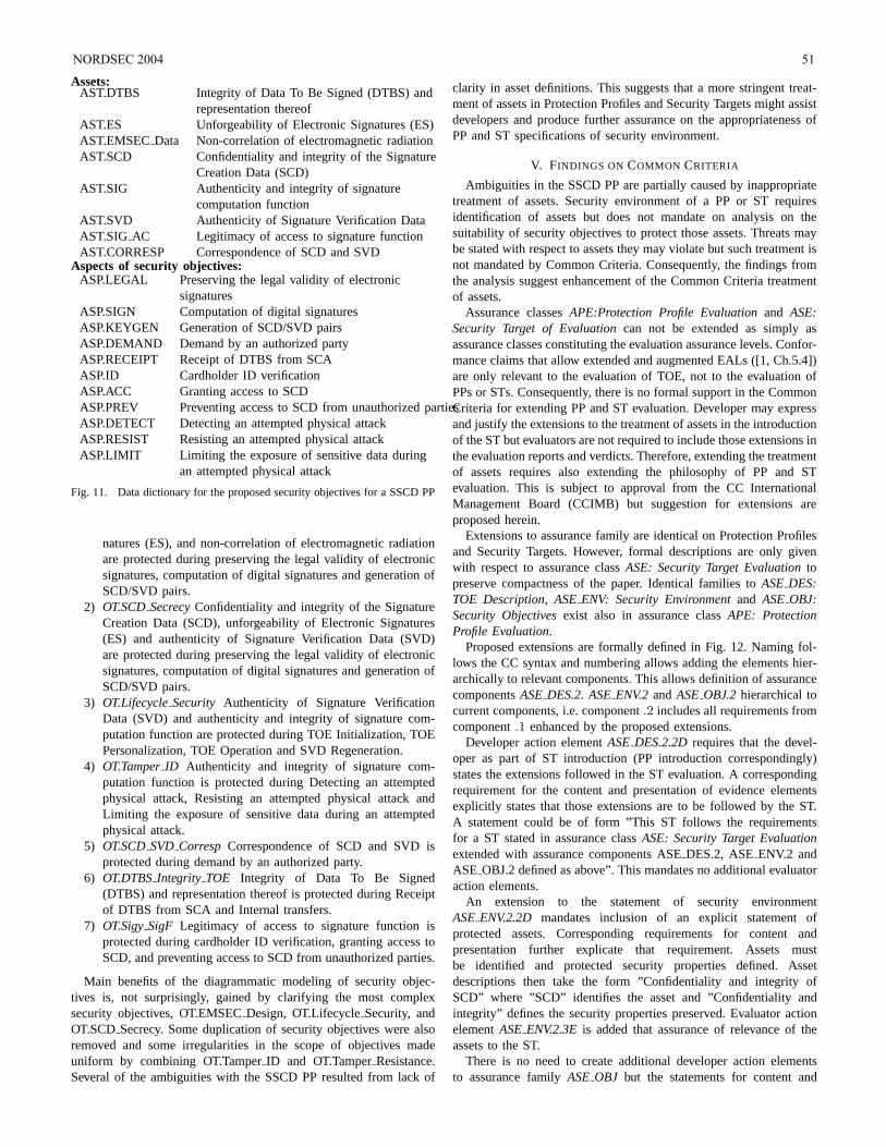
Assets:AST.DTBS Integrity of Data To Be Signed (DTBS) and
representation thereofAST.ES Unforgeability of Electronic Signatures (ES)AST.EMSECData Non-correlation of electromagnetic radiationAST.SCD Confidentiality and integrity of the Signature
Creation Data (SCD)AST.SIG Authenticity and integrity of signature
computation functionAST.SVD Authenticity of Signature Verification DataAST.SIG AC Legitimacy of access to signature functionAST.CORRESP Correspondence of SCD and SVD
Aspects of security objectives:ASP.LEGAL Preserving the legal validity of electronic
signaturesASP.SIGN Computation of digital signaturesASP.KEYGEN Generation of SCD/SVD pairsASP.DEMAND Demand by an authorized partyASP.RECEIPT Receipt of DTBS from SCAASP.ID Cardholder ID verificationASP.ACC Granting access to SCDASP.PREV Preventing access to SCD from unauthorized partiesASP.DETECT Detecting an attempted physical attackASP.RESIST Resisting an attempted physical attackASP.LIMIT Limiting the exposure of sensitive data during
an attempted physical attack
Fig. 11. Data dictionary for the proposed security objectives for a SSCD PP
natures (ES), and non-correlation of electromagnetic radiationare protected during preserving the legal validity of electronicsignatures, computation of digital signatures and generation ofSCD/SVD pairs.
2) OT.SCDSecrecyConfidentiality and integrity of the SignatureCreation Data (SCD), unforgeability of Electronic Signatures(ES) and authenticity of Signature Verification Data (SVD)are protected during preserving the legal validity of electronicsignatures, computation of digital signatures and generation ofSCD/SVD pairs.
3) OT.LifecycleSecurity Authenticity of Signature VerificationData (SVD) and authenticity and integrity of signature com-putation function are protected during TOE Initialization, TOEPersonalization, TOE Operation and SVD Regeneration.
4) OT.TamperID Authenticity and integrity of signature com-putation function is protected during Detecting an attemptedphysical attack, Resisting an attempted physical attack andLimiting the exposure of sensitive data during an attemptedphysical attack.
5) OT.SCDSVDCorresp Correspondence of SCD and SVD isprotected during demand by an authorized party.
6) OT.DTBSIntegrity TOE Integrity of Data To Be Signed(DTBS) and representation thereof is protected during Receiptof DTBS from SCA and Internal transfers.
7) OT.SigySigF Legitimacy of access to signature function isprotected during cardholder ID verification, granting access toSCD, and preventing access to SCD from unauthorized parties.
Main benefits of the diagrammatic modeling of security objec-tives is, not surprisingly, gained by clarifying the most complexsecurity objectives, OT.EMSECDesign, OT.LifecycleSecurity, andOT.SCDSecrecy. Some duplication of security objectives were alsoremoved and some irregularities in the scope of objectives madeuniform by combining OT.TamperID and OT.TamperResistance.Several of the ambiguities with the SSCD PP resulted from lack of
clarity in asset definitions. This suggests that a more stringent treat-ment of assets in Protection Profiles and Security Targets might assistdevelopers and produce further assurance on the appropriatenessofPP and ST specifications of security environment.
V. FINDINGS ON COMMON CRITERIA
Ambiguities in the SSCD PP are partially caused by inappropriatetreatment of assets. Security environment of a PP or ST requiresidentification of assets but does not mandate on analysis on thesuitability of security objectives to protect those assets. Threats maybe stated with respect to assets they may violate but such treatment isnot mandated by Common Criteria. Consequently, the findings fromthe analysis suggest enhancement of the Common Criteria treatmentof assets.
Assurance classesAPE:Protection Profile Evaluationand ASE:Security Target of Evaluationcan not be extended as simply asassurance classes constituting the evaluation assurance levels. Confor-mance claims that allow extended and augmented EALs ([1, Ch.5.4])are only relevant to the evaluation of TOE, not to the evaluation ofPPs or STs. Consequently, there is no formal support in the CommonCriteria for extending PP and ST evaluation. Developer may expressand justify the extensions to the treatment of assets in the introductionof the ST but evaluators are not required to include those extensions inthe evaluation reports and verdicts. Therefore, extending the treatmentof assets requires also extending the philosophy of PP and STevaluation. This is subject to approval from the CC InternationalManagement Board (CCIMB) but suggestion for extensions areproposed herein.
Extensions to assurance family are identical on Protection Profilesand Security Targets. However, formal descriptions are only givenwith respect to assurance classASE: Security Target Evaluationtopreserve compactness of the paper. Identical families toASEDES:TOE Description, ASEENV: Security Environmentand ASEOBJ:Security Objectivesexist also in assurance classAPE: ProtectionProfile Evaluation.
Proposed extensions are formally defined in Fig. 12. Naming fol-lows the CC syntax and numbering allows adding the elements hier-archically to relevant components. This allows definition of assurancecomponentsASEDES.2. ASEENV.2andASEOBJ.2hierarchical tocurrent components, i.e. component.2 includes all requirements fromcomponent.1 enhanced by the proposed extensions.
Developer action elementASEDES.2.2Drequires that the devel-oper as part of ST introduction (PP introduction correspondingly)states the extensions followed in the ST evaluation. A correspondingrequirement for the content and presentation of evidence elementsexplicitly states that those extensions are to be followed by the ST.A statement could be of form ”This ST follows the requirementsfor a ST stated in assurance classASE: Security Target Evaluationextended with assurance components ASEDES.2, ASEENV.2 andASE OBJ.2 defined as above”. This mandates no additional evaluatoraction elements.
An extension to the statement of security environmentASEENV.2.2D mandates inclusion of an explicit statement ofprotected assets. Corresponding requirements for content andpresentation further explicate that requirement. Assets mustbe identified and protected security properties defined. Assetdescriptions then take the form ”Confidentiality and integrity ofSCD” where ”SCD” identifies the asset and ”Confidentiality andintegrity” defines the security properties preserved. Evaluator actionelementASEENV.2.3Eis added that assurance of relevance of theassets to the ST.
There is no need to create additional developer action elementsto assurance familyASEOBJ but the statements for content and
NORDSEC 2004 51
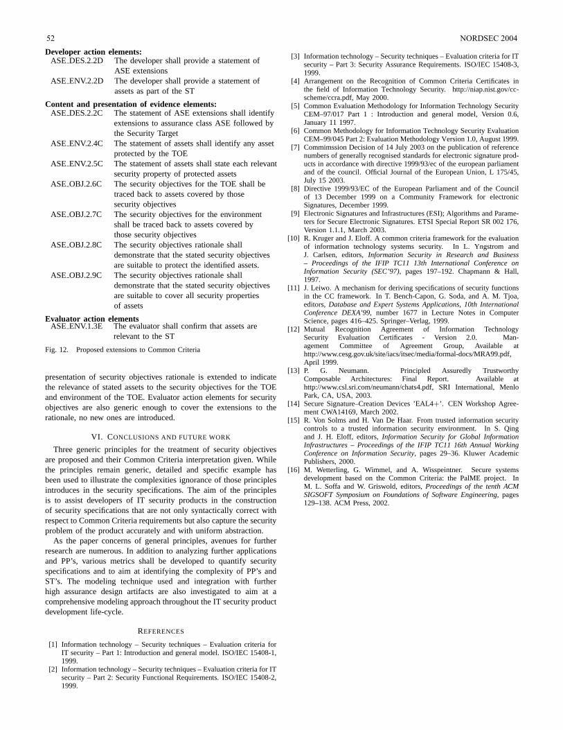
Developer action elements:ASE DES.2.2D The developer shall provide a statement of
ASE extensionsASE ENV.2.2D The developer shall provide a statement of
assets as part of the ST
Content and presentation of evidence elements:ASE DES.2.2C The statement of ASE extensions shall identify
extensions to assurance class ASE followed bythe Security Target
ASE ENV.2.4C The statement of assets shall identify any assetprotected by the TOE
ASE ENV.2.5C The statement of assets shall state each relevantsecurity property of protected assets
ASE OBJ.2.6C The security objectives for the TOE shall betraced back to assets covered by thosesecurity objectives
ASE OBJ.2.7C The security objectives for the environmentshall be traced back to assets covered bythose security objectives
ASE OBJ.2.8C The security objectives rationale shalldemonstrate that the stated security objectivesare suitable to protect the identified assets.
ASE OBJ.2.9C The security objectives rationale shalldemonstrate that the stated security objectivesare suitable to cover all security propertiesof assets
Evaluator action elementsASE ENV.1.3E The evaluator shall confirm that assets are
relevant to the ST
Fig. 12. Proposed extensions to Common Criteria
presentation of security objectives rationale is extended to indicatethe relevance of stated assets to the security objectives for the TOEand environment of the TOE. Evaluator action elements for securityobjectives are also generic enough to cover the extensions to therationale, no new ones are introduced.
VI. CONCLUSIONS AND FUTURE WORK
Three generic principles for the treatment of security objectivesare proposed and their Common Criteria interpretation given. Whilethe principles remain generic, detailed and specific example hasbeen used to illustrate the complexities ignorance of those principlesintroduces in the security specifications. The aim of the principlesis to assist developers of IT security products in the constructionof security specifications that are not only syntactically correct withrespect to Common Criteria requirements but also capture the securityproblem of the product accurately and with uniform abstraction.
As the paper concerns of general principles, avenues for furtherresearch are numerous. In addition to analyzing further applicationsand PP’s, various metrics shall be developed to quantify securityspecifications and to aim at identifying the complexity of PP’s andST’s. The modeling technique used and integration with furtherhigh assurance design artifacts are also investigated to aim at acomprehensive modeling approach throughout the IT security productdevelopment life-cycle.
REFERENCES
[1] Information technology – Security techniques – Evaluation criteria forIT security – Part 1: Introduction and general model. ISO/IEC15408-1,1999.
[2] Information technology – Security techniques – Evaluation criteria for ITsecurity – Part 2: Security Functional Requirements. ISO/IEC 15408-2,1999.
[3] Information technology – Security techniques – Evaluation criteria for ITsecurity – Part 3: Security Assurance Requirements. ISO/IEC15408-3,1999.
[4] Arrangement on the Recognition of Common Criteria Certificates inthe field of Information Technology Security. http://niap.nist.gov/cc-scheme/ccra.pdf, May 2000.
[5] Common Evaluation Methodology for Information TechnologySecurityCEM–97/017 Part 1 : Introduction and general model, Version 0.6,January 11 1997.
[6] Common Methodology for Information Technology Security EvaluationCEM–99/045 Part 2: Evaluation Methodology Version 1.0, August 1999.
[7] Commimssion Decision of 14 July 2003 on the publication of referencenumbers of generally recognised standards for electronic signature prod-ucts in accordance with directive 1999/93/ec of the european parliamentand of the council. Official Journal of the European Union, L 175/45,July 15 2003.
[8] Directive 1999/93/EC of the European Parliament and of the Councilof 13 December 1999 on a Community Framework for electronicSignatures, December 1999.
[9] Electronic Signatures and Infrastructures (ESI); Algorithms and Parame-ters for Secure Electronic Signatures. ETSI Special ReportSR 002 176,Version 1.1.1, March 2003.
[10] R. Kruger and J. Eloff. A common criteria framework for the evaluationof information technology systems security. In L. Yngstrom andJ. Carlsen, editors,Information Security in Research and Business– Proceedings of the IFIP TC11 13th International Conference onInformation Security (SEC’97), pages 197–192. Chapmann & Hall,1997.
[11] J. Leiwo. A mechanism for deriving specifications of security functionsin the CC framework. In T. Bench-Capon, G. Soda, and A. M. Tjoa,editors,Database and Expert Systems Applications, 10th InternationalConference DEXA’99, number 1677 in Lecture Notes in ComputerScience, pages 416–425. Springer–Verlag, 1999.
[12] Mutual Recognition Agreement of Information TechnologySecurity Evaluation Certificates - Version 2.0. Man-agement Committee of Agreement Group, Available athttp://www.cesg.gov.uk/site/iacs/itsec/media/formal-docs/MRA99.pdf,April 1999.
[13] P. G. Neumann. Principled Assuredly TrustworthyComposable Architectures: Final Report. Available athttp://www.csl.sri.com/neumann/chats4.pdf, SRI International, MenloPark, CA, USA, 2003.
[14] Secure Signature–Creation Devices ’EAL4+’. CEN Workshop Agree-ment CWA14169, March 2002.
[15] R. Von Solms and H. Van De Haar. From trusted information securitycontrols to a trusted information security environment. In S.Qingand J. H. Eloff, editors,Information Security for Global InformationInfrastructures – Proceedings of the IFIP TC11 16th Annual WorkingConference on Information Security, pages 29–36. Kluwer AcademicPublishers, 2000.
[16] M. Wetterling, G. Wimmel, and A. Wisspeintner. Secure systemsdevelopment based on the Common Criteria: the PalME project. InM. L. Soffa and W. Griswold, editors,Proceedings of the tenth ACMSIGSOFT Symposium on Foundations of Software Engineering, pages129–138. ACM Press, 2002.
52 NORDSEC 2004
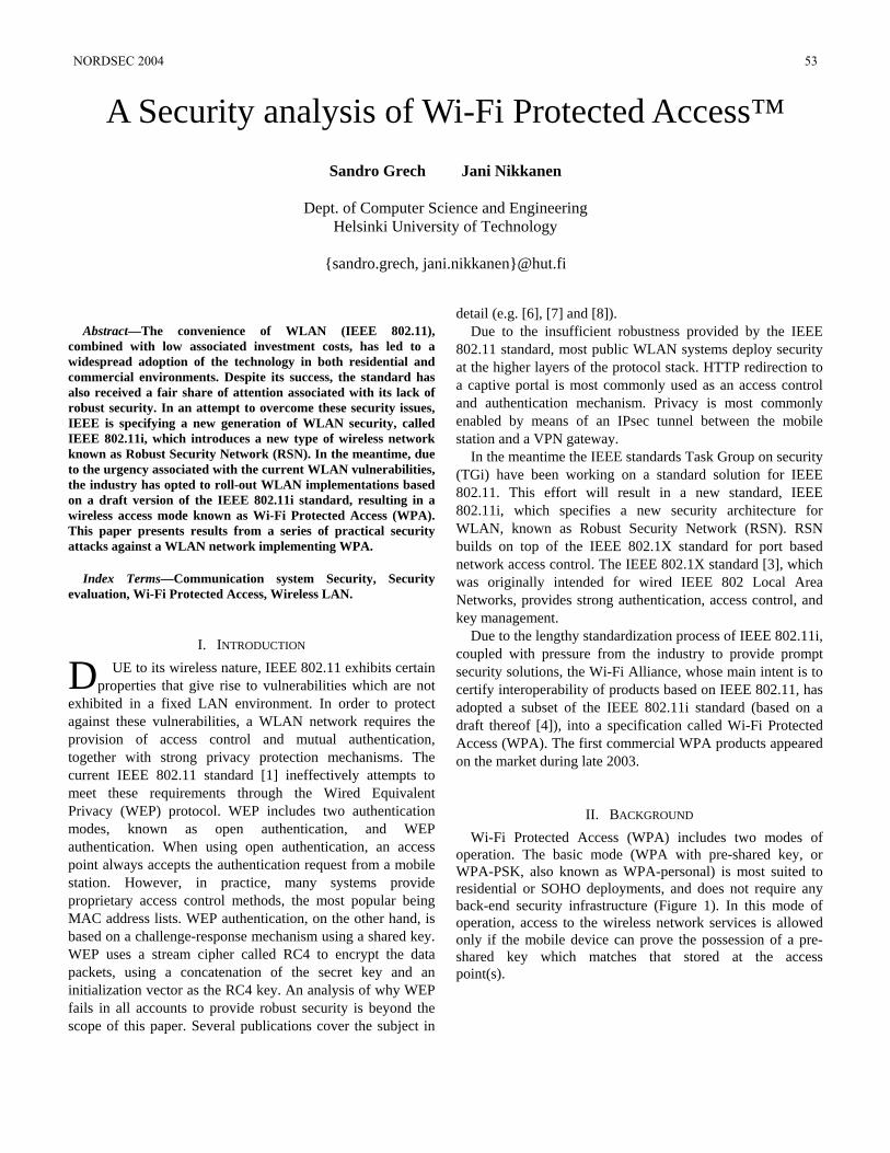
Abstract—The convenience of WLAN (IEEE 802.11),
combined with low associated investment costs, has led to a widespread adoption of the technology in both residential and commercial environments. Despite its success, the standard has also received a fair share of attention associated with its lack of robust security. In an attempt to overcome these security issues, IEEE is specifying a new generation of WLAN security, called IEEE 802.11i, which introduces a new type of wireless network known as Robust Security Network (RSN). In the meantime, due to the urgency associated with the current WLAN vulnerabilities, the industry has opted to roll-out WLAN implementations based on a draft version of the IEEE 802.11i standard, resulting in a wireless access mode known as Wi-Fi Protected Access (WPA). This paper presents results from a series of practical security attacks against a WLAN network implementing WPA.
Index Terms—Communication system Security, Security evaluation, Wi-Fi Protected Access, Wireless LAN.
I. INTRODUCTION UE to its wireless nature, IEEE 802.11 exhibits certain
properties that give rise to vulnerabilities which are not exhibited in a fixed LAN environment. In order to protect against these vulnerabilities, a WLAN network requires the provision of access control and mutual authentication, together with strong privacy protection mechanisms. The current IEEE 802.11 standard [1] ineffectively attempts to meet these requirements through the Wired Equivalent Privacy (WEP) protocol. WEP includes two authentication modes, known as open authentication, and WEP authentication. When using open authentication, an access point always accepts the authentication request from a mobile station. However, in practice, many systems provide proprietary access control methods, the most popular being MAC address lists. WEP authentication, on the other hand, is based on a challenge-response mechanism using a shared key. WEP uses a stream cipher called RC4 to encrypt the data packets, using a concatenation of the secret key and an initialization vector as the RC4 key. An analysis of why WEP fails in all accounts to provide robust security is beyond the scope of this paper. Several publications cover the subject in
detail (e.g. [6], [7] and [8]). Due to the insufficient robustness provided by the IEEE
802.11 standard, most public WLAN systems deploy security at the higher layers of the protocol stack. HTTP redirection to a captive portal is most commonly used as an access control and authentication mechanism. Privacy is most commonly enabled by means of an IPsec tunnel between the mobile station and a VPN gateway.
In the meantime the IEEE standards Task Group on security (TGi) have been working on a standard solution for IEEE 802.11. This effort will result in a new standard, IEEE 802.11i, which specifies a new security architecture for WLAN, known as Robust Security Network (RSN). RSN builds on top of the IEEE 802.1X standard for port based network access control. The IEEE 802.1X standard [3], which was originally intended for wired IEEE 802 Local Area Networks, provides strong authentication, access control, and key management.
Due to the lengthy standardization process of IEEE 802.11i, coupled with pressure from the industry to provide prompt security solutions, the Wi-Fi Alliance, whose main intent is to certify interoperability of products based on IEEE 802.11, has adopted a subset of the IEEE 802.11i standard (based on a draft thereof [4]), into a specification called Wi-Fi Protected Access (WPA). The first commercial WPA products appeared on the market during late 2003.
II. BACKGROUND Wi-Fi Protected Access (WPA) includes two modes of
operation. The basic mode (WPA with pre-shared key, or WPA-PSK, also known as WPA-personal) is most suited to residential or SOHO deployments, and does not require any back-end security infrastructure (Figure 1). In this mode of operation, access to the wireless network services is allowed only if the mobile device can prove the possession of a pre-shared key which matches that stored at the access point(s).
A Security analysis of Wi-Fi Protected Access™ Sandro Grech Jani Nikkanen
Dept. of Computer Science and Engineering
Helsinki University of Technology
sandro.grech, [email protected]
D
NORDSEC 2004 53
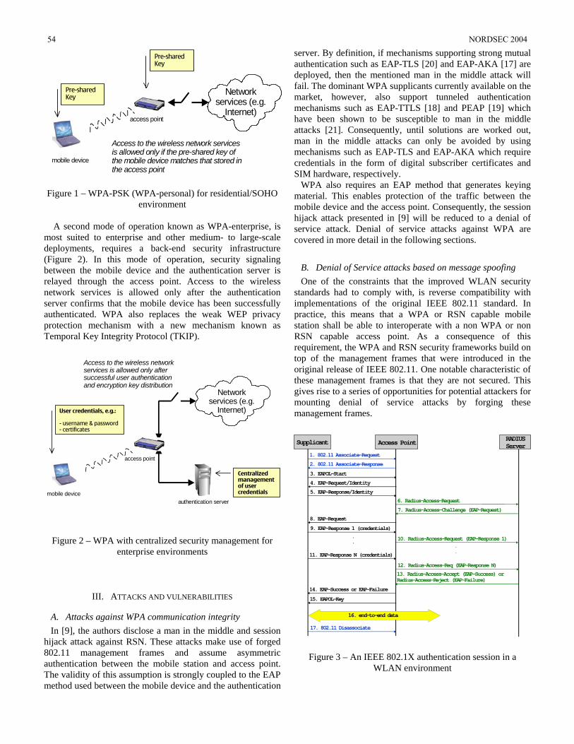
access point
Network services (e.g.
Internet)
Pre-shared Key
Pre-shared Key
mobile device
Access to the wireless network services is allowed only if the pre-shared key of the mobile device matches that stored in the access point
Figure 1 – WPA-PSK (WPA-personal) for residential/SOHO
environment
A second mode of operation known as WPA-enterprise, is most suited to enterprise and other medium- to large-scale deployments, requires a back-end security infrastructure (Figure 2). In this mode of operation, security signaling between the mobile device and the authentication server is relayed through the access point. Access to the wireless network services is allowed only after the authentication server confirms that the mobile device has been successfully authenticated. WPA also replaces the weak WEP privacy protection mechanism with a new mechanism known as Temporal Key Integrity Protocol (TKIP).
access point
Network services (e.g.
Internet)User credentials, e.g.:
- username & password- certificates
Centralized management of user credentialsmobile device
Access to the wireless network services is allowed only after successful user authentication and encryption key distribution
authentication server
Figure 2 – WPA with centralized security management for enterprise environments
III. ATTACKS AND VULNERABILITIES
A. Attacks against WPA communication integrity In [9], the authors disclose a man in the middle and session
hijack attack against RSN. These attacks make use of forged 802.11 management frames and assume asymmetric authentication between the mobile station and access point. The validity of this assumption is strongly coupled to the EAP method used between the mobile device and the authentication
server. By definition, if mechanisms supporting strong mutual authentication such as EAP-TLS [20] and EAP-AKA [17] are deployed, then the mentioned man in the middle attack will fail. The dominant WPA supplicants currently available on the market, however, also support tunneled authentication mechanisms such as EAP-TTLS [18] and PEAP [19] which have been shown to be susceptible to man in the middle attacks [21]. Consequently, until solutions are worked out, man in the middle attacks can only be avoided by using mechanisms such as EAP-TLS and EAP-AKA which require credentials in the form of digital subscriber certificates and SIM hardware, respectively.
WPA also requires an EAP method that generates keying material. This enables protection of the traffic between the mobile device and the access point. Consequently, the session hijack attack presented in [9] will be reduced to a denial of service attack. Denial of service attacks against WPA are covered in more detail in the following sections.
B. Denial of Service attacks based on message spoofing One of the constraints that the improved WLAN security
standards had to comply with, is reverse compatibility with implementations of the original IEEE 802.11 standard. In practice, this means that a WPA or RSN capable mobile station shall be able to interoperate with a non WPA or non RSN capable access point. As a consequence of this requirement, the WPA and RSN security frameworks build on top of the management frames that were introduced in the original release of IEEE 802.11. One notable characteristic of these management frames is that they are not secured. This gives rise to a series of opportunities for potential attackers for mounting denial of service attacks by forging these management frames.
13. Radius-Access-Accept (EAP-Success) or Radius-Access-Reject (EAP-Failure)
1. 802.11 Associate-Request
2. 802.11 Associate-Response
3. EAPOL-Start
4. EAP-Request/Identity
5. EAP-Response/Identity
6. Radius-Access-Request
7. Radius-Access-Challenge (EAP-Request)
10. Radius-Access-Request (EAP-Response 1)
8. EAP-Request
9. EAP-Response 1 (credentials)
12. Radius-Access-Req (EAP-Response N)
11. EAP-Response N (credentials)
.
...
14. EAP-Success or EAP-Failure
15. EAPOL-Key
17. 802.11 Disassociate
16. end-to-end data
Supplicant RADIUS ServerAccess Point
Figure 3 – An IEEE 802.1X authentication session in a WLAN environment
54 NORDSEC 2004
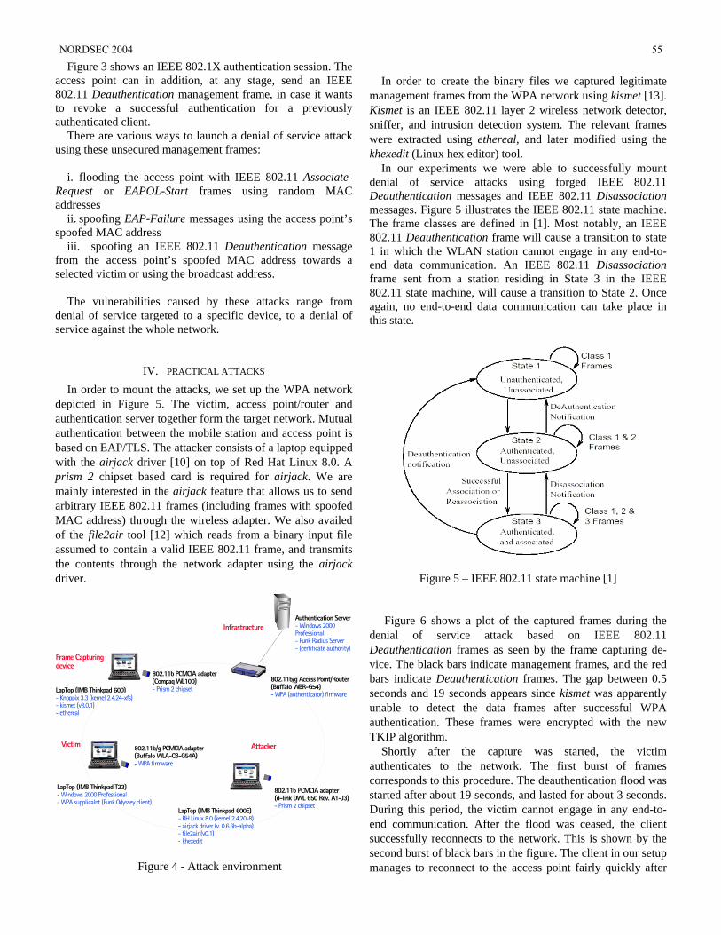
Figure 3 shows an IEEE 802.1X authentication session. The access point can in addition, at any stage, send an IEEE 802.11 Deauthentication management frame, in case it wants to revoke a successful authentication for a previously authenticated client.
There are various ways to launch a denial of service attack using these unsecured management frames:
i. flooding the access point with IEEE 802.11 Associate-Request or EAPOL-Start frames using random MAC addresses
ii. spoofing EAP-Failure messages using the access point’s spoofed MAC address
iii. spoofing an IEEE 802.11 Deauthentication message from the access point’s spoofed MAC address towards a selected victim or using the broadcast address.
The vulnerabilities caused by these attacks range from
denial of service targeted to a specific device, to a denial of service against the whole network.
IV. PRACTICAL ATTACKS In order to mount the attacks, we set up the WPA network
depicted in Figure 5. The victim, access point/router and authentication server together form the target network. Mutual authentication between the mobile station and access point is based on EAP/TLS. The attacker consists of a laptop equipped with the airjack driver [10] on top of Red Hat Linux 8.0. A prism 2 chipset based card is required for airjack. We are mainly interested in the airjack feature that allows us to send arbitrary IEEE 802.11 frames (including frames with spoofed MAC address) through the wireless adapter. We also availed of the file2air tool [12] which reads from a binary input file assumed to contain a valid IEEE 802.11 frame, and transmits the contents through the network adapter using the airjack driver.
Attacker802.11b/g PCMCIA adapter (Buffalo WLA-CB-G54A)- WPA firmware
LapTop (IMB Thinkpad T23)- Windows 2000 Professional- WPA supplicalnt (Funk Odyssey client)
802.11b PCMCIA adapter(d-link DWL 650 Rev. A1-J3)- Prism 2 chipset
LapTop (IMB Thinkpad 600E)- RH Linux 8.0 (kernel 2.4.20-8)- airjack driver (v. 0.6.6b-alpha)- file2air (v0.1)- khexedit
Victim
802.11b/g Access Point/Router(Buffalo WBR-G54)- WPA (authenticator) firmware
Authentication Server- Windows 2000 Professional- Funk Radius Server- (certificate authority)
Infrastructure
Frame Capturing device
802.11b PCMCIA adapter(Compaq WL100)- Prism 2 chipsetLapTop (IMB Thinkpad 600)
- Knoppix 3.3 (kernel 2.4.24-xfs)- kismet (v3.0.1)- ethereal
Figure 4 - Attack environment
In order to create the binary files we captured legitimate
management frames from the WPA network using kismet [13]. Kismet is an IEEE 802.11 layer 2 wireless network detector, sniffer, and intrusion detection system. The relevant frames were extracted using ethereal, and later modified using the khexedit (Linux hex editor) tool.
In our experiments we were able to successfully mount denial of service attacks using forged IEEE 802.11 Deauthentication messages and IEEE 802.11 Disassociation messages. Figure 5 illustrates the IEEE 802.11 state machine. The frame classes are defined in [1]. Most notably, an IEEE 802.11 Deauthentication frame will cause a transition to state 1 in which the WLAN station cannot engage in any end-to-end data communication. An IEEE 802.11 Disassociation frame sent from a station residing in State 3 in the IEEE 802.11 state machine, will cause a transition to State 2. Once again, no end-to-end data communication can take place in this state.
Figure 5 – IEEE 802.11 state machine [1]
Figure 6 shows a plot of the captured frames during the
denial of service attack based on IEEE 802.11 Deauthentication frames as seen by the frame capturing de-vice. The black bars indicate management frames, and the red bars indicate Deauthentication frames. The gap between 0.5 seconds and 19 seconds appears since kismet was apparently unable to detect the data frames after successful WPA authentication. These frames were encrypted with the new TKIP algorithm.
Shortly after the capture was started, the victim authenticates to the network. The first burst of frames corresponds to this procedure. The deauthentication flood was started after about 19 seconds, and lasted for about 3 seconds. During this period, the victim cannot engage in any end-to-end communication. After the flood was ceased, the client successfully reconnects to the network. This is shown by the second burst of black bars in the figure. The client in our setup manages to reconnect to the access point fairly quickly after
NORDSEC 2004 55
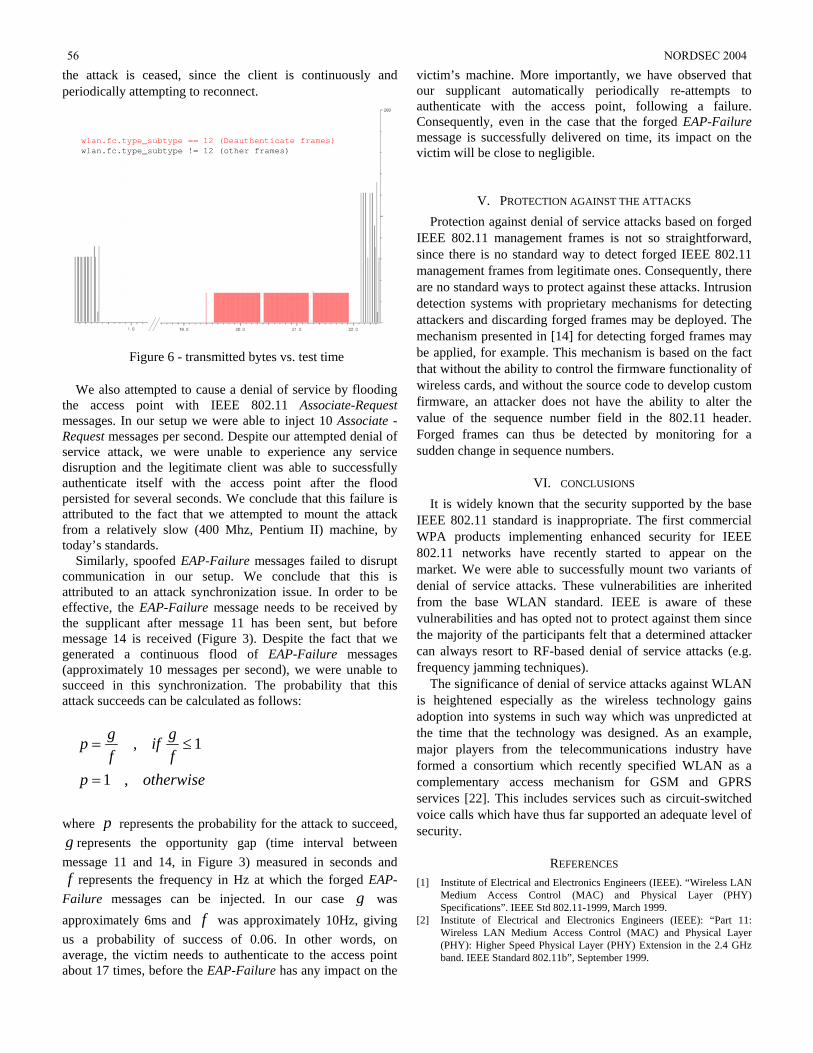
the attack is ceased, since the client is continuously and periodically attempting to reconnect.
wlan.fc.type_subtype == 12 (Deauthenticate frames)wlan.fc.type_subtype != 12 (other frames)
Figure 6 - transmitted bytes vs. test time
We also attempted to cause a denial of service by flooding the access point with IEEE 802.11 Associate-Request messages. In our setup we were able to inject 10 Associate -Request messages per second. Despite our attempted denial of service attack, we were unable to experience any service disruption and the legitimate client was able to successfully authenticate itself with the access point after the flood persisted for several seconds. We conclude that this failure is attributed to the fact that we attempted to mount the attack from a relatively slow (400 Mhz, Pentium II) machine, by today’s standards.
Similarly, spoofed EAP-Failure messages failed to disrupt communication in our setup. We conclude that this is attributed to an attack synchronization issue. In order to be effective, the EAP-Failure message needs to be received by the supplicant after message 11 has been sent, but before message 14 is received (Figure 3). Despite the fact that we generated a continuous flood of EAP-Failure messages (approximately 10 messages per second), we were unable to succeed in this synchronization. The probability that this attack succeeds can be calculated as follows:
otherwisepfgif
fgp
,1
1,
=
≤=
where p represents the probability for the attack to succeed, g represents the opportunity gap (time interval between message 11 and 14, in Figure 3) measured in seconds and f represents the frequency in Hz at which the forged EAP-
Failure messages can be injected. In our case g was approximately 6ms and f was approximately 10Hz, giving us a probability of success of 0.06. In other words, on average, the victim needs to authenticate to the access point about 17 times, before the EAP-Failure has any impact on the
victim’s machine. More importantly, we have observed that our supplicant automatically periodically re-attempts to authenticate with the access point, following a failure. Consequently, even in the case that the forged EAP-Failure message is successfully delivered on time, its impact on the victim will be close to negligible.
V. PROTECTION AGAINST THE ATTACKS Protection against denial of service attacks based on forged
IEEE 802.11 management frames is not so straightforward, since there is no standard way to detect forged IEEE 802.11 management frames from legitimate ones. Consequently, there are no standard ways to protect against these attacks. Intrusion detection systems with proprietary mechanisms for detecting attackers and discarding forged frames may be deployed. The mechanism presented in [14] for detecting forged frames may be applied, for example. This mechanism is based on the fact that without the ability to control the firmware functionality of wireless cards, and without the source code to develop custom firmware, an attacker does not have the ability to alter the value of the sequence number field in the 802.11 header. Forged frames can thus be detected by monitoring for a sudden change in sequence numbers.
VI. CONCLUSIONS It is widely known that the security supported by the base
IEEE 802.11 standard is inappropriate. The first commercial WPA products implementing enhanced security for IEEE 802.11 networks have recently started to appear on the market. We were able to successfully mount two variants of denial of service attacks. These vulnerabilities are inherited from the base WLAN standard. IEEE is aware of these vulnerabilities and has opted not to protect against them since the majority of the participants felt that a determined attacker can always resort to RF-based denial of service attacks (e.g. frequency jamming techniques).
The significance of denial of service attacks against WLAN is heightened especially as the wireless technology gains adoption into systems in such way which was unpredicted at the time that the technology was designed. As an example, major players from the telecommunications industry have formed a consortium which recently specified WLAN as a complementary access mechanism for GSM and GPRS services [22]. This includes services such as circuit-switched voice calls which have thus far supported an adequate level of security.
REFERENCES [1] Institute of Electrical and Electronics Engineers (IEEE). “Wireless LAN
Medium Access Control (MAC) and Physical Layer (PHY) Specifications”. IEEE Std 802.11-1999, March 1999.
[2] Institute of Electrical and Electronics Engineers (IEEE): “Part 11: Wireless LAN Medium Access Control (MAC) and Physical Layer (PHY): Higher Speed Physical Layer (PHY) Extension in the 2.4 GHz band. IEEE Standard 802.11b”, September 1999.
56 NORDSEC 2004
[3] Institute of Electrical and Electronics Engineers (IEEE). “Standard for Port based Network Access Control”. IEEE Draft P802.1X/D11, March 2001.
[4] Institute of Electrical and Electronics Engineers (IEEE). "Draft supplement to standard for telecommunications and information exchange between systems - LAN/MAN specific requirements - Part 11: wireless Medium Access Control (MAC) and physical layer (PHY) specifications: specification for enhanced security". IEEE Draft 802.11i/D3, November 2002.
[5] Wi-Fi Alliance: “Wi-Fi Protected Access Documentation”, version 2.0, April 29, 2003.
[6] N. Borisov, I. Goldberg, and D. Wagner.: “Intercepting mobile communications: the insecurity of 802.11.” MOBICOM, 2001.
[7] J. Walker: “Unsafe at any key size: an analysis of the WEP Encapsulation”, Tech. Rep. 03628E. IEEE 802.11 committee, March 2000.
[8] W. A. Arbaugh, N. Shankar and J. Wang. “Your 802.11 Wireless Network has No Clothes”, In Proceedings of the first IEEE International Conference on Wireless LANs and Home Networks, December 2001.
[9] A. Mishra and W. A. Arbaugh: “An initial security analysis of the IEEE 802.1X standard”. Technical Report UMIACS-TR-2002-10.
[10] AirJack: http://802.11ninja.net/airjack/ [11] W. A. Arbaugh, N. Shankar and Y. J. Wan: “Your 802.11 wireless
network has no clothes”. In Proceedings of the First International Conference on Wireless LANs and Home Networks (Singapore, 2001).
[12] file2air: http://home.jwu.edu/jwright/code/file2air-0.1.tar.bz2 [13] Kismet: http://www.kismetwireless.net [14] J. Wright: “Detecting WLAN MAC address spoofing”, January 2003.
http://home.jwu.edu/jwright/papers/wlan-mac-spoof.pdf [15] L. Blunk, and J. Vollbrecht, "PPP Extensible Authentication Protocol
(EAP)", RFC 2284, March 1998. [16] H. Haverinen and J. Salowey, "EAP SIM Authentication", draft-
haverinen-pppext-eap-sim-13.txt, Internet draft (work in progress), October 2003.
[17] J. Arkko, H. Haverinen, "EAP AKA Authentication", draft-arkko-pppext-eap-aka-12.txt, Internet draft (work in progress), April 2004.
[18] P. Funk and S. Blake-Wilson, “EAP Tunneled TLS Authentication Protocol (EAPTTLS)”, draft-ietf-pppext-eap-ttls-04.txt, Internet draft (work in progress), April 2004.
[19] S. Josefsson, et al., "Protected EAP Protocol (PEAP)", draft-josefsson-pppext-eap-tls-eap-06.txt, Internet draft (work in progress), March 2003.
[20] B. Aboba, and D. Simon, "PPP EAP TLS Authentication Protocol", RFC 2716, October 1999.
[21] N. Asokan, V. Niemi, and K. Nyberg: "Man-in-the-middle in tunnelled authentication", In the Proceedings of the 11th International Workshop on Security Protocols, Cambridge, UK, April 2003.
[22] The Unlicenced Mobile Access (UMA) Consortium Specifications. Available: http://www.umatechnology.org.
NORDSEC 2004 57
Abstract—Identity management systems like .NET Passport
and the Liberty Alliance Project allow for different forms of authentication to be used. Although simple username and password schemes are very commonly used, these are not considered to be very secure. This paper describes the Internet ID approach for user authentication in identity management systems. The approach utilizes the huge existing base and high security of SIM smart cards in mobile phones to authenticate end users in Liberty Alliance based systems. The Internet ID approach is applicable to both the mobile and fixed Internet worlds, i.e. services can be accessed via a mobile terminal or via a PC. Authentication is, in both cases, done via the mobile phone and its SIM card, combining the security of the SIM with the “always on” capability and convenience of the mobile phone.
Index Terms—Identity management, Single Sign-On, SIM, authentication,
I. INTRODUCTION DENTITY management, particularly the aspect of Single Sign-On (SSO), has gained a lot of attention in recent years.
The main reason for this trend is the increasing number of Service Providers (SP) on the Internet that require users to establish login accounts before they grant access to their services. The account data typically include credentials – often in the form of a username and a password – that need to be presented when a user wants to log in to the SP site to use its services. As most people are unable or unwilling to handle more than a few different username/password combinations, they start either to use password management software on their PCs, to write passwords down, or to use the same username/password combinations for different accounts. This behavior makes it easier for attackers to get hold of the users’ credentials and thus lowers the protection of the users’ accounts in the Internet.
Identity management systems aim to reduce the number of passwords users have to handle through SSO: users do not have to authenticate themselves at different service providers (SP) separately, but can reuse a successful authentication from
1) M. Schuba is with Ericsson Research, Corporate Unit in Aachen, Germany (phone: +49-2407-575-7782; fax: +49-2407-575--400; e-mail: [email protected]).
2) V. Gerstenberger works for Giesecke & Devrient, Telecommunications in Munich, Germany (e-mail: [email protected]).
3) P. Lahaije works for Vodafone Group Research and Development in Maastricht, The Netherlands (e-mail: [email protected]).
one SP to authenticate at other SPs. Typically the first authentication will be done towards a trusted party (often called an Identity Provider (IDP)), so that the user, in principle, only has to maintain a single set of credentials.
SSO not only improves the convenience for end users but may also improve security since users, only having to remember a single password, could select one that is hard to guess.
On the other hand there is also the risk that SSO makes it even easier for attackers: a badly protected password used for SSO might open up not only a single user account, but a large number of user accounts all over the Internet. Thus, the credentials that are to be used for SSO need to be particularly secure.
Commonly used authentication credentials are usually based on one, or a combination, of the following types: “something you know” (e.g. a password), “something you have” (e.g. a security token), and “something you are” (biometrics). In order to improve the security of the credentials used for SSO, the purely password-based approach should be extended.
The Internet ID concept demonstrates how the security of today’s mobile phones (GSM authentication based on the Subscriber Identity Module (SIM)) can be re-used to improve the security of SSO authentication. We apply our approach to the Liberty Alliance protocols, as they allow IDPs to choose between different authentication methods. The flexibility of this approach enables users to utilize SIM security not only for mobile Internet services but also for services accessed via a PC. The authentication credentials can be exchanged over the cellular network or over the fixed Internet and Bluetooth.
The rest of the paper is structured as follows. Section II gives a brief introduction to two identity management systems: .NET Passport and the Liberty Alliance Project. Section III discusses the different authentication methods offered by the SIM card and the security advantages that the SIM provides. Section IV describes the Internet ID approach, which combines Liberty Alliance protocols with the authentication security of the SIM for universal service access. Finally, section V gives some concluding remarks and an outlook on future research.
II. IDENTITY MANAGEMENT SYSTEMS A tremendous number of identity management solutions
exist in the market today and this section describes two of
Internet ID - Flexible Re-use of Mobile Phone Authentication Security for Service Access
Marko Schuba1), Volker Gerstenberger2), Paul Lahaije3)
I
58 NORDSEC 2004
them in more detail: Microsoft .NET Passport and the Liberty Alliance Project. The reason for selecting these two is that both solutions provide a framework for identity management, whilst others are commercial products.
A. .NET Passport Microsoft launched .NET Passport in 1999 [1, 2, 3]. It is a
web-based authentication service, which provides SSO1 to users. A participating user has one email address and password to log in to all .NET Passport enabled sites and services. .NET Passport stores personal information in a profile and this information can be automatically shared during SSO, thus allowing enabled sites to provide personalized services to the customer. A further option in the profile is the configuration of a .NET Passport wallet. In this case, attributes like credit card information and shipping addresses etc. are stored in the profile. To ensure higher security wallet information is stored separately from the base profile.
During registration of a .NET Passport account, a .NET Passport User ID (PUID) is generated that serves as a unique identifier for the account. The PUID, which is different from the user’s email address, is used by SPs to identify the same person from one SSO session to the next.
When a user wants to access a protected service, the SP first checks the authentication status of the user. If authentication is required the user can click on a ‘Sign-On’ button that re-directs him/her to the .NET Passport Login server. The .NET Passport Login server checks the SP data (passed as parameters during re-direction) and, provided the SP is a partner, displays a sign-on page to the user. Upon positive authentication with email address and password, the .NET Passport Login server generates a set of three encrypted cookies and re-directs the user back to the SP. A Ticket cookie contains the PUID and a time stamp, whilst a Profile cookie stores profile data that the user has chosen to share with the SP. Both cookies are set for the SP’s domain as well as for the .NET Passport domain and can therefore be decrypted with the SP’s encryption key. The SP uses these two cookies to verify the authentication and to extract profile information. If the authentication was successful, access to the protected service is granted. The third cookie is used for the actual SSO process: this Visited Sites cookie contains the names of all sites to which the user has signed-on during the session. It is set only for the .NET Passport domain and is therefore only encrypted with a .NET Passport key. When an SP re-directs the user to the .NET Passport Login server, the server first checks for the existence of this cookie. Only if it does not exist or is no longer valid does the server ask the user for his/her credentials.
There is no direct server-to-server communication between the .NET Passport Login server and SPs servers for SSO. The information exchange occurs through the user’s Internet browser using HTTP re-directs and cookies. However, .NET
1 .NET Passport actually uses the term Single Sign-In. For reasons of consistency, we use the term Single Sign-On throughout this paper.
Passport does perform server-to-server communication periodically to update operational information about the locations of the .NET Passport servers.
In the future Microsoft plans to support additional authentication methods and security levels (e.g. Kerberos v5 authentication protocols), smart cards, and digital certificates within the .NET Passport framework.
B. Liberty Alliance Project The Liberty Alliance Project (LAP), which was started in
2001, is a common effort of global companies and organizations to standardize a network identity management framework [4, 5, 6]. Its main objectives are to:
- Develop specifications that enable commercial and non-commercial organizations to protect consumer privacy;
- Provide an open SSO specification that includes federated authentication from multiple providers operating independently;
- Enable commercial and non-commercial organizations to control, maintain and enhance relationships with constituents;
- Create a network identity infrastructure that supports all current and emerging network access devices.
The first set of specifications developed by LAP focuses on the federation of accounts and SSO in a so-called Circle of Trust (CoT). A CoT is comprised of a set of SPs and one or more IDPs. The SPs have a business relationship with the IDP(s) that allows the IDP to authenticate users (who are called Principals in LAP) on their behalf. However, before this can happen, the Principal has to federate their respective SP account with their account at the IDP (in .NET Passport this is done implicitly without asking the user for consent). Once federated, the browser of a Principal, who tries to access a protected service at an SP, is re-directed to the IDP for authentication. If the authentication is successful the IDP issues a signed assertion that allows an SP to authenticate the Principal without further interaction, after his/her browser has been re-directed back to the SP. The Principal is now free to move between any (federated) SPs within the CoT in an SSO manner.
In order to protect the Principal’s privacy the accounts used at the different SPs and IDPs can, and should, have different usernames. As LAP uses pseudonyms to map each username at an SP to a username at an IDP, the accounts of a Principal cannot easily be connected by any two SPs. The IDP however, which acts as a trusted intermediate, could collect more information about Principals and so it is important for Principals to select an IDP carefully, or use more than one IDP.
The LAP specifications do not standardize a single set of credentials to be used for authentication. Instead, LAP supports various so-called authentication contexts, which range from using a password sent over an unprotected link to Public Key Infrastructure (PKI) in combination with smart cards. It is up to the SP to decide if it accepts the
NORDSEC 2004 59
authentication context offered by a particular IDP. It should also be noted that the LAP specifications do not
only support SSO, but also define a framework for permission-based sharing of user attributes among partners. This could enable services such as Profiles, Calendars, Personal Information Management, Wallets, Alerts etc.
III. MOBILE PHONE AND SIM SECURITY The security design of mobile phones is usually more
sophisticated than that of PCs or PDAs. For more than a decade GSM phones, for example, have used a smart card in the form of a SIM for authentication to GSM networks [7]. This means that a widely deployed base of smart cards exists today. Furthermore, these smart cards reside in an online smart card reader (i.e. the mobile terminal) that means that they can be accessed (almost) anywhere and anytime.
A smart card is a computing device, which is tamper-resistant to the extent that a malicious person can only obtain data stored or processed in the smart card by using very costly techniques (see e.g. [8]). Therefore smart cards are ideally suited for performing sensitive operations such as storing cryptographic keys and execution of cryptographic algorithms. For instance, if a user is to use a private key for public-key-cryptography operations (such as creating digital signatures), then it is often convenient, secure and practical to put this private key (and the operations relating to the use of the private key) on a smart card. It is perfectly possible for smart cards with a suitable coprocessor to produce 1024-bit RSA signatures in a commercially acceptable time.
The SIM is a key component for GSM (GPRS, EDGE) and UMTS authentication. (Note that although the SIM has been updated for UMTS, and is then referred to as a Universal SIM (USIM), we will continue to use the term SIM here to encompass both SIMs and USIMs.) For each subscription a shared secret key, Ki, is held in the SIM card and in the home operator’s Authentication Centre (AuC). Authentication is based on a random challenge (Rand) and key-dependent expected response (XRES). The challenge and expected response are generated by the AuC and sent to the visited network. The visited network then sends the challenge over the air (via the mobile terminal) to the SIM, which uses the Ki to calculate a response (SRES). This SRES is returned, via the mobile terminal, to the visited network, which compares the SRES and XRES values. If they match, authentication has been successful. Simultaneously to the calculation of XRES and SRES a cipher key is generated, which can be used to secure the radio link. For UMTS this process is enhanced by the introduction of an authentication procedure that allows for mutual authentication of both the (U)SIM and the network.
Because the cryptographic computations required for authentication take place only on the SIM and in the AuC the key, Ki, never has to leave the SIM or the AuC. Indeed it is effectively infeasible for anyone to read the Ki from the SIM, or to deduce it by observing the I/O of the SIM. This is even the case if specific challenges (Rand) and responses (SRES)
can be observed. (Weak authentication algorithms, or weak implementations of authentication algorithms, can reduce this security, but in general this assertion is true.) This is very important because it prevents SIMs from being cloned in the distribution chain, or by people who “borrow” another user’s SIM, or (worse) by people sending Rand challenges over the air to the mobile. Hence it prevents customers from being able to refute their phone bills on the grounds that they may have been a victim of SIM cloning.
The GSM authentication process described above authenticates the SIM - i.e. the subscription - to the network. This in itself does not strictly authenticate the subscriber, since someone else might have stolen the phone and might use it to make calls. Therefore, the SIM provides a mechanism to lock the SIM to a particular customer by requiring the customer to enter a Card Holder Verification (CHV) PIN before the SIM can be used. (Note though that for normal GSM telephony use, the user may switch off this PIN request.)
In recent years the SIM’s functionality has been extended, as follows:
- Additional protocols have been developed that use the SIM for more general authentication purposes (see e.g. [9, 10, 11]). To date this form of authentication still focuses on access network authentication (e.g. for WLAN) as opposed to service level authentication.
- In the context of WAP a SWIM card (SIM application plus a Wireless Identity Module (WIM) application [12] in the same smart card) can be used for two extra forms of authentication:
1) WTLS authentication: here, the WIM and a network server can be mutually authenticated at the transport level. Depending on the version of WAP, the server end point is either the remote server or the WAP gateway. Authentication is based on public key algorithms (RSA or Elliptic Curve) using Diffie-Hellman key exchange and authentication certificates. Normally a URL is used to point to the location of WIM certificates, in order to save space in the smart card.
2) User authentication: in this case the remote server authenticates the end user at the application level. This authentication can use two different public key algorithms: RSA digital signature or Elliptic Curve digital signature. The remote server sends a text to be signed and a challenge to the mobile phone using WMLScript. After the user has entered a mandatory signature PIN (the user cannot switch off this PIN requirement) the mobile phone calculates a hash of the text and sends it to the WIM application to calculate the digital signature. The digital signature and the URL of the user’s signing certificate are then sent to the remote server for authentication. Note that the WMLScript command used for the signature (signText) only accepts text strings, so it is impossible to sign binary values.
60 NORDSEC 2004
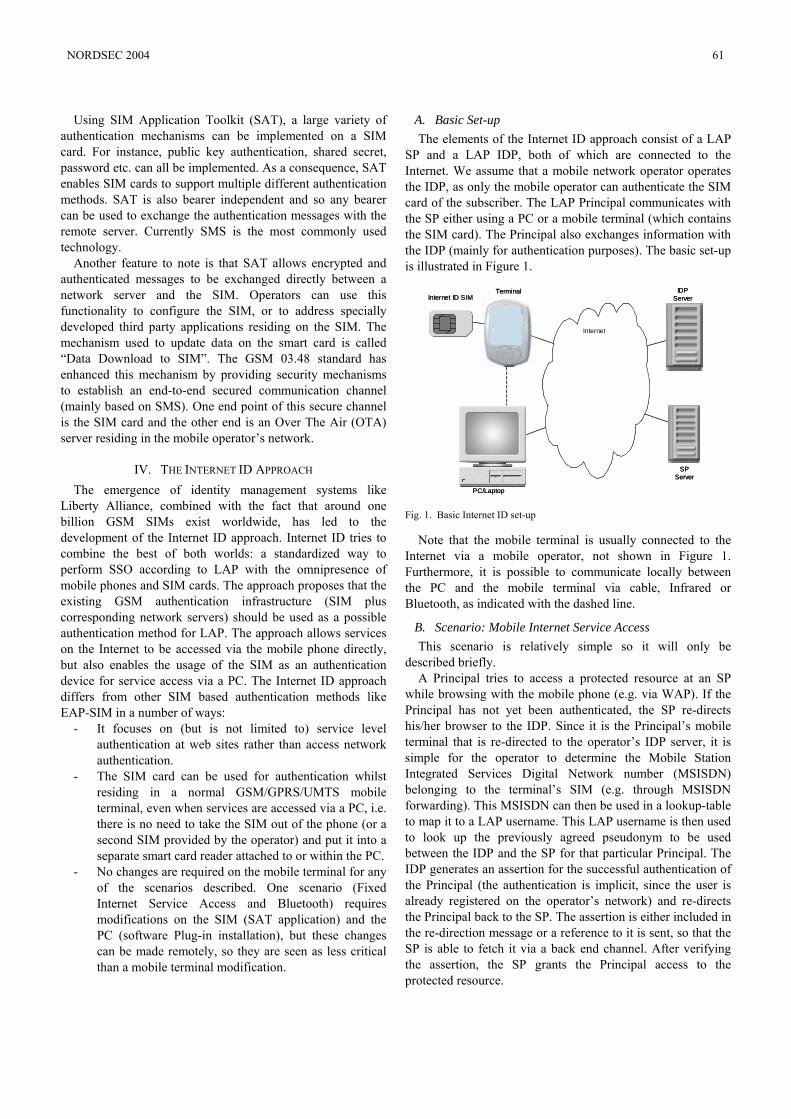
Using SIM Application Toolkit (SAT), a large variety of authentication mechanisms can be implemented on a SIM card. For instance, public key authentication, shared secret, password etc. can all be implemented. As a consequence, SAT enables SIM cards to support multiple different authentication methods. SAT is also bearer independent and so any bearer can be used to exchange the authentication messages with the remote server. Currently SMS is the most commonly used technology.
Another feature to note is that SAT allows encrypted and authenticated messages to be exchanged directly between a network server and the SIM. Operators can use this functionality to configure the SIM, or to address specially developed third party applications residing on the SIM. The mechanism used to update data on the smart card is called “Data Download to SIM”. The GSM 03.48 standard has enhanced this mechanism by providing security mechanisms to establish an end-to-end secured communication channel (mainly based on SMS). One end point of this secure channel is the SIM card and the other end is an Over The Air (OTA) server residing in the mobile operator’s network.
IV. THE INTERNET ID APPROACH The emergence of identity management systems like
Liberty Alliance, combined with the fact that around one billion GSM SIMs exist worldwide, has led to the development of the Internet ID approach. Internet ID tries to combine the best of both worlds: a standardized way to perform SSO according to LAP with the omnipresence of mobile phones and SIM cards. The approach proposes that the existing GSM authentication infrastructure (SIM plus corresponding network servers) should be used as a possible authentication method for LAP. The approach allows services on the Internet to be accessed via the mobile phone directly, but also enables the usage of the SIM as an authentication device for service access via a PC. The Internet ID approach differs from other SIM based authentication methods like EAP-SIM in a number of ways:
- It focuses on (but is not limited to) service level authentication at web sites rather than access network authentication.
- The SIM card can be used for authentication whilst residing in a normal GSM/GPRS/UMTS mobile terminal, even when services are accessed via a PC, i.e. there is no need to take the SIM out of the phone (or a second SIM provided by the operator) and put it into a separate smart card reader attached to or within the PC.
- No changes are required on the mobile terminal for any of the scenarios described. One scenario (Fixed Internet Service Access and Bluetooth) requires modifications on the SIM (SAT application) and the PC (software Plug-in installation), but these changes can be made remotely, so they are seen as less critical than a mobile terminal modification.
A. Basic Set-up The elements of the Internet ID approach consist of a LAP
SP and a LAP IDP, both of which are connected to the Internet. We assume that a mobile network operator operates the IDP, as only the mobile operator can authenticate the SIM card of the subscriber. The LAP Principal communicates with the SP either using a PC or a mobile terminal (which contains the SIM card). The Principal also exchanges information with the IDP (mainly for authentication purposes). The basic set-up is illustrated in Figure 1.
Note that the mobile terminal is usually connected to the Internet via a mobile operator, not shown in Figure 1. Furthermore, it is possible to communicate locally between the PC and the mobile terminal via cable, Infrared or Bluetooth, as indicated with the dashed line.
B. Scenario: Mobile Internet Service Access This scenario is relatively simple so it will only be
described briefly. A Principal tries to access a protected resource at an SP
while browsing with the mobile phone (e.g. via WAP). If the Principal has not yet been authenticated, the SP re-directs his/her browser to the IDP. Since it is the Principal’s mobile terminal that is re-directed to the operator’s IDP server, it is simple for the operator to determine the Mobile Station Integrated Services Digital Network number (MSISDN) belonging to the terminal’s SIM (e.g. through MSISDN forwarding). This MSISDN can then be used in a lookup-table to map it to a LAP username. This LAP username is then used to look up the previously agreed pseudonym to be used between the IDP and the SP for that particular Principal. The IDP generates an assertion for the successful authentication of the Principal (the authentication is implicit, since the user is already registered on the operator’s network) and re-directs the Principal back to the SP. The assertion is either included in the re-direction message or a reference to it is sent, so that the SP is able to fetch it via a back end channel. After verifying the assertion, the SP grants the Principal access to the protected resource.
Internet ID SIM
PC/Laptop
Terminal
SPServer
IDPServer
Internet
Internet ID SIM
PC/Laptop
Terminal
SPServer
IDPServer
Internet
Fig. 1. Basic Internet ID set-up
NORDSEC 2004 61
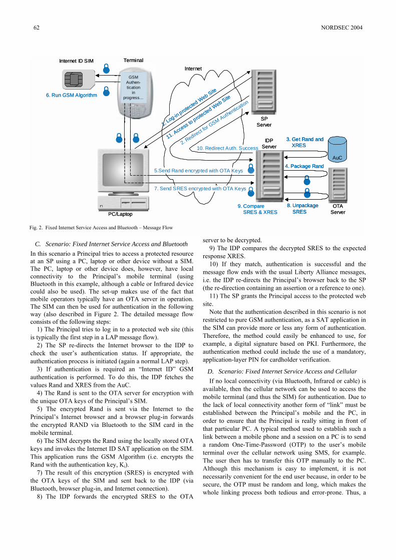
C. Scenario: Fixed Internet Service Access and Bluetooth In this scenario a Principal tries to access a protected resource at an SP using a PC, laptop or other device without a SIM. The PC, laptop or other device does, however, have local connectivity to the Principal’s mobile terminal (using Bluetooth in this example, although a cable or Infrared device could also be used). The set-up makes use of the fact that mobile operators typically have an OTA server in operation. The SIM can then be used for authentication in the following way (also described in Figure 2. The detailed message flow consists of the following steps:
1) The Principal tries to log in to a protected web site (this is typically the first step in a LAP message flow).
2) The SP re-directs the Internet browser to the IDP to check the user’s authentication status. If appropriate, the authentication process is initiated (again a normal LAP step).
3) If authentication is required an “Internet ID” GSM authentication is performed. To do this, the IDP fetches the values Rand and XRES from the AuC.
4) The Rand is sent to the OTA server for encryption with the unique OTA keys of the Principal’s SIM.
5) The encrypted Rand is sent via the Internet to the Principal’s Internet browser and a browser plug-in forwards the encrypted RAND via Bluetooth to the SIM card in the mobile terminal.
6) The SIM decrypts the Rand using the locally stored OTA keys and invokes the Internet ID SAT application on the SIM. This application runs the GSM Algorithm (i.e. encrypts the Rand with the authentication key, Ki).
7) The result of this encryption (SRES) is encrypted with the OTA keys of the SIM and sent back to the IDP (via Bluetooth, browser plug-in, and Internet connection).
8) The IDP forwards the encrypted SRES to the OTA
server to be decrypted. 9) The IDP compares the decrypted SRES to the expected
response XRES. 10) If they match, authentication is successful and the
message flow ends with the usual Liberty Alliance messages, i.e. the IDP re-directs the Principal’s browser back to the SP (the re-direction containing an assertion or a reference to one).
11) The SP grants the Principal access to the protected web site.
Note that the authentication described in this scenario is not restricted to pure GSM authentication, as a SAT application in the SIM can provide more or less any form of authentication. Therefore, the method could easily be enhanced to use, for example, a digital signature based on PKI. Furthermore, the authentication method could include the use of a mandatory, application-layer PIN for cardholder verification.
D. Scenario: Fixed Internet Service Access and Cellular If no local connectivity (via Bluetooth, Infrared or cable) is
available, then the cellular network can be used to access the mobile terminal (and thus the SIM) for authentication. Due to the lack of local connectivity another form of “link” must be established between the Principal’s mobile and the PC, in order to ensure that the Principal is really sitting in front of that particular PC. A typical method used to establish such a link between a mobile phone and a session on a PC is to send a random One-Time-Password (OTP) to the user’s mobile terminal over the cellular network using SMS, for example. The user then has to transfer this OTP manually to the PC. Although this mechanism is easy to implement, it is not necessarily convenient for the end user because, in order to be secure, the OTP must be random and long, which makes the whole linking process both tedious and error-prone. Thus, a
7. Send SRES encrypted with OTA Keys
!
!
!
!
5.Send Rand encrypted with OTA Keys
!
!
Internet ID SIM
PC/Laptop
Terminal
SPServer
OTAServer
IDPServer
AuC
1. Log-in protected W
eb Site
11. Access to protecte
d Web Site
6. Run GSM Algorithm
Internet
2. Redirect for G
SM Authentication
10. Redirect Auth. Success
3. Get Rand andXRES
4. Package Rand
!
8. Unpackage SRES
!9. Compare
SRES & XRES
GSM Authen-tication
in progress...
GSM Authen-tication
in progress...
7. Send SRES encrypted with OTA Keys
!
!
!
!
5.Send Rand encrypted with OTA Keys
!
!
Internet ID SIM
PC/Laptop
Terminal
SPServer
OTAServer
IDPServer
AuC
1. Log-in protected W
eb Site
11. Access to protecte
d Web Site
6. Run GSM Algorithm
Internet
2. Redirect for G
SM Authentication
10. Redirect Auth. Success
3. Get Rand andXRES
3. Get Rand andXRES
4. Package Rand
!
4. Package Rand
!
8. Unpackage SRES
!8. Unpackage
SRES
!9. Compare
SRES & XRES
GSM Authen-tication
in progress...
GSM Authen-tication
in progress...
Fig. 2. Fixed Internet Service Access and Bluetooth – Message Flow
62 NORDSEC 2004
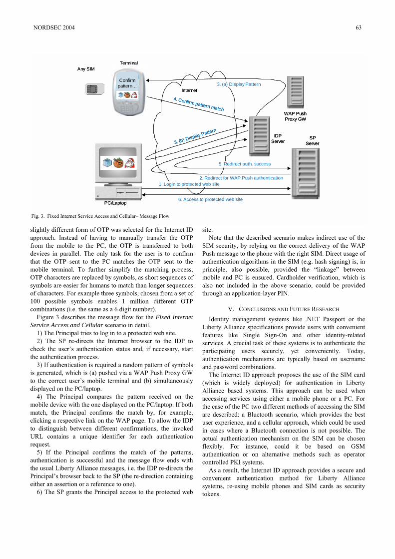
slightly different form of OTP was selected for the Internet ID approach. Instead of having to manually transfer the OTP from the mobile to the PC, the OTP is transferred to both devices in parallel. The only task for the user is to confirm that the OTP sent to the PC matches the OTP sent to the mobile terminal. To further simplify the matching process, OTP characters are replaced by symbols, as short sequences of symbols are easier for humans to match than longer sequences of characters. For example three symbols, chosen from a set of 100 possible symbols enables 1 million different OTP combinations (i.e. the same as a 6 digit number).
Figure 3 describes the message flow for the Fixed Internet Service Access and Cellular scenario in detail.
1) The Principal tries to log in to a protected web site. 2) The SP re-directs the Internet browser to the IDP to
check the user’s authentication status and, if necessary, start the authentication process.
3) If authentication is required a random pattern of symbols is generated, which is (a) pushed via a WAP Push Proxy GW to the correct user’s mobile terminal and (b) simultaneously displayed on the PC/laptop.
4) The Principal compares the pattern received on the mobile device with the one displayed on the PC/laptop. If both match, the Principal confirms the match by, for example, clicking a respective link on the WAP page. To allow the IDP to distinguish between different confirmations, the invoked URL contains a unique identifier for each authentication request.
5) If the Principal confirms the match of the patterns, authentication is successful and the message flow ends with the usual Liberty Alliance messages, i.e. the IDP re-directs the Principal’s browser back to the SP (the re-direction containing either an assertion or a reference to one).
6) The SP grants the Principal access to the protected web
site. Note that the described scenario makes indirect use of the
SIM security, by relying on the correct delivery of the WAP Push message to the phone with the right SIM. Direct usage of authentication algorithms in the SIM (e.g. hash signing) is, in principle, also possible, provided the “linkage” between mobile and PC is ensured. Cardholder verification, which is also not included in the above scenario, could be provided through an application-layer PIN.
V. CONCLUSIONS AND FUTURE RESEARCH Identity management systems like .NET Passport or the
Liberty Alliance specifications provide users with convenient features like Single Sign-On and other identity-related services. A crucial task of these systems is to authenticate the participating users securely, yet conveniently. Today, authentication mechanisms are typically based on username and password combinations.
The Internet ID approach proposes the use of the SIM card (which is widely deployed) for authentication in Liberty Alliance based systems. This approach can be used when accessing services using either a mobile phone or a PC. For the case of the PC two different methods of accessing the SIM are described: a Bluetooth scenario, which provides the best user experience, and a cellular approach, which could be used in cases where a Bluetooth connection is not possible. The actual authentication mechanism on the SIM can be chosen flexibly. For instance, could it be based on GSM authentication or on alternative methods such as operator controlled PKI systems.
As a result, the Internet ID approach provides a secure and convenient authentication method for Liberty Alliance systems, re-using mobile phones and SIM cards as security tokens.
PC/Laptop
Any SIMTerminal
SPServer
WAP PushProxy GW
IDPServer
Confirmpattern…
4. Confirm pattern match
Internet
5. Redirect auth. success
3. (a) Display Pattern
3. (b) Display Pattern
2. Redirect for WAP Push authentication1. Login to protected web site
6. Access to protected web sitePC/Laptop
Any SIMTerminal
SPServer
WAP PushProxy GW
IDPServer
Confirmpattern…
4. Confirm pattern match
Internet
5. Redirect auth. success
3. (a) Display Pattern
3. (b) Display Pattern
2. Redirect for WAP Push authentication1. Login to protected web site
6. Access to protected web site
Fig. 3. Fixed Internet Service Access and Cellular– Message Flow
NORDSEC 2004 63
In the future the Internet ID approach could be extended in a number of ways:
- The SIM could be used for purposes other than authentication. For example, it could be used for other Liberty Alliance identity services such as attribute sharing (user consent via mobile phone, attributes stored in the SIM) or payments (payment authorization via mobile phone).
- The SIM could be used for authentication for services that are not accessed via a web browser. An example could be access network authentication (e.g. WLAN, DSL) or physical access to buildings.
- Approaches like EAP-SIM and EAP-AKA could be investigated with regards to their use for authentication for web site access.
In the long term such studies could lead to the mobile phone and the SIM becoming a universal security token for the user, independent of the service accessed or the device used to access the service.
ACKNOWLEDGMENT The Internet ID approach is the result of collaboration
between Ericsson, Giesecke & Devrient, and Vodafone. The authors would like to thank Monika Girnghuber, Silke Holtmanns, Jos Bosch, Najib Koraichi, and Alex Walter for their contributions to the Internet ID concept.
REFERENCES [1] Microsoft .NET Passport web page, www.passport.com. [2] Microsoft, “.NET Passport: Balanced Authentication Solutions”, White
Paper, April 2003. [3] J. Hall Gailey, “What is .NET Passport”, www.sys-
con.com/webservices/articleprint.cfm?id=307. [4] Liberty Alliance Project web page, www.projectliberty.org. [5] Liberty Alliance Project, “Introduction to the Liberty Alliance Identity
Architecture – Revision 1.0”, March 2003. [6] Liberty Alliance Project, “Liberty ID-FF Bindings and Profiles
Specification, Version 1.2”, April 2003. [7] M. Mouly, M.-B. Pautet, “The GSM System for Mobile
Communications”, CELL & SYS, 1992. [8] W. Rankl, W. Effing, “Smart Card Handbook”, Wiley, 1997. [9] B. Aboba, L. Blunk, J. Vollbrecht, J. Carlson, H. Levkowetz,
“Extensible Authentication Protocol (EAP)”, RFC 3748, June 2004. [10] H. Haverinen, J. Salowey, “Extensible Authentication Protocol Method
for GSM Subscriber Identity Modules (EAP-SIM)”, Internet Draft, April 2004.
[11] J. Arkko, H. Haverinen, “Extensible Authentication Protocol Method for UMTS Authentication and Key Agreement (EAP-AKA)”, Internet Draft, June 2004.
[12] Wireless Identity Module Specification, WAP-260-WIM-20010712-a, http://www.wapforum.org/what/technical.htm.
64 NORDSEC 2004
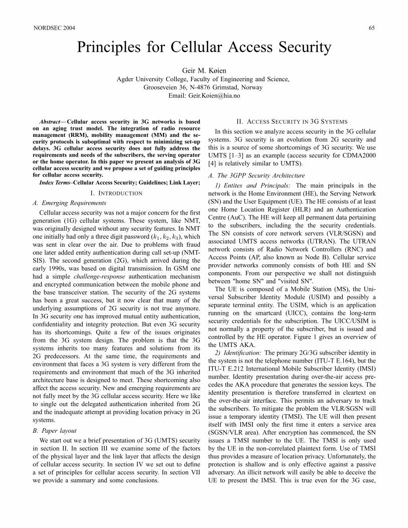
Principles for Cellular Access SecurityGeir M. Køien
Agder University College, Faculty of Engineering and Science,Grooseveien 36, N-4876 Grimstad, Norway
Email: [email protected]
Abstract—Cellular access security in 3G networks is basedon an aging trust model. The integration of radio resourcemanagement (RRM), mobility management (MM) and the se-curity protocols is suboptimal with respect to minimizing set-updelays. 3G cellular access security does not fully address therequirements and needs of the subscribers, the serving operatoror the home operator. In this paper we present an analysis of 3Gcellular access security and we propose a set of guiding principlesfor cellular access security.Index Terms–Cellular Access Security; Guidelines; Link Layer;
I. INTRODUCTIONA. Emerging RequirementsCellular access security was not a major concern for the first
generation (1G) cellular systems. These system, like NMT,was originally designed without any security features. In NMTone initially had only a three digit password (k1, k2, k3), whichwas sent in clear over the air. Due to problems with fraudone later added entity authentication during call set-up (NMT-SIS). The second generation (2G), which arrived during theearly 1990s, was based on digital transmission. In GSM onehad a simple challenge-response authentication mechanismand encrypted communication between the mobile phone andthe base transceiver station. The security of the 2G systemshas been a great success, but it now clear that many of theunderlying assumptions of 2G security is not true anymore.In 3G security one has improved mutual entity authentication,confidentiality and integrity protection. But even 3G securityhas its shortcomings. Quite a few of the issues originatesfrom the 3G system design. The problem is that the 3Gsystems inherits too many features and solutions from its2G predecessors. At the same time, the requirements andenvironment that faces a 3G system is very different from therequirements and environment that much of the 3G inheritedarchitecture base is designed to meet. These shortcoming alsoaffect the access security. New and emerging requirements arenot fully meet by the 3G cellular access security. Here we liketo single out the delegated authentication inherited from 2Gand the inadequate attempt at providing location privacy in 2Gsystems.B. Paper layoutWe start out we a brief presentation of 3G (UMTS) security
in section II. In section III we examine some of the factorsof the physical layer and the link layer that affects the designof cellular access security. In section IV we set out to definea set of principles for cellular access security. In section VIIwe provide a summary and some conclusions.
II. ACCESS SECURITY IN 3G SYSTEMSIn this section we analyze access security in the 3G cellular
systems. 3G security is an evolution from 2G security andthis is a source of some shortcomings of 3G security. We useUMTS [1–3] as an example (access security for CDMA2000[4] is relatively similar to UMTS).
A. The 3GPP Security Architecture1) Entites and Principals: The main principals in the
network is the Home Environment (HE), the Serving Network(SN) and the User Equipment (UE). The HE consists of at leastone Home Location Register (HLR) and an AuthenticationCentre (AuC). The HE will keep all permanent data pertainingto the subscribers, including the the security credentials.The SN consists of core network servers (VLR/SGSN) andassociated UMTS access networks (UTRAN). The UTRANnetwork consists of Radio Network Controllers (RNC) andAccess Points (AP, also known as Node B). Cellular serviceprovider networks commonly consists of both HE and SNcomponents. From our perspective we shall not distinguishbetween "home SN" and "visited SN".The UE is composed of a Mobile Station (MS), the Uni-
versal Subscriber Identity Module (USIM) and possibly aseparate terminal entity. The USIM, which is an applicationrunning on the smartcard (UICC), contains the long-termsecurity credentials for the subscription. The UICC/USIM isnot normally a property of the subscriber, but is issued andcontrolled by the HE operator. Figure 1 gives an overview ofthe UMTS AKA.2) Identification: The primary 2G/3G subscriber identity in
the system is not the telephone number (ITU-T E.164), but theITU-T E.212 International Mobile Subscriber Identity (IMSI)number. Identity presentation during over-the-air access pre-cedes the AKA procedure that generates the session keys. Theidentity presentation is therefore transferred in cleartext onthe over-the-air interface. This permits an adversary to trackthe subscribers. To mitigate the problem the VLR/SGSN willissue a temporary identity (TMSI). The UE will then presentitself with IMSI only the first time it enters a service area(SGSN/VLR area). After encryption has commenced, the SNissues a TMSI number to the UE. The TMSI is only usedby the UE in the non-correlated plaintext form. Use of TMSIthus provides a measure of location privacy. Unfortunately, theprotection is shallow and is only effective against a passiveadversary. An illicit network will easily be able to deceive theUE to present the IMSI. This is true even for the 3G case,
NORDSEC 2004 65
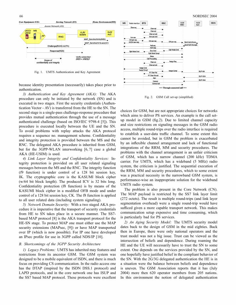
Fig. 1. UMTS Authentication and Key Agreement
because identity presentation (necessarily) takes place prior toauthentication.3) Authentication and Key Agreement (AKA): The AKA
procedure can only be initiated by the network (SN) and isexecuted in two stages. First the security credentials (Authen-tication Vector - AV) is transferred from the HE to the SN. Thesecond stage is a single-pass challenge-response procedure thatprovides mutual authentication through the use of a messageauthenticated challenge (based on ISO/IEC 9798-4 [5]). Thisprocedure is executed locally between the UE and the SN.To avoid problems with replay attacks the AKA protocolrequires a sequence no. management scheme. Confidentialityand integrity protection is provided between the MS and theRNC. The delegated AKA procedure is inherited from GSM,but for the 3GPP-WLAN interworking [6, 7] case a globalAKA (HE-USIM) is used.4) Link Layer Integrity and Confidentiality Services: In-
tegrity protection is provided on all user related signalingmessages between the MS and the RNC. The integrity function(f9 function) is under control of a 128 bit session key,IK. The cryptographic core is the KASUMI block cipher(w/64 bit block length). The produced ICV is 32 bits long.Confidentiality protection (f8 function) is by means of theKASUMI block cipher in a modified OFB mode and undercontrol of a 128 bit session key, CK. The f8 function is appliedto all user related data (including system signaling).5) Network Domain Security: With a two staged AKA pro-
cedure it is imperative that the transport of security credentialsfrom HE to SN takes place in a secure manner. The SS7-based MAP protocol [8] is the AKA transport protocol for theHE-SN stage. To protect MAP one must either use the MAPsecurity extensions (MAPsec, [9]) or have MAP transportedover IP (which is now possible). For IP one have developedan IPsec profile for use in 3GPP called NDS/IP [10].
B. Shortcomings of the 3GPP Security Architecture1) Legacy Problems: UMTS has inherited may features and
restrictions from its ancestor GSM. The GSM system wasdesigned to be a mobile equivalent of ISDN, and there is muchfocus on providing CS communication. In the radio access onehas the DTAP (inspired by the ISDN DSS.1 protocol) andLAPD protocols, and in the core network one has ISUP andthe SS7 based MAP protocol. These protocols were excellent
Fig. 2. GSM Call set-up (simplified)
choices for GSM, but are not appropriate choices for networkswhich aims to deliver PS services. An example is the call set-up model in GSM (fig.2). Due to limited channel capacityand size restrictions on signaling messages in the GSM radioaccess, multiple round-trips over the radio interface is requiredto establish a user-data traffic channel. To some extent thiscannot be avoided, but in GSM the problem is exacerbatedby an inflexible channel arrangement and lack of functionalintegrations of the RRM, MM and security procedures. Theproblems with the channel arrangement is an unfair criticismof GSM, which has a narrow channel (200 kHz) TDMAcarrier. For UMTS, which has a wideband (5 MHz) radiosystem, the criticism is justified. The sequential execution ofthe RRM, MM and security procedures, which to some extentwas a practical necessity in the narrowband GSM system, isperformance-wise an inappropriate solution for the widebandUMTS radio system.The problem is also present in the Core Network (CN).
The MAP payload is restricted by the SS7 link layer limit(272 octets). The result is multiple round-trips (and link layersegmentation overhead) were a single round-trip would havesufficed given a more capable transport network. This makescommunication setup expensive and time consuming, whichis particularly bad for PS services.2) An Aging Security Model: The UMTS security model
dates back to the design of GSM in the mid eighties. Backthen in Europe, there were only national operators and thetrust model was not a big issue. Trust can be viewed as theintersection of beliefs and dependence. During roaming theHE and the UE will necessarily have to trust the SN to someextent. One depends on the services provided by the SN, andone hopefully have justified belief in the compliant behavior ofthe SN. With the 2G/3G delegated authentication the HE is ina situation were the balance between beliefs and dependenceis uneven. The GSM Association reports that it has (July2004) more then 620 operator members from 205 nations.In this environment the notion of delegated authentication
66 NORDSEC 2004
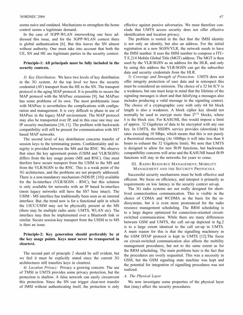
seems naive and outdated. Mechanisms to strengthen the homecontrol seems a legitimate demand.In the case of 3GPP-WLAN interworking one have ad-
dressed this issue, and for the 3GPP-WLAN context thereis global authentication [6]. But this leaves the SN almostwithout authority. One must take into account that both theUE, SN and HE are legitimate parties in the security context.
Principle-1: All principals must be fully included in thesecurity contexts.
3) Key Distribution: We have two levels of key distributionin the 3G system. At the top level we have the securitycredential (AV) transport from the HE to the SN. The transportprotocol is the aging MAP protocol. It is possible to secure theMAP protocol with the MAPsec extensions [9], but MAPsechas some problems of its own. The most problematic issuewith MAPsec is nevertheless the complications with configu-ration and management. It is very difficult to phase in use ofMAPsec in the legacy MAP environment. The MAP protocolmay also be transported over IP, and in this case one may useIP security mechanisms [10, 11]. The problem with backwardscompatibility will still be present for communication with SS7based MAP networks.The second level of key distribution concerns transfer of
session keys to the terminating points. Confidentiality and in-tegrity is provided between the MS and the RNC. We observethat since the key agreement points (USIM and VLR/SGSN)differs from the key usage points (MS and RNC). One musttherfore have secure transport from the USIM to the MS andfrom the VLR/SGSN to the RNC. This is a weak point of the3G architecture, and the problems are not properly addressed.There is a non-mandatory mechanism (NDS/IP, [10]) availablefor the Iu-interface (VLR/SGSN - RNC), but this solutionis only available for networks with an IP based Iu-interface(most legacy networks still have the SS7 base intact). TheUSIM - MS interface has traditionally been seen as an internalinterface. But, the trend now is for a functional split in whichthe UICC/USIM may not be physically present at the MS(there may be multiple radio units: UMTS, WLAN etc). Theinterface may then be implemented over a Bluetooth link orsimilar. Secure session-key transport from the USIM to to MSis then an issue.
Principle-2: Key generation should preferably be atthe key usage points. Keys must never be transported incleartext.
The second part of principle 2 should be self evident, butwe feel it must be explicitly stated since the current 3Garchitectures still transfers keys in cleartext.4) Location Privacy: Privacy a growing concern. The use
of TMSI in UMTS provides some privacy protection, but theprotection is shallow. A false network can easily circumventthis protection. Since the SN can trigger clear-text transferof IMSI without authenticating itself, the protection is only
effective against passive adversaries. We must therefore con-clude that UMTS access security does not offer effectiveidentification and location privacy.The problem is rooted in the fact that the IMSI identity
is not only an identity, but also an address. For the initialregistration at a new SGSN/VLR, the network needs to havethe IMSI number. It uses the IMSI number to compose a ITU-T E.214 Mobile Global Title (MGT) address. The MGT is thenused by the VLR/SGSN as an address for the HLR, and onlyby using this address the VLR/SGSN can get the subscriberdata and security credentials from the HLR.5) Coverage and Strength of Protection: UMTS does not
offer integrity protection of user data and in retrospect thismust be considered an omission. The choice of a 32 bit ICV isa weakness, but one must keep in mind that the lifetime of thesignaling messages is short and that falsifying a messages alsoincludes producing a valid message in the signaling context.The choice of a cryptographic core with only 64 bit blocklength is also a weakness. A block cipher key should notnormally be used to encrypt more than 2b/2 blocks, whereb is the block size. For KASUMI, this would impose a limitof approx. 32 Gigabytes of data to be encrypted with any onekey. In UMTS, the HSDPA service provides (downlink) bitrates exceeding 10 Mbps, which means that this is not purelya theoretical shortcoming (At 10Mbps it will take less than 8hours to exhaust the 32 Gigabyte limit). We note that UMTSis designed to allow for new f8/f9 functions, but backwardscompatibility concerns will arise and the KASUMI based f8/f9functions will stay in the networks for years to come.
III. RADIO RESOURCE MANAGEMENT, MOBILITYMANAGEMENT AND THE SECURITY PROTOCOLS
Successful security mechanisms must be both effective andefficient. We focus on efficiency, and interpret it primarily asrequirements on low latency in the security context set-up.The 3G radio systems are not really designed for short-
lived connectionless communication. This is visible in thechoice of CDMA and WCDMA as the basis for the ra-diosystems, but it is even more pronounced for the radioresource management scheduling. The RRM scheduling isto a large degree optimized for connection-oriented circuit-switched communication. While there are many differencesbetween GSM and UMTS, the call set-up depicted in fig.2is to a large extent identical to the call set-up in UMTS.A main reason for this is that the signalling machinery inthe GSM DTAP protocol is kept in UMTS [12].The focuson circuit-switched communication also affects the mobilitymanagement procedures, but not to the same extent as forthe RRM scheduling. The main problems here is the fact thatthe procedures are overly sequential. This was a necessity inGSM, but the GSM signaling state machine was kept andthe potential for integration of signalling procedures was notrealized.A. The Physical LayerWe now investigate some properties of the physical layer
that (may) affect the security procedures.
NORDSEC 2004 67
1) Modulation: Modern radio systems are flexible andmodulation schemes can often be chosen per carrier/subcarrier.For signaling a relatively conservative modulation scheme isneeded.2) Coding and Error detection/correction: For system sig-
naling it is imperative that there are no residual errors in thecontrol plane messages. One tend not to include the strongesterror correction for signaling. Instead one relies on a robusterror detection mechanism to avoid accepting (radio) corruptedmessages. Low latency is first priority and retransmissionis therefore not applicable (retransmission itself is a linklayer feature). Coding schemes for signaling are usually acombination of convolutional coding and block coding. Turbocodes, which is a hot topic in coding theory, is generally notsuited for applications that cannot tolerate long propagationdelays.3) Interleaving: Interleaving induces a delay in the process-
ing as multiple frames must be present before de-interleavingcan take place. For transaction-oriented services the penaltycan be substantial (for sustained throughput applicationsw/large window size the effect is negligible). Interleavingdepth is a design decision, and an example from GSM illus-trates this. The interleaving used for data on a full-rate traffic(TCH/F) channel induces a delay of more than 100 ms, whilethe shallow the interleaving on the dedicated signaling channel(SDCCH) only induces a 14 ms delay.4) Bandwidth: We need "sufficient" bandwidth. This re-
quirement is related to the need for sufficiently large MTUsize. Performance-wise it is undesirable to have MTU seg-mentation for signaling messages. During the set-up phasesegmentation is commonly not allowed.5) Physical channel arrangement: What we want is a
wideband channel arrangement with flexible modulation andcoding. Furthermore, we want availability of both narrowlow-capacity channels and large (multiplexed) channels. Fi-nally, we want fine grained temporal control on the alloca-tions. To support this one will need a flexible scheme likeOFDM/OFDMA (fig.3)The channel arrangement in OFDMA systems is based on
wideband carriers that are divided into sub-carriers. These sub-carriers are again divided into sub-channels (time/frequency).This scheme is flexible and allows allocation of both widebanddata channels as well as narrow channels. To complementthe picture the various channels/sub-carriers can have differ-ent power levels, error protection (incl.interleaving depths)etc. The possibility of making fine-grained allocations makesOFDMA an excellent choice for provision of PS services. Thehigh resolution in both time and frequency allows for CS-like channel reservations and short burst-like high capacityallocations. The newer Wi-Fi standards (for instance IEEE802.11g) and the upcoming WiMAX (IEEE 802.16a) standardall include OFDM technology.
B. Link Layer - Radio Resource Management1) Retransmission: Retransmission at the link layer is for
services that cannot tolerate biterrors or were the cost of
Fig. 3. OFDMA channel structure
handling errors at higher layers (e.g. TCP) is too high. Retrans-mission can induce significant delays and will add payloadoverhead. Retransmission is therefore not used for lower layercontrol channels.2) Channel granularity: The present FDMA, TDMA and
CDMA schemes are inflexible with respect to channel alloca-tion.On the other hand, OFDMA systems do provide the nec-
essary flexibility. One can then allow UE-SN to have apermanent low capacity (low latency) control channel. Thisis attractive for PS environments, and it will permit fasterset-up of new sessions and improved management of securitycontexts. A permanent control channel is also useful for fastchannel allocations to facilitate high quality PS services. Thiswill impact the security model in that immediate availability ofa security context is crucial for the perceived service quality.Thus, the security context must be established prior to demandor it must be generated on the fly.3) Link Layer Address Schemes: Link layer address infor-
mation will be exposed in the RRM procedures. This cannotbe avoided, but unless care is taken it will allow an adversaryto track the subscribers.4) RRM Integration: There is potential for integration of
RRM and security procedures, and in particular for sessionestablishment and keying/rekeying procedures. There is alsoroom for improved integration of handover and security con-text transfer procedures. Integration of selected RRM andsecurity procedures will reduce the no. of round-trips.
C. Link Layer - Mobility ManagementMany control issues and service model requirements are
intrinsic in the design of the MM mechanism. The controlmodel is essential to the security architecture.1) Control Aspects: The traditional relationship between
the principals (UE,SN,HE) is asymmetrical. The HE hasjurisdiction over the UE, and the HE and SN has mutual(roaming) agreements. By assuming transitive trust, the UEand SN can interact. The relationship between SN-UE isinherently unbalanced. The SN unilaterally controls channelallocations and relocation (handover). On the other hand, theUE is in principle entitled to choose which SN to attach to,though it is restricted by HE-SN roaming agreements.One may have control models in which the HE functionality
is under jurisdiction of the user (Mobile IP is an example, [13])and were control decisions (session transfer etc) are made bythe mobile node. Whatever the control model may be, it iscrucial that the security architecture reflects the trust model
68 NORDSEC 2004
that is assumed by the control model. In this paper we assumea traditional cellular system control model.2) Micro- and Macro Mobility: We define micro-mobility
to be the procedures necessary to allow seamless radio channeltransfers. Mobility is managed by coordination of resourceallocation at the physical and link layer to provide transparenthandovers between radio channels. Micro-mobility, by its verynature, requires close coordination or the radio resources. Oneoften confine this type of mobility handling to homogenousaccess network architectures, but we observe that micro-mobility management can also be had for heterogenous ac-cess networks provided one can synchronize and control theresources closely.Macro-mobility is normally defined as the handling of
mobility issues at the network layer. This makes close controlof the radio environment almost impossible, but it is often theonly means for handling heterogeneous access technologies.Macro-mobility management is global in scope with respectto addressing schemes etc and is therefore well suited for han-dling connection reestablishment and non-time critical sessiontransfers.3) Reestablishmen/handover: Transparent handovers re-
quires infrastructure resource coordination, and it is probablybest that the access network be in control of transparentlink layer handovers. Session reestablishment is easier toprovide, but it is inappropriate for streaming services (like forinstance speech). We assume infrastructure supported seamlesshandovers.4) MM Integration: The potential for integration of MM
and security procedures is good, both for the SN-UE pro-cedures and the HE-UE procedures. We note that in par-ticular the registrations (location updating) and the securitycontext establishment (and renewal) are good candidates forintegration. Even loose integration with logically decoupledmessages contained in the same packet will achieve substantialimprovement in latency as redundant round-trips are avoided.
Principle-3: In order to reduce the required no.ofsignaling round-trips, selected RRM, MM and securityprotocol procedures should be integrated.
IV. DESIGN OF CELLULAR ACCESS SECURITYA. The Need for a Hierarchical StructureOne may classify the security relations according to either
spatial or temporal coverage, but in practice the two viewswill yield similar structures. We have three basic levels:• Permanent–Global. There are two types of Permanent–Global security contexts.A) The roaming agrement between the HE and SN.This security context covers the necessary security cre-dentials to set up secure communications channels be-tween the HE and SN entities. The HE-SN roamingagreement normally applies to all HE subscribers andfor the full SN area. The lifetime of the agreement isnormally in the order of years.
B) The subscription context between HE and UE. Thelifetime of the HE-UE context is permanent with respectto the subscription contract. The coverage is normallyglobal in the sense that the UE is permitted to roam allthe networks that the HE has roaming agreement with.
• Medium–Term. Here we potentially have three contexts.A) The HE-UE context. This medium-term contextcovers authentication between HE-UE and the productionof associated medium-term security credentials. The secu-rity credentials is to be the basis for production of sessionkeys for communication directly between the HE and theUE. We note that lawful interception requirements maydemand that the SN be able to incept the communication.The HE-UE context may be used to secure HE configu-ration of UE data etc, but there may also be requirementsfor tunneling all user related communication back to thehome network.The validity of this context would typically be locked tothe UE presence in the service area (associated with aserver (VLR/SGSN)) or with a location area (associatedwith a radio controller). The validity should also berestricted by a maximum time and by a maximum usage(represented as the maximum derived session key sets).B) The HE-SN context. This context would use thesecurity credentials from the roaming agreement context.One may then have mutual entity authentication betweennodes in the HE and SN networks. The respective nodeswill then have 1-to-1 medium-term context. Since thiscontext is independent of the UEs, we expect the contextsto be managed independently of any particular roam-ing/security event.Note: We shall consider further analysis of the HE-SNcontext to be outside the scope of this paper since it isindependent of UE related events.Additionally, one may decide that it is beneficial to havea dedicated per-UE protected channel between the HEand the SN. The validity of the dedicated context wouldsimilar as to the HE-UE medium-term context.C) The SN-UE context. This context covers authen-tication between SN and UE. It includes medium-termsecurity credentials to be used as basis for the short-term context. The validity of the SN-UE context wouldbe similar to the HE-UE context.
• Short-Term. The short-term contexts are concerned withsession keys. We have three contexts.A) The HE-UE context. This context contains thesession keys and is derived from the medium-term cre-dentials. The validity of the HE-UE short-term contextis limited to the lifetime of the associated medium-termcontext, but may be significantly shorter.B) The HE-SN context. See note above.C) The SN-UE context. This context contains thesession keys and is derived from the medium-term cre-dentials. The validity of the SN-UE short-term context
NORDSEC 2004 69
is limited to the lifetime of the associated medium-term context, but may be significantly shorter. We expectrekeying (context renewal) to occur when one changeaccess points, for periodic location updating and otherRRM events (like bandwidth changes, QoS changes etc).
Principle-4: A hierarchical security context structure isneeded for cellular access security.
1) Separation of Access Networks: Modern cellular systemsis expected to support multiple access methods. The SN musttherefore be prepared to support multiple heterogenous accessnetworks with potentially different levels of physical securityof the network elements, differing coverage of protection etc.The actual security level of the different access networks willvary correspondingly, and it is therefore unsound practice touse the same security credentials for different access networks.
Principle-5: The UE-SN must maintain separatemedium-term security contexts for separate access net-works.
B. Computational Balance1) Triggering Events: Triggering of access security events
cannot be controlled by the principals. They must therefore beable to execute the security protocols on demand.2) Secure Storage Card: The secure storage cards (smart-
cards) have limited processing power and limited storagespace, but they frequently include HW support for the crypto-primitives. The basic requirement is to compute the AKAfunctions on-the-fly. Modern smartcards can do this withrelative ease.3) The Mobile Station: The MS must be able to run the
confidentiality and integrity algorithms without delay whenthe MS sends/receives data at maximum speed. In practice,the processing requirements for the security algorithms aremodest. The primitives are typically implemented in HW toincrease processing speed and to reduce power consumption.4) The Serving Network: The 3GPP AKA does not require
the SN nodes to do much during the AKA since the keymaterial and response value is pre-computed by the HLR/AuC.For improved AKA protocols the SN should be an activepart in the AKA processing. However, the SN nodes willserve a large number of users and must be able to executethe AKA protocol on-demand. The instantaneous processingrequirements may therefore potentially be quite demanding.It may be beneficial if the SN is allowed to delay non-time critical sequences. Session security context renewal isa sequence were the parties have some freedom in delayingthe sequence as long as it can be assured to complete beforethe current context expires.When it comes to confidentiality/integrity related processing
we have much the same case as for the MS. We assume thatthe crypto-processing will relatively be modest (compared tothe radio-related processing).
5) The Home Subscriber Server (HSS): A 3GPP HLR/AuCmay serve a huge no. of subscribers. To instantly computesession credentials for all of them will create a substantialload. For 3GPP AKA the HLR/AuC can pre-compute AVs forthe subscribers. Peak processing performance is therefore nottoo important as long as the average capacity is sufficient. Formobile networks with distinct busy hour conditions this is aconsiderable advantage.For a post-3G HSS the situation is more difficult. AKA
events are time critical and the HSS may not be affordedthe luxury of pre-computation. The HSS must then be dimen-sioned for a higher instantaneous crypto-processing load thanthe 3GPP HLR/AuCs. Still, with optimized crypto-primitivesimplemented in HW we postulate that the capacity requiredneed not be excessive. Due to Moore’s law we expect therelative AKA processing requirements pr subscriber to belower for a post-3G HSS than it was for the AuC during GSMrollout in the early 1990s.
C. Communication Capacity Balance
1) Radio Interface (MS-AN): For a shared radio interfaceone will necessarily have capacity restrictions. These restric-tions will not affect the modest capacity requirements forsignaling, but there are commonly restrictions on signalingmessage size during the initial phase of set-up events. Thismay preclude support for primitives that requires large infor-mation elements (IEs) (e.g. Diffie-Hellman based key genera-tion). Furthermore, support for data expanding (EK(M)→ C,where |C | > |M |) primitives is problematic.2) Other Interfaces: The remaining interfaces will be fixed
network interfaces with permanent resource allocations onthe link layer. The message size restrictions will then bedetermined by the MTU size of the link layer and/or messagesize restrictions on the network layer. In practice, these restric-tions pose no problems for our signaling needs (the commonminimum is for a MTU size of 1500 bytes).Use of a conventional Diffie-Hellman exchange for produc-
tion of shared secrets of 256 bits will require exchange of dataelements with a length of approx. 15000 bits, but even this ispermissible for fixed line connections.
D. Cryptographic Primitives and Key Strength
We assume that the primitives are effective and that theyare used appropriately. It has been argued that one todayshould design systems for 128 bit security [14]. This is finefor confidentiality since we already have good block cipherprimitives with 128 bit blocksize controlled by a 128 bit key.The goal is less practical for integrity protection. To have128 bit worth of "collision avoidance" one need, due to thebirthday paradox, as a minium a 256 bit key. The producedintegrity check value (ICV) should also be 256 bits. However,for link layer security this is neither necessary nor feasible.The messages are short and its totally impractical to add a256 bit ICV to each message. Considering the validity timeof link layer messages it is also completely overkill.
70 NORDSEC 2004
Principle-6: Confidentiality and Integrity services shouldbe pervasive and available to both control plane and userplane transfers.
1) Confidentiality: We only consider symmetric primitives.Block cipher primitives in stream mode (output-feedback orcounter mode) will likely be preferred, but we do not excludestream ciphers.
Principle-7: Confidentiality; Key size for confidentialityalgorithms should be 128 bit. Block size (inner state)should be 128 bit.
2) Message Authentication / Integrity: We only considersymmetric primitives. We do not have a strong preferences onwhether the MAC function should be constructed from ciphersor from cryptographic hash functions.
Principle-8: Integrity; Key size for message authentica-tion should be 128 bit. Integrity check value size shouldbe at least 64 bit.
The above recommendation is for link layer integrity pro-tection. The frame/message size on the link layer is short andadding more than 64 bits probably cannot be justified. Also,the validity time of link layer frames is very short and thusthere is no need for protection that can withstand attacks withyears of compuation time.
E. The Basis for AKAThe UMTS AKA is based on a long-term 128 bit shared
secret, K, stored at the USIM and the AuC. For the accumu-lated number of invocations of the AKA algorithms during thelifetime of the UICC/USIM, the length of K seems sufficient.The average lifetime for GSM SIM is modest (1-3 years). Evenif we assume a lifetime of 5 years and 100 AKA invocationspr day, the total no. of AKA invocations will be less than90000 during the lifetime of the UICC/USIM. This will notexhaust K. We note that the USIM will only respond to validchallenges. One cannot "drive" the functions as one can forGSM AKA.UMTS uses MAC functions for the AKA functions, and
use of one-way functions to derive key material seems moreattractive than to transfer keys to the UE. The alternative topre-shared secrets is use of public-key (PK) key pairs. Wenote that ECC, with relatively short keys and fast execution,is an excellent choice for wireless security [15]. To usea combination of PK signatures, PK encryption and hashfunctions is attractive since it provides more flexibility thanthe use of pre-shared secrets does.
F. Location PrivacyTo provide location privacy functionality one must hide
the correlation between the logical subscriber identity and thepresented link layer address/identity. The mechanism currentlyused by 3G networks is insufficient and can be circumvented
by an active attacker. The root of the problem is that thepermanent identity, IMSI, is also an address. During initialregistration the IMSI must be in clear to the SN since the SNneeds to derive the HLR address from the IMSI. Without thisaddress (the Mobile Global Title) the SN cannot request thesubscriber data or the security credentials from the HLR/AuC.
Principle-9: UE identity and UE address informationshould be decoupled.
Principle-10: The UE identity should never be exposedon the radio interface.
Decoupling alone does not solve the problem, and the UEidentity must be made available to the HE. However, thereis no compelling reason for the SN to know the UE identityprovided it has assurance from the HE that it acknowledges theUE. The justification here is that the HE has full jurisdictionover the UE with respect to the security credentials and tocharging/billing. The SN does not need to know the trueidentity of the UE provided that the HE accepts responsibilityfor the UE.
Principle-11: The permanent UE identity should not berevealed to the SN.
Registration in a new service area is always triggered by theMS/UE. This event will also trigger the need for establishmentof a security context between the SN and the UE. In order tomanage the security context and the channel allocations oneneeds a reference. This reference (TREF) only needs to bea temporary link layer reference for communication betweenthe UE/MS and the SN/AN. It is possible for both the UEand the SN/AN to generate the TREF. We note that if the UEis to generate TREF, then the TREF information element willhave to be generated at random and it must have sufficient sizefor collisions to occur at a very low probability. Given that aservice area potentially can encompass millions of subscribers,we must require the bit length of the TREF to be comparativelylong. However, even if the service area contains a billion activeusers, a 64 bit TREF will make the probability so small as tobe completely insignificant. We therefore postulate that thetemporary identity (TREF) can be selected by the UE.To maintain location privacy, we must additionally require
that the TREF, combined with radio context information, doesnot permit the an adversary to derive the true user identity.As has been mentioned, the MM Registration procedure istriggered by the UE. If this procedure is integrated with themedium-term security context set-up, one can optimize thesignaling and still provide full location privacy. This wouldrequire the UE to be the initiator of the AKA protocol and theentity that chooses the TREF.
Principle-12: The UE shall be the initiator of the AKAprotocol for medium-term security context establishment.
NORDSEC 2004 71
Another aspect of location privacy is whether or not the HEneeds to know the location of the UE. We postulate that the HEdoes not have a legitimate need to know the precise locationof UE for execution of AKA. See [16] for a proposal on howto limit HE knowledge of UE position. We must balance thisagainst the legitimate need the HE has for "home control" [17].The SN will always be able to deduce UE location based onradio information, but this is permissible since we have statedthat the SN shall not know the permanent UE identity.
Principle-13: The HE shall not be given precise UElocation information.
We note that the service area, which is associated with theSN server (VLR/SGSN), will likely be known to the HE. Thelocation area would not normally be known to the HE, butunless this area is very small it may also be permissible to letthe HE know the location area code.
V. FORMAL VERIFICATIONCorrectness, both at the (syntactical) protocol level and
(semantic) security logic level, is an absolute condition.Model checking tools are very appropriate for communicationprotocols. Tools like Promela/SPIN [19] are excellent forverifying state-machine properties, but have weak support forverification of security properties.Security properties have traditionally been verified by logic
based tools and techniques. The IST AVISPA project havesuccessfully managed to develop model checking tools forsecurity verification. An example here is the OFMC [20]tool which is both efficient and effective at verifying securityprotocols.However, no single tool/technique will suite all needs. We
therefore advocate the use of multiple formal verificationmethods since the various techniques and tools have differentstrengths and weaknesses.
Principle-14: Formal verification of security protocols isessential for our trust in the protocols.
VI. SUMMARY1) Flawed 3G Security: Our analysis shows that the current
3G cellular access security architectures are flawed. Theproblems are related to system features and restrictions in-herited from the 2G antecedents, including an outdated 2Gtrust model, a 2G system architecture and service modelfocused almost exclusively on CS service provision and finallytechnical restrictions due to the now obsolete SS7 signalingprotocols.2) Improved Integration: Future cellular system will have
better and more flexible radio networks. This will allow fordesigns with integrated RRM, MM and security protocols,and one may then be able to provide near instantaneousaccess. To be able to realize this potential one needs torethink the cellular access security model and to develop newsecurity architectures in conjunction with the RRM and MMfunctionality.
3) Design Principles: The set of identified principles andremarks collectively form a a high-level set of guidelines andobservations for cellular access security. This is in the spiritof the principles in [18], although here applied to a specificdomain. The principles constitute a valuable input for thedesign of a cellular access security architecture, but they areno substitute for formal verification.4) Conclusion: We have analyzed the current 3G access se-
curity and found it wanting. From a performance perspective,better integration with RRM and MM procedures is necessary.The full potential will only be realized for high-capacity radionetworks with flexible channel management.We believe that our stated principles can form the basis
for design of modern cellular access security architectures.However, we do not claim that our set of principles areexhaustive or that following them will necessarily lead to anefficient and effective security architecture.
REFERENCES[1] 3G TS 33.102: 3G Security; Security architetcure (Release 6), 3GPP,
Sophia Antipolis, France, 2004[2] G.M. Køien, An Introduction to Access Security in UMTS. IEEEWireless
Communications Mag., Vol.11, No.1, pp.8-18, Feb. 2004[3] K. Nyberg and V. Niemi, UMTS Security. ISBN 0-470-84794-8, Wiley,
2003[4] G. Rose and G.M, Køien, Access Security in CDMA2000, Including a
Comparison with UMTS Access Security. IEEE Wireless Communica-tions Mag., Vol.11, No.1, pp.19-25, Feb. 2004
[5] ISO/IEC 9798-4: Information technology - Security techniques - Entityauthentication - Part 4: Mechanisms using a cryptographic checkfunction. ISO, Geneva, Switzerland, 1999
[6] 3G TS 33.234: 3G Security; Wireless Local Area Network (WLAN)Interworking Security (Release 6). 3GPP, Sophia Antipolis, France, 2004
[7] G.M. Køien and T. Haslestad, Security Aspects of 3G-WLAN Interwork-ing. IEEE Communications Mag., Vol.41, No.11, pp.82-88, Nov. 2003
[8] 3G TS 29.002: 3rd Generation Partnership Project; Technical Specifica-tion Group Core Network; Mobile Application Part (MAP) specification;,3GPP, Sophia Antipolis, France, 2004
[9] 3G TS 33.200: 3G Security; Network Domain Security; MAP applicationlayer security (Release 5). Sophia Antipolis, France, 2002
[10] 3G TS 33.210: 3G Security; Network Domain Security; IP network layersecurity (Release 6). Sophia Antipolis, France, 2004
[11] S. Kent, and R. Atkinson, Security Architecture for the Internet Protocol.IETF RFC 2401, Nov. 1998
[12] 3G TS 24.008: 3rd Generation Partnership Project; Technical Specifica-tion Group Core Network; Mobile radio interface Layer 3 specification;Core network protocols; Stage 3, Sophia Antipolis, France, 2004
[13] D. Johnson, C. Perkins and J. Arkko, Mobility Support in IPv6, IETFRFC 3775, June 2004
[14] N. Ferguson and B. Schneier, Practical Cryptography, ISBN 0-471-22357-3, Wiley, 2003
[15] K. Lauter, The Advantages of Elliptic Curve Cryptography for Wire-less Security. IEEE Wireless Communications Magazine, Vol.11, No.1,pp.62-67, Feb. 2004
[16] G.M.Køien and V.A.Oleshchuk, Privacy-Preserving Spatially Aware Au-thentication Protocols: Analysis and Solutions, Proceedings of NORD-SEC 2003, pp.161-173, ISBN 82-993980–4-5, Gjøvik, Norway, 2003
[17] G.M.Køien and V.A.Oleshchuk, Spatio-Temporal Exposure Control;An investigation of spatial home control and location privacy issues,Proceedings of IEEE PIMRC 2003, pp.2760-2764, Beijing, China, 2003
[18] M. Abadi and R. Needham, Prudent Engineering Practice for Crypto-graphic Protocols. DEC SRC Research Report 125, California, USA,June 1994
[19] G.J. Holzmann, The Spin Model Checker : Primer and ReferenceManual. ISBN 0-321-22862-6, Addison-Wesley, Sept. 2003
[20] D. Basin, S. Mödersheim and L. Viganò, An On-the-Fly Model-Checkerfor Security Protocol Analysis. In Proc. of ESORICS 2003, LNCS 2808,Springer-Verlag, Oct. 2003
72 NORDSEC 2004
On Private Similarity Search ProtocolsSven Laur and Helger Lipmaa
Laboratory for Theoretical CS, Department of CS&EHelsinki University of Technology, P.O.Box 5400, FIN-02015 HUT, Espoo, Finland
Email: slaur,[email protected]
Abstract— In a private similarity search (PSS) protocol, a clientreceives from the database the entry, closest to her query, withouteither the client or the database getting to know more informationthan necessary. PSS protocols have potentially wide applicationin areas like bioinformatics, where precise queries might beimpossible. We show that the previously proposed PSS protocolsby Du and Atallah have serious weaknesses; in particular, someof their protocols can be broken by a semi-honest third party whoobserves a relatively small amount of traffic. In several cases, weshow that even maximally securified versions of these protocols—when used as proposed by Du and Atallah—are not private inthe sense, needed in the practice. We propose a few protocols thatare better from the privacy viewpoint, but none of the proposedprotocols is really efficient.
Index Terms—Cryptanalysis, cryptographic protocols, privacy-preserving data-mining, private similarity search.
I. I NTRODUCTION
In a private similarity search (PSS) protocol [1], a clientreceives from the database (the index of the) the entry, closestto her query, without either the client or the database gettingto know more information. Similarity search is used in manycases where, e.g., finding the exact match is impossible orinfeasible, when the data is corrupted by noise or the useris really interested in similar objects. A canonical applicationarea of the PSS is bioinformatics, together with related fieldslike biometrics. A motivating task could be, given a DNAsample of a criminal, to find the closest match in the genomedatabase without compromising the safety of honest citizens.To implement such applications, one must address the privacyconcerns. Otherwise, both clients and database maintainerswould be discouraged to participate in such services.
One can expect private similarity search to be a hardproblem, in particular since at some point during the PSSprotocol, the participants have to find minimum over non-public distances. Private minimum finding is a well-knowncryptographic hard problem and only generic inefficient pro-tocols for it are known [2].
Thus, one cannot expect to design really practical protocolsfor the PSS that are secure in the sense of secure two-partycomputations [3]. The main goal of published research onthe PSS [1] has been to proposeefficientPSS protocols thatare secure according to somewhat less stringent notions. Forexample, in [1] the authors propose several PSS protocols thatare relatively efficient but make use of a conditionally trustedthird party Ursula, who is assumed to follow the protocol andnot to collaborate with any other party. Moreover, the protocols
from [1] are only claimed to be secure againstciphertext-onlyattack.Our contributions. We show that several protocols in [1] areinsecure even following the weak security definitions of theirauthors. First, [1] proposes protocols for the PSS with respectto the Euclidean distance. This protocol essentially employsa private minimal scalar product (PMSP) protocol, using thehelp of Ursula to find the minimum. The PMSP protocol masksthe real distances by usingadditive masking functions.
We show that the PMSP protocol of Du and Atallah [1] iscompletely insecure against ciphertext-only attacks. Namely,we show that a conditionally trusted third party Ursula canrecover the queries by observing a small amount of traffic andusing a straightforward matrix equations. Our attack againstthis protocol succeeds with a very high probability as soon asthe database has a reasonable size. As a consequence, the fullPSS protocol becomes insecure in practice.
After that, we show that all PMSP protocols, that arecomputed by using additive masking functions, must revealthe differences between the scalar products. We then proposetwo new SMSP protocols that do not reveal anything else,except these differences, in the security-model proposed byDu and Atallah (security against ciphertext-only attacks withthe help of a semi-honest third party Ursula). This protocol isas efficient as the Du-Atallah PMSP protocol and quantifiablymore secure.
However, ciphertext-only security is not sufficient in manypractical applications, since additional public informationabout the database may easily disclose private information.We argue that practical PSS protocol must at least withstandstatistical attacks (where the attacker knows something non-trivial about the database) and known-plaintext attacks. Weshow that any PMSP protocol, where Ursula learns distancedifferences, is insecure against very simple statistical attacks.While a refinement to the additive masking (the use of order-preserving affine transformation, defined later in this paper)can resist simple statistical attacks, it is not sufficient for moreelaborate attacks. Finally, in Sect. IV, we propose the divideand conquer technique that provides more security, but it isalso computationally more demanding.
We stress that also the protocols, proposed in this paper,are applicable only in limited environments, e.g., when onlythe ciphertext-only attacks are allowed. Still, the provablysecure alternative of using Yao’s alternative garbled circuitevaluation [4] is computationally too costly for large databases,and therefore our new protocols could be used in the practice
NORDSEC 2004 73
when a trade-off between security and efficiency is desired. Itis a major open problem to design a PSS protocol that is bothsecure and efficient.Road-map. Section II introduces the reader to notation andpreliminaries. Section III describes our attacks against MIN-DASP protocol and improved PSS protocols. Section IVgives a brief overview of other possible attack scenarios andsolutions.
II. N OTATION AND PRELIMINARIES
Notation. A PSS database can consist of either discrete,continuous or hybrid vectors. For example, genome data canbe represented over discrete alphabet, whereas biometric datais inherently continuous. For discrete data, we use elements ofsome quotient ringZt, and we think of continuous parametersas fixed point real numbers that are mapped intoZt by usinga suitable affine transform.
For n-dimensional vectors, two standard distance functionsare the Euclidean distanced2(x,y) :=
[∑i(xi − yi)2
]1/2
and the Manhattan distanced1(x,y) :=∑
i |xi − yi|, whereall calculations are done inR. (If made in Zt, no modularreductions should appear in the computations.)Cryptographic background. A public-key cryptosystemΠ isa triple (G, E, D) of probabilistic polynomial-time algorithmsfor key-generation, encryption and decryption. A cryptosystemΠ is homomorphic ifEK(m1; r) · EK(m2; s) = EK(m1 +m2; r ·s), where+ is a group operation and· is a groupoid op-eration, and semantically secure if no probabilistic polynomial-time adversary can distinguish between random encryptions oftwo elements, chosen by herself. See, e.g., [5], for an efficientsemantically secure homomorphic public-key cryptosystem.Linear-algebraic background. The next results are necessaryto quantify our attacks in the next section. For the sake ofcompleteness, we present them together with proofs.
First, let us denote the ring ofm×n matrices over the ringZt by Matm×n(Zt). Recall that a matrix equationMx = yover the finite fieldGF(q) = Zq can have at mostqn−rank(M)
solutions. Generally, whenZt is a ring, the solution ofMx =y is unique iff the matrixM is left-invertible. LetL be theset of left-invertible matrices. DefinePm×n(t) := Pr[M ←Matm×n(Zt) : M ∈ L].
Lemma 1:Let m ≥ n, let q, q1, . . . , q` be someprimes. Then the following claims hold: (a)Pm×n(q) =∏n−1
k=0
(1− q−m+k
);
(b) Pm×n(qr) = Pm×n(q);(c) Pm×n(qr1
1 · · · qr`
` ) =∏`
i=1 Pm×n(qi).Proof: (a) Since Zq is a finite field, a matrixM
over Zq is left-invertible iff all columns ofM are linearlyindependent. Now, if the firstk columns ofM are linearlyindependent, they span a vector space of dimensionk and sizeqk. The probability that the next column avoids this space is1−qk/qm and thus probability that alln columns are linearlyindependent is
∏n−1k=0(1− q−m+k).
(b) Follows directly sinceM has a left-inverse moduloqr iffM mod q has a left-inverse moduloq. (c) By the Chineseremainder theorem, matricesMi ≡ M mod qri
i for every
i have left-inverses iffM does. Random sampling inZt isequivalent to random sampling moduloqri
i for every i, andthus the probability in this case is just a product of theprobabilities given by case (a).Private similarity search. A private similarity search (PSS)protocol has two parties, the querier Alice and the databaseowner Bob. Alice’s private input is a vector (query)x;Bob’s private input is the database with vector elementsy1, . . . ,ym. Assume that the similarity between two vectorsis determined by a public distance (score) functiond(·, ·).During a PSS protocol, Alice learns thematch indexb,s.t. yb = arg minyi
d(x,yi). and the correspondingmatchscore d(x,yb) = mini d(x,yi). If b is not unique, Bobmay return a randomly chosen index that minimisesb. Alicemust gain no new information, except her private output (thematch index and the match score). Bob must gain no newinformation. Some PSS protocols use a conditionally trustedthird party Ursula, who must gain no new information duringthe protocol.Du-Atallah protocol for finding minimal Euclidean dis-tance.The task of finding the closest match can be simplifiedwhen d(·, ·) is the Euclidean distance. Then one can ignorethe square root and computed2(x,yi) :=
∑nj=1(xj − yij)2,
where yi = (yi1, . . . , yin). Moreover, sinced2(x,yi) =x2 − 2x · yi + yi
2 andx2 is a constant known to Alice, it issufficient for Alice to learn the minimal value of−2x·yi+yi
2
over all i-s. The latter task can be reduced to the privateminimal scalar product problem by defining new vectorsx′ :=(−2x1, . . . ,−2xn, 1) and y′
i := (yi1, . . . , yin,∑n
j=1 y2ij) for
all i-s; thenx′ · y′i = −2x · yi + yi
2.Since only generic inefficient protocols are known for the
minimum finding [2], the hardest part of any reasonablePSS protocol is to find the minimum over the distances.To overcome this issue Du and Atallah proposed in [1] touse a trusted third party Ursula. Their proposed protocol,M INDASP, is depicted by Protocol 1.
INPUT: A query x and a databasey1, . . . , ym.OUTPUT: The indexb and the scorex · yb.
1) Alice and Bob jointly generate two random numbersrA, rB .2) For every rowi:
a) Alice and Bob jointly generate two random vectorsRA
i , RBi .
b) Alice sendswAi ← x + RA
i andsAi ← x ·RB
i + rA
to Ursula.c) Bob sendswB
i ← yi + RBi andsB
i ← RAi ·wB
i + rB
to Ursula.d) Ursula computes and storesvi ← wA
i ·wBi − sA
i − sBi .
3) Ursula finds an indexb for which vb = mini vi. She sendsbandvb to Alice. Alice outputsvb + rA + rB .
Protocol 1: M INDASP protocol.
During this protocol, for everyi, Ursula learns the valuevi = x·yi−rA−rB for rA andrB unknown to her. Therefore,provided that Ursula is honest, Alice learns the correct answer.Though Ursula gains new non-trivial information about thequery, the authors of [1] argue that it is not sufficient to
74 NORDSEC 2004
reveal either the match scores, the queries or the database.However, [1] does not give any further analysis. It also doesnot specify how to choose random values. In the case of adiscrete search space, we should useZt with t being largerthan any intermediate scalar product. More precisely, let∆ :=maxx · yi − x · yj; then we must havet > 2∆ sinceotherwise, Ursula cannot determine the smallestvi. Thus, inthe discrete case, Alice and Bob first agree on a safeZt,perform all calculations inZt and choose all necessary randomnumbers uniformly fromZt. If the vectors are continuous,Alice and Bob have to embed real numbers into large enoughZt. More precisely, they should first fix the precision parameterp and use transformationx 7→ bp · xe. Therefore, we musthave t > p2∆, since otherwise Ursula cannot determine theminimum.Du-Atallah security model. In the security model of Du andAtallah, only ciphertext-only attacks with the next restrictions,are allowed: Ursula colludes with nobody and has no priorinformation about queries and a database. A protocol isconsidered secure in this model if Ursula cannot restore anyqueries, database vectors or corresponding match scores. Itis still required that Bob must learn no new informationand Alice must only learn the match index and the matchscore. It is easy to see that during the MINDASP protocol,Ursula can trivially learn distance differences. This does notdirectly imply that ciphertext-only attacks are dangerous to thisprotocol in the Du-Atallah security model, as the differencesthemselves do not reveal any vectors or match scores.
III. A NALYSIS OF SMSP PROTOCOLS
Efficient ciphertext-only attack against MIN DASP. Recallthat m is the number of database elements andn is thedimension of the vectors.
Lemma 2:Assume that the MINDASP protocol is executedover the ring Zt. If m > n, a semi-honest Ursula canreconstructx with probability P(m−1)×n(t).
Proof: For anyi, sBi = (wA
i − x) ·wBi + rB and thus
wBi ·x = wA
i ·wBi + rB − sB
i . Hence, Ursula obtainsm− 1equations(wB
i −wB1 ) ·x = wA
i ·wBi −wA
1 ·wB1 −(sB
i −sB1 ).
The claim now follows from Lemma 1.As an example, ift = 10, n = 6 and m = 7, the success
probability is roughly0.22, while m = 11 raises it to0.94. Ifm > 2n, the success rate will be almost1.Improved protocols. Next, we propose two alternative PMSPprotocols that achieve the security goal, proposed by Du andAtallah: namely, Alice learns exactly the closest match and thematch index, Bob gains no new information and Ursula learnsonly the distance differencesdij := d(x,yi)− d(x,yj).
The MINTSP protocol, depicted by Protocol 2, is a simpletweak to MINDASP that achieves the required security level.(Note that scalar products in the MINTSP protocol representdistances up to an additive constant.)
Lemma 3:Assume the participants are semi-honest. Duringa single run of Protocol 2, Alice learns only the match scoreand match index, Bob learns nothing and Ursula learns onlythe scalar product differencesdij := x · yi − x · yj .
INPUT: A query x and a databasey1, . . . , ym.OUTPUT: The indexb and the scorex · yb.
1) Alice and Bob jointly a random query keyr.2) For every rowi:
a) Alice and Bob randomly choose vectorsRAi , RB
i anda scalarri.
b) Alice sendswAi ← x + RA
i andsAi ← x ·RB
i + ri toUrsula.
c) Bob sendswBi ← yi + RB
i andsB
i ← RAi ·wB
i − r − ri to Ursula.d) Ursula computes and storesvi ← wA
i ·wBi − sA
i − sBi .
3) Ursula finds the minimising indexb such thatvb = mini vi.Then sendsb andvb to Alice, who finds the scorevb − r.
Protocol 2: The MINTSP protocol
Proof: Correctness is clear, sincewAi ·wB
i −sAi −sB
i =(x + RA
i ) · (yi + RBi )− (x ·RB
i + ri)− (RAi · (yi + RB
i )−r − ri) = x · yi + r. It is straightforward to simulate theviews of Alice and Bob, and therefore nothing will be leakedto them. To prove that nothing else, except the valuesdij , isleaked to Ursula, we show how to perfectly simulate viewsof Ursula by a simulator who knows all the differencesdij .Consider the view of Ursula. In a valid protocol run, Ursulasees tuples(wA
i ,wBi , sA
i , sBi ), such thatwA
i ·wBi −sA
i −sBi =
x · yi + r. SinceRAi ,RB
i , ri are chosen uniformly, the triple(wA
i ,wBi , sA
i ) has also a uniform distribution. Consequently,the simulator can choosev1, w
Ai , wB
i , sAi at random and
computesBi = wA
i · wBi − sA
i − v1 − di1.To reduce the number of required random bits and the com-
munication, Alice and Bob can use a pseudo-random generatorfor generatingr, RA
i ,RBi , ri. Then they have to agree only on
random seeds and only send the tuple(wAi ,wB
i , sAi , sB
i ) toUrsula. This reduces the communication between Alice andBob to a few hundred bits.
Provided that vectors belong or can be safely embedded intoZn
t , whereZt is the plaintext space of the used semanticallysecure homomorphic public-key cryptosystemΠ = (G, E, D),one can alternatively use the next communication-efficientM INHSP protocol, depicted by Protocol 3. Note that the samekey K can be used in multiple protocols.
ALICE’ S INPUT: A query x = (x1, . . . , xn)BOB’ S INPUT: A databasey1, . . . , ym, whereyi = (yi1, . . . , yin).OUTPUT: The indexb and the scorex · yb.
1) Ursula generates a new private-public key pair forΠ andsends the public keyK to Alice and Bob.
2) Alice and Bob choose a randomr from the plaintext space ofΠ.
3) For eachj ∈ [n], Alice sendscj ← EK(xj ; tj) to Bob,wheretj is a fresh random number.
4) For each rowi, Bob sendssi ←Q
cyij
j · EK(r; t), for afresh random numbert, to Ursula.
5) Ursula decrypts the result and sends the match indexb andvb ← DK(sb) to Alice. Alice computes the scorevb − r.
Protocol 3: The MINHSP protocol
Alice’s and Bob’s privacy in the MINHSP protocol relies onthe semantical security ofΠ. The security proof for Protocol 3
NORDSEC 2004 75
is very standard and therefore omitted. The MINHSP protocolrequires n encryptions by Alice, andmn exponentiationsby Bob. The number of exponentiations can be amortised.For example, if vectorsyi consist of binary data, Bob willnot have to perform any exponentiations. Hence, the mostdemanding computational burden ofm decryptions is placedon Ursula. The communication of the MINHSP protocol isonly m+n ciphertexts, whereas the MINTSP protocol requiressending at least2m(n+1) scalars. Since the MINTSP protocolis computationally more efficient, we will have a trade-offbetween communicational and computational complexity.
IV. SECURITY AGAINST MORE ELABORATED ATTACKS
To avoid the costly minimum finding operation, the previousprotocols make use of a trusted third party Ursula. However,Ursula learns some non-trivial information—namely, the dis-tance differences—about the queries and the database. Next,we will analyse how Ursula can abuse this information andwhat could be the possible counter-measures.Known-plaintext attacks. As Ursula obtains the list of dis-tance differencesdij = x·yi−x·yj , the knowledge ofx·yi forany singlei reveals all scalar products. If Ursula knowsr > ndatabase elementsyi0 , . . . ,yir
, she will obtainr equationsdiki0 = x · (yik
− yi0). Consequently, she can restore allquery vectorsx, provided thatyi1 − yi0 , . . . ,yir − yi0 arelinearly independent. The latter holds for a random databasewith probability, given by Lemma 1. By a similar argument,the knowledge ofr > n linearly independent query vectors tothe same database reveals all differencesyj − y1.
Some simple attacks can be avoided by randomly permutingthe database elements before each query. This forces Ursulato determine the valuesvj0 , . . . , vjr
that are paired withyi0 , . . . ,yir . Since the number of valid pairings ism(m −1) · · · (m−r+1), wherem is the number of database elements,such attacks become infeasible for most databases, at least ifassuming that Ursula does not have any extra knowledge aboutthe database.Statistical attacks. However, the random permuting of thedatabase rows does not provide absolute protection sinceUrsula still learns the multi-setd(x,yi) + r. If n is largeand the database vectors contain enough entropy, then one canapproximate the empirical distance distribution with a data-independent distribution (this is caused by thecurse of highdimensions). This statement is of course purely qualitative;quantitative estimates require the knowledge of the distributionof query and database vectors. For example, if the databaseand query vectors are uniformly and at random chosen from0, 1n, then the distribution ofd2
2 can be approximated withthe Gaussian distributionN (n
2 , n4 ). Similar results can be
obtained if the vector components are assumed to be (weakly)independent; then the desired results follow from the theoremsof weak convergence.
Assume now that the distance distributionD is known toUrsula and for a single query, all distances are independentlysampled fromD. Consequently, Ursula can compute severalpoint estimators like the mean value, the median or the
variance and then use the obtained knowledge to reconstructthe match score. For example, in the case of the MINTSPand the MINHSP protocols, one can compute the expectedvalue ofvi, Exp(vi) := 1
m
∑mi=1 vi = Exp(di) + r. Therefore,
d(x,yb) = vb − Exp(vi) + Exp(di). Since by assumption,all di-s are sampled randomly fromD, then the standardcentral limit theorem assures thatExp(di) has the GaussiandistributionN (µ, σ2/m), whereµ andσ are the mean and thevariance of the distributionD. Let d∗ = vb−Exp(vi)+µ, thenone can use standard results from statistics to show that thematch scored(x,yb) is in the intervald∗ ± σ2/
√m with the
probability 68%. For example, ifn = 100, µ = 50 andm >σ2 = 625, Ursula can with probability68% infer the matchscore with precision±1. Ursula can estimate the varianceσ2 ≈ Exp((vi−Exp(vi))2) = 1/m
∑i(vi−Exp(vi))2 directly
from the multi-setd(x,yi) + r and thus also compare thedifferent match scores without knowing the distribution.Detection of identical queries. In all presented protocols,Ursula can detect identical queries, since identical (or evenjust similar) queries have identical (resp., similar) distancemulti-setsd(x,yi). Thus, with a high probability, Ursulacan decide whether two queries were equal or not. The rate offalse positives—two different queries that have have identicalor similar distance multi-sets—depends on database vectors,but is certainly small. E.g., this rate can be computed if alldistances are sampled independently fromD. If the queriesare similar,d(x1,x2) < τ , then |d(x1,yi)− d(x2,yi)| < τ .If v1
i andv2i are ordered lists of the valuesvi obtained in the
PSS protocols then for similar queries,|v1i −v2
i −v11 +v2
1 | < τ .Order preserving transformations. The previously describedprotocols make use of the simplest order preserving transfor-mationdi 7→ di + r. This map corresponds to the use of one-time pad, and thus the knowledge of a single distance compro-mises all distances. If say a randomised affine transformationdi 7→ sdi + r + ε, with a random distortionε, is used, we geta bit more security but the database can still be completelydetermined by a known distance pair.
In the MINTSP and MINHSP protocols, it is straightfor-ward to replace the additive masking function with an affinetransformation. First note that not all affine transformationspreserve order: (a)∆ := maxx · yi − x · yj < t/(2s)must hold to avoid modular reduction; (b)0 < ε < s musthold to avoid local re-ordering. Thus, to implement affinemasking, Alice must chooses randomly from valid intervals ∈ [smin, smax], wheresmin and smax are chosen so thatthe resulting transformation would preserve order, and thenuse sx instead ofx, while Bob must user + ε instead ofr. However, as not all values ofs are valid, Ursula knowsthat di − dj ∈ [(vi − vj)/smax, (vi − vj)/smin]. Hence, theratio smax/smin classifies the maximum uncertainty, thoughthe knowledge of∆ sometimes allows to exclude part of theinterval. Therefore, the knowledge of the mean valueµ of Ddoes not reveal the match score ifsmax/smin > µ/(µ−dmin),wheredmin = mini di.Divide-and-conquer technique. The underlying idea ofdivide-and-conquer approach (see Protocol 4) is to find mini-
76 NORDSEC 2004
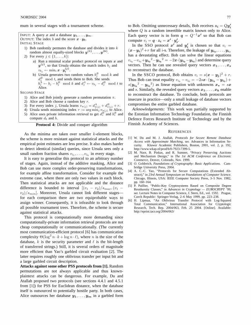
mum in several stages with a tournament scheme.
INPUT: A query x and a databasey1, . . . , ym.OUTPUT: The indexb and the scorex · yb.INITIAL STAGE
1) Bob randomly permutes the database and divides it intokrandom almost equally-sized blocksy(1), . . . , y(k).
2) For everyj ∈ 1, . . . , k:a) Run a minimal scalar product protocol on inputsx and
y(j), so that Ursula obtains the match indexbj andvbj ← mini x · y(j)
i .b) Ursula generates two random valuesbB
j mod k anddB
j mod t, and sends them to Bob. She sendsbAj ← bj − bB
j mod k anddAj ← vbj − dB
j mod t toAlice.
SECOND STAGE
1) Alice and Bob jointly generate a random permutationπ.2) Alice and Bob choose a random keyr.3) For every indexj, Ursula learnsvπ(j) = dA
π(j) + dBπ(j) + r.
4) Ursula sends minimising indexτ := arg minj vπ(j) to Alice.5) Alice uses private information retrieval to getdB
τ andbBτ and
computedb andb.
Protocol 4: Divide and conquer algorithm
As the minima are taken over smallerk-element blocks,the scheme is more resistant against statistical attacks and theempirical point estimates are less precise. It also makes harderto detect identical (similar) queries, since Ursula sees only asmall random fraction sharesvi1 , . . . , vik
in every stage.It is easy to generalise this protocol to an arbitrary number
of stages. Again, instead of the additive masking, Alice andBob can use more complex order-preserving transformations,for example affine transformation. Consider for example theextreme case, where there are only two values in each block.Then statistical attacks are not applicable and the distancedifference is bounded to interval[(v1 − v2)/smax, (v1 −v2)/smin]. Moreover, Ursula cannot link different stages—for each comparison there are two equiprobable ways toassign winner. Consequently, it is infeasible to look throughall possible tournament trees. Therefore, the scheme is secureagainst statistical attacks.
This protocol is computationally more demanding sincecomputationally-private information retrieval protocols are notcheap computationally or communicationally. (The currentlymost communication-efficient protocol [6] has communicationcomplexityΘ(log2 n · k + log n · `), wheren is the size of thedatabase,k is the security parameter andis the bit-lengthof transferred strings.) Still, it is several orders of magnitudemore efficient than Yao’s garbled circuit evaluation [2]. Thelatter requires roughly one oblivious transfer per input bit anda large garbled circuit description.Attacks against some other PSS protocols from [1].Randompermutations are not always applicable and thus known-plaintext attacks can be dangerous. For example, Du andAtallah proposed two protocols (see sections 4.4.1 and 4.5.1from [1]) for PSS for Euclidean distance, when the databaseitself is outsourced to potentially hostile party. In both cases,Alice outsources her databasey1, . . . ,ym in a garbled form
to Bob. Omitting unnecessary details, Bob receiveszi = Qy′i
whereQ is a random invertible matrix known only to Alice.Each query vector is in formq = Q−1x′ so that Bob cancomputevi = q · zi = x′ · y′
i.In the SSO protocolx′ and y′
i is chosen so thatvi =(x−yi)2+r for all i-s. Therefore, the leakage ofyi0 , . . . ,yir
has a devastating effect. Bob can solve the linear equationsvik−vi0+yi0
2−yik2 = −2x·(yik−yi0) and determine query
vectors. Then he can use revealed query vectorsx1, . . . ,xs
to reconstruct the database.In the SSCO protocol, Bob obtainsvi = s(x − yj)2 + r.
Thus Bob can treat equalityvik− vi0 = −2sx · (yik
−yi0)+s(yik
2 − yi02) as linear equation with unknownsx∗ = sx
ands. Similarly, the revealed query vectorsx1, . . . ,xk enableto reconstruct the database. To conclude, both protocols areinsecure in practice—only a small leakage of database vectorscompromises the entire garbled database.
Acknowledgements:This work was partially supported bythe Estonian Information Technology Foundation, the FinnishDefence Forces Research Institute of Technology and by theFinnish Academy of Sciences.
REFERENCES
[1] W. Du and M. J. Atallah,Protocols for Secure Remote DatabaseAccess with Approximate Matching, ser. Advances in Information Se-curity. Kluwer Academic Publishers, Boston, 2001, vol. 2, p. 192,http://www.wkap.nl/prod/b/0-7923-7399-5.
[2] M. Naor, B. Pinkas, and R. Sumner, “Privacy Preserving Auctionsand Mechanism Design,” inThe 1st ACM Conference on ElectronicCommerce, Denver, Colorado, Nov. 1999.
[3] O. Goldreich,Foundations of Cryptography: Basic Applications. Cam-bridge University Press, 2004.
[4] A. C.-C. Yao, “Protocols for Secure Computations (Extended Ab-stract),” in23rd Annual Symposium on Foundations of Computer Science.Chicago, Illinois, USA: IEEE Computer Society Press, 3–5 Nov. 1982,pp. 160–164.
[5] P. Paillier, “Public-Key Cryptosystems Based on Composite DegreeResiduosity Classes,” inAdvances in Cryptology — EUROCRYPT ’99,ser. Lecture Notes in Computer Science, J. Stern, Ed., vol. 1592. Prague,Czech Republic: Springer-Verlag, 2–6 May 1999, pp. 223–238.
[6] H. Lipmaa, “An Oblivious Transfer Protocol with Log-SquaredTotal Communication,” International Association for CryptologicResearch, Tech. Rep. 2004/063, Feb. 25 2004. [Online]. Available:http://eprint.iacr.org/2004/063/
NORDSEC 2004 77
Carnival An Application Framework for Enforcement of Privacy Policies
Ragni R. Arnesen, Jerker Danielsson, and Bjørn Nordlund
Abstract—This paper presents Carnival, a framework
providing privacy access control and audit functionality to application developers. Carnival enforces privacy policies that regulate access based on the action requested, the identity and/or roles of the requesting user, the purpose of the access, the identity and preferences of the data subject associated with the data, and the type of personal data to be accessed. A description of our implementation of Carnival in Java, and an outline of how to develop and deploy applications using this framework, is provided.
Index Terms—Access control, Privacy, Privacy policy
enforcement.
I. INTRODUCTION The presence of extensive data collection and processing
capabilities threatens the privacy of individuals and organizations. However, the inherent privacy intruding effect of these collection and processing practices can be substantially reduced.
Data collectors should analyze their current collection practices and evaluate the types and amount of data collected, whether the collection is “needed and worth it” and whether pseudonymized data or less granular data is sufficient for the purposes of the data collection. (See e.g. Hansen and Pfitzmann [11] for a definition of pseudonymity.) Furthermore, under some circumstances it is possible to let the data subject, i.e. the person whose identity is, or may be, connected to the data, remain in control over her personal data by letting her control the transformation between pseudonym and identifier. That is, the data subject controls the keys that unlock the pseudonyms.
However, there are circumstances where processing of identifiable personal data is both useful and necessary. For example, medical data must be collected and processed within the hospital sector, and banks need personal data to evaluate
customers’ credit. In other cases, processing of personal data (possibly pseudonymized) is not strictly necessary, but may be of benefit to both data collector and data subject. An example of such a case is the possibility for a data collector to customize offers to the data subject based on her interests, history, and current context, e.g. location.
Manuscript submitted August 2, 2004. The work presented in this paper is
fully funded by the Norwegian Research Council through the research project “Personalized Internet-Based Services and Privacy Protection.”
R. R. Arnesen is with Norsk Regnesentral (Norwegian Computing Center), P.O.Box 114 Blindern, NO-0314 Oslo, Norway (phone: +47 22852565; fax: +47 22697660; e-mail: [email protected]).
J. Danielsson, is with Norsk Regnesentral (Norwegian Computing Center), P.O.Box 114 Blindern, NO-0314 Oslo, Norway (e-mail: [email protected]).
B. Nordlund is with Norsk Regnesentral (Norwegian Computing Center), P.O.Box 114 Blindern, NO-0314 Oslo, Norway (e-mail: [email protected]).
In any case, as long as the personal data is not anonymized, its use needs to be regulated. This paper proposes an automated mechanism for mandatory enforcement of privacy promises given to customers.
A. Motivation The data subject whose personnel data is collected and
stored usually has little control over its usage. The notion of privacy when personal data is collected implies some form of trust in the data-collecting entity, but this trust is not necessarily extended to its employees. There is thus a need for privacy protection mechanisms to enforce the privacy promises made by data-collecting organizations to data subjects (e.g. customers).
Furthermore, privacy is very subjective. Different people have different opinions of what is privacy intrusive and what is not, and also on whether an entity is trustworthy or not. In other words, people have different privacy preferences, and should be allowed to express these preferences and have them respected. For an organization having thousands of customers with different privacy preferences, automated solutions for privacy enforcement are necessary.
A system for automated and mandatory enforcement of privacy policies would provide a tool for organizations to enforce the privacy promises given to customers. The implementation of such a system in an organization may contribute to the establishment of trust, and allow individual preferences to be taken into account.
This paper presents Carnival, a framework which, when integrated with applications, provides both access control regulated by privacy policies, and audit functionality to ensure accountability.
Carnival provides functionality for proactive and reactive control to ensure that the purpose of each access corresponds to the purpose stated when the data was collected. It provides a tool for organizations to ensure that their privacy promises are enforced and not breached by individuals associated with the organization.
B. Outline Section II presents some related work in the area of privacy
78 NORDSEC 2004
access control. How privacy access control differs from “traditional” access control is discussed in section III. Then, in section IV the functionality needed in a framework like Carnival is explored. How this functionality is provided by Carnival is discussed in section V, and section VI explains how Carnival is configured and used. Finally, section VII provides some closing remarks.
II. RELATED WORK In [7] Fischer-Hübner presents a formal task-based privacy
model for enforcement of privacy policies and its implementation. The central idea is to control access to personal data through strict control of the tasks users perform. In this setting, a task consists of a set of allowed transformation procedures. Access to personal data is only granted if it is necessary for the task, the user is authorized for the task, and the purpose of the task corresponds to the purpose stated when the information was collected, unless the user has consented to the new purpose.
Karjoth and Schunter present a privacy policy model for enterprises in [10]. They create a privacy control language that includes, among others, user consent, other conditions, and obligations. The policy model allows administration of the system authorizations to be distributed e.g. between a privacy officer and a security officer, while guaranteeing separation of duty.
IBM has developed Declarative Privacy Monitoring (DPM) [5]. DPM is a Java library for adding privacy access control and auditing functionality to J2EE web applications, and hence it can only be applied to applications running in a J2EE context. In contrast, our implementation of Carnival works with plain Java applications. Like Carnival, DPM provides access control based on the action requested, the identity/role of the requesting user, the purpose of the access, the identity and preferences of the data subject associated with the data, and the type of personal data to be accessed. However, DPM does not include any functionality for communicating the current task (i.e. purpose) to the user or functionality for the user to override the current task.
In [2] we present a framework for enforcement of privacy policies. Here we give a description of the functionalities that are necessary to enforce privacy policies and legislation. In the context of this framework Carnival implements the Reference Monitor and it provides a tool for generating the logs that are analyzed by the components of the Monitoring element.
The Hippocratic Database concept is introduced in [1]. It is argued that future database systems should include functionality for protecting the privacy of the data they store. A strawman design for such a database is presented. The design outlines, among others, how queries on the data in the database is regulated according to policy and how information about performed queries are logged.
One main difference between the proposed solutions is at which layer the privacy access control logic is applied. The
purpose of an access is easiest determined at the layers closest to the user, whereas the personal data accessed is easiest determined at lower layers. DPM, like Carnival, implements access control in the data layer of the application and determines the purpose of access in higher layers. The Hippocratic Database implements access control in the database layer, and the implementation of Fischer-Hübner’s privacy model implements access control in the operating system layer. These two last solutions require applications to propagate the purpose of accesses to the database and the operating system, respectively.
III. PRIVACY ACCESS CONTROL Access control forms a necessary basis for enforcement of
privacy, but it is important to realize that privacy access control is different from “traditional” access control. This is mainly for two reasons.
First, the purpose of data access is important. When personal information is collected, the purpose of the collection must be stated. If a subsequent request for access to the information is made, the purpose of the information access must correspond to the purpose stated when the information was collected. Using the information for other purposes should not be allowed unless the data subject consents, or there is a legal right (or obligation) to do this. These principles can be found in the OECD guidelines [12], and are important in most enacted privacy legislations (e.g. EU Directive [6]). The stated purpose of accesses is up to the discretion of the user and therefore audit is necessary to detect misuse through false purpose statements.
Second, access to personal information could lead to obligations that must be addressed. For example, legislation may require that a person should be notified when someone runs a credit check on him, or one may be required to delete or depersonalize information after a given period of time. In many cases, it is not possible to check that the obligations are fulfilled before information access is granted. Hence, proper workflow control and audit of system behavior are crucial to ensure that obligations are indeed fulfilled as required.
Privacy access control is regulated by the rules of a privacy policy. An example of such a rule written in plain English is: “An insurance agent (role) may read (action) information about my financial situation and living conditions (data type) if he uses it to offer me a tailored insurance package (purpose), provided that I am notified (obligation)“. Such rules may be written in a machine-readable policy language, e.g. EPAL [3], for automated evaluation by a rule engine.
Carnival regulates access based on the current purpose of the user. Privacy policies, and the purpose statements they contain, may be rather abstract to be manageable and accessible to humans. Computer applications are generally only aware of what the user wants to do (i.e. the requested operation), not why (i.e. for which purpose). To automatically enforce abstract policies the stated purposes may have to be refined into more concretely defined purposes and these
NORDSEC 2004 79
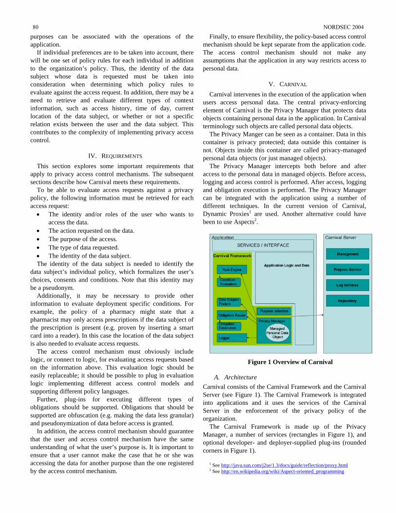
purposes can be associated with the operations of the application.
If individual preferences are to be taken into account, there will be one set of policy rules for each individual in addition to the organization’s policy. Thus, the identity of the data subject whose data is requested must be taken into consideration when determining which policy rules to evaluate against the access request. In addition, there may be a need to retrieve and evaluate different types of context information, such as access history, time of day, current location of the data subject, or whether or not a specific relation exists between the user and the data subject. This contributes to the complexity of implementing privacy access control.
IV. REQUIREMENTS This section explores some important requirements that
apply to privacy access control mechanisms. The subsequent sections describe how Carnival meets these requirements.
To be able to evaluate access requests against a privacy policy, the following information must be retrieved for each access request:
• The identity and/or roles of the user who wants to access the data.
• The action requested on the data. • The purpose of the access. • The type of data requested. • The identity of the data subject. The identity of the data subject is needed to identify the
data subject’s individual policy, which formalizes the user’s choices, consents and conditions. Note that this identity may be a pseudonym.
Additionally, it may be necessary to provide other information to evaluate deployment specific conditions. For example, the policy of a pharmacy might state that a pharmacist may only access prescriptions if the data subject of the prescription is present (e.g. proven by inserting a smart card into a reader). In this case the location of the data subject is also needed to evaluate access requests.
The access control mechanism must obviously include logic, or connect to logic, for evaluating access requests based on the information above. This evaluation logic should be easily replaceable; it should be possible to plug in evaluation logic implementing different access control models and supporting different policy languages.
Further, plug-ins for executing different types of obligations should be supported. Obligations that should be supported are obfuscation (e.g. making the data less granular) and pseudonymization of data before access is granted.
In addition, the access control mechanism should guarantee that the user and access control mechanism have the same understanding of what the user’s purpose is. It is important to ensure that a user cannot make the case that he or she was accessing the data for another purpose than the one registered by the access control mechanism.
Finally, to ensure flexibility, the policy-based access control mechanism should be kept separate from the application code. The access control mechanism should not make any assumptions that the application in any way restricts access to personal data.
V. CARNIVAL Carnival intervenes in the execution of the application when
users access personal data. The central privacy-enforcing element of Carnival is the Privacy Manager that protects data objects containing personal data in the application. In Carnival terminology such objects are called personal data objects.
The Privacy Manger can be seen as a container. Data in this container is privacy protected; data outside this container is not. Objects inside this container are called privacy-managed personal data objects (or just managed objects).
The Privacy Manager intercepts both before and after access to the personal data in managed objects. Before access, logging and access control is performed. After access, logging and obligation execution is performed. The Privacy Manager can be integrated with the application using a number of different techniques. In the current version of Carnival, Dynamic Proxies1 are used. Another alternative could have been to use Aspects2.
Figure 1 Overview of Carnival
A. Architecture Carnival consists of the Carnival Framework and the Carnival Server (see Figure 1). The Carnival Framework is integrated into applications and it uses the services of the Carnival Server in the enforcement of the privacy policy of the organization.
The Carnival Framework is made up of the Privacy Manager, a number of services (rectangles in Figure 1), and optional developer- and deployer-supplied plug-ins (rounded corners in Figure 1).
1 See http://java.sun.com/j2se/1.3/docs/guide/reflection/proxy.html2 See http://en.wikipedia.org/wiki/Aspect-oriented_programming
80 NORDSEC 2004
The Privacy Manager intercepts and collects information about access requests to personal data in managed objects. The Privacy Manager uses Data Subject Finder plug-ins to retrieve the identity of the data subjects whose personal data is requested.
The Rule Engine evaluates access requests on behalf of the Privacy Manager. The Rule Engine used by the current version of Carnival evaluates EPAL policies. It is possible to replace this Rule Engine with other implementation possibly supporting other access control models (e.g. Chinese Wall [4]) and/or policy languages. In the work of evaluating an access request the Rule Engine may call one or several Condition Evaluator plug-ins.
Accesses may result in obligations. These obligations are interpreted by the Obligation Router and handed off to the appropriate Obligation Executor plug-in.
Audit logs are created by the Logger service. It receives information about access requests and accesses to managed personal data objects from the Privacy Manager and constructs log records according to the log policy.
Finally, the Purpose Selection service implements logic for determining users’ current purposes. A method for determining a user’s current purpose is presented in section V.E.
The Carnival Server consists of: • A Management interface, for managing organization
policy (vocabularies, privacy policies, and log policies) and application configuration (links to user directory, purpose rules, and privacy metadata descriptor).
• A Repository, providing the Carnival Framework access to configuration and policy.
• A Purpose service, which stores users’ current purposes. A central Purpose service enables the purposes of users to be determined based on their actions in different applications.
• A Log service, which receives and accumulates the logs created by the Logger.
Carnival enforces privacy policies that regulate access based on the action requested, the identity and/or roles of the requesting user, the purpose of the access, the identity and preferences of the data subject associated with the data, and the type of personal data to be accessed. This information is application independent. Hence, unfavorable coupling of policy and applications is avoided. The same organization-wide policy can be applied to all applications without any adaptation to the policy.
The Carnival Server leverages this decoupling between policy and applications by providing central management and integration of policy enforcement in applications. It offers a default implementation of the services that are needed by the Carnival Framework. This reference implementation may be replaced with other solutions implementing the interfaces and services required by the Carnival Framework.
B. Execution flow Carnival regulates access to get and set methods3 in
managed personal data objects. Carnival requires that all access to personal data contained in personal data objects goes through get and set methods.
When data in a managed object is requested the Privacy Manager derives the action requested from the method called and retrieves the purpose and roles of the requesting user from the Carnival Server.
The Privacy Manager also retrieves information about the data subject and the data types of the data to be accessed. This information is collectively termed privacy metadata.
All this information is passed on to the Rule Engine that determines which policy to evaluate the request against. If an individual policy is available, it is used. Otherwise, the default local policy is used.
If the policy contains conditions these are evaluated by Condition Evaluator plug-ins. Condition Evaluators receive information about the access request (user, data subject, etc) from the Rule Engine. If the Condition Evaluator needs other information for evaluating the condition the Condition Evaluator retrieves this information from the application or some external information source.
The Rule Engine may decide that the user is denied access or, alternatively, that the access is granted. If access is denied, an exception is thrown, which the application should take appropriate actions to handle, e.g. roll back transactions and/or provide a message to the user.
The Rule Engine may associate the grant to access with one or several obligations, as determined by the applicable policy. If so, the obligations are passed on to the Obligation Router by the Privacy Manager. The Obligation Router routes the individual obligations to the correct Obligation Executor instances.
There are two types of Obligation Executors: synchronous and asynchronous. Synchronous Obligation Executors block until a result is returned. The Rule Engine may, for example, demand that, before access is granted, the level of detail in the result should be reduced according to a specification provided by the policy. For example, the age of the data subject may be replaced by an interval.
Asynchronous Obligation Executors do their job in the background. An example of such an Obligation Executor is one that is capable of sending notifications to data subjects through email.
The rest of this paper focuses on the access control functionality of Carnival. Under the hood the logging functionality is implemented much the same way as the access control functionality. The main difference is that in the case of logging, information collected is used to create a log record that is sent to the Log Service, whereas for access control the information is sent to the Rule Engine for evaluation. It is important that the log is subjected to manual and possibly
3 A get method (e.g. getId) of an object retrieves the value of an instance
variable (id) of the object. A set method modifies the value of an instance variable of an object.
NORDSEC 2004 81
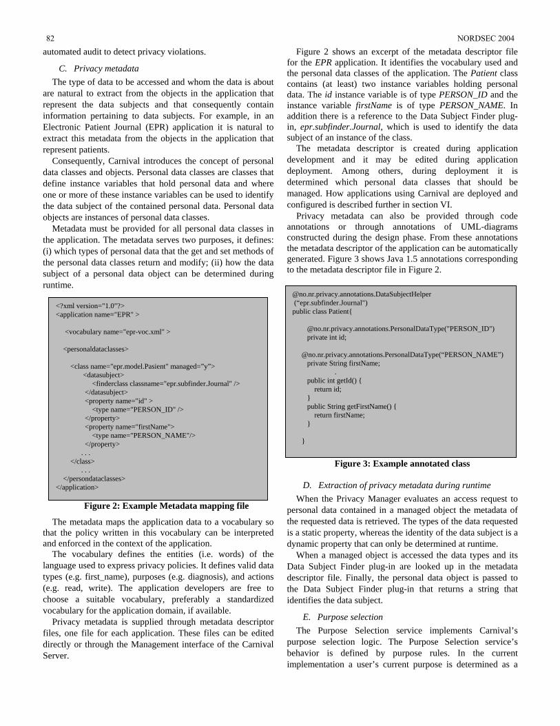
automated audit to detect privacy violations.
C. Privacy metadata The type of data to be accessed and whom the data is about
are natural to extract from the objects in the application that represent the data subjects and that consequently contain information pertaining to data subjects. For example, in an Electronic Patient Journal (EPR) application it is natural to extract this metadata from the objects in the application that represent patients.
Consequently, Carnival introduces the concept of personal data classes and objects. Personal data classes are classes that define instance variables that hold personal data and where one or more of these instance variables can be used to identify the data subject of the contained personal data. Personal data objects are instances of personal data classes.
Metadata must be provided for all personal data classes in the application. The metadata serves two purposes, it defines: (i) which types of personal data that the get and set methods of the personal data classes return and modify; (ii) how the data subject of a personal data object can be determined during runtime.
thaan
lantyp(e.chvo
fildirSe
Figure 2 shows an excerpt of the metadata descriptor file for the EPR application. It identifies the vocabulary used and the personal data classes of the application. The Patient class contains (at least) two instance variables holding personal data. The id instance variable is of type PERSON_ID and the instance variable firstName is of type PERSON_NAME. In addition there is a reference to the Data Subject Finder plug-in, epr.subfinder.Journal, which is used to identify the data subject of an instance of the class.
The metadata descriptor is created during application development and it may be edited during application deployment. Among others, during deployment it is determined which personal data classes that should be managed. How applications using Carnival are deployed and configured is described further in section VI.
Privacy metadata can also be provided through code annotations or through annotations of UML-diagrams constructed during the design phase. From these annotations the metadata descriptor of the application can be automatically generated. Figure 3 shows Java 1.5 annotations corresponding to the metadata descriptor file in Figure 2.
Figure 3: Example annotated class
@no.nr.privacy.annotations.DataSubjectHelper (“epr.subfinder.Journal") public class Patient
@no.nr.privacy.annotations.PersonalDataType("PERSON_ID") private int id; @no.nr.privacy.annotations.PersonalDataType(“PERSON_NAME”) private String firstName;
. public int getId() return id; public String getFirstName() return firstName;
D. Extraction of privacy metadata during runtime
82 NORDSEC 2004
<?xml version="1.0"?> <application name="EPR" > <vocabulary name="epr-voc.xml" > <personaldataclasses> <class name="epr.model.Pasient" managed=”y”> <datasubject> <finderclass classname="epr.subfinder.Journal" /> </datasubject> <property name="id" > <type name="PERSON_ID" /> </property> <property name="firstName"> <type name="PERSON_NAME"/> </property> . . . </class> . . . </persondataclasses> </application>
Figure 2: Example Metadata mapping file
The metadata maps the application data to a vocabulary so t the policy written in this vocabulary can be interpreted
d enforced in the context of the application. The vocabulary defines the entities (i.e. words) of the guage used to express privacy policies. It defines valid data es (e.g. first_name), purposes (e.g. diagnosis), and actions g. read, write). The application developers are free to oose a suitable vocabulary, preferably a standardized cabulary for the application domain, if available. Privacy metadata is supplied through metadata descriptor es, one file for each application. These files can be edited ectly or through the Management interface of the Carnival rver.
When the Privacy Manager evaluates an access request to personal data contained in a managed object the metadata of the requested data is retrieved. The types of the data requested is a static property, whereas the identity of the data subject is a dynamic property that can only be determined at runtime.
When a managed object is accessed the data types and its Data Subject Finder plug-in are looked up in the metadata descriptor file. Finally, the personal data object is passed to the Data Subject Finder plug-in that returns a string that identifies the data subject.
E. Purpose selection The Purpose Selection service implements Carnival’s
purpose selection logic. The Purpose Selection service’s behavior is defined by purpose rules. In the current implementation a user’s current purpose is determined as a
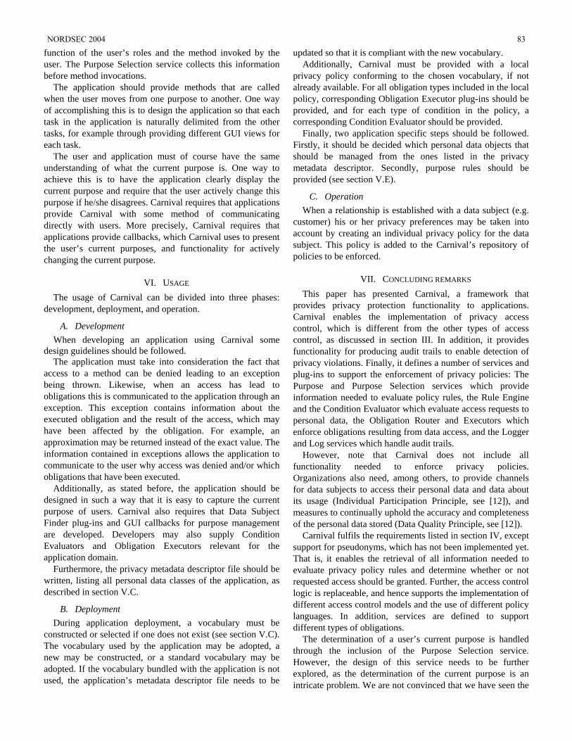
function of the user’s roles and the method invoked by the user. The Purpose Selection service collects this information before method invocations.
The application should provide methods that are called when the user moves from one purpose to another. One way of accomplishing this is to design the application so that each task in the application is naturally delimited from the other tasks, for example through providing different GUI views for each task.
The user and application must of course have the same understanding of what the current purpose is. One way to achieve this is to have the application clearly display the current purpose and require that the user actively change this purpose if he/she disagrees. Carnival requires that applications provide Carnival with some method of communicating directly with users. More precisely, Carnival requires that applications provide callbacks, which Carnival uses to present the user’s current purposes, and functionality for actively changing the current purpose.
VI. USAGE The usage of Carnival can be divided into three phases:
development, deployment, and operation.
A. Development When developing an application using Carnival some
design guidelines should be followed. The application must take into consideration the fact that
access to a method can be denied leading to an exception being thrown. Likewise, when an access has lead to obligations this is communicated to the application through an exception. This exception contains information about the executed obligation and the result of the access, which may have been affected by the obligation. For example, an approximation may be returned instead of the exact value. The information contained in exceptions allows the application to communicate to the user why access was denied and/or which obligations that have been executed.
Additionally, as stated before, the application should be designed in such a way that it is easy to capture the current purpose of users. Carnival also requires that Data Subject Finder plug-ins and GUI callbacks for purpose management are developed. Developers may also supply Condition Evaluators and Obligation Executors relevant for the application domain.
Furthermore, the privacy metadata descriptor file should be written, listing all personal data classes of the application, as described in section V.C.
B. Deployment During application deployment, a vocabulary must be
constructed or selected if one does not exist (see section V.C). The vocabulary used by the application may be adopted, a new may be constructed, or a standard vocabulary may be adopted. If the vocabulary bundled with the application is not used, the application’s metadata descriptor file needs to be
updated so that it is compliant with the new vocabulary. Additionally, Carnival must be provided with a local
privacy policy conforming to the chosen vocabulary, if not already available. For all obligation types included in the local policy, corresponding Obligation Executor plug-ins should be provided, and for each type of condition in the policy, a corresponding Condition Evaluator should be provided.
Finally, two application specific steps should be followed. Firstly, it should be decided which personal data objects that should be managed from the ones listed in the privacy metadata descriptor. Secondly, purpose rules should be provided (see section V.E).
C. Operation When a relationship is established with a data subject (e.g.
customer) his or her privacy preferences may be taken into account by creating an individual privacy policy for the data subject. This policy is added to the Carnival’s repository of policies to be enforced.
VII. CONCLUDING REMARKS This paper has presented Carnival, a framework that
provides privacy protection functionality to applications. Carnival enables the implementation of privacy access control, which is different from the other types of access control, as discussed in section III. In addition, it provides functionality for producing audit trails to enable detection of privacy violations. Finally, it defines a number of services and plug-ins to support the enforcement of privacy policies: The Purpose and Purpose Selection services which provide information needed to evaluate policy rules, the Rule Engine and the Condition Evaluator which evaluate access requests to personal data, the Obligation Router and Executors which enforce obligations resulting from data access, and the Logger and Log services which handle audit trails.
However, note that Carnival does not include all functionality needed to enforce privacy policies. Organizations also need, among others, to provide channels for data subjects to access their personal data and data about its usage (Individual Participation Principle, see [12]), and measures to continually uphold the accuracy and completeness of the personal data stored (Data Quality Principle, see [12]).
Carnival fulfils the requirements listed in section IV, except support for pseudonyms, which has not been implemented yet. That is, it enables the retrieval of all information needed to evaluate privacy policy rules and determine whether or not requested access should be granted. Further, the access control logic is replaceable, and hence supports the implementation of different access control models and the use of different policy languages. In addition, services are defined to support different types of obligations.
The determination of a user’s current purpose is handled through the inclusion of the Purpose Selection service. However, the design of this service needs to be further explored, as the determination of the current purpose is an intricate problem. We are not convinced that we have seen the
NORDSEC 2004 83
best solutions to this problem yet. One possibility we will investigate further is the use of a formal workflow-control system based on the use of Petri nets (see e.g. [9]). An advantage of this type of solution is that purposes can easily be defined across different applications.
Going forward, we plan to add support in Carnival for creation and management of pseudo domains, as proposed in [8]. Carnival will thus include functionality for generating pseudonyms, and regulating linkage between pseudonyms and the disclosure of the identities behind pseudonyms. This functionality is motivated by the fact that some functions in an organization may not need to have knowledge of information that directly identifies data subjects, typically the data subjects’ name or identity number. Their work can equally well be carried out when data subjects are identified by pseudonyms. Additionally, different functions can be provided with different pseudonyms for the same data subject, preventing unauthorized linking and matching of information.
We also plan to further evaluate the usefulness and performance of Carnival. Questions related to how intuitively it is to integrate with applications, how well it scales, and how it affects performance, will be further examined.
VIII. REFERENCES [1] R. Agrawal, J. Kiernana, S. Ramakrishnan, and Y. Xu, Hippocratic
Databases, IBM Almaden Research Center. Available at: http://www.almaden.ibm.com/software/dm/Hippocratic_Databases/hippocratic.pdf
[2] R. R. Arnesen and J. Danielsson: “A Framework for Enforcement of Privacy Policies,” in Proceedings of the Nordic Security Workshop NORDSEC 2003, October 2003. Available at: http://publications.nr.no/A_Framework_for_Enforcement_of_Privacy_Policies.pdf
[3] P. Ashley, S. Hada, G. Karjoth, C. Powers, and M. Schunter (ed.), Enterprise Privacy Authorisation Language (EPAL 1.1), IBM, 2003. Available via http://www.zurich.ibm.com/security/enterprise-privacy/epal/
[4] D.F.C. Brewer and M.J. Nash, "The Chinese Wall Security Policy," IEEE Symposium on Security and Privacy, pp. 215-228, 1989
[5] Declarative Privacy Monitoring, IBM alphaWorks, http://www.alphaworks.ibm.com/tech/dpm
[6] Directive 95/46/EC of the European Parliament and of the Council of 24 October 1995 on the protection of individuals with regard to the processing of personal data and on the free movement of such data. Official Journal L 281, 23/11/1995, pp. 31-50. Available from http://europa.eu.int/eur-lex/en/index.html
[7] S. Fischer-Hübner and A. Ott., “From a Formal Privacy Policy Model to its Implementation,” National Information Systems Security Conference (NISSC 98), 1998. Available at http://www.rsbac.org/niss98.htm
[8] R. Hes and J. Borking, (eds.), Privacy-enhancing technologies: The path to anonymity, Revised edition. ISBN: 90-74087-12-4. Registratiekamer, The Hague, August 2000
[9] K. Jensen, “Coloured Petri Nets - Basic Concepts, Analysis Methods and Practical Use, Volume 1, Basic Concepts.” Monographs in Theoretical Computer Science, Springer-Verlag, 1997
[10] G. Karjoth and M. Schunter, A Privacy Policy Model for Enterprises, 15th IEEE Computer Security Foundations Workshop, June 2002
[11] M. Hansen and A. Pfitzmann, Anonymity, Unobservability and Pseudonymity – A Proposal for Terminology, v0.21, Available at http://dud.inf.tu-dresden.de/Literatur_V1.shtml
[12] OECD, Guidelines on the Protection of Privacy and Transborder Flows of Personal Data, Available at http://www1.oecd.org/publications/e-book/9302011E.PDF
84 NORDSEC 2004
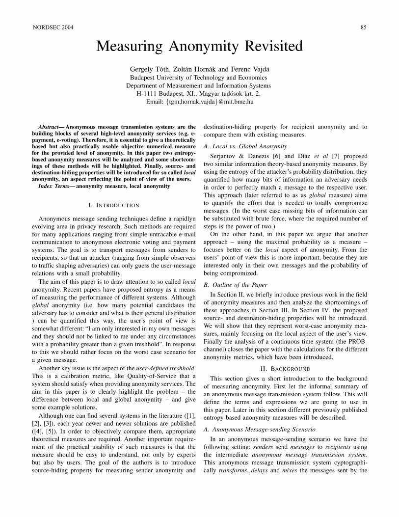
Measuring Anonymity Revisited
Gergely Toth, Zoltan Hornak and Ferenc Vajda
Budapest University of Technology and Economics
Department of Measurement and Information Systems
H-1111 Budapest, XI., Magyar tudosok krt. 2.
Email: tgm,hornak,[email protected]
Abstract— Anonymous message transmission systems are thebuilding blocks of several high-level anonymity services (e.g. e-payment, e-voting). Therefore, it is essential to give a theoreticallybased but also practically usable objective numerical measurefor the provided level of anonymity. In this paper two entropy-based anonymity measures will be analyzed and some shortcom-ings of these methods will be highlighted. Finally, source- anddestination-hiding properties will be introduced for so called local
anonymity, an aspect reflecting the point of view of the users.
Index Terms— anonymity measure, local anonymity
I. INTRODUCTION
Anonymous message sending techniques define a rapidlyn
evolving area in privacy research. Such methods are required
for many applications ranging from simple untracable e-mail
communication to anonymous electronic voting and payment
systems. The goal is to transport messages from senders to
recipients, so that an attacker (ranging from simple observers
to traffic shaping adversaries) can only guess the user-message
relations with a small probability.
The aim of this paper is to draw attention to so called local
anonymity. Recent papers have proposed entropy as a means
of measuring the performance of different systems. Although
global anonymity (i.e. how many potential candidates the
adversary has to consider and what is their general distribution
) can be quantified this way, the user’s point of view is
somewhat different: “I am only interested in my own messages
and they should not be linked to me under any circumstances
with a probability greater than a given treshhold”. In response
to this we should rather focus on the worst case scenario for
a given message.
Another key issue is the aspect of the user-defined treshhold.
This is a calibration metric, like Quality-of-Service that a
system should satisfy when providing anonymity services. The
aim in this paper is to clearly highlight the problem – the
difference between local and global anonymity – and give
some example solutions.
Although one can find several systems in the literature ([1],
[2], [3]), each year newer and newer solutions are published
([4], [5]). In order to objectively compare them, appropriate
theoretical measures are required. Another important require-
ment of the practical usability of such measures is that the
measure should be easy to understand, not only by experts
but also by users. The goal of the authors is to introduce
source-hiding property for measuring sender anonymity and
destination-hiding property for recipient anonymity and to
compare them with existing measures.
A. Local vs. Global Anonymity
Serjantov & Danezis [6] and Dıaz et al [7] proposed
two similar information theory-based anonymity measures. By
using the entropy of the attacker’s probability distribution, they
quantified how many bits of information an adversary needs
in order to perfectly match a message to the respective user.
This approach (later referred to as as global measure) aims
to quantify the effort that is needed to totally compromize
messages. (In the worst case missing bits of information can
be substituted with brute force, where the required number of
steps is the power of two.)
On the other hand, in this paper we argue that another
approach – using the maximal probability as a measure –
focuses better on the local aspect of anonymity. From the
users’ point of view this is more important, because they are
interested only in their own messages and the probability of
being compromized.
B. Outline of the Paper
In Section II. we briefly introduce previous work in the field
of anonymity measures and then analyze the shortcomings of
these approaches in Section III. In Section IV. the proposed
source- and destination-hiding properties will be introduced.
We will show that they represent worst-case anonymity mea-
sures, mainly focusing on the local aspect of the user’s view.
Finally the analysis of a continuous time system (the PROB-
channel) closes the paper with the calculations for the different
anonymity metrics, which have been introduced.
II. BACKGROUND
This section gives a short introduction to the background
of measuring anonymity. First let the informal summary of
an anonymous message transmission system follow. This will
define the terms and expressions we are going to use in
this paper. Later in this section different previously published
entropy-based anonymity measures will be described.
A. Anonymous Message-sending Scenario
In an anonymous message-sending scenario we have the
following setting: senders send messages to recipients using
the intermediate anonymous message transmission system.
This anonymous message transmission system cyptographi-
cally transforms, delays and mixes the messages sent by the
NORDSEC 2004 85
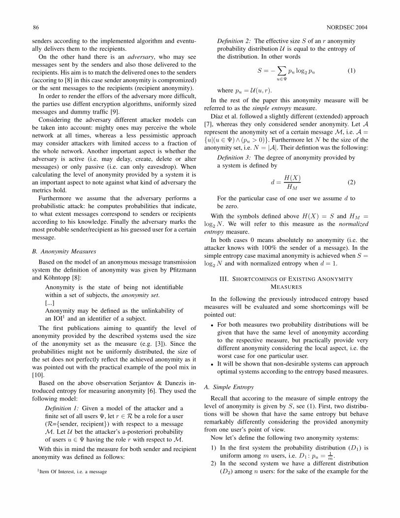
senders according to the implemented algorithm and eventu-
ally delivers them to the recipients.
On the other hand there is an adversary, who may see
messages sent by the senders and also those delivered to the
recipients. His aim is to match the delivered ones to the senders
(accoring to [8] in this case sender anonymity is compromized)
or the sent messages to the recipients (recipient anonymity).
In order to render the effors of the adversary more difficult,
the parties use diffent encryption algorithms, uniformly sized
messages and dummy traffic [9].
Considering the adversary different attacker models can
be taken into account: mighty ones may perceive the whole
network at all times, whereas a less pessimistic approach
may consider attackers with limited access to a fraction of
the whole network. Another important aspect is whether the
adversary is active (i.e. may delay, create, delete or alter
messages) or only passive (i.e. can only eavesdrop). When
calculating the level of anonymity provided by a system it is
an important aspect to note against what kind of adversary the
metrics hold.
Furthermore we assume that the adversary performs a
probabilistic attack: he computes probabilities that indicate,
to what extent messages correspond to senders or recipients
according to his knowledge. Finally the adversary marks the
most probable sender/recipient as his guessed user for a certain
message.
B. Anonymity Measures
Based on the model of an anonymous message transmission
system the definition of anonymity was given by Pfitzmann
and Kohntopp [8]:
Anonymity is the state of being not identifiable
within a set of subjects, the anonymity set.
[...]
Anonymity may be defined as the unlinkability of
an IOI1 and an identifier of a subject.
The first publications aiming to quantify the level of
anonymity provided by the described systems used the size
of the anonymity set as the measure (e.g. [3]). Since the
probabilities might not be uniformly distributed, the size of
the set does not perfectly reflect the achieved anonymity as it
was pointed out with the practical example of the pool mix in
[10].
Based on the above observation Serjantov & Danezis in-
troduced entropy for measuring anonymity [6]. They used the
following model:
Definition 1: Given a model of the attacker and a
finite set of all users Ψ, let r ∈ R be a role for a user
(R=sender, recipient) with respect to a message
M. Let U bet the attacker’s a-posteriori probability
of users u ∈ Ψ having the role r with respect to M.
With this in mind the measure for both sender and recipient
anonymity was defined as follows:
1Item Of Interest, i.e. a message
Definition 2: The effective size S of an r anonymity
probability distribution U is equal to the entropy of
the distribution. In other words
S = −∑
u∈Ψ
pu log2 pu (1)
where pu = U(u, r).
In the rest of the paper this anonymity measure will be
referred to as the simple entropy measure.
Dıaz et al. followed a slightly different (extended) approach
[7], whereas they only considered sender anonymity. Let Arepresent the anonymity set of a certain message M, i.e. A =u|(u ∈ Ψ)∧ (pu > 0). Furthermore let N be the size of the
anonymity set, i.e. N = |A|. Their defintion was the following:
Definition 3: The degree of anonymity provided by
a system is defined by
d =H(X)
HM
(2)
For the particular case of one user we assume d to
be zero.
With the symbols defined above H(X) = S and HM =log2 N . We will refer to this measure as the normalized
entropy measure.
In both cases 0 means absolutely no anonymity (i.e. the
attacker knows with 100% the sender of a message). In the
simple entropy case maximal anonymity is achieved when S =log2 N and with normalized entropy when d = 1.
III. SHORTCOMINGS OF EXISTING ANONYMITY
MEASURES
In the following the previously introduced entropy based
measures will be evaluated and some shortcomings will be
pointed out:
• For both measures two probability distributions will be
given that have the same level of anonymity according
to the respective measure, but practically provide very
different anonymity considering the local aspect, i.e. the
worst case for one particular user.
• It will be shown that non-desirable systems can approach
optimal systems according to the entropy based measures.
A. Simple Entropy
Recall that accoring to the measure of simple entropy the
level of anonymity is given by S, see (1). First, two distribu-
tions will be shown that have the same entropy but behave
remarkably differently considering the provided anonymity
from one user’s point of view.
Now let’s define the following two anonymity systems:
1) In the first system the probability distribution (D1) is
uniform among m users, i.e. D1 : pu = 1m
.
2) In the second system we have a different distribution
(D2) among n users: for the sake of the example for the
86 NORDSEC 2004
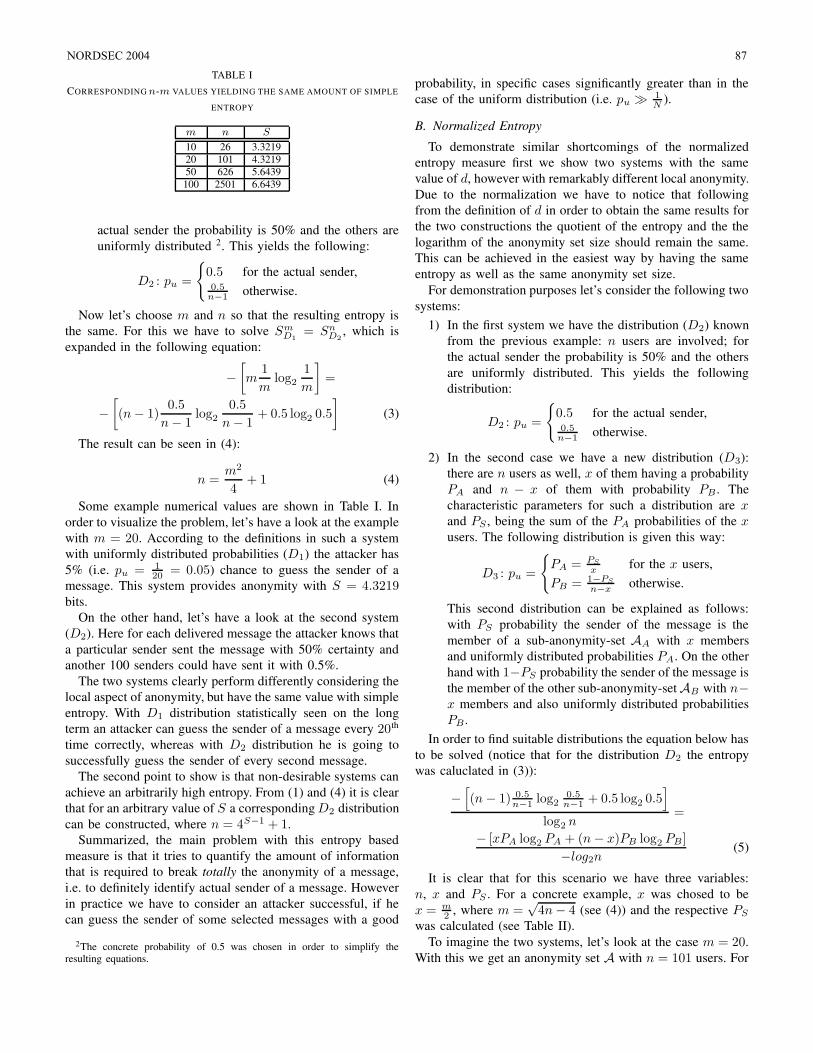
TABLE I
CORRESPONDING n-m VALUES YIELDING THE SAME AMOUNT OF SIMPLE
ENTROPY
m n S
10 26 3.3219
20 101 4.3219
50 626 5.6439
100 2501 6.6439
actual sender the probability is 50% and the others are
uniformly distributed 2. This yields the following:
D2 : pu =
0.5 for the actual sender,0.5
n−1 otherwise.
Now let’s choose m and n so that the resulting entropy is
the same. For this we have to solve SmD1
= SnD2
, which is
expanded in the following equation:
−
[
m1
mlog2
1
m
]
=
−
[
(n − 1)0.5
n − 1log2
0.5
n − 1+ 0.5 log2 0.5
]
(3)
The result can be seen in (4):
n =m2
4+ 1 (4)
Some example numerical values are shown in Table I. In
order to visualize the problem, let’s have a look at the example
with m = 20. According to the definitions in such a system
with uniformly distributed probabilities (D1) the attacker has
5% (i.e. pu = 120 = 0.05) chance to guess the sender of a
message. This system provides anonymity with S = 4.3219bits.
On the other hand, let’s have a look at the second system
(D2). Here for each delivered message the attacker knows that
a particular sender sent the message with 50% certainty and
another 100 senders could have sent it with 0.5%.
The two systems clearly perform differently considering the
local aspect of anonymity, but have the same value with simple
entropy. With D1 distribution statistically seen on the long
term an attacker can guess the sender of a message every 20th
time correctly, whereas with D2 distribution he is going to
successfully guess the sender of every second message.
The second point to show is that non-desirable systems can
achieve an arbitrarily high entropy. From (1) and (4) it is clear
that for an arbitrary value of S a corresponding D2 distribution
can be constructed, where n = 4S−1 + 1.
Summarized, the main problem with this entropy based
measure is that it tries to quantify the amount of information
that is required to break totally the anonymity of a message,
i.e. to definitely identify actual sender of a message. However
in practice we have to consider an attacker successful, if he
can guess the sender of some selected messages with a good
2The concrete probability of 0.5 was chosen in order to simplify theresulting equations.
probability, in specific cases significantly greater than in the
case of the uniform distribution (i.e. pu 1N
).
B. Normalized Entropy
To demonstrate similar shortcomings of the normalized
entropy measure first we show two systems with the same
value of d, however with remarkably different local anonymity.
Due to the normalization we have to notice that following
from the definition of d in order to obtain the same results for
the two constructions the quotient of the entropy and the the
logarithm of the anonymity set size should remain the same.
This can be achieved in the easiest way by having the same
entropy as well as the same anonymity set size.
For demonstration purposes let’s consider the following two
systems:
1) In the first system we have the distribution (D2) known
from the previous example: n users are involved; for
the actual sender the probability is 50% and the others
are uniformly distributed. This yields the following
distribution:
D2 : pu =
0.5 for the actual sender,0.5
n−1 otherwise.
2) In the second case we have a new distribution (D3):
there are n users as well, x of them having a probability
PA and n − x of them with probability PB . The
characteristic parameters for such a distribution are x
and PS , being the sum of the PA probabilities of the x
users. The following distribution is given this way:
D3 : pu =
PA = PS
xfor the x users,
PB = 1−PS
n−xotherwise.
This second distribution can be explained as follows:
with PS probability the sender of the message is the
member of a sub-anonymity-set AA with x members
and uniformly distributed probabilities PA. On the other
hand with 1−PS probability the sender of the message is
the member of the other sub-anonymity-set AB with n−x members and also uniformly distributed probabilities
PB .
In order to find suitable distributions the equation below has
to be solved (notice that for the distribution D2 the entropy
was caluclated in (3)):
−[
(n − 1) 0.5n−1 log2
0.5n−1 + 0.5 log2 0.5
]
log2 n=
− [xPA log2 PA + (n − x)PB log2 PB ]
−log2n(5)
It is clear that for this scenario we have three variables:
n, x and PS . For a concrete example, x was chosed to be
x = m2 , where m =
√4n − 4 (see (4)) and the respective PS
was calculated (see Table II).
To imagine the two systems, let’s look at the case m = 20.
With this we get an anonymity set A with n = 101 users. For
NORDSEC 2004 87
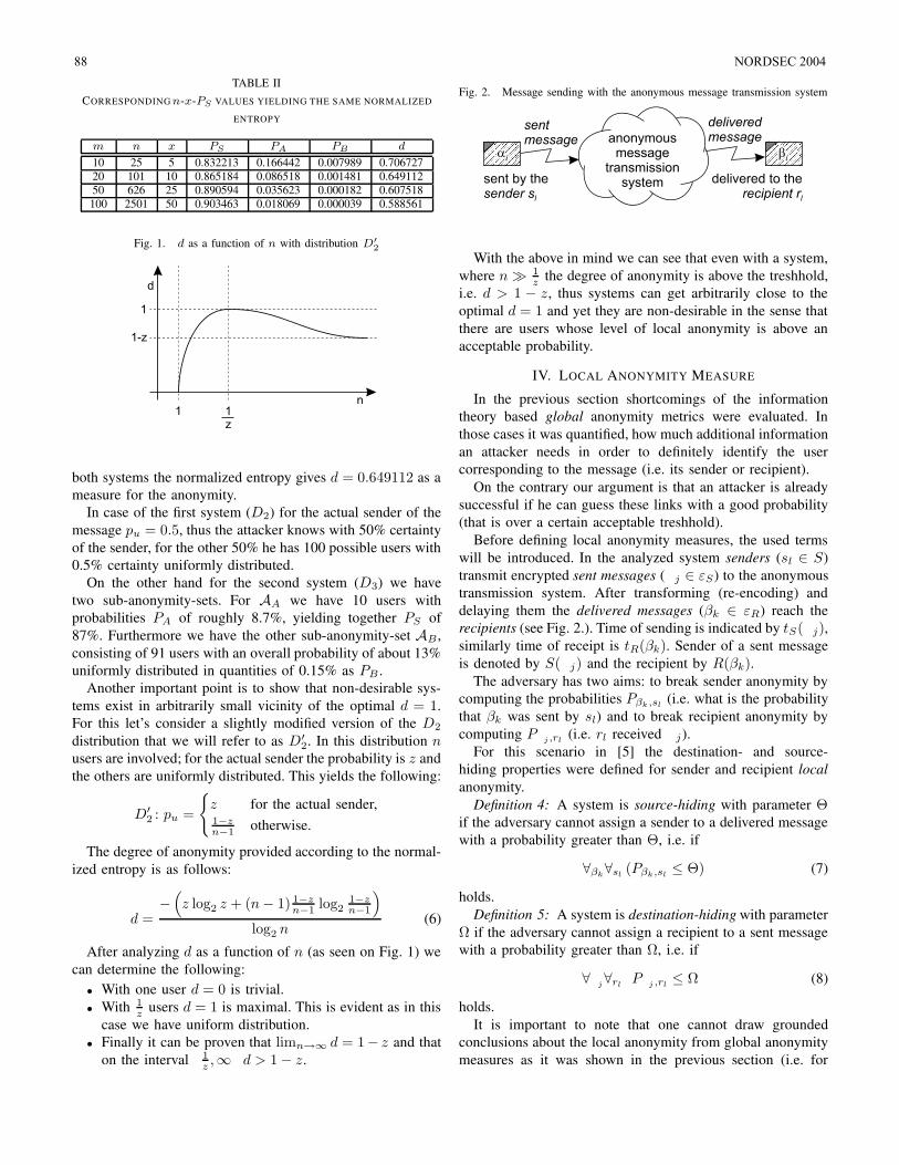
TABLE II
CORRESPONDING n-x-PS VALUES YIELDING THE SAME NORMALIZED
ENTROPY
m n x PS PA PB d
10 25 5 0.832213 0.166442 0.007989 0.706727
20 101 10 0.865184 0.086518 0.001481 0.649112
50 626 25 0.890594 0.035623 0.000182 0.607518
100 2501 50 0.903463 0.018069 0.000039 0.588561
Fig. 1. d as a function of n with distribution D′
2
both systems the normalized entropy gives d = 0.649112 as a
measure for the anonymity.
In case of the first system (D2) for the actual sender of the
message pu = 0.5, thus the attacker knows with 50% certainty
of the sender, for the other 50% he has 100 possible users with
0.5% certainty uniformly distributed.
On the other hand for the second system (D3) we have
two sub-anonymity-sets. For AA we have 10 users with
probabilities PA of roughly 8.7%, yielding together PS of
87%. Furthermore we have the other sub-anonymity-set AB ,
consisting of 91 users with an overall probability of about 13%
uniformly distributed in quantities of 0.15% as PB .
Another important point is to show that non-desirable sys-
tems exist in arbitrarily small vicinity of the optimal d = 1.
For this let’s consider a slightly modified version of the D2
distribution that we will refer to as D′2. In this distribution n
users are involved; for the actual sender the probability is z and
the others are uniformly distributed. This yields the following:
D′2 : pu =
z for the actual sender,1−zn−1 otherwise.
The degree of anonymity provided according to the normal-
ized entropy is as follows:
d =−
(
z log2 z + (n − 1) 1−zn−1 log2
1−zn−1
)
log2 n(6)
After analyzing d as a function of n (as seen on Fig. 1) we
can determine the following:
• With one user d = 0 is trivial.
• With 1z
users d = 1 is maximal. This is evident as in this
case we have uniform distribution.
• Finally it can be proven that limn→∞ d = 1− z and that
on the interval
1z,∞
d > 1 − z.
Fig. 2. Message sending with the anonymous message transmission system
With the above in mind we can see that even with a system,
where n 1z
the degree of anonymity is above the treshhold,
i.e. d > 1 − z, thus systems can get arbitrarily close to the
optimal d = 1 and yet they are non-desirable in the sense that
there are users whose level of local anonymity is above an
acceptable probability.
IV. LOCAL ANONYMITY MEASURE
In the previous section shortcomings of the information
theory based global anonymity metrics were evaluated. In
those cases it was quantified, how much additional information
an attacker needs in order to definitely identify the user
corresponding to the message (i.e. its sender or recipient).
On the contrary our argument is that an attacker is already
successful if he can guess these links with a good probability
(that is over a certain acceptable treshhold).
Before defining local anonymity measures, the used terms
will be introduced. In the analyzed system senders (sl ∈ S)
transmit encrypted sent messages (j ∈ εS) to the anonymous
transmission system. After transforming (re-encoding) and
delaying them the delivered messages (βk ∈ εR) reach the
recipients (see Fig. 2.). Time of sending is indicated by tS(j),similarly time of receipt is tR(βk). Sender of a sent message
is denoted by S(j) and the recipient by R(βk).The adversary has two aims: to break sender anonymity by
computing the probabilities Pβk ,sl(i.e. what is the probability
that βk was sent by sl) and to break recipient anonymity by
computing Pj ,rl(i.e. rl received j).
For this scenario in [5] the destination- and source-
hiding properties were defined for sender and recipient local
anonymity.
Definition 4: A system is source-hiding with parameter Θif the adversary cannot assign a sender to a delivered message
with a probability greater than Θ, i.e. if
∀βk∀sl
(Pβk,sl≤ Θ) (7)
holds.
Definition 5: A system is destination-hiding with parameter
Ω if the adversary cannot assign a recipient to a sent message
with a probability greater than Ω, i.e. if
∀j∀rl
Pj ,rl≤ Ω
(8)
holds.
It is important to note that one cannot draw grounded
conclusions about the local anonymity from global anonymity
measures as it was shown in the previous section (i.e. for
88 NORDSEC 2004
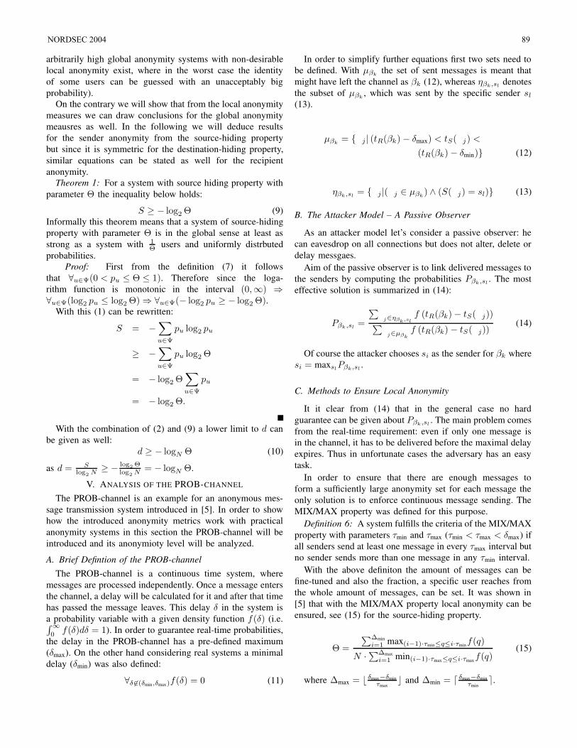
arbitrarily high global anonymity systems with non-desirable
local anonymity exist, where in the worst case the identity
of some users can be guessed with an unacceptably big
probability).
On the contrary we will show that from the local anonymity
measures we can draw conclusions for the global anonymity
meausres as well. In the following we will deduce results
for the sender anonymity from the source-hiding property
but since it is symmetric for the destination-hiding property,
similar equations can be stated as well for the recipient
anonymity.
Theorem 1: For a system with source hiding property with
parameter Θ the inequality below holds:
S ≥ − log2 Θ (9)
Informally this theorem means that a system of source-hiding
property with parameter Θ is in the global sense at least as
strong as a system with 1Θ users and uniformly distrbuted
probabilities.
Proof: First from the definition (7) it follows
that ∀u∈Ψ(0 < pu ≤ Θ ≤ 1). Therefore since the loga-
rithm function is monotonic in the interval (0,∞) ⇒∀u∈Ψ(log2 pu ≤ log2 Θ) ⇒ ∀u∈Ψ(− log2 pu ≥ − log2 Θ).
With this (1) can be rewritten:
S = −∑
u∈Ψ
pu log2 pu
≥ −∑
u∈Ψ
pu log2 Θ
= − log2 Θ∑
u∈Ψ
pu
= − log2 Θ.
With the combination of (2) and (9) a lower limit to d can
be given as well:
d ≥ − logN Θ (10)
as d = Slog
2N
≥ −log
2Θ
log2
N= − logN Θ.
V. ANALYSIS OF THE PROB-CHANNEL
The PROB-channel is an example for an anonymous mes-
sage transmission system introduced in [5]. In order to show
how the introduced anonymity metrics work with practical
anonymity systems in this section the PROB-channel will be
introduced and its anonymioty level will be analyzed.
A. Brief Defintion of the PROB-channel
The PROB-channel is a continuous time system, where
messages are processed independently. Once a message enters
the channel, a delay will be calculated for it and after that time
has passed the message leaves. This delay δ in the system is
a probability variable with a given density function f(δ) (i.e.∫ ∞
0f(δ)dδ = 1). In order to guarantee real-time probabilities,
the delay in the PROB-channel has a pre-defined maximum
(δmax). On the other hand considering real systems a minimal
delay (δmin) was also defined:
∀δ 6∈(δmin,δmax)f(δ) = 0 (11)
In order to simplify further equations first two sets need to
be defined. With µβkthe set of sent messages is meant that
might have left the channel as βk (12), whereas ηβk,sldenotes
the subset of µβk, which was sent by the specific sender sl
(13).
µβk= j | (tR(βk) − δmax) < tS(j) <
(tR(βk) − δmin) (12)
ηβk,sl= j |(j ∈ µβk
) ∧ (S(j) = sl) (13)
B. The Attacker Model – A Passive Observer
As an attacker model let’s consider a passive observer: he
can eavesdrop on all connections but does not alter, delete or
delay messgaes.
Aim of the passive observer is to link delivered messages to
the senders by computing the probabilities Pβk,sl. The most
effective solution is summarized in (14):
Pβk ,sl=
∑
j∈ηβk
,sl
f (tR(βk) − tS(j))∑
j∈µβk
f (tR(βk) − tS(j))(14)
Of course the attacker chooses si as the sender for βk where
si = maxslPβk,sl
.
C. Methods to Ensure Local Anonymity
It it clear from (14) that in the general case no hard
guarantee can be given about Pβk,sl. The main problem comes
from the real-time requirement: even if only one message is
in the channel, it has to be delivered before the maximal delay
expires. Thus in unfortunate cases the adversary has an easy
task.
In order to ensure that there are enough messages to
form a sufficiently large anonymity set for each message the
only solution is to enforce continuous message sending. The
MIX/MAX property was defined for this purpose.
Definition 6: A system fulfills the criteria of the MIX/MAX
property with parameters τmin and τmax (τmin < τmax < δmax) if
all senders send at least one message in every τmax interval but
no sender sends more than one message in any τmin interval.
With the above definiton the amount of messages can be
fine-tuned and also the fraction, a specific user reaches from
the whole amount of messages, can be set. It was shown in
[5] that with the MIX/MAX property local anonymity can be
ensured, see (15) for the source-hiding property.
Θ =
∑∆min
i=1 max(i−1)·τmin≤q≤i·τminf(q)
N ·∑∆max
i=1 min(i−1)·τmax≤q≤i·τmaxf(q)
(15)
where ∆max = b δmax−δmin
τmaxc and ∆min = d δmax−δmin
τmine.
NORDSEC 2004 89
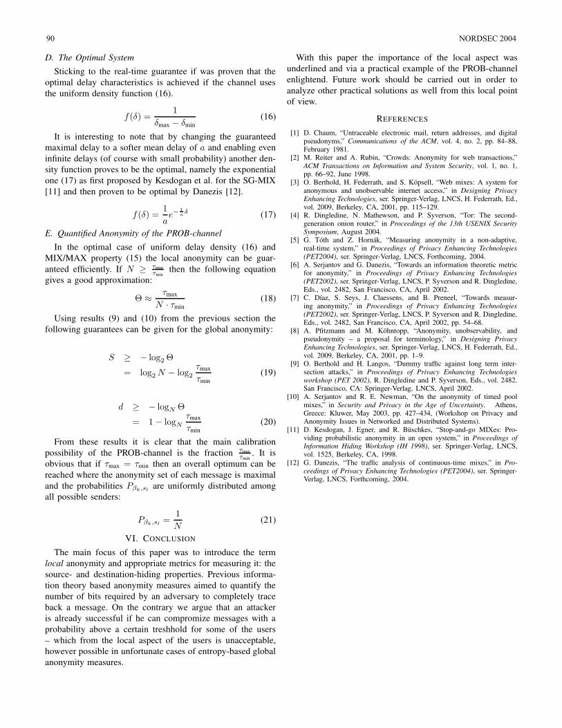
D. The Optimal System
Sticking to the real-time guarantee if was proven that the
optimal delay characteristics is achieved if the channel uses
the uniform density function (16).
f(δ) =1
δmax − δmin
(16)
It is interesting to note that by changing the guaranteed
maximal delay to a softer mean delay of a and enabling even
infinite delays (of course with small probability) another den-
sity function proves to be the optimal, namely the exponential
one (17) as first proposed by Kesdogan et al. for the SG-MIX
[11] and then proven to be optimal by Danezis [12].
f(δ) =1
ae−
1
aδ (17)
E. Quantified Anonymity of the PROB-channel
In the optimal case of uniform delay density (16) and
MIX/MAX property (15) the local anonymity can be guar-
anteed efficiently. If N ≥ τmax
τminthen the following equation
gives a good approximation:
Θ ≈τmax
N · τmin
(18)
Using results (9) and (10) from the previous section the
following guarantees can be given for the global anonymity:
S ≥ − log2 Θ
= log2 N − log2
τmax
τmin
(19)
d ≥ − logN Θ
= 1 − logN
τmax
τmin
(20)
From these results it is clear that the main calibration
possibility of the PROB-channel is the fraction τmax
τmin. It is
obvious that if τmax = τmin then an overall optimum can be
reached where the anonymity set of each message is maximal
and the probabilities Pβk,slare uniformly distributed among
all possible senders:
Pβk,sl=
1
N(21)
VI. CONCLUSION
The main focus of this paper was to introduce the term
local anonymity and appropriate metrics for measuring it: the
source- and destination-hiding properties. Previous informa-
tion theory based anonymity measures aimed to quantify the
number of bits required by an adversary to completely trace
back a message. On the contrary we argue that an attacker
is already successful if he can compromize messages with a
probability above a certain treshhold for some of the users
– which from the local aspect of the users is unacceptable,
however possible in unfortunate cases of entropy-based global
anonymity measures.
With this paper the importance of the local aspect was
underlined and via a practical example of the PROB-channel
enlightend. Future work should be carried out in order to
analyze other practical solutions as well from this local point
of view.
REFERENCES
[1] D. Chaum, “Untraceable electronic mail, return addresses, and digitalpseudonyms,” Communications of the ACM, vol. 4, no. 2, pp. 84–88,February 1981.
[2] M. Reiter and A. Rubin, “Crowds: Anonymity for web transactions,”ACM Transactions on Information and System Security, vol. 1, no. 1,pp. 66–92, June 1998.
[3] O. Berthold, H. Federrath, and S. Kopsell, “Web mixes: A system foranonymous and unobservable internet access,” in Designing Privacy
Enhancing Technologies, ser. Springer-Verlag, LNCS, H. Federrath, Ed.,vol. 2009, Berkeley, CA, 2001, pp. 115–129.
[4] R. Dingledine, N. Mathewson, and P. Syverson, “Tor: The second-generation onion router,” in Proceedings of the 13th USENIX Security
Symposium, August 2004.[5] G. Toth and Z. Hornak, “Measuring anonymity in a non-adaptive,
real-time system,” in Proceedings of Privacy Enhancing Technologies
(PET2004), ser. Springer-Verlag, LNCS, Forthcoming, 2004.[6] A. Serjantov and G. Danezis, “Towards an information theoretic metric
for anonymity,” in Proceedings of Privacy Enhancing Technologies
(PET2002), ser. Springer-Verlag, LNCS, P. Syverson and R. Dingledine,Eds., vol. 2482, San Francisco, CA, April 2002.
[7] C. Dıaz, S. Seys, J. Claessens, and B. Preneel, “Towards measur-ing anonymity,” in Proceedings of Privacy Enhancing Technologies
(PET2002), ser. Springer-Verlag, LNCS, P. Syverson and R. Dingledine,Eds., vol. 2482, San Francisco, CA, April 2002, pp. 54–68.
[8] A. Pfitzmann and M. Kohntopp, “Anonymity, unobservability, andpseudonymity – a proposal for terminology,” in Designing Privacy
Enhancing Technologies, ser. Springer-Verlag, LNCS, H. Federrath, Ed.,vol. 2009, Berkeley, CA, 2001, pp. 1–9.
[9] O. Berthold and H. Langos, “Dummy traffic against long term inter-section attacks,” in Proceedings of Privacy Enhancing Technologies
workshop (PET 2002), R. Dingledine and P. Syverson, Eds., vol. 2482.San Francisco, CA: Springer-Verlag, LNCS, April 2002.
[10] A. Serjantov and R. E. Newman, “On the anonymity of timed poolmixes,” in Security and Privacy in the Age of Uncertainty. Athens,Greece: Kluwer, May 2003, pp. 427–434, (Workshop on Privacy andAnonymity Issues in Networked and Distributed Systems).
[11] D. Kesdogan, J. Egner, and R. Buschkes, “Stop-and-go MIXes: Pro-viding probabilistic anonymity in an open system,” in Proceedings ofInformation Hiding Workshop (IH 1998), ser. Springer-Verlag, LNCS,vol. 1525, Berkeley, CA, 1998.
[12] G. Danezis, “The traffic analysis of continuous-time mixes,” in Pro-
ceedings of Privacy Enhancing Technologies (PET2004), ser. Springer-Verlag, LNCS, Forthcoming, 2004.
90 NORDSEC 2004
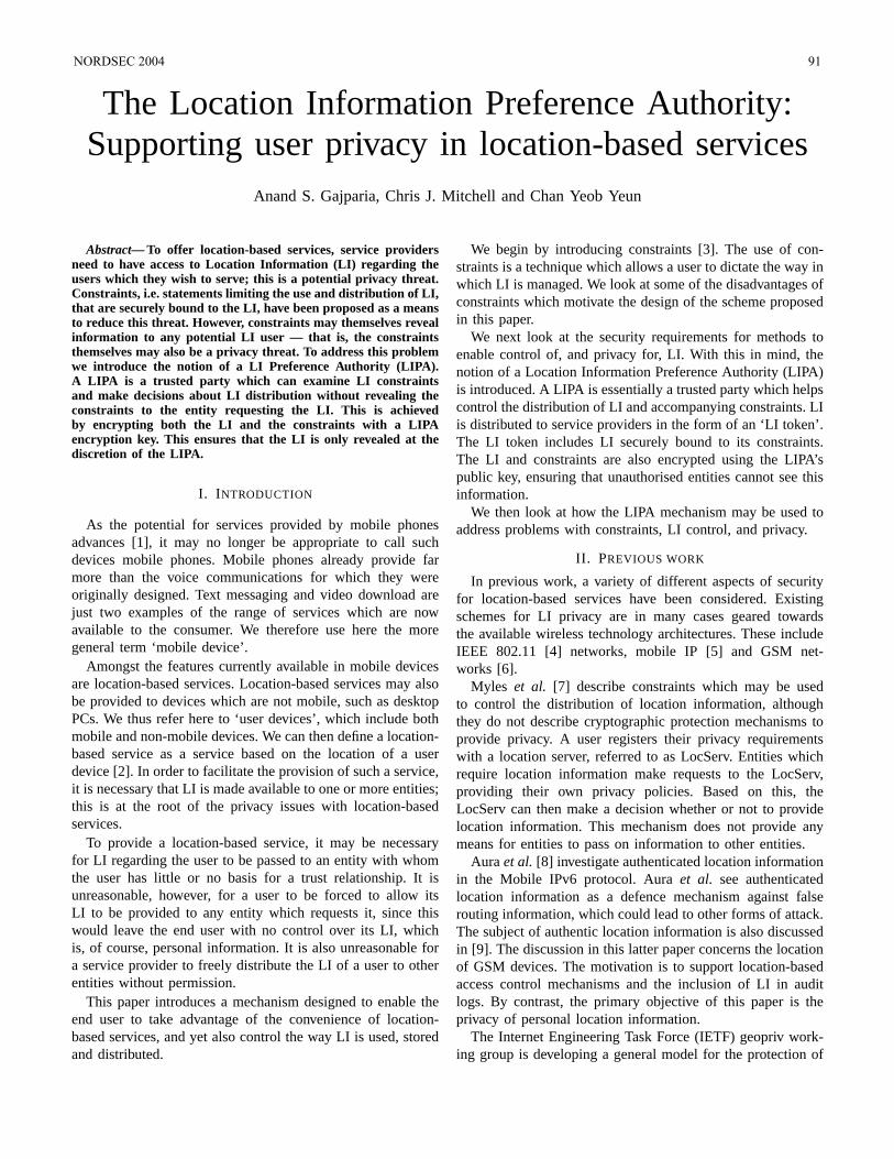
The Location Information Preference Authority:Supporting user privacy in location-based services
Anand S. Gajparia, Chris J. Mitchell and Chan Yeob Yeun
Abstract— To offer location-based services, service providersneed to have access to Location Information (LI) regarding theusers which they wish to serve; this is a potential privacy threat.Constraints, i.e. statements limiting the use and distribution of LI,that are securely bound to the LI, have been proposed as a meansto reduce this threat. However, constraints may themselves revealinformation to any potential LI user — that is, the constraintsthemselves may also be a privacy threat. To address this problemwe introduce the notion of a LI Preference Authority (LIPA).A LIPA is a trusted party which can examine LI constraintsand make decisions about LI distribution without revealing theconstraints to the entity requesting the LI. This is achievedby encrypting both the LI and the constraints with a LIPAencryption key. This ensures that the LI is only revealed at thediscretion of the LIPA.
I. I NTRODUCTION
As the potential for services provided by mobile phonesadvances [1], it may no longer be appropriate to call suchdevices mobile phones. Mobile phones already provide farmore than the voice communications for which they wereoriginally designed. Text messaging and video download arejust two examples of the range of services which are nowavailable to the consumer. We therefore use here the moregeneral term ‘mobile device’.
Amongst the features currently available in mobile devicesare location-based services. Location-based services mayalsobe provided to devices which are not mobile, such as desktopPCs. We thus refer here to ‘user devices’, which include bothmobile and non-mobile devices. We can then define a location-based service as a service based on the location of a userdevice [2]. In order to facilitate the provision of such a service,it is necessary that LI is made available to one or more entities;this is at the root of the privacy issues with location-basedservices.
To provide a location-based service, it may be necessaryfor LI regarding the user to be passed to an entity with whomthe user has little or no basis for a trust relationship. It isunreasonable, however, for a user to be forced to allow itsLI to be provided to any entity which requests it, since thiswould leave the end user with no control over its LI, whichis, of course, personal information. It is also unreasonable fora service provider to freely distribute the LI of a user to otherentities without permission.
This paper introduces a mechanism designed to enable theend user to take advantage of the convenience of location-based services, and yet also control the way LI is used, storedand distributed.
We begin by introducing constraints [3]. The use of con-straints is a technique which allows a user to dictate the wayinwhich LI is managed. We look at some of the disadvantages ofconstraints which motivate the design of the scheme proposedin this paper.
We next look at the security requirements for methods toenable control of, and privacy for, LI. With this in mind, thenotion of a Location Information Preference Authority (LIPA)is introduced. A LIPA is essentially a trusted party which helpscontrol the distribution of LI and accompanying constraints. LIis distributed to service providers in the form of an ‘LI token’.The LI token includes LI securely bound to its constraints.The LI and constraints are also encrypted using the LIPA’spublic key, ensuring that unauthorised entities cannot seethisinformation.
We then look at how the LIPA mechanism may be used toaddress problems with constraints, LI control, and privacy.
II. PREVIOUS WORK
In previous work, a variety of different aspects of securityfor location-based services have been considered. Existingschemes for LI privacy are in many cases geared towardsthe available wireless technology architectures. These includeIEEE 802.11 [4] networks, mobile IP [5] and GSM net-works [6].
Myles et al. [7] describe constraints which may be usedto control the distribution of location information, althoughthey do not describe cryptographic protection mechanisms toprovide privacy. A user registers their privacy requirementswith a location server, referred to as LocServ. Entities whichrequire location information make requests to the LocServ,providing their own privacy policies. Based on this, theLocServ can then make a decision whether or not to providelocation information. This mechanism does not provide anymeans for entities to pass on information to other entities.
Aura et al. [8] investigate authenticated location informationin the Mobile IPv6 protocol. Auraet al. see authenticatedlocation information as a defence mechanism against falserouting information, which could lead to other forms of attack.The subject of authentic location information is also discussedin [9]. The discussion in this latter paper concerns the locationof GSM devices. The motivation is to support location-basedaccess control mechanisms and the inclusion of LI in auditlogs. By contrast, the primary objective of this paper is theprivacy of personal location information.
The Internet Engineering Task Force (IETF) geopriv work-ing group is developing a general model for the protection of
NORDSEC 2004 91
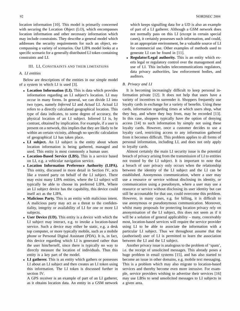
location information [10]. This model is primarily concernedwith securing the Location Object (LO), which encompasseslocation information and other necessary information whichmay include constraints. They describe a general model whichaddresses the security requirements for such an object, en-compassing a variety of scenarios. Our LIPA model looks at aspecific scenario for a generally distributed LI token containingconstraints and LI.
III. LI, C ONSTRAINTS AND THEIR LIMITATIONS
A. LI entities
Below are descriptions of the entities in our simple modelof a system in which LI is used [3].
• Location Information (LI). This is data which providesinformation regarding an LI subject’s location. LI mayoccur in many forms. In general, we can divide LI intotwo types, namelyInferred LI and Actual LI. Actual LIrefers to a directly calculated geographical location. Thistype of data indicates, to some degree of accuracy, thephysical location of an LI subject. Inferred LI is, bycontrast, obtained by implication. For example, if a user ispresent on a network, this implies that they are likely to bewithin an certain vicinity, although no specific calculationof geographical LI has taken place.
• LI subject. An LI subject is the entity about whomlocation information is being gathered, managed andused. This entity is most commonly a human user.
• Location-Based Service (LBS).This is a service basedon LI, e.g. a vehicular navigation service.
• Location Information Preference Authority (LIPA).This entity, discussed in more detail in Section IV, actslike a trusted party on behalf of the LI subject. Theremay exist many LIPA entities, where the LI subject willtypically be able to choose its preferred LIPA. Wherean LI subject device has the capability, this device coulditself act as the LIPA.
• Malicious Party. This is an entity with malicious intent.A malicious party may act as a threat to the confiden-tiality, integrity or availability of LI for one or more LIsubjects.
• User Device (UD).This entity is a device with which theLI subject may interact, e.g. to invoke a location-basedservice. Such a device may either be static, e.g. a desktop computer, or more typically mobile, such as a mobilephone or Personal Digital Assistant (PDA). It is, in fact,this device regarding which LI is generated rather thanthe user him/herself, since there is typically no way todirectly measure the location of individuals. Thus thisentity is a key part of the model.
• LI gatherer. This is an entity which gathers or possessesLI about an LI subject and then creates an LI token usingthis information. The LI token is discussed further insection IV.A GPS receiver is an example of part of an LI gatherer,as it obtains location data. An entity in a GSM network
which keeps signalling data for a UD is also an exampleof part of a LI gatherer. Although a GSM network doesnot normally pass on this LI (except in certain specialcases), it certainly possesses such information, and could,in an appropriate environment, be a valuable source of LIfor commercial use. Other examples of methods used togenerate LI can be found in [11].
• Regulator/Legal authority. This is an entity which ex-erts legal or regulatory control over the management anduse of LI. This includes telecommunications regulators,data privacy authorities, law enforcement bodies, andauditors.
B. Privacy and LI
It is becoming increasingly difficult to keep personal in-formation private [12]. It does not help that users have avariety of incentives to surrender it. Shoppers frequentlyuseloyalty cards in exchange for a variety of benefits. Using thesecards, information regarding times at which users shop, whatthey buy, and where they buy from, may be recorded [13].In this case, shoppers typically have the option of denyingaccess [14] to such information by simply not using theseloyalty cards. However, once a customer decides to use aloyalty card, restricting access to any information gatheredfrom it becomes difficult. This problem applies to all forms ofpersonal information, including LI, and does not only applyto loyalty cards.
Almost certainly the main LI security issue is the potentialbreach of privacy arising from the transmission of LI to entitiesnot trusted by the LI subject. It is important to note thata breach of user privacy only occurs when the relationshipbetween the identity of the LI subject and the LI can beestablished. Anonymous communication, where a user mayuse a resource or service without disclosing its identity, orcommunication using a pseudonym, where a user may use aresource or service without disclosing its user identity but canstill be accountable for that use, could overcome this problem.However, in many cases, e.g. for billing, it is difficult touse anonymous or pseudonymous communication. Moreover,whilst many proposals for protecting location privacy relyonanonymisation of the LI subject, this does not seem as if itwill be a solution of general applicability – many, conceivablymost, location-based services will require the service providerusing LI to be able to associate the information with aparticular LI subject. Thus we throughout assume that the(authorised) user of LI is permitted to learn the associationbetween the LI and the LI subject.
Another privacy issue is analogous to the problem of ‘spam’,i.e. the receipt of unsolicited messages. This already poses ahuge problem in email systems [15], and has also started tobecome an issue in other domains, e.g. mobile text messaging.This is a problem which may also migrate to location-basedservices and thereby become even more intrusive. For exam-ple, service providers wishing to advertise their services[16]may use LBSs to send unsolicited messages to LI subjects ina given area.
92 NORDSEC 2004
To resolve these issues, LI should only be provided toentities authorised by the LI subject.
C. Constraints
Constraints are simply statements, bound to LI, which maybe used to help control the use, storage and distribution of thisLI [3].
An LI subject may, for example, want to limit the periodof time an entity stores their LI. This will prevent entitiescollating data to provide information about the LI subject’stravel habits. Storage time may be limited either by statingin the constraints the amount of time that the LI may bekept from a specified start point, or by stating a point intime after which the LI must be deleted. In the first case,the start point may be indicated by including a time stamp inthe constraints, e.g. the time at which the LI was generated.However, as previously discussed in [3], placing a time stampin the constraints allows receiving entities to learn the timeat which LI was generated, and so the time when the LIsubject was at a particular location. By contrast, a mechanismstating the time when the LI expires will limit the informationrevealed, as the time at which the LI subject was at a locationcannot be precisely determined.
Limiting the distribution of LI ensures that LI is only sentto entities authorised by the LI subject. Restrictions on LIdistribution may be specified either by stating the entitieswhoare authorised to receive the LI, or by listing the entitiesnot authorised to receive the LI. However, statements aboutpermitted distribution give a receiving entity knowledge aboutrelationships between the LI subject and other entities. Forexample, it enables entities to know which other entities aretrusted by the LI subject and those which are not.
LI use may be restricted by stating how LI is or is not to beused. For example, an LI subject may only want their LI usedfor navigation purposes, and the constraints could state this.Conversely, the constraints could contain a negative statementindicating that, for example, the LI is not to be used foradvertising purposes. These types of statement also provideinformation about the preferences of an LI subject, i.e. theyare themselves a potential breach of user privacy.
Thus, providing information about how LI is to be managedallows personal information to be divulged. This is becausethe preferences of an LI subject are themselves personalinformation. Thus, in order to fully protect user privacy,the statements in the constraints must somehow be enforcedwithout divulging the contents of the constraints to the LIconsumers.
IV. A MECHANISM TO PROVIDE SECURITY FOR
CONSTRAINTS
In this section the LIPA-based mechanism, providing pri-vacy control for LI and associated constraints, is described.
A. Overview of the mechanism
In order to ensure that the information held within the con-straints remains private, we propose the use of a trusted party
which we call a Location Information Preference Authority(LIPA). The LI gatherer is assumed to be in possession ofthe list of preferred LIPAs for each LI subject for which itgenerates LI. This is an indication of the LIPAs trusted by theLI subject. The LI gatherer must be trusted by the LI subjectto act according to its wishes.
1) LI gathering. The first step in our mechanism involvesthe provision of LI by the gatherer. The LI gatherermay be at any location, including in the UD itself. TheLI gatherer may obtain LI in response to a request byan LBS provider or an LI subject, or it may constantlycollect LI for a large number of LI subjects.
2) LI token generation. The LI gatherer then creates whatwe refer to as an LI token. This includes both LI andaccompanying constraints. The LI and constraints areencrypted by the LI gatherer using the public key of theLIPA. This ensures that only the LIPA is able to viewthis information. Also contained within the scope of thetoken is information which helps to identify both theLI subject and the LIPA, together with a unique tokenidentifier. The LI token includes the signature of the LIgatherer, guaranteeing the integrity of the LI token. Thisalso provides evidence to receiving entities regarding theidentity of the LI gatherer. An LI gatherer may generateseveral tokens for the same LI, e.g. if an LI subjectuses two or more LIPAs. There is also provision for theinclusion of an optional public key certificate for the LIgatherer’s public key.
3) LI token distribution. When LI is required, an LI tokenis provided to the LBS provider wishing to use the LIfor service provision. This could occur in a variety ofways, e.g. by using third party LI token repositories, bysending the LI token via the UD, or by direct transferfrom the LI gatherer to the service provider.
4) LI token verification and decryption. Once an LBSprovider wishing to use LI receives an LI token, it mustsubmit it to the appropriate LIPA. From the LI tokenthe LBS provider can establish the identity of the LIsubject, the identifier for the LI token and the identityof the LIPA, but not the LI or constraints since they areencrypted.Upon receiving the LI token, the LIPA verifies thesignature, then decrypts the LI and the constraints, andchecks if access to this LI is permitted for the requestingLBS provider. If access to the LI is permitted by theconstraints, the LIPA returns the LI, the date/time ofexpiry of the LI, and the identifier of the LI token, allencrypted with the public key of the LBS provider, andsigned by the LIPA. If permission is denied, a messagestating this, together with the identity of the LI token,is returned to the LBS provider.
There are numerous ways that the LIPA may generate incomefor the provision of its service. The LIPA may charge for eachrequest for LI which it receives, or each successful requestforLI, i.e. when LI is sent to a LBS provider by a LIPA. Also,
NORDSEC 2004 93
billing may be per LI token or per individual request. Theentities which could potentially be billed for the LIPA serviceare the LI subject and the LBS provider. Billing the LI subjectmay result in a scenario where LBSs could request LI fromthe LIPA, which will charge the LI subject whether or notthe LBS provider gives any service to the subject, and this isclearly not a desirable scenario. Alternatively, billing the LBSprovider appears a more appropriate solution since the LBSprovider can potentially recover the cost of obtaining the LIby including it in the charge for services provided.
The LI gatherer (unless it is the LI subject him/herself)will also typically require a means of obtaining payment forproviding LI tokens. However, the LI gatherer may have noobvious party to charge except for the LI subject. In caseswhere the LI gatherer provides LI tokens for use by LBSproviders not providing services to the LI subject, this isprobably unviable. Another possibility might be for the LIPAentities to pass on a percentage of charges they make to LBSproviders to the LI gatherers.
B. Requirements for use of the mechanism
This section describes the requirements on the entitiesinvolved in use of the mechanism.
The LI gatherer is the entity responsible for creating LI. Itmust possess a signature key pair. It must also possess a trustedcopy of the public encryption key for all the LIPAs used bythe LI subjects for which it generates/collects LI. These keysare used to encrypt the LI and the constraints in the LI token.The LI gatherer must also be in possession of a reliable copyof the constraints and LIPA preferences for each LI subjectfor which it generates LI.
The LIPA entity must possess both a signature key pairand an asymmetric encryption key pair. It must also possessa trusted copy of the verification key of every LI gathererwhose LI it needs to process, and a trusted copy of the publicencryption key of each service provider to whom it mightwish to provide decrypted LI. (The need for LIPAs to holdpublic keys of LI gatherers and LBS providers can be obviatedby requiring LI gatherers and LBS providers to obtain anddistribute public key certificates).
Each LBS provider must possess a trusted copy of the publicsignature verification key of each LIPA with which it interacts.It must also possess an asymmetric encryption key pair.
It is assumed that all the necessary encryption and signa-ture algorithms have been globally agreed before use of thescheme.
C. LI creation
The entity responsible for generating LI is also responsiblefor creating what we refer to as an LI token. At the time ofcreation (or acquisition) of the LI, we suppose that the LIgatherer generates accompanying constraintsC based on pre-specified LI subject preferences. The structure of the LI tokenis described below.
LI Token: EeL(LI‖C)‖ IL‖IS‖TokenID‖IG‖
SG(EeL(LI‖C)‖IL‖IS‖TokenID‖IG)‖ [CertG]
where: EK(X) denotes the asymmetric encryption of datastring X using the public keyK; SA(X) denotes a digitalsignature (not providing message recovery) computed on datastring X using the private key of entityA; eX representsthe public encryption key of entityX; X‖Y represents theconcatenation of data itemsX andY ; L represents the LIPA;S represents the LI subject;G represents the LI gatherer;IX represents an identifier for entityX, e.g. IG denotes anidentifier for the LI gathererG; CertG is the public keycertificate of the LI gatherer;[...] represents an optional dataitem.
The LI token is divided into four parts: the encrypted part,the plaintext part, the digital signature, and the (optional)public key certificate of the LI gatherer. The encrypted sectioncontains theLI and the constraints,C. These are encryptedusing the public key of the LIPA,eL. This ensures that entitiesother than the LIPA cannot see this information. The plaintextpart consists ofIL, IS , TokenID and IG. The identifierIL
identifies the LIPA whose public key has been used to encryptthe LI and the constraints. This enables any entity wishing togain access to the contents of an LI token to determine whichLIPA it can be requested from. This identifier could take avariety of forms, e.g. a URL or an IP address. The identifierIS allows any entity to identify the LI Subject to which theLI in the token relates. This identifier may be a pseudonym.TheTokenID is an identifier which, in conjunction withIG,enables an LI token to be uniquely identified. The identifierIG allows any entity to determine which entity generated theLI token. This also enables entities to decide which publickey to use to verify the digital signature. This identifier mayalso be a pseudonym. The digital signature is computed overboth the encrypted and plaintext parts of the LI token. Thisprovides assurance that the LI Token has not been tamperedwith, and authenticates the entity which created the LI. ThecertificateCertG may be optionally included in the LI token.This makes it easier for LIPAs which communicate with manyLI subjects to obtain the necessary public keys.
Before proceeding, note that the encrypted part of the LItoken could alternatively be encrypted using a symmetric en-cryption scheme with a shared secret key. The major advantageof such an approach would be that a symmetric encryptionalgorithm is typically much less computationally intensive thatan asymmetric scheme. The main disadvantage is the keymanagement overhead, since such an approach would requireeach LI gatherer to share a secret key with every LIPA withwhich it ‘does business’. A variety of different mechanismsexist to provide the necessary key management functions —see, for example, [17].
D. LI distribution
Section IV-C describes the structure of an LI token. Whenthere is a request for LI or, when an LI subject requests aservice, the LI token is sent to the relevant LBS provider.
LI Gatherer→ P :EeL
(LI‖C)‖ IL‖IS‖TokenID‖IG‖SG(EeL
(LI‖C)‖IL‖IS‖TokenID‖IG)‖ [CertG]
94 NORDSEC 2004
where:A → B represents the communication of a message from
entity A to entity B; andP represents the LBS provider.LI should always be distributed within an LI token, regard-
less of who is sending the LI. The message above describesdirect communication of the LI token from the LI gatherer tothe LBS provider; however, as mentioned earlier, LI tokensmay also be distributed via third parties and between LBSproviders.
E. LI use
This section describes how an entity uses an LI token. Whena LBS provider decides that it want to gain access to the LIwithin an LI token, it must send the LI token to the LIPAwhose identifier is in the token, and hence whose public keywas used to encrypt the LI in the token.
P → LIPA entity:EeL
(LI‖C)‖ IL‖IS‖TokenID‖IG‖SG(EeL
(LI‖C)‖IL‖IS‖TokenID‖IG)‖[CertG]‖[CertP ]
The above indicates that the LBS provider sends the LI tokento the LIPA entity. The LBS provider may also optionallyinclude a certificate for its public key, to avoid the need fortheLIPA to possess a trusted copy of every LBS provider’s publickey. When the LIPA receives the LI token, it must first verifythe signature and decrypt the enclosed LI and constraints. Ifthe signature is invalid, or the token syntax is not as expected,then the LBS provider must be sent the ‘Permission Denied’message (see below). The LIPA must then check that the LBSis permitted by the constraints of the LI subject to receive thisLI. The LIPA must also check the authenticity of the LBSprovider, which may be based on the certificate provided bythe LBS provider. Details of a mechanism to provide this checkfor authenticity are not discussed further in this document. Ifthe LBS provider is permitted to have access to the LI in thetoken, then it may be sent. The structure of the message usedto send the LI back toP is described below. The LIPA alsokeeps a record of the LI token and the entity to which it isproviding LI.
LIPA entity → P :EeP
(LI‖Expiry‖TokenID)SL(EeP
(LI‖Expiry‖TokenID))
The message from the LIPA to the service entity containstwo parts: the encrypted part, which containsLI, Expiry
and theTokenID, and the signature. The encrypted part isencrypted with the public key of the service entity requestingthe LI. This ensures that only the service entity can readthis information, preventing malicious parties intercepting datawhile in transit.Expiry is a time-stamp extracted from theconstraints and specifies when the LI expires, i.e. when theLI should be deleted. This is the only information from theconstraints which needs to be sent to the service entity. TheTokenID allows the LI subject to relate the LI received fromthe LIPA to the LI token from which it has been taken. Thedigital signature allows the receiving entity to check whetherthe message has been tampered with during transit.
If the requesting entity is not permitted to have access tothe LI in the token then the followingPermissionDenied
message is sent to the requesting entity:
LIPA entity →P :TokenID‖PermissionDenied
V. SECURITY ANALYSIS
In this section we describe how our mechanism addressescontrol and privacy issues for LI. We also describe certainremaining issues with the mechanism. These could providesuitable topics for further research.
The primary aim is to provide a mechanism which en-ables the control of access to LI and constraints, enablinga greater degree of privacy without divulging extra personalinformation. By enabling the LIPA to make decisions basedon constraints, untrusted entities do not gain access to theinformation found in constraints or LI. However, this doesmean that the LIPA has access to both the constraints andthe LI. Should the LIPA be compromised, the malicious partywould have access to both the LI and the constraints of anyLI subject using its services.
Once an entity is in possession of LI, maintaining control ofthis information is a difficult task. Ensuring that LI is managedaccording to the preferences of the LI subject once an entitypossesses it, can only be based on trust. A problem inherentto LI is that when an entity has plaintext LI, they are free todo with it as they please. Our mechanism aims to provide LIonly to entities which can be trusted, giving the LI subjectcontrol over their LI. Of course, even trusted entities cannotbe trusted all the time and once these trusted entities havethis LI, the LI subject can only rely on a regulatory or legalauthority to ensure that messages are being transmitted in themanner which has been previously agreed. If an entity wishesto redistribute the LI of an LI subject, it should only distributethe LI token. If it chooses to redistribute LI in other forms,then this can only be addressed by some form of policing,e.g. through peer enforcement. Of course this could enhancedby a regulatory authority which ensures that rules are beingadhered to.
Auditability should allow the identification of entities actingin violation of the rules set by the constraints. Identifyingthese entities is difficult, and is a desirable property. Theuse of peer pressure to enable auditability was introducedin [3]. To prevent unauthorised distribution of LI, its origin,i.e. the entity responsible for generating the LI token, mustbe verifiable. In addition, users of LI must be accountable forits use. Therefore, if a malicious entity redistributes LI in away prohibited by the LI constraints, the recipient will detectthis, and the malicious entity can be held responsible for thebreach of constraints.
An additional concern is the potential for overloading theLIPA with requests for access to LI. This entity is of course,the central point for LI requests from service providers. Thisproblem can be addressed by distributing the LIPA serviceacross multiple servers, thereby removing the potential bottle-neck and the single point of failure.
NORDSEC 2004 95
VI. CONCLUSION
This paper addresses the issue of control and privacy ofLI and associated usage constraints by introducing a TrustedThird Party based framework. We have introduced a mecha-nism which gives the end user the ability to control their LIwithout having to divulge additional personal data.
ACKNOWLEDGMENT
The research presented in this paper is being supportedby sponsorship from Toshiba Telecommunications ResearchLaboratory, UK.
REFERENCES
[1] U. Varshney and R. Vetter, “Mobile commerce: framework, applicationsand networking support,”Mobile Networks and Applications, vol. 7,no. 3, pp. 185–198, June 2002.
[2] E. Kaasinen, “User needs for location-aware mobile services,”Personaland Ubiquitous Computing, vol. 7, no. 1, pp. 70–79, May 2003.
[3] A. S. Gajparia, C. J. Mitchell, and C. Y. Yeun, “Using constraints toprotect personal location information,” inProceedings of VTC 2003 Fall,IEEE Semiannual Vehicular Technology Conference, vol. 3. IEEE press,2003, pp. 2112–2116,.
[4] M. Gruteser and D. Grunwald, “Enhancing location privacy in wirelessLAN through disposable interface identifiers: A quantitative analysis,”in First ACM international workshop on Wireless mobile applicationsand services on WLAN hotspots. ACM Press, September 2003, pp.46–55.
[5] J. Zao, J. Gahm, G. Troxel, M. Condell, P. Helinek, N. Y. I. Castineyra,and S. Kent, “A public-key based secure mobile IP,”Wireless Networks,vol. 5, no. 5, pp. 373–390, October 1999.
[6] C.-H. Lee, M.-S. Hwang, and W.-P. Yang, “Enhanced privacy and au-thentication for the global system for mobile communications,” WirelessNetworks, vol. 5, no. 4, pp. 231–243, July 1999.
[7] G. Myles, A. Friday, and N. Davies, “Preserving privacy in environmentswith location-based applications,”IEEE Pervasive Computing, vol. 2,no. 1, pp. 56–64, 2003.
[8] T. Aura, M. Roe, and J. Arkko, “Security of internet location man-agement,” in18th Annual Computer Security Applications Conference.IEEE Computer Society, December 2002, pp. 78–87.
[9] C. Wullems, M. Looi, and A. Clark, “Enhancing the securityof internetapplications using location: A new model for tamper-resistant GSMlocation,” in Eighth IEEE International Symposium on Computers andCommunications. IEEE Press, June 2003, pp. 1251–1258.
[10] J. Cuellar, J. Morris, D. Mulligan, J. Peterson, and J. Polk, “Geoprivrequirements,” IETF, RFC 3693, February 2004.
[11] J. Hightower and G. Borriello, “Location systems for ubiquitous com-puting,” Computer, vol. 34, no. 8, pp. 57–66, August 2001.
[12] L. Palen and P. Dourish, “Unpacking “privacy” for a networked world,”in Proceedings of the conference on Human factors in computingsystems, G. Cockton and P. Korhonen, Eds. ACM Press, April 2003,pp. 129–136.
[13] A. Adams, “A whole picture is worth a thousand words,”ACM SIGCHIBulletin, vol. 35, no. 3, p. 12, May/June 2003.
[14] J. H. Moor, “Towards a theory of privacy in the information age,”ACMSIGCAS Computers and Society, vol. 27, no. 3, pp. 27–32, September1997.
[15] L. F. Cranor and B. A. L. Macchia, “Spam!”Communications of theACM, vol. 41, no. 8, pp. 74–83, August 1998.
[16] A. Ranganathan and R. H. Campbell, “Advertising in a pervasivecomputing environment,” inProceedings of the second internationalworkshop on Mobile commerce. ACM Press, September 2002, pp.10–14.
[17] A. J. Menezes, P. C. van Oorschot, and S. A. Vanstone,Handbook ofapplied cryptography, ser. CRC Press Series on Discrete Mathematicsand Its Applications. Boca Raton, Florida: CRC Press, 1997.
96 NORDSEC 2004
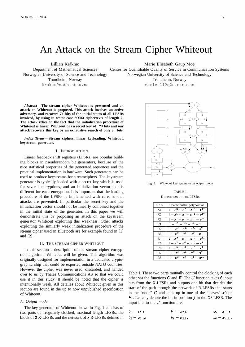
An Attack on the Stream Cipher WhiteoutLillian Kråkmo
Department of Mathematical SciencesNorwegian University of Science and Technology
Trondheim, [email protected]
Marie Elisabeth Gaup MoeCentre for Quantifiable Quality of Service in Communication Systems
Norwegian University of Science and TechnologyTrondheim, Norway
Abstract— The stream cipher Whiteout is presented and anattack on Whiteout is proposed. This attack involves an activeadversary, and recovers
bits of the initial states of all LFSRs
involved, by using in worst case ciphertexts of length .The attack relies on the fact that the initialization procedure ofWhiteout is linear. Whiteout has a secret key of bits and ourattack recovers this key by an exhaustive search of only
bits.
Index Terms— Stream ciphers, linear keyloading, Whiteout,keystream generator.
I. INTRODUCTION
Linear feedback shift registers (LFSRs) are popular build-ing blocks in pseudorandom bit generators, because of thenice statistical properties of the generated sequences and thepractical implementation in hardware. Such generators can beused to produce keystreams for streamciphers. The keystreamgenerator is typically loaded with a secret key which is usedfor several encryptions, and an initialization vector that isdifferent for each encryption. It is important that the loadingprocedure of the LFSRs is implemented with care, so thatattacks are prevented. In particular the secret key and theinitialization vector should not be linearly combined togetherin the initial state of the generator. In this paper we willdemonstrate this by proposing an attack on the keystreamgenerator Whiteout exploiting this weakness. Other attacksexploiting the similarly weak initialization procedure of thestream cipher used in Bluetooth are for example found in [1]and [2].
II. THE STREAM CIPHER WHITEOUT
In this section a description of the stream cipher encryp-tion algorithm Whiteout will be given. This algorithm wasoriginally designed for implementation in a dedicated crypto-graphic chip that could be exported outside NATO countries.However the cipher was never used, discarded, and handedover to us by Thales Communications AS so that we coulduse it in this study. It should be noted that the cipher isintentionally weak. All detailes about Whiteout given in thissection are found in the up to now unpublished specificationof Whiteout.
A. Output mode
The key generator of Whiteout shown in Fig. 1 consists oftwo parts of irregularly clocked, maximal length LFSRs, theblock of X-LFSRs and the network of R-LFSRs defined in
X1
X2
X3
MV
k0 k1
R1 R2
R3 R4
R5 R6
R7 R8
G
S
F
0 1
0 1 1 0
1 1 0
1 0 1 0
0 1 1 0
0
p1
p2
p3
p4
p5
u
Fig. 1. Whiteout key generator in output mode
TABLE I
DEFINITION OF THE LFSRS
LFSR Characteristic polynomial
X1 X2 !X3 " # R1 $ # $%&R2 $ # " $ % &R3 $'# $ ! &R4 # ( &R5 # ! ( &R6 (&R7 $ $ &R8 $ $%&
Table I. These two parts mutually control the clocking of eachother via the functions ) and * . The ) function takes + inputbits from the X-LFSRs and outputs one bit that decides thestart of the path through the network of R-LFSRs that startsin the “node” ) and ends up in one of the “leaves” ,.- or,0/ . Let 1324 5 denote the bit in position 6 in the X 7 -LFSR. Theinput bits to the ) function are:
89;: 1 9 4 < 8=>: 1?4 @ 8BA>: 1 = 4 9C98 ? : 1 9 4 9ED 8BFG: 1?4 9 < 8BD>: 1 = 4 ?C?'H
NORDSEC 2004 97

TABLE II
H FUNCTION TAPPING POSITIONS
R-LFSR x y z
R1 2 5 7
R2 10 8 3
R3 6 9 4
R4 3 7 8
R5 8 4 2
R6 4 10 6
R7 5 2 9
R8 7 3 5
The output of ) is given by:
) 8 9 8 ? 8 = 8 F 8 A 8 D : 8 ? 8 D 8 F 8 A 8 A 8 D 8 = 8 F 8 ? 8 A 8 9 8 A 8 9 8 ? 8 F 8 A 8 D 8 = 8 A 8 D 8 = 8 F 8 A 8 ? 8 A 8 D 8 ? 8 F 8 D 8 ? 8 F 8 A 8 ? 8B=8D 898B=8A 898B=8BF 898 ? 8A 898 ? 8=8 F 898 ? 8BF8BA 898 ? 8 F8D 898B=8 F8BD 8 ? 8B=8 F8BD HThe output of ) determines which of the LFSRs / or that will be enabled and defines the start of a path through thenetwork of R-LFSRs that will be calculated during each cyclein output mode. The path through the network of R-LFSRs isdefined as a binary -tuple 9 3? = F A , where F and A may be undefined, 9 is the output of ) , 0? is the output of / or dependent on which LFSRs that was enabled by 9 , = is the output of or , and so on. The path gives inputto the clocking function * and decides which R-LFSRs thatwill be clocked during the cycle. The path also determines thevalue of the leaves , - and ,0/ . ,.- and ,0/ are initially set to -in the start of each cycle, when the path ends in one of them,the value of the terminating leaf is changed to / .
The output of the R-LFSRs is given by the function thattakes input bits 1 , and from the R-LFSRs and outputs onebit that determines which R-LFSR next to enable accordingto Fig. 1. The tapping positions for the input to for therespective R-LFSRs are given in Table II, the output of isgiven by:
1 : 1 10HThe function * decides the clocking of the X-LFSRs and is
computed after the path through the R-LFSRs is calculated. *takes input bits and outputs a triple 9 ? = , 2 - / where 2 counts the number of steps the LFSR X 7 is going tobe clocked. Let ! 24 5 denote the bit in position 6 in the R 7 -LFSR. The input bits to * are:
" 9;: 9 " FG: ! A 4 9$# !%4 <" ? : ? " A>: ! D 4 9$# !<4 < " = : =where 9 , ? and = are the first, second and third bit in thecalculated path through the R-LFSRs. From these input bits
TABLE III
F PERMUTATION
& 0 1 2 3 4 5 6 7' 20 19 17 31 11 8 29 14& 8 9 10 11 12 13 14 15' 24 30 15 22 28 25 2 18& 16 17 18 19 20 21 22 23' 21 6 13 26 3 23 7 1& 24 25 26 27 28 29 30 31' 9 27 12 0 5 4 16 10
TABLE IV
F CLOCKING OF X-LFSRS
' 0 1 2 3 4 5 6 7( 1 0 1 1 0 0 1 2(*)2 1 0 0 2 1 2 1(*+0 2 2 2 1 2 0 0' 8 9 10 11 12 13 14 15( 2 2 2 2 2 1 1 2(*)1 0 1 1 0 2 2 0(*+0 1 0 0 1 0 0 1' 16 17 18 19 20 21 22 23( 0 1 1 1 0 2 0 1(*)2 0 2 0 1 1 2 2(*+1 2 0 2 2 0 1 0' 24 25 26 27 28 29 30 31( 1 2 2 2 1 0 2 0(*)2 1 1 0 2 1 1 2(*+0 0 0 1 0 2 0 1
a corresponding integer value , - - / HHH / is calculatedas:
, : /+ " 9. " ? . " =/. " F/. " A H* is defined by a permutation of the possible values for ,
given in Table III, the 0 -value is then the input to the look-uptable given in Table IV, which gives the stepping numbers.
The function 132 (majority vote function) outputs theselector bit 4 :
4 : 1321 : 1 15 where 1 : 1 9 4 # , : 1?4 # and : 1 = 4 # . If 4 : - the producedkey bit 0 : ,.- , else 0 : ,0/ . Since ,.- and ,0/ always willbe the inverse of each other at the time when the key bit iscalculated, the produced key bit can be written as
0 : 4 ,.- HTo sum up, one cycle of the key generator of Whiteout in
output mode is defined by the following steps:
1) Compute the output of )2) Compute the path through the network of R-LFSRs3) Compute 132 to find 44) Compute the keystream bit 0
98 NORDSEC 2004
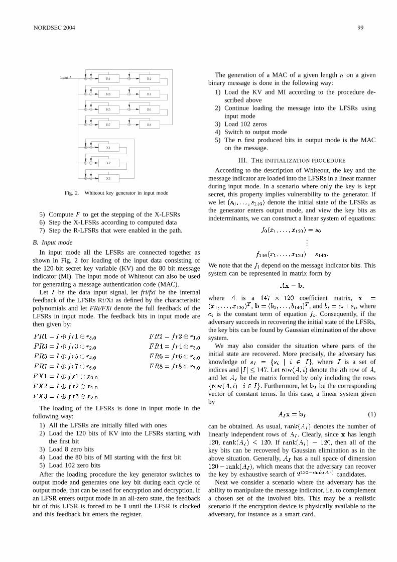
Input I R1
R3
R7
R5
R2
R4
R6
R8
X1
X2
X3
Fig. 2. Whiteout key generator in input mode
5) Compute * to get the stepping of the X-LFSRs6) Step the X-LFSRs according to computed data7) Step the R-LFSRs that were enabled in the path.
B. Input mode
In input mode all the LFSRs are connected together asshown in Fig. 2 for loading of the input data consisting ofthe 120 bit secret key variable (KV) and the 80 bit messageindicator (MI). The input mode of Whiteout can also be usedfor generating a message authentication code (MAC).
Let be the data input signal, let fri/fxi be the internalfeedback of the LFSRs R 7 /X 7 as defined by the characteristicpolynomials and let FRi/FXi denote the full feedback of theLFSRs in input mode. The feedback bits in input mode arethen given by:
* / : !/ !<4 # * : ! ! 9 4 #* : ! !?4 # * : ! ! = 4 #* : ! ! F 4 # * + : ! + ! A 4 #* : ! ! D 4 # * : ! !%4 #* / : 1/ 1 = 4 #* : 15 1 9 4 #* : 13 13?4 #
The loading of the LFSRs is done in input mode in thefollowing way:
1) All the LFSRs are initially filled with ones2) Load the 120 bits of KV into the LFSRs starting with
the first bit3) Load 8 zero bits4) Load the 80 bits of MI starting with the first bit5) Load 102 zero bitsAfter the loading procedure the key generator switches to
output mode and generates one key bit during each cycle ofoutput mode, that can be used for encryption and decryption. Ifan LFSR enters output mode in an all-zero state, the feedbackbit of this LFSR is forced to be / until the LFSR is clockedand this feedback bit enters the register.
The generation of a MAC of a given length on a givenbinary message is done in the following way:
1) Load the KV and MI according to the procedure de-scribed above
2) Continue loading the message into the LFSRs usinginput mode
3) Load 102 zeros4) Switch to output mode5) The first produced bits in output mode is the MAC
on the message.
III. THE INITIALIZATION PROCEDURE
According to the description of Whiteout, the key and themessage indicator are loaded into the LFSRs in a linear mannerduring input mode. In a scenario where only the key is keptsecret, this property implies vulnerability to the generator. Ifwe let 4 # HHH 4 9&F D denote the initial state of the LFSRs asthe generator enters output mode, and view the key bits asindeterminants, we can construct a linear system of equations:
# 1 9 HHH 1 9 ? # : 4 #...
9&F D 1 9 HHH 1 9 ? # : 4 9EF D HWe note that the 2 depend on the message indicator bits. Thissystem can be represented in matrix form by : where
is a / /- coefficient matrix,
: 1 9 HHH 1 9 ? # ,
: 8 # HHH 8 9EF D , and8 2 : " 2 . 4 2 , where" 2 is the constant term of equation 2 . Consequently, if the
adversary succeeds in recovering the initial state of the LFSRs,the key bits can be found by Gaussian elimination of the abovesystem.
We may also consider the situation where parts of theinitial state are recovered. More precisely, the adversary hasknowledge of 4 : 42 7 , where is a set ofindices and / . Let 7 denote the 7 th row of
,
and let be the matrix formed by only including the rows
7 7 . Furthermore, let be the corresponding
vector of constant terms. In this case, a linear system givenby : (1)
can be obtained. As usual, ! #"%$ denotes the number oflinearly independent rows of
. Clearly, since
has length/- , "%$5 /- . If "%$5 : /- , then all of thekey bits can be recovered by Gaussian elimination as in theabove situation. Generally,
has a null space of dimension/-'&(! #")$5 , which means that the adversary can recoverthe key by exhaustive search of
9 ? #+*-,/.021436587!9 candidates.Next we consider a scenario where the adversary has the
ability to manipulate the message indicator, i.e. to complementa chosen set of the involved bits. This may be a realisticscenario if the encryption device is physically available to theadversary, for instance as a smart card.
NORDSEC 2004 99
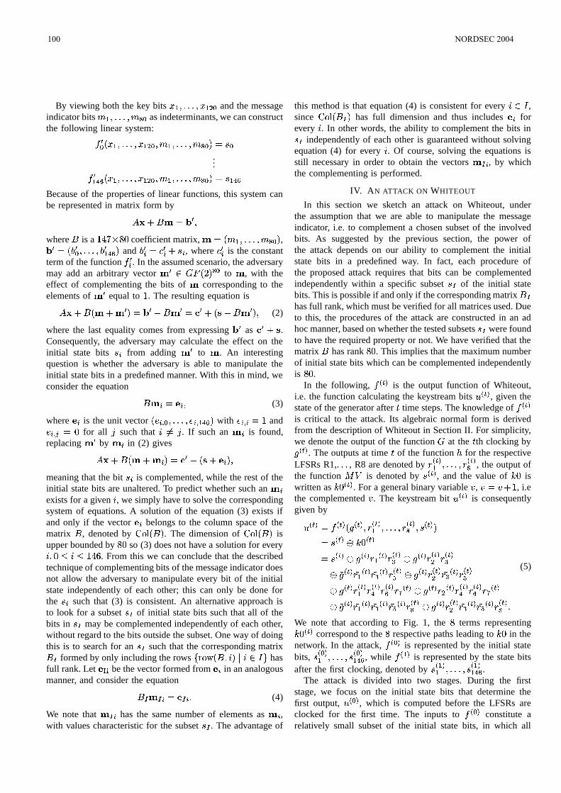
By viewing both the key bits 1 9 HHH 1 9 ? # and the messageindicator bits 9 HHH < # as indeterminants, we can constructthe following linear system:
# 1 9 HHH 1 9 ? # 9 HHH < # : 4 #...
9EF D 1 9 HHH 1 9 ? # 9 HHH < # : 4 9&F DBecause of the properties of linear functions, this system canbe represented in matrix form by' . : where
is a / ; - coefficient matrix,
: 9 HHH < # , : 8 # HHH 8 9EF D and8 2 : " 2 . 4 2 , where " 2 is the constant
term of the function 2 . In the assumed scenario, the adversarymay add an arbitrary vector
) * <#
to
, with theeffect of complementing the bits of
corresponding to the
elements of
equal to / . The resulting equation is' . . : . : . . (2)
where the last equality comes from expressing
as . .
Consequently, the adversary may calculate the effect on theinitial state bits 4 2 from adding
to
. An interesting
question is whether the adversary is able to manipulate theinitial state bits in a predefined manner. With this in mind, weconsider the equation
2 : 2 (3)
where 2 is the unit vector 24 # HHH 24 9&F D with 24 2 : / and
24 5 : - for all 6 such that 7: 6 . If such an 2 is found,
replacing
by 2 in (2) gives' . . 2 : . . 2
meaning that the bit 42 is complemented, while the rest of theinitial state bits are unaltered. To predict whether such an
2exists for a given 7 , we simply have to solve the correspondingsystem of equations. A solution of the equation (3) exists ifand only if the vector
2 belongs to the column space of thematrix
, denoted by . The dimension of is
upper bounded by '- so (3) does not have a solution for every7 - 7 /'+ . From this we can conclude that the describedtechnique of complementing bits of the message indicator doesnot allow the adversary to manipulate every bit of the initialstate independently of each other; this can only be done forthe 42 such that (3) is consistent. An alternative approach isto look for a subset 44 of initial state bits such that all of thebits in 44 may be complemented independently of each other,without regard to the bits outside the subset. One way of doingthis is to search for an 4 such that the corresponding matrix formed by only including the rows 7 7 hasfull rank. Let
be the vector formed from
2 in an analogousmanner, and consider the equation
2 : 2 H (4)
We note that 2 has the same number of elements as
2 ,with values characteristic for the subset 4 . The advantage of
this method is that equation (4) is consistent for every 7 ,since has full dimension and thus includes
2 forevery 7 . In other words, the ability to complement the bits in44 independently of each other is guaranteed without solvingequation (4) for every 7 . Of course, solving the equations isstill necessary in order to obtain the vectors
2 , by whichthe complementing is performed.
IV. AN ATTACK ON WHITEOUT
In this section we sketch an attack on Whiteout, underthe assumption that we are able to manipulate the messageindicator, i.e. to complement a chosen subset of the involvedbits. As suggested by the previous section, the power ofthe attack depends on our ability to complement the initialstate bits in a predefined way. In fact, each procedure ofthe proposed attack requires that bits can be complementedindependently within a specific subset 4 of the initial statebits. This is possible if and only if the corresponding matrix
has full rank, which must be verified for all matrices used. Dueto this, the procedures of the attack are constructed in an adhoc manner, based on whether the tested subsets 4 were foundto have the required property or not. We have verified that thematrix
has rank - . This implies that the maximum number
of initial state bits which can be complemented independentlyis - .
In the following, 3/9
is the output function of Whiteout,i.e. the function calculating the keystream bits 0
3/9, given the
state of the generator after time steps. The knowledge of 3/9
is critical to the attack. Its algebraic normal form is derivedfrom the description of Whiteout in Section II. For simplicity,we denote the output of the function ) at the th clocking by 3/9 . The outputs at time of the function for the respectiveLFSRs R1, HHH , R8 are denoted by !
3/99 HHH !3/9< , the output of
the function 132 is denoted by 43/9
, and the value of ,.- iswritten as ,.-
3/9. For a general binary variable , , , : , . / , i.e
the complemented , . The keystream bit 03/9
is consequentlygiven by
03/9 :
3/9 3/9 !
3/99 HHH !3/9< 4
3/9 : 4
3/9 ,.-
3/9: 4
3/9
3/9! 93/9!3/9=
3/9!3/9? !
3/9=
3/9! 93/9! =3/9!3/9A 3/9 !
3/9? ! =
3/9!3/9A
3/9!3/99 !
3/9F !3/9D ! %
3/9
3/9! ?3/9!3/9F !
3/9D ! %3/9
3/9! 93/9! =3/9! A3/9!3/9<
3/9!3/9? ! =
3/9! A3/9!3/9< H
(5)
We note that according to Fig. 1, the terms representing,.-3/9
correspond to the respective paths leading to , - in thenetwork. In the attack,
3 #9is represented by the initial state
bits, 43 #99 HHH 4
3 #!99EF D, while
3 99is represented by the state bits
after the first clocking, denoted by 43 999 HHH 4
3 999EF D.
The attack is divided into two stages. During the firststage, we focus on the initial state bits that determine thefirst output, 0
3 #!9, which is computed before the LFSRs are
clocked for the first time. The inputs to 3 #!9
constitute arelatively small subset of the initial state bits, in which all
100 NORDSEC 2004
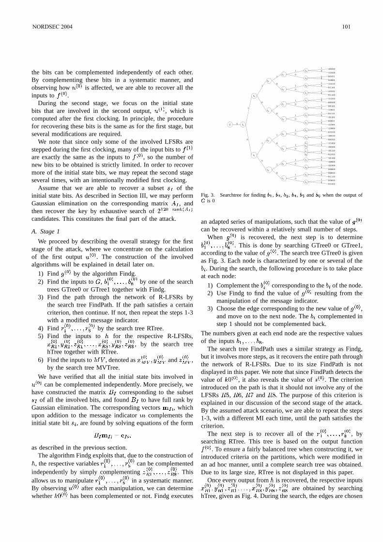
the bits can be complemented independently of each other.By complementing these bits in a systematic manner, andobserving how 0
3 #!9is affected, we are able to recover all the
inputs to 3 #!9
.During the second stage, we focus on the initial state
bits that are involved in the second output, 03 99
, which iscomputed after the first clocking. In principle, the procedurefor recovering these bits is the same as for the first stage, butseveral modifications are required.
We note that since only some of the involved LFSRs arestepped during the first clocking, many of the input bits to
3 99are exactly the same as the inputs to
3 #!9, so the number of
new bits to be obtained is strictly limited. In order to recovermore of the initial state bits, we may repeat the second stageseveral times, with an intentionally modified first clocking.
Assume that we are able to recover a subset 4 of theinitial state bits. As described in Section III, we may performGaussian elimination on the corresponding matrix
, andthen recover the key by exhaustive search of
9 ? #+*-,/.0214365879candidates. This constitutes the final part of the attack.
A. Stage 1
We proceed by describing the overall strategy for the firststage of the attack, where we concentrate on the calculationof the first output 0
3 #9. The construction of the involved
algorithms will be explained in detail later on.
1) Find 3 #!9
by the algorithm Findg.2) Find the inputs to ) ,
8 3 #!99 HHH 83 #!9D
by one of the searchtrees GTree0 or GTree1 together with Findg.
3) Find the path through the network of R-LFSRs bythe search tree FindPath. If the path satisfies a certaincriterion, then continue. If not, then repeat the steps 1-3with a modified message indicator.
4) Find !3 #!99 HHH !
3 #!9< by the search tree RTree.
5) Find the inputs to for the respective R-LFSRs,13 #9 9
3 #9 9
3 #!9 9 HHH 1
3 #!9 <
3 #9 <
3 #!9 < , by the search tree
hTree together with RTree.6) Find the inputs to 132 , denoted as 1
3 #9
3 #!9 and
3 #9 ,
by the search tree MVTree.
We have verified that all the initial state bits involved in03 #!9
can be complemented independently. More precisely, wehave constructed the matrix
corresponding to the subset4 of all the involved bits, and found
to have full rank byGaussian elimination. The corresponding vectors
2 , whichupon addition to the message indicator complements theinitial state bit 4 2 , are found by solving equations of the form
2 : 2 as described in the previous section.
The algorithm Findg exploits that, due to the construction of , the respective variables !
3 #99 HHH !3 #9< can be complemented
independently by simply complementing 3 #!9 9 HHH
3 #9 < . This
allows us to manipulate !3 #!99 HHH !
3 #9< in a systematic manner.
By observing 03 #!9
after each manipulation, we can determinewhether ,.-
3 #!9has been complemented or not. Findg executes
10
10
101010
110100
001011
010001
110110
011101
110111
011100
111010
000100
001101
110011
011111
101101
000011
111001
110000
010110
100110
001010
111000
100100
101110
011010
101100
100000
101000
000000
000010
011110
010010
001000
b2
G
b2
b1
b2
b4
b1
b1
1
0
1
0
1
0
1
0
1
0
1
0
1
0
1
0
1
0
1
0
1
0
1
0
1
0
1
0
1
0
1
0
1
0
10
1
0
1
0
1
0
1
0
1
0
1
0
1
0
1
0
1
0
1
0
1
0
0b3
b6
b1
b3
b3
b2
b1
b2
b4
b3
b1
b3
b2
b3
b6
b4
b6
b4
b4
b4
b1
b1
b6
b6
b5
b2
Fig. 3. Searchtree for finding , # , , , and " when the output ofis 0
an adapted series of manipulations, such that the value of 3 #9
can be recovered within a relatively small number of steps.When 3 #!9 is recovered, the next step is to determine8 3 #!99 HHH 8
3 #!9D. This is done by searching GTree0 or GTree1,
according to the value of 3 #!9
. The search tree GTree0 is givenas Fig. 3. Each node is characterized by one or several of the8 2 . During the search, the following procedure is to take placeat each node:
1) Complement the8 3 #92 corresponding to the
8 2 of the node.2) Use Findg to find the value of
3 #9resulting from the
manipulation of the message indicator.3) Choose the edge corresponding to the new value of
3 #9,
and move on to the next node. The8 2 complemented in
step 1 should not be complemented back.
The numbers given at each end node are the respective valuesof the inputs
8 9 HHH 8 D .The search tree FindPath uses a similar strategy as Findg,
but it involves more steps, as it recovers the entire path throughthe network of R-LFSRs. Due to its size FindPath is notdisplayed in this paper. We note that since FindPath detects thevalue of ,.-
3 #!9, it also reveals the value of 4
3 #9. The criterion
introduced on the path is that it should not involve any of theLFSRs , + , and . The purpose of this criterion isexplained in our discussion of the second stage of the attack.By the assumed attack scenario, we are able to repeat the steps1-3, with a different MI each time, until the path satisfies thecriterion.
The next step is to recover all of the !3 #!99 HHH !
3 #!9< , by
searching RTree. This tree is based on the output function3 #!9
. To ensure a fairly balanced tree when constructing it, weintroduced criteria on the partitions, which were modified inan ad hoc manner, until a complete search tree was obtained.Due to its large size, RTree is not displayed in this paper.
Once every output from is recovered, the respective inputs13 #9 9
3 #9 9
3 #!9 9 HHH 1
3 #!9 <
3 #!9 <
3 #!9 < are obtained by searching
hTree, given as Fig. 4. During the search, the edges are chosen
NORDSEC 2004 101
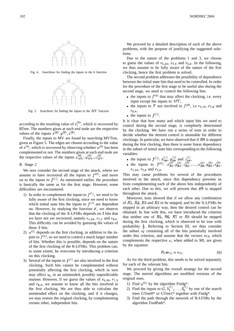
1
1
1
0
0
0
1
0
0
0
1
0
1
1
0
0
0
0
1
0
1
1
1
1
1
h
x x
y y y y
0 1
0 1 0 1
0 1 0 1 0 1 0
Fig. 4. Searchtree for finding the inputs to the function
MV
1
0
0
1
0
0
1
1
0
0 1
1
y y y y
0 1
0 1 0 1
0 1 0 1 0 1 0 1
z z
0
1 1
1
0 1
1
0
1
0 0
0
Fig. 5. Searchtree for finding the inputs to the function
according to the resulting value of !3 #!92 , which is recovered by
RTree. The numbers given at each end node are the respectivevalues of the inputs 1
3 #!9 3 #!9 3 #!9 .Finally, the inputs to MV are found by searching MVTree,
given as Figure 5. The edges are chosen according to the valueof 4
3 #9, which is recovered by observing whether 0
3 #9has been
complemented or not. The numbers given at each end node arethe respective values of the inputs 1
3 #9
3 #!9
3 #!9 .
B. Stage 2
We now consider the second stage of the attack, where weassume to have recovered all the inputs to
3 #!9, and move
on to the inputs to 3 99
. As mentioned earlier, the procedureis basically the same as for the first stage. However, somedifficulties are encountered:
1) In order to complement the inputs to 3 99
, we need to befully aware of the first clocking, since we need to knowwhich initial state bits the inputs to
3 99are dependent
on. However, by studying the function * , we observethat the clocking of the X-LFSRs depends on bits thatwe have not yet recovered, namely ! A 4 9$# , ! %4 < and ! <4 < .This difficulty can be avoided by guessing the values ofthese bits.
2) 03 99
depends on the first clocking, in addition to the in-puts to
3 99, so we need to control a much larger number
of bits. Whether this is possible, depends on the natureof the first clocking of the R-LFSRs. This problem can,to some extent, be overcome by introducing a criterionon this clocking.
3) Several of the inputs to 3 99
are also involved in the firstclocking. Such bits cannot be complemented withoutpotentially affecting the first clocking, which in turnmay affect 0 9 in an unintended, possibly unpredictablemanner. However, if we guess the values of ! A 4 9 # , ! %4 <and ! <4 < , we assume to know all the bits involved inthe first clocking. We are thus able to calculate theunintended effect on the clocking, and if it changes,we may restore the original clocking, by complementingcertain other, independent bits.
We proceed by a detailed description of each of the aboveproblems, with the purpose of justifying the suggested solu-tions.
Due to the nature of the problems 1 and 3, we chooseto guess the values of ! A 4 9 # , !%4 < and !<4 < . In the following,we thus assume to be fully aware of the nature of the firstclocking, hence the first problem is solved.
The second problem addresses the possibility of dependencebetween the initial state bits that need to be controlled. In orderfor the procedure of the first stage to be useful also during thesecond stage, we need to control the following bits: the inputs to
3 #9that may affect the clocking, i.e. every
input except the inputs to 132 , the inputs to * not involved in
3 #!9, i.e ! A 4 9$# , !%4 < and
!<4 < , the inputs to
3 99.
It is clear that how many and which input bits we need tocontrol during the second stage, is completely determinedby the clocking. We have run a series of tests in order todecide whether the desired control is attainable for differentclockings. In particular, we have observed that if is steppedduring the first clocking, then there is some linear dependencyin the subset of initial state bits corresponding to the followingvariables: the inputs to
3 99: 1
3 99 < ,
3 99 < and
3 99 < ,
the inputs to 3 #!9
: 13 #!9 9
3 #!9 9
3 #!9 9 HHH 1
3 #!9 <
3 #!9 <
3 #9 < ,
! A 4 9$# , ! %4 < and ! <4 < .This may cause problems for several of the proceduresinvolved in the attack, since this dependency prevents usfrom complementing each of the above bits independently ofeach other. Due to this, we will prevent that is steppedthroughout the attack.
Moreover, tests showed that if we allow any combinationof / , , and to be stepped, and let the X-LFSRs bestepped in an arbitrary way, then the desired control can beobtained. In line with this, we have introduced the criterionthat neither one of , + , or should be steppedduring the first clocking, which is observed to be true withprobability
9? . Referring to Section III, we thus consider
the subset 4 containing all of the bits potentially involvedunder this criterion, and assume that the vectors 2 whichcomplements the respective 4 2 when added to MI, are givenby the equation
2 : 2 H (6)
As for the third problem, this needs to be solved separatelyfor each of the relevant bits.
We proceed by giving the overall strategy for the secondstage. The starred algorithms are modified versions of theoriginal ones.
1) Find 3 99
by the algorithm Findg*.2) Find the inputs to ) ,
8 3 999 HHH 83 99D
by one of the searchtrees GTree0* or GTree1* together with Findg*.
3) Find the path through the network of R-LFSRs by thealgorithm FindPath*.
102 NORDSEC 2004
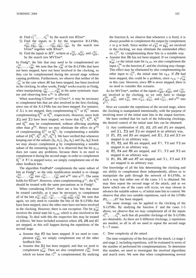
4) Find !3 999 HHH !
3 99< by the search tree RTree*.
5) Find the inputs to for the respective R-LFSRs,13 99 9
3 99 9
3 99 9 HHH 1
3 99 <
3 99 <
3 99 < , by the search tree
hTree* together with RTree*.6) Find the inputs to 132 , written as 1
3 99
3 99 and
3 99 ,
by the search tree MVTree*.
In Findg*, the bits that may need to be complemented are3 99 9 HHH
3 99 < . We note that the
3 99 2 of the R-LFSRs that have
not been stepped, have not been involved in the clocking, sothey can be complemented during the second stage withoutcausing problems. Furthermore, we observe that neither of the3 99 2 in the case where 7 has been stepped, has been involved
in the clocking. In other words, Findg* works exactly as Findg,when manipulating
3 99 9 HHH
3 99 < in the same systematic man-
ner and observing how 03 99
is affected.When searching GTree0* or GTree1*, it may be necessary
to complement bits that are also involved in the first clocking,since one of the X-LFSRs has not been stepped. For instance,if / is not stepped, then complementing
8 3 999or
8 3 99? meanscomplementing
8 3 #99or
8 3 #!9? , respectively. However, since both and have been stepped, we know that
8 3 #!9=,8 3 #!9F
,8 3 #!9A
and8 3 #!9D
may be complemented, without affecting anythingother than 3 #9 . Hence we may eliminate the effect on 3 #!9of complementing
8 3 999or
8 3 99? , by complementing a suitablesubset of 8
3 #!9= 8 3 #!9F 8 3 #9A 8 3 #9D . We have verified that wheneverkeeping one of the subsets 8 9 8 ? , 8 = 8 F and 8 A 8 D fixed,we may always complement by complementing a suitablesubset of the remaining inputs. It is observed that the bit 1 9 4 <does not cause any problems, because there is no need tocomplement it during the second stage; in order to complement8 3 99? if / is stepped twice, we simply complement one of theother feedback bits.
The algorithm FindPath* complements the same subset ofbits as Findg*, so the only modification needed is to change3 #!9 9 HHH
3 #9 < into
3 99 9 HHH
3 99 < and 0
3 #9into 0
3 99. The same
holds for RTree*. However, when complementing 3 99
, the8 3 #!92
should be treated with the same precautions as in Findg*.When considering hTree*, there are a few bits that must
be treated carefully, as it may be necessary to complementall of the bits 1
3 99 9
3 99 9
3 99 9 HHH 1
3 99 <
3 99 <
3 99 < . We note that
again, we only need to consider the bits of the R-LFSRs thathave been stepped, since the other ones have not been involvedin the clocking. However, there is one exception: The bit
3 99 D
involves the initial state bit ! D 4 9$# , which is also involved in theclocking. To deal with this the respective bits may be treatedas follows. We have included scenarios where , + and are stepped, as this will happen during the repetitions of thesecond stage. Assume that has been stepped. If we need to com-
plement 13 99 ? , we simply complement one of the other
feedback bits. Assume that has been stepped, and that we need to
complement 3 99 F . Then we also complement
3 #!9 F , from
which we know that !3 #!9F
is complemented. By studying
the function , we observe that whenever is fixed, it isalways possible to complement the output by complement1 or or both. Since neither of 1
3 99 F or
3 99 F are involved
in the clocking, we may eliminate the unintended effecton !
3 #9F, by complementing these bits in a suitable way.
Assume that + has not been stepped. If we complement3 99 D , i.e the initial state bit ! D 4 9$# , we also complement the
input "3 #9A
to the function * , and the clocking may change.This effect may be eliminated by also complementing theother input to " 3 #!9A , the initial state bit !<4 < . If hadbeen stepped, this could be a problem, since ! <4 < : 1
3 99 <
in this case. However, since is never stepped, there isno need to consider this scenario.
As for MVTree*, neither of the inputs 13 99
3 99 and
3 99
are involved in the clocking, so we only have to change13 #9
3 #!9 and
3 #!9 into 1
3 99
3 99 and
3 99 , and 4
3 #9into
43 99
.Next we consider the repetitions of the second stage, where
the clocking is manipulated intentionally, with the purpose ofinvolving more of the initial state bits in the output function.
We have verified that for each of the following clockings,the desired control of the initial state bits can be obtained:
1) Any combination of / , , and are stepped,and / , and are stepped in an arbitrary way,
2) / , , and are stepped, and / , and arestepped in an arbitrary way,
3) , , and are stepped, and / , and arestepped in an arbitrary way,
4) , and + are stepped, and / , and arestepped in an arbitrary way.
5) / , , + and are stepped, and / , and are stepped in an arbitrary way.
Our knowledge of all the bits determining the clocking andour ability to complement them independently, allows us tomanipulate the path through the network of R-LFSRs, insuch a way that either one of the cases 1-5 is obtained. Wemay then repeat the second stage of the attack, and as weknow which one of the cases will occur, we may choose inadvance the suitable subset 4 of initial state bits to control. Weobserve that after two suitable repetitions, each of the LFSRs/ HHH has been stepped.
The same strategy can be applied to the clocking of theX-LFSRs. By studying the function * and the cases 1-5above, we observe that we may complement all of the inputs" 3 #!99 HHH "
3 #!9A, such that all possible clockings of the X-LFSRs
are obtainable. As there are + different clockings, repetitionsare needed, so all in all we need to repeat the second stage & times.
C. Time complexity of the attack
The time complexity of the first part of the attack, i.e stage 1and stage 2, including repetitions, will be evaluated in terms ofthe number of performed bit complementations. To determinethis number, we need to investigate the involved algorithmsand search trees. We note that when complementing several
NORDSEC 2004 103
bits at a time, this has the same complexity as complementingone bit. We have observed that Findg performs a maximumnumber of /+ bit complementations and that GTree0 andGTree1 both have depth /+ . The actual depth of RTree hasnot been examined, but the criteria introduced on the partitionsimply that it is / in the worst case. FindPath has depth /+ andhTree and MVTree both have depth . From this we deducethe following worst-case numbers of bit complementations foreach of the steps of stage 1:
1) /+2) /+3) /+4) /5) /6)
Hence, for stage 1, the total number of bit complementationsneeded is '-' in the worst case.
As for stage 2, we observe that the worst-case number is thesame as for stage 1, since the number of bit complementationsin each procedure is essentially the same.
In the worst case, stage 2 must be repeated times. Since weare guessing the values of ! A 4 9 # , ! %4 < and ! <4 < , we must repeatthe first part of the attack at most times. We thus concludethat the worst-case number of necessary bit complementationsis totally - -'--'- .
As mentioned introductorily in this section, the final partof the attack involves exhaustive search of the remainingcandidate keys. The time complexity of this process clearlydepends on the number of initial state bits recovered at thisstage.
We note that some of the obtained bits are actually feedbackbits. For simplicity, the feedback bit of an LFSR at the thclocking is marked by the subscript 8 . From the descriptionof the attack, we deduce that the following initial state bitsare recovered: ! 9 4 ? , ! 9 4 = , ! 9 4 A , ! 9 4 D , ! 9 4 % , ! 9 4 < , ! ?4 = , ! ?4 F , ! ?4 < , ! ?4 @ , ! ?4 9 # , ! ?4 # , ! = 4 F , ! = 4 A , ! = 4 D , ! = 4 % , ! = 4 @ , ! = 4 9$# , ! F 4 = , ! F 4 F , ! F 4 % , ! F 4 < , ! F 4 @ , ! A 4 ? , ! A 4 = , ! A 4 F , ! A 4 A , ! A 4 < , ! A 4 @ , ! A 4 9 # , ! D 4 F , ! D 4 A , ! D 4 D , ! D 4 % , ! D 4 9 # , ! D 4 # , !%4 ? , !%4 = , !%4 A , !%4 D , 1 %4 < , !%4 @ , !%4 9 # , !<4 = , !<4 A , !<4 % , !<4 < , 1 9 4 # , 1 9 4 9 , 1 9 4 ? , 1 9 4 < , 1 9 4 @ , 1 9 4 9$# , 1 9 4 9 D , 1 9 4 # , 1 9 4 9 , 13?4 # , 1?4 9 , 13?4 ? , 1?4 @ , 13?4 9 # , 13?4 9 9 , 13?4 9 < , 13?4 # , 1?4 9 , 1 = 4 # , 1 = 4 9 , 1 = 4 ? , 1 = 4 9 9 , 1 = 4 9 ? , 1 = 4 9E= , 1 = 4 ?C? , 1 = 4 # , 1 = 4 9 .Although the obtained feedback bits can not be directly
identified with initial state bits, they are equally valuable tothe attacker. As an example, consider the feedback bit ! D 4 # ,and assume that it has the value - . This gives
! D 4 # ! D 4 = ! D 4 F ! D 4 9$#G: - which allows us to eliminate one of the unknown bits. Hencethe recovery of a feedback bit may be regarded as recoveringan initial state bit, as long as the feedback bit depends on at
least one unknown bit. In our case, this is observed to holdfor each of the relevant feedback bits.
From the above we conclude that we have recovered initial state bits. Let 4 denote the subset constituted by thesebits. By performing Gaussian elimination on the correspondingmatrix
, the secret key is obtained by exhaustive searchof
9 ? #2* ,/.021365879 candidates. We have verified that has
full rank, so the number of candidates to be tested is F D
.Comparing this number to the number of bit complementationsperformed in the first part, it is clear that the exhaustive searchdominates the total time complexity of the attack.
It must be taken under consideration that we guess thevalues of the bits ! A 4 9 # , !%4 < and !<4 < . In most cases, guessingthe wrong values may be detected at an early stage of theattack. But, in worst case, the attack must be repeated
=times in order to be successful. This gives a time complexitycorresponding to exhaustive search of
F @ candidates.For a more detailed description of the attack and all the
involved algorithms we refer to our master thesis, which canbe obtained upon request to the authors. In our master thesiswe also point out some correlations in Whiteout, which couldbe exploited in a divide and conquer correlation attack [3] ona modified version of Whiteout. It would be interesting to seeif these correlations could be used in an optimization of theexhaustive search involved in the attack. In our thesis we havealso discussed why the MAC algorithm of Whiteout does nothave the computation-resistance property, which is requiredfor a MAC to resist forgery attacks [4].
V. CONCLUSION
We have studied the stream cipher Whiteout and proposedan attack, that may be carried out by an active adversary, onthe cipher which recovers bits of the initial states of allLFSRs involved. In worst case -'--'- ciphertexts of length are needed to find these bits. The attack relies on the fact thatthe initialization procedure of Whiteout is linear. This allowsus to construct linear equations relating the initial state withthe initialization vector variables and the secret key. Whiteouthas a secret key of /- bits and our attack recovers this keyby an exhaustive search of only bits.
ACKNOWLEDGMENT
We would like to thank Leif Nilsen and Thales Communi-cations AS for allowing us to study Whiteout, we also thankour supervisor Kristian Gjøsteen for his help and advice whenworking with our master thesis.
REFERENCES
[1] J. D. Golic, V. Bagini, and G. Morgari, “Linear Cryptanalysis of BluetoothStream Cipher,” in EUROCRYPT 2002, ser. Lecture Notes in ComputerScience, L. R. Knudsen, Ed. Springer, 2002, pp. 238–255.
[2] S. Fluhrer and S. Lucks, “Analysis of the ( Encryption System,” inSAC 2001, ser. Lecture Notes in Computer Science, S. Vadenay andA. Youssef, Eds., vol. 2259. Springer, 2001, pp. 38–48.
[3] T. Siegenthaler, “Decrypting a Class of Stream Ciphers Using CiphertextOnly,” IEEE Transactions on Computers, vol. c-34, january 1985.
[4] A. Menezes, P. van Oorschot, and S. Vanstone, Handbook of AppliedCryptography. CRC Press, 1996.
104 NORDSEC 2004
Upgrade of Bluetooth Encryption and Key ReplayAttack
Kaarle Ritvanen and Kaisa NybergNokia Research Center
Helsinki, Finlandkaarle.ritvanen,[email protected]
Abstract— After adoption of the Advanced Encryption Stan-dard (AES), security systems of many information and com-munication systems are being upgraded to support AES basedencryption mechanisms. Also within Bluetooth SIG, discussionsabout replacing the proprietary Bluetooth encryption algorithmE0 with a new, possibly AES based algorithm have been initiated.The purpose of this paper is to show that this action alone doesnot improve the overall security because in the Bluetooth system,an active attacker can set up a previously used encryption keyby a replay attack. We analyze the problem and show that it ispossible to overcome it. Finally, we present alternative modifi-cations to the Bluetooth Baseband and Profiles specifications tosupport secure use of two different encryption algorithms.
Index Terms— AES, Bluetooth, E0, encryption, key replayattack
I. INTRODUCTION
Bluetooth is a wireless communications standard intendedto be used in personal area networks. Many handheld devices,such as mobile phones, personal digital assistants, and laptopcomputers, incorporate a Bluetooth radio to enable low-costwireless data transmission.
Like all modern radio communications systems, Bluetoothuses an encryption algorithm to conceal the transmitted datafrom eavesdroppers. The encryption algorithm is a streamcipher called E0, which is based on Linear Feedback ShiftRegisters (LFSRs) and a summation combiner [1]. The lengthof the encryption key can be varied between 8 and 128 bitsand there is a negotiation procedure by which it can be agreedon. [2, Part H, Chpt. 4]
The E0 encryption algorithm is a proprietary algorithmdesigned for the Bluetooth system. There are incentives to in-troduce a stronger encryption mechanism to Bluetooth, prefer-ably based on the Advanced Encryption Standard (AES) [3].Nevertheless, support for E0 cannot be removed, in order toprovide compatibility with legacy devices. Previous attackson the GSM system by Barkan, Biham, and Keller [4] showthat two different encryption algorithms within the samesystem may interfere in an undesirable manner. In one ofthe scenarios [4, Sect. 7.1], the attacker can force the victimto reuse a previously used encryption key with the weakalgorithm, and then recover the key. Then the attacker candecrypt the previously generated ciphertext, even if strongencryption has been used. We show that such an attack mayalso be possible in Bluetooth if appropriate counter-measuresare not taken. Section IV presents the details on how the
attack is carried out in the Bluetooth system. The fundamentalcause of the problem is that it is possible to replay encryptionkeys. In Section IV-D, we present our recommendations for thecounter-measures that would be sufficient to allow a secondencryption algorithm to be securely taken into use in Bluetoothsystem.
It should be noted that recovering encryption keys is notthe only exploit of the possibility for encryption key replay.For instance, Gauthier presented a key replay attack applicableagainst the EAP-AKA protocol [5] when a Bluetooth link isused between the victim devices [6].
Before presenting the details of our attack, some backgroundinformation is covered. Section II reviews the state-of-the-artattacks on E0. The Bluetooth encryption key exchange andauthentication procedures are described in Section III.
II. STATUS OF ENCRYPTION ALGORITHM E0
In 1999, Hermelin and Nyberg showed how it is possibleto recover the initial state of the LFSRs from 264 consecutivekeystream bits doing a work of 264 [7]. The amount of workhas later been reduced to 261 and the required knowledge ofkeystream bits to 250 [8]. These attacks exploit linear correla-tions in the summation combiner. Nevertheless, these attacksare of theoretical nature, since the LFSRs are reinitialized aftereach packet and the length of the keystream never exceeds2744 bits1 [2].
At the moment, algebraic attacks seem to be the mosteffective attacks on E0. Krause devised an attack requiringa work of 277 but only 128 consecutive bits of knownplaintext [9, Sect. 7]. That amount is eminently realistic foran attacker to obtain but the workload is still prohibitive andequivalent to exhaustive key search of a 78-bit key. Later,Armknecht and Krause showed how to recover the initialstate from 223 keystream bits doing a work of 268 [10]. Byusing a technique called fast algebraic attack, which requiressome precomputation, the amount of work can be reduced to255 [11], [12].
The aforementioned attacks concentrate on discovering theinitial state of the LFSRs from the keystream bits. However, it
1The Bluetooth specifications state that the maximum size of payload is2745 bits. This maximum is achieved by type DM5 packets with 228-bytepayload, which maps to 2745 bits due to error-correcting channel coding.However, encryption is applied before channel coding and therefore themaximal-length keystream is used with type DH5 packets having 343-bytepayload, which equals to 2744 bits.
NORDSEC 2004 105
has been proven that having an effective algorithm for initialstate recovery yields an effective algorithm for recovering thesecret key [13].
According to Armknecht, recovering E0 keys using presentknown plaintext attacks would require about 128 GB ofmemory and 8 MB of keystream. With present computingmachinery, it would take at least 159 years to perform thecomputations. [14]
Even if not breakable in practice, E0 is of lower securitylevel than AES based stream ciphers are currently believed tobe. Therefore, if a second AES based encryption algorithm isspecified for Bluetooth, the Baseband or the application profilespecifications must ensure that two different encryption algo-rithms can coexist in Bluetooth without causing vulnerabilitiesto each other.
III. PROCEDURES FOR KEY EXCHANGE AND
AUTHENTICATION
This section presents the Bluetooth encryption key exchangeand authentication procedures as defined in [2]. The generalorder in which the related activities take place is:
1) Change of link key2) Mutual authentication3) Encryption key exchangeIn Bluetooth networks, there is one master device, with the
clock of which the other devices synchronize. These otherdevices are called slaves. The security protocols are alwaysperformed only between the master and a slave but neverbetween two slaves. They are not symmetric and depend onthese roles, as we will see.
Mutual authentication and key exchange are mandatoryafter link key renewal but they are allowed to happen atany other time too. Link keys are discussed in Section III-A.Section III-B explains how authentication works in Bluetoothand Section III-C shows how encryption keys are agreed on.
A. Link Keys
Link key is a shared secret between the communicatingdevices. In principle, there are four types of link keys:
• combination keys• unit keys• temporary keys2
• initialization keysUnit keys are used by devices with limited memory re-
sources but their use is deprecated and they are ignored in thisdiscussion. Initialization keys are used when pairing devices.The attack presented in Section IV assumes that the deviceshave already been paired, so initialization keys neither areinteresting in this context.
Temporary keys are used in point-to-multipoint configura-tions. As the name suggests, such configurations are usuallyrelatively short-lived. Applications may make the slaves use a
2In [2], keys of this type are called master keys, but this term is a bitmisleading. In specifications of some other wireless communications systems,such as those of Wireless Local Area Networks [15], long-term link keys(combination key equivalents) are called master keys.
common encryption key derived from this common temporarylink key to allow encryption of broadcast traffic. Note thatalso unicast traffic is encrypted with the common key if atemporary link key has been set up. After the master hasfinished broadcasting that needs encryption, the slaves can betold to fall back to the previous link keys.
In most cases, the link key is a combination key. Accordingto the specifications, combination keys are semi-permanent,in the sense that they can be changed but typically have longlifetimes. In fact, the specification suggests that combinationkeys can be stored into non-volatile memory and used toauthenticate and generate encryption keys for future sessions.So it is reasonable to assume that link keys do not changevery often in point-to-point configurations.
B. Authentication
Bluetooth uses a special algorithm named E1 to authenticateother devices. It is based on the SAFER+ block cipher [16].The inputs to E1 are:
• current link key• device address of the claimant• 128-bit challenge
The challenge is generated by the verifier and sent to theclaimant. Both parties run E1 and the claimant sends theresponse to the verifier that checks whether the results match.E1 produces also another result, which is called AuthenticatedCiphering Offset (ACO). This 96-bit value is used in keyexchange and is discussed in Section III-C.
Authentication always takes place for both directions afterthe link key has been changed. Also the order is fixed: firstthe master authenticates the slave and then vice versa. Thisis also true when a temporary multipoint key is taken intouse. It is up to the application whether authentication isperformed at other times. These additional authentications donot necessarily have to be mutual. In principle, authenticationcan be performed arbitrarily many times and in arbitrary orderunless the application imposes some restrictions on that.
C. Encryption Key Exchange
E0 encryption keys are generated by an algorithm called E3,which produces a 128-bit result. If the encryption key is to beshorter than that, the key is shortened by a binary polynomialmodulo operation. The inputs to E3 are:
• current link key• 128-bit random number• Ciphering Offset number (COF)
The random number is generated by the master and issupplied to the slave with the control message that requestsstarting encryption. The last input, COF, takes one of thefollowing values:
• the device address of the master repeated twice, if thelink key is a temporary key, or
• ACO produced by the latest authentication, otherwise.
106 NORDSEC 2004
IV. ACTIVE ATTACK ON STRONG ENCRYPTION
ALGORITHM
Let us now assume that a second alternative encryptionalgorithm is inserted to the Bluetooth system. Then the supportfor the original E0 algorithm will be maintained to ensurebackward compatibility. Hence, it is necessary to insert acipher negotiation mechanism to the Link Manager Protocol(LMP) [2, Part C] so that the devices can agree on a commonalgorithm. Moreover, it is natural to impose change of en-cryption key after change of encryption algorithm to preventthe same encryption key from being used with two differentalgorithms.
We also make the following additional assumptions abouthow the new feature is used in Bluetooth system. The as-sumptions are realistic and in accordance with the currentspecification.
1) The same E3 algorithm is used to generate the en-cryption keys for all encryption algorithms. This isreasonable, since most modern block ciphers, such asAES, use 128-bit keys.
2) The application does not restrict the order of executionof authentication procedures.
3) The link key is not changed often (i.e. it remains thesame throughout all sessions involved in the attack).
Finally, we make the general assumption that passive wire-tapping and recording of Bluetooth communication as wellas active “Man-in-the-Middle” impersonation is possible inBluetooth. In particular, we assume that the attacker canimpersonate the master to a slave, and send control messagesto the slave. Note that we do not assume that the master canadjust its clock as is required by Gauthier’s attack [17, Sect. 2].
We show that if these assumptions hold, then it is possiblefor an active attacker to force a Bluetooth slave device to reusea previously used encryption key with an encryption algorithmselected by the attacker. In this manner, a situation is createdwhere the attack of Barkan et al. works. This violates therequirement that the different encryption algorithms must notpose any threat to each other.
At first, in Section IV-A we consider a simple case involvingonly combination-type link keys. In Section IV-B, we showthat under certain conditions this attack can be even easierto perform. Section IV-C discusses whether the attack can beextended to sessions containing encrypted point-to-multipointtransmissions.
A. Basic Attack
In case of point-to-point configurations, which we are nowconsidering, the value of ACO is directly used as COF, theinput to the encryption key generation algorithm E3. If au-thentication is performed for both parties, the ACO producedby the latest authentication is used. Hence the factors thatdetermine the encryption key are:
• current link key• master-supplied random number
• challenge supplied by the verifier of the last authentica-tion
• device address of the claimant of the last authenticationThe attack works as follows. At first, the attacker records
a session that is encrypted by using a strong algorithm. Priorto that, he sees the master supply the last authentication chal-lenge, observes the random number attached to the encryptionstart request, and saves those messages.
Later, at a moment best suitable for him, the attackerbecomes active and impersonates the master to the slave. Theold link key is used, so there is no need for mutual authen-tication. Now the attacker runs the negotiation procedure totake the weak encryption algorithm into use. As explainedin the beginning of Section IV, a procedure to exchange anew encryption key is performed. It may be possible to usean existing ACO value, as discussed in the next subsection.If a new ACO value is needed, the attacker requests theslave to authenticate itself by sending the previously recordedchallenge, as allowed by assumption 2. Being unaware of thereal link key, the attacker of course cannot verify the responseof the slave, but the result is that the challenge he suppliesdefines the same ACO, as before. Then the attacker initiatesencryption by replaying the random number it recorded fromthe previous session. The resulting encryption key is identicalto the one of the session that the attacker recorded.
It is important to note that if the master is the verifier inthe last authentication, the encryption key solely depends onvalues supplied by him.3 The slave has then no opportunityto affect the key. This enables the attacker to set up the sameencryption key by replaying these values, since by assump-tion 1 the same E3 algorithm is used with both encryptionalgorithms. Now the attacker can try to recover the key byusing an attack on the weak algorithm, and then decrypt theciphertext created using the strong algorithm if he succeeds.
B. Using Existing ACO
A variation of the attack may be possible if the same ACO isallowed to be used for several encryption key computations. Ifthe same ACO were used, COF would remain constant for longperiods of time, just like the link key. Then we are again inthe situation where the master is the only one who affects theencryption key. The specifications do not forbid reusing ACOs.In fact, they encourage using the same ACO for several keycomputations in certain situations. When discussing mutualauthentication after a temporary key has been distributed, theysay [2, Part H, Sect. 3.2.8]:
The ACO values from the authentications shall notreplace the current ACO, as this ACO is needed to(re)compute a ciphering key when the master fallsback to the previous (non-temporary) link key.
Therefore, it is highly probable that several implementationsdo not require a fresh ACO for each encryption key derivation.
3Indeed, the encryption key depends on the current link key the attackerdoes not know. But because of assumption 3, it is constant throughout theattack and in that sense does not affect the encryption key. As regards to thedevice address, the same holds.
NORDSEC 2004 107
Attacking on such implementations necessitates only replayingthe random number input for E3, not the authenticationchallenge, thus rendering assumption 2 unnecessary. It is noteven necessary for the attacker to know the last challenge, it isrequired only that the replay takes place when the ACO valueis the same as in the recorded session.
C. Point-to-Multipoint Configurations
Let us assume that the application allows the master tomake the slaves switch to temporary link and encryption keys,and the attacker has recorded a session that contains suchencrypted broadcast episodes. It is clear that the attacker isable to recover such parts of the recorded session that wereencrypted using a point-to-point key, since he can replayseparately all authentications and key exchanges he has seen.But could the attacker somehow recover broadcast encryptionkeys too?
Before broadcast encryption can be started, a new temporarylink key is created and transmitted to the slaves, in encryptedform of course. But as mutual authentication always occursafter this, there is no way for the attacker to remain unde-tected, since he does not know the new link key. [2, Part H,Sect. 3.2.8]
However, there can be applications that constantly use thetemporary link key. In that case, the temporary key is neverrelinquished and the attack works well, just like in the point-to-point case. Note that in this case, the attacker need not knowthe authentication challenge, but can send any plausible value,since COF is derived from the master’s address.
D. Possible Counter-Measures
Assumption 3 stated that the link key is not changed often.However, if the specifications dictated that the link key mustbe changed regularly, that would offer some protection againstthis replay attack. Replaying the challenge and the randomnumber would no longer yield the same encryption key, hadthe link key been changed. Moreover, as mutual authenticationmust always occur after change of link key, changing link keysfrequently would certainly offer protection against attacks ofthis kind. Point-to-multipoint applications constantly switchingbetween combination and temporary group keys naturally usethis means of protection.
Another possibility to protect against replay attacks isto make the slave always supply the last challenge. LMPdefinition rules that the slave supplies the last challenge inmutual authentication after the link key has been changed [2,Part C, Sect. 4.2]. However, this does not by itself prevent themaster from initiating new authentication and key exchangeprocedures immediately after that.
We made the assumption that after each negotiation ofencryption algorithm a new encryption key must be exchanged.We assumed that in this process authentication is performedonly one way: master authenticates the slave. One mightthink that requiring mutual authentication would be sufficientto prevent the attacker from replaying an encryption key.However, this is not the case. By impersonating the slave to
the real master, the attacker can forward the challenge to themaster and get the correct response which it forwards to theslave.
We implicitly assumed that the attacker can freely selectthe encryption algorithms in protocol negotiation phase. Thisassumption is based on the fact that currently there is no otherintegrity protection mechanism than encryption in Bluetooth,and encryption cannot be used before the algorithm has beenagreed on. In theory, using message authentication codes basedon link keys to protect the negotiation would prevent thisattack. However, it would not prevent other types of encryptionkey replay attacks, such as Gauthier’s attack mentioned inSection I.
Another counter-measure that prevents the same encryptionkey from being used for two different encryption algorithmsis to specify a new different E3 algorithm for each newencryption algorithm. But again, other types of replay attackswould not be neutralized.
V. CONCLUSION
In this paper we demonstrated that just introducing a secondstronger encryption algorithm is not sufficient to upgrade thesecurity level as desired. The root cause of the problem is thatit may be possible for a master device to replay authenticationand key exchange.
Four alternative approaches to protect against the attackdiscussed in Section IV were proposed:
• The link key is changed frequently.• Bluetooth application profiles mandate the slave to pro-
vide the last authentication challenge before encryptionkey derivation and forbid using a single ACO to deriveseveral encryption keys.
• Encryption algorithm negotiation is authenticated.• Different key derivation algorithms are specified for each
encryption algorithm.
The first is contradictory to the idea of link keys. Accordingto the specifications, combination keys are semi-permanent,although changing them frequently would really increase se-curity against active attacks. The second approach is neitherin line with the specifications, which tell the implementors tostore the ACO for future use. The specifications should ratherencourage avoiding ACO reuse under all circumstances.
The last two approaches would only thwart the attacks onmultiple encryption algorithms presented in this paper. The keyreplay attack by Gauthier would still remain valid. But eitherone of the first two counter-measures would also work againstthat attack, and therefore are the recommended options.
REFERENCES
[1] R. A. Rueppel. Correlation immunity and the summation generator.In H. C. Williams, editor, Advances in Cryptology — CRYPTO ’85,volume 218 of Lecture Notes in Computer Science, pages 260–272,Santa Barbara, CA, USA, August 1985. Springer.
[2] Core System Package [Controller volume]. Volume 2 of Specificationof the Bluetooth System, Version 1.2. Promoter Members of BluetoothSIG, November 2003.
[3] Specification for the Advanced Encryption Standard (AES). NIST FIPSPublication 197, November 2001.
108 NORDSEC 2004
[4] E. Barkan, E. Biham, and N. Keller. Instant ciphertext-only cryptanalysisof GSM encrypted communications. In Boneh [18], pages 600–616.
[5] J. Arkko and H. Haverinen. Extensible Authentication Protocol Methodfor UMTS Authentication and Key Agreement (EAP-AKA). InternetDraft (draft-arkko-pppext-eap-aka-12.txt), April 2004.
[6] E. Gauthier. A man-in-the-middle attack using Bluetooth in a WLANinterworking environment. 3GPP TSG SA WG3 Meeting #32, S3-040163, February 2004.
[7] M. Hermelin and K. Nyberg. Correlation properties of the Bluetoothcombiner. In J-S. Song, editor, Proceedings of ICISC ’99, volume 1787of Lecture Notes in Computer Science, pages 17–29, Seoul, South Korea,December 1999. Korea University, Springer.
[8] P. Ekdahl and T. Johansson. Some results on correlations in theBluetooth stream cipher. In Proceedings of the 10th Joint Conferenceon Communications and Coding, Obertauern, Austria, 2000.
[9] M. Krause. BDD-based cryptanalysis of key stream generators. InL. R. Knudsen, editor, Advances in Cryptology — EUROCRYPT 2002,volume 2332 of Lecture Notes in Computer Science, pages 222–237,Amsterdam, The Netherlands, 2002. Springer.
[10] F. Armknecht and M. Krause. Algebraic attacks on combiners withmemory. In Boneh [18], pages 162–176.
[11] N. T. Courtois. Fast algebraic attacks on stream ciphers with linearfeedback. In Boneh [18], pages 177–194.
[12] F. Armknecht. Improving fast algebraic attacks. In B. K. Roy andW. Meier, editors, Proceedings of Fast Software Encryption 2004,volume 3017 of Lecture Notes in Computer Science, pages 65–82, Delhi,India, February 2004. Springer.
[13] F. Armknecht, J. Lano, and B. Preneel. Extending the frameworkof the resynchronization attack. In Proceedings of Selected Areas inCryptography 2004, Lecture Notes in Computer Science, Waterloo,Ontario, Canada, August 2004. University of Waterloo, Springer.
[14] F. Armknecht. Algebraic attacks on stream ciphers. Presentation inminisymposium “Secure Crypto for Industry” at ECCOMAS 2004, July2004.
[15] IEEE Standard for Information Technology; Telecommunications andinformation exchange between systems; Local and metropolitan areanetworks; Specific requirements; Part 11: Wireless LAN Medium AccessControl (MAC) and Physical Layer (PHY) Specifications; Amend-ment 6: Medium Access Control (MAC) Security Enhancements. IEEEStandard 802.11i-2004, July 2004.
[16] J. L. Massey, G. H. Khachatrian, and M. K. Kuregian. Nomination ofSAFER+ as Candidate Algorithm for the Advanced Encryption Standard(AES). 1st AES Conference, Ventura, CA, USA, August 1998.
[17] Notes on Gauthier’s replay attack on the UE functionality split scenario.3GPP TSG SA WG3 Meeting #32, S3-040091, February 2004.
[18] D. Boneh, editor. Advances in Cryptology — CRYPTO 2003, 23rdAnnual International Cryptology Conference, Proceedings, volume 2729of Lecture Notes in Computer Science, Santa Barbara, CA, USA, August2003. Springer.
NORDSEC 2004 109
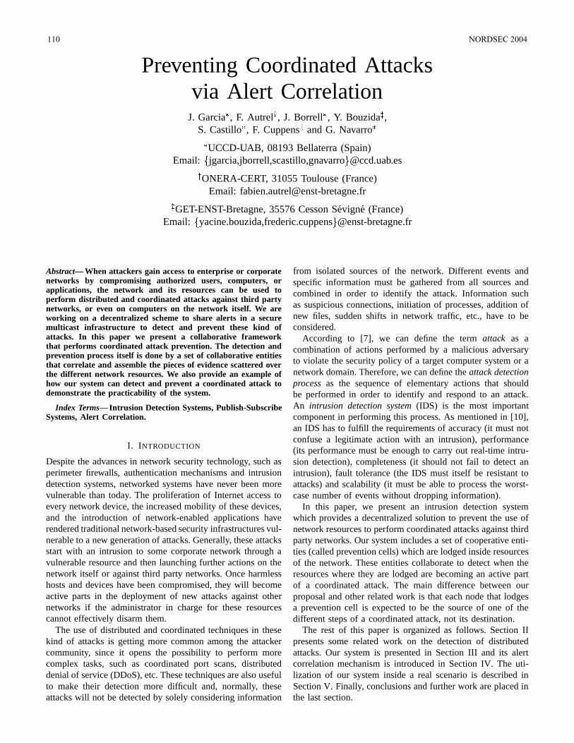
Preventing Coordinated Attacksvia Alert Correlation
J. Garcia, F. Autrel
, J. Borrell
, Y. Bouzida
,
S. Castillo, F. Cuppens
and G. Navarro
UCCD-UAB, 08193 Bellaterra (Spain)
Email: jgarcia,jborrell,scastillo,gnavarro @ccd.uab.esONERA-CERT, 31055 Toulouse (France)
Email: [email protected], 35576 Cesson Sevigne (France)
Email: yacine.bouzida,frederic.cuppens @enst-bretagne.fr
Abstract— When attackers gain access to enterprise or corporatenetworks by compromising authorized users, computers, orapplications, the network and its resources can be used toperform distributed and coordinated attacks against third partynetworks, or even on computers on the network itself. We areworking on a decentralized scheme to share alerts in a securemulticast infrastructure to detect and prevent these kind ofattacks. In this paper we present a collaborative frameworkthat performs coordinated attack prevention. The detection andprevention process itself is done by a set of collaborative entitiesthat correlate and assemble the pieces of evidence scattered overthe different network resources. We also provide an example ofhow our system can detect and prevent a coordinated attack todemonstrate the practicability of the system.
Index Terms— Intrusion Detection Systems, Publish-SubscribeSystems, Alert Correlation.
I. INTRODUCTION
Despite the advances in network security technology, such asperimeter firewalls, authentication mechanisms and intrusiondetection systems, networked systems have never been morevulnerable than today. The proliferation of Internet access toevery network device, the increased mobility of these devices,and the introduction of network-enabled applications haverendered traditional network-based security infrastructures vul-nerable to a new generation of attacks. Generally, these attacksstart with an intrusion to some corporate network through avulnerable resource and then launching further actions on thenetwork itself or against third party networks. Once harmlesshosts and devices have been compromised, they will becomeactive parts in the deployment of new attacks against othernetworks if the administrator in charge for these resourcescannot effectively disarm them.
The use of distributed and coordinated techniques in thesekind of attacks is getting more common among the attackercommunity, since it opens the possibility to perform morecomplex tasks, such as coordinated port scans, distributeddenial of service (DDoS), etc. These techniques are also usefulto make their detection more difficult and, normally, theseattacks will not be detected by solely considering information
from isolated sources of the network. Different events andspecific information must be gathered from all sources andcombined in order to identify the attack. Information suchas suspicious connections, initiation of processes, addition ofnew files, sudden shifts in network traffic, etc., have to beconsidered.
According to [7], we can define the term attack as acombination of actions performed by a malicious adversaryto violate the security policy of a target computer system or anetwork domain. Therefore, we can define the attack detectionprocess as the sequence of elementary actions that shouldbe performed in order to identify and respond to an attack.An intrusion detection system (IDS) is the most importantcomponent in performing this process. As mentioned in [10],an IDS has to fulfill the requirements of accuracy (it must notconfuse a legitimate action with an intrusion), performance(its performance must be enough to carry out real-time intru-sion detection), completeness (it should not fail to detect anintrusion), fault tolerance (the IDS must itself be resistant toattacks) and scalability (it must be able to process the worst-case number of events without dropping information).
In this paper, we present an intrusion detection systemwhich provides a decentralized solution to prevent the use ofnetwork resources to perform coordinated attacks against thirdparty networks. Our system includes a set of cooperative enti-ties (called prevention cells) which are lodged inside resourcesof the network. These entities collaborate to detect when theresources where they are lodged are becoming an active partof a coordinated attack. The main difference between ourproposal and other related work is that each node that lodgesa prevention cell is expected to be the source of one of thedifferent steps of a coordinated attack, not its destination.
The rest of this paper is organized as follows. Section IIpresents some related work on the detection of distributedattacks. Our system is presented in Section III and its alertcorrelation mechanism is introduced in Section IV. The uti-lization of our system inside a real scenario is described inSection V. Finally, conclusions and further work are placed inthe last section.
110 NORDSEC 2004
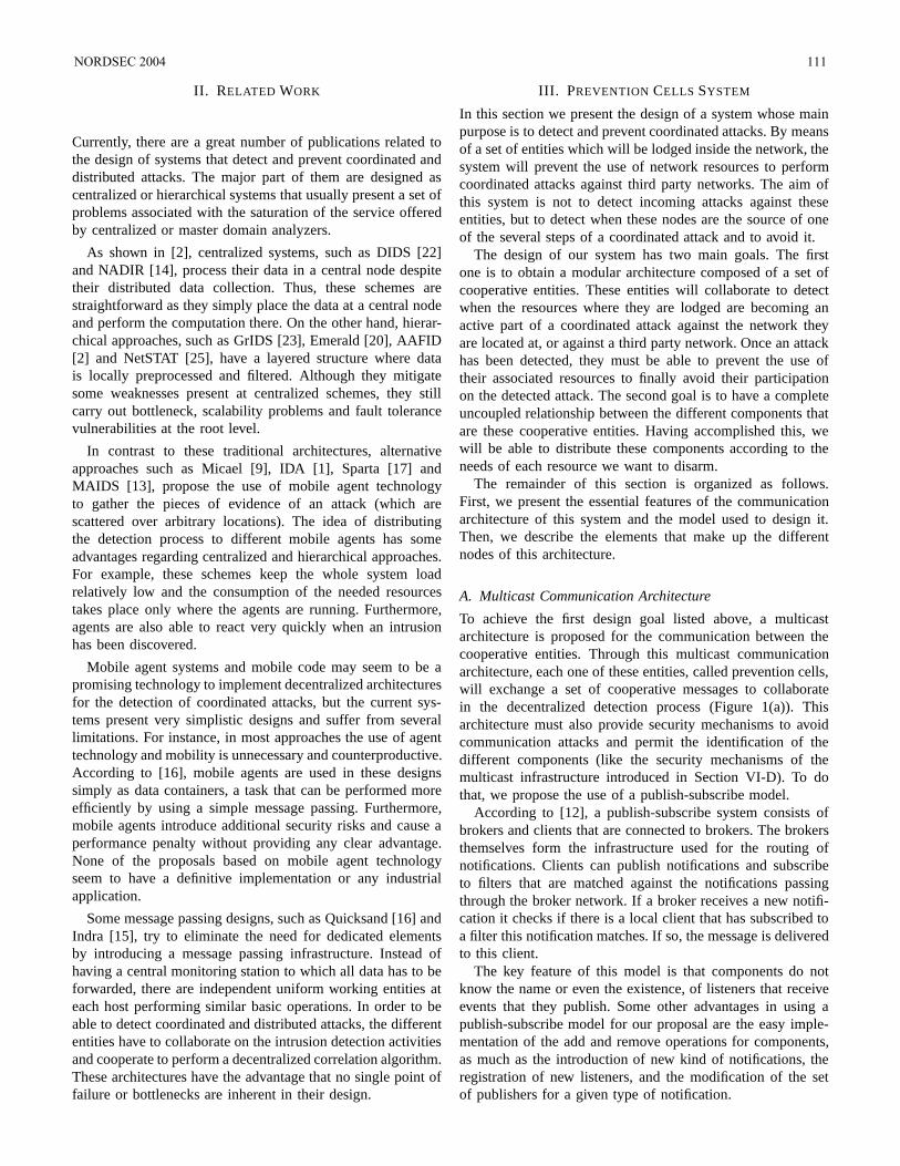
II. RELATED WORK
Currently, there are a great number of publications related tothe design of systems that detect and prevent coordinated anddistributed attacks. The major part of them are designed ascentralized or hierarchical systems that usually present a set ofproblems associated with the saturation of the service offeredby centralized or master domain analyzers.
As shown in [2], centralized systems, such as DIDS [22]and NADIR [14], process their data in a central node despitetheir distributed data collection. Thus, these schemes arestraightforward as they simply place the data at a central nodeand perform the computation there. On the other hand, hierar-chical approaches, such as GrIDS [23], Emerald [20], AAFID[2] and NetSTAT [25], have a layered structure where datais locally preprocessed and filtered. Although they mitigatesome weaknesses present at centralized schemes, they stillcarry out bottleneck, scalability problems and fault tolerancevulnerabilities at the root level.
In contrast to these traditional architectures, alternativeapproaches such as Micael [9], IDA [1], Sparta [17] andMAIDS [13], propose the use of mobile agent technologyto gather the pieces of evidence of an attack (which arescattered over arbitrary locations). The idea of distributingthe detection process to different mobile agents has someadvantages regarding centralized and hierarchical approaches.For example, these schemes keep the whole system loadrelatively low and the consumption of the needed resourcestakes place only where the agents are running. Furthermore,agents are also able to react very quickly when an intrusionhas been discovered.
Mobile agent systems and mobile code may seem to be apromising technology to implement decentralized architecturesfor the detection of coordinated attacks, but the current sys-tems present very simplistic designs and suffer from severallimitations. For instance, in most approaches the use of agenttechnology and mobility is unnecessary and counterproductive.According to [16], mobile agents are used in these designssimply as data containers, a task that can be performed moreefficiently by using a simple message passing. Furthermore,mobile agents introduce additional security risks and cause aperformance penalty without providing any clear advantage.None of the proposals based on mobile agent technologyseem to have a definitive implementation or any industrialapplication.
Some message passing designs, such as Quicksand [16] andIndra [15], try to eliminate the need for dedicated elementsby introducing a message passing infrastructure. Instead ofhaving a central monitoring station to which all data has to beforwarded, there are independent uniform working entities ateach host performing similar basic operations. In order to beable to detect coordinated and distributed attacks, the differententities have to collaborate on the intrusion detection activitiesand cooperate to perform a decentralized correlation algorithm.These architectures have the advantage that no single point offailure or bottlenecks are inherent in their design.
III. PREVENTION CELLS SYSTEM
In this section we present the design of a system whose mainpurpose is to detect and prevent coordinated attacks. By meansof a set of entities which will be lodged inside the network, thesystem will prevent the use of network resources to performcoordinated attacks against third party networks. The aim ofthis system is not to detect incoming attacks against theseentities, but to detect when these nodes are the source of oneof the several steps of a coordinated attack and to avoid it.
The design of our system has two main goals. The firstone is to obtain a modular architecture composed of a set ofcooperative entities. These entities will collaborate to detectwhen the resources where they are lodged are becoming anactive part of a coordinated attack against the network theyare located at, or against a third party network. Once an attackhas been detected, they must be able to prevent the use oftheir associated resources to finally avoid their participationon the detected attack. The second goal is to have a completeuncoupled relationship between the different components thatare these cooperative entities. Having accomplished this, wewill be able to distribute these components according to theneeds of each resource we want to disarm.
The remainder of this section is organized as follows.First, we present the essential features of the communicationarchitecture of this system and the model used to design it.Then, we describe the elements that make up the differentnodes of this architecture.
A. Multicast Communication Architecture
To achieve the first design goal listed above, a multicastarchitecture is proposed for the communication between thecooperative entities. Through this multicast communicationarchitecture, each one of these entities, called prevention cells,will exchange a set of cooperative messages to collaboratein the decentralized detection process (Figure 1(a)). Thisarchitecture must also provide security mechanisms to avoidcommunication attacks and permit the identification of thedifferent components (like the security mechanisms of themulticast infrastructure introduced in Section VI-D). To dothat, we propose the use of a publish-subscribe model.
According to [12], a publish-subscribe system consists ofbrokers and clients that are connected to brokers. The brokersthemselves form the infrastructure used for the routing ofnotifications. Clients can publish notifications and subscribeto filters that are matched against the notifications passingthrough the broker network. If a broker receives a new notifi-cation it checks if there is a local client that has subscribed toa filter this notification matches. If so, the message is deliveredto this client.
The key feature of this model is that components do notknow the name or even the existence, of listeners that receiveevents that they publish. Some other advantages in using apublish-subscribe model for our proposal are the easy imple-mentation of the add and remove operations for components,as much as the introduction of new kind of notifications, theregistration of new listeners, and the modification of the setof publishers for a given type of notification.
NORDSEC 2004 111
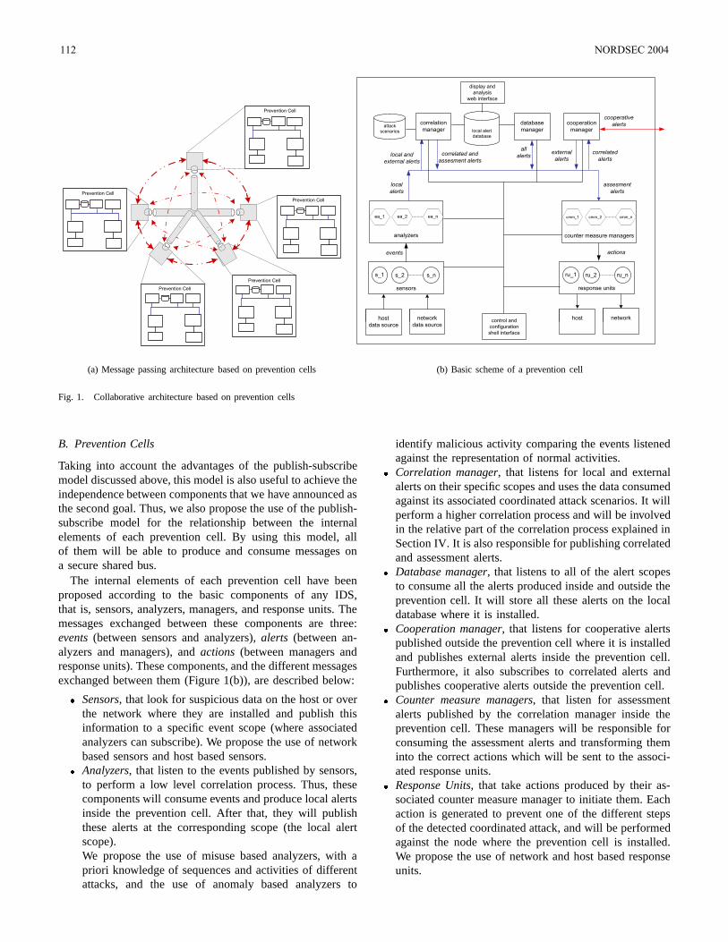
Prevention Cell
Prevention Cell
Prevention Cell
Prevention Cell
Prevention Cell
(a) Message passing architecture based on prevention cells
host
data source
analyzers
sensors
s_1 s_2 s_n
network
data source
host
response units
ru_1 ru_2 ru_n
network
events
ea_1 ea_2 ea_n
local alert
database
attack
scenarios
counter measure managers
cmm_1 cmm_2 cmm_n
display and
analysis
web interface
control and
configuration
shell interface
local
alerts
assesment
alerts
cooperation
manager
database
manager
correlated
alerts
cooperative
alerts
all
alertsexternal
alertslocal and
external alerts
correlation
manager
correlated and
assesment alerts
actions
(b) Basic scheme of a prevention cell
Fig. 1. Collaborative architecture based on prevention cells
B. Prevention Cells
Taking into account the advantages of the publish-subscribemodel discussed above, this model is also useful to achieve theindependence between components that we have announced asthe second goal. Thus, we also propose the use of the publish-subscribe model for the relationship between the internalelements of each prevention cell. By using this model, allof them will be able to produce and consume messages ona secure shared bus.
The internal elements of each prevention cell have beenproposed according to the basic components of any IDS,that is, sensors, analyzers, managers, and response units. Themessages exchanged between these components are three:events (between sensors and analyzers), alerts (between an-alyzers and managers), and actions (between managers andresponse units). These components, and the different messagesexchanged between them (Figure 1(b)), are described below:
Sensors, that look for suspicious data on the host or overthe network where they are installed and publish thisinformation to a specific event scope (where associatedanalyzers can subscribe). We propose the use of networkbased sensors and host based sensors.
Analyzers, that listen to the events published by sensors,to perform a low level correlation process. Thus, thesecomponents will consume events and produce local alertsinside the prevention cell. After that, they will publishthese alerts at the corresponding scope (the local alertscope).We propose the use of misuse based analyzers, with apriori knowledge of sequences and activities of differentattacks, and the use of anomaly based analyzers to
identify malicious activity comparing the events listenedagainst the representation of normal activities.
Correlation manager, that listens for local and externalalerts on their specific scopes and uses the data consumedagainst its associated coordinated attack scenarios. It willperform a higher correlation process and will be involvedin the relative part of the correlation process explained inSection IV. It is also responsible for publishing correlatedand assessment alerts.
Database manager, that listens to all of the alert scopesto consume all the alerts produced inside and outside theprevention cell. It will store all these alerts on the localdatabase where it is installed.
Cooperation manager, that listens for cooperative alertspublished outside the prevention cell where it is installedand publishes external alerts inside the prevention cell.Furthermore, it also subscribes to correlated alerts andpublishes cooperative alerts outside the prevention cell.
Counter measure managers, that listen for assessmentalerts published by the correlation manager inside theprevention cell. These managers will be responsible forconsuming the assessment alerts and transforming theminto the correct actions which will be sent to the associ-ated response units.
Response Units, that take actions produced by their as-sociated counter measure manager to initiate them. Eachaction is generated to prevent one of the different stepsof the detected coordinated attack, and will be performedagainst the node where the prevention cell is installed.We propose the use of network and host based responseunits.
112 NORDSEC 2004
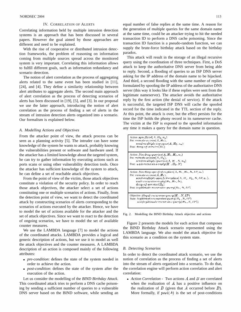
IV. CORRELATION OF ALERTS
Correlating information held by multiple intrusion detectionsystems is an approach that has been discussed in severalpapers. However the goal aimed by those approaches aredifferent and need to be explained.
With the rise of cooperative or distributed intrusion detec-tion frameworks, the problem of reasoning on informationcoming from multiple sources spread across the monitoredsystem is very important. Correlating this information allowsto fulfill different goals, such as information redundancy andscenario detection.
The notion of alert correlation as the process of aggregatingalerts related to the same event has been studied in [11],[24], and [4]. They define a similarity relationship betweenalert attributes to aggregate alerts. The second main approachof alert correlation as the process of detecting scenarios ofalerts has been discussed in [19], [5], and [3]. In our proposalwe use the latter approach, introducing the notion of alertcorrelation as the process of finding a set of alerts in thestream of intrusion detection alerts organized into a scenario.Our formalism is explained below.
A. Modelling Actions and Objectives
From the attacker point of view, the attack process can beseen as a planning activity [5]. The intruder can have someknowledge of the system he wants to attack, probably knowingthe vulnerabilities present or software and hardware used. Ifthe attacker has a limited knowledge about the targeted system,he can try to gather information by executing actions such asports scans or using other vulnerability detection tools. Oncethe attacker has sufficient knowledge of the system to attack,he can define a set of reachable attack objectives.
From the point of view of the victim, those attack objectivesconstitute a violation of the security policy. In order to reachthose attack objectives, the attacker select a set of actionsconstituting one or multiple scenarios of actions. Finally, fromthe detection point of view, we want to detect the coordinatedattack by constructing scenarios of alerts corresponding to thescenarios of actions executed by the attacker. Hence, we haveto model the set of actions available for the attacker and theset of attack objectives. Since we want to react to the detectionof ongoing scenarios, we have to model the set of availablecounter measures.
We use the LAMBDA language [7] to model the actionsof the coordinated attacks. LAMBDA provides a logical andgeneric description of actions, but we use it to model as wellthe attack objectives and the counter measures. A LAMBDAdescription of an action is composed mainly of the followingattributes:
pre-condition: defines the state of the system needed inorder to achieve the action.
post-condition: defines the state of the system after theexecution of the action.
Let us consider the modelling of the BIND Birthday Attack.This coordinated attack tries to perform a DNS cache poison-ing by sending a sufficient number of queries to a vulnerableDNS server based on the BIND software, while sending an
equal number of false replies at the same time. A reason forthe generation of multiple queries for the same domain nameat the same time, could be an attacker trying to hit the neededtransaction ID to perform a DNS cache poisoning. Since thetransaction ID function is a pseudo-random function, we cansupply the brute-force birthday attack based on the birthdayparadox.
This attack will result in the storage of an illegal recursivequery using the coordination of three techniques. First, a DoSattack to keep the authoritative DNS server from being ableto reply. Second, a flooding of queries to an ISP DNS serverasking for the IP address of the domain name to be hijacked.And third, a second flooding with the same number of repliesformulated by spoofing the IP address of the authoritative DNSserver (this way it looks like if these replies were sent from thelegitimate nameserver). The attacker avoids the authoritativereply by the first action (the denial of service). If the attackis successful, the targeted ISP DNS will cache the spoofedrecord for the time indicated in the TTL section of the reply.At this point, the attack is over, but the effect persists for thetime the ISP holds the phony record in its nameserver cache.The victim at the ISP is exposed to the spoofed informationany time it makes a query for the domain name in question.
Action - Pre: - !"" #$% - &'(*),+ - "+ - %- # Post: ./ - - 0.)1" Action -)32 - 4 &3)1 65-#%7 Pre: - !"" #65 $% - &'(*),+ - 4 &8)1 5 9: 7 Post: ;<!)= - -"$&8)0 - -+=8 65>>9Action -)32 - #+>' - -+=)1 65..9:?-@A#/BPre: - !"" # 5 $% - &'(*),+ - +8 - -+=)1 5 9?-@C B $;<!.)= - -"$&8)0 - -+=8 65>>9$./ - - 0.)1" -Post: $2.)=*):!- - "$&'-)0 - 4&38 5 9?-@<Objective )==$2!- - -"$&8)0 - 4&38 6539?-@<State: $2.)=*):!- - -"$&8)0 - 4&38 6539?-@<% $ =2-)*)!. - "$&8-)0 - 4 &33 5 9?-@<*
Fig. 2. Modelling the BIND Birthday Attack objective and actions
Figure 2 presents the models for each action that composesthe BIND Birthday Attack scenario represented using theLAMBDA language. We also model the attack objective forthis scenario as a condition on the system state.
B. Detecting Scenarios
In order to detect the coordinated attack scenario, we use thenotion of correlation as the process of finding a set of alertsinto the stream of alerts organized into a scenario. To do that,the correlation engine will perform action correlation and alertcorrelation:
Action Correlation - Two actions D and E are correlatedwhen the realization of D has a positive influence onthe realization of E (given that D occurred before E ).More formally, if FHG/IJKDML is the set of post-conditions
NORDSEC 2004 113
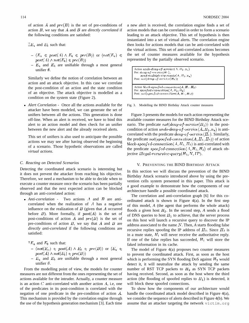
of action D and F KE L is the set of pre-conditions ofaction E , we say that D and E are directly correlated ifthe following conditions are satisfied:
! and
such that:
– K ! FHG/I>JKDML F KE LL or K<G8JK ! L FCG/IJKD L<G8JK L F KE L L
– ! and
are unifiable through a most general
unifier .
Similarly we define the notion of correlation between anaction and an attack objective. In this case we correlatethe post-condition of an action and the state conditionof an objective. The attack objective is modelled as acondition on the system state (Figure 2).
Alert Correlation - Once all the actions available for theattacker have been modeled, we can generate the set ofunifiers between all the actions. This generation is doneoff-line. When an alert is received, we have to bind thisalert to an action model and then check for an unifierbetween the new alert and the already received alerts.
This set of unifiers is also used to anticipate the possibleactions we may see after having observed the beginningof a scenario. Those hypothetic observations are calledvirtual actions.
C. Reacting on Detected Scenarios
Detecting the coordinated attack scenario is interesting butit does not prevent the attacker from reaching his objective.Therefore, we need a mechanism to be able to decide when toexecute a counter measure once the scenario has been partiallyobserved and that the next expected action can be blockedthrough an anti-correlated action:
Anti-correlation - Two actions D and E are anti-correlated when the realization of D has a negativeinfluence on the realization of E (given that D occurredbefore E ). More formally, if FCG/IJKD L is the set ofpost-conditions of action D and F KE L is the set ofpre-conditions of action E , we say that D and E aredirectly anti-correlated if the following conditions aresatisfied:
! and
such that:
– K<G8JK ! L FCG/IJKDML F KE LL or K ! FCG/IJKD L<G8JK L F KE L L
– ! and
are unifiable through a most general
unifier .
From the modelling point of view, the models for countermeasures are not different from the ones representing the set ofactions available for the intruder. Actually, a counter measureis an action anti-correlated with another action D , i.e, oneof the predicates in its post-condition is correlated with thenegation of one predicate in the pre-condition of action D .This mechanism is provided by the correlation engine throughthe use of the hypothesis generation mechanism [3]. Each time
a new alert is received, the correlation engine finds a set ofaction models that can be correlated in order to form a scenarioleading to an attack objective. This set of hypothesis is theninstantiated into a set of virtual alerts. The correlation enginethen looks for actions models that can be anti-correlated withthe virtual actions. This set of anti-correlated actions becomesthe set of counter measures available for the hypothesisrepresented by the partially observed scenario.
Action &8%. - .% - - 0.)" # 5 Pre: ./ - - 0.)1" 65% - &'(*),+ - "+ - $ 65-Post: $ ./ - - 0.)1" 65*Action
" - #+>' - "/% "#*) $ 5 Pre: +8 - " %%"#*)1 #65#Post: $ #+>' - "/% "#*) 65.*
Fig. 3. Modelling the BIND Birthday Attack counter measures
Figure 3 presents the models for each action representing theavailable counter measures for the BIND Birthday Attack sce-nario. The predicate <G8JK - G - I !"# K%$&.LL in the post-condition of action '( G - - G - I)!"# KD+*,$&-*. L is anti-correlated with the predicate - G - I)!"# K%$&L . Similarly,the predicate <G8JK#I FHG3G/ - "G ( ".J!G 6KD+*,$0&*,$21LL of action354 G"76 - I FHG3G/ - "G ( ".J!G 6KD+*,$0&-*,$21L is anti-correlated withthe predicate I FHG3G/ - "G ( ".J!G 6KD+*,$0& *,$21L of attack ob-jective ! 4%4 -8:9 4 - "#'/I-!;) - < '= K%$0&#*,>?*A@B L .
V. PREVENTING THE BIND BIRTHDAY ATTACK
In this section we will discuss the prevention of the BINDBirthday Attack scenario introduced above by using the pre-vention cells system presented in this paper. This attack isa good example to demonstrate how the components of ourarchitecture handle a possible coordinated attack.
The correlation and anti-correlation graph [6] for this co-ordinated attack is shown in Figure 4(a). In the first stepof this model, A (the agent that performs the whole attack)floods a given host $C1 . In the second step, A sends a floodof DNS queries to host $& to achieve, that the server processon this host will launch a recursive query to discover the IPaddress associated to the name > . Then, A starts flooding falserecursive replies spoofing the IP address of $01 . Since $C1 isin a mute state, $0& will never receive the authoritative reply.If one of the false replies has succeeded, $D& will store thefaked information in its cache.
The model of Figure 4(a) proposes two counter measuresto prevent the coordinated attack. First, as soon as the hostwhich is performing the SYN flooding DoS against $01 woulddetect it, it will neutralize the attack by sending the samenumber of RST TCP packets to $ 1 as SYN TCP packetshaving received. Second, as soon as the host where the thirdaction (the flooding of spoofed replies to $ & ) is detected, itwill block these spoofed connections.
To show how the components of our architecture wouldhandle the coordinated attack model described in Figure 4(a),we consider the sequence of alerts described in Figure 4(b). Weassume that an attacker targeting the network victim.org
114 NORDSEC 2004
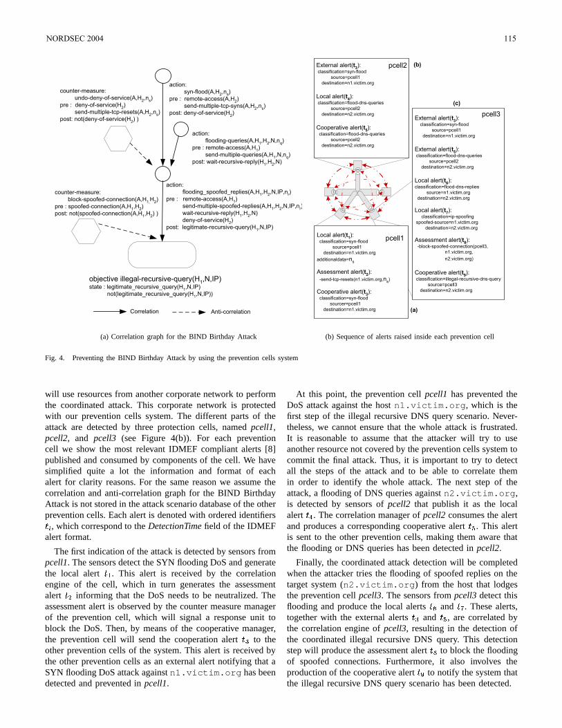
action:
syn-flood(A,H2,n
s)
pre : remote-access(A,H2)
send-multiple-tcp-syns(A,H2,n
s)
post: deny-of-service(H2)
action:
flooding_spoofed_replies(A,H1,H
2,N,IP,n
r)
pre : remote-access(A,H1)
send-multiple-spoofed-replies(A,H1,H
2,N,IP,n
r)
wait-recursive-reply(H1,H
2,N)
deny-of-service(H2)
post: legitimate-recursive-query(H1,N,IP)
objective illegal-recursive-query(H1,N,IP)
state : legitimate_recursive_query(H1,N,IP)
not(legitimate_recursive_query(H1,N,IP))
counter-measure:
block-spoofed-connection(A,H1,
H2)
pre : spoofed-connection(A,H1,H
2)
post: not(spoofed-connection(A,H1,H
2) )
counter-measure:
undo-deny-of-service(A,H2,n
s)
pre : deny-of-service(H2)
send-multiple-tcp-resets(A,H2,n
s)
post: not(deny-of-service(H2) )
Correlation Anti-correlation
action:
flooding-queries(A,H1,H
2,N,n
q)
pre : remote-access(A,H1)
send-multiple-queries(A,H1,N,n
q)
post: wait-recursive-reply(H1,H
2,N)
(a) Correlation graph for the BIND Birthday Attack
Local alert(t1):
classification=syn-flood
source=pcell1
destination=n1.victim.org
additionaldata=ns
Assessment alert(t2):
-send-tcp-resets(n1.victim.org,ns)
Cooperative alert(t3):
classification=syn-flood
sourcer=pcell1
destination=n1.victim.org
External alert(t3):
classification=syn-flood
source=pcell1
destination=n1.victim.org
Local alert(t4):
classification=flood-dns-queries
source=pcell2
destination=n2.victim.org
Cooperative alert(t5):
classification=flood-dns-queries
source=pcell2
destination=n2.victim.org
External alert(t3):
classification=syn-flood
source=pcell1
destination=n1.victim.org
External alert(t5):
classification=flood-dns-queries
source=pcell2
destination=n2.victim.org
Local alert(t6):
classification=flood-dns-replies
source=n1.victim.org
destination=n2.victim.org
Local alert(t7):
classification=ip-spoofing
spoofed-source=n1.victim.org
destination=n2.victim.org
Assessment alert(t8):
-block-spoofed-connection(pcell3,
n1.victim.org,
n2.victim.org)
Cooperative alert(t9):
classification=illegal-recursive-dns-query
source=pcell3
destination=n2.victim.org
(b)
(c)
(a)
pcell2
pcell3
pcell1
(b) Sequence of alerts raised inside each prevention cell
Fig. 4. Preventing the BIND Birthday Attack by using the prevention cells system
will use resources from another corporate network to performthe coordinated attack. This corporate network is protectedwith our prevention cells system. The different parts of theattack are detected by three protection cells, named pcell1,pcell2, and pcell3 (see Figure 4(b)). For each preventioncell we show the most relevant IDMEF compliant alerts [8]published and consumed by components of the cell. We havesimplified quite a lot the information and format of eachalert for clarity reasons. For the same reason we assume thecorrelation and anti-correlation graph for the BIND BirthdayAttack is not stored in the attack scenario database of the otherprevention cells. Each alert is denoted with ordered identifiersJ ) , which correspond to the DetectionTime field of the IDMEFalert format.
The first indication of the attack is detected by sensors frompcell1. The sensors detect the SYN flooding DoS and generatethe local alert JA& . This alert is received by the correlationengine of the cell, which in turn generates the assessmentalert J.1 informing that the DoS needs to be neutralized. Theassessment alert is observed by the counter measure managerof the prevention cell, which will signal a response unit toblock the DoS. Then, by means of the cooperative manager,the prevention cell will send the cooperation alert J to theother prevention cells of the system. This alert is received bythe other prevention cells as an external alert notifying that aSYN flooding DoS attack against n1.victim.org has beendetected and prevented in pcell1.
At this point, the prevention cell pcell1 has prevented theDoS attack against the host n1.victim.org, which is thefirst step of the illegal recursive DNS query scenario. Never-theless, we cannot ensure that the whole attack is frustrated.It is reasonable to assume that the attacker will try to useanother resource not covered by the prevention cells system tocommit the final attack. Thus, it is important to try to detectall the steps of the attack and to be able to correlate themin order to identify the whole attack. The next step of theattack, a flooding of DNS queries against n2.victim.org,is detected by sensors of pcell2 that publish it as the localalert J . The correlation manager of pcell2 consumes the alertand produces a corresponding cooperative alert J . This alertis sent to the other prevention cells, making them aware thatthe flooding or DNS queries has been detected in pcell2.
Finally, the coordinated attack detection will be completedwhen the attacker tries the flooding of spoofed replies on thetarget system (n2.victim.org) from the host that lodgesthe prevention cell pcell3. The sensors from pcell3 detect thisflooding and produce the local alerts J and J . These alerts,together with the external alerts J and J , are correlated bythe correlation engine of pcell3, resulting in the detection ofthe coordinated illegal recursive DNS query. This detectionstep will produce the assessment alert J to block the floodingof spoofed connections. Furthermore, it also involves theproduction of the cooperative alert J to notify the system thatthe illegal recursive DNS query scenario has been detected.
NORDSEC 2004 115
VI. CURRENT DEVELOPMENT
This section presents a brief overview of an implementationof our prevention system and that deploys all the basiccomponents proposed in this paper. This platform has beendeveloped for GNU/Linux systems in C and C++. Our im-plementation has been tested on different versions of Linux2.4.x series and on the versions 2.9.x and 3.x of GNU’s gcccompiler. The combination of free high-quality documentation,development and network solutions provided by GNU/Linuxoperating systems eased the analysis of requirements and thedevelopment of this platform. Below, we introduce the maincomponents of our prototype.
A. Sensors and Response Units
Our prototype started with the design and implementation of aset of sensors and response units embedded in the Linux 2.4.xseries as kernel modules. Even though, third party sensorsand third party response units could easily be integrated inour platform. The implementation of the network sensors andresponse units is based on the netfilter subsystem, a frameworkfor packet manipulation that enables packet filtering, networkaddress translation and other packet mangling on Linux 2.4.xand upper series.
At this time, we have developed the following networkbased sensors and response units: a sensor to detect stealthscanning (syns s), a sensor to detect IP spoofing (spoof s), asensor to detect buffer overflows on the packet payload (bof s),a sensor to detect TCP connection establishments that willbe used to infer connection chains (conn s), three sensors todetect denial of service (DoS) attacks based on SYN, UDPand ICMP flooding (sflood s, uflood s, iflood s) and, finally, aresponse unit capable of producing packet filtering (pfilter ru).
The implementation of the host sensors is based on theinterception of some system calls with the purpose of obtaininguseful information in the search process of illicit or suspiciousactivities. On the other hand, the implementation of the hostbased response units uses the same idea to provide the neededmechanisms to prevent the associated action related with thestep of the attack to avoid. We have finished the developmentof a sensor to monitor the execution of programs (execve s),a sensor to detect which processes want to be finished (kill s)and a response unit able to kill and protect host processes(kill ru).
B. Communication of Events and Actions
The sensors provide the events to each prevention cell an-alyzer. On the other hand, the counter measure manager ofeach prevention cell provides the actions to the response units.As we already mentioned, sensors and response units work inkernel space. The complexity of these components and thelimitation that supposes to work in a kernel scope entailsto design them as daemon processes in user space. Thus, aspecific communication mechanism between kernel space anduser space is needed.
Among the diverse alternatives for performing the com-munication between kernel space and user space, we have
chosen the netlink sockets to bind the proposed sensors and re-sponse units with the analyzers and counter measure managers.Netlink sockets is a Linux specific mechanism that providesconnectionless and asynchronous bidirectional communicationlinks. Although the use of netlink sockets has been designedwith focus on implementing protocols based on IP services,this mechanism can also be used as a standard interface toperform communication between kernel modules and userspace processes. Netlink sockets allows us to use the wellknown primitives from the socket treatment, providing ustransparency with the buffering mechanisms.
C. Analyzers and Managers
Both the implementation of the analyzer and the countermeasure components, as well as the other managers of eachprevention cell, are based on a plug-in mechanism to facilitatethe development and the maintenance of the different featuresthat these components will offer. Thus, through the use ofNetlink sockets, both the event watcher analyzer and thecounter measure manager will consume and produce infor-mation.
To generate this information or to manage it, different plug-ins will be enabled or disabled. Some of these plug-ins willbe launched in a multi-threading fashion. The event watcheranalyzer, for example, will launch the different plug-ins tohandle the events received from the sensors using this multi-threading mechanism. This way, it is possible to parallelizethe gathering of the different events produced by the setof sensors. Other plug-ins, such as the one responsible forsending actions to the response units, the one responsible formanaging external alerts and transform them to internal alerts,etc. will not need the use of this multi-threading mechanismto perform its work.
D. Communication of Alerts
The communication between the analyzers and managers,inside each prevention cell as well as between the otherprevention cells of our architecture, is performed by usingthe Elvin publish-subscribe system [21]. Elvin is a networkcommunication product that provides a simple, flexible andsecure communication infrastructure. To be able to use theinfrastructure offered by the Elvin publish-subscribe system,both, the analyzers and the managers of our implementation,have been developed using libelvin and e4xx, two portable Cand C++ libraries for the Elvin client protocol. Additionally,each host with a prevention cell lodged inside will run an Elvinserver to route all the alerts published inside each preventioncell.
Finally, to share the cooperative alerts produced by thedifferent prevention cells in a secure multicast fashion, weuse the federation and reliable local-area multicast protocolprovided by Elvin and other interesting features offered by thispublish-subscribe system, such as fail-over and cryptographicsettings. By using SSL at the transport layer we guaranteeconfidentiality, integrity and authenticity of the cooperativealerts communicated between each prevention cell.
116 NORDSEC 2004
VII. CONCLUSIONS AND FURTHER WORK
We have presented in this paper a decentralized solution forthe detection and prevention of distributed and coordinatedattacks from network resources. This system uses a securemulticast communication between different entities to avoidtheir participation in a coordinated attack against third partynetworks or even the local network. We have also outlinedhow our system can detect and prevent the BIND BirthdayAttack, exploiting the distribution and coordination of thesystem components. Then, we have briefly discussed theimplementation of a platform, which has been developed andwhich implements the major part of the components of thearchitecture previously proposed for GNU/Linux systems. Al-though the detection and reaction components of this platform(sensors and response units implemented as Linux modules)are at this time developed only for Linux 2.4, we plan toupgrade them to Linux 2.6.
As a further work, we are evaluating the possibility to incor-porate the formal data model proposed in [18] in our approach.We are also making a more in-depth study of the IDMEFformat [8] to solve unnecessary duplicated calculus inside eachprevention cell. Finally, we will incorporate intrusion tolerantmechanisms to make our system more reliable when the hostthat lodges a prevention cell is infected.
ACKNOWLEDGMENTS
We would like to thank Michael A. Jaeger for his commentson early drafts of this paper.
The work of J. Garcia, J. Borrell, S. Castillo and G.Navarro has been partially funded by the Spanish GovernmentCommission CICYT, through its grant TIC2003-02041, andthe Catalan Government Department DURSI, with its grant2001SGR-219.
REFERENCES
[1] M. Asaka, A. Taguchi, and S. Goto. The implementation of IDA: Anintrusion detection agent system. In 11th Annual FIRST Conference onComputer Security Incident Handling and Response (FIRST’99), 1999.
[2] J. S. Balasubramaniyan, J. O. Garcia-Fernandez, D. Isacoff, Eugene H.Spafford, and Diego Zamboni. An architecture for intrusion detectionusing autonomous agents. In ACSAC 1998, pages 13–24, 1998.
[3] S. Benferhat, F. Autrel, and F. Cuppens. Enhanced correlation in anintrusion detection process. In Mathematical Methods, Models andArchitecture for Computer Network Security (MMM-ACNS 2003), StPetersburg, Russia, September 2003.
[4] F. Cuppens. Managing Alerts in a Multi-Intrusion Detection Environ-ment. In 17th Annual Computer Security Applications Conference New-Orleans, New-Orleans, USA, December 2001.
[5] F. Cuppens, F. Autrel, A. Miege, and S. Benferhat. Recognizing mali-cious intention in an intrusion detection process. In Second InternationalConference on Hybrid Intelligent Systems (HIS’2002), pages 806–817,Santiago, Chile, October 2002.
[6] F. Cuppens, S. Gombault, and T. Sans. Selecting appropriate counter-measures in an intrusion detection framework. In Proceedings of17th IEEE Computer Security Foundations Workshop, Asilomar, PacificGrove, CA, June 2004.
[7] F. Cuppens and R. Ortalo. LAMBDA: A language to model a databasefor detection of attacks. In Third International Workshop on the RecentAdvances in Intrusion Detection (RAID’2000), Toulouse, France, 2000.
[8] D. Curry, H. Debar, and B. Feinstein. Intrusion detection messageexchange format data model and extensible markup language (xml)document type definition. Internet draft, January 2004.
[9] J. D. de Queiroz, L. F. R. da Costa Carmo, and L. Pirmez. Micael: Anautonomous mobile agent system to protect new generation networkedapplications. In 2nd Annual Workshop on Recent Advances in IntrusionDetection, Purdue, IN, USA, September 1999.
[10] H. Debar, M. Dacier, and A. Wespi. Towards a Taxonomy of IntrusionDetection Systems. Computer Networks, 1999.
[11] H. Debar and A. Wespi. Aggregation and Correlation of Intrusion-Detection Alerts. In Fourth International Workshop on the RecentAdvances in Intrusion Detection (RAID’2001), Davis, USA, October2001.
[12] D. Garlan, S. Khersonsky, and J. S. Kim. Model checking publish-subscribe systems. In Proceedings of the 10th International SPINWorkshop, Portland, Oregon, USA, May, 2003.
[13] G. Helmer, J. Wong, M. Slagell, V. Honavar, L. Miller, R. Lutz, andY. Wang. Software fault tree and colored petri net based specification,design and implementation of agent-based intrusion detection systems.,2002. Submitted to IEEE Transaction of Software Engineering.
[14] J. Hochberg, K. Jackson, C. Stallins, J. F. McClary, D. DuBois, andJ. Ford. NADIR: An automated system for detecting network intrusionand misuse. In Computer and Security, volume 12(3), pages 235–248.May 1993.
[15] R. Janakiraman, M. Waldvogel, and Q. Zhang. Indra: A peer-to-peerapproach to network intrusion detection and prevention. In Proceedingsof IEEE WETICE 2003, Austria, June 2003.
[16] C. Kruegel. Network Alertness - Towards an adaptive, collaboratingIntrusion Detection System. PhD thesis, Technical University of Vienna,June 2002.
[17] C. Kruegel and T. Toth. Flexible, mobile agent based intrusion detectionfor dynamic networks. In European Wireless, Italy, February 2002.
[18] B. Morin, L. Me, H. Debar, and M. Ducasse. M2D2: a formal datamodel for intrusion alarm correlation. In Proceedings of the 5th Re-cent Advances in Intrusion Detection (RAID2002), Zurich, Switzerland,October 2002.
[19] P. Ning, Y. Cui, and D. Reeves. Constructing Attack Scenarios ThroughCorrelation of Intrusion Alerts. In proceedings of the 9th ACMconference on Computer and communication security, pages 245–254,Washington DC, USA, 2002.
[20] P. A. Porras and P. G. Neumann. EMERALD: Event monitoringenabling responses to anomalous live disturbances. In Proceedings of the20th National Information Systems Security Conference, pages 353–365,October 1997.
[21] B. Segall and D. Arnold. Elvin has left the building: A publish/subscribenotification service with quenching. In Proceedings of the third annualtechnical conference of AUUG 1997, pages 243–255, Brisbane, Septem-ber 1997.
[22] S. R. Snapp, J. Brentano, G. V. Dias, T. L. Goan, L. T. Heberlein,C. Ho, K. N. Levitt, B. Mukherjee, S. E. Smaha, T. Grance, D. M.Teal, and D. Mansur. DIDS (distributed intrusion detection system) -motivation, architecture and an early prototype. In Proceedings 14thNational Security Conference, pages 167–176, October, 1991.
[23] S. Staniford-Chen, S. Cheung, R. Crawford, M. Dilger, J. Frank,J. Hoagland K. Levitt, C. Wee, R. Yip, and D. Zerkle. GrIDS – a graph-based intrusion detection system for large networks. In Proceedings ofthe 19th National Information Systems Security Conference, 1996.
[24] A. Valdes and K. Skinner. Probabilistic alert correlation. In FourthInternational Symposium on Recent Advances in Intrusion Detection(RAID2001), pages 58–68, Davis, CA, USA, October 2001.
[25] G. Vigna and R. A. Kemmerer. NetSTAT: A network-based intrusiondetection system. Journal of Computer Security, 7(1):37–71, 1999.
NORDSEC 2004 117
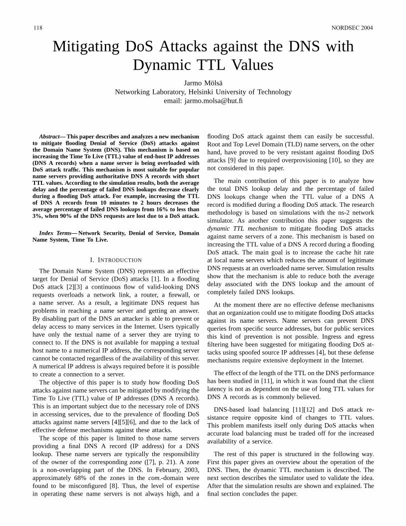
Mitigating DoS Attacks against the DNS withDynamic TTL Values
Jarmo MolsaNetworking Laboratory, Helsinki University of Technology
email: [email protected]
Abstract— This paper describes and analyzes a new mechanismto mitigate flooding Denial of Service (DoS) attacks againstthe Domain Name System (DNS). This mechanism is based onincreasing the Time To Live (TTL) value of end-host IP addresses(DNS A records) when a name server is being overloaded withDoS attack traffic. This mechanism is most suitable for popularname servers providing authoritative DNS A records with shortTTL values. According to the simulation results, both the averagedelay and the percentage of failed DNS lookups decrease clearlyduring a flooding DoS attack. For example, increasing the TTLof DNS A records from 10 minutes to 2 hours decreases theaverage percentage of failed DNS lookups from 16% to less than3%, when 90% of the DNS requests are lost due to a DoS attack.
Index Terms— Network Security, Denial of Service, DomainName System, Time To Live.
I. I NTRODUCTION
The Domain Name System (DNS) represents an effectivetarget for Denial of Service (DoS) attacks [1]. In a floodingDoS attack [2][3] a continuous flow of valid-looking DNSrequests overloads a network link, a router, a firewall, ora name server. As a result, a legitimate DNS request hasproblems in reaching a name server and getting an answer.By disabling part of the DNS an attacker is able to prevent ordelay access to many services in the Internet. Users typicallyhave only the textual name of a server they are trying toconnect to. If the DNS is not available for mapping a textualhost name to a numerical IP address, the corresponding servercannot be contacted regardless of the availability of this server.A numerical IP address is always required before it is possibleto create a connection to a server.
The objective of this paper is to study how flooding DoSattacks against name servers can be mitigated by modifying theTime To Live (TTL) value of IP addresses (DNS A records).This is an important subject due to the necessary role of DNSin accessing services, due to the prevalence of flooding DoSattacks against name servers [4][5][6], and due to the lack ofeffective defense mechanisms against these attacks.
The scope of this paper is limited to those name serversproviding a final DNS A record (IP address) for a DNSlookup. These name servers are typically the responsibilityof the owner of the correspondingzone([7], p. 21). A zoneis a non-overlapping part of the DNS. In February, 2003,approximately 68% of the zones in thecom.-domain werefound to be misconfigured [8]. Thus, the level of expertisein operating these name servers is not always high, and a
flooding DoS attack against them can easily be successful.Root and Top Level Domain (TLD) name servers, on the otherhand, have proved to be very resistant against flooding DoSattacks [9] due to required overprovisioning [10], so they arenot considered in this paper.
The main contribution of this paper is to analyze howthe total DNS lookup delay and the percentage of failedDNS lookups change when the TTL value of a DNS Arecord is modified during a flooding DoS attack. The researchmethodology is based on simulations with the ns-2 networksimulator. As another contribution this paper suggests thedynamic TTL mechanismto mitigate flooding DoS attacksagainst name servers of a zone. This mechanism is based onincreasing the TTL value of a DNS A record during a floodingDoS attack. The main goal is to increase the cache hit rateat local name servers which reduces the amount of legitimateDNS requests at an overloaded name server. Simulation resultsshow that the mechanism is able to reduce both the averagedelay associated with the DNS lookup and the amount ofcompletely failed DNS lookups.
At the moment there are no effective defense mechanismsthat an organization could use to mitigate flooding DoS attacksagainst its name servers. Name servers can prevent DNSqueries from specific source addresses, but for public servicesthis kind of prevention is not possible. Ingress and egressfiltering have been suggested for mitigating flooding DoS at-tacks using spoofed source IP addresses [4], but these defensemechanisms require extensive deployment in the Internet.
The effect of the length of the TTL on the DNS performancehas been studied in [11], in which it was found that the clientlatency is not as dependent on the use of long TTL values forDNS A records as is commonly believed.
DNS-based load balancing [11][12] and DoS attack re-sistance require opposite kind of changes to TTL values.This problem manifests itself only during DoS attacks whenaccurate load balancing must be traded off for the increasedavailability of a service.
The rest of this paper is structured in the following way.First this paper gives an overview about the operation of theDNS. Then, the dynamic TTL mechanism is described. Thenext section describes the simulator used to validate the idea.After that the simulation results are shown and explained. Thefinal section concludes the paper.
118 NORDSEC 2004
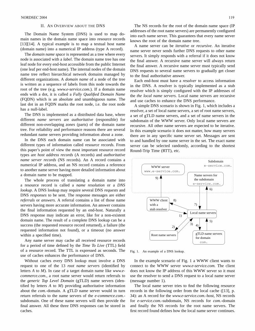
II. A N OVERVIEW ABOUT THE DNS
The Domain Name System (DNS) is used to map do-main names in the domain name space into resource records[13][14]. A typical example is to map a textual host name(domain name) into a numerical IP address (type A record).
Thedomain name spaceis represented as a tree where everynode is associated with alabel. The domain name tree has oneleaf node for every end-host accessible from the public Internet(one leaf per end-host name). The internal nodes of the domainname tree reflect hierarchical network domains managed bydifferent organizations. Adomain nameof a node of the treeis written as a sequence of labels from this node towards theroot of the tree (e.g.www.e-service.com.). If a domain nameends with a dot, it is called aFully Qualified Domain Name(FQDN) which is an absolute and unambiguous name. Thelast dot in an FQDN marks the root node, i.e. the root nodehas a null-label.
The DNS is implemented as a distributed data base, wheredifferent name serversare authoritative (responsible) fordifferent non-overlappingzones(parts) of the domain nametree. For reliability and performance reasons there are severalredundant name servers providing information about a zone.
In the DNS each domain name can be associated withdifferent types of information calledresource records. Fromthis paper’s point of view the most important resource recordtypes arehost address records(A records) andauthoritativename server records(NS records). An A record contains anumerical IP address, and an NS record contains a referenceto another name server having more detailed information abouta domain name to be mapped.
The whole process of translating a domain name intoa resource record is called aname resolutionor a DNSlookup. A DNS lookup may require several DNSrequestsandDNS responsesto be sent. The response messages are eitherreferrals or answers. A referral contains a list of those nameservers having more accurate information. An answer containsthe final information requested by an end-host. Naturally aDNS response may indicate an error, like for a non-existentdomain name. The result of a complete DNS lookup can be asuccess (the requested resource record returned), a failure (therequested information not found), or a timeout (no answerwithin a specified time).
Any name server may cache all received resource recordsfor a period of time defined by theTime To Live(TTL) fieldof a resource record. The TTL is expressed as seconds. Theuse of caches enhances the performance of DNS.
Without caches every DNS lookup must involve a DNSrequest to one of the 13root name servers(identified bylettersA to M). In case of a target domain name likewww.e-commerce.com., a root name server would return referrals tothe generic Top Level Domain(gTLD) name servers (iden-tified by lettersA to M) providing authoritative informationabout thecom.-domain. A gTLD name server would in turnreturn referrals to the name servers of thee-commerce.com.-subdomain. One of these name servers will then provide thefinal answer. All these three DNS responses can be stored incaches.
The NS records for the root of the domain name space (IPaddresses of the root name servers) are permanently configuredinto each name server. This guarantees that every name serverknows the root of the domain name tree.
A name server can beiterative or recursive. An iterativename server never sends further DNS requests to other nameservers. It simply responds with a referral if it does not knowthe final answer. A recursive name server will always returnthe final answer. A recursive name server must typically sendDNS requests to several name servers to gradually get closerto the final authoritative answer.
Each end-host must have aresolver to access informationin the DNS. A resolver is typically implemented as a stubresolver which is simply configured with the IP addresses ofthe the local name servers. Local name servers are recursiveand use caches to enhance the DNS performance.
A simple DNS scenario is shown in Fig. 1, which includes aresolver, a set of local name servers, a set of root name servers,a set of gTLD name servers, and a set of name servers in thesubdomain of the WWW server. Only local name servers arerecursive. All other name servers are expected to be iterative.In this example scenario it does not matter, how many serversthere are in any specific name server set. Messages are sentto and handled by one name server in the set. The exact nameserver can be selected randomly, according to the shortestRound-Trip Time (RTT), etc.
www.e−service.com.WWW server
e−service.com.the subdomain
Subdomain
with astub resolver
WWW client
1)
5)
8)7)
gTLD name serversfor domain
Root name servers
com.
3) 4)2)
e−service.com.
Local name servers
Name servers for9)
6)
Fig. 1. An example of a DNS lookup.
In the example scenario of Fig. 1 a WWW client wants toconnect to the WWW serverwww.e-service.com.The clientdoes not know the IP address of this WWW server so it mustuse the resolver to send a DNS request to a local name server(message number 1).
The local name server tries to find the following resourcerecords in the following order from the local cache ([13], p.34): an A record for thewww.e-service.com.-host, NS recordsfor e-service.com.-subdomain, NS records forcom.-domainand finally the NS records for the root name servers. Thefirst record found defines how the local name server continues.
NORDSEC 2004 119
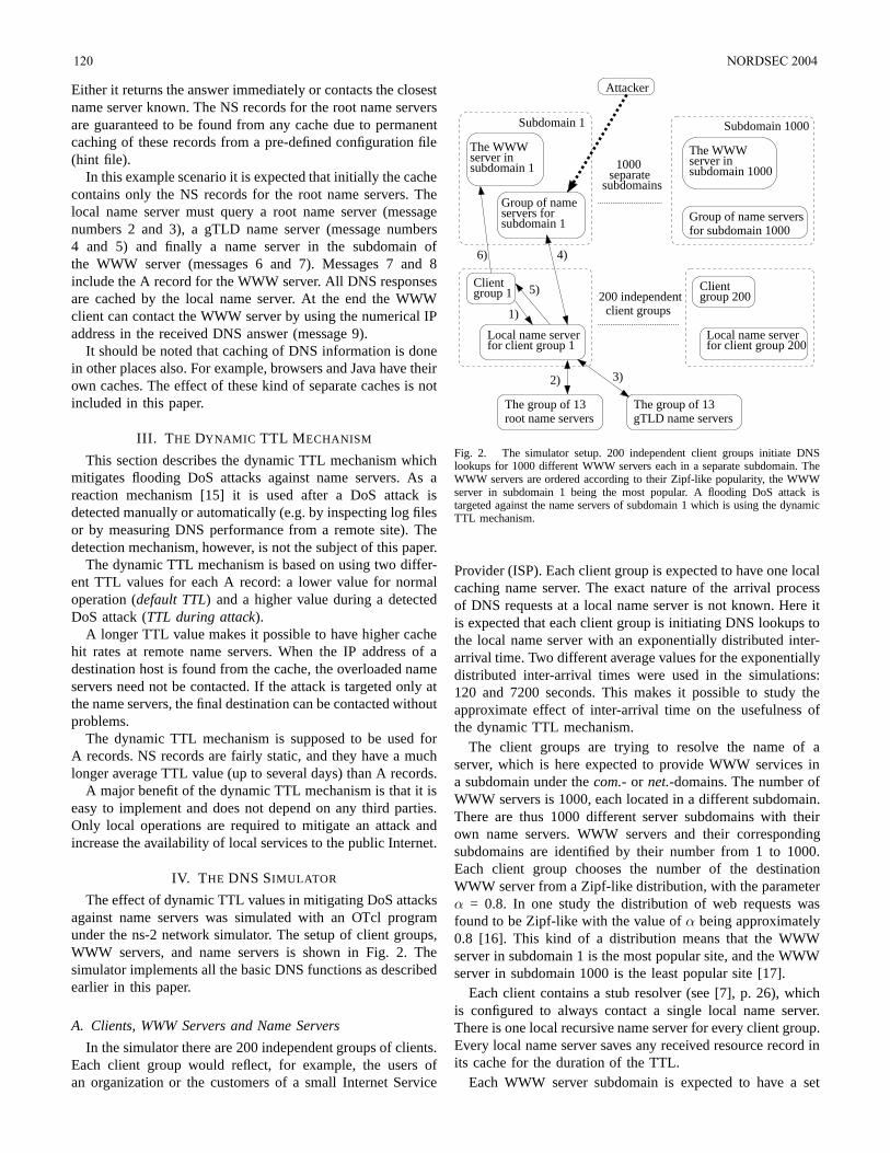
Either it returns the answer immediately or contacts the closestname server known. The NS records for the root name serversare guaranteed to be found from any cache due to permanentcaching of these records from a pre-defined configuration file(hint file).
In this example scenario it is expected that initially the cachecontains only the NS records for the root name servers. Thelocal name server must query a root name server (messagenumbers 2 and 3), a gTLD name server (message numbers4 and 5) and finally a name server in the subdomain ofthe WWW server (messages 6 and 7). Messages 7 and 8include the A record for the WWW server. All DNS responsesare cached by the local name server. At the end the WWWclient can contact the WWW server by using the numerical IPaddress in the received DNS answer (message 9).
It should be noted that caching of DNS information is donein other places also. For example, browsers and Java have theirown caches. The effect of these kind of separate caches is notincluded in this paper.
III. T HE DYNAMIC TTL M ECHANISM
This section describes the dynamic TTL mechanism whichmitigates flooding DoS attacks against name servers. As areaction mechanism [15] it is used after a DoS attack isdetected manually or automatically (e.g. by inspecting log filesor by measuring DNS performance from a remote site). Thedetection mechanism, however, is not the subject of this paper.
The dynamic TTL mechanism is based on using two differ-ent TTL values for each A record: a lower value for normaloperation (default TTL) and a higher value during a detectedDoS attack (TTL during attack).
A longer TTL value makes it possible to have higher cachehit rates at remote name servers. When the IP address of adestination host is found from the cache, the overloaded nameservers need not be contacted. If the attack is targeted only atthe name servers, the final destination can be contacted withoutproblems.
The dynamic TTL mechanism is supposed to be used forA records. NS records are fairly static, and they have a muchlonger average TTL value (up to several days) than A records.
A major benefit of the dynamic TTL mechanism is that it iseasy to implement and does not depend on any third parties.Only local operations are required to mitigate an attack andincrease the availability of local services to the public Internet.
IV. T HE DNS SIMULATOR
The effect of dynamic TTL values in mitigating DoS attacksagainst name servers was simulated with an OTcl programunder the ns-2 network simulator. The setup of client groups,WWW servers, and name servers is shown in Fig. 2. Thesimulator implements all the basic DNS functions as describedearlier in this paper.
A. Clients, WWW Servers and Name Servers
In the simulator there are 200 independent groups of clients.Each client group would reflect, for example, the users ofan organization or the customers of a small Internet Service
Subdomain 1000Subdomain 1
The WWW
5)
client groups200 independent
Local name server
group 200Client
Local name server
6)
1)
3)
servers forfor subdomain 1000Group of name servers
subdomainsseparate
1000 subdomain 1000server inThe WWW
for client group 200for client group 1
subdomain 1server in
Group of name
Attacker
subdomain 1
Client
root name serversThe group of 13gTLD name servers
The group of 13
2)
group 1
4)
Fig. 2. The simulator setup. 200 independent client groups initiate DNSlookups for 1000 different WWW servers each in a separate subdomain. TheWWW servers are ordered according to their Zipf-like popularity, the WWWserver in subdomain 1 being the most popular. A flooding DoS attack istargeted against the name servers of subdomain 1 which is using the dynamicTTL mechanism.
Provider (ISP). Each client group is expected to have one localcaching name server. The exact nature of the arrival processof DNS requests at a local name server is not known. Here itis expected that each client group is initiating DNS lookups tothe local name server with an exponentially distributed inter-arrival time. Two different average values for the exponentiallydistributed inter-arrival times were used in the simulations:120 and 7200 seconds. This makes it possible to study theapproximate effect of inter-arrival time on the usefulness ofthe dynamic TTL mechanism.
The client groups are trying to resolve the name of aserver, which is here expected to provide WWW services ina subdomain under thecom.-or net.-domains. The number ofWWW servers is 1000, each located in a different subdomain.There are thus 1000 different server subdomains with theirown name servers. WWW servers and their correspondingsubdomains are identified by their number from 1 to 1000.Each client group chooses the number of the destinationWWW server from a Zipf-like distribution, with the parameterα = 0.8. In one study the distribution of web requests wasfound to be Zipf-like with the value ofα being approximately0.8 [16]. This kind of a distribution means that the WWWserver in subdomain 1 is the most popular site, and the WWWserver in subdomain 1000 is the least popular site [17].
Each client contains a stub resolver (see [7], p. 26), whichis configured to always contact a single local name server.There is one local recursive name server for every client group.Every local name server saves any received resource record inits cache for the duration of the TTL.
Each WWW server subdomain is expected to have a set
120 NORDSEC 2004
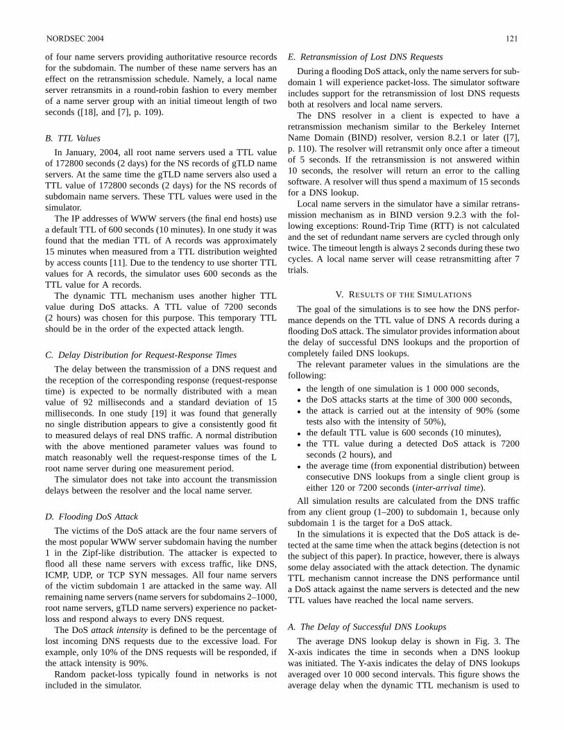
of four name servers providing authoritative resource recordsfor the subdomain. The number of these name servers has aneffect on the retransmission schedule. Namely, a local nameserver retransmits in a round-robin fashion to every memberof a name server group with an initial timeout length of twoseconds ([18], and [7], p. 109).
B. TTL Values
In January, 2004, all root name servers used a TTL valueof 172800 seconds (2 days) for the NS records of gTLD nameservers. At the same time the gTLD name servers also used aTTL value of 172800 seconds (2 days) for the NS records ofsubdomain name servers. These TTL values were used in thesimulator.
The IP addresses of WWW servers (the final end hosts) usea default TTL of 600 seconds (10 minutes). In one study it wasfound that the median TTL of A records was approximately15 minutes when measured from a TTL distribution weightedby access counts [11]. Due to the tendency to use shorter TTLvalues for A records, the simulator uses 600 seconds as theTTL value for A records.
The dynamic TTL mechanism uses another higher TTLvalue during DoS attacks. A TTL value of 7200 seconds(2 hours) was chosen for this purpose. This temporary TTLshould be in the order of the expected attack length.
C. Delay Distribution for Request-Response Times
The delay between the transmission of a DNS request andthe reception of the corresponding response (request-responsetime) is expected to be normally distributed with a meanvalue of 92 milliseconds and a standard deviation of 15milliseconds. In one study [19] it was found that generallyno single distribution appears to give a consistently good fitto measured delays of real DNS traffic. A normal distributionwith the above mentioned parameter values was found tomatch reasonably well the request-response times of the Lroot name server during one measurement period.
The simulator does not take into account the transmissiondelays between the resolver and the local name server.
D. Flooding DoS Attack
The victims of the DoS attack are the four name servers ofthe most popular WWW server subdomain having the number1 in the Zipf-like distribution. The attacker is expected toflood all these name servers with excess traffic, like DNS,ICMP, UDP, or TCP SYN messages. All four name serversof the victim subdomain 1 are attacked in the same way. Allremaining name servers (name servers for subdomains 2–1000,root name servers, gTLD name servers) experience no packet-loss and respond always to every DNS request.
The DoSattack intensityis defined to be the percentage oflost incoming DNS requests due to the excessive load. Forexample, only 10% of the DNS requests will be responded, ifthe attack intensity is 90%.
Random packet-loss typically found in networks is notincluded in the simulator.
E. Retransmission of Lost DNS Requests
During a flooding DoS attack, only the name servers for sub-domain 1 will experience packet-loss. The simulator softwareincludes support for the retransmission of lost DNS requestsboth at resolvers and local name servers.
The DNS resolver in a client is expected to have aretransmission mechanism similar to the Berkeley InternetName Domain (BIND) resolver, version 8.2.1 or later ([7],p. 110). The resolver will retransmit only once after a timeoutof 5 seconds. If the retransmission is not answered within10 seconds, the resolver will return an error to the callingsoftware. A resolver will thus spend a maximum of 15 secondsfor a DNS lookup.
Local name servers in the simulator have a similar retrans-mission mechanism as in BIND version 9.2.3 with the fol-lowing exceptions: Round-Trip Time (RTT) is not calculatedand the set of redundant name servers are cycled through onlytwice. The timeout length is always 2 seconds during these twocycles. A local name server will cease retransmitting after 7trials.
V. RESULTS OF THESIMULATIONS
The goal of the simulations is to see how the DNS perfor-mance depends on the TTL value of DNS A records during aflooding DoS attack. The simulator provides information aboutthe delay of successful DNS lookups and the proportion ofcompletely failed DNS lookups.
The relevant parameter values in the simulations are thefollowing:
• the length of one simulation is 1 000 000 seconds,• the DoS attacks starts at the time of 300 000 seconds,• the attack is carried out at the intensity of 90% (some
tests also with the intensity of 50%),• the default TTL value is 600 seconds (10 minutes),• the TTL value during a detected DoS attack is 7200
seconds (2 hours), and• the average time (from exponential distribution) between
consecutive DNS lookups from a single client group iseither 120 or 7200 seconds (inter-arrival time).
All simulation results are calculated from the DNS trafficfrom any client group (1–200) to subdomain 1, because onlysubdomain 1 is the target for a DoS attack.
In the simulations it is expected that the DoS attack is de-tected at the same time when the attack begins (detection is notthe subject of this paper). In practice, however, there is alwayssome delay associated with the attack detection. The dynamicTTL mechanism cannot increase the DNS performance untila DoS attack against the name servers is detected and the newTTL values have reached the local name servers.
A. The Delay of Successful DNS Lookups
The average DNS lookup delay is shown in Fig. 3. TheX-axis indicates the time in seconds when a DNS lookupwas initiated. The Y-axis indicates the delay of DNS lookupsaveraged over 10 000 second intervals. This figure shows theaverage delay when the dynamic TTL mechanism is used to
NORDSEC 2004 121

protect the subdomain 1 (TTL = 600/7200)and when thismechanism is not used (TTL = 600). The results are shownfor inter-arrival values of 7200 seconds (thick lines) and 120seconds (thin lines).
0
1
2
3
4
5
6
7
0 200000 400000 600000 800000 1e+06
Ave
rage
del
ay (
seco
nds)
DNS lookup initiation time (seconds)
DoS attack intensity 90 %, attack starts at time 300000 s
Inter-arrival time = 7200, TTL = 600Inter-arrival time = 7200, TTL = 600 / 7200
Inter-arrival time = 120, TTL = 600Inter-arrival time = 120, TTL = 600 / 7200
Fig. 3. The delay of successful DNS lookups averaged over 10 000 secondintervals.
If the inter-arrival time is 120 seconds, the average delayis reduced almost 90% from 1.5 seconds to approximately0.16 seconds. When the inter-arrival time is 7200 seconds, theaverage DNS lookup delay is much longer than when inter-arrival time is 120 seconds. The reason for this is very logical,because the more DNS lookups there are in a time unit, themore lookups will result in a cache hit at the local name server.This pulls down the average lookup delay.
The positive effect of the dynamic TTL mechanism isvisible with both inter-arrival times. This effect is, however,stronger when inter-arrival time is shorter. The shorter theinter-arrival time is, the more cache hits will result at the localname server. If a subdomain is visited very seldom, the cachedA record will time out before the next visit to it.
As expected, the dynamic TTL mechanism provides thebest benefit for those client groups which have many clientsreferencing a similar set of popular destinations. This increasesthe possibility for a cache hit at the local name server.
Averaging DNS lookup delays over 10 000 second intervalshides some details of shorter time scale. For this reason thetime range from 290 000 seconds to 350 000 seconds ofFig. 3 is magnified in Fig. 4 which shows the delay of DNSlookups averaged over 200 second intervals. Only results forthe inter-arrival time of 120 seconds are shown in this figure.Figure 4 shows well that all client groups are practicallysynchronized due to the short TTL value (600 seconds) afterthe DoS attack starts at the time of 300 000 seconds. The clientgroups gradually desynchronize due to the randomness in boththe DNS lookup initiation process and the request-responsetimes. Figure 4 also shows the delay until the dynamic TTLmechanism begins to enhance the DNS performance after theattack is detected (the high peak at the time of 300 000seconds).
0
0.5
1
1.5
2
2.5
290000 300000 310000 320000 330000 340000 350000
Ave
rage
del
ay (
seco
nds)
DNS lookup initiation time (seconds)
Inter-arrival time = 120 seconds, DoS attack intensity 90 %
TTL = 600 TTL = 600 / 7200
Fig. 4. The delay of successful DNS lookups averaged over 200 secondintervals during the time range from 290 000 to 350 000 seconds.
B. The Percentage of Failed DNS Lookups
The average percentage of failed DNS lookups is shown inFig. 5. The X-axis indicates the time in seconds when a DNSlookup was initiated. The Y-axis indicates the percentage offailed DNS lookups averaged over 10 000 second intervals.A DNS lookup fails if it times out completely at a resolverwithout an answer. This figure shows the average percentageof failed DNS lookups when the dynamic TTL mechanism isused to protect the subdomain 1 (TTL = 600/7200)and whenthis mechanism is not used (TTL = 600). The results are shownfor inter-arrival values of 7200 seconds (thick lines) and 120seconds (thin lines).
0
10
20
30
40
50
60
0 200000 400000 600000 800000 1e+06
Per
cent
age
of fa
iled
DN
S lo
okup
s (%
)
DNS lookup initiation time (seconds)
DoS attack intensity 90 %, attack starts at time 300000 s
Inter-arrival time = 7200, TTL = 600Inter-arrival time = 7200, TTL = 600 / 7200
Inter-arrival time = 120, TTL = 600Inter-arrival time = 120, TTL = 600 / 7200
Fig. 5. The percentage of failed DNS lookups averaged over 10 000 secondintervals.
The positive effect of the dynamic TTL mechanism isvisible with both inter-arrival times. The shorter inter-arrivaltime (120 seconds) results in more cache hits at the local nameserver, which decreases the need to send any DNS requests tothe overloaded name servers. This reduces the average DNSlookup failure percentage. Increasing the TTL value of Arecords from 10 minutes to 2 hours decreases the averagepercentage of failed DNS lookups from 16% to less than 3%,when 90% of the DNS requests are lost due to a DoS attack(inter-arrival time being 120 seconds).
122 NORDSEC 2004
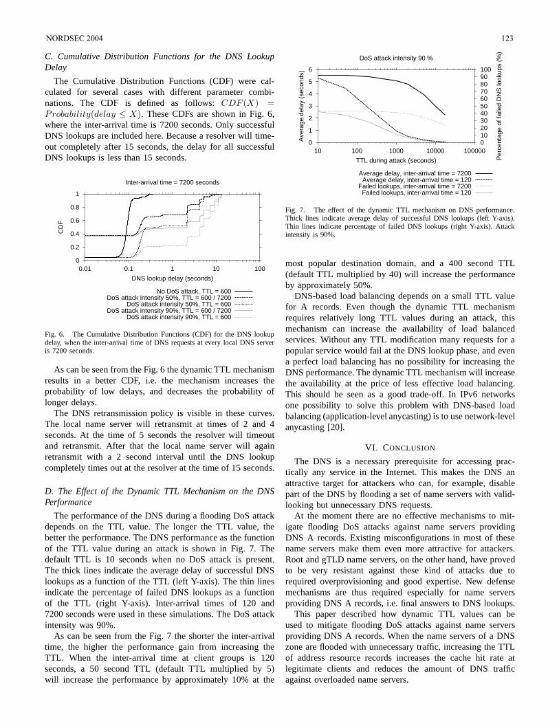
C. Cumulative Distribution Functions for the DNS LookupDelay
The Cumulative Distribution Functions (CDF) were cal-culated for several cases with different parameter combi-nations. The CDF is defined as follows:CDF (X) =Probability(delay ≤ X). These CDFs are shown in Fig. 6,where the inter-arrival time is 7200 seconds. Only successfulDNS lookups are included here. Because a resolver will time-out completely after 15 seconds, the delay for all successfulDNS lookups is less than 15 seconds.
0
0.2
0.4
0.6
0.8
1
0.01 0.1 1 10 100
CD
F
DNS lookup delay (seconds)
Inter-arrival time = 7200 seconds
No DoS attack, TTL = 600DoS attack intensity 50%, TTL = 600 / 7200
DoS attack intensity 50%, TTL = 600DoS attack intensity 90%, TTL = 600 / 7200
DoS attack intensity 90%, TTL = 600
Fig. 6. The Cumulative Distribution Functions (CDF) for the DNS lookupdelay, when the inter-arrival time of DNS requests at every local DNS serveris 7200 seconds.
As can be seen from the Fig. 6 the dynamic TTL mechanismresults in a better CDF, i.e. the mechanism increases theprobability of low delays, and decreases the probability oflonger delays.
The DNS retransmission policy is visible in these curves.The local name server will retransmit at times of 2 and 4seconds. At the time of 5 seconds the resolver will timeoutand retransmit. After that the local name server will againretransmit with a 2 second interval until the DNS lookupcompletely times out at the resolver at the time of 15 seconds.
D. The Effect of the Dynamic TTL Mechanism on the DNSPerformance
The performance of the DNS during a flooding DoS attackdepends on the TTL value. The longer the TTL value, thebetter the performance. The DNS performance as the functionof the TTL value during an attack is shown in Fig. 7. Thedefault TTL is 10 seconds when no DoS attack is present.The thick lines indicate the average delay of successful DNSlookups as a function of the TTL (left Y-axis). The thin linesindicate the percentage of failed DNS lookups as a functionof the TTL (right Y-axis). Inter-arrival times of 120 and7200 seconds were used in these simulations. The DoS attackintensity was 90%.
As can be seen from the Fig. 7 the shorter the inter-arrivaltime, the higher the performance gain from increasing theTTL. When the inter-arrival time at client groups is 120seconds, a 50 second TTL (default TTL multiplied by 5)will increase the performance by approximately 10% at the
0
1
2
3
4
5
6
10 100 1000 10000 1000000102030405060708090100
Ave
rage
del
ay (
seco
nds)
Per
cent
age
of fa
iled
DN
S lo
okup
s (%
)
TTL during attack (seconds)
DoS attack intensity 90 %
Average delay, inter-arrival time = 7200Average delay, inter-arrival time = 120
Failed lookups, inter-arrival time = 7200Failed lookups, inter-arrival time = 120
Fig. 7. The effect of the dynamic TTL mechanism on DNS performance.Thick lines indicate average delay of successful DNS lookups (left Y-axis).Thin lines indicate percentage of failed DNS lookups (right Y-axis). Attackintensity is 90%.
most popular destination domain, and a 400 second TTL(default TTL multiplied by 40) will increase the performanceby approximately 50%.
DNS-based load balancing depends on a small TTL valuefor A records. Even though the dynamic TTL mechanismrequires relatively long TTL values during an attack, thismechanism can increase the availability of load balancedservices. Without any TTL modification many requests for apopular service would fail at the DNS lookup phase, and evena perfect load balancing has no possibility for increasing theDNS performance. The dynamic TTL mechanism will increasethe availability at the price of less effective load balancing.This should be seen as a good trade-off. In IPv6 networksone possibility to solve this problem with DNS-based loadbalancing (application-level anycasting) is to use network-levelanycasting [20].
VI. CONCLUSION
The DNS is a necessary prerequisite for accessing prac-tically any service in the Internet. This makes the DNS anattractive target for attackers who can, for example, disablepart of the DNS by flooding a set of name servers with valid-looking but unnecessary DNS requests.
At the moment there are no effective mechanisms to mit-igate flooding DoS attacks against name servers providingDNS A records. Existing misconfigurations in most of thesename servers make them even more attractive for attackers.Root and gTLD name servers, on the other hand, have provedto be very resistant against these kind of attacks due torequired overprovisioning and good expertise. New defensemechanisms are thus required especially for name serversproviding DNS A records, i.e. final answers to DNS lookups.
This paper described how dynamic TTL values can beused to mitigate flooding DoS attacks against name serversproviding DNS A records. When the name servers of a DNSzone are flooded with unnecessary traffic, increasing the TTLof address resource records increases the cache hit rate atlegitimate clients and reduces the amount of DNS trafficagainst overloaded name servers.
NORDSEC 2004 123
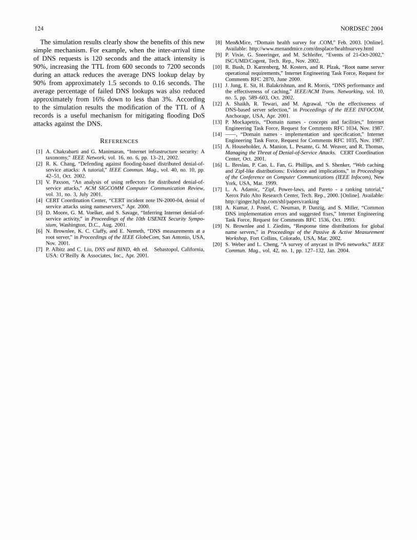
The simulation results clearly show the benefits of this newsimple mechanism. For example, when the inter-arrival timeof DNS requests is 120 seconds and the attack intensity is90%, increasing the TTL from 600 seconds to 7200 secondsduring an attack reduces the average DNS lookup delay by90% from approximately 1.5 seconds to 0.16 seconds. Theaverage percentage of failed DNS lookups was also reducedapproximately from 16% down to less than 3%. Accordingto the simulation results the modification of the TTL of Arecords is a useful mechanism for mitigating flooding DoSattacks against the DNS.
REFERENCES
[1] A. Chakrabarti and G. Manimaran, “Internet infrastructure security: Ataxonomy,” IEEE Network, vol. 16, no. 6, pp. 13–21, 2002.
[2] R. K. Chang, “Defending against flooding-based distributed denial-of-service attacks: A tutorial,”IEEE Commun. Mag., vol. 40, no. 10, pp.42–51, Oct. 2002.
[3] V. Paxson, “An analysis of using reflectors for distributed denial-of-service attacks,”ACM SIGCOMM Computer Communication Review,vol. 31, no. 3, July 2001.
[4] CERT Coordination Center, “CERT incident note IN-2000-04, denial ofservice attacks using nameservers,” Apr. 2000.
[5] D. Moore, G. M. Voelker, and S. Savage, “Inferring Internet denial-of-service activity,” inProceedings of the 10th USENIX Security Sympo-sium, Washington, D.C., Aug. 2001.
[6] N. Brownlee, K. C. Claffy, and E. Nemeth, “DNS measurements at aroot server,” inProceedings of the IEEE GlobeCom, San Antonio, USA,Nov. 2001.
[7] P. Albitz and C. Liu,DNS and BIND, 4th ed. Sebastopol, California,USA: O’Reilly & Associates, Inc., Apr. 2001.
[8] Men&Mice, “Domain health survey for .COM,” Feb. 2003. [Online].Available: http://www.menandmice.com/dnsplace/healthsurvey.html
[9] P. Vixie, G. Sneeringer, and M. Schleifer, “Events of 21-Oct-2002,”ISC/UMD/Cogent, Tech. Rep., Nov. 2002.
[10] R. Bush, D. Karrenberg, M. Kosters, and R. Plzak, “Root name serveroperational requirements,” Internet Engineering Task Force, Request forComments RFC 2870, June 2000.
[11] J. Jung, E. Sit, H. Balakrishnan, and R. Morris, “DNS performance andthe effectiveness of caching,”IEEE/ACM Trans. Networking, vol. 10,no. 5, pp. 589–603, Oct. 2002.
[12] A. Shaikh, R. Tewari, and M. Agrawal, “On the effectiveness ofDNS-based server selection,” inProceedings of the IEEE INFOCOM,Anchorage, USA, Apr. 2001.
[13] P. Mockapetris, “Domain names - concepts and facilities,” InternetEngineering Task Force, Request for Comments RFC 1034, Nov. 1987.
[14] ——, “Domain names - implementation and specification,” InternetEngineering Task Force, Request for Comments RFC 1035, Nov. 1987.
[15] A. Householder, A. Manion, L. Pesante, G. M. Weaver, and R. Thomas,Managing the Threat of Denial-of-Service Attacks. CERT CoordinationCenter, Oct. 2001.
[16] L. Breslau, P. Cao, L. Fan, G. Phillips, and S. Shenker, “Web cachingand Zipf-like distributions: Evidence and implications,” inProceedingsof the Conference on Computer Communications (IEEE Infocom), NewYork, USA, Mar. 1999.
[17] L. A. Adamic, “Zipf, Power-laws, and Pareto - a ranking tutorial,”Xerox Palo Alto Research Center, Tech. Rep., 2000. [Online]. Available:http://ginger.hpl.hp.com/shl/papers/ranking
[18] A. Kumar, J. Postel, C. Neuman, P. Danzig, and S. Miller, “CommonDNS implementation errors and suggested fixes,” Internet EngineeringTask Force, Request for Comments RFC 1536, Oct. 1993.
[19] N. Brownlee and I. Ziedins, “Response time distributions for globalname servers,” inProceedings of the Passive & Active MeasurementWorkshop, Fort Collins, Colorado, USA, Mar. 2002.
[20] S. Weber and L. Cheng, “A survey of anycast in IPv6 networks,”IEEECommun. Mag., vol. 42, no. 1, pp. 127–132, Jan. 2004.
124 NORDSEC 2004
A Distributed Defense Mechanism AgainstLow–Bandwidth TCP SYN Flooding Attacks
Emmanuel GuitonHelsinki University of Technology
Networking LaboratoryP.O. Box 3000
FIN–02015 HUT, FinlandEmail: [email protected]
Abstract— TCP servers have typically few resources dedicatedto connection establishments; only a small amount of half–open connections can be queued. TCP SYN flooding attacksperform denial of service by exhausting this backlog buffercapacity. Typical local networks include normal workstationswhose backlog queues are not used as they are not meantto be servers. Thus, these networks have a pool of availableresources that can be used to release a server from a flood ofTCP connection requests. This paper presents a new firewall–based defense mechanism that silently distributes the load of TCPSYN requests amongst several hosts when a server is overloaded.A prototype implementation showed the viability of this end–system defense approach as long as the bandwidth capacity ofthe network links is not the bottleneck resource. This method canbe easily implemented and a prototype showed that 3 computerscan withstand a 280 kb/s (650 messages/s) TCP SYN floodingattack.
Index Terms— Denial of Service, TCP SYN flooding, firewall,Network Address Translation, Connection Request Distribution.
I. INTRODUCTION
In spite of its oldness, the TCP SYN flooding technique [1]is still one of the most common methods to perform Denial ofService (DoS) attacks [2]. Well-known DoS attack tools suchas TFN [3] [4], TFN2k [5], Stacheldraht [6], and also virusesor worms like W32/Blaster [7] include this functionality.Several mechanisms have been proposed to cope with thatproblem but no complete solution still exists. Some issuesare directly related to the place of the defense mechanismson the attack path: the closer to the attack sources they are,the more false–positives they trigger. In return, the closerto the target, the less able to cope with flooding they are.However, when bottleneck links are not overloaded, end–system defenses can be the most effective and reliable. [1]presents such methods, including firewall based proposals likethe one described hereafter.
This paper proposes a new approach that aims to distributethe TCP connection establishment load amongst several hostsin a local network. The mechanism is managed by a firewallthat forwards and redirects messages so that connection re-quests are always sent to an host which has available resources.First, every connection request is normally forwarded to theserver. When an attack occurs and the server’s backlog queue
gets full, the firewall uses the Network Address Port Transla-tion (NAPT) method to redirect the TCP SYN requests towardsone or several another host in the local network, which we willcall relays. When a connection is established with a relay, thefirewall moves it to the real server so that the legitimate clientand the server can communicate normally.
In the next section, overall information about DoS attacks,the TCP SYN flooding mechanism, and NAPT is provided.Then, two firewall–based defense mechanisms closely relatedto the proposal in this study are presented. Following is thedescription of the proposal itself with particular attention onits critical issues. This proposal has been implemented andtested in a Linux environment. The results are provided in thelast but one section before concluding this paper.
II. BACKGROUND
A. Denial of Service attacks
DoS attacks aim to deny legitimate users the access to aservice. A famous example is the wave of attacks in the earlyFebruary 2000, when the websites of Amazon, CNN, eBay,Yahoo!, etc. were unreachable during several hours [8]. Morerecently, the SCO Group, Inc. has suffered a distributed DoSattack against its website from 1st to 12th of February 2004,rendering it inaccessible. To maintain the website accessibility,the company chose to change the address and to remove theoriginal one from the DNS databases.
DoS attacks can be separated into two different categories.Logic attacks rely on intelligent exploitations of softwarevulnerabilities. Flooding attacks aim to exhaust a resourcesuch as link bandwidth, processing power, disk space, etc.This second category includes the TCP SYN flooding attack,described in detail in [1]. The TCP SYN flooding was therelying technique used in the attacks mentioned above. TheW32/Novarg.A virus (also called Mydoom) [9], which wasused in the attack against SCO illustrates that this method isstill used and very effective. From now on, we will concentrateon that particular kind of attack.
B. Defense methods
To defend against TCP SYN flooding attacks, generalmethods against DoS attacks and also several specific methods
NORDSEC 2004 125
can be used. Specific methods aim to improve the attack re-sistance or the reliability of the TCP connection establishmentmechanism. Such methods include an optimization of servers’resources, the use of firewalls [1], active monitors [1], puzzleauctions [10], and so on. Some other defense mechanismslike blocking or several systems based on rate–limiting [11][12] [13], aim to disrupt the flooding itself and can generallybe applied to mitigate other flooding attacks. Usually, thesemethods also rely on traffic identification and selection, forthe purpose of which Intrusion Detection Systems (IDS) areoften used. Defense techniques also differ by their places onthe attack path. While the first quoted ones are implementedon the target side, anti–flooding methods gain in being appliedas close as possible to the attack sources. For that reason, alot of recent work has focused on mechanisms that are able totrace attacks back to their sources [12], [14], [15], [16], [17],[18], [19], [20], [21].
All of these proposals have their own advantages anddrawbacks. The closer to the target, the better the reliabilityof attack detection usually is. Traceback and rate–limitingtechniques are commonly based on statistical analyses, whichare liable to false–positives. Thus, legitimate users can bedenied services because of these methods. On the other hand,when the defense is implemented close to the target, it cannotdefend against every DoS attack. It is particularly uselessagainst any high–bandwidth flooding attack since it cannotavoid the overload in upstream links. However, if wasteof resources is not considered, it is worth noticing that anattack should not be mitigated in the upstream nodes if thetarget can handle it without problem. Otherwise, the defensemechanisms would risk denying services to some legitimateusers without compensating with positive effects. Therefore,reliable and effective end–target defense methods are stilluseful, or even necessary. Moreover, it has been shown in [2]that more than 90% of the attacks on the Internet during a threeweek period in the beginning of year 2001 were TCP basedand most probably used the TCP SYN mechanism. We canfurther deduce from the results in [2] that around 80% of theattacks used less than 2000 packets per second. Consideringa TCP message size of 54 bytes (a TCP SYN message witoutoptions), a bottleneck link of 1Mb/s requires 2315 messages tobe overwhelmed. Thus, a reliable end–target defense methodcan be expected to be more effective and trigger less unduedamage to legitimate users in a good proportion of attacks.However this proportion cannot be reliably deduced from[2]. For example, attack bandwidths may be adapted to thecapacities of the targets’ connections to the Internet. Moreover,since 2001, the substructures of the Internet has continuedto grow worldwide in size and also in bandwidth capacity.Although the data given in [2] may be outdated, we can onlyrefer to them as more recent measurements on the InternetDoS activity have not been published.
C. Network Address Port Translation
The security mechanism described in this paper is meantto be used in a local network, protected by a firewall from
the public network. Indeed, the method relies on the NetworkAddress Translation (NAT) principle, whose first descriptionwas published in [22]. It enables assigning freely IP addressesinside a local network. When a host wants to communicateoutside the local network, its address is mapped into anotherone, which is globally unique on the outer network (theInternet, for example). The Network Address Port Translation(NAPT) [23] extended the number of possible mappings byusing the IP address, TCP/UDP port pair instead of thesingle IP address.
The application areas of NAT, NAPT, and the variousvariants on the method [24] overtook the original goals, whichwas to provide a short term solution to the shortage of IPv4addresses. Particularly, applications in security and networkadministration were quickly understood [25].
III. RELATED WORK
Firewall–based defenses against TCP SYN flooding havealready been proposed. In addition to a precise analysis ofthe TCP SYN flooding attack, [1] proposes several defensemethods against it, including two firewall–based approaches.
A. Firewall as a relay
The first of these two proposals uses a firewall as a relay.The firewall is located at the interface between the local andthe public network. When a TCP SYN request from the publicnetwork is sent to a local host, the firewall answers on itsbehalf. If the final TCP ACK message of the three-way hand-shake never arrives, the firewall terminates the connection. Onthe contrary, if the three-way handshake proceeds correctly, thefirewall creates a second connection between itself and the truedestination so that the communication path is completed. Afterthat, the firewall acts as a proxy, forwarding the datagramsand translating the sequence numbers between the two endsof the connection. This method avoids that the destinationhost receives any spoofed TCP message. However, as reportedin the same paper [1], this mechanism works only if thefirewall is not itself vulnerable to TCP SYN flooding attacks.Indeed, the resource allocation issue is simply moved fromthe server to the firewall. Moreover, this method adds delay toevery legitimate connection. Finally, the timeout period mustbe carefully selected; otherwise legitimate hosts with longresponse times may not be able to establish TCP connections.
B. Firewall as a semi–transparent gateway
The second firewall–based proposal in [1] uses a firewall asa semi–transparent gateway. In this case, the firewall monitorsand reacts to the traffic exchanged between a local network anda public network. Unlike in the previous method, the TCP SYNand TCP ACK messages go through the firewall. However,when an internal host generates a TCP SYN+ACK message,the firewall establishes the connection with the local host bysending a TCP ACK message to it. This operation aims tofree the resources allocated for the half–open connection inthe local host’s backlog queue. Once in this situation, twocases can occur. Firstly, the TCP SYN message can be part
126 NORDSEC 2004
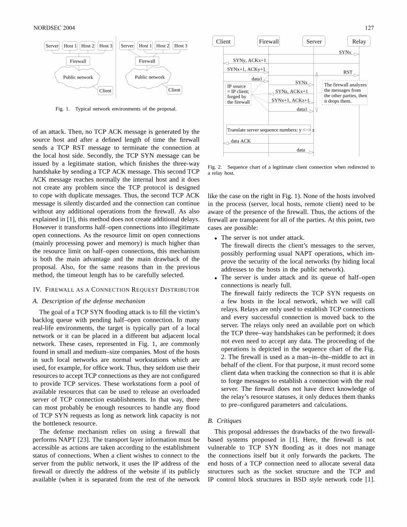
Client
Firewall
Server Host 1 Host 2 Host 3
Public network
Server Host 1 Host 2 Host 3
Firewall
Client
Public network
Fig. 1. Typical network environments of the proposal.
of an attack. Then, no TCP ACK message is generated by thesource host and after a defined length of time the firewallsends a TCP RST message to terminate the connection atthe local host side. Secondly, the TCP SYN message can beissued by a legitimate station, which finishes the three-wayhandshake by sending a TCP ACK message. This second TCPACK message reaches normally the internal host and it doesnot create any problem since the TCP protocol is designedto cope with duplicate messages. Thus, the second TCP ACKmessage is silently discarded and the connection can continuewithout any additional operations from the firewall. As alsoexplained in [1], this method does not create additional delays.However it transforms half–open connections into illegitimateopen connections. As the resource limit on open connections(mainly processing power and memory) is much higher thanthe resource limit on half–open connections, this mechanismis both the main advantage and the main drawback of theproposal. Also, for the same reasons than in the previousmethod, the timeout length has to be carefully selected.
IV. FIREWALL AS A CONNECTION REQUEST DISTRIBUTOR
A. Description of the defense mechanism
The goal of a TCP SYN flooding attack is to fill the victim’sbacklog queue with pending half–open connection. In manyreal-life environments, the target is typically part of a localnetwork or it can be placed in a different but adjacent localnetwork. These cases, represented in Fig. 1, are commonlyfound in small and medium–size companies. Most of the hostsin such local networks are normal workstations which areused, for example, for office work. Thus, they seldom use theirresources to accept TCP connections as they are not configuredto provide TCP services. These workstations form a pool ofavailable resources that can be used to release an overloadedserver of TCP connection establishments. In that way, therecan most probably be enough resources to handle any floodof TCP SYN requests as long as network link capacity is notthe bottleneck resource.
The defense mechanism relies on using a firewall thatperforms NAPT [23]. The transport layer information must beaccessible as actions are taken according to the establishmentstatus of connections. When a client wishes to connect to theserver from the public network, it uses the IP address of thefirewall or directly the address of the website if its publiclyavailable (when it is separated from the rest of the network
Translate server sequence numbers: y <−> z
data1
SYNx
SYNz, ACKx+1
SYNx+1, ACKz+1forged bythe firewall
= IP client;IP source The firewall analyzes
the messages fromthe other parties, thenit drops them.
SYNy, ACKx+1
SYNx
Client Firewall Server
data1
data
data ACK
Relay
SYNx+1, ACKy+1RST
Fig. 2. Sequence chart of a legitimate client connection when redirected toa relay host.
like the case on the right in Fig. 1). None of the hosts involvedin the process (server, local hosts, remote client) need to beaware of the presence of the firewall. Thus, the actions of thefirewall are transparent for all of the parties. At this point, twocases are possible:
• The server is not under attack.The firewall directs the client’s messages to the server,possibly performing usual NAPT operations, which im-prove the security of the local networks (by hiding localaddresses to the hosts in the public network).
• The server is under attack and its queue of half–openconnections is nearly full.The firewall fairly redirects the TCP SYN requests ona few hosts in the local network, which we will callrelays. Relays are only used to establish TCP connectionsand every successful connection is moved back to theserver. The relays only need an available port on whichthe TCP three–way handshakes can be performed; it doesnot even need to accept any data. The proceeding of theoperations is depicted in the sequence chart of the Fig.2. The firewall is used as a man–in–the–middle to act inbehalf of the client. For that purpose, it must record someclient data when tracking the connection so that it is ableto forge messages to establish a connection with the realserver. The firewall does not have direct knowledge ofthe relay’s resource statuses, it only deduces them thanksto pre–configured parameters and calculations.
B. Critiques
This proposal addresses the drawbacks of the two firewall-based systems proposed in [1]. Here, the firewall is notvulnerable to TCP SYN flooding as it does not managethe connections itself but it only forwards the packets. Theend hosts of a TCP connection need to allocate several datastructures such as the socket structure and the TCP andIP control block structures in BSD style network code [1].
NORDSEC 2004 127
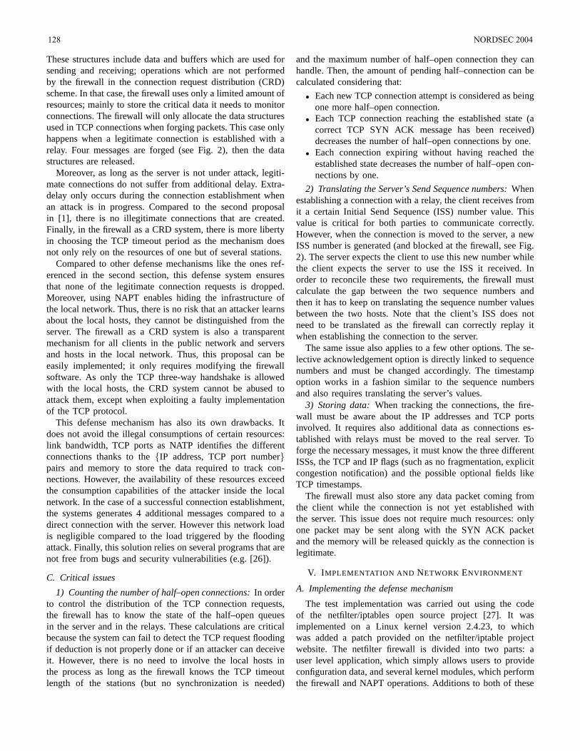
These structures include data and buffers which are used forsending and receiving; operations which are not performedby the firewall in the connection request distribution (CRD)scheme. In that case, the firewall uses only a limited amount ofresources; mainly to store the critical data it needs to monitorconnections. The firewall will only allocate the data structuresused in TCP connections when forging packets. This case onlyhappens when a legitimate connection is established with arelay. Four messages are forged (see Fig. 2), then the datastructures are released.
Moreover, as long as the server is not under attack, legiti-mate connections do not suffer from additional delay. Extra-delay only occurs during the connection establishment whenan attack is in progress. Compared to the second proposalin [1], there is no illegitimate connections that are created.Finally, in the firewall as a CRD system, there is more libertyin choosing the TCP timeout period as the mechanism doesnot only rely on the resources of one but of several stations.
Compared to other defense mechanisms like the ones ref-erenced in the second section, this defense system ensuresthat none of the legitimate connection requests is dropped.Moreover, using NAPT enables hiding the infrastructure ofthe local network. Thus, there is no risk that an attacker learnsabout the local hosts, they cannot be distinguished from theserver. The firewall as a CRD system is also a transparentmechanism for all clients in the public network and serversand hosts in the local network. Thus, this proposal can beeasily implemented; it only requires modifying the firewallsoftware. As only the TCP three-way handshake is allowedwith the local hosts, the CRD system cannot be abused toattack them, except when exploiting a faulty implementationof the TCP protocol.
This defense mechanism has also its own drawbacks. Itdoes not avoid the illegal consumptions of certain resources:link bandwidth, TCP ports as NATP identifies the differentconnections thanks to the IP address, TCP port numberpairs and memory to store the data required to track con-nections. However, the availability of these resources exceedthe consumption capabilities of the attacker inside the localnetwork. In the case of a successful connection establishment,the systems generates 4 additional messages compared to adirect connection with the server. However this network loadis negligible compared to the load triggered by the floodingattack. Finally, this solution relies on several programs that arenot free from bugs and security vulnerabilities (e.g. [26]).
C. Critical issues
1) Counting the number of half–open connections: In orderto control the distribution of the TCP connection requests,the firewall has to know the state of the half–open queuesin the server and in the relays. These calculations are criticalbecause the system can fail to detect the TCP request floodingif deduction is not properly done or if an attacker can deceiveit. However, there is no need to involve the local hosts inthe process as long as the firewall knows the TCP timeoutlength of the stations (but no synchronization is needed)
and the maximum number of half–open connection they canhandle. Then, the amount of pending half–connection can becalculated considering that:
• Each new TCP connection attempt is considered as beingone more half–open connection.
• Each TCP connection reaching the established state (acorrect TCP SYN ACK message has been received)decreases the number of half–open connections by one.
• Each connection expiring without having reached theestablished state decreases the number of half–open con-nections by one.
2) Translating the Server’s Send Sequence numbers: Whenestablishing a connection with a relay, the client receives fromit a certain Initial Send Sequence (ISS) number value. Thisvalue is critical for both parties to communicate correctly.However, when the connection is moved to the server, a newISS number is generated (and blocked at the firewall, see Fig.2). The server expects the client to use this new number whilethe client expects the server to use the ISS it received. Inorder to reconcile these two requirements, the firewall mustcalculate the gap between the two sequence numbers andthen it has to keep on translating the sequence number valuesbetween the two hosts. Note that the client’s ISS does notneed to be translated as the firewall can correctly replay itwhen establishing the connection to the server.
The same issue also applies to a few other options. The se-lective acknowledgement option is directly linked to sequencenumbers and must be changed accordingly. The timestampoption works in a fashion similar to the sequence numbersand also requires translating the server’s values.
3) Storing data: When tracking the connections, the fire-wall must be aware about the IP addresses and TCP portsinvolved. It requires also additional data as connections es-tablished with relays must be moved to the real server. Toforge the necessary messages, it must know the three differentISSs, the TCP and IP flags (such as no fragmentation, explicitcongestion notification) and the possible optional fields likeTCP timestamps.
The firewall must also store any data packet coming fromthe client while the connection is not yet established withthe server. This issue does not require much resources: onlyone packet may be sent along with the SYN ACK packetand the memory will be released quickly as the connection islegitimate.
V. IMPLEMENTATION AND NETWORK ENVIRONMENT
A. Implementing the defense mechanism
The test implementation was carried out using the codeof the netfilter/iptables open source project [27]. It wasimplemented on a Linux kernel version 2.4.23, to whichwas added a patch provided on the netfilter/iptable projectwebsite. The netfilter firewall is divided into two parts: auser level application, which simply allows users to provideconfiguration data, and several kernel modules, which performthe firewall and NAPT operations. Additions to both of these
128 NORDSEC 2004
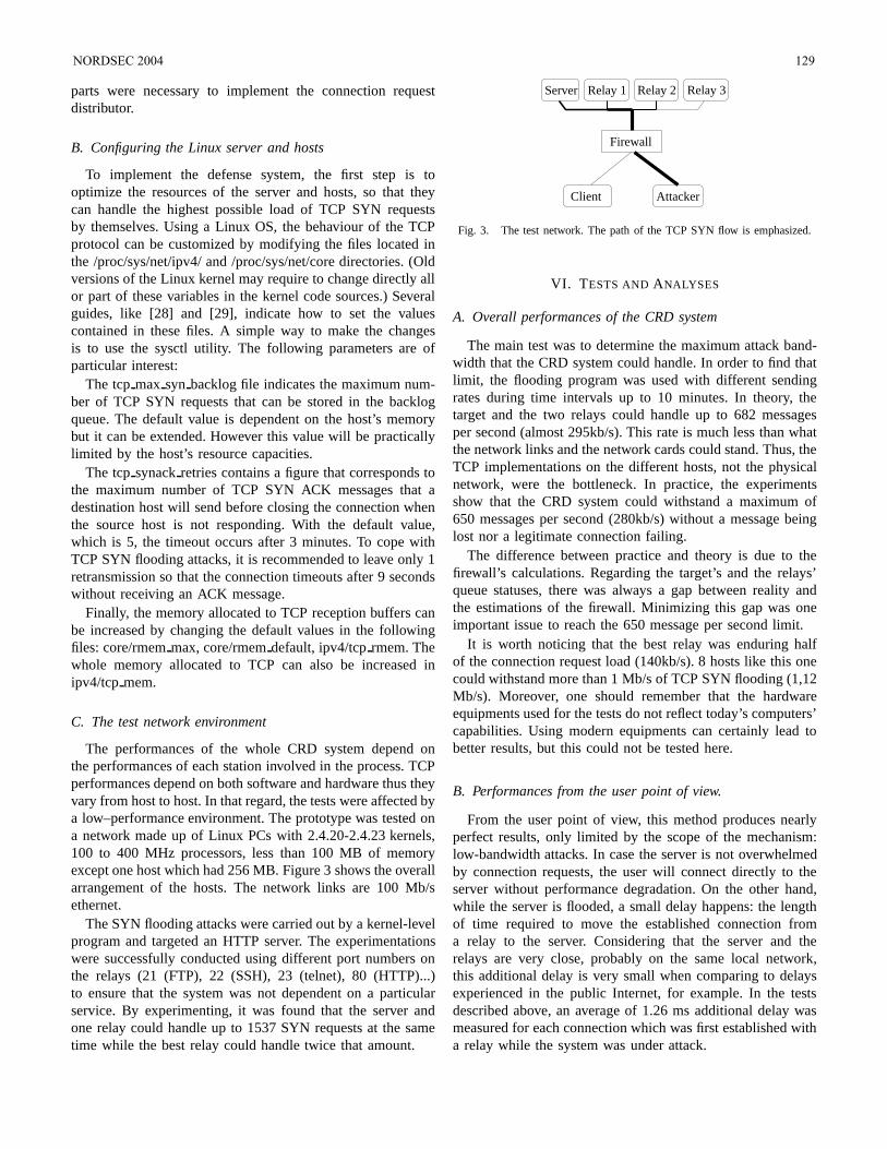
parts were necessary to implement the connection requestdistributor.
B. Configuring the Linux server and hosts
To implement the defense system, the first step is tooptimize the resources of the server and hosts, so that theycan handle the highest possible load of TCP SYN requestsby themselves. Using a Linux OS, the behaviour of the TCPprotocol can be customized by modifying the files located inthe /proc/sys/net/ipv4/ and /proc/sys/net/core directories. (Oldversions of the Linux kernel may require to change directly allor part of these variables in the kernel code sources.) Severalguides, like [28] and [29], indicate how to set the valuescontained in these files. A simple way to make the changesis to use the sysctl utility. The following parameters are ofparticular interest:
The tcp max syn backlog file indicates the maximum num-ber of TCP SYN requests that can be stored in the backlogqueue. The default value is dependent on the host’s memorybut it can be extended. However this value will be practicallylimited by the host’s resource capacities.
The tcp synack retries contains a figure that corresponds tothe maximum number of TCP SYN ACK messages that adestination host will send before closing the connection whenthe source host is not responding. With the default value,which is 5, the timeout occurs after 3 minutes. To cope withTCP SYN flooding attacks, it is recommended to leave only 1retransmission so that the connection timeouts after 9 secondswithout receiving an ACK message.
Finally, the memory allocated to TCP reception buffers canbe increased by changing the default values in the followingfiles: core/rmem max, core/rmem default, ipv4/tcp rmem. Thewhole memory allocated to TCP can also be increased inipv4/tcp mem.
C. The test network environment
The performances of the whole CRD system depend onthe performances of each station involved in the process. TCPperformances depend on both software and hardware thus theyvary from host to host. In that regard, the tests were affected bya low–performance environment. The prototype was tested ona network made up of Linux PCs with 2.4.20-2.4.23 kernels,100 to 400 MHz processors, less than 100 MB of memoryexcept one host which had 256 MB. Figure 3 shows the overallarrangement of the hosts. The network links are 100 Mb/sethernet.
The SYN flooding attacks were carried out by a kernel-levelprogram and targeted an HTTP server. The experimentationswere successfully conducted using different port numbers onthe relays (21 (FTP), 22 (SSH), 23 (telnet), 80 (HTTP)...)to ensure that the system was not dependent on a particularservice. By experimenting, it was found that the server andone relay could handle up to 1537 SYN requests at the sametime while the best relay could handle twice that amount.
Firewall
Server Relay 1 Relay 2 Relay 3
AttackerClient
Fig. 3. The test network. The path of the TCP SYN flow is emphasized.
VI. TESTS AND ANALYSES
A. Overall performances of the CRD system
The main test was to determine the maximum attack band-width that the CRD system could handle. In order to find thatlimit, the flooding program was used with different sendingrates during time intervals up to 10 minutes. In theory, thetarget and the two relays could handle up to 682 messagesper second (almost 295kb/s). This rate is much less than whatthe network links and the network cards could stand. Thus, theTCP implementations on the different hosts, not the physicalnetwork, were the bottleneck. In practice, the experimentsshow that the CRD system could withstand a maximum of650 messages per second (280kb/s) without a message beinglost nor a legitimate connection failing.
The difference between practice and theory is due to thefirewall’s calculations. Regarding the target’s and the relays’queue statuses, there was always a gap between reality andthe estimations of the firewall. Minimizing this gap was oneimportant issue to reach the 650 message per second limit.
It is worth noticing that the best relay was enduring halfof the connection request load (140kb/s). 8 hosts like this onecould withstand more than 1 Mb/s of TCP SYN flooding (1,12Mb/s). Moreover, one should remember that the hardwareequipments used for the tests do not reflect today’s computers’capabilities. Using modern equipments can certainly lead tobetter results, but this could not be tested here.
B. Performances from the user point of view.
From the user point of view, this method produces nearlyperfect results, only limited by the scope of the mechanism:low-bandwidth attacks. In case the server is not overwhelmedby connection requests, the user will connect directly to theserver without performance degradation. On the other hand,while the server is flooded, a small delay happens: the lengthof time required to move the established connection froma relay to the server. Considering that the server and therelays are very close, probably on the same local network,this additional delay is very small when comparing to delaysexperienced in the public Internet, for example. In the testsdescribed above, an average of 1.26 ms additional delay wasmeasured for each connection which was first established witha relay while the system was under attack.
NORDSEC 2004 129
VII. CONCLUSION
This paper introduced a new end-system mechanism todefend a server against TCP SYN flooding attacks. Theconnection request distribution system uses a transport levelpacket based firewall to distribute the load of TCP SYNrequests between several hosts. When a connection is estab-lished with a relay (the connection is legitimate), it is movedback to the real server. This method does not require specialresources and it is also easy to implement (as an additionalfeature to existing firewall software), deploy and configure.A Linux–based prototype system showed the viability of themechanism. Tests showed that a three-computer network couldwithstand 280 kb/s of TCP SYN flooding. The prototypeshould now being further developed and optimized to createa safely deployable system whose performances should easilyapproach theoretical bounds. The implementation flaws shouldbe corrected and the design should be improved to copewith the complexity of real life environments (where potentialrelays are not always up and running, for example). This paperdoes not investigate all the performance aspects of the system.More tests could be performed with an improved version ofthe prototype and a network environment reflecting modernequipment capabilities. Particularly, performance issues in thefirewall and the relays should be addressed. Finally, this paperintroduced the idea of a distributed defense to address aparticular issue: the TCP SYN flooding. The method may suitsimilar issues for other protocols.
REFERENCES
[1] C. L. Schuba, I. V. Krsul, M. G. Kuhn, E. H. Spafford, A. Sundaram,and D. Zamboni, “Analysis of a denial of service attack on TCP,” inProc. IEEE Symposium on Security and Privacy 1997, May 4–7, 1997,pp. 208–223.
[2] D. Moore, G. M. Voelker, and S. Savage, “Inferring internet denial ofservice activity,” in Proc. Tenth USENIX Security Symposium, Washing-ton D.C., Aug. 2001.
[3] “Distributed denial of service tools,” CERT Coordination Center,Carnegie Mellon University, Pittsburgh, Pennsylvania, USA,Incident Note IN–99–07, Jan. 15 2001. [Online]. Available:http://www.cert.org/incident notes/IN–99–07.html#tfn
[4] D. Dittrich. (1999, Oct. 21) The DoS project’s “trinoo”distributed denial of service attack tool. University ofWashington. Seattle, Washington, USA. [Online]. Available:http://www.staff.washington.edu/dittrich/misc/trinoo.analysis
[5] “Denial of service tools,” CERT Coordination Center, Carnegie MellonUniversity, Pittsburgh, Pennsylvania, USA, Advisory CA–1999–17,Mar. 3 2000. [Online]. Available: http://www.cert.org/advisories/CA–1999–17.html
[6] D. Dittrich. (1999, Dec. 31) The “stacheldraht” dis-tributed denial of service attack tool. University ofWashington. Seattle, Washington, USA. [Online]. Available:http://www.staff.washington.edu/dittrich/misc/stacheldraht.analysis
[7] “W32/blaster worm,” CERT Coordination Center, Carnegie MellonUniversity, Pittsburgh, Pennsylvania, USA, Advisory CA–2003–20,Aug. 14 2003. [Online]. Available: http://www.cert.org/advisories/CA–2003–20.html
[8] L. Garber, “Denial–of–service attacks rip the internet,” IEEE Computer,vol. 33, no. 4, pp. 12–17, Apr. 2000.
[9] “W32/novarg.a virus,” CERT Coordination Center, CarnegieMellon University, Pittsburgh, Pennsylvania, USA, IncidentNote IN–2004–01, Jan. 30 2004. [Online]. Available:http://www.cert.org/incident notes/IN–2004–01.html
[10] X. Wang and M. K. Reiter, “Defending against denial–of–service attackswith puzzle auctions,” in Proc. Symposium on Security and Privacy, May11–14 2003, pp. 78–92.
[11] A. Gaeil, K. Kiyoung, and J. Jongsoo, “MF (minority first) scheme fordefeating distributed denial of service attacks,” in Proc. Eighth IEEEInternational Symposium on Computers and Communication (ISCC2003), 2003, pp. 1233–1238.
[12] R. Mahajan, S. M. Bellovin, S. Floyd, J. Ioannidis, V. Paxson, andS. Shenker, “Controlling high bandwidth aggregates in the network,”ACM SIGCOMM Computer Communication Review, vol. 32, no. 3, pp.62–73, July 2002.
[13] D. Sterne, K. Djahandari, B. Wilson, B. Babson, D. Schnackenberg,H. Holliday, and T. Reid, “Autonomic response to distributed denialof service attacks,” in Proc. Fourth International Sympsium on RecentAdvances in Intrusion Detection, Davis, California, USA, Oct. 2001, pp.134–149.
[14] S. Bellovin and T. Taylor. (2001, Oct.) ICMP traceback messages.Internet draft. [Online]. Available: www.globecom.net/ietf/draft/draft–ietf–itrace–01.html
[15] A. Mankin, D. Massey, W. Chien-Lung, S. F. Wu, and L. Zhang, “Auto-nomic response to distributed denial of service attacks,” in Proc. TenthInternational Conference on Computer Communications and Networks,Oct. 15–17 2001, pp. 159–165.
[16] A. C. Snoeren, C. Partridge, L. A. Sanchez, C. E. Jones, F. Tchakountio,S. T. Kent, and W. T. Strayer, “Hash–based ip traceback,” in Proc. ACMSIGCOMM Conference on Applications, Technologies, Architectures,and Protocols for Computer Communications, San Diego, California,USA, 2001, pp. 3–14.
[17] W. T. Strayer, C. E. Jones, F. Tchakountio, A. C. Snoeren, B. Schwartz,R. C. Clements, M. Condell, and C. Partridge, “Traceback of single ippackets using spie,” in Proc. DARPA Information Survivability Confer-ence and Exposition, vol. 2, Davis, California, USA, Apr. 22–24 2003,pp. 266–270.
[18] H. Aljifri, “IP traceback: a new denial–of–service deterrent?” IEEESecurity & Privacy Magazine, vol. 1, no. 3, pp. 24–31, May/June 2003.
[19] K. T. Law, J. C. S. Lui, and D. K. Y. Yau, “You can run, but youcan’t hide: an effective methodology to traceback ddos attackers,” inProc. Tenth IEEE International Symposium on Modeling, Analysis andSimulation of Computer and Telecommunications Systems (MASCOTS2002), Oct. 11–16 2002, pp. 433–440.
[20] S. Savage, D. Wetherall, A. Karlin, and T. Anderson, “Network supportfor ip traceback,” ACM IEEE Transactions on Networking, vol. 9, no. 3,pp. 226–237, June 2001.
[21] M. T. Goodrich, “Efficient packet marking for large–scale ip traceback,”in Proc. Nineth ACM conference on Computer and communicationssecurity, 2002, pp. 117–126.
[22] K. Egevang and P. Francis, “The ip network address translator (NAT),”RFC 1631, Internet Engineering Task Force, May 1994.
[23] P. Srisuresh and K. Egevang, “Traditional IP network address translator(traditional NAT),” RFC 3022, Internet Engineering Task Force, Jan.2001.
[24] P. Srisuresh and M. Holdrege, “IP network address translator (NAT)terminology and considerations,” RFC 2663, Internet Engineering TaskForce, Aug. 1999.
[25] M. Smith and R. Hunt, “Network security using NAT and NAPT,” inProc. 10th IEEE International Conference on Networks (ICON 2002),Aug. 27–30 2002, pp. 355–360.
[26] “Linux kernel netfilter irc dcc helper module creates overly permissivefirewall rules,” US-CERT, Carnegie Mellon University, Pittsburgh,Pennsylvania, USA, Vulnerability Note VU#230307, July 05 2002.[Online]. Available: http://www.kb.cert.org/vuls/id/230307
[27] (2004) The netfilter / iptables project homepage. [Online]. Available:http://www.netfilter.org/
[28] O. Andreasson. (2003, May 21) Ipsysctl tutorial 1.0.4. web-page. [Online]. Available: http://ipsysctl-tutorial.frozentux.net/ipsysctl-tutorial.html
[29] B. L. Tierney. (2001, Feb.) TCP tuning guide. webpage. [Online].Available: http://www-didc.lbl.gov/TCP-tuning/TCP-tuning.html
130 NORDSEC 2004