non-segmented grain oriented steel in induction machines
TRANSCRIPT

Progress In Electromagnetics Research C, Vol. 47, 1–10, 2014
Non-Segmented Grain Oriented Steel in Induction Machines
Bertrand Cassoret1, 2 *, Samuel Lopez1, 2,Jean-Francois Brudny1, 2, and Thierry Belgrand3
Abstract—This paper presents a technique which improves energy efficiency of AC rotating machinesby using Grain Oriented (GO) steel at stator core instead of Non Oriented (NO) steel. The losses ofGO steel are lower than the NO ones, but only when the magnetic flux circulates along the rollingdirection; consequently it is rarely used in AC machines where the magnetic flux rotates. By stackingmany shifted GO laminations of AC machine stator, the flux pass from one lamination to another, andthe core losses are reduced. A lot of experimentations have been done with unidirectional field, rotatingfield and with real induction machines. They show important improvements with GO shifted steel.The efficiency difference between a classical 10 kW induction machine and a modified machine with GOstator is more than 2 points. Moreover, the no-load current, and so the reactive power are smaller. Thistechnique creates environmental and financial gains.
1. INTRODUCTION
Fossil fuels (coal, gas, and oil) account for 85% of the energy consumed on Earth. Their productionwill not always increase [1]. In addition, their use emits CO2, widely recognized responsible for thegreenhouse effect and global warming. In the coming decades, other sources of energy such as nuclear andrenewable will not be enough to replace fossil energies. So it is necessary to reduce energy consumption.This could come from improvements of energy efficiency.
About 20% of the energy consumed on earth is used to produce electricity. This percentage couldincrease in the future: with less gas and oil, a part of consumption for heating and transports couldcome from electricity (heat pump, electrical public transport, electrical cars. . .). On the other hand,alternative energy sources to fossil fuels (renewable and nuclear) allow to generate electricity.
The majority of electricity consumption in industrialized countries is due to electric motors. Electricmotor applications in industry consume between 30% and 40% of the generated electrical energyworldwide [2]. Electric motors with improved efficiency in combination with frequency converters cansave about 7% of the total worldwide electrical energy. Roughly one quarter to one third of these savingscould come from the improved efficiency of the motor [3]. Consequently, it is very important to reducelosses of electric motors.
This paper presents a method to reduce losses of AC rotating machines by using Grain Orientedsteel. First, reminders about AC machines and electrical steels are given. Then, the use of shifted GrainOriented steel is presented, with many experiments. Finally, the results of experimentations with realmachines connected to the network are shown.
Received 20 November 2013, Accepted 14 January 2014, Scheduled 25 January 2014* Corresponding author: Bertrand Cassoret ([email protected]).1 Universite Lille Nord de France, F-59000, France. 2 UArtois, LSEE, Universite d’Artois, Bethune F-62400, France. 3 ThyssenKruppElectrical Steel, Isbergues F-62330, France.

2 Cassoret et al.
2. ELECTRICAL AC MACHINES AND STEELS
2.1. Electrical AC Machines
In a rotating electrical AC machine, the flow of electrical currents generates magnetic fields which arecanalized by laminated magnetic cores. Those last are generaly built with a stack of thin Non Orientedsteel sheets. Figure 1 shows a wound stator (without frame) and a steel sheet of an 11 kW inductionmachine.
Figure 1. Wound stator and steel sheet from an induction machine.
The International Electrotechnical Commission defined in the international standard 60034-30 [3]the efficiency of three-phase induction motors: there are 4 classes from IE1 (standard) to IE4 (superpremium, the best). In Europe the class EFF1 (the best) is equivalent to IE2, and EFF2 is equivalentto IE1.
Losses of electrical rotating machines come essentially from [4]:
- friction and windage loss,- Joule effect losses tied to the windings heating, they represent approximately 30% of the losses at
no load and 70% at full load,- iron core losses due to the magnetic flux variation in the magnetic circuits; they represent, in a
classical induction machine, approximately 50% of the losses at no load and 25% at full load.- stray load losses tied to complex phenomena [5].
Majority of machines work rarely at full load. As iron losses are practically not in relation with theload-state, it is very important to reduce them. They are largely influenced by the steel quality. Manyelectrical steels exist.
2.2. Electrical Steels
The magnetic properties of GO steel are better than NO steel in the lamination direction. But thisanisotropy is a problem in AC machines because of the rotating magnetic field. Only a few specialmachines, big turbo-generator particularly, use GO segmented steel [6].
Electrical steels can essentially be characterized by their magnetic permeability and their losses.In a general way the losses are in relation to the thickness of the sheets, but the steel quality is alsoimportant. The Table 1 shows the losses of some NO and GO steels at 50 Hz, b is the peak flux densityvalue. It can be seen that three different steels with the same thickness 0.35 mm don’t have the samelosses (the losses of NO M 235-35A are given at 1.5 T, they would be more important at 1.7 T).
Among the iron losses, the static, dynamic and excess losses can be distinguished [7, 8]. At 50 or60 Hz, most of the losses of classical NO machines are static losses (often called “hysteresis losses”).

Progress In Electromagnetics Research C, Vol. 47, 2014 3
Table 1. Examples of characteristics of NO and GO steels.
Name ThicknessMagnetic losses at 50Hz
b = 1.7 T b = 1.5 T
GO M 80-23 P 0.23 mm 0.8 W/kg
GO M 125-35 P 0.35 mm 1.25 W/kg
GO M 140-35 S 0.35 mm 1.4 W/kg
NO M 235-35A 0.35 mm 2.35 W/kg
NO M 400-50A 0.5 mm 4 W/kg
NO M 700-565A 0.65 mm 7 W/kg
2.3. Anisotropy
Sheet strips have been cut at an angle α with respect to the Rolling Direction (RD) as shown onFigure 2, and their dimensions are 30 × 300 mm.
Measures were performed at Epstein Frame at 50 Hz [9]. The losses (in Watts/kg) versus thepeak flux density b (in T) are in Figure 3 for GO M 140-35 and Figure 4 for NO 400-50A. The strong
Figure 2. Epstein strips cut with an angle α (from S. Lopez’s thesis [9]).
Figure 3. Losses of GO M 140-35 steel at 50 Hz(from S. Lopez’s thesis [9]).
Figure 4. Losses of NO 400-50A steel at 50 Hz(from S. Lopez’s thesis [9]).
4 Cassoret et al.
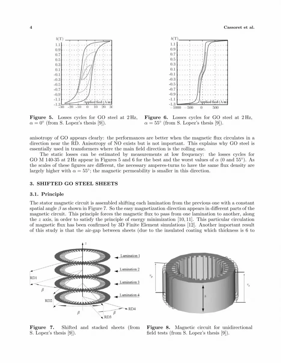
Figure 5. Losses cycles for GO steel at 2Hz,α = 0◦ (from S. Lopez’s thesis [9]).
Figure 6. Losses cycles for GO steel at 2 Hz,α = 55◦ (from S. Lopez’s thesis [9]).
anisotropy of GO appears clearly: the performances are better when the magnetic flux circulates in adirection near the RD. Anisotropy of NO exists but is not important. This explains why GO steel isessentially used in transformers where the main field direction is the rolling one.
The static losses can be estimated by measurements at low frequency: the losses cycles forGO M 140-35 at 2Hz appear in Figures 5 and 6 for the best and the worst values of α (0 and 55◦). Asthe scales of these figures are different, the necessary amperes-turns to have the same flux density arelargely higher with α = 55◦; the magnetic permeability is smaller in this direction.
3. SHIFTED GO STEEL SHEETS
3.1. Principle
The stator magnetic circuit is assembled shifting each lamination from the previous one with a constantspatial angle β as shown in Figure 7. So the easy magnetization direction appears in different parts of themagnetic circuit. This principle forces the magnetic flux to pass from one lamination to another, alongthe z axis, in order to satisfy the principle of energy minimization [10, 11]. This particular circulationof magnetic flux has been confirmed by 3D Finite Element simulations [12]. Another important resultof this study is that the air-gap between sheets (due to the insulated coating which thickness is 6 to
Figure 7. Shifted and stacked sheets (fromS. Lopez’s thesis [9]).
Figure 8. Magnetic circuit for unidirectionalfield tests (from S. Lopez’s thesis [9]).

Progress In Electromagnetics Research C, Vol. 47, 2014 5
8µm) has a very low influence on the flux repartition.In the following the notation GO35β is used for example with 0.35 mm GO steel shifted with β
degrees.
3.2. Experiments with Unidirectional Field
Several magnetic cores were built as shown in Figure 8 with different qualities of electrical steel anddifferent β shift angle. Each core has a primary 100 turn winding, supplied with a sinusoidal voltage. Asecondary 100 turn winding allows appreciating the magnetic behavior and calculating the flux densityby measuring the induced voltage. In this way the teeth are not magnetized. The cores contain100 laminations if their thickness is 0.5 mm, or 143 if their thickness is 0.35 mm; so the total core lengthh is always 50 mm and the masses are the same. The external diameter is 200 mm and the internal oneis 163 mm. By measuring the primary current and the secondary voltage, it is possible to deduce theactive and reactive power as in a transformer and so the iron losses and the magnetic permeability [13].
Figure 9 shows the core losses and Figure 10 the permeability μr at 50 Hz for different steels versusthe flux density: NO50 concerns non shifted NO M 400-50A, GO35 concerns GO M 140-35 S with severalshift angles. It appears clearly that the performances of the GO core are better than those of the NOone, and that the best shift angle is near than 90◦.
AC machines use generally 0.65 mm NO steel; so the tested NO M 400-50A which thickness is0.5 mm is a better one. Nevertheless some calculations have been done to estimate the losses if theNO thickness was 0.35 mm, as the used GO. The static, dynamic, and excess losses were separated
Figure 9. Core losses for different configurationsof GO and NO steel with 50 Hz unidirectional field(from S. Lopez’s thesis [9]).
Figure 10. Magnetic permeability for differentconfigurations of GO and NO steel with 50 Hzunidirectional field (from S. Lopez’s thesis [9]).
Figure 11. Core losses for NO 0.5 mm, NO 0.35 mm and GO 0.35 mm with 50 Hz unidirectional field(from S. Lopez’s thesis [9]).

6 Cassoret et al.
with measurements at low frequency; then the estimated losses of a fictitious 0.35 mm NO core werecalculated [13]. The results are given in Figure 11: the performances of the GO core are better thanthose of the NO core even if the thicknesses of the laminations are the same. This principle has beenpatented [14].
3.3. Experiments with “Static Motors”
The previous experimentations have to be confirmed with rotating field [15]; consequently “staticmotors” were built. The principle consists of stacking some laminations especially laser cut: theyare similar to real ones but the rotor circuit is included and attached to the stator by 3 small joints.Figure 12 shows one lamination and a static motor. The total core height is 8 cm. Two three-phasewindings are placed in the slots. The primary one is electrically powered and creates a rotating fieldas in a real machine. The auxiliary one is used to measure the induced voltage: it allows to estimatethe air-gap flux density and, measuring the primary current, to calculate the core losses without Jouleslosses. Moreover there are no mechanic losses because there is no rotation, and it is relatively easy tocreate a lot of configurations with different steel qualities and shift angles.
A lot of measures were done with static motors [16] with NO M 400-50A and GO M 140-35 S.Figure 13 shows the core losses versus the air-gap flux density. The conclusions are similar to theprevious ones: shifted GO are largely better than non-shifted GO and NO steel.
Figure 12. Static motor: one sheet and awound stack.
Figure 13. Core losses for different configurationsof GO and NO steel with 50 Hz rotating field (fromS. Lopez’s thesis [9]).
4. APPLICATION TO INDUCTION MACHINES
Real induction machines have been realized with shifted GO steel.
4.1. Practical Realization
Many three-phase induction machines have been modified. New GO and NO laminations have beenlaser cut, annealed, and placed into stator frames with different shift angles.
The initial machines had the following characteristics: 10 kW, 230/400 V, 36.5/21 A, 1440 rpm,50 Hz, cos ϕ = 0.81, iron length 0.179 m, external diameter of the laminations 200 mm, 48 stator slots.One machine wasn’t modified; its laminations are NO M 700-65A (0.65 mm). A machine with NO M 400-50A (0.5 mm) were built with β = 60◦ (the NO sheets were shifted, in the case where the small anisotropyof the NO steel would ameliorate the performances). Two machines with GO M 140-35 S (0.35 mm)were realized, one with β = 60◦, the other with β = 90◦. In each machine, a small auxiliary statorwinding allows to estimate the flux density in the air-gap by measuring the induced voltage. The massesof the different machines are the same. The rotors have not been modified.

Progress In Electromagnetics Research C, Vol. 47, 2014 7
4.2. Results
The machines were powered by a system of 50 Hz three-phase balanced voltage.
4.2.1. No Load Experiments
The no-load tests are important because a lot of electrical machines in industry work often at no loador low load. Moreover the iron losses are practically independent of the load state. The active powerand the current absorbed by the different machines were measured.
The results concerning the no-load active power and the no-load R.M.S. current are given in Table 2for three configurations: NO65, NO5060◦, GO3560◦. The no-load losses include not only the iron losses,but also Joules and mechanical losses, which are not influenced by the change of sheets. Despite this, theGO core is largely better. The difference between the machine with GO core and the original machineis 38%. Furthermore the no-load current is 14% lower with GO core although this quantity is largelyinfluenced by the air-gap thickness (which is the same on all the machines). This reduction of no-loadcurrent means a better power factor and so, less reactive power and less line losses.
Table 2. No load losses and current for different machines.
GO3560◦ NO5060◦ NO65
Losses (W) 396.2 444.2 548.7Stator current (A) 8.6 8.85 9.8
4.2.2. Characteristics with Load
The currents, the different losses and so the efficiency are calculated for all the machines as recommendedby the standard IEC-60034-2 [17, 18]. The parameters of the single-phase equivalent scheme areseparately determined by practical classic tests (no-load, blocked rotor. . .). Then it’s possible tocalculate the characteristics at different operating points [9].
For example, the calculated stator current versus slip is presented in Figure 14, and the calculatediron losses in Figure 15. The difference between NO and GO is approximately constant concerning theiron losses, but it increases with the slip concerning the stator current. Consequently the differencesconcerning the joules losses increase with the slip, which influences the efficiency.
Figure 14. Stator current for different machines(from S. Lopez’s thesis [9]).
Figure 15. Iron losses for different machines(from S. Lopez’s thesis [9]).
8 Cassoret et al.
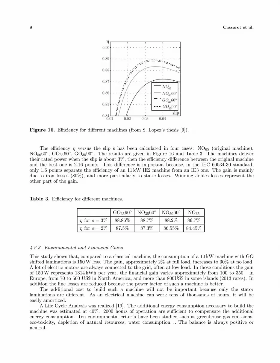
Figure 16. Efficiency for different machines (from S. Lopez’s thesis [9]).
The efficiency η versus the slip s has been calculated in four cases: NO65 (original machine),NO5060◦, GO3560◦, GO3590◦. The results are given in Figure 16 and Table 3. The machines delivertheir rated power when the slip is about 3%, then the efficiency difference between the original machineand the best one is 2.16 points. This difference is important because, in the IEC 60034-30 standard,only 1.6 points separate the efficiency of an 11 kW IE2 machine from an IE3 one. The gain is mainlydue to iron losses (80%), and more particularly to static losses. Winding Joules losses represent theother part of the gain.
Table 3. Efficiency for different machines.
GO3590◦ NO3560◦ NO5060◦ NO65
η for s = 3% 88.86% 88.7% 88.2% 86.7%
η for s = 2% 87.5% 87.3% 86.55% 84.45%
4.2.3. Environmental and Financial Gains
This study shows that, compared to a classical machine, the consumption of a 10 kW machine with GOshifted laminations is 150 W less. The gain, approximately 2% at full load, increases to 30% at no load.A lot of electric motors are always connected to the grid, often at low load. In those conditions the gainof 150 W represents 1314 kWh per year, the financial gain varies approximately from 100 to 350 inEurope, from 70 to 500 US$ in North America, and more than 800US$ in some islands (2013 rates). Inaddition the line losses are reduced because the power factor of such a machine is better.
The additional cost to build such a machine will not be important because only the statorlaminations are different. As an electrical machine can work tens of thousands of hours, it will beeasily amortized.
A Life Cycle Analysis was realized [19]. The additional energy consumption necessary to build themachine was estimated at 40%. 2000 hours of operation are sufficient to compensate the additionalenergy consumption. Ten environmental criteria have been studied such as greenhouse gas emissions,eco-toxicity, depletion of natural resources, water consumption. . . The balance is always positive orneutral.

Progress In Electromagnetics Research C, Vol. 47, 2014 9
5. CONCLUSION
The losses of induction machines can be reduced by using GO electrical steel instead of NO steel. Thestator laminations have to be shifted. Experiments have been done with single-phase magnetic core,three-phase “static motors”, and real 10 kW induction machines, and show that the performances arebetter with GO shifted. The best shift angle is 90◦. The efficiency of a GO modified machine wasincreased by more than 2 points.
These results can probably be improved by using a better GO steel quality. Moreover, the energygains would be greater with a more powerful and higher efficiency machine (designed to work at lowflux density).
Furthermore, it is likely that the conclusions would be similar to other AC machines (synchronous,switched reluctance. . .). Possible applications therefore concern a lot of motors whose uses are verydifferent (pumping, ventilation, cold production, transport. . .) but also electricity production. Manybig alternators already use GO steel with a cut sheet metal into segments, but this is not the case ofmedium power alternators used, for example, in wind turbines. They could produce more electricitywith this technique.
Another positive point concerns the magnetic noise: electromagnetic phenomena in the air-gap ofthe machine produce forces, stator vibrations, and noise. Some ongoing studies suggest that shiftedlaminations have a positive influence on vibrations and noise [20, 21].
ACKNOWLEDGMENT
This work was supported by the MEDEE program supervised by the French national technologicalresearch cluster on electrical machine efficiency increase. This program was sponsored by ThyssenKruppElectrical Steel TKES, the region Nord Pas-de-Calais (France), the French ministry and the Europeanfunds (FEDER). Many results of this paper are extracted from the work of S. Lopez who prepared hisdoctoral thesis [9] with the authors at LSEE (Bethune, France).
REFERENCES
1. Heinberg, R., The Party’s Over: Oil, War and the Fate of Industrial Societies, Kindle Edition,2005.
2. Hanitsch, R., “Energy efficient electric motors,” World, Climate and Energy Event, Rio, 2002.3. “Rotating electrical machines-efficiency classes of single-speed, three-phase, cage-induction
motors,” International Standard IEC 60034-30, 2008.4. Aoulkadi, M. and A. Binder, “When loads stray: Evaluation of different measurement methods to
determine stray load losses in induction machines,” IEEE Industrial Electronics Magazine, Vol. 2,No. 1, 21–30, Mar. 2008.
5. Nagornyy, A., A. K. Wallace, and A. V. Jouanne, “Stray load loss efficiency connections,” IEEEIndustry Applications Magazine, Vol. 10, No. 3, 62–69, 2004.
6. Enokizono, M., T. Todaka, H. Shimoji, and A. Ikariga, “Optimum design of rotating machines usinggrain-oriented electrical steel sheet by two-dimensional vector magnetic property,” InternationalAegean Conference on Electrical Machines and Power Electronics, ACEMP’ 07, 468–473, 2007.
7. Steinmetz, C., “On the law of hysteresis,” Proceedings of the IEEE, Vol. 72, 197–221, 1984.8. Bertotti, G., “General properties of power losses in soft ferromagnetic materials,” IEEE Trans. on
Magnetics, Vol. 24, No. 1, 621–630, Jan. 1988.9. Lopez, S., “Definition de nouvelles structures de circuits magnetiques de machines a courant
alternatif utilisant des toles a grains orientes,” Ph.D. Thesis, Univ. Lille Nord de France, Univ.Artois, LSEE, France, 2011.
10. Hihat, N., K. Komeza, E. Napieralska, and J. P. Lecointe, “Experimental and numericalcharacterization of magnetically anisotropic laminations in the direction normal to their surface,”IEEE Trans. on Magnetics, Vol. 47, No. 11, 4517–4522, Oct. 2011.

10 Cassoret et al.
11. Andrei, H. and F. Spinei, “The minimum energetical principle in electric and magnetic circuits,”Proc. 18th ECCTD, Vol. 99, 906–909, 2007.
12. Parent, G., R. Penin, J. P. Lecointe, J. F. Brudny, and T. Belgrand, “Analysis of the magneticflux distribution in a new shifted non segmented grain oriented AC motor magnetic circuit,” IEEETrans. on Magnetics, Vol. 49, No. 5, 1977–1980, Apr. 2013.
13. Lopez, S., B. Cassoret, J. F. Brudny, L. Lefebvre, and J. N. Vincent, “Grain oriented steel assemblycharacterization for the development of high efficiency AC rotating electrical machines,” IEEETrans. on Magnetics, Vol. 45, No. 10, 4161–4164, Oct. 2009.
14. Brudny, J. F., B. Cassoret, R. Lemaitre, and J. N. Vincent, “Magnetic core and use of magneticcore for electrical machines,” International Patent PCT/EP2008/061884, Mar. 2009.
15. Findlay, R. D., N. Stranges, and D. K. MacKay, “Losses due to rotational flux in three phaseinduction motors,” IEEE Trans. on Energy Conversion, Vol. 9, No. 3, 543–549, 1994.
16. Lopez, S., L. Lefebvre, B. Cassoret, J. F. Brudny, and J. N. Vincent, “Validation of a highefficiency AC rotating electrical machine magnetic circuit by particular tests at standstill,” Proc.Soft Magnetic Materials, Ref. C2-01, Torino, Italy, Sep. 2009.
17. Cao, W., “Comparison of IEEE 112 and new IEC Standard 60034-2-1,” IEEE Trans. on EnergyConversion, Vol. 24, No. 3, 802–808, 2009.
18. McKinnon, D. J. and C. Grantham, “Improved efficiency test methods for three-phase inductionmachines,” Industry Applications Conference, Fourtieth IAS Annual Meeting, Conference Recordof the 2005, Vol. 1, 466–473, 2005.
19. Boughanmi, W., J. P. Manata, D. Roger, T. Jacq, and F. Streiff, “Life cycle assessment of a three-phase electrical machine in continuous operation,” IET Electric Power Applications, Vol. 6, No. 5,277–285, 2012.
20. Demian, C., B. Cassoret, J. F. Brudny, and T. Belgrand, “AC magnetic circuits using nonsegmented shifted grain oriented electrical steel sheets: Impact on induction machine magneticnoise,” IEEE Trans. on Magnetics, Vol. 48, No. 4, 1409–1412, 2012.
21. Penin, R., J. P. Lecointe, G. Parent, J. F. Brudny, and T. Belgrand, “Estimation ofrelative magnetostriction and Maxwell’s forces in stacked grain oriented steel structures,” Proc.International Conference on Electrical Machines, 1971–1976, Sep. 2012.