new erasmusrand pedestrian bridge over ... - saice
TRANSCRIPT
Sivili Enjeneereng
March 2020 Vol 28 No 2
NEW ERASMUSRAND PEDESTRIAN BRIDGE OVER N1 IN PRETORIA
UPGRADING OF THE RIMER’S CREEK WATER TREATMENT WORKS
SAISC 2019 STEEL AWARDS ALL THE WINNERS

Ethics is topical in our economy and body politic, primarily because of the challenges the country is currently facing – corruption, growing inequality, high unemployment rate, blurred lines on conflict of interest, construction mafias, nepotism, procure-ment rules not followed, late awarding of contracts, patronage networks, not fin-ishing projects, appointing inexperienced contractors, cutting maintenance budgets, and so on. These are threatening to undo the great achievements of the democratic dispensation. In this respect the following three problem areas have a ripple effect:
ProcurementMy submission is that our country has good laws, policies and regulations, and if we follow them by the book, many of these problems would not exist. Conducting procurement of goods and services from suppliers should not be as difficult as landing on the moon or performing heart surgery. The seven cardinal sins (greed, gluttony, pride, envy, lust, wrath and sloth) are holding back the country’s development and negatively impacting on the opportu-nity to be considered one of the respectable nations of the world. In particular greed (intense and selfish desire for wealth, power, fame, etc, at the expense of others) has been seen to normalise wrongdoing with no consequences to the wrongdoers. This malfeasance is destroying our today and stealing our tomorrow. One can only envy the development that is taking place in countries like China, where the development of economic infrastructure is a top priority.
corruPtion robs the Poor the mostThe village where I grew up in Limpopo (Thabampshe, Ga-Masemola) has seen a great change in the last 26 years. In 1994, when we voted for the first time, the village did not have electricity (yes I mean 0% coverage), no tarred roads and a severe water shortage. I wrote matric in 1991 using paraffin and candle lights. Fast-forward to 2020 – every household has electricity and the village has a tarred
main road connecting it to other sur-rounding villages and centres of economic activity. The development is so remarkable that people are now building themselves double-storey houses on stands of 2 000 to 3 000 m2, which is leading to questions of whether the classification of a village is still appropriate. The place is now looking more and more like a township. Similarly, the surrounding areas that were regarded as villages are transitioning to townships. The same can be said of areas around Nandoni Dam in Venda, where villages are being turned into ‘Golf Estates’. This is good, because some people now no longer see the need to migrate to urban areas in search of jobs. Shopping centres are built in these areas and have become a source of local employment. Our government should be commended for the sterling work they have done in providing some of the basic services to these communities. Of course one acknowledges that more work is still required.
This brings me to the question of stealing from the poor. The above develop-ments are great and must be commended as indicated; however, the quality of the new infrastructure (especially roads) is very poor. The new roads are built by inexperienced contractors who are “politically connected”, resulting in poor quality roads that are not fully achieving the ultimate goal of encouraging economic activity in these areas. Hence the full value for money is not realised, as repair main-tenance on these roads has to start earlier than expected.
Decisive leaDershiPIn his book “The Architects of Poverty”, Moeletsi Mbeki reminds us that countries develop primarily by pooling the collective strengths and energies of their citizens to achieve a common goal. For this to happen two key elements must be present – institutions that facilitate cooperation, and leaders who ensure that these institutions function and deliver on expectations. If individuals or households are expected to pool their energies and resources
with other individuals or households there must be a mechanism that makes it possible and desirable for them to cooperate – i.e. the benefits of cooperation must outweigh those of working in isola-tion, and similarly the costs of working in cooperation with others must be lower than those of working alone. This is where bold and decisive leadership is required to take the country on an inclusive growth trajectory in an ever-changing global environment. One acknowledges that, in the process of seeking solutions, various stakeholders’ interests should be addressed and catered for.
in conclusionThe Thuma Mina spirit (“send me”), albeit with a reduced momentum, is a great initiative which should be supported by every South African who desires economic growth levels above 3%. As the National Development Plan aspires to achieve eco-nomic growth levels of more than 5%, we should raise our hands now, as we cannot wait until we get there.
Fana Marutla
SAICE President [email protected]
FR O M T H E PR E SI D EN T ’ S D E SK
Ethical leadership
civil engineering March 2020 1
South African Institution of Civil Engineering
civil engineering March 2020
Sivili Enjiniereng
march 2020 vol 28 no 2
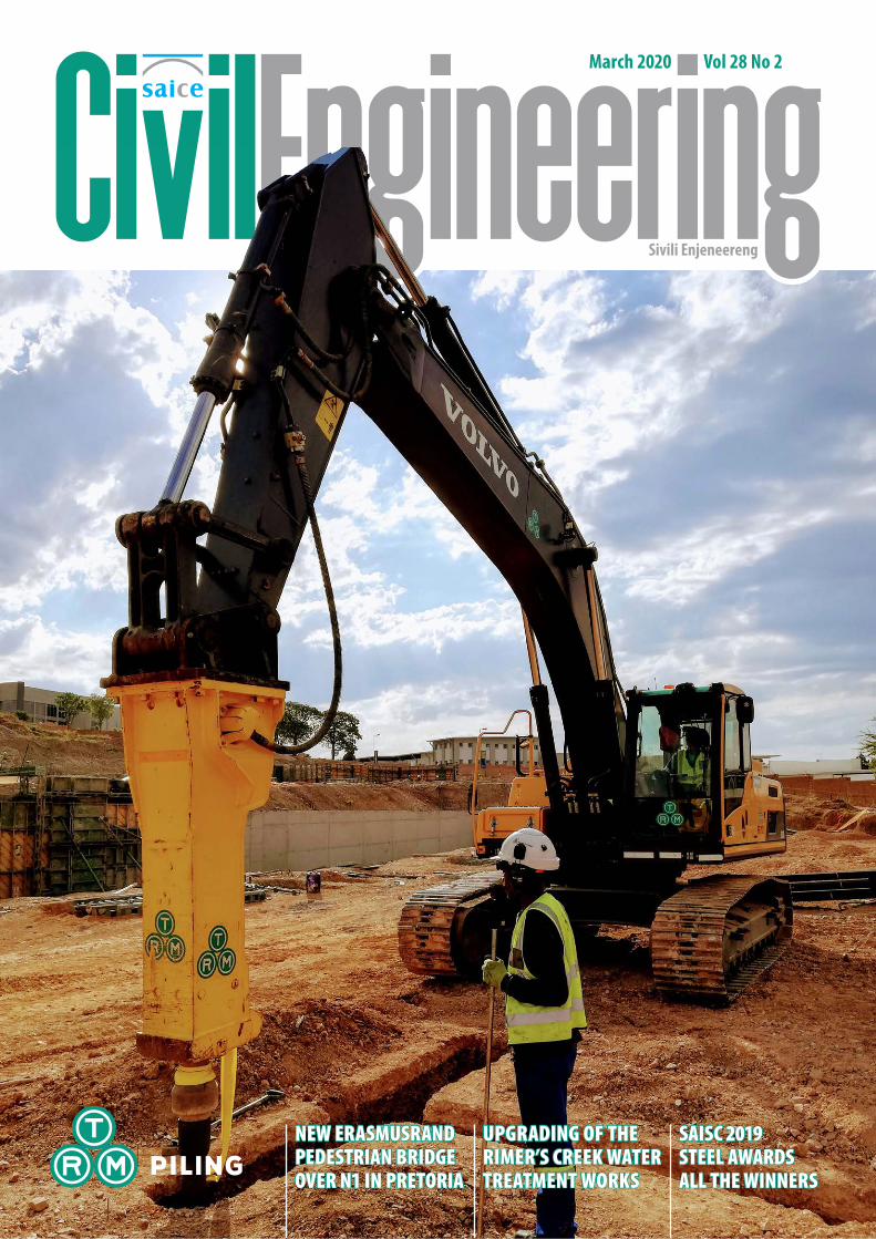
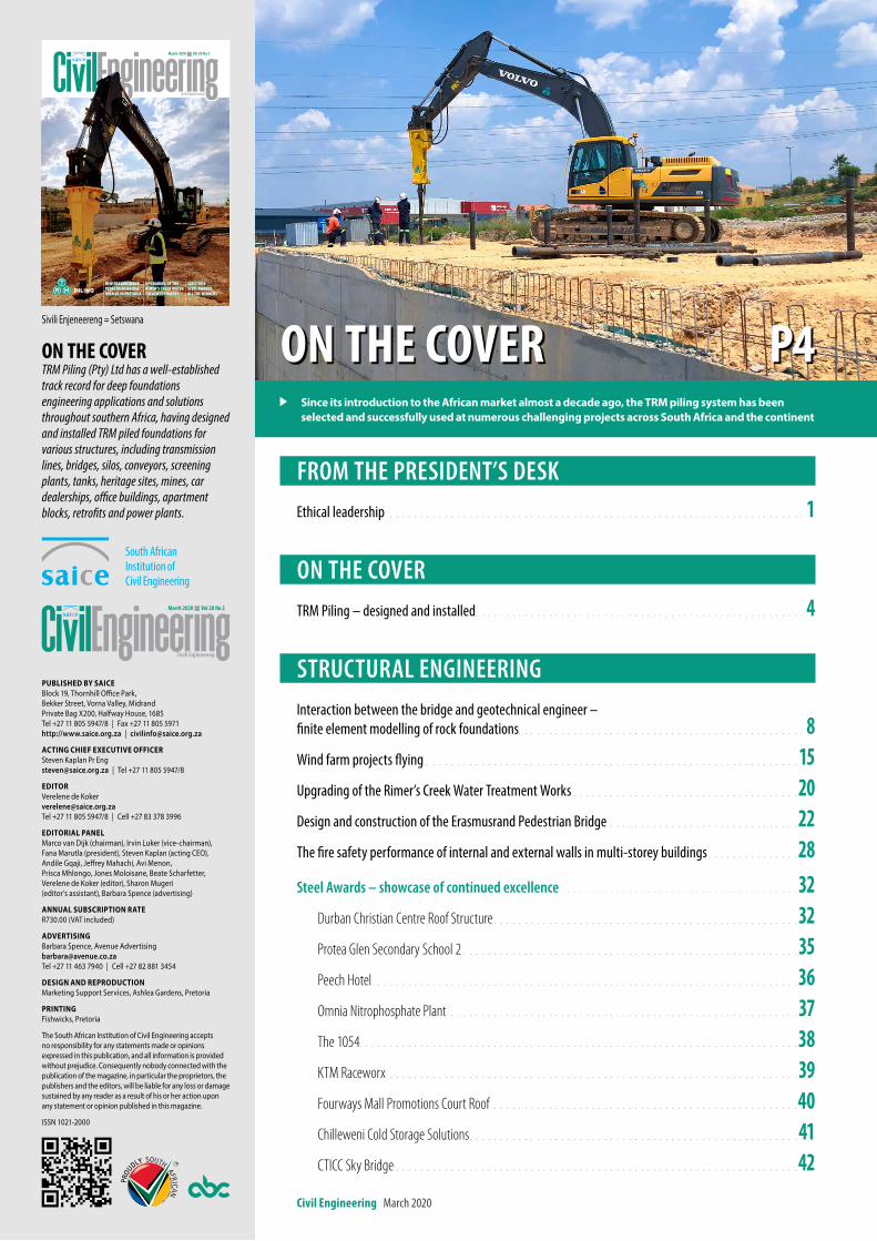
on the coverTRM Piling (Pty) Ltd has a well-established track record for deep foundations engineering applications and solutions throughout southern Africa, having designed and installed TRM piled foundations for various structures, including transmission lines, bridges, silos, conveyors, screening plants, tanks, heritage sites, mines, car dealerships, office buildings, apartment blocks, retrofits and power plants.
FROM THE PRESIDENT’S DESK Ethical leadership . . . . . . . . . . . . . . . . . . . . . . . . . . . . . . . . . . . . . . . . . . . . . . . . . . . . . . . . . . . . . . . . . . . . 1
ON THE COVERTRM Piling – designed and installed . . . . . . . . . . . . . . . . . . . . . . . . . . . . . . . . . . . . . . . . . . . . . . . . . . . . . . 4
STRUCTURAL ENGINEERINGInteraction between the bridge and geotechnical engineer – finite element modelling of rock foundations. . . . . . . . . . . . . . . . . . . . . . . . . . . . . . . . . . . . . . . . . . . . . . . 8Wind farm projects flying . . . . . . . . . . . . . . . . . . . . . . . . . . . . . . . . . . . . . . . . . . . . . . . . . . . . . . . . . . . . . 15Upgrading of the Rimer’s Creek Water Treatment Works . . . . . . . . . . . . . . . . . . . . . . . . . . . . . . . . . . . . . 20Design and construction of the Erasmusrand Pedestrian Bridge . . . . . . . . . . . . . . . . . . . . . . . . . . . . . . . 22The fire safety performance of internal and external walls in multi-storey buildings . . . . . . . . . . . . . . . 28 Steel Awards – showcase of continued excellence . . . . . . . . . . . . . . . . . . . . . . . . . . . . . . . . . . . . . . . 32
Durban Christian Centre Roof Structure . . . . . . . . . . . . . . . . . . . . . . . . . . . . . . . . . . . . . . . . . . . . . . . . . . 32 Protea Glen Secondary School 2 . . . . . . . . . . . . . . . . . . . . . . . . . . . . . . . . . . . . . . . . . . . . . . . . . . . . . . . 35Peech Hotel. . . . . . . . . . . . . . . . . . . . . . . . . . . . . . . . . . . . . . . . . . . . . . . . . . . . . . . . . . . . . . . . . . . . . . 36Omnia Nitrophosphate Plant . . . . . . . . . . . . . . . . . . . . . . . . . . . . . . . . . . . . . . . . . . . . . . . . . . . . . . . . . 37The 1054. . . . . . . . . . . . . . . . . . . . . . . . . . . . . . . . . . . . . . . . . . . . . . . . . . . . . . . . . . . . . . . . . . . . . . . . 38KTM Raceworx . . . . . . . . . . . . . . . . . . . . . . . . . . . . . . . . . . . . . . . . . . . . . . . . . . . . . . . . . . . . . . . . . . . 39Fourways Mall Promotions Court Roof . . . . . . . . . . . . . . . . . . . . . . . . . . . . . . . . . . . . . . . . . . . . . . . . . . 40 Chilleweni Cold Storage Solutions . . . . . . . . . . . . . . . . . . . . . . . . . . . . . . . . . . . . . . . . . . . . . . . . . . . . . . 41CTICC Sky Bridge . . . . . . . . . . . . . . . . . . . . . . . . . . . . . . . . . . . . . . . . . . . . . . . . . . . . . . . . . . . . . . . . . . 42
on the cover P4
Sivili Enjeneereng
March 2020 Vol 28 No 2
NEW ERASMUSRAND PEDESTRIAN BRIDGE OVER N1 IN PRETORIA
UPGRADING OF THE RIMER’S CREEK WATER TREATMENT WORKS
SAISC 2019 STEEL AWARDS ALL THE WINNERS
Sivili Enjeneereng = Setswana
Published by sAiCeBlock 19, Thornhill Office Park, Bekker Street, Vorna Valley, MidrandPrivate Bag X200, Halfway House, 1685Tel +27 11 805 5947/8 | Fax +27 11 805 5971http://www.saice.org.za | [email protected]
ACting ChieF exeCutive OFFiCerSteven Kaplan Pr [email protected] | Tel +27 11 805 5947/8
editOrVerelene de [email protected] Tel +27 11 805 5947/8 | Cell +27 83 378 3996
editOriAl PAnelMarco van Dijk (chairman), Irvin Luker (vice‑chairman), Fana Marutla (president), Steven Kaplan (acting CEO), Andile Gqaji, Jeffrey Mahachi, Avi Menon, Prisca Mhlongo, Jones Moloisane, Beate Scharfetter, Verelene de Koker (editor), Sharon Mugeri (editor’s assistant), Barbara Spence (advertising)
AnnuAl subsCriPtiOn rAteR730.00 (VAT included)
AdvertisingBarbara Spence, Avenue [email protected] Tel +27 11 463 7940 | Cell +27 82 881 3454
design And rePrOduCtiOnMarketing Support Services, Ashlea Gardens, Pretoria
PrintingFishwicks, Pretoria
The South African Institution of Civil Engineering accepts no responsibility for any statements made or opinions expressed in this publication, and all information is provided without prejudice. Consequently nobody connected with the publication of the magazine, in particular the proprietors, the publishers and the editors, will be liable for any loss or damage sustained by any reader as a result of his or her action upon any statement or opinion published in this magazine.
ISSN 1021‑2000
since its introduction to the African market almost a decade ago, the trM piling system has been selected and successfully used at numerous challenging projects across south Africa and the continent
3
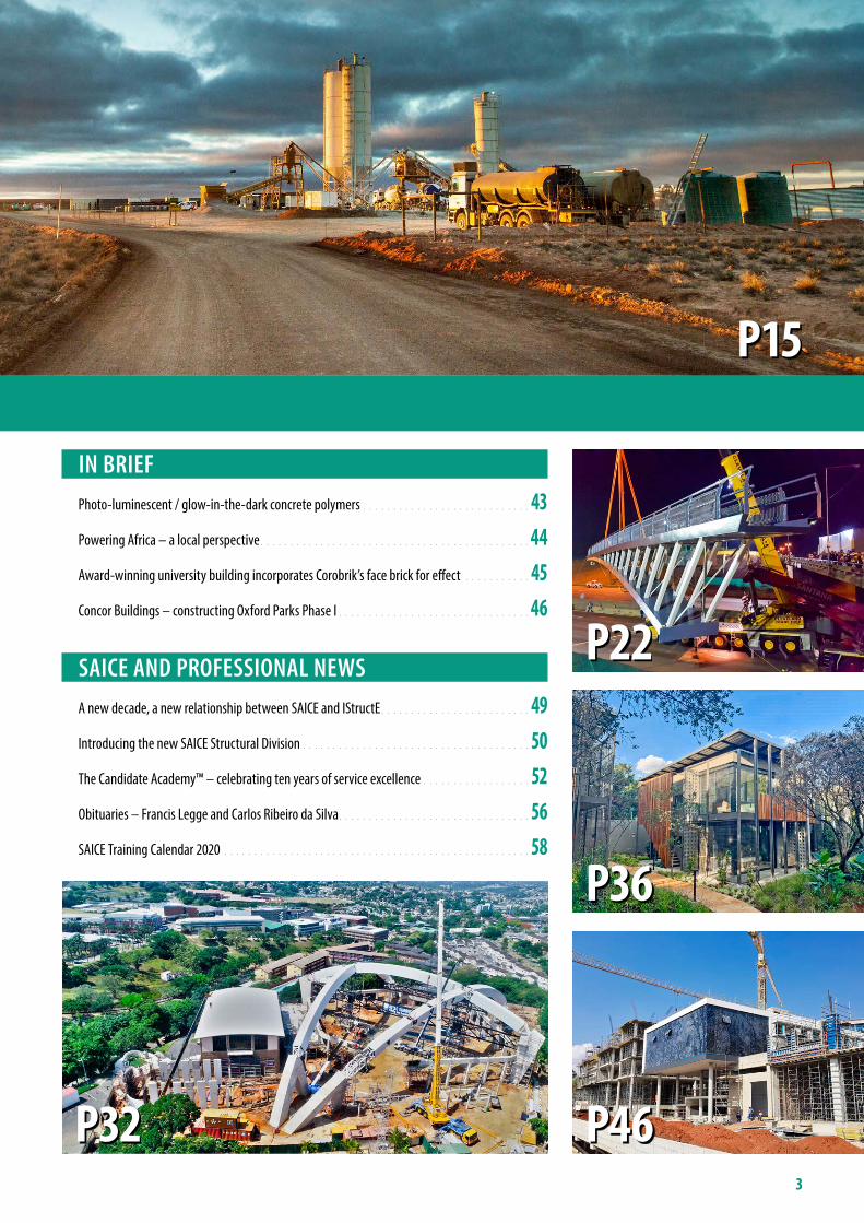
IN BRIEF Photo-luminescent / glow-in-the-dark concrete polymers . . . . . . . . . . . . . . . . . . . . . . . . . . . . 43Powering Africa – a local perspective . . . . . . . . . . . . . . . . . . . . . . . . . . . . . . . . . . . . . . . . . . . . . 44Award-winning university building incorporates Corobrik’s face brick for effect . . . . . . . . . . . 45Concor Buildings – constructing Oxford Parks Phase I . . . . . . . . . . . . . . . . . . . . . . . . . . . . . . . . 46
SAICE AND PROFESSIONAL NEWSA new decade, a new relationship between SAICE and IStructE . . . . . . . . . . . . . . . . . . . . . . . . . 49Introducing the new SAICE Structural Division . . . . . . . . . . . . . . . . . . . . . . . . . . . . . . . . . . . . . . 50The Candidate Academy™ – celebrating ten years of service excellence . . . . . . . . . . . . . . . . . . 52Obituaries – Francis Legge and Carlos Ribeiro da Silva . . . . . . . . . . . . . . . . . . . . . . . . . . . . . . . . 56SAICE Training Calendar 2020 . . . . . . . . . . . . . . . . . . . . . . . . . . . . . . . . . . . . . . . . . . . . . . . . . . . 58
P15
P36
P46
P22
P32
O N T H E COV ER
TRM Piling’s success to date with clients has been achieved based on quality, safety, mutual trust and respect. Since being in-troduced into the African market almost a decade ago, the TRM piling system has been selected and successfully used at numerous challenging projects across South Africa and the African continent, including piling for transmission lines, bridges, silos, conveyors, screening plants, tanks, heritage sites, various mines, car dealerships, office buildings, apartment blocks, retrofits and several types of power plants.
risK reDuctionThe TRM piling system offers total versatility between end-bearing and friction-pile systems for geotechnical load transfer. This makes it a dependable, flexible and adaptable system of choice to minimise risks in case of limited geotechnical information or unexpected variations. Pile depth/length adjusts auto-matically to match actual unique sub-soil conditions encountered at each individual pile location.
Classified as displacement piles and using a high-frequency hammer, vibration is minimal (normal peak particle velocity <1 mm/s) enabling pile installation as close as 40 cm from existing structures, inclu-ding potentially sensitive buildings. Pile load-bearing capacity is proven during the pile-driving process for every pile installed, optimising pile lengths and enabling the minimisation of expensive large-scale
trm Piling – designed and installed
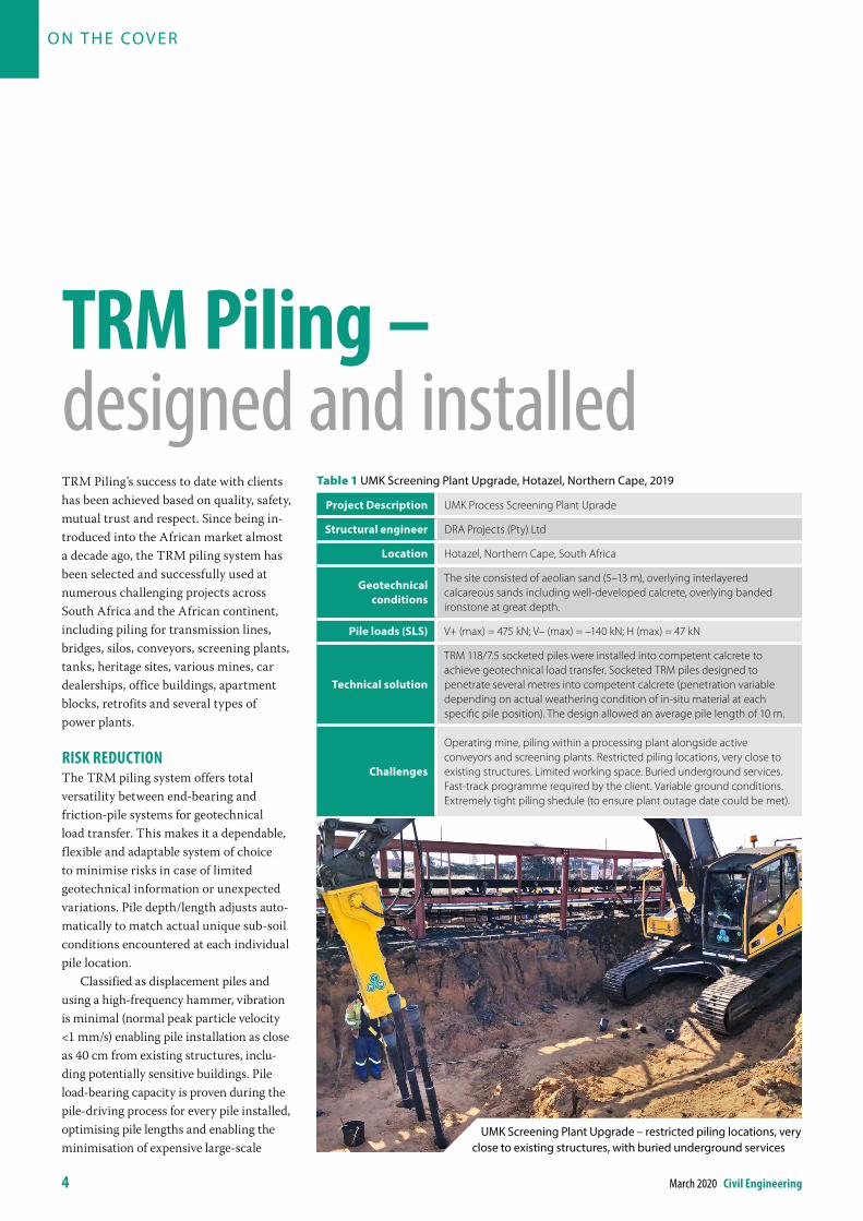
Table 1 UMK Screening Plant Upgrade, Hotazel, Northern Cape, 2019
Project description UMK Process Screening Plant Uprade
structural engineer DRA Projects (Pty) Ltd
location Hotazel, Northern Cape, South Africa
geotechnical conditions
The site consisted of aeolian sand (5–13 m), overlying interlayered calcareous sands including well-developed calcrete, overlying banded ironstone at great depth.
Pile loads (sls) V+ (max) = 475 kN; V– (max) = –140 kN; H (max) = 47 kN
technical solution
TRM 118/7.5 socketed piles were installed into competent calcrete to achieve geotechnical load transfer. Socketed TRM piles designed to penetrate several metres into competent calcrete (penetration variable depending on actual weathering condition of in-situ material at each specific pile position). The design allowed an average pile length of 10 m.
Challenges
Operating mine, piling within a processing plant alongside active conveyors and screening plants. Restricted piling locations, very close to existing structures. Limited working space. Buried underground services. Fast-track programme required by the client. Variable ground conditions. Extremely tight piling shedule (to ensure plant outage date could be met).
4 March 2020 civil engineering
UMK Screening Plant Upgrade – restricted piling locations, very close to existing structures, with buried underground services
civil engineering March 2020 5
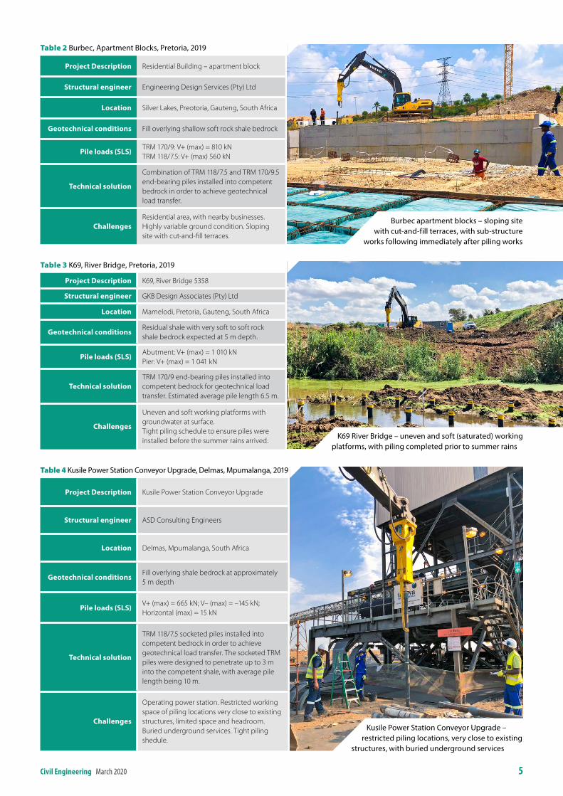
Table 2 Burbec, Apartment Blocks, Pretoria, 2019
Project description Residential Building – apartment block
structural engineer Engineering Design Services (Pty) Ltd
location Silver Lakes, Preotoria, Gauteng, South Africa
geotechnical conditions Fill overlying shallow soft rock shale bedrock
Pile loads (sls)TRM 170/9: V+ (max) = 810 kNTRM 118/7.5: V+ (max) 560 kN
technical solution
Combination of TRM 118/7.5 and TRM 170/9.5 end-bearing piles installed into competent bedrock in order to achieve geotechnical load transfer.
ChallengesResidential area, with nearby businesses. Highly variable ground condition. Sloping site with cut-and-fill terraces.
Table 3 K69, River Bridge, Pretoria, 2019
Project description K69, River Bridge 5358
structural engineer GKB Design Associates (Pty) Ltd
location Mamelodi, Pretoria, Gauteng, South Africa
geotechnical conditionsResidual shale with very soft to soft rock shale bedrock expected at 5 m depth.
Pile loads (sls)Abutment: V+ (max) = 1 010 kNPier: V+ (max) = 1 041 kN
technical solutionTRM 170/9 end-bearing piles installed into competent bedrock for geotechnical load transfer. Estimated average pile length 6.5 m.
Challenges
Uneven and soft working platforms with groundwater at surface.Tight piling schedule to ensure piles were installed before the summer rains arrived.
Table 4 Kusile Power Station Conveyor Upgrade, Delmas, Mpumalanga, 2019
Project description Kusile Power Station Conveyor Upgrade
structural engineer ASD Consulting Engineers
location Delmas, Mpumalanga, South Africa
geotechnical conditionsFill overlying shale bedrock at approximately 5 m depth
Pile loads (sls)V+ (max) = 665 kN; V– (max) = –145 kN; Horizontal (max) = 15 kN
technical solution
TRM 118/7.5 socketed piles installed into competent bedrock in order to achieve geotechnical load transfer. The socketed TRM piles were designed to penetrate up to 3 m into the competent shale, with average pile length being 10 m.
Challenges
Operating power station. Restricted working space of piling locations very close to existing structures, limited space and headroom. Buried underground services. Tight piling shedule.
Burbec apartment blocks – sloping site with cut‑and‑fill terraces, with sub‑structure
works following immediately after piling works
K69 River Bridge – uneven and soft (saturated) working platforms, with piling completed prior to summer rains
Kusile Power Station Conveyor Upgrade – restricted piling locations, very close to existing
structures, with buried underground services
6 March 2020 civil engineering
load and quality testing. Additionally, the exceptional corrosion resistance of ductile iron pile material guarantees a structural service life of up to 100 years.
time anD scoPe savinGs beFore, DurinG anD aFter PilinG eQuates to siGniFicant client cost reDuctionFast mobilisation and site set-up of light-weight mobile equipment enables imme-diate access and commencement of piling works on site, even under challenging conditions. Using compact and versatile piling equipment, the TRM piling system accesses challenging working positions, and reaches down into pre-excavated pilecap (sub-structure) excavations. Being a full-displacement piling system, the sub-soil is also compacted, with no piling spoil or debris left behind.
Further siGniFicant cost anD time savinGs PossibleBy selecting and awarding the TRM piling system from an early stage, further significant cost and time savings are also being achieved. Closer pile centres of TRM piles, with reduced inter-pile span distances, enable the sub-structure dimensions to be value-engineered, resulting in overall volume reductions of potentially up to 80%, and major time and cost savings.
The TRM piling system has brought value engineering solutions to many deep foundation projects over recent years (see Tables 1–7 for examples).
in conclusionDuring the past decade, the TRM PILING SYSTEM has earned a well-established track record for high-quality deep foundations engineering applications and
solutions throughout South Africa and the wider region.
The TRM piling system has been used and accepted by many highly regarded professional entities including ACSA, ASD Consulting Engineers, Arup, Aurecon, BA Engineers, BIGEN Africa, DRA Projects, EDS Consulting, ESKOM, GKB Design Associates, Greene Group, Jones & Wagener, Kantey & Templer, LNW Consulting Engineers, Moroff & Kuhne, Mosomo, Mott Macdonald, PRASA, RHDHV, SASOL, SRK, V&H Consulting Engineers, VNA Consulting and many more.
info
Tyrone ShuttleworthLanseria Head Office+27 74 310 [email protected]
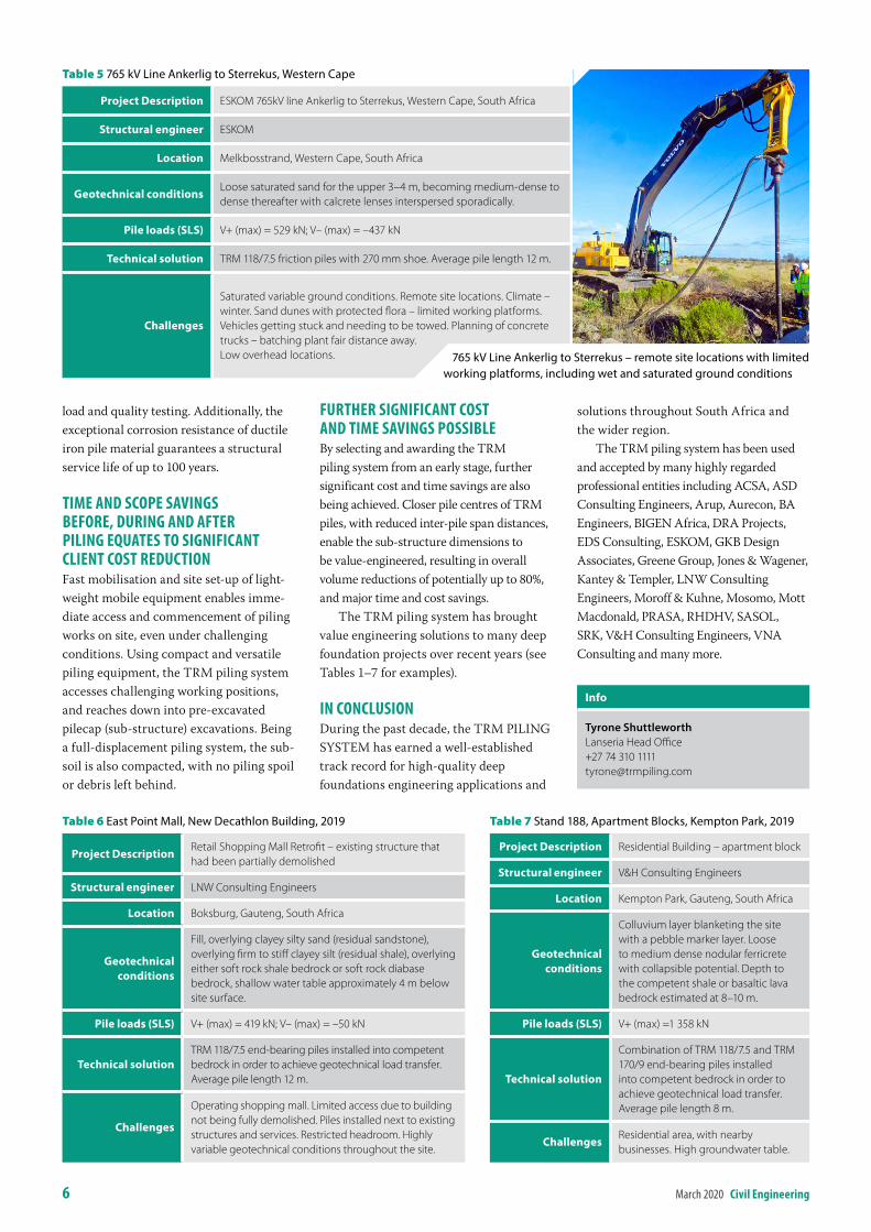
Table 5 765 kV Line Ankerlig to Sterrekus, Western Cape
Project description ESKOM 765kV line Ankerlig to Sterrekus, Western Cape, South Africa
structural engineer ESKOM
location Melkbosstrand, Western Cape, South Africa
geotechnical conditionsLoose saturated sand for the upper 3–4 m, becoming medium-dense to dense thereafter with calcrete lenses interspersed sporadically.
Pile loads (sls) V+ (max) = 529 kN; V– (max) = –437 kN
technical solution TRM 118/7.5 friction piles with 270 mm shoe. Average pile length 12 m.
Challenges
Saturated variable ground conditions. Remote site locations. Climate – winter. Sand dunes with protected flora – limited working platforms. Vehicles getting stuck and needing to be towed. Planning of concrete trucks – batching plant fair distance away. Low overhead locations.
Table 6 East Point Mall, New Decathlon Building, 2019
Project descriptionRetail Shopping Mall Retrofit – existing structure that had been partially demolished
structural engineer LNW Consulting Engineers
location Boksburg, Gauteng, South Africa
geotechnical conditions
Fill, overlying clayey silty sand (residual sandstone), overlying firm to stiff clayey silt (residual shale), overlying either soft rock shale bedrock or soft rock diabase bedrock, shallow water table approximately 4 m below site surface.
Pile loads (sls) V+ (max) = 419 kN; V– (max) = –50 kN
technical solutionTRM 118/7.5 end-bearing piles installed into competent bedrock in order to achieve geotechnical load transfer. Average pile length 12 m.
Challenges
Operating shopping mall. Limited access due to building not being fully demolished. Piles installed next to existing structures and services. Restricted headroom. Highly variable geotechnical conditions throughout the site.
Table 7 Stand 188, Apartment Blocks, Kempton Park, 2019
Project description Residential Building – apartment block
structural engineer V&H Consulting Engineers
location Kempton Park, Gauteng, South Africa
geotechnical conditions
Colluvium layer blanketing the site with a pebble marker layer. Loose to medium dense nodular ferricrete with collapsible potential. Depth to the competent shale or basaltic lava bedrock estimated at 8–10 m.
Pile loads (sls) V+ (max) =1 358 kN
technical solution
Combination of TRM 118/7.5 and TRM 170/9 end-bearing piles installed into competent bedrock in order to achieve geotechnical load transfer. Average pile length 8 m.
ChallengesResidential area, with nearby businesses. High groundwater table.
765 kV Line Ankerlig to Sterrekus – remote site locations with limited working platforms, including wet and saturated ground conditions
Reinforced Earth® RETAIN, CROSS and PROTECT techniques are used for the following applications:Bridge Abutments, overpasses & underpasses, approach ramps, access road and railway retaining walls, dump walls, storage bunkers, reclaim tunnels, reservoirs…
An upgraded section of the historic Cogmanskloof Pass, which was originally designed by Thomas Bain in the mid 1870s, runs through the Langeberg Mountains of the Western Cape. Being sensitive to preserving the historic and scenic
Reinforced Earth® retaining structuresare custom designed to meet unique technical and environmental requirements.
character of the pass, infrastructure firm AECOM combined Reinforced Earth TerraTrel® retaining walls with local stone cladding. This technical and aesthetic solution provides an improved experience for road users of the pass.
Contact our team and let us know about your next project. Email: [email protected] Phone: +27 11 726 6180
Sports & Leisure
Rivers & Waterways
Water management
Railways Ports & Coastal works
Roads & Motorways
Dams & Reservoirs
Mining & Minerals
EnergyConstruction materials
Industry Land development & Building
EnvironmentalWaste management
MilitaryAirports Bridges
Reinforced Earth Applications
Reinforced Earth (Pty) Ltd South Africa 2nd Floor, 1 Park Road,Richmond, Johannesburg
Tel: +27 11 726 6180www.recosa.co.za - www.terre-armee.com
RETAIN
8 March 2020 civil engineering
overvieWThe design and modelling of foundations cross two civil engineering disciplines, namely structural and geotechnical engineering. The structural engineer goes into great detail when sizing foundations to ensure effective load transfer from the superstructure to the underlying geoma-terials. This is usually accomplished by deriving the load and moment taken down from the superstructure onto the founda-tion. This load takedown is normally established as a first estimate based on either a fixed-base or an assumed springs stiffness model in structural finite element (FE) analysis. The loads transferred from the superstructure to the various piers and foundations will vary depending on the fixity assumed by the structural engineer, and could result in large discrepancies when modelled with the same stiffness when certain foundations are stiffer than others. This becomes more critical in large bridge structures with tall piers where even the slightest differentials in displacement at the base of adjacent piers could lead to significant differential tilt and settlement at
the top of the piers, resulting in significant load redistribution between piers.
It is therefore proposed that the analysis process is, and should be, an iterative pro-cess between the structural and geotech-nical engineer, as settlement and distortion are best estimated by the geotechnical engineer, whilst load take-down due to these varying foundation stiffnesses is best estimated by the structural engineer. This iteration should continue until convergence is reached between the two models. This study aimed to compile a guideline to optimise the iteration process between the geotechnical and structural engineer, and to assist the geotechnical engineer in improving the consistency in the finite element modelling (FEM) of the interac-tion between the structure and the rock. This was achieved by modelling a bridge footing on rock using a 3D geotechnical FE software package, obtaining the footing’s settlement and rotation, deriving structural springs and inserting these revised springs back into a structural FE software package to determine the revised load takedown. This should result in more realistic and accurate modelling by the bridge engineer.
introDuctionLarge bridge structures require suitable support from the geomaterials beneath them. Due to the ability of rock to with-stand immense shear and tensile loading, structures such as bridge piers and dams are more frequently founded on rock as an alternative to soil. However, caution must be exercised when constructing founda-tions on rock, as a single low-strength discontinuity in the rock mass at a certain orientation may cause total failure of the rock. These discontinuities range from joints with rough surfaces that have sub-stantial shear strengths to massive faults that contain various kinds of clays with
relatively low shear strengths, and most rocks contain them (Wyllie 1999).
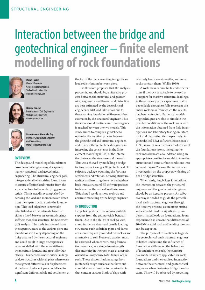
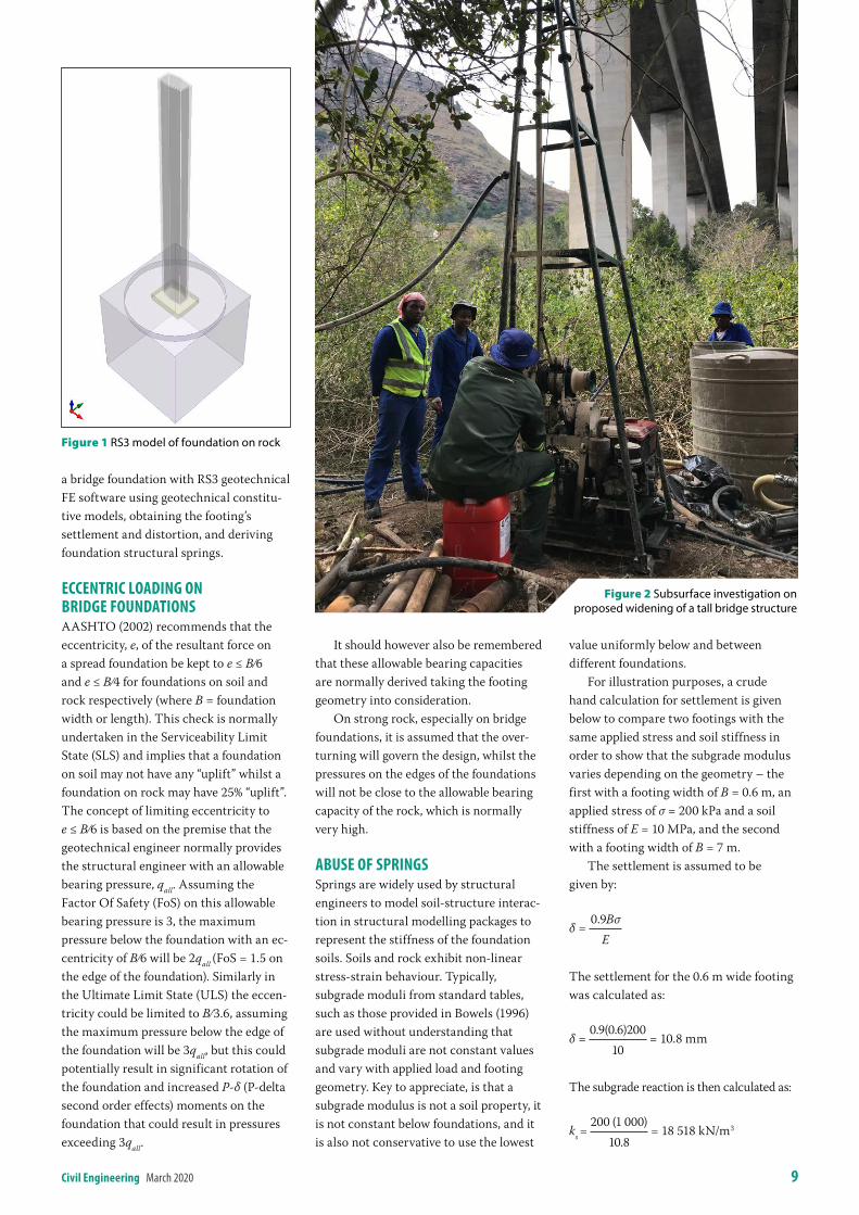
A rock mass cannot be tested to deter-mine if the rock is suitable to be used as a support for massive structural loadings, as there is rarely a rock specimen that is dependable enough to fully represent the entire rock mass from which the results had been extracted. Numerical model-ling techniques are able to simulate the possible conditions of the rock mass with the information obtained from field inves-tigations and laboratory testing on intact rock and discontinuities respectively. A geotechnical FEM software, Rocscience’s RS3 (Figure 1), was used as a tool to model the foundation system, including the rock mass beneath a foundation using an appropriate constitutive model to take the structure and joint surface conditions into account. Figure 2 shows the subsurface investigation on the proposed widening of a tall bridge structure.
When designing bridge foundations, the interaction between the structural engineer and the geotechnical engineer should be an iterative process. An effec-tive way is needed to guide the geotech-nical and structural engineer through the iterative process, as incorrect spring values could result in significantly un-derestimated loads on foundations. From experience it is known that differences of 10–25% in axial load and bending moment can be expected.
The purpose of this article is to guide the geotechnical and structural engineer to better understand the influence of foundation stiffness on the behaviour of foundations on rock, the constitu-tive models that are applicable for rock foundations and the required interaction between the structural and geotechnical engineers when designing bridge founda-tions. This will be achieved by modelling
S T R U C T U R A L EN G I N EER I N G
Dylan FourieMaster’s GraduateGeotechnical EngineeringStellenbosch [email protected]
nanine FouchéDepartment of Civil EngineeringStellenbosch [email protected]
Frans van der merwe Pr engPrincipal Geostructural EngineerGaGE [email protected]
Interaction between the bridge and geotechnical engineer – finite element modelling of rock foundations
civil engineering March 2020 9
a bridge foundation with RS3 geotechnical FE software using geotechnical constitu-tive models, obtaining the footing’s settlement and distortion, and deriving foundation structural springs.
eccentric loaDinG on briDGe FounDationsAASHTO (2002) recommends that the eccentricity, e, of the resultant force on a spread foundation be kept to e ≤ B ∕6 and e ≤ B ∕4 for foundations on soil and rock respectively (where B = foundation width or length). This check is normally undertaken in the Serviceability Limit State (SLS) and implies that a foundation on soil may not have any “uplift” whilst a foundation on rock may have 25% “uplift”. The concept of limiting eccentricity to e ≤ B ∕6 is based on the premise that the geotechnical engineer normally provides the structural engineer with an allowable bearing pressure, qall. Assuming the Factor Of Safety (FoS) on this allowable bearing pressure is 3, the maximum pressure below the foundation with an ec-centricity of B ∕6 will be 2qall (FoS = 1.5 on the edge of the foundation). Similarly in the Ultimate Limit State (ULS) the eccen-tricity could be limited to B ∕ 3.6, assuming the maximum pressure below the edge of the foundation will be 3qall, but this could potentially result in significant rotation of the foundation and increased P-δ (P-delta second order effects) moments on the foundation that could result in pressures exceeding 3qall.
It should however also be remembered that these allowable bearing capacities are normally derived taking the footing geometry into consideration.
On strong rock, especially on bridge foundations, it is assumed that the over-turning will govern the design, whilst the pressures on the edges of the foundations will not be close to the allowable bearing capacity of the rock, which is normally very high.
abuse oF sPrinGsSprings are widely used by structural engineers to model soil-structure interac-tion in structural modelling packages to represent the stiffness of the foundation soils. Soils and rock exhibit non-linear stress-strain behaviour. Typically, subgrade moduli from standard tables, such as those provided in Bowels (1996) are used without understanding that subgrade moduli are not constant values and vary with applied load and footing geometry. Key to appreciate, is that a subgrade modulus is not a soil property, it is not constant below foundations, and it is also not conservative to use the lowest
value uniformly below and between different foundations.
For illustration purposes, a crude hand calculation for settlement is given below to compare two footings with the same applied stress and soil stiffness in order to show that the subgrade modulus varies depending on the geometry – the first with a footing width of B = 0.6 m, an applied stress of σ = 200 kPa and a soil stiffness of E = 10 MPa, and the second with a footing width of B = 7 m.
The settlement is assumed to be given by:
δ = 0.9Bσ
E
The settlement for the 0.6 m wide footing was calculated as:
δ = 0.9(0.6)200
10 = 10.8 mm
The subgrade reaction is then calculated as:
ks = 200 (1 000)
10.8 = 18 518 kN/m3
Figure 1 RS3 model of foundation on rock
Figure 2 Subsurface investigation on proposed widening of a tall bridge structure
10 March 2020 civil engineering
Whereas, the settlement for the 7 m wide footing was calculated as δ = 126 mm, and the subgrade reaction as:
ks = 1587.3 kN/m3.
In addition to the above, if the applied stress was changed, the Young’s modulus would change, as the stress-strain behav-iour is non-linear, and Young’s modulus will decrease with an increase in strain.
Considering the above, a structural model using springs assumed from the above could result in erroneous load take-down, assumed differential vertical settle-ments and predicted tilt which for tall or large structures could be problematic and inaccurate.
relevant constitutive moDels For rocKConstitutive models describe a material’s response to different loading conditions, such as mechanical loads, which in turn provide the stress-strain relations of the material to formulate governing equations (Zhang et al 2017). The Hoek-Brown (HB) failure criterion is one of the most widely accepted failure criteria used to estimate rock strength. However, the original HB failure criterion is limited in many ways and has thus been adapted and expanded over four decades to allow the criterion to be used for an extensive range of rock properties. The Generalised Hoek-Brown (GHB) failure criterion is the most widely accepted constitutive model for a con-tinuum rock mass. It appears to provide the most reliable set of results for use as input for methods of analysis currently used in rock engineering (Hoek 2001). The GHB parameters were based on the subsurface investigation logs, geophysical test results and laboratory test results for the specific example. If jointing or dis-continuity planes govern the behaviour of the founding rock, these should be added into the FE model and the foundation modelled as a discontinuum mass.
FounDation stiFFnessThe term foundation is often used to describe the structural component that transmits the weight of, and loads acting upon, the entire structure onto the ground. However, this is not a fitting description for a foundation, but is just one aspect of a system, as the foundation system incor-porates not only the concrete component,
but the materials on which it rests as well (Chen & Duan 2014). Foundation systems are complex, as there are different constituents, each with variable material properties interacting with one another (Lemmen et al 2016). With the exception of unusual conditions, design codes such as the TMH7 Part 3 (1989), allow a varying linear soil pressure distribution to be assumed for eccentrically loaded footings. This represents rigid behaviour. The actual behaviour can be tested in 3D geotechnical FE models using geotechnical constitutive models, as discussed below.
Experience has demonstrated that the assumption of a linear pressure distribution is adequate for the majority of cases because of the conservative load estimates and safety factors in the materials. However, there are also cases where the footing must be analysed as a flexible structure, specifically for long, thin or wide foundations (Tabsh & Al-shawa 2005).
One of the most important aspects of the rock-soil interaction is the contact stress distribution and settlements beneath the footing, which will vary as follows:
Q Rigid footing settlement is nearly uniform for all types of soil, whereas the contact stress beneath the footing is highly dependent on soil type.
Q In the case of a flexible footing, the footing is considered to have some
degree of flexibility, and thus when a pressure or concentrated load is ap-plied, the footing undergoes bending. As the flexible footing bends, the soil beneath the footing settles differen-tially and leads to a non-linear pressure distribution.
Contact stress beneath a flexible footing is also highly dependent on soil type, whereas the settlement is nearly uniform for all types of soil. The rigidity behaviour of the foundation was tested in two ways namely:
Q Applying only uniform stress (of varying magnitude) on a rigid foundation (concrete E = 1 × 10⁶ GPa) and on concrete of normal stiffness (E = 30 GPa).
Q Applying only axial load on top of the pier using both E = 30 GPa (semi-flexible) and E = 1 × 10⁶ GPa for the foundation dimensions and rock prop-erties discussed in the next section.
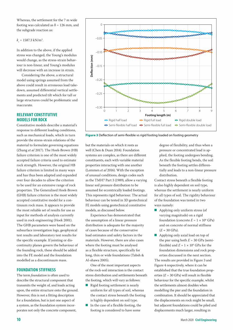
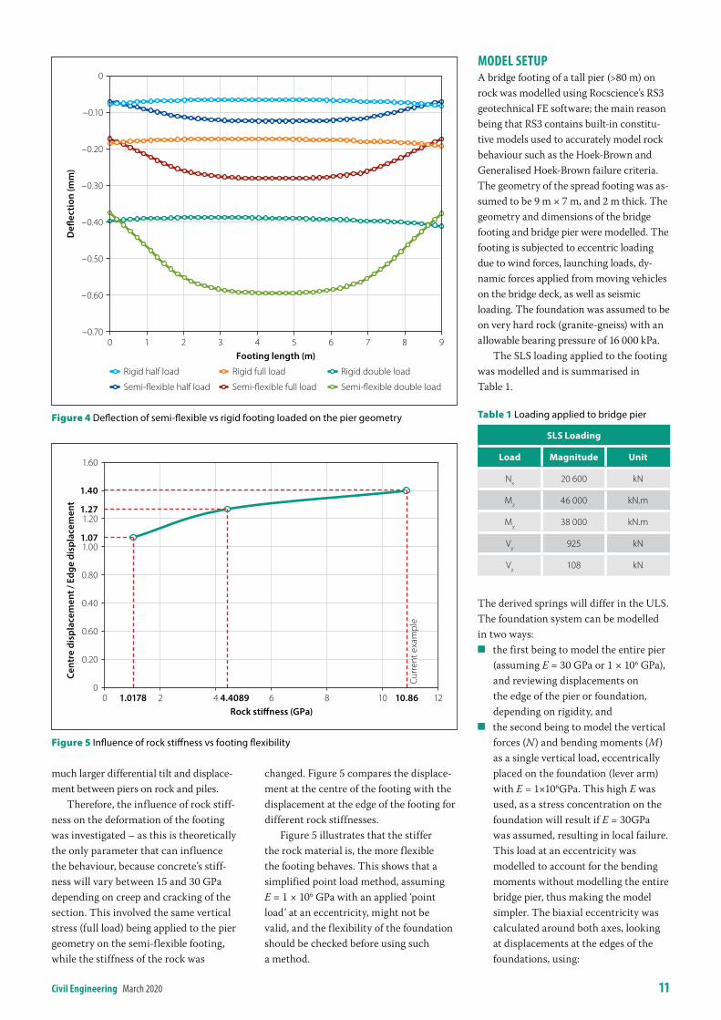
The results are provided in Figure 3 and Figure 4 respectively, where it can be established that the true foundation prop-erties (E = 30 GPa) will result in flexible behaviour for the specific example, whilst the settlements almost doubles when modelling the pier and the foundation in combination. It should be appreciated that the displacements on rock might be small, but adjacent foundations could be piled and displacements much larger, resulting in
Defl
ecti
on (m
m)
–0.25
–0.30
–0.15
–0.20
–0.10
0
–0.05
Footing length (m)97 864 5320 1
Figure 3 Deflection of semi‑flexible vs rigid footing loaded on footing geometry
Semi-flexible half load
Rigid half load
Semi-flexible full load
Rigid full load
Semi-flexible double load
Rigid double load
civil engineering March 2020 11
much larger differential tilt and displace-ment between piers on rock and piles.
Therefore, the influence of rock stiff-ness on the deformation of the footing was investigated – as this is theoretically the only parameter that can influence the behaviour, because concrete’s stiff-ness will vary between 15 and 30 GPa depending on creep and cracking of the section. This involved the same vertical stress (full load) being applied to the pier geometry on the semi-flexible footing, while the stiffness of the rock was
changed. Figure 5 compares the displace-ment at the centre of the footing with the displacement at the edge of the footing for different rock stiffnesses.
Figure 5 illustrates that the stiffer the rock material is, the more flexible the footing behaves. This shows that a simplified point load method, assuming E = 1 × 10⁶ GPa with an applied ‘point load’ at an eccentricity, might not be valid, and the flexibility of the foundation should be checked before using such a method.
moDel setuPA bridge footing of a tall pier (>80 m) on rock was modelled using Rocscience’s RS3 geotechnical FE software; the main reason being that RS3 contains built-in constitu-tive models used to accurately model rock behaviour such as the Hoek-Brown and Generalised Hoek-Brown failure criteria. The geometry of the spread footing was as-sumed to be 9 m × 7 m, and 2 m thick. The geometry and dimensions of the bridge footing and bridge pier were modelled. The footing is subjected to eccentric loading due to wind forces, launching loads, dy-namic forces applied from moving vehicles on the bridge deck, as well as seismic loading. The foundation was assumed to be on very hard rock (granite-gneiss) with an allowable bearing pressure of 16 000 kPa.
The SLS loading applied to the footing was modelled and is summarised in Table 1.
Table 1 Loading applied to bridge pier
sls loading
load Magnitude unit
Nx 20 600 kN
Mz 46 000 kN.m
My 38 000 kN.m
Vy 925 kN
Vz 108 kN
The derived springs will differ in the ULS. The foundation system can be modelled in two ways:
Q the first being to model the entire pier (assuming E = 30 GPa or 1 × 10⁶ GPa), and reviewing displacements on the edge of the pier or foundation, depending on rigidity, and
Q the second being to model the vertical forces (N) and bending moments (M) as a single vertical load, eccentrically placed on the foundation (lever arm) with E = 1×10⁶GPa. This high E was used, as a stress concentration on the foundation will result if E = 30GPa was assumed, resulting in local failure. This load at an eccentricity was modelled to account for the bending moments without modelling the entire bridge pier, thus making the model simpler. The biaxial eccentricity was calculated around both axes, looking at displacements at the edges of the foundations, using:
Defl
ecti
on (m
m)
–0.50
–0.60
–0.30
–0.40
–0.20
0
–0.10
Footing length (m)97 864 5320 1
–0.70
Semi-flexible half load
Rigid half load
Semi-flexible full load
Rigid full load
Semi-flexible double load
Rigid double load
Figure 4 Deflection of semi‑flexible vs rigid footing loaded on the pier geometry
Cent
re d
ispl
acem
ent /
Edg
e di
spla
cem
ent
1.60
1.40
1.271.20
1.071.00
0.80
0.60
0.40
0.20
01210
Rock stiffness (GPa)86420 1.0178 4.4089 10.86
Curr
ent e
xam
ple
Figure 5 Influence of rock stiffness vs footing flexibility
12 March 2020 civil engineering
e =
MN
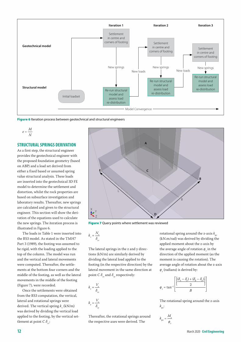
structural sPrinGs DerivationAs a first step, the structural engineer provides the geotechnical engineer with the proposed foundation geometry (based on ABP) and a load set derived from either a fixed based or assumed spring value structural analysis. These loads are inserted into the geotechnical 3D FE model to determine the settlement and distortion, whilst the rock properties are based on subsurface investigation and laboratory results. Thereafter, new springs are calculated and given to the structural engineer. This section will show the deri-vation of the equations used to calculate the new springs. The iteration process is illustrated in Figure 6.
The loads in Table 1 were inserted into the RS3 model. As stated in the TMH7 Part 3 (1989), the footing was assumed to be rigid, with the loading applied to the top of the column. The model was run and the vertical and lateral movements were computed. Thereafter, the settle-ments at the bottom four corners and the middle of the footing, as well as the lateral movements in the middle of the footing (Figure 7), were recorded.
Once the settlements were obtained from the RS3 computation, the vertical, lateral and rotational springs were derived. The vertical spring kv (kN/m) was derived by dividing the vertical load applied to the footing, by the vertical set-tlement at point C δcv:
kv = Nx
δcv
The lateral springs in the z and y direc-tions (kN/m) are similarly derived by dividing the lateral load applied to the footing (in the respective direction) by the lateral movement in the same direction at point C δcz and δcy respectively:
kz = Vz
δcz
ky = Vy
δcy
Thereafter, the rotational springs around the respective axes were derived. The
rotational spring around the z-axis kφz (kN.m/rad) was derived by dividing the applied moment about the z-axis by the average angle of rotation φz in the direction of the applied moment (as the moment is causing the rotation). The average angle of rotation about the z-axis φz (radians) is derived by:
φz = tan–1
⎧⎪⎩(δA – δE) + (δB – δD)
2⎧⎪⎩
B
The rotational spring around the z-axis kφz:
kφz = Mz
φz
Model Convergence
Settlement in centre and
corners of footing Settlement in centre and
corners of footing
Re-run structural model and assess load
re-distribution
Re-run structural model and assess load
re-distribution
Re-run structural model and assess load
re-distribution
Settlement in centre and
corners of footing
Geotechnical model
Structural model
Initial loadset
New springsNew loads
New springsNew loads
New springs
Iteration 1 Iteration 2 Iteration 3
Figure 6 Iteration process between geotechnical and structural engineers
Figure 7 Query points where settlement was reviewed
Z
YX
A
B
D
E C
B
L
civil engineering March 2020 13
Similarly, the rotational spring around the perpendicular axis can be determined by taking the average distortion around that axis.
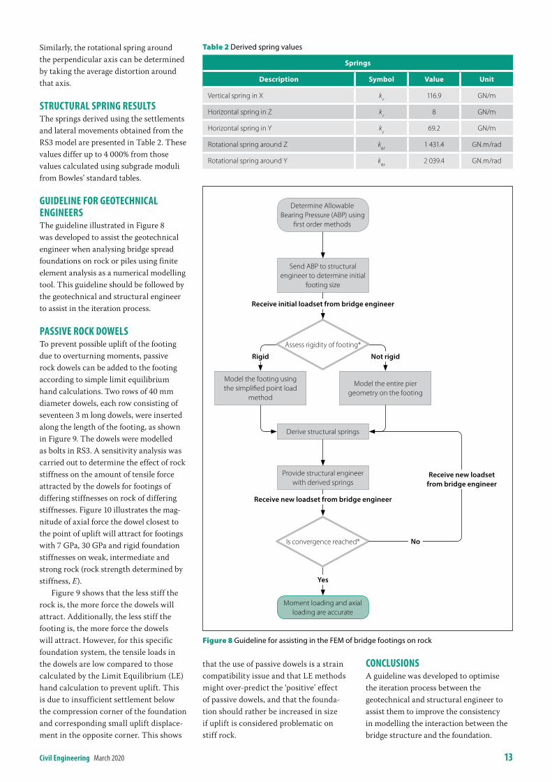
structural sPrinG resultsThe springs derived using the settlements and lateral movements obtained from the RS3 model are presented in Table 2. These values differ up to 4 000% from those values calculated using subgrade moduli from Bowles’ standard tables.
GuiDeline For Geotechnical enGineersThe guideline illustrated in Figure 8 was developed to assist the geotechnical engineer when analysing bridge spread foundations on rock or piles using finite element analysis as a numerical modelling tool. This guideline should be followed by the geotechnical and structural engineer to assist in the iteration process.
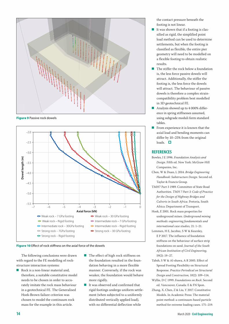
Passive rocK DoWelsTo prevent possible uplift of the footing due to overturning moments, passive rock dowels can be added to the footing according to simple limit equilibrium hand calculations. Two rows of 40 mm diameter dowels, each row consisting of seventeen 3 m long dowels, were inserted along the length of the footing, as shown in Figure 9. The dowels were modelled as bolts in RS3. A sensitivity analysis was carried out to determine the effect of rock stiffness on the amount of tensile force attracted by the dowels for footings of differing stiffnesses on rock of differing stiffnesses. Figure 10 illustrates the mag-nitude of axial force the dowel closest to the point of uplift will attract for footings with 7 GPa, 30 GPa and rigid foundation stiffnesses on weak, intermediate and strong rock (rock strength determined by stiffness, E).
Figure 9 shows that the less stiff the rock is, the more force the dowels will attract. Additionally, the less stiff the footing is, the more force the dowels will attract. However, for this specific foundation system, the tensile loads in the dowels are low compared to those calculated by the Limit Equilibrium (LE) hand calculation to prevent uplift. This is due to insufficient settlement below the compression corner of the foundation and corresponding small uplift displace-ment in the opposite corner. This shows
that the use of passive dowels is a strain compatibility issue and that LE methods might over-predict the ‘positive’ effect of passive dowels, and that the founda-tion should rather be increased in size if uplift is considered problematic on stiff rock.
conclusionsA guideline was developed to optimise the iteration process between the geotechnical and structural engineer to assist them to improve the consistency in modelling the interaction between the bridge structure and the foundation.
Table 2 Derived spring values
springs
description symbol value unit
Vertical spring in X kv 116.9 GN/m
Horizontal spring in Z kz 8 GN/m
Horizontal spring in Y ky 69.2 GN/m
Rotational spring around Z kφz 1 431.4 GN.m/rad
Rotational spring around Y kφy 2 039.4 GN.m/rad
Send ABP to structural engineer to determine initial
footing size
Determine Allowable Bearing Pressure (ABP) using
first order methods
Model the footing using the simplified point load
method
Model the entire pier geometry on the footing
Derive structural springs
Provide structural engineer with derived springs
Moment loading and axial loading are accurate
Assess rigidity of footing*
Receive initial loadset from bridge engineer
Rigid Not rigid
Is convergence reached*
Receive new loadset from bridge engineer
Receive new loadset from bridge engineer
No
Yes
Figure 8 Guideline for assisting in the FEM of bridge footings on rock
14 March 2020 civil engineering
The following conclusions were drawn with regard to the FE modelling of rock-structure interaction systems:
Q Rock is a non-linear material and, therefore, a suitable constitutive model needs to be chosen in order to accu-rately imitate the rock mass behaviour in a geotechnical FE. The Generalised Hoek-Brown failure criterion was chosen to model the continuum rock mass for the example in this article.
Q The effect of high rock stiffness on the foundation resulted in the foun-dation behaving in a more flexible manner. Conversely, if the rock was weaker, the foundation would behave more rigidly.
Q It was observed and confirmed that rigid footings undergo uniform settle-ment (when subjected to a uniformly distributed vertically applied load), with no differential deflection while
the contact pressure beneath the footing is not linear.
Q It was shown that if a footing is clas-sified as rigid, the simplified point load method can be used to determine settlements, but when the footing is classified as flexible, the entire pier geometry will need to be modelled on a flexible footing to obtain realistic results.
Q The stiffer the rock below a foundation is, the less force passive dowels will attract. Additionally, the stiffer the footing is, the less force the dowels will attract. The behaviour of passive dowels is therefore a complex strain-compatibility problem best modelled in 3D geotechnical FE.
Q Analysis showed up to 4 000% differ-ence in spring stiffnesses assumed, using subgrade moduli form standard tables.
Q From experience it is known that the axial load and bending moments can differ by 10–25% from the original loads.
reFerencesBowles, J E 1996. Foundation Analysis and
Design. Fifth ed. New York: McGraw-Hill Companies, Inc.
Chen, W & Duan, L 2014. Bridge Engineering Handbook: Substructure Design. Second ed. Taylor & Francis Group.
TMH7 Part 3 1989. Committee of State Road Authorities. TMH 7 Part 3: Code of Practice for the Design of Highway Bridges and Culverts in South Africa. Pretoria, South Africa: Department of Transport.
Hoek, E 2001. Rock mass properties for underground mines. Underground mining methods: engineering fundamentals and international case studies, 21: 1–21.
Lemmen, H E, Jacobsz, S W & Kearsley, E P 2017. The influence of foundation stiffness on the behaviour of surface strip foundations on sand. Journal of the South African Institution of Civil Engineering, 59(2): 19–27.
Tabsh, S W & Al-shawa, A R 2005. Effect of Spread Footing Flexibility on Structural Response. Practice Periodical on Structural Design and Construction, 10(2): 109–114.
Wyllie, D C 1999. Foundations on Rock. Second ed. Vancouver, Canada: E & FN Spon.
Zhang, X, Chen, Z & Liu, Y 2017. Constitutive Models. In Academic Press: The material point method: a continuum-based particle method for extreme loading cases. 175–219.
Figure 9 Passive rock dowels
Dow
el le
ngth
(m)
–5.5
–5.0
–4.5
–4.0
–3.5
–3.0
–2.5
–2.0
–7 –6 –5 –4 –3 –2 –1 0Axial force (kN)
Weak rock – 30 GPa footing
Intermediate rock – 7 GPa footing
Intermediate rock – Rigid footing
Strong rock – 30 GPa footing
Weak rock – 7 GPa footing
Weak rock – Rigid footing
Intermediate rock – 30GPa footing
Strong rock – 7GPa footing
Strong rock – Rigid footing
Figure 10 Effect of rock stiffness on the axial force of the dowels
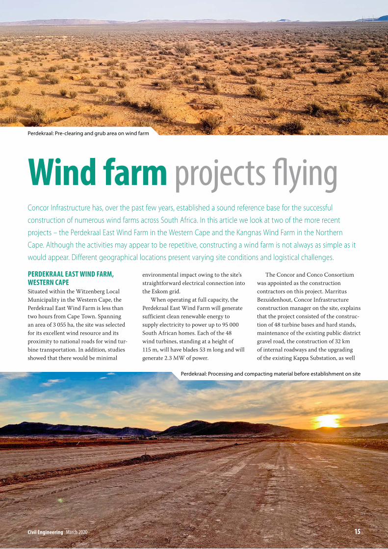
PerDeKraal east WinD Farm, Western caPeSituated within the Witzenberg Local Municipality in the Western Cape, the Perdekraal East Wind Farm is less than two hours from Cape Town. Spanning an area of 3 055 ha, the site was selected for its excellent wind resource and its proximity to national roads for wind tur-bine transportation. In addition, studies showed that there would be minimal
environmental impact owing to the site’s straightforward electrical connection into the Eskom grid.
When operating at full capacity, the Perdekraal East Wind Farm will generate sufficient clean renewable energy to supply electricity to power up to 95 000 South African homes. Each of the 48 wind turbines, standing at a height of 115 m, will have blades 53 m long and will generate 2.3 MW of power.
The Concor and Conco Consortium was appointed as the construction contractors on this project. Marritus Bezuidenhout, Concor Infrastructure construction manager on the site, explains that the project consisted of the construc-tion of 48 turbine bases and hard stands, maintenance of the existing public district gravel road, the construction of 32 km of internal roadways and the upgrading of the existing Kappa Substation, as well
Wind farm projects flyingConcor Infrastructure has, over the past few years, established a sound reference base for the successful construction of numerous wind farms across South Africa. In this article we look at two of the more recent projects – the Perdekraal East Wind Farm in the Western Cape and the Kangnas Wind Farm in the Northern Cape. Although the activities may appear to be repetitive, constructing a wind farm is not always as simple as it would appear. Different geographical locations present varying site conditions and logistical challenges.
civil engineering March 2020 15
Perdekraal: Pre‑clearing and grub area on wind farm
Perdekraal: Processing and compacting material before establishment on site
16 March 2020 civil engineering
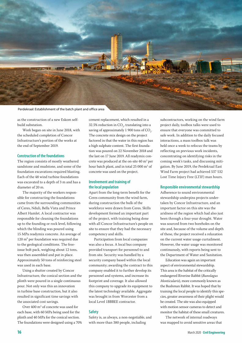
as the construction of a new Eskom self-build substation.
Work began on site in June 2018, with the scheduled completion of Concor Infrastructure’s portion of the works at the end of September 2019.
Construction of the foundationsThe region consists of mostly weathered sandstone and mudstone, and some of the foundation excavations required blasting. Each of the 48 wind turbine foundations was excavated to a depth of 3 m and has a diameter of 20 m.
The majority of the workers respon-sible for constructing the foundations came from the surrounding communities of Ceres, Nduli, Bella Vista and Prince Albert Hamlet. A local contractor was responsible for cleaning the foundations up to the founding or rock level, following which the blinding was poured using 15 MPa readymix concrete. An average of 120 m³ per foundation was required due to the geological conditions. The free-issue bolt pack, weighing about 12 tons, was then assembled and put in place. Approximately 50 tons of reinforcing steel was used in each base.
Using a shutter created by Concor Infrastructure, the conical section and the plinth were poured in a single continuous pour. Not only was this an innovation in turbine base construction, but it also resulted in significant time savings with the associated cost savings.
Over 400 m3 of concrete was used for each base, with 60 MPa being used for the plinth and 40 MPa for the conical section. The foundations were designed using a 70%
cement replacement, which resulted in a 32.5% reduction in CO2, translating into a saving of approximately 1 900 tons of CO2. The concrete mix design on the project factored in that the water in this region has a high sulphate content. The first founda-tion was poured on 22 November 2018 and the last on 17 June 2019. All readymix con-crete was produced at the on-site 40 m3 per hour batch plant, and in total 25 000 m3 of concrete was used on the project.
Involvement and training of the local populationApart from the long-term benefit for the Ceres community from the wind farm, during construction the bulk of the workforce were drawn from Ceres. Skills development formed an important part of the project, with training being done with all Concor Infrastructure’s people on site to ensure that they had the necessary competency and skills.
Participation from local companies was also a focus. A local bus company provided transport for personnel to and from site. Security was handled by a security company based within the local community; awarding the contract to this company enabled it to further develop its personnel and systems, and increase its footprint and coverage. It also allowed this company to upgrade its equipment to the latest technology available. Aggregate was brought in from Worcester from a local Level 1BBBEE contractor.
SafetySafety is, as always, a non-negotiable, and with more than 380 people, including
subcontractors, working on the wind farm project daily, toolbox talks were used to ensure that everyone was committed to safe work. In addition to the daily focused interactions, a mass toolbox talk was held once a week to refocus the teams by reflecting on previous work incidents, concentrating on identifying risks in the coming week’s tasks, and discussing miti-gation. By June 2019, the Perdekraal East Wind Farm project had achieved 537 532 Lost Time Injury Free (LTIF) man hours.
Responsible environmental stewardshipAdherence to sound environmental stewardship underpins projects under-taken by Concor Infrastructure, and an important factor on this site was the aridness of the region which had also just been through a four-year drought. Water was sourced from two boreholes on the site and, because of the volume and depth of these, the project received a relaxation on the current water usage curtailment. However, the water usage was monitored continuously, with reports being sent to the Department of Water and Sanitation.
Education was again an important aspect of environmental stewardship. This area is the habitat of the critically endangered Riverine Rabbit (Bunolagus Monticularis), more commonly known as the Bushman Rabbit. It was hoped that by training the local people to identify this spe-cies, greater awareness of their plight would be created. The site was also equipped with motion sensor cameras to detect and monitor the habitat of these small creatures.
The network of internal roadways was mapped to avoid sensitive areas that
Perdekraal: Establishment of the batch plant and office area

civil engineering March 2020 17
could affect the local flora and fauna. This includes endangered species of succulents. Sections of the area through which the roads pass were designated as no-go areas, as these consist of exposed calcareous gravel with dense populations of Tanquana Prismatica and Didymautus Lapidiformis. Both are endemic species which have a highly restricted distribution and should not be disturbed or destroyed. Bezuidenhout explains: “By declaring no-go zones, we set out the footprint within which all personnel had to stay while working on the project. This went a long way, not only to protecting local species, but also to creating an awareness and interest in preservation. The areas of the no-go demarcation also include graves and archaeological sites which require protection.
KanGnas WinD Farm, northern caPeKangnas Wind Farm is approximately 40 km east of Springbok, in the Northern Cape’s Nama Khoi Municipal area. Construction commenced on this wind Perdekraal: Preparing the levels to cast a wind turbine base
RANGE KEMACH JCB
f in
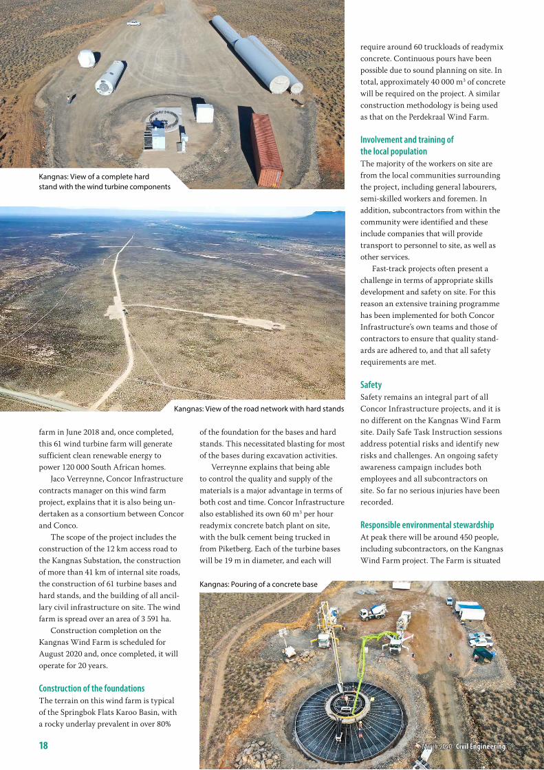
farm in June 2018 and, once completed, this 61 wind turbine farm will generate sufficient clean renewable energy to power 120 000 South African homes.
Jaco Verreynne, Concor Infrastructure contracts manager on this wind farm project, explains that it is also being un-dertaken as a consortium between Concor and Conco.
The scope of the project includes the construction of the 12 km access road to the Kangnas Substation, the construction of more than 41 km of internal site roads, the construction of 61 turbine bases and hard stands, and the building of all ancil-lary civil infrastructure on site. The wind farm is spread over an area of 3 591 ha.
Construction completion on the Kangnas Wind Farm is scheduled for August 2020 and, once completed, it will operate for 20 years.
Construction of the foundationsThe terrain on this wind farm is typical of the Springbok Flats Karoo Basin, with a rocky underlay prevalent in over 80%
of the foundation for the bases and hard stands. This necessitated blasting for most of the bases during excavation activities.
Verreynne explains that being able to control the quality and supply of the materials is a major advantage in terms of both cost and time. Concor Infrastructure also established its own 60 m3 per hour readymix concrete batch plant on site, with the bulk cement being trucked in from Piketberg. Each of the turbine bases will be 19 m in diameter, and each will
require around 60 truckloads of readymix concrete. Continuous pours have been possible due to sound planning on site. In total, approximately 40 000 m3 of concrete will be required on the project. A similar construction methodology is being used as that on the Perdekraal Wind Farm.
Involvement and training of the local populationThe majority of the workers on site are from the local communities surrounding the project, including general labourers, semi-skilled workers and foremen. In addition, subcontractors from within the community were identified and these include companies that will provide transport to personnel to site, as well as other services.
Fast-track projects often present a challenge in terms of appropriate skills development and safety on site. For this reason an extensive training programme has been implemented for both Concor Infrastructure’s own teams and those of contractors to ensure that quality stand-ards are adhered to, and that all safety requirements are met.
SafetySafety remains an integral part of all Concor Infrastructure projects, and it is no different on the Kangnas Wind Farm site. Daily Safe Task Instruction sessions address potential risks and identify new risks and challenges. An ongoing safety awareness campaign includes both employees and all subcontractors on site. So far no serious injuries have been recorded.
Responsible environmental stewardshipAt peak there will be around 450 people, including subcontractors, on the Kangnas Wind Farm project. The Farm is situated
Kangnas: View of a complete hard stand with the wind turbine components
Kangnas: View of the road network with hard stands
Kangnas: Pouring of a concrete base
18 March 2020 civil engineering
civil engineering March 2020 19
within Namaqualand and no-go areas were identified before the project began, with the wind farm footprint planned around these areas to ensure they are not compromised.
Sound environmental stewardship by Concor Infrastructure has seen measures taken on site to contain all traffic, as far as possible, within the allowed footprint. Access roads are maintained, and with 300 people on average traversing the site, a stringent preventative approach towards litter, including educational awareness, has been implemented.
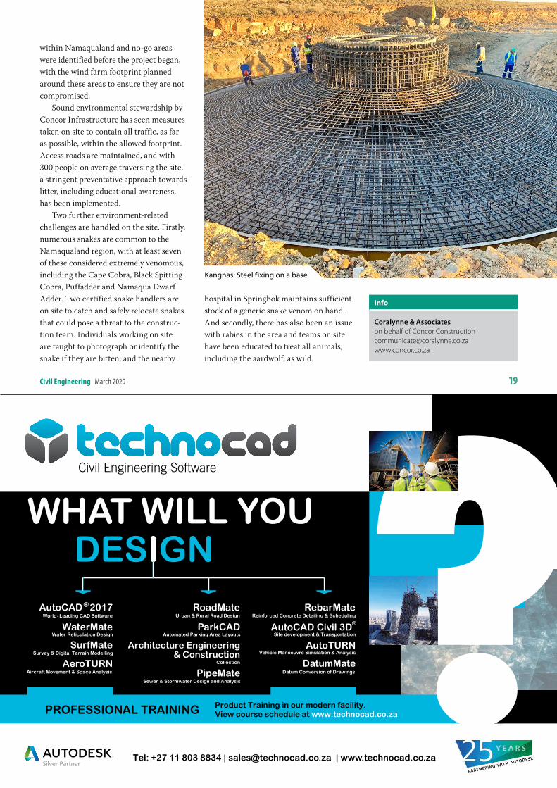
Two further environment-related challenges are handled on the site. Firstly, numerous snakes are common to the Namaqualand region, with at least seven of these considered extremely venomous, including the Cape Cobra, Black Spitting Cobra, Puffadder and Namaqua Dwarf Adder. Two certified snake handlers are on site to catch and safely relocate snakes that could pose a threat to the construc-tion team. Individuals working on site are taught to photograph or identify the snake if they are bitten, and the nearby
hospital in Springbok maintains sufficient stock of a generic snake venom on hand. And secondly, there has also been an issue with rabies in the area and teams on site have been educated to treat all animals, including the aardwolf, as wild.
info
Coralynne & Associateson behalf of Concor [email protected]
Kangnas: Steel fixing on a base
introDuctionThis part of the Lowveld is better known for its rich gold and asbestos deposits, mine disasters and Jock of the Bushveld than for infrastructure development. During 2014, following a lengthy political process, a decision was taken by govern-ment to amalgamate the then Mjindi Local Municipality, earlier known as Barberton, with the municipality of the capital of Mpumalanga, Mbombela Municipality. As part of the amalgama-tion, a ‘wedding gift’ from government was making funding available for the refurbishment and upgrading of bulk water supply infrastructure. One of the projects identified and prioritised was the refurbishment and upgrading of the Rimer’s Creek Water Treatment Works, including the outlet works of the main raw water source, the Lomati Dam.
Following a lengthy procurement process for professional service providers, AFI Consult was awarded the work as the preferred service provider, and work com-menced in all earnest.
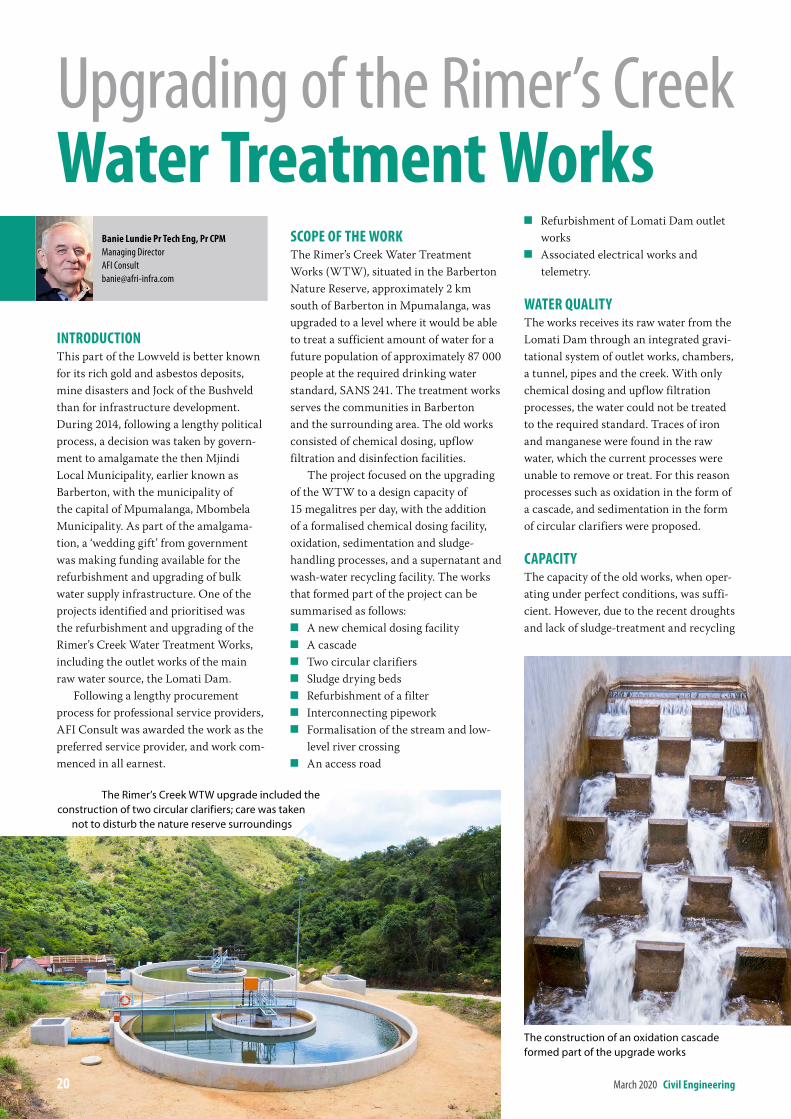
scoPe oF the WorKThe Rimer’s Creek Water Treatment Works (WTW), situated in the Barberton Nature Reserve, approximately 2 km south of Barberton in Mpumalanga, was upgraded to a level where it would be able to treat a sufficient amount of water for a future population of approximately 87 000 people at the required drinking water standard, SANS 241. The treatment works serves the communities in Barberton and the surrounding area. The old works consisted of chemical dosing, upflow filtration and disinfection facilities.
The project focused on the upgrading of the WTW to a design capacity of 15 megalitres per day, with the addition of a formalised chemical dosing facility, oxidation, sedimentation and sludge-handling processes, and a supernatant and wash-water recycling facility. The works that formed part of the project can be summarised as follows:
Q A new chemical dosing facility Q A cascade Q Two circular clarifiers Q Sludge drying beds Q Refurbishment of a filter Q Interconnecting pipework Q Formalisation of the stream and low-
level river crossing Q An access road
Q Refurbishment of Lomati Dam outlet works
Q Associated electrical works and telemetry.
Water QualitYThe works receives its raw water from the Lomati Dam through an integrated gravi-tational system of outlet works, chambers, a tunnel, pipes and the creek. With only chemical dosing and upflow filtration processes, the water could not be treated to the required standard. Traces of iron and manganese were found in the raw water, which the current processes were unable to remove or treat. For this reason processes such as oxidation in the form of a cascade, and sedimentation in the form of circular clarifiers were proposed.
caPacitYThe capacity of the old works, when oper-ating under perfect conditions, was suffi-cient. However, due to the recent droughts and lack of sludge-treatment and recycling
Upgrading of the Rimer’s Creek Water treatment Works
banie lundie Pr tech eng, Pr cPmManaging DirectorAFI [email protected]
The Rimer’s Creek WTW upgrade included the construction of two circular clarifiers; care was taken
not to disturb the nature reserve surroundings
The construction of an oxidation cascade formed part of the upgrade works
20 March 2020 civil engineering
civil engineering March 2020 21
facilities, the filter backwash cycles had been neglected. Consequently, the works could only operate at approximately 80% of its design capacity. Similarly, the raw water quality had deteriorated because of the changing catchment characteristics of the Lomati Dam. The design capacity for the upgraded works was to remain at 15 megalitres per day.
environmentalWith the works being located inside the Barberton Nature Reserve adjacent to Rimer’s Creek, a lengthy environmental process had to be conducted, with environmental authorisation being granted as well as a water-use licence. The environmental management programme was stringently enforced to ensure that minimal disruption and damage were caused during construction. The addition of the sludge-handling process further ensured that the ecological system down-stream of the works can be restored to normal conditions.
innovationDue to some steep slopes and a stream dissecting the old and the extended works, the location of the works proved to be challenging. The design team and
contractor had to find innovative ways to make the upgrade fit-for-purpose.
Various level platforms had to be created for infrastructure, while ensuring that the hydraulics through the works remained unaffected.
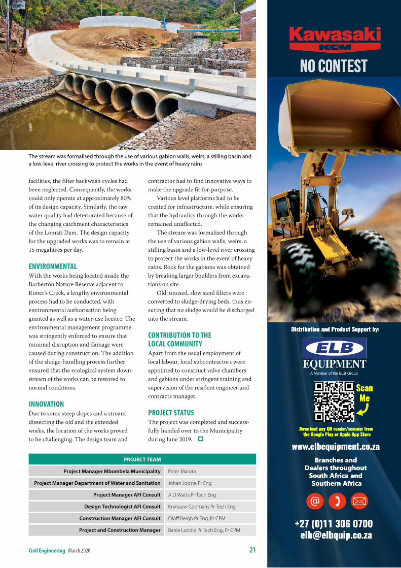
The stream was formalised through the use of various gabion walls, weirs, a stilling basin and a low-level river crossing to protect the works in the event of heavy rains. Rock for the gabions was obtained by breaking larger boulders from excava-tions on site.
Old, unused, slow sand filters were converted to sludge-drying beds, thus en-suring that no sludge would be discharged into the stream.
contribution to the local communitYApart from the usual employment of local labour, local subcontractors were appointed to construct valve chambers and gabions under stringent training and supervision of the resident engineer and contracts manager.
ProJect statusThe project was completed and success-fully handed over to the Municipality during June 2019.
PrOJeCt teAM
Project Manager Mbombela Municipality Peter Marota
Project Manager Department of Water and Sanitation Johan Jooste Pr Eng
Project Manager AFI Consult A D Watts Pr Tech Eng
Design Technologist AFI Consult Krynauw Coomans Pr Tech Eng
Construction Manager AFI Consult Oloff Bergh Pr Eng, Pr CPM
Project and Construction Manager Banie Lundie Pr Tech Eng, Pr CPM
The stream was formalised through the use of various gabion walls, weirs, a stilling basin and a low‑level river crossing to protect the works in the event of heavy rains
Download any QR reader/scanner from the Google Play or Apple App Store
+27 (0)11 306 0700 [email protected]
www.elbequipment.co.zaBranches and
Dealers throughout South Africa and Southern Africa
Distribution and Product Support by:
No Contest
ScanMe
22 March 2020 civil engineering
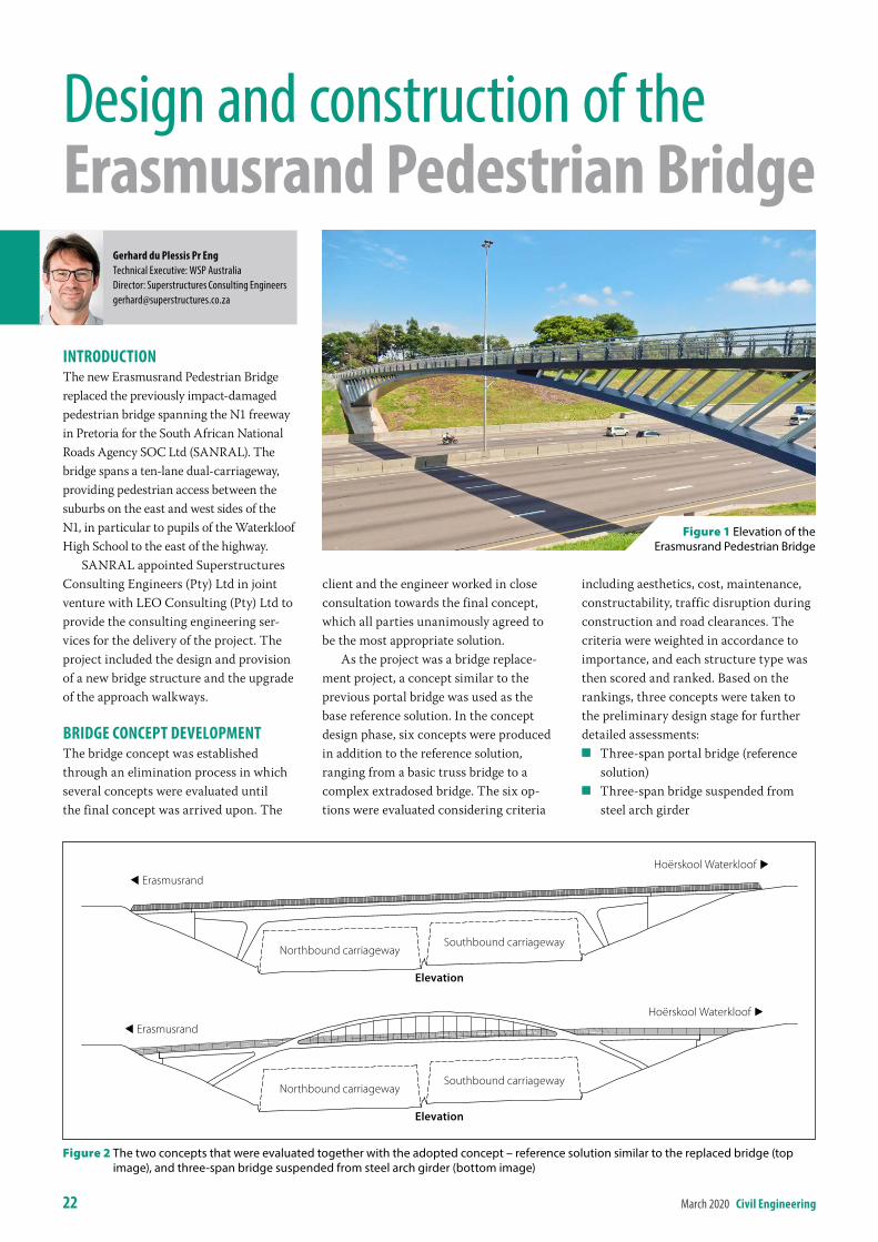
introDuctionThe new Erasmusrand Pedestrian Bridge replaced the previously impact-damaged pedestrian bridge spanning the N1 freeway in Pretoria for the South African National Roads Agency SOC Ltd (SANRAL). The bridge spans a ten-lane dual-carriageway, providing pedestrian access between the suburbs on the east and west sides of the N1, in particular to pupils of the Waterkloof High School to the east of the highway.
SANRAL appointed Superstructures Consulting Engineers (Pty) Ltd in joint venture with LEO Consulting (Pty) Ltd to provide the consulting engineering ser-vices for the delivery of the project. The project included the design and provision of a new bridge structure and the upgrade of the approach walkways.
briDGe concePt DeveloPmentThe bridge concept was established through an elimination process in which several concepts were evaluated until the final concept was arrived upon. The
client and the engineer worked in close consultation towards the final concept, which all parties unanimously agreed to be the most appropriate solution.
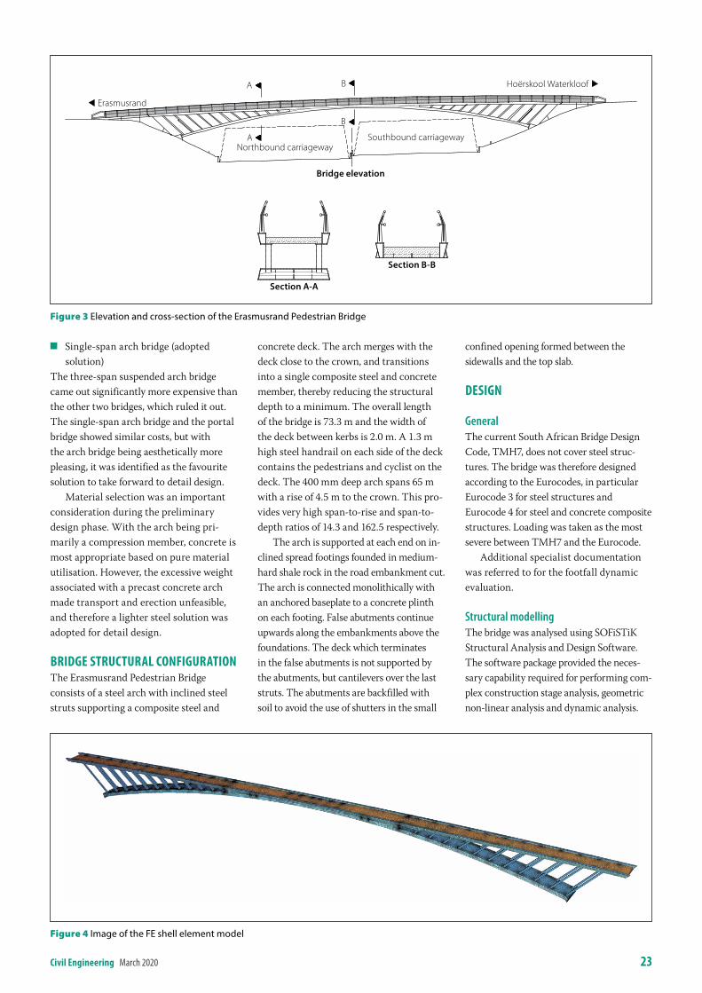
As the project was a bridge replace-ment project, a concept similar to the previous portal bridge was used as the base reference solution. In the concept design phase, six concepts were produced in addition to the reference solution, ranging from a basic truss bridge to a complex extradosed bridge. The six op-tions were evaluated considering criteria
including aesthetics, cost, maintenance, constructability, traffic disruption during construction and road clearances. The criteria were weighted in accordance to importance, and each structure type was then scored and ranked. Based on the rankings, three concepts were taken to the preliminary design stage for further detailed assessments:
Q Three-span portal bridge (reference solution)
Q Three-span bridge suspended from steel arch girder
Gerhard du Plessis Pr engTechnical Executive: WSP AustraliaDirector: Superstructures Consulting [email protected]
Design and construction of the erasmusrand Pedestrian bridge
Figure 1 Elevation of the Erasmusrand Pedestrian Bridge
ErasmusrandHoërskool Waterkloof
Elevation
Figure 2 The two concepts that were evaluated together with the adopted concept – reference solution similar to the replaced bridge (top image), and three‑span bridge suspended from steel arch girder (bottom image)
ErasmusrandHoërskool Waterkloof
Elevation
Northbound carriagewaySouthbound carriageway
Northbound carriagewaySouthbound carriageway
civil engineering March 2020 23
Q Single-span arch bridge (adopted solution)
The three-span suspended arch bridge came out significantly more expensive than the other two bridges, which ruled it out. The single-span arch bridge and the portal bridge showed similar costs, but with the arch bridge being aesthetically more pleasing, it was identified as the favourite solution to take forward to detail design.
Material selection was an important consideration during the preliminary design phase. With the arch being pri-marily a compression member, concrete is most appropriate based on pure material utilisation. However, the excessive weight associated with a precast concrete arch made transport and erection unfeasible, and therefore a lighter steel solution was adopted for detail design.
briDGe structural conFiGurationThe Erasmusrand Pedestrian Bridge consists of a steel arch with inclined steel struts supporting a composite steel and
concrete deck. The arch merges with the deck close to the crown, and transitions into a single composite steel and concrete member, thereby reducing the structural depth to a minimum. The overall length of the bridge is 73.3 m and the width of the deck between kerbs is 2.0 m. A 1.3 m high steel handrail on each side of the deck contains the pedestrians and cyclist on the deck. The 400 mm deep arch spans 65 m with a rise of 4.5 m to the crown. This pro-vides very high span-to-rise and span-to-depth ratios of 14.3 and 162.5 respectively.
The arch is supported at each end on in-clined spread footings founded in medium-hard shale rock in the road embankment cut. The arch is connected monolithically with an anchored baseplate to a concrete plinth on each footing. False abutments continue upwards along the embankments above the foundations. The deck which terminates in the false abutments is not supported by the abutments, but cantilevers over the last struts. The abutments are backfilled with soil to avoid the use of shutters in the small
confined opening formed between the sidewalls and the top slab.
DesiGn
GeneralThe current South African Bridge Design Code, TMH7, does not cover steel struc-tures. The bridge was therefore designed according to the Eurocodes, in particular Eurocode 3 for steel structures and Eurocode 4 for steel and concrete composite structures. Loading was taken as the most severe between TMH7 and the Eurocode.
Additional specialist documentation was referred to for the footfall dynamic evaluation.
Structural modellingThe bridge was analysed using SOFiSTiK Structural Analysis and Design Software. The software package provided the neces-sary capability required for performing com-plex construction stage analysis, geometric non-linear analysis and dynamic analysis.
Figure 3 Elevation and cross‑section of the Erasmusrand Pedestrian Bridge
Section A-A
Section B-B
Bridge elevation
Erasmusrand
Hoërskool WaterkloofA
A
B
B
Northbound carriagewaySouthbound carriageway
Figure 4 Image of the FE shell element model
24 March 2020 civil engineering
Two global models were produced – a composite beam model and a Finite Element (FE) shell model. The beam model was used for general global ana-lysis. The shell element model was used to evaluate detail stress distributions, local buckling and transverse actions not captured by the beam model.
The structure is sensitive to the effects of direct and induced loading. Foundation settlement and temperature loading cause relatively large deflections. With the large deflections associated to the flat arch, third-order large displacement analysis is essential for an accurate structural assessment.
Construction stagesThe bridge was erected in two halves sup-ported on a temporary median pier. The concrete was poured afterwards, making the deck and the arch composite. To capture the redistribution of forces during construction, and to incorporate the effects of concrete creep and shrinkage, detailed non-linear construction stage analysis was performed.
A major challenge was the deflection control of the segments when placed in position before the arch could be mobilised. Analysis showed large vertical and horizontal displacements should the segments be placed without additional restraint. The initial solution was to tie each segment back to an anchor block. However, the cost of the anchor blocks proved to be too expensive. An innovative solution was consequently developed by the engineer and the steel contractor through which the segments were temporarily stressed with stressing bars between the base and the tips of the segments. This introduced an upward
bow in the segments and pulled the tips back such that, when placed, the required geometry was reached with the horizontal displacement limited within the erection tolerance. The stressing bars were released after the arch had been closed and welded together, thereby locking the pre-stressing forces into the system. The generated pre-loading had the beneficial effect of increasing the structure’s tolerance against the adverse effects of support settlement and tem-perature reduction.
Strength designThe arch cross-section is a “Class 4” section for which local cross-sectional buckling occurs prior to yielding of the section, due to the slenderness of the individual plate elements. Cross-sectional strength design was performed using the force results from the global beam struc-tural model in combination with effective width models in which part of the section is deemed non-effective and ignored.
Further FE analysis was performed to capture the effects of out-of-plane bending of the flanges due to the curvature of the members. Radial loads imposed on the flanges result in trans-verse bending of the flanges and the webs, which is not captured in the global beam model. Local buckling and strength of the longitudinal and transverse stiffeners were checked with the FE model and confirmed with hand calculations.
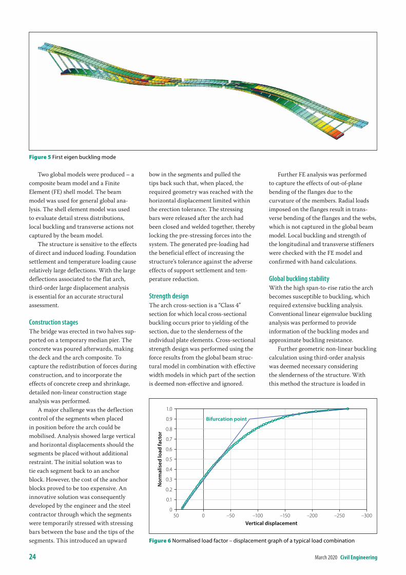
Global buckling stabilityWith the high span-to-rise ratio the arch becomes susceptible to buckling, which required extensive buckling analysis. Conventional linear eigenvalue buckling analysis was performed to provide information of the buckling modes and approximate buckling resistance.
Further geometric non-linear buckling calculation using third-order analysis was deemed necessary considering the slenderness of the structure. With this method the structure is loaded in
Figure 5 First eigen buckling modeN
orm
alis
ed lo
ad fa
ctor
1.0
0.9
0.8
0.7
0.6
0.5
0.4
0.3
0.2
0.1
0–300–250–200–150–100–50050
Vertical displacement
Bifurcation point
Figure 6 Normalised load factor – displacement graph of a typical load combination
civil engineering March 2020 25
increments and at each load level the geometrical stiffness matrix is updated by incorporating the lateral displacement (second-order), as well as axial shortening (third-order) of the elements. The point where the global stiffness matrix becomes negative signifies buckling of the structure.
Also important is to capture the ef-fects of the construction stages contained in the structure. This is achieved by using the end condition of the non-linear construction stage analysis as a primary load case containing the starting stress and displacement state for the buckling analysis.
Non-linear buckling analysis was done on each of the load combinations to ensure that the absolute lowest buckling factor was identified. Because of the slenderness of the structure, the load displacement graph becomes non-linear at low load levels. The slope shows a gradual transition from the initial full stiffness to the reduced stiffness at buckling. The bifurcation point is established by the intersection of the initial slope and end
slope extensions. The load associated to the bifurcation point, which is normally perceived as the initial buckling load, is at a load level of approximately 90% of the final buckling load.
Dynamic behaviourWith the relatively long span and light construction, the bridge becomes sus-ceptible to vibrations due to pedestrian footfall loading. The recommendations contained in the JRC publication, Design of Lightweight Footbridges for Human Induced Vibrations, were used to assess the dynamic behaviour of the bridge. According to this document, the critical ranges in which pedestrian bridges can become susceptible to dynamic excita-tion is 1.25 Hz to 2.3 Hz and 0.5 Hz to 1.2 Hz for vertical and lateral vibrations
respectively. The second vertical mode, with a frequency of 1.91 Hz, falls in the critical range, and further detailed analysis was therefore required. The first horizontal mode with a frequency of 2.1 Hz is well outside the critical range for lateral excitation.
In accordance to the JRC method, the bridge could be designed to achieve a certain comfort class for the relevant pedestrian traffic class. Comfort classes range from a maximum degree of comfort with an associated acceleration of 0.5 m/ s2 to unacceptable discomfort at accelera-tions greater than 2.5 m/s2. Traffic classes range from very weak traffic to excep-tionally dense traffic where crowding is starting and one can no longer pace freely. Traffic counts showed very weak traffic during peak hours. However, it
In accordance to the JRC method, the bridge could be designed to achieve a certain comfort class for the relevant pedestrian traffic class. Comfort classes range from a maximum degree of comfort with an associated acceleration of 0.5 m/s2 to unacceptable discomfort at accelerations greater than 2.5 m/s2.
Call us for more info: 010 823 8688www.sika.co.za
shaping the world around you
SIKA PRODUCTS FROM BASEMENT TO ROOF
At Sika, our goal is to develop the most reliable product solutions for the construction industry. Sika provides technologies for the entire life cycle of commercial buildings, residential properties and infrastructure rehabilitation projects.
SEALING & BONDING
ROOFING
FLOORING STRUCTURAL GLAZING
WATERPROOFING
REFURBISHMENT
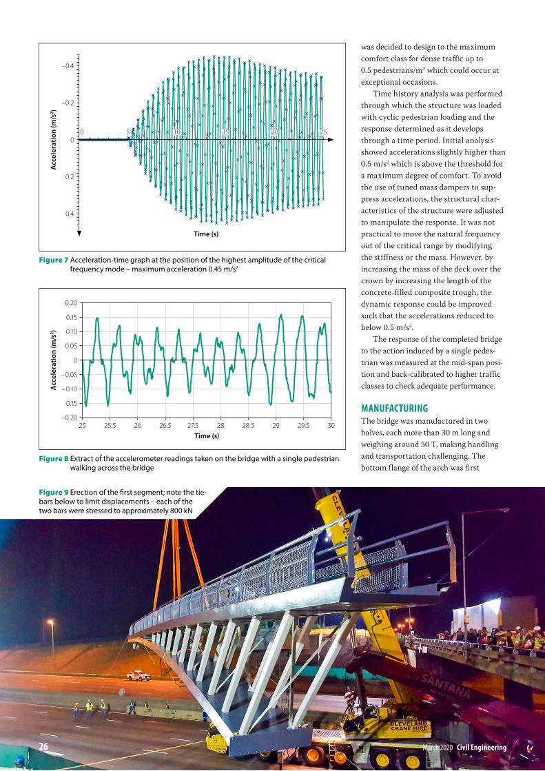
was decided to design to the maximum comfort class for dense traffic up to 0.5 pedestrians/m2 which could occur at exceptional occasions.
Time history analysis was performed through which the structure was loaded with cyclic pedestrian loading and the response determined as it develops through a time period. Initial analysis showed accelerations slightly higher than 0.5 m/s2 which is above the threshold for a maximum degree of comfort. To avoid the use of tuned mass dampers to sup-press accelerations, the structural char-acteristics of the structure were adjusted to manipulate the response. It was not practical to move the natural frequency out of the critical range by modifying the stiffness or the mass. However, by increasing the mass of the deck over the crown by increasing the length of the concrete-filled composite trough, the dynamic response could be improved such that the accelerations reduced to below 0.5 m/s2.
The response of the completed bridge to the action induced by a single pedes-trian was measured at the mid-span posi-tion and back-calibrated to higher traffic classes to check adequate performance.
manuFacturinGThe bridge was manufactured in two halves, each more than 30 m long and weighing around 50 T, making handling and transportation challenging. The bottom flange of the arch was first
Acc
eler
atio
n (m
/s2 )
–0.4
–0.2
0
0.2
0.4
2520151050
Figure 7 Acceleration‑time graph at the position of the highest amplitude of the critical frequency mode – maximum acceleration 0.45 m/s2
Figure 8 Extract of the accelerometer readings taken on the bridge with a single pedestrian walking across the bridge
Acc
eler
atio
n (m
/s2 )
0.20
0.15
0.10
0.05
0
–0.05
–0.10
0.15
–0.203029.52928.52827.526.52625.525
Time (s)
26 March 2020 civil engineering
Figure 9 Erection of the first segment; note the tie‑bars below to limit displacements – each of the two bars were stressed to approximately 800 kN
Time (s)
civil engineering March 2020 27
assembled on pedestals to the required curvature. Thereafter the side webs were installed and the internal stiffeners welded onto the open section. The box was then closed by welding in the stiff-ened top flange. Finally, the struts and the deck elements were added.
Manufacturing the curved mem-bers with inclined faces merging was extremely challenging. Precision detailing played an important role in assuring that the complex geometry was achieved to a high level of accuracy. Welding in confined areas in the box also proved challenging. Temporary access openings were left in the flanges to allow for the final internal welding of critical elements.
transPort anD erectionStability of the structure during erec-tion was a critical aspect that required close collaboration between the design engineer and steel contractor. Each construction stage, and each handling and transport condition had to be analysed to ensure that stability would be maintained throughout.
The two segments were transported in a horizontal position on lowbed trucks to be within the clearance limitations of the transportation route. The segments were lifted into place successively on two nights over a weekend. The N1 traffic was diverted via an alternative route during these placements. Precision crane lifting was required to position the
segments with tight tolerances onto the concrete abutments.
The support and arch levels were monitored throughout the construction process to ensure the settlements and de-flections were within the predicted range.
in conclusionThe bridge posed many challenges in its design and construction. These were overcome by effective communication between the client, the engineer and the contractor, and the project was suc-cessfully completed within budget and programme. Using the latest technolo-gies available in design, detailing and construction, a structure with complex geometry and challenging proportions could be produced with minimal risk.
acKnoWleDGementsThis article is being published with SANRAL’s permission. Special thanks for their inputs go to Edwin Kruger, SANRAL Bridge Manager, and Alan Agaienz, SANRAL Project Manager for this project.
PrOJeCt teAM
Client South African National Roads Agency SOC Ltd (SANRAL)
Consulting engineer LEO-Superstructures Consulting Engineers Joint Venture
Main contractor Ndugane Teichmann Structures Joint Venture
Steel contractor CADCON
Find our branches at www.technicrete.co.za
paving | mining | masonry | kerbs | erosion protection | retaining walls | drainage
• Rivers, Estuaries, Dams, Reservoirs• Areas subject to wave action• Access roads• Parking areas• Stormwater drift crossings
SUITABLE FOR:
SPECIALLY DESIGNED:• Compressed concrete blocks• Interlocking system• Partial taper of each block• Various sizes of blocks available
Technicrete is a subsidiary of ISG, a leading supplier of innovative infrastructure products to the construction and mining markets in Southern Africa.
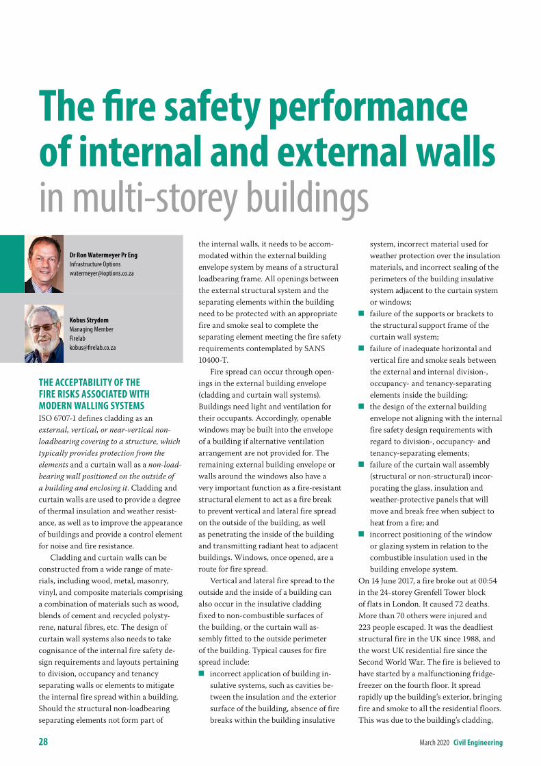
28 March 2020 civil engineering
the accePtabilitY oF the Fire risKs associateD With moDern WallinG sYstemsISO 6707-1 defines cladding as an external, vertical, or near-vertical non-loadbearing covering to a structure, which typically provides protection from the elements and a curtain wall as a non-load-bearing wall positioned on the outside of a building and enclosing it. Cladding and curtain walls are used to provide a degree of thermal insulation and weather resist-ance, as well as to improve the appearance of buildings and provide a control element for noise and fire resistance.
Cladding and curtain walls can be constructed from a wide range of mate-rials, including wood, metal, masonry, vinyl, and composite materials comprising a combination of materials such as wood, blends of cement and recycled polysty-rene, natural fibres, etc. The design of curtain wall systems also needs to take cognisance of the internal fire safety de-sign requirements and layouts pertaining to division, occupancy and tenancy separating walls or elements to mitigate the internal fire spread within a building. Should the structural non-loadbearing separating elements not form part of
the internal walls, it needs to be accom-modated within the external building envelope system by means of a structural loadbearing frame. All openings between the external structural system and the separating elements within the building need to be protected with an appropriate fire and smoke seal to complete the separating element meeting the fire safety requirements contemplated by SANS 10400-T.
Fire spread can occur through open-ings in the external building envelope (cladding and curtain wall systems). Buildings need light and ventilation for their occupants. Accordingly, openable windows may be built into the envelope of a building if alternative ventilation arrangement are not provided for. The remaining external building envelope or walls around the windows also have a very important function as a fire-resistant structural element to act as a fire break to prevent vertical and lateral fire spread on the outside of the building, as well as penetrating the inside of the building and transmitting radiant heat to adjacent buildings. Windows, once opened, are a route for fire spread.
Vertical and lateral fire spread to the outside and the inside of a building can also occur in the insulative cladding fixed to non-combustible surfaces of the building, or the curtain wall as-sembly fitted to the outside perimeter of the building. Typical causes for fire spread include:
Q incorrect application of building in-sulative systems, such as cavities be-tween the insulation and the exterior surface of the building, absence of fire breaks within the building insulative
system, incorrect material used for weather protection over the insulation materials, and incorrect sealing of the perimeters of the building insulative system adjacent to the curtain system or windows;
Q failure of the supports or brackets to the structural support frame of the curtain wall system;
Q failure of inadequate horizontal and vertical fire and smoke seals between the external and internal division-, occupancy- and tenancy-separating elements inside the building;
Q the design of the external building envelope not aligning with the internal fire safety design requirements with regard to division-, occupancy- and tenancy-separating elements;
Q failure of the curtain wall assembly (structural or non-structural) incor-porating the glass, insulation and weather-protective panels that will move and break free when subject to heat from a fire; and
Q incorrect positioning of the window or glazing system in relation to the combustible insulation used in the building envelope system.
On 14 June 2017, a fire broke out at 00:54 in the 24-storey Grenfell Tower block of flats in London. It caused 72 deaths. More than 70 others were injured and 223 people escaped. It was the deadliest structural fire in the UK since 1988, and the worst UK residential fire since the Second World War. The fire is believed to have started by a malfunctioning fridge-freezer on the fourth floor. It spread rapidly up the building’s exterior, bringing fire and smoke to all the residential floors. This was due to the building’s cladding,
Dr ron Watermeyer Pr engInfrastructure [email protected]
Kobus strydomManaging [email protected]
the fire safety performance of internal and external walls in multi-storey buildings
civil engineering March 2020 29
the external insulation and the air gap between the cladding and the insulation. It burned for about 60 hours before finally being extinguished. More than 250 fire-fighters and 70 fire engines were involved from stations all across London in efforts to control the fire and rescue residents.
The Grenville Tower fire has trig-gered a series of questions regarding the acceptability of certain types of external claddings to buildings. For example, new laws have recently been introduced in Australia for buildings with “combustible cladding”, i.e.:
Q any cladding or cladding system comprising metal composite panels, including aluminium, zinc and copper, that is applied to any of the building’s external walls or to any other external area of the building; or
Q any insulated cladding system, including a system comprising polystyrene, polyurethane or poly-isocyanurate, that is applied to any of the building’s external walls or to any other external area of the building.
The New South Wales Environmental Planning and Assessment Amendment (Identification of Buildings with Combustible Cladding) Regulation 2018 requires that owners of residential apart-ment buildings, other types of residential buildings where people sleep (e.g. hotels, boarding houses, student accommodation), aged-care buildings, hospitals and day sur-geries (and any associated single dwellings within the building), shop top housing and public assembly buildings (e.g. theatres, cinemas, schools and churches) having two or more storeys with external combustible cladding, register their building with the NSW Government to enable councils to undertake risk assessments of the fire safety characteristics of such buildings. A ban has also been made on the use of certain aluminum composite panels on the external areas of certain types of buildings.
The Ministries of Housing, Communities and Local Government (UK) are currently consulting regarding a ban on the use of combustible materials in and on external walls of buildings, including building types covered, height threshold, list of exemptions, attachments such as blinds, shutters and awnings, and a proposal to specifically ban the use of metal composite panels in and on the external walls of all buildings. This consultation closes on 13 April 2020.
Currently the ban applies to the full height of external walls of buildings with a floor at least 18 metres above ground level and which contain one or more dwellings, an institution, or a room for residential purposes (excluding hostels, hotels, or a boarding house). A height threshold of 11 m is being proposed, as well as an extension of the ban to hotels and hostels.
The Welsh government has with effect from January 2020 banned combustible cladding on all new residential buildings and hospitals over 18 m in height. The Welsh government has also made £3 m available to replace cladding in three resi-dential high-rise buildings in the Welsh social housing sector confirmed as having aluminium composite material systems corresponding with those which failed large-scale fire tests.
the current south aFrican aPProach to reGulatinG the Fire Protection oF builDinGsThe National Building Regulations estab-lish performance requirements for the fire protection of buildings. These require-ments focus on life safety (protection and life safety of occupants), controlling the spread and intensity of a fire, providing retention of stability to ensure smoke control, and the provision of access and equipment for detecting, fighting, con-trolling and extinguishing fires.
SANS 10400-T provides deemed-to-satisfy provisions in the form of a set of rules which, if correctly applied, enables the performance requirements for walls in terms of the National Building Regulations to be satisfied. These rules were developed in the main around tra-ditional construction technologies, such as loadbearing masonry and concrete or steel-framed building construction and materials and assemblies, which:
Q are mostly non-combustible when tested in accordance with the provi-sions of SANS 10177-5;
Q are constructed inside or on the pe-rimeter of the concrete or steel-framed buildings;
Q meet the structural fire-resistant requirements for a structural element or component supporting a separating element for divisions, occupancies or tenancies, separating elements, parti-tion walls and external walls in relation to particular applications when tested in accordance with SANS 10177-2; and
Q have elements in the assembly of the building which are clearly identified and are found to be non-combustible.
Combustible material can be found in internal walls (partitions, divisions, occu-pancy and tenancy separating walls) and curtain or insulated building envelopes in new and emerging wall assemblies, many of which are designed to satisfy thermal insulation criteria. All internal walls are required to satisfy fire protection perfor-mance requirements in terms of SANS 10400-T. However, in most cases, these separating elements are tested without any electrical service terminations such as plugs, switches, distribution boards and plumbing services like waste pipes which impair the fire rating of the wall.
SANS 10400-T also requires that all external walls incorporate structural fire-resistant elements to meet the requirements for vertical and horizontal fire spread on the outside of the building. However, the evaluation of the fire propagation of these systems falls outside the scope of the deemed-to-satisfy requirements of the National Building Regulations.
controllinG Fire ProPaGation Within builDinGsExternal fire propagation is the major concern with external building insulated systems and non-loadbearing external building envelopes fitted to a building. The external insulation system or building envelopes to the building may include combustible insulation material or non-combustible insulation. However, both these insulation materials may be protected with combustible composite weather-protection panels. The performance of the system cannot be based on the fire performance tests of the individual components of the assembly. The full assembly needs to be tested in accordance with the provisions of SANS 8414-1 for building insulation systems, and SANS 8414-2 for insulated building envelopes. Fire propagation relates to a number of factors, including the framing system, the fixings of the frame, cavities behind the insulation, horizontal and vertical fire breaks in the insulation, fire-stopping and smoke seals at the perimeter of the fire separating elements, external or weather protection used over insulation, the stability of the cladding, etc.
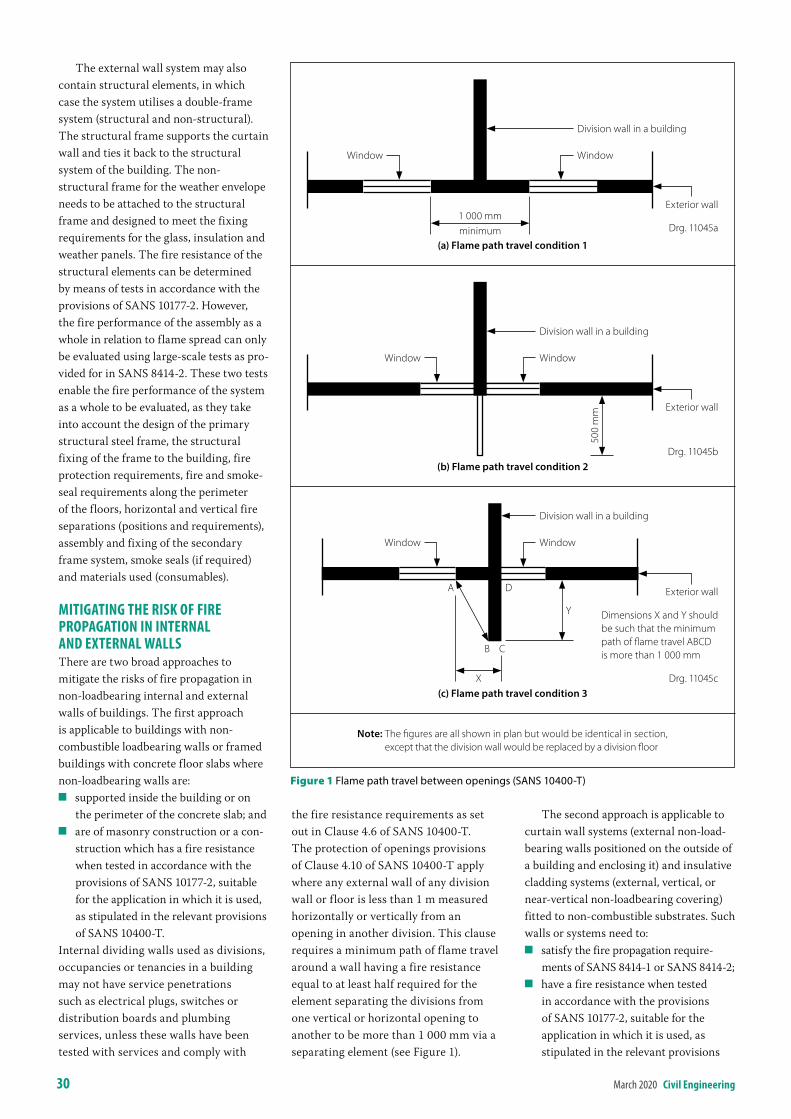
30 March 2020 civil engineering
The external wall system may also contain structural elements, in which case the system utilises a double-frame system (structural and non-structural). The structural frame supports the curtain wall and ties it back to the structural system of the building. The non-structural frame for the weather envelope needs to be attached to the structural frame and designed to meet the fixing requirements for the glass, insulation and weather panels. The fire resistance of the structural elements can be determined by means of tests in accordance with the provisions of SANS 10177-2. However, the fire performance of the assembly as a whole in relation to flame spread can only be evaluated using large-scale tests as pro-vided for in SANS 8414-2. These two tests enable the fire performance of the system as a whole to be evaluated, as they take into account the design of the primary structural steel frame, the structural fixing of the frame to the building, fire protection requirements, fire and smoke-seal requirements along the perimeter of the floors, horizontal and vertical fire separations (positions and requirements), assembly and fixing of the secondary frame system, smoke seals (if required) and materials used (consumables).
mitiGatinG the risK oF Fire ProPaGation in internal anD eXternal WallsThere are two broad approaches to mitigate the risks of fire propagation in non-loadbearing internal and external walls of buildings. The first approach is applicable to buildings with non-combustible loadbearing walls or framed buildings with concrete floor slabs where non-loadbearing walls are:
Q supported inside the building or on the perimeter of the concrete slab; and
Q are of masonry construction or a con-struction which has a fire resistance when tested in accordance with the provisions of SANS 10177-2, suitable for the application in which it is used, as stipulated in the relevant provisions of SANS 10400-T.
Internal dividing walls used as divisions, occupancies or tenancies in a building may not have service penetrations such as electrical plugs, switches or distribution boards and plumbing services, unless these walls have been tested with services and comply with
the fire resistance requirements as set out in Clause 4.6 of SANS 10400-T. The protection of openings provisions of Clause 4.10 of SANS 10400-T apply where any external wall of any division wall or floor is less than 1 m measured horizontally or vertically from an opening in another division. This clause requires a minimum path of flame travel around a wall having a fire resistance equal to at least half required for the element separating the divisions from one vertical or horizontal opening to another to be more than 1 000 mm via a separating element (see Figure 1).
The second approach is applicable to curtain wall systems (external non-load-bearing walls positioned on the outside of a building and enclosing it) and insulative cladding systems (external, vertical, or near-vertical non-loadbearing covering) fitted to non-combustible substrates. Such walls or systems need to:
Q satisfy the fire propagation require-ments of SANS 8414-1 or SANS 8414-2;
Q have a fire resistance when tested in accordance with the provisions of SANS 10177-2, suitable for the application in which it is used, as stipulated in the relevant provisions
Division wall in a building
WindowWindow
Exterior wall
Y
CB
A
X
Dimensions X and Y should be such that the minimum path of flame travel ABCD is more than 1 000 mm
D
(c) Flame path travel condition 3Drg. 11045c
Exterior wall
Division wall in a building
WindowWindow
500
mm
Drg. 11045b(b) Flame path travel condition 2
Division wall in a building
Exterior wall
WindowWindow
1 000 mmminimum Drg. 11045a
(a) Flame path travel condition 1
Figure 1 Flame path travel between openings (SANS 10400‑T)
Note: The figures are all shown in plan but would be identical in section, except that the division wall would be replaced by a division floor
civil engineering March 2020 31
of SANS 10400-T, provided that the fire resistance of the structural frame supporting the curtain wall including its fixings has a fire resistance not less than that required for the structural system of the building.
assemblies FitteD to the outsiDe oF builDinGsExternal building fires very often start within combustible assemblies added to the outside of the building, such as signs, advertising boards, external building fa-çade advertising on buildings, sunshades, canopies and blinds. Such assemblies may be fixed only to non-combustible external walls either at ground-floor level or in the storey immediately above ground level, provided that it is not above an exit or in a position where, in the event of a fire, it would render the exit un-useable.
Any combustible assembly other than those satisfying the aforementioned requirements needs to be suitably tested in the context of the installation or the way it would be applied or fitted to the
building. Testing of such components can vary from small-scale to large-scale testing to evaluate the likely fire behav-iour of the system. Small-scale testing or material classification relates only to the fire properties of the respective material and is not intended to confirm the fitness-for-purpose of the system as a whole.
The structural fixing and the fire behaviour of the respective applications need to be such that no collapse of the system or any flaming debris should fall down to ground level and endanger pedestrians or occupants evacuating the building.
reFerencesAustralian Building Codes Board. Advisory
note: Fire performance of external walls and cladding. 1 February 2019. www.abcb.gov.au/Resources/Publications/Education-Training/Fire-performance-of-external-walls-and-cladding.
ISO 6707-1:2017 Buildings and civil engineering works — Vocabulary — Part 1: General terms. International Organisation for
Standardisation. South African Bureau of Standards.
SANS 8414-1: 2017. Fire performance of external cladding systems–Test method for non-loadbearing external cladding systems applied to the masonry face of a building. South African Bureau of Standards.
SANS 8414-2: 2017. Fire performance of external cladding systems Part 2: Test method for non-loadbearing external cladding systems fixed to and supported by a structural steel frame. South African Bureau of Standards.
SANS 10400-T: 2011. The application of the National Building Regulations: Part T Fire Protection. South African Bureau of Standards.
SANS 10177-2: 2005. Fire testing of materials, components and elements used in buildings Part 2: Fire resistance test for building elements. South African Bureau of Standards.
SANS 10177-5: 2012. Fire testing of materials, components and elements used in buildings Part 5: Non-combustibility at 750°C of building materials. South African Bureau of Standards.
The Contractors of Choice
WE HAVE AN UNRIVALLED
REPUTATION Civil Engineering
Bulk Earthworks
Impact Compaction
Demolitions
www.iconearthworks.co.za 010 591 6828 [email protected]
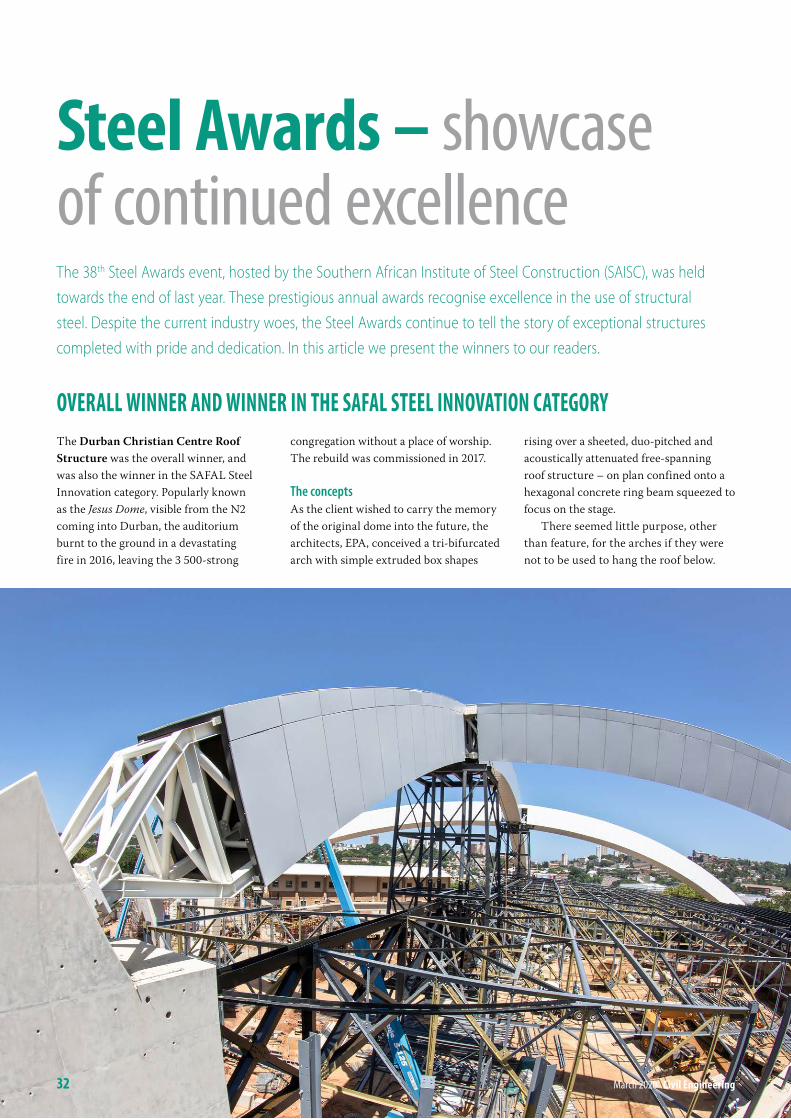
overall Winner anD Winner in the saFal steel innovation cateGorYThe Durban Christian Centre Roof Structure was the overall winner, and was also the winner in the SAFAL Steel Innovation category. Popularly known as the Jesus Dome, visible from the N2 coming into Durban, the auditorium burnt to the ground in a devastating fire in 2016, leaving the 3 500-strong
congregation without a place of worship. The rebuild was commissioned in 2017.
The conceptsAs the client wished to carry the memory of the original dome into the future, the architects, EPA, conceived a tri-bifurcated arch with simple extruded box shapes
rising over a sheeted, duo-pitched and acoustically attenuated free-spanning roof structure – on plan confined onto a hexagonal concrete ring beam squeezed to focus on the stage.
There seemed little purpose, other than feature, for the arches if they were not to be used to hang the roof below.
steel awards – showcase of continued excellenceThe 38th Steel Awards event, hosted by the Southern African Institute of Steel Construction (SAISC), was held towards the end of last year. These prestigious annual awards recognise excellence in the use of structural steel. Despite the current industry woes, the Steel Awards continue to tell the story of exceptional structures completed with pride and dedication. In this article we present the winners to our readers.
32 March 2020 civil engineering
civil engineering March 2020 33
Two possible schemes were therefore followed in parallel – one with no arches (the roof structure truss grillage made deep enough to free span), and a second with the arches used to hang the primary apex girder, thereby economising on the truss grillage. This gave cost compari-sons to the client in respect of spend to achieve the arches over a more conven-tional structure.
Taking it to the groundSteel arches need support points, which for this structure were some 15 m off the ground. Off-shutter concrete prisms seemed to fulfil the need in every way. The primary arch buttresses needed to be slimmed to allow access on a restricted footprint, so this arch was tied – the primary girder running under the primary arch forms the arch tie, interconnected in a bold move through large welded steel elbows set into the 2.5 m wide reinforced concrete but-tresses. The secondary arch buttresses were free to sweep to the ground along the steel arch thrust lines.
For the balance of the roof structure, a concrete ring beam sits atop 7 m high concrete columns, tied into the double-storey structures at the front and back of the building.
Making the geometry workThe arches are, as a trio, wedged from a single sphere, with the origin deep below the floor slab. Each arch is the rind of a perfect slim slice through the origin of the sphere and as such, in radial section, is very slightly trapezoidal – this variation was so small that the shape could easily be rationalised to rectangular, allowing the designers and fabricators to select UC sections radiused about the major axis. The Hulabond cladding box adopted the final trapezoidal form. Round tubes were used for the lacing, in combination with web plates.
With the concept realised, the struc-tural design team got to work developing a parametric algorithm in the visual programming environment of Dynamo, which works seamlessly with Revit. This was then used to solve the geometry of
all the arches by iterating through the parameters of the sphere, and the arch truss centre lines imported into the global OASYS analyses and REVIT models, and ultimately into TEKLA.
Getting the design doneThe internal truss grillage is a simple 6×6 grid, allowing the designers some latitude for spot loads at the intersections and providing a sensible patchwork for the arrangement of acoustic lining, services reticulation and suspended acoustic blades above the auditorium which seats 3 500 worshippers.
Simple IPE purlins set up a bottom flange shelf frame for the acoustic lining and a platform for the Klip-Tite sheeting system. A clamped bracket was devised for all the in-roof services so that post-erection drilling or screwing could be prohibited globally.
A series of global analysis models were set up, augmented by a suite of simpler two-dimensional model checks. The primary software used was the OASYS GSA Building Suite program allowing the
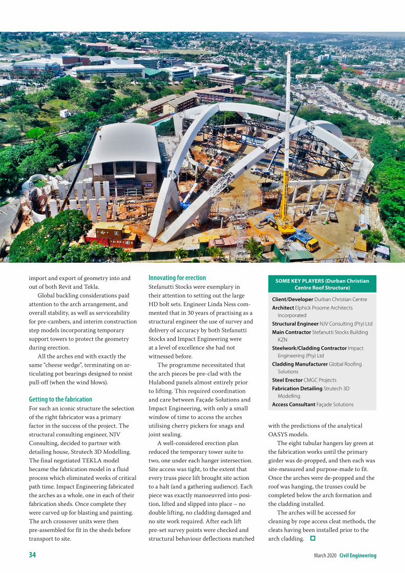
34 March 2020 civil engineering
import and export of geometry into and out of both Revit and Tekla.
Global buckling considerations paid attention to the arch arrangement, and overall stability, as well as serviceability for pre-cambers, and interim construction step models incorporating temporary support towers to protect the geometry during erection.
All the arches end with exactly the same “cheese wedge”, terminating on ar-ticulating pot bearings designed to resist pull-off (when the wind blows).
Getting to the fabricationFor such an iconic structure the selection of the right fabricator was a primary factor in the success of the project. The structural consulting engineer, NJV Consulting, decided to partner with detailing house, Strutech 3D Modelling. The final negotiated TEKLA model became the fabrication model in a fluid process which eliminated weeks of critical path time. Impact Engineering fabricated the arches as a whole, one in each of their fabrication sheds. Once complete they were carved up for blasting and painting. The arch crossover units were then pre-assembled for fit in the sheds before transport to site.
Innovating for erectionStefanutti Stocks were exemplary in their attention to setting out the large HD bolt sets. Engineer Linda Ness com-mented that in 30 years of practising as a structural engineer the use of survey and delivery of accuracy by both Stefanutti Stocks and Impact Engineering were at a level of excellence she had not witnessed before.
The programme necessitated that the arch pieces be pre-clad with the Hulabond panels almost entirely prior to lifting. This required coordination and care between Façade Solutions and Impact Engineering, with only a small window of time to access the arches utilising cherry pickers for snags and joint sealing.
A well-considered erection plan reduced the temporary tower suite to two, one under each hanger intersection. Site access was tight, to the extent that every truss piece lift brought site action to a halt (and a gathering audience). Each piece was exactly manoeuvred into posi-tion, lifted and slipped into place – no double lifting, no cladding damaged and no site work required. After each lift pre-set survey points were checked and structural behaviour deflections matched
with the predictions of the analytical OASYS models.
The eight tubular hangers lay green at the fabrication works until the primary girder was de-propped, and then each was site-measured and purpose-made to fit. Once the arches were de-propped and the roof was hanging, the trusses could be completed below the arch formation and the cladding installed.
The arches will be accessed for cleaning by rope access cleat methods, the cleats having been installed prior to the arch cladding.
sOMe Key PlAyers (durban Christian Centre roof structure)
Client/Developer Durban Christian Centre
Architect Elphick Proome Architects Incorporated
Structural Engineer NJV Consulting (Pty) Ltd
Main Contractor Stefanutti Stocks Building KZN
Steelwork/Cladding Contractor Impact Engineering (Pty) Ltd
Cladding Manufacturer Global Roofing Solutions
Steel Erector CMGC Projects
Fabrication Detailing Strutech 3D Modelling
Access Consultant Façade Solutions
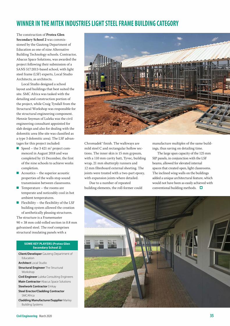
civil engineering March 2020 35
Winner in the miteK inDustries liGht steel Frame builDinG cateGorYThe construction of Protea Glen Secondary School 2 was commis-sioned by the Gauteng Department of Education as one of nine Alternative Building Technology schools. Contractor, Abacus Space Solutions, was awarded the project following their submission of a SANS 517:2013-based school, with light steel frame (LSF) experts, Local Studio Architects, as architects.
Local Studio designed a school layout and buildings that best suited the site. SMC Africa was tasked with the detailing and construction portion of the project, while Craig Tyndall from the Structural Workshop was responsible for the structural engineering component. Hennie Snyman of Luleka was the civil engineering consultant appointed for slab design and also for dealing with the dolomitic area (the site was classified as a type 3 dolomitic area). The LSF advan-tages for this project included:
Q Speed – the 3 421 m2 project com-menced in August 2018 and was completed by 15 December, the first of the nine schools to achieve works completion.
Q Acoustics – the superior acoustic properties of the walls stop sound transmission between classrooms.
Q Temperature – the rooms are temperate and noticeably cool in hot ambient temperatures.
Q Flexibility – the flexibility of the LSF building system allowed the creation of aesthetically pleasing structures.
The structure is a Framemaster 90 × 38 mm cold-rolled section in 0.8 mm galvanised steel. The roof comprises structural insulating panels with a
Chromadek® finish. The walkways are mild steel C and rectangular hollow sec-tions. The inner skin is 15 mm gypsum, with a 110 mm cavity batt, Tyvec, building wrap, 21 mm shutterply runners and 12 mm fibreboard external sheeting. The joints were treated with a two-part epoxy, with expansion joints where detailed.
Due to a number of repeated building elements, the roll-former could
manufacture multiples of the same build-ings, thus saving on detailing time.
The large span capacity of the 125 mm SIP panels, in conjunction with the LSF beams, allowed for elevated internal spaces that created open, light classrooms. The inclined wing walls on the buildings added a unique architectural feature, which would not have been as easily achieved with conventional building methods.
sOMe Key PlAyers (Protea glen secondary school 2)
Client/Developer Gauteng Department of Education
Architect Local Studio
Structural Engineer The Structural Workshop
Civil Engineer Luleka Consulting Engineers
Main Contractor Abacus Space Solutions
Steelwork Contractor Emkay
Steel Erector/Cladding Contractor SMCAfrica
Cladding Manufacturer/Supplier Marley Building Systems
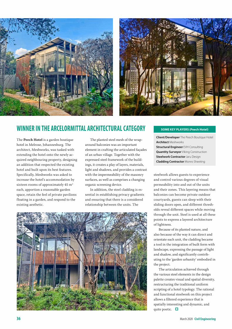
36 March 2020 civil engineering
Winner in the arcelormittal architectural cateGorYThe Peech Hotel is a garden boutique hotel in Melrose, Johannesburg. The architect, Meshworks, was tasked with extending the hotel onto the newly ac-quired neighbouring property, designing an addition that respected the existing hotel and built upon its best features. Specifically, Meshworks was asked to increase the hotel’s accommodation by sixteen rooms of approximately 45 m2 each, apportion a reasonable garden space, retain the feel of private pavilions floating in a garden, and respond to the existing aesthetic.
The planted steel mesh of the wrap-around balconies was an important element in crafting the articulated façades of an urban village. Together with the expressed steel framework of the build-ings, it creates a play of layers, materials, light and shadows, and provides a contrast with the impermeability of the masonry surfaces, as well as comprises a changing organic screening device.
In addition, the steel cladding is es-sential in establishing privacy gradients and ensuring that there is a considered relationship between the units. The
steelwork allows guests to experience and control various degrees of visual permeability into and out of the units and their zones. This layering means that balconies can become private outdoor courtyards, guests can sleep with their sliding doors open, and different thresh-olds reveal different spaces while moving through the unit. Steel is used at all these points to express a layered architecture of lightness.
Because of its planted nature, and also because of the way it can direct and orientate each unit, the cladding became a tool in the integration of built form with landscape, expressing the passage of light and shadow, and significantly contrib-uting to the ‘garden urbanity’ embodied in the project.
The articulation achieved through the various steel elements in the design palette creates visual and spatial diversity, restructuring the traditional uniform scripting of a hotel typology. The rational and functional steelwork on this project allows a filtered experience that is spatially interesting and dynamic, and quite poetic.
sOMe Key PlAyers (Peech hotel)
Client/Developer The Peech Boutique Hotel
Architect Meshworks
Structural Engineer EVH Consulting
Quantity Surveyor Viking Construction
Steelwork Contractor Jaru Design
Cladding Contractor Monro Sheeting
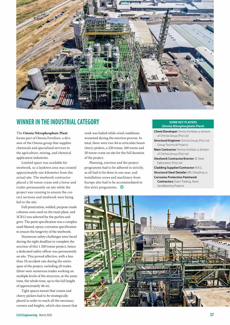
civil engineering March 2020 37
Winner in the inDustrial cateGorYThe Omnia Nitrophosphate Plant forms part of Omnia Fertilizer, a divi-sion of the Omnia group that supplies chemicals and specialised services to the agriculture, mining, and chemical application industries.
Limited space was available for steelwork, so a laydown area was created approximately one kilometre from the actual site. The steelwork contractor placed a 20-tonne crane and a horse and trailer permanently on site while the project was running to ensure the cor-rect sections and steelwork were being fed to the site.
Full-penetration, welded, purpose-made columns were used on the main plant, and 3CR12 was selected for the purlins and girts. The paint specification was a complex sand-blasted, epoxy-corrosion specification to ensure the longevity of the steelwork.
Numerous safety challenges were faced during the tight deadline to complete the erection of this 1 200 tonne project, hence a dedicated safety officer was permanently on site. This proved effective, with a less than 1% accident rate during the entire span of the project, including all trades (there were numerous trades working on multiple levels of the structure, at the same time, the whole time, up to the full height of approximately 46 m).
Tight spaces meant that cranes and cherry pickers had to be strategically placed in order to reach all the necessary corners and heights, which also meant that
work was halted while wind conditions worsened during the erection process. In total, there were two 44 m articulate boom cherry pickers, a 220 tonne, 160 tonne and 50 tonne crane on site for the full duration of the project.
Planning, erection and the project programme had to be adhered to strictly, as all had to be done in one year, and installation crews and machinery from Europe also had to be accommodated in this strict programme.
sOMe Key PlAyers (Omnia nitrophosphate Plant)
Client/Developer Omnia Fertilizer, a division of Omnia Group (Pty) Ltd
Structural Engineer Omnia Group (Pty) Ltd: Group Technical Projects
Main Contractor Omnia Fertilizer, a division of Omnia Group (Pty) Ltd
Steelwork Contractor/Erector SE Steel Fabrication (Pty) Ltd
Cladding Supplier/Contractor M.R.G.
Structural Steel Detailer KRU Detailing cc
Corrosion Protection Paintwork Contractors Dram Trading, Rand Sandblasting Projects
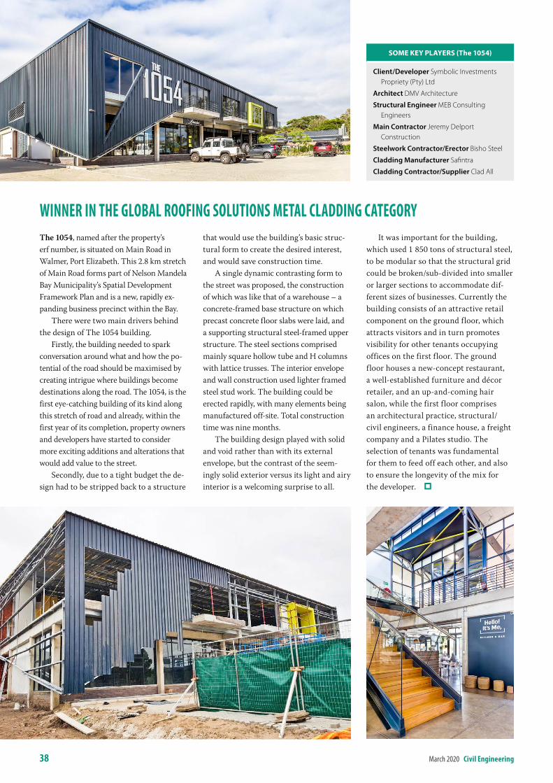
38 March 2020 civil engineering
Winner in the Global rooFinG solutions metal claDDinG cateGorYThe 1054, named after the property’s erf number, is situated on Main Road in Walmer, Port Elizabeth. This 2.8 km stretch of Main Road forms part of Nelson Mandela Bay Municipality’s Spatial Development Framework Plan and is a new, rapidly ex-panding business precinct within the Bay.
There were two main drivers behind the design of The 1054 building.
Firstly, the building needed to spark conversation around what and how the po-tential of the road should be maximised by creating intrigue where buildings become destinations along the road. The 1054, is the first eye-catching building of its kind along this stretch of road and already, within the first year of its completion, property owners and developers have started to consider more exciting additions and alterations that would add value to the street.
Secondly, due to a tight budget the de-sign had to be stripped back to a structure
that would use the building’s basic struc-tural form to create the desired interest, and would save construction time.
A single dynamic contrasting form to the street was proposed, the construction of which was like that of a warehouse – a concrete-framed base structure on which precast concrete floor slabs were laid, and a supporting structural steel-framed upper structure. The steel sections comprised mainly square hollow tube and H columns with lattice trusses. The interior envelope and wall construction used lighter framed steel stud work. The building could be erected rapidly, with many elements being manufactured off-site. Total construction time was nine months.
The building design played with solid and void rather than with its external envelope, but the contrast of the seem-ingly solid exterior versus its light and airy interior is a welcoming surprise to all.
It was important for the building, which used 1 850 tons of structural steel, to be modular so that the structural grid could be broken/sub-divided into smaller or larger sections to accommodate dif-ferent sizes of businesses. Currently the building consists of an attractive retail component on the ground floor, which attracts visitors and in turn promotes visibility for other tenants occupying offices on the first floor. The ground floor houses a new-concept restaurant, a well-established furniture and décor retailer, and an up-and-coming hair salon, while the first floor comprises an architectural practice, structural/civil engineers, a finance house, a freight company and a Pilates studio. The selection of tenants was fundamental for them to feed off each other, and also to ensure the longevity of the mix for the developer.
sOMe Key PlAyers (the 1054)
Client/Developer Symbolic Investments Propriety (Pty) Ltd
Architect DMV Architecture
Structural Engineer MEB Consulting Engineers
Main Contractor Jeremy Delport Construction
Steelwork Contractor/Erector Bisho Steel
Cladding Manufacturer Safintra
Cladding Contractor/Supplier Clad All
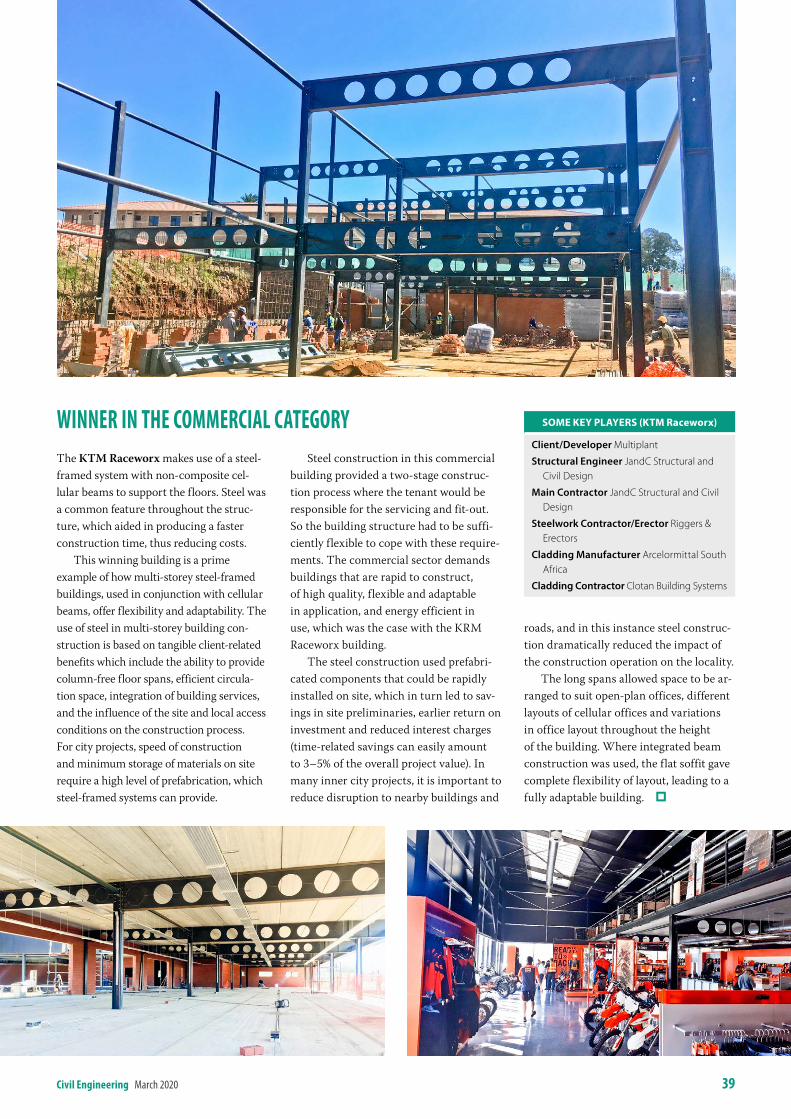
civil engineering March 2020 39
Winner in the commercial cateGorYThe KTM Raceworx makes use of a steel-framed system with non-composite cel-lular beams to support the floors. Steel was a common feature throughout the struc-ture, which aided in producing a faster construction time, thus reducing costs.
This winning building is a prime example of how multi-storey steel-framed buildings, used in conjunction with cellular beams, offer flexibility and adaptability. The use of steel in multi-storey building con-struction is based on tangible client-related benefits which include the ability to provide column-free floor spans, efficient circula-tion space, integration of building services, and the influence of the site and local access conditions on the construction process. For city projects, speed of construction and minimum storage of materials on site require a high level of prefabrication, which steel-framed systems can provide.
Steel construction in this commercial building provided a two-stage construc-tion process where the tenant would be responsible for the servicing and fit-out. So the building structure had to be suffi-ciently flexible to cope with these require-ments. The commercial sector demands buildings that are rapid to construct, of high quality, flexible and adaptable in application, and energy efficient in use, which was the case with the KRM Raceworx building.
The steel construction used prefabri-cated components that could be rapidly installed on site, which in turn led to sav-ings in site preliminaries, earlier return on investment and reduced interest charges (time-related savings can easily amount to 3–5% of the overall project value). In many inner city projects, it is important to reduce disruption to nearby buildings and
roads, and in this instance steel construc-tion dramatically reduced the impact of the construction operation on the locality.
The long spans allowed space to be ar-ranged to suit open-plan offices, different layouts of cellular offices and variations in office layout throughout the height of the building. Where integrated beam construction was used, the flat soffit gave complete flexibility of layout, leading to a fully adaptable building.
sOMe Key PlAyers (KtM raceworx)
Client/Developer Multiplant
Structural Engineer JandC Structural and Civil Design
Main Contractor JandC Structural and Civil Design
Steelwork Contractor/Erector Riggers & Erectors
Cladding Manufacturer Arcelormittal South Africa
Cladding Contractor Clotan Building Systems
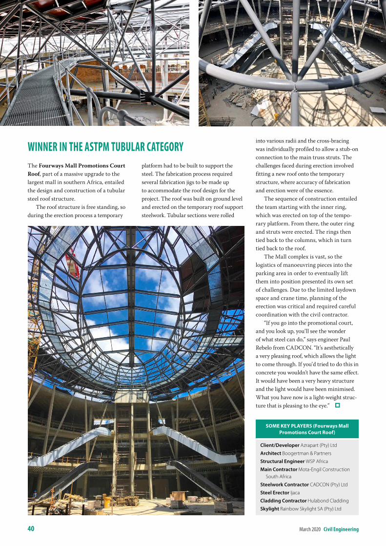
Winner in the astPm tubular cateGorYThe Fourways Mall Promotions Court Roof, part of a massive upgrade to the largest mall in southern Africa, entailed the design and construction of a tubular steel roof structure.
The roof structure is free standing, so during the erection process a temporary
platform had to be built to support the steel. The fabrication process required several fabrication jigs to be made up to accommodate the roof design for the project. The roof was built on ground level and erected on the temporary roof support steelwork. Tubular sections were rolled
into various radii and the cross-bracing was individually profiled to allow a stub-on connection to the main truss struts. The challenges faced during erection involved fitting a new roof onto the temporary structure, where accuracy of fabrication and erection were of the essence.
The sequence of construction entailed the team starting with the inner ring, which was erected on top of the tempo-rary platform. From there, the outer ring and struts were erected. The rings then tied back to the columns, which in turn tied back to the roof.
The Mall complex is vast, so the logistics of manoeuvring pieces into the parking area in order to eventually lift them into position presented its own set of challenges. Due to the limited laydown space and crane time, planning of the erection was critical and required careful coordination with the civil contractor.
“If you go into the promotional court, and you look up, you’ll see the wonder of what steel can do,” says engineer Paul Rebelo from CADCON. “It’s aesthetically a very pleasing roof, which allows the light to come through. If you’d tried to do this in concrete you wouldn’t have the same effect. It would have been a very heavy structure and the light would have been minimised. What you have now is a light-weight struc-ture that is pleasing to the eye.”
sOMe Key PlAyers (Fourways Mall Promotions Court roof)
Client/Developer Azrapart (Pty) Ltd
Architect Boogertman & Partners
Structural Engineer WSP Africa
Main Contractor Mota-Engil Construction South Africa
Steelwork Contractor CADCON (Pty) Ltd
Steel Erector Ijaca
Cladding Contractor Hulabond Cladding
Skylight Rainbow Skylight SA (Pty) Ltd
40 March 2020 civil engineering
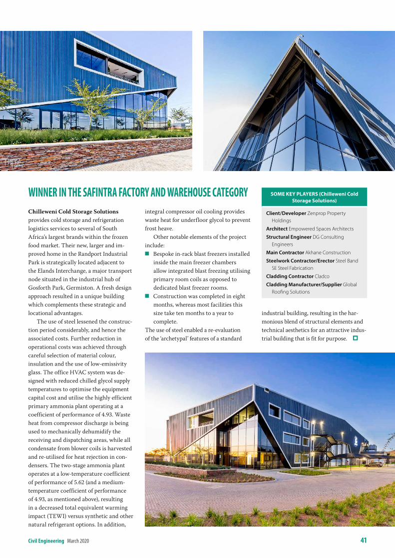
civil engineering March 2020 41
Winner in the saFintra FactorY anD Warehouse cateGorYChilleweni Cold Storage Solutions provides cold storage and refrigeration logistics services to several of South Africa’s largest brands within the frozen food market. Their new, larger and im-proved home in the Randport Industrial Park is strategically located adjacent to the Elands Interchange, a major transport node situated in the industrial hub of Gosforth Park, Germiston. A fresh design approach resulted in a unique building which complements these strategic and locational advantages.
The use of steel lessened the construc-tion period considerably, and hence the associated costs. Further reduction in operational costs was achieved through careful selection of material colour, insulation and the use of low-emissivity glass. The office HVAC system was de-signed with reduced chilled glycol supply temperatures to optimise the equipment capital cost and utilise the highly efficient primary ammonia plant operating at a coefficient of performance of 4.93. Waste heat from compressor discharge is being used to mechanically dehumidify the receiving and dispatching areas, while all condensate from blower coils is harvested and re-utilised for heat rejection in con-densers. The two-stage ammonia plant operates at a low-temperature coefficient of performance of 5.62 (and a medium-temperature coefficient of performance of 4.93, as mentioned above), resulting in a decreased total equivalent warming impact (TEWI) versus synthetic and other natural refrigerant options. In addition,
integral compressor oil cooling provides waste heat for underfloor glycol to prevent frost heave.
Other notable elements of the project include:
Q Bespoke in-rack blast freezers installed inside the main freezer chambers allow integrated blast freezing utilising primary room coils as opposed to dedicated blast freezer rooms.
Q Construction was completed in eight months, whereas most facilities this size take ten months to a year to complete.
The use of steel enabled a re-evaluation of the ‘archetypal’ features of a standard
industrial building, resulting in the har-monious blend of structural elements and technical aesthetics for an attractive indus-trial building that is fit for purpose.
sOMe Key PlAyers (Chilleweni Cold storage solutions)
Client/Developer Zenprop Property Holdings
Architect Empowered Spaces Architects
Structural Engineer DG Consulting Engineers
Main Contractor Akhane Construction
Steelwork Contractor/Erector Steel Band SE Steel Fabrication
Cladding Contractor Cladco
Cladding Manufacturer/Supplier Global Roofing Solutions
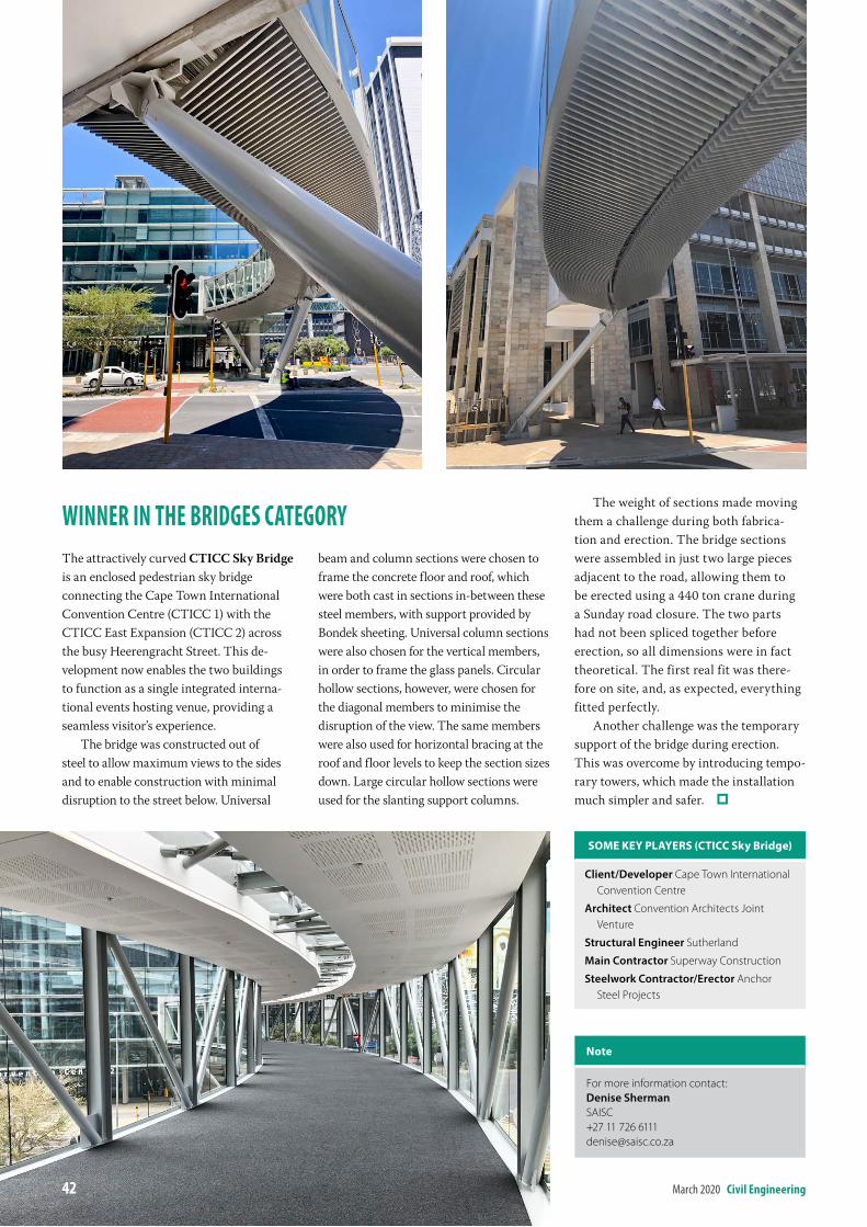
Winner in the briDGes cateGorYThe attractively curved CTICC Sky Bridge is an enclosed pedestrian sky bridge connecting the Cape Town International Convention Centre (CTICC 1) with the CTICC East Expansion (CTICC 2) across the busy Heerengracht Street. This de-velopment now enables the two buildings to function as a single integrated interna-tional events hosting venue, providing a seamless visitor’s experience.
The bridge was constructed out of steel to allow maximum views to the sides and to enable construction with minimal disruption to the street below. Universal
beam and column sections were chosen to frame the concrete floor and roof, which were both cast in sections in-between these steel members, with support provided by Bondek sheeting. Universal column sections were also chosen for the vertical members, in order to frame the glass panels. Circular hollow sections, however, were chosen for the diagonal members to minimise the disruption of the view. The same members were also used for horizontal bracing at the roof and floor levels to keep the section sizes down. Large circular hollow sections were used for the slanting support columns.
The weight of sections made moving them a challenge during both fabrica-tion and erection. The bridge sections were assembled in just two large pieces adjacent to the road, allowing them to be erected using a 440 ton crane during a Sunday road closure. The two parts had not been spliced together before erection, so all dimensions were in fact theoretical. The first real fit was there-fore on site, and, as expected, everything fitted perfectly.
Another challenge was the temporary support of the bridge during erection. This was overcome by introducing tempo-rary towers, which made the installation much simpler and safer.
note
For more information contact:Denise ShermanSAISC+27 11 726 [email protected]
sOMe Key PlAyers (CtiCC sky bridge)
Client/Developer Cape Town International Convention Centre
Architect Convention Architects Joint Venture
Structural Engineer Sutherland
Main Contractor Superway Construction
Steelwork Contractor/Erector Anchor Steel Projects
42 March 2020 civil engineering
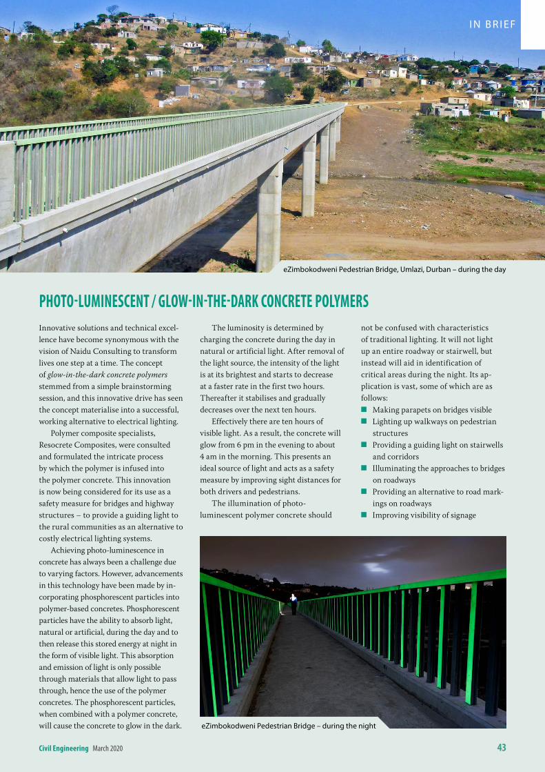
civil engineering March 2020 43
Photo-luminescent / GloW-in-the-DarK concrete PolYmersInnovative solutions and technical excel-lence have become synonymous with the vision of Naidu Consulting to transform lives one step at a time. The concept of glow-in-the-dark concrete polymers stemmed from a simple brainstorming session, and this innovative drive has seen the concept materialise into a successful, working alternative to electrical lighting.
Polymer composite specialists, Resocrete Composites, were consulted and formulated the intricate process by which the polymer is infused into the polymer concrete. This innovation is now being considered for its use as a safety measure for bridges and highway structures – to provide a guiding light to the rural communities as an alternative to costly electrical lighting systems.
Achieving photo-luminescence in concrete has always been a challenge due to varying factors. However, advancements in this technology have been made by in-corporating phosphorescent particles into polymer-based concretes. Phosphorescent particles have the ability to absorb light, natural or artificial, during the day and to then release this stored energy at night in the form of visible light. This absorption and emission of light is only possible through materials that allow light to pass through, hence the use of the polymer concretes. The phosphorescent particles, when combined with a polymer concrete, will cause the concrete to glow in the dark.
The luminosity is determined by charging the concrete during the day in natural or artificial light. After removal of the light source, the intensity of the light is at its brightest and starts to decrease at a faster rate in the first two hours. Thereafter it stabilises and gradually decreases over the next ten hours.
Effectively there are ten hours of visible light. As a result, the concrete will glow from 6 pm in the evening to about 4 am in the morning. This presents an ideal source of light and acts as a safety measure by improving sight distances for both drivers and pedestrians.
The illumination of photo-luminescent polymer concrete should
not be confused with characteristics of traditional lighting. It will not light up an entire roadway or stairwell, but instead will aid in identification of critical areas during the night. Its ap-plication is vast, some of which are as follows:
Q Making parapets on bridges visible Q Lighting up walkways on pedestrian
structures Q Providing a guiding light on stairwells
and corridors Q Illuminating the approaches to bridges
on roadways Q Providing an alternative to road mark-
ings on roadways Q Improving visibility of signage
eZimbokodweni Pedestrian Bridge, Umlazi, Durban – during the day
eZimbokodweni Pedestrian Bridge – during the night
I N B R I EF
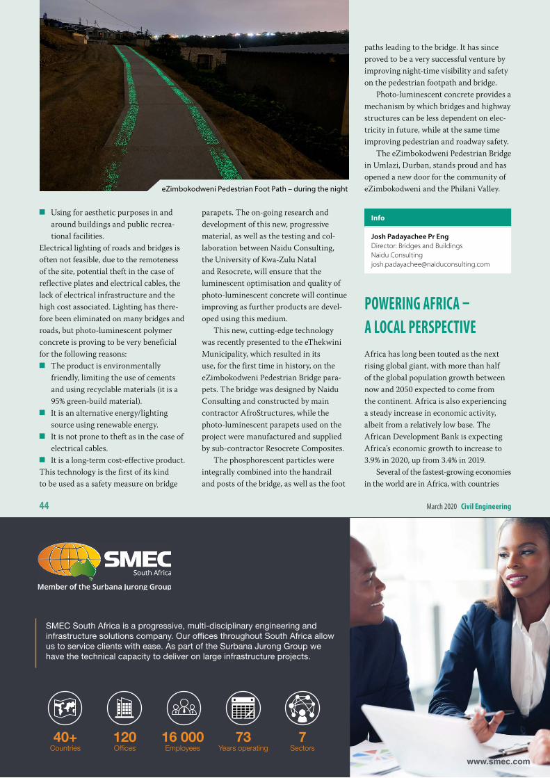
44 March 2020 civil engineering
Q Using for aesthetic purposes in and around buildings and public recrea-tional facilities.
Electrical lighting of roads and bridges is often not feasible, due to the remoteness of the site, potential theft in the case of reflective plates and electrical cables, the lack of electrical infrastructure and the high cost associated. Lighting has there-fore been eliminated on many bridges and roads, but photo-luminescent polymer concrete is proving to be very beneficial for the following reasons:
Q The product is environmentally friendly, limiting the use of cements and using recyclable materials (it is a 95% green-build material).
Q It is an alternative energy/lighting source using renewable energy.
Q It is not prone to theft as in the case of electrical cables.
Q It is a long-term cost-effective product.This technology is the first of its kind to be used as a safety measure on bridge
parapets. The on-going research and development of this new, progressive material, as well as the testing and col-laboration between Naidu Consulting, the University of Kwa-Zulu Natal and Resocrete, will ensure that the luminescent optimisation and quality of photo-luminescent concrete will continue improving as further products are devel-oped using this medium.
This new, cutting-edge technology was recently presented to the eThekwini Municipality, which resulted in its use, for the first time in history, on the eZimbokodweni Pedestrian Bridge para-pets. The bridge was designed by Naidu Consulting and constructed by main contractor AfroStructures, while the photo-luminescent parapets used on the project were manufactured and supplied by sub-contractor Resocrete Composites.
The phosphorescent particles were integrally combined into the handrail and posts of the bridge, as well as the foot
paths leading to the bridge. It has since proved to be a very successful venture by improving night-time visibility and safety on the pedestrian footpath and bridge.
Photo-luminescent concrete provides a mechanism by which bridges and highway structures can be less dependent on elec-tricity in future, while at the same time improving pedestrian and roadway safety.
The eZimbokodweni Pedestrian Bridge in Umlazi, Durban, stands proud and has opened a new door for the community of eZimbokodweni and the Philani Valley.
info
Josh Padayachee Pr EngDirector: Bridges and BuildingsNaidu [email protected]
PoWerinG aFrica – a local PersPectiveAfrica has long been touted as the next rising global giant, with more than half of the global population growth between now and 2050 expected to come from the continent. Africa is also experiencing a steady increase in economic activity, albeit from a relatively low base. The African Development Bank is expecting Africa’s economic growth to increase to 3.9% in 2020, up from 3.4% in 2019.
Several of the fastest-growing economies in the world are in Africa, with countries
eZimbokodweni Pedestrian Foot Path – during the night
South Africa
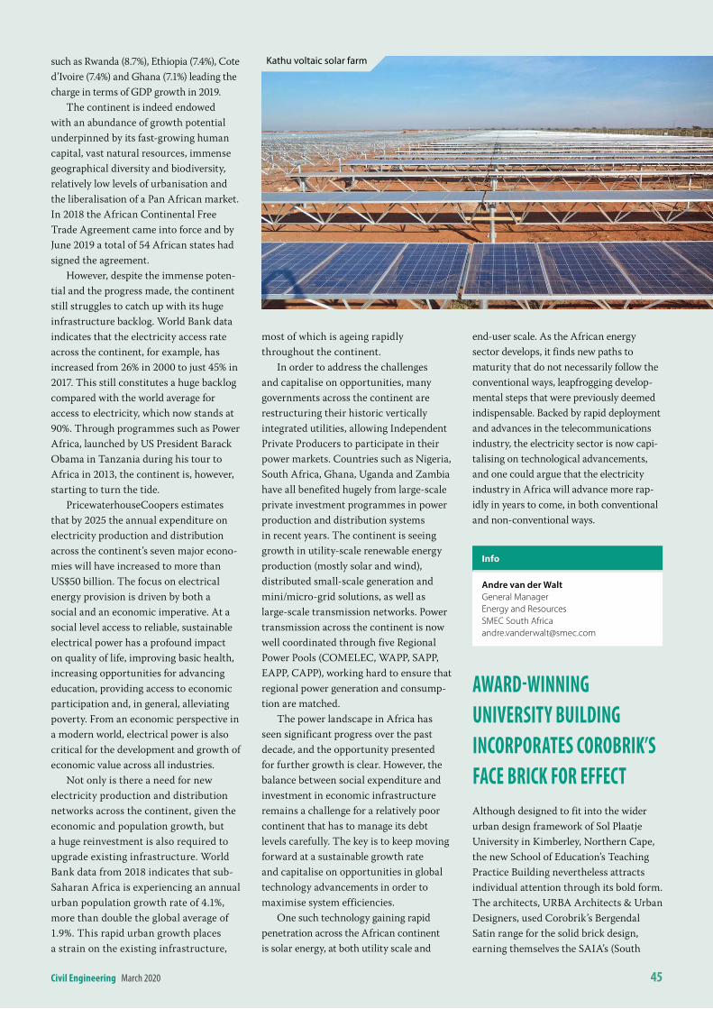
civil engineering March 2020 45
such as Rwanda (8.7%), Ethiopia (7.4%), Cote d’Ivoire (7.4%) and Ghana (7.1%) leading the charge in terms of GDP growth in 2019.
The continent is indeed endowed with an abundance of growth potential underpinned by its fast-growing human capital, vast natural resources, immense geographical diversity and biodiversity, relatively low levels of urbanisation and the liberalisation of a Pan African market. In 2018 the African Continental Free Trade Agreement came into force and by June 2019 a total of 54 African states had signed the agreement.
However, despite the immense poten-tial and the progress made, the continent still struggles to catch up with its huge infrastructure backlog. World Bank data indicates that the electricity access rate across the continent, for example, has increased from 26% in 2000 to just 45% in 2017. This still constitutes a huge backlog compared with the world average for access to electricity, which now stands at 90%. Through programmes such as Power Africa, launched by US President Barack Obama in Tanzania during his tour to Africa in 2013, the continent is, however, starting to turn the tide.
PricewaterhouseCoopers estimates that by 2025 the annual expenditure on electricity production and distribution across the continent’s seven major econo-mies will have increased to more than US$50 billion. The focus on electrical energy provision is driven by both a social and an economic imperative. At a social level access to reliable, sustainable electrical power has a profound impact on quality of life, improving basic health, increasing opportunities for advancing education, providing access to economic participation and, in general, alleviating poverty. From an economic perspective in a modern world, electrical power is also critical for the development and growth of economic value across all industries.
Not only is there a need for new electricity production and distribution networks across the continent, given the economic and population growth, but a huge reinvestment is also required to upgrade existing infrastructure. World Bank data from 2018 indicates that sub-Saharan Africa is experiencing an annual urban population growth rate of 4.1%, more than double the global average of 1.9%. This rapid urban growth places a strain on the existing infrastructure,
most of which is ageing rapidly throughout the continent.
In order to address the challenges and capitalise on opportunities, many governments across the continent are restructuring their historic vertically integrated utilities, allowing Independent Private Producers to participate in their power markets. Countries such as Nigeria, South Africa, Ghana, Uganda and Zambia have all benefited hugely from large-scale private investment programmes in power production and distribution systems in recent years. The continent is seeing growth in utility-scale renewable energy production (mostly solar and wind), distributed small-scale generation and mini/micro-grid solutions, as well as large-scale transmission networks. Power transmission across the continent is now well coordinated through five Regional Power Pools (COMELEC, WAPP, SAPP, EAPP, CAPP), working hard to ensure that regional power generation and consump-tion are matched.
The power landscape in Africa has seen significant progress over the past decade, and the opportunity presented for further growth is clear. However, the balance between social expenditure and investment in economic infrastructure remains a challenge for a relatively poor continent that has to manage its debt levels carefully. The key is to keep moving forward at a sustainable growth rate and capitalise on opportunities in global technology advancements in order to maximise system efficiencies.
One such technology gaining rapid penetration across the African continent is solar energy, at both utility scale and
end-user scale. As the African energy sector develops, it finds new paths to maturity that do not necessarily follow the conventional ways, leapfrogging develop-mental steps that were previously deemed indispensable. Backed by rapid deployment and advances in the telecommunications industry, the electricity sector is now capi-talising on technological advancements, and one could argue that the electricity industry in Africa will advance more rap-idly in years to come, in both conventional and non-conventional ways.
info
Andre van der WaltGeneral ManagerEnergy and ResourcesSMEC South [email protected]
aWarD-WinninG universitY builDinG incorPorates corobriK’s Face bricK For eFFectAlthough designed to fit into the wider urban design framework of Sol Plaatje University in Kimberley, Northern Cape, the new School of Education’s Teaching Practice Building nevertheless attracts individual attention through its bold form. The architects, URBA Architects & Urban Designers, used Corobrik’s Bergendal Satin range for the solid brick design, earning themselves the SAIA’s (South
Kathu voltaic solar farm
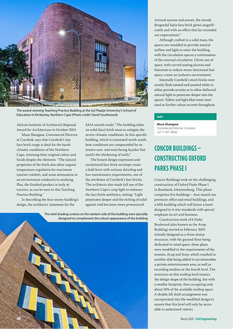
ad
African Institute of Architects) Regional Award for Architecture in October 2019.
Musa Shangase, Commercial Director at Corobrik, says that Corobrik’s clay face brick range is ideal for the harsh climatic conditions of the Northern Cape, retaining their original colour and finish despite the elements. “The natural properties of the brick also allow organic temperature regulation for maximum interior comfort, and noise attenuation in an environment conducive to studying. Plus, the finished product is truly at-tractive, as can be seen in this Teaching Practice Building.”
In describing the four-storey building’s design, the architects’ statement for the
SAIA awards reads: “The building relies on solid (face) brick mass to mitigate the severe climatic conditions. In this specific building, which is orientated north-south, heat conditions are compounded by ex-tensive east- and west-facing façades that justify the thickening of walls.”
The honest design expression and uncluttered face brick envelope create a bold form with unfussy detailing and low-maintenance requirements, one of the attributes of Corobrik’s face bricks. The architects also made full use of the Northern Cape’s crisp light to enhance the face brick aesthetics, stating: “Light penetrates deeper and the etching of solid against void becomes more pronounced.
Around sunrise and sunset, the moody Bergendal Satin face brick glows magnifi-cently and with an effect that far exceeded our expectations.”
Although crafted in a solid mass, the spaces are moulded to provide natural airflow and light to enter the building, with the circulation spaces a continuation of the external circulation. Clever use of space, with carved seating alcoves and balconies to reduce mono-functional lost space, create an inclusive environment.
Internally Corobrik’s stock bricks were mostly flush-jointed and painted white to either provide accents or to allow deflected natural light to penetrate deeper into the spaces. Yellow and light-blue tones were used as further colour accents throughout.
info
Musa ShangaseCommercial Director: Corobrik+27 11 871 8600
concor builDinGs – constructinG oXForD ParKs Phase iConcor Buildings took on the challenging construction of Oxford Parks Phase I in Rosebank, Johannesburg. This phase comprises five buildings – four mixed-use premium office and retail buildings, and a fifth building which will house a hotel designed to 4-star standards with special emphasis on art and business.
Construction work of 6 Parks Boulevard (also known as the Arup Building) started in February 2019. Initially designed as a three-storey structure, with the ground floor being dedicated to retail space, these plans were modified to the requirements of the tenants, Arup and Sony, which resulted in another slab being added to accommodate a private entertainment area, as well as recording studios on the fourth level. The structure on this rooftop level mimics the design shape of the building, but with a smaller footprint, thus occupying only about 50% of the available rooftop space. A double-lift shaft arrangement was incorporated into the modified design to ensure that this level will only be acces-sible to authorised visitors.
The award‑winning Teaching Practice Building at the Sol Plaatje University’s School of Education in Kimberley, Northern Cape (Photo credit: David Southwood)
The steel shading screens on the western side of the building were specially designed to complement the robust appearance of the building
46 March 2020 civil engineering
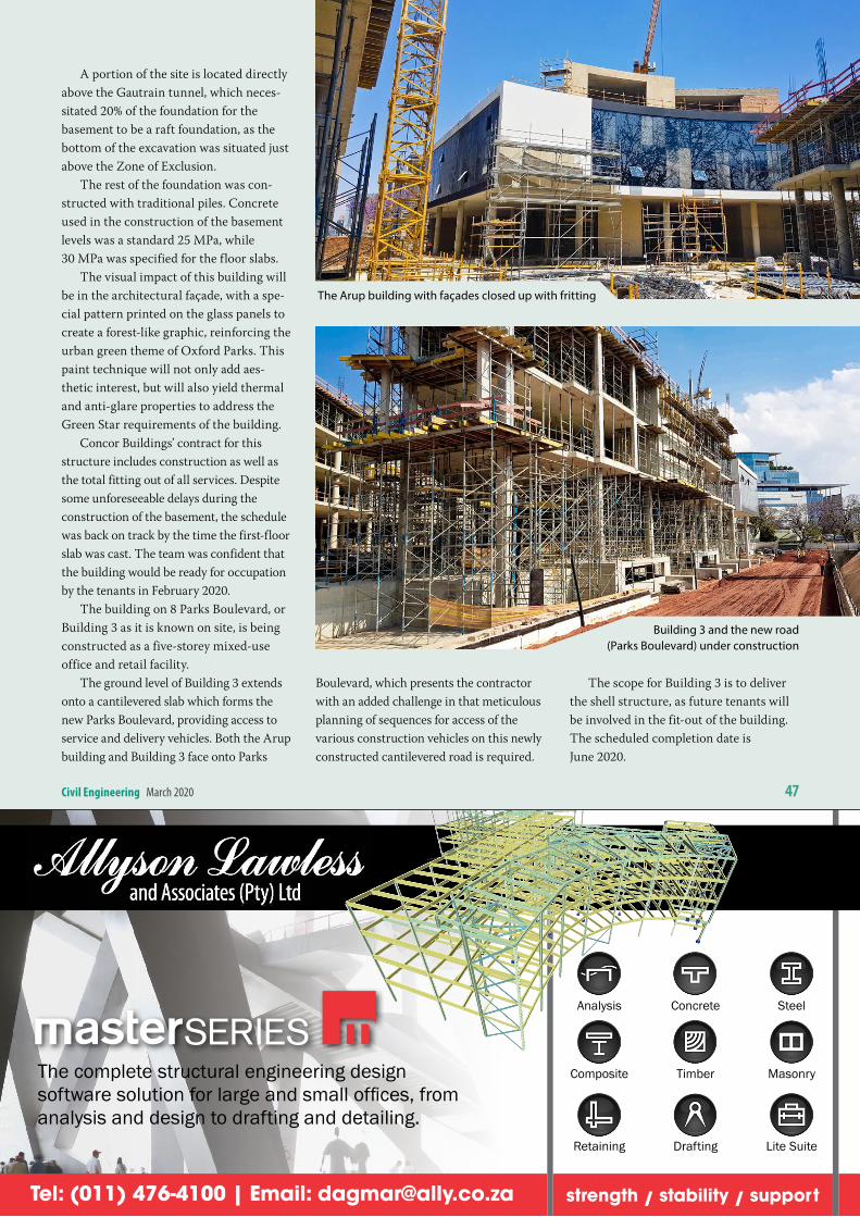
ad
civil engineering March 2020 47
A portion of the site is located directly above the Gautrain tunnel, which neces-sitated 20% of the foundation for the basement to be a raft foundation, as the bottom of the excavation was situated just above the Zone of Exclusion.
The rest of the foundation was con-structed with traditional piles. Concrete used in the construction of the basement levels was a standard 25 MPa, while 30 MPa was specified for the floor slabs.
The visual impact of this building will be in the architectural façade, with a spe-cial pattern printed on the glass panels to create a forest-like graphic, reinforcing the urban green theme of Oxford Parks. This paint technique will not only add aes-thetic interest, but will also yield thermal and anti-glare properties to address the Green Star requirements of the building.
Concor Buildings’ contract for this structure includes construction as well as the total fitting out of all services. Despite some unforeseeable delays during the construction of the basement, the schedule was back on track by the time the first-floor slab was cast. The team was confident that the building would be ready for occupation by the tenants in February 2020.
The building on 8 Parks Boulevard, or Building 3 as it is known on site, is being constructed as a five-storey mixed-use office and retail facility.
The ground level of Building 3 extends onto a cantilevered slab which forms the new Parks Boulevard, providing access to service and delivery vehicles. Both the Arup building and Building 3 face onto Parks
Boulevard, which presents the contractor with an added challenge in that meticulous planning of sequences for access of the various construction vehicles on this newly constructed cantilevered road is required.
The scope for Building 3 is to deliver the shell structure, as future tenants will be involved in the fit-out of the building. The scheduled completion date is June 2020.
The Arup building with façades closed up with fritting
Building 3 and the new road (Parks Boulevard) under construction
Analysis Concrete Steel
Composite Timber Masonry
Retaining Drafting Lite Suite
The complete structural engineering design software solution for large and small offices, from analysis and design to drafting and detailing.
strength / stability / supportTel: (011) 476-4100 | Email: [email protected]
AnalysisConcreteSteel
CompositeTimberMasonry
Retaining DraftingLite Suite
The complete structural engineering design software solution for large and small offices, from analysis and design to drafting and detailing.
strength / stability / support Tel: (011) 476-4100 | Email: [email protected]
AnalysisConcreteSteel
CompositeTimberMasonry
Retaining DraftingLite Suite
The complete structural engineering design software solution for large and small offices, from analysis and design to drafting and detailing.
strength / stability / support Tel: (011) 476-4100 | Email: [email protected]
Analysis Concrete Steel
Composite Timber Masonry
Retaining Drafting Lite Suite
The complete structural engineering design software solution for large and small offices, from analysis and design to drafting and detailing.
strength / stability / supportTel: (011) 476-4100 | Email: [email protected]
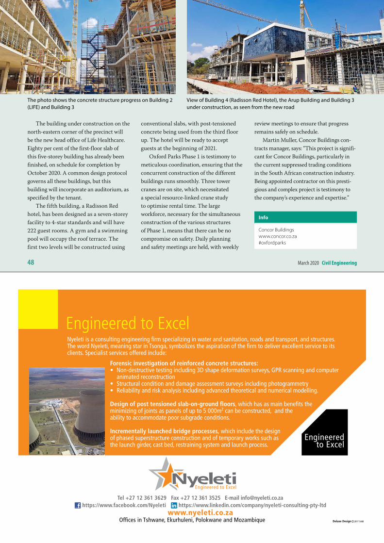
48 March 2020 civil engineering
The building under construction on the north-eastern corner of the precinct will be the new head office of Life Healthcare. Eighty per cent of the first-floor slab of this five-storey building has already been finished, on schedule for completion by October 2020. A common design protocol governs all these buildings, but this building will incorporate an auditorium, as specified by the tenant.
The fifth building, a Radisson Red hotel, has been designed as a seven-storey facility to 4-star standards and will have 222 guest rooms. A gym and a swimming pool will occupy the roof terrace. The first two levels will be constructed using
conventional slabs, with post-tensioned concrete being used from the third floor up. The hotel will be ready to accept guests at the beginning of 2021.
Oxford Parks Phase 1 is testimony to meticulous coordination, ensuring that the concurrent construction of the different buildings runs smoothly. Three tower cranes are on site, which necessitated a special resource-linked crane study to optimise rental time. The large workforce, necessary for the simultaneous construction of the various structures of Phase 1, means that there can be no compromise on safety. Daily planning and safety meetings are held, with weekly
review meetings to ensure that progress remains safely on schedule.
Martin Muller, Concor Buildings con-tracts manager, says: “This project is signifi-cant for Concor Buildings, particularly in the current suppressed trading conditions in the South African construction industry. Being appointed contractor on this presti-gious and complex project is testimony to the company’s experience and expertise.”
info
Concor Buildingswww.concor.co.za#oxfordparks
The photo shows the concrete structure progress on Building 2 (LIFE) and Building 3
View of Building 4 (Radisson Red Hotel), the Arup Building and Building 3 under construction, as seen from the new road
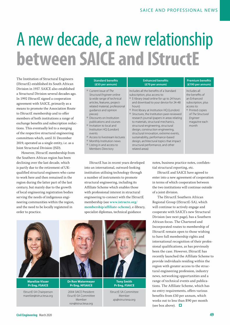
civil engineering March 2020 49
The Institution of Structural Engineers (IStructE) established its South African Division in 1937. SAICE also established a Structural Division several decades ago. In 1992 IStructE signed a cooperation agreement with SAICE, primarily as a means to promote the Association Route to IStructE membership and to offer members of both institutions a range of exchange benefits and subscription reduc-tions. This eventually led to a merging of the respective structural engineering committees which, until 31 December 2019, operated as a single entity, i.e. as a Joint Structural Division (JSD).
However, IStructE membership from the Southern African region has been declining over the last decade, which is partly due to the retirement of UK-qualified structural engineers who came to work here and then remained in the region during the latter part of the last century, but mainly due to the growth of local engineering registration bodies serving the needs of indigenous engi-neering communities within the region, and the need to be locally registered in order to practice.
IStructE has in recent years developed into an international, outward-looking institution utilising technology through a number of instruments to promote structural engineering, including its Affiliate Scheme which enables those with professional interest in structural engineering to connect with the IStructE membership (see www.istructe.org/membership/affiliate-scheme), e-library, specialist diplomas, technical guidance
notes, business practice notes, confiden-tial structural reporting, etc.
IStructE and SAICE have agreed to enter into a new agreement of cooperation in terms of which cooperation between the two institutions will continue outside of a joint division.
The IStructE Southern African Regional Group (IStructE-SA), which will continue to actively engage and cooperate with SAICE’s new Structural Division (see next page), has a Southern African focus. The Chartered and Incorporated routes to membership of IStructE remain open to those wishing to have full membership rights and international recognition of their profes-sional qualifications, as has previously been the case. However, IStructE has recently launched the Affiliate Scheme to provide individuals residing within the region with greater access to the struc-tural engineering profession, industry news, networking opportunities and a range of technical events and publica-tions. The Affiliate Scheme, which has no entry requirements, offers various benefits from £50 per annum, which works out to less than R90 per month (see box above).
SA I CE A N D PR O FE SSI O NA L N E W S
A new decade, a new relationship between saice and istructe
Standard benefits (£50 per annum)
Enhanced benefits (£70 per annum)
Premium benefits (£190 per annum)
Q Current issue of The Structural Engineer online (a wide range of technical articles, features, project-related material, professional guidance and opinion pieces)
Q Discounts on Institution publications and courses
Q Invitation to local and Institution HQ (London) events
Q Access to livestream lectures Q Monthly Institution news Q Listing in and access to Members Directory
Includes all the benefits of a Standard subscription, plus access to:
Q E-library (read online for up to 24 hours and download to your device for 24-48 hours)
Q Print library at Institution HQ (London) Q Structures, the Institution peer-reviewed research journal (papers in areas relating to materials, structural mechanics, structural engineering, structural design, construction engineering, structural innovation, extreme events, sustainability, performance-based design, architectural topics that impact structural performance, and other related areas)
Includes all the benefits of an Enhanced subscription, plus access to:
Q Printed copies of The Structural Engineer magazine each month
Marelize visser Pr eng, FsAiCe
dr ron Watermeyer Pr eng, hFsAiCe
tony smith Pr eng, FsAiCe
IStructE-SA [email protected]
2004 SAICE PresidentISructE-SA Committee
IStructE-SA Committee Member
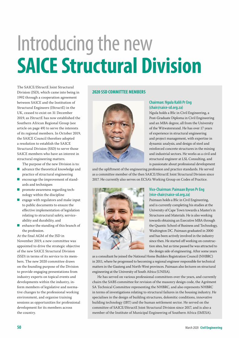
50 March 2020 civil engineering
The SAICE/IStructE Joint Structural Division (JSD), which came into being in 1992 through a cooperation agreement between SAICE and the Institution of Structural Engineers (IStructE) in the UK, ceased to exist on 31 December 2019, as IStructE has now established the Southern African Regional Group (see article on page 49) to serve the interests of its regional members. In October 2019, the SAICE Council therefore adopted a resolution to establish the SAICE Structural Division (SSD) to serve those SAICE members who have an interest in structural engineering matters.
The purpose of the new Division is to: Q advance the theoretical knowledge and
practice of structural engineering Q encourage the improvement of stand-
ards and techniques Q promote awareness regarding tech-
nology within the discipline Q engage with regulators and make input
to public documents to ensure the effective implementation of legislation relating to structural safety, service-ability and durability, and
Q enhance the standing of this branch of the profession.
At the final AGM of the JSD in November 2019, a new committee was appointed to drive the strategic objective of the new SAICE Structural Division (SSD) in terms of its service to its mem-bers. The new 2020 committee draws on the founding purpose of the Division to provide engaging presentations from industry experts on topical events and developments within the industry, in-form members of legislative and norma-tive changes to the professional working environment, and organise training sessions as opportunities for professional development for its members across the country.
Introducing the new saice structural Division
2020 ssD committee members
Chairman: Ngula Kalili Pr Eng ([email protected]) Ngula holds a BSc in Civil Engineering, a Post-Graduate Diploma in Civil Engineering and an MBA degree, all from the University of the Witwatersrand. He has over 17 years of experience in structural engineering and project management, with expertise in dynamic analysis, and design of steel and reinforced concrete structures in the mining and industrial sectors. He works as a civil and structural engineer at LSL Consulting, and is passionate about professional development
and the upliftment of the engineering profession and practice standards. He served as a committee member of the then SAICE/IStructE Joint Structural Division since 2017. He currently also serves on ECSA’s Working Group on Codes of Practice.
Vice-Chairman: Paimaan Byron Pr Eng ([email protected])Paimaan holds a BSc in Civil Engineering, and is currently completing his studies at the University of Cape Town towards a Master’s in Structures and Materials. He is also working towards obtaining an Executive MBA through the Quantic School of Business and Technology, Washington DC. Paimaan graduated in 2000 and has been actively involved in the industry since then. He started off working on construc-tion sites, but as time passed he was attracted to the design side of engineering. After some years
as a consultant he joined the National Home Builders Registration Council (NHBRC) in 2011, where he progressed to becoming a regional engineer responsible for technical matters in the Gauteng and North-West provinces. Paimaan also lectures on structural engineering at the University of South Africa (UNISA).
He has served on various professional committees over the years, and currently chairs the SABS committee for revision of the masonry design code, the Agrément SA Technical Committee representing the NHBRC, and also represents NHBRC in terms of investigations relating to structural failures in the housing industry. He specialises in the design of building structures, dolomitic conditions, innovative building technology (IBT) and the human settlement sector. He served on the committee of SAICE/IStructE Joint Structural Division since 2017, and is also a member of the Institute of Municipal Engineering of Southern Africa (IMESA).
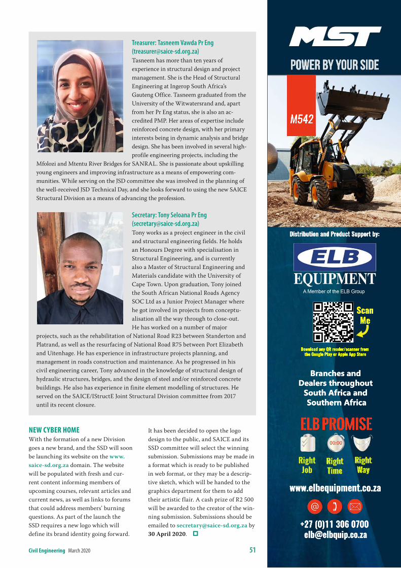
civil engineering March 2020 51
Treasurer: Tasneem Vawda Pr Eng ([email protected])Tasneem has more than ten years of experience in structural design and project management. She is the Head of Structural Engineering at Ingerop South Africa’s Gauteng Office. Tasneem graduated from the University of the Witwatersrand and, apart from her Pr Eng status, she is also an ac-credited PMP. Her areas of expertise include reinforced concrete design, with her primary interests being in dynamic analysis and bridge design. She has been involved in several high-profile engineering projects, including the
Mfolozi and Mtentu River Bridges for SANRAL. She is passionate about upskilling young engineers and improving infrastructure as a means of empowering com-munities. While serving on the JSD committee she was involved in the planning of the well-received JSD Technical Day, and she looks forward to using the new SAICE Structural Division as a means of advancing the profession.
Secretary: Tony Seloana Pr Eng ([email protected])Tony works as a project engineer in the civil and structural engineering fields. He holds an Honours Degree with specialisation in Structural Engineering, and is currently also a Master of Structural Engineering and Materials candidate with the University of Cape Town. Upon graduation, Tony joined the South African National Roads Agency SOC Ltd as a Junior Project Manager where he got involved in projects from conceptu-alisation all the way through to close-out. He has worked on a number of major
projects, such as the rehabilitation of National Road R23 between Standerton and Platrand, as well as the resurfacing of National Road R75 between Port Elizabeth and Uitenhage. He has experience in infrastructure projects planning, and management in roads construction and maintenance. As he progressed in his civil engineering career, Tony advanced in the knowledge of structural design of hydraulic structures, bridges, and the design of steel and/or reinforced concrete buildings. He also has experience in finite element modelling of structures. He served on the SAICE/IStructE Joint Structural Division committee from 2017 until its recent closure.
neW cYber homeWith the formation of a new Division goes a new brand, and the SSD will soon be launching its website on the www.saice-sd.org.za domain. The website will be populated with fresh and cur-rent content informing members of upcoming courses, relevant articles and current news, as well as links to forums that could address members’ burning questions. As part of the launch the SSD requires a new logo which will define its brand identity going forward.
It has been decided to open the logo design to the public, and SAICE and its SSD committee will select the winning submission. Submissions may be made in a format which is ready to be published in web format, or they may be a descrip-tive sketch, which will be handed to the graphics department for them to add their artistic flair. A cash prize of R2 500 will be awarded to the creator of the win-ning submission. Submissions should be emailed to [email protected] by 30 April 2020.
Download any QR reader/scanner from the Google Play or Apple App Store
ScanMe
Right Job
Right Time
Right Way
ELB Promise
M542
+27 (0)11 306 0700 [email protected]
www.elbequipment.co.za
Branches and Dealers throughout
South Africa and Southern Africa
Distribution and Product Support by:
Power by your side
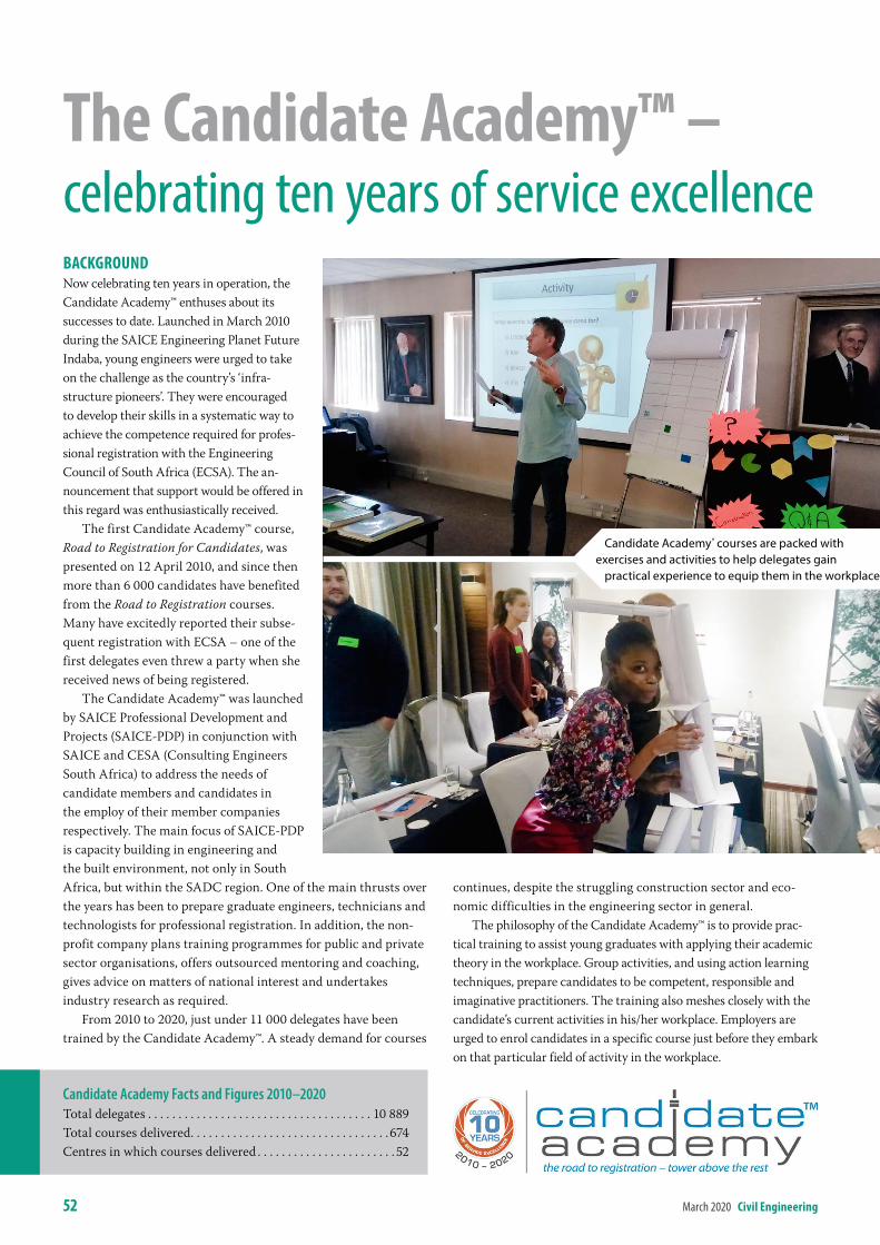
52 March 2020 civil engineering
bacKGrounDNow celebrating ten years in operation, the Candidate Academy™ enthuses about its successes to date. Launched in March 2010 during the SAICE Engineering Planet Future Indaba, young engineers were urged to take on the challenge as the country’s ‘infra-structure pioneers’. They were encouraged to develop their skills in a systematic way to achieve the competence required for profes-sional registration with the Engineering Council of South Africa (ECSA). The an-nouncement that support would be offered in this regard was enthusiastically received.
The first Candidate Academy™ course, Road to Registration for Candidates, was presented on 12 April 2010, and since then more than 6 000 candidates have benefited from the Road to Registration courses. Many have excitedly reported their subse-quent registration with ECSA – one of the first delegates even threw a party when she received news of being registered.
The Candidate Academy™ was launched by SAICE Professional Development and Projects (SAICE-PDP) in conjunction with SAICE and CESA (Consulting Engineers South Africa) to address the needs of candidate members and candidates in the employ of their member companies respectively. The main focus of SAICE-PDP is capacity building in engineering and the built environment, not only in South Africa, but within the SADC region. One of the main thrusts over the years has been to prepare graduate engineers, technicians and technologists for professional registration. In addition, the non-profit company plans training programmes for public and private sector organisations, offers outsourced mentoring and coaching, gives advice on matters of national interest and undertakes industry research as required.
From 2010 to 2020, just under 11 000 delegates have been trained by the Candidate Academy™. A steady demand for courses
continues, despite the struggling construction sector and eco-nomic difficulties in the engineering sector in general.
The philosophy of the Candidate Academy™ is to provide prac-tical training to assist young graduates with applying their academic theory in the workplace. Group activities, and using action learning techniques, prepare candidates to be competent, responsible and imaginative practitioners. The training also meshes closely with the candidate’s current activities in his/her workplace. Employers are urged to enrol candidates in a specific course just before they embark on that particular field of activity in the workplace.
the candidate academy™ – celebrating ten years of service excellence
Candidate Academy Facts and Figures 2010–2020Total delegates . . . . . . . . . . . . . . . . . . . . . . . . . . . . . . . . . . . . . 10 889Total courses delivered . . . . . . . . . . . . . . . . . . . . . . . . . . . . . . . . . 674Centres in which courses delivered . . . . . . . . . . . . . . . . . . . . . . . 52
Candidate Academy® courses are packed with exercises and activities to help delegates gain
practical experience to equip them in the workplace
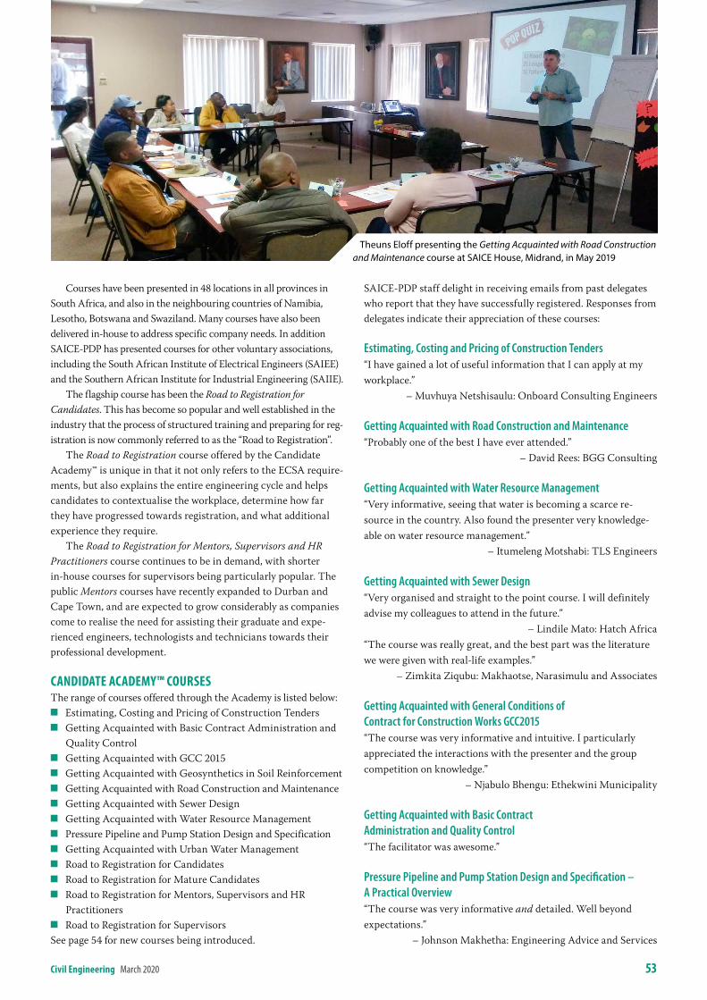
civil engineering March 2020 53
Courses have been presented in 48 locations in all provinces in South Africa, and also in the neighbouring countries of Namibia, Lesotho, Botswana and Swaziland. Many courses have also been delivered in-house to address specific company needs. In addition SAICE-PDP has presented courses for other voluntary associations, including the South African Institute of Electrical Engineers (SAIEE) and the Southern African Institute for Industrial Engineering (SAIIE).
The flagship course has been the Road to Registration for Candidates. This has become so popular and well established in the industry that the process of structured training and preparing for reg-istration is now commonly referred to as the “Road to Registration”.
The Road to Registration course offered by the Candidate Academy™ is unique in that it not only refers to the ECSA require-ments, but also explains the entire engineering cycle and helps candidates to contextualise the workplace, determine how far they have progressed towards registration, and what additional experience they require.
The Road to Registration for Mentors, Supervisors and HR Practitioners course continues to be in demand, with shorter in-house courses for supervisors being particularly popular. The public Mentors courses have recently expanded to Durban and Cape Town, and are expected to grow considerably as companies come to realise the need for assisting their graduate and expe-rienced engineers, technologists and technicians towards their professional development.
canDiDate acaDemY™ coursesThe range of courses offered through the Academy is listed below:
Q Estimating, Costing and Pricing of Construction Tenders Q Getting Acquainted with Basic Contract Administration and
Quality Control Q Getting Acquainted with GCC 2015 Q Getting Acquainted with Geosynthetics in Soil Reinforcement Q Getting Acquainted with Road Construction and Maintenance Q Getting Acquainted with Sewer Design Q Getting Acquainted with Water Resource Management Q Pressure Pipeline and Pump Station Design and Specification Q Getting Acquainted with Urban Water Management Q Road to Registration for Candidates Q Road to Registration for Mature Candidates Q Road to Registration for Mentors, Supervisors and HR
Practitioners Q Road to Registration for Supervisors
See page 54 for new courses being introduced.
Candidate Academy® courses are packed with exercises and activities to help delegates gain
practical experience to equip them in the workplace
Theuns Eloff presenting the Getting Acquainted with Road Construction and Maintenance course at SAICE House, Midrand, in May 2019
SAICE-PDP staff delight in receiving emails from past delegates who report that they have successfully registered. Responses from delegates indicate their appreciation of these courses:
Estimating, Costing and Pricing of Construction Tenders“I have gained a lot of useful information that I can apply at my workplace.” – Muvhuya Netshisaulu: Onboard Consulting Engineers
Getting Acquainted with Road Construction and Maintenance“Probably one of the best I have ever attended.” – David Rees: BGG Consulting
Getting Acquainted with Water Resource Management“Very informative, seeing that water is becoming a scarce re-source in the country. Also found the presenter very knowledge-able on water resource management.” – Itumeleng Motshabi: TLS Engineers
Getting Acquainted with Sewer Design“Very organised and straight to the point course. I will definitely advise my colleagues to attend in the future.” – Lindile Mato: Hatch Africa“The course was really great, and the best part was the literature we were given with real-life examples.” – Zimkita Ziqubu: Makhaotse, Narasimulu and Associates
Getting Acquainted with General Conditions of Contract for Construction Works GCC2015“The course was very informative and intuitive. I particularly appreciated the interactions with the presenter and the group competition on knowledge.” – Njabulo Bhengu: Ethekwini Municipality
Getting Acquainted with Basic Contract Administration and Quality Control“The facilitator was awesome.”
Pressure Pipeline and Pump Station Design and Specification – A Practical Overview“The course was very informative and detailed. Well beyond expectations.” – Johnson Makhetha: Engineering Advice and Services
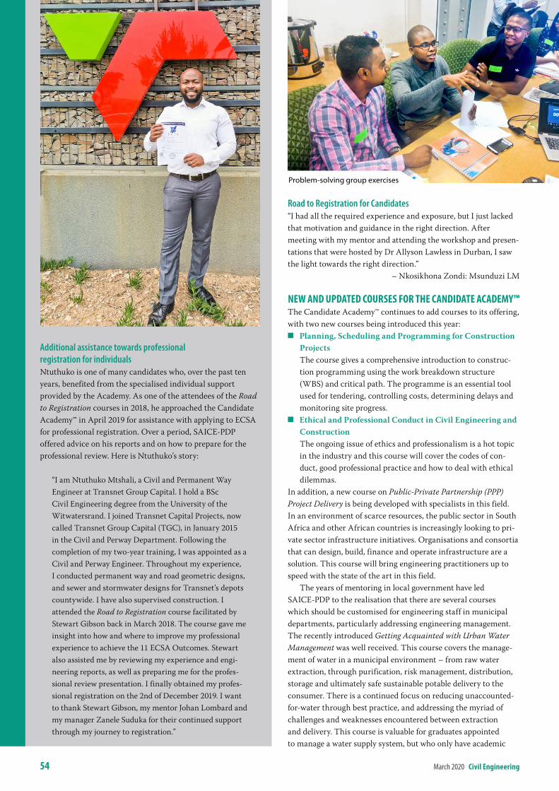
54 March 2020 civil engineering
Road to Registration for Candidates“I had all the required experience and exposure, but I just lacked that motivation and guidance in the right direction. After meeting with my mentor and attending the workshop and presen-tations that were hosted by Dr Allyson Lawless in Durban, I saw the light towards the right direction.” – Nkosikhona Zondi: Msunduzi LM
neW anD uPDateD courses For the canDiDate acaDemY™The Candidate Academy™ continues to add courses to its offering, with two new courses being introduced this year:
Q Planning, Scheduling and Programming for Construction Projects
The course gives a comprehensive introduction to construc-tion programming using the work breakdown structure (WBS) and critical path. The programme is an essential tool used for tendering, controlling costs, determining delays and monitoring site progress.
Q Ethical and Professional Conduct in Civil Engineering and Construction
The ongoing issue of ethics and professionalism is a hot topic in the industry and this course will cover the codes of con-duct, good professional practice and how to deal with ethical dilemmas.
In addition, a new course on Public-Private Partnership (PPP) Project Delivery is being developed with specialists in this field. In an environment of scarce resources, the public sector in South Africa and other African countries is increasingly looking to pri-vate sector infrastructure initiatives. Organisations and consortia that can design, build, finance and operate infrastructure are a solution. This course will bring engineering practitioners up to speed with the state of the art in this field.
The years of mentoring in local government have led SAICE-PDP to the realisation that there are several courses which should be customised for engineering staff in municipal departments, particularly addressing engineering management. The recently introduced Getting Acquainted with Urban Water Management was well received. This course covers the manage-ment of water in a municipal environment – from raw water extraction, through purification, risk management, distribution, storage and ultimately safe sustainable potable delivery to the consumer. There is a continued focus on reducing unaccounted-for-water through best practice, and addressing the myriad of challenges and weaknesses encountered between extraction and delivery. This course is valuable for graduates appointed to manage a water supply system, but who only have academic
Additional assistance towards professional registration for individualsNtuthuko is one of many candidates who, over the past ten years, benefited from the specialised individual support provided by the Academy. As one of the attendees of the Road to Registration courses in 2018, he approached the Candidate Academy™ in April 2019 for assistance with applying to ECSA for professional registration. Over a period, SAICE-PDP offered advice on his reports and on how to prepare for the professional review. Here is Ntuthuko’s story:
“I am Ntuthuko Mtshali, a Civil and Permanent Way Engineer at Transnet Group Capital. I hold a BSc Civil Engineering degree from the University of the Witwatersrand. I joined Transnet Capital Projects, now called Transnet Group Capital (TGC), in January 2015 in the Civil and Perway Department. Following the completion of my two-year training, I was appointed as a Civil and Perway Engineer. Throughout my experience, I conducted permanent way and road geometric designs, and sewer and stormwater designs for Transnet’s depots countywide. I have also supervised construction. I attended the Road to Registration course facilitated by Stewart Gibson back in March 2018. The course gave me insight into how and where to improve my professional experience to achieve the 11 ECSA Outcomes. Stewart also assisted me by reviewing my experience and engi-neering reports, as well as preparing me for the profes-sional review presentation. I finally obtained my profes-sional registration on the 2nd of December 2019. I want to thank Stewart Gibson, my mentor Johan Lombard and my manager Zanele Suduka for their continued support through my journey to registration.”
Problem‑solving group exercises
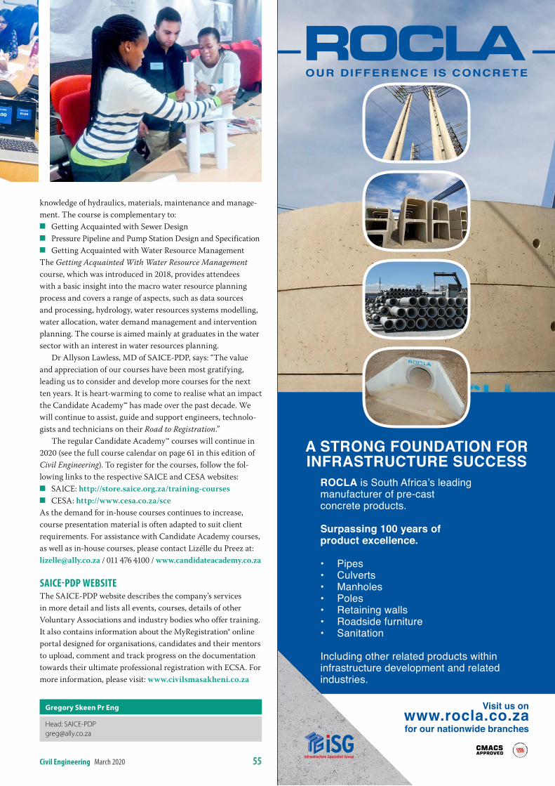
civil engineering March 2020 55
knowledge of hydraulics, materials, maintenance and manage-ment. The course is complementary to:
Q Getting Acquainted with Sewer Design Q Pressure Pipeline and Pump Station Design and Specification Q Getting Acquainted with Water Resource Management
The Getting Acquainted With Water Resource Management course, which was introduced in 2018, provides attendees with a basic insight into the macro water resource planning process and covers a range of aspects, such as data sources and processing, hydrology, water resources systems modelling, water allocation, water demand management and intervention planning. The course is aimed mainly at graduates in the water sector with an interest in water resources planning.
Dr Allyson Lawless, MD of SAICE-PDP, says: “The value and appreciation of our courses have been most gratifying, leading us to consider and develop more courses for the next ten years. It is heart-warming to come to realise what an impact the Candidate Academy™ has made over the past decade. We will continue to assist, guide and support engineers, technolo-gists and technicians on their Road to Registration.”
The regular Candidate Academy™ courses will continue in 2020 (see the full course calendar on page 61 in this edition of Civil Engineering). To register for the courses, follow the fol-lowing links to the respective SAICE and CESA websites:
Q SAICE: http://store.saice.org.za/training-courses Q CESA: http://www.cesa.co.za/sce
As the demand for in-house courses continues to increase, course presentation material is often adapted to suit client requirements. For assistance with Candidate Academy courses, as well as in-house courses, please contact Lizélle du Preez at: [email protected] / 011 476 4100 / www.candidateacademy.co.za
saice-PDP WebsiteThe SAICE-PDP website describes the company’s services in more detail and lists all events, courses, details of other Voluntary Associations and industry bodies who offer training. It also contains information about the MyRegistration® online portal designed for organisations, candidates and their mentors to upload, comment and track progress on the documentation towards their ultimate professional registration with ECSA. For more information, please visit: www.civilsmasakheni.co.za
gregory skeen Pr eng
Head: [email protected]
A STRONG FOUNDATION FOR INFRASTRUCTURE SUCCESS
Visit us on www.rocla.co.za for our nationwide branches
ROCLA is South Africa’s leading manufacturer of pre-cast concrete products.
Surpassing 100 years of product excellence.
• Pipes• Culverts• Manholes• Poles• Retaining walls• Roadside furniture• Sanitation
Including other related products within infrastructure development and related industries.
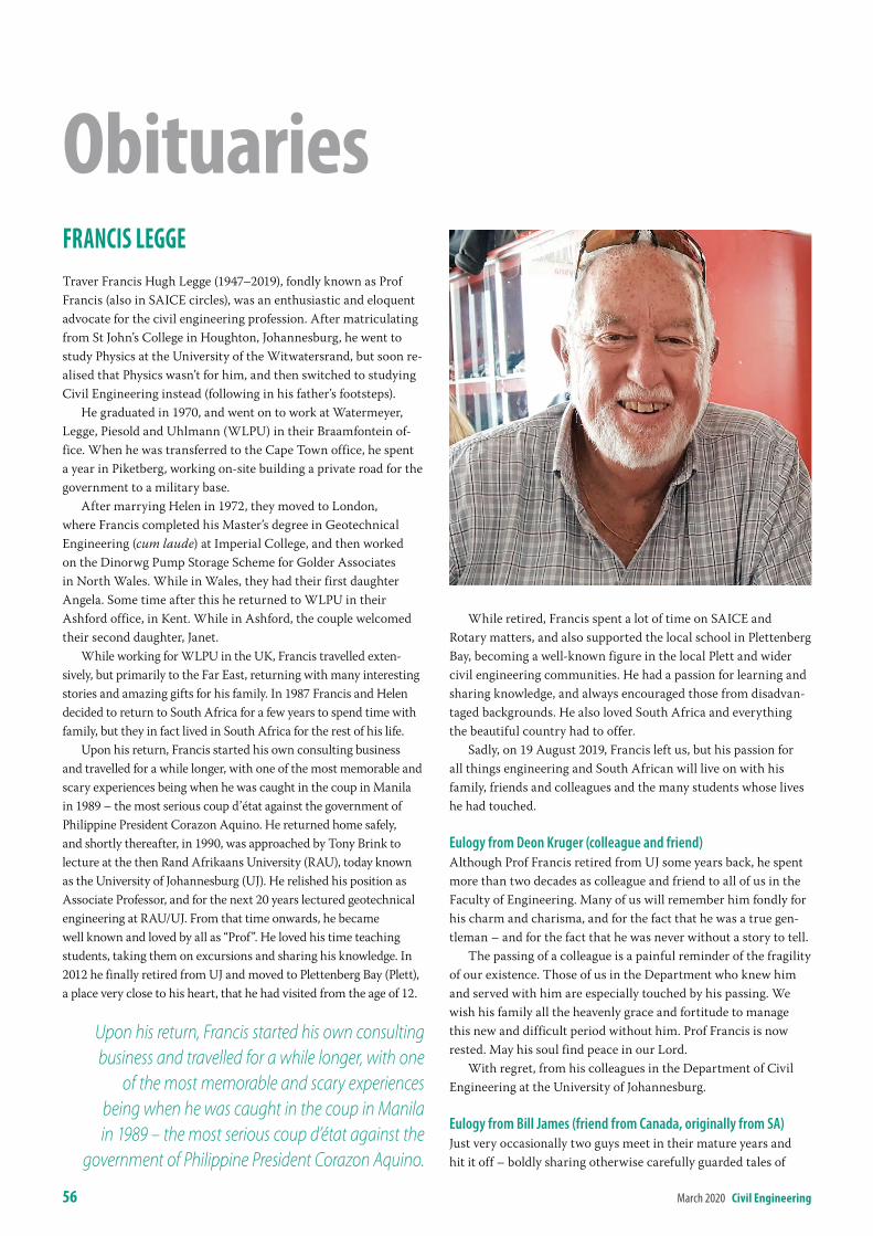
56 March 2020 civil engineering
Francis leGGeTraver Francis Hugh Legge (1947–2019), fondly known as Prof Francis (also in SAICE circles), was an enthusiastic and eloquent advocate for the civil engineering profession. After matriculating from St John’s College in Houghton, Johannesburg, he went to study Physics at the University of the Witwatersrand, but soon re-alised that Physics wasn’t for him, and then switched to studying Civil Engineering instead (following in his father’s footsteps).
He graduated in 1970, and went on to work at Watermeyer, Legge, Piesold and Uhlmann (WLPU) in their Braamfontein of-fice. When he was transferred to the Cape Town office, he spent a year in Piketberg, working on-site building a private road for the government to a military base.
After marrying Helen in 1972, they moved to London, where Francis completed his Master’s degree in Geotechnical Engineering (cum laude) at Imperial College, and then worked on the Dinorwg Pump Storage Scheme for Golder Associates in North Wales. While in Wales, they had their first daughter Angela. Some time after this he returned to WLPU in their Ashford office, in Kent. While in Ashford, the couple welcomed their second daughter, Janet.
While working for WLPU in the UK, Francis travelled exten-sively, but primarily to the Far East, returning with many interesting stories and amazing gifts for his family. In 1987 Francis and Helen decided to return to South Africa for a few years to spend time with family, but they in fact lived in South Africa for the rest of his life.
Upon his return, Francis started his own consulting business and travelled for a while longer, with one of the most memorable and scary experiences being when he was caught in the coup in Manila in 1989 – the most serious coup d’état against the government of Philippine President Corazon Aquino. He returned home safely, and shortly thereafter, in 1990, was approached by Tony Brink to lecture at the then Rand Afrikaans University (RAU), today known as the University of Johannesburg (UJ). He relished his position as Associate Professor, and for the next 20 years lectured geotechnical engineering at RAU/UJ. From that time onwards, he became well known and loved by all as “Prof”. He loved his time teaching students, taking them on excursions and sharing his knowledge. In 2012 he finally retired from UJ and moved to Plettenberg Bay (Plett), a place very close to his heart, that he had visited from the age of 12.
While retired, Francis spent a lot of time on SAICE and Rotary matters, and also supported the local school in Plettenberg Bay, becoming a well-known figure in the local Plett and wider civil engineering communities. He had a passion for learning and sharing knowledge, and always encouraged those from disadvan-taged backgrounds. He also loved South Africa and everything the beautiful country had to offer.
Sadly, on 19 August 2019, Francis left us, but his passion for all things engineering and South African will live on with his family, friends and colleagues and the many students whose lives he had touched.
Eulogy from Deon Kruger (colleague and friend)Although Prof Francis retired from UJ some years back, he spent more than two decades as colleague and friend to all of us in the Faculty of Engineering. Many of us will remember him fondly for his charm and charisma, and for the fact that he was a true gen-tleman – and for the fact that he was never without a story to tell.
The passing of a colleague is a painful reminder of the fragility of our existence. Those of us in the Department who knew him and served with him are especially touched by his passing. We wish his family all the heavenly grace and fortitude to manage this new and difficult period without him. Prof Francis is now rested. May his soul find peace in our Lord.
With regret, from his colleagues in the Department of Civil Engineering at the University of Johannesburg.
Eulogy from Bill James (friend from Canada, originally from SA)Just very occasionally two guys meet in their mature years and hit it off – boldly sharing otherwise carefully guarded tales of
obituaries
Upon his return, Francis started his own consulting business and travelled for a while longer, with one
of the most memorable and scary experiences being when he was caught in the coup in Manila in 1989 – the most serious coup d’état against the
government of Philippine President Corazon Aquino.
achievements, joys, mistakes and utterly regrettable stupidity. So it was with my old friend Francis. He was a wellspring of experi-ence and knowledge – geological and foundational – especially on South African and British civil engineering monuments and monumental men, but also on life itself. Blessed with a good memory, gentle, a large man in several senses of the descriptor, kind, confident, an excellent engineer, and sometimes somewhat easily heard and noticed. He well understood and broadcast what a noble profession civil engineering is – we shared that deep appreciation, often over a glass of good wine in a wonderful, lingering South African sunset. And often during a long South African road trip in his lumbering truck. He knew how to laugh.
So, my good academic friend Francis Legge has been taken from us. It had to be, of course, but please God, this was just too soon. We shall miss his fascinating knowledge. In the murkiness that has enveloped South Africa in my time, he was a shining light that attracted me to visit, time and again. I shall miss him. I can’t even imagine how much his family will.
But, thinking on it, in this world we, his friends, were, after all, very lucky. Yet we weep.
Eulogy from Johannes Haarhoff (colleague and friend)Francis and I met in a moment of mutual distrust early in 1990 as we shared a small lounge while waiting for our interviews at the Rand Afrikaans University (RAU, now UJ). Great was the relief on 1 June 1990 when we walked into our new jobs as young academics – not as competitors vying for the same job as we had assumed at first, but as colleagues in the Department of Civil Engineering. That was the start of more than 20 years of being colleagues and friends before Francis and Helen retired to Plettenberg Bay, with us following shortly there-after to Graaff-Reinet. During these years at RAU we shared many work-related experiences, often ending up as roommates on student tours and excursions. Our relationship extended beyond the campus – we had the privilege of being together on camping trips to some rougher parts of Africa. Good days, good camaraderie! Since retire-ment, we continued to meet – mostly in the company of other retired engineers who make annual trips to visit places in South Africa with interesting railway engineering history. All the more poignant was the fact that this group visited the area between Port Elizabeth and George about six weeks after his passing – the trip had been arranged months ahead of time and Francis was pencilled in to present one or two impromptu talks in and around Plettenberg Bay.
Allow me to condense the flood of memories that were brought on by his death. First – a person who was always friendly and always radiating genuine joy when meeting old friends or students. Second – a raconteur who had an endless store of interesting personal experiences and stories which he shared in such an entertaining way! Third – a vast general knowledge which went way beyond the speciality of geotechnical engineering. He was perfectly at ease in discussion on just about anything to anybody. Fourth – especially dear to his predominantly Afrikaans colleagues at RAU – was his keen interest and sharp analysis of words and language. He derived great joy from many Afrikaans expressions, often making us aware of subtle nuances which we had never thought about before (such as Mossel Bay, Riversdal, Choo-Tsjoe), where Afrikaans and English converge into a single name.
You are going to be missed, Francis. In the words of Afrikaans poet NP van Wyk Louw – ons gaan “eendag net mooi dinge van jou weet”.
carlos ribeiro Da silvaOn 13 March 2019 the engineering world lost a valued and skilled engineer when Carlos Ribeiro da Silva passed away suddenly at his home in Vereeniging.
Carlos graduated with a degree in Civil Engineering from the University of Lourenco Marques (Maputo) in 1974, spe-cialising in structural engineering. He moved to South Africa where he continued his studies with a GDE at the University of the Witwatersrand. In 1974 he joined BS Bergman and Partners (now Ingerop) where he became proficient in designing bridges, such as the Nyl River Bridge, 12th Avenue Bridge in Sandton and the S18 Interchange Bridge on the N3, to name a few.
Carlos had extensive knowledge of reinforced concrete and pre-stressed design. From 1983 to 1987 he worked at Baikoff & Associates, continuing his work in the structural engineering industry. In 1987 he joined another consulting firm (Lame and Van Blerk Associates) as director. There he not only got in-volved with numerous international projects in Mozambique, Botswana and Angola, but also with local industrial clients such as ISCOR and Suprachem. In 2000 he became one of the directors of Sikhulile Infra-Tech (trading as Sintec), where he secured numerous infrastructure contracts, such as the upgrading of the Sebokeng Water Care Works, to name one. He was also the Principal Engineer for Phases 1 and 2 of the Riverfront in Vosloo Park (in Three Rivers, Vereeniging), The Don Hotel (in Isando, Johannesburg), luxury apartments Le Touessrok (in Ramsgate, KwaZulu-Natal) and several other commercial, residential and industrial projects around the country. His contribution to the South African civil engi-neering industry was certainly enormous and meaningful.
Carlos also found time to be a caring husband and father, and he is deeply missed by his wife Adelaide, and his son and daughter, Marco and Barbara. Rest in Peace Carlos.
Marco da silva and barbara Affleck
[email protected] / [email protected]
civil engineering March 2020 57
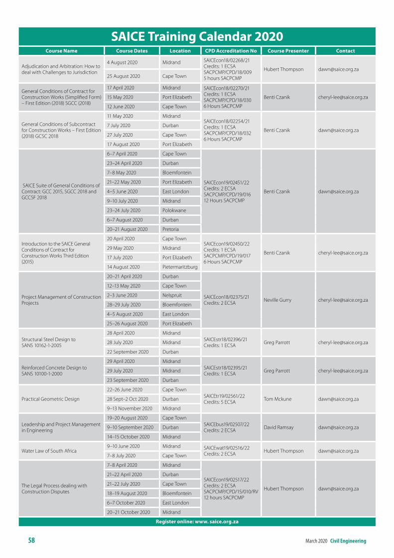
58 March 2020 civil engineering
Course name Course dates location CPd Accreditation no Course Presenter Contact
Adjudication and Arbitration: How to deal with Challenges to Jurisdiction
4 August 2020 Midrand SAICEcon18/02268/21Credits: 1 ECSASACPCMP/CPD/18/009 5 hours SACPCMP
Hubert Thompson [email protected] August 2020 Cape Town
General Conditions of Contract for Construction Works (Simplified Form) – First Edition (2018) SGCC (2018)
17 April 2020 Midrand SAICEcon18/02270/21Credits: 1 ECSASACPCMP/CPD/18/0306 Hours SACPCMP
Benti Czanik [email protected] May 2020 Port Elizabeth
12 June 2020 Cape Town
General Conditions of Subcontract for Construction Works – First Edition (2018) GCSC 2018
11 May 2020 MidrandSAICEcon18/02254/21Credits: 1 ECSASACPCMP/CPD/18/0326 Hours SACPCMP
Benti Czanik [email protected] July 2020 Durban
27 July 2020 Cape Town
17 August 2020 Port Elizabeth
SAICE Suite of General Conditions of Contract: GCC 2015, SGCC 2018 and GCCSF 2018
6–7 April 2020 Cape Town
SAICEcon19/02451/22Credits: 2 ECSASACPCMP/CPD/19/01612 Hours SACPCMP
Benti Czanik [email protected]
23–24 April 2020 Durban
7–8 May 2020 Bloemfontein
21–22 May 2020 Port Elizabeth
4–5 June 2020 East London
9–10 July 2020 Midrand
23–24 July 2020 Polokwane
6–7 August 2020 Durban
20–21 August 2020 Pretoria
Introduction to the SAICE General Conditions of Contract for Construction Works Third Edition (2015)
20 April 2020 Cape TownSAICEcon19/02450/22Credits: 1 ECSASACPCMP/CPD/19/0176 Hours SACPCMP
Benti Czanik [email protected] May 2020 Midrand
17 July 2020 Port Elizabeth
14 August 2020 Pietermaritzburg
Project Management of Construction Projects
20–21 April 2020 Durban
SAICEcon18/02375/21Credits: 2 ECSA Neville Gurry [email protected]
12–13 May 2020 Cape Town
2–3 June 2020 Nelspruit
28–29 July 2020 Bloemfontein
4–5 August 2020 East London
25–26 August 2020 Port Elizabeth
Structural Steel Design to SANS 10162-1-2005
28 April 2020 MidrandSAICEstr18/02396/21Credits: 1 ECSA Greg Parrott [email protected] July 2020 Midrand
22 September 2020 Durban
Reinforced Concrete Design to SANS 10100-1-2000
29 April 2020 MidrandSAICEstr18/02395/21Credits: 1 ECSA Greg Parrott [email protected] July 2020 Midrand
23 September 2020 Durban
Practical Geometric Design
22–26 June 2020 Cape TownSAICEtr19/02561/22 Credits: 5 ECSA Tom Mckune [email protected] Sept–2 Oct 2020 Durban
9–13 November 2020 Midrand
Leadership and Project Management in Engineering
19–20 August 2020 Cape TownSAICEbus19/02507/22Credits: 2 ECSA David Ramsay [email protected]–10 September 2020 Durban
14–15 October 2020 Midrand
Water Law of South Africa9–10 June 2020 Midrand SAICEwat19/02516/22
Credits: 2 ECSA Hubert Thompson [email protected]–8 July 2020 Cape Town
The Legal Process dealing with Construction Disputes
7–8 April 2020 Midrand
SAICEcon19/02517/22Credits: 2 ECSASACPCMP/CPD/15/010/RV12 hours SACPCMP
Hubert Thompson [email protected]
21–22 April 2020 Durban
21–22 July 2020 Cape Town
18–19 August 2020 Bloemfontein
6–7 October 2020 East London
20–21 October 2020 Midrand
register online: www. saice.org.za
sAiCe training Calendar 2020
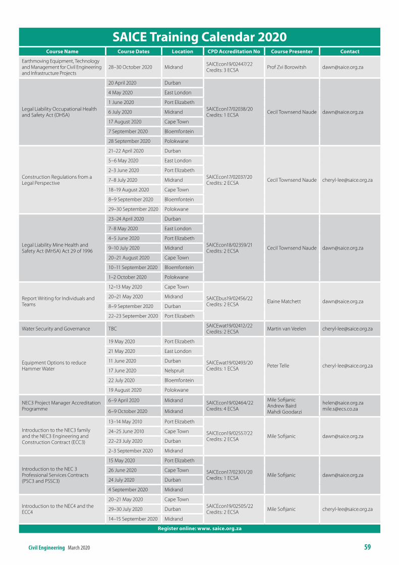
civil engineering March 2020 59
Course name Course dates location CPd Accreditation no Course Presenter Contact
Earthmoving Equipment, Technology and Management for Civil Engineering and Infrastructure Projects
28–30 October 2020 Midrand SAICEcon19/02447/22Credits: 3 ECSA Prof Zvi Borowitsh [email protected]
Legal Liability Occupational Health and Safety Act (OHSA)
20 April 2020 Durban
SAICEcon17/02038/20Credits: 1 ECSA Cecil Townsend Naude [email protected]
4 May 2020 East London
1 June 2020 Port Elizabeth
6 July 2020 Midrand
17 August 2020 Cape Town
7 September 2020 Bloemfontein
28 September 2020 Polokwane
Construction Regulations from a Legal Perspective
21–22 April 2020 Durban
SAICEcon17/02037/20Credits: 2 ECSA Cecil Townsend Naude [email protected]
5–6 May 2020 East London
2–3 June 2020 Port Elizabeth
7–8 July 2020 Midrand
18–19 August 2020 Cape Town
8–9 September 2020 Bloemfontein
29–30 September 2020 Polokwane
Legal Liability Mine Health and Safety Act (MHSA) Act 29 of 1996
23–24 April 2020 Durban
SAICEcon18/02359/21Credits: 2 ECSA Cecil Townsend Naude [email protected]
7–8 May 2020 East London
4–5 June 2020 Port Elizabeth
9–10 July 2020 Midrand
20–21 August 2020 Cape Town
10–11 September 2020 Bloemfontein
1–2 October 2020 Polokwane
Report Writing for Individuals and Teams
12–13 May 2020 Cape Town
SAICEbus19/02456/22Credits: 2 ECSA Elaine Matchett [email protected]
20–21 May 2020 Midrand
8–9 September 2020 Durban
22–23 September 2020 Port Elizabeth
Water Security and Governance TBC SAICEwat19/02412/22Credits: 2 ECSA Martin van Veelen [email protected]
Equipment Options to reduce Hammer Water
19 May 2020 Port Elizabeth
SAICEwat19/02493/20Credits: 1 ECSA Peter Telle [email protected]
21 May 2020 East London
11 June 2020 Durban
17 June 2020 Nelspruit
22 July 2020 Bloemfontein
19 August 2020 Polokwane
NEC3 Project Manager Accreditation Programme
6–9 April 2020 Midrand SAICEcon19/02464/22Credits: 4 ECSA
Mile SofijanicAndrew BairdMahdi Goodarzi
[email protected]@ecs.co.za6–9 October 2020 Midrand
Introduction to the NEC3 family and the NEC3 Engineering and Construction Contract (ECC3)
13–14 May 2010 Port Elizabeth
SAICEcon19/02557/22Credits: 2 ECSA Mile Sofijanic [email protected]
24–25 June 2010 Cape Town
22–23 July 2020 Durban
2–3 September 2020 Midrand
Introduction to the NEC 3 Professional Services Contracts (PSC3 and PSSC3)
15 May 2020 Port Elizabeth
SAICEcon17/02301/20Credits: 1 ECSA Mile Sofijanic [email protected]
26 June 2020 Cape Town
24 July 2020 Durban
4 September 2020 Midrand
Introduction to the NEC4 and the ECC4
20–21 May 2020 Cape TownSAICEcon19/02505/22Credits: 2 ECSA Mile Sofijanic [email protected]–30 July 2020 Durban
14–15 September 2020 Midrand
register online: www. saice.org.za
sAiCe training Calendar 2020
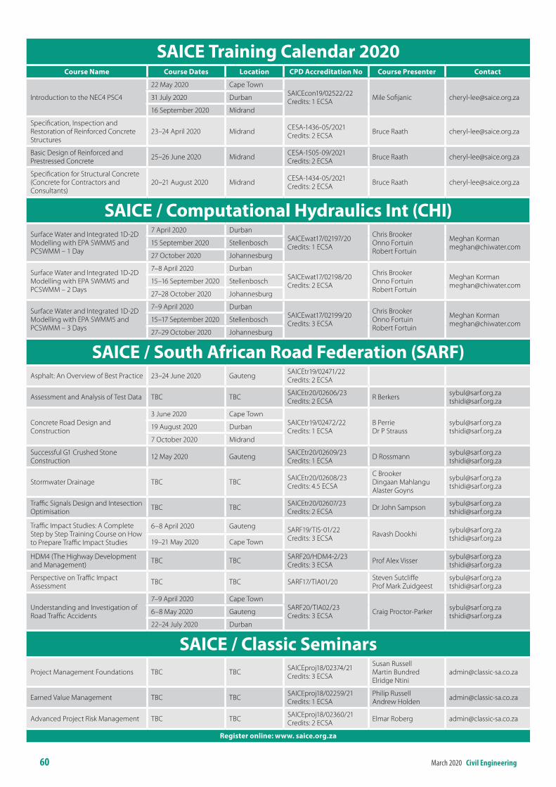
60 March 2020 civil engineering
Course name Course dates location CPd Accreditation no Course Presenter Contact
Introduction to the NEC4 PSC4
22 May 2020 Cape TownSAICEcon19/02522/22Credits: 1 ECSA Mile Sofijanic [email protected] July 2020 Durban
16 September 2020 Midrand
Specification, Inspection and Restoration of Reinforced Concrete Structures
23–24 April 2020 Midrand CESA-1436-05/2021Credits: 2 ECSA Bruce Raath [email protected]
Basic Design of Reinforced and Prestressed Concrete 25–26 June 2020 Midrand CESA-1505-09/2021
Credits: 2 ECSA Bruce Raath [email protected]
Specification for Structural Concrete (Concrete for Contractors and Consultants)
20–21 August 2020 Midrand CESA-1434-05/2021Credits: 2 ECSA Bruce Raath [email protected]
sAiCe / Computational hydraulics int (Chi)Surface Water and Integrated 1D-2D Modelling with EPA SWMM5 and PCSWMM – 1 Day
7 April 2020 DurbanSAICEwat17/02197/20Credits: 1 ECSA
Chris Brooker Onno Fortuin Robert Fortuin
Meghan [email protected] September 2020 Stellenbosch
27 October 2020 Johannesburg
Surface Water and Integrated 1D-2D Modelling with EPA SWMM5 and PCSWMM – 2 Days
7–8 April 2020 DurbanSAICEwat17/02198/20Credits: 2 ECSA
Chris Brooker Onno Fortuin Robert Fortuin
Meghan [email protected]–16 September 2020 Stellenbosch
27–28 October 2020 Johannesburg
Surface Water and Integrated 1D-2D Modelling with EPA SWMM5 and PCSWMM – 3 Days
7–9 April 2020 DurbanSAICEwat17/02199/20Credits: 3 ECSA
Chris Brooker Onno Fortuin Robert Fortuin
Meghan [email protected]–17 September 2020 Stellenbosch
27–29 October 2020 Johannesburg
sAiCe / south African road Federation (sArF)Asphalt: An Overview of Best Practice 23–24 June 2020 Gauteng SAICEtr19/02471/22
Credits: 2 ECSA
Assessment and Analysis of Test Data TBC TBC SAICEtr20/02606/23Credits: 2 ECSA R Berkers [email protected]
Concrete Road Design and Construction
3 June 2020 Cape TownSAICEtr19/02472/22Credits: 1 ECSA
B PerrieDr P Strauss
[email protected]@sarf.org.za19 August 2020 Durban
7 October 2020 Midrand
Successful G1 Crushed Stone Construction 12 May 2020 Gauteng SAICEtr20/02609/23
Credits: 1 ECSA D Rossmann [email protected]@sarf.org.za
Stormwater Drainage TBC TBC SAICEtr20/02608/23Credits: 4.5 ECSA
C Brooker Dingaan Mahlangu Alaster Goyns
[email protected]@sarf.org.za
Traffic Signals Design and Intesection Optimisation TBC TBC SAICEtr20/02607/23
Credits: 2 ECSA Dr John Sampson [email protected]@sarf.org.za
Traffic Impact Studies: A Complete Step by Step Training Course on How to Prepare Traffic Impact Studies
6–8 April 2020 Gauteng SARF19/TIS-01/22Credits: 3 ECSA Ravash Dookhi [email protected]
[email protected]–21 May 2020 Cape Town
HDM4 (The Highway Development and Management) TBC TBC SARF20/HDM4-2/23
Credits: 3 ECSA Prof Alex Visser [email protected]@sarf.org.za
Perspective on Traffic Impact Assessment TBC TBC SARF17/TIA01/20 Steven Sutcliffe
Prof Mark [email protected]@sarf.org.za
Understanding and Investigation of Road Traffic Accidents
7–9 April 2020 Cape Town SARF20/TIA02/23Credits: 3 ECSA Craig Proctor-Parker [email protected]
[email protected]–8 May 2020 Gauteng
22–24 July 2020 Durban
sAiCe / Classic seminarsProject Management Foundations TBC TBC SAICEproj18/02374/21
Credits: 3 ECSA
Susan RussellMartin BundredElridge Ntini
Earned Value Management TBC TBC SAICEproj18/02259/21Credits: 1 ECSA
Philip Russell Andrew Holden [email protected]
Advanced Project Risk Management TBC TBC SAICEproj18/02360/21Credits: 2 ECSA Elmar Roberg [email protected]
register online: www. saice.org.za
sAiCe training Calendar 2020
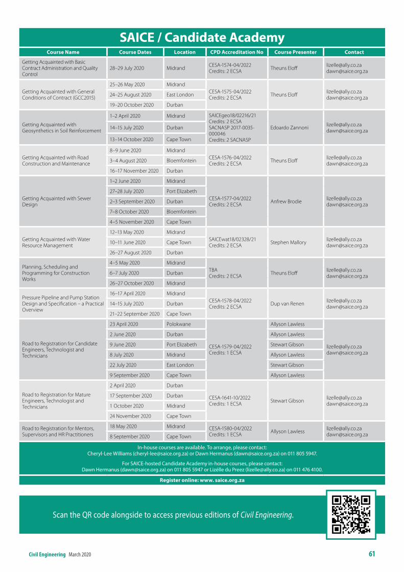
civil engineering March 2020 61
Course name Course dates location CPd Accreditation no Course Presenter Contact
Getting Acquainted with Basic Contract Administration and Quality Control
28–29 July 2020 Midrand CESA-1574-04/2022Credits: 2 ECSA Theuns Eloff [email protected]
Getting Acquainted with General Conditions of Contract (GCC2015)
25–26 May 2020 MidrandCESA-1575-04/2022Credits: 2 ECSA Theuns Eloff [email protected]
[email protected]–25 August 2020 East London
19–20 October 2020 Durban
Getting Acquainted with Geosynthetics in Soil Reinforcement
1–2 April 2020 Midrand SAICEgeo18/02216/21Credits: 2 ECSASACNASP 2017-0035-000046Credits: 2 SACNASP
Edoardo Zannoni [email protected]@saice.org.za14–15 July 2020 Durban
13–14 October 2020 Cape Town
Getting Acquainted with Road Construction and Maintenance
8–9 June 2020 MidrandCESA-1576-04/2022Credits: 2 ECSA Theuns Eloff [email protected]
[email protected]–4 August 2020 Bloemfontein
16–17 November 2020 Durban
Getting Acquainted with Sewer Design
1–2 June 2020 Midrand
CESA-1577-04/2022 Credits: 2 ECSA Anfrew Brodie [email protected]
27–28 July 2020 Port Elizabeth
2–3 September 2020 Durban
7–8 October 2020 Bloemfontein
4–5 November 2020 Cape Town
Getting Acquainted with Water Resource Management
12–13 May 2020 MidrandSAICEwat18/02328/21Credits: 2 ECSA Stephen Mallory [email protected]
[email protected]–11 June 2020 Cape Town
26–27 August 2020 Durban
Planning, Scheduling and Programming for Construction Works
4–5 May 2020 MidrandTBACredits: 2 ECSA Theuns Eloff [email protected]
[email protected]–7 July 2020 Durban
26–27 October 2020 Midrand
Pressure Pipeline and Pump Station Design and Specification – a Practical Overview
16–17 April 2020 MidrandCESA-1578-04/2022Credits: 2 ECSA Dup van Renen [email protected]
[email protected]–15 July 2020 Durban
21–22 September 2020 Cape Town
Road to Registration for Candidate Engineers, Technologist and Technicians
23 April 2020 Polokwane
CESA-1579-04/2022Credits: 1 ECSA
Allyson Lawless
[email protected]@saice.org.za
2 June 2020 Durban Allyson Lawless
9 June 2020 Port Elizabeth Stewart Gibson
8 July 2020 Midrand Allyson Lawless
22 July 2020 East London Stewart Gibson
9 September 2020 Cape Town Allyson Lawless
Road to Registration for Mature Engineers, Technologist and Technicians
2 April 2020 Durban
CESA-1641-10/2022Credits: 1 ECSA Stewart Gibson [email protected]
17 September 2020 Durban
1 October 2020 Midrand
24 November 2020 Cape Town
Road to Registration for Mentors, Supervisors and HR Practitioners
18 May 2020 Midrand CESA-1580-04/2022Credits: 1 ECSA Allyson Lawless [email protected]
[email protected] September 2020 Cape Town
In‑house courses are available. To arrange, please contact: Cheryl‑Lee Williams (cheryl‑[email protected]) or Dawn Hermanus ([email protected]) on 011 805 5947.
For SAICE‑hosted Candidate Academy in‑house courses, please contact: Dawn Hermanus ([email protected]) on 011 805 5947 or Lizélle du Preez ([email protected]) on 011 476 4100.
register online: www. saice.org.za
sAiCe / Candidate Academy
Scan the QR code alongside to access previous editions of Civil Engineering.

aFrisam
IT TAKES MORE THAN CONCRETE TO BUILDYOUR VISION.
HERE’S TO THE BUILDER IN YOU.
Creating Concrete Possibilitieswww.afrisam.com
PRO
MIS
E_13
397/
E