design of t-beam rail-over bridge
TRANSCRIPT

International Journal of Research Available at https://edupediapublications.org/journals
e-ISSN: 2348-6848 p-ISSN: 2348-795X
Volume 05 Issue-01 January 2018
Available online: https://edupediapublications.org/journals/index.php/IJR/ P a g e | 1100
Design of T-Beam Rail-Over Bridge Pokala Adithya & T.Ajith
1M.Tech (Structural Engineering),
2Assistant.Professor(Civil Engineering Department)
AVN Institute of engineering and technology.AVN Institute of engineering and technology.
ABSTRACT:Beam and slab bridges are the
most common form concrete bridge in today.
They have the virtue of simplicity, economy,
wide availability of the standard sections, and
speed of erection. The present beams are placed
on the supporting piers or abutments, usually on
rubber bearings which are maintenance free. In
this project study on design of long span decks,
foundation, design of Girders, beams, resistance
of vibration in bridge span sections, and
difference between RCC girders and heavy steel
girders, composite bridge decks, structural
analysis of concrete bridges, The Bridge which
is in disstress is a R.C. beam- slab type in all
spans of the bridge except in one span i.e.,
railway portion which is of Box girder type. The
super structure is divided into two parts
independently and each part consists of three
girders with deck slab, simply supported on
common R.C pier / Abutment.
This project includes causes and
identification of failures and defects in concrete
structures. Techniques for repairs and
rehabilitation of concrete structure
(bridge).Some of the techniques are epoxy
resins, polymer concrete composites and
corrosion proof epoxy painting.
INTRODUCTION:A bridge is a structure that
crosses over a river, bay, or other obstruction,
permitting the smooth and safe passage of
vehicles, trains, and pedestrians. An elevation
view of a typical bridge is A bridge structure is
divided into an upper part (the superstructure),
which consists of the slab, the floor system, and
the main truss or girders, and a lower part (the
substructure), which are columns, piers, towers,
footings, piles, and abutments. The
superstructure provides horizontal spans such as
deck and girders and carries traffic loads
directly. The substructure supports the horizontal
spans, elevating above the ground surface.
Classification of Bridges:
1. Classification by Materials:
Steel Bridges: steel bridge may use a wide
variety of structural steel components and
systems: girders, frames, trusses, arches, and
suspension cables.
Concrete Bridges: There are two primary types
of concrete bridges: reinforced and pre-stressed.
Timber Bridges: Wooden bridges are used
when the span is relatively short.
International Journal of Research Available at https://edupediapublications.org/journals
e-ISSN: 2348-6848 p-ISSN: 2348-795X
Volume 05 Issue-01 January 2018
Available online: https://edupediapublications.org/journals/index.php/IJR/ P a g e | 1101
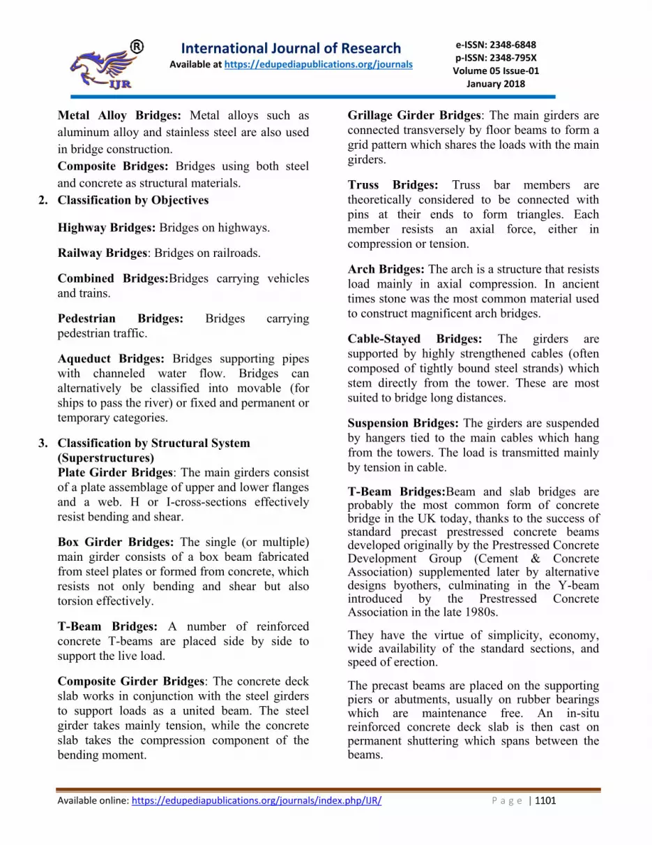
Metal Alloy Bridges: Metal alloys such as
aluminum alloy and stainless steel are also used
in bridge construction.
Composite Bridges: Bridges using both steel
and concrete as structural materials.
2. Classification by Objectives
Highway Bridges: Bridges on highways.
Railway Bridges: Bridges on railroads.
Combined Bridges:Bridges carrying vehicles
and trains.
Pedestrian Bridges: Bridges carrying
pedestrian traffic.
Aqueduct Bridges: Bridges supporting pipes
with channeled water flow. Bridges can
alternatively be classified into movable (for
ships to pass the river) or fixed and permanent or
temporary categories.
3. Classification by Structural System
(Superstructures)
Plate Girder Bridges: The main girders consist
of a plate assemblage of upper and lower flanges
and a web. H or I-cross-sections effectively
resist bending and shear.
Box Girder Bridges: The single (or multiple)
main girder consists of a box beam fabricated
from steel plates or formed from concrete, which
resists not only bending and shear but also
torsion effectively.
T-Beam Bridges: A number of reinforced
concrete T-beams are placed side by side to
support the live load.
Composite Girder Bridges: The concrete deck
slab works in conjunction with the steel girders
to support loads as a united beam. The steel
girder takes mainly tension, while the concrete
slab takes the compression component of the
bending moment.
Grillage Girder Bridges: The main girders are
connected transversely by floor beams to form a
grid pattern which shares the loads with the main
girders.
Truss Bridges: Truss bar members are
theoretically considered to be connected with
pins at their ends to form triangles. Each
member resists an axial force, either in
compression or tension.
Arch Bridges: The arch is a structure that resists
load mainly in axial compression. In ancient
times stone was the most common material used
to construct magnificent arch bridges.
Cable-Stayed Bridges: The girders are
supported by highly strengthened cables (often
composed of tightly bound steel strands) which
stem directly from the tower. These are most
suited to bridge long distances.
Suspension Bridges: The girders are suspended
by hangers tied to the main cables which hang
from the towers. The load is transmitted mainly
by tension in cable.
T-Beam Bridges:Beam and slab bridges are probably the most common form of concrete bridge in the UK today, thanks to the success of standard precast prestressed concrete beams developed originally by the Prestressed Concrete Development Group (Cement & Concrete Association) supplemented later by alternative designs byothers, culminating in the Y-beam introduced by the Prestressed Concrete Association in the late 1980s. They have the virtue of simplicity, economy, wide availability of the standard sections, and speed of erection. The precast beams are placed on the supporting piers or abutments, usually on rubber bearings which are maintenance free. An in-situ reinforced concrete deck slab is then cast on permanent shuttering which spans between the beams.

International Journal of Research Available at https://edupediapublications.org/journals
e-ISSN: 2348-6848 p-ISSN: 2348-795X
Volume 05 Issue-01 January 2018
Available online: https://edupediapublications.org/journals/index.php/IJR/ P a g e | 1102
The precast beams can be joined together at the supports to form continuous beams which are structurally more efficient. However, this is not normally done because the costs involved are not justified by the increased efficiency. Simply supported concrete beams and slab bridges are now giving way to integral bridges which offer the advantages of less cost and lower maintenance due to the elimination of expansion joints and bearings. Nearly 590,000 roadway bridges span waterways, dry land depressions, other roads, and railroads throughout the United States. The most dramatic bridges use complex systems like arches, cables, or triangle-filled trusses to carry the roadway between majestic columns or towers. However, the work-horse of the highway bridge system is the relatively simple and inexpensive concrete beam bridge.
Also known as a girder bridge, a beam bridge consists of a horizontal slab supported at each end. Because all of the weight of the slab (and any objects on the slab) is transferred vertically to the support columns, the columns can be less massive than supports for arch or suspension bridges, which transfer part of the weight horizontally.
A simple beam bridge is generally used to span a distance of 250 ft (76.2 m) or less. Longer distances can be spanned by connecting a series of simple beam bridges into what is known as a continuous span. In fact, the world's longest bridge, the Lake Pontchartrain Causeway in Louisiana, is a pair of parallel, two-lane continuous span bridges almost 24 mi (38.4 km) long. The first of the two bridges was completed in 1956 and consists of more than 2,000 individual spans. The sister bridge (now carrying the north-bound traffic) was completed 13 years later; although it is 228 ft longer than the first bridge, it contains only 1,500 spans.
A bridge has three main elements. First, the substructure (foundation) transfers the loaded 1weight of the bridge to the ground; it consists of components such as columns (also called piers) and abutments. An abutment is the connection between the end of the bridge and the earth; it provides support for the end sections of the bridge. Second, the superstructure of the bridge is the horizontal platform that spans the space between columns. Finally, the deck of the bridge is the traffic-carrying surface added to the superstructure. Construction Materials and Their
Development: Most highway beam bridges are built of concrete and steel. The Romans used concrete made of lime and pozzalana (a red, volcanic powder) in their bridges. This material set quickly, even under water, and it was strong and waterproof. During the Middle Ages in Europe, lime mortar was used instead, but it was water soluble. Today's popular Portland cement, a particular mixture of limestone and clay, was invented in 1824 by an English bricklayer named Joseph Aspdin, but it was not widely used as a foundation material until the early 1900s.
Concrete has good strength to withstand compression (pressing force), but is not as strong under tension (pulling force). There were several attempts in Europe and the United States during the nineteenth century to strengthen concrete by embedding tension-resisting iron in it. A superior version was developed in France during the 1880s by Francois Hennebique, who used reinforcing bars made of steel. The first significant use of reinforced concrete in a bridge in the United States was in the Alvord Lake Bridge in San Francisco's Golden Gate Park; completed in 1889 and still in use today, it was built with reinforcing bars of twisted steel devised by designer Ernest L. Ransome.
The next significant advance in concrete construction was the development of

International Journal of Research Available at https://edupediapublications.org/journals
e-ISSN: 2348-6848 p-ISSN: 2348-795X
Volume 05 Issue-01 January 2018
Available online: https://edupediapublications.org/journals/index.php/IJR/ P a g e | 1103
prestressing. A concrete beam is prestressedby pulling on steel rods running through the beam and then anchoring the ends of the rods to the ends of the beam. This exerts a compressive force on the concrete, offsetting tensile forces that are exerted on the beam when a load is placed on it. (A weight pressing down on a horizontal beam tends to bend the beam downward in the middle, creating compressive forces along the top of the beam and tensile forces along the bottom of the beam.)
Prestressing can be applied to a concrete beam that is precast at a factory, brought to the construction site, and lifted into place by a crane; or it can be applied to cast-in-place concrete that is poured in the beam's final location. Tension can be applied to the steel wires or rods before the concrete is poured (pretensioning), or the concrete can be poured around tubes containinguntensioned steel to which tension is applied after the concrete has hardened (postensioning).
Design:Each bridge must be designed individually before it is built. The designer must take into account a number of factors, including the local topography, water currents, river ice formation possibilities, wind patterns, earthquake potential, soil conditions, projected traffic volumes, esthetics, and cost limitations. In addition, the bridge must be designed to be structurally sound. This involves analyzing the forces that will act on each component of the completed bridge. Three types of loads contribute to these forces. Dead load refers to the weight of the bridge itself. Live load refers to the weight of the traffic the bridge will carry. Environmental load refers to other external forces such as wind, possible earthquake action, and potential traffic collisions with bridge supports. The analysis is carried out for the static (stationary) forces of the dead load and the dynamic (moving) forces of the live and
environmental loads. Construction Procedure:Because each bridge is uniquely designed for a specific site and
function, the construction process also varies from one bridge to another. The process described below represents the major steps in constructing a fairly typical reinforced concrete bridge spanning a shallow river, with intermediate concrete column supports located in the river.
Example sizes for many of the bridge components are included in the following description as an aid to visualization. Some have been taken from suppliers' brochures or industry standard specifications. Others are details of a freeway bridge that was built across the Rio Grande in Albuquerque, New Mexico, in 1993. The 1,245-ft long, 10-lane wide bridge is supported by 88 columns. It contains 11,456 cubic yards of concrete in the structure and an additional 8,000 cubic yards in the pavement. It also contains 6.2 million pounds of reinforcing steel. Substructure:
1. A cofferdam is constructed around each column location in the riverbed, and the water is pumped from inside the enclosure. One method of setting the foundation is to drill shafts through the riverbed, down to bedrock. As an auger brings soil up from the shaft, a clay slurry is pumped into the hole to replace the soil and keep the shaft from collapsing. When the proper depth is reached (e.g., about 80 ft or 24.4 m), a cylindrical cage of reinforcing steel (rebar) is lowered into the slurry-filled shaft (e.g., 72 in or 2 m in diameter). Concrete is pumped to the bottom of the shaft. As theshaft fills with concrete, the slurry is forced out of the top of the shaft, where it is collected and cleaned so it can be reused. The aboveground portion of each column can either be formed and cast in place, or be precast and lifted into place and attached to the foundation.
2. Bridge abutments are prepared on the riverbank where the bridge end will rest. A concrete backwall is formed and poured between the top of the bank and the riverbed; this is a retaining wall for the soil beyond the end of the bridge. A

International Journal of Research Available at https://edupediapublications.org/journals
e-ISSN: 2348-6848 p-ISSN: 2348-795X
Volume 05 Issue-01 January 2018
Available online: https://edupediapublications.org/journals/index.php/IJR/ P a g e | 1104
ledge (seat) for the bridge end to rest on is formed in the top of the backwall. Wing walls may also be needed, extending outward from the back-wall along the riverbank to retain fill dirt for the bridge approaches. Super structure:A crane is used to set steel or prestressed concrete girders between consecutive sets of columns throughout the length of the bridge. The girders are bolted to the column caps. For the Albuquerque freeway bridge, each girder is 6 ft (1.8 m) tall and up to 130 ft (40 m) long, weighing as much as 54 tons. Steel panels or precast concrete slabs are laid across the girders to form a solid platform, completing the bridge superstructure. One manufacturer offers a 4.5 in (11.43 cm) deep corrugated panel of heavy (7-or 9-gauge) steel, for example. Another alternative is a stay-in-place steel form for the concrete deck that will be poured later.
Deck:A moisture barrier is placed atop the
superstructure platform. Hot-applied polymer-
modified asphalt might be used, for example.
A grid of reinforcing steel bars is constructed
atop the moisture barrier; this grid will
subsequently be encased in a concrete slab. The
grid is three-dimensional, with a layer of rebar
near the bottom of the slab and another near the
top.
Concrete pavement is poured. A thickness of 8-
12 in (20.32-30.5 cm) of concrete pavement is
appropriate for a highway. If stay-in-place forms
were used as the superstructure platform,
concrete is poured into them. If forms were not
used, the concrete can be applied with a slipform
paving machine that spreads, consolidates, and
smooths the concrete in one continuous
operation. In either case, a skid-resistant texture
is placed on the fresh concrete slab by manually
or mechanically scoring the surface with a brush
or rough material like burlap. Lateral joints are
provided approximately every 15 ft (5 m) to
discourage cracking of the pavement; these are
either added to the forms before pouring
concrete or cut after a slipformed slab has
hardened. A flexible sealant is used to seal the
joint.
Plan of Bridge Deck
Project Statement: A reinforced concrete bridge was to be
constructed over a railway line. It was required
to Design the bridge superstructure and to sketch
the layout of plan, elevation and reinforcement
details of various components for the following
data: Width of carriage way = 7.5 m Effective span = 14 m Centre to centre spacing of longitudinal girders
= 3.2 m Number of longitudinal girders = 3 No. of cross girders = 4 Thickness of wearing coat = 56 mm
Material for construction = M-35 grade concrete and Fe-415 steel conforming to IS 1786.

International Journal of Research Available at https://edupediapublications.org/journals
e-ISSN: 2348-6848 p-ISSN: 2348-795X
Volume 05 Issue-01 January 2018
Available online: https://edupediapublications.org/journals/index.php/IJR/ P a g e | 1105
Loading = IRC class A-A and IRC class A
,which given worst effect
Footpath = 1.7 m on left hand side of the bridge.
Total width of road = 10.3 m.
Cantilever Slab:
Cantilever Slab with Class A Wheel
Computation of Dead Load Bending Moment due
to Cantilever Slab.
Component Dead load Leve
l arm
B.M(K
N-m)
Vehicle crash
barrier
0.275x24=6.6 1.65
m
10.89
Slab
(rectangular)
1.8x0.1x24=4.32 0.9m 3.89
Slab(Triangul
ar)
0.25x1.8x0.5x24=
5.4
0.6m 3.24
Wearing coat 0.056x22x1.3=1.6 0.65
m
1.04
Total 17.92 19.06
Design of Longitudinal Girders:
The reaction factors will be maximum if
eccentricity of the C.G. of loads with respect to
the axis of the bridge is maximum.
According to Courbon's method, reaction factor
Ri is given by
Ri= PIi( 1 + ƩIi . e di)
ƩIiƩIidi2
P = total live load
II = moment of inertia of longitudinal girder i e
= eccentricity of the live load
di = distance of girder I from the axis of the
bridge Effective span = 14.00 m
Slab thickness = 225 mm
Width of rib = 300 mm
Spacing of main girder = 3200 mm
Overall depth = 1600 mm.
Girder
Max. D.L.
B.M.
Max.
L.L.B.M. Total B.M.
Outer
girder 1021.46 1535.2 2556.66
Inner
girder 1021.46 781.68 1803.14
Max.
D.L.S.F.
Max.
L.L.S.F. Total S.F.
Outer
girder 309.42 449.3 758.72
Inner
girder 309.42 239.47 548.89
The loads are arranged on the span such that the
max. Moment will occur under the fourth load
from the left. The loads shown in figure are

International Journal of Research Available at https://edupediapublications.org/journals
e-ISSN: 2348-6848 p-ISSN: 2348-795X
Volume 05 Issue-01 January 2018
Available online: https://edupediapublications.org/journals/index.php/IJR/ P a g e | 1106
corresponding Class A train load multiplied by
1.33 (reaction factor at intermediate beam ) and
further multiplied by impact factor of 1.225. For
example:- the first load of 22 KN, if the product
of first train load of 13.5 KN and the factor 1.33
and 1.225.
RESULTS:
Deck Slab:
Overall Depth = 225 mm Reinforcement 16 mm Dia @140 mm c/c (1408
mm2) along shorter span.
Reinforcement 16 mm Dia @140 mm c/c (1408
mm2) along longer span.
Cantilever Slab:
Depth at support = 350 mm Depth at cantilever side = 100 mm Main Steel Provide 16mm Dia bars @150 c/c
(Ast = 1340.67 mm2)
Distribution Steel Provide 8 mm Dia bars @150
c/c (Ast = 335.33 mm2)
Longitudinal Girders:
Width of rib = 300 mm Spacing of main girder = 3200 mm Overall Depth = 1600 mm Outer Longitudinal Girder Main reinforcement of 16 bars of 32 mm Dia in
4 rows(Ast = 12873.14 mm2) Shear
reinforcement of 10 mm Dia 4 legged stirrups
@150 c/c Inner Longitudinal Girder
Main reinforcement of 12 bars of 32 mm Dia in
3 rows(Ast = 12873.14 mm2) Shear
reinforcement of 10 mm Dia 4 legged stirrups
@200 c/c
Cross Girders
Width of rib = 250 mm Spacing of main girder = 4667 mm Overall depth = 1600 mm Main reinforcement of 5 bars of 25 mm Dia (Ast
= 12873.14 mm2)
Shear reinforcement of 8 mm Dia 2 legged
stirrups @160 c/c
Bearings
Outer Bearings
Plan dimensions = 250 mm x 500 mm
Overall thickness = 40 mm
Thickness of individual layer = 10 mm
Number of internal elastomer layers = 2
Number of laminates = 3
Thickness of each laminate = 3 mm
Thickness or top or bottom cover = 5 mm
Inner Bearings
Plan dimensions = 320 mm x 500 mm
Overall thickness = 39 mm
Thickness of individual layer = 10 mm
Number of internal elastomer layers = 2
Number of laminates = 3
International Journal of Research Available at https://edupediapublications.org/journals
e-ISSN: 2348-6848 p-ISSN: 2348-795X
Volume 05 Issue-01 January 2018
Available online: https://edupediapublications.org/journals/index.php/IJR/ P a g e | 1107
Thickness of each laminate = 3 mm
Thickness or top or bottom cover = 5 mm
References: [1] IRC : 5 - 1998, "Standard Specifications and
Code of Practice for Road Bridges, Section I – General Features of Design", The Indian Road Congress.
[2] IRC : 6 - 2000, "Standard Specifications and Code of Practice for Road Bridges, Section II - Loads and Stresses", The Indian Road Congress.
[3] IS : 456 - 2000, "Plain and Reinforcement Concrete - Code of Practice", Bureau of Indian Standards, New Delhi, 2000.
[4] Krishna Raju, N., "Design of Bridges". [5] Victor, D.J., "Essential of Bridge
Engineering". [6] Punmia, B.C. and Jain, A.K., "R.C.C. Designs". [7] Analysis and design of substructures by
swami saran. [8] Essentials of bridge engineering by
S.Ponuswamy. [9] IRC-(SP-2001-1) [10] IRC-5 Bridge code section1 general
feature’s [11] IRC-6 section 2 bridge code lloads and
stresses. [12] IRC-78 Bridge code section 6
substructure and foundation.