cms procedure template - qatar rail
TRANSCRIPT
LEADING EXCELLENCE │ TM-224-G01, Rev. 1.0, 31/07/18 Printed copy is uncontrolled and only valid at the time of printing. Always refer online for the latest approved revision.
Qatar Rail
Guidance for Monitoring Works by Third Party on Existing Qatar Rail Assets

Qatar Rail
Guidance for Monitoring Works by Third Party on Existing Qatar Rail Assets
Company Management System
LEADING EXCELLENCE │ TM-224-G01, Rev. 1.0, 31/07/18 Page 2 of 155 Printed copy is uncontrolled and only valid at the time of printing. Always refer online for the latest approved revision.
Table of contents
Introduction .................................................................................................................................................. 8
Purpose & Scope 8 Densely Populated Areas 8 Risk of Structural Failure 8 Assessing the Situation 9 Background and Law 10 Safeguarding 11 Protection Zone Hierarchy 11 Provision of Document 12 Applicability 12
Change of Ownership 12 Replacement of Facility 12 Document Control and Revision 13 Definitions 13 Abbreviations 18 Liability 20 Disclaimer 21
Specifications & Standards ........................................................................................................................... 22
Specifications 22 Standards 22 Hierarchy of Standards 22
Scope - Field of application - Obligations and Responsibilities ..................................................................... 23
Scope 23 Purpose of Monitoring 23 Roles and Responsibilities 23
Third Party Liabilities and Obligation in the Design-Execution of Works 23 Competent & Qualified Person 24 Design Engineer 24 Supervision Engineer 24 Thrid Party Developer 25 Instrumentation & Monitoring Team 25
Health, Safety & Environment ...................................................................................................................... 26
Personal Protective and Safety Equipment 27 Medical / First Aid Facilities 27 Protection of the Environment 27
Risk Management ........................................................................................................................................ 28
General 28 Risk Assessment Process 29 ALARP 30 Risk & Hazard Identification 30
General 30 Risk Origin 30 Obtain Information 31
Risk & Hazard Review & Assessment 34 Future Railway Structures 34 Existing Railway Structures 34 Risk Assessment 35 Three Stage Risk Assessment 35
Qatar Rail
Guidance for Monitoring Works by Third Party on Existing Qatar Rail Assets
Company Management System
LEADING EXCELLENCE │ TM-224-G01, Rev. 1.0, 31/07/18 Page 3 of 155 Printed copy is uncontrolled and only valid at the time of printing. Always refer online for the latest approved revision.
Risk Assessment (Settlement-) Reports 36 Risk & Hazard Evaluation 36
Frequency Category (Settlement-) Hazard 36 Hazard Severity 37 Risk Matrix 37
Risk & Hazard Control 38
Railway Zone of Influence ............................................................................................................................ 39
Allowable Limits ........................................................................................................................................... 41
General 41 Guidance 41 Principle 42 Pre-Survey of Track – Zero Reading 43 Absolute Displacement Limit of 5 mm 43 Existing Ground (-Level) vs. Design Ground Level 43 Noise and Vibration Plan 51
Minimum Area of Monitoring 54 Vibration Mitigation 54 Noise Assessment 55 Noise Mitigation 55
Monitoring ................................................................................................................................................... 57
8.1 Monitoring Requirement 59 8.2 Pre- & Post Condition Survey 61 8.3 Monitoring Categories 61 8.4 Required Instrumentation within the Rail Protection Zone 62 8.5 Monitoring Data Distribution 65
8.5.1 Threshold / Risk Levels 65 8.5.2 Risk & Trigger Review Levels 66
8.6 Frequency of Monitoring 68 8.7 Guidance – Classification of Damage 68
8.7.1 General 68 8.7.2 Concrete Cracks 69 8.7.3 Concrete Cracks Characteristics 69 8.7.4 Concrete Cracks Width 69 8.7.5 Concrete Cracks Location & Orientation 71 8.7.6 Concrete Cracks Depth 71 8.7.7 Concrete Cracks Spatial Distribution 71 8.7.8 Concrete Cracks & Water 71 8.7.9 Repair – EN 1504 71 8.7.10 Non-Concrete Elements 72
8.8 Monitoring Program & Plan 73 8.8.1 Baseline 73 8.8.2 Construction Monitoring 73 8.8.3 Close-out Monitoring 73 8.8.4 Frequency of Monitoring 73
8.9 Monitoring Parts 74 8.10 Central Monitoring Software 74 8.11 Data Transmission 76
8.11.1 Automatic Upload 76 8.11.2 Manual Upload 76 8.11.3 Visualisation 76
9 Excavations & Structures .............................................................................................................................. 78
9.1 General 78

Qatar Rail
Guidance for Monitoring Works by Third Party on Existing Qatar Rail Assets
Company Management System
LEADING EXCELLENCE │ TM-224-G01, Rev. 1.0, 31/07/18 Page 4 of 155 Printed copy is uncontrolled and only valid at the time of printing. Always refer online for the latest approved revision.
9.2 Review of Data 83 9.3 Instrumentation 83 9.4 Layout 84
9.4.1 General 84 9.4.2 Metro Tunnel 84 9.4.3 New Austrian Tunnelling Method NATM 84 9.4.4 Shafts 84 9.4.5 TBM Launch 84 9.4.6 Temporary Works 84 9.4.7 Existing Structures & Utilities 85 9.4.8 Underground Utilities 85 9.4.9 Buildings & Structures on Piles 85
9.5 Monitoring Installation 85 9.6 Piezometers 86 9.7 Inclinometer 86 9.8 Load Cells 86 9.9 Extensometers 87 9.10 Maintenance, Inspection and Calibration of Instruments 89 9.11 Removal of Instruments 89 9.12 Accuracy Requirements 89 9.13 Survey Monitoring with Geodetic Instruments 90 9.14 Equipment for Distance and Elevation Measurements 90
9.14.1 Total Station 90 9.14.2 Digital Leveller 91 9.14.3 Bolts and Prisms 91
10 Track Monitoring .......................................................................................................................................... 92
10.1 General 92 10.2 Instrumentation & Monitoring Strategy (IMS) 92 10.3 Monitoring Methods 93 10.4 Wireless Sensor Networks (WSNs) 93 10.5 Fixed Monitoring 93
10.5.1 Railway Tracks 96 10.5.2 Railway Bed 97
10.6 Movable Monitoring 97
11 Structural Health Monitoring SHM ............................................................................................................... 99
11.1 General 99 11.2 Background 99 11.3 Objectives 99 11.4 Structural Risk 100
11.4.1 General 100 11.5 Principles 102 11.6 Methods 105
11.6.1 Crack Monitoring 105 11.6.2 Displacement Monitoring 107 11.6.3 Robotic Total Stations RTS 108 11.6.4 Global Positioning System (GPS) 108 11.6.5 Deformation - Strains 109 11.6.6 Fiber Bragg Grating System FBG 109 11.6.7 Brillouin Monitoring System 110 11.6.8 Decision Support System DSS 110 11.6.9 Determistic and probabilistic Assessment Algorithms 111 11.6.10 Data Interpretation of Strain Measurements 114 11.6.11 Railway Tunnels 114

Qatar Rail
Guidance for Monitoring Works by Third Party on Existing Qatar Rail Assets
Company Management System
LEADING EXCELLENCE │ TM-224-G01, Rev. 1.0, 31/07/18 Page 5 of 155 Printed copy is uncontrolled and only valid at the time of printing. Always refer online for the latest approved revision.
12 Corrosion Monitoring & Mitigation ............................................................................................................ 120
12.1 General 120 12.2 Qatar Rail Practice 121
12.2.1 Interaface Connecton Points to the Reinforcement 121 12.2.2 Interface Points - Datalogger 121 12.2.3 Interface Points – Hybrid Anodes Pre-Installed 126 12.2.4 Corrosion Sensors 126
13 Image Based System for Change Detection ................................................................................................ 129
14 Automatic Deformation Tunnel Monitoring System ADMS ........................................................................ 130
14.1 Reference 130 14.2 ADMS - Description 130
15 Documentation .......................................................................................................................................... 134
15.1 Records 134 15.2 Installation Records 134 15.3 Material Data Sheet Submissions 134
16 Contingency Action Plan & Emergency List ................................................................................................. 135
16.1 Contingency Action Plan 135 16.2 Emergency Contacts 136 16.3 Damage Recording 136
17 Complaints Procedure ................................................................................................................................ 137
18 Building Damage Assessment Procedures .................................................................................................. 138
18.1 State of the Art 138
19 Independent Verification ........................................................................................................................... 139
20 References ................................................................................................................................................. 140
21 Example Damage Assessment Sheet .......................................................................................................... 143
22 Structural Challenges ................................................................................................................................. 144
23 Metro Network Phase 1 ............................................................................................................................. 153
24 Metro Network Phase 1 (Doha) .................................................................................................................. 154
25 Metro Network Phase 1a ........................................................................................................................... 155
List of Tables
Table 1 – Abbreviations ............................................................................................................................................ 18 Table 2 – Standards .................................................................................................................................................. 22 Table 3 – Hierarchy of Standards ............................................................................................................................. 22 Table 4 – Based on Occupancy ................................................................................................................................. 30 Table 5 – Frequency Category .................................................................................................................................. 36 Table 6 – Hazard Severity Categories ....................................................................................................................... 37 Table 7 – Risk Matrix ................................................................................................................................................ 37 Table 8 – Risk Categories .......................................................................................................................................... 38 Table 9 – Risk Category Actions ................................................................................................................................ 38 Table 10 – Control Hierarchy .................................................................................................................................... 38 Table 11 – Allowable Limits – Civil Structure ........................................................................................................... 43 Table 12 – Crack Width Limit .................................................................................................................................... 46 Table 13 – Allowable Limits – Track Structure ......................................................................................................... 46 Table 14 – Allowable Limits – Track Geometry Smoothness Limits ......................................................................... 48 Table 15 –Vibration Limit (ground-borne) ................................................................................................................ 51

Qatar Rail
Guidance for Monitoring Works by Third Party on Existing Qatar Rail Assets
Company Management System
LEADING EXCELLENCE │ TM-224-G01, Rev. 1.0, 31/07/18 Page 6 of 155 Printed copy is uncontrolled and only valid at the time of printing. Always refer online for the latest approved revision.
Table 16 – Reaction of People to Vibration .............................................................................................................. 51 Table 17 – Vibration Limits relating to Minor Cosmetic Damage to Bildings ........................................................... 52 Table 18 – Guidance on Vibration Limits from construction which may result in structural damage BS 7385 ....... 52 Table 19 – Guidance on Vibration Limits from construction which may result in structural damage
(DIN4150:3) ....................................................................................................................................... 52 Table 20 – Guidance on Short-Term Vibration Limits and Damage to buried Pipes (DIN4150:3) ............................ 53 Table 21 – AASHTO Maximum Vibration Levels for Preventing Damage ................................................................. 53 Table 22 – Approximate generated Vibration Levels for various Sources ............................................................... 53 Table 23 – Blasting Limits (recommended ANZEC 1990) ......................................................................................... 54 Table 24 – Possible Vibration Control Measures ...................................................................................................... 54 Table 25 – Noise Limits ............................................................................................................................................. 55 Table 26 – Possible Noise Control Measures ........................................................................................................... 55 Table 27 – Main Categories of Railway Infrastructure Monitoring (GRAĐEVINAR 66 (2014) 4, 347-358) ............... 61 Table 28 – Required Instrumentation within RPZ .................................................................................................... 63 Table 29 – Minimum Monitoring Requirement for Development Activities Near Rail Tunnels – In Ground........... 63 Table 30 – Minimum monitoring requirement for development activities near rail tunnels – within rail
tunnels ............................................................................................................................................... 64 Table 31 – Trigger (Risk) Levels ................................................................................................................................ 66 Table 32 –Monitoring Threshold (Review) Levels .................................................................................................... 67 Table 33 – Typical Instrumentation & Frequency .................................................................................................... 68 Table 34 – Category of Crack Width ......................................................................................................................... 69 Table 35 – Category of Concrete Damage ................................................................................................................ 70 Table 36 – Guidance Category of Damage & Severity .............................................................................................. 72 Table 37 – Accuracy Requirements .......................................................................................................................... 89 Table 38 – Details of the Sensor Devices used in Railway Condition Monitoring with WSNs .................................. 95 Table 39 – Details of the Sensor Devices used in Railway ........................................................................................ 97 Table 40 – Definition of Consequences Classes for 3rd Party Development and Metro ....................................... 101 Table 41 – Trigger Value Table and Actions ........................................................................................................... 135 Table 42 – Example Contact Lists ........................................................................................................................... 136 Table 43 – Deterioration of bearing structure ....................................................................................................... 136 Table 44 – References ............................................................................................................................................ 140
List of Figures
Figure 1 – Failure Singapore collapse of Nicoll Highway (Asianews) (example) ......................................................... 8 Figure 2 – Piles and Tunnels Close enough for interaction ........................................................................................ 9 Figure 3 – Excavaton – building / tunnel / foundation interaction ............................................................................ 9 Figure 4 – Zone Hierarchy ........................................................................................................................................ 11 Figure 5 – Example – Metro Safety Briefing ............................................................................................................. 26 Figure 6 – Examples of Organisation in risk management team .............................................................................. 29 Figure 7 – Possible Impact on Railway Structures .................................................................................................... 32 Figure 8 – Zone of Influence ..................................................................................................................................... 39 Figure 9 – Indicative Structural Monitoring Arrangement ....................................................................................... 58 Figure 10 – Doha Metro Elevated Section ................................................................................................................ 58 Figure 11 – Example – Air Speed Test in Red Line South UG Tunnel ........................................................................ 59 Figure 12 – General Condition Monitoring System (GRAĐEVINAR 66 (2014) 4, 347-358) ....................................... 60 Figure 13 – Example Extend of Monitoring .............................................................................................................. 64 Figure 14 – Typical example of Risk levels in chromatic scale at the top right of the screen .................................. 65 Figure 15 – Excavation over Tunnel.......................................................................................................................... 79 Figure 16 – Excavation near Tunnel ......................................................................................................................... 79 Figure 17 – Displacement nephogram of Tunnel ..................................................................................................... 80 Figure 18 – Displacement of Tunnel ......................................................................................................................... 81 Figure 19 – Example Cross-Section of Tunnel & Ground .......................................................................................... 81 Figure 20 – Regular Cross-Section of Tunnel Elements (C50/60) ............................................................................. 82 Figure 21 – Segment Tunnel Lining Definitions (A. Luttikholt, 2007) ....................................................................... 82 Figure 22 – Tunnel Segment Joint & Gasket ............................................................................................................. 83

Qatar Rail
Guidance for Monitoring Works by Third Party on Existing Qatar Rail Assets
Company Management System
LEADING EXCELLENCE │ TM-224-G01, Rev. 1.0, 31/07/18 Page 7 of 155 Printed copy is uncontrolled and only valid at the time of printing. Always refer online for the latest approved revision.
Figure 23 – Load Cell ................................................................................................................................................ 87 Figure 24 – Rod Extensometer ................................................................................................................................. 87 Figure 25 – Magnet Extensometer ........................................................................................................................... 88 Figure 26 – Example Survey Equipment ................................................................................................................... 90 Figure 27 – Prisms .................................................................................................................................................... 91 Figure 28 – Excerpt from SISGEO system ................................................................................................................. 93 Figure 29 – Excerpt from SISGEO system – undertrack works zone of influence..................................................... 94 Figure 30 – Excerpt from SISGEO system – undertrack works ................................................................................. 94 Figure 31 – Metro Tunnel before Track Installation ................................................................................................. 96 Figure 32 – Concrete Trough (transition from UG to Elevated) at Metro Red Line South (old Airport) ................ 102 Figure 33 – Hamad Hospital Transfer system – massive concrete post tensioned slab ......................................... 104 Figure 34 – Al Sadd TOD – extensive transfer steel truss system ........................................................................... 104 Figure 35 – Legtaifiya transfer Post tensioned slab ................................................................................................ 105 Figure 36 – Tell-Tale Crackmeter ............................................................................................................................ 106 Figure 37 – Measuring crack width ........................................................................................................................ 106 Figure 38 – Picture Edinburgh Tram near Network Rail embankment .................................................................. 107 Figure 39 – Example Monitoring Arrangement ...................................................................................................... 107 Figure 40 – Rototic Total Station ............................................................................................................................ 108 Figure 41 – FBG Sensors and Interrogation Software ............................................................................................ 110 Figure 42 – DSS Architecture (Loupos K. et al (2011) ............................................................................................. 110 Figure 43 – DSS Algorithms .................................................................................................................................... 111 Figure 44 – Example Bridge/Viaduct ...................................................................................................................... 111 Figure 45 –Fibre Optic Bragg Grating sensor arrangement on precast I-type beams of a bridge, and FE
interpretation analysis. .................................................................................................................... 112 Figure 46 – Arrangement of combined bending-tension Fibre Bragg Grating sensors .......................................... 113 Figure 47 – Picture – Fibre Optic Bending Sensors ................................................................................................. 113 Figure 48 – Theoretical variation of strains due to TOD in proximity to the tunnel .............................................. 115 Figure 49 – The basic working principle of the fiber optic sensors FBGs ............................................................... 116 Figure 50 – fibre optic sensor (typical) ................................................................................................................... 116 Figure 51 – Unilateral bending cross section or bilateral cross section ................................................................. 116 Figure 52 – Typical point wise sensor ..................................................................................................................... 117 Figure 53 – Typical fibre optic instrumentation on the lining of a tunnel .............................................................. 117 Figure 54 – Typical Instrumentation on the rail ..................................................................................................... 118 Figure 55 – Typical instrumentation of the tunnel lining with one channel .......................................................... 118 Figure 56 – Picture, CP system & Concrete Repair at Jetty .................................................................................... 120 Figure 57 – Typical example of rebar connectivity points – slab section ............................................................... 121 Figure 58 – Typical example of rebar connectivity points – slab section Detail C and apparatus for
connectivity checking and incipient current provision .................................................................... 122 Figure 59 – Typical example of rebar connectivity points and apparatus for connectivity checking and
incipient current provision .............................................................................................................. 122 Figure 60 – Typical example of rebar connectivity points – Inspection housing chamber..................................... 124 Figure 61 – Distribution of connectivity points along a typical station .................................................................. 124 Figure 62 – System Negative/Instrument Connection Rod welded to rebar ......................................................... 125 Figure 63 – Picture CP system in piles .................................................................................................................... 125 Figure 64 – Typical distribution of hybrid anodes could be pre-installed .............................................................. 126 Figure 65 – Embedded Corrosion Sensor ............................................................................................................... 127 Figure 66 – Measurement via embedded sensor ................................................................................................... 127 Figure 67 – Drawing of installed C4 probe in tunnel segment ............................................................................... 128 Figure 68 – Overview of a System .......................................................................................................................... 129 Figure 69 – Examples of construction works potentially causing damage or displacement to tunnel .................. 130 Figure 70 – Possible damage assessement procedure – aspects & parameters .................................................... 139
Qatar Rail
Guidance for Monitoring Works by Third Party on Existing Qatar Rail Assets
Company Management System
LEADING EXCELLENCE │ TM-224-G01, Rev. 1.0, 31/07/18 Page 8 of 155 Printed copy is uncontrolled and only valid at the time of printing. Always refer online for the latest approved revision.
Introduction
Purpose & Scope
The purpose of this document is to define the criteria for monitoring works performed by third parties working in the proximity of or working on existing Qatar Rail assets. This document has to be read in conjunction with document TM-219-G01 and any other relevant Qatar Rail documents.
Controlling the effects of construction activities adjacent to existing rail structures is of high concern to Qatar Rail. Similar to modern cities in other parts of the world, land development and infrastructure projects along the existing rail corridors pose a potential risk which should not be underestimated. Such external construction activities may cause significant and detrimental effects on the rail structures if inadequate precaution and protection measures are deployed during design and construction.
Also see sections 1.9 and 3.
Densely Populated Areas
Many cities are highly populated where living districts and business areas can hardly be distinguished anymore. In the centres of our countries, cities are densely populated all around the world. Therefore, the use of deep excavations for underground spaces (car parks, shops) or infrastructure as well as building on top of each other is becoming common practice. The increasing demand on space for different functions such as residential housing, transportation, power, sewers, etc. requires the planners of today to think diverse in order to realize complex projects. Although extensive planning, design and construction efforts are invested, construction activities do not go without problems. In order to reduce and limit damage to buildings/assets and nuisance for neighbouring residents all kinds of measures are taken.
Risk of Structural Failure
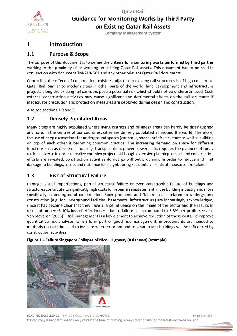
Damage, visual imperfections, partial structural failure or even catastrophic failure of buildings and structures contribute to significatly high costs for repair & reinstatement in the building industry and more specifically in underground construction. Such problems and ‘failure costs’ related to underground construction (e.g. for underground facilities, basements, infrastructure) are increasingly acknowledged, since it has become clear that they have a large influence on the image of the sector and the results in terms of money (5-10% loss of effectiveness due to failure costs compared to 2-3% net profit, see also Van Staveren (2006)). Risk management is a key element to achieve reduction of these costs. To improve quantitative risk analyses, which form part of good risk management, improvements are needed to methods that can be used to indicate whether or not and to what extent buildings will be influenced by construction activities.
Figure 1 – Failure Singapore Collapse of Nicoll Highway (Asianews) (example)
Qatar Rail
Guidance for Monitoring Works by Third Party on Existing Qatar Rail Assets
Company Management System
LEADING EXCELLENCE │ TM-224-G01, Rev. 1.0, 31/07/18 Page 9 of 155 Printed copy is uncontrolled and only valid at the time of printing. Always refer online for the latest approved revision.
Assessing the Situation
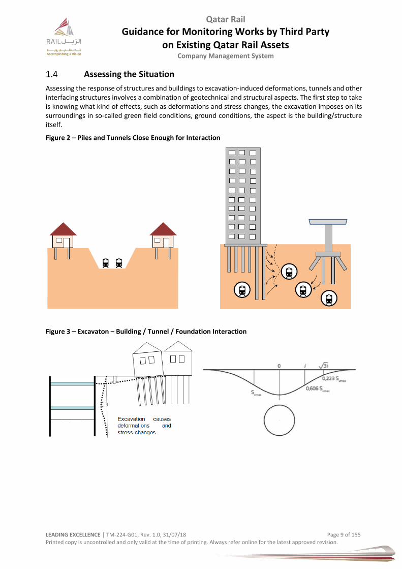
Assessing the response of structures and buildings to excavation-induced deformations, tunnels and other interfacing structures involves a combination of geotechnical and structural aspects. The first step to take is knowing what kind of effects, such as deformations and stress changes, the excavation imposes on its surroundings in so-called green field conditions, ground conditions, the aspect is the building/structure itself.
Figure 2 – Piles and Tunnels Close Enough for Interaction
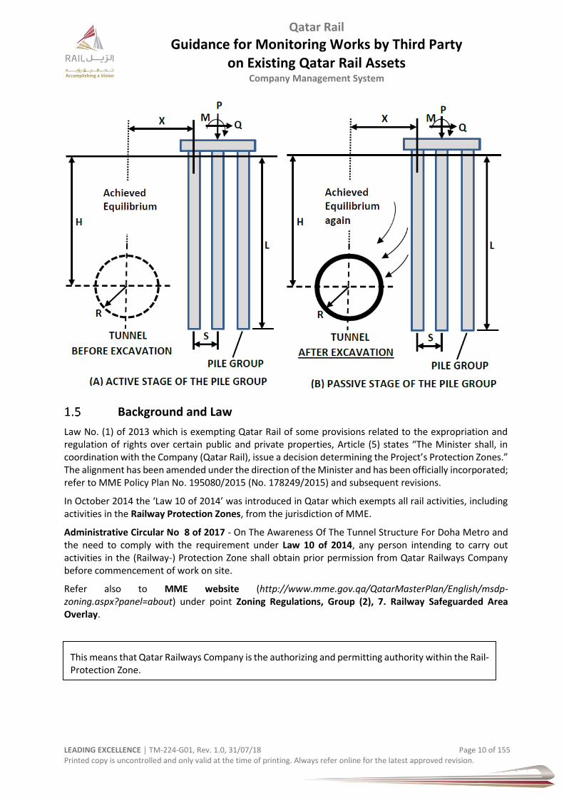
Figure 3 – Excavaton – Building / Tunnel / Foundation Interaction
Qatar Rail
Guidance for Monitoring Works by Third Party on Existing Qatar Rail Assets
Company Management System
LEADING EXCELLENCE │ TM-224-G01, Rev. 1.0, 31/07/18 Page 10 of 155 Printed copy is uncontrolled and only valid at the time of printing. Always refer online for the latest approved revision.
Background and Law
Law No. (1) of 2013 which is exempting Qatar Rail of some provisions related to the expropriation and regulation of rights over certain public and private properties, Article (5) states “The Minister shall, in coordination with the Company (Qatar Rail), issue a decision determining the Project’s Protection Zones.” The alignment has been amended under the direction of the Minister and has been officially incorporated; refer to MME Policy Plan No. 195080/2015 (No. 178249/2015) and subsequent revisions.
In October 2014 the ‘Law 10 of 2014’ was introduced in Qatar which exempts all rail activities, including activities in the Railway Protection Zones, from the jurisdiction of MME.
Administrative Circular No 8 of 2017 - On The Awareness Of The Tunnel Structure For Doha Metro and the need to comply with the requirement under Law 10 of 2014, any person intending to carry out activities in the (Railway-) Protection Zone shall obtain prior permission from Qatar Railways Company before commencement of work on site.
Refer also to MME website (http://www.mme.gov.qa/QatarMasterPlan/English/msdp-zoning.aspx?panel=about) under point Zoning Regulations, Group (2), 7. Railway Safeguarded Area Overlay.
This means that Qatar Railways Company is the authorizing and permitting authority within the Rail-Protection Zone.
Qatar Rail
Guidance for Monitoring Works by Third Party on Existing Qatar Rail Assets
Company Management System
LEADING EXCELLENCE │ TM-224-G01, Rev. 1.0, 31/07/18 Page 11 of 155 Printed copy is uncontrolled and only valid at the time of printing. Always refer online for the latest approved revision.
Safeguarding
The overarching principle is defined by the Qatar Rail Safeguarding Document (CMS Ref. TM-201-SR05). All activities (design and construction) require consultation with Qatar Rail and a Qatar Rail NOC within the rail protection zone. No works are permitted in the critical or exclusion zone. Exceptions apply.
Safeguarding is the process by which the proposed route or location of a project can be protected from conflicting third party developments.
Transport infrastructure, like the long distance railway, metro, light rail or trams, takes a long time to plan, design and then build. During this time, it has to be ensured that the space needed for the new railway, above and below ground, fits in with proposed new development around it. This is done through the process called ‘safeguarding’.
Safeguarding is a formal process, undertaken by the MME under direction of MOTC, to protect land required for major new infrastructure projects from developments. The ‘safeguarding direction & requirement’ instructs local planning authorities to consult with Qatar Rail on planning applications for land and developments within the safeguarded area (= ‘rail protection zone’ or ‘protection zone’).
The safeguarded area includes the possible route of railway sections which can be elevated, at-grade, and tunnels (underground) as well as land at ground level that is or may be used for the construction of the tunnels, stations and ventilation and emergency access shafts.
Railway Protection
Railway Protection Plans have been gazetted under the MME Policy in defining the Rail-Protection-Zone and the Critical Zone. The objective of the railway protection is to safeguard the future and operating railway structures and facilities from the effects of construction works carried out within the RPZ (refer also to paper “Design and Implementation of Automatic Deformation Monitoring System for the Construction of Railway Tunnel: A Case Study in West Island Line”, Calvin Tse, Jennifer Luk, Land Surveying Section, 6/F Fo Tan Railway House, Fo Tan, Hong Kong, ctse.jysluk)mrt.com.hk).
Should 3rd party developments be planned or constructed within the RPZ, a monitoring scheme has to be provided in order to ensure that safety and stability of the railway construction & operating railway is not jeopardized by the adjacent construction activities.
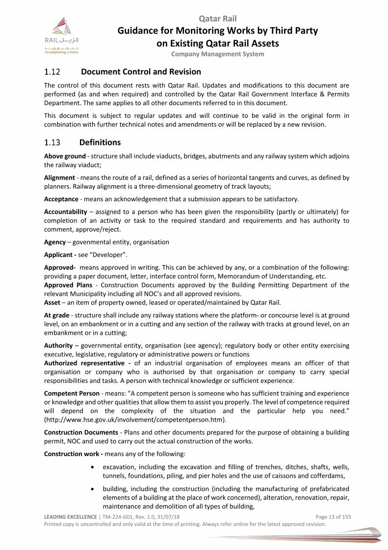
Protection Zone Hierarchy
The hierarchy of zones near a railway line follows a clear zoning arrangement.
Depending in which zone the third party scheme is located Qatar Rail will carry out an assessment on the impact and define requirements the third party has to comply with.
These conditions and restrictions become more stringent the closer you get to the actual railway asset (e.g. rail track, tunnel, etc.).
Figure 4 – Zone Hierarchy

Qatar Rail
Guidance for Monitoring Works by Third Party on Existing Qatar Rail Assets
Company Management System
LEADING EXCELLENCE │ TM-224-G01, Rev. 1.0, 31/07/18 Page 12 of 155 Printed copy is uncontrolled and only valid at the time of printing. Always refer online for the latest approved revision.
Provision of Document
Copies of this document are available electronically, within Qatar Rail’s organisation. Soft- and hard copies of the document are available on request from the Qatar Rail Government Interface & Permits Department. Organisations can obtain copies of this document from Qatar Rail directly on request.
Applicability
This document is a guideline for the design and construction phase of projects and schemes. Additional requirements, guidelines, regulations or standard operation procedures may be required during the testing & commissioning phase as well as the operational phase of the railway.
This document shall apply to all design and construction work to be carried out by private, public or cooperatively owned developers that could affect the railway, including rail stations and other related facilities. This shall include but not limited to the following:
railway projects
road & highway projects
utility companies
consultants
contractors
any other entity who is planning, installing and maintaining utility crossings inside or within the vicinity of the railway corridor
This document applies to all schemes that are located within the railway protection zone under the jurisdiction of the railway organisation such as:
new installations / new construction
additions to existing installations
temporary works (to facilitate the construction of permanent works)
repair works
protection works
enhancements
replacements
adjustments or relocations
emergency works
maintenance works
Change of Ownership
It is the scheme owner’s responsibility to inform Qatar Rail, in writing, of any changes to ownership, company or organisation name, address, points of contact, emergency numbers and websites.
Replacement of Facility
Any replacement or modification of an existing facility either with the same or of a different type, or design, is to be considered as a new utility installation and all work shall adhere to this document.
Qatar Rail
Guidance for Monitoring Works by Third Party on Existing Qatar Rail Assets
Company Management System
LEADING EXCELLENCE │ TM-224-G01, Rev. 1.0, 31/07/18 Page 13 of 155 Printed copy is uncontrolled and only valid at the time of printing. Always refer online for the latest approved revision.
Document Control and Revision
The control of this document rests with Qatar Rail. Updates and modifications to this document are performed (as and when required) and controlled by the Qatar Rail Government Interface & Permits Department. The same applies to all other documents referred to in this document.
This document is subject to regular updates and will continue to be valid in the original form in combination with further technical notes and amendments or will be replaced by a new revision.
Definitions
Above ground - structure shall include viaducts, bridges, abutments and any railway system which adjoins the railway viaduct;
Alignment - means the route of a rail, defined as a series of horizontal tangents and curves, as defined by planners. Railway alignment is a three-dimensional geometry of track layouts;
Acceptance - means an acknowledgement that a submission appears to be satisfactory.
Accountability – assigned to a person who has been given the responsibility (partly or ultimately) for completion of an activity or task to the required standard and requirements and has authority to comment, approve/reject.
Agency – govenmental entity, organisation
Applicant - see “Developer”.
Approved- means approved in writing. This can be achieved by any, or a combination of the following: providing a paper document, letter, interface control form, Memorandum of Understanding, etc. Approved Plans - Construction Documents approved by the Building Permitting Department of the relevant Municipality including all NOC’s and all approved revisions. Asset – an item of property owned, leased or operated/maintained by Qatar Rail.
At grade - structure shall include any railway stations where the platform- or concourse level is at ground level, on an embankment or in a cutting and any section of the railway with tracks at ground level, on an embankment or in a cutting;
Authority – governmental entity, organisation (see agency); regulatory body or other entity exercising executive, legislative, regulatory or administrative powers or functions Authorized representative - of an industrial organisation of employees means an officer of that organisation or company who is authorised by that organisation or company to carry special responsibilities and tasks. A person with technical knowledge or sufficient experience.
Competent Person - means: “A competent person is someone who has sufficient training and experience or knowledge and other qualities that allow them to assist you properly. The level of competence required will depend on the complexity of the situation and the particular help you need.” (http://www.hse.gov.uk/involvement/competentperson.htm).
Construction Documents - Plans and other documents prepared for the purpose of obtaining a building permit, NOC and used to carry out the actual construction of the works.
Construction work - means any of the following:
excavation, including the excavation and filling of trenches, ditches, shafts, wells, tunnels, foundations, piling, and pier holes and the use of caissons and cofferdams,
building, including the construction (including the manufacturing of prefabricated elements of a building at the place of work concerned), alteration, renovation, repair, maintenance and demolition of all types of building,
Qatar Rail
Guidance for Monitoring Works by Third Party on Existing Qatar Rail Assets
Company Management System
LEADING EXCELLENCE │ TM-224-G01, Rev. 1.0, 31/07/18 Page 14 of 155 Printed copy is uncontrolled and only valid at the time of printing. Always refer online for the latest approved revision.
civil engineering, including the construction, structural alteration , repair, maintenance and demolition of, for example, docks, harbours, inland waterways, dams, river and see defence works, roads and highways, railways, bridges and tunnels, viaducts, and works related to the provision of services such as communication, drainage, sewerage, water and energy supplies.
Control Measures - means measures taken to minimise a risk to the lowest level reasonably possible.
Corridor - means a railway zone dedicated for a particular purpose.
Critical Zone – refer to the Qatar Rail Safeguarding document Deep Excavation – means a trench which is deeper than 1.4 meters and a shaft deeper than 2.0 meters.
Design - means all design data comprising all drawings, layout and connection details, specifications and bill of quantities (including the specification of articles or substances), reports, documents, plans, software, formulae, calculations and other data whatsoever in any medium prepared relating to the design and construction of the works.
Demonstration of Evidence – related to coordination & agreement amongst parties; also safety related; documents which proves…
a) That the Third Party Design & Construction has been fully coordinated related to the railway b) that the railway infrastructure and railway vehicles including a functional robust safety
management system is applied in the rail operation system and suitable for safe operation Elevated - means above ground, usually bridge, viaduct type of structure, station or emergency exit;
Embankment - means a raised earth or gravel structure used to carry a railway;
Freight - means transport of goods in relation to railways often used as Freight Railway as part of the Long Distance network;
Emergency – an undesired event which has life threatening and/or extreme loss implication and requires immediate action.
Engineer - A full-time, qualified employee under the direct supervision of an inspecting Registered Design Professional retained to conduct continuous actual or assist with on-site inspections and testing.
Enhancement - means works delivered through a project that changes the operational capacity of the infrastructure. Also called improvements and amendments.
Environment – means surroundings in which an organisation works and operates, including air, water, land, natural resources, flora, fauna, humans and their interaction.
Development – new construction or alteration works or combination that could affect the railway tunnel and associated structures & infrastructure. These works can include demolition, alterations to existing structures, buildings, basements, foundations, anchors, temporary and permanent dewatering (groundwater table lowering), pipe jacking, site investigation, tunnelling, retaining walls, and any related works.
Developer – the person or organisation responsible for the new design & construction or alterations or any combination
Exclusion Zone – see critical zone Inspection - The periodic or random observation of work and the performance of tests for certain building’s or structure’s code compliance for a system or group of assembled components to assure compliance with the State and contract requirements.
Inspector – staff authorized by Qatar Rail to verify the safety of the railway infrastructure and operation of the railway; they guide, advise, monitor, supervise and carry out reviews, checks, surveys/measurements, investigations, records findings; ensures compliance with Qatar Rail
Qatar Rail
Guidance for Monitoring Works by Third Party on Existing Qatar Rail Assets
Company Management System
LEADING EXCELLENCE │ TM-224-G01, Rev. 1.0, 31/07/18 Page 15 of 155 Printed copy is uncontrolled and only valid at the time of printing. Always refer online for the latest approved revision.
requirements and conditions; recommend necessary and urgent actions to address any action or development that may affect or pose a threat to the safety of the railway; advises & issues improvement, stop notices, and non-compliances.
“Live” railway means connected to any source of electrical supply or subject to hazardous induces or capacitive voltages
Life Cycle - means the process of planning, design, construction, operation and maintenance;
Long Distance - means a rail system with higher loads and higher speeds, usually faster than metro and light rail;
Maintainer - means the entity or company responsible for maintenance (preserving something);
Method Statement - A Method Statement regulates - related to job positions - how specific tasks have to be performed in demanded quality. All steps of procedure and their sequence are documented.
Monitoring Database - The Monitoring Database collects the data from the various monitoring measurements.
Monitoring Design - refers to the design report and installation drawings on monitoring prepared by the Designer. Monitoring Design documents will be submitted for each section of the works as the design progresses.
Non-Structural Elements - Elements of a building, structure or element of the works that are not primary or secondary structural elements such as exterior curtain walls and cladding, non-load bearing partitions and stair railings. Inspection is required to assure compliance with the applicable standards.
Operator – the authorized party for the operation or maintenance of the railway infrastructure or railway vehicles (rolling stock), or both for the purposes of transportation.
Permit – a formal written approval granted by the agency/authority (Qatar Rail) in respect of a proposal for works interfacing with railways.
PPE (Personal Protective Equipment) – all equipment designated to be worn or held to protect against hazards likely to endanger safety and health at work.
Pre-Engineered Structural Elements - Structural elements specified by the Structural Engineer of Record, but which may be designed by a specialty registered design professional. Examples can be: girders; wood trusses; combination wood, metal; pre-cast concrete elements; prefabricated wood or metal buildings; tilt-up concrete panel reinforcement.
Primary Structural System - The combination of elements that serve to support the weight of the proposed works structural shell, the applicable live load based upon use and occupancy, and environmental loads such as wind, thermal loads and seismic loads, etc.
Pipe or Pipeline: a pipeline is not a tunnel and usually used for transport of commodies such as water, sewage, oil, etc.; can have different sizes and diameters.
Qualified person – a person who is educated, trained, experienced enough, professional engineer under the law an dregistration.
Qualified Professional - An individual practicing within their area of expertise meeting the qualifications established by the State of Qatar through this document and/or the requirements of the a accredited Board of Licensed Professionals.
Qatar Construction Standard 2014:
The objective of the Qatar Construction Standard is to provide up-to- date standards and specifications for all construction works in Qatar.

Qatar Rail
Guidance for Monitoring Works by Third Party on Existing Qatar Rail Assets
Company Management System
LEADING EXCELLENCE │ TM-224-G01, Rev. 1.0, 31/07/18 Page 16 of 155 Printed copy is uncontrolled and only valid at the time of printing. Always refer online for the latest approved revision.
Qatar Survey Manual:
The objective of the Qatar Survey Manual is to provide up-to-date standards and specifications for all survey and mapping activities in Qatar. It is based on generally accepted principles and practices of surveying. All surveys have to be conducted in accordance to the standards and specifications as laid out in the manual.
“Qatar Railways Company” hereafter called ‘Qatar Rail’, ‘Railway Company’, ‘Railway Organisation’, means the operating organisation provided with specific authorities by the government of Qatar. The organisation has specific authority to determine rules, requirements within the RPZ. Designs, builds and operates the railway.
RoW - means the Public Right of Way. The right-of-way is defined by state statutes as "the land, interest therein, acquired for devoted to a road, utility, highway and/or pedestrian zone.
Rail Protection Zone – refer to Qatar Rail Safeguarding Document
Railway - hereafter refers to all structures within the railway reserve and shall include but not be limited to the rail track, its foundations and embankments and all associated infrastructure and systems.
Rail (-way) Infrastructure – all establishments, installations, facilities, system and software necessary to operate railways and allow for safe operation including railway tracks, embankments, associated track structures, service roads, signalling- and communication systems, control systems, electric power supply, traction systems, utility buildings, stations, stabling yards, depots, warehouses, machinery, equipment, structures, corridors, tunnels, bridges, fences, barriers, associated utilities, and areas, parts and elements rail-related nature.
Railway lines - means the a specific type of rail route with an railway network defined by its use and purpose, railway lines can be categorised depending on the railway system used (i.e. Metro, Long Distance, etc.);
Railway facility - is any structure or associated land related to the operation of the railway system. Railway facilities include railway corridors, freight yards, depots and any type of station;
Replacement - means works that involve the replacement of a structure (or part of one) where there is no change to the functionality of that structure.
Responsibility - assigned to the person who undertakes the activity. This person may delegate the task or part thereof to another party, but remains responsible for the outcome.
Restricted Activity – Any activity considered by Qatar Rail to jeopardise (or has potential) or adversely affect the railway or poses a threat of risk to the railway. Refer to Qatar Rail manual.
Risk Assessment - means a report that documents the determination of quantitative or qualitative value of risk related to a situation and a recognized threat (also called hazard) and detailing the control measures. The identification of potential risks and mitigation measures required to carry out any intended work.
Safety – free from unacceptable risks of loss and damage
Safety Requirements – set of rules, standards and guidelines to be adhered to while designing and constructing and going operational and operating intended works. Target is to eliminate or minimize risks.
Secondary Structural Elements – Building elements that are structurally significant for the function they serve, but are not necessary for the stability of the primary structure. Examples include: support beams above the primary roof structure which carry an air conditioning unit (chiller), elevator support rails and beams, retaining walls independent of the primary building, flagpole or light pole foundations, false work required for the erection of the primary structural system, steel stairs or railings, etc.
Qatar Rail
Guidance for Monitoring Works by Third Party on Existing Qatar Rail Assets
Company Management System
LEADING EXCELLENCE │ TM-224-G01, Rev. 1.0, 31/07/18 Page 17 of 155 Printed copy is uncontrolled and only valid at the time of printing. Always refer online for the latest approved revision.
Structure – The term “structure” refers mainly to reinforced concrete or structural steel structures that comprise the infrastructure wealth of Qatar Rail metro and include the tunnels, stations, emergency shafts and cross passages, underground subways, viaducts, bridges, troughs, ramps, retaining walls, etc.; means the mode of building, construction and arrangement of parts and elements, this can be a concrete or earth structure.
Structural Intervention: refer to document TM-219-G01
Surveying authority in Qatar is the Centre for GIS (CGIS) of the Ministry of Municipality and Urban Planning.
Standards – means an agreed way (national or international recognised organisations, standardisation) of doing something (i.e. product, process, supply, etc.). Standards articulate minimum constraints on internal and external designer, suppliers and contractors. The word ‘standard’ references in this document for simplicity also codes, guidelines, manuals and similar documents.
Structure – means any concrete or reinforced concrete structure and/or building including earthworks, embankments, any foundations including fence post footings.
Software – IRIS is the name of the central monitoring software. TUnIS is a navigation software for tunnelling.
Support zone – zone where structure supports are located. Comprise of anchors, ground improvement, grouted zones, and similar elements contributing to structural integrity and stability.
Third Party – A person, company, organisation, agency, authority or entity of similar nature besides the two primarily involved in a situation, project, scheme or work activity, may it be design or construction related.
Tolerance – means construction tolerance and is a permissible range of variation in a dimension of an object. Tolerances in construction are generally a variation in a dimension, construction limit, or physical characteristic of a material;
Top of Rail – means the uppermost part of the rail (crest); abbreviated with ToR or TOR;
Track – means the track on a railway or railroad, also known as the permanent way, is the structure consisting of the rails, fasteners, railroad ties (sleepers) and ballast (or slab track), plus the underlying subgrade. It enables trains to move by providing a dependable surface for their wheels to roll;
Track Gauge – distance between the running edges of the two running rails on same track.
Traction Current – Electrical supply to conductor rail system.
Trained Personnel – staff and workers suitably educated and trained to carry out a specific role and/or activity suitable for the job.
Tramway – or tram means an electrically driven public transport vehicle that runs on rails let into the surface of the road, usually shared space between road traffic and tram traffic;
Tunnel – means an artificial underground passage; and
Tunnel – there is a vaiety of sources for definitions.
Road tunnel in the UK: “a subsurface highway structure for a length of 150 meters or more”
NFPA (USA): “An underground structure with a length greater than 23 meters and a diameter greater than 1,800 millimeters.”
A tunnel may be used for transport, i.e. for pedestrians (by foot) or cyclists, vehicluar road traffic, railway, metro, trams.
Exceptions apply for utility tunnels.
Trench – opening which length is greater than its depth and the width is less than its length.
Qatar Rail
Guidance for Monitoring Works by Third Party on Existing Qatar Rail Assets
Company Management System
LEADING EXCELLENCE │ TM-224-G01, Rev. 1.0, 31/07/18 Page 18 of 155 Printed copy is uncontrolled and only valid at the time of printing. Always refer online for the latest approved revision.
Shaft – any vertical opening which dimension is less than its depth.
Shallow Excavation – means a trench which is shallower than 1.4 meters and a shaft shallower than 2.0 meters
Underground structure – shall include any transition structure, station, bored tunnel, cut and cover tunnel,
interchange shaft, pedestrian passage, cross passages between tunnels and emergency escape shafts
Work –means the whole of the design and construction for the proposed works.
Writing - includes all matters written, typewritten or printed either in whole or part.
Zone of Influence – of a railway structure below ground is the area over which external loads are likely to affect the railway structure.
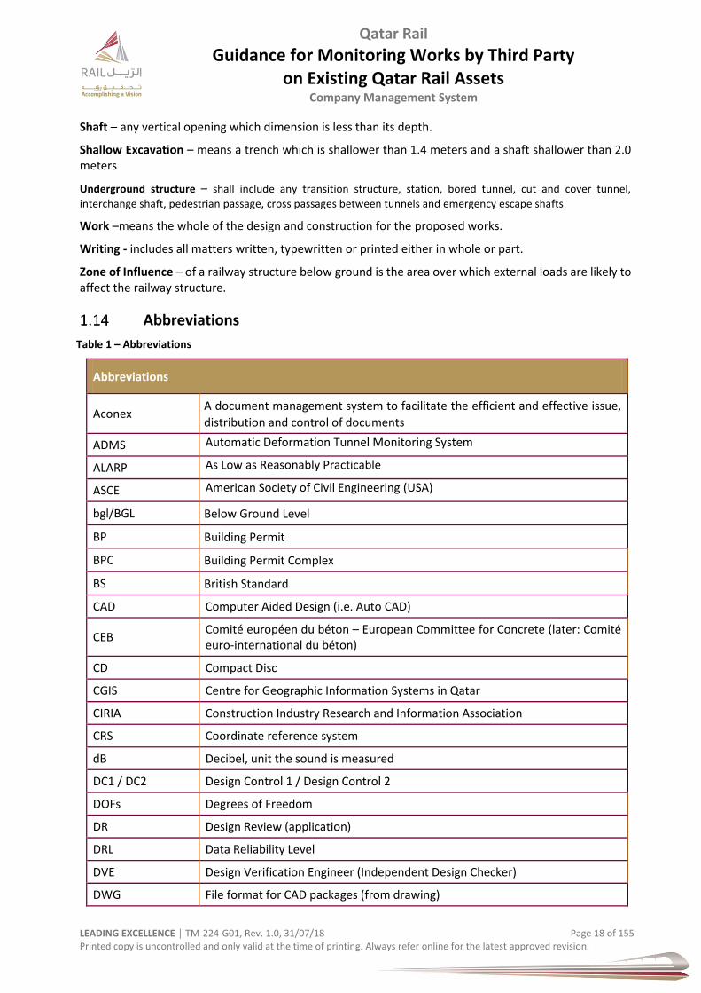
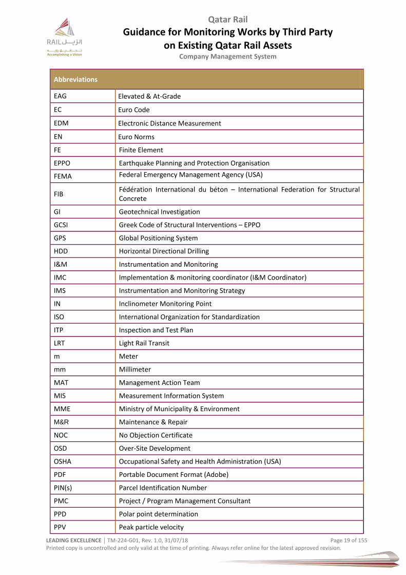
Abbreviations
Table 1 – Abbreviations
Abbreviations
Aconex A document management system to facilitate the efficient and effective issue,
distribution and control of documents
ADMS Automatic Deformation Tunnel Monitoring System
ALARP As Low as Reasonably Practicable
ASCE American Society of Civil Engineering (USA)
bgl/BGL Below Ground Level
BP Building Permit
BPC Building Permit Complex
BS British Standard
CAD Computer Aided Design (i.e. Auto CAD)
CEB Comité européen du béton – European Committee for Concrete (later: Comité euro-international du béton)
CD Compact Disc
CGIS Centre for Geographic Information Systems in Qatar
CIRIA Construction Industry Research and Information Association
CRS Coordinate reference system
dB Decibel, unit the sound is measured
DC1 / DC2 Design Control 1 / Design Control 2
DOFs Degrees of Freedom
DR Design Review (application)
DRL Data Reliability Level
DVE Design Verification Engineer (Independent Design Checker)
DWG File format for CAD packages (from drawing)
Qatar Rail
Guidance for Monitoring Works by Third Party on Existing Qatar Rail Assets
Company Management System
LEADING EXCELLENCE │ TM-224-G01, Rev. 1.0, 31/07/18 Page 19 of 155 Printed copy is uncontrolled and only valid at the time of printing. Always refer online for the latest approved revision.
Abbreviations
EAG Elevated & At-Grade
EC Euro Code
EDM Electronic Distance Measurement
EN Euro Norms
FE Finite Element
EPPO Earthquake Planning and Protection Organisation
FEMA Federal Emergency Management Agency (USA)
FIB Fédération International du béton – International Federation for Structural Concrete
GI Geotechnical Investigation
GCSI Greek Code of Structural Interventions – EPPO
GPS Global Positioning System
HDD Horizontal Directional Drilling
I&M Instrumentation and Monitoring
IMC Implementation & monitoring coordinator (I&M Coordinator)
IMS Instrumentation and Monitoring Strategy
IN Inclinometer Monitoring Point
ISO International Organization for Standardization
ITP Inspection and Test Plan
LRT Light Rail Transit
m Meter
mm Millimeter
MAT Management Action Team
MIS Measurement Information System
MME Ministry of Municipality & Environment
M&R Maintenance & Repair
NOC No Objection Certificate
OSD Over-Site Development
OSHA Occupational Safety and Health Administration (USA)
PDF Portable Document Format (Adobe)
PIN(s) Parcel Identification Number
PMC Project / Program Management Consultant
PPD Polar point determination
PPV Peak particle velocity
Qatar Rail
Guidance for Monitoring Works by Third Party on Existing Qatar Rail Assets
Company Management System
LEADING EXCELLENCE │ TM-224-G01, Rev. 1.0, 31/07/18 Page 20 of 155 Printed copy is uncontrolled and only valid at the time of printing. Always refer online for the latest approved revision.
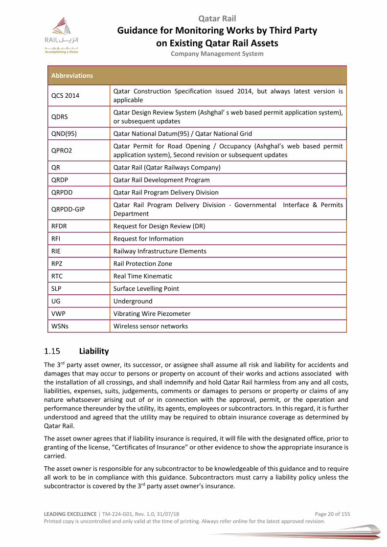
Abbreviations
QCS 2014 Qatar Construction Specification issued 2014, but always latest version is applicable
QDRS Qatar Design Review System (Ashghal’ s web based permit application system), or subsequent updates
QND(95) Qatar National Datum(95) / Qatar National Grid
QPRO2 Qatar Permit for Road Opening / Occupancy (Ashghal’s web based permit application system), Second revision or subsequent updates
QR Qatar Rail (Qatar Railways Company)
QRDP Qatar Rail Development Program
QRPDD Qatar Rail Program Delivery Division
QRPDD-GIP Qatar Rail Program Delivery Division - Governmental Interface & Permits Department
RFDR Request for Design Review (DR)
RFI Request for Information
RIE Railway Infrastructure Elements
RPZ Rail Protection Zone
RTC Real Time Kinematic
SLP Surface Levelling Point
UG Underground
VWP Vibrating Wire Piezometer
WSNs Wireless sensor networks
Liability
The 3rd party asset owner, its successor, or assignee shall assume all risk and liability for accidents and damages that may occur to persons or property on account of their works and actions associated with the installation of all crossings, and shall indemnify and hold Qatar Rail harmless from any and all costs, liabilities, expenses, suits, judgements, comments or damages to persons or property or claims of any nature whatsoever arising out of or in connection with the approval, permit, or the operation and performance thereunder by the utility, its agents, employees or subcontractors. In this regard, it is further understood and agreed that the utility may be required to obtain insurance coverage as determined by Qatar Rail.
The asset owner agrees that if liability insurance is required, it will file with the designated office, prior to granting of the license, “Certificates of Insurance” or other evidence to show the appropriate insurance is carried.
The asset owner is responsible for any subcontractor to be knowledgeable of this guidance and to require all work to be in compliance with this guidance. Subcontractors must carry a liability policy unless the subcontractor is covered by the 3rd party asset owner’s insurance.

Qatar Rail
Guidance for Monitoring Works by Third Party on Existing Qatar Rail Assets
Company Management System
LEADING EXCELLENCE │ TM-224-G01, Rev. 1.0, 31/07/18 Page 21 of 155 Printed copy is uncontrolled and only valid at the time of printing. Always refer online for the latest approved revision.
Disclaimer
Qatar Rail has taken care to ensure that the content of this document is accurate, complete and suitable
for its stated purpose. Qatar Rail does not take warranties, express or implied that compliance with the
contents of this document shall be sufficient to ensure safe systems of work or operation. Qatar Rail will
not be liable to pay compensation in respect of the content or subsequent use of this document for any
purpose other than its stated purpose or for any purpose other than that for which it was prepared except
where Qatar Rail can be shown to have acted in bad faith or where there has been wilful default.
Participation, opinion, permission or approval by Qatar Rail does not extend to or imply any warranty to
representation concerning the suitability or adequacy of the works. Nor does it displace the responsibility
of the developer in relation to such matters.
Qatar Rail
Guidance for Monitoring Works by Third Party on Existing Qatar Rail Assets
Company Management System
LEADING EXCELLENCE │ TM-224-G01, Rev. 1.0, 31/07/18 Page 22 of 155 Printed copy is uncontrolled and only valid at the time of printing. Always refer online for the latest approved revision.
Specifications & Standards
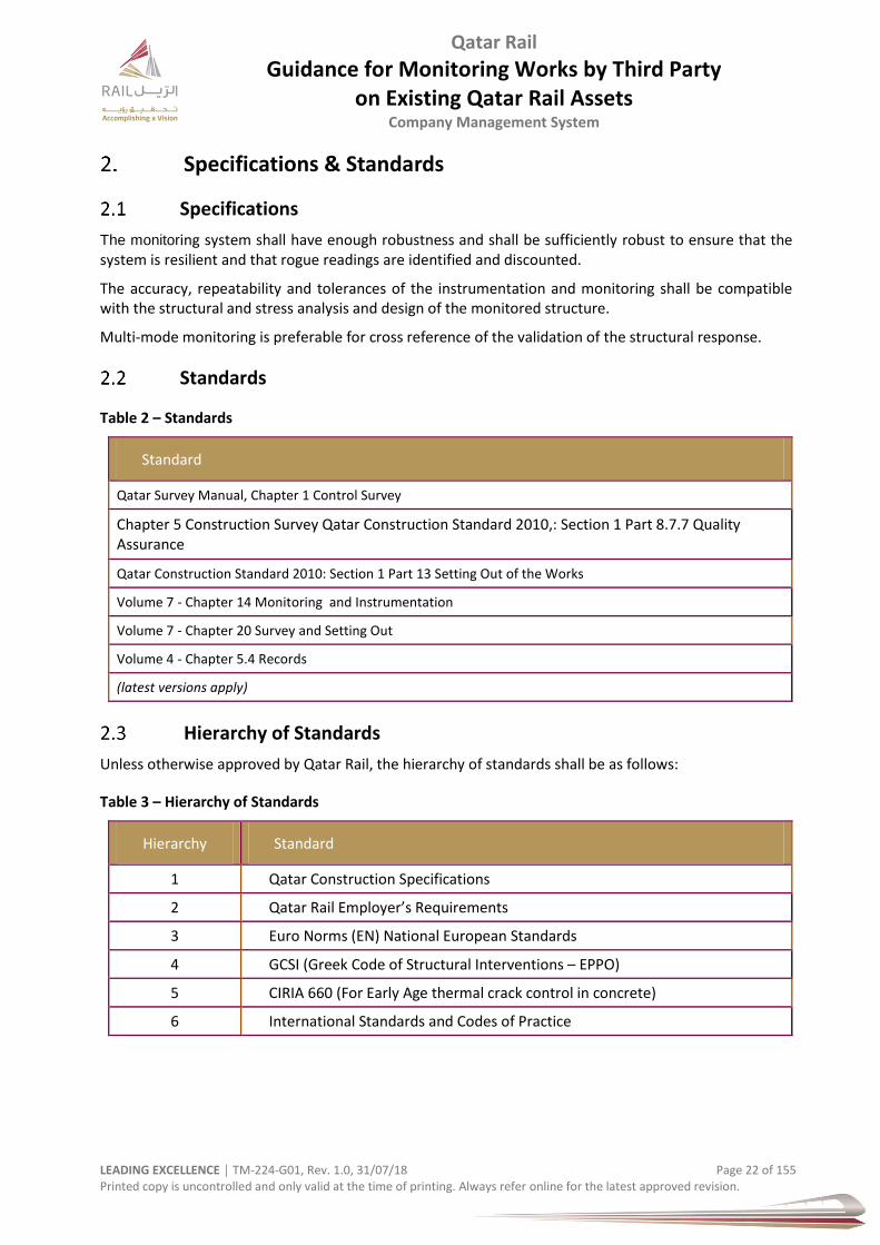
Specifications
The monitoring system shall have enough robustness and shall be sufficiently robust to ensure that the system is resilient and that rogue readings are identified and discounted.
The accuracy, repeatability and tolerances of the instrumentation and monitoring shall be compatible with the structural and stress analysis and design of the monitored structure.
Multi-mode monitoring is preferable for cross reference of the validation of the structural response.
Standards
Table 2 – Standards
Standard
Qatar Survey Manual, Chapter 1 Control Survey
Chapter 5 Construction Survey Qatar Construction Standard 2010,: Section 1 Part 8.7.7 Quality Assurance
Qatar Construction Standard 2010: Section 1 Part 13 Setting Out of the Works
Volume 7 - Chapter 14 Monitoring and Instrumentation
Volume 7 - Chapter 20 Survey and Setting Out
Volume 4 - Chapter 5.4 Records
(latest versions apply)
Hierarchy of Standards
Unless otherwise approved by Qatar Rail, the hierarchy of standards shall be as follows:
Table 3 – Hierarchy of Standards
Hierarchy Standard
1 Qatar Construction Specifications
2 Qatar Rail Employer’s Requirements
3 Euro Norms (EN) National European Standards
4 GCSI (Greek Code of Structural Interventions – EPPO)
5 CIRIA 660 (For Early Age thermal crack control in concrete)
6 International Standards and Codes of Practice
Qatar Rail
Guidance for Monitoring Works by Third Party on Existing Qatar Rail Assets
Company Management System
LEADING EXCELLENCE │ TM-224-G01, Rev. 1.0, 31/07/18 Page 23 of 155 Printed copy is uncontrolled and only valid at the time of printing. Always refer online for the latest approved revision.
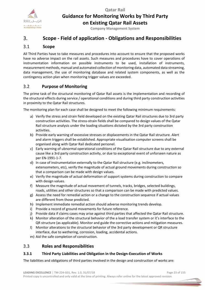
Scope - Field of application - Obligations and Responsibilities
Scope
All Third Parties have to take measures and procedures into account to ensure that the proposed works have no adverse impact on the rail assets. Such measures and procedures have to cover operations of instrumentation information on possible instruments to be used, installation of instruments, measurement methods, manual and automated collection of monitoring data, automated data streaming, data management, the use of monitoring database and related system components, as well as the contingency action plan when monitoring trigger values are exceeded.
Purpose of Monitoring
The prime task of the structural monitoring of Qatar Rail assets is the implementation and recording of the structural effects during service / operational conditions and during third party construction activities in proximity to the Qatar Rail structures.
The monitoring plan for each case shall be designed to meet the following minimum requirements:
Verify the stress and strain field developed on the existing Qatar Rail structures due to 3rd party construction activities. The stress-strain fields shall be compared to design values of the Qatar Rail structure analysis under the loading situations dictated by the 3rd party construction activities.
Provide early warning of excessive stresses or displacements in the Qatar Rail structure. Alert and alarm triggers shall be established. Appropriate visualisation computer screens shall be organised along with Qatar Rail dedicated personel.
Early warning of ubnormal operational conditions of the Qatar Rail structure due to any external cause like a 3rd party construction activity, or due to exceptional event of unforseen nature as per EN-1991-1-7.
In case of instrumentation externally to the Qatar Rail structure (e.g. inclinometers, extensometers, etc), verify the magnitude of actual ground movements during construction so that a comparison can be made with design values.
Verify the magnitude of actual deformation of support systems during construction to compare with design values.
Measure the magnitude of actual movement of tunnels, tracks, bridges, selected buildings, roads, utilities and other structures so that a comparison can be made with predicted values.
Assess the need for remedial action or a change to the construction sequence if actual values are different from those predicted.
Implement immediate remedial action should adverse monitoring trends develop. Provide a record of ground movements for future reference. Provide data if claims cases may arise against third parties that affected the Qatar Rail structure. Monitor alteration of the structural behavior of the a load transfer system or it’s interface to the
QR structure (as applicable). Monitor and guide the corrective actions and mitigation measures. Monitor alterations to the structural behavior of the 3rd party development or QR structure
interface, due to wethering, corrosion, loading, accidental actions. Aid the safe completion of construction.
Roles and Responsibilities
Third Party Liabilities and Obligation in the Design-Execution of Works
The liabilities and obligations of third parties involved in the design and construction of works are:

Qatar Rail
Guidance for Monitoring Works by Third Party on Existing Qatar Rail Assets
Company Management System
LEADING EXCELLENCE │ TM-224-G01, Rev. 1.0, 31/07/18 Page 24 of 155 Printed copy is uncontrolled and only valid at the time of printing. Always refer online for the latest approved revision.
a) The liability of structural damages or of any kind of reduction of the Design Life of the Qatar Rail structural assets is undertaken by the 3rd party developer and its design and execution team. Similarly, any deviation from the agreed timetable of the works that causes disturbance to the Qatar Rail services and operations belongs to the 3rd party developer.
b) The design, construction and use of new structures in the Rail-Protection-Zone of Qatar Rail, under a combination of actions including accidental actions, such as excessive wind action, explosion, hazardous action, and other unforeseen actions as per EN1991-1-7, and EN1998, shall be done in such a way as to ensure the satisfaction, in whole or in part, of the following requirements, depending on the desired performance level:
i. The third party engineer responsible for the design and supervision of the Works shall have the necessary qualifications and the appropriate experience concerning the type of structures to be checked, repaired, modified or strengthened.
ii. Appropriate means must be put in place to properly monitor and measure performance of infrastructure elements.
iii. Reliable methods, means and tools must be developed for assessing and forecasting condition of infrastructure elements, and for consequential remedial works- and M&R planning, as well as for optimization of resource allocation activities.
Competent & Qualified Person
A "competent person" is defined as "one who is capable of identifying existing and predictable hazards in the surroundings or working conditions which are unsanitary, hazardous, or dangerous to employees, and who has authorization to take prompt corrective measures to eliminate them" [OSHA 29 CFR 1926.32(f)].
A qualified person is one who, by possession of a recognized degree, certificate, or professional standing, or who by extensive knowledge, training, and experience, has successfully deomonstrated his abiltiy and skills, received training to recognize and avoid the hazards involved in carrying out all duties required for his/her position.
Design Engineer
The Third Party Design Engineer has the obligation of developing a complete and technically sound design
of the intervention, this includes:
a) Identifying of rail interfaces b) Addressing rail interfaces c) Assessing the impact of the proposed works on the railway d) Proposing a robust monitoring scheme to ensure the impact of the proposed works on the railway
is adequately controlled, monitored, recorded and reported. e) Agreeing with Qatar Rail any such measures. f) Provided a fully comprehensive Monitoring Design
The design Engineer must suggest all the necessary safety measures to the owner, prior to any initiation
of works.
Supervision Engineer
The Supervising Engineer shall be on charge of the complete technical implementation of the approved design of the intervention and montiroing of the railway. The responsibility of the supervising Engineer is to properly supervise & control the works in accordance with the provisions of this document, with the aim to implement the approved design and methods.
Qatar Rail
Guidance for Monitoring Works by Third Party on Existing Qatar Rail Assets
Company Management System
LEADING EXCELLENCE │ TM-224-G01, Rev. 1.0, 31/07/18 Page 25 of 155 Printed copy is uncontrolled and only valid at the time of printing. Always refer online for the latest approved revision.
Thrid Party Developer
The Third Party Developers involved are required to perform the works and monitoring according to the design, this document, the applicable technical standards and guidelines, and the state of the art, while taking all the necessary safety measures. The 3rd party developer has the responsibility for providing, and preserving the agreed (with Qatar Rail) level of reliability of data from the investigation works.
The 3rd party developer is also responsible for the necessary structural & track monitoring needed to verify the response of the existing Qatar Rail structural assets and operations during the works.
The responsibility of 3rd party developers involved in the project consists also of the proper workmanship of the works according to this document, the design of the intervention, the applicable technical specifications and instructions and the state of the art, as well as the observance of the indicated safety measures.
The 3rd party developer along with his Design team shall schedule and supervise a series of investigative works and monitoring in order to document and justify the assumptions and the structural assessment.
Instrumentation & Monitoring Team
I&M Manager - leads and executes the I&M programme, reviews monitoring data in terms of reliability and accuracy, ensures timely reporting, distribution and collection of feedbacks on monitoring results, decides on reporting tools and templates, acts as the custodian for instrument list and monitoring database, authorises modification to monitoring software and database, and represents the third party towards I&M matters
Geotechnical Engineer / Geotechnical Design Manager / Bridge Engineer and Bridge Manager - review monitoring results jointly to compare predictions with observed values, assist in interpretation of monitoring results, advise the construction team on contingency measures upon discussion, if necessary, with designers and others, and cross check the effectiveness of implemented contingency measures through site inspections.
Design Manager - actsas the third party monitoring coordinator to facilitate / improve communication among the I&M team members and Qatar Rail.
Designer's Coordinator - provides technical advice on monitoring design, actively involve in the analysis of data and comparison between predictions and performance, carries out interpretation of monitoring results and design back-analysis (if necessary), and recommends potential contingency measures in design reports.
I&M Engineer - supervises technicians and surveyors of I&M subcontractor, examines monitoring records to detect any unexpected trends, ensures timely and technically correct reporting of monitoring data, coordinates with relevant site personnel to maintain functioning of instruments throughout the monitoring period, and observes the behaviours of the ground and structures on site independently
Chief Surveyor - manages the subcontractors, reviews construction related surveying and monitoring data & requirements and provides technical and contractual guidance on site operations.
Surveyor – carries out day to day survey activities on site, reviews construction related surveying and monitoring data & requirements and provides survey data, measurements, comparisons and reports from site operations.

Qatar Rail
Guidance for Monitoring Works by Third Party on Existing Qatar Rail Assets
Company Management System
LEADING EXCELLENCE │ TM-224-G01, Rev. 1.0, 31/07/18 Page 26 of 155 Printed copy is uncontrolled and only valid at the time of printing. Always refer online for the latest approved revision.
Health, Safety & Environment
Prior to commencement of any activity, a method statement for monitoring and instrumentation shall be submitted to Qatar Rail for review and approval. This detailed method statement shall include, but not be limited to:
detailed specifications for the installation of all instruments, data loggers, automatic 3D-
Deformation Optical Monitoring System and related systems to be used on the Project;
detailed plan for instrumentation and monitoring, including instrumentation layout, trigger
(warning and alarm), design and allowable values and the procedures for evaluating the
monitored data;
detailed information for all instruments to be used on the Project;
maintenance, inspection and calibration schedules for all instruments, including read out and data
loggers;
for each section of the works (i.e. C&C Sections, TBM, Tunnels Sprayed Concrete Lining Tunnels)
detailed measurement concepts. The measurement concepts shall include but are not limited to:
i. definition, purpose, and method of measurement;
ii. requirements for accuracy;
iii. details of measurement methods, measurement systems and measurement accuracies;
iv. for all instrumentation, the calibration certificates and installation details of each
instrument;
v. detailed plan of instrumentation locations;
vi. measures to protect the measuring systems;
vii. proposed schedule for installing instrumentation;
viii. description of data collection and data management;
ix. description of analysis, documentation and reporting of all monitoring data.
Prior to commencement of any activity, the workforce shall receive an induction on the project site safety requirements. Additonally Daily task talks and Tool box talk shall be conducted.
Figure 5 – Example – Metro Safety Briefing
Qatar Rail
Guidance for Monitoring Works by Third Party on Existing Qatar Rail Assets
Company Management System
LEADING EXCELLENCE │ TM-224-G01, Rev. 1.0, 31/07/18 Page 27 of 155 Printed copy is uncontrolled and only valid at the time of printing. Always refer online for the latest approved revision.
Frontline Supervisors shall ensure that personnel protective equipment is worn by site personnel at all times during construction activity. They shall also be responsible to ensure all workers perform their duties in a safe manner. Heat stress training will be provided and provision of adequate drinking water will be in place at all times. The inspection area shall be secured by providing warning barriers / signs. Proper access shall be provided accordingly. Good Housekeeping will be observed in work areas at all times. Construction wastes will be segregated and disposed of to an approved dump yard.
Personal Protective and Safety Equipment
All personnel involved in excavation work will wear the minimum PPE:
• Safety Helmets • Safety Shoes • High Visibility Vests. • Protective eye wear (glasses) • Gloves • Any other PPE deemed appropriate and/or necessary.
Medical / First Aid Facilities
Prior to the commencement of work, confirmation should be made that all appropriate and required first aid facilities and trained first aiders are available on the site and if necessary, shall be made available for prompt attention to the injured person.
Protection of the Environment
The Third Party / developer shall take into account the environmental impacts that can affect the existing rail tunnels and the rail operations with a view to minimizing any effects throughout the entire life cycle of the proposed development/ scheme. Typically:
Stormwater management
Air quality and dust (comply with State of Qatar Environmental Protection Law, Annex (3/1st), latest version
Noise and vibration
Traffic impact
Visual impact
Waste management
Ecological impact (goundwater draw-down)
Groundwater contamination
Qatar Rail
Guidance for Monitoring Works by Third Party on Existing Qatar Rail Assets
Company Management System
LEADING EXCELLENCE │ TM-224-G01, Rev. 1.0, 31/07/18 Page 28 of 155 Printed copy is uncontrolled and only valid at the time of printing. Always refer online for the latest approved revision.
Risk Management
General
When projects are implemented next to other assets, existing or planned, effects on each other are unavoidable. This needs to be addressed already during the design process. In the construction phase, the ‘dynamics’ of a scheme can become increasingly significant. Interaction of the project with and impact on surroundings develops rapidly into tangible and real issues.
It may be advised to establish risk management team during all project phases for design, engineering, construction, control, supervision and finance. Responsibilities have to be clearly defined and teams should be integrated in the project sturcture. Pro-active behaviour should be fostered. Such team can be led by a risk manager and several specialist (geological, structural, hydrological, environmental engineers, site supervisor, monitoring coordinator, accountants, etc.).
Identifying the risks goes ‘hand in hand’ with the method of construction. Countless literature is availble to guide, manage and control such procedures in development, realisation, implementation and control.
The Third Party shall undertake a comprehensive site specific risk assessment to ensure that potential hazards which could have an adverse impact on the railway throughout all project stages (construction, operation or planned) are clearly addressed.
The Third Party must prepare a risk assessment report for submission to Qatar Rail and obtain approval before carrying out the works.
Risk management consists of a vairety of components. It identifies:
Hazard – event that has the potential to impact a project, which could result in a undesirable consequence.
Likelihood/ probability of occurance – ranking of the hazard. Expressed in percent or a number of predetermined scale.
Severity of impact - defines the ranking a hazard has for how severe the consequence would be if the hazard occurs. Expressed in percent or a number of predetermined scale.
Detectability – how easy or hard a hazard can happen.
Risk Program – a structured procedure to identify, quantify and mitigate risks associated with the project.
Risk Management - phase of the risk program in which identified and specified risks are avoided or eliminated, transferred or other parties better positioned to manage them, mitigated or accepted and controlled by the project. It involves also contingency plans to deal with the risks and definition of resources and budget.
Identification – of hazards identified at a specific point/time in the project. Hazards can be added at any point in time and gathered in the risk register.
Risk Register – a format for recording risk information, description, likelihood, impact, mitigation, status and ownership.
Risk Assessment - identifies the hazard and assesses, in qualitative and often also in quantitative terms the likelihood of the hazard event, its consequences, puts a value to a concrete situation and recognized threat.
Risk Analysis – makes the identified hazards sepcific with regards to location, responsible parties, and quantifies likelihood and impact.
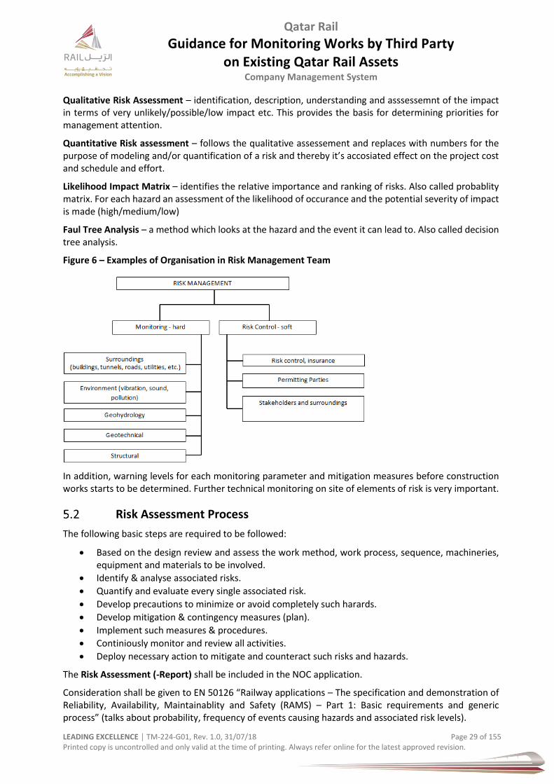
Qatar Rail
Guidance for Monitoring Works by Third Party on Existing Qatar Rail Assets
Company Management System
LEADING EXCELLENCE │ TM-224-G01, Rev. 1.0, 31/07/18 Page 29 of 155 Printed copy is uncontrolled and only valid at the time of printing. Always refer online for the latest approved revision.
Qualitative Risk Assessment – identification, description, understanding and asssessemnt of the impact in terms of very unlikely/possible/low impact etc. This provides the basis for determining priorities for management attention.
Quantitative Risk assessment – follows the qualitative assessement and replaces with numbers for the purpose of modeling and/or quantification of a risk and thereby it’s accosiated effect on the project cost and schedule and effort.
Likelihood Impact Matrix – identifies the relative importance and ranking of risks. Also called probablity matrix. For each hazard an assessment of the likelihood of occurance and the potential severity of impact is made (high/medium/low)
Faul Tree Analysis – a method which looks at the hazard and the event it can lead to. Also called decision tree analysis.
Figure 6 – Examples of Organisation in Risk Management Team
In addition, warning levels for each monitoring parameter and mitigation measures before construction works starts to be determined. Further technical monitoring on site of elements of risk is very important.
Risk Assessment Process
The following basic steps are required to be followed:
Based on the design review and assess the work method, work process, sequence, machineries, equipment and materials to be involved.
Identify & analyse associated risks.
Quantify and evaluate every single associated risk.
Develop precautions to minimize or avoid completely such harards.
Develop mitigation & contingency measures (plan).
Implement such measures & procedures.
Continiously monitor and review all activities.
Deploy necessary action to mitigate and counteract such risks and hazards.
The Risk Assessment (-Report) shall be included in the NOC application.
Consideration shall be given to EN 50126 “Railway applications – The specification and demonstration of Reliability, Availability, Maintainablity and Safety (RAMS) – Part 1: Basic requirements and generic process” (talks about probability, frequency of events causing hazards and associated risk levels).

Qatar Rail
Guidance for Monitoring Works by Third Party on Existing Qatar Rail Assets
Company Management System
LEADING EXCELLENCE │ TM-224-G01, Rev. 1.0, 31/07/18 Page 30 of 155 Printed copy is uncontrolled and only valid at the time of printing. Always refer online for the latest approved revision.
ALARP
The principle “As Low as Reasonably Practicable” shall be followed. The following steps assist in achieving ALARP:
1. Hazard idenification for proposed activities within the Rail Protection Zone 2. Evaluate the hazard in matrix against frequency of occurance, severity of impact. 3. Identify measures to lower the risk to a negligible or tolerable level. 4. Demonstrate effectiveness / feasability / robustness of proposed mitigation and monitoring
regime.
Risk & Hazard Identification
General
The Third Party shall indentify all possible hazards of the porposed works/activities before the works commencement during the NOC process. The Third Party shall interfaces and effects on the railway which could cause damage or disruption to the railway and consider all available information, such as:
Site set-up / arrangment
Work environment
Work method and process
Existing, planned and under construction works / assets
Railway operation
Members of public (vehicular & pedestrian & cyclilsts)
Other public transport (bus, taxi, etc.)
Plant, machinery, and equipment
Temporary works
Competency of responsible staff, labour and operators
Relevant laws, standards, specifications, guidance documents, and legislations
Risk Origin
The origin of a risk or hazard can arise from different sources. This can for example be distinguished by “type of use and occupancy” or “type of structure”. The ways of differentiating are endless and should be reasonably defined.
Table 4 – Based on Occupancy
Section Example
Agricultural Small simple building, barn, farm house, chicken coop, buildings to raise livestock, cow shed
Commercial Ware house, bank, convention centres, gas station, automobile companies, super markets, sky scrapers, market house, commercial shops, office buildings
Assembly Cinema, symphony and concert halls, television and radio stations admitting an audience, theatres, amusement arcades, stadiums, arenas
Residential / domestic buildings Apartment, villa, bungalow, nursing home, compounds
Educational Museum, art galleries, school, archive, library
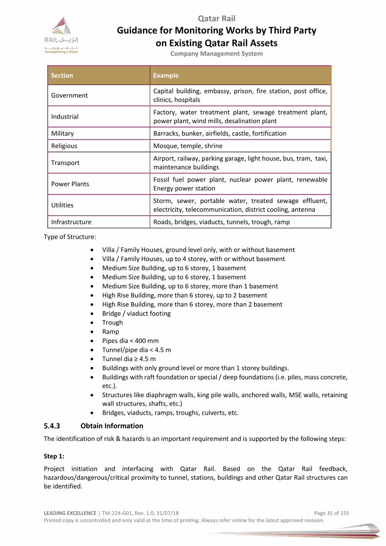
Qatar Rail
Guidance for Monitoring Works by Third Party on Existing Qatar Rail Assets
Company Management System
LEADING EXCELLENCE │ TM-224-G01, Rev. 1.0, 31/07/18 Page 31 of 155 Printed copy is uncontrolled and only valid at the time of printing. Always refer online for the latest approved revision.
Section Example
Government Capital building, embassy, prison, fire station, post office, clinics, hospitals
Industrial Factory, water treatment plant, sewage treatment plant, power plant, wind mills, desalination plant
Military Barracks, bunker, airfields, castle, fortification
Religious Mosque, temple, shrine
Transport Airport, railway, parking garage, light house, bus, tram, taxi, maintenance buildings
Power Plants Fossil fuel power plant, nuclear power plant, renewable Energy power station
Utilities Storm, sewer, portable water, treated sewage effluent, electricity, telecommunication, district cooling, antenna
Infrastructure Roads, bridges, viaducts, tunnels, trough, ramp
Type of Structure:
Villa / Family Houses, ground level only, with or without basement
Villa / Family Houses, up to 4 storey, with or without basement
Medium Size Building, up to 6 storey, 1 basement
Medium Size Building, up to 6 storey, 1 basement
Medium Size Building, up to 6 storey, more than 1 basement
High Rise Building, more than 6 storey, up to 2 basement
High Rise Building, more than 6 storey, more than 2 basement
Bridge / viaduct footing
Trough
Ramp
Pipes dia < 400 mm
Tunnel/pipe dia < 4.5 m
Tunnel dia ≥ 4.5 m
Buildings with only ground level or more than 1 storey buildings.
Buildings with raft foundation or special / deep foundations (i.e. piles, mass concrete, etc.).
Structures like diaphragm walls, king pile walls, anchored walls, MSE walls, retaining wall structures, shafts, etc.)
Bridges, viaducts, ramps, troughs, culverts, etc.
Obtain Information
The identification of risk & hazards is an important requirement and is supported by the following steps: Step 1:
Project initiation and interfacing with Qatar Rail. Based on the Qatar Rail feedback, hazardous/dangerous/critical proximity to tunnel, stations, buildings and other Qatar Rail structures can be identified.
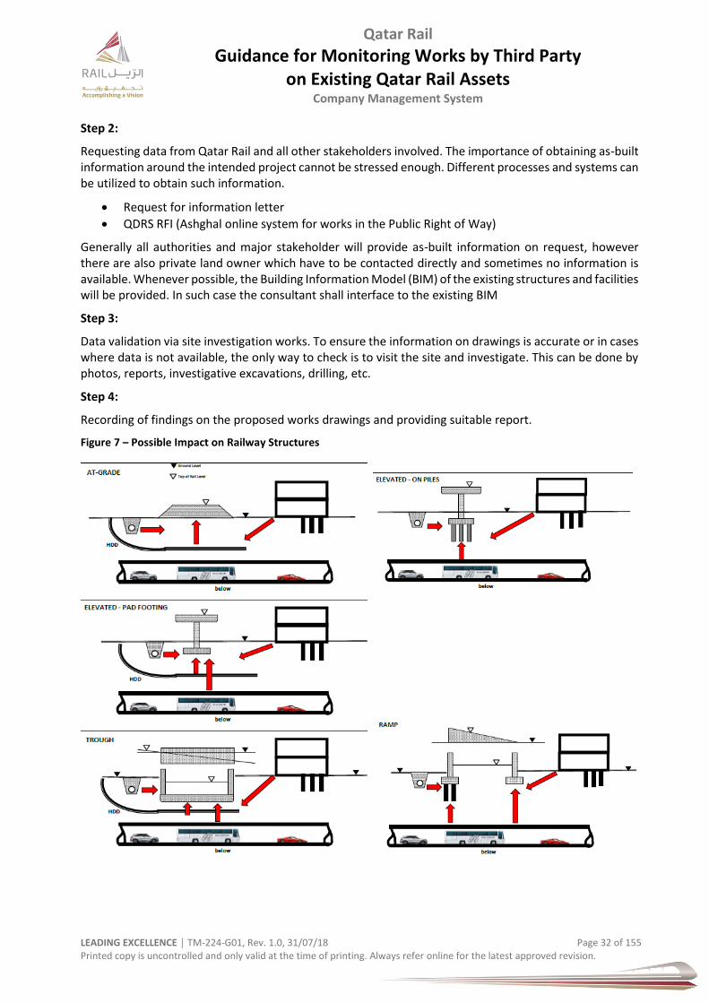
Qatar Rail
Guidance for Monitoring Works by Third Party on Existing Qatar Rail Assets
Company Management System
LEADING EXCELLENCE │ TM-224-G01, Rev. 1.0, 31/07/18 Page 32 of 155 Printed copy is uncontrolled and only valid at the time of printing. Always refer online for the latest approved revision.
Step 2:
Requesting data from Qatar Rail and all other stakeholders involved. The importance of obtaining as-built information around the intended project cannot be stressed enough. Different processes and systems can be utilized to obtain such information.
Request for information letter
QDRS RFI (Ashghal online system for works in the Public Right of Way)
Generally all authorities and major stakeholder will provide as-built information on request, however there are also private land owner which have to be contacted directly and sometimes no information is available. Whenever possible, the Building Information Model (BIM) of the existing structures and facilities will be provided. In such case the consultant shall interface to the existing BIM
Step 3:
Data validation via site investigation works. To ensure the information on drawings is accurate or in cases where data is not available, the only way to check is to visit the site and investigate. This can be done by photos, reports, investigative excavations, drilling, etc.
Step 4:
Recording of findings on the proposed works drawings and providing suitable report.
Figure 7 – Possible Impact on Railway Structures
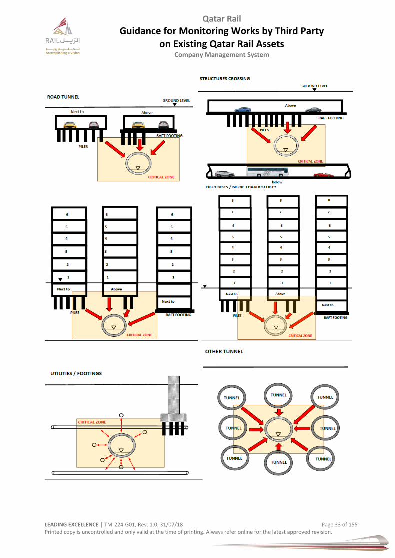
Qatar Rail
Guidance for Monitoring Works by Third Party on Existing Qatar Rail Assets
Company Management System
LEADING EXCELLENCE │ TM-224-G01, Rev. 1.0, 31/07/18 Page 33 of 155 Printed copy is uncontrolled and only valid at the time of printing. Always refer online for the latest approved revision.
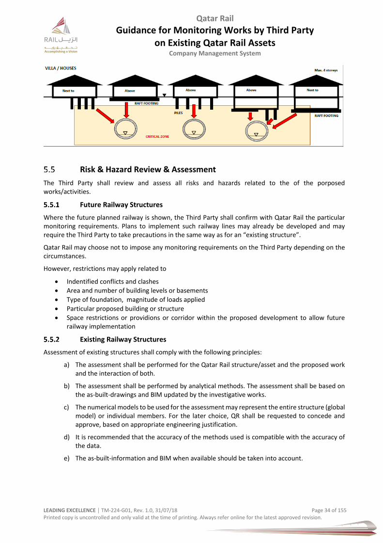
Qatar Rail
Guidance for Monitoring Works by Third Party on Existing Qatar Rail Assets
Company Management System
LEADING EXCELLENCE │ TM-224-G01, Rev. 1.0, 31/07/18 Page 34 of 155 Printed copy is uncontrolled and only valid at the time of printing. Always refer online for the latest approved revision.
Risk & Hazard Review & Assessment
The Third Party shall review and assess all risks and hazards related to the of the porposed works/activities.
Future Railway Structures
Where the future planned railway is shown, the Third Party shall confirm with Qatar Rail the particular monitoring requirements. Plans to implement such railway lines may already be developed and may require the Third Party to take precautions in the same way as for an “existing structure”.
Qatar Rail may choose not to impose any monitoring requirements on the Third Party depending on the circumstances.
However, restrictions may apply related to
Indentified conflicts and clashes
Area and number of building levels or basements
Type of foundation, magnitude of loads applied
Particular proposed building or structure
Space restrictions or providions or corridor within the proposed development to allow future railway implementation
Existing Railway Structures
Assessment of existing structures shall comply with the following principles:
a) The assessment shall be performed for the Qatar Rail structure/asset and the proposed work and the interaction of both.
b) The assessment shall be performed by analytical methods. The assessment shall be based on the as-built-drawings and BIM updated by the investigative works.
c) The numerical models to be used for the assessment may represent the entire structure (global model) or individual members. For the later choice, QR shall be requested to concede and approve, based on appropriate engineering justification.
d) It is recommended that the accuracy of the methods used is compatible with the accuracy of the data.
e) The as-built-information and BIM when available should be taken into account.
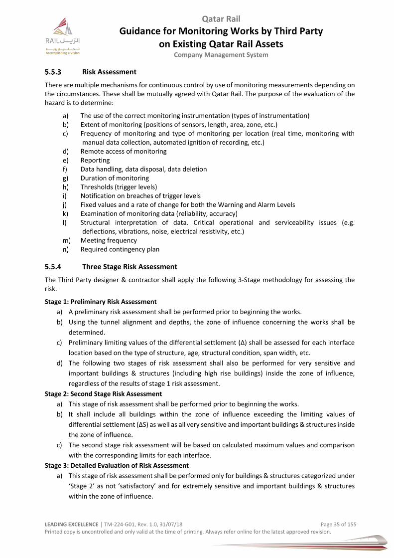
Qatar Rail
Guidance for Monitoring Works by Third Party on Existing Qatar Rail Assets
Company Management System
LEADING EXCELLENCE │ TM-224-G01, Rev. 1.0, 31/07/18 Page 35 of 155 Printed copy is uncontrolled and only valid at the time of printing. Always refer online for the latest approved revision.
Risk Assessment
There are multiple mechanisms for continuous control by use of monitoring measurements depending on the circumstances. These shall be mutually agreed with Qatar Rail. The purpose of the evaluation of the hazard is to determine:
The use of the correct monitoring instrumentation (types of instrumentation) Extent of monitoring (positions of sensors, length, area, zone, etc.) Frequency of monitoring and type of monitoring per location (real time, monitoring with
manual data collection, automated ignition of recording, etc.) Remote access of monitoring Reporting Data handling, data disposal, data deletion Duration of monitoring Thresholds (trigger levels)
Notification on breaches of trigger levels Fixed values and a rate of change for both the Warning and Alarm Levels Examination of monitoring data (reliability, accuracy) Structural interpretation of data. Critical operational and serviceability issues (e.g.
deflections, vibrations, noise, electrical resistivity, etc.) Meeting frequency Required contingency plan
Three Stage Risk Assessment
The Third Party designer & contractor shall apply the following 3-Stage methodology for assessing the risk.
Stage 1: Preliminary Risk Assessment
a) A preliminary risk assessment shall be performed prior to beginning the works.
b) Using the tunnel alignment and depths, the zone of influence concerning the works shall be
determined.
c) Preliminary limiting values of the differential settlement (Δ) shall be assessed for each interface
location based on the type of structure, age, structural condition, span width, etc.
d) The following two stages of risk assessment shall also be performed for very sensitive and
important buildings & structures (including high rise buildings) inside the zone of influence,
regardless of the results of stage 1 risk assessment.
Stage 2: Second Stage Risk Assessment
a) This stage of risk assessment shall be performed prior to beginning the works.
b) It shall include all buildings within the zone of influence exceeding the limiting values of
differential settlement (ΔS) as well as all very sensitive and important buildings & structures inside
the zone of influence.
c) The second stage risk assessment will be based on calculated maximum values and comparison
with the corresponding limits for each interface.
Stage 3: Detailed Evaluation of Risk Assessment
a) This stage of risk assessment shall be performed only for buildings & structures categorized under
‘Stage 2’ as not ‘satisfactory’ and for extremely sensitive and important buildings & structures
within the zone of influence.
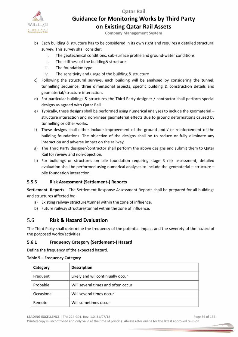
Qatar Rail
Guidance for Monitoring Works by Third Party on Existing Qatar Rail Assets
Company Management System
LEADING EXCELLENCE │ TM-224-G01, Rev. 1.0, 31/07/18 Page 36 of 155 Printed copy is uncontrolled and only valid at the time of printing. Always refer online for the latest approved revision.
b) Each building & structure has to be considered in its own right and requires a detailed structural
survey. This survey shall consider:
i. The geotechnical conditions, sub-surface profile and ground-water conditions
ii. The stiffness of the building& structure
iii. The foundation type
iv. The sensitivity and usage of the building & structure
c) Following the structural surveys, each building will be analysed by considering the tunnel,
tunnelling sequence, three dimensional aspects, specific building & construction details and
geomaterial/structure interaction.
d) For particular buildings & structures the Third Party designer / contractor shall perform special
designs as agreed with Qatar Rail.
e) Typically, these designs shall be performed using numerical analyses to include the geomaterial –
structure interaction and non-linear geomaterial effects due to ground deformations caused by
tunnelling or other works.
f) These designs shall either include improvement of the ground and / or reinforcement of the
building foundations. The objective of the designs shall be to reduce or fully eliminate any
interaction and adverse impact on the railway.
g) The Third Party designer/contractor shall perform the above designs and submit them to Qatar
Rail for review and non-objection.
h) For buildings or structures on pile foundation requiring stage 3 risk assessment, detailed
evaluation shall be performed using numerical analyses to include the geomaterial – structure –
pile foundation interaction.
Risk Assessment (Settlement-) Reports
Settlement- Reports – The Settlement Response Assessment Reports shall be prepared for all buildings
and structures affected by:
a) Existing railway structure/tunnel within the zone of influence.
b) Future railway structure/tunnel within the zone of influence.
Risk & Hazard Evaluation
The Third Party shall determine the frequency of the potential impact and the severety of the hazard of the porposed works/activities.
Frequency Category (Settlement-) Hazard
Define the frequency of the expected hazard.
Table 5 – Frequency Category
Category Description
Frequent Likely and wil continiually occur
Probable Will several times and often occur
Occasional Will several times occur
Remote Will sometimes occur
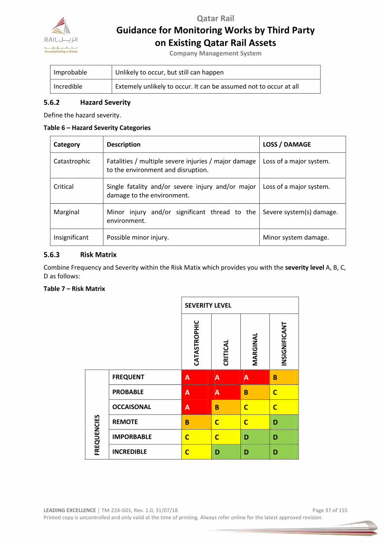
Qatar Rail
Guidance for Monitoring Works by Third Party on Existing Qatar Rail Assets
Company Management System
LEADING EXCELLENCE │ TM-224-G01, Rev. 1.0, 31/07/18 Page 37 of 155 Printed copy is uncontrolled and only valid at the time of printing. Always refer online for the latest approved revision.
Improbable Unlikely to occur, but still can happen
Incredible Extemely unlikely to occur. It can be assumed not to occur at all
Hazard Severity
Define the hazard severity.
Table 6 – Hazard Severity Categories
Category Description LOSS / DAMAGE
Catastrophic Fatalities / multiple severe injuries / major damage to the environment and disruption.
Loss of a major system.
Critical Single fatality and/or severe injury and/or major damage to the environment.
Loss of a major system.
Marginal Minor injury and/or significant thread to the environment.
Severe system(s) damage.
Insignificant Possible minor injury. Minor system damage.
Risk Matrix
Combine Frequency and Severity within the Risk Matix which provides you with the severity level A, B, C, D as follows:
Table 7 – Risk Matrix
SEVERITY LEVEL
CA
TAST
RO
PH
IC
CR
ITIC
AL
MA
RG
INA
L
INSI
GN
IFIC
AN
T
FREQ
UEN
CIE
S
FREQUENT A A A B
PROBABLE A A B C
OCCAISONAL A B C C
REMOTE B C C D
IMPORBABLE C C D D
INCREDIBLE C D D D

Qatar Rail
Guidance for Monitoring Works by Third Party on Existing Qatar Rail Assets
Company Management System
LEADING EXCELLENCE │ TM-224-G01, Rev. 1.0, 31/07/18 Page 38 of 155 Printed copy is uncontrolled and only valid at the time of printing. Always refer online for the latest approved revision.
Allocate the severity level A, B, C or D to each potential hazard which provides you with the risk level for each potential hazard (intolerable, undesireable, tolerable and negligible.
Table 8 – Risk Categories
A Intolerable
B Undersireble
C Tolerable
D Negligible
Following the risk level (category) the associated action tells what has to be done, as per table below.
It is important to respond to the respective risk action clear, comprehensively, by means of staffing, monitoring, and controlling and / or engineering and construction methods.
Table 9 – Risk Category Actions
RISK CATEGORY ACTION
INTOLERABLE MUST BE ELIMINATED / AVOIDED
UNDESIREABLE SHALL ONLY BE ACCEPTED WHEN RISK REDUCTION IS IMPRACTICABLE AND WITH THE AGREEMENT OF QATAR RAIL.
TOLERABLE ACCEPTABLE WITH ADEQUADE CONTROL MEASURES AND THE AGREEMENT OF QATAR RAIL.
NEGLIGIBLE ACCEPTABLE
Risk & Hazard Control
The Third Party shall, depending on the magnitude of the risk (see chapter before), manage the risk and determine control measures with the goal to reduce the risk to an acceptable level.
Highest priority is to remove the hazard at the origin by either choosing a suitable design, material, machinery/equipment, method(s) and people.
The right way to approach this is illustrated as follows:
Table 10 – Control Hierarchy
RANK
HIERARCHY ACTION
1 ELIMINATE PHYSICALLY AVOID AND REMOVE THE HAZARD
2 SUBSTITUTE REPLACE THE HAZARD
3 ENGINEERING CONTROLS ISOLATE HAZARDS & PEOPLE
4 ADMINISTRATIVE ‘SOFT‘ CONTROLS
INTRODUCE HOLD-POINTS AND CHECKS; CHANGE PEOPLE BEHAVIOR
5 TRAINING & PPE PROTECT STAFF, WORKER AND PUBLIC
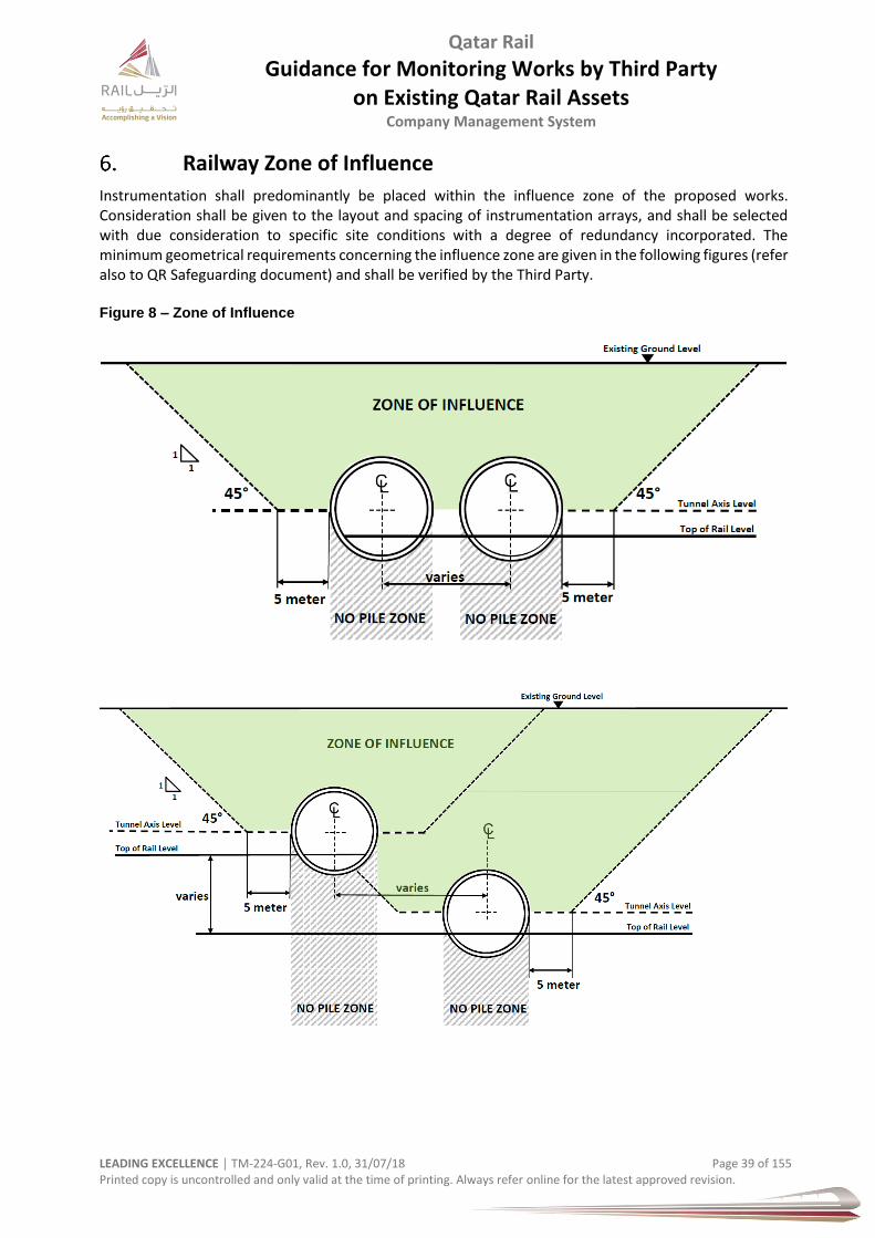
Qatar Rail
Guidance for Monitoring Works by Third Party on Existing Qatar Rail Assets
Company Management System
LEADING EXCELLENCE │ TM-224-G01, Rev. 1.0, 31/07/18 Page 39 of 155 Printed copy is uncontrolled and only valid at the time of printing. Always refer online for the latest approved revision.
Railway Zone of Influence
Instrumentation shall predominantly be placed within the influence zone of the proposed works. Consideration shall be given to the layout and spacing of instrumentation arrays, and shall be selected with due consideration to specific site conditions with a degree of redundancy incorporated. The minimum geometrical requirements concerning the influence zone are given in the following figures (refer also to QR Safeguarding document) and shall be verified by the Third Party. Figure 8 – Zone of Influence
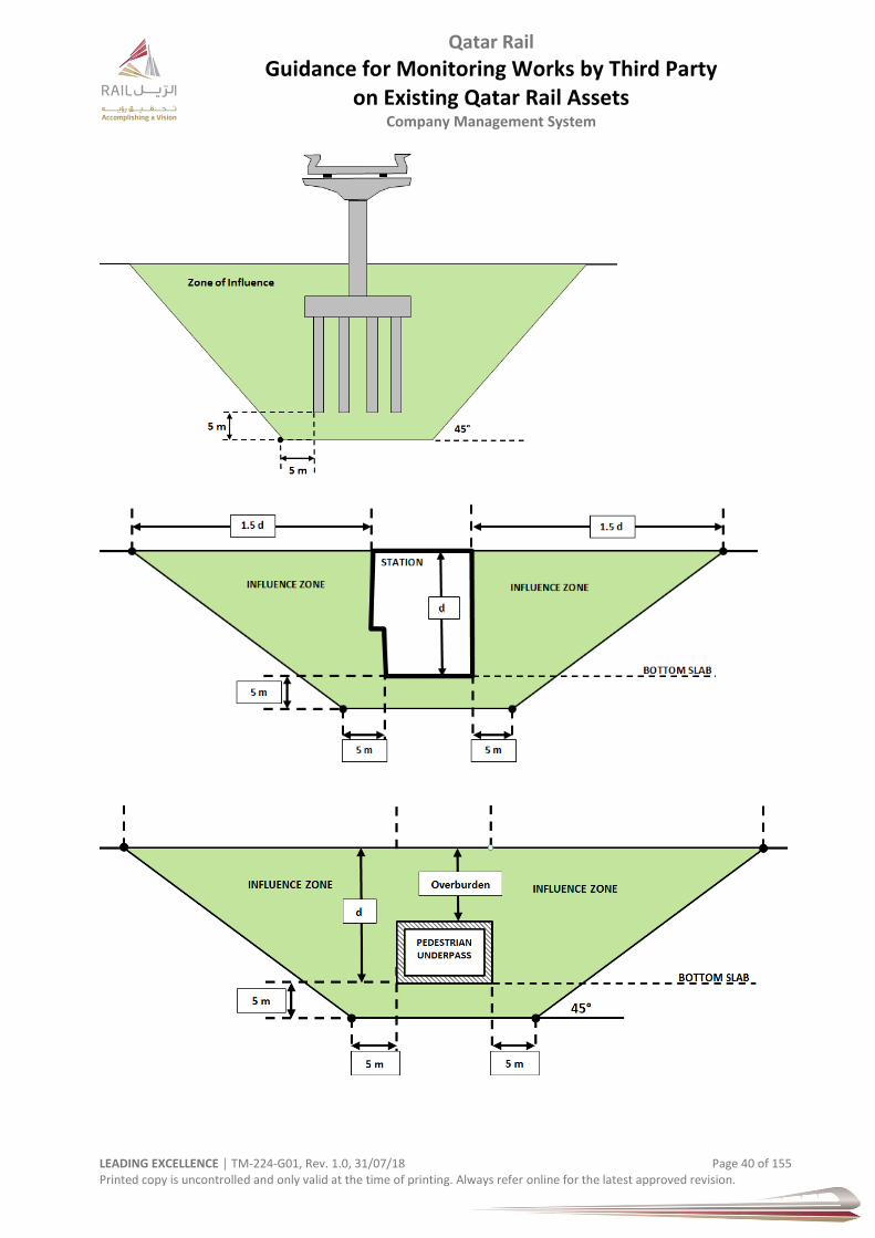
Qatar Rail
Guidance for Monitoring Works by Third Party on Existing Qatar Rail Assets
Company Management System
LEADING EXCELLENCE │ TM-224-G01, Rev. 1.0, 31/07/18 Page 40 of 155 Printed copy is uncontrolled and only valid at the time of printing. Always refer online for the latest approved revision.

Qatar Rail
Guidance for Monitoring Works by Third Party on Existing Qatar Rail Assets
Company Management System
LEADING EXCELLENCE │ TM-224-G01, Rev. 1.0, 31/07/18 Page 41 of 155 Printed copy is uncontrolled and only valid at the time of printing. Always refer online for the latest approved revision.
Allowable Limits
General
For any new development or infrastructure project within the Rail Protection Zone, the required permits must be obtained from Qatar Rail by a competent/qualified person before the intended works starting.
A engineering evaluation report with assessment, review and justification to fulfil the allowable limits together with a site specific method statement and risk assessment of the intended work, instrumentation proposal and review levels for the instruments needed to be submitted by the competent/qualified person to Qatar Rail for review and approval (best during planning/design stage). The third party design shall include and incorporate all necessary measures to ensure the safety of the rail structure(s).
Guidance
Differential settlements and displacements that could occur at structure joints of the Doha Metro civil structures if there are further property developments or infrastructure schemes taking place on or near the Doha Metro civil structures have to follow limits. Unwanted effects of such developments are not confined to joints of structures only. They can occur within a structure such as with displacements of bored tunnels or of earthworks.
The civil structures contain of many nominal “joints”, but in principle it is normally assumed that with respect to train movements all structure joints are taken as nominally “static joints”. The only exceptions being those joints of bridge- and viaduct structures that are “joints designed for movement”.
The “guideway” contains of the structure clearance (space for trains) to travel and the railway track which supports and guides the trains within the structure clearance space. The track itself being supported by the civil works/structure.
Considerations need to cover:- a) Limits for Design Controls
As a limit from existing to a static value at the end of the new work
b) Consider monitoring measurements during the new works construction
There could be set limits for triggering actions to construction and possibly to railway operations
c) Train movements from beginning to end of the new construction need to be unrestricted over the
full duration.
Intermediate and/or final adjustments to track or rail supports may be necessary t rail supports
or track supports.
d) Limits of structure movement on guideway are generally based on ride comfort limits (also called
running quality, or smoothness).
These are usually framed in terms of tolerances of “track geometry”.
e) There can be secondary (less immediate) effects after “ride comfort” such as:-
Local increased deterioration of track components and even track structure
f) There must also be planned limits in place for safety and these considering:-
i. Gradual effects (relative to train operations) - such that monitoring activities can detect
movements before they reach a degree that can affect train services.
ii. Sudden effects (relative to train operations) –
Trains affected without notice.
Discomfort requiring speed restriction
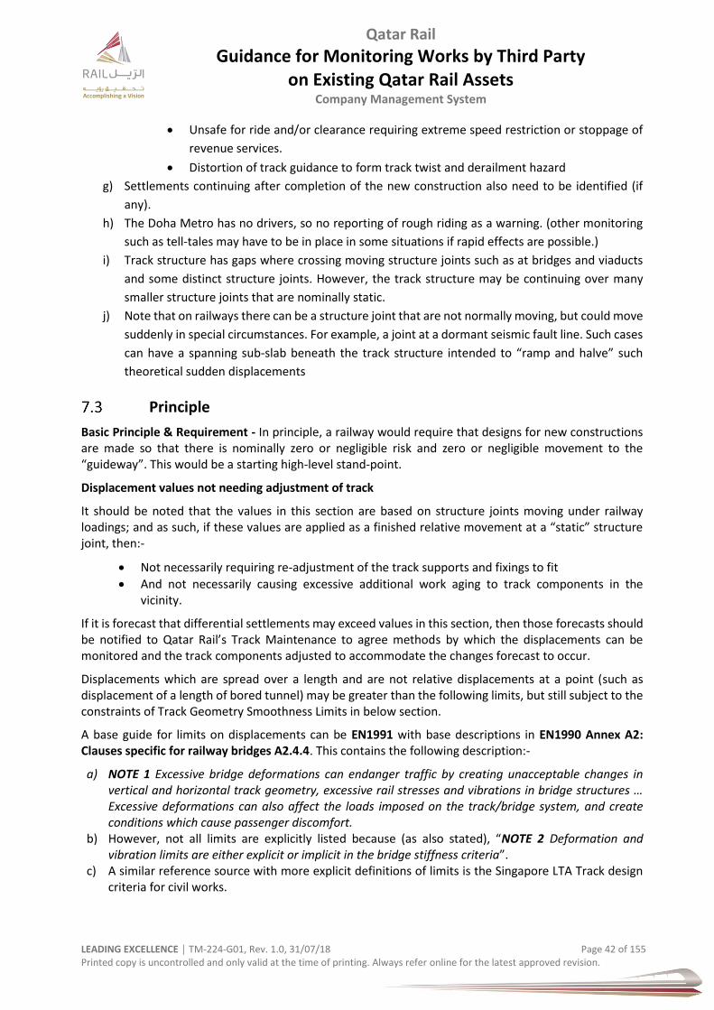
Qatar Rail
Guidance for Monitoring Works by Third Party on Existing Qatar Rail Assets
Company Management System
LEADING EXCELLENCE │ TM-224-G01, Rev. 1.0, 31/07/18 Page 42 of 155 Printed copy is uncontrolled and only valid at the time of printing. Always refer online for the latest approved revision.
Unsafe for ride and/or clearance requiring extreme speed restriction or stoppage of
revenue services.
Distortion of track guidance to form track twist and derailment hazard
g) Settlements continuing after completion of the new construction also need to be identified (if
any).
h) The Doha Metro has no drivers, so no reporting of rough riding as a warning. (other monitoring
such as tell-tales may have to be in place in some situations if rapid effects are possible.)
i) Track structure has gaps where crossing moving structure joints such as at bridges and viaducts
and some distinct structure joints. However, the track structure may be continuing over many
smaller structure joints that are nominally static.
j) Note that on railways there can be a structure joint that are not normally moving, but could move
suddenly in special circumstances. For example, a joint at a dormant seismic fault line. Such cases
can have a spanning sub-slab beneath the track structure intended to “ramp and halve” such
theoretical sudden displacements
Principle
Basic Principle & Requirement - In principle, a railway would require that designs for new constructions are made so that there is nominally zero or negligible risk and zero or negligible movement to the “guideway”. This would be a starting high-level stand-point.
Displacement values not needing adjustment of track
It should be noted that the values in this section are based on structure joints moving under railway loadings; and as such, if these values are applied as a finished relative movement at a “static” structure joint, then:-
Not necessarily requiring re-adjustment of the track supports and fixings to fit
And not necessarily causing excessive additional work aging to track components in the vicinity.
If it is forecast that differential settlements may exceed values in this section, then those forecasts should be notified to Qatar Rail’s Track Maintenance to agree methods by which the displacements can be monitored and the track components adjusted to accommodate the changes forecast to occur.
Displacements which are spread over a length and are not relative displacements at a point (such as displacement of a length of bored tunnel) may be greater than the following limits, but still subject to the constraints of Track Geometry Smoothness Limits in below section.
A base guide for limits on displacements can be EN1991 with base descriptions in EN1990 Annex A2: Clauses specific for railway bridges A2.4.4. This contains the following description:-
a) NOTE 1 Excessive bridge deformations can endanger traffic by creating unacceptable changes in vertical and horizontal track geometry, excessive rail stresses and vibrations in bridge structures … Excessive deformations can also affect the loads imposed on the track/bridge system, and create conditions which cause passenger discomfort.
b) However, not all limits are explicitly listed because (as also stated), “NOTE 2 Deformation and vibration limits are either explicit or implicit in the bridge stiffness criteria”.
c) A similar reference source with more explicit definitions of limits is the Singapore LTA Track design criteria for civil works.
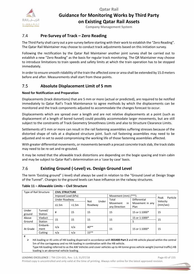
Qatar Rail
Guidance for Monitoring Works by Third Party on Existing Qatar Rail Assets
Company Management System
LEADING EXCELLENCE │ TM-224-G01, Rev. 1.0, 31/07/18 Page 43 of 155 Printed copy is uncontrolled and only valid at the time of printing. Always refer online for the latest approved revision.
Pre-Survey of Track – Zero Reading
The Third Party shall carry out a pre-survey before starting with their work to establish the “Zero Reading”. The Qatar Rail Maintainer may choose to conduct track adjustments based on this initiation survey.
Following the rectification by the Qatar Rail Maintainer another joint survey shall be carried out to establish a new “Zero Reading” as the basis for regular track monitoring. The QR Maintainer may choose to introduce limitations to train speeds and safety limits at which the train operation has to be stopped immediately.
In order to ensure smooth ridability of the train the affected zone or area shall be extended by 15.0 meters before and after. Measurements shall start from these points.
Absolute Displacement Limit of 5 mm
Need for Notification and Preparation
Displacements (track distortions) that are 5 mm or more (actual or predicted), are required to be notified immediately to Qatar Rail’s Track Maintenance to agree methods by which the displacements can be monitored and the track components adjusted to accommodate the changes forecast to occur.
Displacements which are spread over a length and are not relative displacements at a point (such as displacement of a length of bored tunnel) could possibly accommodate larger movements, but are still subject to the constraints of Track Geometry Smoothness Limits and also to Structure Clearance Limits.
Settlements of 5 mm or more can result in the rail fastening assemblies suffering stresses because of the distorted shape of rails at a displaced structure joint. Such rail fastening assemblies may need to be adjusted and re-set to avoid compromising the working life of those fastening assemblies affected.
With greater differential movements, or movements beneath a precast concrete track slab, the track slabs may need to be re-set and re-grouted.
It may be noted that the allowable track distortions are depending on the bogie spacing and train cabin and may be subject to Qatar Rail’s determination on a ‘case by case’ basis.
Existing Ground (-Level) vs. Design Ground Level
The term ‘Existing ground” (-level) shall always be used in relation to the “Ground Level at Design Stage of the Tunnel”. Changes to the ground levels can have influence on the railway structures.
Table 11 – Allowable Limits – Civil Structure
Type of Rail Structure CIVIL STRUCTURE
Imposed Load (kPa) Movement (mm) (***) Peak Particle Velocity (mm/sec)
Under Roadway Not Under Roadway
Total Movement in any Direction
Differential Movement in any Plan
≤1.5m ˃1.5m
Under ground
Tunnel/ Station
# 15 15 15 15 or 1:1000* 15
Above Ground
Viaduct 15 15 15 15
15 or 1:1000* 15
Station 5
At Grade
Embank-ment
n/a n/a 40** 15 15 or 1:1000* 15
Cutting n/a n/a 15**
# HA loading or 45 units of HB loading dispersed in accordance with BS5400 Part 2 and HB vehicle placed within the central
5m of the carriageway and no HA loading in combination with the HB vehicle. Type HA loading referred to as the AW Vehicles and cover vehicles up to 44 tonne gross vehicle weight (normal traffic).HB loading is an abnormal vehicle loading.

Qatar Rail
Guidance for Monitoring Works by Third Party on Existing Qatar Rail Assets
Company Management System
LEADING EXCELLENCE │ TM-224-G01, Rev. 1.0, 31/07/18 Page 44 of 155 Printed copy is uncontrolled and only valid at the time of printing. Always refer online for the latest approved revision.
Or Highway loading specified in EN 1991-2, LM 1; shall not be less. No dynamic allowance required if overburden greater than 1.5 meter.
kPa = 1000 N/m2 = 1kN/m2 = 101,1 kg/cm2 (*) whichever is lesser (**) outside the critical / exclusion zone (***) These criteria (limits) are applicable if waterproofing or the segmental liningis not affected by gasket decompression. Differential movement (settlement) is the maximum difference between two points in a building element.
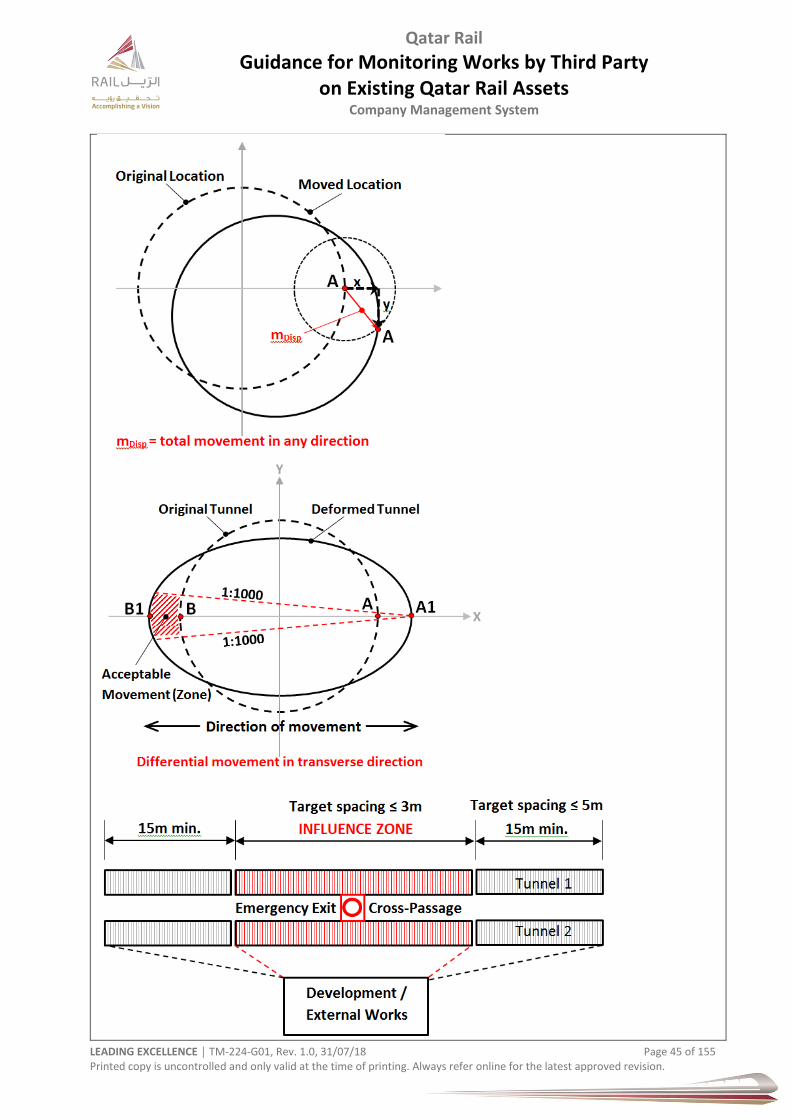
Qatar Rail
Guidance for Monitoring Works by Third Party on Existing Qatar Rail Assets
Company Management System
LEADING EXCELLENCE │ TM-224-G01, Rev. 1.0, 31/07/18 Page 45 of 155 Printed copy is uncontrolled and only valid at the time of printing. Always refer online for the latest approved revision.
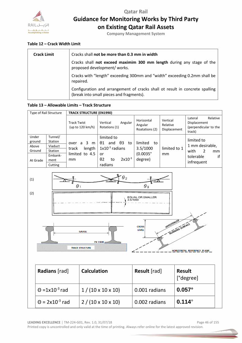
Qatar Rail
Guidance for Monitoring Works by Third Party on Existing Qatar Rail Assets
Company Management System
LEADING EXCELLENCE │ TM-224-G01, Rev. 1.0, 31/07/18 Page 46 of 155 Printed copy is uncontrolled and only valid at the time of printing. Always refer online for the latest approved revision.
Table 12 – Crack Width Limit
Crack Limit Cracks shall not be more than 0.3 mm in width
Cracks shall not exceed maximim 300 mm length during any stage of the proposed development/ works.
Cracks with “length” exceeding 300mm and “width” exceeding 0.2mm shall be repaired.
Configuration and arrangement of cracks shall ot result in concrete spalling (break into small pieces and fragments).
Table 13 – Allowable Limits – Track Structure
Type of Rail Structure TRACK STRUCTURE (EN1990)
Track Twist (up to 120 km/h)
Vertical Angular Rotations (1)
Horizontal Angular Roatations (2)
Vertical Relative Displacement
Lateral Relative Displacement (perpendicular to the track)
Under ground
Tunnel/ Station over a 3 m
track length limited to 4.5 mm
limited to θ1 and θ3 to 1x10⁻³ radians or θ2 to 2x10⁻³ radians
limited to 3.5/1000 (0.0035° degree)
limited to 1 mm
limited to 1 mm desirable, with 2 mm tolerable if infrequent
Above Ground
Viaduct
Station
At Grade
Embank-ment
Cutting
(1)
(2)
Radians [rad] Calculation Result [rad] Result [°degree]
Θ =1x10⁻³ rad 1 / (10 x 10 x 10) 0.001 radians 0.057°
Θ = 2x10⁻³ rad 2 / (10 x 10 x 10) 0.002 radians 0.114°

Qatar Rail
Guidance for Monitoring Works by Third Party on Existing Qatar Rail Assets
Company Management System
LEADING EXCELLENCE │ TM-224-G01, Rev. 1.0, 31/07/18 Page 47 of 155 Printed copy is uncontrolled and only valid at the time of printing. Always refer online for the latest approved revision.
Exert from EN 1990:
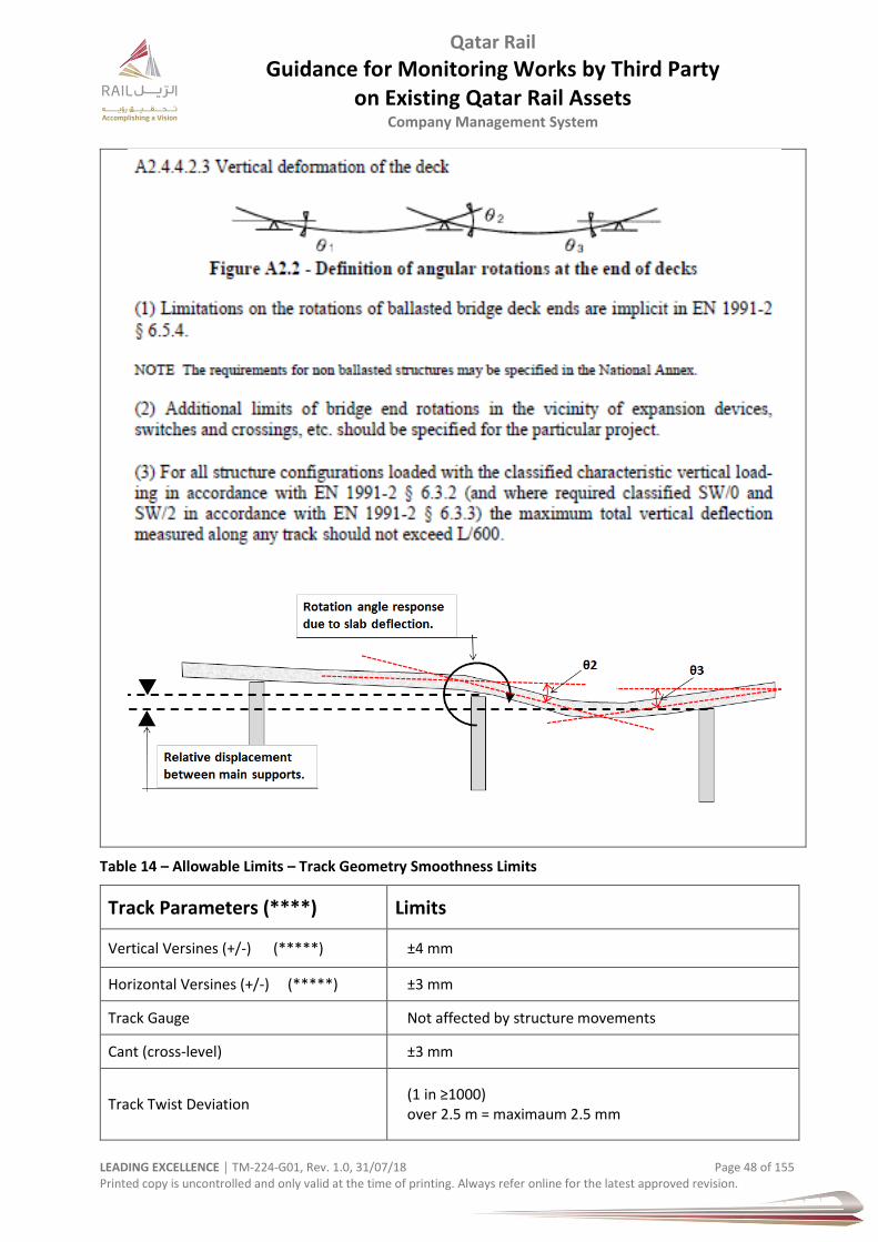
Qatar Rail
Guidance for Monitoring Works by Third Party on Existing Qatar Rail Assets
Company Management System
LEADING EXCELLENCE │ TM-224-G01, Rev. 1.0, 31/07/18 Page 48 of 155 Printed copy is uncontrolled and only valid at the time of printing. Always refer online for the latest approved revision.
Table 14 – Allowable Limits – Track Geometry Smoothness Limits
Track Parameters (****) Limits
Vertical Versines (+/-) (*****) ±4 mm
Horizontal Versines (+/-) (*****) ±3 mm
Track Gauge Not affected by structure movements
Cant (cross-level) ±3 mm
Track Twist Deviation (1 in ≥1000) over 2.5 m = maximaum 2.5 mm

Qatar Rail
Guidance for Monitoring Works by Third Party on Existing Qatar Rail Assets
Company Management System
LEADING EXCELLENCE │ TM-224-G01, Rev. 1.0, 31/07/18 Page 49 of 155 Printed copy is uncontrolled and only valid at the time of printing. Always refer online for the latest approved revision.
(****) Track geometry Smoothness Tolerances are measured on the rails relative to points on the rail before and after the measuring position. (*****) Carry out a Pre-Survey of the track jointly with Qatar Rail (Maintainer) as “Zero” reading. The Maintainer (Qatar Rail) may choose to rectify the track prior to the Third Party starting their work. “Versine” in the table above means the offset at the centre of a 10 m Chord placed on a rail. So:-
a) if point in the track has settled by 6 mm, then the versines measured at 5 m each side of the point are +3 mm, but the versine measured at the point of settlement will be -6 mm.
the rail supports at the settled point would need to be raised to smooth-out the dip b) if a section of tunnel has settled 6 mm from the abutting tunnel section, then the vertical versines across the
point of deviation will read: 0, +3, +3, -3, -3, 0
the rail supports near the joint on the settled tunnel side would need to be raised progressively to create a 6mm gradual ramp instead of the 6 mm step.
Recommendation: EN 1990, Annex A2 only minimum conditions for bridge deformations are given. This rule does not take into account track maintenance. A simplified rule for permissible deflections is given below for trains and speeds up to 200 km/h, to avoid the need for excessive track maintenance. In addition, this simplified rule has the advantage, that no dynamic analysis is necessary for speeds less than 200 km/h. For all classified railway lines with α ˃ 1.00, that means also if α = 1.33 (UIC Code 702, 2003) is adopted for Ultimate Limit State ULS, the following permissible values for deflections are recommended, always calculated with LM71 “+” SW/O, multiplied by ф and with α = 1.00:
Train speed V < 80 km/h δ ≤ l/800 (=(L/600) x 1.33)
Train speed 80 ≤ V ≤ 200 km/h δ ≤ l / (15V – 400); Note: The upper limit l/2600 for 200 km/h is the permissible deflection which the Deutche Bahn (DB) has taken during many years for designing bridges for high speed lines in Germany, with satisfactory results.
Train speed V ˃ 200 km/h value determined by dynamic study, but min. δ ≤ l / 2600.
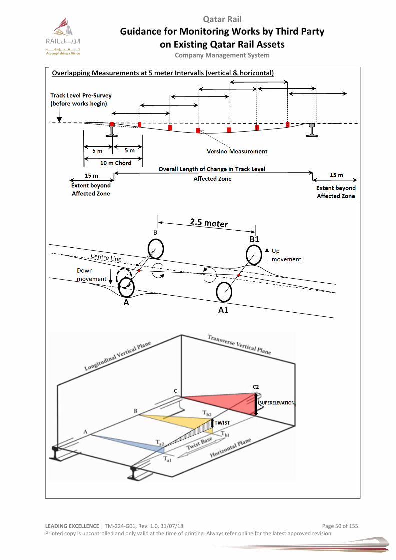
Qatar Rail
Guidance for Monitoring Works by Third Party on Existing Qatar Rail Assets
Company Management System
LEADING EXCELLENCE │ TM-224-G01, Rev. 1.0, 31/07/18 Page 50 of 155 Printed copy is uncontrolled and only valid at the time of printing. Always refer online for the latest approved revision.

Qatar Rail
Guidance for Monitoring Works by Third Party on Existing Qatar Rail Assets
Company Management System
LEADING EXCELLENCE │ TM-224-G01, Rev. 1.0, 31/07/18 Page 51 of 155 Printed copy is uncontrolled and only valid at the time of printing. Always refer online for the latest approved revision.
Noise and Vibration Plan
Noise and vibration is a internationally recognised nuisance, but can also carry structural harm. The effects of noise and vibration shall be considered in the design, construction and operational stage of the Third Party development on the near rail infrastructure. Emitting noise shall be considered following statutory requirements and particular noise & vibration limit requirements by Qatar Rail. Highest priority is always to avoid noise & vibration. An acoustic & vibration assessment report including a vibration monitoring plan shall be prepared and submitted to Qatar Rail.
Perception and damage due to vibration is depending on the associated separation and distance between the source of vibration and the receiver and the magnitude of the generated vibration.
Vibration from construction activities have generally the potential to cause structural damage such as cracking of walls.
Ground-Borne Vibration
In general, magnitudes of ground vibrations that are considered to be able to cause structural damage to buildings are above 15 mm/s.
Table 15 –Vibration Limit (ground-borne)
Warning Level Impacted Element Peak Particle Velocity PPV
Amber Tack signalling & communication 10 mm/sec
Red Civil structure Railway track structure (continious and intermittent vibration
15 mm/sec
Table 16 – Reaction of People to Vibration
Human Reaction PPV (mm/sec)
Vibration might be just perceptible in the most sensitive situation for most vibrating frequencies associated with construction. At lower frequencies, people are less sensitive to vibration.
0.14
Vibration might be just perceptible in residential environments. 0.30
Human preseption level causing disdurbance Greater than 0.30
It is likely that vibration of theis level in residential environments will cause complaint, but can be tolerated if prior warning and explanation has been given to residents.
1.0
Vibrations readily perceptible (easily noticeable) 2.0
Amplitude at which continious vibrations begin to annoy people 2.5
Vibrations annoying to people in buidings (strongly noticeable) 5.0
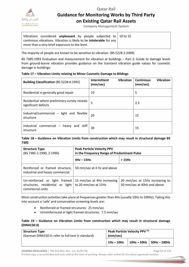
Qatar Rail
Guidance for Monitoring Works by Third Party on Existing Qatar Rail Assets
Company Management System
LEADING EXCELLENCE │ TM-224-G01, Rev. 1.0, 31/07/18 Page 52 of 155 Printed copy is uncontrolled and only valid at the time of printing. Always refer online for the latest approved revision.
Vibrations considered unpleasant by people subjected to continious vibrations. Vibration is likely to be intolerable for any more than a very brief exporsure to the level.
10 to 15
The majority of people are known to be sensitive to vibration. (BS 5228-2:2009)
BS 7385:1993 Evaluation and measurement for vibration at buildings – Part 2: Guide to damage levels from ground-borne vibration provides guidance on the transient vibration guide values for cosmetic damage in buildings:
Table 17 – Vibration Limits relating to Minor Cosmetic Damage to Bildings
Building Classification (BS 5228:4:1992) Intermittent Vibration (mm/sec)
Continious Vibration (mm/sec)
Residential in generally good repair 10 5
Residential where preliminary survey reveals significant defects
5 2.5
Industrial/commercial – light and flexible structure
20 15
Industrial commercial – heavy and stiff structure
30 15
Table 18 – Guidance on Vibration Limits from construction which may result in structural damage BS 7385
Structure Type (BS 7385-1:1990, 2:1990)
Peak Particle Velocity PPV in the Frequency Range of Predominant Pulse
4Hz – 15Hz ˃ 15Hz
Reinforced or framed structure, industrial and heavy commercial
50 mm/sec at 4 Hz and above
Un-reinforced or light framed structures, residential or light commercial units
15 mm/sec at 4Hz increasing to 20 mm/sec at 15Hz
20 mm/sec at 15Hz increasing to 50 mm/sec at 40Hz and above
Most construction activities take place at frequences greater than 4Hz (usually 10Hz to 100Hz). Taking this into account a ‘safe’ and conservative screening levels are:
Reinforced or framed strcutures: 25 mm/sec
Unreinformced or light framed structures: 7.5 mm/sec Table 19 – Guidance on Vibration Limits from construction which may result in structural damage (DIN4150:3)
Structure Type (German DIN4150:3; refer to full text in standard)
Peak Particle Velocity PPV (1)
(mm/sec)
1Hz – 10Hz 10Hz – 50Hz 50Hz – 100Hz
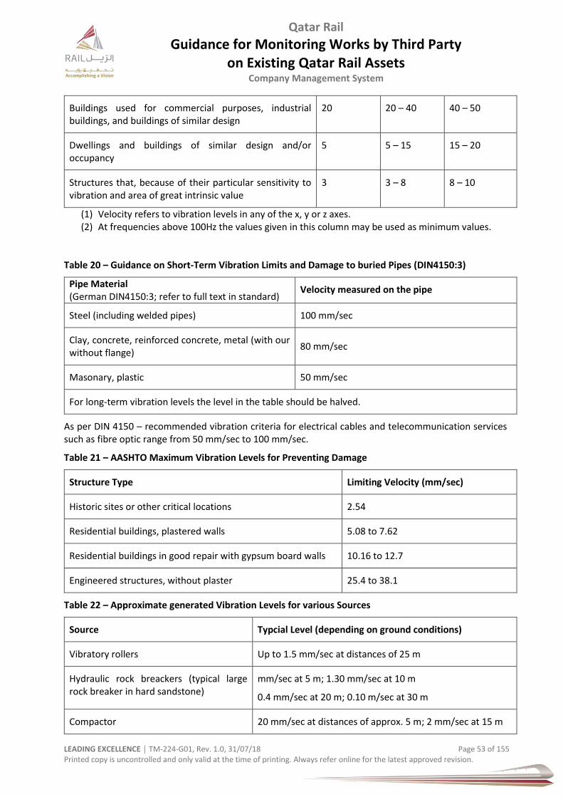
Qatar Rail
Guidance for Monitoring Works by Third Party on Existing Qatar Rail Assets
Company Management System
LEADING EXCELLENCE │ TM-224-G01, Rev. 1.0, 31/07/18 Page 53 of 155 Printed copy is uncontrolled and only valid at the time of printing. Always refer online for the latest approved revision.
Buildings used for commercial purposes, industrial buildings, and buildings of similar design
20 20 – 40 40 – 50
Dwellings and buildings of similar design and/or occupancy
5 5 – 15 15 – 20
Structures that, because of their particular sensitivity to vibration and area of great intrinsic value
3 3 – 8 8 – 10
(1) Velocity refers to vibration levels in any of the x, y or z axes. (2) At frequencies above 100Hz the values given in this column may be used as minimum values.
Table 20 – Guidance on Short-Term Vibration Limits and Damage to buried Pipes (DIN4150:3)
Pipe Material (German DIN4150:3; refer to full text in standard)
Velocity measured on the pipe
Steel (including welded pipes) 100 mm/sec
Clay, concrete, reinforced concrete, metal (with our without flange)
80 mm/sec
Masonary, plastic 50 mm/sec
For long-term vibration levels the level in the table should be halved.
As per DIN 4150 – recommended vibration criteria for electrical cables and telecommunication services such as fibre optic range from 50 mm/sec to 100 mm/sec.
Table 21 – AASHTO Maximum Vibration Levels for Preventing Damage
Structure Type Limiting Velocity (mm/sec)
Historic sites or other critical locations 2.54
Residential buildings, plastered walls 5.08 to 7.62
Residential buildings in good repair with gypsum board walls 10.16 to 12.7
Engineered structures, without plaster 25.4 to 38.1
Table 22 – Approximate generated Vibration Levels for various Sources
Source Typcial Level (depending on ground conditions)
Vibratory rollers Up to 1.5 mm/sec at distances of 25 m
Hydraulic rock breackers (typical large rock breaker in hard sandstone)
mm/sec at 5 m; 1.30 mm/sec at 10 m
0.4 mm/sec at 20 m; 0.10 m/sec at 30 m
Compactor 20 mm/sec at distances of approx. 5 m; 2 mm/sec at 15 m
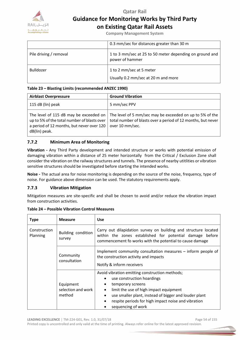
Qatar Rail
Guidance for Monitoring Works by Third Party on Existing Qatar Rail Assets
Company Management System
LEADING EXCELLENCE │ TM-224-G01, Rev. 1.0, 31/07/18 Page 54 of 155 Printed copy is uncontrolled and only valid at the time of printing. Always refer online for the latest approved revision.
0.3 mm/sec for distances greater than 30 m
Pile driving / removal 1 to 3 mm/sec at 25 to 50 meter depending on ground and power of hammer
Bulldozer 1 to 2 mm/sec at 5 meter
Usually 0.2 mm/sec at 20 m and more
Table 23 – Blasting Limits (recommended ANZEC 1990)
Airblast Overpressure Ground Vibration
115 dB (lin) peak 5 mm/sec PPV
The level of 115 dB may be exceeded on up to 5% of the total number of blasts over a period of 12 months, but never over 120 dB(lin) peak.
The level of 5 mm/sec may be exceeded on up to 5% of the total number of blasts over a period of 12 months, but never over 10 mm/sec.
Minimum Area of Monitoring
Vibration - Any Third Party development and intended structure or works with potential emission of damaging vibration within a distance of 25 meter horizontally from the Critical / Exclusion Zone shall consider the vibration on the railway structures and tunnels. The presence of nearby utitlities or vibration sensitive structures should be investigated before starting the intended works.
Noise - The actual area for noise monitoring is depending on the source of the noise, frequency, type of noise. For guidance above dimension can be used. The statutory requirements apply.
Vibration Mitigation
Mitigation measures are site-specific and shall be chosen to avoid and/or reduce the vibration impact from construction activities.
Table 24 – Possible Vibration Control Measures
Type Measure Use
Construction Planning
Building condition survey
Carry out dilapidation survey on building and structure located within the zones established for potential damage before commencement fo works with the potential to cause damage
Community consultation
Implement community consultation measures – inform people of the construction activity and impacts
Notify & inform receivers
Equipment selection and work method
Avoid vibration emitting construction methods;
use construction hoardings
temporary screens
limit the use of high impact equipment
use smaller plant, instead of bigger and louder plant
respite periods for high impact noise and vibration
sequencing of work
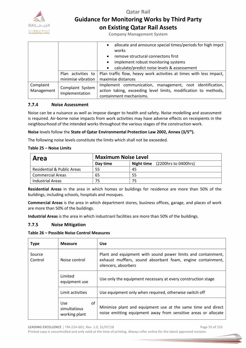
Qatar Rail
Guidance for Monitoring Works by Third Party on Existing Qatar Rail Assets
Company Management System
LEADING EXCELLENCE │ TM-224-G01, Rev. 1.0, 31/07/18 Page 55 of 155 Printed copy is uncontrolled and only valid at the time of printing. Always refer online for the latest approved revision.
allocate and announce special times/periods for high impct works
remove structural connectons first
implement robust monitoring systems
calculate/predict noise levels & assessement
Plan activities to minimise vibration
Plan traffic flow, heavy work activities at times with less impact, maximise distances
Complaint Management
Complaint System Implementation
Implement communication, management, root identification, action taking, exceeding level limits, modification to methods, containment mechanisms.
Noise Assessment
Noise can be a nuisance as well as impose danger to health and safety. Noise modelling and assessment is required. Air-borne noise impacts from work activities may have adverse effects on receipients in the neighbourhood of the intended works throughout the various stages of the construction work.
Noise levels follow the State of Qatar Environmental Protection Law 2002, Annex (3/5th).
The following noise levels constitute the limits which shall not be exceeded.
Table 25 – Noise Limits
Area Maximum Noise Level Day time Night time (2200hrs to 0400hrs)
Residential & Public Areas 55 45
Commercial Areas 65 55
Industrial Areas 75 75
Residential Areas in the area in which homes or buildings for residence are more than 50% of the buildings, including schools, hospitals and mosques.
Commercial Areas is the area in which department stores, business offices, garage, and places of work are more than 50% of the buildings.
Industrial Areas is the area in which industrianl facilities are more than 50% of the buildings.
Noise Mitigation
Table 26 – Possible Noise Control Measures
Type Measure Use
Source Control Noise control
Plant and equipment with sound power limits and containment, exhaust mufflers, sound absorbant foam, engine containment, silencers, absorbers
Limited equipment use
Use only the equipment necessary at every construction stage
Limit activities Use equipment only when required, otherwise switch off
Use of simultatious working plant
Minimize plant and equipment use at the same time and direct noise emitting equipment away from sensitive areas or allocate

Qatar Rail
Guidance for Monitoring Works by Third Party on Existing Qatar Rail Assets
Company Management System
LEADING EXCELLENCE │ TM-224-G01, Rev. 1.0, 31/07/18 Page 56 of 155 Printed copy is uncontrolled and only valid at the time of printing. Always refer online for the latest approved revision.
heavy equipment at other non-sensitive locations, as much as possible
Equipment selection
Use quieter equipment
Noise Management
Site induction / tool box talks
Induct and inform all people working on site about
Nearest sensitive receivers
Vibration limitations / use of particular equipment
Hours of work / allocated for noisy work
Special requirements / permits
Parking requirements
Community consultation
Inform communities and neighbourhoods of construction activities
Behavioural Monitoring
No shouting and unnecessary noise generation or loud behaviour allowed on site
Noise Monitoring To be carried out.
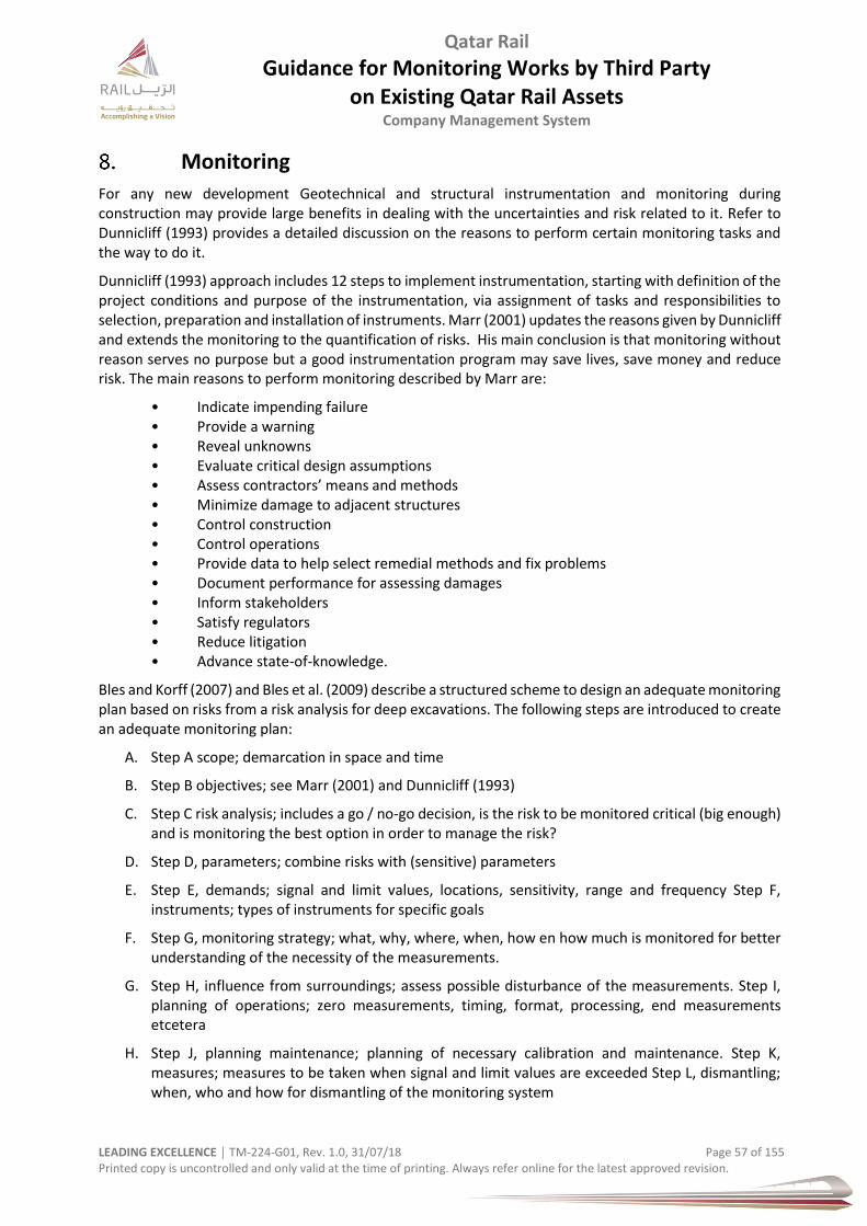
Qatar Rail
Guidance for Monitoring Works by Third Party on Existing Qatar Rail Assets
Company Management System
LEADING EXCELLENCE │ TM-224-G01, Rev. 1.0, 31/07/18 Page 57 of 155 Printed copy is uncontrolled and only valid at the time of printing. Always refer online for the latest approved revision.
Monitoring
For any new development Geotechnical and structural instrumentation and monitoring during construction may provide large benefits in dealing with the uncertainties and risk related to it. Refer to Dunnicliff (1993) provides a detailed discussion on the reasons to perform certain monitoring tasks and the way to do it.
Dunnicliff (1993) approach includes 12 steps to implement instrumentation, starting with definition of the project conditions and purpose of the instrumentation, via assignment of tasks and responsibilities to selection, preparation and installation of instruments. Marr (2001) updates the reasons given by Dunnicliff and extends the monitoring to the quantification of risks. His main conclusion is that monitoring without reason serves no purpose but a good instrumentation program may save lives, save money and reduce risk. The main reasons to perform monitoring described by Marr are:
• Indicate impending failure • Provide a warning • Reveal unknowns • Evaluate critical design assumptions • Assess contractors’ means and methods • Minimize damage to adjacent structures • Control construction • Control operations • Provide data to help select remedial methods and fix problems • Document performance for assessing damages • Inform stakeholders • Satisfy regulators • Reduce litigation • Advance state-of-knowledge.
Bles and Korff (2007) and Bles et al. (2009) describe a structured scheme to design an adequate monitoring plan based on risks from a risk analysis for deep excavations. The following steps are introduced to create an adequate monitoring plan:
A. Step A scope; demarcation in space and time
B. Step B objectives; see Marr (2001) and Dunnicliff (1993)
C. Step C risk analysis; includes a go / no-go decision, is the risk to be monitored critical (big enough) and is monitoring the best option in order to manage the risk?
D. Step D, parameters; combine risks with (sensitive) parameters
E. Step E, demands; signal and limit values, locations, sensitivity, range and frequency Step F, instruments; types of instruments for specific goals
F. Step G, monitoring strategy; what, why, where, when, how en how much is monitored for better understanding of the necessity of the measurements.
G. Step H, influence from surroundings; assess possible disturbance of the measurements. Step I, planning of operations; zero measurements, timing, format, processing, end measurements etcetera
H. Step J, planning maintenance; planning of necessary calibration and maintenance. Step K, measures; measures to be taken when signal and limit values are exceeded Step L, dismantling; when, who and how for dismantling of the monitoring system
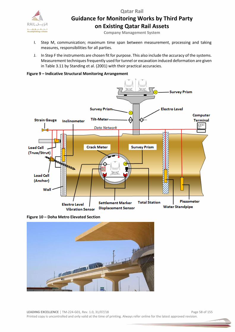
Qatar Rail
Guidance for Monitoring Works by Third Party on Existing Qatar Rail Assets
Company Management System
LEADING EXCELLENCE │ TM-224-G01, Rev. 1.0, 31/07/18 Page 58 of 155 Printed copy is uncontrolled and only valid at the time of printing. Always refer online for the latest approved revision.
I. Step M, communication; maximum time span between measurement, processing and taking measures, responsibilities for all parties.
J. In Step F the instruments are chosen fit for purpose. This also include the accuracy of the systems. Measurement techniques frequently used for tunnel or excavation induced deformation are given in Table 3.11 by Standing et al. (2001) with their practical accuracies.
Figure 9 – Indicative Structural Monitoring Arrangement
Figure 10 – Doha Metro Elevated Section
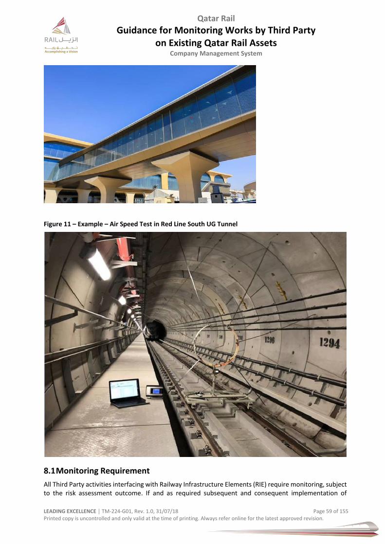
Qatar Rail
Guidance for Monitoring Works by Third Party on Existing Qatar Rail Assets
Company Management System
LEADING EXCELLENCE │ TM-224-G01, Rev. 1.0, 31/07/18 Page 59 of 155 Printed copy is uncontrolled and only valid at the time of printing. Always refer online for the latest approved revision.
Figure 11 – Example – Air Speed Test in Red Line South UG Tunnel
8.1 Monitoring Requirement
All Third Party activities interfacing with Railway Infrastructure Elements (RIE) require monitoring, subject to the risk assessment outcome. If and as required subsequent and consequent implementation of
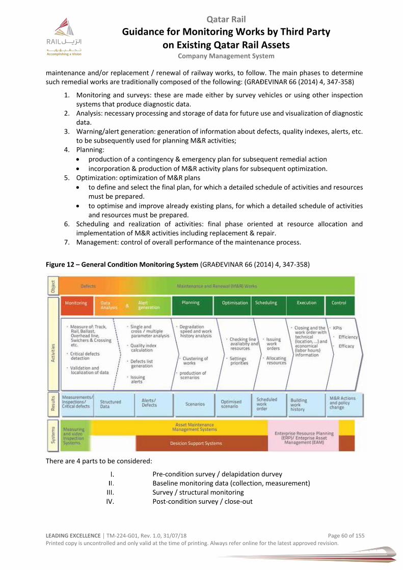
Qatar Rail
Guidance for Monitoring Works by Third Party on Existing Qatar Rail Assets
Company Management System
LEADING EXCELLENCE │ TM-224-G01, Rev. 1.0, 31/07/18 Page 60 of 155 Printed copy is uncontrolled and only valid at the time of printing. Always refer online for the latest approved revision.
maintenance and/or replacement / renewal of railway works, to follow. The main phases to determine such remedial works are traditionally composed of the following: (GRAĐEVINAR 66 (2014) 4, 347-358)
1. Monitoring and surveys: these are made either by survey vehicles or using other inspection systems that produce diagnostic data.
2. Analysis: necessary processing and storage of data for future use and visualization of diagnostic data.
3. Warning/alert generation: generation of information about defects, quality indexes, alerts, etc. to be subsequently used for planning M&R activities;
4. Planning:
production of a contingency & emergency plan for subsequent remedial action
incorporation & production of M&R activity plans for subsequent optimization. 5. Optimization: optimization of M&R plans
to define and select the final plan, for which a detailed schedule of activities and resources must be prepared.
to optimise and improve already existing plans, for which a detailed schedule of activities and resources must be prepared.
6. Scheduling and realization of activities: final phase oriented at resource allocation and implementation of M&R activities including replacement & repair.
7. Management: control of overall performance of the maintenance process.
Figure 12 – General Condition Monitoring System (GRAĐEVINAR 66 (2014) 4, 347-358)
There are 4 parts to be considered:
Pre-condition survey / delapidation durvey Baseline monitoring data (collection, measurement) Survey / structural monitoring Post-condition survey / close-out
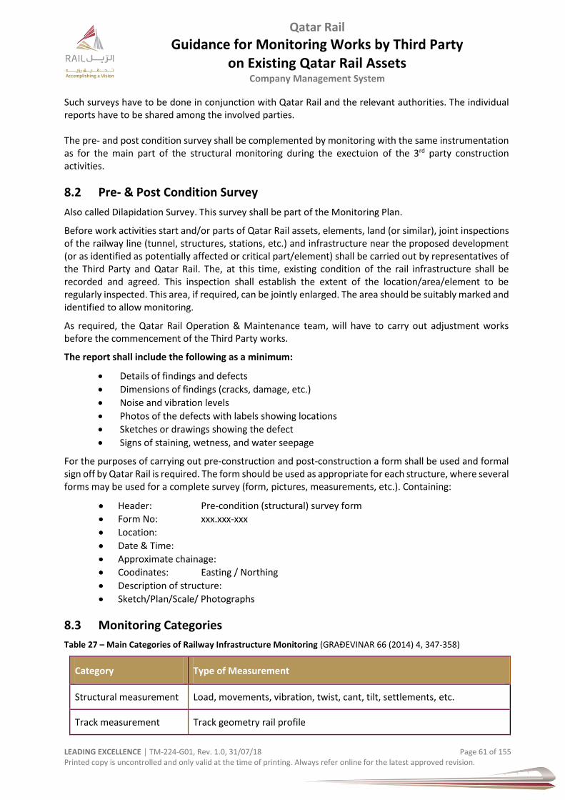
Qatar Rail
Guidance for Monitoring Works by Third Party on Existing Qatar Rail Assets
Company Management System
LEADING EXCELLENCE │ TM-224-G01, Rev. 1.0, 31/07/18 Page 61 of 155 Printed copy is uncontrolled and only valid at the time of printing. Always refer online for the latest approved revision.
Such surveys have to be done in conjunction with Qatar Rail and the relevant authorities. The individual reports have to be shared among the involved parties. The pre- and post condition survey shall be complemented by monitoring with the same instrumentation as for the main part of the structural monitoring during the exectuion of the 3rd party construction activities.
8.2 Pre- & Post Condition Survey
Also called Dilapidation Survey. This survey shall be part of the Monitoring Plan.
Before work activities start and/or parts of Qatar Rail assets, elements, land (or similar), joint inspections of the railway line (tunnel, structures, stations, etc.) and infrastructure near the proposed development (or as identified as potentially affected or critical part/element) shall be carried out by representatives of the Third Party and Qatar Rail. The, at this time, existing condition of the rail infrastructure shall be recorded and agreed. This inspection shall establish the extent of the location/area/element to be regularly inspected. This area, if required, can be jointly enlarged. The area should be suitably marked and identified to allow monitoring.
As required, the Qatar Rail Operation & Maintenance team, will have to carry out adjustment works before the commencement of the Third Party works.
The report shall include the following as a minimum:
Details of findings and defects
Dimensions of findings (cracks, damage, etc.)
Noise and vibration levels
Photos of the defects with labels showing locations
Sketches or drawings showing the defect
Signs of staining, wetness, and water seepage
For the purposes of carrying out pre-construction and post-construction a form shall be used and formal sign off by Qatar Rail is required. The form should be used as appropriate for each structure, where several forms may be used for a complete survey (form, pictures, measurements, etc.). Containing:
Header: Pre-condition (structural) survey form
Form No: xxx.xxx-xxx
Location:
Date & Time:
Approximate chainage:
Coodinates: Easting / Northing
Description of structure:
Sketch/Plan/Scale/ Photographs
8.3 Monitoring Categories
Table 27 – Main Categories of Railway Infrastructure Monitoring (GRAĐEVINAR 66 (2014) 4, 347-358)
Category Type of Measurement
Structural measurement Load, movements, vibration, twist, cant, tilt, settlements, etc.
Track measurement Track geometry rail profile

Qatar Rail
Guidance for Monitoring Works by Third Party on Existing Qatar Rail Assets
Company Management System
LEADING EXCELLENCE │ TM-224-G01, Rev. 1.0, 31/07/18 Page 62 of 155 Printed copy is uncontrolled and only valid at the time of printing. Always refer online for the latest approved revision.
Category Type of Measurement
Rail corrugation ballast profile
Also, all measuring systems are available for any type of track gauge and they can be operated:
With operators on-board and real-time analysis (manned)
Without operators on-board and with automatic data retrieval (unmanned).
Overhead line measurement
Overhead line geometry contact wire wear pantograph interaction Arc detection
Overhead line electric parameters
Vehicle dynamics measurement
Ride quality
Body, bogie and axle boxes accelerations wheel-rail Interaction forces
Wheel-rail contact
"Vision" systems Automatic rail surface defects detection automatic overhead line defects detection
Video inspection Railway section and surroundings track surface
Overhead line platforms way side
Other asset related monitoring
Signalling telecommunication quality Environmental temperature
Tunnel ceiling status detection railway infrastructure kinematic envelope/gauge
Tunnel detection system Positioning system
Monitoring of signalling systems Time radio-synchronization system
Noise Monitoring noise levels (dB)
Vibration Monitoring vibration levels (mm/sec)
Dust Dust control, dust development, dust avoidance/minimizing
Waste Waste control, debris containment, housekeeping, visual nuisance
8.4 Required Instrumentation within the Rail Protection Zone
For the safety of railway tunnels, structures and associated infrastructure it is mandatory to monitor the such structure and their performance during construction to verify the predicted, movements, displacements, stress levels in the individual elements and vibration levels. The Third Party shall implement comprehensive monitoring scheme which includes early warning criteria in agreement with Qatar Rail.
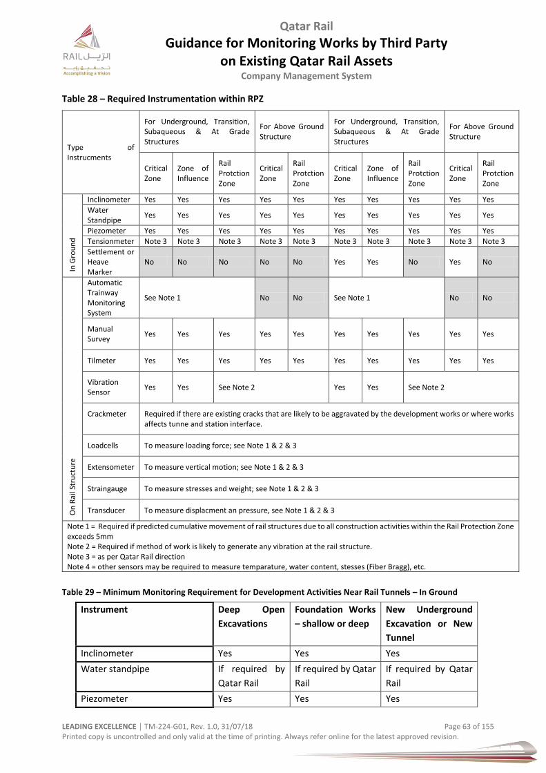
Qatar Rail
Guidance for Monitoring Works by Third Party on Existing Qatar Rail Assets
Company Management System
LEADING EXCELLENCE │ TM-224-G01, Rev. 1.0, 31/07/18 Page 63 of 155 Printed copy is uncontrolled and only valid at the time of printing. Always refer online for the latest approved revision.
Table 28 – Required Instrumentation within RPZ
Type of Instrucments
For Underground, Transition, Subaqueous & At Grade Structures
For Above Ground Structure
For Underground, Transition, Subaqueous & At Grade Structures
For Above Ground Structure
Critical Zone
Zone of Influence
Rail Protction Zone
Critical Zone
Rail Protction Zone
Critical Zone
Zone of Influence
Rail Protction Zone
Critical Zone
Rail Protction Zone
In G
rou
nd
Inclinometer Yes Yes Yes Yes Yes Yes Yes Yes Yes Yes
Water Standpipe
Yes Yes Yes Yes Yes Yes Yes Yes Yes Yes
Piezometer Yes Yes Yes Yes Yes Yes Yes Yes Yes Yes
Tensionmeter Note 3 Note 3 Note 3 Note 3 Note 3 Note 3 Note 3 Note 3 Note 3 Note 3
Settlement or Heave Marker
No No No No No Yes Yes No Yes No
On
Rai
l Str
uct
ure
Automatic Trainway Monitoring System
See Note 1 No No See Note 1 No No
Manual Survey
Yes Yes Yes Yes Yes Yes Yes Yes Yes Yes
Tilmeter Yes Yes Yes Yes Yes Yes Yes Yes Yes Yes
Vibration Sensor
Yes Yes See Note 2 Yes Yes See Note 2
Crackmeter Required if there are existing cracks that are likely to be aggravated by the development works or where works affects tunne and station interface.
Loadcells To measure loading force; see Note 1 & 2 & 3
Extensometer To measure vertical motion; see Note 1 & 2 & 3
Straingauge To measure stresses and weight; see Note 1 & 2 & 3
Transducer To measure displacment an pressure, see Note 1 & 2 & 3
Note 1 = Required if predicted cumulative movement of rail structures due to all construction activities within the Rail Protection Zone exceeds 5mm Note 2 = Required if method of work is likely to generate any vibration at the rail structure. Note 3 = as per Qatar Rail direction Note 4 = other sensors may be required to measure temparature, water content, stesses (Fiber Bragg), etc.
Table 29 – Minimum Monitoring Requirement for Development Activities Near Rail Tunnels – In Ground
Instrument Deep Open
Excavations
Foundation Works
– shallow or deep
New Underground
Excavation or New
Tunnel
Inclinometer Yes Yes Yes
Water standpipe If required by
Qatar Rail
If required by Qatar
Rail
If required by Qatar
Rail
Piezometer Yes Yes Yes
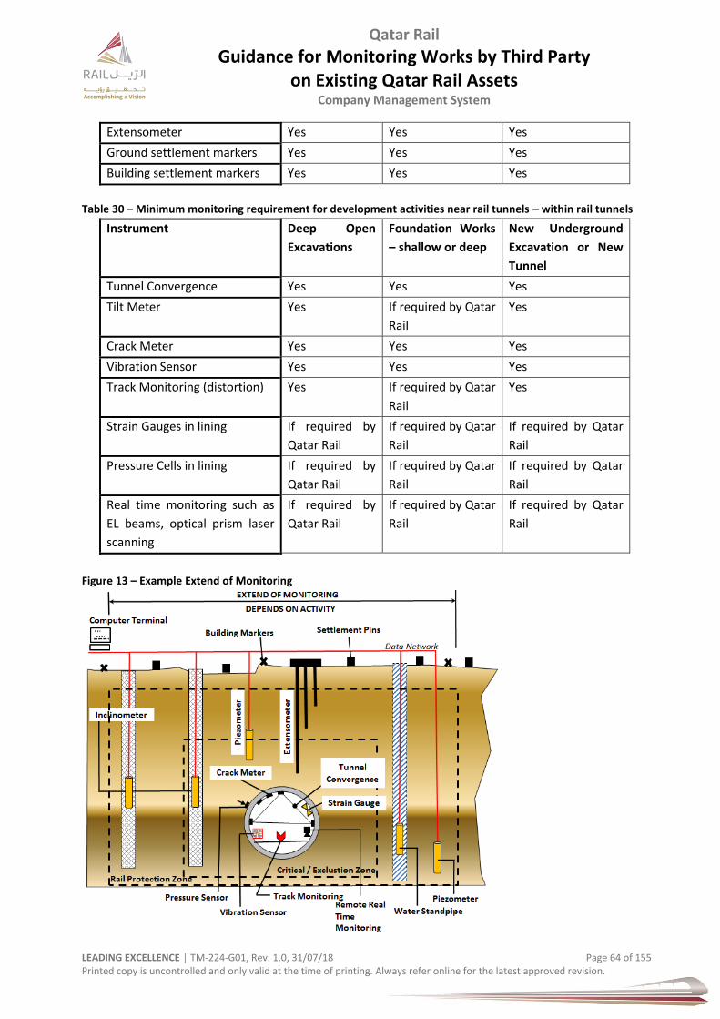
Qatar Rail
Guidance for Monitoring Works by Third Party on Existing Qatar Rail Assets
Company Management System
LEADING EXCELLENCE │ TM-224-G01, Rev. 1.0, 31/07/18 Page 64 of 155 Printed copy is uncontrolled and only valid at the time of printing. Always refer online for the latest approved revision.
Extensometer Yes Yes Yes
Ground settlement markers Yes Yes Yes
Building settlement markers Yes Yes Yes
Table 30 – Minimum monitoring requirement for development activities near rail tunnels – within rail tunnels
Instrument Deep Open
Excavations
Foundation Works
– shallow or deep
New Underground
Excavation or New
Tunnel
Tunnel Convergence Yes Yes Yes
Tilt Meter Yes If required by Qatar
Rail
Yes
Crack Meter Yes Yes Yes
Vibration Sensor Yes Yes Yes
Track Monitoring (distortion) Yes If required by Qatar
Rail
Yes
Strain Gauges in lining If required by
Qatar Rail
If required by Qatar
Rail
If required by Qatar
Rail
Pressure Cells in lining If required by
Qatar Rail
If required by Qatar
Rail
If required by Qatar
Rail
Real time monitoring such as
EL beams, optical prism laser
scanning
If required by
Qatar Rail
If required by Qatar
Rail
If required by Qatar
Rail
Figure 13 – Example Extend of Monitoring
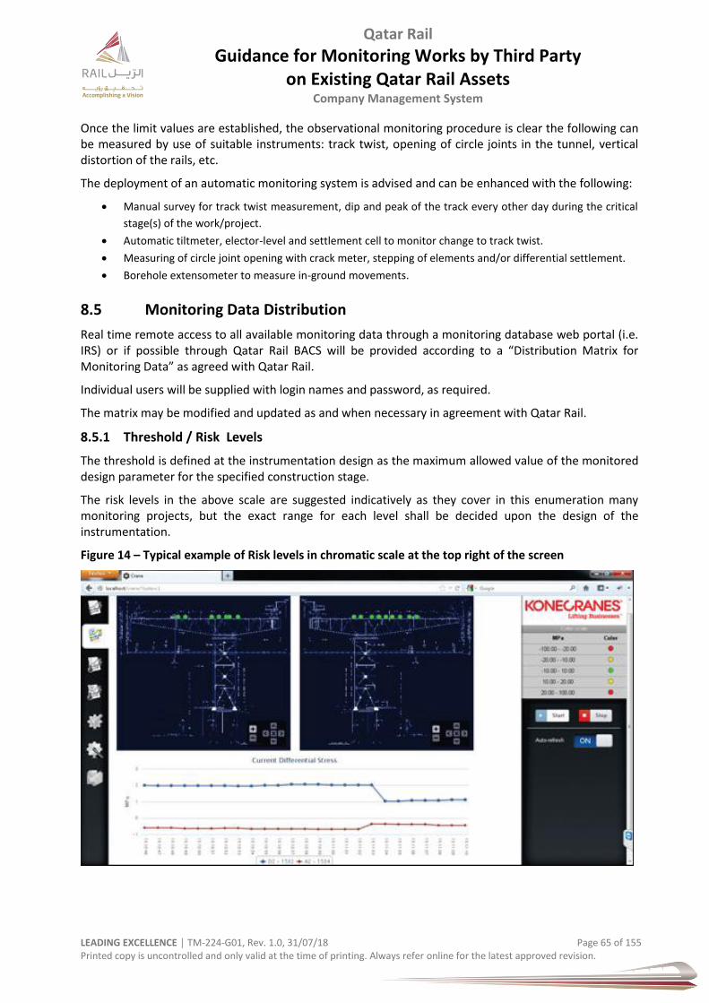
Qatar Rail
Guidance for Monitoring Works by Third Party on Existing Qatar Rail Assets
Company Management System
LEADING EXCELLENCE │ TM-224-G01, Rev. 1.0, 31/07/18 Page 65 of 155 Printed copy is uncontrolled and only valid at the time of printing. Always refer online for the latest approved revision.
Once the limit values are established, the observational monitoring procedure is clear the following can be measured by use of suitable instruments: track twist, opening of circle joints in the tunnel, vertical distortion of the rails, etc.
The deployment of an automatic monitoring system is advised and can be enhanced with the following:
Manual survey for track twist measurement, dip and peak of the track every other day during the critical
stage(s) of the work/project.
Automatic tiltmeter, elector-level and settlement cell to monitor change to track twist.
Measuring of circle joint opening with crack meter, stepping of elements and/or differential settlement.
Borehole extensometer to measure in-ground movements.
8.5 Monitoring Data Distribution
Real time remote access to all available monitoring data through a monitoring database web portal (i.e. IRS) or if possible through Qatar Rail BACS will be provided according to a “Distribution Matrix for Monitoring Data” as agreed with Qatar Rail.
Individual users will be supplied with login names and password, as required.
The matrix may be modified and updated as and when necessary in agreement with Qatar Rail.
8.5.1 Threshold / Risk Levels
The threshold is defined at the instrumentation design as the maximum allowed value of the monitored design parameter for the specified construction stage.
The risk levels in the above scale are suggested indicatively as they cover in this enumeration many monitoring projects, but the exact range for each level shall be decided upon the design of the instrumentation.
Figure 14 – Typical example of Risk levels in chromatic scale at the top right of the screen

Qatar Rail
Guidance for Monitoring Works by Third Party on Existing Qatar Rail Assets
Company Management System
LEADING EXCELLENCE │ TM-224-G01, Rev. 1.0, 31/07/18 Page 66 of 155 Printed copy is uncontrolled and only valid at the time of printing. Always refer online for the latest approved revision.
8.5.2 Risk & Trigger Review Levels
There are four distinct risk levels corresponding to the levels of the values of design parameters monitored. Such levels shall be represented in all documents and visualisation screens and wherever applicable in a chromatic scale:
Table 31 – Trigger (Risk) Levels
LEVEL ACTION
Green Normal conditions service/operation. continue construction.
Yellow High values for the monitored parameters – upto or slightly below 70% of threshold.
Amber Warning - values of the monitored parameters above 80% of threshold. Prepare for deployment of contingency measures, increase rate of monitoring.
Red Alarm values above 90% of threshold. Stop, reduce movements and implement contingenty measures.
A detailed description of the trigger values (i.e. warning and alarm levels) for each work, excavation, structure and instrument type shall be provided in the corresponding “Monitoring Design” documents.
In particular instances these values to be defined for site specific situations.
The review levels are established based on design and risk levels. Depending on the final design of the instrumentation they may or may not coincide with the risk levels. The definition of the review levels will enable preventative measures to be introduced in an acceptable time. Three review levels are adopted as follows:
a) Normal service/operation conditions: Design parameter monitored less than a pre-fixed maximum allowed value. Usually, this is set to 65 to 70%.
b) Alert Level: A predetermined level prior to the action level and alarm level for compliance with the contract, i.e. a fraction of the expected maximum deflection or anchor load. Normaly, this is defined at 70% of the maximum allowed design parameter monitored.
c) Action Level: A predetermined level after the alert level and prior to the alarm level for compliance with the contract. i.e. a fraction of the expected maximum deflection or anchor load. Normally, this is defined at the 80% of the maximum allowed design parameter monitored.
d) Alarm Level: Maximum or minimum (as appropriate) reading allowable based on the result from serviceability limit analysis for the monitored element. A default value shall be 90% of the max design values, subject to the final design of the instrumentation.
Review levels are shown in below table. These levels are to be quantified on the basis of assessments described in the Assessment of Construction Effects on Existing Structures Report.
During 3rd party construction, changes to the values selected as review levels may be proposed on the basis of observed performance. If the review levels are to be changed during construction, the following process will be followed:
Revised review levels brought to the attention of supervising engineer
Discussion and review of change with the monitoring contractor.
If review level change is deemed necessary the recommended change will be submitted to the Engineer for approval prior to implementation.
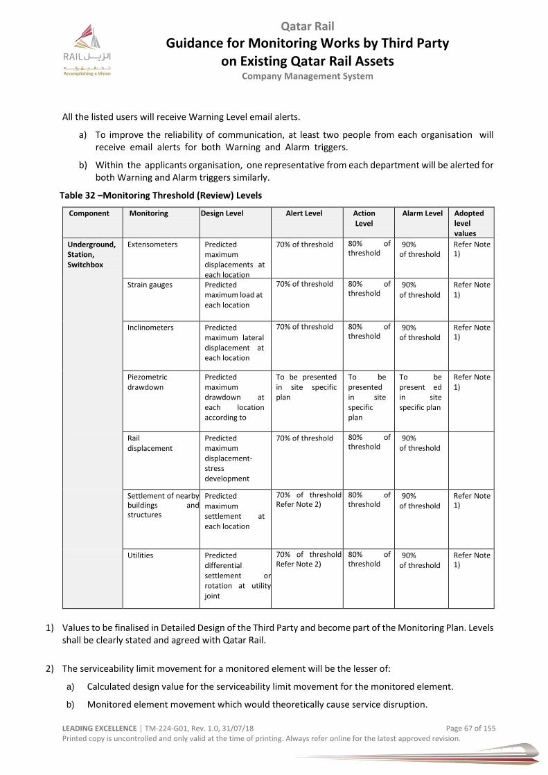
Qatar Rail
Guidance for Monitoring Works by Third Party on Existing Qatar Rail Assets
Company Management System
LEADING EXCELLENCE │ TM-224-G01, Rev. 1.0, 31/07/18 Page 67 of 155 Printed copy is uncontrolled and only valid at the time of printing. Always refer online for the latest approved revision.
All the listed users will receive Warning Level email alerts.
a) To improve the reliability of communication, at least two people from each organisation will receive email alerts for both Warning and Alarm triggers.
b) Within the applicants organisation, one representative from each department will be alerted for both Warning and Alarm triggers similarly.
Table 32 –Monitoring Threshold (Review) Levels
Component Monitoring Design Level Alert Level Action Level
Alarm Level Adopted level values
Underground, Station, Switchbox
Extensometers Predicted maximum displacements at each location
70% of threshold 80% of threshold
90% of threshold
Refer Note 1)
Strain gauges Predicted maximum load at each location
70% of threshold 80% of threshold
90% of threshold
Refer Note 1)
Inclinometers Predicted maximum lateral displacement at each location
70% of threshold 80% of threshold
90% of threshold
Refer Note 1)
Piezometric drawdown
Predicted maximum drawdown at each location according to
To be presented in site specific plan
To be presented in site specific plan
To be present ed in site specific plan
Refer Note 1)
Rail displacement
Predicted maximum displacement-stress development
70% of threshold
80% of threshold
90% of threshold
Settlement of nearby buildings and structures
Predicted maximum settlement at each location
70% of threshold Refer Note 2)
80% of threshold
90% of threshold
Refer Note 1)
Utilities Predicted differential settlement or rotation at utility joint
70% of threshold Refer Note 2)
80% of threshold
90% of threshold
Refer Note 1)
1) Values to be finalised in Detailed Design of the Third Party and become part of the Monitoring Plan. Levels shall be clearly stated and agreed with Qatar Rail.
2) The serviceability limit movement for a monitored element will be the lesser of:
a) Calculated design value for the serviceability limit movement for the monitored element.
b) Monitored element movement which would theoretically cause service disruption.
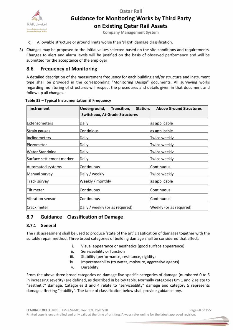
Qatar Rail
Guidance for Monitoring Works by Third Party on Existing Qatar Rail Assets
Company Management System
LEADING EXCELLENCE │ TM-224-G01, Rev. 1.0, 31/07/18 Page 68 of 155 Printed copy is uncontrolled and only valid at the time of printing. Always refer online for the latest approved revision.
c) Allowable structure or ground limits worse than ‘slight’ damage classification.
3) Changes may be proposed to the initial values selected based on the site conditions and requirements. Changes to alert and alarm levels will be justified on the basis of observed performance and will be submitted for the acceptance of the employer
8.6 Frequency of Monitoring
A detailed description of the measurement frequency for each building and/or structure and instrument type shall be provided in the corresponding “Monitoring Design” documents. All surveying works regarding monitoring of structures will respect the procedures and details given in that document and follow up all changes.
Table 33 – Typical Instrumentation & Frequency
Instrument Underground, Transition, Station,
Switchbox, At-Grade Structures
Above Ground Structures
Extensometers Daily as applicable
Strain gauges Continious as applicable
Inclinometers Daily Twice weekly
Piezometer Daily Twice weekly
Water Standpipe Daily Twice weekly
Surface settlement marker Daily Twice weekly
Automated systems Continuous Continuous
Manual survey Daily / weekly Twice weekly
Track survey Weekly / monthly as applicable
Tilt meter Continuous Continuous
Vibration sensor Continuous Continuous
Crack meter Daily / weekly (or as required) Weekly (or as required)
8.7 Guidance – Classification of Damage
8.7.1 General
The risk assessment shall be used to produce ‘state of the art’ classification of damages together with the suitable repair method. Three broad categories of building damage shall be considered that affect:
i. Visual appearance or aesthetics (good surface appearance) ii. Serviceability or function
iii. Stability (performance, resistance, rigidity) iv. Imperemeability (to water, moisture, aggressive agents) v. Durability
From the above three broad categories od damage five specific categories of damage (numbered 0 to 5 in increasing severity) are defined, as described in below table. Normally categories 0m 1 and 2 relate to “aesthetic” damage. Categories 3 and 4 relate to “serviceablity” damage and category 5 represents damage affecting “stability”. The table of classification below shall provide guidance ony.
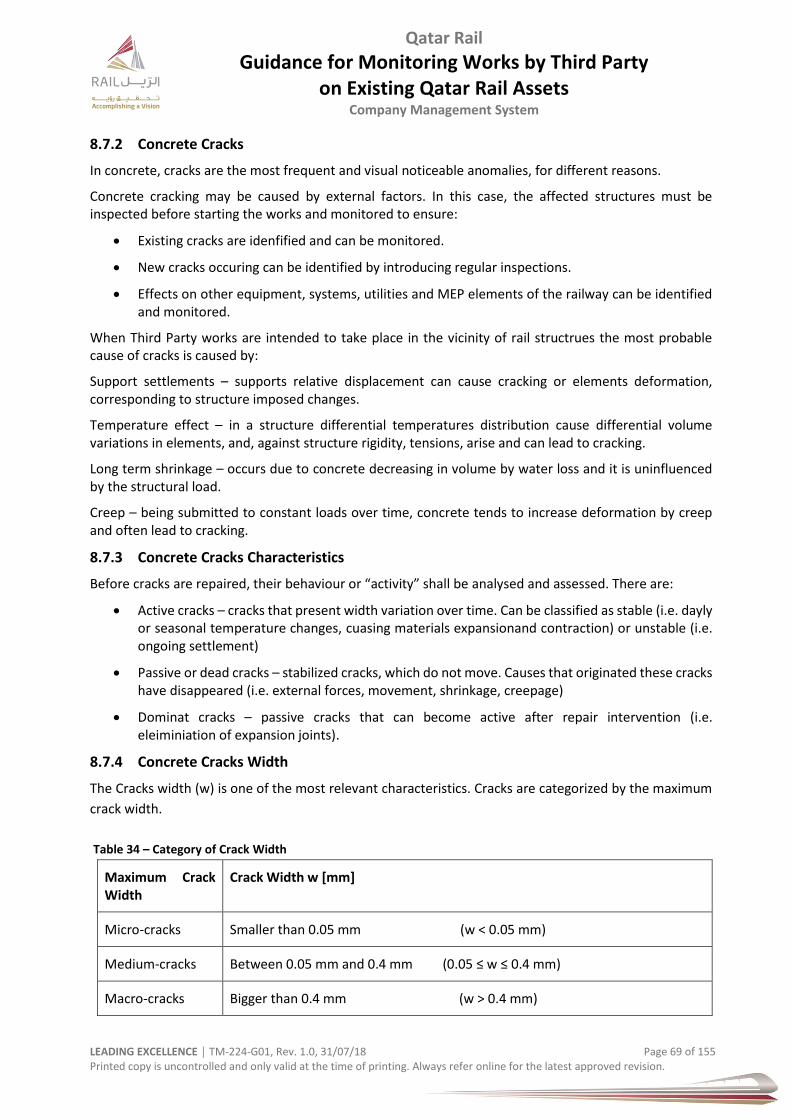
Qatar Rail
Guidance for Monitoring Works by Third Party on Existing Qatar Rail Assets
Company Management System
LEADING EXCELLENCE │ TM-224-G01, Rev. 1.0, 31/07/18 Page 69 of 155 Printed copy is uncontrolled and only valid at the time of printing. Always refer online for the latest approved revision.
8.7.2 Concrete Cracks
In concrete, cracks are the most frequent and visual noticeable anomalies, for different reasons.
Concrete cracking may be caused by external factors. In this case, the affected structures must be inspected before starting the works and monitored to ensure:
Existing cracks are idenfified and can be monitored.
New cracks occuring can be identified by introducing regular inspections.
Effects on other equipment, systems, utilities and MEP elements of the railway can be identified and monitored.
When Third Party works are intended to take place in the vicinity of rail structrues the most probable cause of cracks is caused by:
Support settlements – supports relative displacement can cause cracking or elements deformation, corresponding to structure imposed changes.
Temperature effect – in a structure differential temperatures distribution cause differential volume variations in elements, and, against structure rigidity, tensions, arise and can lead to cracking.
Long term shrinkage – occurs due to concrete decreasing in volume by water loss and it is uninfluenced by the structural load.
Creep – being submitted to constant loads over time, concrete tends to increase deformation by creep and often lead to cracking.
8.7.3 Concrete Cracks Characteristics
Before cracks are repaired, their behaviour or “activity” shall be analysed and assessed. There are:
Active cracks – cracks that present width variation over time. Can be classified as stable (i.e. dayly or seasonal temperature changes, cuasing materials expansionand contraction) or unstable (i.e. ongoing settlement)
Passive or dead cracks – stabilized cracks, which do not move. Causes that originated these cracks have disappeared (i.e. external forces, movement, shrinkage, creepage)
Dominat cracks – passive cracks that can become active after repair intervention (i.e. eleiminiation of expansion joints).
8.7.4 Concrete Cracks Width
The Cracks width (w) is one of the most relevant characteristics. Cracks are categorized by the maximum
crack width.
Table 34 – Category of Crack Width
Maximum Crack Width
Crack Width w [mm]
Micro-cracks Smaller than 0.05 mm (w < 0.05 mm)
Medium-cracks Between 0.05 mm and 0.4 mm (0.05 ≤ w ≤ 0.4 mm)
Macro-cracks Bigger than 0.4 mm (w ˃ 0.4 mm)
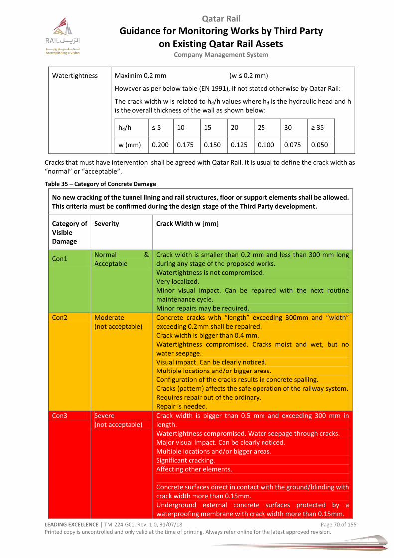
Qatar Rail
Guidance for Monitoring Works by Third Party on Existing Qatar Rail Assets
Company Management System
LEADING EXCELLENCE │ TM-224-G01, Rev. 1.0, 31/07/18 Page 70 of 155 Printed copy is uncontrolled and only valid at the time of printing. Always refer online for the latest approved revision.
Watertightness Maximim 0.2 mm (w ≤ 0.2 mm)
However as per below table (EN 1991), if not stated otherwise by Qatar Rail:
The crack width w is related to hd/h values where hd is the hydraulic head and h is the overall thickness of the wall as shown below:
hd/h ≤ 5 10 15 20 25 30 ≥ 35
w (mm) 0.200 0.175 0.150 0.125 0.100 0.075 0.050
Cracks that must have intervention shall be agreed with Qatar Rail. It is usual to define the crack width as “normal” or “acceptable”.
Table 35 – Category of Concrete Damage
No new cracking of the tunnel lining and rail structures, floor or support elements shall be allowed. This criteria must be confirmed during the design stage of the Third Party development.
Category of Visible Damage
Severity Crack Width w [mm]
Con1 Normal & Acceptable
Crack width is smaller than 0.2 mm and less than 300 mm long during any stage of the proposed works. Watertightness is not compromised. Very localized. Minor visual impact. Can be repaired with the next routine maintenance cycle. Minor repairs may be required.
Con2 Moderate (not acceptable)
Concrete cracks with “length” exceeding 300mm and “width” exceeding 0.2mm shall be repaired. Crack width is bigger than 0.4 mm. Watertightness compromised. Cracks moist and wet, but no water seepage. Visual impact. Can be clearly noticed. Multiple locations and/or bigger areas. Configuration of the cracks results in concrete spalling. Cracks (pattern) affects the safe operation of the railway system. Requires repair out of the ordinary. Repair is needed.
Con3 Severe (not acceptable)
Crack width is bigger than 0.5 mm and exceeding 300 mm in length. Watertightness compromised. Water seepage through cracks. Major visual impact. Can be clearly noticed. Multiple locations and/or bigger areas. Significant cracking. Affecting other elements. Concrete surfaces direct in contact with the ground/blinding with crack width more than 0.15mm. Underground external concrete surfaces protected by a waterproofing membrane with crack width more than 0.15mm.
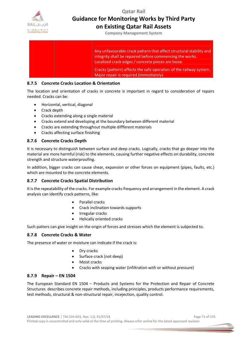
Qatar Rail
Guidance for Monitoring Works by Third Party on Existing Qatar Rail Assets
Company Management System
LEADING EXCELLENCE │ TM-224-G01, Rev. 1.0, 31/07/18 Page 71 of 155 Printed copy is uncontrolled and only valid at the time of printing. Always refer online for the latest approved revision.
Any unfavourable crack pattern that affect structural stability and integrity shall be repaired before commencing the works. Localized crack edges / concrete pieces are loose.
Cracks (pattern) affects the safe operation of the railway system. Major repair is required (immediately).
8.7.5 Concrete Cracks Location & Orientation
The location and orientation of cracks in concrete is important in regard to consideration of repairs needed. Cracks can be:
Horizontal, vertical, diagonal
Crack depth
Cracks extending along a single material
Cracks extend and developing at the boundary between different material
Cracks are extending throughout multiple diffferent materials
Cracks affecting surface finishing
8.7.6 Concrete Cracks Depth
It is necessary to distinguish between surface and deep cracks. Logically, cracks that go deeper into the material are more harmful (risk) to the elements, causing further negative effects on durability, concrete strength and structure waterproofing.
In addition, bigger cracks can cause shear, expansion or other forces on equipment (pipes, faults, etc.) which are mounted to the concrete elements.
8.7.7 Concrete Cracks Spatial Distribution
It is the repeatability of the cracks. For example cracks frequency and arrangement in the element. A crack analysis can identify crack patterns, like:
Parallel cracks
Crack inclination towards supports
Irregular cracks
Helically oriented cracks
Such patters can give insight on the origin of forces and stresses which the element is subjected to.
8.7.8 Concrete Cracks & Water
The presence of water or moisture can indicate if the crack is:
Dry cracks
Surface crack (not deep)
Moist cracks
Cracks with seaping water (infiltration with or without pressure)
8.7.9 Repair – EN 1504
The European Standard EN 1504 – Products and Systems for the Protection and Repair of Concrete Structures describes concrete repair methods, including principles, products performance requirements, test methods, structural & non-structural repair, incejection, quality control.
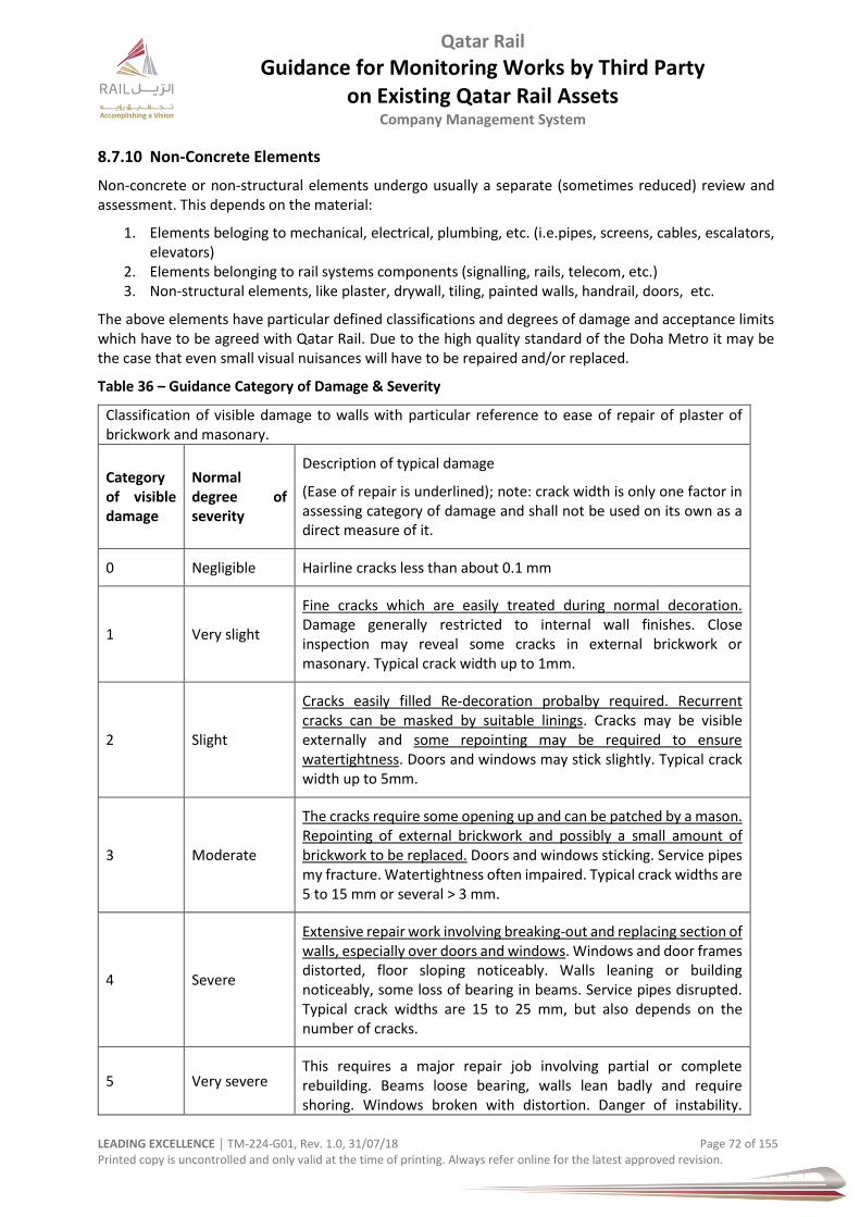
Qatar Rail
Guidance for Monitoring Works by Third Party on Existing Qatar Rail Assets
Company Management System
LEADING EXCELLENCE │ TM-224-G01, Rev. 1.0, 31/07/18 Page 72 of 155 Printed copy is uncontrolled and only valid at the time of printing. Always refer online for the latest approved revision.
8.7.10 Non-Concrete Elements
Non-concrete or non-structural elements undergo usually a separate (sometimes reduced) review and assessment. This depends on the material:
1. Elements beloging to mechanical, electrical, plumbing, etc. (i.e.pipes, screens, cables, escalators, elevators)
2. Elements belonging to rail systems components (signalling, rails, telecom, etc.) 3. Non-structural elements, like plaster, drywall, tiling, painted walls, handrail, doors, etc.
The above elements have particular defined classifications and degrees of damage and acceptance limits which have to be agreed with Qatar Rail. Due to the high quality standard of the Doha Metro it may be the case that even small visual nuisances will have to be repaired and/or replaced.
Table 36 – Guidance Category of Damage & Severity
Classification of visible damage to walls with particular reference to ease of repair of plaster of brickwork and masonary.
Category of visible damage
Normal degree of severity
Description of typical damage
(Ease of repair is underlined); note: crack width is only one factor in assessing category of damage and shall not be used on its own as a direct measure of it.
0 Negligible Hairline cracks less than about 0.1 mm
1 Very slight
Fine cracks which are easily treated during normal decoration. Damage generally restricted to internal wall finishes. Close inspection may reveal some cracks in external brickwork or masonary. Typical crack width up to 1mm.
2 Slight
Cracks easily filled Re-decoration probalby required. Recurrent cracks can be masked by suitable linings. Cracks may be visible externally and some repointing may be required to ensure watertightness. Doors and windows may stick slightly. Typical crack width up to 5mm.
3 Moderate
The cracks require some opening up and can be patched by a mason. Repointing of external brickwork and possibly a small amount of brickwork to be replaced. Doors and windows sticking. Service pipes my fracture. Watertightness often impaired. Typical crack widths are 5 to 15 mm or several ˃ 3 mm.
4 Severe
Extensive repair work involving breaking-out and replacing section of walls, especially over doors and windows. Windows and door frames distorted, floor sloping noticeably. Walls leaning or building noticeably, some loss of bearing in beams. Service pipes disrupted. Typical crack widths are 15 to 25 mm, but also depends on the number of cracks.
5 Very severe This requires a major repair job involving partial or complete rebuilding. Beams loose bearing, walls lean badly and require shoring. Windows broken with distortion. Danger of instability.
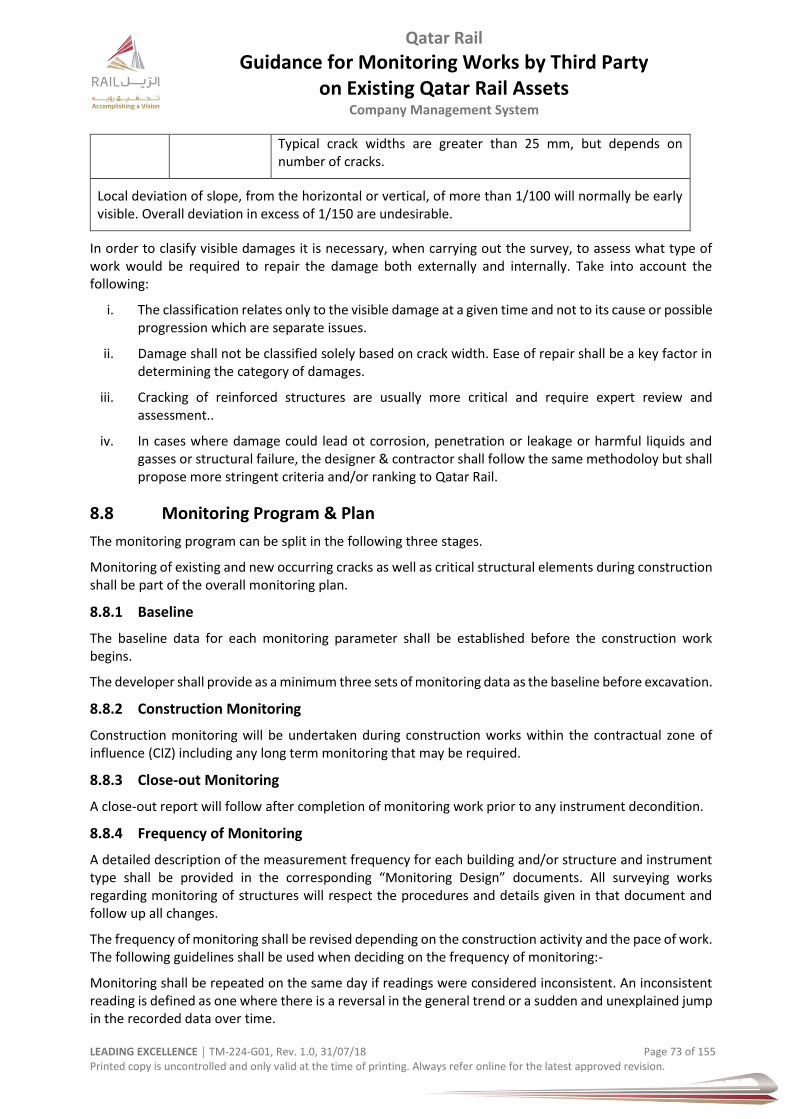
Qatar Rail
Guidance for Monitoring Works by Third Party on Existing Qatar Rail Assets
Company Management System
LEADING EXCELLENCE │ TM-224-G01, Rev. 1.0, 31/07/18 Page 73 of 155 Printed copy is uncontrolled and only valid at the time of printing. Always refer online for the latest approved revision.
Typical crack widths are greater than 25 mm, but depends on number of cracks.
Local deviation of slope, from the horizontal or vertical, of more than 1/100 will normally be early visible. Overall deviation in excess of 1/150 are undesirable.
In order to clasify visible damages it is necessary, when carrying out the survey, to assess what type of work would be required to repair the damage both externally and internally. Take into account the following:
i. The classification relates only to the visible damage at a given time and not to its cause or possible progression which are separate issues.
ii. Damage shall not be classified solely based on crack width. Ease of repair shall be a key factor in determining the category of damages.
iii. Cracking of reinforced structures are usually more critical and require expert review and assessment..
iv. In cases where damage could lead ot corrosion, penetration or leakage or harmful liquids and gasses or structural failure, the designer & contractor shall follow the same methodoloy but shall propose more stringent criteria and/or ranking to Qatar Rail.
8.8 Monitoring Program & Plan
The monitoring program can be split in the following three stages.
Monitoring of existing and new occurring cracks as well as critical structural elements during construction shall be part of the overall monitoring plan.
8.8.1 Baseline
The baseline data for each monitoring parameter shall be established before the construction work begins.
The developer shall provide as a minimum three sets of monitoring data as the baseline before excavation.
8.8.2 Construction Monitoring
Construction monitoring will be undertaken during construction works within the contractual zone of influence (CIZ) including any long term monitoring that may be required.
8.8.3 Close-out Monitoring
A close-out report will follow after completion of monitoring work prior to any instrument decondition.
8.8.4 Frequency of Monitoring
A detailed description of the measurement frequency for each building and/or structure and instrument type shall be provided in the corresponding “Monitoring Design” documents. All surveying works regarding monitoring of structures will respect the procedures and details given in that document and follow up all changes.
The frequency of monitoring shall be revised depending on the construction activity and the pace of work. The following guidelines shall be used when deciding on the frequency of monitoring:-
Monitoring shall be repeated on the same day if readings were considered inconsistent. An inconsistent reading is defined as one where there is a reversal in the general trend or a sudden and unexplained jump in the recorded data over time.
Qatar Rail
Guidance for Monitoring Works by Third Party on Existing Qatar Rail Assets
Company Management System
LEADING EXCELLENCE │ TM-224-G01, Rev. 1.0, 31/07/18 Page 74 of 155 Printed copy is uncontrolled and only valid at the time of printing. Always refer online for the latest approved revision.
If the readings show significant change, the frequency of monitoring shall be increased. A significant change is defined as an increase or decrease in the recorded value between consecutive monitoring visits which greatly increases the rate of change of the general trend. For example a settlement of >5mm between monitoring visits.
The frequency of monitoring shall be increased if the occurrence of undesirable phenomenon such as excessive ground loss, base heave or base blow out is detected.
In the event that further geotechnical investigations, detailed analysis and design indicate that protection works are required on existing structures, the works should be completed approximately 1 month prior to any excavation or tunnelling work.
The program for monitoring of the instrumentation and other works is tied to the overall construction program. In general, instruments will be installed prior to the excavation activity likely to affect the instruments. Therefore, repeatable base line readings will be measured prior to excavation or tunnelling work.
Monitoring shall continue until convergence of the readings can be demonstrated and that all works which could induce ground movement within the coverage zone of the instruments have been completed. Monitoring frequencies will be continually reviewed so that the rate is appropriate with construction activity and trends of monitoring results.
8.9 Monitoring Parts
levelling of surface
levelling of buildings
Deflections of columns (especially of stations/switchbox)
vertical and horizontal deformations of existing buildings or other structures
3D targets of automatic optical deformation monitoring systems
crack meter readings of structures
load/stress cell measurements for concrete lining (if applicable)
Inclinometer, extensometer
Strain gauge readings
groundwater monitoring i.e. piezometer readings
groundwater discharge quantities (e.g. from flow meter connected to pumping dewatering
wells)
vibration measurements
excavation progress
calibration reports or certificates of instruments (in form of report soft copy)
installation record sheets
8.10 Central Monitoring Software
An automatic data acquisition system shall be designed that captures the measured results of all suitable instruments (above and below ground), irrespective of the type of sensor and the physical measurement parameters, and can be automatically viewed in real time and transmitted to a central station outside the settlement zone.
A computer database for the integration, storage, analysis, recording and processing of all
monitored data shall be established. The computer database shall be stored on a web based server.
Qatar Rail
Guidance for Monitoring Works by Third Party on Existing Qatar Rail Assets
Company Management System
LEADING EXCELLENCE │ TM-224-G01, Rev. 1.0, 31/07/18 Page 75 of 155 Printed copy is uncontrolled and only valid at the time of printing. Always refer online for the latest approved revision.
Real-time remote access to all monitoring data shall be provided. The instrumentation and monitoring system shall include the real-time information from the TBM
control parameter operations and information on buildings/structures within the zone of influence of the Works.
Reliability
The monitoring system (software) collects data from different systems in order to provide its services including visualization of sensor measurements. The reliability of the system - and the quality of the services provided - heavily depends on the reliability of the provided measuring data and documents. The monitoring system should check incoming data against a number of conditions but cannot provide a complete plausibility check.
Actuality
As a web-based system, a particular monitoring system(i.e. IRIS.Geomonitoring) involves automatically transferred data. The overall delay is the sum of time delays from the underlying data-acquisition, the data-processing, the network connections and the sampling rate.
For the manual upload of measurement data and the input of construction reports, the actuality of the system i.e. how often the database is updated strongly depends on the cooperativeness of the contributers.
Integrity
The monitoring system should run daily and weekly backup routines that include additional backup server and databases. The system should therefore not only provide a central system for collection of data from various sensor systems, it could also act as a central backup system for all measurement data and related documents.
Time Schedule
In order to provide its full service to the construction project, the monitoring system must be installed with project- and site-specific settings. This information needs to be provided to the monitoring team. Because such settings require effort and time the information should be provided in a timely manner.
Interfaces
If not using a well prooven monitoring specification for arrangement of fields within a CSV format, the particular specification needs to be communicated to the monitoring team as soon as possilbe before activation of the interface.
Activation of Alarm Recipients
For each sensor installed on site an alarm will be sent to registered recipients when a predefined threshold has been violated. Email addresses of alarm recipients shall be obtained and activated following the Distribution Matrix for Monitoring Data.
Activation of Trigger Values / Thresholds
These thresholds need to be sent to the monitoring I&M team at a reasonable time before activation.
The web application is structured in accordance to the requirements of the project and it may be modified to suit the evolving needs of the project.
Qatar Rail
Guidance for Monitoring Works by Third Party on Existing Qatar Rail Assets
Company Management System
LEADING EXCELLENCE │ TM-224-G01, Rev. 1.0, 31/07/18 Page 76 of 155 Printed copy is uncontrolled and only valid at the time of printing. Always refer online for the latest approved revision.
8.11 Data Transmission
The monitoring/survey system can be set up to provide access to all necessary data from the project. Multiple user groups could be allowed to have access to the program. The user groups could be allocated as following:
a) internal project team: I&M Core Team (contractor) b) measurement team: Surveying and Monitoring; 3rd parties c) external project team: Other third parties d) authorized persons/entities: authorized by Qatar Railways and others
8.11.1 Automatic Upload
Sensor groups that support automatic transfer can automatically send their measured values to the survey and data management system. In the planned installation these include for example automatic measurements of 3D targets with total station.
CSV files are uploaded using the File Transfer Protocol (FTP). The external application has to upload these files onto the survey and data management server itself in order to be detected and processed.
8.11.2 Manual Upload
Other sensor measurements are recorded manually. In the planned installation these include inclinometers, extensometers, piezometers, load cells, surface settlements and manual 3D measurements.
The generated CSV files can be uploaded manually through web forms (HTTP) to be processed by the survey and data management system.
8.11.3 Visualisation
Measured sensor values are visualized by the surveyor and any applicable system with the four visualization methods described in this section.
Value versus Time
The measured value of a selected sensor is displayed over a selected time interval as a curve. This visualization is generally applicable for anchor load cells, strain gauges and other sensors that periodically measure a single value. The system also allows multiple selection of sensors and supports multiple y-axes for sensors with different units of measurement.
Horizontal Deformation versus Depth
The standard inclinometer diagram shows the horizontal deformation on the x-axis versus the depth on the y-axis for a selected measurement or as aggregated values over a time interval. IRIS supports selection of multiple time instances to display multiple deformation graphs in one diagram. Selection of differently proportioned time intervals in order to analyse deformation trends is also possible.
Settlement over a Cross Section
Vertical settlement along a cross-section can be displayed for a selected measurement or as aggregated values over a time interval.
Alarm
Trigger level notifications or “alarms” are activated when a sensor’s measured value violates a predefined threshold or trigger value. These definitions, as contained in the Monitoring Design reports, will be provided by PSH JV to the IRIS team in order to be activated. IRIS currently supports two levels of severity corresponding to two intervals defined for the range of each sensor. IRIS communicates “alarm” messages through three channels.
Qatar Rail
Guidance for Monitoring Works by Third Party on Existing Qatar Rail Assets
Company Management System
LEADING EXCELLENCE │ TM-224-G01, Rev. 1.0, 31/07/18 Page 77 of 155 Printed copy is uncontrolled and only valid at the time of printing. Always refer online for the latest approved revision.
Personalised Alarms
The IRIS system sends alarm messages as emails to a pre-defined mailing list (refer to the Distribution Matrix for Monitoring Data).
Online Alarm Message
As long as an alarm is active, a message also appears on the IRIS web application at a central position within each page. On the front page a dashboard with all active alarms is displayed.
Alarm History
For traceability, the IRIS web application shows a list of all previous alarm events and actions performed for selected sensors (who has been informed through which channel).
Independent third-party systems, such as measurement systems for noise and vibrations, must provide their own alarming system independent from the IRIS system. This will ensure that alarms are announced directly to the site and adequate actions can be performed immediately.
Qatar Rail
Guidance for Monitoring Works by Third Party on Existing Qatar Rail Assets
Company Management System
LEADING EXCELLENCE │ TM-224-G01, Rev. 1.0, 31/07/18 Page 78 of 155 Printed copy is uncontrolled and only valid at the time of printing. Always refer online for the latest approved revision.
9 Excavations & Structures
9.1 General
This chapter gives guidance regarding the steps required for surveying and measuring works to carry out monitoring of excavations and structures. All monitoring schemes will be coordinated on the project grid. All elevation monitoring will be conducted on the project datum.
The site surveyor will use the set references and benchmarks in order to execute the setting out of the monitoring lines and instrumentation as well as the measurements of the surface levelling points and 3D targets.
A detailed description of the monitoring system for each location or structure shall be provided by the third party within the Monitoring Design reports prepared by the Designer. As part of the Monitoring Design, monitoring installation drawings provide the actual cross sections details for installation of instruments. All instrumentation and monitoring of stations or structures will reflect the requirements and details given in the Monitoring Design documents and follow-up changes.
Concerning the excavation of buildings or structures, manual or automated monitoring is possible. Automated monitoring will be carried out for all sensitive buildings and structures. ‘Sensitivity’ for implementation of automated monitoring will be determined based on the risk classification of a building/structure.
In general, monitoring can consist of the following components:
a) ground surface vertical deformations & displacements b) open-cut slopes three dimensional deformations c) TBM head-walls horizontal deformations d) horizontal ground displacements around the structure e) groundwater level fluctuations f) anchor loads
but also:
a) Extrusion and ground ahead of face b) relative vertical movement c) lateral displacement d) change in inclination e) change in earth pressure f) change in water pressure g) crack and joint movement h) strain in structural members (and lining) i) tunnel lining diametrical distortion j) stresses (in lining, structure) k) leakage l) noise and vibration
All monitoring points shall be clearly identified. All points are named in the “monitoring installation drawings” which are part of the Monitoring Design documents. The unique names will be used for all measurements and evaluations as part of the measurement and surveying works.
The contractor shall carry out Additional Geotechnical Investigation (AGI) in order to examine the geological, hydrogeological and geotechnical conditions and determine the design geotechnical parameters, as required:
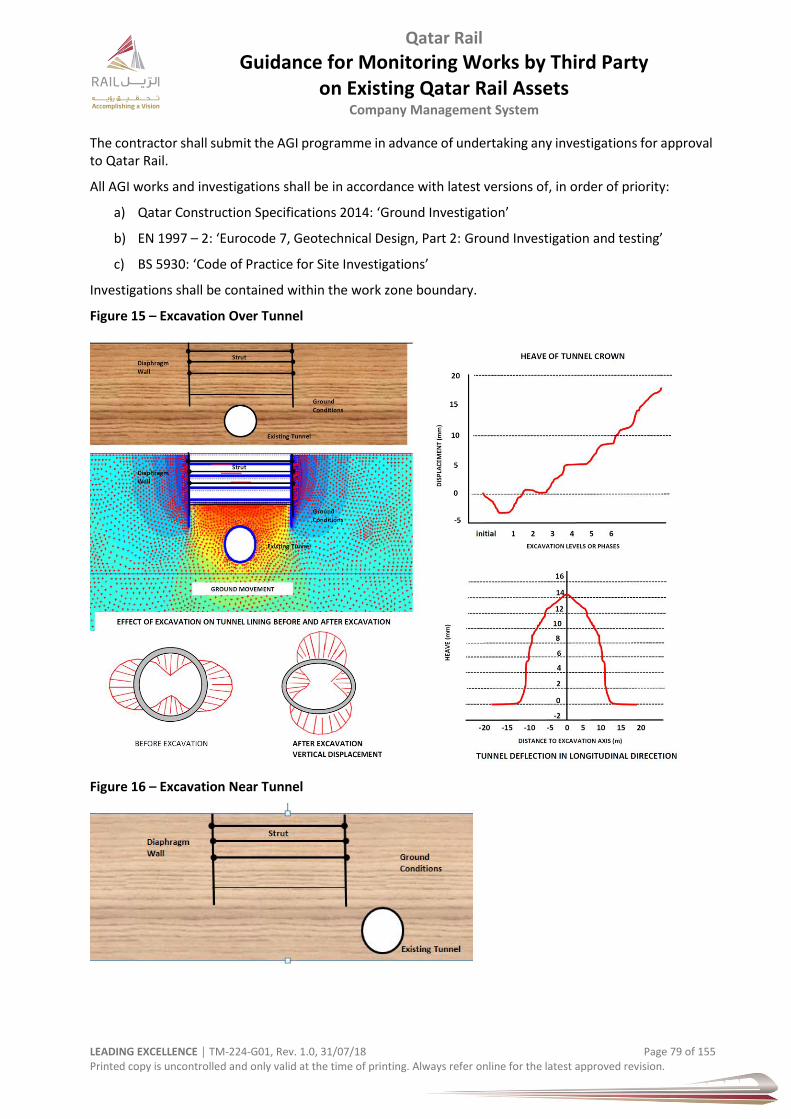
Qatar Rail
Guidance for Monitoring Works by Third Party on Existing Qatar Rail Assets
Company Management System
LEADING EXCELLENCE │ TM-224-G01, Rev. 1.0, 31/07/18 Page 79 of 155 Printed copy is uncontrolled and only valid at the time of printing. Always refer online for the latest approved revision.
The contractor shall submit the AGI programme in advance of undertaking any investigations for approval to Qatar Rail.
All AGI works and investigations shall be in accordance with latest versions of, in order of priority:
a) Qatar Construction Specifications 2014: ‘Ground Investigation’
b) EN 1997 – 2: ‘Eurocode 7, Geotechnical Design, Part 2: Ground Investigation and testing’
c) BS 5930: ‘Code of Practice for Site Investigations’
Investigations shall be contained within the work zone boundary.
Figure 15 – Excavation Over Tunnel
Figure 16 – Excavation Near Tunnel
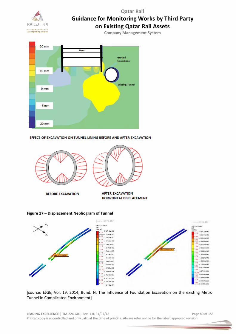
Qatar Rail
Guidance for Monitoring Works by Third Party on Existing Qatar Rail Assets
Company Management System
LEADING EXCELLENCE │ TM-224-G01, Rev. 1.0, 31/07/18 Page 80 of 155 Printed copy is uncontrolled and only valid at the time of printing. Always refer online for the latest approved revision.
Figure 17 – Displacement Nephogram of Tunnel
[source: EJGE, Vol. 19, 2014, Bund. N, The Influence of Foundation Excavation on the existing Metro Tunnel in Complicated Environment]

Qatar Rail
Guidance for Monitoring Works by Third Party on Existing Qatar Rail Assets
Company Management System
LEADING EXCELLENCE │ TM-224-G01, Rev. 1.0, 31/07/18 Page 81 of 155 Printed copy is uncontrolled and only valid at the time of printing. Always refer online for the latest approved revision.
Figure 18 – Displacement of Tunnel
Figure 19 – Example Cross-Section of Tunnel & Ground
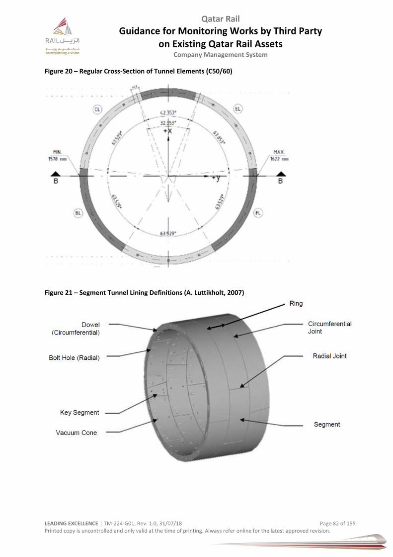
Qatar Rail
Guidance for Monitoring Works by Third Party on Existing Qatar Rail Assets
Company Management System
LEADING EXCELLENCE │ TM-224-G01, Rev. 1.0, 31/07/18 Page 82 of 155 Printed copy is uncontrolled and only valid at the time of printing. Always refer online for the latest approved revision.
Figure 20 – Regular Cross-Section of Tunnel Elements (C50/60)
Figure 21 – Segment Tunnel Lining Definitions (A. Luttikholt, 2007)

Qatar Rail
Guidance for Monitoring Works by Third Party on Existing Qatar Rail Assets
Company Management System
LEADING EXCELLENCE │ TM-224-G01, Rev. 1.0, 31/07/18 Page 83 of 155 Printed copy is uncontrolled and only valid at the time of printing. Always refer online for the latest approved revision.
Figure 22 – Tunnel Segment Joint & Gasket
9.2 Review of Data
The Third Party contractor and its designer(s) will review and evaluate available monitoring results and their trends during regular meetings (weekly).
Emails could be used as a tool to notify breaches of trigger levels.
These have to be programmed into the monitoring database software. The third party designer will interpret together with the Qatar Rail Expert(s) the relevant results when a trigger level is exceeded but not all results on a daily basis.
In addition, a procedure has to be established to examine monitoring data in terms of reliability and accuracy on a continuous basis. A site personnel is also expected to be identified for each site in stages to review monitoring results on a continuous basis in tandem with progress of site works
9.3 Instrumentation
The following equipment may be utilised in carrying out the works (not exhaustive):
a) Extrusion and ground ahead of face b) Surface Levelling Points (SLPs) c) Surface settlement points (survey points fixed to pavements or installed into the ground to
measure surface settlement, or fixed to services where appropriate); d) Building settlement levelling points e) 3D Targets; Monitoring of structures using bi-reflex targets or glass prisms fixed to the structures,
to enable three dimensional displacements to be optically recorded f) Vibrating Wire Piezometers (piezometers will be installed in boreholes at suitable levels, with
either sand or gravel filled response zone) g) Water level observation wells (boreholes with slotted pipes backfilled with pea gravel) – this will
be provided as part of the Additional Ground Investigation and also if required shall be installed for specific stations.
h) Inclinometers (used to measure the lateral displacement of the ground or wall and will be installed in boreholes at suitable levels)
i) Automatic piezometers and inclinometers
Qatar Rail
Guidance for Monitoring Works by Third Party on Existing Qatar Rail Assets
Company Management System
LEADING EXCELLENCE │ TM-224-G01, Rev. 1.0, 31/07/18 Page 84 of 155 Printed copy is uncontrolled and only valid at the time of printing. Always refer online for the latest approved revision.
j) Extensometers used to measure the displacements, separation, settlements and , convergence); could be installed at suitable levels of the roof and sidewall surrounding the tunnel opening
k) Load Cells (strain gauge type centre-hole load cells) used to measure the anchor force and shall be installed according to the anchor design supplier instructions
l) Total Stations m) Digital Levels
A list of the measuring equipment shall be provided with all calibration certificates, when applicable. Detailed descriptions on the instrument types, accuracy and features shall be provided to Qatar Rail.
9.4 Layout
9.4.1 General
The layout of the instrumentation including planned coordinates is to be shown on the monitoring installation drawings which are part of the monitoring design, as agreed with Qatar Rail. The as-built coordinates of the instruments and monitoring points shall be provided in the monitoring database and can be exported in CSV format.
Topographic control points of levelling and 3D measurements, as well as survey reference points (outside the zone of influence) shall be established and shall be available in the monitoring database.
The proposed instrumentation layout is summarized on the Instrumentation and Monitoring Typical Array Details and General Arrangement drawings produced by the third party. All proposed monitoring points should be positioned within the zone of influence. The arrays are based on the following regime:
9.4.2 Metro Tunnel
METRO TUNNEL. The TBM monitoring sections include an arrangement of Array Type A and Array Type B surface settlement monitoring points. Type B arrays are spaced at every 300m with Type A arrays in between at every 75m. The total number of surface settlement monitoring points is a function of the length of each TBM monitoring section.
9.4.3 New Austrian Tunnelling Method NATM
NATM Cross Passages. The cross passages should be monitored by 5 No. convergence monitoring points at the centre of the cross passage and surface monitoring points at ground level above the centre point of the cross passage.
9.4.4 Shafts
SHAFTS: The Emergency Exit Shafts Monitoring comprises 6 surface settlement points spread out radially from the shaft. In addition, internal monitoring cross sections to monitor convergence and strain of shaft lining are required. 5 No. convergence monitoring points are required every 10m in each shaft. The arrangement is shown on the Typical Internal Convergence Points Detail. Construction dewatering to be monitored by the installation of a single piezometer to record changes in groundwater levels.
9.4.5 TBM Launch
TBM LAUNCH/ARRIVAL AREA IN STATIONS. Monitoring zone type MZA is required at TBM Launching and arrival locations. This comprises surface settlement monitoring points at approximately 10m c/c arranged as shown on the Instrumentation and Monitoring Typical Array Details Drawings.
9.4.6 Temporary Works
TEMPORARY WORKS FOR STATIONS. Temporary excavations lateral support system will be design which will be independent from permanent works and will be monitored using the surface settlement monitoring points provided at interval shown on the Typical Arrays E, F, G and H.
Qatar Rail
Guidance for Monitoring Works by Third Party on Existing Qatar Rail Assets
Company Management System
LEADING EXCELLENCE │ TM-224-G01, Rev. 1.0, 31/07/18 Page 85 of 155 Printed copy is uncontrolled and only valid at the time of printing. Always refer online for the latest approved revision.
9.4.7 Existing Structures & Utilities
EXISTING STRUCTURES AND UTILITIES. Typical settlements are expected to be small and therefore it is only proposed to monitor selected and critical buildings during the tunnelling/deep excavation works by an automated measuring system for the total (3D) in real time for the building. Tensile strains will be monitored by optical survey or similar for all buildings with predicted tensile strain greater than 0.075% and for any building subjected to protection works. Surface settlement points are to be located at no interval longer than 20m along critical utility lines. The critical nature of utilities will be determined based on the flexibility of the construction material. This will be confirmed in a final Monitoring and Instrumentation Geotechnical Design Report to be issued following receipt of the third party requirements, as built and services drawings.
9.4.8 Underground Utilities
UNDERGROUND UTILITIES - Underground utilities include service mains, such as drinking water, sewerage, energy (gas, power, oil, etc.) and public or private underground transport infrastructure. It involves various structures in size, design and depth. However, these structures are all characterized by their large length in relation to their transverse size, which is roughly circular.
Large diameter utilities (>2 m) are less numerous, which justifies a case by case studies to be performed by means of sophisticated modelling techniques to assess the impact of adjacent underground works in such cases. This can in turn lead to an evaluation of the magnitude of allowable movements.
A similar approach cannot be used for a great number of highly sensitive service mains. The sensitivity of these structures to ground movements widely depends on their lining material (concrete, cast iron, ductile iron, PVC, PE, etc.) and gasket characteristics.
9.4.9 Buildings & Structures on Piles
BUILDINGS AND STRUCTURES FOUNDED ON PILES -Buildings and structures founded on piles will be
subject to the Third Party designers & contractors risk assessment if they are located within the zone of
influence of the works.
For buildings and structures on pile foundations, the Third Party designers & contractors detailed risk
evaluation requires numerical analysis including the geometrical – structure – pile foundation interaction.
9.5 Monitoring Installation
All instrumentation shall be installed in an adequate time period before the commencement of the works for the determination of the zero measurements. This point in time has to be confirmed in close coordination between the site management and Qatar Rail. All instruments will be tagged with:
project title and contract number
equipment reference number
contact name and telephone number
last calibration date
All equipment shall be installed and tested strictly in accordance with the manufacturer´s instructions and recommendations.
Pre-installation checks shall take place regarding visible damages in packing, completeness, checking of manufacturer´s certificates, system check by connecting parts and checking for correct configuration. A system or component that fails the pre-installation acceptance test shall be replaced before installing.
Installation records will be collected and stored digitally in the monitoring database.

Qatar Rail
Guidance for Monitoring Works by Third Party on Existing Qatar Rail Assets
Company Management System
LEADING EXCELLENCE │ TM-224-G01, Rev. 1.0, 31/07/18 Page 86 of 155 Printed copy is uncontrolled and only valid at the time of printing. Always refer online for the latest approved revision.
Protection measures for instruments have to be coordinated by the site management. In any case there will be the following measures:
highly visible warning equipment like tapes and area blocks
all instruments in the ground are protected in steel cases and with covers
Instruments and sensors will be clearly marked with colour spray or similar
9.6 Piezometers
Vibrating wire piezometers (in boreholes) are used to monitor pore-water pressure in soils. They are typically sealed in boreholes but can also be embedded in fills, or suspended in a well.
Typical applications include evaluating slope stability, dewatering and drainage schemes, overpressure in silt and clay soils, permeability and hydraulic gradients in dams, and also ground water levels. They can also be used to monitor up-lift pressures in gravity dams.
Typical schenarios:
Dams and fill embankments
Measurement of ground water
Dewatering activities
Landslides monitoring
Natural or cut slope sites
Monitoring of up-lift pressure
Advanages:
Long-term stability
Cable length does not affect reading
Long working life and reliability
Built-in surge protection
(overvoltage)
Built-in temperature sensor
Hermetically sealed
9.7 Inclinometer
The inclinometer system is used for measurement of lateral movement of ground as well as tilt. A near vertical gage well is made by installing the inclinometer casing in the borehole.
The following pre-conditions are required before installation:
i. properly completed borehole (particularly with regards to borehole verticality); ii. correct sealing on the couplings;
iii. appropriate grouting to ensure that the tube follows the deformation of the adjacent soil or structure
9.8 Load Cells
The installation of load cells shall be done by experienced and trained construction workers and technicians at the same time as the installation of anchors.
The load cell shall be installed on the anchor before the anchor tensioning operation starts. Anchor load cells will be installed with particular care to obtain load bearing surfaces flat and parallel to avoid any significant distortion under load. Between the cell and wall surfaces will be installed an abutment plate. The plate will be at least of the same thickness as the distribution plate (30mm) with diameter at least 20 mm larger than the load cell.
To obtain correct measurements, the load cell shall be inserted between two distribution plates stiffer than the load cell as the load cell has to be the most deformable element in the anchor head assembly.

Qatar Rail
Guidance for Monitoring Works by Third Party on Existing Qatar Rail Assets
Company Management System
LEADING EXCELLENCE │ TM-224-G01, Rev. 1.0, 31/07/18 Page 87 of 155 Printed copy is uncontrolled and only valid at the time of printing. Always refer online for the latest approved revision.
Figure 23 – Load Cell
9.9 Extensometers
A type of multi-level extensometers, either magnet extensometers or rod extensometers, shall be installed directly above railway tunnels (TBM drives) in vertical boreholes that will not penetrate the railway tunnels.
Figure 24 – Rod Extensometer

Qatar Rail
Guidance for Monitoring Works by Third Party on Existing Qatar Rail Assets
Company Management System
LEADING EXCELLENCE │ TM-224-G01, Rev. 1.0, 31/07/18 Page 88 of 155 Printed copy is uncontrolled and only valid at the time of printing. Always refer online for the latest approved revision.
The rod extensometer monitors changes in the distance between one or more downhole anchors and a reference head at the borehole collar. Typical applications include:
Monitoring settlement in foundations.
Monitoring subsidence above tunnels and mines.
Monitoring heave in excavations. Monitoring the stability of tunnels and other underground openings.
Monitoring deformation in abutments and walls.
The magnet extensometer is used to monitor
settlement and heave in excavations,
foundations,
dams, and
embankments.
It can also be installed behind retaining structures, such as sheet piles and slurry walls, and at above underground openings, such as tunnels and shafts. Data from the extensometer indicate the depths at which settlement has occurred as well as the total amount of settlement.
Figure 25 – Magnet Extensometer
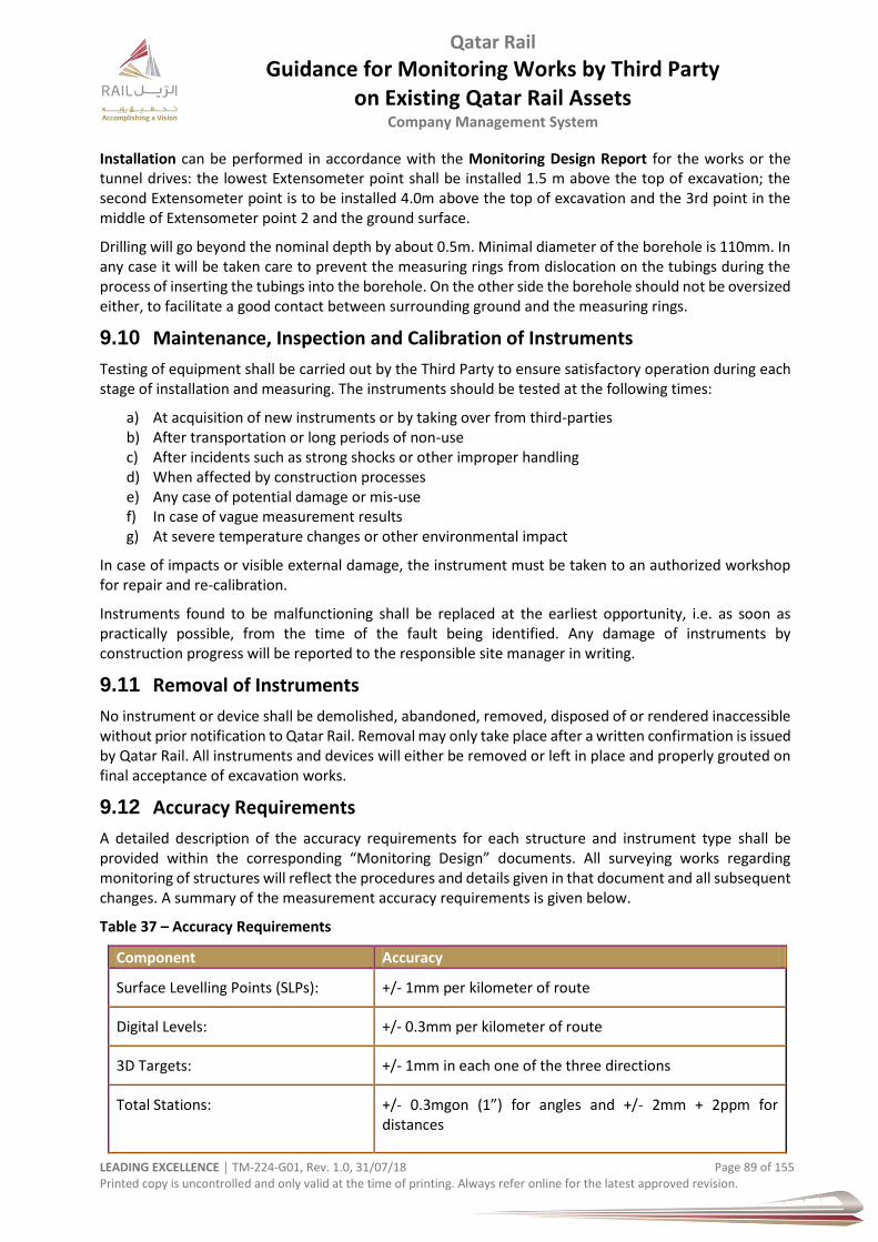
Qatar Rail
Guidance for Monitoring Works by Third Party on Existing Qatar Rail Assets
Company Management System
LEADING EXCELLENCE │ TM-224-G01, Rev. 1.0, 31/07/18 Page 89 of 155 Printed copy is uncontrolled and only valid at the time of printing. Always refer online for the latest approved revision.
Installation can be performed in accordance with the Monitoring Design Report for the works or the tunnel drives: the lowest Extensometer point shall be installed 1.5 m above the top of excavation; the second Extensometer point is to be installed 4.0m above the top of excavation and the 3rd point in the middle of Extensometer point 2 and the ground surface.
Drilling will go beyond the nominal depth by about 0.5m. Minimal diameter of the borehole is 110mm. In any case it will be taken care to prevent the measuring rings from dislocation on the tubings during the process of inserting the tubings into the borehole. On the other side the borehole should not be oversized either, to facilitate a good contact between surrounding ground and the measuring rings.
9.10 Maintenance, Inspection and Calibration of Instruments
Testing of equipment shall be carried out by the Third Party to ensure satisfactory operation during each stage of installation and measuring. The instruments should be tested at the following times:
a) At acquisition of new instruments or by taking over from third-parties b) After transportation or long periods of non-use c) After incidents such as strong shocks or other improper handling d) When affected by construction processes e) Any case of potential damage or mis-use f) In case of vague measurement results g) At severe temperature changes or other environmental impact
In case of impacts or visible external damage, the instrument must be taken to an authorized workshop for repair and re-calibration.
Instruments found to be malfunctioning shall be replaced at the earliest opportunity, i.e. as soon as practically possible, from the time of the fault being identified. Any damage of instruments by construction progress will be reported to the responsible site manager in writing.
9.11 Removal of Instruments
No instrument or device shall be demolished, abandoned, removed, disposed of or rendered inaccessible without prior notification to Qatar Rail. Removal may only take place after a written confirmation is issued by Qatar Rail. All instruments and devices will either be removed or left in place and properly grouted on final acceptance of excavation works.
9.12 Accuracy Requirements
A detailed description of the accuracy requirements for each structure and instrument type shall be provided within the corresponding “Monitoring Design” documents. All surveying works regarding monitoring of structures will reflect the procedures and details given in that document and all subsequent changes. A summary of the measurement accuracy requirements is given below.
Table 37 – Accuracy Requirements
Component Accuracy
Surface Levelling Points (SLPs): +/- 1mm per kilometer of route
Digital Levels: +/- 0.3mm per kilometer of route
3D Targets: +/- 1mm in each one of the three directions
Total Stations:
+/- 0.3mgon (1”) for angles and +/- 2mm + 2ppm for distances
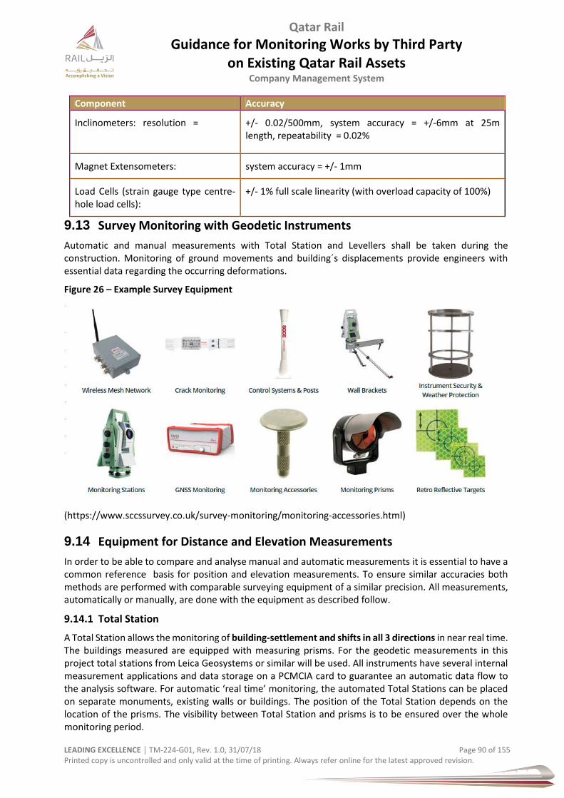
Qatar Rail
Guidance for Monitoring Works by Third Party on Existing Qatar Rail Assets
Company Management System
LEADING EXCELLENCE │ TM-224-G01, Rev. 1.0, 31/07/18 Page 90 of 155 Printed copy is uncontrolled and only valid at the time of printing. Always refer online for the latest approved revision.
Component Accuracy
Inclinometers: resolution =
+/- 0.02/500mm, system accuracy = +/-6mm at 25m length, repeatability = 0.02%
Magnet Extensometers: system accuracy = +/- 1mm
Load Cells (strain gauge type centre-hole load cells):
+/- 1% full scale linearity (with overload capacity of 100%)
9.13 Survey Monitoring with Geodetic Instruments
Automatic and manual measurements with Total Station and Levellers shall be taken during the construction. Monitoring of ground movements and building´s displacements provide engineers with essential data regarding the occurring deformations.
Figure 26 – Example Survey Equipment
(https://www.sccssurvey.co.uk/survey-monitoring/monitoring-accessories.html)
9.14 Equipment for Distance and Elevation Measurements
In order to be able to compare and analyse manual and automatic measurements it is essential to have a common reference basis for position and elevation measurements. To ensure similar accuracies both methods are performed with comparable surveying equipment of a similar precision. All measurements, automatically or manually, are done with the equipment as described follow.
9.14.1 Total Station
A Total Station allows the monitoring of building-settlement and shifts in all 3 directions in near real time. The buildings measured are equipped with measuring prisms. For the geodetic measurements in this project total stations from Leica Geosystems or similar will be used. All instruments have several internal measurement applications and data storage on a PCMCIA card to guarantee an automatic data flow to the analysis software. For automatic ‘real time’ monitoring, the automated Total Stations can be placed on separate monuments, existing walls or buildings. The position of the Total Station depends on the location of the prisms. The visibility between Total Station and prisms is to be ensured over the whole monitoring period.

Qatar Rail
Guidance for Monitoring Works by Third Party on Existing Qatar Rail Assets
Company Management System
LEADING EXCELLENCE │ TM-224-G01, Rev. 1.0, 31/07/18 Page 91 of 155 Printed copy is uncontrolled and only valid at the time of printing. Always refer online for the latest approved revision.
9.14.2 Digital Leveller
For the determination of vertical displacements digital high precision levelling instruments from Leica Geosystems or similar can being used.
All measurements are adapted to the meteorological conditions (temperature, air pressure).
Geometric corrections are made during data processing in the office
All basic angle measurements are measured in two faces.
Stations will be set up with heavy tripods.
Every levelling will performed as a doubled levelling.
9.14.3 Bolts and Prisms
Depending on how rough the surface is and from what material it is made from, prisms are either fixed with adhesive or fastened by dowels and bolts. Prisms may also serve as building settlement or levelling points.
The figure below shows samples of prisms to be used for 3D measurements. The L prism, used usually for building monitoring, can be turned in any direction to enable proper orientation towards the Total Station. The tilting brackets with a glass mini prism will be used as 3D targets for monitoring of excavation face. Dedicated mounting accessories will be used for fixing the prisms. Fixing bolts will be purchased together with the prisms from the manufacturer.
Figure 27 – Prisms
3D target (10x10cm)
Qatar Rail
Guidance for Monitoring Works by Third Party on Existing Qatar Rail Assets
Company Management System
LEADING EXCELLENCE │ TM-224-G01, Rev. 1.0, 31/07/18 Page 92 of 155 Printed copy is uncontrolled and only valid at the time of printing. Always refer online for the latest approved revision.
10 Track Monitoring
10.1 General
Track monitoring (systems) play a vital role in maintaining the safety of the railways. Monitoring bridges and tunnels (see next paragraphs) uses sensors to identify and analyze defects (cracking and displacement) in large structures. Both interact with each other and are immensely important for the safety but also for maintenance reasons. Such systems provide excellent early warning information in order to avoid any issues arising from changes to the track or related structures.
Assistant Prof. Stanislav Jovanović, PhD. CE, University of Novi Sad, says “Average annual maintenance and renewal (M&R) expenditures per 1 km of tracks of advanced railway networks nowadays revolve around EUR (€) 50.000. Estimated cost-savings resulting from the use of a modern condition-based decision-making approach, embedded in a suitable decision-support information system, are reported to range from modest 15 % up to the optimistic 55 %. Most important railway track condition-monitoring methods applied worldwide are described, and a data analysis process used for the M&R management purposes is presented.” (GRAĐEVINAR 66 (2014) 4, 347-358)
The monitoring system shall have enough robustness and shall be sufficiently robust to ensure that the system is resilient and that rogue readings are identified and discounted.
The accuracy, repeatability and tolerances of the instrumentation and monitoring shall be compatible with the structural and stress analysis and design of the monitored structure.
Multi-mode monitoring is preferable for cross reference of the validation of the structural response.
10.2 Instrumentation & Monitoring Strategy (IMS)
The designer of the IMS shall include details of:
• Parts of the structures that will be instrumented, and the suggested design parameter ranges.
• Instrument specifications, calibration and design of sensor arrangement and their attachment.
• Collection and preparation of monitoring data and progress information including information from data loggers and real-time systems
• Processing and validation of data and information including comparison of real-time data with manual back up surveys
• Investigation and process of dealing with anomalous readings
• Presentation, interpretation and review of information
• Methodology for comparison of actual measurements with the predicted structural response during the construction stages and also the operation phase.
• Processes for implementing required actions
• The structure and membership of review groups required
• Areas of responsibility and authority including the I&M Coordinator (IMC), monitoring engineers, instrumentation engineers and surveyors
• The protocols for distribution of information and communications
• The procedure for mobilising the Management Action Team (MAT)
• On-call personnel including contact details (to be issued weekly)
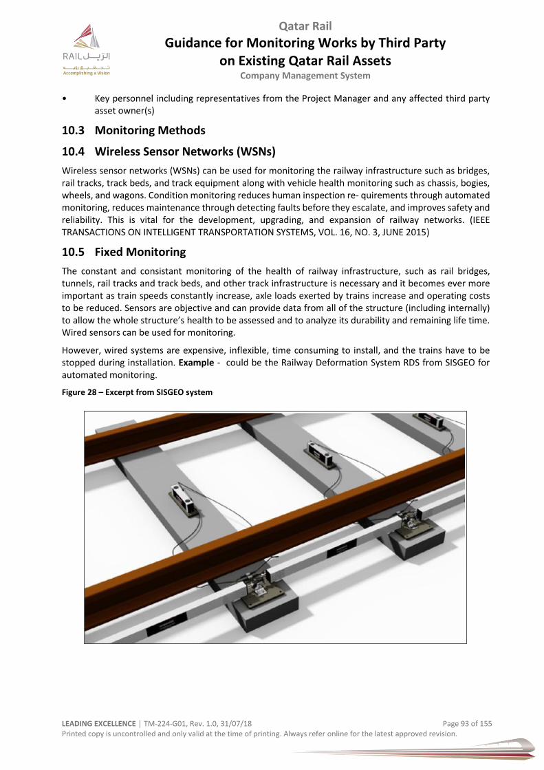
Qatar Rail
Guidance for Monitoring Works by Third Party on Existing Qatar Rail Assets
Company Management System
LEADING EXCELLENCE │ TM-224-G01, Rev. 1.0, 31/07/18 Page 93 of 155 Printed copy is uncontrolled and only valid at the time of printing. Always refer online for the latest approved revision.
• Key personnel including representatives from the Project Manager and any affected third party asset owner(s)
10.3 Monitoring Methods
10.4 Wireless Sensor Networks (WSNs)
Wireless sensor networks (WSNs) can be used for monitoring the railway infrastructure such as bridges, rail tracks, track beds, and track equipment along with vehicle health monitoring such as chassis, bogies, wheels, and wagons. Condition monitoring reduces human inspection re- quirements through automated monitoring, reduces maintenance through detecting faults before they escalate, and improves safety and reliability. This is vital for the development, upgrading, and expansion of railway networks. (IEEE TRANSACTIONS ON INTELLIGENT TRANSPORTATION SYSTEMS, VOL. 16, NO. 3, JUNE 2015)
10.5 Fixed Monitoring
The constant and consistant monitoring of the health of railway infrastructure, such as rail bridges, tunnels, rail tracks and track beds, and other track infrastructure is necessary and it becomes ever more important as train speeds constantly increase, axle loads exerted by trains increase and operating costs to be reduced. Sensors are objective and can provide data from all of the structure (including internally) to allow the whole structure’s health to be assessed and to analyze its durability and remaining life time. Wired sensors can be used for monitoring.
However, wired systems are expensive, inflexible, time consuming to install, and the trains have to be stopped during installation. Example - could be the Railway Deformation System RDS from SISGEO for automated monitoring.
Figure 28 – Excerpt from SISGEO system

Qatar Rail
Guidance for Monitoring Works by Third Party on Existing Qatar Rail Assets
Company Management System
LEADING EXCELLENCE │ TM-224-G01, Rev. 1.0, 31/07/18 Page 94 of 155 Printed copy is uncontrolled and only valid at the time of printing. Always refer online for the latest approved revision.
Figure 29 – Excerpt from SISGEO System – Undertrack Works Zone of Influence
Figure 30 – Excerpt from SISGEO System – Undertrack Works
An overview of fixed monitoring systems is given in table below.
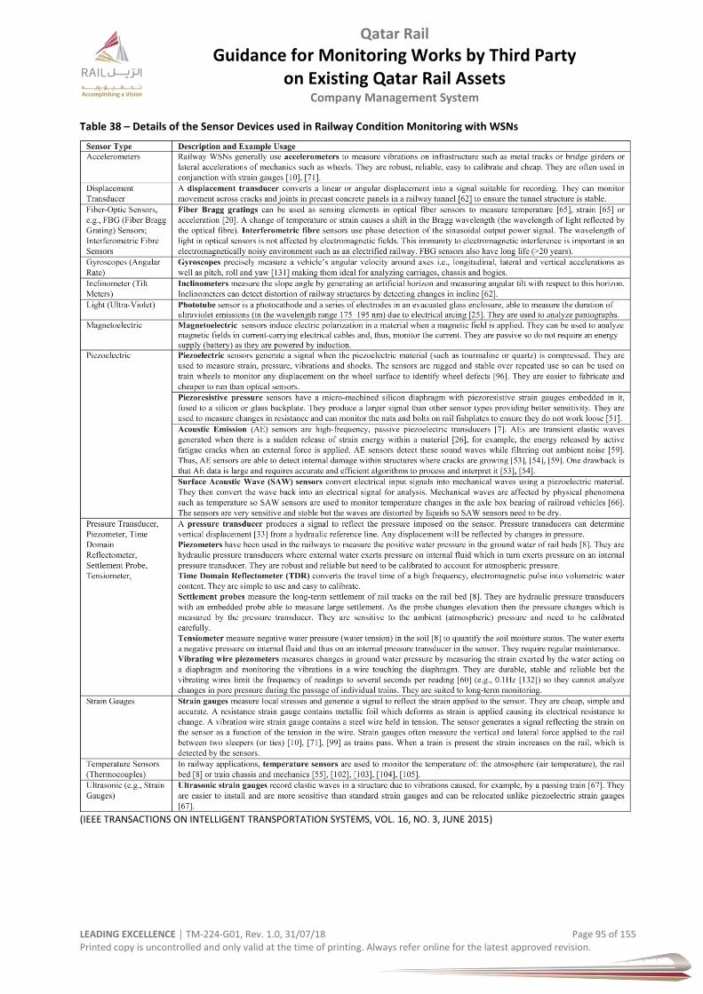
Qatar Rail
Guidance for Monitoring Works by Third Party on Existing Qatar Rail Assets
Company Management System
LEADING EXCELLENCE │ TM-224-G01, Rev. 1.0, 31/07/18 Page 95 of 155 Printed copy is uncontrolled and only valid at the time of printing. Always refer online for the latest approved revision.
Table 38 – Details of the Sensor Devices used in Railway Condition Monitoring with WSNs
(IEEE TRANSACTIONS ON INTELLIGENT TRANSPORTATION SYSTEMS, VOL. 16, NO. 3, JUNE 2015)

Qatar Rail
Guidance for Monitoring Works by Third Party on Existing Qatar Rail Assets
Company Management System
LEADING EXCELLENCE │ TM-224-G01, Rev. 1.0, 31/07/18 Page 96 of 155 Printed copy is uncontrolled and only valid at the time of printing. Always refer online for the latest approved revision.
10.5.1 Railway Tracks
Track monitoring systems also play a vital role in maintaining the safety of the railways. Monitoring bridges and tunnels (discussed in the previous paragraphs) uses sensors to identify and analyze defects (cracking and displace- ment) in large structures. In contrast to structural monitoring (large structures), track monitoring involves identifying and analyzing defects in long narrow metal rails. Possible changes to railway tracks :
Cracking
Displacement
Twist
Tilt (incline)
Hence, track monitoring can vary from detecting settlement and twist such as that caused by nearby tunnelling or excavation; to measuring the forces exerted by train wheels on the tracks; to monitoring the development of cracks and structural flaws as trains pass and over the longer term. Possible use of:
a) mounted inclinometers parallel with the tracks directly on the sleepers or b) in the ballast with continuous tensioned rails to monitor tilt c) mounted inclinometers parallel with the tracks to measure settlement d) mounted inclinome- ters perpendicular to the track (on the ties) to monitor twist e) use inclinometers to monitor ties to detect broken ties or sabotage f) using track-mounted strain gauges (monitor the forces exerted by trains (“weigh in motion”) g) piezoelectric strain sensors h) FBG strain sensors (on each side of a track to detect imbalances on the two sides of train wheels.
If there is a large variation between the left and right axle loading then there is the danger of train derailment)
i) AE sensors (detect and analyze cracks, as well as monitor defects) j) accelerometers (measure vibrations, motion of the track)
Condition monitoring protects both the trains and the track, increases the track and train reliability and allows repair to be scheduled.
Figure 31 – Metro Tunnel before Track Installation
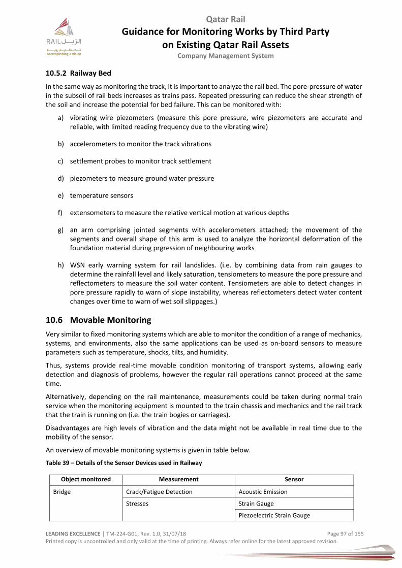
Qatar Rail
Guidance for Monitoring Works by Third Party on Existing Qatar Rail Assets
Company Management System
LEADING EXCELLENCE │ TM-224-G01, Rev. 1.0, 31/07/18 Page 97 of 155 Printed copy is uncontrolled and only valid at the time of printing. Always refer online for the latest approved revision.
10.5.2 Railway Bed
In the same way as monitoring the track, it is important to analyze the rail bed. The pore-pressure of water in the subsoil of rail beds increases as trains pass. Repeated pressuring can reduce the shear strength of the soil and increase the potential for bed failure. This can be monitored with:
a) vibrating wire piezometers (measure this pore pressure, wire piezometers are accurate and reliable, with limited reading frequency due to the vibrating wire)
b) accelerometers to monitor the track vibrations
c) settlement probes to monitor track settlement
d) piezometers to measure ground water pressure
e) temperature sensors
f) extensometers to measure the relative vertical motion at various depths
g) an arm comprising jointed segments with accelerometers attached; the movement of the segments and overall shape of this arm is used to analyze the horizontal deformation of the foundation material during prgression of neighbouring works
h) WSN early warning system for rail landslides. (i.e. by combining data from rain gauges to determine the rainfall level and likely saturation, tensiometers to measure the pore pressure and reflectometers to measure the soil water content. Tensiometers are able to detect changes in pore pressure rapidly to warn of slope instability, whereas reflectometers detect water content changes over time to warn of wet soil slippages.)
10.6 Movable Monitoring
Very similar to fixed monitoring systems which are able to monitor the condition of a range of mechanics, systems, and environments, also the same applications can be used as on-board sensors to measure parameters such as temperature, shocks, tilts, and humidity.
Thus, systems provide real-time movable condition monitoring of transport systems, allowing early detection and diagnosis of problems, however the regular rail operations cannot proceed at the same time.
Alternatively, depending on the rail maintenance, measurements could be taken during normal train service when the monitoring equipment is mounted to the train chassis and mechanics and the rail track that the train is running on (i.e. the train bogies or carriages).
Disadvantages are high levels of vibration and the data might not be available in real time due to the mobility of the sensor.
An overview of movable monitoring systems is given in table below.
Table 39 – Details of the Sensor Devices used in Railway
Object monitored Measurement Sensor
Bridge Crack/Fatigue Detection Acoustic Emission
Stresses Strain Gauge
Piezoelectric Strain Gauge
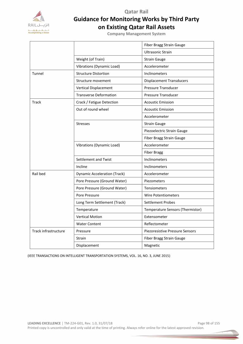
Qatar Rail
Guidance for Monitoring Works by Third Party on Existing Qatar Rail Assets
Company Management System
LEADING EXCELLENCE │ TM-224-G01, Rev. 1.0, 31/07/18 Page 98 of 155 Printed copy is uncontrolled and only valid at the time of printing. Always refer online for the latest approved revision.
Fiber Bragg Strain Gauge
Ultrasonic Strain
Weight (of Train) Strain Gauge
Vibrations (Dynamic Load) Accelerometer
Tunnel Structure Distortion Inclinometers
Structure movement Displacement Transducers
Vertical Displacement Pressure Transducer
Transverse Deformation Pressure Transducer
Track Crack / Fatigue Detection Acoustic Emission
Out of round wheel Acoustic Emission
Accelerometer
Stresses Strain Gauge
Piezoelectric Strain Gauge
Fiber Bragg Strain Gauge
Vibrations (Dynamic Load) Accelerometer
Fiber Bragg
Settlement and Twist Inclinometers
Incline Inclinometers
Rail bed Dynamic Acceleration (Track) Accelerometer
Pore Pressure (Ground Water) Piezometers
Pore Pressure (Ground Water) Tensiometers
Pore Pressure Wire Potentiometers
Long Term Settlement (Track) Settlement Probes
Temperature Temperature Sensors (Thermistor)
Vertical Motion Extensometer
Water Content Reflectometer
Track infrastructure Pressure Piezoresistive Pressure Sensors
Strain Fiber Bragg Strain Gauge
Displacement Magnetic
(IEEE TRANSACTIONS ON INTELLIGENT TRANSPORTATION SYSTEMS, VOL. 16, NO. 3, JUNE 2015)

Qatar Rail
Guidance for Monitoring Works by Third Party on Existing Qatar Rail Assets
Company Management System
LEADING EXCELLENCE │ TM-224-G01, Rev. 1.0, 31/07/18 Page 99 of 155 Printed copy is uncontrolled and only valid at the time of printing. Always refer online for the latest approved revision.
11 Structural Health Monitoring SHM
11.1 General
This section defines the Qatar Rail’s minimum requirements for structural monitoring. In this section there is a general description of methods and systems, specifications, and performance requirements.
This report intends to provide the basic principles for the structural instrumentation and monitoring of the developments in proximity of Qatar Rail assets. The Structural Health Monitoring (SHM) is intended to cover
existing QR structures that are potentially affected by any development as well as
key structural elements of the development itself.
11.2 Background
Qatar Rail’s Transit Oriented Developments - This chapter is briefly elaborating about the background which initiated the necessity of the SHM. This part further includes important conclusions from the initial concept of the structural Transit Oriented Developments TOD design (by Qatar Rail) which also hints to critical structural elements and construction phases requiring instrumentation.
Some international best-practices are also discussed in order to provide paradigms of the envisaged monitoring tasks.
11.3 Objectives
The Structural Health Monitoring and corresponding instrumentation must be carefully designed taking into account the structural analysis and the range of the chosen design parameters (like stresses, displacements, etc.). But also, In addition, the instrumentation apparatus itself must be coordinated introduced into the Building Information Modelling (BIM) system, including cabling, conduits, data logger rooms, etc.
This is an equally significant task, as the practical application of the SHM will never be accomplished into the complex 3rd party construction environment, unless all materials is are defined and depicted in BIM, related drawings and reports.
The SHM shall work in favour of QR needs which are required to be complemented with appropriate organogram, communication plan, definition of trigger- and alert values, and scenarios for a variety of situations, and mitigation- as well as emergency plans. In the organogram the roles and responsibilities of the engineering personnel needs to be clearly defined. A structural or geotechnical/tunnel risk assessor is indispensable.
Moreover, some the necessary steps for Validation and Verification need to be defined in order to control and stir the whole procedure.
The contractor shall design the structural monitoring system to achieve the following objectives:
i. Confirm that the works and the impact of construction are as predicted and in accordance with the design
ii. Monitor ground movements and third party assets to demonstrate compliance with the tolerances provided by Employer’s Requirements and agreements in relation to third party assets
iii. Monitor short and long term ground and groundwater movements
iv. To provide warning of trigger level breaches that initiate pre-planned contingency measures.
v. robustness in the sensing systems
Qatar Rail
Guidance for Monitoring Works by Third Party on Existing Qatar Rail Assets
Company Management System
LEADING EXCELLENCE │ TM-224-G01, Rev. 1.0, 31/07/18 Page 100 of 155 Printed copy is uncontrolled and only valid at the time of printing. Always refer online for the latest approved revision.
vi. redundancy of the sensors
vii. validation: secondary verification systems should be specified in order to verify the results and validate the method. For example, strain gauges may be the most suitable method to investigate the stress-strain field, but it should be validated with displacement measurements. Also, if pairs of inclinometers and extensomenters are used to monitor the soil mass deformation around the tunnel, then strain gauges attached to the concrete shell should be used and the stresses measured should validate the geotechnical instruments and vice versa.
11.4 Structural Risk
11.4.1 General
The instrumentation of existing Qatar Rail structures and of the 3rd party development shall be designed according to the major structural engineering risks as these shall be identified in the initial stages of the design of the 3rd party development.
The structural risks are not only related to the structural integrity of the existing structural assets of Qatar Rail, but also to the unobstructed & safe Metro (railway) operations.
High risks are also arising from the 3rd party development itself (for example the functionality of a transfer truss must never be impaired or otherwise the whole development would be affected or even endangered as a whole. The criticality of such structures as “key elements” is identified and categorized in the Euronorms, (refer to EN1991-1-7). The 3rd party development and the underground QR station/ switchbox or tunnel must be considered as one unified structure, where there is continuous stress flow from the superstructure to the existing underground QR station or tunnel.
This is evident in the case of direct structural connection where the individual parts are mutually affecting each other. It is highlighted that there is significant stress flow transferred to the tunnels or station walls through the soil in the case of mere proximity of the 3rd party development to the underground QR structures.
Vibrations, forces and displacements due to construction, erection, or service loads communicated between the substructures are being simulated to the best practice of the Finite Element Methods in use during the subsequent 3rd party development design stages. Many assumptions are expected to be employed for these analysis. The risks and potential impact arising from the validity correctness of such assumptions is expected to be significant.
This design inherited risk along with risks due to a multitude of unknown parameters originating from existing structural reserves, localization of soil characteristics, construction procedures, and technical risks of 3rd party developments makes SHM imperative.
The necessity of a comprehensive ‘thought-through’ design of the Structural Monitoring Scheme is paramount. This applies to both, existing QR structures and 3rd party developments. The requirement for such measures embarks from the following sources:
I. Contractual Documents
II. Normative Specifications from EN1990 and EN1991
III. Best Practice as reported in many international scientific publications, Best practice in similar
projects around the World - Best practice in similar projects around the world
The 3rd Party designer shall:
The objectives of the instrumentation and monitoring of the works are to determine ground movements and the effects on existing structures, services and utilities in a form that will allow direct comparison with the Third Party contractor’s performance criteria and design expectations.
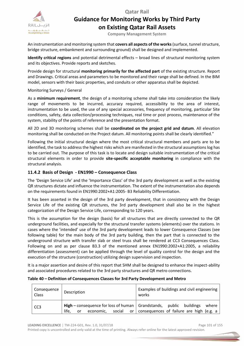
Qatar Rail
Guidance for Monitoring Works by Third Party on Existing Qatar Rail Assets
Company Management System
LEADING EXCELLENCE │ TM-224-G01, Rev. 1.0, 31/07/18 Page 101 of 155 Printed copy is uncontrolled and only valid at the time of printing. Always refer online for the latest approved revision.
An instrumentation and monitoring system that covers all aspects of the works (surface, tunnel structure, bridge structure, embankment and surrounding ground) shall be designed and implemented.
Identify critical regions and potential detrimental effects – broad lines of structural monitoring system and its objectives. Provide reports and sketches.
Provide design for structural monitoring primarily for the affected part of the existing structure. Report and Drawings. Critical areas and parameters to be monitored and their range shall be defined. In the BIM model, sensors with their basic properties, and conduits or other apparatus shall be depicted.
Monitoring Surveys / General
As a minimum requirement, the design of a monitoring scheme shall take into consideration the likely range of movements to be incurred, accuracy required, accessibility to the area of interest, instrumentation to be used, the use of any special accessories, frequency of monitoring, particular Site conditions, safety, data collection/processing techniques, real time or post process, maintenance of the system, stability of the points of reference and the presentation format.
All 2D and 3D monitoring schemes shall be coordinated on the project grid and datum. All elevation monitoring shall be conducted on the Project datum. All monitoring points shall be clearly identified.”
Following the initial structural design where the most critical structural members and parts are to be identified, the task to address the highest risks which are manifested in the structural assumptions log has to be carried out. The purpose of this task is to locate and design suitable instrumentation of the critical structural elements in order to provide site-specific acceptable monitoring in compliance with the structural analysis.
11.4.2 Basis of Design - EN1990 – Consequence Class
The ‘Design Service Life’ and the ‘Importance Class’ of the 3rd party development as well as the existing QR structures dictate and influence the instrumentation. The extent of the instrumentation also depends on the requirements found in EN1990:2002+A1:2005- B3 Reliability Differentiation.
It has been asserted in the design of the 3rd party development, that in consistency with the Design Service Life of the existing QR structures, the 3rd party development shall also be in the highest categorization of the Design Service Life, corresponding to 120 years.
This is the assumption for the design (basis) for all structures that are directly connected to the QR underground facilities, and especially for the structural transfer systems (elements) over the stations. In cases where the ’intended’ use of the 3rd party development leads to lower Consequence Classes (see following table) for the main body of the 3rd party building, then the part that is connected to the underground structure with transfer slab or steel truss shall be rendered at CC3 Consequences Class. Following on and as per clause B3.3 of the mentioned annex EN1990:2002+A1:2005, a reliability differentiation (assessment) can be applied through the level of quality control for the design and the execution of the structure (construction) utilizing design supervision and inspection.
It is a major assertion and desire of this report that SHM shall be designed to enhance the inspect-ability and associated procedures related to the 3rd party structures and QR metro connections.
Table 40 – Definition of Consequences Classes for 3rd Party Development and Metro
Consequence Class
Description Examples of buildings and civil engineering works
CC3 High – consequence for loss of human life, or economic, social or
Grandstands, public buildings where consequences of failure are high (e.g. a
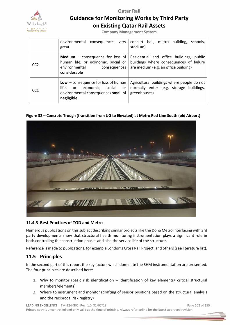
Qatar Rail
Guidance for Monitoring Works by Third Party on Existing Qatar Rail Assets
Company Management System
LEADING EXCELLENCE │ TM-224-G01, Rev. 1.0, 31/07/18 Page 102 of 155 Printed copy is uncontrolled and only valid at the time of printing. Always refer online for the latest approved revision.
environmental consequences very great
concert hall, metro building, schools, stadium)
CC2
Medium – consequence for loss of human life, or economic, social or environmental consequences considerable
Residential and office buildings, public buildings where consequences of failure are medium (e.g. an office building)
CC1
Low – consequence for loss of human life, or economic, social or environmental consequences small of negligible
Agricultural buildings where people do not normally enter (e.g. storage buildings, greenhouses)
Figure 32 – Concrete Trough (transition from UG to Elevated) at Metro Red Line South (old Airport)
11.4.3 Best Practices of TOD and Metro
Numerous publications on this subject describing similar projects like the Doha Metro interfacing with 3rd party developments show that structural health monitoring instrumentation plays a significant role in both controlling the construction phases and also the service life of the structure.
Reference is made to publications, for example London’s Cross Rail Project, and others (see literature list).
11.5 Principles
In the second part of this report the key factors which dominate the SHM instrumentation are presented. The four principles are described here:
1. Why to monitor (basic risk identification – identification of key elements/ critical structural
members/elements)
2. Where to instrument and monitor (drafting of sensor positions based on the structural analysis
and the reciprocal risk registry)

Qatar Rail
Guidance for Monitoring Works by Third Party on Existing Qatar Rail Assets
Company Management System
LEADING EXCELLENCE │ TM-224-G01, Rev. 1.0, 31/07/18 Page 103 of 155 Printed copy is uncontrolled and only valid at the time of printing. Always refer online for the latest approved revision.
3. When and How (which methods are more suitable, which design parameters should be monitored
and how often – sampling, which construction phase and/ or during service life etc.)
11.5.1 Structural Elements
The elements that must not be missed out in the SHM instrumentation include (but are not limited to):
Existing structure a) Stress concentration points as indicated in the structural assessment due to 3rd party
development b) Internal columns – bearing shear walls c) Lining walls d) Head walls e) Roof slab f) Tunnel rings and segments g) Tunnel interfaces to the station h) Rail deformations into the station and in the tunnel
Transfer system a) Transfer post tensioned slab b) Transfer systems by steel truss
Heavy Post tensioning - All significant and not repetitive post tensioning systems – e.g. Elevated pt transfer slabs
Critical structural members - mega columns – long span girders
Vibration output points - centre of slabs of building block
Parameters to be monitored
The parameters to monitor should be in accordance with the local maxima of the structural analysis.
Displacement components and their first and second derivatives as appropriate:
a) Displacement field: u, v, w (3 directions) b) Displacement field in terms of vertical and lateral displacements shall be monitored at target
points. Results shall be used to correlate with strain field and acceleration components monitored.
c) Stress/strain field: εχ, εy, εz or directly if possible: σχ, σy, σz, or if analysis provides at specific locations, ε1, ε2 or directly if possible :σ1, σ2.
d) The stress field can be derived indirectly from the strain field, providing there is good knowledge of the modulus of elasticity of concrete.
e) In case of slender line-rod elements with high importance, enough sensing points should be defined in a typical cross section to provide the rotation of the neutral axis and compare with the structural analysis.
Accelerations –Vibration monitoring
At specific target points there will be vibration monitoring and correlation of results to the stress-strain and displacement field.
Ambient vibration analysis and modal identification method, utilising accelerometers shall be incorporated in the structural monitoring scheme.
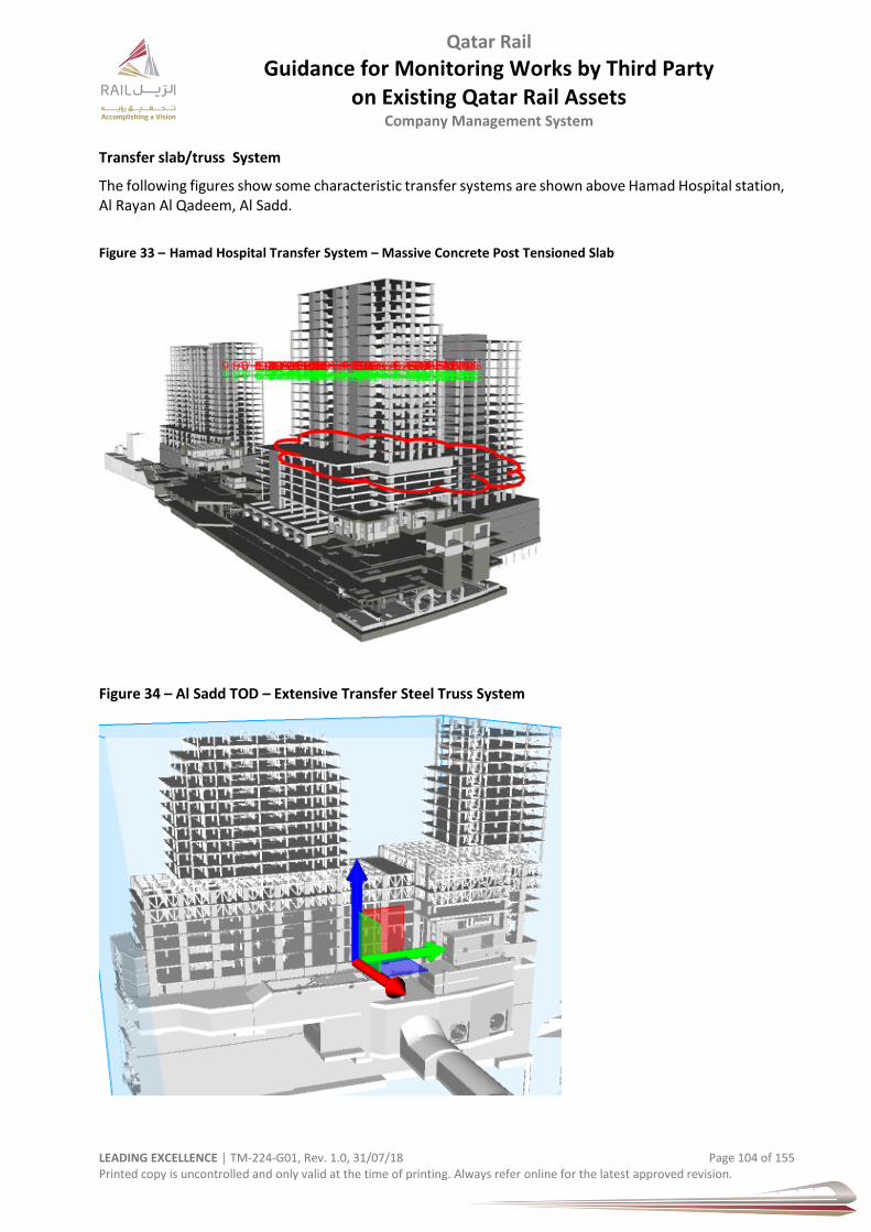
Qatar Rail
Guidance for Monitoring Works by Third Party on Existing Qatar Rail Assets
Company Management System
LEADING EXCELLENCE │ TM-224-G01, Rev. 1.0, 31/07/18 Page 104 of 155 Printed copy is uncontrolled and only valid at the time of printing. Always refer online for the latest approved revision.
Transfer slab/truss System
The following figures show some characteristic transfer systems are shown above Hamad Hospital station, Al Rayan Al Qadeem, Al Sadd.
Figure 33 – Hamad Hospital Transfer System – Massive Concrete Post Tensioned Slab
Figure 34 – Al Sadd TOD – Extensive Transfer Steel Truss System
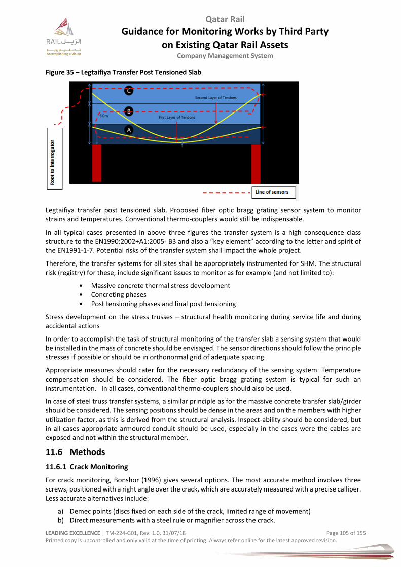
Qatar Rail
Guidance for Monitoring Works by Third Party on Existing Qatar Rail Assets
Company Management System
LEADING EXCELLENCE │ TM-224-G01, Rev. 1.0, 31/07/18 Page 105 of 155 Printed copy is uncontrolled and only valid at the time of printing. Always refer online for the latest approved revision.
Figure 35 – Legtaifiya Transfer Post Tensioned Slab
Legtaifiya transfer post tensioned slab. Proposed fiber optic bragg grating sensor system to monitor strains and temperatures. Conventional thermo-couplers would still be indispensable.
In all typical cases presented in above three figures the transfer system is a high consequence class structure to the EN1990:2002+A1:2005- B3 and also a “key element” according to the letter and spirit of the EN1991-1-7. Potential risks of the transfer system shall impact the whole project.
Therefore, the transfer systems for all sites shall be appropriately instrumented for SHM. The structural risk (registry) for these, include significant issues to monitor as for example (and not limited to):
• Massive concrete thermal stress development • Concreting phases • Post tensioning phases and final post tensioning
Stress development on the stress trusses – structural health monitoring during service life and during accidental actions
In order to accomplish the task of structural monitoring of the transfer slab a sensing system that would be installed in the mass of concrete should be envisaged. The sensor directions should follow the principle stresses if possible or should be in orthonormal grid of adequate spacing.
Appropriate measures should cater for the necessary redundancy of the sensing system. Temperature compensation should be considered. The fiber optic bragg grating system is typical for such an instrumentation. In all cases, conventional thermo-couplers should also be used.
In case of steel truss transfer systems, a similar principle as for the massive concrete transfer slab/girder should be considered. The sensing positions should be dense in the areas and on the members with higher utilization factor, as this is derived from the structural analysis. Inspect-ability should be considered, but in all cases appropriate armoured conduit should be used, especially in the cases were the cables are exposed and not within the structural member.
11.6 Methods
11.6.1 Crack Monitoring
For crack monitoring, Bonshor (1996) gives several options. The most accurate method involves three screws, positioned with a right angle over the crack, which are accurately measured with a precise calliper. Less accurate alternatives include:
a) Demec points (discs fixed on each side of the crack, limited range of movement) b) Direct measurements with a steel rule or magnifier across the crack.

Qatar Rail
Guidance for Monitoring Works by Third Party on Existing Qatar Rail Assets
Company Management System
LEADING EXCELLENCE │ TM-224-G01, Rev. 1.0, 31/07/18 Page 106 of 155 Printed copy is uncontrolled and only valid at the time of printing. Always refer online for the latest approved revision.
c) Glass tell tales (should be avoided, give little indication of movement and easily vandalised) d) Plastic tell tales (limited accuracy). e) These measurements should be combined with measurements of the levels and verticality
to provide a full picture of the building distortion.
Tell-tale crackmeters may be required to monitor any significant cracks, if they are found during the pre-condition survey of the building or relevant structure. Drilling of holes shall be avoided. Removable adhesive shall be used on a clean, dry surface.
Figure 36 – Tell-Tale Crackmeter
The Qatar Rail Employer’s Requirements specify the allowable crack widths for internal concrete surfaces and external surfaces
Crack identification on the existing structure shall be followed by crack monitoring through the intervention period. The crack width shall be measured three times over a distance of about 100mm to avoid a high error state (CEB-FIB, Monitoring and safety Evaluation of Existing Concrete Structures [17]). The average value of the three measurements can be calculated to obtain the final authoritative crack width.
Figure 37 – Measuring Crack Width
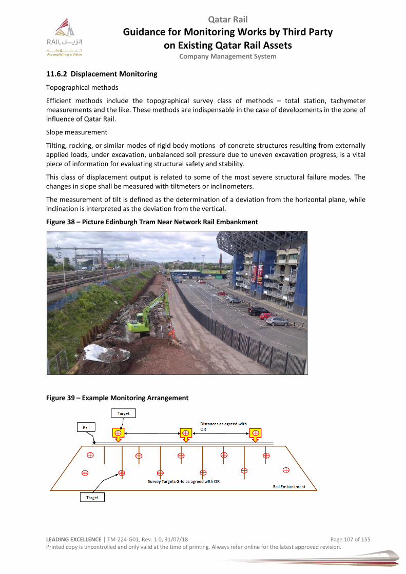
Qatar Rail
Guidance for Monitoring Works by Third Party on Existing Qatar Rail Assets
Company Management System
LEADING EXCELLENCE │ TM-224-G01, Rev. 1.0, 31/07/18 Page 107 of 155 Printed copy is uncontrolled and only valid at the time of printing. Always refer online for the latest approved revision.
11.6.2 Displacement Monitoring
Topographical methods
Efficient methods include the topographical survey class of methods – total station, tachymeter measurements and the like. These methods are indispensable in the case of developments in the zone of influence of Qatar Rail.
Slope measurement
Tilting, rocking, or similar modes of rigid body motions of concrete structures resulting from externally applied loads, under excavation, unbalanced soil pressure due to uneven excavation progress, is a vital piece of information for evaluating structural safety and stability.
This class of displacement output is related to some of the most severe structural failure modes. The changes in slope shall be measured with tiltmeters or inclinometers.
The measurement of tilt is defined as the determination of a deviation from the horizontal plane, while inclination is interpreted as the deviation from the vertical.
Figure 38 – Picture Edinburgh Tram Near Network Rail Embankment
Figure 39 – Example Monitoring Arrangement
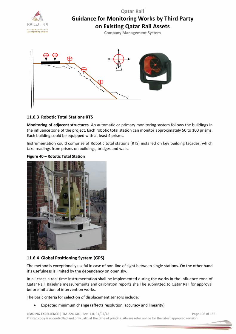
Qatar Rail
Guidance for Monitoring Works by Third Party on Existing Qatar Rail Assets
Company Management System
LEADING EXCELLENCE │ TM-224-G01, Rev. 1.0, 31/07/18 Page 108 of 155 Printed copy is uncontrolled and only valid at the time of printing. Always refer online for the latest approved revision.
11.6.3 Robotic Total Stations RTS
Monitoring of adjacent structures. An automatic or primary monitoring system follows the buildings in the influence zone of the project. Each robotic total station can monitor approximately 50 to 100 prisms. Each building could be equipped with at least 4 prisms.
Instrumentation could comprise of Robotic total stations (RTS) installed on key building facades, which take readings from prisms on buildings, bridges and walls.
Figure 40 – Rototic Total Station
11.6.4 Global Positioning System (GPS)
The method is exceptionally useful in case of non-line of sight between single stations. On the other hand it’s usefulness is limited by the dependency on open sky.
In all cases a real time instrumentation shall be implemented during the works in the influence zone of Qatar Rail. Baseline measurements and calibration reports shall be submitted to Qatar Rail for approval before initiation of intervention works.
The basic criteria for selection of displacement sensors include:
Expected minimum change (affects resolution, accuracy and linearity)
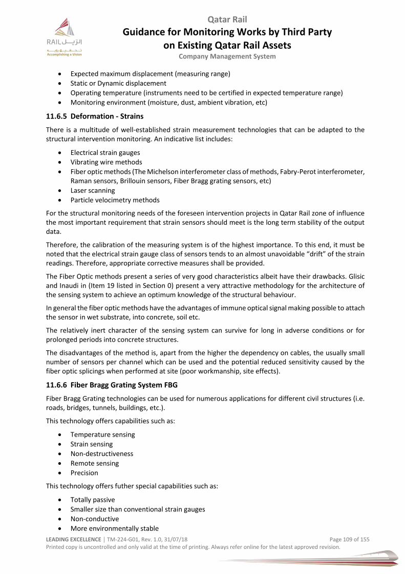
Qatar Rail
Guidance for Monitoring Works by Third Party on Existing Qatar Rail Assets
Company Management System
LEADING EXCELLENCE │ TM-224-G01, Rev. 1.0, 31/07/18 Page 109 of 155 Printed copy is uncontrolled and only valid at the time of printing. Always refer online for the latest approved revision.
Expected maximum displacement (measuring range)
Static or Dynamic displacement
Operating temperature (instruments need to be certified in expected temperature range)
Monitoring environment (moisture, dust, ambient vibration, etc)
11.6.5 Deformation - Strains
There is a multitude of well-established strain measurement technologies that can be adapted to the structural intervention monitoring. An indicative list includes:
Electrical strain gauges
Vibrating wire methods
Fiber optic methods (The Michelson interferometer class of methods, Fabry-Perot interferometer, Raman sensors, Brillouin sensors, Fiber Bragg grating sensors, etc)
Laser scanning
Particle velocimetry methods
For the structural monitoring needs of the foreseen intervention projects in Qatar Rail zone of influence the most important requirement that strain sensors should meet is the long term stability of the output data.
Therefore, the calibration of the measuring system is of the highest importance. To this end, it must be noted that the electrical strain gauge class of sensors tends to an almost unavoidable “drift” of the strain readings. Therefore, appropriate corrective measures shall be provided.
The Fiber Optic methods present a series of very good characteristics albeit have their drawbacks. Glisic and Inaudi in (Item 19 listed in Section 0) present a very attractive methodology for the architecture of the sensing system to achieve an optimum knowledge of the structural behaviour.
In general the fiber optic methods have the advantages of immune optical signal making possible to attach the sensor in wet substrate, into concrete, soil etc.
The relatively inert character of the sensing system can survive for long in adverse conditions or for prolonged periods into concrete structures.
The disadvantages of the method is, apart from the higher the dependency on cables, the usually small number of sensors per channel which can be used and the potential reduced sensitivity caused by the fiber optic splicings when performed at site (poor workmanship, site effects).
11.6.6 Fiber Bragg Grating System FBG
Fiber Bragg Grating technologies can be used for numerous applications for different civil structures (i.e. roads, bridges, tunnels, buildings, etc.).
This technology offers capabilities such as:
Temperature sensing
Strain sensing
Non-destructiveness
Remote sensing
Precision
This technology offers futher special capabilities such as:
Totally passive
Smaller size than conventional strain gauges
Non-conductive
More environmentally stable
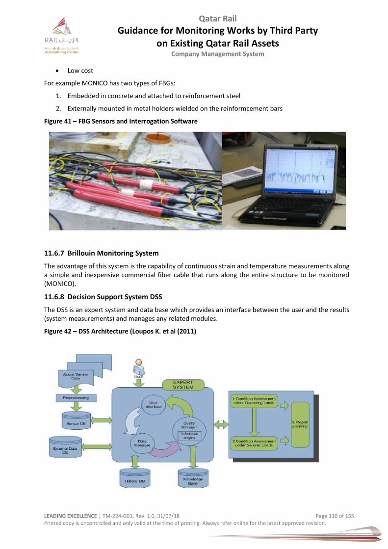
Qatar Rail
Guidance for Monitoring Works by Third Party on Existing Qatar Rail Assets
Company Management System
LEADING EXCELLENCE │ TM-224-G01, Rev. 1.0, 31/07/18 Page 110 of 155 Printed copy is uncontrolled and only valid at the time of printing. Always refer online for the latest approved revision.
Low cost
For example MONICO has two types of FBGs:
1. Embedded in concrete and attached to reinforcement steel
2. Externally mounted in metal holders wielded on the reinformcement bars
Figure 41 – FBG Sensors and Interrogation Software
11.6.7 Brillouin Monitoring System
The advantage of this system is the capability of continuous strain and temperature measurements along a simple and inexpensive commercial fiber cable that runs along the entire structure to be monitored (MONICO).
11.6.8 Decision Support System DSS
The DSS is an expert system and data base which provides an interface between the user and the results (system measurements) and manages any related modules.
Figure 42 – DSS Architecture (Loupos K. et al (2011)
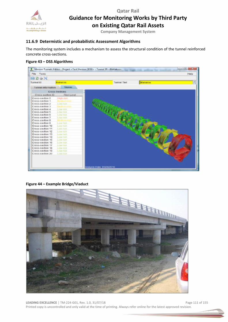
Qatar Rail
Guidance for Monitoring Works by Third Party on Existing Qatar Rail Assets
Company Management System
LEADING EXCELLENCE │ TM-224-G01, Rev. 1.0, 31/07/18 Page 111 of 155 Printed copy is uncontrolled and only valid at the time of printing. Always refer online for the latest approved revision.
11.6.9 Determistic and probabilistic Assessment Algorithms
The monitoring system includes a mechanism to assess the structural condition of the tunnel reinforced concrete cross-sections.
Figure 43 – DSS Algorithms
Figure 44 – Example Bridge/Viaduct

Qatar Rail
Guidance for Monitoring Works by Third Party on Existing Qatar Rail Assets
Company Management System
LEADING EXCELLENCE │ TM-224-G01, Rev. 1.0, 31/07/18 Page 112 of 155 Printed copy is uncontrolled and only valid at the time of printing. Always refer online for the latest approved revision.
Figure 45 –Fibre Optic Bragg Grating Sensor Arrangement on Precast I-Type Beams of a Bridge, and FE Interpretation Analysis.
It is notable that any interpretative analysis of the strain measurements is always dependable on the assumptions set about the structure mechanical characteristics and load distribution.
Other important parameters that affect the accuracy of the strain monitoring invariably to the sensor type are, the sensor gauge length, the attachment method the sampling frequency and the temperature compensation methodology, which will be covered in the following paragraph.
8-1564
2-1531
7-15556-1551
5-1547
4-1539
3-1535
1-1527
Δοκός 4
Δοκός 3

Qatar Rail
Guidance for Monitoring Works by Third Party on Existing Qatar Rail Assets
Company Management System
LEADING EXCELLENCE │ TM-224-G01, Rev. 1.0, 31/07/18 Page 113 of 155 Printed copy is uncontrolled and only valid at the time of printing. Always refer online for the latest approved revision.
At this point it suffices to note that the sensor gauge length should be carefully chosen. For concrete structures and for point strain monitoring a gauge length of 12 to 16 cm seems to be adequate in most cases.
Smaller lengths may not be capable to overcome concrete construction anomalies like voids, honeycombs etc. Longer sensors are more pertinent for complementary monitoring to point-wise monitoring and for bending moment monitoring.
Figure 46 – Arrangement of combined bending-tension Fibre Bragg Grating sensors
Figure 47 – Picture – Fibre Optic Bending Sensors
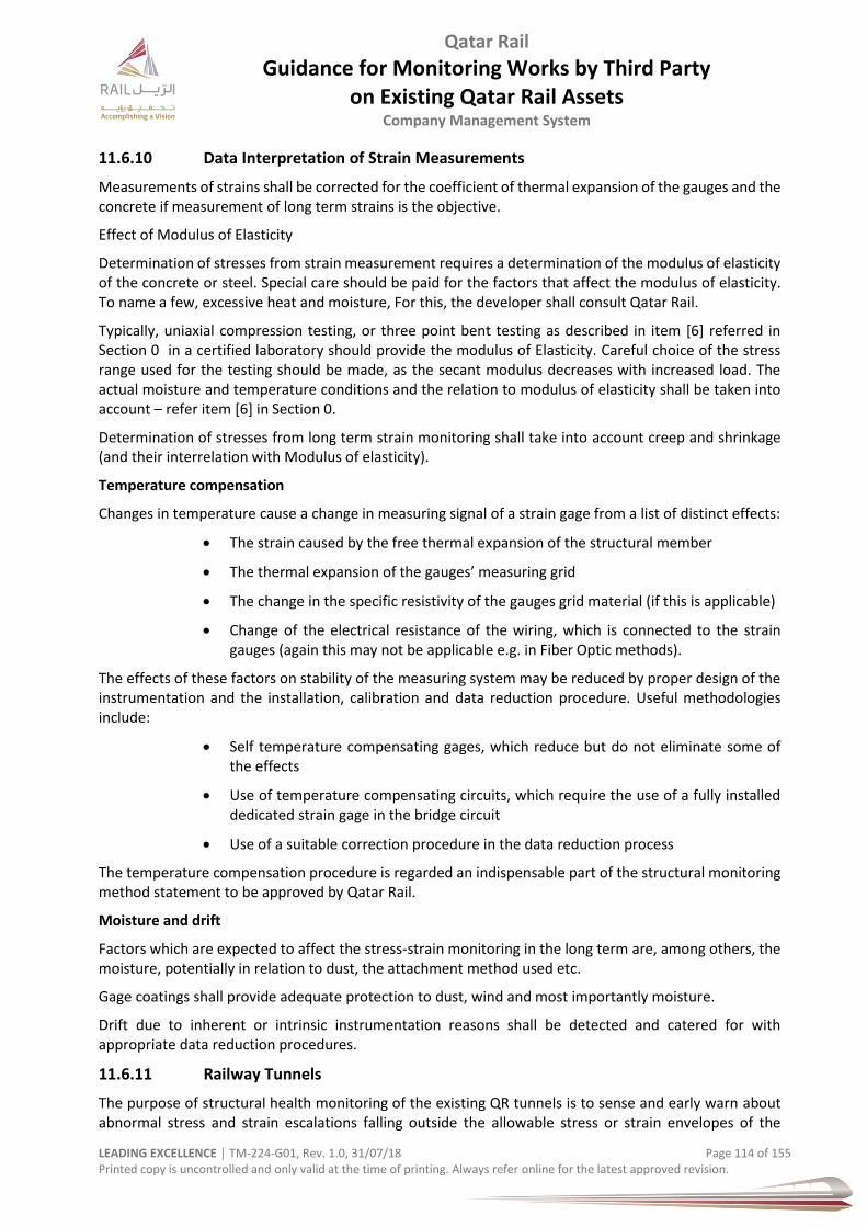
Qatar Rail
Guidance for Monitoring Works by Third Party on Existing Qatar Rail Assets
Company Management System
LEADING EXCELLENCE │ TM-224-G01, Rev. 1.0, 31/07/18 Page 114 of 155 Printed copy is uncontrolled and only valid at the time of printing. Always refer online for the latest approved revision.
11.6.10 Data Interpretation of Strain Measurements
Measurements of strains shall be corrected for the coefficient of thermal expansion of the gauges and the concrete if measurement of long term strains is the objective.
Effect of Modulus of Elasticity
Determination of stresses from strain measurement requires a determination of the modulus of elasticity of the concrete or steel. Special care should be paid for the factors that affect the modulus of elasticity. To name a few, excessive heat and moisture, For this, the developer shall consult Qatar Rail.
Typically, uniaxial compression testing, or three point bent testing as described in item [6] referred in Section 0 in a certified laboratory should provide the modulus of Elasticity. Careful choice of the stress range used for the testing should be made, as the secant modulus decreases with increased load. The actual moisture and temperature conditions and the relation to modulus of elasticity shall be taken into account – refer item [6] in Section 0.
Determination of stresses from long term strain monitoring shall take into account creep and shrinkage (and their interrelation with Modulus of elasticity).
Temperature compensation
Changes in temperature cause a change in measuring signal of a strain gage from a list of distinct effects:
The strain caused by the free thermal expansion of the structural member
The thermal expansion of the gauges’ measuring grid
The change in the specific resistivity of the gauges grid material (if this is applicable)
Change of the electrical resistance of the wiring, which is connected to the strain gauges (again this may not be applicable e.g. in Fiber Optic methods).
The effects of these factors on stability of the measuring system may be reduced by proper design of the instrumentation and the installation, calibration and data reduction procedure. Useful methodologies include:
Self temperature compensating gages, which reduce but do not eliminate some of the effects
Use of temperature compensating circuits, which require the use of a fully installed dedicated strain gage in the bridge circuit
Use of a suitable correction procedure in the data reduction process
The temperature compensation procedure is regarded an indispensable part of the structural monitoring method statement to be approved by Qatar Rail.
Moisture and drift
Factors which are expected to affect the stress-strain monitoring in the long term are, among others, the moisture, potentially in relation to dust, the attachment method used etc.
Gage coatings shall provide adequate protection to dust, wind and most importantly moisture.
Drift due to inherent or intrinsic instrumentation reasons shall be detected and catered for with appropriate data reduction procedures.
11.6.11 Railway Tunnels
The purpose of structural health monitoring of the existing QR tunnels is to sense and early warn about abnormal stress and strain escalations falling outside the allowable stress or strain envelopes of the
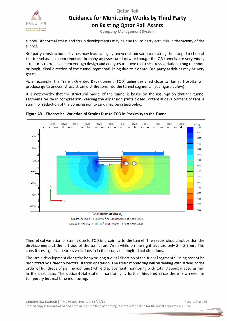
Qatar Rail
Guidance for Monitoring Works by Third Party on Existing Qatar Rail Assets
Company Management System
LEADING EXCELLENCE │ TM-224-G01, Rev. 1.0, 31/07/18 Page 115 of 155 Printed copy is uncontrolled and only valid at the time of printing. Always refer online for the latest approved revision.
tunnel. Abnormal stress and strain developments may be due to 3rd party activities in the vicinity of the tunnel.
3rd party construction activities may lead to highly uneven strain variations along the hoop direction of the tunnel as has been reported in many analyses until now. Although the QR tunnels are very young structures there have been enough design and analyses to prove that the stress variation along the hoop or longitudinal direction of the tunnel segmental lining due to extenral-3rd party activities may be very great.
As an example, the Transit Oriented Development (TOD) being designed close to Hamad Hospital will produce quite uneven stress-strain distributions into the tunnel segments. (see figure below)
It is noteworthy that the structural model of the tunnel is based on the assumption that the tunnel segments reside in compression, keeping the expansion joints closed. Potential development of tensile strain, or reduction of the compression to zero may be catastrophic.
Figure 48 – Theoretical Variation of Strains Due to TOD in Proximity to the Tunnel
Theoretical variation of strains due to TOD in proximity to the tunnel. The reader should notice that the displacements at the left side of the tunnel are 7mm while on the right side are only 3 – 3.5mm. This constitutes significant stress variations in in the hoop and longitudinal directions.
The strain development along the hoop or longitudinal direction of the tunnel segmental lining cannot be monitored by a theodolite-total station operation. The strain monitoring will be dealing with strains of the order of hundreds of με (microstrains) while displacement monitoring with total stations measures mm in the best case. The optical-total station monitoring is further hindered since there is a need for temporary but real time monitoring.
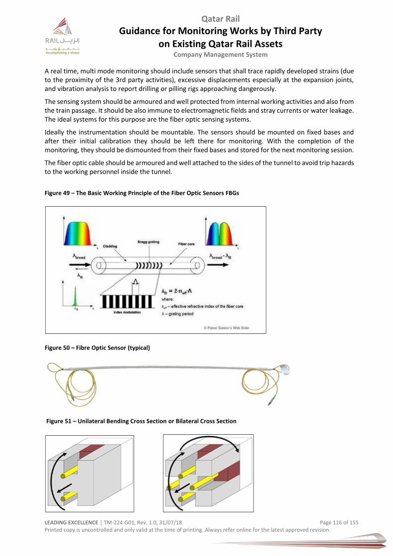
Qatar Rail
Guidance for Monitoring Works by Third Party on Existing Qatar Rail Assets
Company Management System
LEADING EXCELLENCE │ TM-224-G01, Rev. 1.0, 31/07/18 Page 116 of 155 Printed copy is uncontrolled and only valid at the time of printing. Always refer online for the latest approved revision.
A real time, multi mode monitoring should include sensors that shall trace rapidly developed strains (due to the proximity of the 3rd party activities), excessive displacements especially at the expansion joints, and vibration analysis to report drilling or pilling rigs approaching dangerously.
The sensing system should be armoured and well protected from internal working activities and also from the train passage. It should be also immune to electromagnetic fields and stray currents or water leakage. The ideal systems for this purpose are the fiber optic sensing systems.
Ideally the instrumentation should be mountable. The sensors should be mounted on fixed bases and after their initial calibration they should be left there for monitoring. With the completion of the monitoring, they should be dismounted from their fixed bases and stored for the next monitoring session.
The fiber optic cable should be armoured and well attached to the sides of the tunnel to avoid trip hazards to the working personnel inside the tunnel.
Figure 49 – The Basic Working Principle of the Fiber Optic Sensors FBGs
Figure 50 – Fibre Optic Sensor (typical)
Figure 51 – Unilateral Bending Cross Section or Bilateral Cross Section
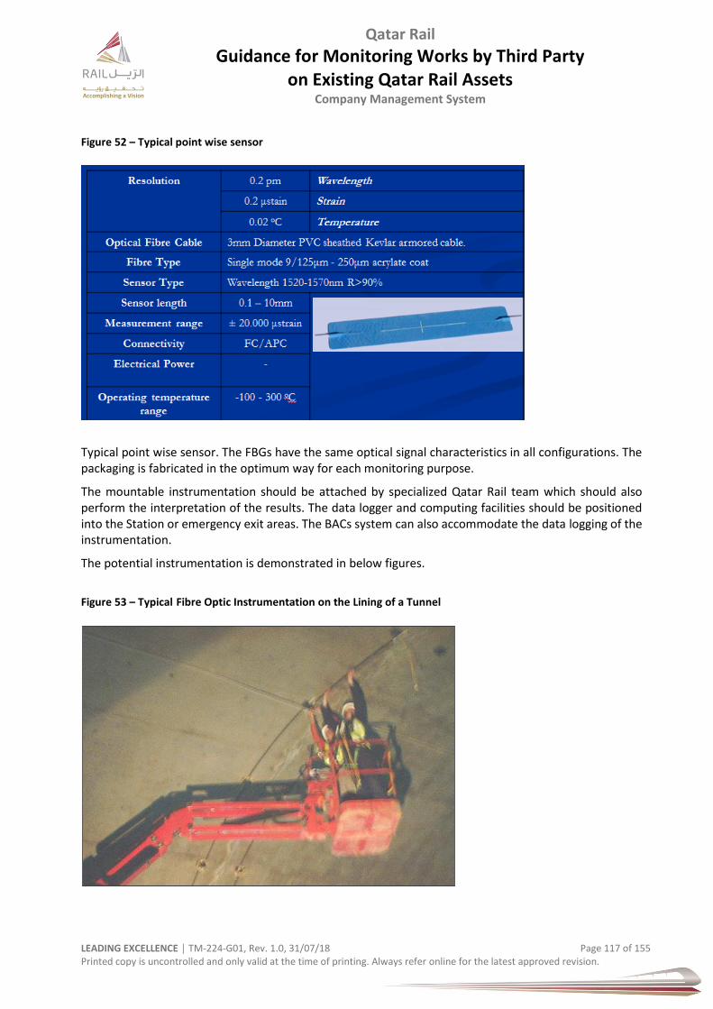
Qatar Rail
Guidance for Monitoring Works by Third Party on Existing Qatar Rail Assets
Company Management System
LEADING EXCELLENCE │ TM-224-G01, Rev. 1.0, 31/07/18 Page 117 of 155 Printed copy is uncontrolled and only valid at the time of printing. Always refer online for the latest approved revision.
Figure 52 – Typical point wise sensor
Typical point wise sensor. The FBGs have the same optical signal characteristics in all configurations. The packaging is fabricated in the optimum way for each monitoring purpose.
The mountable instrumentation should be attached by specialized Qatar Rail team which should also perform the interpretation of the results. The data logger and computing facilities should be positioned into the Station or emergency exit areas. The BACs system can also accommodate the data logging of the instrumentation.
The potential instrumentation is demonstrated in below figures.
Figure 53 – Typical Fibre Optic Instrumentation on the Lining of a Tunnel
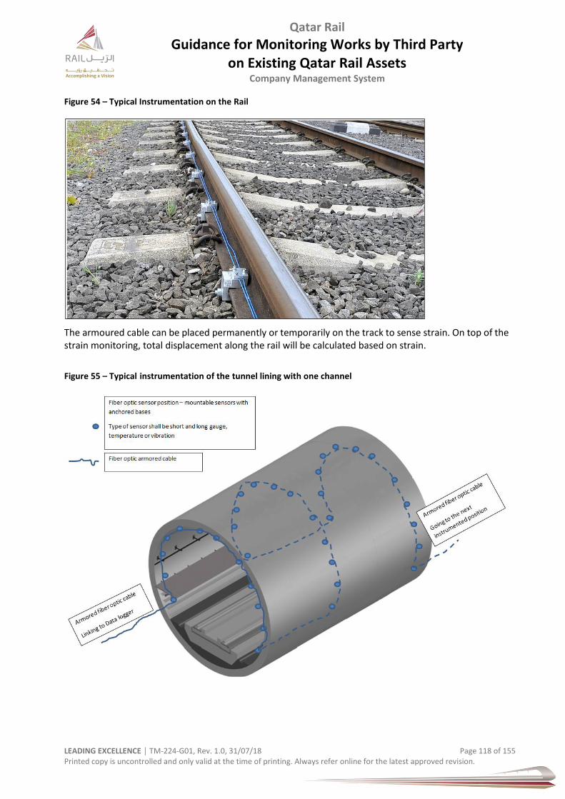
Qatar Rail
Guidance for Monitoring Works by Third Party on Existing Qatar Rail Assets
Company Management System
LEADING EXCELLENCE │ TM-224-G01, Rev. 1.0, 31/07/18 Page 118 of 155 Printed copy is uncontrolled and only valid at the time of printing. Always refer online for the latest approved revision.
Figure 54 – Typical Instrumentation on the Rail
The armoured cable can be placed permanently or temporarily on the track to sense strain. On top of the strain monitoring, total displacement along the rail will be calculated based on strain.
Figure 55 – Typical instrumentation of the tunnel lining with one channel
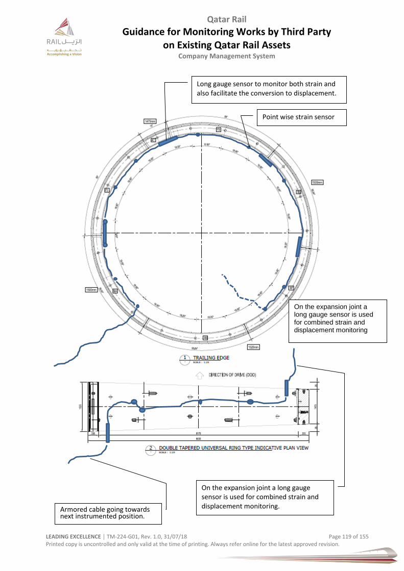
Qatar Rail
Guidance for Monitoring Works by Third Party on Existing Qatar Rail Assets
Company Management System
LEADING EXCELLENCE │ TM-224-G01, Rev. 1.0, 31/07/18 Page 119 of 155 Printed copy is uncontrolled and only valid at the time of printing. Always refer online for the latest approved revision.
On the expansion joint a long gauge sensor is used for combined strain and displacement monitoring
Armored cable going towards next instrumented position.
On the expansion joint a long gauge sensor is used for combined strain and displacement monitoring.
Point wise strain sensor
Long gauge sensor to monitor both strain and also facilitate the conversion to displacement.
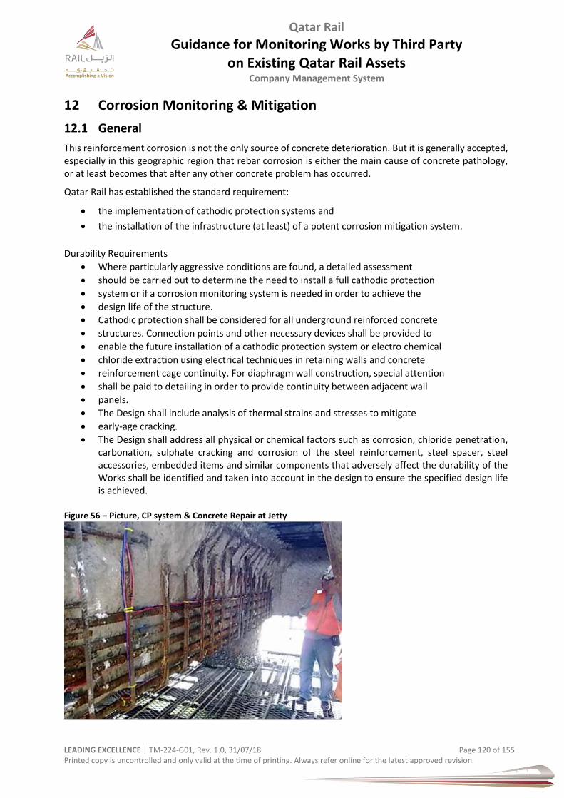
Qatar Rail
Guidance for Monitoring Works by Third Party on Existing Qatar Rail Assets
Company Management System
LEADING EXCELLENCE │ TM-224-G01, Rev. 1.0, 31/07/18 Page 120 of 155 Printed copy is uncontrolled and only valid at the time of printing. Always refer online for the latest approved revision.
12 Corrosion Monitoring & Mitigation
12.1 General
This reinforcement corrosion is not the only source of concrete deterioration. But it is generally accepted, especially in this geographic region that rebar corrosion is either the main cause of concrete pathology, or at least becomes that after any other concrete problem has occurred.
Qatar Rail has established the standard requirement:
the implementation of cathodic protection systems and
the installation of the infrastructure (at least) of a potent corrosion mitigation system.
Durability Requirements
Where particularly aggressive conditions are found, a detailed assessment
should be carried out to determine the need to install a full cathodic protection
system or if a corrosion monitoring system is needed in order to achieve the
design life of the structure.
Cathodic protection shall be considered for all underground reinforced concrete
structures. Connection points and other necessary devices shall be provided to
enable the future installation of a cathodic protection system or electro chemical
chloride extraction using electrical techniques in retaining walls and concrete
reinforcement cage continuity. For diaphragm wall construction, special attention
shall be paid to detailing in order to provide continuity between adjacent wall
panels.
The Design shall include analysis of thermal strains and stresses to mitigate
early-age cracking.
The Design shall address all physical or chemical factors such as corrosion, chloride penetration, carbonation, sulphate cracking and corrosion of the steel reinforcement, steel spacer, steel accessories, embedded items and similar components that adversely affect the durability of the Works shall be identified and taken into account in the design to ensure the specified design life is achieved.
Figure 56 – Picture, CP system & Concrete Repair at Jetty
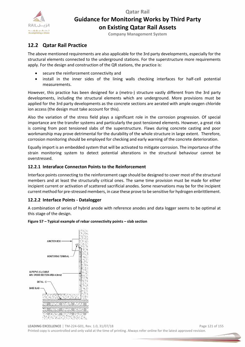
Qatar Rail
Guidance for Monitoring Works by Third Party on Existing Qatar Rail Assets
Company Management System
LEADING EXCELLENCE │ TM-224-G01, Rev. 1.0, 31/07/18 Page 121 of 155 Printed copy is uncontrolled and only valid at the time of printing. Always refer online for the latest approved revision.
12.2 Qatar Rail Practice
The above mentioned requirements are also applicable for the 3rd party developments, especially for the structural elements connected to the underground stations. For the superstructure more requirements apply. For the design and construction of the QR stations, the practice is:
secure the reinforcement connectivity and
install in the inner sides of the lining walls checking interfaces for half-cell potential measurements.
However, this practice has been designed for a (metro-) structure vastly different from the 3rd party developments, including the structural elements which are underground. More provisions must be applied for the 3rd party developments as the concrete sections are aerated with ample oxygen chloride ion access (the design must take account for this).
Also the variation of the stress field plays a significant role in the corrosion progression. Of special importance are the transfer systems and particularly the post tensioned elements. However, a great risk is coming from post tensioned slabs of the superstructure. Flaws during concrete casting and poor workmanship may prove detrimental for the durability of the whole structure in large extent. Therefore, corrosion monitoring should be employed for checking and early warning of the concrete deterioration.
Equally import is an embedded system that will be activated to mitigate corrosion. The importance of the strain monitoring system to detect potential alterations in the structural behaviour cannot be overstressed.
12.2.1 Interaface Connecton Points to the Reinforcement
Interface points connecting to the reinforcement cage should be designed to cover most of the structural members and at least the structurally critical ones. The same time provision must be made for either incipient current or activation of scattered sacrificial anodes. Some reservations may be for the incipient current method for pre-stressed members, in case these prove to be sensitive for hydrogen enbrittlement.
12.2.2 Interface Points - Datalogger
A combination of series of hybrid anode with reference anodes and data logger seems to be optimal at this stage of the design.
Figure 57 – Typical example of rebar connectivity points – slab section

Qatar Rail
Guidance for Monitoring Works by Third Party on Existing Qatar Rail Assets
Company Management System
LEADING EXCELLENCE │ TM-224-G01, Rev. 1.0, 31/07/18 Page 122 of 155 Printed copy is uncontrolled and only valid at the time of printing. Always refer online for the latest approved revision.
Figure 58 – Typical example of rebar connectivity points – slab section Detail C and apparatus for connectivity checking and incipient current provision
Figure 59 – Typical example of rebar connectivity points and apparatus for connectivity checking and incipient current provision
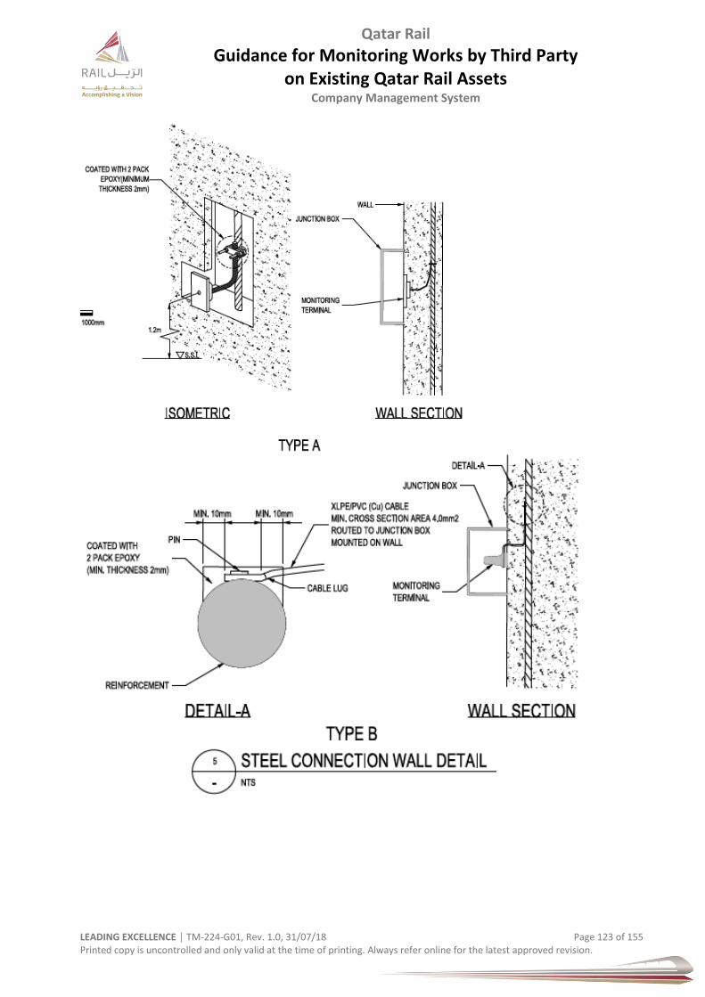
Qatar Rail
Guidance for Monitoring Works by Third Party on Existing Qatar Rail Assets
Company Management System
LEADING EXCELLENCE │ TM-224-G01, Rev. 1.0, 31/07/18 Page 123 of 155 Printed copy is uncontrolled and only valid at the time of printing. Always refer online for the latest approved revision.
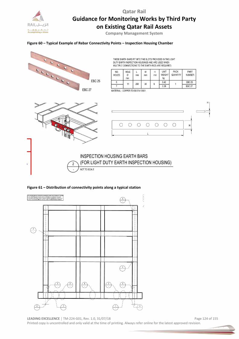
Qatar Rail
Guidance for Monitoring Works by Third Party on Existing Qatar Rail Assets
Company Management System
LEADING EXCELLENCE │ TM-224-G01, Rev. 1.0, 31/07/18 Page 124 of 155 Printed copy is uncontrolled and only valid at the time of printing. Always refer online for the latest approved revision.
Figure 60 – Typical Example of Rebar Connectivity Points – Inspection Housing Chamber
Figure 61 – Distribution of connectivity points along a typical station
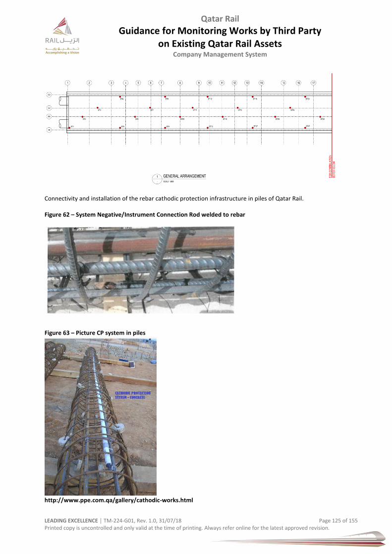
Qatar Rail
Guidance for Monitoring Works by Third Party on Existing Qatar Rail Assets
Company Management System
LEADING EXCELLENCE │ TM-224-G01, Rev. 1.0, 31/07/18 Page 125 of 155 Printed copy is uncontrolled and only valid at the time of printing. Always refer online for the latest approved revision.
Connectivity and installation of the rebar cathodic protection infrastructure in piles of Qatar Rail. Figure 62 – System Negative/Instrument Connection Rod welded to rebar
Figure 63 – Picture CP system in piles
http://www.ppe.com.qa/gallery/cathodic-works.html

Qatar Rail
Guidance for Monitoring Works by Third Party on Existing Qatar Rail Assets
Company Management System
LEADING EXCELLENCE │ TM-224-G01, Rev. 1.0, 31/07/18 Page 126 of 155 Printed copy is uncontrolled and only valid at the time of printing. Always refer online for the latest approved revision.
Qatar Rail’s TOD consultants for the Metro stations Al Doha Al Jadeeda and Al Sadd have specified corrosion detection devices to be installed in the concrete. These are installed in variable depth and their distribution needs to be carefully designed and depicted in BIM.
The general, the method for corrosion mitigation is subject to the review of designer’s proposal and approval by Qatar Rail.
12.2.3 Interface Points – Hybrid Anodes Pre-Installed
A typical distribution of hybrid anodes could be pre-installed (holes) and periodically maintained. It seems to be a convenient and conservative approach for transfer slabs or girders with heavy post tensioning.
Figure 64 – Typical Distribution of Hybrid Anodes Could be Pre-installed
12.2.4 Corrosion Sensors
Where can corrosion sensors be placed? Corrosion monitoring solutions can designed for concrete structures where loss of basicity is the root cause for corrosion of rebar. A few use cases are listed below.
• Splash zone corrosion monitoring for piles and piers • Bridge deck corrosion monitoring • Any concrete structural element where there is cyclical wetting and drying up of concrete • There is a potential influx of salts • Scour induced leakage of seawater into concrete structure. • Crack induced entry of salt water into the structure.
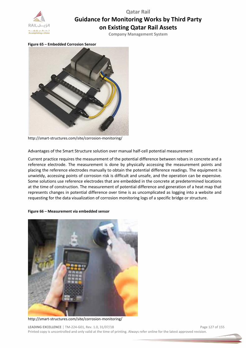
Qatar Rail
Guidance for Monitoring Works by Third Party on Existing Qatar Rail Assets
Company Management System
LEADING EXCELLENCE │ TM-224-G01, Rev. 1.0, 31/07/18 Page 127 of 155 Printed copy is uncontrolled and only valid at the time of printing. Always refer online for the latest approved revision.
Figure 65 – Embedded Corrosion Sensor
http://smart-structures.com/site/corrosion-monitoring/
Advantages of the Smart Structure solution over manual half-cell potential measurement
Current practice requires the measurement of the potential difference between rebars in concrete and a reference electrode. The measurement is done by physically accessing the measurement points and placing the reference electrodes manually to obtain the potential difference readings. The equipment is unwieldy, accessing points of corrosion risk is difficult and unsafe, and the operation can be expensive. Some solutions use reference electrodes that are embedded in the concrete at predetermined locations at the time of construction. The measurement of potential difference and generation of a heat map that represents changes in potential difference over time is as uncomplicated as logging into a website and requesting for the data visualization of corrosion monitoring logs of a specific bridge or structure.
Figure 66 – Measurement via embedded sensor
http://smart-structures.com/site/corrosion-monitoring/

Qatar Rail
Guidance for Monitoring Works by Third Party on Existing Qatar Rail Assets
Company Management System
LEADING EXCELLENCE │ TM-224-G01, Rev. 1.0, 31/07/18 Page 128 of 155 Printed copy is uncontrolled and only valid at the time of printing. Always refer online for the latest approved revision.
Figure 67 – Drawing of installed C4 probe in tunnel segment
(refer to Intertek)

Qatar Rail
Guidance for Monitoring Works by Third Party on Existing Qatar Rail Assets
Company Management System
LEADING EXCELLENCE │ TM-224-G01, Rev. 1.0, 31/07/18 Page 129 of 155 Printed copy is uncontrolled and only valid at the time of printing. Always refer online for the latest approved revision.
13 Image Based System for Change Detection
This is an automated system for detecting visual changes on tunnel linings by taking pictures and comparing ‘before & after’ taken pictures by projecting them on a tree-dimensional tunnel surface model. Applied are structure and motion techniques which allow accurate detection of changes during regular inspections followed by an assessment by an expert.
This method can be used especially for large-scale tunnel infrastructures where efficient and fast monitoring and inspection is of essence no to disturb operation.
As with most detection systems, critical performance failure and early finding is important to avoid leakages, cracks, corrosion or even catastrophic collapse.
Examplary reference: Paper from Simon Stent*, Riccardo Gherardi+, Bjoern Stenger+, Kenichi Soga*, Roberto Cipolla*; * Department of Engineering/University of Cambridge,UK; + Toshiba Research Europe, Cambridge, UK
Figure 68 – Overview of a System
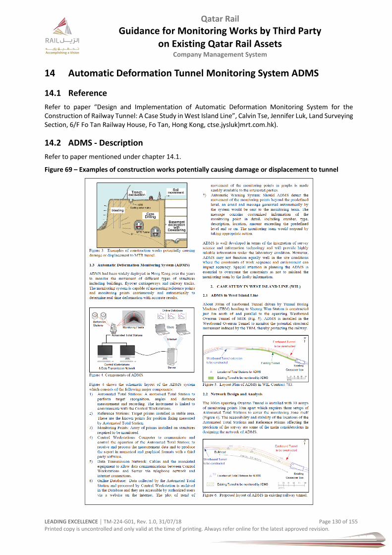
Qatar Rail
Guidance for Monitoring Works by Third Party on Existing Qatar Rail Assets
Company Management System
LEADING EXCELLENCE │ TM-224-G01, Rev. 1.0, 31/07/18 Page 130 of 155 Printed copy is uncontrolled and only valid at the time of printing. Always refer online for the latest approved revision.
14 Automatic Deformation Tunnel Monitoring System ADMS
14.1 Reference
Refer to paper “Design and Implementation of Automatic Deformation Monitoring System for the Construction of Railway Tunnel: A Case Study in West Island Line”, Calvin Tse, Jennifer Luk, Land Surveying Section, 6/F Fo Tan Railway House, Fo Tan, Hong Kong, ctse.jysluk)mrt.com.hk).
14.2 ADMS - Description
Refer to paper mentioned under chapter 14.1.
Figure 69 – Examples of construction works potentially causing damage or displacement to tunnel

Qatar Rail
Guidance for Monitoring Works by Third Party on Existing Qatar Rail Assets
Company Management System
LEADING EXCELLENCE │ TM-224-G01, Rev. 1.0, 31/07/18 Page 131 of 155 Printed copy is uncontrolled and only valid at the time of printing. Always refer online for the latest approved revision.
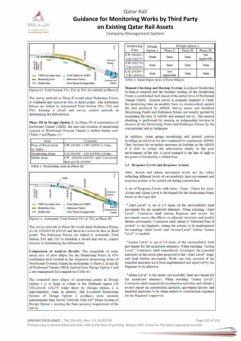
Qatar Rail
Guidance for Monitoring Works by Third Party on Existing Qatar Rail Assets
Company Management System
LEADING EXCELLENCE │ TM-224-G01, Rev. 1.0, 31/07/18 Page 132 of 155 Printed copy is uncontrolled and only valid at the time of printing. Always refer online for the latest approved revision.

Qatar Rail
Guidance for Monitoring Works by Third Party on Existing Qatar Rail Assets
Company Management System
LEADING EXCELLENCE │ TM-224-G01, Rev. 1.0, 31/07/18 Page 133 of 155 Printed copy is uncontrolled and only valid at the time of printing. Always refer online for the latest approved revision.
Qatar Rail
Guidance for Monitoring Works by Third Party on Existing Qatar Rail Assets
Company Management System
LEADING EXCELLENCE │ TM-224-G01, Rev. 1.0, 31/07/18 Page 134 of 155 Printed copy is uncontrolled and only valid at the time of printing. Always refer online for the latest approved revision.
15 Documentation
15.1 Records
All measurement data regarding monitoring will be provided to Qatar Rail
original data reports in the Monitoring Database.
15.2 Installation Records
A copy digital and print to be provided to Qatar Rail.
15.3 Material Data Sheet Submissions
A digital copy (pdf format) of the material sheets or brochures containing technical data for inclinometer, load cell and extensometers (magnet and rod types) or any other instrument shall be provided to Qatar Rail.

Qatar Rail
Guidance for Monitoring Works by Third Party on Existing Qatar Rail Assets
Company Management System
LEADING EXCELLENCE │ TM-224-G01, Rev. 1.0, 31/07/18 Page 135 of 155 Printed copy is uncontrolled and only valid at the time of printing. Always refer online for the latest approved revision.
16 Contingency Action Plan & Emergency List
16.1 Contingency Action Plan
The contingency action plan to be applied when monitoring trigger values are exceeded is as shown below: Table 41 – Trigger Value Table and Actions
Normal Conditions
Warning Level Alarm Level
(Exceeding Design Value)
Green
Amber
Action By
Red
Action By
No actions
required
1. Immediate notification of JV monitoring coordinator and JV
Design department. 2. Verification of measured
values and confirmation with earlier recipients.
3. On site inspection and evaluation
of the conditions of the construction sites and adjacent structures.
4. Increase of measurement
frequency to daily ASAP until decisions are made in meeting of
Step 6 below.
5. Evaluation of the situation by the
JV - preparation of a letter report
describing the outcome of Steps 2 and 3 as well as any preliminary recommendations.
6. Calling of a meeting involving JV
Design Department and Designers within 48 hours. Presentation of the evaluation report from Step 5 above.
7. Undertaking actions agreed upon
during the meeting.
8. Reporting and addressing the issue
in the next regular monitoring report or meeting
I&M Manager I&M Manager
JV Design and Construction
I&M Manager
JV Design and
Construction - report by JV Design
JV Design;
Joint Decision by JV Design and
Construction JV
Construction
All
1. Immediate notification of JV monitoring coordinator, JV
Design dept. and Designer.
2. Verification of measured values
and confirmation with earlier recipients.
3. Notification of the PMC and
Client, if verified as accurate
4. On site detailed inspection and
evaluation of the conditions of the
construction sites and adjacent structures.
5. Determination and application of
contingency measures as
described in the Monitoring Design; Increase of measurement frequency ASAP to twice daily.
6. Evaluation of the situation by the
JV and Designer - preparation of a letter report containing the outcome of Steps 2, 4 and 5.
7. Calling of a meeting involving the
PMC, Designer and JV
departments within 24 hours. Presentation of the evaluation report from Step 6 above.
8. Application of additional
contingency measures agreed upon during the meeting (if any).
9. Reporting and addressing the
issue in the next regular monitoring report or meeting
I&M Manager I&M Manager I&M Manager JV Design and Construction, and others
Joint Decision by JV Design
and Construction
JV Design and
Construction - report by JV Design
JV Design
JV
Construction All
Note: Upon triggering of Alarm Level, Steps 1 to 4 have to be carried out very urgently and as effective as possible, especially with regards to the time taken to avoid a false alarm.
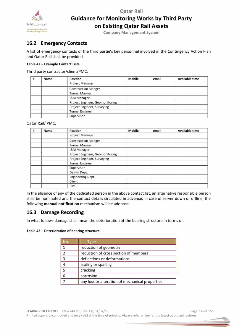
Qatar Rail
Guidance for Monitoring Works by Third Party on Existing Qatar Rail Assets
Company Management System
LEADING EXCELLENCE │ TM-224-G01, Rev. 1.0, 31/07/18 Page 136 of 155 Printed copy is uncontrolled and only valid at the time of printing. Always refer online for the latest approved revision.
16.2 Emergency Contacts
A list of emergency contacts of the thrid partie’s key personnel involved in the Contingency Action Plan and Qatar Rail shall be provided.
Table 42 – Example Contact Lists
Thrid party contractor/client/PMC:
# Name Position Mobile email Available time
Project Manager
Construction Manger
Tunnel Manger
I&M Manager
Project Engineer, Geomonitoring
Project Engineer, Surveying
Tunnel Engineer
Supervisor
Qatar Rail/ PMC:
# Name Position Mobile email Available time
Project Manager
Construction Manger
Tunnel Manger
I&M Manager
Project Engineer, Geomonitoring
Project Engineer, Surveying
Tunnel Engineer
Supervisor
Design Dept.
Engineering Dept.
Client
PMC
In the absence of any of the dedicated person in the above contact list, an alternative responsible person shall be nominated and the contact details circulated in advance. In case of server down or offline, the following manual notification mechanism will be adopted:
16.3 Damage Recording
In what follows damage shall mean the deterioration of the bearing structure in terms of: Table 43 – Deterioration of bearing structure
No. Type
1 reduction of geometry
2 reduction of cross section of members
3 deflections or deformations
4 scaling or spalling
5 cracking
6 corrosion
7 any loss or alteration of mechanical properties
Qatar Rail
Guidance for Monitoring Works by Third Party on Existing Qatar Rail Assets
Company Management System
LEADING EXCELLENCE │ TM-224-G01, Rev. 1.0, 31/07/18 Page 137 of 155 Printed copy is uncontrolled and only valid at the time of printing. Always refer online for the latest approved revision.
17 Complaints Procedure
Complaints shall be managed properly and outlined within a procedure which identifies communication channels, trigger levels, response times, cause and route identification, actions and mitigations, close out, general management. The procedure shall be proposed to Qatar Rail and agreed jointly.

Qatar Rail
Guidance for Monitoring Works by Third Party on Existing Qatar Rail Assets
Company Management System
LEADING EXCELLENCE │ TM-224-G01, Rev. 1.0, 31/07/18 Page 138 of 155 Printed copy is uncontrolled and only valid at the time of printing. Always refer online for the latest approved revision.
18 Building Damage Assessment Procedures
18.1 State of the Art
To assess the amount of damage expected in adjacent buildings the step wise approach after Mair et al. (1996) can be followed.
Step 1: determine green field ground movements, both vertical and horizontal
Step 2: determine potential damage, assuming no interaction and full transfer of deformations to the buildings.
If the expected damage does not exceed the numbers given by Rankin (1988), being a rotation of the building of not more than 1:500 and/or absolute settlement of 10 mm, negligible damage is to be expected. If the expected damage exceeds these values, proceed to step 3.
Step 3: Interaction calculation
In a more detailed assessment the damage can be predicted either directly with more advanced damage indicators (such as described in section 3.4.2), or by including the interaction of the building with the soil.
This will include the following sub steps:
a) project green field ground movements on to the building
b) determine strains in building, using fictitious beam model
c) optional: account for current initial state of building, foundation
d) optional: include the effect of building stiffness and project the resulting deformations on the building.
e) classify damage related to strain levels (negligible, very slight, slight, moderate, severe, very severe)
Check whether the damage level is acceptable by using damage criteria according to Burland et al (1977). If the predicted level is not acceptable, the calculation can be repeated including mitigative measures either in the soil or at the building, change of construction methods, and/or a more detailed analysis.

Qatar Rail
Guidance for Monitoring Works by Third Party on Existing Qatar Rail Assets
Company Management System
LEADING EXCELLENCE │ TM-224-G01, Rev. 1.0, 31/07/18 Page 139 of 155 Printed copy is uncontrolled and only valid at the time of printing. Always refer online for the latest approved revision.
19 Independent Verification
The Third Party shall carry out ‘Independent Verification’ of the engineering analysis and impact assessment or as agreed with Qatar Rail.
The independent verification shall be arranged by the Third Party.
Qatar Rail reserves the right to object to the organisation proposed by the Third Party.
Figure 70 – Possible Damage Assessement Procedure – Aspects & parameters
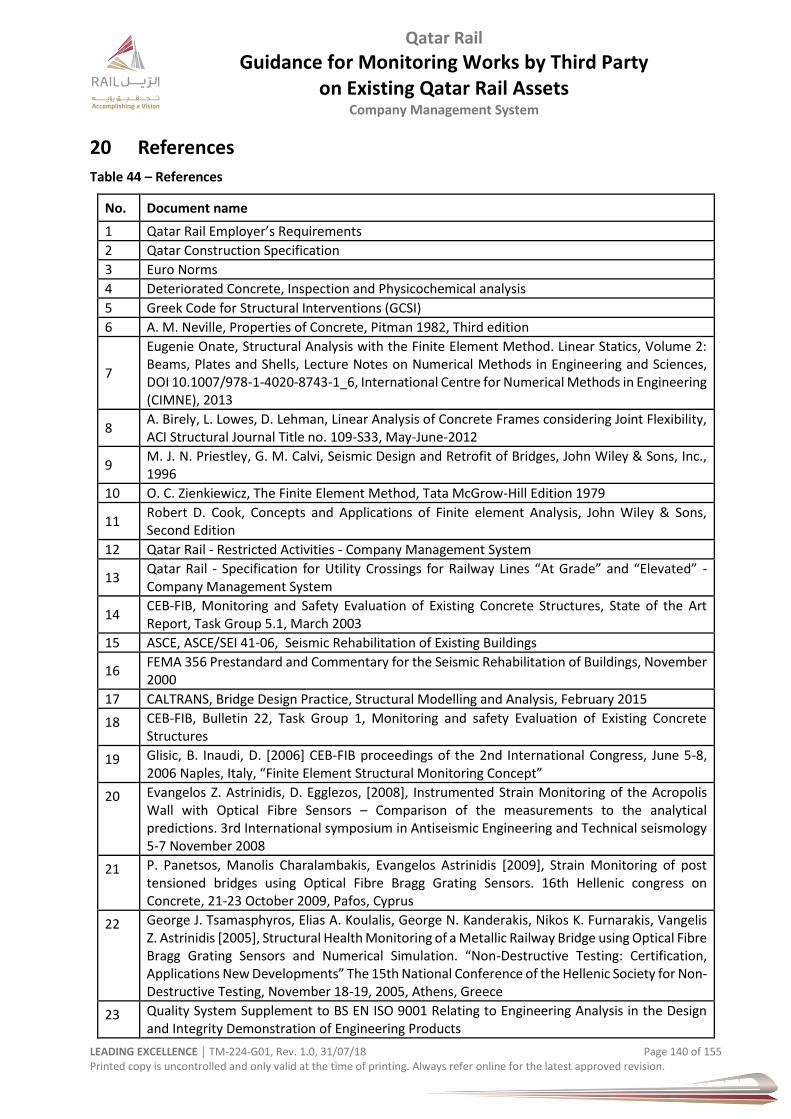
Qatar Rail
Guidance for Monitoring Works by Third Party on Existing Qatar Rail Assets
Company Management System
LEADING EXCELLENCE │ TM-224-G01, Rev. 1.0, 31/07/18 Page 140 of 155 Printed copy is uncontrolled and only valid at the time of printing. Always refer online for the latest approved revision.
20 References
Table 44 – References
No. Document name
1 Qatar Rail Employer’s Requirements
2 Qatar Construction Specification
3 Euro Norms
4 Deteriorated Concrete, Inspection and Physicochemical analysis
5 Greek Code for Structural Interventions (GCSI)
6 A. M. Neville, Properties of Concrete, Pitman 1982, Third edition
7
Eugenie Onate, Structural Analysis with the Finite Element Method. Linear Statics, Volume 2: Beams, Plates and Shells, Lecture Notes on Numerical Methods in Engineering and Sciences, DOI 10.1007/978-1-4020-8743-1_6, International Centre for Numerical Methods in Engineering (CIMNE), 2013
8 A. Birely, L. Lowes, D. Lehman, Linear Analysis of Concrete Frames considering Joint Flexibility, ACI Structural Journal Title no. 109-S33, May-June-2012
9 M. J. N. Priestley, G. M. Calvi, Seismic Design and Retrofit of Bridges, John Wiley & Sons, Inc., 1996
10 O. C. Zienkiewicz, The Finite Element Method, Tata McGrow-Hill Edition 1979
11 Robert D. Cook, Concepts and Applications of Finite element Analysis, John Wiley & Sons, Second Edition
12 Qatar Rail - Restricted Activities - Company Management System
13 Qatar Rail - Specification for Utility Crossings for Railway Lines “At Grade” and “Elevated” - Company Management System
14 CEB-FIB, Monitoring and Safety Evaluation of Existing Concrete Structures, State of the Art Report, Task Group 5.1, March 2003
15 ASCE, ASCE/SEI 41-06, Seismic Rehabilitation of Existing Buildings
16 FEMA 356 Prestandard and Commentary for the Seismic Rehabilitation of Buildings, November 2000
17 CALTRANS, Bridge Design Practice, Structural Modelling and Analysis, February 2015
18 CEB-FIB, Bulletin 22, Task Group 1, Monitoring and safety Evaluation of Existing Concrete Structures
19 Glisic, B. Inaudi, D. [2006] CEB-FIB proceedings of the 2nd International Congress, June 5-8, 2006 Naples, Italy, “Finite Element Structural Monitoring Concept”
20 Evangelos Z. Astrinidis, D. Egglezos, [2008], Instrumented Strain Monitoring of the Acropolis Wall with Optical Fibre Sensors – Comparison of the measurements to the analytical predictions. 3rd International symposium in Antiseismic Engineering and Technical seismology 5-7 November 2008
21 P. Panetsos, Manolis Charalambakis, Evangelos Astrinidis [2009], Strain Monitoring of post tensioned bridges using Optical Fibre Bragg Grating Sensors. 16th Hellenic congress on Concrete, 21-23 October 2009, Pafos, Cyprus
22 George J. Tsamasphyros, Elias A. Koulalis, George N. Kanderakis, Nikos K. Furnarakis, Vangelis Z. Astrinidis [2005], Structural Health Monitoring of a Metallic Railway Bridge using Optical Fibre Bragg Grating Sensors and Numerical Simulation. “Non-Destructive Testing: Certification, Applications New Developments” The 15th National Conference of the Hellenic Society for Non-Destructive Testing, November 18-19, 2005, Athens, Greece
23 Quality System Supplement to BS EN ISO 9001 Relating to Engineering Analysis in the Design and Integrity Demonstration of Engineering Products
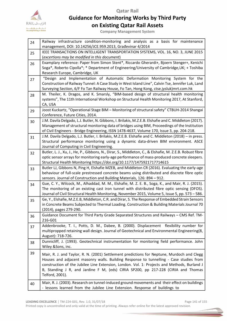
Qatar Rail
Guidance for Monitoring Works by Third Party on Existing Qatar Rail Assets
Company Management System
LEADING EXCELLENCE │ TM-224-G01, Rev. 1.0, 31/07/18 Page 141 of 155 Printed copy is uncontrolled and only valid at the time of printing. Always refer online for the latest approved revision.
24 Railway infrastructure condition-monitoring and analysis as a basis for maintenance management, DOI: 10.14256/JCE.959.2013, Građevinar 4/2014
25 IEEE TRANSACTIONS ON INTELLIGENT TRANSPORTATION SYSTEMS, VOL. 16, NO. 3, JUNE 2015 (excertions may be modified in this document)
26 Examplary reference: Paper from Simon Stent*, Riccardo Gherardi+, Bjoern Stenger+, Kenichi Soga*, Roberto Cipolla*; * Department of Engineering/University of Cambridge,UK; + Toshiba Research Europe, Cambridge, UK
27 “Design and Implementation of Automatic Deformation Monitoring System for the Construction of Railway Tunnel: A Case Study in West Island Line”, Calvin Tse, Jennifer Luk, Land Surveying Section, 6/F Fo Tan Railway House, Fo Tan, Hong Kong, ctse.jysluk)mrt.com.hk
28 M. Theiler, K. Dragos, and K. Smarsly, “BIM-based design of structural health monitoring systems”, The 11th International Workshop on Structural Health Monitoring 2017, At Stanford, CA, USA
29 Joost Kuckartz, “Operational Stage BIM – Monitoring of structural safety” CTBUH-2014 Shangai Conference, Future Cities, 2014.
30 J.M. Davila Delgado, L.J. Butler, N. Gibbons, I. Brilakis, M.Z.E.B. Elshafie and C. Middleton (2017). Management of structural monitoring data of bridges using BIM, Proceedings of the Institution of Civil Engineers - Bridge Engineering, ISSN 1478-4637, Volume 170, Issue 3, pp. 204-218.
31 J.M. Davila Delgado, L.J. Butler, I. Brilakis, M.Z.E.B. Elshafie and C. Middleton (2018) – in press. Structural performance monitoring using a dynamic data-driven BIM environment. ASCE Journal of Computing in Civil Engineering.
32 Butler, L. J., Xu, J., He, P., Gibbons, N., Dirar, S., Middleton, C., & Elshafie, M. Z.E.B. Robust fibre optic sensor arrays for monitoring early-age performance of mass-produced concrete sleepers. Structural Health Monitoring https://doi.org/10.1177/1475921717714615
33 Butler LJ, Gibbons N, Ping H, Elshafie MZEB, and Middleton CR (2016). Evaluating the early-age behaviour of full-scale prestressed concrete beams using distributed and discrete fibre optic sensors. Journal of Construction and Building Materials, 126: 894 – 912.
34 Gue, C. Y., Wilcock, M., Alhaddad, M. M., Elshafie, M. Z. E. B., Soga, K., and Mair, R. J. (2015). The monitoring of an existing cast iron tunnel with distributed fibre optic sensing (DFOS). Journal of Civil Structural Health Monitoring, November 2015, Volume 5, Issue 5, pp. 573 – 586.
35 Ge, Y., Elshafie, M.Z.E.B, Middleton, C.R. and Dirar, S. The Response of Embedded Strain Sensors in Concrete Beams Subjected to Thermal Loading. Construction & Building Materials Journal 70 (2014), pages 279-290.
36 Guidance Document for Third Party Grade Separated Structures and Railways – CMS Ref. TM-216-G01
37 Addenbrooke, T. I., Potts, D. M., Dabee, B. (2000). Displacement flexibility number for multipropped retaining wall design. Journal of Geotechnical and Environmental Engineering(8, August): 718-726.
38 Dunnicliff, J. (1993). Geotechnical instrumentation for monitoring field performance. John Wiley &Sons, inc.
39 Mair, R. J. and Taylor, R. N. (2001) Settlement predictions for Neptune, Murdoch and Clegg Houses and adjacent masonry walls. Building Response to tunnelling - Case studies from construction of the Jubilee Line Extension, London. Vol. 1: Projects and Methods, Burland J B, Standing J R, and Jardine F M, (eds) CIRIA SP200, pp 217-228 (CIRIA and Thomas Telford, 2001).
40 Mair, R. J. (2003). Research on tunnel-induced ground movements and their effect on buildings - lessons learned from the Jubilee Line Extension. Response of buildings to
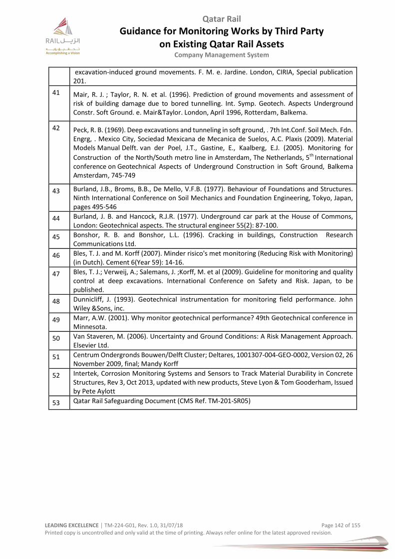
Qatar Rail
Guidance for Monitoring Works by Third Party on Existing Qatar Rail Assets
Company Management System
LEADING EXCELLENCE │ TM-224-G01, Rev. 1.0, 31/07/18 Page 142 of 155 Printed copy is uncontrolled and only valid at the time of printing. Always refer online for the latest approved revision.
excavation-induced ground movements. F. M. e. Jardine. London, CIRIA, Special publication 201.
41 Mair, R. J. ; Taylor, R. N. et al. (1996). Prediction of ground movements and assessment of risk of building damage due to bored tunnelling. Int. Symp. Geotech. Aspects Underground Constr. Soft Ground. e. Mair&Taylor. London, April 1996, Rotterdam, Balkema.
42 Peck, R. B. (1969). Deep excavations and tunneling in soft ground, . 7th Int.Conf. Soil Mech. Fdn. Engrg, . Mexico City, Sociedad Mexicana de Mecanica de Suelos, A.C. Plaxis (2009). Material Models Manual Delft. van der Poel, J.T., Gastine, E., Kaalberg, E.J. (2005). Monitoring for
Construction of the North/South metro line in Amsterdam, The Netherlands, 5th International conference on Geotechnical Aspects of Underground Construction in Soft Ground, Balkema Amsterdam, 745-749
43 Burland, J.B., Broms, B.B., De Mello, V.F.B. (1977). Behaviour of Foundations and Structures. Ninth International Conference on Soil Mechanics and Foundation Engineering, Tokyo, Japan, pages 495-546
44 Burland, J. B. and Hancock, R.J.R. (1977). Underground car park at the House of Commons, London: Geotechnical aspects. The structural engineer 55(2): 87-100.
45 Bonshor, R. B. and Bonshor, L.L. (1996). Cracking in buildings, Construction Research Communications Ltd.
46 Bles, T. J. and M. Korff (2007). Minder risico's met monitoring (Reducing Risk with Monitoring) (in Dutch). Cement 6(Year 59): 14-16.
47 Bles, T. J.; Verweij, A.; Salemans, J. ;Korff, M. et al (2009). Guideline for monitoring and quality control at deep excavations. International Conference on Safety and Risk. Japan, to be published.
48 Dunnicliff, J. (1993). Geotechnical instrumentation for monitoring field performance. John Wiley &Sons, inc.
49 Marr, A.W. (2001). Why monitor geotechnical performance? 49th Geotechnical conference in Minnesota.
50 Van Staveren, M. (2006). Uncertainty and Ground Conditions: A Risk Management Approach. Elsevier Ltd.
51 Centrum Ondergronds Bouwen/Delft Cluster; Deltares, 1001307-004-GEO-0002, Version 02, 26 November 2009, final; Mandy Korff
52 Intertek, Corrosion Monitoring Systems and Sensors to Track Material Durability in Concrete Structures, Rev 3, Oct 2013, updated with new products, Steve Lyon & Tom Gooderham, Issued by Pete Aylott
53 Qatar Rail Safeguarding Document (CMS Ref. TM-201-SR05)
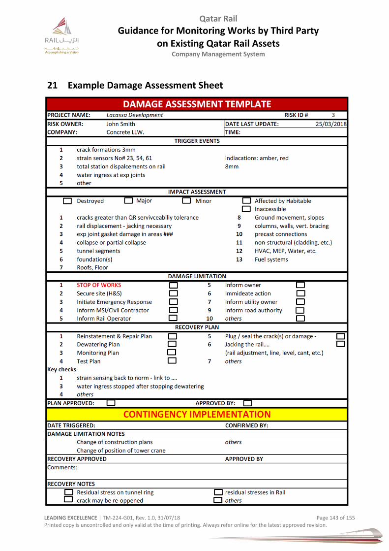
Qatar Rail
Guidance for Monitoring Works by Third Party on Existing Qatar Rail Assets
Company Management System
LEADING EXCELLENCE │ TM-224-G01, Rev. 1.0, 31/07/18 Page 143 of 155 Printed copy is uncontrolled and only valid at the time of printing. Always refer online for the latest approved revision.
21 Example Damage Assessment Sheet
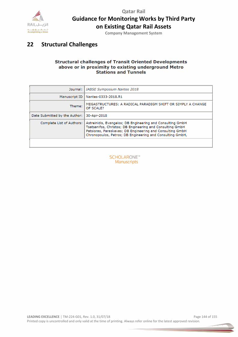
Qatar Rail
Guidance for Monitoring Works by Third Party on Existing Qatar Rail Assets
Company Management System
LEADING EXCELLENCE │ TM-224-G01, Rev. 1.0, 31/07/18 Page 144 of 155 Printed copy is uncontrolled and only valid at the time of printing. Always refer online for the latest approved revision.
22 Structural Challenges
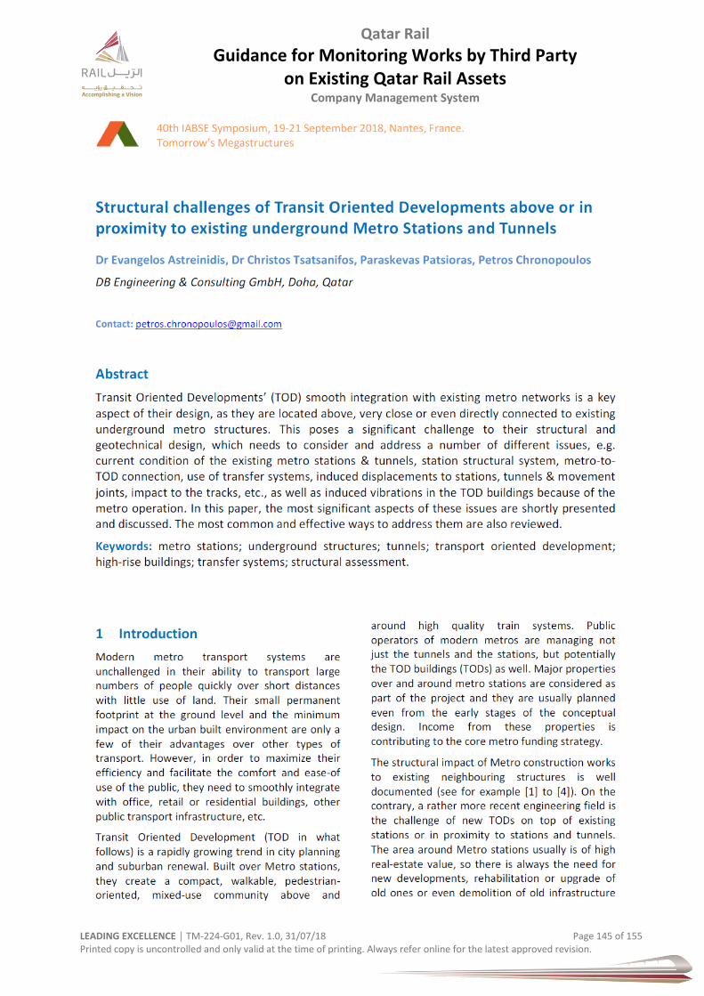
Qatar Rail
Guidance for Monitoring Works by Third Party on Existing Qatar Rail Assets
Company Management System
LEADING EXCELLENCE │ TM-224-G01, Rev. 1.0, 31/07/18 Page 145 of 155 Printed copy is uncontrolled and only valid at the time of printing. Always refer online for the latest approved revision.
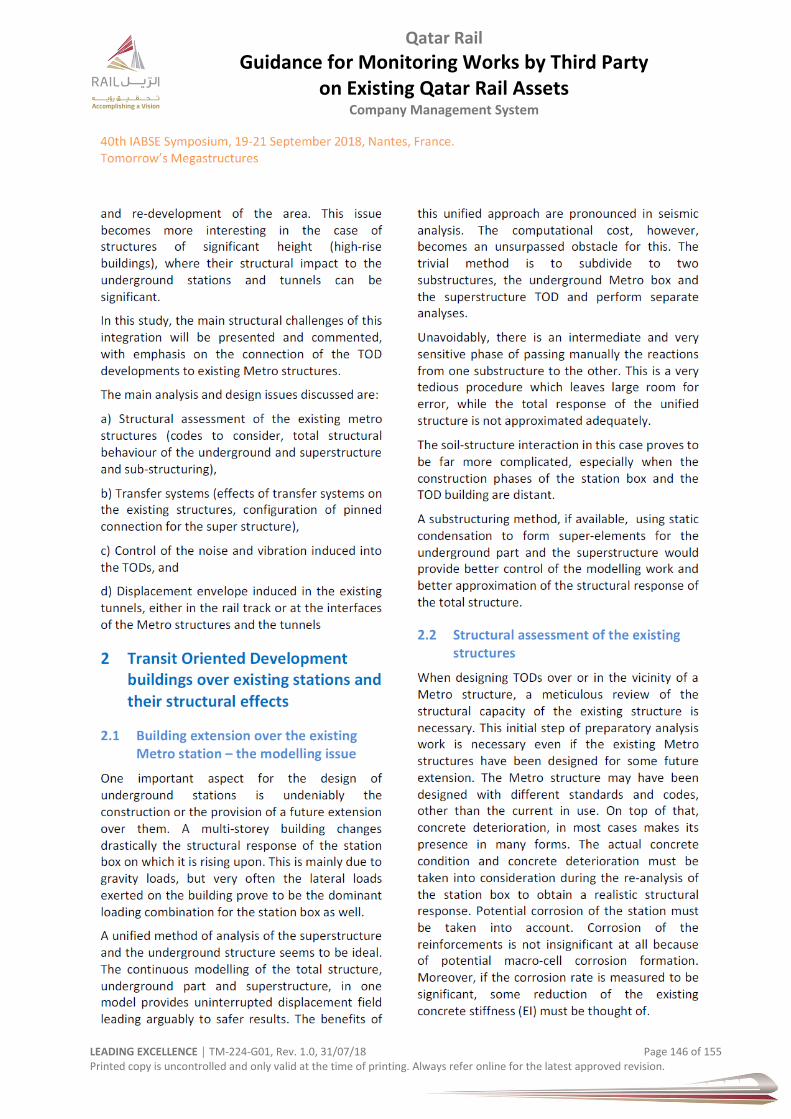
Qatar Rail
Guidance for Monitoring Works by Third Party on Existing Qatar Rail Assets
Company Management System
LEADING EXCELLENCE │ TM-224-G01, Rev. 1.0, 31/07/18 Page 146 of 155 Printed copy is uncontrolled and only valid at the time of printing. Always refer online for the latest approved revision.
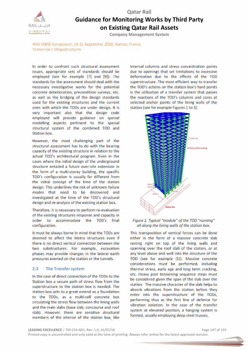
Qatar Rail
Guidance for Monitoring Works by Third Party on Existing Qatar Rail Assets
Company Management System
LEADING EXCELLENCE │ TM-224-G01, Rev. 1.0, 31/07/18 Page 147 of 155 Printed copy is uncontrolled and only valid at the time of printing. Always refer online for the latest approved revision.

Qatar Rail
Guidance for Monitoring Works by Third Party on Existing Qatar Rail Assets
Company Management System
LEADING EXCELLENCE │ TM-224-G01, Rev. 1.0, 31/07/18 Page 148 of 155 Printed copy is uncontrolled and only valid at the time of printing. Always refer online for the latest approved revision.
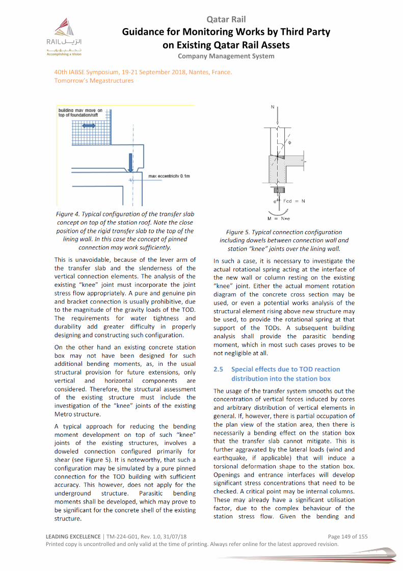
Qatar Rail
Guidance for Monitoring Works by Third Party on Existing Qatar Rail Assets
Company Management System
LEADING EXCELLENCE │ TM-224-G01, Rev. 1.0, 31/07/18 Page 149 of 155 Printed copy is uncontrolled and only valid at the time of printing. Always refer online for the latest approved revision.
Qatar Rail
Guidance for Monitoring Works by Third Party on Existing Qatar Rail Assets
Company Management System
LEADING EXCELLENCE │ TM-224-G01, Rev. 1.0, 31/07/18 Page 150 of 155 Printed copy is uncontrolled and only valid at the time of printing. Always refer online for the latest approved revision.
Qatar Rail
Guidance for Monitoring Works by Third Party on Existing Qatar Rail Assets
Company Management System
LEADING EXCELLENCE │ TM-224-G01, Rev. 1.0, 31/07/18 Page 151 of 155 Printed copy is uncontrolled and only valid at the time of printing. Always refer online for the latest approved revision.
Qatar Rail
Guidance for Monitoring Works by Third Party on Existing Qatar Rail Assets
Company Management System
LEADING EXCELLENCE │ TM-224-G01, Rev. 1.0, 31/07/18 Page 152 of 155 Printed copy is uncontrolled and only valid at the time of printing. Always refer online for the latest approved revision.

Qatar Rail
Guidance for Monitoring Works by Third Party on Existing Qatar Rail Assets
Company Management System
LEADING EXCELLENCE │ TM-224-G01, Rev. 1.0, 31/07/18 Page 153 of 155 Printed copy is uncontrolled and only valid at the time of printing. Always refer online for the latest approved revision.
23 Metro Network Phase 1

Qatar Rail
Guidance for Monitoring Works by Third Party on Existing Qatar Rail Assets
Company Management System
LEADING EXCELLENCE │ TM-224-G01, Rev. 1.0, 31/07/18 Page 154 of 155 Printed copy is uncontrolled and only valid at the time of printing. Always refer online for the latest approved revision.
24 Metro Network Phase 1 (Doha)
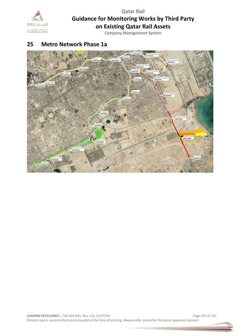
Qatar Rail
Guidance for Monitoring Works by Third Party on Existing Qatar Rail Assets
Company Management System
LEADING EXCELLENCE │ TM-224-G01, Rev. 1.0, 31/07/18 Page 155 of 155 Printed copy is uncontrolled and only valid at the time of printing. Always refer online for the latest approved revision.
25 Metro Network Phase 1a