nano-electrocatalyst materials for low temperature fuel cells: a review
TRANSCRIPT

ChineseJournalofCatalysis36(2015)458–472 催化学报2015年第36卷第4期|www.chxb.cn
a v a i l a b l e a t www . s c i e n c e d i r e c t . c om
j o u r n a l h omep a g e : www . e l s e v i e r . c om / l o c a t e / c h n j c
Review (Special Column on Electrocatalysis for Fuel Cells)
Nano‐electrocatalystmaterialsforlowtemperaturefuelcells: Areview
K.Vignaroobana,e,J.Linb,A.Arvayc,S.Kollia,I.Kruusenbergd,K.Tammeveskid,L.Munukutlaa, A.M.Kannana,*aFuelCellLaboratory,DepartmentofEngineeringandComputingSystems,ArizonaStateUniversity,Mesa,AZ85212,USAbGolisanoInstituteforSustainability,RochesterInstituteofTechnology,Rochester,NY14623,USAcComputerScienceDepartment,UniversityofAuckland,Auckland1142,NewZealanddInstituteofChemistry,UniversityofTartu,Ravila14a,50411Tartu,EstoniaeDepartmentofPhysics,FacultyofScience,UniversityofJaffna,Jaffna40000,SriLanka
A R T I C L E I N F O
A B S T R A C T
Articlehistory:Received6April2014Accepted20May2014Published20April2015
Lowtemperaturefuelcellsareanattractivetechnologyfortransportationandresidentialapplica‐tionsduetotheirquickstartupandshutdowncapabilities.Thisreviewanalyzedthecurrentstatusofnanocatalysts forprotonexchangemembrane fuel cells andalkalinemembrane fuel cells.Thepreparationprocessinfluencestheperformanceofthenanocatalyst.Severalsynthesismethodsarecovered for noble and non‐noble metal catalysts on various catalyst supports including carbonnanotubes, carbon nanofibers, nanowires, and graphenes. Ex situ and in situ characterizationmethodslikescanningelectronmicroscopy,transmissionelectronmicroscopy,X‐rayphotoelectronspectroscopyandfuelcelltestingofthenanocatalystsonvarioussupportsforbothprotonexchangeandalkalinemembranefuelcellsarediscussed.Theaccelerateddurabilityestimateofthenanocat‐alysts,predictedbymeasuringchangesintheelectrochemicallyactivesurfaceareausingavoltagecyclingmethod,isconsideredoneofthemostreliableandvaluablemethodforestablishingdurabil‐ity.
©2015,DalianInstituteofChemicalPhysics,ChineseAcademyofSciences.PublishedbyElsevierB.V.Allrightsreserved.
Keywords:NanocatalystSynthesismethodCatalystsupportmaterialLowtemperaturefuelcells
1. Introduction
Unlike conventional power generating systemswhich relyonthethermalexpansionofgasestodriveelectro‐mechanicalgenerators, fuel cells do not have moving parts except forblowers and controllers.Direct conversion avoidsmechanicalfrictional losses and leads to increased fuel conversion effi‐ciency. Inaddition, fuelcellsarenot limitedbythethermody‐namicconstraintsimposedbyCarnotefficiency[1,2].
Thechoiceoftheelectrolytedeterminestherangeofoper‐atingtemperatureandphysico‐chemicalpropertiesoftheothercell components (catalysts, electrodes, interconnectors and
currentcollectors) [3].Forexample,aprotonexchangemem‐branefuelcell(PEMFC)istypicallyoperatedbelow100°Candhencecouldbeapotentialsystemforautomotiveapplications.In contrast, themolten carbonate fuel cell requires tempera‐turesexceeding800°Cwhichmakesitslowtostartupanditshould be run continuously rather than intermittently.Whilelowtemperaturefuelcellsarebettersuitedforperiodiconandoff usage patterns, the slow electrochemical kinetics at lowtemperaturerequirestheuseofcatalyststoachievethetypeofperformancerequiredfortypicaltransportationapplications.
Fig.1illustratestheschematicofasinglePEMFCconfigura‐tionand itsmain components including thebipolarplate, gas
*Correspondingauthor.Tel:+1‐480‐7271102;Fax:+1‐480‐7271549;E‐mail:[email protected]:10.1016/S1872‐2067(14)60175‐3|http://www.sciencedirect.com/science/journal/18722067|Chin.J.Catal.,Vol.36,No.4,April2015

K.Vignaroobanetal./ChineseJournalofCatalysis36(2015)458–472 459
diffusion layer (GDL) electrode, electrocatalyst layer, polymerelectrolyte membrane and sealant. The hydrogen oxidationreaction (HOR) occurs at the anode catalyst layer, while theoxygen reduction reaction (ORR) takes place at the cathodecatalystlayer.Protonsgeneratedattheanodearetransportedthroughahumidifiedelectrolytemembraneandtheycombinedwithpureoxygen(oroxygenfromair)atthecathodetoformwaterandheat.Themembranepreventselectrons frompass‐ingthrough,sotheymovethroughanexternalcircuittodrivethe load. Nafion (DuPontTM) is a commercially available elec‐trolytemembraneforPEMFCsandit isbasedonachemicallystabilized perfluorosulfonic acid/PTFE (Poly‐tetra‐fluoro‐eth‐ylene)copolymerinacidform,whichprovidesarelativelyhighionicconductivity(e.g.,0.16Scm–1for117µmthicknessmem‐brane)[4].AsseeninFig.1,theelectrolyteissandwichedwiththeelectrocatalystandGDLlayersandtheassemblyisgeneral‐lyreferredtoasamembraneelectrodeassembly(MEA).
Since the1960s,much progress has beenmade inPEMFCdevelopment in termsof increasing the stack conversioneffi‐ciencyandreducingtheoverallsystemcost.However,thereareseveraltechnicalbarrierswhich limitthecommercialviabilityof PEMFCs. These include issues associated with hydrogengeneration, storageanddistribution, systemcost and fuel cellreliabilityanddurability[5].Electrocatalystssuchasplatinumorotherhighlyactivematerialsplayacritical role in thecostand durability of PEMFCs [6]. With the Pt‐based anode andcathodecatalystsused inPEMFCs, thecostof theelectrocata‐lysts accounts for 35%–42% of the total cost of the PEMFCstacks[7].Furthermore,thesensitivityofPt‐basedcatalyststocontamination, carbon corrosion and particle agglomerationhasshiftedthetechnicalburdentoahighpurityhydrogensup‐plyandthedevelopmentofadvancedsupportmaterials.Are‐centpublicationhighlightsthevariousapproachesindevelop‐ing Pt‐based nanocatalystswith the focus to improve perfor‐manceaswellasdurability[8].Themajorobjectiveofthisre‐viewis toexamineadvancednanomaterialsandthesynthesistechniques used to enhance electrocatalyst properties andelectrochemicalperformancetopromotecost‐effectivecatalystuseinPEMandalkalinefuelcells.Inparticular,advancedelec‐trocatalyst support nanomaterials, durable Pt nanocatalystsynthesis, advanced non‐platinum electrocatalyst fabrication,core‐shellnanocatalystdevelopmentandcatalystcharacteriza‐tion(includingtheevaluationofcatalystdegradation,analysis
of fuel cell performance and failuremode diagnosis) are dis‐cussedindetail.
2. Electrocatalystsupportstructures
Theelectrochemicalactivityofcatalystsdependsonthesizeof the catalyst particles and their dispersion on the supportnetwork.Theidealsupportmaterialshouldhavethefollowingproperties:highsurfacearea,optimumporesizeanddistribu‐tion,goodelectricalconductivity,goodphysico‐chemicalstabil‐ity, oxidative stability and cost effectiveness [9,10]. Commer‐cially available carbon black‐supported Pt catalyst (Pt/C) iswidelyuseddueto itssimplesynthesisprocessaswellasthehigh surface area of the carbon particles. However, it is wellknownthataPt/CcatalystshowsarelativelylowPtutilizationdue to thepoormass transfer characteristicsof carbonblack.Carbonblackisalsosensitivetoelectrochemicaloxidationun‐der many fuel cell service conditions such as H2 starvation,stack start‐up/shut‐downand ahigh cell potential, leading tocarboncorrosionandPtdetachmentfromthesupportmaterial[11].Advancedsupportmaterialswithnanostructuressuchascarbon nanotubes (CNTs), carbon nanofibers (CNFs), nan‐owires(NWs)andgraphenesarediscussedandconsolidatedinthefollowingsections.
2.1. Carbonnanotubesupports
Significant progress has been made in CNT synthesis andproperty improvement since its first discovery by Iijima in1991[12].CNTshaveextraordinarymechanicalandelectricalproperties and have been extensively applied in various re‐search fields (including nanocomposite materials, nanoelec‐trodematerials, fieldemittersandnanoscalesensors)[13,14].There are many special issues of journals and books docu‐mentingthepotentialapplicationsofCNTs[15–17].CNTscanbe classified into twomain types: single‐walled carbonnano‐tubes (SWCNTs) and multi‐walled carbon nanotubes(MWCNTs).ThecommonsynthesistechniquesofCNTsincludearc discharge, laser ablation and chemical vapor deposition(CVD).Thefirsttwomethodsuseahighenergyinputtoreleasecarbonatoms fromprecursors,whereasCVDapplies catalyticdecompositionfromaprecursorontothesurfaceoftransitionmetalparticles.Thistechniqueenablesthescale‐uptoindustri‐allevelforhighvolumeCNTproduction.Fig.2(a)showsverti‐callyalignedCNTsproducedusingaphoto‐thermalCVDtech‐nique by a Ti/Fe bilayer film as the catalyst, which was ob‐tainedbytheresearchgroupofShangetal.[18].
Prior to introducing the catalyst onto the CNT support,manynon‐covalentandcovalentmodificationmethodscanbeemployed to functionalize the CNTs and create active sitesaround the inert CNTwalls for improving catalyst dispersionandmolecular interactions.To incorporate carboxyl, carbonylandhydroxylgroupsonthesurfaceoftheCNTs,astrongacidtreatment (e.g., HNO3, HNO3 + H2SO4) has been used [19]. Amildandfacilemethodusingcitricacidpreventsthedegrada‐tion of the CNT nanostructure during the functionalizationprocess[19,20].Infact,citricacidfunctionalizationofMWCNTs
Fig.1.Schematicdiagramofafuelcellshowingthegasflowplates,gasdiffusionlayers,catalystlayersandelectrolyte.

460 K.Vignaroobanetal./ChineseJournalofCatalysis36(2015)458–472
prevents thedamageofπ‐bondingarising fromsp2hybridiza‐tion.
2.2. Carbonnanofibersupports
CNFs (or carbon filaments) consist of graphite sheetsalignedinexactdirectionsthataredeterminedbythecatalystselected for the growthprocess.Unlike conventional graphitematerials and CNTs where the basal plane is exposed, CNFsonly expose their edge region and this feature provides thecatalystsupportsites.MetalparticlessupportedonCNFshavealsobeen reported tohave less susceptibility to carbonmon‐oxide poisoning compared to traditional catalyst systems[21,22]. Similar to CNTs, CNFs also require functionalizationbeforetheintroductionofmetallicnanoparticles.Forinstance,Toebesetal.[23]suspendedCNFsintodilutenitricacid(pHof3)at90°Cunderaninertatmospheretogenerateactivesitesandremovethemetallicnickelcatalyst.Tangetal.[24]report‐edanelectrodepositionmethod to introducePtnanoparticlesongraphiticCNFs fromanacidic solutionofH2PtCl6bycyclicvoltammetry(CV) in thepotential range from+0.1 to–0.25Vvs.SCEatasweeprateof15mVs–1.Fig.2(b)showsverticallyalignedcarbonnanofibers(VACNFs)grownbySaracetal.[25]using ligand‐stabilized Ni nanoparticle catalysts and plas‐ma‐enhancedCVD.
2.3. Carbon‐ceramicsupportstructures
These carbon‐ceramic support structures are a promisingtype of silicate‐containing electrodes for fuel cell applicationsand consist of electronically conducting carbon particles at‐tached by a ceramic binder formed by a sol‐gel process [26].Carbon‐supported Pt with a silicate (SiO2) ceramic is mostcommonlyused.Theuseofacarbon‐ceramicsupportstructure
withSiO2ceramichasbeenreportedbyAndersonetal.[27]fordirectmethanolfuelcells.Accordingtotheirwork,theelectro‐catalytic activity for methanol oxidation at colloidal‐Pt‐modi‐fied carbon‐silica composite aerogels was increased by fourorders of magnitude per gram of Pt over that at a nativePt‐modified carbon powder. Jennie et al. [26] have used asol‐gelprocessusing20%PtonVulcanXC72carbonblackandtetraethylorthosilicate(TEOS)astheorganosilaneprecursor.Theyreportedthattheprocessledtoahomogeneousdistribu‐tion of SiO2 on the carbon supported Pt catalyst and amaxi‐mumintheactiveareaofPtoccurredwith45%SiO2loading.
2.4. Mesoporous‐carbonsupportstructures
Infuelcellapplications,carbonblackisgenerallyusedasthecatalyst support to improve the dispersion and utilization ofthe catalyst. Several properties of carbon materials such asporesize,particlemorphologyandsizedistributionneedtobeconsideredfortheapplicationsinPEMfuelcells[28].Theporesize of the carbon material generally determines the masstransport rate of gaseous and liquid reactants and products.Mesoporouscarbonmaterialswithaporesize intherangeof2–50nmarecommonlyusedasthecatalystsupport[28,29].Atechniqueknownastemplate‐assistedultrasonicspraypyroly‐sis(TA‐USP)wasdevelopedbyZhangetal. [28]tosynthesizecarbonmaterials with a large surface area and tunable poresize.UsingthisTA‐USPaerosolprocess,ahomogeneousmeso‐porouscarbonpowderwithsphericalsolidorhollowparticleswere synthesized. Song et al. [30] studied the effect of poremorphologyon the catalytic activity in twodifferentmesopo‐rous carbons:OMC‐CMK‐3 (orderedmesoporous carbon)andWMC(worm‐likemesoporouscarbon).Itwasfoundfromtheirexperiments thathighlyorderedOMC‐CMK‐3providedPtna‐noparticleswithmore electrochemically active Pt sites and ahigherelectrochemicalsurfacearea.
2.5. Nanowiresupportsubstrates
Similar to CNTs, nanowires (also called nanowhiskers ornanorods) are one dimensional crystalline structures with ahigh aspect ratio and superior electrical, optical, mechanicaland thermal properties. Nanowires (NW) can also be madefrom non‐carbon materials (e.g., metals, semiconductors andinorganiccompounds)andthereisabroadchoiceofcrystallinematerials with compatible properties. For example, a 3Mnanostructuredthin film(NSTF)catalystcontainsneithercar‐bonnoranadditional ionomer intheelectrode layerand it iscoatedwith amonolayer of oriented crystalline organic (pig‐ment)nanowhiskers to increase thedispersionofPtparticles[22]. The organic whiskers have high thermal, chemical andelectrochemicalstabilityandencapsulatethecatalystparticles,whicheliminate issuesthatwouldexistwithanunstablesup‐port. The NSTF nanostructure shown in Fig. 2(c) [22] illus‐trates thehomogenousgeometryofnanowhiskers.Themajorchallenge in NW synthesis is to control their phase purity,crystal structure anddimensionwith a uniformenvironment.Physical techniques (e.g., lithography, patterning) are more
Fig.2. SEM images of differentmaterials. (a) Vertically aligned CNTsusingaphoto‐thermalCVDtechniqueindifferentmagnitudes(Repro‐duced with permission from Ref. [18]); (b) Nickel grown verticallyaligned carbon nanofibers (VACNFs) (Reproduced with permissionfromRef.[25]);(c)Typicalnanostructurethinfilm(NSTF)catalystsasfabricated on a microstructured catalyst transfer substrate (Repro‐ducedwithpermissionfromRef.[22]);(d)ChemicallyreducedPt(19wt%) catalysts onpuregraphene (Reproducedwithpermission fromRef.[33]).

K.Vignaroobanetal./ChineseJournalofCatalysis36(2015)458–472 461
expensive and less versatile than chemicalmethods (such asCVD,metal‐organicCVD,arcdischargeandsol‐gel).NucleationandgrowthratefactorshavedirectimpactonthequalityoftheNWs.
2.6. Graphenenanocatalystsupport
Functionalized graphene sheets (FGSs) synthesized by athermalexpansionprocessusingahightemperaturetreatmentare used as high conductivity support materials [31,32]. Thesynthesisbeginswiththechemicaloxidationofgraphiteflakes.The resulting graphite oxides are then split apart by a rapidthermal expansion process to yield single but wrinkled gra‐phene sheets. To prepare Pt/FGS, a Pt precursor H2PtCl6 inacetone is added dropwise into the FGS powder under mildstirring.ThegraphenepowderloadedwithPtprecursoris in‐cubatedintheovenat100°Covernight,andthentreatedinH2at 300 °C for2h.Thehomogenousdispersionof the catalystparticlesonthesurfaceofthegraphenelayer isshowninFig.2(d)[33].
3. NanocatalystsforPEMfuelcells
Investigations onmaterials which can electro‐catalyze theORRisakeytopicinthefieldoffuelcellresearch.Inparticular,theperformanceofalowtemperaturePEMfuelcellislimiteddue to the sluggishORR on Pt [34]. To improve the catalyticactivity inPEM fuel cells, transitionmetals likeFe,Co, andNiarealloyedwithPt.Thehighcostofplatinumisamajorcon‐cernforthemassproductionofPEMfuelcells,whicharecom‐monlyused topower lightdutyvehicles [35].Differentmeth‐odshavebeenadopted to reduce thePt loadings inPEM fuelcells and at the same time increase the power density. Also,severalnon‐platinumcatalystshaverecentlybeensynthesizedtoreducethecostofthefuelcells.Thesenobleandnon‐noblemetalcatalystsusedinPEMfuelcellsaredescribedbelow.
3.1. Noblemetalnanocatalysts
In the early 1990s, binary Pt alloy systems such as PtNi,PtCo and PtCr were investigated at Texas A&M [36]. In thiswork,20wt%PtonVulcancarbonwasalloyedwithdifferentmetals at 900 °C. The test results showed 20‐30mV activitygainsoverPt/C.ThehighestactivitywasrecordedforaPtCr/Ccatalyst.Activationenergies forPtandPtalloycatalystswerefound to be comparable. Several other Pt‐based binary alloycatalysts suchasPtFe,PtMnandPtTi (withPt:M=50:50)onPt‐alloy/Vulcan support were investigated and 25% activitygainsforPtTi,PtMnandPtFewereobservedincomparisontothePt/Cbaselinecatalyst.
DuetothelimitedsupplyandhighcostofPt,reducingthePtloading is a key requirement in theR&Dof fuel cells. SeveralmethodshavebeenadoptedtosynthesizelowPtloadingcata‐lystsforPEMfuelcells.TheseareexplainedinSection4.TheUSDepartmentofEnergyhasseta0.05mgcm–2Ptloadingorevenless requirement for50kWPEM fuel cell stacks [37]. Severalworkshavebeenreportedwithdifferentsynthesismethodsto
reducePtloadings.In2010,asolutionphasesynthesismethodwas studied by Li et al. [38] to prepare a carbon supportedPt‐Coalloycatalyst.Inthiswork,organicprecursorsofPtacet‐ylacetonate and Co acetylacetonate were reduced in a highboilingpointsolventofoctyletherinthepresenceofoleicacidand oleylamine to produce fine Pt‐Co nanoparticles, whichwere subsequently deposited on a carbon support to obtainPt‐Co/Ccatalysts.Fuel cell tests showed that theheat‐treatedPt‐Co/CcatalysthashigheractivitytowardstheORRthanPt/Cat 0.9Voperatingvoltage. Thiswas attributed to the smallerparticlesizeandreducedlatticeparameter.
Pt electrocatalysts supported on functionalized orderedmesoporouscarbon(CMK‐3)havebeentestedbyCalvilloetal.[39]forlowtemperaturePEMfuelcellapplications.Pt/CMK‐3showedabetterelectrocatalyticperformancethancommercialPt/Cblack(E‐Tek),possiblyduetoeffectivehydrogendiffusionto the active catalyst sites through the ordered porous struc‐tureofthesupport.
Zhu et al. [40] studied a Cu@Pt/C core‐shell nanocatalystsynthesizedbyatwo‐stepreductionmethod.Inthiscore‐shellstructure,theactivemetalwasdistributedonlyonthesurfaceoftheothertransitionmetalwhichledtoincreasedPtutiliza‐tion even with reduced Pt loading. Electrocatalytic activitymeasured by CV (cyclic voltammetry) showed a higher valueforthiscore‐shellstructurecomparedtoaregularPt/Ccatalystwith same amount of Pt. Zhuang etal. [41] have synthesizedand studied carbon supported Pt‐Cu catalyst (Pt‐Cu/C) withsurfaceenrichedPt.Theresultsoftheirelectrochemicaltestingshowed 3.7 times higher Ptmass activity for Pt‐Cu/C for theORRascomparedtoacommercialPt/Ccatalyst.Accordingtotheirreport,thisincreasedORRactivityofPt‐Cu/CwasduetothereductioninsurfaceblockingofoxygenatedspeciescausedbythemoderatedelectronicpropertiesofthesurfacePtatoms.Moreira et al. [42] have synthesized a catalyst based on Pd.TheypreparedPd/CandPd/Vulcancatalystsusinganimpreg‐nationmethodusingPd(II)acetylacetonatedissolvedinace‐tone.The fuel cell test showed that thePd/VulcanperformedbetterthanPd/C.Bingetal.[43]synthesizedcarbonsupportedIr‐V nanocatalysts using IrCl3 and NH4VO3 precursors. Theyfoundthat thepHvalue for thesynthesisof catalystsaffectedthecatalyticperformanceandthemaximumperformancewasreportedforaloadingof0.4mgcm–240%Ir‐10%V/CcatalystsynthesizedatpH12.Thisgaveapowerdensityof1008mWcm–2at0.6Vand70°C.Thisis50%higherthanthecommercialPt/Ccatalyst.
3.2. Non‐noblemetalnanocatalysts
DuetothelowavailabilityandhighcostofPt,severalothernanocatalystsbasedonnon‐noblemetalsweresynthesizedandtestedintherecentpast.InsteadofusingaminimizedamountofanexpensivecatalystlikePt,usingalargeramountofaverycheap catalyst can have several advantages, even if it is lessactive[35].Twomainadvantagesarethereductionofcostandlessimpactonfuelcellperformancewithtime.Someimportantnon‐noblemetal catalyst works in the literature are summa‐rized below. Further details on these non‐noble PEMFC cata‐

462 K.Vignaroobanetal./ChineseJournalofCatalysis36(2015)458–472
lystsaregivenelsewhere[35]. Zhang et al. [44] have synthesized a non‐precious metal
FeCoTETA/CcatalystbychelatingFeandCowithtriethylene‐tetramine (TETA) in ethanol followed by pyrolyzing in an Aratmosphere. TETA is a simple and cheap ligand. The electro‐chemical testing showedbetterORRactivitycompared toCo‐TETA/C.
4. Noblemetalnanocatalystsynthesisforlow temperaturefuelcells
BecauseofthehighcostandlowavailabilityofPt,itiscru‐cialtodevelopacost‐effectivenanocatalystsynthetictechniquethatreducesPtcontentbutmaintainsitshighelectrochemicallyactive surface area. There are two general techniques to pre‐parePtanditsassociatedcatalystsonthenano‐scale.Physicalmethods, such as plasma sputter, laser ablation ormetal or‐ganic CVD benefit from the well‐controlled metal depositionand growth environment. However, these techniques sufferfromthehighcostoftheoperatinginstruments,time‐consum‐ingprocedureandchallengetoscaleuptheprocesswithhighcatalystyields.Chemicalmethodssuchascolloidal, impregna‐tionormicroemulsionmethodscreatePtnanoparticlesthatarewelldisseminatedon theadvancedcatalyst support structureinasimpleandversatilemanner.
Therearenumerousstudiesinvestigatingthemechanismofnanoparticle growth, which starts with the nucleation stageandformssolidseeds[45–47].Tostabilizetheparticlesize,theseedsshouldgrowtoacriticalsizewherethevolumetosurfaceratio ishighenoughandtheWulffTheoremunderthermody‐namic equilibrium conditions dominates the particle shape[45].Pthasa facecenteredcubic(FCC)structurewithatrun‐catedoctahedronequilibriumshape.Theparticlesstartgrow‐ing insizeafter thesolidseedsare formedandtheprocess isduetoseedcollisionbyBrownianagitationandOstwaldripen‐ing[46].Thefollowingsub‐sectionsdiscussthevarioussynthe‐sismethods.
4.1. Chemicalprecipitationmethod
The chemical precipitation synthesis method has beenwidelyusedduetoitssimplicity.Thecombinationofareducingagentwith theprecursor solution forms thePtnanoparticles.By controlling the process conditions (temperature, solutionpH,ratioofPt ion to reductionagent, reaction timeandsoni‐cationfrequency/magneticstirringrate),themetalparticlesizecan be manipulated. For example, alkaline solutions such asNaOH,Na2CO3orLi2CO3areusedtoadjustthepHvalueintheaqueousmixtureof thePt salts (H2PtCl6).Reetzetal. [47] re‐ported PtOx precipitation and used catalyst supports as thestabilizer to immobilize PtOx according to the chemical reac‐tion:
2 3 2Li CO /H O2 6H PtCl + C PtO /Cx (1)
Shenetal. [48]studiedtheeffectofpHonbridgingPtCl42–onaminefunctionalizedmulti‐walledcarbonnanotubes(NH2‐
MWCNTs).AfterdispersingNH2‐MWCNTsinanaqueoussolu‐tionandadjustingthepHto3.5withhydrochloricacid,K2PtCl4
was added and kept stirring overnight. It is reported thatPtCl42–adsorbedontheMWCNTs,andthereactionproductwascollected with a nylon membrane filter followed by a heattreatmentwithH2 gas reduction at 300–600 °C. The effect offurnace temperatureoncatalystparticlegrowthwasnot sub‐stantial(2.1nmat300°Cand2.6nmat600°C),asshowninFig.3[49].Oneofthemajordrawbacksofthechemicalreduc‐tionmethodisthenon‐uniformityofthenanoparticles(shapeand size)due to the sensitivityofparticlegrowth toenviron‐mentalconditions.
4.2. Colloidalsynthesismethod
AfterpreparingaPtsaltsolution,areducingagent(e.g.so‐diumborohydride)andacappingagent(surfactant)areadded.Thecappingagentallowsforparticlesizecontrolandpreventsthe agglomeration of the catalyst. Bönnemann et al. [50] ap‐plied tetraalkylammonium triethylborohydride(N(alk)4)+(B(et)3H)– as a reducing agent to reduce an anhy‐drous PtCl2 platinum salt solution. Reducing agent dropletswereaddedtothemixtureandthePt2+ionreductionreactionoccursbasedonthechemicalreaction
PtCl2+2[N(CnH2n+1)4+][B(C2H5)3H–]→
Pt([N(CnH2n+1)4+]Cl–)2 + 2B(C2H5)3 + H2] (2)The tetraalkyl chloride surfactant suppresses Pt particle
growth in the colloidal solution. Fig. 4(a) [51] shows a sche‐matic of Pt nanoparticles protected by the surfactant chainsand the TEM image of the Pt[N(octyl)4Cl]2 colloid precursorshowninFig.4(b)[51]confirmedtheeffectofthesurfactantonPt particle size control and the homogenous dispersion. Thecatalystsupportsubstratecanbeaddedtothecolloidsolutionandthesurfactant isremovedbycalcinationoftheremainingpowderat300°Cinair[52].Thecatalystpowderwaswashed
Diameter of particles (nm) Diameter of particles (nm)
Diameter of particles (nm) Diameter of particles (nm)
Fre
qu
en
cy
Fre
qu
en
cy
Fre
qu
en
cy
Fre
qu
en
cy
Fig.3.HRTEM imagesofPt/MWCNTs formedby aheat treatmentofPtCl42–/MWCNTsinH2atmosphereat300(a),400(b),500(c),and600°C(d)(ReproducedwithpermissionfromRef.[49]).

K.Vignaroobanetal./ChineseJournalofCatalysis36(2015)458–472 463
withultrapurewaterinordertoremoveimpurities(e.g.,chlo‐rides,bromides).TofurthercontrolthePtcrystallinestructureandreducethefusionrateofthesolidseedstoavoidagglom‐eration,organicco‐solventsareintroducedastheenvironmentfor the Pt reduction reaction. Our research group usedtetraoctylammonium bromide [TOAB, N(C5H17)4Br] to extractPt2+ from aqueous chloroplatinic acid into the non‐aqueousmedium [53]. After preparing Pt‐thiol ligands by introducingdodecanethiol (DDT) to the organic mixture, functionalizedMWCNTswereaddedandthePt‐thiolligandsself‐assembleonthesurfaceoftheMWCNTs.ThePtreductionreactionfollowsafter introducingsodiumformate,whichisamilderreductingagent.Fig.5[53]illustratestheschemeofthesesteps.Thesur‐factantwas further removed at 500 °C for 30min.Bimetallicand other colloidal catalyst alloys can be prepared byco‐reduction using similar methods. The colloidal synthetictechniqueshavethebenefitsofawell‐controlledPtnanoparti‐clesizeandcrystallinestructure,andthesemethodsalsogiveastable colloidal solution that last for several months withoutanydecantationof theplatinumparticles.However, this tech‐nique requires additional steps to remove the capping agent(surfactant)andensurethepurityofthePtnanoparticles.
4.3. Sol‐gelsynthesismethod
The sol‐gel technique startswith the formationof a liquidsolutionwithsuspendedparticles(asol)thatisagedanddried
toformasemi‐solidsuspensionofparticlesinaliquid(agel).Thisisfollowedbycalcination.Amesoporoussolidorpowderis the finalproduct.Generally, thereare fourdistinct steps inthe sol‐gel technique: (1) gel formation, (2) aging to allow fi‐ne‐tuning of gel properties, (3) gel solvent removal and (4)calcination. The pore size distribution and volume are con‐trolledduringtheagingandcalcinationstagesbyadjustingtheexperimentalparameters(reactiontime, temperature,heatingrate and liquid composition). Prefabricated nanoparticles canbe incorporated into the mesoporous solids by adding theseparticlesintothesol‐gelmixtureandmetalsaltscanbeaddedduringthegelformationoraftertheformationofthemesopo‐rous structure [54]. Liu et al. [55] prepared carbon xerogels(CX) by the resorcinol‐formaldehyde sol‐gel method and Ptcatalystwasprecipitatedonto the carbonpowder. ThePt/CXwasfilteredandthoroughlywashedwithDIwater,followedby100 °C vacuum drying. Fig. 6 shows the dispersion of the PtnanoparticlesonCXandtheVulcanXC‐72Rcarbonblacksup‐port. A major disadvantage associated with this technique isthe burning of the catalytic nanoparticles in the structure orpores, which may make them inaccessible to reactants andreducecatalystutilization.
4.4. Impregnationmethod
Impregnationisoneofthewidelyusedmethodstopreparemetalcatalystparticlesonlargesurfaceareacarbonsupports.Chloridesaltsarecommonlyusedastheprecursorforimpreg‐nation, which is followed by a reduction stagewith reducingagents (suchasNa2S2O3,NaBH4,N2H4, formicacidandH2gasphase). In this technique, the Pt precursor salt and reducingagentaredirectlymixedintotheaqueoussolvent,whichavoidsthe use of organic solvents. However, Pt particles can easilyagglomerateinanaqueoussolventandthehighsurfacetensionoftheliquidsolutioncancausefragilesupports(e.g.,aerogels)to collapse [56].Fig. 7demonstrates the schematicofusing asuper critical fluid (SCF) as processing solvent to synthesizesupportednanoparticlesviadepositionorimpregnation[56].
4.5. Microemulsionmethod
Mostmetalprecursorsareinorganicsaltsandaresolubleinwater. The reduction of the particle growth rate and particleshapecontrolisachievedbymixingasmallpartoftheaqueousmetalsaltintoanorganicsolventtoformawater‐in‐oilstruc‐
Fig.4.(a)Schematicofaplatinumparticleprotectedbytetraalkylchlo‐ride surfactant chains; (b) TEM image of the Pt[N(octyl)4Cl]2 colloidprecursor(ReproducedwithpermissionfromRef.[51]).
Fig.5. SchematicofPt/MWCNTnanocatalyst synthesisvia twophasetransfer anda self‐assembledmonolith (ReproducedwithpermissionfromRef.[53]).
Fig.6.TEMimageofPt/CX(a)andPt/VulcanXC‐72Rcarbonblack(b)(ReproducedwithpermissionfromRef.[55]).

464 K.Vignaroobanetal./ChineseJournalofCatalysis36(2015)458–472
ture (microemulsion). The inherent hydrophobicity of the or‐ganicchainactsastheprotectionchaintopreventparticleag‐glomeration when the reducing agent is added. The mi‐celle‐encapsulated nanoparticle defines the crystalline struc‐tureofthemetalcatalyst.Thesizeofthewater‐in‐oildropletsiscontrolledbytheamountofwatercontentandsurfactantchainlength. Lin et al. [57] created micelle‐encapsulated MWCNTswith sodium dodecyl sulfate (SDS) as the catalyst support,shown in Fig. 8. The Pt/MWCNTswith 4 nm Pt particle sizeshowed superior performance stability with a power densitydegradationofonly30%aftercompleting1500potentialcyclesbetween 0.1 to 1.2 V, as compared to 70% power reductionwithacommercialPt/Ccatalyst fabricationbymicroemulsiontechnique. However, due to the use of expensive surfactantsandorganicsolvents,theprocessisexpensive,andalsomostofthesesolventsareenvironmentallynotbenign.
4.6. Microwave‐assistedpolyolmethod
ThepolyolmethodisverypromisingforthepreparationofPtnanoparticles.Inthismethod,nanoparticlesaresynthesizedby thereductionofmetal salts inethyleneglycol [58,59].Themainadvantageisthatthereductioncanbeperformedwithouttheadditionofasurfactant,andalsothesolventused(ethyleneglycol)isinexpensive.Conventionally,thereductionreactionisactivated by temperature by heating the reaction mixture attemperatureshigherthan120°C.TosynthesizeaPt/Ccatalyst,
Liuetal. [60]refluxedapolyolsolutionwiththemetalsaltat120–170 °C and decomposed ethylene glycol to reduce themetal ions. Recently, Lebegue et al. [61] developed a micro‐wave‐assistedmethodtosynthesizeawell‐dispersedPt/Ccat‐alystwithahighelectrochemicalsurfacearea.Thismethodofsynthesis usingmicrowave impulsion resulted in a highly ac‐tivePt/Ccatalyst fortheORR.Microwaveassistedheatingledto improvedmonodispersity andmorphological control com‐paredtosamplesheatedconventionally.Also,thesynthesisofcatalysts with very small (< 3 nm) nanoparticles is possiblewith short pulses ofmicrowave irradiation to induce nuclea‐tion.
4.7. Othersynthesismethods
Manyothertechniquessuchaselectrodeposition,spraypy‐rolysisandvapordepositionhavealsobeenreported forsyn‐thesizing nanocatalysts. Their benefits and drawbacks areconsolidated in Table 1. Among these, spray pyrolysis is theonlyeasymethodforscale‐up.Thereadersareadvisedtorefertothereferencesformoredetails[62–68].
5. Nanocatalystsforalkalinefuelcellapplications
5.1. Noblemetalnanocatalystsforalkalinefuelcells
Inordertoensurethedirectfourelectrontransferreaction
Fig.7. Schematic representation of supported nanoparticle synthesisusingasupercritical fluidasprocessingsolventviadepositionor im‐pregnationroutes(ReproducedwithpermissionfromRef.[56]).
Fig.8.SchematicrepresentationofSDS‐MWCNTmicelles(ReproducedwithpermissionfromRef.[57].
Table1 Catalystsynthesistechniques:electrodeposition,spraypyrolysisandvapordeposition.
Technique Benefits DrawbacksElectrodeposition Ptnanoparticlecanbedirectlydepositedonthesubstrates(e.g.,GDL)andcon‐
trol2Dor3Dgrowthwithunderpotentialdepositionandcurrentpulsedeposi‐tion
Challengingtocontrolthechargingvoltage.HighvolumeofPtsaltsisusedinsolutionthanwhatisactuallydepositedonthesubstrates
Spraypyrolysis Easytodopefilmsandfromalloy;norequirementsforhighpuritysubstrateandvacuum.Thismethodisalsolesssensitivetooperatingenvironments.Themajoradvantageisthesimplicityinscalingup
Stableagentslikepolyethyleneglycol(PEG)isrequiredtopreventparticleagglomerationdur‐ingsolventevaporationstage
Vapordeposition Wellcontrolledalloycompositioninsourceprecursors.Thecatalystdirectlyformsanddepositsontheelectrodesubstrates(GDL)
Ptorassociatedcatalystparticleisaffectedbysublimationtemperature,vaporpressure,andmasstransferkinetics.Theprecursorsarealsohighlytoxicanddifficulttoworkwith

K.Vignaroobanetal./ChineseJournalofCatalysis36(2015)458–472 465
forthecathodicreductionofoxygen,the focuswasmainlyondevelopingPt orPt‐alloy electrocatalysts in alkaline fuel cells[69].ItisworthnotingthatthePtAu/C(1.6mWcm−2mg−1)ismoreactivethanthePtBi/C(1.25mWcm−2mg−1)catalystforglucose(0.3mol/L)electro‐oxidationinalkalinemedium.Inarecent study, Pt crystallites with an average particle size of50–100nmweredepositedbythegalvanicdisplacementoftheNilayer.ElectrodescontainingPtloadingof16.5µgcm−2werefoundtobemoreactivethanPttowardtheelectro‐oxidationofborohydride,methanolandethanolinthealkalinemedia[70].Extensiveresearchwascarriedoutforimprovingthecatalyticactivity by using coconut shell carbon supported bimetallicelectrocatalystsbyA.K.Shukla’sgroupinthe1980sand1990s[71]. Zhiani et al. [72] have consolidated the performance ofvariousnoblemetalcatalystspublishedintheliteratureunderdifferentconditions inalkalinemedia. It is interesting tonotethattheTafelslopevaluesareintherangeof50to120mVperdecadeforoxygenreduction.AveryrecentpublicationbyLaietal.[73]dealtwithsynthesizingAgnanoparticles(2−10nm)oncarbon nanofibers for oxygen reduction in 0.1 mol/L KOHaqueous solution using the rotating disk/rotating ring diskelectrode (RDE/RRDE) technique. The electrocatalytic resultsrevealedthatalltheAg/CNFsystemsexhibitedhighactivityintheORRmatching the theoretical four electron pathway, andthemassactivity(119mAmg−1),exceededthatofthecommer‐cialPt/Ccatalyst(98mAmg−1).
5.2. Non‐noblemetalnanocatalystsforalkalinefuelcells
Research activity for non‐noble metal catalysts has in‐creased due to the limited availability andhigh cost of Pt foruseasthecatalystforlargescalefuelcellapplications.Transi‐tion metal‐nitrogen containing MN4 macrocycles, particularlymetallophthalocyanines and metalloporphyrins, are the mostpromisingnon‐noblemetal catalysts. Theyhavebeen investi‐gatedintensivelysincethepioneeringresearchworkofJasinski[74]. Thesemacrocyclic compounds are especially interestingbecause of their cost advantage compared to platinum‐basednanocatalysts.SincetheworkofJasinskiinthemid‐60s,severalreview articles on O2 reduction using MN4 macrocyle‐basedelectrodes have been published [75,76]. Also, the ability ofsome MN4 macrocycles to reduce O2 via the four electronpathwayhas led toenormousresearchactivityon thesecata‐lysts[77–79].
Evenwithnumerouspublications,itisdifficulttomakedef‐initeconclusionsabouttheexactcatalyticmechanismonthesecatalysts.Similarly,informationaboutparticularMN4macrocy‐cliccomplexesthatreduceoxygenvia thedirect fourelectronpathwayorproducingH2O2canbecontradictory.Inanyevent,theliteraturemakesitpossibletochoosecatalystmaterialsfordifferent environments and applications. In several cases, thecentralmetal ionhasbeenconsideredasthedriving force fortheORRandthemechanismoftheORRdependsonthenatureof the metal center in these complexes. For monomeric ironandmanganesephthalocyanines,ithasbeenfoundthatatlowoverpotentials, the four electron reduction is favored whilemanyotherMN4‐macrocycleswithadifferentcentralmetalion
(Ni,CoandCu)promoteoxygenreductionmostlyvia thetwoelectron pathway, and therefore, they are not suitable as thefuel cell cathode catalyst [80]. In contrast to most simplemonomericMN4macrocycles, thepolymerized formsof thesecomplexescancatalyze theORR inadifferentway fromtheirmonomericstructure.Forexample,polymerizedFephthalocy‐anines only promote the two electron reduction whereas itsmonomercatalyzed theORRvia the fourelectronpathwaytowaterasmentionedabove.
Opposite effects have been recognized for Co phthalocya‐nine and its polymeric form [81,82]. There are, of course, al‐ways exceptions in the research results of different scientificworking groups, which is caused by the so named “co‐facialMN4macrocycle” effect,where themolecular arrangement ofthemetallocomplexrefers to the situation inwhich themetalionsofthetwoindependentmacrocyclesexistface‐to‐facewitheachotherduetoπ‐πstackingorbyprovidingspecialsyntheticprocedures [83]. For this case, twometal central ions in theMN4 macrocycles have been proposed to act in concert toachieve the electro‐reduction of oxygen via the four‐electronpathway[84].SomeauthorshaveproposedthatthesplittingoftheO=Obondtakesplacebecauseoftheformationofaperoxodimeronthetwometalactivesites(socalleddual‐sitemecha‐nism), which is possible in the case of polymerized metallo‐macrocycles or the formation of cofacial MN4 macrocycles.OtherauthorshavesuggestedthatMN4macrocycleswillcata‐lysetheORRviathedual‐sitemechanismwhereoxygencoor‐dinates to the metal active center and to the N atom on themacrocyclic ligand[85].Thisleadstotheimportanceofnitro‐gen ligands. There is a general agreement in the literaturethat besides the transitionmetal, the nitrogen ligands in theMN4macrocycle play an important role in their stability andactivity,althoughtheactivesiteandexactmechanismareun‐certain[86].However,thenumberofsimpleMN4‐metallomac‐rocycliccomplexesfordirectfourelectronORRislimited.
5.2.1. MetallomacrocyclessupportedoncarbonnanomaterialsToemployMN4‐macrocyclesonfuelcellelectrodes,theycan
besupportedoncarbonnanotubesorgraphene.Themodifica‐tion of carbon materials with MN4 macrocycles enables thetransformation of two‐electron reduction metallomacrocycliccomplexes intohybridmaterialswith thecapability to reduceoxygen towatervia thedirect fourelectron transferpathway[87–89]. Tammeveski’s group has recently reported that ironporphyrineandcobaltphthalocyaninesupportedonMWCNTsafforded the electro‐reduction of oxygen via directfour‐electrontransferin0.1mol/LKOHsolution[90].Catalystsupports including carbonnanotubes, carbonnanofibers, gra‐phene,KetjenBlackandVulcancarbonhavebeenemployedfordifferent MN4macrocyclic complexes in numerous studies inthefieldofORRelectrocatalysis[88,91–93].
5.2.2. Metallomacrocyclessupportedoncarbonhybridmaterials
MN4 macrocycle materials in tetrahydrofuran (THF) andtheirimpregnationonCNTs(MN4:CNT=2:1)arecarriedoutbyultrasonication to form a homogeneous dispersion. Then, the

466 K.Vignaroobanetal./ChineseJournalofCatalysis36(2015)458–472
THF solvent is evaporated under a nitrogen stream. A sche‐matic representation of some hybrid catalysts systems isshowninFig.9[89].Topreparethedispersionforrotatingdiscelectrode studies, the catalyst ink solutions are prepared bysonicating3mgofhybridcatalystpowderin0.75mLofethanoland75LofNafionorTokuyamaAS‐4 ionomersolution(0.5wt%inalcohol)[89].Thestabilitytestshaveshownthat longtermstabilityisamajorprobleminusingMN4macrocyclesinfuel cells. It has been found that pyrolysis in an inert atmos‐phere increasedboth thecatalytic activityandstabilityof themetallomacrocyclic catalystmaterials [94]. Since the pioneer‐ing studyof Jahnkeetal. [95],who reported the effect of theheattreatment,numerousresearcheffortshavebeenmadetofindandoptimizetheconditionsofpyrolysisaswellastoclari‐fytheexactstructureofthecatalyticcenterwiththeelectrocat‐alyticactivity fortheORR[96].Thechoiceoftemperatureforthe heat treatment depends on the specific MN4‐macrocycle.TemperaturesusedforthepyrolysisofMN4‐macrocyclesinaninert atmosphere vary from 500 to 1000 °C, but it has beenfound that most macrocycles achieve the highest activity at
temperaturesfrom500to800°C.TypicalRDE(RotatingDiskElectrode) polarization curves of heat‐treated MN4‐macrocy‐cle‐modifiedcarboncatalystsarepresentedinFig.10[97].
5.2.3. Alkalinefuelcellperformancewithmetalphthalocyanines
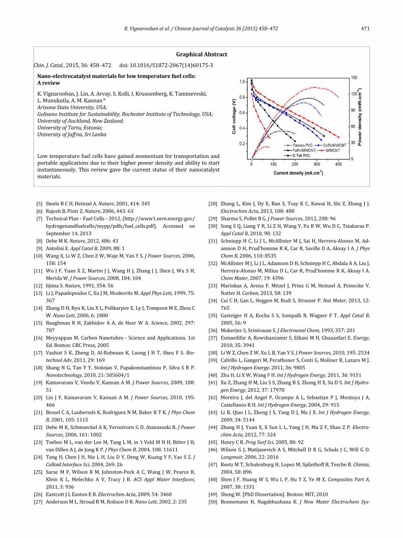
WehavedevelopedCo‐andFe‐phthalocyanines(CoPcandFePc)based‐cathodesandevaluatedthealkalinefuelcellusingaTokuyamamembrane(#A201).AscanbeseenfromtheFig.11 [98], the Tanaka Pt/C catalyst showed the highest perfor‐mance (~120 mW cm–2). CoPc/MWCNT performed almost(power density 100 mW cm–2) as well as the E‐TEK cata‐lyst‐basedMEAs.However,theFePc/MWCNTsbasedMEAonlyshowed about 60 mW cm–2 under identical operating condi‐tions.
6. Nanocatalystcharacterizationtechniques
The characterization of nanocatalysts is carried out bothunder ex situ aswell as in situ conditions.The following sec‐tions describe typical characterization methods like electron
Fig.9.ChemicalstructureofMN4andschematicrepresentationofthehybridcatalysts(ReproducedwithpermissionfromRef.[89]).
Fig.10.Rotatingdiskelectrodedataat1900rpmfortheoxygenreduc‐tion reaction for cobaltphthalocyanine/MWCNTannealedat400and800 °C in O2‐saturated 0.1mol/L KOH (Reproducedwith permissionfromRef.[97]).
Fig.11. FuelcellperformanceofMEAswithvariousmetallomacrocy‐cle/MWCNTcatalystsalongwithcommercialcatalystsbasedcathodesusing the Tokuyama’s A201 anion exchangemembrane (ReproducedwithpermissionfromRef.[98]).

K.Vignaroobanetal./ChineseJournalofCatalysis36(2015)458–472 467
microscopy,XRD,BETmethod,CV,andfuelcellperformance.
6.1. Catalystmorphologyanalysisbyelectronmicroscopy
SEMimagesshowtopographicalandelementalinformationdue to their superb resolution. They help to determine thechemical composition and structural changes of the fuel cellmaterialunderdifferentoperatingconditions.TheSEMprima‐ryimagingmethodoperatesbythecollectionofthesecondaryelectrons released by the sample. The SEM scans its electronbeam line by line over the sample instead of forming a realimage.TheTEMhastheadvantageof increasedmagnificationand resolution, and it can provide the “inside” image of thesampleratherthanthesurface.TEMbuildsanimagebywayofdifferentialcontrastanditformsblackandwhiteimages.TEMhasaspatialresolutionontheorderofafewAngstroms,anditismainlyusedtoanalyzethestructure,compositionandprop‐ertiesofaspecimen.
6.2. Catalystcompositionandphaseanalysis
X‐ray diffraction (XRD) is a non‐destructive technique tocharacterize materials in terms of chemical composition andcrystallographic structure. X‐ray diffraction takes place fromlattice planes based on Bragg’s Law. By scanning a range ofanglesofreflection,apatternofpeakswithdifferentintensitiesis identified.Planeswithhighelectrondensityhavestrongin‐tensityandreflectstrongly.Fig.12showstheXRDpatternofagraphiticcarbonnanofiber(GCNF)supportedPt‐Rualloysyn‐thesizedbySteigerwaltetal.[99].Itshowsthecompositepat‐tern of the catalyst’s Pt‐Ru peaks consistent with the FCCstructure(111).Electrondiffraction(ED)isacollectiveelasticscattering phenomenonwhere the electrons are scattered byatoms ina regulararray inacrystal.Whenan incomingelec‐tronwaveinteractswiththeatoms,secondarywavesaregen‐eratedandinterferewitheachotherandtheyformdiffractionpatterns. EDhas the benefit of the strong interaction of elec‐tronswith the sample because the electrons are scatteredbythepositivepotentialinsidetheelectroncloud,whereasX‐raysinteractwith theelectroncloud.ED isavaluable tool incrys‐
tallography and it can provide information about the crystalsymmetry of active catalytic components. Fig. 13 shows theTEM bright field images and electron diffraction patterns ofelectrodeposited Ni and Co nanowires in nanochannel mem‐brane filters from Ohgai et al. [100]. According to the TEMbright field images, the shape of the nanowires was almostcylindricalandtheelectrondiffractionpatternsarecomposedofspots,whichsuggestthatthenanowireconsistsofacrystal‐linephasewithapreferentialorientation.
6.3. Measurementsofthecatalystphysicalsurfaceareaandelectrochemicalactivesurfacearea
In1938,Brunauer,Emmett,andTeller[101]developedtheBET method to estimate the catalyst surface area. The BETmethodisbasedonthesurfaceareaofadsorbedgasmolecules.By measuring the amount of gas adsorbed by the sample atequilibrium,thesurfaceareaofthesamplecanbedetermined.N2ismostlyusedtomeasuretheBETsurface.ArorKrmayalsobeusedifthesurfaceareaissmall.Theelectrochemicalactivesurfacearea(ESA)ofaPt‐associatedcatalystcanbemeasuredby the electrochemical hydrogen adsorption/desorption ap‐proach.TheCVmethodisbasedontheformationofahydrogenmonolayerelectrochemicallyadsorbedon thecatalyst surface[102].Fig.14[51]showsatypicalCVofPt/CinH2SO4solution.Twowell‐resolvedpeaksonthecathodicsweepinthelowpo‐tentialarea(regionA)correspondedtohydrogendepositiononthe electrode surface.The electrochemical active surface area
20 25 30 35 40 45 50
2θ/(o)
Graphite003
RuOx
Ru100
Pt-Ru111
Ru101
Pt-Ru200In
ten
sity
Fig.12. XRD scanof aPt‐Ru/graphitic carbonnanofiber composition(ReproducedwithpermissionfromRef.[99]).
Fig.13.TEMbrightfieldimagesandelectrondiffractionpatternsofNi((a)and(c)respectively)andCo((b)and(d)respectively)nanowireselectrodeposited in nanochannelmembrane filters (ReproducedwithpermissionfromRef.[100]).

468 K.Vignaroobanetal./ChineseJournalofCatalysis36(2015)458–472
SESA(m2g–1)canbeestimatedbytheequation
SESA=Q(μCcm–2)/[Catalyst loading(mg cm–2)·210(μC cm–2)] (3)
whereSESA is theelectrochemicalsurfaceareaofcatalyst,Q isthechargedensityand210isaglobalchargeoftheadsorptionof ahydrogenmonolayeron apolycrystallinePt surface. It isworthwhile to note that thehydrogenpeaks canbeused notonlytomeasuretheactivesurfaceareaofacatalystbutalsoasan indicator to qualitatively estimate the purity of the Pt/Ccatalyst.
6.4. Catalystsurfaceandcomposition
XPSemploysX‐raytubeswithaluminumormagnesiuman‐odes.Itcanbeusedtostudytheelectronsinbothvalencebandand core states because the X‐rays have sufficient energy toionizethecorelevelsinallelements.XPSisusedtoidentifytheatomsatthesurfacebycomparingtheobservedlineswithei‐thercalculatedcorelevelbindingenergyorexperimentalspec‐
trafromstandards.XPSanalysiscanprovideinformationabouttheelementalsurfacecompositionofthecatalyst,theoxidationstateof anatom, the chemicalenvironment, and so forth.Fig.15showstheXPSspectraofaPt‐associatedcatalystalloyandcore‐shellcatalysts reportedbyGaoetal. [103].ThemetalPt4f7/2 lines for Ru@Pt1Pd1/C, Ru@Pt2Pd1/C and Ru@Pt1Pd2/Coccurat71.26,71.34,and71.14eV,respectively,whereasthemetal Pt 4f5/2 lines are at 74.55, 74.65, and 74.49 eV respec‐tively. The Pt binding energies of theRu@PtxPdy/C core‐shellcatalystsarehigherthanthoseofPt2Pd1/C,indicatinganinter‐actionbetweenRuandPtxPdy.ThepercentagesofPtinthezerovalence state for Ru@Pt1Pd2/C, Ru@Pt1Pd1/C andRu@Pt2Pd1/CarehigherthanthatinPt2Pd1/C(71.2%),andare74.6%,75.8%,and80.4%,respectively,andincreasedwiththeincreaseofPtcontent.
Electronsscatteredwithintheexcitationvolumeofaspeci‐mendepositenergyinmanyatomsandtheatomreleasesdis‐tinctquantumenergywhentheyreturntothegroundstate.Ifthe excited atomejects an inner‐shell electron, an outer‐shellelectron fills that vacancy and emits an X‐ray having energyequal to the difference between the two electron shells. De‐tectionoftheX‐raysemittedbythespecimenduringtheelec‐tron‐beamexcitation isknownas the energydispersive spec‐troscopy(EDS).EDS isgenerallyassociatedwithSEMorTEManalysis andprovides further information about the chemicalcompositionforselectedregionsofthesurface.TheEDStech‐niquehasbeenextensivelyusedinmetalalloycatalystcharac‐terizationtodeterminetherelativeamountsofindividualmet‐alspeciesinthecatalyst.Fig.16showsabroadareaEDSspec‐trumofaPt‐Rualloycatalystdepositedonagraphiticcarbonnanofiber[99].TherelativeintensityoftheappropriatepairsofPtandRuemissionsgivethePt/Rustoichiometryandatomicratio.TheCuemissionwasattributedtothecoppergridofthesample holder and the Si emission was derived from traceamountsofthecarbonnanofibergrowthsupport.
Fig. 14. Electrochemical characterization of a Pt(40 wt%)/VulcanXC‐72catalystinN2‐saturated0.5mol/LH2SO4electrolytewithascanrateof20mVs–1(ReproducedwithpermissionfromRef.[51]).
Fig.15.XPSspectraofPt(a–d),Pd(e),andRu(f)nanocatalysts(ReproducedwithpermissionfromRef.[103]).

K.Vignaroobanetal./ChineseJournalofCatalysis36(2015)458–472 469
6.5. Half‐cellelectrodeperformance
Even though ex situ methods are very important processcontroltools,insitumethodsareneededforunderstandingthenanocatalysts under actual fuel cell operating conditions inacidicandalkalinemedia.Catalystpropertiessuchasreductioncurrentbytherotatingdiskelectrode,electrochemicallyactivesurfaceareabycyclicvoltammetry,structuraldeformationandparticle size growth, electrochemical impedance, oxidationand/or dissolution and durability (accelerated cycling) byvoltage cycling and also actual single electrode performance(both for fuel oxidation and oxidant reduction) can be deter‐mined by in situmethods. These characterization techniquesalsofocusonmeasuringtheeffectoftheothercomponentsofthefuelcellonthecatalysts.Theinsitucharacterizationofthenanocatalysts can be conducted by assembling and studyingthethreeelectrodehalfcellsorsinglecellfuelcells.Galvanos‐tatic or potentiostatic polarization methods can be used tocharacterizenanocatalysts at variousRH conditions and tem‐peraturesusingdissolvedoxygenintheelectrolytewithoxygenblanketinhalfcellsinacidicoralkalinemedia.Inaddition,thefollowing in situ techniques can be used to characterize thenanoelectrocatalysts.
7. Electrochemicalperformanceanddurabilityofnano‐electrocatalysts
Nano‐electrocatalysts are evaluatedbothby ex situ and insitumethodsforperformanceaswellasdurability.Thefollow‐ing sub‐sectionsdescribe nanocatalyst characterization in theMEA for fuel cell performance and durability by acceleratedmethods.
7.1. Fuelcellperformanceofnano‐electrocatalysts
Polarizationcurvesareoneofthemostcommonmethodstomeasure the performanceof a PEMFC. It is a non‐destructivetestwhichgeneratesachartthatplotstherelationshipbetweencurrentdensityandvoltage.Thistestcanbeveryeffectiveforassessingtherealworldperformanceofafullyassembledsys‐temas it includestheinteractionsbetweenindividualcompo‐nents.Unfortunately, thisalsomeansthatthereducedperfor‐
manceofacellcannotbeclearlyattributedtoaparticularfail‐ing component.Polarizationcurves canbe compared throughthousandsofcyclesandasimplequantitativemeasureofper‐formancedegradationovertimecanbemade[104].
As described in section 6.3, the electrochemically activesurface area (ESA) and Pt loading are two other importantperformance measures. Increasing the ESA improves perfor‐mancebycreatinga largersurfaceareawherechemicalreac‐tionscantakeplace.ThePtloadingreferstotheweightaswellasthedistributionandisusuallyexpressedintermsofµgcm–2.HigherPtloadingswiththesamecatalystmaterialwillcreateathicker layerof theporous catalystmaterial andwill thus in‐crease theESA,whichwill increase theperformance ina fuelcell.Ptisarareandexpensivemetal,soitisimportanttomini‐mize the amount of Pt required. Reduction of the Pt loadingwhilemaintaining the same performance is an area of activeresearch.
7.2. Durabilityevaluationofnano‐electrocatalysts
DurabilityinPEMFCsisusuallyanexpressionoftheabilitytomaintain performance over time. A fuel cell that is highlydurablewillbeabletomaintaininitialperformancecharacter‐isticsafterlongperiodsofintermittentorcontinuoususe.Du‐rability canalso refer to the abilityof the system tomaintainperformance after uncommon events such as mechanicalshock, extreme high or low temperature, or varied humidityconditions. Current US Department of Energy targets fortransportationapplicationsinclude5000hofoperation,whichis theequivalentof150000miles travelled.Thereareseveralknown degradation mechanisms of nanocatalysts, which areactivelyresearched. Thedominantformofdegradationinthecatalystlayerisplatinumparticledissolution.Manydepositiontechniques rely on suspending the Pt particles in an ionomersolution,whichisthendepositeduniformlyonthemembrane.DissolutioncausesPtparticlestodiffuse,throughamechanismknown as Ostwald ripening, and form agglomerates withneighboringparticles(Fig.17).Theseparticleshavealsobeenobserved tomigrate into themembrane to formabandofPtparticles. These processes cause a reduction in the electro‐chemically active surface area and gradually reduce the per‐formanceofaPEMFC[105].
Inte
nsi
ty
0 5 10 15 20
Energy (keV)
Pt
Ru
Cu
Pt
Pt
PtRu
SiCu
Fig.16.BroadareaEDSspectrumofPt‐Ru/graphiticcarbonnanofiber(ReproducedwithpermissionfromRef.[99]).
Fig.17. Schematic illustration of Pt nanoparticle growth through (a)Ostwald ripening and (b) particle agglomeration (Reproduced withpermissionfromRef.[105]).

470 K.Vignaroobanetal./ChineseJournalofCatalysis36(2015)458–472
Othersourcesofperformancelossincludesubstratedegra‐dationandadsorptionofcontaminants fromexternalsources.Ptparticles aredispersedonahighlyporous carbonblackoranothermaterial. This support material must be highly elec‐tronicallyconductive,maintainahighsurfacearea,andbehy‐drophobic. Corrosion of the carbon substrate can lead to re‐ducedconductivity.Thisisespeciallyproblematicinpurecar‐bonsubstrates,whicharesusceptibletocorrosionattheoper‐atingconditionstypicallyfoundinPEMFCs.Hightemperaturesincreasetheoxidationrateofthecarbonsupport.Thesubstratecan also be subjected to physical stresses during the freeze‐thawcycles.Adsorptionofexternalcontaminantssuchascar‐bon monoxide is particularly important when reformed hy‐drogenisusedasthefuel[106].Contaminationcanalsocomefromthebyproductsofcorrosioninvariousothercomponentsof the fuel cell. There are severalmethods formeasuring thedegradation of the nanocatalyst. One of the most commonmethods is the use of CV. This method uses a potentiostat/galvanostatandafunctiongeneratortosimulateloadchangingand generally scans from1.0 to 0.4V. These CV scans give aqualitativemeasurement of the ESA,which can be comparedacrosscyclestogivesomeinsightintothenatureofthechangeswithin the cell such as corrosion or increasing particle size[104,107].Fig. 18 [53] shows theCVdata aswell as the esti‐matedESAwithcyclenumberforPt/MWCNTsinPEMFCs.
Direct measurement of catalyst layer degradation can beperformedusingelectronmicroscopy.ImagesproducedeitherbySEMorTEMhavehighenoughresolutiontoshowplatinumagglomeration. Particle size distributions can be generatedfromtheseimages.Theinitial imagescanbecomparedto im‐ages taken thousands of cycles later and compared. Studiesusing this technique have shown that agglomeration and de‐tachment are among the primary causes of catalyst degrada‐tion.
8. Conclusions
Electrocatalystsare thekey in theperformance,durability,reliability and cost that limit the commercial viability of fuelcells.Thisreviewbroughttogethersynthesisandcharacteriza‐tionmethodsfornanocatalystsforprotonexchangemembranefuelcellsandalkalinemembranefuelcells.Toimprovecatalystutilizationandreducecatalystloading(andcost),variouscata‐lyst support materials are explored in the literature, but thecommercialcatalystsstillemployVulcanXCoranotherspheri‐calcarbonduetotheirsimplesynthesisprocessandrelativelylower costs. Numerous synthesis methods for nanocatalystpreparation such as chemical, colloidal, sol‐gel, impregnation,microemulsionmethods,andelectrodeposition,spraypyrolysisandvapordepositionarewelldocumentedintheliterature.Allthemethodshaveadvantagesanddisadvantagesrelatedtotheperformance and durability of the nanocatalysts. The reviewalsodiscussedthedurabilityevaluationofnanocatalystsasoneofthereliableinsituacceleratedtestmethods.
Acknowledgments
AMKacknowledgesfinancialsupportfromtheArizonaStateUniversity.References
[1] SchellA,PengH,TranD,StamosE,LinC,KimM.AnnualRevCon‐trol,2005,29(1):159
[2] EG>echnicalServicesInc.FuelCellHandbook.7thEd.WestVirginia,USA:USDepartmentofEnergy,2004
[3] SinghalSC.ElectrochemSocInterface,2007,16(4):41[4] Slade S, Campbell S A, Ralph T R,Walsh F C. JElectrochem Soc,
2002,149:A1556
Fig.18.(a–c)CyclicvoltammogramsofdifferentPt/MWCNTcathodematerialsand(d)thecorrespondingchangesintheelectrochemicallyactivesurfaceareawithpotentialcycling(ReproducedwithpermissionfromRef.[53]).
K.Vignaroobanetal./ChineseJournalofCatalysis36(2015)458–472 471
[5] SteeleBCH,HeinzelA.Nature,2001,414:345[6] RajeshB,PiotrZ.Nature,2006,443:63[7] TechnicalPlan‐FuelCells‐2012,(http://www1.eere.energy.gov/
hydrogenandfuelcells/mypp/pdfs/fuel_cells.pdf), Accessed onSeptember14,2013
[8] DebeMK.Nature,2012,486:43[9] AntoliniE.ApplCatalB,2009,88:1[10] WangX,LiWZ,ChenZW,WajeM,YanYS.JPowerSources,2006,
158:154[11] WuJF,YuanXZ,MartinJJ,WangHJ,ZhangJJ,ShenJ,WuSH,
MeridaW.JPowerSources,2008,184:104[12] IijimaS.Nature,1991,354:56[13] LiJ,PapadopoulosC,XuJM,MoskovitsM.ApplPhysLett,1999,75:
367[14] ZhangDH,RyuK,LiuXL,PolikarpovE,LyJ,TompsonME,ZhouC
W.NanoLett,2006,6:1880[15] BaughmanRH,ZakhidovAA,deHeerWA.Science, 2002,297:
787[16] MeyyappanM.CarbonNanotubes‐ScienceandApplications.1st
Ed.Boston:CRCPress,2005[17] Vashist SK, ZhengD,Al‐RubeaanK, Luong JHT, SheuF S.Bio‐
technolAdv,2011,29:169[18] ShangNG,TanYY, StolojanV,PapakonstantinouP,SilvaSRP.
Nanotechnology,2010,21:505604/1[19] KamavaramV,VeeduV,KannanAM.JPowerSources,2009,188:
51[20] Lin JF,KamavaramV,KannanAM. JPowerSources, 2010,195:
466[21] BesselCA,LauberndsK,RodriguezNM,BakerRTK.JPhysChem
B,2001,105:1115[22] DebeMK,SchmoeckelAK,VernstrornGD,AtanasoskiR.JPower
Sources,2006,161:1002[23] ToebesML,vanderLeeM,TangLM,in'tVeldMHH,BitterJH,
vanDillenAJ,deJongKP.JPhysChemB,2004,108:11611[24] TangH,ChenJH,NieLH,LiuDY,DengW,KuangYF,YaoSZ.J
ColloidInterfaceSci,2004,269:26[25] SaracMF,WilsonRM, Johnston‐PeckAC,Wang JW,PearceR,
Klein K L, Melechko A V, Tracy J B. ACS ApplMater Interfaces,2011,3:936
[26] EastcottJI,EastonEB.ElectrochimActa,2009,54:3460[27] AndersonML,StroudRM,RolisonDR.NanoLett,2002,2:235
[28] ZhangL,Kim J,DyE,BanS,TsayKC,KawaiH, ShiZ,Zhang J J.ElectrochimActa,2013,108:480
[29] SharmaS,PolletBG.JPowerSources,2012,208:96[30] SongSQ,LiangYR,LiZH,WangY,FuRW,WuDC,TsiakarasP.
ApplCatalB,2010,98:132[31] SchnieppHC,LiJL,McAllisterMJ,SaiH,Herrera‐AlonsoM,Ad‐
amsonDH,Prud'hommeRK,CarR,SavilleDA,AksayIA.JPhysChemB,2006,110:8535
[32] McAllisterMJ,LiJL,AdamsonDH,SchnieppHC,AbdalaAA,LiuJ,Herrera‐AlonsoM,MiliusDL,CarR,Prud'hommeRK,AksayIA.ChemMater,2007,19:4396
[33] MarinkasA,Arena F,Mitzel J, PrinzGM,HeinzelA, PeineckeV,NatterH.Carbon,2013,58:139
[34] CuiCH,GanL,HeggenM,RudiS,StrasserP.NatMater,2013,12:765
[35] GasteigerHA,Kocha S S, Sompalli B,Wagner FT.ApplCatalB,2005,56:9
[36] MukerjeeS,SrinivasanS.JElectroanalChem,1993,357:201[37] EsmaeilifarA,RowshanzamirS,EikaniMH,GhazanfariE.Energy,
2010,35:3941[38] LiWZ,ChenZW,XuLB,YanYS.JPowerSources,2010,195:2534[39] CalvilloL,GangeriM,PerathonerS,CentiG,MolinerR,LazaroMJ.
IntJHydrogenEnergy,2011,36:9805[40] ZhuH,LiXW,WangFH.IntJHydrogenEnergy,2011,36:9151[41] XuZ,ZhangHM,LiuSS,ZhangBS,ZhongHX,SuDS.IntJHydro‐
genEnergy,2012,37:17978[42] Moreira J, del Angel P, OcampoA L, Sebastian P J,Montoya J A,
CastellanosRH.IntJHydrogenEnergy,2004,29:915[43] LiB,QiaoJL,ZhengJS,YangDJ,Ma JX. Int JHydrogenEnergy,
2009,34:5144[44] ZhangHJ,YuanX,XSunLL,YangJH,MaZF,ShaoZP.Electro‐
chimActa,2012,77:324[45] HenryCR.ProgSurfSci,2005,80:92[46] WilsonGJ,MatijasevichAS,MitchellDRG,Schulz JC,WillGD.
Langmuir,2006,22:2016[47] ReetzMT,SchulenburgH,LopezM,SpliethoffB,TescheB.Chimia,
2004,58:896[48] ShenJF,HuangWS,WuLP,HuYZ,YeMX.CompositesPartA,
2007,38:1331[49] ShengW.[PhDDissertation].Boston:MIT,2010[50] Bonnemann H, Nagabhushana K. JNewMater Electrochem Sys‐
GraphicalAbstract
Chin.J.Catal.,2015,36:458–472 doi:10.1016/S1872‐2067(14)60175‐3
Nano‐electrocatalystmaterialsforlowtemperaturefuelcells: Areview
K.Vignarooban,J.Lin,A.Arvay,S.Kolli,I.Kruusenberg,K.Tammeveski, L.Munukutla,A.M.Kannan*ArizonaStateUniversity,USA; GolisanoInstituteforSustainability,RochesterInstituteofTechnology,USA;UniversityofAuckland,NewZealand; UniversityofTartu,Estonia;UniversityofJaffna,SriLanka
Lowtemperaturefuelcellshavegainedmomentumfortransportationandportableapplicationsduetotheirhigherpowerdensityandabilitytostartinstantaneously. This reviewgave the current status of theirnanocatalystmaterials.

472 K.Vignaroobanetal./ChineseJournalofCatalysis36(2015)458–472
tems,2004,7(2):93[51] HashimAA. TheDeliveryofNanoparticles. Chapter19.Croatia:
InTech,2012.406[52] Grolleau C, Coutanceau C, Pierre F, Leger J M.ElectrochimActa,
2008,53:7157[53] LinJF,AdameA,KannanAM.JElectrochemSoc,2010,157:B846[54] BronsteinLM.TopCurrChem,2003,226:55[55] LiuB,CreagerS.JPowerSources,2010,195:1812[56] ZhangY,ErkeyC.JSupercriticalFluids,2006,38:252[57] LinJF,MasonCW,AdameA,LiuX,PengXH,KannanAM.Elec‐
trochimActa,2010,55:6496[58] Harish S, Baranton S, Coutanceau C, Joseph J. J Power Sources,
2012,214:33[59] FievetF,LagierJP,BlinB,BeaudoinB,FiglarzM.SolidStateIonics,
1989,32‐33:198[60] LiuZL,GanLM,HongL,ChenWX,LeeJY.JPowerSources,2005,
139:73[61] LebegueE,BarantonS,CoutanceauC.JPowerSources,2011,196:
920[62] WhiteRJ,LuqueR,BudarinVL,ClarkJH,MacquarrieDJ.Chem
SocRev,2009,38:481[63] SaminathanK,KamavaramV,VeeduV,KannanAM.IntJHydro‐
genEnergy,2009,34:3838[64] MehtaV,CooperJS.JPowerSources,2003,114:32[65] JungDS,ParkSB,KangYC.KoreanJChemEng,2010,27:1621[66] MorseJD,JankowskiAF,GraffRT,HayesJP.JVacuumSciTechnol
A,2000,18:2003[67] Girishkumar G, Rettker M, Underhile R, Binz D, Vinodgopal K,
McGinnP,KamatP.Langmuir,2005,21:8487[68] WeeJH,LeeKY,KimSH.JPowerSources,2007,165:667[69] BasuD,BasuS.ElectrochimActa,2011,56:7758[70] Tamasauskaite‐Tamasiunaite L, BalciunaiteA, VaiciukevicieneA,
SelskisA,PakstasV.JPowerSources,2012,208:242[71] RameshKV,ShuklaAK.JPowerSources,1987,19:279[72] Zhiani M, Gasteiger H A, Piana M, Catanorchi S. Int JHydrogen
Energy,2011,36:5110[73] LaiCL,KollaP,ZhaoY,FongH,SmirnovaAL.ElectrochimActa,
2014,130:431[74] JasinskiRJ.Nature,1964,201:1212[75] ZagalJH.CoordChemRev,1992,119:89[76] Vasudevan P, Santosh, Mann N, Tyagi S. TransitionMetal Chem,
1990,15:81[77] SchillingT,OkunolaA,MasaJ,SchuhmannW,BronM.Electrochim
Acta,2010,55:7597[78] TarasevichMR,ZhutaevaGV,RadinaMV,KarichevZR,TeishevE
A,MinersJH,GoueresP,Sanchez‐CorteronE.RussJElectrochem,2003,39:1094
[79] BakerR,WilkinsonD P, Zhang J J.ElectrochimActa, 2008, 53:6906
[80] ZagalJ,PaezM,TanakaAA,DosSantosJuniorJR,LinkousCA.JElectroanalChem,1992,339:13
[81] RamirezG,TrollundE,IsaacsM,ArmijoF,ZagalJ,CostamagnaJ,AguirreMJ.Electroanalysis,2002,14:540
[82] TseYH,JandaP,LamH,ZhangJJ,PietroWJ,LeverABP.JPor‐phyrinsPhthalocyanines,1997,1(1):3
[83] CollmanJP,ElliottCM,HalbertTR,TovrogBS.ProcNatAcadSciUSA,1977,74:18
[84] DurandRR,BencosmeCS,CollmanJP,AnsonFC. JAmChemSoc,1983,105:2710
[85] TanakaAA,FierroC,SchersonDA,YeagerE.MaterChemPhys,1989,22:431
[86] DingL,DaiXF,LinR,WangHJ,QiaoJL.JElectrochemSoc,2012,159:F577
[87] KruusenbergI,MondalJ,MatisenL,SammelselgV,TammeveskiK.ElectrochemCommun,2013,33:18
[88] ZagalJH,GriveauS,OzoemenaKI,NyokongT,BediouiF.JNa‐nosciNanotechnol,2009,9:2201
[89] Morozan A, Campidelli S, Filoramo A, Jousselme B, Palacin S.Carbon,2011,49:4839
[90] KruusenbergI,MatisenL,TammeveskiK.JNanosciNanotechnol,2013,13:621
[91] OkunolaA,KowalewskaB,BronM,KuleszaPJ,SchuhmannW.ElectrochimActa,2009,54:1954
[92] YamazakiS,YamadaY,IoroiT,FujiwaraN,SiromaZ,YasudaK,MiyazakiY.JElectroanalChem,2005,576:253
[93] MamuruSA,OzoemenaKI.Electroanalysis,2010,22:985[94] LalandeG, CoteR, GuayD,Dodelet J P,Weng LT, BertrandP.
ElectrochimActa,1997,42:1379[95] JahnkeH,SchonbornM.,ZimmermannG.TopCurrChem,1976,
61:133[96] RamavathuLN,ManiamKK,GopalramK,ChettyR.JApplElec‐
trochem,2012,42:945[97] KruusenbergI,MatisenL,TammeveskiK. Int JElectrochemSci,
2013,8(1):1057[98] KruusenbergI,MatisenL,ShahQ,KannanAM,TammeveskiK.
IntJHydrogenEnergy,2012,37:4406[99] SteigerwaltES,DelugaGA,CliffelDE,LukehartCM.JPhysChem
B,2001,105:8097[100] OhgaiT.In:PengXHed.Nanowires‐RecentAdvances.Shang‐
hai,China:InTech,2012.101[101] BrunauerS,EmmettPH,TellerE.JAmChemSoc,1938,60:309[102] PozioA,FrancescoMD,CemmiA,CardelliniF,GiorgiL.JPower
Sources,2002,105:13[103] GaoH L, Liao S J, Zeng J H, Xie Y C, DangD.ElectrochimActa,
2011,56:2024[104] OhyagiS,MatsudaT,IsekiY,SasakiT,KaitoC. JPowerSources,
2011,196:3743[105] MenchM,KumburEC,VezirogluTN.PolymerElectrolyteFuel
CellDegradation.Oxford:Elsevier,2011.472[106] BellowsRJ,MarucchiSoosEP,BuckleyDT. IndEngChemRes,
1996,35:1235[107] OhyagiS,SasakiT.ElectrochimActa,2013,102:336