myanmar national building code 2020 - mlr company limited
TRANSCRIPT
PART 3 - STRUCTURAL DESIGN
PART 4 - SOIL AND FOUNDATION
MYANMAR
NATIONAL
BUILDING
CODE -
2020
MINISTRY OF CONSTRUCTION
THE REPUBLIC OF THE UNION OF MYANMAR
JUNE, 2020
PART 3 - STRUCTURAL DESIGN
PART 4 - SOIL AND FOUNDATION
MYANMAR NATIONAL BUILDING CODE
2020
MINISTRY OF CONSTRUCTION
THE REPUBLIC OF THE UNION OF MYANMAR

Printing Record
Printing - First Printing, June, 2020
Publisher - Published by
International Relation and Legal Section
Department of Building
Ministry of Construction
Printed Number - 500
MYANMAR
NATIONAL
BUILDING
CODE
2020
PART 3
STRUCTURAL DESIGN
i
CONTENTS
NO. TITLE PAGE
3.1 GENERAL
3.1.1 Definitions and Notation ................................................................................1-3
3.1.1.1 Definitions
3.1.1.2 Notation
3.1.2 Construction Documents .................................................................................3-5
3.1.2.1 General
3.1.2.1.1 Floor Live Load
3.1.2.1.2 Roof Live Load
3.1.2.1.3 Wind Design Data
3.1.2.1.4 Earthquake Design Data
3.1.2.1.5 Special Loads
3.1.2.1.6 Material Properties
3.1.2.1.7 Soil and Foundation Data
3.1.2.2 Systems and Components Requiring Special Inspections for Seismic
Resistance
3.1.2.3 Restrictions on Loading
3.1.2.4 Live Loads Posted
3.1.2.5 Occupancy Permits for Changed Loads
3.1.3 General Design Requirements .........................................................................5-10
3.1.3.1 General
3.1.3.2 Strength
3.1.3.3 Serviceability
3.1.3.3.1 Deflections
3.1.3.3.2 Reinforced Concrete
3.1.3.3.3 Steel
3.1.3.3.4 Masonry
3.1.3.3.5 Aluminum
3.1.3.3.6 Limits
3.1.3.4 Analysis
3.1.3.5 Occupancy Category
3.1.3.5.1 Multiple Occupancies
3.1.3.6 In-Situ Load Tests
3.1.3.7 Preconstruction Load Tests
3.1.3.8 Anchorage
3.1.3.8.1 General
3.1.3.8.2 Concrete and Masonry Walls
3.1.3.9 Decks
3.1.3.10 Counteracting Structural Actions
3.1.3.11 Wind and Seismic Detailing

ii
3.2 LOAD COMBINATIONS AND LOADS
3.2.1 Load Combinations .........................................................................................11-13
3.2.1.1 General
3.2.1.2 Combining Factored Loads Using Strength Design or Load and Resistance
Factor Design
3.2.1.2.1 Applicability
3.2.1.2.2 Basic Load Combinations
3.2.1.2.3 Load Combinations Including Flood Load
3.2.1.3 Combining Nominal Loads Using Allowable Stress Design or Working Stress
Design
3.2.1.3.1 Basic Load Combinations
3.2.1.3.2 Stress Increases
3.2.1.3.3 Load Combinations Including Flood Load
3.2.1.4 Load Combinations for Extraordinary Events
3.2.1.5 Special Seismic Load Combinations
3.2.2 Dead Loads, Soil Loads and Hydrostatic Pressure ..........................................13-15
3.2.2.1 Dead Loads
3.2.2.1.1 Definition
3.2.2.1.2 Weights of Materials and Constructions
3.2.2.1.3 Weight of Fixed Service Equipment
3.2.2.2 Soil Loads and Hydrostatic Pressure
3.2.2.2.1 Lateral Pressures
3.2.2.2.2 Uplift on Floors and Foundations
3.2.3 Live Loads .......................................................................................................15-27
3.2.3.1 Definitions
3.2.3.2 Uniformly Distributed Loads
3.2.3.2.1 Required Live Loads
3.2.3.2.2 Provision for Partitions
3.2.3.3 Concentrated Loads
3.2.3.4 Truck and Bus Garages
3.2.3.4.1 Truck and Bus Garage Live Load Application
3.2.3.5 Loads on Handrails, Guardrail Systems, Grab Bar Systems, Vehicle Barrier
Systems, and Fixed Ladders
3.2.3.5.1 Loads on Handrails and Guardrail Systems
3.2.3.5.2 Loads on Grab Bar Systems
3.2.3.5.3 Loads on Vehicle Barrier Systems
3.2.3.5.4 Loads on Fixed Ladders
3.2.3.6 Loads Not Specified
3.2.3.7 Partial Loading
3.2.3.8 Impact Loads
3.2.3.8.1 Elevators
3.2.3.8.2 Machinery
3.2.3.9 Reduction in Live Loads
iii
3.2.3.9.1 General
3.2.3.9.1.1 Heavy Live Loads
3.2.3.9.1.2 Passenger Car Garages
3.2.3.9.1.3 Special Occupancies
3.2.3.9.1.4 Special Structural Elements
3.2.3.9.2 Alternative Floor Live Load Reduction
3.2.3.10 Distribution of Floor Loads
3.2.3.11 Roof Loads
3.2.3.11.1 Distribution of Roof Loads
3.2.3.11.2 Reduction in Roof Live Loads
3.2.3.11.2.1 Flat, Pitched, and Curved Roofs
3.2.3.11.2.2 Special Purpose Roofs
3.2.3.11.2.3 Landscaped Roofs
3.2.3.11.2.4 Awnings and Canopies
3.2.3.12 Crane Loads
3.2.3.12.1 Maximum Wheel Load
3.2.3.12.2 Vertical Impact Force
3.2.3.12.3 Lateral Force
3.2.3.12.4 Longitudinal Force
3.2.3.13 Interior Walls and Partitions
3.2.3.13.1 Fabric Partition
3.2.4 Rain Loads .......................................................................................................27-28
3.2.4.1 Symbols and Notation
3.2.4.2 Roof Drainage
3.2.4.3 Design Rain Loads
3.2.4.4 Ponding Instability
3.2.4.5 Controlled Drainage
3.2.5 Flood Loads .....................................................................................................28-34
3.2.5.1 General
3.2.5.2 Definitions
3.2.5.3 Design Requirements
3.2.5.3.1 Design Loads
3.2.5.3.2 Erosion and Scour
3.2.5.3.3 Loads on Breakaway Walls
3.2.5.4 Loads During Flooding
3.2.5.4.1 Load Basis
3.2.5.4.2 Hydrostatic Loads
3.2.5.4.3 Hydrodynamic Loads
3.2.5.4.4 Wave Loads
3.2.5.4.4.1 Breaking Wave Loads on Vertical Pilings and Columns
3.2.5.4.4.2 Breaking Wave Loads on Vertical Walls
3.2.5.4.4.3 Breaking Wave Loads on Nonvertical Walls
3.2.5.4.4.4 Breaking Wave Loads from Obliquely Incident Waves
3.2.5.4.5 Impact Loads
iv
3.3 WIND DESIGN CRITERIA
3.3.1 General ............................................................................................................35
3.3.1.1 Scope
3.3.1.2 Allowed Procedures
3.3.1.3 Wind Pressures Acting on Opposite Faces of Each Building Surface
3.3.1.4 Minimum Design Wind Loading
3.3.1.4.1 Main Wind-Force Resisting System
3.3.1.4.2 Components and Cladding
3.3.2 Definitions .......................................................................................................35-37
3.3.3 Symbols and Notation .....................................................................................38-41
3.3.4 Method 1 – Simplified Procedure ...................................................................41-57
3.3.4.1 Scope
3.3.4.1.1 Main Wind-Force Resisting Systems
3.3.4.1.2 Components and Cladding
3.3.4.2 Design Procedure
3.3.4.2.1 Main Wind-Force Resisting System
3.3.4.2.1.1 Minimum Pressures
3.3.4.2.2 Components and Cladding
3.3.4.2.2.1 Minimum Pressures
3.3.4.3 Air Permeable Cladding
3.3.4.4 Basic Wind Speed
3.3.4.4.1 Special Wind Regions
3.3.4.4.2 Estimation of Basic Wind Speeds from Regional Climatic Data
3.3.4.5 Importance Factor
3.3.4.6 Exposure
3.3.4.6.1 Wind Directions and Sectors
3.3.4.6.2 Surface Roughness Categories
3.3.4.6.3 Exposure Categories
3.3.4.7 Topographic Effects
3.3.4.7.1 Wind Speed-Up Over Hills, Ridges, and Escarpments
3.3.4.7.2 Topographic Factor
3.4 SEISMIC DESIGN CRITERIA AND DESIGN REQUIREMENTS FOR
BUILDINGS
3.4.1 Seismic Design Criteria ...................................................................................58-79
3.4.1.1 General
3.4.1.1.1 Purpose
3.4.1.1.2 Scope
3.4.1.1.3 Applicability
3.4.1.1.4 Alternate Materials and Methods of Construction
3.4.1.2 Definitions
3.4.1.3 Notation
v
3.4.1.4 Seismic Ground Motion Values
3.4.1.4.1 Specified Acceleration Parameters
3.4.1.4.2 Site Class Definitions
3.4.1.4.3 Site Coefficients and Adjusted Maximum Considered Earthquake
(MCE) Spectral Response Acceleration Parameters
3.4.1.4.4 Design Spectral Acceleration Parameters
3.4.1.4.5 Design Response Spectrum
3.4.1.4.6 MCE Response Spectrum
3.4.1.4.7 Site-Specific Ground Motion Procedures
3.4.1.4.8 Site Classification for Seismic Design
3.4.1.4.8.1 Steps for Classifying a Site
3.4.1.5 Importance Factor and Occupancy Category
3.4.1.5.1 Importance Factor
3.4.1.5.2 Protected Access for Occupancy Category IV
3.4.1.6 Seismic Design Category
3.4.1.6.1 Determination of Seismic Design Category
3.4.1.6.2 Alternative Seismic Design Category Determination
3.4.1.6.3 Simplified Design Procedure
3.4.2 Structural System Selection .............................................................................79-86
3.4.2.1 Selection and Limitations
3.4.2.2 Combinations of Framing Systems in Different Directions
3.4.2.3 Combinations of Framing Systems in the Same Direction
3.4.2.3.1.1 R, Cd, and Ω0 values for vertical combinations.
3.4.2.3.1.2 R, Cd, and Ω0 values for horizontal combinations.
3.4.2.4 Combination framing detailing requirements Modeling Criteria
3.4.2.5 System Specific Requirements
3.4.2.5.1 Dual System
3.4.2.5.2 Cantilever Column Systems
3.4.2.5.3 Inverted Pendulum-types Structures
3.4.2.5.4 Increased building height limit for steel braced frames and special
reinforced concrete shear walls
3.4.2.5.5 Special moment frames in structures assigned to Seismic Design
Categories D through F
3.4.2.5.6 Single-storey steel ordinary and intermediate moment frames in
structures assigned to Seismic Design Category D or E
3.4.2.5.7 Other steel ordinary and intermediate moment frames in structures
assigned to Seismic Design Category D or E
3.4.2.5.8 Single-storey steel ordinary and intermediate moment frames in
structures assigned to Seismic Design Category F
3.4.2.5.9 Other steel intermediate moment frame limitations in structures
assigned to Seismic Design Category F
3.4.2.5.10 Shear wall-frame interactive systems
3.4.3 Diaphragm Flexibility, Configuration Irregularities, and Redundancy…… ..86-91
3.4.3.1 Diaphragm flexibility
vi
3.4.3.1.1 Flexible diaphragm condition
3.4.3.1.2 Alternatives to ASCE 7
3.4.3.1.3 Rigid diaphragm condition
3.4.3.1.4 Calculated flexible diaphragm conditions
3.4.3.2 Irregular and regular classification
3.4.3.2.1 Horizontal Irregularity
3.4.3.2.2 Vertical Irregularity
3.4.3.3 Limitations and additional requirements for systems with structural
irregularities
3.4.3.3.1 Prohibited horizontal and vertical irregularities for Seismic Design
Categories D through F
3.4.3.3.2 Extreme weak storeys
3.4.3.3.3 Elements supporting discontinuous walls or frames
3.4.3.3.4 Increase in forces due to irregularities for Seismic Design Categories D
through F
3.4.3.4 Redundancy
3.4.3.4.1 Conditions where value of ρ is 1.0
3.4.3.4.2 Redundancy factor, ρ, for Seismic Design Categories D through F
3.4.4 Seismic Load Effects and Combinations .........................................................91-95
3.4.4.1 Applicability
3.4.4.2 Seismic load effect
3.4.4.2.1 Horizontal Seismic Load Effect
3.4.4.2.2 Vertical Seismic load effect
3.4.4.2.3 Seismic load combinations
3.4.4.3 Seismic Load effect including overstrength factor
3.4.4.3.1 Horizontal seismic load effect with overstrength factor
3.4.4.3.2 Load Combination with Overstrength factor
3.4.4.3.3 Allowable stress increase for load combination with overstrength
3.4.4.4 Minimum upward for horizontal cantilevers for Seismic Design Categories D
through F
3.4.5 Direction of Loading .......................................................................................95-96
3.4.5.1 Directional of loading Criteria
3.4.5.2 Seismic Design Category B
3.4.5.3 Seismic Design Category C
3.4.5.4 Seismic Design Categories D through F
3.4.6 Analysis Procedure Selection .........................................................................96
3.4.7 Modeling Criteria ...........................................................................................96-98
3.4.7.1 Foundation Modeling
3.4.7.2 Effective Seismic Weight
3.4.7.3 Structural Modeling
3.4.7.4 Interaction effects
3.4.8 Equivalent Lateral Force Procedure ...............................................................98-104
3.4.8.1 Seismic Base Shear
3.4.8.1.1 Seismic base shear
vii
3.4.8.1.2 Soil Structural Interaction reduction
3.4.8.1.3 Maximum Ss Value in Determination of Cs
3.4.8.2 Period Determination
3.4.8.2.1 Approximate Fundamental Period
3.4.8.3 Vertical Distribution of Seismic Forces
3.4.8.4 Horizontal Distribution of Forces
3.4.8.4.1 Inherent Torsion
3.4.8.4.2 Accidental Torsion
3.4.8.4.3 Amplification of Accidental Torsional Moment
3.4.8.5 Overturning
3.4.8.6 Storey Drift Determination
3.4.8.6.1 Minimum Base Shear For Computing Drift
3.4.8.6.2 Period For Computing Drift
3.4.8.7 P-Delta Effects
3.4.9 Modal Response Spectrum Analysis ..............................................................104-105
3.4.9.1 Number of Modes
3.4.9.2 Modal Response parameters
3.4.9.3 Combined Response Parameters
3.4.9.4 Scaling Design Values of Combined Response
3.4.9.5 Horizontal Shear Distribution
3.4.9.6 P-Delta Effects
3.4.9.7 Soil Structure Interaction Reduction
3.4.10 Diaphragms, Chords, and Collectors ..............................................................105-106
3.4.10.1 Diaphragm Design
3.4.10.1.1 Diaphragm Design Forces
3.4.10.2 Collector elements
3.4.10.2.1 Collector elements requiring load combinations with overstrength
factor for Seismic Design Categories C through F
3.4.11 Structural Walls and Their Anchorage ...........................................................107-108
3.4.11.1 Design for Out-of-plane Forces
3.4.11.2 Anchorage of Concrete Or Masonry Structural Walls
3.4.11.2.1 Anchorage of concrete or masonry structural walls to flexible
diaphragms
3.4.11.2.2 Additional requirements for diaphragms in structures assigned to
Seismic Design Categories C through F
3.4.11.2.2.1 Transfer of anchorage forces into diaphragm
3.4.11.2.2.2 Steel Elements of Structural wall anchorage system
3.4.11.2.2.3 Wood Diaphragms
3.4.11.2.2.4 Metal Deck Diaphragms
3.4.11.2.2.5 Embedded straps
3.4.11.2.2.6 Eccentrically Loaded anchorage system
3.4.11.2.2.7 Walls with pilasters
3.4.12 Storey Drift Limit ...........................................................................................108-110
3.4.12.1 Storey drift limit
viii
3.4.12.1.1 Moment Frame in Structures assigned to Seismic Design Categories D
through F
3.4.12.2 Diaphragm Deflection
3.4.12.3 Building Separation
3.4.12.4 Deformation Compatibility for Seismic Design Categories D through F
3.5 CONCRETE
3.5.1 General ............................................................................................................111
3.5.1.1 Scope
3.5.1.2 Plain and Reinforced Concrete
3.5.1.3 Source and Applicability
3.5.1.4 Construction Documents
3.5.2 Definitions .......................................................................................................112
3.5.2.1 General
3.5.2.2 Glass Fiber Reinforced Concrete
3.5.3 Specifications for Tests and Materials ............................................................112
3.5.3.1 General
3.5.3.2 Glass Fiber Reinforced Concrete
3.5.4 Modifications to ACI 318-08 ..........................................................................112-116
3.5.4.1 General
3.5.4.1.1 ACI 318-08, Section 2.2
3.5.4.1.2 ACI 318-08, Section 21.1.1
3.5.4.1.3 ACI 318-08, Section 21.4
3.5.4.1.4 ACI 318-08, Section 21.9
3.5.4.1.5 ACI 318-08, Section 21.10
3.5.4.1.6 ACI 318-08, Section 21.12.1.1
3.5.4.1.7 ACI 318-08, Section 21.6
3.5.4.1.8 ACI 318-08, Section 21.10
3.5.4.1.9 ACI 318-08, Section D.3.3
3.5.4.1.10 ACI 318-08, Section D.4.2.2
3.5.5 Structural Plain Concrete .................................................................................116-117
3.5.5.1 Scope
3.5.5.1.1 Special Structures
3.5.5.2 Limitations
3.5.5.3 Joints
3.5.5.4 Design
3.5.5.5 Precast Members
3.5.5.6 Walls
3.5.5.6.1 Basement Walls
3.5.5.6.2 Other Walls
3.5.5.6.3 Openings in Walls
3.5.6 Minimum Slab Provisions ...............................................................................117
ix
3.5.6.1 General
3.5.7 Anchorage to Concrete -Allowable Stress Design ..........................................118-119
3.5.7.1 Scope
3.5.7.2 Allowable Service Load
3.5.7.3 Required Edge Distance and Spacing
3.5.7.4 Increase for Special Inspection
3.5.8 Anchorage to Concrete - Strength Design .......................................................119
3.5.8.1 Scope
3.5.9 Shotcrete ..........................................................................................................119-122
3.5.9.1 General
3.5.9.2 Proportions and Materials
3.5.9.3 Aggregate
3.5.9.4 Reinforcement
3.5.9.4.1 Size
3.5.9.4.2 Clearance
3.5.9.4.3 Splices
3.5.9.4.4 Spirally Tied Columns
3.5.9.5 Preconstruction Tests
3.5.9.6 Rebound
3.5.9.7 Joints
3.5.9.8 Damage
3.5.9.9 Curing
3.5.9.9.1 Initial Curing
3.5.9.9.2 Final Curing
3.5.9.9.3 Natural Curing
3.5.9.10 Strength Tests
3.5.9.10.1 Sampling
3.5.9.10.2 Panel Criteria
3.5.9.10.3 Acceptance Criteria
3.5.10 Concrete Filled Pipe Columns .........................................................................122-123
3.5.10.1 General
3.5.10.2 Design
3.5.10.3 Connections
3.5.10.4 Reinforcement
3.5.10.5 Fire-Resistance-Rating Protection
3.5.10.6 Approvals
3.6 STEEL
3.6.1 General ............................................................................................................124
3.6.1.1 Scope
3.6.2 Definitions .......................................................................................................124
3.6.3 Identification and Protection of Steel for Structural Purposes ........................124
3.6.3.1 Identification
x
3.6.3.2 Protection
3.6.4 Connections .....................................................................................................124-125
3.6.4.1 Welding
3.6.4.2 Bolting
3.6.4.2.1 Anchor rods
3.6.5 Structural Steel–Design ...................................................................................125-126
3.6.5.1 General
3.6.5.2 Seismic Requirements for Steel Structures
3.6.5.2.1 Seismic Design Category A, B or C
3.6.5.2.2 Seismic Design Category D, E or F
3.6.5.3 Seismic Requirements for Composite Construction
3.6.5.3.1 Seismic Design Categories D, E and F
3.6.6 Steel Joists .......................................................................................................126-127
3.6.6.1 General
3.6.6.2 Design
3.6.6.3 Calculations
3.6.6.4 Steel Joist Drawings
3.6.6.5 Certification
3.6.7 Steel Cable Structures .....................................................................................128
3.6.7.1 General
3.6.7.2 Seismic Requirements for Steel Cable
3.6.8 Steel Storage Racks .........................................................................................128
3.6.8.1 Storage Racks
3.6.9 Cold-Formed Steel ..........................................................................................128
3.6.9.1 General
3.6.9.2 Composite Slabs on Steel Decks
3.6.10 Cold-Formed Steel, Light-Framed Construction .............................................129
3.6.10.1 General
3.6.10.2 Headers
3.6.10.3 Trusses
3.6.10.4 Wall Stud Design
3.6.10.5 Lateral Design
3.6.10.6 Prescriptive Framing
APPENDIX ..............................................................................................................130-159
MYANMAR NATIONAL BUILDING CODE – 2020 PART 3 – STRUCTURAL DESIGN
1
SECTION 3.1
GENERAL
3.1.1 - Definitions and Notation
3.1.1.1 Definitions
The following words and terms shall, for the purposes of this PART, have the meanings shown herein.
ALLOWABLE STRESS DESIGN: A method of proportioning structural members, such that
elastically computed stresses produced in the members by nominal loads do not exceed specified
allowable stresses (also called ―working stress design‖).
BALCONY, EXTERIOR: An exterior floor projecting from and supported by a structure without
additional independent supports.
DEAD LOADS: The weight of materials of construction incorporated into the building, including but
not limited to walls, floors, roofs, ceilings, stairways, built-in partitions, finishes, cladding and other
similarly incorporated architectural and structural items, and the weight of fixed service equipment,
such as cranes, plumbing stacks and risers, electrical feeders, heating, ventilating and air-conditioning
systems and fire sprinkler systems.
DECK: An exterior floor supported on at least two opposing sides by an adjacent structure, and/or
posts, piers or other independent supports.
DESIGN STRENGTH: The product of the nominal strength and a resistance factor (or strength
reduction factor).
DIAPHRAGM: A horizontal or sloped system acting to transmit lateral forces to the vertical-
resisting elements. When the term ―diaphragm‖ is used, it shall include horizontal bracing systems.
DIAPHRAGM, BLOCKED: In light-frame construction, a diaphragm in which all sheathing edges
not occurring on a framing member are supported on and fastened to blocking.
DIAPHRAGM BOUNDARY: In light-frame construction, a location where shear is transferred into
or out of the diaphragm sheathing. Transfer is either to a boundary element or to another force-
resisting element.
DIAPHRAGM CHORD: A diaphragm boundary element perpendicular to the applied load that is
assumed to take axial stresses due to the diaphragm moment.
DIAPHRAGM, FLEXIBLE: A diaphragm is flexible for the purpose of distribution of storey shear
and torsional moment where so indicated in Section 12.3.1.1 of ASCE 7-05, as modified in Section
3.4.2.7.1 of this PART.
DIAPHRAGM, RIGID: A diaphragm is rigid for the purpose of distribution of storey shear and
torsional moment when the lateral deformation of the diaphragm is less than or equal to two times the
average storey drift.
DURATION OF LOAD: The period of continuous application of a given load, or the aggregate of
periods of intermittent applications of the same load.
MYANMAR NATIONAL BUILDING CODE – 2020 PART 3 – STRUCTURAL DESIGN
2
ESSENTIAL FACILITIES: Buildings and other structures that are intended to remain operational in
the event of extreme environmental loading from flood, wind or earthquakes.
FABRIC PARTITIONS: A partition consisting of a finished surface made of fabric, without a
continuous rigid backing, that is directly attached to a framing system in which the vertical framing
members are spaced greater than 4 feet (1219 mm) on center.
FACTORED LOAD: The product of a nominal load and a load factor.
IMPACT LOAD: The load resulting from moving machinery, elevators, crane ways, vehicles and
other similar forces and kinetic loads, pressure and possible surcharge from fixed or moving loads.
LIMIT STATE: A condition beyond which a structure or member becomes unfit for service and is
judged to be no longer useful for its intended function (serviceability limit state) or to be unsafe
(strength limit state).
LIVE LOADS: Those loads produced by the use and occupancy of the building or other structure and
do not include construction or environmental loads such as wind load, rain load, earthquake load,
flood load or dead load.
LIVE LOADS (ROOF): Those loads produced (1) during maintenance by workers, equipment and
materials; and (2) during the life of the structure by movable objects such as planters and by people.
LOAD AND RESISTANCE FACTOR DESIGN (LRFD): A method of proportioning structural
members and their connections using load and resistance factors such that no applicable limit state is
reached when the structure is subjected to appropriate load combinations. The term ―LRFD‖ is used in
the design of steel and timber structures.
LOAD EFFECTS: Forces and deformations produced in structural members by the applied loads.
LOAD FACTOR: A factor that accounts for deviations of the actual load from the nominal load, for
uncertainties in the analysis that transforms the load into a load effect and for the probability that
more than one extreme load will occur simultaneously.
LOADS: Forces or other actions that result from the weight of building materials, occupants and their
possessions, environmental effects, differential movement and restrained dimensional changes.
Permanent loads are those loads in which variations over time are rare or of small magnitude, such as
dead loads. All other loads are variable loads (see also ―Nominal loads‖).
NOMINAL LOADS: The magnitudes of the loads specified in this PART (dead, live, soil, rain,
wind, and earthquake).
OCCUPANCY CATEGORY: A category used to determine structural requirements based on
occupancy.
OTHER STRUCTURES: Structures, other than buildings, for which loads are specified in this
section.
PANEL (PART OF A STRUCTURE): The section of a floor, wall or roof comprised between the
supporting frame of two adjacent rows of columns and girders or column bands of floor or roof
construction.
RESISTANCE FACTOR: A factor that accounts for deviations of the actual strength from the

MYANMAR NATIONAL BUILDING CODE – 2020 PART 3 – STRUCTURAL DESIGN
3
nominal strength and the manner and consequences of failure (also called ―strength reduction factor‖).
STRENGTH, NOMINAL: The capacity of a structure or member to resist the effects of loads, as
determined by computations using specified material strengths and dimensions and equations derived
from accepted principles of structural mechanics or by field tests or laboratory tests of scaled models,
allowing for modeling effects and differences between laboratory and field conditions.
STRENGTH, REQUIRED: Strength of a member, cross section or connection required to resist
factored loads or related internal moments and forces in such combinations as stipulated by these
provisions.
STRENGTH DESIGN: A method of proportioning structural members such that the computed
forces produced in the members by factored loads do not exceed the member design strength also
called ―load and resistance factor design‖ (LRFD)]. The term ―strength design‖ is used in the design
of concrete and masonry structural elements.
VEHICLE BARRIER SYSTEM: A system of building components near open sides of a garage
floor or ramp or building walls that act as restraints for vehicles.
3.1.1.2 Notation
D = Dead load
E = Combined effect of horizontal and vertical earthquake induced forces as defined in Section
12.4.2 of ASCE 7-05
Em = Maximum seismic load effect of horizontal and vertical seismic forces as set forth in Section
12.4.3 of ASCE 7-05
F = Load due to fluids with well-defined pressures and maximum heights
Fa = Flood Load
H = Load due to lateral earth pressures, ground water pressure or pressure of bulk materials
L = Live load, except roof live load, including any permitted live load reduction
Lr = Roof live load including any permitted live load reduction
R = Rain load
T = Self-straining force arising from contraction or expansion resulting from temperature change,
shrinkage, moisture change, creep in component materials, movement due to differential
settlement or combinations thereof
W = Load due to wind pressure
3.1.2 Construction Documents
3.1.2.1 General
Construction documents shall show the size, section and relative locations of structural members with
floor levels, column centers and offsets dimensioned. The design loads and other information
pertinent to the structural design required by Sections 3.1.2.1.1 through 3.1.2.1.6 shall be indicated on
the construction documents.
MYANMAR NATIONAL BUILDING CODE – 2020 PART 3 – STRUCTURAL DESIGN
4
3.1.2.1.1 Floor Live Load
The uniformly distributed, concentrated and impact floor live load (if any) used in the design shall be
indicated in the design document. Use of floor live load reduction in accordance with Section 3.2.3.9
is permitted in the design.
3.1.2.1.2 Roof Live Load
The roof live load used in the design shall be indicated for roof areas (section 3.2.3.11).
3.1.2.1.3 Wind Design Data
The following information related to wind loads shall be shown, regardless of whether wind loads
govern the design of the lateral-force-resisting system of the building:
1. Basic wind speed (3-second gust), miles per hour
2. Wind importance factor, I, and occupancy category
3. Wind exposure parameters and wind coefficients
4. The applicable internal pressure coefficient
5. Components and cladding. The design wind pressures in terms of psf (kN/m2) to be used for the
design of exterior component and cladding materials not specifically designed by the registered design
professional.
3.1.2.1.4 Earthquake Design Data
The following information related to seismic loads shall be shown, regardless of whether seismic
loads govern the design of the lateral force resisting system of the building:
1. Seismic importance factor, I, and occupancy category.
2. Mapped spectral response accelerations, SS and S1.
3. Site class.
4. Spectral response coefficients, SDS and SD1.
5. Seismic design category (SDC).
6. Basic seismic-force-resisting system(s).
7. Design base shear.
8. Seismic response coefficient(s), Cs.
9. Response modification factor(s), R.
10. Analysis procedure used.
3.1.2.1.5 Special Loads
Special loads that are applicable to the design of the building, structure or portions thereof shall be
indicated in the design document.
3.1.2.1.6 Material Properties
The properties of the materials as used in the design calculations shall be mentioned in the design
document.
MYANMAR NATIONAL BUILDING CODE – 2020 PART 3 – STRUCTURAL DESIGN
5
3.1.2.1.7 Soil and Foundation Data
The relevant soil and foundation data as used in the design calculations shall be mentioned in the
design document.
3.1.2.2 Systems and Components Requiring Special Inspections for Seismic Resistance
Design and construction documents or specifications shall be prepared for those systems and
components requiring special inspection for seismic resistance (if any).
3.1.2.3 Restrictions on Loading
It shall be unlawful to place, or cause or permit to be placed, on any floor or roof of a building,
structure or portion thereof, a load greater than is permitted by the provisions of this PART, unless
approved by the authority having jurisdiction for special situation.
3.1.2.4 Live Loads Posted
Where the live loads for which each floor or portion thereof of a commercial or industrial building is
or has been designed to exceed 50 psf (2.40 kN/m2), such design live loads shall be conspicuously
posted by the owner in that part of each story in which they apply, using durable signs. It shall be
unlawful to remove or deface such notices.
3.1.2.5 Occupancy Permits for Changed Loads
Occupancy permits for buildings hereafter erected shall not be issued until the floor load signs,
required by Section 3.1.2.4, have been installed.
3.1.3 – General Design Requirements
3.1.3.1. General
Buildings, and parts thereof, shall be designed and constructed in accordance with strength design,
load and resistance factor design, allowable stress design, empirical design or conventional
construction methods, as permitted by the applicable material sections of this PART. Analysis shall be
carried out by following the guidelines of Section 3.1.3.4 and, where relevant, by using the methods
permitted by this PART.
3.1.3.2 Strength
Buildings, and parts thereof, shall be designed and constructed to support safely the factored loads in
load combinations defined in this PART without exceeding the appropriate strength limit states for the
materials of construction.
Alternatively, buildings, and parts thereof, shall be designed and constructed to support safely the
nominal loads in load combinations defined in this PART without exceeding the appropriate specified
allowable stresses for the materials of construction.
Loads and forces for occupancies or uses not covered in this PART shall be subject to the approval of
the building official.
MYANMAR NATIONAL BUILDING CODE – 2020 PART 3 – STRUCTURAL DESIGN
6
3.1.3.3 Serviceability
Structural systems and members thereof shall be designed to have adequate stiffness to limit
deflections and lateral drift. See Section 12.12.1 of ASCE7-05 for drift limits applicable to earthquake
loading.
3.1.3.3.1 Deflections
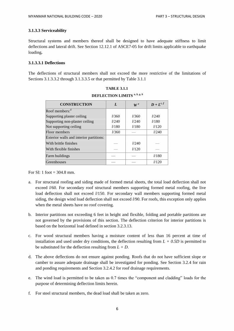
The deflections of structural members shall not exceed the more restrictive of the limitations of
Sections 3.1.3.3.2 through 3.1.3.3.5 or that permitted by Table 3.1.1
TABLE 3.1.1
DEFLECTION LIMITS a, b, g, h
CONSTRUCTION L W e D + L
c, f
Roof members:d
Supporting plaster ceiling l/360 l/360 l/240
Supporting non-plaster ceiling l/240 l/240 l/180
Not supporting ceiling l/180 l/180 l/120
Floor members l/360 — l/240
Exterior walls and interior partitions:
With brittle finishes — l/240 —
With flexible finishes — l/120 —
Farm buildings — — l/180
Greenhouses — — l/120
For SI: 1 foot = 304.8 mm.
a. For structural roofing and siding made of formed metal sheets, the total load deflection shall not
exceed l/60. For secondary roof structural members supporting formed metal roofing, the live
load deflection shall not exceed l/150. For secondary wall members supporting formed metal
siding, the design wind load deflection shall not exceed l/90. For roofs, this exception only applies
when the metal sheets have no roof covering.
b. Interior partitions not exceeding 6 feet in height and flexible, folding and portable partitions are
not governed by the provisions of this section. The deflection criterion for interior partitions is
based on the horizontal load defined in section 3.2.3.13.
c. For wood structural members having a moisture content of less than 16 percent at time of
installation and used under dry conditions, the deflection resulting from L + 0.5D is permitted to
be substituted for the deflection resulting from L + D.
d. The above deflections do not ensure against ponding. Roofs that do not have sufficient slope or
camber to assure adequate drainage shall be investigated for ponding. See Section 3.2.4 for rain
and ponding requirements and Section 3.2.4.2 for roof drainage requirements.
e. The wind load is permitted to be taken as 0.7 times the ―component and cladding‖ loads for the
purpose of determining deflection limits herein.
f. For steel structural members, the dead load shall be taken as zero.
MYANMAR NATIONAL BUILDING CODE – 2020 PART 3 – STRUCTURAL DESIGN
7
g. For aluminum structural members or aluminum panels used in skylights and sloped glazing
framing, roofs or walls of sunroom additions or patio covers, not supporting edge of glass or
aluminum sandwich panels, the total load deflection shall not exceed l/120.
h. For cantilever members, l shall be taken as twice the length of the cantilever.
3.1.3.3.2 Reinforced Concrete
The deflection of reinforced concrete structural members shall not exceed that permitted by ACI 318-
08.
3.1.3.3.3 Steel
The deflection of steel structural members shall not exceed that permitted by AISC 360, AISI-NAS,
AISI-General, AISI-Truss, ASCE 3, ASCE 8, SJI JG-1.1, SJI K-1.1 or SJI LH/DLH-1.1, as
applicable.
3.1.3.3.4 Masonry
The deflection of masonry structural members shall not exceed that permitted by ACI 530/ASCE
5/TMS 402.
3.1.3.3.5 Aluminum
The deflection of aluminum structural members shall not exceed that permitted by AA ADM1.
3.1.3.3.6 Limits
Deflection of structural members over span, l shall not exceed that permitted by Table 3.1.1.
3.1.3.4 Analysis
Load effects on structural members and their connections shall be determined by methods of
structural analysis that take into account equilibrium, general stability, geometric compatibility and
both short- and long-term material properties.
Members that tend to accumulate residual deformations under repeated service loads shall have
included in their analysis the added eccentricities expected to occur during their service life.
Any system or method of construction to be used shall be based on a rational analysis in accordance
with well-established principles of mechanics. Such analysis shall result in a system that provides a
complete load path capable of transferring loads from their point of origin to the load-resisting
elements.
The total lateral force shall be distributed to the various vertical elements of the lateral-force-resisting
system in proportion to their rigidities, considering the rigidity of the horizontal bracing system or
diaphragm. Rigid elements assumed not to be a part of the lateral-force-resisting system are permitted
to be incorporated into buildings provided their effect on the action of the system is considered and
provided for in the design. Except where diaphragms are flexible, or are permitted to be analyzed as
flexible, provisions shall be made for the increased forces induced on resisting elements of the
structural system resulting from torsion due to eccentricity between the centre of application of the
MYANMAR NATIONAL BUILDING CODE – 2020 PART 3 – STRUCTURAL DESIGN
8
lateral forces and the centre of rigidity of the lateral-force-resisting system.
Structures shall be designed to resist the overturning effects caused by the lateral forces specified in
this PART if it is required to consider lateral loads. See Section 3.3 for wind loads, Section 3.2.2 for
lateral soil loads and hydrostatic pressures and Section 3.4 for earthquake loads.
3.1.3.5 Occupancy Category
Buildings shall be assigned an occupancy category in accordance with Table 3.1.2.
3.1.3.5.1 Multiple Occupancies
Where a structure is occupied by two or more occupancies not included in the same occupancy
category, the structure shall be assigned the classification of the highest occupancy category
corresponding to the various occupancies. Where structures have two or more portions that are
structurally separated, each portion shall be separately classified. Where a separated portion of a
structure provides required access to, required egress from or shares life safety components with
another portion having a higher occupancy category, both portions shall be assigned to the higher
occupancy category.
3.1.3.6 In-Situ Load Tests
The building official is authorized to require an engineering analysis or a strength test or a load test, or
any combination, of any construction whenever there is reason to question the safety of the
construction for the intended occupancy.
3.1.3.7 Preconstruction Load Tests
Materials and methods of construction that are not capable of being designed by approved engineering
analysis or that do not comply with the applicable material design standards listed shall be load tested
or tested for strength and deformation characteristics.
3.1.3.8 Anchorage
3.1.3.8.1 General
Anchorage of the roof to walls and columns, and of walls and columns to foundations, shall be
provided to resist the uplift and sliding forces that result from the application of the prescribed loads.
3.1.3.8.2 Concrete and Masonry Walls
Concrete and masonry walls shall be anchored to floors, roofs and other structural elements that
provide lateral support for the wall. Such anchorage shall provide a positive direct connection capable
of resisting the horizontal forces specified in this part but not less than a minimum strength design
horizontal force of 280 plf (4.10 kN/m) of wall, substituted for ―E‖ in the load combinations of
Section 3.2.1.2 or 3.2.1.3. Walls shall be designed to resist bending between anchors where the anchor
spacing exceeds 4 feet (1219 mm). Required anchors in masonry walls of hollow units or cavity walls
shall be embedded in a reinforced grouted structural element of the wall. See Sections 3.3 for wind
design requirements and see Section 3.4 for seismic design requirements.
MYANMAR NATIONAL BUILDING CODE – 2020 PART 3 – STRUCTURAL DESIGN
9
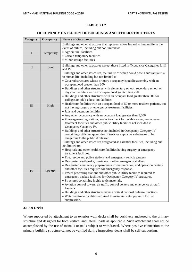
TABLE 3.1.2
OCCUPANCY CATEGORY OF BUILDINGS AND OTHER STRUCTURES
Category Occupancy Nature of Occupancy
I Temporary
Buildings and other structures that represent a low hazard to human life in the
event of failure, including but not limited to:
Agricultural facilities
Certain temporary facilities
Minor storage facilities
II Low Buildings and other structures except those listed in Occupancy Categories I, III
and IV
III High
Buildings and other structures, the failure of which could pose a substantial risk
to human life, including but not limited to:
Covered structures whose primary occupancy is public assembly with an
occupant load greater than 300.
Buildings and other structures with elementary school, secondary school or
day care facilities with an occupant load greater than 250.
Buildings and other structures with an occupant load greater than 500 for
colleges or adult education facilities.
Healthcare facilities with an occupant load of 50 or more resident patients, but
not having surgery or emergency treatment facilities.
Jails and detention facilities.
Any other occupancy with an occupant load greater than 5,000.
Power-generating stations, water treatment for potable water, waste water
treatment facilities and other public utility facilities not included in
Occupancy Category IV.
Buildings and other structures not included in Occupancy Category IV
containing sufficient quantities of toxic or explosive substances to be
dangerous to the public if released.
IV Essential
Buildings and other structures designated as essential facilities, including but
not limited to:
Hospitals and other health care facilities having surgery or emergency
treatment facilities.
Fire, rescue and police stations and emergency vehicle garages.
Designated earthquake, hurricane or other emergency shelters.
Designated emergency preparedness, communication, and operation centers
and other facilities required for emergency response.
Power generating stations and other public utility facilities required as
emergency backup facilities for Occupancy Category IV structures.
Structures containing highly toxic materials.
Aviation control towers, air traffic control centers and emergency aircraft
hangars.
Buildings and other structures having critical national defense functions.
Water treatment facilities required to maintain water pressure for fire
suppression.
3.1.3.9 Decks
Where supported by attachment to an exterior wall, decks shall be positively anchored to the primary
structure and designed for both vertical and lateral loads as applicable. Such attachment shall not be
accomplished by the use of toenails or nails subject to withdrawal. Where positive connection to the
primary building structure cannot be verified during inspection, decks shall be self-supporting.

MYANMAR NATIONAL BUILDING CODE – 2020 PART 3 – STRUCTURAL DESIGN
10
3.1.3.10 Counteracting Structural Actions
Structural members, systems, components and cladding shall be designed to resist forces due to
earthquake and wind, with consideration of overturning, sliding, and uplift. Continuous load paths
shall be provided for transmitting these forces to the foundation. Where sliding is used to isolate the
elements, the effects of friction between sliding elements shall be included as a force.
3.1.3.11 Wind and Seismic Detailing
Where required by the authority department, lateral-force-resisting systems shall meet seismic
detailing requirements and limitations prescribed in this PART and ASCE 7-05, excluding Chapter 14
and Appendix 11A, even when wind code prescribed load effects are greater than seismic load effects.
MYANMAR NATIONAL BUILDING CODE – 2020 PART 3 – STRUCTURAL DESIGN
11
SECTION 3.2
LOAD COMBINATIONS AND LOADS
3.2.1 – Load Combinations
3.2.1.1 General
Buildings and other structures and portions thereof, shall be designed using the provisions of either
Section 3.2.1.2 or 3.2.1.3. Either Section 3.2.1.2 or 3.2.1.3 shall be used exclusively for proportioning
elements of a particular construction material throughout the structure. Each load combination shall
also be investigated with one or more of the variable loads set to zero.
3.2.1.2 Combining Factored Loads Using Strength Design or Load and Resistance Factor Design
3.2.1.2.1 Applicability
The load combinations and load factors given in Section 3.2.1.2.2 shall be used only in those cases in
which they are specifically authorized by the applicable material design standard. Otherwise, the
provisions of the applicable material design standard shall be used.
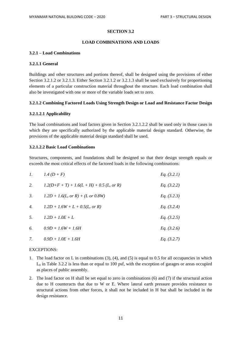
3.2.1.2.2 Basic Load Combinations
Structures, components, and foundations shall be designed so that their design strength equals or
exceeds the most critical effects of the factored loads in the following combinations:
1. 1.4 (D + F) Eq. (3.2.1)
2. 1.2(D+F + T) + 1.6(L + H) + 0.5 (Lr or R) Eq. (3.2.2)
3. 1.2D + 1.6(Lr or R) + (L or 0.8W) Eq. (3.2.3)
4. 1.2D + 1.6W + L + 0.5(Lr or R) Eq. (3.2.4)
5. 1.2D + 1.0E + L Eq. (3.2.5)
6. 0.9D + 1.6W + 1.6H Eq. (3.2.6)
7. 0.9D + 1.0E + 1.6H Eq. (3.2.7)
EXCEPTIONS:
1. The load factor on L in combinations (3), (4), and (5) is equal to 0.5 for all occupancies in which
L0 in Table 3.2.2 is less than or equal to 100 psf, with the exception of garages or areas occupied
as places of public assembly.
2. The load factor on H shall be set equal to zero in combinations (6) and (7) if the structural action
due to H counteracts that due to W or E. Where lateral earth pressure provides resistance to
structural actions from other forces, it shall not be included in H but shall be included in the
design resistance.
MYANMAR NATIONAL BUILDING CODE – 2020 PART 3 – STRUCTURAL DESIGN
12
Each relevant strength limit state shall be investigated. Effects of one or more loads not acting shall be
investigated. The most unfavorable effects from both wind and earthquake loads shall be investigated,
where appropriate, but they need not be considered to act simultaneously.
As an exception, where other factored load combinations are specifically required by the provisions of
this PART, such combinations shall take precedence.
3.2.1.2.3 Load Combinations Including Flood Load
When a structure is located in a flood zone (Section 3.2.5.3.1), the following load combinations shall
be considered:
1. In V-Zones or Coastal A-Zones, 1.6W in combinations (4) and (6) shall be replaced by 1.6W +
2.0Fa.
2. In non-coastal A-Zones, 1.6W in combinations (4) and (6) shall be replaced by 0.8W + 1.0Fa.
3.2.1.3 Combining Nominal Loads Using Allowable Stress Design or Working Stress Design
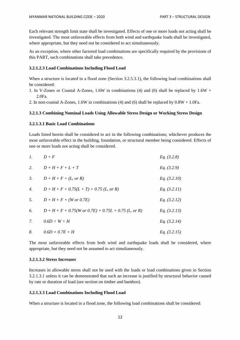
3.2.1.3.1 Basic Load Combinations
Loads listed herein shall be considered to act in the following combinations; whichever produces the
most unfavorable effect in the building, foundation, or structural member being considered. Effects of
one or more loads not acting shall be considered.
1. D + F Eq. (3.2.8)
2. D + H + F + L + T Eq. (3.2.9)
3. D + H + F + (Lr or R) Eq. (3.2.10)
4. D + H + F + 0.75(L + T) + 0.75 (Lr or R) Eq. (3.2.11)
5. D + H + F + (W or 0.7E) Eq. (3.2.12)
6. D + H + F + 0.75(W or 0.7E) + 0.75L + 0.75 (Lr or R) Eq. (3.2.13)
7. 0.6D + W + H Eq. (3.2.14)
8. 0.6D + 0.7E + H Eq. (3.2.15)
The most unfavorable effects from both wind and earthquake loads shall be considered, where
appropriate, but they need not be assumed to act simultaneously.
3.2.1.3.2 Stress Increases
Increases in allowable stress shall not be used with the loads or load combinations given in Section
3.2.1.3.1 unless it can be demonstrated that such an increase is justified by structural behavior caused
by rate or duration of load (see section on timber and bamboo).
3.2.1.3.3 Load Combinations Including Flood Load
When a structure is located in a flood zone, the following load combinations shall be considered:
MYANMAR NATIONAL BUILDING CODE – 2020 PART 3 – STRUCTURAL DESIGN
13
1. In V-Zones or Coastal A-Zones (Section 3.2.5.3. l), 1.5 Fa shall be added to other loads in
combinations (5), (6), and (7), and E shall be set equal to zero in (5) and (6).
2. In non-coastal A-Zones, 0.75 Fa shall be added to combinations (5), (6), and (7), and E shall be set
equal to zero in (5) and (6).
3.2.1.4 Load Combinations for Extraordinary Events
Where required by the applicable code, standard, or the authority having jurisdiction, strength and
stability shall be checked to ensure that structures are capable of withstanding the effects of
extraordinary (i.e., low-probability) events, such as fires, explosions, and vehicular impact.
3.2.1.5 Special Seismic Load Combinations
For both strength and allowable stress design methods where specifically required by relevant
material design standards, elements and components shall be designed to resist the forces calculated
using Eq. (3.2.16) when the effects of the seismic ground motion are additive to gravity forces and
those calculated using Eq. (3.2.17) when the effects of the seismic ground motion counteract gravity
forces.
1. 1.2D + f1L +Em Eq. (3.2.16)
2. 0.9D+Em Eq. (3.2.17)
Where Em = the maximum effect of horizontal and vertical forces as set forth in Section12.4.3 of
ASCE 7-05.
The load factor f1 for L in combination Eq. (3.2.16) is equal to 0.5 for all occupancies when live load
is less than or equal to 100 psf (4.79 kN/m2), with the exception of garages or areas of public
assembly. Otherwise, f1 is equal to 1.
3.2.2 Dead Loads, Soil Loads and Hydrostatic Pressure
3.2.2.1 Dead Loads
3.2.2.1.1 Definition
Dead loads consist of the weight of all materials of construction incorporated into the building
including, but not limited to, walls, floors, roofs, ceilings, stair ways, built-in partitions, finishes,
cladding, and other similarly incorporated architectural and structural items, and fixed service
equipment including the weight of cranes.
3.2.2.1.2 Weights of Materials and Constructions
In determining dead loads for purposes of design, the actual weights of materials and constructions
shall be used provided that in the absence of definite information, values approved by the authority
having jurisdiction shall be used.
3.2.2.1.3 Weight of Fixed Service Equipment
In determining dead loads for purposes of design, the weight of fixed service equipment, such as
plumbing stacks and risers, electrical feeders, and heating, ventilating, and air conditioning systems
shall be included.
MYANMAR NATIONAL BUILDING CODE – 2020 PART 3 – STRUCTURAL DESIGN
14
3.2.2.2 Soil Loads and Hydrostatic Pressure
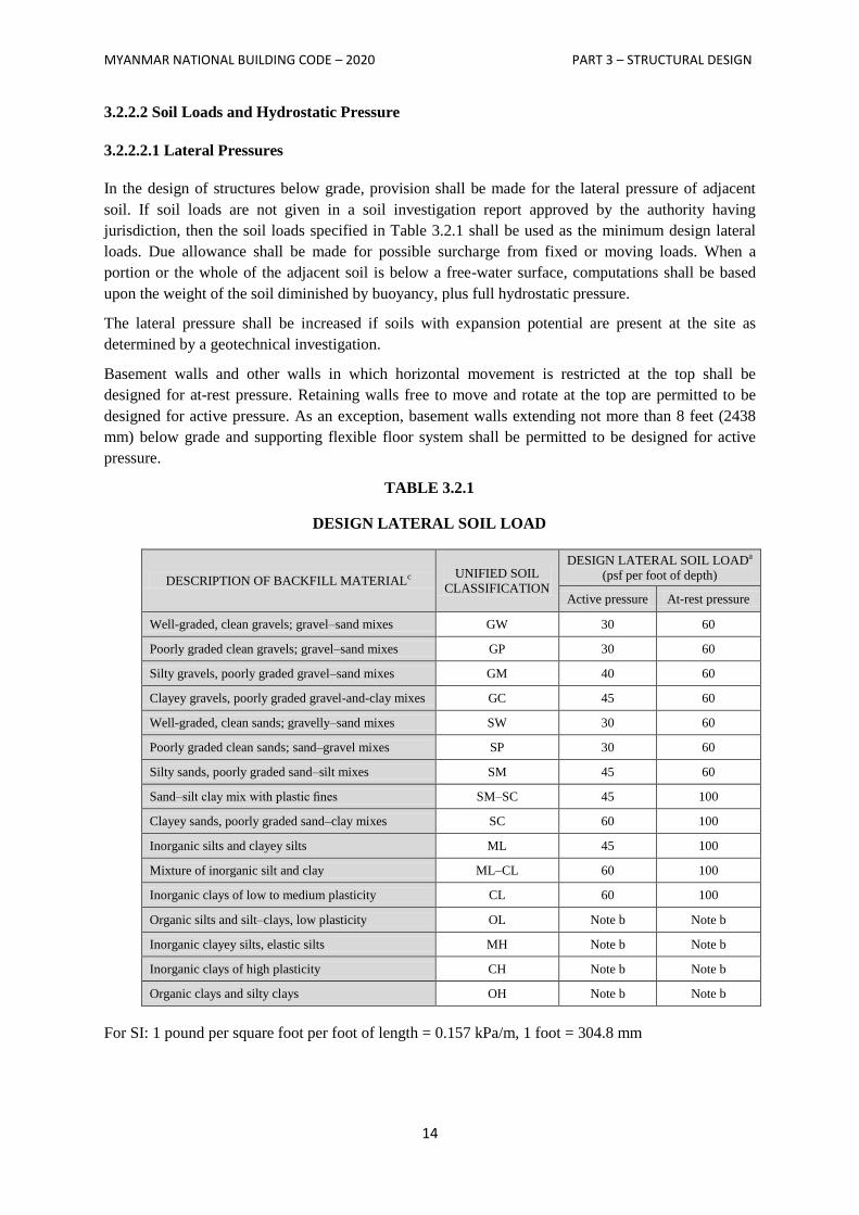
3.2.2.2.1 Lateral Pressures
In the design of structures below grade, provision shall be made for the lateral pressure of adjacent
soil. If soil loads are not given in a soil investigation report approved by the authority having
jurisdiction, then the soil loads specified in Table 3.2.1 shall be used as the minimum design lateral
loads. Due allowance shall be made for possible surcharge from fixed or moving loads. When a
portion or the whole of the adjacent soil is below a free-water surface, computations shall be based
upon the weight of the soil diminished by buoyancy, plus full hydrostatic pressure.
The lateral pressure shall be increased if soils with expansion potential are present at the site as
determined by a geotechnical investigation.
Basement walls and other walls in which horizontal movement is restricted at the top shall be
designed for at-rest pressure. Retaining walls free to move and rotate at the top are permitted to be
designed for active pressure. As an exception, basement walls extending not more than 8 feet (2438
mm) below grade and supporting flexible floor system shall be permitted to be designed for active
pressure.
TABLE 3.2.1
DESIGN LATERAL SOIL LOAD
DESCRIPTION OF BACKFILL MATERIALc UNIFIED SOIL
CLASSIFICATION
DESIGN LATERAL SOIL LOADa
(psf per foot of depth)
Active pressure At-rest pressure
Well-graded, clean gravels; gravel–sand mixes GW 30 60
Poorly graded clean gravels; gravel–sand mixes GP 30 60
Silty gravels, poorly graded gravel–sand mixes GM 40 60
Clayey gravels, poorly graded gravel-and-clay mixes GC 45 60
Well-graded, clean sands; gravelly–sand mixes SW 30 60
Poorly graded clean sands; sand–gravel mixes SP 30 60
Silty sands, poorly graded sand–silt mixes SM 45 60
Sand–silt clay mix with plastic fines SM–SC 45 100
Clayey sands, poorly graded sand–clay mixes SC 60 100
Inorganic silts and clayey silts ML 45 100
Mixture of inorganic silt and clay ML–CL 60 100
Inorganic clays of low to medium plasticity CL 60 100
Organic silts and silt–clays, low plasticity OL Note b Note b
Inorganic clayey silts, elastic silts MH Note b Note b
Inorganic clays of high plasticity CH Note b Note b
Organic clays and silty clays OH Note b Note b
For SI: 1 pound per square foot per foot of length = 0.157 kPa/m, 1 foot = 304.8 mm
MYANMAR NATIONAL BUILDING CODE – 2020 PART 3 – STRUCTURAL DESIGN
15
a Design lateral soil loads are given for moist conditions for the specified soils at their optimum
densities. Actual field conditions shall govern. Submerged or saturated soil pressures shall include
the weight of the buoyant soil plus the hydrostatic loads.
b Unsuitable as backfill material.
c The definition and classification of soil materials shall be in accordance with ASTM D2487.
3.2.2.2.2 Uplift on Floors and Foundations
In the design of basement floors and similar approximately horizontal elements below grade, the
upward pressure of water, where applicable, shall be taken as the full hydrostatic pressure applied
over the entire area. The hydrostatic load shall be measured from the underside of the construction.
Any other upward loads shall be included in the design.
Where expansive soils are present under foundations or slabs-on-ground, the foundations, slabs, and
other components shall be designed to tolerate the movement or resist the upward loads caused by the
expansive soils, or the expansive soil shall be removed or stabilized around and beneath the structure.
3.2.3 – Live Loads
3.2.3.1 Definitions
The following definitions apply only to the provision of Section 3.2.3.
LIVE LOAD: A load produced by the use and occupancy of the building or other structure that does
not include construction or environmental loads, such as wind load, snow load, rain load, earthquake
load, flood load, or dead load.
ROOF LIVE LOAD: A load on a roof produced (1) during maintenance by workers, equipment, and
materials and (2) during the life of the structure by movable objects, such as planters or other similar
small decorative appurtenances that are not occupancy related.
FIXED LADDER: A ladder that is permanently attached to a structure, building, or equipment.
GRAB BAR SYSTEM: A bar provided to support body weight in locations such as toilets, showers,
and tub enclosures.
GUARDRAIL SYSTEM: A system of building components near open sides of an elevated surface
for the purpose of minimizing the possibility of a fall from the elevated surface by people, equipment,
or material.
HANDRAIL: A rail grasped by hand for guidance and support. A handrail assembly includes the
handrail, supporting attachments, and structures.
VEHICLE BARRIER SYSTEM: A system of building components near open sides of a garage
floor or ramp, or building walls that act as restraints for vehicles.
3.2.3.2 Uniformly Distributed Loads
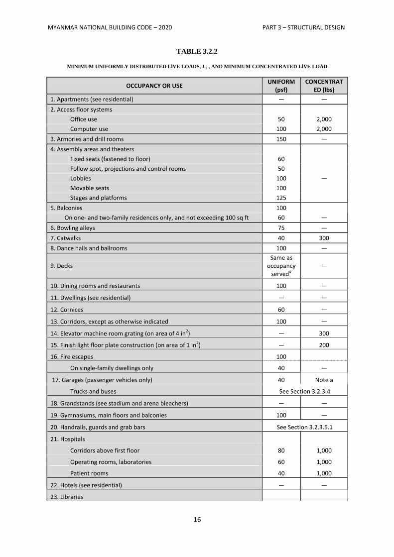
3.2.3.2.1 Required Live Loads
The live loads used in the design of buildings and other structures shall be the maximum loads
expected by the intended use or occupancy but shall in no case be less than the minimum uniformly
distributed unit loads required by Table 3.2.2.
MYANMAR NATIONAL BUILDING CODE – 2020 PART 3 – STRUCTURAL DESIGN
16
TABLE 3.2.2
MINIMUM UNIFORMLY DISTRIBUTED LlVE LOADS, L0 , AND MINIMUM CONCENTRATED LlVE LOAD
OCCUPANCY OR USE UNIFORM
(psf) CONCENTRAT
ED (lbs)
1. Apartments (see residential) — —
2. Access floor systems
Office use 50 2,000
Computer use 100 2,000
3. Armories and drill rooms 150 —
4. Assembly areas and theaters
Fixed seats (fastened to floor) 60
Follow spot, projections and control rooms 50
Lobbies 100 —
Movable seats 100
Stages and platforms 125
5. Balconies 100
On one- and two-family residences only, and not exceeding 100 sq ft 60 —
6. Bowling alleys 75 —
7. Catwalks 40 300
8. Dance halls and ballrooms 100 —
9. Decks Same as
occupancy served
g
—
10. Dining rooms and restaurants 100 —
11. Dwellings (see residential) — —
12. Cornices 60 —
13. Corridors, except as otherwise indicated 100 —
14. Elevator machine room grating (on area of 4 in2) — 300
15. Finish light floor plate construction (on area of 1 in2) — 200
16. Fire escapes 100
On single-family dwellings only 40 —
17. Garages (passenger vehicles only) 40 Note a
Trucks and buses See Section 3.2.3.4
18. Grandstands (see stadium and arena bleachers) — —
19. Gymnasiums, main floors and balconies 100 —
20. Handrails, guards and grab bars See Section 3.2.3.5.1
21. Hospitals
Corridors above first floor 80 1,000
Operating rooms, laboratories 60 1,000
Patient rooms 40 1,000
22. Hotels (see residential) — —
23. Libraries
MYANMAR NATIONAL BUILDING CODE – 2020 PART 3 – STRUCTURAL DESIGN
17
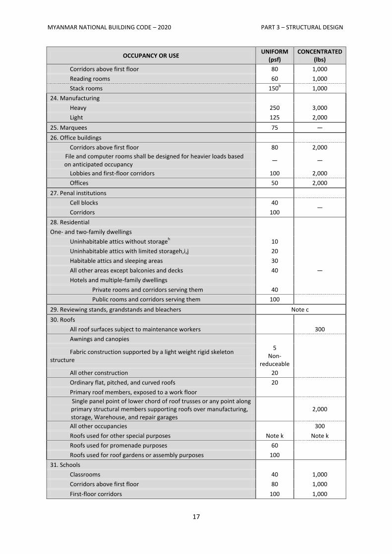
OCCUPANCY OR USE UNIFORM
(psf) CONCENTRATED
(lbs)
Corridors above first floor 80 1,000
Reading rooms 60 1,000
Stack rooms 150b 1,000
24. Manufacturing
Heavy 250 3,000
Light 125 2,000
25. Marquees 75 —
26. Office buildings
Corridors above first floor 80 2,000
File and computer rooms shall be designed for heavier loads based on anticipated occupancy
— —
Lobbies and first-floor corridors 100 2,000
Offices 50 2,000
27. Penal institutions
Cell blocks 40 —
Corridors 100
28. Residential
One- and two-family dwellings
Uninhabitable attics without storageh 10
Uninhabitable attics with limited storageh,i,j 20
Habitable attics and sleeping areas 30
All other areas except balconies and decks 40 —
Hotels and multiple-family dwellings
Private rooms and corridors serving them 40
Public rooms and corridors serving them 100
29. Reviewing stands, grandstands and bleachers Note c
30. Roofs
All roof surfaces subject to maintenance workers
300
Awnings and canopies
Fabric construction supported by a light weight rigid skeleton structure
5 Non-
reduceable
All other construction 20
Ordinary flat, pitched, and curved roofs 20
Primary roof members, exposed to a work floor
Single panel point of lower chord of roof trusses or any point along primary structural members supporting roofs over manufacturing, storage, Warehouse, and repair garages
2,000
All other occupancies
300
Roofs used for other special purposes Note k Note k
Roofs used for promenade purposes 60
Roofs used for roof gardens or assembly purposes 100
31. Schools
Classrooms 40 1,000
Corridors above first floor 80 1,000
First-floor corridors 100 1,000
MYANMAR NATIONAL BUILDING CODE – 2020 PART 3 – STRUCTURAL DESIGN
18
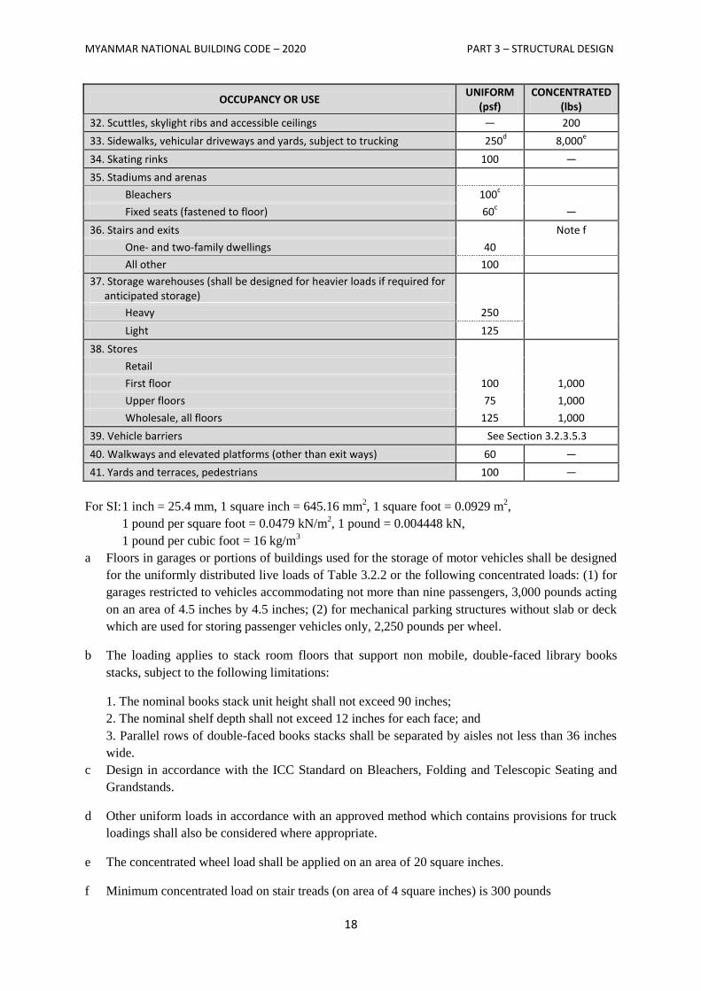
OCCUPANCY OR USE UNIFORM
(psf) CONCENTRATED
(lbs)
32. Scuttles, skylight ribs and accessible ceilings — 200
33. Sidewalks, vehicular driveways and yards, subject to trucking 250d 8,000
e
34. Skating rinks 100 —
35. Stadiums and arenas
Bleachers 100c
Fixed seats (fastened to floor) 60
c —
36. Stairs and exits
Note f
One- and two-family dwellings 40
All other 100
37. Storage warehouses (shall be designed for heavier loads if required for anticipated storage)
Heavy 250
Light 125
38. Stores
Retail
First floor 100 1,000
Upper floors 75 1,000
Wholesale, all floors 125 1,000
39. Vehicle barriers See Section 3.2.3.5.3
40. Walkways and elevated platforms (other than exit ways) 60 —
41. Yards and terraces, pedestrians 100 —
For SI: 1 inch = 25.4 mm, 1 square inch = 645.16 mm2, 1 square foot = 0.0929 m
2,
1 pound per square foot = 0.0479 kN/m2, 1 pound = 0.004448 kN,
1 pound per cubic foot = 16 kg/m3
a Floors in garages or portions of buildings used for the storage of motor vehicles shall be designed
for the uniformly distributed live loads of Table 3.2.2 or the following concentrated loads: (1) for
garages restricted to vehicles accommodating not more than nine passengers, 3,000 pounds acting
on an area of 4.5 inches by 4.5 inches; (2) for mechanical parking structures without slab or deck
which are used for storing passenger vehicles only, 2,250 pounds per wheel.
b The loading applies to stack room floors that support non mobile, double-faced library books
stacks, subject to the following limitations:
1. The nominal books stack unit height shall not exceed 90 inches;
2. The nominal shelf depth shall not exceed 12 inches for each face; and
3. Parallel rows of double-faced books stacks shall be separated by aisles not less than 36 inches
wide.
c Design in accordance with the ICC Standard on Bleachers, Folding and Telescopic Seating and
Grandstands.
d Other uniform loads in accordance with an approved method which contains provisions for truck
loadings shall also be considered where appropriate.
e The concentrated wheel load shall be applied on an area of 20 square inches.
f Minimum concentrated load on stair treads (on area of 4 square inches) is 300 pounds
MYANMAR NATIONAL BUILDING CODE – 2020 PART 3 – STRUCTURAL DESIGN
19
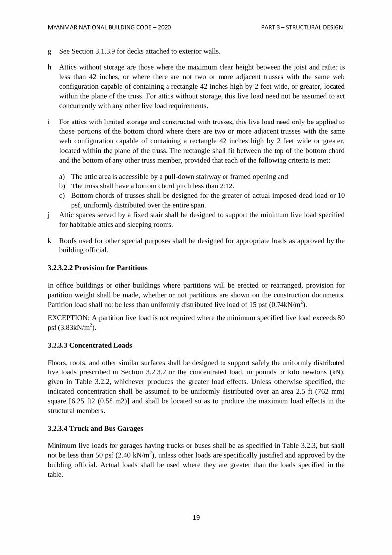
g See Section 3.1.3.9 for decks attached to exterior walls.
h Attics without storage are those where the maximum clear height between the joist and rafter is
less than 42 inches, or where there are not two or more adjacent trusses with the same web
configuration capable of containing a rectangle 42 inches high by 2 feet wide, or greater, located
within the plane of the truss. For attics without storage, this live load need not be assumed to act
concurrently with any other live load requirements.
i For attics with limited storage and constructed with trusses, this live load need only be applied to
those portions of the bottom chord where there are two or more adjacent trusses with the same
web configuration capable of containing a rectangle 42 inches high by 2 feet wide or greater,
located within the plane of the truss. The rectangle shall fit between the top of the bottom chord
and the bottom of any other truss member, provided that each of the following criteria is met:
a) The attic area is accessible by a pull-down stairway or framed opening and
b) The truss shall have a bottom chord pitch less than 2:12.
c) Bottom chords of trusses shall be designed for the greater of actual imposed dead load or 10
psf, uniformly distributed over the entire span.
j Attic spaces served by a fixed stair shall be designed to support the minimum live load specified
for habitable attics and sleeping rooms.
k Roofs used for other special purposes shall be designed for appropriate loads as approved by the
building official.
3.2.3.2.2 Provision for Partitions
In office buildings or other buildings where partitions will be erected or rearranged, provision for
partition weight shall be made, whether or not partitions are shown on the construction documents.
Partition load shall not be less than uniformly distributed live load of 15 psf (0.74kN/m2).
EXCEPTION: A partition live load is not required where the minimum specified live load exceeds 80
psf (3.83kN/m2).
3.2.3.3 Concentrated Loads
Floors, roofs, and other similar surfaces shall be designed to support safely the uniformly distributed
live loads prescribed in Section 3.2.3.2 or the concentrated load, in pounds or kilo newtons (kN),
given in Table 3.2.2, whichever produces the greater load effects. Unless otherwise specified, the
indicated concentration shall be assumed to be uniformly distributed over an area 2.5 ft (762 mm)
square [6.25 ft2 (0.58 m2)] and shall be located so as to produce the maximum load effects in the
structural members.
3.2.3.4 Truck and Bus Garages
Minimum live loads for garages having trucks or buses shall be as specified in Table 3.2.3, but shall
not be less than 50 psf (2.40 kN/m2), unless other loads are specifically justified and approved by the
building official. Actual loads shall be used where they are greater than the loads specified in the
table.
MYANMAR NATIONAL BUILDING CODE – 2020 PART 3 – STRUCTURAL DESIGN
20
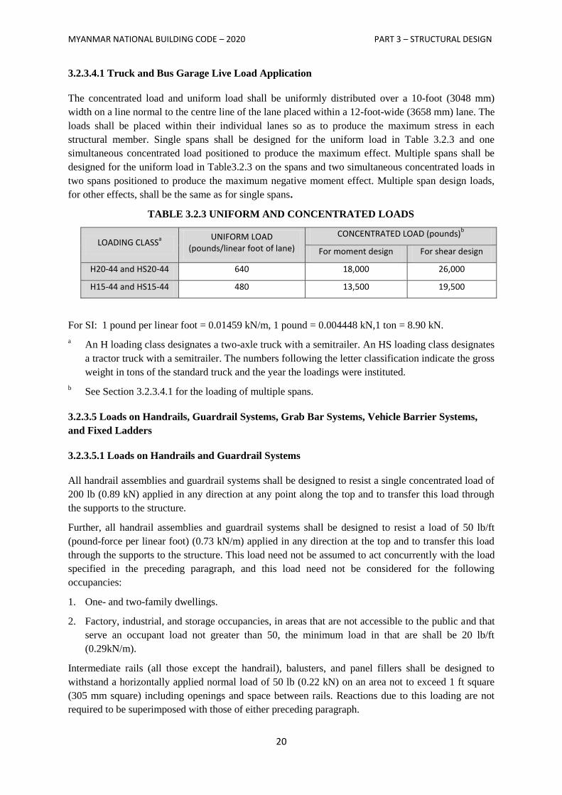
3.2.3.4.1 Truck and Bus Garage Live Load Application
The concentrated load and uniform load shall be uniformly distributed over a 10-foot (3048 mm)
width on a line normal to the centre line of the lane placed within a 12-foot-wide (3658 mm) lane. The
loads shall be placed within their individual lanes so as to produce the maximum stress in each
structural member. Single spans shall be designed for the uniform load in Table 3.2.3 and one
simultaneous concentrated load positioned to produce the maximum effect. Multiple spans shall be
designed for the uniform load in Table3.2.3 on the spans and two simultaneous concentrated loads in
two spans positioned to produce the maximum negative moment effect. Multiple span design loads,
for other effects, shall be the same as for single spans.
TABLE 3.2.3 UNIFORM AND CONCENTRATED LOADS
LOADING CLASSa
UNIFORM LOAD (pounds/linear foot of lane)
CONCENTRATED LOAD (pounds)b
For moment design For shear design
H20-44 and HS20-44 640 18,000 26,000
H15-44 and HS15-44 480 13,500 19,500
For SI: 1 pound per linear foot = 0.01459 kN/m, 1 pound = 0.004448 kN,1 ton = 8.90 kN.
a An H loading class designates a two-axle truck with a semitrailer. An HS loading class designates
a tractor truck with a semitrailer. The numbers following the letter classification indicate the gross
weight in tons of the standard truck and the year the loadings were instituted.
b See Section 3.2.3.4.1 for the loading of multiple spans.
3.2.3.5 Loads on Handrails, Guardrail Systems, Grab Bar Systems, Vehicle Barrier Systems,
and Fixed Ladders
3.2.3.5.1 Loads on Handrails and Guardrail Systems
All handrail assemblies and guardrail systems shall be designed to resist a single concentrated load of
200 lb (0.89 kN) applied in any direction at any point along the top and to transfer this load through
the supports to the structure.
Further, all handrail assemblies and guardrail systems shall be designed to resist a load of 50 lb/ft
(pound-force per linear foot) (0.73 kN/m) applied in any direction at the top and to transfer this load
through the supports to the structure. This load need not be assumed to act concurrently with the load
specified in the preceding paragraph, and this load need not be considered for the following
occupancies:
1. One- and two-family dwellings.
2. Factory, industrial, and storage occupancies, in areas that are not accessible to the public and that
serve an occupant load not greater than 50, the minimum load in that are shall be 20 lb/ft
(0.29kN/m).
Intermediate rails (all those except the handrail), balusters, and panel fillers shall be designed to
withstand a horizontally applied normal load of 50 lb (0.22 kN) on an area not to exceed 1 ft square
(305 mm square) including openings and space between rails. Reactions due to this loading are not
required to be superimposed with those of either preceding paragraph.
MYANMAR NATIONAL BUILDING CODE – 2020 PART 3 – STRUCTURAL DESIGN
21
Where handrails and guards are designed using working stress design exclusively for the loads
specified in this section, the allowable stress for the members and their attachments are permitted to
be increased by one-third.
3.2.3.5.2 Loads on Grab Bar Systems
Grab bar systems shall be designed to resist a single concentrated load of 250 lb (1.11 kN) applied in
any direction at any point.
3.2.3.5.3 Loads on Vehicle Barrier Systems
Vehicle barrier systems for passenger cars shall be designed to resist a single load of 6,000 lb (26.70
kN) applied horizontally in any direction to the barrier system, and shall have anchorages or
attachments capable of transferring this load to the structure. For design of the system, the load shall
be assumed to act at a minimum height of 1 ft 6 in. (460 mm) above the floor or ramp surface on an
area not to exceed 1 foot square (305 mm square), and is not required to be assumed to act
concurrently with any handrail or guardrail loadings specified in Section 3.2.3.4.1. Garages
accommodating trucks and buses shall be designed in accordance with an approved method, which
contains provision for traffic railings.
3.2.3.5.4 Loads on Fixed Ladders
The minimum design live load on fixed ladders with rungs shall be a single concentrated load of 300
lb (1.33 kN), and shall be applied at any point to produce the maximum load effect on the element
being considered. The number and position of additional concentrated live load units shall be a
minimum of 1 unit of 300 lb (1.33 kN) for every 10 ft (3,048 mm) of ladder height.
Where rails of fixed ladders extend above a floor or platform at the top of the ladder, each side rail
extension shall be designed to resist a concentrated live load of 100 lb (0.445 kN) in any direction at
any height up to the top of the side rail extension. Ship ladders with treads instead of rungs shall have
minimum design loads as stairs, defined in Table 3.2.2.
3.2.3.6 Loads Not Specified
For occupancies or uses not designated in Sections 3.2.3.2 or 3.2.3.3, the live load shall be determined
in accordance with a method approved by the authority having jurisdiction.
3.2.3.7 Partial Loading
The full intensity of the appropriately reduced live load applied only to a portion of a structure or
member shall be accounted for if it produces a more unfavorable effect than the same intensity applied
over the full structure or member. Roof live loads are to be distributed as specified in Table 3.2.2.
3.2.3.8 Impact Loads
The live loads specified in Sections 3.2.3.2.1 and 3.2.3.5.2 shall be assumed to include adequate
allowance for ordinary impact conditions. Provision shall be made in the structural design for uses
and loads that involve unusual vibration and impact forces.
3.2.3.8.1 Elevators
All elevator loads shall be increased by 100 percent for impact and the structural supports shall be
designed within the limits of deflection prescribed by ANSI A17.2 and ANSI/ASME A17.1.
MYANMAR NATIONAL BUILDING CODE – 2020 PART 3 – STRUCTURAL DESIGN
22
3.2.3.8.2 Machinery
For the purpose of design, the weight of machinery and moving loads shall be increased as follows to
allow for impact: (I) elevator machinery, 100 percent; (2) light machinery, shaft- or motor-driven, 20
percent; (3) reciprocating machinery or power-driven units, 50 percent; and (4) hangers for floors or
balconies, 33 percent. All percentages shall be increased where specified by the manufacturer.
3.2.3.9 Reduction in Live Loads
Except for roof uniform live loads, all other minimum uniformly distributed live loads, L0 in Table
3.2.2, may be reduced according to the following provisions.
3.2.3.9.1 General
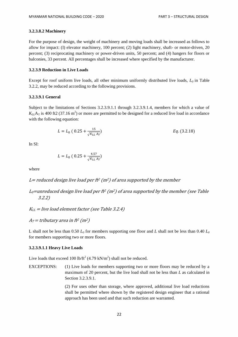
Subject to the limitations of Sections 3.2.3.9.1.1 through 3.2.3.9.1.4, members for which a value of
KLLAT is 400 ft2 (37.16 m2) or more are permitted to be designed for a reduced live load in accordance
with the following equation:
√
In SI:
√
where
L= reduced design live load per ft2 (m2) of area supported by the member
L0=unreduced design live load per ft2 (m2) of area supported by the member (see Table
3.2.2)
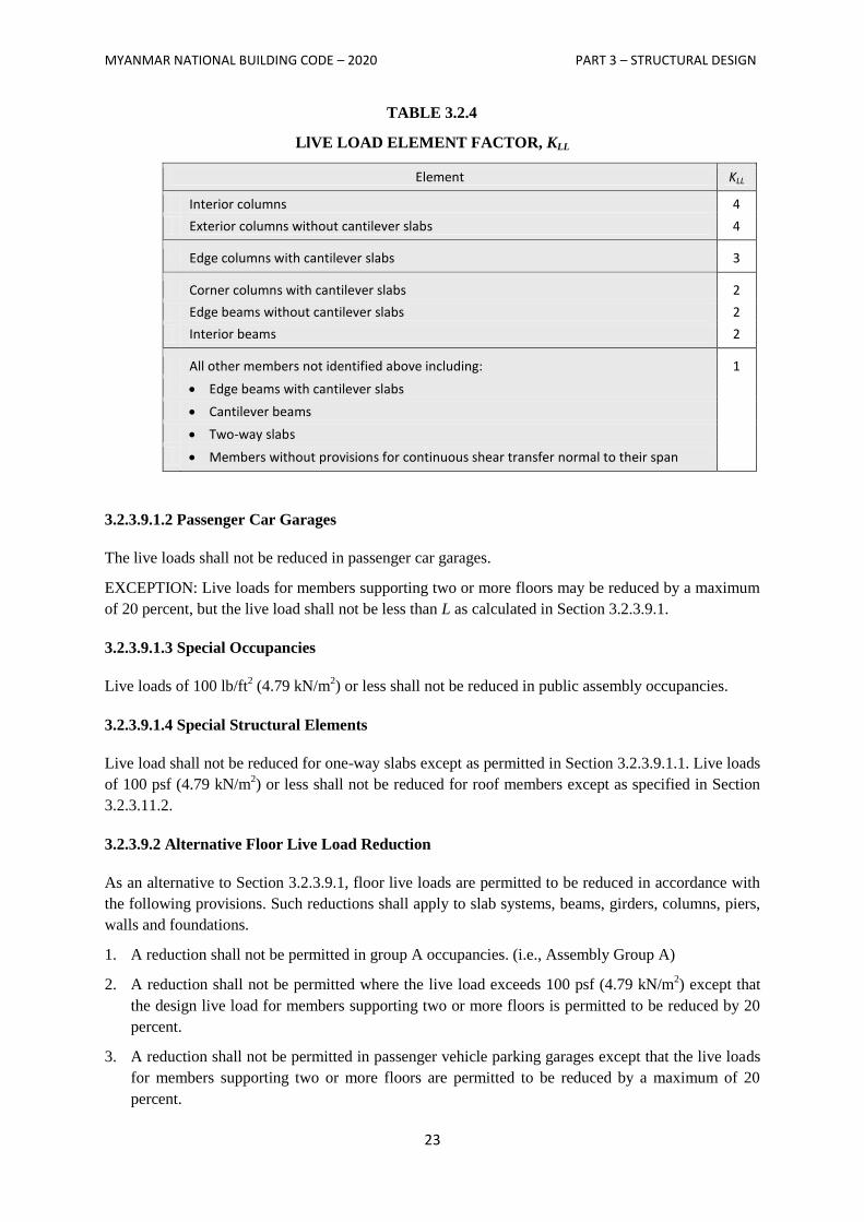
KLL = live load element factor (see Table 3.2.4)
AT = tributary area in ft2 (m2)
L shall not be less than 0.50 L0 for members supporting one floor and L shall not be less than 0.40 L0
for members supporting two or more floors.
3.2.3.9.1.1 Heavy Live Loads
Live loads that exceed 100 lb/ft2 (4.79 kN/m
2) shall not be reduced.
EXCEPTIONS: (1) Live loads for members supporting two or more floors may be reduced by a
maximum of 20 percent, but the live load shall not be less than L as calculated in
Section 3.2.3.9.1.
(2) For uses other than storage, where approved, additional live load reductions
shall be permitted where shown by the registered design engineer that a rational
approach has been used and that such reduction are warranted.
MYANMAR NATIONAL BUILDING CODE – 2020 PART 3 – STRUCTURAL DESIGN
23
TABLE 3.2.4
LlVE LOAD ELEMENT FACTOR, KLL
Element KLL
Interior columns 4
Exterior columns without cantilever slabs 4
Edge columns with cantilever slabs 3
Corner columns with cantilever slabs 2
Edge beams without cantilever slabs 2
Interior beams 2
All other members not identified above including: 1
Edge beams with cantilever slabs
Cantilever beams
Two-way slabs
Members without provisions for continuous shear transfer normal to their span
3.2.3.9.1.2 Passenger Car Garages
The live loads shall not be reduced in passenger car garages.
EXCEPTION: Live loads for members supporting two or more floors may be reduced by a maximum
of 20 percent, but the live load shall not be less than L as calculated in Section 3.2.3.9.1.
3.2.3.9.1.3 Special Occupancies
Live loads of 100 lb/ft2 (4.79 kN/m
2) or less shall not be reduced in public assembly occupancies.
3.2.3.9.1.4 Special Structural Elements
Live load shall not be reduced for one-way slabs except as permitted in Section 3.2.3.9.1.1. Live loads
of 100 psf (4.79 kN/m2) or less shall not be reduced for roof members except as specified in Section
3.2.3.11.2.
3.2.3.9.2 Alternative Floor Live Load Reduction
As an alternative to Section 3.2.3.9.1, floor live loads are permitted to be reduced in accordance with
the following provisions. Such reductions shall apply to slab systems, beams, girders, columns, piers,
walls and foundations.
1. A reduction shall not be permitted in group A occupancies. (i.e., Assembly Group A)
2. A reduction shall not be permitted where the live load exceeds 100 psf (4.79 kN/m2) except that
the design live load for members supporting two or more floors is permitted to be reduced by 20
percent.
3. A reduction shall not be permitted in passenger vehicle parking garages except that the live loads
for members supporting two or more floors are permitted to be reduced by a maximum of 20
percent.
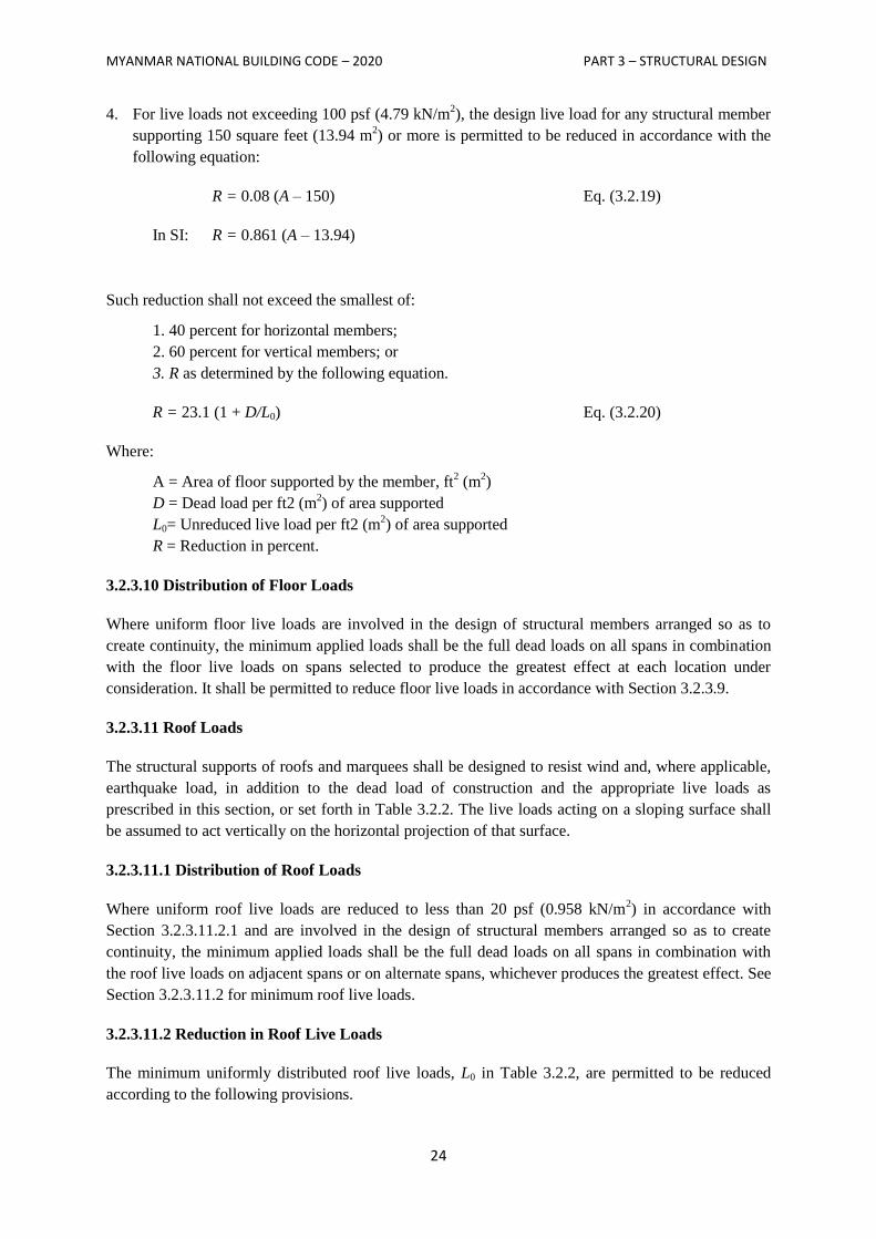
MYANMAR NATIONAL BUILDING CODE – 2020 PART 3 – STRUCTURAL DESIGN
24
4. For live loads not exceeding 100 psf (4.79 kN/m2), the design live load for any structural member
supporting 150 square feet (13.94 m2) or more is permitted to be reduced in accordance with the
following equation:
R = 0.08 (A – 150) Eq. (3.2.19)
In SI: R = 0.861 (A – 13.94)
Such reduction shall not exceed the smallest of:
1. 40 percent for horizontal members;
2. 60 percent for vertical members; or
3. R as determined by the following equation.
R = 23.1 (1 + D/L0) Eq. (3.2.20)
Where:
A = Area of floor supported by the member, ft2 (m
2)
D = Dead load per ft2 (m2) of area supported
L0= Unreduced live load per ft2 (m2) of area supported
R = Reduction in percent.
3.2.3.10 Distribution of Floor Loads
Where uniform floor live loads are involved in the design of structural members arranged so as to
create continuity, the minimum applied loads shall be the full dead loads on all spans in combination
with the floor live loads on spans selected to produce the greatest effect at each location under
consideration. It shall be permitted to reduce floor live loads in accordance with Section 3.2.3.9.
3.2.3.11 Roof Loads
The structural supports of roofs and marquees shall be designed to resist wind and, where applicable,
earthquake load, in addition to the dead load of construction and the appropriate live loads as
prescribed in this section, or set forth in Table 3.2.2. The live loads acting on a sloping surface shall
be assumed to act vertically on the horizontal projection of that surface.
3.2.3.11.1 Distribution of Roof Loads
Where uniform roof live loads are reduced to less than 20 psf (0.958 kN/m2) in accordance with
Section 3.2.3.11.2.1 and are involved in the design of structural members arranged so as to create
continuity, the minimum applied loads shall be the full dead loads on all spans in combination with
the roof live loads on adjacent spans or on alternate spans, whichever produces the greatest effect. See
Section 3.2.3.11.2 for minimum roof live loads.
3.2.3.11.2 Reduction in Roof Live Loads
The minimum uniformly distributed roof live loads, L0 in Table 3.2.2, are permitted to be reduced
according to the following provisions.
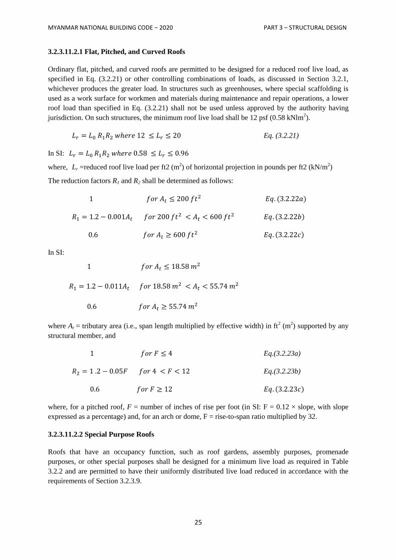
MYANMAR NATIONAL BUILDING CODE – 2020 PART 3 – STRUCTURAL DESIGN
25
3.2.3.11.2.1 Flat, Pitched, and Curved Roofs
Ordinary flat, pitched, and curved roofs are permitted to be designed for a reduced roof live load, as
specified in Eq. (3.2.21) or other controlling combinations of loads, as discussed in Section 3.2.1,
whichever produces the greater load. In structures such as greenhouses, where special scaffolding is
used as a work surface for workmen and materials during maintenance and repair operations, a lower
roof load than specified in Eq. (3.2.21) shall not be used unless approved by the authority having
jurisdiction. On such structures, the minimum roof live load shall be 12 psf (0.58 kNlm2).
Eq. (3.2.21)
In SI:
where, Lr =reduced roof live load per ft2 (m2) of horizontal projection in pounds per ft2 (kN/m
2)
The reduction factors R1 and R2 shall be determined as follows:
In SI:
where At = tributary area (i.e., span length multiplied by effective width) in ft2 (m
2) supported by any
structural member, and
Eq.(3.2.23a)
Eq.(3.2.23b)
where, for a pitched roof, F = number of inches of rise per foot (in SI: F = 0.12 × slope, with slope
expressed as a percentage) and, for an arch or dome, F = rise-to-span ratio multiplied by 32.
3.2.3.11.2.2 Special Purpose Roofs
Roofs that have an occupancy function, such as roof gardens, assembly purposes, promenade
purposes, or other special purposes shall be designed for a minimum live load as required in Table
3.2.2 and are permitted to have their uniformly distributed live load reduced in accordance with the
requirements of Section 3.2.3.9.
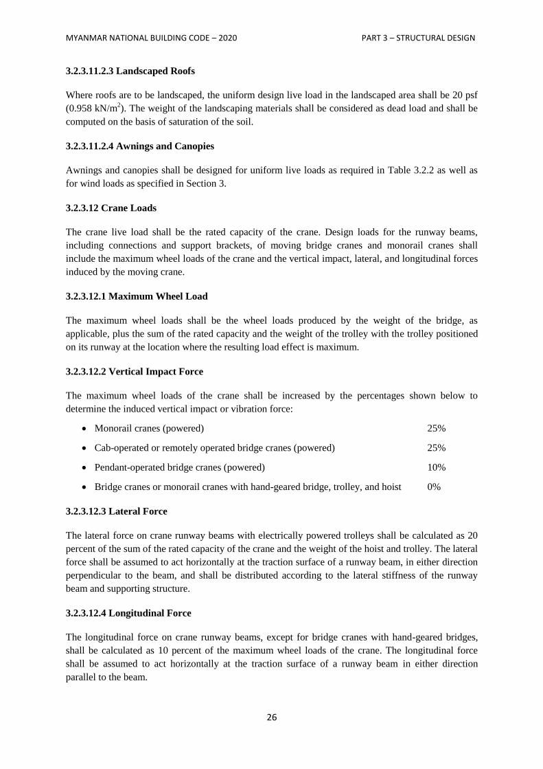
MYANMAR NATIONAL BUILDING CODE – 2020 PART 3 – STRUCTURAL DESIGN
26
3.2.3.11.2.3 Landscaped Roofs
Where roofs are to be landscaped, the uniform design live load in the landscaped area shall be 20 psf
(0.958 kN/m2). The weight of the landscaping materials shall be considered as dead load and shall be
computed on the basis of saturation of the soil.
3.2.3.11.2.4 Awnings and Canopies
Awnings and canopies shall be designed for uniform live loads as required in Table 3.2.2 as well as
for wind loads as specified in Section 3.
3.2.3.12 Crane Loads
The crane live load shall be the rated capacity of the crane. Design loads for the runway beams,
including connections and support brackets, of moving bridge cranes and monorail cranes shall
include the maximum wheel loads of the crane and the vertical impact, lateral, and longitudinal forces
induced by the moving crane.
3.2.3.12.1 Maximum Wheel Load
The maximum wheel loads shall be the wheel loads produced by the weight of the bridge, as
applicable, plus the sum of the rated capacity and the weight of the trolley with the trolley positioned
on its runway at the location where the resulting load effect is maximum.
3.2.3.12.2 Vertical Impact Force
The maximum wheel loads of the crane shall be increased by the percentages shown below to
determine the induced vertical impact or vibration force:
Monorail cranes (powered) 25%
Cab-operated or remotely operated bridge cranes (powered) 25%
Pendant-operated bridge cranes (powered) 10%
Bridge cranes or monorail cranes with hand-geared bridge, trolley, and hoist 0%
3.2.3.12.3 Lateral Force
The lateral force on crane runway beams with electrically powered trolleys shall be calculated as 20
percent of the sum of the rated capacity of the crane and the weight of the hoist and trolley. The lateral
force shall be assumed to act horizontally at the traction surface of a runway beam, in either direction
perpendicular to the beam, and shall be distributed according to the lateral stiffness of the runway
beam and supporting structure.
3.2.3.12.4 Longitudinal Force
The longitudinal force on crane runway beams, except for bridge cranes with hand-geared bridges,
shall be calculated as 10 percent of the maximum wheel loads of the crane. The longitudinal force
shall be assumed to act horizontally at the traction surface of a runway beam in either direction
parallel to the beam.
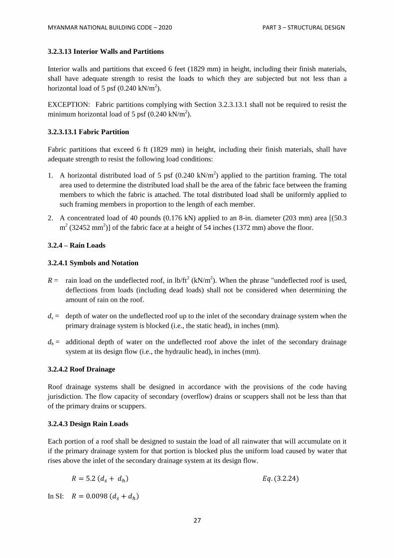
MYANMAR NATIONAL BUILDING CODE – 2020 PART 3 – STRUCTURAL DESIGN
27
3.2.3.13 Interior Walls and Partitions
Interior walls and partitions that exceed 6 feet (1829 mm) in height, including their finish materials,
shall have adequate strength to resist the loads to which they are subjected but not less than a
horizontal load of 5 psf (0.240 kN/m2).
EXCEPTION: Fabric partitions complying with Section 3.2.3.13.1 shall not be required to resist the
minimum horizontal load of 5 psf (0.240 kN/m2).
3.2.3.13.1 Fabric Partition
Fabric partitions that exceed 6 ft (1829 mm) in height, including their finish materials, shall have
adequate strength to resist the following load conditions:
1. A horizontal distributed load of 5 psf (0.240 kN/m2) applied to the partition framing. The total
area used to determine the distributed load shall be the area of the fabric face between the framing
members to which the fabric is attached. The total distributed load shall be uniformly applied to
such framing members in proportion to the length of each member.
2. A concentrated load of 40 pounds (0.176 kN) applied to an 8-in. diameter (203 mm) area [(50.3
m2 (32452 mm
2)] of the fabric face at a height of 54 inches (1372 mm) above the floor.
3.2.4 – Rain Loads
3.2.4.1 Symbols and Notation
R = rain load on the undeflected roof, in lb/ft2 (kN/m
2). When the phrase "undeflected roof is used,
deflections from loads (including dead loads) shall not be considered when determining the
amount of rain on the roof.
ds = depth of water on the undeflected roof up to the inlet of the secondary drainage system when the
primary drainage system is blocked (i.e., the static head), in inches (mm).
dh = additional depth of water on the undeflected roof above the inlet of the secondary drainage
system at its design flow (i.e., the hydraulic head), in inches (mm).
3.2.4.2 Roof Drainage
Roof drainage systems shall be designed in accordance with the provisions of the code having
jurisdiction. The flow capacity of secondary (overflow) drains or scuppers shall not be less than that
of the primary drains or scuppers.
3.2.4.3 Design Rain Loads
Each portion of a roof shall be designed to sustain the load of all rainwater that will accumulate on it
if the primary drainage system for that portion is blocked plus the uniform load caused by water that
rises above the inlet of the secondary drainage system at its design flow.
In SI:
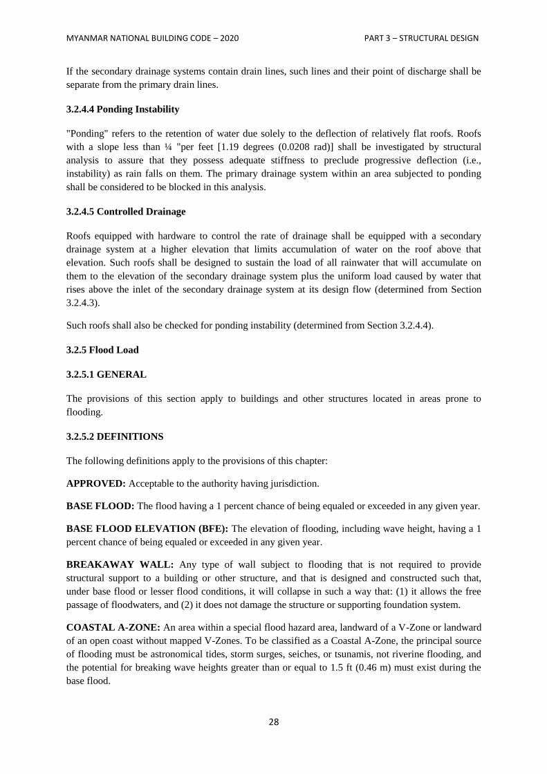
MYANMAR NATIONAL BUILDING CODE – 2020 PART 3 – STRUCTURAL DESIGN
28
If the secondary drainage systems contain drain lines, such lines and their point of discharge shall be
separate from the primary drain lines.
3.2.4.4 Ponding Instability
"Ponding" refers to the retention of water due solely to the deflection of relatively flat roofs. Roofs
with a slope less than ¼ "per feet [1.19 degrees (0.0208 rad)] shall be investigated by structural
analysis to assure that they possess adequate stiffness to preclude progressive deflection (i.e.,
instability) as rain falls on them. The primary drainage system within an area subjected to ponding
shall be considered to be blocked in this analysis.
3.2.4.5 Controlled Drainage
Roofs equipped with hardware to control the rate of drainage shall be equipped with a secondary
drainage system at a higher elevation that limits accumulation of water on the roof above that
elevation. Such roofs shall be designed to sustain the load of all rainwater that will accumulate on
them to the elevation of the secondary drainage system plus the uniform load caused by water that
rises above the inlet of the secondary drainage system at its design flow (determined from Section
3.2.4.3).
Such roofs shall also be checked for ponding instability (determined from Section 3.2.4.4).
3.2.5 Flood Load
3.2.5.1 GENERAL
The provisions of this section apply to buildings and other structures located in areas prone to
flooding.
3.2.5.2 DEFINITIONS
The following definitions apply to the provisions of this chapter:
APPROVED: Acceptable to the authority having jurisdiction.
BASE FLOOD: The flood having a 1 percent chance of being equaled or exceeded in any given year.
BASE FLOOD ELEVATION (BFE): The elevation of flooding, including wave height, having a 1
percent chance of being equaled or exceeded in any given year.
BREAKAWAY WALL: Any type of wall subject to flooding that is not required to provide
structural support to a building or other structure, and that is designed and constructed such that,
under base flood or lesser flood conditions, it will collapse in such a way that: (1) it allows the free
passage of floodwaters, and (2) it does not damage the structure or supporting foundation system.
COASTAL A-ZONE: An area within a special flood hazard area, landward of a V-Zone or landward
of an open coast without mapped V-Zones. To be classified as a Coastal A-Zone, the principal source
of flooding must be astronomical tides, storm surges, seiches, or tsunamis, not riverine flooding, and
the potential for breaking wave heights greater than or equal to 1.5 ft (0.46 m) must exist during the
base flood.
MYANMAR NATIONAL BUILDING CODE – 2020 PART 3 – STRUCTURAL DESIGN
29
COASTAL HIGH HAZARD AREA (V-ZONE): An area within a Special Flood Hazard Area,
extending from offshore to the inland limit of a primary frontal dune along an open coast, and any
other area that is subject to high-velocity wave action from storms or seismic sources.
DESIGN FLOOD ELEVATION (DFE): The elevation of the design flood, including wave height,
relative to the datum specified on a community’s flood hazard map.
FLOOD HAZARD AREA: The area subject to flooding during the design flood.
SPECIAL FLOOD HAZARD AREA (AREA OF SPECIAL FLOOD HAZARD): The land in the
floodplain subject to a 1 percent or greater chance of flooding in any given year.
3.2.5.3 Design Requirements
3.2.5.3.1 Design Loads
Structural systems of buildings or other structures shall be designed, constructed, connected, and
anchored to resist flotation, collapse, and permanent lateral displacement due to action of flood loads
associated with the design flood (see Section 3.2.5.3.3) and other loads in accordance with the load
combinations of Section 3.2.1.
3.2.5.3.2 Erosion and Scour
The effects of erosion and scour shall be included in the calculation of loads on buildings and other
structures in flood hazard areas.
3.2.5.3.3 Loads on Breakaway Walls
Walls and partitions required by ASCE/SEI 24, to break away, including their connections to the
structure, shall be designed for the largest of the following loads acting perpendicular to the plane of
the wall:
1. The wind load specified in Section 3.3.
2. The earthquake load specified in Section 3.4.
3. 10 psf (0.48 kN/m2).
The loading at which breakaway walls are intended to collapse shall not exceed 20 psf (0.96 kN/m2)
unless the design meets the following conditions:
1. Breakaway wall collapse is designed to result from a flood load less than that which occurs during
the base flood.
2. The supporting foundation and the elevated portion of the building shall be designed against
collapse, permanent lateral displacement, and other structural damage due to the effects of flood
loads in combination with other loads as specified in Section 3.2.1.
3.2.5.4 Loads During Flooding
3.2.5.4.1 Load Basis
In flood hazard areas, the structural design shall be based on the design flood.
MYANMAR NATIONAL BUILDING CODE – 2020 PART 3 – STRUCTURAL DESIGN
30
3.2.5.4.2 Hydrostatic Loads
Hydrostatic loads caused by a depth of water to the level of the DFE shall be applied over all surfaces
involved, both above and below ground level, except that for surfaces exposed to free water, the
design depth shall be increased by 1 ft (0.30 m).
Reduced uplift and lateral loads on surfaces of enclosed spaces below the DFE shall apply only if
provision is made for entry and exit of floodwater.
3.2.5.4.3 Hydrodynamic Loads
Dynamic effects of moving water shall be determined by a detailed analysis utilizing basic concepts
of fluid mechanics.
EXCEPTION: Where water velocities do not exceed 10 ft/s (3.05 m/s), dynamic effects of moving
water shall be permitted to be converted into equivalent hydrostatic loads by increasing the DFE for
design purposes by an equivalent surcharge depth, dh, on the headwater side and above the ground
level only, equal to
Eq.
Where,
V = average velocity of water in ft/s (m/s)
g = acceleration due to gravity, 32.2 ft/s (9.81 m/s2)
a = coefficient of drag or shape factor (not less than 1.25)
The equivalent surcharge depth shall be added to the DFE design depth and the resultant hydrostatic
pressures applied to, and uniformly distributed across, the vertical projected area of the building or
structure that is perpendicular to the flow. Surfaces parallel to the flow or surfaces wetted by the tail
water shall be subject to the hydrostatic pressures for depths to the DFE only.
3.2.5.4.4 Wave Loads
Wave loads shall be determined by one of the following three methods: (1) by using the analytical
procedures outlined in this section, (2) by more advanced numerical modeling procedures, or (3) by
laboratory test procedures (physical modeling).
Wave loads are those loads that result from water waves propagating over the water surface and
striking a building or other structure. Design and construction of buildings and other structures subject
to wave loads shall account for the following loads: waves breaking on any portion of the building or
structure; uplift forces caused by shoaling waves beneath a building or structure, or portion thereof;
wave runup striking any portion of the building or structure; wave-induced drag and inertia forces;
and wave-induced scour at the base of a building or structure, or its foundation. Wave loads shall be
included for both V-Zones and A-Zones. In V-Zones, waves are 3 ft (0.91 m) high, or higher; in
coastal floodplains landward of the V-Zone, waves are less than 3 ft high (0.91 m).
Nonbreaking and broken wave loads shall be calculated using the procedures described in Sections
3.2.5.4.2 and 3.2.5.4.3 that show how to calculate hydrostatic and hydrodynamic loads.
MYANMAR NATIONAL BUILDING CODE – 2020 PART 3 – STRUCTURAL DESIGN
31
Breaking wave loads shall be calculated using the procedures described in Sections 3.2.5.4.4.1
through 3.2.5.4.4.4. Breaking wave heights used in the procedures described in Sections 3.2.5.4.4.1
through 3.2.5.4.4.4 shall be calculated for V-Zones and Coastal A-Zones using Eqs. 3.2.26 and 3.2.27.
Eq.
where,
Hb = breaking wave height in ft (m)
ds = local still water depth in ft (m)
The local still water depth shall be calculated using Eq. 3.2.27, unless more advanced procedures or
laboratory tests permitted by this section are used.
Eq.
where,
BFE = BFE in ft (m)
G = ground elevation in ft (m)
3.2.5.4.4.1 Breaking Wave Loads on Vertical Pilings and Columns
The net force resulting from a breaking wave acting on a rigid vertical pile or column shall be
assumed to act at the still water elevation and shall be calculated by the following:
Eq.
where,
FD = net wave force, in lb (kN)
γw = unit weight of water, in lb per cubic ft (kN/m3),
= 62.4 pcf (9.80 kN/m3) for fresh water and 64.0 pcf (10.05 kN/m
3) for salt water
CD = coefficient of drag for breaking waves,
= 1.75 for round piles or columns, and
= 2.25 for square piles or columns
D = pile or column diameter, in ft (m) for circular sections, or for a square pile or column,
1.4 times the width of the pile or column in ft (m)
Hb = breaking wave height, in ft (m)
3.2.5.4.4.2 Breaking Wave Loads on Vertical Walls
Maximum pressures and net forces resulting from a normally incident breaking wave (depth-limited
in size, with Hb = 0.78ds) acting on a rigid vertical wall shall be calculated by the following:
Pmax = Cpγwds + 1.2γwds Eq (3.2.29)
and
Ft = 1.1Cpγwd2
s + 2.4γwds2 Eq (3.2.30)
where
Pmax = maximum combined dynamic (Cpγwds) and static (1.2γwds) wave pressures, also referred to
as shock pressures in lb/ft2 (kN/m
2)
MYANMAR NATIONAL BUILDING CODE – 2020 PART 3 – STRUCTURAL DESIGN
32
Ft = net breaking wave force per unit length of structure, also referred to as shock, impulse, or
wave impact force in lb/ft (kN/m), acting near the still water elevation
Cp = dynamic pressure coefficient (1.6 < Cp < 3.5) (see Table 3.2.5-1)
γw = unit weight of water, in lb per cubic ft (kN/m3), = 62.4 pcf (9.80 kN/m
3) for fresh water
and 64.0 pcf (10.05 kN/m3) for salt water
ds = still water depth in ft (m) at base of building or other structure where the wave breaks
This procedure assumes the vertical wall causes a reflected or standing wave against the waterward
side of the wall with the crest of the wave at a height of 1.2ds above the still water level. Thus, the
dynamic static and total pressure distributions against the wall are as shown in Fig. 3.2.5-1.
This procedure also assumes the space behind the vertical wall is dry, with no fluid balancing the
static component of the wave force on the outside of the wall. If free water exists behind the wall, a
portion of the hydrostatic component of the wave pressure and force disappears (see Fig. 3.2.5-2) and
the net force shall be computed by Eq. 3.2.31 (the maximum combined wave pressure is still
computed with Eq. 3.2.29).
Ft = 1.1Cpγwd2s + 1.9γwd s
2 Eq. (3.2.31)
where
Ft = net breaking wave force per unit length of structure, also referred to as shock,
impulse, or wave impact force in lb/ft (kN/m), acting near the still water elevation
Cp = dynamic pressure coefficient (1.6 < Cp < 3.5) (see Table 3.2.5-1)
γw = unit weight of water, in lb per cubic ft (kN/m3), = 62.4 pcf (9.80 kN/m
3) for fresh
water and 64.0 pcf (10.05 kN/m3) for salt water
ds = still water depth in ft (m) at base of building or other structure where the wave
breaks
3.2.5.4.4.3 Breaking Wave Loads on Non Vertical Walls
Breaking wave forces given by Eqs. 3.2.30 and 3.2.31 shall be modified in instances where the walls
or surfaces upon which the breaking waves act are non-vertical. The horizontal component of
breaking wave force shall be given by
Fnv = Ft sin2 a Eq. (3.2.32)
where
Fnv = horizontal component of breaking wave force in lb/ft (kN/m)
Ft = net breaking wave force acting on a vertical surface in lb/ft (kN/m)
a = vertical angle between non-vertical surface and the horizontal
3.2.5.4.4.4 Breaking Wave Loads from Obliquely Incident Waves
Breaking wave forces given by Eqs. 3.2.30 and 3.2.31 shall be modified in instances where waves are
obliquely incident. Breaking wave forces from non-normally incident waves shall be given by
Foi = Ft sin2 a Eq. (3.2.33)
where
Foi = horizontal component of obliquely incident breaking wave force in lb/ft (kN/m)
Ft = net breaking wave force (normally incident waves) acting on a vertical surface in lb/ft
(kN/m)
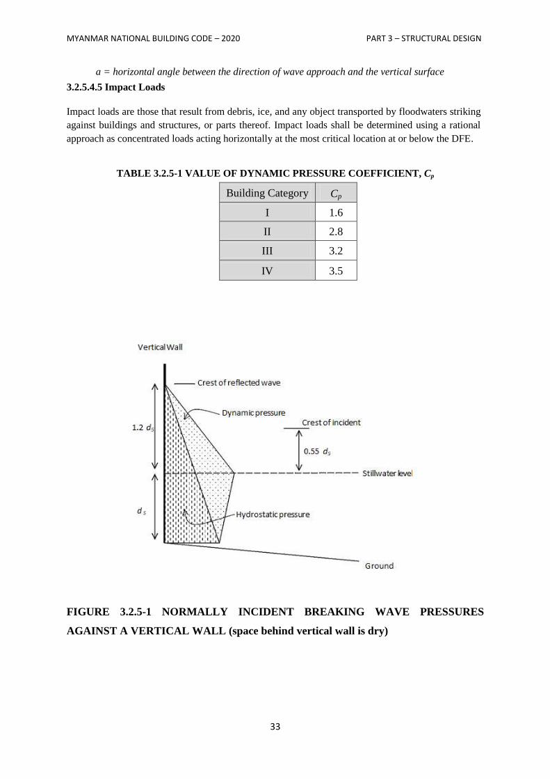
MYANMAR NATIONAL BUILDING CODE – 2020 PART 3 – STRUCTURAL DESIGN
33
a = horizontal angle between the direction of wave approach and the vertical surface
3.2.5.4.5 Impact Loads
Impact loads are those that result from debris, ice, and any object transported by floodwaters striking
against buildings and structures, or parts thereof. Impact loads shall be determined using a rational
approach as concentrated loads acting horizontally at the most critical location at or below the DFE.
TABLE 3.2.5-1 VALUE OF DYNAMIC PRESSURE COEFFICIENT, Cp
Building Category Cp
I 1.6
II 2.8
III 3.2
IV 3.5
FIGURE 3.2.5-1 NORMALLY INCIDENT BREAKING WAVE PRESSURES
AGAINST A VERTICAL WALL (space behind vertical wall is dry)
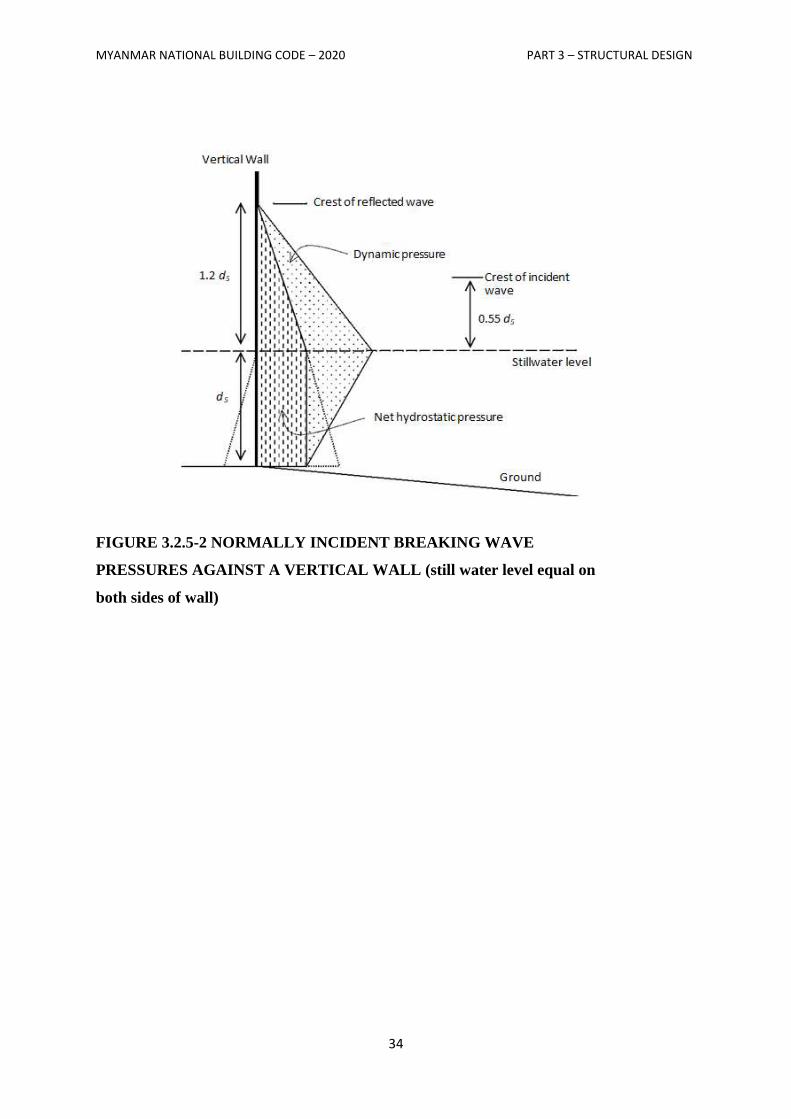
MYANMAR NATIONAL BUILDING CODE – 2020 PART 3 – STRUCTURAL DESIGN
34
FIGURE 3.2.5-2 NORMALLY INCIDENT BREAKING WAVE
PRESSURES AGAINST A VERTICAL WALL (still water level equal on
both sides of wall)
MYANMAR NATIONAL BUILDING CODE – 2020 PART 3 – STRUCTURAL DESIGN
35
SECTION 3.3
WIND DESIGN CRITERIA
3.3.1 General
3.3.1.1 Scope
Buildings and other structures, including the Main Wind-Force Resisting System (MWFRS) and all
components and cladding thereof, shall be designed and constructed to resist wind loads as specified
herein. Decreases in wind loads shall not be made for the effect of shielding by other structures.
3.3.1.2 Allowed Procedures
The design wind loads for buildings and other structures, including the MWFRS and component and
cladding elements thereof, shall be determined using one of the following procedures:(1) Method 1 –
Simplified Procedure as specified in Section 3.3.4 for buildings meeting the requirements specified
therein; (2) Method 2 – Analytical Procedure as specified in Section 6.5 of ASCE 7-05 for buildings
meeting the requirements specified therein; (3) Method 3 – Wind Tunnel Procedure as specified in
Section 6.6 of ASCE 7-05.
3.3.1.3 Wind Pressures Acting on Opposite Faces of Each Building Surface
In the calculation of design wind loads for the MWFRS and for components and cladding of
buildings, the algebraic sum of the pressures acting on opposite faces of each building surface shall be
taken into account.
3.3.1.4 Minimum Design Wind Loading
The design wind load, determined by any one of the procedures specified in Section 3.3.1.2, shall be
not less than that specified in this section.
3.3.1.4.1 Main Wind-Force Resisting System
The wind load to be used in the design of the MWFRS for an enclosed or partially enclosed building
shall not be less than 10 lb/ft2 (0.48 kN/m
2) multiplied by the area of the building or structure
projected onto a vertical plane normal to the assumed wind direction. The design wind force for open
buildings and other structures shall be not less than 10 lb/ft2 (0.48 kN/m
2) multiplied by the area Af.
3.3.1.4.2 Components and Cladding
The design wind pressure for components and cladding of buildings shall not be less than net pressure
of10lb/ft2 (0.48kN/m
2) acting in either direction normal to the surface.
3.3.2 Definitions
The following definitions apply only to the provisions of Section 3.3.
APPROVED: Acceptable to the authority having jurisdiction.
BASIC WIND SPEED, V: Three-second gust speed at 33 ft (10 m) above the ground in Exposure C
(see Section 3.3.4.6.3) as determined in accordance with Section 3.3.4.4.
MYANMAR NATIONAL BUILDING CODE – 2020 PART 3 – STRUCTURAL DESIGN
36
BUILDING, ENCLOSED: A building that does not comply with the requirements for open or
partially enclosed buildings.
BUILDING ENVELOPE: Cladding, roofing, exterior walls, glazing, door assemblies, window
assemblies, skylight assemblies, and other components enclosing the building.
BUILDING AND OTHER STRUCTURE, FLEXIBLE: Slender buildings that have a fundamental
natural frequency less than 1Hz.
BUILDING, LOW-RISE: Enclosed or partially enclosed buildings that comply with the following
conditions:
1. Mean roof height h less than or equal to 60 ft (18 m).
2. Mean roof height h does not exceed least horizontal dimension.
BUILDING, OPEN: A building having each wall at least 80 percent open. This condition is
expressed for each wall by the equation A0 ≥ 0.8Agwhere
A0 = total area of openings in a wall that receives positive external pressure, in ft2 (m
2)
Ax = the gross area of that wall in which A0 is identified, in ft2 (m
2)
BUILDING PARTIALLY ENCLOSED: A building that complies with both of the following
conditions:
1. The total area of openings in a wall that receives positive external pressure exceeds the sum of the
areas of openings in the balance of the building envelope (walls and roof) by more than 10 percent.
2. The total area of openings in a wall that receives positive external pressure exceeds 4 ft2 (0.37 m
2)
or 1 percent of the area of that wall, whichever is smaller, and the percentage of openings in the
balance of the building envelope does not exceed 20 percent.
These conditions are expressed by the following equations:
1. A0> 1.10 A0i;
2. A0> 4 sqft (0.37 m2) or> 0.01 Ag, whichever is smaller, and A0i / Agi ≤0.20
where
A0, Ag are as defined for Open Building
A0i = the sum of the areas of openings in the building envelope (walls and roof) not including
A0, in ft2 (m
2)
Agi = the sum of the gross surface areas of the building envelope (walls and roof) not including
Ag, in ft2 (m
2)
BUILDING OR OTHER STRUCTURES, REGULAR-SHAPED: A building having no unusual
geometrical irregularity in spatial form.
BUILDING OR OTHER STRUCTURES, RIGID: A building whose fundamental frequency is
greater than or equal to1Hz.
BUILDING, SIMPLE DIAPHRAGM: A building in which both windward and leeward wind loads
are transmitted through floor and roof diaphragms to the same vertical MWFRS (e.g., no structural
separations).
COMPONENTS AND CLADDING: Elements of the building envelope that do not qualify as part
of the MWFRS.
MYANMAR NATIONAL BUILDING CODE – 2020 PART 3 – STRUCTURAL DESIGN
37
DESIGNFORCE, F: Equivalent static force to be used in the determination of wind loads for open
buildings.
DESIGN PRESSURE, p: Equivalent static pressure to be used in the determination of wind loads for
buildings.
EAVE HEIGHT, h: The distance from the ground surface adjacent to the building to the roof eave
line at a particular wall.
If the height of the eave varies along the wall, the average height shall be used.
EFFECTIVE WIND AREA, A: The area used to determine GCp. For component and cladding
elements, the effective wind area in Fig: 6-11 through 6-17 and Fig: 6-19 in Appendix is the span
length multiplied by an effective width that need not be less than one-third the span length. For
cladding fasteners, the effective wind area shall not be greater than the area that is tributary to an
individual fastener.
ESCARPMENT: Also known as scarp, with respect to topographic effects in Section 3.3.5.7, a cliff
or steep slope generally separating two levels or gently sloping areas (see Fig.3.3.3).
FREE ROOF: Roof with a configuration generally conforming to those shown in Fig 6-18A through
6-18D in Appendix (mono slope, pitched, or troughed) in an open building with no enclosing walls
underneath the roof surface.
GLAZING: Glass or transparent or translucent plastic sheet used in windows, doors, skylights, or
curtain walls.
GLAZING, IMPACT RESISTANT: Glazing that has been shown by testing in accordance with
ASTM El886 and ASTM El996 or other approved test methods to withstand the impact of wind-borne
missiles likely to be generated in wind-borne debris regions during design winds.
HILL: With respect to topographic effects in Section 3.3.5.7, a land surface characterized by strong
relief in any horizontal direction (see Fig. 3.3.3).
IMPORTANCE FACTOR, I: A factor that accounts for the degree of hazard to human life and
damage to property.
MAIN WIND-FORCE RESISTING SYSTEM (MWFRS): An assemblage of structural elements
assigned to provide support and stability for the overall structure. The system generally receives wind
loading from more than one surface.
MEAN ROOF HEIGHT, h: The average of the roof eave height and the height to the highest point
on the roof surface, except that, for roof angles of less than or equal to 10°, the mean roof height shall
be the roof eave height.
OPENINGS: Apertures or holes in the building envelope that allow air to flow through the building
envelope and that are designed as "open" during design winds as defined by these provisions.
RECOGNIZED LITERATURE: Published research findings and technical papers that are
approved.
RIDGE: With respect to topographic effects in Section 3.3.4.7 an elongated crest of a hill
characterized by strong relief in two directions (see Fig. 3.3.3).
MYANMAR NATIONAL BUILDING CODE – 2020 PART 3 – STRUCTURAL DESIGN
38
3.3.3 Symbols and Notation
The following symbols and notation apply only to the provisions of Section 3.3.
A = effective wind area, in ft2 (m
2)
Af = area of open buildings either normal to the wind direction or projected on a plane normal to
the wind direction, in ft2 (m
2)
Ag = the gross area of that wall in which A0 is identified, in ft2 (m
2)
Agi = the sum of the gross surface areas of the building envelope (walls and roof) not including Ag,
in ft2 (m
2)
A0 = total area of openings in a wall that receives positive external pressure, in ft2 (m
2)
A0i = the sum of the areas of openings in the building envelope (walls and roof) not including A0, in
ft2 (m
2)
A0g = total area of openings in the building envelope, in ft2 (m
2)
As = gross area of the solid freestanding wall or solid sign, in ft2 (m
2)
a = width of pressure coefficient zone, in ft (m)
B = horizontal dimension of building measured normal to wind direction, in ft (m)
b = mean hourly wind speed factor in Eq. 6-14 from Table 6-2 (ASCE 7-05)
b = 3-s gust speed factor from Table 6-2 (ASCE 7-05)
Cf = force coefficient to be used in determination of wind loads for other structures
CN = net pressure coefficient to be used in determination of wind loads for open buildings
Cp = external pressure coefficient to be used in determination of wind loads for buildings
c = turbulence intensity factor in Eq. 6-5 from Table 6-2 (ASCE 7-05)
D = diameter of a circular structure or member, in ft (m)
D' = depth of protruding elements such as ribs and spoilers, in ft (m)
F = design wind force for other structures, in lb (N)
G = gust effect factor
Gf = gust effect factor for MWFRSs of flexible buildings
GCpn = combined net pressure coefficient for a parapet
GCp = product of external pressure coefficient and gust effect factor to be used in determination of
wind loads for buildings
GCpf = product of the equivalent external pressure coefficient and gust-effect factor to be used in
determination of wind loads for MWFRS of low-rise buildings
GCpi = product of internal pressure coefficient and gust-effect factor to be used in determination of
wind loads for buildings
gQ = peak factor for background response Eq. 6-4 and 6-8 (ASCE 7-05)
MYANMAR NATIONAL BUILDING CODE – 2020 PART 3 – STRUCTURAL DESIGN
39
gR = peak factor for resonant response Eq. 6-8 (ASCE 7-05)
gv = peak factor for wind response Eq. 6-4 and 6-8 (ASCE 7-05)
H = height of hill or escarpment in Fig. 3.3.3, in ft (m)
h = mean roof height of a building, except that eave height shall be used for roof angle θ of less
than or equal to 10°, in ft(m)
he = roof eave height at a particular wall, or the average height if the eave varies long the wall
I = importance factor
zI = intensity of turbulence from Eq. 6-5 (ASCE 7-05)
K1, K2, K3= multipliers in Fig.3.3.3 to obtain Kzt
Kd = wind directionality factor in Table 6-4 (ASCE 7-05)
Kh = velocity pressure exposure coefficient evaluated at height z=h
Kz = velocity pressure exposure coefficient evaluated at height z
Kzt = topographic factor as defined in Section 3.3.4.7
L = horizontal dimension of a building measured parallel the wind direction, in ft(m)
Lh = distance upwind of crest of hill or escarpment in Fig.3.3.3 to where the difference in ground
elevation is half the height of hill or escarpment, in ft (m)
zL = integral length scale of turbulence, in ft (m)
Lr = horizontal dimension of return corner for a solid freestanding wall or solid sign from Fig.6-20
(ASCE 7-05), in ft (m)
= integral length scale factor from Table 3.3.3, ft (m)
N1 = reduced frequency from Eq. 6-12 (ASCE 7-05)
n1 = building natural frequency, Hz
p = design pressure to be used in determination of wind loads for buildings, in lb/ft2 (N/m
2)
pL = wind pressure acting on leeward face in Fig 6-9 (ASCE 7-05), in lb/ft2 (N/m
2)
pnet = net design wind pressure from Eq. (3.3.2), in lb/ft2 (N/m
2)
pnet30 = net design wind pressure for Exposure B at h=30ft and I= 1.0 from Fig.3.3.2, in lb/ft2 (N/m
2)
pp = combined net pressure on a parapet from Eq 6-20 (ASCE 7-05) in lb/ft2 (N/m
2)
ps = net design wind pressure from Eq. (3.3.1), in lb/ft2 (N/m
2)
ps 30 = simplified design wind pressure for Exposure B at h= 30ft and I=1.0 from Fig.3.3.1, in lb/ft2
(N/m2)
pw = wind pressure acting on windward face in Fig 6-9 (ASCE 7-05), in lb/ft2 (N/m
2)
Q = background response factor from Eq. 6-6 (ASCE 7-05)
q = velocity pressure, in lb/ft2 (N/m
2)
hq = velocity pressure evaluated at height z= h, in lb/ft2 (N/m
2)
MYANMAR NATIONAL BUILDING CODE – 2020 PART 3 – STRUCTURAL DESIGN
40
iq = velocity pressure for internal pressure determination, in lb/ft2 (N/m
2)
qp = velocity pressure at top of parapet, in lb/ft2 (N/m
2)
qz = velocity pressure evaluated at height z above ground, in lb/ft2 (N/m
2)
R = resonant response factor from Eq. 6-10 (ASCE 7-05)
RB, Rh, RL =values from Eq. 6-13 (ASCE 7-05)
Ri = reduction factor from Eq. 6-16 (ASCE 7-05)
Rn = value from Eq. 6-11 (ASCE 7-05)
s = vertical dimension of the solid freestanding wall or solid sign from Fig 6-20 (ASCE 7-05), in
ft (m)
r = rise-to-span ratio for arched roofs
V =basic wind speed obtained from Table 3.3.1, in mi/h (m/s). The basic wind speed corresponds
to a 3-s gust speed at 33 ft (10 m) above ground in exposure Category C
Vi = un partitioned internal volume, ft3 (m
3)
zV = mean hourly wind speed at height z , ft/s (m/s)
W = width of building in Figs. 6-12 and 6-14A (ASCE 7-05) and B and width of span in Figs.6-13
and 6-15 (ASCE 7-05), in ft(m)
X = distance to centre of pressure from wind ward edge in Fig.6-18 (ASCE 7-05), in ft (m)
x = distance up wind or downwind of crest in Fig.3.3.3, in ft (m)
z = height above ground level, in ft (m)
z = equivalent height of structure, in ft (m)
zg = nominal height of the atmospheric boundary layer used in this standard. Values appear in
Table 6-2 (ASCE 7-05)
zmin = exposure constant from Table 6-2 (ASCE 7-05)
α = 3-s gust-speed power law exponent from Table 6-2 (ASCE 7-05)
ᾶ = reciprocal of α from Table 6-2 (ASCE 7-05)
ᾱ = mean hourly wind-speed power law exponent in Eq.6-14 from Table 6-2 (ASCE 7-05)
β = damping ratio, percent critical for buildings
ϵ = ratio of solid area to gross area for solid free-standing wall, solid sign, open sign, face of a
trussed tower, or lattice structure
λ = adjustment factor for building height and exposure from Figs.3.3.1 and 3.3.2
= integral length scale power law exponent in Eq. 6-7 from Table 6-2 (ASCE 7-05)
η = value used in Eq. 6-13 (see Section 6.5.8.2) (ASCE 7-05)
θ = angle of plane of roof from horizontal, in degrees
v = height-to-width ratio for solid sign
MYANMAR NATIONAL BUILDING CODE – 2020 PART 3 – STRUCTURAL DESIGN
41
3.3.4 – Method 1 - Simplified Procedure
3.3.4.1 Scope
A building whose design wind loads are determined in accordance with this section shall meet all the
conditions of 3.3.4.1.1 or 3.3.4.1.2. If a building qualifies only under 3.3.4.1.2 for design of its
components and cladding, then its MWFRS shall be designed by Method 2 – Analytical Procedure as
specified in Section 6.5 of ASCE 7-05 (or) Method 3 – Wind Tunnel Procedure as specified in
Section 6.6 of ASCE 7-05.
3.3.4.1.1 Main Wind-Force Resisting Systems
For the design of MWFRSs the building must meet all of the following conditions:
1. The building is a simple diaphragm building as defined in Section 3.3.2.
2. The building is a low-rise building as defined in Section 3.3.2.
3. The building is enclosed as defined in Section 3.3.2
4. The building is a regular-shaped building or structure as defined in Section 3.3.2.
5. The building is not classified as a flexible building as defined in Section 3.3.2.
6. The building does not have response characteristics making it subject to across wind loading,
vortex shedding, instability due to galloping or flutter; and does not have a site location for which
channeling effects or buffeting in the wake of upwind obstructions warrant special consideration.
7. The building has an approximately symmetrical cross section in each direction with either a flat
roof or a gable or hip roof with θ ≤ 45°.
8. The building is exempted from torsional load cases as indicated in Note 5 of Fig.6-10 (ASCE 7-
05), or the torsional load cases defined in Note 5 do not control the design of any of the MWFRSs
of the building.
3.3.4.1.2 Components and Cladding
For the design of components and cladding the building must meet all the following conditions:
1. The mean roof height h must be less than or equal to 60 ft (h ≤ 60 ft).
2. The building is enclosed as defined in Section 3.3.2
3. The building is a regular-shaped building or structure as defined in Section 3.3.2.
4. The building does not have response characteristics making it subject to across wind loading,
vortex shedding, instability due to galloping or flutter; and does not have a site location for which
channeling effects or buffeting in the wake of upwind obstructions warrant special consideration.
5. The building has a flat roof, a gable roof with, or a hip roof with θ ≤ 45°, or a hip roof with θ ≤
27°.
3.3.4.2 Design Procedure
1. The basic wind speed V shall be determined in accordance with Section 3.3.4.4. The wind shall be
assumed to come from any horizontal direction.
2. An importance factor I shall be determined in accordance with Section 3.3.4.5.
3. An exposure category shall be determined in accordance with Section 3.3.4.6.
MYANMAR NATIONAL BUILDING CODE – 2020 PART 3 – STRUCTURAL DESIGN
42
4. A height and exposure adjustment coefficient, λ, shall be determined from Fig. 3.3.1.
3.3.4.2.1 Main Wind-Force Resisting System
Simplified design wind pressures, ps, for the MWFRSs of low-rise simple diaphragm buildings
represent the net pressures (sum of internal and external) to be applied to the horizontal and vertical
projections of building surfaces as shown in Fig. 3.3.1. For the horizontal pressures (zones A, B, C,
D), ps is the combination of the windward and leeward net pressures. ps, shall be determined by the
following equation:
Eq. (3.3.1)
where
λ = adjustment factor for building height and exposure from Fig. 3.3.1
Kzt = topographic factor as defined in Section 3.3.4.7 evaluated at mean roof height, h
I = importance factor as defined in Section 3.3.2
= simplified design wind pressure for Exposure B, at h = 30 ft, and for I = 1.0, from
Fig. 3.3.1
3.3.4.2.1.1 Minimum Pressures
The load effects of the design wind pressures from Section 3.3.4.2.1 shall not be less than the
minimum load case from Section 3.3.1.4.1 assuming the pressures, ps, for zones A, B, C, and D all
equal to +10 psf, while assuming zones E, F, G, and H all equal to 0 psf.
3.3.4.2.2 Components and Cladding
Net design wind pressures, pnet, for the components and cladding of buildings designed using Method
1 represent the net pressures (sum of internal and external) to be applied normal to each building
surface as shown in Fig. 3.2. pnet shall be determined by the following equation:
Eq. (3.3.2)
where
λ = adjustment factor for building height and exposure from Fig. 3.3.2
Kzt = topographic factor as defined in Section 3.3.4.7 evaluated at mean roof height, h
I = importance factor as defined in Section 3.3.2
= net design wind pressure for exposure B, at h = 30 ft, and for I = 1.0, from Fig.
3.3.2
3.3.4.2.2.1 Minimum pressures
The positive design wind pressures, pnet , from Section 3.3.4.2.2 shall not be less than +10 psf, and the
negative design wind pressures, pnet ,from Section 3.3.4.2.2 shall not be less than - 10 psf.
3.3.4.3 Air Permeable Cladding
Design wind loads determined from Fig. 3.3.2 shall be used for all air permeable cladding unless
approved test data or the recognized literature demonstrate lower loads for the type of air permeable
cladding being considered.
MYANMAR NATIONAL BUILDING CODE – 2020 PART 3 – STRUCTURAL DESIGN
43
3.3.4.4 Basic Wind Speed
The basic wind speed, V, used in the determination of design wind loads on buildings shall be as
given in Table 3.3.1 except as provided in Sections 3.3.4.4.1 and 3.3.4.4.2. The wind shall be assumed
to come from any horizontal direction.
3.3.4.4.1 Special Wind Regions
The basic wind speed shall be increased where records or experience indicate that the wind speeds are
higher than those reflected in Table 3.3.1. Mountainous terrain gorges and special regions shall be
examined for unusual wind conditions. The authority having jurisdiction shall, if necessary, adjust the
values given in Table 3.3.1 to account for higher local wind speeds. Such adjustment shall be based
on meteorological information and an estimate of the basic wind speed obtained in accordance with
the provisions of Section 3.3.4.4.2.
3.3.4.4.2 Estimation of Basic Wind Speeds from Regional Climatic Data
Regional climatic data shall only be used in lieu of the basic wind speeds given in Table 3.3.1 when
(1) approved extreme-value statistical-analysis procedures have been employed in reducing the data;
and (2) the length of record, sampling error, averaging time, anemometer height, data quality, and
terrain exposure of the anemometer have been taken into account. Reduction in basic wind speed
below that of Table 3.3.1 shall not be permitted.
When the basic wind speed is estimated from regional climatic data, the basic wind speed shall be not
less than the wind speed associated with an annual probability of 0.02 (50- year mean recurrence
interval), and the estimate shall be adjusted for equivalence to a 3-s gust wind speed at 33 ft (10 m)
above ground in exposure Category C. The data analysis shall be performed in accordance with this
section.
3.3.4.5 Importance Factor
An importance factor, I, for the building shall be determined from Table 3.3.2 based on building
categories listed in Table 3.1.2.
3.3.4.6 Exposure
For each wind direction considered, the upwind exposure category shall be based on ground surface
roughness that is determined from natural topography, vegetation, and constructed facilities.
3.3.4.6.1 Wind Directions and Sectors
For each selected wind direction at which the wind loads are to be evaluated, the exposure of the
building or structure shall be determined for the two upwind sectors extending 45° either side of the
selected wind direction. The exposures in these two sectors shall be determined in accordance with
Sections 3.3.4.6.2 and 3.3.4.6.3 and the exposure resulting in the highest wind loads shall be used to
represent the winds from that direction.
3.3.4.6.2 Surface Roughness Categories
A ground surface roughness within each 45° sector shall be determined for a distance upwind of the
site as defined in Section 3.3.4.6.3 from the categories defined in the following text, for the purpose of
assigning an exposure category as defined in Section 3.3.4.6.3.
MYANMAR NATIONAL BUILDING CODE – 2020 PART 3 – STRUCTURAL DESIGN
44
Surface Roughness B: Urban and suburban areas, wooded areas, or other terrain with numerous
closely spaced obstructions having the size of single-family dwellings or larger.
Surface Roughness C: Open terrain with scattered obstructions having heights generally less than 30
ft (9.1 m).
Surface Roughness D: Flat, unobstructed areas and water surfaces. This category includes smooth
mud flats and salt flats.
3.3.4.6.3 Exposure categories
Exposure B: Exposure B shall apply where the ground surface roughness condition, as defined by
Surface Roughness B, prevails in the upwind direction for a distance of at least 2,600 ft (792 m) or 20
times the height of the building, whichever is greater.
EXCEPTION: For buildings whose mean roof height is less than or equal to 30 ft, the upwind
distance may be reduced to 1,500 ft (457 m).
Exposure C: Exposure C shall apply for all cases where Exposures B or D do not apply.
Exposure D: Exposure D shall apply where the ground surface roughness, as defined by Surface
Roughness D, prevails in the upwind direction for a distance greater than 5,000 ft (1,524 m) or 20
times the building height, whichever is greater. Exposure D shall extend into downwind areas of
Surface Roughness B or C for a distance of 600 ft (200 m) or 20 times the height of the building,
whichever is greater.
For a site located in the transition zone between exposure categories, the category resulting in the
largest wind forces shall be used.
EXCEPTION: An intermediate exposure between the preceding categories is permitted in a
transition zone provided that it is determined by a rational analysis method defined in the recognized
literature.
3.3.4.7 Topographic Effects
3.3.4.7.1 Wind Speed-Up Over Hills, Ridges, and Escarpments
Wind speed-up effects at isolated hills, ridges, and escarpments constituting abrupt changes in the
general topography, located in any exposure category, and shall be included in the design when
buildings and other site conditions and locations of structures meet all of the following conditions:
1. The hill, ridge, or escarpment is isolated and unobstructed upwind by other similar topographic
features of comparable height for 100 times the height of the topographic feature (100H) or 2 mi
(3.22 km), whichever is less. This distance shall be measured horizontally from the point at which
the height H of the hill, ridge, or escarpment is determined.
2. The hill, ridge, or escarpment protrudes above the height of upwind terrain features within a 2-mi
(3.22 km) radius in any quadrant by a factor of two or more.
MYANMAR NATIONAL BUILDING CODE – 2020 PART 3 – STRUCTURAL DESIGN
45
3. The structure is located as shown in Fig. 3.3.3 in the upper one-half of a hill or ridge or near the
crest of an escarpment
4. H/Lh 0.2.
5. H is greater than or equal to 15 ft (4.5 m) for Exposures C and D and 60 ft (18 m) for Exposure B.
3.3.4.7.2 Topographic Factor
The wind speed-up effect shall be included in the calculation of design wind loads by using the factor
Kzt:
Eq. (3.3.3)
where K1, K2, and K3 are given in Fig. 3.3.3
If site conditions and locations of structures do not meet all the conditions specified in section
3.3.4.7.1 then Kzt= 1.0.
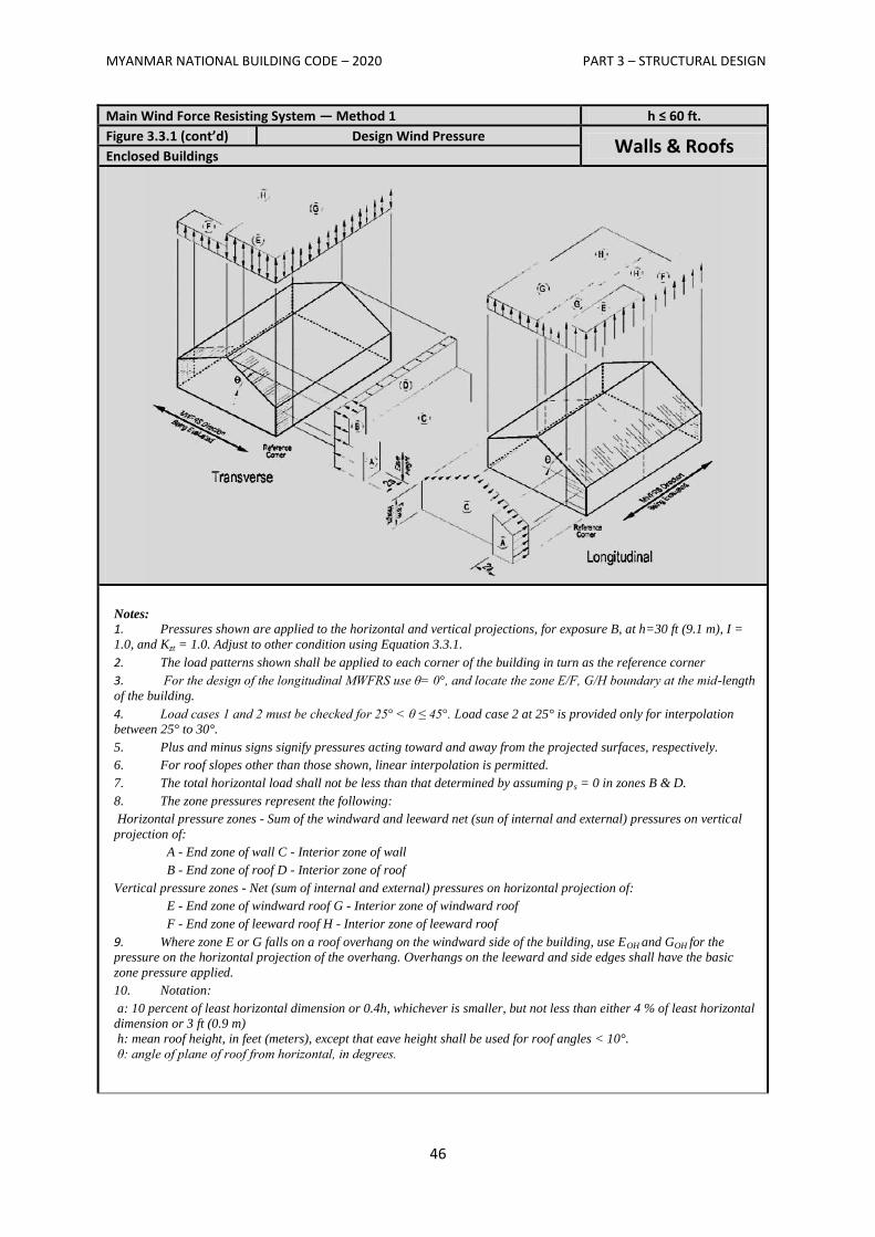
MYANMAR NATIONAL BUILDING CODE – 2020 PART 3 – STRUCTURAL DESIGN
46
Main Wind Force Resisting System — Method 1 h ≤ 60 ft.
Figure 3.3.1 (cont’d) Design Wind Pressure Walls & Roofs
Enclosed Buildings
Notes: 1. Pressures shown are applied to the horizontal and vertical projections, for exposure B, at h=30 ft (9.1 m), I =
1.0, and Kzt = 1.0. Adjust to other condition using Equation 3.3.1.
2. The load patterns shown shall be applied to each corner of the building in turn as the reference corner
3. For the design of the longitudinal MWFRS use θ= 0°, and locate the zone E/F, G/H boundary at the mid-length
of the building.
4. Load cases 1 and 2 must be checked for 25° < θ ≤ 45°. Load case 2 at 25° is provided only for interpolation
between 25° to 30°.
5. Plus and minus signs signify pressures acting toward and away from the projected surfaces, respectively.
6. For roof slopes other than those shown, linear interpolation is permitted.
7. The total horizontal load shall not be less than that determined by assuming ps = 0 in zones B & D.
8. The zone pressures represent the following:
Horizontal pressure zones - Sum of the windward and leeward net (sun of internal and external) pressures on vertical
projection of:
A - End zone of wall C - Interior zone of wall
B - End zone of roof D - Interior zone of roof
Vertical pressure zones - Net (sum of internal and external) pressures on horizontal projection of:
E - End zone of windward roof G - Interior zone of windward roof
F - End zone of leeward roof H - Interior zone of leeward roof
9. Where zone E or G falls on a roof overhang on the windward side of the building, use EOH and GOH for the
pressure on the horizontal projection of the overhang. Overhangs on the leeward and side edges shall have the basic
zone pressure applied.
10. Notation:
a: 10 percent of least horizontal dimension or 0.4h, whichever is smaller, but not less than either 4 % of least horizontal
dimension or 3 ft (0.9 m)
h: mean roof height, in feet (meters), except that eave height shall be used for roof angles < 10°.
θ: angle of plane of roof from horizontal, in degrees.
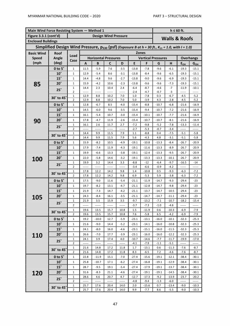
MYANMAR NATIONAL BUILDING CODE – 2020 PART 3 – STRUCTURAL DESIGN
47
Main Wind Force Resisting System — Method 1 h ≤ 60 ft.
Figure 3.3.1 (cont’d) Design Wind Pressure Walls & Roofs
Enclosed Buildings
Simplified Design Wind Pressure, pS30 (psf) (Exposure B at h = 30 ft., K21 = 1.0, with I = 1.0)
Basic Wind Speed (mph
Roof Angle (deg)
Load Case
Zones
Horizontal Pressures Vertical Pressures Overhangs
A B C D E F G H EOH GOH
85
0 to 5˚ 1 11.5 -5.9 7.6 -3.5 -13.8 -7.8 -9.6 -6.1 -19.3 -15.1
10˚ 1 12.9 -5.4 8.6 -3.1 -13.8 -8.4 -9.6 -6.5 -19.3 -15.1
15˚ 1 14.4 -4.8 9.6 -2.7 -13.8 -9.0 -9.6 -6.9 -19.3 -15.1
20˚ 1 15.9 -4.2 10.6 -2.3 -13.8 -9.6 -9.6 -7.3 -19.3 -15.1
25˚ 1 14.4 2.3 10.4 2.4 -6.4 -8.7 -4.6 -7 -11.9 -10.1
2 ------ ------ ------ ------ -2.4 -4.7 -0.7 -3 ------ ------
30˚ to 45˚ 1 12.9 8.8 10.2 7.0 1.0 -7.8 0.3 -6.7 -4.5 -5.2
2 12.9 8.8 10.2 7.0 5.0 -3.9 4.3 -2.8 -4.5 -5.2
90
0 to 5˚ 1 12.8 -6.7 8.5 -4.0 -15.4 -8.8 -10.7 -6.8 -21.6 -16.9
10˚ 1 14.5 -6.0 9.6 -3.5 -15.4 -9.4 -10.7 -7.2 -21.6 -16.9
15˚ 1 16.1 -5.4 10.7 -3.0 -15.4 -10.1 -10.7 -7.7 -21.6 -16.9
20˚ 1 17.8 -4.7 11.9 -2.6 -15.4 -10.7 -10.7 -8.1 -21.6 -16.9
25˚ 1 16.1 2.6 11.7 2.7 -7.2 -9.8 -5.2 -7.8 -13.3 -11.4
2 ------ ------ ------ ------ -2.7 -5.3 -0.7 -3.4 ------ ------
30˚ to 45˚ 1 14.4 9.9 11.5 7.9 1.1 -8.8 0.4 -7.5 -5.1 -5.8
2 14.4 9.9 11.5 7.9 5.6 -4.3 4.8 -3.1 -5.1 -5.8
100
0 to 5˚ 1 15.9 -8.2 10.5 -4.9 -19.1 -10.8 -13.3 -8.4 -26.7 -20.9
10˚ 1 17.9 -7.4 11.9 -4.3 -19.1 -11.6 -13.3 -8.9 -26.7 -20.9
15˚ 1 19.9 -6.6 13.3 -3.8 -19.1 -12.4 -13.3 -9.5 -26.7 -20.9
20˚ 1 22.0 -5.8 14.6 -3.2 -19.1 -13.3 -13.3 -10.1 -26.7 -20.9
25˚ 1 19.9 3.2 14.4 3.3 -8.8 -12 -6.4 -9.7 -16.5 -14
2 ------ ------ ------ ------ -3.4 -6.6 -0.9 -4.2 ------ ------
30˚ to 45˚ 1 17.8 12.2 14.2 9.8 1.4 -10.8 0.5 -9.3 -6.3 -7.2
2 17.8 12.2 14.2 9.8 6.9 -5.3 5.9 -3.8 -6.3 -7.2
105
0 to 5˚ 1 17.5 -9.0 11.6 -5.4 -21.1 -11.9 -14.7 -9.3 -29.4 -23
10˚ 1 19.7 -8.2 13.1 -4.7 -21.1 -12.8 -14.7 -9.8 -29.4 -23
15˚ 1 21.9 -7.3 14.7 -4.2 -21.1 -13.7 -14.7 -10.5 -29.4 -23
20˚ 1 24.3 -8.4 16.1 -3.5 -21.1 -14.7 -14.7 -11.1 -29.4 -23
25˚ 1 21.9 3.5 15.9 3.5 -9.7 -13.2 -7.1 -10.7 -18.2 -15.4
2 ------ ------ ------ ------ -3.7 -7.3 -1.0 -4.6 ------ ------
30˚ to 45˚ 1 19.6 13.5 15.7 10.8 1.5 -11.9 0.6 -10.3 -6.9 -7.9
2 19.6 13.5 15.7 10.8 7.6 -5.8 6.5 -4.2 -6.9 -7.9
110
0 to 5˚ 1 19.2 -10.0 12.7 -5.9 -23.1 -13.1 -16.0 -10.1 -32.3 -25.3
10˚ 1 21.6 -9.0 14.4 -5.2 -23.1 -14.1 -16.0 -10.8 -32.3 -25.3
15˚ 1 24.1 -8.0 16.0 -4.6 -23.1 -15.1 -16.0 -11.5 -32.3 -25.3
20˚ 1 26.6 -7.0 17.7 -3.9 -23.1 -16.0 -16.0 -12.2 -32.3 -25.3
25˚ 1 24.1 3.9 17.4 4.0 -10.7 -14.6 -7.7 -11.7 -19.9 -17.0
2 ------ ------ ------ ------ -4.1 -7.9 -1.1 -5.1 ------ ------
30˚ to 45˚ 1 21.6 14.8 17.2 11.8 1.7 -13.1 0.6 -11.3 -7.6 -8.7
2 21.6 14.8 17.2 11.8 8.3 -6.5 7.2 -4.6 -7.6 -8.7
120
0 to 5˚ 1 22.8 -11.9 15.1 -7.0 -27.4 -15.6 -19.1 -12.1 -38.4 -30.1
10˚ 1 25.8 -10.7 17.1 -6.2 -27.4 -16.8 -19.1 -12.9 -38.4 -30.1
15˚ 1 28.7 -9.5 19.1 -5.4 -27.4 -17.9 -19.1 -13.7 -38.4 -30.1
20˚ 1 31.6 -8.3 21.1 -4.6 -27.4 -19.1 -19.1 -14.5 -38.4 -30.1
25˚ 1 28.6 4.6 20.7 4.7 -12.7 -17.3 -9.2 -13.9 -23.7 -20.2
2 ------ ------ ------ ------ -4.8 -9.4 -1.3 -6.0 ------ ------
30˚ to 45˚ 1 25.7 17.6 20.4 14.0 2.0 -15.6 0.7 -13.4 -9.0 -10.3
2 25.7 17.6 20.4 14.0 9.9 -7.7 8.6 -5.5 -9.0 -10.3
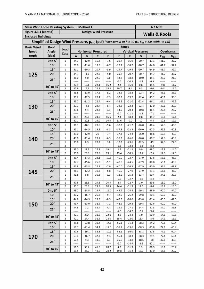
MYANMAR NATIONAL BUILDING CODE – 2020 PART 3 – STRUCTURAL DESIGN
48
Main Wind Force Resisting System — Method 1 h ≤ 60 ft.
Figure 3.3.1 (cont’d) Design Wind Pressure Walls & Roofs
Enclosed Buildings
Simplified Design Wind Pressure, ps30 (psf) (Exposure B at h = 30 ft., K21 = 1.0, with I = 1.0)
Basic Wind Speed (mph
Roof Angle (deg)
Load Case
Zones
Horizontal Pressures Vertical Pressures Overhangs
A B C D E F G H EOH GOH
125
0 to 5˚ 1 24.7 -12.9 16.4 -7.6 -29.7 -16.9 -20.7 -13.1 -41.7 -32.7
10˚ 1 28.0 -11.6 18.6 -6.7 -29.7 -18.2 -20.7 -14.0 -41.7 -32.7
15˚ 1 31.1 -10.3 20.7 -5.9 -29.7 -19.4 -20.7 -14.9 -41.7 -32.7
20˚ 1 34.3 -9.0 22.9 -5.0 -29.7 -20.7 -20.7 -15.7 -41.7 -32.7
25˚ 1 31.0 5.0 22.5 5.1 -13.8 -18.8 -10.0 -15.1 -25.7 -21.9
2 ------ ------ ------ ------ -5.2 -10.2 -1.4 -6.5 ------ ------
30˚ to 45˚ 1 27.9 19.1 22.1 15.2 2.2 -16.9 0.8 -14.5 -9.8 -11.2
2 27.9 19.1 22.1 15.2 10.7 -8.4 9.3 -6.0 -9.8 -11.2
130
0 to 5˚ 1 26.8 -13.9 17.8 -8.2 -32.2 -18.3 -22.4 -14.2 -45.1 -35.3
10˚ 1 30.2 -12.5 20.1 -7.3 -32.2 -19.7 -22.4 -15.1 -45.1 -35.3
15˚ 1 33.7 -11.2 22.4 -6.4 -32.2 -21.0 -22.4 -16.1 -45.1 -35.3
20˚ 1 37.1 -9.8 24.7 -5.4 -32.2 -22.4 -22.4 -17.0 -45.1 -35.3
25˚ 1 33.6 5.4 24.3 5.5 -14.9 -20.4 -10.8 -16.4 -27.8 -23.7
2 ------ ------ ------ ------ -5.7 -11.1 -1.5 -7.1 ------ ------
30˚ to 45˚ 1 30.1 20.6 24.0 16.5 2.3 -18.3 0.8 -15.7 -10.6 -12.1
2 30.1 20.6 24.0 16.5 11.6 -9.0 10 -6.4 -10.6 -12.1
140
0 to 5˚ 1 31.1 -16.1 20.6 -9.6 -37.3 -21.2 -26.0 -16.4 -52.3 -40.9
10˚ 1 35.1 -14.5 23.3 -8.5 -37.3 -22.8 -26.0 -17.5 -52.3 -40.9
15˚ 1 39.0 -12.9 26 -7.4 -37.3 -24.4 -26.0 -18.6 -52.3 -40.9
20˚ 1 43.0 -11.4 28.7 -6.3 -37.3 -26.0 -26.0 -19.7 -52.3 -40.9
25˚ 1 39.0 6.3 28.2 6.4 -17.3 -23.6 -12.5 -19 -32.3 -27.5
2 ------ ------ ------ ------ -6.6 -12.8 -1.8 -8.2 ------ ------
30˚ to 45˚ 1 35.0 23.9 27.8 19.1 2.7 -21.2 0.9 -18.2 -12.3 -14.0
2 35.0 23.9 27.8 19.1 13.4 -10.5 11.7 -7.5 -12.3 -14.0
145
0 to 5˚ 1 33.4 -17.3 22.1 -10.3 -40.0 -22.7 -27.9 -17.6 -56.1 -43.9
10˚ 1 37.7 -15.6 25.0 -9.1 -40.0 -24.5 -27.9 -18.8 -56.1 -43.9
15˚ 1 41.8 -13.8 27.9 -7.9 -40.0 -26.2 -27.9 -20.0 -56.1 -43.9
20˚ 1 46.1 -12.2 30.8 -6.8 -40.0 -27.9 -27.9 -21.1 -56.1 -43.9
25˚ 1 41.8 6.8 30.3 6.9 -18.6 -25.3 -13.4 -20.4 -34.6 -29.5
2 ------ ------ ------ ------ -7.1 -13.7 -1.9 -8.8 ------ ------
30˚ to 45˚ 1 37.5 25.6 29.8 20.5 2.9 -22.7 1.0 -19.5 -13.2 -15.0
2 35.7 25.6 29.8 20.5 14.4 -11.3 12.6 -8.0 -13.2 -15.0
150
0 to 5˚ 1 35.7 -18.5 23.7 -11.0 -42.9 -24.4 -29.8 -18.9 -60.0 -47.0
10˚ 1 40.2 -16.7 26.8 -9.7 -42.9 -26.2 -29.8 -20.1 -60.0 -47.0
15˚ 1 44.8 -14.9 29.8 -8.5 -42.9 -28.0 -29.8 -21.4 -60.0 -47.0
20˚ 1 49.4 -13.0 32.9 -7.2 -42.9 -29.8 -29.8 -22.6 -60.0 -47.0
25˚ 1 44.8 7.2 32.4 7.4 -19.9 -27.1 -14.4 -21.8 -37.0 -31.6
2 ------ ------ ------ ------ -7.5 -14.7 -2.1 -9.4 ------ ------
30˚ to 45˚ 1 40.1 27.4 31.9 22.0 3.1 -24.4 1.0 -20.9 -14.1 -16.1
2 40.1 27.4 31.9 22.0 15.4 -12.0 13.4 -8.6 -14.1 -16.1
170
0 to 5˚ 1 45.8 -23.8 30.4 -14.1 -55.1 -31.3 -38.3 -24.2 -77.1 -60.4
10˚ 1 51.7 -21.4 34.4 -12.5 -55.1 -33.6 -38.3 -25.8 -77.1 -60.4
15˚ 1 57.6 -19.1 38.3 -10.9 -55.1 -36.0 -38.3 -27.5 -77.1 -60.4
20˚ 1 63.4 -16.7 42.3 -9.3 -55.1 -38.3 -38.3 -29.1 -77.1 -60.4
25˚ 1 57.5 9.3 41.6 9.5 -25.6 -34.8 -18.5 -28 -47.6 -40.5
2 ------ ------ ------ ------ -9.7 -18.9 -2.6 -12.1 ------ ------
30˚ to 45˚ 1 51.5 35.2 41.0 28.2 4.0 -31.3 1.3 -26.9 -18.1 -20.7
2 51.5 35.2 41.0 28.2 19.8 -15.4 17.2 -11.0 -18.1 -20.7
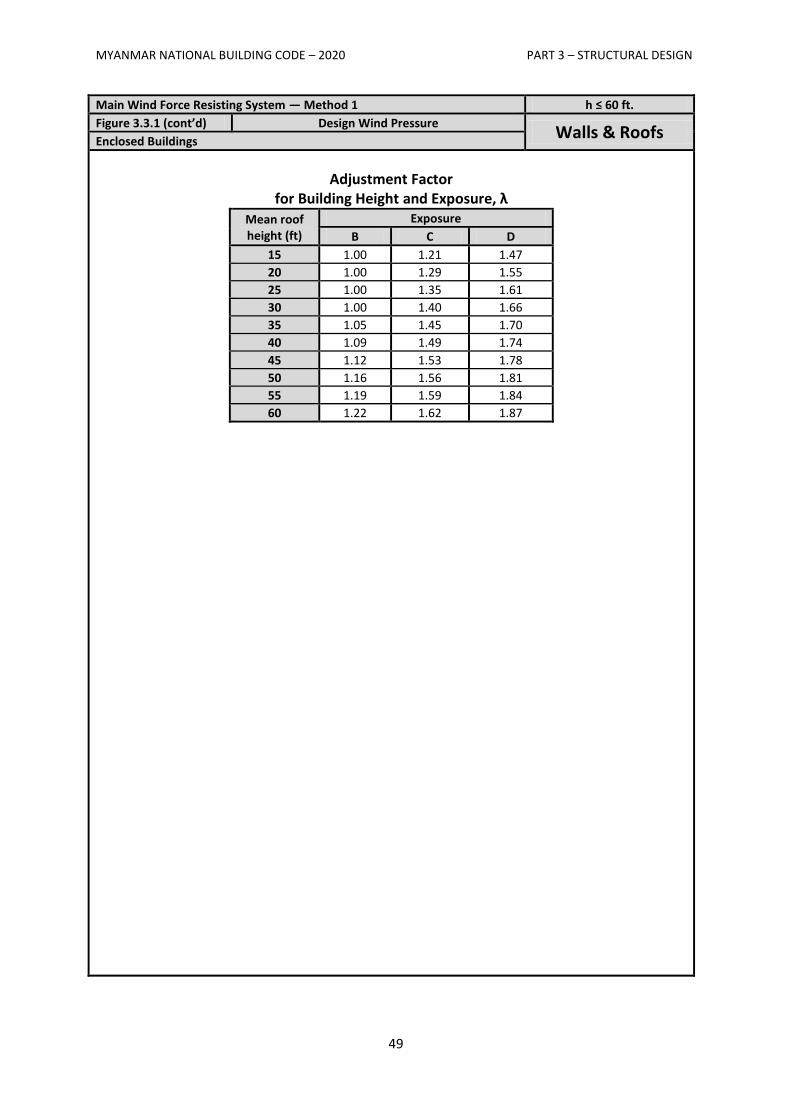
MYANMAR NATIONAL BUILDING CODE – 2020 PART 3 – STRUCTURAL DESIGN
49
Main Wind Force Resisting System — Method 1 h ≤ 60 ft.
Figure 3.3.1 (cont’d) Design Wind Pressure Walls & Roofs
Enclosed Buildings
Adjustment Factor for Building Height and Exposure, λ
Mean roof height (ft)
Exposure
B C D
15 1.00 1.21 1.47
20 1.00 1.29 1.55
25 1.00 1.35 1.61
30 1.00 1.40 1.66
35 1.05 1.45 1.70
40 1.09 1.49 1.74
45 1.12 1.53 1.78
50 1.16 1.56 1.81
55 1.19 1.59 1.84
60 1.22 1.62 1.87
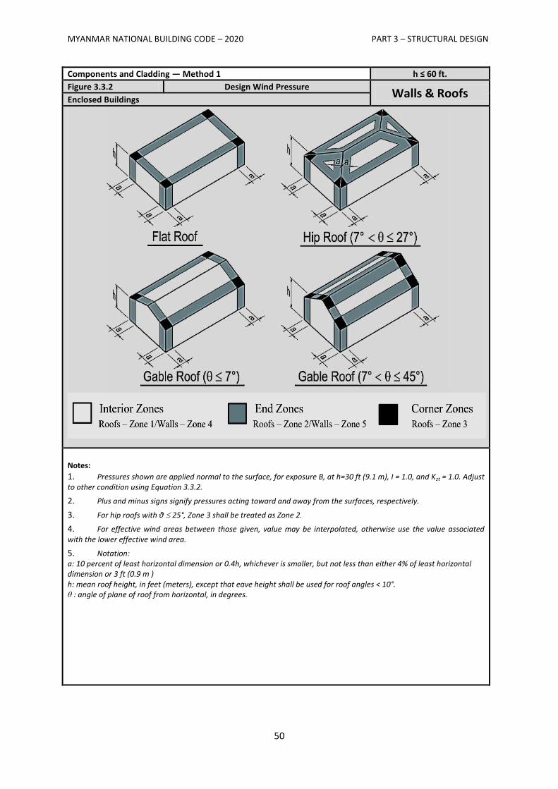
MYANMAR NATIONAL BUILDING CODE – 2020 PART 3 – STRUCTURAL DESIGN
50
Components and Cladding — Method 1 h ≤ 60 ft.
Figure 3.3.2 Design Wind Pressure Walls & Roofs
Enclosed Buildings
Notes:
1. Pressures shown are applied normal to the surface, for exposure B, at h=30 ft (9.1 m), I = 1.0, and Kzt = 1.0. Adjust to other condition using Equation 3.3.2.
2. Plus and minus signs signify pressures acting toward and away from the surfaces, respectively.
3. For hip roofs with θ 25°, Zone 3 shall be treated as Zone 2.
4. For effective wind areas between those given, value may be interpolated, otherwise use the value associated with the lower effective wind area.
5. Notation: a: 10 percent of least horizontal dimension or 0.4h, whichever is smaller, but not less than either 4% of least horizontal dimension or 3 ft (0.9 m ) h: mean roof height, in feet (meters), except that eave height shall be used for roof angles < 10°. θ : angle of plane of roof from horizontal, in degrees.
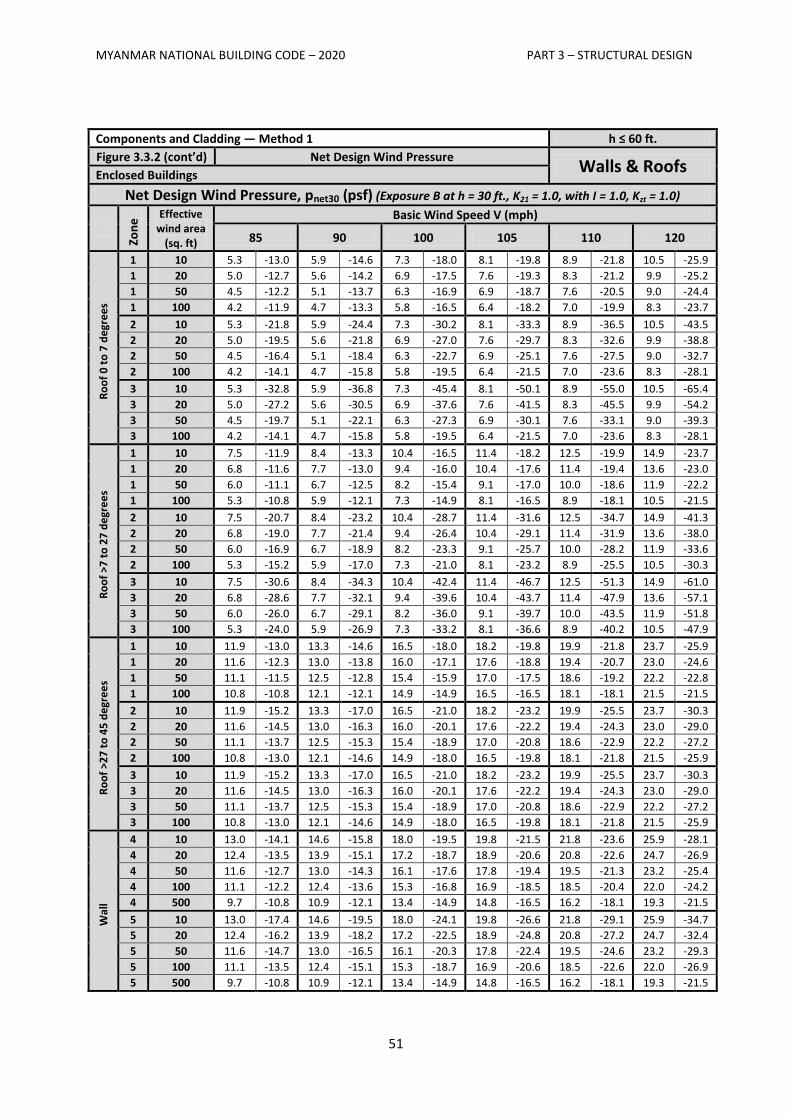
MYANMAR NATIONAL BUILDING CODE – 2020 PART 3 – STRUCTURAL DESIGN
51
Components and Cladding — Method 1 h ≤ 60 ft.
Figure 3.3.2 (cont’d) Net Design Wind Pressure Walls & Roofs
Enclosed Buildings
Net Design Wind Pressure, pnet30 (psf) (Exposure B at h = 30 ft., K21 = 1.0, with I = 1.0, Kzt = 1.0)
Zon
e
Effective wind area
(sq. ft)
Basic Wind Speed V (mph)
85 90 100 105 110 120
Ro
of
0 t
o 7
de
gre
es
1 10 5.3 -13.0 5.9 -14.6 7.3 -18.0 8.1 -19.8 8.9 -21.8 10.5 -25.9
1 20 5.0 -12.7 5.6 -14.2 6.9 -17.5 7.6 -19.3 8.3 -21.2 9.9 -25.2
1 50 4.5 -12.2 5.1 -13.7 6.3 -16.9 6.9 -18.7 7.6 -20.5 9.0 -24.4
1 100 4.2 -11.9 4.7 -13.3 5.8 -16.5 6.4 -18.2 7.0 -19.9 8.3 -23.7
2 10 5.3 -21.8 5.9 -24.4 7.3 -30.2 8.1 -33.3 8.9 -36.5 10.5 -43.5
2 20 5.0 -19.5 5.6 -21.8 6.9 -27.0 7.6 -29.7 8.3 -32.6 9.9 -38.8
2 50 4.5 -16.4 5.1 -18.4 6.3 -22.7 6.9 -25.1 7.6 -27.5 9.0 -32.7
2 100 4.2 -14.1 4.7 -15.8 5.8 -19.5 6.4 -21.5 7.0 -23.6 8.3 -28.1
3 10 5.3 -32.8 5.9 -36.8 7.3 -45.4 8.1 -50.1 8.9 -55.0 10.5 -65.4
3 20 5.0 -27.2 5.6 -30.5 6.9 -37.6 7.6 -41.5 8.3 -45.5 9.9 -54.2
3 50 4.5 -19.7 5.1 -22.1 6.3 -27.3 6.9 -30.1 7.6 -33.1 9.0 -39.3
3 100 4.2 -14.1 4.7 -15.8 5.8 -19.5 6.4 -21.5 7.0 -23.6 8.3 -28.1
Ro
of
>7 t
o 2
7 d
egr
ee
s
1 10 7.5 -11.9 8.4 -13.3 10.4 -16.5 11.4 -18.2 12.5 -19.9 14.9 -23.7
1 20 6.8 -11.6 7.7 -13.0 9.4 -16.0 10.4 -17.6 11.4 -19.4 13.6 -23.0
1 50 6.0 -11.1 6.7 -12.5 8.2 -15.4 9.1 -17.0 10.0 -18.6 11.9 -22.2
1 100 5.3 -10.8 5.9 -12.1 7.3 -14.9 8.1 -16.5 8.9 -18.1 10.5 -21.5
2 10 7.5 -20.7 8.4 -23.2 10.4 -28.7 11.4 -31.6 12.5 -34.7 14.9 -41.3
2 20 6.8 -19.0 7.7 -21.4 9.4 -26.4 10.4 -29.1 11.4 -31.9 13.6 -38.0
2 50 6.0 -16.9 6.7 -18.9 8.2 -23.3 9.1 -25.7 10.0 -28.2 11.9 -33.6
2 100 5.3 -15.2 5.9 -17.0 7.3 -21.0 8.1 -23.2 8.9 -25.5 10.5 -30.3
3 10 7.5 -30.6 8.4 -34.3 10.4 -42.4 11.4 -46.7 12.5 -51.3 14.9 -61.0
3 20 6.8 -28.6 7.7 -32.1 9.4 -39.6 10.4 -43.7 11.4 -47.9 13.6 -57.1
3 50 6.0 -26.0 6.7 -29.1 8.2 -36.0 9.1 -39.7 10.0 -43.5 11.9 -51.8
3 100 5.3 -24.0 5.9 -26.9 7.3 -33.2 8.1 -36.6 8.9 -40.2 10.5 -47.9
Ro
of
>27
to
45
de
gre
es
1 10 11.9 -13.0 13.3 -14.6 16.5 -18.0 18.2 -19.8 19.9 -21.8 23.7 -25.9
1 20 11.6 -12.3 13.0 -13.8 16.0 -17.1 17.6 -18.8 19.4 -20.7 23.0 -24.6
1 50 11.1 -11.5 12.5 -12.8 15.4 -15.9 17.0 -17.5 18.6 -19.2 22.2 -22.8
1 100 10.8 -10.8 12.1 -12.1 14.9 -14.9 16.5 -16.5 18.1 -18.1 21.5 -21.5
2 10 11.9 -15.2 13.3 -17.0 16.5 -21.0 18.2 -23.2 19.9 -25.5 23.7 -30.3
2 20 11.6 -14.5 13.0 -16.3 16.0 -20.1 17.6 -22.2 19.4 -24.3 23.0 -29.0
2 50 11.1 -13.7 12.5 -15.3 15.4 -18.9 17.0 -20.8 18.6 -22.9 22.2 -27.2
2 100 10.8 -13.0 12.1 -14.6 14.9 -18.0 16.5 -19.8 18.1 -21.8 21.5 -25.9
3 10 11.9 -15.2 13.3 -17.0 16.5 -21.0 18.2 -23.2 19.9 -25.5 23.7 -30.3
3 20 11.6 -14.5 13.0 -16.3 16.0 -20.1 17.6 -22.2 19.4 -24.3 23.0 -29.0
3 50 11.1 -13.7 12.5 -15.3 15.4 -18.9 17.0 -20.8 18.6 -22.9 22.2 -27.2
3 100 10.8 -13.0 12.1 -14.6 14.9 -18.0 16.5 -19.8 18.1 -21.8 21.5 -25.9
Wal
l
4 10 13.0 -14.1 14.6 -15.8 18.0 -19.5 19.8 -21.5 21.8 -23.6 25.9 -28.1
4 20 12.4 -13.5 13.9 -15.1 17.2 -18.7 18.9 -20.6 20.8 -22.6 24.7 -26.9
4 50 11.6 -12.7 13.0 -14.3 16.1 -17.6 17.8 -19.4 19.5 -21.3 23.2 -25.4
4 100 11.1 -12.2 12.4 -13.6 15.3 -16.8 16.9 -18.5 18.5 -20.4 22.0 -24.2
4 500 9.7 -10.8 10.9 -12.1 13.4 -14.9 14.8 -16.5 16.2 -18.1 19.3 -21.5
5 10 13.0 -17.4 14.6 -19.5 18.0 -24.1 19.8 -26.6 21.8 -29.1 25.9 -34.7
5 20 12.4 -16.2 13.9 -18.2 17.2 -22.5 18.9 -24.8 20.8 -27.2 24.7 -32.4
5 50 11.6 -14.7 13.0 -16.5 16.1 -20.3 17.8 -22.4 19.5 -24.6 23.2 -29.3
5 100 11.1 -13.5 12.4 -15.1 15.3 -18.7 16.9 -20.6 18.5 -22.6 22.0 -26.9
5 500 9.7 -10.8 10.9 -12.1 13.4 -14.9 14.8 -16.5 16.2 -18.1 19.3 -21.5
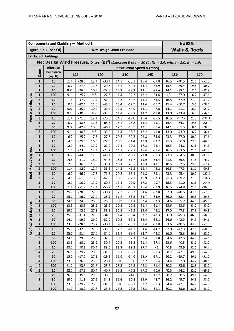
MYANMAR NATIONAL BUILDING CODE – 2020 PART 3 – STRUCTURAL DESIGN
52
Components and Cladding — Method 1 h ≤ 60 ft.
Figure 3.3.2 (cont’d) Net Design Wind Pressure Walls & Roofs Enclosed Buildings
Net Design Wind Pressure, pnet30 (psf) (Exposure B at h = 30 ft., K21 = 1.0, with I = 1.0, Kzt = 1.0)
Zon
e
Effective wind area
(sq. ft)
Basic Wind Speed V (mph)
125 130 140 145 150 170
Ro
of
0 t
o 7
de
gre
es
1 10 11.4 -28.1 12.4 -30.4 14.3 -35.3 15.4 -37.8 16.5 -40.5 21.1 -52.0
1 20 10.7 -27.4 11.6 -29.6 13.4 -34.4 14.4 -36.9 15.4 -39.4 19.8 -50.7
1 50 9.8 -26.4 10.6 -28.6 12.3 -33.2 13.1 -35.6 14.1 -38.1 18.1 -48.9
1 100 9.1 -25.7 9.8 -27.8 11.4 -32.3 12.2 -34.6 13 -37.0 16.7 -47.6
2 10 11.4 -47.2 12.4 -51.0 14.3 -59.2 15.4 -63.5 16.5 -67.9 21.1 -87.2
2 20 10.7 -42.1 11.6 -45.6 13.4 -52.9 14.4 -56.7 15.4 -60.7 19.8 -78.0
2 50 9.8 -35.5 10.6 -38.4 12.3 -44.5 13.1 -47.8 14.1 -51.1 18.1 -65.7
2 100 9.1 -30.5 9.8 -33.0 11.4 -38.2 12.2 -41.0 13.0 -43.9 16.7 -56.4
3 10 11.4 -71.0 12.4 -76.8 14.3 -89.0 15.4 -95.5 16.5 -102.2 21.1 -131.3
3 20 10.7 -58.5 11.6 -63.6 13.4 -73.8 14.4 -79.1 15.4 -84.7 19.8 -108.7
3 50 9.8 -42.7 10.6 -46.2 12.3 -53.5 13.1 -57.4 14.1 -61.5 18.1 -78.9
3 100 9.1 -30.5 9.8 -33.0 11.4 -38.2 12.2 -41.0 13.0 -43.9 16.7 -56.4
Ro
of
>7 t
o 2
7 d
egr
ee
s
1 10 16.2 -25.7 17.5 -27.8 20.3 -32.3 21.8 -34.6 23.3 -37.0 30.0 -47.6
1 20 14.8 -25.0 16.0 -27.0 18.5 -31.4 19.9 -33.7 21.3 -36.0 27.3 -46.3
1 50 12.9 -24.1 13.9 -26.0 16.1 -30.2 17.3 -32.4 18.5 -34.6 23.8 -44.5
1 100 11.4 -23.2 12.4 -25.2 14.3 -29.3 15.4 -31.4 16.5 -33.6 21.1 -43.2
2 10 16.2 -44.8 17.5 -48.4 20.3 -56.2 21.8 -60.3 23.3 -64.5 30.0 -82.8
2 20 14.8 -41.2 16.0 -44.6 18.5 -51.7 19.9 -55.4 21.3 -59.3 27.3 -76.2
2 50 12.9 -36.5 13.9 -39.4 16.1 -45.7 17.3 -49.1 18.5 -52.5 23.8 -67.4
2 100 11.4 -32.9 12.4 -35.6 14.3 -41.2 15.4 -44.2 16.5 -47.3 21.1 -60.8
3 10 16.2 -66.2 17.5 -71.6 20.3 -83.1 21.8 -89.1 23.3 -95.4 30.0 -122.5
3 20 14.8 -61.9 16.0 -67.0 18.5 -77.7 19.9 -83.3 21.3 -89.2 27.3 -114.5
3 50 12.9 -56.2 13.9 -60.8 16.1 -70.5 17.3 -75.7 18.5 -81.0 23.8 -104.0
3 100 11.4 -51.9 12.4 -56.2 14.3 -65.1 15.4 -69.9 16.5 -74.8 21.1 -96.0
Ro
of
>27
to
45
de
gre
es
1 10 25.7 -28.1 27.8 -30.4 32.3 -35.3 34.6 -37.8 37.0 -40.5 47.6 -52.0
1 20 25.0 -26.7 27.0 -28.9 31.4 -33.5 33.7 -35.9 36.0 -38.4 46.3 -49.3
1 50 24.1 -24.8 26.0 -26.8 30.2 -31.1 32.4 -33.3 34.6 -35.7 44.5 -45.8
1 100 23.3 -23.3 25.2 -25.2 29.3 -29.3 31.4 -31.4 33.6 -33.6 43.2 -43.2
2 10 25.7 -32.9 27.8 -35.6 32.3 -41.2 34.6 -44.2 37.0 -47.3 47.6 -60.8
2 20 25.0 -31.4 27.0 -34.0 31.4 -39.4 33.7 -42.3 36.0 -45.3 46.3 -58.1
2 50 24.1 -29.5 26.0 -32.0 30.2 -37.1 32.4 -39.8 34.6 -42.5 44.5 -54.6
2 100 23.2 -28.1 25.2 -30.4 29.3 -35.3 31.4 -37.8 33.6 -40.5 43.2 -52.0
3 10 25.7 -32.9 27.8 -35.6 32.3 -41.2 34.6 -44.2 37.0 -47.3 47.6 -60.8
3 20 25.0 -31.4 27.0 -34.0 31.4 -39.4 33.7 -42.3 36.0 -45.3 46.3 -58.1
3 50 24.1 -29.5 26.0 -32.0 30.2 -37.1 32.4 -39.8 34.6 -42.5 44.5 -54.6
3 100 23.3 -28.1 25.2 -30.4 29.3 -35.3 31.4 -37.8 33.6 -40.5 43.2 -52.0
Wal
l
4 10 28.1 -30.5 30.4 -33.0 35.3 -38.2 37.8 -41 40.5 -43.9 52.0 -56.4
4 20 26.8 -29.2 29.0 -31.6 33.7 -36.7 36.1 -39.3 38.7 -42.1 49.6 -54.1
4 50 25.2 -27.5 27.2 -29.8 31.6 -34.6 33.9 -37.1 36.2 -39.7 46.6 -51.0
4 100 23.9 -26.3 25.9 -28.4 30.0 -33.0 32.2 -35.4 34.4 -37.8 44.2 -48.6
4 500 21.0 -23.3 22.7 -25.2 26.3 -29.3 28.2 -31.4 30.2 -33.6 38.8 -43.2
5 10 28.1 -37.6 30.4 -40.7 35.3 -47.2 37.8 -50.6 40.5 -54.2 52.0 -69.6
5 20 26.8 -35.1 29.0 -38.0 33.7 -44.0 36.1 -47.2 38.7 -50.5 49.6 -64.9
5 50 25.2 -31.8 27.2 -34.3 31.6 -39.8 33.9 -42.7 36.2 -45.7 46.6 -58.7
5 100 23.9 -29.2 25.9 -31.6 30.0 -36.7 32.2 -39.3 34.4 -42.1 44.2 -54.1
5 500 21.0 -23.2 22.7 -25.2 26.3 -29.3 28.2 -31.1 30.2 -33.6 38.8 -43.2
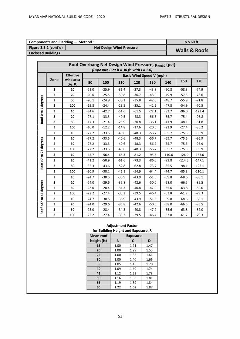
MYANMAR NATIONAL BUILDING CODE – 2020 PART 3 – STRUCTURAL DESIGN
53
Components and Cladding — Method 1 h ≤ 60 ft.
Figure 3.3.2 (cont’d) Net Design Wind Pressure Walls & Roofs
Enclosed Buildings
Roof Overhang Net Design Wind Pressure, pnet30 (psf) (Exposure B at h = 30 ft. with I = 1.0)
Zone Effective
wind area (sq. ft)
Basic Wind Speed V (mph)
90 100 110 120 130 140 150 170
Ro
of
0 t
o 7
de
gre
es
2 10 -21.0 -25.9 -31.4 -37.3 -43.8 -50.8 -58.3 -74.9
2 20 -20.6 -25.5 -30.8 -36.7 -43.0 -49.9 -57.3 -73.6
2 50 -20.1 -24.9 -30.1 -35.8 -42.0 -48.7 -55.9 -71.8
2 100 -19.8 -24.4 -29.5 -35.1 -41.2 -47.8 -54.9 -70.5
3 10 -34.6 -42.7 -51.6 -61.5 -72.1 -83.7 -96.0 -123.4
3 20 -27.1 -33.5 -40.5 -48.3 -56.6 -65.7 -75.4 -96.8
3 50 -17.3 -21.4 -25.9 -30.8 -36.1 -41.9 -48.1 -61.8
3 100 -10.0 -12.2 -14.8 -17.6 -20.6 -23.9 -27.4 -35.2
Ro
of
>7 t
o 2
7 d
egr
ee
s
2 10 -27.2 -33.5 -40.6 -48.3 -56.7 -65.7 -75.5 -96.9
2 20 -27.2 -33.5 -40.6 -48.3 -56.7 -65.7 -75.5 -96.9
2 50 -27.2 -33.5 -40.6 -48.3 -56.7 -65.7 -75.5 -96.9
2 100 -27.2 -33.5 -40.6 -48.3 -56.7 -65.7 -75.5 -96.9
3 10 -45.7 -56.4 -68.3 -81.2 -95.3 -110.6 -126.9 -163.0
3 20 -41.2 -50.9 -61.6 -73.3 -86.0 -99.8 -114.5 -147.1
3 50 -35.3 -43.6 -52.8 -62.8 -73.7 -85.5 -98.1 -126.1
3 100 -30.9 -38.1 -46.1 -54.9 -64.4 -74.7 -85.8 -110.1
Ro
of
>27
to
45
de
gre
es
2 10 -24.7 -30.5 -36.9 -43.9 -51.5 -59.8 -68.6 -88.1
2 20 -24.0 -29.6 -35.8 -42.6 -50.0 -58.0 -66.5 -85.5
2 50 -23.0 -28.4 -34.3 -40.8 -47.9 -55.6 -63.8 -82.0
2 100 -22.2 -27.4 -33.2 -39.5 -46.4 -53.8 -61.7 -79.3
3 10 -24.7 -30.5 -36.9 -43.9 -51.5 -59.8 -68.6 -88.1
3 20 -24.0 -29.6 -35.8 -42.6 -50.0 -58.0 -66.5 -85.5
3 50 -23.0 -28.4 -34.3 -40.8 -47.9 -55.6 -63.8 -82.0
3 100 -22.2 -27.4 -33.2 -39.5 -46.4 -53.8 -61.7 -79.3
Adjustment Factor
for Building Height and Exposure, λ
Mean roof height (ft)
Exposure
B C D 15 1.00 1.21 1.47
20 1.00 1.29 1.55
25 1.00 1.35 1.61
30 1.00 1.40 1.66
35 1.05 1.45 1.70
40 1.09 1.49 1.74
45 1.12 1.53 1.78
50 1.16 1.56 1.81
55 1.19 1.59 1.84
60 1.22 1.62 1.87
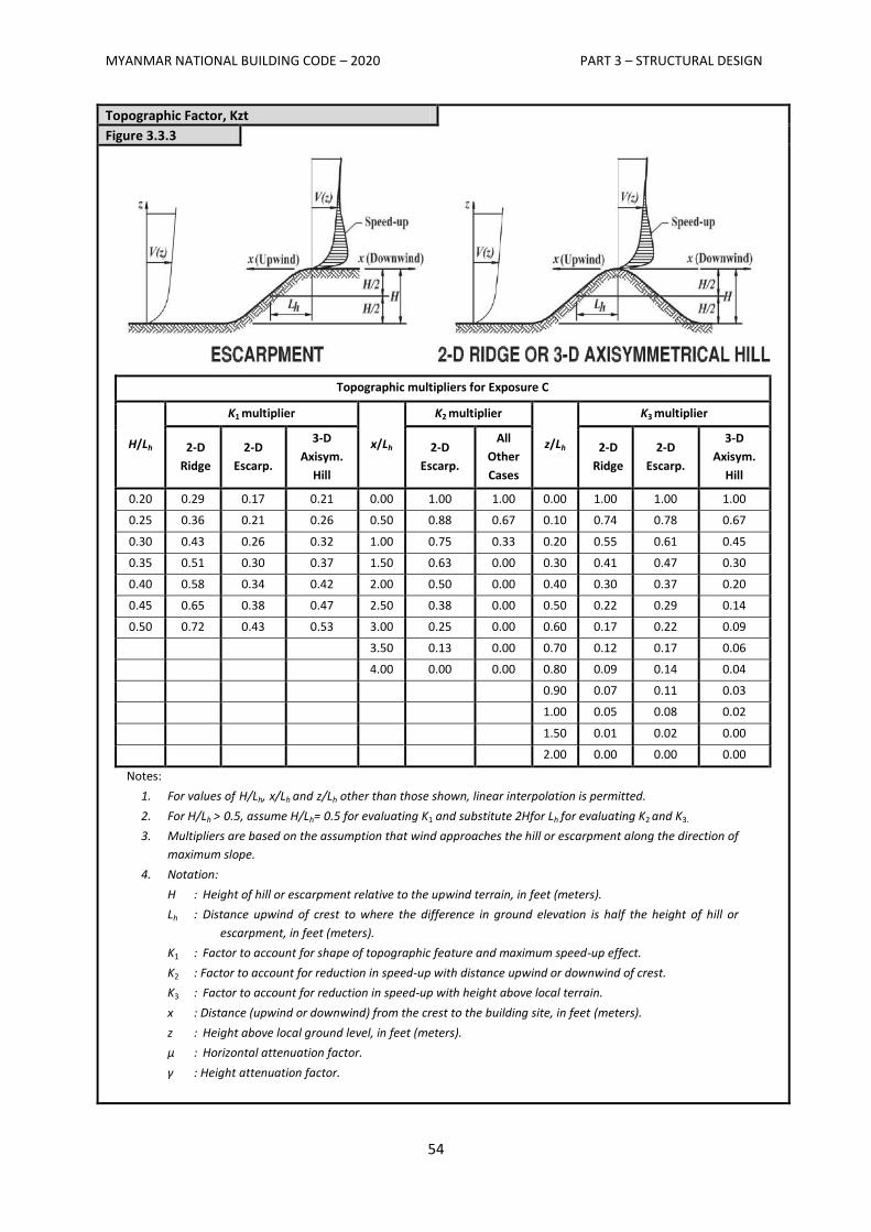
MYANMAR NATIONAL BUILDING CODE – 2020 PART 3 – STRUCTURAL DESIGN
54
Topographic Factor, Kzt
Figure 3.3.3
Topographic multipliers for Exposure C
H/Lh
K1 multiplier
x/Lh
K2 multiplier
z/Lh
K3 multiplier
2-D
Ridge
2-D
Escarp.
3-D
Axisym.
Hill
2-D
Escarp.
All
Other
Cases
2-D
Ridge
2-D
Escarp.
3-D
Axisym.
Hill
0.20 0.29 0.17 0.21 0.00 1.00 1.00 0.00 1.00 1.00 1.00
0.25 0.36 0.21 0.26 0.50 0.88 0.67 0.10 0.74 0.78 0.67
0.30 0.43 0.26 0.32 1.00 0.75 0.33 0.20 0.55 0.61 0.45
0.35 0.51 0.30 0.37 1.50 0.63 0.00 0.30 0.41 0.47 0.30
0.40 0.58 0.34 0.42 2.00 0.50 0.00 0.40 0.30 0.37 0.20
0.45 0.65 0.38 0.47 2.50 0.38 0.00 0.50 0.22 0.29 0.14
0.50 0.72 0.43 0.53 3.00 0.25 0.00 0.60 0.17 0.22 0.09
3.50 0.13 0.00 0.70 0.12 0.17 0.06
4.00 0.00 0.00 0.80 0.09 0.14 0.04
0.90 0.07 0.11 0.03
1.00 0.05 0.08 0.02
1.50 0.01 0.02 0.00
2.00 0.00 0.00 0.00
Notes:
1. For values of H/Lh, x/Lh and z/Lh other than those shown, linear interpolation is permitted.
2. For H/Lh > 0.5, assume H/Lh= 0.5 for evaluating K1 and substitute 2Hfor Lh for evaluating K2 and K3.
3. Multipliers are based on the assumption that wind approaches the hill or escarpment along the direction of
maximum slope.
4. Notation:
H : Height of hill or escarpment relative to the upwind terrain, in feet (meters).
Lh : Distance upwind of crest to where the difference in ground elevation is half the height of hill or
escarpment, in feet (meters).
K1 : Factor to account for shape of topographic feature and maximum speed-up effect.
K2 : Factor to account for reduction in speed-up with distance upwind or downwind of crest.
K3 : Factor to account for reduction in speed-up with height above local terrain.
x : Distance (upwind or downwind) from the crest to the building site, in feet (meters).
z : Height above local ground level, in feet (meters).
μ : Horizontal attenuation factor.
γ : Height attenuation factor.
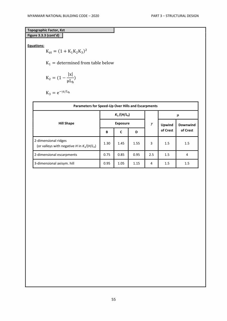
MYANMAR NATIONAL BUILDING CODE – 2020 PART 3 – STRUCTURAL DESIGN
55
Topographic Factor, Kzt
Figure 3.3.3 (cont’d)
Equations:
| |
Parameters for Speed-Up Over Hills and Escarpments
Hill Shape
K1 /(H/Lh)
Exposure Upwind
of Crest
Downwind
of Crest B C D
2-dimensional ridges
(or valleys with negative H in K1/(H/Lh) 1.30 1.45 1.55 3 1.5 1.5
2-dimensional escarpments 0.75 0.85 0.95 2.5 1.5 4
3-dimensional axisym. hill 0.95 1.05 1.15 4 1.5 1.5
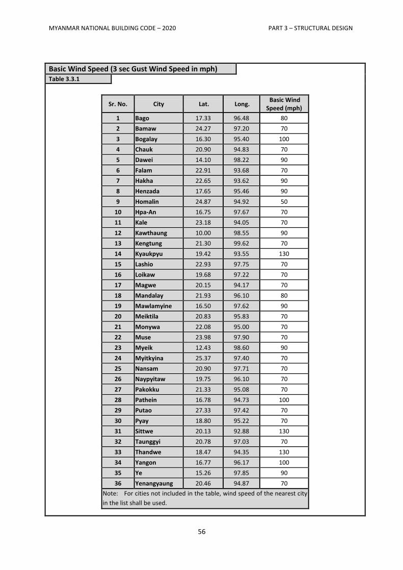
MYANMAR NATIONAL BUILDING CODE – 2020 PART 3 – STRUCTURAL DESIGN
56
Basic Wind Speed (3 sec Gust Wind Speed in mph)
Table 3.3.1
Sr. No. City Lat. Long. Basic Wind
Speed (mph)
1 Bago 17.33 96.48 80
2 Bamaw 24.27 97.20 70
3 Bogalay 16.30 95.40 100
4 Chauk 20.90 94.83 70
5 Dawei 14.10 98.22 90
6 Falam 22.91 93.68 70
7 Hakha 22.65 93.62 90
8 Henzada 17.65 95.46 90
9 Homalin 24.87 94.92 50
10 Hpa-An 16.75 97.67 70
11 Kale 23.18 94.05 70
12 Kawthaung 10.00 98.55 90
13 Kengtung 21.30 99.62 70
14 Kyaukpyu 19.42 93.55 130
15 Lashio 22.93 97.75 70
16 Loikaw 19.68 97.22 70
17 Magwe 20.15 94.17 70
18 Mandalay 21.93 96.10 80
19 Mawlamyine 16.50 97.62 90
20 Meiktila 20.83 95.83 70
21 Monywa 22.08 95.00 70
22 Muse 23.98 97.90 70
23 Myeik 12.43 98.60 90
24 Myitkyina 25.37 97.40 70
25 Nansam 20.90 97.71 70
26 Naypyitaw 19.75 96.10 70
27 Pakokku 21.33 95.08 70
28 Pathein 16.78 94.73 100
29 Putao 27.33 97.42 70
30 Pyay 18.80 95.22 70
31 Sittwe 20.13 92.88 130
32 Taunggyi 20.78 97.03 70
33 Thandwe 18.47 94.35 130
34 Yangon 16.77 96.17 100
35 Ye 15.26 97.85 90
36 Yenangyaung 20.46 94.87 70
Note: For cities not included in the table, wind speed of the nearest city
in the list shall be used.
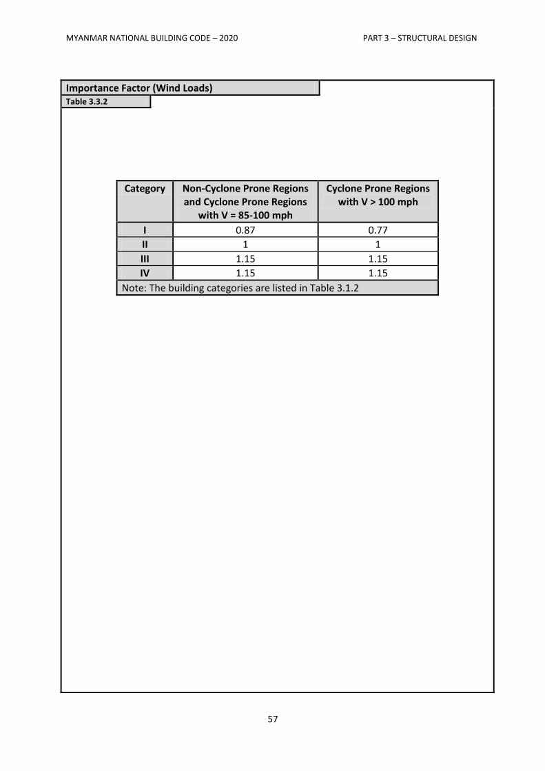
MYANMAR NATIONAL BUILDING CODE – 2020 PART 3 – STRUCTURAL DESIGN
57
Importance Factor (Wind Loads)
Table 3.3.2
Category Non-Cyclone Prone Regions and Cyclone Prone Regions
with V = 85-100 mph
Cyclone Prone Regions with V > 100 mph
I 0.87 0.77
II 1 1
III 1.15 1.15
IV 1.15 1.15
Note: The building categories are listed in Table 3.1.2
MYANMAR NATIONAL BUILDING CODE – 2020 PART 3 – STRUCTURAL DESIGN
58
SECTION 3.4
SEISMIC DESIGN CRITERIA AND DESIGN REQUIREMENTS FOR BUILDINGS
3.4.1 Seismic Design Criteria
3.4.1.1 General
3.4.1.1.1 Purpose
This section presents criteria for the design and construction of buildings and other structures subject
to earthquake ground motions. The specified earthquake loads are based upon post-elastic energy
dissipation in the structure, and because of this fact, the requirements for design, detailing, and
construction shall be satisfied even for structures and members for which load combinations that do
not contain earthquake loads indicate larger demands than combinations that include earthquake
loads.
3.4.1.1.2 Scope
Every structure, and portion thereof, including nonstructural components that are permanently
attached to structures and their supports and attachments, shall be designed and constructed to resist
the effects of earthquake motions in accordance with this code and ASCE 7-05, excluding Chapter 14
and Appendix 11A. The seismic design category for a structure is permitted to be determined in
accordance with Section 3.4 or ASCE 7-05.
Exceptions:
1. Detached one- and two-family dwellings, assigned to Seismic Design Category A, B or C, or
located where the mapped short-period spectral response acceleration, SS, is less than 0.4 g.
2. The seismic-force-resisting system of wood-frame buildings that conform to the provisions of
Section 2308 (IBC-2006) are not required to be analyzed as specified in this section.
3. Agricultural storage structures intended only for incidental human occupancy.
4. Structures that require special consideration of their response characteristics and environment
that are not addressed by this code or ASCE 7-05 and for which other regulations provide
seismic criteria, such as vehicular bridges, electrical transmission towers, hydraulic structures,
buried utility lines and their appurtenances and nuclear reactors.
3.4.1.1.3 Applicability
Structures and their nonstructural components shall be designed and constructed in accordance with
the requirement of Section 3.4.2.
3.4.1.1.4 Alternate Materials and Methods of Construction
Alternate materials and methods of construction to those prescribed in the seismic requirements of
this standard shall not be used unless approved by the authority having jurisdiction. Substantiating
evidence shall be submitted demonstrating that the proposed alternate, for the purpose intended, will
be at least equal in strength, durability, and seismic resistance.
MYANMAR NATIONAL BUILDING CODE – 2020 PART 3 – STRUCTURAL DESIGN
59
3.4.1.2 Definitions
The following definitions apply only to the seismic requirements of this standard.
ACTIVE FAULT: A fault determined to be active by the authority having jurisdiction from properly
substantiated data (e.g., most recent mapping of active faults by the authority Department).
ADDITION: An increase in building area, aggregate floor area, height, or number of storeys of a
structure.
ALTERATION: Any construction or renovation to an existing structure other than an addition.
APPENDAGE: An architectural component such as a canopy, marquee, ornamental balcony, or
statuary.
APPROVAL: The written acceptance by the authority having jurisdiction of documentation that
establishes the qualification of a material, system, component, procedure, or person to fulfill the
requirements of this standard for the intended use.
ATTACHMENTS: Means by which components and their supports are secured or connected to the
seismic force-resisting system of the structure. Such attachments include anchor bolts, welded
connections, and mechanical fasteners.
BASE: The level at which the horizontal seismic ground motions are considered to be imparted to the
structure.
BASEMENT: A basement is any storey below the lowest storey above grade.
BASE SHEAR: Total design lateral force or shear at the base.
BOUNDARY ELEMENTS: Diaphragm and shear wall boundary members to which the diaphragm
transfers forces. Boundary members include chords and drag struts at diaphragm and shear wall
perimeters, interior openings, discontinuities, and reentrant corners.
BOUNDARY MEMBERS: Portions along wall and diaphragm edges strengthened by longitudinal
and transverse reinforcement. Boundary members include chords and drag struts at diaphragm and
shear wall perimeters, interior openings, discontinuities, and reentrant corners.
BUILDING: Any structure whose intended use includes shelter of human occupants.
CANTILEVERED COLUMN SYSTEM: A seismic force-resisting system in which lateral forces
are resisted entirely by columns acting as cantilevers from the base.
CHARACTERISTIC EARTHQUAKE: An earthquake assessed for an active fault having a
magnitude equal to the best estimate of the maximum magnitude capable of occurring on the fault, but
not less than the largest magnitude that has occurred historically on the fault.
COMPONENT: A part of element of an architectural, electrical, mechanical, or structural system.
Component, Equipment: A mechanical or electrical component or element that is part of a
mechanical and/or electrical system within or without a building system.
Component, Flexible: Component, including its attachments, having a fundamental period greater
than 0.06s.
MYANMAR NATIONAL BUILDING CODE – 2020 PART 3 – STRUCTURAL DESIGN
60
Component, Rigid: Component, including its attachments, having a fundamental period less than or
equal to 0.06s.
COMPONENT SUPPORT: Those structural members or assemblies of members, including braces,
frames, struts, and attachments that transmit all loads and forces between systems, components, or
elements and the structures.
CONCRETE, PLAIN: Concrete that is either unreinforced or contains less reinforcement than the
minimum amount specified in ACI 318-08 for reinforced concrete.
CONCRETE, REINFORCED: Concrete reinforced with no less reinforcement than the minimum
amount required by ACI 318-08 prestressed or non-prestressed, and designed on the assumption that
the two materials act together in resisting forces.
CONSTRUCTION DOCUMENTS: The written, graphic, electronic and pictorial documents
describing design, locations and physical characteristics of the project required to verify compliance
with this standard.
COUPLING BEAM: A beam that is used to connect adjacent concrete wall elements to make them
act together as a unit to resist lateral loads.
DEFORMABILITY: The ratio of the ultimate deformation to the limit deformation.
High-Deformability Element: An element whose deformability is not less than 3.5 where subjected
to four fully reversed cycles at the limit deformation.
Limited-Deformability Element: An element that is neither low- deformability or a high-
deformability element.
Low-Deformability Element: An element whose deformability is 1.5 or less.
DEFORMATION:
Limit Deformation: Two times the initial deformation that occurs at a load equal to 40 percent of the
maximum strength.
Ultimate Deformation: The deformation at which failure occurs and that shall be deemed to occur if
the sustainable load reduces to 80 percent or less of the maximum strength.
DESIGNATED SEISMIC SYSTEMS: The seismic force-resisting system and those architectural,
electrical, and mechanical system or their components and for which the component importance
factor, Ip, is greater than 1.0.
DESIGN EARTHQUAKE: The earthquake effects that are two-thirds of the corresponding
Maximum Considered Earthquake (MCE) effects.
DESIGN EARTHQUAKE GROUND MOTION: The earthquake ground motions that are two-
thirds of the corresponding MCE ground motions.
DIAPHRAGM: Roof, floor, or other membrane or bracing system acting to transfer the lateral forces
to the vertical resisting elements.
DIAPHRAGM BOUNDARY: A location where shear is transferred into or out of the diaphragm
element. Transfer is either to a boundary element or to another force-resisting element.
DIAPHRAGM CHORD: A diaphragm boundary element perpendicular to the applied load that is
assumed to take axial stresses due to the diaphragm moment.
MYANMAR NATIONAL BUILDING CODE – 2020 PART 3 – STRUCTURAL DESIGN
61
DRAG STRUT (COLLECTOR, TIE, DIAPHRAGM STRUT): A diaphragm or shear wall
boundary element parallel to the applied load that collects and transfers diaphragm shear forces to the
vertical force-resisting elements or distributes forces within the diaphragm or shear wall.
ENCLOSURE: An interior space surrounded by walls.
EQUIPMENT SUPPORT: Those structural members or assemblies of members or manufactured
elements, including braces, frames, legs, lugs, snuggers, hangers, or saddles that transmit gravity
loads and operating loads between the equipment and the structure.
FLEXIBLE EQUIPMENT CONNECTIONS: Those connections between equipment components
that permit rotational and/or translational movement without degradation of performance. Examples
include universal joints, bellows expansion joints, and flexible metal hose.
FRAME:
Braced Frame: An essentially vertical truss, or its equivalent, of the concentric or eccentric type that
is provided in a building frame system or dual system to resist seismic forces.
Concentrically Braced Frame (CBF): A braced frame in which the members are subjected primarily
to axial forces. CBFs are categorized as ordinary concentrically braced frames (OCBF) or special
concentrically braced frames (SCBF).
Eccentrically Braced Frame (EBF): A diagonally braced frame in which at least one end of each
frames into a beam a short distance from a beam-column or from another diagonal brace.
Moment Frame: A Frame in which members and joints resist lateral forces by flexure as well as
along the axis of the members. Moment frames are categorized as intermediate moment frames (IMF),
ordinary moment frames (OMF), and special moment frames (SMF).
STRUCTURAL SYSTEM:
Building Frame System: A structural system with an essentially complete space frame providing
support for vertical loads. Seismic force resistance is provided by shear walls or braced frames.
Dual System: A structural system with an essentially complete space frame providing support for
vertical loads. Seismic force resistance is provided by moment resisting fames and shear walls or
braced frames as prescribed in Section 3.4.2.5.1.
Shear Wall-Frame Interactive System: A structural system that uses combinations of ordinary
reinforced concrete shear walls and ordinary reinforced concrete moment frames designed to resist
lateral forces in proportion to their rigidities considering interaction between shear walls and frames
on all levels.
Space Frame System: A 3-D structural system composed of interconnected members, other than
bearing walls, that is capable of supporting vertical loads and, where designed for such an application,
is capable of providing resistance to seismic forces.
GLAZED CURTAIN WALL: A nonbearing wall that extends beyond the edges of building floor
slabs, and includes a glazing material installed in the curtain wall framing.
GLAZED STOREFRONT: A nonbearing wall that is installed between floor slabs, typically
including entrances, and includes a glazing material installed in the storefront framing.
GRADE PLANE: A reference plane representing the average of finished ground level adjoining the
structure at all exterior walls. Where the finished ground level slopes away from the exterior walls,
MYANMAR NATIONAL BUILDING CODE – 2020 PART 3 – STRUCTURAL DESIGN
62
the reference plane shall be established by the lowest points within the area between the buildings and
the lot line or, where the lot line is more than 6 ft (1,829 mm) from the structure, between the
structure and points 6 ft (1,829 mm) from the structure.
HAZARDOUS CONTENTS: A material that is highly toxic or potentially explosive and in
sufficient quantity to pose a significant life- safety threat to the general public if an uncontrolled
release were to occur.
IMPORTANCE FACTOR: A factor assigned to each structure according to its Occupancy Category
as prescribed in Section 3.4.1.5.
INSPECTION, SPECIAL: The observation of the work by a special inspector to determine
compliance with the approved construction documents and these standards in accordance with the
quality assurance plan.
Continuous Special Inspection: The full-time or intermittent observation of the work by a special
inspector who is present in the area where work is being performed.
Periodic Special Inspection: The part-time or intermittent observation of the work by a special
inspector who is present in the area where work has been or is being performed.
INSPECTOR, SPECIAL (who shall be identified as the owner’s inspector): A person approved
by the authority having jurisdiction to perform special inspection.
INVERTED PENDULUM-TYPE STRUCTURES: Structures in which more than 50 percent of the
structure’s mass is concentrated at the top of a slender, cantilevered structure and in which stability of
the mass at the top of the structure relies on rotational restraint to the top of the cantilevered element.
JOINT: The geometric volume common to intersecting members.
LIGHT-FRAME CONSTRUCTION: A method of construction where the structural assemblies
(e.g., walls, floors, ceilings and roofs) are primarily formed by a system of repetitive wood or cold-
formed steel framing members of subassemblies of these members (e.g., trusses).
LONGITUDINAL REINFORCEMENT RATIO: Area of longitudinal reinforcement divided by
the cross-sectional area of the concrete.
MAXIMUM CONSIDERED EARTHQUAKE (MCE) GROUND MOTION: The most severe
earthquake effects considered by this standard as defined in Section 3.4.1.4.
MECHANICALLY ANCHORED TANKS OR VESSELS: Tanks or vessels provided with
mechanical anchors to resist overturning moments.
NONBUILDING STRUCTURE: A structure, other than a building, constructed of a type included
in Chapter 15 (ASCE 7-05) and within the limits of Section 15.1.1 (ASCE 7-05).
NONBUILDING STRUCTURE SIMILAR TO A BUILDING: A non-building structure that is
designed and constructed in a manner similar to buildings, will respond to strong ground motion in a
fashion similar to buildings, and have basic lateral and vertical seismic-force-resisting-system
conforming to one of the types indicated in Table 15.4-1(ASCE 7-05).
ORTHOGONAL: To be in two horizontal directions, at 90 to each other.
OWNER: Any person, agent, firm, or corporation having a legal or equitable interest in the property.
MYANMAR NATIONAL BUILDING CODE – 2020 PART 3 – STRUCTURAL DESIGN
63
PARTITION: A nonstructural interior wall that spans horizontally or vertically from support to
support. The supports may be the basic building frame, subsidiary structural members, or other
portions of the partition system.
P-DELTA EFFECT: The secondary effect on shears and moments of structural members due to the
action of the vertical loads induced by horizontal displacement of the structure resulting from various
loading conditions.
PILE: Deep foundation components including piers, caissons, and piles.
PILE CAP: Foundation elements to which piles are connected including grade beams and mats.
REGISTERED STRUCTURAL DESIGN PROFESSIONAL: An engineer, registered or licensed
to practice professional engineering, as defined by the statutory requirements of the professional
registrations laws of the state in which the project is to be constructed.
SEISMIC DESIGN CATEGORY: A classification assigned to a structure based on its Occupancy
Category and the severity of the design earthquake ground motion at the site as defined in Section
3.4.1.6.
SEISMIC FORCE-RESISTING SYSTEM: That part of the structural system that has been
considered in the design to provide the required resistance to the seismic forces prescribed herein.
SEISMIC FORCES: The assumed forces prescribed herein, related to the response of the structure to
earthquake motions, to be used in the design of the structure and its components.
SELF-ANCHORED TANKS OR VESSELS: Tanks or vessels that is stable under design
overturning moment without the need for mechanical anchors to resist uplift.
SHEAR PANEL: A floor, roof, or wall component sheathed to act as a shear wall or diaphragm.
SITE CLASS: A classification assigned to a site based on the types of soils present and their
engineering properties.
STORAGE RACKS: Include industrial pallet racks, moveable shelf racks, and stacker racks made of
cold-formed or hot-rolled structural members. Does not include other types of racks such as drive-in
and drive-through racks, cantilever racks, portable racks, or racks made of materials other than steel.
STOREY: The portion of a structure between the tops of two successive finished floor surfaces and,
for the topmost storey, from the top of the floor finish to the top of the roof structural element.
STOREY ABOVE GRADE: Any storey having its finished floor surface entirely above grade,
except that a storey shall be considered as a storey above grade where the finished floor surface of the
storey immediately above is more than 6 ft (1,829 mm) above the grade plane, more than 6 ft (1,829
mm) above the finished ground level for more than 40 percent of the total structure perimeter, or more
than 12 ft (3,658 mm) above the finished ground level at any point.
STOREY DRIFT: The horizontal deflection at the top of the storey relative to the bottom of the
storey as determined in Section 12.8.6 in ASCE 7-05.
STOREYS DRIFT RATIO: The storey drift, as determined in Section 12.8.6 in ASCE 7-05divided
by the storey height.
STOREY SHEAR: The summation of design lateral seismic forces at levels above the storey under
consideration.
MYANMAR NATIONAL BUILDING CODE – 2020 PART 3 – STRUCTURAL DESIGN
64
STRENGTH:
Design Strength: Nominal strength multiplied by a strength reduction factor, ϕ.
Nominal Strength: Strength of a member or cross-section calculated in accordance with the
requirements and assumptions of the strength design methods of this standard (or the reference
documents) before application of any strength- reduction factors.
Required Strength: Strength of a member, cross-section, or connection required to resist factored
loads or related internal moments and forces in such combinations as stipulated by this standard.
STRUCTURAL OBSERVATIONS: The visual observations to determine that the seismic force-
resisting system is constructed in general conformance with the construction documents.
STRUCTURE: That which is built or constructed and limited to buildings and non-building
structures as defined herein.
SUBDIAPHRAGM: A portion of a diaphragm used to transfer wall anchorage forces to diaphragm
cross ties.
SUPPORTS: Those structural members, assemblies of members, or manufactured elements,
including braces, frames, legs, lugs, snubbers, hangers, saddles, or struts, which transmit loads
between the nonstructural components and the structure.
TESTING AGENCY: A company or corporation that provides testing and/or inspection services.
VENEERS: Facings or ornamentation of brick, concrete, stone, tile, or similar materials attached to a
backing.
WALL: A component that has a slope of 60 or greater with the horizontal plane used to enclose or
divide space.
Bearing Wall: Any wall meeting either of the following classifications:
1. Any metal or wood stud wall that supports more than 100 lb/linear ft (1,459 N/m) of vertical load
in addition to its own weight.
2. Any concrete or masonry wall that supports more than 200 lb/linear ft (2,919 N/m) of vertical
load in addition to its own weight.
Light-Framed Wall: A wall with wood or steel studs.
Light-Framed Wood Shear Wall: A wall constructed with wood studs and sheathed with material
rated for shear resistance.
Nonbearing Wall: Any wall that is not a bearing wall.
Nonstructural Wall: All walls other than bearing walls or shear walls.
Shear Wall (Vertical Diaphragm): A wall, bearing or non- bearing, designed to resist lateral forces
acting in the plane of the wall (sometimes referred to as a ―vertical diaphragm‖).
Structural Wall: Walls that meet the definition for bearing walls or shear walls.
WALL SYSTEM, BEARING: A structural system with bearing walls providing support for all or
major portions of the vertical loads. Shear walls or braced frames provide seismic force resistance.
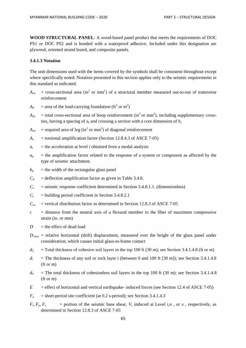
MYANMAR NATIONAL BUILDING CODE – 2020 PART 3 – STRUCTURAL DESIGN
65
WOOD STRUCTURAL PANEL: A wood-based panel product that meets the requirements of DOC
PS1 or DOC PS2 and is bonded with a waterproof adhesive. Included under this designation are
plywood, oriented strand board, and composite panels.
3.4.1.3 Notation
The unit dimensions used with the items covered by the symbols shall be consistent throughout except
where specifically noted. Notation presented in this section applies only to the seismic requirements in
this standard as indicated.
Ach = cross-sectional area (in2 or mm
2) of a structural member measured out-to-out of transverse
reinforcement
A0 = area of the load-carrying foundation (ft2 or m
2)
Ash = total cross-sectional area of hoop reinforcement (in2
or mm2), including supplementary cross-
ties, having a spacing of sh and crossing a section with a core dimension of hc
Avd = required area of leg (in2 or mm
2) of diagonal reinforcement
Ax = torsional amplification factor (Section 12.8.4.3 of ASCE 7-05)
ai = the acceleration at level i obtained from a modal analysis
ap = the amplification factor related to the response of a system or component as affected by the
type of seismic attachment.
bp = the width of the rectangular glass panel
Cd = deflection amplification factor as given in Table 3.4.8.
Cs = seismic response coefficient determined in Section 3.4.8.1.1. (dimensionless)
Ct = building period coefficient in Section 3.4.8.2.1
Cvx = vertical distribution factor as determined in Section 12.8.3 of ASCE 7-05
c = distance from the neutral axis of a flexural member to the fiber of maximum compressive
strain (in. or mm)
D = the effect of dead load
Dclear = relative horizontal (drift) displacement, measured over the height of the glass panel under
consideration, which causes initial glass-to-frame contact
dC = Total thickness of cohesive soil layers in the top 100 ft (30 m); see Section 3.4.1.4.8 (ft or m)
di = The thickness of any soil or rock layer i (between 0 and 100 ft [30 m]); see Section 3.4.1.4.8
(ft or m)
dS = The total thickness of cohesionless soil layers in the top 100 ft (30 m); see Section 3.4.1.4.8
(ft or m)
E = effect of horizontal and vertical earthquake- induced forces (see Section 12.4 of ASCE 7-05)
Fa = short-period site coefficient (at 0.2 s-period); see Section 3.4.1.4.3
Fi, Fn, Fx = portion of the seismic base shear, V, induced at Level i,n , or x , respectively, as
determined in Section 12.8.3 of ASCE 7-05
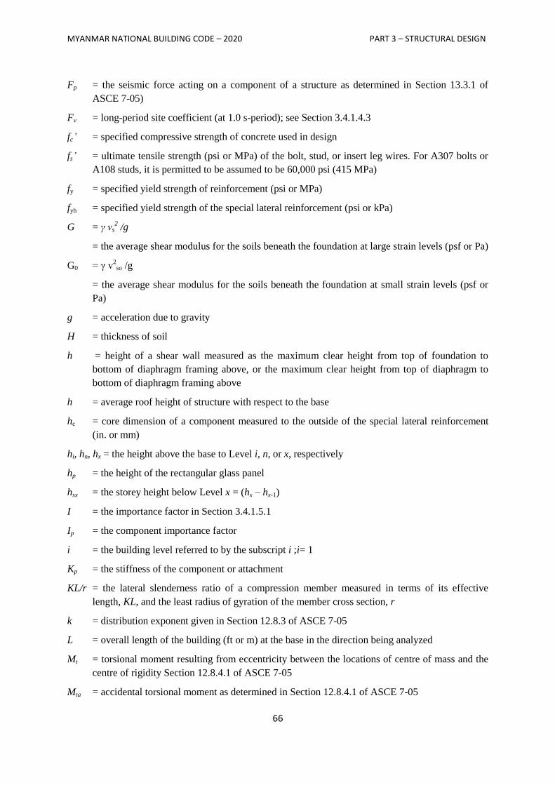
MYANMAR NATIONAL BUILDING CODE – 2020 PART 3 – STRUCTURAL DESIGN
66
Fp = the seismic force acting on a component of a structure as determined in Section 13.3.1 of
ASCE 7-05)
Fv = long-period site coefficient (at 1.0 s-period); see Section 3.4.1.4.3
fc’ = specified compressive strength of concrete used in design
fs’ = ultimate tensile strength (psi or MPa) of the bolt, stud, or insert leg wires. For A307 bolts or
A108 studs, it is permitted to be assumed to be 60,000 psi (415 MPa)
fy = specified yield strength of reinforcement (psi or MPa)
fyh = specified yield strength of the special lateral reinforcement (psi or kPa)
G = γ vs2 /g
= the average shear modulus for the soils beneath the foundation at large strain levels (psf or Pa)
G0 = γ v2
so /g
= the average shear modulus for the soils beneath the foundation at small strain levels (psf or
Pa)
g = acceleration due to gravity
H = thickness of soil
h = height of a shear wall measured as the maximum clear height from top of foundation to
bottom of diaphragm framing above, or the maximum clear height from top of diaphragm to
bottom of diaphragm framing above
h = average roof height of structure with respect to the base
hc = core dimension of a component measured to the outside of the special lateral reinforcement
(in. or mm)
hi, hn, hx = the height above the base to Level i, n, or x, respectively
hp = the height of the rectangular glass panel
hsx = the storey height below Level x = (hx – hx-1)
I = the importance factor in Section 3.4.1.5.1
Ip = the component importance factor
i = the building level referred to by the subscript i ;i= 1
Kp = the stiffness of the component or attachment
KL/r = the lateral slenderness ratio of a compression member measured in terms of its effective
length, KL, and the least radius of gyration of the member cross section, r
k = distribution exponent given in Section 12.8.3 of ASCE 7-05
L = overall length of the building (ft or m) at the base in the direction being analyzed
Mt = torsional moment resulting from eccentricity between the locations of centre of mass and the
centre of rigidity Section 12.8.4.1 of ASCE 7-05
Mta = accidental torsional moment as determined in Section 12.8.4.1 of ASCE 7-05
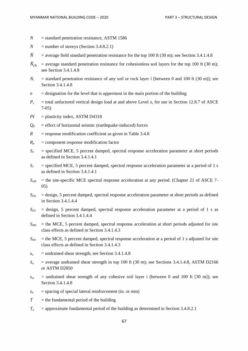
MYANMAR NATIONAL BUILDING CODE – 2020 PART 3 – STRUCTURAL DESIGN
67
N = standard penetration resistance, ASTM 1586
N = number of storeys (Section 3.4.8.2.1)
= average field standard penetration resistance for the top 100 ft (30 m); see Section 3.4.1.4.8
= average standard penetration resistance for cohesionless soil layers for the top 100 ft (30 m);
see Section 3.4.1.4.8
Ni = standard penetration resistance of any soil or rock layer i [between 0 and 100 ft (30 m)]; see
Section 3.4.1.4.8
n = designation for the level that is uppermost in the main portion of the building
Px = total unfactored vertical design load at and above Level x, for use in Section 12.8.7 of ASCE
7-05)
PI = plasticity index, ASTM D4318
QE = effect of horizontal seismic (earthquake-induced) forces
R = response modification coefficient as given in Table 3.4.8
Rp = component response modification factor
SS = specified MCE, 5 percent damped, spectral response acceleration parameter at short periods
as defined in Section 3.4.1.4.1
S1 = specified MCE, 5 percent damped, spectral response acceleration parameter at a period of 1 s
as defined in Section 3.4.1.4.1
SaM = the site-specific MCE spectral response acceleration at any period. (Chapter 21 of ASCE 7-
05)
SDS = design, 5 percent damped, spectral response acceleration parameter at short periods as defined
in Section 3.4.1.4.4
SD1 = design, 5 percent damped, spectral response acceleration parameter at a period of 1 s as
defined in Section 3.4.1.4.4
SMS = the MCE, 5 percent damped, spectral response acceleration at short periods adjusted for site
class effects as defined in Section 3.4.1.4.3
SM1 = the MCE, 5 percent damped, spectral response acceleration at a period of 1 s adjusted for site
class effects as defined in Section 3.4.1.4.3
su = undrained shear strength; see Section 3.4.1.4.8
u = average undrained shear strength in top 100 ft (30 m); see Sections 3.4.1.4.8, ASTM D2166
or ASTM D2850
sui = undrained shear strength of any cohesive soil layer i (between 0 and 100 ft [30 m]); see
Section 3.4.1.4.8
sh = spacing of special lateral reinforcement (in. or mm)
T = the fundamental period of the building
Ta = approximate fundamental period of the building as determined in Section 3.4.8.2.1
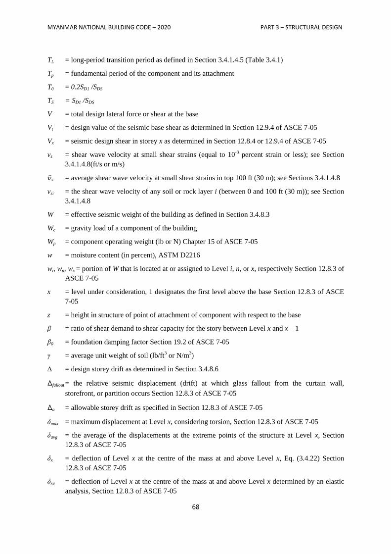
MYANMAR NATIONAL BUILDING CODE – 2020 PART 3 – STRUCTURAL DESIGN
68
TL = long-period transition period as defined in Section 3.4.1.4.5 (Table 3.4.1)
Tp = fundamental period of the component and its attachment
T0 = 0.2SD1 /SDS
TS = SD1 /SDS
V = total design lateral force or shear at the base
Vt = design value of the seismic base shear as determined in Section 12.9.4 of ASCE 7-05
Vx = seismic design shear in storey x as determined in Section 12.8.4 or 12.9.4 of ASCE 7-05
vs = shear wave velocity at small shear strains (equal to 10-3
percent strain or less); see Section
3.4.1.4.8(ft/s or m/s)
s = average shear wave velocity at small shear strains in top 100 ft (30 m); see Sections 3.4.1.4.8
vsi = the shear wave velocity of any soil or rock layer i (between 0 and 100 ft (30 m)); see Section
3.4.1.4.8
W = effective seismic weight of the building as defined in Section 3.4.8.3
Wc = gravity load of a component of the building
Wp = component operating weight (lb or N) Chapter 15 of ASCE 7-05
w = moisture content (in percent), ASTM D2216
wi, wn, wx = portion of W that is located at or assigned to Level i, n, or x, respectively Section 12.8.3 of
ASCE 7-05
x = level under consideration, 1 designates the first level above the base Section 12.8.3 of ASCE
7-05
z = height in structure of point of attachment of component with respect to the base
β = ratio of shear demand to shear capacity for the story between Level x and x – 1
β0 = foundation damping factor Section 19.2 of ASCE 7-05
γ = average unit weight of soil (lb/ft3 or N/m
3)
∆ = design storey drift as determined in Section 3.4.8.6
∆fallout = the relative seismic displacement (drift) at which glass fallout from the curtain wall,
storefront, or partition occurs Section 12.8.3 of ASCE 7-05
∆a = allowable storey drift as specified in Section 12.8.3 of ASCE 7-05
δmax = maximum displacement at Level x, considering torsion, Section 12.8.3 of ASCE 7-05
δavg = the average of the displacements at the extreme points of the structure at Level x, Section
12.8.3 of ASCE 7-05
δx = deflection of Level x at the centre of the mass at and above Level x, Eq. (3.4.22) Section
12.8.3 of ASCE 7-05
δxe = deflection of Level x at the centre of the mass at and above Level x determined by an elastic
analysis, Section 12.8.3 of ASCE 7-05
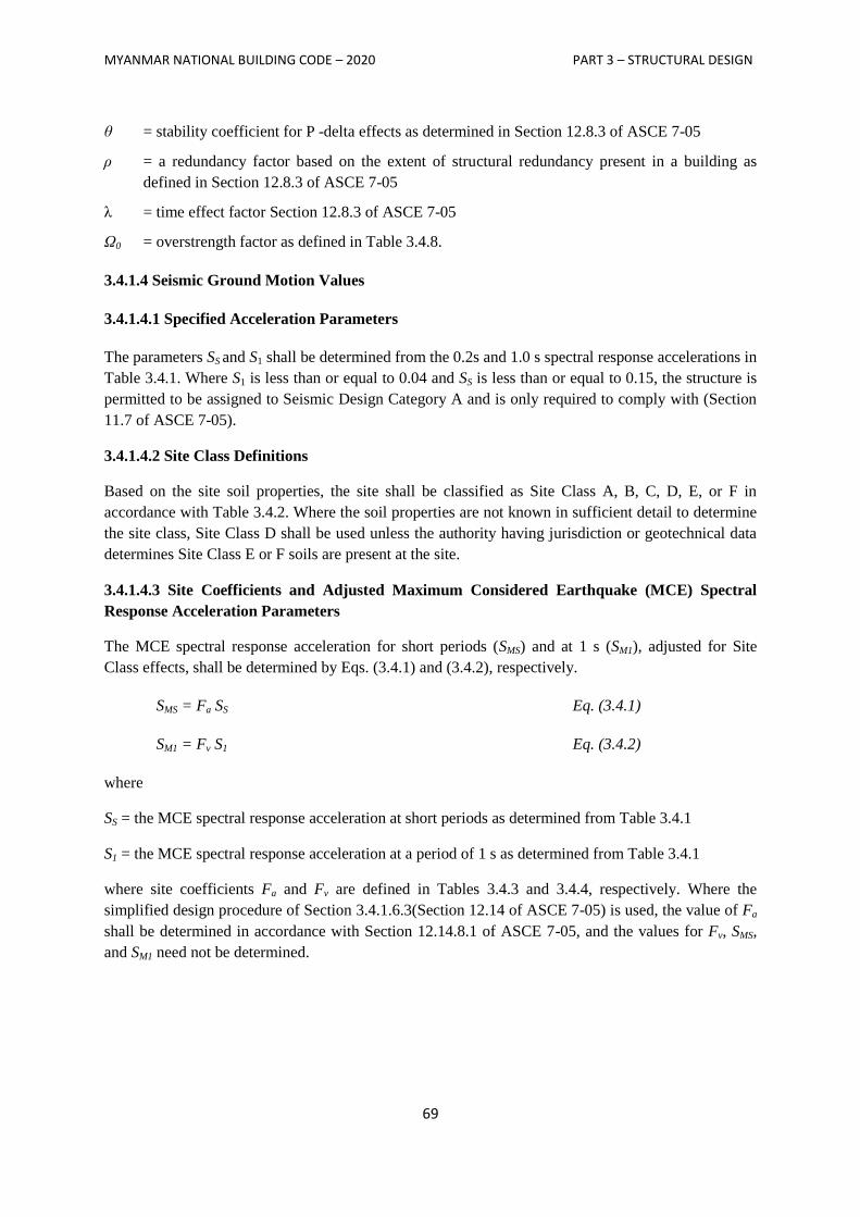
MYANMAR NATIONAL BUILDING CODE – 2020 PART 3 – STRUCTURAL DESIGN
69
θ = stability coefficient for P -delta effects as determined in Section 12.8.3 of ASCE 7-05
ρ = a redundancy factor based on the extent of structural redundancy present in a building as
defined in Section 12.8.3 of ASCE 7-05
λ = time effect factor Section 12.8.3 of ASCE 7-05
Ω0 = overstrength factor as defined in Table 3.4.8.
3.4.1.4 Seismic Ground Motion Values
3.4.1.4.1 Specified Acceleration Parameters
The parameters SS and S1 shall be determined from the 0.2s and 1.0 s spectral response accelerations in
Table 3.4.1. Where S1 is less than or equal to 0.04 and SS is less than or equal to 0.15, the structure is
permitted to be assigned to Seismic Design Category A and is only required to comply with (Section
11.7 of ASCE 7-05).
3.4.1.4.2 Site Class Definitions
Based on the site soil properties, the site shall be classified as Site Class A, B, C, D, E, or F in
accordance with Table 3.4.2. Where the soil properties are not known in sufficient detail to determine
the site class, Site Class D shall be used unless the authority having jurisdiction or geotechnical data
determines Site Class E or F soils are present at the site.
3.4.1.4.3 Site Coefficients and Adjusted Maximum Considered Earthquake (MCE) Spectral
Response Acceleration Parameters
The MCE spectral response acceleration for short periods (SMS) and at 1 s (SM1), adjusted for Site
Class effects, shall be determined by Eqs. (3.4.1) and (3.4.2), respectively.
SMS = Fa SS Eq. (3.4.1)
SM1 = Fv S1 Eq. (3.4.2)
where
SS = the MCE spectral response acceleration at short periods as determined from Table 3.4.1
S1 = the MCE spectral response acceleration at a period of 1 s as determined from Table 3.4.1
where site coefficients Fa and Fv are defined in Tables 3.4.3 and 3.4.4, respectively. Where the
simplified design procedure of Section 3.4.1.6.3(Section 12.14 of ASCE 7-05) is used, the value of Fa
shall be determined in accordance with Section 12.14.8.1 of ASCE 7-05, and the values for Fv, SMS,
and SM1 need not be determined.
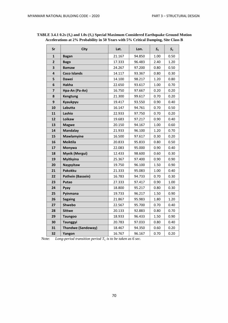
MYANMAR NATIONAL BUILDING CODE – 2020 PART 3 – STRUCTURAL DESIGN
70
TABLE 3.4.1 0.2s (Ss) and 1.0s (S1) Special Maximum Considered Earthquake Ground Motion
Accelerations at 2% Probability in 50 Years with 5% Critical Damping, Site Class B
Sr City Lat. Lon. SS S1
1 Bagan 21.167 94.850 1.00 0.50
2 Bago 17.333 96.483 2.40 1.20
3 Bamaw 24.267 97.200 0.80 0.50
4 Coco Islands 14.117 93.367 0.80 0.30
5 Dawei 14.100 98.217 1.20 0.80
6 Hakha 22.650 93.617 1.00 0.70
7 Hpa-An (Pa-An) 16.750 97.667 0.20 0.20
8 Kengtung 21.300 99.617 0.70 0.20
9 Kyaukpyu 19.417 93.550 0.90 0.40
10 Labutta 16.147 94.761 0.70 0.50
11 Lashio 22.933 97.750 0.70 0.20
12 Loikaw 19.683 97.217 0.90 0.40
13 Magwe 20.150 94.167 1.00 0.60
14 Mandalay 21.933 96.100 1.20 0.70
15 Mawlamyine 16.500 97.617 0.30 0.20
16 Meiktila 20.833 95.833 0.80 0.50
17 Monywa 22.083 95.000 0.90 0.40
18 Myeik (Mergui) 12.433 98.600 0.60 0.30
19 Myitkyina 25.367 97.400 0.90 0.90
20 Naypyitaw 19.750 96.100 1.50 0.90
21 Pakokku 21.333 95.083 1.00 0.40
22 Pathein (Bassein) 16.783 94.733 0.70 0.30
23 Putao 27.333 97.417 0.90 1.00
24 Pyay 18.800 95.217 0.80 0.30
25 Pyinmana 19.733 96.217 1.50 0.90
26 Sagaing 21.867 95.983 1.80 1.20
27 Shwebo 22.567 95.700 0.70 0.40
28 Sittwe 20.133 92.883 0.80 0.70
29 Taungoo 18.933 96.433 1.50 0.90
30 Taunggyi 20.783 97.033 0.80 0.40
31 Thandwe (Sandoway) 18.467 94.350 0.60 0.20
32 Yangon 16.767 96.167 0.70 0.20
Note: Long-period transition period TL is to be taken as 6 sec.
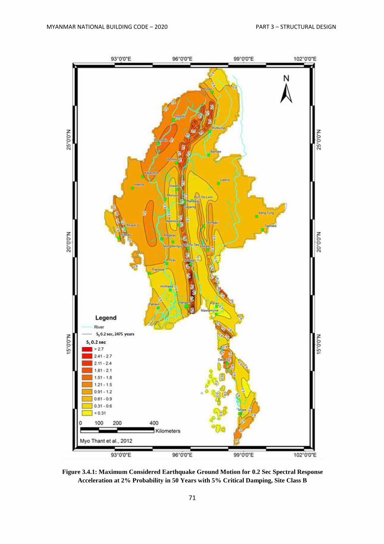
MYANMAR NATIONAL BUILDING CODE – 2020 PART 3 – STRUCTURAL DESIGN
71
Figure 3.4.1: Maximum Considered Earthquake Ground Motion for 0.2 Sec Spectral Response
Acceleration at 2% Probability in 50 Years with 5% Critical Damping, Site Class B
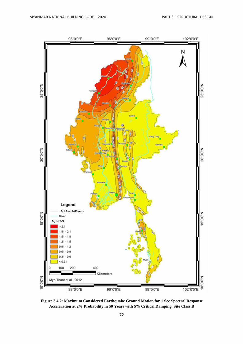
MYANMAR NATIONAL BUILDING CODE – 2020 PART 3 – STRUCTURAL DESIGN
72
Figure 3.4.2: Maximum Considered Earthquake Ground Motion for 1 Sec Spectral Response
Acceleration at 2% Probability in 50 Years with 5% Critical Damping, Site Class B
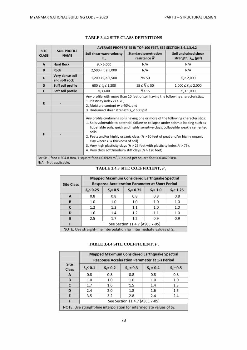
MYANMAR NATIONAL BUILDING CODE – 2020 PART 3 – STRUCTURAL DESIGN
73
TABLE 3.4.2 SITE CLASS DEFINITIONS
SITE CLASS
SOIL PROFILE NAME
AVERAGE PROPERTIES IN TOP 100 FEET, SEE SECTION 3.4.1.3.4.2
Soil shear wave velocity
Standard penetration
resistance Soil undrained shear
strength, , (psf)
A Hard Rock > 5,000 N/A N/A
B Rock 2,500 < ≤ 5,000 N/A N/A
C Very dense soil and soft rock
1,200 < ≤ 2,500 > 50 ≥ 2,000
D Stiff soil profile 600 ≤ ≤ 1,200 15 ≤ ≤ 50 1,000 ≤ ≤ 2,000
E Soft soil profile < 600 < 15 < 1,000
E -
Any profile with more than 10 feet of soil having the following characteristics: 1. Plasticity index PI > 20, 2. Moisture content w ≥ 40%, and 3. Undrained shear strength < 500 psf
F -
Any profile containing soils having one or more of the following characteristics: 1. Soils vulnerable to potential failure or collapse under seismic loading such as
liquefiable soils, quick and highly sensitive clays, collapsible weakly cemented soils.
2. Peats and/or highly organic clays (H > 10 feet of peat and/or highly organic clay where H = thickness of soil)
3. Very high plasticity clays (H > 25 feet with plasticity index PI > 75). 4. Very thick soft/medium stiff clays (H > 120 feet)
For SI: 1 foot = 304.8 mm, 1 square foot = 0.0929 m2, 1 pound per square foot = 0.0479 kPa.
N/A = Not applicable. TABLE 3.4.3 SITE COEFFICIENT, Fa
Site Class
Mapped Maximum Considered Earthquake Spectral
Response Acceleration Parameter at Short Period
SS≤ 0.25 SS= 0.5 SS= 0.75 SS= 1.0 SS≥ 1.25
A 0.8 0.8 0.8 0.8 0.8
B 1.0 1.0 1.0 1.0 1.0
C 1.2 1.2 1.1 1.0 1.0
D 1.6 1.4 1.2 1.1 1.0
E 2.5 1.7 1.2 0.9 0.9
F See Section 11.4.7 (ASCE 7-05)
NOTE: Use straight-line interpolation for intermediate values of Ss.
TABLE 3.4.4 SITE COEFFICIENT, Fv
Site Class
Mapped Maximum Considered Earthquake Spectral
Response Acceleration Parameter at 1-s Period
S1≤ 0.1 S1= 0.2 S1 = 0.3 S1 = 0.4 S1≥ 0.5
A 0.8 0.8 0.8 0.8 0.8
B 1.0 1.0 1.0 1.0 1.0
C 1.7 1.6 1.5 1.4 1.3
D 2.4 2.0 1.8 1.6 1.5
E 3.5 3.2 2.8 2.4 2.4
F See Section 11.4.7 (ASCE 7-05)
NOTE: Use straight-line interpolation for intermediate values of S1.
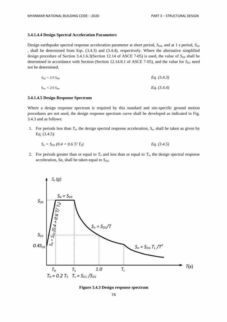
MYANMAR NATIONAL BUILDING CODE – 2020 PART 3 – STRUCTURAL DESIGN
74
3.4.1.4.4 Design Spectral Acceleration Parameters
Design earthquake spectral response acceleration parameter at short period, SDS, and at 1 s period, SD1
, shall be determined from Eqs. (3.4.3) and (3.4.4), respectively. Where the alternative simplified
design procedure of Section 3.4.1.6.3(Section 12.14 of ASCE 7-05) is used, the value of SDS shall be
determined in accordance with Section (Section 12.14.8.1 of ASCE 7-05), and the value for SD1 need
not be determined.
SDS = 2/3 SMS Eq. (3.4.3)
SD1 = 2/3 SM1 Eq. (3.4.4)
3.4.1.4.5 Design Response Spectrum
Where a design response spectrum is required by this standard and site-specific ground motion
procedures are not used, the design response spectrum curve shall be developed as indicated in Fig.
3.4.3 and as follows:
1. For periods less than T0, the design spectral response acceleration, Sa, shall be taken as given by
Eq. (3.4.5):
Sa = SDS (0.4 + 0.6 T/ T0) Eq. (3.4.5)
2. For periods greater than or equal to T0 and less than or equal to TS, the design spectral response
acceleration, Sa, shall be taken equal to SDS.
Figure 3.4.3 Design response spectrum
MYANMAR NATIONAL BUILDING CODE – 2020 PART 3 – STRUCTURAL DESIGN
75
3. For periods greater than TS, and less than or equal to TL, the design spectral response
acceleration, Sa, shall be taken as given by Eq. (3.4.6):
Sa= SD1/T Eq. (3.4.6)
4. For periods greater than TL, Sa shall be taken as given by Eq. (3.4.7):
Sa = SD1TL/T2 Eq. (3.4.7)
where
SDS = the design spectral response acceleration parameter at short periods
SD1 = the design spectral response acceleration parameter at 1-s period
T = the fundamental period of the structure, s
T0 = 0.2 SD1/SDS
TS = SD1/SDS and
TL = long-period transition period as specified in Table 3.4.1
3.4.1.4.6 MCE Response Spectrum
Where a MCE response spectrum is required, it shall be determined by multiplying the design
response spectrum by 1.5.
3.4.1.4.7 Site-Specific Ground Motion Procedures
The site-specific ground motion procedures set forth in Chapter 21 of ASCE 7-05 are permitted to be
used to determine ground motions for any structure.
3.4.1.4.8 Site Classification for Seismic Design
Site classification for Site Class C, D or E shall be determined from Table 3.4.5.
The notation presented below apply to the upper 100 feet (30,480 mm) of the site profile. Profiles
containing distinctly different soil and/or rock layers shall be subdivided into those layers designated
by a number that ranges from 1 to n at the bottom where there is a total of n distinct layers in the
upper 100 feet (30,480 mm). The symbol i then refers to any one of the layers between 1 and n.
where
vsi= the shear wave velocity in feet per second (m/s).
di = the thickness of any layer between 0 and 100 feet (30,480 mm).
where
MYANMAR NATIONAL BUILDING CODE – 2020 PART 3 – STRUCTURAL DESIGN
76
∑
∑
Eq. (3.4.8)
∑ = 100 ft (30,480 mm)
Ni is the Standard Penetration Resistance (ASTM D1586) not to exceed 100 blows/foot (304.8 mm) as
directly measured in the field without corrections. When refusal is met for a rock layer, Ni shall be
taken as 100 blows/foot (304.8 mm).
=∑
∑
Eq. (3.4.9)
where Ni and di in Equation (3.4.9) are for cohesionless soil, cohesive soil and rock layers.
=
∑
Eq. (3.4.10)
where
∑
Use di and Ni for cohesionless soil layers only in Equation (3.4.10)
ds= total thickness of cohesionless soil layers in the top 100 feet (30,480 mm)
m = number of cohesionless soil layers in the top 100 feet (30,480 mm)
sui = the undrained shear strength in psf (kPa), not to exceed 5,000 psf (240 kPa), ASTM
D2166 or D2850
∑
Eq. (3.4.11)
where
∑
dc = the total thickness of cohesive soil layers in the top 100 feet (30,480 mm)
k = the number of cohesive soil layers in the top 100 feet (30,480 mm)
PI = the plasticity index, ASTM D 4318
w = the moisture content in percent, ASTM D 2216
Where a site does not qualify under the criteria for Site Class F and there is a total thickness of soft
clay greater than 10 feet (3048 mm) where a soft clay layer is defined by: su< 500 psf (24 kPa), w ≥ 40
percent, and PI > 20, it shall be classified as Site Class E.

MYANMAR NATIONAL BUILDING CODE – 2020 PART 3 – STRUCTURAL DESIGN
77
The shear wave velocity for rock, Site Class B, shall be either measured on site or estimated by a
geotechnical engineer or engineering geologist/seismologist for competent rock with moderate
fracturing and weathering. Softer and more highly fractured and weathered rock shall either be
measured on site for shear wave velocity or classified as Site Class C.
The hard rock category, Site Class A, shall be supported by shear wave velocity measurements either
on site or on profiles of the same rock type in the same formation with an equal or greater degree of
weathering and fracturing. Where hard rock conditions are known to be continuous to a depth of 100
feet (30480 mm), surficial shear wave velocity measurements are permitted to be extrapolated to
assess .
The rock categories, Site Classes A and B, shall not be used if there is more than 10 feet (3,048 mm)
of soil between the rock surface and the bottom of the spread footing or mat foundation.
TABLE 3.4.5 SITE CLASSIFICATIONa
SITE CLASS or
C 1,200 to 2,500 ft/s >50 > 2,000
D 600 to 1,200 ft/s 15 to 50 1,000 to 2,000 psf
E < 600 ft/s < 15 < 1,000 psf
For SI: 1 foot per second = 304.8 mm per second, 1 pound per square foot = 0.0479 kN/m2.
a. If the method is used and the and criteria differ, select the category with the softer soils (for example,
use Site Class E instead of D).
3.4.1.4.8.1 Steps for Classifying a Site
1. Check for the four categories of Site Class F requiring site-specific evaluation. If the site
corresponds to any of these categories, classify the site as Site Class F and conduct a site-specific
evaluation.
2. Check for the existence of a total thickness of soft clay > 10 feet (3,048 mm) where a soft clay
layer is defined by: < 500 psf (24 kPa), w ≥ 40 percent and PI > 20. If these criteria are
satisfied, classify the site as Site Class E.
3. Categorize the site using one of the following three methods with , , and and computed in all
cases as specified:
(i) for the top 100 feet (30,480 mm) ( method)
(ii) for the top 100 feet (30,480 mm) ( method)
(iii) for cohesionless soil layers (PI < 20) in the top 100 feet (30,480 mm) and average, for
cohesive soil layers (PI > 20) in the top 100 feet (30,480 mm) ( method)
3.4.1.5 Importance Factor and Occupancy Category
3.4.1.5.1 Importance Factor
An importance factor, I, shall be assigned to each structure in accordance with Table 3.4.6 based on
the Occupancy Category from Table 3.1.2.
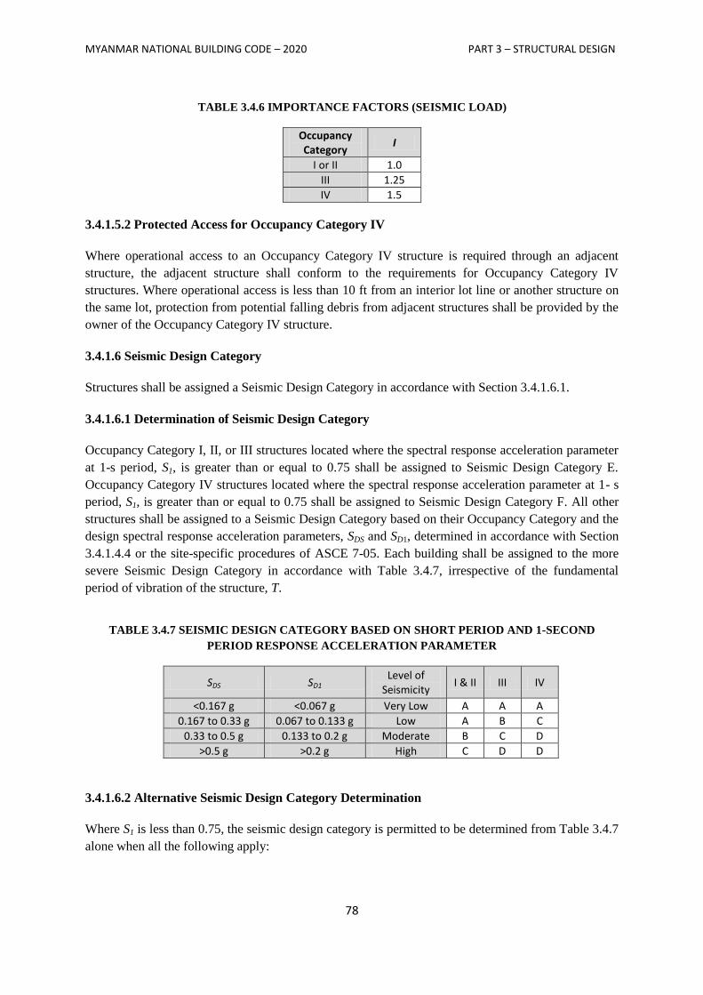
MYANMAR NATIONAL BUILDING CODE – 2020 PART 3 – STRUCTURAL DESIGN
78
TABLE 3.4.6 IMPORTANCE FACTORS (SEISMIC LOAD)
Occupancy Category
I
I or II 1.0
III 1.25
IV 1.5
3.4.1.5.2 Protected Access for Occupancy Category IV
Where operational access to an Occupancy Category IV structure is required through an adjacent
structure, the adjacent structure shall conform to the requirements for Occupancy Category IV
structures. Where operational access is less than 10 ft from an interior lot line or another structure on
the same lot, protection from potential falling debris from adjacent structures shall be provided by the
owner of the Occupancy Category IV structure.
3.4.1.6 Seismic Design Category
Structures shall be assigned a Seismic Design Category in accordance with Section 3.4.1.6.1.
3.4.1.6.1 Determination of Seismic Design Category
Occupancy Category I, II, or III structures located where the spectral response acceleration parameter
at 1-s period, S1, is greater than or equal to 0.75 shall be assigned to Seismic Design Category E.
Occupancy Category IV structures located where the spectral response acceleration parameter at 1- s
period, S1, is greater than or equal to 0.75 shall be assigned to Seismic Design Category F. All other
structures shall be assigned to a Seismic Design Category based on their Occupancy Category and the
design spectral response acceleration parameters, SDS and SD1, determined in accordance with Section
3.4.1.4.4 or the site-specific procedures of ASCE 7-05. Each building shall be assigned to the more
severe Seismic Design Category in accordance with Table 3.4.7, irrespective of the fundamental
period of vibration of the structure, T.
TABLE 3.4.7 SEISMIC DESIGN CATEGORY BASED ON SHORT PERIOD AND 1-SECOND
PERIOD RESPONSE ACCELERATION PARAMETER
SDS SD1 Level of
Seismicity I & II III IV
<0.167 g <0.067 g Very Low A A A
0.167 to 0.33 g 0.067 to 0.133 g Low A B C
0.33 to 0.5 g 0.133 to 0.2 g Moderate B C D
>0.5 g >0.2 g High C D D
3.4.1.6.2 Alternative Seismic Design Category Determination
Where S1 is less than 0.75, the seismic design category is permitted to be determined from Table 3.4.7
alone when all the following apply:
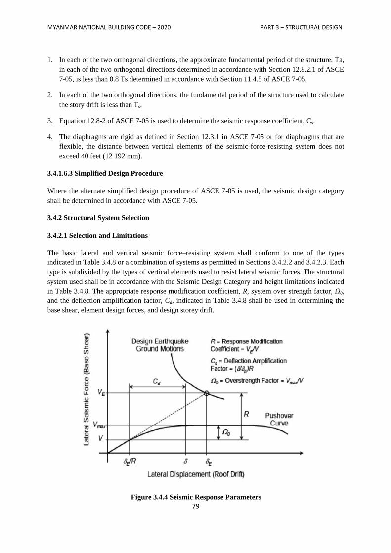
MYANMAR NATIONAL BUILDING CODE – 2020 PART 3 – STRUCTURAL DESIGN
79
1. In each of the two orthogonal directions, the approximate fundamental period of the structure, Ta,
in each of the two orthogonal directions determined in accordance with Section 12.8.2.1 of ASCE
7-05, is less than 0.8 Ts determined in accordance with Section 11.4.5 of ASCE 7-05.
2. In each of the two orthogonal directions, the fundamental period of the structure used to calculate
the story drift is less than Ts.
3. Equation 12.8-2 of ASCE 7-05 is used to determine the seismic response coefficient, Cs.
4. The diaphragms are rigid as defined in Section 12.3.1 in ASCE 7-05 or for diaphragms that are
flexible, the distance between vertical elements of the seismic-force-resisting system does not
exceed 40 feet (12 192 mm).
3.4.1.6.3 Simplified Design Procedure
Where the alternate simplified design procedure of ASCE 7-05 is used, the seismic design category
shall be determined in accordance with ASCE 7-05.
3.4.2 Structural System Selection
3.4.2.1 Selection and Limitations
The basic lateral and vertical seismic force–resisting system shall conform to one of the types
indicated in Table 3.4.8 or a combination of systems as permitted in Sections 3.4.2.2 and 3.4.2.3. Each
type is subdivided by the types of vertical elements used to resist lateral seismic forces. The structural
system used shall be in accordance with the Seismic Design Category and height limitations indicated
in Table 3.4.8. The appropriate response modification coefficient, R, system over strength factor, Ω0,
and the deflection amplification factor, Cd, indicated in Table 3.4.8 shall be used in determining the
base shear, element design forces, and design storey drift.
Figure 3.4.4 Seismic Response Parameters
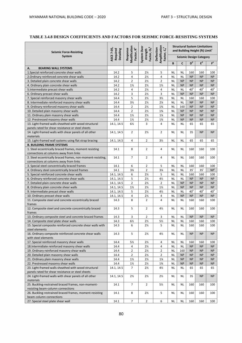
MYANMAR NATIONAL BUILDING CODE – 2020 PART 3 – STRUCTURAL DESIGN
80
TABLE 3.4.8 DESIGN COEFFICIENTS AND FACTORS FOR SEISMIC FORCE-RESISTING SYSTEMS
Seismic Force-Resisting System
ASC
E 7-
05
, R
eq
uir
ed
D
eta
ilin
g
Re
spo
nse
Mo
dif
icat
ion
Fa
cto
r, R
a
Syst
em
Ove
r st
ren
gth
Fact
or,
Ω0g
De
fle
ctio
n
Am
plif
icat
ion
Fa
cto
r, C
db Structural System Limitations
and Building Height (ft) Limitc
Seismic Design Category
B C Dd Ed Fe
A. BEARING WALL SYSTEMS
1.Special reinforced concrete shear walls 14.2 5 2½ 5 NL NL 160 160 100
2.Ordinary reinforced concrete shear walls 14.2 4 2½ 4 NL NL NP NP NP
3. Detailed plain concrete shear walls 14.2 2 2½ 2 NL NP NP NP NP
4. Ordinary plain concrete shear walls 14.2 1½ 2½ 1½ NL NP NP NP NP
5.Intermediate precast shear walls 14.2 4 2½ 4 NL NL 40k 40k 40k
6. Ordinary precast shear walls 14.2 3 2½ 3 NL NP NP NP NP
7. Special reinforced masonry shear walls 14.4 5 2½ 3½ NL NL 160 160 100
8. Intermediate reinforced masonry shear walls 14.4 3½ 2½ 2¼ NL NL NP NP NP
9. Ordinary reinforced masonry shear walls 14.4 2 2½ 1¾ NL 160 NP NP NP
10. Detailed plain masonry shear walls 14.4 2 2½ 1¾ NL NP NP NP NP
11. Ordinary plain masonry shear walls 14.4 1½ 2½ 1¼ NL NP NP NP NP
12. Prestressed masonry shear walls 14.4 1½ 2½ 1¾ NL NP NP NP NP
13. Light-framed walls sheathed with wood structural
panels rated for shear resistance or steel sheets
14.1, 14.5 6½ 3 4 NL NL 65 65 65
14. Light-framed walls with shear panels of all other
materials
14.1, 14.5 2 2½ 2 NL NL 35 NP NP
15. Light-framed wall systems using flat strap bracing 14.1, 14.5 4 2 3½ NL NL 65 65 65
B. BUILDING FRAME SYSTEMS
1. Steel eccentrically braced frames, moment resisting connections at columns away from links
14.1 8 2 4 NL NL 160 160 100
2. Steel eccentrically braced frames, non-moment-resisting, connections at columns away from links
14.1 7 2 4 NL NL 160 160 100
3. Special steel concentrically braced frames 14.1 6 2 5 NL NL 160 160 100
4. Ordinary steel concentrically braced frames 14.1 3¼ 2 3¼ NL NL 35j 35j NPj
5. Special reinforced concrete shear walls 14.1, 14.5 6 2½ 5 NL NL 160 160 100
6. Ordinary reinforced concrete shear walls 14.1, 14.5 5 2½ 4½ NL NL NP NP NP
7. Detailed plain concrete shear walls 14.1, 14.5 2 2½ 2 NL NP NP NP NP
8. Ordinary plain concrete shear walls 14.1, 14.5 1½ 2½ 1½ NL NP NP NP NP
9. Intermediate precast shear walls 14.1, 14.5 5 2½ 4½ NL NL 40k 40k 40k
10. Ordinary precast shear walls 14.1, 14.5 4 2½ 4 NL NP NP NP NP
11. Composite steel and concrete eccentrically braced frames
14.3 8 2 4 NL NL 160 160 100
12. Composite steel and concrete concentrically braced frames
14.3 5 2 4½ NL NL 160 160 100
13. Ordinary composite steel and concrete braced frames 14.3 3 2 3 NL NL NP NP NP
14. Composite steel plate shear walls 14.3 6½ 2½ 5½ NL NL 160 160 100
15. Special composite reinforced concrete shear walls with
steel elements
14.3 6 2½ 5 NL NL 160 160 100
16. Ordinary composite reinforced concrete shear walls
with steel elements
14.3 5 2½ 4½ NL NL NP NP NP
17. Special reinforced masonry shear walls 14.4 5½ 2½ 4 NL NL 160 160 100
18.Intermidiate reinforced masonry shear walls 14.4 4 2½ 4 NL NL NP NP NP
19. Ordinary reinforced masonry shear walls 14.4 2 2½ 2 NL 160 NP NP NP
20. Detailed plain masonry shear walls 14.4 2 2½ 2 NL NP NP NP NP
21. Ordinary plain masonry shear walls 14.4 1½ 2½ 1¼ NL NP NP NP NP
22. Prestressed masonry shear walls 14.4 1½ 2½ 1¾ NL NP NP NP NP
23. Light-framed walls sheathed with wood structural panels rated for shear resistance or steel sheets
14.1, 14.5 7 2½ 4½ NL NL 65 65 65
24. Light-framed walls with shear panels of all other materials
14.1, 14.5 2½ 2½ 2½ NL NL 35 NP NP
25. Buckling-restrained braced frames, non-moment-resisting beam-column connections
14.1 7 2 5½ NL NL 160 160 100
26. Buckling-restrained braced frames, moment-resisting beam-column connections
14.1 8 2½ 5 NL NL 160 160 100
27. Special steel plate shear wall 14.1 7 2 6 NL NL 160 160 100
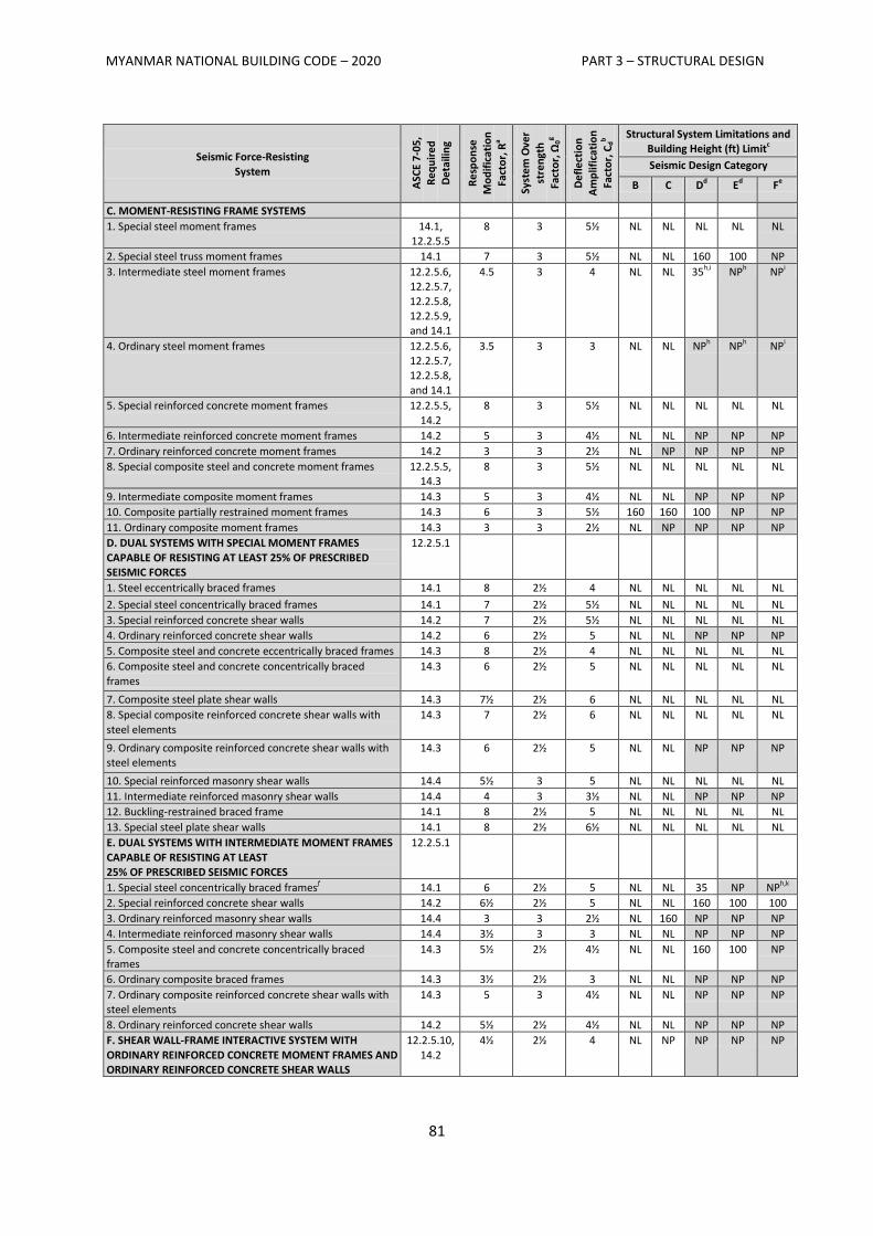
MYANMAR NATIONAL BUILDING CODE – 2020 PART 3 – STRUCTURAL DESIGN
81
Seismic Force-Resisting
System
ASC
E 7-
05
, R
eq
uir
ed
D
eta
ilin
g
Re
spo
nse
M
od
ific
atio
n
Fact
or,
Ra
Syst
em
Ove
r st
ren
gth
Fact
or,
Ω0
g
De
fle
ctio
n
Am
plif
icat
ion
Fact
or,
Cd
b Structural System Limitations and
Building Height (ft) Limitc
Seismic Design Category
B C Dd Ed Fe
C. MOMENT-RESISTING FRAME SYSTEMS
1. Special steel moment frames 14.1, 12.2.5.5
8 3 5½ NL NL NL NL NL
2. Special steel truss moment frames 14.1 7 3 5½ NL NL 160 100 NP
3. Intermediate steel moment frames 12.2.5.6, 12.2.5.7,
12.2.5.8, 12.2.5.9, and 14.1
4.5 3 4 NL NL 35h,i NPh NPi
4. Ordinary steel moment frames 12.2.5.6, 12.2.5.7, 12.2.5.8,
and 14.1
3.5 3 3 NL NL NPh NPh NPi
5. Special reinforced concrete moment frames 12.2.5.5,
14.2
8 3 5½ NL NL NL NL NL
6. Intermediate reinforced concrete moment frames 14.2 5 3 4½ NL NL NP NP NP
7. Ordinary reinforced concrete moment frames 14.2 3 3 2½ NL NP NP NP NP
8. Special composite steel and concrete moment frames 12.2.5.5, 14.3
8 3 5½ NL NL NL NL NL
9. Intermediate composite moment frames 14.3 5 3 4½ NL NL NP NP NP
10. Composite partially restrained moment frames 14.3 6 3 5½ 160 160 100 NP NP
11. Ordinary composite moment frames 14.3 3 3 2½ NL NP NP NP NP
D. DUAL SYSTEMS WITH SPECIAL MOMENT FRAMES
CAPABLE OF RESISTING AT LEAST 25% OF PRESCRIBED SEISMIC FORCES
12.2.5.1
1. Steel eccentrically braced frames 14.1 8 2½ 4 NL NL NL NL NL
2. Special steel concentrically braced frames 14.1 7 2½ 5½ NL NL NL NL NL
3. Special reinforced concrete shear walls 14.2 7 2½ 5½ NL NL NL NL NL
4. Ordinary reinforced concrete shear walls 14.2 6 2½ 5 NL NL NP NP NP
5. Composite steel and concrete eccentrically braced frames 14.3 8 2½ 4 NL NL NL NL NL
6. Composite steel and concrete concentrically braced
frames
14.3 6 2½ 5 NL NL NL NL NL
7. Composite steel plate shear walls 14.3 7½ 2½ 6 NL NL NL NL NL
8. Special composite reinforced concrete shear walls with
steel elements
14.3 7 2½ 6 NL NL NL NL NL
9. Ordinary composite reinforced concrete shear walls with steel elements
14.3 6 2½ 5 NL NL NP NP NP
10. Special reinforced masonry shear walls 14.4 5½ 3 5 NL NL NL NL NL
11. Intermediate reinforced masonry shear walls 14.4 4 3 3½ NL NL NP NP NP
12. Buckling-restrained braced frame 14.1 8 2½ 5 NL NL NL NL NL
13. Special steel plate shear walls 14.1 8 2½ 6½ NL NL NL NL NL
E. DUAL SYSTEMS WITH INTERMEDIATE MOMENT FRAMES
CAPABLE OF RESISTING AT LEAST 25% OF PRESCRIBED SEISMIC FORCES
12.2.5.1
1. Special steel concentrically braced framesf 14.1 6 2½ 5 NL NL 35 NP NPh,k
2. Special reinforced concrete shear walls 14.2 6½ 2½ 5 NL NL 160 100 100
3. Ordinary reinforced masonry shear walls 14.4 3 3 2½ NL 160 NP NP NP
4. Intermediate reinforced masonry shear walls 14.4 3½ 3 3 NL NL NP NP NP
5. Composite steel and concrete concentrically braced frames
14.3 5½ 2½ 4½ NL NL 160 100 NP
6. Ordinary composite braced frames 14.3 3½ 2½ 3 NL NL NP NP NP
7. Ordinary composite reinforced concrete shear walls with steel elements
14.3 5 3 4½ NL NL NP NP NP
8. Ordinary reinforced concrete shear walls 14.2 5½ 2½ 4½ NL NL NP NP NP
F. SHEAR WALL-FRAME INTERACTIVE SYSTEM WITH
ORDINARY REINFORCED CONCRETE MOMENT FRAMES AND ORDINARY REINFORCED CONCRETE SHEAR WALLS
12.2.5.10,
14.2
4½ 2½ 4 NL NP NP NP NP
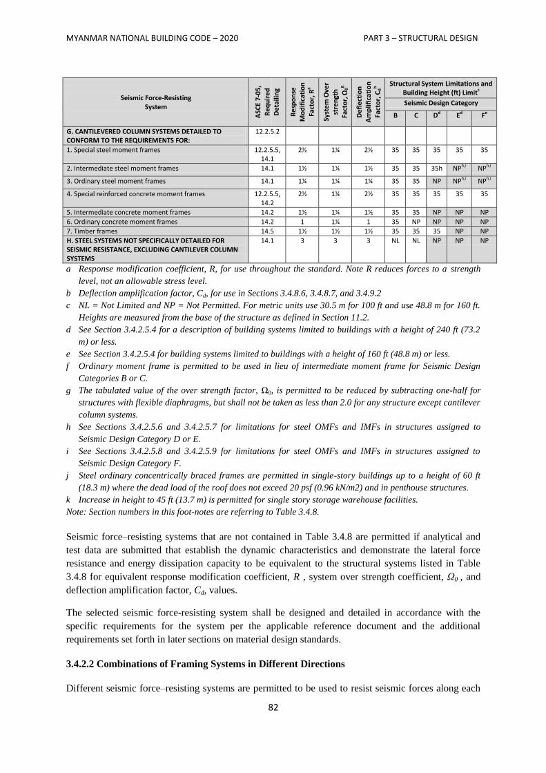
MYANMAR NATIONAL BUILDING CODE – 2020 PART 3 – STRUCTURAL DESIGN
82
Seismic Force-Resisting System
ASC
E 7-
05
,
Re
qu
ire
d
De
taili
ng
Re
spo
nse
M
od
ific
atio
n
Fact
or,
Ra
Syst
em
Ove
r st
ren
gth
Fact
or,
Ω0
g
De
fle
ctio
n
Am
plif
icat
ion
Fact
or,
Cd
b Structural System Limitations and
Building Height (ft) Limitc
Seismic Design Category
B C Dd Ed Fe
G. CANTILEVERED COLUMN SYSTEMS DETAILED TO CONFORM TO THE REQUIREMENTS FOR:
12.2.5.2
1. Special steel moment frames 12.2.5.5, 14.1
2½ 1¼ 2½ 35 35 35 35 35
2. Intermediate steel moment frames 14.1 1½ 1¼ 1½ 35 35 35h NPh,i NPh,i
3. Ordinary steel moment frames 14.1 1¼ 1¼ 1¼ 35 35 NP NPh,i NPh,i
4. Special reinforced concrete moment frames 12.2.5.5, 14.2
2½ 1¼ 2½ 35 35 35 35 35
5. Intermediate concrete moment frames 14.2 1½ 1¼ 1½ 35 35 NP NP NP
6. Ordinary concrete moment frames 14.2 1 1¼ 1 35 NP NP NP NP
7. Timber frames 14.5 1½ 1½ 1½ 35 35 35 NP NP
H. STEEL SYSTEMS NOT SPECIFICALLY DETAILED FOR SEISMIC RESISTANCE, EXCLUDING CANTILEVER COLUMN SYSTEMS
14.1 3 3 3 NL NL NP NP NP
a Response modification coefficient, R, for use throughout the standard. Note R reduces forces to a strength
level, not an allowable stress level.
b Deflection amplification factor, Cd, for use in Sections 3.4.8.6, 3.4.8.7, and 3.4.9.2
c NL = Not Limited and NP = Not Permitted. For metric units use 30.5 m for 100 ft and use 48.8 m for 160 ft.
Heights are measured from the base of the structure as defined in Section 11.2.
d See Section 3.4.2.5.4 for a description of building systems limited to buildings with a height of 240 ft (73.2
m) or less.
e See Section 3.4.2.5.4 for building systems limited to buildings with a height of 160 ft (48.8 m) or less.
f Ordinary moment frame is permitted to be used in lieu of intermediate moment frame for Seismic Design
Categories B or C.
g The tabulated value of the over strength factor, Ω0, is permitted to be reduced by subtracting one-half for
structures with flexible diaphragms, but shall not be taken as less than 2.0 for any structure except cantilever
column systems.
h See Sections 3.4.2.5.6 and 3.4.2.5.7 for limitations for steel OMFs and IMFs in structures assigned to
Seismic Design Category D or E.
i See Sections 3.4.2.5.8 and 3.4.2.5.9 for limitations for steel OMFs and IMFs in structures assigned to
Seismic Design Category F.
j Steel ordinary concentrically braced frames are permitted in single-story buildings up to a height of 60 ft
(18.3 m) where the dead load of the roof does not exceed 20 psf (0.96 kN/m2) and in penthouse structures.
k Increase in height to 45 ft (13.7 m) is permitted for single story storage warehouse facilities.
Note: Section numbers in this foot-notes are referring to Table 3.4.8.
Seismic force–resisting systems that are not contained in Table 3.4.8 are permitted if analytical and
test data are submitted that establish the dynamic characteristics and demonstrate the lateral force
resistance and energy dissipation capacity to be equivalent to the structural systems listed in Table
3.4.8 for equivalent response modification coefficient, R , system over strength coefficient, Ω0 , and
deflection amplification factor, Cd, values.
The selected seismic force-resisting system shall be designed and detailed in accordance with the
specific requirements for the system per the applicable reference document and the additional
requirements set forth in later sections on material design standards.
3.4.2.2 Combinations of Framing Systems in Different Directions
Different seismic force–resisting systems are permitted to be used to resist seismic forces along each
MYANMAR NATIONAL BUILDING CODE – 2020 PART 3 – STRUCTURAL DESIGN
83
of the two orthogonal axes of the structure. Where different systems are used, the respective R, Cd,
and Ω0 coefficients shall apply to each system, including the limitations on system use contained in
Table 3.4.8.
3.4.2.3 Combinations of Framing Systems in the Same Direction
Where different seismic force–resisting systems are used in combination to resist seismic forces in the
same direction of structural response, other than those combinations considered as dual systems, the
more stringent system limitation contained in Table 3.4.8 shall apply and the design shall comply with
the requirements of this section.
3.4.2.3.1 R, Cd, and Ω0 Values for Vertical Combinations
The value of the response modification coefficient, R, used for design at any storey shall not exceed
the lowest value of R that is used in the same direction at any storey above that storey. Likewise, the
deflection amplification factor, Cd, and the system over strength factor, Ω0, used for the design at any
storey shall not be less than the largest value of this factor that is used in the same direction at any
storey above that storey.
EXCEPTIONS:
1. Rooftop structures not exceeding two storeys in height and 10 percent of the total structure
weight.
2. Other supported structural systems with a weight equal to or less than 10 percent of the weight
of the structure.
3. Detached one- and two-family dwellings of light-frame construction.
A two-stage equivalent lateral force procedure is permitted to be used for structures having a flexible
upper portion above a rigid lower portion, provided that the design of the structure complies with the
following:
a. The stiffness of the lower portion must be at least 10 times the stiffness of the upper portion.
b. The period of the entire structure shall not be greater than 1.1 times the period of the upper
portion considered as a separate structure fixed at the base.
c. The flexible upper portion shall be designed as a separate structure using the appropriate
values of R and ρ.
d. The rigid lower portion shall be designed as a separate structure using the appropriate values
of R and ρ. The reactions from the upper portion shall be those determined from the analysis
of the upper portion amplified by the ratio of the R/ρ of the upper portion over R/ρ of the
lower portion. This ratio shall not be less than 1.0.
3.4.2.3.2 R, Cd, and Ω0 Values for Horizontal Combinations
Where a combination of different structural systems is utilized to resist lateral forces in the same
direction, the value of R used for design in that direction shall not be greater than the least value of R
for any of the systems utilized in that direction. Resisting elements are permitted to be designed using
the least value of R for the different structural systems found in each independent line of resistance if
the following three conditions are met: (1) Occupancy Category I or II building, (2) two storeys or
less in height, and (3) use of light-frame construction or flexible diaphragms. The value of R used for
MYANMAR NATIONAL BUILDING CODE – 2020 PART 3 – STRUCTURAL DESIGN
84
design of diaphragms in such structures shall not be greater than the least value for any of the systems
utilized in the same direction.
The deflection amplification factor, Cd , and the system over strength factor, Ω0 , in the direction
under consideration at any storey shall not be less than the largest value of this factor for the R factor
used in the same direction being considered.
3.4.2.4 Combination Framing Detailing Requirements
Structural components common to different framing systems used to resist seismic motions in any
direction shall be designed using the detailing requirements of Section 3.4.2 required by the highest
response modification coefficient, R, of the connected framing systems.
3.4.2.5 System Specific Requirements
The structural framing system shall also comply with the following system specific requirements of
this section.
3.4.2.5.1 Dual System
For a dual system, the moment frames shall be capable of resisting at least 25 percent of the design
seismic forces. The total seismic force resistance is to be provided by the combination of the moment
frames and the shear walls or braced frames in proportion to their rigidities.
3.4.2.5.2 Cantilever Column Systems
Cantilever column systems are permitted as indicated in Table 3.4.8 and as follows. The axial load on
individual cantilever column elements calculated in accordance with the load combinations of Section
2.1.2 shall not exceed 15 percent of the design strength of the column to resist axial loads alone, or for
allowable stress design, the axial load stress on individual cantilever column elements, calculated in
accordance with the load combinations of Section 2.1.3 shall not exceed 15 percent of the permissible
axial stress.
Foundation and other elements used to provide overturning resistance at the base of cantilever column
elements shall have the strength to resist the load combinations with overstrength factor of Section
3.4.4.3.2.
3.4.2.5.3 Inverted Pendulum-Type Structures
Regardless of the structural system selected, inverted pendulums as defined in Section 3.4.1.2, shall
comply with this section. Supporting columns or piers of inverted pendulum-type structures shall be
designed for the bending moment calculated at the base determined using the procedures given in
Section 3.4.8 and varying uniformly to a moment at the top equal to one-half the calculated bending
moment at the base.
3.4.2.5.4 Increased Building Height Limit for Steel Braced Frames and Special Reinforced
Concrete Shear Walls
The height limits in Table 3.4.8 are permitted to be increased from160 ft (50 m) to 240 ft (75 m) for
structures assigned to Seismic Design Categories D or E and from 100 ft (30 m) to 160 ft (50 m) for
MYANMAR NATIONAL BUILDING CODE – 2020 PART 3 – STRUCTURAL DESIGN
85
structures assigned to Seismic Design Category F that have steel braced frames or special reinforced
concrete cast-in-place shear walls and that meet both of the following requirements:
1. The structure shall not have an extreme torsional irregularity as defined in Table 3.4.9
(horizontal structural irregularity Type H1b).
2. The braced frames or shear walls in any one plane shall resist no more than 60 percent of the
total seismic forces in each direction, neglecting accidental torsional effects.
3.4.2.5.5 Special Moment Frames in Structures Assigned to Seismic Design Categories D
Through F
For structures assigned to Seismic Design Categories D, E, or F, a special moment frame that is used
but not required by Table 3.4.8 shall not be discontinued and supported by a more rigid system with a
lower response modification coefficient, R, unless the requirements of Sections 3.4.2.3.2 and 3.4.3.3.4
are met. Where a special moment frame is required by Table 3.4.8, the frame shall be continuous to
the foundation.
3.4.2.5.6 Single-Storey Steel Ordinary and Intermediate Moment Frames in Structures Assigned
to Seismic Design Category D or E
Single-storey steel ordinary moment frames and intermediate moment frames in structures assigned
to Seismic Design Category D or E are permitted up to a height of 65 ft (20 m) where the dead load
supported by and tributary to the roof does not exceed 20 psf (0.96 kN/m2). In addition, the dead loads
tributary to the moment frame, of the exterior wall more than 35 ft above the base shall not exceed 20
psf (0.96 kN/m2).
3.4.2.5.7 Other Steel Ordinary and Intermediate Moment Frames in Structures Assigned to
Seismic Design Category D or E
Steel ordinary moment frames in structures assigned to Seismic Design Category D or E not meeting
the limitations set forth in Section 3.4.2.5.6 are permitted within light-frame construction up to a
height of 35 ft (10.6 m) where neither the roof nor the floor dead load supported by and tributary to
the moment frames exceeds 35 psf (1.68 kN/m2 ). In addition, the dead load of the exterior walls
tributary to the moment frame shall not exceed 20 psf (0.96 kN/m2). Steel intermediate moment
frames in structures assigned to Seismic Design Category D or E not meeting the limitations set forth
in Section 3.4.2.5.6 permitted as follows:
1. In Seismic Design Category D, intermediate moment frames are permitted to a height of 35
ft (10.6 m).
2. In Seismic Design Category E, intermediate moment frames are permitted to a height of 35 ft
(10.6 m) provided neither the roof nor the floor dead load supported by and tributary to the
moment frames exceeds 35 psf (1.68 kN/m2). In addition, the dead load of the exterior walls
tributary to the moment frame shall not exceed 20 psf (0.96 kN/m2).
MYANMAR NATIONAL BUILDING CODE – 2020 PART 3 – STRUCTURAL DESIGN
86
3.4.2.5.8 Single-Storey Steel Ordinary and Intermediate Moment Frames in Structures Assigned
to Seismic Design Category F
Single-storey steel ordinary moment frames and intermediate moment frames in structures assigned to
Seismic Design Category F are permitted up to a height of 65 ft (20 m) where the dead load supported
by and tributary to the roof does not exceed 20 psf (0.96 kN/m2). In addition, the dead loads of the
exterior walls tributary to the moment frame shall not exceed 20 psf (0.96 kN/m2).
3.4.2.5.9 Other Steel Intermediate Moment Frame Limitations in Structures Assigned to Seismic
Design Category F
In addition to the limitations for steel intermediate moment frames in structures assigned to Seismic
Design Category E as set forth in Section 3.4.2.5.7, steel intermediate moment frames in structures
assigned to Seismic Design Category F are permitted in light-frame construction.
3.4.2.5.10 Shear Wall-Frame Interactive Systems
The shear strength of the shear walls of the shear wall-frame interactive system shall be at least 75
percent of the design storey shear at each storey. The frames of the shear wall-frame interactive
system shall be capable of resisting at least 25 percent of the design storey shear in every storey.
3.4.3 Diaphragm Flexibility, Configuration Irregularities, and Redundancy
3.4.3.1 Diaphragm Flexibility
The structural analysis shall consider the relative stiffnesses of diaphragms and the vertical elements
of the seismic force–resisting system. Unless a diaphragm can be idealized as either flexible or rigid
in accordance with Sections 3.4.3.1.1, 3.4.3.1.2, or 3.4.3.1.3, the structural analysis shall explicitly
include consideration of the stiffness of the diaphragm (i.e., semirigid modeling assumption).
3.4.3.1.1 Flexible Diaphragm Condition
Diaphragms constructed of untopped steel decking or wood structural panels are permitted to be
idealized as flexible in structures in which the vertical elements are steel or composite steel and
concrete braced frames, or concrete, masonry, steel, or composite shear walls. Diaphragms of wood
structural panels or untopped steel decks in one- and two-family residential buildings of light-frame
construction shall also be permitted to be idealized as flexible.
3.4.3.1.2 Alternatives to ASCE 7
The following provisions shall be permitted as alternatives to the relevant provisions of ASCE 7.
Diaphragms constructed of wood structural panels or untopped steel decking shall also be permitted to
be idealized as flexible, provided all of the following conditions are met:
1. Toppings of concrete or similar materials are not placed over wood structural panel
diaphragms except for nonstructural toppings no greater than 1½ inches (38 mm) thick.
2. Each line of vertical elements of the lateral-force-resisting system complies with the
allowable storey drift of Table 3.4.8.
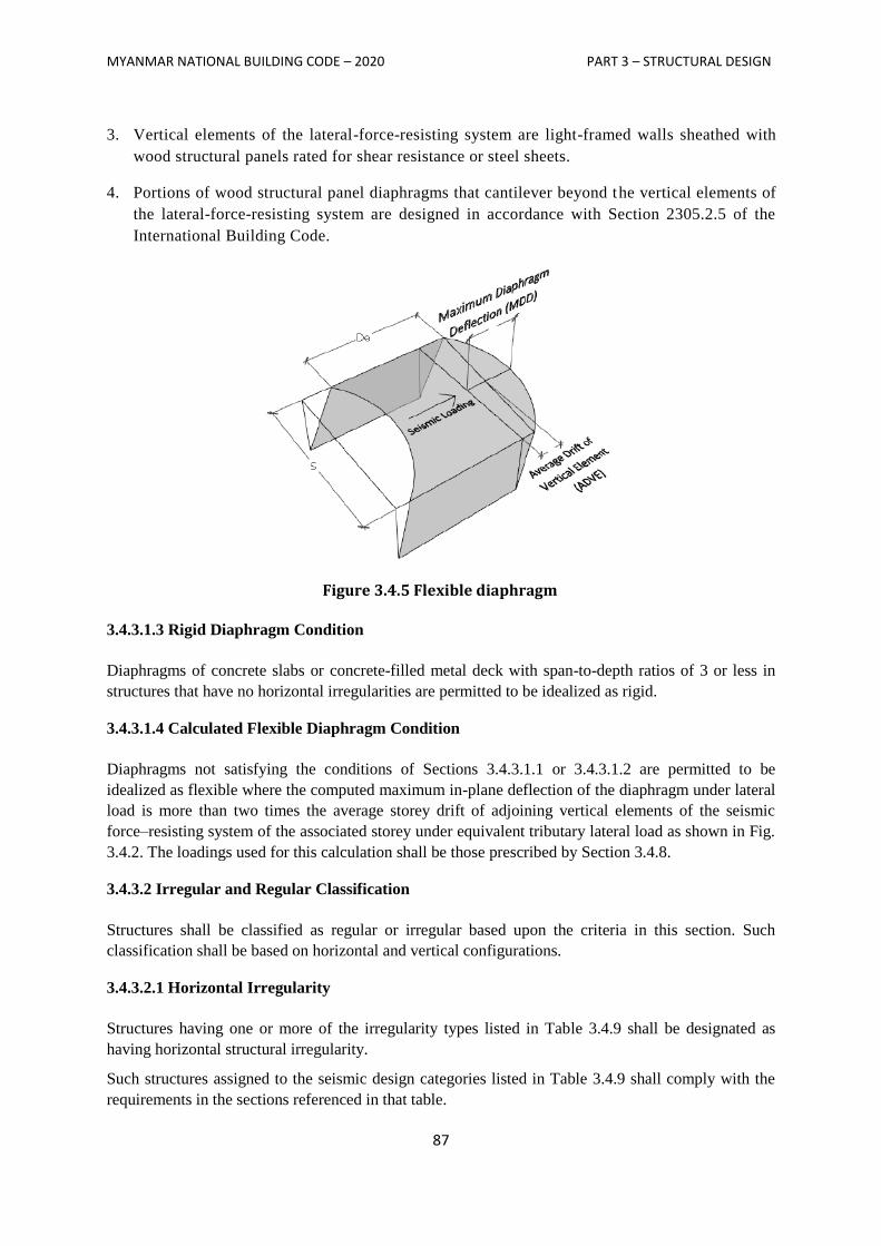
MYANMAR NATIONAL BUILDING CODE – 2020 PART 3 – STRUCTURAL DESIGN
87
3. Vertical elements of the lateral-force-resisting system are light-framed walls sheathed with
wood structural panels rated for shear resistance or steel sheets.
4. Portions of wood structural panel diaphragms that cantilever beyond the vertical elements of
the lateral-force-resisting system are designed in accordance with Section 2305.2.5 of the
International Building Code.
Figure 3.4.5 Flexible diaphragm
3.4.3.1.3 Rigid Diaphragm Condition
Diaphragms of concrete slabs or concrete-filled metal deck with span-to-depth ratios of 3 or less in
structures that have no horizontal irregularities are permitted to be idealized as rigid.
3.4.3.1.4 Calculated Flexible Diaphragm Condition
Diaphragms not satisfying the conditions of Sections 3.4.3.1.1 or 3.4.3.1.2 are permitted to be
idealized as flexible where the computed maximum in-plane deflection of the diaphragm under lateral
load is more than two times the average storey drift of adjoining vertical elements of the seismic
force–resisting system of the associated storey under equivalent tributary lateral load as shown in Fig.
3.4.2. The loadings used for this calculation shall be those prescribed by Section 3.4.8.
3.4.3.2 Irregular and Regular Classification
Structures shall be classified as regular or irregular based upon the criteria in this section. Such
classification shall be based on horizontal and vertical configurations.
3.4.3.2.1 Horizontal Irregularity
Structures having one or more of the irregularity types listed in Table 3.4.9 shall be designated as
having horizontal structural irregularity.
Such structures assigned to the seismic design categories listed in Table 3.4.9 shall comply with the
requirements in the sections referenced in that table.
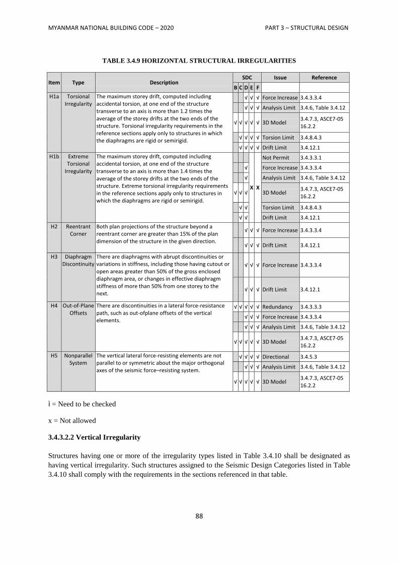
MYANMAR NATIONAL BUILDING CODE – 2020 PART 3 – STRUCTURAL DESIGN
88
TABLE 3.4.9 HORIZONTAL STRUCTURAL IRREGULARITIES
Item Type Description SDC Issue Reference
B C D E F
H1a Torsional Irregularity
The maximum storey drift, computed including accidental torsion, at one end of the structure transverse to an axis is more than 1.2 times the average of the storey drifts at the two ends of the structure. Torsional irregularity requirements in the reference sections apply only to structures in which the diaphragms are rigid or semirigid.
√ √ √ Force Increase 3.4.3.3.4
√ √ √ Analysis Limit 3.4.6, Table 3.4.12
√ √ √ √ √ 3D Model 3.4.7.3, ASCE7-05 16.2.2
√ √ √ √ Torsion Limit 3.4.8.4.3
√ √ √ √ Drift Limit 3.4.12.1
H1b Extreme Torsional
Irregularity
The maximum storey drift, computed including accidental torsion, at one end of the structure transverse to an axis is more than 1.4 times the average of the storey drifts at the two ends of the structure. Extreme torsional irregularity requirements in the reference sections apply only to structures in which the diaphragms are rigid or semirigid.
X X
Not Permit 3.4.3.3.1
√ Force Increase 3.4.3.3.4
√ Analysis Limit 3.4.6, Table 3.4.12
√ √ √ 3D Model 3.4.7.3, ASCE7-05 16.2.2
√ √ Torsion Limit 3.4.8.4.3
√ √ Drift Limit 3.4.12.1
H2 Reentrant Corner
Both plan projections of the structure beyond a reentrant corner are greater than 15% of the plan dimension of the structure in the given direction.
√ √ √ Force Increase 3.4.3.3.4
√ √ √ Drift Limit 3.4.12.1
H3 Diaphragm Discontinuity
There are diaphragms with abrupt discontinuities or variations in stiffness, including those having cutout or open areas greater than 50% of the gross enclosed diaphragm area, or changes in effective diaphragm stiffness of more than 50% from one storey to the next.
√ √ √ Force Increase 3.4.3.3.4
√ √ √ Drift Limit 3.4.12.1
H4 Out-of-Plane Offsets
There are discontinuities in a lateral force-resistance path, such as out-ofplane offsets of the vertical elements.
√ √ √ √ √ Redundancy 3.4.3.3.3
√ √ √ Force Increase 3.4.3.3.4
√ √ √ Analysis Limit 3.4.6, Table 3.4.12
√ √ √ √ √ 3D Model 3.4.7.3, ASCE7-05 16.2.2
H5 Nonparallel System
The vertical lateral force-resisting elements are not parallel to or symmetric about the major orthogonal axes of the seismic force–resisting system.
√ √ √ √ Directional 3.4.5.3
√ √ √ Analysis Limit 3.4.6, Table 3.4.12
√ √ √ √ √ 3D Model 3.4.7.3, ASCE7-05 16.2.2
ì = Need to be checked
x = Not allowed
3.4.3.2.2 Vertical Irregularity
Structures having one or more of the irregularity types listed in Table 3.4.10 shall be designated as
having vertical irregularity. Such structures assigned to the Seismic Design Categories listed in Table
3.4.10 shall comply with the requirements in the sections referenced in that table.
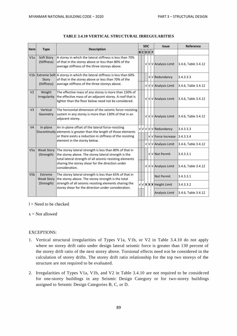
MYANMAR NATIONAL BUILDING CODE – 2020 PART 3 – STRUCTURAL DESIGN
89
TABLE 3.4.10 VERTICAL STRUCTURAL IRREGULARITIES
Item Type Description SDC Issue Reference
B C D E F
V1a Soft Story (Stiffness)
A storey in which the lateral stiffness is less than 70% of that in the storey above or less than 80% of the average stiffness of the three storeys above.
√ √ √ Analysis Limit 3.4.6, Table 3.4.12
V1b Extreme Soft Story
(Stiffness)
A storey in which the lateral stiffness is less than 60% of that in the storey above or less than 70% of the average stiffness of the three storeys above.
√ √ Redundancy 3.4.3.3.3
√ √ √ Analysis Limit 3.4.6, Table 3.4.12
V2 Weight Irregularity
The effective mass of any storey is more than 150% of the effective mass of an adjacent storey. A roof that is lighter than the floor below need not be considered.
√ √ √ Analysis Limit 3.4.6, Table 3.4.12
V3 Vertical Geometry
The horizontal dimension of the seismic force–resisting system in any storey is more than 130% of that in an adjacent storey.
√ √ √ Analysis Limit 3.4.6, Table 3.4.12
V4 In-plane Discontinuity
An in-plane offset of the lateral force-resisting elements is greater than the length of those elements or there exists a reduction in stiffness of the resisting element in the storey below.
√ √ √ √ √ Redundancy 3.4.3.3.3
√ √ Force Increase 3.4.3.3.4
√ √ √ Analysis Limit 3.4.6, Table 3.4.12
V5a Weak Story (Strength)
The storey lateral strength is less than 80% of that in the storey above. The storey lateral strength is the total lateral strength of all seismic-resisting elements sharing the storey shear for the direction under consideration.
√ √ Not Permit 3.4.3.3.1
√ √ √ Analysis Limit 3.4.6, Table 3.4.12
V5b Extreme Weak Story (Strength)
The storey lateral strength is less than 65% of that in the storey above. The storey strength is the total strength of all seismic-resisting elements sharing the storey shear for the direction under consideration.
X X X
Not Permit 3.4.3.3.1
√ √ Height Limit 3.4.3.3.2
Analysis Limit 3.4.6, Table 3.4.12
ì = Need to be checked
x = Not allowed
EXCEPTIONS:
1. Vertical structural irregularities of Types V1a, V1b, or V2 in Table 3.4.10 do not apply
where no storey drift ratio under design lateral seismic force is greater than 130 percent of
the storey drift ratio of the next storey above. Torsional effects need not be considered in the
calculation of storey drifts. The storey drift ratio relationship for the top two storeys of the
structure are not required to be evaluated.
2. Irregularities of Types V1a, V1b, and V2 in Table 3.4.10 are not required to be considered
for one-storey buildings in any Seismic Design Category or for two-storey buildings
assigned to Seismic Design Categories B, C, or D.
MYANMAR NATIONAL BUILDING CODE – 2020 PART 3 – STRUCTURAL DESIGN
90
3.4.3.3 Limitations and Additional Requirements for Systems with Structural Irregularities
3.4.3.3.1 Prohibited Horizontal and Vertical Irregularities for Seismic Design Categories D
Through F
Structures assigned to Seismic Design Category E or F having horizontal irregularity Type H1b of
Table 3.4.9 or vertical irregularities Type V1b, V5a, or V5b of Table 3.4.10 shall not be permitted.
Structures assigned to Seismic Design Category D having vertical irregularity Type V5b of Table
3.4.9 shall not be permitted.
3.4.3.3.2 Extreme Weak Storeys
Structures with a vertical irregularity Type V5b as defined in Table 3.4.10, shall not be over two
storeys or 30 ft (9 m) in height.
EXCEPTION: The limit does not apply where the ―weak‖ storey is capable of resisting a total seismic
force equal to Ω0 times the design force prescribed in Section 3.4.2.9.
3.4.3.3.3 Elements Supporting Discontinuous Walls or Frames
Columns, beams, trusses, or slabs supporting discontinuous walls or frames of structures having
horizontal irregularity Type H4 of Table 3.4.9 or vertical irregularity Type V4 of Table 3.4.10 shall
have the design strength to resist the maximum axial force that can develop in accordance with the
load combinations with overstrength factor of Section 3.4.4.3.2. The connections of such
discontinuous elements to the supporting members shall be adequate to transmit the forces for which
the discontinuous elements were required to be designed.
3.4.3.3.4 Increase in Forces Due to Irregularities for Seismic Design Categories D Through F
For structures assigned to Seismic Design Category D, E, or F and having a horizontal structural
irregularity of Type H1a, H1b, H2, H3, or H4 in Table 3.4.9 or a vertical structural irregularity of
Type V4 in Table 3.4.10, the design forces determined from Section 3.4.8.1 shall be increased 25
percent for connections of diaphragms to vertical elements and to collectors and for connections of
collectors to the vertical elements. Collectors and their connections also shall be designed for these
increased forces unless they are designed for the load combinations with overstrength factor of
Section 3.4.4.3.2, in accordance with Section 3.4.10.2.1.
3.4.3.4 Redundancy
A redundancy factor, ρ, shall be assigned to the seismic force–resisting system in each of
two orthogonal directions for all structures in accordance with this section.
3.4.3.4.1 Conditions Where Value of ρ is 1.0
The value of ρ is permitted to equal 1.0 for the following:
1. Structures assigned to Seismic Design Category B or C.
2. Drift calculation and P-delta effects.
3. Design of nonstructural components.
4. Design of nonbuilding structures that are not similar to buildings.
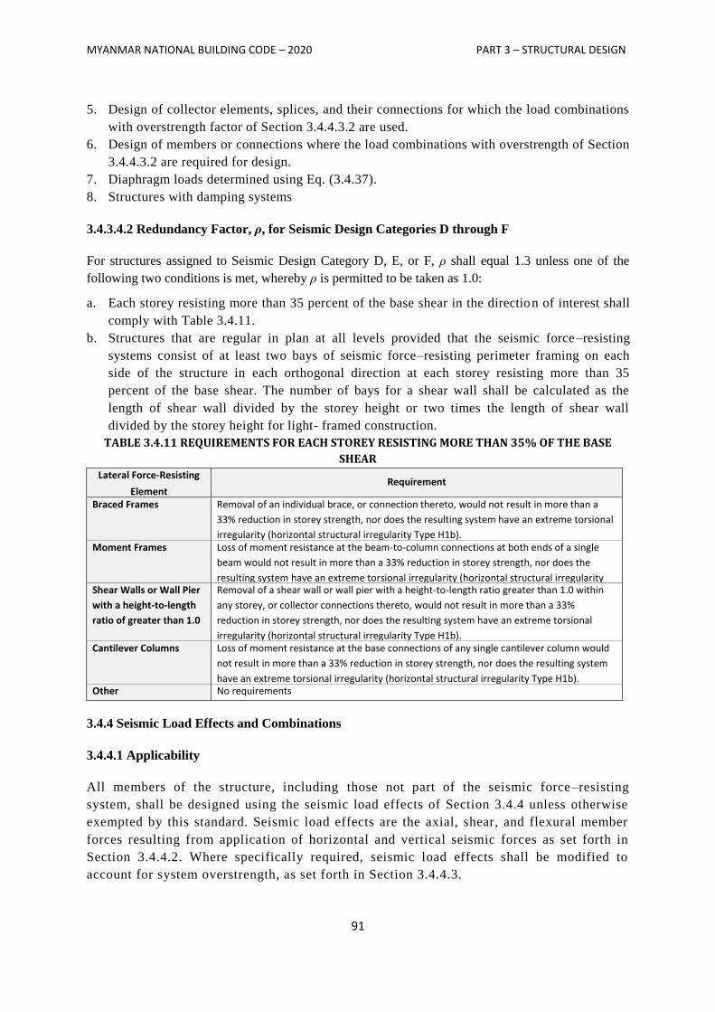
MYANMAR NATIONAL BUILDING CODE – 2020 PART 3 – STRUCTURAL DESIGN
91
5. Design of collector elements, splices, and their connections for which the load combinations
with overstrength factor of Section 3.4.4.3.2 are used.
6. Design of members or connections where the load combinations with overstrength of Section
3.4.4.3.2 are required for design.
7. Diaphragm loads determined using Eq. (3.4.37).
8. Structures with damping systems
3.4.3.4.2 Redundancy Factor, ρ, for Seismic Design Categories D through F
For structures assigned to Seismic Design Category D, E, or F, ρ shall equal 1.3 unless one of the
following two conditions is met, whereby ρ is permitted to be taken as 1.0:
a. Each storey resisting more than 35 percent of the base shear in the direction of interest shall
comply with Table 3.4.11.
b. Structures that are regular in plan at all levels provided that the seismic force–resisting
systems consist of at least two bays of seismic force–resisting perimeter framing on each
side of the structure in each orthogonal direction at each storey resisting more than 35
percent of the base shear. The number of bays for a shear wall shall be calculated as the
length of shear wall divided by the storey height or two times the length of shear wall
divided by the storey height for light- framed construction.
TABLE 3.4.11 REQUIREMENTS FOR EACH STOREY RESISTING MORE THAN 35% OF THE BASE
SHEAR
Lateral Force-Resisting
Element Requirement
Braced Frames Removal of an individual brace, or connection thereto, would not result in more than a
33% reduction in storey strength, nor does the resulting system have an extreme torsional
irregularity (horizontal structural irregularity Type H1b). Moment Frames Loss of moment resistance at the beam-to-column connections at both ends of a single
beam would not result in more than a 33% reduction in storey strength, nor does the
resulting system have an extreme torsional irregularity (horizontal structural irregularity
Type H1b). Shear Walls or Wall Pier
with a height-to-length
ratio of greater than 1.0
Removal of a shear wall or wall pier with a height-to-length ratio greater than 1.0 within
any storey, or collector connections thereto, would not result in more than a 33%
reduction in storey strength, nor does the resulting system have an extreme torsional
irregularity (horizontal structural irregularity Type H1b).
Cantilever Columns Loss of moment resistance at the base connections of any single cantilever column would
not result in more than a 33% reduction in storey strength, nor does the resulting system
have an extreme torsional irregularity (horizontal structural irregularity Type H1b). Other No requirements
3.4.4 Seismic Load Effects and Combinations
3.4.4.1 Applicability
All members of the structure, including those not part of the seismic force–resisting
system, shall be designed using the seismic load effects of Section 3.4.4 unless otherwise
exempted by this standard. Seismic load effects are the axial, shear, and flexural member
forces resulting from application of horizontal and vertical seismic forces as set forth in
Section 3.4.4.2. Where specifically required, seismic load effects shall be modified to
account for system overstrength, as set forth in Section 3.4.4.3.
MYANMAR NATIONAL BUILDING CODE – 2020 PART 3 – STRUCTURAL DESIGN
92
3.4.4.2 Seismic Load Effect
The seismic load effect, E, shall be determined in accordance with the following:
1. For use in load combination 5 in Section 3.2.1.2.2 or load combinations 5 and 6 in Section
3.2.1.3.1, E shall be determined in accordance with Eq. (3.4.12) as follows:
E = Eh + Ev Eq. (3.4.12)
2. For use in load combination 7 in Section 3.2.1.2.1 or load combination 8 in Section 3.2.1.3.1, E
shall be determined in accordance with Eq. (3.4.13) as follows:
E = Eh – Ev Eq. (3.4.13)
where
E = seismic load effect
Eh = effect of horizontal seismic forces as defined in Section 3.4.4.2.1
Ev = effect of vertical seismic forces as defined in Section 3.4.4.2.2
3.4.4.2.1 Horizontal Seismic Load Effect
The horizontal seismic load effect, Eh , shall be determined in accordance with Eq.(3.4.14) as follows:
Eh = ρ QE Eq. (3.4.14)
where
QE = effects of horizontal seismic forces from V or Fp . Where required in Sections 3.4.5.3
and 3.4.5.4, such effects shall result from application of horizontal forces
simultaneously in two directions at right angles to each other.
ρ = redundancy factor, as defined in Section 3.4.3.4
3.4.4.2.2 Vertical Seismic Load Effect
The vertical seismic load effect, Ev, shall be determined in accordance with Eq. (3.4.15) as follows:
Ev = 0.2 SDS D Eq. (3.4.15)
where
SDS = design spectral response acceleration parameter at short periods obtained from
Section 3.4.1.4.4
D = effect of dead load
EXCEPTIONS: The vertical seismic load effect, Ev , is permitted to be taken as zero for either of the
following conditions:
1. In Eqs. (3.4.12), (3.4.13), (3.4.16), and (3.4.17) where SDS is equal to or less than 0.125.
2. In Eq. (3.4.14) where determining demands on the soil-structure interface of foundations.
3.4.4.2.3 Seismic Load Combinations
Where the prescribed seismic load effect, E, defined in Section 3.4.4.2 is combined with the effects of
other loads as set forth in Section 3.2, the following seismic load combinations for structures not
MYANMAR NATIONAL BUILDING CODE – 2020 PART 3 – STRUCTURAL DESIGN
93
subject to flood or atmospheric ice loads shall be used in lieu of the seismic load combinations in
either Section 3.2.1.2.2 or 3.2.1.3.1.
Basic combinations for strength design (see Sections 3.2.1.2.2 and 3.1.1.2 for notation)
5. (1.2 + 0.2 SDS) D + ρ QE + L
7. (0.9 − 0.2 SDS) D + ρ QE + 1.6 H
NOTES:
1. The load factor on L in combination 5 is permitted to equal 0.5 for all occupancies in
which L0 in Table 3.2.2 is less than or equal to 100 psf (3.4.79 kN/m2 ), with the
exception of garages or areas occupied as places of public assembly.
2. The load factor on H shall be set equal to zero in combination 7 if the structural action
due to H counteracts that due to E. Where lateral earth pressure provides resistance to
structural actions from other forces, it shall not be included in H but shall be included
in the design resistance.
Basic combinations for allowable stress design (see Sections 3.2.1.3.1 and 3.1.1.2 for notation).
5. (1.0 + 0.14 SDS) D + H + F + 0.7Ω0 QE
6. (1.0 + 0.105 SDS) D + H + F + 0.525 Ω0 QE + 0.75L+ 0.75(Lr or R)
8. (0.6 − 0.14SDS) D + 0.7 Ω0 QE + H
3.4.4.3 Seismic Load Effect Including Overstrength Factor
Where specifically required, conditions requiring overstrength factor applications shall be determined
in accordance with the following:
1. For use in load combination 5 in Section 3.2.1.2.2 or load combinations 5 and 6 in Section
3.2.1.3.1, E shall be taken equal to Em as determined in accordance with Eq. (3.4.16) as
follows:
Em = Emh + Ev Eq. (3.4.16)
2. For use in load combination 7 in Section 3.2.1.2.2 or load combination 8 in Section 3.2.1.3.1,
E shall be taken equal to Em as determined in accordance with Eq. (3.4.17) as follows:
Em = Emh − Ev Eq. (3.4.17)
where
Em = seismic load effect including overstrength factor
Emh = effect of horizontal seismic forces including structural overstrength as defined in
Section 3.4.4.3.1
Ev = vertical seismic load effect as defined in Section 3.4.4.2.2
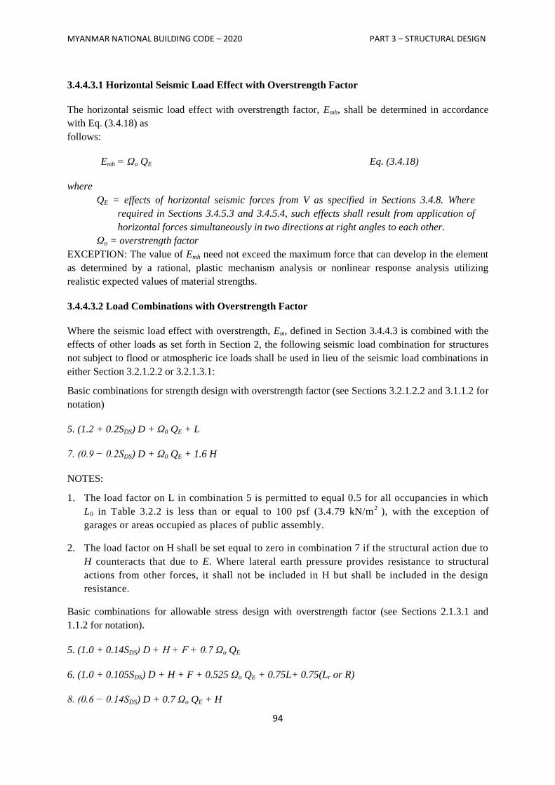
MYANMAR NATIONAL BUILDING CODE – 2020 PART 3 – STRUCTURAL DESIGN
94
3.4.4.3.1 Horizontal Seismic Load Effect with Overstrength Factor
The horizontal seismic load effect with overstrength factor, Emh, shall be determined in accordance
with Eq. (3.4.18) as
follows:
Emh = Ωo QE Eq. (3.4.18)
where
QE = effects of horizontal seismic forces from V as specified in Sections 3.4.8. Where
required in Sections 3.4.5.3 and 3.4.5.4, such effects shall result from application of
horizontal forces simultaneously in two directions at right angles to each other.
Ωo = overstrength factor
EXCEPTION: The value of Emh need not exceed the maximum force that can develop in the element
as determined by a rational, plastic mechanism analysis or nonlinear response analysis utilizing
realistic expected values of material strengths.
3.4.4.3.2 Load Combinations with Overstrength Factor
Where the seismic load effect with overstrength, Em, defined in Section 3.4.4.3 is combined with the
effects of other loads as set forth in Section 2, the following seismic load combination for structures
not subject to flood or atmospheric ice loads shall be used in lieu of the seismic load combinations in
either Section 3.2.1.2.2 or 3.2.1.3.1:
Basic combinations for strength design with overstrength factor (see Sections 3.2.1.2.2 and 3.1.1.2 for
notation)
5. (1.2 + 0.2SDS) D + Ω0 QE + L
7. (0.9 − 0.2SDS) D + Ω0 QE + 1.6 H
NOTES:
1. The load factor on L in combination 5 is permitted to equal 0.5 for all occupancies in which
L0 in Table 3.2.2 is less than or equal to 100 psf (3.4.79 kN/m2
), with the exception of
garages or areas occupied as places of public assembly.
2. The load factor on H shall be set equal to zero in combination 7 if the structural action due to
H counteracts that due to E. Where lateral earth pressure provides resistance to structural
actions from other forces, it shall not be included in H but shall be included in the design
resistance.
Basic combinations for allowable stress design with overstrength factor (see Sections 2.1.3.1 and
1.1.2 for notation).
5. (1.0 + 0.14SDS) D + H + F + 0.7 Ωo QE
6. (1.0 + 0.105SDS) D + H + F + 0.525 Ωo QE + 0.75L+ 0.75(Lr or R)
8. (0.6 − 0.14SDS) D + 0.7 Ωo QE + H
MYANMAR NATIONAL BUILDING CODE – 2020 PART 3 – STRUCTURAL DESIGN
95
3.4.4.3.3 Allowable Stress Increase for Load Combinations with Overstrength
Where allowable stress design methodologies are used with the seismic load effect defined in Section
3.4.4.3 applied in load combinations 5, 6, or 8 of Section 3.2.1.3.1, allowable stresses are permitted to
be determined using an allowable stress increase of 1.2. This increase shall not be combined with
increases in allowable stresses or load combination reductions otherwise permitted by this standard or
the material reference document except that combination with the duration of load increases permitted
in AF&PA NDS (Refer to ASCE7-05) is permitted.
3.4.4.4 Minimum Upward Force for Horizontal Cantilevers for Seismic Design Categories D
Through F
In structures assigned to Seismic Design Category D, E, or F, horizontal cantilever structural
components shall be designed for a minimum net upward force of 0.2 times the dead load in addition
to the applicable load combinations of Section 3.4.4.
3.4.5 Direction of Loading
3.4.5.1 Direction of Loading Criteria
The directions of application of seismic forces used in the design shall be those which will
produce the most critical load effects. It is permitted to satisfy this requirement using the
procedures of Section 3.4.5.2 for Seismic Design Category B, Section 3.4.5.3 for Seismic
Design Category C, and Section 3.4.5.4 for Seismic Design Categories D, E, and F.
3.4.5.2 Seismic Design Category B
For structures assigned to Seismic Design Category B, the design seismic forces are permitted to
be applied independently in each of two orthogonal directions and orthogonal interaction effects
are permitted to be neglected.
3.4.5.3 Seismic Design Category C
Loading applied to structures assigned to Seismic Design Category C shall, as a minimum,
conform to the requirements of Section 3.4.5.2 for Seismic Design Category B and the
requirements of this section. Structures that have horizontal structural irregularity Type H5 in
Table 3.4.9 shall use one of the following procedures:
a. Orthogonal Combination Procedure
The structure shall be analyzed using the equivalent lateral force analysis procedure of Section
3.4.8, the modal response spectrum analysis procedure of Section 3.4.9, or the linear response
history procedure of Section 16.1 (ASCE 7-05), as permitted under Section 3.4.6, with the
loading applied independently in any two orthogonal directions and the most critical load effect
due to direction of application of seismic forces on the structure is permitted to be assumed to be
satisfied if components and their foundations are designed for the following combination of
prescribed loads: 100 percent of the forces for one direction plus 30 percent of the forces for the
MYANMAR NATIONAL BUILDING CODE – 2020 PART 3 – STRUCTURAL DESIGN
96
perpendicular direction; the combination requiring the maximum component strength shall be
used.
b. Simultaneous Application of Orthogonal Ground Motion
The structure shall be analyzed using the linear response history procedure of Section 16.1
(ASCE 7-05) or the nonlinear response history procedure of Section 16.2 (ASCE 7-05), as
permitted by Section 3.4.6, with orthogonal pairs of ground motion acceleration histories applied
simultaneously.
3.4.5.4 Seismic Design Categories D Through F
Structures assigned to Seismic Design Category D, E, or F shall, as a minimum, conform to the
requirements of Section 3.4.5.3. In addition, any column or wall that forms part of two or more
intersecting seismic force–resisting systems and is subjected to axial load due to seismic forces
acting along either principal plan axis equaling or exceeding 20 percent of the axial design
strength of the column or wall shall be designed for the most critical load effect due to
application of seismic forces in any direction. Either of the procedures of Section 3.4.5.3 a or b
are permitted to be used to satisfy this requirement. Except as required by Section 3.4.7.3, 2 -D
analyses are permitted for structures with flexible diaphragms.
3.4.6 Analysis Procedure Selection
The structural analysis required by Section 3.4 shall consist of one of the types permitted in Table
3.4.12, based on the structure’s Seismic Design Category, structural system, dynamic properties, and
regularity, or with the approval of the authority having jurisdiction, an alternative generally accepted
procedure is permitted to be used. The analysis procedure selected shall be completed in accordance
with the requirements of the corresponding section referenced in Table 3.4.12.
3.4.7 Modeling Criteria
3.4.7.1 Foundation Modeling
For purposes of determining seismic loads, it is permitted to consider the structure to be fixed at the
base. Alternatively, where foundation flexibility is considered it shall be in accordance with section
12.13.3 (ASCE 7-05) or Chapter 19 (ASCE 7-05).
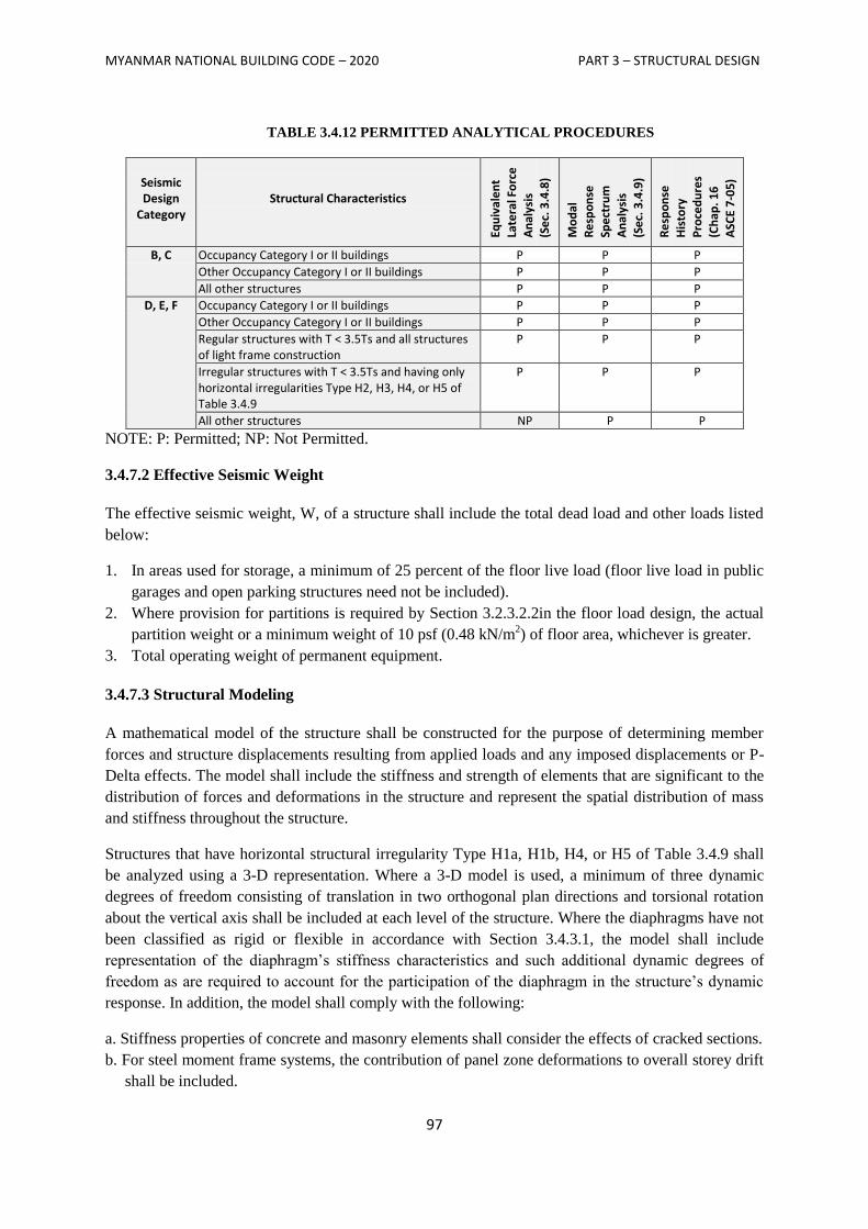
MYANMAR NATIONAL BUILDING CODE – 2020 PART 3 – STRUCTURAL DESIGN
97
TABLE 3.4.12 PERMITTED ANALYTICAL PROCEDURES
Seismic Design
Category
Structural Characteristics
Equ
ival
en
t
Late
ral F
orc
e
An
alys
is
(Se
c. 3
.4.8
)
Mo
dal
Re
spo
nse
Spe
ctru
m
An
alys
is
(Se
c. 3
.4.9
)
Re
spo
nse
His
tory
Pro
ced
ure
s
(Ch
ap. 1
6
ASC
E 7
-05
)
B, C Occupancy Category I or II buildings P P P
Other Occupancy Category I or II buildings P P P
All other structures P P P
D, E, F Occupancy Category I or II buildings P P P
Other Occupancy Category I or II buildings P P P
Regular structures with T < 3.5Ts and all structures of light frame construction
P P P
Irregular structures with T < 3.5Ts and having only horizontal irregularities Type H2, H3, H4, or H5 of Table 3.4.9
P P P
All other structures NP P P
NOTE: P: Permitted; NP: Not Permitted.
3.4.7.2 Effective Seismic Weight
The effective seismic weight, W, of a structure shall include the total dead load and other loads listed
below:
1. In areas used for storage, a minimum of 25 percent of the floor live load (floor live load in public
garages and open parking structures need not be included).
2. Where provision for partitions is required by Section 3.2.3.2.2in the floor load design, the actual
partition weight or a minimum weight of 10 psf (0.48 kN/m2) of floor area, whichever is greater.
3. Total operating weight of permanent equipment.
3.4.7.3 Structural Modeling
A mathematical model of the structure shall be constructed for the purpose of determining member
forces and structure displacements resulting from applied loads and any imposed displacements or P-
Delta effects. The model shall include the stiffness and strength of elements that are significant to the
distribution of forces and deformations in the structure and represent the spatial distribution of mass
and stiffness throughout the structure.
Structures that have horizontal structural irregularity Type H1a, H1b, H4, or H5 of Table 3.4.9 shall
be analyzed using a 3-D representation. Where a 3-D model is used, a minimum of three dynamic
degrees of freedom consisting of translation in two orthogonal plan directions and torsional rotation
about the vertical axis shall be included at each level of the structure. Where the diaphragms have not
been classified as rigid or flexible in accordance with Section 3.4.3.1, the model shall include
representation of the diaphragm’s stiffness characteristics and such additional dynamic degrees of
freedom as are required to account for the participation of the diaphragm in the structure’s dynamic
response. In addition, the model shall comply with the following:
a. Stiffness properties of concrete and masonry elements shall consider the effects of cracked sections.
b. For steel moment frame systems, the contribution of panel zone deformations to overall storey drift
shall be included.
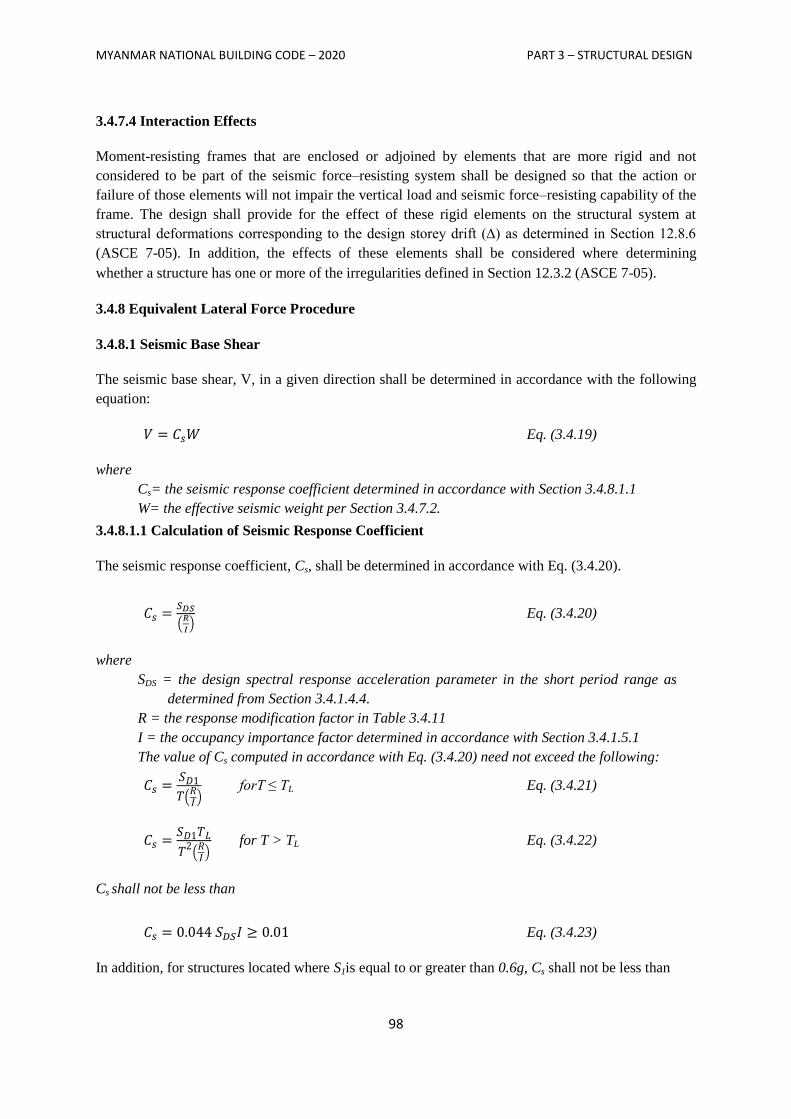
MYANMAR NATIONAL BUILDING CODE – 2020 PART 3 – STRUCTURAL DESIGN
98
3.4.7.4 Interaction Effects
Moment-resisting frames that are enclosed or adjoined by elements that are more rigid and not
considered to be part of the seismic force–resisting system shall be designed so that the action or
failure of those elements will not impair the vertical load and seismic force–resisting capability of the
frame. The design shall provide for the effect of these rigid elements on the structural system at
structural deformations corresponding to the design storey drift (∆) as determined in Section 12.8.6
(ASCE 7-05). In addition, the effects of these elements shall be considered where determining
whether a structure has one or more of the irregularities defined in Section 12.3.2 (ASCE 7-05).
3.4.8 Equivalent Lateral Force Procedure
3.4.8.1 Seismic Base Shear
The seismic base shear, V, in a given direction shall be determined in accordance with the following
equation:
Eq. (3.4.19)
where
Cs= the seismic response coefficient determined in accordance with Section 3.4.8.1.1
W= the effective seismic weight per Section 3.4.7.2.
3.4.8.1.1 Calculation of Seismic Response Coefficient
The seismic response coefficient, Cs, shall be determined in accordance with Eq. (3.4.20).
(
) Eq. (3.4.20)
where
SDS = the design spectral response acceleration parameter in the short period range as
determined from Section 3.4.1.4.4.
R = the response modification factor in Table 3.4.11
I = the occupancy importance factor determined in accordance with Section 3.4.1.5.1
The value of Cs computed in accordance with Eq. (3.4.20) need not exceed the following:
( ) forT ≤ TL Eq. (3.4.21)
( )
for T > TL Eq. (3.4.22)
Cs shall not be less than
Eq. (3.4.23)
In addition, for structures located where S1is equal to or greater than 0.6g, Cs shall not be less than
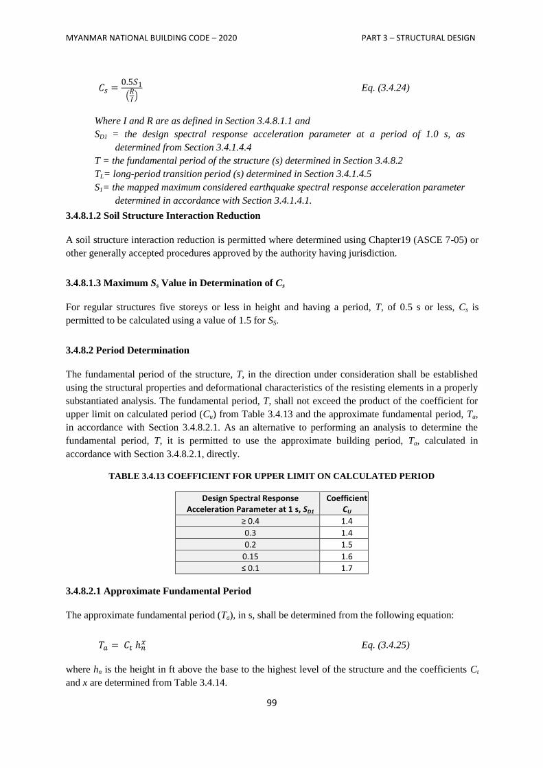
MYANMAR NATIONAL BUILDING CODE – 2020 PART 3 – STRUCTURAL DESIGN
99
( )
Eq. (3.4.24)
Where I and R are as defined in Section 3.4.8.1.1 and
SD1 = the design spectral response acceleration parameter at a period of 1.0 s, as
determined from Section 3.4.1.4.4
T = the fundamental period of the structure (s) determined in Section 3.4.8.2
TL= long-period transition period (s) determined in Section 3.4.1.4.5
S1= the mapped maximum considered earthquake spectral response acceleration parameter
determined in accordance with Section 3.4.1.4.1.
3.4.8.1.2 Soil Structure Interaction Reduction
A soil structure interaction reduction is permitted where determined using Chapter19 (ASCE 7-05) or
other generally accepted procedures approved by the authority having jurisdiction.
3.4.8.1.3 Maximum Ss Value in Determination of Cs
For regular structures five storeys or less in height and having a period, T, of 0.5 s or less, Cs is
permitted to be calculated using a value of 1.5 for SS.
3.4.8.2 Period Determination
The fundamental period of the structure, T, in the direction under consideration shall be established
using the structural properties and deformational characteristics of the resisting elements in a properly
substantiated analysis. The fundamental period, T, shall not exceed the product of the coefficient for
upper limit on calculated period (Cu) from Table 3.4.13 and the approximate fundamental period, Ta,
in accordance with Section 3.4.8.2.1. As an alternative to performing an analysis to determine the
fundamental period, T, it is permitted to use the approximate building period, Ta, calculated in
accordance with Section 3.4.8.2.1, directly.
TABLE 3.4.13 COEFFICIENT FOR UPPER LIMIT ON CALCULATED PERIOD
Design Spectral Response Acceleration Parameter at 1 s, SD1
Coefficient CU
≥ 0.4 1.4
0.3 1.4
0.2 1.5
0.15 1.6
≤ 0.1 1.7
3.4.8.2.1 Approximate Fundamental Period
The approximate fundamental period (Ta), in s, shall be determined from the following equation:
Eq. (3.4.25)
where hn is the height in ft above the base to the highest level of the structure and the coefficients Ct
and x are determined from Table 3.4.14.
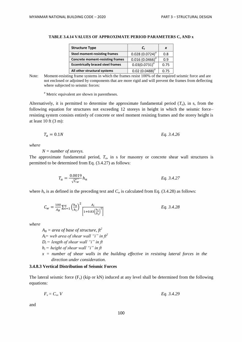
MYANMAR NATIONAL BUILDING CODE – 2020 PART 3 – STRUCTURAL DESIGN
100
TABLE 3.4.14 VALUES OF APPROXIMATE PERIOD PARAMETERS Ct AND x
Structure Type Ct x
Steel moment-resisting frames 0.028 (0.0724)a 0.8
Concrete moment-resisting frames 0.016 (0.0466)a 0.9
Eccentrically braced steel frames 0.03(0.0731)a 0.75
All other structural systems 0.02 (0.0488)a 0.75
Note: Moment-resisting frame systems in which the frames resist 100% of the required seismic force and are
not enclosed or adjoined by components that are more rigid and will prevent the frames from deflecting
where subjected to seismic forces:
a Metric equivalent are shown in parentheses.
Alternatively, it is permitted to determine the approximate fundamental period (Ta), in s, from the
following equation for structures not exceeding 12 storeys in height in which the seismic force–
resisting system consists entirely of concrete or steel moment resisting frames and the storey height is
at least 10 ft (3 m):
Eq. 3.4.26
where
N = number of storeys.
The approximate fundamental period, Ta, in s for masonry or concrete shear wall structures is
permitted to be determined from Eq. (3.4.27) as follows:
√ Eq. 3.4.27
where hn is as defined in the preceding text and Cw is calculated from Eq. (3.4.28) as follows:
∑ (
)
[ (
)
]
Eq. 3.4.28
where
AB = area of base of structure, ft2
Ai= web area of shear wall “i” in ft2
Di = length of shear wall “i” in ft
hi = height of shear wall “i” in ft
x = number of shear walls in the building effective in resisting lateral forces in the
direction under consideration.
3.4.8.3 Vertical Distribution of Seismic Forces
The lateral seismic force (Fx) (kip or kN) induced at any level shall be determined from the following
equations:
Fx = Cvx V Eq. 3.4.29
and
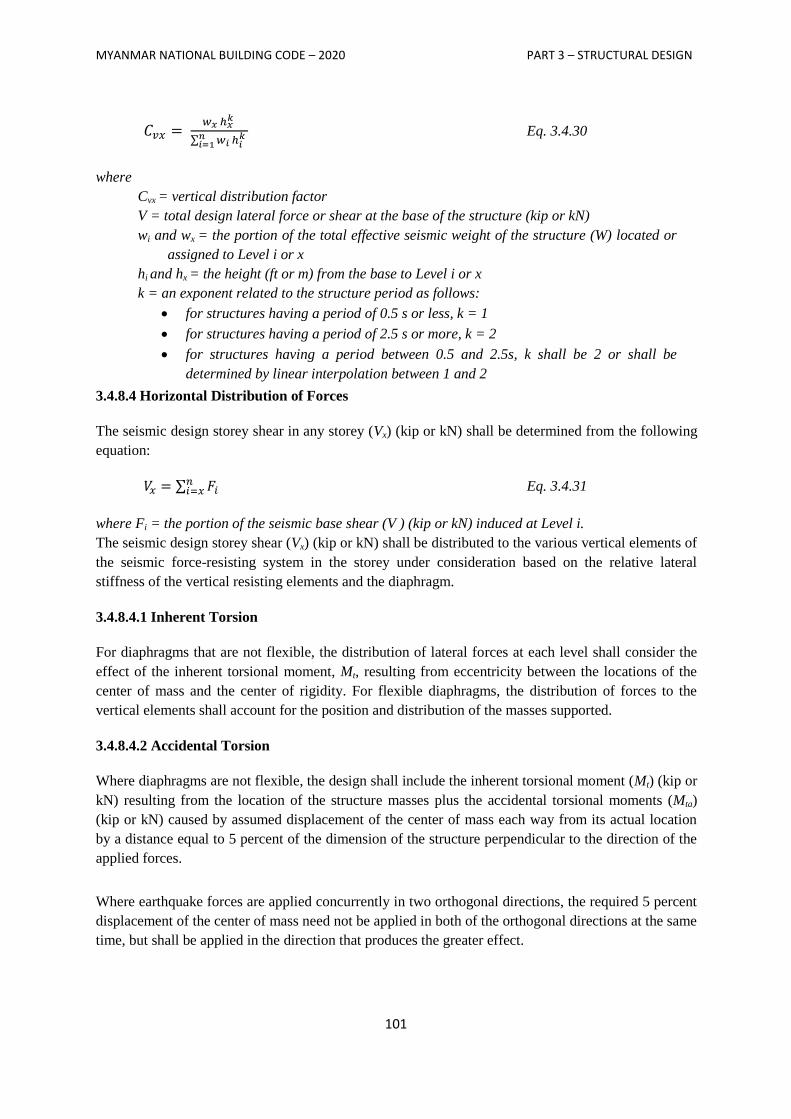
MYANMAR NATIONAL BUILDING CODE – 2020 PART 3 – STRUCTURAL DESIGN
101
∑
Eq. 3.4.30
where
Cvx = vertical distribution factor
V = total design lateral force or shear at the base of the structure (kip or kN)
wi and wx = the portion of the total effective seismic weight of the structure (W) located or
assigned to Level i or x
hi and hx = the height (ft or m) from the base to Level i or x
k = an exponent related to the structure period as follows:
for structures having a period of 0.5 s or less, k = 1
for structures having a period of 2.5 s or more, k = 2
for structures having a period between 0.5 and 2.5s, k shall be 2 or shall be
determined by linear interpolation between 1 and 2
3.4.8.4 Horizontal Distribution of Forces
The seismic design storey shear in any storey (Vx) (kip or kN) shall be determined from the following
equation:
∑ Eq. 3.4.31
where Fi = the portion of the seismic base shear (V ) (kip or kN) induced at Level i.
The seismic design storey shear (Vx) (kip or kN) shall be distributed to the various vertical elements of
the seismic force-resisting system in the storey under consideration based on the relative lateral
stiffness of the vertical resisting elements and the diaphragm.
3.4.8.4.1 Inherent Torsion
For diaphragms that are not flexible, the distribution of lateral forces at each level shall consider the
effect of the inherent torsional moment, Mt, resulting from eccentricity between the locations of the
center of mass and the center of rigidity. For flexible diaphragms, the distribution of forces to the
vertical elements shall account for the position and distribution of the masses supported.
3.4.8.4.2 Accidental Torsion
Where diaphragms are not flexible, the design shall include the inherent torsional moment (Mt) (kip or
kN) resulting from the location of the structure masses plus the accidental torsional moments (Mta)
(kip or kN) caused by assumed displacement of the center of mass each way from its actual location
by a distance equal to 5 percent of the dimension of the structure perpendicular to the direction of the
applied forces.
Where earthquake forces are applied concurrently in two orthogonal directions, the required 5 percent
displacement of the center of mass need not be applied in both of the orthogonal directions at the same
time, but shall be applied in the direction that produces the greater effect.
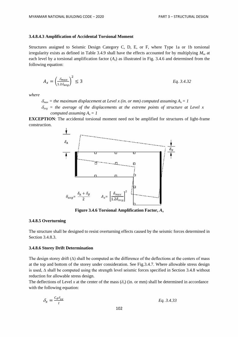
MYANMAR NATIONAL BUILDING CODE – 2020 PART 3 – STRUCTURAL DESIGN
102
3.4.8.4.3 Amplification of Accidental Torsional Moment
Structures assigned to Seismic Design Category C, D, E, or F, where Type 1a or 1b torsional
irregularity exists as defined in Table 3.4.9 shall have the effects accounted for by multiplying Mta at
each level by a torsional amplification factor (Ax) as illustrated in Fig. 3.4.6 and determined from the
following equation:
(
)
Eq. 3.4.32
where
max = the maximum displacement at Level x (in. or mm) computed assuming Ax = 1
avg = the average of the displacements at the extreme points of structure at Level x
computed assuming Ax = 1
EXCEPTION: The accidental torsional moment need not be amplified for structures of light-frame
construction.
Figure 3.4.6 Torsional Amplification Factor, Ax
3.4.8.5 Overturning
The structure shall be designed to resist overturning effects caused by the seismic forces determined in
Section 3.4.8.3.
3.4.8.6 Storey Drift Determination
The design storey drift (∆) shall be computed as the difference of the deflections at the centers of mass
at the top and bottom of the storey under consideration. See Fig.3.4.7. Where allowable stress design
is used, ∆ shall be computed using the strength level seismic forces specified in Section 3.4.8 without
reduction for allowable stress design.
The deflections of Level x at the center of the mass (δx) (in. or mm) shall be determined in accordance
with the following equation:
Eq. 3.4.33
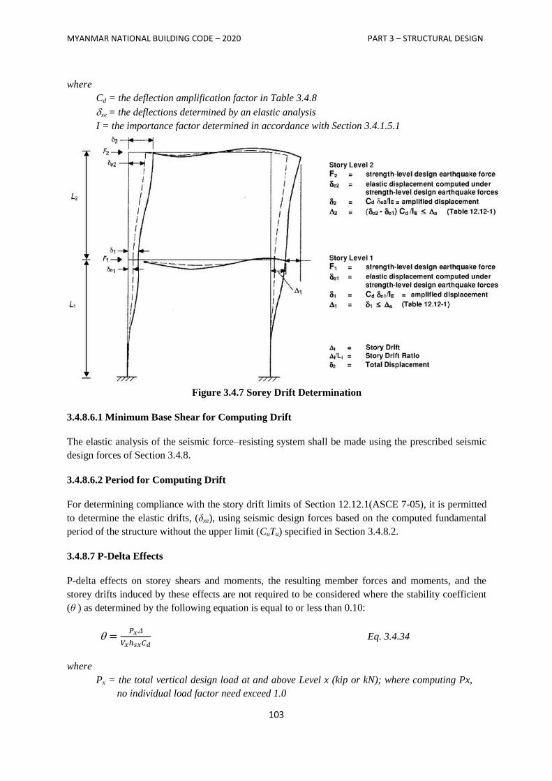
MYANMAR NATIONAL BUILDING CODE – 2020 PART 3 – STRUCTURAL DESIGN
103
where
Cd = the deflection amplification factor in Table 3.4.8
xe = the deflections determined by an elastic analysis
I = the importance factor determined in accordance with Section 3.4.1.5.1
Figure 3.4.7 Sorey Drift Determination
3.4.8.6.1 Minimum Base Shear for Computing Drift
The elastic analysis of the seismic force–resisting system shall be made using the prescribed seismic
design forces of Section 3.4.8.
3.4.8.6.2 Period for Computing Drift
For determining compliance with the story drift limits of Section 12.12.1(ASCE 7-05), it is permitted
to determine the elastic drifts, (δxe), using seismic design forces based on the computed fundamental
period of the structure without the upper limit (CuTa) specified in Section 3.4.8.2.
3.4.8.7 P-Delta Effects
P-delta effects on storey shears and moments, the resulting member forces and moments, and the
storey drifts induced by these effects are not required to be considered where the stability coefficient
(θ ) as determined by the following equation is equal to or less than 0.10:
Eq. 3.4.34
where
Px = the total vertical design load at and above Level x (kip or kN); where computing Px,
no individual load factor need exceed 1.0
MYANMAR NATIONAL BUILDING CODE – 2020 PART 3 – STRUCTURAL DESIGN
104
= the design storey drift as defined in Section 3.4.8.6 occurring simultaneously with Vx
(in. or mm)
Vx = the seismic shear force acting between Levels x and x −1 (kip or kN)
hsx = the storey height below Level x (in. or mm)
Cd = the deflection amplification factor in Table 3.4.7
The stability coefficient (θ) shall not exceed θmax determined as follows:
Eq. 3.4.35
where β is the ratio of shear demand to shear capacity for the storey between Levels x and x−1.
This ratio is permitted to be conservatively taken as 1.0.
where the stability coefficient ( ) is greater than 0.10 but less than or equal to max, the
incremental factor related to P-delta effects on displacements and member forces shall be
determined by rational analysis. Alternatively, it is permitted to multiply displacements and
member forces by 1.0/(1− ).
where θ is greater than max, the structure is potentially unstable and shall be redesigned.
where the P-delta effect is included in an automated analysis, Eq. (3.4.35) shall still be satisfied,
however, the value of θ computed from Eq. (3.4.34) using the results of the P-delta analysis is
permitted to be divided by (1 + θ) before checking Eq. (3.4.35).
3.4.9 Modal Response Spectrum Analysis
3.4.9.1 Number of Modes
An analysis shall be conducted to determine the natural modes of vibration for the structure. The
analysis shall include a sufficient number of modes to obtain a combined modal mass participation of
at least 90 percent of the actual mass in each of the orthogonal horizontal directions of response
considered by the model.
3.4.9.2 Modal Response Parameters
The value for each force- related design parameter of interest, including storey drifts, support forces,
and individual member forces for each mode of response shall be computed using the properties of
each mode and the response spectra defined in either Section 3.4.1.4.5 divided by the quantity R/I.
The value for displacement and drift quantities shall be multiplied by the quantity Cd/I.
3.4.9.3 Combined Response Parameters
The value for each parameter of interest calculated for the various modes shall be combined using
either the square root of the sum of the squares method (SRSS) or the complete quadratic combination
method (CQC), in accordance with ASCE 3.4. The CQC method shall be used for each of the modal
values or where closely spaced modes that have significant cross-correlation of translational and
torsional response.
3.4.9.4 Scaling Design Values of Combined Response
A base shear (V) shall be calculated in each of the two orthogonal horizontal directions using the
calculated fundamental period of the structure T in each direction and the procedures of Section 3.4.8,
MYANMAR NATIONAL BUILDING CODE – 2020 PART 3 – STRUCTURAL DESIGN
105
except where the calculated fundamental period exceeds (Cu) (Ta), then (Cu)(Ta) shall be used in lieu
of T in that direction. Where the combined response for the modal base shear (Vt) is less than 85
percent of the calculated base shear (V) using the equivalent lateral force procedure, the forces, but not
the drifts, shall be multiplied by 0.85
:
where
V = the equivalent lateral force procedure base shear, calculated in accordance with this
section and Section 3.4.8.
Vt = the base shear from the required modal combination
3.4.9.5 Horizontal Shear Distribution
The distribution of horizontal shear shall be in accordance with the requirements of Section 3.4.8.4
except that amplification of torsion per Section 3.4.8.4.3 is not required where accidental torsional
effects are included in the dynamic analysis model.
3.4.9.6 P-Delta Effects
The P-delta effects shall be determined in accordance with Section 3.4.8.7. The base shear used to
determine the storey shears and the storey drifts shall be determined in accordance with Section
3.4.8.6.
3.4.9.7 Soil Structure Interaction Reduction
A soil structure interaction reduction is permitted where determined using generally accepted
procedures approved by the authority having jurisdiction.
3.4.10 Diaphragms, Chords and Collectors
3.4.10.1 Diaphragm Design
Diaphragms shall be designed for both the shear and bending stresses resulting from design forces. At
diaphragm discontinuities, such as openings and reentrant corners, the design shall assure that the
dissipation or transfer of edge (chord) forces combined with other forces in the diaphragm is within
shear and tension capacity of the diaphragm.
3.4.10.1.1 Diaphragm Design Forces
Floor and roof diaphragms shall be designed to resist design seismic forces from the structural
analysis, but shall not be less than that determined in accordance with Eq. (3.4.36) as follows:
∑
∑
Eq. 3.4.36
where
Fpx = the diaphragm design force
Fi = the design force applied to Level i
wi = the weight tributary to Level i
wpx = the weight tributary to the diaphragm at Level x
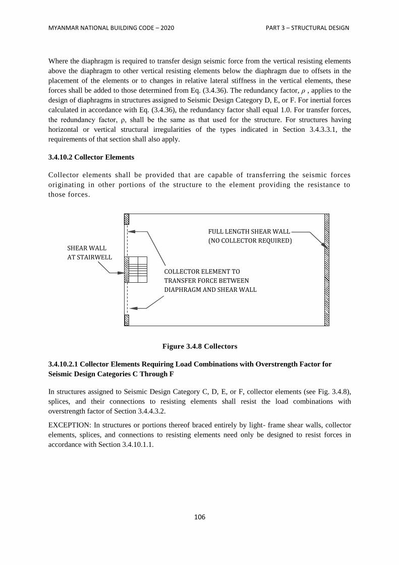
MYANMAR NATIONAL BUILDING CODE – 2020 PART 3 – STRUCTURAL DESIGN
106
Where the diaphragm is required to transfer design seismic force from the vertical resisting elements
above the diaphragm to other vertical resisting elements below the diaphragm due to offsets in the
placement of the elements or to changes in relative lateral stiffness in the vertical elements, these
forces shall be added to those determined from Eq. (3.4.36). The redundancy factor, ρ , applies to the
design of diaphragms in structures assigned to Seismic Design Category D, E, or F. For inertial forces
calculated in accordance with Eq. (3.4.36), the redundancy factor shall equal 1.0. For transfer forces,
the redundancy factor, ρ, shall be the same as that used for the structure. For structures having
horizontal or vertical structural irregularities of the types indicated in Section 3.4.3.3.1, the
requirements of that section shall also apply.
3.4.10.2 Collector Elements
Collector elements shall be provided that are capable of transferring the seismic forces
originating in other portions of the structure to the element providing the resistance to
those forces.
Figure 3.4.8 Collectors
3.4.10.2.1 Collector Elements Requiring Load Combinations with Overstrength Factor for
Seismic Design Categories C Through F
In structures assigned to Seismic Design Category C, D, E, or F, collector elements (see Fig. 3.4.8),
splices, and their connections to resisting elements shall resist the load combinations with
overstrength factor of Section 3.4.4.3.2.
EXCEPTION: In structures or portions thereof braced entirely by light- frame shear walls, collector
elements, splices, and connections to resisting elements need only be designed to resist forces in
accordance with Section 3.4.10.1.1.
FULL LENGTH SHEAR WALL
(NO COLLECTOR REQUIRED)
COLLECTOR ELEMENT TO
TRANSFER FORCE BETWEEN
DIAPHRAGM AND SHEAR WALL
SHEAR WALL
AT STAIRWELL
MYANMAR NATIONAL BUILDING CODE – 2020 PART 3 – STRUCTURAL DESIGN
107
3.4.11 Structural Walls and Their Anchorage
3.4.11.1 Design for Out-of-Plane Forces
Structural walls and their anchorage shall be designed for a force normal to the surface equal to
0.4SDSI times the weight of the structural wall with a minimum force of 10 percent of the weight of
the structural wall. Interconnection of structural wall elements and connections to supporting framing
systems shall have sufficient ductility, rotational capacity, or sufficient strength to resist shrinkage,
thermal changes, and differential foundation settlement when combined with seismic forces.
3.4.11.2 Anchorage of Concrete or Masonry Structural Walls
The anchorage of concrete or masonry structural walls to supporting construction shall provide a
direct connection capable of resisting the greater of the following:
a. The force set forth in Section 3.4.11.1.
b. A force of 400 SDS I lb/ linear ft (5.84 SDS I kN/m) of wall
c. 280 lb/linear ft (3.4.09 kN/m) of wall
Structural walls shall be designed to resist bending between anchors where the anchor
spacing exceeds 4 ft (1,219 mm).
3.4.11.2.1 Anchorage of Concrete or Masonry Structural Walls to Flexible Diaphragms
In addition to the requirements set forth in Section 3.4.11.2, anchorage of concrete or masonry
structural walls to flexible diaphragms in structures assigned to Seismic Design Category C, D, E, or
F shall have the strength to develop the out-of-plane force given by Eq. (3.4.37):
FP = 0.8SDS IWP Eq. (3.4.37)
where
FP = the design force in the individual anchors
SDS = the design spectral response acceleration parameter at short periods per Section
3.4.1.4.4
I = the occupancy importance factor per Section 3.4.1.5.1
Wp = the weight of the wall tributary to the anchor
3.4.11.2.2 Additional Requirements for Diaphragms in Structures Assigned to Seismic Design
Categories C through F
3.4.11.2.2.1 Transfer of Anchorage Forces into Diaphragm
Diaphragms shall be provided with continuous ties or struts between diaphragm chords to distribute
these anchorage forces into the diaphragms. Diaphragm connections shall be positive, mechanical, or
welded. Added chords are permitted to be used to form sub-diaphragms to transmit the anchorage
forces to the main continuous cross-ties. The maximum length-to-width ratio of the structural sub-
diaphragm shall be 2.5 to 1. Connections and anchorages capable of resisting the prescribed forces
shall be provided between the diaphragm and the attached components. Connections shall extend into
the diaphragm a sufficient distance to develop the force transferred into the diaphragm.
MYANMAR NATIONAL BUILDING CODE – 2020 PART 3 – STRUCTURAL DESIGN
108
3.4.11.2.2.2 Steel Elements of Structural Wall Anchorage System
The strength design forces for steel elements of the structural wall anchorage system, with the
exception of anchor bolts and reinforcing steel, shall be increased by 1.4 times the forces otherwise
required by this section.
3.4.11.2.2.3 Wood Diaphragms
In wood diaphragms, the continuous ties shall be in addition to the diaphragm sheathing. Anchorage
shall not be accomplished by use of toe nails or nails subject to withdrawal nor shall wood ledgers or
framing be used in cross-grain bending or cross-grain tension. The diaphragm sheathing shall not be
considered effective as providing the ties or struts required by this section.
3.4.11.2.2.4 Metal Deck Diaphragms
In metal deck diaphragms, the metal deck shall not be used as the continuous ties required by this
section in the direction perpendicular to the deck span.
3.4.11.2.2.5 Embedded Straps
Diaphragm to structural wall anchorage using embedded straps shall be attached to, or hooked around,
the reinforcing steel or otherwise terminated so as to effectively transfer forces to the reinforcing steel.
3.4.11.2.2.6 Eccentrically Loaded Anchorage System
Where elements of the wall anchorage system are loaded eccentrically or are not perpendicular to the
wall, the system shall be designed to resist all components of the forces induced by the eccentricity.
3.4.11.2.2.7 Walls with Pilasters
Where pilasters are present in the wall, the anchorage force at the pilasters shall be calculated
considering the additional load transferred from the wall panels to the pilasters. However, the
minimum anchorage force at a floor or roof shall not be reduced.
3.4.12 Drift and Deformation
3.4.12.1 Storey Drift Limit
The design storey drift (∆) as determined in Sections 3.4.8.6, 3.4.9.2, or 3.4.3.1 shall not exceed the
allowable story drift (∆a) as obtained from Table 3.4.15 for any storey. For structures with significant
torsional deflections, the maximum drift shall include torsional effects. For structures assigned to
Seismic Design Category C, D, E, or F having horizontal irregularity Types H1a or H1b of Table
3.4.9, the design storey drift, ∆, shall be computed as the largest difference of the deflections along
any of the edges of the structure at the top and bottom of the storey under consideration.
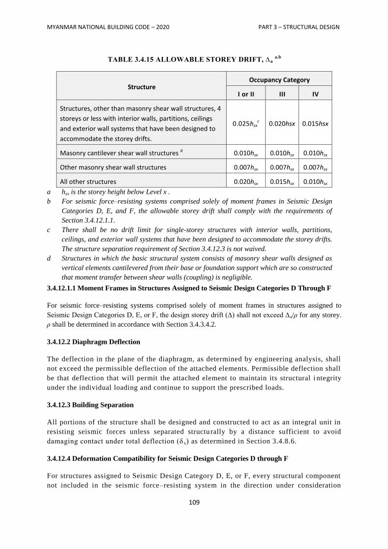
MYANMAR NATIONAL BUILDING CODE – 2020 PART 3 – STRUCTURAL DESIGN
109
TABLE 3.4.15 ALLOWABLE STOREY DRIFT, ∆a a.b
Structure Occupancy Category
I or II III IV
Structures, other than masonry shear wall structures, 4
storeys or less with interior walls, partitions, ceilings
and exterior wall systems that have been designed to
accommodate the storey drifts.
0.025hsxc 0.020hsx 0.015hsx
Masonry cantilever shear wall structures d 0.010hsx 0.010hsx 0.010hsx
Other masonry shear wall structures 0.007hsx 0.007hsx 0.007hsx
All other structures 0.020hsx 0.015hsx 0.010hsx
a hsx is the storey height below Level x .
b For seismic force–resisting systems comprised solely of moment frames in Seismic Design
Categories D, E, and F, the allowable storey drift shall comply with the requirements of
Section 3.4.12.1.1.
c There shall be no drift limit for single-storey structures with interior walls, partitions,
ceilings, and exterior wall systems that have been designed to accommodate the storey drifts.
The structure separation requirement of Section 3.4.12.3 is not waived.
d Structures in which the basic structural system consists of masonry shear walls designed as
vertical elements cantilevered from their base or foundation support which are so constructed
that moment transfer between shear walls (coupling) is negligible.
3.4.12.1.1 Moment Frames in Structures Assigned to Seismic Design Categories D Through F
For seismic force–resisting systems comprised solely of moment frames in structures assigned to
Seismic Design Categories D, E, or F, the design storey drift (∆) shall not exceed ∆a/ρ for any storey.
ρ shall be determined in accordance with Section 3.4.3.4.2.
3.4.12.2 Diaphragm Deflection
The deflection in the plane of the diaphragm, as determined by engineering analysis, shall
not exceed the permissible deflection of the attached elements. Permissible deflection shall
be that deflection that will permit the attached element to maintain its structural i ntegrity
under the individual loading and continue to support the prescribed loads.
3.4.12.3 Building Separation
All portions of the structure shall be designed and constructed to act as an integral unit in
resisting seismic forces unless separated structurally by a distance sufficient to avoid
damaging contact under total deflection (δ x) as determined in Section 3.4.8.6.
3.4.12.4 Deformation Compatibility for Seismic Design Categories D through F
For structures assigned to Seismic Design Category D, E, or F, every structural component
not included in the seismic force–resisting system in the direction under consideration

MYANMAR NATIONAL BUILDING CODE – 2020 PART 3 – STRUCTURAL DESIGN
110
shall be designed to be adequate for the gravity load effects and the seismic forces
resulting from displacement to the design storey drift (∆ ) as determined in accordance
with Section 3.4.8.6 (see also Section 3.4.12.1).
EXCEPTION: Reinforced concrete frame members not designed as part of the seismic
force–resisting system shall comply with Section 21.11 of ACI 318-08.
Where determining the moments and shears induced in components that are not included in
the seismic force–resisting system in the direction under consideration, the stiffening
effects of adjoining rigid structural and nonstructural elements shall be considered and a
rational value of member and restraint stiffness shall be used.
MYANMAR NATIONAL BUILDING CODE – 2020 PART 3 – STRUCTURAL DESIGN
111
SECTION 3.5
CONCRETE
Italics are used for text within Sections 3.5.3 through 3.5.4 of this PART to indicate provisions that
differ from ACI 318-08.
3.5.1 General
3.5.1.1 Scope
The provisions of this section shall govern the materials, quality control, design and construction of
concrete used in structures.
3.5.1.2 Plain and Reinforced Concrete
Structural concrete shall be designed and constructed in accordance with the requirements of this
SECTION and ACI 318-08 as amended in Section 3.5.4. Except for the provisions of Sections 1904
and 1910 (IBC-2006), the design and construction of slabs on grade shall not be governed by this
SECTION unless they transmit vertical loads or lateral forces from other parts of the structure to the
soil.
3.5.1.3 Source and Applicability
The format and subject matter of Sections 3.5.2 through 3.5.4 and 3.5.6 of this section are patterned
after, and in general conformity with, the provisions for structural concrete in ACI 318-08.
3.5.1.4 Construction Documents
The design and construction documents for structural concrete construction shall include:
1. The specified compressive strength of concrete at the stated ages or stages of construction for
which each concrete element is designed.
2. The specified strength or grade of reinforcement.
3. The size and location of structural elements, reinforcement, and anchors.
4. Provision for dimensional changes resulting from creep, shrinkage and temperature.
5. The magnitude and location of prestressing forces.
6. Anchorage length of reinforcement and location and length of lap splices.
7. Type and location of mechanical and welded splices of reinforcement.
8. Details and location of contraction or isolation joints specified for plain concrete.
9. Minimum concrete compressive strength at time of posttensioning.
10. Stressing sequence for posttensioning tendons.
11. For structures assigned to Seismic Design Category D, E or F, a statement if slab on grade is
designed as a structural diaphragm (see Section 21.12.3.4 of ACI 318-08).
MYANMAR NATIONAL BUILDING CODE – 2020 PART 3 – STRUCTURAL DESIGN
112
3.5.2 Definitions
3.5.2.1 General
The words and terms defined in ACI 318-08 shall, for the purposes of this section and as used
elsewhere in this part for concrete construction, have the meanings shown in ACI 318-08.
3.5.3 Specifications for Tests and Materials
3.5.3.1 General
Materials used to produce concrete; concrete itself and testing thereof shall comply with the
applicable standards listed in ACI 318-08.
3.5.3.2 Glass Fiber Reinforced Concrete
Glass fiber reinforced concrete (GFRC) and the materials used in such concrete shall be in accordance
with the PCI MNL 128 standard.
3.5.4 MODIFICATIONS TO ACI318-08
3.5.4.1 General
The text of ACI 318-08 shall be modified as indicated in Sections 3.5.4.1.1 through 3.5.4.1.10.
3.5.4.1.1 ACI 318-08, Section 2.2
Modify existing definitions and add the following definitions to ACI 318-08, Section 2.2.
DESIGN DISPLACEMENT. Total lateral displacement expected for the design-basis earthquake, as
specified by Section 12.8.6 of ASCE 7-05.
DETAILEDPLAINCONCRETESTRUCTURAL WALL. A wall complying with the requirements of
Chapter 22, including 22.6.7.
ORDINARYPRECASTSTRUCTURAL WALL. A precast wall complying with the requirements of
Chapters 1 through 18.
ORDINARY REINFORCED CONCRETE STRUCTURAL WALL. A cast-in-place wall complying
with the requirements of Chapters 1 through 18.
ORDINARY STRUCTURAL PLAIN CONCRETE WALL. A wall complying with the requirements
of Chapter 22, excluding 22.6.7.
SPECIAL STRUCTURAL WALL. A cast-in-place or precast wall complying with the requirements
of 21 .1.3 through 21.1.7,21.9 and 21.10, as applicable, in addition to the requirements for ordinary
reinforced concrete structural walls or ordinary precast structural walls, as applicable. Where ASCE
7-05 refers to a "special reinforced concrete structural wall," it shall be deemed to mean a "special
structural wall. "
WALL PIER. A wall segment with a horizontal length to- thickness ratio of at least 2.5, but not
exceeding 6, whose clear height is at least two times its horizontal length.
3.5.4.1.2 ACI 318-08, Section 21.1.1
Modify ACI 318-08 Sections 21.1.1.3 and 21.1.1.7 to read as follows:
MYANMAR NATIONAL BUILDING CODE – 2020 PART 3 – STRUCTURAL DESIGN
113
21.1.1.3 - Structures assigned to Seismic Design Category A shall satisfy requirements of Chapters 1
to 19 and 22, Chapter 21 does not apply. Structures assigned to Seismic Design Category B, C, D, E
or F also shall satisfy 21.1.1.4 through 21.1.1.8, as applicable. Except for structural elements of plain
concrete complying with Section 3.5.4.1.8, structural elements of plain concrete are prohibited in
structures assigned to Seismic Design Category C, D, E or F.
21.1.1.7 - Structural systems designated as part of the seismic-force-resisting system shall be
restricted to those permitted by ASCE 7-05. Except for Seismic Design Category A, for which Chapter
21 does not apply, the following provisions shall be satisfied for each structural system designated as
part of the seismic-force-resisting system, regardless of the Seismic Design Category:
(a) Ordinary moment frames shall satisfy 21.2.
(b) Ordinary reinforced concrete structural walls and ordinary precast structural walls need not
satisfy any provisions in Chapter 21.
(c) Intermediate moment frames shall satisfy 21.3.
(d) Intermediate precast structural walls shall satisfy 21.4.
(e) Special moment frames shall satisfy 21 .5 through 21.8.
(f) Special structural walls shall satisfy 21.9.
(g) Special structural walls constructed using pre- I cast concrete shall satisfy 21.10. All special
moment frames and special structural walls shall also satisfy 21.1.3 through 21.1.7.
3.5.4.1.3 ACI 318-08, Section 21.4
Modify ACI 318-08, Section 21.4, by renumbering Section 21.4.3 to become 21.4.4 and adding new
Sections 21.4.3, 21.4.5 and 21.4.6 to read as follows:
21.4.3 - Connections that are designed to yield shall be capable of maintaining 80 percent of their
design strength at the deformation induced by the design displacement or shall use Type 2 mechanical
splices.
21.4.4 - Elements of the connection that are not designed to yield shall develop at least 1.5 Sy.
21.4.5 - Wall piers not designed as part of a moment frame shall have transverse reinforcement
designed to resist the shear forces determined from 21.3.3. Spacing of transverse reinforcement shall
not exceed 8 inches (203 mm). Transverse reinforcement shall be extended beyond the pier clear
height for at least 12 inches (305 mm).
Exceptions:
1. Wall piers that satisfy 21.13.
2. Wall piers along a wall line within a story where other shear wall segments provide lateral support
to the wall piers and such segments have a total stiffness of at least six times the sum of the stiffnesses
of all the wall piers.
21.4.6- Wall segments with a horizontal length-to-thickness ratio less than 2.5 shall be designed as
columns.
3.5.4.1.4 ACI 318-08, Section 21.9
Modify ACI 318-08, Section 21.9, by adding new Section 21.9.10 to read as follows:
21.9.10 - Wall piers and wall segments.
21.9.10.1 - Wall piers not designed as a part of a special moment frame shall have transverse
reinforcement designed to satisfy the requirements in 21.9.10.2.
Exceptions:
1. Wall piers that satisfy 21.13.
MYANMAR NATIONAL BUILDING CODE – 2020 PART 3 – STRUCTURAL DESIGN
114
2. Wall piers along a wall line within a story where other shear wall segments provide lateral support
to the wall piers and such segments have a total stiffness of at least six times the sum of the stiffnesses
of all the wall piers.
21.9.10.2 - Transverse reinforcement with seismic hooks at both ends shall be designed to resist the
shear forces determined from 21.6.5.1. Spacing of transverse reinforcement shall not exceed 6 inches
(152 mm). Transverse reinforcement shall be extended beyond the pier clear height for at least 12
inches (305 mm).
21.9.10.3 - Wall segments with a horizontal length-to thickness ratio less than 2.5 shall be designed
as columns.
3.5.4.1.5 ACI 318-08, Section 21.10
Modify ACI 318-08, Section 21.10.2, to read as follows:
21.10.2 - Special structural walls constructed using precast concrete shall satisfy all the requirements
of 21.9 for cast-in-place special structural walls in addition to Sections 21.4.2 through 21.4.4.
3.5.4.1.6 ACI 318-08, Section 21.12.1.1
Modify ACI 318-08, Section 21.12.1.1, to read as follows:
21.12.1.1 - Foundations resisting earthquake-induced forces or transferring earthquake-induced forces
between a structure and ground shall comply with the requirements of Section 21.12 and other
applicable provisions of ACI 318-08 unless modified by Chapter 18 of the International Building
Code.
3.5.4.1.7 ACI 318-08, Section 22.6
Modify ACI 318-08, Section 22.6, by adding new Section 22.6.7 to read as follows:
22.6.7 - Detailed plain concrete structural walls.
22.6.7.1 - Detailed plain concrete structural walls are walls conforming to the requirements of
ordinary structural plain concrete walls and 22.6.7.2.
22.6.7.2 - Reinforcement shall be provided as follows:
(a) Vertical reinforcement of at least 0.20 square inch (129 mm2) in cross-sectional area shall be
provided continuously from support to support at each corner, at each side of each opening and at the
ends of walls. The continuous vertical bar required beside an opening is permitted to substitute for
one of the two No.5 bars required by 22.6.6.5.
(b) Horizontal reinforcement at least 0.20 square inch (129 mm2) in cross-sectional area shall be
provided:
1. Continuously at structurally connected roof and floor levels and at the top of walls;
2. At the bottom of load-bearing walls or in the top of foundations where doweled to the wall; and
3. At a maximum spacing of 120 inches (3048 mm). Reinforcement at the top and bottom of openings,
where used in determining the maximum spacing specified in Item 3 above, shall be continuous in the
wall.
3.5.4.1.8 ACI 318-08, Section 22.10
Delete ACI 318-08, Section 22.10, and replace with the following:
22.10 - Plain concrete in structures assigned to Seismic Design Category C, D, E or F
MYANMAR NATIONAL BUILDING CODE – 2020 PART 3 – STRUCTURAL DESIGN
115
22.10.1 - Structures assigned to Seismic Design Category C, D, E or F shall not have elements of
structural
plain concrete, except as follows:
(a) Structural plain concrete basement, foundation or other walls below the base are permitted in
detached one- and two-family dwellings three stories or less in height constructed with stud-bearing
walls. In dwellings assigned to Seismic Design Category D or E, the height of the wall shall not
exceed 8 feet (2438 mm), the thickness shall not be less than 710 inches (190 mm), and the wall shall
retain no more than 4 feet
(1219 mm) of unbalanced fill. Walls shall have reinforcement in accordance with 22.6.6.5.
(b) Isolated footings of plain concrete supporting pedestals or columns are permitted, provided the
projection of the footing beyond the face of the supported member does not exceed the footing
thickness.
Exception: In detached one- and two-family dwellings three stories or less in height, the projection of
the footing beyond the face of the supported member is permitted to exceed the footing thickness.
(c) Plain concrete footings supporting walls are permitted, provided the footings have at least two
continuous longitudinal reinforcing bars. Bars shall not be smaller than No. 4 and shall have a total
area of not less than 0.002 times the gross cross-sectional area of the footing. For footings that
exceed8inches (203mm) in thickness, a minimum of one bar shall be provided at the top and bottom of
the footing. Continuity of reinforcement shall be provided at corners and intersections.
Exceptions:
1. In detached one- and two-family dwellings three stories or less in height and constructed with stud-
bearing walls, plain concrete footings without longitudinal reinforcement supporting walls are
permitted.
2. For foundation systems consisting of a plain concrete footing and a plain concrete stem wall, a
minimum of one bar shall be provided at the top of the stem wall and at the bottom of the footing.
3. Where a slab on ground is cast monolithically with the footing, one No.5 bar is permitted to be
located at either the top of the slab or bottom of the footing.
3.5.4.1.9 ACI 318-08, Section D.3.3
Modify ACI 318-08, Sections D.3.3.4 and D.3.3.5 to read as follows:
D.3.3.4 - Anchors shall be designed to be governed by the steel strength of a ductile steel element as
determined in accordance with D. 5.1 and D. 6.1, unless either D.3.3.5 or D.3.3.6 is satisfied.
Exceptions:
1. Anchors in concrete designed to support nonstructural components in accordance with ASCE 7-05
Section 13.4.2 need not satisfy Section D. 3. 3. 4.
2. Anchors designed to resist wall out-of-plane forces with design strengths equal to or greater than
the force determined in accordance with ASCE 7-05 Equation 12.11-1 or 12.14-10 need not satisfy
Section D.3.3.4.
D.3.3.5 - Instead of D.3.3.4, the attachment that the anchor is connecting to the structure shall be
designed so that the attachment will undergo ductile yielding at a force level corresponding to anchor
forces no greater than the design strength of anchors specified in D.3.3.3.
Exceptions:
1. Anchors in concrete designed to support nonstructural components in accordance with ASCE 7-05
Section 13.4.2 need not satisfy Section D. 3. 3. 5.
MYANMAR NATIONAL BUILDING CODE – 2020 PART 3 – STRUCTURAL DESIGN
116
2. Anchors designed to resist wall out-of-plane forces with design strengths equal to or greater than
the force determined in accordance with ASCE 7-05 Equation 12.11-1 or 12.14-10 need not satisfy
Section D. 3. 3.5.
3.5.4.1.10 ACI 318-08, Section D.4.2.2
Delete ACI 318-08, Section D.4.2.2, and replace with the following:
D.4.2.2 - The concrete breakout strength requirements for anchors in tension shall be considered
satisfied by the design procedure of D.5.2 provided Equation D-8 is not used for anchor embedment
exceeding 25inches. The concrete breakout strength requirements for anchors in shear with diameters
not exceeding 2 inches shall be considered satisfied by the design procedure of D.6.2. For anchors in
shear with diameters exceeding2 inches, shear anchor reinforcement shall be provided in accordance
with the procedures of D.6.2.9.
3.5.5 Structural Plain Concrete
3.5.5.1 Scope
The design and construction of structural plain concrete, both cast-in-place and precast, shall comply
with the minimum requirements of Section 3.5.5 and Chapter 22 of ACI 318-08, as modified in
Section 3.5.4.
3.5.5.1.1 Special Structures
For special structures, such as arches, underground utility structures, gravity walls and shielding
walls, the provisions of this section shall govern where applicable.
3.5.5.2 Limitations
The use of structural plain concrete shall be limited to:
1. Members that are continuously supported by soil, such as walls and footings, or by other
structural members capable of providing continuous vertical support.
2. Members for which arch action provides compression under all conditions of loading.
3. Walls and pedestals.
The use of structural plain concrete columns and structural plain concrete footings on piles is not
permitted. See Section 3.5.4.1.19 for additional limitations on the use of structural plain concrete.
3.5.5.3 Joints
Contraction or isolation joints shall be provided to divide structural plain concrete members into
flexurally discontinuous elements in accordance with ACI 318-08, Section 22.3.
3.5.5.4 Design
Structural plain concrete walls, footings and pedestals shall be designed for adequate strength in
accordance with ACI 318-08, Sections 22.4 through 22.8.
MYANMAR NATIONAL BUILDING CODE – 2020 PART 3 – STRUCTURAL DESIGN
117
Exception: For Group R-3 occupancies and buildings of other occupancies less than two storeys in
height of light-frame construction, the required edge thickness of ACI 318-08 is permitted to be
reduced to 6 inches (152 mm), provided that the footing does not extend more than 4 inches (102 mm)
on either side of the supported wall.
3.5.5.5 Precast Members
The design, fabrication, transportation and erection of precast, structural plain concrete elements shall
be in accordance with ACI 318-08, Section 22.9.
3.5.5.6 Walls
In addition to the requirements of this section, structural plain concrete walls shall comply with the
applicable requirements of ACI 318-08, Chapter 22.
3.5.5.6.1 Basement Walls
The thickness of exterior basement walls and foundation walls shall be not less than 7½ inches (191
mm). Structural plain concrete exterior basement walls shall be exempt from the requirements for
special exposure conditions of Section 1904.2.2 (IBC 2006).
3.5.5.6.2 Other Walls
Except as provided for in Section 3.5.5.6.1, the thickness of bearing walls shall be not less than 1/24
the unsupported height or length, whichever is shorter, but not less than 5½ inches (140 mm).
3.5.5.6.3 Openings in Walls
Not less than two No. 5 bars shall be provided around window and door openings. Such bars shall
extend at least 24 inches (610 mm) beyond the corners of openings.
3.5.6 Minimum Slab Provisions
3.5.6.1 General
The thickness of concrete floor slabs supported directly on the ground shall not be less than 3½ inches
(89 mm). A 6-mil (0.006 inch; 0.15 mm) polyethylene vapour retarder with joints lapped not less than
6 inches (152 mm) shall be placed between the base course or subgrade and the concrete floor slab, or
other approved equivalent methods or materials shall be used to retard vapour transmission through
the floor slab.
Exception: A vapour retarder is not required:
1. For detached structures accessory to occupancies in Group R-3 (permanent residential group),
such as garages, utility buildings or other unheated facilities.
2. For unheated storage rooms having an area of less than 70 square feet (6.5 m2) and carports
attached to occupancies in Group R-3.
MYANMAR NATIONAL BUILDING CODE – 2020 PART 3 – STRUCTURAL DESIGN
118
3. For buildings of other occupancies where migration of moisture through the slab from below will
not be detrimental to the intended occupancy of the building.
4. For driveways, walks, patios and other flatwork which will not be enclosed at a later date.
5. Where approved based on local site conditions.
3.5.7 Anchorage to Concrete –– Allowable Stress Design
3.5.7.1 Scope
The provisions of this section shall govern the allowable stress design of headed bolts and headed stud
anchors cast in normal-weight concrete for purposes of transmitting structural loads from one
connected element to the other. These provisions do not apply to anchors installed in hardened
concrete or where load combinations include earthquake loads or effects. The bearing area of headed
anchors shall be not less than one and one-half times the shank area. Where strength design is used, or
where load combinations include earthquake loads or effects, the design strength of anchors shall be
determined in accordance with Section 3.5.8. Bolts shall conform to ASTM A 307 or an approved
equivalent.
3.5.7.2 Allowable Service Load
The allowable service load for headed anchors in shear or tension shall be as indicated in Table 3.5.1.
Where anchors are subject to combined shear and tension, the following relationship shall be satisfied:
Eq. (3.5.1)
where:
Ps= Applied tension service load, pounds (N).
Pt = Allowable tension service load from Table 3.5.1, pounds (N).
Vs = Applied shear service load, pounds (N).
Vt= Allowable shear service load from Table 3.5.1, pounds (N).
TABLE 3.5.1
ALLOWABLE SERVICE LOAD ON EMBEDDED BOLTS (Pounds)
BOLT DIAMETER
(inches)
MINIMUM EMBEDMENT
(inches)
EDGE DISTANCE (inches)
SPACING (inches)
MINIMUM CONCRETE STRENGTH (psi)
f'c = 2,500 f'c = 3,000 f'c = 4,000
Tension Shear Tension Shear Tension Shear
1/4 21/2 1
1/2 3 200 500 200 500 200 500
3/8 3 21/4 4
1/2 500 1,100 500 1,100 500 1,100
1/2 4 4
3 5
6 6
950 1,450
1,250 1,600
950 1,500
1,250 1,650
950 1,550
1,250 1,750
5/8 41/2
41/2
33/4
61/4
71/2
71/2
1,500 2,125
2,750 2,950
1,500 2,200
2,750 3,000
1,500 2,400
2,750 3,050
3/4 5 5
41/2
71/2
9 9
2,250 2,825
3,250 4,275
2,250 2,950
3,560 4,300
2,250 3,200
3,560 4,400
7/8 6 51/4 10
1/2 2,550 3,700 2,550 4,050 2,550 4,050
1 7 6 12 3,050 4,125 3,250 4,500 3,650 5,300
11/8 8 63/4 13
1/2 3,400 4,750 3,400 4,750 3,400 4,750
11/4 9 71/2 15 4,000 5,800 4,000 5,800 4,000 5,800
For SI: 1 inch = 25.4 mm, 1 pound per square inch = 0.00689 MPa, 1 pound = 4.45 N.
MYANMAR NATIONAL BUILDING CODE – 2020 PART 3 – STRUCTURAL DESIGN
119
3.5.7.3 Required Edge Distance and Spacing
The allowable service loads in tension and shear specified in Table 3.5.1 are for the edge distance and
spacing specified. The edge distance and spacing are permitted to be reduced to 50 percent of the
values specified with an equal reduction in allowable service load. Where edge distance and spacing
are reduced less than 50 percent, the allowable service load shall be determined by linear
interpolation.
3.5.7.4 Increase for Special Inspection
Where special inspection is provided for the installation of anchors, a 100-percent increase in the
allowable tension values of Table 3.5.1 is permitted. No increase in shear value is permitted.
3.5.8 Anchorage to Concrete- Strength Design
3.5.8.1 Scope
The provisions of this section shall govern the strength design of anchors installed in concrete for
purposes of transmitting structural loads from one connected element to the other. Headed bolts,
headed studs and hooked (J- or L-) bolts cast in concrete and expansion anchors and undercut anchors
installed in hardened concrete shall be designed in accordance with Appendix D of ACI 318-08 as
modified by Section 3.5.4.1.20, provided they are within the scope of Appendix D of ACI Code.
Exception: Where the basic concrete breakout strength in tension of a single anchor, Nb, is
determined in accordance with Equation (D-7), the concrete breakout strength requirements of Section
D.4.2.2 of ACI Code shall be considered satisfied by the design procedures of Sections D.5.2 and
D.6.2 of ACI Code for anchors exceeding 2 inches (51 mm) in diameter or 25 inches (635 mm) tensile
embedment depth.
The strength design of anchors that are not within the scope of Appendix D of ACI 318-08, and as
amended above, shall be in accordance with an approved procedure.
3.5.9 Shotcrete
3.5.9.1 General
Shotcrete is mortar or concrete that is pneumatically projected at high velocity onto a surface. Except
as specified in this section, shotcrete shall conform to the requirements of this section for plain or
reinforced concrete.
3.5.9.2 Proportions and Materials
Shotcrete proportions shall be selected that allow suitable placement procedures using the delivery
equipment selected and shall result in finished in-place hardened shotcrete meeting the strength
requirements of this code.
3.5.9.3 Aggregate
Coarse aggregate, if used, shall not exceed 3/4 inch (19.1 mm).
MYANMAR NATIONAL BUILDING CODE – 2020 PART 3 – STRUCTURAL DESIGN
120
3.5.9.4 Reinforcement
Reinforcement used in shotcrete construction shall comply with the provisions of Sections 3.5.9.4.1
through 3.5.9.4.4.
3.5.9.4.1 Size
The maximum size of reinforcement shall be No. 5 bars unless it is demonstrated by preconstruction
tests that adequate encasement of larger bars will be achieved.
3.5.9.4.2 Clearance
When No. 5 or smaller bars are used, there shall be a minimum clearance between parallel
reinforcement bars of 2½ inches (64 mm). When bars larger than No. 5 are permitted, there shall be a
minimum clearance between parallel bars equal to six diameters of the bars used. When two curtains
of steel are provided, the curtain nearer the nozzle shall have a minimum spacing equal to 12 bar
diameters and the remaining curtain shall have a minimum spacing of six bar diameters.
Exception: Subject to the approval of the building official, required clearances shall be reduced
where it is demonstrated by preconstruction tests that adequate encasement of the bars used in the
design will be achieved.
3.5.9.4.3 Splices
Lap splices of reinforcing bars shall utilize the noncontact lap splice method with a minimum
clearance of 2 inches (51 mm) between bars. The use of contact lap splices necessary for support of
the reinforcing is permitted when approved by the building official, based on satisfactory
preconstruction tests that show that adequate encasement of the bars will be achieved, and provided
that the splice is oriented so that a plane through the centre of the spliced bars is perpendicular to the
surface of the shotcrete.
3.5.9.4.4 Spirally Tied Columns
Shotcrete shall not be applied to spirally tied columns.
3.5.9.5 Preconstruction Tests
When required by the building official, a test panel shall be shot, cured, cored or sawn, examined and
tested prior to commencement of the project. The sample panel shall be representative of the project
and simulate job conditions as closely as possible. The panel thickness and reinforcing shall reproduce
the thickest and most congested area specified in the structural design. It shall be shot at the same
angle, using the same nozzleman and with the same concrete mix design that will be used on the
project. The equipment used in preconstruction testing shall be the same equipment used in the work
requiring such testing, unless substitute equipment is approved by the building official.
3.5.9.6 Rebound
Any rebound or accumulated loose aggregate shall be removed from the surfaces to be covered prior
to placing the initial or any succeeding layers of shotcrete. Rebound shall not be used as aggregate.
MYANMAR NATIONAL BUILDING CODE – 2020 PART 3 – STRUCTURAL DESIGN
121
3.5.9.7 Joints
Except where permitted herein, unfinished work shall not be allowed to stand for more than 30
minutes unless edges are sloped to a thin edge. For structural elements that will be under compression
and for construction joints shown on the approved construction documents, square joints are
permitted. Before placing additional material adjacent to previously applied work, sloping and square
edges shall be cleaned and wetted.
3.5.9.8 Damage
In-place shotcrete that exhibits sags, sloughs, segregation, honeycombing, sand pockets or other
obvious defects shall be removed and replaced. Shotcrete above sags and sloughs shall be removed
and replaced while still plastic.
3.5.9.9 Curing
During the curing periods specified herein, shotcrete shall be maintained above 40°F (4°C) and in
moist condition.
3.5.9.9.1 Initial Curing
Shotcrete shall be kept continuously moist for 24 hours after shotcreting is complete or shall be sealed
with an approved curing compound.
3.5.9.9.2 Final Curing
Final curing shall continue for seven days after shotcreting, or for three days if high- early-strength
cement is used, or until the specified strength is obtained. Final curing shall consist of the initial
curing process or the shotcrete shall be covered with an approved moisture-retaining cover.
3.5.9.9.3 Natural Curing
Natural curing shall not be used in lieu of that specified in this section unless the relative humidity
remains at or above 85 percent, and is authorized by the registered design professional and approved
by the building official.
3.5.9.10 Strength Tests
Strength tests for shotcrete shall be made by an approved agency on specimens that are representative
of the work and which have been water soaked for at least 24 hours prior to testing. When the
maximum-size aggregate is larger than 3/8 inch (9.5 mm), specimens shall consist of not less than
three 3-inch-diameter (76 mm) cores or 3-inch (76 mm) cubes. When the maximum-size aggregate is
3/8 inch (9.5 mm) or smaller, specimens shall consist of not less than 2-inch-diameter (51 mm) cores
or 2-inch (51 mm) cubes.
3.5.9.10.1 Sampling
Specimens shall be taken from the in-place work or from test panels, and shall be taken at least once
each shift, but not less than one for each 50 cubic yards (38.2 m3) of shotcrete.
MYANMAR NATIONAL BUILDING CODE – 2020 PART 3 – STRUCTURAL DESIGN
122
3.5.9.10.2 Panel Criteria
When the maximum-size aggregate is larger than 3/8 inch (9.5 mm), the test panels shall have
minimum dimensions of 18 inches by 18 inches (457 mm by 457 mm). When the maximum size
aggregate is 3/8 inch (9.5 mm) or smaller, the test panels shall have minimum dimensions of 12
inches by 12 inches (305 mm by 305 mm). Panels shall be shot in the same position as the work,
during the course of the work and by the nozzlemen doing the work. The conditions under which the
panels are cured shall be the same as the work.
3.5.9.10.3 Acceptance Criteria
The average compressive strength of three cores from the in-place work or a single test panel shall
equal or exceed 0.85 with no single core less than 0.75
. The average compressive strength of
three cubes taken from the in-place work or a single test panel shall equal or exceed with no
individual cube less than 0.88 . To check accuracy, locations represented by erratic core or cube
strengths shall be retested.
3.5.10 Concrete- Filled Pipe Columns
3.5.10.1 General
Concrete-filled pipe columns shall be manufactured from standard, extra-strong or double-extra-
strong steel pipe or tubing that is filled with concrete so placed and manipulated as to secure
maximum density and to ensure complete filling of the pipe without voids.
3.5.10.2 Design
The safe supporting capacity of concrete-filled pipe columns shall be computed in accordance with
the approved rules or as determined by a test.
3.5.10.3 Connections
Caps, base plates and connections shall be of approved types and shall be positively attached to the
shell and anchored to the concrete core. Welding of brackets without mechanical anchorage shall be
prohibited. Where the pipe is slotted to accommodate webs of brackets or other connections, the
integrity of the shell shall be restored by welding to ensure hooping action of the composite section.
3.5.10.4 Reinforcement
To increase the safe load-supporting capacity of concrete-filled pipe columns, the steel reinforcement
shall be in the form of rods, structural shapes or pipe embedded in the concrete core with sufficient
clearance to ensure the composite action of the section, but not nearer than 1 inch (25 mm) to the
exterior steel shell. Structural shapes used as reinforcement shall be milled to ensure bearing on cap
and base plates.
3.5.10.5 Fire-Resistance-Rating Protection
Pipe columns shall be of such size or so protected as to develop the required fire-resistance ratings
specified in this Code. Where an outer steel shell is used to enclose the fire-resistant covering, the

MYANMAR NATIONAL BUILDING CODE – 2020 PART 3 – STRUCTURAL DESIGN
123
shell shall not be included in the calculations for strength of the column section. The minimum
diameter of pipe columns shall be 4 inches (102 mm) except that in structures of Type V construction
not exceeding three storeys or 40 feet (12192 mm) in height, pipe columns used in the basement and
as secondary steel members shall have a minimum diameter of 3 inches (76 mm).
3.5.10.6 Approvals
Details of column connections and splices shall be shop fabricated by approved methods and shall be
approved only after tests in accordance with the approved rules. Shop-fabricated concrete-filled pipe
columns shall be inspected by the building official or by an approved representative of the
manufacturer at the plant.
MYANMAR NATIONAL BUILDING CODE – 2020 PART 3 – STRUCTURAL DESIGN
124
SECTION 3.6
STEEL
3.6.1 General
3.6.1.1 Scope.
The provisions of this section govern the quality, design, fabrication and erection of steel used
structurally in buildings.
3.6.2 Definitions
The following words and terms shall, for the purposes of this chapter and as used elsewhere in this
code, have the meaning shown herein
STEEL CONSTRUCTION, COLD-FORMED. That type of construction made up entirely or in
part of steel structural members cold formed to shape from sheet or strip steel such as roof deck, floor
and wall panels, studs, floor joists, roof joists and other structural elements.
STEEL JOIST. Any steel structural member of a building or structure made of hot-rolled or cold-
formed solid or open-web sections, or riveted or welded bars, strip or sheet steel members, or slotted
and expanded, or otherwise deformed rolled sections.
STEEL MEMBER, STRUCTURAL. Any steel structural member of a building or structure
consisting of a rolled steel structural shape other than cold-formed steel, or steel joist members
3.6.3 Identification and Protection of Steel for Structural Purposes
3.6.3.1 Identification
Steel furnished for structural load-carrying purposes shall be properly identified for conformity to the
ordered grade in accordance with the specified ASTM standard or other specification and the
provisions of this section. Steel that is not readily identifiable as to grade from marking and test
records shall be tested to determine conformity to such standards.
3.6.3.2 Protection
Painting of structural steel shall comply with the requirements contained in AISC 360. Individual
structural members and assembled panels of cold-formed steel construction, except where fabricated
of approved corrosion-resistant steel or of steel having a corrosion-resistant or other approved coating,
shall be protected against corrosion with an approved coat of paint, enamel or other approved
protection.
3.6.4 Connections
3.6.4.1 Welding
The details of design, workmanship and technique for welding, inspection of welding and
qualification of welding operators shall conform to the requirements of the specifications listed in
MYANMAR NATIONAL BUILDING CODE – 2020 PART 3 – STRUCTURAL DESIGN
125
Sections 3.6.5, 3.6.6, 3.6.7, 3.6.9 and 3.6.10. Special inspection of welding shall be provided where
required by the authority having jurisdiction.
3.6.4.2 Bolting
The design, installation and inspection of bolts shall be in accordance with the requirements of the
specifications listed in Sections 3.6.5, 3.6.6, 3.6.7, 3.6.9 and 3.6.10. Special inspection of the
installation of high-strength bolts shall be provided where required by the authority having
jurisdiction.
3.6.4.2.1 Anchor rods
Anchor rods shall be set accurately to the pattern and dimensions called for on the plans. The
protrusion of the threaded ends through the connected material shall be sufficient to fully engage the
threads of the nuts, but shall not be greater than the length of the threads on the bolts.
3.6.5 Structural Steel–Design
3.6.5.1 General
The design of structural steel for buildings and structures shall be in accordance with AISC 360-05.
Where required, the seismic design of steel structures shall be in accordance with the additional
provisions of Section 3.6.5.2.
3.6.5.2 Seismic Requirements for Steel Structures
The design of structural steel structures to resist seismic forces shall be in accordance with the
provisions of Section 3.6.5.2.1 or 3.6.5.2.2 for the appropriate Seismic Design Category.
3.6.5.2.1 Seismic Design Category A, B or C
Structural steel structures assigned to Seismic Design Category A, B or C shall be of any construction
permitted in Section 3.6.5. An R factor as set forth in Section 12.2.1 of ASCE 7-05 for the appropriate
steel system is permitted where the structure is designed and detailed in accordance with the
provisions of AISC 341, Part I. Systems not detailed in accordance with the above shall use the R
factor in Section 12.2.1 of ASCE 7-05 designated for ―structural steel systems not specifically
detailed for seismic resistance.‖
3.6.5.2.2 Seismic Design Category D, E or F
Structural steel structures assigned to Seismic Design Category D, E or F shall be designed and
detailed in accordance with AISC 341, Part I.
3.6.5.3 Seismic Requirements for Composite Construction
The design, construction and quality of composite steel and concrete components that resist seismic
forces shall conform to the requirements of the AISC 360-05 and ACI 318-08. An R factor as set forth
in Section 12.2.1 of ASCE 7-05 for the appropriate composite steel and concrete system is permitted
where the structure is designed and detailed in accordance with the provisions of AISC 341, Part II. In
MYANMAR NATIONAL BUILDING CODE – 2020 PART 3 – STRUCTURAL DESIGN
126
Seismic Design Category B or above, the design of such systems shall conform to the requirements of
AISC 341, Part II.
3.6.5.3.1 Seismic Design Categories D, E and F
Composite structures are permitted in Seismic Design Categories D, E and F, subject to the limitations
in Section 12.2.1 of ASCE 7-05, where substantiating evidence is provided to demonstrate that the
proposed system will perform as intended by AISC 341, Part II. The substantiating evidence shall be
subject to building official approval. Where composite elements or connections are required to sustain
inelastic deformations, the substantiating evidence shall be based on cyclic testing.
3.6.6 Steel Joists
3.6.6.1 General
The design, manufacture and use of open web steel joists and joist girders shall be in accordance with
one of the following Steel Joist Institute (SJI) specifications:
1. SJI K-1.1
2. SJI LH/DLH-1.1
3. SJI JG-1.1
Where required, the seismic design of buildings shall be in accordance with the additional provisions
of Section 6.5.2 or 6.10.5.
3.6.6.2 Design
The registered design professional shall indicate on the construction documents the steel joist and/or
steel joist girder designations from the specifications listed in Section 3.6.6.1 and shall indicate the
requirements for joist and joist girder design, layout, end supports, anchorage, non-SJI standard
bridging, bridging termination connections and bearing connection design to resist uplift and lateral
loads. These documents shall indicate special requirements as follows:
1. Special loads including:
1.1. Concentrated loads;
1.2. Non-uniform loads;
1.3. Net uplift loads;
1.4. Axial loads;
1.5. End moments; and
1.6. Connection forces.
2. Special considerations including:
2.1. Profiles for nonstandard joist and joist girder configurations (standard joist and joist girder
configurations are as indicated in the SJI catalog);
2.2. Oversized or other nonstandard web openings; and
2.3. Extended ends.
3. Deflection criteria for live and total loads for non-SJI standard joists.
MYANMAR NATIONAL BUILDING CODE – 2020 PART 3 – STRUCTURAL DESIGN
127
3.6.6.3 Calculations
The steel joist and joist girder manufacturer shall design the steel joists and/or steel joist girders in
accordance with the current SJI specifications and load tables to support the load requirements of
Section 3.6.6.2. The registered design professional may require submission of the steel joist and joist
girder calculations as prepared by a registered design professional responsible for the product design.
If requested by the registered design professional, the steel joist manufacturer shall submit design
calculations with a cover letter bearing the seal and signature of the joist manufacturer’s registered
design professional. In addition to standard calculations under this seal and signature, submittal of the
following shall be included:
1. Non-SJI standard bridging details (e.g. for cantilevered conditions, net uplift, etc.).
2. Connection details for:
2.1. Non-SJI standard connections (e.g. flush-framed or framed connections);
2.2. Field splices; and
2.3. Joist headers.
3.6.6.4 Steel Joist Drawings
Steel joist placement plans shall be provided to show the steel joist products as specified on the
construction documents and are to be utilized for field installation in accordance with specific project
requirements as stated in Section 3.6.6.2. Steel placement plans shall include, at a minimum, the
following:
1. Listing of all applicable loads as stated in Section 3.6.6.2 and used in the design of the steel joists
and joist girders as specified in the construction documents.
2. Profiles for nonstandard joist and joist girder configurations (standard joist and joist girder
configurations are as indicated in the SJI catalog).
3. Connection requirements for:
3.1. Joist supports;
3.2. Joist girder supports;
3.3. Field splices; and
3.4. Bridging attachments.
4. Deflection criteria for live and total loads for non-SJI standard joists.
5. Size, location and connections for all bridging.
6. Joist headers.
Steel joist placement plans do not require the seal and signature of the joist manufacturer’s registered
design professional.
3.6.6.5 Certification
At completion of fabrication, the steel joist manufacturer shall submit a certificate of compliance in
accordance with Section 1704.2.2 stating that work was performed in accordance with approved
construction documents and with SJI standard specifications.
MYANMAR NATIONAL BUILDING CODE – 2020 PART 3 – STRUCTURAL DESIGN
128
3.6.7 Steel Cable Structures
3.6.7.1 General
The design, fabrication and erection including related connections, and protective coatings of steel
cables for buildings shall be in accordance with ASCE 19.
3.6.7.2 Seismic Requirements for Steel Cable
The design strength of steel cables shall be determined by the provisions of ASCE 19 except as
modified by these provisions.
1. A load factor of 1.1 shall be applied to the prestress force included in T3 and T4 as defined in
Section 3.12.
2. In Section 3.2.1, Item (c) shall be replaced with ―1.5 T3‖ and Item (d) shall be replaced with ―1.5
T4.‖
3.6.8 Steel Storage Racks
3.6.8.1 Storage Racks
The design, testing and utilization of industrial steel storage racks shall be in accordance with the RMI
Specification for the Design, Testing and Utilization of Industrial Steel Storage Racks. Racks in the
scope of this specification include industrial pallet racks, movable shelf racks and stacker racks and
does not apply to other types of racks, such as drive-in and drive-through racks, cantilever racks,
portable racks or rack buildings. Where required, the seismic design of storage racks shall be in
accordance with the provisions of Section 15.5.3 of ASCE 7.
3.6.9 Cold-Formed Steel
3.6.9.1 General
The design of cold-formed carbon and low-alloy steel structural members shall be in accordance with
AISI-NAS. The design of cold-formed stainless-steel structural members shall be in accordance with
ASCE 8. Cold-formed steel light-framed construction shall comply with Section 3.6.10.
3.6.9.2 Composite Slabs on Steel Decks
Composite slabs of concrete and steel deck shall be designed and constructed in accordance with
ASCE 3.

MYANMAR NATIONAL BUILDING CODE – 2020 PART 3 – STRUCTURAL DESIGN
129
3.6.10 Cold-Formed Steel, Light-Framed Construction
3.6.10.1 General
The design, installation and construction of cold-formed carbon or low-alloy steel, structural and
nonstructural steel framing shall be in accordance with AISI-General and AISI-NAS.
3.6.10.2 Headers
The design and installation of cold-formed steel box headers, back-to-back headers and single and
double L-headers used in single-span conditions for load-carrying purposes shall be in accordance
with AISI-Header, subject to the limitations therein.
3.6.10.3 Trusses
The design, quality assurance, installation and testing of cold-formed steel trusses shall be in
accordance with AISI-Truss, subject to the limitations therein.
3.6.10.4 Wall Stud Design
The design and installation of cold-formed steel studs for structural and nonstructural walls shall be in
accordance with AISI-WSD.
3.6.10.5 Lateral Design
The design of light-framed cold-formed steel walls and diaphragms to resist wind and seismic loads
shall be in accordance with AISI-Lateral.
3.6.10.6 Prescriptive Framing
Detached one- and two-family dwellings and townhouses, up to two storeys in height, shall be
permitted to be constructed in accordance with AISI-PM, subject to the limitations therein.
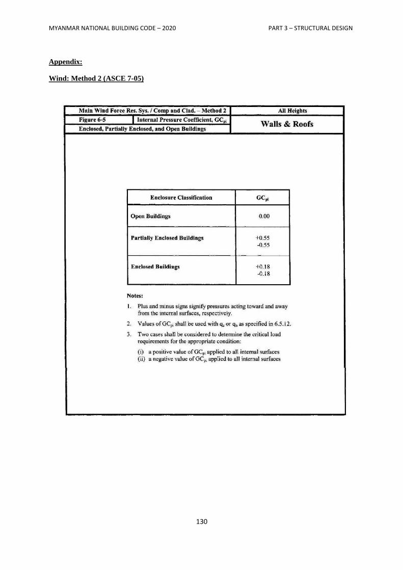
MYANMAR NATIONAL BUILDING CODE – 2020 PART 3 – STRUCTURAL DESIGN
130
Appendix:
Wind: Method 2 (ASCE 7-05)
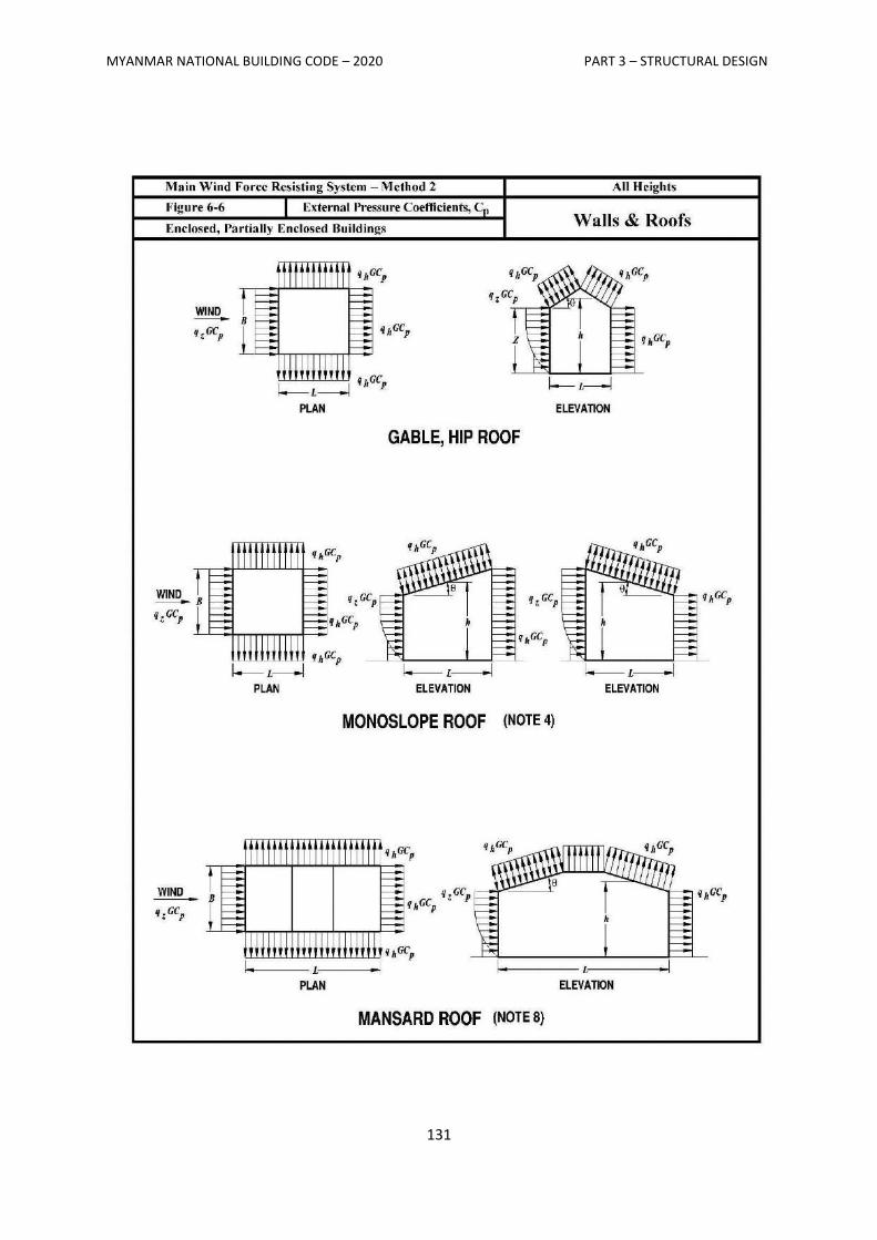
MYANMAR NATIONAL BUILDING CODE – 2020 PART 3 – STRUCTURAL DESIGN
131
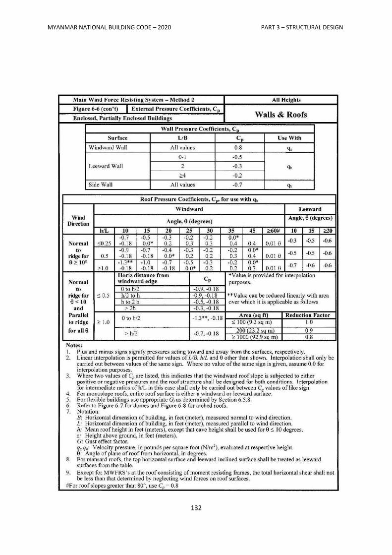
MYANMAR NATIONAL BUILDING CODE – 2020 PART 3 – STRUCTURAL DESIGN
132
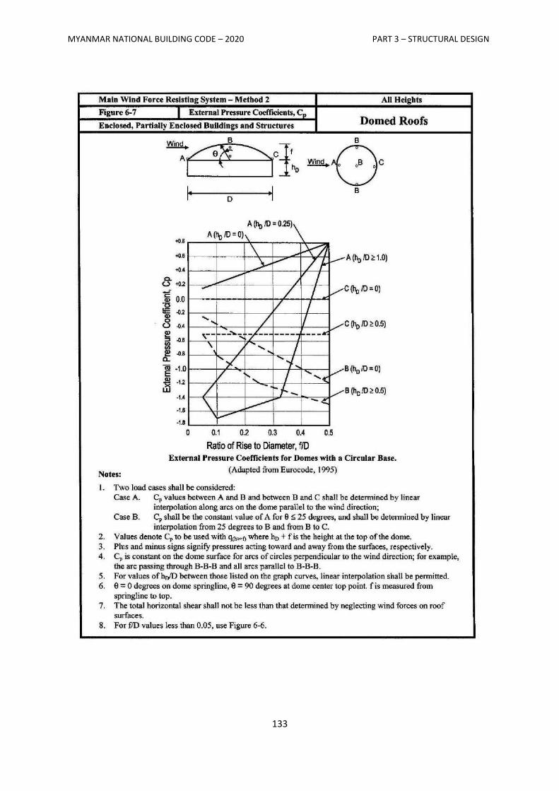
MYANMAR NATIONAL BUILDING CODE – 2020 PART 3 – STRUCTURAL DESIGN
133
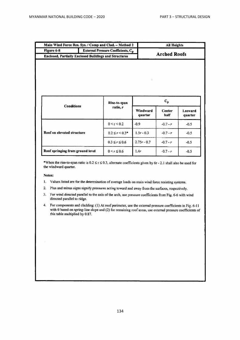
MYANMAR NATIONAL BUILDING CODE – 2020 PART 3 – STRUCTURAL DESIGN
134
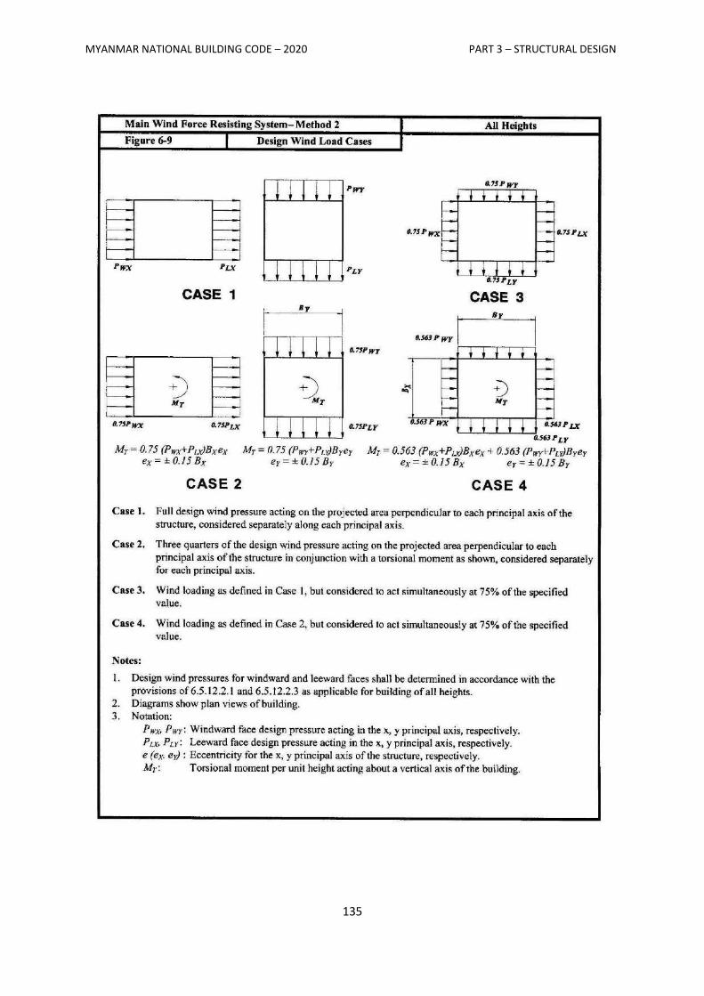
MYANMAR NATIONAL BUILDING CODE – 2020 PART 3 – STRUCTURAL DESIGN
135
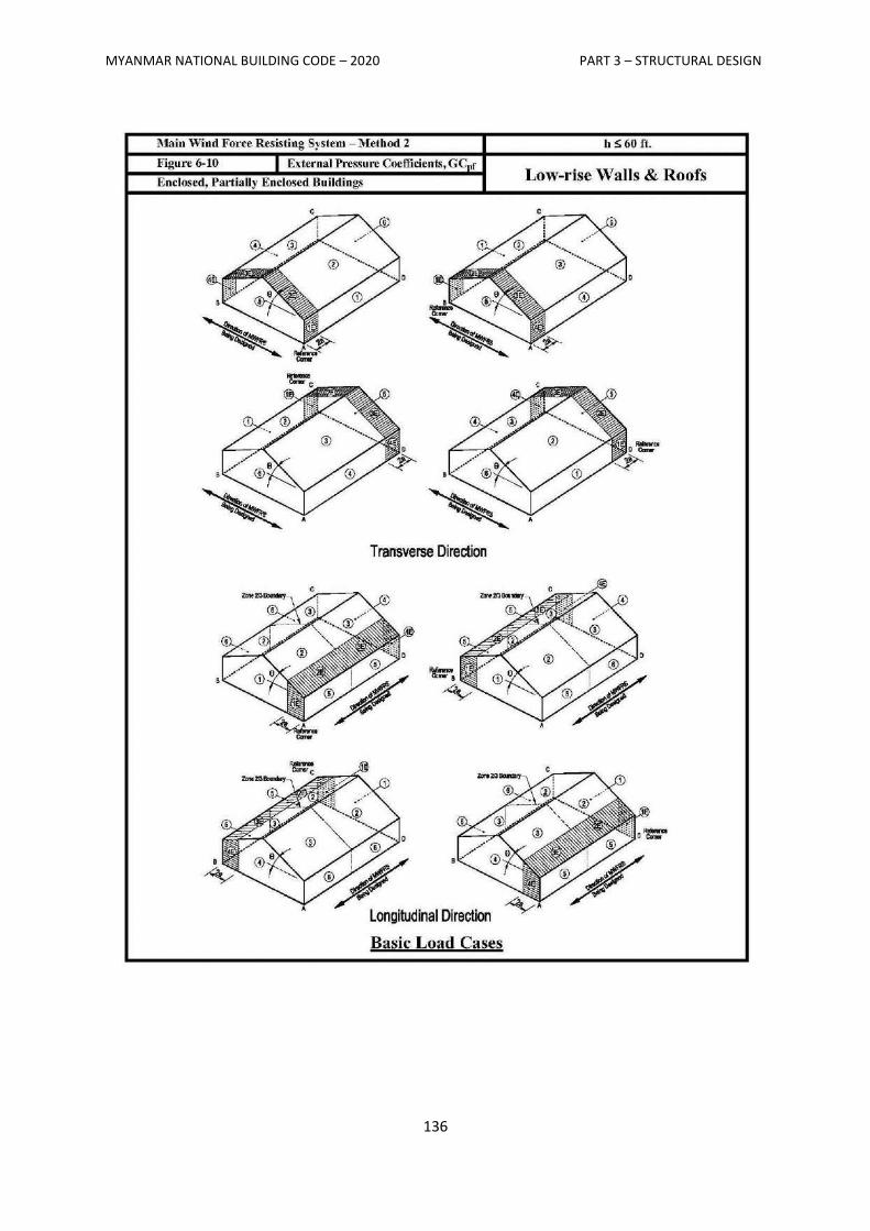
MYANMAR NATIONAL BUILDING CODE – 2020 PART 3 – STRUCTURAL DESIGN
136
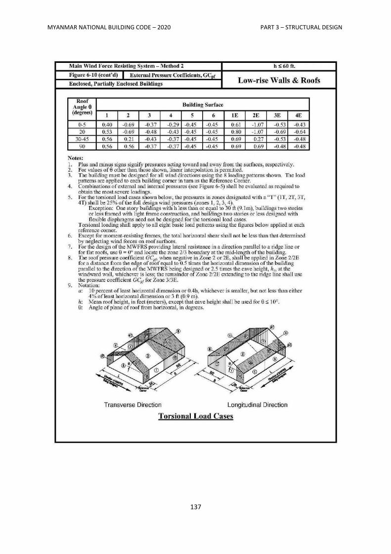
MYANMAR NATIONAL BUILDING CODE – 2020 PART 3 – STRUCTURAL DESIGN
137
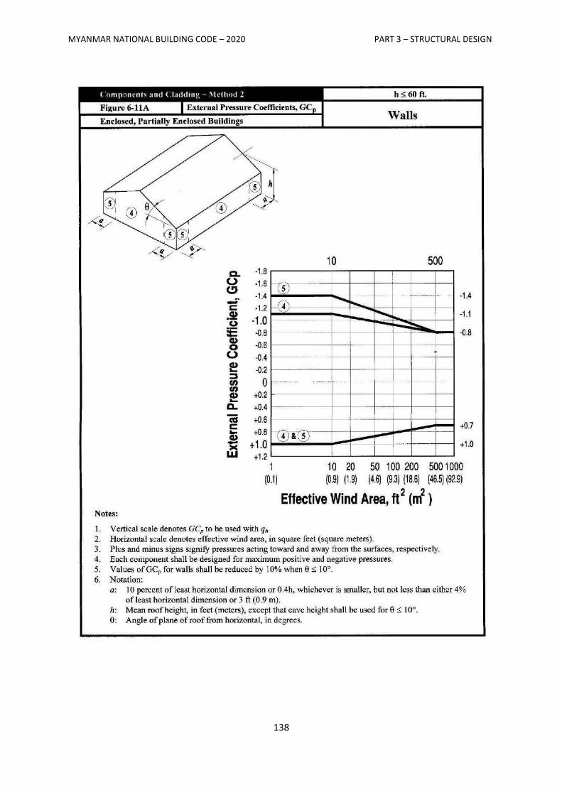
MYANMAR NATIONAL BUILDING CODE – 2020 PART 3 – STRUCTURAL DESIGN
138
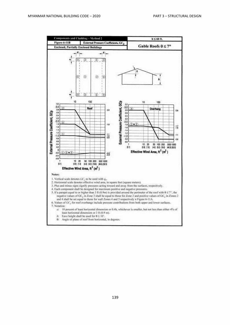
MYANMAR NATIONAL BUILDING CODE – 2020 PART 3 – STRUCTURAL DESIGN
139
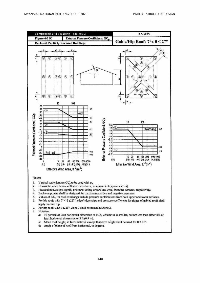
MYANMAR NATIONAL BUILDING CODE – 2020 PART 3 – STRUCTURAL DESIGN
140
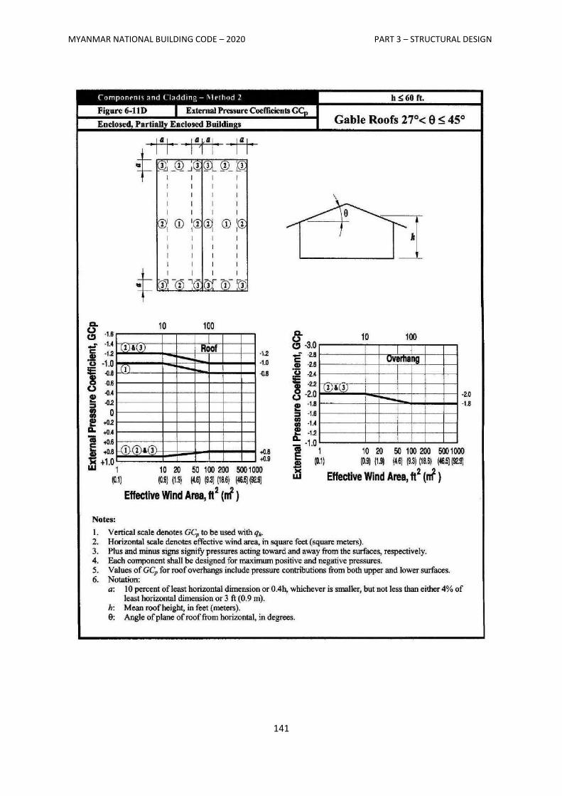
MYANMAR NATIONAL BUILDING CODE – 2020 PART 3 – STRUCTURAL DESIGN
141
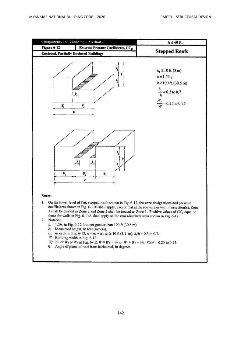
MYANMAR NATIONAL BUILDING CODE – 2020 PART 3 – STRUCTURAL DESIGN
142
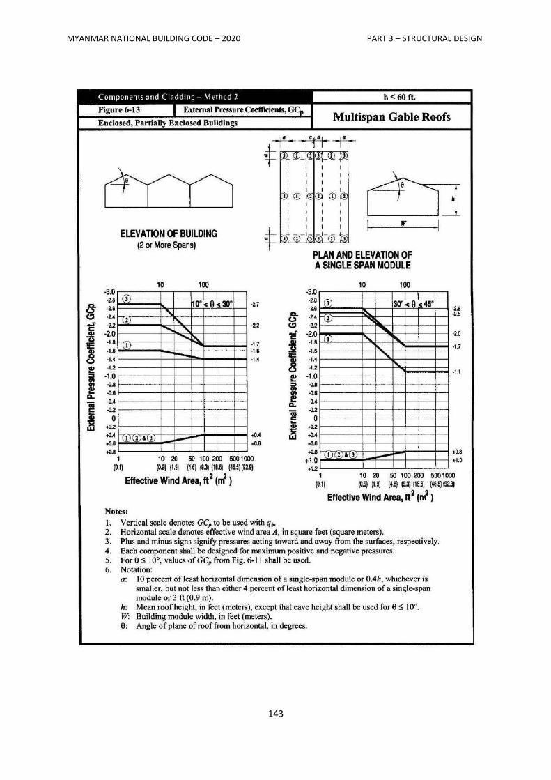
MYANMAR NATIONAL BUILDING CODE – 2020 PART 3 – STRUCTURAL DESIGN
143
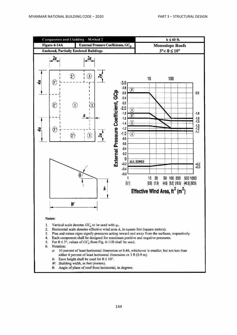
MYANMAR NATIONAL BUILDING CODE – 2020 PART 3 – STRUCTURAL DESIGN
144
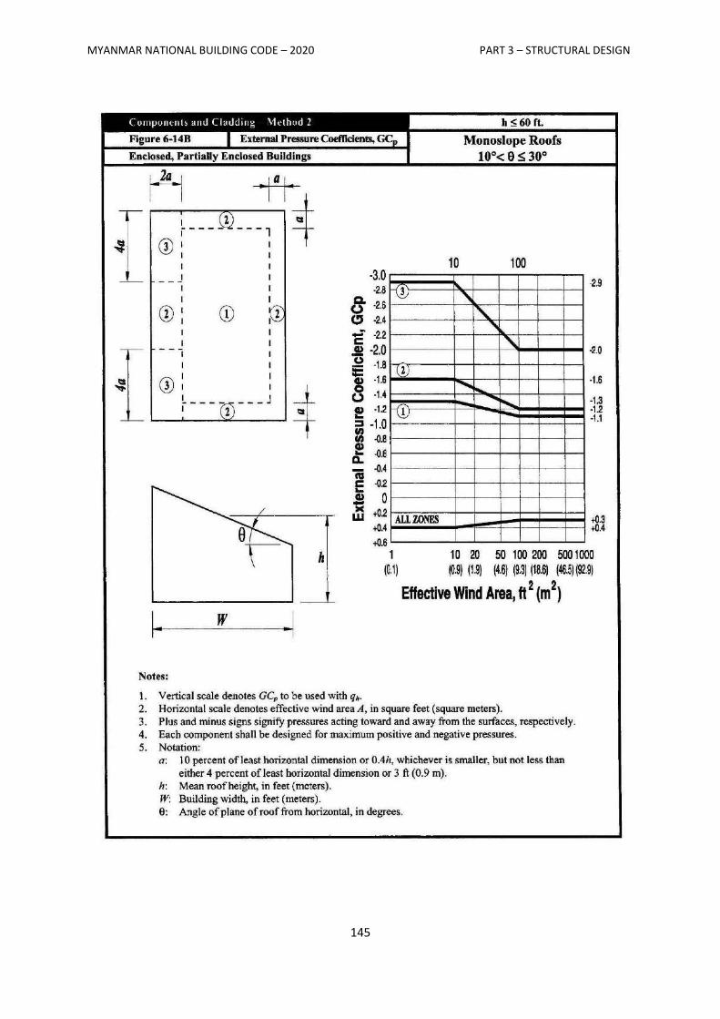
MYANMAR NATIONAL BUILDING CODE – 2020 PART 3 – STRUCTURAL DESIGN
145
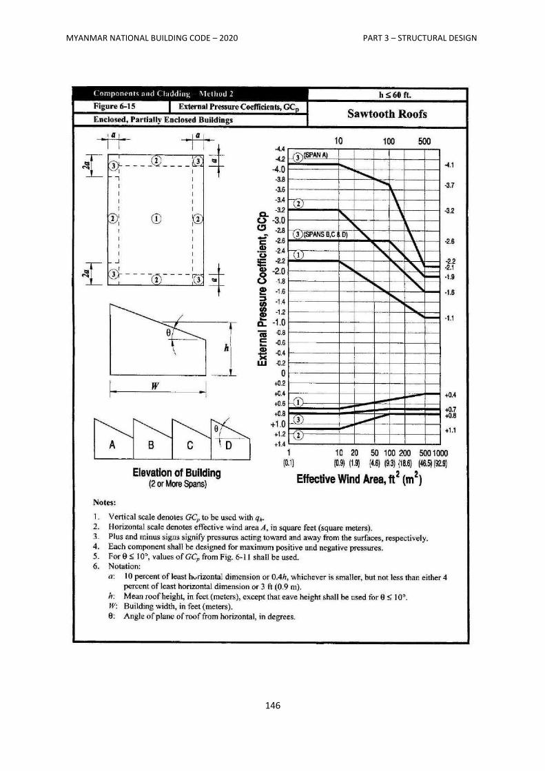
MYANMAR NATIONAL BUILDING CODE – 2020 PART 3 – STRUCTURAL DESIGN
146
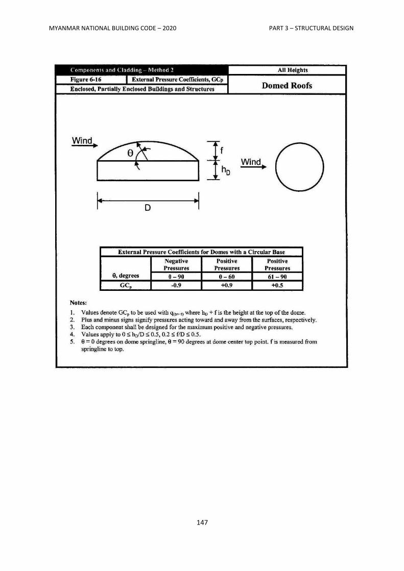
MYANMAR NATIONAL BUILDING CODE – 2020 PART 3 – STRUCTURAL DESIGN
147
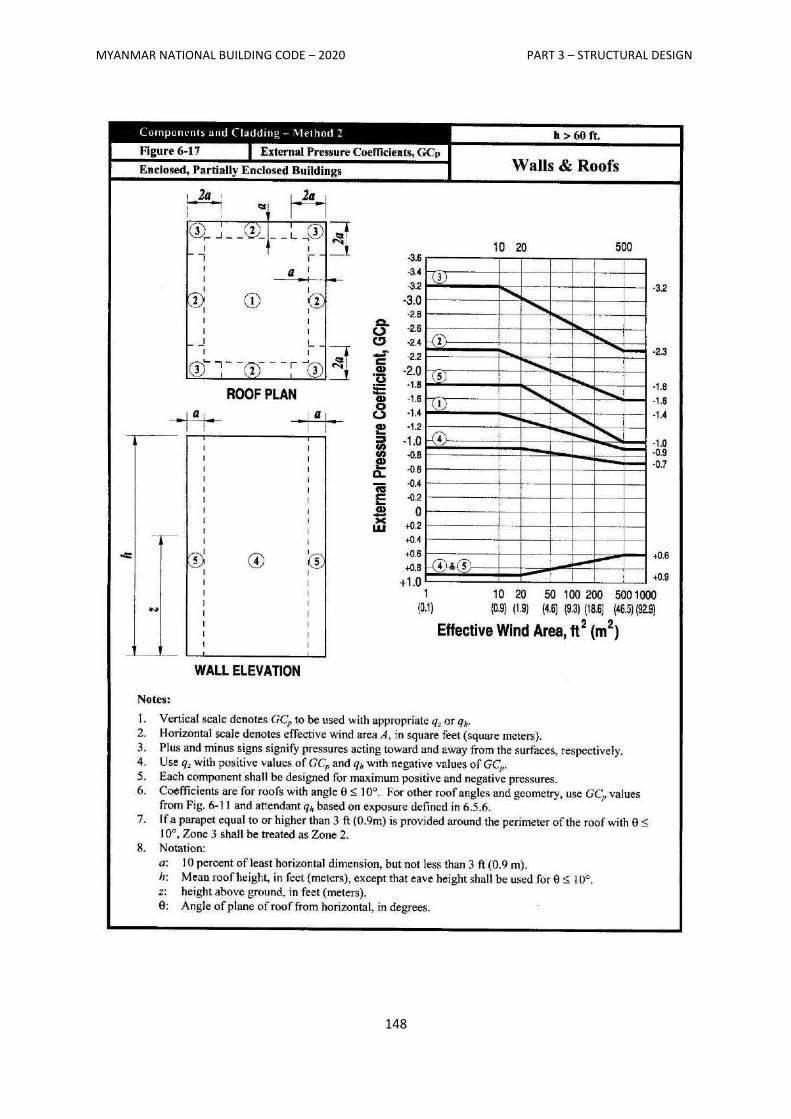
MYANMAR NATIONAL BUILDING CODE – 2020 PART 3 – STRUCTURAL DESIGN
148
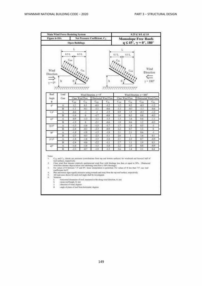
MYANMAR NATIONAL BUILDING CODE – 2020 PART 3 – STRUCTURAL DESIGN
149
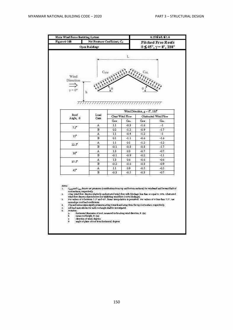
MYANMAR NATIONAL BUILDING CODE – 2020 PART 3 – STRUCTURAL DESIGN
150
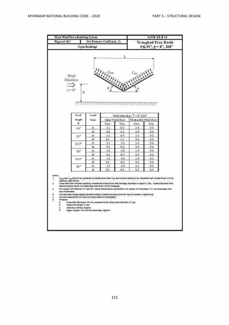
MYANMAR NATIONAL BUILDING CODE – 2020 PART 3 – STRUCTURAL DESIGN
151
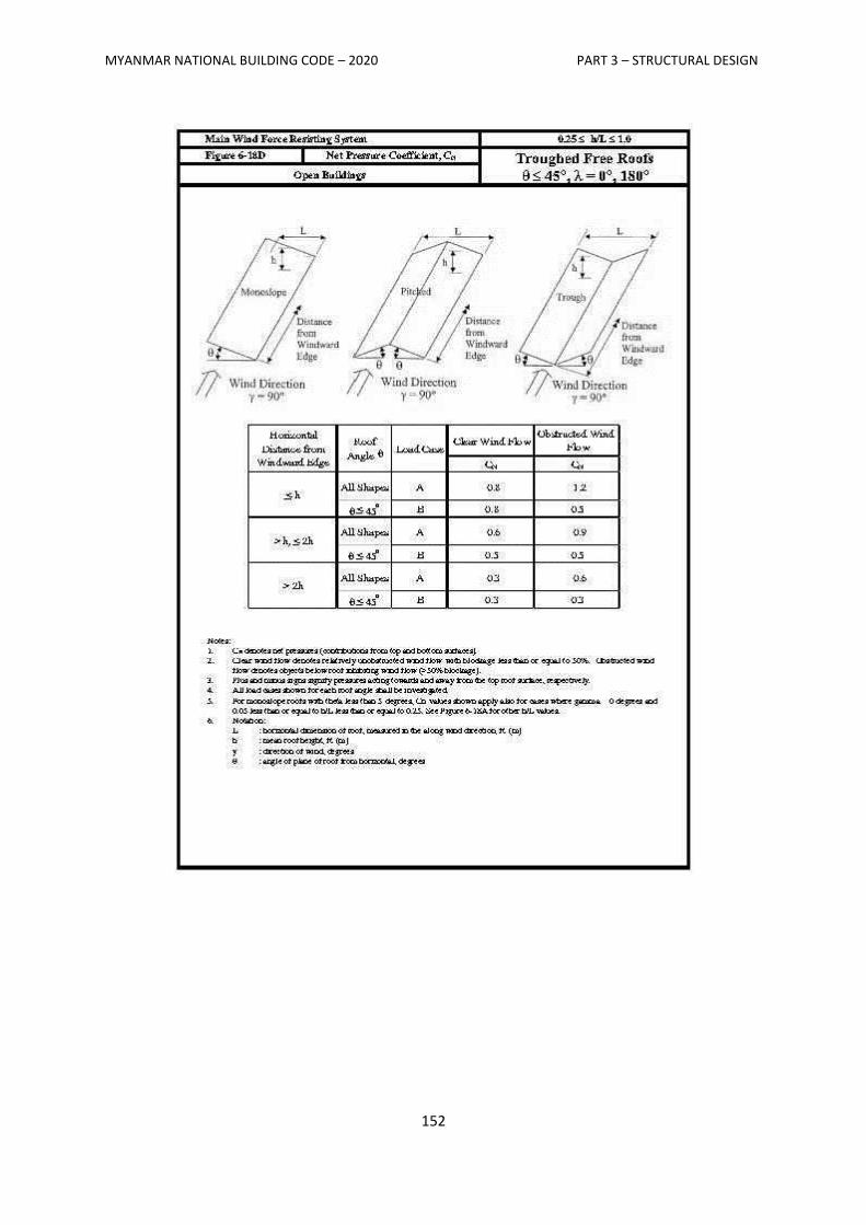
MYANMAR NATIONAL BUILDING CODE – 2020 PART 3 – STRUCTURAL DESIGN
152
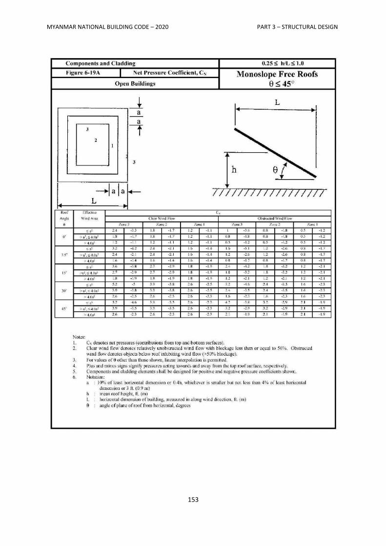
MYANMAR NATIONAL BUILDING CODE – 2020 PART 3 – STRUCTURAL DESIGN
153
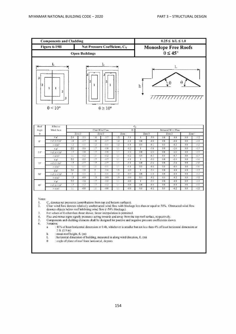
MYANMAR NATIONAL BUILDING CODE – 2020 PART 3 – STRUCTURAL DESIGN
154
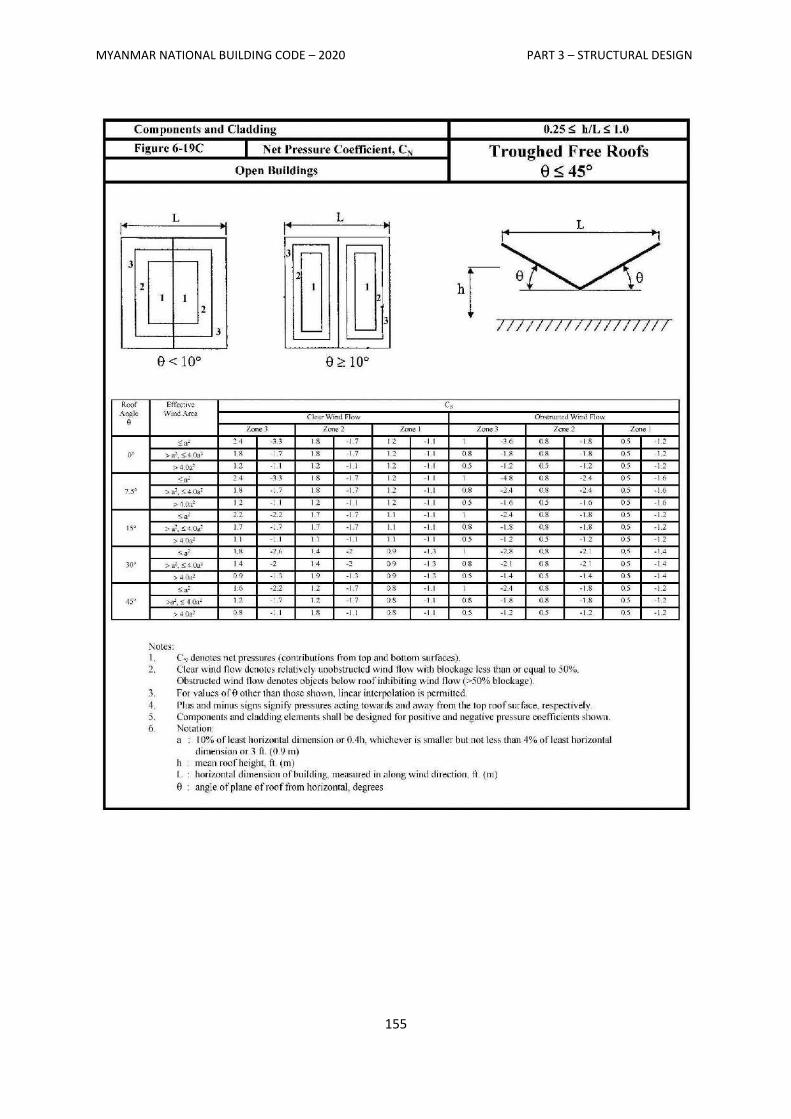
MYANMAR NATIONAL BUILDING CODE – 2020 PART 3 – STRUCTURAL DESIGN
155
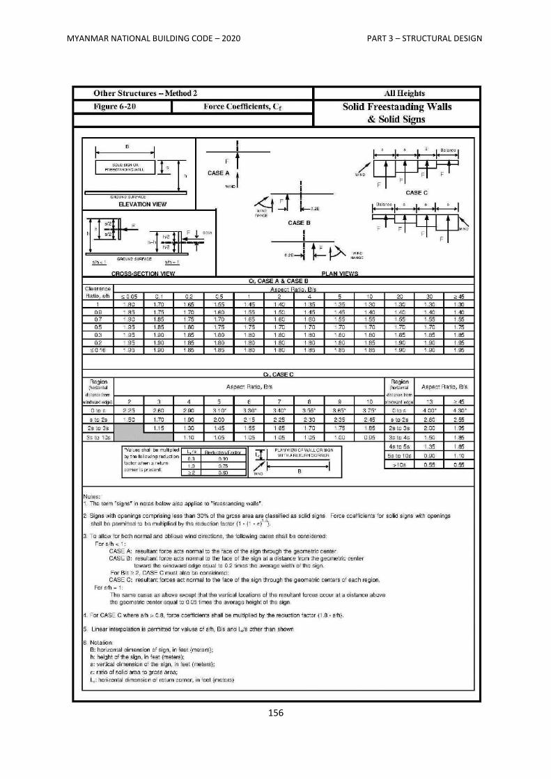
MYANMAR NATIONAL BUILDING CODE – 2020 PART 3 – STRUCTURAL DESIGN
156
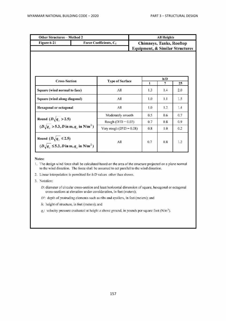
MYANMAR NATIONAL BUILDING CODE – 2020 PART 3 – STRUCTURAL DESIGN
157
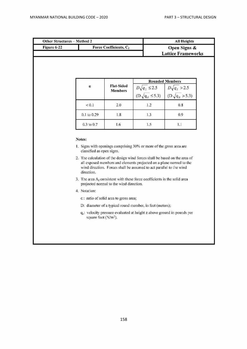
MYANMAR NATIONAL BUILDING CODE – 2020 PART 3 – STRUCTURAL DESIGN
158
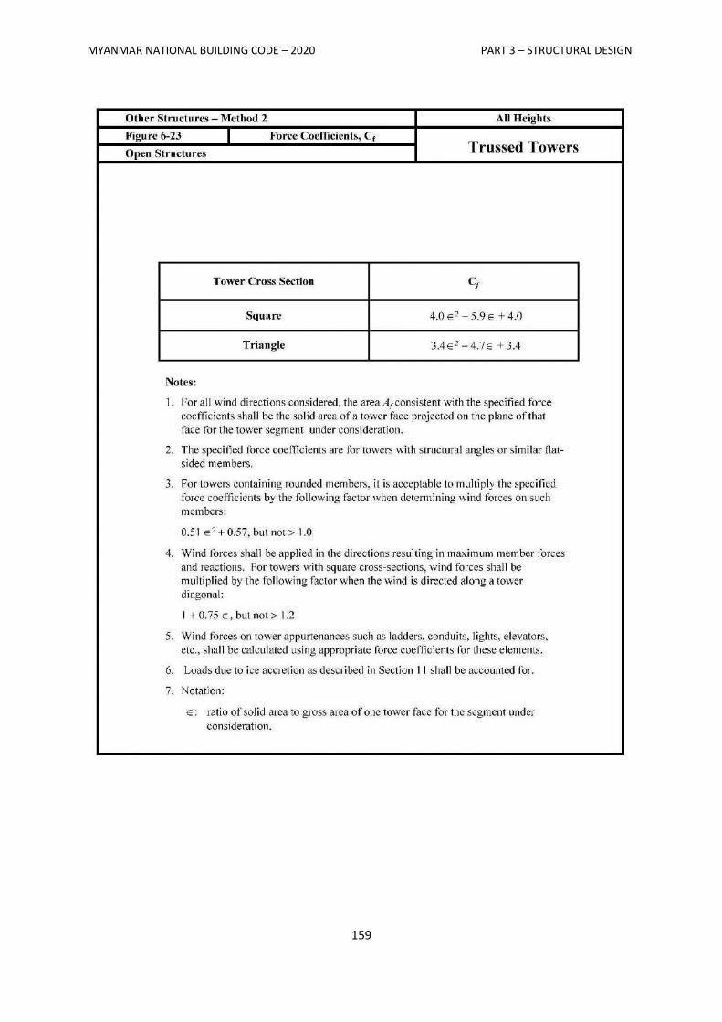
MYANMAR NATIONAL BUILDING CODE – 2020 PART 3 – STRUCTURAL DESIGN
159
MYANMAR NATIONAL BUILDING CODE – 2020 PART 3 – STRUCTURAL DESIGN
160
List of participators and coordinators in TWG-3
1. U Nyi Hla Nge Group Leader
2. U Saw Htwe Zaw Coordinator
3. U Khin Maung Chit Member
4. U Hla Phone Maw Member
5. Dr. Toe Toe Win Member
6. U Myint Oo Member
7. U Shwe Than Soe Member
8. U Shwe Kyaw Hla Member
9. Dr. Kyaw Kyaw Tun Member
10. U Win Aung Cho Member
11. U Soe Naing Member
12. U Shwe Maung Member
13. Dr. Maung Maung Wai Yan Member
14. U Tun Kyi Member
15. U Min Han Member
16. U Nay Aung Ye Myint Member
17. U Kyaw Lin Shwe Member
18. Dr. Yin Myo Min Htwe Member
19. U Hla Naing Member
20. U Thura Naing Member
21. U Htin Aung Member
22. U Thet Soe Oo Member
23. U Myo Thant Member
24. Daw Mya Mya Win Member
25. Dr. Tin Tin Win Member
26. Daw Kyi Kyi Khaing Member
27. Daw Ohnmar Mya Member
28. Daw May Sandar Soe Member
29. Daw Mar Mar Swe Member
30. Daw San San Thwin Member

MYANMAR NATIONAL BUILDING CODE – 2020 PART 3 – STRUCTURAL DESIGN
161
31. Daw May Moe Moe Khaing Member
32. Daw Myat Thuzar Maw Member
33. Daw Aung May Oo Member
34. Dr. Mar Mar Cho Member
MYANMAR
NATIONAL
BUILDING
CODE
2020
PART 4
SOIL AND FOUNDATION
MYANMAR NATIONAL BUILDING CODE – 2020 PART 4 – SOIL AND FOUNDATION
i
MYANMAR NATIONAL BUILDING CODE – 2020
PART 4 SOIL AND FOUNDATION
TABLE OF CONTENTS
Table of Contents ........................................................................................................................... i
List of Tables
………...………………………………………….…………………………………...vii
List of Figures
……....……………………………………………………….………………………...viii
4.1 GENERAL ............................................................................................................................... 1 4.1.1 Scope .............................................................................................................................. 1 4.1.2 Referenced codes and standards ..................................................................................... 1 4.1.3 Design ............................................................................................................................. 1
4.1.3.1 Foundation design for seismic overturning ........................................................... 1 4.1.3.1.1 Reduction of foundation overturning ........................................................... 1
4.1.4 Liquefaction .................................................................................................................... 2 4.1.5 Definitions and notations ................................................................................................ 2
4.1.5.1 Definitions ............................................................................................................. 2 4.1.5.1.1 Deep foundations .......................................................................................... 3
4.1.5.2 Notations ............................................................................................................... 4
4.2 GEOTECHNICAL INVESTIGATION ................................................................................ 5 4.2.1 General ........................................................................................................................... 5 4.2.2 Investigations required ................................................................................................... 5
4.2.2.1 Questionable soil ................................................................................................... 5 4.2.2.2 Expansive soils ...................................................................................................... 5 4.2.2.3 Ground-water table ................................................................................................ 5 4.2.2.4 Pile and pier foundations ....................................................................................... 5 4.2.2.5 Rock strata ............................................................................................................. 5 4.2.2.6 Seismic Design Category C ................................................................................... 5 4.2.2.7 Seismic Design Category D, E or F ...................................................................... 6
4.2.3 Soil classification ........................................................................................................... 6 4.2.3.1 General .................................................................................................................. 6 4.2.3.2 Expansive soils ...................................................................................................... 6
4.2.4 Investigation ................................................................................................................... 6 4.2.4.1 Exploratory boring ................................................................................................ 7 4.2.4.2 Number and location of borings ............................................................................ 7 4.2.4.3 Depth of boring ..................................................................................................... 7
4.2.5 Soil boring and sampling ................................................................................................ 7 4.2.6 Reports ............................................................................................................................ 8
4.3 EXCAVATION, GRADING AND FILL .............................................................................. 9 4.3.1 Excavations near footing or foundations ........................................................................ 9 4.3.2 Placement of backfill ...................................................................................................... 9
MYANMAR NATIONAL BUILDING CODE – 2020 PART 4 – SOIL AND FOUNDATION
ii
4.3.3 Site grading ..................................................................................................................... 9 4.3.4 Grading and filling in flood hazard areas ....................................................................... 9 4.3.5 Compacted fill material .................................................................................................. 9 4.3.6 Controlled low-strength material .................................................................................. 10
4.4 DAMPPROOFING AND WATERPROOFING ................................................................ 11 4.4.1 General ......................................................................................................................... 11
4.4.1.1 Story above grade plane ...................................................................................... 11 4.4.1.2 Under-floor space ................................................................................................ 11
4.4.1.2.1 Flood hazard areas ...................................................................................... 11 4.4.1.3 Ground-water control .......................................................................................... 11
4.4.2 Damp proofing ............................................................................................................. 11 4.4.2.1 Floors ................................................................................................................... 11 4.4.2.2 Walls .................................................................................................................... 11
4.4.2.2.1 Surface preparation of walls ....................................................................... 12 4.4.3 Water proofing ............................................................................................................. 12
4.4.3.1 Floors ................................................................................................................... 12 4.4.3.2 Walls .................................................................................................................... 12
4.4.3.2.1 Surface preparation of walls ....................................................................... 12 4.4.3.3 Joints and penetrations ........................................................................................ 12
4.4.4 Subsoil drainage system ............................................................................................... 12 4.4.4.1 Floor base course. ................................................................................................ 12 4.4.4.2 Foundation drain. ................................................................................................. 13 4.4.4.3 Drainage discharge. ............................................................................................. 13
4.5 EARTH RETAINING SYSTEMS ...................................................................................... 14 4.5.1 General .......................................................................................................................... 14 4.5.2 Temporary earth retaining systems .............................................................................. 14
4.5.3.1 Temporary earth retaining systems intended to be integrated with permanent
structure ........................................................................................................................... 14
4.6 ALLOWABLE LOAD BEARING VALUES OF SOIL .................................................... 15 4.6.1 General ......................................................................................................................... 15 4.6.2 Presumptive load-bearing values .................................................................................. 15 4.6.3 Lateral sliding resistance .............................................................................................. 15
4.6.3.1 Increases in allowable lateral sliding resistance .................................................. 15
4.7 FOOTINGS AND FOUNDATIONS ................................................................................... 17 4.7.1 General ......................................................................................................................... 17 4.7.2 Depth of footings .......................................................................................................... 17
4.7.2.1 Frost protection .................................................................................................... 17 4.7.2.2 Isolated footings .................................................................................................. 17 4.7.2.3 Shifting or moving soils ...................................................................................... 17
4.7.3 Footings on or adjacent to slopes ................................................................................. 18 4.7.3.1 Building clearance from ascending slopes .......................................................... 18 4.7.3.2 Footing setback from descending slope surface .................................................. 18 4.7.3.3 Pools .................................................................................................................... 19
MYANMAR NATIONAL BUILDING CODE – 2020 PART 4 – SOIL AND FOUNDATION
iii
4.7.3.4 Foundation elevation ........................................................................................... 19 4.7.3.5 Alternate setback and clearance .......................................................................... 19
4.7.4 Footings ........................................................................................................................ 19 4.7.4.1 Design .................................................................................................................. 19
4.7.4.1.1 Design loads ............................................................................................... 19 4.7.4.1.2 Vibratory loads ........................................................................................... 19
4.7.4.2 Concrete footings ................................................................................................ 19 4.7.4.2.1 Concrete strength ........................................................................................ 20 4.7.4.2.2 Footing seismic ties .................................................................................... 20 4.7.4.2.3 Plain concrete footings ............................................................................... 20 4.7.4.2.4 Placement of concrete ................................................................................ 20 4.7.4.2.5 Protection of concrete ................................................................................. 21 4.7.4.2.6 Forming of concrete ................................................................................... 21
4.7.4.3 Steel grillage footings .......................................................................................... 21 4.7.5 Foundation walls .......................................................................................................... 21
4.7.5.1 Foundation wall thickness ................................................................................... 26 4.7.5.1.1 Thickness at top of foundation wall ........................................................... 26 4.7.5.1.2 Thickness based on soil loads, unbalanced backfill height and wall height
................................................................................................................................... 26 4.7.5.1.3 Rubble stone ............................................................................................... 26
4.7.5.2 Foundation wall materials ................................................................................... 26 4.7.5.2.1 Concrete foundation walls .......................................................................... 26 4.7.5.2.2 Masonry foundation walls .......................................................................... 27
4.7.5.3 Alternative foundation wall reinforcement ......................................................... 27 4.7.5.4 Hollow masonry walls ......................................................................................... 27 4.7.5.5 Seismic requirements .......................................................................................... 27
4.7.5.5.1 Seismic requirements for concrete foundation walls ................................. 28 4.7.5.5.2 Seismic requirements for masonry foundation walls ................................. 28
4.7.5.6 Foundation wall drainage .................................................................................... 28 4.7.5.7 Pier and curtain wall foundations ........................................................................ 28
4.7.6 Designs employing lateral bearing ............................................................................... 29 4.7.6.1 Limitations ........................................................................................................... 29 4.7.6.2 Design criteria ..................................................................................................... 29
4.7.6.2.1 Nonconstrained ........................................................................................... 29 4.7.6.2.2 Constrained ................................................................................................. 30 4.7.6.2.3 Vertical load ............................................................................................... 30
4.7.6.3 Backfill ................................................................................................................ 30 4.7.7 Design for expansive soils ............................................................................................ 30
4.7.7.1 Foundations ......................................................................................................... 30 4.7.7.2 Slab-on-ground foundations ................................................................................ 31 4.7.7.3 Removal of expansive soil .................................................................................. 31 4.7.7.4 Stabilization ......................................................................................................... 31
4.7.8 Seismic requirements ................................................................................................... 31
4.8 GENERAL REQUIREMENTS FOR PIER AND PILE FOUNDATIONS .................... 32 4.8.1 General ......................................................................................................................... 32 4.8.2 Special types of piles .................................................................................................... 32
MYANMAR NATIONAL BUILDING CODE – 2020 PART 4 – SOIL AND FOUNDATION
iv
4.8.3 Pile caps ........................................................................................................................ 32 4.8.4 Stability ........................................................................................................................ 32 4.8.5 Structural integrity ........................................................................................................ 33 4.8.6 Splices .......................................................................................................................... 33 4.8.7 Allowable pier or pile loads ......................................................................................... 33
4.8.7.1 Determination of allowable loads ........................................................................ 33 4.8.7.2 Driving criteria .................................................................................................... 33 4.8.7.3 Load tests ............................................................................................................. 33
4.8.7.3.1 Load test evaluation .................................................................................... 33 4.8.7.3.2 Non-destructive testing ............................................................................... 34
4.8.7.4 Allowable frictional resistance ............................................................................ 34 4.8.7.5 Uplift capacity ..................................................................................................... 34 4.8.7.6 Load-bearing capacity ......................................................................................... 34 4.8.7.7 Bent piers or piles ................................................................................................ 34 4.8.7.8 Overloads on piers or piles .................................................................................. 34
4.8.8 Lateral support .............................................................................................................. 34 4.8.8.1 General ................................................................................................................ 34 4.8.8.2 Unbraced piles ..................................................................................................... 34 4.8.8.3 Allowable lateral load ......................................................................................... 35
4.8.9 Use of higher allowable pier or pile stresses ................................................................ 35 4.8.10 Piles in subsiding areas ............................................................................................... 35 4.8.11 Negative skin friction or down drag force .................................................................. 35 4.8.12 Settlement analysis ..................................................................................................... 35 4.8.13 Pre-excavation ............................................................................................................ 35 4.8.14 Installation sequence .................................................................................................. 36 4.8.15 Use of vibratory drivers .............................................................................................. 36 4.8.16 Pile drivability ............................................................................................................ 36 4.8.17 Protection of pile materials ......................................................................................... 36 4.8.18 Use of existing piers or piles ...................................................................................... 36 4.8.19 Heaved piles ............................................................................................................... 36 4.8.20 Identification .............................................................................................................. 36 4.8.21 Pier or pile location plan ............................................................................................ 36 4.8.22 Spacing of Piles .......................................................................................................... 37 4.8.23 Special inspection ....................................................................................................... 37
4.8.23.1 Pier foundations ................................................................................................. 37 4.8.23.2 Pile foundations ................................................................................................. 37
4.8.24 Seismic design of piers or piles .................................................................................. 37 4.8.24.1 Seismic Design Category C ............................................................................... 37
4.8.24.1.1 Connection to pile cap .............................................................................. 37 4.8.24.1.2 Design details ........................................................................................... 38
4.8.24.2 Seismic Design Category D, E or F .................................................................. 38 4.8.24.2.1 Design details for piers, piles and grade beams ....................................... 38 4.8.24.2.2 Connection to pile cap .............................................................................. 39 4.8.24.2.3 Flexural strength ....................................................................................... 39
4.9 DRIVEN PILE FOUNDATIONS ........................................................................................ 41 4.9.1 Timber piles .................................................................................................................. 41
MYANMAR NATIONAL BUILDING CODE – 2020 PART 4 – SOIL AND FOUNDATION
v
4.9.1.1 Materials .............................................................................................................. 41 4.9.1.2 Preservative treatment ......................................................................................... 41 4.9.1.3 Defective piles ..................................................................................................... 41 4.9.1.4 Allowable stresses ............................................................................................... 41
4.9.2 Precast concrete piles ................................................................................................... 41 4.9.2.1 The materials, reinforcement and installation of precast concrete piles ............. 41
4.9.2.1.1 Design and manufacture ............................................................................. 42 4.9.2.1.2 Minimum dimension .................................................................................. 42 4.9.2.1.3 Reinforcement ............................................................................................ 42 4.9.2.1.4 Installation .................................................................................................. 42
4.9.2.2 Precast non-prestressed piles ............................................................................... 42 4.9.2.2.1 Materials ..................................................................................................... 42 4.9.2.2.2 Minimum reinforcement ............................................................................. 42
4.9.2.2.2.1 Seismic reinforcement in Seismic Design Category C ..................... 42 4.9.2.2.2.2 Seismic reinforcement in Seismic Design Category D, E or F ......... 42
4.9.2.2.3 Allowable stresses ...................................................................................... 43 4.9.2.2.4 Installation .................................................................................................. 43 4.9.2.2.5 Concrete cover ............................................................................................ 43
4.9.2.3 Precast prestressed piles ...................................................................................... 43 4.9.2.3.1 Materials ..................................................................................................... 43 4.9.2.3.2 Design ......................................................................................................... 43
4.9.2.3.2.1 Design in Seismic Design Category C .............................................. 43 4.9.2.3.2.2 Design in Seismic Design Category D, E or F .................................. 44
4.9.2.3.3 Allowable stresses ...................................................................................... 45 4.9.2.3.4 Installation .................................................................................................. 45 4.9.2.3.5 Concrete cover ............................................................................................ 46
4.9.3 Structural steel piles ..................................................................................................... 46 4.9.3.1 Materials .............................................................................................................. 46 4.9.3.2 Allowable stresses ............................................................................................... 46 4.9.3.3 Dimensions of H-piles ......................................................................................... 46 4.9.3.4 Dimensions of steel pipe piles ............................................................................. 46
4.10 CAST-IN-PLACE CONCRETE PILE FOUNDATIONS ............................................... 47 4.10.1 General ....................................................................................................................... 47
4.10.1.1 Materials ............................................................................................................ 47 4.10.1.2 Reinforcement ................................................................................................... 47
4.10.1.2.1 Reinforcement in Seismic Design Category C ......................................... 47 4.10.1.2.2 Reinforcement in Seismic Design Category D, E or F ............................. 47
4.10.1.3 Concrete placement ........................................................................................... 48 4.10.2 Enlarged base piles ..................................................................................................... 48
4.10.2.1 Materials ............................................................................................................ 48 4.10.2.2 Allowable stresses ............................................................................................. 48 4.10.2.3 Installation ......................................................................................................... 48 4.10.2.4 Load-bearing capacity ....................................................................................... 48 4.10.2.5 Concrete cover ................................................................................................... 48
4.10.3 Drilled or augured uncased piles ................................................................................ 48 4.10.3.1 Allowable stresses ............................................................................................. 48
MYANMAR NATIONAL BUILDING CODE – 2020 PART 4 – SOIL AND FOUNDATION
vi
4.10.3.2 Dimensions ........................................................................................................ 49 4.10.3.3 Installation ......................................................................................................... 49 4.10.3.4 Reinforcement ................................................................................................... 49 4.10.3.5 Reinforcement in Seismic Design Category C, D, E or F ................................. 49
4.10.4 Driven uncased piles .................................................................................................. 50 4.10.4.1 Allowable stresses ............................................................................................. 50 4.10.4.2 Dimensions ........................................................................................................ 50 4.10.4.3 Installation ......................................................................................................... 50 4.10.4.4 Concrete cover ................................................................................................... 50
4.10.5 Steel-cased piles ......................................................................................................... 50 4.10.5.1 Materials ............................................................................................................ 50 4.10.5.2 Allowable stresses ............................................................................................. 50
4.10.5.2.1 Shell thickness .......................................................................................... 50 4.10.5.2.2 Shell type .................................................................................................. 51 4.10.5.2.3 Strength .................................................................................................... 51 4.10.5.2.4 Diameter ................................................................................................... 51
4.10.5.3 Installation ......................................................................................................... 51 4.10.5.4 Reinforcement ................................................................................................... 51
4.10.5.4.1 Seismic reinforcement .............................................................................. 51 4.10.6 Concrete-filled steel pipe and tube piles .................................................................... 51
4.10.6.1 Materials ............................................................................................................ 51 4.10.6.2 Allowable stresses ............................................................................................. 51 4.10.6.3 Minimum dimensions ........................................................................................ 52 4.10.6.4 Reinforcement ................................................................................................... 52
4.10.6.4.1 Seismic reinforcement .............................................................................. 52 4.10.6.5 Placing concrete ................................................................................................ 52
4.10.7 Caisson piles ............................................................................................................... 52 4.10.7.1 Construction ...................................................................................................... 52 4.10.7.2 Materials ............................................................................................................ 52 4.10.7.3 Design ................................................................................................................ 52 4.10.7.4 Structural core ................................................................................................... 53 4.10.7.5 Allowable stresses ............................................................................................. 53 4.10.7.6 Installation ......................................................................................................... 53
4.10.8 Micro piles .................................................................................................................. 53 4.10.8.1 Construction ...................................................................................................... 53 4.10.8.2 Materials ............................................................................................................ 53 4.10.8.3 Allowable stresses ............................................................................................. 53 4.10.8.4 Reinforcement ................................................................................................... 53
4.10.8.4.1 Seismic reinforcement .............................................................................. 54 4.10.8.5 Installation ......................................................................................................... 54
4.11 COMPOSITE PILES.......................................................................................................... 55 4.11.1 General ....................................................................................................................... 55 4.11.2 Design ......................................................................................................................... 55 4.11.3 Limitation of load ....................................................................................................... 55 4.11.4 Splices ........................................................................................................................ 55 4.11.5 Seismic reinforcement ................................................................................................ 55
MYANMAR NATIONAL BUILDING CODE – 2020 PART 4 – SOIL AND FOUNDATION
vii
4.12 PIER FOUNDATIONS ...................................................................................................... 56 4.12.1 General ....................................................................................................................... 56 4.12.2 Lateral dimensions and height .................................................................................... 56 4.12.3 Materials ..................................................................................................................... 56 4.12.4 Reinforcement ............................................................................................................ 56 4.12.5 Concrete placement .................................................................................................... 57 4.12.6 Belled bottoms ............................................................................................................ 57 4.12.7 Masonry ...................................................................................................................... 57 4.12.8 Concrete ...................................................................................................................... 57 4.12.9 Steel shell ................................................................................................................... 57 4.12.10 Dewatering ............................................................................................................... 57
4.13 OTHER REQUIREMENTS .............................................................................................. 58 4.13.1 Soil improvement ....................................................................................................... 58 4.13.2 Instrumentation and monitoring ................................................................................. 58
APPENDIX A: USEFUL INFORMATION FOR MYANMAR ............................................. 59
APPENDIX B: UNIFIED SOIL CLASSIFICATION SYSTEM ........................................... 62
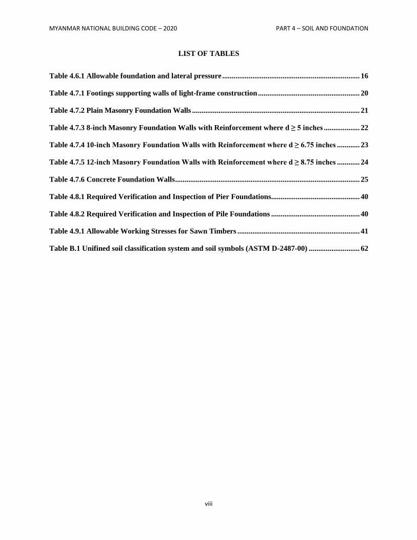
MYANMAR NATIONAL BUILDING CODE – 2020 PART 4 – SOIL AND FOUNDATION
viii
LIST OF TABLES
Table 4.6.1 Allowable foundation and lateral pressure ......................................................................... 16
Table 4.7.1 Footings supporting walls of light-frame construction ...................................................... 20
Table 4.7.2 Plain Masonry Foundation Walls ......................................................................................... 21
Table 4.7.3 8-inch Masonry Foundation Walls with Reinforcement where d ≥ 5 inches ................... 22
Table 4.7.4 10-inch Masonry Foundation Walls with Reinforcement where d ≥ 6.75 inches ............ 23
Table 4.7.5 12-inch Masonry Foundation Walls with Reinforcement where d ≥ 8.75 inches ............ 24
Table 4.7.6 Concrete Foundation Walls .................................................................................................. 25
Table 4.8.1 Required Verification and Inspection of Pier Foundations............................................... 40
Table 4.8.2 Required Verification and Inspection of Pile Foundations ............................................... 40
Table 4.9.1 Allowable Working Stresses for Sawn Timbers ................................................................. 41
Table B.1 Unifined soil classification system and soil symbols (ASTM D-2487-00) ........................... 62
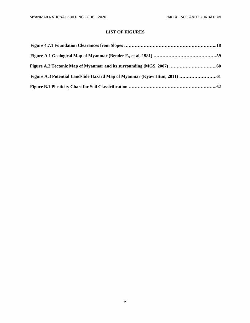
MYANMAR NATIONAL BUILDING CODE – 2020 PART 4 – SOIL AND FOUNDATION
ix
LIST OF FIGURES
Figure 4.7.1 Foundation Clearances from Slopes ……………………………………………………..18
Figure A.1 Geological Map of Myanmar (Bender F., et al, 1981) ……………………………………59
Figure A.2 Tectonic Map of Myanmar and its surrounding (MGS, 2007) …………………………..60
Figure A.3 Potential Landslide Hazard Map of Myanmar (Kyaw Htun, 2011) …………………….61
Figure B.1 Plasticity Chart for Soil Classicification …………………………………………………..62
MYANMAR NATIONAL BUILDING CODE – 2020 PART 4 – SOIL AND FOUNDATION
1
SECTION 4.1
GENERAL
4.1.1 Scope
This section covers soil and foundation design for all buildings such as individual footings, combined
footings, strip footings, rafts, piles and other foundation systems to ensure safety and serviceability
without exceeding the permissible stresses of foundation material and the bearing capacity of the
supporting soil. Some parameters related to seismic – resistant designs are also included.
This section is formulated with a view to implement in national and economic policies in soils and
foundations, such that the design of buildings can be accomplished with safety and usability, using
advanced technology, with economy and rationality, assuring the quality and protection of the
environment.
Design of soil and foundation must be carried out based on the principles of suiting measures to local
conditions, using local materials, protecting the environment and economizing on resources. The design
shall be painstakingly performed with comprehensive consideration given to the type of structures,
availability of materials and geotechnical survey data of soil and rock.
4.1.2 Referenced codes and standards
The other codes and standards referenced in this PART shall be considered part of the requirements of
this code to the prescribed extent of each reference. Version of referenced code or standard shall
conform to IBC 2006 unless otherwise specified in this PART. Where conflicts occur between
requirements of this PART and referenced codes and standards, the requirements of this PART shall
apply.
4.1.3 Design
Allowable bearing pressures, allowable stresses and design formulae provided in this section shall be
used with the allowable stress design load combinations specified in Structural Design Section 3.2.1. The
quality and design of materials used structurally in excavations, footings and foundations shall conform to
the requirements specified in this code (see Section on Structural Design, Concrete, Masonry and Steel).
Safety during construction and the protection of adjacent public and private properties shall govern the
design and construction of excavations and fills.
4.1.3.1 Foundation design for seismic overturning
Where the foundation is proportioned using the load combinations specified in Structural Design Section
3.4.2, and the computation of the seismic overturning moment is by the equivalent lateral-force method or
the model analysis, the proportioning shall be in accordance with Section 3.4.2.
4.1.3.1.1 Reduction of foundation overturning
Overturning effects at the soil foundation interface are permitted to be reduced by 25 percent for
foundations of structures that satisfy both of the following conditions:
a) The structure is designed in accordance with the Equivalent Lateral Force Analysis as set forth
in Structural Design Section 3.4.2.
b) The structure is not an inverted pendulum or cantilevered column type structure.
Overturning effects at the soil-foundation interface are permitted to be reduced by 10 percent for
foundations of structures designed in accordance with the modal analysis requirements of Structural
Design Section 3.4.2.
MYANMAR NATIONAL BUILDING CODE – 2020 PART 4 – SOIL AND FOUNDATION
2
4.1.4 Liquefaction
Liquefaction potential of project area shall be evaluated by design professional using currently
established procedures. Provisions against probable liquefaction effect shall be proposed by design
professional to ensure safety and performance of project or as required by building authorities.
4.1.5 Definitions and notations
For the purpose of this PART, the following definitions and notations shall apply.
4.1.5.1 Definitions
Unless otherwise expressly stated, the following words and terms shall, for the purposes of this PART,
have the meanings shown in this section. Where terms are not defined in this PART and are defined in
other PARTS or referenced codes and standards, such terms shall have the meanings ascribed to them as
in those PARTS or referenced codes and standards. Where terms are not defined through the methods
authorized by this section, such terms shall have ordinarily accepted meanings such as the context
implies.
BASEMENT. That portion of a building that is partly or completely below grade plane. A basement shall
be considered as a story above grade plane where the finished surface of the floor above the basement is:
1. More than 6 feet (1829 mm) above grade plane; or
2. More than 12 feet (3658 mm) above the finished ground level at any point.
BUILDING. Any structure used or intended for supporting or sheltering any use or occupancy.
BUILDING OFFICIAL. The officer or other designated authority charged with the administration and
enforcement of this code, or a duly authorized representative.
CONSTRUCTION DOCUMENTS. Written, graphic and pictorial documents prepared or assembled
for describing the design, location and physical characteristics of the elements of a project necessary for
obtaining a building permit.
GRADE PLANE. A reference plane representing the average of finished ground level adjoining the
building at exterior walls. Where the finished ground level slopes away from the exterior walls, the
reference plane shall be established by the lowest points within the area between the building and the lot
line or, where the lot line is more than 6 feet (1829 mm) from the building, between the building and a
point 6 feet (1829 mm) from the building.
LIGHT-FRAME CONSTRUCTION. A type of construction whose vertical and horizontal structural
elements are primarily formed by a system of repetitive wood or light gage steel framing members.
REGISTERED DESIGN PROFESSIONAL. An individual who is registered or licensed to practice their
respective design profession as defined by the statutory requirements of the professional registration laws
of the jurisdiction in which the project is to be constructed.
STORY (also STOREY). That portion of a building included between the upper surface of a floor and
the upper surface of the floor or roof next above. It is measured as the vertical distance from top to top of
two successive tiers of beams or finished floor surfaces and, for the topmost story, from the top of the
floor finish to the top of the ceiling joists or, where there is not a ceiling, to the top of the roof rafters.
STORY ABOVE GRADE PLANE. Any story having its finished floor surface entirely above grade
plane, except that a basement shall be considered as a story above grade plane where the finished surface
of the floor above the basement is:
1. More than 6 feet (1829 mm) above grade plane; or
2. More than 12 feet (3658 mm) above the finished ground level at any point.
MYANMAR NATIONAL BUILDING CODE – 2020 PART 4 – SOIL AND FOUNDATION
3
4.1.5.1.1 Deep foundations
The following words and terms shall, for the purposes of sections related to pier and pile foundations,
have the meanings shown herein.
FLEXURAL LENGTH. Flexural length is the length of the pile from the first point of zero lateral
deflection to the underside of the pile cap or grade beam.
MICROPILES. Micropiles are 12-inch-diameter (305 mm) or less bored, grouted-in-place piles
incorporating steel pipe (casing) and/or steel reinforcement.
PIER FOUNDATIONS. Pier foundations consist of isolated masonry or cast-in-place concrete structural
elements extending into firm materials. Piers are relatively short in comparison to their width, with
lengths less than or equal to 12 times the least horizontal dimension of the pier. Piers derive their load-
carrying capacity through skin friction, through end bearing, or a combination of both.
Belled piers. Belled piers are cast-in-place concrete piers constructed with a base that is larger than
the diameter of the remainder of the pier. The belled base is designed to increase the load-bearing
area of the pier in end bearing.
PILE FOUNDATIONS. Pile foundations consist of concrete, wood or steel structural elements either
driven into the ground or cast in place. Piles are relatively slender in comparison to their length, with
lengths exceeding 12 times the least horizontal dimension. Piles derive their load-carrying capacity
through skin friction, end bearing or a combination of both.
Augered uncased piles. Augered uncased piles are constructed by depositing concrete into an
uncased augered hole, either during or after the withdrawal of the auger.
Caisson piles. Caisson piles are cast-in-place concrete piles extending into bedrock. The upper
portion of a caisson pile consists of a cased pile that extends to the bedrock. The lower portion of the
caisson pile consists of an uncased socket drilled into the bedrock.
Concrete-filled steel pipe and tube piles. Concrete-filled steel pipe and tube piles are constructed by
driving a steel pipe or tube section into the soil and filling the pipe or tube section with concrete. The
steel pipe or tube section is left in place during and after the deposition of the concrete.
Drilled uncased piles. Drilled uncased piles are constructed by depositing concrete into an uncased
drilled hole which is supported by a steel casing or other approved method during installation
process.
Driven uncased piles. Driven uncased piles are constructed by driving a steel shell into the soil to shore
an unexcavated hole that is later filled with concrete. The steel casing is lifted out of the hole during the
deposition of the concrete.
Enlarged base piles. Enlarged base piles are cast-in-place concrete piles constructed with a base that
is larger than the diameter of the remainder of the pile. The enlarged base is designed to increase the
load-bearing area of the pile in end bearing.
Steel-cased piles. Steel-cased piles are constructed by driving a steel shell into the soil to shore an
unexcavated hole. The steel casing is left permanently in place and filled with concrete.
Timber piles. Timber piles are round, tapered timbers with the small (tip) end embedded into the soil.
SPECIAL INSPECTION. Inspection as herein required of the materials, installation, fabrication,
erection or placement of components and connections requiring special expertise to ensure compliance
with approved construction documents and referenced standards.
SPECIAL INSPECTION, CONTINUOUS. The full-time observation of work requiring special
inspection by an approved special inspector who is present in the area where the work is being performed.
SPECIAL INSPECTION, PERIODIC. The part-time or intermittent observation of work requiring
special inspection by an approved special inspector who is present in the area where the work has been or
is being performed and at the completion of the work.
MYANMAR NATIONAL BUILDING CODE – 2020 PART 4 – SOIL AND FOUNDATION
4
4.1.5.2 Notations
Ag Pile cross-sectional area, square inches
Ach Core area defined by spiral outside diameter
Ash Cross-sectional area of transverse reinforcement
CLSM Controlled low- strength material
E Modulus of Elasticity
𝑓𝑐′ Specified compressive strength of concrete
fyh Yield strength of spiral reinforcement
fpc Effective stress on the gross section
Fy Minimum specified yield strength of steel
Fb Bending at fiber stress
Fv Longitudinal shear
Fc Axial compression
Fcb Axial compression when combined with bending
Fc(per) Compression perpendicular to grain
Ft(par) Tension parallel to grain
Ft(per) Tension perpendicular to grain
hc Cross-sectional dimension of pile core measured center to center of hoop reinforcement
P Axial load on pile, pounds
SPT Standard Penetration Test
s Spacing of transverse reinforcement measured along length of pile
ρs Spiral reinforcement index (vol. spiral/vol. core)
MYANMAR NATIONAL BUILDING CODE – 2020 PART 4 – SOIL AND FOUNDATION
5
SECTION 4.2
GEOTECHNICAL INVESTIGATION
4.2.1 General
Geotechnical investigations shall be conducted in conformance with Sections 4.2.2 through 4.2.6. Where
required by the building official, the classification and investigation of the soil shall be made by a
registered design professional.
4.2.2 Investigations required
The owner or applicant shall submit a geotechnical investigation to the building official where required in
Sections 4.2.2.1 through 4.2.2.7.
Exception:
The building official need not require a geotechnical investigation where satisfactory data from
adjacent areas is available that demonstrates an investigation is not necessary for any of the
conditions in Sections 4.2.2.1 through 4.2.2.7.
4.2.2.1 Questionable soil
Where the classification, strength or compressibility of the soil are in doubt or where a load-bearing value
superior to that specified in this code is claimed, the building official shall require that the necessary
investigation be made. Such investigation shall comply with the provisions of Sections 4.2.4 through
4.2.6.
4.2.2.2 Expansive soils
In areas likely to have expansive soil, the building official shall require soil tests to determine where such
soils do exist.
4.2.2.3 Ground-water table
A subsurface soil investigation shall be performed to determine whether the existing ground-water table
is above or within 5 feet (1524 mm) below the elevation of the lowest floor level where such floor is
located below the finished ground level adjacent to the foundation.
4.2.2.4 Pile and pier foundations
Pile and pier foundations shall be designed and installed on the basis of a foundation investigation and
report as specified in Sections 4.2.4 through 4.2.6 and Section 4.8.2.2.
4.2.2.5 Rock strata
Where subsurface explorations at the project site indicate variations or doubtful characteristics in the
structure of the rock upon which foundations are to be constructed, a sufficient number of borings shall be
made to a depth of not less than 10 feet (3048 mm) below the level of the foundations to provide
assurance of the soundness of the foundation bed and its load-bearing capacity.
4.2.2.6 Seismic Design Category C
Where a structure is determined to be in Seismic Design Category C in accordance with Section 3.4, an
investigation shall be conducted and shall include an evaluation of the following potential hazards
resulting from earthquake motions: slope instability, liquefaction and surface rupture due to faulting or
lateral spreading.
MYANMAR NATIONAL BUILDING CODE – 2020 PART 4 – SOIL AND FOUNDATION
6
4.2.2.7 Seismic Design Category D, E or F
Where the structure is determined to be in Seismic Design Category D, E or F, in accordance with
Section 3.4, the soils investigation requirements for Seismic Design Category C, given in Section 4.2.2.6,
shall be met, in addition to the following. The investigation shall include:
1. A determination of lateral pressures on basement and retaining walls due to earthquake
motions.
2. An assessment of potential consequences of any liquefaction and soil strength loss, including
estimation of differential settlement, lateral movement or reduction in foundation soil-bearing
capacity, and shall address mitigation measures. Such measures shall be given consideration in the
design of the structure and can include but are not limited to ground stabilization, selection of
appropriate foundation type and depths, selection of appropriate structural systems to
accommodate anticipated displacements or any combination of these measures. The potential for
liquefaction and soil strength loss shall be evaluated for site peak ground acceleration magnitudes
and source characteristics consistent with the design earthquake ground motions. Peak ground
acceleration shall be determined from a site-specific study taking into account soil amplification
effects, as specified in Chapter 21 of ASCE 7-05.
Exception:
A site-specific study need not be performed, provided that peak ground acceleration equal to
SDS/2.5 is used, where SDS is determined in accordance with Section 3.4.1.4.
4.2.3 Soil classification
Where required, soils shall be classified in accordance with Section 4.2.3.1 or 4.2.3.2.
4.2.3.1 General
For the purposes of this chapter, the definition and classification of soil materials for use in Table 4.6.2
shall be in accordance with ASTM D 2487.
4.2.3.2 Expansive soils
Soils meeting all four of the following provisions shall be considered expansive, except that tests to show
compliance with Items 1, 2 and 3 shall not be required if the test prescribed in Item 4 is conducted:
1. Plasticity index (PI) of 15 or greater, determined in accordance with ASTM D 4318.
2. More than 10 percent of the soil particles pass a No. 200 sieve (75 m), determined in
accordance with ASTM D 422.
3. More than 10 percent of the soil particles are less than 5 micrometers in size, determined in
accordance with ASTM D 422.
4. Expansion index greater than 20, determined in accordance with ASTM D 4829.
4.2.4 Investigation
Soil classification shall be based on observation and any necessary tests of the materials disclosed by
borings, test pits or other subsurface exploration made in appropriate locations. Additional studies shall
be made as necessary to evaluate slope stability, soil strength, position and adequacy of load-bearing
soils, the effect of moisture variation on soil-bearing capacity, compressibility, liquefaction and
expansiveness.
MYANMAR NATIONAL BUILDING CODE – 2020 PART 4 – SOIL AND FOUNDATION
7
4.2.4.1 Exploratory boring
The scope of the soil investigation including the types of borings or soundings, the equipment used to
drill and sample, the in-situ testing equipment and the laboratory testing program shall be determined by
registered geotechnical professional and/or design professional in compliance with requirements of
concerning building authorities.
4.2.4.2 Number and location of borings
Site investigation shall be carried out to sufficient extent to establish adequate information for the
significant soil strata and ground variation. Location of borings shall be determined by registered
geotechnical professional and/or design professional. Number of borings shall be as follows:
1. Minimum of 2 borings for every project.
2. One boring for every 2500 sq-ft (or 250 sq-m) for built-over area ≤ 10,000 sq-ft (or 1,000 sq-
m).
3. One additional boring for every extra 5,000 sq-ft (or 500 sq-m) for large area projects >10,000
sq-ft (or 1,000 sq-m).
3. Additional borings for irregular soil conditions as required by design professional and/or
concerning building authority.
4.2.4.3 Depth of boring
Site investigation shall be carried out to sufficient depth to establish adequate information for the
significant soil strata and ground variation.
Depth of boring shall be as follows:
1. For shallow foundations, minimum depth of boring shall be larger value of 1.5 times lesser
dimension of the shallow foundation or 30ft (10 m).
2. For deep foundations, minimum depth of boring shall be as follows:
20 S0.7
(ft.) or 6 S0.7
(m) where S = number of storeys including basements.
The boring shall not be terminated until soil layer with 3 consecutive SPT values larger than
100 is encountered.
3. For any type of foundation in seismic design purposes (Seismic Design Categories A to F),
minimum depth of boring shall be 100 ft. (or 30 m) to enable proper determination of Site Class
in the proposed project.
4. In all cases, depth of boring shall be decided by the requirements of design professional and/or
building authority to provide adequate information for design purposes. Boreholes should
penetrate more than 5 meters into hard stratum with SPT blow counts of 100 or at least 5 times
pile diameter beyond the intended founding level for deep foundations.
4.2.5 Soil boring and sampling
The soil boring and sampling procedure and apparatus shall be in accordance with generally accepted
engineering practice. The registered design professional shall have a fully qualified representative on the
site during all boring and sampling operations.
MYANMAR NATIONAL BUILDING CODE – 2020 PART 4 – SOIL AND FOUNDATION
8
4.2.6 Reports
The soil classification and design load-bearing capacity shall be shown on the construction document. A
written report of the investigation shall be submitted that includes, but need not be limited to, the
following information:
1. A plot showing the location of test borings and/or excavations.
2. A complete record of the soil samples.
3. A complete record of the soil profile.
4. Elevation of the water table, if encountered.
5. Physical and mechanical properties of soil samples. Seismic-related properties and chemical
properties shall be provided where required by design professional or building authorities.
6. Recommendations for foundation type and design criteria, including but not limited to: bearing
capacity of natural or compacted soil; provisions to mitigate the effects of expansive soils;
mitigation of the effects of liquefaction, differential settlement and varying soil strength; and the
effects of adjacent loads.
7. Information related to pile and pier foundation in accordance with Section 4.8.2.2.
8. Special design and construction provisions for footings or foundations founded on expansive soils,
as necessary.
9. Compacted fill material properties and testing in accordance with Section 4.3.5.
MYANMAR NATIONAL BUILDING CODE – 2020 PART 4 – SOIL AND FOUNDATION
9
SECTION 4.3
EXCAVATION, GRADING AND FILL
4.3.1 Excavations near footing or foundations
Excavations for any purpose shall not remove lateral support from any footing or foundation without first
underpinning or protecting the footing or foundation against settlement or lateral translation.
4.3.2 Placement of backfill
Excavations outside the foundation shall be backfilled with soil that is free of organic material,
construction debris, cobbles and boulders or shall be backfilled with a controlled low-strength material
(CLSM).The backfill shall be placed in lifts and compacted in a manner that does not damage the
foundation, the waterproofing or the damp-proofing material.
4.3.3 Site grading
The ground immediately adjacent to the foundation shall be sloped away from the building at a slope of
not less than one unit vertical in 20 units horizontal (5 percent slope) for a minimum distance of 10 feet
(3048 mm) measured perpendicular to the face of the wall. If physical obstruction or allotment
boundaries prohibit 10 feet (3048mm) of horizontal distance, a 5 percent slope shall be provided to an
approved alternative method of diverting water away from the foundation. Swales used for this purpose
shall be sloped a minimum of 2 percent where located within 10 feet (3048 mm) of the building
foundation. Impervious surfaces within 10 feet (3048 mm) of the building foundation shall be sloped a
minimum of 2 percent away from the building.
4.3.4 Grading and filling in flood hazard areas
In flood hazard areas established in Section 3.2.5, grading and/or fill shall not be approved:-
1. Unless such fill is placed, compacted and sloped to minimize shifting, slumping and erosion
during the rise and fall of flood water and, as applicable, wave action.
2. In floodways, unless it has been demonstrated through hydrologic and hydraulic analyses,
performed by a registered design professional in accordance with standard engineering practice,
that the proposed grading or fill, or both, will not result in increased flood levels during the
occurrence of the design flood.
3. In flood hazard areas subject to high velocity wave action, unless such fill is conducted and/or
placed to avoid diversion of water and waves toward any building or structure.
4. Where design flood elevations are specified but floodways have not been designated, unless it
has been demonstrated that the cumulative effect of the proposed flood hazard area
encroachment, when combined with all other existing and anticipated flood hazard area
encroachments, will not increase the design flood elevation more than 1 foot (305 mm) at any
point.
4.3.5 Compacted fill material
Where footings bear onto compacted fill material, the compacted fill shall comply with the provisions of
an approved report, which shall contain the following:
1. Specifications for the preparation of the site prior to placement of compacted fill material.
2. Specifications for material to be used as compacted fill.
MYANMAR NATIONAL BUILDING CODE – 2020 PART 4 – SOIL AND FOUNDATION
10
3. Test methods to be used to determine the maximum dry density and optimum moisture content
of the material to be used as compacted fill.
4. Maximum allowable thickness of each lift of compacted fill material.
5. Field test methods for determining the in – place dry density of the compacted fill.
6. The minimum acceptable in-place dry density expressed as a percentage of the maximum dry
density determined in accordance with Item 3.
7. The number and frequency of field tests required to determine compliance with Item 6.
Exception:
Compacted fill material less than 12 inches (305mm) in depth need not comply with an approved
report, provided it has been compacted to a minimum of 90 percent Modified Proctor in
accordance with ASTM D1557. The compaction shall be verified by a qualified inspector
approved by the building official.
4.3.6 Controlled low-strength material
Where footings will bear on controlled low-strength material (CLSM), the CLSM shall comply with the
provisions of an approved report, which shall contain the following:
1. Specifications for the preparation of the site prior to placement of the CLSM.
2. Specifications for the CLSM.
3. Laboratory or field test method(s) to be used to determine the compressive strength or bearing
capacity of the CLSM.
4. Test methods for determining the acceptance of the CLSM in the field.
5. Number and frequency of field tests required to determine compliance with Item 4.
MYANMAR NATIONAL BUILDING CODE – 2020 PART 4 – SOIL AND FOUNDATION
11
SECTION 4.4
DAMPPROOFING AND WATERPROOFING
4.4.1 General
Walls or portions that retain earth and enclose interior spaces and floors below grade shall be damp
proofed and water proofed in accordance with this section. Groups other than residential or institutional,
omission of damp proofed and water proofed for those spaces are not detrimental effect to the building or
occupancy.
4.4.1.1 Story above grade plane
Where a basement is considered a story above graded plane and the basement floor and wall is partially
below the finished ground level for 25 percent or more of the perimeter, the floor and walls shall be damp
proofed and a foundation drain shall be installed. The foundation drain shall be installed around the
portion of the perimeter where the basement floor is below ground level.
4.4.1.2 Under-floor space
Unless an approved drainage system is provided ,the ground level of the under-floor space shall be as
high as the outside finished ground level where the ground water table rises to within 6 inches (152 mm)
of the ground level at the outside building perimeter, or that the surface water does not readily drain from
the building site.
4.4.1.2.1 Flood hazard areas
For buildings and structures in flood hazard areas, the finished ground level of an under-floor space such
as crawl space shall be equal to or higher than the outside finished ground level.
4.4.1.3 Ground-water control
The floor and walls shall be damp proofed, where the ground water table is lowered and maintained at an
elevation not less than 6 inches (152 mm) below the bottom of the lowest floor. The design of the system
to lower the ground-water table shall be based on accepted principles of engineering.
4.4.2 Damp proofing
Floors and walls shall be damp proofed where the ground-water investigation indicates that a hydrostatic
pressure will not occur.
4.4.2.1 Floors
Damp proofing materials for floors shall be installed between the floor and the base course, except where
a separate floor is provided above a concrete slab. Damp proofing materials shall be used locally
available materials or other approved methods or materials. Joints in the membrane shall be lapped and
sealed in accordance with the manufacturer’s installation instructions.
4.4.2.2 Walls
Damp proofing materials for walls shall be installed on the exterior surface of the wall, and shall extend
from the top of the footing to above ground level. Damp proofing materials for walls shall be used locally
available materials or other approved materials.
MYANMAR NATIONAL BUILDING CODE – 2020 PART 4 – SOIL AND FOUNDATION
12
4.4.2.2.1 Surface preparation of walls
All the holes and recesses on the concrete walls shall be sealed by bituminous material or other approved
methods or materials prior to the application of damp proofing materials. Unit masonry walls shall be
parged on the exterior surface below ground level with not less than 0.375 inches (10 mm) of Portland
cement. The parging shall be coved at the footing.
Exception:
Parging of unit masonry walls is not required where a material is approved for direct application
to the masonry.
4.4.3 Water proofing
Floors and walls shall be water proofed where the ground-water investigation indicates that a hydrostatic
pressure condition exists, and design does not include a ground-water control system.
4.4.3.1 Floors
Concrete floors are required to be water proofed and designed and constructed to resist the hydrostatic
pressures to which the floors will be subjected. Waterproofing shall be accomplished by placing a
membrane of locally available materials or other approved methods or materials. Joints in the membrane
shall be lapped and sealed in accordance with the manufacturer’s installation instruction.
4.4.3.2 Walls
Concrete walls and masonry walls are required to be water proofed and shall be designed and constructed
to withstand hydrostatic pressures and other lateral loads to which the wall be subjected. Water proofing
shall be applied from the bottom of the wall to not less than 12 inches (305 mm) above the maximum
elevation of the ground-water table. The remainder of the wall shall be damp proofed. Water proofing
materials for walls shall be used locally available materials or other approved materials. Joints in the
membrane shall be lapped and sealed in accordance with the manufacturer’s installation instruction.
4.4.3.2.1 Surface preparation of walls
The walls shall be prepared prior to application of waterproofing materials on concrete or masonry walls.
4.4.3.3 Joints and penetrations
Joints in walls and floors, joints between the wall and floor and penetrations of the wall and floor shall be
made water-tight utilizing approved methods and materials.
4.4.4 Subsoil drainage system
Where a hydrostatic pressure condition does not exist, damp proofing shall be provided and a base shall
be installed under the floor and a drain installed around the foundation perimeter. A subsoil drainage
system designed and constructed in accordance with Section 4.4.1.3 shall be deemed adequate for
lowering the ground-water table.
4.4.4.1 Floor base course.
Floors of basements, except as provided for in Section 4.4.1.1, shall be placed over a floor base course
not less than 4 inches (102 mm) in thickness that consists of gravel or crushed stone containing not more
than 10 percent of material that passes through a No. 4 (4.75 mm) sieve.
Exception:
MYANMAR NATIONAL BUILDING CODE – 2020 PART 4 – SOIL AND FOUNDATION
13
Where a site is located in well-drained gravel or sand/gravel mixture soils, a floor base course is
not required.
4.4.4.2 Foundation drain.
A drain shall be placed around the perimeter of a foundation that consists of gravel or crushed stone
containing not more than 10-percent material that passes through a No. 4 (4.75 mm) sieve. The drain shall
extend a minimum of 12 inches (305 mm) beyond the outside edge of the footing. The thickness shall be
such that the bottom of the drain is not higher than the bottom of the base under the floor, and that the top
of the drain is not less than 6 inches (152 mm) above the top of the footing. The top of the drain shall be
covered with an approved filter membrane material. Where a drain tile or perforated pipe is used, the
invert of the pipe or tile shall not be higher than the floor elevation. The top of joints or the top of
perforations shall be protected with an approved filter membrane material. The pipe or tile shall be placed
on not less than 2 inches (51 mm) of gravel or crushed stone complying with Section 4.4.4.1, and shall be
covered with not less than 6 inches (152 mm) of the same material.
4.4.4.3 Drainage discharge.
The floor base and foundation perimeter drain shall discharge by gravity or mechanical means into an
approved drainage system that complies with the requirements of concerning building authority.
Exception:
Where a site is located in well-drained gravel or sand/gravel mixture soils, a dedicated drainage
system is not required.
MYANMAR NATIONAL BUILDING CODE – 2020 PART 4 – SOIL AND FOUNDATION
14
SECTION 4.5
EARTH RETAINING SYSTEMS
4.5.1 General
Retaining walls shall be designed to ensure stability against overturning, sliding, excessive foundation
pressure and water uplift. Retaining walls shall be designed for a safety factor of 1.5 against lateral sliding
and overturning. The design shall be done by the registered design professional.
4.5.2 Temporary earth retaining systems
Temporary earth retaining system shall be designed to meet requirements of specific construction site.
The system shall include all necessary supporting systems to ensure stability of excavation. The design
shall be done by the registered design professional.
4.5.3.1 Temporary earth retaining systems intended to be integrated with permanent structure
When a temporary earth retaining system is intended to be integrated with permanent structure, the design
of that system shall satisfy requirements of both temporary and permanent earth retaining structure. The
design shall be done the registered design professional.
MYANMAR NATIONAL BUILDING CODE – 2020 PART 4 – SOIL AND FOUNDATION
15
SECTION 4.6
ALLOWABLE LOAD BEARING VALUES OF SOIL
4.6.1 General
Unless otherwise specified by concerning building authorities, the presumptive load-bearing values
provided in Table 4.6.1 shall be used with the allowable stress design load combinations specified in
Section 3.2.
4.6.2 Presumptive load-bearing values
The maximum allowable foundation pressure, lateral pressure or lateral sliding-resistance values for
supporting soils near the surface shall not exceed the values specified in Table 4.6.1 unless data to
substantiate the use of a higher value are submitted and approved.
Presumptive load-bearing values shall apply to materials with similar physical characteristics and
dispositions.
Mud, organic silt, organic clays, peat or unprepared fill shall not be assumed to have a presumptive load-
bearing capacity unless data to substantiate the use of such a value are submitted.
Exception:
A presumptive load-bearing capacity is permitted to be used where the building official deems
the load-bearing capacity of mud, organic silt or unprepared fill is adequate for the support of
lightweight and temporary structures.
4.6.3 Lateral sliding resistance
The resistance of structural walls to lateral sliding shall be calculated by combining the values derived
from the lateral bearing and the lateral sliding resistance shown in Table 4.6.1 unless data to substantiate
the use of higher values are submitted for approval.
For clay, sandy clay, silty clay and clayey silt, in no case shall the lateral sliding resistance exceed one-
half the dead load.
4.6.3.1 Increases in allowable lateral sliding resistance
The resistance values derived from the table are permitted to be increased by the tabular value for each
additional foot (305 mm) of depth to a maximum of 15 times the tabular value.
Isolated poles for uses such as flagpoles or signs and poles used to support buildings that are not
adversely affected by a 0.5 inch (12.7 mm) motion at the ground surface due to short-term lateral loads
are permitted to be designed using lateral-bearing values equal to two times the tabular values.
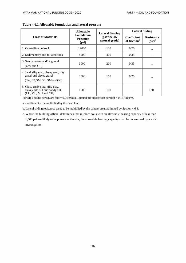
MYANMAR NATIONAL BUILDING CODE – 2020 PART 4 – SOIL AND FOUNDATION
16
Table 4.6.1 Allowable foundation and lateral pressure
Class of Materials
Allowable
Foundation
Pressure
(psf)
Lateral Bearing
(psf/f below
natural grade)
Lateral Sliding
Coefficient
of frictiona
Resistance
(psf)b
1. Crystalline bedrock 12000 120 0.70 _
2. Sedimentary and foliated rock 4000 400 0.35 _
3. Sandy gravel and/or gravel
(GW and GP) 3000 200 0.35 _
4. Sand, silty sand, clayey sand, silty gravel and clayey gravel
(SW, SP, SM, SC, GM and GC)
2000 150 0.25 _
5. Clay, sandy clay, silty clay, clayey silt, silt and sandy silt (CL, ML, MH and CH)
1500 100 _ 130
For SI: 1 pound per square foot = 0.0479 kPa, 1 pound per square foot per foot = 0.157 kPa/m.
a. Coefficient to be multiplied by the dead load.
b. Lateral sliding resistance value to be multiplied by the contact area, as limited by Section 4.6.3.
c. Where the building official determines that in-place soils with an allowable bearing capacity of less than
1,500 psf are likely to be present at the site, the allowable bearing capacity shall be determined by a soils
investigation.
MYANMAR NATIONAL BUILDING CODE – 2020 PART 4 – SOIL AND FOUNDATION
17
SECTION 4.7
FOOTINGS AND FOUNDATIONS
4.7.1 General
Footings and foundations shall be designed and constructed in accordance with Sections 4.7.1 through
4.7.9. Footings and foundations shall be built on undisturbed soil, compacted fill material or CLSM.
Compacted fill material shall be placed in accordance with Section 4.3.5. CLSM shall be placed in
accordance with Section 4.3.6.
The top surface of footings shall be level. The bottom surface of footings is permitted to have a slope not
exceeding one unit vertical in 10 units horizontal (10-percent slope). Footings shall be stepped where it is
necessary to change the elevation of the top surface of the footing or where the surface of the ground
slopes more than one unit vertical in 10 units horizontal (10-percent slope).
4.7.2 Depth of footings
The minimum depth of footings below the undisturbed ground surface shall be 24 inches (610 mm).
Where applicable, the depth of footings shall also conform to Sections 4.7.2.1 through 4.7.2.3.
4.7.2.1 Frost protection
Except where otherwise protected from frost, foundation walls, piers and other permanent supports of
buildings and structures shall be protected by one or more of the following methods:
1. Extending below the frost line of the locality;
2. Constructing in accordance with ASCE 32; or
3. Erecting on solid rock.
Exception:
Free-standing buildings meeting all of the following conditions shall not be required to be pro-
tected:
1. Classified in Occupancy Category I, in accordance with Section 3.1.3.5;
2. Area of 600 square feet (56 m2) or less for light-frame construction or 400 square feet (37 m
2)
or less for other than light-frame construction; and
3. Eave height of 10 feet (3048 mm) or less.
Footings shall not bear on frozen soil unless such frozen condition is of a permanent character.
4.7.2.2 Isolated footings
Footings shall be so located that the line drawn between the lower edges of adjoining footings shall not
have a slope steeper than 30 degrees (0.52 rad) with the horizontal, unless the material supporting the
higher footing is braced or retained or otherwise laterally supported in an approved manner or a greater
slope has been properly established by engineering analysis.
4.7.2.3 Shifting or moving soils
Where it is known that the shallow subsoils are of a shifting or moving character, footings shall be carried
to a sufficient depth to ensure stability.
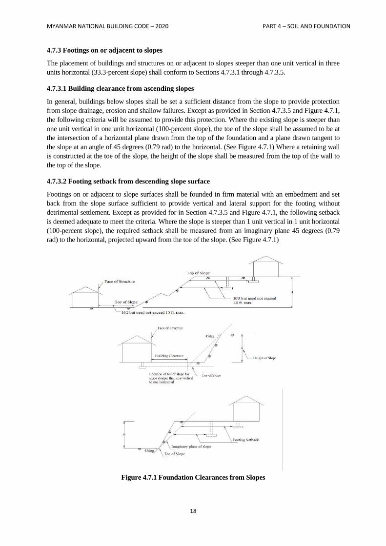
MYANMAR NATIONAL BUILDING CODE – 2020 PART 4 – SOIL AND FOUNDATION
18
4.7.3 Footings on or adjacent to slopes
The placement of buildings and structures on or adjacent to slopes steeper than one unit vertical in three
units horizontal (33.3-percent slope) shall conform to Sections 4.7.3.1 through 4.7.3.5.
4.7.3.1 Building clearance from ascending slopes
In general, buildings below slopes shall be set a sufficient distance from the slope to provide protection
from slope drainage, erosion and shallow failures. Except as provided in Section 4.7.3.5 and Figure 4.7.1,
the following criteria will be assumed to provide this protection. Where the existing slope is steeper than
one unit vertical in one unit horizontal (100-percent slope), the toe of the slope shall be assumed to be at
the intersection of a horizontal plane drawn from the top of the foundation and a plane drawn tangent to
the slope at an angle of 45 degrees (0.79 rad) to the horizontal. (See Figure 4.7.1) Where a retaining wall
is constructed at the toe of the slope, the height of the slope shall be measured from the top of the wall to
the top of the slope.
4.7.3.2 Footing setback from descending slope surface
Footings on or adjacent to slope surfaces shall be founded in firm material with an embedment and set
back from the slope surface sufficient to provide vertical and lateral support for the footing without
detrimental settlement. Except as provided for in Section 4.7.3.5 and Figure 4.7.1, the following setback
is deemed adequate to meet the criteria. Where the slope is steeper than 1 unit vertical in 1 unit horizontal
(100-percent slope), the required setback shall be measured from an imaginary plane 45 degrees (0.79
rad) to the horizontal, projected upward from the toe of the slope. (See Figure 4.7.1)
Figure 4.7.1 Foundation Clearances from Slopes
MYANMAR NATIONAL BUILDING CODE – 2020 PART 4 – SOIL AND FOUNDATION
19
4.7.3.3 Pools
The setback between pools regulated by this code and slopes shall be equal to one-half the building
footing setback distance required by this section. That portion of the pool wall within a horizontal
distance of 7 feet (2134 mm) from the top of the slope shall be capable of supporting the water in the pool
without soil support.
4.7.3.4 Foundation elevation
On graded sites, the top of any exterior foundation shall extend above the elevation of the street gutter at
point of discharge or the inlet of an approved drainage device a minimum of 12 inches (305 mm) plus 2
percent. Alternate elevations are permitted subject to the approval of the building official, provided it can
be demonstrated that required drainage to the point of discharge and away from the structure is provided
at all locations on the site.
4.7.3.5 Alternate setback and clearance
Alternate setbacks and clearances are permitted, subject to the approval of the building official. The
building official is permitted to require an investigation and recommendation of a registered design
professional to demonstrate that the intent of this section has been satisfied. Such an investigation shall
include consideration of material, height of slope, slope gradient, load intensity and erosion
characteristics of slope material.
4.7.4 Footings
Footings shall be designed and constructed in accordance with Sections 4.7.4.1 through 4.7.4.3.
4.7.4.1 Design
Footings shall be so designed that the allowable bearing capacity of the soil is not exceeded, and that
differential settlement is minimized. The minimum width of footings shall be 12 inches (305 mm).
Footings in areas with expansive soils shall be designed in accordance with the provisions of Section
4.7.8.
4.7.4.1.1 Design loads
Footings shall be designed for the most unfavorable effects due to the combinations of loads specified in
Section 3.2.1. The dead load is permitted to include the weight of foundations, footings and overlying fill.
Reduced live loads, as specified in Sections 3.2.3.9 and 3.2.3.11, are permitted to be used in the design of
footings.
4.7.4.1.2 Vibratory loads
Where machinery operations or other vibrations are transmitted through the foundation, consideration
shall be given in the footing design to prevent detrimental disturbances of the soil.
4.7.4.2 Concrete footings
The design, materials and construction of concrete footings shall comply with Sections 4.7.4.2.1 through
4.7.4.2.6 and the provisions of Section 3.5.
Exception:
Where a specific design is not provided, concrete footings supporting walls of light-frame
construction are permitted to be designed in accordance with Table 4.7.1.
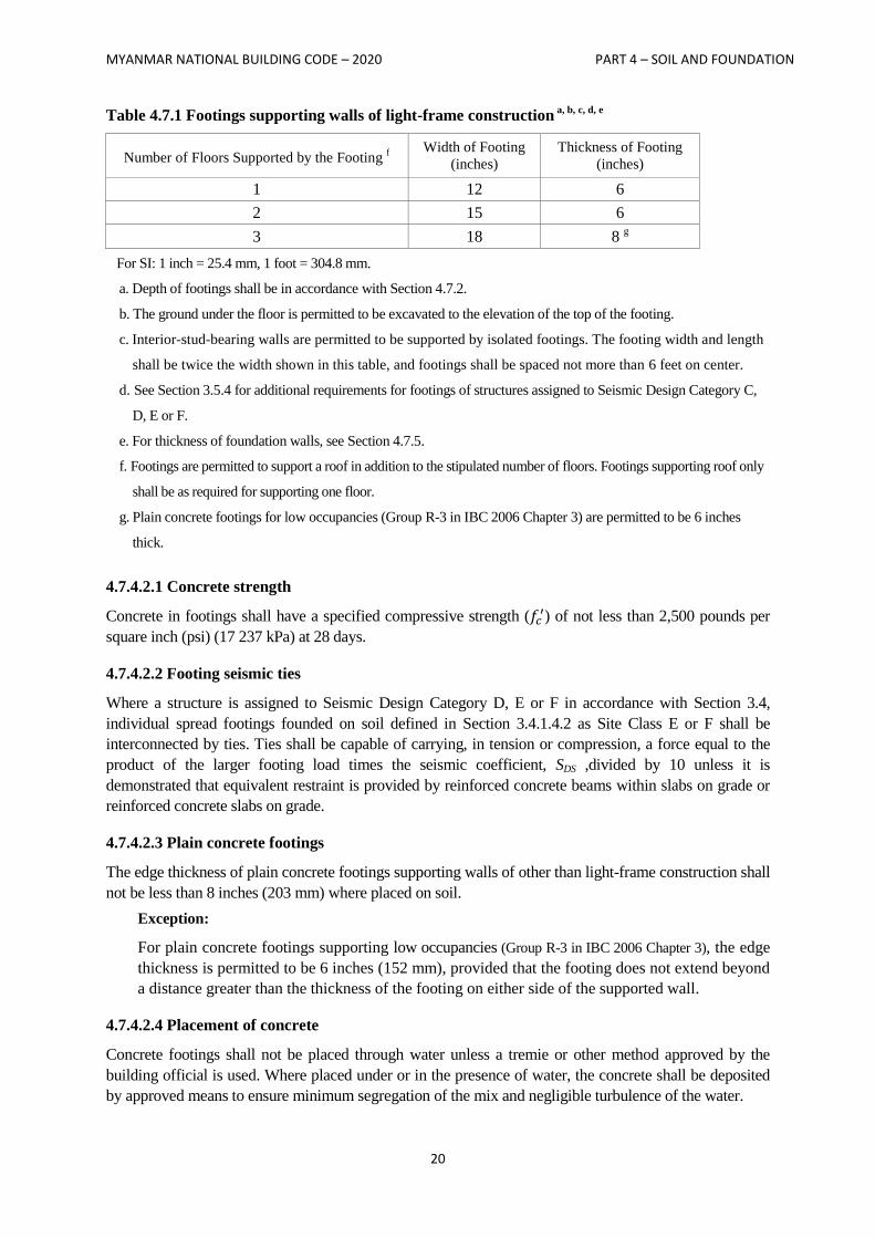
MYANMAR NATIONAL BUILDING CODE – 2020 PART 4 – SOIL AND FOUNDATION
20
Table 4.7.1 Footings supporting walls of light-frame construction a, b, c, d, e
Number of Floors Supported by the Footing f
Width of Footing
(inches) Thickness of Footing
(inches)
1 12 6
2 15 6
3 18 8 g
For SI: 1 inch = 25.4 mm, 1 foot = 304.8 mm.
a. Depth of footings shall be in accordance with Section 4.7.2.
b. The ground under the floor is permitted to be excavated to the elevation of the top of the footing.
c. Interior-stud-bearing walls are permitted to be supported by isolated footings. The footing width and length
shall be twice the width shown in this table, and footings shall be spaced not more than 6 feet on center.
d. See Section 3.5.4 for additional requirements for footings of structures assigned to Seismic Design Category C,
D, E or F.
e. For thickness of foundation walls, see Section 4.7.5.
f. Footings are permitted to support a roof in addition to the stipulated number of floors. Footings supporting roof only
shall be as required for supporting one floor.
g. Plain concrete footings for low occupancies (Group R-3 in IBC 2006 Chapter 3) are permitted to be 6 inches
thick.
4.7.4.2.1 Concrete strength
Concrete in footings shall have a specified compressive strength (𝑓𝑐′) of not less than 2,500 pounds per
square inch (psi) (17 237 kPa) at 28 days.
4.7.4.2.2 Footing seismic ties
Where a structure is assigned to Seismic Design Category D, E or F in accordance with Section 3.4,
individual spread footings founded on soil defined in Section 3.4.1.4.2 as Site Class E or F shall be
interconnected by ties. Ties shall be capable of carrying, in tension or compression, a force equal to the
product of the larger footing load times the seismic coefficient, SDS ,divided by 10 unless it is
demonstrated that equivalent restraint is provided by reinforced concrete beams within slabs on grade or
reinforced concrete slabs on grade.
4.7.4.2.3 Plain concrete footings
The edge thickness of plain concrete footings supporting walls of other than light-frame construction shall
not be less than 8 inches (203 mm) where placed on soil.
Exception:
For plain concrete footings supporting low occupancies (Group R-3 in IBC 2006 Chapter 3), the edge
thickness is permitted to be 6 inches (152 mm), provided that the footing does not extend beyond
a distance greater than the thickness of the footing on either side of the supported wall.
4.7.4.2.4 Placement of concrete
Concrete footings shall not be placed through water unless a tremie or other method approved by the
building official is used. Where placed under or in the presence of water, the concrete shall be deposited
by approved means to ensure minimum segregation of the mix and negligible turbulence of the water.
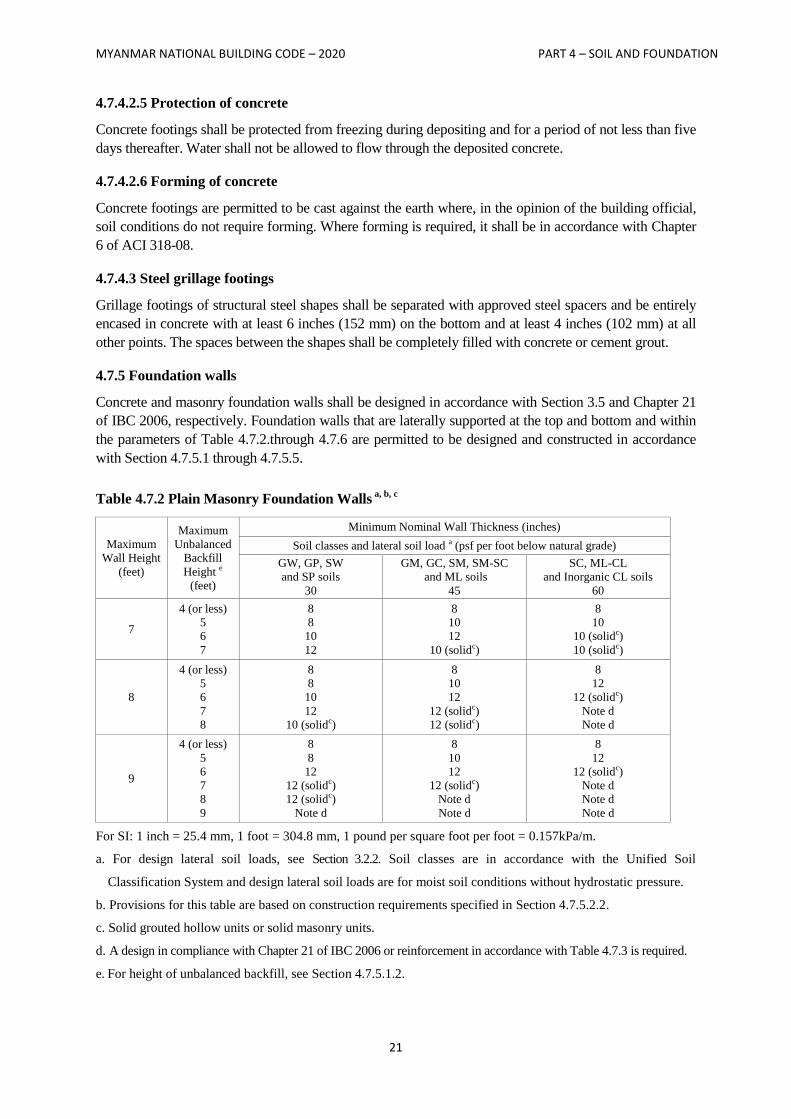
MYANMAR NATIONAL BUILDING CODE – 2020 PART 4 – SOIL AND FOUNDATION
21
4.7.4.2.5 Protection of concrete
Concrete footings shall be protected from freezing during depositing and for a period of not less than five
days thereafter. Water shall not be allowed to flow through the deposited concrete.
4.7.4.2.6 Forming of concrete
Concrete footings are permitted to be cast against the earth where, in the opinion of the building official,
soil conditions do not require forming. Where forming is required, it shall be in accordance with Chapter
6 of ACI 318-08.
4.7.4.3 Steel grillage footings
Grillage footings of structural steel shapes shall be separated with approved steel spacers and be entirely
encased in concrete with at least 6 inches (152 mm) on the bottom and at least 4 inches (102 mm) at all
other points. The spaces between the shapes shall be completely filled with concrete or cement grout.
4.7.5 Foundation walls
Concrete and masonry foundation walls shall be designed in accordance with Section 3.5 and Chapter 21
of IBC 2006, respectively. Foundation walls that are laterally supported at the top and bottom and within
the parameters of Table 4.7.2.through 4.7.6 are permitted to be designed and constructed in accordance
with Section 4.7.5.1 through 4.7.5.5.
Table 4.7.2 Plain Masonry Foundation Walls a, b, c
Maximum
Wall Height
(feet)
Maximum
Unbalanced
Backfill
Height e
(feet)
Minimum Nominal Wall Thickness (inches)
Soil classes and lateral soil load a (psf per foot below natural grade)
GW, GP, SW
and SP soils
30
GM, GC, SM, SM-SC
and ML soils
45
SC, ML-CL
and Inorganic CL soils
60
7
4 (or less)
5
6
7
8
8
10
12
8
10
12
10 (solidc)
8
10
10 (solidc)
10 (solidc)
8
4 (or less)
5
6
7
8
8
8
10
12
10 (solidc)
8
10
12
12 (solidc)
12 (solidc)
8
12
12 (solidc)
Note d
Note d
9
4 (or less)
5
6
7
8
9
8
8
12
12 (solidc)
12 (solidc)
Note d
8
10
12
12 (solidc)
Note d
Note d
8
12
12 (solidc)
Note d
Note d
Note d For SI: 1 inch = 25.4 mm, 1 foot = 304.8 mm, 1 pound per square foot per foot = 0.157kPa/m.
a. For design lateral soil loads, see Section 3.2.2. Soil classes are in accordance with the Unified Soil
Classification System and design lateral soil loads are for moist soil conditions without hydrostatic pressure.
b. Provisions for this table are based on construction requirements specified in Section 4.7.5.2.2.
c. Solid grouted hollow units or solid masonry units.
d. A design in compliance with Chapter 21 of IBC 2006 or reinforcement in accordance with Table 4.7.3 is required.
e. For height of unbalanced backfill, see Section 4.7.5.1.2.
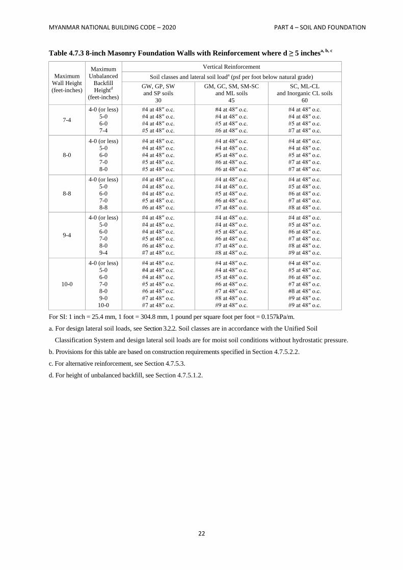
MYANMAR NATIONAL BUILDING CODE – 2020 PART 4 – SOIL AND FOUNDATION
22
Table 4.7.3 8-inch Masonry Foundation Walls with Reinforcement where d ≥ 5 inchesa, b, c
Maximum
Wall Height
(feet-inches)
Maximum
Unbalanced
Backfill
Heightd
(feet-inches)
Vertical Reinforcement
Soil classes and lateral soil loada (psf per foot below natural grade)
GW, GP, SW
and SP soils
30
GM, GC, SM, SM-SC
and ML soils
45
SC, ML-CL
and Inorganic CL soils
60
7-4
4-0 (or less)
5-0
6-0
7-4
#4 at 48″ o.c.
#4 at 48″ o.c.
#4 at 48″ o.c.
#5 at 48″ o.c.
#4 at 48″ o.c.
#4 at 48″ o.c.
#5 at 48″ o.c.
#6 at 48″ o.c.
#4 at 48″ o.c.
#4 at 48″ o.c.
#5 at 48″ o.c.
#7 at 48″ o.c.
8-0
4-0 (or less)
5-0
6-0
7-0
8-0
#4 at 48″ o.c.
#4 at 48″ o.c.
#4 at 48″ o.c.
#5 at 48″ o.c.
#5 at 48″ o.c.
#4 at 48″ o.c.
#4 at 48″ o.c.
#5 at 48″ o.c.
#6 at 48″ o.c.
#6 at 48″ o.c.
#4 at 48″ o.c.
#4 at 48″ o.c.
#5 at 48″ o.c.
#7 at 48″ o.c.
#7 at 48″ o.c.
8-8
4-0 (or less)
5-0
6-0
7-0
8-8
#4 at 48″ o.c.
#4 at 48″ o.c.
#4 at 48″ o.c.
#5 at 48″ o.c.
#6 at 48″ o.c.
#4 at 48″ o.c.
#4 at 48″ o.c.
#5 at 48″ o.c.
#6 at 48″ o.c.
#7 at 48″ o.c.
#4 at 48″ o.c.
#5 at 48″ o.c.
#6 at 48″ o.c.
#7 at 48″ o.c.
#8 at 48″ o.c.
9-4
4-0 (or less)
5-0
6-0
7-0
8-0
9-4
#4 at 48″ o.c.
#4 at 48″ o.c.
#4 at 48″ o.c.
#5 at 48″ o.c.
#6 at 48″ o.c.
#7 at 48″ o.c.
#4 at 48″ o.c.
#4 at 48″ o.c.
#5 at 48″ o.c.
#6 at 48″ o.c.
#7 at 48″ o.c.
#8 at 48″ o.c.
#4 at 48″ o.c.
#5 at 48″ o.c.
#6 at 48″ o.c.
#7 at 48″ o.c.
#8 at 48″ o.c.
#9 at 48″ o.c.
10-0
4-0 (or less)
5-0
6-0
7-0
8-0
9-0
10-0
#4 at 48″ o.c.
#4 at 48″ o.c.
#4 at 48″ o.c.
#5 at 48″ o.c.
#6 at 48″ o.c.
#7 at 48″ o.c.
#7 at 48″ o.c.
#4 at 48″ o.c.
#4 at 48″ o.c.
#5 at 48″ o.c.
#6 at 48″ o.c.
#7 at 48″ o.c.
#8 at 48″ o.c.
#9 at 48″ o.c.
#4 at 48″ o.c.
#5 at 48″ o.c.
#6 at 48″ o.c.
#7 at 48″ o.c.
#8 at 48″ o.c.
#9 at 48″ o.c.
#9 at 48″ o.c. For SI: 1 inch = 25.4 mm, 1 foot = 304.8 mm, 1 pound per square foot per foot = 0.157kPa/m.
a. For design lateral soil loads, see Section 3.2.2. Soil classes are in accordance with the Unified Soil
Classification System and design lateral soil loads are for moist soil conditions without hydrostatic pressure.
b. Provisions for this table are based on construction requirements specified in Section 4.7.5.2.2.
c. For alternative reinforcement, see Section 4.7.5.3.
d. For height of unbalanced backfill, see Section 4.7.5.1.2.
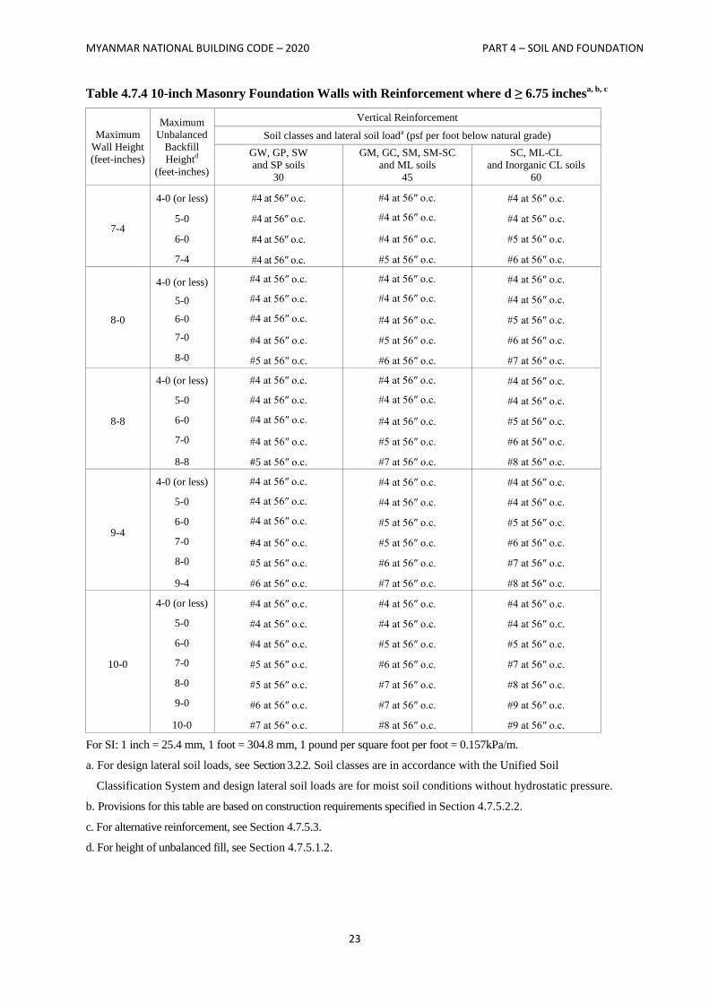
MYANMAR NATIONAL BUILDING CODE – 2020 PART 4 – SOIL AND FOUNDATION
23
Table 4.7.4 10-inch Masonry Foundation Walls with Reinforcement where d ≥ 6.75 inchesa, b, c
Maximum
Wall Height
(feet-inches)
Maximum
Unbalanced
Backfill
Heightd
(feet-inches)
Vertical Reinforcement
Soil classes and lateral soil loada (psf per foot below natural grade)
GW, GP, SW
and SP soils
30
GM, GC, SM, SM-SC
and ML soils
45
SC, ML-CL
and Inorganic CL soils
60
7-4
4-0 (or less)
5-0
6-0
7-4
#4 at 56″ o.c.
#4 at 56″ o.c.
#4 at 56″ o.c.
#4 at 56″ o.c.
#4 at 56″ o.c.
#4 at 56″ o.c.
#4 at 56″ o.c.
#5 at 56″ o.c.
#4 at 56″ o.c.
#4 at 56″ o.c.
#5 at 56″ o.c.
#6 at 56″ o.c.
8-0
4-0 (or less)
5-0
6-0
7-0
8-0
#4 at 56″ o.c.
#4 at 56″ o.c.
#4 at 56″ o.c.
#4 at 56″ o.c.
#5 at 56″ o.c.
#4 at 56″ o.c.
#4 at 56″ o.c.
#4 at 56″ o.c.
#5 at 56″ o.c.
#6 at 56″ o.c.
#4 at 56″ o.c.
#4 at 56″ o.c.
#5 at 56″ o.c.
#6 at 56″ o.c.
#7 at 56″ o.c.
8-8
4-0 (or less)
5-0
6-0
7-0
8-8
#4 at 56″ o.c.
#4 at 56″ o.c.
#4 at 56″ o.c.
#4 at 56″ o.c.
#5 at 56″ o.c.
#4 at 56″ o.c.
#4 at 56″ o.c.
#4 at 56″ o.c.
#5 at 56″ o.c.
#7 at 56″ o.c.
#4 at 56″ o.c.
#4 at 56″ o.c.
#5 at 56″ o.c.
#6 at 56″ o.c.
#8 at 56″ o.c.
9-4
4-0 (or less)
5-0
6-0
7-0
8-0
9-4
#4 at 56″ o.c.
#4 at 56″ o.c.
#4 at 56″ o.c.
#4 at 56″ o.c.
#5 at 56″ o.c.
#6 at 56″ o.c.
#4 at 56″ o.c.
#4 at 56″ o.c.
#5 at 56″ o.c.
#5 at 56″ o.c.
#6 at 56″ o.c.
#7 at 56″ o.c.
#4 at 56″ o.c.
#4 at 56″ o.c.
#5 at 56″ o.c.
#6 at 56″ o.c.
#7 at 56″ o.c.
#8 at 56″ o.c.
10-0
4-0 (or less)
5-0
6-0
7-0
8-0
9-0
10-0
#4 at 56″ o.c.
#4 at 56″ o.c.
#4 at 56″ o.c.
#5 at 56″ o.c.
#5 at 56″ o.c.
#6 at 56″ o.c.
#7 at 56″ o.c.
#4 at 56″ o.c.
#4 at 56″ o.c.
#5 at 56″ o.c.
#6 at 56″ o.c.
#7 at 56″ o.c.
#7 at 56″ o.c.
#8 at 56″ o.c.
#4 at 56″ o.c.
#4 at 56″ o.c.
#5 at 56″ o.c.
#7 at 56″ o.c.
#8 at 56″ o.c.
#9 at 56″ o.c.
#9 at 56″ o.c. For SI: 1 inch = 25.4 mm, 1 foot = 304.8 mm, 1 pound per square foot per foot = 0.157kPa/m.
a. For design lateral soil loads, see Section 3.2.2. Soil classes are in accordance with the Unified Soil
Classification System and design lateral soil loads are for moist soil conditions without hydrostatic pressure.
b. Provisions for this table are based on construction requirements specified in Section 4.7.5.2.2.
c. For alternative reinforcement, see Section 4.7.5.3.
d. For height of unbalanced fill, see Section 4.7.5.1.2.
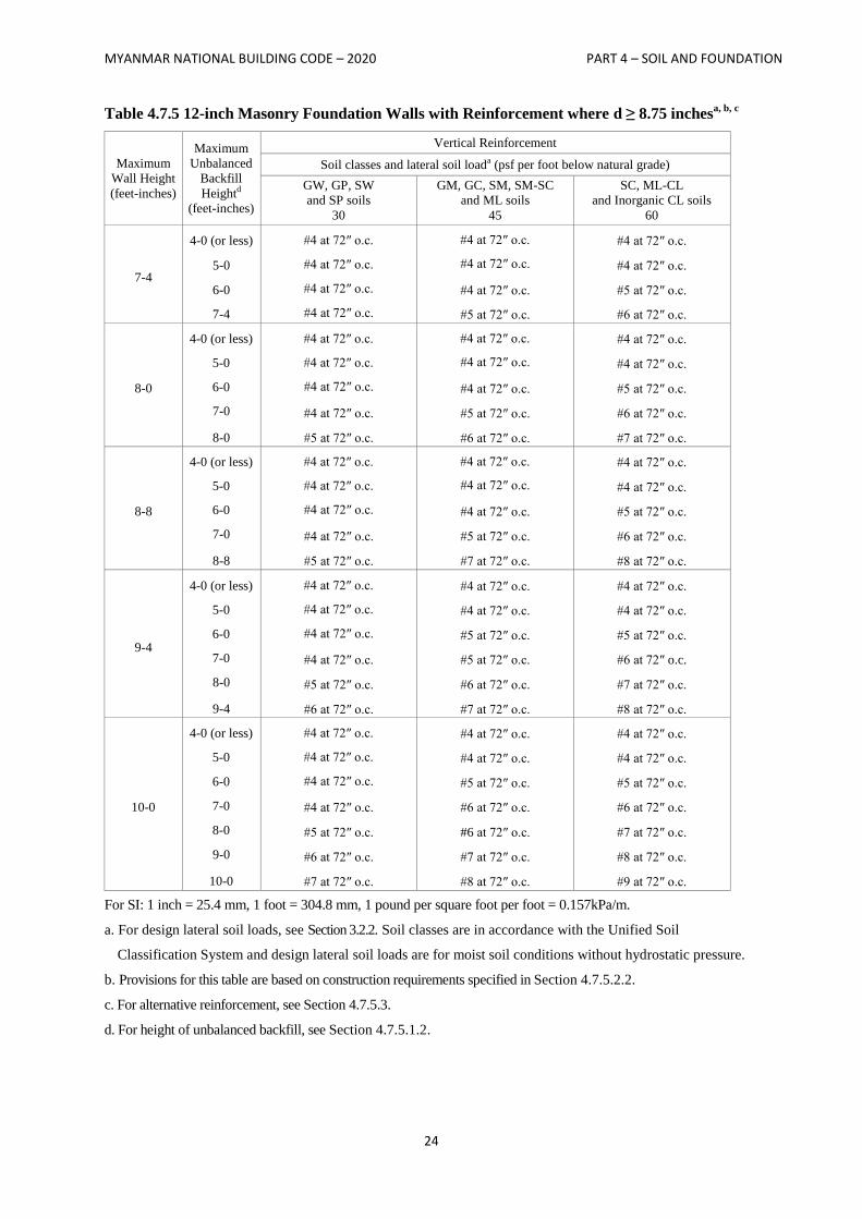
MYANMAR NATIONAL BUILDING CODE – 2020 PART 4 – SOIL AND FOUNDATION
24
Table 4.7.5 12-inch Masonry Foundation Walls with Reinforcement where d ≥ 8.75 inchesa, b, c
Maximum
Wall Height
(feet-inches)
Maximum
Unbalanced
Backfill
Heightd
(feet-inches)
Vertical Reinforcement
Soil classes and lateral soil loada (psf per foot below natural grade)
GW, GP, SW
and SP soils
30
GM, GC, SM, SM-SC
and ML soils
45
SC, ML-CL
and Inorganic CL soils
60
7-4
4-0 (or less)
5-0
6-0
7-4
#4 at 72″ o.c.
#4 at 72″ o.c.
#4 at 72″ o.c.
#4 at 72″ o.c.
#4 at 72″ o.c.
#4 at 72″ o.c.
#4 at 72″ o.c.
#5 at 72″ o.c.
#4 at 72″ o.c.
#4 at 72″ o.c.
#5 at 72″ o.c.
#6 at 72″ o.c.
8-0
4-0 (or less)
5-0
6-0
7-0
8-0
#4 at 72″ o.c.
#4 at 72″ o.c.
#4 at 72″ o.c.
#4 at 72″ o.c.
#5 at 72″ o.c.
#4 at 72″ o.c.
#4 at 72″ o.c.
#4 at 72″ o.c.
#5 at 72″ o.c.
#6 at 72″ o.c.
#4 at 72″ o.c.
#4 at 72″ o.c.
#5 at 72″ o.c.
#6 at 72″ o.c.
#7 at 72″ o.c.
8-8
4-0 (or less)
5-0
6-0
7-0
8-8
#4 at 72″ o.c.
#4 at 72″ o.c.
#4 at 72″ o.c.
#4 at 72″ o.c.
#5 at 72″ o.c.
#4 at 72″ o.c.
#4 at 72″ o.c.
#4 at 72″ o.c.
#5 at 72″ o.c.
#7 at 72″ o.c.
#4 at 72″ o.c.
#4 at 72″ o.c.
#5 at 72″ o.c.
#6 at 72″ o.c.
#8 at 72″ o.c.
9-4
4-0 (or less)
5-0
6-0
7-0
8-0
9-4
#4 at 72″ o.c.
#4 at 72″ o.c.
#4 at 72″ o.c.
#4 at 72″ o.c.
#5 at 72″ o.c.
#6 at 72″ o.c.
#4 at 72″ o.c.
#4 at 72″ o.c.
#5 at 72″ o.c.
#5 at 72″ o.c.
#6 at 72″ o.c.
#7 at 72″ o.c.
#4 at 72″ o.c.
#4 at 72″ o.c.
#5 at 72″ o.c.
#6 at 72″ o.c.
#7 at 72″ o.c.
#8 at 72″ o.c.
10-0
4-0 (or less)
5-0
6-0
7-0
8-0
9-0
10-0
#4 at 72″ o.c.
#4 at 72″ o.c.
#4 at 72″ o.c.
#4 at 72″ o.c.
#5 at 72″ o.c.
#6 at 72″ o.c.
#7 at 72″ o.c.
#4 at 72″ o.c.
#4 at 72″ o.c.
#5 at 72″ o.c.
#6 at 72″ o.c.
#6 at 72″ o.c.
#7 at 72″ o.c.
#8 at 72″ o.c.
#4 at 72″ o.c.
#4 at 72″ o.c.
#5 at 72″ o.c.
#6 at 72″ o.c.
#7 at 72″ o.c.
#8 at 72″ o.c.
#9 at 72″ o.c. For SI: 1 inch = 25.4 mm, 1 foot = 304.8 mm, 1 pound per square foot per foot = 0.157kPa/m.
a. For design lateral soil loads, see Section 3.2.2. Soil classes are in accordance with the Unified Soil
Classification System and design lateral soil loads are for moist soil conditions without hydrostatic pressure.
b. Provisions for this table are based on construction requirements specified in Section 4.7.5.2.2.
c. For alternative reinforcement, see Section 4.7.5.3.
d. For height of unbalanced backfill, see Section 4.7.5.1.2.
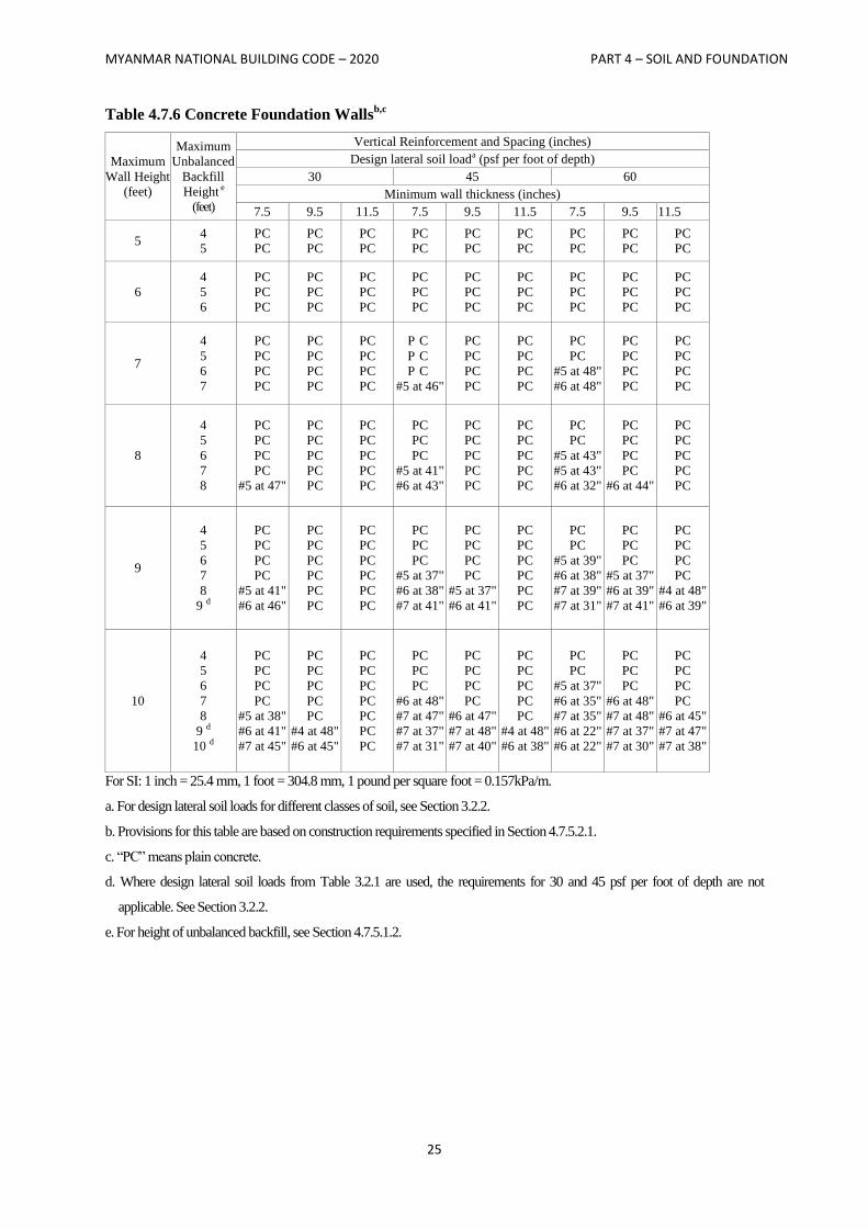
MYANMAR NATIONAL BUILDING CODE – 2020 PART 4 – SOIL AND FOUNDATION
25
Table 4.7.6 Concrete Foundation Wallsb,c
Maximum
Wall Height
(feet)
Maximum
Unbalanced
Backfill
Height e
(feet)
Vertical Reinforcement and Spacing (inches)
Design lateral soil loada (psf per foot of depth)
30 45 60
Minimum wall thickness (inches)
7.5 9.5 11.5 7.5 9.5 11.5 7.5 9.5 11.5
5 4
5
PC
PC
PC
PC
PC
PC
PC
PC
PC
PC
PC
PC
PC
PC
PC
PC
PC
PC
6
4
5
6
PC
PC
PC
PC
PC
PC
PC
PC
PC
PC
PC
PC
PC
PC
PC
PC
PC
PC
PC
PC
PC
PC
PC
PC
PC
PC
PC
7
4
5
6
7
PC
PC
PC
PC
PC
PC
PC
PC
PC
PC
PC
PC
P C
P C
P C
#5 at 46"
PC
PC
PC
PC
PC
PC
PC
PC
PC
PC
#5 at 48"
#6 at 48"
PC
PC
PC
PC
PC
PC
PC
PC
8
4
5
6
7
8
PC
PC
PC
PC
#5 at 47"
PC
PC
PC
PC
PC
PC
PC
PC
PC
PC
PC
PC
PC
#5 at 41"
#6 at 43"
PC
PC
PC
PC
PC
PC
PC
PC
PC
PC
PC
PC
#5 at 43"
#5 at 43"
#6 at 32"
PC
PC
PC
PC
#6 at 44"
PC
PC
PC
PC
PC
9
4
5
6
7
8
9 d
PC
PC
PC
PC
#5 at 41"
#6 at 46"
PC
PC
PC
PC
PC
PC
PC
PC
PC
PC
PC
PC
PC
PC
PC
#5 at 37"
#6 at 38"
#7 at 41"
PC
PC
PC
PC
#5 at 37"
#6 at 41"
PC
PC
PC
PC
PC
PC
PC
PC
#5 at 39"
#6 at 38"
#7 at 39"
#7 at 31"
PC
PC
PC
#5 at 37"
#6 at 39"
#7 at 41"
PC
PC
PC
PC
#4 at 48"
#6 at 39"
10
4
5
6
7
8
9 d
10 d
PC
PC
PC
PC
#5 at 38"
#6 at 41"
#7 at 45"
PC
PC
PC
PC
PC
#4 at 48"
#6 at 45"
PC
PC
PC
PC
PC
PC
PC
PC
PC
PC
#6 at 48"
#7 at 47"
#7 at 37"
#7 at 31"
PC
PC
PC
PC
#6 at 47"
#7 at 48"
#7 at 40"
PC
PC
PC
PC
PC
#4 at 48"
#6 at 38"
PC
PC
#5 at 37"
#6 at 35"
#7 at 35"
#6 at 22"
#6 at 22"
PC
PC
PC
#6 at 48"
#7 at 48"
#7 at 37"
#7 at 30"
PC
PC
PC
PC
#6 at 45"
#7 at 47"
#7 at 38"
For SI: 1 inch = 25.4 mm, 1 foot = 304.8 mm, 1 pound per square foot = 0.157kPa/m.
a. For design lateral soil loads for different classes of soil, see Section 3.2.2.
b. Provisions for this table are based on construction requirements specified in Section 4.7.5.2.1.
c. “PC” means plain concrete.
d. Where design lateral soil loads from Table 3.2.1 are used, the requirements for 30 and 45 psf per foot of depth are not
applicable. See Section 3.2.2.
e. For height of unbalanced backfill, see Section 4.7.5.1.2.
MYANMAR NATIONAL BUILDING CODE – 2020 PART 4 – SOIL AND FOUNDATION
26
4.7.5.1 Foundation wall thickness
The minimum thickness of concrete and masonry foundation walls shall comply with Section 4.7.5.1.1
through 4.7.5.1.3.
4.7.5.1.1 Thickness at top of foundation wall
The thickness of foundation walls shall not be less than the thickness of the wall supported, except that
foundation walls of at least 8-inch (203 mm) nominal width are permitted to support brick-veneered
frame walls and 10-inch-wide (254 mm) cavity walls provided the requirements of Section 4.7.5.1.2 are
met. Corbeling of masonry shall be in accordance with Section 2104.2 of IBC 2006. Where an 8-inch
(203 mm) wall is corbeled, the top corbel shall not extend higher than the bottom of the floor framing and
shall be a full course of headers at least 6 inches (152 mm) in length or the top course bed joint shall be
tied to the vertical wall projection. The tie shall be W2.8 (4.8 mm) and spaced at a maximum horizontal
distance of 36 inches (914 mm); the hollow space behind the corbelled masonry shall be filled with
mortar or grout.
4.7.5.1.2 Thickness based on soil loads, unbalanced backfill height and wall height
The thickness of foundation walls shall comply with the requirements of Table 4.7.6 for concrete walls,
Table 4.7.2 for plain masonry walls or Table 4.7.3, 4.7.4 or 4.7.5 for masonry walls with reinforcement.
When using the tables, masonry shall be laid in running bond and the mortar shall be Type M or S (see
IBC 2006 Chapter 21).
Unbalanced backfill height is the difference in height between the exterior finish ground level and the
lower of the top of the concrete footing that supports the foundation wall or the interior finish ground
level. Where an interior concrete slab on grade is provided and is in contact with the interior surface of
the foundation wall, the unbalanced backfill height is permitted to be measured from the exterior finish
ground level to the top of the interior concrete slab.
4.7.5.1.3 Rubble stone
Foundation walls of rough or random rubble stone shall not be less than 16 inches (406 mm) thick.
Rubble stone shall not be used for foundations for structures in Seismic Design Category C, D, E or F.
4.7.5.2 Foundation wall materials
Concrete foundation walls constructed in accordance with Table 4.7.6 shall comply with Section
4.7.5.2.1. Masonry foundation walls constructed in accordance with Table 4.7.2, 4.7.3, 4.7.4 or 4.7.5 shall
comply with Section 4.7.5.2.2.
4.7.5.2.1 Concrete foundation walls
Concrete foundation walls shall comply with the following:
1. The size and spacing of vertical reinforcement shown in Table 4.7.6 is based on the use of
reinforcement with a minimum yield strength of 60,000 psi (414 MPa). Vertical reinforcement
with a minimum yield strength of 40,000 psi (276 MPa) or 50,000 psi (345 MPa) is permitted,
provided the same size bar is used and the spacing shown in the table is reduced by multiplying
the spacing by 0.67 or 0.83, respectively.
2. Vertical reinforcement, when required, shall be placed nearest the inside face of the wall a distance,
d, from the outside face (soil side) of the wall. The distance, d, is equal to the wall thickness, t,
minus 1.25 inches (32 mm) plus one-half the bar diameter, db [𝑑 = 𝑡 − (1.25 + 𝑑𝑏 2⁄ )]. The
reinforcement shall be placed within a tolerance of ± 3 8⁄ inch (9.5 mm) where d is less than or equal
to 8 inches (203 mm) or inch (2.7 mm) where d is greater than 8 inches (203 mm).
MYANMAR NATIONAL BUILDING CODE – 2020 PART 4 – SOIL AND FOUNDATION
27
3. In lieu of the reinforcement shown in Table 4.7.6, smaller reinforcing bar sizes with closer
spacings that provide an equivalent cross-sectional area of reinforcement per unit length of wall
are permitted.
4. Concrete cover for reinforcement measured from the inside face of the wall shall not be less
than 3/4 inch (19.1 mm). Concrete cover for reinforcement measured from the outside face of
the wall shall not be less than 1.5 inches (38 mm) for No. 5 bars and smaller and not less than 2
inches (51 mm) for larger bars.
5. Concrete shall have a specified compressive strength, 𝑓𝑐′ of not less than 2,500 psi (17.2 MPa)
at 28 days.
6. The unfactored axial load per linear foot of wall shall not exceed 1.2𝑡𝑓𝑐′, where t is the
specified wall thickness in inches.
4.7.5.2.2 Masonry foundation walls
Masonry foundation walls shall comply with the following:
1. Vertical reinforcement shall have a minimum yield strength of 60,000 psi (414 MPa).
2. The specified location of the reinforcement shall equal or exceed the effective depth distance,
d, noted in Tables 4.7.3, 4.7.4 and 4.7.5 and shall be measured from the face of the exterior
(soil) side of the wall to the center of the vertical reinforcement. The reinforcement shall be
placed within the tolerances specified in ACI 530.1/ASCE 6/TMS 402, Article 3.4 B7 of the
specified location.
3. Grout shall comply with Section 2103.12 of IBC 2006.
4. Concrete masonry units shall comply with ASTM C 90.
5. Clay masonry units shall comply with ASTM C 652 for hollow brick, except compliance with
ASTM C 62 or ASTM C 216 is permitted when solid masonry units are installed in accordance
with Table 4.7.2 for plain masonry.
6. Masonry units shall be installed with Type M or S mortar in accordance with Section 2103.8 of
IBC 2006.
7. The unfactored axial load per linear foot of wall shall not exceed 1.2tfm where t is the specified
wall thickness in inches and fm is the specified compressive strength of masonry in pounds per
square inch
4.7.5.3 Alternative foundation wall reinforcement
In lieu of the reinforcement provisions for masonry foundation walls in Table 4.7.3, 4.7.4 or 4.7.5,
alternative reinforcing bar sizes and spacings having an equivalent cross-sectional area of reinforcement
per linear foot (mm) of wall are permitted to be used, provided the spacing of reinforcement does not
exceed 72 inches (1829 mm) and reinforcing bar sizes do not exceed No. 11.
4.7.5.4 Hollow masonry walls
At least 4 inches (102 mm) of solid masonry shall be provided at girder supports at the top of hollow
masonry unit foundation walls.
4.7.5.5 Seismic requirements
Tables 4.7.2 through 4.7.6 shall be subject to the following limitations in Sections 4.7.5.5.1 and 4.7.5.5.2
based on the seismic design category assigned to the structure as defined in Section 3.4.
MYANMAR NATIONAL BUILDING CODE – 2020 PART 4 – SOIL AND FOUNDATION
28
4.7.5.5.1 Seismic requirements for concrete foundation walls
Concrete foundation walls designed using Table 4.7.6 shall be subject to the following limitations:
1. Seismic Design Categories A and B
No additional seismic requirements, except provide not less than two No. 5 bars around
window and door openings. Such bars shall extend at least 24 inches (610 mm) beyond the
corners of the openings.
2. Seismic Design Categories C, D, E and F
Tables shall not be used except as allowed for plain concrete members in Section 3.5.4.1.18.
4.7.5.5.2 Seismic requirements for masonry foundation walls
Masonry foundation walls designed using Tables 4.7.2 through 4.7.5 shall be subject to the following
limitations:
1. Seismic Design Categories A and B: No additional seismic requirements.
2. Seismic Design Category C: A design using Tables 4.7.2 through 4.7.5 is subject to the seismic
requirements of Section 2106.4 of IBC 2006.
3. Seismic Design Category D: A design using Tables 4.7.3 through 4.7.5 is subject to the seismic
requirements of Section 2106.5 of IBC 2006.
4. Seismic Design Categories E and F: A design using Tables 4.7.3 through 4.7.5 is subject to the
seismic requirements of Section 2106.6 of IBC 2006.
4.7.5.6 Foundation wall drainage
Foundation walls shall be designed to support the weight of the full hydrostatic pressure of undrained
backfill unless a drainage system is installed in accordance with Sections 4.4.4.2 and 4.4.4.3.
4.7.5.7 Pier and curtain wall foundations
Except in Seismic Design Categories D, E and F, pier and curtain wall foundations are permitted to be
used to support light-frame construction not more than two stories in height, provided the following
requirements are met:
1. All load-bearing walls shall be placed on continuous concrete footings bonded integrally with
the exterior wall footings.
2. The minimum actual thickness of a load-bearing masonry wall shall not be less than 4 inches
(102 mm) nominal or 3.625 inches (92 mm) actual thickness, and shall be bonded integrally
with piers spaced 6 feet (1829 mm) on center.
3. Piers shall be constructed in accordance with Chapter 21 of IBC 2006 and the following:
3.1. The unsupported height of the masonry piers shall not exceed 10 times their least
dimension.
3.2. Where structural clay tile or hollow concrete masonry units are used for piers supporting
beams and girders, the cellular spaces shall be filled solidly with concrete or Type M or
S mortar (see IBC 2006 Chapter 21).
Exception:
Unfilled hollow piers are permitted where the unsupported height of the pier is not more
than four times its least dimension.
MYANMAR NATIONAL BUILDING CODE – 2020 PART 4 – SOIL AND FOUNDATION
29
3.3. Hollow piers shall be capped with 4 inches (102 mm) of solid masonry or concrete or the
cavities of the top course shall be filled with concrete or grout.
4. The maximum height of a 4-inch (102 mm) load-bearing masonry foundation wall supporting
wood frame walls and floors shall not be more than 4 feet (1219 mm) in height.
5. The unbalanced fill for 4-inch (102 mm) foundation walls shall not exceed 24 inches (610 mm)
for solid masonry, nor 12 inches (305 mm) for hollow masonry.
4.7.6 Designs employing lateral bearing
Designs to resist both axial and lateral loads employing posts or poles as columns embedded in earth or
embedded in concrete footings in the earth shall conform to the requirements of Section 4.7.6.1 through
4.7.6.3.
4.7.6.1 Limitations
The design procedures outlined in this section are subject to the following limitations:
1. The frictional resistance for structural walls and slabs on silts and clays shall be limited to one-
half of the normal force imposed on the soil by the weight of the footing or slab.
2. Posts embedded in earth shall not be used to provide lateral support for structural or
nonstructural materials such as plaster, masonry or concrete unless bracing is provided that
develops the limited deflection required.
4.7.6.2 Design criteria
The depth to resist lateral loads shall be determined by the design criteria established in Sections 4.7.6.2.1
through 4.7.6.2.3, or by other methods approved by the building official.
4.7.6.2.1 Nonconstrained
The following formula shall be used in determining the depth of embedment required to resist lateral
loads where no constraint is provided at the ground surface, such as rigid floor or rigid ground surface
pavement, and where no lateral constraint is provided above the ground surface, such as a structural
diaphragm.
𝑑 = 0.5𝐴1 + [1 + (4.36 ℎ 𝐴)]⁄ 1 2⁄ (Equation 18-1)
where:
A = 2.34 P/S1 b.
b = Diameter of round post or footing or diagonal dimension of square post or footing, feet (m).
d = Depth of embedment in earth in feet (m) but not over 12 feet (3658 mm) for purpose of computing
lateral pressure.
h = Distance in feet (m) from ground surface to point of application of “P.”
P = Applied lateral force in pounds (kN).
S1 = Allowable lateral soil-bearing pressure as set forth in Section 4.6.3 based on a depth of one-third the
depth of embedment in pounds per square foot (psf) (kPa).
MYANMAR NATIONAL BUILDING CODE – 2020 PART 4 – SOIL AND FOUNDATION
30
4.7.6.2.2 Constrained
The following formula shall be used to determine the depth of embedment required to resist lateral loads
where constraint is provided at the ground surface, such as a rigid floor or pavement.
d2 = 4.25(Ph/S3 b) (Equation 18-2)
or alternatively
d2
= 4.25 (Mg/S3 b) (Equation 18-3)
where:
Mg = Moment in the post at grade, in foot-pounds (kN-m).
S3 = Allowable lateral soil-bearing pressure as set forth in Section 4.6.3 based on a depth equal to the
depth of embedment in pounds per square foot (kPa).
4.7.6.2.3 Vertical load
The resistance to vertical loads shall be determined by the allowable soil-bearing pressure set forth in
Table 4.6.2.
4.7.6.3 Backfill
The backfill in the annular space around columns not embedded in poured footings shall be by one of the
following methods:
1. Backfill shall be of concrete with an ultimate strength of 2,000 psi (13.8 MPa) at 28 days. The
hole shall not be less than 4 inches (102 mm) larger than the diameter of the column at its
bottom or 4 inches (102 mm) larger than the diagonal dimension of a square or rectangular
column.
2. Backfill shall be of clean sand. The sand shall be thoroughly compacted by tamping in layers
not more than 8 inches (203 mm) in depth.
3. Backfill shall be of controlled low-strength material (CLSM).
4.7.7 Design for expansive soils
Footings or foundations for buildings and structures founded on expansive soils shall be designed in
accordance with Section 4.7.7.1 or 4.7.7.2.
Footing or foundation design need not comply with Section 4.7.7.1 or 4.7.7.2 where the soil is removed
in accordance with Section 4.7.7.3, nor where the building official approves stabilization of the soil in
accordance with Section 4.7.7.4.
4.7.7.1 Foundations
Footings or foundations placed on or within the active zone of expansive soils shall be designed to resist
differential volume changes and to prevent structural damage to the supported structure. Deflection and
racking of the supported structure shall be limited to that which will not interfere with the usability and
serviceability of the structure.
Foundations placed below where volume change occurs or below expansive soil shall comply with the
following provisions:
1. Foundations extending into or penetrating expansive soils shall be designed to prevent uplift of
the supported structure.
MYANMAR NATIONAL BUILDING CODE – 2020 PART 4 – SOIL AND FOUNDATION
31
2. Foundations penetrating expansive soils shall be designed to resist forces exerted on the
foundation due to soil volume changes or shall be isolated from the expansive soil.
4.7.7.2 Slab-on-ground foundations
Moments, shears and deflections for use in designing slab-on-ground, mat or raft foundations on
expansive soils shall be determined in accordance with WRI/CRSI Design of Slab-on-Ground
Foundations or PTI Standard Requirements for Analysis of Shallow Concrete Foundations on Expansive
Soils. Using the moments, shears and deflections determined above, nonprestressed slabs-on-ground, mat
or raft foundations on expansive soils shall be designed in accordance with WRI/CRSI Design of Slab-on-
Ground Foundations and post-tensioned slab-on-ground, mat or raft foundations on expansive soils shall
be designed in accordance with PTI Standard Requirements for Design of Shallow Post-Tensioned
Concrete Foundations on Expansive Soils. It shall be permitted to analyze and design such slabs by other
methods that account for soil-structure interaction, the deformed shape of the soil support, the plate or
stiffened plate action of the slab as well as both center lift and edge lift conditions. Such alternative
methods shall be rational and the basis for all aspects and parameters of the method shall be available for
peer review.
4.7.7.3 Removal of expansive soil
Where expansive soil is removed in lieu of designing footings or foundations in accordance with Section
4.7.7.1 or 4.7.7.2, the soil shall be removed to a depth sufficient to ensure a constant moisture content in
the remaining soil. Fill material shall not contain expansive soils and shall comply with Section 4.3.5 or
4.3.6.
Exception:
Expansive soil need not be removed to the depth of constant moisture, provided the confining
pressure in the expansive soil created by the fill and supported structure exceeds the swell
pressure.
4.7.7.4 Stabilization
Where the active zone of expansive soils is stabilized in lieu of designing footings or foundations in
accordance with Section 4.7.7.1 or 4.7.7.2, the soil shall be stabilized by chemical, dewatering,
presaturation or equivalent techniques.
4.7.8 Seismic requirements
See Section 3.5.4 for additional requirements for footings and foundations of structures assigned to
Seismic Design Category C, D, E or F.
For structures assigned to Seismic Design Category D, E or F, provisions of ACI 318-08, Sections
21.12.1 to 21.12.3, shall apply when not in conflict with the provisions of Section 4.7.
Concrete shall have a specified compressive strength of not less than 3,000 psi (20.68 MPa) at 28 days.
Exceptions:
1. Temporary and low occupancies (Group U and R in IBC 2006 Chapter 3) of light-framed
construction and two stories or less in height are permitted to use concrete with a specified
compressive strength of not less than 2,500 psi (17.2 MPa) at 28 days.
2. Detached one- and two-family dwellings of light-frame construction and two stories or less
in height are not required to comply with the provisions of ACI 318-08, Sections 21.12.1 to
21.12.3.
MYANMAR NATIONAL BUILDING CODE – 2020 PART 4 – SOIL AND FOUNDATION
32
SECTION 4.8
GENERAL REQUIREMENTS FOR PIER AND PILE FOUNDATIONS
4.8.1 General
Pier and pile foundations shall be designed and installed on the basis of a geotechnical investigation as
defined in section 4.2, unless sufficient data upon which to base the design and installation is available.
The investigation and report provisions of Section 4.2 shall be expanded to include, but not be limited to,
the following:
1. Recommended pier or pile types and installed capacities.
2. Recommended center-to-center spacing of piers or piles.
3. Driving criteria.
4. Installation procedures.
5. Field inspection and reporting procedures (to include procedures for verification of the installed
bearing capacity where required).
6. Pier or pile load test requirements.
7. Durability of pier or pile materials.
8. Designation of bearing stratum or strata.
9. Reductions for group action, where necessary.
4.8.2 Special types of piles
The use of types of piles not specifically mentioned herein is permitted, subject to the approval of the
building official, upon the submission of acceptable test data, calculations and other information relating
to the structural properties and load capacity of such piles. The allowable stresses shall not in any case
exceed the limitations specified herein.
4.8.3 Pile caps
Pile caps shall be of reinforced concrete, and shall include all elements to which piles are connected,
including grade beams and mats. The soil immediately below the pile cap shall not be considered as
carrying any vertical load. The tops of piles shall be embedded not less than 3 inches (76 mm) into pile
caps and the caps shall extend at least 4 inches (102 mm) beyond the edges of piles. The tops of piles
shall be cut back to sound material before capping.
4.8.4 Stability
Piers or piles shall be braced to provide lateral stability in all directions. Three or more piles connected by
a rigid cap shall be considered braced, provided that the piles are located in radial directions from the
centroid of the group not less than 60 degrees apart. A two-pile group in a rigid cap shall be considered to
be braced along the axis connecting the two piles. Methods used to brace piers or piles shall be subject to
the approval of the building official. Piles supporting walls shall be driven alternately in lines spaced at
least 1 foot (305 mm) apart and located symmetrically under the center of gravity of the wall load carried,
unless effective measures are taken to provide for eccentricity and lateral forces, or the wall piles are
adequately braced to provide for lateral stability. A single row of piles without lateral bracing is permitted
for one- and two-family dwellings and lightweight construction not exceeding two stories or 35 feet
(10668 mm) in height, provided the centers of the piles are located within the width of the foundation
wall.
MYANMAR NATIONAL BUILDING CODE – 2020 PART 4 – SOIL AND FOUNDATION
33
4.8.5 Structural integrity
Piers or piles shall be installed in such a manner and sequence as to prevent distortion or damage that may
adversely affect the structural integrity of piles being installed or already in place.
4.8.6 Splices
Splices shall be constructed so as to provide and maintain true alignment and position of the component
parts of the pier or pile during installation and subsequent thereto and shall be of adequate strength to
transmit the vertical and lateral loads and moments occurring at the location of the splice during driving
and under service loading. Splices shall develop not less than 50 percent of the least capacity of the pier
or pile in bending. In addition, splices occurring in the upper 10 feet (3048 mm) of the embedded portion
of the pier or pile shall be capable of resisting at allowable working stresses the moment and shear that
would result from an assumed eccentricity of the pier or pile load of 3 inches (76 mm), or the pier or pile
shall be braced in accordance with Section 4.8.4 to other piers or piles that do not have splices in the
upper 10 feet (3048 mm) of embedment.
4.8.7 Allowable pier or pile loads
4.8.7.1 Determination of allowable loads
The allowable axial and lateral loads on piers or piles shall be determined by an approved formula, load
tests or method of analysis.
4.8.7.2 Driving criteria
Allowable compressive load on any pile shall be determined by the application of an approved driving
formula. Allowable loads shall be verified by load tests in accordance with Section 4.8.7.3. The formula
or wave equation load shall be determined for gravity-drop or power-actuated hammers and the hammer
energy used shall be the maximum consistent with the size, strength and weight of the driven piles. The
introduction of fresh hammer cushion or pile cushion material just prior to final penetration is not
permitted.
4.8.7.3 Load tests
Where design compressive loads per pier or pile are greater than those permitted by Section 4.8.9 or
where the design load for any pier or pile foundation is in doubt or where required by the building
official, control test piers or piles shall be tested in accordance with ASTM D 1143-07 or ASTM D 4945-
08. At least one pier or pile shall be test loaded in each area of uniform subsoil conditions. Where
required by the building official, additional piers or piles shall be load tested where necessary to establish
the safe design capacity. The resulting allowable loads shall not be more than one-half of the ultimate
axial load capacity of the test pier or pile as assessed by one of the published methods with consideration
for the test type, duration and subsoil. The ultimate axial load capacity shall be determined by a registered
design professional with consideration given to tolerable total and differential settlements at design load
in accordance with settlement analysis. In subsequent installation of the balance of foundation piles, all
piles shall be deemed to have a supporting capacity equal to the control pile where such piles are of the
same type, size and relative length as the test pile; are installed using the same or comparable methods
and equipment as the test pile; are installed in similar subsoil conditions as the test pile; and, for driven
piles, where the rate of penetration (e.g., net displacement per blow) of such piles is equal to or less than
that of the test pile driven with the same hammer through a comparable driving distance.
4.8.7.3.1 Load test evaluation
It shall be permitted to evaluate pile load tests with any of the currently recognized methods in
geotechnical engineering.
MYANMAR NATIONAL BUILDING CODE – 2020 PART 4 – SOIL AND FOUNDATION
34
4.8.7.3.2 Non-destructive testing
For quality assurance of concrete piles, non-destructive integrity test may be carried out prior to
construction of cap beam or caps.
4.8.7.4 Allowable frictional resistance
The assumed frictional resistance developed by any pier or uncased cast-in-place pile shall not exceed
one-sixth of the bearing value of the soil material as set forth in Table 4.6.1, up to a maximum of 500 psf
(24 kPa), unless a greater value is allowed by the building official after a soil investigation is submitted or
a greater value is substantiated by a load test.
4.8.7.5 Uplift capacity
Where required by the design, the uplift capacity of a single pier or pile shall be determined by an
approved method of analysis based on a minimum factor of safety of three or by load tests conducted in
accordance with ASTM D 3689. The maximum allowable uplift load shall not exceed the ultimate load
capacity as determined in Section 4.8.7.3 divided by a factor of safety of two. For pile groups subjected to
uplift, the allowable working uplift load for the group shall be the lesser of:
1. The proposed individual pile uplift working load times the number of piles in the group.
2. Two-thirds of the effective weight of the pile group and the soil contained within a block
defined by the perimeter of the group and the length of the pile.
4.8.7.6 Load-bearing capacity
Piers, individual piles and groups of piles shall develop ultimate load capacities of at least twice the
design working loads in the designated load-bearing layers. Analysis shall show that no soil layer
underlying the designated load-bearing layers causes the load-bearing capacity safety factor to be less
than two.
4.8.7.7 Bent piers or piles
The load-bearing capacity of piers or piles discovered to have a sharp or sweeping bend shall be
determined by an approved method of analysis or by load testing a representative pier or pile.
4.8.7.8 Overloads on piers or piles
The maximum compressive load on any pier or pile due to mislocation shall not exceed 110 percent of
the allowable design load.
4.8.8 Lateral support
4.8.8.1 General
Any soil other than fluid soil shall be deemed to afford sufficient lateral support to the pier or pile to
prevent buckling and to permit the design of the pier or pile in accordance with accepted engineering
practice and the applicable provisions of this code.
4.8.8.2 Unbraced piles
Piles standing unbraced in air, water or in fluid soils shall be designed as columns in accordance with the
provisions of this code. Such piles driven into firm ground can be considered fixed and laterally
supported at 5 feet (1524 mm) below the ground surface and in soft material at 10 feet (3048 mm) below
the ground surface unless otherwise prescribed by the building official after a foundation investigation by
an approved agency.
MYANMAR NATIONAL BUILDING CODE – 2020 PART 4 – SOIL AND FOUNDATION
35
4.8.8.3 Allowable lateral load
Where required by the design, the lateral load capacity of a pier, a single pile or a pile group shall be
determined by an approved method of analysis or by lateral load tests to at least twice the proposed
design working load. The resulting allowable load shall not be more than one-half of that test load that
produces a gross lateral movement of 1 inch (25.4 mm) at the ground surface.
4.8.9 Use of higher allowable pier or pile stresses
Allowable stresses greater than those specified for piers or for each pile type are permitted where
supporting data justifying such higher stresses is filed with the building official. Such substantiating data
shall include:
1. A soils investigation in accordance with Section 4.2.
2. Pier or pile load tests in accordance with Section 4.8.7.3, regardless of the load supported by
the pier or pile.
The design and installation of the pier or pile foundation shall be under the direct supervision of a
registered design professional knowledgeable in the field of soil mechanics and pier or pile foundations
who shall certify to the building official that the piers or piles as installed satisfy the design criteria.
4.8.10 Piles in subsiding areas
Where piles are installed through subsiding fills or other subsiding strata and derive support from
underlying firmer materials, consideration shall be given to the downward frictional forces that may be
imposed on the piles by the subsiding upper strata. Where the influence of subsiding fills is considered as
imposing loads on the pile, the allowable stresses specified in respective sections are permitted to be
increased where satisfactory substantiating data are submitted.
4.8.11 Negative skin friction or down drag force
When a soil stratum, through which a pile shaft has penetrated into an underlying hard stratum,
compresses as a result of either its being unconsolidated or its being under a newly placed fill or as a
result of re-moulding during driving of the pile, a drag down force is generated along the pile shaft up to a
point in depth where the surrounding soil does not move downwards relative to the pile shaft.
Recognition of the existence of such a phenomenon shall be made and a suitable reduction shall be made
to the allowable load, where appropriate.
4.8.12 Settlement analysis
The settlement of piers, individual piles or groups of piles shall be estimated based on approved methods
of analysis. The predicted settlement shall cause neither harmful distortion of, nor instability in, the
structure, nor cause any stresses to exceed allowable values.
4.8.13 Pre-excavation
The use of jetting, auguring or other methods of pre-excavation shall be subject to the approval of the
building official. Where permitted, pre-excavation shall be carried out in the same manner as used for
piers or piles subject to load tests and in such a manner that will not impair the carrying capacity of the
piers or piles already in place or damage adjacent structures. Pile tips shall be driven below the pre-
excavated depth until the required resistance or penetration is obtained.
MYANMAR NATIONAL BUILDING CODE – 2020 PART 4 – SOIL AND FOUNDATION
36
4.8.14 Installation sequence
Piles shall be installed in such sequence as to avoid compaction the surrounding soil to the extent that
other piles cannot be installed properly, and to prevent ground movements that are capable of damaging
adjacent structures.
4.8.15 Use of vibratory drivers
Vibratory drivers shall only be used to install piles where the pile load capacity is verified by load tests in
accordance with Section 4.8.7.3. The installation of production piles shall be controlled according to
power consumption, rate of penetration or other approved means that ensure pile capacities equal or
exceed those of the test piles.
4.8.16 Pile drivability
Pile cross sections shall be of sufficient size and strength to withstand driving stresses without damage to
the pile, and to provide sufficient stiffness to transmit the required driving forces.
4.8.17 Protection of pile materials
Where boring records or site conditions indicate possible deleterious action on pier or pile materials
because of soil constituents, changing water levels or other factors, the pier or pile materials shall be
adequately protected by materials, methods or processes approved by the building official. Protective
materials shall be applied to the piles so as not to be rendered ineffective by driving. The effectiveness of
such protective measures for the particular purpose shall have been thoroughly established by satisfactory
service records or other evidence.
4.8.18 Use of existing piers or piles
Piers or piles left in place where a structure has been demolished shall not be used for the support of new
construction unless satisfactory evidence is submitted to the building official, which indicates that the
piers or piles are sound and meet the requirements of this code. Such piers or piles shall be load tested or
redriven to verify their capacities. The design load applied to such piers or piles shall be the lowest
allowable load as determined by tests or re-driving data.
4.8.19 Heaved piles
Piles that have heaved during the driving of adjacent piles shall be redriven as necessary to develop the
required capacity and penetration, or the capacity of the pile shall be verified by load tests in accordance
with Section 4.8.7.3.
4.8.20 Identification
Pier or pile materials shall be identified for conformity to the specified grade with this identity maintained
continuously from the point of manufacture to the point of installation or shall be tested by an approved
agency to determine conformity to the specified grade. The approved agency shall furnish an affidavit of
compliance to the building official.
4.8.21 Pier or pile location plan
A plan showing the location and designation of piers or piles by an identification system shall be filed
with the building official prior to installation of such piers or piles. Detailed records for piers or individual
piles shall bear an identification corresponding to that shown on the plan.
MYANMAR NATIONAL BUILDING CODE – 2020 PART 4 – SOIL AND FOUNDATION
37
4.8.22 Spacing of Piles
The centre to centre spacing of a pile is considered from two aspects as follows:
a) Practical aspects of installing the piles; and
b) The nature of the load transfer to the soil and possible reduction in bearing capacity of a group
of piles thereby.
In the case of piles founded on a very hard stratum and deriving their capacity mainly from end bearing,
the spacing will be governed by the competency of the end bearing strata. The minimum spacing in such
cases shall be 2.5 times the diameter of the shaft. In case of piles resting on rock, a spacing of two times
the diameter may be adopted. Piles deriving their bearing capacity mainly from friction shall be
sufficiently apart to ensure that the zones of soil from which the piles derive their support do not overlap
to such an extent that their bearing values are reduced. Generally, the spacing in such cases shall not be
less than three times the diameter of the shaft. In the case of loose sand or filling, closer spacing than in
dense sand may be possible, in driven piles since displacement during the piling may be absorbed by
vertical and horizontal compaction of the strata. The minimum spacing in such strata may be two times
the diameter of the shaft.
4.8.23 Special inspection
4.8.23.1 Pier foundations
Special inspections shall be performed during installation and testing of pier foundations as required by
Table 4.8.1. The approved soils report, required by Section 4.2, and the documents prepared by the
registered design professional in responsible charge shall be used to determine compliance.
4.8.23.2 Pile foundations
Special inspections shall be performed during installation and testing of pile foundations as required by
Table 4.8.2. The approved soils report, required by Section 4.2, and the documents prepared by the
registered design professional in responsible charge shall be used to determine compliance.
4.8.24 Seismic design of piers or piles
4.8.24.1 Seismic Design Category C
Where a structure is assigned to Seismic Design Category C in accordance with Section 3.4 of Part 3
(Structural Design), the following shall apply. Individual pile caps, piers or piles shall be interconnected
by ties. Ties shall be capable of carrying, in tension and compression, a force equal to the product of the
larger pile cap or column load times the seismic coefficient, SDS, divided by 10 unless it can be
demonstrated that equivalent restraint is provided by reinforced concrete beams within slabs on grade,
reinforced concrete slabs on grade, confinement by competent rock, hard cohesive soils or very dense
granular soils.
Exception:
Piers supporting foundation walls, isolated interior posts detailed so the pier is not subject to
lateral loads, lightly loaded exterior decks and patios of temporary and low occupancies (Group
U and R-3 in IBC 2006 Chapter 3) not exceeding two stories of light-frame construction, are not
subject to interconnection if it can be shown the soils are of adequate stiffness, subject to the
approval of the building official.
4.8.24.1.1 Connection to pile cap
Concrete piles and concrete-filled steel pipe piles shall be connected to the pile cap by embedding the pile
reinforcement or field-placed dowels anchored in the concrete pile in the pile cap for a distance equal to
MYANMAR NATIONAL BUILDING CODE – 2020 PART 4 – SOIL AND FOUNDATION
38
the development length. For deformed bars, the development length is the full development length for
compression or tension, in the case of uplift, without reduction in length for excess area. Alternative
measures for laterally confining concrete and maintaining toughness and ductile-like behavior at the top
of the pile will be permitted provided the design is such that any hinging occurs in the confined region.
Ends of hoops, spirals and ties shall be terminated with seismic hooks, turned into the confined concrete
core. The minimum transverse steel ratio for confinement shall not be less than one-half of that required
for columns. For resistance to uplift forces, anchorage of steel pipe (round HSS sections), concrete-filled
steel pipe or H-piles to the pile cap shall be made by means other than concrete bond to the bare steel
section.
Exception:
Anchorage of concrete-filled steel pipe piles is permitted to be accomplished using deformed bars
developed into the concrete portion of the pile. Splices of pile segments shall develop the full
strength of the pile, but the splice need not develop the nominal strength of the pile in tension,
shear and bending when it has been designed to resist axial and shear forces and moments from
the load combinations of Structural Design Section 3.2.
4.8.24.1.2 Design details
Pier or pile moments, shears and lateral deflections used for design shall be established considering the
nonlinear interaction of the shaft and soil, as recommended by a registered design professional. Where the
ratio of the depth of embedment of the pile-to-pile diameter or width is less than or equal to six, the pile
may be assumed to be rigid. Pile group effects from soil on lateral pile nominal strength shall be included
where pile center-to-center spacing in the direction of lateral force is less than eight pile diameters. Pile
group effects on vertical nominal strength shall be included where pile center- to-center spacing is less
than three pile diameters. The pile uplift soil nominal strength shall be taken as the pile uplift strength as
limited by the frictional force developed between the soil and the pile. Where a minimum length for
reinforcement or the extent of closely spaced confinement reinforcement is specified at the top of the pier
or pile, provisions shall be made so that those specified lengths or extents are maintained after pier or pile
cutoff.
4.8.24.2 Seismic Design Category D, E or F
Where a structure is assigned to Seismic Design Category D, E or F in accordance with Structural Design
Section 3.4, the requirements for Seismic Design Category C given in Section 4.8.24.1 shall be met, in
addition to the following. Provisions of ACI 318-08, Section 21.12.4, shall apply when not in conflict
with the provisions of Sections 4.8, 4.9, 4.10, 4.11 and 4.12. Concrete shall have a specified compressive
strength of not less than 3,000 psi (20.68 MPa) at 28 days.
Exceptions:
1. Temporary and low occupancies (Group U or R in IBC 2006 Chapter 3) of light-framed
construction and two stories or less in height are permitted to use concrete with a specified
compressive strength of not less than 2,500 psi (17.2MPa) at 28 days.
2. Detached one- and two-family dwellings of light-frame construction and two stories or less in
height are not required to comply with the provisions of ACI 318-08, Section 21.12.4.
3. Section 21.12.4.4 (a) of ACI 318-08 need not apply to concrete piles.
4.8.24.2.1 Design details for piers, piles and grade beams
Piers or piles shall be designed and constructed to withstand maximum imposed curvatures from
earthquake ground motions and structure response. Curvatures shall include free-field soil strains
modified for soil-pile-structure interaction coupled with pier or pile deformations induced by lateral pier
MYANMAR NATIONAL BUILDING CODE – 2020 PART 4 – SOIL AND FOUNDATION
39
or pile resistance to structure seismic forces. Concrete piers or piles on Site Class E or F sites, as
determined in Structural Design Section 3.4, shall be designed and detailed in accordance with Sections
21.6.4.2, 21.6.4.3 and 21.6.4.4 of ACI 318-08 within seven pile diameters of the pile cap and the
interfaces of soft to medium stiff clay or liquefiable strata. For precast prestressed concrete piles, detailing
provisions as given in Section 4.9.2.3.2.1 and 4.9.2.3.2.2 shall apply. Grade beams shall be designed as
beams in accordance with ACI 318-08, Chapter 21. When grade beams have the capacity to resist the
forces from the load combinations in Structural Design Section 3.2.1.5, they need not conform to ACI
318-08, Chapter 21.
4.8.24.2.2 Connection to pile cap
For piles required to resist uplift forces or provide rotational restraint, design of anchorage of piles into
the pile cap shall be provided considering the combined effect of axial forces due to uplift and bending
moments due to fixity to the pile cap. Anchorage shall develop a minimum of 25 percent of the strength
of the pile in tension. Anchorage into the pile cap shall be capable of developing the following:
1. In the case of uplift, the lesser of the nominal tensile strength of the longitudinal reinforcement
in a concrete pile, or the nominal tensile strength of a steel pile, or the pile uplift soil nominal
strength factored by 1.3 or the axial tension force resulting from the load combinations of
Structural Design Section 3.2.
2. In the case of rotational restraint, the lesser of the axial and shear forces, and moments
resulting from the load combinations of Structural Design Section 3.2 or development of the
full axial, bending and shear nominal strength of the pile.
4.8.24.2.3 Flexural strength
Where the vertical lateral-force-resisting elements are columns, the grade beam or pile cap flexural
strengths shall exceed the column flexural strength. The connection between batter piles and grade
beams or pile caps shall be designed to resist the nominal strength of the pile acting as a short column.
Batter piles and their connection shall be capable of resisting forces and moments from the load
combinations of Structural Design Section 3.2.
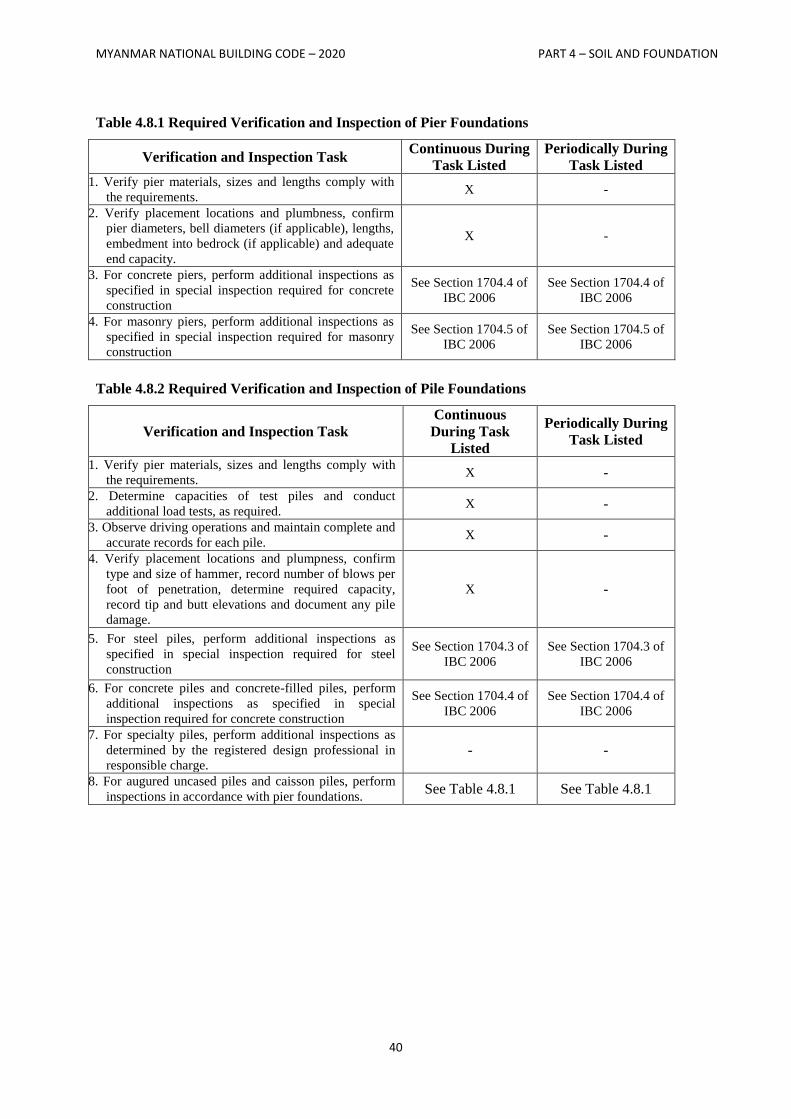
MYANMAR NATIONAL BUILDING CODE – 2020 PART 4 – SOIL AND FOUNDATION
40
Table 4.8.1 Required Verification and Inspection of Pier Foundations
Verification and Inspection Task Continuous During
Task Listed
Periodically During
Task Listed 1. Verify pier materials, sizes and lengths comply with
the requirements. X -
2. Verify placement locations and plumbness, confirm
pier diameters, bell diameters (if applicable), lengths,
embedment into bedrock (if applicable) and adequate
end capacity.
X -
3. For concrete piers, perform additional inspections as
specified in special inspection required for concrete
construction
See Section 1704.4 of
IBC 2006
See Section 1704.4 of
IBC 2006
4. For masonry piers, perform additional inspections as
specified in special inspection required for masonry
construction
See Section 1704.5 of
IBC 2006
See Section 1704.5 of
IBC 2006
Table 4.8.2 Required Verification and Inspection of Pile Foundations
Verification and Inspection Task
Continuous
During Task
Listed
Periodically During
Task Listed
1. Verify pier materials, sizes and lengths comply with
the requirements. X -
2. Determine capacities of test piles and conduct
additional load tests, as required. X -
3. Observe driving operations and maintain complete and
accurate records for each pile. X -
4. Verify placement locations and plumpness, confirm
type and size of hammer, record number of blows per
foot of penetration, determine required capacity,
record tip and butt elevations and document any pile
damage.
X -
5. For steel piles, perform additional inspections as
specified in special inspection required for steel
construction
See Section 1704.3 of
IBC 2006
See Section 1704.3 of
IBC 2006
6. For concrete piles and concrete-filled piles, perform
additional inspections as specified in special
inspection required for concrete construction
See Section 1704.4 of
IBC 2006
See Section 1704.4 of
IBC 2006
7. For specialty piles, perform additional inspections as
determined by the registered design professional in
responsible charge. - -
8. For augured uncased piles and caisson piles, perform
inspections in accordance with pier foundations. See Table 4.8.1 See Table 4.8.1
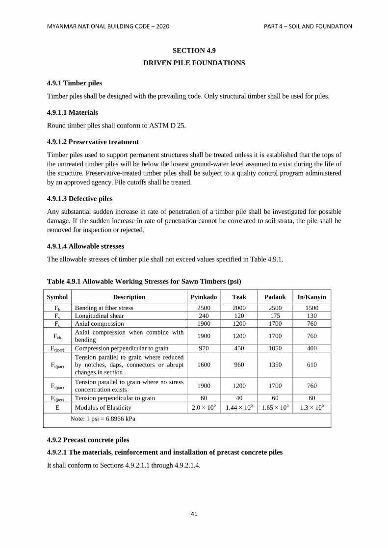
MYANMAR NATIONAL BUILDING CODE – 2020 PART 4 – SOIL AND FOUNDATION
41
SECTION 4.9
DRIVEN PILE FOUNDATIONS
4.9.1 Timber piles
Timber piles shall be designed with the prevailing code. Only structural timber shall be used for piles.
4.9.1.1 Materials
Round timber piles shall conform to ASTM D 25.
4.9.1.2 Preservative treatment
Timber piles used to support permanent structures shall be treated unless it is established that the tops of
the untreated timber piles will be below the lowest ground-water level assumed to exist during the life of
the structure. Preservative-treated timber piles shall be subject to a quality control program administered
by an approved agency. Pile cutoffs shall be treated.
4.9.1.3 Defective piles
Any substantial sudden increase in rate of penetration of a timber pile shall be investigated for possible
damage. If the sudden increase in rate of penetration cannot be correlated to soil strata, the pile shall be
removed for inspection or rejected.
4.9.1.4 Allowable stresses
The allowable stresses of timber pile shall not exceed values specified in Table 4.9.1.
Table 4.9.1 Allowable Working Stresses for Sawn Timbers (psi)
Symbol Description Pyinkado Teak Padauk In/Kanyin
Fb Bending at fiber stress 2500 2000 2500 1500
Fv Longitudinal shear 240 120 175 130
Fc Axial compression 1900 1200 1700 760
Fcb Axial compression when combine with
bending 1900 1200 1700 760
Fc(per) Compression perpendicular to grain 970 450 1050 400
Ft(par)
Tension parallel to grain where reduced
by notches, daps, connectors or abrupt
changes in section
1600 960 1350 610
Ft(par) Tension parallel to grain where no stress
concentration exists 1900 1200 1700 760
Ft(per) Tension perpendicular to grain 60 40 60 60
E Modulus of Elasticity 2.0 × 10⁶ 1.44 × 10
6 1.65 × 10
6 1.3 × 10
6
Note: 1 psi = 6.8966 kPa
4.9.2 Precast concrete piles
4.9.2.1 The materials, reinforcement and installation of precast concrete piles
It shall conform to Sections 4.9.2.1.1 through 4.9.2.1.4.
MYANMAR NATIONAL BUILDING CODE – 2020 PART 4 – SOIL AND FOUNDATION
42
4.9.2.1.1 Design and manufacture
Piles shall be designed and manufactured in accordance with accepted engineering practice to resist all
stresses induced by handling, driving and service loads.
4.9.2.1.2 Minimum dimension
The minimum lateral dimension shall be 6 inches (152 mm).
4.9.2.1.3 Reinforcement
Longitudinal steel shall be arranged in a symmetrical pattern and be laterally tied with steel ties or wire
spiral spaced not more than 4 inches (102 mm) apart, center to center, for a distance of 2 feet (610 mm)
from the ends of the pile; and not more than 6 inches (152 mm) elsewhere except that at the ends of each
pile, the first five ties or spirals shall be spaced 1 inch (25.4 mm) center to center. The gage of ties and
spirals shall be as follows:
1. For piles having a diameter of 16 inches (406 mm) or less, wire shall not be smaller 6 mm.
2. For piles having a diameter of more than 16 inches (406 mm) and less than 20 inches (508
mm), wire shall not be smaller than 8 mm.
3. For piles having a diameter of 20 inches (508 mm) and larger, wire shall not be smaller than 9
mm.
4.9.2.1.4 Installation
Piles shall be handled and driven so as not to cause injury or overstressing, which affects durability or
strength.
4.9.2.2 Precast non-prestressed piles
Precast non-prestressed concrete piles shall conform to Sections 4.9.2.2.1 through 4.9.2.2.5.
4.9.2.2.1 Materials
Concrete shall have a 28-day specified compressive strength (𝑓𝑐′) of not less than 3,000 psi (20.68 MPa).
4.9.2.2.2 Minimum reinforcement
The minimum amount of longitudinal reinforcement shall be 0.8 percent of the concrete section and shall
consist of at least four bars.
4.9.2.2.2.1 Seismic reinforcement in Seismic Design Category C
Where a structure is assigned to Seismic Design Category C in accordance with Section 3.4, the
following shall apply. Longitudinal reinforcement with a minimum steel ratio of 0.01 shall be provided
throughout the length of precast concrete piles. Within three pile diameters from the bottom of the pile
cap, the longitudinal reinforcement shall be confined with closed ties or spirals of a minimum 3/8 inch
(10 mm) diameter. Ties or spirals shall be provided at a maximum spacing of eight times the diameter of
the smallest longitudinal bar, not to exceed 6 inches (152 mm). Throughout the remainder of the pile, the
closed ties or spirals shall have a maximum spacing of 16 times the smallest longitudinal bar diameter not
to exceed 8 inches (203 mm).
4.9.2.2.2.2 Seismic reinforcement in Seismic Design Category D, E or F
Where a structure is assigned to Seismic Design Category D, E or F in accordance with Section 3.4, the
requirements for Seismic Design Category C in Section 4.9.2.2.2.1 shall apply except as modified by this
MYANMAR NATIONAL BUILDING CODE – 2020 PART 4 – SOIL AND FOUNDATION
43
section. Transverse confinement reinforcement consisting of closed ties or equivalent spirals shall be
provided in accordance with Sections 21.6.4.2, 21.6.4.3 and 21.6.4.4 of ACI 318-08 within three pile
diameters from the bottom of the pile cap. For other than Site Class E or F, or liquefiable sites and where
spirals are used as the transverse reinforcement, a volumetric ratio of spiral reinforcement of not less than
one-half that required by Section 21.6.4.4(a) of ACI 318-08 shall be permitted.
4.9.2.2.3 Allowable stresses
The allowable compressive stress in the concrete shall not exceed 33 percent of the 28-day specified
compressive strength (𝑓𝑐′) applied to the gross cross-sectional area of the pile. The allowable compressive
stress in the reinforcing steel shall not exceed 40 percent of the yield strength of the steel (Fy) or a
maximum of 30,000 psi (207 MPa). The allowable tensile stress in the reinforcing steel shall not exceed
50 percent of the yield strength of the steel (Fy) or a maximum of 24,000 psi (165 MPa).
4.9.2.2.4 Installation
A precast concrete pile shall not be driven before the concrete has attained a compressive strength of at
least 75 percent of the 28-day specified compressive strength (𝑓𝑐′), but not less than the strength sufficient
to withstand handling and driving forces.
4.9.2.2.5 Concrete cover
Reinforcement for piles that are not manufactured under plant conditions shall have a concrete cover of
not less than 2 inches (51 mm). Reinforcement for piles manufactured under plant control conditions shall
have a concrete cover of not less than 1.25 inches (32 mm) for No. 5 bars and smaller, and not less than
1.5 inches (38 mm) for No. 6 through No. 11 bars except that longitudinal bars spaced less than 1.5
inches (38 mm) clear distance apart shall be considered bundled bars for which the minimum concrete
cover shall be equal to that for the equivalent diameter of the bundled bars. Reinforcement for piles
exposed to seawater shall have a concrete cover of not less than 3 inches (76 mm).
4.9.2.3 Precast prestressed piles
Precast prestressed concrete piles shall conform to the requirements of Sections 4.9.2.3.1 through
4.9.2.3.5.
4.9.2.3.1 Materials
Prestressing steel shall conform to ASTM A 416. Concrete shall have a 28-day specified compressive
strength (𝑓𝑐′) of not less than 5,000 psi (34.48 MPa).
4.9.2.3.2 Design
Precast prestressed piles shall be designed to resist stresses induced by handling and driving as well as by
loads. The effective prestress in the pile shall not be less than 400 psi (2.76MPa) for piles up to 30 feet
(9144 mm) in length, 550 psi (3.79 MPa) for piles up to 50 feet (15 240 mm) in length and 700 psi (4.83
MPa) for piles greater than 50 feet (15 240 mm) in length. Effective prestress shall be based on an
assumed loss of 30,000 psi (207 MPa) in the prestressing steel. The tensile stress in the prestressing steel
shall not exceed the values specified in ACI 318-08.
4.9.2.3.2.1 Design in Seismic Design Category C
Where a structure is assigned to Seismic Design Category C in accordance with Section 3.4, the
following shall apply. The minimum volumetric ratio of spiral reinforcement shall not be less than 0.007
or the amount required by the following formula for the upper 20 feet (6096 mm) of the pile.
MYANMAR NATIONAL BUILDING CODE – 2020 PART 4 – SOIL AND FOUNDATION
44
𝜌𝑠 = 0.12𝑓𝑐′ 𝑓𝑦ℎ⁄ (Equation 4.9.1)
where:
𝑓𝑐′ = Specified compressive strength of concrete, psi (MPa).
𝑓𝑦ℎ
= Yield strength of spiral reinforcement ≤ 85,000 psi (586 MPa).
𝜌𝑠 = Spiral reinforcement index (vol. spiral/vol. core).
At least one-half the volumetric ratio required by Equation 4.9.1 shall be provided below the upper 20
feet (6096 mm) of the pile.
The pile cap connection by means of dowels as indicated in Section 4.8.24 is permitted. Pile cap
connection by means of developing pile reinforcing strand is permitted provided that the pile reinforcing
strand results in a ductile connection.
4.9.2.3.2.2 Design in Seismic Design Category D, E or F
Where a structure is assigned to Seismic Design Category D, E or F in accordance with Section 3.4, the
requirements for Seismic Design Category C in Section 4.9.2.3.2.1 shall be met, in addition to the
following:
1. Requirements in ACI 318-08, Chapter 21, need not apply, unless specifically referenced.
2. Where the total pile length in the soil is 35 feet (10668 mm) or less, the lateral transverse
reinforcement in the ductile region shall occur through the length of the pile. Where the pile
length exceeds 35 feet (10 668 mm), the ductile pile region shall be taken as the greater of 35
feet (10668 mm) or the distance from the underside of the pile cap to the point of zero
curvature plus three times the least pile dimension.
3. In the ductile region, the center-to-center spacing of the spirals or hoop reinforcement shall not
exceed one-fifth of the least pile dimension, six times the diameter of the longitudinal strand, or
8 inches (203 mm), whichever is smaller.
4. Circular spiral reinforcement shall be spliced by lapping one full turn and bending the end of
the spiral to a 90-degree hook or by use of a mechanical or welded splice complying with
Section 12.14.3 of ACI 318-08.
5. Where the transverse reinforcement consists of circular spirals, the volumetric ratio of spiral
transverse reinforcement in the ductile region shall comply with the following:
𝜌𝑠 = 0.25(𝑓𝑐′ 𝑓𝑦ℎ⁄ )(𝐴𝑔 𝐴𝑐ℎ⁄ − 1.0)[0.5 + 1.4𝑃 𝑓𝑐
′⁄ 𝐴𝑔)] (Equation 4.9.2)
but not less than:
𝜌𝑠 = 0.12(𝑓𝑐′ 𝑓𝑦ℎ⁄ )[0.5 + 1.4𝑃 𝑓𝑐
′⁄ 𝐴𝑔)] (Equation 4.9.3)
and need not exceed:
𝜌𝑠 = 0.021 (Equation 4.9.4)
where:
Ag = Pile cross-sectional area, square inches (mm2).
Ach = Core area defined by spiral outside diameter, square inches (mm2).
MYANMAR NATIONAL BUILDING CODE – 2020 PART 4 – SOIL AND FOUNDATION
45
𝑓𝑐′ = Specified compressive strength of concrete, psi (MPa).
fyh = Yield strength of spiral reinforcement ≤ 85,000 psi (586 MPa).
P = Axial load on pile, pounds (kN), as determined from Equations 3.2.5 and 3.2.6.
𝜌𝑠 = Volumetric ratio (vol. spiral/ vol. core).
This required amount of spiral reinforcement is permitted to be obtained by providing an inner
and outer spiral.
6. When transverse reinforcement consists of rectangular hoops and cross ties, the total cross-
sectional area of lateral transverse reinforcement in the ductile region with spacing, and
perpendicular to dimension, hc, shall conform to:
𝐴𝑠ℎ = 0.3𝑠ℎ𝑐(𝑓𝑐′ 𝑓𝑦ℎ⁄ )(𝐴𝑔 𝐴𝑐ℎ⁄ − 1.0)[0.5 + 1.4𝑃 𝑓𝑐
′⁄ 𝐴𝑔)] (Equation 4.9.5)
but not less than:
𝐴𝑠ℎ = 0.12𝑠ℎ𝑐(𝑓𝑐′ 𝑓𝑦ℎ⁄ )[0.5 + 1.4𝑃 𝑓𝑐
′⁄ 𝐴𝑔)] (Equation 4.9.6)
where:
fyh = ≤ 70,000 psi (483 MPa)
hc = Cross-sectional dimension of pile core measured center to center of hoop reinforcement, inch
(mm).
s = Spacing of transverse reinforcement measured along length of pile, inch (mm).
Ash = Cross-sectional area of transverse reinforcement, square inches (mm2).
𝑓𝑐′ = Specified compressive strength of concrete, psi (MPa).
The hoops and cross ties shall be equivalent to deformed bars not less than 10 mm in size. Rectangular
hoop ends shall terminate at a corner with seismic hooks.
Outside of the length of the pile requiring transverse confinement reinforcing, the spiral or hoop
reinforcing with a volumetric ratio not less than one-half of that required for transverse confinement
reinforcing shall be provided.
4.9.2.3.3 Allowable stresses
The allowable design compressive stress, fc, in concrete shall be determined as follows:
𝑓𝑐′ = 0.33𝑓𝑐
′ − 0.27𝑓𝑝𝑐 (Equation 4.9.7)
where:
𝑓𝑐′ = The 28-day specified compressive strength of the concrete.
fpc = The effective prestress stress on the gross section.
4.9.2.3.4 Installation
A prestressed pile shall not be driven before the concrete has attained a compressive strength of at least
75 percent of the 28-day specified compressive strength (𝑓𝑐′), but not less than the strength sufficient to
withstand handling and driving forces.
MYANMAR NATIONAL BUILDING CODE – 2020 PART 4 – SOIL AND FOUNDATION
46
4.9.2.3.5 Concrete cover
Prestressing steel and pile reinforcement shall have a concrete cover of not less than 1¼ inches (32 mm)
for square piles of 12 inches (305 mm) or smaller size and 1½ inches (38 mm) for larger piles, except that
for piles exposed to seawater, the minimum protective concrete cover shall not be less than 2½ inches (64
mm).
4.9.3 Structural steel piles
Structural steel piles shall conform to the requirements of Sections 4.9.3.1 through 4.9.3.4.
4.9.3.1 Materials
Structural steel piles, steel pipe and fully welded steel piles fabricated from plates shall conform to
ASTM A36, ASTM A252, ASTM A283, ASTM A572, ASTM A588, ASTM A690, ASTM A913 or
ASTM A992.
4.9.3.2 Allowable stresses
The allowable axial stresses shall not exceed 35 percent of the minimum specified yield strength (Fy).
Exception:
Where justified in accordance with Section 4.8.9, the allowable axial stress is permitted to be
increased above 0.35Fy, but shall not exceed 0.5Fy.
4.9.3.3 Dimensions of H-piles
Sections of H-piles shall comply with the following:
1. The flange projections shall not exceed 14 times the minimum thickness of metal in either the
flange or the web and the flange widths shall not be less than 80 percent of the depth of the
section.
2. The nominal depth in the direction of the web shall not be less than 8 inches (203 mm).
3. Flanges and web shall have a minimum nominal thickness of 3/8 inch (10 mm).
4.9.3.4 Dimensions of steel pipe piles
Steel pipe piles driven open ended shall have a nominal outside diameter of not less than 8 inches (203
mm). The pipe shall have a minimum cross section of 0.34 square inch (219 mm2) to resist each 1,000
foot-pounds (1356 N-m) of pile hammer energy, or shall have the equivalent strength for steels having a
yield strength greater than 35,000 psi (241 MPa) or the wave equation analysis shall be permitted to be
used to assess compression stresses induced by driving to evaluate if the pile section is appropriate for the
selected hammer. Where pipe wall thickness less than 0.179 inch (4.6 mm) is driven open ended, a
suitable cutting shoe shall be provided.
MYANMAR NATIONAL BUILDING CODE – 2020 PART 4 – SOIL AND FOUNDATION
47
SECTION 4.10
CAST-IN-PLACE CONCRETE PILE FOUNDATIONS
4.10.1 General
The materials, reinforcement and installation of cast-in-place concrete piles shall conform to Sections
4.10.1.1 through 4.10.1.3.
4.10.1.1 Materials
Concrete shall have a 28-day specified compressive strength (𝑓𝑐′) of not less than 3000 psi (MPa). Where
concrete is placed through a funnel hopper at the top of the pile, the concrete mix shall be designed and
proportioned so as to produce a cohesive workable mix having a slump of not less than 4 inches (102
mm) and not more than 8 inches (203 mm). Where concrete is to be pumped, the mix design including
slump shall be adjusted to produce a pumpable concrete.
4.10.1.2 Reinforcement
Reinforcement shall be provided to meet requirements of rational analysis or building authorities. Except
for steel dowels embedded 5 feet (1524 mm) or less in the pile and as provided in Section 4.10.3.4,
reinforcement where required shall be assembled and tied together and shall be placed in the pile as a unit
before the reinforced portion of the pile is filled with concrete except in augured uncased cast-in-place
piles. Tied reinforcement in augured uncased cast-in-place piles shall be placed after piles are concreted,
while the concrete is still in a semi fluid state.
4.10.1.2.1 Reinforcement in Seismic Design Category C
Where a structure is assigned to Seismic Design Category C in accordance with Section 3.4, the
following shall apply unless otherwise specified by building authorities. A minimum longitudinal
reinforcement ratio of 0.0025 shall be provided for uncased cast-in-place concrete drilled or augured
piles, piers or caissons in the top one-third of the pile length, a minimum length of 10 feet (3048 mm)
below the ground or that required by analysis, whichever length is greatest. The minimum reinforcement
ratio, but no less than that ratio required by rational analysis, shall be continued throughout the flexural
length of the pile. There shall be a minimum of four longitudinal bars with closed ties (or equivalent
spirals) of a minimum 3/8 inch (9 mm) diameter provided at 16-longitudinal-bar diameter maximum
spacing. Transverse confinement reinforcement with a maximum spacing of 6 inches (152 mm) or 8-
longitudinal- bar diameters, whichever is less, shall be provided within a distance equal to three times the
least pile dimension from the bottom of the pile cap.
4.10.1.2.2 Reinforcement in Seismic Design Category D, E or F
Where a structure is assigned to Seismic Design Category D, E or F in accordance with Section 3.4, the
requirements for Seismic Design Category C given above shall be met, in addition to the following
requirements unless otherwise specified by building authorities. A minimum longitudinal reinforcement
ratio of 0.005 shall be provided for uncased cast-in-place drilled or augured concrete piles, piers or
caissons in the top one-half of the pile length, a minimum length of 10 feet (3048 mm) below ground or
throughout the flexural length of the pile, whichever length is greatest. The flexural length shall be taken
as the length of the pile to a point where the concrete section cracking moment strength multiplied by 0.4
exceeds the required moment strength at that point. There shall be a minimum of four longitudinal bars
with transverse confinement reinforcement provided in the pile in accordance with Sections 21.6.4.2,
21.6.4.3 and 21.6.4.4 of ACI 318-08 within three times the least pile dimension from the bottom of the
pile cap. A transverse spiral reinforcement ratio of not less than one-half of that required in Section
21.6.4.4 (a) of ACI 318-08 for other than Class E, F or liquefiable sites is permitted. Tie spacing
MYANMAR NATIONAL BUILDING CODE – 2020 PART 4 – SOIL AND FOUNDATION
48
throughout the remainder of the concrete section shall neither exceed 12-longitudinal-bar diameters, one-
half the least dimension of the section, nor 12 inches (305 mm). Ties shall be a minimum of 10 mm bars
for piles with a least dimension up to 20 inches (508 mm), and 12 mm bars for larger piles.
4.10.1.3 Concrete placement
Concrete shall be placed in such a manner as to ensure the exclusion of any foreign matter and to secure a
full-sized shaft. Concrete shall not be placed through water except where a tremie or other approved
method is used. When depositing concrete from the top of the pile, the concrete shall not be chuted
directly into the pile but shall be poured in a rapid and continuous operation through a funnel hopper
centered at the top of the pile.
4.10.2 Enlarged base piles
Enlarged base piles shall conform to the requirements of Sections 4.10.2.1 through 4.10.2.5.
4.10.2.1 Materials
The maximum size for coarse aggregate for concrete shall be ¾ inch (19.1 mm). Concrete to be
compacted shall have a zero slump.
4.10.2.2 Allowable stresses
The maximum allowable design compressive stress for concrete not placed in a permanent steel casing
shall be 25 percent of the 28-day specified compressive strength (𝑓𝑐′). Where the concrete is placed in a
permanent steel casing, the maximum allowable concrete stress shall be 33 percent of the 28-day
specified compressive strength (𝑓𝑐′).
4.10.2.3 Installation
Enlarged bases formed either by compacting concrete or driving a precast base shall be formed in or
driven into granular soils. Piles shall be constructed in the same manner as successful prototype test piles
driven for the project. Pile shafts extending through peat or other organic soil shall be encased in a
permanent steel casing. Where a cased shaft is used, the shaft shall be adequately reinforced to resist
column action or the annular space around the pile shaft shall be filled sufficiently to reestablish lateral
support by the soil. Where pile heave occurs, the pile shall be replaced unless it is demonstrated that the
pile is undamaged and capable of carrying twice its design load.
4.10.2.4 Load-bearing capacity
Pile load-bearing capacity shall be verified by load tests in accordance with Section 4.8.7.3.
4.10.2.5 Concrete cover
The minimum concrete cover shall be 2 ½ inches (64 mm) for uncased shafts and 1 inch (25 mm) for
cased shafts.
4.10.3 Drilled or augured uncased piles
Drilled or augured uncased piles shall conform to Sections 4.10.3.1 through 4.10.3.5.
4.10.3.1 Allowable stresses
The allowable design stress in the concrete of drilled or augured uncased piles shall not exceed 33 percent
of the 28-day specified compressive strength (𝑓𝑐′). The allowable compressive stress of reinforcement
shall not exceed 40 percent of the yield strength of the steel or 25,500 psi (175.8 MPa).
MYANMAR NATIONAL BUILDING CODE – 2020 PART 4 – SOIL AND FOUNDATION
49
4.10.3.2 Dimensions
The pile length shall not exceed 30 times the average diameter. The minimum diameter shall be 12 inches
(305 mm).
Exception:
The length of the pile is permitted to exceed 30 times the diameter, provided that the design and
installation of the pile foundation are under the direct supervision of a registered design
professional knowledgeable in the field of soil mechanics and pile foundations. The registered
design professional shall certify to the building official that the piles were installed in compliance
with the approved construction documents.
4.10.3.3 Installation
Open-drilled hole shall be supported by a steel liner or other approved method to offset any hydrostatic or
lateral soil pressure. Concrete placement shall be in accordance with Section 4.10.1.3. Where pile shafts
are formed through unstable soils and concrete is placed in an open-drilled hole, a steel liner shall be
inserted in the hole prior to placing the concrete. Where the steel liner is withdrawn during concreting, the
level of concrete shall be maintained above the bottom of the liner at a sufficient height to offset any
hydrostatic or lateral soil pressure.
Where concrete is placed by pumping through a hollow- stem auger, the auger shall be permitted to rotate
in a clockwise direction during withdrawal. The auger shall be withdrawn in continuous increments.
Concreting pumping pressures shall be measured and maintained high enough at all times to offset
hydrostatic and lateral earth pressures. Concrete volumes shall be measured to ensure that the volume of
concrete placed in each pile is equal to or greater than the theoretical volume of the hole created by the
auger.
Where the installation process of any pile is interrupted or a loss of concreting pressure occurs, the pile
shall be redrilled to 5 feet (1524 mm) below the elevation of the tip of the auger when the installation was
interrupted or concrete pressure was lost and reformed.
Augured cast-in-place piles shall not be installed within six pile diameters center to center of a pile filled
with concrete less than 12 hours old, unless approved by the building official. If the concrete level in any
completed pile drops due to installation of an adjacent pile, the pile shall be replaced.
4.10.3.4 Reinforcement
Reinforcements shall be provided to meet requirements of Section 4.10.1.2. All pile reinforcement shall
have a concrete cover of not less than 2.5 inches (64 mm). For piles installed with a hollow-stem auger
where full-length longitudinal steel reinforcement is placed, the reinforcement shall be placed through the
hollow stem of the auger prior to filling the pile with concrete.
Exception:
Where physical constraints do not allow the placement of the longitudinal reinforcement prior to
filling the pile with concrete or where partial-length longitudinal reinforcement is placed, the
reinforcement is allowed to be placed after the piles are completely concreted but while concrete
is still in a semifluid state.
4.10.3.5 Reinforcement in Seismic Design Category C, D, E or F
Where a structure is assigned to Seismic Design Category C, D, E or F in accordance with Section 3.4,
the corresponding requirements of Sections 4.10.1.2.1 and 4.10.1.2.2 shall be met.
MYANMAR NATIONAL BUILDING CODE – 2020 PART 4 – SOIL AND FOUNDATION
50
4.10.4 Driven uncased piles
Driven uncased piles shall conform to Sections 4.10.4.1 through 4.10.4.4.
4.10.4.1 Allowable stresses
The allowable design stress in the concrete shall not exceed 25 percent of the 28-day specified
compressive strength (𝑓𝑐′) applied to a cross-sectional area not greater than the inside area of the drive
casing or mandrel.
4.10.4.2 Dimensions
The pile length shall not exceed 30 times the average diameter. The minimum diameter shall be 12 inches
(305 mm).
Exception:
The length of the pile is permitted to exceed 30 times the diameter, provided that the design and
installation of the pile foundation is under the direct supervision of a registered design
professional knowledgeable in the field of soil mechanics and pile foundations. The registered
design professional shall certify to the building official that the piles were installed in compliance
with the approved design.
4.10.4.3 Installation
Piles shall not be driven within six pile diameters center to center in granular soils or within one-half the
pile length in cohesive soils of a pile filled with concrete not less than 48 hours old unless approved by
the registered design professional the building official. If the concrete surface in any completed pile rises
or drops, the pile shall be replaced. Piles shall not be installed in soils that could cause pile heave.
4.10.4.4 Concrete cover
Pile reinforcement shall have a concrete cover of not less than 2.5 inches (64 mm), measured from the
inside face of the drive casing or mandrel.
4.10.5 Steel-cased piles
Steel-cased piles shall comply with the requirements of Sections 4.10.5.1 through 4.10.5.4.
4.10.5.1 Materials
Pile shells or casings shall be of steel and shall be sufficiently strong to resist collapse and sufficiently
water tight to exclude any foreign materials during the placing of concrete. Steel shells shall have a sealed
tip with a diameter of not less than 8 inches (203 mm).
4.10.5.2 Allowable stresses
The allowable design compressive stress in the concrete shall not exceed 33 percent of the 28-day
specified compressive strength (𝑓𝑐′). The allowable concrete compressive stress shall be 0.40 (𝑓𝑐
′) for that
portion of the pile meeting the conditions specified in Sections 4.10.5.2.1 through 4.10.5.2.4.
4.10.5.2.1 Shell thickness
The thickness of the steel shell shall not be less than manufacturer’s standard gage No. 14 gage (0.068
inch) (1.75 mm) minimum.
MYANMAR NATIONAL BUILDING CODE – 2020 PART 4 – SOIL AND FOUNDATION
51
4.10.5.2.2 Shell type
The shell shall be seamless or provided with seams of strength equal to the basic material and be of a
configuration that will provide confinement to the cast-in-place concrete.
4.10.5.2.3 Strength
The ratio of steel yield strength (Fy) to 28-day specified compressive strength (𝑓𝑐′) shall not be less than
six.
4.10.5.2.4 Diameter
The nominal pile diameter shall not be greater than 16 inches (406 mm).
4.10.5.3 Installation
Steel shells shall be mandrel driven their full length in contact with the surrounding soil. The steel shells
shall be driven in such order and with such spacing as to ensure against distortion of or injury to piles
already in place. A pile shall not be driven within four and one-half average pile diameters of a pile filled
with concrete less than 24 hours old unless approved by the building official. Concrete shall not be placed
in steel shells within heave range of driving.
4.10.5.4 Reinforcement
Reinforcement shall not be placed within 1 inch (25 mm) of the steel shell. Reinforcing shall be required
for unsupported pile lengths or where the pile is designed to resist uplift or unbalanced lateral loads.
4.10.5.4.1 Seismic reinforcement
Where a structure is assigned to Seismic Design Category C, D, E or F in accordance with Section 3.4,
the reinforcement requirements for drilled or augured uncased piles in Section 4.10.3.5 shall be met.
Exception:
A spiral-welded metal casing of a thickness no less than the manufacturer’s standard gage No. 14
gauge [0.068 inch (1.7 mm)] is permitted to provide concrete confinement in lieu of the closed
ties or equivalent spirals required in an uncased concrete pile. Where used as such, the metal
casing shall be protected against possible deleterious action due to soil constituents, changing
water levels or other factors indicated by boring records of site conditions.
4.10.6 Concrete-filled steel pipe and tube piles
Concrete-filled steel pipe and tube piles shall conform to the requirements of Sections 4.10.6.1 through
4.10.6.5.
4.10.6.1 Materials
Steel pipe and tube sections used for piles shall conform to ASTM A252 or ASTM A283. Concrete shall
conform to Section 4.10.1.1. The maximum coarse aggregate size shall be ¾ inch (19.1 mm).
4.10.6.2 Allowable stresses
The allowable design compressive stress in the concrete shall not exceed 33 percent of the 28-day
specified compressive strength (𝑓𝑐′). The allowable design compressive stress in the steel shall not exceed
35 percent of the minimum specified yield strength of the steel (Fy), provided Fy shall not be assumed
greater than 36,000 psi (248 MPa) for computational purposes.
Exception:
MYANMAR NATIONAL BUILDING CODE – 2020 PART 4 – SOIL AND FOUNDATION
52
Where justified in accordance with Section 4.8.9, the allowable stresses are permitted to be
increased to 0.50 Fy.
4.10.6.3 Minimum dimensions
Piles shall have a nominal outside diameter of not less than 8 inches (203 mm) and a minimum wall
thickness in accordance with Section 4.5.3.2.3.4. For mandrel-driven pipe piles, the minimum wall
thickness shall be 1/10 inch (2.5 mm).
4.10.6.4 Reinforcement
Reinforcement steel shall conform to Section 4.8.9. Reinforcement shall not be placed within 1 inch (25
mm) of the steel casing.
4.10.6.4.1 Seismic reinforcement
Where a structure is assigned to Seismic Design Category C, D, E or F in accordance with Section 3.4,
the following shall apply. Minimum reinforcement no less than 0.01 times the cross-sectional area of the
pile concrete shall be provided in the top of the pile with a length equal to two times the required cap
embedment anchorage into the pile cap, but not less than the tension development length of the
reinforcement. The wall thickness of the steel pipe shall not be less than 3/16 inch (5 mm).
4.10.6.5 Placing concrete
The placement of concrete shall conform to Section 4.10.1.3, but is permitted to be chuted directly into
smooth-sided pipes and tubes without a centering funnel hopper.
4.10.7 Caisson piles
Caisson piles shall conform to the requirements of Sections 4.10.7.1 through 4.10.7.6.
4.10.7.1 Construction
Caisson piles shall consist of a shaft section of concrete-filled pipe extending to bedrock with an uncased
socket drilled into the bedrock and filled with concrete. The caisson pile shall have a full-length structural
steel core or a stub core installed in the rock socket and extending into the pipe portion a distance equal to
the socket depth.
4.10.7.2 Materials
Pipe and steel cores shall conform to the material requirements in Section 4.9.3. Pipes shall have a
minimum wall thickness of 3/8 inch (9.5 mm) and shall be fitted with a suitable steel-driving shoe welded
to the bottom of the pipe. Concrete shall have a 28-day specified compressive strength (𝑓𝑐′) of not less
than 4,000 psi (27.58 MPa). The concrete mix shall be designed and proportioned so as to produce a
cohesive workable mix with a slump of 4 inches to 6 inches (102 mm to 152 mm).
4.10.7.3 Design
The depth of the rock socket shall be sufficient to develop the full load-bearing capacity of the caisson
pile with a minimum safety factor of two, but the depth shall not be less than the outside diameter of the
pipe. The design of the rock socket is permitted to be predicated on the sum of the allowable load-bearing
pressure on the bottom of the socket plus bond along the sides of the socket. The minimum outside
diameter of the caisson pile shall be 18 inches (457 mm), and the diameter of the rock socket shall be
approximately equal to the inside diameter of the pile.
MYANMAR NATIONAL BUILDING CODE – 2020 PART 4 – SOIL AND FOUNDATION
53
4.10.7.4 Structural core
The gross cross-sectional area of the structural steel core shall not exceed 25 percent of the gross area of
the caisson. The minimum clearance between the structural core and the pipe shall be 2 inches (51 mm).
Where cores are to be spliced, the ends shall be milled or ground to provide full contact and shall be full-
depth welded.
4.10.7.5 Allowable stresses
The allowable design compressive stresses shall not exceed the following:
concrete, 0.33 𝑓𝑐′;
steel pipe, 0.35 Fy
structural steel core, 0.50 Fy
4.10.7.6 Installation
The rock socket and pile shall be thoroughly cleaned of foreign materials before filling with concrete.
Steel cores shall be bedded in cement grout at the base of the rock socket. Concrete shall not be placed
through water except where a tremie or other approved method is used
4.10.8 Micro piles
Micro piles shall conform to the requirements of Sections 4.10.8.1 through 4.10.8.5.
4.10.8.1 Construction
Micro piles shall consist of a grouted section reinforced with steel pipe or steel reinforcing. Micro piles
shall develop their load-carrying capacity through a bond zone in soil, bedrock or a combination of soil
and bedrock. The full length of the micro pile shall contain either a steel pipe or steel reinforcement.
4.10.8.2 Materials
Grout shall have a 28-day specified compressive strength (𝑓𝑐′) of not less than 4,000 psi (27.58 MPa). The
grout mix shall be designed and proportioned so as to produce a pumpable mixture. Reinforcing steel
shall be deformed bars in accordance with ASTM A615 Grade 60 or 75 or ASTM A722 Grade 150.
Pipe/casing shall have a minimum wall thickness of 3/16 inch (4.8 mm) and as required to meet Section
4.8.6. Pipe/casing shall meet the tensile requirements of ASTM A252 Grade 3, except the minimum yield
strength shall be as used in the design submittal [typically 50,000 psi to 80,000 psi (345 MPa to 552
MPa)] and minimum elongation shall be 15 percent.
4.10.8.3 Allowable stresses
The allowable design compressive stress on grout shall not exceed 0.33𝑓𝑐′. The allowable design
compressive stress on steel pipe and steel reinforcement shall not exceed the lesser of 0.40Fy, or 32,000
psi (220 MPa). The allowable design tensile stress for steel reinforcement shall not exceed 0.60Fy. The
allowable design tensile stress for the cement grout shall be zero.
4.10.8.4 Reinforcement
For piles or portions of piles grouted inside a temporary or permanent casing or inside a hole drilled into
bedrock or a hole drilled with grout, the steel pipe or steel reinforcement shall be designed to carry at least
40 percent of the design compression load. Piles or portions of piles grouted in an open hole in soil
without temporary or permanent casing and without suitable means of verifying the hole diameter during
grouting shall be designed to carry the entire compression load in the reinforcing steel. Where a steel pipe
MYANMAR NATIONAL BUILDING CODE – 2020 PART 4 – SOIL AND FOUNDATION
54
is used for reinforcement, the portion of the cement grout enclosed within the pipe is permitted to be
included at the allowable stress of the grout.
4.10.8.4.1 Seismic reinforcement
Where a structure is assigned to Seismic Design Category C, a permanent steel casing shall be provided
from the top of the pile down 120 percent times the flexural length. The flexural length is the length of the
pile from the first point of zero lateral deflection to the underside of the pile cap or grade beam. Where a
structure is assigned to Seismic Design Category D, E or F, the pile shall be considered as an alternative
system. The alternative pile system design, supporting documentation and test data shall be submitted to
the building official for review and approval.
4.10.8.5 Installation
The pile shall be permitted to be formed in a hole advanced by rotary or percussive drilling methods, with
or without casing. The pile shall be grouted with a fluid cement grout. The grout shall be pumped through
a tremie pipe extending to the bottom of the pile until grout of suitable quality returns at the top of the
pile.
The following requirements apply to specific installation methods:
1. For piles grouted inside a temporary casing, the reinforcing steel shall be inserted prior to
withdrawal of the casing. The casing shall be withdrawn in a controlled manner with the grout
level maintained at the top of the pile to ensure that the grout completely fills the drill hole.
2. During withdrawal of the casing, the grout level inside the casing shall be monitored to check
that the flow of grout inside the casing is not obstructed. For a pile or portion of a pile grouted
in an open drill hole in soil without temporary casing, the minimum design diameter of the drill
hole shall be verified by a suitable device during grouting.
3. For piles designed for end bearing, a suitable means shall be employed to verify that the
bearing surface is properly cleaned prior to grouting.
4. Subsequent piles shall not be drilled near piles that have been grouted until the grout has had
sufficient time to harden.
5. Piles shall be grouted as soon as possible after drilling is completed.
6. For piles designed with casing full length, the casing must be pulled back to the top of the bond
zone and reinserted or some other suitable means shall be employed to verify grout coverage
outside the casing.
MYANMAR NATIONAL BUILDING CODE – 2020 PART 4 – SOIL AND FOUNDATION
55
SECTION 4.11
COMPOSITE PILES
4.11.1 General
Composite piles shall conform to the requirements of Sections 4.11.2 through 4.11.5.
4.11.2 Design
Composite piles consisting of two or more approved pile types shall be designed to meet the conditions of
installation and requirements of concerning building authorities.
4.11.3 Limitation of load
The maximum allowable load shall be limited by the capacity of the weakest section incorporated in the
pile.
4.11.4 Splices
Splices between concrete and steel or wood sections shall be designed to prevent separation both before
and after the concrete portion has set, and to ensure the alignment and transmission of the total pile load.
Splices shall be designed to resist uplift caused by upheaval during driving of adjacent piles, and shall
develop the full compressive strength and not less than 50 percent of the tension and bending strength of
the weaker section.
4.11.5 Seismic reinforcement
Where a structure is assigned to Seismic Design Category C, D, E or F in accordance with Section 3.4,
the following shall apply. Where concrete and steel are used as part of the pile assembly, the concrete
reinforcement shall comply with that given in Sections 4.10.1.2.1 and 4.10.1.2.2 or the steel section shall
comply with Section 4.10.6.4.1.
MYANMAR NATIONAL BUILDING CODE – 2020 PART 4 – SOIL AND FOUNDATION
56
SECTION 4.12
PIER FOUNDATIONS
4.12.1 General
Isolated and multiple piers used as foundations shall conform to the requirements of Sections 4.12.2
through 4.12.10, as well as the applicable provisions of Section 4.8.
4.12.2 Lateral dimensions and height
The minimum dimension of isolated piers used as foundations shall be 2 feet (610 mm), and the height
shall not exceed 12 times the least horizontal dimension.
4.12.3 Materials
Concrete shall have a 28-day specified compressive strength (𝑓𝑐′) of not less than 2,500 psi (17.24 MPa).
Where concrete is placed through a funnel hopper at the top of the pier, the concrete mix shall be
designed and proportioned so as to produce a cohesive workable mix having a slump of not less than 4
inches (102 mm) and not more than 6 inches (152 mm). Where concrete is to be pumped, the mix design
including slump shall be adjusted to produce a pump able concrete.
4.12.4 Reinforcement
Except for steel dowels embedded 5 feet (1524 mm) or less in the pier, reinforcement where required
shall be assembled and tied together and shall be placed in the pier hole as a unit before the reinforced
portion of the pier is filled with concrete.
Exception:
Reinforcement is permitted to be wet set and the 2 ½ inch (64 mm) concrete cover requirement
be reduced to 2 inches (51 mm) for temporary and low occupancies (Group U and R-3 in IBC
2006 Chapter 3) not exceeding two stories of light-frame construction, provided the construction
method can be demonstrated to the satisfaction of the building official.
Reinforcement shall conform to the requirements of Sections 4.12.1.2.1 and 4.12.1.2.2.
Exceptions:
1. Isolated piers supporting posts of temporary and low occupancies (Group U and R-3 in IBC
2006 Chapter 3) not exceeding two stories of light-frame construction are permitted to be
reinforced as required by rational analysis but not less than a minimum of one No. 4 bar,
without ties or spirals, when detailed so the pier is not subject to lateral loads and the soil
is determined to be of adequate stiffness.
2. Isolated piers supporting posts and bracing from decks and patios appurtenant to temporary
and low occupancies (Group U and R-3 in IBC 2006 Chapter 3) not exceeding two stories
of light-frame construction are permitted to be reinforced as required by rational analysis
but not less than one No. 4 bar, without ties or spirals, when the lateral load, E, to the top
of the pier does not exceed 200 pounds (890 N) and the soil is determined to be of
adequate stiffness.
3. Piers supporting the concrete foundation wall of temporary and low occupancies (Group U
and R-3 in IBC 2006 Chapter 3) not exceeding two stories of light-frame construction are
permitted to be reinforced as required by rational analysis but not less than two No. 4 bars,
without ties or spirals, when it can be shown the concrete pier will not rupture when

MYANMAR NATIONAL BUILDING CODE – 2020 PART 4 – SOIL AND FOUNDATION
57
designed for the maximum seismic load, Em, and the soil is determined to be of adequate
stiffness.
4. Closed ties or spirals where required by Section 4.12.1.2.2 are permitted to be limited to the
top 3 feet (914 mm) of the piers 10 feet (3048 mm) or less in depth supporting temporary
and low occupancies (Group U and R-3 in IBC 2006 Chapter 3) of Seismic Design
Category D, not exceeding two stories of light-frame construction.
4.12.5 Concrete placement
Concrete shall be placed in such a manner as to ensure the exclusion of any foreign matter and to secure a
full-sized shaft. Concrete shall not be placed through water except where a tremie or other approved
method is used. When depositing concrete from the top of the pier, the concrete shall not be chute directly
into the pier but shall be poured in a rapid and continuous operation through a funnel hopper centered at
the top of the pier.
4.12.6 Belled bottoms
Where pier foundations are belled at the bottom, the edge thickness of the bell shall not be less than that
required for the edge of footings. When the sides of the bell slope at an angle less than 60 degrees (1 rad)
from the horizontal, the effects of vertical shear shall be considered.
4.12.7 Masonry
Where the unsupported height of foundation piers exceeds six times the least dimension, the allowable
working stress on piers of unit masonry shall be reduced in accordance with ACI 530/ASCE 5/TMS 402.
4.12.8 Concrete
Where adequate lateral support is not provided, and the unsupported height to least lateral dimension does
not exceed three, piers of plain concrete shall be designed and constructed as pilasters in accordance with
ACI 318-08. Where the unsupported height to least lateral dimension exceeds three, piers shall be
constructed of reinforced concrete, and shall conform to the requirements for columns in ACI 318-08.
Exception:
Where adequate lateral support is furnished by the surrounding materials as defined in Section
4.8.8, piers are permitted to be constructed of plain or reinforced concrete. The requirements of
ACI 318-08 for bearing on concrete shall apply.
4.12.9 Steel shell
Where concrete piers are entirely encased with a circular steel shell, and the area of the shell steel is
considered reinforcing steel, the steel shall be protected under the conditions specified in Section 4.8.17.
Horizontal joints in the shell shall be spliced to comply with Section 4.8.6.
4.12.10 Dewatering
Where piers are carried to depths below water level, the piers shall be constructed by a method that will
provide accurate preparation and inspection of the bottom, and the depositing or construction of sound
concrete or other masonry in the dry.
MYANMAR NATIONAL BUILDING CODE – 2020 PART 4 – SOIL AND FOUNDATION
58
SECTION 4.13
OTHER REQUIREMENTS
4.13.1 Soil improvement
Suitable improvement methods should be applied according to the requirements of proposed sites.
Necessity and application of suitable soil improvement program shall be determined by registered
geotechnical professional.
4.13.2 Instrumentation and monitoring
Suitable instrumentation and monitoring methods should be applied according to the requirements of
proposed sites. Necessity and application of suitable instrumentation and monitoring scheme shall be
determined by registered geotechnical professional.
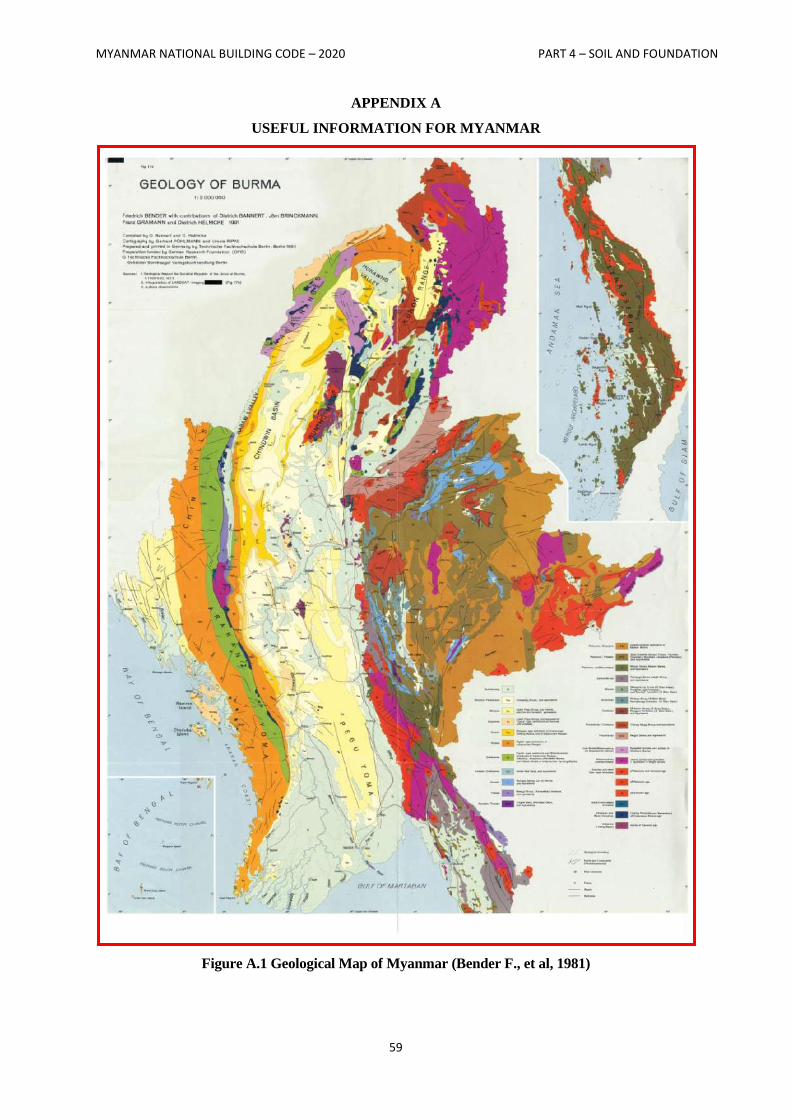
MYANMAR NATIONAL BUILDING CODE – 2020 PART 4 – SOIL AND FOUNDATION
59
APPENDIX A
USEFUL INFORMATION FOR MYANMAR
Figure A.1 Geological Map of Myanmar (Bender F., et al, 1981)
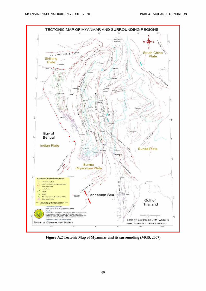
MYANMAR NATIONAL BUILDING CODE – 2020 PART 4 – SOIL AND FOUNDATION
60
Figure A.2 Tectonic Map of Myanmar and its surrounding (MGS, 2007)
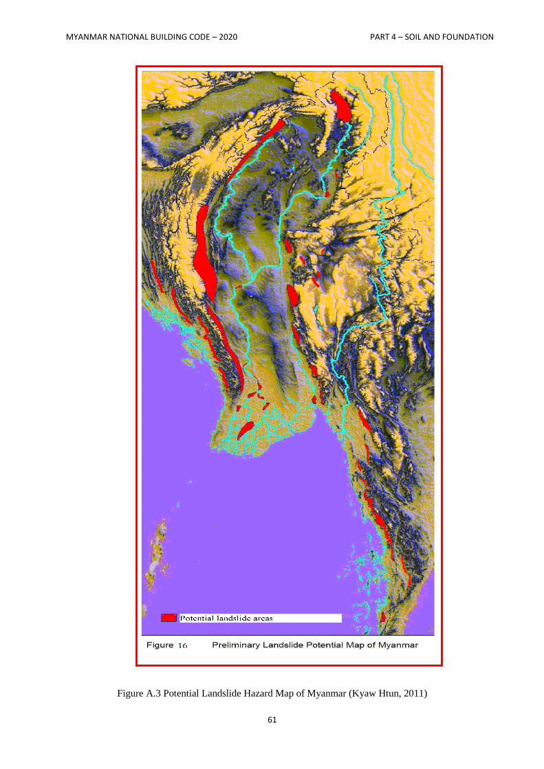
MYANMAR NATIONAL BUILDING CODE – 2020 PART 4 – SOIL AND FOUNDATION
61
Figure A.3 Potential Landslide Hazard Map of Myanmar (Kyaw Htun, 2011)
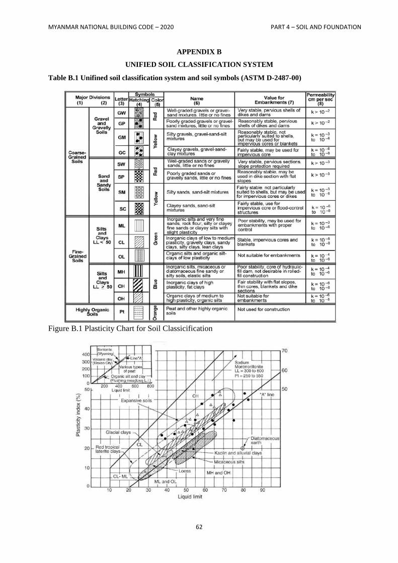
MYANMAR NATIONAL BUILDING CODE – 2020 PART 4 – SOIL AND FOUNDATION
62
APPENDIX B
UNIFIED SOIL CLASSIFICATION SYSTEM
Table B.1 Unifined soil classification system and soil symbols (ASTM D-2487-00)
Figure B.1 Plasticity Chart for Soil Classicification
MYANMAR NATIONAL BUILDING CODE – 2020 PART 4 – SOIL AND FOUNDATION
63
List of participators and coordinators in TWG-4
1. Dr. Nyan Myint Kyaw Group Leader
2. U Kyaw San Win Coordinator
3. U Nyunt Oo Member
4. U Khin Maung Tint Member
5. U Saw Htwe Zaw Member
6. U Thaung Sein Member
7. U Maung Maung Cho Member
8. U Hla Shwe Member
9. Dr. Tun Naing Member
10. U Aung Myat Kyaw Member
11. U Maung Maung Htwe Member
12. U Thein Paing Member
13. U Khin Maung Lwin Member
14. U Hla Phone Maw Member
15. Dr. Kay Thwe Tun Member
16. U Linn Khine Member
17. U Kyaw Tun Member
18. U Khin Maung Aye Member
19. U Htay Win Member
20. Daw Mya Mya Win Member
21. Daw Soe Soe Tin Member
22. Dr. Zin Zin Htike Member
23. U Nay Win Member
24. Dr. Min Maung Maung Member
25. U Shwe Kyaw Hla Member
26. U Thein Htay Member
27. U Zaw Naing Oo Member
28. U Zarli Chan Member
29. Dr. Tin Tin Win Member
30. Daw Khine Khine Oo Member
31. Daw Mar Mar Swe Member
32. U Hla Naing Member
33. U Thura Naing Member
34. U Thet Soe Oo Member

MYANMAR NATIONAL BUILDING CODE – 2020 PART 4 – SOIL AND FOUNDATION
64
35. Daw San San Thwin Member
36. Daw May Moe Moe Khine Member
37. Daw May Sandar Soe Member
38. Daw Myat Thu Zar Maw Member