mv dynamic power factor correction - explore exchange
TRANSCRIPT
Power Quality - Medium Voltage
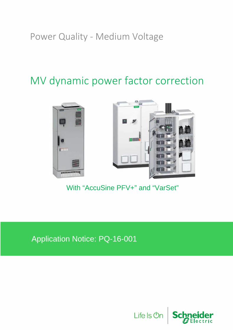
MV dynamic power factor correction
With “AccuSine PFV+” and “VarSet”
Application Notice: PQ-16-001

Medium voltage dynamic power factor correction Contents
© 2016 Schneider Electric. All rights reserved. Page 3 of 28
Legal Information The Schneider Electric brand and any registered trademarks of Schneider Electric Industries SAS referred to in this guide are the sole property of Schneider Electric SA and its subsidiaries. They may not be used for any purpose without the owner's permission, given in writing. This guide and its content are protected, within the meaning of the French intellectual property code (Code de la propriété intellectuelle français, referred to hereafter as "the Code"), under the laws of copyright covering texts, drawings and models, as well as by trademark law. You agree not to reproduce, other than for your own personal, noncommercial use as defined in the Code, all or part of this guide on any medium whatsoever without Schneider Electric’s permission, given in writing. You also agree not to establish any hypertext links to this guide or its content. Schneider Electric does not grant any right or license for the personal and noncommercial use of the guide or its content, except for a non-exclusive license to consult it on an "as is" basis, at your own risk. All other rights are reserved.
Electrical equipment should be installed, operated, serviced and maintained only by qualified personnel. No responsibility is assumed by Schneider Electric for any consequences arising out of the use of this material.
As standards, specifications and designs change from time to time, please ask for confirmation of the information given in this publication.
Contents
Legal Information ....................................................................................................................................... 3
Contents .......................................... ............................................................................................................. 4
Introduction ...................................... ............................................................................................................ 5
Document Scope .................................... ..................................................................................................... 5
Supporting Documentation ........................................................................................................................ 5
Terms and Definitions ............................. .................................................................................................... 6
1 MV power factor correction ........................ ......................................................................................... 7
1.1 “Conventional” MV power factor correction .................................................................................... 7
1.1.1 Fixed power factor correction .................................................................................................. 7
1.1.2 Automatic power factor correction ........................................................................................... 8
2 Dynamic MV power factor correction ................ ................................................................................ 9
2.1 “AccuSine PFV+” ............................................................................................................................ 9
2.2 “VarSet” capacitor bank .................................................................................................................. 9
2.3 Operation principle ........................................................................................................................ 10
3 Solution architectures ............................ ........................................................................................... 11
3.1 Architecture 1 – (Lagging PF correction only) .............................................................................. 11
3.2 Architecture 2 – (Lagging or leading correction) ........................................................................... 13
3.3 Architecture 3 – (Integrated capacitors) ........................................................................................ 15
4 Performance comparison ............................ ...................................................................................... 17
4.1 Case 1 – With a 1200kvar fixed capacitor bank ........................................................................... 18
4.2 Case 2 - Automatic 3x400kvar capacitor bank ............................................................................. 19
4.3 Case 3: Dynamic solution 1200kvar ............................................................................................. 20
4.4 Case 4: Dynamic solution 900kvar ............................................................................................... 21
5 Conclusion ........................................ .................................................................................................. 22
Appendices ........................................ ........................................................................................................ 23
Appendix 1 – AccuSine PFV+ range ....................................................................................................... 24
Appendix 2 – VarSet 400V – 50Hz range ................................................................................................ 25
Medium voltage dynamic power factor correction Introduction
© 2016 Schneider Electric. All rights reserved. Page 5 of 28
Introduction Our “medium voltage dynamic power correction solution” is made of our AccuSine PFV+ dynamic var compensation equipment, VarSet low voltage capacitor banks, MV/LV transformers and LV switchboards.
Our purpose is to provide a “standard product” based solution for applications requiring a high performance system for power factor correction at medium voltage level, up to 36kV.
Document Scope This guide is intended for Application Engineers, third-party integrators, and other qualified personnel who are responsible for power quality solutions design.
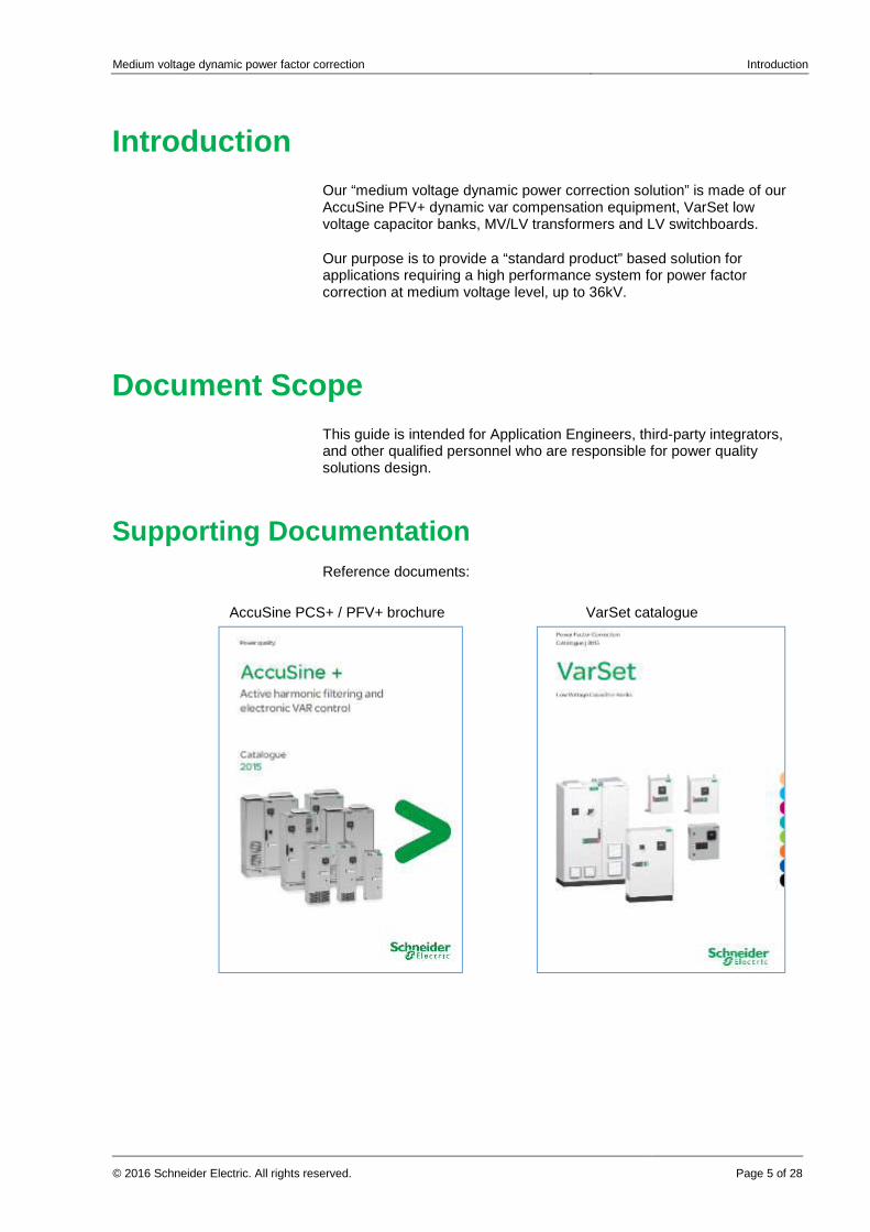
Supporting Documentation Reference documents:
AccuSine PCS+ / PFV+ brochure VarSet catalogue

Medium voltage dynamic power factor correction Terms and Definitions
Page 6 of 28 © 2016 Schneider Electric. All rights reserved.
Terms and Definitions Terms used in document
Term Description
PFC Power Factor Correction
MV Medium Voltage
LV Low Voltage
CB Circuit Breaker
PQ Power Quality
PM Power Meter
PME Power Monitoring Expert
DR Detuning reactor
PF Power Factor
DPF Displacement Power Factor (= cosine phi)
Medium voltage dynamic power factor correction MV power factor correction
© 2016 Schneider Electric. All rights reserved. Page 7 of 28
1 MV power factor correction Heavy industries, like steel factory, cement plant, automotive plants… are very large electrical energy consumers. To be able to receive such amounts, they have to connect to the utility grid at the medium or high voltage level.
These companies have to implement solutions to ensure an optimized usage of electrical energy.
One of them is “medium voltage power factor correction”.
1.1 “Conventional” MV power factor correction The “conventional” solution for medium voltage power factor correction is the use medium voltage capacitor banks.
These capacitor banks are of two main types:
• The “Fixed” capacitor banks,
• The “Automatic” capacitor banks,
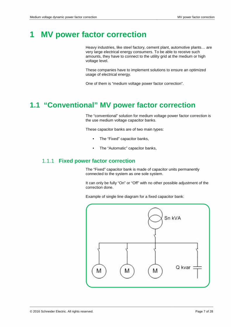
1.1.1 Fixed power factor correction The “Fixed” capacitor bank is made of capacitor units permanently connected to the system as one sole system.
It can only be fully “On” or “Off” with no other possible adjustment of the correction done.
Example of single line diagram for a fixed capacitor bank:
Medium voltage dynamic power factor correction MV power factor correction
Page 8 of 28 © 2016 Schneider Electric. All rights reserved.
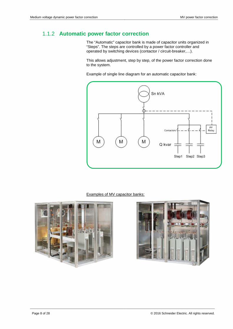
1.1.2 Automatic power factor correction The “Automatic” capacitor bank is made of capacitor units organized in “Steps”. The steps are controlled by a power factor controller and operated by switching devices (contactor / circuit-breaker,…).
This allows adjustment, step by step, of the power factor correction done to the system.
Example of single line diagram for an automatic capacitor bank:
Examples of MV capacitor banks:
Medium voltage dynamic power factor correction Dynamic MV power factor correction
© 2016 Schneider Electric. All rights reserved. Page 9 of 28
2 Dynamic MV power factor correction Our “dynamic” solution for medium voltage power factor correction solution is using Schneider Electric “standard” equipment:
• AccuSine PFV+ electronic var compensator,
• VarSet low voltage capacitor banks,
• MV/LV Transformers (TRIHAL, …)
• LV Switchboard (Blokset, Okken, Prisma, …)
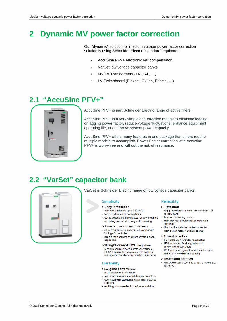
2.1 “AccuSine PFV+” AccuSine PFV+ is part Schneider Electric range of active filters. AccuSine PFV+ is a very simple and effective means to eliminate leading or lagging power factor, reduce voltage fluctuations, enhance equipment operating life, and improve system power capacity. AccuSine PFV+ offers many features in one package that others require multiple models to accomplish. Power Factor correction with Accusine PFV+ is worry-free and without the risk of resonance.
2.2 “VarSet” capacitor bank VarSet is Schneider Electric range of low voltage capacitor banks.
Medium voltage dynamic power factor correction Dynamic MV power factor correction
Page 10 of 28 © 2016 Schneider Electric. All rights reserved.
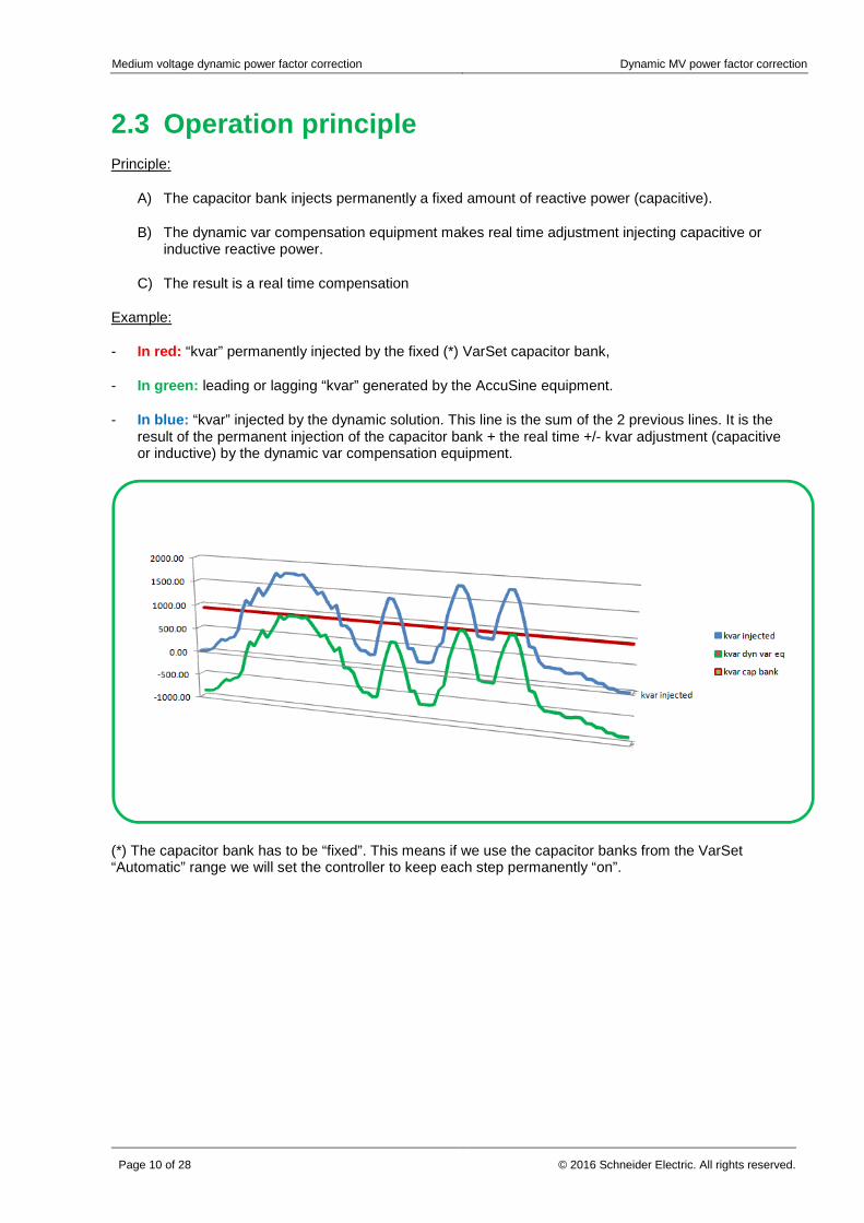
2.3 Operation principle Principle:
A) The capacitor bank injects permanently a fixed amount of reactive power (capacitive).
B) The dynamic var compensation equipment makes real time adjustment injecting capacitive or inductive reactive power.
C) The result is a real time compensation
Example:
- In red: “kvar” permanently injected by the fixed (*) VarSet capacitor bank,
- In green: leading or lagging “kvar” generated by the AccuSine equipment.
- In blue: “kvar” injected by the dynamic solution. This line is the sum of the 2 previous lines. It is the result of the permanent injection of the capacitor bank + the real time +/- kvar adjustment (capacitive or inductive) by the dynamic var compensation equipment.
(*) The capacitor bank has to be “fixed”. This means if we use the capacitor banks from the VarSet “Automatic” range we will set the controller to keep each step permanently “on”.
Medium voltage dynamic power factor correction Solution architectures
© 2016 Schneider Electric. All rights reserved. Page 11 of 28
3 Solution architectures Typical “dynamic” solutions architectures are shown in below diagrams.
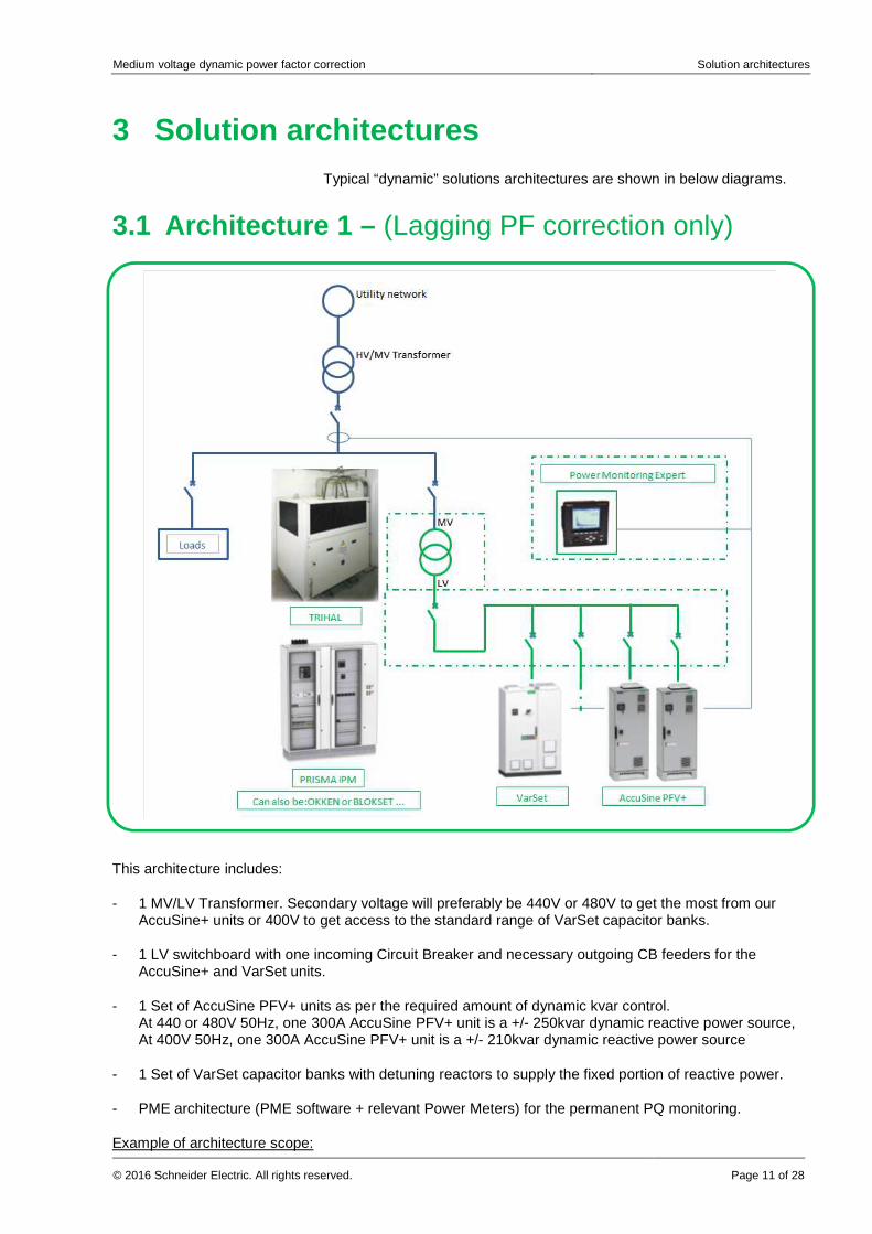
3.1 Architecture 1 – (Lagging PF correction only)
This architecture includes:
- 1 MV/LV Transformer. Secondary voltage will preferably be 440V or 480V to get the most from our AccuSine+ units or 400V to get access to the standard range of VarSet capacitor banks.
- 1 LV switchboard with one incoming Circuit Breaker and necessary outgoing CB feeders for the AccuSine+ and VarSet units.
- 1 Set of AccuSine PFV+ units as per the required amount of dynamic kvar control. At 440 or 480V 50Hz, one 300A AccuSine PFV+ unit is a +/- 250kvar dynamic reactive power source, At 400V 50Hz, one 300A AccuSine PFV+ unit is a +/- 210kvar dynamic reactive power source
- 1 Set of VarSet capacitor banks with detuning reactors to supply the fixed portion of reactive power.
- PME architecture (PME software + relevant Power Meters) for the permanent PQ monitoring.
Example of architecture scope:
Medium voltage dynamic power factor correction Solution architectures
Page 12 of 28 © 2016 Schneider Electric. All rights reserved.
For one 1000kvar / 10kV – 50Hz dynamic solution we would typically use:
- One 1250kVA 10kV/440V – Dry type transformer, coupling Dyn11 (Any coupling is fine, just select the most standard available option), impedance as low as 5% if possible,
- One 440V – 50Hz switchboard, with one 2000A incoming circuit breaker and one CB feeder for each dynamic var compensation equipment and each capacitor bank.
- Dynamic var compensation system sized to inject 500kvar – 50Hz of leading or lagging reactive power,
- A 500kvar / 440V – 50Hz capacitor bank with detuning reactors (typically 7% reactors)
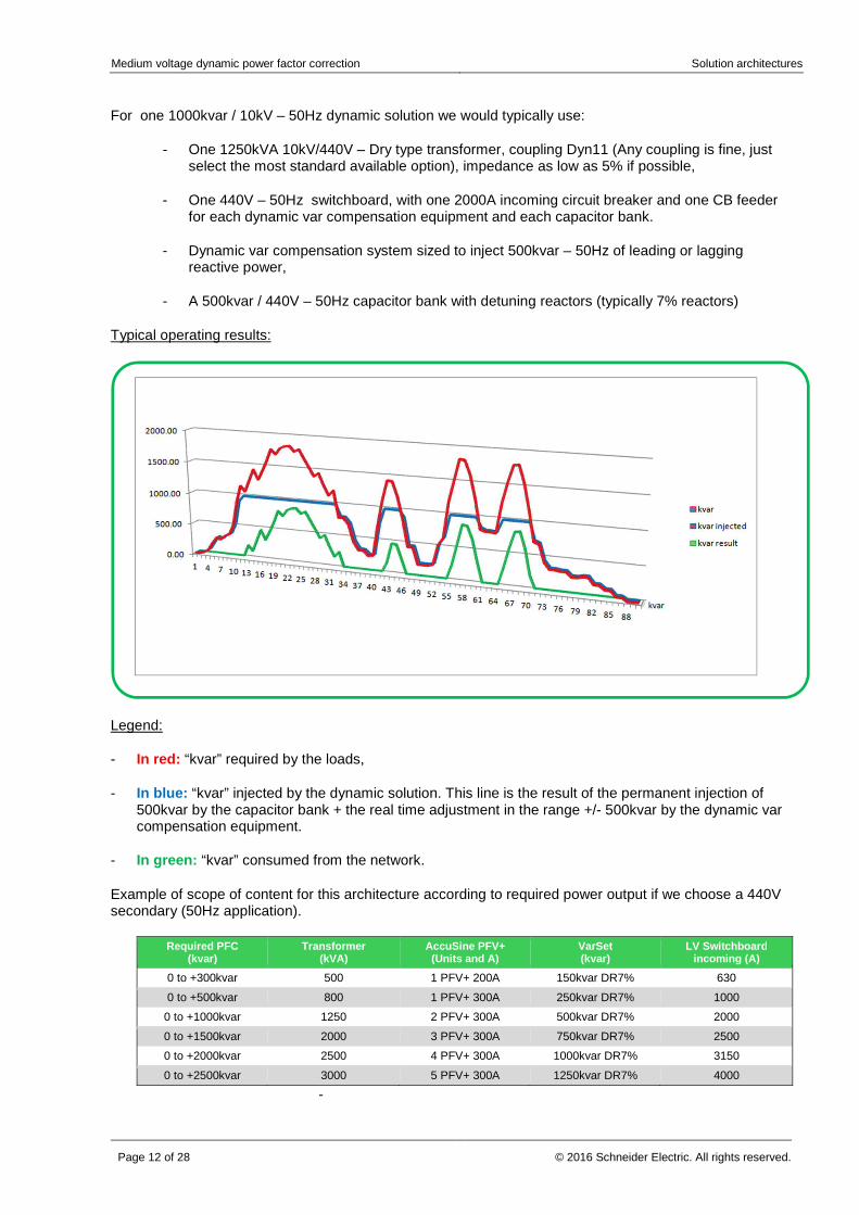
Typical operating results:
Legend:
- In red: “kvar” required by the loads,
- In blue: “kvar” injected by the dynamic solution. This line is the result of the permanent injection of 500kvar by the capacitor bank + the real time adjustment in the range +/- 500kvar by the dynamic var compensation equipment.
- In green: “kvar” consumed from the network.
Example of scope of content for this architecture according to required power output if we choose a 440V secondary (50Hz application).
Required PFC (kvar)
Transformer (kVA)
AccuSine PFV+ (Units and A)
VarSet (kvar)
LV Switchboard incoming (A)
0 to +300kvar 500 1 PFV+ 200A 150kvar DR7% 630
0 to +500kvar 800 1 PFV+ 300A 250kvar DR7% 1000
0 to +1000kvar 1250 2 PFV+ 300A 500kvar DR7% 2000
0 to +1500kvar 2000 3 PFV+ 300A 750kvar DR7% 2500
0 to +2000kvar 2500 4 PFV+ 300A 1000kvar DR7% 3150
0 to +2500kvar 3000 5 PFV+ 300A 1250kvar DR7% 4000
-
Medium voltage dynamic power factor correction Solution architectures
© 2016 Schneider Electric. All rights reserved. Page 13 of 28
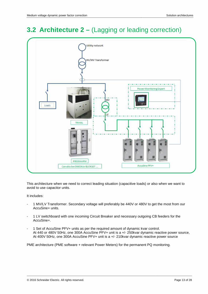
3.2 Architecture 2 – (Lagging or leading correction)
This architecture when we need to correct leading situation (capacitive loads) or also when we want to avoid to use capacitor units.
It includes:
- 1 MV/LV Transformer. Secondary voltage will preferably be 440V or 480V to get the most from our AccuSine+ units.
- 1 LV switchboard with one incoming Circuit Breaker and necessary outgoing CB feeders for the AccuSine+.
- 1 Set of AccuSine PFV+ units as per the required amount of dynamic kvar control. At 440 or 480V 50Hz, one 300A AccuSine PFV+ unit is a +/- 250kvar dynamic reactive power source, At 400V 50Hz, one 300A AccuSine PFV+ unit is a +/- 210kvar dynamic reactive power source
PME architecture (PME software + relevant Power Meters) for the permanent PQ monitoring.
Medium voltage dynamic power factor correction Solution architectures
Page 14 of 28 © 2016 Schneider Electric. All rights reserved.
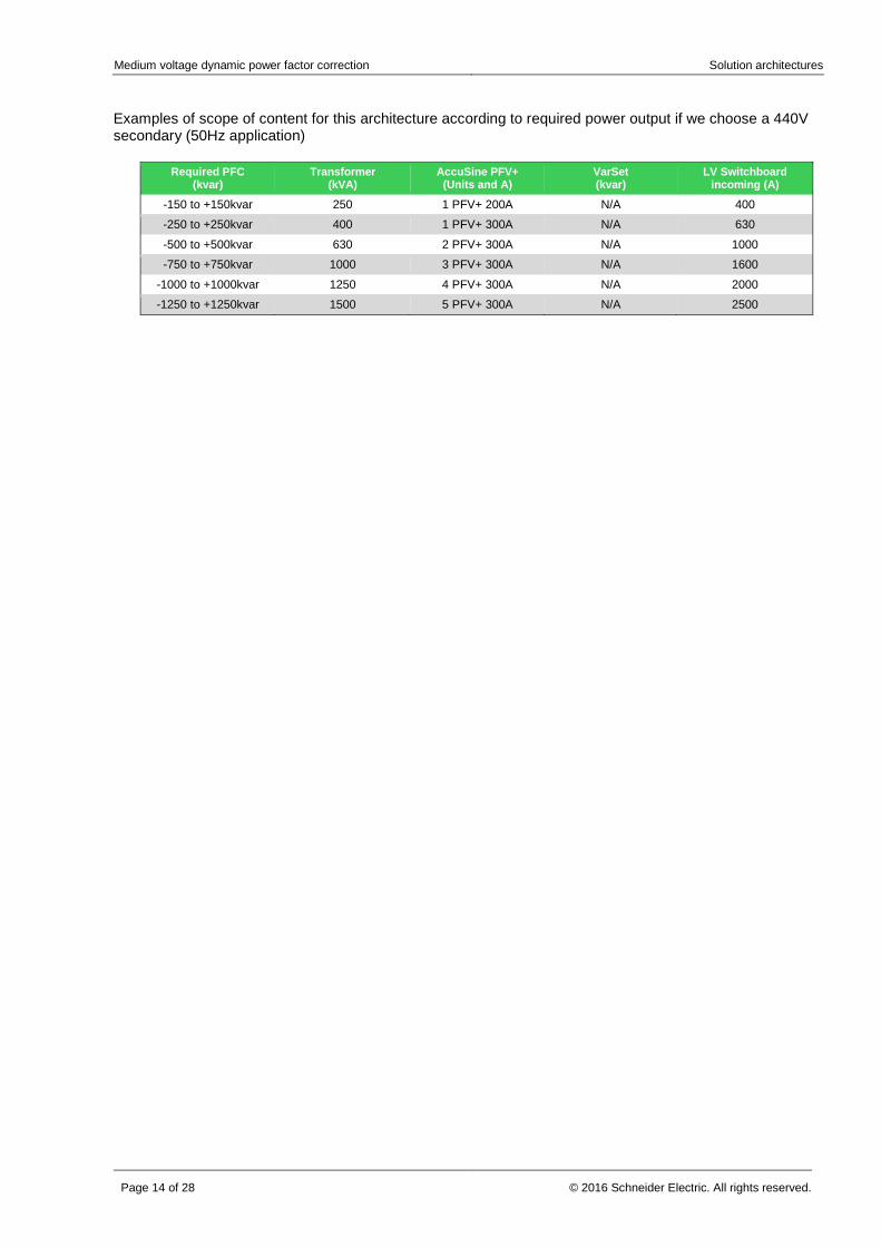
Examples of scope of content for this architecture according to required power output if we choose a 440V secondary (50Hz application)
Required PFC (kvar)
Transformer (kVA)
AccuSine PFV+ (Units and A)
VarSet (kvar)
LV Switchboard incoming (A)
-150 to +150kvar 250 1 PFV+ 200A N/A 400
-250 to +250kvar 400 1 PFV+ 300A N/A 630
-500 to +500kvar 630 2 PFV+ 300A N/A 1000
-750 to +750kvar 1000 3 PFV+ 300A N/A 1600
-1000 to +1000kvar 1250 4 PFV+ 300A N/A 2000
-1250 to +1250kvar 1500 5 PFV+ 300A N/A 2500

Medium voltage dynamic power factor correction Solution architectures
© 2016 Schneider Electric. All rights reserved. Page 15 of 28
3.3 Architecture 3 – (Integrated capacitors)
Compare to Architecture 1 the only difference is that the capacitor units can be integrated in the LV switchboard.
This architecture includes:
- 1 MV/LV Transformer. Secondary voltage will preferably be 440V or 480V to get the most from our AccuSine+ units or 400V to get access to the standard range of VarSet capacitor banks.
- 1 LV switchboard with one incoming Circuit Breaker, necessary outgoing CB feeders for the AccuSine+ and compartments with VarPlus capacitor units with 7% detuning reactors.
- 1 Set of AccuSine PFV+ units as per the required amount of dynamic kvar control. At 440 or 480V 50Hz, one 300A AccuSine PFV+ unit is a +/- 250kvar dynamic reactive power source, At 400V 50Hz, one 300A AccuSine PFV+ unit is a +/- 210kvar dynamic reactive power source
- PME architecture (PME software + relevant Power Meters) for the permanent PQ monitoring.
Medium voltage dynamic power factor correction Solution architectures
Page 16 of 28 © 2016 Schneider Electric. All rights reserved.
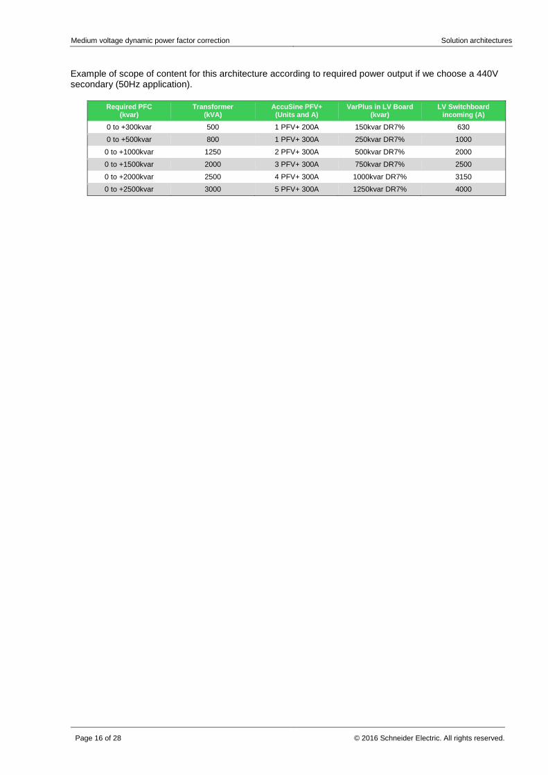
Example of scope of content for this architecture according to required power output if we choose a 440V secondary (50Hz application).
Required PFC (kvar)
Transformer (kVA)
AccuSine PFV+ (Units and A)
VarPlus in LV Board (kvar)
LV Switchboard incoming (A)
0 to +300kvar 500 1 PFV+ 200A 150kvar DR7% 630
0 to +500kvar 800 1 PFV+ 300A 250kvar DR7% 1000
0 to +1000kvar 1250 2 PFV+ 300A 500kvar DR7% 2000
0 to +1500kvar 2000 3 PFV+ 300A 750kvar DR7% 2500
0 to +2000kvar 2500 4 PFV+ 300A 1000kvar DR7% 3150
0 to +2500kvar 3000 5 PFV+ 300A 1250kvar DR7% 4000
Medium voltage dynamic power factor correction Performance comparison
© 2016 Schneider Electric. All rights reserved. Page 17 of 28
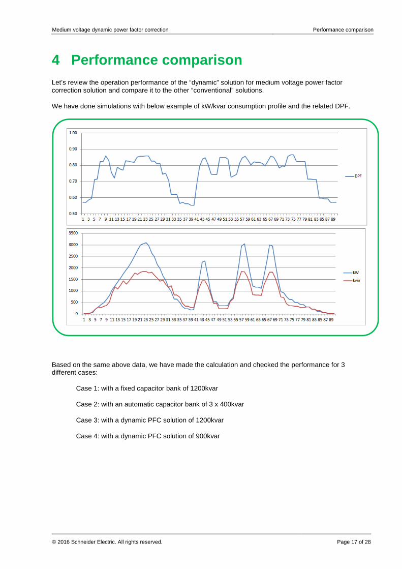
4 Performance comparison Let’s review the operation performance of the “dynamic” solution for medium voltage power factor correction solution and compare it to the other “conventional” solutions.
We have done simulations with below example of kW/kvar consumption profile and the related DPF.
Based on the same above data, we have made the calculation and checked the performance for 3 different cases:
Case 1: with a fixed capacitor bank of 1200kvar
Case 2: with an automatic capacitor bank of 3 x 400kvar
Case 3: with a dynamic PFC solution of 1200kvar
Case 4: with a dynamic PFC solution of 900kvar
Medium voltage dynamic power factor correction Performance comparison
Page 18 of 28 © 2016 Schneider Electric. All rights reserved.
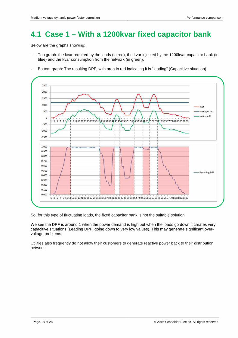
4.1 Case 1 – With a 1200kvar fixed capacitor bank Below are the graphs showing:
- Top graph: the kvar required by the loads (in red), the kvar injected by the 1200kvar capacitor bank (in blue) and the kvar consumption from the network (in green).
- Bottom graph: The resulting DPF, with area in red indicating it is “leading” (Capacitive situation)
So, for this type of fluctuating loads, the fixed capacitor bank is not the suitable solution.
We see the DPF is around 1 when the power demand is high but when the loads go down it creates very capacitive situations (Leading DPF, going down to very low values). This may generate significant over-voltage problems.
Utilities also frequently do not allow their customers to generate reactive power back to their distribution network.

Medium voltage dynamic power factor correction Performance comparison
© 2016 Schneider Electric. All rights reserved. Page 19 of 28
4.2 Case 2 - Automatic 3x400kvar capacitor bank Below are the graphs showing:
- Top graph: the kvar required by the loads (in red), the kvar injected by the automatic 3 x 400kvar capacitor bank (in blue) and the kvar consumption from the network (in green).
- Bottom graph: The resulting DPF, with area in red indicating it is “leading” (Capacitive situation)
For this type of fluctuating loads, the automatic capacitor bank is a more suitable solution.
We see the DPF is quite good during long periods.
When the power demand goes down it still creates “leading” situations but not as bad as in case of fixed bank. (DPF remains > 0,6). It still can generate some over-voltage problems.
The lower than expected DPF periods and the leading situations are due to the slow response time of the MV capacitor banks. (Several minutes)
Medium voltage dynamic power factor correction Performance comparison
Page 20 of 28 © 2016 Schneider Electric. All rights reserved.
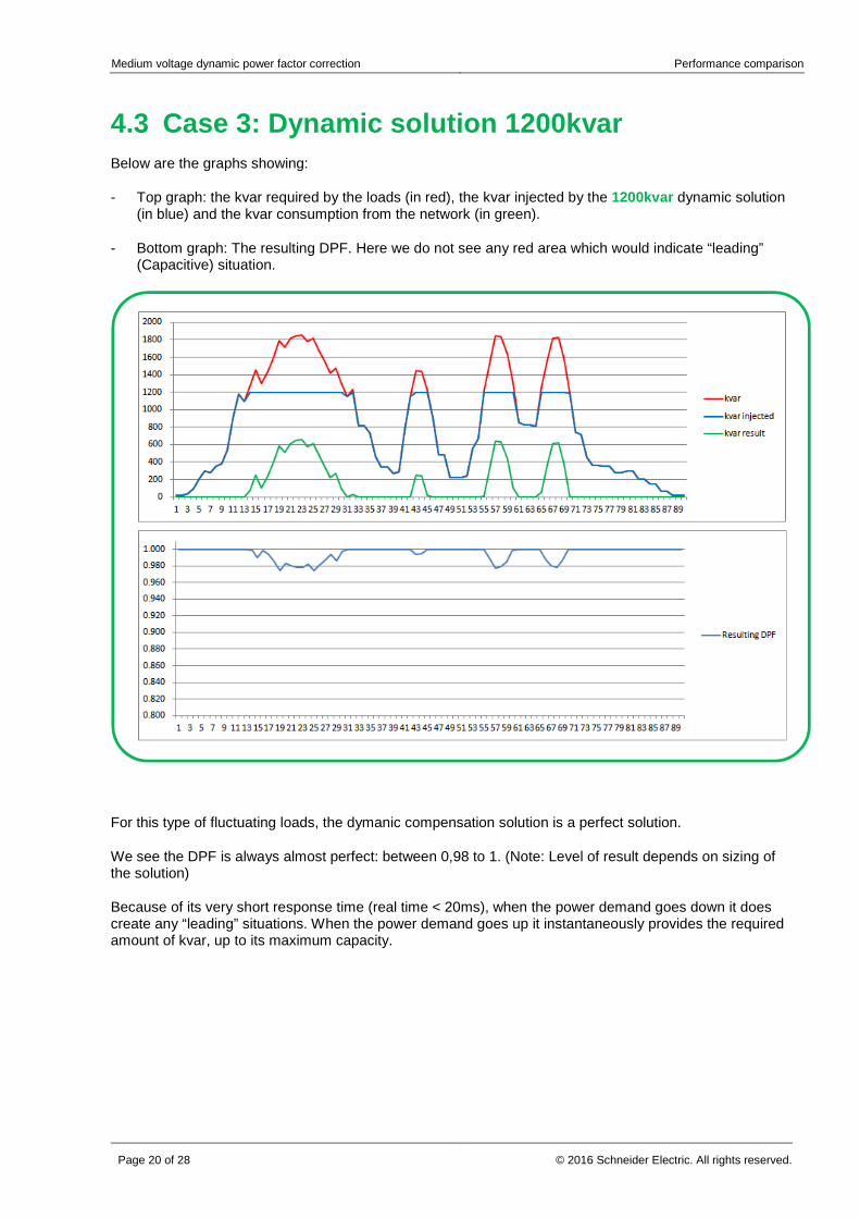
4.3 Case 3: Dynamic solution 1200kvar Below are the graphs showing:
- Top graph: the kvar required by the loads (in red), the kvar injected by the 1200kvar dynamic solution (in blue) and the kvar consumption from the network (in green).
- Bottom graph: The resulting DPF. Here we do not see any red area which would indicate “leading” (Capacitive) situation.
For this type of fluctuating loads, the dymanic compensation solution is a perfect solution.
We see the DPF is always almost perfect: between 0,98 to 1. (Note: Level of result depends on sizing of the solution)
Because of its very short response time (real time < 20ms), when the power demand goes down it does create any “leading” situations. When the power demand goes up it instantaneously provides the required amount of kvar, up to its maximum capacity.
Medium voltage dynamic power factor correction Performance comparison
© 2016 Schneider Electric. All rights reserved. Page 21 of 28
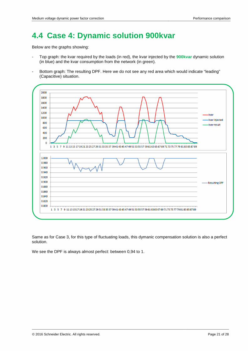
4.4 Case 4: Dynamic solution 900kvar Below are the graphs showing:
- Top graph: the kvar required by the loads (in red), the kvar injected by the 900kvar dynamic solution (in blue) and the kvar consumption from the network (in green).
- Bottom graph: The resulting DPF. Here we do not see any red area which would indicate “leading” (Capacitive) situation.
Same as for Case 3, for this type of fluctuating loads, this dymanic compensation solution is also a perfect solution.
We see the DPF is always almost perfect: between 0,94 to 1.
Medium voltage dynamic power factor correction Conclusion
Page 22 of 28 © 2016 Schneider Electric. All rights reserved.
5 Conclusion Medium Voltage Dynamic Power Factor Correction systems are the fruit of Schneider Electric long practice and experience in Power Quality.
This solution is based on a smart combination of master pieces of Schneider Electric electrical distribution equipment and products offers.
It is basically made of:
� One MV/LV transformer, � One LV smart panel, for the protection, control and monitoring � One set of low voltage capacitor banks, for the basic reactive power
compensation, � One set of “AccuSine PFV+”, for the dynamic reactive power
compensation, On top of this Schneider Electric Power Monitoring Experts system will ensure the relevant and permanent power quality survey.
The result is an automatic medium voltage power factor correction which provides the following main advantages compare to conventional MV capacitor banks:
• Dynamic correction: Response time: < 20ms (5 to 10 minutes for MV cap banks),
• Transient free correction: smooth var adjustments,
• Usage can be extended to Harmonics mitigation (Consult us),
• Smooth, permanent, and “step-less” correction,
• No voltage rise at no-load, no risk of over-compensation nor
resonance,
• Can also compensate for leading situations (Capacitive systems)
• Flexible for extensions and easy implementation,
Fast
Flexible
Accurate
Clean

Medium voltage dynamic power factor correction Appendices
© 2016 Schneider Electric. All rights reserved. Page 23 of 28
Appendices
Medium voltage dynamic power factor correction Appendices
Page 24 of 28 © 2016 Schneider Electric. All rights reserved.
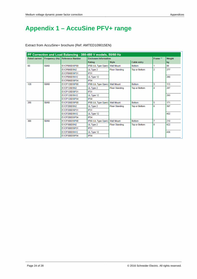
Appendix 1 – AccuSine PFV+ range
Extract from AccuSine+ brochure (Ref: AMTED109015EN)
Medium voltage dynamic power factor correction Appendices
© 2016 Schneider Electric. All rights reserved. Page 25 of 28
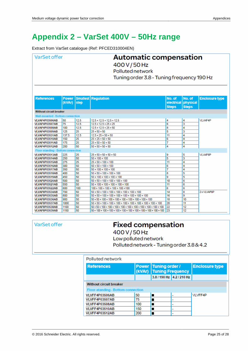
Appendix 2 – VarSet 400V – 50Hz range Extract from VarSet catalogue (Ref: PFCED310004EN)


Application Notice PQ-16-001
Schneider Electric
35 rue Joseph Monier 92500 Rueil Malmaison – France www.schneider-electric.com
As standards, specifications, and designs change from time to time, please ask for confirmation of the information given in this publication. Copyright 2016 Schneider Electric. All rights reserved.

08/2016