modified exit-ply delamination model for drilling frps
TRANSCRIPT

Modified Exit-ply Delamination Model forDrilling FRPs
S. GURURAJA* AND M. RAMULU
Mechanical Engineering, University of Washington, Seattle, WA 98195, USA
ABSTRACT: Delamination has been identified as one of the most deleteriousdamage processes associated with drilling fiber reinforced plastics (FRPs) due to theresulting drastic reduction of structural strength and stiffness. In recent years, severalexperimental, numerical, and analytical studies have been conducted aimed atunderstanding delamination initiation and progression during drilling. In this study,a comprehensive review of existing analytical studies has been presented comparingand contrasting their respective advantages and disadvantages. Special emphasis hasbeen laid upon presenting all assumptions made and the underlying implicationsthereby. Suggestions at improving the existing models so as to facilitate a morerealistic description of the drill process using composite lamination theories have alsobeen included.
KEY WORDS: delamination, fiber reinforced plastics (FRPs), analytical studies,drilling.
INTRODUCTION
IN RECENT TIMES, several studies have been conducted on drilling FRPs to identify themajor challenges at obtaining an efficient, cost-effective way of hole generation. Despite
advances in nontraditional machining processes (water jet cutting, ultrasonic machining,etc.), conventional machining processes such as drilling are still widely used in industrytoday. Due to the inherent inhomogeniety and anisotropy of FRP laminates, the drillingprocess is currently rife with damage phenomenon such as spalling, delamination, edgechipping, fiber pull-outs, crack formation, thermal residual stresses and excessive toolwear. Exit-ply delamination has been identified as the most deleterious damagephenomenon for structural components as it results in a significant loss of strength andstiffness of the laminate and, consequently its load carrying capacity. Identification andprevention of delamination therefore becomes particularly important for compositecomponents subjected to compressive, shear, cyclic loads and adverse environmentalconditions over extended periods of time. In order to ascertain the structural integrity of amachined component, these drilling damages need to be addressed adequately [1–11].
*Author to whom correspondence should be addressed. E-mail: [email protected] 3, 4, 6 and 7 appear in color online: http://jcm.sagepub.com
Journal of COMPOSITE MATERIALS, Vol. 43, No. 05/2009 483
0021-9983/09/05 0483–18 $10.00/0 DOI: 10.1177/0021998308097677� SAGE Publications 2009
Los Angeles, London, New Delhi and Singapore
at NORTH DAKOTA STATE UNIV LIB on May 21, 2015jcm.sagepub.comDownloaded from

Delamination has been identified as a resin or matrix dominated failure occurringpredominantly in the interply region of a laminate. Associated problems of delaminationinclude exposure to adverse weather conditions which result in long-term performancedeterioration of a structural component. Drilling-induced delamination has been known tooccur both at the entrance and exit planes [12]. Figure 1 depicts the two delaminationmechanisms observed in drilling of FRPs, namely, push-out at the exit and peel-up at theentrance. Figure 2 depicts the top view and side view of entrance and exit-delamination asobserved during drilling graphite/bismalemide (Gr/BMI) using HSS tools [6]. Loose fiberscan be seen extending from the hole both at the entry and exit, more pronounced in theexit side of the hole. Figure 3 demonstrates a badly damaged hole in a thermoplasticcomposite showing fiber pull-outs and matrix burning. The efforts have been made tooptimize the drilling parameters and conditions for minimizing drilling induced damage.Increased thrust force and torque leads to greater damage. The effect of the cutting speedon the cutting forces has been found to be insignificant [6,10]; however, both cutting forceshave been found to be directly proportional to the feed [2–8]. Specifically, feed rate hasbeen found to be linearly related to both thrust and torque at both high and low drillingspeeds. Thus, by proper selection of feed rate, the amount of delamination due to thrustcan be minimized, while still drilling in a timely manner [5].
Now, as the drill approaches the bottom of the laminate, the uncut thickness underneaththe drill progressively decreases. After a certain depth has been drilled, the stresses exerted
Pc
Pc
Drill
Drill
FRP laminate
FRP laminateD
D
Delamination z z
a h
(a) Push-out at exit; (b) Peel-up at entrance
Figure 1. Schematic shape of the delamination zone in a unidirectional laminate [12].
Exit-ply delamination
(push-out)
Entrance delamination(pull-off)
Top view
Figure 2. Top view and side view of holes drilled in Gr/BMI with worn HSS drill [6].
484 S. GURURAJA AND M. RAMULU
at NORTH DAKOTA STATE UNIV LIB on May 21, 2015jcm.sagepub.comDownloaded from

on the uncut laminate exceed the interlaminar strength resulting in delamination. Sucha delamination is more commonly known as the exit-ply delamination and the thrust forcethat causes exit-ply delamination to occur at a certain depth is termed as the ‘critical thrustforce’. This concept was initially proposed by Konig [1] and has been subsequently verifiedby several researchers independently [12–18]. The identification and preventionof delamination from occurring during a drilling operation is thus viewed asthe prediction of the critical thrust force (or feed) which would lead to delamination-freedrilling of FRPs.
Peel-up at the entrance is commonly observed when the cutting edge of the drill abradesthe workpiece laminate initially. As the drill moves forward, the abraded material is pulledalong the flute direction. This introduces a peeling up effect whereby the material spiralsup before the machining process is complete. For the purpose of this article, studies relatedto exit-ply delamination will be addressed not peel-up fracture.
A few analytical studies have been conducted in the past with the aim of predictingthe critical thrust force below which delamination free drilling can be achieved.In reality, the actual delamination process in drilling composites is very complex and itis an arduous task to model all the different mechanisms in play during drilling.However, researchers have been trying to better understand the delamination processby making assumptions in order to simplify the analysis. This present article presentssome salient features of the existing models and discusses their relative meritssuggesting ways of improvement.
BACKGROUND
A few analytical studies have attempted to model delamination during drillingemphasizing on the identification of a critical thrust force [12–18] or feed [15] in orderto attain delamination-free drilling as depicted in Table 1. Universally, the delaminationcrack is assumed to propagate in a self-similar manner such that linear elastic fracturemechanics (LEFM) Mode I energy balance equation can be used as follows [1]:
Pcdwo ¼ G1cdA� dU ð1Þ
Figure 3. Severe delamination and uncut fibers in thermoplastic [7].
Modified Exit-ply Delamination Model for Drilling FRPs 485
at NORTH DAKOTA STATE UNIV LIB on May 21, 2015jcm.sagepub.comDownloaded from

where Pc is the critical thrust force at which delamination initiates, dwo is the displacementof the drill along the direction of hole generation, GIc is the Mode I energy release rate ofthe laminate, dA is the incremental increase in area of the crack, and dU is the infinitesimalstrain energy of the laminate of assumed domain.
Although Equation (1) has been predominantly used in existing exit-ply delaminationmodels, differences in the definition of drilling domain, load profile and the materialproperties result in significant differences in the critical thrust force.
Hocheng–Dharan (HD) Model
The HD model assumed a circular fractured area underneath the cutting drill. A circularplate with homogeneous isotropic properties has been assumed to be representative ofthe circular fractured zone. A point load at the center of the circular plate simulatingthe chisel edge of the drill has been assumed [12]. Critical thrust force estimatedusing classical bending theory and energy balance for Mode I crack of Equation (1)has been compared with experimental results. Reasonably good agreement forsmaller number of plies has been reported. Final form of the critical thrust force Pc forthe HD-model is:
Pc ¼ �8G1cEh
3
3ð1� v2Þ
� �1=2: ð2Þ
Table 1. Variation of Pc with tool-geometry.
Drill geometry Model Expressions for Pc
Twist drill Hocheng et al. [6] �ffiffiffiffiffiffiffiffiffiffiffiffiffiffi8G1c Eh3
3 1��2ð Þ
q
Upadhyay et al. [17] �
ffiffiffiffiffiffiffiffiffiffiffiffiffiffiffiffiffiffiffiffiffiffiffiffiffiffiffiffiffiffiffiffiffiffiffiffiffiffiffiffiffiffiffiffiffiffiffiffiffiffiffiffiffiffiffiffiffiffiffiffiffiffiffiffiffiffiffiffiffiffiffiffi8G1c Eh3 1�1:464ðwo=hÞ
2ð Þ 1�0:0488ðw0=hÞ2ð Þ
2
3 1��2ð Þ 1�1:708ðwo=hÞ2�0:107ðwo=hÞ
4f g
r
Lachuad et al. [16] Pc ¼ 8�ffiffiffiffiffiffiffiffiffiffiffiffiffiffiffiffiffiffiffiffiffi
G1c Dð1=3Þ�ðD=8DÞ
q
Jain et al. [15] 3� D22D11
� �1=4 ffiffiffiffiffiffiffiffiffiffiffiffiffiffiffiffiffi2G1cD�c
pZhang et al. [18]
ffiffiffiffiffiffiffiffiffiffiffiffiffiffi�G1c
� C3�Kð Þ
q
Saw drill Hocheng et al. [13] �ffiffiffiffiffiffiffiffiffiffiffiffiffiffiffiffiffiffiffiffiffiffiffiffiffiffiffiffiffiffiffiffi
8G1c Eh3
3 1��2ð Þ 1�2s2�s4ð Þ
qwith s¼ c/a
Candle Stick drill Hocheng et al. [13] �ð1� �Þffiffiffiffiffiffiffiffiffiffiffiffiffiffiffiffiffiffiffiffiffiffiffiffiffiffiffiffiffiffiffiffiffiffiffiffiffiffiffiffiffiffiffi
8G1c Eh3
3 1��2ð Þ 1��2 1�2s2�s4ð Þð Þ
qwith s¼ c/a and �¼p2/p1 (load ratio at two ends)
Core drill Hocheng et al. [13] ��ð2� �Þffiffiffiffiffiffiffiffiffiffiffiffiffiffiffiffiffiffiffiffiffiffiffiffiffiffiffiffiffiffiffiffiffiffiffiffiffiffiffiffiffiffiffiffiffiffiffiffiffiffiffiffiffiffiffiffiffiffiffiffiffiffiffiffiffiffi
5G1c Eh3
3 1��2ð Þ1� 1� �ð Þ
2� �
�
ð1=2Þs2 1� 1� �ð Þ6� �
( )vuuut
with s¼ c/a, p2¼ (1��)2 p1
486 S. GURURAJA AND M. RAMULU
at NORTH DAKOTA STATE UNIV LIB on May 21, 2015jcm.sagepub.comDownloaded from
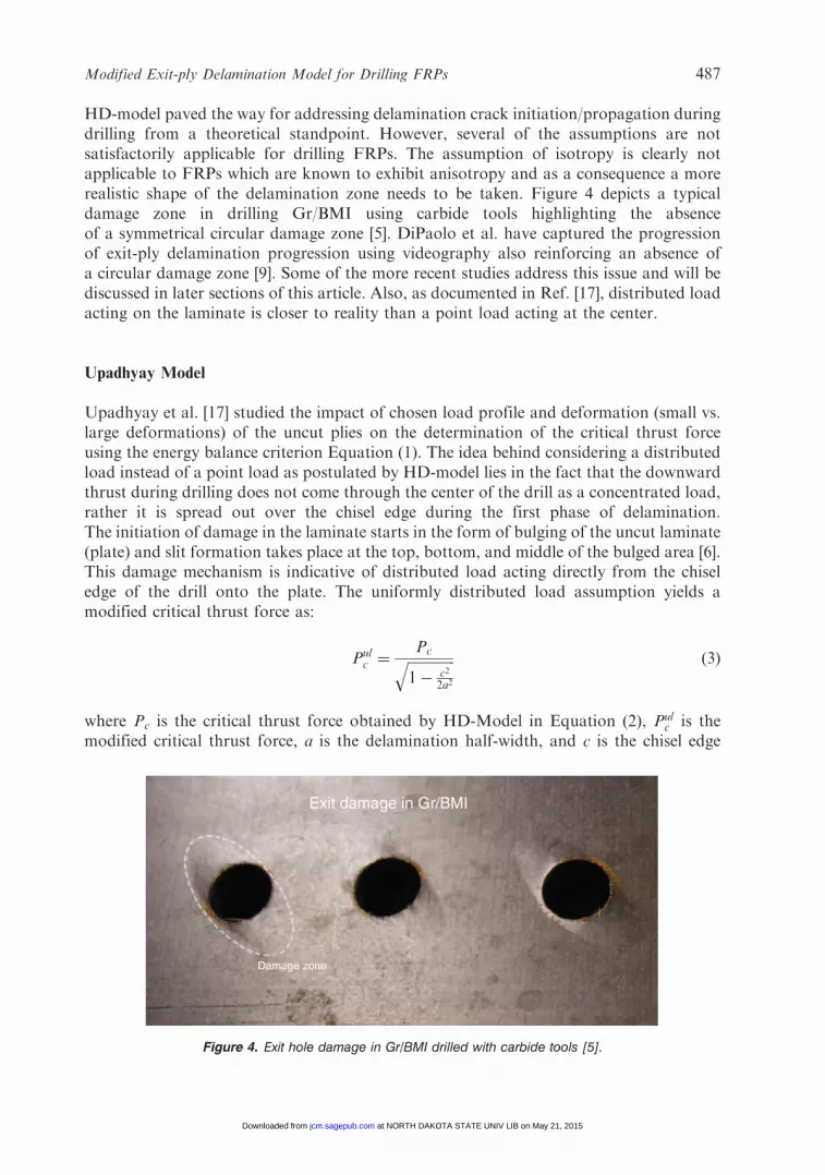
HD-model paved the way for addressing delamination crack initiation/propagation duringdrilling from a theoretical standpoint. However, several of the assumptions are notsatisfactorily applicable for drilling FRPs. The assumption of isotropy is clearly notapplicable to FRPs which are known to exhibit anisotropy and as a consequence a morerealistic shape of the delamination zone needs to be taken. Figure 4 depicts a typicaldamage zone in drilling Gr/BMI using carbide tools highlighting the absenceof a symmetrical circular damage zone [5]. DiPaolo et al. have captured the progressionof exit-ply delamination progression using videography also reinforcing an absence ofa circular damage zone [9]. Some of the more recent studies address this issue and will bediscussed in later sections of this article. Also, as documented in Ref. [17], distributed loadacting on the laminate is closer to reality than a point load acting at the center.
Upadhyay Model
Upadhyay et al. [17] studied the impact of chosen load profile and deformation (small vs.large deformations) of the uncut plies on the determination of the critical thrust forceusing the energy balance criterion Equation (1). The idea behind considering a distributedload instead of a point load as postulated by HD-model lies in the fact that the downwardthrust during drilling does not come through the center of the drill as a concentrated load,rather it is spread out over the chisel edge during the first phase of delamination.The initiation of damage in the laminate starts in the form of bulging of the uncut laminate(plate) and slit formation takes place at the top, bottom, and middle of the bulged area [6].This damage mechanism is indicative of distributed load acting directly from the chiseledge of the drill onto the plate. The uniformly distributed load assumption yields amodified critical thrust force as:
Pulc ¼
Pcffiffiffiffiffiffiffiffiffiffiffiffiffiffi1� c2
2a2
q ð3Þ
where Pc is the critical thrust force obtained by HD-Model in Equation (2), Pulc is the
modified critical thrust force, a is the delamination half-width, and c is the chisel edge
Exit damage in Gr/BMI
Damage zone
Figure 4. Exit hole damage in Gr/BMI drilled with carbide tools [5].
Modified Exit-ply Delamination Model for Drilling FRPs 487
at NORTH DAKOTA STATE UNIV LIB on May 21, 2015jcm.sagepub.comDownloaded from

width or the drill diameter depending on whether the crack initiation is due to the thrustthrough chisel edge or the crack growth is beyond the drill radius.
Large deformation including mid-plane stretching yields:
P�lm ¼ Pc
ffiffiffiffiffiffiffiffiffiffiffiffiffiffiffiffiffiffiffiffiffiffiffiffiffiffiffiffiffiffiffiffiffiffiffiffiffiffiffiffiffiffiffiffiffiffiffiffiffiffiffiffiffiffiffiffiffiffiffiffiffiffiffiffiffiffiffiffiffiffiffiffiffiffiffiffiffiffiffiffiffiffiffiffiffiffi1� 1:464 wo=hð Þ
2� �
1� 0:0488 wo=hð Þ2
� �21� 1:708 wo=hð Þ
2�0:107 wo=hð Þ
4
" #vuut : ð4Þ
Lachuad Model
Other researchers like Lachuad et al. [16] have also looked at the geometrical natureof the contact between the tool and the laminate by considering different load profilesof the thrust force. It has been found that a distributed load profile yields closercorrelation with experiments than a point load profile. For a distributed uniform load, thecritical thrust force expression is as:
Pc ¼ 8�
ffiffiffiffiffiffiffiffiffiffiffiffiffiffiffiffiffiffiffiffiffiffiffiffiffiffiffiffiffiffiffiffiffiffiffiG1cD
ð1=3Þ � ðD=8DÞð Þ
sð5Þ
where:
D ¼1
83D11 � 2D12 � 4D66 � 3D22ð Þ
and:
D ¼D11 �D22
2�D12 � 2D66
3:
Lachuad model considered a circular plate as the delamination zone and did not take intoaccount the coupling between extension and bending components.
Jain–Yang (JY) Model
Following the HD-model, Jain–Yang (JY) model considers a more realistic ellipticalplate as delamination zone under the cutting tool indicative of the orthotropic propertiesapplicable for a Uni-Directional FRP (UD-FRP) laminate [15]. Figure 5 depicts the saiddelamination zone with ‘a’ and ‘b’ representing the lengths along the fiber and transversedirections respectively. Emphasis has been placed on the determination of critical feed ratesince unlike the thrust force which is a result of drilling, feed rate can be controlled as aninput parameter. This has been accomplished by using an empirical relation between thrustand feedrate. Equation (1) energy balance and laminated plate theory have been used todevelop critical thrusts and critical feed rates at which delamination is initiated at differentply locations. In addition, contributions of tool geometry and chisel width to thedelamination crack propagation have also been highlighted reinforcing the importance of
488 S. GURURAJA AND M. RAMULU
at NORTH DAKOTA STATE UNIV LIB on May 21, 2015jcm.sagepub.comDownloaded from

the chisel width to the thrust force observed in a drilling operation. The thrust expressionfrom the JY-model is given by:
P� ¼ 3�b
a
� � ffiffiffiffiffiffiffiffiffiffiffiffiffiffiffi2G1cD�
pð6Þ
where:
D� ¼ D11 �2 D12 � 2D66ð Þ
3
a
b
� �2�D22
a
b
� �4:
In Equation (6), a/b represents the ellipticity ratio of the laminate and is estimated byminimizing the thrust force PC yielding:
Min ðP�Þ ¼ 3�ffiffiffiffiffiffiffiffiffi2GIc
pMin
ffiffiffiffiffiffiffiffiffiffiffiffiffiffiffiffiffiffiffiffiffiffiffiffiffiffiffiffiffiffiffiffiffiffiffiffiffiffiffiffiffiffiffiffiffiffib
a
� �2
D11�2 D12�2D66ð Þ
3
s�D22
a
b
� �20@
1A
)Minb
a
ffiffiffiffiffiffiffiffiD11
p�a
b
ffiffiffiffiffiffiffiffiD22
p� �2
�2 D12 � 2D66ð Þ
3� 2
ffiffiffiffiffiffiffiffiffiffiffiffiffiffiffiD11D22
p !
)b
a
ffiffiffiffiffiffiffiffiD11
p¼
a
b
ffiffiffiffiffiffiffiffiD22
p)
a
b¼
D11
D22
� �1=4:
ð7Þ
Equation (6) thus takes the following form for critical thrust force:
Pc ¼ 3�D22
D11
� �1=4 ffiffiffiffiffiffiffiffiffiffiffiffiffiffiffi2G1cD�c
pð8Þ
where:
D�c ¼ 2D11�2 D12�2D66ð Þ
3
ffiffiffiffiffiffiffiffiD11
D22
r:
Interestingly, Jain and Yang proceeded to relate the feedrate with the critical thrust forcepredicted in order to develop a variable feedrate strategy using an empirical relationbetween thrust force, hardness of work material, feed, and drill diameter. Although, theJY-model considers a realistic elliptical domain for the fractured region during drilling,only UD-FRP laminates can be analyzed using this model since coupling between bendingand stretching terms have been neglected in the model.
2
1b
a
(D22)
(D11)
Figure 5. Schematic shape of the delamination zone in a unidirectional laminate [15].
Modified Exit-ply Delamination Model for Drilling FRPs 489
at NORTH DAKOTA STATE UNIV LIB on May 21, 2015jcm.sagepub.comDownloaded from

Zhang Model
To date, the model presented by Zhang et al. is most realistic in terms of incorporatingthe coupling between bending and stretching components commonly observed in FRPswith various lay-ups [18]. Classical lamination plate theory (CLPT) has been used todevelop the displacement equations which are in turn used to estimate the critical thrustforce using energy balance Equation (1).
As in JY-model, the delamination zone has been defined as an elliptical plate with theellipticity ratio estimated using an optimization scheme. The displacement fields chosenhave been derived previously by Bert in Ref. [19] as:
u ¼ u1x
a� u2
y
b
� �1�
x2
a2�y2
b2
� �, v ¼ v1
x
a� v2
y
b
� �1�
x2
a2�y2
b2
� �
w ¼ wo 1�x2
a2�y2
b2
� �:
ð9Þ
The constitutive relations for FRPs are [20]:
NM
�¼
ABBD
�"o
�
�ð10Þ
where [N] is 3� 1 vector of the normal and shear forces, [M] is 3� 1 vector of themoments, ["o] is 3� 1 vector of mid-plane strains, [k] is 3� 1 vector of the curvatures, [A]is 3� 3 matrix of the extensional stiffnesses, [B] is 3� 3 matrix of the coupling betweenextension and bending and [D] is 3� 3 matrix of bending stiffness. The in-plane strains andcurvatures can be estimated for the assumed displacement field using small displacementassumption as:
"ox ¼@u
@x, "oy ¼
o_v
@y, "oxy ¼
@u
@y�@v
@x
�x ¼ �@2w
@x2, �y ¼ �
@2w
@y2, �xy ¼ �2
@2w
@x@y
ð11Þ
The [A], [B], and [D] matrices are defined as:
Aij,Bij,Dij
� �¼
Z h=2
�h=2
Qij 1, z, z2
� �dz ð12Þ
where Qij are the reduced stiffnesses for plane stress case and ‘h’ is the total thickness ofthe uncut laminate under the drill bit [20]. The normal/shear forces [N] vector and themoments [M] are related via equilibrium equations:
Nx, x �Nxy, y ¼ 0, Nxy, x �Ny, y ¼ 0
Mx, xx � 2Mxy, xy �My, yy � q ¼ 0ð13Þ
490 S. GURURAJA AND M. RAMULU
at NORTH DAKOTA STATE UNIV LIB on May 21, 2015jcm.sagepub.comDownloaded from

where
q ¼Pc
�ab¼
Pc�
�a2; � ¼
a
b:
‘q’ represents the assumed uniformly distributed lateral load acting on the elliptical plate.Using Equations (10)–(13), a system of equations are generated for the estimation of thedisplacement constants u1, u2, wo, v1, v2 as:
u1 ¼ PcC1a, v1 ¼ PcC2a, !o ¼ PcC3a2, u2 ¼ PcC4a, v2 ¼ PcC5a: ð14Þ
It should be noted that all the C’s in the above expression are known in terms of the uncutlaminate properties (constituent material properties and lay-up) and ellipticity ratio �.Furthermore, in order to simplify the computing process, the laminate has beenrotated an angle corresponding to the fiber orientation of each layer such that forany given number of plies, the topmost ply is oriented along the principal materialdirections [18].
Based on the displacement fields in Equation (14), the strain energy of the uncutlaminate has been estimated:
U ¼ KP2ca
2 ð15Þ
with K given by:
K ¼�
2
A11
� 3C21 � C2
4
� �� 2A12 C1C2 � C4C5ð Þ � A22� 3C2
2 � C25
� �� 2A16
� 2�C1C4 � 3C1C5 � C2C4ð Þ � 2A163�C2C4 � 2C2C5
��C1C5
� �� A66
� � C1 � C2ð Þ2�3�2C2
4 � 3C25 � 2�C4C5
� �� 24B11
� C1C3
�8B12C3 �C1 � C2ð Þ � 24B16C3 C4 �C5
�
� �� 24B22�
2C2C3
�24B26�C3 C5 � �C4ð Þ � 16B66C3 �C1 � C2ð Þ
�16C2
3
� 3D11 � 2�2D12 � 3�4D22 � 4�2D66
� �
2666666666664
3777777777775: ð16Þ
Using the energy balance Equation (1), the critical thrust force has been estimated as
Pc ¼
ffiffiffiffiffiffiffiffiffiffiffiffiffiffiffiffiffiffiffiffi�G1c
� C3 � Kð Þ
s: ð17Þ
All expressions described in this model depend on the lay-up of the uncut laminateunderneath the drill bit. As drilling progresses, the layup underneath the drill changes andthe analysis is performed again to obtain a predicted critical thrust value correspondingto the uncut thickness of the laminate. It should be pointed out here that althoughZhang et al. have considered a uniformly distributed load in the derivation of the strainenergy expressions, the estimation of external work done has been based on a point loadprofile. This has led to some improvement in the critical thrust force predictions despite arealistic representation of the drill process. Therefore, Zhang et al.’s model has been
Modified Exit-ply Delamination Model for Drilling FRPs 491
at NORTH DAKOTA STATE UNIV LIB on May 21, 2015jcm.sagepub.comDownloaded from

modified to account for distributed load acting on the entire elliptical plate domain andthe implications of such a formulation has been observed in the following sections.
Recently, Hocheng and Tsao modified the critical thrust calculations based on thegeometry of drill bits in Ref. [13,14]. Table 1 summarizes the analytic expressions of someof the drill bits as documented in Ref. [13,14] alongside expressions of Pc (critical thrust)proposed by different researchers over the years for a twist drill. However, it shouldbe noted that all these models rely on the basic energy balance relation of Equation (1) forthe determination of Pc.
MODIFIED EXIT-PLY DELAMINATION MODEL
Based on the expressions presented thus far, attempts at modifying the existingmodels have been carried out in order to establish a more realistic representation ofthe loading and delamination zone during drilling of FRPs. As mentioned earlier,Zhang et al.’s model is the most realistic to date in terms of engaging the anisotropicnature of FRPs, loading profile and the delamination zone representative of a drillingprocess. The expressions for displacements, constitutive equations and strain energycalculations in Equations (9)–(17) discussed earlier in the discussion of Zhang et al.model have been adopted in the present model. The determination of external workdone due to the distributed load acting on the elliptical plate has been modified hereusing the procedure:
W ¼
Z a
�a
Z bffiffiffiffiffiffiffiffiffiffiffiffiffiffiffi1�ðx2=a2Þp
�bffiffiffiffiffiffiffiffiffiffiffiffiffiffiffi1�ðx2=a2Þp q � wdydx ð18Þ
where:
q ¼Pc
�ab
w ¼ wo 1�x2
a2�y2
b2
� �2
with:
wo ¼ C3Pca2:
Equation (18) yields the following expression for external work done:
W ¼
Z a
�a
Z bffiffiffiffiffiffiffiffiffiffiffiffiffiffiffi1�ðx2=a2Þp
�bffiffiffiffiffiffiffiffiffiffiffiffiffiffiffi1�ðx2=a2Þp
Pc
�abPcC3a
2 1�x2
a2�y2
b2
� �2
dydx)W ¼p2cC3
3a2: ð19Þ
The modified form of critical thrust force is obtained using the energy balance equation ofEquation (1) as:
; Pcð Þmodified¼
ffiffiffiffiffiffiffiffiffiffiffiffiffiffiffiffiffiffiffiffiffiffiffiffiffiffiffiffi�Glc
� ðC3=3Þ � Kð Þ
s: ð20Þ
492 S. GURURAJA AND M. RAMULU
at NORTH DAKOTA STATE UNIV LIB on May 21, 2015jcm.sagepub.comDownloaded from

The determination of external work done has been modified compared to Zhang modeland the implications of this modification shall be discussed.
Model Validation
In order to validate the modified expression for critical thrust force further, a specialcase of UD-FRP laminate has been considered. It should be noted that if the laminate isassumed to be isotropic, Equation (20) replicates HD model solution of Equation (2).For UD-FRP laminate, the extension bending coupling [B] matrix is zero along withbending twisting components D16, D26¼ 0. Thus, the moment-curvature equations takethe form:
Mx
My
Mxy
24
35 ¼ D11 D12 0
D12 D12 00 0 D66
24
35 �x
�y�xy
24
35: ð21Þ
Substituting the [B] matrix as zero along with D16, D26¼ 0, the displacement constant wo isobtained as:
wo ¼2Pc�a
2
� 48D11 � 32�2 D12 � 2D66ð Þ � 48�4D22ð Þð22Þ
or:
wo ¼Pca
2�
24�D�
with:
D� ¼ D11 �2
3D12 � 2D66ð Þ � �4D22
Strain energy U is thus given by:
U ¼�
144�D�P2ca
2 ¼ KP2ca
2 ð23Þ
with:
K ¼�
144�D�:
The critical thrust force expression becomes:
Pc ¼12�
�
ffiffiffiffiffiffiffiffiffiffiffiffiffiffiG1cD�:
pð24Þ
Modified Exit-ply Delamination Model for Drilling FRPs 493
at NORTH DAKOTA STATE UNIV LIB on May 21, 2015jcm.sagepub.comDownloaded from

Expanding the expression for critical thrust force by Lachuad et al. [16] for a circular plateneglecting the [B] matrix and D16, D26¼ 0 for a symmetrical layup as shown inEquation (5) we get:
Pc ¼ 8�
ffiffiffiffiffiffiffiffiffiffiffiffiffiffiffiffiffiffiffiffiffiffiffiffiffiffiffiffiffiffiffiffiffiffiffiffiffiffiffiffiffiffiffiffiffiffiffiffiffiffiffiffiffiffiffiffiffiffiffiffiffiffiffiffiffiffiffiffiffiffiffiffiffiffiffiffiffiffiffiffiffiffiffiffiffiffiffiffiffiffiffiffiffiffiffiffiffiffiG1cD
ð1=3Þ � ðD=8DÞð Þ¼ 8�
ffiffiffiffiffiffiffiffiffiffiffiffiffiffiffiffiffiffiffiffiffiffiffiG1cð3=8ÞD�
13�
D�2
3D�
s8�
ffiffiffiffiffiffiffiffiffiffiffiffiffiffiffiffi9
4G1cD�
rvuut) Pcð ÞLachuad ¼ 12�
ffiffiffiffiffiffiffiffiffiffiffiffiffiG1cD�
p ð25Þ
where:
D ¼1
83D11 � 2D12 � 4D66 � 3D22ð Þ ¼
3
8D�
D ¼D11 �D22
2�D12 � 2D66
3¼
D�
2:
Equation (24) is identical to Equation (25) for an ellipticity ratio of � ¼ 1 for a circularplate. This confirms that the modified model works for a special case of UD-FRP laminatealthough the expressions have been developed for a multi-directional laminate.The modified exit-ply delamination model presented here replicates the solutions ofHD-model for the special case of isotropic laminate and Lachuad model solutions for thespecial case of UD-FRP laminate.
Another validation effort has been carried out by reproducing the critical thrustforce predictions in Ref. [18] at different ply locations from the bottom of theworkpiece laminate. As in Ref. [18], a quasi-isotropic [458, 908, �458, 08]6S T300/634Gr/Ep composite laminate with El¼ 133GPa, �lt¼ 0.33, Et¼ 7.7GPa, Glt¼ 4.2GPa, h (plythickness)¼ 0.1mm and GIc¼ 300N/mm has been chosen. Table 2 shows thevalues of predicted critical thrust forces for the quasi-isotropic lay-up chosen for thefollowing cases:
(1) Zhang model documented in Ref. [18],(2) verified by the present authors using the same equations that Zhang et al. used, and(3) using the modified delamination model.
The value of calculated Pc and corresponding ellipticity ratio is identical (or very close) tothe corresponding values documented in Ref. [18]. There exists a considerable difference in
Table 2. Replication of critical thrust forces.
Ply number 1 2 3 4 5 6 7 8
Table 2 from Ref. [18]� 2.04 1.3 1.0 1.35 1.78 1.34 1.0 1.09Pc [N] 17.8 49.9 82.7 150.4 217.5 355.5 449.7 551.3
Estimated using Zhang model� 2.04 1.3 1.0 1.34 1.77 1.34 1.0 1.04Pc [N] 17.8 49.9 86.8 150.6 217.5 355.9 456.5 551.3
Estimated using modified exit-ply delamination model� 2.04 1.3 1.0 1.35 1.77 1.34 1.0 1.04Pc [N] 50.5 141.1 245.5 425.6 615.3 1006.5 1291.1 1559.2
494 S. GURURAJA AND M. RAMULU
at NORTH DAKOTA STATE UNIV LIB on May 21, 2015jcm.sagepub.comDownloaded from
the values of Pc for the Zhang model and the modified model especially as the ply numberincreases.
In order to ascertain the relative performance of the analytical models discussed so far,a comparison of the respective predicted thrust forces with experimental data has beenconducted. To this end, it becomes necessary to choose the delamination results citedin a particular article so that the predicted thrust forces from the different delaminationmodels can be compared. In view of the clarity of the results presented in Ref. [16]and based on the fact that other models can be used to predict the thrust forcefor the laminate layup in Ref. [16], the 24-ply quasi-isotropic Fibredux 914/T300(Hexcel) carbon/epoxy composite delamination data has been chosen. Each ply hasbeen documented to have the following properties: El¼ 144GPa, �lt¼ 0.3, Et¼ 8.7GPa,Glt¼ 4.14GPa, h (ply thickness)¼ 0.125mm and GIc¼ 150N/mm [16]. Four models havebeen considered for comparison, namely:
(1) HD-model,(2) Zhang model,(3) Lachuad model and(4) modified exit-ply delamination model.
Based on the experimental data in Ref. [16], a total of Six plies have been chosen forthe present analysis. Since exit-ply delamination model is applicable as the drill-bitapproaches the exit-side of the laminate being machined, the bottom Six plies will bestudied for this analysis.
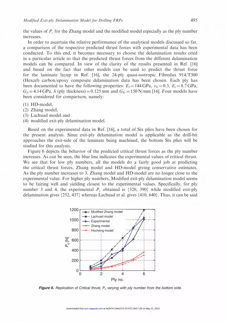
Figure 6 depicts the behavior of the predicted critical thrust forces as the ply numberincreases. As can be seen, the blue line indicates the experimental values of critical thrust.We see that for low ply numbers, all the models do a fairly good job at predictingthe critical thrust forces, Zhang model and HD-model giving conservative estimates.As the ply number increases to 3, Zhang model and HD-model are no longer close to theexperimental value. For higher ply numbers, Modified exit-ply delamination model seemsto be fairing well and yielding closest to the experimental values. Specifically, for plynumber 3 and 4, the experimental Pc obtained is {320, 390} while modified exit-plydelamination gives {252, 437} whereas Lachuad et al. gives {410, 640}. Thus, it can be said
1200
1000
800
Pc
[N]
600
400
200
00
Ply no.
Modified Zhang model
Lachuad model
Experimental
Zhang model
Hocheng model
2 4 6
Figure 6. Replication of Critical thrust, Pc varying with ply number from the bottom side.
Modified Exit-ply Delamination Model for Drilling FRPs 495
at NORTH DAKOTA STATE UNIV LIB on May 21, 2015jcm.sagepub.comDownloaded from
with certainty that modified exit-ply delamination model fares well as compared to theother models chosen in this analysis. Table 3 has all the data points of Figure 6.
In all the models it is interesting to note the absence of the delamination initial size orthe drill hole dimension in the critical thrust force expression. This implies that thedelamination observed is in fact independent of the drill size and as such only criticalthrust force can predicted, not the resulting delamination size.
DISCUSSION
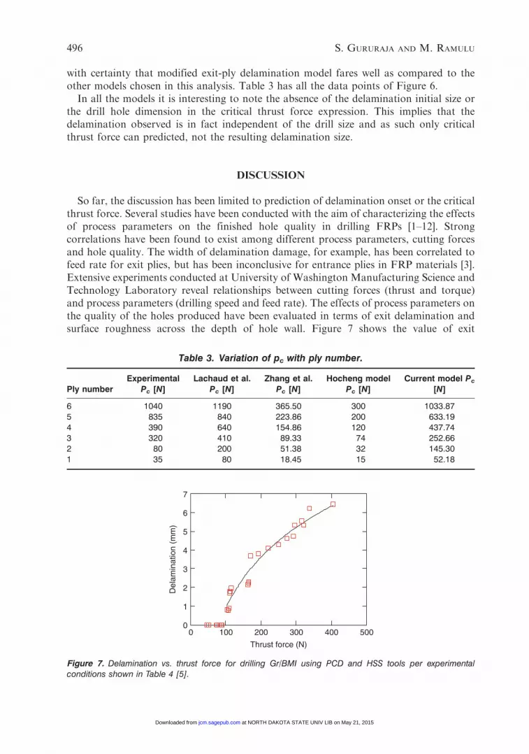
So far, the discussion has been limited to prediction of delamination onset or the criticalthrust force. Several studies have been conducted with the aim of characterizing the effectsof process parameters on the finished hole quality in drilling FRPs [1–12]. Strongcorrelations have been found to exist among different process parameters, cutting forcesand hole quality. The width of delamination damage, for example, has been correlated tofeed rate for exit plies, but has been inconclusive for entrance plies in FRP materials [3].Extensive experiments conducted at University of Washington Manufacturing Science andTechnology Laboratory reveal relationships between cutting forces (thrust and torque)and process parameters (drilling speed and feed rate). The effects of process parameters onthe quality of the holes produced have been evaluated in terms of exit delamination andsurface roughness across the depth of hole wall. Figure 7 shows the value of exit
Table 3. Variation of pc with ply number.
Ply numberExperimental
Pc [N]Lachaud et al.
Pc [N]Zhang et al.
Pc [N]Hocheng model
Pc [N]Current model Pc
[N]
6 1040 1190 365.50 300 1033.875 835 840 223.86 200 633.194 390 640 154.86 120 437.743 320 410 89.33 74 252.662 80 200 51.38 32 145.301 35 80 18.45 15 52.18
7
6
5
4
3
2
1
00 100 200
Thrust force (N)
300 400 500
Del
amin
atio
n (m
m)
Figure 7. Delamination vs. thrust force for drilling Gr/BMI using PCD and HSS tools per experimentalconditions shown in Table 4 [5].
496 S. GURURAJA AND M. RAMULU
at NORTH DAKOTA STATE UNIV LIB on May 21, 2015jcm.sagepub.comDownloaded from
delamination using PCD and HSS drills in Gr/BMI. As drilling progresses, the drill bitgradually wears out resulting in higher thrust forces and consequently higher observed exitdelamination lengths. As discussed in the models presented earlier, Figure 7 depicts acritical thrust force of 100N beyond which delamination is seen to occur. This onset loadis slightly higher for Gr/BMI as compared to Gr/Ep (35N) due to the superior toughnessproperties of Gr/BMI [21].
It has been routinely observed that the delamination progression is not well-defined asassumed in the existing models [1–11]. A more realistic model would need to incorporatethe shear stress contributions due to the torsional components that act on the workpiecematerial during drilling. Therefore, analytical models should incorporate the effect oftorque for precise damage prediction. Attempts have been made to characterize the effectof these shear forces on the delamination initiation load using finite element analysis(FEA) [23–26]. However, focusing on the last few plies, Mode I fracture criterion can bejustifiably used [6].
The peel-up at entrance delamination on the other hand is shear dominated and wouldinvolve Mode II and Mode III contributions. Purely for the sake of argument, assuming a
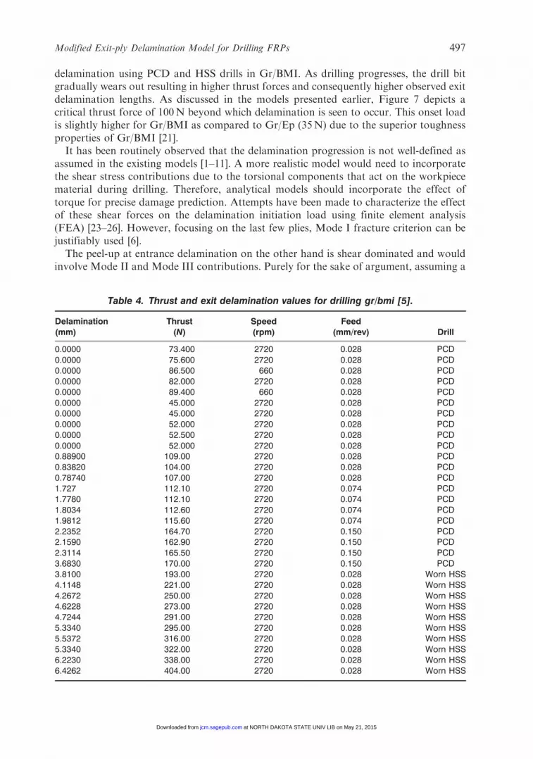
Table 4. Thrust and exit delamination values for drilling gr/bmi [5].
Delamination Thrust Speed Feed(mm) (N) (rpm) (mm/rev) Drill
0.0000 73.400 2720 0.028 PCD0.0000 75.600 2720 0.028 PCD0.0000 86.500 660 0.028 PCD0.0000 82.000 2720 0.028 PCD0.0000 89.400 660 0.028 PCD0.0000 45.000 2720 0.028 PCD0.0000 45.000 2720 0.028 PCD0.0000 52.000 2720 0.028 PCD0.0000 52.500 2720 0.028 PCD0.0000 52.000 2720 0.028 PCD0.88900 109.00 2720 0.028 PCD0.83820 104.00 2720 0.028 PCD0.78740 107.00 2720 0.028 PCD1.727 112.10 2720 0.074 PCD1.7780 112.10 2720 0.074 PCD1.8034 112.60 2720 0.074 PCD1.9812 115.60 2720 0.074 PCD2.2352 164.70 2720 0.150 PCD2.1590 162.90 2720 0.150 PCD2.3114 165.50 2720 0.150 PCD3.6830 170.00 2720 0.150 PCD3.8100 193.00 2720 0.028 Worn HSS4.1148 221.00 2720 0.028 Worn HSS4.2672 250.00 2720 0.028 Worn HSS4.6228 273.00 2720 0.028 Worn HSS4.7244 291.00 2720 0.028 Worn HSS5.3340 295.00 2720 0.028 Worn HSS5.5372 316.00 2720 0.028 Worn HSS5.3340 322.00 2720 0.028 Worn HSS6.2230 338.00 2720 0.028 Worn HSS6.4262 404.00 2720 0.028 Worn HSS
Modified Exit-ply Delamination Model for Drilling FRPs 497
at NORTH DAKOTA STATE UNIV LIB on May 21, 2015jcm.sagepub.comDownloaded from

simplistic circular self-similar delamination at the entry with isotropic laminate propertiesand clamped boundary condition per Hocheng Model, the critical thrust force for entry-delamination can be derived as follows for a Mode II fracture criterion [22]:
Pc ¼ �8GllcEh
3
3 1� v2ð Þ
� �1=2ð26Þ
GIIc value is typically higher than GIc [25] and consequently, the entry-critical thrust force(based on Equation (26)) would be higher than the exit-critical thrust force (based onHocheng Model). Thus, a variable feed approach can be tailored based on the aboveformulation. Such an approach has been proposed and successfully demonstrated by Jainet al. [15] although their reasoning was based on Mode I criterion as discussed in an earliersection. On a related note, since the onset is inherently dependent on the materialproperties of the inter-ply region, choosing woven fabric plies on the entry or exit-side ofthe laminate would be helpful in preventing excessive delamination due to thedemonstrated superior GIc [2,25].
CONCLUSIONS
A modified exit-ply delamination model was proposed in this study and the followingconclusions have been drawn:
(1) Anisotropic behavior of the uncut laminate underneath the drill bit has been used tomodel the exit-ply delamination phenomenon allowing for extension-bendingcoupling. An elliptical delamination zone with clamped boundary condition hasbeen assumed, ellipticity ratio has been determined from an optimization process.Crack has been assumed to grow in a self-similar manner such that LEFM approachhas been deemed applicable.
(2) A distributed loading has been assumed over the entire delamination zone per previousstudies indicating a better replication of the experimentally observed drillingphenomenon. The load profile depends inherently on the drill geometry and hencehas been appended accordingly.
(3) Comparison of the existing models with experimental data indicates that the proposedmodified exit-ply delamination model yields better correlation.
(4) Damage progression has not been captured by any existing (exit-ply delamination)analytical model. Damage progression has been found to have a non-linear behaviorwith respect to thrust force. Drilling parameters (tool geometry and feed in particular)and conditions (tool wear in particular) have been found to effect the exit-plydelamination.
REFERENCES
1. Konig, W., Wulf, Ch., Grass, P. and Willerscheid, H. (1985). Machining of Fiber-reinforcedplastics, Annals of the CIRP, 34(2): 537–548.
2. Colligan, K. and Ramulu, M. (1992). An Experimental Investigation into Pitting of Hole Surfaceswhen Drilling Graphite/Epoxy Materials, Symposium on Processing, Fabrication andManufacturing of Composite Materials, ASME, 35: 11–25.
498 S. GURURAJA AND M. RAMULU
at NORTH DAKOTA STATE UNIV LIB on May 21, 2015jcm.sagepub.comDownloaded from
3. Wern, C.W., Ramulu, M. and Colligan, K. (1993). A Study of the Surface Texture of CompositeDrilled Holes, Journal of Materials Processing Technology, 37(1): 373–389.
4. Bhatnagar, N., Naik, N.K. and Ramakrishnan, N. (1993). Experimental Investigationsof Drilling on CFRP Composites, Materials and Manufacturing Processes, 8: 683–701.
5. Young, P. (1995). Drilling Forces in Graphite Reinforced Composites and Subsequent HoleQuality, Master of Science Thesis, University of Washington, Seattle.
6. Ramulu, M., Young, P. and Kao, H. (1999). Drilling of Graphite/Bismaleimide CompositeMaterial, Journal of Materials Engineering and Performance, 8(3): 330–338.
7. Kim, D. (2002). Machining and Drilling of Hybrid Composites, PhD Dissertation, Universityof Washington, Seattle.
8. Kim, D., Ramulu, M. and Doan, X. (2005). Influence of Consolidation Process on the DrillingPerformance and Machinability of PIXA-M and PEEK Thermoplastic Composites, Journalof Thermoplastic Composite Materials, 18: 195–217.
9. DiPaolo, G., Kapoor, S.G. and DeVor, R.E. (1996). An Experimental Investigation of theCrack Growth Phenomenon for Drilling of Fiber-reinforced Composite Materials, Transactionsof ASME, 118: 104–110.
10. Chen, W. (1997). Some Experimental Investigations in the Drilling of Carbon Fiber ReinforcedPlastic Composite Laminates, International Journal of Machine Tools and Manufacturing, 37(8):1097–1108.
11. Khashaba, U.A. (2004). Delamination in Drilling GFR-thermoset Composites, CompositeStructures, 63: 313–327.
12. Hocheng, H. and Dharan, C.K.H. (1990). Delamination During Drilling in CompositeLaminates, Transactions of ASME, Journal of Engineering for Industry, 112: 236–239.
13. Hocheng, H. and Tsao, C.C. (2003). Comprehensive Analysis of Delamination in Drillingof Composite Materials with Various Drill Bits, Journal of Materials Processing Technology,140: 335–339.
14. Tsao, C.C. and Hocheng, H. (2005). Effect of Eccentricity of Twist Drill and Candle Stick Drillon Delamination in Drilling Composite Materials, International Journal of Machine Tools andManufacture, 45(2).
15. Jain, S. and Yang, D.C.H. (1993). Effects of Feedrate and Chisel Edge on Delaminationin Composites Drilling, Transactions of ASME, Journal of Engineering for Industry, 115: 398–405.
16. Lachuad, F., Piquet, R., Collombet, F. and Surcin, L. (2001). Drilling of Composite Structures,Composite Structures, 52: 511–516.
17. Upadhyay, P.C. and Lyons, J.S. (1999). On the Evaluation of Critical Thrust for Delamination-freeDrilling of Composite Laminates, Journal of Reinforced Plastics and Composites, 18(14): 1287–1303.
18. Zhang, L.B., Wang, L.J. and Liu, X.Y. (2001). Mechanical Model for Predicting Critical ThrustForces in Drilling Composite Laminates, Proceedings of the I MECH E Part B Journalof Engineering Manufacture, 215: 135–146.
19. Bert, C.W. (1983). Closed Form Solution of an Arbitrarily Laminated, Anisotropic, EllipticPlate Under Uniform Pressure, Journal of Elasticity, 11(3): 337–340.
20. Reddy, J.N. (1997). Mechanics of Laminated Composite Plates: Theory and Analysis, CRC Press,New York.
21. Ambur, D.R., Starnes, J.H. and Prasad, C.B. (1995). Influence of Impact Parameters on theResponse of Laminated Composite Plates, In: R.H. Martin (Ed.), Composite Materials: Fatigueand Fracture, 5th Volume, ASTM SP 1230, American Society of Testing and Materials,Philadelphia, 389–404.
22. Davies, G.A.O., Zhang, X., Zhou, G. and Watson, S. (1994). Numerical Modeling of ImpactDamage, Composites, 25(5): 342–350.
23. Langella, A., Nele, L. and Maio, A. (2005). A Torque and Thrust Prediction Model for Drillingof Composite Materials, Composites: Part A, 36: 83–93.
24. Singh, I. and Bhatnagar, N. (2006). Drilling Induced Damage in Uni-Directional Glass
Reinforced Plastic (UD-GFRP) Composite Laminate, International Journal of Advanced
Manufacturing Technology, 27: 877–882.
Modified Exit-ply Delamination Model for Drilling FRPs 499
at NORTH DAKOTA STATE UNIV LIB on May 21, 2015jcm.sagepub.comDownloaded from

25. Durao, L.M.P., deMoura, M.F.S.F. and Marques, A.T. (2006). Numerical Simulationof the Drilling Process on Carbon/Epoxy Composite Laminates, Composites: Part A, 37:1325–1333.
26. Zitoune, R. and Collombet, F. (2007). Numerical Prediction of the Thrust Force Responsible ofDelamination During the Drilling of the Long-fiber Composite Structures, Composites: Part A,38: 858–866.
500 S. GURURAJA AND M. RAMULU
at NORTH DAKOTA STATE UNIV LIB on May 21, 2015jcm.sagepub.comDownloaded from