micromechanical analysis of asphalt mixture fracture with adhesive and cohesive failure
TRANSCRIPT

Engineering Fracture Mechanics 132 (2014) 104–119
Contents lists available at ScienceDirect
Engineering Fracture Mechanics
journal homepage: www.elsevier .com/locate /engfracmech
Micromechanical analysis of asphalt mixture fracture withadhesive and cohesive failure
http://dx.doi.org/10.1016/j.engfracmech.2014.10.0290013-7944/� 2014 Elsevier Ltd. All rights reserved.
⇑ Corresponding author.E-mail addresses: [email protected] (H. Wang), [email protected] (J. Wang), [email protected] (J. Chen).
Hao Wang a,⇑, Jian Wang a, Jiaqi Chen b
a Department of Civil and Environmental Engineering, Rutgers, The State University of New Jersey, Piscataway 08854, USAb School of Civil Engineering, Central South University, Changsha, Hunan 410075, China
a r t i c l e i n f o
Article history:Received 22 April 2014Received in revised form 24 October 2014Accepted 29 October 2014Available online 6 November 2014
Keywords:Asphalt mixtureExtended finite element method (XFEM)Cohesive zone modelingCrack initiation and propagationInterface fracture
a b s t r a c t
This paper investigated the fracture behavior of asphalt mixture using randomly generatedtwo-dimensional (2-D) microstructure models. Asphalt mixture was modeled as amulti-phase heterogeneous material with both adhesive and cohesive failure potential.Viscoelastic properties were assigned to asphalt binder. Two different fracture models,cohesive zone model (CZM) and extended finite element model (XFEM), were adopted tosimulate the fracture damage within the Fine Aggregate Matrix (FAM) (cohesive failure)and at the FAM–aggregate interface (adhesive failure), respectively. The numerical simula-tion offers both qualitative and quantitative results to understand the fracture behavior ofasphalt mixture considering the interaction between cohesive and adhesive failure.Parametric studies were conducted to evaluate the effect of loading rate, FAM modulus,and fracture parameters on fracture potential of asphalt mixture. This study provides aneffective method to study the fracture mechanism of heterogeneous material by consider-ing different fracture mechanisms for matrix material and bi-material interface.
� 2014 Elsevier Ltd. All rights reserved.
1. Introduction
Cracking is one of the major causes of asphalt pavement deterioration at low and intermediate temperatures. Cracks sig-nificantly reduce the lifespan of pavements and increase maintenance and repair costs. Understanding cracking mechanismof asphalt mixtures is crucial for developing a mechanistic-based design method for asphalt pavements. Asphalt mixture is aheterogeneous multi-phase material including aggregate, binder, air void, and other additives. The overall fractureperformance of asphalt mixture is dependent on the properties of each component, such as the moduli of asphalt binderand aggregate, binder viscosity, and the bonding condition between aggregate and asphalt. Other factors like the gradation,shape, angularity, and texture of aggregates also affect the fracture behavior of asphalt mixture [1,2]. Therefore, a fracturemodel that can consider the microstructure of asphalt mixture is needed to accurately predict the fracture behavior ofasphalt mixture and evaluate the effect of each mixture component on the overall performance of asphalt mixture.
Currently, two types of methods are available to generate the microstructure of asphalt mixture: digital image processingand random microstructure generation. For digital image processing, a high-resolution camera or X-ray computed tomogra-phy (CT) scanner is used to obtain the internal structure of asphalt mixtures (two-dimensional or three-dimensional). Post-processing of image is required to build the microstructure using the boundary recognition technique. This method has beenused to generate numerical models for discrete element and finite element analysis of asphalt mixtures [3–7]. The numerical

Nomenclature
aI nodal enriched degree of freedom vector of the crack interiorba
I nodal enriched degree of freedom vector of the crack tipFa elastic asymptotic crack tip functionG0 instantaneous modulusG1 long-term equilibrium modulusGi spring constants in the generalized Maxwell modelGn work done by the traction force in the normal directionGs work done by the traction force in the first shear directionGt work done by the traction force in the second shear direction
GCn critical fracture energy in the normal direction
GCs critical fracture energy in the first shear direction
GCt critical fracture energy in the second shear direction
GI strain energy release rate in the normal directionGIc critical strain energy release rate in the normal directionGII strain energy release rate in the first shear directionGIIc critical strain energy release rate in the first shear directionGIII strain energy release rate in the second shear directionGIIIc critical strain energy release rate in the second shear directionH discontinuous jump function across the crack surfacer radius in the polar coordinate systemNI usual nodal shape functiontn nominal traction stress in the normal directionto
n peak values of the nominal stress in the normal directionts nominal traction stress in the first shear directionto
s peak values of the nominal stress in the first shear directiontt nominal traction stress in the second shear directionto
t peak values of the nominal stress in the second shear direction�t stress component when there is no damage within the cohesive elementuI usual nodal displacement vector
Greek symbolsa power index in the power lawh angle in the polar coordinate systemqi relaxation time
H. Wang et al. / Engineering Fracture Mechanics 132 (2014) 104–119 105
model generated through this method has the same aggregate gradation and spatial distribution as the physical sample.Therefore, multiple specimens need to be scanned to reflect the variation of microstructure that is inherent for construc-tional materials such as asphalt mixture. This requires extensive labor work to prepare and test the specimens in thelaboratory.
On the other hand, random generation method generates microstructure models of asphalt mixtures according to acertain algorithm that considers the gradation and shape of aggregates. For example, an elliptical particle model was usedin analyzing the fracture behavior of random asphalt mixtures without considering the aggregate angularity effect [8]. How-ever, the elliptical model cannot simulate the stress concentration near the aggregate tip. A recent study was conducted tosimulate the tension-induced fracture behavior of heterogeneous asphalt mixture using equilateral convex polyhedron torepresent coarse aggregates, which simplified the geometry of aggregates by assuming the same length for the edges ofaggregates [9].
Besides the heterogeneous microstructure, damage characterization is another challenging issue in computationalfracture simulation of asphalt mixture. The traditional linear elastic fracture mechanics (LEFM) theory is not competentto solve the fracture problem in heterogeneous materials due to a large amount of re-meshing work. The modeling difficultyincreases as the rate-dependent material properties are taken into consideration, such as the viscoelasticity of asphalt bin-der. Cohesive zone models (CZM) have been used by many researchers to model fracture of asphalt mixtures at micro-scale.It is compatible with existing numerical methods such as finite element method and discrete element method. Most impor-tantly, it is a powerful tool to model bi-material interface especially when the material interface can be pre-defined. In theasphalt mixture, the weak areas that are most prone to cracking are usually the binder–aggregate interface. Previous studieshave successfully utilized CZM to predict the fracture behavior along the mastic–aggregate interface [10–13]. However, it hasbeen reported that convergence difficulty is usually accoutered when the crack path is not pre-defined and a large amount ofCZM elements need to be embedded in the potential fracture area.

106 H. Wang et al. / Engineering Fracture Mechanics 132 (2014) 104–119
Recently, the extended finite element method (XFEM) has been used to model the crack propagation within theheterogeneous asphalt mixture [14–17]. The advantage of XFEM is that no pre-defined crack initiation and propagationpath is needed. This means that crack can initiate and propagate depending on the stress distribution and the definedfailure criteria. Compared to the cohesive zone method, the XFEM does not require the special element embedded atthe element interface for crack development. However, it is difficult to simulate the interaction between the crack inthe FAM material and the FAM–aggregate interface using the XFEM. Previous studies either use the same failure modelat the FAM–aggregate interface and in the FAM material [14,15] or neglect the heterogeneous nature of asphalt mixture[16,17].
2. Objective
The objective of this study is to develop a numerical model for fracture simulation of asphalt mixtures withheterogeneous microstructure. The two-dimensional (2-D) microstructure models of asphalt mixtures were randomlygenerated with polygon shaped aggregates using a ‘‘take-and-place’’ approach. Asphalt mixture was modeled as a het-erogeneous material with Fine Aggregate Matrix (FAM), coarse aggregate, and the interface between FAM and aggregate.FAM was modeled as a viscoelastic material, while aggregate was modeled as a linear elastic material. Two differentfracture models, cohesive zone model (CZM) and extended finite element model (XFEM), were adopted to simulatethe fracture damage at the FAM–aggregate interface (adhesive) and within the FAM (cohesive), respectively. Thegenerated microstructure samples were tested with direct tension loading at different loading rates. Crack initiationand propagation patterns were analyzed for both adhesive and cohesive failure. Parametric studies were conducted toevaluate the effect of loading rate, FAM instantaneous modulus, and bonding properties on the fracture behavior ofasphalt mixture.
3. Generation of microstructure of asphalt mixtures
In order to predict the fracture behavior of asphalt mixtures, a numerical microstructure model is required to consideraggregate shape, size, and spatial distribution within the asphalt mixture. The predictive capabilities of numerical simula-tions directly rely on the accuracy of the microstructure model. This study modified the aggregate/inclusion generation algo-rithm that was originally proposed by Wang et al. [18] by generating angular coarse aggregates as polygons with prescribedelongation ratios. The generation algorithm allows the number of aggregate edges vary from 4 to 10. After the shape and sizeof aggregate has been determined, the random aggregate structure is generated using a ‘‘take-and-place’’ approach [19–21].An aggregate particle having the largest size was first generated, and then placed randomly within the geometry boundaries.After the first take-and-place process, the process was repeated with a checking step that was used to prevent the secondparticle from overlapping with the first one. The above process was repeated until the aggregate particles coincide withthe gradation curve. Since the particles are randomly generated, both concave and convex shapes can be generated. Thisrandom aggregate generation approach was tailored to model the interfacial zone surrounding the aggregate. A secondboundary was generated around the aggregate to represent the binder film layer that has different fracture properties thanthe asphalt binder matrix.
Fig. 1 shows five different microstructure models generated using the ‘‘take-and-place’’ approach. The aggregategradation that was used to generate the microstructure of asphalt mixture is listed in Table 1 [22]. The microstructurewas generated by taking the aggregate size as a random variable uniformly distributed between adjoining sieve sizes. Thewidth of the particle was defined to represent the size of the aggregate according to the definition used in sieving analysis.Pentagon was selected to represent the aggregate shapes in this study. The FAM–aggregate interface zone was generatedwith a thickness assumed to be five percent of the aggregate size [23].
4. Theoretical background
4.1. Viscoelastic model for FAM
The FAM material is a mixture of asphalt binder and fine aggregate (passing sieve size 4.75 mm). It is modeled as aviscoelastic material to characterize the rate-dependent effect due to viscoelasticity of asphalt binder. Generalized Maxwellmodel (Maxwell–Wiechert model) is widely used for viscoelastic materials like the asphalt mixture [24]. The relaxationmodulus can be plotted as a function of time and Prony series fit the data efficiently. The Prony series of the relaxationmodulus can be expressed as:
GðtÞ ¼ G1 þXn
i¼1
Gi expð�t=qiÞ ð1Þ
where G1, Gi, qi and n are long-term equilibrium modulus, spring constants in the generalized Maxwell model, relaxationtime and number of Maxwell unites in the generalized Maxwell model respectively.

Sample # 1 Sample # 2
Sample # 3 Sample # 4
Sample # 5
Fig. 1. Microstructure of asphalt mixture from random generation.
H. Wang et al. / Engineering Fracture Mechanics 132 (2014) 104–119 107
An alternative form can be expressed with instantaneous modulus G0:
Gðt ¼ 0Þ ¼ G0 ¼ G1 þXn
i¼1
Gi ð2Þ
Therefore,
GðtÞ ¼ G0 �Xn
i¼1
Gi½1� expð�t=qiÞ� ð3Þ
This form is more convenient when specifying the elastic properties separately from the viscous properties [25,26].
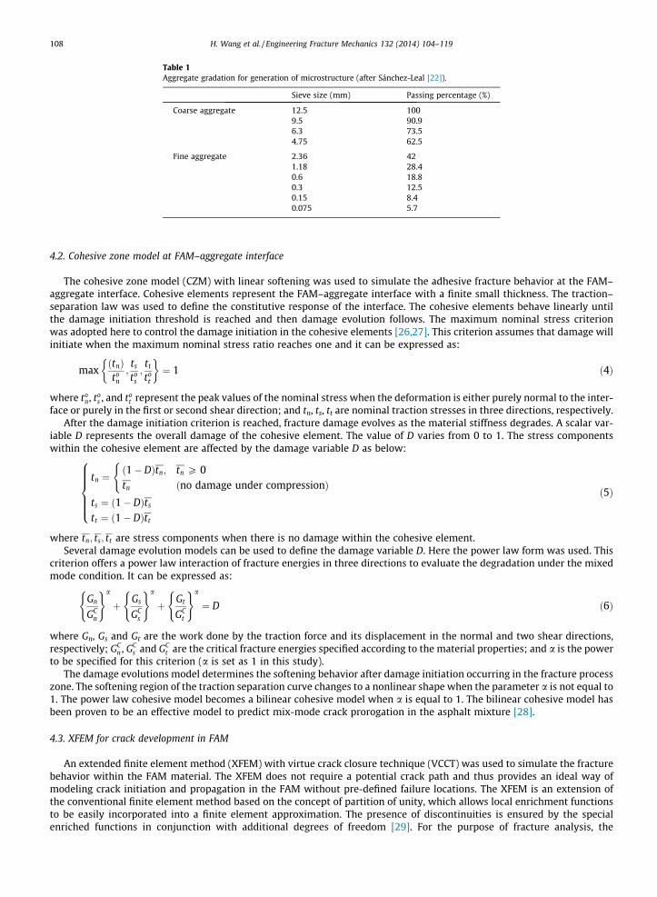
Table 1Aggregate gradation for generation of microstructure (after Sánchez-Leal [22]).
Sieve size (mm) Passing percentage (%)
Coarse aggregate 12.5 1009.5 90.96.3 73.54.75 62.5
Fine aggregate 2.36 421.18 28.40.6 18.80.3 12.50.15 8.40.075 5.7
108 H. Wang et al. / Engineering Fracture Mechanics 132 (2014) 104–119
4.2. Cohesive zone model at FAM–aggregate interface
The cohesive zone model (CZM) with linear softening was used to simulate the adhesive fracture behavior at the FAM–aggregate interface. Cohesive elements represent the FAM–aggregate interface with a finite small thickness. The traction–separation law was used to define the constitutive response of the interface. The cohesive elements behave linearly untilthe damage initiation threshold is reached and then damage evolution follows. The maximum nominal stress criterionwas adopted here to control the damage initiation in the cohesive elements [26,27]. This criterion assumes that damage willinitiate when the maximum nominal stress ratio reaches one and it can be expressed as:
maxðtnÞto
n;ts
tos;tt
tot
� �¼ 1 ð4Þ
where ton, to
s , and tot represent the peak values of the nominal stress when the deformation is either purely normal to the inter-
face or purely in the first or second shear direction; and tn, ts, tt are nominal traction stresses in three directions, respectively.After the damage initiation criterion is reached, fracture damage evolves as the material stiffness degrades. A scalar var-
iable D represents the overall damage of the cohesive element. The value of D varies from 0 to 1. The stress componentswithin the cohesive element are affected by the damage variable D as below:
tn ¼ð1� DÞtn; tn P 0tn ðno damage under compressionÞ
(
ts ¼ ð1� DÞts
tt ¼ ð1� DÞtt
8>>>><>>>>:
ð5Þ
where tn; ts; tt are stress components when there is no damage within the cohesive element.Several damage evolution models can be used to define the damage variable D. Here the power law form was used. This
criterion offers a power law interaction of fracture energies in three directions to evaluate the degradation under the mixedmode condition. It can be expressed as:
Gn
GCn
( )a
þ Gs
GCs
( )a
þ Gt
GCt
( )a
¼ D ð6Þ
where Gn, Gs and Gt are the work done by the traction force and its displacement in the normal and two shear directions,respectively; GC
n , GCs and GC
t are the critical fracture energies specified according to the material properties; and a is the powerto be specified for this criterion (a is set as 1 in this study).
The damage evolutions model determines the softening behavior after damage initiation occurring in the fracture processzone. The softening region of the traction separation curve changes to a nonlinear shape when the parameter a is not equal to1. The power law cohesive model becomes a bilinear cohesive model when a is equal to 1. The bilinear cohesive model hasbeen proven to be an effective model to predict mix-mode crack prorogation in the asphalt mixture [28].
4.3. XFEM for crack development in FAM
An extended finite element method (XFEM) with virtue crack closure technique (VCCT) was used to simulate the fracturebehavior within the FAM material. The XFEM does not require a potential crack path and thus provides an ideal way ofmodeling crack initiation and propagation in the FAM without pre-defined failure locations. The XFEM is an extension ofthe conventional finite element method based on the concept of partition of unity, which allows local enrichment functionsto be easily incorporated into a finite element approximation. The presence of discontinuities is ensured by the specialenriched functions in conjunction with additional degrees of freedom [29]. For the purpose of fracture analysis, the
H. Wang et al. / Engineering Fracture Mechanics 132 (2014) 104–119 109
enrichment functions typically consist of the near-tip asymptotic functions that capture the singularity around the crack tipand a discontinuous function that represents the jump in displacement across the crack surfaces.
The crack initiates depending on the stress distribution in the FAM material. The nodal enrichment function method andphantom node method were used to enable the prediction of crack initiation and crack propagation without re-meshing[30,31]. The approximation for a displacement vector function with the partition of unity enrichment is shown in Eq. (7):
u ¼XN
I¼1
NIðxÞ uI þ HðxÞaI þX4
a¼1
FaðxÞbaI
" #ð7Þ
where NI(x) are the usual nodal shape functions; uI is the usual nodal displacement vector associated with the continuouspart of the finite element solution; aI is the nodal enriched degree of freedom vector; H(x) is the associated discontinuousjump function across the crack surfaces; Fa(x) is the associated elastic asymptotic crack tip functions and ba
I is the nodalenriched degree of freedom. The first term on the right-hand side is applicable to all the nodes in the model; the second termis valid for nodes whose shape function support is cut by the crack interior; and the third term is used only for nodes whoseshape function support is cut by the crack tip.
The discontinuous jump function across the crack surfaces, H(x), is given by:
HðxÞ ¼1 if ðx� x�Þ � n P 0�1 otherwise
�ð8Þ
where x is a sample (Gauss) point; x⁄ is the point on the crack closest to x; and n is the unit outward normal to the crack at x⁄.The asymptotic crack tip functions in an isotropic elastic material, Fa(x) is given by:
FaðxÞ ¼ffiffiffirp
sinh2;ffiffiffirp
cosh2;ffiffiffirp
sin h sinh2;ffiffiffirp
sin h cosh2
� �ð9Þ
where (r, h) is a polar coordinate system with its origin at the crack tip and h = 0 is tangent to the crack at the tip.The crack initiation criterion used in the FAM material was consistent with the criterion used at the FAM–aggregate inter-
face. The virtue crack closure technique (VCCT) was used to control the crack propagation in the FAM material. The VCCTassumes that the strain energy released when a crack is extended by a certain amount is the same as the energy requiredto close the crack. Here a power law form is used to model the mix model behavior [32]:
f ¼ GI
GIC
� �am
þ GII
GIIC
� �an
þ GIII
GIIIC
� �ao
ð10Þ
where crack tip debonds when f reaches the value of 1.0; GI, GII and GIII are strain energy release rates in normal and twoshear directions; GIC, GIIC and GIIIC are critical energy release rates in normal and two shear direction; am, an and ao arethe power index for each component respectively (they are assumed to be 1 in this study).
5. Model geometry and parameters
Due to the viscoelastic properties of asphalt binder, asphalt mixtures have different failure modes at low and hightemperatures. In this study, asphalt mixture samples are assumed to be tested at the low temperature so fracture is the pre-dominant failure mode. The heterogeneous nature of asphalt mixture requires fracture parameters to be modeled locally.This means that the FAM–aggregate interface and FAM material should have different fracture parameters.
Experimental tests have been carried out to study the fracture properties of FAM and FAM–aggregate interface, respec-tively. Aragão et al. [33] conducted two bending tests (semi-circular bending (SCB) and single-edge notched beam (SEB)) andone tension test (disk-shaped compact tension (DCT)) to characterize fracture properties of a fine aggregate mixture andprovided the fracture properties at different temperatures. Khattak et al. [34] studied mastic–aggregate adhesion and mech-anistic characteristics of different asphalt mixtures by using the lap-shear test and tensile test with in-situ environmentalscanning electron microscope. Fini and Al-Qadi [35] developed a blister test to study the mastic–aggregate fracture proper-ties and estimated the interface strength and fracture energy. This study selected the fracture properties from previousresearches to realistically build the computational model. The material parameters used in this study are listed in Table 2.
The numerical simulations were conducted using the commercial finite element analysis package ABAQUS. Due to thehigh stress singularity at aggregate tip and the random distribution of aggregate within the asphalt mixture model, the freemeshing method with mesh control was used. Mesh sensitivity analysis was conducted to assure the model accuracy. Tohave a balance between computational accuracy and time, an overall mesh seed size of 0.5 mm was used to generate themesh. The representative volume element (RVE) size selected here is a 50 mm � 50 mm square. It has the capacity of includ-ing at least two largest aggregates without significantly increasing the computational cost. An illustration of meshes isshown in Fig. 2(a). The numerical specimen was fixed at the bottom and the tension load was applied on the top surface,as shown in Fig. 2(b). A vertical displacement was applied to the model at a rate of 0.5 mm/s.

Table 2Material properties of each mixture component at low temperatures.
Aggregate FAM–aggregate interface Fine aggregate matrix
Elastic modulus 50 GPa Elastic modulus 50 GPa Viscoelastic series Prony Fracture strength Normal: 2.5 MPaFracture strength Normal: 0.5 MPa i Ei (Pa) si (s) 1st shear: 2.5 MPa
1st shear: 0.5 MPa 0 17.5E9 0 2nd shear: 2.5 MPa2nd shear: 0.5 MPa 1 6.79E9 1.13E�4 Critical energy
release rateNormal: 200 J/m2
Fracture energy Normal: 150 J/m2 2 5.51E9 3.14E�3Poisson ratio 0.15 3 3.03E9 1.3E�2 1st shear: 600 J/m2
1st shear: 450 J/m2 4 1.44E9 1.64E�15 4.39E8 2.09 2nd shear: 600 J/m2
2nd shear: 450 J/m2 6 1.87E8 37.7
Fig. 2. (a) Meshes of the finite element model and (b) boundary and loading condition (Sample #2 selected).
110 H. Wang et al. / Engineering Fracture Mechanics 132 (2014) 104–119
6. Model results and analysis
6.1. Crack initiation
An intact model that only contains continuum elements and does not allow fracture development was first devel-oped for comparison with the fracture model. Fig. 3(a)–(c) compares the tensile stress distributions between the intactmodel, the fracture model with adhesive failure only, and the fracture model with cohesive and adhesive failure. Theresults from the intact model and the fracture model with adhesive failure only indicate that a very high level ofstress concentrates near the aggregate tip that is close to another large aggregate tip. This indicates where fracturewould initiate within the FAM material. On the other hand, in the fracture model with cohesive and adhesive failure,crack initiates in the FAM material along with the development of interface damage. The local strain energy is releasedto create new crack surfaces and the crack initiation reduces the stress concentration. The damage along the FAM–aggregate interface results in lower stresses around the aggregate tip, compared to the intact model without crackpotential.
To study how the cohesive and adhesive failure develop under loading, two separate simulations were conducted: oneallowed cracking to initiate and propagate at the FAM–aggregate interface (adhesive failure) and within the FAM material(cohesive failure); and the other one only allowed cracking to occur at the FAM–aggregate interface. The average valuesof stiffness degradation variable (SDEG) of four cohesive elements near the area where the crack in the FAM material initiateswere compared between two models, as is shown in Fig. 4. The SDEG indicates the adhesive failure of cohesive elements atthe FAM–aggregate interface with a scale of 0–1. The SDEG value of one indicates that the cohesive element is fully cracked.It shows that consideration of cohesive failure in the FAM material causes the adhesive failure at the FAM–aggregateinterface to develop faster. Fig. 5(a)–(e) shows how the overall damage evolves at different displacements. The evolutionof cracking failure shows that the damage in the FAM material would develop first at the small displacement and then inter-connected with the damage developed at the mastic–aggregate interface. As the displacement keeps increasing, the interfaceadhesive damage is the dominant failure mode.

Fig. 3. Tensile stress distribution and local damage for (a) the intact model without crack potential, (b) the model with adhesive failure only, and (c) themodel with cohesive and adhesive failure.
0
0.2
0.4
0.6
0.8
1
0 0.2 0.4 0.6 0.8 1
SDE
G d
amag
e
Loading time (sec)
model with only adhesive failuremodel with cohesive and adhesive failure
Fig. 4. Average SDEG values of cohesive elements close to the crack in the FAM.
H. Wang et al. / Engineering Fracture Mechanics 132 (2014) 104–119 111

Fig. 5. FAM–aggregate interface damage at displacement of (a) 0.1 mm; (b) 0.2 mm; (c) 0.3 mm (d) 0.4 mm; and (e) 0.5 mm.
112 H. Wang et al. / Engineering Fracture Mechanics 132 (2014) 104–119
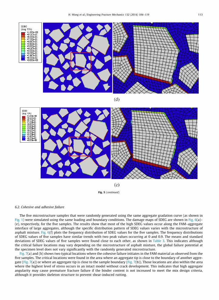
Fig. 5 (continued)
H. Wang et al. / Engineering Fracture Mechanics 132 (2014) 104–119 113
6.2. Cohesive and adhesive failure
The five microstructure samples that were randomly generated using the same aggregate gradation curve (as shown inFig. 1) were simulated using the same loading and boundary conditions. The damage maps of SDEG are shown in Fig. 6(a)–(e), respectively, for the five samples. The results show that most of the high SDEG values occur along the FAM–aggregateinterface of large aggregates, although the specific distribution pattern of SDEG values varies with the microstructure ofasphalt mixture. Fig. 6(f) plots the frequency distribution of SDEG values for the five samples. The frequency distributionsof SDEG values of five samples have similar trends with two peak values occurring at 0 and 0.9. The means and standarddeviations of SDEG values of five samples were found close to each other, as shown in Table 3. This indicates althoughthe critical failure locations may vary depending on the microstructure of asphalt mixture, the global failure potential atthe specimen level does not vary significantly with the randomly generated microstructure.
Fig. 7(a) and (b) shows two typical locations where the cohesive failure initiates in the FAM material as observed from thefive samples. The critical locations were found in the area where an aggregate tip is close to the boundary of another aggre-gate (Fig. 7(a)) or where an aggregate tip is close to the sample boundary (Fig. 7(b)). Those locations are also within the areawhere the highest level of stress occurs in an intact model without crack development. This indicates that high aggregateangularity may cause premature fracture failure if the binder content is not increased to meet the mix design criteria,although it provides skeleton structure to prevent shear-induced rutting.

Fig. 6. (a)–(e) SDEG maps and (f) frequency distribution of SDEG values of five randomly generated samples.
114 H. Wang et al. / Engineering Fracture Mechanics 132 (2014) 104–119

0
0.1
0.2
0.3
0.4
0.5
0 0.1 0.2 0.3 0.4 0.5 0.6 0.7 0.8 0.9 1
Ele
men
t per
cent
age
SDEG Damage value
Asphalt mixture sample#1Asphalt mixture sample#2Asphalt mixture sample#3Asphalt mixture sample#4Asphalt mixture sample#5
(f)
Fig. 6 (continued)
Table 3SDEG values of different samples.
Sample # Mean SDEG values Standard deviation of SDEG values
1 0.499 0.3552 0.534 0.3433 0.517 0.3544 0.522 0.3565 0.527 0.352
Fig. 7. Two typical crack initiation locations in FAM: (a) where a sharp aggregate tip is close to another aggregate boundary and (b) where a sharp tip isclose to sample boundary.
H. Wang et al. / Engineering Fracture Mechanics 132 (2014) 104–119 115
7. Parametric study of fracture potential
7.1. Effect of loading rate
To quantify how the loading rates affect the fracture behavior, three different loading rates were applied: 0.5 mm/min,0.5 mm/s and 5 mm/s. The frequency distributions of SDEG values were plotted in Fig. 8. The mean SDEG values of the

116 H. Wang et al. / Engineering Fracture Mechanics 132 (2014) 104–119
asphalt mixture samples are 0.573, 0.534 and 0.414, respectively, under 5 mm/s, 0.5 mm/s and 0.5 mm/min loading rates.The peak of the frequency distribution curve shifts to a higher value as the loading rate increases. This indicates that thehigher loading rates induce the greater fracture potential in the asphalt mixture. Viscoelastic properties of FAM materialinduce a rate-dependent effect on the overall mixture performance. The higher loading rate results in the greater modulusof FAM in the model. The higher modulus of FAM would induce more stress concentration at the interface layer betweenaggregate and FAM where the CZM was used. The greater stress concentration at the interface causes more fracture damage.
7.2. Effect of FAM modulus
One key parameter affecting the fracture behavior is the instantaneous modulus of the FAM material that is dependent onthe performance grade of asphalt binder. The instantaneous modulus (E0) used in previous cases is 17.5 GPa. To investigatehow the FAM modulus affects the overall fracture behavior, 1/3 E0, 2/3 E0 and 4/3 E0 were assigned to the FAM material at thesame loading rate (0.5 mm/s). The frequency distribution curves of SDEG values were plotted in Fig. 9, respectively, for dif-ferent FAM moduli. It reveals that the higher modulus results in the higher damage level in the asphalt mixture, which isconsistent with the results at different loading rates.
7.3. Effect of interface bonding properties
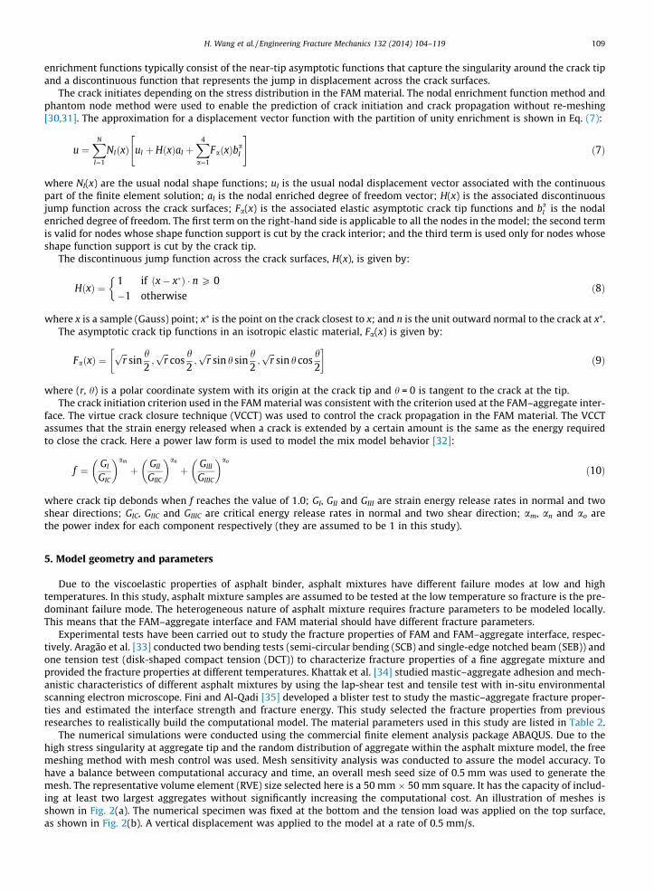
The effect of fracture strength and fracture energy at the FAM–aggregate interface on the failure potential of asphalt mix-ture was analyzed. This analysis is necessary considering different interface conditions may exist in the reality. It has beenfound that the bonding between aggregate and asphalt binder is affected by the physical properties and chemical composi-tion of aggregate, interfacial tension between binder and aggregate, temperature and moisture conditions [36]. Bondingstrength and interfacial fracture energy were analyzed separately. The effects of bonding strength on fracture potential wereshown in Fig. 10(a) and (b), respectively, for the tensile and shear adhesive strength. It was found that the adhesive shearstrength has more significant effect on the fracture potential as compared to the adhesive tensile strength. As the adhesivestrength changes from 0.9 to 0.3 MPa, the mean SDEG values of the asphalt mixture samples changes from 0.485 to 0.585 forshear adhesive strength and from 0.421 to 0.648 for shear adhesive strength. This indicates that the failure at the aggregate–mastic interface could be more prone to shear failure due to the heterogeneous nature of asphalt mixture. It further empha-sized the important influence of aggregate microstructure on fracture potential of asphalt mixture.
0
0.1
0.2
0.3
0.4
0.5
0 0.1 0.2 0.3 0.4 0.5 0.6 0.7 0.8 0.9 1
Ele
men
t Per
cent
age
SDEG Damage value
loading rate 0.5mm/minloading rate 0.5mm/sloading rate 5mm/s
Fig. 8. SDEG frequency distributions of the sample under different loading rates.
0
0.1
0.2
0.3
0.4
0.5
0 0.1 0.2 0.3 0.4 0.5 0.6 0.7 0.8 0.9 1
Ele
men
t Per
cent
age
SDEG Damage Value
E0=5.83GPaE0=11.7GPaE0=17.5GPaE0=23.3GPa
Fig. 9. SDEG frequency distributions of samples with different E0.
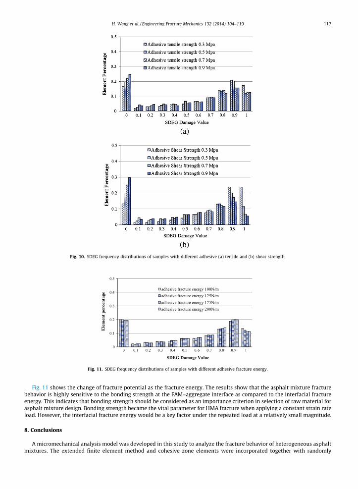
Fig. 10. SDEG frequency distributions of samples with different adhesive (a) tensile and (b) shear strength.
0
0.1
0.2
0.3
0.4
0.5
0 0.1 0.2 0.3 0.4 0.5 0.6 0.7 0.8 0.9 1
Ele
men
t per
cent
age
SDEG Damage Value
adhesive fracture energy 100N/madhesive fracture energy 125N/madhesive fracture energy 175N/madhesive fracture energy 200N/m
Fig. 11. SDEG frequency distributions of samples with different adhesive fracture energy.
H. Wang et al. / Engineering Fracture Mechanics 132 (2014) 104–119 117
Fig. 11 shows the change of fracture potential as the fracture energy. The results show that the asphalt mixture fracturebehavior is highly sensitive to the bonding strength at the FAM–aggregate interface as compared to the interfacial fractureenergy. This indicates that bonding strength should be considered as an importance criterion in selection of raw material forasphalt mixture design. Bonding strength became the vital parameter for HMA fracture when applying a constant strain rateload. However, the interfacial fracture energy would be a key factor under the repeated load at a relatively small magnitude.
8. Conclusions
A micromechanical analysis model was developed in this study to analyze the fracture behavior of heterogeneous asphaltmixtures. The extended finite element method and cohesive zone elements were incorporated together with randomly
118 H. Wang et al. / Engineering Fracture Mechanics 132 (2014) 104–119
generated microstructures to simulate the cohesive and adhesive fracture behaviors of asphalt mixtures, respectively.Asphalt mixture samples under tension loading conditions were simulated and the sensitivity of fracture resistance todifferent material and fracture parameters was studied. The following conclusions can be concluded from the analysis:
(1) The development of cracking shows that the damage in the FAM material would initiate first at a small displacementand then interconnect with the damage developed at the FAM–aggregate interface. As the displacement keeps increas-ing, the interface adhesive damage becomes the dominant failure mode.
(2) The critical locations for crack initiation in the FAM material were found in the area where an aggregate tip is close tothe boundary of another aggregate or where an aggregate tip is close to the sample boundary. This indicates that highaggregate angularity may cause premature fracture failure although it provides skeleton structure to prevent shear-induced rutting.
(3) Although the critical failure locations may vary depending on the microstructure of asphalt mixture, the global failurepotential at the specimen level does not vary significantly with the randomly generated aggregate microstructureusing the same aggregate gradation.
(4) The higher FAM modulus due to low temperatures or high loading rates could result in the greater fracture potential inasphalt mixtures. Better interface bonding strength between the aggregate and binder could significantly improve thefracture resistance of asphalt mixtures.
Acknowledgement
This study is partially supported by the National Science Foundation under Grant No. 1338297.
References
[1] Guddati MN, Feng Z, Kim YR. Toward a micromechanics-based procedure to characterize fatigue performance of asphalt concrete. Transport Res Rec: JTransport Res Board 2002;1789(1):121–8.
[2] Sadd MH, Dai Q, Parameswaran V, Shukla A. Microstructural simulation of asphalt materials: modeling and experimental studies. J Mater Civ Engng2004;16(2):107–15.
[3] Dai Q, Sadd MH, Parameswaran V, Shukla A. Prediction of damage behaviors in asphalt materials using a micromechanical finite-element model andimage analysis. J Engng Mech 2005;131(7):668–77.
[4] Kim YR, Allen DH, Little DN. Damage-induced modeling of asphalt mixtures through computational micromechanics and cohesive zone fracture. JMater Civ Engng 2005;17(5):477–84.
[5] Kim YR, Allen DH, Little DN. Computational constitutive model for predicting nonlinear viscoelastic damage and fracture failure of asphalt concretemixtures. Int J Geomech 2007;7(2):102–10.
[6] Kim H, Wagoner MP, Buttlar WG. Simulation of fracture behavior in asphalt concrete using a heterogeneous cohesive zone discrete element model. JMater Civ Engng 2008;20(8):552–63.
[7] Aragão FTS, Kim YR, Lee J, Allen DH. Micromechanical model for heterogeneous asphalt concrete mixtures subjected to fracture failure. J Mater CivEngng 2010;23(1):30–8.
[8] Kristiansen KDL, Wouterse A, Philipse A. Simulation of random packing of binary sphere mixtures by mechanical contraction. Physica A: Stat MechAppl 2005;358(2):249–62.
[9] Yin A, Yang X, Gao H, Zhu H. Tensile fracture simulation of random heterogeneous asphalt mixture with cohesive crack model. Engng Fract Mech2012;92:40–55.
[10] de Souza FV, Soares JB, Allen DH, Evangelista F. Model for predicting damage evolution in heterogeneous viscoelastic asphaltic mixtures. Transport ResRec: J Transport Res Board 2004;1891:131–9.
[11] Soares JB, Freitas FAC, Allen DH. Crack modeling of asphaltic mixtures considering heterogeneity of the material. Transport Res Rec 2003;1832:113–20.[12] Souza LT, Kim YR, Souza FV, Castro LS. Experimental testing and finite-element modeling to evaluate the effects of aggregate angularity on bituminous
mixture performance. J Mater Civ Engng 2012;24(3):249–58.[13] Kim YR, Aragão FTS. Microstructure modeling of rate-dependent fracture behavior in bituminous paving mixtures. Finite Elem Anal Des
2013;63:23–32.[14] Ng K, Dai Q. Investigation of fracture behavior of heterogeneous infrastructure materials with extended-finite-element method and image analysis. J
Mater Civ Engng 2011;23(12):1662–71.[15] Ng K, Dai Q. Tailored extended finite-element model for predicting crack propagation and fracture properties within idealized and digital cementitious
material samples. J Engng Mech 2011;138(1):89–100.[16] Mahmoud E, Saadeh S, Hakimelahi H, Harvey J. Extended finite-element modelling of asphalt mixtures fracture properties using the semi-circular
bending test. Road Mater Pavement Des 2014;15(1):153–66.[17] Lancastera M, Khalida HA, Kougioumtzogloub IA. Extended FEM modelling of crack propagation using the semi-circular bending test. Constr Build
Mater 2013;48:270–7.[18] Wang ZM, Kwan AKH, Chan HC. Mesoscopic study of concrete I: generation of random aggregate structure and finite element mesh. Comput Struct
1999;70(5):533–44.[19] Bazant ZP, Tabbara MR, Kazemi MT, Pijaudier-Cabot G. Random particle model for fracture of aggregate or fiber composites. J Engng Mech
1990;116(8):1686–705.[20] Wittmann FH, Roelfstra PE, Sadouki H. Simulation and analysis of composite structures. Mater Sci Engng 1985;68(2):239–48.[21] De Schutter G, Taerwe L. Random particle model for concrete based on Delaunay triangulation. Mater Struct 1993;26(2):67–73.[22] Sánchez-Leal FJ. Gradation chart for asphalt mixes: development. J Mater Civ Engng 2007;19(2):185–97.[23] Wang D, Wang LB, Druta C, Xue W, Xiong H, Sun W. Experimental evaluation of a simple contact model containing two elastic particles bonded by a
thin layer of viscoelastic binder. J Nanomech Micromech 2013;3(4):04013005.[24] Tschoegl NW, Tschoegl NW. The phenomenological theory of linear viscoelastic behavior: an introduction. Berlin, German: Springer-Verlag; 1989.[25] Ferry JD. Viscoelastic properties of polymers. Hoboken, NJ, USA: John Wiley & Sons; 1980.[26] ABAQUS. ABAQUS analysis user’s manual, version 6.10. Pawtucket, RI, USA: Habbit, Karlsson & Sorenson Inc.; 2010.[27] Hillerborg A, Modéer M, Petersson PE. Analysis of crack formation and crack growth in concrete by means of fracture mechanics and finite elements.
Cem Concr Res 1976;6:773–82.

H. Wang et al. / Engineering Fracture Mechanics 132 (2014) 104–119 119
[28] Song SH, Paulino GH, Buttlar WG. A bilinear cohesive zone model tailored for fracture of asphalt concrete considering viscoelastic bulk material. EngngFract Mech 2006;73(18):2829–48.
[29] Belytschko T, Black T. Elastic crack growth in finite elements with minimal remeshing. Int J Numer Meth Engng 1999;45:601–20.[30] Babuska I, Melenk J. The partition of unity method. Int J Numer Meth Engng 1997;40(4):727–58.[31] Osher SJ, Fedkiw RP. Level set methods and dynamic implicit surfaces. Berlin, German: Springer-Verlag; 2002.[32] Xie D, Bivvers SB. Progressive crack growth analysis using interface element based on the virtual crack closure technique. Finite Elem Anal Des
2006;42(11):977–84.[33] Aragão FTS, Hartmann DA, Kim YR, da Motta LMG, Javaherian MH. Numerical–experimental approach to characterize fracture properties of asphalt
mixtures at low in-service temperatures. In: Proceeding of transportation research board 93rd annual meeting; 2014 [paper # 14-4905].[34] Khattak MJ, Baladi GY, Drzal LT. Low temperature binder–aggregate adhesion and mechanistic characteristics of polymer modified asphalt mixtures. J
Mater Civ Engng 2007;19(5):411–22.[35] Fini EH, Al-Qadi IL. Development of a pressurized blister test for interface characterization of aggregate highly polymerized bituminous materials. J
Mater Civ Engng 2011;23(5):656–63.[36] Tarrer AR, Wagh V. The effect of the physical and chemical characteristics of the aggregate on bonding (No. SHRP-A/UIR-91-507). Washington,
DC: Strategic Highway Research Program, National Research Council; 1991.