metals & fabrication - geometric development
TRANSCRIPT

METALS & FABRICATION
GEOMETRIC DEVELOPMENT
Learning Resource
ENG091

ENG091
Geometric Development
Learning Resource

Copyright and Terms of Use
© Department of Training and Workforce Development 2016 (unless indicated otherwise, for example ‘Excluded Material’).
The copyright material published in this product is subject to the Copyright Act 1968 (Cth), and is owned by the Department of Training and Workforce Development or, where indicated, by a party other than the Department of Training and Workforce Development. The Department of Training and Workforce Development supports and encourages use of its material for all legitimate purposes.
Copyright material available in this product is licensed under a Creative Commons Attribution 4.0 (CC BY 4.0) license unless indicated otherwise (Excluded Material).
Except in relation to Excluded Material this license allows you to: • Share — copy and redistribute the material in any medium or format • Adapt — remix, transform, and build upon the material for any purpose, even commercially
provided you attribute the Department of Training and Workforce Development as the source of the copyright material. The Department of Training and Workforce Development requests attribution as: © Department of Training and Workforce Development (year of publication).
Excluded Material not available under a Creative Commons license: 1. The Department of Training and Workforce Development logo, other logos and trademark protected material; and 2. Material owned by third parties that has been reproduced with permission. Permission will need to be obtained from third parties to
re-use their material.
Excluded Material may not be licensed under a CC BY license and can only be used in accordance with the specific terms of use attached to that material or where permitted by the Copyright Act 1968 (Cth). If you want to use such material in a manner that is not covered by those specific terms of use, you must request permission from the copyright owner of the material.
If you have any questions regarding use of material available in this product, please contact the Department of Training and Workforce Development.
Training Sector Services Telephone: 08 6212 9789 Email: [email protected] Website: www.dtwd.wa.gov.au

ISBN 978-0-7307-9720-3
First published 2009
2nd edition 2010
Published by and available from:
Department of Training and Workforce Development
1 Prospect Place West Perth WA 6005Tel: (08) 6212 9700 Fax: (08) 9227 8393Email: [email protected]: www.vetinfonet.dtwd.wa.gov.au
© VET (WA) Ministerial Corporation 2010
Metals & Engineering Training Package: Interpreting Technical Drawings, Training Publications
All rights reserved. No part of this publication may be reproduced, stored in a retrieval system or transmitted in any form or by any means, electronic, mechanical, photocopying, recording or otherwise, without the prior written permission of the Department of Training and Workforce Development.
Whilst every effort has been made to ensure the accuracy of the information contained in this publication, no guarantee can be given that all errors and omissions have been excluded. No responsibility for loss occasioned to any person acting or refraining from action as a result of the material in this publication can be accepted by the Department of Training and Workforce Development.
Australian Standard® is a registered trade mark of Standards Australia Limited ACN 087 326 690.
Various photographs reproduced with permission, from the 2006 edition of the BOC Industrial Reference Manual, BOC Australia Limited, Sydney.
This product contains various images © JupiterImages 2009, used under licence.
3
Fabrication& Geometric development
Content
Introduction 4
SectionsSection 1 Parallel line development 5
Section 2 Radial line development 39
Section 3 Triangulation development 67
Appendix Competency mapping 107
4
Fabrication& Geometric development
Introduction
This self-paced unit provides an introduction to the three most common geometric pattern development techniques; parallel line, radial line and triangulation.
On completion of this unit you should be able to produce geometrically developed patterns using the three techniques mentioned.
Although this unit stands alone, it is also a foundation module for those students who wish to extend their knowledge and skills in any one or all three of the pattern development techniques.
Three prerequisite units are to be completed prior to attempting this unit.
• MEM12023A Perform engineering measurements
• MEM12024A Perform computations
• MEM09002B Interpret technical drawings
For the purpose of the geometrical drawing exercises, no material allowances have been used.
If you were to fabricate a particular transition you would need to consider the appropriate material allowance for the formation of each development.
Your trainer will explain the allowances required or you may wish to re-visit the ENG1041 Perform engineering measurements workbook.
Spare drawing paper has been provided for you at the back of this workbook.
5
Fabrication& Geometric development
TerminologyTerminology is used in every aspect of our lives. For example, when someone talks about The Web, we all know what it is. It is the system which allows people to communicate via their PCs; personal computers. The Web is just another term or terminology. Understanding of the words commonly used in technical drawing and especially pattern development is essential for communication to take place.
The terminology used in parallel line development can be listed under the following three headings.
Shapes• prism• cylinder• pattern.
Lines• centreline• girth line• generator line• datum line.
Surface• flat surface• curved surface• incline planes.
Section 1 – Parallel line development
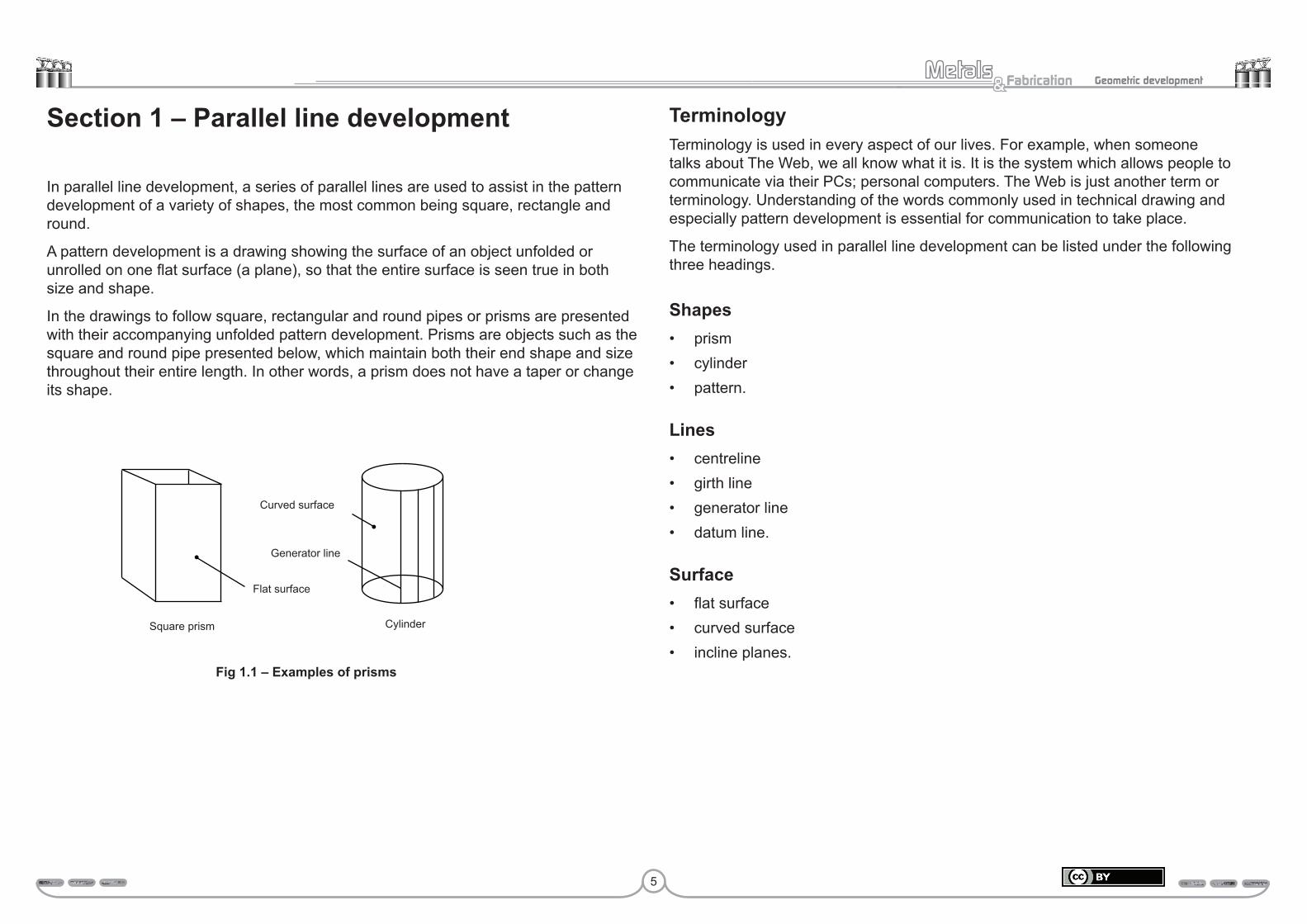
In parallel line development, a series of parallel lines are used to assist in the pattern development of a variety of shapes, the most common being square, rectangle and round.
A pattern development is a drawing showing the surface of an object unfolded or unrolled on one flat surface (a plane), so that the entire surface is seen true in both size and shape.
In the drawings to follow square, rectangular and round pipes or prisms are presented with their accompanying unfolded pattern development. Prisms are objects such as the square and round pipe presented below, which maintain both their end shape and size throughout their entire length. In other words, a prism does not have a taper or change its shape.
Flat surface
Generator line
Curved surface
Square prism Cylinder
Fig 1.1 – Examples of prisms
6
Fabrication& Geometric development
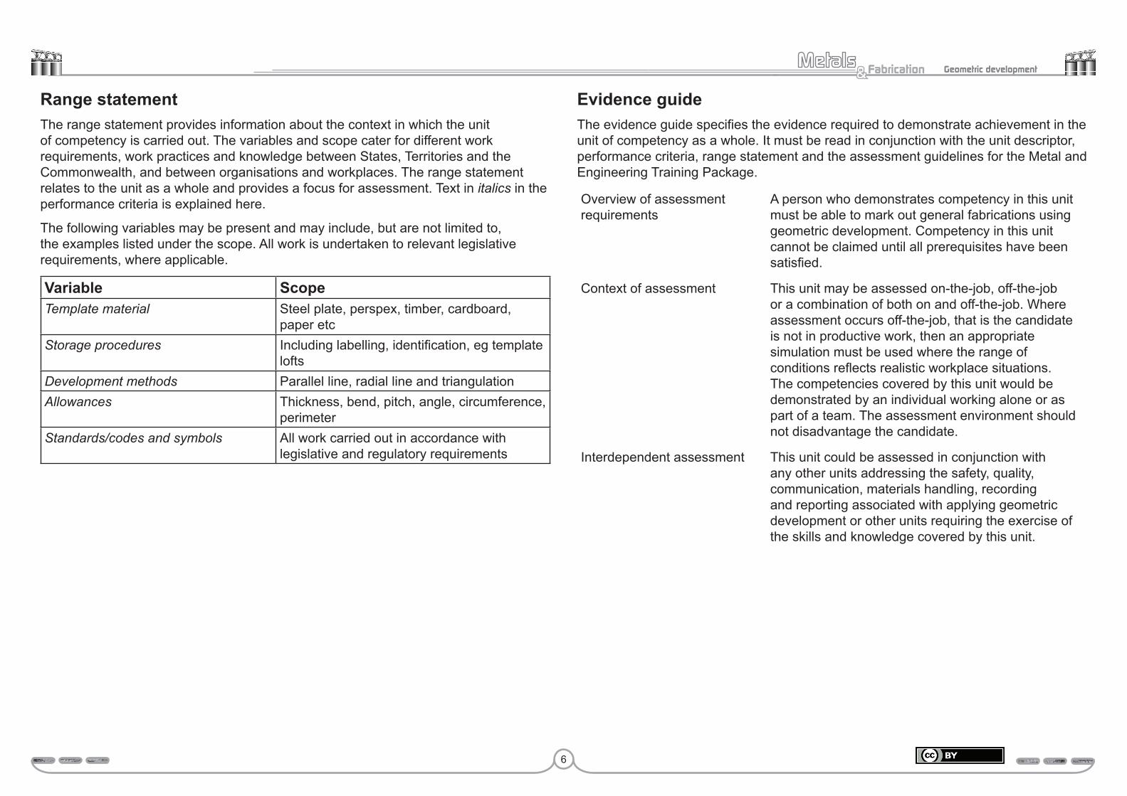
Range statementThe range statement provides information about the context in which the unit of competency is carried out. The variables and scope cater for different work requirements, work practices and knowledge between States, Territories and the Commonwealth, and between organisations and workplaces. The range statement relates to the unit as a whole and provides a focus for assessment. Text in italics in the performance criteria is explained here.
The following variables may be present and may include, but are not limited to, the examples listed under the scope. All work is undertaken to relevant legislative requirements, where applicable.
Variable ScopeTemplate material Steel plate, perspex, timber, cardboard,
paper etcStorage procedures Including labelling, identification, eg template
loftsDevelopment methods Parallel line, radial line and triangulationAllowances Thickness, bend, pitch, angle, circumference,
perimeterStandards/codes and symbols All work carried out in accordance with
legislative and regulatory requirements
Evidence guideThe evidence guide specifies the evidence required to demonstrate achievement in the unit of competency as a whole. It must be read in conjunction with the unit descriptor, performance criteria, range statement and the assessment guidelines for the Metal and Engineering Training Package.
Overview of assessment requirements
A person who demonstrates competency in this unit must be able to mark out general fabrications using geometric development. Competency in this unit cannot be claimed until all prerequisites have been satisfied.
Context of assessment This unit may be assessed on-the-job, off-the-job or a combination of both on and off-the-job. Where assessment occurs off-the-job, that is the candidate is not in productive work, then an appropriate simulation must be used where the range of conditions reflects realistic workplace situations. The competencies covered by this unit would be demonstrated by an individual working alone or as part of a team. The assessment environment should not disadvantage the candidate.
Interdependent assessment This unit could be assessed in conjunction with any other units addressing the safety, quality, communication, materials handling, recording and reporting associated with applying geometric development or other units requiring the exercise of the skills and knowledge covered by this unit.

7
Fabrication& Geometric development
Student equipment/clothing requirementsTo successfully complete this unit you are required to supply the following for your use.
Theory and drawing
• drawing instruments (compass set with extension bar)• eraser• pens• pencils (a 0.5 mm mechanical pencil, with HB lead is preferred)• scale rule• 45 degree set square (220 mm)• 60/30 degree set square (300 mm) both the 45° and the 60/30° squares are
available in a set• scientific calculator.
Occupational health and safetyThe Occupational Health and Safety Act requires you to protect yourself. Therefore, you must supply your own personal industrial clothing and equipment. If you do not supply and wear the stated clothing and equipment you will not be allowed to participate in any of the practical components of this unit.
Your trainer will make any final decisions on what is and what is not acceptable, but you will require at least:
• industrial type trousers and shirt, or overalls• safety boots or solid leather shoes• safety glasses• ear muffs and/or ear plugs.All accidents and injuries that happen during classes must be reported to your trainer.
Note: This workbook is designed as a self-paced learning package which means that you decide what you will do and when you will do it. However, it is very strongly suggested that you follow the sequence of this workbook as
presented.
Complete any theory and study components before attempting the associated pattern development.
Thoroughly study and understand each component, before moving on to the next. You will not only gain competency in the three elements, but also be judged to be competent.
Remember you trainer is there to assist you with your learning. So, if you need help – just ask!
Pattern developmentIt is important to adopt a logical sequence of events when planning the development of any pattern. This will ensure not only an accurate pattern, but also an effective and efficient use of all resources. The following is one such sequence of events.
Step 1 Draw the required views; for example – top and side view.
The pattern development cannot be commenced until the required views have been drawn. Fig 1.2 illustrates the two views required when the pattern for a square or rectangular prism is to be developed. Whereas Fig 1.3 shows the two views required when the pattern for a cylindrical prism is to be developed.
Fig 1.2 – Two views for a square or rectangular prism
Fig 1.3 –Two views for a cylindrical prism
Top view Top view
Side view Side view
40
4025
7070
8
Fabrication& Geometric development
Perimeter of the rectangle
Perimeter = (length + width) × 2 = (40 + 25) × 2 = 65 × 2 = 130 mm
Circumference of the circle
Circumference = π × diameter = 3.142 × 40 = 125.68 mm
Top view
40 BA
25
D C
Side view70
Fig 1.4 – Rectangular top view
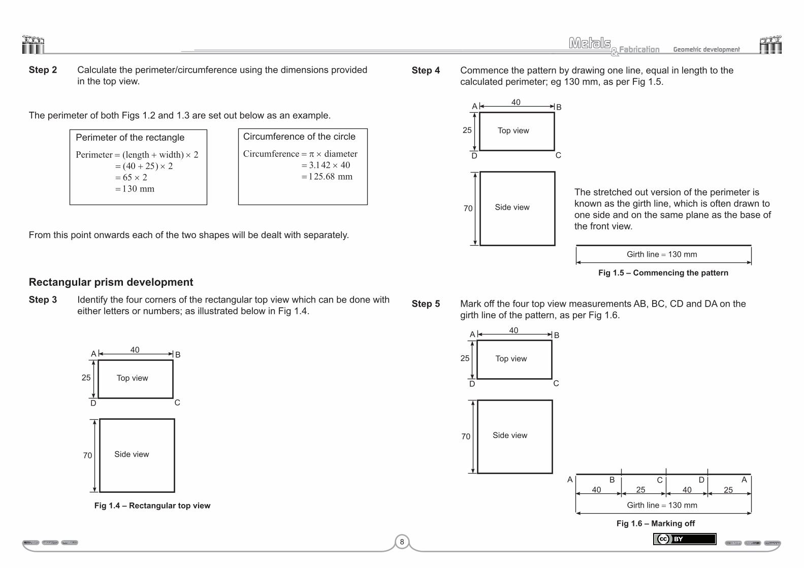
Step 2 Calculate the perimeter/circumference using the dimensions provided in the top view.
The perimeter of both Figs 1.2 and 1.3 are set out below as an example.
From this point onwards each of the two shapes will be dealt with separately.
Rectangular prism developmentStep 3 Identify the four corners of the rectangular top view which can be done with either letters or numbers; as illustrated below in Fig 1.4.
Step 4 Commence the pattern by drawing one line, equal in length to the calculated perimeter; eg 130 mm, as per Fig 1.5.
Step 5 Mark off the four top view measurements AB, BC, CD and DA on the girth line of the pattern, as per Fig 1.6.
Top view
40 BA
25
D C
Side view70
Girth line = 130 mm
Fig 1.6 – Marking off
A B C D A40 4025 25
Top view
40 BA
25
D C
Side view70
Girth line = 130 mm
Fig 1.5 – Commencing the pattern
The stretched out version of the perimeter is known as the girth line, which is often drawn to one side and on the same plane as the base of the front view.

9
Fabrication& Geometric development
Step 6 The pattern is completed by constructing five parallel lines which are drawn perpendicular to the girth line, from each of the five points A, B, C, D and A. These lines are drawn to a height equal in height to the side view. The pattern is finally completed when a line is drawn parallel to the girth line to connect the top of the five lines A, B, C, D and A.
Top view
40 BA
25
Side view70
D C
Fig 1.7 – A completed pattern
Pattern
A B C D A
Pattern development of a cylindrical prismStep 1 Draw the required views; for example – top and side view.
Pattern development cannot be commenced until the required views have been drawn. Fig 1.3 showed the two views required when the pattern for a cylindrical prism is to be developed.
Step 2 Calculate the circumference using the dimension provided in the top view.
The circumference of the top view of Fig 1.3 is set out below as an example.
Step 3 Divide the circumference of the top view into 12 equal parts, as illustrated in Fig 1.8.
Circumference of the circle
Circumference = π × diameter = 3.142 × 40 = 125.68 mm
Project each of the points located in the top view to the side view, where they are presented as a series of vertical and parallel lines.
Fig 1.8 – Divide the circumference
10
Fabrication& Geometric development
Fig 1.10 – Dividing the girth
Fig 1.11 – Completing the pattern
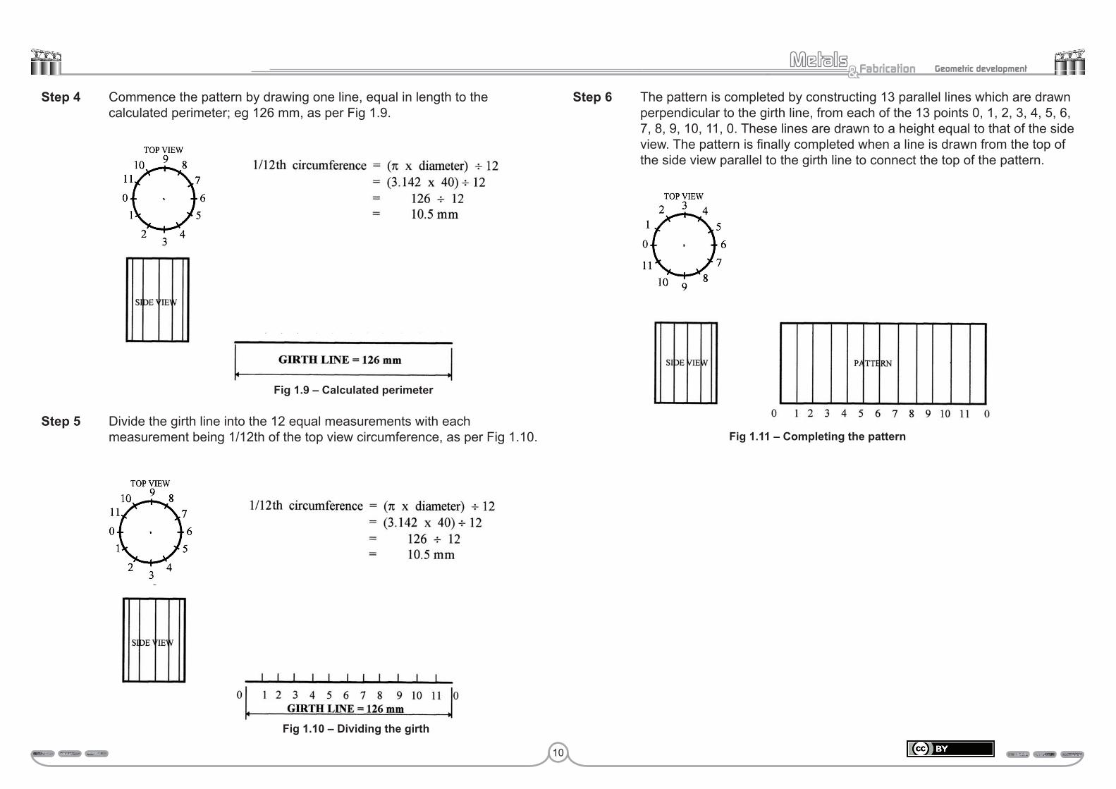
Step 6 The pattern is completed by constructing 13 parallel lines which are drawn perpendicular to the girth line, from each of the 13 points 0, 1, 2, 3, 4, 5, 6, 7, 8, 9, 10, 11, 0. These lines are drawn to a height equal to that of the side view. The pattern is finally completed when a line is drawn from the top of the side view parallel to the girth line to connect the top of the pattern.
Step 4 Commence the pattern by drawing one line, equal in length to the calculated perimeter; eg 126 mm, as per Fig 1.9.
Step 5 Divide the girth line into the 12 equal measurements with each measurement being 1/12th of the top view circumference, as per Fig 1.10.
Fig 1.9 – Calculated perimeter

11
Fabrication& Geometric development
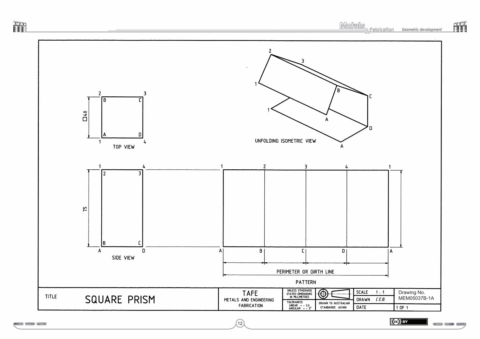
Study drawing MEM05037B-1A – Square prismDrawing MEM05037B-1A presents the pattern development of a square (prism).
1. Identify the two views that provide all of the information required to develop the pattern.
_________________ view _________________ view
2. Print the six missing dimensions, including the girth dimension in the spaces provided on the pattern of drawing MEM05037B-1A.
3. Complete the perimeter calculation in the space provided below.
Perimeter = side × 4
= 40 × 4
= 160 mm
4. Identify the position of the join or seam.
The join position is _____________________________________________ .
5. Explain the term prism.
A prism is _____________________________________________________ .
Submit these answers to your trainer for assessment.
Assessment:Date Signature Signature
Competent
Hold
12
Fabrication& Geometric development
Study drawing MEM05037B-1B – Mitred square prismDrawing MEM05037B-1B presents the pattern development for a mitred square (prism) which is a common pattern frequently produced by the metal fabricator.
While learning about this pattern development, you will once again follow the six basic steps you learnt earlier in the introduction to parallel line development.
Step 1 Draw the required views which once again you will note are the top and side views. These two views provide all of the following five pieces of information required to layout the pattern.
• The size of the sides of the square which is 40 mm.
• The perimeter or girth.
• The two heights presented in the side view, one being 75 mm, while the other height you can easily copy and transfer to the pattern, however its actual height is (35 mm).
• The angle of the mitre.
• The position of the seam or join which is in the centre of the short side.
• A more appropriate method that is preferred in industry is that the seam is placed to the edge of the short side then joined by the appropriate means, eliminating the need for an extra fold. Heavier sections may be folded twice (into a ‘U’ shape) and then the shorter side welded in on both edges.
Step 2 Identify each of the four corners with either letters or numbers and also in this example the position of the seam needs to be identified.
In this drawing the bottom four corners have been identified as A, B, C, and D. whereas the top four corners have been identified with the numbers 1, 2, 3, and 4. The word seam is used in the top view, but only its first letter (S) is used in the pattern as identification.
Step 3 Calculate the perimeter of this square prism.
Perimeter = side × 4
= 40 × 4
= 160 mm
Perform geometric development 11 MEM 05037 B
Drawing No MEM05037B-1ADrawing No.MEM05037B-1A
13
Fabrication& Geometric development
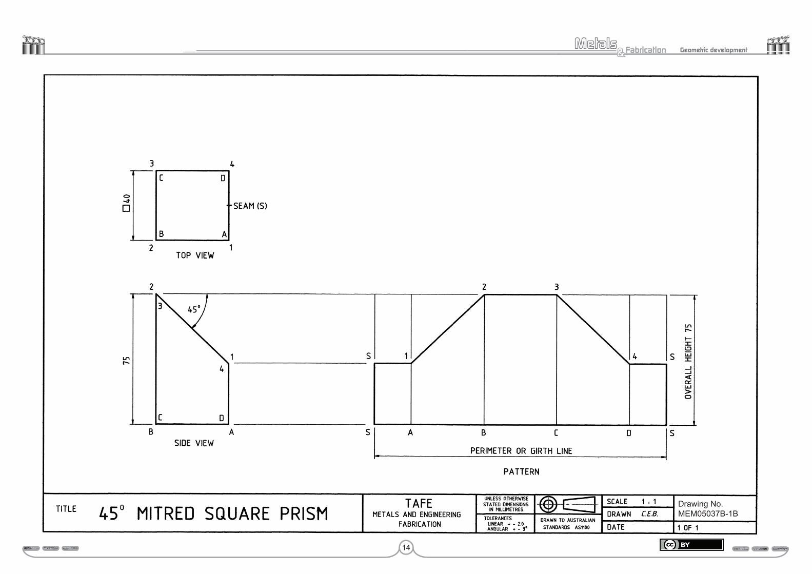
Study drawing MEM05037B-1B – Mitred square prismDrawing MEM05037B-1B presents the pattern development for a mitred square (prism) which is a common pattern frequently produced by the metal fabricator.
While learning about this pattern development, you will once again follow the six basic steps you learnt earlier in the introduction to parallel line development.
Step 1 Draw the required views which once again you will note are the top and side views. These two views provide all of the following five pieces of information required to layout the pattern.
• The size of the sides of the square which is 40 mm.
• The perimeter or girth.
• The two heights presented in the side view, one being 75 mm, while the other height you can easily copy and transfer to the pattern, however its actual height is 35 mm.
• The angle of the mitre.
• The position of the seam or join which is in the centre of the short side.
• A more appropriate method that is preferred in industry is that the seam is placed to the edge of the short side then joined by the appropriate means, eliminating the need for an extra fold. Heavier sections may be folded twice (into a ‘U’ shape) and then the shorter side welded in on both edges.
Step 2 Identify each of the four corners with either letters or numbers and also in this example the position of the seam needs to be identified.
In this drawing the bottom four corners have been identified as A, B, C, and D. whereas the top four corners have been identified with the numbers 1, 2, 3, and 4. The word seam is used in the top view, but only its first letter S is used in the pattern as identification.
Step 3 Calculate the perimeter of this square prism.
Perimeter = side × 4
= 40 × 4
= 160 mm
Step 4 Commence the pattern by drawing its girth line which as you can see has been drawn to the right and on the same horizontal plane as the base line of the side view.
Step 5 Mark off the five top view measurements SA, AB, BC, CD and DS along the girth line of the development, as illustrated.
Step 6 Construct the six parallel lines SS, A1, B2, C3, D4 and SS perpendicular to the girth line. To easily obtain the correct heights for these lines, project two horizontal construction lines from the side view; one from position 2–3 and the other from 1–4.
Do note, each of the six parallel lines SS, A1, B2, C3, D4 and SS can be transferred from the side view to the pattern with a compass.
To finalise the pattern simply join each of the points S1, 1–2, 2–3, 3–4 and 4S with an outline. Also outline the other three sides – SS, SS and the girth line.
Activity drawing MEM05037B-1B – Square prismA blank drawing sheet has been provided for you to photocopy at the end of this resource or your trainer will supply you with an appropriate drawing sheet.
All activities must be marked with a title block including:
• your name• date• drawing title.Submit the activities to your trainer for assessment.
14
Fabrication& Geometric development
Step 4 Commence the pattern by drawing its girth line which as you can see has been drawn to the right and on the same horizontal plane as the base line of the side view.
Step 5 Mark off the five top view measurements SA, AB, BC, CD and DS along the girth line of the development, as illustrated.
Step 6 Construct the six parallel lines SS, A1, B2, C3, D4 and SS perpendicular to the girth line. To easily obtain the correct heights for these lines, project two horizontal construction lines from the side view; one from position 2-3 and the other from 1-4.
Do note, each of the six parallel lines SS, A1, B2, C3, D4 and SS can be transferred from the side view to the pattern with a compass.
To finalise the pattern simply join each of the points S1, 1-2, 2-3, 3-4 and 4S with an outline. Also outline the other three sides – SS, SS and the girth line.
Activity drawing MEM05037B-1B – Square prismDraw both the top and side view for this drawing MEM05037B-1B and then develop the pattern. When developing the pattern do not look at the example, try working from what you have learnt. In other words treat this drawing as a test paper.
Paper is provided at the back of this resource package.
Submit this drawing to your trainer for assessment.
Assessment:Date Signature Signature
Competent
Hold
Perform geometric development 13 MEM 05037 B
Drawing No MEM05037B-1B
Drawing No. MEM05037B-1B
15
Fabrication& Geometric development
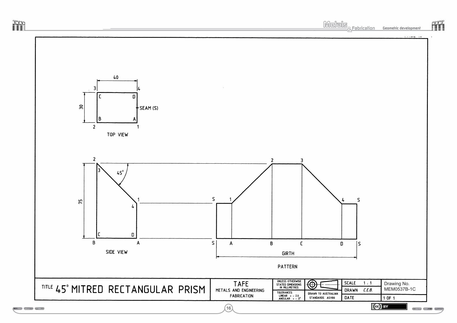
Study drawing MEM05037B-1C – Rectangular prismDrawing MEM05037B-1C presents the pattern development for a mitred rectangular (prism) which is another common pattern frequently produced by the metal fabricator.
While learning about this pattern development, you will once again follow the six basic steps you learnt earlier in the introduction to parallel line development.
Step 1 Draw the required views which once again you will note are the top and side views. These two views provide all of the following five pieces of information required to layout the pattern.
• The length and width of the rectangle which are 45 by 30 mm.
• The perimeter or girth.
• The two heights presented in the side view, one being 75 mm, while the other height you can easily copy and transfer to the pattern, however its actual height is 30 mm.
• The angle of the mitre.
• A more appropriate method that is preferred in industry is that the seam is placed to the edge of the short side then joined by the appropriate means, eliminating the need for an extra fold. Heavier sections may be folded twice (into a ‘U’ shape) and then the shorter side welded in on both edges.
Step 2 Identify each of the four corners with either letters or numbers and also in this example the position of the seam needs to be identified.
In this drawing the bottom four corners have been identified as A, B, C, and D. Whereas the top four corners have been identified with the numbers 1, 2, 3, and 4. The word seam is used in the top view, but only its first letter S is used in the pattern as identification.
Step 3 Calculate the perimeter of this rectangular prism.
Perimeter = (length + width) × 2
= (40 + 30) × 2
= 140 mm
Step 4 Commence the pattern by drawing its girth line which as you can see has been drawn to the right and on the same horizontal plane as the base line of the side view.
Step 5 Mark off the five top view measurements SA, AB, BC, CD and DS along the girth line of the development, as illustrated.
Step 6 Construct the six parallel lines SS, A1, B2, C3, D4 and SS from and perpendicular to the girth line. To easily obtain the correct heights for these lines, project two horizontal construction lines from the side view; one from position 2–3 and the other from 1–4.
Note: Each of the six parallel lines SS, A1, B2, C3, D4 and SS can be transferred from the side view to the pattern with a compass.
To finalise the pattern simply join each of the points S1, 1–2, 2–3, 3–4 and 4S with an outline. Also outline the other three sides – SS, SS and the girth line.
Activity drawing MEM05037B-1C – Rectangular prismDraw both the top and side view for this drawing MEM05037B-1C and then develop the pattern with the seam at the corner 1A.
When developing the pattern do not look at the example, try working from what you have learnt. In other words, treat this drawing as a test paper.
Submit this drawing to your trainer for assessment.
Assessment:Date Signature Signature
Competent
Hold
16
Fabrication& Geometric development
Perform geometric development 15 MEM 05037 B
Drawing No MEM 05037B-1ADrawing No. MEM0537B-1C
17
Fabrication& Geometric development
Study drawing MEM05037B-1D – Rectangular prismDrawing MEM05037B-1D presents the pattern development for a 30° rectangular elbow which is another common pattern frequently produced by the metal fabricator.
While learning about this pattern development, you will once again follow the six basic steps you learnt earlier in both the introduction and the previous three drawings.
Step 1 Draw the required views which are the sectional view and side view. These two views provide the five pieces of information required to layout the pattern.
The side view is produced in the following manner.
1. Draw the horizontal base line AB.
2. Now draw the two perpendicular lines A1 and B2.
3. From point 2 construct the line 2P, 70 mm long at the given angle of 30°.
4. The 45 mm long line PQ is drawn next. Do note, the angle 2PQ is 90°, therefore the line PQ must be drawn at an angle 30° to the horizontal.
5. The line Q1 can now be drawn parallel to the line 2P which must also be at an angle of 30° to the vertical. This line is draw so that it intersects the line A1 at point 1.
6. Finally, draw a line from point 1 to point 2 to produce the intersection line between the two equal parts of this elbow.
Step 2 Identify each of the four corners with either letters or numbers, in this example the seam is to be positioned at the corner A–1.
Step 3 Calculate the perimeter of this rectangular prism.
Perimeter = (length + width) × 2
Step 4 Commence the pattern by drawing its girth line which as you can see has been drawn to the right and on the same horizontal plane as the base line of the side view.
Step 5 Mark off the five top view measurements, AB, BC, CD and DA along the girth line of the development, as illustrated.
Step 6 Construct the five parallel lines A1, B2, C3, D4 and A1 from and perpendicular to the girth line. To easily obtain the correct heights for these lines, project two horizontal construction lines from the side view; one from position 2–3 and the other from 1–4.
Note: Each of the six parallel lines A1, B2, C3, D4 and can be transferred from the side view to the pattern with a compass.
To finalise the pattern simply join each of the points 1–2, 2–3, 3–4 and 4–1 with an outline. Also outline the other three sides – A1, A1 and the girth line.
Activity drawing MEM05037B-1D – Rectangular prismDraw both the sectional view and side view for this drawing MEM05037B-1D and then develop the pattern with the seam at the corner A-1.
When developing the pattern do not look at the example, try working from what you have learnt. In other words, treat this drawing as a test paper.
Submit this drawing to your trainer for assessment.
Assessment:Date Signature Signature
Competent
Hold

18
Fabrication& Geometric development
Perform geometric development 17 MEM 05037 B
Drawing No MEM 05037B-1DDrawing No. MEM05037B-1D

19
Fabrication& Geometric development
Study drawing MEM05037B-1E– Rectangular prismDrawing MEM05037B-1E presents a variation of the rectangular prism pattern development which requires just a little more thought than the previous four patterns. As a metal fabricator you must be prepared for all possibilities.
While learning about this pattern development, you will once again follow the six basic steps you learnt in both the introduction and the previous three drawings.
Step 1 Draw the required views which are the top view and side view. These two views provide the five pieces of information required to layout the pattern.
Step 2 Not only is there a need to identify each of the four corners in this example, but also the change of shape (C3 and F6) located mid way along the long side of the rectangular prism which can only be seen in the side view. The seam or join is positioned at the corner A–1.
Step 3 Calculate the perimeter of this rectangle prism.
Perimeter = (length + width) × 2
Step 4 Commence the pattern by drawing its girth line which as you can see has been drawn to the right and on the same horizontal plane as the base line of the side view.
Step 5 Mark off the six top view measurements, AB, BC, CD, DE, EF and FA along the girth line of the development, as illustrated.
Step 6 Construct the seven parallel lines from and perpendicular to the girth line. Each of these seven lines being A1, B2, C3, D4, E5, F6, and A1 a second time. To easily obtain the correct heights for these lines, project two horizontal construction lines from the side view; one from position 1–6 and the other from 4–5.
Note: Each of the seven vertical and parallel lines can be transferred from the side view to the pattern with a compass.
To finalise the pattern simply join each of the points 1–2, 2–3, 3–4, 4–5, 5–6 and 6–1 with an outline. Also outline the other three sides – A1, A1 and the girth line.
Activity drawing MEM05037B-1E – Rectangular prismDraw both the top view and side view for this drawing MEM05037B-1E and then develop the pattern with the seam positioned at the corner A-1.
When developing the pattern do not look at the example, try working from what you have learned. In other words, treat this drawing as a test paper.
Submit this drawing to your trainer for assessment.
Assessment:Date Signature Signature
Competent
Hold

20
Fabrication& Geometric development
Perform geometric development 19 MEM 05037 B
Drawing No MEM 05037B-1EDrawing No. MEM05037B-1E
21
Fabrication& Geometric development
Study drawing MEM05037B-1F – Square prismDrawing MEM05037B-1F presents the intersection of two prisms, however you are only required to develop the prism identified as part x, which is the intersecting or branch piece. The pattern development may appear a little difficult at first, but with just a little thought you will realise that the development for part x is the same for MEM05037B-1B.
You will also realise that it is the presentation of the problem that makes it appear difficult or just simply different to the previous drawings. As a metal fabricator you must be prepared for all presentation variations.
While learning about this particular pattern development, you will once again follow the six basic steps you learnt in both the introduction and the previous five drawings.
Note that this drawing not only provides both the top and side view, but also an auxiliary view. The purpose of an auxiliary view is to provide additional information which in this drawing tells you that part x is a square prism.
Step 1 Draw the required views which are the top view and side view. Did you expect to find both part x and the auxiliary view to be removed from the main drawing, re-drawn in a slightly different presentation and used as the two views required so that the pattern could be developed? These two views provide the five pieces of information required to layout the pattern.
Step 2 You probably know these six steps off by heart now and do not need to be reminded to identify the corners and seam position with letters and numbers.
Step 3 Calculate the perimeter of this square prism.
Perimeter or girth line dimension = side × 4
Step 4 Commence the pattern by drawing its girth line which as you can see has been drawn to the right and on the same horizontal plane as the base line of the side view.
Step 5 Mark off the five top view measurements SS, AB, BC, CD and SS along the girth line of the development, as illustrated.
Step 6 Construct the six parallel lines from and perpendicular to the girth line. Each of these six lines being SS, A1, B2, C3, D4 and SS a second time. To easily obtain the correct heights for these lines, project two horizontal construction lines from the side view; one from position 2–3 and the other from 1–4.
Note: Each of the six vertical and parallel lines can be transferred from the side view to the pattern with a compass.
To finalise the pattern simply join each of the points S1, 1–2, 2–3, 3–4 and 4S with an outline. Also outline the other three sides – SS, SS and the girth line.
Study drawing MEM05037B-1F – Square prismDraw both the top view and side view for this drawing MEM05037B-1F and then develop the pattern for part x with the seam in the centre of the short side A1–D4.
When developing the pattern do not look at the example, try working from what you have learnt. In other words, treat this drawing as a test paper.
Note: A more appropriate method that is preferred in industry is that the seam is placed to the edge of the short side then joined by the appropriate means, eliminating the need for extra fold. Heavier sections may be folded twice (into a ‘U’ shape) and then the shorter side welded in on both edges.
Submit this drawing to your trainer for assessment.
Assessment:Date Signature Signature
Competent
Hold

22
Fabrication& Geometric development

23
Fabrication& Geometric development
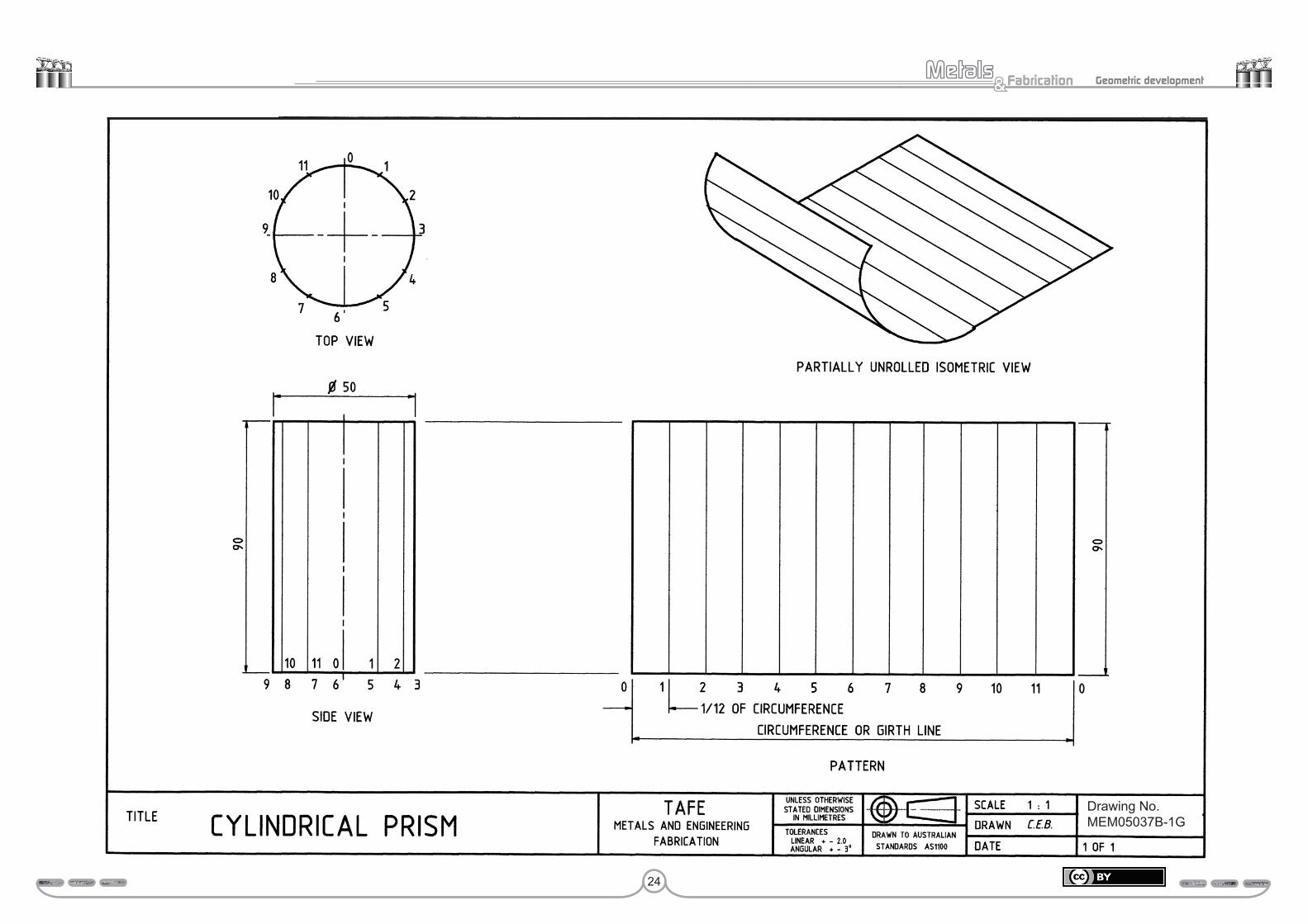
Study drawing MEM05037B-1G – Cylindrical prismDrawing MEM05037B-1G presents the pattern development of a cylindrical (prism) pipe.
1. Identify the two views that provide all of the information required to develop the pattern.
_________________ view _________________ view
2. Calculate both the circumference and 1/12th of the circumference for drawing MEM05037B-1G in the space provided below.
Circumference = π × diameter 1/12th of the circumference =
= =
= =
3. Print the three missing dimensions in the spaces provided on the pattern of drawing MEM05037B-1G.
4. Identify the position of the join or seam.
The joint position is ____________________________________________ .
5. Why is the circumference of the circular top view divided into 12 equal divisions?
______________________________________________________________ .
Submit these answers to your trainer for assessment.
Assessment:Date Signature Signature
Competent
Hold
24
Fabrication& Geometric development
Perform geometric development 23 MEM 05037 B
Drawing No MEM 05037B-1GDrawing No. MEM05037B-1G
25
Fabrication& Geometric development
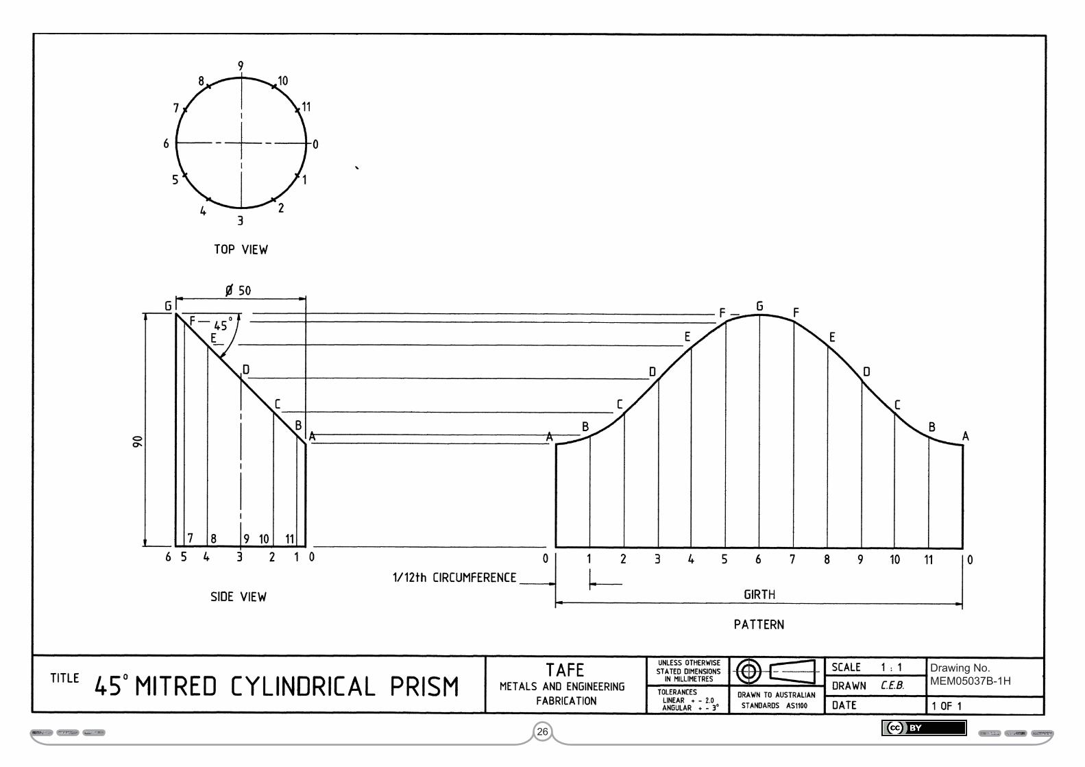
Study drawing MEM05037B-1H – Cylindrical prismDrawing MEM05037B-1H presents the pattern development for a 45° mitred cylindrical (prism) pipe, which is a pattern frequently produced by the metal fabricator.
While learning about this pattern development, you will once again follow the six basic steps you learnt earlier in the introduction to parallel line development.
Step 1 Draw the required views which are the top view and side view. These two views provide all of the five pieces of information required to layout the pattern.
• The diameter of the cylindrical which is 50 mm.• The circumference or girth.• The angle of the mitre.• The seven heights presented in the side view.• The position of the seam join, which is identified by 0 (zero). The
shortest height of the side view.
Step 2 Divide the circumference of the top view into 12 equal divisions and identify each point as illustrated.
Project each of the points.0, 1, 2, 3, 4, 5 and 6 to the side view, so as to produce the seven vertical and parallel lines.
Step 3 Calculate the circumference or girth for this cylindrical prism.
Circumference = π × diameter
= 3.142 × 50
= 157 mm
Step 4 Commence the pattern by drawing its girth line which, as you can see has been drawn to the right and on the same horizontal plane as the base line of the side view.
Step 5 Divide the girth line into 12 equal divisions as illustrated in the pattern.Construct the 13 parallel lines which are drawn perpendicular to the girth line.
Step 6 The height of each line is obtained from the side view. You can either transfer each line’s height as illustrated in this drawing by projecting lines from the side view points A, B, C, D, E, F and G to the pattern or use a compass to copy and transfer each height.
To finalise the pattern simply join each of the points AB, BC, CD, DE, EF, FG, GF, FE, ED, DC, CB and BA with a smooth flowing curved outline as illustrated. Also outline the other three sides – 0A, A0 and the girth line.
Activity drawing MEM05037B-1H – Cylindrical prismDraw both the top view and side view for this drawing MEM05037B-1H and then develop the pattern, with the seam at the short side A-0. In industry seems are preferred on the short edge; one reason for this is that it reduces the amount of welding.
When developing the pattern do not look at the example, try working from what you have learnt. In other words, treat this drawing as a test paper.
Submit this drawing to your trainer for assessment.
Assessment:Date Signature Signature
Competent
Hold
26
Fabrication& Geometric development
Perform geometric development 25 MEM 05037 B
Drawing No MEM 05037B-1HDrawing No. MEM05037B-1H
27
Fabrication& Geometric development
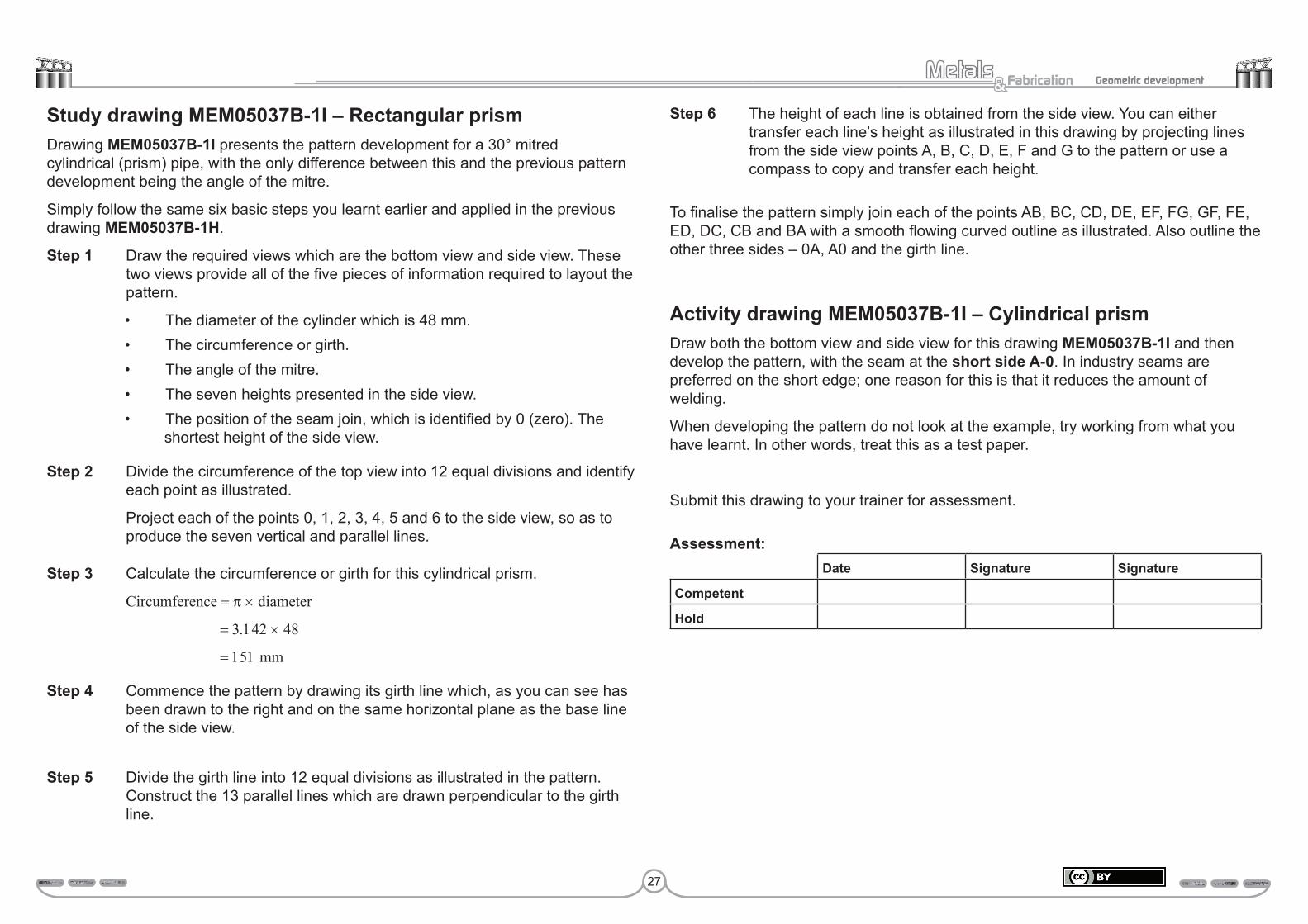
Study drawing MEM05037B-1I – Rectangular prismDrawing MEM05037B-1I presents the pattern development for a 30° mitred cylindrical (prism) pipe, with the only difference between this and the previous pattern development being the angle of the mitre.
Simply follow the same six basic steps you learnt earlier and applied in the previous drawing MEM05037B-1H.
Step 1 Draw the required views which are the bottom view and side view. These two views provide all of the five pieces of information required to layout the pattern.
• The diameter of the cylinder which is 48 mm.• The circumference or girth.• The angle of the mitre.• The seven heights presented in the side view.• The position of the seam join, which is identified by 0 (zero). The
shortest height of the side view.
Step 2 Divide the circumference of the top view into 12 equal divisions and identify each point as illustrated.
Project each of the points 0, 1, 2, 3, 4, 5 and 6 to the side view, so as to produce the seven vertical and parallel lines.
Step 3 Calculate the circumference or girth for this cylindrical prism.
Circumference = π × diameter
= 3.142 × 48
= 151 mm
Step 4 Commence the pattern by drawing its girth line which, as you can see has been drawn to the right and on the same horizontal plane as the base line of the side view.
Step 5 Divide the girth line into 12 equal divisions as illustrated in the pattern. Construct the 13 parallel lines which are drawn perpendicular to the girth line.
Step 6 The height of each line is obtained from the side view. You can either transfer each line’s height as illustrated in this drawing by projecting lines from the side view points A, B, C, D, E, F and G to the pattern or use a compass to copy and transfer each height.
To finalise the pattern simply join each of the points AB, BC, CD, DE, EF, FG, GF, FE, ED, DC, CB and BA with a smooth flowing curved outline as illustrated. Also outline the other three sides – 0A, A0 and the girth line.
Activity drawing MEM05037B-1I – Cylindrical prismDraw both the bottom view and side view for this drawing MEM05037B-1I and then develop the pattern, with the seam at the short side A-0. In industry seams are preferred on the short edge; one reason for this is that it reduces the amount of welding.
When developing the pattern do not look at the example, try working from what you have learnt. In other words, treat this as a test paper.
Submit this drawing to your trainer for assessment.
Assessment:Date Signature Signature
Competent
Hold

28
Fabrication& Geometric development
Perform geometric development 27 MEM 05037 B
Drawing No MEM 05037B-1I
Drawing No. MEM05037B-1I
29
Fabrication& Geometric development
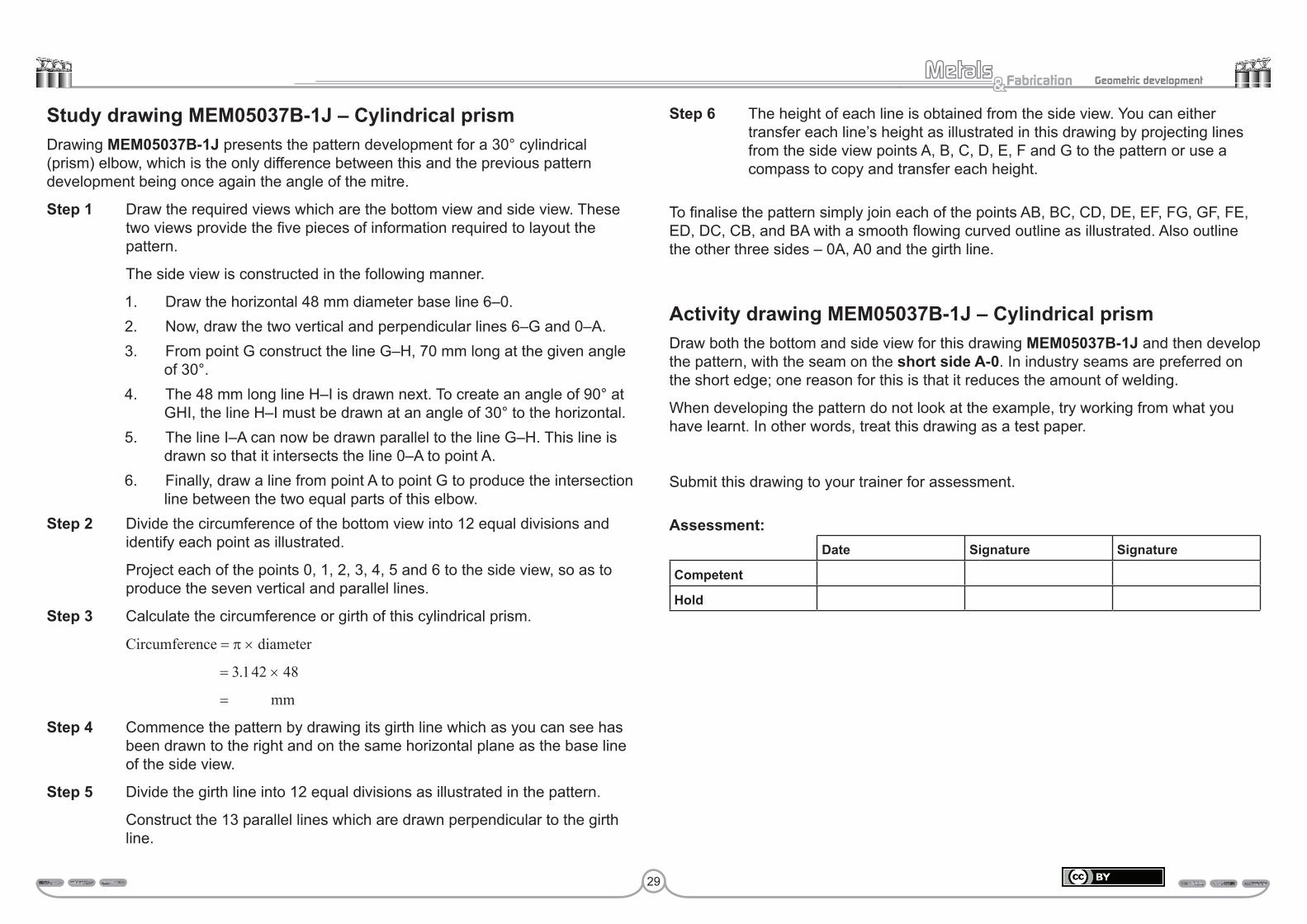
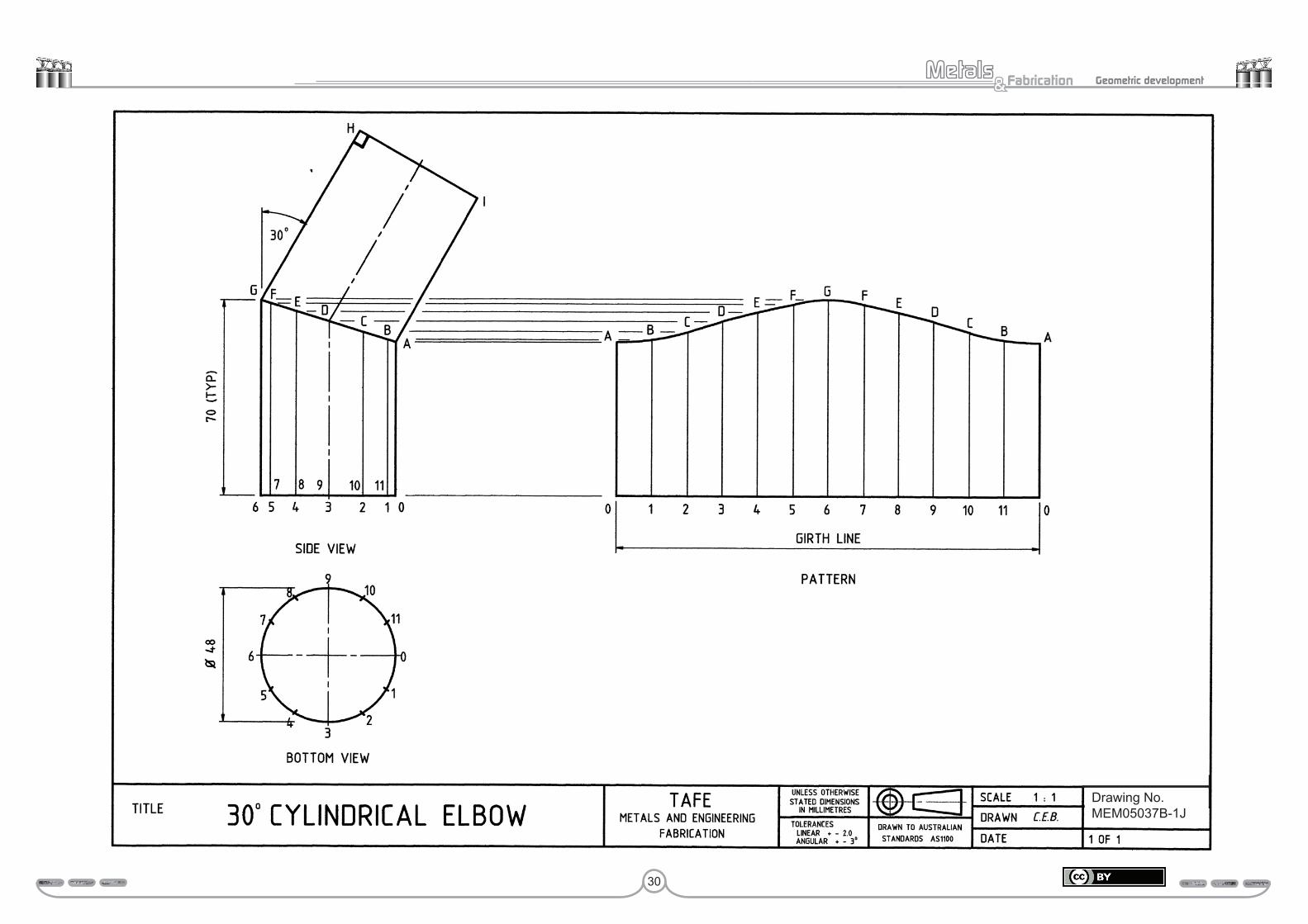
Study drawing MEM05037B-1J – Cylindrical prismDrawing MEM05037B-1J presents the pattern development for a 30° cylindrical (prism) elbow, which is the only difference between this and the previous pattern development being once again the angle of the mitre.
Step 1 Draw the required views which are the bottom view and side view. These two views provide the five pieces of information required to layout the pattern.
The side view is constructed in the following manner.
1. Draw the horizontal 48 mm diameter base line 6–0.2. Now, draw the two vertical and perpendicular lines 6–G and 0–A.3. From point G construct the line G–H, 70 mm long at the given angle
of 30°.4. The 48 mm long line H–I is drawn next. To create an angle of 90° at
GHI, the line H–I must be drawn at an angle of 30° to the horizontal.5. The line I–A can now be drawn parallel to the line G–H. This line is
drawn so that it intersects the line 0–A to point A.6. Finally, draw a line from point A to point G to produce the intersection
line between the two equal parts of this elbow.Step 2 Divide the circumference of the bottom view into 12 equal divisions and identify each point as illustrated.
Project each of the points 0, 1, 2, 3, 4, 5 and 6 to the side view, so as to produce the seven vertical and parallel lines.
Step 3 Calculate the circumference or girth of this cylindrical prism.
Circumference = π × diameter
= 3.142 × 48
= mm
Step 4 Commence the pattern by drawing its girth line which as you can see has been drawn to the right and on the same horizontal plane as the base line of the side view.
Step 5 Divide the girth line into 12 equal divisions as illustrated in the pattern.
Construct the 13 parallel lines which are drawn perpendicular to the girth line.
Step 6 The height of each line is obtained from the side view. You can either transfer each line’s height as illustrated in this drawing by projecting lines from the side view points A, B, C, D, E, F and G to the pattern or use a compass to copy and transfer each height.
To finalise the pattern simply join each of the points AB, BC, CD, DE, EF, FG, GF, FE, ED, DC, CB, and BA with a smooth flowing curved outline as illustrated. Also outline the other three sides – 0A, A0 and the girth line.
Activity drawing MEM05037B-1J – Cylindrical prismDraw both the bottom and side view for this drawing MEM05037B-1J and then develop the pattern, with the seam on the short side A-0. In industry seams are preferred on the short edge; one reason for this is that it reduces the amount of welding.
When developing the pattern do not look at the example, try working from what you have learnt. In other words, treat this drawing as a test paper.
Submit this drawing to your trainer for assessment.
Assessment:Date Signature Signature
Competent
Hold
30
Fabrication& Geometric development
Perform geometric development 29 MEM 05037 B
Drawing No MEM 05037B-1JDrawing No. MEM05037B-1J

31
Fabrication& Geometric development
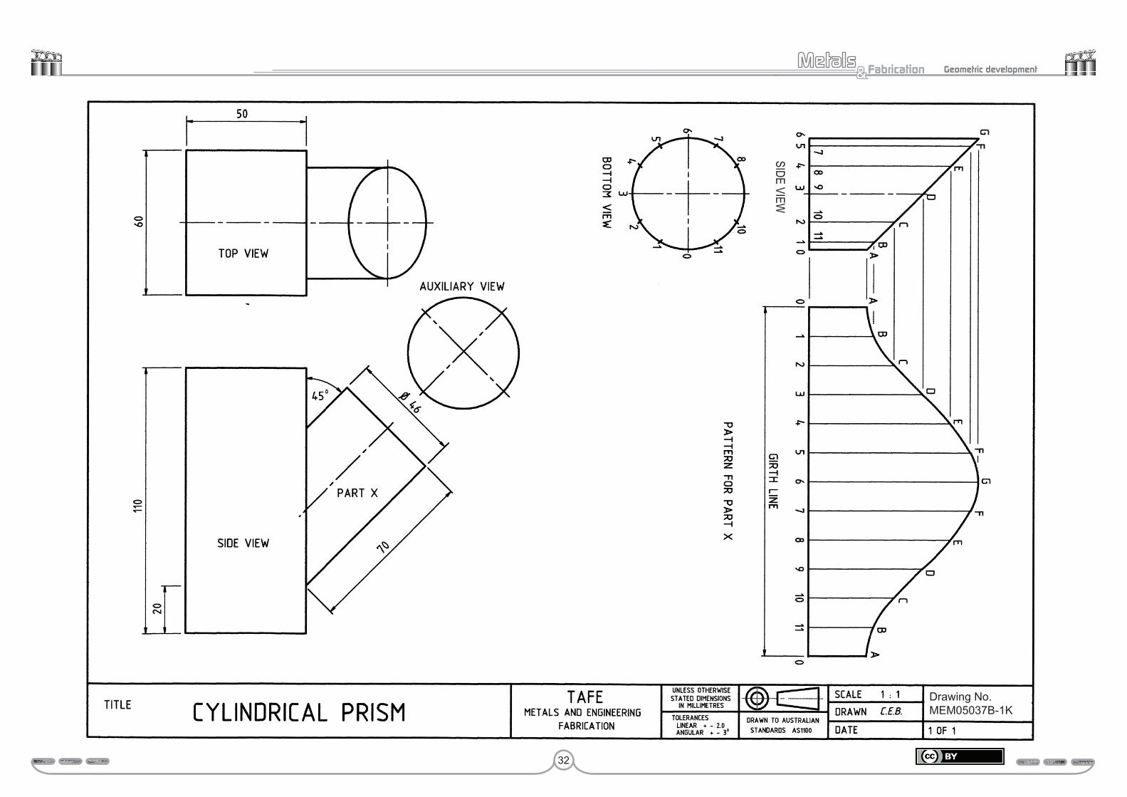
Study drawing MEM05037B-1K – Cylindrical prismDrawing MEM05037B-1K presents the 45° intersection between a rectangular and round pipe. However only the pattern for the intersecting round pipe will be developed. Although the pattern may appear a little complex at first, you will soon realise that it is the same for MEM05037B-1H and MEM05037B-1F.
It is the presentation of the drawing that makes it appear a little complex or just different to the previous drawings, and as a metal fabricator you must be prepared for all presentation variations.
While learning about this particular pattern development, you will once again follow the six basic steps you learnt in both the introduction and have practised in the previous three drawings.
Note that this drawing not only provides both the top and side view, but also an auxiliary view. The purpose of an auxiliary view is to provide additional information, which in this drawing tells you that part x is a cylinder.
Step 1 Draw the required views which are the side view and bottom view. Did you expect to find both part x and the auxiliary view to be removed from the main drawing and used as the side and bottom views? These two views provide all of the five pieces of information required to layout the pattern.
Step 2 You probably nearly know these six steps of pattern layout off by heart now and do not need the usual extensive explanation, so just a few key reminders will be given.
Step 3 Calculate the circumference or girth for this cylindrical prism.
Step 4 Draw the girth line to commence the pattern.
Step 5 Divide the girth line of the development into 12 equal divisions.
Step 6 Construct the 13 parallel lines which are drawn perpendicular to the girth line. To easily obtain the correct heights for these lines, project the seven horizontal construction lines from the side view as illustrated.
Finish the pattern by outlining as you have done in previous drawings.
Activity drawing MEM05037B-1K – Cylindrical prism Draw both the bottom view and side view for this drawing MEM05037B-1K and then develop the pattern for part x with the seam on the short side. In industry seams are preferred on the short edge; one reason for this is that it reduces the amount of welding.
When developing the pattern do not look at the example, try working from what you have learnt. In other words, treat this drawing as a test paper.
Submit these answers to your trainer for assessment.
Assessment:Date Signature Signature
Competent
Hold
32
Fabrication& Geometric development
Perform geometric development 31 MEM 05037 B
Drawing No MEM 05037B-1K
SIDE VIEW
Drawing No.MEM05037B-1K
33
Fabrication& Geometric development
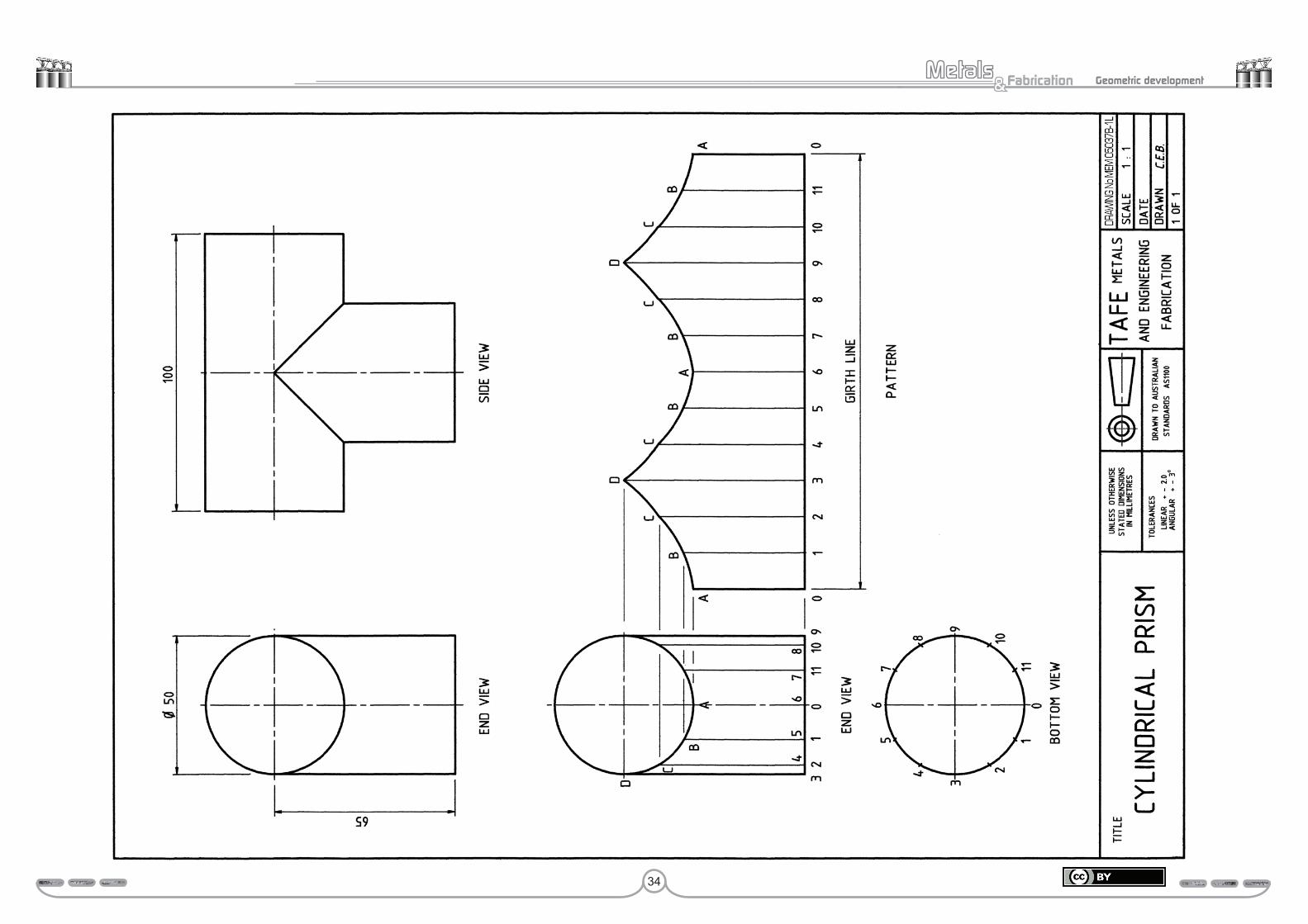
Study drawing MEM05037B-1L – Cylindrical prismDrawing MEM05037B-1L presents the pattern development for an equal diameter 90° cylindrical tee piece, which requires only the pattern for the branch or vertical cylinder to be developed.
Note: With a 90° tee piece only the end view and bottom view are needed to obtain all of the information for the pattern development of the branch piece.
Step 1 Draw the required views, which are the end and bottom views. These two views provide all the following five pieces of information required to layout the pattern.
• The diameter of the cylinder which is 50 mm.• The perimeter or girth.• The intersection line, which presents the junction of the two parts.• The four heights presented in the end view.• The position of the seam or join which is the line identified as line 0,
the shortest height of the end view.Step 2 Divide the circumference of the bottom view into 12 equal divisions and identify each point as illustrated.
Project each of the points 0, 1, 2, 3, 4, 5 and 6 to the end view, so as to produce the seven vertical and parallel lines.
Step 3 Calculate the perimeter or girth of this cylindrical prism.
Circumference = π × diameter = 3.142 × 50 = mm
Step 4 Commence the pattern by drawing its girth line which as you can see has been drawn to the right and on the same horizontal plane as the base line of the end view.
Step 5 Divide the girth line into 12 equal divisions as illustrated in the pattern. Construct the 13 parallel lines, which are drawn perpendicular to the girth line.
Step 6 The height of each line is obtained from the end view. You can either transfer each line’s height as illustrated in this drawing by projecting horizontal construction lines to the pattern or use a compass to copy and transfer each height.
Outlining of this development completes the pattern.
Activity drawing MEM05037B-1L – Cylindrical prism Draw both the bottom and side view for this drawing MEM05037B-1L and then develop the pattern, with the seam on the short side A-0. In industry seams are preferred on the short edge; one reason for this is that it reduces the amount of welding.
When developing the pattern do not look at the example, try working from what you have learnt. In other words, treat this drawing as a test paper.
Submit this drawing to your trainer for assessment.
Assessment:Date Signature Signature
Competent
Hold
34
Fabrication& Geometric development
35
Fabrication& Geometric development
Study drawing MEM05037B-1M – Cylindrical prismDrawing MEM05037B-1M presents the pattern development for an unequal diameter 90° cylindrical tee piece, which requires only the pattern for the branch or vertical cylinder (prism) to be developed.
Note: With a 90° tee piece only the end view and bottom view are needed to obtain all of the information for the pattern development of the branch piece.
Also note that the only difference between this and the previous drawing MEM05037B-1L is the diameter of the branch or vertical cylinder. Therefore the pattern development is carried out in exactly the same way as the previous drawing MEM05037B-1L.
Step 1 Draw the required views, which are the end and bottom views. These two views provide all the following five pieces of information required to layout the pattern.
• The diameter of the cylinder which is 90 mm.• The perimeter or girth.• The intersection line, which presents the junction of the two parts.• The four heights presented in the end view.• The position of the seam or join which is the line identified as line 0,
the shortest height of the end view.
Step 2 Divide the circumference of the bottom view into 12 equal divisions and identify each point as illustrated.
Project each of the points 0, 1, 2, 3, 4, 5 and 6 to the end view, so as to produce the seven vertical and parallel lines.
Step 3 Calculate the perimeter or girth of this cylindrical prism.
Step 4 Commence the pattern by drawing its girth line which as you can see has been drawn to the right and on the same horizontal plane as the base line of the end view.
Step 5 Divide the girth line into 12 equal divisions as illustrated in pattern.
Construct the 13 parallel lines, which are drawn perpendicular to the girth line.
Step 6 The height of each line is obtained from the end view. You can either transfer each line’s height as illustrated in this drawing by projecting horizontal construction lines to the pattern or use a compass to copy and transfer each height.
Outlining of this development completes the pattern.
Activity drawing MEM05037B-1M – Cylindrical prismDraw both the bottom and side view for this drawing MEM05037B-1M and then develop the pattern, with the seam on the short side A-0. In industry seams are preferred on the short edge; one reason for this is that it reduces the amount of welding.
When developing the pattern do not look at the example, try working from what you have learnt. In other words, treat this drawing as a test paper.
Submit this drawing to your trainer for assessment.
Assessment:Date Signature Signature
Competent
Hold

36
Fabrication& Geometric development

37
Fabrication& Geometric development
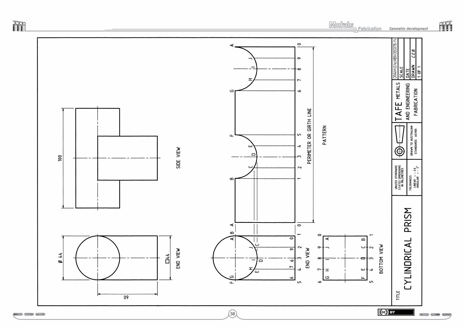
Study drawing MEM05037B-1N – Cylindrical prismDrawing MEM05037B-1N presents the pattern development for an unequal diameter 90° tee piece, which consists of an intersection between a square and circular pipe. Only the pattern for the branch or square (prism) to be developed.
Presented at the top of this drawing are the two typical views. However as with all 90° tee pieces only the end and bottom views are needed, to obtain all of the information required for the development of the square branch. As can be seen in the lower half of this drawing.
You will notice that the two views and the pattern on the right-hand side have been drawn to best use the space available.
The difference between this and the previous drawing MEM05037B-1M is the shape of the branch pipe. Therefore the first part of the pattern will be the same as for all square or rectangle prisms.
Step 1 Draw the required views, which are the end and bottom views. These two views provide all the following five pieces of information required to layout the pattern.
• The diameter of the cylinder which is 44 mm.• The perimeter or girth.• The intersection line, which presents the junction of the two parts.• The five heights presented in the end view.• The position of the seam or join, which is the corner identified as 0.
Step 2 Divide the two bottom view sides GA and FB into four divisions and identify each point as illustrated.
Project each of the points 1, 2 and 3 to the end view, so as to produce the three internal, vertical and parallel lines.
Step 3 Calculate the perimeter or girth of this square pipe.
Step 4 Commence the pattern by drawing its girth line which as you can see has been drawn to the right and on the same plane as the base line of the end view.
Step 5 Divide the girth line into 4 sides of the square and construct the five perpendicular lines 0, 1, 5, 6 and 0 again as illustrated in the pattern.
Divide the two sides 1–5 and 6–0 of the girth line into four equal divisions and construct the parallel lines 2 (9), 3 (8) and 4 (7), which are drawn perpendicular to the girth line.
Step 6 The height of each line is obtained from the end view. You can either transfer each line’s height as illustrated in this drawing by projecting horizontal construction lines to the pattern, or use a compass to copy and transfer each height.
You will have realised that the two semi-circular shapes of the pattern could quite easily have been constructed by locating their centres and scribing them with your compass.
Activity drawing MEM05037B-1N – Cylindrical prismDraw both the bottom and side view for this drawing MEM05037B-1N and then develop the pattern, with the seam located the short side I-8 or D-3. In industry seams are preferred on the short edge; one reason for this is that it reduces the amount of welding.
When developing the pattern do not look at the example, try working from what you have learnt. In other words, treat this drawing as a test paper.
Submit this drawing to your trainer for assessment.
Assessment:Date Signature Signature
Competent
Hold
38
Fabrication& Geometric development
39
Fabrication& Geometric development
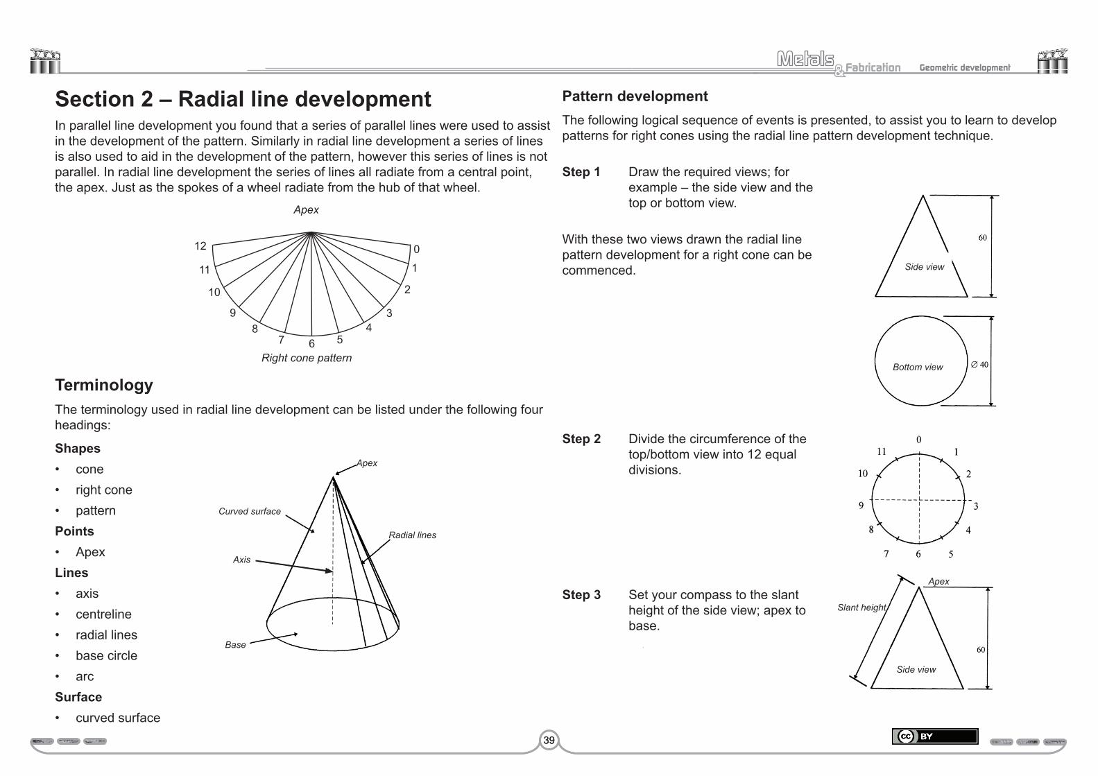
Section 2 – Radial line development In parallel line development you found that a series of parallel lines were used to assist in the development of the pattern. Similarly in radial line development a series of lines is also used to aid in the development of the pattern, however this series of lines is not parallel. In radial line development the series of lines all radiate from a central point, the apex. Just as the spokes of a wheel radiate from the hub of that wheel.
TerminologyThe terminology used in radial line development can be listed under the following four headings:
Shapes• cone• right cone• patternPoints• ApexLines• axis • centreline• radial lines• base circle• arcSurface• curved surface
Pattern developmentThe following logical sequence of events is presented, to assist you to learn to develop patterns for right cones using the radial line pattern development technique.
Apex
Apex
Radial lines
Curved surface
Axis
Base
Step 1 Draw the required views; for example – the side view and the top or bottom view.
With these two views drawn the radial line pattern development for a right cone can be commenced.
Step 2 Divide the circumference of the top/bottom view into 12 equal divisions.
Step 3 Set your compass to the slant height of the side view; apex to base.
Apex
Side view
Slant height
Bottom view
Side view
39
12
11
10
98
7 6 54
3
2
1
0
Right cone pattern

40
Fabrication& Geometric development
Apex
Arc
Bottom view
Apex
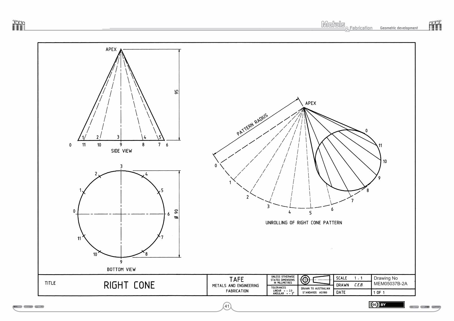
Study drawing MEM05037B-2A – Right coneDrawing MEM05037B-2A the pattern development of a right cone.
1. Identify the two views that provide all of the information required to develop the pattern. _________________ view _________________ view
2. Calculate the base circumference calculation in the space provide below. Circumference =
==
3. Calculate 1/12th of the base circumference calculation in the space provided below. 1/12th circumference =
===
4. Identify the position of the join or seam. The joint position is ____________________________________________ .
5. Which side view line is used as the pattern radius? Apex to _____________________________________________________ .
Submit these answers to your trainer for assessment.
Assessment:Date Signature Signature
Competent
Hold
Step 4 Commence the pattern by scribing an arc, which has a radius equal to the slant height of the side view.
Step 5 Set your compass to 1/12th of the cone’s base circumference.
The dimension can either be copied from one of the bottom view divisions or it can be calculated.
1/12th of circumference x diameter
= π (3.142 x 40) ÷ 12
126 mm ÷ 12 10.5 mm
===
Step 6 The pattern is completed by stepping off 1/12th of the base diameter of the cone (10.5 mm) twelve times along the arc of the pattern, to reproduce the cone’s base circumference.
Outline the three sides of the pattern apex to 0, apex to 12 and the arc 0 to 12.
Slant height pattern radius=
41
Fabrication& Geometric development
Drawing NoMEM05037B-2A

42
Fabrication& Geometric development
Study drawing MEM05037B-2B – Right coneDrawing MEM05037B-2B shows the pattern development for a right cone, which is a common pattern frequently produced by the metal fabricator.
While learning about this pattern development, you will once again follow the six basic steps you learnt earlier in the introduction to radial line development.
Step 1 Draw the required views, which once again you will note are the top or bottom view and side view. These two views provide the two pieces of information required to layout the pattern for this right cone.
• The vertical height, which is 95 mm.• The slant height which is used as the radius to commence the pattern
layout.• The diameter of the base of the cone, which is 90 mm.
Step 2 Divide the circumference of the bottom view into 12 divisions, as illustrated in the drawing 2B. The lines drawn from each of these points on the circumference to the apex, represent those drawn from the cone’s base to the apex in the side view.
Step 3 Set your compass to the slant height of the side view; apex to base.
Step 4 With your compass set at this measurement, scribe an arc to commence the pattern layout.
Step 5 Set your compass to 1/12th of the cone’s base circumference, eg 0 to1 of the bottom view.
A more accurate method of obtaining 1/12th of the circumference of the cone’s base is to calculate it.
1/12th of circumference x diameter
= π 3.142 x 90 ÷ 12
282.75 ÷ 12 23.56 mm
===
Step 6 With your compass set at this measurement, step it off 12 times along the arc of the pattern layout, so as to transfer the cone’s base circumference to the pattern layout.
Finalise the pattern by outlining the two seam lines 0 to apex and apex to 0, and outline the portion of the arc required.
Note, each of the points 2, 3, 4, 5, 6, 7, 8, 9, 10 and 11 on the arc of the pattern can be joined to the apex with a light construction line if you wish. These lines will assist you when rolling the cone into shape, but are of no other practical use to the pattern.
With the aid of the knowledge gained from this drawing, move onto Activity drawing MEM05037B-2B – Right cone.

43
Fabrication& Geometric development
Drawing NoMEM05037B-2B

44
Fabrication& Geometric development
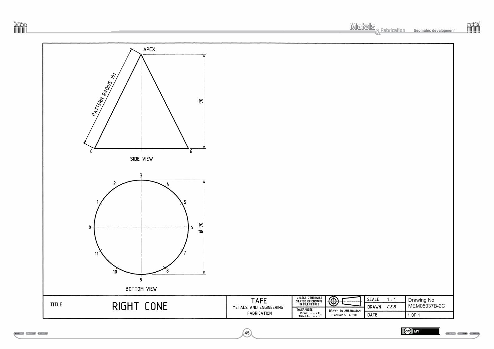
Study drawing MEM05037B-2C – Right coneUsing the given bottom view and side view of drawing MEM05037B-2C, develop your pattern.
When developing the pattern do not look at the example, try working from what you have learnt. In other words, treat this drawing as a test paper.
Submit these answers to your trainer for assessment.
Assessment:Date Signature Signature
Competent
Hold
45
Fabrication& Geometric development
Drawing NoMEM05037B-2C

46
Fabrication& Geometric development
Study drawing MEM05037B-2D – Right cone frustumDrawing MEM05037B-2D presents two sets of both the side and bottom view of a right cone frustum, which is the most common pattern developed by the metal fabricator.
On the left of this drawing is presented the top and bottom views of a right cone frustum, with all of the necessary dimensions. You will note that the side view lacks an apex, this is because the top section of the cone has been removed to create a frustum of a right cone.
The side view on the right of this drawing has an apex; to locate this apex is your first job. This is usually done while drawing the side view, by simply extending not only the centreline but also the sloping sides 0–A and 6–G; all of which should meet at a common point.
Note: This method should only be used for smaller ‘right cone frustum’. Inaccuracy may develop with larger right cone frustums and therefore the calculation method is required.
With the apex in place, you can now continue as before by dividing the cone’s base circumference into 12 equal divisions, as illustrated in the bottom view which is also on the right of this drawing.
You will note that these points located on the circumference of the bottom view have only been numbered from 0 to 6. This is because both halves of the cone and its pattern are exactly the same. Hence there will be less congestion at the base of the side view in subsequent drawings as can be seen in the next drawing MEM05037B-2D.
Now that you know how to obtain the apex for the side view, you can move on to the next drawing.

47
Fabrication& Geometric development
Slant height (SH)The calculated sloping height of the right cone or pyramid.
Formula:
SH = +H R2 2
Slant height of frustum (Shf)The calculated true length of the slant height of the frustum.
Formula:
Shf = +−
h D d22
2
Circumference/sThese are calculated measurements of the base and top of the cone (frustum) to locate the length and shape of the pattern.
Frustum of a cone
Calculations for radial line developmentCalculations are an important part of radial line development.
Some are used for the layout and development of cones, others for checking developed patterns.
Conical patterns can also be developed by:
• calculations• computers.
These methods will be covered in later units.
The calculations required for radial line development are:
• apex height (H)• slant height (SH)• slant height of frustum (Shf)• circumference/s.
Apex height (H)The calculated height of the apex point.
Formula:
H = ×−
D hD d
d
h
H
R
D
Top of frustum
Base of cone
SH
shf
48
Fabrication& Geometric development
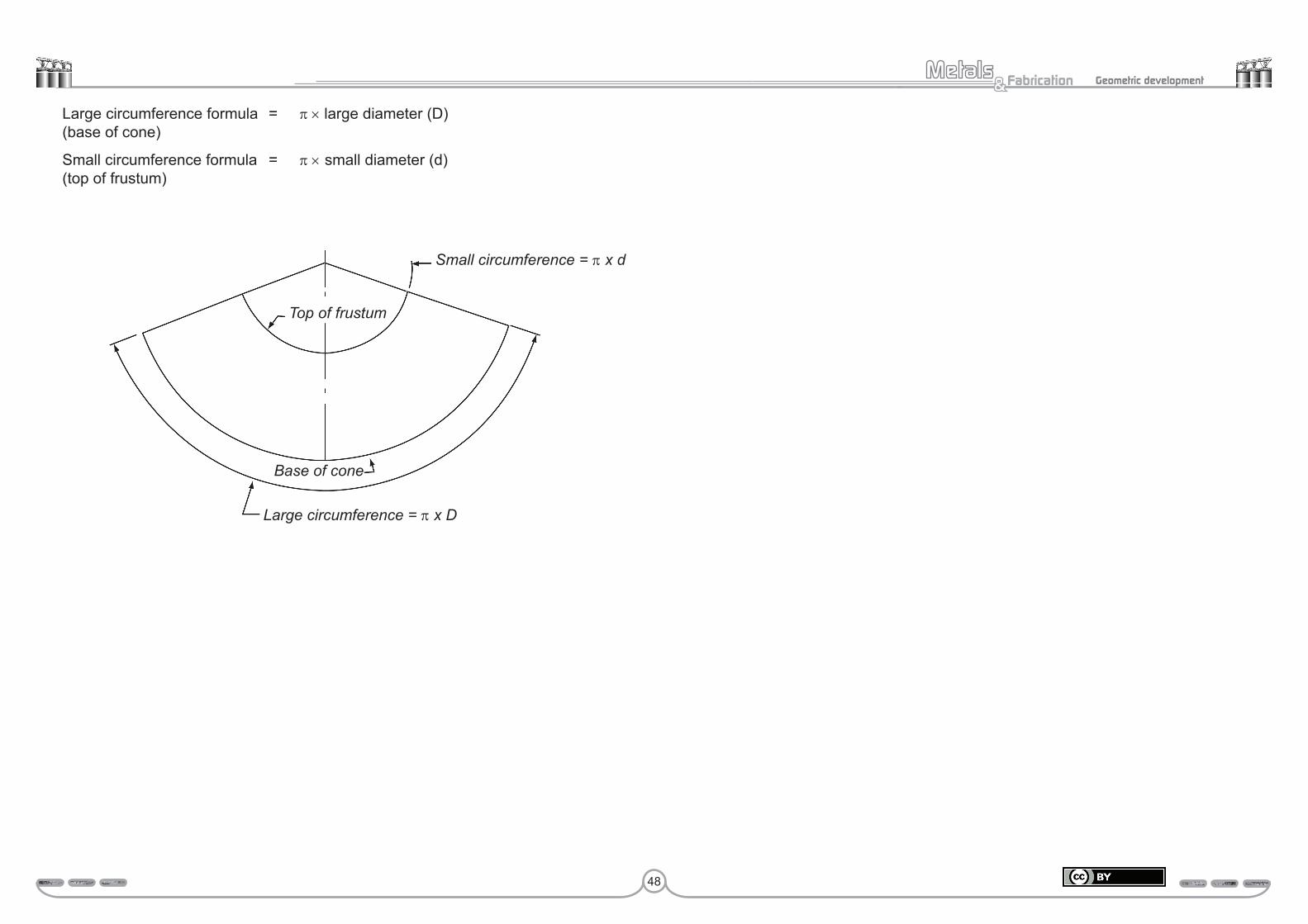
Large circumference formula = π × large diameter (D) (base of cone)
Small circumference formula = π × small diameter (d) (top of frustum)
Base of cone
Small circumference = π x d
Large circumference = π x D
Top of frustum
49
Fabrication& Geometric development
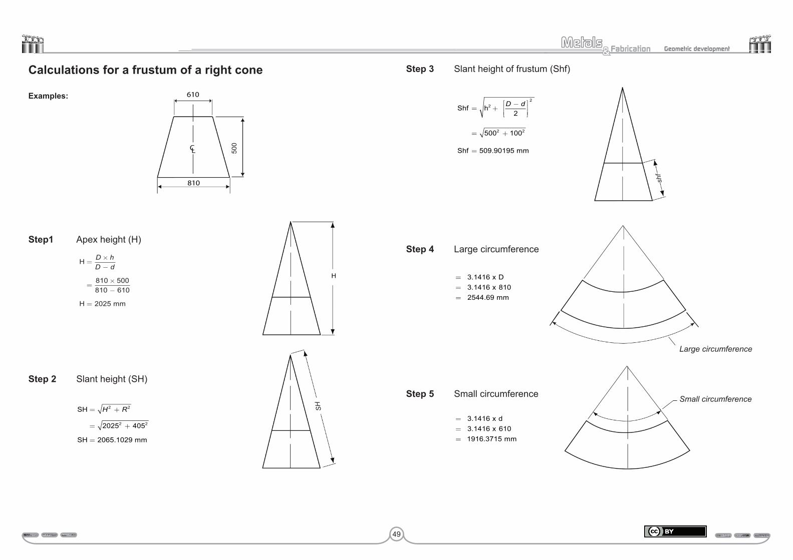
Calculations for a frustum of a right cone
Examples:
Step1 Apex height (H)
Step 2 Slant height (SH)
SH
SH mm
= +
= +
=
H R2 2
2 22025 405
2065 1029.
Step 3 Slant height of frustum (Shf)
Step 4 Large circumference
===
3 14163 1416 8102544 69
.
..
x Dx
mm
Step 5 Small circumference
===
3 14163 1416 6101916 3715
.
..
x dx
mm
H
H mm
=×−
=×−
=
D hD d
810 500810 610
2025
Shf h
Shf mm
= +−
= +
=
22
2 2
2
500 100
509 90195
D d
.
Small circumference
Large circumference
SH
shf
500

50
Fabrication& Geometric development
Drawing NoMEM05037B-2D
51
Fabrication& Geometric development
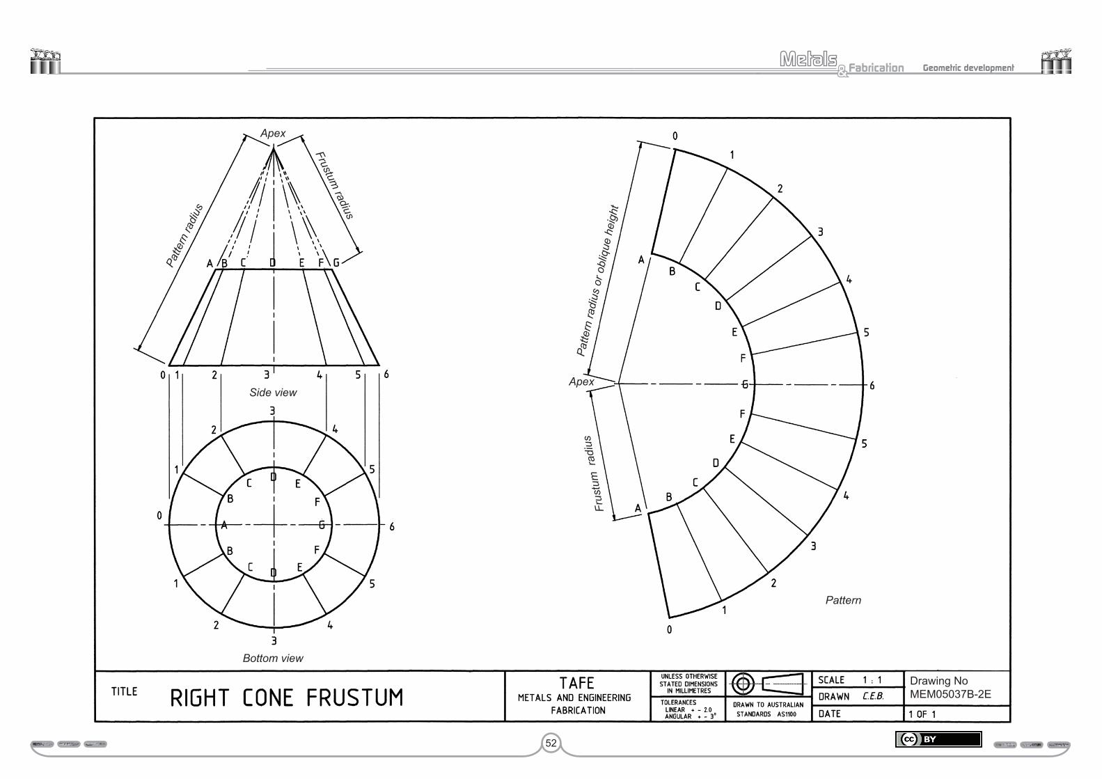
Study drawing MEM05037B-2E – Right cone frustumDrawing MEM05037B-2E presents the pattern development for the right cone frustum, for which you located the apex in the previous drawing MEM05037B-2D.
While learning about this pattern development, you will once again follow the six basic steps you learnt earlier in the introduction to develop a whole pattern for a right cone. Then add two new steps (steps 7 and 8) to complete the pattern by laying out the frustum arc of the cone.
Step 1 Draw the required views, which once again you will note are the top or bottom view and side views. These two views provide the four pieces of information required to layout the pattern for this right cone.
While learning about this pattern development, you will once again follow the six basic steps you learnt earlier in the introduction to radial line development.
• The vertical height of the frustum, which is 42 mm.• The oblique height of the frustum and the oblique height of the whole
cone once you have located the apex, both of which are used to develop the pattern.
• The diameter of the base of the cone, which is 90 mm.• The smaller diameter, or frustum diameter, which is 50 mm.
Step 2 Divide the circumference of the bottom view into 12 equal divisions, as illustrated in the drawing 2E. The lines drawn from each of these points on the circumference towards the apex, represent those drawn from the cone’s base to the apex in the side view. These lines can be drawn through to the apex in the bottom view if you wish.
Step 3 Set your compass to the oblique height of the side view; apex to 0 on the base.
Step 4 With your compass set at this measurement, scribe an arc to commence the pattern layout.
Step 5 Calculate 1/12th of the circumference of the cone’s base.
1/12th of circumference ( x diameter) ÷ 12
= π
Step 6 With your compass set at this measurement, step it off 12 times along the arc of the pattern layout, so as to transfer the cone’s base circumference to the pattern layout.
Step 7 Now set your compass to the side view partial oblique height measurement apex to A.
Step 8 With your compass set to this measurement, transfer it to the pattern, where you once again position the point of the compass on the apex and scribe an arc. This arc is both shorter and smaller in diameter than the first arc drawn.
To finalise the pattern outline the portion required, as illustrated.
Note: Each of the points 2, 3, 4 and 5 on the arc of the pattern can be drawn to the apex with a light construction line, or only drawn within the frustum of the pattern as illustrated. These lines will assist you when rolling the cone into shape, but are of no other practical use to the pattern.
Armed with this knowledge of how to develop the pattern for a frustum of a right cone you can confidently move on to the next drawing, which is an activity drawing requiring you to put your new found knowledge in to practice.
52
Fabrication& Geometric development
Side view
Patte
rn ra
dius
Bottom view
Pattern
Apex
Apex
Patte
rn ra
dius
or o
bliq
ue h
eigh
t
Frustum radius
Frus
tum
rad
ius
Drawing NoMEM05037B-2E

53
Fabrication& Geometric development
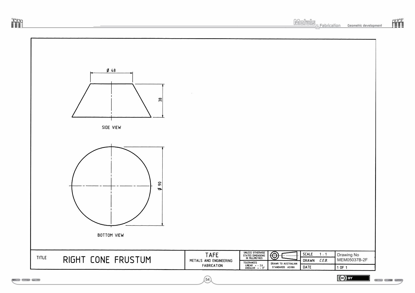
Study drawing MEM05037B-2F – Right cone frustumUsing both the bottom view and side view provided in drawing MEM05037B-2F, develop the pattern.
When developing the pattern try not look at any of the previous example, but to work from what you have learnt. In other words, treat this drawing as a test paper. This will cause you to become aware of what you have learnt and know; or if you wish, what you do not know.
Submit this drawing to your trainer for assessment.
Assessment:Date Signature Signature
Competent
Hold
54
Fabrication& Geometric development
Drawing NoMEM05037B-2F

55
Fabrication& Geometric development
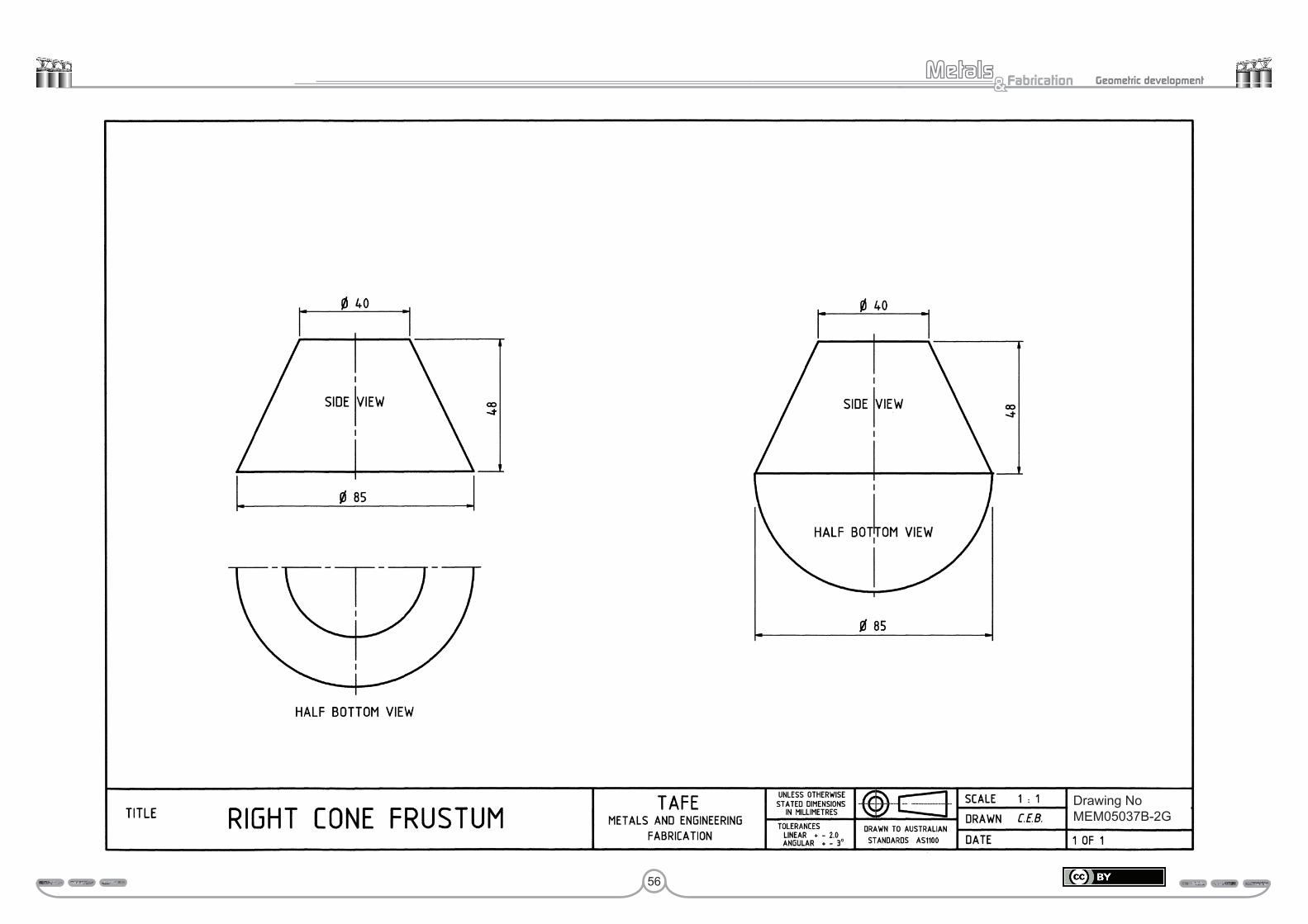
Study drawing MEM05037B-2G – Right cone frustumDrawing MEM05037B-2G presents two sets of the side and half bottom views for a right cone frustum.
The reason for this drawing is to present to you a means of reducing the amount of work required to produce a pattern for a right cone.
On the left of this drawing is presented the top and bottom views of a right cone frustum. Why only a half bottom view? Because it provides all of the information needed to layout the required pattern.
If you look at the side and bottom view presented on the right of this drawing, you will find that not only has the half bottom view been attached to the bottom of the side view, but the smaller of frustum half circle has been removed.
You can appreciate that this attached half bottom view and side view will still provide you with an accurate pattern development, but require you to do less work; due to the reduced effort required to produce these two views, especially the half bottom view.
You will still have to locate the apex, as illustrated in drawing MEM05037B-2D, before the pattern can be commenced.
56
Fabrication& Geometric development
Drawing NoMEM05037B-2G
57
Fabrication& Geometric development
Study drawing MEM05037B-2H1 – Truncated right cone
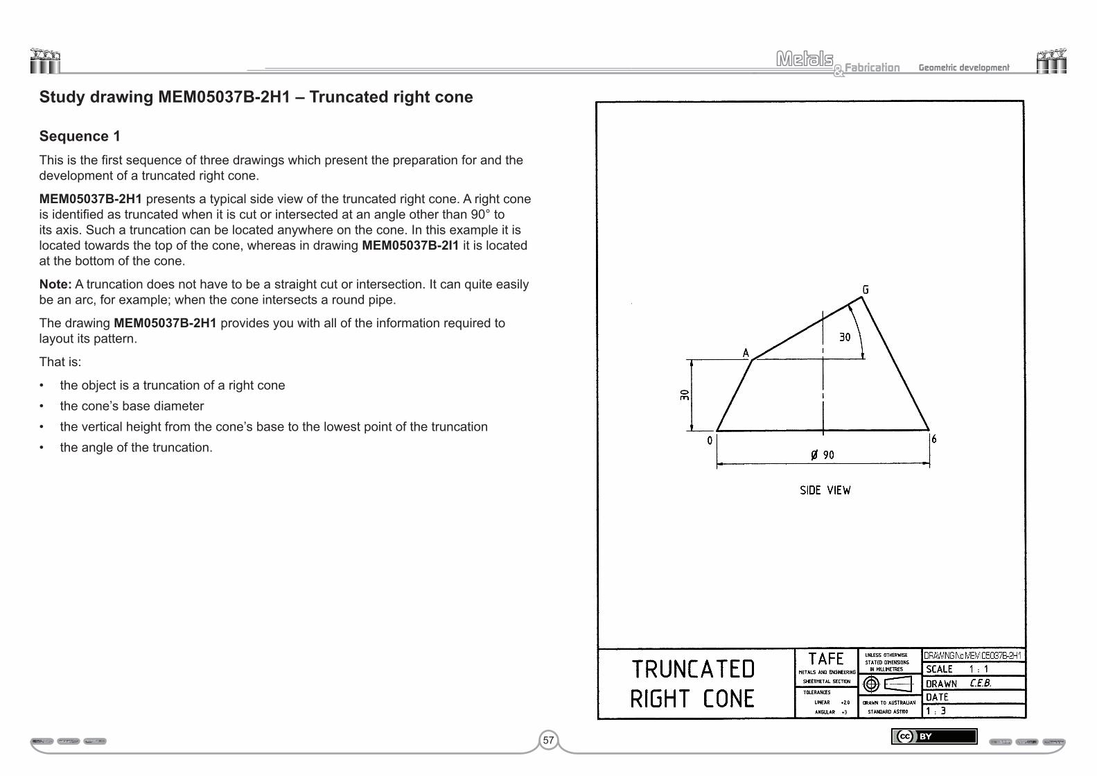
Sequence 1This is the first sequence of three drawings which present the preparation for and the development of a truncated right cone.
MEM05037B-2H1 presents a typical side view of the truncated right cone. A right cone is identified as truncated when it is cut or intersected at an angle other than 90° to its axis. Such a truncation can be located anywhere on the cone. In this example it is located towards the top of the cone, whereas in drawing MEM05037B-2I1 it is located at the bottom of the cone.
Note: A truncation does not have to be a straight cut or intersection. It can quite easily be an arc, for example; when the cone intersects a round pipe.
The drawing MEM05037B-2H1 provides you with all of the information required to layout its pattern.
That is:
• the object is a truncation of a right cone• the cone’s base diameter• the vertical height from the cone’s base to the lowest point of the truncation• the angle of the truncation.
58
Fabrication& Geometric development
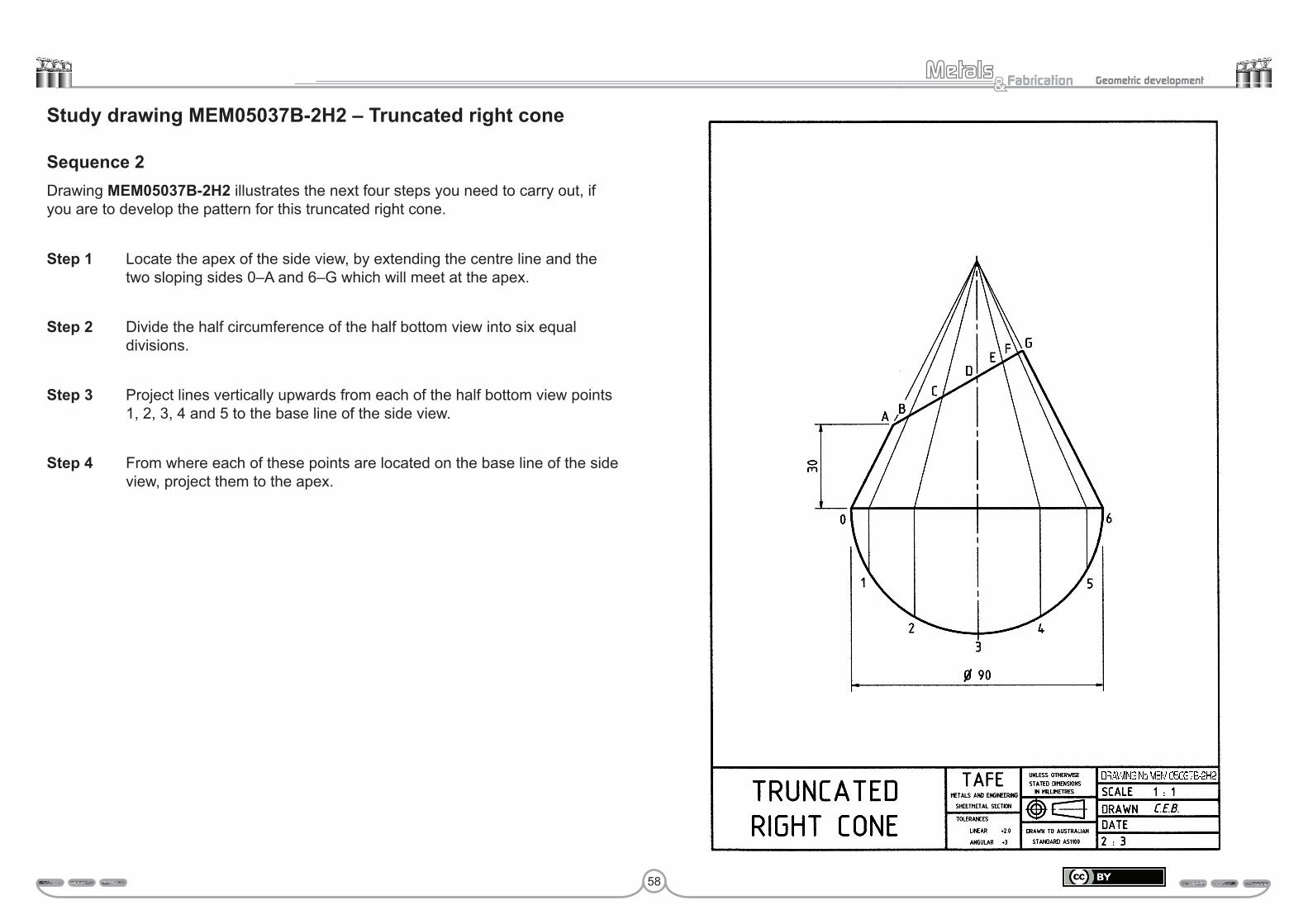
Study drawing MEM05037B-2H2 – Truncated right cone
Sequence 2Drawing MEM05037B-2H2 illustrates the next four steps you need to carry out, if you are to develop the pattern for this truncated right cone.
Step 1 Locate the apex of the side view, by extending the centre line and the two sloping sides 0–A and 6–G which will meet at the apex.
Step 2 Divide the half circumference of the half bottom view into six equal divisions.
Step 3 Project lines vertically upwards from each of the half bottom view points 1, 2, 3, 4 and 5 to the base line of the side view.
Step 4 From where each of these points are located on the base line of the side view, project them to the apex.
DRAWING No MEM 05037B-2H2

59
Fabrication& Geometric development
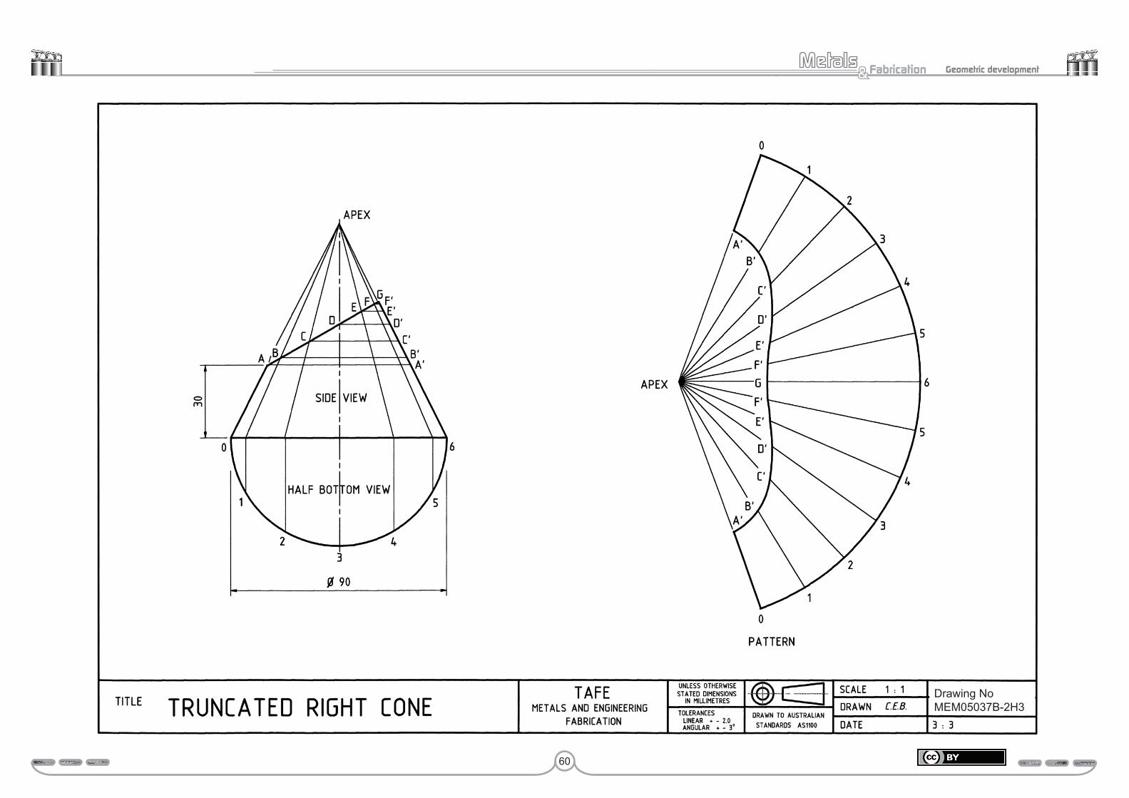
Study drawing MEM05037B-2H3 – Truncated right cone
Sequence 3This is the last of the sequence of three drawings which presents the preparation for and the development of a truncated right cone.
Drawing MEM05037B-2H3 presents the complete side view of the truncated right cone and its pattern development.
Step 5 Transfer each of the side view points A, B, C, D, E and F to one of the sloping sides (slant heights) at an angle of 90° to the axis, to obtain the points A’, B’, C’, D’, E’, F’ and G.
Step 6 Develop the whole pattern for this right cone as usual. Developing the whole pattern is always the first requirement of any right cone or part right cone pattern development.
Step 7 Draw all of the 13 radial lines from the 13 points on the pattern’s arc to the pattern’s apex.
Step 8 Place the point of your compass on the apex of the side view. Then extend the compass to point A’ to obtain the slant height apex–A’. Transfer this measurement to line apex–0 of the pattern by pointing the compass at the pattern apex and scribing a small arc on the line apex–0 to create the point A’. As there are two apex–0 lines this will have to be done on both lines.
Step 9 Repeat this procedure for the other six oblique heights: – apex–B’, apex–C’, apex–D’, apex–E’, apex–F’ and apex–G. Place each on the appropriately numbered line of the pattern. For example apex–B’ is located on radial line 1, apex–C’ on radial line 2, apex–D’ on radial line 3 and so on, until the pattern is complete. Do outline the required part of the pattern as usual.
Activity drawing MEM05037B-2H – Truncated right coneDraw both the half bottom and side view for this drawing MEM05037B-2H, however draw the side view with a base diameter of 100 mm.
When developing the pattern do not look at the example, try working from what your have learnt. In other words, treat this as a test paper.
Submit this drawing to your trainer for assessment.
Assessment:Date Signature Signature
Competent
Hold
60
Fabrication& Geometric development
Drawing NoMEM05037B-2H3

61
Fabrication& Geometric development
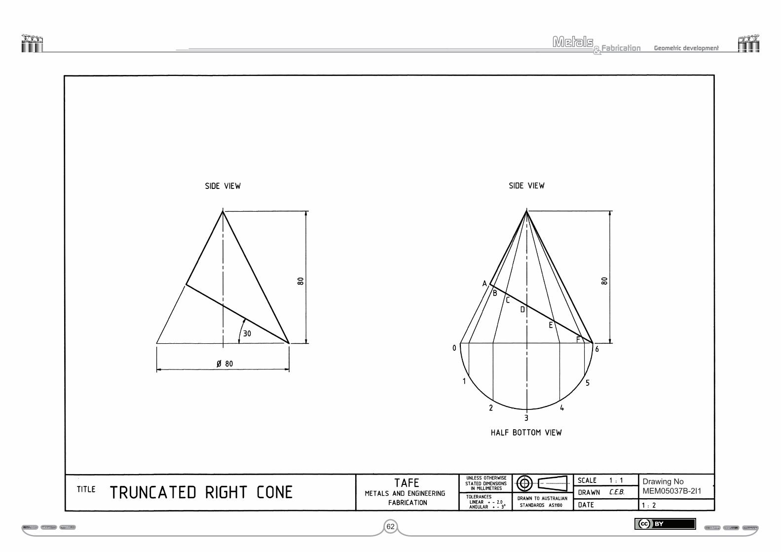
Study drawing MEM05037B-2I1 – Truncated right cone
Sequence 1On the left-hand side of drawing MEM05037B-2I1 is presented the side view only of a truncated right cone. This provides all of the information required for the pattern development to be completed successfully.
Where on the right you can see that not only has a half bottom view been added, but lines have been projected vertical then at an angle to the apex from the points 1, 2, 3, 4 and 5 of the half bottom view. Where each of these lines intersect, the truncated line identification has been made with the labels A, B, C, D, E and F.
You will be aware that the same sequence of events or steps has been followed as were presented in the previous drawing MEM05037B-2H2 to bring the side view to this stage.
View the next drawing MEM05037B-2I2 and its accompanying instruction for the remaining procedural steps or sequence of events to bring the pattern to its conclusion.
62
Fabrication& Geometric development
Drawing NoMEM05037B-2I1

63
Fabrication& Geometric development
Study drawing MEM05037B-2I2 – Truncated right cone
Sequence 2Drawing MEM05037B-2I2 presents the complete side view, half bottom view and the pattern for this truncated right cone.
You will no doubt have realised by now that the same sequence of events as presented in drawing MEM05037B-2H3 will lead to a successful pattern development in this drawing. The only difference between drawing MEM05037B-2H3 and this drawing is the position of the truncation.
Each of the truncation points A, B, C, D, E and F need to be transferred to the slant height, so that true dimensions can be obtained from the apex for each measurement. With each individual measurement; such as apex–A’, apex–B’, and so on being transferred to the pattern, where they are located on the appropriately numbered radial line from the apex. For example; apex–D’ is transferred to the pattern radial line apex–3.
You will note that point 6 of the side view is on the base of the cone, therefore it is logical to expect it to be located on the base or pattern radius arc in the pattern.
It is difficult to go wrong with such pattern developments when you remember and apply the following two rules.
• You must always commence the pattern development for a right cone by laying out a whole pattern. Then and only then can any frustum or truncation be produced.
• The true length of any point on a truncated line can only be found on the slant height or outside sloping side. Measurements within a right cone are not the true length, therefore they should never be transferred directly to the pattern.
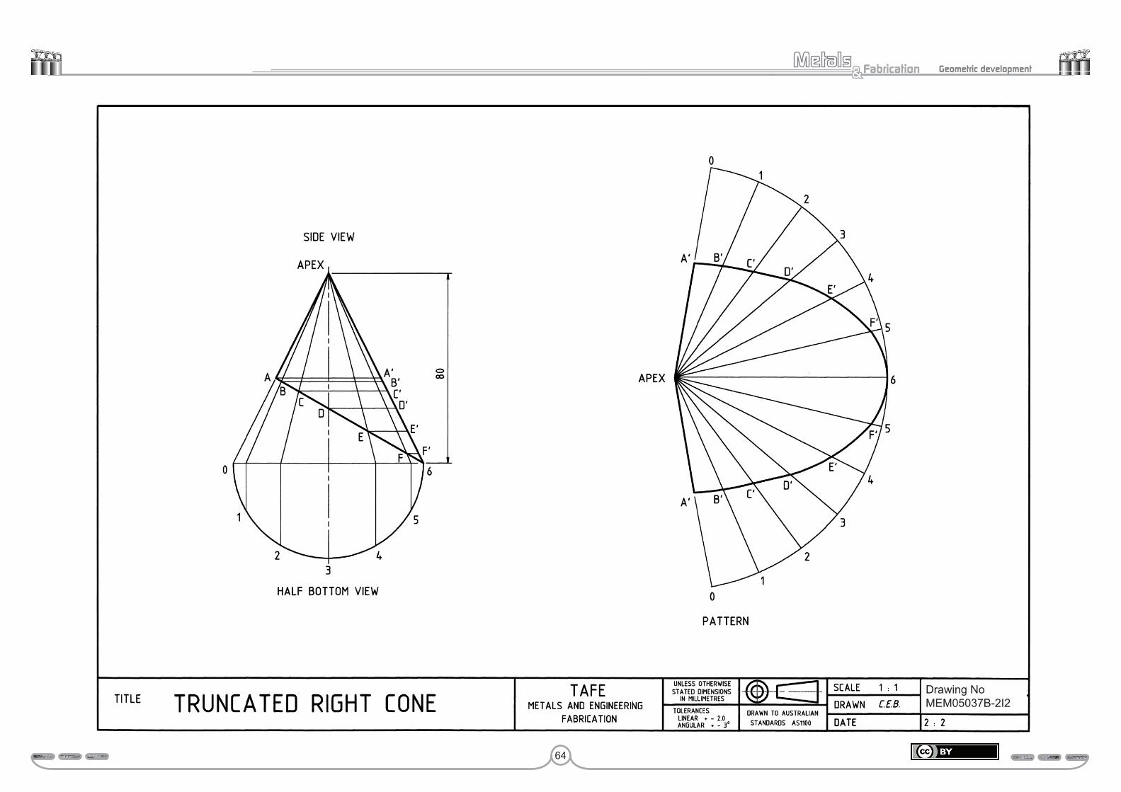
64
Fabrication& Geometric development
DRAWING No MEM 05037B-2I2
Drawing NoMEM05037B-2I2

65
Fabrication& Geometric development
Study drawing MEM05037B-2J – Truncated right coneUtilising the side view provided in drawing MEM05037B-2J develop the pattern for this truncated right cone.
As with all of the activity drawings, you are asked not to look back at any of the previous examples, but to work from what you have learnt. If you are unable to complete the pattern without referring to the previous drawings, you must realise that there is something you have not learnt.
If at anytime you find there is something you do not understand, do not hesitate to contact your trainer.
Submit this drawing to your trainer for assessment.
Assessment:Date Signature Signature
Competent
Hold
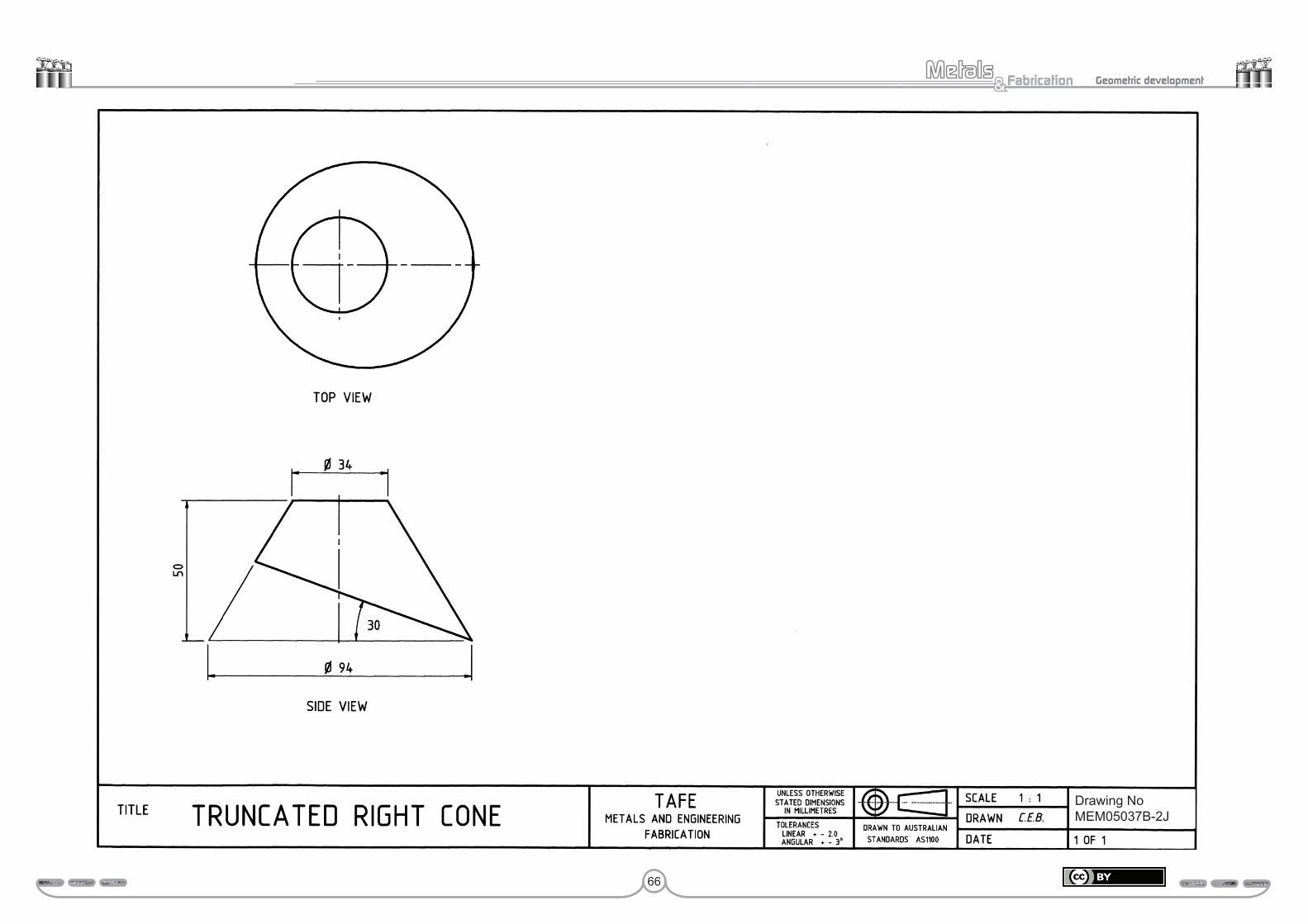
66
Fabrication& Geometric development
Perform geometric development 65 MEM 05037 B
Drawing No MEM 05037B-2JDrawing NoMEM05037B-2J
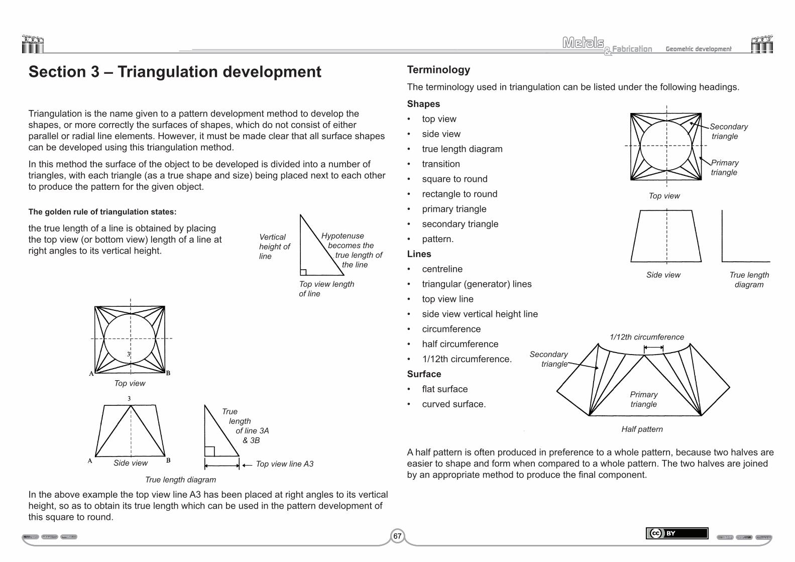
67
Fabrication& Geometric development
Section 3 – Triangulation development
Triangulation is the name given to a pattern development method to develop the shapes, or more correctly the surfaces of shapes, which do not consist of either parallel or radial line elements. However, it must be made clear that all surface shapes can be developed using this triangulation method.
In this method the surface of the object to be developed is divided into a number of triangles, with each triangle (as a true shape and size) being placed next to each other to produce the pattern for the given object.
The golden rule of triangulation states:
the true length of a line is obtained by placing the top view (or bottom view) length of a line at right angles to its vertical height.
In the above example the top view line A3 has been placed at right angles to its vertical height, so as to obtain its true length which can be used in the pattern development of this square to round.
TerminologyThe terminology used in triangulation can be listed under the following headings.
Shapes• top view• side view• true length diagram• transition• square to round• rectangle to round• primary triangle• secondary triangle• pattern.Lines• centreline• triangular (generator) lines• top view line• side view vertical height line• circumference• half circumference• 1/12th circumference.Surface• flat surface• curved surface.
A half pattern is often produced in preference to a whole pattern, because two halves are easier to shape and form when compared to a whole pattern. The two halves are joined by an appropriate method to produce the final component.
Side view
True length diagram
Top view line A3
True length
of line 3A & 3B
Half pattern
Vertical height of line
Hypotenuse becomes the
true length of the line
Top view length of line
Top view
Secondary triangle
Primary triangle
Top view
Side view True length diagram
Secondary triangle
Primary triangle
1/12th circumference
67
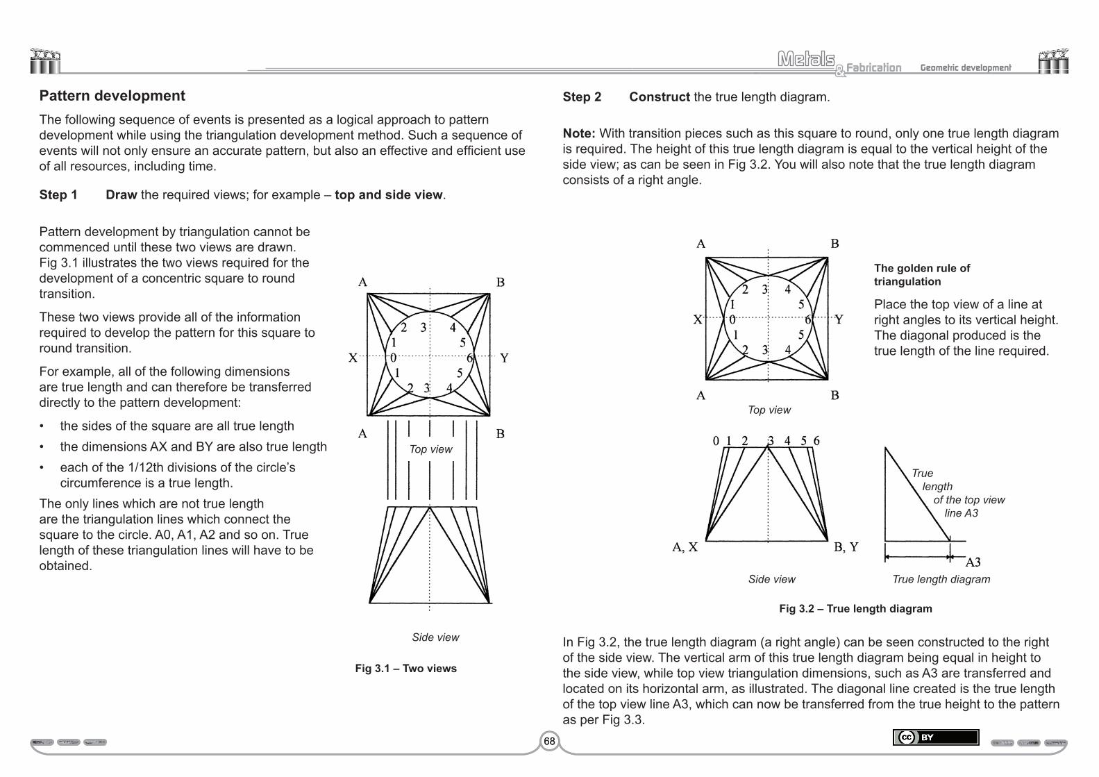
68
Fabrication& Geometric development
Pattern developmentThe following sequence of events is presented as a logical approach to pattern development while using the triangulation development method. Such a sequence of events will not only ensure an accurate pattern, but also an effective and efficient use of all resources, including time.
Step 1 Draw the required views; for example – top and side view.
Fig 3.1 – Two views
Pattern development by triangulation cannot be commenced until these two views are drawn. Fig 3.1 illustrates the two views required for the development of a concentric square to round transition.
These two views provide all of the information required to develop the pattern for this square to round transition.
For example, all of the following dimensions are true length and can therefore be transferred directly to the pattern development:
• the sides of the square are all true length• the dimensions AX and BY are also true length• each of the 1/12th divisions of the circle’s
circumference is a true length.The only lines which are not true length are the triangulation lines which connect the square to the circle. A0, A1, A2 and so on. True length of these triangulation lines will have to be obtained.
Side view
Step 2 Construct the true length diagram.
Note: With transition pieces such as this square to round, only one true length diagram is required. The height of this true length diagram is equal to the vertical height of the side view; as can be seen in Fig 3.2. You will also note that the true length diagram consists of a right angle.
In Fig 3.2, the true length diagram (a right angle) can be seen constructed to the right of the side view. The vertical arm of this true length diagram being equal in height to the side view, while top view triangulation dimensions, such as A3 are transferred and located on its horizontal arm, as illustrated. The diagonal line created is the true length of the top view line A3, which can now be transferred from the true height to the pattern as per Fig 3.3.
The golden rule of triangulation
Place the top view of a line at right angles to its vertical height. The diagonal produced is the true length of the line required.
Top view
Top view
Side view True length diagram
Fig 3.2 – True length diagram
True length
of the top view line A3
68

69
Fabrication& Geometric development
Step 4 Plot the location of the next two points in the pattern, which are points 2 and 4.
• The locating of these next two points will create the next two triangles. These triangles being A–3–2 and B–3–4, both of which are secondary triangles.
• To do this, the true length of the top view lines A2 and B4 need to be obtained from the true height diagram and transferred to the pattern, when centering at both A and B arcs are scribed either side of point 3.
• Whereas the two measurements 3–2 and 3–4 are simply 1/12th of the circle’s circumference. These are both stepped off from point 3. To the left to intersect the arc scribed from A to create the point 2 and similarly to the right from 3 to locate the point 4.
Calculation
Step 5 Plot the next two points 1 and 5, to create the next two secondary triangles in the pattern.
• To do this, the true length of the top view lines A1 and B5 need to be obtained from the true height diagram and transferred to the pattern, in the same way as A2 and B4 were.
• Whereas the two measurements 3–2 and 3–4, which are 15.7 mm in (1/12th of the circle’s circumference) are stepped off, one from point 2 to locate point 1 and the other from point 4 to locate point 5.
Fig 3.5 – Secondary triangle (1)
Step 3 Commence the pattern development by constructing the primary triangle AB3. Note, in this example only a half pattern will be developed.
The primary triangle AB3 is commenced by drawing a horizontal line, equal in length to the top view line AB.
• Whereas to locate the position of 3 in the pattern the true length line A3 (which is also B3) is transferred from the true length diagram to the pattern with a compass.
• Centre the compass on A, swing an arc above the line AB. This procedure is then repeated from point B of the pattern, producing the true location of point 3. That is where the two arcs intersect.
Top view
Side view True length diagram
True length B 3Fig 3.4 – Pattern
development
Primary Triangle
Fig 3.6 – Secondary triangle (2)
Secondary triangle1/12th of circumference (3.142 x diameter) 12
= ,
(3.142 x 60) 12 188 12 15.7 mm
= ,= ,=
69
Fig 3.3 – Constructing the primary trianglet

70
Fabrication& Geometric development
Step 6 Locate the next two points 0 and 6, so as to add the next two primary triangles.
• Begin by transferring the top view length A0 (B6) to the horizontal arm of the height diagram, so that its true length can be obtained.
• Next, transfer the true length of A0 (B6) to the pattern. Centre the compass at A and scribe an arc to the left of point 1. Repeat this procedure from B.
• Now with the compass set to 15.7 mm, scribe an arc from point 1 to intersect the arc scribed from A, to locate the point 0 to the left of point 1. Repeat this procedure from 5, to locate point 6.
Step 7 Complete the half pattern by locating the two points X and Y which can be found in the top view.
• Transfer the top view true length line AX directly to the pattern. Centre the compass at A and scribe arc AX to the left of A. Repeat this procedure from B to produce arc BY to the right of B.
• Now, transfer the top view line 0X to the true length diagram, to obtain its true length.
• Next, transfer the true length of 0X to the pattern. Centre the compass on 0 and scribe arc 0X to intersect the arc scribed from A, to locate the point X. Repeat this procedure from point 6 to locate the point Y.
• Finalise the pattern by outlining and draw light construction lines for each of the surface triangulation lines from A and B to points 0, 1, 2, 3, 4, 5 and 6 respectively.
Study drawing MEM05037B-3A – Square to roundDrawing 3A presents the half pattern development of a square to round transition.
1. Complete the following statement, to identify the two views that provide all of the information required to develop the pattern. _________________________ view _________________________ view
2. Complete the calculation for 1/12th of the circle’s circumference in the space provided below.
1/12th of circumference
====
3. Print the three missing dimensions in the spaces provided on the pattern of drawing MEM05037B-3A.
4. Identify the position of the join or seam on the top view.
The joint position is _______________________________________________ .
5. Explain the golden rule of triangulation.
The true length of a line is obtained by ________________________________
________________________________________________________________ .
Submit this drawing to your trainer for assessment.
Assessment:Date Signature Signature
Competent
Hold
Fig 3.7 – Adding primary triangles
Fig 3.8 – Finalising the pattern

71
Fabrication& Geometric development
Drawing NoMEM05037B-3A
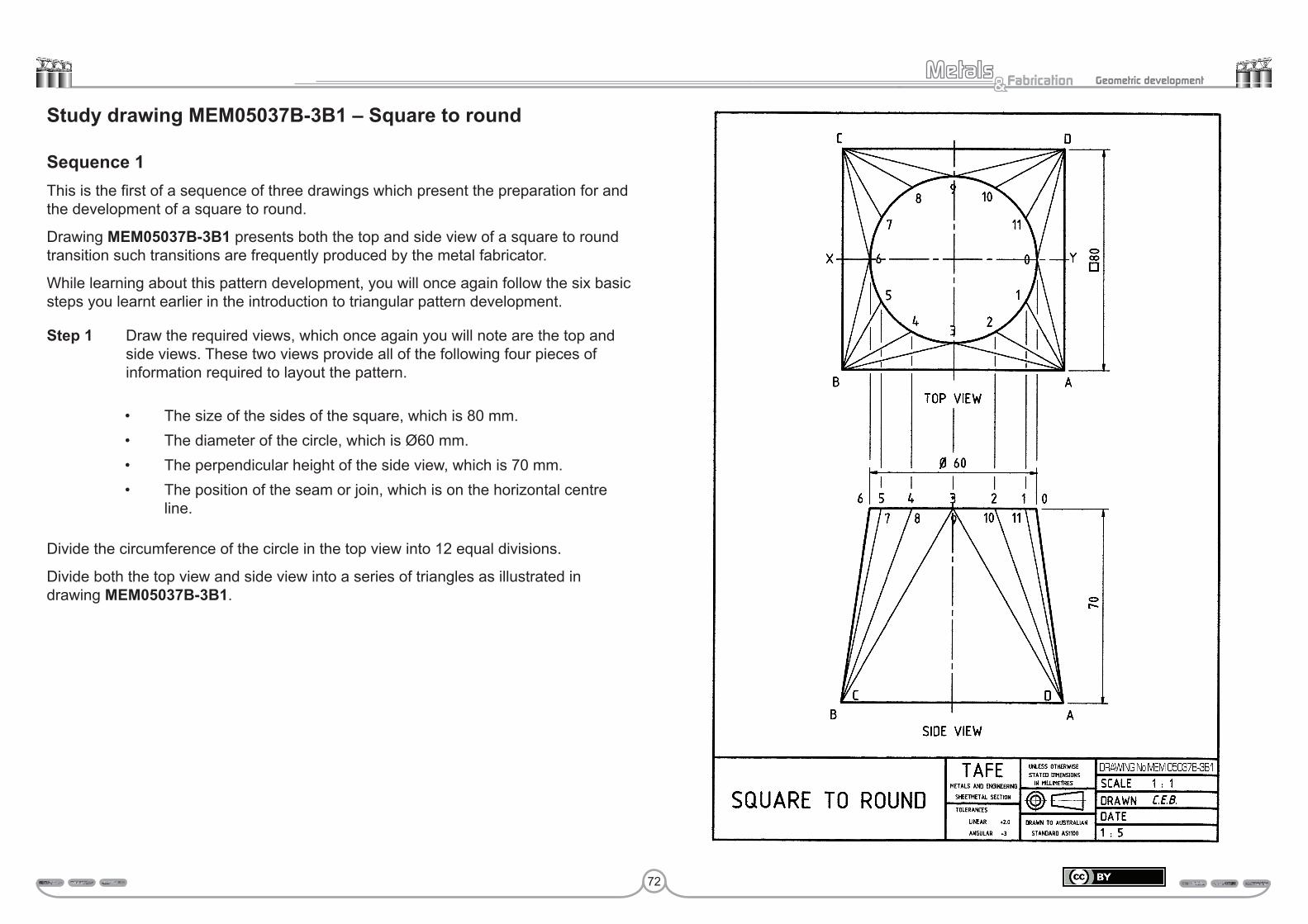
72
Fabrication& Geometric development
Study drawing MEM05037B-3B1 – Square to round
Sequence 1This is the first of a sequence of three drawings which present the preparation for and the development of a square to round.
Drawing MEM05037B-3B1 presents both the top and side view of a square to round transition such transitions are frequently produced by the metal fabricator.
While learning about this pattern development, you will once again follow the six basic steps you learnt earlier in the introduction to triangular pattern development.
Step 1 Draw the required views, which once again you will note are the top and side views. These two views provide all of the following four pieces of information required to layout the pattern.
• The size of the sides of the square, which is 80 mm.• The diameter of the circle, which is Ø60 mm.• The perpendicular height of the side view, which is 70 mm.• The position of the seam or join, which is on the horizontal centre
line.
Divide the circumference of the circle in the top view into 12 equal divisions.
Divide both the top view and side view into a series of triangles as illustrated in drawing MEM05037B-3B1.
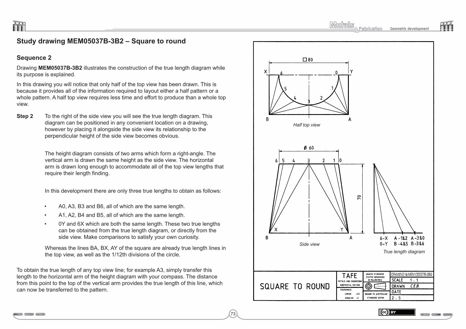
73
Fabrication& Geometric development
Study drawing MEM05037B-3B2 – Square to round
Sequence 2Drawing MEM05037B-3B2 illustrates the construction of the true length diagram while its purpose is explained.
In this drawing you will notice that only half of the top view has been drawn. This is because it provides all of the information required to layout either a half pattern or a whole pattern. A half top view requires less time and effort to produce than a whole top view.
Step 2 To the right of the side view you will see the true length diagram. This diagram can be positioned in any convenient location on a drawing, however by placing it alongside the side view its relationship to the perpendicular height of the side view becomes obvious.
The height diagram consists of two arms which form a right-angle. The vertical arm is drawn the same height as the side view. The horizontal arm is drawn long enough to accommodate all of the top view lengths that require their length finding.
In this development there are only three true lengths to obtain as follows:
• A0, A3, B3 and B6, all of which are the same length.• A1, A2, B4 and B5, all of which are the same length.• 0Y and 6X which are both the same length. These two true lengths
can be obtained from the true length diagram, or directly from the side view. Make comparisons to satisfy your own curiosity.
Whereas the lines BA, BX, AY of the square are already true length lines in the top view, as well as the 1/12th divisions of the circle.
To obtain the true length of any top view line; for example A3, simply transfer this length to the horizontal arm of the height diagram with your compass. The distance from this point to the top of the vertical arm provides the true length of this line, which can now be transferred to the pattern.
Half top view
Side viewTrue length diagram
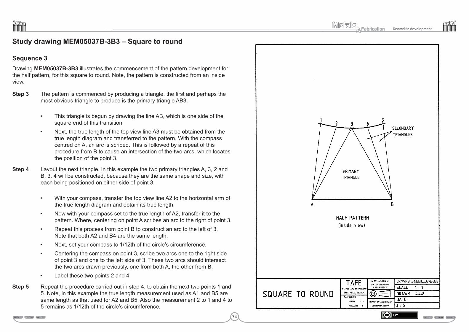
74
Fabrication& Geometric development
Study drawing MEM05037B-3B3 – Square to round
Sequence 3Drawing MEM05037B-3B3 illustrates the commencement of the pattern development for the half pattern, for this square to round. Note, the pattern is constructed from an inside view.
Step 3 The pattern is commenced by producing a triangle, the first and perhaps the most obvious triangle to produce is the primary triangle AB3.
• This triangle is begun by drawing the line AB, which is one side of the square end of this transition.
• Next, the true length of the top view line A3 must be obtained from the true length diagram and transferred to the pattern. With the compass centred on A, an arc is scribed. This is followed by a repeat of this procedure from B to cause an intersection of the two arcs, which locates the position of the point 3.
Step 4 Layout the next triangle. In this example the two primary triangles A, 3, 2 and B, 3, 4 will be constructed, because they are the same shape and size, with each being positioned on either side of point 3.
• With your compass, transfer the top view line A2 to the horizontal arm of the true length diagram and obtain its true length.
• Now with your compass set to the true length of A2, transfer it to the pattern. Where, centering on point A scribes an arc to the right of point 3.
• Repeat this process from point B to construct an arc to the left of 3. Note that both A2 and B4 are the same length.
• Next, set your compass to 1/12th of the circle’s circumference.• Centering the compass on point 3, scribe two arcs one to the right side
of point 3 and one to the left side of 3. These two arcs should intersect the two arcs drawn previously, one from both A, the other from B.
• Label these two points 2 and 4.
Step 5 Repeat the procedure carried out in step 4, to obtain the next two points 1 and 5. Note, in this example the true length measurement used as A1 and B5 are same length as that used for A2 and B5. Also the measurement 2 to 1 and 4 to 5 remains as 1/12th of the circle’s circumference.
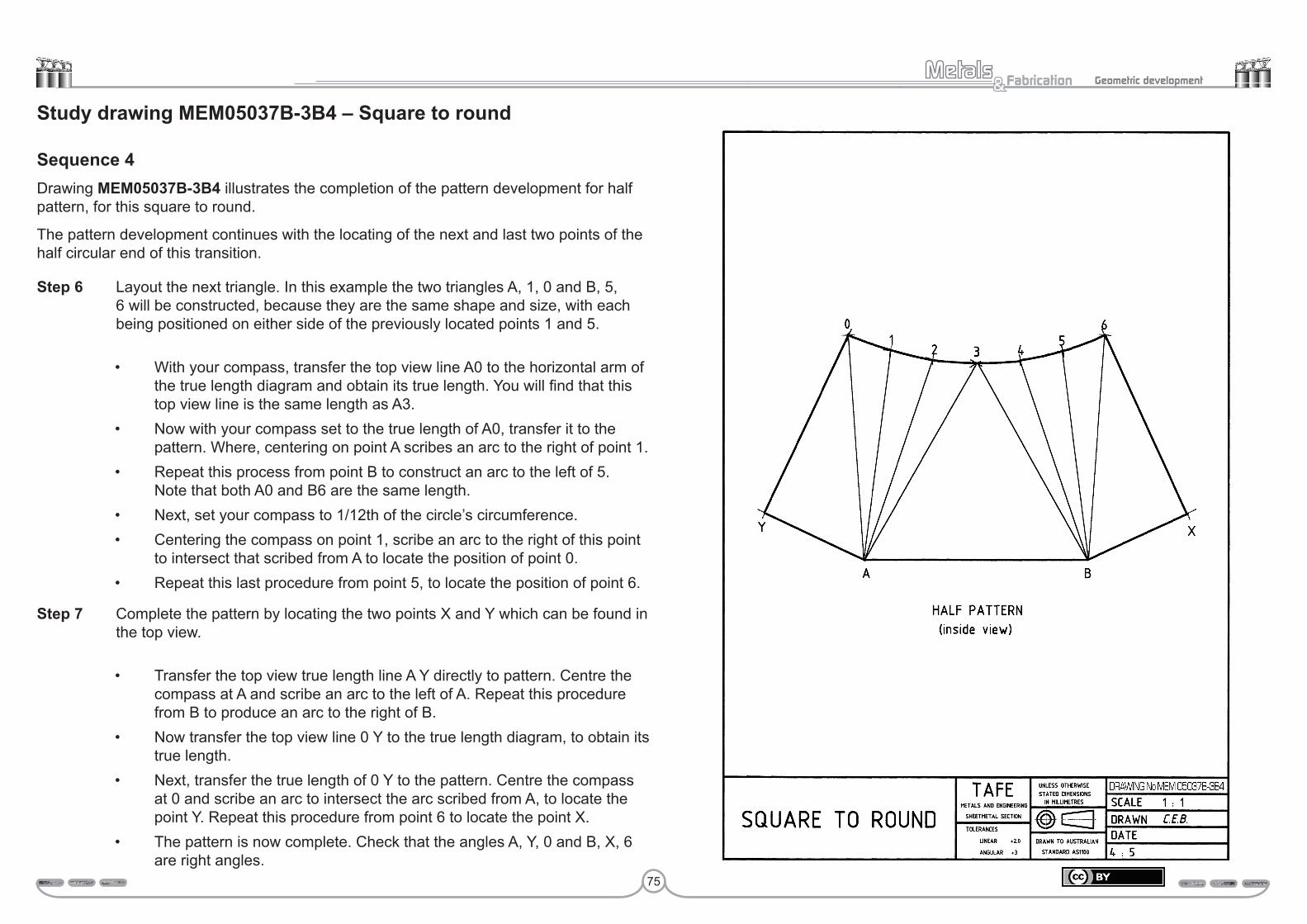
75
Fabrication& Geometric development
Study drawing MEM05037B-3B4 – Square to round
Sequence 4Drawing MEM05037B-3B4 illustrates the completion of the pattern development for half pattern, for this square to round.
The pattern development continues with the locating of the next and last two points of the half circular end of this transition.
Step 6 Layout the next triangle. In this example the two triangles A, 1, 0 and B, 5, 6 will be constructed, because they are the same shape and size, with each being positioned on either side of the previously located points 1 and 5.
• With your compass, transfer the top view line A0 to the horizontal arm of the true length diagram and obtain its true length. You will find that this top view line is the same length as A3.
• Now with your compass set to the true length of A0, transfer it to the pattern. Where, centering on point A scribes an arc to the right of point 1.
• Repeat this process from point B to construct an arc to the left of 5. Note that both A0 and B6 are the same length.
• Next, set your compass to 1/12th of the circle’s circumference.• Centering the compass on point 1, scribe an arc to the right of this point
to intersect that scribed from A to locate the position of point 0.• Repeat this last procedure from point 5, to locate the position of point 6.
Step 7 Complete the pattern by locating the two points X and Y which can be found in the top view.
• Transfer the top view true length line A Y directly to pattern. Centre the compass at A and scribe an arc to the left of A. Repeat this procedure from B to produce an arc to the right of B.
• Now transfer the top view line 0 Y to the true length diagram, to obtain its true length.
• Next, transfer the true length of 0 Y to the pattern. Centre the compass at 0 and scribe an arc to intersect the arc scribed from A, to locate the point Y. Repeat this procedure from point 6 to locate the point X.
• The pattern is now complete. Check that the angles A, Y, 0 and B, X, 6 are right angles.

76
Fabrication& Geometric development
Study drawing MEM05037B-3B5 – Square to roundHere is presented the completed drawing and pattern development for the square to round. You have been studying the developmental progress of this during the previous four drawings.
Remember to check that the two final triangles produce right angles at both X and Y.
Another point worth remembering is that the two diagonals X–0 and Y–6 should be the same measurement.
Carry out these two checks for accuracy as your final quality control.
Realise that what has been produced is only the basic pattern, or more correctly in this instance half pattern. Therefore there may be need of additions for such things as joint allowances etc.
Submit this drawing to your trainer for assessment.
Assessment:Date Signature Signature
Competent
Hold
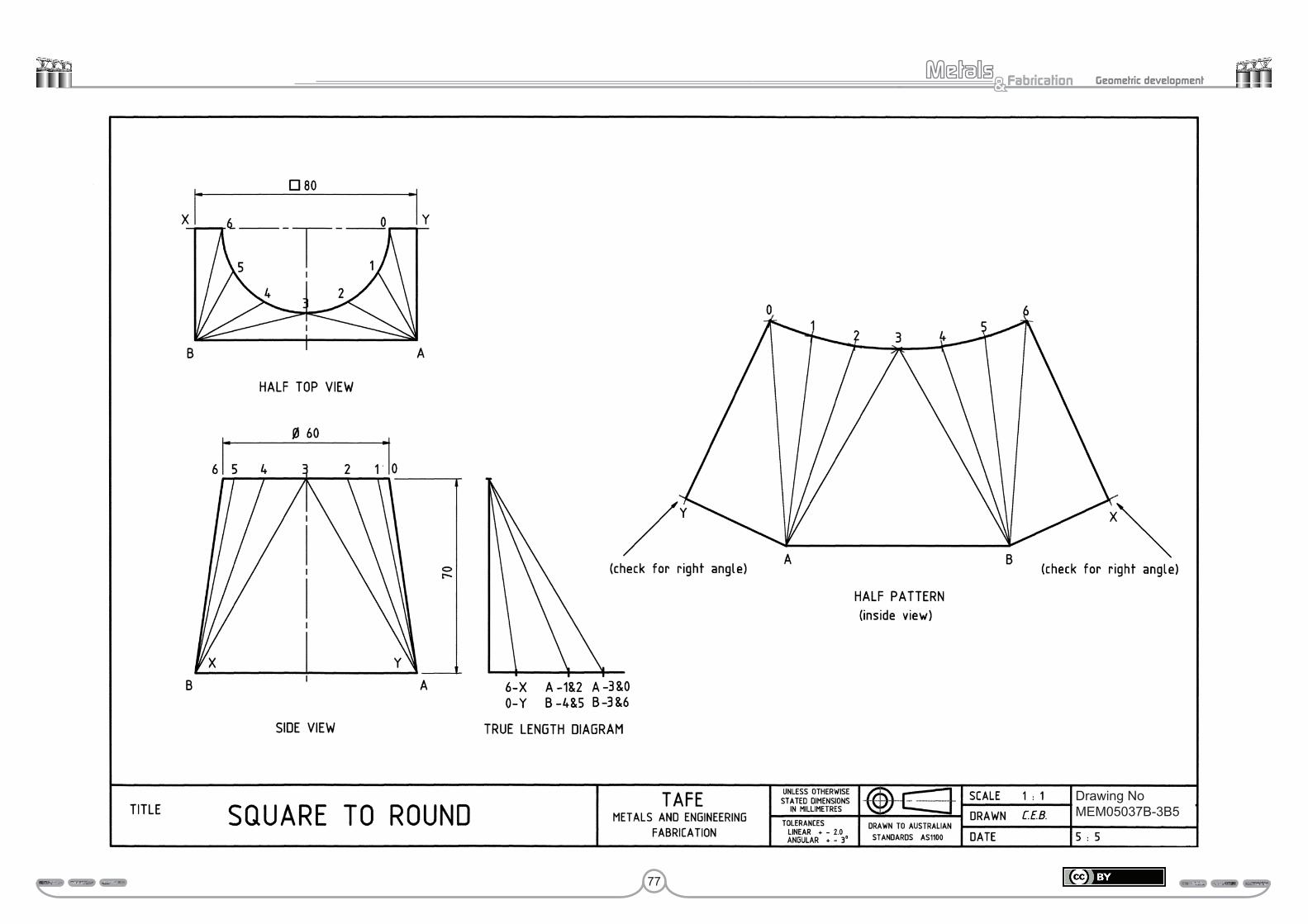
77
Fabrication& Geometric development
Drawing NoMEM05037B-3B5

78
Fabrication& Geometric development
Study drawing MEM05037B-3C – Square to roundUsing both the bottom and side view provided in drawing MEM05037B-3C, develop a half pattern for this square to round transition.
While developing the pattern, try not to look back at the previous example; just work with what you have learnt. In other words, treat this as a test paper. If you find it necessary to refer to the previous drawing, do so.
Submit this drawing to your trainer for assessment.
Assessment:Date Signature Signature
Competent
Hold

79
Fabrication& Geometric development
Drawing NoMEM05037B-3C

80
Fabrication& Geometric development
Study drawing MEM05037B-3D – Rectangle to roundDrawing MEM05037B-3D presents the layout for a half pattern of a rectangle to a round.
The pattern development procedure follows the same 7 steps as those presented in both the introduction and the previous study drawing MEM05037B-3B.
Is there a difference between this drawing and MEM02037B-3B? Yes, the base shape is now a rectangle and not a square.
How does this change the pattern development? From procedural (how the pattern is developed) point of view there is no difference. However, in this example there are more surface triangulation lines that need their true length finding.
To put it in a nutshell, there are a few more top view surface triangulation lines which need to be transferred to the true length diagram, so that their true length can be obtained before they can be transferred to the pattern.
Note, the following pairs of lines are the same length:
• A3 and B3• A2 and B4• A1 and B5• A0 and B6• 0X and 6Y.
Once again the pattern is commenced with the primary triangle AB3. Followed by each of the secondary triangles until points 0 and 6 are located.
This is followed by laying out the two half primary triangles AX0 and BY6. Remember both of these last two triangles should produce angles of 90° at X and Y.
Each of the two diagonals X6 and Y0 should be checked to ensure that they are the same length, so as to verify pattern accuracy.
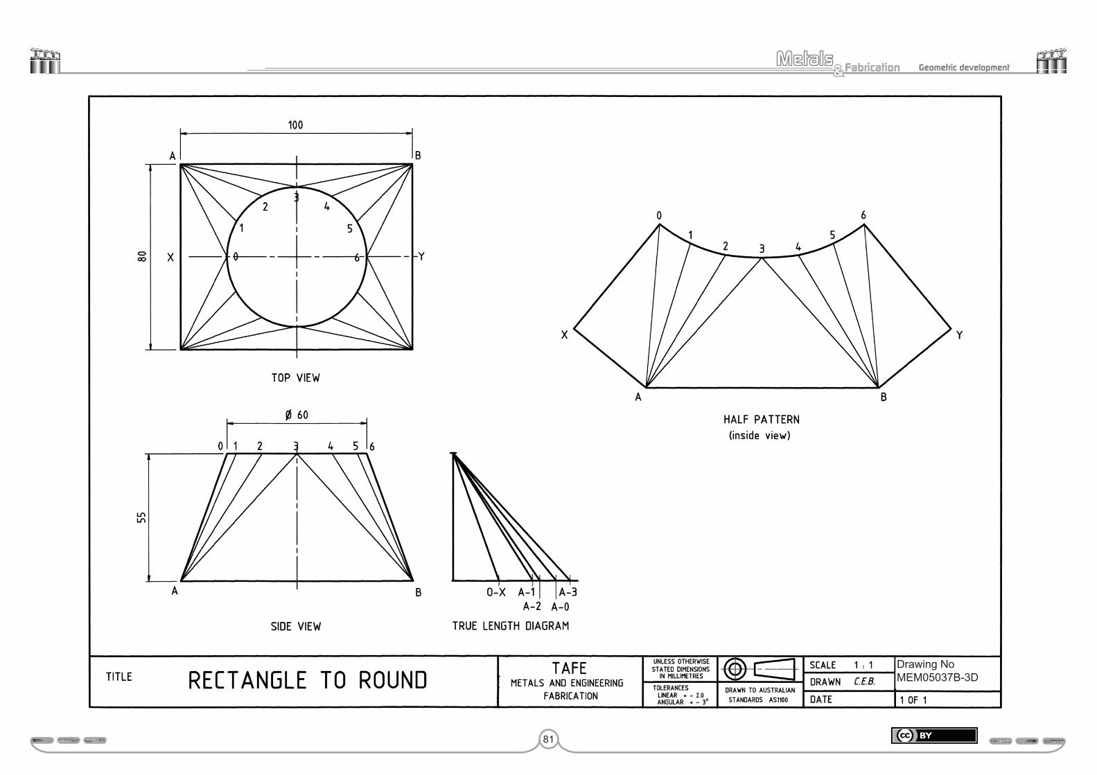
81
Fabrication& Geometric development
Drawing NoMEM05037B-3D

82
Fabrication& Geometric development
Study drawing MEM05037B-3E – Rectangle to roundDevelop a half pattern for the rectangle to round presented in drawing MEM05037B-3E.
When developing the pattern do not look at the example, try working from what you have learnt. In other words, treat this drawing as a test paper.
While preparing to and while developing this pattern, remember those things which you have learnt in the previous triangulations drawings.
These are:
• the sides of the square or rectangle are true length and can therefore be transferred directly to the pattern
• the circumference of the circle is true length and is transferred directly to the pattern 1/12th at a time. This dimension is more accurate when calculated
• the surface triangulation lines are not true length and must be transferred from the top view to the true length diagram so as to obtain their true length, which can then be transferred to the pattern development
• although a pattern does not have to be started with a primary triangle, most people find this the easiest place to start
• the last triangle produced should provide a right angle.
Submit this drawing to your trainer for assessment.
Assessment:Date Signature Signature
Competent
Hold

83
Fabrication& Geometric development
90
Drawing NoMEM05037B-3E

84
Fabrication& Geometric development
Study drawing MEM05037B-3F1 – Rectangle to round (with rounded corners)
Sequence 1Drawings MEM05037B-3F1, MEM05037B-3F2, MEM05037B-3F3 and MEM05037B-3F4 present a slight variation to the pattern development of a rectangle to round. As can be seen in this example, the rectangle has corners, which is used more commonly by those people who work in heavier plate. It is easier to form such a shape in thicker plate than the usual rectangle to round, which has the sharp 90° corners.
You will note that this drawing MEM05037B-3F1 presents the basic layout of both the top and side view of this rectangular to round with rounded corners, and primary triangles on the left-hand side. Whereas on the right-hand side, both views are completed with all of the surface triangulation lines, plus the true length diagram.
You will realise that only a half top view is needed, in fact only a quarter would quite easily suffice. However a complete top view has been provided for reasons of drawing and interpretation clarity.
Construct the rounded corners
• To position the rounded corners accurately, begin by drawing a complete rectangle. With the compass set to a radius of 20 mm, centre on the corner (T) of the rectangle and mark off this distance on either side, to create locations such as A and D as presented in the top left hand corner. See (a) at right.
• With the compass still set to 20 mm, centre on A and construct an arc within the rectangle. Repeat this procedure from D. The intersection of the two arcs provides the position (P) where the compass is centred (still set at 20 mm) to construct the rounded corner, which is exactly a quarter of a circle. See (a) at right.
• Repeat this procedure for the other three corners.
Dividing the corner quarter circle in to 3 equal spaces
• By aligning your 60°–30° set-square with the centre position P just created, construct two angles, one at 30° and the other at 60° to locate the two positions B and C on the quarter cycle. See (b) below.
The surface triangulation lines are now constructed, dividing the transition’s surface into a series of triangles as illustrated in the drawing MEM05037B-3F1 in preparation for the development of the pattern. Each of the top view surface triangulation lines can now be transferred to the horizontal arm of the true length diagram, so that their true lengths can be obtained.
(a) (b)
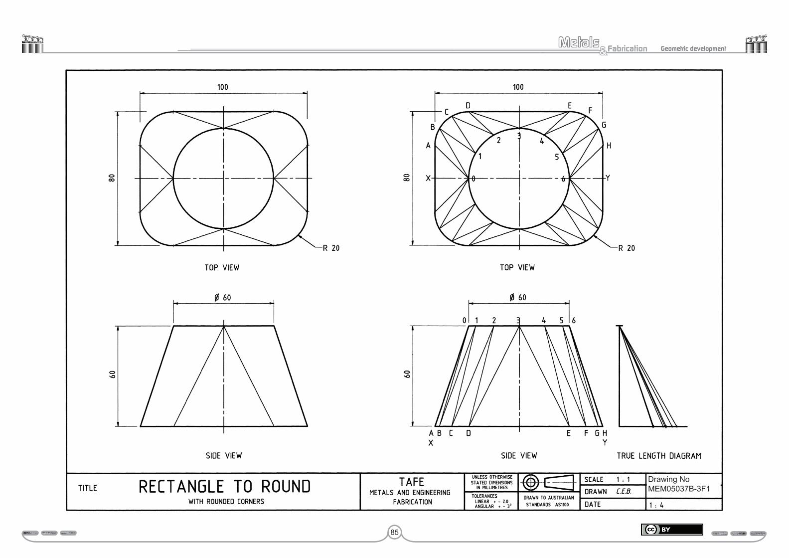
85
Fabrication& Geometric development
Drawing NoMEM05037B-3F1
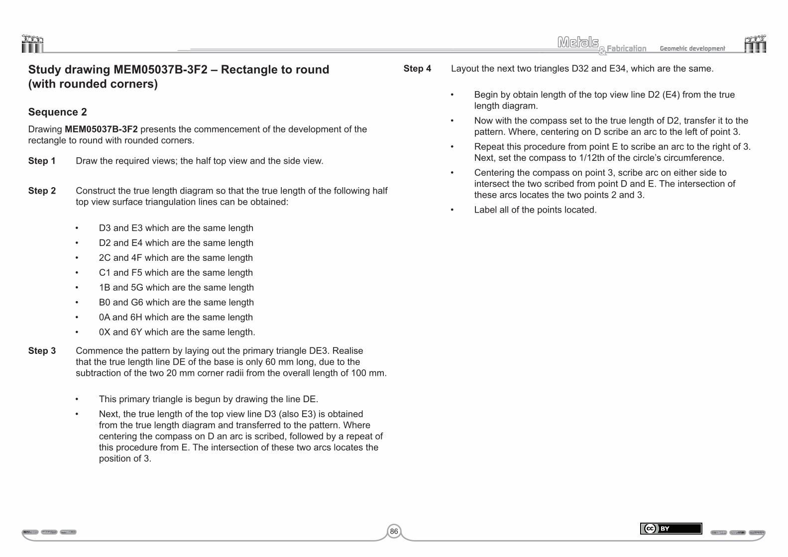
86
Fabrication& Geometric development
Study drawing MEM05037B-3F2 – Rectangle to round (with rounded corners)
Sequence 2Drawing MEM05037B-3F2 presents the commencement of the development of the rectangle to round with rounded corners.
Step 1 Draw the required views; the half top view and the side view.
Step 2 Construct the true length diagram so that the true length of the following half top view surface triangulation lines can be obtained:
• D3 and E3 which are the same length• D2 and E4 which are the same length• 2C and 4F which are the same length• C1 and F5 which are the same length• 1B and 5G which are the same length• B0 and G6 which are the same length• 0A and 6H which are the same length• 0X and 6Y which are the same length.
Step 3 Commence the pattern by laying out the primary triangle DE3. Realise that the true length line DE of the base is only 60 mm long, due to the subtraction of the two 20 mm corner radii from the overall length of 100 mm.
• This primary triangle is begun by drawing the line DE.• Next, the true length of the top view line D3 (also E3) is obtained
from the true length diagram and transferred to the pattern. Where centering the compass on D an arc is scribed, followed by a repeat of this procedure from E. The intersection of these two arcs locates the position of 3.
Step 4 Layout the next two triangles D32 and E34, which are the same.
• Begin by obtain length of the top view line D2 (E4) from the true length diagram.
• Now with the compass set to the true length of D2, transfer it to the pattern. Where, centering on D scribe an arc to the left of point 3.
• Repeat this procedure from point E to scribe an arc to the right of 3. Next, set the compass to 1/12th of the circle’s circumference.
• Centering the compass on point 3, scribe arc on either side to intersect the two scribed from point D and E. The intersection of these arcs locates the two points 2 and 3.
• Label all of the points located.
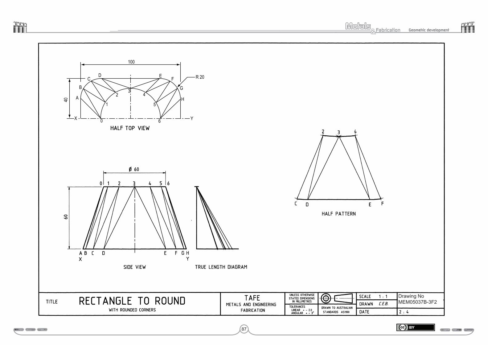
87
Fabrication& Geometric development
DC
B
A40
X 0
1
23
4
5
6 Y
H
FE R 20
100
G
HALF TOP VIEW
Drawing NoMEM05037B-3F2
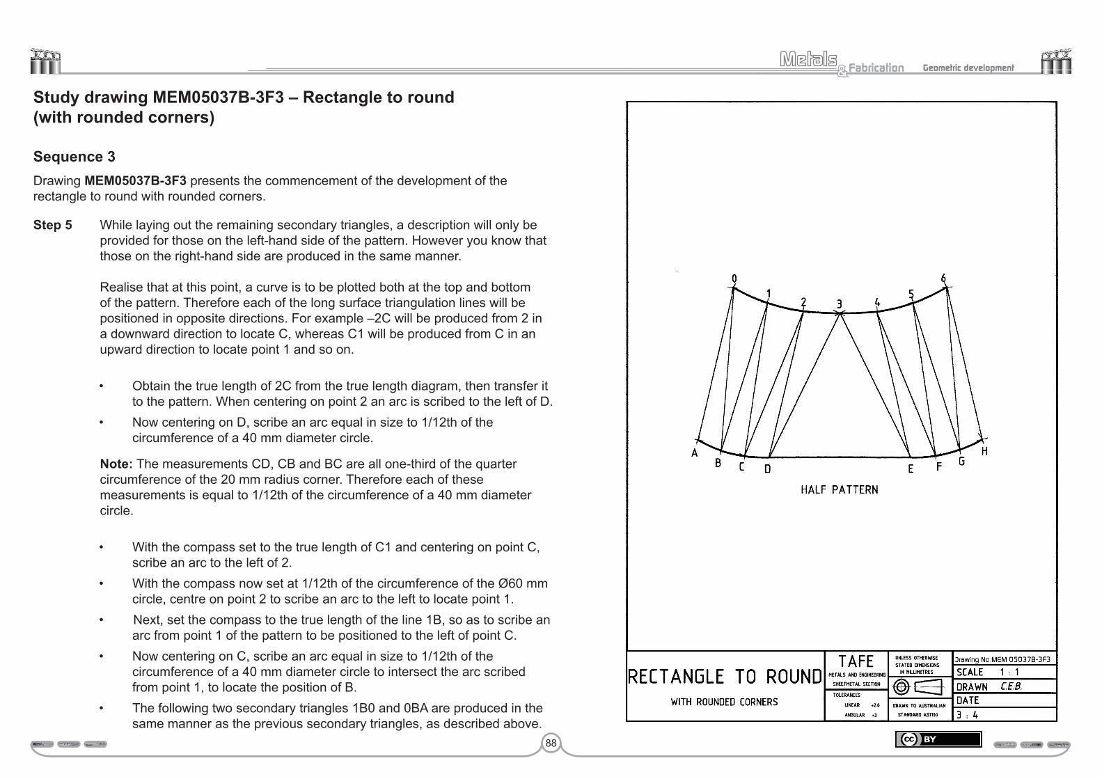
88
Fabrication& Geometric development
Study drawing MEM05037B-3F3 – Rectangle to round (with rounded corners)
Sequence 3Drawing MEM05037B-3F3 presents the commencement of the development of the rectangle to round with rounded corners.
Step 5 While laying out the remaining secondary triangles, a description will only be provided for those on the left-hand side of the pattern. However you know that those on the right-hand side are produced in the same manner. Realise that at this point, a curve is to be plotted both at the top and bottom of the pattern. Therefore each of the long surface triangulation lines will be positioned in opposite directions. For example –2C will be produced from 2 in a downward direction to locate C, whereas C1 will be produced from C in an upward direction to locate point 1 and so on.
• Obtain the true length of 2C from the true length diagram, then transfer it to the pattern. When centering on point 2 an arc is scribed to the left of D.
• Now centering on D, scribe an arc equal in size to 1/12th of the circumference of a 40 mm diameter circle.
Note: The measurements CD, CB and BC are all one-third of the quarter circumference of the 20 mm radius corner. Therefore each of these measurements is equal to 1/12th of the circumference of a 40 mm diameter circle.
• With the compass set to the true length of C1 and centering on point C, scribe an arc to the left of 2.
• With the compass now set at 1/12th of the circumference of the Ø60 mm circle, centre on point 2 to scribe an arc to the left to locate point 1.
• Next, set the compass to the true length of the line 1B, so as to scribe an arc from point 1 of the pattern to be positioned to the left of point C.
• Now centering on C, scribe an arc equal in size to 1/12th of the circumference of a 40 mm diameter circle to intersect the arc scribed from point 1, to locate the position of B.
• The following two secondary triangles 1B0 and 0BA are produced in the same manner as the previous secondary triangles, as described above.
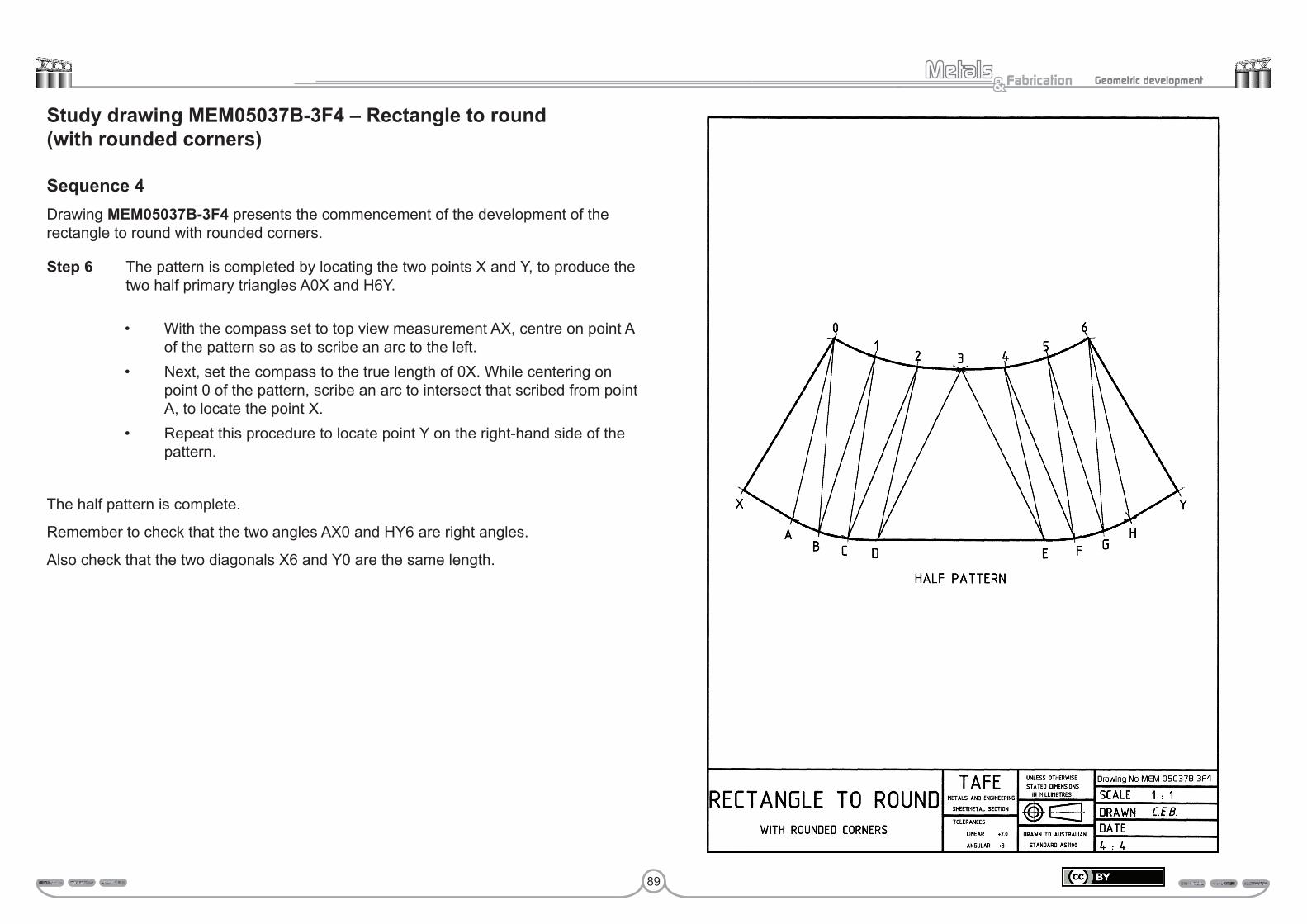
89
Fabrication& Geometric development
Study drawing MEM05037B-3F4 – Rectangle to round (with rounded corners)
Sequence 4Drawing MEM05037B-3F4 presents the commencement of the development of the rectangle to round with rounded corners.
Step 6 The pattern is completed by locating the two points X and Y, to produce the two half primary triangles A0X and H6Y.
• With the compass set to top view measurement AX, centre on point A of the pattern so as to scribe an arc to the left.
• Next, set the compass to the true length of 0X. While centering on point 0 of the pattern, scribe an arc to intersect that scribed from point A, to locate the point X.
• Repeat this procedure to locate point Y on the right-hand side of the pattern.
The half pattern is complete.
Remember to check that the two angles AX0 and HY6 are right angles.
Also check that the two diagonals X6 and Y0 are the same length.

90
Fabrication& Geometric development
Study drawing MEM05037B-3G – Rectangle to round (with rounded corners)Develop a half pattern for the rectangle to round presented in drawing MEM05037B-3G. When developing the pattern do not look at the example, try working from what you have learnt. In other words, treat this drawing as a test paper.
While preparing and developing this pattern, remember those things that you have learnt in the previous triangulation drawings. These are:
• the straight sides of the square or rectangle are true length and can therefore be transferred directly to the pattern
• the quarter circumference corners, which are divided into three equal parts, are true length.
• the circumference of the circle is true length and is transferred directly to the pattern 1/12th at a time. This dimension is more accurate when calculated
• the surface triangulation lines are not true length and must be transferred from the top view to the true length diagram, so as to obtain their true length, which can then be transferred to the pattern development
• although a pattern does not have to be started with a primary triangle, most people find this the easiest place to start
• the last triangle produced should provide a right angle.
Submit this drawing to your trainer for assessment.
Assessment:Date Signature Signature
Competent
Hold
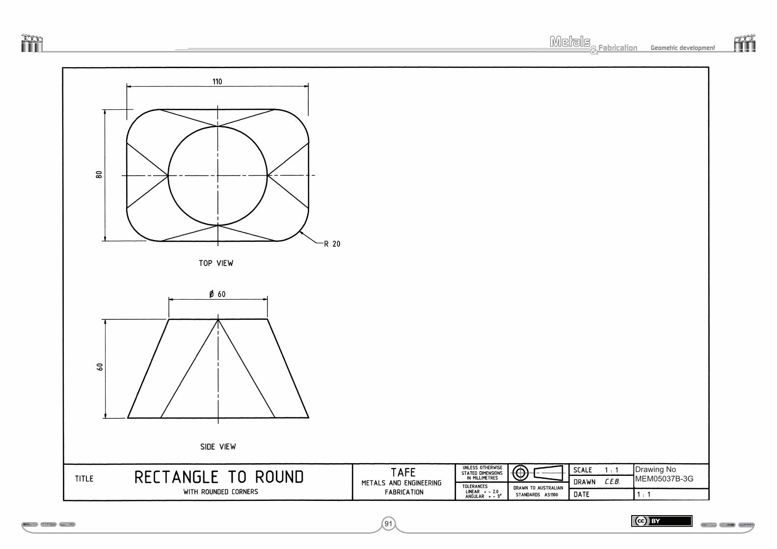
91
Fabrication& Geometric development
Drawing NoMEM05037B-3G
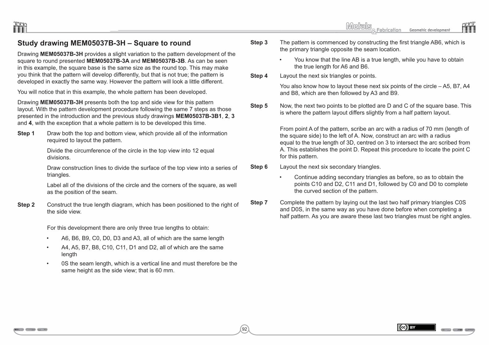
92
Fabrication& Geometric development
Study drawing MEM05037B-3H – Square to roundDrawing MEM05037B-3H provides a slight variation to the pattern development of the square to round presented MEM05037B-3A and MEM05037B-3B. As can be seen in this example, the square base is the same size as the round top. This may make you think that the pattern will develop differently, but that is not true; the pattern is developed in exactly the same way. However the pattern will look a little different.
You will notice that in this example, the whole pattern has been developed.
Drawing MEM05037B-3H presents both the top and side view for this pattern layout. With the pattern development procedure following the same 7 steps as those presented in the introduction and the previous study drawings MEM05037B-3B1, 2, 3 and 4, with the exception that a whole pattern is to be developed this time.
Step 1 Draw both the top and bottom view, which provide all of the information required to layout the pattern.
Divide the circumference of the circle in the top view into 12 equal divisions.
Draw construction lines to divide the surface of the top view into a series of triangles.
Label all of the divisions of the circle and the corners of the square, as well as the position of the seam.
Step 2 Construct the true length diagram, which has been positioned to the right of the side view.
For this development there are only three true lengths to obtain:
• A6, B6, B9, C0, D0, D3 and A3, all of which are the same length• A4, A5, B7, B8, C10, C11, D1 and D2, all of which are the same
length• 0S the seam length, which is a vertical line and must therefore be the
same height as the side view; that is 60 mm.
Step 3 The pattern is commenced by constructing the first triangle AB6, which is the primary triangle opposite the seam location.
• You know that the line AB is a true length, while you have to obtain the true length for A6 and B6.
Step 4 Layout the next six triangles or points.
You also know how to layout these next six points of the circle – A5, B7, A4 and B8, which are then followed by A3 and B9.
Step 5 Now, the next two points to be plotted are D and C of the square base. This is where the pattern layout differs slightly from a half pattern layout.
From point A of the pattern, scribe an arc with a radius of 70 mm (length of the square side) to the left of A. Now, construct an arc with a radius equal to the true length of 3D, centred on 3 to intersect the arc scribed from A. This establishes the point D. Repeat this procedure to locate the point C for this pattern.
Step 6 Layout the next six secondary triangles.
• Continue adding secondary triangles as before, so as to obtain the points C10 and D2, C11 and D1, followed by C0 and D0 to complete the curved section of the pattern.
Step 7 Complete the pattern by laying out the last two half primary triangles C0S and D0S, in the same way as you have done before when completing a half pattern. As you are aware these last two triangles must be right angles.

93
Fabrication& Geometric development
Drawing NoMEM05037B-3H

94
Fabrication& Geometric development
Study drawing MEM05037B-3I – Square to roundUsing both the top and side view provided in drawing MEM05037B-3I, develop for this square to round transition.
While developing the pattern try not look at the previous example, try working from what you have learnt. In other words, treat this as a test paper. If you find it necessary to refer to the previous drawing, do so.
Submit this drawing to your trainer for assessment.
Assessment:Date Signature Signature
Competent
Hold

95
Fabrication& Geometric development
Drawing NoMEM05037B-3I
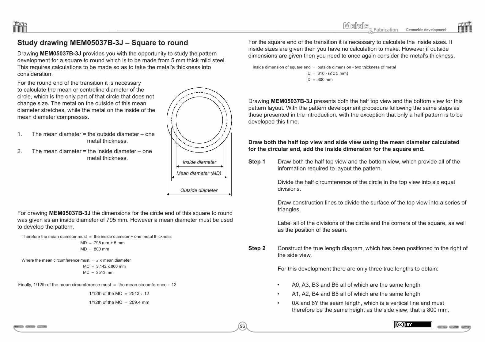
96
Fabrication& Geometric development
Study drawing MEM05037B-3J – Square to roundDrawing MEM05037B-3J provides you with the opportunity to study the pattern development for a square to round which is to be made from 5 mm thick mild steel. This requires calculations to be made so as to take the metal’s thickness into consideration.
For drawing MEM05037B-3J the dimensions for the circle end of this square to round was given as an inside diameter of 795 mm. However a mean diameter must be used to develop the pattern.
For the square end of the transition it is necessary to calculate the inside sizes. If inside sizes are given then you have no calculation to make. However if outside dimensions are given then you need to once again consider the metal’s thickness.
Drawing MEM05037B-3J presents both the half top view and the bottom view for this pattern layout. With the pattern development procedure following the same steps as those presented in the introduction, with the exception that only a half pattern is to be developed this time.
Draw both the half top view and side view using the mean diameter calculated for the circular end, add the inside dimension for the square end.
Step 1 Draw both the half top view and the bottom view, which provide all of the information required to layout the pattern. Divide the half circumference of the circle in the top view into six equal divisions. Draw construction lines to divide the surface of the top view into a series of triangles. Label all of the divisions of the circle and the corners of the square, as well as the position of the seam.
Step 2 Construct the true length diagram, which has been positioned to the right of the side view. For this development there are only three true lengths to obtain:
• A0, A3, B3 and B6 all of which are the same length• A1, A2, B4 and B5 all of which are the same length• 0X and 6Y the seam length, which is a vertical line and must
therefore be the same height as the side view; that is 800 mm.
For the round end of the transition it is necessary to calculate the mean or centreline diameter of the circle, which is the only part of that circle that does not change size. The metal on the outside of this mean diameter stretches, while the metal on the inside of the mean diameter compresses.
1. The mean diameter = the outside diameter – one metal thickness.
2. The mean diameter = the inside diameter – one metal thickness.
Therefore the mean diameter must the inside diameter + o= nne metal thicknessMD 795 mm + 5 mm
=
MD 800 mm=
Inside dimension of square end outside dimension - two t= hhickness of metalID 810 - (2 x 5 mm)
=
ID 800 mm=
Inside diameter
Mean diameter (MD)
Outside diameter
Where the mean circumference must π mean diameterMC
==
x 3.142 x 800 mm
MC 2513 mm=
Finally, 1/12th of the mean circumference must = the mean circumference ÷ 12
1/12th of the MC = 2513 ÷ 12
1/12th of the MC = 209.4 mm
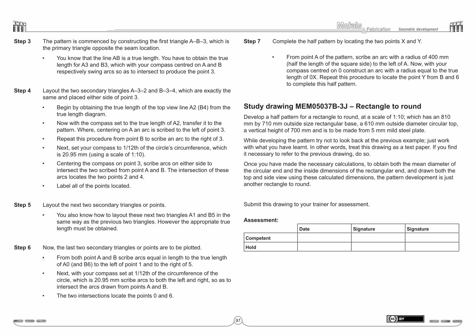
97
Fabrication& Geometric development
Step 3 The pattern is commenced by constructing the first triangle A–B–3, which is the primary triangle opposite the seam location.
• You know that the line AB is a true length. You have to obtain the true length for A3 and B3, which with your compass centred on A and B respectively swing arcs so as to intersect to produce the point 3.
Step 4 Layout the two secondary triangles A–3–2 and B–3–4, which are exactly the same and placed either side of point 3.
• Begin by obtaining the true length of the top view line A2 (B4) from the true length diagram.
• Now with the compass set to the true length of A2, transfer it to the pattern. Where, centering on A an arc is scribed to the left of point 3.
• Repeat this procedure from point B to scribe an arc to the right of 3.• Next, set your compass to 1/12th of the circle’s circumference, which
is 20.95 mm (using a scale of 1:10).• Centering the compass on point 3, scribe arcs on either side to
intersect the two scribed from point A and B. The intersection of these arcs locates the two points 2 and 4.
• Label all of the points located.
Step 5 Layout the next two secondary triangles or points.
• You also know how to layout these next two triangles A1 and B5 in the same way as the previous two triangles. However the appropriate true length must be obtained.
Step 6 Now, the last two secondary triangles or points are to be plotted.
• From both point A and B scribe arcs equal in length to the true length of A0 (and B6) to the left of point 1 and to the right of 5.
• Next, with your compass set at 1/12th of the circumference of the circle, which is 20.95 mm scribe arcs to both the left and right, so as to intersect the arcs drawn from points A and B.
• The two intersections locate the points 0 and 6.
Step 7 Complete the half pattern by locating the two points X and Y.
• From point A of the pattern, scribe an arc with a radius of 400 mm (half the length of the square side) to the left of A. Now, with your compass centred on 0 construct an arc with a radius equal to the true length of 0X. Repeat this procedure to locate the point Y from B and 6 to complete this half pattern.
Study drawing MEM05037B-3J – Rectangle to roundDevelop a half pattern for a rectangle to round, at a scale of 1:10; which has an 810 mm by 710 mm outside size rectangular base, a 610 mm outside diameter circular top, a vertical height of 700 mm and is to be made from 5 mm mild steel plate.
While developing the pattern try not to look back at the previous example; just work with what you have learnt. In other words, treat this drawing as a test paper. If you find it necessary to refer to the previous drawing, do so.
Once you have made the necessary calculations, to obtain both the mean diameter of the circular end and the inside dimensions of the rectangular end, and drawn both the top and side view using these calculated dimensions, the pattern development is just another rectangle to round.
Submit this drawing to your trainer for assessment.
Assessment:Date Signature Signature
Competent
Hold
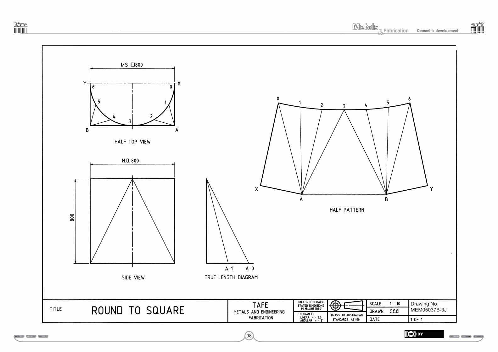
98
Fabrication& Geometric development
Drawing NoMEM05037B-3J
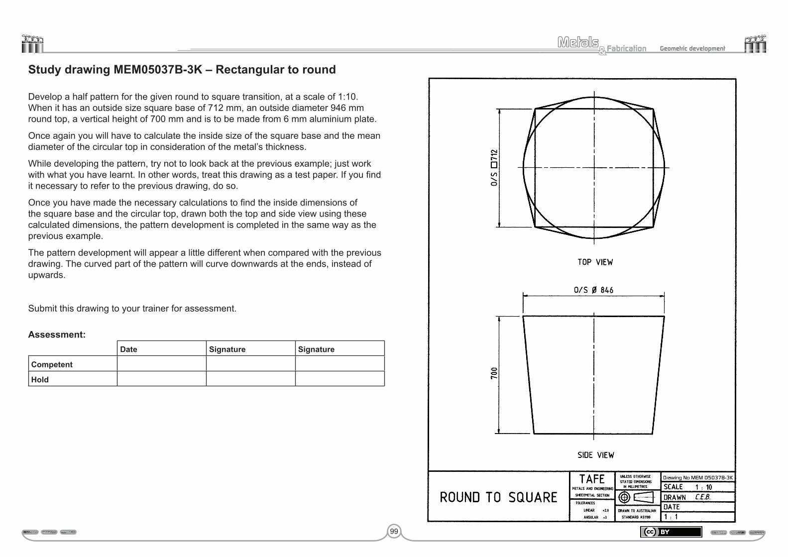
99
Fabrication& Geometric development
Study drawing MEM05037B-3K – Rectangular to round
Develop a half pattern for the given round to square transition, at a scale of 1:10. When it has an outside size square base of 712 mm, an outside diameter 946 mm round top, a vertical height of 700 mm and is to be made from 6 mm aluminium plate.
Once again you will have to calculate the inside size of the square base and the mean diameter of the circular top in consideration of the metal’s thickness.
While developing the pattern, try not to look back at the previous example; just work with what you have learnt. In other words, treat this drawing as a test paper. If you find it necessary to refer to the previous drawing, do so.
Once you have made the necessary calculations to find the inside dimensions of the square base and the circular top, drawn both the top and side view using these calculated dimensions, the pattern development is completed in the same way as the previous example.
The pattern development will appear a little different when compared with the previous drawing. The curved part of the pattern will curve downwards at the ends, instead of upwards.
Submit this drawing to your trainer for assessment.
Assessment:Date Signature Signature
Competent
Hold
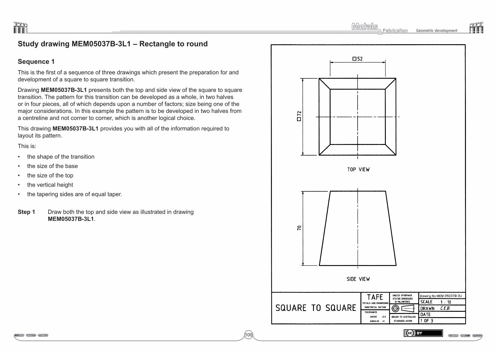
100
Fabrication& Geometric development
Study drawing MEM05037B-3L1 – Rectangle to round
Sequence 1This is the first of a sequence of three drawings which present the preparation for and development of a square to square transition.
Drawing MEM05037B-3L1 presents both the top and side view of the square to square transition. The pattern for this transition can be developed as a whole, in two halves or in four pieces, all of which depends upon a number of factors; size being one of the major considerations. In this example the pattern is to be developed in two halves from a centreline and not corner to corner, which is another logical choice.
This drawing MEM05037B-3L1 provides you with all of the information required to layout its pattern.
This is:
• the shape of the transition• the size of the base• the size of the top• the vertical height• the tapering sides are of equal taper.
Step 1 Draw both the top and side view as illustrated in drawing MEM05037B-3L1.
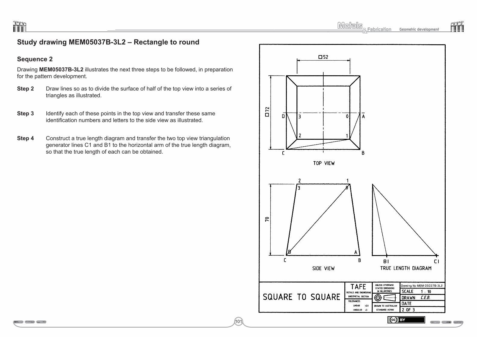
101
Fabrication& Geometric development
Study drawing MEM05037B-3L2 – Rectangle to round
Sequence 2Drawing MEM05037B-3L2 illustrates the next three steps to be followed, in preparation for the pattern development.
Step 2 Draw lines so as to divide the surface of half of the top view into a series of triangles as illustrated.
Step 3 Identify each of these points in the top view and transfer these same identification numbers and letters to the side view as illustrated.
Step 4 Construct a true length diagram and transfer the two top view triangulation generator lines C1 and B1 to the horizontal arm of the true length diagram, so that the true length of each can be obtained.
102
Fabrication& Geometric development
Study drawing MEM05037B-3L3 – Rectangle to round
Sequence 3Drawing MEM05037B-3L3 illustrates the steps to be followed to develop the pattern for this equal taper square to square transition.
Step 5 Commence the pattern by drawing the base line BC. Centering on C of the pattern, scribe an arc equal in radius to the true length of C1. Adjust your compass to the true length of B1 and scribe an arc from point B to intersect the arc drawn from C, to locate the point 1.
Step 6 The next point to be located is number 2, to create the triangle C–1–2. Begin by transferring the top view dimension 1–2 to the pattern. Where centering on 1, an arc is scribed to the right of point 2. Adjust your compass to the true length of C2, and centering on C scribe an arc so as to intersect the arc drawn from 1, to locate the point 2. This completes the front side of the pattern.
Step 7 The two end half sides are developed in the same way. Begin by centering your compass on point B, and with a radius equal to the top view dimension BA, scribe an arc to the right of B. Next, set your compass to the true length of 1A, and centering on A scribe an arc so as to intersect that drawn from point B. The intersection of the two arcs locates the point A. Repeat this procedure on the right-hand side of the pattern to locate point D.
Step 8 The last point 0 is found by first setting your compass to the top view true dimension 1–0 and centering on point 1. Scribe an arc to the left of this point. Finish the pattern by setting your compass to the true length of A0 and scribe an arc from A, so that it intersects the arc drawn from point 1. The intersection of the two arcs locates point 0. Once again, repeat this procedure on the right-hand side of the pattern to obtain the point 3.
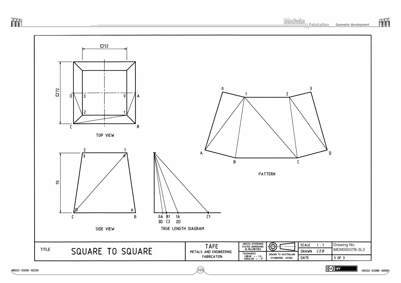
103
Fabrication& Geometric development
Drawing NoMEM05037B-3L3

104
Fabrication& Geometric development
Study drawing MEM05037B-3M – Rectangle to square1. Develop a half pattern for the rectangle to square transition, presented on page
105.
2. The dimensions provided are all inside sizes.
3. While developing the pattern, try not to look back at the previous example. Just work with what you have learnt. In other words, treat this drawing as a test paper. If you find it necessary to refer to the previous drawing, do so.
4. The pattern development will appear just slightly different when compared with the previous drawing, due to the base being rectangular instead of square.
Submit this drawing to your trainer for assessment.
Assessment:Date Signature Signature
Competent
Hold
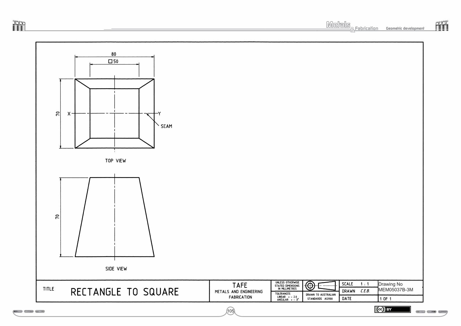
105
Fabrication& Geometric development
Drawing NoMEM05037B-3M
106
Fabrication& Geometric development
Perform geometric development 108 MEM 05037 B

107
Fabrication& Geometric development
Appendix – Metals and fabrication competency mapping
Book title Section title Comp code Competency title Full = Partial =
ENG091 Geometrical development1. Parallel line development MEM05037B Perform geometrical development
MEM12023A Perform engineering measurements MEM12007C Mark off/out structural fabrication and shapes MEM05010B Apply fabrication, forming and shaping techniques MEM18001C Use hand tools MEM12024A Perform computation MEM15002A Apply quality systems MEM15024A Apply quality procedures MEM14004A Plan to undertake a routine task MEM09002B Interpret technical drawing MEM14005A Plan a complete activity MEM16006A Organise and communicate information MEM16007A Work with others in a manufacturing, engineering or related environment
2. Radial line development MEM05037B Perform geometrical development MEM12023A Perform engineering measurements MEM12007C Mark off/out structural fabrication and shapes MEM05010B Apply fabrication, forming and shaping techniques MEM18001C Use hand tools MEM12024A Perform computation MEM15002A Apply quality systems MEM15024A Apply quality procedures MEM14004A Plan to undertake a routine task MEM09002B Interpret technical drawing MEM14005A Plan a complete activity MEM16006A Organise and communicate information MEM16007A Work with others in a manufacturing, engineering or related environment
3. Triangulation development MEM05037B Perform geometrical development MEM12023A Perform engineering measurements MEM12007C Mark off/out structural fabrication and shapes MEM05010B Apply fabrication, forming and shaping techniques MEM18001C Use hand tools MEM12024A Perform computation MEM15002A Apply quality systems MEM15024A Apply quality procedures MEM14004A Plan to undertake a routine task MEM09002B Interpret technical drawing MEM14005A Plan a complete activity MEM16006A Organise and communicate information MEM16007A Work with others in a manufacturing, engineering or related environment

108
Fabrication& Geometric development
Perform geometrical developmentThis resource is specifically designed to provide basic underpinning knowledge related to a number of competency units used in the Engineering Tradesperson Fabrication (Heavy) pathway across TAFE WA from January 2009. This pathway was specifically designed to meet the needs of the heavy metal fabrication industry after industry consultation and TAFE WA moderation sessions held in 2008. This pathway is also designed to be common across all colleges of TAFE WA (customisation to suit local conditions is encouraged).The pathway meets the requirements and guidelines of the MEM05 Training Package.
Context of assessmentAssessors are reminded the individual units may be assessed on-the-job, off-the-job or a combination of both on and off-the-job. Where assessment occurs off-the-job, that is the candidate is not in productive work, then an appropriate simulation must be used where the range of conditions reflects realistic workplace situations.
Project work, IntegrationThese units could be assessed in conjunction with mandatory units addressing the safety, quality, communication, mathematics etc. Units may also be assessed with other units requiring the exercise of the skills and knowledge.
Method of assessmentAssessors should gather a range of evidence that is valid, sufficient, current and authentic. Evidence can be gathered through a variety of ways including direct observation, supervisor’s reports, project work, samples and questioning. Questioning should not require language, literacy and numeracy skills beyond those required in this unit. The candidate must have access to all tools, equipment, materials and documentation required. The candidate must be permitted to refer to any relevant workplace procedures, product and manufacturing specifications, codes, standards, manuals and reference materials.
Consistency of performanceAssessors must be satisfied that the candidate can competently and consistently perform all elements of the units as specified by the criteria, including required knowledge, and be capable of applying the competency in new and different situations and contexts.
METALS & FABRICATION
GEOMETRIC DEVELOPMENT
Learning Resource
DESCRIPTION
This resource supports learners to develop introductory-level skills and knowledge in common geometric pattern development techniques. It relates to a number of competency units used in the Engineering Tradesperson learning pathway.
Topics covered include the following.
• Parallel line development• Radial line development• Triangulation development
The book is divided into separate chapters, each containing workshop-based activities that will provide opportunities for practice before assessment. Detailed graphics and technical drawings are provided throughout the book to support learners.
A comprehensive mapping guide is included, to show where the content in this resource aligns with the relevant competencies
EDITION
2009
CATEGORY
METALS & ENGINEERING
TRAINING PACKAGE
• MEM05
ORDERING INFORMATION:Contact WestOne Services on Tel: (08) 9229 5200 Fax: (08) 9227 8393 Email: [email protected] can also be placed through the website: www.westone.wa.gov.au 9 7 8 0 7 3 0 7 9 7 2 0 3
ENG091 GEOMETRIC DEVELOPMENT
ISBN 978-0-7307-9720-3
ORDERING INFORMATION:Tel: (08) 6212 9700 Fax: (08) 9227 8393 Email: [email protected] can also be placed through the website: www.vetinfonet.dtwd.wa.gov.au