metal forming handbook - iis windows server
TRANSCRIPT

هب انم خدا

Metal Forming Handbook
Metal Forming Handbook /Schuler (c) Springer-Verlag Berlin Heidelberg 1998

3BerlinHeidelbergNew YorkBarcelonaBudapestHong KongLondonMilanParisSanta ClaraSingaporeTokyo
Metal Forming Handbook /Schuler (c) Springer-Verlag Berlin Heidelberg 1998

META L F O RM I N GH AND BOO K
123Metal Forming Handbook /Schuler (c) Springer-Verlag Berlin Heidelberg 1998
SCHULER GmbHBahnhofstr. 41 73033 GöppingenGermany
Consulting editor: Professor Taylan Altan Director, Engineering Research Center for Net Shape Manufacturing The Ohio State University, USA
Cataloging-in-Publication Data applied for
Die Deutsche Bibliothek – CIP-Einheitsaufnahme
Metal forming handbook / Schuler. – Berlin ; Heidelberg ; New York ; Barcelona ;Budapest ; Hong Kong ; London ; Milan ; Paris ; Santa Clara ; Singapore ; Tokyo :Springer, 1998
Dt. Ausg. u. d. T.: Handbuch der UmformtechnikISBN 3-540-61185-1
ISBN 3-540-61185-1 Springer-Verlag Berlin Heidelberg New York
This work is subject to copyright.All rights are reserved, whether the whole part of the material is concerned,specifically the rights of translation, reprinting, reuse of illustrations, recitation, broadcasting, reproductionon microfilm or in any other way, and storage in data banks. Duplication of this publication or parts thereofis permitted only under the provisions of the German Copyright Law of September 9, 1965, in its current ver-sion, and permission for use must always be obtained from Springer-Verlag. Violations are liable for prose-cution under the German Copyright Law.
© Springer-Verlag Berlin Heidelberg 1998Printed in Germany
The use of general descriptive names, registered names, trademarks, etc. in this publication does not imply,even in the absence of a specific statement, that such names are exempt from the relevant protective laws andregulations and therefore free for general use.
Cover design by MEDIO, BerlinLayout design and data conversion by MEDIO, BerlinPrinting and binding by Konrad Triltsch Druck- und Verlagsanstalt, WürzburgSPIN: 10514857 3020/ 62/ 5 4 3 2 1 0 – Printed on acid-free paper.
Metal Forming Handbook /Schuler (c) Springer-Verlag Berlin Heidelberg 1998
Preface
Following the long tradition of the Schuler Company, the Metal For-ming Handbook presents the scientific fundamentals of metal formingtechnology in a way which is both compact and easily understood.Thus, this book makes the theory and practice of this field accessible toteaching and practical implementation.
The first Schuler “Metal Forming Handbook” was published in 1930.The last edition of 1966, already revised four times, was translated intoa number of languages, and met with resounding approval around theglobe.
Over the last 30 years, the field of forming technology has been rad-ically changed by a number of innovations. New forming techniquesand extended product design possibilities have been developed andintroduced. This Metal Forming Handbook has been fundamentallyrevised to take account of these technological changes. It is both a text-book and a reference work whose initial chapters are concerned to pro-vide a survey of the fundamental processes of forming technology andpress design. The book then goes on to provide an in-depth study of themajor fields of sheet metal forming, cutting, hydroforming and solidforming. A large number of relevant calculations offers state of the artsolutions in the field of metal forming technology. In presenting tech-nical explanations, particular emphasis was placed on easily under-standable graphic visualization. All illustrations and diagrams werecompiled using a standardized system of functionally oriented colorcodes with a view to aiding the reader’s understanding.
It is sincerely hoped that this Handbook helps not only disseminatespecialized knowledge but also provides an impetus for dialoguebetween the fields of production engineering, production line con-struction, teaching and research.
Metal Forming Handbook /Schuler (c) Springer-Verlag Berlin Heidelberg 1998

This Handbook is the product of dedicated commitment and the widerange of specialized knowledge contributed by many employees of theSCHULER Group in close cooperation with Prof. Dr.-Ing. H. Hoffmannand Dipl.-Ing. M. Kasparbauer of the utg, Institute for Metal Formingand Casting at the Technical University of Munich. In close cooperationwith the SCHULER team, they have created a solid foundation for thepractical and scientific competence presented in this Handbook. Wewish to offer our sincere thanks and appreciation to all those involved.
Goeppingen, March 1998
Schuler GmbHBoard of Management
VI Metal Forming Handbook
Metal Forming Handbook /Schuler (c) Springer-Verlag Berlin Heidelberg 1998

Contributors
ADAM, K., Dipl.-Ing. (FH), SMG Süddeutsche Maschinenbau GmbH & CoBAREIS, A., Dipl.-Ing. (FH), Schuler Pressen GmbH & CoBIRZER, F., Prof. Dipl.-Ing., Feintool AGBLASIG, N., Dipl.-Ing. (FH), Schleicher Automation GmbH & CoBRANDSTETTER, R., Dipl.-Ing. (FH), Schuler Pressen GmbH & CoBREUER, W., Dipl.-Ing., Schuler Pressen GmbH & CoFRONTZEK, H., Dr.-Ing., Schuler GmbHHOFFMANN, H., Prof. Dr.-Ing., Lehrstuhl für Umformtechnik und Gieße-
reiwesen, Technische Universität MünchenJAROSCH, B., Dipl.-Ing. (FH), Schuler Pressen GmbH & CoKÄSMACHER, H., SMG Engineering für Industrieanlagen GmbHKASPARBAUER, M., Dipl.-Ing., Lehrstuhl für Umformtechnik und Gießerei-
wesen, Technische Universität MünchenKELLENBENZ, R., Dipl.-Ing. (FH), Schuler Pressen GmbH & CoKIEFER, A., Dipl.-Ing. (BA), GMG Automation GmbH & CoKLEIN, P., Gräbener Pressensysteme GmbH & Co. KGKLEMM, P., Dr.-Ing., Schuler Pressen GmbH & CoKNAUß, V., Dipl.-Ing. (FH), Schuler Werkzeuge GmbH & CoKOHLER, H., Dipl.-Ing., Schuler Guß GmbH & CoKÖRNER, E., Dr.-Ing., Schuler Pressen GmbH & CoKUTSCHER, H.-W., Dipl.-Ing.(FH), Gräbener Pressensysteme GmbH & Co. KGLEITLOFF, F.-U., Dr.-Ing., Schäfer Hydroforming GmbH & CoMERKLE, D., Schuler Pressen GmbH & CoOSEN, W., Dr.- Ing., SMG Süddeutsche Maschinenbau GmbH & CoPFEIFLE, P., Dipl.-Ing. (FH), Schuler Pressen GmbH & CoREITMEIER, C., Dipl.-Ing., Schäfer Hydroforming GmbH & CoREMPPIS, M., Ing. grad., Schuler Pressen GmbH & CoROSENAUER, K., Dipl.-Ing. (FH), Schuler Werkzeuge GmbH & Co
Metal Forming Handbook /Schuler (c) Springer-Verlag Berlin Heidelberg 1998

SCHÄFER, A.W., Schäfer Hydroforming GmbH & CoSCHMID, W., Dipl.-Ing. (FH), Schuler Werkzeuge GmbH & CoSCHMITT, K. P., Schuler Pressen GmbH & CoSCHNEIDER, F., Dipl.-Ing. (FH), Schuler Pressen GmbH & CoSIMON, H., Dr.-Ing., Schuler Werkzeuge GmbH & CoSTEINMETZ, M., Dipl.-Wirt.-Ing., SMG Engineering für Industrieanlagen
GmbHSTROMMER, K., Dipl.-Ing. (FH), Schuler Pressen GmbH & CoVOGEL, N., Dipl.-Ing., Schleicher Automation GmbH & CoWEGENER, K., Dr.-Ing., Schuler Pressen GmbH & Co
VIII Metal Forming Handbook
Metal Forming Handbook /Schuler (c) Springer-Verlag Berlin Heidelberg 1998
Contents
Index of formula symbols . . . . . . . . . . . . . . . . . . . . . . . . . . . . . . . XV
1 Introduction . . . . . . . . . . . . . . . . . . . . . . . . . . . . . . . . . . . . . . . . 1
2 Basic principles of metal forming . . . . . . . . . . . . . . . . . . . . . . 5
2.1 Methods of forming and cutting technology . . . . . . . . . 52.1.1 Summary . . . . . . . . . . . . . . . . . . . . . . . . . . . . . . . . . 52.1.2 Forming . . . . . . . . . . . . . . . . . . . . . . . . . . . . . . . . . . 62.1.3 Dividing . . . . . . . . . . . . . . . . . . . . . . . . . . . . . . . . . . 192.1.4 Combinations of processes in manufacturing . . . . . 22
2.2 Basic terms . . . . . . . . . . . . . . . . . . . . . . . . . . . . . . . . . . . . . 252.2.1 Flow condition and flow curve. . . . . . . . . . . . . . . . . 252.2.2 Deformation and material flow . . . . . . . . . . . . . . . . 262.2.3 Force and work . . . . . . . . . . . . . . . . . . . . . . . . . . . . . 282.2.4 Formability . . . . . . . . . . . . . . . . . . . . . . . . . . . . . . . . 302.2.5 Units of measurement . . . . . . . . . . . . . . . . . . . . . . . 31
Bibliography . . . . . . . . . . . . . . . . . . . . . . . . . . . . . . . . . . . . . . . . . 32
3 Fundamentals of press design. . . . . . . . . . . . . . . . . . . . . . . . . . 33
3.1 Press types and press construction . . . . . . . . . . . . . . . . . . 333.1.1 Press frame . . . . . . . . . . . . . . . . . . . . . . . . . . . . . . . . 343.1.2 Slide drive . . . . . . . . . . . . . . . . . . . . . . . . . . . . . . . . . 373.1.3 Drive systems for deep drawing presses . . . . . . . . . . 413.1.4 Draw cushions . . . . . . . . . . . . . . . . . . . . . . . . . . . . . 44
Metal Forming Handbook /Schuler (c) Springer-Verlag Berlin Heidelberg 1998
3.2 Mechanical presses . . . . . . . . . . . . . . . . . . . . . . . . . . . . . . 493.2.1 Determination of characteristic data . . . . . . . . . . . 493.2.2 Types of drive system . . . . . . . . . . . . . . . . . . . . . . . 543.2.3 Drive motor and flywheel . . . . . . . . . . . . . . . . . . . . 603.2.4 Clutch and brake . . . . . . . . . . . . . . . . . . . . . . . . . . 613.2.5 Longitudinal and transverse shaft drive . . . . . . . . . 633.2.6 Gear drives . . . . . . . . . . . . . . . . . . . . . . . . . . . . . . . 653.2.7 Press crown assembly . . . . . . . . . . . . . . . . . . . . . . . 663.2.8 Slide and blank holder . . . . . . . . . . . . . . . . . . . . . . 663.2.9 Pneumatic system . . . . . . . . . . . . . . . . . . . . . . . . . . 703.2.10 Hydraulic system . . . . . . . . . . . . . . . . . . . . . . . . . . . 713.2.11 Lubrication . . . . . . . . . . . . . . . . . . . . . . . . . . . . . . . 72
3.3 Hydraulic presses . . . . . . . . . . . . . . . . . . . . . . . . . . . . . . . 733.3.1 Drive system . . . . . . . . . . . . . . . . . . . . . . . . . . . . . . 733.3.2 Hydraulic oil . . . . . . . . . . . . . . . . . . . . . . . . . . . . . . 773.3.3 Parallelism of the slide . . . . . . . . . . . . . . . . . . . . . . 803.3.4 Stroke limitation and damping . . . . . . . . . . . . . . . 823.3.5 Slide locking . . . . . . . . . . . . . . . . . . . . . . . . . . . . . . 83
3.4 Changing dies . . . . . . . . . . . . . . . . . . . . . . . . . . . . . . . . . . 863.4.1 Die handling . . . . . . . . . . . . . . . . . . . . . . . . . . . . . . 863.4.2 Die clamping devices . . . . . . . . . . . . . . . . . . . . . . . 91
3.5 Press control systems . . . . . . . . . . . . . . . . . . . . . . . . . . . . 943.5.1 Functions of the control system . . . . . . . . . . . . . . . 943.5.2 Electrical components of presses . . . . . . . . . . . . . . 943.5.3 Operating and visualization system . . . . . . . . . . . . 953.5.4 Structure of electrical control systems . . . . . . . . . . 973.5.5 Functional structure of the control system . . . . . . 993.5.6 Major electronic control components . . . . . . . . . . 993.5.7 Architecture and hardware configuration . . . . . . . 1013.5.8 Architecture of the PLC software . . . . . . . . . . . . . . 1013.5.9 Future outlook . . . . . . . . . . . . . . . . . . . . . . . . . . . . 102
3.6 Press safety and certification . . . . . . . . . . . . . . . . . . . . . . 1063.6.1 Accident prevention . . . . . . . . . . . . . . . . . . . . . . . . 1063.6.2 Legislation . . . . . . . . . . . . . . . . . . . . . . . . . . . . . . . . 1073.6.3 European safety requirements . . . . . . . . . . . . . . . . 1073.6.4 CE marking . . . . . . . . . . . . . . . . . . . . . . . . . . . . . . . 111
X Metal Forming Handbook
Metal Forming Handbook /Schuler (c) Springer-Verlag Berlin Heidelberg 1998
3.6.5 Measures to be undertaken by the user . . . . . . . . . 1153.6.6 Safety requirements in the USA . . . . . . . . . . . . . . . 117
3.7 Casting components for presses . . . . . . . . . . . . . . . . . . . 120
Bibliography . . . . . . . . . . . . . . . . . . . . . . . . . . . . . . . . . . . . . . . . . 122
4 Sheet metal forming and blanking . . . . . . . . . . . . . . . . . . . . 1234.1 Principles of die manufacture . . . . . . . . . . . . . . . . . . . . . 123
4.1.1 Classification of dies . . . . . . . . . . . . . . . . . . . . . . . . 1234.1.2 Die development . . . . . . . . . . . . . . . . . . . . . . . . . . 1284.1.3 Die materials . . . . . . . . . . . . . . . . . . . . . . . . . . . . . . 1424.1.4 Casting of dies . . . . . . . . . . . . . . . . . . . . . . . . . . . . . 1424.1.5 Try-out equipment . . . . . . . . . . . . . . . . . . . . . . . . . 1484.1.6 Transfer simulators . . . . . . . . . . . . . . . . . . . . . . . . . 154
4.2 Deep drawing and stretch drawing . . . . . . . . . . . . . . . . . 1564.2.1 Forming process . . . . . . . . . . . . . . . . . . . . . . . . . . . 1564.2.2 Materials for sheet metal forming . . . . . . . . . . . . . 1744.2.3 Friction, wear and lubrication during
sheet metal forming . . . . . . . . . . . . . . . . . . . . . . . . 1794.2.4 Hydro-mechanical deep drawing . . . . . . . . . . . . . . 1854.2.5 Active hydro-mechanical drawing . . . . . . . . . . . . . 188
4.3 Coil lines . . . . . . . . . . . . . . . . . . . . . . . . . . . . . . . . . . . . . . 194
4.4 Sheet metal forming lines . . . . . . . . . . . . . . . . . . . . . . . . 1984.4.1 Universal presses . . . . . . . . . . . . . . . . . . . . . . . . . . . 1984.4.2 Production lines for the manufacture of
flat radiator plates . . . . . . . . . . . . . . . . . . . . . . . . . 2084.4.3 Lines for side member manufacture . . . . . . . . . . . . 2104.4.4 Destackers and blank turnover stations . . . . . . . . 2174.4.5 Press lines . . . . . . . . . . . . . . . . . . . . . . . . . . . . . . . . 2224.4.6 Transfer presses for small and
medium sized parts . . . . . . . . . . . . . . . . . . . . . . . . . 2294.4.7 Large-panel tri-axis transfer presses . . . . . . . . . . . . 2344.4.8 Crossbar transfer presses . . . . . . . . . . . . . . . . . . . . . 2434.4.9 Presses for plastics . . . . . . . . . . . . . . . . . . . . . . . . . . 2504.4.10 Stacking units for finished parts . . . . . . . . . . . . . . . 2524.4.11 Control systems for large-panel transfer presses . . 254
XIContents
Metal Forming Handbook /Schuler (c) Springer-Verlag Berlin Heidelberg 1998
4.5 Blanking processes . . . . . . . . . . . . . . . . . . . . . . . . . . . . . . 268
4.6 Shearing lines . . . . . . . . . . . . . . . . . . . . . . . . . . . . . . . . . . 2844.6.1 Slitting lines . . . . . . . . . . . . . . . . . . . . . . . . . . . . . . 2844.6.2 Blanking lines . . . . . . . . . . . . . . . . . . . . . . . . . . . . . 2864.6.3 High-speed blanking lines . . . . . . . . . . . . . . . . . . . 2914.6.4 Lines for the production of
electric motor laminations . . . . . . . . . . . . . . . . . . . 2964.6.5 Production and processing of tailored blanks . . . . 3104.6.6 Perforating presses . . . . . . . . . . . . . . . . . . . . . . . . . 3144.6.7 Control systems for blanking presses . . . . . . . . . . . 320
4.7 Fine blanking . . . . . . . . . . . . . . . . . . . . . . . . . . . . . . . . . . . 3304.7.1 Fine blanking process . . . . . . . . . . . . . . . . . . . . . . . 3304.7.2 Fine blanking materials, forces, quality
characteristics and part variety . . . . . . . . . . . . . . . . 3384.7.3 Fine blanking tools . . . . . . . . . . . . . . . . . . . . . . . . . 3514.7.4 Fine blanking presses and lines . . . . . . . . . . . . . . . 359
4.8 Bending . . . . . . . . . . . . . . . . . . . . . . . . . . . . . . . . . . . . . . . 3664.8.1 Bending process . . . . . . . . . . . . . . . . . . . . . . . . . . . 3664.8.2 Roll forming and variety of sections . . . . . . . . . . . . 3734.8.3 Roller straightening . . . . . . . . . . . . . . . . . . . . . . . . 383
4.9 Organization of stamping plants . . . . . . . . . . . . . . . . . . 3894.9.1 Design . . . . . . . . . . . . . . . . . . . . . . . . . . . . . . . . . . . 3894.9.2 Layout . . . . . . . . . . . . . . . . . . . . . . . . . . . . . . . . . . . 3914.9.3 Quality assurance through quality control . . . . . . 398
Bibliography . . . . . . . . . . . . . . . . . . . . . . . . . . . . . . . . . . . . . . . . . 403
5 Hydroforming . . . . . . . . . . . . . . . . . . . . . . . . . . . . . . . . . . . . . . 405
5.1 General . . . . . . . . . . . . . . . . . . . . . . . . . . . . . . . . . . . . . . . . 405
5.2 Process technology and example applications . . . . . . . 4055.2.1 Process technology . . . . . . . . . . . . . . . . . . . . . . . . . 4055.2.2 Types of hydroformed components . . . . . . . . . . . . 4085.2.3 Fields of application . . . . . . . . . . . . . . . . . . . . . . . . 410
XII Metal Forming Handbook
Metal Forming Handbook /Schuler (c) Springer-Verlag Berlin Heidelberg 1998
5.3 Component development . . . . . . . . . . . . . . . . . . . . . . . . . 4135.3.1 User-oriented project management . . . . . . . . . . . . 4135.3.2 Feasibility studies . . . . . . . . . . . . . . . . . . . . . . . . . . 4145.3.3 Component design . . . . . . . . . . . . . . . . . . . . . . . . . 416
5.4 Die engineering . . . . . . . . . . . . . . . . . . . . . . . . . . . . . . . . . 4205.4.1 Die layout. . . . . . . . . . . . . . . . . . . . . . . . . . . . . . . . . 4205.4.2 Lubricants . . . . . . . . . . . . . . . . . . . . . . . . . . . . . . . . 422
5.5 Materials and preforms forproducing hydroformed components . . . . . . . . . . . . . . 4235.5.1 Materials and heat treatment . . . . . . . . . . . . . . . . . 4235.5.2 Preforms and preparation . . . . . . . . . . . . . . . . . . . . 424
5.6 Presses for hydroforming . . . . . . . . . . . . . . . . . . . . . . . . . 426
5.7 General considerations . . . . . . . . . . . . . . . . . . . . . . . . . . . 4295.7.1 Production technology issues . . . . . . . . . . . . . . . . . 4295.7.2 Technical and economic considerations . . . . . . . . 431
Bibliography . . . . . . . . . . . . . . . . . . . . . . . . . . . . . . . . . . . . . . . . . 432
6 Solid forming (Forging) . . . . . . . . . . . . . . . . . . . . . . . . . . . . . . 433
6.1 General . . . . . . . . . . . . . . . . . . . . . . . . . . . . . . . . . . . . . . . . 433
6.2 Benefits of solid forming . . . . . . . . . . . . . . . . . . . . . . . . . 4416.2.1 Economic aspects . . . . . . . . . . . . . . . . . . . . . . . . . . 4416.2.2 Workpiece properties . . . . . . . . . . . . . . . . . . . . . . . . 443
6.3 Materials, billet production and surface treatment . . . 4506.3.1 Materials. . . . . . . . . . . . . . . . . . . . . . . . . . . . . . . . . . 4506.3.2 Billet or slug preparation . . . . . . . . . . . . . . . . . . . . . 4546.3.3 Surface treatment. . . . . . . . . . . . . . . . . . . . . . . . . . . 459
6.4 Formed part and process plan . . . . . . . . . . . . . . . . . . . . . 4646.4.1 The formed part . . . . . . . . . . . . . . . . . . . . . . . . . . . . 4646.4.2 Process plan . . . . . . . . . . . . . . . . . . . . . . . . . . . . . . . 467
6.5 Force and work requirement . . . . . . . . . . . . . . . . . . . . . . 4696.5.1 Forward rod extrusion . . . . . . . . . . . . . . . . . . . . . . . 4696.5.2 Forward tube extrusion . . . . . . . . . . . . . . . . . . . . . . 474
XIIIContents
Metal Forming Handbook /Schuler (c) Springer-Verlag Berlin Heidelberg 1998
6.5.3 Backward cup extrusion and centering . . . . . . . . . 4746.5.4 Reducing (open die forward extrusion). . . . . . . . . . 4756.5.5 Ironing . . . . . . . . . . . . . . . . . . . . . . . . . . . . . . . . . . . 4766.5.6 Upsetting . . . . . . . . . . . . . . . . . . . . . . . . . . . . . . . . . 4766.5.7 Lateral extrusion . . . . . . . . . . . . . . . . . . . . . . . . . . . 477
6.6 Part transfer . . . . . . . . . . . . . . . . . . . . . . . . . . . . . . . . . . . . 4786.6.1 Loading station . . . . . . . . . . . . . . . . . . . . . . . . . . . . 4796.6.2 Transfer study . . . . . . . . . . . . . . . . . . . . . . . . . . . . . 481
6.7 Die design . . . . . . . . . . . . . . . . . . . . . . . . . . . . . . . . . . . . . 4856.7.1 Die holders . . . . . . . . . . . . . . . . . . . . . . . . . . . . . . . 4886.7.2 Die and punch design . . . . . . . . . . . . . . . . . . . . . . 4916.7.3 Die and punch materials . . . . . . . . . . . . . . . . . . . . 4966.7.4 Die closing systems
(multiple-action dies) . . . . . . . . . . . . . . . . . . . . . . . 502
6.8 Presses used for solid forming . . . . . . . . . . . . . . . . . . . . 5056.8.1 Choice of press . . . . . . . . . . . . . . . . . . . . . . . . . . . . 5056.8.2 Mechanical presses . . . . . . . . . . . . . . . . . . . . . . . . . 5076.8.3 Hydraulic presses . . . . . . . . . . . . . . . . . . . . . . . . . . 5146.8.4 Supplementary equipment . . . . . . . . . . . . . . . . . . 5176.8.5 Special features of hot and warm forming lines . . 5206.8.6 Sizing and coining presses . . . . . . . . . . . . . . . . . . . 5226.8.7 Minting and coin blanking lines . . . . . . . . . . . . . . 526
Bibliography . . . . . . . . . . . . . . . . . . . . . . . . . . . . . . . . . . . . . . . . . 541
Index . . . . . . . . . . . . . . . . . . . . . . . . . . . . . . . . . . . . . . . . . . . . . . . . 543
XIV Metal Forming Handbook
Metal Forming Handbook /Schuler (c) Springer-Verlag Berlin Heidelberg 1998
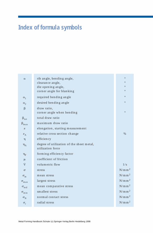
Index of formula symbols
a rib angle, bending angle, °clearance angle, °die opening angle, °corner angle for blanking °
a1 required bending angle °
a2 desired bending angle °
b draw ratio, corner angle when bending °
btot total draw ratio
bmax maximum draw ratio
« elongation, starting measurement
«A relative cross section change %
h efficiency
hA degree of utilization of the sheet metal, utilization force
hF forming efficiency factor
m coefficient of friction
V volumetric flow 1/s
s stress N/mm2
sm mean stress N/mm2
smax largest stress N/mm2
smd mean comparative stress N/mm2
smin smallest stress N/mm2
sN normal contact stress N/mm2
sr radial stress N/mm2
·
Metal Forming Handbook /Schuler (c) Springer-Verlag Berlin Heidelberg 1998
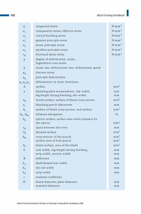
st tangential stress N/mm2
sv comparative stress, effective stress N/mm2
sz critical buckling stress N/mm2
s1 greatest principle stress N/mm2
s2 mean principle stress N/mm2
s3 smallest principle stress N/mm2
tR frictional shear stress N/mm2
w degree of deformation, strain, logarithmic/true strain
w strain rate, deformation rate, deformation speed
wB fracture strain
wg principle deformation
w1,w2,w3 deformation in main directions
A surface mm2
a blanking plate measurement, rim width, mmleg length during bending, slot width mm
A0 initial surface, surface of blank cross section mm2
a1 blanking punch dimension mm
A1 surface of blank cross section, end surface mm2
A5, A80 ultimate elongation %
AG ejector surface, surface area under pressure bythe ejector mm2
aR space between the rows mm
AS sheared surface mm2
ASt cross section of the punch, mm2
surface area of hole punch mm2
AZ blank surface, area of the blank mm2
b web width, leg length during bending, mmstrip width, section width mm
B deflection mm
bA shell-shaped tear width mm
bE die roll width mm
bS strip width mm
c material coefficient
D blank diameter, plate diameter, mmmandrel diameter mm
XVI Metal Forming Handbook
·
Metal Forming Handbook /Schuler (c) Springer-Verlag Berlin Heidelberg 1998
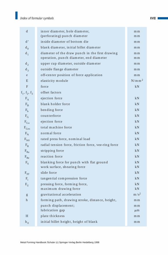
d inner diameter, hole diameter, mm(perforating) punch diameter mm
d’ inside diameter of bottom die mm
d0 blank diameter, initial billet diameter mm
d1 diameter of the draw punch in the first drawing mmoperation, punch diameter, end diameter mm
d2 upper cup diameter, outside diameter mm
d3 outside flange diameter mm
e off-center position of force application mm
E elasticity module N/mm2
F force kN
f1, f2, f3 offset factors
FA ejection force kN
FB blank holder force kN
Fb bending force kN
FG counterforce kN
FGa ejection force kN
FGes total machine force kN
FN normal force kN
FN0 rated press force, nominal load kN
FR radial tension force, friction force, vee-ring force kN
FRa stripping force kN
FRe reaction force kN
FS blanking force for punch with flat ground kNwork surface, shearing force kN
FST slide force kN
Ft tangential compression force kN
FU pressing force, forming force, kNmaximum drawing force kN
g gravitational acceleration m/s2
h forming path, drawing stroke, distance, height, mm
punch displacement; mmlubrication gap mm
H plate thickness mm
h0 initial billet height, height of blank mm
XVIIIndex of formular symbols
Metal Forming Handbook /Schuler (c) Springer-Verlag Berlin Heidelberg 1998
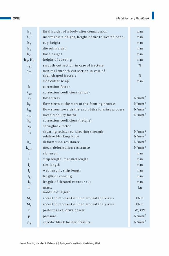
h1 final height of a body after compression mm
h1’ intermediate height, height of the truncated cone mm
h2 cup height mm
hE die roll height mm
hG flash height mm
hR, HR height of vee-ring mm
hS1 smooth cut section in case of fracture %
hS2 minimal smooth cut section in case of shell-shaped fracture %
i side cutter scrap mm
k correction factor
k2a correction coefficient (angle)
kf flow stress N/mm2
kf0 flow stress at the start of the forming process N/mm2
kf1 flow stress towards the end of the forming process N/mm2
kfm mean stability factor N/mm2
kh correction coefficient (height)
kR springback factor
kS shearing resistance, shearing strength, N/mm2
relative blanking force N/mm2
kw deformation resistance N/mm2
kwm mean deformation resistance N/mm2
l rib length mm
L strip length, mandrel length mm
la rim length mm
le web length, strip length mm
lR length of vee-ring mm
lS length of sheared contour cut mm
m mass, kgmodule of a gear
Mx eccentric moment of load around the x axis kNm
My eccentric moment of load around the y axis kNm
P performance, drive power W, kW
p pressure N/mm2
pB specific blank holder pressure N/mm2
XVIII Metal Forming Handbook
Metal Forming Handbook /Schuler (c) Springer-Verlag Berlin Heidelberg 1998
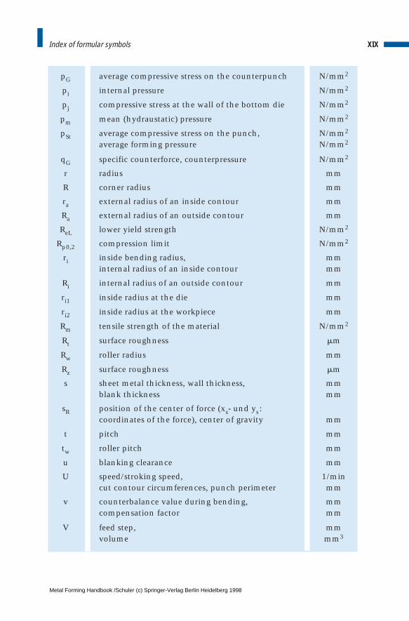
pG average compressive stress on the counterpunch N/mm2
pi internal pressure N/mm2
pj compressive stress at the wall of the bottom die N/mm2
pm mean (hydraustatic) pressure N/mm2
pSt average compressive stress on the punch, N/mm2
average forming pressure N/mm2
qG specific counterforce, counterpressure N/mm2
r radius mm
R corner radius mm
ra external radius of an inside contour mm
Ra external radius of an outside contour mm
ReL lower yield strength N/mm2
Rp0,2 compression limit N/mm2
ri inside bending radius, mminternal radius of an inside contour mm
Ri internal radius of an outside contour mm
ri1 inside radius at the die mm
ri2 inside radius at the workpiece mm
Rm tensile strength of the material N/mm2
Rt surface roughness mm
Rw roller radius mm
Rz surface roughness mm
s sheet metal thickness, wall thickness, mmblank thickness mm
sR position of the center of force (xs- und ys:coordinates of the force), center of gravity mm
t pitch mm
tw roller pitch mm
u blanking clearance mm
U speed/stroking speed, 1/mincut contour circumferences, punch perimeter mm
v counterbalance value during bending, mmcompensation factor mm
V feed step, mmvolume mm3
XIXIndex of formular symbols
Metal Forming Handbook /Schuler (c) Springer-Verlag Berlin Heidelberg 1998
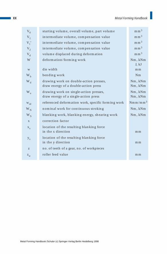
V0 starting volume, overall volume, part volume mm3
V1 intermediate volume, compensation value mm3
V1’ intermediate volume, compensation value mm3
V2 intermediate volume, compensation value mm3
Vd volume displaced during deformation mm3
W deformation/forming work Nm, kNmJ, kJ
w die width mm
Wb bending work Nm
Wd drawing work on double-action presses, Nm, kNmdraw energy of a double-action press Nm, kNm
We drawing work on single-action presses, Nm, kNmdraw energy of a single-action press Nm, kNm
wid referenced deformation work, specific forming work Nmm/mm3
WN nominal work for continuous stroking Nm, kNm
WS blanking work, blanking energy, shearing work Nm, kNm
x correction factor
xs location of the resulting blanking force in the x direction mm
ys location of the resulting blanking force in the y direction mm
z no. of teeth of a gear, no. of workpieces
zw roller feed value mm
XX Metal Forming Handbook
Metal Forming Handbook /Schuler (c) Springer-Verlag Berlin Heidelberg 1998
1 Introduction
Technology has exerted a far greater influence on the development ofour past than most history books give credit for. As late as the 19th cen-tury, craftmanship and technology were practically synonymous. It isonly with the advent of mechanisation – through the use of machines –that the term technology took on a new meaning of its own.
Today, technology is one of the bastions of our modern lifestyle andthe basis for our prosperity, in which metal forming technology plays acentral role. Alongside the manufacture of semi-finished productsthrough rolling, wire drawing and extrusion, the production of discretecomponents using sheet metal and solid forming techniques is of majorsignificance. Its fields of application range from automotive engineer-ing, production line and container construction through to the build-ing construction, household appliance and packaging industries.
The machine tool, with its capacity to precisely guide and drive oneor more tools for the machining of metal, has become a symbol of eco-nomic metalworking. In the past, the work processes typically seen inmetal forming technology used to be executed in a series of individualoperations on manually operated machine tools. Today, however, auto-matic production cells and interlinked individual machines through tothe compact production line with integrated feed, transport, monitor-ing and finished part stacking systems are the state of the art. Develop-ments in this field created the technological basis to allow the benefitsof formed workpieces, such as a more favorable flow line, optimumstrength characteristics and low material and energy input, to be com-bined with higher production output, dimensional control and surfacequality.
As a reputed German manufacturer of machine tools, the companySCHULER has played a determining role in this development over a period
Metal Forming Handbook /Schuler (c) Springer-Verlag Berlin Heidelberg 1998

of more than 150 years: From the manually operated sheet metal shearto the fully automatic transfer press for complete car body side panels.
Over the millenniums, the handworking of metal by forming reachedwhat may still today be considered a remarkable degree of skill, result-ing in the creation of magnificent works in gold, silver, bronze, copperand brass. It was only in around 1800 that iron sheet produced inrolling plants began to find its way into the craftsmen’s workshops,requiring completely new processing techniques: In contrast to non-ferrous metals, the much harder and more brittle new material could bemore economically worked with the aid of machines.
In 1839, master locksmith Louis Schuler founded a modest workshopcomprising primarily a tinsmith’s shop, as well as a blacksmith’s forgeand a smithy. Driven by his Swabian business sense, he considered thepossibilities opened up by the newly available, cheaper iron sheet. Hewas quick to realize that the increased input required in terms of phys-ical strength and working time, and thus the manufacturing costsinvolved in producing the finished article were far too high to benefitfrom the favorable price of the iron sheet itself. Step by step, LouisSchuler accordingly began to replace manual work processes by mechan-ical fixtures and devices. He began to mechanise his workshop withsheet shears, bending machines and press breaks, which were consider-able innovations in those days.
Inspired by the World Exhibition in London in 1851, Louis Schulerdecided to concentrate his activities entirely on producing machines forsheet metal working. His production range was continuously extendedto include sheet metal straightening machines, metal spinning andlevelling benches, eccentric presses, spindle presses, turret, crank anddrawing presses, both mechanically and hydraulically powered, notch-ing presses as well as cutting and forming tools and dies. As early as1859, he exported his first sheet metal forming machines.
At the end of the 1870s, Schuler registered his first patent for “Inno-vations in punching dies, shears and similar”. In 1895, he patented“Hydraulic drawing presses with two pistons fitted into each other”,and in the same year was also awarded first prize at the Sheet MetalIndustry Trade Exhibition in Leipzig. With expansion of the productionprogram, the workforce as well as the company premises had under-gone continuous growth (Fig. 1.1). The Schuler machine tool company
2 Metal Forming Handbook
Metal Forming Handbook /Schuler (c) Springer-Verlag Berlin Heidelberg 1998

was one of the foresighted enterprises of the day to pioneer the processof differentiation taking place in the field of machine tool engineering.As a supplier of machines and production lines for industrial man-ufacture – in particular series production – the company’s reputationincreased rapidly.
The increasing export volume and a consistent process of diversifica-tion in the field of forming technology led to an early process of glob-alisation and to the development of the international SCHULER Group ofCompanies.
The SCHULER Group’s process of globalisation got under way at thebeginning of the sixties with the founding of foreign subsidiaries. To-day, SCHULER runs not only eight manufacturing plants in Germany butalso additional five production facilities in France, the US, Brazil andChina. Alongside its world-wide network of sales agencies, SCHULER hasalso set up its own sales and service centers in Spain, India, Malaysiaand Thailand.
An internationally-based network of production facilities coordinat-ed from the parent plant in Goeppingen permits rapid response to thechanges taking place in the targeted markets. Production in overseaslocations brings about not only a reduction in costs but also creates
3Introduction
Fig. 1.1 L. Schuler, Machine tool factory and foundry, Goeppingen, around 1900
Metal Forming Handbook /Schuler (c) Springer-Verlag Berlin Heidelberg 1998
major strategic benefits by increasing “local content” and so ensuringan improved market position.
The North and South American markets are supplied locally. TheNAFTA area is coordinated by Schuler Inc. in Ohio, while South Ameri-ca’s common market, the Mercosul, is supervised from Brazil. The highstandard of quality achieved by the SCHULER plant in Brazil has openedup even the most demanding markets.
In the growing market of China, the SCHULER Group runs two jointventure corporations in cooperation with Chinese partners for the man-ufacture of mechanical presses and hydraulic presses.
Today, we stand on the threshold to a new millennium marked byincreasing market globalisation and rapidly changing organizationaland producing structures. Under these rapidly changing conditions, itis SCHULER’s workforce which remains the single most important deter-mining factor between success and failure. The technological orienta-tion of the staff provides the innovative impetus which will secure thecompany’s development as it moves into the 21st century.
This Metal Forming Handbook reflects the technical competence, therich source of ideas and the creativity of the SCHULER Group’s workforce.The book takes an in-depth look at the pioneering stage of developmentreached by today’s presses and forming lines, and at related productionprocesses, with particular emphasis on the development of controlengineering and automation. Developments in the classical fields ofdesign, mechanical engineering, dynamics and hydraulics are nowbeing influenced to an ever greater degree by more recently developedtechnologies such as CAD, CAM, CIM, mechatronics, process simula-tion and computer-aided measurement and process control technology.In today’s environment, the main objective of achieving enhancedproduct quality and productivity is coupled with lower investment andoperating costs. In addition, questions of reliability, uptime, accidentprevention, process accounting, economical use of resources and envi-ronmental conservation play also a central role.
In view of the fundamental importance of metal forming technologytoday, this Handbook offers the reader a reference work whose useful-ness stretches to practically every branch of industry. The book providesan in-depth analysis of most of the important manufacturing tech-nologies as a system comprising the three elements: process, productionline and product.
4 Metal Forming Handbook
Metal Forming Handbook /Schuler (c) Springer-Verlag Berlin Heidelberg 1998
2 Basic principles of metal forming
2.1 Methods of forming and cutting technology
2.1.1 Summary
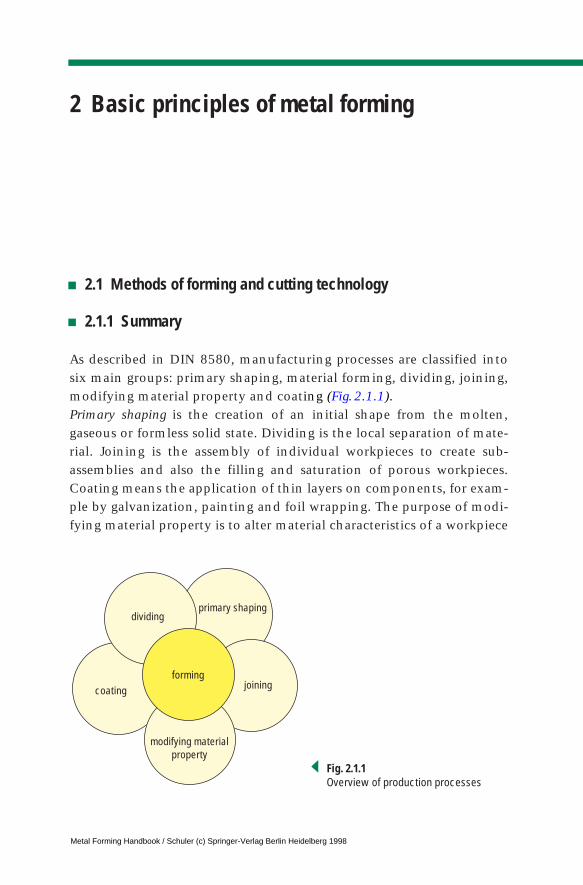
As described in DIN 8580, manufacturing processes are classified intosix main groups: primary shaping, material forming, dividing, joining,modifying material property and coating (Fig.2.1.1).Primary shaping is the creation of an initial shape from the molten,gaseous or formless solid state. Dividing is the local separation of mate-rial. Joining is the assembly of individual workpieces to create sub-assemblies and also the filling and saturation of porous workpieces.Coating means the application of thin layers on components, for exam-ple by galvanization, painting and foil wrapping. The purpose of modi-fying material property is to alter material characteristics of a workpiece
coating
dividing
joining
modifying materialproperty
primary shaping
forming
Fig. 2.1.1Overview of production processes
Metal Forming Handbook / Schuler (c) Springer-Verlag Berlin Heidelberg 1998
to achieve certain useful properties. Such processes include heat treat-ment processes such as hardening or recrystallization annealing.
Forming – as the technology forming the central subject matter of thisbook – is defined by DIN 8580 as manufacturing through the three-dimensional or plastic modification of a shape while retaining its massand material cohesion. In contrast to deformation, forming is the mod-ification of a shape with controlled geometry. Forming processes arecategorized as chipless or non-material removal processes.
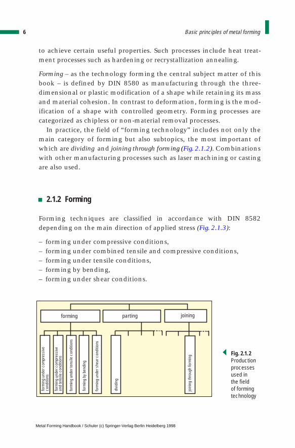
In practice, the field of “forming technology” includes not only themain category of forming but also subtopics, the most important ofwhich are dividing and joining through forming (Fig.2.1.2). Combinationswith other manufacturing processes such as laser machining or castingare also used.
2.1.2 Forming
Forming techniques are classified in accordance with DIN 8582depending on the main direction of applied stress (Fig. 2.1.3):
– forming under compressive conditions,– forming under combined tensile and compressive conditions,– forming under tensile conditions,– forming by bending,– forming under shear conditions.
6 Basic principles of metal forming
form
ing
unde
r com
pres
sive
cond
ition
s
form
ing
unde
r she
ar c
ondi
tions
form
ing
unde
r com
pres
sive
and
tens
ile c
ondi
tions
form
ing
unde
r ten
sile
con
ditio
ns
forming parting joining
form
ing
bybe
ndin
g
join
ing
thro
ugh
form
ing
divi
ding
Fig. 2.1.2Productionprocessesused in the field of formingtechnology
Metal Forming Handbook / Schuler (c) Springer-Verlag Berlin Heidelberg 1998
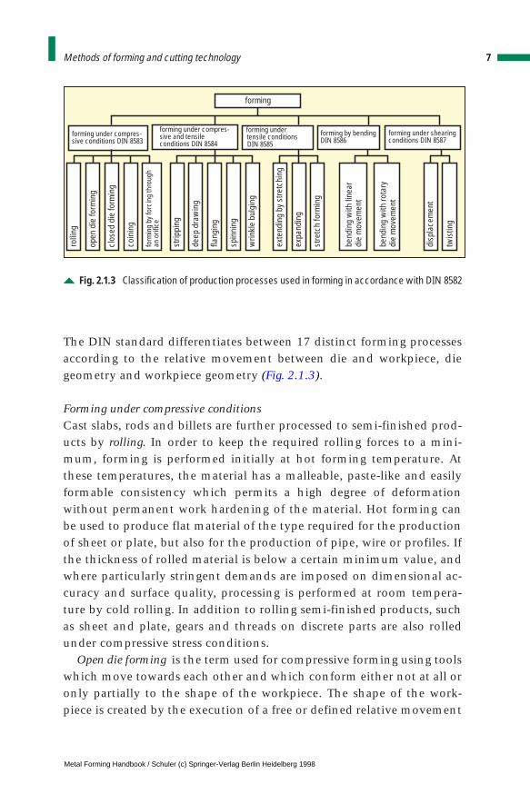
The DIN standard differentiates between 17 distinct forming processesaccording to the relative movement between die and workpiece, diegeometry and workpiece geometry (Fig. 2.1.3).
Forming under compressive conditionsCast slabs, rods and billets are further processed to semi-finished prod-ucts by rolling. In order to keep the required rolling forces to a mini-mum, forming is performed initially at hot forming temperature. Atthese temperatures, the material has a malleable, paste-like and easilyformable consistency which permits a high degree of deformationwithout permanent work hardening of the material. Hot forming canbe used to produce flat material of the type required for the productionof sheet or plate, but also for the production of pipe, wire or profiles. Ifthe thickness of rolled material is below a certain minimum value, andwhere particularly stringent demands are imposed on dimensional ac-curacy and surface quality, processing is performed at room tempera-ture by cold rolling. In addition to rolling semi-finished products, suchas sheet and plate, gears and threads on discrete parts are also rolledunder compressive stress conditions.
Open die forming is the term used for compressive forming using toolswhich move towards each other and which conform either not at all oronly partially to the shape of the workpiece. The shape of the work-piece is created by the execution of a free or defined relative movement
7Methods of forming and cutting technology
forming under compres-sive conditions DIN 8583
forming under compres-sive and tensileconditions DIN 8584
forming undertensile conditionsDIN 8585
forming under shearingconditions DIN 8587
forming by bendingDIN 8586
forming
rolli
ng
open
die
form
ing
clos
ed d
ie fo
rmin
g
coin
ing
strip
ping
deep
dra
win
g
flang
ing
spin
ning
wrin
kle
bulg
ing
exte
ndin
g by
stre
tchi
ng
expa
ndin
g
disp
lace
men
t
twis
ting
stre
tch
form
ing
bend
ing
with
line
ardi
e m
ovem
ent
bend
ing
with
rota
rydi
e m
ovem
ent
form
ing
by fo
rcin
g th
roug
han
orif
ice
Fig. 2.1.3 Classification of production processes used in forming in accordance with DIN 8582
Metal Forming Handbook / Schuler (c) Springer-Verlag Berlin Heidelberg 1998
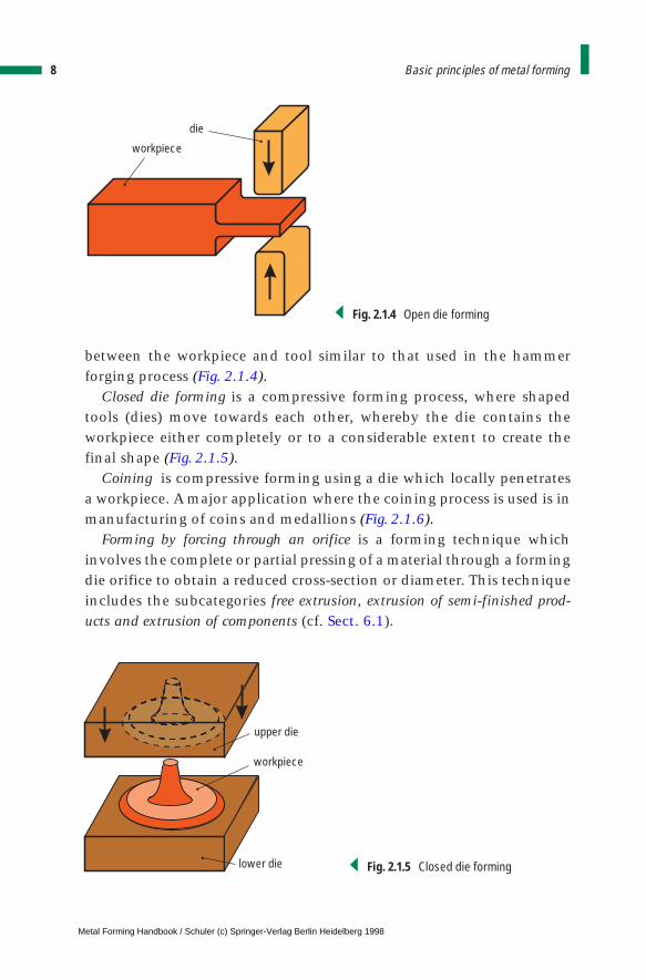
between the workpiece and tool similar to that used in the hammerforging process (Fig. 2.1.4).
Closed die forming is a compressive forming process, where shapedtools (dies) move towards each other, whereby the die contains theworkpiece either completely or to a considerable extent to create thefinal shape (Fig. 2.1.5).
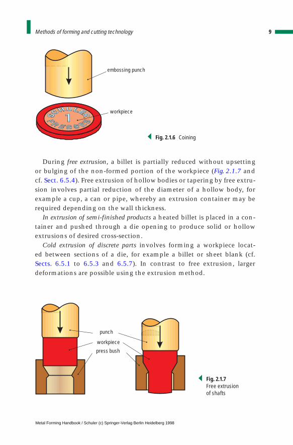
Coining is compressive forming using a die which locally penetratesa workpiece. A major application where the coining process is used is inmanufacturing of coins and medallions (Fig. 2.1.6).
Forming by forcing through an orifice is a forming technique whichinvolves the complete or partial pressing of a material through a formingdie orifice to obtain a reduced cross-section or diameter. This techniqueincludes the subcategories free extrusion, extrusion of semi-finished prod-ucts and extrusion of components (cf. Sect. 6.1).
8 Basic principles of metal forming
die
workpiece
Fig. 2.1.4 Open die forming
upper die
workpiece
lower die Fig. 2.1.5 Closed die forming
Metal Forming Handbook / Schuler (c) Springer-Verlag Berlin Heidelberg 1998
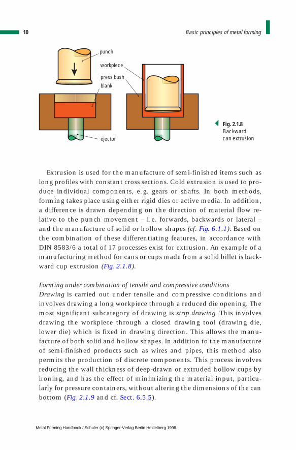
During free extrusion, a billet is partially reduced without upsetting or bulging of the non-formed portion of the workpiece (Fig. 2.1.7 andcf. Sect. 6.5.4). Free extrusion of hollow bodies or tapering by free extru-sion involves partial reduction of the diameter of a hollow body, forexample a cup, a can or pipe, whereby an extrusion container may berequired depending on the wall thickness.
In extrusion of semi-finished products a heated billet is placed in a con-tainer and pushed through a die opening to produce solid or hollowextrusions of desired cross-section.
Cold extrusion of discrete parts involves forming a workpiece locat-ed between sections of a die, for example a billet or sheet blank (cf. Sects. 6.5.1 to 6.5.3 and 6.5.7). In contrast to free extrusion, largerdeformations are possible using the extrusion method.
9Methods of forming and cutting technology
embossing punch
workpiece
Fig. 2.1.6 Coining
punch
workpiece
press bush
Fig. 2.1.7 Free extrusionof shafts
Metal Forming Handbook / Schuler (c) Springer-Verlag Berlin Heidelberg 1998
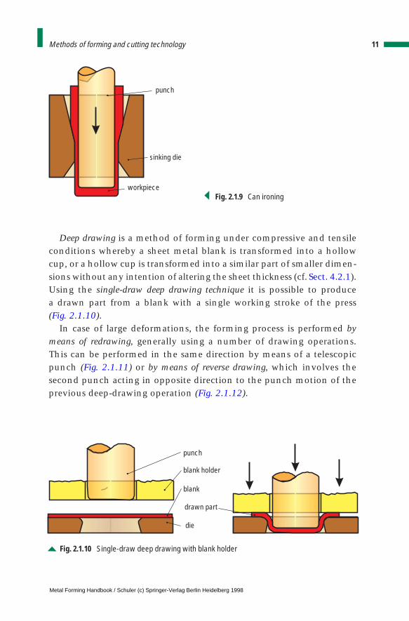
Extrusion is used for the manufacture of semi-finished items such aslong profiles with constant cross sections. Cold extrusion is used to pro-duce individual components, e. g. gears or shafts. In both methods,forming takes place using either rigid dies or active media. In addition,a difference is drawn depending on the direction of material flow re-lative to the punch movement – i.e. forwards, backwards or lateral –and the manufacture of solid or hollow shapes (cf. Fig. 6.1.1). Based onthe combination of these differentiating features, in accordance withDIN 8583/6 a total of 17 processes exist for extrusion. An example of amanufacturing method for cans or cups made from a solid billet is back-ward cup extrusion (Fig. 2.1.8).
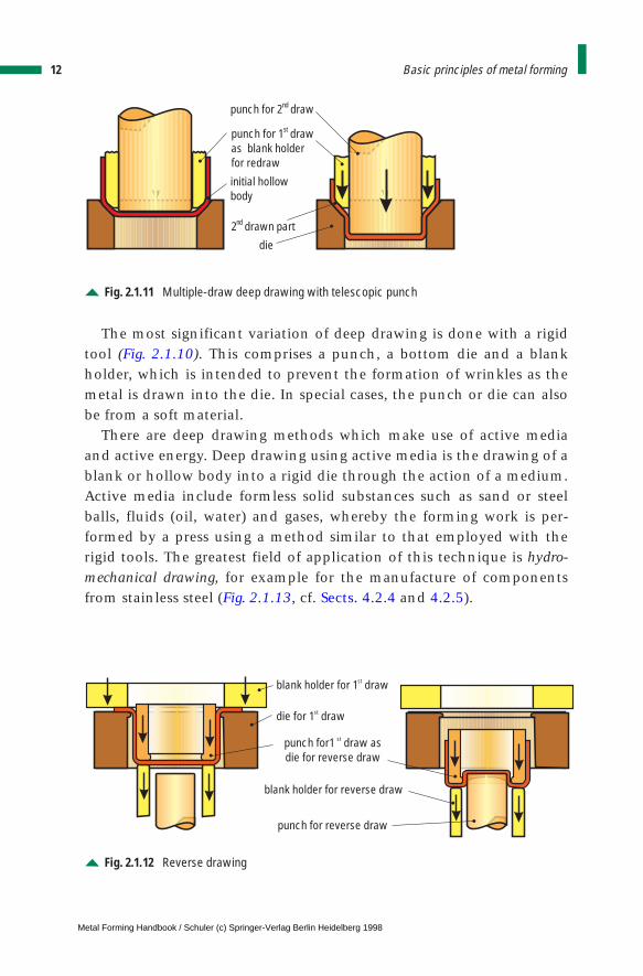
Forming under combination of tensile and compressive conditionsDrawing is carried out under tensile and compressive conditions andinvolves drawing a long workpiece through a reduced die opening. Themost significant subcategory of drawing is strip drawing. This involvesdrawing the workpiece through a closed drawing tool (drawing die,lower die) which is fixed in drawing direction. This allows the manu-facture of both solid and hollow shapes. In addition to the manufactureof semi-finished products such as wires and pipes, this method alsopermits the production of discrete components. This process involvesreducing the wall thickness of deep-drawn or extruded hollow cups byironing, and has the effect of minimizing the material input, particu-larly for pressure containers, without altering the dimensions of the canbottom (Fig. 2.1.9 and cf. Sect. 6.5.5).
10 Basic principles of metal forming
punch
workpiece
press bush
blank
ejector
Fig. 2.1.8 Backwardcan extrusion
Metal Forming Handbook / Schuler (c) Springer-Verlag Berlin Heidelberg 1998
Deep drawing is a method of forming under compressive and tensileconditions whereby a sheet metal blank is transformed into a hollowcup, or a hollow cup is transformed into a similar part of smaller dimen-sions without any intention of altering the sheet thickness (cf. Sect. 4.2.1).Using the single-draw deep drawing technique it is possible to produce a drawn part from a blank with a single working stroke of the press (Fig. 2.1.10).
In case of large deformations, the forming process is performed bymeans of redrawing, generally using a number of drawing operations.This can be performed in the same direction by means of a telescopicpunch (Fig. 2.1.11) or by means of reverse drawing, which involves thesecond punch acting in opposite direction to the punch motion of theprevious deep-drawing operation (Fig. 2.1.12).
11Methods of forming and cutting technology
punch
workpiece
sinking die
Fig. 2.1.9 Can ironing
punch
blank holder
blank
drawn part
die
Fig. 2.1.10 Single-draw deep drawing with blank holder
Metal Forming Handbook / Schuler (c) Springer-Verlag Berlin Heidelberg 1998
The most significant variation of deep drawing is done with a rigidtool (Fig. 2.1.10). This comprises a punch, a bottom die and a blankholder, which is intended to prevent the formation of wrinkles as themetal is drawn into the die. In special cases, the punch or die can alsobe from a soft material.
There are deep drawing methods which make use of active mediaand active energy. Deep drawing using active media is the drawing of ablank or hollow body into a rigid die through the action of a medium.Active media include formless solid substances such as sand or steelballs, fluids (oil, water) and gases, whereby the forming work is per-formed by a press using a method similar to that employed with therigid tools. The greatest field of application of this technique is hydro-mechanical drawing, for example for the manufacture of componentsfrom stainless steel (Fig. 2.1.13, cf. Sects. 4.2.4 and 4.2.5).
12 Basic principles of metal forming
punch for 2 drawnd
punch for 1 drawas blank holderfor redraw
st
initial hollowbody
2 drawn partnd
die
Fig. 2.1.11 Multiple-draw deep drawing with telescopic punch
die for 1 drawst
blank holder for 1 drawst
punch for1 draw asdie for reverse draw
st
blank holder for reverse draw
punch for reverse draw
Fig. 2.1.12 Reverse drawing
Metal Forming Handbook / Schuler (c) Springer-Verlag Berlin Heidelberg 1998
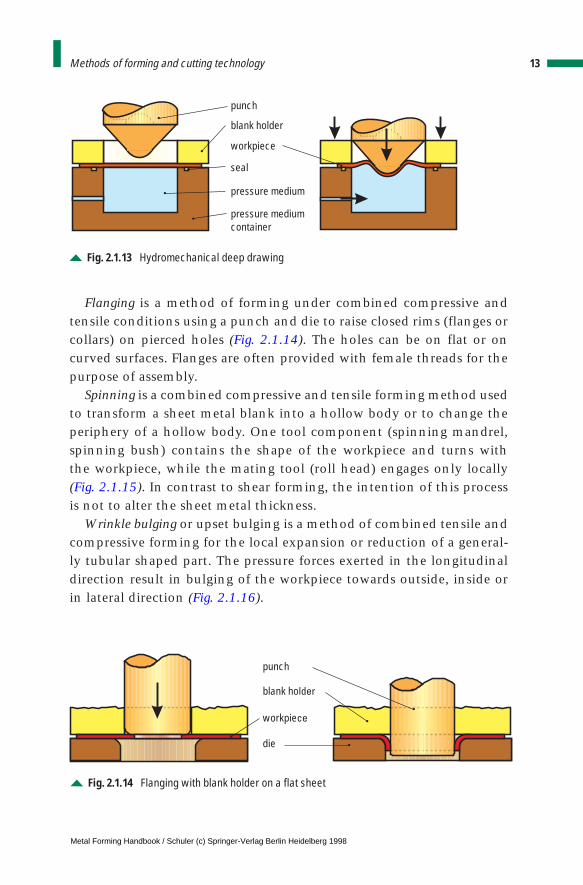
Flanging is a method of forming under combined compressive andtensile conditions using a punch and die to raise closed rims (flanges orcollars) on pierced holes (Fig. 2.1.14). The holes can be on flat or oncurved surfaces. Flanges are often provided with female threads for thepurpose of assembly.
Spinning is a combined compressive and tensile forming method usedto transform a sheet metal blank into a hollow body or to change theperiphery of a hollow body. One tool component (spinning mandrel,spinning bush) contains the shape of the workpiece and turns with the workpiece, while the mating tool (roll head) engages only locally(Fig. 2.1.15). In contrast to shear forming, the intention of this processis not to alter the sheet metal thickness.
Wrinkle bulging or upset bulging is a method of combined tensile andcompressive forming for the local expansion or reduction of a general-ly tubular shaped part. The pressure forces exerted in the longitudinaldirection result in bulging of the workpiece towards outside, inside orin lateral direction (Fig. 2.1.16).
13Methods of forming and cutting technology
punch
blank holder
seal
pressure mediumcontainer
pressure medium
workpiece
Fig. 2.1.13 Hydromechanical deep drawing
punch
blank holder
workpiece
die
Fig. 2.1.14 Flanging with blank holder on a flat sheet
Metal Forming Handbook / Schuler (c) Springer-Verlag Berlin Heidelberg 1998
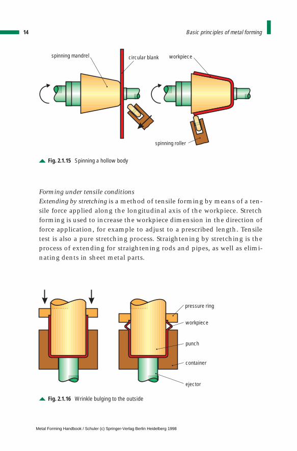
Forming under tensile conditionsExtending by stretching is a method of tensile forming by means of a ten-sile force applied along the longitudinal axis of the workpiece. Stretchforming is used to increase the workpiece dimension in the direction offorce application, for example to adjust to a prescribed length. Tensiletest is also a pure stretching process. Straightening by stretching is theprocess of extending for straightening rods and pipes, as well as elimi-nating dents in sheet metal parts.
14 Basic principles of metal forming
spinning mandrel
spinning roller
circular blank workpiece
Fig. 2.1.15 Spinning a hollow body
pressure ring
workpiece
punch
container
ejector
Fig. 2.1.16 Wrinkle bulging to the outside
Metal Forming Handbook / Schuler (c) Springer-Verlag Berlin Heidelberg 1998
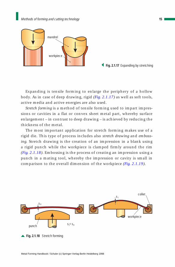
Expanding is tensile forming to enlarge the periphery of a hollowbody. As in case of deep drawing, rigid (Fig. 2.1.17) as well as soft tools,active media and active energies are also used.
Stretch forming is a method of tensile forming used to impart impres-sions or cavities in a flat or convex sheet metal part, whereby surfaceenlargement – in contrast to deep drawing – is achieved by reducing thethickness of the metal.
The most important application for stretch forming makes use of arigid die. This type of process includes also stretch drawing and emboss-ing. Stretch drawing is the creation of an impression in a blank using a rigid punch while the workpiece is clamped firmly around the rim(Fig. 2.1.18). Embossing is the process of creating an impression using apunch in a mating tool, whereby the impression or cavity is small incomparison to the overall dimension of the workpiece (Fig. 2.1.19).
15Methods of forming and cutting technology
mandrel
workpiece
collet
punch
workpiece
s
s1
1
0
0s < s
Fig. 2.1.18 Stretch forming
Fig. 2.1.17 Expanding by stretching
Metal Forming Handbook / Schuler (c) Springer-Verlag Berlin Heidelberg 1998
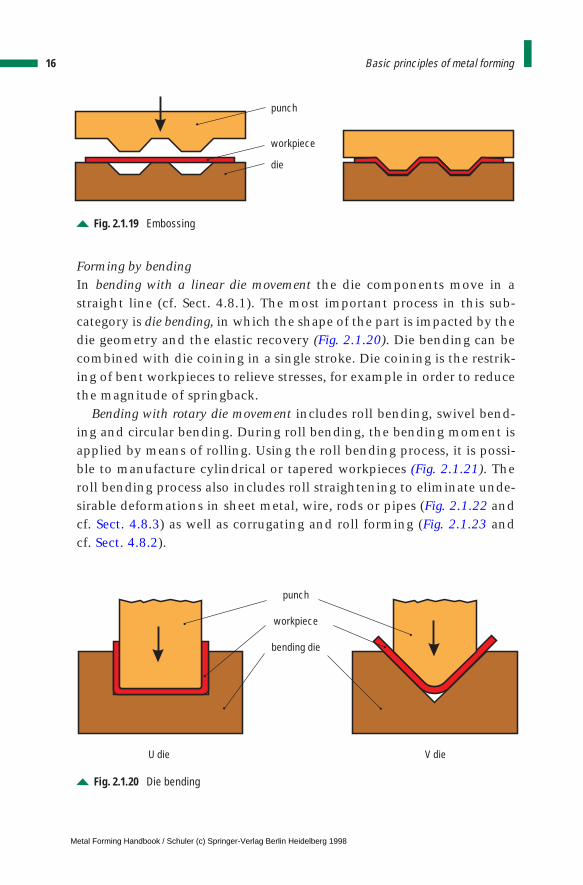
Forming by bendingIn bending with a linear die movement the die components move in astraight line (cf. Sect. 4.8.1). The most important process in this sub-category is die bending, in which the shape of the part is impacted by thedie geometry and the elastic recovery (Fig. 2.1.20). Die bending can becombined with die coining in a single stroke. Die coining is the restrik-ing of bent workpieces to relieve stresses, for example in order to reducethe magnitude of springback.
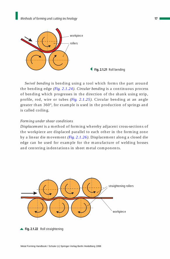
Bending with rotary die movement includes roll bending, swivel bend-ing and circular bending. During roll bending, the bending moment isapplied by means of rolling. Using the roll bending process, it is possi-ble to manufacture cylindrical or tapered workpieces (Fig. 2.1.21). Theroll bending process also includes roll straightening to eliminate unde-sirable deformations in sheet metal, wire, rods or pipes (Fig. 2.1.22 andcf. Sect. 4.8.3) as well as corrugating and roll forming (Fig. 2.1.23 and cf. Sect. 4.8.2).
16 Basic principles of metal forming
punch
die
workpiece
Fig. 2.1.19 Embossing
punch
workpiece
bending die
U die V die
Fig. 2.1.20 Die bending
Metal Forming Handbook / Schuler (c) Springer-Verlag Berlin Heidelberg 1998
Swivel bending is bending using a tool which forms the part aroundthe bending edge (Fig. 2.1.24). Circular bending is a continuous processof bending which progresses in the direction of the shank using strip,profile, rod, wire or tubes (Fig. 2.1.25). Circular bending at an anglegreater than 360°, for example is used in the production of springs andis called coiling.
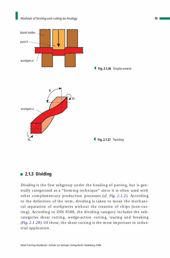
Forming under shear conditionsDisplacement is a method of forming whereby adjacent cross-sections ofthe workpiece are displaced parallel to each other in the forming zoneby a linear die movement (Fig. 2.1.26). Displacement along a closed dieedge can be used for example for the manufacture of welding bossesand centering indentations in sheet metal components.
17Methods of forming and cutting technology
workpiece
straightening rollers
Fig. 2.1.22 Roll straightening
workpiece
rollers
Fig. 2.1.21 Roll bending
Metal Forming Handbook / Schuler (c) Springer-Verlag Berlin Heidelberg 1998
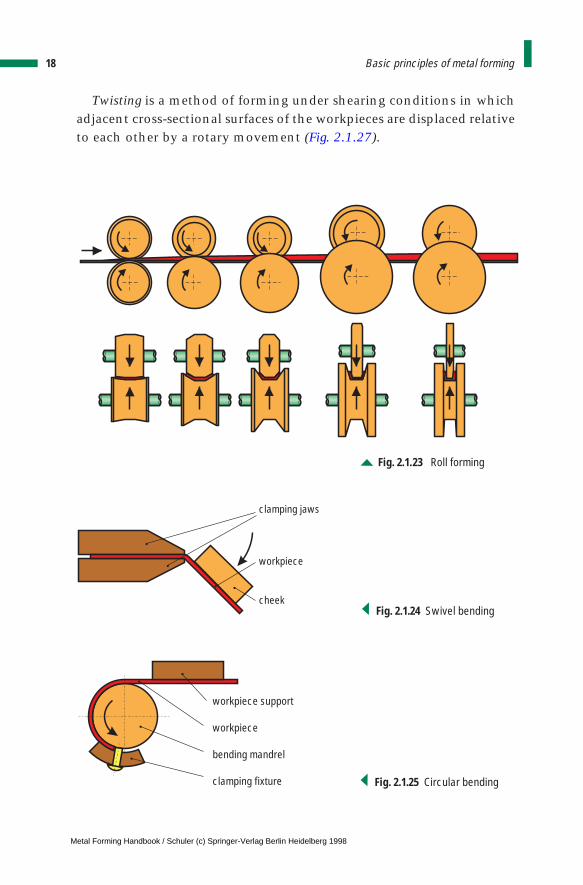
Twisting is a method of forming under shearing conditions in whichadjacent cross-sectional surfaces of the workpieces are displaced relativeto each other by a rotary movement (Fig. 2.1.27).
18 Basic principles of metal forming
Fig. 2.1.23 Roll forming
clamping jaws
workpiece
cheekFig. 2.1.24 Swivel bending
workpiece support
workpiece
bending mandrel
clamping fixture Fig. 2.1.25 Circular bending
Metal Forming Handbook / Schuler (c) Springer-Verlag Berlin Heidelberg 1998
2.1.3 Dividing
Dividing is the first subgroup under the heading of parting, but is gen-erally categorized as a “forming technique” since it is often used withother complementary production processes (cf. Fig. 2.1.2). According to the definition of the term, dividing is taken to mean the mechani-cal separation of workpieces without the creation of chips (non-cut-ting). According to DIN 8588, the dividing category includes the sub-categories shear cutting, wedge-action cutting, tearing and breaking(Fig. 2.1.28). Of these, the shear cutting is the most important in indus-trial application.
19Methods of forming and cutting technology
punch
workpiece
blank holder
Fig. 2.1.26 Displacement
ϕ
workpiece
MT
MT Fig. 2.1.27 Twisting
Metal Forming Handbook / Schuler (c) Springer-Verlag Berlin Heidelberg 1998
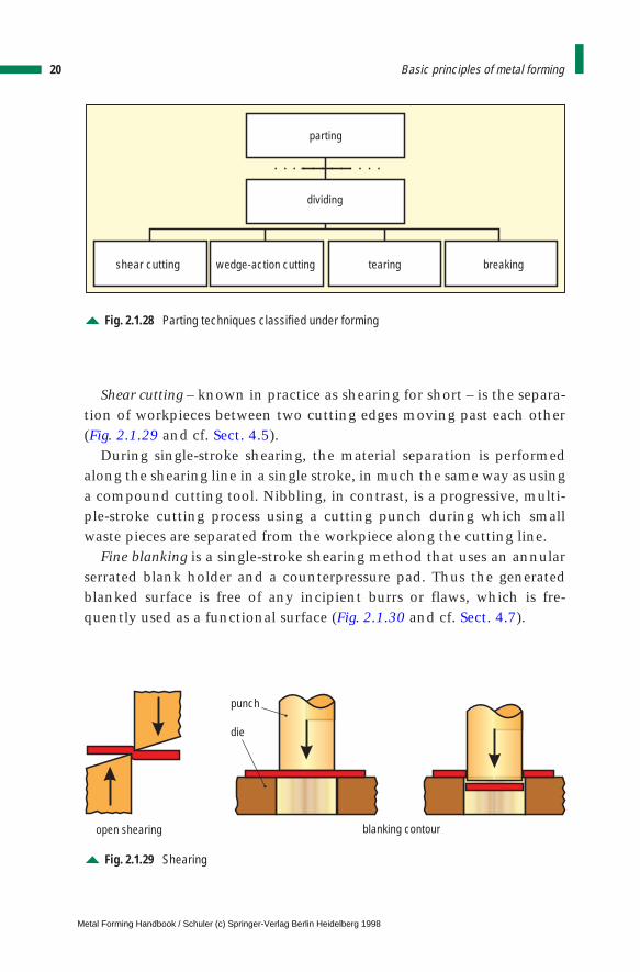
Shear cutting – known in practice as shearing for short – is the separa-tion of workpieces between two cutting edges moving past each other(Fig. 2.1.29 and cf. Sect. 4.5).
During single-stroke shearing, the material separation is performedalong the shearing line in a single stroke, in much the same way as usinga compound cutting tool. Nibbling, in contrast, is a progressive, multi-ple-stroke cutting process using a cutting punch during which smallwaste pieces are separated from the workpiece along the cutting line.
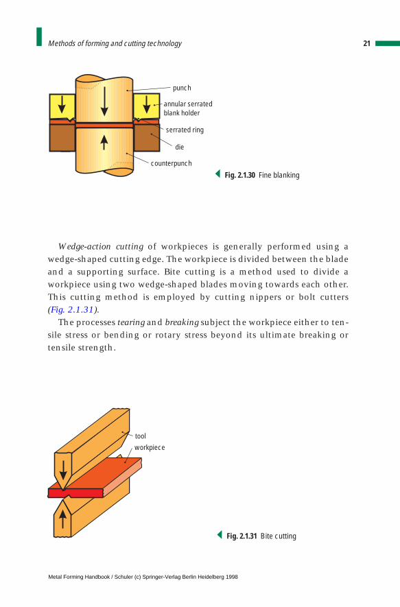
Fine blanking is a single-stroke shearing method that uses an annularserrated blank holder and a counterpressure pad. Thus the generatedblanked surface is free of any incipient burrs or flaws, which is fre-quently used as a functional surface (Fig. 2.1.30 and cf. Sect. 4.7).
20 Basic principles of metal forming
parting
dividing
breakingtearingwedge-action cuttingshear cutting
Fig. 2.1.28 Parting techniques classified under forming
open shearing blanking contour
punch
die
Fig. 2.1.29 Shearing
Metal Forming Handbook / Schuler (c) Springer-Verlag Berlin Heidelberg 1998
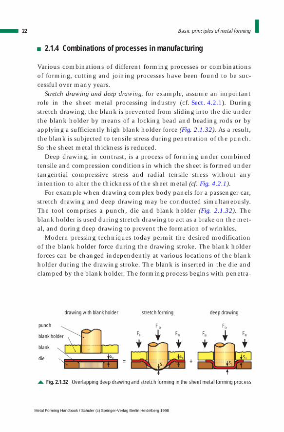
Wedge-action cutting of workpieces is generally performed using awedge-shaped cutting edge. The workpiece is divided between the bladeand a supporting surface. Bite cutting is a method used to divide aworkpiece using two wedge-shaped blades moving towards each other.This cutting method is employed by cutting nippers or bolt cutters (Fig. 2.1.31).
The processes tearing and breaking subject the workpiece either to ten-sile stress or bending or rotary stress beyond its ultimate breaking ortensile strength.
21Methods of forming and cutting technology
die
counterpunch
punch
serrated ring
annular serratedblank holder
Fig. 2.1.30 Fine blanking
workpiece
tool
Fig. 2.1.31 Bite cutting
Metal Forming Handbook / Schuler (c) Springer-Verlag Berlin Heidelberg 1998
2.1.4 Combinations of processes in manufacturing
Various combinations of different forming processes or combinationsof forming, cutting and joining processes have been found to be suc-cessful over many years.
Stretch drawing and deep drawing, for example, assume an importantrole in the sheet metal processing industry (cf. Sect. 4.2.1). Duringstretch drawing, the blank is prevented from sliding into the die underthe blank holder by means of a locking bead and beading rods or byapplying a sufficiently high blank holder force (Fig. 2.1.32). As a result,the blank is subjected to tensile stress during penetration of the punch.So the sheet metal thickness is reduced.
Deep drawing, in contrast, is a process of forming under combinedtensile and compression conditions in which the sheet is formed undertangential compressive stress and radial tensile stress without anyintention to alter the thickness of the sheet metal (cf. Fig. 4.2.1).
For example when drawing complex body panels for a passenger car,stretch drawing and deep drawing may be conducted simultaneously.The tool comprises a punch, die and blank holder (Fig. 2.1.32). Theblank holder is used during stretch drawing to act as a brake on the met-al, and during deep drawing to prevent the formation of wrinkles.
Modern pressing techniques today permit the desired modificationof the blank holder force during the drawing stroke. The blank holderforces can be changed independently at various locations of the blankholder during the drawing stroke. The blank is inserted in the die andclamped by the blank holder. The forming process begins with penetra-
22 Basic principles of metal forming
drawing with blank holder stretch forming deep drawing
+=
punch
blank holder
blank
die
FBl FBl FBl FBl
F St FSt
s0 s0 s0
s0s1
Fig. 2.1.32 Overlapping deep drawing and stretch forming in the sheet metal forming process
Metal Forming Handbook / Schuler (c) Springer-Verlag Berlin Heidelberg 1998
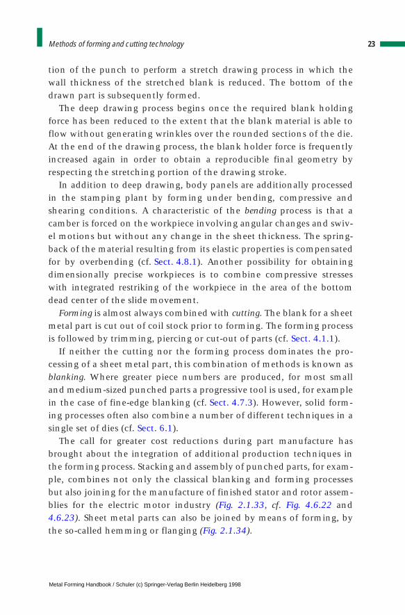
tion of the punch to perform a stretch drawing process in which thewall thickness of the stretched blank is reduced. The bottom of thedrawn part is subsequently formed.
The deep drawing process begins once the required blank holdingforce has been reduced to the extent that the blank material is able toflow without generating wrinkles over the rounded sections of the die.At the end of the drawing process, the blank holder force is frequentlyincreased again in order to obtain a reproducible final geometry byrespecting the stretching portion of the drawing stroke.
In addition to deep drawing, body panels are additionally processedin the stamping plant by forming under bending, compressive andshearing conditions. A characteristic of the bending process is that acamber is forced on the workpiece involving angular changes and swiv-el motions but without any change in the sheet thickness. The spring-back of the material resulting from its elastic properties is compensatedfor by overbending (cf. Sect. 4.8.1). Another possibility for obtainingdimensionally precise workpieces is to combine compressive stresseswith integrated restriking of the workpiece in the area of the bottomdead center of the slide movement.
Forming is almost always combined with cutting. The blank for a sheetmetal part is cut out of coil stock prior to forming. The forming processis followed by trimming, piercing or cut-out of parts (cf. Sect. 4.1.1).
If neither the cutting nor the forming process dominates the pro-cessing of a sheet metal part, this combination of methods is known asblanking. Where greater piece numbers are produced, for most smalland medium-sized punched parts a progressive tool is used, for examplein the case of fine-edge blanking (cf. Sect. 4.7.3). However, solid form-ing processes often also combine a number of different techniques in asingle set of dies (cf. Sect. 6.1).
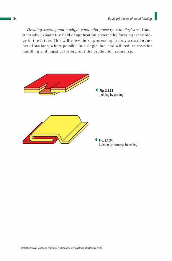
The call for greater cost reductions during part manufacture hasbrought about the integration of additional production techniques inthe forming process. Stacking and assembly of punched parts, for exam-ple, combines not only the classical blanking and forming processesbut also joining for the manufacture of finished stator and rotor assem-blies for the electric motor industry (Fig. 2.1.33, cf. Fig. 4.6.22 and4.6.23). Sheet metal parts can also be joined by means of forming, bythe so-called hemming or flanging (Fig. 2.1.34).
23Methods of forming and cutting technology
Metal Forming Handbook / Schuler (c) Springer-Verlag Berlin Heidelberg 1998
Dividing, coating and modifying material property technologies will sub-stantially expand the field of application covered by forming technolo-gy in the future. This will allow finish processing in only a small num-ber of stations, where possible in a single line, and will reduce costs forhandling and logistics throughout the production sequence.
24 Basic principles of metal forming
Fig. 2.1.33Joining by parting
Fig. 2.1.34Joining by forming: hemming
Metal Forming Handbook / Schuler (c) Springer-Verlag Berlin Heidelberg 1998
2 Basic principles of metal forming
2.2 Basic terms
2.2.1 Flow condition and flow curve
Metallic materials may be shaped by applying external forces to themwithout reducing their structural cohesion. This property is known asthe formability of metal. Deformation or flow occurs when the rows ofatoms within the individual crystalline grains are able, when stressedbeyond a certain limit, to slide against one another and cohesionbetween the rows of atoms takes place at the following atomic lattice.This sliding occurs along planes and directions determined by the crys-talline structure and is only made possible by, for example, dislocations(faults in the arrangement of the atomic lattice). Other flow mecha-nisms such as twin crystal formation, in which a permanent deforma-tion is caused by a rotation of the lattice from one position to another,play only a minor role in metal forming technology.
Flow commences at the moment when the principle stress difference(smax – smin) reaches the value of the flow stress kf, or when the shearstrain caused by a purely shearing stress is equal to half the flow stress,given by:
By neglecting the principle stress s2, this mathematical expression rep-resents an approximate solution of the shearing stress hypothesis withthe greatest principle stress s1 and the smallest principle stress s3:
kf = σ σmax min–
kf = σ σ1 3–
Metal Forming Handbook / Schuler (c) Springer-Verlag Berlin Heidelberg 1998
The value of the flow stress depends on the material, the temperature,the deformation or strain, w, and the speed at which deformation orstrain rate is carried out, w. Below the recrystallisation temperature, theflow stress generally rises with increasing deformation, while the tem-perature and deformation rate exert only a minimal influence. Excep-tions to this rule are forming techniques such as rolling and forging, inwhich extremely high deformation rates are used. Above the recrys-tallisation temperature, the flow stress is generally subject to the tem-perature and deformation rate, while a previous deformation historyhas only minimal influence. The flow stress generally drops with in-creasing temperature and decreasing deformation rate.
Accordingly, DIN 8582 differentiates between metal forming process-es involving a lasting change in strength properties and those involvingno appreciable change in strength properties, previously designated ascold and hot forming. In the temperature range between, deformationinvolves only a temporary change in the strength properties of thematerial. In this case, the deformation speed is higher than the recov-ery or recrystallisation rate. Recrystallisation starts only after comple-tion of the forming process. The rules of metal forming with lastingchange in the strength properties apply in this case.
The DIN 8582 standard also breaks down the process according toforming without heating (cold forming) and forming after the applica-tion of heat (hot forming). These terms simply specify whether heatingdevices are necessary. Unlike their former meaning, these terms are notphysically related to the material concerned. The flow stress of the indi-vidual materials is determined by experiments in function of deforma-tion (or strain) and deformation rate (or strain rate) at the various tem-perature ranges, and described in flow curves. One of the uses of flowcurves is to aid the calculation of possible deformation, force, energyand performance.
2.2.2 Deformation and material flow
Actual deformation w, also called logarithmic or true strain, is given by:
26 Basic principles of metal forming
.
ϕ11
00
1
= =∫ dh
h
h
hh
h
ln
Metal Forming Handbook / Schuler (c) Springer-Verlag Berlin Heidelberg 1998
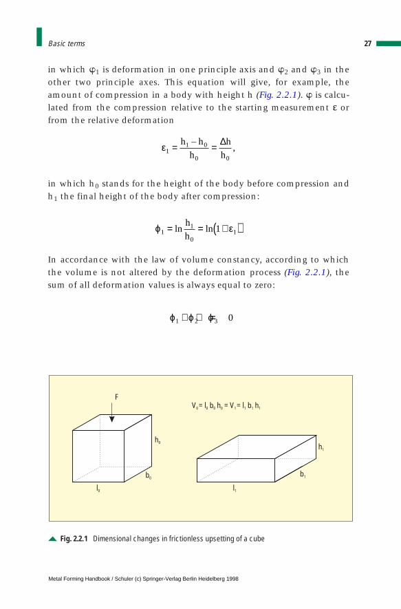
in which w1 is deformation in one principle axis and w2 and w3 in theother two principle axes. This equation will give, for example, theamount of compression in a body with height h (Fig. 2.2.1). w is calcu-lated from the compression relative to the starting measurement e orfrom the relative deformation
in which h0 stands for the height of the body before compression andh1 the final height of the body after compression:
In accordance with the law of volume constancy, according to whichthe volume is not altered by the deformation process (Fig. 2.2.1), thesum of all deformation values is always equal to zero:
27Basic terms
ε11 0
0 0
= =h h
h
h
h
–,
∆
ϕ ε11
011= = +( )ln ln
h
h
ϕ ϕ ϕ1 2 3 0+ + =
V = l b h = V = l b h0 0 0 0 1 1 1 1
F
h0
l0
b0
h1
l1
b1
Fig. 2.2.1 Dimensional changes in frictionless upsetting of a cube
Metal Forming Handbook / Schuler (c) Springer-Verlag Berlin Heidelberg 1998
The greatest deformation, which is equal to the sum of the two otherdeformations, is designated the principle deformation jg:
The principle deformation must be a known quantity, as it forms thebasis for every calculation, for example of deformation force. It is easyto determine, as it carries a different sign to the other two. In the com-pression of a cubic body, for example, the increase of width (b1 > b0)and length (l1 > l0) results in a positive sign, while the decrease of height(h1 < h0) produces a negative sign (Fig. 2.2.1). Accordingly, the absolutegreatest deformation is along the vertical axis j1.
Similar to the sum of deformations, the sum of deformation rates jmust always be equal to zero:
The flow law applies approximately:
with the mean stress sm given by
The material flow along the direction of the stress which lies betweenthe largest stress smax and the smallest stress smin will therefore besmall and will be zero in cases of plane strain material flow, wheredeformation is only in one plane.
2.2.3 Force and work
In calculating the forces required for forming operations, a distinctionmust be made between operations in which forces are applied directlyand those in which they are applied indirectly. Direct application offorce means that the material is induced to flow under the direct appli-
28 Basic principles of metal forming
ϕ ϕ ϕ ϕ1 2 3= − +( ) = g
.
˙ ϕ 1+ ˙ j 2 + ˙ ϕ 3 = 0
ϕ ϕ ϕ σ σ σ σ σ σ1 2 3 1 2 3: : : : ,= −( ) −( ) −( )m m m
σ σ σ σm = + +1 2 3
3
Metal Forming Handbook / Schuler (c) Springer-Verlag Berlin Heidelberg 1998
cation of an exterior force. This requires surfaces to move directly againstone another under pressure, for example when upsetting and rolling.Indirect application of force, in contrast, involves the exertion of a forcesome distance from the actual forming zone, as for example when thematerial is drawn or forced through a nozzle or a clearance. Additionalstresses are generated during this process which induce the material toflow. Examples of this method include wire drawing or deep drawing.
In the direct application of force, the force F is given by:
where A is the area under compression and kw is the deformation resis-tance. The deformation resistance is calculated from the flow stress kf
after taking into account the losses arising, usually through friction.The losses are combined in the forming efficiency factor ηF:
The force applied in indirect forming operations is given by:
where A represents the transverse section area through which the force istransmitted to the forming zone, kwm is the mean deformation resistanceand kfm the mean stability factor, both of which are given by the integralmean of the flow stress at the entry and exit of the deformation zone.The arithmetic mean can usually be used in place of the integral value.The referenced deformation work wid is the work necessary to deform avolume element of 1 mm3 by a certain volume of displacement:
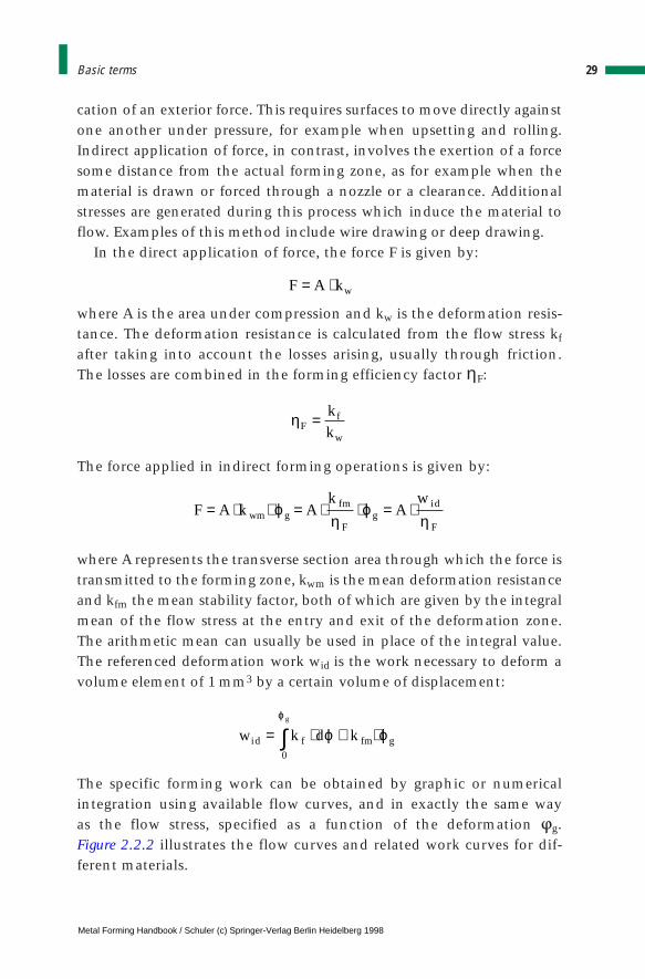
The specific forming work can be obtained by graphic or numericalintegration using available flow curves, and in exactly the same way as the flow stress, specified as a function of the deformation jg.Figure 2.2.2 illustrates the flow curves and related work curves for dif-ferent materials.
29Basic terms
F A k Ak
Aw
wm gfm
Fg
id
F
= ⋅ ⋅ = ⋅ ⋅ = ⋅ϕη
ϕη
w k d kid f fm g
g
= ⋅ ≅ ⋅∫0
ϕ
ϕ ϕ
ηF = k
kf
w
F A kw= ⋅
Metal Forming Handbook / Schuler (c) Springer-Verlag Berlin Heidelberg 1998
If there is no flow curve available for a particular material, it can bedetermined by experimentation. A tensile, compressive or hydraulicindentation test would be a conceivable method for this. If the specificdeformation work wid and the entire volume V or the displaced volumeVd are known quantities, the total deformation work W is calculated onthe following basis:
2.2.4 Formability
The identification of formability should only be based on those cases ofmaterial failure caused as a result of displacement or cleavage fractureswhere no further deformation is possible without failure. If, therefore, amaterial breaks before reaching maximum force as a result of a cleavage
30 Basic principles of metal forming
200
400
600
800
1000
100
300
500
700
0
spec
ific
defo
rmat
ion
wor
kw
id
200
400
600
800
1000
100
300
500
700
0
flow
stre
ssk f
Nmm 2
Nmmmm 3
0,2 0,4 0,6 0,8 1,0 1,2log. principle deformation gϕ
St 14St 37C 35 (normally annealed)
Fig. 2.2.2Flow curvesand curvesshowing thespecific defor-mation workfor differentmaterials
W Vw
Vk
Vkid
Fg
fm
Fd
fm
F
= ⋅ ≅ ⋅ ⋅ = ⋅η
ϕη η
Metal Forming Handbook / Schuler (c) Springer-Verlag Berlin Heidelberg 1998
fracture, this characteristic may be taken as a point of reference in thedetermination of formability, for example during a tensile test. Howev-er, cases of failure in which the stability criterion between the outer andinner forces is indicative of the achievable deformation, cannot be usedas a basis for determining formability. Such cases include for examplethe uniform strain of a material with marked necking. The formabilityof different materials differs even though other conditions are equal.Thus it is that some materials are described as malleable and others asbrittle. These descriptions are usually based on the characteristics re-vealed in tensile testing for fractures due to shrinkage or elongation.
The formability of a material is not a fixed quantity, however, it de-pends on the mean hydrostatic pressure pm exerted during the formingoperation:
Thus, for example, a material can have a low formability for one type of forming operation where the mean hydrostatic pressure is low. How-ever, if a different forming process is employed in which the meanhydrostatic pressure is higher, the same material can be formed withoutproblems. Even marble can be plastically deformed if the mean hydro-static pressure exerted is sufficiently great.
2.2.5 Units of measurement
Since the implementation of the law governing standardised units ofmeasurement, it is only permissible to use the variables prescribed bythe statutory international unit system (SI units).
Table 2.2.1 provides a comparison of the units applied in the oldtechnical system of measurement and the SI units. The given vari-ables can be transferred to the international metric system using thefactor 9.81. For approximate calculations, it is generally sufficient touse factor 10, for example:
31Basic terms
pp p p
m = + +1 2 3
3
1 10kp N≈
Metal Forming Handbook / Schuler (c) Springer-Verlag Berlin Heidelberg 1998

32 Basic principles of metal forming
Table 2.2.1: Conversion of technical to SI units of measurement
Unit system Technical (m kp s) SI (MKS)
Time: t 1 s 1 sLength: l 1 m 1 mSpeed: v 1 m/s 1 m/sRevolutions /no. of strokes: rpm rpmAcceleration: a 1 m/s2 1 m/s2
Mass: G 9,81 kg = 1 kp s2/m 1 kg1 t = 1000 kg
Density: r 9,81 kg/m3 = 1 kp s2/m4 1 kg/m3
Force: F 9,81 kg m/s2 = 1 N (Newton) = 1 kg m/s2
1 kp 1MP = 1000 kp 1 kN = 1000 NPressure: p 9,81 N/m2 = 1 kp/m2 1 N/m2 = 1 Pa (Pascal) = 1 kg/m s2
0,0981 bar = 1 at 105 N/m2 = 1 bar1,333 mbar = 1 Torr
Tension: s 9,81 N/mm2 = 1 kp/mm2 1 N/mm2
Torque: M 9,81 N m = 1 kp m 1 N m1 kN m = 1000 N m
Mass moment of inertia: J 9,81 kg m2 = 1 kp m s2 1 kgm2
Performance: P 9,81 W = 1 kp m/s 1 N m/s = 1 W (Watt) 0,7355 kW = 1 PS 1kW = 1000 W
Work: W 9,81 J = 1 kp m 1 J (Joule) = 1 N m = 1 W s 1kJ = 1000 J
Quantity of heat: Q 4,19 kJ = 1 kcal 1 kJ Sound pressure level: L 1 dB(A) 1 dB(A)
BibliographyDIN 8580 (Entwurf): Manufacturing Methods, Classification, Beuth Verlag, Berlin.DIN 8582: Manufacturing methods, forming, classification, subdivision, Beuth Verlag, Berlin.DIN 8583: Manufacturing methods, forming under compressive conditions, Part 1 - 6, Beuth Verlag,
Berlin.DIN 8584: Manufacturing methods, forming under combination of tensile and compressive conditions,
part 1 - 6, Beuth Verlag, Berlin.DIN 8585: Manufacturing methods, forming under tensile conditions, part 1 - 4, Beuth Verlag, Berlin.DIN 8586: Manufacturing methods, forming by bending, Beuth Verlag, Berlin.DIN 8587: Manufacturing methods, forming under shearing conditions, Beuth Verlag, Berlin.DIN 8588: Manufacturing methods, terms, dividing, Beuth Verlag, Berlin.Lange, K: Umformtechnik, Band 1: Grundlagen, Springer-Verlag, Heidelberg (1984).
Metal Forming Handbook / Schuler (c) Springer-Verlag Berlin Heidelberg 1998

3 Fundamentals of press design
3.1 Press types and press construction
The function of a press is to transfer one or more forces and movementsto a tool or die with the purpose of forming or blanking a workpiece.Press design calls for special knowledge of the production process to beused. Depending on the intended application, the press is designedeither to execute a specific process or for mainly universal use.
In a “specialized production line”, in view of economic production,the output is the most important issue, while maintaining the requiredpart quality. Material-related influences such as the maximum deepdrawing speed or workpiece-related influences such as the suitability ofparts for transportation, as well as aspects such as operating ergonom-ics and working safety all have to be taken into consideration.
The purpose of a universal production line, in contrast, is to offer flexi-bility and use a larger variety of dies covering as wide a part spectrum aspossible.
Achievement of the maximum possible uptime is a determining fac-tor in the design of any press, with the objective of reducing unpro-ductive or downtime to a minimum – for example necessary for chang-ing dies, maintenance or tryout. Furthermore, all presses are expectedto ensure the longest possible service life of tools and dies. Therefore,for example, the precision guidance of the slide is required.
On the basis of the production techniques used, presses are divided intothe following subcategories:
– sheet metal forming presses (cf. Sect. 4.4), – blanking presses (cf. Sects. 4.6 and 4.7.4),
Metal Forming Handbook / Schuler (c) Springer-Verlag Berlin Heidelberg 1998
– presses for solid forming, such as forging, extrusion and coiningpresses (cf. Sect. 6.8),
– presses for internal high-pressure forming (cf. Sect. 5.6), – pressure forming, stretching and stamping presses.
Shears are also commonly used, generally in separate lines, for the man-ufacture of sheet metal blanks (cf. Sects. 4.6.1 and 4.6.2).
3.1.1 Press frame
The function of the press frame is to absorb forces, to provide a preciseslide guidance and to support the drive system and other auxiliaryunits. The structural design of the frame depends on
– the pressing force – this determines the required rigidity,– the dimensions of dies influencing the size of the tool area,– work area accessibility that determines on the shape of the press
frame,– the degree of guidance precision. This influences both the shape and
the rigidity of the frame.
Presses with relatively low press forces, up to 2,500 kN, frequently makeuse of the open-front press design (cf. Fig. 4.6.14). This construction ischaracterized particularly by the easy access to the tool area. However,its drawback lies in the asymmetrical deflection of the frame, whichcontributes to reductions in part accuracy and die life, particularly inblanking applications. Inclined or horizontal designs permit faster partejection making use of gravity following the forming process, for exam-ple when forging or coining (cf. Fig. 6.8.20). As a rule, open-front pressesare used in conjunction with single dies.
Presses with a nominal pressing force over 4,000 kN are constructedexclusively in a gantry-type design. These are known as straight-sidepresses (Fig. 3.1.1). In this press type, the press bed with the bed plate,the two uprights and the crown form the frame. The application spec-trum of straight-side presses ranges from small parts produced usingprogression dies, compound progression dies or transfer dies through toindividual dies for varying part sizes (cf. Sect. 4.1.1). When using pro-gression tools, the parts are conveyed by the sheet strip itself. Con-
34 Fundamentals of press design
Metal Forming Handbook / Schuler (c) Springer-Verlag Berlin Heidelberg 1998
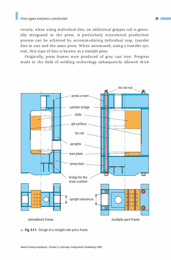
versely, when using individual dies, an additional gripper rail is gener-ally integrated in the press. A particularly economical productionprocess can be achieved by accommodating individual resp. transferdies in one and the same press. When automated, using a transfer sys-tem, this type of line is known as a transfer press.
Originally, press frames were produced of gray cast iron. Progressmade in the field of welding technology subsequently allowed thick
35Press types and press construction
gib surface
cylinder bridge
upright clearance
bridge for the
draw cushion
bed plate
press bed
press crown
slide
tie rod
uprights
tie rod nut
monoblock frame multiple-part frame
Fig. 3.1.1 Design of a straight-side press frame
Metal Forming Handbook / Schuler (c) Springer-Verlag Berlin Heidelberg 1998
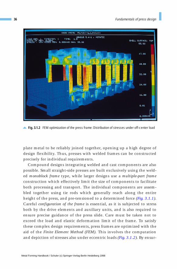
plate metal to be reliably joined together, opening up a high degree ofdesign flexibility. Thus, presses with welded frames can be constructedprecisely for individual requirements.
Compound designs integrating welded and cast components are alsopossible. Small straight-side presses are built exclusively using the weld-ed monoblock frame type, while larger designs use a multiple-part frameconstruction which effectively limit the size of components to facilitateboth processing and transport. The individual components are assem-bled together using tie rods which generally reach along the entireheight of the press, and pre-tensioned to a determined force (Fig. 3.1.1).Careful configuration of the frame is essential, as it is subjected to stressboth by the drive elements and auxiliary units, and is also required toensure precise guidance of the press slide. Care must be taken not toexceed the load and elastic deformation limit of the frame. To satisfythese complex design requirements, press frames are optimized with theaid of the Finite Element Method (FEM). This involves the computationand depiction of stresses also under eccentric loads (Fig. 3.1.2). By ensur-
36 Fundamentals of press design
Fig. 3.1.2 FEM optimization of the press frame: Distribution of stresses under off-center load
Metal Forming Handbook / Schuler (c) Springer-Verlag Berlin Heidelberg 1998
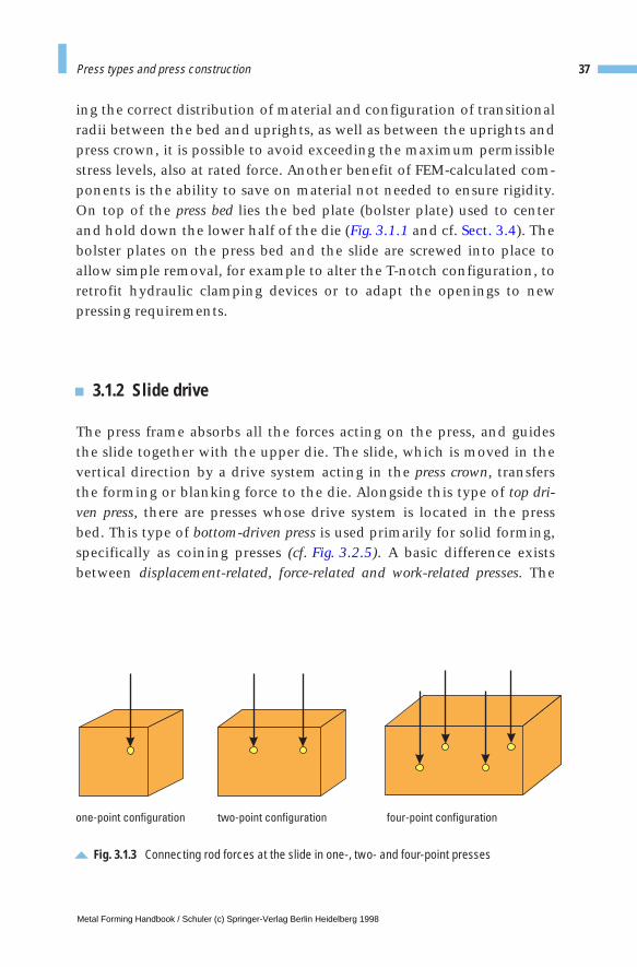
ing the correct distribution of material and configuration of transitionalradii between the bed and uprights, as well as between the uprights andpress crown, it is possible to avoid exceeding the maximum permissiblestress levels, also at rated force. Another benefit of FEM-calculated com-ponents is the ability to save on material not needed to ensure rigidity.On top of the press bed lies the bed plate (bolster plate) used to centerand hold down the lower half of the die (Fig. 3.1.1 and cf. Sect. 3.4). Thebolster plates on the press bed and the slide are screwed into place toallow simple removal, for example to alter the T-notch configuration, toretrofit hydraulic clamping devices or to adapt the openings to newpressing requirements.
3.1.2 Slide drive
The press frame absorbs all the forces acting on the press, and guidesthe slide together with the upper die. The slide, which is moved in thevertical direction by a drive system acting in the press crown, transfersthe forming or blanking force to the die. Alongside this type of top dri-ven press, there are presses whose drive system is located in the pressbed. This type of bottom-driven press is used primarily for solid forming,specifically as coining presses (cf. Fig. 3.2.5). A basic difference existsbetween displacement-related, force-related and work-related presses. The
37Press types and press construction
one-point configuration two-point configuration four-point configuration
Fig. 3.1.3 Connecting rod forces at the slide in one-, two- and four-point presses
Metal Forming Handbook / Schuler (c) Springer-Verlag Berlin Heidelberg 1998
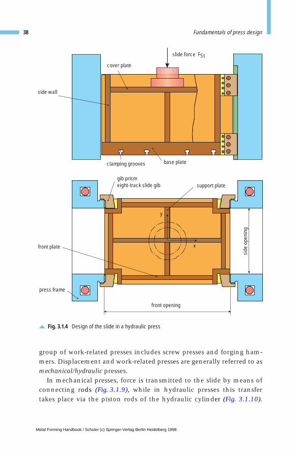
group of work-related presses includes screw presses and forging ham-mers. Displacement and work-related presses are generally referred to asmechanical/hydraulic presses.
In mechanical presses, force is transmitted to the slide by means ofconnecting rods (Fig. 3.1.9), while in hydraulic presses this transfertakes place via the piston rods of the hydraulic cylinder (Fig. 3.1.10).
38 Fundamentals of press design
side wall
cover plate
gib prismeight-track slide gib support plate
y
base plate
xfront plate
press frame
front opening
slide force FSt
clamping grooves
side
ope
ning
Fig. 3.1.4 Design of the slide in a hydraulic press
Metal Forming Handbook / Schuler (c) Springer-Verlag Berlin Heidelberg 1998

Depending on the number of force transmitting elements, there areone, two or four-point configurations in the slide (Fig. 3.1.3). When an off-center load is exerted by the die on the slide, a multiple-point press isbetter able to counter the resulting tilting moment.
The slide, which generally has a welded box shape, is guided in thepress frame (Fig. 3.1.4). In the case of off-center loads, the slide gibs alsoprovide part of the supporting forces. Figure 3.1.5 illustrates some com-mon types of gibs. A multiple-point press, used in conjunction with astable slide gib system, offers the best conditions for achieving goodpart quality and a long die life as a result of minimal tilting of the slide.For large-scale presses with two or four connecting rod drive systems,the gibs have long guidance lengths and relatively large vertical elon-gation of the frame. This calls for a readjustment feature. The gib clear-ance should not exceed 0.1mm.
Standard deep drawing presses are equipped with easily adjustableand exchangeable 45° bronze gibs. In the case of blanking and transfer
39Press types and press construction
Fig. 3.1.5 Different gib configurations
column gib
slide
ball joint gib
eight-track gib forwide side uprights
eight-track gib fornarrow side uprights
V-prism gib
presswith2 sideuprights
presswith2 sideuprights
presswith4 sideuprights
presswith4 sideuprights
eight-track gibfor high eccentricloads in they direction
eight-track block gibfor high eccentricloads in thex and y direction
x
y
z
z
Metal Forming Handbook / Schuler (c) Springer-Verlag Berlin Heidelberg 1998
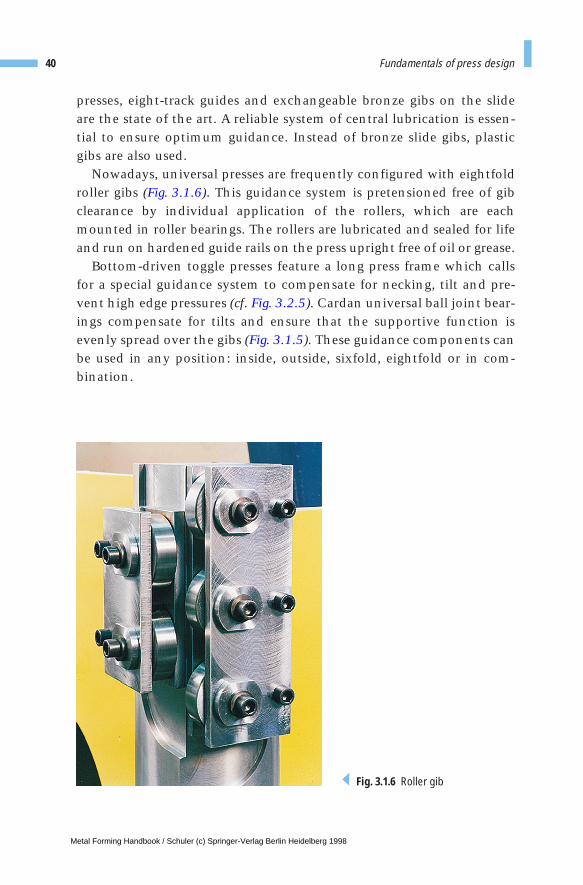
presses, eight-track guides and exchangeable bronze gibs on the slideare the state of the art. A reliable system of central lubrication is essen-tial to ensure optimum guidance. Instead of bronze slide gibs, plasticgibs are also used.
Nowadays, universal presses are frequently configured with eightfoldroller gibs (Fig. 3.1.6). This guidance system is pretensioned free of gibclearance by individual application of the rollers, which are eachmounted in roller bearings. The rollers are lubricated and sealed for lifeand run on hardened guide rails on the press upright free of oil or grease.
Bottom-driven toggle presses feature a long press frame which callsfor a special guidance system to compensate for necking, tilt and pre-vent high edge pressures (cf. Fig. 3.2.5). Cardan universal ball joint bear-ings compensate for tilts and ensure that the supportive function isevenly spread over the gibs (Fig. 3.1.5). These guidance components canbe used in any position: inside, outside, sixfold, eightfold or in com-bination.
40 Fundamentals of press design
Fig. 3.1.6 Roller gib
Metal Forming Handbook / Schuler (c) Springer-Verlag Berlin Heidelberg 1998
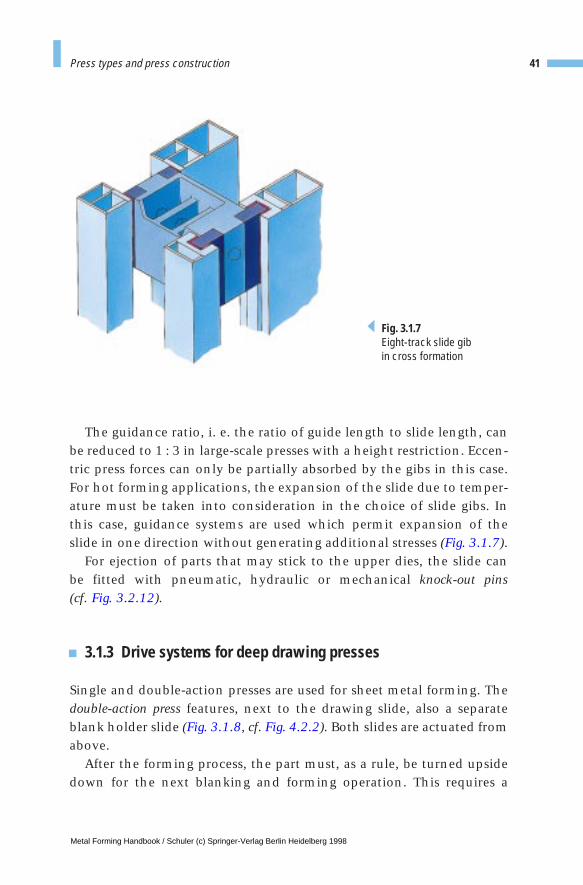
The guidance ratio, i. e. the ratio of guide length to slide length, canbe reduced to 1 : 3 in large-scale presses with a height restriction. Eccen-tric press forces can only be partially absorbed by the gibs in this case.For hot forming applications, the expansion of the slide due to temper-ature must be taken into consideration in the choice of slide gibs. Inthis case, guidance systems are used which permit expansion of theslide in one direction without generating additional stresses (Fig. 3.1.7).
For ejection of parts that may stick to the upper dies, the slide can be fitted with pneumatic, hydraulic or mechanical knock-out pins (cf. Fig. 3.2.12).
3.1.3 Drive systems for deep drawing presses
Single and double-action presses are used for sheet metal forming. Thedouble-action press features, next to the drawing slide, also a separateblank holder slide (Fig. 3.1.8, cf. Fig. 4.2.2). Both slides are actuated fromabove.
After the forming process, the part must, as a rule, be turned upsidedown for the next blanking and forming operation. This requires a
41Press types and press construction
Fig. 3.1.7Eight-track slide gib in cross formation
Metal Forming Handbook / Schuler (c) Springer-Verlag Berlin Heidelberg 1998
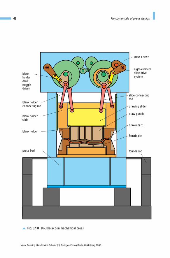
42 Fundamentals of press design
blank holderconnecting rod
blank holderslide
blank holder
press bed
blankholderdrive(toggledrive)
slide connecting rod
drawing slide
draw punch
drawn part
female die
foundation
press crown
eight-elementslide drivesystem
Fig. 3.1.8 Double-action mechanical press
Metal Forming Handbook / Schuler (c) Springer-Verlag Berlin Heidelberg 1998
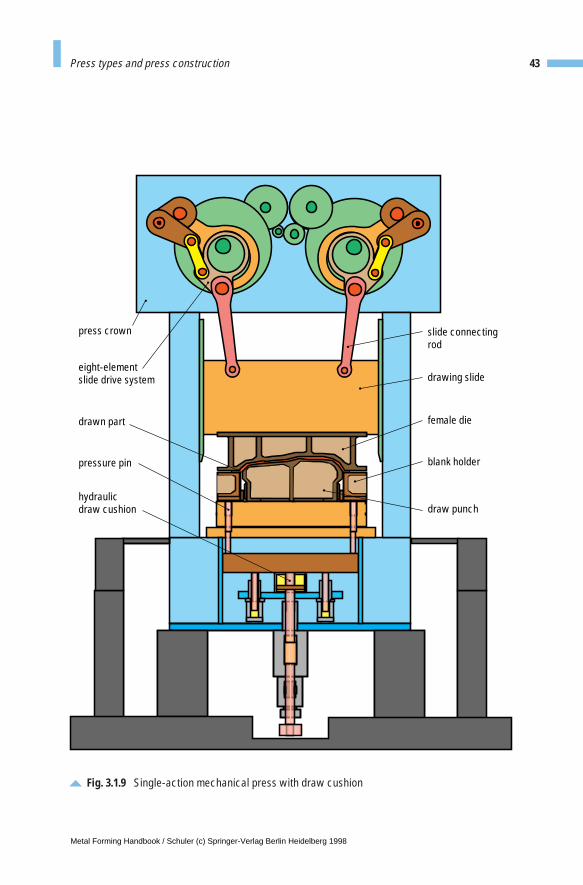
43Press types and press construction
Fig. 3.1.9 Single-action mechanical press with draw cushion
drawing slide
blank holder
slide connecting rod
female die
draw punch
drawn part
hydraulic draw cushion
pressure pin
press crown
eight-elementslide drive system
Metal Forming Handbook / Schuler (c) Springer-Verlag Berlin Heidelberg 1998
bulky, cost-intensive turning device to be installed downstream from thedouble-action press. There are advantages in forming a part in the reverseposition, i. e. the bottom of the part facing upwards. In this case part ejec-tion is simpler through a slide cushion in subsequent forming stations.The alternative is to work with a draw cushion or nitrogen cylinders.Furthermore, the centering in subsequent stations is improved, since theparts can be positioned over their entire inner shape by the bottom die.In addition, the sensitive surfaces of the material – for example whenworking with automotive body panels – are less likely to sustain damageduring transportation in the press and when centering in the die. It isalso possible to install the blanking punches at a lower level for subse-quent operations if the part has previously been turned over.
In the case of single-acting deep drawing presses, in contrast, the blank holder force is transmitted from underneath by a draw cushion(Fig. 3.1.9 and cf. Fig. 4.2.3). Both the forming and the blank holderforce are applied by the slide, as the slide forces the draw cushion down-wards. After the drawing, without “turning over”, the part is ideallypositioned for the subsequent operations.
When used together with a hydraulically driven slide movement, thedraw cushion can also be used for active counter-drawing (Fig. 3.1.10 andcf. Fig. 4.2.4). From the point of view of energy savings, it is beneficialthat the slide holds the blank while the draw cushion applies the form-ing force.
In order to achieve as great a degree of flexibility as possible, double-action presses can also be configured with a draw cushion.
3.1.4 Draw cushions
The function of the draw cushion is to hold the blank during deepdrawing operations in mechanical and hydraulic presses (cf. Sect.2.1.4). The cushion thus prevents the formation of wrinkles and, as aresult of the ejection function, raises the parts to the transport levelduring the return motion of the slide. Modern draw cushions can beeither hydraulically or pneumatically actuated. A major differencebetween the two is the larger force of the hydraulic draw cushion. Thecushion force is initiated during downward travel of the slide by, forexample, four hydraulic cylinders via the lifting bridges and com-
44 Fundamentals of press design
Metal Forming Handbook / Schuler (c) Springer-Verlag Berlin Heidelberg 1998
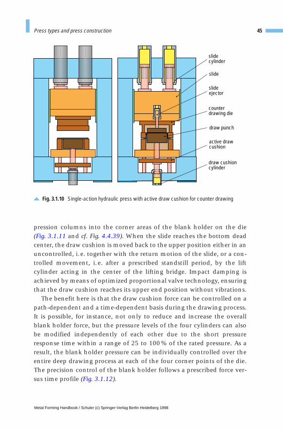
Fig. 3.1.10 Single-action hydraulic press with active draw cushion for counter drawing
slidecylinder
slideejector
counter drawing die
active drawcushion
draw cushioncylinder
slide
draw punch
pression columns into the corner areas of the blank holder on the die(Fig. 3.1.11 and cf. Fig. 4.4.39). When the slide reaches the bottom deadcenter, the draw cushion is moved back to the upper position either in anuncontrolled, i.e. together with the return motion of the slide, or a con-trolled movement, i.e. after a prescribed standstill period, by the liftcylinder acting in the center of the lifting bridge. Impact damping isachieved by means of optimized proportional valve technology, ensuringthat the draw cushion reaches its upper end position without vibrations.
The benefit here is that the draw cushion force can be controlled on apath-dependent and a time-dependent basis during the drawing process.It is possible, for instance, not only to reduce and increase the overallblank holder force, but the pressure levels of the four cylinders can alsobe modified independently of each other due to the short pressureresponse time within a range of 25 to 100% of the rated pressure. As aresult, the blank holder pressure can be individually controlled over theentire deep drawing process at each of the four corner points of the die.The precision control of the blank holder follows a prescribed force ver-sus time profile (Fig. 3.1.12).
45Press types and press construction
Metal Forming Handbook / Schuler (c) Springer-Verlag Berlin Heidelberg 1998
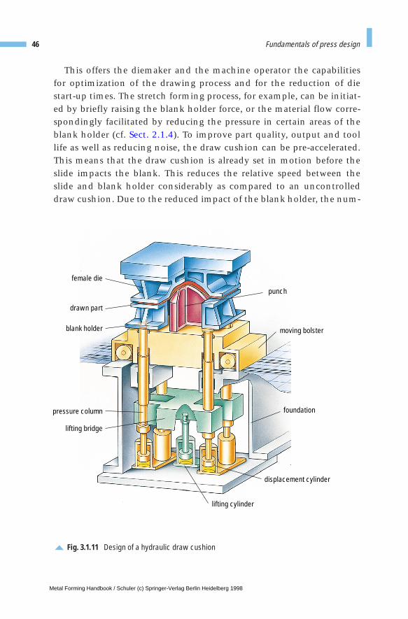
This offers the diemaker and the machine operator the capabilitiesfor optimization of the drawing process and for the reduction of diestart-up times. The stretch forming process, for example, can be initiat-ed by briefly raising the blank holder force, or the material flow corre-spondingly facilitated by reducing the pressure in certain areas of theblank holder (cf. Sect. 2.1.4). To improve part quality, output and toollife as well as reducing noise, the draw cushion can be pre-accelerated.This means that the draw cushion is already set in motion before theslide impacts the blank. This reduces the relative speed between theslide and blank holder considerably as compared to an uncontrolleddraw cushion. Due to the reduced impact of the blank holder, the num-
46 Fundamentals of press design
Fig. 3.1.11 Design of a hydraulic draw cushion
female die
drawn part
blank holder
pressure column
lifting bridge
punch
moving bolster
foundation
displacement cylinder
lifting cylinder
Metal Forming Handbook / Schuler (c) Springer-Verlag Berlin Heidelberg 1998
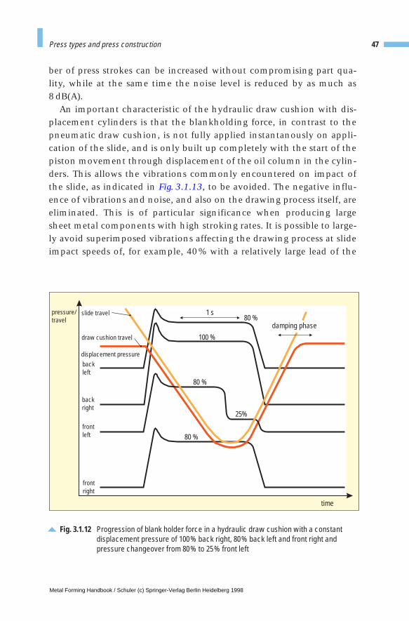
ber of press strokes can be increased without compromising part qua-lity, while at the same time the noise level is reduced by as much as 8 dB(A).
An important characteristic of the hydraulic draw cushion with dis-placement cylinders is that the blankholding force, in contrast to thepneumatic draw cushion, is not fully applied instantanously on appli-cation of the slide, and is only built up completely with the start of thepiston movement through displacement of the oil column in the cylin-ders. This allows the vibrations commonly encountered on impact ofthe slide, as indicated in Fig. 3.1.13, to be avoided. The negative influ-ence of vibrations and noise, and also on the drawing process itself, areeliminated. This is of particular significance when producing largesheet metal components with high stroking rates. It is possible to large-ly avoid superimposed vibrations affecting the drawing process at slideimpact speeds of, for example, 40% with a relatively large lead of the
47Press types and press construction
Fig. 3.1.12 Progression of blank holder force in a hydraulic draw cushion with a constantdisplacement pressure of 100% back right, 80% back left and front right andpressure changeover from 80% to 25% front left
1 s
displacement pressure
draw cushion travel
slide travel
time
pressure/travel
frontleft
backright
backleft
frontright
damping phase
100 %
25%
80 %
80 %
80 %
Metal Forming Handbook / Schuler (c) Springer-Verlag Berlin Heidelberg 1998
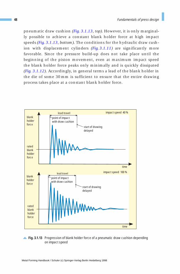
pneumatic draw cushion (Fig. 3.1.13, top). However, it is only marginal-ly possible to achieve a constant blank holder force at high impactspeeds (Fig. 3.1.13, bottom). The conditions for the hydraulic draw cush-ion with displacement cylinders (Fig. 3.1.11) are significantly morefavorable. Since the pressure build-up does not take place until thebeginning of the piston movement, even at maximum impact speedthe blank holder force peaks only minimally and is quickly dissipated(Fig. 3.1.12). Accordingly, in general terms a lead of the blank holder inthe die of some 30 mm is sufficient to ensure that the entire drawingprocess takes place at a constant blank holder force.
48 Fundamentals of press design
impact speed 40 %
time
blankholderforce
ratedblankholderforce
lead travel
point of impactwith draw cushion
start of drawingdelayed
impact speed 100 %
time
blankholderforce
ratedblankholderforce
start of drawingdelayed
point of impactwith draw cushion
lead travel
Fig. 3.1.13 Progression of blank holder force of a pneumatic draw cushion dependingon impact speed
Metal Forming Handbook / Schuler (c) Springer-Verlag Berlin Heidelberg 1998
3 Fundamentals of press design
3.2 Mechanical presses
3.2.1 Determination of characteristic data
The following paragraphs will deal with basic principles concerningforce, work and power of mechanical presses.
If a weight of 75 kg is suspended from a crane rope, a force of around750 N (force F = Mass m · gravitational acceleration g) acts on the rope.As long as the weight is not raised, no work is performed, as the workW [Nm] is the product of force F [N] and distance h [m]:
If this weight is now raised by 1m, the work performed amounts to:
This work can be obtained from the weight again when it drops by 1m.However, the magnitude of the resulting force depends on the distanceover which the work takes place:
If, therefore, a force of 750N is uniformly exerted to raise the weightover a distance of 1 m, the same force will be expended if the entirework is performed when lowering the weight over a distance of 1 m. A different situation results if the weight initially drops freely for half
W F h= ⋅
W N m Nm= ⋅ =750 1 750
F W h= /
Metal Forming Handbook / Schuler (c) Springer-Verlag Berlin Heidelberg 1998

the distance and then the entire work of 750 Nm is expended over thelast 50 cm = 0.5 m. The force is then given by:
Since the work has been performed over only half the distance, theforce has doubled. If the entire work is performed over only one tenthof the distance (i. e. 0.1 m), the force rises tenfold:
In Fig. 3.2.1, the force exerted over the relevant distance is indicated forall three cases. The results are three rectangles whose areas correspondto the product of force F · distance h and thus to the work W. If a curve istraced through the corners of the rectangles, provided the existing workof 750 Nm is performed evenly over a certain distance, it is possible todirectly read the magnitude of the force applied. With a forming dis-tance of 0.2 m, for instance, the force applied is 3,750 N (Fig. 3.2.1).
In summary, it is generally valid that
– force and work are two terms which can be related to each other onlyby means of a third variable, i. e. distance.
– If a force is applied over a certain distance, work is performed. Thiscorresponds in the force-distance graph to the area of the rectanglebelow the force curve.
– If a certain amount of work is performed, the distance over which itis performed determines the magnitude of the generated force.
The relations described here using the example of a weight, apply gen-erally to the field of press construction. They are applied also in theforging hammer. The hammer has a certain weight and is raised over acertain distance. This gives it a defined quantity of potential energy.When it gives up the work stored in it, i. e. transfers its energy to thedie, the magnitude of its force at the moment of impact depends on thedisplacement over which deformation takes place. This force can bevery large if the displacement of the workpiece is very small, and caneven result in damage to the tool and the press. On the other hand, in
50 Fundamentals of press design
F Nm m N= =750 0 5 1,500/ .
F Nm m N= =750 0 1 7 500/ . ,
Metal Forming Handbook / Schuler (c) Springer-Verlag Berlin Heidelberg 1998
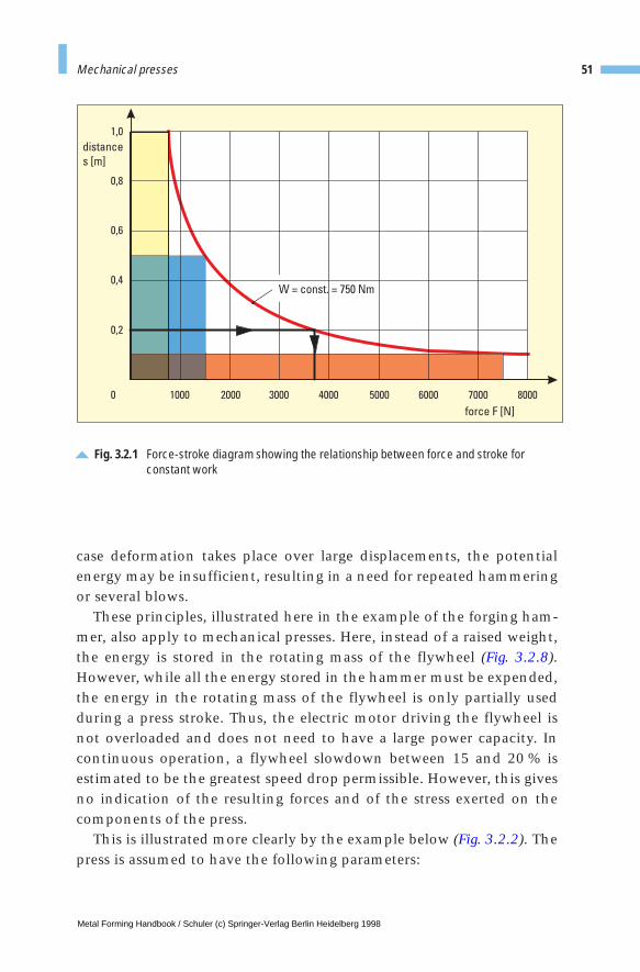
case deformation takes place over large displacements, the potentialenergy may be insufficient, resulting in a need for repeated hammeringor several blows.
These principles, illustrated here in the example of the forging ham-mer, also apply to mechanical presses. Here, instead of a raised weight,the energy is stored in the rotating mass of the flywheel (Fig. 3.2.8).However, while all the energy stored in the hammer must be expended,the energy in the rotating mass of the flywheel is only partially usedduring a press stroke. Thus, the electric motor driving the flywheel isnot overloaded and does not need to have a large power capacity. Incontinuous operation, a flywheel slowdown between 15 and 20 % isestimated to be the greatest speed drop permissible. However, this givesno indication of the resulting forces and of the stress exerted on thecomponents of the press.
This is illustrated more clearly by the example below (Fig. 3.2.2). Thepress is assumed to have the following parameters:
51Mechanical presses
Fig. 3.2.1 Force-stroke diagram showing the relationship between force and stroke for constant work
distance
s [m]
0,2
0,4
0,6
0,8
1,0
force F [N]
0 1000 2000 3000 4000 5000 6000 7000 8000
W = const. = 750 Nm
Metal Forming Handbook / Schuler (c) Springer-Verlag Berlin Heidelberg 1998
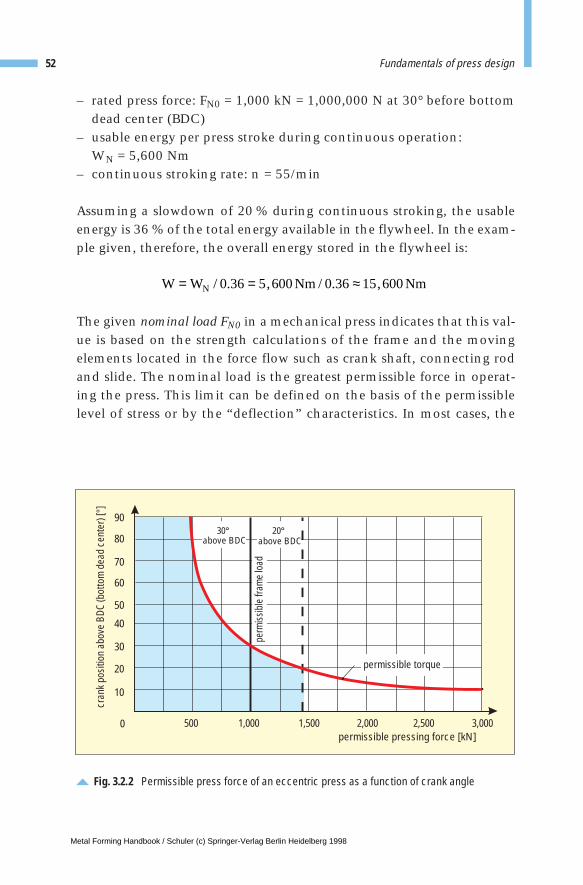
– rated press force: FN0 = 1,000 kN = 1,000,000 N at 30° before bottomdead center (BDC)
– usable energy per press stroke during continuous operation: WN = 5,600 Nm
– continuous stroking rate: n = 55/min
Assuming a slowdown of 20 % during continuous stroking, the usableenergy is 36 % of the total energy available in the flywheel. In the exam-ple given, therefore, the overall energy stored in the flywheel is:
The given nominal load FN0 in a mechanical press indicates that this val-ue is based on the strength calculations of the frame and the movingelements located in the force flow such as crank shaft, connecting rodand slide. The nominal load is the greatest permissible force in operat-ing the press. This limit can be defined on the basis of the permissiblelevel of stress or by the “deflection” characteristics. In most cases, the
52 Fundamentals of press design
Fig. 3.2.2 Permissible press force of an eccentric press as a function of crank angle
permissible pressing force [kN]
cran
k po
sitio
n ab
ove
BDC
(bot
tom
dea
d ce
nter
) [°]
0
20
40
60
50
80
70
90
30
10
500 1,000 1,500 2,000 2,500 3,000
permissible torque
perm
issib
lefra
me
load
30 20above BDC above BDC
W W Nm NmN= = ≈/ . , / . ,0 36 5 600 0 36 15 600
Metal Forming Handbook / Schuler (c) Springer-Verlag Berlin Heidelberg 1998
stress on the frame is kept low to achieve the maximum possible rigid-ity. The nominal load is specified at 30° before bottom dead center toindicate that from here to the bottom dead center, the drive com-ponents that transmit the power, such as the driveshaft, the clutch,etc., have also been designed for the torque corresponding to thenominal press force. Therefore, between 90° and 30° before the bottomdead center, the movable parts must be subjected to smaller stresses toavoid overloading. The force versus crank angle curve, Fig. 3.2.2, indi-cates that the press in question may be subjected to a nominal load of 1,000 kN between 30° before bottom dead center and at bottom dead center, while at 90° before bottom dead center a slide load of onlyFN0 /2 = 500 kN is permissible.
If a press with the parameters specified here is used to perform anoperation in which a constant force of F = 1,000 kN is applied over adistance of h = 5.6 mm, the energy used during forming is:
The press is then being used to the limits of its rated force and energy.If the same force were to act over a distance of only h = 3 mm = 0.003 m,the energy expended amounts to:
The force of the press is then fully used, while the available energy isnot completely used.
The situation is much more unfavorable if the rated flywheel energyof 5,600 Nm is applied over a working distance of h = 3 mm. In thiscase, the effective force of the slide will be:
As the maximum permissible press force is only 1,000 kN, the press isbeing severely overloaded. In spite of the fact that the flywheel slow-down is still within the normal limits and gives no indication of over-loading, all elements that are subjected to the press force may be dam-aged, such as the press frame, slide, connection rods, etc. Serious over-loading often occurs when press forming is conducted using high forces
53Mechanical presses
W N m Nm= ⋅ =1 000 000 0 003 3 000, , . ,
F W h Nm m N kNN= = ≈ =/ , / . , , ,5 600 0 003 1 867 000 1 867
W F h N m Nm= ⋅ = ⋅ =1 000 000 0 0056 5 600, , . ,
Metal Forming Handbook / Schuler (c) Springer-Verlag Berlin Heidelberg 1998
over small distances, for instance during blanking or coining. The greatdanger is that such overloading may go undetected. For this reason, over-loading safety devices must be used to protect the press (cf. Sect. 3.2.8).
Another form of overloading results from taking too much energyfrom the flywheel. Such overloading can result in extremely high pressforces if the displacement during deformation is too small. However, ifthe energy is applied over a large displacement, this type of overload ismuch less dangerous. For example, if the press described above isbrought to a stop during a working distance of h = 100 mm, the entireflywheel energy of W = 15,600 Nm is utilized. Assuming that no peakloads have occurred, the mean press force exerted is only
The press is therefore by no means overloaded although the flywheel has been brought to a standstill. In this case, only the drive motor suffers a very large slowdown and it is necessary to use a press of a largerflywheel energy capacity, although the permissible press force of 1,000 kNis more than adequate. Overloads of this type occur more frequently ifdeformation is done over a large distance, e. g. during deep drawing, openor closed die extrusion.
3.2.2 Types of drive system
Eccentric or crank driveFor a long time, eccentric or crank drive systems were the only type ofdrive mechanisms used in mechanical presses. The sinusoidal slide dis-placement of an eccentric press is seen in (Fig.3.2.3).The relatively highimpact speed on die closure and the reduction of slide speed during theforming processes are drawbacks which often preclude the use of thistype of press for deep drawing at high stroking rates.
However, in presses with capacities up to a nominal force of 5,000 kN,such as universal or blanking presses, eccentric or crank drive is still themost effective drive system. This is especially true when using automat-ed systems where the eccentric drive offers a good compromise betweentime necessary for processing and that required for part transport. Evenin the latest crossbar transfer presses, eccentric drive systems used in
54 Fundamentals of press design
F W h Nm m N kN= = = =/ , / . ,15 600 0 1 156 000 156
Metal Forming Handbook / Schuler (c) Springer-Verlag Berlin Heidelberg 1998

subsequent processing stations, after the drawing station, satisfy therequirements for system simplification. Stroke lengths of up to 1,300 mmare achieved using eccentric gears with a diameter of 3,000 mm. Theeccentric gears are manufactured from ductile iron in accordance withthe highest quality standards (cf. Sect. 3.7).
Linkage driveRequirements for improved economy lead directly to higher strokingrates. When using crank or eccentric drive systems, this involvesincreasing the slide speed. However, when performing deep-drawingwork, for technical reasons the ram speed should not exceed 0.4 to 0.5 m/s during deformation. The linkage drive system can be designedsuch that in mechanical presses, the slide speed during the drawingprocess can be reduced, compared to eccentric drive by between a half and a third (Fig. 3.2.3). The slide in a double-acting deep drawing press, for example, is actuated using a specially designed linkage drive (Fig. 3.2.4 and cf. Fig. 3.1.8).
55Mechanical presses
Fig. 3.2.3 Displacement-time diagram: comparison of the slide motion performed by aneccentric, a knuckle-joint and a link-driven press
0 90 180 270 360
bottom dead center (BDC)
crank angle[
100
200
300
400
500
600
700
900
0
eccentricdrive system
eight-linkdrive system
modifiedknuckle-jointdrive system/six-linkdrive system
stro
ke[m
m]
800
approx. 180
approx. 170approx.110
Metal Forming Handbook / Schuler (c) Springer-Verlag Berlin Heidelberg 1998
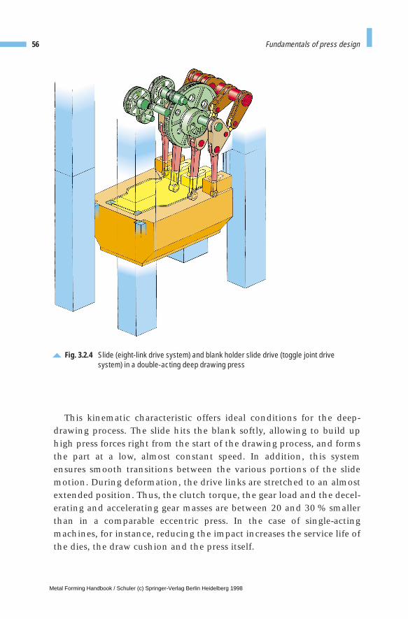
This kinematic characteristic offers ideal conditions for the deep-drawing process. The slide hits the blank softly, allowing to build uphigh press forces right from the start of the drawing process, and formsthe part at a low, almost constant speed. In addition, this systemensures smooth transitions between the various portions of the slidemotion. During deformation, the drive links are stretched to an almostextended position. Thus, the clutch torque, the gear load and the decel-erating and accelerating gear masses are between 20 and 30 % smallerthan in a comparable eccentric press. In the case of single-actingmachines, for instance, reducing the impact increases the service life ofthe dies, the draw cushion and the press itself.
56 Fundamentals of press design
Fig. 3.2.4 Slide (eight-link drive system) and blank holder slide drive (toggle joint drivesystem) in a double-acting deep drawing press
Metal Forming Handbook / Schuler (c) Springer-Verlag Berlin Heidelberg 1998
This offers a number of important benefits in production: for thesame nominal press force and the same nominal slide stroke, a link-driven press can be loaded substantially earlier in the stroke, becausethe press force displacement curve is steeper within the deformationrange. Therefore, the linkage press has a more favorable force-displace-ment curve than on an eccentrically-driven press (Fig. 3.2.2). Withoutincreasing the impact speed, it is possible to achieve an appreciableincrease in the stroking rate and output. Due to the improved drawingconditions, a higher degree of product quality is achieved; even sheetmetal of an inferior quality can be used with satisfactory results. Inaddition, this system reduces stress both on the die and the draw cush-ion and also on the clutch and brake. Furthermore, noise emissions arereduced as a result of the lower impact speed of the slide and the quieter herringbone gears of the drive wheels.
In the case of large-panel transfer presses, the use of six or eight-element linkage drive systems is largely determined by deformationconditions, the part transport movement and the overall structure ofthe presses. As a result, in the case of transfer presses with tri-axis transfer system, a six-element linkage drive system is frequently used,since this represents the best possible compromise between optimumpress geometry and manufacturing costs (cf. Sect. 4.4.7). In the case of crossbar transfer presses, either an eight-element linkage drive or acombination of linkage and eccentric drives are used in order to opti-mize the die-specific transfer movements (cf. Sect. 4.4.8). The linkageelements are made of ductile iron, the linkage pins are from steel with hardened contact surfaces and the bearing bushes are from highly stress-resistant non-ferrous alloys. A reliable system of lubrica-tion and oil distribution guarantees safe operation of these highlystressed bearings (cf. Sect. 3.2.11).
Knuckle-joint drive systemThis design principle is applied primarily for coining work. The knuck-le-joint drive system consists of an eccentric or crank mechanism dri-ving a knuckle-joint. Figure 3.2.5 shows this concept used in a presswith bottom drive. The fixed joint and bed plate form a compact unit.The lower joint moves the press frame. It acts as a slide and moves theattached top die up and down. Due to the optimum force flow and thefavorable configuration possibilities offered by the force-transmitting
57Mechanical presses
Metal Forming Handbook / Schuler (c) Springer-Verlag Berlin Heidelberg 1998
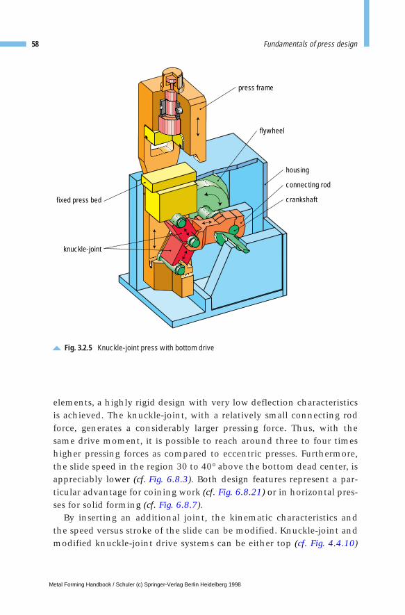
elements, a highly rigid design with very low deflection characteristicsis achieved. The knuckle-joint, with a relatively small connecting rodforce, generates a considerably larger pressing force. Thus, with thesame drive moment, it is possible to reach around three to four timeshigher pressing forces as compared to eccentric presses. Furthermore,the slide speed in the region 30 to 40° above the bottom dead center, isappreciably lower (cf. Fig. 6.8.3). Both design features represent a par-ticular advantage for coining work (cf. Fig. 6.8.21) or in horizontal pres-ses for solid forming (cf. Fig. 6.8.7).
By inserting an additional joint, the kinematic characteristics andthe speed versus stroke of the slide can be modified. Knuckle-joint andmodified knuckle-joint drive systems can be either top (cf. Fig. 4.4.10)
58 Fundamentals of press design
flywheel
press frame
housing
connecting rod
crankshaftfixed press bed
knuckle-joint
Fig. 3.2.5 Knuckle-joint press with bottom drive
Metal Forming Handbook / Schuler (c) Springer-Verlag Berlin Heidelberg 1998
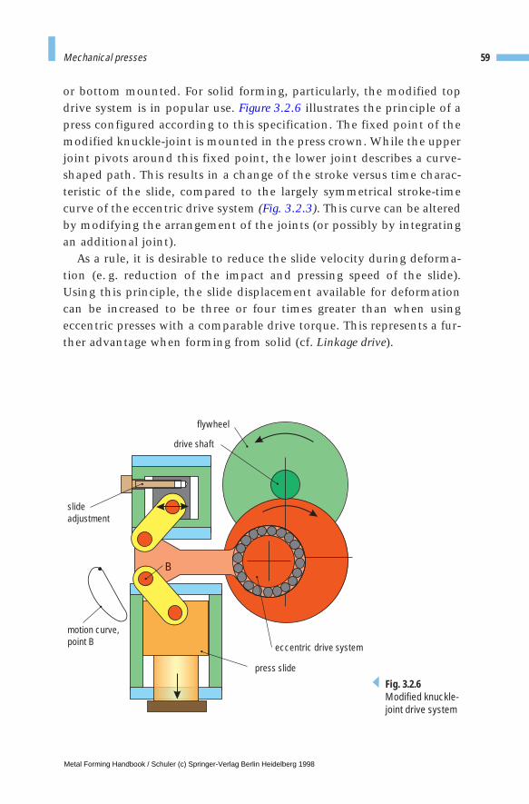
or bottom mounted. For solid forming, particularly, the modified topdrive system is in popular use. Figure 3.2.6 illustrates the principle of apress configured according to this specification. The fixed point of themodified knuckle-joint is mounted in the press crown. While the upperjoint pivots around this fixed point, the lower joint describes a curve-shaped path. This results in a change of the stroke versus time charac-teristic of the slide, compared to the largely symmetrical stroke-timecurve of the eccentric drive system (Fig. 3.2.3). This curve can be alteredby modifying the arrangement of the joints (or possibly by integratingan additional joint).
As a rule, it is desirable to reduce the slide velocity during deforma-tion (e. g. reduction of the impact and pressing speed of the slide).Using this principle, the slide displacement available for deformationcan be increased to be three or four times greater than when usingeccentric presses with a comparable drive torque. This represents a fur-ther advantage when forming from solid (cf. Linkage drive).
59Mechanical presses
flywheel
drive shaft
eccentric drive system
press slide
slideadjustment
motion curve,point B
B
Fig. 3.2.6Modified knuckle-joint drive system
Metal Forming Handbook / Schuler (c) Springer-Verlag Berlin Heidelberg 1998
The blank holder drive, sometimes used in double-acting deep drawpresses, is a special case (Fig. 3.2.4 and cf. Fig. 3.1.8). The required stand-still of the blank holder during the deep-drawing phase is achieved inthis type of machine by superimposing a double knuckle-joint systemcoupled with the eccentric or linkage drive of the slide. The standstill ofthe blank holder represents a crank angle of between 90 and 130° witha maximum residual movement of 0.5 mm. This residual movementdoes not, however, influence the deep-drawing process because theblank holder overload safeguard acts as a storage system and the elasticdeflection of the entire press, which is a few millimeters, has an over-riding effect. The slide drive, the blank holder drive and the wheel gearare integrated in the press crown.
3.2.3 Drive motor and flywheel
In larger-scale presses, the main drive system is usually powered by DCmotors, primarily in order to provide a large stroking rate. Frequency-controlled threephase motors offer an alternative, particularly where ahigh protection class rating is called for. The output of a press, which isdetermined by force, slide displacement and speed, including lost ener-gy, is provided by the main motor. Periodically occurring load peaks arecompensated by the flywheel which stores energy. The highly elasticDC drive system is able to compensate for a drop of the flywheel speedof up to 20 % in every press stroke and to replace the consumed energyby acceleration of the flywheel prior to the subsequent stroke.
Useful energy should also be available during set-up operation with areduced stroking rate, for example five strokes per minute. In this case,a speed drop of 50 % is admissible. An important criterion in configur-ing the energy balance is to ensure a short run-up time. Running up a large-panel press from its minimum to its maximum productionstroking rate generally takes less than one minute under load.
Due to the required useful energy and the permissible flywheel slow-down of 20 %, the flywheel is generally designed to operate under themost energy-consuming condition, i. e. in the lower stroking range ofthe press. Although a high flywheel speed is beneficial here, this is lim-ited by the admissible speed of the clutch, brake and flywheel itself.
60 Fundamentals of press design
Metal Forming Handbook / Schuler (c) Springer-Verlag Berlin Heidelberg 1998
In crossbar transfer presses, flywheels of up to 2,500 mm in diameterand a weight of 25 t are used. The mounting and lubrication of this type of flywheel in roller bearings are highly demanding, as a largequantity of lubricant and continuous temperature monitoring arerequired (cf. Sect. 3.2.11). The flywheel is driven by the main motor viaa flat belt or high-performance V-belt. When the main drive system isswitched off, the flywheel is brought to a standstill within a maximumof 30 s by reverse braking of the motor and by an additional pneumaticbrake.
In isolated cases, normal car body presses and tri-axis transfer pressesare equipped with mechanical creep speed drive systems of one strokeper minute. In this case, the drive is achieved by a threephase motoracting on a worm gear which actuates the drive shaft via the brakeflange of the main brake. The transmitted torque generally falls short ofthe nominal drive torque. However, by means of a pneumatic orhydraulic servo system in the brake, the nominal force may be achievedfor distances of up to 10 mm. This is generally sufficient for set-upoperation.
3.2.4 Clutch and brake
One of the characteristics of mechanical presses is the clutch used totransmit the motor and flywheel torque to the gear shaft and, afterclutch release, the brake which is used to decelerate the slide, the top dieand the gear. Particularly when working in single-stroke mode, themasses in translational or rotational motion must be brought to a stand-still after every stroke within an extremely short time: 200 to 300 ms forlarge-panel presses and 100 to 150 ms in universal presses. Conversely,after engaging the clutch, the same masses must be accelerated fromzero to operating speed.
For safety reasons, braking is generated mechanically by spring pow-er. The clutch torque is calculated from the nominal press force and therequired working distance, generally 13 to 25 mm above bottom deadcenter.
Pneumatic single-disk clutch and brake combinations with minimumrotating masses have been in successful use for decades (Fig. 3.2.7).
61Mechanical presses
Metal Forming Handbook / Schuler (c) Springer-Verlag Berlin Heidelberg 1998
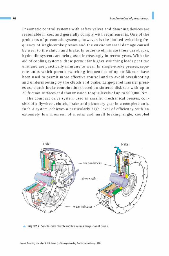
Pneumatic control systems with safety valves and damping devices arereasonable in cost and generally comply with requirements. One of theproblems of pneumatic systems, however, is the limited switching fre-quency of single-stroke presses and the environmental damage causedby wear to the clutch and brake. In order to eliminate these drawbacks,hydraulic systems are being used increasingly in recent years. With theaid of cooling systems, these permit far higher switching loads per timeunit and are practically immune to wear. In single-stroke presses, sepa-rate units which permit switching frequencies of up to 30/min havebeen used to permit more effective control and to avoid overshootingand undershooting by the clutch and brake. Large-panel transfer press-es use clutch-brake combinations based on sintered disk sets with up to20 friction surfaces and transmission torque levels of up to 500,000 Nm.
The compact drive system used in smaller mechanical presses, con-sists of a flywheel, clutch, brake and planetary gear in a complete unit.Such a system achieves a particularly high level of efficiency with anextremely low moment of inertia and small braking angle, coupled
62 Fundamentals of press design
clutch brake
friction blocks
drive shaft
wear indicator
Fig. 3.2.7 Single-disk clutch and brake in a large-panel press
Metal Forming Handbook / Schuler (c) Springer-Verlag Berlin Heidelberg 1998
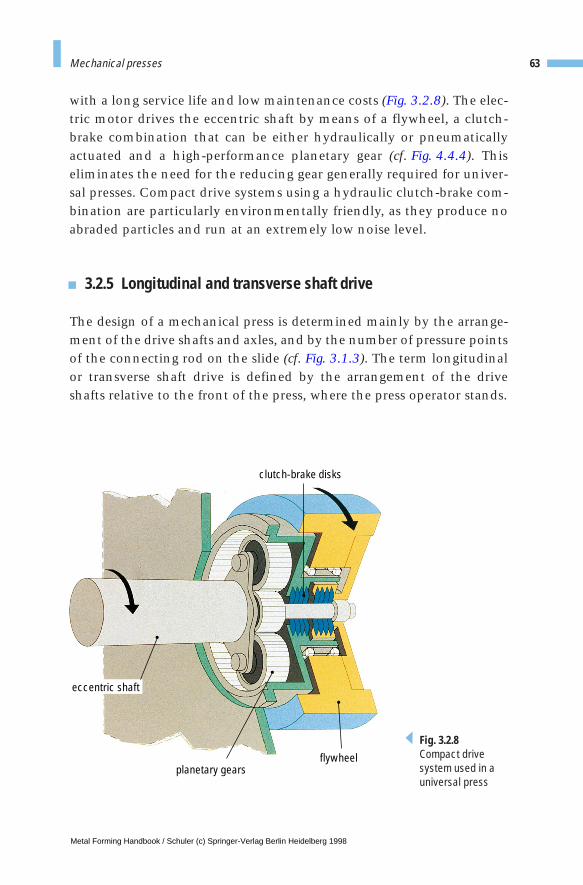
with a long service life and low maintenance costs (Fig. 3.2.8). The elec-tric motor drives the eccentric shaft by means of a flywheel, a clutch-brake combination that can be either hydraulically or pneumaticallyactuated and a high-performance planetary gear (cf. Fig. 4.4.4). Thiseliminates the need for the reducing gear generally required for univer-sal presses. Compact drive systems using a hydraulic clutch-brake com-bination are particularly environmentally friendly, as they produce noabraded particles and run at an extremely low noise level.
3.2.5 Longitudinal and transverse shaft drive
The design of a mechanical press is determined mainly by the arrange-ment of the drive shafts and axles, and by the number of pressure pointsof the connecting rod on the slide (cf. Fig. 3.1.3). The term longitudinalor transverse shaft drive is defined by the arrangement of the driveshafts relative to the front of the press, where the press operator stands.
63Mechanical presses
clutch-brake disks
flywheelplanetary gears
eccentric shaft
Fig. 3.2.8Compact drivesystem used in auniversal press
Metal Forming Handbook / Schuler (c) Springer-Verlag Berlin Heidelberg 1998
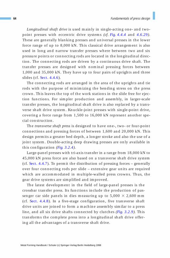
Longitudinal shaft drive is used mainly in single-acting one- and two-point presses with eccentric drive systems (cf. Fig. 4.4.4 and 4.6.29).These are generally blanking presses and universal presses in the lowerforce range of up to 8,000 kN. This classical drive arrangement is alsoused in long and narrow transfer presses where between two and sixpressure points or connecting rods are located in the longitudinal direc-tion. The connecting rods are driven by a continuous drive shaft. Thetransfer presses are designed with nominal pressing forces between1,000 and 35,000 kN. They have up to four pairs of uprights and threeslides (cf. Sect. 4.4.6).
The connecting rods are arranged in the area of the uprights and tierods with the purpose of minimizing the bending stress on the presscrown. This leaves the top of the work stations in the slide free for ejec-tion functions. For simpler production and assembly, in larger-scaletransfer presses, the longitudinal shaft drive is also replaced by a trans-verse shaft drive system. Knuckle-joint presses with single-point drive,covering a force range from 1,500 to 16,000 kN represent another spe-cial construction.
The transverse shaft press is designed to have one-, two- or four-pointconnections and pressing forces of between 1,600 and 20,000 kN. Thisdesign permits a greater bed depth, a longer stroke and also the use of ajoint system. Double-acting deep drawing presses are only available inthis configuration (Fig. 3.2.4).
Large-panel presses with tri-axis transfer in a range from 18,000 kN to45,000 kN press force are also based on a transverse shaft drive system(cf. Sect. 4.4.7). To permit the distribution of pressing forces – generallyover four connecting rods per slide – extensive gear units are requiredwhich are accommodated in multiple-walled press crowns. Thus, thegear drive systems are simplified and improved.
The latest development in the field of large-panel presses is thecrossbar transfer press. Its functions include the production of pas-senger car side panels in dies measuring up to 5,000 3 2,600 mm (cf. Sect. 4.4.8). In a five-stage configuration, five transverse shaftdrive units are joined to form a machine assembly similar to a pressline, and all six drive shafts connected by clutches (Fig. 3.2.9). Thistransforms the complete press into a longitudinal shaft drive offer-ing all the advantages of a transverse shaft drive.
64 Fundamentals of press design
Metal Forming Handbook / Schuler (c) Springer-Verlag Berlin Heidelberg 1998
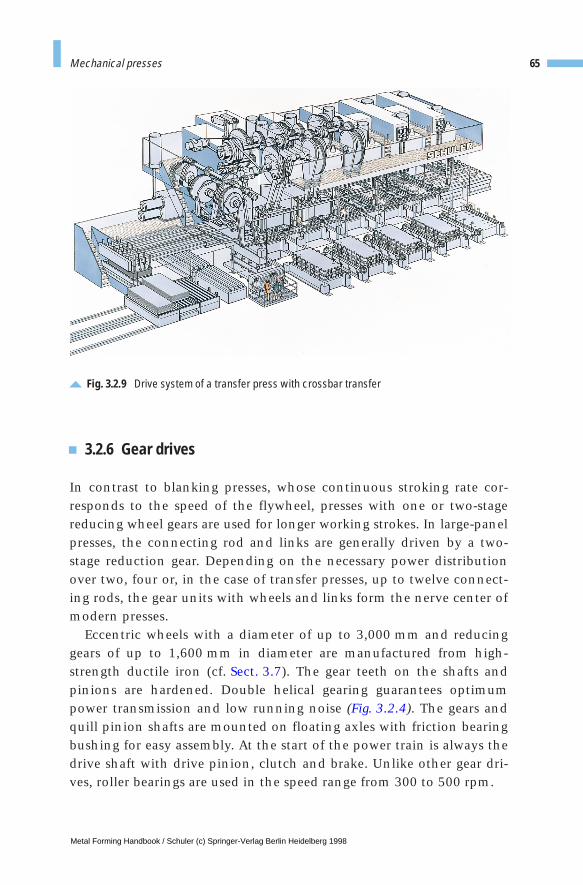
3.2.6 Gear drives
In contrast to blanking presses, whose continuous stroking rate cor-responds to the speed of the flywheel, presses with one or two-stagereducing wheel gears are used for longer working strokes. In large-panelpresses, the connecting rod and links are generally driven by a two-stage reduction gear. Depending on the necessary power distributionover two, four or, in the case of transfer presses, up to twelve connect-ing rods, the gear units with wheels and links form the nerve center ofmodern presses.
Eccentric wheels with a diameter of up to 3,000 mm and reducinggears of up to 1,600 mm in diameter are manufactured from high-strength ductile iron (cf. Sect. 3.7). The gear teeth on the shafts andpinions are hardened. Double helical gearing guarantees optimumpower transmission and low running noise (Fig. 3.2.4). The gears andquill pinion shafts are mounted on floating axles with friction bearingbushing for easy assembly. At the start of the power train is always thedrive shaft with drive pinion, clutch and brake. Unlike other gear dri-ves, roller bearings are used in the speed range from 300 to 500 rpm.
65Mechanical presses
Fig. 3.2.9 Drive system of a transfer press with crossbar transfer
Metal Forming Handbook / Schuler (c) Springer-Verlag Berlin Heidelberg 1998
3.2.7 Press crown assembly
The connecting rod, links, gears and main drive system determine thecapacity and the size of the press crown. The welded components weighup to 150 t, as do the mounted gear drive elements contained in thecrown of a large-panel press.
The dimensional limits of such large-scale parts are around 6,000 33,600 3 12,000 mm, whereby width, height and weight depend on thepossibilities offered for road transport on low-bed trucks – which gen-erally require special authorization. Waterways represent a less difficultmethod of transporting this type of components.
Stress-relief annealing of large welded assemblies and also machiningon drilling centers is restricted to a maximum length of 12 m. The entireproblem of transport logistics plays a major role in large-panel pressdesign and must be taken into consideration right from the planningstage.
3.2.8 Slide and blank holder
The rotary motion generated by the press drive is transmitted to thelinear motion of the slide and blank holder using a suitable speed andforce progression. The most important functional units, particularly inlarge-panel presses, are the pressure points containing slide adjustmentand an overload safety device.
Slide adjustmentIn individual presses, pressure points with a slide adjustment of up to600 mm are used in the main spindle in order to adjust the press shutheight to various die heights (Fig. 3.2.10). In universal and transferpresses, slide adjustment distances of 150 mm are sufficient. In thiscase, pressure points with a low overall height are useful. Using brakemotors and worm gears, adjusting speeds of 60 mm/min are obtained.With multiple-stage presses used for solid forming, to achieve high stiff-ness, wedge adjustments are frequently used in the die set or at the slideclamping plate. In this case, a slide adjustment is no longer necessary.
66 Fundamentals of press design
Metal Forming Handbook / Schuler (c) Springer-Verlag Berlin Heidelberg 1998

Overload safety devicesThe nominal force of the press is limited and safeguarded by thehydraulic overload safety device in the slide. If the nominal press forceis exceeded, the pressure exerted on a hydraulic cushion integrated inthe pressure point is quickly relieved, allowing an overload displace-ment.
For blank holders used in double-acting mechanical presses, the over-load safety function is coupled to the adjustment function of the blankholder force. The overload safety function is activated only when thedeflection of the four blank holder pressure points has exceeded a per-missible magnitude of approx. 3 mm. The safety function is actuated byan air-hydraulic pressure scale. By changing the compressed air setting,the blank holder force can be adjusted to the requirements of the die atthe four pressure points within a range of 40 to 100 %.
Slide counterbalanceThe slide weight is compensated by the slide counterbalance system.Thus, the weight of all moving parts such as joints, connecting rods, the slide and upper die, is balanced out by pneumatic cylinders (Fig. 3.2.11). As a result, the drive system is largely free of gravity forces.There are no stresses acting on the slide adjustment and there is an addi-
67Mechanical presses
slideadjustmentdevice
connecting rod
wrist pin
adjustment nut
overload bolt
oil cushion
pressure pad
adjustment spindle
adjustment device
connecting rod
wrist pin
adjustment nut
adjustment pad
overload bolt
oil cushion
Fig. 3.2.10 Spindle (left) and pressure point (right)
Metal Forming Handbook / Schuler (c) Springer-Verlag Berlin Heidelberg 1998
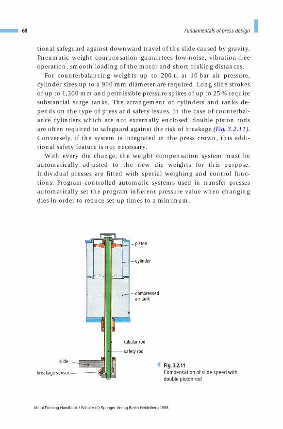
tional safeguard against downward travel of the slide caused by gravity.Pneumatic weight compensation guarantees low-noise, vibration-freeoperation, smooth loading of the motor and short braking distances.
For counterbalancing weights up to 200 t, at 10 bar air pressure,cylinder sizes up to a 900 mm diameter are required. Long slide strokesof up to 1,300 mm and permissible pressure spikes of up to 25 % requiresubstantial surge tanks. The arrangement of cylinders and tanks de-pends on the type of press and safety issues. In the case of counterbal-ance cylinders which are not externally enclosed, double piston rodsare often required to safeguard against the risk of breakage (Fig. 3.2.11).Conversely, if the system is integrated in the press crown, this addi-tional safety feature is not necessary.
With every die change, the weight compensation system must beautomatically adjusted to the new die weights for this purpose.Individual presses are fitted with special weighing and control func-tions. Program-controlled automatic systems used in transfer pressesautomatically set the program inherent pressure value when changingdies in order to reduce set-up times to a minimum.
68 Fundamentals of press design
slide
breakage sensor
tubular rod
safety rod
piston
cylinder
compressedair tank
Fig. 3.2.11Compensation of slide speed with double piston rod
Metal Forming Handbook / Schuler (c) Springer-Verlag Berlin Heidelberg 1998
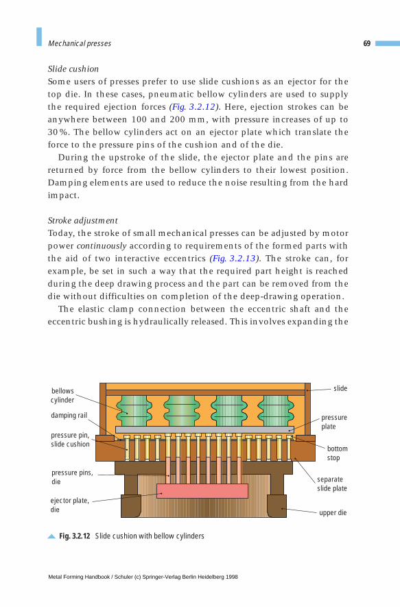
Slide cushionSome users of presses prefer to use slide cushions as an ejector for thetop die. In these cases, pneumatic bellow cylinders are used to supplythe required ejection forces (Fig. 3.2.12). Here, ejection strokes can beanywhere between 100 and 200 mm, with pressure increases of up to 30%. The bellow cylinders act on an ejector plate which translate theforce to the pressure pins of the cushion and of the die.
During the upstroke of the slide, the ejector plate and the pins arereturned by force from the bellow cylinders to their lowest position.Damping elements are used to reduce the noise resulting from the hardimpact.
Stroke adjustmentToday, the stroke of small mechanical presses can be adjusted by motorpower continuously according to requirements of the formed parts withthe aid of two interactive eccentrics (Fig. 3.2.13). The stroke can, forexample, be set in such a way that the required part height is reachedduring the deep drawing process and the part can be removed from thedie without difficulties on completion of the deep-drawing operation.
The elastic clamp connection between the eccentric shaft and theeccentric bushing is hydraulically released. This involves expanding the
69Mechanical presses
bellowscylinder
damping rail
pressure pin,slide cushion
pressure pins,die
ejector plate,die
separateslide plate
pressureplate
bottomstop
slide
upper die
Fig. 3.2.12 Slide cushion with bellow cylinders
Metal Forming Handbook / Schuler (c) Springer-Verlag Berlin Heidelberg 1998
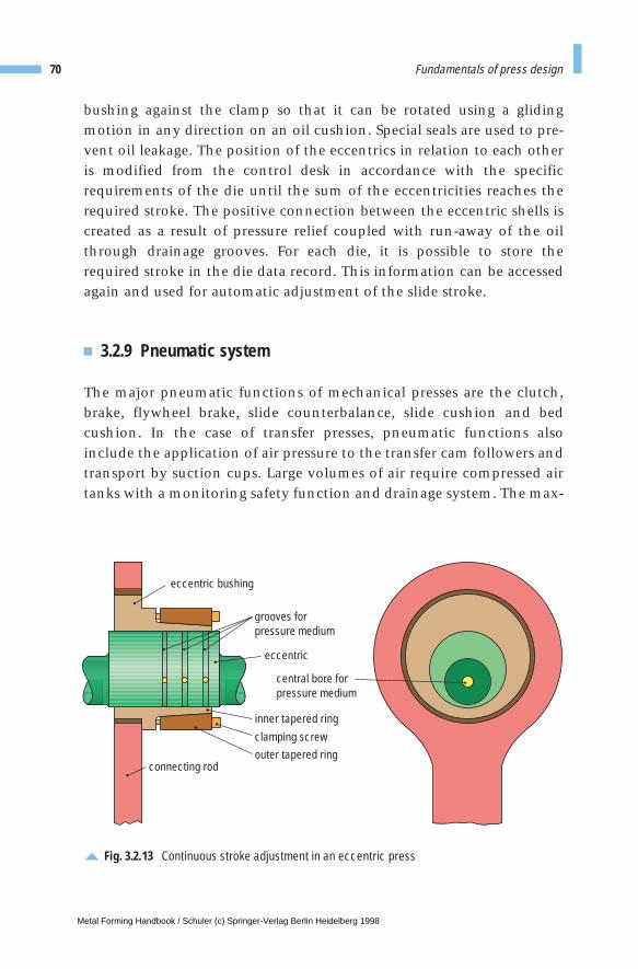
bushing against the clamp so that it can be rotated using a glidingmotion in any direction on an oil cushion. Special seals are used to pre-vent oil leakage. The position of the eccentrics in relation to each otheris modified from the control desk in accordance with the specificrequirements of the die until the sum of the eccentricities reaches therequired stroke. The positive connection between the eccentric shells iscreated as a result of pressure relief coupled with run-away of the oilthrough drainage grooves. For each die, it is possible to store therequired stroke in the die data record. This information can be accessedagain and used for automatic adjustment of the slide stroke.
3.2.9 Pneumatic system
The major pneumatic functions of mechanical presses are the clutch,brake, flywheel brake, slide counterbalance, slide cushion and bedcushion. In the case of transfer presses, pneumatic functions alsoinclude the application of air pressure to the transfer cam followers andtransport by suction cups. Large volumes of air require compressed airtanks with a monitoring safety function and drainage system. The max-
70 Fundamentals of press design
eccentric
eccentric bushing
inner tapered ring
outer tapered ringclamping screw
central bore forpressure medium
connecting rod
grooves forpressure medium
Fig. 3.2.13 Continuous stroke adjustment in an eccentric press
Metal Forming Handbook / Schuler (c) Springer-Verlag Berlin Heidelberg 1998
imum pneumatic pressure is generally 6 bar, although high-pressurenetworks or compressors producing a maximum of 16 bar are increas-ingly employed.
The engineering of these auxiliary units is determined by valid stan-dards and legal requirements. In general, galvanized gas lines between1'' and 6'' are used for installation purposes. Smaller lines are configuredusing steel piping and cutting ring or beaded unions. The installationrequired for a large-panel transfer press with a structural volume ofaround 40 3 10 3 15 m can comprise up 40 t, including compressed airtank, pipes and appliances.
3.2.10 Hydraulic system
The use of hydraulics in mechanical press construction is relativelyminimal. Standard use of hydraulic engineering in this type of press isrestricted to the hydraulic overload safeguard, raising the moving bol-ster and hydraulic die clamping systems. All these functions are gener-ally supplied from a central hydraulic unit. In the case of transfer press-es, these basic functions are complemented by other functions such asengagement of the clutch between the press and transfer drive systemsand the comprehensive system of scrap ejection flaps. In addition, var-ious clamping and locking devices around the press are hydraulicallydriven.
The most important function in mechanical presses, engaging andbraking the slide drive system, is being increasingly done by hydraulicmeans. The use of hydraulics permits higher switching frequencies insingle presses and is also more environmentally friendly in terms ofnoise and air pollution.
The clutch and brake are supplied by a central hydraulic unitequipped with a cooling system. A dual-channel safety control withregulated damping facility and pressure filtration to 10 µm is required.
The increased use of deep drawing with single-acting presses placesparticularly stringent demands on the blankholding function and thusthe draw cushion in the press bed (cf. Sect. 3.1.4), particularly in large-panel presses. Multiple-point bed cushions with pressure control capa-bility are then only possible using a complex servo hydraulic system.
71Mechanical presses
Metal Forming Handbook / Schuler (c) Springer-Verlag Berlin Heidelberg 1998

This requires separate supply units with oil tank, pump outputs ofapprox. 150 kW and oil flow rates of approx. 1,000 l/min for the drawcushion. Control is performed using proportional valves complying toDIN and ISO standards in the pressure range up to 300 bar.
3.2.11 Lubrication
The complex lubrication systems used to supply the lubrication pointsin mechanical presses are substantially simplified by using valve blocks(cf. Fig. 3.3.4). The system most commonly used here consists of paral-lel-switching progressive distributors. Allocation of the required quan-tity of lubricant is aided by volume controllers, dividers and similar ele-ments. The flow of oil is monitored at the distributor blocks. To ensureoptimum operating conditions, a control system regulates the temper-ature of the lubricant within a relatively narrow bandwidth by usingauxiliary heating and cooling functions.
To guarantee maximum operating safety, complex production instal-lations for metal forming are always fitted with twin supply unit ele-ments such as pumps and filters. If one pump fails, there is no need tointerrupt production, as the second system cuts in automatically.Maintenance or exchange of the defective system does not result inproduction standstill, increasing uptime. The quality of the oil is safe-guarded by supplementary filtration in the secondary circuit, increas-ing its service life.
In smaller presses, and in particular by knuckle-joint presses withbottom drive, central lubrication systems with multiple-circuit gearedpumps are used. Up to 20 main lubrication points are continuouslysupplied directly by the gear stages with a constant supply of oil.During the short swivel movements executed by the thrust elementsand joints, a constant flow of lubricant is available even under varyingresistance levels in the individual user and supply lines.
72 Fundamentals of press design
Metal Forming Handbook / Schuler (c) Springer-Verlag Berlin Heidelberg 1998
3 Fundamentals of press design
3.3 Hydraulic presses
3.3.1 Drive system
Hydraulic presses operate on the physical principle that a hydrostaticpressure is distributed evenly through a system of pipes, and that a pres-sure p [N/m2], acting on a surface A [m2], produces a force F [N]:
The force acting on the slide of the press depends on the forming orblanking process performed. For this reason, the pressure p acting onthe piston surface is also a function of the deformation process con-ducted. Its measurement may be used directly to calculate the force act-ing on the slide. The maximum slide force can be selected by limitingthe maximum hydraulic pressure through a relief valve at any positionof the slide.
The drive power P [W] of a hydraulic press depends on the volumetricflow of hydraulic fluid V [m3/s] and therefore on the speed of the slideas well as on the hydraulic pressure p, the forces at the slide, and themechanical and electrical losses hges :
In contrast to mechanical presses, there is generally no reserve of ener-gy available in hydraulic presses. Thus, the entire power must beapplied when carrying out the forming operation. For this reason,hydraulic presses require a significantly higher drive power than inmechanical presses, with comparable force capacity (cf. Sect. 4.4.1).
·
F p A= ⋅
PV p
ges
= ⋅˙
η
Metal Forming Handbook / Schuler (c) Springer-Verlag Berlin Heidelberg 1998
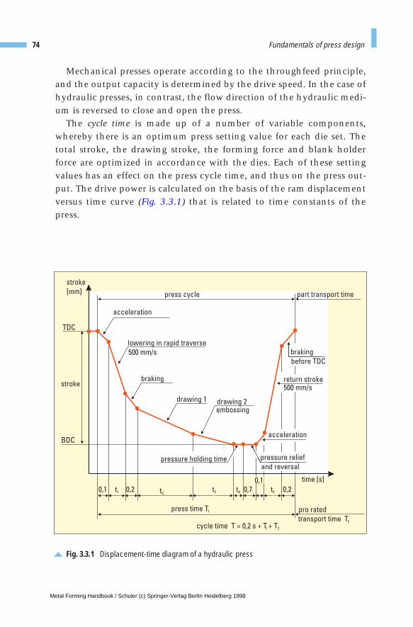
74 Fundamentals of press design
Mechanical presses operate according to the throughfeed principle,and the output capacity is determined by the drive speed. In the case ofhydraulic presses, in contrast, the flow direction of the hydraulic medi-um is reversed to close and open the press.
The cycle time is made up of a number of variable components,whereby there is an optimum press setting value for each die set. Thetotal stroke, the drawing stroke, the forming force and blank holderforce are optimized in accordance with the dies. Each of these settingvalues has an effect on the press cycle time, and thus on the press out-put. The drive power is calculated on the basis of the ram displacementversus time curve (Fig. 3.3.1) that is related to time constants of thepress.
Fig. 3.3.1 Displacement-time diagram of a hydraulic press
2 3 4 5
stroke
stroke
[mm] part transport time
transport time T2
press cycle
acceleration
lowering in rapid traverse
500 mm/s
braking
drawing 1 drawing 2
braking
before TDC
embossing
return stroke500 mm/s
acceleration
time [s]
0,1 0,2 0,7 0,2
TDC
BDC
t1
pro ratedpress time T1
cycle time T = 0,2 s + T + T1 2
pressure holding timeand reversal
pressure relief
0,1
t2t3 t4 t5
Metal Forming Handbook / Schuler (c) Springer-Verlag Berlin Heidelberg 1998
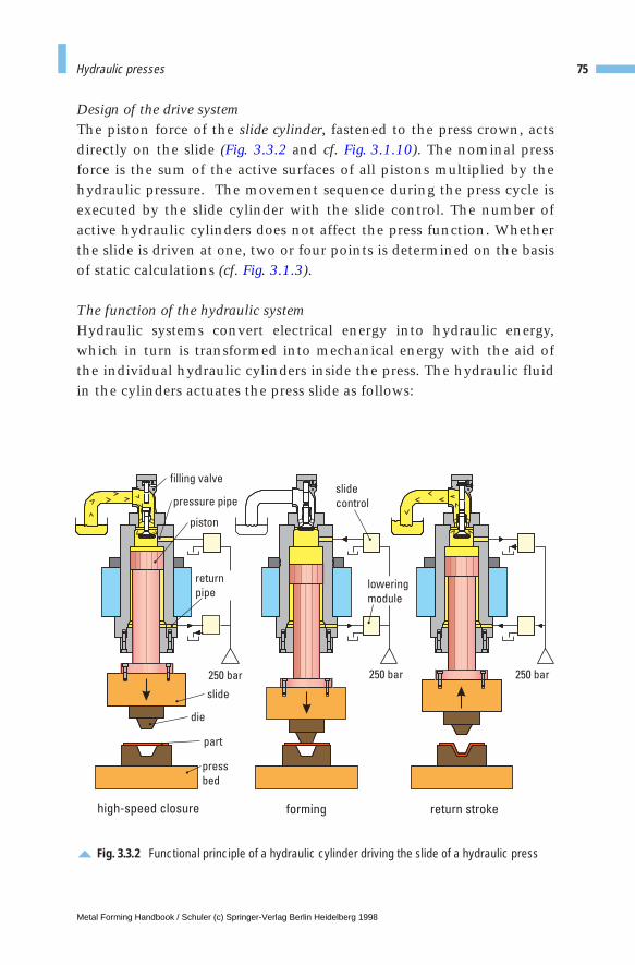
75Hydraulic presses
Design of the drive systemThe piston force of the slide cylinder, fastened to the press crown, actsdirectly on the slide (Fig. 3.3.2 and cf. Fig. 3.1.10). The nominal pressforce is the sum of the active surfaces of all pistons multiplied by thehydraulic pressure. The movement sequence during the press cycle isexecuted by the slide cylinder with the slide control. The number ofactive hydraulic cylinders does not affect the press function. Whetherthe slide is driven at one, two or four points is determined on the basisof static calculations (cf. Fig. 3.1.3).
The function of the hydraulic systemHydraulic systems convert electrical energy into hydraulic energy,which in turn is transformed into mechanical energy with the aid ofthe individual hydraulic cylinders inside the press. The hydraulic fluidin the cylinders actuates the press slide as follows:
Fig. 3.3.2 Functional principle of a hydraulic cylinder driving the slide of a hydraulic press
high-speed closure forming return stroke
250 bar 250 bar 250 bar
slide
control
filling valve
piston
die
part
slide
press
bed
pressure pipe
lowering
module
return
pipe
Metal Forming Handbook / Schuler (c) Springer-Verlag Berlin Heidelberg 1998
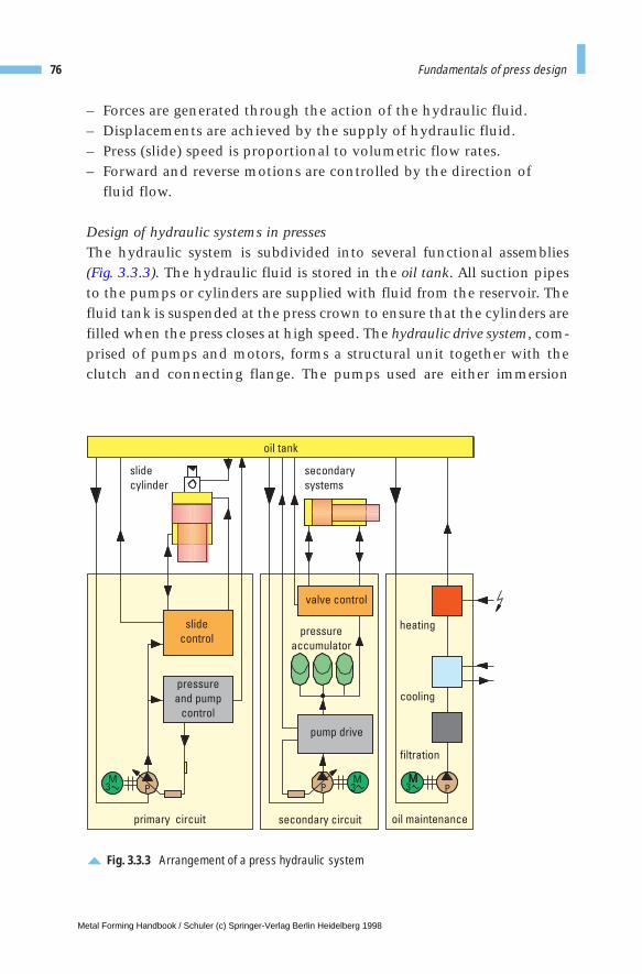
76 Fundamentals of press design
– Forces are generated through the action of the hydraulic fluid.– Displacements are achieved by the supply of hydraulic fluid.– Press (slide) speed is proportional to volumetric flow rates.– Forward and reverse motions are controlled by the direction of
fluid flow.
Design of hydraulic systems in pressesThe hydraulic system is subdivided into several functional assemblies(Fig. 3.3.3). The hydraulic fluid is stored in the oil tank. All suction pipesto the pumps or cylinders are supplied with fluid from the reservoir. Thefluid tank is suspended at the press crown to ensure that the cylinders arefilled when the press closes at high speed. The hydraulic drive system, com-prised of pumps and motors, forms a structural unit together with theclutch and connecting flange. The pumps used are either immersion
Fig. 3.3.3 Arrangement of a press hydraulic system
oil tank
slide
cylinder
secondary
systems
valve control
slide
controlheating
cooling
filtration
PM333MMM
pressure
and pump
control
pump drive
PP
primary circuit secondary circuit oil maintenance
pressure
accumulator
Metal Forming Handbook / Schuler (c) Springer-Verlag Berlin Heidelberg 1998

pumps suspended in the oil tank, or they are mounted on supports in thepress foundation. The motors drive the pumps via an elastic clutch. Thepumps are supplied by suction pipes, and the hydraulic fluid is conveyedto the valve control by means of high-pressure pipes. The valve controlsystem guides the hydraulic fluid to the appropriate units. Depending onthe function in question, the hydraulic cylinders are extended or retract-ed, moved actively or passively in the press. The return flow is guidedback to the oil tank. The consumers, cylinders or hydraulic motors, movethe slide or cushions, or adjust spindles. They generate forces, lift loads orclamp the dies. The service unit operates in a bypass circuit away from themain hydraulic flow. In this unit, the fluid is recirculated by means of fil-ters and coolers in a separate circuit, purifying and cooling it to ensurethat the press remains ready for production at all times.
Pressure accumulator drive systemIf the pump conveys the fluid to a pressure accumulator, it is possible tosmooth out the energy delivery from the main electrical net. Largequantities of hydraulic oil can be drawn from the pressure accumulatorfor a short time, which has to be replenished by the pump before thenext press cycle. If the extraction of hydraulic oil is followed by a longidle period, the accumulator can be supplied by a small pump – forexample when loading and unloading the die after retraction of theslide. However, for processes requiring large quantities of hydraulic fluidto be drawn in quick succession, a higher delivery power must be avail-able – for example a drawing operation followed by the opening of thepress. For the second example, a pressure accumulator-type drive sys-tem is not suitable, since not only a large accumulator system but alsoa large pump is required. Draw presses involve short cycle and transporttimes which often cannot be achieved using an accumulator drive sys-tem. Table 3.3.1 demonstrates additional differences between pumpand accumulator drive systems.
3.3.2 Hydraulic oil
Hydraulic systems in presses are operated using standard hydraulic oil(HLP) according to DIN 51524 Part 2. Hydraulic oils are required tocomply with strict standards:
77Hydraulic presses
Metal Forming Handbook / Schuler (c) Springer-Verlag Berlin Heidelberg 1998

78 Fundamentals of press design
– lubrication and wear protection,– constant viscosity level at temperatures between 20 and 60 °C,– resistance to temperature,– low compressibility,– low foaming characteristics,– low absorption of air,– good rust protection,– good filtration properties,– low cost.
All hydraulic units are designed for use with hydraulic oils conformingto these standards. Characteristics, life expectancy and pressure ranges,as well as the choice of seals and gaskets correspond to the oil type used.Due to the compressibility of hydraulic oil, the volume of hydraulic fluidchanges under pressure. As pressure is increased, the fluid column iscompressed. This property affects the control and regulating functionsin the press: the higher the pressure, the longer the response time.When calculating cycle times or determining the use of different drivesystems, the compressibility factor must be taken into account, as thishas a pronounced effect, particularly where short forming strokes areinvolved, for example when blanking or coining. In the case of mineraloils, a compressibility factor of 0.7 to 0.8 % per 100 bar oil pressure canbe expected. This property of hydraulic fluids also affects the release of
Table 3.3.1: Comparison of hydraulic drive systems
Pump drive system
The installed pump capacity determines theachievable speeds with the motor output.
Requirement-oriented hydraulic oil deliveryresults in peak loads on the electrical mains.
Work capacity is unlimited, as the pressingforce is available over the entire stroke.
The system pressure corresponds directly tothe power requirement of the die.
The pressing force can be simply limited bymeans of pressure reducing valves.
Pressure accumulator drive system
Speeds are determined by valve cross-sectionsand the pressure head.
Continuous hydraulic oil delivery exerts an evendegree of stress on the mains.
Work capacity is limited by the available usefulvolume of the accumulator.
Pump pressure corresponds to the accumulatorboost pressure. In case of a lower energyrequirement, excess energy is converted intoheat.
It is not possible to regulate the pressure of an accumulator, which always operates at fullcapacity.
Metal Forming Handbook / Schuler (c) Springer-Verlag Berlin Heidelberg 1998
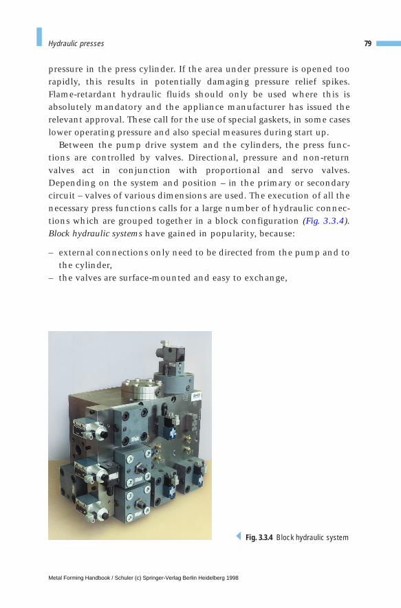
79Hydraulic presses
pressure in the press cylinder. If the area under pressure is opened toorapidly, this results in potentially damaging pressure relief spikes.Flame-retardant hydraulic fluids should only be used where this isabsolutely mandatory and the appliance manufacturer has issued therelevant approval. These call for the use of special gaskets, in some caseslower operating pressure and also special measures during start up.
Between the pump drive system and the cylinders, the press func-tions are controlled by valves. Directional, pressure and non-returnvalves act in conjunction with proportional and servo valves.Depending on the system and position – in the primary or secondarycircuit – valves of various dimensions are used. The execution of all thenecessary press functions calls for a large number of hydraulic connec-tions which are grouped together in a block configuration (Fig. 3.3.4).Block hydraulic systems have gained in popularity, because:
– external connections only need to be directed from the pump and tothe cylinder,
– the valves are surface-mounted and easy to exchange,
Fig. 3.3.4 Block hydraulic system
Metal Forming Handbook / Schuler (c) Springer-Verlag Berlin Heidelberg 1998

– their nature inevitably results in a standardization process: the valveblocks do not need to be redesigned for each different press,
– all the valves are brought together to create a functional assembly ona single block,
– integrated valves are sensibly combined with space-saving, low-costauxiliary valves,
– troubleshooting is simplified by the presence of drilled-in functionaland test connections.
3.3.3 Parallelism of the slide
The capacity of the press frame to absorb eccentric loads plays a majorrole. Eccentric forces occur during the forming process when the load ofthe resulting die force is not exerted centrally on the slide, causing it totilt (Fig. 3.3.5). The standard press is able to absorb a maximum eccen-tric moment of load of
via the slide gibs. This results in a maximum slide tilt of 0.8 mm/m. If ahigher off center loading capability is desired, then the press designmust be more rigid. In this case, the slide gibs will have greater stability,the press frame will be more rigid, and the slide will be higher.
If it is not economically possible to achieve the allowable amount ofslide tilt within the required limits by increasing press rigidity, it is nec-essary to use hydraulic parallelism control systems, using electroniccontrol technology (Fig. 3.3.5), for example in the case of hydraulictransfer presses (cf. Fig. 4.4.14). The parallelism control systems act in thedie mounting area to counter slide tilt. Position measurement sensorsmonitor the position of the slide and activate the parallelism controlsystem (Fig. 3.3.5). The parallelism controlling cylinders act on the cor-ners of the slide plate and they are pushed during the forming processagainst a centrally applied pressure. If the electronic parallelism moni-tor sensor detects a position error, the pressure on the leading side isincreased by means of servo valves, and at the same time reduced onthe opposite side to the same degree. The sum of exerted parallelism
80 Fundamentals of press design
M m F kNm
MM
kNm
x N
yx
= ⋅ [ ]
= [ ]
0 075
2
0.
Metal Forming Handbook / Schuler (c) Springer-Verlag Berlin Heidelberg 1998
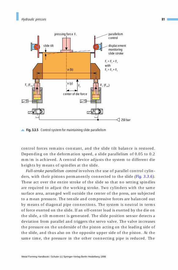
control forces remains constant, and the slide tilt balance is restored.Depending on the deformation speed, a slide parallelism of 0.05 to 0.2mm/m is achieved. A central device adjusts the system to different dieheights by means of spindles at the slide.
Full-stroke parallelism control involves the use of parallel control cylin-ders, with their pistons permanently connected to the slide (Fig. 3.3.6).These act over the entire stroke of the slide so that no setting spindlesare required to adjust the working stroke. Two cylinders with the samesurface area, arranged well outside the center of the press, are subjectedto a mean pressure. The tensile and compressive forces are balanced outby means of diagonal pipe connections. The system is neutral in termsof force exerted on the slide. If an off-center load is exerted by the die onthe slide, a tilt moment is generated. The slide position sensor detects adeviation from parallel and triggers the servo valve. The valve increasesthe pressure on the underside of the piston acting on the leading side ofthe slide, and thus also on the opposite upper side of the piston. At thesame time, the pressure in the other connecting pipe is reduced. The
81Hydraulic presses
Fig. 3.3.5 Control system for maintaining slide parallelism
I PI P
F = F + Fwith F = F + F
1 2 3
3 4 5
F4 F5
F1
F2
slide tilt
pressing force parallelismcontrol
displacementmonitoringslide stroke
(F )min
center of die force
250 bar
(F )maxx (y)
a (b)
Metal Forming Handbook / Schuler (c) Springer-Verlag Berlin Heidelberg 1998
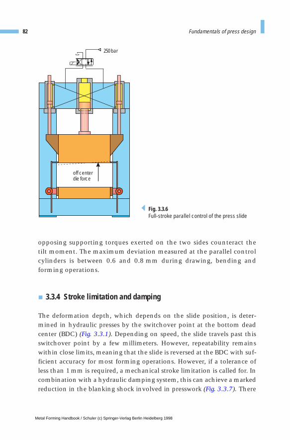
opposing supporting torques exerted on the two sides counteract thetilt moment. The maximum deviation measured at the parallel controlcylinders is between 0.6 and 0.8 mm during drawing, bending andforming operations.
3.3.4 Stroke limitation and damping
The deformation depth, which depends on the slide position, is deter-mined in hydraulic presses by the switchover point at the bottom deadcenter (BDC) (Fig. 3.3.1). Depending on speed, the slide travels past thisswitchover point by a few millimeters. However, repeatability remainswithin close limits, meaning that the slide is reversed at the BDC with suf-ficient accuracy for most forming operations. However, if a tolerance ofless than 1 mm is required, a mechanical stroke limitation is called for. Incombination with a hydraulic damping system, this can achieve a markedreduction in the blanking shock involved in presswork (Fig. 3.3.7). There
82 Fundamentals of press design
250 bar
off centerdie force
Fig. 3.3.6Full-stroke parallel control of the press slide
Metal Forming Handbook / Schuler (c) Springer-Verlag Berlin Heidelberg 1998
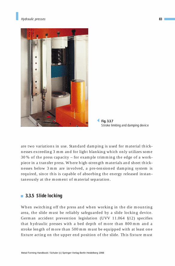
are two variations in use. Standard damping is used for material thick-nesses exceeding 3 mm and for light blanking which only utilizes some30 % of the press capacity – for example trimming the edge of a work-piece in a transfer press. Where high-strength materials and sheet thick-nesses below 3 mm are involved, a pre-tensioned damping system isrequired, since this is capable of absorbing the energy released instan-taneously at the moment of material separation.
3.3.5 Slide locking
When switching off the press and when working in the die mountingarea, the slide must be reliably safeguarded by a slide locking device.German accident prevention legislation (UVV 11.064 §12) specifiesthat hydraulic presses with a bed depth of more than 800 mm and astroke length of more than 500 mm must be equipped with at least onefixture acting on the upper end position of the slide. This fixture must
83Hydraulic presses
Fig. 3.3.7Stroke limiting and damping device
Metal Forming Handbook / Schuler (c) Springer-Verlag Berlin Heidelberg 1998
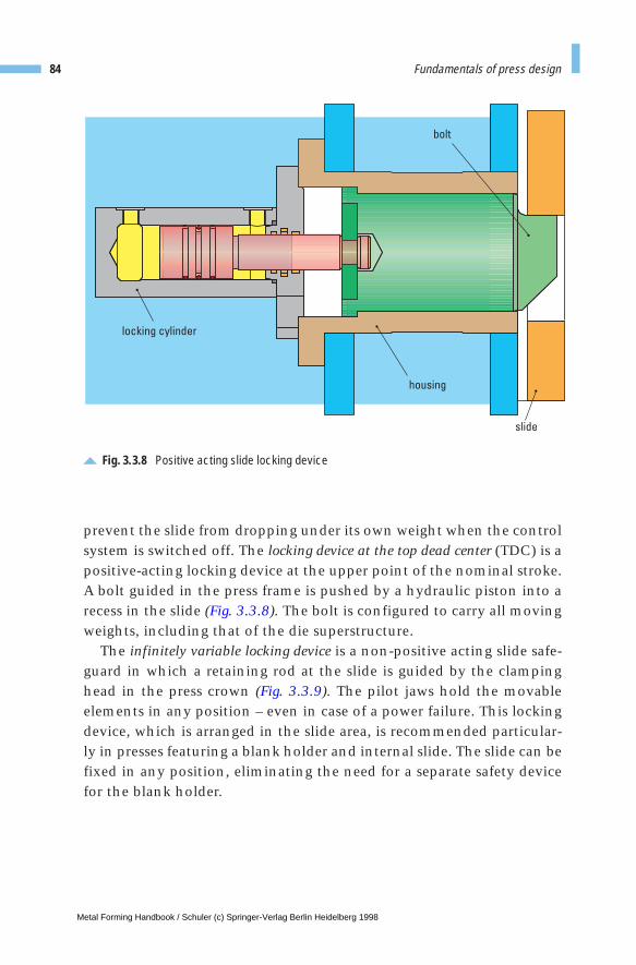
prevent the slide from dropping under its own weight when the controlsystem is switched off. The locking device at the top dead center (TDC) is apositive-acting locking device at the upper point of the nominal stroke.A bolt guided in the press frame is pushed by a hydraulic piston into arecess in the slide (Fig. 3.3.8). The bolt is configured to carry all movingweights, including that of the die superstructure.
The infinitely variable locking device is a non-positive acting slide safe-guard in which a retaining rod at the slide is guided by the clampinghead in the press crown (Fig. 3.3.9). The pilot jaws hold the movableelements in any position – even in case of a power failure. This lockingdevice, which is arranged in the slide area, is recommended particular-ly in presses featuring a blank holder and internal slide. The slide can befixed in any position, eliminating the need for a separate safety devicefor the blank holder.
84 Fundamentals of press design
Fig. 3.3.8 Positive acting slide locking device
bolt
locking cylinder
housing
slide
Metal Forming Handbook / Schuler (c) Springer-Verlag Berlin Heidelberg 1998
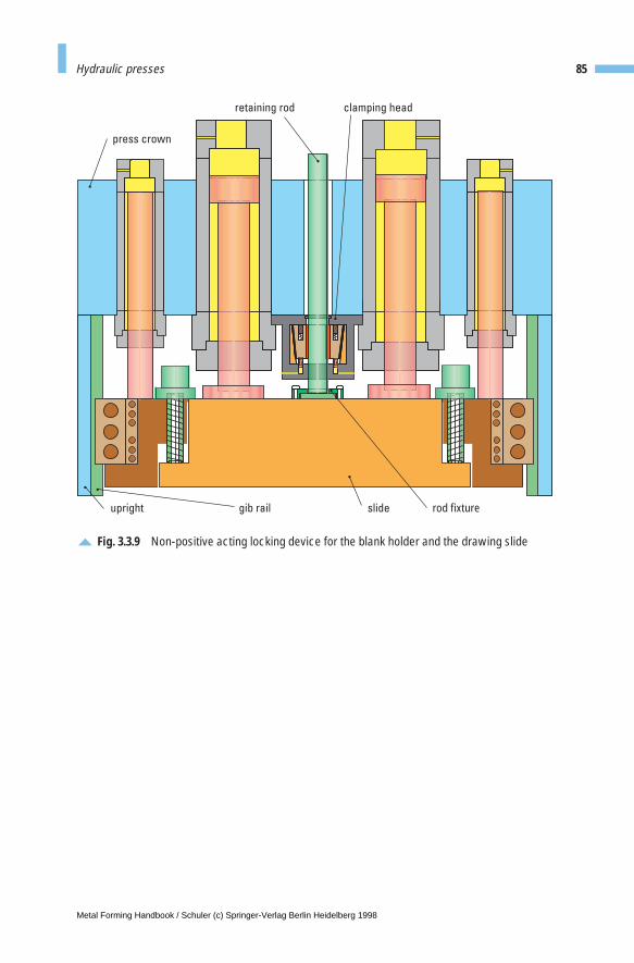
85Hydraulic presses
Fig. 3.3.9 Non-positive acting locking device for the blank holder and the drawing slide
upright slidegib rail
press crown
rod fixture
clamping headretaining rod
Metal Forming Handbook / Schuler (c) Springer-Verlag Berlin Heidelberg 1998
3 Fundamentals of press design
3.4 Changing dies
3.4.1 Die handling
Devices used for the fast exchange of dies help to reduce set-up times,allowing the economical production of different components evenwhere small batch sizes are required. Small and medium-sized formingand blanking dies are transported within the stamping plant usingcranes, forklifts or other industrial trucks. The transportation of larger-scale dies into the press and their alignment call for special die chang-ing fixtures, as the dies cannot be deposited directly on the press bed.Trouble-free die change is only possible if the upper and lower dies areperfectly centered. In addition, it must be possible to deposit the diesoutside the press. The purpose of die changing fixtures is to simplifyand accelerate transport into the die mounting area, to ensure simplehandling of the pressure pins for the draw cushion, and to permit fast,reliable clamping of dies.
Swivelling bracketsA swivelling bracket is a low-cost die changing fixture for the transport ofthe die into the press. Such fixtures can be used up to a die weight ofaround 6 t. In the case of dies weighing up to around 2 t, insertablebrackets suspended from retaining hooks located in the press bed areused. When higher die weights are involved, support feet, where possi-ble fitted with rollers, are essential. Double-jointed swivelling bracketscan be turned into a parked position after die change (Fig. 3.4.1). It ispossible for dies to be manually pushed into position by one person up
Metal Forming Handbook / Schuler (c) Springer-Verlag Berlin Heidelberg 1998
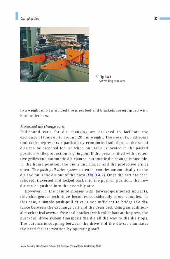
to a weight of 3 t provided the press bed and brackets are equipped withhard roller bars.
Motorized die change cartsRail-bound carts for die changing are designed to facilitate theexchange of tools up to around 20 t in weight. The use of two adjacenttool tables represents a particularly economical solution, as the set ofdies can be prepared for use when one table is located in the parkedposition while production is going on. If the press is fitted with protec-tive grilles and automatic die clamps, automatic die change is possible.In the home position, the die is unclamped and the protective grillesopen. The push-pull drive system extends, couples automatically to thedie and pulls the die out of the press (Fig. 3.4.2). Once the cart has beenreleased, traversed and locked back into the push-in position, the newdie can be pushed into the assembly area.
However, in the case of presses with forward-positioned uprights,this changeover technique becomes considerably more complex. Inthis case, a simple push-pull drive is not sufficient to bridge the dis-tance between the exchange cart and the press bed. Using an addition-al mechanical overrun drive and brackets with roller bars at the press, thepush-pull drive system transports the die all the way to the die stops.The automatic coupling between the drive and the die-set eliminatesthe need for intervention by operating staff.
87Changing dies
Fig. 3.4.1Swivelling brackets
Metal Forming Handbook / Schuler (c) Springer-Verlag Berlin Heidelberg 1998
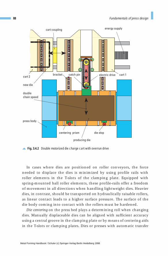
In cases where dies are positioned on roller conveyors, the forceneeded to displace the dies is minimized by using profile rails withroller elements in the T-slots of the clamping plate. Equipped withspring-mounted ball roller elements, these profile-rails offer a freedomof movement in all directions when handling lightweight dies. Heavierdies, in contrast, should be transported on hydraulically raisable rollers,as linear contact leads to a higher surface pressure. The surface of thedie body coming into contact with the rollers must be hardened.
Die centering on the press bed plays a determining roll when changingdies. Manually displaceable dies can be aligned with sufficient accuracyusing a central groove in the clamping plate or by means of centering aidsin the T-slots or clamping plates. Dies or presses with automatic transfer
88 Fundamentals of press design
Fig. 3.4.2 Double motorized die charge cart with overrun drive
cart coupling energy supply
cart 1electric drivecatch pinbracketcart 2
new die
press body
centering prism die stop
producing die
double
chain speed
Metal Forming Handbook / Schuler (c) Springer-Verlag Berlin Heidelberg 1998
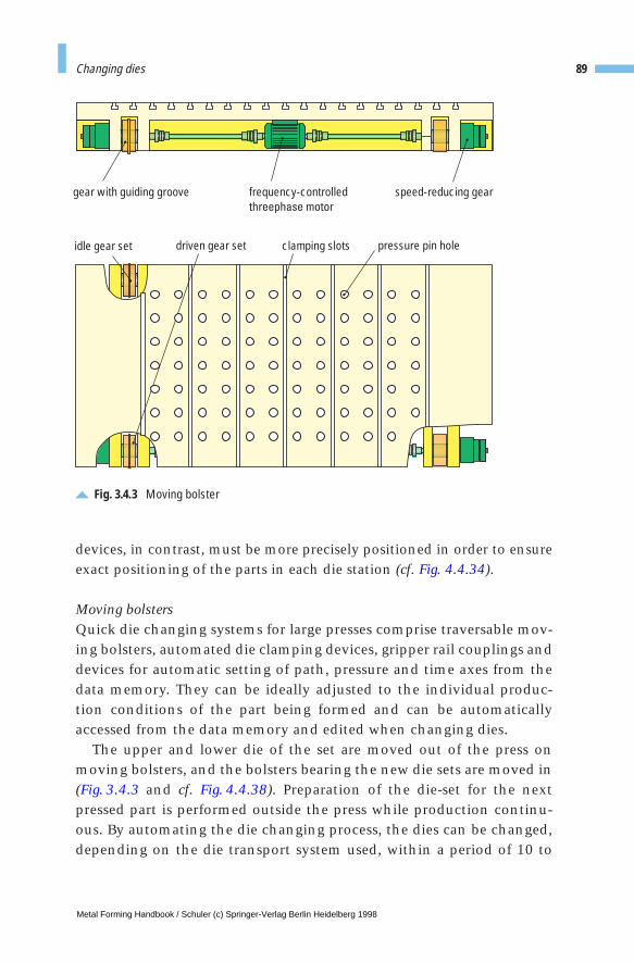
devices, in contrast, must be more precisely positioned in order to ensureexact positioning of the parts in each die station (cf. Fig. 4.4.34).
Moving bolstersQuick die changing systems for large presses comprise traversable mov-ing bolsters, automated die clamping devices, gripper rail couplings anddevices for automatic setting of path, pressure and time axes from thedata memory. They can be ideally adjusted to the individual produc-tion conditions of the part being formed and can be automaticallyaccessed from the data memory and edited when changing dies.
The upper and lower die of the set are moved out of the press onmoving bolsters, and the bolsters bearing the new die sets are moved in(Fig. 3.4.3 and cf. Fig. 4.4.38). Preparation of the die-set for the nextpressed part is performed outside the press while production continu-ous. By automating the die changing process, the dies can be changed,depending on the die transport system used, within a period of 10 to
89Changing dies
Fig. 3.4.3 Moving bolster
frequency-controlledthreephase motor
speed-reducing geargear with guiding groove
driven gear setidle gear set clamping slots pressure pin hole
Metal Forming Handbook / Schuler (c) Springer-Verlag Berlin Heidelberg 1998
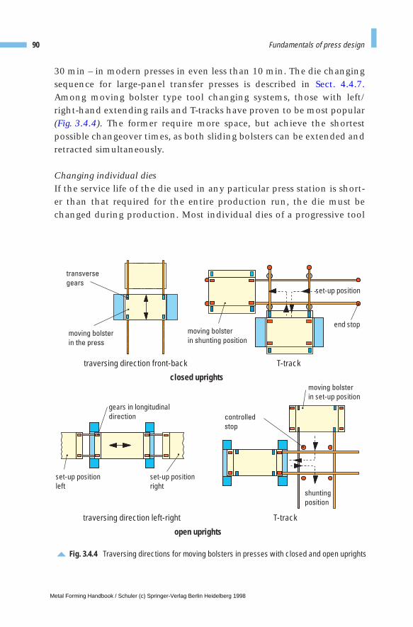
30 min – in modern presses in even less than 10 min. The die changingsequence for large-panel transfer presses is described in Sect. 4.4.7.Among moving bolster type tool changing systems, those with left/right-hand extending rails and T-tracks have proven to be most popular(Fig. 3.4.4). The former require more space, but achieve the shortestpossible changeover times, as both sliding bolsters can be extended andretracted simultaneously.
Changing individual diesIf the service life of the die used in any particular press station is short-er than that required for the entire production run, the die must bechanged during production. Most individual dies of a progressive tool
90 Fundamentals of press design
Fig. 3.4.4 Traversing directions for moving bolsters in presses with closed and open uprights
transverse
gears
gears in longitudinaldirection
moving bolster
in the press
moving bolster
in set-up position
moving bolster
in shunting position
T-tracktraversing direction left-right
traversing direction front-back T-track
closed uprights
open uprights
controlled
stop
set-up positionleft
set-up positionright
set-up position
end stop
shunting
position
Metal Forming Handbook / Schuler (c) Springer-Verlag Berlin Heidelberg 1998
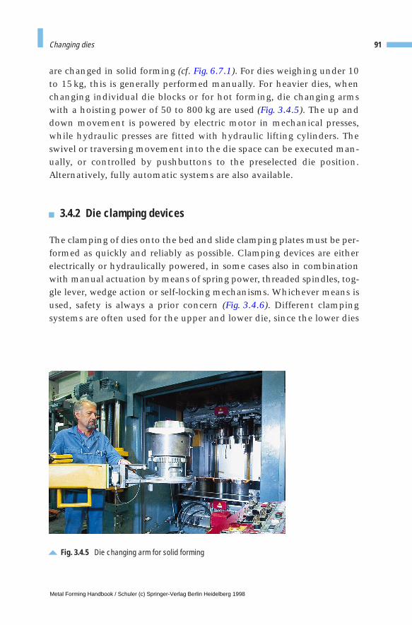
are changed in solid forming (cf. Fig. 6.7.1). For dies weighing under 10to 15kg, this is generally performed manually. For heavier dies, whenchanging individual die blocks or for hot forming, die changing armswith a hoisting power of 50 to 800 kg are used (Fig. 3.4.5). The up anddown movement is powered by electric motor in mechanical presses,while hydraulic presses are fitted with hydraulic lifting cylinders. Theswivel or traversing movement into the die space can be executed man-ually, or controlled by pushbuttons to the preselected die position.Alternatively, fully automatic systems are also available.
3.4.2 Die clamping devices
The clamping of dies onto the bed and slide clamping plates must be per-formed as quickly and reliably as possible. Clamping devices are eitherelectrically or hydraulically powered, in some cases also in combinationwith manual actuation by means of spring power, threaded spindles, tog-gle lever, wedge action or self-locking mechanisms. Whichever means isused, safety is always a prior concern (Fig. 3.4.6). Different clampingsystems are often used for the upper and lower die, since the lower dies
91Changing dies
Fig. 3.4.5 Die changing arm for solid forming
Metal Forming Handbook / Schuler (c) Springer-Verlag Berlin Heidelberg 1998
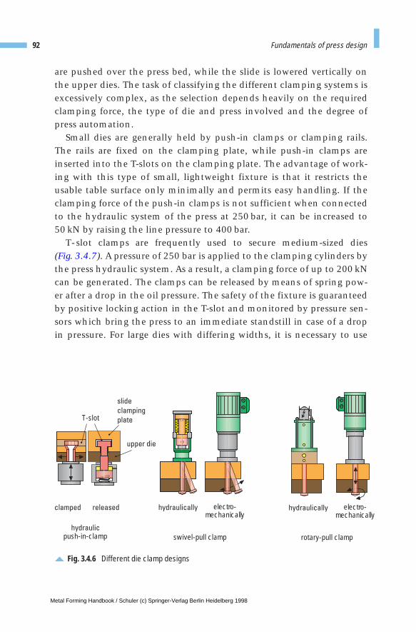
are pushed over the press bed, while the slide is lowered vertically onthe upper dies. The task of classifying the different clamping systems isexcessively complex, as the selection depends heavily on the requiredclamping force, the type of die and press involved and the degree ofpress automation.
Small dies are generally held by push-in clamps or clamping rails.The rails are fixed on the clamping plate, while push-in clamps areinserted into the T-slots on the clamping plate. The advantage of work-ing with this type of small, lightweight fixture is that it restricts theusable table surface only minimally and permits easy handling. If theclamping force of the push-in clamps is not sufficient when connectedto the hydraulic system of the press at 250 bar, it can be increased to 50 kN by raising the line pressure to 400 bar.
T- slot clamps are frequently used to secure medium-sized dies (Fig. 3.4.7). A pressure of 250 bar is applied to the clamping cylinders bythe press hydraulic system. As a result, a clamping force of up to 200 kNcan be generated. The clamps can be released by means of spring pow-er after a drop in the oil pressure. The safety of the fixture is guaranteedby positive locking action in the T-slot and monitored by pressure sen-sors which bring the press to an immediate standstill in case of a dropin pressure. For large dies with differing widths, it is necessary to use
92 Fundamentals of press design
Fig. 3.4.6 Different die clamp designs
clamped released
swivel-pull clamphydraulic
push-in-clamp
hydraulically hydraulicallyelectro-mechanically
electro-mechanically
rotary-pull clamp
slide
clamping
plate
upper die
T-slot
Metal Forming Handbook / Schuler (c) Springer-Verlag Berlin Heidelberg 1998
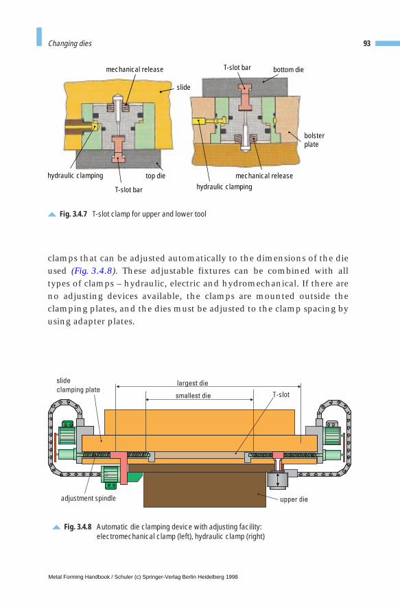
clamps that can be adjusted automatically to the dimensions of the dieused (Fig. 3.4.8). These adjustable fixtures can be combined with alltypes of clamps – hydraulic, electric and hydromechanical. If there areno adjusting devices available, the clamps are mounted outside theclamping plates, and the dies must be adjusted to the clamp spacing byusing adapter plates.
93Changing dies
Fig. 3.4.7 T-slot clamp for upper and lower tool
mechanical release
slide
top die
T-slot bar
hydraulic clamping
T-slot bar
mechanical releasehydraulic clamping
bolsterplate
bottom die
Fig. 3.4.8 Automatic die clamping device with adjusting facility: electromechanical clamp (left), hydraulic clamp (right)
adjustment spindle upper die
slide
clamping platelargest die
smallest die T-slot
Metal Forming Handbook / Schuler (c) Springer-Verlag Berlin Heidelberg 1998
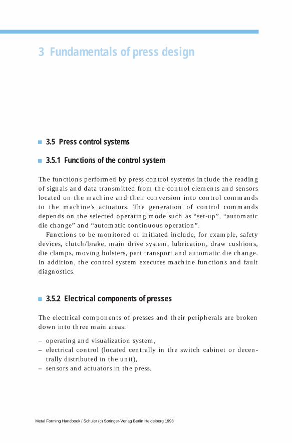
3 Fundamentals of press design
3.5 Press control systems
3.5.1 Functions of the control system
The functions performed by press control systems include the readingof signals and data transmitted from the control elements and sensorslocated on the machine and their conversion into control commandsto the machine’s actuators. The generation of control commandsdepends on the selected operating mode such as “set-up”, “automaticdie change” and “automatic continuous operation”.
Functions to be monitored or initiated include, for example, safetydevices, clutch/brake, main drive system, lubrication, draw cushions,die clamps, moving bolsters, part transport and automatic die change.In addition, the control system executes machine functions and faultdiagnostics.
3.5.2 Electrical components of presses
The electrical components of presses and their peripherals are brokendown into three main areas:
– operating and visualization system, – electrical control (located centrally in the switch cabinet or decen-
trally distributed in the unit),– sensors and actuators in the press.
Metal Forming Handbook / Schuler (c) Springer-Verlag Berlin Heidelberg 1998
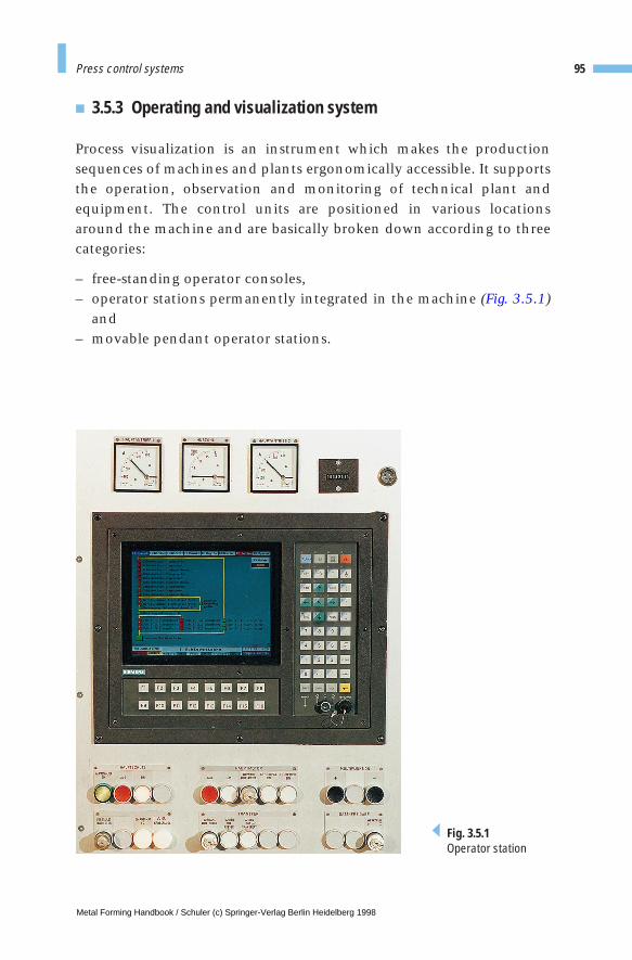
3.5.3 Operating and visualization system
Process visualization is an instrument which makes the productionsequences of machines and plants ergonomically accessible. It supportsthe operation, observation and monitoring of technical plant andequipment. The control units are positioned in various locationsaround the machine and are basically broken down according to threecategories:
– free-standing operator consoles,– operator stations permanently integrated in the machine (Fig. 3.5.1)
and– movable pendant operator stations.
95Press control systems
Fig. 3.5.1Operator station
Metal Forming Handbook / Schuler (c) Springer-Verlag Berlin Heidelberg 1998
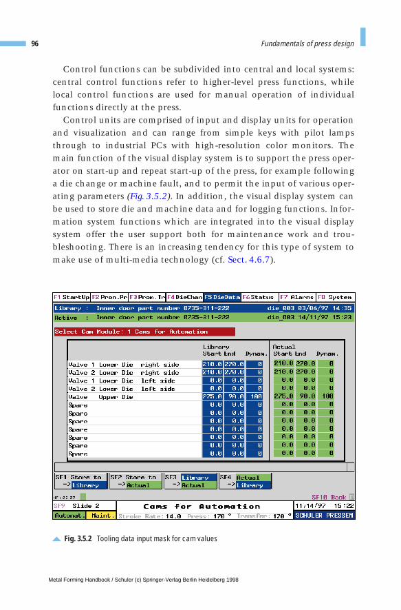
Control functions can be subdivided into central and local systems:central control functions refer to higher-level press functions, whilelocal control functions are used for manual operation of individualfunctions directly at the press.
Control units are comprised of input and display units for operationand visualization and can range from simple keys with pilot lampsthrough to industrial PCs with high-resolution color monitors. Themain function of the visual display system is to support the press oper-ator on start-up and repeat start-up of the press, for example followinga die change or machine fault, and to permit the input of various oper-ating parameters (Fig. 3.5.2). In addition, the visual display system canbe used to store die and machine data and for logging functions. Infor-mation system functions which are integrated into the visual displaysystem offer the user support both for maintenance work and trou-bleshooting. There is an increasing tendency for this type of system tomake use of multi-media technology (cf. Sect. 4.6.7).
96 Fundamentals of press design
Fig. 3.5.2 Tooling data input mask for cam values
Metal Forming Handbook / Schuler (c) Springer-Verlag Berlin Heidelberg 1998

3.5.4 Structure of electrical control systems
Electrical control systems are broken down into four main areas:
– the conventional part, – the programmable logic controller (PLC), – input and output systems and– the communication system.
The conventional part of the electrical system consists of the powersupply, drive controllers, the individual electrical and electronic con-trol devices and the low-voltage switchgear for power control monitor-ing and attaching the components in the control cabinets and themachine. The safety control represents a particularly important com-ponent of the conventional part for all functions relevant to safety suchas the emergency stop, monitoring of safety gates or safety doors andthe engagement of the clutch/brake in mechanical presses.
In addition, the electrical control system must reliably prevent thepress from starting up or running through independently, following theoccurrence of any individual fault. In case of failure of any component,it must ensure that no further press closing movement can be initiated.
The safety function of the conventional part of a hydraulic pressmonitors the valves responsible for reliable standstill of a movementwhich could lead to injury. These include the valves located in the low-er cylinder area which control die closure. Hydraulic redundancy isachieved by means of two monitored valves. Failure of one of thesedoes not lead to the execution of a hazardous movement. If one valvefails, the press’s valve monitoring circuit automatically brings the pressto a standstill.
The PLC controls and monitors all machine functions not covered bythe conventional control circuits and automatic die change, performsfault diagnostics and provides the interface to other machine sections.
The sensors and actuators of the machine are connected to the cen-tral PLC by means of the input/output system. There are two differenttechnologies being used: first the central input/output modules whichare integrated in the PLC racks or in additional units of the control cab-inet; second, on an increasing basis, local input/output modules withinthe press connected via fast communication systems to the central PLCunit (Fig. 3.5.3).
97Press control systems
Metal Forming Handbook / Schuler (c) Springer-Verlag Berlin Heidelberg 1998

98 Fundamentals of press design
Fig. 3.5.3 PLC with central and distributed input/output systems
distributed I/O
. .. . .. . .. . ..
switch cabinet
PLC
machine
sensors and actuators
distributedI/O module
distributedI/O module
distributedI/O module
distributedI/O module
serial bus
central I/O
. .. . .. . .. . ..
switch cabinet
PLC
terminal box terminal box terminal box terminal box
machine
parallel individualsignals
parallel individualsignals
sensors and actuators
I/O
Metal Forming Handbook / Schuler (c) Springer-Verlag Berlin Heidelberg 1998
The communication system connects the PLC, and provides dataexchange with the visual displays within the machine and also com-munication with external systems.
3.5.5 Functional structure of the control system
Depending on the type of machine or press, the control system is bro-ken down according to the following functional groupings:
– feed, – main drive system, – safety control, – slide functions (interlocking, overload safeguard, weight compen-
sation, die clamping system, adjustment), – draw cushion or blank holder functions (pressure control, adjustment),– moving bolster functions (traversing, lifting/lowering, clamping), – functions of the workpiece transport devices and dies, – hydraulic, pneumatic, lubrication functions, – special die changing functions.
Cam operated limit switches play a special role in press control systems.These press-specific functional units generate switching signals for cer-tain functions depending on the position of the crank angle. A differ-ence must be drawn between electromechanical rotating cam limitswitches (Fig. 3.5.4), which are used for safety-relevant functions, andelectronic cam switches that are programmable. The latter comprise ameasuring system for the crank angle of the press and an electronicevaluating module.
In contrast to mechanical presses, valves for the downstroke andupstroke of the slide are separate in a hydraulic press, so eliminating theneed for a cam operated safety device.
3.5.6 Major electronic control components
Safety control systems used in Europe are generally still the dual-chan-nel, self-monitoring conventional type using contactors. In contrast,since the mid-eighties, the safety control systems used in large-panel
99Press control systems
Metal Forming Handbook / Schuler (c) Springer-Verlag Berlin Heidelberg 1998
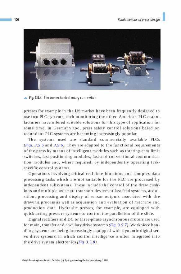
presses for example in the US market have been frequently designed touse two PLC systems, each monitoring the other. American PLC manu-facturers have offered suitable solutions for this type of application forsome time. In Germany too, press safety control solutions based onredundant PLC systems are becoming increasingly popular.
The systems used are standard commercially available PLCs (Figs. 3.5.5 and 3.5.6). They are adapted to the functional requirementsof the press by means of intelligent modules such as rotating cam limitswitches, fast positioning modules, fast and conventional communica-tion modules and, where required, by independently operating task-specific control systems.
Operations involving critical real-time functions and complex dataprocessing tasks which are not suitable for the PLC are processed byindependent subsystems. These include the control of the draw cush-ions and multiple-axis part transport devices or fast feed systems, acqui-sition, processing and display of sensor outputs associated with thedrawing process as well as acquisition and evaluation of machine andproduction data. Hydraulic presses, for example, are equipped withquick-acting pressure systems to control the parallelism of the slide.
Digital rectifiers and DC or three-phase asynchronous motors are usedfor main, transfer and ancillary drive systems (Fig. 3.5.7). Workpiece han-dling systems are being increasingly equipped with dynamic digital ser-vo drive systems, in which control intelligence is often integrated intothe drive system electronics (Fig. 3.5.8).
100 Fundamentals of press design
Fig. 3.5.4 Electromechanical rotary cam switch
Metal Forming Handbook / Schuler (c) Springer-Verlag Berlin Heidelberg 1998
3.5.7 Architecture and hardware configuration
The control system is divided into modules according to functionalgroupings. This applies to the circuit diagram, the arrangement of theswitch cabinet and structure of the PLC software. The functional mod-ules do not necessarily correspond to the mechanical structural units –in some cases similar functions such as all emergency stop circuits, allprotective grilles and the lubrication are grouped together.
Criteria used to determine the control structure include the logical andfunctional coherence between different system elements and the mini-mization of interfaces between the individual groups of functions. A welldesigned architecture of the control system enhances clarity and trans-parency of the electrical documentation and thus reduces the time spentin design and start-up as well as in troubleshoooting during production.
3.5.8 Architecture of the PLC software
The PLC software is designed to correspond to the functional groupingsof the circuit diagram. Functional sequences, in particular those used
101Press control systems
Fig. 3.5.5 PLC European manufacturer
Metal Forming Handbook / Schuler (c) Springer-Verlag Berlin Heidelberg 1998
for workpiece handling and die changing, are programmed usingsequential programming methods. Where fast response times are calledfor, the relevant PLC input signals are defined as interrupt inputswhich, as the name suggests, interrupt cyclically processed control soft-ware functions and trigger a response program which responds to exter-nal events in an extremely short time.
3.5.9 Future outlook
Programmable logic controllers are ideally suited to their respectiveapplication as single-purpose systems. They are particularly well suitedfor the processing of logic operations. The trend is towards equippingsystems with ever more extensive, cost-intensive processing capability.Development of programming languages, on the other hand, hasslowed down almost to a halt. Programs are still being written in theform of ladder diagrams and instruction lists, which are comparable to
102 Fundamentals of press design
Fig. 3.5.6PLC Americanmanufacturer
Metal Forming Handbook / Schuler (c) Springer-Verlag Berlin Heidelberg 1998
an assembler language. These originally application-oriented program-ming languages are now being used for achieving visual display, dataprocessing, data management and communication functions.
The consequences of this trend are high software development andmaintenance costs, non-transparent programs – which not even pro-gram design standardization can make any easier to understand – andlong lead times to put the press into operation. To permit the integra-tion of this type function, the PLC has to be equipped with additionalexpensive hardware modules.
In comparison, industrial computers, for example PCs, offer the ben-efits of graphic user interfaces, data processing capability and facilityfor object-oriented programming through the use of powerful pro-gramming tools. The basic requirements imposed on a future-orientedpress control system, i. e. the ability to access as many functions and asmuch information as possible directly at the machine, are only achiev-able in the future through the use of greater intelligence and more com-puting capacity. In addition, modern automation engineering calls for
103Press control systems
Fig. 3.5.7 Switch cabinet with components for main press drive
Metal Forming Handbook / Schuler (c) Springer-Verlag Berlin Heidelberg 1998
control systems with greater networking capability through standardnetworks for the exchange of control, production and process data aswell as the capability for diagnosis and intervention in the control sys-tem through public telecommunication networks. The PLC alone is notable to cope with these demands, although its continued existence as asubordinate, fast machine control concept is still justified.
Practically all the components required for realization of the abovefunctions are available in the industrial computer. Alongside its com-puting performance, the industrial computer also profits from theopen-ended software world. Furthermore, despite the steady rise in per-formance limits, the costs of the technology are falling in many cases.In view of this trend, control structures featuring distributed intelli-gence and higher-level industrial computers interlinked with fast com-munication systems are certain to gain increasingly in popularity.Added to this is the increased use of distributed input/output modulesand sensor/actuator communication systems with a view to reducingthe necessary installation and wiring input. Methods of programmingthe control software will become more standardized and simplified inthe future, for example by the introduction of the international stan-dard IEC 1131.
104 Fundamentals of press design
Fig. 3.5.8 Components of a servo drive system
Metal Forming Handbook / Schuler (c) Springer-Verlag Berlin Heidelberg 1998

Other approaches exist in the form of programming through the useof status graphs, application (“object”) oriented programming and userlanguage. In this case, reusable modules with any degree of complexitycan be generated and stored in a user-specific macro library. The pre-pared objects in the library are in parametric form and can be groupedwith a minimum of complication to cover a large number of the pressor machine functions. All that is necessary to then join the interfacesfor data exchange.
Information technology is being integrated to an ever greater degreeinto the plants or machines themselves.
As internationally stable “information highways” become available,new forms of fault diagnostics and maintenance back-up will naturallydevelop, allowing possible faults and operating errors to be ascertainedand mechanical faults to be traced using video technology or micro-phones, so realizing a system of temporary or continuous on-line moni-toring.
105Press control systems
Metal Forming Handbook / Schuler (c) Springer-Verlag Berlin Heidelberg 1998

3 Fundamentals of press design
3.6 Press safety and certification
3.6.1 Accident prevention
Due to their mode of operation and the energy input levels involved,presses represent – compared to many other machines – a higher poten-tial hazard to the operator. However, as a result of considerable effort,notably the revision of the German accident prevention regulations forpresses VBG7n5.1 dated April 1, 1987, the number of serious accidentsoccurring on or at presses has been substantially reduced. In addition tocomplying with legislation on safety requirements based on the “stateof the art”, manufacturers must also have the capability to recognizeand implement sensible safety measures. The manufacturer’s own sphereof responsibility in this field is a major portion of European safety legis-lation. As part of the service package offered by manufacturers, theoperating instruction manual contains special safety provisions andinstructions.
A major goal is to make the press operator recognize the necessity forsafety measures. The unpredictable nature of human reaction in surpriseor emergency situations must be taken into account here. Highlightingthe accident risk is the first and most important step when trainingmachine personnel on safety matters. As long as the operator or mainte-nance personnel are not convinced of the necessity for safety measures,they will be inclined to find ways of bypassing them. Excessive or super-fluous safety measures by the manufacturer are also certain to creategreater willingness on the part of operating staff to attempt to overridesafety functions. Reasons that justify negligence with regard to safetymeasures become quickly insignificant if an accident does actually occur.
Metal Forming Handbook / Schuler (c) Springer-Verlag Berlin Heidelberg 1998
3.6.2 Legislation
Alongside legislation and regulations defining requirements imposedon technical products – such as the German Pressure Vessel and Appli-ance Safety Acts – legislation has also been adopted which regulates cas-es of human injury caused by technical equipment. If the machinemanufacturer adheres to the technological standards defined by the so-called characteristic requirements, it may be assumed that he will beexempt from liability. An accident taking place despite these precau-tions is defined as a “statutory accident”, in which case the companiesproviding industrial accident insurance are responsible for settling anyfinancial claims arising as a result of the damage.
In Europe, these characteristic requirements are defined by the ECMachine Directive, the EMC (electromagnetic compatibility) Directiveand the Directive Governing Simple Pressure Vessels. Product liability isalso treated on a standardized basis in Europe through the EC Directivefor Harmonization of Product Liability Legislation.
In the case of particularly dangerous machines, state agencies orinstitutions acting on behalf of state agencies are commissioned tocheck and certify equipment provided the technical requirements ofthe equipment have been correctly implemented. Foreign trade in tech-nical products is obstructed to a considerable degree by differences ofopinion on the best ways to achieve safety and on the targeted stan-dards of safety in the individual countries. Machine manufacturersoperating on a global basis need to study the numerous different safetyrequirements and standards in force in each different export market.Thus, they must become familiar with the different safety philosophies,and must use locally approved components.
3.6.3 European safety requirements
Since January 1, 1995, new safety regulations have been in effect in theEEC (European Economic Community) which are briefly outlinedbelow (Fig. 3.6.1). EC legislation is based on a system of decrees anddirectives. EC decrees apply directly in the respective member state,while directives are taken up by the national governments, which haveto convert them within a reasonable period into national law with or
107Press safety and certification
Metal Forming Handbook / Schuler (c) Springer-Verlag Berlin Heidelberg 1998
108 Fundamentals of press design
Fig. 3.6.1 Chart showing European safety legislation: EC Machine Directives 89/392/EEC (ECMD) CE Mark
EC law governing technology:
Objectives:– Harmonization of safety standards in Europe– No compromises on safety in a member state– Free trade in machinery
EC regulations EC directives89/392/EEC (Machine Directive)87/404/EEC (Simple Pressure Vessels)89/655/EEC (Operating Resources)
Immediate validity National legislation
Appliance Safety Act (9. GSGV)Product Liability Act
Standards
Harmonized standards Non-harmonized standards
Standardization order from the Other EN standards commission, publication in the Official National standards Journal of the EC
National lists of useful and importantstandards for implementation of the89/392/EEC
Type A standard
General principles
EN292 (General principles for design)
Type B standard (horizontal standard)
Definition of safety devices, stipulations of general relevance with different machinesEN294 (Safety distances to prevent) EN574 (Two-hand operated devices)EN953 (Insulating safety devices) Type C standard (vertical standard)
Stipulations relating to a particular machine categoryEN692 (Mechanical presses)EN693 (Hydraulic presses)
Metal Forming Handbook / Schuler (c) Springer-Verlag Berlin Heidelberg 1998
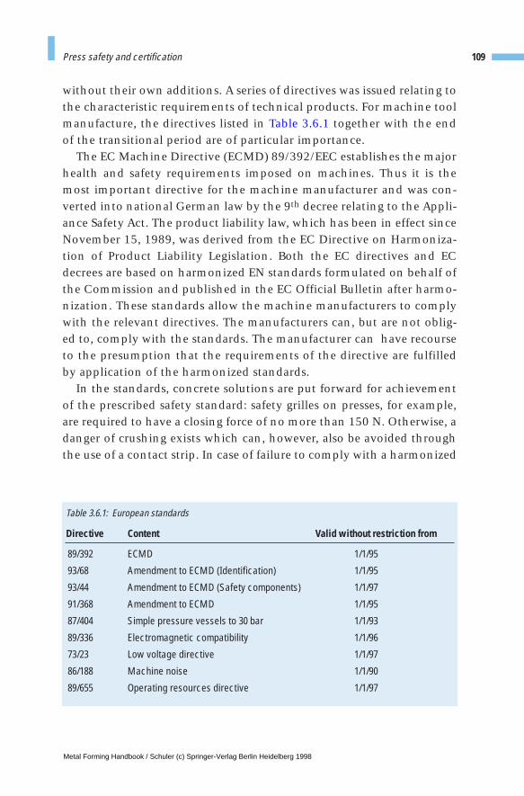
without their own additions. A series of directives was issued relating tothe characteristic requirements of technical products. For machine toolmanufacture, the directives listed in Table 3.6.1 together with the endof the transitional period are of particular importance.
The EC Machine Directive (ECMD) 89/392/EEC establishes the majorhealth and safety requirements imposed on machines. Thus it is themost important directive for the machine manufacturer and was con-verted into national German law by the 9th decree relating to the Appli-ance Safety Act. The product liability law, which has been in effect sinceNovember 15, 1989, was derived from the EC Directive on Harmoniza-tion of Product Liability Legislation. Both the EC directives and ECdecrees are based on harmonized EN standards formulated on behalf ofthe Commission and published in the EC Official Bulletin after harmo-nization. These standards allow the machine manufacturers to complywith the relevant directives. The manufacturers can, but are not oblig-ed to, comply with the standards. The manufacturer can have recourseto the presumption that the requirements of the directive are fulfilledby application of the harmonized standards.
In the standards, concrete solutions are put forward for achievementof the prescribed safety standard: safety grilles on presses, for example,are required to have a closing force of no more than 150 N. Otherwise, adanger of crushing exists which can, however, also be avoided throughthe use of a contact strip. In case of failure to comply with a harmonized
109Press safety and certification
Directive Content Valid without restriction from
89/392 ECMD 1/1/95
93/68 Amendment to ECMD (Identification) 1/1/95
93/44 Amendment to ECMD (Safety components) 1/1/97
91/368 Amendment to ECMD 1/1/95
87/404 Simple pressure vessels to 30 bar 1/1/93
89/336 Electromagnetic compatibility 1/1/96
73/23 Low voltage directive 1/1/97
86/188 Machine noise 1/1/90
89/655 Operating resources directive 1/1/97
Table 3.6.1: European standards
Metal Forming Handbook / Schuler (c) Springer-Verlag Berlin Heidelberg 1998
standard, the manufacturer can fulfill the health and safety standardsusing alternative methods. In contrast, however, failure to comply withthe ECMD will result in prosecution of the manufacturer, withdrawal ofthe product from the European market and decommissioning of thehazardous press.
EN standards are classified under three categories, each with its ownfunction and purpose. General guidelines and safety targets are setdown in so-called A standards. B standards impose requirements on cer-tain facilities, for example safety equipment used for different types ofmachines. C standards define machine categories and the requirementsimposed on these. For a given machine category, the C standards laydown the way in which risks are likely to occur and how they should beevaluated and safeguarded against. Due to the generality with whichmachines are grouped to create machine categories – the mechanicalpress category, for example, ranges from the notching machine to thelarge-panel transfer press – it can, in certain cases, be expedient to devi-ate from the standard while still complying with the requirements ofthe ECMD.
As documentary evidence of compliance with health and safetyrequirements, the machine manufacturer issues the owner with a Cer-tificate of Conformity (Fig. 3.6.2) according to annex II A, and attachesthe CE mark to the machine. No machine has been commissioned inthe EEC without a Declaration of Conformity or CE mark since January1, 1995.
The ECMD differentiates between independently working machinesand machines intended for installation as part of an overall productionline. A production line comprised of several components constitutes amachine which has only one CE mark and only one declaration of conformity. For all production line components which are incapable ofoperating independently, the subcontractor issues a manufacturer’sdeclaration in compliance with annex II B. Under certain circum-stances, component machines of this type do not permit safeguardingunless integrated in the overall line. An individual destacker withoutthe press, for instance, permits free access to hazardous movements andis thus incapable of complying with the ECMD. The party responsiblefor the overall line, whose function it is to issue the declaration of con-formity, must therefore ensure that the manufacturer of the compo-nents
110 Fundamentals of press design
Metal Forming Handbook / Schuler (c) Springer-Verlag Berlin Heidelberg 1998
– stipulates in the manufacturer’s declaration that the componentcomplies as far as possible with the ECMD,
– has compiled and archived the required documentation as laid downby annex V, point 3,
– stipulates the applied safety standards and – has made reference in the operating instructions to the safety regula-
tions for the manufacturer of the line into which his components areto be integrated.
All those involved assume that the prescribed minimum statement, asindicated in annex II B, is insufficient and the machine cannot be com-missioned until the overall line has been proven to comply with theECMD. Frequently, and in particular in the case of large-scale presses,part of the equipment originates from the user and part of it from thepurchaser of the press. As the ECMD requires static stability and safeaccess to all points of possible intervention, with the declaration ofconformity the production line manufacturer assumes responsibilityalso for the structural work carried out for the press, for example theconstruction of the necessary foundations. The identity of the manu-facturer or construction foreman as defined by ECMD must be contrac-tually laid down in the case of this type of production line. The respon-sible party then has the other contractual partners confirm compliancewith health and safety standards to the extent of their respective per-formance.
3.6.4 CE marking
The flow chart in Fig. 3.6.3 indicates what is required of the manufac-turer wishing to apply the CE mark to his machine. An underlying dif-ference is drawn between two cases. According to annex IV of theECMD, presses intended for manual feed operation have been classifiedas hazardous machines since January 1, 1995. In this case, a C standard– the EN692 for mechanical and EN693 for hydraulic presses – mustexist, and the press must be constructed without restrictions in accor-dance with this standard. If this is not the case, or if the relevant C stan-dard does not yet exist, the manufacturer is required to commission atype test of the machine by a notified body (i. e. an appropriate testing
111Press safety and certification
Metal Forming Handbook / Schuler (c) Springer-Verlag Berlin Heidelberg 1998

112 Fundamentals of press design
Fig. 3.6.2 Sample Declaration of Conformity
EG-Declaration of Conformityper specifications of the machine directive 89/392/EEC, annex II A
Applied EC-directives :
x machine directive 89/392/EEC and 91/368/EECx electromagnetic compatibility directive 89/336/EEC and 93/31/EECx low-voltage directive 73/23/EEC ………………………………
We herewith declare that the following identified machine / line
………………………………………………………………………………………………………(make, type designation, year of manufacturing, order number)
as marketed by us meets the essential health and safety requirements of the EC machinery directive 89/392/EEC relating to the design and construction. This declaration will become invalid in case of modifications of the machine / line, not accepted by us.
Applied harmonized standards:
x DIN EN 292x DIN EN 294x DIN EN 60204 T1x DIN EN 692x DIN EN 418x E DIN EN 953x DIN EN 954x DIN EN 982x DIN EN 983x DIN EN 1037
Applied national German standards and technical specifications :
…………………………………
A technical construction file has been compiled and will remain available.
An instruction manual for the machinery has been composed and delivered in :
x community language of the manufacturers country (original version)x community language of the user country …………………………………
Place, date …………………………………
Manager design services …………………………………(title and designation of the undersigned) (Legally binding signature
of the manufacturer)
Metal Forming Handbook / Schuler (c) Springer-Verlag Berlin Heidelberg 1998
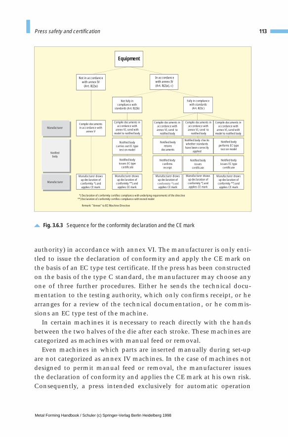
authority) in accordance with annex VI. The manufacturer is only enti-tled to issue the declaration of conformity and apply the CE mark onthe basis of an EC type test certificate. If the press has been constructedon the basis of the type C standard, the manufacturer may choose anyone of three further procedures. Either he sends the technical docu-mentation to the testing authority, which only confirms receipt, or hearranges for a review of the technical documentation, or he commis-sions an EC type test of the machine.
In certain machines it is necessary to reach directly with the handsbetween the two halves of the die after each stroke. These machines arecategorized as machines with manual feed or removal.
Even machines in which parts are inserted manually during set-upare not categorized as annex IV machines. In the case of machines notdesigned to permit manual feed or removal, the manufacturer issuesthe declaration of conformity and applies the CE mark at his own risk.Consequently, a press intended exclusively for automatic operation
113Press safety and certification
Fig. 3.6.3 Sequence for the conformity declaration and the CE mark
Notifiedbody
Equipment
Manufacturer
Manufacturer
*) Declaration of conformity certifies compliance with underlying requirements of the directive**) Declaration of conformity certifies compliance with tested model
Remark:
Not in accordancewith annex IV
(Art. 8(2)a)
Not fully incompliance with
standards (Art. 8(2)b)
Compile documentsin accordance with
annex V
Manufacturer drawsup declaration ofconformity *) andapplies CE mark
Manufacturer drawsup declaration ofconformity *) andapplies CE mark
Manufacturer drawsup declaration ofconformity *) andapplies CE mark
Manufacturer drawsup declaration of
conformity **) andapplies CE mark
Manufacturer drawsup declaration of
conformity **) andapplies CE mark
Notified bodycarries out EC type
test on model
Notified bodyissues EC type
certificate
Notified bodyissues EC type
certificate
Notified bodyissues
certificate
Notified bodyretains
documents
Notified body checkswhether standards
have been correctlyapplied
Notified bodyperforms EC type
test on model
Notified bodyconfirmsreceipt
Compile documents inaccordance with
annex VI, send withmodel to notified body
Compile documents inaccordance with
annex VI, send withmodel to notified body
Compile documents inaccordance withannex VI, send to
notified body
Compile documents inaccordance withannex VI, send to
notified body
Fully in compliancewith standards
(Art. 8(2)c)
In accordancewith annex IV(Art. 8(2)a), c)
Metal Forming Handbook / Schuler (c) Springer-Verlag Berlin Heidelberg 1998
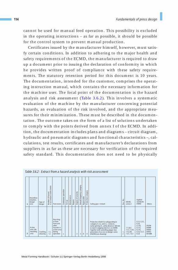
Table 3.6.2 : Extract from a hazard analysis with risk assessment
Hazardoussituation,dangerarea
Active area, diemountingarea
Type ofdanger
Crushing,shearing
1.1,1.2
1,2x 3 3 0 4
Part event
Reachingin from front andotherhazards inactive areaduringoperation
1.1.2a,f,1.3.7, 1.3.8,1.4.2.2B,1.4.1, 1.6.1
5.3.3, 5.3.5.,5.3.6,5.3.10,5.3.12,5.3.15,5.5.6, 5.5.7,5.5.8
EN294EN999EN954EN953EN1088
89/392,annex I
Appliedstandards EN692 Others
Protective shield 1st safeguarding tocategory 4, n.o. and n.c. contacts,early opening tS, safety distance 320 mmto match stopping time 0.2 s to EN999.Together with swivelling gripper boxprevention of access to danger zones(EN294) (see drawing)
Safety gear / remark1
2
Num
ber o
f haz
ard
in a
ccor
danc
e w
ith E
N41
4
Cont
inuo
us o
pera
tion
Set-u
p
Mai
nten
ance
Repa
irs
Degr
ee o
f sev
erity
Over
all f
requ
ency
cat
egor
y
Bypa
ssab
le
Prot
ectio
n ca
tego
ry
Doc.
No.
cannot be used for manual feed operation. This possibility is excludedin the operating instructions – as far as possible, it should be possiblefor the control system to prevent manual production.
Certificates issued by the manufacturer himself, however, must satis-fy certain conditions. In addition to adhering to the major health andsafety requirements of the ECMD, the manufacturer is required to drawup a document prior to issuing the declaration of conformity in whichhe provides written proof of compliance with these safety require-ments. The statutory retention period for this document is 10 years.The documentation, intended for the customer, comprises the operat-ing instruction manual, which contains the necessary information forthe machine user. The focal point of the documentation is the hazardanalysis and risk assessment (Table 3.6.2). This involves a systematicevaluation of the machine by the manufacturer concerning potentialhazards, an evaluation of the risk involved, and the appropriate mea-sures for their minimization. These must be described in the documen-tation. The outcome takes on the form of a list of solutions undertakento comply with the points derived from annex I of the ECMD. In addi-tion, the documentation includes plans and diagrams – circuit diagram,hydraulic and pneumatic diagrams and functional characteristics –, cal-culations, test results, certificates and manufacturer’s declarations fromsuppliers in as far as these are necessary for verification of the requiredsafety standard. This documentation does not need to be physically
114 Fundamentals of press design
Metal Forming Handbook / Schuler (c) Springer-Verlag Berlin Heidelberg 1998
present, but comprises an index which makes reference to the varioussections by means of an identification number.
In the case of a hazard analysis, safety is monitored over each phaseof the machine’s life, from assembly through to commissioning, utiliza-tion, repair and final scrapping. Protective measures must apply equallyto machine operators, set-up and maintenance staff. Depending on therisk, safety must also be guaranteed in case of machine malfunctions. As,for example, the failure of a brake valve and thus the unchecked move-ment of the slide could lead to serious injury, dynamically monitoredpress safety valves must be used unless it is possible to provide an equiv-alent degree of safety by keeping safety devices closed. The monitoredvalves are redundant (double valves) and, depending on the require-ments of their respective functions, they are self-monitoring. Thismeans that despite a brake valve failure, the “braking” function is stillperformed, accompanied by a message indicating whether the twovalves have operated correctly or not. A positive “function OK” signal isused for self-monitoring of the signalling module (cf. Sect. 3.5).
In analysing potential hazards, the manufacturer must also consider“foreseeable unusual situations”, e.g. surprise situations of the typepreviously mentioned. The operating instructions must accordinglyinclude a statement on machine utilization in accordance with theintended purpose of the machine, and also prohibit any foreseeable cas-es of violation, for example operation of the press while observers arelocated behind the closed protective gear in order to observe themachine operation. Indications of possible violation of operating regu-lations are often only possible after observation of operating, set-upand maintenance staff. The results of the hazard analysis are reflectedin the design of protective gear, remarks relating to residual risk at themachine and in the operating instruction manual. Thus, they are madeknown to the machine user.
3.6.5 Measures to be undertaken by the user
When purchasing a machine, the user must establish by means of acontractual agreement the identity of the manufacturer as defined bythe ECMD and the position with regard to items of equipment provid-ed by the user. When purchasing machines, whether new or used, from
115Press safety and certification
Metal Forming Handbook / Schuler (c) Springer-Verlag Berlin Heidelberg 1998
foreign countries outside of Europe, the user should contractually stip-ulate compliance with the current revision of 89/EEC/392. Europeanmanufacturers are required in any case to comply with this legalrequirement, making a contractual provision to this effect unnecessary.
When the user himself performs no conversion work on the press, heis only required to be acquainted with the provided operating instruc-tions and the accident prevention regulations applicable for press oper-ation. In Germany, the following accident prevention regulations areamong the most important in this context:
– VBG 7n5.1 for eccentric and related presses,– VBG 7n5.2 for hydraulic presses,– VBG 7n5.3 for spindle presses,– VBG 5 for power-driven operating equipment.
Directive 89/655/EEC on the provision of equipment obliges the user toretrofit all machines to a defined minimum standard by January 1,1997. It is safe to assume that users who converted their machines inline with accident prevention regulations valid up until December 31,1993, will be unaffected by this ruling.
If the user intends to perform his own conversion work on themachine, he assumes full responsibility for his actions. He must accord-ingly be acquainted with all the valid directives, regulations and stan-dards. Conversion of an annex IV machine, i.e. a press intended for man-ual feeding and unloading, requires notification of the testing bodywhich performed the EC type test. The conversion of an automaticmachine for manual feeding or unloading calls for EC type testing unlessthe complete construction has been performed in compliance with the Cstandard. Although the ECMD does not apply to used machinery, i.e.machines coming into circulation in the EEC prior to December 31,1994. These machines do not bear the CE mark and do contain certainprovisions which are of importance in this context. Used machines fromforeign countries outside Europe must always bear the CE mark and beaccompanied by a conformity declaration. The conversion of usedmachines must be performed with a view to the health and safetyrequirements of annex I of the ECMD. However, in case of major modifi-cations, functional changes or increased performance, the entiremachine or producton line must be subjected to a conformance check bythe construction foreman, after which it will receive the CE mark.
116 Fundamentals of press design
Metal Forming Handbook / Schuler (c) Springer-Verlag Berlin Heidelberg 1998

3.6.6 Safety requirements in the USA
The following brief analysis of safety requirements in the USA providesa representative comparison with safety regulations applicable outsideEurope. Alongside the ANSI (American National Standards Institute)Standard B11.1-1971, the regulations of the OSHA (Occupational Safe-ty and Health Administration) apply.
ANSI national standards cover a number of areas including safetyequipment, although application of these standards is voluntary. Incontrast, compliance with the OSHA regulations is a statutory require-ment.
This stipulates that a Lock-Out Procedure to §1910.147 be used on allmachines. This requirement specifies a description of how each type ofenergy and each energy source can be rendered harmless. This must beperformed in four stages: shut-down of the energy source, dissolution ofresidual energy, a check of energy-free status and safeguarding the energy-free status against unintentional restart. This step-by-step approach forthe isolation of energy sources has been adopted by the EN1037 to applyto European standards. As a minimum requirement, main switches mustbe capable of locking in the energy-free status. The OSHA represents thephilosophy that every staff member should carry padlocks usable onlyby himself or herself which safely eliminate any possibility of restart bythird parties. Only he or she can cancel the disabled status.
Like the ANSI standard, the OSHA requires from the manufacturerthe compilation of instructions ensuring safe machine operation andmaintenance. According to OSHA, equipment must be delivered with a lock-out plate in accordance with Fig. 3.6.4 indicating the devicesrequired to render the equipment harmless using the four steps listedabove for each of the energy sources used. The warning pictograms arealso attached at the relevant points of the machine. As mentioned ear-lier, the OSHA places particular emphasis on the training of operators,set-up personnel and maintenance staff in particular. The objective ofthe training is to indicate possible sources of accidents, promote safety-conscious work and point out the purpose and function of the safetygear. Employers should provide training on initial transfer and com-missioning of the equipment and thereafter once a year, and have thisconfirmed by means of a signature. Application of the OSHA regula-tions varies from region to region, as the OSHA orients its interpreta-
117Press safety and certification
Metal Forming Handbook / Schuler (c) Springer-Verlag Berlin Heidelberg 1998

118 Fundamentals of press design
Fig. 3.6.4Lock-out plate in accordance with US regulations
Metal Forming Handbook / Schuler (c) Springer-Verlag Berlin Heidelberg 1998

tion of the safety measures to the regulations already existing in therespective companies. In the USA, the first burden of proof lies with theowner of the equipment who accordingly has an interest in equipmentsafety. For this reason, it makes sense for details of safety engineering tobe coordinated with the safety officer of the company running themachine.
In view of the almost unpredictable amounts reached by damageclaims in the USA, qualified safety engineering and good documenta-tion are gaining in significance.
Characteristic requirements imposed on mechanical presses aredefined in §1910.217, and those imposed on forging machines in§1910.218. Compliance Safety and Health Officers from the Departmentof Labor should be given access to monitor compliance with safetyrequirements. Much of this responsibility lies with the equipment user.
119Press safety and certification
Metal Forming Handbook / Schuler (c) Springer-Verlag Berlin Heidelberg 1998
3 Fundamentals of press design
3.7 Casting components for presses
The proportion of cast components in presses in terms of their weightdiffers considerably. In individual presses such as minting and coiningpresses (cf. Sect. 6.8.7) or automatic notching machines (cf. Sect. 4.6.4),some 80 % of the total press weight is made up of gray cast iron, in gen-eral in nodular cast iron. This proportion is made up predominantly oflarge components such as uprights, press frames and press bodies(cf. Fig. 3.1.1). In the case of large presses with individual part weightsexceeding 20 t, however, welded constructions predominate. Freedomfrom scale, good machining properties, non-leakage of oil and adher-ence to mechanical values laid down in the drawing specifications arecriteria which govern the quality of castings. They determine the com-pliance of castings with general mechanical engineering requirements.Due to the size of the castings and their low production volume, theseparts are typically made using the manual molding technique, i.e. with-out the use of mechanical aids.
The casting industry is challenged to a far greater degree by the pro-duction of components to drive mechanical presses, in particular trans-fer presses. Eccentric wheels, for example, cam wheels, reducing gears,connecting rods and clutch components represent a particular chal-lenge to the castings producer due to the special quality requirementsinvolved (cf. Sect. 3.2.6). The focal point of this type of drive system isthe eccentric wheel, which can have a part weight ranging anywherefrom 5 to 25 t (Fig. 3.7.1). For this type of component, ductile castingsin GGG-70 quality are increasingly used, while in the past it was cus-tomary to use steel castings. This change necessitated extensive experi-mentation and continuous further development from the point of view
Metal Forming Handbook / Schuler (c) Springer-Verlag Berlin Heidelberg 1998
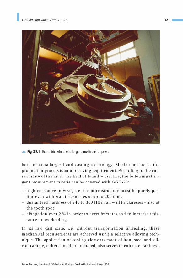
Fig. 3.7.1 Eccentric wheel of a large-panel transfer press
both of metallurgical and casting technology. Maximum care in theproduction process is an underlying requirement. According to the cur-rent state of the art in the field of foundry practice, the following strin-gent requirement criteria can be covered with GGG-70:
– high resistance to wear, i. e. the microstructure must be purely per-litic even with wall thicknesses of up to 200 mm,
– guaranteed hardness of 240 to 300 HB in all wall thicknesses – also atthe tooth root,
– elongation over 2 % in order to avert fractures and to increase resis-tance to overloading.
In its raw cast state, i.e. without transformation annealing, thesemechanical requirements are achieved using a selective alloying tech-nique. The application of cooling elements made of iron, steel and sili-con carbide, either cooled or uncooled, also serves to enhance hardness.
121Casting components for presses
Metal Forming Handbook / Schuler (c) Springer-Verlag Berlin Heidelberg 1998

However, the casting technician can only alloy and cool within restrict-ed limits, as elongation drops with increasing hardness. Due to this typeof metallurgical-technological operation, and because of their geometri-cal shape, castings such as eccentric wheels are inevitably exposed tohigh degrees of residual stress. As a result, stress relief annealing at 560 to580 °C is an absolute necessity.
In the foundry, quality standards must be assured in order to avert therisk of cracks and fractures in the castings. The marked tendency of thematerial to form scale substantially impedes the production of compo-nents made of GGG-70. The porosity risk therefore is addressed by feed-ing and selective solidification. All components, naturally including alsolarge parts for press drive systems, are subject to highly stringent qualitycontrols, including ultrasound, X-ray, crack detection and hardness test-ing, as well as testing of mechanical values using test-bar specimen, casttogether with produced component.
122 Fundamentals of press design
BibliographyAnselmann, N. (editor): Europäisches Recht der Technik, Beuth Verlag, Berlin, Vienna, Zurich (1993).
ANSI B11.1-1971: Safety requirements for the construction, care, and use of mechanical powerpresses, American National Standards Institute Inc., New York (1971).
Becker, U., Ostermann, H.-J.: Wegweiser Maschinenrichtlinie, Bundesanzeiger-Verlag, Cologne (1995).
Bodenschatz, W., Fichna, G., Voth, D.: Produkthaftung, Maschinenbau-Verlag, Frankfurt/Main, 4th edition. (1990).
DIN EN 692 (Draft): Mechanische Pressen – Sicherheit, Beuth Verlag, Berlin (1992).
DIN EN 693 (Draft): Hydraulische Pressen – Sicherheit, Beuth Verlag, Berlin (1992).
DIN EN 1037 (Draft): Sicherheit von Maschinen, Trennung von der Energiezufuhr und Energieabbau,Vermeidung von unerwartetem Anlauf, Beuth-Verlag, Berlin (1993).
Hoffmann, H., Schneider, F.: Schwingen verhindert-Hydraulische Zieheinrichtung für die Fertigung mithoher Qualität in einfachwirkenden Pressen, Maschinenmarkt 95 (1989) 51/52.
Hoffmann, H.: Vergleichende Untersuchung von Zieheinrichtungen, Bänder Bleche Rohre (1991) 12 and (1992) 1.
Kürzinger, F.-X.: Kraftneutrale Parallelregelung über gesamten Hub, Bänder Bleche Rohre (1995) 9.
Occupational Safety and Health Administration: OSHA Regulations 29 CFR Ch XVII, Part 1910, Office ofthe Federal Register, Washington D.C., 7-1-92 Edition (1992).
Schmidt, K.: Die neue Druckbehälterverordnung, WEKA Fachverlag, Augsburg (1995).
Schwebel, R.: Geringe Parallelitätsabweichungen - Anwendungsspektrum hydraulischer Pressen,Industriebedarf (1994) 9.
Süddeutsche Metall-Berufsgenossenschaft: Unfallverhütungsvorschriften, Carl Heymanns Verlag KG,Luxemburg (1994).
TÜV Hannover-Sachsen-Anhalt: Kurzinformation EG-Maschinen-Richtlinie, Eigenverlag (1995).
Metal Forming Handbook / Schuler (c) Springer-Verlag Berlin Heidelberg 1998
4 Sheet metal forming and blanking
4.1 Principles of die manufacture
4.1.1 Classification of dies
In metalforming, the geometry of the workpiece is established entirely orpartially by the geometry of the die. In contrast to machining processes,significantly greater forces are necessary in forming. Due to the com-plexity of the parts, forming is often not carried out in a single operation.Depending on the geometry of the part, production is carried out in sev-eral operational steps via one or several production processes such asforming or blanking. One operation can also include several processessimultaneously (cf. Sect. 2.1.4).
During the design phase, the necessary manufacturing methods aswell as the sequence and number of production steps are established ina processing plan (Fig. 4.1.1). In this plan, the availability of machines,the planned production volumes of the part and other boundary con-ditions are taken into account.
The aim is to minimize the number of dies to be used while keeping upa high level of operational reliability. The parts are greatly simplifiedright from their design stage by close collaboration between the PartDesign and Production Departments in order to enable several formingand related blanking processes to be carried out in one forming station.
Obviously, the more operations which are integrated into a singledie, the more complex the structure of the die becomes. The conse-quences are higher costs, a decrease in output and a lower reliability.
Metal Forming Handbook / Schuler (c) Springer-Verlag Berlin Heidelberg 1998
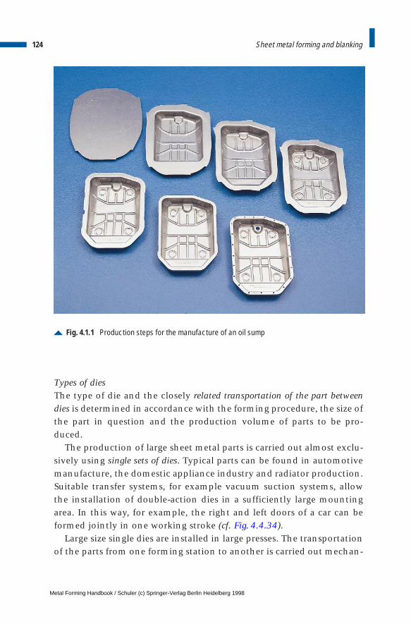
Types of diesThe type of die and the closely related transportation of the part betweendies is determined in accordance with the forming procedure, the size ofthe part in question and the production volume of parts to be pro-duced.
The production of large sheet metal parts is carried out almost exclu-sively using single sets of dies. Typical parts can be found in automotivemanufacture, the domestic appliance industry and radiator production.Suitable transfer systems, for example vacuum suction systems, allowthe installation of double-action dies in a sufficiently large mountingarea. In this way, for example, the right and left doors of a car can beformed jointly in one working stroke (cf. Fig. 4.4.34).
Large size single dies are installed in large presses. The transportationof the parts from one forming station to another is carried out mechan-
124 Sheet metal forming and blanking
Fig. 4.1.1 Production steps for the manufacture of an oil sump
Metal Forming Handbook / Schuler (c) Springer-Verlag Berlin Heidelberg 1998
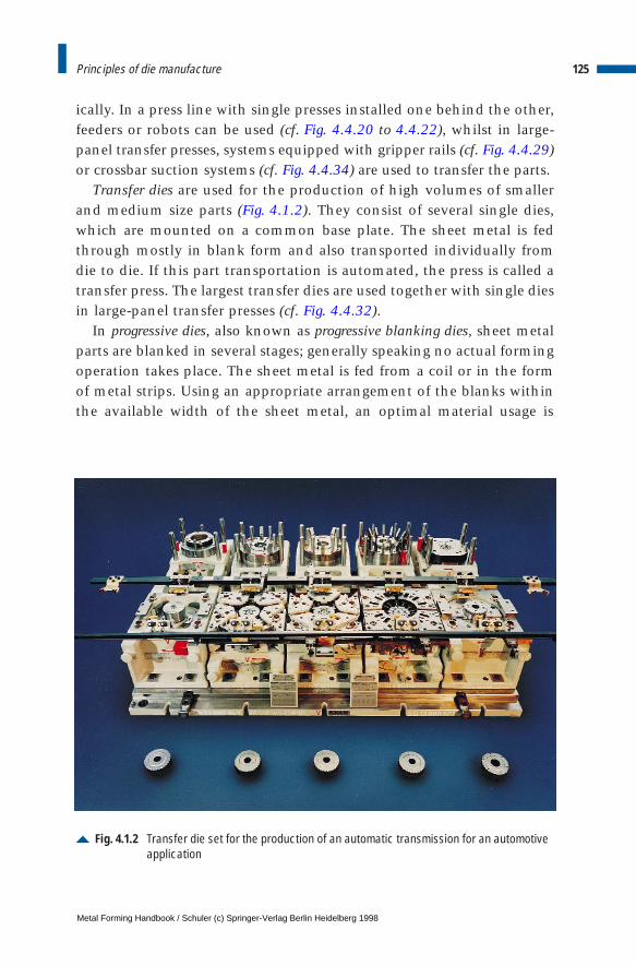
ically. In a press line with single presses installed one behind the other,feeders or robots can be used (cf. Fig. 4.4.20 to 4.4.22), whilst in large-panel transfer presses, systems equipped with gripper rails (cf. Fig. 4.4.29)or crossbar suction systems (cf. Fig. 4.4.34) are used to transfer the parts.
Transfer dies are used for the production of high volumes of smallerand medium size parts (Fig. 4.1.2). They consist of several single dies,which are mounted on a common base plate. The sheet metal is fedthrough mostly in blank form and also transported individually fromdie to die. If this part transportation is automated, the press is called atransfer press. The largest transfer dies are used together with single diesin large-panel transfer presses (cf. Fig. 4.4.32).
In progressive dies, also known as progressive blanking dies, sheet metalparts are blanked in several stages; generally speaking no actual formingoperation takes place. The sheet metal is fed from a coil or in the formof metal strips. Using an appropriate arrangement of the blanks withinthe available width of the sheet metal, an optimal material usage is
125Principles of die manufacture
Fig. 4.1.2 Transfer die set for the production of an automatic transmission for an automotiveapplication
Metal Forming Handbook / Schuler (c) Springer-Verlag Berlin Heidelberg 1998

ensured (cf. Fig. 4.5.2 to 4.5.5). The workpiece remains fixed to the stripskeleton up until the last operation. The parts are transferred when theentire strip is shifted further in the work flow direction after the blank-ing operation. The length of the shift is equal to the center line spacingof the dies and it is also called the step width. Side shears, very precisefeeding devices or pilot pins ensure feed-related part accuracy. In thefinal production operation, the finished part, i. e. the last part in thesequence, is disconnected from the skeleton. A field of application forprogressive blanking tools is, for example, in the production of metalrotors or stator blanks for electric motors (cf. Fig. 4.6.11 and 4.6.20).
In progressive compound dies smaller formed parts are produced inseveral sequential operations. In contrast to progressive dies, not only blanking but also forming operations are performed. However, the workpiece also remains in the skeleton up to the last operation (Fig. 4.1.3 and cf. Fig. 4.7.2). Due to the height of the parts, the metalstrip must be raised up, generally using lifting edges or similar liftingdevices in order to allow the strip metal to be transported mechanical-ly. Pressed metal parts which cannot be produced within a metal strip
126 Sheet metal forming and blanking
Fig. 4.1.3 Reinforcing part of a car produced in a strip by a compound die set
Metal Forming Handbook / Schuler (c) Springer-Verlag Berlin Heidelberg 1998
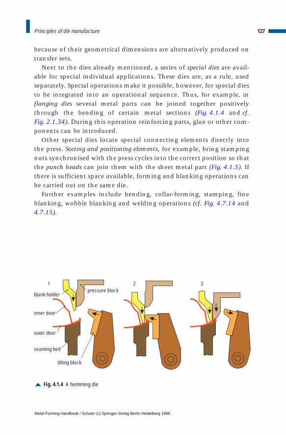
because of their geometrical dimensions are alternatively produced ontransfer sets.
Next to the dies already mentioned, a series of special dies are avail-able for special individual applications. These dies are, as a rule, usedseparately. Special operations make it possible, however, for special diesto be integrated into an operational sequence. Thus, for example, inflanging dies several metal parts can be joined together positivelythrough the bending of certain metal sections (Fig. 4.1.4 and cf. Fig. 2.1.34). During this operation reinforcing parts, glue or other com-ponents can be introduced.
Other special dies locate special connecting elements directly intothe press. Sorting and positioning elements, for example, bring stampingnuts synchronised with the press cycles into the correct position so thatthe punch heads can join them with the sheet metal part (Fig. 4.1.5). Ifthere is sufficient space available, forming and blanking operations canbe carried out on the same die.
Further examples include bending, collar-forming, stamping, fineblanking, wobble blanking and welding operations (cf. Fig. 4.7.14 and4.7.15).
127Principles of die manufacture
Fig. 4.1.4 A hemming die
1 2 3
blank holder
inner door
outer door
seaming bed
pressure block
tilting block
Metal Forming Handbook / Schuler (c) Springer-Verlag Berlin Heidelberg 1998

4.1.2 Die development
Traditionally the business of die engineering has been influenced bythe automotive industry. The following observations about the diedevelopment are mostly related to body panel die construction. Es-sential statements are, however, made in a fundamental context, sothat they are applicable to all areas involved with the production ofsheet-metal forming and blanking dies.
Timing cycle for a mass produced car body panelUntil the end of the 1980s some car models were still being produced forsix to eight years more or less unchanged or in slightly modified form.Today, however, production time cycles are set for only five years or less(Fig. 4.1.6). Following the new different model policy, the demands ondie makers have also changed fundamentally. Comprehensive contractsof much greater scope such as Simultaneous Engineering (SE) contractsare becoming increasingly common. As a result, the die maker is ofteninvolved at the initial development phase of the metal part as well as in the planning phase for the production process. Therefore, a muchbroader involvement is established well before the actual die develop-ment is initiated.
128 Sheet metal forming and blanking
Fig. 4.1.5 A pressed partwith an integrated punched nut
Metal Forming Handbook / Schuler (c) Springer-Verlag Berlin Heidelberg 1998
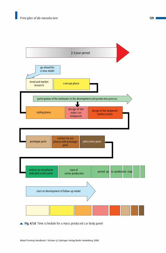
129Principles of die manufacture
Fig. 4.1.6 Time schedule for a mass produced car body panel
2-3 year period
go-ahead fora new model
trend and marketresearch
concept phase
participation of the toolmaker in the development and production process
styling phasedesign of the
outer carbodywork
design of the bodyworkreinforcement
prototype parts pilot series partsvarious try-out
phases with prototypeparts
various try-out phaseswith pilot series parts
start of series production
period up to production stop
start on development of follow-up model
Metal Forming Handbook / Schuler (c) Springer-Verlag Berlin Heidelberg 1998
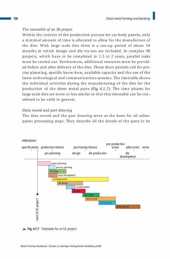
The timetable of an SE projectWithin the context of the production process for car body panels, onlya minimal amount of time is allocated to allow for the manufacture ofthe dies. With large scale dies there is a run-up period of about 10months in which design and die try-out are included. In complex SEprojects, which have to be completed in 1.5 to 2 years, parallel tasksmust be carried out. Furthermore, additional resources must be provid-ed before and after delivery of the dies. These short periods call for pre-cise planning, specific know-how, available capacity and the use of thelatest technological and communications systems. The timetable showsthe individual activities during the manufacturing of the dies for theproduction of the sheet metal parts (Fig. 4.1.7). The time phases forlarge scale dies are more or less similar so that this timetable can be con-sidered to be valid in general.
Data record and part drawingThe data record and the part drawing serve as the basis for all subse-quent processing steps. They describe all the details of the parts to be
130 Sheet metal forming and blanking
Fig. 4.1.7 Timetable for an SE project
production releasespecifications
star
t of S
E pr
ojec
t
milestones:
purchasing releasepre-production
series pilot series series
pre-planning
process planning
CAD data
prototype parts
draw development
project planning
die design
casting models
machining
casting
bench work
home try-out
series try-out
design die production die development
Metal Forming Handbook / Schuler (c) Springer-Verlag Berlin Heidelberg 1998
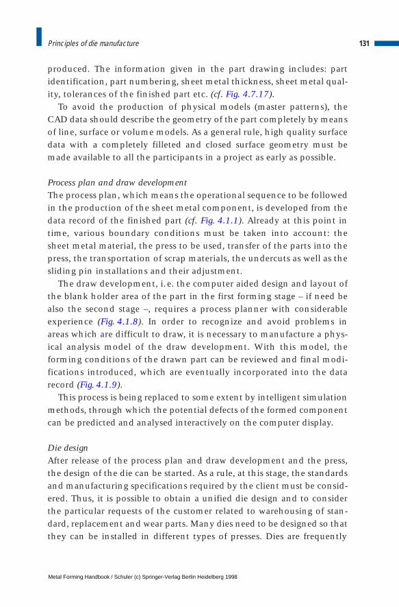
produced. The information given in the part drawing includes: partidentification, part numbering, sheet metal thickness, sheet metal qual-ity, tolerances of the finished part etc. (cf. Fig. 4.7.17).
To avoid the production of physical models (master patterns), theCAD data should describe the geometry of the part completely by meansof line, surface or volume models. As a general rule, high quality surfacedata with a completely filleted and closed surface geometry must bemade available to all the participants in a project as early as possible.
Process plan and draw developmentThe process plan, which means the operational sequence to be followedin the production of the sheet metal component, is developed from thedata record of the finished part (cf. Fig. 4.1.1). Already at this point intime, various boundary conditions must be taken into account: thesheet metal material, the press to be used, transfer of the parts into thepress, the transportation of scrap materials, the undercuts as well as thesliding pin installations and their adjustment.
The draw development, i.e. the computer aided design and layout ofthe blank holder area of the part in the first forming stage – if need bealso the second stage –, requires a process planner with considerableexperience (Fig. 4.1.8). In order to recognize and avoid problems inareas which are difficult to draw, it is necessary to manufacture a phys-ical analysis model of the draw development. With this model, theforming conditions of the drawn part can be reviewed and final modi-fications introduced, which are eventually incorporated into the datarecord (Fig. 4.1.9).
This process is being replaced to some extent by intelligent simulationmethods, through which the potential defects of the formed componentcan be predicted and analysed interactively on the computer display.
Die designAfter release of the process plan and draw development and the press,the design of the die can be started. As a rule, at this stage, the standardsand manufacturing specifications required by the client must be consid-ered. Thus, it is possible to obtain a unified die design and to considerthe particular requests of the customer related to warehousing of stan-dard, replacement and wear parts. Many dies need to be designed so thatthey can be installed in different types of presses. Dies are frequently
131Principles of die manufacture
Metal Forming Handbook / Schuler (c) Springer-Verlag Berlin Heidelberg 1998
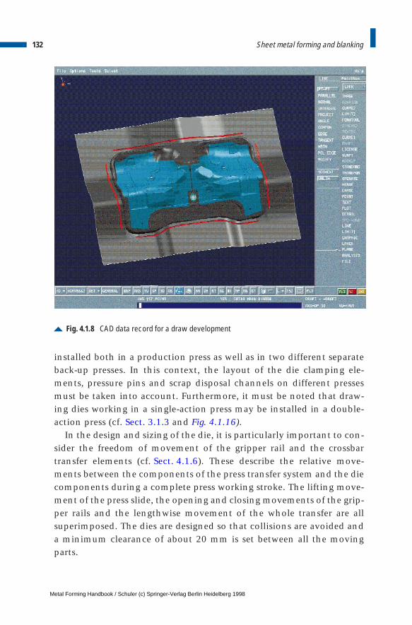
installed both in a production press as well as in two different separateback-up presses. In this context, the layout of the die clamping ele-ments, pressure pins and scrap disposal channels on different pressesmust be taken into account. Furthermore, it must be noted that draw-ing dies working in a single-action press may be installed in a double-action press (cf. Sect. 3.1.3 and Fig. 4.1.16).
In the design and sizing of the die, it is particularly important to con-sider the freedom of movement of the gripper rail and the crossbartransfer elements (cf. Sect. 4.1.6). These describe the relative move-ments between the components of the press transfer system and the diecomponents during a complete press working stroke. The lifting move-ment of the press slide, the opening and closing movements of the grip-per rails and the lengthwise movement of the whole transfer are allsuperimposed. The dies are designed so that collisions are avoided anda minimum clearance of about 20 mm is set between all the movingparts.
132 Sheet metal forming and blanking
Fig. 4.1.8 CAD data record for a draw development
Metal Forming Handbook / Schuler (c) Springer-Verlag Berlin Heidelberg 1998
Guides of the upper and lower dies must carry the shearing forcesand be sized according to the calculated and anticipated forces andfunctions. Large scale gibs show nearly no lateral displacement and a consistent, unchanging pressure pattern of the operational die(cf. Sect. 4.1.5). Furthermore, they reduce the tilting of the die and thepress slides (Fig. 4.1.10). Thus, a consistent overall high quality ofpressed parts is achieved.
In order to avoid errors and potential problem areas later in produc-tion, the so-called FMEA (Failure Mode and Effects Analysis) is usedwith proven success during the design stage with the close collabora-tion of all those involved with the project. The design of the pressedparts and their arrangement and positioning in the dies have a greatinfluence on production safety. In sheet metal forming well-designedpress components will lead to simple, production-friendly and low costtools. Difficult to form press parts, on the other hand, involve expen-sive, complicated and high cost dies, which are less easily integrated
133Principles of die manufacture
Fig. 4.1.9 Physical analysis model of a draw development
Metal Forming Handbook / Schuler (c) Springer-Verlag Berlin Heidelberg 1998
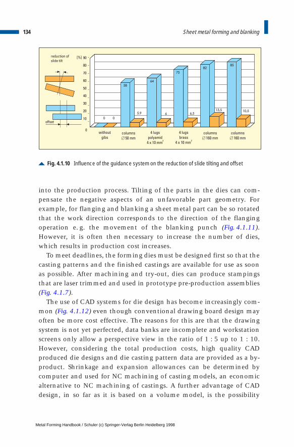
into the production process. Tilting of the parts in the dies can com-pensate the negative aspects of an unfavorable part geometry. Forexample, for flanging and blanking a sheet metal part can be so rotatedthat the work direction corresponds to the direction of the flangingoperation e. g. the movement of the blanking punch (Fig. 4.1.11).However, it is often then necessary to increase the number of dies,which results in production cost increases.
To meet deadlines, the forming dies must be designed first so that thecasting patterns and the finished castings are available for use as soonas possible. After machining and try-out, dies can produce stampingsthat are laser trimmed and used in prototype pre-production assemblies(Fig. 4.1.7).
The use of CAD systems for die design has become increasingly com-mon (Fig. 4.1.12) even though conventional drawing board design mayoften be more cost effective. The reasons for this are that the drawingsystem is not yet perfected, data banks are incomplete and workstationscreens only allow a perspective view in the ratio of 1 : 5 up to 1 : 10.However, considering the total production costs, high quality CADproduced die designs and die casting pattern data are provided as a by-product. Shrinkage and expansion allowances can be determined bycomputer and used for NC machining of casting models, an economicalternative to NC machining of castings. A further advantage of CADdesign, in so far as it is based on a volume model, is the possibility
134 Sheet metal forming and blanking
Fig. 4.1.10 Influence of the guidance system on the reduction of slide tilting and offset
58
64
75
8285
0
5,9 6 6,5
13,5 10,5
0
0
10
20
30
40
50
60
70
80
90
offset
[%]
columns
160 mm[
columns
160 mm[
4 lugs
polyamid
4 x 10 mm2
columns
50 mm[
without
gibs
4 lugs
brass
4 x 10 mm2
reduction of
slide tilt
Metal Forming Handbook / Schuler (c) Springer-Verlag Berlin Heidelberg 1998
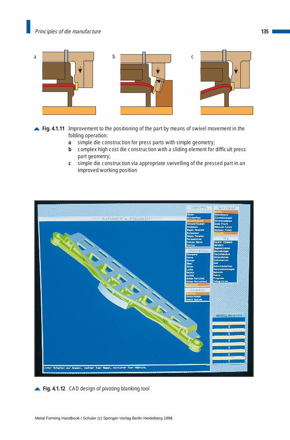
135Principles of die manufacture
Fig. 4.1.12 CAD design of pivoting blanking tool
Fig. 4.1.11 Improvement to the positioning of the part by means of swivel movement in thefolding operation: a simple die construction for press parts with simple geometry; b complex high cost die construction with a sliding element for difficult press
part geometry; c simple die construction via appropriate swivelling of the pressed part in an
improved working position
a b c
Metal Forming Handbook / Schuler (c) Springer-Verlag Berlin Heidelberg 1998
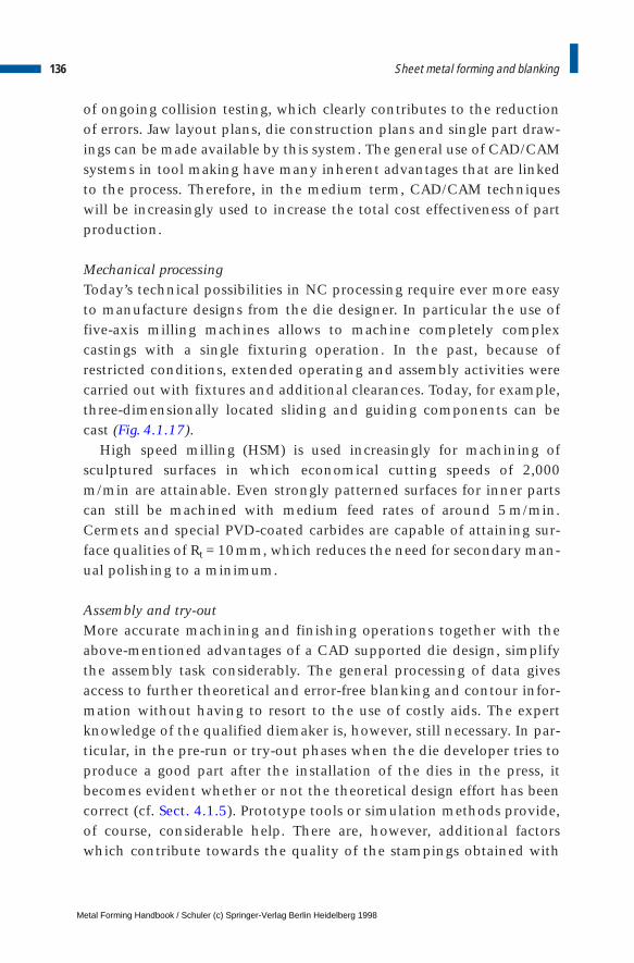
of ongoing collision testing, which clearly contributes to the reductionof errors. Jaw layout plans, die construction plans and single part draw-ings can be made available by this system. The general use of CAD/CAMsystems in tool making have many inherent advantages that are linkedto the process. Therefore, in the medium term, CAD/CAM techniqueswill be increasingly used to increase the total cost effectiveness of partproduction.
Mechanical processingToday’s technical possibilities in NC processing require ever more easyto manufacture designs from the die designer. In particular the use offive-axis milling machines allows to machine completely complexcastings with a single fixturing operation. In the past, because ofrestricted conditions, extended operating and assembly activities werecarried out with fixtures and additional clearances. Today, for example,three-dimensionally located sliding and guiding components can becast (Fig. 4.1.17).
High speed milling (HSM) is used increasingly for machining ofsculptured surfaces in which economical cutting speeds of 2,000m/min are attainable. Even strongly patterned surfaces for inner partscan still be machined with medium feed rates of around 5 m/min.Cermets and special PVD-coated carbides are capable of attaining sur-face qualities of Rt = 10mm, which reduces the need for secondary man-ual polishing to a minimum.
Assembly and try-outMore accurate machining and finishing operations together with theabove-mentioned advantages of a CAD supported die design, simplifythe assembly task considerably. The general processing of data givesaccess to further theoretical and error-free blanking and contour infor-mation without having to resort to the use of costly aids. The expertknowledge of the qualified diemaker is, however, still necessary. In par-ticular, in the pre-run or try-out phases when the die developer tries toproduce a good part after the installation of the dies in the press, itbecomes evident whether or not the theoretical design effort has beencorrect (cf. Sect. 4.1.5). Prototype tools or simulation methods provide,of course, considerable help. There are, however, additional factorswhich contribute towards the quality of the stampings obtained with
136 Sheet metal forming and blanking
Metal Forming Handbook / Schuler (c) Springer-Verlag Berlin Heidelberg 1998
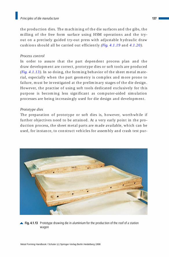
the production dies. The machining of the die surfaces and the gibs, themilling of the free form surface using HSM operations and the try-out on a precisely guided try-out press with adjustable hydraulic drawcushions should all be carried out efficiently (Fig. 4.1.19 and 4.1.20).
Process controlIn order to assure that the part dependent process plan and the draw development are correct, prototype dies or soft tools are produced(Fig. 4.1.13). In so doing, the forming behavior of the sheet metal mate-rial, especially when the part geometry is complex and more prone tofailure, must be investigated at the preliminary stages of the die design.However, the practise of using soft tools dedicated exclusively for thispurpose is becoming less significant as computer-aided simulationprocesses are being increasingly used for die design and development.
Prototype diesThe preparation of prototype or soft dies is, however, worthwhile iffurther objectives need to be attained. At a very early point in the pro-duction process, the sheet metal parts are made available, which can beused, for instance, to construct vehicles for assembly and crash test pur-
137Principles of die manufacture
Fig. 4.1.13 Prototype drawing die in aluminium for the production of the roof of a station wagon
Metal Forming Handbook / Schuler (c) Springer-Verlag Berlin Heidelberg 1998
poses. In certain cases, these parts may be used as pre-production series(Fig. 4.1.7). A further consideration which justifies the production ofprototype dies is when the timing of their manufacture is close to theschedule for the beginning of series production. Thus, information onthe formability and tolerances of the parts can be obtained, which con-tributes to goal oriented and cost-effective die manufacture.
The following are some of the points which must be taken into accounthere:
– the die material – the complexity of the sheet metal part– the blank material – the design of the draw development– the geometrical parameters such as degree of shrinkage, cambering,
prestressing– the process-related variable such as lubrication, blank holder forces,
work-flow direction, draw beads– the size and geometry of the blanks– special factors and parameters which influence the results of the
stamping operation
The type and design of the prototype dies are influenced by differentfactors. The choice of prototype material will be in line with the sheetmetal specification, thickness and the number of parts to be produced.Today, plastics, aluminium alloys (Fig. 4.1.13), different qualities of castmetals as well as rolled steel can be used as prototype or soft die material. A summary of the choice and application criteria is given inTable 4.1.1.
Methods of process simulationComputer-aided simulation techniques, e. g. the analysis of the form-ing process without any physical dies, will increasingly replace the useof prototype and soft dies. This development is becoming more practi-cal through rapidly growing hardware developments which allow theprocessing of ever increasing amounts of computerised data in evershorter time spans. In addition, the computer software used for processsimulation has become more reliable and more user friendly.
138 Sheet metal forming and blanking
Metal Forming Handbook / Schuler (c) Springer-Verlag Berlin Heidelberg 1998
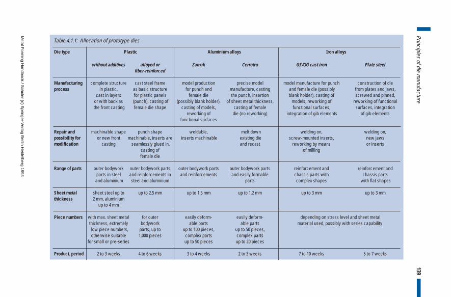
139Principles of die m
anufacture
Die type Plastic Aluminium alloys Iron alloys
without additives alloyed or Zamak Cerrotru GS/GG cast iron Plate steelfiber-reinforced
Manufacturing complete structure cast steel frame model production precise model model manufacture for punch construction of dieprocess in plastic, as basic structure for punch and manufacture, casting and female die (possibly from plates and jaws,
cast in layers for plastic panels female die the punch, insertion blank holder), casting of screwed and pinned,or with back as (punch), casting of (possibly blank holder), of sheet metal thickness, models, reworking of reworking of functionalthe front casting female die shape casting of models, casting of female functional surfaces, surfaces, integration
reworking of die (no reworking) integration of gib elements of gib elementsfunctional surfaces
Repair and machinable shape punch shape weldable, melt down welding on, welding on, possibility for or new front machinable, inserts are inserts machinable existing die screw-mounted inserts, new jawsmodification casting seamlessly glued in, and recast reworking by means or inserts
casting of of millingfemale die
Range of parts outer bodywork outer bodywork parts outer bodywork parts outer bodywork parts reinforcement and reinforcement and parts in steel and reinforcements in and reinforcements and easily formable chassis parts with chassis parts
and aluminium steel and aluminium parts complex shapes with flat shapes
Sheet metal sheet steel up to up to 2.5 mm up to 1.5 mm up to 1.2 mm up to 3 mm up to 3 mmthickness 2 mm, aluminium
up to 4 mm
Piece numbers with max. sheet metal for outer easily deform- easily deform- depending on stress level and sheet metal thickness, extremely bodywork able parts able parts material used, possibly with series capabilitylow piece numbers, parts, up to up to 100 pieces, up to 50 pieces,otherwise suitable 1,000 pieces complex parts complex parts
for small or pre-series up to 50 pieces up to 20 pieces
Product. period 2 to 3 weeks 4 to 6 weeks 3 to 4 weeks 2 to 3 weeks 7 to 10 weeks 5 to 7 weeks
Table 4.1.1: Allocation of prototype dies
Metal F
orming H
andbook / Schuler (c) S
pringer-Verlag B
erlin Heidelberg 1998
For the evaluation of the geometry data, which has been establishedby the processing plan and the draw development as well as the pro-duction parameters, CAE solutions are available which are based uponmathematical and plasto-mechanical equations or on experimentallyproven data. Analytical and numerical simulation belong to these solu-tions. The numerical methods, and here in particular the FiniteElement Method (FEM), deliver today the most accurate results.Stampings can be almost completely interactively analysed on a work-station in relation to the most important failure criteria. The results arethe distribution of stress (tears) (Fig. 4.1.14), the tendency towardswrinkling (Fig. 4.1.15) and the variation of the sheet metal thickness.The necessary steps and the prerequisites for a simulation run are as fol-lows:
– preparation of CAD data for the punch, female die and blank holderas well as the total geometry of the draw development in the work-ing direction (Fig. 4.1.8),
– determination and input of the blank size (cf. Sect. 4.2.1 and 4.5),– input of the process parameters such as sheet metal material, rolling
direction, blank holder force, frictional conditions,– definition i. e. establishment of the FE mesh (partly automatic) and– initiation of the calculation process.
By varying the process and die parameters, the simulation can berepeated as often as required until a failure-free drawing part is pro-duced. The advantage of this process lies in the fact that any objectiveand necessary component changes can be introduced at any time priorto the actual manufacture of the dies. Specific measures for the control-ling metal flow, for example through the shape of the blank or throughthe use of draw beads, can be simulated. Similarly, calculations can bemade to predict and compensate for spring back (cf. Sect. 4.8.1).
Through process simulation, process planners and die designers re-ceive reliable information at an early stage in the die development,which really contributes to the production of fully operational and reli-able dies.
140 Sheet metal forming and blanking
Metal Forming Handbook / Schuler (c) Springer-Verlag Berlin Heidelberg 1998

141Principles of die manufacture
1.200.00 Maximum strain limit
0.04000.0000 Wrinkling
Fig. 4.1.15Representationof possiblewrinkle formation bymeans of FEMsimulation
Fig. 4.1.14Representationof stress distribution bymeans of FEMsimulation
Metal Forming Handbook / Schuler (c) Springer-Verlag Berlin Heidelberg 1998
4.1.3 Die materials
The processing of high strength sheet metal, which is becoming morewidely used in stamping technology, calls for higher pressing forces.This means higher loads on the dies and greater overall wear on thetools. In order to meet the requirements for long die life, while main-taining acceptable component quality, special materials – most ofwhich have been hardened or coated – must be used in the construc-tion of the dies. The basic structure of different types of dies and theirmost important components are shown in Figs. 4.1.16 and 4.1.17.
Table 4.1.2 lists the various components of dies used for drawing,blanking, folding and flanging as well as the materials used to manu-facture them. Table 4.1.3 lists various surface hardening processes andcoating methods for dies. Coatings, for example through hard chromi-um plating, can improve the sliding characteristics in deep drawing, sothat the need for lubrication is greatly reduced.
4.1.4 Casting of dies
The casting process is one of the steps in the overall process of manu-facturing production dies for sheet metal forming where the higheststandards are required by die makers. In contrast to castings used ingeneral machinery manufacture, in die manufacture, multiple usage ofa model is not possible, as no two tools are exactly the same. A dispos-able pattern made from polystyrene (polyester, hard foam) is thereforeused for the die casting process (Fig. 4.1.18).
The casting is carried out as a full form casting process: the poly-styrene pattern stays in its resin-hardened quartz sand form. The liquidmetal, which is poured in, evaporates or rather melts the pattern. Withthe full form casting process, the foundry industry has developed a pro-duction method which offers a large measure of design-related, techni-cal, economic and logistical improvements in die making. For thedesigner, there is the possibility of precise measurement and functionalcontrol, as the full form pattern is identical in shape to the piece beingcast. Product development is made easier, as the pattern can be alteredwithout any problems by means of machining or gluing processes.Furthermore, the costs of core box, core production, core transport andcore installation are reduced.
142 Sheet metal forming and blanking
Metal Forming Handbook / Schuler (c) Springer-Verlag Berlin Heidelberg 1998
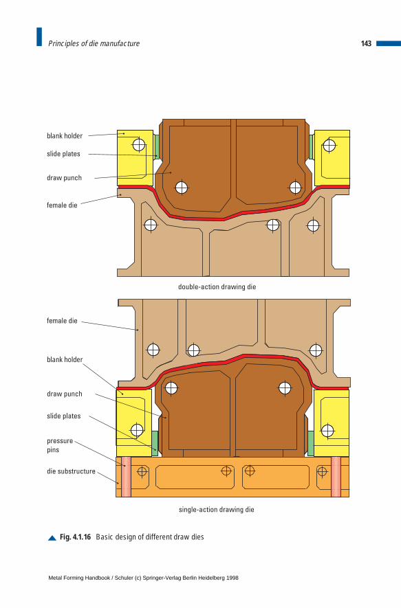
143Principles of die manufacture
Fig. 4.1.16 Basic design of different draw dies
blank holder
slide plates
draw punch
female die
female die
blank holder
pressure
pins
double-action drawing die
single-action drawing die
die substructure
draw punch
slide plates
Metal Forming Handbook / Schuler (c) Springer-Verlag Berlin Heidelberg 1998
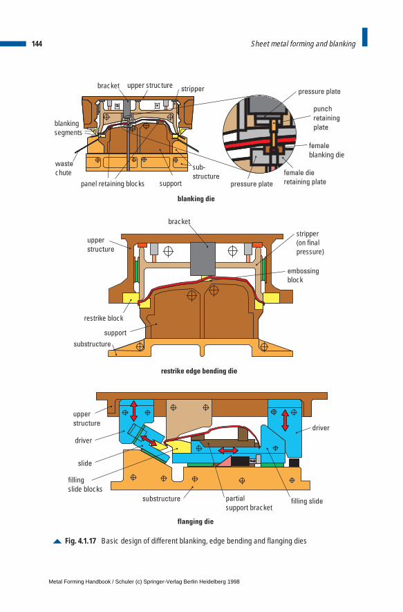
144 Sheet metal forming and blanking
Fig. 4.1.17 Basic design of different blanking, edge bending and flanging dies
driver
driver
filling slidepartial
support bracketsubstructure
filling
slide blocks
slide
upper
structure
female
blanking die
punch
retaining
plateblankingsegments
sub-structure
pressure plate
pressure plate
female die
retaining plate
waste
chutepanel retaining blocks support
upper structurebracket stripper
upper
structure
restrike block
stripper(on finalpressure)
support
substructure
bracket
embossing
block
blanking die
restrike edge bending die
flanging die
Metal Forming Handbook / Schuler (c) Springer-Verlag Berlin Heidelberg 1998
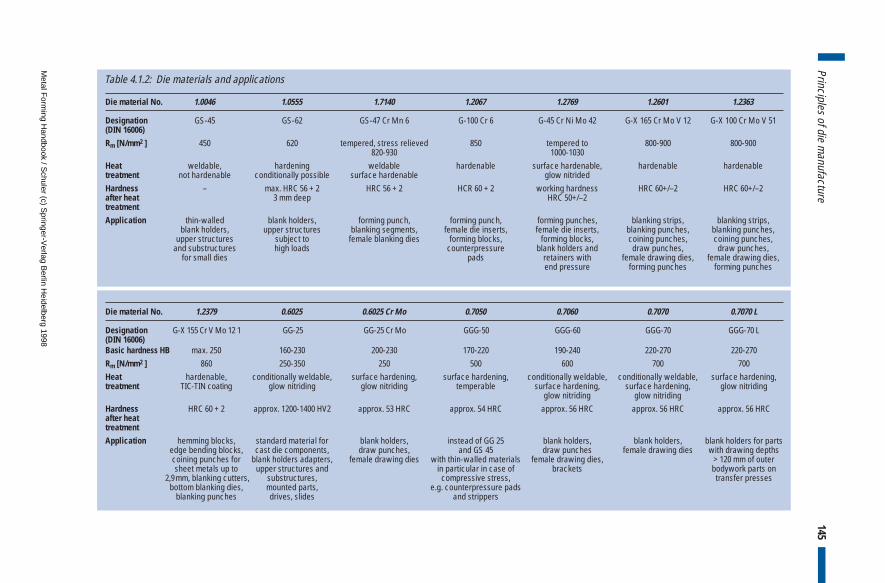
145Principles of die m
anufacture
Die material No. 1.0046 1.0555 1.7140 1.2067 1.2769 1.2601 1.2363
Designation GS-45 GS-62 GS-47 Cr Mn 6 G-100 Cr 6 G-45 Cr Ni Mo 42 G-X 165 Cr Mo V 12 G-X 100 Cr Mo V 51(DIN 16006)
Rm [N/mm2 ] 450 620 tempered, stress relieved 850 tempered to 800-900 800-900820-930 1000-1030
Heat weldable, hardening weldable hardenable surface hardenable, hardenable hardenabletreatment not hardenable conditionally possible surface hardenable glow nitridedHardness – max. HRC 56 + 2 HRC 56 + 2 HCR 60 + 2 working hardness HRC 60+/–2 HRC 60+/–2after heat 3 mm deep HRC 50+/–2treatment
Application thin-walled blank holders, forming punch, forming punch, forming punches, blanking strips, blanking strips,blank holders, upper structures blanking segments, female die inserts, female die inserts, blanking punches, blanking punches,
upper structures subject to female blanking dies forming blocks, forming blocks, coining punches, coining punches,and substructures high loads counterpressure blank holders and draw punches, draw punches,
for small dies pads retainers with female drawing dies, female drawing dies,end pressure forming punches forming punches
Die material No. 1.2379 0.6025 0.6025 Cr Mo 0.7050 0.7060 0.7070 0.7070 L
Designation G-X 155 Cr V Mo 12 1 GG-25 GG-25 Cr Mo GGG-50 GGG-60 GGG-70 GGG-70 L(DIN 16006)Basic hardness HB max. 250 160-230 200-230 170-220 190-240 220-270 220-270Rm [N/mm2 ] 860 250-350 250 500 600 700 700Heat hardenable, conditionally weldable, surface hardening, surface hardening, conditionally weldable, conditionally weldable, surface hardening,treatment TIC-TIN coating glow nitriding glow nitriding temperable surface hardening, surface hardening, glow nitriding
glow nitriding glow nitridingHardness HRC 60 + 2 approx. 1200-1400 HV2 approx. 53 HRC approx. 54 HRC approx. 56 HRC approx. 56 HRC approx. 56 HRCafter heattreatment
Application hemming blocks, standard material for blank holders, instead of GG 25 blank holders, blank holders, blank holders for partsedge bending blocks, cast die components, draw punches, and GS 45 draw punches female drawing dies with drawing depths coining punches for blank holders adapters, female drawing dies with thin-walled materials female drawing dies, > 120 mm of outer sheet metals up to upper structures and in particular in case of brackets bodywork parts on
2,9mm, blanking cutters, substructures, compressive stress, transfer pressesbottom blanking dies, mounted parts, e.g. counterpressure pads
blanking punches drives, slides and strippers
Table 4.1.2: Die materials and applications
Metal F
orming H
andbook / Schuler (c) S
pringer-Verlag B
erlin Heidelberg 1998
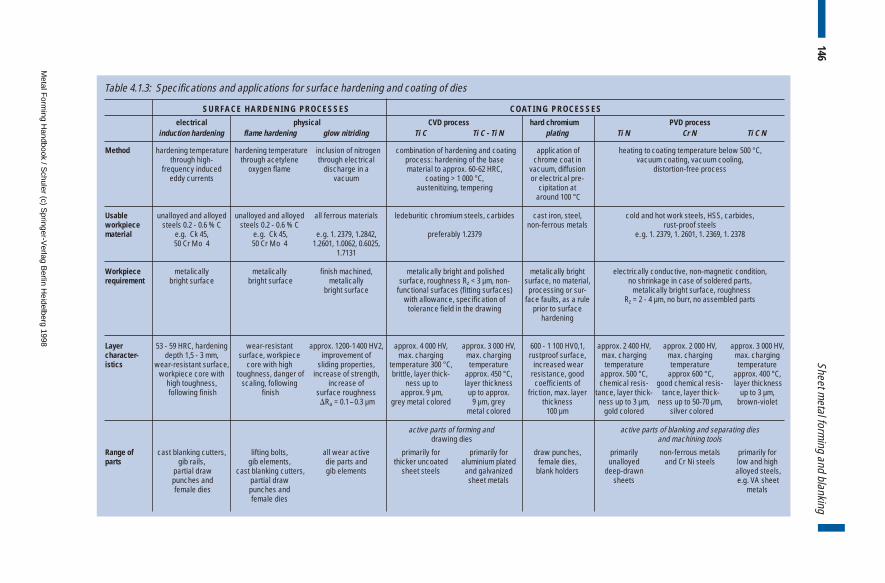
146Sheet m
etal forming and blanking
SURFACE HARDENING PROCESSES COATING PROCESSES
electrical physical CVD process hard chromium PVD processinduction hardening flame hardening glow nitriding Ti C Ti C - Ti N plating Ti N Cr N Ti C N
Method hardening temperature hardening temperature inclusion of nitrogen combination of hardening and coating application of heating to coating temperature below 500 °C,through high- through acetylene through electrical process: hardening of the base chrome coat in vacuum coating, vacuum cooling,
frequency induced oxygen flame discharge in a material to approx. 60-62 HRC, vacuum, diffusion distortion-free processeddy currents vacuum coating > 1 000 °C, or electrical pre-
austenitizing, tempering cipitation ataround 100 °C
Usable unalloyed and alloyed unalloyed and alloyed all ferrous materials ledeburitic chromium steels, carbides cast iron, steel, cold and hot work steels, HSS, carbides,workpiece steels 0.2 - 0.6 % C steels 0.2 - 0.6 % C non-ferrous metals rust-proof steelsmaterial e.g. Ck 45, e.g. Ck 45, e.g. 1. 2379, 1.2842, preferably 1.2379 e.g. 1. 2379, 1. 2601, 1. 2369, 1. 2378
50 Cr Mo 4 50 Cr Mo 4 1.2601, 1.0062, 0.6025,1.7131
Workpiece metalically metalically finish machined, metalically bright and polished metalically bright electrically conductive, non-magnetic condition,requirement bright surface bright surface metalically surface, roughness Rz < 3 µm, non- surface, no material, no shrinkage in case of soldered parts,
bright surface functional surfaces (fitting surfaces) processing or sur- metalically bright surface, roughnesswith allowance, specification of face faults, as a rule Rz = 2 - 4 µm, no burr, no assembled parts
tolerance field in the drawing prior to surface hardening
Layer 53 - 59 HRC, hardening wear-resistant approx. 1200-1 400 HV2, approx. 4 000 HV, approx. 3 000 HV, 600 - 1 100 HV0,1, approx. 2 400 HV, approx. 2 000 HV, approx. 3 000 HV, character- depth 1,5 - 3 mm, surface, workpiece improvement of max. charging max. charging rustproof surface, max. charging max. charging max. chargingistics wear-resistant surface, core with high sliding properties, temperature 300 °C, temperature increased wear temperature temperature temperature
workpiece core with toughness, danger of increase of strength, brittle, layer thick- approx. 450 °C, resistance, good approx. 500 °C, approx 600 °C, approx. 400 °C, high toughness, scaling, following increase of ness up to layer thickness coefficients of chemical resis- good chemical resis- layer thicknessfollowing finish finish surface roughness approx. 9 µm, up to approx. friction, max. layer tance, layer thick- tance, layer thick- up to 3 µm,
DRa = 0.1–0.3 µm grey metal colored 9 µm, grey thickness ness up to 3 µm, ness up to 50-70 µm, brown-violetmetal colored 100 µm gold colored silver colored
active parts of forming and active parts of blanking and separating diesdrawing dies and machining tools
Range of cast blanking cutters, lifting bolts, all wear active primarily for primarily for draw punches, primarily non-ferrous metals primarily for parts gib rails, gib elements, die parts and thicker uncoated aluminium plated female dies, unalloyed and Cr Ni steels low and high
partial draw cast blanking cutters, gib elements sheet steels and galvanized blank holders deep-drawn alloyed steels,punches and partial draw sheet metals sheets e.g. VA sheet female dies punches and metals
female dies
Table 4.1.3: Specifications and applications for surface hardening and coating of dies
Metal F
orming H
andbook / Schuler (c) S
pringer-Verlag B
erlin Heidelberg 1998
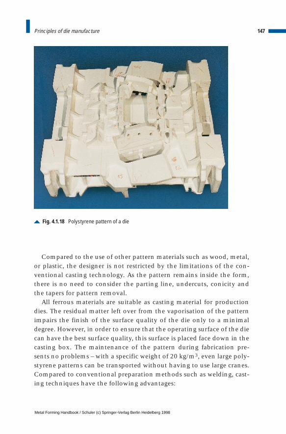
Compared to the use of other pattern materials such as wood, metal,or plastic, the designer is not restricted by the limitations of the con-ventional casting technology. As the pattern remains inside the form,there is no need to consider the parting line, undercuts, conicity andthe tapers for pattern removal.
All ferrous materials are suitable as casting material for productiondies. The residual matter left over from the vaporisation of the patternimpairs the finish of the surface quality of the die only to a minimaldegree. However, in order to ensure that the operating surface of the diecan have the best surface quality, this surface is placed face down in thecasting box. The maintenance of the pattern during fabrication pre-sents no problems – with a specific weight of 20 kg/m3, even large poly-styrene patterns can be transported without having to use large cranes.Compared to conventional preparation methods such as welding, cast-ing techniques have the following advantages:
147Principles of die manufacture
Fig. 4.1.18 Polystyrene pattern of a die
Metal Forming Handbook / Schuler (c) Springer-Verlag Berlin Heidelberg 1998
– ability to work with complicated components with small manufac-turing tolerances,
– better distribution of forces in the cast piece via curvatures andsmooth blending of surfaces,
– better damping characteristics of cast iron compared to steel plate con-struction; as a result, quiet and low vibration proven components thatcan be highly stressed and provide low noise level in production,
– less tendency to distortion with cast iron, which ensures that a highlevel of precision is delivered from the production system,
– good wear and sliding characteristics,– die materials that can be hardened; thus, the cast component can
fullfill various functional requirements without any additional at-tachments,
– oil-tight containers, etc.,– no corners and cracks in the seams, which can lead to absorption of
moisture and corrosion,– good machinability, through which savings in the order of 20 to
50% on machining costs can be achieved,– as a rule, no stress-relieving process is necessary.
4.1.5 Try-out equipment
Try-out pressesEquipment for die try-out plays an important role in modern pressworkoperations. Dies are tested on a try-out press before starting production.In this way, the die set-up time on a production line press is reduced toa minimum. Press running times for all parts are consequently limitedto set-up and production time only and this increases the profitabilityof the production line.
In making dies for sheet metal forming, the sculptured surface of thedie cavity will be machined to form the male and female dies using theCAD-generated data for the finished part. As a general practice, bothparts of the die are normally produced from cast patterns (cf. Sect.4.1.4).During die development on a try-out press, it is possible to ascertain forthe first time, where any reworking needs to be carried out on thegeometry. The operational characteristics of the dies and the contactpattern are checked out. The flow of the material is evaluated to see
148 Sheet metal forming and blanking
Metal Forming Handbook / Schuler (c) Springer-Verlag Berlin Heidelberg 1998
how it compares with the theoretical calculations. The formed parts areinspected for presence of any wrinkling, tears or bulges. In particular,high material thicknesses do occur in the corner areas of the blankholder surface because of tangential compressive stresses, which lead toundesirable higher surface pressures and can adversely affect results ofthe deep drawing process. To rectify this, it is necessary to remove mate-rial and rework specific areas of the blank holder.
In a try-out press, the die geometry is modified by first forming a partand then grinding the punch, the die and the blank holder at the mostcritical points in order to obtain the required part quality. This proce-dure, e. g. forming and regrinding, is repeated until good quality partsare formed. The aim is to perfect the die on the try-out press, so thatcostly modifications for a series run on a production press are mini-mized. Try-out operations can only be considered complete when therequired part quality is achieved, i. e. when the first good part is pro-duced, and production on the production presses can then start.
If the draw cushion of a single-action press or for that matter, theblank holder of a double-action press, is equipped with a multi pointcontroller, the try-out costs can be greatly reduced (cf. Sect. 3.1.4 and3.2.8) – the production press onto which the die will later be installedand the try-out press should certainly be equipped, as far as possible,with a similar type of control system. Instead of working on the spe-cific die area, or using draw beads (cf. Fig. 4.2.6 and 4.2.7), the requireddeep drawing result can be achieved simply by making adjustments ofindividual control cylinders. An additional device, which controls thepressure during the draw stroke (cf. Fig. 3.1.12) contributes significant-ly to reducing try-out costs and achieving the highest part quality onthe production press.
During the try-out process, the parameters of the forming operation,especially those which can be adjusted on the actual press being used,play a decisive role. Hydraulic and mechanical try-out presses test thedies under conditions which are as close as possible to those found innormal production runs. In order to achieve a faster and more reliableproduction start-up, a high degree of compatibility of the main presscharacteristics – such as the rigidity and transverse bending of the bedand slide, etc. – between the try-out press and the stations of the pro-duction press is an advantage. The closer the characteristics of the try-out press are to those of the production line press, the shorter will be
149Principles of die manufacture
Metal Forming Handbook / Schuler (c) Springer-Verlag Berlin Heidelberg 1998
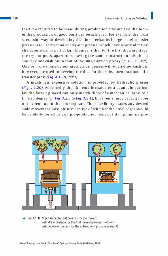
the time required to be spent during production start-up and the soon-er the production of good parts can be achieved. For example, the mostsuccessful way of developing dies for mechanical large-panel transferpresses is to use mechanical try-out presses, which have nearly identicalcharacteristics. In particular, this means that for the first drawing stage,the try-out press, apart from having the same construction, also has asimilar draw cushion to that of the single-action press (Fig. 4.1.19, left).One or more single-action mechanical presses without a draw cushion,however, are used to develop the dies for the subsequent stations of atransfer press (Fig. 4.1.19, right).
A much less expensive solution is provided by hydraulic presses (Fig. 4.1.20). Admittedly, their kinematic characteristics and, in particu-lar, the forming speed can only match those of a mechanical press to alimited degree (cf. Fig. 3.2.3 to Fig. 3.3.1); but their energy capacity doesnot depend upon the stroking rate. Their flexibility makes any desiredslide movement possible irrespective of whether the dowl edges shouldbe carefully tested or any pre-production series of stampings are pro-
150 Sheet metal forming and blanking
Fig. 4.1.19 Mechanical try-out presses for die try-out:with draw cushion for the first forming process (left) andwithout draw cushion for the subsequent processes (right)
Metal Forming Handbook / Schuler (c) Springer-Verlag Berlin Heidelberg 1998
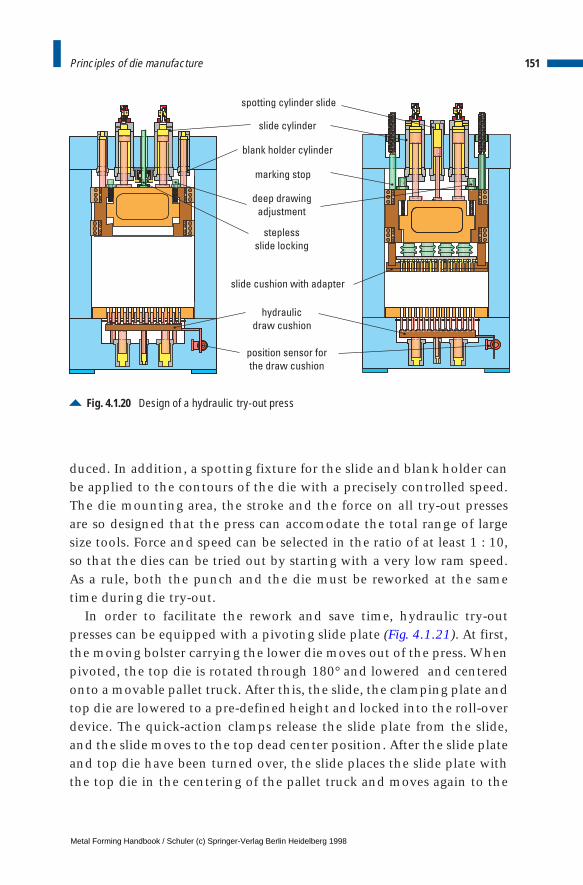
duced. In addition, a spotting fixture for the slide and blank holder canbe applied to the contours of the die with a precisely controlled speed.The die mounting area, the stroke and the force on all try-out pressesare so designed that the press can accomodate the total range of largesize tools. Force and speed can be selected in the ratio of at least 1 : 10,so that the dies can be tried out by starting with a very low ram speed.As a rule, both the punch and the die must be reworked at the sametime during die try-out.
In order to facilitate the rework and save time, hydraulic try-outpresses can be equipped with a pivoting slide plate (Fig. 4.1.21). At first,the moving bolster carrying the lower die moves out of the press. Whenpivoted, the top die is rotated through 180° and lowered and centeredonto a movable pallet truck. After this, the slide, the clamping plate andtop die are lowered to a pre-defined height and locked into the roll-overdevice. The quick-action clamps release the slide plate from the slide,and the slide moves to the top dead center position. After the slide plateand top die have been turned over, the slide places the slide plate withthe top die in the centering of the pallet truck and moves again to the
151Principles of die manufacture
Fig. 4.1.20 Design of a hydraulic try-out press
hydraulic
draw cushion
deep drawing
adjustment
stepless
slide locking
blank holder cylinder
slide cylinder
marking stop
slide cushion with adapter
position sensor for
the draw cushion
spotting cylinder slide
Metal Forming Handbook / Schuler (c) Springer-Verlag Berlin Heidelberg 1998
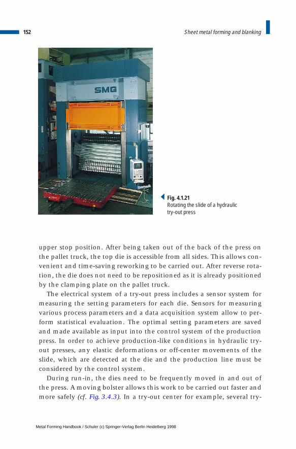
upper stop position. After being taken out of the back of the press onthe pallet truck, the top die is accessible from all sides. This allows con-venient and time-saving reworking to be carried out. After reverse rota-tion, the die does not need to be repositioned as it is already positionedby the clamping plate on the pallet truck.
The electrical system of a try-out press includes a sensor system formeasuring the setting parameters for each die. Sensors for measuringvarious process parameters and a data acquisition system allow to per-form statistical evaluation. The optimal setting parameters are savedand made available as input into the control system of the productionpress. In order to achieve production-like conditions in hydraulic try-out presses, any elastic deformations or off-center movements of theslide, which are detected at the die and the production line must beconsidered by the control system.
During run-in, the dies need to be frequently moved in and out ofthe press. A moving bolster allows this work to be carried out faster andmore safely (cf. Fig. 3.4.3). In a try-out center for example, several try-
152 Sheet metal forming and blanking
Fig. 4.1.21Rotating the slide of a hydraulic try-out press
Metal Forming Handbook / Schuler (c) Springer-Verlag Berlin Heidelberg 1998
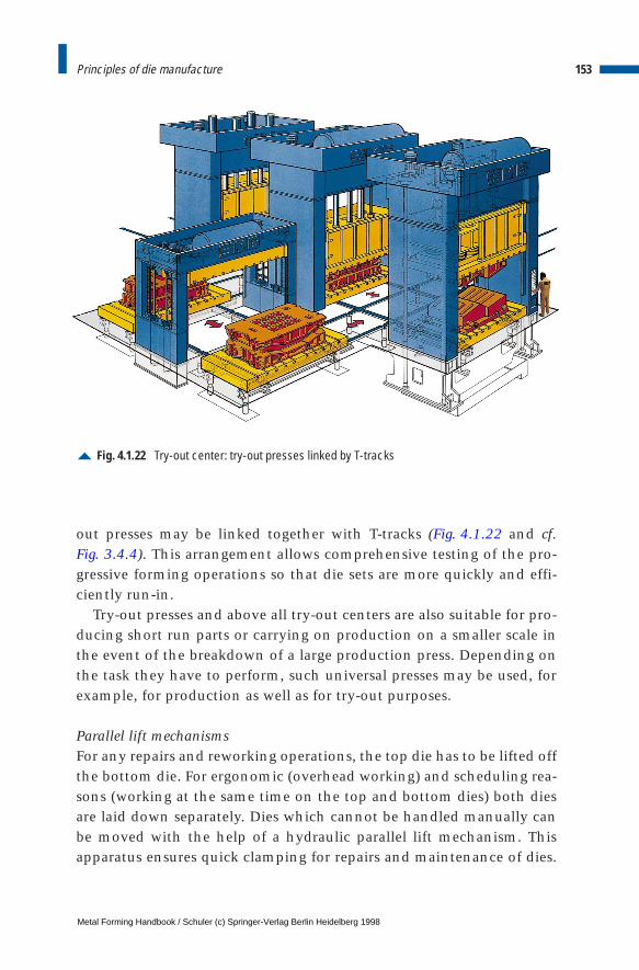
out presses may be linked together with T-tracks (Fig. 4.1.22 and cf. Fig. 3.4.4). This arrangement allows comprehensive testing of the pro-gressive forming operations so that die sets are more quickly and effi-ciently run-in.
Try-out presses and above all try-out centers are also suitable for pro-ducing short run parts or carrying on production on a smaller scale inthe event of the breakdown of a large production press. Depending onthe task they have to perform, such universal presses may be used, forexample, for production as well as for try-out purposes.
Parallel lift mechanismsFor any repairs and reworking operations, the top die has to be lifted offthe bottom die. For ergonomic (overhead working) and scheduling rea-sons (working at the same time on the top and bottom dies) both diesare laid down separately. Dies which cannot be handled manually canbe moved with the help of a hydraulic parallel lift mechanism. Thisapparatus ensures quick clamping for repairs and maintenance of dies.
153Principles of die manufacture
Fig. 4.1.22 Try-out center: try-out presses linked by T-tracks
Metal Forming Handbook / Schuler (c) Springer-Verlag Berlin Heidelberg 1998
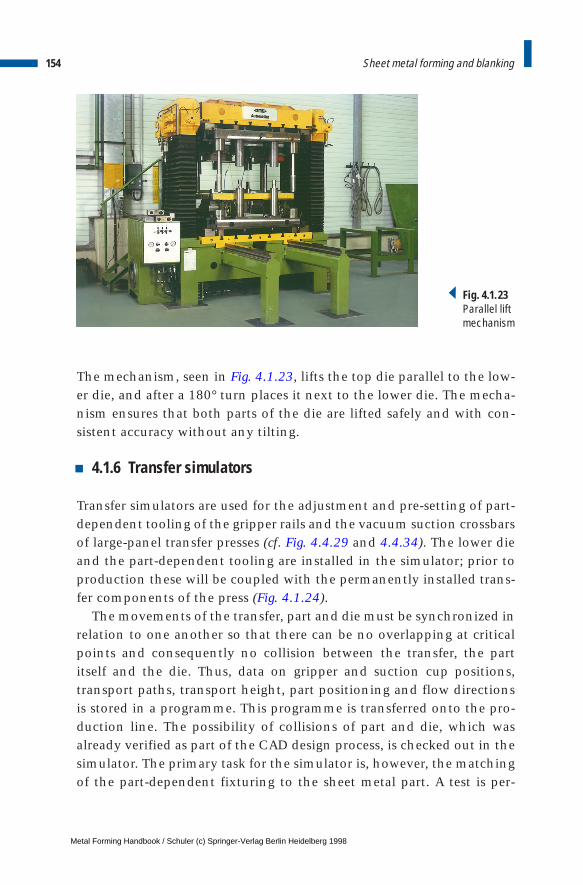
The mechanism, seen in Fig. 4.1.23, lifts the top die parallel to the low-er die, and after a 180° turn places it next to the lower die. The mecha-nism ensures that both parts of the die are lifted safely and with con-sistent accuracy without any tilting.
4.1.6 Transfer simulators
Transfer simulators are used for the adjustment and pre-setting of part-dependent tooling of the gripper rails and the vacuum suction crossbarsof large-panel transfer presses (cf. Fig. 4.4.29 and 4.4.34). The lower dieand the part-dependent tooling are installed in the simulator; prior toproduction these will be coupled with the permanently installed trans-fer components of the press (Fig. 4.1.24).
The movements of the transfer, part and die must be synchronized inrelation to one another so that there can be no overlapping at criticalpoints and consequently no collision between the transfer, the partitself and the die. Thus, data on gripper and suction cup positions,transport paths, transport height, part positioning and flow directionsis stored in a programme. This programme is transferred onto the pro-duction line. The possibility of collisions of part and die, which wasalready verified as part of the CAD design process, is checked out in thesimulator. The primary task for the simulator is, however, the matchingof the part-dependent fixturing to the sheet metal part. A test is per-
154 Sheet metal forming and blanking
Fig. 4.1.23Parallel liftmechanism
Metal Forming Handbook / Schuler (c) Springer-Verlag Berlin Heidelberg 1998
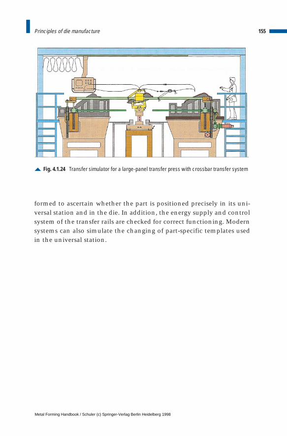
formed to ascertain whether the part is positioned precisely in its uni-versal station and in the die. In addition, the energy supply and controlsystem of the transfer rails are checked for correct functioning. Modernsystems can also simulate the changing of part-specific templates usedin the universal station.
155Principles of die manufacture
Fig. 4.1.24 Transfer simulator for a large-panel transfer press with crossbar transfer system
Metal Forming Handbook / Schuler (c) Springer-Verlag Berlin Heidelberg 1998
4 Sheet metal forming and blanking
4.2 Deep drawing and stretch drawing
4.2.1 Forming process
In deep drawing operations forming is carried out with tools (rigid andflexible), active media (e. g. sand, steel pellets, liquid) or active energy(i.e. a magnetic field). The following section covers possible applica-tions for stretch and deep drawing processes with rigid tools as a firstand subsequent operation (cf. Fig. 2.1.10 to 2.1.12). Sections 4.2.4 and4.2.5 will cover deep drawing with active media (cf. Fig.2.1.13).
Unlike in deep drawing, in stretch forming the sheet metal cannotflow because it is gripped by clamps or held in a blank holder. The form-ing process takes place with a reduction in the thickness of the sheetmetal. Pure stretch drawing is a forming process conducted under ten-sile stresses (cf. Fig.2.1.18). Mostly large-scale work pieces such as, forexample, body panel components used in aircraft or automotive man-ufacturing, are produced on special production lines. This is certainlytrue in producing low volume or large size parts, as, for example, withthe wing elements of an aircraft. The advantage of this process is thatthe tooling and machining costs are relatively modest in proportion tothe size of the part being produced.
Deep drawing is a compression-tension forming process according toDIN 8582. The procedure with the greatest range of applications is deepdrawing with rigid tooling, involving draw punches, a blank holder and afemale die (cf. Fig. 2.1.10). The blank is generally pulled over the drawpunch into the die, the blank holder prevents any wrinkling takingplace in the flange. In pure deep drawing, the thickness of the sheet
Metal Forming Handbook / Schuler (c) Springer-Verlag Berlin Heidelberg 1998
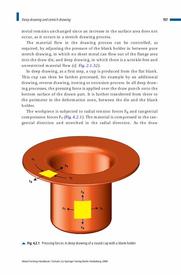
metal remains unchanged since an increase in the surface area does notoccur, as it occurs in a stretch drawing process.
The material flow in the drawing process can be controlled, asrequired, by adjusting the pressure of the blank holder in between purestretch drawing, in which no sheet metal can flow out of the flange areainto the draw die, and deep drawing, in which there is a wrinkle-free andunrestricted material flow (cf. Fig. 2.1.32).
In deep drawing, as a first step, a cup is produced from the flat blank.This cup can then be further processed, for example by an additionaldrawing, reverse drawing, ironing or extrusion process. In all deep draw-ing processes, the pressing force is applied over the draw punch onto thebottom surface of the drawn part. It is further transferred from there tothe perimeter in the deformation zone, between the die and the blankholder.
The workpiece is subjected to radial tension forces FR and tangentialcompression forces FT (Fig. 4.2.1). The material is compressed in the tan-gential direction and stretched in the radial direction. As the draw
157Deep drawing and stretch drawing
Fig. 4.2.1 Pressing forces in deep drawing of a round cup with a blank holder
FT
FR
FTFR
FT FT
FR
FR
Metal Forming Handbook / Schuler (c) Springer-Verlag Berlin Heidelberg 1998
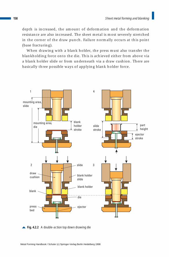
depth is increased, the amount of deformation and the deformationresistance are also increased. The sheet metal is most severely stretchedin the corner of the draw punch. Failure normally occurs at this point(base fracturing).
When drawing with a blank holder, the press must also transfer theblankholding force onto the die. This is achieved either from above viaa blank holder slide or from underneath via a draw cushion. There arebasically three possible ways of applying blank holder force.
158 Sheet metal forming and blanking
Fig. 4.2.2 A double-action top down drawing die
draw
cushion
blank
press
bedejector
die
blank holder
blank holder
slide
slide
1
2 3
4
slide
stroke
mounting area,
slide
blank
holder
stroke
mounting area
diepart
height
ejector
stroke
,
Metal Forming Handbook / Schuler (c) Springer-Verlag Berlin Heidelberg 1998
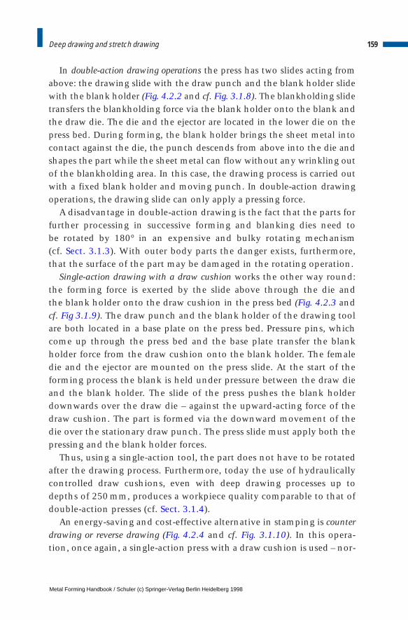
In double-action drawing operations the press has two slides acting fromabove: the drawing slide with the draw punch and the blank holder slidewith the blank holder (Fig. 4.2.2 and cf. Fig. 3.1.8). The blankholding slidetransfers the blankholding force via the blank holder onto the blank andthe draw die. The die and the ejector are located in the lower die on thepress bed. During forming, the blank holder brings the sheet metal intocontact against the die, the punch descends from above into the die andshapes the part while the sheet metal can flow without any wrinkling outof the blankholding area. In this case, the drawing process is carried outwith a fixed blank holder and moving punch. In double-action drawingoperations, the drawing slide can only apply a pressing force.
A disadvantage in double-action drawing is the fact that the parts forfurther processing in successive forming and blanking dies need to be rotated by 180° in an expensive and bulky rotating mechanism (cf. Sect. 3.1.3). With outer body parts the danger exists, furthermore,that the surface of the part may be damaged in the rotating operation.
Single-action drawing with a draw cushion works the other way round:the forming force is exerted by the slide above through the die and the blank holder onto the draw cushion in the press bed (Fig. 4.2.3 andcf. Fig 3.1.9). The draw punch and the blank holder of the drawing toolare both located in a base plate on the press bed. Pressure pins, whichcome up through the press bed and the base plate transfer the blankholder force from the draw cushion onto the blank holder. The femaledie and the ejector are mounted on the press slide. At the start of theforming process the blank is held under pressure between the draw dieand the blank holder. The slide of the press pushes the blank holderdownwards over the draw die – against the upward-acting force of thedraw cushion. The part is formed via the downward movement of thedie over the stationary draw punch. The press slide must apply both thepressing and the blank holder forces.
Thus, using a single-action tool, the part does not have to be rotatedafter the drawing process. Furthermore, today the use of hydraulicallycontrolled draw cushions, even with deep drawing processes up todepths of 250 mm, produces a workpiece quality comparable to that ofdouble-action presses (cf. Sect. 3.1.4).
An energy-saving and cost-effective alternative in stamping is counterdrawing or reverse drawing (Fig. 4.2.4 and cf. Fig. 3.1.10). In this opera-tion, once again, a single-action press with a draw cushion is used – nor-
159Deep drawing and stretch drawing
Metal Forming Handbook / Schuler (c) Springer-Verlag Berlin Heidelberg 1998
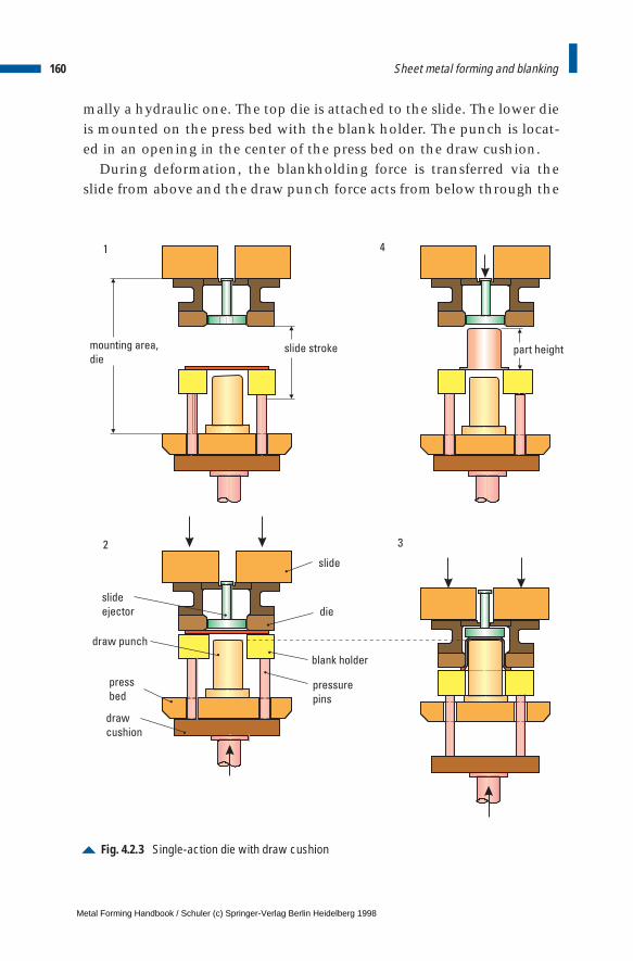
mally a hydraulic one. The top die is attached to the slide. The lower dieis mounted on the press bed with the blank holder. The punch is locat-ed in an opening in the center of the press bed on the draw cushion.
During deformation, the blankholding force is transferred via theslide from above and the draw punch force acts from below through the
160 Sheet metal forming and blanking
Fig. 4.2.3 Single-action die with draw cushion
mounting area,
die
1
2
4
3
slide
die
blank holder
pressure
pins
slide
ejector
press
bed
draw
cushion
slide stroke
draw punch
part height
Metal Forming Handbook / Schuler (c) Springer-Verlag Berlin Heidelberg 1998
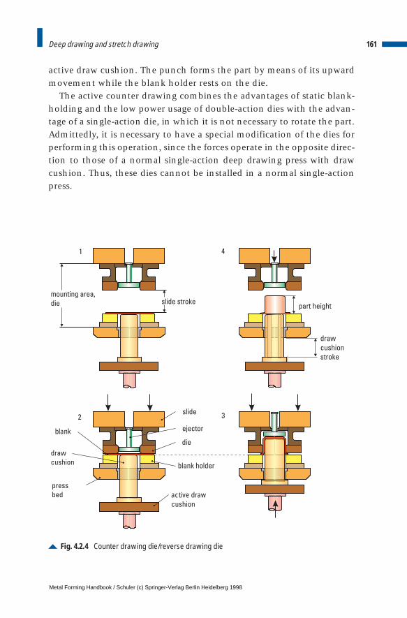
active draw cushion. The punch forms the part by means of its upwardmovement while the blank holder rests on the die.
The active counter drawing combines the advantages of static blank-holding and the low power usage of double-action dies with the advan-tage of a single-action die, in which it is not necessary to rotate the part.Admittedly, it is necessary to have a special modification of the dies forperforming this operation, since the forces operate in the opposite direc-tion to those of a normal single-action deep drawing press with drawcushion. Thus, these dies cannot be installed in a normal single-actionpress.
161Deep drawing and stretch drawing
Fig. 4.2.4 Counter drawing die/reverse drawing die
mounting area,
die slide stroke
2
1 4
3slide
ejector
die
blank holder
draw
cushion
press
bed
blank
draw
cushion
stroke
active drawcushion
part height
Metal Forming Handbook / Schuler (c) Springer-Verlag Berlin Heidelberg 1998
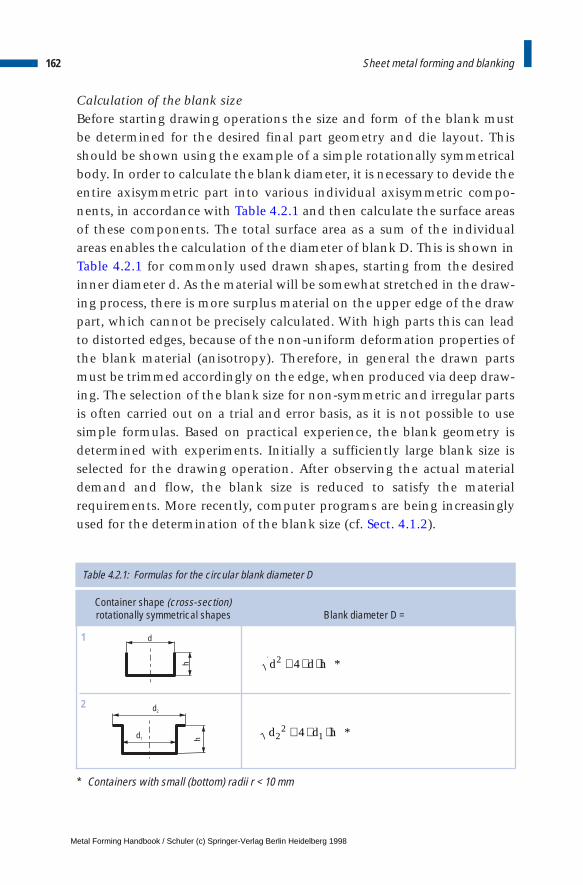
Calculation of the blank sizeBefore starting drawing operations the size and form of the blank must be determined for the desired final part geometry and die layout. Thisshould be shown using the example of a simple rotationally symmetricalbody. In order to calculate the blank diameter, it is necessary to devide theentire axisymmetric part into various individual axisymmetric compo-nents, in accordance with Table 4.2.1 and then calculate the surface areasof these components. The total surface area as a sum of the individualareas enables the calculation of the diameter of blank D. This is shown inTable 4.2.1 for commonly used drawn shapes, starting from the desiredinner diameter d. As the material will be somewhat stretched in the draw-ing process, there is more surplus material on the upper edge of the drawpart, which cannot be precisely calculated. With high parts this can leadto distorted edges, because of the non-uniform deformation properties ofthe blank material (anisotropy). Therefore, in general the drawn partsmust be trimmed accordingly on the edge, when produced via deep draw-ing. The selection of the blank size for non-symmetric and irregular partsis often carried out on a trial and error basis, as it is not possible to usesimple formulas. Based on practical experience, the blank geometry isdetermined with experiments. Initially a sufficiently large blank size isselected for the drawing operation. After observing the actual materialdemand and flow, the blank size is reduced to satisfy the materialrequirements. More recently, computer programs are being increasinglyused for the determination of the blank size (cf. Sect. 4.1.2).
162 Sheet metal forming and blanking
Table 4.2.1: Formulas for the circular blank diameter D
Container shape (cross-section)rotationally symmetrical shapes Blank diameter D =
d
h
d1
d2
1
2
d d h2 4+ ⋅ ⋅ *
d d h22
14+ ⋅ ⋅ *
* Containers with small (bottom) radii r < 10 mm
Metal Forming Handbook / Schuler (c) Springer-Verlag Berlin Heidelberg 1998
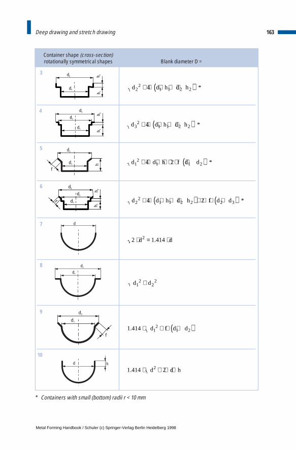
163Deep drawing and stretch drawing
Container shape (cross-section)rotationally symmetrical shapes Blank diameter D =
d1
h 1
d2 h 2
d1
d2
d3
h 2h 1
3
4
d d h d h22
1 1 2 24+ ⋅ ⋅ + ⋅( ) *
d d h d h32
1 1 2 24+ ⋅ ⋅ + ⋅( ) *
d1
d2
f
d1
h 1
d2
d3
h 2
5
6
d d h f d d12
1 1 24 2+ ⋅ ⋅ + ⋅ ⋅ +( ) *
d d h d h f d d22
1 1 2 2 2 34 2+ ⋅ ⋅ + ⋅( ) + ⋅ ⋅ +( ) *
d
d1
d2
7
8
2 1 4142⋅ = ⋅d d.
d d12
22+
d1
d2
f
d h
9
10
1 414 12
1 2. ⋅ + ⋅ +( )d f d d
1 414 22. ⋅ + ⋅ ⋅d d h
* Containers with small (bottom) radii r < 10 mm
Metal Forming Handbook / Schuler (c) Springer-Verlag Berlin Heidelberg 1998
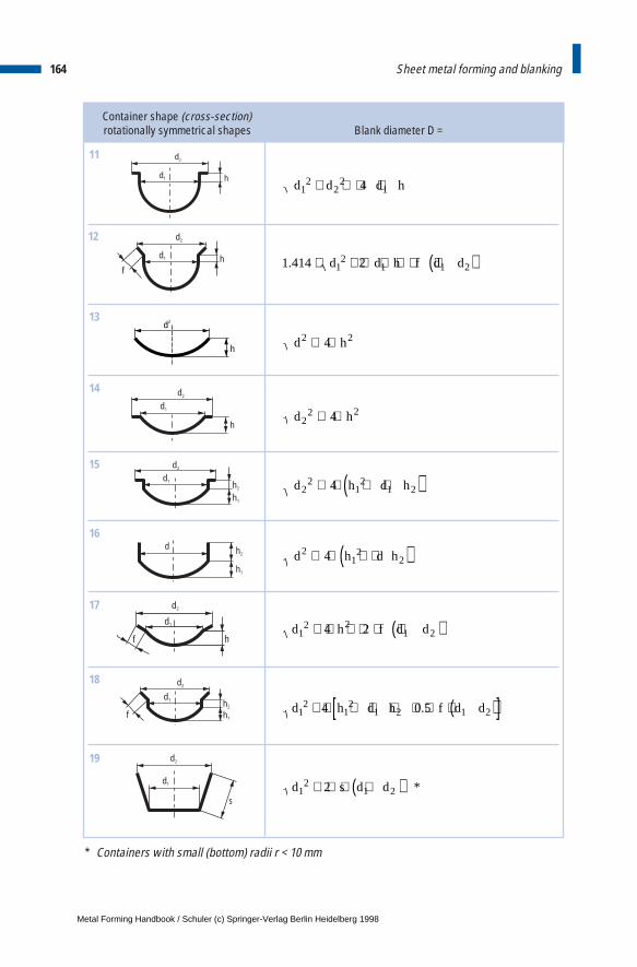
164 Sheet metal forming and blanking
Container shape (cross-section)rotationally symmetrical shapes Blank diameter D =
d1 h
d2
d1 h
d2
f
11
12
d d d h12
22
14+ + ⋅ ⋅
1 414 212
1 1 2. ⋅ + ⋅ ⋅ + ⋅ +( )d d h f d d
h
d2
d1
h
d2
13
14
d h2 24+ ⋅
d h22 24+ ⋅
d1 h2
h1
d2
d h2
h1
15
16
d h d h22
12
1 24+ ⋅ + ⋅( )
d h d h21
224+ ⋅ + ⋅( )
d1
h
d2
f
d1 h2
h1
d2
f
17
18
d h f d d12 2
1 24 2+ ⋅ + ⋅ ⋅ +( )
d h d h f d d12
12
1 2 1 24 0 5+ ⋅ + ⋅ + ⋅ ⋅ +( )[ ].
d1
d2
s
19
d s d d12
1 22+ ⋅ ⋅ +( ) *
* Containers with small (bottom) radii r < 10 mm
Metal Forming Handbook / Schuler (c) Springer-Verlag Berlin Heidelberg 1998
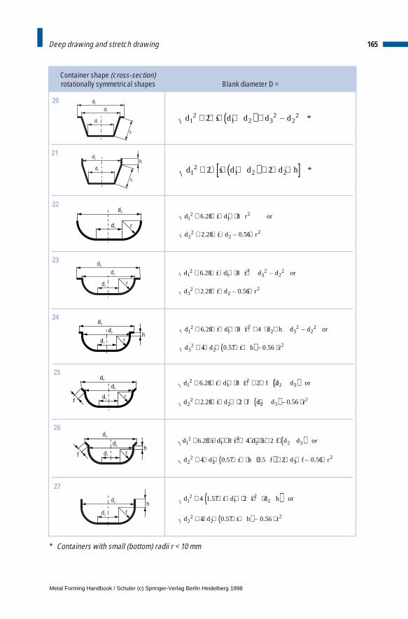
165Deep drawing and stretch drawing
Container shape (cross-section)rotationally symmetrical shapes Blank diameter D =
d1
d2
d3
s
d1
d2
s
h
20
21
d s d d d d12
1 2 32
222+ ⋅ ⋅ +( ) + – *
d s d d d h12
1 2 22 2+ ⋅ ⋅ +( ) + ⋅ ⋅[ ] *
d1
d2
r
d3
d1
d2
r
22
23
d r d r or
d r d r
12
12
22
22
6 28 8
2 28 0 56
+ ⋅ ⋅ + ⋅
+ ⋅ ⋅ ⋅
.
. – .
d r d r d d or
d r d r
12
12
32
22
32
22
6 28 8
2 28 0 56
+ ⋅ ⋅ + ⋅ +
+ ⋅ ⋅ ⋅
. –
. – .
d3
d1
hd2
r
d3
d1
d2
fr
24
25
d r d r d h d d or
d d r h r
12
12
2 32
22
32
22
6 28 8 4
4 0 57 0 56
+ ⋅ ⋅ + ⋅ + ⋅ ⋅ +
+ ⋅ ⋅ ⋅ +( ) ⋅
. –
. – .
d r d r f d d or
d r d f d d r
12
12
2 3
22
2 2 32
6 28 8 2
2 28 2 0 56
+ ⋅ ⋅ + ⋅ + ⋅ ⋅ +( )
+ ⋅ ⋅ + ⋅ ⋅ +( ) ⋅
.
. – .
d3
d1
hd2
f r
d1
hd2
r
26
27
d r d r d h f d d or
d d r h f d f r
12
12
2 2 3
22
2 32
6 28 8 4 2
4 0 57 0 5 2 0 56
+ ⋅ ⋅ + ⋅ + ⋅ ⋅ + ⋅ ⋅ +( )
+ ⋅ ⋅ ⋅ + + ⋅( ) + ⋅ ⋅ ⋅
.
. . – .
d r d r d h or
d d r h r
12
12
2
22
22
4 1 57 2
4 0 57 0 56
+ ⋅ ⋅ + ⋅ + ⋅( )+ ⋅ ⋅ ⋅ +( ) ⋅
.
. – .
* Containers with small (bottom) radii r < 10 mm
Metal Forming Handbook / Schuler (c) Springer-Verlag Berlin Heidelberg 1998
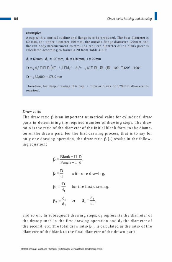
Example:A cup with a conical outline and flange is to be produced. The base diameter is60 mm, the upper diameter 100mm, the outside flange diameter 120mm andthe can body measurement 75mm. The required diameter of the blank piece iscalculated according to formula 20 from Table 4.2.1:
Therefore, for deep drawing this cup, a circular blank of 179 mm diameter isrequired.
Draw ratioThe draw ratio b is an important numerical value for cylindrical drawparts in determining the required number of drawing steps. The drawratio is the ratio of the diameter of the initial blank form to the diame-ter of the drawn part. For the first drawing process, that is to say foronly one drawing operation, the draw ratio b [–] results in the follow-ing equation:
with one drawing,
for the first drawing,
or
and so on. In subsequent drawing steps, d1 represents the diameter ofthe draw punch in the first drawing operation and d2 the diameter ofthe second, etc. The total draw ratio btot is calculated as the ratio of thediameter of the blank to the final diameter of the drawn part:
166 Sheet metal forming and blanking
β32
3
= d
d,
d mm d mm d mm s mm
D d s d d d d
D mm
1 2 3
12
1 2 32
22 2 2 2
60 100 120 75
2 60 2 75 60 100 120 100
32 000 178 9
= = = =
= + ⋅ ⋅ +( ) + = + ⋅ ⋅ +( ) +
= =
, , ,
– –
, .
β
β
β
β
= − ∅− ∅
=
=
=
Blank D
Punch d
D
d
D
d
d
d
,
11
21
2
Metal Forming Handbook / Schuler (c) Springer-Verlag Berlin Heidelberg 1998

The maximum draw ratio depends on the properties of the blank mate-rial used. As a rough estimate, the first drawing can be calculated ashaving a maximum ratio of b = 2. To achieve b > 2 several drawings arerequired and it must be noted that b, because of work hardening, canonly achieve a level of 1.3 in the next drawing step. If the part isannealed before the next drawing operation, a b of 1.7 can be assumed.
With several drawing steps, the total draw ratio becomes a product ofthe individual draw ratios:
Example:From a 1mm thick blank of sheet metal material number 1.0338 (St 14) a hol-low cylindrical part with a diameter of 45 mm and a can body height of 90 mmis to be drawn. First, the initial diameter of the circular blank D is calculated asper Formula 1 from Table 4.2.1:
Thus, the total draw ratio btot is established:
Because btot is greater than the remaining limiting draw ratio of 2, several draw-ing operations are needed whereby b1 may have a maximum value of 2, and allfollowing b values are less than 1.3.
The required draw ratio can be attained with three operations. In order to havea robust and reproducable production sequence, the maximum permitted drawratios should not be fully utilised. In the event that btot = 1.95 · 1.25 · 1.25 = 3is selected. This calls for punch diameters of:
167Deep drawing and stretch drawing
βtotInitial D
Final d= − ∅
− ∅
β β β βtot n= ⋅ ⋅ … ⋅1 2
D d d h mm= + ⋅ ⋅ = + ⋅ ⋅ = =2 24 45 4 45 90 18 225 135,
β tot
D
d= = =135
453
β β β β
β β β
tot n
n
= ⋅ ⋅ … ⋅ =
= ⋅ ⋅ … ⋅ < ⋅ ⋅
1 2
1 2
3
3 2 1 3 1 3. .
➔
Metal Forming Handbook / Schuler (c) Springer-Verlag Berlin Heidelberg 1998

The maximum draw ratio bmax, does depend however on other factorsas well (cf. Sect. 4.2.3):
When the friction between the drawn part and the punch is low, thenfailures will occur in the base of the part. If the friction between the partand the punch is high, the base of the drawn part will be increasinglystressed with increasing friction in the can body so that the failure zonewill be moved to the body of the drawn can. In order to ensure a safeproduction process, it is preferable to select a draw ratio that is rathermodest and less than the maximum possible value.
Drawing forceFor drawing round parts in a single drawing, the maximum drawingforce FU can be calculated per the following equation:
where:
d1 = punch diameter [mm]s = sheet metal thickness [mm]Rm = material tensile strength [N/mm2]b = actual draw ratio [–]bmax = maximum draw ratio [–]
dD mm
mm d mm
dd mm
mm d mm
d mm before mentioned withmm
mm
11
1
21
22
3 3
135
1 9569 2 69
69
1 2555 2 55
4555
451 22
= = = ⇒ =
= = = ⇒ =
= = =
β
β
β
..
..
( ) .
168 Sheet metal forming and blanking
β µmax ( , , , , )= − …f D d r value s
F d s s R NU m= ⋅ + ⋅ ⋅ ⋅ ⋅ [ ]π ββ
( ) .–
–max1 1 2
1
1
Metal Forming Handbook / Schuler (c) Springer-Verlag Berlin Heidelberg 1998
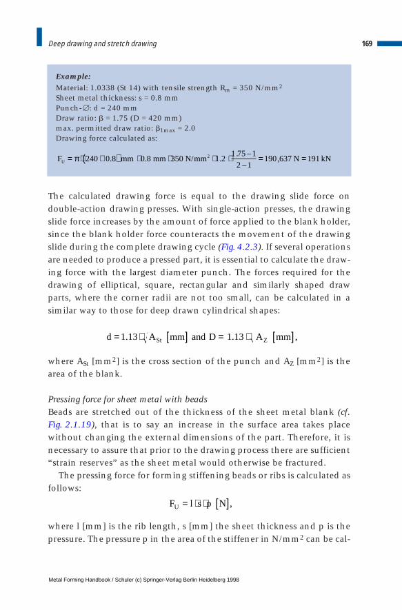
Example:Material: 1.0338 (St 14) with tensile strength Rm = 350 N/mm2
Sheet metal thickness: s = 0.8 mmPunch- [: d = 240 mmDraw ratio: b = 1.75 (D = 420 mm)max. permitted draw ratio: b1max = 2.0Drawing force calculated as:
The calculated drawing force is equal to the drawing slide force ondouble-action drawing presses. With single-action presses, the drawingslide force increases by the amount of force applied to the blank holder,since the blank holder force counteracts the movement of the drawingslide during the complete drawing cycle (Fig. 4.2.3). If several operationsare needed to produce a pressed part, it is essential to calculate the draw-ing force with the largest diameter punch. The forces required for thedrawing of elliptical, square, rectangular and similarly shaped drawparts, where the corner radii are not too small, can be calculated in asimilar way to those for deep drawn cylindrical shapes:
where ASt [mm2] is the cross section of the punch and AZ [mm2] is thearea of the blank.
Pressing force for sheet metal with beadsBeads are stretched out of the thickness of the sheet metal blank (cf. Fig. 2.1.19), that is to say an increase in the surface area takes placewithout changing the external dimensions of the part. Therefore, it isnecessary to assure that prior to the drawing process there are sufficient“strain reserves” as the sheet metal would otherwise be fractured.
The pressing force for forming stiffening beads or ribs is calculated asfollows:
where l [mm] is the rib length, s [mm] the sheet thickness and p is thepressure. The pressure p in the area of the stiffener in N/mm2 can be cal-
169Deep drawing and stretch drawing
F mm mm N mm N kNU = ⋅ +( ) ⋅ ⋅ ⋅ ⋅ = =π 240 0 8 0 8 350 1 21 75 1
2 1190 637 1912. . / .
. –
–,
d A mm and D A mmSt Z= ⋅ [ ] = ⋅ [ ]1 13 1 13. . ,
F l s p NU = ⋅ ⋅ [ ],
Metal Forming Handbook / Schuler (c) Springer-Verlag Berlin Heidelberg 1998
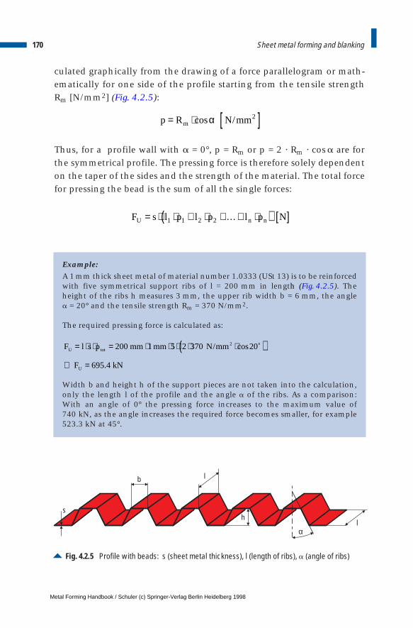
culated graphically from the drawing of a force parallelogram or math-ematically for one side of the profile starting from the tensile strengthRm [N/mm2] (Fig. 4.2.5):
Thus, for a profile wall with a = 0°, p = Rm or p = 2 · Rm · cos a are forthe symmetrical profile. The pressing force is therefore solely dependenton the taper of the sides and the strength of the material. The total forcefor pressing the bead is the sum of all the single forces:
Example:A 1 mm thick sheet metal of material number 1.0333 (USt 13) is to be reinforcedwith five symmetrical support ribs of l = 200 mm in length (Fig. 4.2.5). Theheight of the ribs h measures 3 mm, the upper rib width b = 6 mm, the angle a = 20° and the tensile strength Rm = 370 N/mm2.
The required pressing force is calculated as:
Width b and height h of the support pieces are not taken into the calculation,only the length l of the profile and the angle a of the ribs. As a comparison:With an angle of 0° the pressing force increases to the maximum value of 740 kN, as the angle increases the required force becomes smaller, for example523.3 kN at 45°.
170 Sheet metal forming and blanking
F s l p l p l p NU n n= ⋅ ⋅ + ⋅ +…+ ⋅( ) [ ]1 1 2 2
p R N mmm= ⋅ [ ]cos /α 2
F l s p mm mm N mm
F kN
U tot
U
= ⋅ ⋅ = ⋅ ⋅ ⋅ ⋅ ⋅( )⇒ =
200 1 5 2 370 20
695 4
2 / cos ˚
.
Fig. 4.2.5 Profile with beads: s (sheet metal thickness), l (length of ribs), a (angle of ribs)
lα
h
lb
s
Metal Forming Handbook / Schuler (c) Springer-Verlag Berlin Heidelberg 1998
171Deep drawing and stretch drawing
Blank holder forceThe magnitude of blank holder force is not only an important factor inavoiding wrinkling of the material but also vital because of its influenceon the straining of the upper surface. As the blank holder force isincreased, the restraining effect on the material located between the dieand the blank holder becomes stronger so that the strain on the uppersurface layer is also increased.
The blank holder force required for deep drawing FB [N] is calculatedfrom D [mm], d' [mm] (die diameter), r [mm] (die corner radius) and p[N/mm2] (specific blank holder pressure):
Often the die corner radius and the die/punch clearance can be neglect-ed, in comparison with the punch diameter d [mm], the approximatecalculated value of the blank holder force is:
The required level of the specific blank holder pressure depends on thematerial and punch diameters as well as on the thickness of the sheetmetal. It can be estimated by using the following values:
– steel: p = 2.5 N/mm2
– copper alloy: p = 2.0 … 2.4 N/mm2
– aluminium alloy: p = 1.2 … 1.5 N/mm2
Example:A sheet metal blank from material number 1.0338 (St 14) with Rm = 350 N/mm2
tensile strength is to be formed with a punch having a diameter of d = 240 mmand a draw ratio of b = 1.75 (circular blank diameter D = 420 mm). Thus theblankholder force is estimated to be:
F D d r p NB = ⋅ + ⋅( )[ ]⋅ [ ]π4
22 2– '
F D d p NB ≈ ⋅ ( ) ⋅ [ ]π4
2 2–
F D d p mm mm N mm N kNB = ⋅( ) ⋅ = ⋅ ( ) ( )[ ] ⋅ = =π π4 4
420 240 2 5 63 303 632 2 2 2 2– – . / ,
Metal Forming Handbook / Schuler (c) Springer-Verlag Berlin Heidelberg 1998
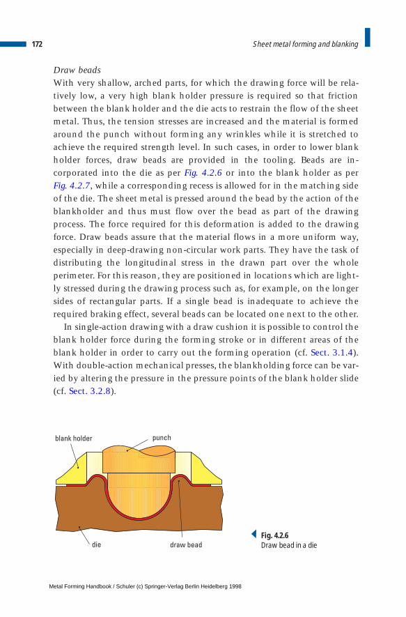
Draw beadsWith very shallow, arched parts, for which the drawing force will be rela-tively low, a very high blank holder pressure is required so that frictionbetween the blank holder and the die acts to restrain the flow of the sheetmetal. Thus, the tension stresses are increased and the material is formedaround the punch without forming any wrinkles while it is stretched toachieve the required strength level. In such cases, in order to lower blankholder forces, draw beads are provided in the tooling. Beads are in-corporated into the die as per Fig. 4.2.6 or into the blank holder as per Fig. 4.2.7, while a corresponding recess is allowed for in the matching sideof the die. The sheet metal is pressed around the bead by the action of theblankholder and thus must flow over the bead as part of the drawingprocess. The force required for this deformation is added to the drawingforce. Draw beads assure that the material flows in a more uniform way,especially in deep-drawing non-circular work parts. They have the task ofdistributing the longitudinal stress in the drawn part over the wholeperimeter. For this reason, they are positioned in locations which are light-ly stressed during the drawing process such as, for example, on the longersides of rectangular parts. If a single bead is inadequate to achieve therequired braking effect, several beads can be located one next to the other.
In single-action drawing with a draw cushion it is possible to control theblank holder force during the forming stroke or in different areas of theblank holder in order to carry out the forming operation (cf. Sect. 3.1.4).With double-action mechanical presses, the blankholding force can be var-ied by altering the pressure in the pressure points of the blank holder slide(cf. Sect. 3.2.8).
172 Sheet metal forming and blanking
blank holder punch
die draw bead
Fig. 4.2.6Draw bead in a die
Metal Forming Handbook / Schuler (c) Springer-Verlag Berlin Heidelberg 1998
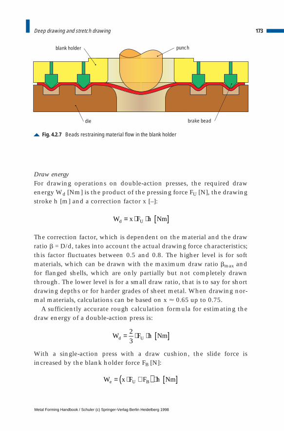
Draw energyFor drawing operations on double-action presses, the required drawenergy Wd [Nm] is the product of the pressing force FU [N], the drawingstroke h [m] and a correction factor x [–]:
The correction factor, which is dependent on the material and the drawratio b = D/d, takes into account the actual drawing force characteristics;this factor fluctuates between 0.5 and 0.8. The higher level is for softmaterials, which can be drawn with the maximum draw ratio bmax andfor flanged shells, which are only partially but not completely drawnthrough. The lower level is for a small draw ratio, that is to say for shortdrawing depths or for harder grades of sheet metal. When drawing nor-mal materials, calculations can be based on x < 0.65 up to 0.75.
A sufficiently accurate rough calculation formula for estimating thedraw energy of a double-action press is:
With a single-action press with a draw cushion, the slide force isincreased by the blank holder force FB [N]:
173Deep drawing and stretch drawing
Fig. 4.2.7 Beads restraining material flow in the blank holder
punch
die
blank holder
brake bead
W F h Nmd U= ⋅ ⋅ [ ]2
3
W x F F h Nme U B= ⋅ +( ) ⋅ [ ]
W x F h Nmd U= ⋅ ⋅ [ ]
Metal Forming Handbook / Schuler (c) Springer-Verlag Berlin Heidelberg 1998

174 Sheet metal forming and blanking
W F h d s s R h
W mm mm mm N mm mm
W N m Nm J
d U m
d
d
= ⋅ ⋅ = ⋅ ⋅ +( ) ⋅ ⋅ ⋅ ⋅ ⋅
= ⋅ ⋅ +( ) ⋅ ⋅ ⋅ ⋅−
⋅
= ⋅ ⋅ = =
2
3
2
31 2
1
1
2
360 0 8 0 8 350 1 2
1 9 1
2 0 140
2
318 385 9 0 04 490 3 490 3
1
2
π ββ
π
.–
–
. . / .. –
.
, . . . .
max
Example:For a drawn cup from 0.8 mm thick sheet metal (material number 1.0338 – Rm = 350 N/mm2) with a diameter of 60 mm and a height of 40 mm (circularblank diameter 115 mm, b = 1.9) the following pressing work for drawing witha double-action press is required:
Deep drawing without a blank holder is only carried out if the part doesnot tend to wrinkle, i. e. with thick sheet metal or small amount ofdeformation (with small draw ratio b).
Drawing defectsIn order to eliminate the possibility of parts being rejected, it is neces-sary to investigate the scrapped parts very thoroughly and to identifythereby the causes of any defects and to take preventive measures.Some of the most common defects are illustrated in Table 4.2.2.
4.2.2 Materials for sheet metal forming
Unalloyed and alloyed steels as well as copper alloys, copper sheet, andlight alloys are all among the commonly used materials in sheet metalforming technology. Among alloyed steels, a difference is drawn betweenphosphor-alloyed steels, types of steel with additional hardening afterheat treatment (bake-hardening steels), ferritic chromium steels,austenitic chromium nickel steels and cold-rolled sheet with higher ten-sile yield strength for cold forming (micro-alloyed steels). Table 4.2.3 listspopular materials with the following specifications:
– material number, – tensile strength Rm [N/mm2],
Metal Forming Handbook / Schuler (c) Springer-Verlag Berlin Heidelberg 1998
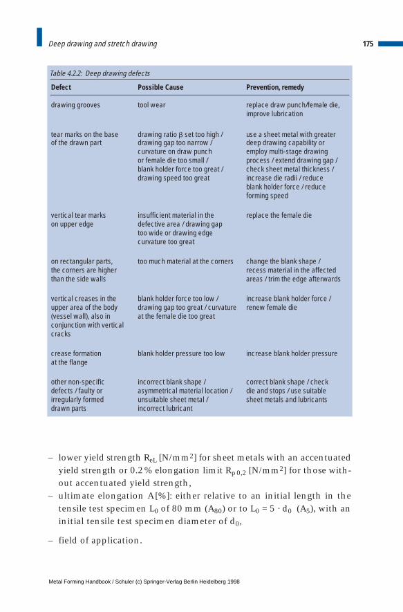
– lower yield strength ReL [N/mm2] for sheet metals with an accentuatedyield strength or 0.2% elongation limit Rp0,2 [N/mm2] for those with-out accentuated yield strength,
– ultimate elongation A [%]: either relative to an initial length in thetensile test specimen L0 of 80 mm (A80) or to L0 = 5 · d0 (A5), with aninitial tensile test specimen diameter of d0,
– field of application.
175Deep drawing and stretch drawing
Defect Possible Cause Prevention, remedy
drawing grooves tool wear replace draw punch/female die, improve lubrication
tear marks on the base drawing ratio b set too high / use a sheet metal with greater of the drawn part drawing gap too narrow / deep drawing capability or
curvature on draw punch employ multi-stage drawingor female die too small / process / extend drawing gap /blank holder force too great / check sheet metal thickness /drawing speed too great increase die radii / reduce
blank holder force / reduce forming speed
vertical tear marks insufficient material in the replace the female dieon upper edge defective area / drawing gap
too wide or drawing edge curvature too great
on rectangular parts, too much material at the corners change the blank shape / the corners are higher recess material in the affected than the side walls areas / trim the edge afterwards
vertical creases in the blank holder force too low / increase blank holder force / upper area of the body drawing gap too great / curvature renew female die(vessel wall), also in at the female die too greatconjunction with vertical cracks
crease formation blank holder pressure too low increase blank holder pressureat the flange
other non-specific incorrect blank shape / correct blank shape / checkdefects / faulty or asymmetrical material location / die and stops / use suitableirregularly formed unsuitable sheet metal / sheet metals and lubricantsdrawn parts incorrect lubricant
Table 4.2.2: Deep drawing defects
Metal Forming Handbook / Schuler (c) Springer-Verlag Berlin Heidelberg 1998
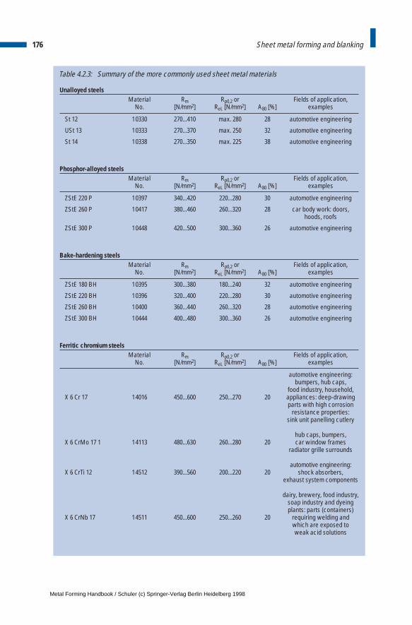
Unalloyed steelsMaterial Rm Rp0,2 or Fields of application,
No. [N/mm2] ReL [N/mm2] A80 [%] examples
St 12 10330 270...410 max. 280 28 automotive engineering
USt 13 10333 270...370 max. 250 32 automotive engineering
St 14 10338 270...350 max. 225 38 automotive engineering
Phosphor-alloyed steelsMaterial Rm Rp0,2 or Fields of application,
No. [N/mm2] ReL [N/mm2] A80 [%] examples
ZStE 220 P 10397 340...420 220...280 30 automotive engineering
ZStE 260 P 10417 380...460 260...320 28 car body work: doors, hoods, roofs
ZStE 300 P 10448 420...500 300...360 26 automotive engineering
Bake-hardening steelsMaterial Rm Rp0,2 or Fields of application,
No. [N/mm2] ReL [N/mm2] A80 [%] examples
ZStE 180 BH 10395 300...380 180...240 32 automotive engineering
ZStE 220 BH 10396 320...400 220...280 30 automotive engineering
ZStE 260 BH 10400 360...440 260...320 28 automotive engineering
ZStE 300 BH 10444 400...480 300...360 26 automotive engineering
Ferritic chromium steelsMaterial Rm Rp0,2 or Fields of application,
No. [N/mm2] ReL [N/mm2] A80 [%] examples
automotive engineering:bumpers, hub caps,
food industry, household,X 6 Cr 17 14016 450...600 250...270 20 appliances: deep-drawing
parts with high corrosionresistance properties:
sink unit panelling cutlery
hub caps, bumpers,X 6 CrMo 17 1 14113 480...630 260...280 20 car window frames
radiator grille surrounds
automotive engineering: X 6 CrTi 12 14512 390...560 200...220 20 shock absorbers,
exhaust system components
dairy, brewery, food industry,soap industry and dyeingplants: parts (containers)
X 6 CrNb 17 14511 450...600 250...260 20 requiring welding andwhich are exposed toweak acid solutions
176 Sheet metal forming and blanking
Table 4.2.3: Summary of the more commonly used sheet metal materials
Metal Forming Handbook / Schuler (c) Springer-Verlag Berlin Heidelberg 1998
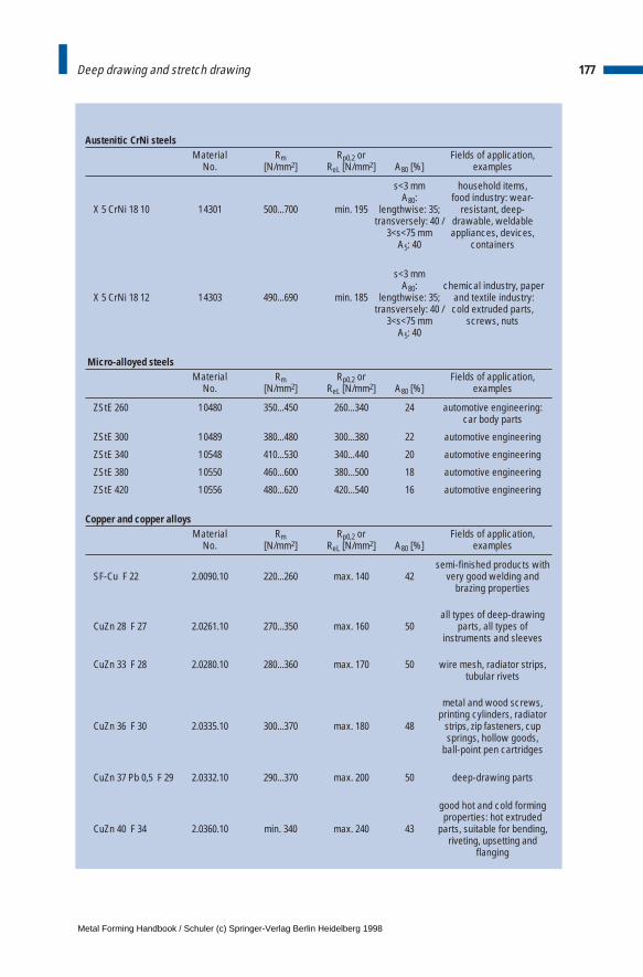
177Deep drawing and stretch drawing
Austenitic CrNi steelsMaterial Rm Rp0,2 or Fields of application,
No. [N/mm2] ReL [N/mm2] A80 [%] examples
s<3 mm household items, A80: food industry: wear-
X 5 CrNi 18 10 14301 500...700 min. 195 lengthwise: 35; resistant, deep-transversely: 40 / drawable, weldable
3<s<75 mm appliances, devices,A5: 40 containers
s<3 mmA80: chemical industry, paper
X 5 CrNi 18 12 14303 490...690 min. 185 lengthwise: 35; and textile industry:transversely: 40 / cold extruded parts,
3<s<75 mm screws, nutsA5: 40
Micro-alloyed steelsMaterial Rm Rp0,2 or Fields of application,
No. [N/mm2] ReL [N/mm2] A80 [%] examples
ZStE 260 10480 350...450 260...340 24 automotive engineering: car body parts
ZStE 300 10489 380...480 300...380 22 automotive engineering
ZStE 340 10548 410...530 340...440 20 automotive engineering
ZStE 380 10550 460...600 380...500 18 automotive engineering
ZStE 420 10556 480...620 420...540 16 automotive engineering
Copper and copper alloysMaterial Rm Rp0,2 or Fields of application,
No. [N/mm2] ReL [N/mm2] A80 [%] examples
semi-finished products withSF-Cu F 22 2.0090.10 220...260 max. 140 42 very good welding and
brazing properties
all types of deep-drawing CuZn 28 F 27 2.0261.10 270...350 max. 160 50 parts, all types of
instruments and sleeves
CuZn 33 F 28 2.0280.10 280...360 max. 170 50 wire mesh, radiator strips,tubular rivets
metal and wood screws, printing cylinders, radiator
CuZn 36 F 30 2.0335.10 300...370 max. 180 48 strips, zip fasteners, cup springs, hollow goods,
ball-point pen cartridges
CuZn 37 Pb 0,5 F 29 2.0332.10 290...370 max. 200 50 deep-drawing parts
good hot and cold formingproperties: hot extruded
CuZn 40 F 34 2.0360.10 min. 340 max. 240 43 parts, suitable for bending,riveting, upsetting and
flanging
Metal Forming Handbook / Schuler (c) Springer-Verlag Berlin Heidelberg 1998
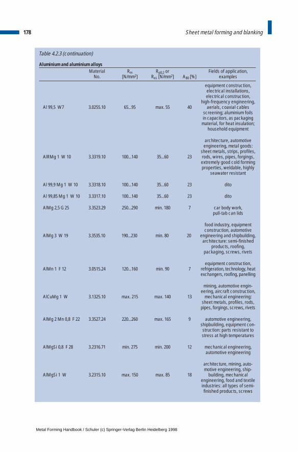
Table 4.2.3 (continuation)
Aluminium and aluminium alloysMaterial Rm Rp0,2 or Fields of application,
No. [N/mm2] ReL [N/mm2] A80 [%] examples
equipment construction,electrical installations,electrical construction,
high-frequency engineering,Al 99,5 W7 3.0255.10 65...95 max. 55 40 aerials, coaxial cables
screening; aluminium foilsin capacitors, as packaging
material, for heat insulation; household equipment
architecture, automotive engineering, metal goods:
sheet metals, strips, profiles,AlRMg 1 W 10 3.3319.10 100...140 35...60 23 rods, wires, pipes, forgings,
extremely good cold formingproperties, weldable, highly
seawater resistant
Al 99,9 Mg 1 W 10 3.3318.10 100...140 35...60 23 dito
Al 99,85 Mg 1 W 10 3.3317.10 100...140 35...60 23 dito
AlMg 2,5 G 25 3.3523.29 250...290 min. 180 7 car body work,pull-tab can lids
food industry, equipment construction, automotive
AlMg 3 W 19 3.3535.10 190...230 min. 80 20 engineering and shipbuilding,architecture: semi-finished
products, roofing, packaging, screws, rivets
equipment construction, AlMn 1 F 12 3.0515.24 120...160 min. 90 7 refrigeration, technology, heat
exchangers, roofing, panelling
mining, automotive engin- eering, aircraft construction,
AlCuMg 1 W 3.1325.10 max. 215 max. 140 13 mechanical engineering: sheet metals, profiles, rods,
pipes, forgings, screws, rivets
AlMg 2 Mn 0,8 F 22 3.3527.24 220...260 max. 165 9 automotive engineering, shipbuilding, equipment con-struction: parts resistant to stress at high temperatures
AlMgSi 0,8 F 28 3.2316.71 min. 275 min. 200 12 mechanical engineering,automotive engineering
architecture, mining, auto- motive engineering, ship-
AlMgSi 1 W 3.2315.10 max. 150 max. 85 18 building, mechanical engineering, food and textileindustries: all types of semi-finished products, screws
178 Sheet metal forming and blanking
Metal Forming Handbook / Schuler (c) Springer-Verlag Berlin Heidelberg 1998
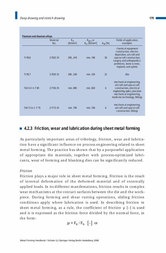
4.2.3 Friction, wear and lubrication during sheet metal forming
As particularly important areas of tribology, friction, wear and lubrica-tion have a significant influence on process engineering related to sheetmetal forming. The practice has shown that by a purposeful applicationof appropriate die materials, together with process-optimized lubri-cants, wear of forming and blanking dies can be significantly reduced.
FrictionFriction plays a major role in sheet metal forming. Friction is the resultof internal deformation of the deformed material and of externallyapplied loads. In its different manifestations, friction results in complexwear mechanisms at the contact surfaces between the die and the work-piece. During forming and shear cutting operations, sliding frictionconditions apply where lubrication is used. In describing friction insheet metal forming, as a rule, the coefficient of friction µ [–] is usedand it is expressed as the friction force divided by the normal force, inthe form:
179Deep drawing and stretch drawing
Titanium and titanium alloysMaterial Rm Rp0,2 or Fields of application,
No. [N/mm2] ReL [N/mm2] A80 [%] examples
chemical equipment construction, electro-
deposition, aircraft and Ti 99,8 3.7025.10 290...410 min. 180 30 spacecraft construction,
surgery and orthopaedics:protheses, bone screws,
implants and splints
Ti 99,7 3.7035.10 390...540 min. 250 22 dito
mechanical engineering,aircraft and spacecraft
TiAl 6 V 4 F 89 3.7165.10 min. 890 min. 820 6 construction, electrical engineering, optics, precisionmechanical engineering,
medicine technology, fittings
mechanical engineering,TiAl 5 Sn 2 F 79 3.7115.10 min. 790 min. 760 6 aircraft and spacecraft
construction, fittings
µ = [ ]F F orR N/ –
Metal Forming Handbook / Schuler (c) Springer-Verlag Berlin Heidelberg 1998
the frictional shear stress divided by normal contact stress
At lower sliding velocities, dry or maximum friction conditions apply;that is to say the dies/the workpiece are primarily separated by the reac-tion or adsorption layers – so-called boundary layers – of a molecularorder of magnitude, whereby solid body friction is also possible in sub-microscopic ranges. Here, the workpiece slides on lubricating films ofmolecular magnitude, i. e. on these boundary layers. In the absence ofsufficient lubrication, the boundary layers can break up locally andweld joints can develop. Coefficients of friction in the range of µ = 0.10to 0.15 are indication of dry friction conditions.
With an increase in sliding velocity, portions of the interface are sup-ported by hydro-dynamic fluid lubrication. The thickness of the lubri-cating film increases, but the lubrication gap h [µm] still remains small-er than the total of the surface roughness Rt [µm] of both, the die andthe workpiece, i. e.:
The frictional forces FR [N] drop sharply and come close asymptoticallyto a limiting value, which is the transition point to pure hydro-dynamicfriction.
The influence of sliding velocity, normal stress and lubricant viscosi-ty is at its maximum in the area of boundary or mixed friction. Here,the die/workpiece pair has the topography of the task of holding thelubricant for as long as possible during the sliding action. As a rule, allforming processes involving boundary friction operate with frictionalcoefficients of µ = 0.05 to 0.10. With further increases in the slidingvelocity, complete hydro-dynamic friction can be achieved in whichthe lubricant film h becomes greater than the sum of the surface rough-ness Rt of both workpiece and die. This condition, however, cannot beachieved in practical metal forming operations:
180 Sheet metal forming and blanking
µ τ σ= [ ]R N/ –
h R Rt die t workpiece< +
h R Rt die t workpiece> +
Metal Forming Handbook / Schuler (c) Springer-Verlag Berlin Heidelberg 1998
High local plastic deformations occur during friction in sheet forming,i.e. with the alteration of the surface of the workpiece a transformationin the topography takes place. Surface transformation takes placedepending upon the state of stress, strength of the sheet metal materialand of the grain size and alignment. This surface transformation whichcan alter considerably the amount of lubricant that is retained at thedie/material interface. These mechanisms receive minimum considera-tion in the laws of friction, as does the influence of frictional tempera-ture and pressure on lubricant viscosity during the sliding operation.
The coefficient of friction can be considered neither as a materialvariable nor as a constant for the die/workpiece pair. However, if thecoefficient of friction is selected for making predictions, its dependenceon various process parameters must be considered. In sheet metal form-ing, the following such parameters are of major importance:
– the material pair and the metallic surfaces which are in contact witheach other,
– the die geometry,– the temperature-dependent properties of the lubricant as well as its
volume and the location of lubricant application,– the actual normal contact stress, which is a function of the load bear-
ing surface portions of both surfaces,– the magnitude of the sliding velocity and the frictional path of the
contacting surfaces and– the surface characteristics of the workpiece material as well as the
changes of these characteristics that take place during the process.
WearIn general, the assessment of the wear behavior of dies is difficultbecause of the presence of several superimposed wear mechanisms. Inorder to describe the various forms of damage, wear mechanismsshould be divided into five basic fundamental phenomena (Fig. 4.2.8):
DeformationUnder external loads, a micro-geometrical adaptation of the surface pairtakes place, initiated by the local deformation at the contacting peaks ofthe roughness of the workpiece surface.
181Deep drawing and stretch drawing
Metal Forming Handbook / Schuler (c) Springer-Verlag Berlin Heidelberg 1998
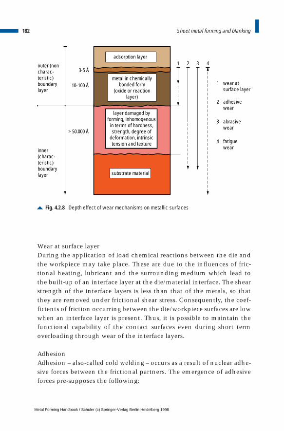
Wear at surface layerDuring the application of load chemical reactions between the die andthe workpiece may take place. These are due to the influences of fric-tional heating, lubricant and the surrounding medium which lead tothe built-up of an interface layer at the die/material interface. The shearstrength of the interface layers is less than that of the metals, so thatthey are removed under frictional shear stress. Consequently, the coef-ficients of friction occurring between the die/workpiece surfaces are lowwhen an interface layer is present. Thus, it is possible to maintain thefunctional capability of the contact surfaces even during short termoverloading through wear of the interface layers.
AdhesionAdhesion – also-called cold welding – occurs as a result of nuclear adhe-sive forces between the frictional partners. The emergence of adhesiveforces pre-supposes the following:
182 Sheet metal forming and blanking
Fig. 4.2.8 Depth effect of wear mechanisms on metallic surfaces
adsorption layer
outer (non-charac-teristic) boundarylayer
inner(charac-teristic) boundarylayer
3-5 Å
10-100 Å
> 50.000 Å
1 32 4
1 wear atsurface layer
2 adhesivewear
3 abrasivewear
4 fatiguewear
metal in chemicallybonded form
(oxide or reactionlayer)
layer damaged byforming, inhomogenous
in terms of hardness,strength, degree of
deformation, intrinsictension and texture
substrate material
Metal Forming Handbook / Schuler (c) Springer-Verlag Berlin Heidelberg 1998
– plastic deformation at the peaks of the roughness of contacting sur-faces,
– surface expansion brought about by the forming process, whichremoves the adhesion presenting boundary layers and brings brightmetal surfaces in contact with one another,
– similar material structures of the frictional partners.
The greater is the difference between the metals and alloys of the fric-tional partners, the lower is the tendency to develop cold welding. Thistendency is at its lowest between metallic and non-metallic materials ofcorresponding hardness.
AbrasionAbrasive wear includes all parting or separation processes that take placeat the interface of frictional partners, where material is released in sub-microscopic particles through a material removal process. The differencein the hardness between the two surfaces of frictional partners is animportant factor for assessing abrasive friction. The wear resistance of adie increases with the hardness of its surface. Due to the relative move-ment of the two surfaces of the frictional partners, a part of the energyused is converted into heat. With most materials, the hardness drops asthe temperature increases and the resistance to wear is reduced. Abrasivewear represents a generally inevitable long-term wear effect on the die.
Surface fatigueFatigue wear is considered to be the separation of micro- and macro-scopic material particles. This separation is caused through fatiguecracking, progressive cracking and residual fracture due to mechanical,thermal or chemical stress-related conditions on the loaded surfaces. Asa rule, surface fatigue plays a minor role in sheet forming dies. However,fatigue is common in cutting tools, as an increasing normal tensionstress is applied onto the front surface in addition to a variable friction-al shear stress that exists over the whole external surface area.
LubricationLubricants are subject to different temperatures and compressive stress-es during their use. Important variables influencing the correct choiceof suitable lubricants are viscosity, density and compressibility, where-
183Deep drawing and stretch drawing
Metal Forming Handbook / Schuler (c) Springer-Verlag Berlin Heidelberg 1998

by viscosity demonstrates the greatest dependence on the two parame-ters: pressure and temperature. Particularly at contact points with highsurface pressure, attention must be paid not only to the temperature,but also to the influence of pressure. Lubricants can be classified as fol-lows:
– water soluble, – non water soluble,– solid lubricants,– foils and varnishes.
Liquid lubricants are predominantly oil based. These are generally blendswithout a consistent composition, as the portions of paraffin, aromaticand naphtha content varies according to the origin of the oils. Animal-based, vegetable and synthetic oils also belong in this category. Paste-type lubricants are stabilized blends of mineral or synthetic oils, greas-es and waxes as well as soap. Powdered or needle shaped hard waxesand hard soaps are used as solid lubricants. The properties of lubricantscan be altered by additives and adjusted to suit the respective applica-tion. Additives serve to improve load bearing capacities, bondingstrength, and viscosity-temperature-pressure characteristics, and alsoassist in preventing corrosion. The additives create either physicaladsorption layers or chemical reaction layers.
By means of so called “friction modifiers” (for example animal andvegetable fats, fat soap etc. also belong in this category), the lubricantbonds itself to the metal surface without causing any chemical reaction.This type of physically-acting additives are, however, inherently tem-perature-dependent. The reduction in cohesive and adhesive strengthunder increasing temperatures leads to an increase in the coefficient offriction. The effect of these additives ranges from a total absence ofphysical adsorption up to a stable chemical bond (formation of metal-lic soap). At high levels of interface pressures, anti-wear additives areused. They form a wear-reducing protective layer. A sub-division of thisgroup are the extreme pressure (EP) additives, which form reaction lay-ers under higher temperatures. With a combination of selective addi-tives, in this range lubricants can be optimized to suit just about anyparticular application.
Based on the discussion given above, the following is a summary ofthe performance requirements of lubricants:
184 Sheet metal forming and blanking
Metal Forming Handbook / Schuler (c) Springer-Verlag Berlin Heidelberg 1998
– development of a cohesive pressure and temperature-resistant lubri-cation film, which separates the surfaces of the workpiece and thedie,
– high adhesive and shearing strength as well as good wetting capabil-ity,
– no involuntary physical or chemical reactions on the surface of thefrictional partners,
– easy and complete removal of the lubricant from the finished part,– no unhealthy or environmentally harmful substances.
4.2.4 Hydro-mechanical deep drawing
Hydro-mechanical deep drawing involves the use of a pressure medi-um, generally oil/water emulsion, to perform the forming process (cf.Fig. 2.1.13). Hydro-mechanical deep drawing is carried out using dou-ble-action hydraulic presses. In addition, a bed cushion is utilised forhydro-mechanical reverse drawing.
Die layoutThe lower die is a so-called pressure medium reservoir or water con-tainer. It is designed as a pressure chamber and serves as a holder for thepart-specific female die (Fig. 4.2.9). The water container is connected tothe pressure regulator in the press. In order to fasten the female die onthe water container a clamp or a shrink ring is used. This ring hasgrooves, which carry away emerging leakage fluid through the over-flow. The female die has a circular groove at the edge of the drawingradius in order to locate a string like polyurethane seal. This is over-lapped at both edges by an angle of approx. 45° when inserted in thesealing groove. This sealing groove can be eliminated in the case ofrotationally-symmetrical hollow components, provided that the femaledie is designed accordingly.
The upper part of the die consists of the blank holder and the drawpunch. The blank holder is normally a casting into which the part-specific blank holder insert is attached. This contains a circular splashring designed to contain leaking fluid. This portion of the die servesalso to bridge a larger blank holder opening in the press. The drawpunch is located inside the blank holder. This is, in general, provided
185Deep drawing and stretch drawing
Metal Forming Handbook / Schuler (c) Springer-Verlag Berlin Heidelberg 1998
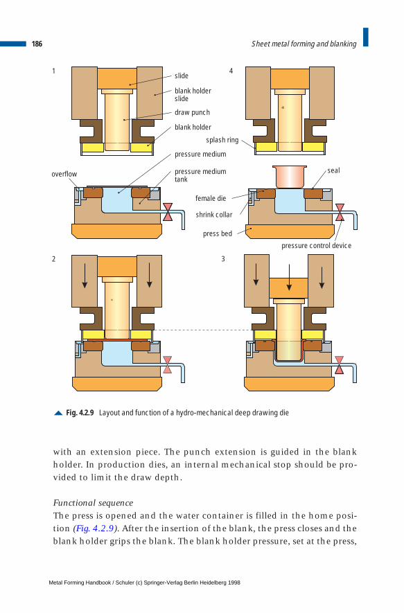
with an extension piece. The punch extension is guided in the blankholder. In production dies, an internal mechanical stop should be pro-vided to limit the draw depth.
Functional sequenceThe press is opened and the water container is filled in the home posi-tion (Fig. 4.2.9). After the insertion of the blank, the press closes and theblank holder grips the blank. The blank holder pressure, set at the press,
186 Sheet metal forming and blanking
Fig. 4.2.9 Layout and function of a hydro-mechanical deep drawing die
1
2 3
4slide
blank holderslide
draw punch
blank holder
splash ring
pressure medium
pressure mediumtank
female die
shrink collar
press bed
pressure control device
sealoverflow
Metal Forming Handbook / Schuler (c) Springer-Verlag Berlin Heidelberg 1998
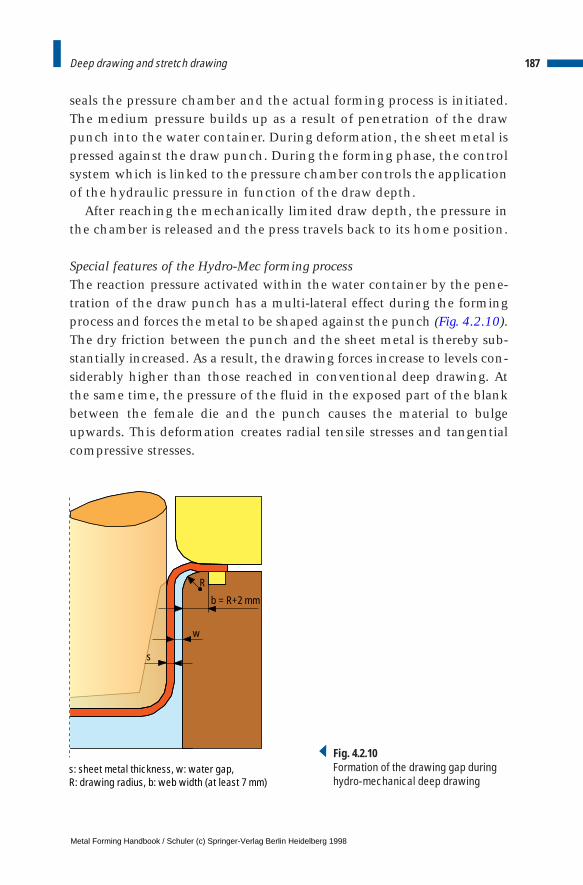
seals the pressure chamber and the actual forming process is initiated.The medium pressure builds up as a result of penetration of the drawpunch into the water container. During deformation, the sheet metal ispressed against the draw punch. During the forming phase, the controlsystem which is linked to the pressure chamber controls the applicationof the hydraulic pressure in function of the draw depth.
After reaching the mechanically limited draw depth, the pressure inthe chamber is released and the press travels back to its home position.
Special features of the Hydro-Mec forming processThe reaction pressure activated within the water container by the pene-tration of the draw punch has a multi-lateral effect during the formingprocess and forces the metal to be shaped against the punch (Fig. 4.2.10).The dry friction between the punch and the sheet metal is thereby sub-stantially increased. As a result, the drawing forces increase to levels con-siderably higher than those reached in conventional deep drawing. Atthe same time, the pressure of the fluid in the exposed part of the blankbetween the female die and the punch causes the material to bulgeupwards. This deformation creates radial tensile stresses and tangentialcompressive stresses.
187Deep drawing and stretch drawing
s
w
R
b = R+2 mm
s: sheet metal thickness, w: water gap, R: drawing radius, b: web width (at least 7 mm)
Fig. 4.2.10Formation of the drawing gap duringhydro-mechanical deep drawing
Metal Forming Handbook / Schuler (c) Springer-Verlag Berlin Heidelberg 1998
Hydro-mechanical deep drawing allows to achieve a significantlylarger draw ratio than that achievable in conventional drawing opera-tions. Whilst the limiting drawing ratio using conventional technologyis b < 2.0, deep drawing ratio limits of up to 2.7 can be achieved inhydro-mechanical deep drawing. Since no intermediate drawing andannealing operations are required, very cost-effective forming is possi-ble. The tool costs can also be reduced because of the reduction in thenumber of necessary forming operations. Another notable benefit is thequality of the surfaces of the drawn parts, as the sheet metal has notbeen drawn over a rigid drawing edge but over a fluid bead. Costs forfinish processing operations such as polishing or grinding are substan-tially reduced or often completely eliminated.
Due to the pressing of the blank against the punch which reduces theamount of spring back, dimensionally accurate part production is pos-sible. This is particularly important in reflector production, as not onlymeasurement tolerances but also optical qualities are tested. The thick-ness of the sheet metal for hydro-mechanically deep drawn parts remainsconsistent within narrow limits. This applies particularly to the smallreduction in thickness on the base radii, so that thinner blank can fre-quently be used for forming the desired part.
Press force is higher in hydro-mechanical drawing than in otherforming methods using rigid tools, due to the reaction pressure in thewater container. Here, the slide force FSt [kN] is the sum of the conven-tional forming force FU [kN] and the reaction force FRe [kN], which actson the punch surface through the pressure medium (Fig. 4.2.11).
Depending upon the particular blank materials being processed, thefollowing pressures occur in the water container:
– aluminium: 50 – 200 bar– steel: 200 – 600 bar– stainless steel: 300 – 1,000 bar
4.2.5 Active hydro-mechanical drawing
Depending on their design, large-panel components for the automobileindustry such as hoods, roofs and doors possess only minimal bucklingstrength in the center region of the parts. The reason for this is the low
188 Sheet metal forming and blanking
Metal Forming Handbook / Schuler (c) Springer-Verlag Berlin Heidelberg 1998
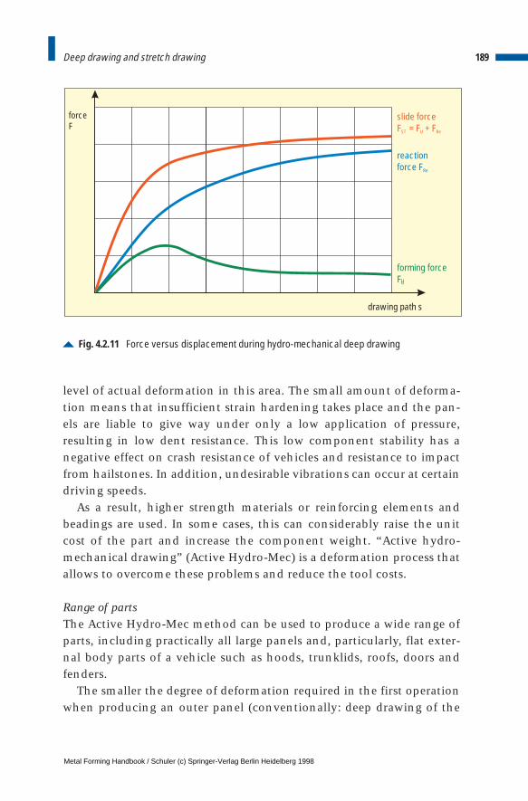
level of actual deformation in this area. The small amount of deforma-tion means that insufficient strain hardening takes place and the pan-els are liable to give way under only a low application of pressure,resulting in low dent resistance. This low component stability has anegative effect on crash resistance of vehicles and resistance to impactfrom hailstones. In addition, undesirable vibrations can occur at certaindriving speeds.
As a result, higher strength materials or reinforcing elements andbeadings are used. In some cases, this can considerably raise the unitcost of the part and increase the component weight. “Active hydro-mechanical drawing” (Active Hydro-Mec) is a deformation process thatallows to overcome these problems and reduce the tool costs.
Range of partsThe Active Hydro-Mec method can be used to produce a wide range ofparts, including practically all large panels and, particularly, flat exter-nal body parts of a vehicle such as hoods, trunklids, roofs, doors andfenders.
The smaller the degree of deformation required in the first operationwhen producing an outer panel (conventionally: deep drawing of the
189Deep drawing and stretch drawing
Fig. 4.2.11 Force versus displacement during hydro-mechanical deep drawing
slide forceF = F + FST U Re
reactionforce FRe
forming forceFUU
drawing path s
forceF
Metal Forming Handbook / Schuler (c) Springer-Verlag Berlin Heidelberg 1998
contoured blank), the more suited is the operation for using the ActiveHydro-Mec method.
Operating principleThe Active Hydro-Mec method involves forming with an operatingmedium (oil-water emulsion), in which a large-size blank is clamped allaround with a watertight seal between the female die and the blankholder – in the form of a water container (Fig. 4.2.12/2). At this stage, adefined, part-specific gap exists between the clamped blank and thepunch. As soon as the blankholding force has built up, the emulsion isactively introduced into the water container by means of a pressureintensifier and a defined pressure is built up (depending on the partbetween 20 and 30 bar). This pressure causes a controlled bulging of theblank which is pre-stretched over what is to become the entire surfaceof the component until it comes to rest against the punch in the centerof the punch surface. This controlled expansion of the sheet metalresults in work hardening of the workpiece which leads to a substantialimprovement in buckling strength of the formed part.
After the pre-stretching process, the whole system – blank holder,blank and female die – is pressed upwards against the stationary punch.This process corresponds to the counter-drawing principle (Fig. 4.2.4)in which the emulsion is displaced. During the process, the pressurelevel can be kept constant or can be regulated to increase or decreaseprogressively or degressively. After completion of the drawing process,the emulsion pressure is actively built up (to a maximum of 600 bar) inorder to ensure optimum application and formation of the blankagainst the contour of the punch.
PressThe press developed for the Active Hydro-Mec-process is a double-action straight-sided press design with Hydro-Mec pressure intensifierand a quick die changing system. Figure 4.2.13 provides a schematicview of the press.
The press force of max. 50,000 kN is applied from below by eightcylinders located in the press bed. Six blank holder cylinders in thepress crown apply a blankholding pressure of max. 16,000 kN duringthe pre-stretching process. Six powered mechanical stops can be adjust-ed for each individual part to determine the limit of the draw depth.
190 Sheet metal forming and blanking
Metal Forming Handbook / Schuler (c) Springer-Verlag Berlin Heidelberg 1998
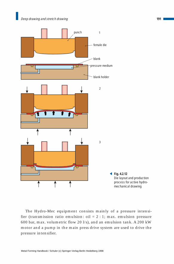
The Hydro-Mec equipment consists mainly of a pressure intensi-fier (transmission ratio emulsion: oil = 2 : 1; max. emulsion pressure 600 bar, max. volumetric flow 20 l/s), and an emulsion tank. A 200 kWmotor and a pump in the main press drive system are used to drive thepressure intensifier.
191Deep drawing and stretch drawing
female die
blank
blank holder
punch
pressure medium
1
2
3
Fig. 4.2.12Die layout and productionprocess for active hydro-mechanical drawing
Metal Forming Handbook / Schuler (c) Springer-Verlag Berlin Heidelberg 1998
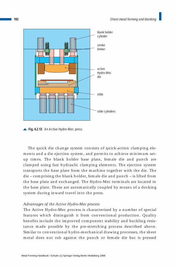
The quick die change system consists of quick-action clamping ele-ments and a die ejection system, and permits to achieve minimum set-up times. The blank holder base plate, female die and punch areclamped using fast hydraulic clamping elements. The ejection systemtransports the base plate from the machine together with the die. Thedie – comprising the blank holder, female die and punch – is lifted fromthe base plate and exchanged. The Hydro-Mec terminals are located inthe base plate. These are automatically coupled by means of a dockingsystem during inward travel into the press.
Advantages of the Active Hydro-Mec processThe Active Hydro-Mec process is characterized by a number of specialfeatures which distinguish it from conventional production. Qualitybenefits include the improved component stability and buckling resis-tance made possible by the pre-stretching process described above.Similar to conventional hydro-mechanical drawing processes, the sheetmetal does not rub against the punch or female die but is pressed
192 Sheet metal forming and blanking
Fig. 4.2.13 An Active Hydro-Mec press
blank holdercylinder
strokelimiter
activeHydro-Mecdie
slide
slide cylinders
Metal Forming Handbook / Schuler (c) Springer-Verlag Berlin Heidelberg 1998

against the punch by the emulsion. At the same time the processensures optimum surface quality of the outer skin. Due to the lowersheet metal thicknesses used and the elimination of reinforcements,the overall assembly weight can be reduced. Another benefit in processengineering terms is the ability to process different materials (steel, alu-minium, high-strength steels) and sheet thicknesses using a single setof dies.
In addition, the Active Hydro-Mec process represents a cost savingover conventional production methods. Tooling costs, in particular,can be reduced by up to 50%, as only one half of the die needs to bemachined to have the part geometry. Furthermore, dies achieve a farlonger service life due to the lower die wear involved in the hydro-mechanical drawing method. Depending on the part contour and thedesign of the die, it is often possible to save a complete processing step.
193Deep drawing and stretch drawing
Metal Forming Handbook / Schuler (c) Springer-Verlag Berlin Heidelberg 1998
4 Sheet metal forming and blanking
4.3 Coil lines
The method of sheet metal feed plays an important role when consid-ering the overall cost effectiveness of forming and blanking lines.When producing small sheet metal parts, the sheet metal coil is feddirectly by a coil feed line into the press.
The function of the coil line is to unwind coils of sheet material, passit through the straightener and to feed it by means of a roll feed pre-cisely to the defined position of the processing line (cf. Fig. 4.6.4).
The main components of a conventional coil line are the decoiler,straightening machine, coil loop and roll feed (Fig. 4.3.1). The straight-ening machine draws the coil stock from the decoiler and flattens the material (cf. Sect. 4.8.3). Using sufficiently large dimensioned rollerassemblies – in order to avoid the material from becoming bent again –the material is transported from the straightening machine continu-ously to the coil loop. The electronically controlled roll feed draws thestock intermittently from the loop and feeds it, correctly positioned,into the press. The maximum feed output of a high-performance coilline for small and medium-sized parts (cf. Fig. 4.4.4) and a blankingpress (cf. Sects. 4.4.5, 4.4.7, 4.4.8) is indicated in Fig. 4.3.2. The strokingrate of the press is specified depending on the feed length and the crankangle which is available for the feed depending on the press and thetool in use.
Compact design coil feeding lines do not require the pit for the coilloop (Fig. 4.3.3). They consist of a decoiler and a feed/straighteningmachine. The decoiler unwinds the stock downwards, opposite thedirection of processing, so forming a horizontally aligned coil loop. The
Metal Forming Handbook / Schuler (c) Springer-Verlag Berlin Heidelberg 1998
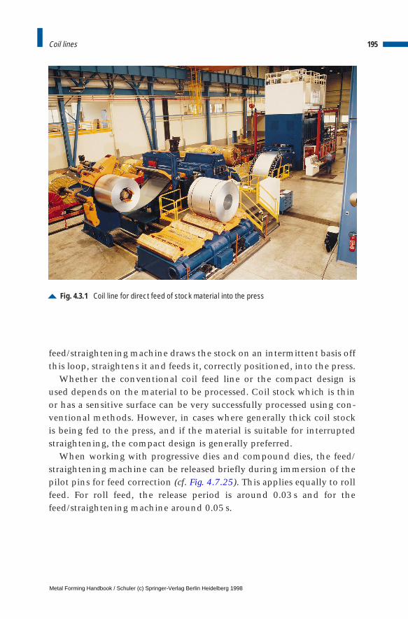
feed/straightening machine draws the stock on an intermittent basis offthis loop, straightens it and feeds it, correctly positioned, into the press.
Whether the conventional coil feed line or the compact design isused depends on the material to be processed. Coil stock which is thinor has a sensitive surface can be very successfully processed using con-ventional methods. However, in cases where generally thick coil stockis being fed to the press, and if the material is suitable for interruptedstraightening, the compact design is generally preferred.
When working with progressive dies and compound dies, the feed/straightening machine can be released briefly during immersion of thepilot pins for feed correction (cf. Fig. 4.7.25). This applies equally to rollfeed. For roll feed, the release period is around 0.03 s and for thefeed/straightening machine around 0.05 s.
195Coil lines
Fig. 4.3.1 Coil line for direct feed of stock material into the press
Metal Forming Handbook / Schuler (c) Springer-Verlag Berlin Heidelberg 1998
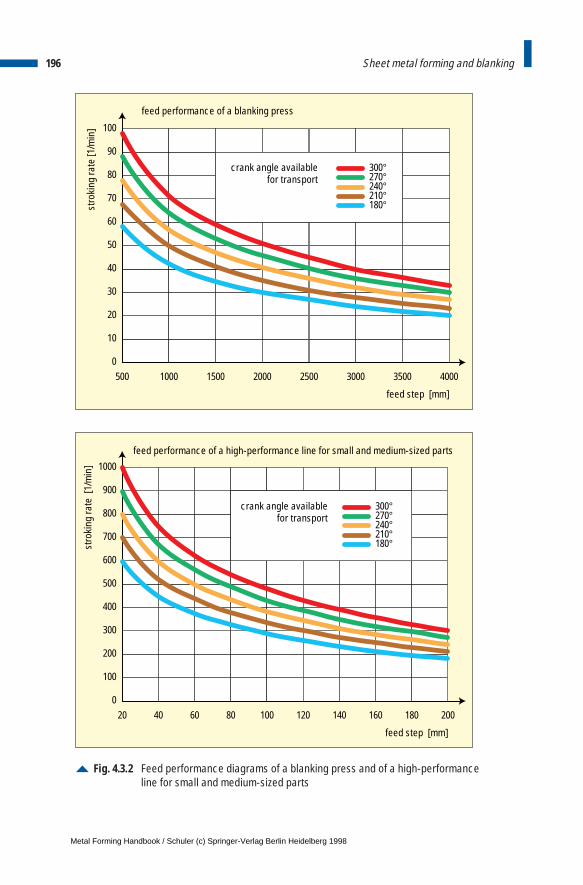
196 Sheet metal forming and blanking
Fig. 4.3.2 Feed performance diagrams of a blanking press and of a high-performanceline for small and medium-sized parts
0
10
20
30
40
50
500
feed step [mm]
feed performance of a blanking press
stro
king
rate
[1/m
in]
1000 1500 2000 2500 3000 3500 4000
60
70
80
90
100
300°270°240°210°180°
crank angle availablefor transport
0
100
200
300
400
500
20
feed step [mm]
stro
king
rate
[1/
min
]
40 60 80 100 120 140 160 180 200
600
700
800
900
1000
300°270°240°210°180°
crank angle availablefor transport
feed performance of a high-performance line for small and medium-sized parts
Metal Forming Handbook / Schuler (c) Springer-Verlag Berlin Heidelberg 1998
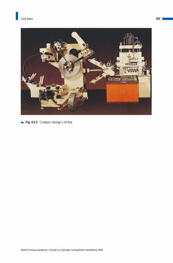
197Coil lines
Fig. 4.3.3 Compact design coil line
Metal Forming Handbook / Schuler (c) Springer-Verlag Berlin Heidelberg 1998
4 Sheet metal forming and blanking
4.4 Sheet metal forming lines
4.4.1 Universal presses
Universal presses are characterized by their high degree of flexibility.They are suitable both for blanking and forming operations (Fig. 4.4.1).In combination with individual, progressive blanking, compound andtransfer dies, this opens up a wide range of application possibilities forthe production of small to medium-sized parts (cf. Sect. 4.1.1). Toincrease the number of formed parts and so enhance the cost-effective-ness of the production process, universal presses are equipped with coillines (cf. Fig. 4.3.1), scrap disposal systems and stacking units for fin-ished products (Fig. 4.4.41). Fully automatic die change plays an impor-tant role in ensuring economical production (cf. Sect. 3.4).
Comparison: mechanically and hydraulically driven universal pressesGenerally speaking, universal presses are driven either mechanically orhydraulically. In the case of mechanical universal presses, the move-ment of the eccentric shaft is transmitted to the slide by means of theconnecting rod. Accordingly, the sinusoidal curve of the stroke is pre-scribed by the geometry of the eccentric or crank shaft (cf. Fig. 3.2.3).
For a mechanical and a hydraulic press with a forming stroke ofapprox. 100 mm, the stroke versus time, the time required for one workcycle (cycle time) and the time available for part handling (transporta-tion time), are shown in Fig. 4.4.2. It is seen that the handling timeavailable is 2.4 s, the cycle time of the mechanical press is 3.6 s, so thatthe corresponding stroking rate is around 17 strokes per minute.
Metal Forming Handbook / Schuler (c) Springer-Verlag Berlin Heidelberg 1998
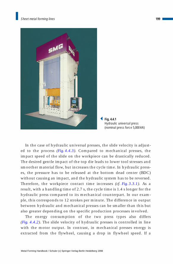
In the case of hydraulic universal presses, the slide velocity is adjust-ed to the process (Fig. 4.4.3). Compared to mechanical presses, theimpact speed of the slide on the workpiece can be drastically reduced.The desired gentle impact of the top die leads to lower tool stresses andsmoother material flow, but increases the cycle time. In hydraulic press-es, the pressure has to be released at the bottom dead center (BDC)without causing an impact, and the hydraulic system has to be reversed.Therefore, the workpiece contact time increases (cf. Fig. 3.3.1). As aresult, with a handling time of 2.7 s, the cycle time is 1.4 s longer for thehydraulic press compared to its mechanical counterpart. In our exam-ple, this corresponds to 12 strokes per minute. The difference in outputbetween hydraulic and mechanical presses can be smaller than this butalso greater depending on the specific production processes involved.
The energy consumption of the two press types also differs (Fig. 4.4.2). The slide velocity of hydraulic presses is controlled in linewith the motor output. In contrast, in mechanical presses energy isextracted from the flywheel, causing a drop in flywheel speed. If a
199Sheet metal forming lines
Fig. 4.4.1Hydraulic universal press(nominal press force 5,000 kN)
Metal Forming Handbook / Schuler (c) Springer-Verlag Berlin Heidelberg 1998
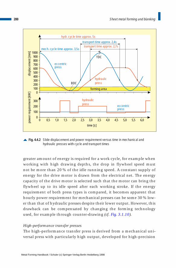
greater amount of energy is required for a work cycle, for example whenworking with high drawing depths, the drop in flywheel speed mustnot be more than 20 % of the idle running speed. A constant supply ofenergy for the drive motor is drawn from the electrical net. The energycapacity of the drive motor is selected such that the motor can bring theflywheel up to its idle speed after each working stroke. If the energyrequirement of both press types is compared, it becomes apparent thathourly power requirement for mechanical presses can be some 30 % low-er than that of hydraulic presses despite their lower output. However, thisdrawback can be compensated by changing the forming technologyused, for example through counter-drawing (cf. Fig. 3.1.10).
High-performance transfer pressesThe high-performance transfer press is derived from a mechanical uni-versal press with particularly high output, developed for high-precision
200 Sheet metal forming and blanking
Fig. 4.4.2 Slide displacement and power requirement versus time in mechanical andhydraulic presses with cycle and transport times
hydr. cycle time approx. 5 s
transport time approx. 2,7 stransport time approx. 2,4 s
hydraulicpress
forming area
hydraulicpress
eccentricpress
eccentricpress
TDC
BDC
mech. cycle time approx. 3,5 s1000
900800700600500400300200100
0
300
200
100
0
disp
lace
men
t [m
m]
pow
er re
quire
men
t [kW
]
time [s]
0 0,5 1,0 1,5 2,0 2,5 3,0 3,5 4,0 4,5 5,0 5,5 6,0
Metal Forming Handbook / Schuler (c) Springer-Verlag Berlin Heidelberg 1998
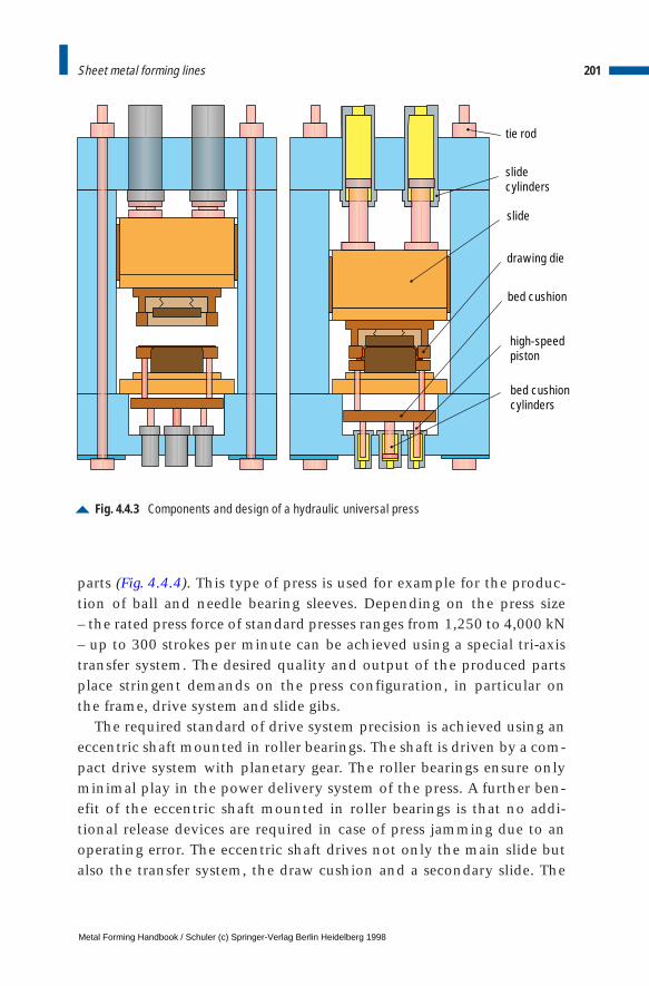
parts (Fig. 4.4.4). This type of press is used for example for the produc-tion of ball and needle bearing sleeves. Depending on the press size – the rated press force of standard presses ranges from 1,250 to 4,000 kN– up to 300 strokes per minute can be achieved using a special tri-axistransfer system. The desired quality and output of the produced partsplace stringent demands on the press configuration, in particular onthe frame, drive system and slide gibs.
The required standard of drive system precision is achieved using aneccentric shaft mounted in roller bearings. The shaft is driven by a com-pact drive system with planetary gear. The roller bearings ensure onlyminimal play in the power delivery system of the press. A further ben-efit of the eccentric shaft mounted in roller bearings is that no addi-tional release devices are required in case of press jamming due to anoperating error. The eccentric shaft drives not only the main slide butalso the transfer system, the draw cushion and a secondary slide. The
201Sheet metal forming lines
Fig. 4.4.3 Components and design of a hydraulic universal press
tie rod
slidecylinders
slide
drawing die
bed cushion
high-speedpiston
bed cushioncylinders
Metal Forming Handbook / Schuler (c) Springer-Verlag Berlin Heidelberg 1998
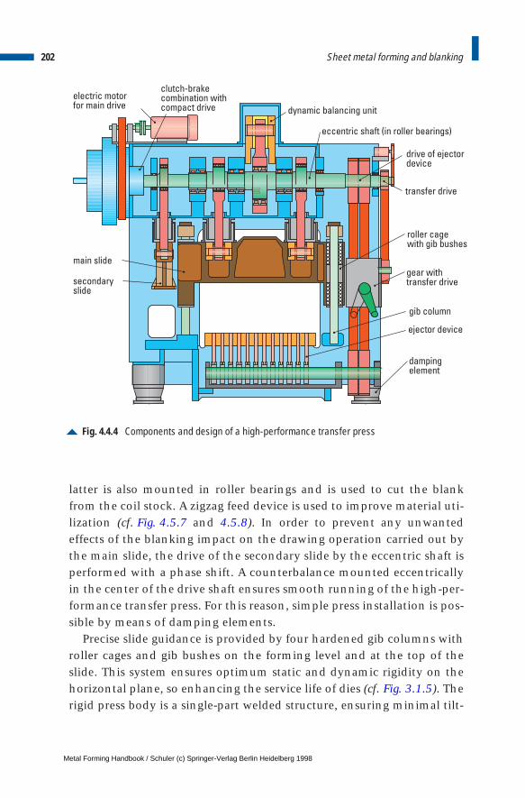
latter is also mounted in roller bearings and is used to cut the blankfrom the coil stock. A zigzag feed device is used to improve material uti-lization (cf. Fig. 4.5.7 and 4.5.8). In order to prevent any unwantedeffects of the blanking impact on the drawing operation carried out bythe main slide, the drive of the secondary slide by the eccentric shaft isperformed with a phase shift. A counterbalance mounted eccentricallyin the center of the drive shaft ensures smooth running of the high-per-formance transfer press. For this reason, simple press installation is pos-sible by means of damping elements.
Precise slide guidance is provided by four hardened gib columns withroller cages and gib bushes on the forming level and at the top of theslide. This system ensures optimum static and dynamic rigidity on thehorizontal plane, so enhancing the service life of dies (cf. Fig. 3.1.5). Therigid press body is a single-part welded structure, ensuring minimal tilt-
202 Sheet metal forming and blanking
Fig. 4.4.4 Components and design of a high-performance transfer press
drive of ejectordevice
clutch-brakecombination withcompact drive
electric motorfor main drive
dynamic balancing unit
eccentric shaft (in roller bearings)
transfer drive
roller cagewith gib bushes
main slide
secondaryslide
gear withtransfer drive
gib column
ejector device
dampingelement
Metal Forming Handbook / Schuler (c) Springer-Verlag Berlin Heidelberg 1998
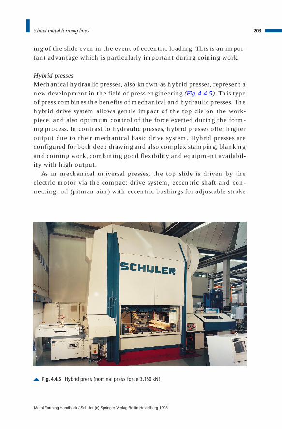
ing of the slide even in the event of eccentric loading. This is an impor-tant advantage which is particularly important during coining work.
Hybrid pressesMechanical hydraulic presses, also known as hybrid presses, represent anew development in the field of press engineering (Fig. 4.4.5). This typeof press combines the benefits of mechanical and hydraulic presses. Thehybrid drive system allows gentle impact of the top die on the work-piece, and also optimum control of the force exerted during the form-ing process. In contrast to hydraulic presses, hybrid presses offer higheroutput due to their mechanical basic drive system. Hybrid presses areconfigured for both deep drawing and also complex stamping, blankingand coining work, combining good flexibility and equipment availabil-ity with high output.
As in mechanical universal presses, the top slide is driven by theelectric motor via the compact drive system, eccentric shaft and con-necting rod (pitman aim) with eccentric bushings for adjustable stroke
203Sheet metal forming lines
Fig. 4.4.5 Hybrid press (nominal press force 3 ,150 kN)
Metal Forming Handbook / Schuler (c) Springer-Verlag Berlin Heidelberg 1998
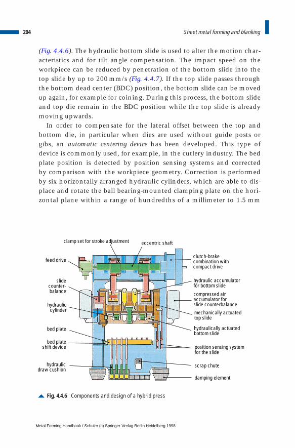
(Fig. 4.4.6). The hydraulic bottom slide is used to alter the motion char-acteristics and for tilt angle compensation. The impact speed on theworkpiece can be reduced by penetration of the bottom slide into thetop slide by up to 200 mm/s (Fig. 4.4.7). If the top slide passes throughthe bottom dead center (BDC) position, the bottom slide can be movedup again, for example for coining. During this process, the bottom slideand top die remain in the BDC position while the top slide is alreadymoving upwards.
In order to compensate for the lateral offset between the top andbottom die, in particular when dies are used without guide posts orgibs, an automatic centering device has been developed. This type ofdevice is commonly used, for example, in the cutlery industry. The bedplate position is detected by position sensing systems and corrected by comparison with the workpiece geometry. Correction is performedby six horizontally arranged hydraulic cylinders, which are able to dis-place and rotate the ball bearing-mounted clamping plate on the hori-zontal plane within a range of hundredths of a millimeter to 1.5 mm
204 Sheet metal forming and blanking
Fig. 4.4.6 Components and design of a hybrid press
feed drive
slidecounter-balance
hydrauliccylinder
bed plateshift device
bed plate
hydraulicdraw cushion
clamp set for stroke adjustment eccentric shaft
clutch-brakecombination withcompact drive
hydraulic accumulatorfor bottom slide
compressed airaccumulator forslide counterbalance
mechanically actuatedtop slide
hydraulically actuatedbottom slide
position sensing systemfor the slide
scrap chute
damping element
Metal Forming Handbook / Schuler (c) Springer-Verlag Berlin Heidelberg 1998
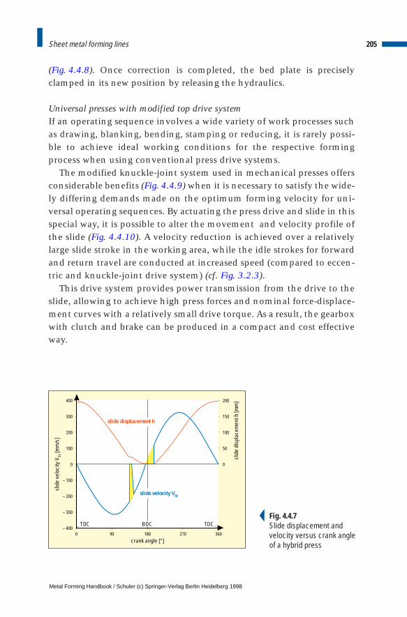
(Fig. 4.4.8). Once correction is completed, the bed plate is preciselyclamped in its new position by releasing the hydraulics.
Universal presses with modified top drive systemIf an operating sequence involves a wide variety of work processes suchas drawing, blanking, bending, stamping or reducing, it is rarely possi-ble to achieve ideal working conditions for the respective formingprocess when using conventional press drive systems.
The modified knuckle-joint system used in mechanical presses offersconsiderable benefits (Fig. 4.4.9) when it is necessary to satisfy the wide-ly differing demands made on the optimum forming velocity for uni-versal operating sequences. By actuating the press drive and slide in thisspecial way, it is possible to alter the movement and velocity profile ofthe slide (Fig. 4.4.10). A velocity reduction is achieved over a relativelylarge slide stroke in the working area, while the idle strokes for forwardand return travel are conducted at increased speed (compared to eccen-tric and knuckle-joint drive system) (cf. Fig. 3.2.3).
This drive system provides power transmission from the drive to theslide, allowing to achieve high press forces and nominal force-displace-ment curves with a relatively small drive torque. As a result, the gearboxwith clutch and brake can be produced in a compact and cost effectiveway.
205Sheet metal forming lines
400
300
200
100
0
– 100
– 200
– 300
– 400
200
150
100
50
0
0 90 180 270 360crank angle [°]
TDC TDC
slid
e ve
loci
ty V
St [m
m/s
]
slide velocity VSt
slid
e di
spla
cem
ent h
[mm
]
BDC
slide displacement h
Fig. 4.4.7Slide displacement and velocity versus crank angle of a hybrid press
Metal Forming Handbook / Schuler (c) Springer-Verlag Berlin Heidelberg 1998

206 Sheet metal forming and blanking
Fig. 4.4.8 Clamping and release device for an adjustable bed plate
shift ball bearings
hydraulic piston
press bed
cup springs
clamping plate
bed clamping plate
Fig. 4.4.9Universal press with modified top drive (nominal press force 8,000 kN)
Metal Forming Handbook / Schuler (c) Springer-Verlag Berlin Heidelberg 1998

The two links are located at the outsides of the slide and allow forgood compensation of the eccentric forces that may occur. Direct appli-cation of force in the upright area of the press crown helps to reducedeflection and bending and makes a major contribution to high systemrigidity. The lateral forces, caused as a result of the force exerted by con-necting rod, are absorbed by a crossbar, so that they cannot adverselyaffect the slide gibs. This system permits extremely precise slide guid-ance under load.
The reduced forming speed permits a higher stroking rate duringdrawing and reducing processes, protects the dies and reduces noisedevelopment. In addition, the added rigidity offers a number of bene-fits during stamping due to precise, plane-parallel forming. A reductionof dynamic deflection effects and blanking shock, as well as lower
207Sheet metal forming lines
Fig. 4.4.10Structure of a modified top drive
Metal Forming Handbook / Schuler (c) Springer-Verlag Berlin Heidelberg 1998
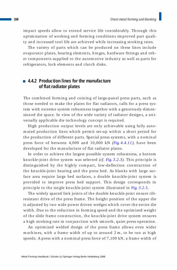
impact speeds allow to extend service life considerably. Through thisoptimization of working and forming conditions improved part quali-ty and increased tool life are achieved while increasing stroking rates.
The variety of parts which can be produced on these lines includeevaporator plates, bearing elements, hinges, hardware fittings and oth-er components supplied to the automotive industry as well as parts forrefrigerators, lock elements and clutch disks.
4.4.2 Production lines for the manufacture of flat radiator plates
The combined forming and coining of large-panel press parts, such asthose needed to make the plates for flat radiators, calls for a press sys-tem with extreme system robustness together with a generously dimen-sioned die space. In view of the wide variety of radiator designs, a uni-versally applicable die technology concept is required.
High production output levels are only achievable using fully auto-mated production lines which permit set-up within a short period forthe production of different parts. Special press systems, with a nominalpress force of between 4,000 and 10,000 kN (Fig. 4.4.11), have beendeveloped for the manufacture of flat radiator plates.
In order to achieve the largest possible system robustness, a bottomknuckle-joint drive system was selected (cf. Fig. 3.2.3). This principle isdistinguished by the highly compact, low-deflection construction ofthe knuckle-joint bearing and the press bed. As blanks with large sur-face area require large bed surfaces, a double knuckle-joint system isprovided to improve press bed support. This design corresponds inprinciple to the single knuckle-joint system illustrated in Fig. 3.2.5.
The widely spaced link joints of the double knuckle-joint ensure tilt-resistant drive of the press frame. The height position of the upper dieis adjusted by two wide power driven wedges which cover the entire diewidth. Due to the reduction in forming speed and the optimized weightof the slide frame construction, the knuckle-joint drive system ensuresa high stroking rate in conjunction with smooth, quiet press operation.
An optimized welded design of the press frame allows even widermachines, with a frame width of up to around 2 m, to be run at highspeeds. A press with a nominal press force of 7,100 kN, a frame width of
208 Sheet metal forming and blanking
Metal Forming Handbook / Schuler (c) Springer-Verlag Berlin Heidelberg 1998
1,860 mm and a working stroke of 80 mm can produce 80 strokes perminute in continuous operation.
The machine is based on a modular design and can be equipped, asrequired, with or without a hydraulic draw cushion in the press bed andslide (cf. Sect. 3.1.4). The wedge adjustment of the slide ensures thehigh degree of rigidity required for drawing and coining work.
The modified knuckle-joint geometry and the connecting rod link-age prevent the knuckle-joint system from being fully extended at thebottom dead center. The bottom dead center has already been reachedwhen the knuckle-joint system is still located some 2 to 3 mm beforethe maximum extended position. This design feature eliminates anypossibility of press jamming, and the need to use a hydraulic overloadsafety system. The press force monitoring can take place exclusivelywith electronic measurement systems.
209Sheet metal forming lines
Fig. 4.4.11Bottom drive knuckle-joint pressfor the manufacture of flat radiator plates (nominal pressforce 6,300 kN)
Metal Forming Handbook / Schuler (c) Springer-Verlag Berlin Heidelberg 1998
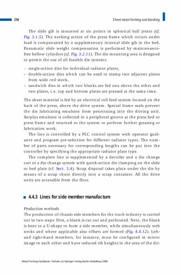
The slide gib is mounted at six points in spherical ball joints (cf. Fig. 3.1.5). The necking action of the press frame which occurs underload is compensated by a supplementary internal slide gib in the bed.Pneumatic slide weight compensation is performed by maintenance-free bellow cylinders (cf. Fig. 3.2.11). The die mounting area is designedto permit the use of all feasible die systems:
– single-action dies for individual radiator plates,– double-action dies which can be used to stamp two adjacent plates
from wide coil stock,– sandwich dies in which two blanks are fed one above the other and
two plates, i. e. top and bottom plates are pressed at the same time.
The sheet material is fed by an electrical roll feed system located on theback of the press, above the drive system. Special frame seals preventthe die lubricating emulsion from penetrating into the driving unit.Surplus emulsion is collected in a peripheral groove at the press bed orpress frame and returned to the system to perform further greasing orlubrication work.
The line is controlled by a PLC control system with operator guid-ance and program pre-selection for different radiator types. The num-ber of parts necessary for corresponding lengths can be put into thecontroller by specifying the appropriate radiator plate type.
The complete line is supplemented by a decoiler and a die changecart or a die change system with quick-action die clamping on the slideor bed plate (cf. Sect. 3.4). Scrap disposal takes place under the die bymeans of a scrap chute directly into a scrap container. All the driveunits are accessible from the floor.
4.4.3 Lines for side member manufacture
Production methodsThe production of chassis side members for the truck industry is carriedout in two steps: First, a blank is cut out and perforated. Next, the blankis bent to a U-shape to form a side member, while simultaneously webnecks and where applicable also offsets are formed (Fig. 4.4.12). Left-and right-hand members, for instance, must be configured in mirrorimage to each other and have reduced rib heights in the area of the dri-
210 Sheet metal forming and blanking
Metal Forming Handbook / Schuler (c) Springer-Verlag Berlin Heidelberg 1998
ver’s cab. Both operations are generally executed in a single line usingtwo die sets.
When manufacturing side members, two different methods are usedin conjunction with different types of production lines. These are dis-tinguished from each other already in the blank feed stage.
Side members with a length of up to 7 m are generally manufacturedfrom plates, which have a maximum thickness of 4 mm. The plates arefed into the press on an intermittent basis transversely to the longitu-dinal axis of the press. With each stroke the blanking die in the presspunches a contoured blank from the plate. The blank is then bent inthe next station to become a side member.
To produce side members with a length ranging from 4 to 13 m,blanks with a thickness of 5 to 10 mm are available. The blanks aregenerally cross-cut directly off the coil to the contoured blank width(cf. Sect. 4.6.1) in order to ensure optimum material utilization. Thecamber shaped blanks produced using this method have to be correct-ed in a separate unit by straightening. The straightened blanks are fedindividually into the longitudinal axis of the press and processed to cre-
211Sheet metal forming lines
Fig. 4.4.12 Side members used in truck production
Metal Forming Handbook / Schuler (c) Springer-Verlag Berlin Heidelberg 1998
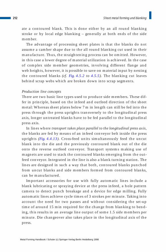
ate a contoured blank. This is done either by an all round blankingstroke or by local edge blanking – generally at both ends of the sidemember.
The advantage of processing sheet plates is that the blanks do notassume a camber shape due to the all round blanking cut used in theirmanufacture. Thus, the straightening process can be omitted. However,in this case a lower degree of material utilization is achieved. In the caseof complex side member geometries, involving different flange andweb heights, however, it is possible to save on material input by nestingthe contoured blanks (cf. Fig. 4.5.2 to 4.5.5). The blanking cut leavesbehind scrap webs which are broken down into scrap segments.
Production line conceptsThere are two basic line types used to produce side members. These dif-fer in principle, based on the infeed and outfeed direction of the sheetmetal: Whereas sheet plates below 7m in length can still be fed into thepress through the press uprights transversely to the longitudinal pressaxis, longer untreated blanks have to be fed parallel to the longitudinalpress axis.
In lines where transport takes place parallel to the longitudinal press axis,the blanks are fed by means of an infeed conveyor belt inside the pressuprights (Fig. 4.4.13). Cross-feed units simultaneously feed the uncutblank into the die and the previously contoured blank out of the dieonto the reverse outfeed conveyor. Transport systems making use ofmagnets are used to stack the contoured blanks emerging from the out-feed conveyor. Integrated in the line is also a blank turning station. Thelines are designed in such a way that both, contoured blanks punchedfrom uncut blanks and side members formed from contoured blanks,can be manufactured.
Important accessories for use with fully automatic lines include ablank lubricating or spraying device at the press infeed, a hole patterncamera to detect punch breakage and a device for edge milling. Fullyautomatic lines achieve cycle times of 3 strokes per minute. Taking intoaccount the need for two passes and without considering the set-uptime of around 15 min required for the change from blanking to bend-ing, this results in an average line output of some 1.5 side members perminute. Die changeover also takes place in the longitudinal axis of thepress.
212 Sheet metal forming and blanking
Metal Forming Handbook / Schuler (c) Springer-Verlag Berlin Heidelberg 1998
In the case of presses with material transport transversely to the longitu-dinal press axis, the sheet plates are guided between the press uprightsby means of a chain conveyor and a gripper feed device in synchro-nization with the press cycle. After each stroke, the remaining platepushes the newly punched contoured blank onto the reverse outfeedconveyor belt. When an operation has been completed, the waste stripof the old plate must be disposed of together with the blanking wastefrom the new plate.
The equipment used for destacking the bales of plates or contouredblanks and the other elements of the line are the same as those used inlines transporting the material in the direction of the longitudinal pressaxis.
213Sheet metal forming lines
Fig. 4.4.13 Layout of a line for the manufacture of truck side members(FN = 50,000 kN, blanking shock damping and stroke limitation, 11 bed cushions,25 slide ejectors, maximum off-center load: 25,000 kNm with electronic controlof parallelity)
Metal Forming Handbook / Schuler (c) Springer-Verlag Berlin Heidelberg 1998
Die conceptThe blanking and bending die each comprise a basic die equipped withtrimming and piercing modules in accordance with the various sidemember lengths. Side members are structured in such a way that cer-tain groups of holes, for example those used to fasten the front and rearsuspension mounting, are identical and only change relative to thewheel base. In the area of the driver’s cab at the front end of the sidemember, the contour and hole patterns are identical. The modules areaccordingly adjusted and positioned according to the requirements ofeach individual side member type:
– front module for the area of the driver’s cab, – main module, for example for the rear axle area, – intermediate module to bridge different side member lengths and – the end module.
If at all possible, right and left-hand side members should have the samehole pattern. Only then it is possible to minimize the effort required fordrawing and mounting piercing hole punches when changing set-upfrom right-hand to left-hand side members. The shearing edges requiredfor blanking the side member contour do not have to be reset, as forexample the left-hand contoured blank is produced from the right-handcontoured blank by simply rotating it in the turning station. However,for the bending process, bending dies, forming edges and ejector beamsin the asymmetrical areas must be changed for a new set-up.
As the position of the front module does not change, if the length ofthe side members decreases, the position of the workpieces in theblanking and bending dies becomes increasingly off-center. If a single-sided coping cut is to be carried out at the same time, e. g. for examplewhen trimming the front, an additional off-center load is applied. Theoff-center forces must be accounted for, either by a balancing module orby providing a suitable press concept. Otherwise an unacceptableamount of slide tilting action will occur.
To reduce the blanking force, the edges of the blanking die andpunch are configured in a saw-tooth arrangement and the piercing holepunches are staggered on several blanking levels. The aim is to achieveuniform loading over the entire length of the workpiece at every blank-ing plane.
214 Sheet metal forming and blanking
Metal Forming Handbook / Schuler (c) Springer-Verlag Berlin Heidelberg 1998
During the bending process, the web surface of the side member issupported above the bed cushion by means of a support beam. By vary-ing the bed cushion pressure levels, it is possible to influence the flat-ness of the web surface, and in particular the rectangularity of the ribs.A stripping device in the die ensures controlled stripping of the angledside members from the bending punch. Parallel ejection is achievedusing the support beams.
Segmented bed cushionAs a result of the variable side member length, the cushions at the endzones of the side members are only partially in use. A tilting momentoccurs here which must be balanced by means of stable gibs.
If all bed cushions are activated at the same time during the upstrokeof the slide for ejection, the cushions which have the smallest load reachthe top dead center first. However, the side members must be ejected inparallel formation in order to avoid damage. There are two alternativeshere: to eject the side member while maintaining continuous contactwith the top die during the upstroke of the slide, or to control the syn-chronous ejection speed of all the cushions. If side members are formedwith right-angled bends, different cushion strokes are required.
Control of parallelity and cylinder deactivationThe pistons of the cylinders that control parallelity are located at theoutside of the slide. During the working stroke, they operate against themean pressure of the servo valves (cf. Fig. 3.3.5). The off-center loadingof the dies generates a tilting moment on the slide. In the event of adeviation from parallelity, the pressure is increased in the control cylin-der that is on the loading side while pressure on the opposite side isreduced. A supporting moment occurs which acts opposite to the tilt-ing moment. In the case of side member tools, the off-center loading ofthe slide can be large due to the arrangement of the individual mod-ules. In some cases, tilting of the slide can no longer be prevented bycontrol of parallelity at a reasonable cost. In such cases, the control ofparallelism is supported by the selective deactivation of individual slidecylinders (Fig. 4.4.14). As a result, the center of application of the pressforce shifts in the direction of the forces generated in the dies. The larg-er lever arms of the parallelism control force help to increase themoment acting opposite to the off-center loading. However, deactiva-tion of individual cylinders reduces the maximum available die force.
215Sheet metal forming lines
Metal Forming Handbook / Schuler (c) Springer-Verlag Berlin Heidelberg 1998
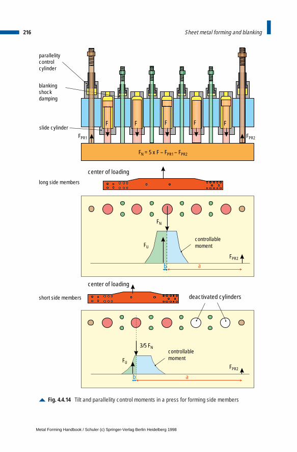
216 Sheet metal forming and blanking
Fig. 4.4.14 Tilt and parallelity control moments in a press for forming side members
a
F F F F F
b
b a
slide cylinder
parallelitycontrolcylinder
blanking shockdamping
center of loading
center of loading
controllablemoment
controllablemoment
FN = 5 x F – FPR1 – FPR2
FPR1 FPR2
long side members
short side members deactivated cylinders
FN
FU
FPR2
3/5 FN
FUFPR2
Metal Forming Handbook / Schuler (c) Springer-Verlag Berlin Heidelberg 1998
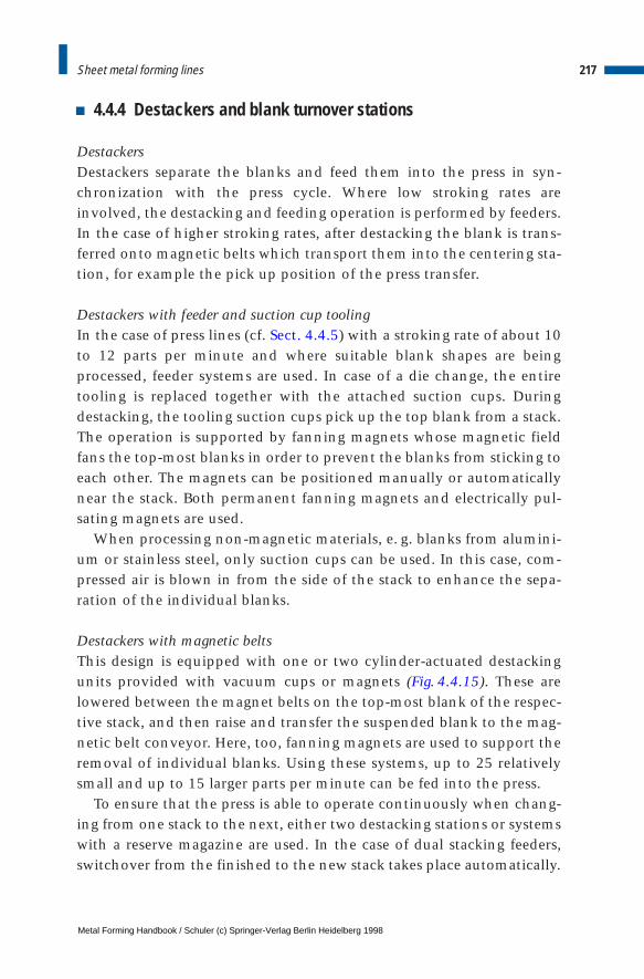
4.4.4 Destackers and blank turnover stations
DestackersDestackers separate the blanks and feed them into the press in syn-chronization with the press cycle. Where low stroking rates areinvolved, the destacking and feeding operation is performed by feeders.In the case of higher stroking rates, after destacking the blank is trans-ferred onto magnetic belts which transport them into the centering sta-tion, for example the pick up position of the press transfer.
Destackers with feeder and suction cup toolingIn the case of press lines (cf. Sect. 4.4.5) with a stroking rate of about 10to 12 parts per minute and where suitable blank shapes are beingprocessed, feeder systems are used. In case of a die change, the entiretooling is replaced together with the attached suction cups. Duringdestacking, the tooling suction cups pick up the top blank from a stack.The operation is supported by fanning magnets whose magnetic fieldfans the top-most blanks in order to prevent the blanks from sticking toeach other. The magnets can be positioned manually or automaticallynear the stack. Both permanent fanning magnets and electrically pul-sating magnets are used.
When processing non-magnetic materials, e. g. blanks from alumini-um or stainless steel, only suction cups can be used. In this case, com-pressed air is blown in from the side of the stack to enhance the sepa-ration of the individual blanks.
Destackers with magnetic beltsThis design is equipped with one or two cylinder-actuated destackingunits provided with vacuum cups or magnets (Fig. 4.4.15). These arelowered between the magnet belts on the top-most blank of the respec-tive stack, and then raise and transfer the suspended blank to the mag-netic belt conveyor. Here, too, fanning magnets are used to support theremoval of individual blanks. Using these systems, up to 25 relativelysmall and up to 15 larger parts per minute can be fed into the press.
To ensure that the press is able to operate continuously when chang-ing from one stack to the next, either two destacking stations or systemswith a reserve magazine are used. In the case of dual stacking feeders,switchover from the finished to the new stack takes place automatically.
217Sheet metal forming lines
Metal Forming Handbook / Schuler (c) Springer-Verlag Berlin Heidelberg 1998
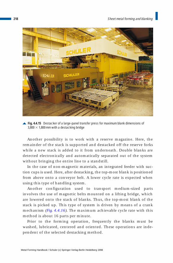
Another possibility is to work with a reserve magazine. Here, theremainder of the stack is supported and destacked off the reserve forkswhile a new stack is added to it from underneath. Double blanks aredetected electronically and automatically separated out of the systemwithout bringing the entire line to a standstill.
In the case of non-magnetic materials, an integrated feeder with suc-tion cups is used. Here, after destacking, the top-most blank is positionedfrom above onto a conveyor belt. A lower cycle rate is expected whenusing this type of handling system.
Another configuration used to transport medium-sized partsinvolves the use of magnetic belts mounted on a lifting bridge, whichare lowered onto the stack of blanks. Thus, the top-most blank of thestack is picked up. This type of system is driven by means of a crankmechanism (Fig. 4.4.16). The maximum achievable cycle rate with thismethod is about 16 parts per minute.
Prior to the forming operation, frequently the blanks must bewashed, lubricated, centered and oriented. These operations are inde-pendent of the selected destacking method.
218 Sheet metal forming and blanking
Fig. 4.4.15 Destacker of a large-panel transfer press for maximum blank dimensions of3,800 3 1,800 mm with a destacking bridge
Metal Forming Handbook / Schuler (c) Springer-Verlag Berlin Heidelberg 1998
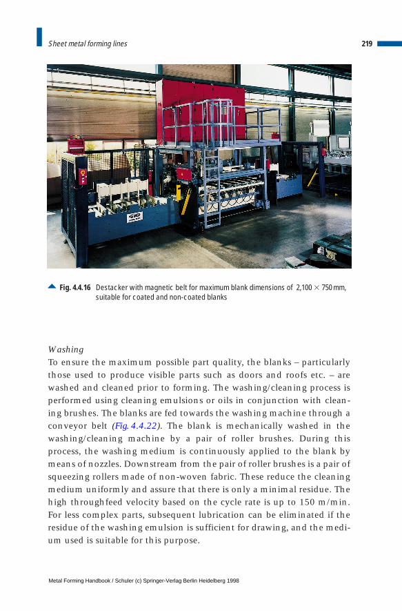
WashingTo ensure the maximum possible part quality, the blanks – particularlythose used to produce visible parts such as doors and roofs etc. – arewashed and cleaned prior to forming. The washing/cleaning process isperformed using cleaning emulsions or oils in conjunction with clean-ing brushes. The blanks are fed towards the washing machine through aconveyor belt (Fig. 4.4.22). The blank is mechanically washed in thewashing/cleaning machine by a pair of roller brushes. During thisprocess, the washing medium is continuously applied to the blank bymeans of nozzles. Downstream from the pair of roller brushes is a pair ofsqueezing rollers made of non-woven fabric. These reduce the cleaningmedium uniformly and assure that there is only a minimal residue. Thehigh throughfeed velocity based on the cycle rate is up to 150 m/min.For less complex parts, subsequent lubrication can be eliminated if theresidue of the washing emulsion is sufficient for drawing, and the medi-um used is suitable for this purpose.
219Sheet metal forming lines
Fig. 4.4.16 Destacker with magnetic belt for maximum blank dimensions of 2,100 3 750 mm,suitable for coated and non-coated blanks
Metal Forming Handbook / Schuler (c) Springer-Verlag Berlin Heidelberg 1998
Oiling/greasing For selective lubrication of blanks, oil spraying and greasing devices areintegrated into the destacker. These can be used to apply the lubricantpartially on the upper and/or lower side of the blank. Modern oilingdevices are computer controlled and capable of partial greasing or oilingof approx. 200 mm length at throughfeed velocity of up to 150 m/min.
Centering/orientationBefore the blank can be automatically transported into the die, it mustbe aligned or centered in line with the required position. Inaccuraciesmay occur when positioning a blank. These may be due to the locationon the stack or transport and they are corrected by means of end stopsor lateral pushers. In order to obtain a high degree of flexibility con-cerning the dimensions and geometry of the blanks, all the positioningdevices can be programmed and power adjusted. As a result, the set-uptimes are reduced.
Turnover devices for blank stacksBlanks intended for further processing in forming lines are parted fromthe coil stock on blanking lines (cf. Sect.4.6.2) and layered to blankstacks. In order to save tool costs, where symmetrical parts are involved,only a single blanking die is produced. Thus, it is possible, for instance,to use the blanks for the left-hand fender also for the right-hand side bysimply turning over the stack. A distinction is made between the fol-lowing blank stack turnover concepts:
– Friction-locked stack turning device: The stack is pressed with suffi-cient force so that friction holds the blanks together and then it isturned over.
– Positive-locked stack turning device: When turning in a drum or forkturning device, the stacks are mechanically supported.
Drum turning device: for blanks with complex geometriesMany blanks with irregular geometry, for example trapezoidal parts,may slip out when the stack is being turned over. Therefore, the stackmust be supported on two sides by means of end stops. In addition,turning devices are often required to occupy only a minimal space anda single location to accommodate stacks both before and after turning.
220 Sheet metal forming and blanking
Metal Forming Handbook / Schuler (c) Springer-Verlag Berlin Heidelberg 1998
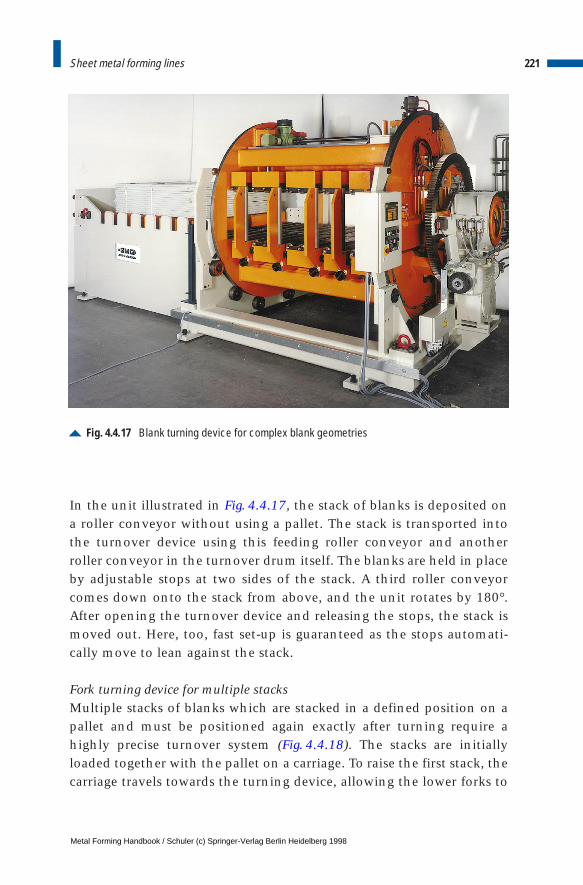
In the unit illustrated in Fig. 4.4.17, the stack of blanks is deposited ona roller conveyor without using a pallet. The stack is transported intothe turnover device using this feeding roller conveyor and anotherroller conveyor in the turnover drum itself. The blanks are held in placeby adjustable stops at two sides of the stack. A third roller conveyorcomes down onto the stack from above, and the unit rotates by 180°.After opening the turnover device and releasing the stops, the stack ismoved out. Here, too, fast set-up is guaranteed as the stops automati-cally move to lean against the stack.
Fork turning device for multiple stacks Multiple stacks of blanks which are stacked in a defined position on apallet and must be positioned again exactly after turning require ahighly precise turnover system (Fig. 4.4.18). The stacks are initiallyloaded together with the pallet on a carriage. To raise the first stack, thecarriage travels towards the turning device, allowing the lower forks to
221Sheet metal forming lines
Fig. 4.4.17 Blank turning device for complex blank geometries
Metal Forming Handbook / Schuler (c) Springer-Verlag Berlin Heidelberg 1998
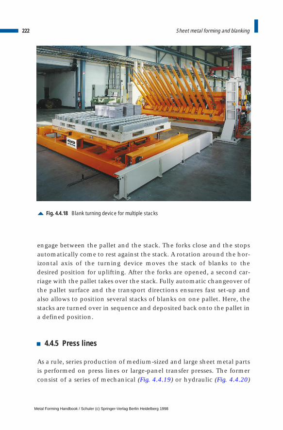
engage between the pallet and the stack. The forks close and the stopsautomatically come to rest against the stack. A rotation around the hor-izontal axis of the turning device moves the stack of blanks to thedesired position for uplifting. After the forks are opened, a second car-riage with the pallet takes over the stack. Fully automatic changeover ofthe pallet surface and the transport directions ensures fast set-up andalso allows to position several stacks of blanks on one pallet. Here, thestacks are turned over in sequence and deposited back onto the pallet ina defined position.
4.4.5 Press lines
As a rule, series production of medium-sized and large sheet metal partsis performed on press lines or large-panel transfer presses. The formerconsist of a series of mechanical (Fig. 4.4.19) or hydraulic (Fig. 4.4.20)
222 Sheet metal forming and blanking
Fig. 4.4.18 Blank turning device for multiple stacks
Metal Forming Handbook / Schuler (c) Springer-Verlag Berlin Heidelberg 1998
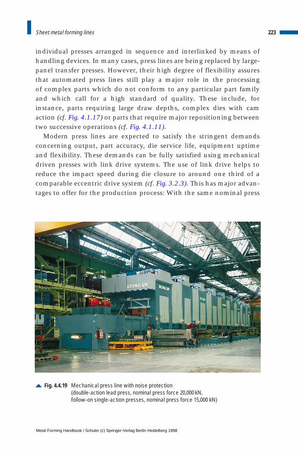
individual presses arranged in sequence and interlinked by means ofhandling devices. In many cases, press lines are being replaced by large-panel transfer presses. However, their high degree of flexibility assuresthat automated press lines still play a major role in the processing of complex parts which do not conform to any particular part familyand which call for a high standard of quality. These include, forinstance, parts requiring large draw depths, complex dies with camaction (cf. Fig. 4.1.17) or parts that require major repositioning betweentwo successive operations (cf. Fig. 4.1.11).
Modern press lines are expected to satisfy the stringent demandsconcerning output, part accuracy, die service life, equipment uptimeand flexibility. These demands can be fully satisfied using mechanicaldriven presses with link drive systems. The use of link drive helps toreduce the impact speed during die closure to around one third of acomparable eccentric drive system (cf. Fig. 3.2.3). This has major advan-tages to offer for the production process: With the same nominal press
223Sheet metal forming lines
Fig. 4.4.19 Mechanical press line with noise protection (double-action lead press, nominal press force 20,000 kN, follow-on single-action presses, nominal press force 15,000 kN)
Metal Forming Handbook / Schuler (c) Springer-Verlag Berlin Heidelberg 1998
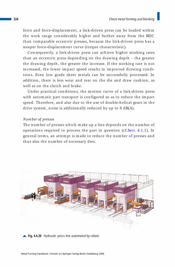
force and force-displacement, a link-driven press can be loaded withinthe work range considerably higher and further away from the BDCthan comparable eccentric presses, because the link-driven press has asteeper force-displacement curve (torque characteristic).
Consequently, a link-driven press can achieve higher stroking ratesthan an eccentric press depending on the drawing depth – the greaterthe drawing depth, the greater the increase. If the stroking rate is notincreased, the lower impact speed results in improved drawing condi-tions. Even low grade sheet metals can be successfully processed. Inaddition, there is less wear and tear on the die and draw cushion, aswell as on the clutch and brake.
Under practical conditions, the motion curve of a link-driven presswith automatic part transport is configured so as to reduce the impactspeed. Therefore, and also due to the use of double-helical gears in thedrive system, noise is additionally reduced by up to 8 dB(A).
Number of pressesThe number of presses which make up a line depends on the number ofoperations required to process the part in question (cf.Sect. 4.1.1). Ingeneral terms, an attempt is made to reduce the number of presses andthus also the number of necessary dies.
224 Sheet metal forming and blanking
Fig. 4.4.20 Hydraulic press line automated by robots
Metal Forming Handbook / Schuler (c) Springer-Verlag Berlin Heidelberg 1998
As early as in the part design stage, through close cooperation withthe component design and production departments, part simplifica-tion can lead to a situation where several different forming or blankingoperations can be grouped together in a single forming station. Themore operations can be combined in this way, however, the more com-plex the die itself becomes. This may lead to higher costs, reduction ofworking speed and higher susceptibility to malfunctions. Therefore, anideal compromise has to be found when defining the number of form-ing processes or presses in a production line. Press lines consist of fourto eight presses, although, depending on the range of produced parts,four to six presses are most commonly used.
Lead press: blank holder slide or draw cushionWhile the lead press is frequently specified as a double-action press, thedownstream presses are single-action, some of them incorporating adraw cushion in the press bed. In the case of double-action lead press-es, separate draw and blank holder slides are available and they are dri-ven either mechanically or hydraulically from above (cf. Fig. 3.1.8 and3.2.4). The blank holder slide contacts and holds the blank firmly at theouter contour prior to the initiation of the forming process by the drawslide (cf. Fig. 4.2.2). In order to avoid wrinkle formation, the four pres-sure points can be separately controlled, i. e. different blank holderforces can be set at the four corners. In certain lines, it is possible to varythe blank holder forces during the drawing process using the pinch con-trol (cf. sect. 3.2.8). These measures help to reduce the try-out periodrequired for a new set of dies, and also improves drawing results. Thedouble-action design of the presses allows the optimum way to achievelarge draw depths. The drawback is that generally the part has to beturned over for the subsequent operation. The turnover stationrequired after the first press limits the overall output rate of the pressline (Fig. 4.4.21).
New CNC-controlled hydraulic draw cushions which simulate thefunction of the blank holder slide have been developed. These cushionsallow to form similarly deep and complex pressed parts on single-actionmechanical or hydraulic lead presses (cf. Sect. 3.1.4).
In this case, the formed part does not require turning over after thedrawing operation. Consequently, the output rate of a press line can beenhanced through the use of a single-action lead press with draw cush-
225Sheet metal forming lines
Metal Forming Handbook / Schuler (c) Springer-Verlag Berlin Heidelberg 1998
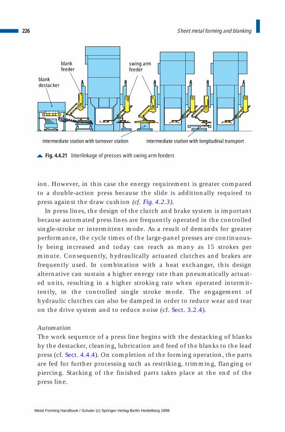
ion. However, in this case the energy requirement is greater comparedto a double-action press because the slide is additionally required topress against the draw cushion (cf. Fig. 4.2.3).
In press lines, the design of the clutch and brake system is importantbecause automated press lines are frequently operated in the controlledsingle-stroke or intermittent mode. As a result of demands for greaterperformance, the cycle times of the large-panel presses are continuous-ly being increased and today can reach as many as 15 strokes perminute. Consequently, hydraulically actuated clutches and brakes arefrequently used. In combination with a heat exchanger, this designalternative can sustain a higher energy rate than pneumatically actuat-ed units, resulting in a higher stroking rate when operated intermit-tently, in the controlled single stroke mode. The engagement ofhydraulic clutches can also be damped in order to reduce wear and tearon the drive system and to reduce noise (cf. Sect. 3.2.4).
AutomationThe work sequence of a press line begins with the destacking of blanksby the destacker, cleaning, lubrication and feed of the blanks to the leadpress (cf. Sect. 4.4.4). On completion of the forming operation, the partsare fed for further processing such as restriking, trimming, flanging orpiercing. Stacking of the finished parts takes place at the end of thepress line.
226 Sheet metal forming and blanking
Fig. 4.4.21 Interlinkage of presses with swing arm feeders
swing armfeeder
blankdestacker
blankfeeder
intermediate station with turnover station intermediate station with longitudinal transport
Metal Forming Handbook / Schuler (c) Springer-Verlag Berlin Heidelberg 1998
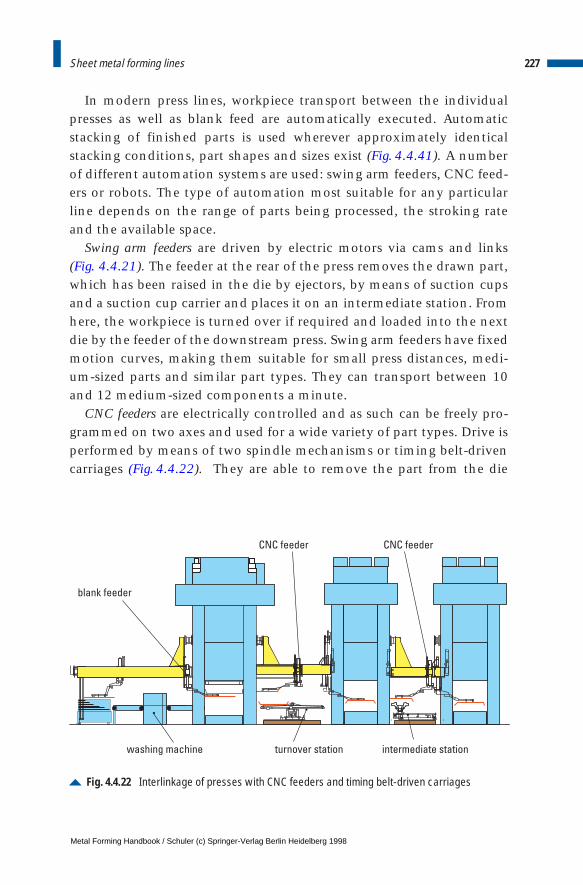
In modern press lines, workpiece transport between the individualpresses as well as blank feed are automatically executed. Automaticstacking of finished parts is used wherever approximately identicalstacking conditions, part shapes and sizes exist (Fig. 4.4.41). A numberof different automation systems are used: swing arm feeders, CNC feed-ers or robots. The type of automation most suitable for any particularline depends on the range of parts being processed, the stroking rateand the available space.
Swing arm feeders are driven by electric motors via cams and links (Fig. 4.4.21). The feeder at the rear of the press removes the drawn part,which has been raised in the die by ejectors, by means of suction cupsand a suction cup carrier and places it on an intermediate station. Fromhere, the workpiece is turned over if required and loaded into the nextdie by the feeder of the downstream press. Swing arm feeders have fixedmotion curves, making them suitable for small press distances, medi-um-sized parts and similar part types. They can transport between 10and 12 medium-sized components a minute.
CNC feeders are electrically controlled and as such can be freely pro-grammed on two axes and used for a wide variety of part types. Drive isperformed by means of two spindle mechanisms or timing belt-drivencarriages (Fig. 4.4.22). They are able to remove the part from the die
227Sheet metal forming lines
Fig. 4.4.22 Interlinkage of presses with CNC feeders and timing belt-driven carriages
washing machine turnover station intermediate station
CNC feederCNC feeder
blank feeder
Metal Forming Handbook / Schuler (c) Springer-Verlag Berlin Heidelberg 1998
without the need for an ejector. The output of a press line making useof a CNC feeder is between 8 and 10 large-sized parts per minute.
When using both, swing arm and CNC feeders, intermediate stationsare required. These intermediate stations are equipped with three tofive programmable axes for part transport in the longitudinal direction,for transverse and height adjustment and also additional tilting move-ments.
Automation using robots offers the advantage that it eliminates theneed to deposit parts between the presses (Fig. 4.4.20). The robot’s grip-per arm positions the part directly from the die of one press into the dieof the next. This means that only one robot is required to service eachpress without the need for intermediate stations. The main drawback ofrobot-linked press lines is that heavy parts can only be transportedslowly or not at all due to the centrifugal forces and the long transportpaths. For this reason, output is largely dependent on part size and cur-rently lies between 6 and 8 parts per minute. The freely programmableaxes of the robot arm, in contrast, ensure that widely differing partshapes can be transported into many different part positions.
Die changeIn addition to the interlinkage of presses in a line, automatic die chang-ing systems also play a major role. Among die changing systems forpress lines, moving bolsters with left/right-hand rails or T-tracks haveproved to be the most popular (cf. Fig. 3.4.4). The former require morespace, but offer the shortest possible die changing times. The upper andlower die of the die set which is no longer required are moved out of thepress on moving bolsters. Subsequently, the opposing bolsters movethe new die sets into the press. Preparation of the dies for the next pro-duction run is performed outside the press during production. As aresult of die changing automation it is possible to achieve changeovertimes of between 10 and 30 min depending on the workpiece transportsystem.
Nowadays, press lines are often enclosed in order to enhance safetyand noise protection. Noise emissions can be reduced by around 15 dB(A) if the space between the individual presses and the peripheralequipment is also enclosed (Fig. 4.4.19).
228 Sheet metal forming and blanking
Metal Forming Handbook / Schuler (c) Springer-Verlag Berlin Heidelberg 1998
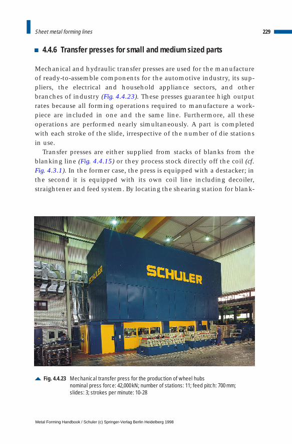
4.4.6 Transfer presses for small and medium sized parts
Mechanical and hydraulic transfer presses are used for the manufactureof ready-to-assemble components for the automotive industry, its sup-pliers, the electrical and household appliance sectors, and otherbranches of industry (Fig. 4.4.23). These presses guarantee high outputrates because all forming operations required to manufacture a work-piece are included in one and the same line. Furthermore, all theseoperations are performed nearly simultaneously. A part is completedwith each stroke of the slide, irrespective of the number of die stationsin use.
Transfer presses are either supplied from stacks of blanks from theblanking line (Fig. 4.4.15) or they process stock directly off the coil (cf.Fig. 4.3.1). In the former case, the press is equipped with a destacker; inthe second it is equipped with its own coil line including decoiler,straightener and feed system. By locating the shearing station for blank-
229Sheet metal forming lines
Fig. 4.4.23 Mechanical transfer press for the production of wheel hubsnominal press force: 42,000kN; number of stations: 11; feed pitch: 700 mm;slides: 3; strokes per minute: 10-28
Metal Forming Handbook / Schuler (c) Springer-Verlag Berlin Heidelberg 1998
ing outside of the press upright, it is possible to choose between lateralor longitudinal material feed to the press. Lateral coil feed offers the ben-efit that the scrap web can be rolled into a coil again. The drawback hereis the greater space requirement of a lateral coil feed system. Generallyspeaking, however, the space requirement of a transfer press is consider-ably less than that of a press line; the lower space requirement alsoserves to reduce ancillary costs.
Forming and blanking operations can be economically performedboth on mechanical and hydraulic transfer presses: blanking, initialdraw and subsequent drawing processes, contour pressing, calibration,flat pressing, flanging, trimming, hole punching, etc. On the one hand,even parts with extreme draw depths and complex or asymmetricalshapes can be manufactured on transfer presses without any problems.Horizontal wedge-driven cutting and forming tools are also used (cf.Fig. 4.1.17). On the other hand, dies can often be simplified by makingmost effective use of the existing number of stations. The number of diestations within the die sets used does not necessarily need to be identi-cal. Idle stations can easily be bypassed. Transfer presses with a largenumber of die stations permit the production of two different partssimultaneously provided the die sets are able to form the part on fewerstations. In these cases, the blanks are fed synchronously to two differ-ent points in the press.
The total nominal force and energy costs of transfer presses are gener-ally lower than it is the case for individual interlinked presses. Operatingand maintenance costs are reduced to a single unit, and favorable con-ditions are created for reducing production costs due to the eliminationof transport distances and intermediate stations.
Mechanical transfer pressesMechanical transfer presses are built with two, three or four uprights.Depending on the range of parts to be manufactured and the numberof stations, the presses are equipped with one, two or three indepen-dently driven slides (Fig. 4.4.23). Each slide is designed individually tosatisfy the requirements for size, nominal force and stroke. In particularfor larger presses with different press force requirements at variousforming stations, this type of multiple upright construction offersconsiderable advantages. It is customary in transfer presses to integratea draw cushion in the bed (cf. Fig. 3.1.11). A hydraulic overload system
230 Sheet metal forming and blanking
Metal Forming Handbook / Schuler (c) Springer-Verlag Berlin Heidelberg 1998
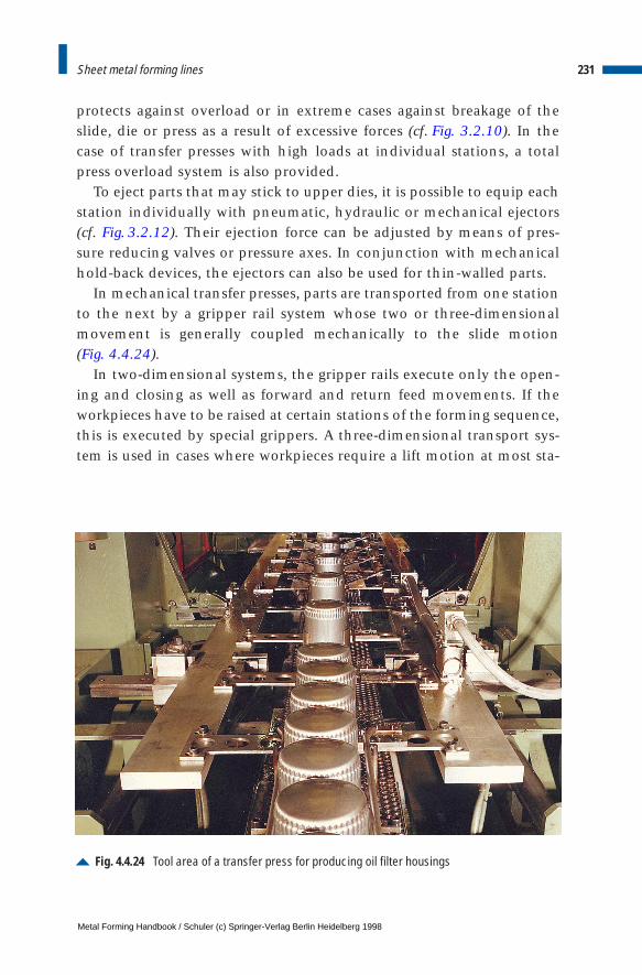
protects against overload or in extreme cases against breakage of theslide, die or press as a result of excessive forces (cf. Fig. 3.2.10). In thecase of transfer presses with high loads at individual stations, a totalpress overload system is also provided.
To eject parts that may stick to upper dies, it is possible to equip eachstation individually with pneumatic, hydraulic or mechanical ejectors(cf. Fig. 3.2.12). Their ejection force can be adjusted by means of pres-sure reducing valves or pressure axes. In conjunction with mechanicalhold-back devices, the ejectors can also be used for thin-walled parts.
In mechanical transfer presses, parts are transported from one stationto the next by a gripper rail system whose two or three-dimensionalmovement is generally coupled mechanically to the slide motion (Fig. 4.4.24).
In two-dimensional systems, the gripper rails execute only the open-ing and closing as well as forward and return feed movements. If theworkpieces have to be raised at certain stations of the forming sequence,this is executed by special grippers. A three-dimensional transport sys-tem is used in cases where workpieces require a lift motion at most sta-
231Sheet metal forming lines
Fig. 4.4.24 Tool area of a transfer press for producing oil filter housings
Metal Forming Handbook / Schuler (c) Springer-Verlag Berlin Heidelberg 1998
tions. The entire gripper rail system is then equipped with a lift stroke.This principle, which is described in Sect. 4.4.7 “tri-axis transfer presses”,is generally in the production of larger panels.
All three axes of the gripper rail drive systems are positively driven bydouble cams. Configuration of the motion curves in accordance withmathematical principles prevents jerky accelerations – in other words,no centrifugal effects are created which would jeopardize reliable work-piece transport. The distance between the gripper rails perpendicular tothe direction of transport can be adjusted infinitely or on a step-by-stepbasis. In the case of parts with small dimensions, this eliminates theneed for long grippers and corresponding motion of large masses.
Hydraulic transfer pressesIn the case of hydraulic transfer presses, an electrically driven gripperrail system transports the workpieces from the destacker to the storagelocation behind the press (Fig. 4.4.25).
The manufacture of parts using the counter drawing method is gener-ally used only in hydraulic presses (Fig. 4.4.26, cf. Fig. 3.1.10 and 4.2.4).The drawing process is performed, generally in two stages, by active drawcushions in the press bed followed by trimming and flanging of the edge.The slide closes and displaces the blank holder while the two rear diesform the edge. The slide reaches its bottom dead center when it makescontact with mechanical stops. Only after this stage is reached, the partsare drawn using the punches by switching over the drive pumps fromslide to bed cushion operation. The blanks are held at every die stationusing the pre-selected force level acting from above. Once the formingoperation has been completed, the slide opens while the bed cushionsreturn to their starting positions. The advantage of this forming methodis that no tilting moment acts on the slide during the forming process, asthe two halves of the die set are resting on each other during the entiredrawing operation. Thus, it is possible to achieve a high standard of partquality and also a favorable energy balance (cf. Sect. 3.3).
If the parts are produced in the transfer press using a single-acting sys-tem with a draw cushion, large off-center loads can occur if drawingforces come into effect in the first stations, e. g. in the front-most dies,while the rear die stations have not yet been subjected to loading. Thissituation leads to tilting of the slide, which can be compensated with theaid of a hydraulic system controlling the slide parallelity (cf. Fig. 3.3.5).
232 Sheet metal forming and blanking
Metal Forming Handbook / Schuler (c) Springer-Verlag Berlin Heidelberg 1998
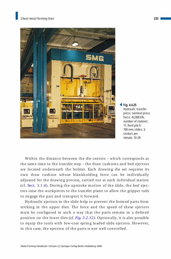
Within the distance between the die centers – which corresponds atthe same time to the transfer step – the draw cushions and bed ejectorsare located underneath the bolster. Each drawing die set requires itsown draw cushion whose blankholding force can be individuallyadjusted for the drawing process, carried out at each individual station(cf. Sect. 3.1.4). During the upstroke motion of the slide, the bed ejec-tors raise the workpieces to the transfer plane to allow the gripper railsto engage the part and transport it forward.
Hydraulic ejectors in the slide help to prevent the formed parts fromsticking in the upper dies. The force and the speed of these ejectorsmust be configured in such a way that the parts remain in a definedposition on the lower dies (cf. Fig. 3.2.12). Optionally, it is also possibleto equip the tools with low-cost spring loaded slide ejectors. However,in this case, the ejection of the parts is not well controlled.
233Sheet metal forming lines
Fig. 4.4.25Hydraulic transferpress: nominal pressforce: 42,000 kN;number of stations:11; feed pitch: 700 mm; slides: 3;strokes perminute: 10-28
Metal Forming Handbook / Schuler (c) Springer-Verlag Berlin Heidelberg 1998
4.4.7 Large-panel tri-axis transfer presses
During the sixties and seventies, developments in the field of press linetechnology led to continuous performance improvement, culminatingin the synchronized press line with fully automatic part transport (cf.Sect. 4.4.5). As a result of developments in large-panel transfer presses, itwas possible to improve production times per part and to further reducecapital investment, production and storage costs. In conjunction withthe integrated gripper rail transfer system, this press concept incorporatesall the processing stages required in a press line (Fig. 4.4.27).
Large-panel transfer presses with a distance between die centers ofapprox. 2,200 mm and die widths of up to 3,000 mm can process largeworkpieces measuring up to 2,500 3 1,500 mm. The forming stationsare moved so close together that several stations can be accommodatedunder a single slide. This reduces the space requirement by 50 and 70 %. The required power is reduced by 40 to 50 % and the investmentby 20 to 40 %. Other benefits are gained as a result of reduced man-
234 Sheet metal forming and blanking
Fig. 4.4.26 Transfer die set for a press with active counter drawing and fixed stops
stop
first
draw
second
drawedge
trimming
edge
flanging
slide ejector
draw
cushion
bolster
Metal Forming Handbook / Schuler (c) Springer-Verlag Berlin Heidelberg 1998
power requirement, increased safety against accidents and reduction ofnoise at lower cost.
In the initial layouts of press lines, the large-panel transfer press wascombined with a double-action draw press (cf. Fig. 3.1.8 and Fig. 4.4.28a),meaning that the drawing technique customary on double-acting press-es was retained. The additionally required turnover device and syn-chronization of the presses, however, reduced the output to approx. 12 parts per minute. In addition, due to the use of the turnover device (cf. Sect. 3.1.3), the time required for die changing was considerablylonger. Investment, operation and space costs still substantially exceededthose of a single-action large-panel transfer press.
235Sheet metal forming lines
Fig. 4.4.27 Large-panel tri-axis transfer pressnominal press force: 38,000kN; slides: 3; work stations: 6;feed pitch: 2,000 mm; strokes per minute: 8-18
Metal Forming Handbook / Schuler (c) Springer-Verlag Berlin Heidelberg 1998
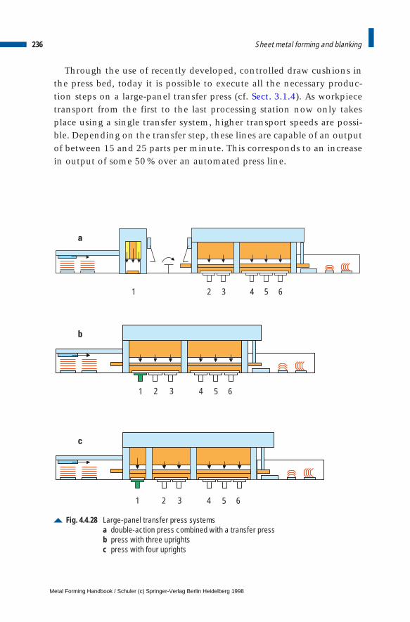
Through the use of recently developed, controlled draw cushions inthe press bed, today it is possible to execute all the necessary produc-tion steps on a large-panel transfer press (cf. Sect. 3.1.4). As workpiecetransport from the first to the last processing station now only takesplace using a single transfer system, higher transport speeds are possi-ble. Depending on the transfer step, these lines are capable of an outputof between 15 and 25 parts per minute. This corresponds to an increasein output of some 50 % over an automated press line.
236 Sheet metal forming and blanking
Fig. 4.4.28 Large-panel transfer press systemsa double-action press combined with a transfer pressb press with three uprightsc press with four uprights
1
1
1
2
2
2
3
3
3
4
4
4
5
5
5
6
6
6
a
b
c
Metal Forming Handbook / Schuler (c) Springer-Verlag Berlin Heidelberg 1998
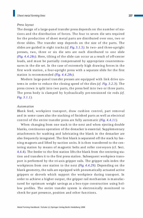
Press layoutThe design of a large-panel transfer press depends on the number of sta-tions and the distribution of forces. The four to seven die sets requiredfor the production of sheet metal parts are distributed over one, two orthree slides. The transfer step depends on the size of the parts. Theslides are guided in eight tracks (cf. Fig. 3.1.5). In two- and three-uprightpresses, two, three or six die sets are each distributed to one slide (Fig. 4.4.28c). Here, tilting of the slide can occur as a result of off-centerloads, and must be partially compensated by appropriate countermea-sures in the die set. In the case of extremely high drawing forces in thefirst work station, a four-upright press with a separate slide for the firststation is recommended (Fig. 4.4.28c).
Modern large-panel transfer presses are equipped with link drive sys-tems in order to reduce the closing speed of the dies (cf. Fig. 3.2.3). Thepress crown is split into two parts, the press bed into two or three parts.The press body is clamped by hydraulically pre-tensioned tie rods (cf.Fig. 3.1.1).
AutomationBlank feed, workpiece transport, draw cushion control, part removaland in some cases also the stacking of finished parts as well as electricalcontrol of the entire transfer press are fully automatic (Fig. 4.4.11).
When changing from one stack to the next and when ejecting doubleblanks, continuous operation of the destacker is essential. Supplementaryattachments for washing and lubricating the blank in the destacker arealso frequently integrated. The first blank is separated off the stack by fan-ning magnets and lifted by suction units. It is then transferred to the cen-tering station by means of magnetic belts and roller conveyors (cf. Sect.4.4.4). The feeder to the first station lifts the blank from the centering sta-tion and transfers it to the first press station. Subsequent workpiece trans-port is performed by the tri-axis gripper rails. The gripper rails index theworkpieces from one station to the next (Fig. 4.4.29). Depending on theblank geometry, the rails are equipped with pneumatically actuated activegrippers or shovels which support the workpiece during transport. Inorder to achieve a higher output, the gripper rail mechanism is manufac-tured for optimum weight savings as a box-type construction using hol-low profiles. The entire transfer system is electronically monitored tocheck for part presence, position and other functions.
237Sheet metal forming lines
Metal Forming Handbook / Schuler (c) Springer-Verlag Berlin Heidelberg 1998
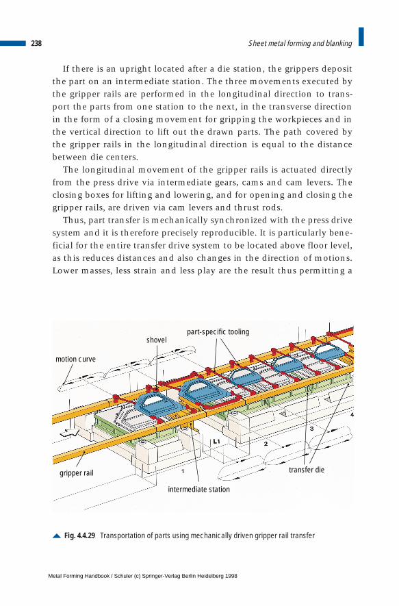
If there is an upright located after a die station, the grippers depositthe part on an intermediate station. The three movements executed bythe gripper rails are performed in the longitudinal direction to trans-port the parts from one station to the next, in the transverse directionin the form of a closing movement for gripping the workpieces and inthe vertical direction to lift out the drawn parts. The path covered bythe gripper rails in the longitudinal direction is equal to the distancebetween die centers.
The longitudinal movement of the gripper rails is actuated directlyfrom the press drive via intermediate gears, cams and cam levers. Theclosing boxes for lifting and lowering, and for opening and closing thegripper rails, are driven via cam levers and thrust rods.
Thus, part transfer is mechanically synchronized with the press drivesystem and it is therefore precisely reproducible. It is particularly bene-ficial for the entire transfer drive system to be located above floor level,as this reduces distances and also changes in the direction of motions.Lower masses, less strain and less play are the result thus permitting a
238 Sheet metal forming and blanking
Fig. 4.4.29 Transportation of parts using mechanically driven gripper rail transfer
motion curve
shovelpart-specific tooling
gripper rail
intermediate station
transfer die
Metal Forming Handbook / Schuler (c) Springer-Verlag Berlin Heidelberg 1998
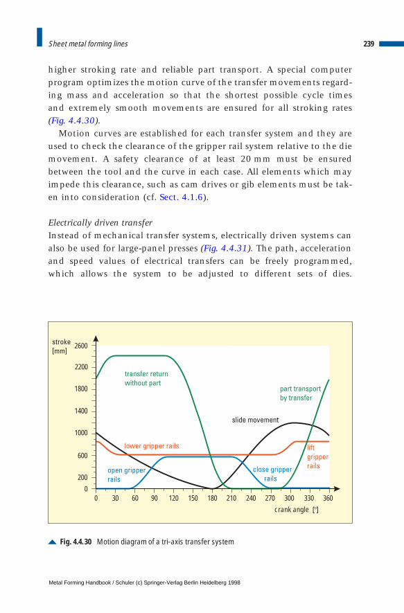
higher stroking rate and reliable part transport. A special computerprogram optimizes the motion curve of the transfer movements regard-ing mass and acceleration so that the shortest possible cycle times and extremely smooth movements are ensured for all stroking rates(Fig. 4.4.30).
Motion curves are established for each transfer system and they areused to check the clearance of the gripper rail system relative to the diemovement. A safety clearance of at least 20 mm must be ensuredbetween the tool and the curve in each case. All elements which mayimpede this clearance, such as cam drives or gib elements must be tak-en into consideration (cf. Sect. 4.1.6).
Electrically driven transferInstead of mechanical transfer systems, electrically driven systems canalso be used for large-panel presses (Fig. 4.4.31). The path, accelerationand speed values of electrical transfers can be freely programmed,which allows the system to be adjusted to different sets of dies.
239Sheet metal forming lines
Fig. 4.4.30 Motion diagram of a tri-axis transfer system
slide movement
part transport
by transfer
transfer return
without part
lift
gripper
rails
lower gripper rails
open gripper
rails
close gripper
rails
stroke
[mm]
crank angle [ ]
2600
2200
1800
1400
1000
600
200
00 30 60 90 120 150 180 210 240 270 300 330 360
Metal Forming Handbook / Schuler (c) Springer-Verlag Berlin Heidelberg 1998
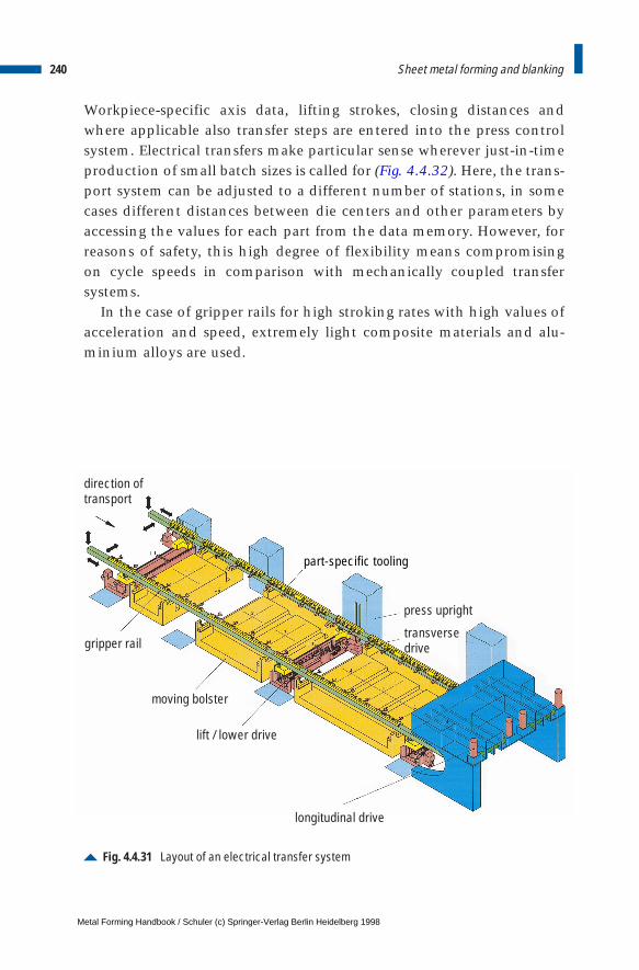
Workpiece-specific axis data, lifting strokes, closing distances andwhere applicable also transfer steps are entered into the press controlsystem. Electrical transfers make particular sense wherever just-in-timeproduction of small batch sizes is called for (Fig. 4.4.32). Here, the trans-port system can be adjusted to a different number of stations, in somecases different distances between die centers and other parameters byaccessing the values for each part from the data memory. However, forreasons of safety, this high degree of flexibility means compromising on cycle speeds in comparison with mechanically coupled transfersystems.
In the case of gripper rails for high stroking rates with high values ofacceleration and speed, extremely light composite materials and alu-minium alloys are used.
240 Sheet metal forming and blanking
Fig. 4.4.31 Layout of an electrical transfer system
part-specific tooling
press upright
transversedrive
direction oftransport
gripper rail
moving bolster
lift / lower drive
longitudinal drive
Metal Forming Handbook / Schuler (c) Springer-Verlag Berlin Heidelberg 1998
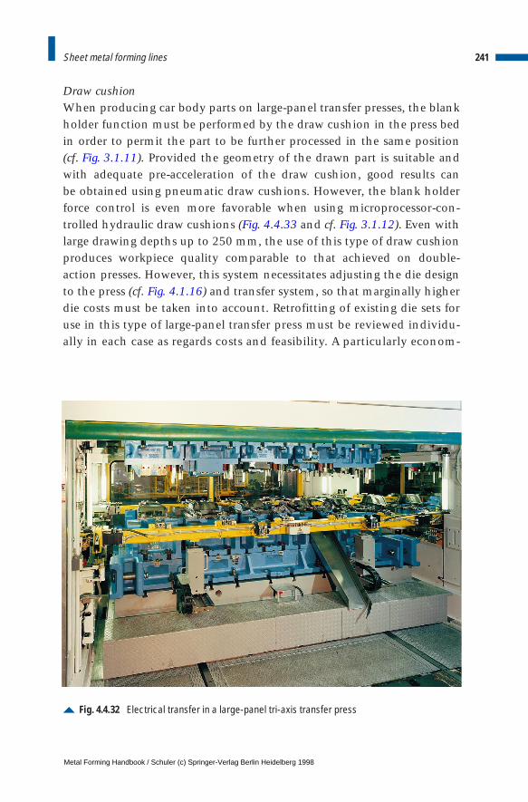
Draw cushionWhen producing car body parts on large-panel transfer presses, the blankholder function must be performed by the draw cushion in the press bedin order to permit the part to be further processed in the same position(cf. Fig. 3.1.11). Provided the geometry of the drawn part is suitable andwith adequate pre-acceleration of the draw cushion, good results can be obtained using pneumatic draw cushions. However, the blank holderforce control is even more favorable when using microprocessor-con-trolled hydraulic draw cushions (Fig. 4.4.33 and cf. Fig. 3.1.12). Even withlarge drawing depths up to 250 mm, the use of this type of draw cushionproduces workpiece quality comparable to that achieved on double-action presses. However, this system necessitates adjusting the die designto the press (cf. Fig. 4.1.16) and transfer system, so that marginally higherdie costs must be taken into account. Retrofitting of existing die sets foruse in this type of large-panel transfer press must be reviewed individu-ally in each case as regards costs and feasibility. A particularly econom-
241Sheet metal forming lines
Fig. 4.4.32 Electrical transfer in a large-panel tri-axis transfer press
Metal Forming Handbook / Schuler (c) Springer-Verlag Berlin Heidelberg 1998
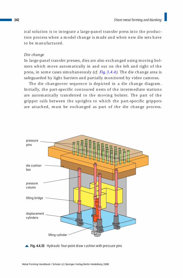
ical solution is to integrate a large-panel transfer press into the produc-tion process when a model change is made and when new die sets haveto be manufactured.
Die changeIn large-panel transfer presses, dies are also exchanged using moving bol-sters which move automatically in and out on the left and right of thepress, in some cases simultaneously (cf. Fig. 3.4.4). The die change area issafeguarded by light barriers and partially monitored by video cameras.
The die changeover sequence is depicted in a die change diagram.Initially, the part-specific contoured nests of the intermediate stationsare automatically transferred to the moving bolster. The part of thegripper rails between the uprights to which the part-specific grippersare attached, must be exchanged as part of the die change process.
242 Sheet metal forming and blanking
Fig. 4.4.33 Hydraulic four-point draw cushion with pressure pins
displacement
cylinders
pressure
column
pressure
pins
lifting cylinder
lifting bridge
die cushion
box
Metal Forming Handbook / Schuler (c) Springer-Verlag Berlin Heidelberg 1998
These components are separated from the part of the rail whichremains in the press by means of an automatic coupling device, anddeposited on the moving bolster.
After releasing the power connections, the moving bolster with thedie and part-specific accessories travels to one side out of the press,while the sliding bolster with the next die enters from the other side(Fig. 4.4.27). After automatic coupling of the gripper rails and powerconnections, the die data such as pressure levels and positions areaccessed from the data memory and automatically set. When the mov-ing bolster with a new die set is set up outside the press, all the part-spe-cific devices such as grippers and contoured nests are exchanged andprepared for the next production process.
A characteristic feature of large-panel transfer presses is their highproductivity with an outstanding degree of flexibility made possible byshort set-up times. The automatic die change process possible in large-panel transfer presses can be completed in less than 5 min. Thus, amajor precondition is satisfied for the reduction of capital costs and ofthe need for intermediate storage of finished parts between the stamp-ing plant and the body assembly plant. This means that, depending onbatch size, it may be possible to perform several die changes per pro-duction shift (cf. Sect. 4.9.2).
Depending on the press operating period, on a large-panel transferpress between 5 and 30 different die sets are used with batch sizes of3,000 to 10,000 panels. To ensure economic utilization of the press, partswith nearly identical form and size and a similar degree of forming com-plexity should be grouped to create families of parts (cf. Fig. 4.9.2 and4.9.3).
4.4.8 Crossbar transfer presses
Where large panels from around 2.5 3 1.5 m in size are processed, thelow inherent stability of the parts during transportation calls for specialmeasures. Conventional gripper rails which only grip or hold the partsaround their outer periphery (Fig. 4.4.29) are not suitable. Particularlylarge unstable parts such as roofs, full body side panels or floor assem-blies are accordingly produced using crossbar transfer presses. Theapplication of this type of press also covers the dual production of
243Sheet metal forming lines
Metal Forming Handbook / Schuler (c) Springer-Verlag Berlin Heidelberg 1998
medium-sized parts, in which two parts are formed from one blank ortwo adjacent blanks (Fig. 4.4.34 and cf. Fig. 4.9.2). Double parts pro-duced from a single blank are separated as required in a subsequentoperation. The production of double parts could refer to any suitableparts, for example passenger car doors. This kind of production doublesthe output per press stroke and increases considerably the economy ofthe system, compared to gripper rail transfer systems. Moreover, dualproduction helps to better utilize the press load capacity when forminga single large and unstable part does not fully require the available pressload.
Large-panel crossbar transfer presses can be structured in differentways. Ideally, each die should be assigned to a separate slide to ensureoptimum peripheral conditions for the die and for the forming process.The design is based on a modular structure comprising individualmachines in which all the drive systems are connected to the mainpress drive system by means of central longitudinal drive shaft andintermediate couplings (cf. Fig. 3.2.9). This ensures synchronous run-ning of all the stations: The transport system can be operated by a con-tinuous transfer with only a minimal safety clearance to the top die.
To transport large unstable parts in transfer presses, a two-axis trans-fer system equipped with crossbars and suction cups is used (Fig. 4.4.34).Unlike the off-center positioning of parts on feeder or robot arms as usedon press lines (Fig. 4.4.35), here the parts are held directly by suction cupcarriers located above the part. Due to the symmetrical arrangement ofthe suction cups relative to the center of gravity of the parts, higheraccelerating forces acting on the part are permissible. In comparisonwith feeder mechanisms, stroke rates can be increased from 13 to 15parts per minute with transport steps between 2,000 and 2,600 mm.
The crossbars are fastened on carriages which execute the longitudi-nal feed step from one die to the next. The carriages run on the two liftbeams of the transfer which move in the vertical direction to raise andlower the part. No supplementary aids, such as lifters or ejectors in thedie, are required for part transport.
The time-motion diagram differs markedly from that of the tri-axistransfer (Fig. 4.4.36). In contrast to a tri-axis transfer, the crossbar trans-fer cannot return during the forming process, as the crossbars are locat-ed between the dies. When the dies are closed the crossbars are locatedin a parked position outside the die area. The die spacing must in any
244 Sheet metal forming and blanking
Metal Forming Handbook / Schuler (c) Springer-Verlag Berlin Heidelberg 1998
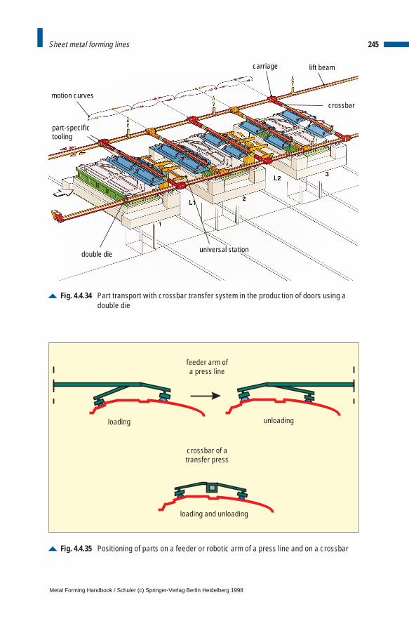
245Sheet metal forming lines
Fig. 4.4.34 Part transport with crossbar transfer system in the production of doors using adouble die
motion curves
carriage lift beam
crossbar
universal stationdouble die
part-specific tooling
Fig. 4.4.35 Positioning of parts on a feeder or robotic arm of a press line and on a crossbar
loading unloading
loading and unloading
feeder arm ofa press line
crossbar of atransfer press
Metal Forming Handbook / Schuler (c) Springer-Verlag Berlin Heidelberg 1998
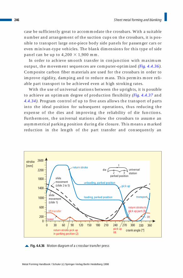
case be sufficiently great to accommodate the crossbars. With a suitablenumber and arrangement of the suction cups on the crossbars, it is pos-sible to transport large one-piece body side panels for passenger cars oreven minivan-type vehicles. The blank dimensions for this type of sidepanel can be up to 4,200 3 1,900 mm.
In order to achieve smooth transfer in conjunction with maximumoutput, the movement sequences are computer-optimized (Fig. 4.4.36).Composite carbon fiber materials are used for the crossbars in order toimprove rigidity, damping and to reduce mass. This permits more reli-able part transport to be achieved even at high stroking rates.
With the use of universal stations between the uprights, it is possibleto achieve an optimum degree of production flexibility (Fig. 4.4.37 and4.4.34). Program control of up to five axes allows the transport of partsinto the ideal position for subsequent operations, thus reducing theexpense of the dies and improving the reliability of die functions.Furthermore, the universal stations allow the crossbars to assume anasymmetrical parking position during die closure. This means a markedreduction in the length of the part transfer and consequently an
246 Sheet metal forming and blanking
Fig. 4.4.36 Motion diagram of a crossbar transfer press
unloading, parked position
loading, parked position
slide
movement
slide
movement
(slide 1)
lift transfer
stroke
[mm]
2600
2200
1800
1400
1000
600
2000
0 30 60 90 120 150 180 210 240 270 300 330 360return stroke pick up
in parking position (2)
return stroke to
pick up part (3)
die
parked position
universal
station
1
2 3
pick up
lift
pick up
lift
transport
lower
return stroke
(slide 2 to 5)
Metal Forming Handbook / Schuler (c) Springer-Verlag Berlin Heidelberg 1998
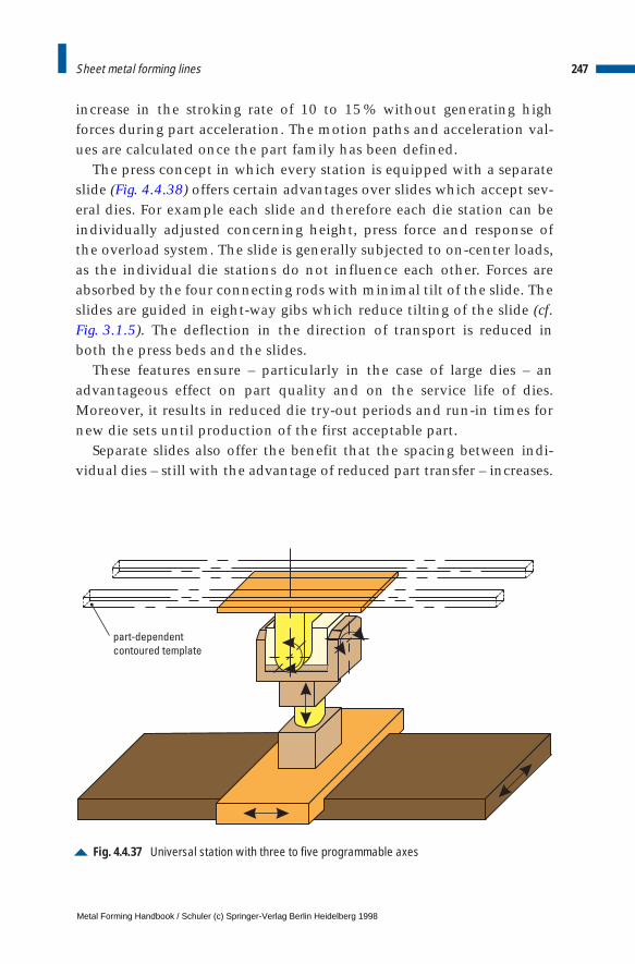
increase in the stroking rate of 10 to 15 % without generating highforces during part acceleration. The motion paths and acceleration val-ues are calculated once the part family has been defined.
The press concept in which every station is equipped with a separateslide (Fig. 4.4.38) offers certain advantages over slides which accept sev-eral dies. For example each slide and therefore each die station can beindividually adjusted concerning height, press force and response ofthe overload system. The slide is generally subjected to on-center loads,as the individual die stations do not influence each other. Forces areabsorbed by the four connecting rods with minimal tilt of the slide. Theslides are guided in eight-way gibs which reduce tilting of the slide (cf.Fig. 3.1.5). The deflection in the direction of transport is reduced inboth the press beds and the slides.
These features ensure – particularly in the case of large dies – anadvantageous effect on part quality and on the service life of dies.Moreover, it results in reduced die try-out periods and run-in times fornew die sets until production of the first acceptable part.
Separate slides also offer the benefit that the spacing between indi-vidual dies – still with the advantage of reduced part transfer – increases.
247Sheet metal forming lines
Fig. 4.4.37 Universal station with three to five programmable axes
part-dependent
contoured template
Metal Forming Handbook / Schuler (c) Springer-Verlag Berlin Heidelberg 1998
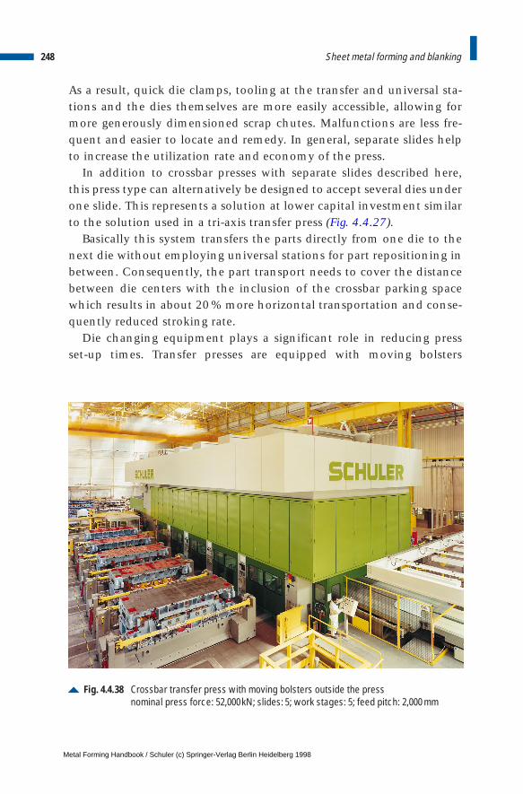
As a result, quick die clamps, tooling at the transfer and universal sta-tions and the dies themselves are more easily accessible, allowing formore generously dimensioned scrap chutes. Malfunctions are less fre-quent and easier to locate and remedy. In general, separate slides helpto increase the utilization rate and economy of the press.
In addition to crossbar presses with separate slides described here,this press type can alternatively be designed to accept several dies underone slide. This represents a solution at lower capital investment similarto the solution used in a tri-axis transfer press (Fig. 4.4.27).
Basically this system transfers the parts directly from one die to thenext die without employing universal stations for part repositioning inbetween. Consequently, the part transport needs to cover the distancebetween die centers with the inclusion of the crossbar parking spacewhich results in about 20 % more horizontal transportation and conse-quently reduced stroking rate.
Die changing equipment plays a significant role in reducing pressset-up times. Transfer presses are equipped with moving bolsters
248 Sheet metal forming and blanking
Fig. 4.4.38 Crossbar transfer press with moving bolsters outside the pressnominal press force: 52,000kN; slides: 5; work stages: 5; feed pitch: 2,000 mm
Metal Forming Handbook / Schuler (c) Springer-Verlag Berlin Heidelberg 1998
(cf. Fig. 3.4.3) for automatic die change. For each die station there aretwo moving bolsters. One die set is used for production inside the press,the other set is located outside the press being prepared for the nextproduction run (Fig. 4.4.38 and cf. Fig. 3.4.4). This allows the die andpart-specific tooling to be prepared while the press is still producing.
While the lift beams stay in the press, the crossbars and the toolingare separated by automatic couplings from the lift beams for die change.They are then positioned on the moving bolster of the die and movedout of the press at 90° to the direction of part flow. Every die set isequipped with its own crossbar and suction cup tooling. When setting-up the moving bolsters outside the press, the crossbars assigned to themoving bolster are equipped with the tooling required for the next part.
The steps performed when changing dies and resetting all relevantparameters of the press are executed automatically. These steps include:deposit and unclamping of top dies, release of crossbar couplings, rais-ing of lift beams to clear traversing of moving bolsters, exit of movingbolsters; entry, lowering and centering of new bolsters, clamping ofupper dies, replacing the next crossbars with tooling and contourednests of the universal stations.
All the die change parameters are automatically set by a programma-ble logic control. Accordingly, all the adjustable parameters of theperipheral press systems such as the destacker or part stacking arerecalled and automatically set (cf. Sect. 4.4.11).
A complete die changeover requires about 10 min, as various reset-ting processes run simultaneously. The individual phases of the diechanging process are locally and centrally displayed on screens formonitoring purposes.
When manufacturing large parts such as one-piece body sides, in par-ticular, individual and direct control of the blankholding forces is veryimportant to achieve good part quality. Just as in tri-axis transfer press-es, power is transmitted via pressure cylinders to the blank holderframe. Generally, systems with four displacement cylinders are used.The fundamental advantage of the hydraulic displacement system,compared to pneumatic draw cushions, is that the draw cushion forcecan be optionally controlled at each individual hydraulic cylinder dur-ing the drawing process by means of microprocessor-controlled servovalves. The pressure can be adjusted between 25 and 100 % of the ratedpressure (cf. Fig. 3.1.12).
249Sheet metal forming lines
Metal Forming Handbook / Schuler (c) Springer-Verlag Berlin Heidelberg 1998
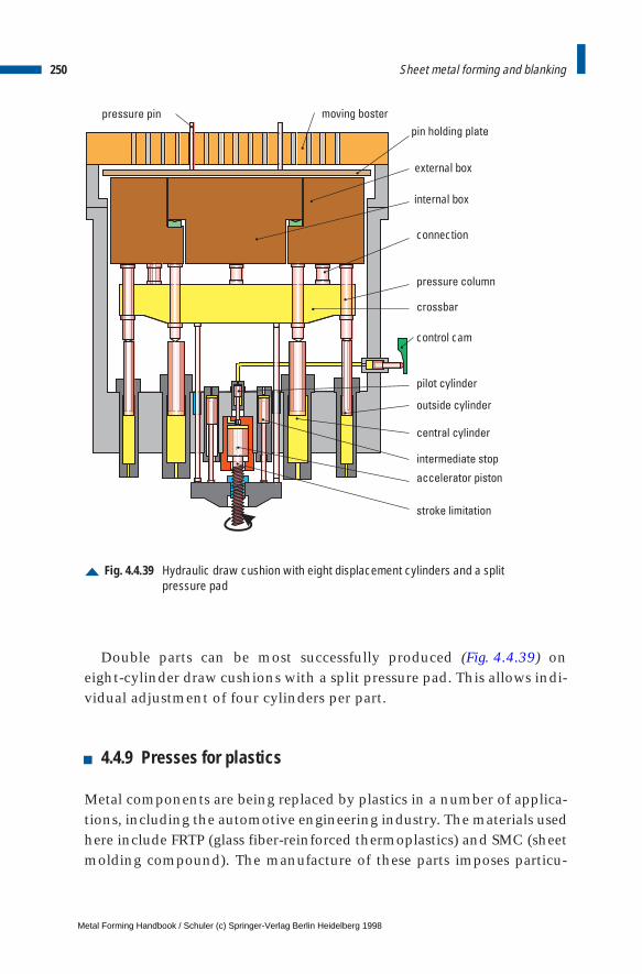
Double parts can be most successfully produced (Fig. 4.4.39) oneight-cylinder draw cushions with a split pressure pad. This allows indi-vidual adjustment of four cylinders per part.
4.4.9 Presses for plastics
Metal components are being replaced by plastics in a number of applica-tions, including the automotive engineering industry. The materials usedhere include FRTP (glass fiber-reinforced thermoplastics) and SMC (sheetmolding compound). The manufacture of these parts imposes particu-
250 Sheet metal forming and blanking
Fig. 4.4.39 Hydraulic draw cushion with eight displacement cylinders and a split pressure pad
moving boster
pin holding plate
external box
internal box
connection
pressure column
crossbar
control cam
pilot cylinder
outside cylinder
central cylinder
intermediate stop
accelerator piston
stroke limitation
pressure pin
Metal Forming Handbook / Schuler (c) Springer-Verlag Berlin Heidelberg 1998
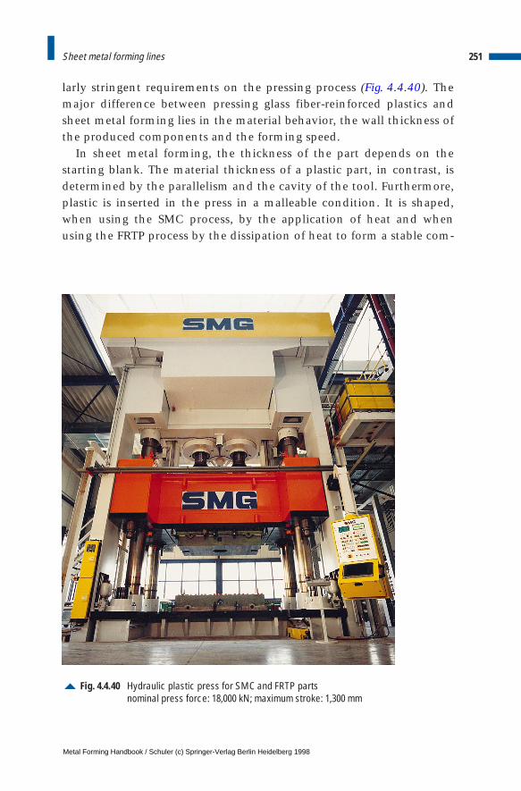
larly stringent requirements on the pressing process (Fig. 4.4.40). Themajor difference between pressing glass fiber-reinforced plastics andsheet metal forming lies in the material behavior, the wall thickness ofthe produced components and the forming speed.
In sheet metal forming, the thickness of the part depends on thestarting blank. The material thickness of a plastic part, in contrast, isdetermined by the parallelism and the cavity of the tool. Furthermore,plastic is inserted in the press in a malleable condition. It is shaped,when using the SMC process, by the application of heat and whenusing the FRTP process by the dissipation of heat to form a stable com-
251Sheet metal forming lines
Fig. 4.4.40 Hydraulic plastic press for SMC and FRTP partsnominal press force: 18,000 kN; maximum stroke: 1,300 mm
Metal Forming Handbook / Schuler (c) Springer-Verlag Berlin Heidelberg 1998
ponent. This imposes additional demands on the functions of the press,in particular on the speed of the slide. This calls for the use of specialcontrol systems (cf. Sect. 3.3.3).
When pressing thermoplastics in refrigerated dies, forming must beperformed quickly, and the cooling process must take place at a com-plete standstill and with optimum parallelism of the two die halves.
In the case of thermoset plastics, a layered mat is inserted in the die.The compound material – glass fiber and resin – must be pressedaccording to a precisely specified speed pattern with precise parallelismof the two die halves, in order to avoid fiber orientation. The materialhardens as heat is applied. In order to achieve a uniform part thickness,the slide must be kept < 0.1 mm/m parallel. These process parametersare essential for the production of high-grade SMC parts and can onlybe implemented using a hydraulic press with multiple axis control. Thetechnological requirements
– fast closure, in order to minimize heat transfer between the work-piece material and the die before forming,
– pressing at the specified speed pattern to ensure uniform front flowbehavior,
– pressing with the specified force pattern to ensure application of thespecial pressure level required for precise forming,
– holding the pressure at a prescribed level while the workpiece hard-ens at the precisely parallel position of the two die halves,
– controlled opening motion to avoid damage to the workpiece
can only be achieved using a hydraulic press. The drive system isbuffered by pressure accumulators in order to assure that the requireddifferent oil volumes are available (cf. Table 3.3.1). The slide operates ina closed control loop, monitored by sensors and controlled by servovalves. The parallelism of the slide is maintained within extremely closetolerances by four cylinders acting on the slide corners (cf. Fig. 3.3.5).
4.4.10 Stacking units for finished parts
Finished parts leaving the press are palletized either manually or withthe aid of an automatic stacking unit to permit their storage or trans-portation. It is often uneconomical to convert the unit for widely vary-
252 Sheet metal forming and blanking
Metal Forming Handbook / Schuler (c) Springer-Verlag Berlin Heidelberg 1998
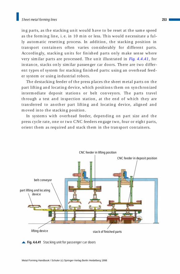
ing parts, as the stacking unit would have to be reset at the same speedas the forming line, i. e. in 10 min or less. This would necessitate a ful-ly automatic resetting process. In addition, the stacking position intransport containers often varies considerably for different parts.Accordingly, stacking units for finished parts only make sense wherevery similar parts are processed. The unit illustrated in Fig. 4.4.41, forinstance, stacks only similar passenger car doors. There are two differ-ent types of system for stacking finished parts: using an overhead feed-er system or using industrial robots.
The destacking feeder of the press places the sheet metal parts on thepart lifting and locating device, which positions them on synchronizedintermediate deposit stations or belt conveyors. The parts travelthrough a test and inspection station, at the end of which they aretransferred to another part lifting and locating device, aligned andmoved into the stacking position.
In systems with overhead feeder, depending on part size and thepress cycle rate, one or two CNC feeders engage two, four or eight parts,orient them as required and stack them in the transport containers.
253Sheet metal forming lines
Fig. 4.4.41 Stacking unit for passenger car doors
part lifting and locating device
belt conveyor
CNC feeder in lifting position
CNC feeder in deposit position
stack of finished partslifting device
Metal Forming Handbook / Schuler (c) Springer-Verlag Berlin Heidelberg 1998
Transport containers with stack latches permit individual removal byindustrial robots. The unit is also equipped with a detection system fortransport containers and with an electrical and mechanical control sys-tem for the stack latches. This ensures that the transport containersbelonging to the various finished parts are made ready and that thestack latches are adjusted to the geometry of the formed sheet metalparts.
The transport containers arranged on both sides of the conveyor beltguarantee continuous stacking even during container changeover. Asupplementary conveyor belt can be used to transport parts out of thepress in the event of a malfunction in the stacking unit or for inspec-tion purposes without interrupting the press operation.
In addition to the solution using overhead feeders, industrial robotswith six axes can be used for removal and stacking of finished parts.This type of automation concept makes particular sense when the partsare placed to be ready in the assembly position by the handling device,necessitating an additional rotating or tilting movement. This type ofconcept is found not only in presses but also for flanging and weldingoperations used in plant construction applications (cf. Sect. 4.6.5).
4.4.11 Control systems for large-panel transfer presses
Thanks to the progress made in microelectronic engineering now elec-tronic control systems, industrial PCs, high-speed communication sys-tems and digital drive systems are available and can be used in thedevelopment of economical press control systems offering maximumcontrol capability for the operating team.
Control systems able to comply with the specific requirements oflarge-panel presses must fulfil the following criteria:
– clearly arranged, easily understood press control structure,– use of standard modules and identical parts to reduce component
variety,– clearly arranged operating and visual display system without excess
amounts of information,– operator support wherever operators are located,
254 Sheet metal forming and blanking
Metal Forming Handbook / Schuler (c) Springer-Verlag Berlin Heidelberg 1998
– efficient troubleshooting, back-up in correcting malfunctions andrepairing failed components,
– use of proven standard components from manufacturers offeringworldwide service,
– use of standard communication systems,– non-standard solutions only in functional areas where this is un-
avoidable,– compliance with customer regulations and specifications,– coordination with and approval from customer regarding the control
concept.
As an example of control engineering applied in large-panel presses, thefollowing is a description of control concepts for large-panel transfer press-es with crossbar transfer system (cf. Sect. 4.4.8). The modular mechanicalstructure and the active universal stations are of particular relevance forthe structure of the control system.
The consistently modular decentralized control structure direct-ly reflects the modular mechanical structure of the press itself (Fig. 4.4.42).
The blankloader, each press module and the associated universal sta-tion are each equipped with their own control unit, the so-called localcontrol unit. It consists of the conventional part, the PLC system, thedecentral input/output system and task-specific individual electroniccontrol systems, and each has its own local visualization unit.
Central functions such as mode selection, clutch/brake, main drive,transfer system with loading feeder, operating units and tool data man-agement are the responsibility of a central control unit in conjunctionwith a central visualization unit.
All the local control units of the press are identical in their internalstructure, only the first control unit differs from the others. Here, thefunctions for the bed cushion are added and the functions relating tothe universal stations do not apply. The PLC programs of all local con-trol units are identical: Different functional requirements are detectedby the program by means of hardware identifiers at the PLC inputs.
The logical communication structure is strictly star-shaped, i.e. nei-ther data nor signals are exchanged between the local control units.These structural characteristics result in standardized, easily manage-able control units with a transparent flow of information and a numberof appreciable benefits for the user:
255Sheet metal forming lines
Metal Forming Handbook / Schuler (c) Springer-Verlag Berlin Heidelberg 1998
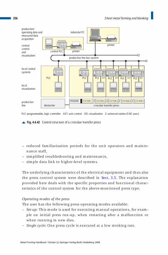
– reduced familiarization periods for the unit operators and mainte-nance staff,
– simplified troubleshooting and maintenance,– simple data link to higher-level systems.
The underlying characteristics of the electrical equipment and thus alsothe press control system were described in Sect. 3.5. The explanationprovided here deals with the specific properties and functional charac-teristics of the control system for the above-mentioned press type.
Operating modes of the pressThe user has the following press operating modes available:– Set-up: This mode is used for executing manual operations, for exam-
ple on initial press run-up, when restarting after a malfunction orwhen running in new dies.
– Single cycle: One press cycle is executed at a low stroking rate.
256 Sheet metal forming and blanking
Fig. 4.4.42 Control structure of a crossbar transfer press
central PLC
PLC PLC PLC PLC PLC PLC
industrial PC
production line bus system
destacker
production/operating data andmeasured data acquisition
central controland visualization
local controlsystems
localvisualization
productionline
printer
printer
PLC: programmable, logic controller AST: axis control VIS: visualization Z: universal station (5 NC axes)
FEEDER
crossbar transfer press
Z Z Z Z
AST AST AST AST
STATION 1 STATION 2 STATION 3 STATION 4 STATION 5
Metal Forming Handbook / Schuler (c) Springer-Verlag Berlin Heidelberg 1998
– Automatic: This is the mode used for part production. The press exe-cutes cyclical production strokes at the set stroking rate, e. g. 15strokes per minute.
– Die change: In this mode, the line is reset for the next job. The entiredie set and all the die-specific tooling are exchanged. In case of fullyautomatic die change, all functions are controlled by the PLC withoutany intervention by operating staff. The sequence can be monitoredat the visualization system using the synoptic die change display.
Conventional control systemThe components and main functions of the conventional press controlsystem were described in Sect. 3.5. A major component of conventionalcontrol systems is safety control. Today, this still generally makes use ofconventional technology using contacts, although machines suppliedto automobile manufacturers in the US are frequently operated usingredundant PLC systems.
For considerations of operating safety, the aim is to also allow trans-fer presses to operate even in the set-up mode only with closed protec-tive gear; this permits considerable simplification of the safety controlsystem while at the same time enhancing working safety for personnel.
Electronic control system The electronic control system comprises the programmable logic con-trollers (PLC), the input/output system, the axis control systems andthe communication system (press bus system). Every PLC is assigned toan input/output system. The components of the input/output system, theinput/output modules, are located in the terminal boxes located at theindividual structural elements of the machine.
Communication between the PLC and the relevant input/outputmodules is executed by a high-speed, easily installed field bus systemwith a deterministic (constant, pre-calculable) time response. To con-trol the NC (Numerical Control) axes, the universal stations and otherfunctional units, axis control systems are used in conjunction with high-ly-dynamic servo drives and absolute position measuring systems. Theaxis movement cycles must be executed in synchronization with thetransfer movement. The line communication system links the program-mable logic controllers with each other and with the central units ofthe visualization system.
257Sheet metal forming lines
Metal Forming Handbook / Schuler (c) Springer-Verlag Berlin Heidelberg 1998
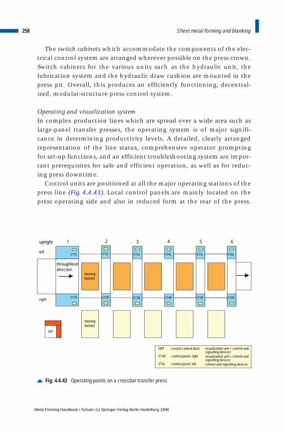
The switch cabinets which accommodate the components of the elec-trical control system are arranged wherever possible on the press crown.Switch cabinets for the various units such as the hydraulic unit, thelubrication system and the hydraulic draw cushion are mounted in thepress pit. Overall, this produces an efficiently functioning, decentral-ized, modular-structure press control system.
Operating and visualization systemIn complex production lines which are spread over a wide area such aslarge-panel transfer presses, the operating system is of major signifi-cance in determining productivity levels. A detailed, clearly arrangedrepresentation of the line status, comprehensive operator promptingfor set-up functions, and an efficient troubleshooting system are impor-tant prerequisites for safe and efficient operation, as well as for reduc-ing press downtime.
Control units are positioned at all the major operating stations of thepress line (Fig. 4.4.43). Local control panels are mainly located on thepress operating side and also in reduced form at the rear of the press.
258 Sheet metal forming and blanking
Fig. 4.4.43 Operating points on a crossbar transfer press
ST1L
ZBP visualization unit + control andsignalling devicesvisualization unit + control andsignalling devicescontrol and signalling devices
STxR
STxL
central control desk
control panel, right
control panel, left
movingbolster
movingbolster
ST1R ST2R ST3R ST4R ST5R ST6R
ST2L ST3L ST4L ST5L ST6L
ZBP
upright
right
left
2 3 4 5 61
throughfeeddirection
Metal Forming Handbook / Schuler (c) Springer-Verlag Berlin Heidelberg 1998
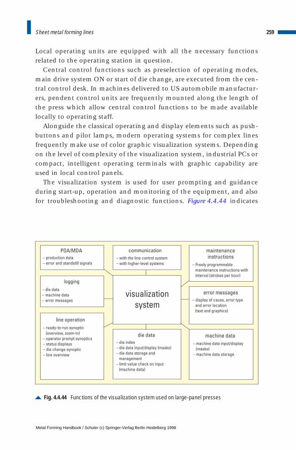
Local operating units are equipped with all the necessary functionsrelated to the operating station in question.
Central control functions such as preselection of operating modes,main drive system ON or start of die change, are executed from the cen-tral control desk. In machines delivered to US automobile manufactur-ers, pendent control units are frequently mounted along the length ofthe press which allow central control functions to be made availablelocally to operating staff.
Alongside the classical operating and display elements such as push-buttons and pilot lamps, modern operating systems for complex linesfrequently make use of color graphic visualization systems. Dependingon the level of complexity of the visualization system, industrial PCs orcompact, intelligent operating terminals with graphic capability areused in local control panels.
The visualization system is used for user prompting and guidanceduring start-up, operation and monitoring of the equipment, and alsofor troubleshooting and diagnostic functions. Figure 4.4.44 indicates
259Sheet metal forming lines
Fig. 4.4.44 Functions of the visualization system used on large-panel presses
PDA/MDA
logging
communication
die data
maintenanceinstructions
error messages
machine data
line operation
– with the line control system
– with higher-level systems
– production data
– error and standstill signals
– die data
– machine data
– error messages – display of cause, error type
and error location
(text and graphics)
– machine data input/display
(masks)
– machine data storage
– Freely programmable
maintenance instructions with
interval (strokes per hour)
visualization
system
– die index
– die data input/display (masks)
– die data storage and
management
– limit value check on input
(machine data)
– ready-to-run synoptic
(overview, zoom-in)
– operator prompt synoptics
– status displays
– die change synoptic
– line overview
Metal Forming Handbook / Schuler (c) Springer-Verlag Berlin Heidelberg 1998

the functions of a visualization system used in large-panel presses.Using modern operating techniques such as pull-down menus and win-dows technology, the press operator is able to access the required func-tions quickly and simply. It is also possible to jump across betweenfunctional areas and from one image to the next. The image frame isstructured identically for all the masks, and the function key assign-ment and operating procedures are standardized throughout. Nographic input device such as a mouse or trackball is required. Thismakes working with the user interface of the visualization systemextremely easy to learn. With a minimum of practice, the system can bequickly and safely operated.
The ready-to-run synoptic display (Fig. 4.4.45), frequently also referredto as the press synoptic, serves to prompt the user one step at a timeuntil ready-to-run status is reached. Green squares represent fulfilledand red squares unfulfilled conditions. Alongside ready-to-run statusesof the functional areas of the press, ready-to-run statuses of other line
260 Sheet metal forming and blanking
Fig. 4.4.45 Ready-to-run synoptic of a crossbar transfer press
Metal Forming Handbook / Schuler (c) Springer-Verlag Berlin Heidelberg 1998
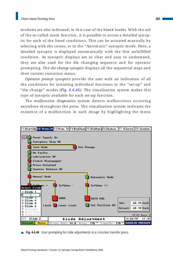
modules are also indicated; in this case of the blank loader. With the aidof the so-called zoom function, it is possible to access a detailed synop-tic for each of the listed conditions. This can be actuated manually byselecting with the cursor, or in the “Automatic” synoptic mode. Here, adetailed synoptic is displayed automatically with the first unfulfilledcondition. As synoptic displays are so clear and easy to understand,they are also used for the die changing sequence and for operatorprompting. The die change synoptic displays all the sequential steps andtheir current execution status.
Operator prompt synoptics provide the user with an indication of allthe conditions for initiating individual functions in the “set-up” and“die change” modes (Fig. 4.4.46). The visualization system makes thistype of synoptic available for each set-up function.
The malfunction diagnostics system detects malfunctions occurringanywhere throughout the press. The visualization system indicates theexistence of a malfunction in each image by highlighting the menu
261Sheet metal forming lines
Fig. 4.4.46 User prompting for slide adjustments in a crossbar transfer press
Metal Forming Handbook / Schuler (c) Springer-Verlag Berlin Heidelberg 1998

point “Error” in the menu line. Error messages contain an error number,plain language, reference to the affected assembly (operating resourcesidentification) and reference to the point in the PLC program. Thisinformation, in conjunction with the status displays, supports thedetection and localization of the source and cause of the malfunction.
Die-dependent data related to all dies used in the line can be enteredand edited at the visualization system. They are stored and managed inthe visualization system. During die change, this data is automaticallytransmitted to the relevant control units.
Alongside the visualization system, which is imperative for line oper-ation and monitoring, PC-based systems are also frequently used forthe acquisition and processing of machine and operational data as wellas measured values.
Machine and production data acquisition and evaluationThe machine and production data acquisition system (MDA/PDA) – orPMS (Press Management System) for short – logs error and standstilldata as well as production data accumulated in the press line. As such,it plays an important role in detecting and analysing weak points andin registering and monitoring press line productivity.
The hardware basis of the PMS is an industrial PC which is directlylinked to the line’s control system. The central PLC is responsible formaking available the necessary data, and so functions as the communi-cation partner for the PMS. Table 4.4.1 indicates the spheres of opera-tion of a PMS for large-panel presses.
The field of machine data acquisition is subdivided according to theacquisition and evaluation of errors and standstill periods.
According to the definition used here, errors are constituted bymachine statuses which are the direct result of faulty or damaged lineelements or components and which generally necessitate repair work.Errors are automatically classified by the PMS. In addition, a freely con-figured event-related comment is possible for each error message.
Errors do not, however, always cause a standstill; Standstills, in turn,do not necessarily result in errors. As a result, alongside the detection oferrors, separate acquisition of all press standstill statuses is required.
Standstill, in accordance with the definition used here, consists of alltimes during which no parts are produced (cf. Sect. 4.9.2). Dependingon the line in question, a difference is made between approx. 30 differ-
262 Sheet metal forming and blanking
Metal Forming Handbook / Schuler (c) Springer-Verlag Berlin Heidelberg 1998
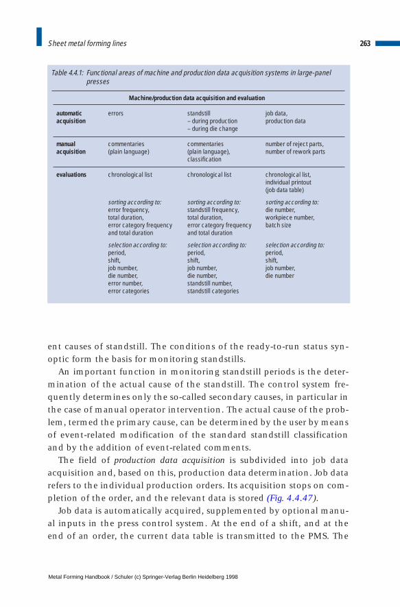
Machine/production data acquisition and evaluation
automatic errors standstill job data,acquisition – during production production data
– during die change
manual commentaries commentaries number of reject parts,acquisition (plain language) (plain language), number of rework parts
classification
evaluations chronological list chronological list chronological list,individual printout (job data table)
sorting according to: sorting according to: sorting according to:error frequency, standstill frequency, die number,total duration, total duration, workpiece number,error category frequency error category frequency batch sizeand total duration and total duration
selection according to: selection according to: selection according to:period, period, period, shift, shift, shift,job number, job number, job number,die number, die number, die numbererror number, standstill number,error categories standstill categories
Table 4.4.1: Functional areas of machine and production data acquisition systems in large-panelpresses
ent causes of standstill. The conditions of the ready-to-run status syn-optic form the basis for monitoring standstills.
An important function in monitoring standstill periods is the deter-mination of the actual cause of the standstill. The control system fre-quently determines only the so-called secondary causes, in particular inthe case of manual operator intervention. The actual cause of the prob-lem, termed the primary cause, can be determined by the user by meansof event-related modification of the standard standstill classificationand by the addition of event-related comments.
The field of production data acquisition is subdivided into job dataacquisition and, based on this, production data determination. Job datarefers to the individual production orders. Its acquisition stops on com-pletion of the order, and the relevant data is stored (Fig. 4.4.47).
Job data is automatically acquired, supplemented by optional manu-al inputs in the press control system. At the end of a shift, and at theend of an order, the current data table is transmitted to the PMS. The
263Sheet metal forming lines
Metal Forming Handbook / Schuler (c) Springer-Verlag Berlin Heidelberg 1998
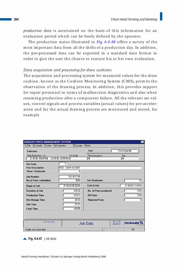
production data is ascertained on the basis of this information for anevaluation period which can be freely defined by the operator.
The production status illustrated in Fig. 4.4.48 offers a survey of themost important data from all the shifts of a production day. In addition,the pre-processed data can be exported in a standard data format inorder to give the user the chance to execute his or her own evaluation.
Data acquisition and processing for draw cushionsThe acquisition and processing system for measured values for the drawcushion, known as the Cushion Monitoring System (CMS), permits theobservation of the drawing process. In addition, this provides supportfor repair personnel in terms of malfunction diagnostics and also whenresuming production after a component failure. All the relevant set val-ues, control signals and process variables (actual values) for pre-acceler-ation and for the actual drawing process are monitored and stored, forexample
264 Sheet metal forming and blanking
Fig. 4.4.47 Job data
Metal Forming Handbook / Schuler (c) Springer-Verlag Berlin Heidelberg 1998
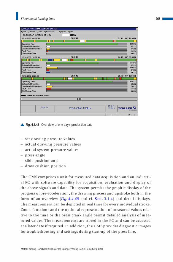
– set drawing pressure values– actual drawing pressure values– actual system pressure values– press angle– slide position and– draw cushion position.
The CMS comprises a unit for measured data acquisition and an industri-al PC with software capability for acquisition, evaluation and display ofthe above signals and data. The system permits the graphic display of theprogress of pre-acceleration, the drawing process and upstroke both in theform of an overview (Fig. 4.4.49 and cf. Sect. 3.1.4) and detail displays.The measurement can be depicted in real time for every individual stroke.Zoom functions and the optional representation of measured values rela-tive to the time or the press crank angle permit detailed analysis of mea-sured values. The measurements are stored in the PC and can be accessedat a later date if required. In addition, the CMS provides diagnostic imagesfor troubleshooting and settings during start-up of the press line.
265Sheet metal forming lines
Fig. 4.4.48 Overview of one day’s production data
Metal Forming Handbook / Schuler (c) Springer-Verlag Berlin Heidelberg 1998
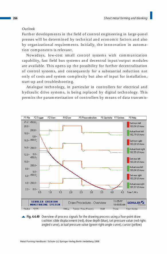
OutlookFurther developments in the field of control engineering in large-panelpresses will be determined by technical and economic factors and alsoby organizational requirements. Initially, the innnovation in automa-tion components is relevant.
Nowadays, low-cost small control systems with communicationcapability, fast field bus systems and decentral input/output modulesare available. This opens up the possibility for further decentralizationof control systems, and consequently for a substantial reduction notonly of costs and system complexity but also of input for installation,start-up and troubleshooting.
Analogue technology, in particular in controllers for electrical andhydraulic drive systems, is being replaced by digital technology. Thispermits the parameterization of controllers by means of data transmis-
266 Sheet metal forming and blanking
Fig. 4.4.49 Overview of process signals for the drawing process using a four-point drawcushion: slide displacement (red), draw depth (blue), set pressure value (red right-angled curve), actual pressure value (green right-angle curve), cursor (yellow)
Metal Forming Handbook / Schuler (c) Springer-Verlag Berlin Heidelberg 1998
sion following a change of requirements or after exchanging defectivecomponents. The benefits here include shorter repair times and thus anincrease of press up-time.
Highly-dynamic electrical feed systems in conjunction with efficientcontrol and regulation systems for movement synchronization areincreasingly replacing mechanically coupled drive systems. This devel-opment not only allows mechanical mechanisms to be simplified andflexibility to be further increased, but in certain cases also enhancesproductivity.
The changes taking place in the field of work organization in manystamping plants are imposing new demands, in particular on the linecontrol center. Production lines are being managed increasingly byindependently acting teams of employees on their own responsibility.These teams require information on site related to production andmachine data, to production quality, waiting production jobs andmaintenance work to be carried out. Only with this information attheir fingertips are team members in a position to optimize the produc-tivity of their line and to assume control functions on the productionlevel. As a result, machine and production data acquisition systemssuch as those described above will continue to be more extensively usedand the functional scope of their application extended to cover everwider fields.
Multi media-based production line information systems which per-mit fast, selective access to stored line documentation and additionalinformation on the elimination of faults and routine maintenance willbe integrated in the future into the press control center. Using thesesystems, it will also be possible for operating personnel to enter theirown findings into the information data base and so develop their ownexperience data base.
In general terms, future developments in the field of control engi-neering will concentrate on reducing complexity and on the develop-ment of more efficient systems for repair and maintenance support toreduce the costs of press control and increase production line uptime.
267Sheet metal forming lines
Metal Forming Handbook / Schuler (c) Springer-Verlag Berlin Heidelberg 1998
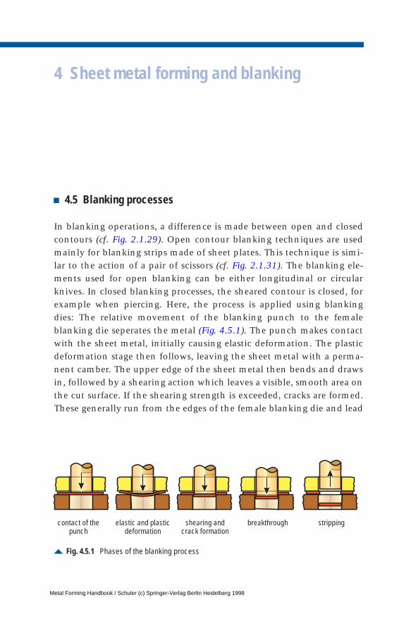
4 Sheet metal forming and blanking
4.5 Blanking processes
In blanking operations, a difference is made between open and closedcontours (cf. Fig. 2.1.29). Open contour blanking techniques are usedmainly for blanking strips made of sheet plates. This technique is simi-lar to the action of a pair of scissors (cf. Fig. 2.1.31). The blanking ele-ments used for open blanking can be either longitudinal or circularknives. In closed blanking processes, the sheared contour is closed, forexample when piercing. Here, the process is applied using blankingdies: The relative movement of the blanking punch to the femaleblanking die seperates the metal (Fig. 4.5.1). The punch makes contactwith the sheet metal, initially causing elastic deformation. The plasticdeformation stage then follows, leaving the sheet metal with a perma-nent camber. The upper edge of the sheet metal then bends and drawsin, followed by a shearing action which leaves a visible, smooth area onthe cut surface. If the shearing strength is exceeded, cracks are formed.These generally run from the edges of the female blanking die and lead
Fig. 4.5.1 Phases of the blanking process
contact of thepunch
elastic and plasticdeformation
shearing andcrack formation
breakthrough stripping
Metal Forming Handbook / Schuler (c) Springer-Verlag Berlin Heidelberg 1998
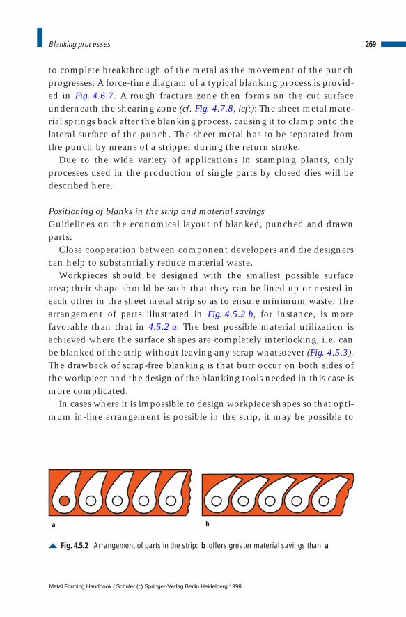
to complete breakthrough of the metal as the movement of the punchprogresses. A force-time diagram of a typical blanking process is provid-ed in Fig. 4.6.7. A rough fracture zone then forms on the cut surfaceunderneath the shearing zone (cf. Fig. 4.7.8, left): The sheet metal mate-rial springs back after the blanking process, causing it to clamp onto thelateral surface of the punch. The sheet metal has to be separated fromthe punch by means of a stripper during the return stroke.
Due to the wide variety of applications in stamping plants, onlyprocesses used in the production of single parts by closed dies will bedescribed here.
Positioning of blanks in the strip and material savingsGuidelines on the economical layout of blanked, punched and drawnparts:
Close cooperation between component developers and die designerscan help to substantially reduce material waste.
Workpieces should be designed with the smallest possible surfacearea; their shape should be such that they can be lined up or nested ineach other in the sheet metal strip so as to ensure minimum waste. Thearrangement of parts illustrated in Fig. 4.5.2 b, for instance, is morefavorable than that in 4.5.2 a. The best possible material utilization isachieved where the surface shapes are completely interlocking, i. e. canbe blanked of the strip without leaving any scrap whatsoever (Fig. 4.5.3).The drawback of scrap-free blanking is that burr occur on both sides ofthe workpiece and the design of the blanking tools needed in this case ismore complicated.
In cases where it is impossible to design workpiece shapes so that opti-mum in-line arrangement is possible in the strip, it may be possible to
269Blanking processes
Fig. 4.5.2 Arrangement of parts in the strip: b offers greater material savings than a
a b
Metal Forming Handbook / Schuler (c) Springer-Verlag Berlin Heidelberg 1998
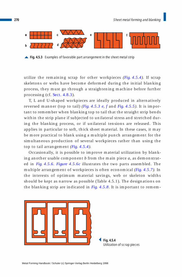
utilize the remaining scrap for other workpieces (Fig. 4.5.4). If scrapskeletons or webs have become deformed during the initial blankingprocess, they must go through a straightening machine before furtherprocessing (cf. Sect. 4.8.3).
T, L and U-shaped workpieces are ideally produced in alternativelyreversed manner (top to tail) (Fig. 4.5.3 e, f and Fig. 4.5.5). It is impor-tant to remember when blanking top to tail that the straight strip bendswithin the strip plane if subjected to unilateral stress and stretched dur-ing the blanking process, or if unilateral tensions are released. Thisapplies in particular to soft, thick sheet material. In these cases, it maybe more practical to blank using a multiple punch arrangement for thesimultaneous production of several workpieces rather than using thetop to tail arrangement (Fig. 4.5.4).
Occasionally, it is possible to improve material utilization by blank-ing another usable component b from the main piece a, as demonstrat-ed in Fig. 4.5.6. Figure 4.5.6c illustrates the two parts assembled. Themultiple arrangement of workpieces is often economical (Fig. 4.5.7). Inthe interests of optimum material savings, web or skeleton widthsshould be kept as narrow as possible (Table 4.5.1). The designations onthe blanking strip are indicated in Fig. 4.5.8. It is important to remem-
270 Sheet metal forming and blanking
Fig. 4.5.3 Examples of favorable part arrangement in the sheet metal strip
aa c
b d
e f
Fig. 4.5.4Utilization of scrap pieces
Metal Forming Handbook / Schuler (c) Springer-Verlag Berlin Heidelberg 1998
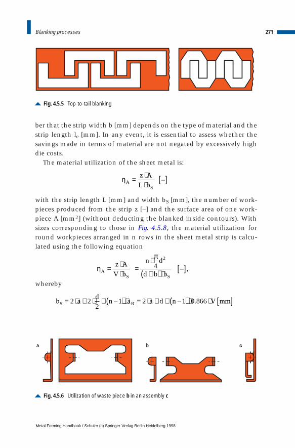
ber that the strip width b [mm] depends on the type of material and thestrip length le [mm]. In any event, it is essential to assess whether thesavings made in terms of material are not negated by excessively highdie costs.
The material utilization of the sheet metal is:
with the strip length L [mm] and width bS [mm], the number of work-pieces produced from the strip z [–] and the surface area of one work-piece A [mm2] (without deducting the blanked inside contours). Withsizes corresponding to those in Fig. 4.5.8, the material utilization forround workpieces arranged in n rows in the sheet metal strip is calcu-lated using the following equation
whereby
271Blanking processes
Fig. 4.5.5 Top-to-tail blanking
Fig. 4.5.6 Utilization of waste piece b in an assembly c
a b c
ηAS
z A
L b= ⋅
⋅[ ] –
η
π
AS S
z A
V b
n d
d b b= ⋅
⋅=
⋅
+( ) ⋅[ ] – ,4
2
b ad
n a a d n V mmS R= ⋅ + ⋅ + ( ) ⋅ = ⋅ + + ( ) ⋅ ⋅ [ ]2 22
1 2 1 0 866– – .
Metal Forming Handbook / Schuler (c) Springer-Verlag Berlin Heidelberg 1998
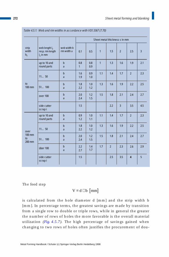
The feed step
is calculated from the hole diameter d [mm] and the strip width b[mm]. In percentage terms, the greatest savings are made by transitionfrom a single row to double or triple rows, while in general the greaterthe number of rows of holes the more favorable is the overall materialutilization (Fig. 4.5.7). The high percentage of savings gained whenchanging to two rows of holes often justifies the procurement of dou-
272 Sheet metal forming and blanking
Table 4.5.1: Web and rim widths in accordance with VDI 3367 (7.70)
0.1 0.5 1 1.5 2 3
b a
0.8 1
0.8 0.9
1 1.3 1.6
1.6 1.9
0.9 1.0
1.1 1.4 1.7
51… 100
11… 50
1.8 2.2
1.0 1.2
1.3 1.6 1.9 2.5
over 100 2.0 2.4
1.2 1.5
1.5 1.8 2.1 2.7
1.5 2.2 3 4.5
2.30.9 1.2
1.0 1.1
1.1 1.4 1.7
11… 501.8 2.2
1.0 1.2
1.3 1.6 1.9
51… 1002.0 2.4
1.2 1.5
1.5 1.8 2.1
über 100 2.2 2.7
1.4 1.7
1.7 2 2.3
1.5 2.5 3.5 4
2.5
1.9
2
2.2
2.4
3.5
2
2.2
2.4
2.6
4
2.1
2.3
2.5
2.7
2.9
5
up to 10 andround parts
web width b rim width a
strip widthbS
web length le
resp. rim length la in mm
b a
b a
b a
b a
b a
b a
b a
side cutter scrap i
up to 10 andround parts
side cutter scrap i
over100 mm to200 mm
to 100 mm
Sheet metal thickness s in mm
V d b mm= + [ ]
Metal Forming Handbook / Schuler (c) Springer-Verlag Berlin Heidelberg 1998

273Blanking processes
Fig. 4.5.7 Strips using single and multiple-row punch arrangement with utilization factor hA in %
56.8% 65.0% 67.4% 73.2%
Fig. 4.5.8 Definitions on the strip: d hole diameter; a rim width; b web width; i side cutter waste; le web length; la rim length; bS strip width; L strip length; V feed step; t pitch; aR space between the rows
le
i
b
a
le
la
la
bS
bS
b
L
60°
aR
V= t
aa
d
Metal Forming Handbook / Schuler (c) Springer-Verlag Berlin Heidelberg 1998
ble dies or, where double dies do not represent a viable investment dueto small batch sizes, the use of a feed system for offset blanking.
Blanking force and blanking workThe necessary blanking force FS [N] for punches with flat ground work-ing surfaces (closed blanking contours) is calculated with the followingequation:
whereby AS is the sheared surface in mm2 and kS the resistance to shear,shearing strength or relative blanking force of the sheet metal expressedin N/mm2. The sheared surface is determined from the length of thesheared contour lS [mm] multiplied by the thickness of the sheet metals [mm], whereby the length of the sheared contour is taken to mean thesum of all sheared edge lengths in mm. If the ratio of the punch diam-eter d to the sheet metal thickness s is greater than 2, the followingequation is sufficient for an approximate calculation of the shearingstrength kS:
whereby Rm [N/mm2] is the tensile strength of the sheet metal. The blanking force must not exceed the nominal press force within
the nominal force-stroke curve, given in press specifications, as other-wise the machine will be overloaded. If the sheet metal thickness islarger than the nominal press force stroke position (i. e. distance beforeBDC, where nominal press force is given), then the permissible pressforces are smaller (cf. Sect. 3.2.1). These can be ascertained from theload versus stroke diagram included in the operating instructions.
The force of the return stroke for stripping the workpiece off thepunch is around 3 to 5 % of the blanking force when the ratio of thepunch diameter d to the sheet metal thickness s is around 10 (d/s = 10).In the case of smaller d/s ratios, the return stroke forces increase substan-tially, amounting with d/s = 2 to around 10 to 20 % of the blanking force,while this drops further with greater d/s ratios. A greater return strokeforce is required for stripping tough materials than for brittle ones. Thereturn stroke force must be taken into account when designing thepunch and dies, and in extreme cases also when dimensioning the press.
Lateral forces can also occur during blanking operations. Particularattention must be paid to these, in particular when the strip layout has
274 Sheet metal forming and blanking
F A k l s k NS S S S S= ⋅ = ⋅ ⋅ [ ] ,
k RN
mmS m= ⋅
0 8 2. ,
Metal Forming Handbook / Schuler (c) Springer-Verlag Berlin Heidelberg 1998
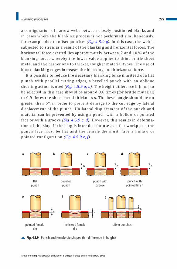
a configuration of narrow webs between closely positioned blanks andin cases where the blanking process is not performed simultaneously,for example due to offset punches (Fig. 4.5.9 g). In this case, the web issubjected to stress as a result of the blanking and horizontal forces. Thehorizontal force exerted lies approximately between 2 and 10 % of theblanking force, whereby the lower value applies to thin, brittle sheetmetal and the higher one to thicker, tougher material types. The use ofblunt blanking edges increases the blanking and horizontal force.
It is possible to reduce the necessary blanking force if instead of a flatpunch with parallel cutting edges, a bevelled punch with an obliqueshearing action is used (Fig. 4.5.9 a, b). The height difference h [mm] tobe selected in this case should be around 0.6 times (for brittle material)to 0.9 times the sheet metal thickness s. The bevel angle should be nogreater than 5°, in order to prevent damage to the cut edge by lateraldisplacement of the punch. Unilateral displacement of the punch andmaterial can be prevented by using a punch with a hollow or pointedface or with a groove (Fig. 4.5.9 c, d). However, this results in deforma-tion of the slug. If the slug is intended for use as a flat workpiece, thepunch face must be flat and the female die must have a hollow orpointed configuration (Fig. 4.5.9 e, f).
275Blanking processes
Fig. 4.5.9 Punch and female die shapes (h = difference in height)
h
h
h
h
h
a
e
b c d
f
d
g
flatpunch
bevelledpunch
punch withgroove
punch withpointed finish
pointed femaledie
hollowed femaledie
offset punches
h
Metal Forming Handbook / Schuler (c) Springer-Verlag Berlin Heidelberg 1998
276 Sheet metal forming and blanking
When using a bevel ground punch or female die, the blanking forceis reduced by at least 30 % compared to punches or female dies with aflat surface, as only a certain part of the die is engaged at any one time(Fig. 4.5.10). However, overall the blanking work remains the same, asthe reduced force acts over a longer stroke.
If there are several punches mounted in a die, it is also possible toreduce the blanking force by causing the punches to act in sequence(Fig. 4.5.9 g). However, in order to ensure a smooth press operation andreduce the stress on the dies, when using this method, the height dif-ference between each punch force should not be greater than the pen-etration depth of the die until the fracture of the sheet metal (around0.3 to 0.4 · s). Bevel grinding of punches or female dies and offsetting inthe case of several punches also help to reduce noise during the blank-ing process.
Example:Assuming a 2 mm thick, hard brass sheet Ms 63 (kS = 380 N/mm2) is to beperforated using a flat ground punch of 113 mm in diameter. The sheared sur-face is:
Accordingly, the blanking force will be:
The blanking work is determined with the following equation:
with the blanking force FS and material thickness s. The factor x [–] takesinto consideration the actual progression of force when blanking anddepends on the material. It lies within the approximate range of 0.4 to0.7, whereby the lower value applies for brittle materials, a large blankingclearance and thick sheet metals, and the upper value is used primarilyfor tougher materials, a small blanking clearance and thin sheet metals.For approximate calculation, the following equation applies:
A d s mm mm mmS = ⋅ ⋅ = ⋅ ⋅ =π π113 2 710 0 2.
F A k N kNS S S= ⋅ = ⋅ = =710 380 270 000 270,
W x F s Nm resp kNmS S= ⋅ ⋅ [ ].
W F s Nm resp kNmS S= ⋅ ⋅ [ ]2
3.
Metal Forming Handbook / Schuler (c) Springer-Verlag Berlin Heidelberg 1998
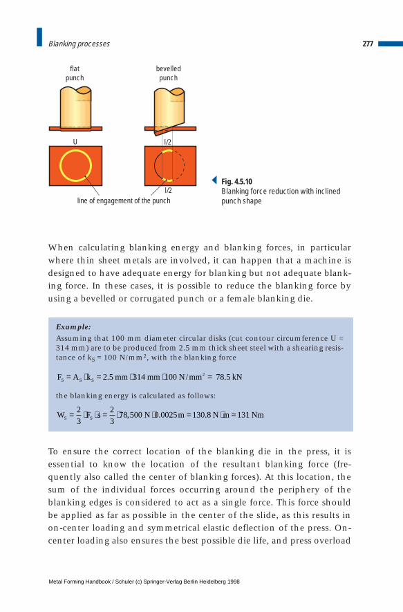
277Blanking processes
U
l/2
l/2
line of engagement of the punch
flatpunch
bevelledpunch
Fig. 4.5.10Blanking force reduction with inclinedpunch shape
When calculating blanking energy and blanking forces, in particularwhere thin sheet metals are involved, it can happen that a machine isdesigned to have adequate energy for blanking but not adequate blank-ing force. In these cases, it is possible to reduce the blanking force byusing a bevelled or corrugated punch or a female blanking die.
Example: Assuming that 100 mm diameter circular disks (cut contour circumference U =314 mm) are to be produced from 2.5 mm thick sheet steel with a shearing resis-tance of kS = 100 N/mm2, with the blanking force
the blanking energy is calculated as follows:
To ensure the correct location of the blanking die in the press, it isessential to know the location of the resultant blanking force (fre-quently also called the center of blanking forces). At this location, thesum of the individual forces occurring around the periphery of theblanking edges is considered to act as a single force. This force shouldbe applied as far as possible in the center of the slide, as this results inon-center loading and symmetrical elastic deflection of the press. On-center loading also ensures the best possible die life, and press overload
F A k mm mm N mm kNS S S= ⋅ = ⋅ ⋅ =2 5 314 100 78 52. / .
W F s N m N m NmS S= ⋅ ⋅ = ⋅ ⋅ = ⋅ ≈2
3
2
378 500 0 0025 130 8 131, . .
Metal Forming Handbook / Schuler (c) Springer-Verlag Berlin Heidelberg 1998

due to off-center loading is eliminated. When dies are provided with alocating pin for clamping in the press, this should be positioned in thelocation of the resultant force.
To determine the location of the resulting blanking force, the shape,scope and position of sheared contours are of importance. The positionof the center of force is generally determined by calculating the center ofgravity of the blanking edges / cut contours or where simple geometries areinvolved (circle, rectangle), by ascertaining the center of gravity of thepunch perimeters / cut contour perimeters. Where asymmetrical punchconfigurations are involved, this calculation must be made for the xand the y direction:
For the location of the resultant force in the x direction (distancefrom the y axis), the following applies:
where U [mm] represents the relevant perimeters of the individualpunches and a [mm] is the distance of their centers of gravity from theselected y axis. If the line centers of gravity are taken as a basis, then
where 1 [mm] is taken to represent the lengths of the blanking edges.The location of the resulting force in the y direction (distance from thex axis) is calculated from the corresponding equation for y, by substi-tuting the distances of the perimeter / blanking edge lengths from thex axis for b [mm]:
278 Sheet metal forming and blanking
xU a U a U a
U U UmmS
n n
n
= ⋅ + ⋅ +…+ ⋅+ +…+
[ ]1 1 2 2
1 2
,
xl a a a
mmSn n
n
= ⋅ + ⋅ +…+ ⋅+ +…+
[ ]1 1 2 2
1 2
1 1
1 1 1
,
yU b U b U b
U U Umm
yl b b b
mm
Sn n
n
Sn n
n
= ⋅ + ⋅ +…+ ⋅+ +…+
[ ]
= ⋅ + ⋅ +…+ ⋅+ +…+
[ ]
1 1 2 2
1 2
1 1 2 2
1 2
1 1
1 1 1
Metal Forming Handbook / Schuler (c) Springer-Verlag Berlin Heidelberg 1998
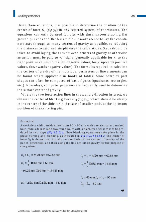
Using these equations, it is possible to determine the position of thecenter of force SR (xS; yS) in any selected system of coordinates. Theequations can only be used for dies with simultaneously acting flatground punches and flat female dies. It makes sense to lay the coordi-nate axes through as many centers of gravity as possible, so reducingthe distances to zero and simplifying the calculations. Steps should betaken to avoid laying the axes between centers of gravity as otherwiseattention must be paid to +/– signs (generally applicable for x: to theright positive values, to the left negative values; for y: upwards positivevalues, downwards negative values). The formulas required to calculatethe centers of gravity of the individual perimeters or line elements canbe found where applicable in books of tables. More complex partshapes can often be composed of basic figures (quadrants, rectangles,etc.). Nowadays, computer programs are frequently used to determinethe surface center of gravity.
Where the two force action lines in the x and y direction interact, weobtain the center of blanking forces SR (xS; yS), which should be ideallyin the center of the slide, or in the case of smaller tools, at the optimumposition of the centering pin.
Example:A workpiece with outside dimensions 80 3 90 mm with a semicircular punchedhole (radius 30 mm) and two round holes with a diameter of 20 mm is to be pro-duced in two steps (Fig. 4.5.11a). Two blanking operations take place in thepress: piercing and blanking, as indicated in Fig. 4.5.11b and c. The center offorce SR is determined initially on the basis of the centers of gravity of thepunch perimeters, and then using the line centers of gravity for the purpose ofcomparison.
279Blanking processes
➔
U U mm mm
U mm mm
mm mm mm
U mm mm mm
1 2
3
4
20 62 83
1
260 60
94 25 60 154 25
2 80 2 90 340
= = ⋅ =
= ⋅ ⋅ +
= + =
= ⋅ + ⋅ =
π
π
.
. .
l l mm mm
l mm mm
l mm l l mm
l l mm
5 6
7
8 9 11
10 12
20 62 83
1
260 94 25
60 90
80
= = ⋅ =
= ⋅ ⋅ =
= = =
= =
π
π
.
.
,
Metal Forming Handbook / Schuler (c) Springer-Verlag Berlin Heidelberg 1998
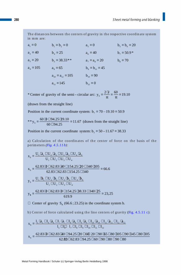
The distances between the centers of gravity in the respective coordinate systemin mm are:
a) Calculation of the coordinates of the center of force on the basis of theperimeters (Fig. 4.5.11b):
b) Center of force calculated using the line centers of gravity (Fig. 4.5.11 c):
280 Sheet metal forming and blanking
b b
b
b
a
a a
a
1 2
4
3
9
10 12
11
0
25
38 33
65
105
145
= =
=
=
=
= =
=
. **
a
a
a a
b b
b
b
5
6
7 8
9 11
10
12
0
40
20
45
90
0
=
=
= =
= =
=
=
b b
b
b
5 6
7
8
20
50 9
70
= =
=
=
. *
* C : y
(d )
P :
(d )
Position i :
enter of gravity of the semi circular arcr
rawn from the straight line
osition in the current coordinate system b
y rawn from the straight line
n the current coordinate system b
S
S
– = ⋅ = =
= =
= ⋅ + ⋅+
=
= =
2 6019 10
70 19 10 50 9
60 0 94 25 19 10
60 94 2511 67
50 11 67 38 33
7
3
π π.
– . .
**. .
..
– . .
xl a l a l a l a l a l a l a l a
l l l l l l l l
x
S
S
= ⋅ + ⋅ + ⋅ + ⋅ + ⋅ + ⋅ + ⋅ + ⋅+ + + + + + +
= ⋅ + ⋅ + ⋅ + ⋅ + ⋅ + ⋅ + ⋅ + ⋅
5 5 6 6 7 7 8 8 9 9 10 10 11 11 12 12
5 6 7 8 9 10 11 12
62 83 0 62 83 40 94 25 20 60 20 90 65 80 105 90 145 80 105
62
. . .
.8383 62 83 94 25 60 90 80 90 80+ + + + + + +. .
a
a
a
a
1
2
3
4
0
40
20
105
=
=
=
=
xU a U a U a U a
U U U U
x
yU b U b U b U b
U U U U
y
S
S
S
= ⋅ + ⋅ + ⋅ + ⋅+ + +
= ⋅ + ⋅ + ⋅ + ⋅+ + +
=
= ⋅ + ⋅ + ⋅ + ⋅+ + +
1 1 2 2 3 3 4 4
1 2 3 4
1 1 2 2 3 3 4 4
1 2 3 4
62 83 0 62 83 40 154 25 20 340 105
62 83 62 83 154 25 34066 6
. . .
. . ..
SS
Renter of gravity S n the coordinate system
= ⋅ + ⋅ + ⋅ + ⋅ =
⇒
62 83 0 62 83 0 154 25 38 33 340 25
619 923 25
66 6 23 25
. . . .
.,
( . ; . ) .C i b
Metal Forming Handbook / Schuler (c) Springer-Verlag Berlin Heidelberg 1998
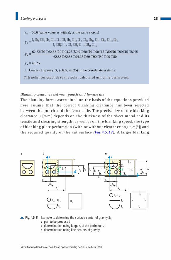
This point corresponds to the point calculated using the perimeters.
Blanking clearance between punch and female dieThe blanking forces ascertained on the basis of the equations providedhere assume that the correct blanking clearance has been selectedbetween the punch and the female die. The precise size of the blankingclearance u [mm] depends on the thickness of the sheet metal and itstensile and shearing strength, as well as on the blanking speed, the typeof blanking plate perforation (with or without clearance angle a [°]) andthe required quality of the cut surface (Fig. 4.5.12). A larger blanking
281Blanking processes
66 6
5 5 6 6 7 7 8 8 9 9 10 10 11 11 12 12
5 6 7 8 9 10 11 12
= −
= ⋅ + ⋅ + ⋅ + ⋅ + ⋅ + ⋅ + ⋅ + ⋅+ + + + + + +
.x ame value as with s the same xis
yl b l b l b l b l b l b l b l b
l l l l l l l l
y
S
S
(s a), a y a )
SS
S
R
y
enter of gravity S the coordinate system
= ⋅ + ⋅ + ⋅ + ⋅ + ⋅ + ⋅ + ⋅ + ⋅+ + + + + + +
=
⇒
62 83 20 62 83 20 94 25 50 9 60 70 90 45 80 90 90 45 80 0
62 83 62 83 94 25 60 90 80 90 80
43 25
66 6 43 25
. . . .
. . .
.
( . ; . )C in c.
Fig. 4.5.11 Example to determine the surface center of gravity SR:a part to be producedb determination using lengths of the perimetersc determination using line centers of gravity
y y
xx
S 3
U 3
S 1
U 1
a3
a
b3
a7
S 7
S 5S 2
= U 2
a2 a6
b5
l = l5 6
b9
l9
b10
l10
l11
l12
b8
b
l8
b7
l7
a4
b4
a10
S 6S 4
S
U 4
S 9
S
S 10
S 11
S 12
S 8
c
Metal Forming Handbook / Schuler (c) Springer-Verlag Berlin Heidelberg 1998
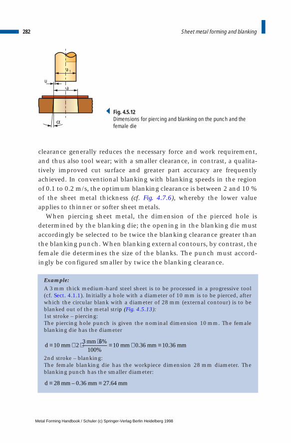
clearance generally reduces the necessary force and work requirement,and thus also tool wear; with a smaller clearance, in contrast, a qualita-tively improved cut surface and greater part accuracy are frequentlyachieved. In conventional blanking with blanking speeds in the regionof 0.1 to 0.2 m/s, the optimum blanking clearance is between 2 and 10 %of the sheet metal thickness (cf. Fig. 4.7.6), whereby the lower valueapplies to thinner or softer sheet metals.
When piercing sheet metal, the dimension of the pierced hole isdetermined by the blanking die; the opening in the blanking die mustaccordingly be selected to be twice the blanking clearance greater thanthe blanking punch. When blanking external contours, by contrast, thefemale die determines the size of the blanks. The punch must accord-ingly be configured smaller by twice the blanking clearance.
Example:A 3 mm thick medium-hard steel sheet is to be processed in a progressive tool(cf. Sect. 4.1.1). Initially a hole with a diameter of 10 mm is to be pierced, afterwhich the circular blank with a diameter of 28 mm (external contour) is to beblanked out of the metal strip (Fig. 4.5.13):1st stroke – piercing:The piercing hole punch is given the nominal dimension 10 mm. The femaleblanking die has the diameter
2nd stroke – blanking:The female blanking die has the workpiece dimension 28 mm diameter. Theblanking punch has the smaller diameter:
282 Sheet metal forming and blanking
a
a 1
u
Fig. 4.5.12Dimensions for piercing and blanking on the punch and thefemale die
d mmmm
mm mm mm= + ⋅ ⋅ = + =10 23 6
10010 0 36 10 36
%
%. .
d mm mm mm= =28 0 36 27 64– . .
Metal Forming Handbook / Schuler (c) Springer-Verlag Berlin Heidelberg 1998

283Blanking processes
Fig. 4.5.13 Workpiece and die dimensions used in the manufacture of a pierced disk
28
1010.36
10
0.18 0.18
27.64
28
Metal Forming Handbook / Schuler (c) Springer-Verlag Berlin Heidelberg 1998
4 Sheet metal forming and blanking
4.6 Shearing lines
4.6.1 Slitting lines
The parting of coiled sheet metal stock to produce several narrow stripcoils is performed using waste-free cutting with rotating circular shearingblades in so-called slitting lines. Materials processed in this way includehot and cold-rolled and stainless steels, NF metals, in particular alu-minium, and coated sheet metals.
Alongside the decoiler and recoiler, the major components of a slit-ting line include the circular shear and the brake frame. The startingcoil is pulled tightly off the decoiler, cut to narrow strips with the cir-cular roller shears and coiled again to form firm rings by the brakeframe and the recoiler (Fig. 4.6.1). The material processed in this way hasgenerally a thickness of 0.2 and 10 mm. The starting coils can weighanywhere between 5 and 30 t. The minimum width of the individualcoil depends on the width of the blade and the thickness of the sheetmetal being processed. Circular shear blades are generally between 10and 20 mm wide and have a diameter of 250 to 500 mm. The maximumnumber of cuts depends on the diameter of the shear shaft and theshaft length. Shaft deflection must not exceed a certain value.
Circular shears with a continuous shaft are equipped with circularblades, rolling rings and distance sleeves (Fig. 4.6.2). Alternatively,hydraulically fastened flanged blades can be used for greater slit coilwidths. To reduce standstill periods, the shears are configured asexchangeable units that can be pre-assembled outside the running slit-ting line prior to production. Where electrically adjustable disk shearsare used, the blade holders are positioned by a control system to the
Metal Forming Handbook / Schuler (c) Springer-Verlag Berlin Heidelberg 1998
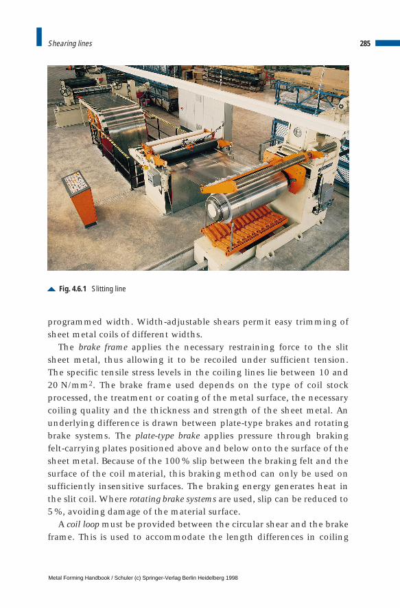
programmed width. Width-adjustable shears permit easy trimming ofsheet metal coils of different widths.
The brake frame applies the necessary restraining force to the slitsheet metal, thus allowing it to be recoiled under sufficient tension. The specific tensile stress levels in the coiling lines lie between 10 and20 N/mm2. The brake frame used depends on the type of coil stockprocessed, the treatment or coating of the metal surface, the necessarycoiling quality and the thickness and strength of the sheet metal. Anunderlying difference is drawn between plate-type brakes and rotatingbrake systems. The plate-type brake applies pressure through brakingfelt-carrying plates positioned above and below onto the surface of thesheet metal. Because of the 100 % slip between the braking felt and thesurface of the coil material, this braking method can only be used onsufficiently insensitive surfaces. The braking energy generates heat inthe slit coil. Where rotating brake systems are used, slip can be reduced to5 %, avoiding damage of the material surface.
A coil loop must be provided between the circular shear and the brakeframe. This is used to accommodate the length differences in coiling
285Shearing lines
Fig. 4.6.1 Slitting line
Metal Forming Handbook / Schuler (c) Springer-Verlag Berlin Heidelberg 1998

which occur between the inner and outer slit coils with each revolutionof the decoiler. The reason for these differences are the thickness varia-tions in the starting coil material over the coil width.
The production speed achieved by slitting lines ranges from 100 to500 m/min. The resetting of blades, as well as the removal and hoopingof the slit coils with packaging tape can lead to system bottlenecks.Improved capacity utilization can be achieved by using automaticexchange of blades and by recoiling outside the line itself.
4.6.2 Blanking lines
Sheet metal parts with medium and large surface areas are not produceddirectly off the coil, but from stacked blanks fed automatically into theforming press. These blanks are produced in blanking lines with cut-to-length shears or blanking presses.
Blanking lines consist of the following components:
– coil line (cf. Sect. 4.3)– shear or blanking press– stacking line
286 Sheet metal forming and blanking
Fig. 4.6.2 Circular shears
rolling ringcircular bladedistance sleeveframe sheet metal strip
Metal Forming Handbook / Schuler (c) Springer-Verlag Berlin Heidelberg 1998
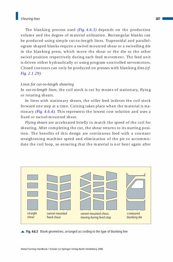
The blanking process used (Fig. 4.6.3) depends on the productionvolume and the degree of material utilization. Rectangular blanks canbe produced using simple cut-to-length lines. Trapezoidal and parallel-ogram shaped blanks require a swivel mounted shear or a swivelling diein the blanking press, which move the shear or the die to the otherswivel position respectively during each feed movement. The feed unitis driven either hydraulically or using program-controlled servomotors.Closed contours can only be produced on presses with blanking dies (cf.Fig. 2.1.29).
Lines for cut-to-length shearingIn cut-to-length lines, the coil stock is cut by means of stationary, flyingor rotating shears.
In lines with stationary shears, the roller feed indexes the coil stockforward one step at a time. Cutting takes place when the material is sta-tionary (Fig. 4.6.4). This represents the lowest cost solution and uses afixed or swivel-mounted shear.
Flying shears are accelerated briefly to match the speed of the coil forshearing. After completing the cut, the shear returns to its starting posi-tion. The benefits of this design are continuous feed with a constantstraightening machine speed and elimination of the pit to accommo-date the coil loop, so ensuring that the material is not bent again after
287Shearing lines
Fig. 4.6.3 Blank geometries, arranged according to the type of blanking line
straightshear
swivel-mountedfixed shear
swivel-mounted shear,moving during feed stop
contouredblanking die
Metal Forming Handbook / Schuler (c) Springer-Verlag Berlin Heidelberg 1998
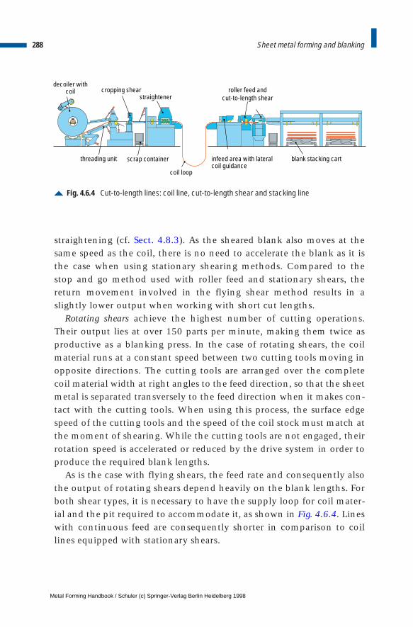
straightening (cf. Sect. 4.8.3). As the sheared blank also moves at thesame speed as the coil, there is no need to accelerate the blank as it isthe case when using stationary shearing methods. Compared to thestop and go method used with roller feed and stationary shears, thereturn movement involved in the flying shear method results in aslightly lower output when working with short cut lengths.
Rotating shears achieve the highest number of cutting operations.Their output lies at over 150 parts per minute, making them twice asproductive as a blanking press. In the case of rotating shears, the coilmaterial runs at a constant speed between two cutting tools moving inopposite directions. The cutting tools are arranged over the completecoil material width at right angles to the feed direction, so that the sheetmetal is separated transversely to the feed direction when it makes con-tact with the cutting tools. When using this process, the surface edgespeed of the cutting tools and the speed of the coil stock must match atthe moment of shearing. While the cutting tools are not engaged, theirrotation speed is accelerated or reduced by the drive system in order toproduce the required blank lengths.
As is the case with flying shears, the feed rate and consequently alsothe output of rotating shears depend heavily on the blank lengths. Forboth shear types, it is necessary to have the supply loop for coil mater-ial and the pit required to accommodate it, as shown in Fig. 4.6.4. Lineswith continuous feed are consequently shorter in comparison to coillines equipped with stationary shears.
288 Sheet metal forming and blanking
Fig. 4.6.4 Cut-to-length lines: coil line, cut-to-length shear and stacking line
decoiler withcoil cropping shear
straightenerroller feed and
cut-to-length shear
threading unit scrap container
coil loop
infeed area with lateralcoil guidance
blank stacking cart
Metal Forming Handbook / Schuler (c) Springer-Verlag Berlin Heidelberg 1998
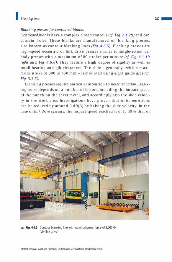
Blanking presses for contoured blanksContoured blanks have a complex closed contour (cf. Fig. 2.1.29) and cancontain holes. These blanks are manufactured on blanking presses, also known as contour blanking lines (Fig. 4.6.5). Blanking presses arehigh-speed eccentric or link drive presses similar to single-action carbody presses with a maximum of 80 strokes per minute (cf. Fig. 4.1.19right and Fig. 4.6.8). They feature a high degree of rigidity as well as small bearing and gib clearances. The slide – generally with a maxi-mum stroke of 300 to 450 mm – is mounted using eight guide gibs (cf. Fig. 3.1.5).
Blanking presses require particular attention to noise reduction. Blank-ing noise depends on a number of factors, including the impact speedof the punch on the sheet metal, and accordingly also the slide veloci-ty in the work area. Investigations have proven that noise emissionscan be reduced by around 6 dB(A) by halving the slide velocity. In thecase of link drive systems, the impact speed reached is only 30 % that of
289Shearing lines
Fig. 4.6.5 Contour blanking line with nominal press force of 8,000 kN (six-link drive)
Metal Forming Handbook / Schuler (c) Springer-Verlag Berlin Heidelberg 1998
eccentric presses, representing a reduction in the noise level of some 12 dB(A) (cf. Fig. 3.2.3). In addition, secondary measures are applied toreduce the noise emission from blanking shock in presses, for exampleby providing a sound enclosure. This can serve to reduce noise by asmuch as 25 dB(A).
As a rule, modern presses are mounted on rocker elements in order toreduce floor vibrations. With a natural line frequency of some 3 Hz, thistype of solution achieves an isolating efficiency of around 80 %.
To allow blanking presses to also produce straight and trapezoidalblanks, swivel dies are used. These are generally configured in the formof impact dies. Vertical guidance of the upper die is integrated directlyinto the die set. The swivel movement is generated by hydraulic cylin-ders or electric motors, nowadays generally using servomotors and geardrive. The PLC control specifies the swivel angle.
Stacking linesBoth in the case of contour blanking lines and cut-to-length lines, theproduced blanks are stacked onto pallets by automatic stacking units(Fig. 4.6.4). Conveyor belts arranged crosswise or lengthwise, relative tothe longitudinal axis of the press, transport the blanks either lying orhanging out of the blanking line up to the adjustable stops, where theyare located and ejected onto pallets. The pallets are put on stackingcarts equipped with lifting devices which are lowered continuously inorder to permit precise stacking. Using two stacking carts in each stack-ing device, continuous operation is possible.
Die changeIn blanking presses, die change is performed fully automatically usingtwo moving bolsters (cf. Fig. 3.4.3). The moving bolsters move out of thepress towards the operating side and are arranged in the form of T-tracks(cf. Fig. 3.4.4). Positioning takes place automatically in the machine, onthe set-up station and in the exchange position. This configurationallows to achieve die change times of under 5 min.
Modern coil lines are also automatically reset (cf. Sect. 4.3). The con-trol system automatically executes the sequences “fetching the coil”,“depositing the coil”, “coil insertion”, “finish processing of the coil”,“welding seam disposal” and “scrap metal disposal”.
290 Sheet metal forming and blanking
Metal Forming Handbook / Schuler (c) Springer-Verlag Berlin Heidelberg 1998

4.6.3 High-speed blanking lines
Blanked and stamped parts made from thicker sheet metal such as chainlink plates, cup springs, aluminium and coin blanks (cf. Fig. 6.8.7) as wellas sheet metals used in electric motors (Fig. 4.6.20) are manufactured inlarge quantities, calling for high-performance lines with high strokingrates – so-called high-speed blanking lines (Fig. 4.6.6).
In this type of press, the blanking process causes sudden changes inpress forces due to the rapid nature of material breakthrough when theshear strength of the material is exceeded. These forces can result inmajor dynamic displacement in the dies (Fig. 4.6.7). Because of possiblenegative effects on part quality and on service life of the dies, high-speed presses are subject to particularly high precision requirements(Fig. 4.6.8).
291Shearing lines
Fig. 4.6.6 Blanking line with 1,250 kN high-speed press and die changing cart for automaticdie change (long version)
Metal Forming Handbook / Schuler (c) Springer-Verlag Berlin Heidelberg 1998
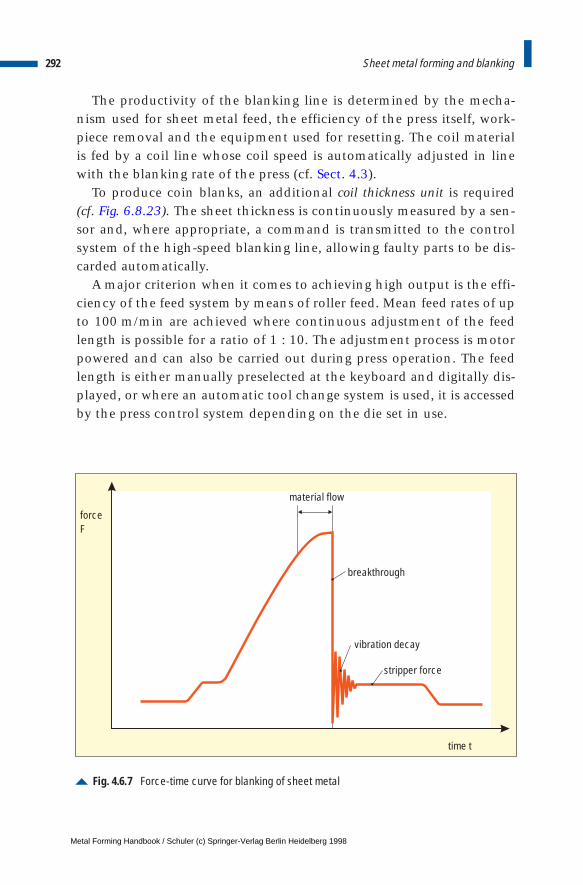
The productivity of the blanking line is determined by the mecha-nism used for sheet metal feed, the efficiency of the press itself, work-piece removal and the equipment used for resetting. The coil materialis fed by a coil line whose coil speed is automatically adjusted in linewith the blanking rate of the press (cf. Sect. 4.3).
To produce coin blanks, an additional coil thickness unit is required(cf. Fig. 6.8.23). The sheet thickness is continuously measured by a sen-sor and, where appropriate, a command is transmitted to the controlsystem of the high-speed blanking line, allowing faulty parts to be dis-carded automatically.
A major criterion when it comes to achieving high output is the effi-ciency of the feed system by means of roller feed. Mean feed rates of upto 100 m/min are achieved where continuous adjustment of the feedlength is possible for a ratio of 1 : 10. The adjustment process is motorpowered and can also be carried out during press operation. The feedlength is either manually preselected at the keyboard and digitally dis-played, or where an automatic tool change system is used, it is accessedby the press control system depending on the die set in use.
292 Sheet metal forming and blanking
Fig. 4.6.7 Force-time curve for blanking of sheet metal
stripper force
time t
forceF
material flow
vibration decay
breakthrough
Metal Forming Handbook / Schuler (c) Springer-Verlag Berlin Heidelberg 1998
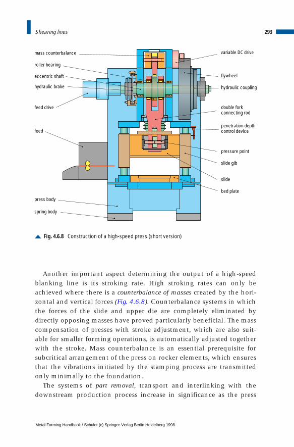
Another important aspect determining the output of a high-speedblanking line is its stroking rate. High stroking rates can only beachieved where there is a counterbalance of masses created by the hori-zontal and vertical forces (Fig. 4.6.8). Counterbalance systems in whichthe forces of the slide and upper die are completely eliminated bydirectly opposing masses have proved particularly beneficial. The masscompensation of presses with stroke adjustment, which are also suit-able for smaller forming operations, is automatically adjusted togetherwith the stroke. Mass counterbalance is an essential prerequisite forsubcritical arrangement of the press on rocker elements, which ensuresthat the vibrations initiated by the stamping process are transmittedonly minimally to the foundation.
The systems of part removal, transport and interlinking with thedownstream production process increase in significance as the press
293Shearing lines
Fig. 4.6.8 Construction of a high-speed press (short version)
roller bearing
mass counterbalance
eccentric shaft
hydraulic brake
feed drive
feed
press body
spring body
variable DC drive
flywheel
hydraulic coupling
double forkconnecting rod
penetration depthcontrol device
pressure point
slide gib
slide
bed plate
Metal Forming Handbook / Schuler (c) Springer-Verlag Berlin Heidelberg 1998
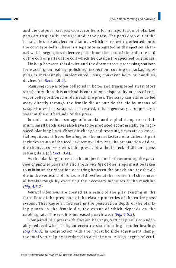
and die output increases. Conveyor belts for transportation of blankedparts are frequently arranged under the press. The parts drop out of thefemale die onto an ejection channel, which is frequently oriented, ontothe conveyor belts. There is a separator integrated in the ejection chan-nel which segregates defective parts from the start of the coil, the endof the coil or parts of the coil which lie outside the specified tolerances.
Link-up between this device and the downstream processing stationsfor washing, annealing, polishing, inspection, coating or packaging ofparts is increasingly implemented using conveyor belts or handlingdevices (cf. Sect. 4.6.4).
Stamping scrap is often collected in boxes and transported away. Moresatisfactory than this method is continuous disposal by means of con-veyor belts positioned underneath the press. The scrap can either be fedaway directly through the female die or outside the die by means ofscrap chutes. If a scrap web is created, this is generally chopped by ashear at the outfeed side of the press.
In order to reduce storage of material and capital tie-up to a mini-mum, small batch sizes also have to be produced economically on high-speed blanking lines. Short die change and resetting times are an essen-tial requirement here. Resetting for the manufacture of a different partincludes set-up of the feed and removal devices, the preparation of dies,die change, conversion of the press and a final check of die and presssetting data (cf. Sect. 3.4).
As the blanking process is the major factor in determining the preci-sion of punched parts and also the service life of dies, steps must be takento minimize the vibration occurring between the punch and the femaledie in the vertical and horizontal direction at the moment of sheet met-al breakthrough by executing the necessary measures at the machine(Fig. 4.6.7).
Vertical vibrations are created as a result of the play existing in theforce flow of the press and of the elastic properties of the entire presssystem. They cause an increase in the penetration depth of the blank-ing punch in the female die, the extent of which depends on thestroking rate. The result is increased punch wear (Fig. 4.6.9).
Compared to a press with friction bearings, vertical play is consider-ably reduced when using an eccentric shaft running in roller bearings(Fig. 4.6.8). In conjunction with the hydraulic slide adjustment clamp,the total vertical play is reduced to a minimum. A high degree of verti-
294 Sheet metal forming and blanking
Metal Forming Handbook / Schuler (c) Springer-Verlag Berlin Heidelberg 1998
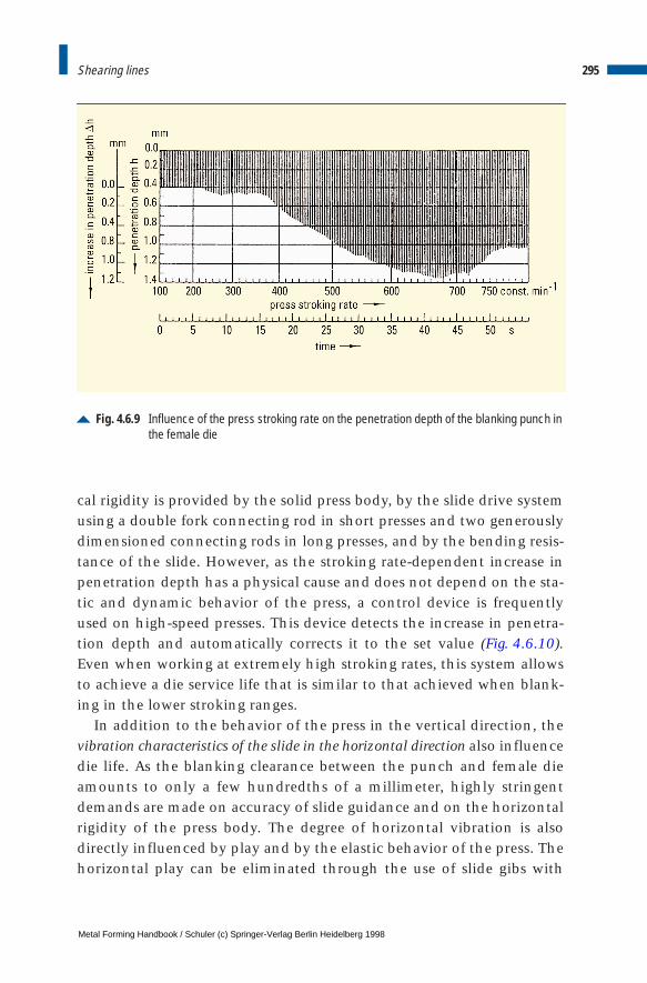
cal rigidity is provided by the solid press body, by the slide drive systemusing a double fork connecting rod in short presses and two generouslydimensioned connecting rods in long presses, and by the bending resis-tance of the slide. However, as the stroking rate-dependent increase inpenetration depth has a physical cause and does not depend on the sta-tic and dynamic behavior of the press, a control device is frequentlyused on high-speed presses. This device detects the increase in penetra-tion depth and automatically corrects it to the set value (Fig. 4.6.10).Even when working at extremely high stroking rates, this system allowsto achieve a die service life that is similar to that achieved when blank-ing in the lower stroking ranges.
In addition to the behavior of the press in the vertical direction, thevibration characteristics of the slide in the horizontal direction also influencedie life. As the blanking clearance between the punch and female dieamounts to only a few hundredths of a millimeter, highly stringentdemands are made on accuracy of slide guidance and on the horizontalrigidity of the press body. The degree of horizontal vibration is alsodirectly influenced by play and by the elastic behavior of the press. Thehorizontal play can be eliminated through the use of slide gibs with
295Shearing lines
Fig. 4.6.9 Influence of the press stroking rate on the penetration depth of the blanking punch inthe female die
Metal Forming Handbook / Schuler (c) Springer-Verlag Berlin Heidelberg 1998
rollers, while the horizontal press rigidity is appreciably increasedthrough special configuration of the press body.
The slide is guided without play by means of rollers at four columns(cf. Fig. 3.1.6). The optimum arrangement of gibs above and on theblanking plane, in particular, serves to reduce slide vibrations comparedto previous slide gib systems so that a substantial increase in die life isachieved.
In contrast to conventional presses, the configuration of the pressbody is now so compact that upright deflection under load is negligi-ble, and horizontal forces generated during blanking can be absorbedevenly over the entire gib area.
4.6.4 Lines for the production of electric motor laminations
Rotors and stators in electric motors and iron cores in transformers aremade from individual layered pieces of sheet metal ranging from 0.5 to1mm in thickness, in order to reduce eddy current loss (Fig. 4.6.11).
The starting material used for this type of application is silicon-alloyed iron sheet or semi-finish sheet, which is available in coil form
296 Sheet metal forming and blanking
Fig. 4.6.10 Effect of penetration depth control on the increase in penetration depth
Metal Forming Handbook / Schuler (c) Springer-Verlag Berlin Heidelberg 1998
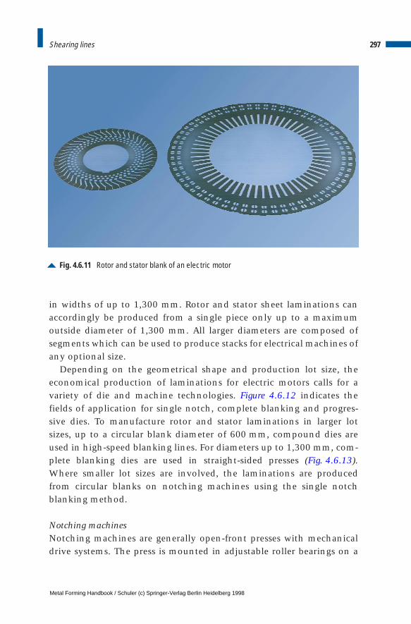
in widths of up to 1,300 mm. Rotor and stator sheet laminations canaccordingly be produced from a single piece only up to a maximumoutside diameter of 1,300 mm. All larger diameters are composed ofsegments which can be used to produce stacks for electrical machines ofany optional size.
Depending on the geometrical shape and production lot size, theeconomical production of laminations for electric motors calls for avariety of die and machine technologies. Figure 4.6.12 indicates thefields of application for single notch, complete blanking and progres-sive dies. To manufacture rotor and stator laminations in larger lotsizes, up to a circular blank diameter of 600 mm, compound dies areused in high-speed blanking lines. For diameters up to 1,300 mm, com-plete blanking dies are used in straight-sided presses (Fig. 4.6.13).Where smaller lot sizes are involved, the laminations are producedfrom circular blanks on notching machines using the single notchblanking method.
Notching machinesNotching machines are generally open-front presses with mechanicaldrive systems. The press is mounted in adjustable roller bearings on a
297Shearing lines
Fig. 4.6.11 Rotor and stator blank of an electric motor
Metal Forming Handbook / Schuler (c) Springer-Verlag Berlin Heidelberg 1998
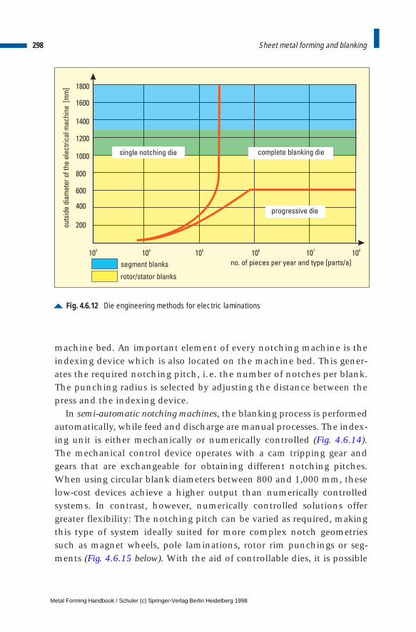
machine bed. An important element of every notching machine is theindexing device which is also located on the machine bed. This gener-ates the required notching pitch, i.e. the number of notches per blank.The punching radius is selected by adjusting the distance between thepress and the indexing device.
In semi-automatic notching machines, the blanking process is performedautomatically, while feed and discharge are manual processes. The index-ing unit is either mechanically or numerically controlled (Fig. 4.6.14).The mechanical control device operates with a cam tripping gear andgears that are exchangeable for obtaining different notching pitches.When using circular blank diameters between 800 and 1,000 mm, theselow-cost devices achieve a higher output than numerically controlledsystems. In contrast, however, numerically controlled solutions offergreater flexibility: The notching pitch can be varied as required, makingthis type of system ideally suited for more complex notch geometriessuch as magnet wheels, pole laminations, rotor rim punchings or seg-ments (Fig. 4.6.15 below). With the aid of controllable dies, it is possible
298 Sheet metal forming and blanking
Fig. 4.6.12 Die engineering methods for electric laminations
no. of pieces per year and type [parts/a]
outs
ide
diam
eter
ofth
eel
ectr
ical
mac
hine
[mm
]
200
400
600
800
1000
1200
1400
1600
1800
103
104
105
106
107
108
single notching die complete blanking die
progressive die
segment blanks
rotor/stator blanks
Metal Forming Handbook / Schuler (c) Springer-Verlag Berlin Heidelberg 1998
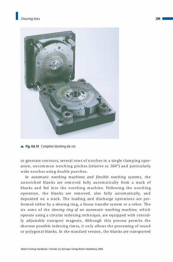
to generate contours, several rows of notches in a single clamping oper-ation, uncommon notching pitches (relative to 360°) and particularlywide notches using double punches.
In automatic notching machines and flexible notching systems, theunnotched blanks are removed fully automatically from a stack ofblanks and fed into the notching machine. Following the notchingoperation, the blanks are removed, also fully automatically, anddeposited on a stack. The loading and discharge operations are per-formed either by a slewing ring, a linear transfer system or a robot. Thesix arms of the slewing ring of an automatic notching machine, whichoperate using a circular indexing technique, are equipped with central-ly adjustable transport magnets. Although this process permits theshortest possible indexing times, it only allows the processing of roundor polygonal blanks. In the standard version, the blanks are transported
299Shearing lines
Fig. 4.6.13 Complete blanking die set
Metal Forming Handbook / Schuler (c) Springer-Verlag Berlin Heidelberg 1998
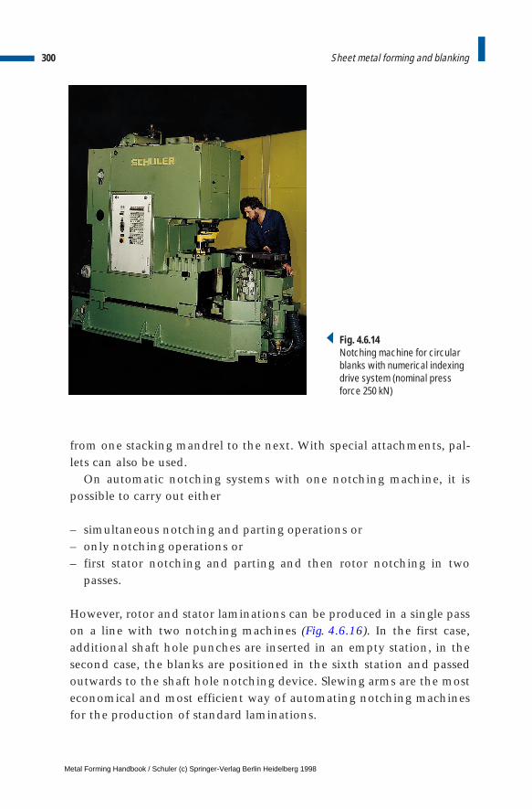
from one stacking mandrel to the next. With special attachments, pal-lets can also be used.
On automatic notching systems with one notching machine, it ispossible to carry out either
– simultaneous notching and parting operations or– only notching operations or– first stator notching and parting and then rotor notching in two
passes.
However, rotor and stator laminations can be produced in a single passon a line with two notching machines (Fig. 4.6.16). In the first case,additional shaft hole punches are inserted in an empty station, in thesecond case, the blanks are positioned in the sixth station and passedoutwards to the shaft hole notching device. Slewing arms are the mosteconomical and most efficient way of automating notching machinesfor the production of standard laminations.
300 Sheet metal forming and blanking
Fig. 4.6.14Notching machine for circularblanks with numerical indexingdrive system (nominal press force 250 kN)
Metal Forming Handbook / Schuler (c) Springer-Verlag Berlin Heidelberg 1998
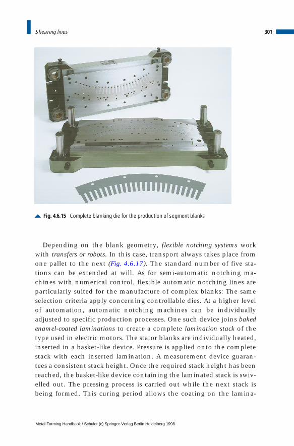
Depending on the blank geometry, flexible notching systems workwith transfers or robots. In this case, transport always takes place fromone pallet to the next (Fig. 4.6.17). The standard number of five sta-tions can be extended at will. As for semi-automatic notching ma-chines with numerical control, flexible automatic notching lines areparticularly suited for the manufacture of complex blanks: The sameselection criteria apply concerning controllable dies. At a higher levelof automation, automatic notching machines can be individuallyadjusted to specific production processes. One such device joins bakedenamel-coated laminations to create a complete lamination stack of thetype used in electric motors. The stator blanks are individually heated,inserted in a basket-like device. Pressure is applied onto the completestack with each inserted lamination. A measurement device guaran-tees a consistent stack height. Once the required stack height has beenreached, the basket-like device containing the laminated stack is swiv-elled out. The pressing process is carried out while the next stack isbeing formed. This curing period allows the coating on the lamina-
301Shearing lines
Fig. 4.6.15 Complete blanking die for the production of segment blanks
Metal Forming Handbook / Schuler (c) Springer-Verlag Berlin Heidelberg 1998
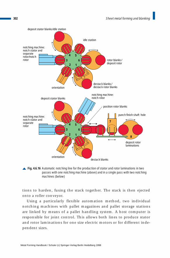
tions to harden, fusing the stack together. The stack is then ejectedonto a roller conveyor.
Using a particularly flexible automation method, two individualnotching machines with pallet magazines and pallet storage stationsare linked by means of a pallet handling system. A host computer isresponsible for joint control. This allows both lines to produce statorand rotor laminations for one size electric motors or for different inde-pendent sizes.
302 Sheet metal forming and blanking
Fig. 4.6.16 Automatic notching line for the production of stator and rotor laminations in two passes with one notching machine (above) and in a single pass with two notchingmachines (below)
1
6
54
3
2
1
6
7
8
54
32
position rotor blanks
notching machine: notch rotor
deposit rotor laminations
rotor blanks /deposit rotor
destack blanks
destack blanks /destack rotor blanks
orientation
orientation
notching machine:notch stator andseparaterotor
notching machine:notch stator and separaterotor/notchrotor
deposit stator blanks
deposit stator blanks/idle station
idle station
punch finish shaft hole
Metal Forming Handbook / Schuler (c) Springer-Verlag Berlin Heidelberg 1998
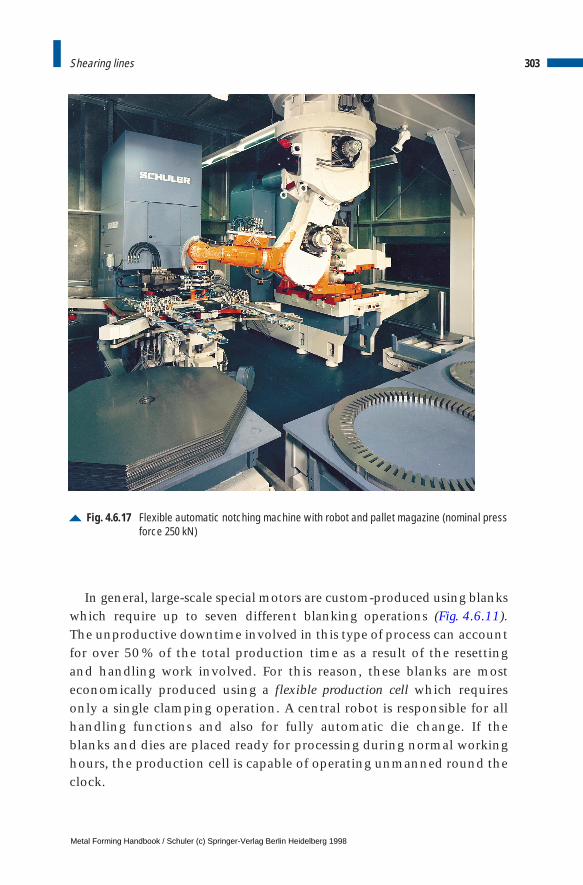
In general, large-scale special motors are custom-produced using blankswhich require up to seven different blanking operations (Fig. 4.6.11).The unproductive downtime involved in this type of process can accountfor over 50 % of the total production time as a result of the resettingand handling work involved. For this reason, these blanks are most economically produced using a flexible production cell which requiresonly a single clamping operation. A central robot is responsible for allhandling functions and also for fully automatic die change. If theblanks and dies are placed ready for processing during normal workinghours, the production cell is capable of operating unmanned round theclock.
303Shearing lines
Fig. 4.6.17 Flexible automatic notching machine with robot and pallet magazine (nominal pressforce 250 kN)
Metal Forming Handbook / Schuler (c) Springer-Verlag Berlin Heidelberg 1998
Notching machines can be equipped with supplementary attachmentsfor special applications. These include devices for the production of
– interrupted hole patterns,– tapered lamination stacks and– skewed lamination stacks.
Blanking lines with complete blanking diesMedium-sized batches of electric motors, finished segments, raw seg-ments and pole blanks are generally produced using complete blankingdies (Fig. 4.6.13). Here, the external contours, holes and notches areblanked in a single work process, generally using straight-sided presses(cf. Fig. 3.1.1). The press concept used here is similar to that of univer-sal mechanical presses (cf. Sect. 4.4.1). It is also possible to manufacturecircular blanks, which are frequently used for further processing innotching machines. The width of the individual blanks, strips or coilmaterial can be anywhere between 300 and 1,250 mm. These pressesare constructed for blanking forces ranging from 1,250 to 5,000 kN. Thestroking rate can be adjusted continuously between 15 and 150 strokesper minute depending on the size of the machine and the process engi-neering concept used.
The dies are often constructed in such a way that the punch with theoutside contours is located in the bottom die holder and the female dieis located in the upper die holder. Several parts can be produced simul-taneously. In some cases, the scrap is punched by the bottom die.
The separate stripper plate in the bottom die strips the scrap webwhile the ejector in the upper die ejects the finished part. This requiresa plate or crossbar ejector in the press slide which is active near the topdead center.
The gib columns generally extend out of the gib bushes when the dieopens. Therefore, they are usually manufactured of steel, while the gibbushes are made of bronze. The coil guiding elements are combinedwith the stripper plate.
As a single-unit welded construction, the press body is configured fora high degree of rigidity. Considering that high-quality blanking diesare used, the precision of the slide gib is of particular importance. Theeight-track roller gib system has proven to be an ideal system here (cf. Fig. 3.1.6). The slide is equipped with a total of 16 roller elements,
304 Sheet metal forming and blanking
Metal Forming Handbook / Schuler (c) Springer-Verlag Berlin Heidelberg 1998
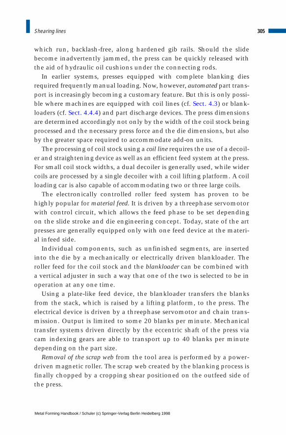
which run, backlash-free, along hardened gib rails. Should the slidebecome inadvertently jammed, the press can be quickly released withthe aid of hydraulic oil cushions under the connecting rods.
In earlier systems, presses equipped with complete blanking diesrequired frequently manual loading. Now, however, automated part trans-port is increasingly becoming a customary feature. But this is only possi-ble where machines are equipped with coil lines (cf. Sect. 4.3) or blank-loaders (cf. Sect. 4.4.4) and part discharge devices. The press dimensionsare determined accordingly not only by the width of the coil stock beingprocessed and the necessary press force and the die dimensions, but alsoby the greater space required to accommodate add-on units.
The processing of coil stock using a coil line requires the use of a decoil-er and straightening device as well as an efficient feed system at the press.For small coil stock widths, a dual decoiler is generally used, while widercoils are processed by a single decoiler with a coil lifting platform. A coilloading car is also capable of accommodating two or three large coils.
The electronically controlled roller feed system has proven to behighly popular for material feed. It is driven by a threephase servomotorwith control circuit, which allows the feed phase to be set dependingon the slide stroke and die engineering concept. Today, state of the artpresses are generally equipped only with one feed device at the materi-al infeed side.
Individual components, such as unfinished segments, are insertedinto the die by a mechanically or electrically driven blankloader. Theroller feed for the coil stock and the blankloader can be combined witha vertical adjuster in such a way that one of the two is selected to be inoperation at any one time.
Using a plate-like feed device, the blankloader transfers the blanksfrom the stack, which is raised by a lifting platform, to the press. Theelectrical device is driven by a threephase servomotor and chain trans-mission. Output is limited to some 20 blanks per minute. Mechanicaltransfer systems driven directly by the eccentric shaft of the press viacam indexing gears are able to transport up to 40 blanks per minutedepending on the part size.
Removal of the scrap web from the tool area is performed by a power-driven magnetic roller. The scrap web created by the blanking process isfinally chopped by a cropping shear positioned on the outfeed side ofthe press.
305Shearing lines
Metal Forming Handbook / Schuler (c) Springer-Verlag Berlin Heidelberg 1998
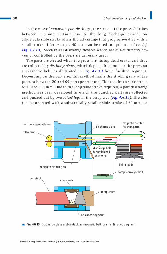
In the case of automatic part discharge, the stroke of the press slide liesbetween 150 and 300 mm due to the long discharge period. Anadjustable slide stroke offers the advantage that progressive dies with asmall stroke of for example 40 mm can be used to optimum effect (cf.Fig. 3.2.13). Mechanical discharge devices which are either directly dri-ven or controlled by the press are generally used.
The parts are ejected when the press is at its top dead center and theyare collected by discharge plates, which deposit them outside the press ona magnetic belt, as illustrated in Fig. 4.6.18 for a finished segment.Depending on the part size, this method limits the stroking rate of thepress to between 20 and 60 parts per minute. This requires a slide strokeof 150 to 300 mm. Due to the long slide stroke required, a part dischargemethod has been developed in which the punched parts are collectedand pushed out by two raised lugs in the scrap web (Fig. 4.6.19). The diescan be operated with a substantially smaller slide stroke of 70 mm, so
306 Sheet metal forming and blanking
Fig. 4.6.18 Discharge plate and destacking magnetic belt for an unfinished segment
magnetic belt for
finished parts
scrap conveyor belt
roller feed
lifting table
finished segment blank
discharge belt
for unfinished
segments
discharge plate
scrap web
unfinished segment
coil stock
scrap chute
complete blanking die
Metal Forming Handbook / Schuler (c) Springer-Verlag Berlin Heidelberg 1998
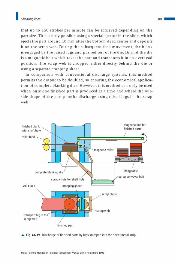
that up to 150 strokes per minute can be achieved depending on thepart size. This is only possible using a special ejector in the slide, whichejects the part around 10 mm after the bottom dead center and depositsit on the scrap web. During the subsequent feed movement, the blankis engaged by the raised lugs and pushed out of the die. Behind the dieis a magnetic belt which takes the part and transports it in an overheadposition. The scrap web is chopped either directly behind the die orusing a separate cropping shear.
In comparison with conventional discharge systems, this methodpermits the output to be doubled, so ensuring the economical applica-tion of complete blanking dies. However, this method can only be usedwhen only one finished part is produced at a time and where the out-side shape of the part permits discharge using raised lugs in the scrapweb.
307Shearing lines
Fig. 4.6.19 Discharge of finished parts by lugs stamped into the sheet metal strip
magnetic belt for
finished parts
scrap conveyor belt
roller feed
lifting table
magnetic roller
cropping shear
finished part
scrap web
finished blank
with shaft hole
coil stock
complete blanking die
scrap chute for shaft hole
scrap chute
transport lug in the
scrap web
Metal Forming Handbook / Schuler (c) Springer-Verlag Berlin Heidelberg 1998
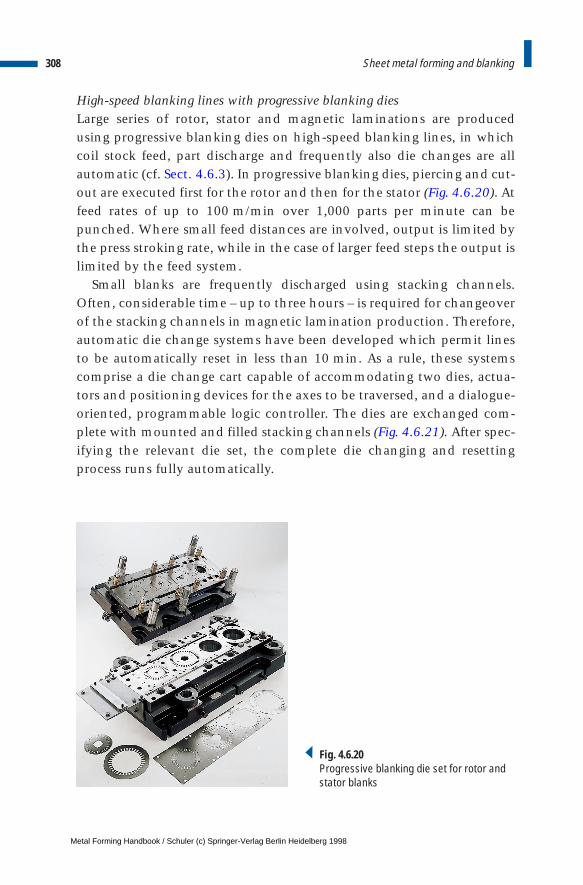
High-speed blanking lines with progressive blanking diesLarge series of rotor, stator and magnetic laminations are producedusing progressive blanking dies on high-speed blanking lines, in whichcoil stock feed, part discharge and frequently also die changes are allautomatic (cf. Sect. 4.6.3). In progressive blanking dies, piercing and cut-out are executed first for the rotor and then for the stator (Fig. 4.6.20). Atfeed rates of up to 100 m/min over 1,000 parts per minute can bepunched. Where small feed distances are involved, output is limited bythe press stroking rate, while in the case of larger feed steps the output islimited by the feed system.
Small blanks are frequently discharged using stacking channels.Often, considerable time – up to three hours – is required for changeoverof the stacking channels in magnetic lamination production. Therefore,automatic die change systems have been developed which permit linesto be automatically reset in less than 10 min. As a rule, these systemscomprise a die change cart capable of accommodating two dies, actua-tors and positioning devices for the axes to be traversed, and a dialogue-oriented, programmable logic controller. The dies are exchanged com-plete with mounted and filled stacking channels (Fig. 4.6.21). After spec-ifying the relevant die set, the complete die changing and resettingprocess runs fully automatically.
308 Sheet metal forming and blanking
Fig. 4.6.20Progressive blanking die set for rotor andstator blanks
Metal Forming Handbook / Schuler (c) Springer-Verlag Berlin Heidelberg 1998

Larger rotor and stator laminations, in contrast, are still arranged inaccordance with their notching pattern in the die, stacked on mandrelsor in magazines up to a preselected stack height and conveyed out ofthe press by means of transport systems. A sequence of stacks of vary-ing heights, for example for ventilated motors, can also be pro-grammed.
Another method for the ordered unloading of electric laminations isby punch-bundling (Fig. 4.6.22). For this purpose, additional punchesare located in the die set and they punch for example lugs, cams or nepsinto the laminations. During the cut-out process, these raised areaspress the laminations into the corresponding recess in the previouslypunched part (Fig. 4.6.23). Once the required stack height has beenreached, the following lamination is pierced where the raised area isprior to bundling by means of a piercing hole punch. This ensures thatthe pierced lamination is not able to link up with the previous lamina-tion and becomes the first lamination of the new stack.
309Shearing lines
Fig. 4.6.21 Automatic die change using a die changeover cart
Metal Forming Handbook / Schuler (c) Springer-Verlag Berlin Heidelberg 1998
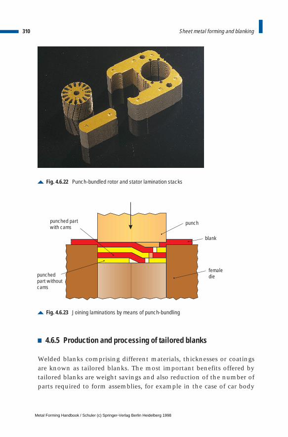
4.6.5 Production and processing of tailored blanks
Welded blanks comprising different materials, thicknesses or coatingsare known as tailored blanks. The most important benefits offered bytailored blanks are weight savings and also reduction of the number ofparts required to form assemblies, for example in the case of car body
310 Sheet metal forming and blanking
Fig. 4.6.22 Punch-bundled rotor and stator lamination stacks
Fig. 4.6.23 Joining laminations by means of punch-bundling
punch
blank
femaledie
punched partwith cams
punched part withoutcams
Metal Forming Handbook / Schuler (c) Springer-Verlag Berlin Heidelberg 1998
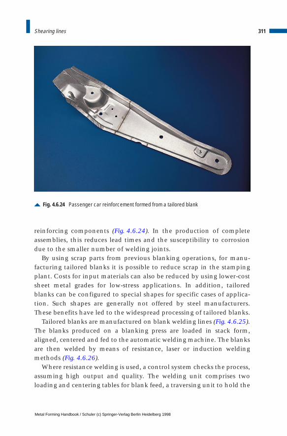
reinforcing components (Fig. 4.6.24). In the production of completeassemblies, this reduces lead times and the susceptibility to corrosiondue to the smaller number of welding joints.
By using scrap parts from previous blanking operations, for manu-facturing tailored blanks it is possible to reduce scrap in the stampingplant. Costs for input materials can also be reduced by using lower-costsheet metal grades for low-stress applications. In addition, tailoredblanks can be configured to special shapes for specific cases of applica-tion. Such shapes are generally not offered by steel manufacturers.These benefits have led to the widespread processing of tailored blanks.
Tailored blanks are manufactured on blank welding lines (Fig. 4.6.25).The blanks produced on a blanking press are loaded in stack form,aligned, centered and fed to the automatic welding machine. The blanksare then welded by means of resistance, laser or induction weldingmethods (Fig. 4.6.26).
Where resistance welding is used, a control system checks the process,assuming high output and quality. The welding unit comprises twoloading and centering tables for blank feed, a traversing unit to hold the
311Shearing lines
Fig. 4.6.24 Passenger car reinforcement formed from a tailored blank
Metal Forming Handbook / Schuler (c) Springer-Verlag Berlin Heidelberg 1998
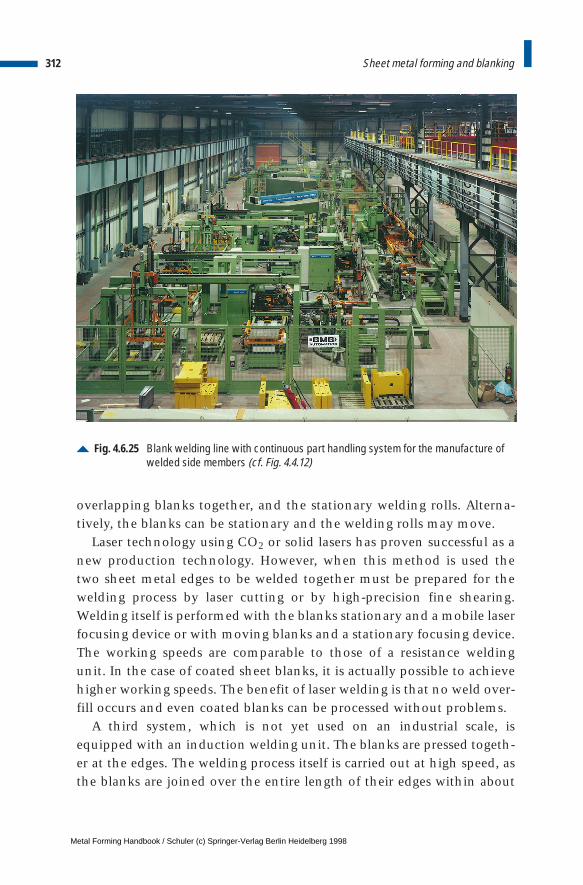
overlapping blanks together, and the stationary welding rolls. Alterna-tively, the blanks can be stationary and the welding rolls may move.
Laser technology using CO2 or solid lasers has proven successful as anew production technology. However, when this method is used thetwo sheet metal edges to be welded together must be prepared for thewelding process by laser cutting or by high-precision fine shearing.Welding itself is performed with the blanks stationary and a mobile laserfocusing device or with moving blanks and a stationary focusing device.The working speeds are comparable to those of a resistance weldingunit. In the case of coated sheet blanks, it is actually possible to achievehigher working speeds. The benefit of laser welding is that no weld over-fill occurs and even coated blanks can be processed without problems.
A third system, which is not yet used on an industrial scale, isequipped with an induction welding unit. The blanks are pressed togeth-er at the edges. The welding process itself is carried out at high speed, asthe blanks are joined over the entire length of their edges within about
312 Sheet metal forming and blanking
Fig. 4.6.25 Blank welding line with continuous part handling system for the manufacture ofwelded side members (cf. Fig. 4.4.12)
Metal Forming Handbook / Schuler (c) Springer-Verlag Berlin Heidelberg 1998
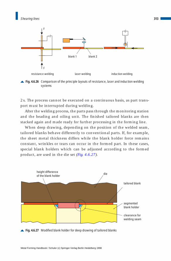
2s. The process cannot be executed on a continuous basis, as part trans-port must be interrupted during welding.
After the welding process, the parts pass through the monitoring stationand the beading and oiling unit. The finished tailored blanks are thenstacked again and made ready for further processing in the forming line.
When deep drawing, depending on the position of the welded seam,tailored blanks behave differently to conventional parts. If, for example,the sheet metal thickness differs while the blank holder force remainsconstant, wrinkles or tears can occur in the formed part. In these cases,special blank holders which can be adjusted according to the formedproduct, are used in the die set (Fig. 4.6.27).
313Shearing lines
Fig. 4.6.26 Comparison of the principle layouts of resistance, laser and induction weldingsystems
F
F
laser welding induction weldingresistance welding
blank 1 blank 2
Fig. 4.6.27 Modified blank holder for deep drawing of tailored blanks
height difference
of the blank holderdie
tailored blank
segmented
blank holder
clearance for
welding seam
Metal Forming Handbook / Schuler (c) Springer-Verlag Berlin Heidelberg 1998
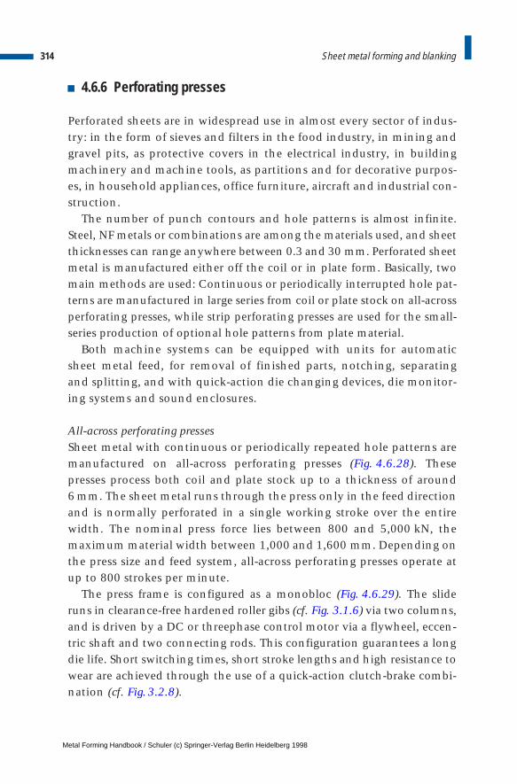
4.6.6 Perforating presses
Perforated sheets are in widespread use in almost every sector of indus-try: in the form of sieves and filters in the food industry, in mining andgravel pits, as protective covers in the electrical industry, in buildingmachinery and machine tools, as partitions and for decorative purpos-es, in household appliances, office furniture, aircraft and industrial con-struction.
The number of punch contours and hole patterns is almost infinite.Steel, NF metals or combinations are among the materials used, and sheetthicknesses can range anywhere between 0.3 and 30 mm. Perforated sheetmetal is manufactured either off the coil or in plate form. Basically, twomain methods are used: Continuous or periodically interrupted hole pat-terns are manufactured in large series from coil or plate stock on all-acrossperforating presses, while strip perforating presses are used for the small-series production of optional hole patterns from plate material.
Both machine systems can be equipped with units for automaticsheet metal feed, for removal of finished parts, notching, separatingand splitting, and with quick-action die changing devices, die monitor-ing systems and sound enclosures.
All-across perforating pressesSheet metal with continuous or periodically repeated hole patterns aremanufactured on all-across perforating presses (Fig. 4.6.28). Thesepresses process both coil and plate stock up to a thickness of around 6 mm. The sheet metal runs through the press only in the feed directionand is normally perforated in a single working stroke over the entirewidth. The nominal press force lies between 800 and 5,000 kN, themaximum material width between 1,000 and 1,600 mm. Depending onthe press size and feed system, all-across perforating presses operate atup to 800 strokes per minute.
The press frame is configured as a monobloc (Fig. 4.6.29). The slideruns in clearance-free hardened roller gibs (cf. Fig. 3.1.6) via two columns,and is driven by a DC or threephase control motor via a flywheel, eccen-tric shaft and two connecting rods. This configuration guarantees a longdie life. Short switching times, short stroke lengths and high resistance towear are achieved through the use of a quick-action clutch-brake combi-nation (cf. Fig. 3.2.8).
314 Sheet metal forming and blanking
Metal Forming Handbook / Schuler (c) Springer-Verlag Berlin Heidelberg 1998
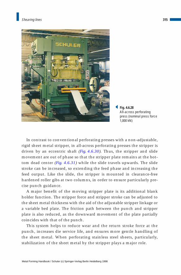
In contrast to conventional perforating presses with a non-adjustable,rigid sheet metal stripper, in all-across perforating presses the stripper isdriven by an eccentric shaft (Fig. 4.6.30). Thus, the stripper and slidemovement are out of phase so that the stripper plate remains at the bot-tom dead center (Fig. 4.6.31) while the slide travels upwards. The slidestroke can be increased, so extending the feed phase and increasing thefeed output. Like the slide, the stripper is mounted in clearance-freehardened roller gibs at two columns, in order to ensure particularly pre-cise punch guidance.
A major benefit of the moving stripper plate is its additional blankholder function. The stripper force and stripper stroke can be adjusted tothe sheet metal thickness with the aid of the adjustable stripper linkage ora variable bed plate. The friction path between the punch and stripperplate is also reduced, as the downward movement of the plate partiallycoincides with that of the punch.
This system helps to reduce wear and the return stroke force at thepunch, increases die service life, and ensures more gentle handling ofthe sheet metal. When perforating stainless steel sheets, particularly,stabilization of the sheet metal by the stripper plays a major role.
315Shearing lines
Fig. 4.6.28All-across perforatingpress (nominal press force1,000 kN)
Metal Forming Handbook / Schuler (c) Springer-Verlag Berlin Heidelberg 1998

316 Sheet metal forming and blanking
Fig. 4.6.29 Structure of an all-across perforating press
drive shaft
slide connecting rod
camshaft
pressure pointstripper slide
pressure point, slide
column gib
punch control unit
die beams
clamping plate
stripper connecting rod
stripper slide
clamps
gear boxfeed drive
Fig. 4.6.30 Section through an all-across perforating press with die holding system and sepa-rating shear
hydraulicclampbottom die
hydraulicclampstripper
hydrauliccroppingshear
outfeedroller
infeed roller
infeed table
punch control beam
moving stripper
press bed
slide
perforating punch
Metal Forming Handbook / Schuler (c) Springer-Verlag Berlin Heidelberg 1998
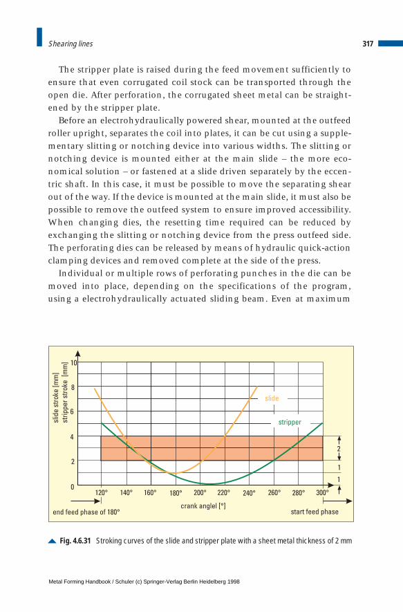
The stripper plate is raised during the feed movement sufficiently toensure that even corrugated coil stock can be transported through theopen die. After perforation, the corrugated sheet metal can be straight-ened by the stripper plate.
Before an electrohydraulically powered shear, mounted at the outfeedroller upright, separates the coil into plates, it can be cut using a supple-mentary slitting or notching device into various widths. The slitting ornotching device is mounted either at the main slide – the more eco-nomical solution – or fastened at a slide driven separately by the eccen-tric shaft. In this case, it must be possible to move the separating shearout of the way. If the device is mounted at the main slide, it must also bepossible to remove the outfeed system to ensure improved accessibility.When changing dies, the resetting time required can be reduced byexchanging the slitting or notching device from the press outfeed side.The perforating dies can be released by means of hydraulic quick-actionclamping devices and removed complete at the side of the press.
Individual or multiple rows of perforating punches in the die can bemoved into place, depending on the specifications of the program,using a electrohydraulically actuated sliding beam. Even at maximum
317Shearing lines
Fig. 4.6.31 Stroking curves of the slide and stripper plate with a sheet metal thickness of 2 mm
slid
est
roke
[mm
]
stri
pp
er
stro
ke[m
m]
start feed phase
0
4
2
2
1
1
6
8
10
120°
slide
stripper
Metal Forming Handbook / Schuler (c) Springer-Verlag Berlin Heidelberg 1998

stroking rates, the control system is able to move the punch in and outof position without the need to stop the press. The feed devices arrangeddirectly in front of and behind the tool mounting area can also be pro-grammed. The upper and lower rollers of the feed units are connected bymeans of clearance-free mechanical intermediate gear drives. Both rollersare supported in several points, and the upper rollers are hydraulicallypressed downward above the support in the area of the rollers. The rollersare lifted manually or by means of program control. The infeed device isremovable, the outfeed device either removable or stationary.
To ensure a perfectly perforated pattern, a photoelectric camera mon-itoring system is used (cf. Fig. 4.9.7). While the all-across perforatingpress is in the set-up mode, the device is programmed using the teach-in mode. If the actual hole pattern deviates from the programmed pat-tern during production, the press is automatically switched off.
Strip perforating pressesWhile perforated sheets are produced in medium and large-series on all-across perforating presses, strip perforating presses are used for theproduction of individual plates, particularly where large or thick sheetmetal materials are used or where individual hole patterns are required(Fig. 4.6.32). Strip perforating presses are available with nominal pressforces ranging from 500 to 2,500 kN for sheet metal plates between1,500 3 3,000 mm and 2,000 3 6,000 mm with a maximum thicknessof 30 mm. Depending on the sheet metal thickness and feed step, it ispossible to achieve between 40 and 400 strokes per minute.
The strip perforating press control system permits simple program-ming on screen and storage of complex hole patterns. The stored datarecords can be simply accessed if a particular production run has to berepeated.
The sheet metal plates are fastened on a clamping plate which can bemoved horizontally in two axes. Electrical servo drive systems withclearance-free intermediate gear drives are used to power the feed sys-tem. These permit perforation to take place during forward and reversemovement of the material. As is the case with all-across perforatingpresses, here too a separately moved stripper plate with stripping func-tion can be used (Fig. 4.6.33).
Stationary single punches or small punch assemblies perforate thesheet metal plates. Where complicated hole patterns are involved, the
318 Sheet metal forming and blanking
Metal Forming Handbook / Schuler (c) Springer-Verlag Berlin Heidelberg 1998

punches can be driven using two additional programmable axes. Par-ticularly complex geometrical shapes can also be programmed recordby record or using the teach-in mode, whereby the patterns being pro-grammed can be displayed on screen. Temporary deactivation of theslide movement irrespective of the clamping plate feed movement canbe used to create optionally interrupted patterns.
319Shearing lines
Fig. 4.6.32 Examples of hole patterns produced on a strip perforating press
Fig. 4.6.33 Die with separately controlled stripper plate
Metal Forming Handbook / Schuler (c) Springer-Verlag Berlin Heidelberg 1998
The clamping plate is equipped with electrohydraulically actuatedclamping dogs which are retracted in the area of a perforation close tothe material edge, so eliminating the need to reclamp the sheet metalplate. Support rails equipped with rollers which can be moved asrequired on the clamping plate are positioned in front of and behind thedie to prevent unwanted sagging of the sheet metal plate. This systemallows to reduce the mass of inertia to a quarter of that of the old-stylesolid construction clamping plates. Used in conjunction with modernoptimized high-performance actuators, extremely short traversing peri-ods of for example 0.2 s with a feed length of 80 mm can be achieved.
4.6.7 Control systems for blanking presses
The concept of production cells and team work is being introduced inproduction and assembly plants in order to improve flexibility, qualityand also productivity. This involves extending the responsibility ofeach group or single workplace to include planning, inspection andmaintenance activities. As a result, structures will become increasinglydecentralized in the future. The greater degree of automation resultingfrom this development will inevitably lead to machines and productionlines of ever greater complexity. At the same time, optimum operatingand maintenance capability as well as high equipment availability mustbe achieved. This means that decentralized units must take increasingresponsibility for the provision and updating of production and equip-ment-related data and information at the point of its generation. A vari-ety of technical aids must be made available to enable the machineoperator to avoid or quickly remedy any machine standstill.
Information technologyIt is necessary to have an operating and information system, integrated inthe machine control, that must fulfil the following criteria (Fig. 4.6.34):
– a simple, easily understood system of operator support when settingthe operating parameters for start-up and resuming operation fol-lowing a die change or machine failure,
– a tool data management system that has an overview of existing diesand related features as well as machine parameters and that permitssimple access and editing,
320 Sheet metal forming and blanking
Metal Forming Handbook / Schuler (c) Springer-Verlag Berlin Heidelberg 1998
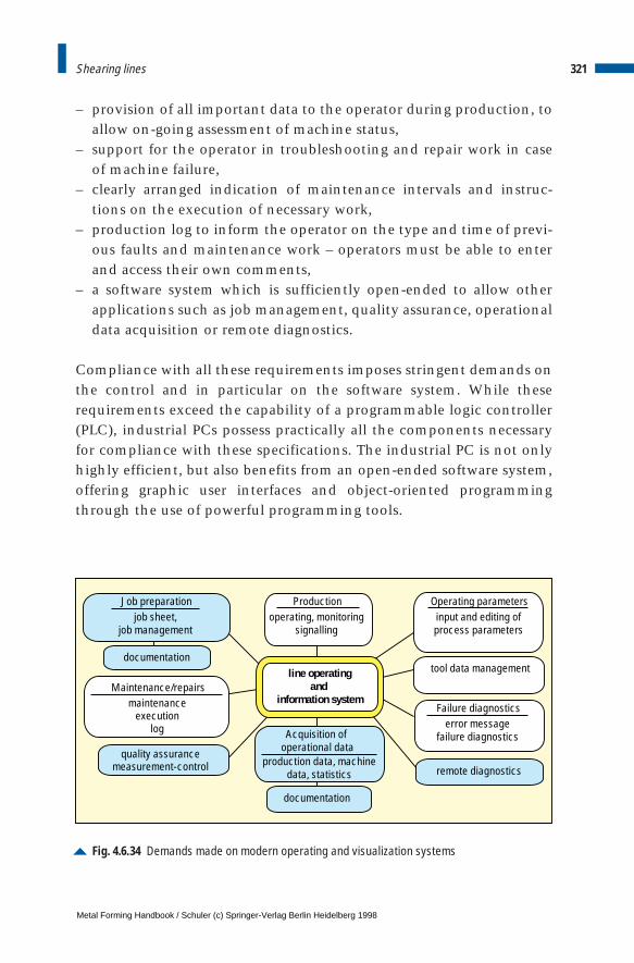
– provision of all important data to the operator during production, toallow on-going assessment of machine status,
– support for the operator in troubleshooting and repair work in caseof machine failure,
– clearly arranged indication of maintenance intervals and instruc-tions on the execution of necessary work,
– production log to inform the operator on the type and time of previ-ous faults and maintenance work – operators must be able to enterand access their own comments,
– a software system which is sufficiently open-ended to allow otherapplications such as job management, quality assurance, operationaldata acquisition or remote diagnostics.
Compliance with all these requirements imposes stringent demands onthe control and in particular on the software system. While theserequirements exceed the capability of a programmable logic controller(PLC), industrial PCs possess practically all the components necessaryfor compliance with these specifications. The industrial PC is not onlyhighly efficient, but also benefits from an open-ended software system,offering graphic user interfaces and object-oriented programmingthrough the use of powerful programming tools.
321Shearing lines
Fig. 4.6.34 Demands made on modern operating and visualization systems
Productionoperating, monitoring
signalling
tool data management
Operating parameters
Acquisition of operational data
Maintenance/repairsmaintenance
executionlog
production data, machinedata, statistics
line operatingand
information system
input and editing ofprocess parameters
Failure diagnosticserror message
failure diagnostics
Job preparationjob sheet,
job management
remote diagnostics
documentation
quality assurancemeasurement-control
documentation
Metal Forming Handbook / Schuler (c) Springer-Verlag Berlin Heidelberg 1998
The widespread popularity of MS Windows as a graphic user interfacehas provided a platform for many software suppliers to offer efficientsoftware solutions – also in the field of process visualization, which pro-vides users with an ergonomically configured representation of produc-tion sequences. Through integration in MS windows, communicationis possible with other Windows applications via the “dynamic dataexchange (DDE)” interface. Drivers for the relevant PLC systems arerequired for communication between the process visualization systemand the “programmable logic controller (PLC)”.
Line operating and information systemThe line operating and information system (ABI-Plus) is a modular,open-ended and flexible software system designed to address presentand future press automation requirements. ABI-Plus helps reducemachine and production line standstill periods, and so contributestowards improved productivity as well as greater flexibility.
Process visualizationFor ABI-Plus, a standard commercially available process visualizationsystem was selected as the core of the overall system. The operator isable to monitor and control the process either interactively or auto-matically through the control system. The man-machine interface pro-vides an optical representation of the machine status with the aid ofdynamic graphics and real images (Fig. 4.6.35).
Intervention in the process is possible using the softkeys. The user isguided through the various operating modes such as set-up, automaticcontinuous operation or die change on a step-by-step basis. The processparameters are entered using an alphanumeric keypad and feasibilitytested by the program.
If a machine error occurs, the relevant error message with date andtime is superimposed on the screen mask currently being used. Theoperator is able to access the troubleshooting module in order to local-ize the fault and remedy it if necessary. The need of a machine mainte-nance interval is also indicated to the operator by means of a flashingmaintenance symbol.
Tool data managementAnother module of the ABI-Plus is a comprehensive tool data manage-ment system which allows all die-specific data and machine settings to
322 Sheet metal forming and blanking
Metal Forming Handbook / Schuler (c) Springer-Verlag Berlin Heidelberg 1998
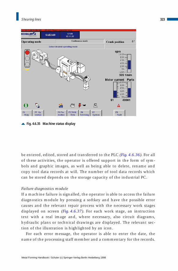
be entered, edited, stored and transferred to the PLC (Fig. 4.6.36). For allof these activities, the operator is offered support in the form of sym-bols and graphic images, as well as being able to delete, rename andcopy tool data records at will. The number of tool data records whichcan be stored depends on the storage capacity of the industrial PC.
Failure diagnostics moduleIf a machine failure is signalled, the operator is able to access the failurediagnostics module by pressing a softkey and have the possible errorcauses and the relevant repair process with the necessary work stagesdisplayed on screen (Fig. 4.6.37). For each work stage, an instructiontext with a real image and, where necessary, also circuit diagrams,hydraulic plans or technical drawings are displayed. The relevant sec-tion of the illustration is highlighted by an icon.
For each error message, the operator is able to enter the date, thename of the processing staff member and a commentary for the records.
323Shearing lines
Fig. 4.6.35 Machine status display
Metal Forming Handbook / Schuler (c) Springer-Verlag Berlin Heidelberg 1998
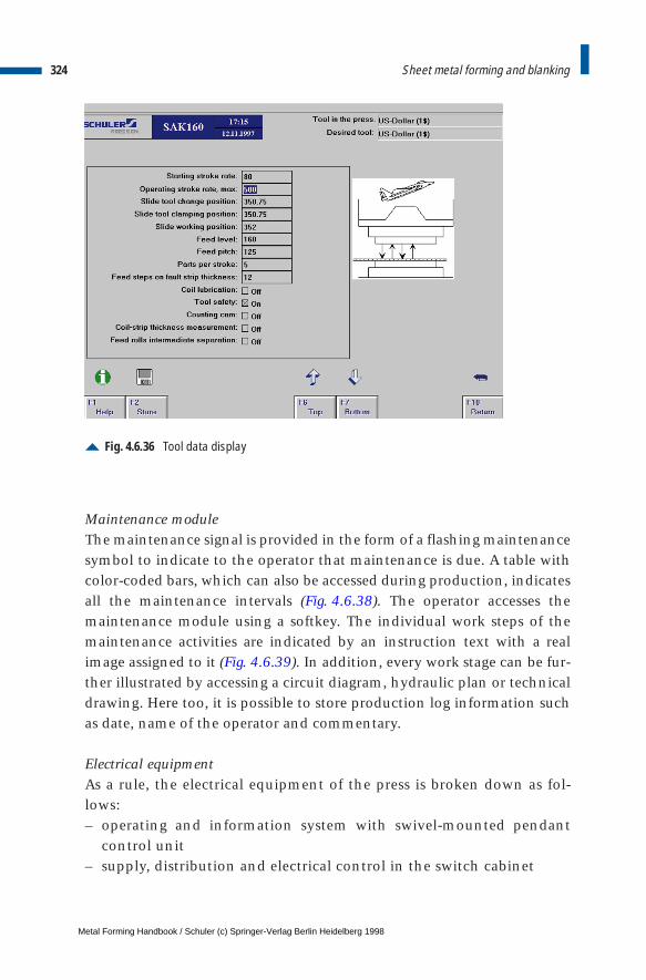
Maintenance moduleThe maintenance signal is provided in the form of a flashing maintenancesymbol to indicate to the operator that maintenance is due. A table withcolor-coded bars, which can also be accessed during production, indicatesall the maintenance intervals (Fig. 4.6.38). The operator accesses themaintenance module using a softkey. The individual work steps of themaintenance activities are indicated by an instruction text with a realimage assigned to it (Fig. 4.6.39). In addition, every work stage can be fur-ther illustrated by accessing a circuit diagram, hydraulic plan or technicaldrawing. Here too, it is possible to store production log information suchas date, name of the operator and commentary.
Electrical equipmentAs a rule, the electrical equipment of the press is broken down as fol-lows:– operating and information system with swivel-mounted pendant
control unit– supply, distribution and electrical control in the switch cabinet
324 Sheet metal forming and blanking
Fig. 4.6.36 Tool data display
Metal Forming Handbook / Schuler (c) Springer-Verlag Berlin Heidelberg 1998
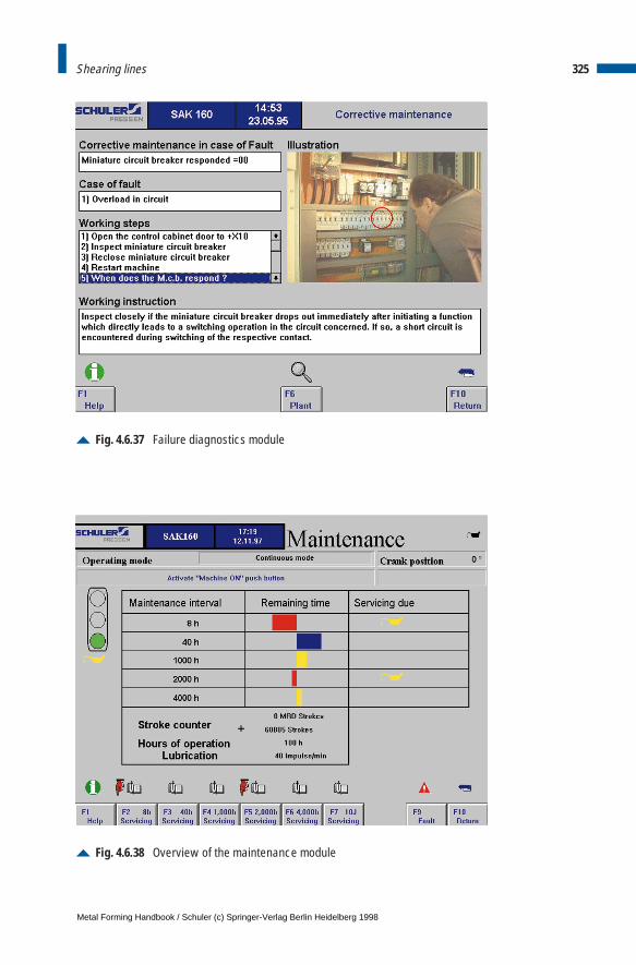
325Shearing lines
Fig. 4.6.37 Failure diagnostics module
Fig. 4.6.38 Overview of the maintenance module
Metal Forming Handbook / Schuler (c) Springer-Verlag Berlin Heidelberg 1998
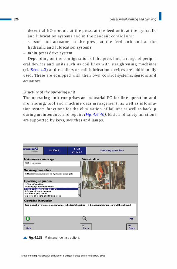
– decentral I/O module at the press, at the feed unit, at the hydraulicand lubrication systems and in the pendant control unit
– sensors and actuators at the press, at the feed unit and at thehydraulic and lubrication systems
– main press drive systemDepending on the configuration of the press line, a range of periph-
eral devices and units such as coil lines with straightening machines (cf. Sect. 4.3) and recoilers or coil lubrication devices are additionallyused. These are equipped with their own control systems, sensors andactuators.
Structure of the operating unitThe operating unit comprises an industrial PC for line operation andmonitoring, tool and machine data management, as well as informa-tion system functions for the elimination of failures as well as backupduring maintenance and repairs (Fig. 4.6.40). Basic and safety functionsare supported by keys, switches and lamps.
326 Sheet metal forming and blanking
Fig. 4.6.39 Maintenance instructions
Metal Forming Handbook / Schuler (c) Springer-Verlag Berlin Heidelberg 1998
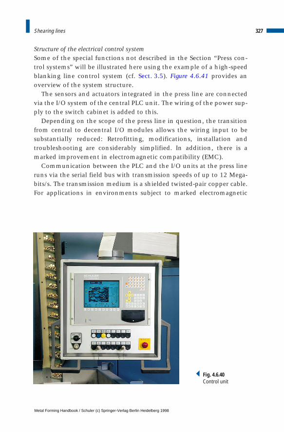
Structure of the electrical control systemSome of the special functions not described in the Section “Press con-trol systems” will be illustrated here using the example of a high-speedblanking line control system (cf. Sect. 3.5). Figure 4.6.41 provides anoverview of the system structure.
The sensors and actuators integrated in the press line are connectedvia the I/O system of the central PLC unit. The wiring of the power sup-ply to the switch cabinet is added to this.
Depending on the scope of the press line in question, the transitionfrom central to decentral I/O modules allows the wiring input to besubstantially reduced: Retrofitting, modifications, installation andtroubleshooting are considerably simplified. In addition, there is amarked improvement in electromagnetic compatibility (EMC).
Communication between the PLC and the I/O units at the press lineruns via the serial field bus with transmission speeds of up to 12 Mega-bits/s. The transmission medium is a shielded twisted-pair copper cable.For applications in environments subject to marked electromagnetic
327Shearing lines
Fig. 4.6.40Control unit
Metal Forming Handbook / Schuler (c) Springer-Verlag Berlin Heidelberg 1998
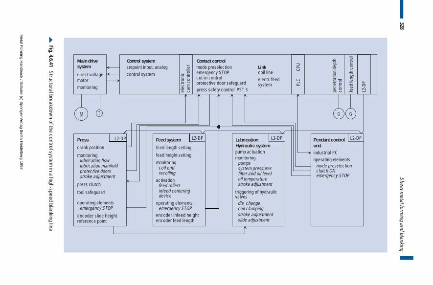
Main drivesystem
Press L2-DP L2-DP L2-DP L2-DP
L2-D
P
Feed system Pendant controlunitcrank position
M T
encoder slide heightslide adjustment
feed length setting
feed height settingmonitoringlubrication flowlubrication manifold
pump actuationmonitoring
pumpssystem pressuresfilter and oil level
triggering of hydraulicvalves
die change
oil temperature
monitoringcoil end
G G
press clutch
encoder feed lengthencoder infeed height
activationfeed rollersinfeed centering device
Contact controlmode preselectionemergency STOPcut-in controlprotective door safeguard
protective doors recoiling
coil clampingstroke adjustment
stroke adjustment
PLC
CPU
tool safeguard
operating elements
operating elements
Control system
stroke adjustment
emergency STOP emergency STOP
emergency STOP
operating elements
Linkcoil lineelectr. feedsystem
clutch ON
reference point
mode preselection
direct voltagemotormonitoring
_
industrial PC
press safety control PST 3
setpoint input, analogcontrol system
elec
troni
cca
m c
ontro
ller
pene
tratio
n de
pth
cont
rol
feed
leng
th c
ontro
l
LubricationHydraulic system
328Sheet m
etal forming and blanking
Fig. 4.6.41 Structural breakdow
n of the control system in a high-speed blanking line
Metal F
orming H
andbook / Schuler (c) S
pringer-Verlag B
erlin Heidelberg 1998

interference, or where both increased transmission ranges and speedsare involved at the same time, fiber optic cables can be used.
Data communication to peripheral equipment such as coil lines, coilstock thickness gauges or coil lubrication systems is performed via theI/O interface of the PLC. Between the industrial PC and the PLC, datacommunication is implemented via an active serial interface with 20 mA. For data communication with a higher-level computer system,an additional serial interface is available in the industrial PC.
329Shearing lines
Metal Forming Handbook / Schuler (c) Springer-Verlag Berlin Heidelberg 1998
4 Sheet metal forming and blanking
4.7 Fine blanking
In practice, fine blanking is also known by the terms precision blanking orfine stamping. The production process involves shear blanking for themanufacture of parts with a smooth cut surface. Like standard shearblanking, according to DIN 8580 fine blanking falls under the main cate-gory of material separation or parting processes, and is defined accordingto DIN 8588 under the sub-category dividing (cf. Fig. 2.1.2). Compared tostandard shear blanking, also known as normal blanking (cf. Fig. 4.5.1),however, different process parameters apply, resulting in a higher work-piece quality.
The basic concept of fine blanking is that, in contrast to standardblanking, the material is separated after being clamped on all sides only as a result of material flow, i. e. without a fractured surface (cf.Fig. 2.1.30).
4.7.1 Fine blanking process
Advantages of fine blankingApart from the quality-related advantages of fine blanking, cost-effec-tiveness is also a decisive factor in favor of the application of thisprocess. Specific blank-related advantages compared to normal shearblanking include:
– smooth blanked surfaces free from fracture and tearing which areable to fulfil functions without the need for reworking,
– extended field of application for shear blanking,
Metal Forming Handbook / Schuler (c) Springer-Verlag Berlin Heidelberg 1998
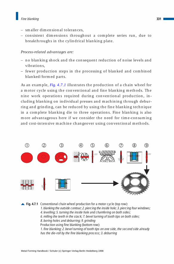
– smaller dimensional tolerances,– consistent dimensions throughout a complete series run, due to
breakthroughs in the cylindrical blanking plate.
Process-related advantages are:
– no blanking shock and the consequent reduction of noise levels andvibrations,
– fewer production steps in the processing of blanked and combinedblanked/formed parts.
As an example, Fig. 4.7.1 illustrates the production of a chain wheel fora motor cycle using the conventional and fine blanking methods. Thenine work operations required during conventional production, in-cluding blanking on individual presses and machining through debur-ring and grinding, can be reduced by using the fine blanking techniquein a complete blanking die to three operations. Fine blanking is alsomore advantageous here if we consider the need for time-consumingand cost-intensive machine changeover using conventional methods.
331Fine blanking
Fig. 4.7.1 Conventional chain wheel production for a motor cycle (top row):1. blanking the outside contour; 2. piercing the inside hole; 3. piercing four windows;4. levelling; 5. turning the inside hole and chamfering on both sides; 6. milling the teeth in the stack; 7. bevel turning of tooth tips on both sides;8. boring holes and deburring; 9. grindingProduction using fine blanking (bottom row):1. fine blanking; 2. bevel turning of tooth tips on one side, the second side alreadyhas the die-roll by the fine blanking process; 3. deburring
���������
Metal Forming Handbook / Schuler (c) Springer-Verlag Berlin Heidelberg 1998
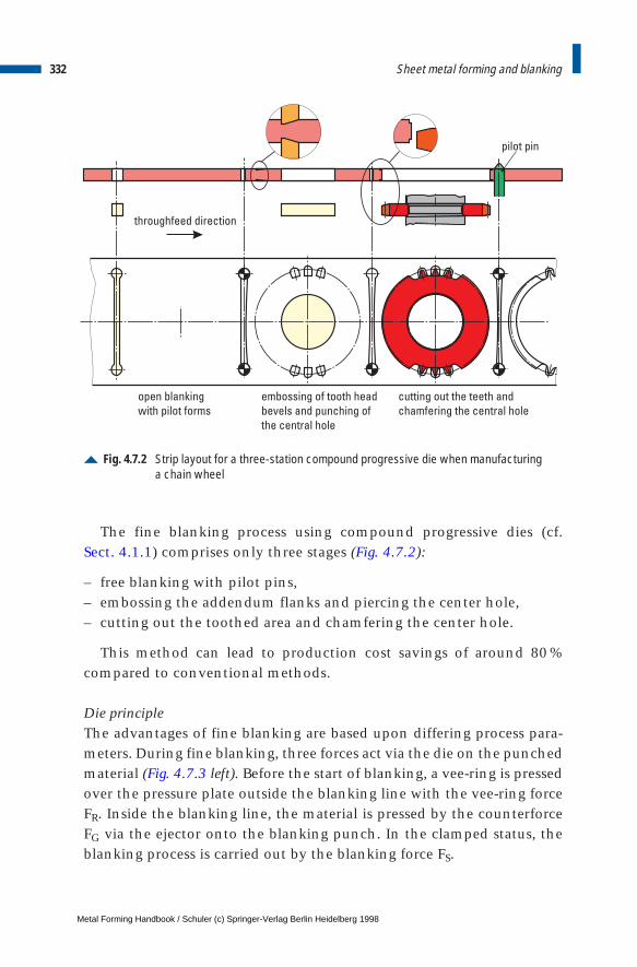
The fine blanking process using compound progressive dies (cf. Sect. 4.1.1) comprises only three stages (Fig. 4.7.2):
– free blanking with pilot pins,– embossing the addendum flanks and piercing the center hole,– cutting out the toothed area and chamfering the center hole.
This method can lead to production cost savings of around 80 %compared to conventional methods.
Die principleThe advantages of fine blanking are based upon differing process para-meters. During fine blanking, three forces act via the die on the punchedmaterial (Fig. 4.7.3 left). Before the start of blanking, a vee-ring is pressedover the pressure plate outside the blanking line with the vee-ring forceFR. Inside the blanking line, the material is pressed by the counterforceFG via the ejector onto the blanking punch. In the clamped status, theblanking process is carried out by the blanking force FS.
332 Sheet metal forming and blanking
Fig. 4.7.2 Strip layout for a three-station compound progressive die when manufacturinga chain wheel
open blanking
with pilot forms
embossing of tooth head
bevels and punching of
the central hole
cutting out the teeth and
chamfering the central hole
pilot pin
throughfeed direction
Metal Forming Handbook / Schuler (c) Springer-Verlag Berlin Heidelberg 1998
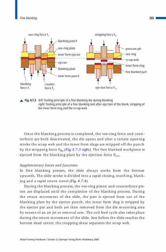
Once the blanking process is completed, the vee-ring force and coun-terforce are both deactivated, the die opens and after a certain openingstroke the scrap web and the inner form slugs are stripped off the punchby the stripping force FRa (Fig.4.7.3 right). The fine blanked workpiece isejected from the blanking plate by the ejection force FGa.
Supplementary forces and functionsIn fine blanking presses, the slide always works from the bottomupwards. The slide stroke is divided into a rapid closing, touching, blank-ing and a rapid return travel (Fig. 4.7.4).
During the blanking process, the vee-ring piston and counterforce pis-ton are displaced until the completion of the blanking process. Duringthe return movement of the slide, the part is ejected from out of theblanking plate by the ejector punch, the inner form slug is stripped bythe ejector pin and both are then removed from the die mounting areaby means of an air jet or removal arm. The coil feed cycle also takes placeduring the return movement of the slide. Just before the slide reaches thebottom dead center, the cropping shear separates the scrap web.
333Fine blanking
Fig. 4.7.3 left: Tooling principle of a fine blanking die during blankingright: Tooling principle of a fine blanking tool after ejection of the blank, stripping ofthe inner form slug and the scrap web
hfi
blanking punch
blanking plate
inner form punch
ejector
inner form ejector
vee-ring plate pressure pin
scrap web
fine blanked part
inner form slug
vee-ring
blankingforce FS
vee-ring force FR stripping force FRa
ejection force FGa
counter-force FG
Metal Forming Handbook / Schuler (c) Springer-Verlag Berlin Heidelberg 1998

Blanking force-stroke diagramFigure 4.7.5 compares the variation of the blanking force over the slidestroke or the time required for normal blanking to that required for fineblanking. During normal blanking, the sheet metal is initially elastical-ly deformed on impact of the blanking punch (I) and then cut (II). Inphase III, the part tears through, and in phase IV the system vibrationsin the machine and die decay in all three directions (cf. Fig. 4.5.1). Thisis the phase in which the greatest die wear takes place. During fineblanking, the tearing and the vibration phases are eliminated. The spe-cial process parameters involved in fine blanking prevent the suddenbreakthrough of the part, ensuring a smooth cut over the entire sheetmetal thickness.
Blanking clearanceThe blanking clearance is the dimensional difference or gap betweenthe blanking punch and the blanking die measured on a single side.
334 Sheet metal forming and blanking
Fig. 4.7.4 Supplementary forces and functions during the slide stroke
rapid closing stroke
tracing stroke
blanking stroke
rapid return travel stroke
movement sequencevee-ring pistonmovement sequencecounterforce piston
cycle for removal/air jetejection of parts and scrap
feed cycle of the punchedmaterialscrap seperator cycle
slidestroke[mm]
BDC BDC
TDC
time [s]
time [s]
supple-mentaryfunctions
Metal Forming Handbook / Schuler (c) Springer-Verlag Berlin Heidelberg 1998
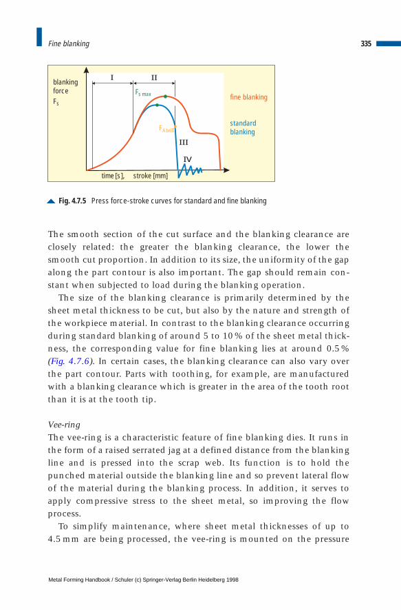
The smooth section of the cut surface and the blanking clearance areclosely related: the greater the blanking clearance, the lower thesmooth cut proportion. In addition to its size, the uniformity of the gapalong the part contour is also important. The gap should remain con-stant when subjected to load during the blanking operation.
The size of the blanking clearance is primarily determined by thesheet metal thickness to be cut, but also by the nature and strength ofthe workpiece material. In contrast to the blanking clearance occurringduring standard blanking of around 5 to 10 % of the sheet metal thick-ness, the corresponding value for fine blanking lies at around 0.5 % (Fig. 4.7.6). In certain cases, the blanking clearance can also vary overthe part contour. Parts with toothing, for example, are manufacturedwith a blanking clearance which is greater in the area of the tooth rootthan it is at the tooth tip.
Vee-ringThe vee-ring is a characteristic feature of fine blanking dies. It runs inthe form of a raised serrated jag at a defined distance from the blankingline and is pressed into the scrap web. Its function is to hold thepunched material outside the blanking line and so prevent lateral flowof the material during the blanking process. In addition, it serves toapply compressive stress to the sheet metal, so improving the flowprocess.
To simplify maintenance, where sheet metal thicknesses of up to 4.5 mm are being processed, the vee-ring is mounted on the pressure
335Fine blanking
Fig. 4.7.5 Press force-stroke curves for standard and fine blanking
I II
III
IV
blankingforceFs
time [s], stroke [mm]
F
Fs max
Abrißstandardblanking
fine blanking
Metal Forming Handbook / Schuler (c) Springer-Verlag Berlin Heidelberg 1998
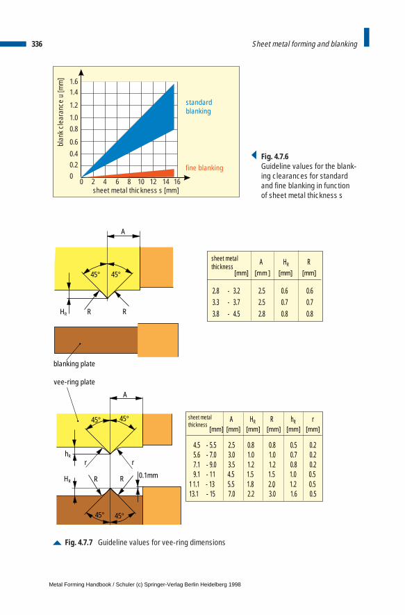
336 Sheet metal forming and blanking
00
2 4 6 8 10 12 14 16
0.20.4
0.6
0.81.0
1.2
1.41.6
sheet metal thickness s [mm]
standardblanking
fine blanking
blan
k cl
eara
nce
u [m
m]
Fig. 4.7.6Guideline values for the blank-ing clearances for standardand fine blanking in function of sheet metal thickness s
Fig. 4.7.7 Guideline values for vee-ring dimensions
45°45°
R RHR
A
blanking plate
A HR R
2.8 - 3.2 2.5 0.6 0.63.3 - 3.7 2.5 0.7 0.73.8 - 4.5 2.8 0.8 0.8
[mm ][mm] [mm] [mm]
A
r
R
r
RHR
hR
45° 45°
45°45°
0.1mm
4.5 - 5.5 2.5 0.8 0.8 0.5 0.25.6 - 7.0 3.0 1.0 1.0 0.7 0.27.1 - 9.0 3.5 1.2 1.2 0.8 0.29.1 - 11 4.5 1.5 1.5 1.0 0.5
1 1.1 - 13 5.5 1.8 2.0 1.2 0.513.1 - 15 7.0 2.2 3.0 1.6 0.5
A HR R hR rsheet metalthickness
sheet metalthickness
.
[mm][mm] [mm] [mm] [mm] [mm]
vee-ring plate
Metal Forming Handbook / Schuler (c) Springer-Verlag Berlin Heidelberg 1998
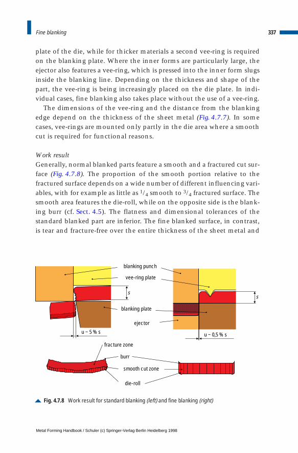
plate of the die, while for thicker materials a second vee-ring is requiredon the blanking plate. Where the inner forms are particularly large, theejector also features a vee-ring, which is pressed into the inner form slugsinside the blanking line. Depending on the thickness and shape of thepart, the vee-ring is being increasingly placed on the die plate. In indi-vidual cases, fine blanking also takes place without the use of a vee-ring.
The dimensions of the vee-ring and the distance from the blankingedge depend on the thickness of the sheet metal (Fig. 4.7.7). In somecases, vee-rings are mounted only partly in the die area where a smoothcut is required for functional reasons.
Work resultGenerally, normal blanked parts feature a smooth and a fractured cut sur-face (Fig. 4.7.8). The proportion of the smooth portion relative to thefractured surface depends on a wide number of different influencing vari-ables, with for example as little as 1/4 smooth to 3/4 fractured surface. Thesmooth area features the die-roll, while on the opposite side is the blank-ing burr (cf. Sect. 4.5). The flatness and dimensional tolerances of thestandard blanked part are inferior. The fine blanked surface, in contrast,is tear and fracture-free over the entire thickness of the sheet metal and
337Fine blanking
Fig. 4.7.8 Work result for standard blanking (left) and fine blanking (right)
ss
burr
fracture zone
blanking punch
vee-ring plate
blanking plate
ejector
smooth cut zone
die-roll
u ~ 5 % s u ~ 0,5 % s
Metal Forming Handbook / Schuler (c) Springer-Verlag Berlin Heidelberg 1998

Steel group Group Abbreviation Material no.as per DIN as per EURO standard
soft, unalloyed steelshot strip 1614 StW22 1.0332 FeP11 EN111metal sheet 1623 St14 1.0338 FeP04 EN10130cold strip 1624 St4 1.0338general structural steels 17 100 St37-3N 1.0116 Fe360D1 EN10025
St44-3N 1.0144 Fe430D1 EN10025fine-grain structural steels 17 102 StE420 1.8902 S420N EN10113-2
StE460 1.8905 P460N EN10028-3case hardening steels 17 210 Ck15 1.1141
16MnCr5 1.7131heat-treatable steels 17 221 Ck45 1.1191 2C45 EN10083-1
17 222 41Cr4 1.7035 41Cr4 EN10083-117 200 42CrMo4 1.7223 42CrMo4 EN10083-1
tool steels 17 350 100Cr6 1.2067C85W 1.1830
stainless steels 17 440ferritic X6Cr13 1.4000
X30Cr13 1.4028austenitic X5CrNi18.10 1.4301
Aluminium and aluminium alloys Copper and copper alloys
Abbreviation Material no. as per DIN Abbreviation Material no. as per DIN
AlMg3 3.3535 1745 CuZn37 2.0321 17670AlMgSi1 3.2315 1745 CuSn8 2.1030 17670
CuNi25 2.0830 17670
approximately vertical relative to the surface of the sheet metal. Thefine blanked part is also flatter than a standard blanked part.
4.7.2 Fine blanking materials, forces, quality characteristics and part variety
Material selectionSteel is the most commonly used material in the field of fine blankingtechnology. Non-ferrous metals such as copper, aluminium and theiralloys account for no more than 10 %, although the tendency to usethese is on the increase. Due to the high proportion of steel materialsused, these are described in greater detail here.
The steel types used are broken down into a number of groups: softunalloyed steels, general structural steels, fine-grained structural steels,
338 Sheet metal forming and blanking
Table 4.7.1: Selection of fine blanking materials
Metal Forming Handbook / Schuler (c) Springer-Verlag Berlin Heidelberg 1998
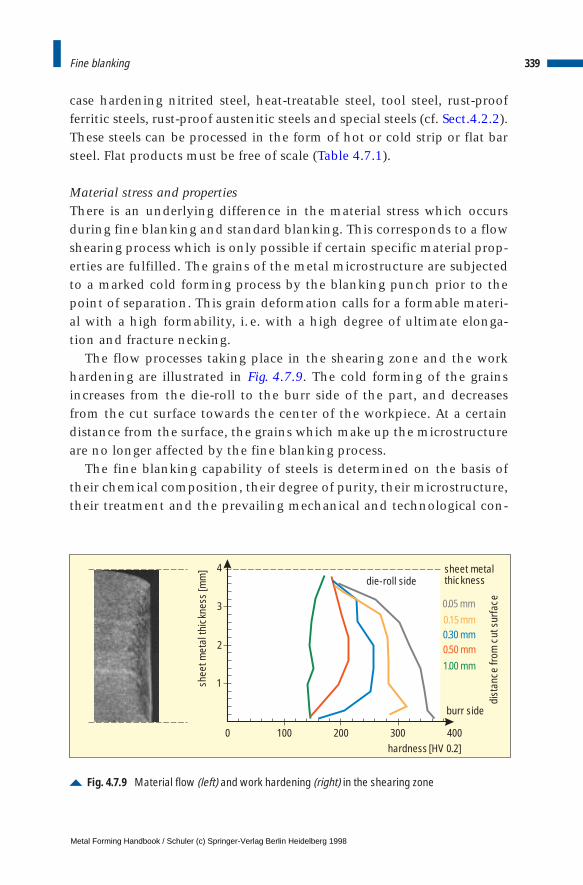
case hardening nitrited steel, heat-treatable steel, tool steel, rust-proofferritic steels, rust-proof austenitic steels and special steels (cf. Sect.4.2.2).These steels can be processed in the form of hot or cold strip or flat barsteel. Flat products must be free of scale (Table 4.7.1).
Material stress and propertiesThere is an underlying difference in the material stress which occursduring fine blanking and standard blanking. This corresponds to a flowshearing process which is only possible if certain specific material prop-erties are fulfilled. The grains of the metal microstructure are subjectedto a marked cold forming process by the blanking punch prior to thepoint of separation. This grain deformation calls for a formable materi-al with a high formability, i. e. with a high degree of ultimate elonga-tion and fracture necking.
The flow processes taking place in the shearing zone and the workhardening are illustrated in Fig. 4.7.9. The cold forming of the grainsincreases from the die-roll to the burr side of the part, and decreasesfrom the cut surface towards the center of the workpiece. At a certaindistance from the surface, the grains which make up the microstructureare no longer affected by the fine blanking process.
The fine blanking capability of steels is determined on the basis oftheir chemical composition, their degree of purity, their microstructure,their treatment and the prevailing mechanical and technological con-
339Fine blanking
Fig. 4.7.9 Material flow (left) and work hardening (right) in the shearing zone
1
2
3
4
0.05 mm
0.30 mm0.15 mm
dist
ance
from
cut
sur
face
0.50 mm1.00 mm
0 100 200 300 400hardness [HV 0.2]
die-roll side
burr side
sheet metalthickness
she
et m
etal
thic
knes
s [m
m]
Metal Forming Handbook / Schuler (c) Springer-Verlag Berlin Heidelberg 1998
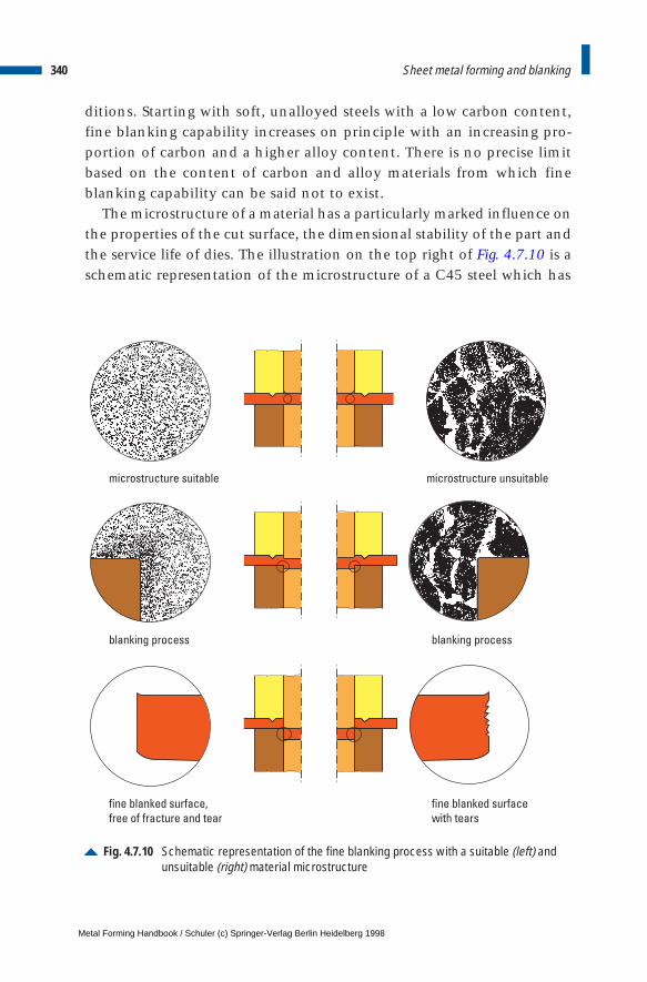
ditions. Starting with soft, unalloyed steels with a low carbon content,fine blanking capability increases on principle with an increasing pro-portion of carbon and a higher alloy content. There is no precise limitbased on the content of carbon and alloy materials from which fineblanking capability can be said not to exist.
The microstructure of a material has a particularly marked influence onthe properties of the cut surface, the dimensional stability of the part andthe service life of dies. The illustration on the top right of Fig. 4.7.10 is aschematic representation of the microstructure of a C45 steel which has
340 Sheet metal forming and blanking
Fig. 4.7.10 Schematic representation of the fine blanking process with a suitable (left) andunsuitable (right) material microstructure
microstructure suitable microstructure unsuitable
blanking process blanking process
fine blanked surface,
free of fracture and tear
fine blanked surface
with tears
Metal Forming Handbook / Schuler (c) Springer-Verlag Berlin Heidelberg 1998
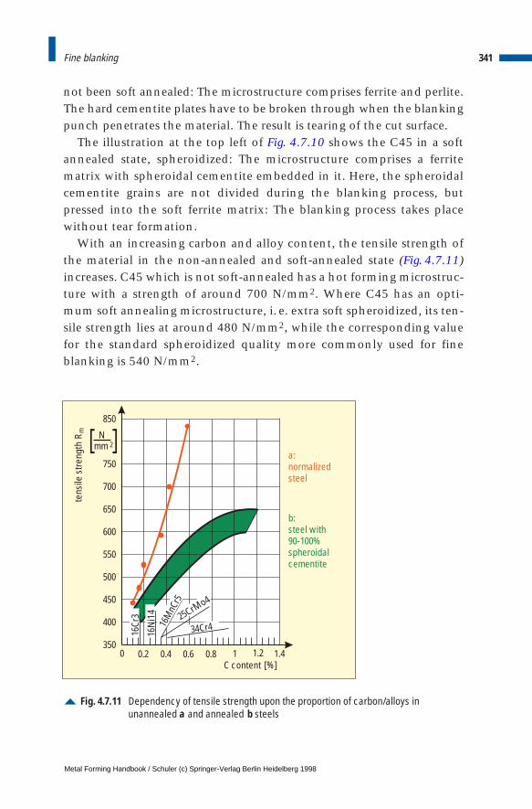
not been soft annealed: The microstructure comprises ferrite and perlite.The hard cementite plates have to be broken through when the blankingpunch penetrates the material. The result is tearing of the cut surface.
The illustration at the top left of Fig. 4.7.10 shows the C45 in a softannealed state, spheroidized: The microstructure comprises a ferritematrix with spheroidal cementite embedded in it. Here, the spheroidalcementite grains are not divided during the blanking process, butpressed into the soft ferrite matrix: The blanking process takes placewithout tear formation.
With an increasing carbon and alloy content, the tensile strength ofthe material in the non-annealed and soft-annealed state (Fig. 4.7.11)increases. C45 which is not soft-annealed has a hot forming microstruc-ture with a strength of around 700 N/mm2. Where C45 has an opti-mum soft annealing microstructure, i. e. extra soft spheroidized, its ten-sile strength lies at around 480 N/mm2, while the corresponding valuefor the standard spheroidized quality more commonly used for fineblanking is 540 N/mm2.
341Fine blanking
Fig. 4.7.11 Dependency of tensile strength upon the proportion of carbon/alloys inunannealed a and annealed b steels
tens
ile s
treng
thR m
[%]C content
350
400
450
500
550
600
650
700
750
850
0 0.2 0.4 0.6 0.8 1 1.41.2
16Cr
3
16N
i14
16M
nCr5
25CrMo4
34Cr4
a: normalizedsteel
b: steel with 90-100%spheroidalcementite
Nmm 2[ ]
Metal Forming Handbook / Schuler (c) Springer-Verlag Berlin Heidelberg 1998

Determining the degree of difficultyThe slide force FSt [N] during fine blanking is
with the blanking force FS [N]:
To calculate the blanking force, the sheet metal thickness s [mm], thetensile strength of the material Rm [N/mm2] and the length of the cutcontour ls [mm] is required (cf. Sect. 4.5). For circular hole punching,for example the following results:
Depending on the prevailing conditions, factor f1 [–] can fluctuatebetween 0.6 and 1.2. In order to ensure a sufficient blanking force, inpractice 0.9 is taken for f1. This takes into consideration the influences ofblanking edge properties (blunting and surface roughness of the blank-ing elements, sheet metal thickness tolerance and alteration of the blank-ing clearance as a result of abrasive wear).
The counterforce FG [N] is calculated from the surface area AG [mm2]under pressure by the ejector and the counterpressure qG [N/mm2]:
The value qG lies between 20 N/mm2 for thin parts with a small surfacearea and 70 N/mm2 for larger parts. The counterforce FG must be select-ed in such a way that the required cut surface quality and optimumevenness of the part are achieved. As the counterforce must be over-come directly by the blanking force, an excessively high counterforceexercises the same effect as if the sheet were of a higher strength levelor thickness. In this way, the high counterforce also influences the ser-vice life of the die. The punch stress and the force exerted by the punchboth increase. Depending on the part geometry, the counterforceamounts to between 10 and 25 % of the blanking force.
With the help of this information and the surface area Ast [mm2] ofthe hole punch with the diameter d [mm], which is:
342 Sheet metal forming and blanking
F F F NSt S G= + [ ],
F l s R f NS S m= ⋅ ⋅ ⋅ [ ]1
l d mmS = ⋅ [ ]π
F A q NG G G= ⋅ [ ]
Ad
mmSt = ⋅ [ ]2
2
4
π,
Metal Forming Handbook / Schuler (c) Springer-Verlag Berlin Heidelberg 1998
it is also possible to determine the mean pressure pm [N/mm2] ap-plied on the punch:
or when punching a hole, whereby the counterforce is generally tak-en as 10 % of the punch force:
The mean pressure pm must not exceed the 0.2% compression limit Rp0.2
[N/mm2] of the perforating punch (pm # Rp0.2 ). Accordingly, on the basisof the previous equation for the maximum ratio of sheet metal thicknesss to perforating punch diameter d, the following equation results:
If we assume that the perforating punch is made of high-speed steel S6-5-2 with Rp0.2 = 3,000 N/mm2 and HRC 63-64 and that the tensilestrength of the fine blanking material is 500 N/mm2, the following s/dratio results when blanking with counterpressure:
and when blanking without counterpressure:
This maximum s/d ratio is generally assumed to be 1 in normal shear-ing practice.
Part configuration: flat and formedThe geometric shape of a part, the thickness of the sheet metal and thecharacteristics of the material determine the production possibilitiesavailable by fine blanking. In order to ascertain whether a part can bemanufactured using fine blanking, its degree of difficulty is determined:S1 (easy), S2 (medium), and S3 (difficult). Here, the various formed ele-ments such as slot widths, section widths, hole diameters, tooth forms,corner angles and radius must be evaluated with the aid of Fig. 4.7.12.
343Fine blanking
pF F
A
N
mmmS G
St
= +
2
ps R f
d
N
mmmm= ⋅ ⋅ ⋅
4 4 12
.
s
d
R
R fp
m
≤⋅ ⋅
[ ]0 2
14 4.
.–
s
d≤
⋅ ⋅= =3 000
4 4 500 0 9
3 000
1 9801 50
,
. .
,
,.
s
d≤
⋅ ⋅= =3 000
4 500 0 9
3 000
1 8001 67
,
.
,
,.
Metal Forming Handbook / Schuler (c) Springer-Verlag Berlin Heidelberg 1998
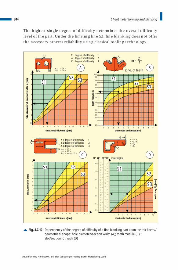
The highest single degree of difficulty determines the overall difficultylevel of the part. Under the limiting line S3, fine blanking does not offerthe necessary process reliability using classical tooling technology.
344 Sheet metal forming and blanking
Fig. 4.7.12 Dependency of the degree of difficulty of a fine blanking part upon the thickness/geometrical shape: hole diameter/section width (A); tooth module (B);slot/section (C); radii (D)
d
S
a
S1 degree of difficulty 1
amin. = 0,6 sdmin. = 0,6 s
S2 degree of difficulty 2S3 degree of difficulty 3
0 1
1
0,5
2
3
4
5
6
7
8
9
10
2 3 4 5 6 7 8 9 10 11 12 13 14 15
S2 S3S1
s
0.1
1 2 3 4 5 6 7 8 9 10 11
0.20.30.4
0.5
1.0
1.5
2.0
3.0
4.0
6.0
8.0
10.0
toot
h m
odul
e m
S1S2
S3
S1 degree of difficulty 1
amin. = 0,6 sd min. = 0,6 sI max. = approx. 15 a
S2 degree of difficulty 2S3 degree of difficulty 3
0 1
1
2
0,6
3
4
5
6
7
8
9
10
11
12
13
14
15
2 3 4 5 6 7 8 9 10 11 12 13 14 15
S1 S2
S3
ab
l
l
b
a
ri
ra
Ri
R = 0.6 Ri ar = 0.6 Ri ar = Ra a
r = Ri i
Ra
a
1 2 3 4 5 6 7 8 9 10
0.10.1
0.5
1.0
1.5
2.0
2.5
3.0
0.1
0.2
0.3
0.4
0.5
0.6
0.7
0.8
0.9
1.0
1.1
1.2
1.3
1.4
1.5
0.2
0.3
0.4
0.5
0.60.7
0.8
0.9
1.0
1.1
1.21.3
1.4
1.5
1.6
1.7
1.81.9
2.0
30° 60° 90°
S3
S2S1
rm =
2rz
z: no. of teeth A B
C D
hole
dia
met
er d
, sec
tion
wid
th a
[mm
]
sheet metal thickness s [mm]sheet metal thickness s [mm]
sheet metal thickness s [mm]sheet metal thickness s [mm]
slot
a, s
ectio
n b
(m
m)
radi
us r
a R
a [m
m]
120° corner angle a
Metal Forming Handbook / Schuler (c) Springer-Verlag Berlin Heidelberg 1998
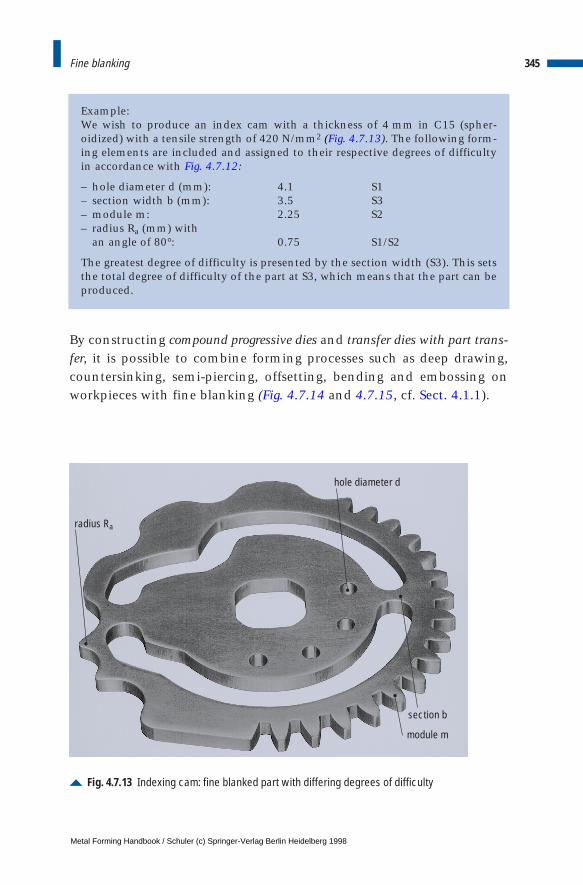
Example:We wish to produce an index cam with a thickness of 4 mm in C15 (spher-oidized) with a tensile strength of 420 N/mm2 (Fig. 4.7.13). The following form-ing elements are included and assigned to their respective degrees of difficultyin accordance with Fig. 4.7.12:
– hole diameter d (mm): 4.1 S1– section width b (mm): 3.5 S3– module m: 2.25 S2– radius Ra (mm) with
an angle of 80°: 0.75 S1/S2
The greatest degree of difficulty is presented by the section width (S3). This setsthe total degree of difficulty of the part at S3, which means that the part can beproduced.
By constructing compound progressive dies and transfer dies with part trans-fer, it is possible to combine forming processes such as deep drawing,countersinking, semi-piercing, offsetting, bending and embossing onworkpieces with fine blanking (Fig. 4.7.14 and 4.7.15, cf. Sect. 4.1.1).
345Fine blanking
Fig. 4.7.13 Indexing cam: fine blanked part with differing degrees of difficulty
radius Ra
section b
module m
hole diameter d
Metal Forming Handbook / Schuler (c) Springer-Verlag Berlin Heidelberg 1998
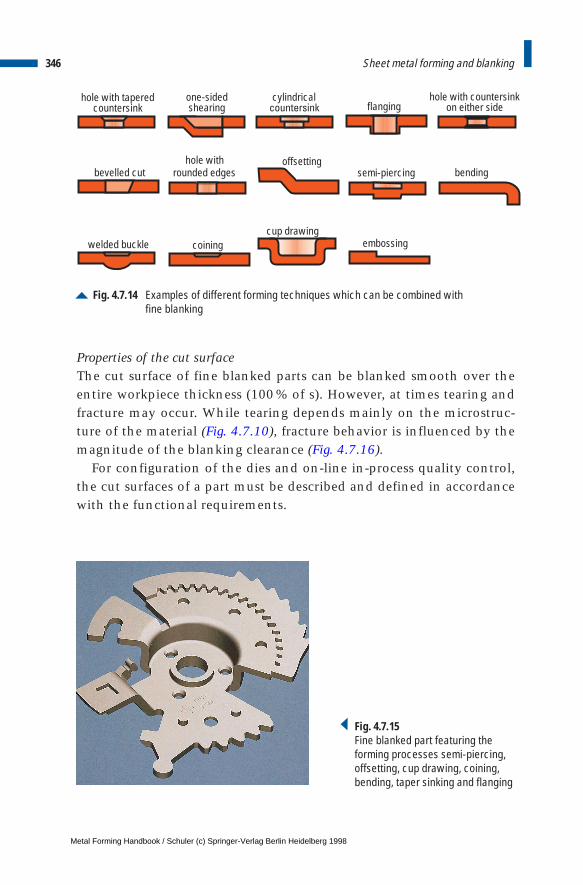
Properties of the cut surfaceThe cut surface of fine blanked parts can be blanked smooth over theentire workpiece thickness (100 % of s). However, at times tearing andfracture may occur. While tearing depends mainly on the microstruc-ture of the material (Fig. 4.7.10), fracture behavior is influenced by themagnitude of the blanking clearance (Fig. 4.7.16).
For configuration of the dies and on-line in-process quality control,the cut surfaces of a part must be described and defined in accordancewith the functional requirements.
346 Sheet metal forming and blanking
Fig. 4.7.14 Examples of different forming techniques which can be combined with fine blanking
bevelled cutoffsetting
bending
embossing
hole with taperedcountersink
one-sidedshearing flanging
cylindricalcountersink
hole with countersinkon either side
hole withrounded edges semi-piercing
welded bucklecup drawing
coining
Fig. 4.7.15 Fine blanked part featuring the forming processes semi-piercing,offsetting, cup drawing, coining,bending, taper sinking and flanging
Metal Forming Handbook / Schuler (c) Springer-Verlag Berlin Heidelberg 1998
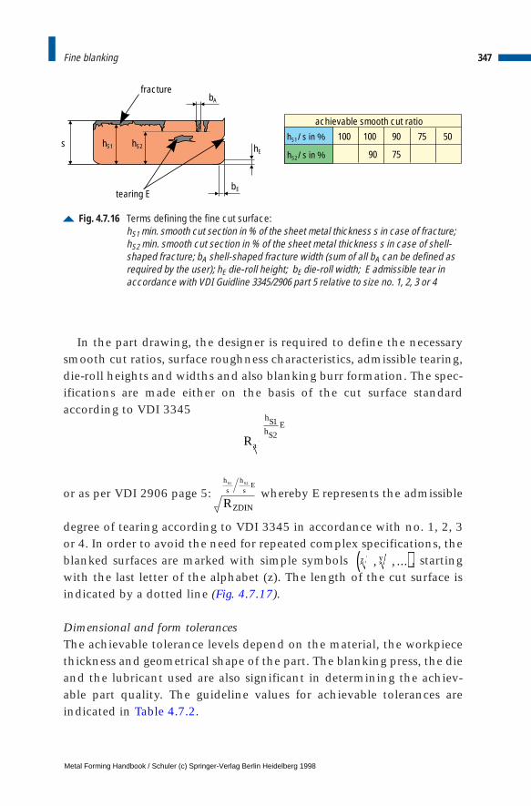
In the part drawing, the designer is required to define the necessarysmooth cut ratios, surface roughness characteristics, admissible tearing,die-roll heights and widths and also blanking burr formation. The spec-ifications are made either on the basis of the cut surface standardaccording to VDI 3345
or as per VDI 2906 page 5: whereby E represents the admissible
degree of tearing according to VDI 3345 in accordance with no. 1, 2, 3or 4. In order to avoid the need for repeated complex specifications, theblanked surfaces are marked with simple symbols , startingwith the last letter of the alphabet (z). The length of the cut surface isindicated by a dotted line (Fig. 4.7.17).
Dimensional and form tolerancesThe achievable tolerance levels depend on the material, the workpiecethickness and geometrical shape of the part. The blanking press, the dieand the lubricant used are also significant in determining the achiev-able part quality. The guideline values for achievable tolerances areindicated in Table 4.7.2.
347Fine blanking
Fig. 4.7.16 Terms defining the fine cut surface:hS1 min. smooth cut section in % of the sheet metal thickness s in case of fracture;hS2 min. smooth cut section in % of the sheet metal thickness s in case of shell-shaped fracture; bA shell-shaped fracture width (sum of all bA can be defined asrequired by the user); hE die-roll height; bE die-roll width; E admissible tear inaccordance with VDI Guidline 3345/2906 part 5 relative to size no. 1, 2, 3 or 4
s
achievable smooth cut ratio
tearing E
fracture
hS2 hE
bE
hS1
bA
h / s in %S1
h / s in %S2
100 100
90
90
75
75 50
Ra
hShS
E1
2
RZDIN
h
s
h
sES S1 2
z y, , …( )
Metal Forming Handbook / Schuler (c) Springer-Verlag Berlin Heidelberg 1998
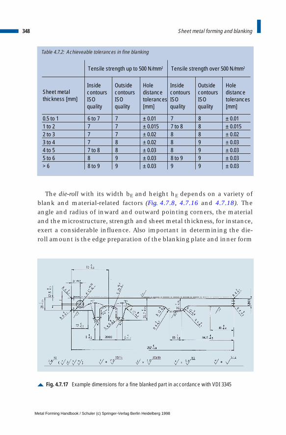
Table 4.7.2: Achieveable tolerances in fine blanking
Sheet metal thickness [mm]
0.5 to 1 6 to 7 7 ± 0.01 7 8 ± 0.011 to 2 7 7 ± 0.015 7 to 8 8 ± 0.0152 to 3 7 7 ± 0.02 8 8 ± 0.023 to 4 7 8 ± 0.02 8 9 ± 0.034 to 5 7 to 8 8 ± 0.03 8 9 ± 0.035 to 6 8 9 ± 0.03 8 to 9 9 ± 0.03> 6 8 to 9 9 ± 0.03 9 9 ± 0.03
InsidecontoursISO quality
OutsidecontoursISOquality
Hole distancetolerances [mm]
InsidecontoursISO quality
OutsidecontoursISOquality
Hole distancetolerances [mm]
Tensile strength over 500 N/mm2Tensile strength up to 500 N/mm2
The die-roll with its width bE and height hE depends on a variety ofblank and material-related factors (Fig. 4.7.8, 4.7.16 and 4.7.18). Theangle and radius of inward and outward pointing corners, the materialand the microstructure, strength and sheet metal thickness, for instance,exert a considerable influence. Also important in determining the die-roll amount is the edge preparation of the blanking plate and inner form
348 Sheet metal forming and blanking
Fig. 4.7.17 Example dimensions for a fine blanked part in accordance with VDI 3345
Metal Forming Handbook / Schuler (c) Springer-Verlag Berlin Heidelberg 1998
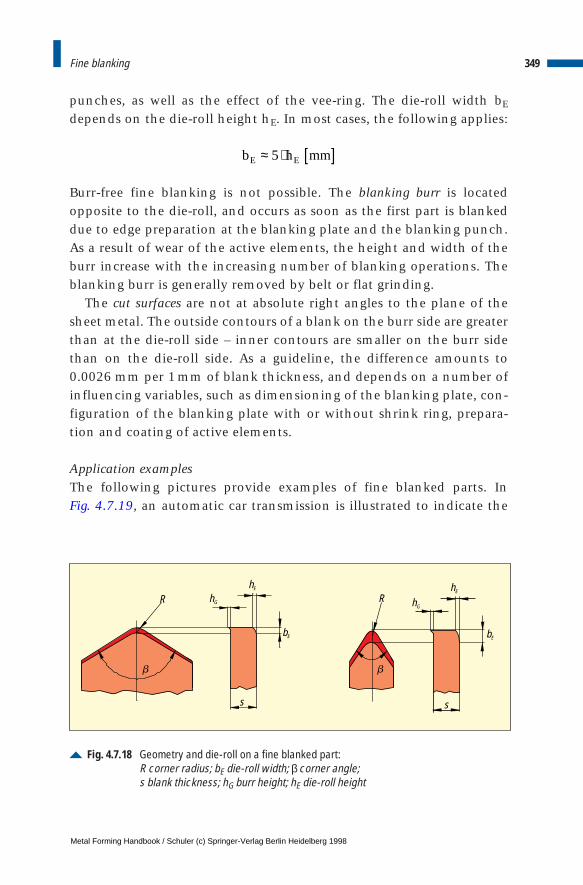
punches, as well as the effect of the vee-ring. The die-roll width bE
depends on the die-roll height hE. In most cases, the following applies:
Burr-free fine blanking is not possible. The blanking burr is locatedopposite to the die-roll, and occurs as soon as the first part is blankeddue to edge preparation at the blanking plate and the blanking punch.As a result of wear of the active elements, the height and width of theburr increase with the increasing number of blanking operations. Theblanking burr is generally removed by belt or flat grinding.
The cut surfaces are not at absolute right angles to the plane of thesheet metal. The outside contours of a blank on the burr side are greaterthan at the die-roll side – inner contours are smaller on the burr sidethan on the die-roll side. As a guideline, the difference amounts to0.0026 mm per 1mm of blank thickness, and depends on a number ofinfluencing variables, such as dimensioning of the blanking plate, con-figuration of the blanking plate with or without shrink ring, prepara-tion and coating of active elements.
Application examplesThe following pictures provide examples of fine blanked parts. In Fig. 4.7.19, an automatic car transmission is illustrated to indicate the
349Fine blanking
b h mmE E≈ ⋅ [ ]5
Fig. 4.7.18 Geometry and die-roll on a fine blanked part: R corner radius; bE die-roll width; βcorner angle;s blank thickness; hG burr height; hE die-roll height
RR hG hG
hE hE
bE bE
s s
b b
Metal Forming Handbook / Schuler (c) Springer-Verlag Berlin Heidelberg 1998

variety of fine blanked parts. High demands concerning cut surfacequality, dimensional tolerances and flatness are required from the lam-inations, drive boxes and intermediate plates. Extremely small holes inthe intermediate plate are also fine blanked, although the s/d ratio liesat around 2.
Several fine blanked parts are also required for subassemblies used inthe brake and drive system (Fig. 4.7.20), for instance brake disks withtheir many holes which have a diameter smaller than half the sheetmetal thickness. These small perforations could not be executed usingstandard blanking methods. In addition, a tear and fracture-free cut surface is essential in order to avoid notching effects, as the disks are
350 Sheet metal forming and blanking
Fig. 4.7.19 Fine blanked components in the automatic transmission of a passenger car
Metal Forming Handbook / Schuler (c) Springer-Verlag Berlin Heidelberg 1998
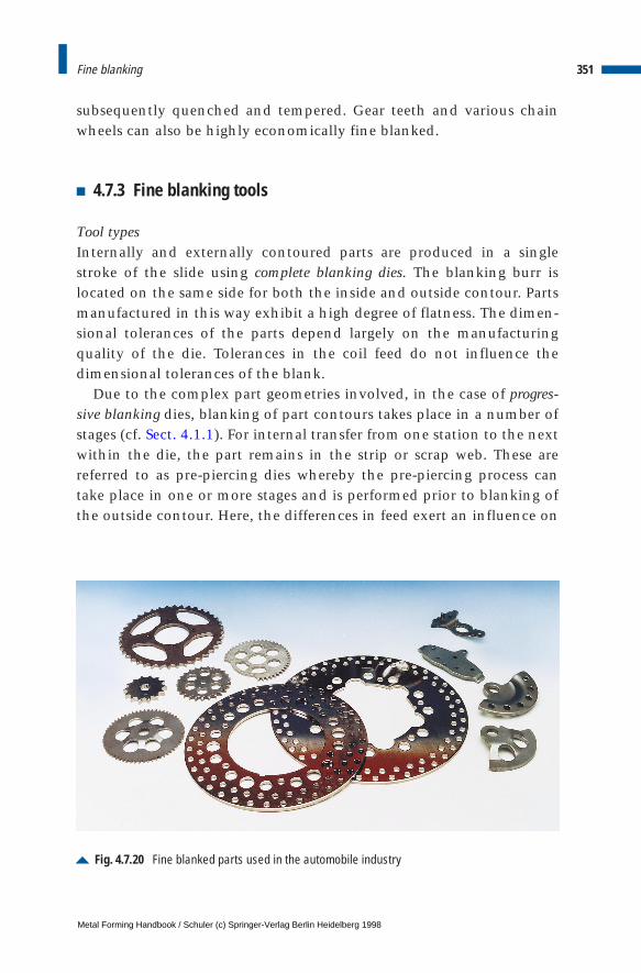
subsequently quenched and tempered. Gear teeth and various chainwheels can also be highly economically fine blanked.
4.7.3 Fine blanking tools
Tool typesInternally and externally contoured parts are produced in a singlestroke of the slide using complete blanking dies. The blanking burr islocated on the same side for both the inside and outside contour. Partsmanufactured in this way exhibit a high degree of flatness. The dimen-sional tolerances of the parts depend largely on the manufacturingquality of the die. Tolerances in the coil feed do not influence thedimensional tolerances of the blank.
Due to the complex part geometries involved, in the case of progres-sive blanking dies, blanking of part contours takes place in a number ofstages (cf. Sect. 4.1.1). For internal transfer from one station to the nextwithin the die, the part remains in the strip or scrap web. These arereferred to as pre-piercing dies whereby the pre-piercing process cantake place in one or more stages and is performed prior to blanking ofthe outside contour. Here, the differences in feed exert an influence on
351Fine blanking
Fig. 4.7.20 Fine blanked parts used in the automobile industry
Metal Forming Handbook / Schuler (c) Springer-Verlag Berlin Heidelberg 1998
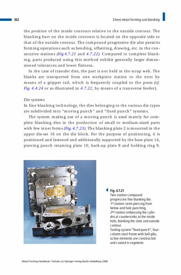
the position of the inside contours relative to the outside contour. Theblanking burr on the inside contours is located on the opposite side tothat of the outside contour. The compound progressive die also permitsforming operations such as bending, offsetting, drawing, etc. in the con-secutive stations (Fig 4.7.21 and 4.7.22). Compared to complete blank-ing, parts produced using this method exhibit generally larger dimen-sioned tolerances and lower flatness.
In the case of transfer dies, the part is not held in the scrap web. Theblanks are transported from one workpiece station to the next bymeans of a gripper rail, which is frequently coupled to the press (cf. Fig. 4.4.24 or as illustrated in 4.7.22, by means of a transverse feeder).
Die systemsIn fine blanking technology, the dies belonging to the various die typesare subdivided into “moving punch” and “fixed punch” systems.
The system making use of a moving punch is used mainly for com-plete blanking dies in the production of small to medium-sized partswith few inner forms (Fig. 4.7.23). The blanking plate 2 is mounted in theupper die-set 16 on the die block. For the purpose of positioning, it ispositioned and fastened and additionally supported by the base plate 14,piercing punch retaining plate 10, back-up plate 8 and holding ring 9.
352 Sheet metal forming and blanking
Fig. 4.7.21Two-station compound progressive fine blanking die:1st station: semi-piercing from below and hole punching,2nd station: embossing the cylin-drical countersinks at the insidehole, blanking the slots and outsidecontour.Tooling system ”fixed punch”, four-column steel frame with ball gibs,active elements are constructedand coated in segments
Metal Forming Handbook / Schuler (c) Springer-Verlag Berlin Heidelberg 1998

The ejector 3 is guided in the blanking plate. The ejector in turn guidesthe inner form punch 5. Via pressure pins 7 and pressure pad 11, coun-terpressure, i.e. ejection force, is applied to the ejector 3.
In lower die-set 17, the guide plate or vee-ring plate 4 is mounteddirectly on the frame, positioned and fastened. The moving punch 1,which is connected to the press via the punch base 12, runs in guideplate 4. The inner form slugs are ejected by the press hydraulic systemvia pressure pins 7 of ejector bridge 13, and the inner form ejector pin6 from punch 1. The upper die-set 16 and lower die-set 17 are precisely
353Fine blanking
Fig. 4.7.22 Two-station compound progressive fine blanking die with part transport by meansof transverse shear pusher:1st station: processing sequence in vertical direction – cup drawing by blankingand drawing2 nd station: processing sequence in vertical direction – setting cup radii, piercinginner form, trimming outside toothing. Active elements are structured in ring for-mation and coated
Metal Forming Handbook / Schuler (c) Springer-Verlag Berlin Heidelberg 1998

positioned by means of the press frame's column gib 18. The blankingand guide plate are fixed using the latch bolt 15.
The fixed punch system is suitable for all die types – in particular for themanufacture of thick, large parts (Fig. 4.7.24). The blanking punch 1 ispositioned on a hardened pressure plate 9 on the upper die-set 16, andis permanently positioned and fastened to the upper die-set 16. The pre-cisely fitted guide plate 15 and the vee-ring plate 8, which bear the latchbolts 14, guarantee the fitting precision of the blanking punch 1 relativeto the blanking plate 2 by means of the column gib unit 18 of the frame.
The inner form slugs are stripped from the blanking punch 1 by theinner form ejectors 6 and 7. Pressure is applied on the ejectors 6 and 7and the vee-ring plate 8 by the vee-ring piston of the press via pressurepins 13. Pressure pins 13 transmit the force of the vee-ring during theblanking process and the stripping force during the stripping cycle.
354 Sheet metal forming and blanking
Fig. 4.7.23 Moving punch system, complete blanking die:1 blanking punch; 2 blanking plate; 3 ejector; 4 guide/vee-ring plate; 5 inner form punch; 6 inner form ejector pin; 7 pressure pins; 8 back-up plate; 9 holding ring; 10 piercing punch retaining plate; 11 pressure pad; 12 punch base; 13 ejector bridge; 14 base plate; 15 latch bolt; 16 upper frame; 17 lower frame; 18 gib unit
1
2 3
4
5
6
7 7
7 7
8
9
10
11
12
13
14
15
16
17
18 18
11
Metal Forming Handbook / Schuler (c) Springer-Verlag Berlin Heidelberg 1998
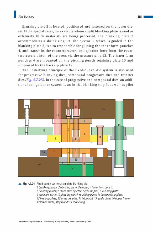
Blanking plate 2 is located, positioned and fastened on the lower die-set 17. In special cases, for example where a split blanking plate is used orextremely thick materials are being processed, the blanking plate 2accommodates a shrink ring 19. The ejector 3, which is guided in theblanking plate 2, is also responsible for guiding the inner form punches4, and transmits the counterpressure and ejection force from the coun-terpressure piston of the press via the pressure pins 13. The inner formpunches 4 are mounted on the piercing punch retaining plate 10 andsupported by the back-up plate 12.
The underlying principle of the fixed-punch die system is also usedfor progressive blanking dies, compound progressive dies and transferdies (Fig. 4.7.25). In the case of progressive and compound dies, an addi-tional coil guidance system 1, an initial blanking stop 3, as well as pilot
355Fine blanking
Fig. 4.7.24 Fixed punch system, complete blanking die:1 blanking punch; 2 blanking plate; 3 ejector; 4 inner form punch; 5 piercing punch; 6 inner form ejector; 7 ejector pins; 8 vee-ring plate; 9 pressure plate; 10 piercing punch retaining plate; 11 intermediate plate; 12 back-up plate; 13 pressure pins; 14 latch bolt; 15 guide plate; 16 upper frame; 17 lower frame; 18 gib unit; 19 shrink ring
8
2
6
45
10
12
13
14
18
13
1313
7
9
16
17
15
19
11
1
3
Metal Forming Handbook / Schuler (c) Springer-Verlag Berlin Heidelberg 1998

pins 7/8 and positive press-off pins 4 are required. The coil guide notonly ensures coil guidance but also stripping of the scrap web from thepilot pins 7/8. The initial blanking stop 3 ensures precise initial blankingof the sheet metal at the start of a coil or strip. The pilot pins 7/8 areresponsible for precisely positioning the sheet metal in each die station,i.e. ensuring that the prescribed feed step is adhered to precisely. Thetask of the positive press-off pins 4 is to compensate for the counter-pressure so that it does not have to be absorbed fully by the individualpiercing punches 6 during initial blanking in the first die station.
Die designThe factors which determine the design layout of a fine blanking die arethe geometrical shape and size of the part and the type and thickness ofthe sheet metal being processed. These parameters determine both thetype of die used and also the die system in general.
Further definition of the type of die design must be carried outaccording to the following conditions, which are basically the same asthose also valid in standard blanking. In order to achieve optimumblanking conditions, the line of application of the slide force mustcoincide as far as possible with that of the blanking or forming force (cf.Sect. 4.5). The more precisely this condition is complied with, the bet-ter the blanking result and the lower the degree of die wear.
The part drawing must contain all the dimension and tolerance spec-ifications, and the cut surface properties of the part must be indicated(Fig. 4.7.17). Depending on the type of die used, the strip layout mustindicate the position of the part in the sheet metal or the processingsequence (Fig. 4.7.2 and cf. Sect. 4.1.1). The most important aspect ofthe strip layout on the sheet metal is always the achievement of opti-mum material utilization (cf. Fig. 4.5.2 to 4.5.7). The strip layout is alsoused to define the strip width and feed step.
Calculation of press forcesThe following forces are exerted during fine blanking: the blankingforce, vee-ring force, counterforce, stripping force and ejection force(Fig. 4.7.3). The first three forces determine the configuration of thepress, adding up to create the total machine force:
356 Sheet metal forming and blanking
F F F F NGes S R G= + + [ ]
Metal Forming Handbook / Schuler (c) Springer-Verlag Berlin Heidelberg 1998
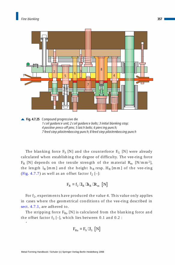
The blanking force FS [N] and the counterforce FG [N] were already calculated when establishing the degree of difficulty. The vee-ring forceFR [N] depends on the tensile strength of the material Rm [N/mm2], the length lR [mm] and the height hR resp. HR [mm] of the vee-ring (Fig. 4.7.7) as well as an offset factor f2 [–]:
For f2, experiments have produced the value 4. This value only appliesin cases where the geometrical conditions of the vee-ring described insect. 4.7.1, are adhered to.
The stripping force FRa [N] is calculated from the blanking force andthe offset factor f3 [–], which lies between 0.1 and 0.2 :
‘
357Fine blanking
Fig. 4.7.25 Compound progressive die1 coil guidance unit; 2 coil guidance bolts; 3 initial blanking stop; 4 positive press-off pins; 5 latch bolts; 6 piercing punch; 7 feed step pilot/embossing punch; 8 feed step pilot/embossing punch
25
6 3 8
4
7
1
F f l h R NR R R m= ⋅ ⋅ ⋅ [ ]2
F F f NRa S= ⋅ [ ]3
Metal Forming Handbook / Schuler (c) Springer-Verlag Berlin Heidelberg 1998
The ejection force FGa [N] is approximately the same as the strippingforce:
With a cut contour of the same length, a toothed shape requires agreater ejector force than a round contour. Both forces are additionallyinfluenced by the lubrication, the surface roughness of the blankingelements and the elastic recovery of the sheet metal.
Die lubricationFine blanking is impossible to perform without lubrication. The processwould lead to cold welding of the active elements to the blank and rapidwear and blunting of the die. Accordingly, the necessary precautions mustbe taken to ensure that the active elements are supplied with sufficientlubricant at every point of the cut contour and forming areas in the die.
Fine blanking oils can be applied to the sheet material using rollers orspray jets. Both the top and the bottom surface of the sheet metal mustbe evenly wetted by a film of lubricant. For this purpose wetting sub-stances are added to the fine blanking oils.
Where a spray system is used, oil mist is created which must beremoved using a suitable extraction device. If high-viscosity oils are usedfor thick, higher strength materials, it is also possible to apply lubricantthrough the rollers.
To ensure that the fine blanking oil applied to the sheet metal surfacealso reaches the friction partners during the blanking process, specialdesign measures are called for at the die. The guide plate, the ejectorand the inner form ejection pins must be chamfered or prepared alongthe cut contours in order to create lubrication pockets (Fig. 4.7.26).Recesses are provided to expose the vee-ring and blanking plate, soensuring that oil-wetted sheet material reaches the active part of the diewith each feed step. In the case of closed dies, the blanking oil on thesheet metal is pressed into the lubrication pockets and serves as a sup-ply for lubrication of the punch and blanking plate.
No universal fine blanking oil exists which satisfies equally allrequirements. The fine blanking oil used in each case must be speciallyadjusted according to the material, the thickness and strength of thepart. The viscosity of the oil must be coordinated to the specific typesof stress occurring during fine blanking.
358 Sheet metal forming and blanking
F F f NGa S= ⋅ [ ]3
Metal Forming Handbook / Schuler (c) Springer-Verlag Berlin Heidelberg 1998
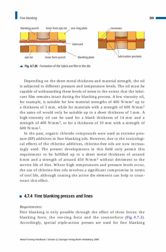
Depending on the sheet metal thickness and material strength, the oilis subjected to different pressure and temperature levels. The oil must becapable of withstanding these levels of stress to the extent that the lubri-cant film remains intact during the blanking process. A low viscosity oil,for example, is suitable for low material strengths of 400 N/mm2 up to a thickness of 3 mm, while for materials with a strength of 600 N/mm2
the same oil would only be suitable up to a sheet thickness of 1 mm. Ahigh-viscosity oil can be used for a blank thickness of 14 mm and astrength of 400 N/mm2, or for a thickness of 10 mm with a strength of600 N/mm2.
In the past, organic chloride compounds were used as extreme pres-sure (EP) additives in fine blanking oils. However, due to the toxicologi-cal effects of the chlorine additives, chlorine-free oils are now increas-ingly used. The present developments in this field only permit thisrequirement to be fulfilled up to a sheet metal thickness of around 6 mm and a strength of around 450 N/mm2 without detriment to theservice life of dies. Where high temperatures and pressure levels occur,the use of chlorine-free oils involves a significant compromise in termsof tool life, although coating the active die elements can help to coun-teract this effect.
4.7.4 Fine blanking presses and lines
RequirementsFine blanking is only possible through the effect of three forces: theblanking force, the vee-ring force and the counterforce (Fig. 4.7.3).Accordingly, special triple-action presses are used for fine blanking
359Fine blanking
Fig. 4.7.26 Formation of the lubricant film in the die
4
1
2
5
lubricant
vee-ring plateblanking punch
ejector blanking plate
inner form ejector
inner form punch lubrication pockets
recesses
Metal Forming Handbook / Schuler (c) Springer-Verlag Berlin Heidelberg 1998
operations. The machines require a controlled movement sequencewith a precise top dead center (Fig. 4.7.4). The narrow blanking clear-ance of the dies must not change even under high levels of stress. Fineblanking presses are, therefore, required to comply with stringent preci-sion requirements for example regarding slide gibs, high frame rigidityand the parallelism of die clamping surfaces. Both mechanical andhydraulic systems are used for the main slide drive.
Machine layout and drive systemIn standard configuration, mechanical presses (Fig. 4.7.27) are equippedwith a “combination bed” for the tool systems of moving and fixed punch(Fig. 4.7.23 and 4.7.24). Making use of the straight-side principle, themonobloc press frame as a welded construction offers good dimensionalrigidity and freedom from vibrations (cf. Fig. 3.1.1). A clearance-free, pre-tensioned slide gib is used (cf. Fig. 3.1.5). A central support in the upperand lower die clamping plate ensures optimum die support and introduc-tion of forces to the die. A controlled, infinitely variable DC motor drivesthe press via the flywheel, a disk clutch and a worm gear pair on two syn-chronously running crankshafts with different eccentricity (Fig. 4.7.27).The crankshafts drive a double knuckle-joint system which generates themovement sequence of the slide required for fine blanking.
This drive system is particularly suited for material thicknessesbetween approx. 1 and 8 mm, and total press forces of up to 2,500 kN.The vee-ring force and counterforce are applied by hydraulic systems.The mechanical drive system is characterized by the following factors:
– a fixed slide movement sequence with constant stroke and preciseposition of the top and bottom dead center,
– low energy consumption,– high output depending on the size of the press with stroking rates of
up to 140/min,– minimal setting and maintenance input.
The press body of hydraulic presses comprises a robust monobloc weldedstraight-side construction with high rigidity (Fig. 4.7.28 and cf. Fig. 3.1.1).This is achieved by implementing suitable design measures such as selec-tion of large upright cross-sections and large ribs. The slide and mainpiston together form a unit which is integrated in the press bed. Theslide is guided in the press body and the lower part of the slide piston.
360 Sheet metal forming and blanking
Metal Forming Handbook / Schuler (c) Springer-Verlag Berlin Heidelberg 1998
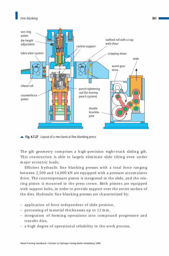
The gib geometry comprises a high-precision eight-track sliding gib.This construction is able to largely eliminate slide tilting even undermajor eccentric loads.
Efficient hydraulic fine blanking presses with a total force rangingbetween 2,500 and 14,000 kN are equipped with a pressure accumulatordrive. The counterpressure piston is integrated in the slide, and the vee-ring piston is mounted in the press crown. Both pistons are equippedwith support bolts, in order to provide support over the entire surface ofthe dies. Hydraulic fine blanking presses are characterized by:
– application of force independent of slide position,– processing of material thicknesses up to 12 mm,– integration of forming operations into compound progressive and
transfer dies,– a high degree of operational reliability in the work process.
361Fine blanking
Fig. 4.7.27 Layout of a mechanical fine blanking press
vee-ringpiston
die height
adjustment
lubrication system
infeed roll
counterforce
piston
central support
punch tightening
rod (for moving
punch system)
double
knuckle-
joint
worm geardrive
slide
outfeed roll with scrapweb shear
cropping shear
Metal Forming Handbook / Schuler (c) Springer-Verlag Berlin Heidelberg 1998
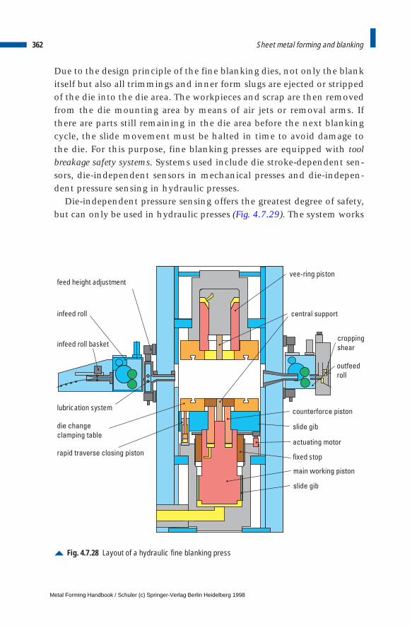
Due to the design principle of the fine blanking dies, not only the blankitself but also all trimmings and inner form slugs are ejected or strippedof the die into the die area. The workpieces and scrap are then removedfrom the die mounting area by means of air jets or removal arms. Ifthere are parts still remaining in the die area before the next blankingcycle, the slide movement must be halted in time to avoid damage tothe die. For this purpose, fine blanking presses are equipped with toolbreakage safety systems. Systems used include die stroke-dependent sen-sors, die-independent sensors in mechanical presses and die-indepen-dent pressure sensing in hydraulic presses.
Die-independent pressure sensing offers the greatest degree of safety,but can only be used in hydraulic presses (Fig. 4.7.29). The system works
362 Sheet metal forming and blanking
Fig. 4.7.28 Layout of a hydraulic fine blanking press
vee-ring piston
die change
clamping table
central support
cropping
shear
outfeed
roll
counterforce piston
slide gib
actuating motor
fixed stop
main working piston
slide gib
feed height adjustment
infeed roll
infeed roll basket
lubrication system
rapid traverse closing piston
Metal Forming Handbook / Schuler (c) Springer-Verlag Berlin Heidelberg 1998
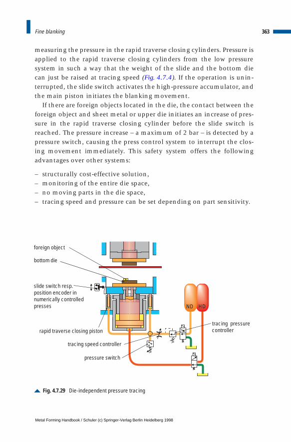
measuring the pressure in the rapid traverse closing cylinders. Pressure isapplied to the rapid traverse closing cylinders from the low pressuresystem in such a way that the weight of the slide and the bottom diecan just be raised at tracing speed (Fig. 4.7.4). If the operation is unin-terrupted, the slide switch activates the high-pressure accumulator, andthe main piston initiates the blanking movement.
If there are foreign objects located in the die, the contact between theforeign object and sheet metal or upper die initiates an increase of pres-sure in the rapid traverse closing cylinder before the slide switch isreached. The pressure increase – a maximum of 2 bar – is detected by apressure switch, causing the press control system to interrupt the clos-ing movement immediately. This safety system offers the followingadvantages over other systems:
– structurally cost-effective solution,– monitoring of the entire die space,– no moving parts in the die space,– tracing speed and pressure can be set depending on part sensitivity.
363Fine blanking
Fig. 4.7.29 Die-independent pressure tracing
HD
)(
ND
foreign object
bottom die
slide switch resp.position encoder innumerically controlledpresses
pressure switch
tracing speed controller
tracing pressurecontrollerrapid traverse closing piston
Metal Forming Handbook / Schuler (c) Springer-Verlag Berlin Heidelberg 1998
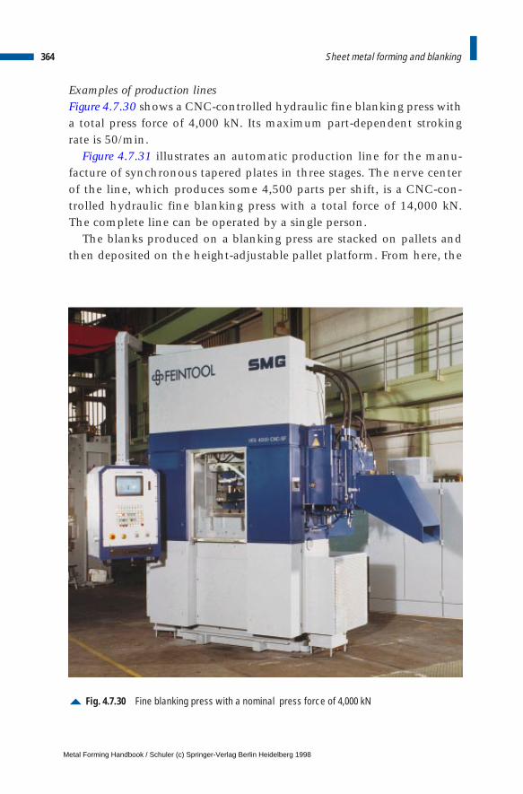
Examples of production linesFigure 4.7.30 shows a CNC-controlled hydraulic fine blanking press witha total press force of 4,000 kN. Its maximum part-dependent strokingrate is 50/min.
Figure 4.7.31 illustrates an automatic production line for the manu-facture of synchronous tapered plates in three stages. The nerve centerof the line, which produces some 4,500 parts per shift, is a CNC-con-trolled hydraulic fine blanking press with a total force of 14,000 kN.The complete line can be operated by a single person.
The blanks produced on a blanking press are stacked on pallets andthen deposited on the height-adjustable pallet platform. From here, the
364 Sheet metal forming and blanking
Fig. 4.7.30 Fine blanking press with a nominal press force of 4,000 kN
Metal Forming Handbook / Schuler (c) Springer-Verlag Berlin Heidelberg 1998
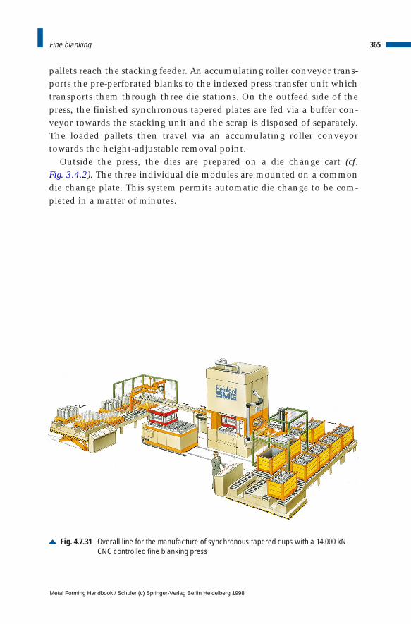
pallets reach the stacking feeder. An accumulating roller conveyor trans-ports the pre-perforated blanks to the indexed press transfer unit whichtransports them through three die stations. On the outfeed side of thepress, the finished synchronous tapered plates are fed via a buffer con-veyor towards the stacking unit and the scrap is disposed of separately.The loaded pallets then travel via an accumulating roller conveyortowards the height-adjustable removal point.
Outside the press, the dies are prepared on a die change cart (cf. Fig. 3.4.2). The three individual die modules are mounted on a commondie change plate. This system permits automatic die change to be com-pleted in a matter of minutes.
365Fine blanking
Fig. 4.7.31 Overall line for the manufacture of synchronous tapered cups with a 14,000 kNCNC controlled fine blanking press
Metal Forming Handbook / Schuler (c) Springer-Verlag Berlin Heidelberg 1998
4 Sheet metal forming and blanking
4.8 Bending
4.8.1 Bending process
Classification of bending processesBending by forming as a production process is subdivided according toDIN 8586 into two groups: bending by forming using linear and rotat-ing die motions (cf. Fig. 2.1.3). Sections 4.8.2 and 4.8.3 deal with bend-ing using rotary die motion, i.e. roll forming and roll straightening.These fall under the category of roll bending.
Bending radius and bending angleBending dies should be designed so as to avoid sharp bent edges. Theinside bending radius ri [mm] depends on the sheet metal thickness s [mm] and should be selected to be as large as possible, because sharpbent edges may lead to material failure. On principle, the bendingradius should assume the values recommended by DIN 6935, i.e. theyshould be selected from the following series (preferably using the valuesin bold type):
1 1,2 1,6 2 2,5 3 4 5 6 8 10 12 16 20 25 28 32 36 40 4550 63 80 100 etc.
When bending sheet metal, particular attention should also be paid tothe rolling direction. The most suitable direction for bending is trans-verse to the direction of rolling. If the bending axis is positioned paral-lel to the rolling direction of the sheet metal, ri min must be selectedhigher than when bending at right angles to the direction of rolling.
Metal Forming Handbook / Schuler (c) Springer-Verlag Berlin Heidelberg 1998
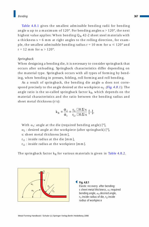
Table 4.8.1 gives the smallest admissible bending radii for bendingangle a up to a maximum of 120°. For bending angles a > 120°, the nexthighest value applies: When bending QSt 42-2 sheet steel materials witha thickness s = 6 mm at right angles to the rolling direction, for exam-ple, the smallest admissible bending radius r = 10 mm for a # 120° andr = 12 mm for a > 120°.
SpringbackWhen designing a bending die, it is necessary to consider springback thatoccurs after unloading. Springback characteristics differ depending onthe material type. Springback occurs with all types of forming by bend-ing, when bending in presses, folding, roll forming and roll bending.
As a result of springback, the bending die angle a does not corre-spond precisely to the angle desired at the workpiece a2 (Fig. 4.8.1). Theangle ratio is the so-called springback factor kR, which depends on thematerial characteristics and the ratio between the bending radius andsheet metal thickness (r/s):
With a1: angle at the die (required bending angle) [°],a2 : desired angle at the workpiece (after springback) [°],s: sheet metal thickness [mm],ri1 : inside radius at the die [mm],ri2 : inside radius at the workpiece [mm].
The springback factor kR for various materials is given in Table 4.8.2.
367Bending
s
ri2
a1
ri1a2
Fig. 4.8.1Elastic recovery after bending: s sheet metal thickness, a1 requiredbending angle, a2 desired angle, ri1 inside radius of die, ri2 insideradius of workpiece
kr s
r sRi
i
= = + ⋅+ ⋅
[ ]αα
2
1
1
2
0 5
0 5
.
.– ,
Metal Forming Handbook / Schuler (c) Springer-Verlag Berlin Heidelberg 1998
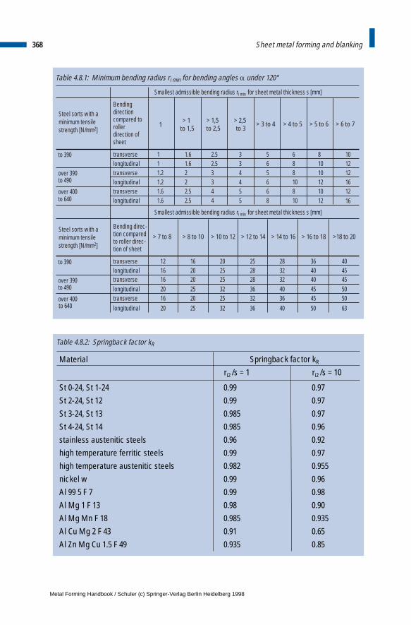
368 Sheet metal forming and blanking
Table 4.8.1: Minimum bending radius ri min for bending angles a under 120°
Bending direction compared toroller direction ofsheet
1> 1
to 1,5> 2,5 to 3
> 3 to 4 > 4 to 5 > 5 to 6 > 6 to 7
to 390 transverse 1 1.6 2.5 3 5 6 8longitudinal 1 1.6 2.5 3 6 8 10
over 390 transverse 1.2 2 3 4 5 8 10to 490 longitudinal 1.2 2 3 4 6 10 12over 400 transverse 1.6 2.5 4 5 6 8 10to 640 longitudinal 1.6 2.5 4 5 8 10 12
101212161216
> 7 to 8 > 8 to 10 > 10 to 12 > 12 to 14 > 14 to 16 > 16 to 18 >18 to 20
to 390 transverse 12 16 20 25 28 36 40longitudinal 16 20 25 28 32 40 45
over 390 transverse 16 20 25 28 32 40 45to 490 longitudinal 20 25 32 36 40 45 50over 400 transverse 16 20 25 32 36 45 50to 640 longitudinal 20 25 32 36 40 50 63
Smallest admissible bending radius ri min for sheet metal thickness s [mm]
Smallest admissible bending radius ri min for sheet metal thickness s [mm]
> 1,5 to 2,5
Steel sorts with a minimum tensilestrength [N/mm2]
Steel sorts with a minimum tensilestrength [N/mm2]
Bending direc-tion compared to roller direc-tion of sheet
Table 4.8.2: Springback factor kR
Material Springback factor kR
St 0-24, St 1-24 0.99St 2-24, St 12 0.99St 3-24, St 13 0.985St 4-24, St 14 0.985stainless austenitic steels 0.96high temperature ferritic steels 0.99high temperature austenitic steels 0.982nickel w 0.99Al 99 5 F 7 0.99Al Mg 1 F 13 0.98Al Mg Mn F 18 0.985Al Cu Mg 2 F 43 0.91Al Zn Mg Cu 1.5 F 49 0.935
ri2 /s = 1
0.970.970.970.960.920.970.9550.960.980.900.9350.650.85
ri2 /s = 10
Metal Forming Handbook / Schuler (c) Springer-Verlag Berlin Heidelberg 1998
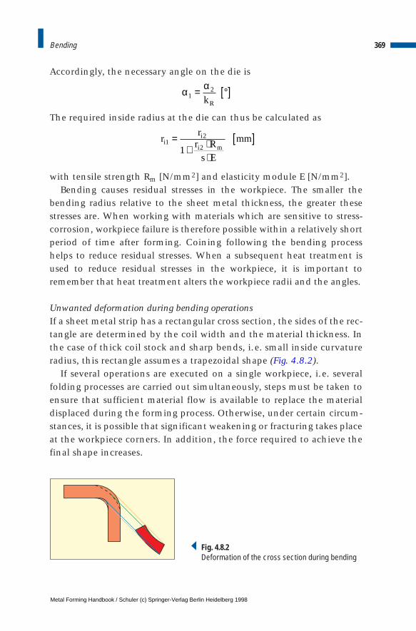
Accordingly, the necessary angle on the die is
The required inside radius at the die can thus be calculated as
with tensile strength Rm [N/mm2] and elasticity module E [N/mm2].Bending causes residual stresses in the workpiece. The smaller the
bending radius relative to the sheet metal thickness, the greater thesestresses are. When working with materials which are sensitive to stress-corrosion, workpiece failure is therefore possible within a relatively shortperiod of time after forming. Coining following the bending processhelps to reduce residual stresses. When a subsequent heat treatment isused to reduce residual stresses in the workpiece, it is important toremember that heat treatment alters the workpiece radii and the angles.
Unwanted deformation during bending operationsIf a sheet metal strip has a rectangular cross section, the sides of the rec-tangle are determined by the coil width and the material thickness. Inthe case of thick coil stock and sharp bends, i.e. small inside curvatureradius, this rectangle assumes a trapezoidal shape (Fig. 4.8.2).
If several operations are executed on a single workpiece, i.e. severalfolding processes are carried out simultaneously, steps must be taken toensure that sufficient material flow is available to replace the materialdisplaced during the forming process. Otherwise, under certain circum-stances, it is possible that significant weakening or fracturing takes placeat the workpiece corners. In addition, the force required to achieve thefinal shape increases.
369Bending
rr
r Rs E
mmii
i m1
2
21=
+ ⋅⋅
[ ]
Fig. 4.8.2Deformation of the cross section during bending
α α1
2= °[ ]kR
Metal Forming Handbook / Schuler (c) Springer-Verlag Berlin Heidelberg 1998

Determining the blank length for bent workpiecesThe blank length of the part to be bent is not equal to the fiber lengthlocated at the center of the cross section after bending. The extendedlength of bent components 1 [mm] is calculated as
whereby a [mm] and b [mm] stand for the lengths of the two bent legs,and v [mm] is a compensation factor which can be either positive ornegative (Fig. 4.8.3).
It should be noted that a is the bending and b the opening angle ofthe bent part. Values for v are contained in DIN 6935 or can be calcu-lated for every required angle:
– for b = 0° to 90°
– for b > 90° to 165°
with correction factor k [–]:
The calculated extended length dimensions should be rounded up tothe next higher full millimeter.
370 Sheet metal forming and blanking
– fo r/s 5 and
– f r/s t 5
k r
kr
sor o
= >
= + ⋅
1
0 651
2. log
b
α
a
β
b
a Fig. 4.8.3Geometry of bent legs
l a b v or opening angles o nd
l a b or opening angles o
= + + [ ] ° °
= + [ ] > ° °
mm
mm
f 0 t 165 a
f 165 t 180
v rs
k r s mmR= ⋅ °°
⋅ + ⋅ ⋅ +( ) [ ]π β180
180 22
––
v rs
k r s mmR= ⋅ °°
⋅ + ⋅ ⋅ +( ) ⋅ ° [ ]π β β180
180 22
180
2
–– tan
–
Metal Forming Handbook / Schuler (c) Springer-Verlag Berlin Heidelberg 1998

Example:You wish to bend a piece of 3 mm thick sheet metal made of St 37-2, materialnumber 1.0037, in accordance with Fig. 4.8.4. The minimum tensile strengthfor this material is Rm = 360 N/mm2. Using Table 4.8.1 it is accordingly possibleto determine the smallest permissible bending radius at ri min = 3 mm. To cal-culate the blank length of the sheet metal part, we require the sum of the leglengths and all the relevant compensation values v, using the appropriate cor-rection factor k for each case.
Sum of the leg lengths:
371Bending
a b c d mm
r mm s mm
k
v mm
r mm s mm
k
+ + + = + + + =
= ° = =
= + ⋅ =
= ⋅ ⋅ + ⋅ ⋅ +( ) =
= ° = =
= + ⋅
30 60 75 20 185
90 5 3
0 651
2
5
30 761
90
1805
3
20 761 2 5 3 6 35
45 3 3
0 651
2
1
1
2
for
for
β
π
β
, , :
. log .
. – – .
, , :
. loglog . log . .
. – – .
, , :
. log .
. –
3
30 65
1
21 0 65 0 0 65
135
1803
3
20 65 2 3 3 2 63
135 10 3
0 651
2
10
30 911
45
18010
3
20 911 2
2
3
3
= + = + =
= ⋅ ⋅ + ⋅ ⋅ +( ) =
= ° = =
= + ⋅ =
= ⋅ ⋅ + ⋅ ⋅
v mm
r mm s mm
k
v
π
β
π
for
1010 345
2
0 25 11 366 26 22 5 1 84
6 35 2 63 1 84 10 82
1 185 10 82 174 18
1 2 3
+( ) ⋅ ° =
= ⋅ ⋅ ⋅ ° =
= + +
= =
= + + + + = =
tan
. . – tan . – .
– . – . – . – .
– . .
π mm
v v v v
v mm
The total extended length adds up to:
a b c d v mm
ges
ges
ges
The sum of the compensation values amounts to:
The result is rounded up to the next higher millimeter,resulting in a final blank dimension of 175 mm.
Metal Forming Handbook / Schuler (c) Springer-Verlag Berlin Heidelberg 1998
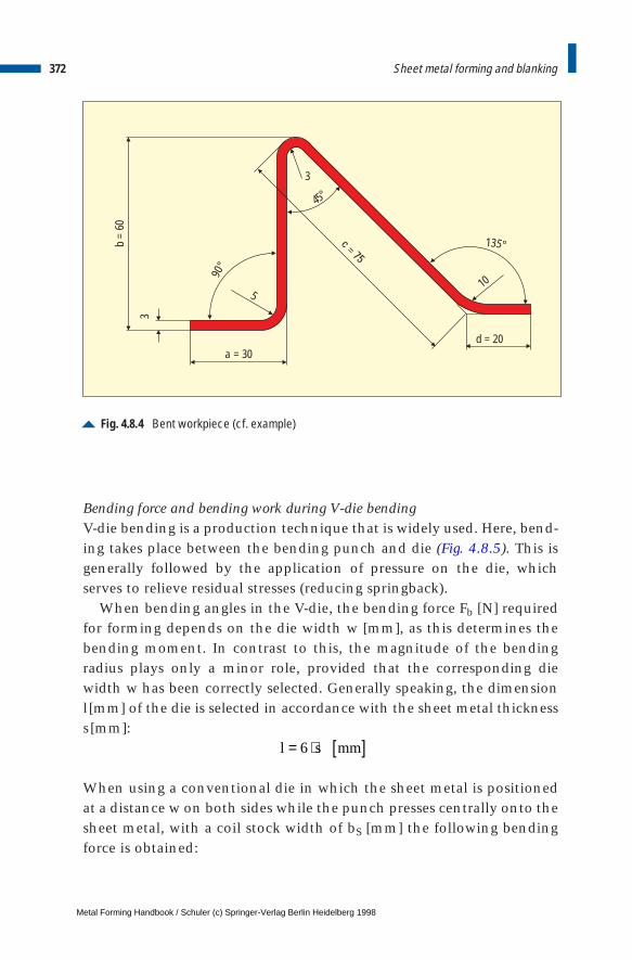
Bending force and bending work during V-die bendingV-die bending is a production technique that is widely used. Here, bend-ing takes place between the bending punch and die (Fig. 4.8.5). This isgenerally followed by the application of pressure on the die, whichserves to relieve residual stresses (reducing springback).
When bending angles in the V-die, the bending force Fb [N] requiredfor forming depends on the die width w [mm], as this determines thebending moment. In contrast to this, the magnitude of the bendingradius plays only a minor role, provided that the corresponding diewidth w has been correctly selected. Generally speaking, the dimensionl[mm] of the die is selected in accordance with the sheet metal thicknesss[mm]:
When using a conventional die in which the sheet metal is positionedat a distance w on both sides while the punch presses centrally onto thesheet metal, with a coil stock width of bS [mm] the following bendingforce is obtained:
372 Sheet metal forming and blanking
Fig. 4.8.4 Bent workpiece (cf. example)
d = 20
3
90°
5
3
45°
135°
10
b=
60
a = 30
l s mm= ⋅ [ ]6
Metal Forming Handbook / Schuler (c) Springer-Verlag Berlin Heidelberg 1998
These are simplified formulae which, however, are sufficient in prac-tice for approximate calculations. The bending work Wb [Nm] amountsto:
if the path of the punch from impact with the sheet metal until the endof the bending process is designated as h [m]. The constant value xtakes into account the uneven force progression along the path of thepunch and generally lies between x = 0.3 and 0.6, depending on bend-ing requirements and machine setting.
Example:If a 2 mm thick aluminium sheet AlMg5Mn measuring 50 mm wide with a min-imum tensile strength of Rm =280 N/mm2 is bent in a V-die with a width of w = 15mm using a punch displacement of h = 7mm, the resulting bending forceis:
When bending using a V-die, the process factor x = 1/3. The bending work thusamounts to:
4.8.2 Roll forming and variety of sections
ProcessRoll forming is categorized according to DIN 8586 as a method of form-ing by bending using a rotary die motion (cf. Fig. 2.1.3). During rollforming, the sheet coil or blank is formed in a stepless and continuous
373Bending
Fb s R
wN w s
Fs
w
b s R
wN w s
bs m
bs m
= ⋅ ⋅ [ ] ≥
= + ⋅ ⋅ ⋅ ⋅ [ ] <
2
2
10
14
10
for
or
for
/
/
W x F h Nmb b= ⋅ ⋅ [ ],
Fmm mm N mm
mmNb = ⋅ ⋅ =50 4 280
153 733
2 2/,
W N m Nm Jb = ⋅ ⋅ = =1
33 733 0 007 8 7 8 7, . . .
Metal Forming Handbook / Schuler (c) Springer-Verlag Berlin Heidelberg 1998
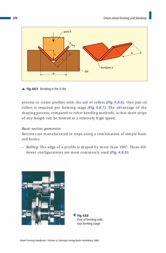
process to create profiles with the aid of rollers (Fig. 4.8.6). One pair ofrollers is required per forming stage (Fig. 4.8.7). The advantage of theshaping process, compared to other bending methods, is that sheet stripsof any length can be formed at a relatively high speed.
Basic section geometriesSections are manufactured in steps using a combination of simple basicroll forms:
– Rolling: The edge of a profile is shaped by more than 180°. Three dif-ferent configurations are most commonly used (Fig. 4.8.8).
374 Sheet metal forming and blanking
Fig. 4.8.5 Bending in the V-die
h
die
punch
workpiece
Fig. 4.8.6Pair of forming rolls: last forming stage
Metal Forming Handbook / Schuler (c) Springer-Verlag Berlin Heidelberg 1998
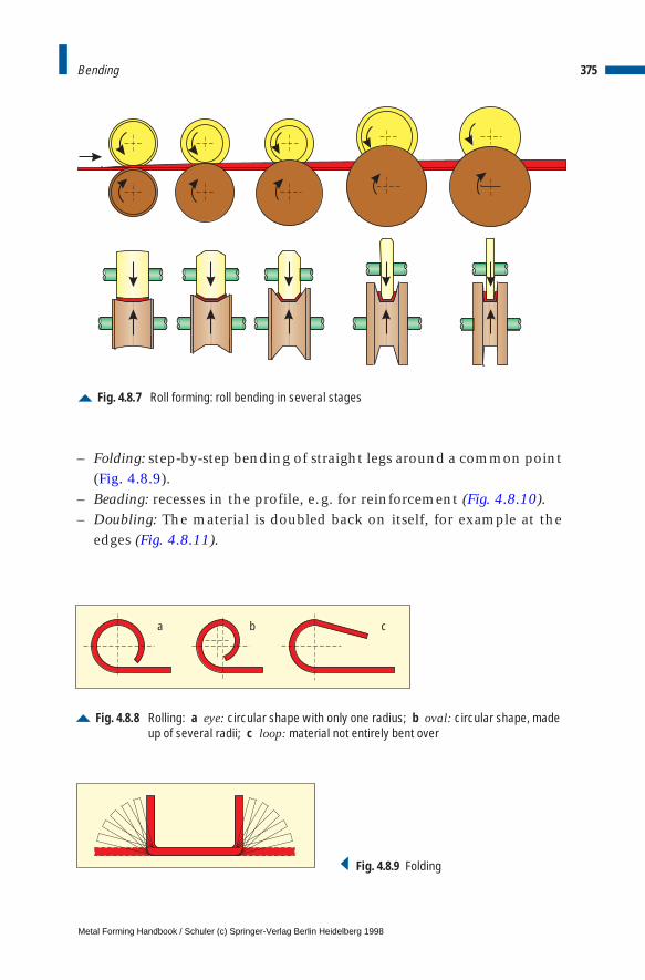
– Folding: step-by-step bending of straight legs around a common point(Fig. 4.8.9).
– Beading: recesses in the profile, e.g. for reinforcement (Fig. 4.8.10).– Doubling: The material is doubled back on itself, for example at the
edges (Fig. 4.8.11).
375Bending
Fig. 4.8.8 Rolling: a eye: circular shape with only one radius; b oval: circular shape, madeup of several radii; c loop: material not entirely bent over
a b c
Fig. 4.8.7 Roll forming: roll bending in several stages
Fig. 4.8.9 Folding
Metal Forming Handbook / Schuler (c) Springer-Verlag Berlin Heidelberg 1998
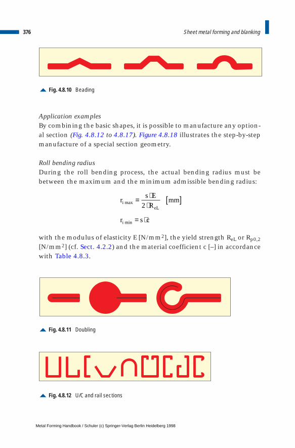
Application examplesBy combining the basic shapes, it is possible to manufacture any option-al section (Fig. 4.8.12 to 4.8.17). Figure 4.8.18 illustrates the step-by-stepmanufacture of a special section geometry.
Roll bending radiusDuring the roll bending process, the actual bending radius must bebetween the maximum and the minimum admissible bending radius:
with the modulus of elasticity E [N/mm2], the yield strength ReL or Rp0,2
[N/mm2] (cf. Sect. 4.2.2) and the material coefficient c [–] in accordancewith Table 4.8.3.
376 Sheet metal forming and blanking
Fig. 4.8.10 Beading
Fig. 4.8.11 Doubling
Fig. 4.8.12 U/C and rail sections
rs E
Rmm
r s c
ieL
i
max
min
= ⋅⋅
[ ]
= ⋅
2
Metal Forming Handbook / Schuler (c) Springer-Verlag Berlin Heidelberg 1998
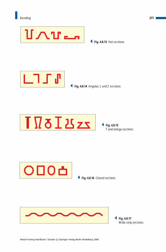
377Bending
Fig. 4.8.13 Hat sections
Fig. 4.8.14 Angular, L and Z sections
Fig. 4.8.15T and omega sections
Fig. 4.8.17Wide strip sections
Fig. 4.8.16 Closed sections
Metal Forming Handbook / Schuler (c) Springer-Verlag Berlin Heidelberg 1998
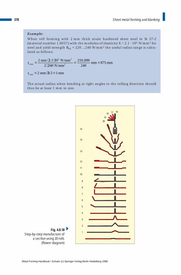
Example:When roll forming with 2 mm thick strain hardened sheet steel in St 37-2(material number 1.0037) with the modulus of elasticity E = 2.1 · 105 N/mm2 forsteel and yield strength ReL = 220…240 N/mm2 the useful radius range is calcu-lated as follows:
The actual radius when bending at right angles to the rolling direction shouldthus be at least 1 mm in size.
378 Sheet metal forming and blanking
rmm N mm
N mmmm mm
r mm mm
i
i
max
min
. /
/
,
.
= ⋅ ⋅⋅
= =
= ⋅ =
2 2 1 10
2 240
210 000
240875
2 0 5 1
5 2
2
1
2
3
4
5
6
7
8
9
10
11
12
13
14
15
16
20
19
1817
Fig. 4.8.18Step-by-step manufacture of
a section using 20 rolls(flower diagram)
Metal Forming Handbook / Schuler (c) Springer-Verlag Berlin Heidelberg 1998

Roll forming linesRoll forming lines are classified according to two different operatingmodes. Start-stop lines consist in their simplest form of a decoiler, a coilloop, a roll forming machine and a parting die. The product length isdetermined by the roll forming machine (Fig. 4.8.19). Due to the use ofthe start-stop method, blanking and embossing operations are also pos-sible using the roll forming machine's positioning system.
Continuous running roll forming lines operate at a constant speed. Thistype of line is used to process sheet metal blanks or strips to create longsections. While on blank processing lines cut-to-length blank metal
379Bending
Table 4.8.3: Material coefficient c for the calculation of ri min
Material coefficient c
MaterialBending directioncompared to rollingdirection of sheet
Material soft annealed
Material strainhardened
Al transverse 0.01 0.30longitudinal 0.30 0.80
Cu transverse 0.01 1.00longitudinal 0.30 2.00
Ms 67, Ms 72, transverse 0.01 0.40CuZn 37 longitudinal 0.30 0.80St 13 transverse 0.01 0.40
longitudinal 0.40 0.80
C 15 – C 25 transverse 0.10 0.50St 37 – St 42 longitudinal 0.50 1.00
C 35 – C 45 transverse 0.30 0.80St 50 – St 70 longitudinal 0.80 1.50
Fig. 4.8.19 Start-stop roll forming line
decoiler with coil
infeed unit coil loop
roll forming machinestraightening machine outfeedroller conveyor
parting device
Metal Forming Handbook / Schuler (c) Springer-Verlag Berlin Heidelberg 1998
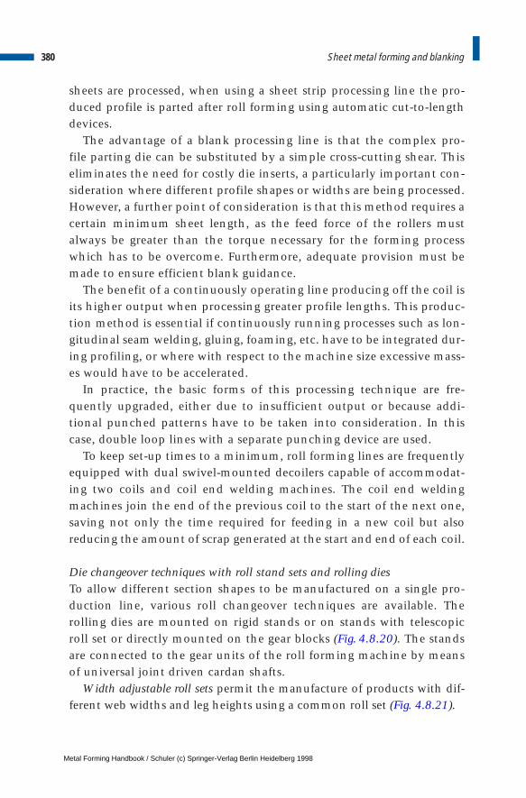
sheets are processed, when using a sheet strip processing line the pro-duced profile is parted after roll forming using automatic cut-to-lengthdevices.
The advantage of a blank processing line is that the complex pro-file parting die can be substituted by a simple cross-cutting shear. This eliminates the need for costly die inserts, a particularly important con-sideration where different profile shapes or widths are being processed.However, a further point of consideration is that this method requires acertain minimum sheet length, as the feed force of the rollers mustalways be greater than the torque necessary for the forming processwhich has to be overcome. Furthermore, adequate provision must bemade to ensure efficient blank guidance.
The benefit of a continuously operating line producing off the coil isits higher output when processing greater profile lengths. This produc-tion method is essential if continuously running processes such as lon-gitudinal seam welding, gluing, foaming, etc. have to be integrated dur-ing profiling, or where with respect to the machine size excessive mass-es would have to be accelerated.
In practice, the basic forms of this processing technique are fre-quently upgraded, either due to insufficient output or because addi-tional punched patterns have to be taken into consideration. In thiscase, double loop lines with a separate punching device are used.
To keep set-up times to a minimum, roll forming lines are frequentlyequipped with dual swivel-mounted decoilers capable of accommodat-ing two coils and coil end welding machines. The coil end weldingmachines join the end of the previous coil to the start of the next one,saving not only the time required for feeding in a new coil but alsoreducing the amount of scrap generated at the start and end of each coil.
Die changeover techniques with roll stand sets and rolling diesTo allow different section shapes to be manufactured on a single pro-duction line, various roll changeover techniques are available. Therolling dies are mounted on rigid stands or on stands with telescopicroll set or directly mounted on the gear blocks (Fig. 4.8.20). The standsare connected to the gear units of the roll forming machine by meansof universal joint driven cardan shafts.
Width adjustable roll sets permit the manufacture of products with dif-ferent web widths and leg heights using a common roll set (Fig. 4.8.21).
380 Sheet metal forming and blanking
Metal Forming Handbook / Schuler (c) Springer-Verlag Berlin Heidelberg 1998
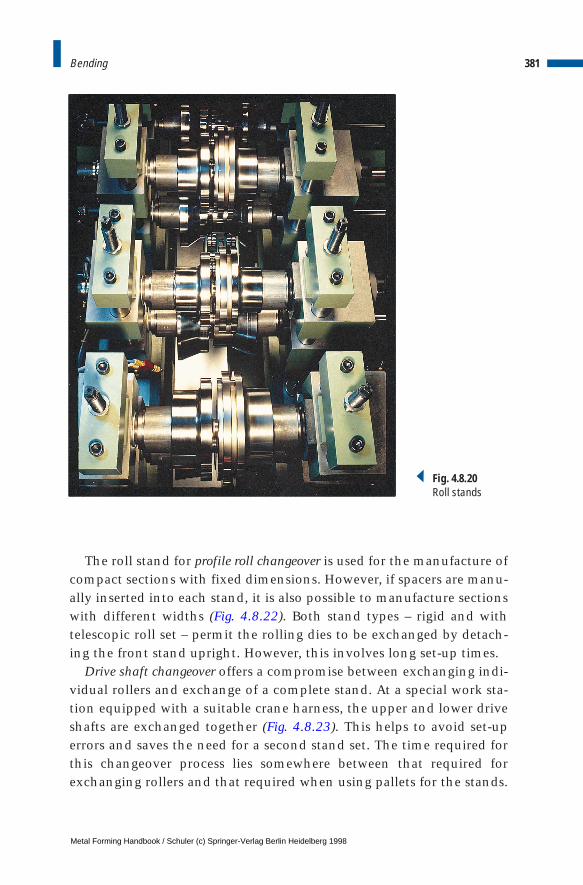
The roll stand for profile roll changeover is used for the manufacture ofcompact sections with fixed dimensions. However, if spacers are manu-ally inserted into each stand, it is also possible to manufacture sectionswith different widths (Fig. 4.8.22). Both stand types – rigid and withtelescopic roll set – permit the rolling dies to be exchanged by detach-ing the front stand upright. However, this involves long set-up times.
Drive shaft changeover offers a compromise between exchanging indi-vidual rollers and exchange of a complete stand. At a special work sta-tion equipped with a suitable crane harness, the upper and lower driveshafts are exchanged together (Fig. 4.8.23). This helps to avoid set-uperrors and saves the need for a second stand set. The time required forthis changeover process lies somewhere between that required forexchanging rollers and that required when using pallets for the stands.
381Bending
Fig. 4.8.20 Roll stands
Metal Forming Handbook / Schuler (c) Springer-Verlag Berlin Heidelberg 1998
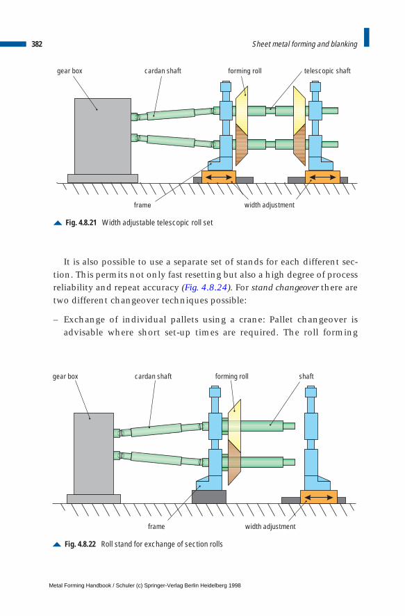
It is also possible to use a separate set of stands for each different sec-tion. This permits not only fast resetting but also a high degree of processreliability and repeat accuracy (Fig. 4.8.24). For stand changeover there aretwo different changeover techniques possible:
– Exchange of individual pallets using a crane: Pallet changeover isadvisable where short set-up times are required. The roll forming
382 Sheet metal forming and blanking
Fig. 4.8.21 Width adjustable telescopic roll set
gear box cardan shaft telescopic shaft
width adjustment
forming roll
frame
Fig. 4.8.22 Roll stand for exchange of section rolls
gear box cardan shaft forming roll shaft
width adjustmentframe
Metal Forming Handbook / Schuler (c) Springer-Verlag Berlin Heidelberg 1998
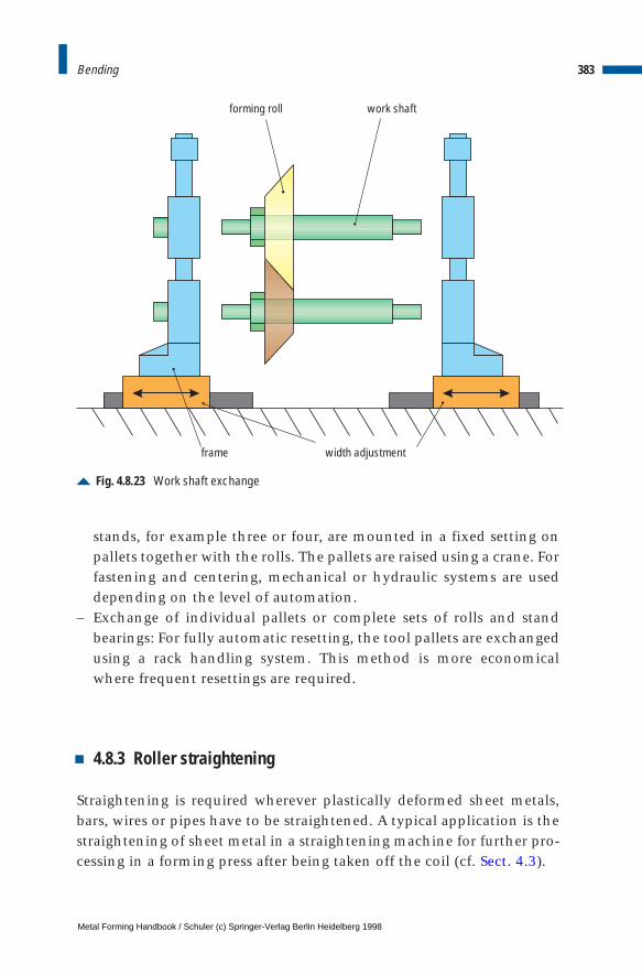
stands, for example three or four, are mounted in a fixed setting onpallets together with the rolls. The pallets are raised using a crane. Forfastening and centering, mechanical or hydraulic systems are useddepending on the level of automation.
– Exchange of individual pallets or complete sets of rolls and standbearings: For fully automatic resetting, the tool pallets are exchangedusing a rack handling system. This method is more economicalwhere frequent resettings are required.
4.8.3 Roller straightening
Straightening is required wherever plastically deformed sheet metals,bars, wires or pipes have to be straightened. A typical application is thestraightening of sheet metal in a straightening machine for further pro-cessing in a forming press after being taken off the coil (cf. Sect. 4.3).
383Bending
Fig. 4.8.23 Work shaft exchange
frame
forming roll work shaft
width adjustment
Metal Forming Handbook / Schuler (c) Springer-Verlag Berlin Heidelberg 1998
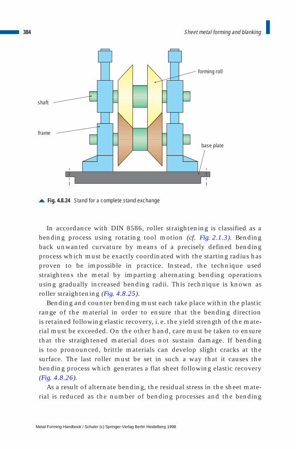
In accordance with DIN 8586, roller straightening is classified as abending process using rotating tool motion (cf. Fig. 2.1.3). Bendingback unwanted curvature by means of a precisely defined bendingprocess which must be exactly coordinated with the starting radius hasproven to be impossible in practice. Instead, the technique usedstraightens the metal by imparting alternating bending operationsusing gradually increased bending radii. This technique is known asroller straightening (Fig. 4.8.25).
Bending and counter bending must each take place within the plasticrange of the material in order to ensure that the bending direction is retained following elastic recovery, i. e. the yield strength of the mate-rial must be exceeded. On the other hand, care must be taken to ensurethat the straightened material does not sustain damage. If bending is too pronounced, brittle materials can develop slight cracks at the surface. The last roller must be set in such a way that it causes the bending process which generates a flat sheet following elastic recovery(Fig. 4.8.26).
As a result of alternate bending, the residual stress in the sheet mate-rial is reduced as the number of bending processes and the bending
384 Sheet metal forming and blanking
Fig. 4.8.24 Stand for a complete stand exchange
frame
shaft
forming roll
base plate
Metal Forming Handbook / Schuler (c) Springer-Verlag Berlin Heidelberg 1998
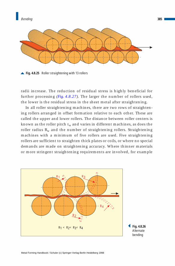
radii increase. The reduction of residual stress is highly beneficial forfurther processing (Fig. 4.8.27). The larger the number of rollers used,the lower is the residual stress in the sheet metal after straightening.
In all roller straightening machines, there are two rows of straighten-ing rollers arranged in offset formation relative to each other. These arecalled the upper and lower rollers. The distance between roller centers isknown as the roller pitch tw and varies in different machines, as does theroller radius Rw and the number of straightening rollers. Straighteningmachines with a minimum of five rollers are used. Five straighteningrollers are sufficient to straighten thick plates or coils, or where no specialdemands are made on straightening accuracy. Where thinner materialsor more stringent straightening requirements are involved, for example
385Bending
Fig. 4.8.25 Roller straightening with 13 rollers
R1
R2
R4
R3
R1 R2 R4R3< < < Fig. 4.8.26Alternatebending
Metal Forming Handbook / Schuler (c) Springer-Verlag Berlin Heidelberg 1998
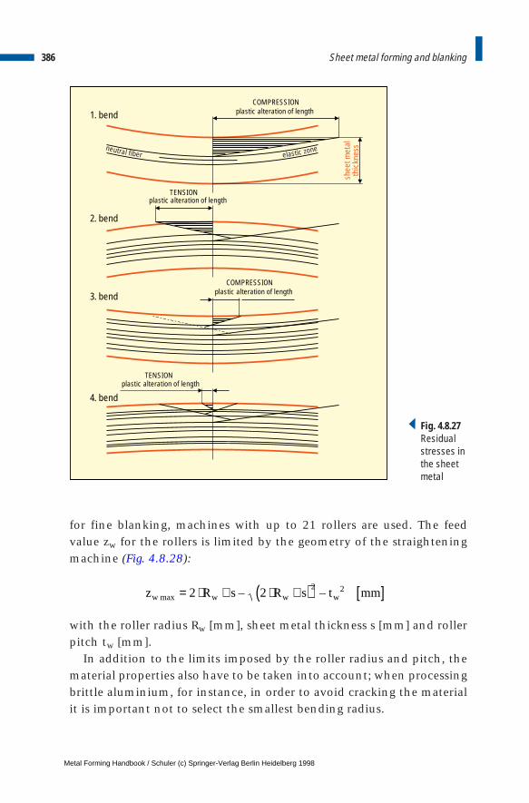
for fine blanking, machines with up to 21 rollers are used. The feedvalue zw for the rollers is limited by the geometry of the straighteningmachine (Fig. 4.8.28):
with the roller radius Rw [mm], sheet metal thickness s [mm] and rollerpitch tw [mm].
In addition to the limits imposed by the roller radius and pitch, thematerial properties also have to be taken into account; when processingbrittle aluminium, for instance, in order to avoid cracking the materialit is important not to select the smallest bending radius.
386 Sheet metal forming and blanking
plastic alteration of lengthCOMPRESSION
plastic alteration of lengthCOMPRESSION
plastic alteration of lengthTENSION
plastic alteration of lengthTENSION
1. bend
2. bend
3. bend
4. bend
neutral fiberenozcitsale
shee
t met
alth
ickn
ess
Fig. 4.8.27Residualstresses inthe sheetmetal
z R s R s t mmw w w wmax – –= ⋅ + ⋅ +( ) [ ]2 22 2
Metal Forming Handbook / Schuler (c) Springer-Verlag Berlin Heidelberg 1998

Example:Sheet steel St 37 (material number 1.0037) with a thickness of 2 mm has to bestraightened. The straightening roller pitch of the straightening machine is tw = 22 mm, the roller diameter Rw = 20 mm. The maximum feed value is calculated as
Roller straightening machinesGenerally speaking, roller straightening machines for straightening sheetmetal comprise an upper and a lower row of straightening rollers withthe same diameter. The two rows are generally arranged horizontally. Therollers in the top row are generally arranged precisely above the gapsbetween the rollers of the bottom row.
To allow modification of the rolling gap, the upper rollers must beadjustable in height. The type of adjustment characterizes the straight-ening machine type. While in one case each upper roller can be sepa-rately height adjustable, in the other type of machine all the upperrollers are grouped together in a block to form an assembly, and are fedtowards the lower rollers by a tilting motion of the block.
The thickness range, the yield strength and the modulus of elasticityof the coil stock to be processed determine the diameter and pitch ofthe straightening rollers. In the case of materials with particularly sen-sitive surfaces, intermediate rollers embedded between the straighten-
387Bending
z W max
t t
s
R W
R WR W
Fig. 4.8.28 Straightening roller geometry
z mmw max – – .= ⋅ + ⋅ +( ) =2 20 2 2 20 2 22 6 22 2
Metal Forming Handbook / Schuler (c) Springer-Verlag Berlin Heidelberg 1998
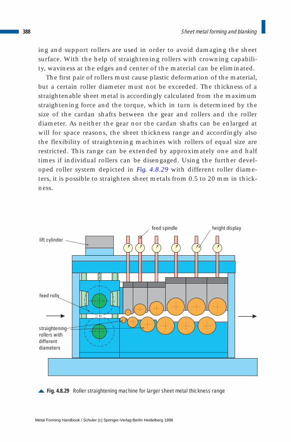
ing and support rollers are used in order to avoid damaging the sheetsurface. With the help of straightening rollers with crowning capabili-ty, waviness at the edges and center of the material can be eliminated.
The first pair of rollers must cause plastic deformation of the material,but a certain roller diameter must not be exceeded. The thickness of astraightenable sheet metal is accordingly calculated from the maximumstraightening force and the torque, which in turn is determined by thesize of the cardan shafts between the gear and rollers and the rollerdiameter. As neither the gear nor the cardan shafts can be enlarged atwill for space reasons, the sheet thickness range and accordingly alsothe flexibility of straightening machines with rollers of equal size arerestricted. This range can be extended by approximately one and halftimes if individual rollers can be disengaged. Using the further devel-oped roller system depicted in Fig. 4.8.29 with different roller diame-ters, it is possible to straighten sheet metals from 0.5 to 20 mm in thick-ness.
388 Sheet metal forming and blanking
Fig. 4.8.29 Roller straightening machine for larger sheet metal thickness range
feed rolls
height display
lift cylinder
feed spindle
straighteningrollers withdifferent
diameters
Metal Forming Handbook / Schuler (c) Springer-Verlag Berlin Heidelberg 1998
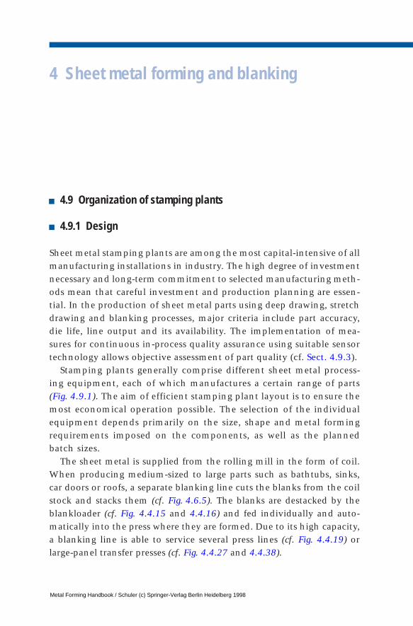
4 Sheet metal forming and blanking
4.9 Organization of stamping plants
4.9.1 Design
Sheet metal stamping plants are among the most capital-intensive of allmanufacturing installations in industry. The high degree of investmentnecessary and long-term commitment to selected manufacturing meth-ods mean that careful investment and production planning are essen-tial. In the production of sheet metal parts using deep drawing, stretchdrawing and blanking processes, major criteria include part accuracy,die life, line output and its availability. The implementation of mea-sures for continuous in-process quality assurance using suitable sensortechnology allows objective assessment of part quality (cf. Sect. 4.9.3).
Stamping plants generally comprise different sheet metal process-ing equipment, each of which manufactures a certain range of parts (Fig. 4.9.1). The aim of efficient stamping plant layout is to ensure themost economical operation possible. The selection of the individualequipment depends primarily on the size, shape and metal formingrequirements imposed on the components, as well as the plannedbatch sizes.
The sheet metal is supplied from the rolling mill in the form of coil.When producing medium-sized to large parts such as bathtubs, sinks,car doors or roofs, a separate blanking line cuts the blanks from the coilstock and stacks them (cf. Fig. 4.6.5). The blanks are destacked by theblankloader (cf. Fig. 4.4.15 and 4.4.16) and fed individually and auto-matically into the press where they are formed. Due to its high capacity,a blanking line is able to service several press lines (cf. Fig. 4.4.19) orlarge-panel transfer presses (cf. Fig. 4.4.27 and 4.4.38).
Metal Forming Handbook / Schuler (c) Springer-Verlag Berlin Heidelberg 1998
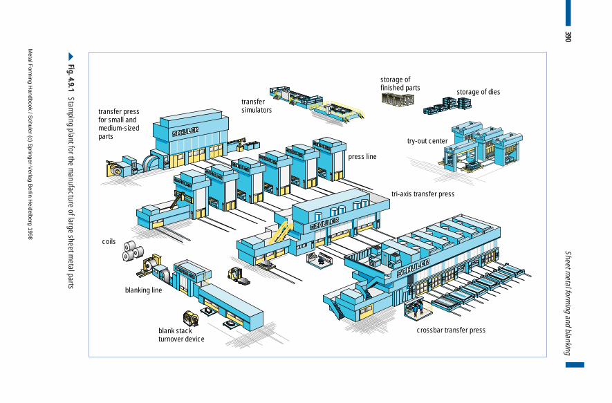
390Sheet m
etal forming and blanking
crossbar transfer press
tri-axis transfer press
press line
try-out center
storage of dies
storage offinished parts
transfersimulators transfer press
for small andmedium-sizedparts
coils
blanking line
blank stackturnover device
Fig. 4.9.1 Stam
ping plant for the manufacture of large sheet m
etal parts
Metal F
orming H
andbook / Schuler (c) S
pringer-Verlag B
erlin Heidelberg 1998
When producing small sheet metal components such as drawerslides, disc carriers for automatic transmissions, wishbones, bicyclebrake levers etc., the coil stock can be fed directly to the press by a coilline (cf. Fig. 4.3.1). The sheet metal forming process takes place in a com-pact piece of equipment, generally a high-speed press (cf. Fig. 4.6.6), auniversal (cf. Fig. 4.4.1) or transfer press (cf. Fig. 4.4.23).
The finished parts are palletized either manually or by using a stack-ing device (cf. Fig. 4.4.41) and made ready for downstream processing,for example welding, painting or hemming. At the same time, scrap dis-posal takes place.
For the introduction of new dies for large parts and transfer presses,try-out presses (cf. Fig. 4.1.19 and 4.1.20) and simulators (cf. Fig. 4.1.24)are employed. These are used by the die shop to prepare tooling as wellas try-out of the dies before the final try-out on the actual productionpress.
This shortens the die try-out time on the production presses sub-stantially for obtaining the first OK parts. Consequently, this procedureshortens the time necessary to produce the first OK parts and increasesthe machine utilization rate.
4.9.2 Layout
The following provides a detailed description of a typical example stamp-ing plant layout. To simplify matters somewhat, our explanation is basedon the assumption of ideal conditions and new installation of the com-plete equipment (Greenfield plant). This is a typical task to establishmanufacturing facilities for the production of medium-sized and largecar body panels such as doors, roofs, hoods, floor panels, side panels,fenders etc. for a particular car type. There are three press systems avail-able: tri-axis transfer presses (cf. Fig. 4.4.27), crossbar transfer presses (cf.Fig. 4.4.38) and press lines (cf. Fig. 4.4.19) of various bed sizes.
Before preparing the plant layout, it is first necessary to determinewhich parts are to be outsourced and which are produced in-house. Thefollowing parts are generally produced in-house:
– outer panels whose surface could be damaged during transport,– joining parts with narrow gap tolerances for precise matching,– parts of large volume resp. size which are difficult to stack or transport.
391Organization of stamping plants
Metal Forming Handbook / Schuler (c) Springer-Verlag Berlin Heidelberg 1998

392 Sheet metal forming and blanking
These so-called A-parts – there are generally between 30 and 40 ofthem per vehicle type – must be grouped together to families of parts.These are then allocated to the different press systems on which theycan be economically manufactured.
Figure 4.9.2 and Table 4.9.1 illustrate the correlation between part sizeand press system. When processing medium-sized panels, a press line witha medium bed size or a tri-axis transfer press will be employed. Press lineswith large bed sizes or crossbar transfer presses offer the ideal conditionsfor processing large panels with low inherent stiffness or double panels.Figure 4.9.3 offers a more precise allocation of parts to both availabletransfer press systems. Some parts can be handled by crossbars withsuction cups as well as by gripper rail systems. They represent theoverlap between two families of parts. Some of these parts, such asdoors, are produced as single parts using gripper rail transfer systems(cf. Fig. 4.4.29) or as double parts using a crossbar transfer system(cf. Fig. 4.4.34).
Fig. 4.9.2 Press systems for the manufacture of car body parts
medium dimension:
tri-axis transfer press
crossbar transfer press
press line
press line
typical family of partslarge dimension:typical family of parts
up to
3,0
00 m
m
up to
5,0
00 m
m
time
up to
5,0
00 m
m
up to
3,0
00 m
m
Metal Forming Handbook / Schuler (c) Springer-Verlag Berlin Heidelberg 1998
393Organization of stamping plants
The selection and loading of presses depend primarily on the num-ber of vehicles to be produced. The number of vehicles determines theproduction requirement of all parts per day. If the A-parts of a vehicletype are manufactured on large-panel transfer presses, the stampingplant must have a capacity of between 3 and 4 million parts per year(basis of planning: 1 vehicle type = 100,000 vehicles per year).
The production scope per year, i.e. the number of parts which can beproduced on the press system per year, must be co-ordinated with theproduction requirement. This calls for an output analysis of the indi-vidual press system. The basis for calculation is the production strokingrate. In transfer presses, this is equivalent to the stroking rate set at thepress. In the case of press lines, the production stroking rate is reducedto some 50 % to 60 % of the set press stroking rate due to standstill peri-ods caused by the single stroke operation. The number of parts whichcan be produced during press operation also depends on the formingrequirements of the individual parts. A complex part requires a longerprocessing time. In addition, the time necessary for transportation of
Table 4.9.1: Criteria for press selection
large-panel transfer pressespress lines
with differing bed sizes
part spectrummedium-sized parts all parts
++ + 0
0 + ++
+ ++ 0
10 10 30
crossbartransfer
tri-axistransfer
large, unstable partsand double parts
complete partproduction
low investment
low spacerequirement
die changetime [min.]
Metal Forming Handbook / Schuler (c) Springer-Verlag Berlin Heidelberg 1998
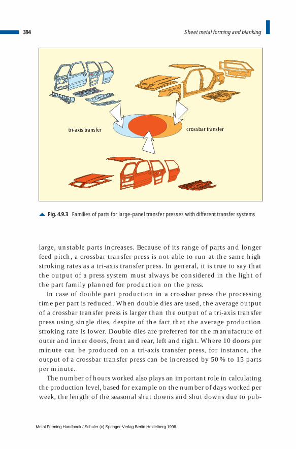
394 Sheet metal forming and blanking
large, unstable parts increases. Because of its range of parts and longerfeed pitch, a crossbar transfer press is not able to run at the same highstroking rates as a tri-axis transfer press. In general, it is true to say thatthe output of a press system must always be considered in the light ofthe part family planned for production on the press.
In case of double part production in a crossbar press the processingtime per part is reduced. When double dies are used, the average outputof a crossbar transfer press is larger than the output of a tri-axis transferpress using single dies, despite of the fact that the average productionstroking rate is lower. Double dies are preferred for the manufacture ofouter and inner doors, front and rear, left and right. Where 10 doors perminute can be produced on a tri-axis transfer press, for instance, theoutput of a crossbar transfer press can be increased by 50 % to 15 partsper minute.
The number of hours worked also plays an important role in calculatingthe production level, based for example on the number of days worked perweek, the length of the seasonal shut downs and shut downs due to pub-
Fig. 4.9.3 Families of parts for large-panel transfer presses with different transfer systems
tri-axis transfer crossbar transfer
Metal Forming Handbook / Schuler (c) Springer-Verlag Berlin Heidelberg 1998
lic holidays which vary from country to country. Let us assume between200 and 300 effective days’ work per year and daily working periods ofbetween 840 and 1,260 min depending on two or three-shift operation.Then the annual production capacity fluctuates between 100% at the low-er end and 225% at the higher end. Major influencing factors which can-not be freely selected by the manufacturer, such as statutory labor legisla-tion, collective agreements etc. may determine the possible framework.This means that production capacity must always be calculated relative topersonnel requirements.
Other influencing factors include for example necessary productionsystem maintenance intervals. If the stamping plant operates at fullcapacity, these periods may have to be deducted from the productioncapacity. In case a five day week is worked, maintenance can be doneon Saturdays and Sundays without loss of production.
If we reduce the working time by the periods in which no productiontakes place, we arrive at the press availability or uptime. Particular factorswhich must be planned for during working hours include for example diechange, die setting or die cleaning times. In addition to scheduled pressstops, unscheduled downtime must also be allowed for. This can be caused,for example, by failure of the blank supply, press or dies. Overall, theuptime of modern large-panel transfer presses is generally in the range of70% of the total available work time (Fig. 4.9.4). The actual average lineoutput is thus calculated from the production stroking rate, the press oper-ation time and the proportion of press running time during which doubleparts are produced. Extrapolated over a whole year, values of up to 4.3 mil-lion parts may result, depending on the press system and working hours.Table 4.9.2 illustrates an example of output for a production system com-prising a blanking line and two large-panel transfer presses. Providing thatdouble parts are produced for 50 % of the time on the crossbar transferpress, with a total of around 3.9 million production strokes of the transferpresses per year, we arrive at an output of 4.8 million sheet metal parts peryear.
When generating a press load schedule, batch sizes and the produc-tion sequence are defined. The sequence is repeated within each com-plete cycle, whereby a part can be produced several times during anyone cycle. Figure 4.9.5 illustrates an example of a press load scheduleand the relevant inventory in the intermediate storage of finished partsfor the production of four different sheet metal parts. Parts A and B are
395Organization of stamping plants
Metal Forming Handbook / Schuler (c) Springer-Verlag Berlin Heidelberg 1998
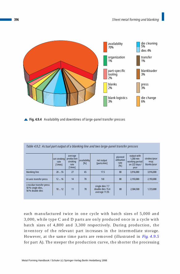
396 Sheet metal forming and blanking
each manufactured twice in one cycle with batch sizes of 5,000 and3,000, while type C and D parts are only produced once in a cycle withbatch sizes of 4,800 and 3,300 respectively. During production, theinventory of the relevant part increases in the intermediate storage.However, at the same time parts are removed (illustrated in Fig. 4.9.5for part A). The steeper the production curve, the shorter the processing
Fig. 4.9.4 Availability and downtimes of large-panel transfer presses
availability70%
organization1%
part-specifictooling2%
blank logistics3%
die cleaning 5%dies 4%
transfer1%
blankloader3%
press3%
die change6%
blanks2%
Table 4.9.2: Actual part output of a blanking line and two large-panel transfer presses
blanking line 20 ... 55 27 65 17.5 80 3,916,000 3,916,000
12 ... 16 14 70 9.8 80 2,193,000 2,193,000
10 ... 12 11 70 80 2,584,500 1,723,000
crossbar transfer press50 % single dies, 50 % double dies
tri-axis transfer press
set strokingrate
[1/min]
averageproduction
strokingrate
[1/min]
availability [%]
net output[parts/min]
plannedutilization
rate[%]
output with1,260 min
working period on 222 days/
year
strokes/yearresp.
blanks/year
single dies 7.7double dies 15.4
average 11.55
Metal Forming Handbook / Schuler (c) Springer-Verlag Berlin Heidelberg 1998
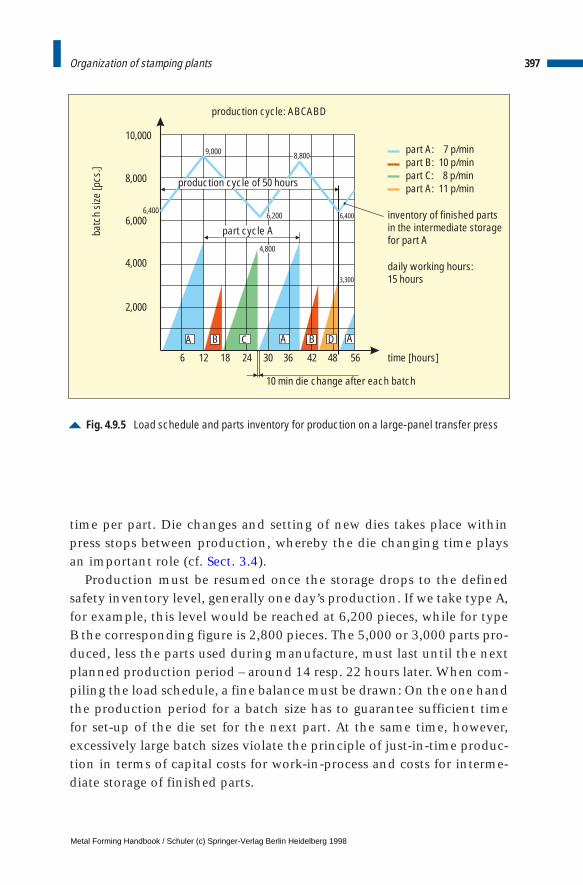
397Organization of stamping plants
time per part. Die changes and setting of new dies takes place withinpress stops between production, whereby the die changing time playsan important role (cf. Sect. 3.4).
Production must be resumed once the storage drops to the definedsafety inventory level, generally one day’s production. If we take type A,for example, this level would be reached at 6,200 pieces, while for typeB the corresponding figure is 2,800 pieces. The 5,000 or 3,000 parts pro-duced, less the parts used during manufacture, must last until the nextplanned production period – around 14 resp. 22 hours later. When com-piling the load schedule, a fine balance must be drawn: On the one handthe production period for a batch size has to guarantee sufficient timefor set-up of the die set for the next part. At the same time, however,excessively large batch sizes violate the principle of just-in-time produc-tion in terms of capital costs for work-in-process and costs for interme-diate storage of finished parts.
Fig. 4.9.5 Load schedule and parts inventory for production on a large-panel transfer press
inventory of finished partsin the intermediate storagefor part A
part A: 7 p/minpart B: 10 p/minpart C: 8 p/minpart A: 11 p/min
daily working hours:15 hours
time [hours]
10 min die change after each batch
batc
h si
ze [p
cs.]
production cycle: ABCABD
10,000
8,000
6,000
4,000
2,000
6 12 18 24 30 36 42 48 56
production cycle of 50 hours
A AB C A B D
6,400
9,000
6,200
8,800
6,400
4,800
3,300
part cycle A
Metal Forming Handbook / Schuler (c) Springer-Verlag Berlin Heidelberg 1998
398 Sheet metal forming and blanking
Example:
A production unit has to be configured in which 44 pressed parts – primarily Aparts – have to be produced every year for 100,000 vehicles. The unit comprisesa blanking line, a crossbar transfer press and a tri-axis transfer press. A possibleconfiguration of this stamping plant with optimized material flow and periph-eral devices is illustrated in Fig. 4.9.6. The material is supplied in the form of coilstock and stored in the coil storage, from where it is fed to the blanking line.This supplies through the blank storage both large-panel transfer presses with atotal of 4 million blanks a year. Following production on the transfer presses,the parts are transported in part-specific racks to the intermediate storage forfinished parts.
Table 4.9.3 lists the part spectrum for both forming presses. The crossbar trans-fer press is run using eight individual and eight double die sets, whereby thedouble dies in this example always produce two different parts. Their diechange time amounts to 10 min. The tri-axis transfer press manufactures 20 dif-ferent parts using 20 die sets. The die change time is also 10 min. Overall, the 44parts are produced using 36 sets of dies – 20 on the tri-axis transfer press, and 24on the crossbar transfer press.
If 222 working days are available per year, parts for 450 vehicles must be pro-duced every day. In three-shift operation with working periods of 1,260 min perday, the total of approx. 4.8 million parts indicated in Table 4.9.2 (achievedwith 3.9 million strokes) can be produced every year on the transfer presses.This is based on a planned capacity utilization of 80 %. Three days are selectedas a production cycle. If we take the simplified assumption that every part isonly run once per cycle, three times 450 parts must be produced per cycle. Theintermediate storage for finished parts has a theoretical maximum inventory of1,800 pressed parts of each part type: 1,350 parts from running production plus450 parts as a minimum safety inventory. On average, however, as body-in-white production runs on a parallel basis, only around half of the parts arelocated in the intermediate storage. At any point in time, the inventory com-prises 900 3 44, i. e. approx. 40,000 parts. As a result, the part storage and thecapital investment this involves are considerably lower than when producingon conventional press lines.
4.9.3 Quality assurance through quality control
The aim of achieving zero-defect production calls for continuous qual-ity control. This involves the detection of any changes in the produc-tion process which could precede a defect, and the segregation of indi-vidual defective parts. Conventional methods of quality assurance instamping plants include visual inspections – in the case of deep drawn
Metal Forming Handbook / Schuler (c) Springer-Verlag Berlin Heidelberg 1998
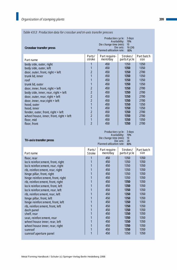
Crossbar transfer press
Parts/ Part require-Part name stroke ment/day
body side, outer, right 1 450 1350body side, outer, left 1 450 1350door, outer, front, right + left 2 450 1350trunk lid, inner 1 450 1350roof 1 450 1350trunk lid, outer 1 450 1350door, inner, front, right + left 2 450 1350body side, inner, rear, right + left 2 450 1350door, outer, rear, right + left 2 450 1350door, inner, rear,right + left 2 450 1350hood, outer 1 450 1350hood, inner 1 450 1350fender, outer, front, right + left 2 450 1350wheel house, inner, front, right + left 2 450 1350floor, mid 1 450 1350floor, front 2 450 1350
Part batchparts/cycle
1350135013501350135013501350135013501350135013501350135013501350
1350
1350135013502700270027002700135013502700270013502700
size
Part batchsize
2700
Tri-axis transfer press
Parts/ Part require- Strokes/
Strokes/
Part name Stroke ment/day parts/cycle
floor, rear 1 450 1350lock reinforcement, front, right 1 450 1350lock reinforcement, rear, right 1 450 1350rib, reinforcement, rear, right 1 450 1350hinge pillar, front, right 1 450 1350hinge reinforcement, front, right 1 450 1350rib, reinforcement, front, right 1 450 1350lock reinforcement, front, left 1 450 1350lock reinforcement, rear, left 1 450 1350rib, reinforcement, rear, left 1 450 1350hinge pillar, front, left 1 450 1350hinge reinforcement, front, left 1 450 1350rib, reinforcement, front, left 1 450 1350dash panel 1 450 1350shelf, rear 1 450 1350seat, reinforcement, rear 1 450 1350wheel house inner, rear, left 1 450 1350wheel house inner, rear, right 1 450 1350
1350
1350
135013501350135013501350135013501350135013501350
13501350135013501350135013501350135013501350135013501350135013501350
sunroof 1 450 1350 1350sunroof aperture panel 1 450 1350 1350
Production cycle: 3 daysAvailability: 70%
Die change time (min): 10Die sets: 20
Planned utilization rate: 80%
Production cycle: 3 daysAvailability: 70%
Die change time (min): 10Die sets: 16 (24)
Planned utilization rate: 80%
399Organization of stamping plants
Table 4.9.3: Production data for crossbar and tri-axis transfer presses
Metal Forming Handbook / Schuler (c) Springer-Verlag Berlin Heidelberg 1998
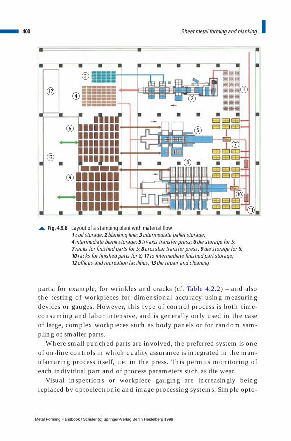
400 Sheet metal forming and blanking
parts, for example, for wrinkles and cracks (cf. Table 4.2.2) – and alsothe testing of workpieces for dimensional accuracy using measuringdevices or gauges. However, this type of control process is both time-consuming and labor intensive, and is generally only used in the caseof large, complex workpieces such as body panels or for random sam-pling of smaller parts.
Where small punched parts are involved, the preferred system is oneof on-line controls in which quality assurance is integrated in the man-ufacturing process itself, i.e. in the press. This permits monitoring ofeach individual part and of process parameters such as die wear.
Visual inspections or workpiece gauging are increasingly beingreplaced by optoelectronic and image processing systems. Simple opto-
Fig. 4.9.6 Layout of a stamping plant with material flow1 coil storage; 2 blanking line; 3 intermediate pallet storage; 4 intermediate blank storage; 5 tri-axis transfer press; 6 die storage for 5; 7 racks for finished parts for 5; 8 crossbar transfer press; 9 die storage for 8; 10 racks for finished parts for 8; 11 to intermediate finished part storage; 12 offices and recreation facilities; 13 die repair and cleaning
1
2
5
7
8
10
11
9
6
412
3
13
Metal Forming Handbook / Schuler (c) Springer-Verlag Berlin Heidelberg 1998
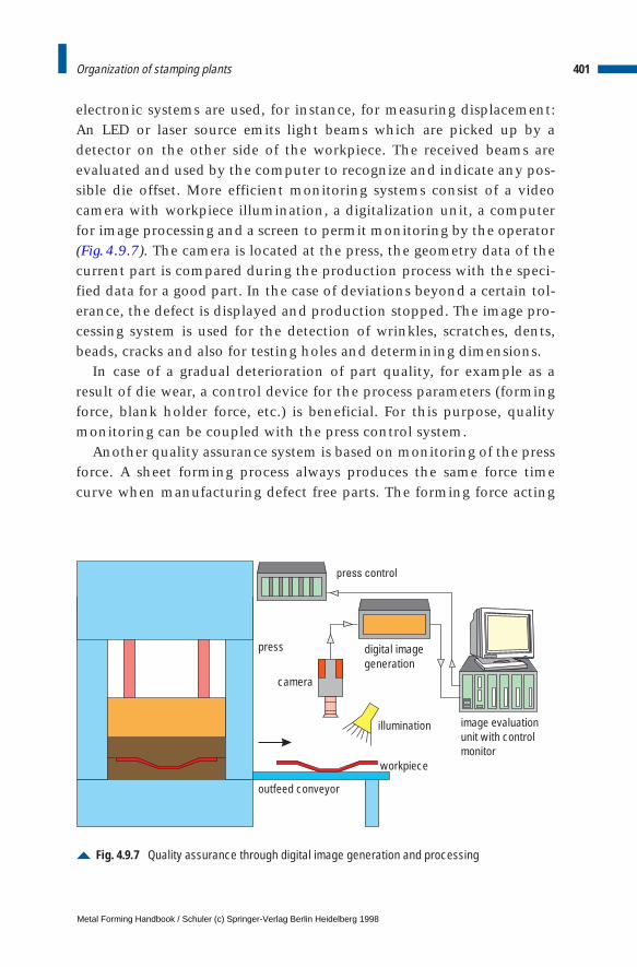
401Organization of stamping plants
electronic systems are used, for instance, for measuring displacement:An LED or laser source emits light beams which are picked up by adetector on the other side of the workpiece. The received beams areevaluated and used by the computer to recognize and indicate any pos-sible die offset. More efficient monitoring systems consist of a videocamera with workpiece illumination, a digitalization unit, a computerfor image processing and a screen to permit monitoring by the operator(Fig.4.9.7). The camera is located at the press, the geometry data of thecurrent part is compared during the production process with the speci-fied data for a good part. In the case of deviations beyond a certain tol-erance, the defect is displayed and production stopped. The image pro-cessing system is used for the detection of wrinkles, scratches, dents,beads, cracks and also for testing holes and determining dimensions.
In case of a gradual deterioration of part quality, for example as aresult of die wear, a control device for the process parameters (formingforce, blank holder force, etc.) is beneficial. For this purpose, qualitymonitoring can be coupled with the press control system.
Another quality assurance system is based on monitoring of the pressforce. A sheet forming process always produces the same force timecurve when manufacturing defect free parts. The forming force acting
Fig. 4.9.7 Quality assurance through digital image generation and processing
press control
image evaluationunit with controlmonitor
camera
workpiece
press digital imagegeneration
illumination
outfeed conveyor
Metal Forming Handbook / Schuler (c) Springer-Verlag Berlin Heidelberg 1998
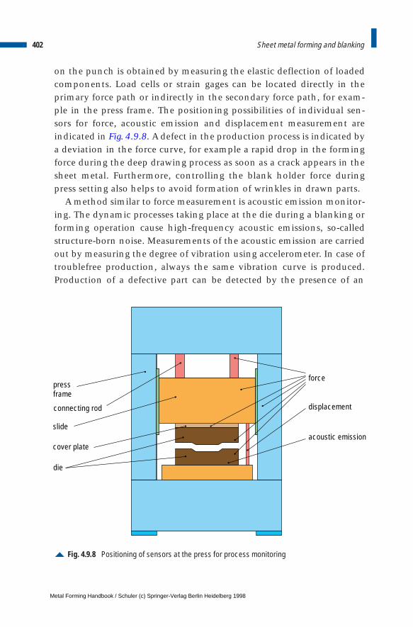
402 Sheet metal forming and blanking
on the punch is obtained by measuring the elastic deflection of loadedcomponents. Load cells or strain gages can be located directly in theprimary force path or indirectly in the secondary force path, for exam-ple in the press frame. The positioning possibilities of individual sen-sors for force, acoustic emission and displacement measurement areindicated in Fig. 4.9.8. A defect in the production process is indicated bya deviation in the force curve, for example a rapid drop in the formingforce during the deep drawing process as soon as a crack appears in thesheet metal. Furthermore, controlling the blank holder force duringpress setting also helps to avoid formation of wrinkles in drawn parts.
A method similar to force measurement is acoustic emission monitor-ing. The dynamic processes taking place at the die during a blanking orforming operation cause high-frequency acoustic emissions, so-calledstructure-born noise. Measurements of the acoustic emission are carriedout by measuring the degree of vibration using accelerometer. In case oftroublefree production, always the same vibration curve is produced.Production of a defective part can be detected by the presence of an
Fig. 4.9.8 Positioning of sensors at the press for process monitoring
force
displacement
acoustic emission
pressframe
connecting rod
slide
cover plate
die
Metal Forming Handbook / Schuler (c) Springer-Verlag Berlin Heidelberg 1998

unexpected acoustic emission signal. The amplitude of the vibrationsincreases in comparison to the usual vibration curve, for instance,when a crack occurs in a drawn part. Monitoring of acoustic emissionsignals are used mainly for the detection of cracks or punch breakage.
The efficiency of quality assurance systems increases with the num-ber of sensors used simultaneously or by combining different systems.When using combined monitoring systems for operation and surveil-lance, whenever possible it is recommended to utilize the same com-puter and display unit. Process data acquisition and documentation areessential to ensure continuous quality assurance. Systems with learningcapability for diagnosis and the avoidance of defects have been shownto offer an optimum solution.
Bibliography Bareis, A., Braun, R., Hoffmann, A.: Hochleistungs-Stanzanlage für die Verarbeitung dickerer Bleche,
VDI-Zeitschrift-Special-Rationelle Blechbearbeitung (1990) 4.
Bareis, A., Dommer, H.-M., Hoffman, H.: Flexibilität in der Stanztechnik, VDI Journal 131 (1989) 9.
Beisel, O.: Tuschieren und Probieren ohne Produktionsausfall, Werkstatt und Betrieb (1993) 10.
Birzer, F.: Fine blanking does even better, Swiss quality production (1993) 4.
Bräutigam, H.: Richten mit Walzenrichtmaschinen, Eigenverlag, (1987), 2nd edition
Breuer, W.: Multimediafähiges Informationssystem ergänzt herkömmliche Pressensteuerung, Maschi-nenmarkt (1995) 16.
DIN 1623: Steel flat products; Cold rolled sheet and strip; technical delivery conditions – part 1 (02.83):Cold reduced sheet and strip, part 2 (02.86): General purpose structural steels, Beuth Verlag, Berlin.
DIN 1745: Wrought aluminium and aluminium alloy plate, sheet and strip greater than 0.35 mm in thick-ness - part 1: Properties, Beuth Verlag, Berlin (02.83).
DIN 1788: Wrought aluminium and aluminium alloy sheet and strip with thicknesses between 0.021 and0.350 mm, properties, Beuth Verlag, Berlin (02.83).
DIN 5512: Werkstoffe für Schienenfahrzeuge; Stähle - Teil 1 (02.84): Allgemeine Baustähle - part 2 (09.89):Flacherzeugnisse aus unlegierten Stählen bis 3 mm Dicke – part 3 (01.91): Flacherzeugnisse ausnichtrostenden Stählen, Beuth Verlag, Berlin.
DIN 6935: Cold bending of flat rolled steel products, Beuth Verlag, Berlin (1975)
DIN 8586: Fertigungsverfahren Biegeumformen, Beuth Verlag, Berlin (1971).
DIN 17 440: Stainless steels; technical delivery conditions for plate and sheet, hot rolled strip, wire rod,drawn wire, steel bars, forgings and semi-finished products, Beuth Verlag, Berlin (07.85).
DIN 17 441: Stainless steels; technical delivery conditions for cold rolled strip and slit strip and for plateand sheet cut therefrom, Beuth Verlag, Berlin (07.85).
DIN 17 670: Wrought copper and copper alloy plate, sheet and strip; - part 1: Properties, Beuth Verlag,Berlin (12.83).
DIN 17 860: Sheet and strip of titanium and wrought titanium, Beuth Verlag, Berlin (11.73).
Doege, E., Besdo, D., Haferkamp, H., Tönshoff, H. K., Wiendahl, H.-P.: Fortschritte in der Werkzeug-technik, Meisenbach Bamberg Verlag, Hannover, (1995).
403Organization of stamping plants
Metal Forming Handbook / Schuler (c) Springer-Verlag Berlin Heidelberg 1998

Fritz, W.: Herstellen einbaufertiger Umformteile aus Stahlblech vom Band, Bänder Bleche Rohre (1994) 7-8.
Frontzek, H.: Beitrag zur Bestimmung der Reibungsverhältnisse in der Blechumformung, Dissertation,Darmstadt, (1990).
Guericke, W.: Theoretische und Experimentelle Untersuchungen der Kräfte und Drehmomente beimRichten von Walzgut auf Rollenrichtmaschinen, Dissertation, Magdeburg (1965).
Habig, K.-H.: Verschleiß und Härte von Werkstoffen, Hanser-Verlag, Munich (1980).
Hoffmann, H., Bareis, A.: Höhere Teilegenauigkeit – Wirtschaftliches Nuten von Elektroblech, Industrie-Anzeiger (1987) 77.
Hoffmann, H., Bareis, A.: Rotor- und Statorbleche für Elektromotoren flexibel fertigen, Werkstatt u. Be-trieb 123 (1990) 7.
Hoffmann, H., Bareis, A., Waller, E.: Optimierte Schnelläuferpressen-Regelung der Stempeleintauchtiefeverlängert die Werkzeugstandzeit, Bänder Bleche Rohre (1988) 3.
Hoffmann, H.: Großteilpressen mit Saugerbrückentransfer, VDI Berichte Nr. 946, VDI-Verlag, Düsseldorf(1982).
Hoffmann, H., Schneider, F.: Wirtschaftlich Fertigen auf Großteil-Stufenpressen, Entwicklung, Bauarten,Produktionsmerkmale, Werkstatt und Betrieb 122 (1989) 5.
Hoffmann, H., Schneider. F.: Wirtschaftlich Fertigen auf Großteil-Stufenpressen, Werkstatt und Betrieb122 (1989) 6.
Kellenbenz, R.: Anforderungen an schnellaufende Schneidpressen bei der Fertigung von Elektroblechen,Neuere Entwicklung in der Blechumformung, DGM Verlag, Oberursel (1990).
König, W.: Fertigungsverfahren, Volume 5: Blechumformung, VDI-Verlag, Düsseldorf (1990).
Lange, K.: Umformtechnik, Volume 3: Blechbearbeitung, Springer-Verlag, Heidelberg, (1990).
Lepper, M.: Flexible automatisierte Blechverarbeitung, Werkstatt und Betrieb (1992) 6.
Lepper, M.: Robot interlinked press line for car body panels, Sheet Metal Industries (1995) 5.
Mang, T.: Schmierung in der Metallbearbeitung, Vogel-Verlag, Würzburg (1983).
Oehler, G., Kaiser, F.: Schnitt-, Stanz- und Ziehwerkzeuge, 7th edition, Springer-Verlag, Berlin (1993).
Oehler, G.: Biegen, Carl Hanser Verlag, Munich (1963).
Pischel, H.: Neue Gesamtfertigung von Längsträgern für LKW-Chassis, Werkstatt und Betrieb (1995) 5.
Pischel, H.: Pressenstraßen optimieren komplexe Fertigungsabläufe, Werkstatt und Betrieb (1995) 3.
Reiss, A.: Walzrichten, Eigenverlag, 2nd edition (1990).
Rossner, S.: Vom Blechband zum Kompressor-Gehäuse, Werkstatt und Betrieb (1993) 6.
Siegert, K.: Innovative Pressentechnik, DGM Verlag, Oberursel (1994).
Stahl-Eisen-Werkstoffblatt 093: Kaltgewalztes Band und Blech mit höherer Streckgrenze zumKaltumformen aus mikrolegierten Stählen, Verein Deutscher Eisenhüttenleute, Verlag Stahleisen,Düsseldorf (2nd edition 03.87).
Stahl-Eisen-Werkstoffblatt 094: Kaltgewalztes Band und Blech mit höherer Streckgrenze, Verein Deut-scher Eisenhüttenleute, Verlag Stahleisen, Düsseldorf (1st edition 07.87).
Tschätsch, H.: Handbuch Umformtechnik, Hoppenstedt Technik Tabellen, Verlag, Darmstadt (1993).
Tschätsch, H.: Taschenbuch Umformtechnik, Carl Hanser Verlag, Munich (1977).
Weimar, G.: Zum gegenwärtigen Stand des Walzprofilierens, Bänder Bleche Rohre, 8 (1967) 5.
404 Sheet metal forming and blanking
Metal Forming Handbook / Schuler (c) Springer-Verlag Berlin Heidelberg 1998
5 Hydroforming
5.1 General
One of the aims of the sheet-metal processing industry is the minimiza-tion of costs and the optimization of its products concerning weight,strength characteristics and rigidity. In search for alternative productionprocesses, hydroforming – the manufacture of hollow bodies with com-plex geometries by means of fluid pressure – has been shown to offer aninteresting technical and economic potential to sheet metal manufac-turers. The achievement of beneficial component characteristics usingthis process is only possible where component and process configura-tion are selected by considering the overall system design.
5.2 Process technology and example applications
5.2.1 Process technology
The hydroforming technique is based on the inflation of, for instance, atube, coupled with axial or radial compression and by subsequent expan-sion and sizing against the die wall. This process comprises in general ofthe following steps: expansion, compression, calibration.
Hydroforming is categorized as a cold forming process. It is used forthe manufacture of geometrically highly complex hollow bodies fromtubular or preforms. An underlying difference is drawn between freehydroforming and hydroforming using dies. The latter is subdividedagain according to processes involving longitudinally and transverselydivided dies (Fig.5.2.1).
Metal Forming Handbook / Schuler (c) Springer-Verlag Berlin Heidelberg 1998
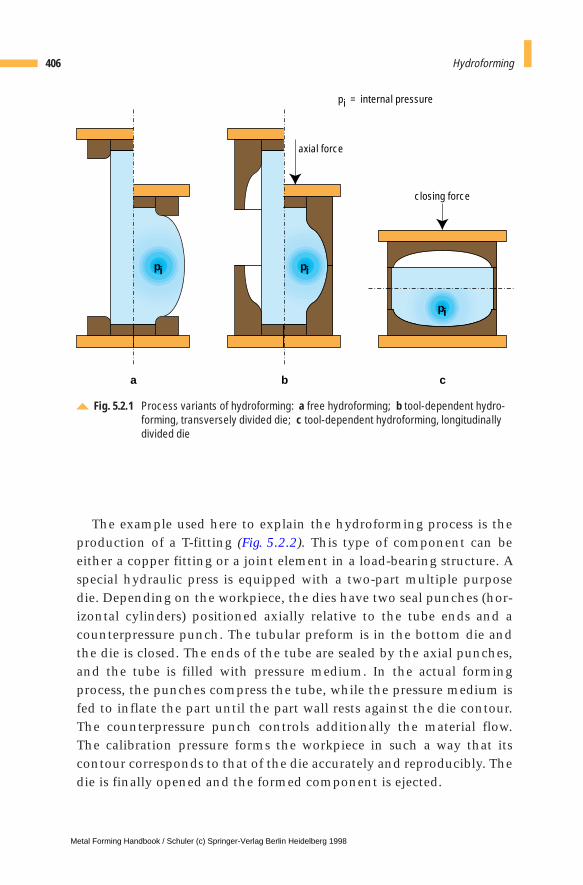
The example used here to explain the hydroforming process is theproduction of a T-fitting (Fig. 5.2.2). This type of component can beeither a copper fitting or a joint element in a load-bearing structure. Aspecial hydraulic press is equipped with a two-part multiple purposedie. Depending on the workpiece, the dies have two seal punches (hor-izontal cylinders) positioned axially relative to the tube ends and acounterpressure punch. The tubular preform is in the bottom die andthe die is closed. The ends of the tube are sealed by the axial punches,and the tube is filled with pressure medium. In the actual formingprocess, the punches compress the tube, while the pressure medium isfed to inflate the part until the part wall rests against the die contour.The counterpressure punch controls additionally the material flow.The calibration pressure forms the workpiece in such a way that itscontour corresponds to that of the die accurately and reproducibly. Thedie is finally opened and the formed component is ejected.
406 Hydroforming
Fig. 5.2.1 Process variants of hydroforming: a free hydroforming; b tool-dependent hydro-forming, transversely divided die; c tool-dependent hydroforming, longitudinallydivided die
axial force
pi = internal pressure
closing force
pi pi
pi
a b c
Metal Forming Handbook / Schuler (c) Springer-Verlag Berlin Heidelberg 1998
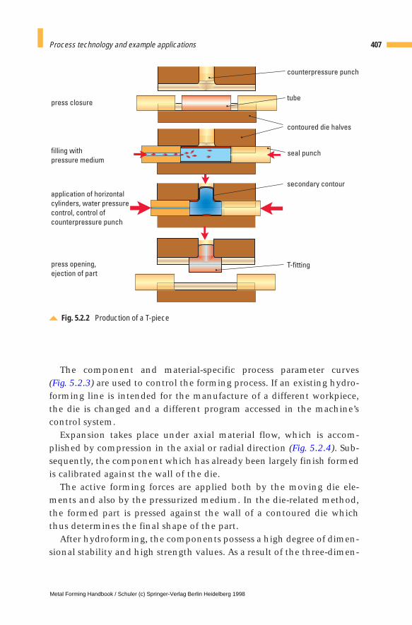
The component and material-specific process parameter curves (Fig. 5.2.3) are used to control the forming process. If an existing hydro-forming line is intended for the manufacture of a different workpiece,the die is changed and a different program accessed in the machine’scontrol system.
Expansion takes place under axial material flow, which is accom-plished by compression in the axial or radial direction (Fig. 5.2.4). Sub-sequently, the component which has already been largely finish formedis calibrated against the wall of the die.
The active forming forces are applied both by the moving die ele-ments and also by the pressurized medium. In the die-related method,the formed part is pressed against the wall of a contoured die whichthus determines the final shape of the part.
After hydroforming, the components possess a high degree of dimen-sional stability and high strength values. As a result of the three-dimen-
407Process technology and example applications
Fig. 5.2.2 Production of a T-piece
tube
counterpressure punch
contoured die halves
filling with
pressure medium
secondary contour
press closure
application of horizontal
cylinders, water pressure
control, control of
counterpressure punch
press opening,
ejection of partT-fitting
seal punch
Metal Forming Handbook / Schuler (c) Springer-Verlag Berlin Heidelberg 1998
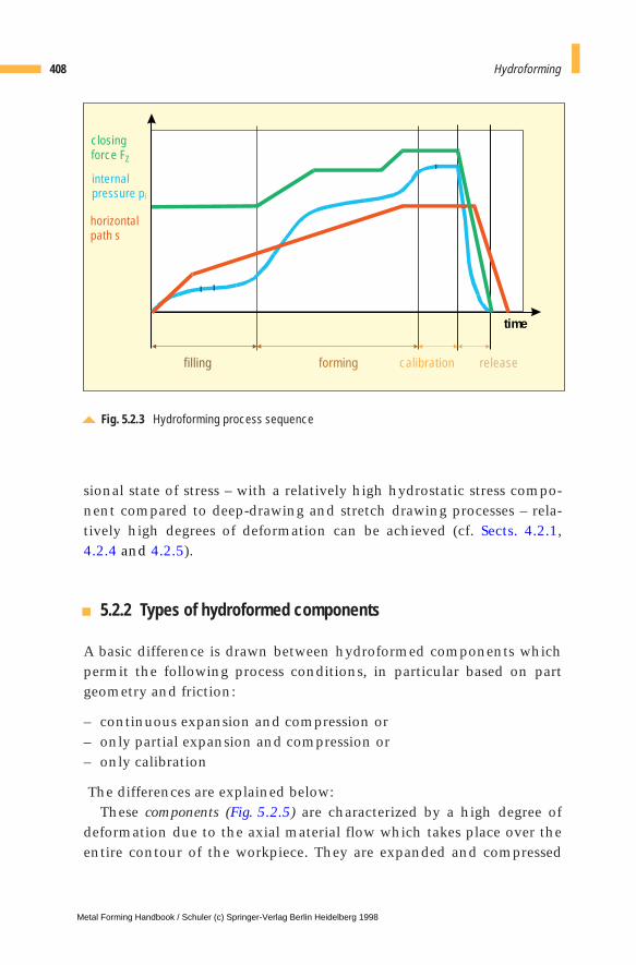
sional state of stress – with a relatively high hydrostatic stress compo-nent compared to deep-drawing and stretch drawing processes – rela-tively high degrees of deformation can be achieved (cf. Sects. 4.2.1,4.2.4 and 4.2.5).
5.2.2 Types of hydroformed components
A basic difference is drawn between hydroformed components whichpermit the following process conditions, in particular based on partgeometry and friction:
– continuous expansion and compression or– only partial expansion and compression or– only calibration
The differences are explained below:These components (Fig. 5.2.5) are characterized by a high degree of
deformation due to the axial material flow which takes place over theentire contour of the workpiece. They are expanded and compressed
408 Hydroforming
Fig. 5.2.3 Hydroforming process sequence
closingforce FZ
internalpressure pi
horizontalpath s
filling forming calibration release
time
Metal Forming Handbook / Schuler (c) Springer-Verlag Berlin Heidelberg 1998
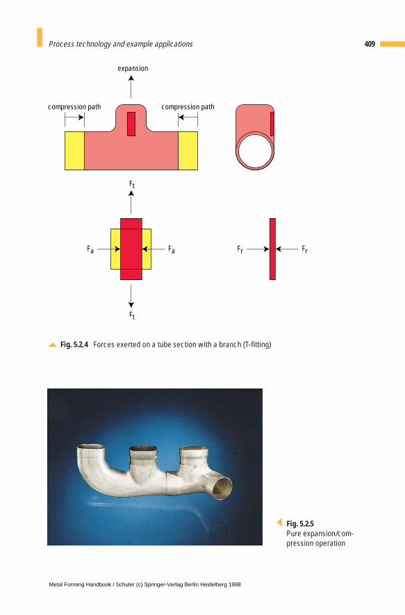
409Process technology and example applications
Fig. 5.2.4 Forces exerted on a tube section with a branch (T-fitting)
compression path
FrFa
Ft
expansion
Ft
compression path
Fa Fr
Fig. 5.2.5Pure expansion/com-pression operation
Metal Forming Handbook / Schuler (c) Springer-Verlag Berlin Heidelberg 1998
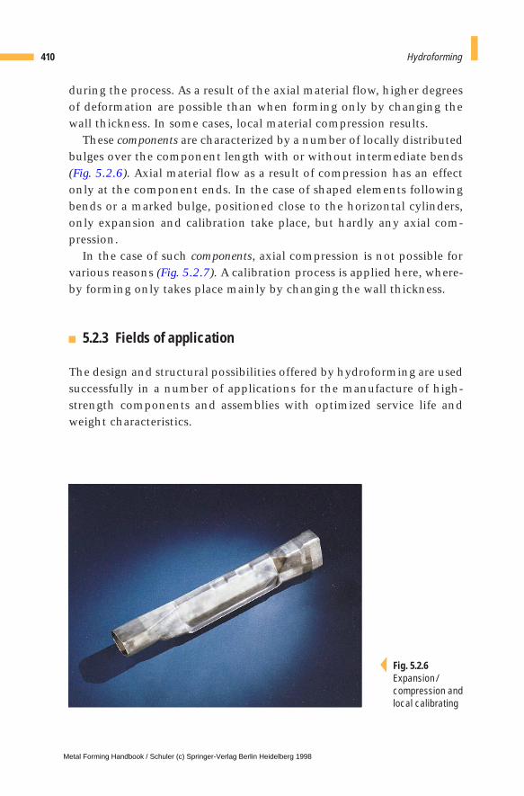
during the process. As a result of the axial material flow, higher degreesof deformation are possible than when forming only by changing thewall thickness. In some cases, local material compression results.
These components are characterized by a number of locally distributedbulges over the component length with or without intermediate bends(Fig. 5.2.6). Axial material flow as a result of compression has an effectonly at the component ends. In the case of shaped elements followingbends or a marked bulge, positioned close to the horizontal cylinders,only expansion and calibration take place, but hardly any axial com-pression.
In the case of such components, axial compression is not possible forvarious reasons (Fig. 5.2.7). A calibration process is applied here, where-by forming only takes place mainly by changing the wall thickness.
5.2.3 Fields of application
The design and structural possibilities offered by hydroforming are usedsuccessfully in a number of applications for the manufacture of high-strength components and assemblies with optimized service life andweight characteristics.
410 Hydroforming
Fig. 5.2.6Expansion/compression andlocal calibrating
Metal Forming Handbook / Schuler (c) Springer-Verlag Berlin Heidelberg 1998
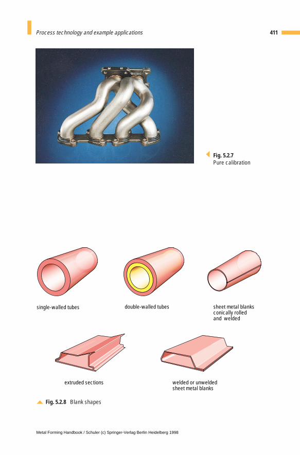
411Process technology and example applications
Fig. 5.2.7Pure calibration
Fig. 5.2.8 Blank shapes
single-walled tubes
extruded sections welded or unwelded sheet metal blanks
double-walled tubes sheet metal blanksconically rolledand welded
Metal Forming Handbook / Schuler (c) Springer-Verlag Berlin Heidelberg 1998
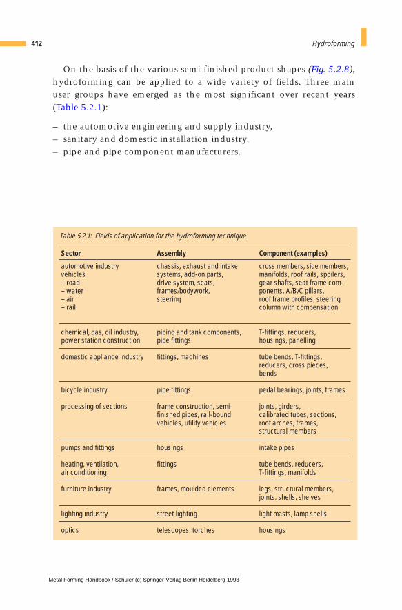
On the basis of the various semi-finished product shapes (Fig. 5.2.8),hydroforming can be applied to a wide variety of fields. Three mainuser groups have emerged as the most significant over recent years(Table 5.2.1):
– the automotive engineering and supply industry,– sanitary and domestic installation industry,– pipe and pipe component manufacturers.
412 Hydroforming
Sector
automotive industry vehicles – road– water – air – rail
chemical, gas, oil industry,power station construction
domestic appliance industry
bicycle industry
processing of sections
pumps and fittings
heating, ventilation, air conditioning
furniture industry
lighting industry
optics
Assembly
chassis, exhaust and intakesystems, add-on parts, drive system, seats,frames/bodywork, steering
piping and tank components,pipe fittings
fittings, machines
pipe fittings
frame construction, semi-finished pipes, rail-boundvehicles, utility vehicles
housings
fittings
frames, moulded elements
street lighting
telescopes, torches
Component (examples)
cross members, side members,manifolds, roof rails, spoilers,gear shafts, seat frame com-ponents, A/B/C pillars,roof frame profiles, steeringcolumn with compensation
T-fittings, reducers, housings, panelling
tube bends, T-fittings,reducers, cross pieces, bends
pedal bearings, joints, frames
joints, girders, calibrated tubes, sections, roof arches, frames, structural members
intake pipes
tube bends, reducers, T-fittings, manifolds
legs, structural members,joints, shells, shelves
light masts, lamp shells
housings
Table 5.2.1: Fields of application for the hydroforming technique
Metal Forming Handbook / Schuler (c) Springer-Verlag Berlin Heidelberg 1998
5 Hydroforming
5.3 Component development
5.3.1 User-oriented project management
In practical industrial application, it is increasingly important to designa component not only for functionality but also for producibility.“Simultaneous engineering” and “early involvement” have becomeimportant watchwords in the field of product design, with customerand process developer cooperating from an early stage in determiningcomponent configuration. Only in this way is it possible to optimizefunctional and process engineering related factors within a short time-frame. A component development activity can be, for example, carriedout as follows:
1. preliminary meeting (customer and developer)
2. technical and economic feasibility study (customer and developer)
3. component configuration suitable for hydroforming (customer anddeveloper) and definition of a production sequence
4. prototype development: CAD surface data generation (customer) andCNC milling data generation (developer), manufacture of a formingdie and production of prototypes using different materials and wallthicknesses (developer)
5. try-out of prototypes (customer)
6. definition of quality-relevant (QA) data (customer)
7. series production (customer or supplier)
Metal Forming Handbook / Schuler (c) Springer-Verlag Berlin Heidelberg 1998
5.3.2 Feasibility studies
When developing hydroformed components, the precise analysis ofboundary conditions is essential. Optimum design of components tak-ing into consideration special process-specific factors enhances safetyand also the cost-effectiveness of series production.
The feasibility study, the component configuration and definition ofa production sequence are closely interlinked. Once these processeshave produced a positive result, it is possible to start with prototypedevelopment of the components. When working through the individ-ual steps, different boundary conditions must be taken into account.These are briefly outlined below.
Review of feasibilityWhen reviewing feasibility, a difference is drawn between two groups ofcomponents: new developments with a geometry that has been config-ured specifically with hydroforming in mind, and the production ofexisting components using hydroform technology.
Significant factors here include the geometry, wall thicknesses, mate-rials and procurement of the semi-finished parts or preforms. Initially,the geometry data is evaluated with the aid of a CAD/CAM system.Circumferences, radii, cross sections and transitions are all determined.A decision must also be taken regarding the characteristics of the pre-form. In the case of a tube, for instance, these factors would include thematerial to be used, the diameter, the wall thickness and also any pos-sible need for pre-forming.
The expected circumferential expansion is then determined. Takinginto account the material data, the wall thickness, pre-forming of thetubular blank and other boundary conditions, it is possible to assess themanufacturing feasibility. Subsequently, the internal pressure, closingforce, forces and movements of the horizontal cylinders have to be cal-culated. Since the correlations between all the different influencingvariables are highly complex, specific expertise is an essential compo-nent of successful part configuration.
Part configurationIf it is possible to manufacture the part, the next stage is to design thedetails, the position in the die and the slide channels. In the case, when
414 Hydroforming
Metal Forming Handbook / Schuler (c) Springer-Verlag Berlin Heidelberg 1998
a component does not appear to be producible using hydroformingtechnology, an attempt is made to modify the existing conditions insuch a way that the part can be produced without modifying its func-tional characteristics.
The part geometry must be optimized taking into account the processlimits. Where assemblies are produced, it may under certain circum-stances be possible to group several parts into a single one or to split theassemblies up differently. A different material can also be selected. Whenmaking this type of modification, the question of reliability in series pro-duction must not be neglected, as this is of decisive importance concern-ing the cost effectiveness and process engineering related issues.
Configuration for series productionThis stage includes the definition of a production sequence and config-uration of the necessary production lines. Consistent implementationof the prototyping results is of particular importance here. An optimumproduct is only achieved through effective interaction of theoreticalanalysis and practice-oriented testing. Another aspect is the definitionof quality-relevant QA data.
Forming simulationThe Finite Element Method (FEM) has become an established feature ofmetal forming technology. The objective of FEM is to replace costly andelaborate experimental testing by fast, low-cost computer simulation.
Any practical implementation of preliminary considerations musttake into account the special features of hydroforming:
– consideration of partial strain hardening on pre-formed tubes,– correlation between process parameters: motions and forces of the
horizontal cylinders, variation of internal pressure in time, motion ofadditional die components such as hole punches and counterpres-sure punches, closing movement of the die,
– functional coordination of process parameters: internal pressure, dif-ferent additional die elements such as hole punches and counter-pressure punches and axial cylinders,
– springback,– failure criteria: buckling and bursting,– material behavior: anisotropy and flow curve and– description of the contact (friction) conditions.
415Component development
Metal Forming Handbook / Schuler (c) Springer-Verlag Berlin Heidelberg 1998
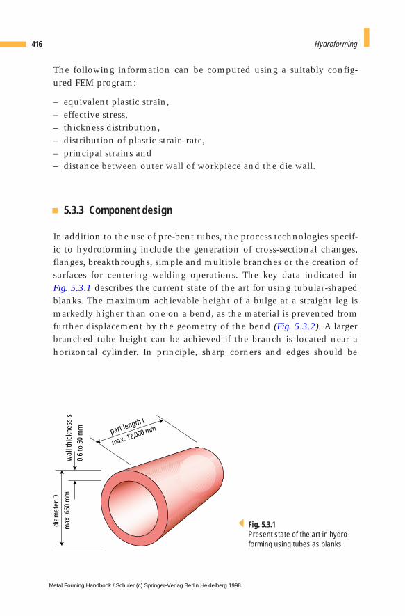
The following information can be computed using a suitably config-ured FEM program:
– equivalent plastic strain,– effective stress,– thickness distribution,– distribution of plastic strain rate,– principal strains and– distance between outer wall of workpiece and the die wall.
5.3.3 Component design
In addition to the use of pre-bent tubes, the process technologies specif-ic to hydroforming include the generation of cross-sectional changes,flanges, breakthroughs, simple and multiple branches or the creation ofsurfaces for centering welding operations. The key data indicated in Fig. 5.3.1 describes the current state of the art for using tubular-shapedblanks. The maximum achievable height of a bulge at a straight leg ismarkedly higher than one on a bend, as the material is prevented fromfurther displacement by the geometry of the bend (Fig. 5.3.2). A largerbranched tube height can be achieved if the branch is located near ahorizontal cylinder. In principle, sharp corners and edges should be
416 Hydroforming
part length L
max. 12,000 mm
wal
l thi
ckne
ss s
0.6
to 5
0 m
m
diam
eter
Dm
ax. 6
60 m
m
Fig. 5.3.1Present state of the art in hydro-forming using tubes as blanks
Metal Forming Handbook / Schuler (c) Springer-Verlag Berlin Heidelberg 1998
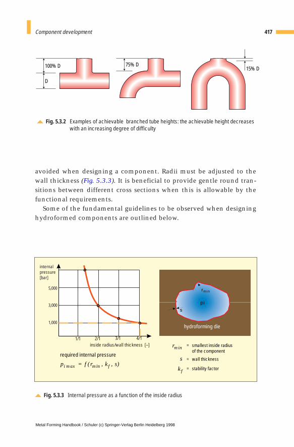
avoided when designing a component. Radii must be adjusted to thewall thickness (Fig. 5.3.3). It is beneficial to provide gentle round tran-sitions between different cross sections when this is allowable by thefunctional requirements.
Some of the fundamental guidelines to be observed when designinghydroformed components are outlined below.
417Component development
Fig. 5.3.2 Examples of achievable branched tube heights: the achievable height decreaseswith an increasing degree of difficulty
D
100% D 75% D15% D
Fig. 5.3.3 Internal pressure as a function of the inside radius
inside radius/wall thickness [–]
internalpressure[bar]
5,000
3,000
1,000
1/1 3/12/1 4/1
p f r k ss
i fmax min
rmin
( , , )=
required internal pressure
hydroforming die
rm in
s
pi
= smallest inside radiusof the component
= wall thickness
= stability factorkf
Metal Forming Handbook / Schuler (c) Springer-Verlag Berlin Heidelberg 1998
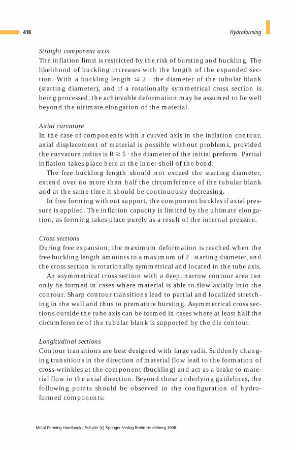
Straight component axisThe inflation limit is restricted by the risk of bursting and buckling. Thelikelihood of buckling increases with the length of the expanded sec-tion. With a buckling length # 2 · the diameter of the tubular blank(starting diameter), and if a rotationally symmetrical cross section isbeing processed, the achievable deformation may be assumed to lie wellbeyond the ultimate elongation of the material.
Axial curvatureIn the case of components with a curved axis in the inflation contour,axial displacement of material is possible without problems, providedthe curvature radius is R $ 5 · the diameter of the initial preform. Partialinflation takes place here at the inner shell of the bend.
The free buckling length should not exceed the starting diameter,extend over no more than half the circumference of the tubular blankand at the same time it should be continuously decreasing.
In free forming without support, the component buckles if axial pres-sure is applied. The inflation capacity is limited by the ultimate elonga-tion, as forming takes place purely as a result of the internal pressure.
Cross sectionsDuring free expansion, the maximum deformation is reached when thefree buckling length amounts to a maximum of 2 · starting diameter, andthe cross section is rotationally symmetrical and located in the tube axis.
An asymmetrical cross section with a deep, narrow contour area canonly be formed in cases where material is able to flow axially into thecontour. Sharp contour transitions lead to partial and localized stretch-ing in the wall and thus to premature bursting. Asymmetrical cross sec-tions outside the tube axis can be formed in cases where at least half thecircumference of the tubular blank is supported by the die contour.
Longitudinal sectionsContour transitions are best designed with large radii. Suddenly chang-ing transitions in the direction of material flow lead to the formation ofcross-wrinkles at the component (buckling) and act as a brake to mate-rial flow in the axial direction. Beyond these underlying guidelines, thefollowing points should be observed in the configuration of hydro-formed components:
418 Hydroforming
Metal Forming Handbook / Schuler (c) Springer-Verlag Berlin Heidelberg 1998

Pure expansion/compressionThe optimum ratio between the pipe diameter D and pipe wall thickness s is
D/s = 20 … 45
Here too, the free buckling length should be # 2 · the starting diameter D.If D/s > 45, there is a danger of bursting or buckling. This can be pre-
vented by reducing the free buckling length.If D/s < 20, the buckling length can be greater with increasing wall
thickness. Thinning of the wall thickness is prevented by axial dis-placement of the material. However, the same displacement can alsolead to compression of the wall. Only a minimal danger of bucklingexists.
Expansion/compression and local calibrationThe maximum inflation capacity is limited by the ultimate elongationof the material. Half the ultimate elongation represents the limit ofachievable deformation where no axial material flow is possible. In thiscase, the buckling length is of no significance.
Pure calibrationThe limit of achievable deformation corresponds to half of the ultimateelongation of the material.
419Component development
Metal Forming Handbook / Schuler (c) Springer-Verlag Berlin Heidelberg 1998
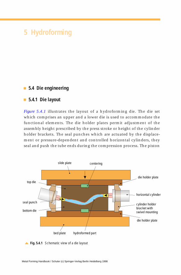
5 Hydroforming
5.4 Die engineering
5.4.1 Die layout
Figure 5.4.1 illustrates the layout of a hydroforming die. The die setwhich comprises an upper and a lower die is used to accommodate thefunctional elements. The die holder plates permit adjustment of theassembly height prescribed by the press stroke or height of the cylinderholder brackets. The seal punches which are actuated by the displace-ment or pressure-dependent and controlled horizontal cylinders, theyseal and push the tube ends during the compression process. The piston
Fig. 5.4.1 Schematic view of a die layout
seal punch
slide plate centering
die holder plate
horizontal cylinder
cylinder holderbracket withswivel mounting
die holder plate
hydroformed partbed plate
top die
bottom die
Metal Forming Handbook / Schuler (c) Springer-Verlag Berlin Heidelberg 1998

diameter and stroke are adjusted to the specific requirements of thecomponent. The cylinder holder brackets absorb the axial forces andalign the horizontal cylinders concentrically with the end guides. Thesecan be moved and positioned on the bed or slide plate.
The modular basic structure of the dies permits flexible implementa-tion of the required component geometries. The objective is to mini-mize production costs, die changing times and the time required toexchange worn parts. In addition, during the development phase it ispossible to try out different tube materials and wall thicknesses withoutchanging the dies. Thus, it is possible to test various preform geometrieswith a minimum of trouble and expense.
Simple changeover from prototype dies to production dies is possibleif only cavity or sliding inserts have to be exchanged (Fig. 5.4.2). Whendesigning a prototype die, its service life is only of minor importance.Except for the sliding inserts, it is not necessary to have time-consum-ing coatings or other surface treatments of the die inserts. Prototyping– and thus step-by-step progress towards a die suitable for series pro-duction – takes place in several stages:
421Die engineering
Fig. 5.4.2 Die systems for prototyping and production
prototype die production dieexchange of wearing partsmodification of individual contour sections
workpiece basic die horizontal cylinder die cavity insert
counterpressure
punch sliding insert
Metal Forming Handbook / Schuler (c) Springer-Verlag Berlin Heidelberg 1998

– development of the basic component geometry,– integration of supplementary operations such as hole piercing,– production of modified inserts.
Here, the following parameters influence the selection of tool materialsand the necessary coating or treatment:– component geometry,– component material,– maximum internal pressure,– sealing system,– application (prototyping, series operation).
5.4.2 Lubricants
As is the case in other cold forming operations, lubricants are amongthe most important aids in the hydroforming process, as they minimizefriction at locations with relative motion between die and workpiece(cf. Sect. 4.2.3). Many components can only be manufactured in therequired shape only through the use of appropriate lubricants.
Lubricants permit to obtain more even wall thickness variation, sim-plify the forming of tubular branches, reduce partial stretching process-es and improve forming in areas that do not allow any material flow byaxial feed.
A number of different lubricants can be considered for use in hydro-forming. Depending on their composition, these can be assigned to thefollowing groups:
– solid lubricants, generally on a graphite or MoS2 basis,– polymer dispersion-based lubricants,– waxes, oils and– emulsions.
Lubricant is generally applied by means of spraying or immersion.Except in the case of oils, the applied coating must generally have driedand hardened prior to the forming process. On principle, attentionmust be paid to ensure an even coating thickness. The optimum thick-ness of the lubricant layer must be determined by trial and error.
422 Hydroforming
Metal Forming Handbook / Schuler (c) Springer-Verlag Berlin Heidelberg 1998

5 Hydroforming
5.5 Materials and preforms for producing hydroformed components
5.5.1 Materials and heat treatment
Basically the same materials which can be used for other cold form-ing techniques such as deep-drawing (cf. Table 4.2.3) are suitable forhydroforming applications. The material should have a fine-grainedmicrostructure and be soft-annealed.
The best forming results are achieved using materials with a highdegree of ultimate elongation, whereby the ultimate elongation at rightangles to the longitudinal direction of the tube – i.e. generally at rightangles to the rolling direction of the sheet metal – is important for theconfiguration of hydroform components. A high degree of strain hard-ening is beneficial.
The tube manufacturing process and pre-forming bring about astrain hardening effect which may have to be eliminated by annealingfor certain components prior to the hydroforming process. If the forma-bility of the material is exceeded during a production step in the man-ufacturing process, forming must be performed using several stages(progressive forming) with intermediate annealing. However, due tothe additional costs involved, heat treatment should only be carriedout when all other possibilities, for example design or material modifi-cations, have been exhausted.
The preferable method of heat treatment for austenitic steels is solu-tionizing – ideally using inert gas. For small parts, a continuous furnacecan be used.
Metal Forming Handbook / Schuler (c) Springer-Verlag Berlin Heidelberg 1998
In the case of ferritic steel, the type and practicality of heat treatmentdepend heavily on the respective material and its forming history. Onprinciple, either of two possible processes can be used: recrystallizationand normal annealing.
Generally, Mn or Si alloys are used for aluminium. The most favorablemethod of heat treatment must be determined in each individual case,whereby particular attention must be paid to the long-term behavior ofthe material, and in the case of strain hardening alloys, to rapid furtherprocessing.
5.5.2 Preforms and preparation
For hydroforming, parts made of the following semi-finished productsare used (Fig. 5.2.8):
– drawn or welded tubes,– double-walled tubes,– extruded profiles,– welded or pre-formed tubular blanks.
In general, tubular preforms with circular cross sections are used.Welded and extruded non-round sections are used less frequently.
The production steps required for the preparation of preforms fortechnically and economically optimum production are described in thefollowing with reference to tubular blanks.
The tube cutting process must be extremely precise in order to avoidundesirable effects such as leaks at the beginning of the hydroformingsequence. These would lead to failure of the component as a result ofbuckling. Fluctuations in the wall thickness along the periphery resultin a high scrap level, and in extreme cases even to failure of the com-ponent. The following tolerances are generally admissible:
– length: +/– 0.5 mm– angle of the cross section relative to the longitudinal axis: +/– 0.5°
Concentricity at the tube ends is important in order to avoid unwantedshearing when the die is closed. The tubes must be cleaned of anychips, as these lead to tool damage, forming errors or marks on the sur-
424 Hydroforming
Metal Forming Handbook / Schuler (c) Springer-Verlag Berlin Heidelberg 1998
face of the component. Tube ends must be deburred for the same rea-son, although chamfers must be avoided under any circumstances.
The ideal preform for the hydroforming process is a straight cylindri-cal tube. However, deviations from this shape are common, as the tubemust be laid adequately in the die in order to ensure part quality. Thisnecessitates a pre-forming process. On principle, any pre-forming processreduces subsequent formability and leads to differences in the wallthickness and faults in the forming behavior of the parts as a result oflocal strain hardening. However, suitable configuration of the compo-nent and optimum selection of the pre-forming process can counteractthese negative effects.
Bending is performed on a mandrel, profile, cam or induction bend-ing machine depending on the bending radius, tube diameter and wallthickness (cf. Sect. 4.8). Because of the notching effects that may oc-cur, surface damage, in particular sharp-edged impressions created byclamping jaws, may lead to premature bursting of the component. Thetolerance for the straight ends, as for cutting, is +/– 0.5 mm. Bendingerrors, such as wrinkles on inside bends, impressions left by clampingjaws or drawing grooves must be avoided, particularly in the case ofthin-walled tubular blanks.
Reduction and expansion processes are used where large peripheral dif-ferences are required on long elongated components or in case of par-tial oversize of the used tube in the central section. Here, too, process-specific defects such as grooves, impressions etc. could have a detri-mental effect.
Pre-forming in the hydroform die represents an ideal solution if it caneliminate any other pre-forming steps required on the straight tube.Pre-forming is also carried out on parts which have been previouslybent, expanded or reduced.
Pre-forming in the die is used in the case of complex geometries, wherethe above processes fail to produce satisfactory results.
Special processes also exist for tapered, welded tubes, welded tubeswith non-round sections, deep-drawn half shells, extruded sections andjoined tubes. In the case of complex components, several pre-formingsteps can be necessary.
425Materials and preforms for producing hydroformed components
Metal Forming Handbook / Schuler (c) Springer-Verlag Berlin Heidelberg 1998

5 Hydroforming
5.6 Presses for hydroforming
Hydroforming presses are specially designed presses that have:
– the electronic system,– the oil hydraulics,– the pressure medium hydraulics and control system,– the bed and slide
adapted to the special requirements of hydroforming. The press types usedare either four-upright presses (Fig. 5.6.1) or frame presses (Fig. 5.6.2). Thefour-upright construction guarantees optimum accessibility of dies forloading, process control and die component changeover. The die can bemounted outside the press and fed into the press using a die changing sys-tem. Inside the press, the die is locked in position by hydraulic clamps: Allthat is necessary to create the hydraulic and electrical connections. Diechange can be executed depending on requirements at the press locationon one of the four sides (cf. Sect. 3.4). The position of the horizontal cylin-der is flexible.
Frame presses are used as single-purpose presses for the production offittings. The horizontal cylinders of this type of press are permanentlyinstalled.
The closing force is applied by means of vertical plunger or differen-tial cylinders (cf. Sect. 3.3). User-specific factors are taken as a basis for
– configuration of the plungers and differential cylinders, – the stroke and diameter of the horizontal and counterpressure cylin-
ders,– dimensioning the pressure intensifier and– determining the size of the bed.
Metal Forming Handbook / Schuler (c) Springer-Verlag Berlin Heidelberg 1998
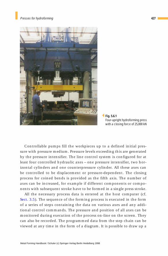
Controllable pumps fill the workpieces up to a defined initial pres-sure with pressure medium. Pressure levels exceeding this are generatedby the pressure intensifier. The line control system is configured for atleast four controlled hydraulic axes – one pressure intensifier, two hor-izontal cylinders and one counterpressure cylinder. All these axes canbe controlled to be displacement or pressure-dependent. The closingprocess for coined bends is provided as the fifth axis. The number ofaxes can be increased, for example if different components or compo-nents with subsequent stroke have to be formed in a single press stroke.
All the necessary process data is entered at the host computer (cf.Sect. 3.5). The sequence of the forming process is executed in the formof a series of steps containing the data on various axes and any addi-tional control commands. The pressure and position of all axes can bemonitored during execution of the process on-line on the screen. Theycan also be recorded. The programmed data from the step chain can beviewed at any time in the form of a diagram. It is possible to draw up a
427Presses for hydroforming
Fig. 5.6.1Four-upright hydroforming presswith a closing force of 25,000 kN
Metal Forming Handbook / Schuler (c) Springer-Verlag Berlin Heidelberg 1998
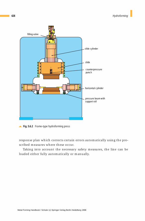
response plan which corrects certain errors automatically using the pre-scribed measures where these occur.
Taking into account the necessary safety measures, the line can beloaded either fully automatically or manually.
428 Hydroforming
Fig. 5.6.2 Frame-type hydroforming press
slide cylinder
slide
counterpressurepunch
horizontal cylinder
pressure beam withsupport roll
filling valve
Metal Forming Handbook / Schuler (c) Springer-Verlag Berlin Heidelberg 1998
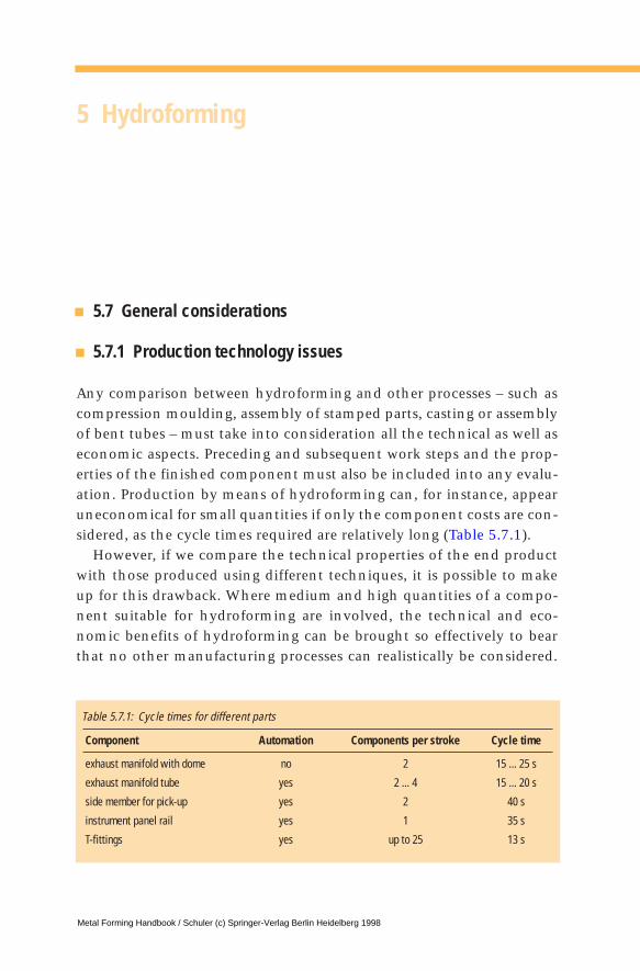
5 Hydroforming
5.7 General considerations
5.7.1 Production technology issues
Any comparison between hydroforming and other processes – such ascompression moulding, assembly of stamped parts, casting or assemblyof bent tubes – must take into consideration all the technical as well aseconomic aspects. Preceding and subsequent work steps and the prop-erties of the finished component must also be included into any evalu-ation. Production by means of hydroforming can, for instance, appearuneconomical for small quantities if only the component costs are con-sidered, as the cycle times required are relatively long (Table 5.7.1).
However, if we compare the technical properties of the end productwith those produced using different techniques, it is possible to makeup for this drawback. Where medium and high quantities of a compo-nent suitable for hydroforming are involved, the technical and eco-nomic benefits of hydroforming can be brought so effectively to bearthat no other manufacturing processes can realistically be considered.
Table 5.7.1: Cycle times for different parts
Component Automation Components per stroke Cycle time
exhaust manifold with dome no 2 15 ... 25 s
exhaust manifold tube yes 2 ... 4 15 ... 20 s
side member for pick-up yes 2 40 s
instrument panel rail yes 1 35 s
T-fittings yes up to 25 13 s
Metal Forming Handbook / Schuler (c) Springer-Verlag Berlin Heidelberg 1998
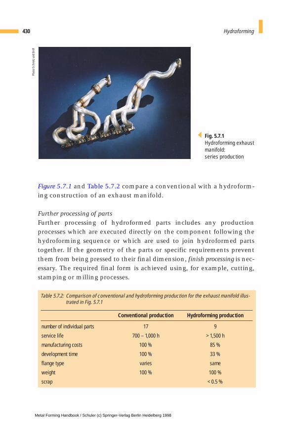
Figure 5.7.1 and Table 5.7.2 compare a conventional with a hydroform-ing construction of an exhaust manifold.
Further processing of partsFurther processing of hydroformed parts includes any productionprocesses which are executed directly on the component following thehydroforming sequence or which are used to join hydroformed partstogether. If the geometry of the parts or specific requirements preventthem from being pressed to their final dimension, finish processing is nec-essary. The required final form is achieved using, for example, cutting,stamping or milling processes.
430 Hydroforming
Fig. 5.7.1Hydroforming exhaustmanifold: series production
Phot
o Sc
hmitz
und
Bril
l
Table 5.7.2: Comparison of conventional and hydroforming production for the exhaust manifold illus-trated in Fig. 5.7.1
Conventional production Hydroforming production
number of individual parts 17 9
service life 700 – 1,000 h > 1,500 h
manufacturing costs 100 % 85 %
development time 100 % 33 %
flange type varies same
weight 100 % 100 %
scrap < 0.5 %
Metal Forming Handbook / Schuler (c) Springer-Verlag Berlin Heidelberg 1998

In addition, hole punching, notching, bending or threading processes can beperformed on the part in cases where this has not already been performedas part of the hydroforming sequence itself (Fig. 5.7.2). By calibrating thepart, it is possible to produce special contours at the ends of the tubes. Aseparate process is required, generally by means of welding, in order toassemble add-on components or to assemble the part with other componentsproduced using different production processes. In the case of a productionlot-related multiple pressing, components that are assembled together areformed in a single pressing process and must be separated by cutting.
5.7.2 Technical and economic considerations
The most important technical and economic aspects of hydroformingare that:– Components with complex geometries can be manufactured which
previously could not be produced in a single piece.
431General considerations
Fig. 5.7.2 Hole punching, notching and bending during hydroforming
p i
p i
inward hole punching
notching andbending over
outwardhole punching
Metal Forming Handbook / Schuler (c) Springer-Verlag Berlin Heidelberg 1998

– The single-part construction eliminates the need for welding seams.– The calibration process ensures a high degree of accuracy in the con-
tours and dimensions of hydroformed components.– Strain hardening generally lends hydroformed components a high
degree of torsional rigidity. Their elastic recovery properties are lesspronounced than is the case with welded sheet metal shells. For thisreason, it is often possible for the wall thickness of hydroformedcomponents to be relatively low compared to cast parts or shell con-structions. This effect can be used either to reduce weight or toenhance strength or rigidity.
– Using the same die, it is possible to use and test tubes which, withincertain limits, have different wall thicknesses and starting diametersand are made of different materials (provided the ultimate deforma-tion is not exceeded). This allows the weight and strength propertiesof the part to be optimized.
– Experience has shown that lower flow resistance and larger fatiguestrength are achieved in exhaust systems.
By selective component and process configuration, it is possible to saveboth energy and material and to reduce development and productiontimes. Thus, generally it is possible to reduce manufacturing costs.
Bibliography Leitloff, F.-U.: Innenhochdruckumformen mit dem Schäfer-ASE-Verfahren, Stahl (1995) 5.
Malle, K.: Aufweiten - Stauchen - Expandieren, VDI Journal 137 (1995) 9.
N. N.: ASE-Verfahren bringt Hohlkörper in Form, Stahlmarkt (1993) 4.
N. N. : Hochdruckumformen - Fertigungsverfahren mit Zukunft, Stahl (1993) 4.
N. N.: Mit Wasser immer in Form, Automobil-Industrie (1993) 4.
N. N.: Schäfer bringt Hohlkörper in Form, Technische Informationsbroschüre zur Schäfer-ASE-Technologie, Wilhelm Schäfer Maschinenbau GmbH & Co.
Schäfer, A. W., Fröb, K., Bieselt, R., Hassanzadah, G.: Kaltgeformte T-Stücke für den Anlagenbau –Anforderungen und technische Realisierbarkeit, 3R International 29 (1990) 9.
432 Hydroforming
Metal Forming Handbook / Schuler (c) Springer-Verlag Berlin Heidelberg 1998
6 Solid forming (Forging)
6.1 General
Processes and partsThe terms sheet metal forming and solid forming are based on practicalindustrial application, and subdivide the field of forming technologyinto two distinct areas. This distinction is made in addition to the defi-nitions established by DIN 8582 “Forming” (cf. Fig. 2.1.3). Solid form-ing entails the three-dimensional forming of “compact” slugs (forexample sheared billets), while the sheet metal forming method gener-ally processes “flat” sheet metal blanks to create three-dimensional hol-low structures with an approximately constant sheet metal thickness.The forces exerted during solid forming are substantially higher thanthose necessary for sheet metal forming. As a result, it is necessary touse relatively rigid compact-design machines and dies. Solid forminginvolves not only the processes of extrusion, indentation and drawingwhich are dealt with in most detail here, but also for example rolling,open die forging (cf. Fig. 2.1.4) or closed die forging (cf. Fig. 2.1.5).
The processes cold extrusion and drawing involve forming a slug or bil-let placed in a die, most commonly for the production of discrete parts.Hot extrusion uses a basically similar forming mechanism to createsemi-finished products such as rods, tubes and sections. The basic processesinvolved in cold extrusion (Fig. 6.1.1) are classified depending on theirforming direction as forward, backward and lateral extrusion and alsoaccording to the final form of the workpiece as rod (solid), tube and cupextrusion. When producing solid parts, the classical operations of coldextrusion technology are supplemented by processes like upsetting andironing (Fig. 6.1.2). The shape variety of parts formed from slugs or bil-
Metal Forming Handbook / Schuler (c) Springer-Verlag Berlin Heidelberg 1998
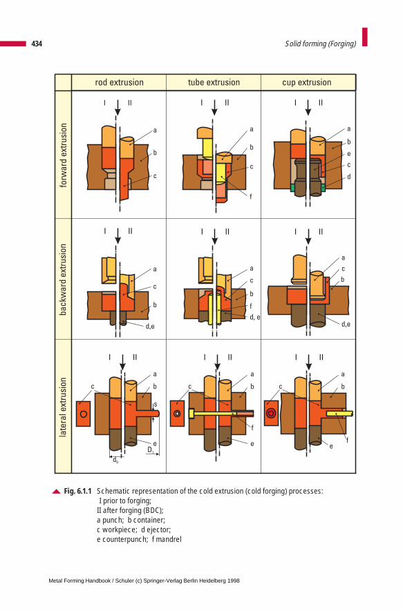
434 Solid forming (Forging)
Fig. 6.1.1 Schematic representation of the cold extrusion (cold forging) processes: I prior to forging;
II after forging (BDC); a punch; b container; c workpiece; d ejector; e counterpunch; f mandrel
I II I II
I II
I II I II
I II
I II
a
b
c
I II
I II
a
b
c
d,e
bc
e
a
a
b
c
f
a
c
b
f
d, e
a
c
b
d,e
a
b
e
c
d
bc
e
a
bc
e
a
rod extrusion tube extrusion cup extrusion
forw
ard
ext
rusi
on
ba
ckw
ard
ext
rusi
on
late
ral e
xtru
sio
n
s
D1
d0
f
f
Metal Forming Handbook / Schuler (c) Springer-Verlag Berlin Heidelberg 1998
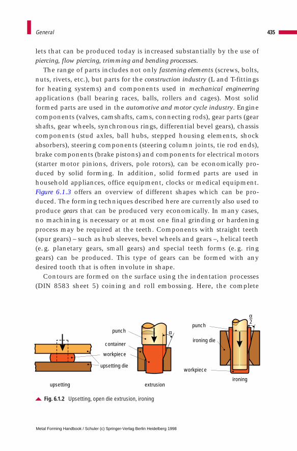
lets that can be produced today is increased substantially by the use ofpiercing, flow piercing, trimming and bending processes.
The range of parts includes not only fastening elements (screws, bolts,nuts, rivets, etc.), but parts for the construction industry (L and T-fittingsfor heating systems) and components used in mechanical engineeringapplications (ball bearing races, balls, rollers and cages). Most solidformed parts are used in the automotive and motor cycle industry. Enginecomponents (valves, camshafts, cams, connecting rods), gear parts (gearshafts, gear wheels, synchronous rings, differential bevel gears), chassiscomponents (stud axles, ball hubs, stepped housing elements, shockabsorbers), steering components (steering column joints, tie rod ends),brake components (brake pistons) and components for electrical motors(starter motor pinions, drivers, pole rotors), can be economically pro-duced by solid forming. In addition, solid formed parts are used inhousehold appliances, office equipment, clocks or medical equipment.Figure 6.1.3 offers an overview of different shapes which can be pro-duced. The forming techniques described here are currently also used toproduce gears that can be produced very economically. In many cases,no machining is necessary or at most one final grinding or hardeningprocess may be required at the teeth. Components with straight teeth(spur gears) – such as hub sleeves, bevel wheels and gears –, helical teeth(e. g. planetary gears, small gears) and special teeth forms (e. g. ringgears) can be produced. This type of gears can be formed with anydesired tooth that is often involute in shape.
Contours are formed on the surface using the indentation processes(DIN 8583 sheet 5) coining and roll embossing. Here, the complete
435General
Fig. 6.1.2 Upsetting, open die extrusion, ironing
upsetting extrusion ironing
α
α
punchpunch
ironing diecontainer
workpiece
workpieceupsetting die
2
Metal Forming Handbook / Schuler (c) Springer-Verlag Berlin Heidelberg 1998
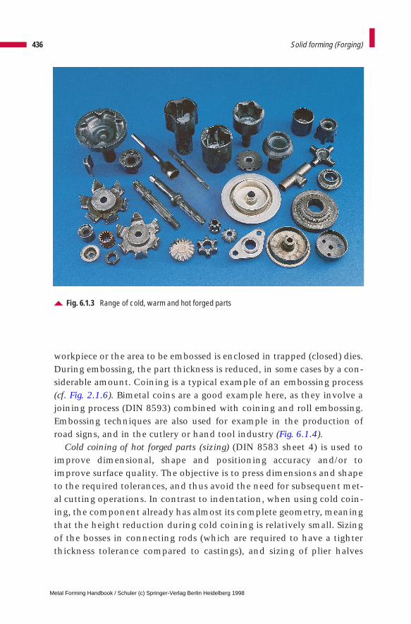
workpiece or the area to be embossed is enclosed in trapped (closed) dies.During embossing, the part thickness is reduced, in some cases by a con-siderable amount. Coining is a typical example of an embossing process(cf. Fig. 2.1.6). Bimetal coins are a good example here, as they involve ajoining process (DIN 8593) combined with coining and roll embossing.Embossing techniques are also used for example in the production ofroad signs, and in the cutlery or hand tool industry (Fig. 6.1.4).
Cold coining of hot forged parts (sizing) (DIN 8583 sheet 4) is used toimprove dimensional, shape and positioning accuracy and/or toimprove surface quality. The objective is to press dimensions and shapeto the required tolerances, and thus avoid the need for subsequent met-al cutting operations. In contrast to indentation, when using cold coin-ing, the component already has almost its complete geometry, meaningthat the height reduction during cold coining is relatively small. Sizingof the bosses in connecting rods (which are required to have a tighterthickness tolerance compared to castings), and sizing of plier halves
436 Solid forming (Forging)
Fig. 6.1.3 Range of cold, warm and hot forged parts
Metal Forming Handbook / Schuler (c) Springer-Verlag Berlin Heidelberg 1998
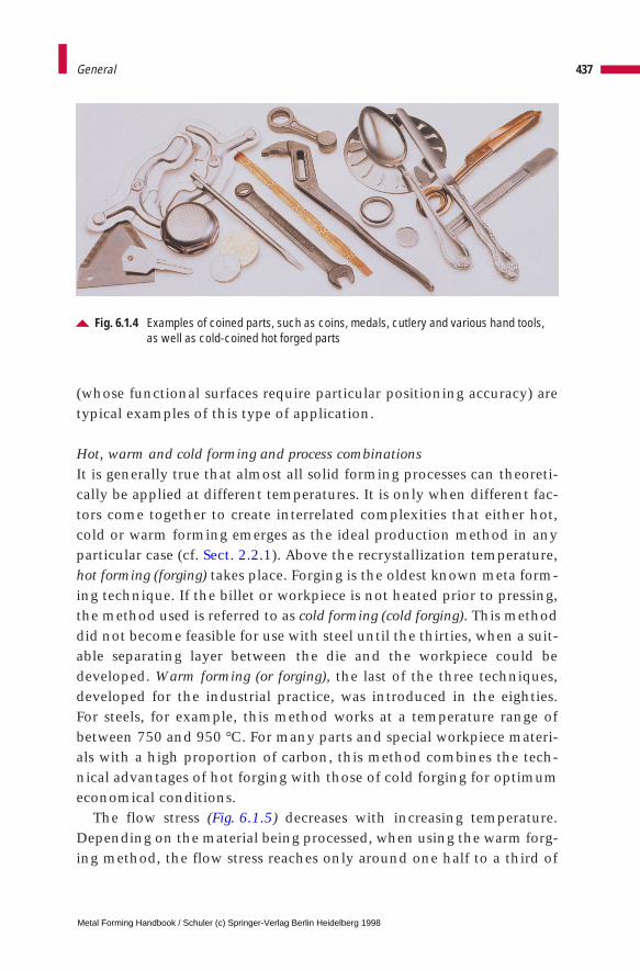
(whose functional surfaces require particular positioning accuracy) aretypical examples of this type of application.
Hot, warm and cold forming and process combinationsIt is generally true that almost all solid forming processes can theoreti-cally be applied at different temperatures. It is only when different fac-tors come together to create interrelated complexities that either hot,cold or warm forming emerges as the ideal production method in anyparticular case (cf. Sect. 2.2.1). Above the recrystallization temperature,hot forming (forging) takes place. Forging is the oldest known meta form-ing technique. If the billet or workpiece is not heated prior to pressing,the method used is referred to as cold forming (cold forging). This methoddid not become feasible for use with steel until the thirties, when a suit-able separating layer between the die and the workpiece could bedeveloped. Warm forming (or forging), the last of the three techniques,developed for the industrial practice, was introduced in the eighties.For steels, for example, this method works at a temperature range ofbetween 750 and 950 °C. For many parts and special workpiece materi-als with a high proportion of carbon, this method combines the tech-nical advantages of hot forging with those of cold forging for optimumeconomical conditions.
The flow stress (Fig. 6.1.5) decreases with increasing temperature.Depending on the material being processed, when using the warm forg-ing method, the flow stress reaches only around one half to a third of
437General
Fig. 6.1.4 Examples of coined parts, such as coins, medals, cutlery and various hand tools,as well as cold-coined hot forged parts
Metal Forming Handbook / Schuler (c) Springer-Verlag Berlin Heidelberg 1998
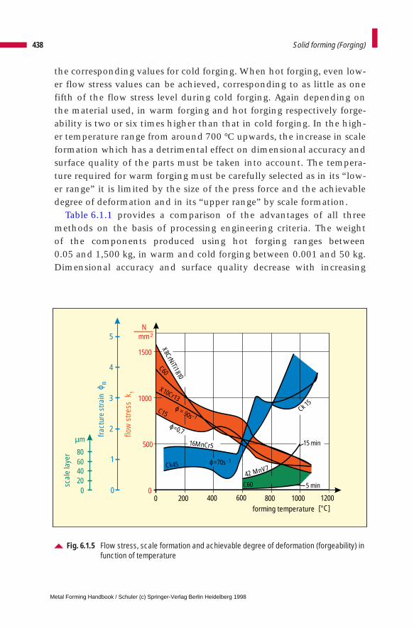
the corresponding values for cold forging. When hot forging, even low-er flow stress values can be achieved, corresponding to as little as onefifth of the flow stress level during cold forging. Again depending onthe material used, in warm forging and hot forging respectively forge-ability is two or six times higher than that in cold forging. In the high-er temperature range from around 700 °C upwards, the increase in scaleformation which has a detrimental effect on dimensional accuracy andsurface quality of the parts must be taken into account. The tempera-ture required for warm forging must be carefully selected as in its “low-er range” it is limited by the size of the press force and the achievabledegree of deformation and in its “upper range” by scale formation.
Table 6.1.1 provides a comparison of the advantages of all threemethods on the basis of processing engineering criteria. The weight of the components produced using hot forging ranges between 0.05 and 1,500 kg, in warm and cold forging between 0.001 and 50 kg.Dimensional accuracy and surface quality decrease with increasing
438 Solid forming (Forging)
Fig. 6.1.5 Flow stress, scale formation and achievable degree of deformation (forgeability) infunction of temperature
00
500
1000
1500
200 400 600 800 1000 1200[°C]forming temperature
flow
stre
ssk f
1
2
3
4
5
0
fract
ure
stra
inϕ B
Nmm 2
0
scal
e la
yer
20406080
µm
X8CrNiTi1810
C60
X10Cr13
ϕ=70s.
ϕ=0,7.
C15
16MnCr5
Ck45
15
5 minC6042 MnV7
Ck 15
-1
ϕ = 90s
.
-1
min
Metal Forming Handbook / Schuler (c) Springer-Verlag Berlin Heidelberg 1998
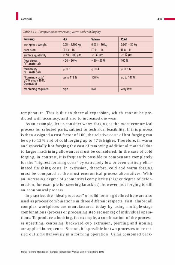
temperature. This is due to thermal expansion, which cannot be pre-dicted with accuracy, and also to increased die wear.
As an example, let us consider warm forging as the most economicalprocess for selected parts, subject to technical feasibility. If this processis then assigned a cost factor of 100, the relative costs of hot forging canbe up to 13% and of cold forging up to 47% higher. Therefore, in warmand especially hot forging the cost of removing additional material dueto larger machining allowances must be considered. In the case of coldforging, in contrast, it is frequently possible to compensate completelyfor the “highest forming costs” by extremely low or even entirely elim-inated finishing costs. In extrusion, therefore, cold and warm forgingmust be compared as the most economical process alternatives. Withan increasing degree of geometrical complexity (higher degree of defor-mation, for example for steering knuckles), however, hot forging is stillan economical process.
In practice, the “ideal processes” of solid forming defined here are alsoused as process combinations in three different respects. First, almost allcomplex workpieces are manufactured today by using multiple-stagecombinations (process or processing step sequence) of individual opera-tions. To produce a bushing, for example, a combination of the process-es upsetting, centering, backward cup extrusion, piercing and ironingare applied in sequence. Second, it is possible for two processes to be car-ried out simultaneously in a forming operation. Using combined back-
439General
Table 6.1.1: Comparison between hot, warm and cold forging
Forming Hot Warm Cold
workpiece weight 0.05 – 1,500 kg 0.001 – 50 kg 0.001 – 30 kg
precision IT 13 – 16 IT 11 – 14 IT 8 – 11
surface quality Rz . 50 – 100 mm
flow stress ~ 20 – 30 % ~ 30 – 50 % 100 %
formabilityf (T, material)
w # 6 w # 4 w # 1.6
“Forming costs“ VDW study 1991,Darmstadt
up to 113 % 100 % up to 147 %
machining required high low very low
f (T, material)
. 30 µm . 10 µm
Metal Forming Handbook / Schuler (c) Springer-Verlag Berlin Heidelberg 1998

ward and forward cup extrusion, for example, tube-shaped workpieceswith a central web (Fig. 6.1.1) can be produced. These and similarprocess combinations reduce the necessary number of processing stepsand generally involve lower press forces than the sum of press forcesused for individual operations. Such process combinations are more eco-nomical, but are only possible using multiple-action presses and dies.
Third, in forming processes where workpieces are initially hot orwarm forged and then cold forged, “process combination” has alsobecome an established term. Using this technology, it is possible tobenefit simultaneously, for example, from (a) the economic benefits ofwarm forming to create “near-net shape” components and (b) the tech-nical benefits of cold extrusion or cold forging, in particular its dimen-sional accuracy and surface quality. In this process, the cold formingstage is not by any means restricted simply to a sizing operation, butcan include a multiple-stage forging process.
440 Solid forming (Forging)
Metal Forming Handbook / Schuler (c) Springer-Verlag Berlin Heidelberg 1998
6 Solid forming (Forging)
6.2 Benefits of solid forming
6.2.1 Economic aspects
The benefits offered by solid forming, compared with other productionprocesses, can be summarized as superior quality combined with lowermanufacturing costs. The standard of quality is due to the favorablemechanical properties of cold and warm forged parts, such as high strengthand toughness, an uninterrupted fiber flow, close tolerances and a good sur-face quality. The cost benefit achieved using forging techniques can be con-siderable, but does depend on the specific part considered and on the pre-viously used production method. Individual cost factors include:
– Low material input: Almost the complete initial volume of the billet isprocessed into the finished part. Compared to machining, savingscan be as great as 75% (Fig. 6.2.1). Where high-alloyed materials areused, the benefit of low material input becomes increasingly signifi-cant in relation to overall manufacturing costs.
– Use of low-cost raw materials: Strain hardening that occurs during warmand cold forming results on the one hand in higher levels of flowstress, but also in higher ultimate and fatigue strength. Therefore, it ispossible to use lower-cost steel grades with lower initial strength char-acteristics in order to achieve the same mechanical properties obtain-able in machined parts. A workpiece with, for example, a hexagonalgeometry is produced where machining methods are used from costlyextruded material with a hexagonal cross section. By forging instead ofmachining, this type of part can be formed using substantially lessexpensive round bar as starting material.
Metal Forming Handbook / Schuler (c) Springer-Verlag Berlin Heidelberg 1998
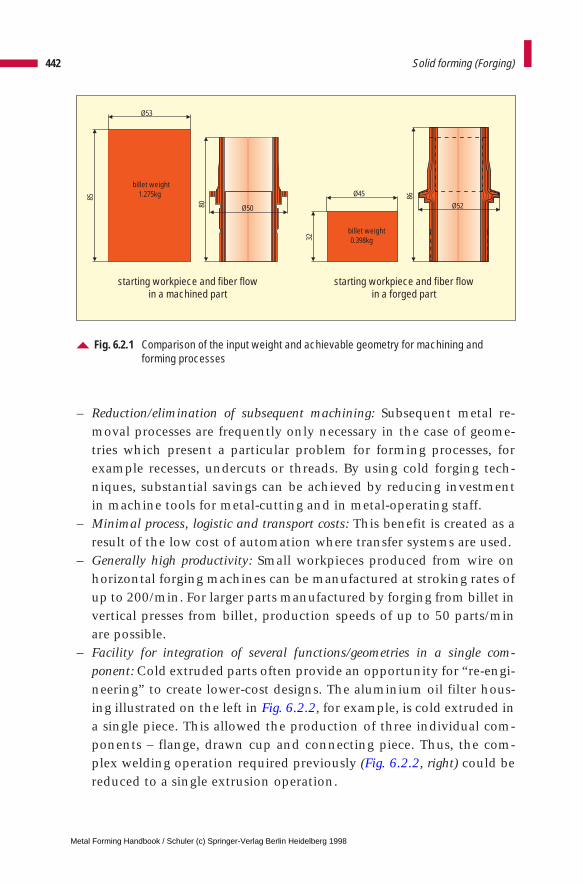
– Reduction/elimination of subsequent machining: Subsequent metal re-moval processes are frequently only necessary in the case of geome-tries which present a particular problem for forming processes, forexample recesses, undercuts or threads. By using cold forging tech-niques, substantial savings can be achieved by reducing investmentin machine tools for metal-cutting and in metal-operating staff.
– Minimal process, logistic and transport costs: This benefit is created as aresult of the low cost of automation where transfer systems are used.
– Generally high productivity: Small workpieces produced from wire onhorizontal forging machines can be manufactured at stroking rates ofup to 200/min. For larger parts manufactured by forging from billet invertical presses from billet, production speeds of up to 50 parts/minare possible.
– Facility for integration of several functions/geometries in a single com-ponent: Cold extruded parts often provide an opportunity for “re-engi-neering” to create lower-cost designs. The aluminium oil filter hous-ing illustrated on the left in Fig. 6.2.2, for example, is cold extruded ina single piece. This allowed the production of three individual com-ponents – flange, drawn cup and connecting piece. Thus, the com-plex welding operation required previously (Fig. 6.2.2, right) could bereduced to a single extrusion operation.
442 Solid forming (Forging)
Fig. 6.2.1 Comparison of the input weight and achievable geometry for machining and forming processes
Ø53
85
billet weight1.275kg
Ø5080Ø45
32
Ø52
86
billet weight0.398kg
starting workpiece and fiber flowin a machined part
starting workpiece and fiber flowin a forged part
Metal Forming Handbook / Schuler (c) Springer-Verlag Berlin Heidelberg 1998
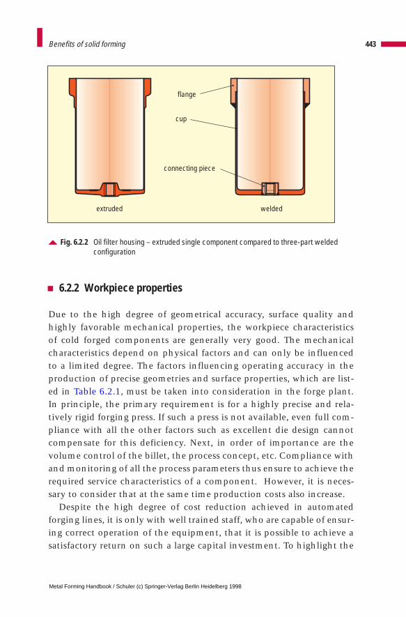
6.2.2 Workpiece properties
Due to the high degree of geometrical accuracy, surface quality andhighly favorable mechanical properties, the workpiece characteristicsof cold forged components are generally very good. The mechanicalcharacteristics depend on physical factors and can only be influencedto a limited degree. The factors influencing operating accuracy in theproduction of precise geometries and surface properties, which are list-ed in Table 6.2.1, must be taken into consideration in the forge plant.In principle, the primary requirement is for a highly precise and rela-tively rigid forging press. If such a press is not available, even full com-pliance with all the other factors such as excellent die design cannotcompensate for this deficiency. Next, in order of importance are thevolume control of the billet, the process concept, etc. Compliance withand monitoring of all the process parameters thus ensure to achieve therequired service characteristics of a component. However, it is neces-sary to consider that at the same time production costs also increase.
Despite the high degree of cost reduction achieved in automatedforging lines, it is only with well trained staff, who are capable of ensur-ing correct operation of the equipment, that it is possible to achieve asatisfactory return on such a large capital investment. To highlight the
443Benefits of solid forming
Fig. 6.2.2 Oil filter housing – extruded single component compared to three-part weldedconfiguration
extruded welded
flange
cup
connecting piece
Metal Forming Handbook / Schuler (c) Springer-Verlag Berlin Heidelberg 1998
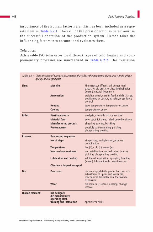
importance of the human factor here, this has been included as a sepa-rate item in Table 6.2.1. The skill of the press operator is paramount inthe successful operation of the production system. He/she takes theinfluencing factors into account and evaluates them.
TolerancesAchievable ISO tolerances for different types of cold forging and com-plementary processes are summarized in Table 6.2.2. The “variation
444 Solid forming (Forging)
Table 6.2.1: Classification of process parameters that affect the geometrical accuracy and surfacequality of a forged part
Line: Machine kinematics, stiffness, off-center load capacity, gib precision, heating behavior (warm), natural frequency
Automation weight control, careful feed and discharge,positioning accuracy, transfer, press force control
Heating type, temperature, temperature controlCooling temperature control
Billet: Starting material analysis, strength, microstructureMaterial form wire, bar, thick sheet; rolled, peeled or drawnManufacturing process shearing, sawing, blankingPre-treatment possibly soft-annealing, pickling,
phosphating, coating
Process: Processing sequenceNo. of steps single-step, multiple-step, process
combinationTemperature hot (h), cold (c), warm (w)Intermediate treatment recrystallization, normalization (warm),
pickling, phosphating, coatingLubrication and cooling additional lubrication, spraying, flooding
(warm), lubricant and coolant (warm)Clearance for part transport
Die: Precision die concept, details, production process, adjustment of upper and lower die, mechanical die deflection, thermal die expansion
Wear die material, surface, coating, change interval
Human element: Die designer, die manufacturer, operating staff, training and instruction specialized skills
Metal Forming Handbook / Schuler (c) Springer-Verlag Berlin Heidelberg 1998
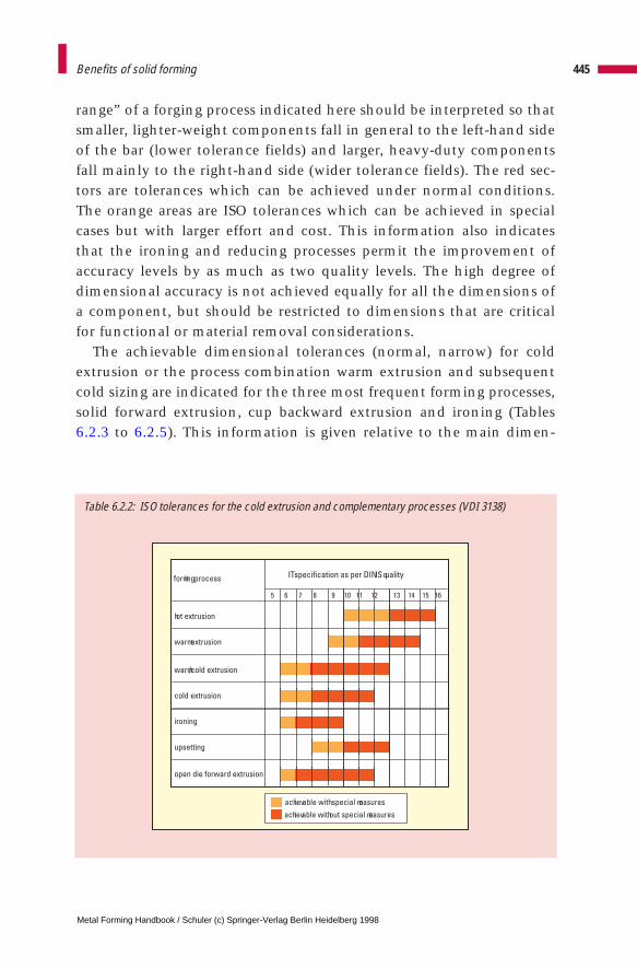
Table 6.2.2: ISO tolerances for the cold extrusion and complementary processes (VDI 3138)
range” of a forging process indicated here should be interpreted so thatsmaller, lighter-weight components fall in general to the left-hand sideof the bar (lower tolerance fields) and larger, heavy-duty componentsfall mainly to the right-hand side (wider tolerance fields). The red sec-tors are tolerances which can be achieved under normal conditions.The orange areas are ISO tolerances which can be achieved in specialcases but with larger effort and cost. This information also indicatesthat the ironing and reducing processes permit the improvement ofaccuracy levels by as much as two quality levels. The high degree ofdimensional accuracy is not achieved equally for all the dimensions ofa component, but should be restricted to dimensions that are criticalfor functional or material removal considerations.
The achievable dimensional tolerances (normal, narrow) for coldextrusion or the process combination warm extrusion and subsequentcold sizing are indicated for the three most frequent forming processes,solid forward extrusion, cup backward extrusion and ironing (Tables6.2.3 to 6.2.5). This information is given relative to the main dimen-
445Benefits of solid forming
forming process
hot extrusion
warm extrusion
warm/cold extrusion
cold extrusion
ironing
upsetting
open die forward extrusion
IT specification as per DIN ISO quality
5 6 7 8 11 129 10 15 161413
achievable with special measures
achievable without special measures
Metal Forming Handbook / Schuler (c) Springer-Verlag Berlin Heidelberg 1998
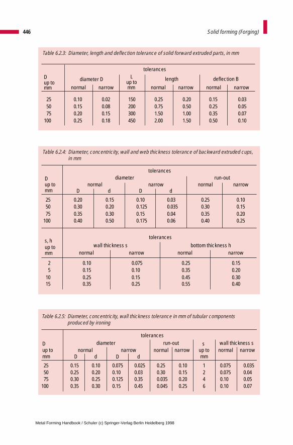
Table 6.2.4: Diameter, concentricity, wall and web thickness tolerance of backward extruded cups,in mm
D tolerances
up todiameter run-out
mmnormal narrow normal narrow
D d D d
25 0.20 0.15 0.10 0.03 0.25 0.1050 0.30 0.20 0.125 0.035 0.30 0.1575 0.35 0.30 0.15 0.04 0.35 0.20
100 0.40 0.50 0.175 0.06 0.40 0.25
s, h tolerances
up to wall thickness s bottom thickness hmm normal narrow normal narrow
2 0.10 0.075 0.25 0.155 0.15 0.10 0.35 0.20
10 0.25 0.15 0.45 0.3015 0.35 0.25 0.55 0.40
446 Solid forming (Forging)
Table 6.2.3: Diameter, length and deflection tolerance of solid forward extruded parts, in mm
D tolerances
Lup to
diameter D up to length deflection B
mm normal narrow narrow narrowmm normal normal
25 0.10 0.02 150 0.25 0.20 0.15 0.0350 0.15 0.08 200 0.75 0.50 0.25 0.0575 0.20 0.15 300 1.50 1.00 0.35 0.07
100 0.25 0.18 450 2.00 1.50 0.50 0.10
Table 6.2.5: Diameter, concentricity, wall thickness tolerance in mm of tubular components produced by ironing
D up to mm
diameter run-out s up tomm
wall thickness snormal narrow normal
D d D d
25 0.15 0.10 0.075 0.025 0.25 0.10 1 0.07550 0.25 0.20 0.10 0.03 0.30 0.15 2 0.07575 0.30 0.25 0.125 0.35 0.035 0.20 4 0.10
100 0.35 0.30 0.15 0.45 0.045 0.25 6 0.10
0.0350.040.050.07
narrownormal narrow
tolerances
Metal Forming Handbook / Schuler (c) Springer-Verlag Berlin Heidelberg 1998
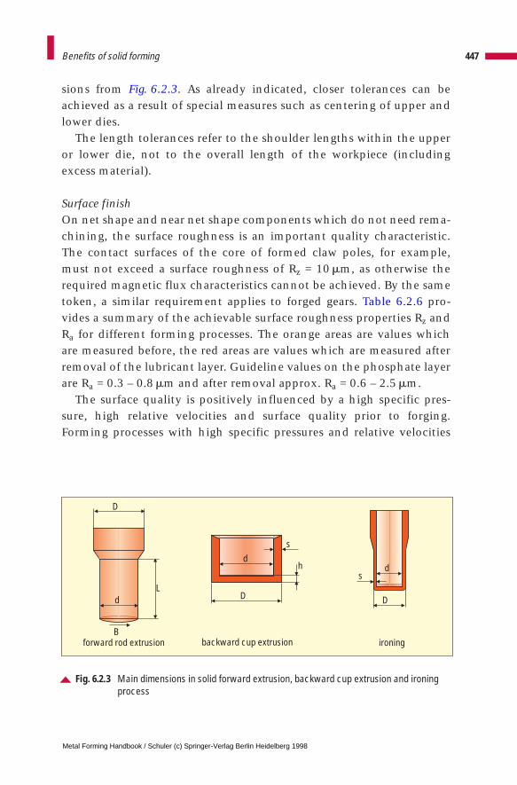
sions from Fig. 6.2.3. As already indicated, closer tolerances can beachieved as a result of special measures such as centering of upper andlower dies.
The length tolerances refer to the shoulder lengths within the upperor lower die, not to the overall length of the workpiece (includingexcess material).
Surface finishOn net shape and near net shape components which do not need rema-chining, the surface roughness is an important quality characteristic.The contact surfaces of the core of formed claw poles, for example,must not exceed a surface roughness of Rz = 10 mm, as otherwise therequired magnetic flux characteristics cannot be achieved. By the sametoken, a similar requirement applies to forged gears. Table 6.2.6 pro-vides a summary of the achievable surface roughness properties Rz andRa for different forming processes. The orange areas are values whichare measured before, the red areas are values which are measured afterremoval of the lubricant layer. Guideline values on the phosphate layerare Ra = 0.3 – 0.8 mm and after removal approx. Ra = 0.6 – 2.5 mm.
The surface quality is positively influenced by a high specific pres-sure, high relative velocities and surface quality prior to forging.Forming processes with high specific pressures and relative velocities
447Benefits of solid forming
Fig. 6.2.3 Main dimensions in solid forward extrusion, backward cup extrusion and ironingprocess
forward rod extrusion backward cup extrusion ironing
sd
DD
D
dh
s
d
B
L
Metal Forming Handbook / Schuler (c) Springer-Verlag Berlin Heidelberg 1998
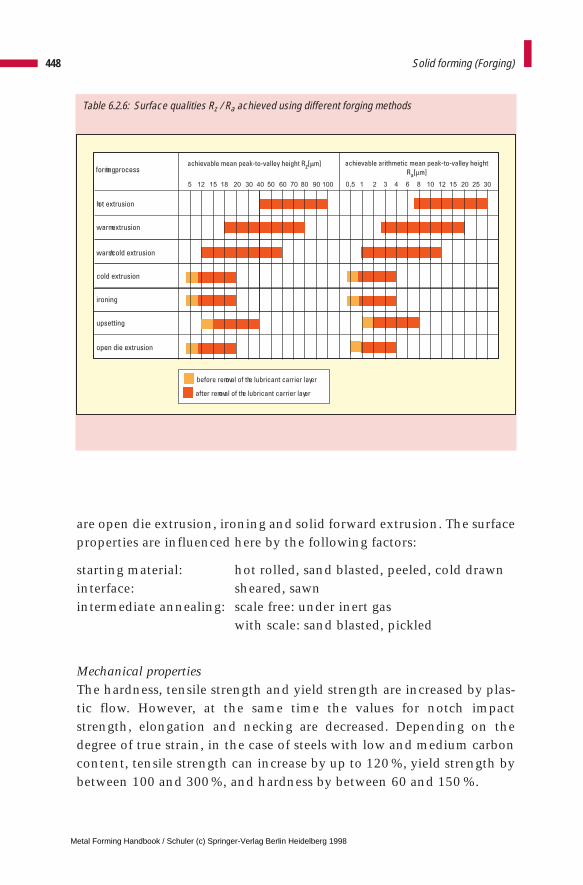
are open die extrusion, ironing and solid forward extrusion. The surfaceproperties are influenced here by the following factors:
starting material: hot rolled, sand blasted, peeled, cold drawn interface: sheared, sawnintermediate annealing: scale free: under inert gas
with scale: sand blasted, pickled
Mechanical propertiesThe hardness, tensile strength and yield strength are increased by plas-tic flow. However, at the same time the values for notch impactstrength, elongation and necking are decreased. Depending on thedegree of true strain, in the case of steels with low and medium carboncontent, tensile strength can increase by up to 120 %, yield strength bybetween 100 and 300%, and hardness by between 60 and 150 %.
448 Solid forming (Forging)
Table 6.2.6: Surface qualities Rz / Ra achieved using different forging methods
forming process
hot extrusion
warm extrusion
warm/cold extrusion
cold extrusion
ironing
upsetting
open die extrusion
5 12 15 18 20 30 40 50 60 70 80 90 100 0,5 21 3 4 6 8 10 12 15 20 25 30
before removal of the lubricant carrier layer
after removal of the lubricant carrier layer
Metal Forming Handbook / Schuler (c) Springer-Verlag Berlin Heidelberg 1998

Where no heat treatment is carried out, this effect can be utilized inorder to replace high-alloy steels by lower-alloy grades. During thedevelopment of the process plan, it is possible within certain limits toachieve specified strength values in certain sections of a component bysuitable choice of the billet diameter and the process sequence.
449Benefits of solid forming
Metal Forming Handbook / Schuler (c) Springer-Verlag Berlin Heidelberg 1998
6 Solid forming (Forging)
6.3 Materials, billet production and surface treatment
Materials used in solid forming are mainly unalloyed, low-alloy andhigh-alloy carbon steels, non-ferrous light and heavy alloys such as alu-minium, magnesium, titanium and copper and their alloys (cf. Sect.4.2.2). Significant factors in the selection of materials are formability(flow stress), the path of the flow curve (cf. Fig. 6.1.5), the permissiblefluctuations in material composition and issues related to billet prepara-tion including preliminary (heat treatment, coating) and intermediatetreatment.
6.3.1 Materials
SteelsLow-carbon and low-alloy steels are particularly suited for cold forming.With a carbon content of up to 0.2%, the conditions for forming are veryfavorable, up to 0.3% favorable and up to 0.45% difficult, which results inlow formability, true strain and higher press forces. Phosphorus and sul-phur content should remain below 0.035%, as these components tend toreduce formability. The content of nitrogen is restricted to less than 0.01%for reasons of susceptibility to ageing. Pre-heat-treated steels can be used forparts which are sensitive to warping (valve tappet rods) and whose highstrength (up to 1,100 N/mm2) permit only minimal deformation. In somecases, micro-alloyed steels containing boron, which permit penetrationhardening, are replacing alloyed steels with the prescribed full heat treat-ment.
All steels which can be cold formed, can also be warm formed. How-ever, it should be emphasized that even steels containing a higher carbon
Metal Forming Handbook / Schuler (c) Springer-Verlag Berlin Heidelberg 1998
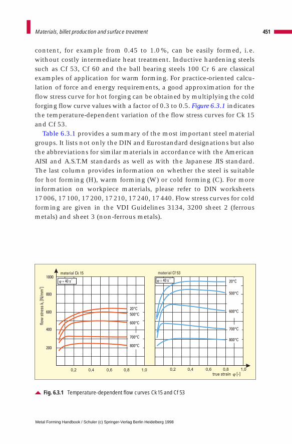
content, for example from 0.45 to 1.0 %, can be easily formed, i.e.without costly intermediate heat treatment. Inductive hardening steelssuch as Cf 53, Cf 60 and the ball bearing steels 100 Cr 6 are classicalexamples of application for warm forming. For practice-oriented calcu-lation of force and energy requirements, a good approximation for theflow stress curve for hot forging can be obtained by multiplying the coldforging flow curve values with a factor of 0.3 to 0.5. Figure 6.3.1 indicatesthe temperature-dependent variation of the flow stress curves for Ck 15and Cf 53.
Table 6.3.1 provides a summary of the most important steel materialgroups. It lists not only the DIN and Eurostandard designations but alsothe abbreviations for similar materials in accordance with the AmericanAISI and A.S.T.M standards as well as with the Japanese JIS standard.The last column provides information on whether the steel is suitablefor hot forming (H), warm forming (W) or cold forming (C). For moreinformation on workpiece materials, please refer to DIN worksheets 17006, 17100, 17200, 17210, 17240, 17440. Flow stress curves for coldforming are given in the VDI Guidelines 3134, 3200 sheet 2 (ferrousmetals) and sheet 3 (non-ferrous metals).
451Materials, billet production and surface treatment
Fig. 6.3.1 Temperature-dependent flow curves Ck 15 and Cf 53
true strain [-]
flo
wst
ress
k[N
/mm
]f
2
200
400
600
800
1000material Ck 15 material Cf 53
0,2 0,4 0,6 0,8 1,0 0,2 0,4 0,6 0,8 1,0
20° C
500° C
600° C
700° C
800° C
20° C
500° C
600° C
700° C
800° C
= 40 s-1 = 40 s
-1
Metal Forming Handbook / Schuler (c) Springer-Verlag Berlin Heidelberg 1998
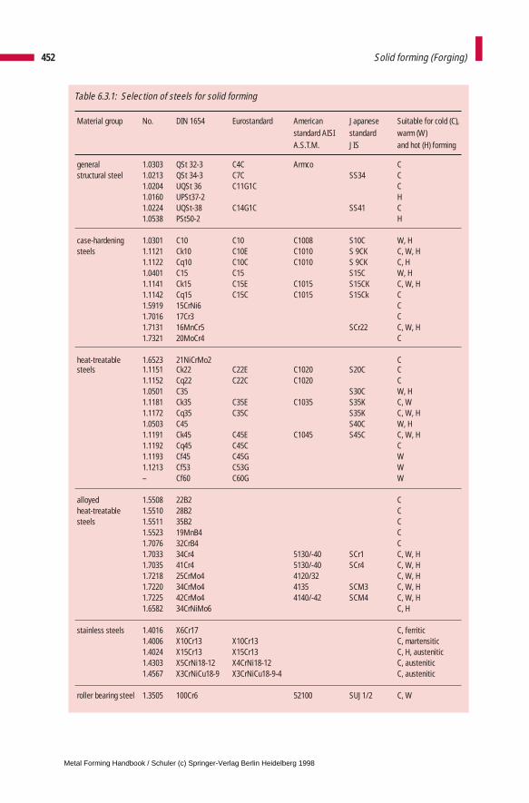
452 Solid forming (Forging)
Table 6.3.1: Selection of steels for solid forming
Material group No. DIN 1654 Eurostandard American Japanese Suitable for cold (C), standard AISI standard warm (W) A.S.T.M. JIS and hot (H) forming
general 1.0303 QSt 32-3 C4C Armco Cstructural steel 1.0213 QSt 34-3 C7C SS34 C
1.0204 UQSt 36 C11G1C C1.0160 UPSt37-2 H1.0224 UQSt-38 C14G1C SS41 C1.0538 PSt50-2 H
case-hardening 1.0301 C10 C10 C1008 S10C W, Hsteels 1.1121 Ck10 C10E C1010 S 9CK C, W, H
1.1122 Cq10 C10C C1010 S 9CK C, H1.0401 C15 C15 S15C W, H1.1141 Ck15 C15E C1015 S15CK C, W, H1.1142 Cq15 C15C C1015 S15Ck C1.5919 15CrNi6 C1.7016 17Cr3 C1.7131 16MnCr5 SCr22 C, W, H1.7321 20MoCr4 C
heat-treatable 1.6523 21NiCrMo2 Csteels 1.1151 Ck22 C22E C1020 S20C C
1.1152 Cq22 C22C C1020 C1.0501 C35 S30C W, H1.1181 Ck35 C35E C1035 S35K C, W1.1172 Cq35 C35C S35K C, W, H1.0503 C45 S40C W, H1.1191 Ck45 C45E C1045 S45C C, W, H1.1192 Cq45 C45C C1.1193 Cf45 C45G W1.1213 Cf53 C53G W– Cf60 C60G W
alloyed 1.5508 22B2 Cheat-treatable 1.5510 28B2 Csteels 1.5511 35B2 C
1.5523 19MnB4 C1.7076 32CrB4 C1.7033 34Cr4 5130/-40 SCr1 C, W, H1.7035 41Cr4 5130/-40 SCr4 C, W, H1.7218 25CrMo4 4120/32 C, W, H1.7220 34CrMo4 4135 SCM3 C, W, H1.7225 42CrMo4 4140/-42 SCM4 C, W, H1.6582 34CrNiMo6 C, H
stainless steels 1.4016 X6Cr17 C, ferritic1.4006 X10Cr13 X10Cr13 C, martensitic1.4024 X15Cr13 X15Cr13 C, H, austenitic1.4303 X5CrNi18-12 X4CrNi18-12 C, austenitic1.4567 X3CrNiCu18-9 X3CrNiCu18-9-4 C, austenitic
roller bearing steel 1.3505 100Cr6 52100 SUJ1/2 C, W
Metal Forming Handbook / Schuler (c) Springer-Verlag Berlin Heidelberg 1998
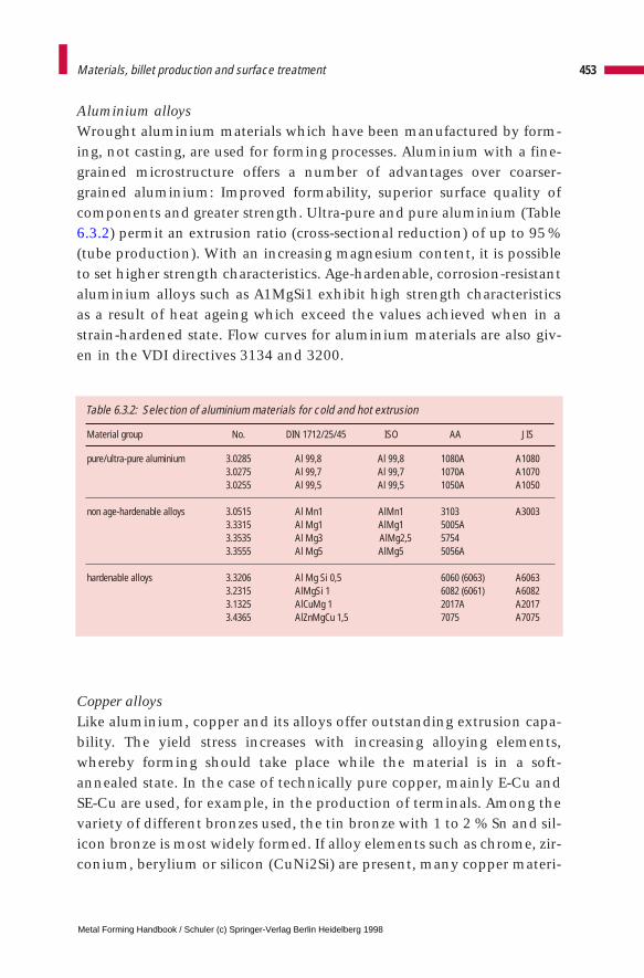
Aluminium alloysWrought aluminium materials which have been manufactured by form-ing, not casting, are used for forming processes. Aluminium with a fine-grained microstructure offers a number of advantages over coarser-grained aluminium: Improved formability, superior surface quality ofcomponents and greater strength. Ultra-pure and pure aluminium (Table6.3.2) permit an extrusion ratio (cross-sectional reduction) of up to 95%(tube production). With an increasing magnesium content, it is possibleto set higher strength characteristics. Age-hardenable, corrosion-resistantaluminium alloys such as A1MgSi1 exhibit high strength characteristicsas a result of heat ageing which exceed the values achieved when in astrain-hardened state. Flow curves for aluminium materials are also giv-en in the VDI directives 3134 and 3200.
Copper alloysLike aluminium, copper and its alloys offer outstanding extrusion capa-bility. The yield stress increases with increasing alloying elements,whereby forming should take place while the material is in a soft-annealed state. In the case of technically pure copper, mainly E-Cu andSE-Cu are used, for example, in the production of terminals. Among thevariety of different bronzes used, the tin bronze with 1 to 2 % Sn and sil-icon bronze is most widely formed. If alloy elements such as chrome, zir-conium, berylium or silicon (CuNi2Si) are present, many copper materi-
453Materials, billet production and surface treatment
Material group No. DIN 1712/25/45 ISO AA JIS
pure/ultra-pure aluminium 3.0285 Al 99,8 Al 99,8 1080A A10803.0275 Al 99,7 Al 99,7 1070A A10703.0255 Al 99,5 Al 99,5 1050A A1050
non age-hardenable alloys 3.0515 Al Mn1 AlMn1 3103 A30033.3315 Al Mg1 AlMg1 5005A3.3535 Al Mg3 AlMg2,5 57543.3555 Al Mg5 AlMg5 5056A
hardenable alloys 3.3206 Al Mg Si 0,5 6060 (6063) A60633.2315 AlMgSi 1 6082 (6061) A60823.1325 AlCuMg 1 2017A A20173.4365 AlZnMgCu 1,5 7075 A7075
Table 6.3.2: Selection of aluminium materials for cold and hot extrusion
Metal Forming Handbook / Schuler (c) Springer-Verlag Berlin Heidelberg 1998
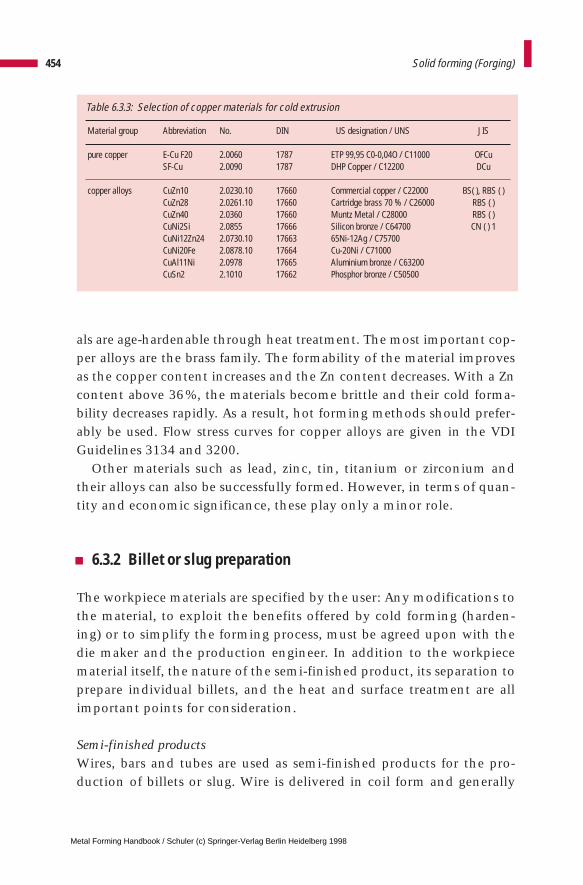
Material group Abbreviation No. DIN US designation / UNS JIS
pure copper E-Cu F20 2.0060 1787 ETP 99,95 C0-0,04O / C11000 OFCuSF-Cu 2.0090 1787 DHP Copper / C12200 DCu
copper alloys CuZn10 2.0230.10 17660 Commercial copper / C22000 BS( ), RBS ( )CuZn28 2.0261.10 17660 Cartridge brass 70 % / C26000 RBS ( )CuZn40 2.0360 17660 Muntz Metal / C28000 RBS ( )CuNi2Si 2.0855 17666 Silicon bronze / C64700 CN ( ) 1CuNi12Zn24 2.0730.10 17663 65Ni-12Ag / C75700CuNi20Fe 2.0878.10 17664 Cu-20Ni / C71000CuAl11Ni 2.0978 17665 Aluminium bronze / C63200CuSn2 2.1010 17662 Phosphor bronze / C50500
als are age-hardenable through heat treatment. The most important cop-per alloys are the brass family. The formability of the material improvesas the copper content increases and the Zn content decreases. With a Zncontent above 36%, the materials become brittle and their cold forma-bility decreases rapidly. As a result, hot forming methods should prefer-ably be used. Flow stress curves for copper alloys are given in the VDIGuidelines 3134 and 3200.
Other materials such as lead, zinc, tin, titanium or zirconium andtheir alloys can also be successfully formed. However, in terms of quan-tity and economic significance, these play only a minor role.
6.3.2 Billet or slug preparation
The workpiece materials are specified by the user: Any modifications tothe material, to exploit the benefits offered by cold forming (harden-ing) or to simplify the forming process, must be agreed upon with thedie maker and the production engineer. In addition to the workpiecematerial itself, the nature of the semi-finished product, its separation toprepare individual billets, and the heat and surface treatment are allimportant points for consideration.
Semi-finished productsWires, bars and tubes are used as semi-finished products for the pro-duction of billets or slug. Wire is delivered in coil form and generally
454 Solid forming (Forging)
Table 6.3.3: Selection of copper materials for cold extrusion
Metal Forming Handbook / Schuler (c) Springer-Verlag Berlin Heidelberg 1998
ranges from 5 to 40 mm in diameter. Wire diameters of up to 50 mm areprocessed in individual cases, although the handling capability of thewire bundle becomes increasingly difficult as the coils increase in weight.
Low-cost rolled wire in accordance with DIN 59 110 and 59 115 hasa wide diameter tolerance and a rough surface finish. It thereforerequires preliminary drawing on a wire breakdown machine. Thereduction in cross section should be between 5 and 8%. The wire mustbe annealed, de-scaled and phosphated.
Drawn wire after DIN 668 K (K = cold drawn) is used to produce partswith a lower true strain (small reduction in area), as the material hasalready undergone a certain degree of preliminary strain hardeningduring the drawing process. This material also has to be descaled, phos-phated and possibly also lubricated (stearate drawn). When a higherdegree of true strain is involved (e.g. cup backward extrusion), after pre-liminary drawing, annealing (G) or spheroidized annealing (GKZ) mustbe performed in order to restore the original material formability. Theform of delivery is specified with the designations K+G or K+GKZ. Lightoiling helps prevent rust formation on the wire. In the case of high-alloy steel qualities, a further finish drawing process takes place afterannealing with cross section reductions of less than 6%. The form ofdelivery is then specified as K+G+K or K+GKZ+K.
In practice, bar stock can also be used economically in the largerdiameter ranges. With diameters of up to 70 mm, bars of between 6 and12 m in length are produced. Hot-rolled round steel to DIN 1013 andDIN 59130 is the most favorable selection in terms of cost.
The allowable diameter tolerances cannot be reduced by drawing,leading to volume variations. These must be fully compensated for byexcess material during the forming process. For a component weighingaround 1.3 kg with a diameter of 46 mm, a weight tolerance of 88 g(average deviation) or 45 g (precision deviation) must be integrated intothe die if the admissible tolerances are fully utilized. The transforma-tion clearance in the first stage has to take account both, the diametertolerance and also the ovality of the billet caused by the shearingprocess. For a material with a diameter of 46 mm, the first transforma-tion clearance will be approx. 2.5 mm.
Where round steel is being cold forged, the descaling, phosphatizingand lubricating operations take place prior to forging. In the case ofwarm forging, the billets are fed directly to the heating line.
455Materials, billet production and surface treatment
Metal Forming Handbook / Schuler (c) Springer-Verlag Berlin Heidelberg 1998
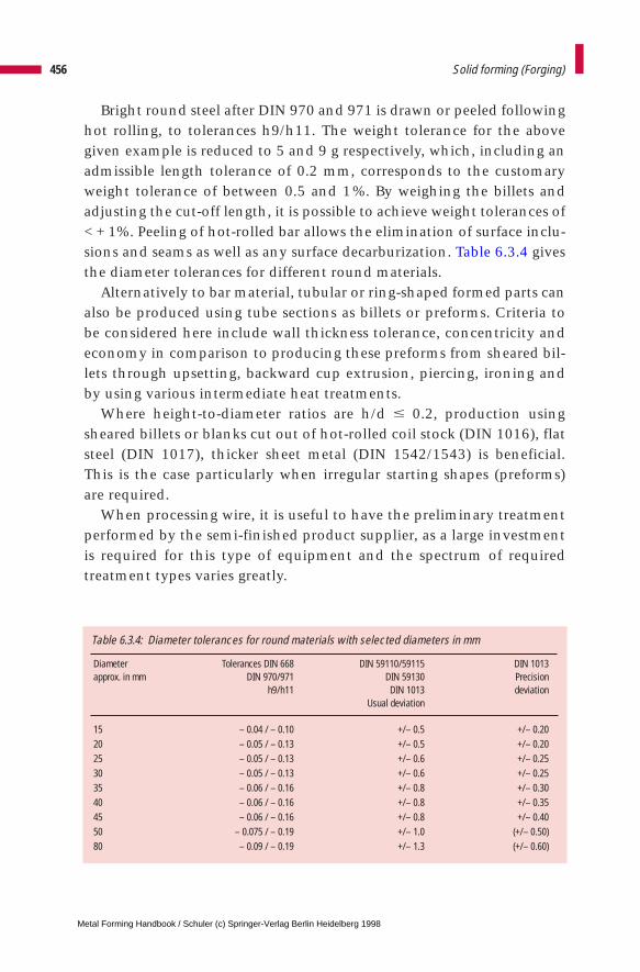
Diameter Tolerances DIN 668 DIN 59110/59115 DIN 1013approx. in mm DIN 970/971 DIN 59130 Precision
h9/h11 DIN 1013 deviationUsual deviation
15 – 0.04 / – 0.10 +/– 0.5 +/– 0.2020 – 0.05 / – 0.13 +/– 0.5 +/– 0.2025 – 0.05 / – 0.13 +/– 0.6 +/– 0.2530 – 0.05 / – 0.13 +/– 0.6 +/– 0.2535 – 0.06 / – 0.16 +/– 0.8 +/– 0.3040 – 0.06 / – 0.16 +/– 0.8 +/– 0.3545 – 0.06 / – 0.16 +/– 0.8 +/– 0.4050 – 0.075 / – 0.19 +/– 1.0 (+/– 0.50)80 – 0.09 / – 0.19 +/– 1.3 (+/– 0.60)
Bright round steel after DIN 970 and 971 is drawn or peeled followinghot rolling, to tolerances h9/h11. The weight tolerance for the abovegiven example is reduced to 5 and 9 g respectively, which, including anadmissible length tolerance of 0.2 mm, corresponds to the customaryweight tolerance of between 0.5 and 1%. By weighing the billets andadjusting the cut-off length, it is possible to achieve weight tolerances of< + 1%. Peeling of hot-rolled bar allows the elimination of surface inclu-sions and seams as well as any surface decarburization. Table 6.3.4 givesthe diameter tolerances for different round materials.
Alternatively to bar material, tubular or ring-shaped formed parts canalso be produced using tube sections as billets or preforms. Criteria tobe considered here include wall thickness tolerance, concentricity andeconomy in comparison to producing these preforms from sheared bil-lets through upsetting, backward cup extrusion, piercing, ironing andby using various intermediate heat treatments.
Where height-to-diameter ratios are h/d # 0.2, production usingsheared billets or blanks cut out of hot-rolled coil stock (DIN 1016), flatsteel (DIN 1017), thicker sheet metal (DIN 1542/1543) is beneficial.This is the case particularly when irregular starting shapes (preforms)are required.
When processing wire, it is useful to have the preliminary treatmentperformed by the semi-finished product supplier, as a large investmentis required for this type of equipment and the spectrum of requiredtreatment types varies greatly.
456 Solid forming (Forging)
Table 6.3.4: Diameter tolerances for round materials with selected diameters in mm
Metal Forming Handbook / Schuler (c) Springer-Verlag Berlin Heidelberg 1998
When using bar and flat material, the billets are generally sheared bythe forger and subjected to heat and surface treatment. Strain-harden-ing effects which occur partially at the flat surfaces of the billet due tothe shearing process are thus eliminated prior to forging.
Billet separationThe most commonly used billet separation process is shearing. Slicingon the trimming lathe is used only rarely, for example for test purpos-es. Blanking and fine blanking are explained in Sects. 4.5 and 4.7.
Shearing is characterized by practically loss-free separation at anextremely high level of output, in terms of quantity. The shear bladeplastically deforms the material until its deformation limit in the shear-ing zone has been exhausted, shearing cracks appear and fractureoccurs. With all four shearing principles – without bar and cut-off hold-er, with bar holder, with bar and cut-off holder and with axial pressureapplication – plastic flow lateral to the shearing direction is increasing-ly prevented, while compressive stress increases during the shearingoperation. Both tendencies exercise a positive influence over the geom-etry (ovality, tolerance) of the sheared surface. The most accurate billetsare produced using the shearing principle with bar and cut-off holder.
For cold forging, the sheared billets should have the greatest possiblerectangularity, volume control and little plastic deformation. Thesheared surfaces should be free of shearing defects and exhibit only amoderate amount of strain-hardening. The appearance of the shearedsurfaces is the result of interactions between workpiece characteristics,tool, machine and friction. The shearing clearance exercises a majorinfluence here. The greater the strength of the steel, the smaller is the shearing clearance (cf. Fig. 4.5.12). However, aluminium and leadalways require a small blanking clearance. The following values may betaken as a guideline for the shearing clearance of steel:
soft steel types 5 – 10 %(of the starting material diameter in mm)hard steel types 3 – 5 %brittle steel types 1 – 3 %
Rough fractured surfaces, tears and seams indicate an excessively wideshearing tool clearance. Cross fractured surfaces and material tongues
457Materials, billet production and surface treatment
Metal Forming Handbook / Schuler (c) Springer-Verlag Berlin Heidelberg 1998
indicate an insufficient tool clearance. With increasing shearing veloc-ity, the deformation zone reduces, the hardness distribution becomesmore uniform and the hardness increase in the sheared surfacebecomes less pronounced, i. e. the material characteristics become more“brittle” (exception: austenitic chrome-nickel and chrome-manganesesteels).
Open shears and closed shearing guides are used as tools (Fig. 6.3.2).Shearing guides produce very high quality blanks, but involve a num-ber of drawbacks: Sheared billets are more difficult to eject, stops haveto be used and demands on the diameter tolerance of the starting mate-rial are more stringent. For round materials, the relative shearing clear-ance for each billet thickness to be sheared can be kept constant bygrinding an elliptical relief cut on the guides. The parts sheared in thisway demonstrate improved angularity and reduced burr formation atthe edge of the fractured surface. Moreover, the sheared billet quality isless dependent on variations in material properties, which in turnreduces variations in volume.
The shearing force FS and shearing work WS can be calculatedapproximately when seperating round material with the diameter dusing the following formula:
FS = AS · kS WS = x · FS · s ,
whereby AS is the sectional surface to be sheared, kS the shearing resis-tance of the billet material and s approx. 20 % (hard, brittle materials)to 40 % (soft, tenacious materials) of the shearing stroke, i.e. the diam-eter d. The correction factor x indicates the extent to which the increasein force deviates from a rectangular force-stroke curve. In general, x istaken to be between 0.4 and 0.7. The shearing resistance kS amounts toapproximately 0.7 to 0.8 · Rm.
Heat treatment of steelSoft-annealing (spheroidized annealing) plays a particularly importantrole in the heat treatment of steel materials used for billet production.Recrystallization annealing, normalization and under certain circum-stances also recovery annealing are typical heat treatments used forintermediate annealing of already formed workpieces whose formabili-ty has been exhausted.
458 Solid forming (Forging)
Metal Forming Handbook / Schuler (c) Springer-Verlag Berlin Heidelberg 1998

The soft annealing process spheroidizes any existing harder flaky ele-ments of the microstructure. While the hardness is retained, the flowstress (cf. Sect. 2.2.3) of the material is reduced.
Recrystallization annealing is advantageous for austenitic steels with alow carbon content, as with this heat treatment the lowest flow stresslevels are obtained. However, if coarse grain occurs as a result of locallylow levels of true strain or deformation (cf. Sect. 2.2.2) during recrystal-lization annealing, and if this type of coarse grain is not permissible, anormalization process should be carried out.
As a result of two-fold recrystallization (perlite + ferrite <=> austenite)an even, fine-grained and fine-lamellar perlite microstructure is achievedthrough normalization. This can be re-annealed if required to creategrained perlite (soft-annealing). A marked difference in microstructure(coarse and fine grains) can also result during warm forming as a result oflocally differing cooling conditions and degrees of true strain. These dif-ferences can cause cracks during subsequent cold sizing operations(reducing, ironing). This problem can be avoided by normal annealing.
Recovery annealing offers a low-cost alternative to recrystallization orsoft annealing, provided the deformation in the subsequent formingoperation is minimal, i.e. the level of true strain is not too large.
6.3.3 Surface treatment
A difference is drawn between abrading and depositing surface treat-ments. Abrading processes include chemical and mechanical cleaning
459Materials, billet production and surface treatment
Fig. 6.3.2 Open and closed shearing knives and a closed shearing knife ground with ellipticalrelief
shearing clearance shearing clearance
wedgeangle
wedge angle
cuttingedge
pressuresurface
pressure surfaceflank surface
depth of relief grind
cutting edgeellipticalrelief grind
Metal Forming Handbook / Schuler (c) Springer-Verlag Berlin Heidelberg 1998

methods, degreasing and descaling. Depositing processes include phos-phating, soaping, molycoting and the use of oils. The phosphate layerserves as a carrier layer which facilitates the adherence of lubricants tothe surface. Soaping is used for simpler forming operations, molycotingfor extremely high degrees of deformation (cf. Sect. 2.2.2) and for partssuch as gears. In the case of horizontal multi-station presses operatingwith wire, oil is used for lubrication and cooling. In vertical multi-station presses, oil is used as a supplementary lubricant in addition tosoap/molycote (spray or flood application) (cf. Sect. 6.8).
Cleaning, degreasing and descalingChemical cleaning and degreasing processes are performed either throughimmersion or spraying of solvents, or through the condensation of sol-vent vapor on the workpieces. Solvent types used include organic solvents(hydrocarbons, petroleum ether, petroleum), chlorinated hydrocarbons(trichloroethylene and perchloroethylene), and water-soluble cleaningagents such as acids, acid saline solutions and alkaline solutions. Themechanical methods used include sand blasting or tumbling using lime,sand, steel shot and other materials. The choice of cleaning methods andagents depends on the type and extent of the contamination, the requireddegree of purity and the type, shape and quantity of the items to becleaned. Environmentally friendly water-soluble cleaning agents are fre-quently used.
Chemical descaling (pickling) is performed using pickling baths con-taining sulphuric acid or hydrochloric acid solutions. The pickling agentsserve to release hydrogen on the substrate metal, causing the oxide layersto split away. As the absorption of hydrogen in the substrate metal leadsto embrittlement, as short a pickling time as possible should be used.Crack formation during forging can, for example, be the result of exces-sive pickling treatment. Sand blasting and tumbling are used for themechanical removal of thick scale layers. Here, the brittle scale layer isparted off from the tough substrate material through partial applicationof force.
PhosphatingPhosphating is taken to mean the generation of cohesive crystallinephosphate layers which are firmly adhered to the substrate material.For cold forming processes, mainly zinc phosphate and in some cases
460 Solid forming (Forging)
Metal Forming Handbook / Schuler (c) Springer-Verlag Berlin Heidelberg 1998
iron phosphate layers are used. Phosphoric acid, zinc phosphate andoxidizing agents are applied in an aqueous solution. On immersion inthe solution, the metal surface is pickled by the phosphoric acid, duringwhich process insoluble zinc sulphate is simultaneously precipitated.The chemical reaction does not come to a standstill until the completesurface is coated with zinc phosphate crystals. The oxidizing agenttransforms the dissolved metal to a phosphate with low solubility whichis precipitated in the form of sludge and has to be removed periodically.
In practice, phosphate layers with a mean thickness of around 8 to 15mm are applied, which leave behind a shiny coating after forming.The phosphate layer can resist temperatures up to 200 °C. Over 200 °C,a partial transformation takes place. At over 450 °C, complete decom-position of the phosphate layer takes place. Depending on the lubricantused, however, working temperatures of up to 300 °C can be realizedduring forging.
Soaping and molycotingSoaping takes place by immersion of the parts in an alkaline soap solu-tion. The main component of these solutions is sodium stearate. A partof the zinc phosphate layer reacts with the sodium soap to form a water-insoluble zinc soap layer. The zinc soap is additionally coated with thesodium soap. This combination of layers has a very low shear strengthand thus reduces the effective coefficients of friction (cf. Sect. 4.2.3).Soaping should not take longer than 5 min, as otherwise the entire phos-phate layer will be used up and no longer provide an adhesive substrate.
To make sure that the soap coating offers good lubrication propertiesit is necessary to dry the coated billets completely. A waiting period ofone day previous to processing of the treated blanks is usually recom-mended. The soaps are temperature-resistant to approx. 250 °C, abovewhich chemical transformation processes take place. Excessive soapingresults in soap deposits building up on the dies.
Molybdenum disulphide is used under difficult forming conditions.Compared to soap lubricants, molybdenum disulphide causes greaterfriction losses which mean that larger press and ejector forces have tobe taken into consideration. However, it is capable of withstanding fargreater levels of stress, i.e. the lubricant film only breaks away underextremely high degrees of surface pressure, and permits considerablesurface expansion of the workpiece. Therefore, molybdenum disul-
461Materials, billet production and surface treatment
Metal Forming Handbook / Schuler (c) Springer-Verlag Berlin Heidelberg 1998

phide is used when large deformations, i.e. large true strains, are pre-sent. In addition, molybdenum disulphide creates fewer problems asregards the accumulation of surplus lubricant in the dies. The upperapplication temperature limit is around 350 °C. At higher temperatures,molybdenum trisulphide is created, which is ineffective as a lubricant.
Molybdenum disulphide is also applied in an immersion bath, andin some cases sprayed or applied by tumbling. The coated billets shouldbe stored for one day prior to processing. A storage period of one weekshould not be exceeded.
As a rough guideline, the overall sequence of surface treatment withthe respective functions of different baths, bath composition, timesand temperatures is summarized below:
1. Degreasing: Chemical degreasing in a 5% sodium hydrox-ide solution at 80 to 95 °C for around 5 to 10 min.
2. Cold rinsing: Removal of sodium solution residues, cold rins-ing in running water for approx. 2 min (watersurface must always be clean).
3. Pickling: Pickling in 12 % sulphuric acid or 18 % hydro-chloric acid at approx. 50 to 65 °C, durationapprox. 10 to 18 min (acid content is correct ifthe pickle effervesces).
4. Cold rinsing: Removal of acid residues, cold rising in run-ning water for approx. 2 min.
5. Hot rinsing: Hot rinsing to pre-heat the parts – influencesthe phosphate layer thickness, 70 – 90 °C, foraround 2 to 3 min (at lower temperatures, alower layer thickness results).
6. Phosphating: Mainly using zinc phosphate, for rustproofsteels with iron oxolate, 70 to 80 °C for around8 to 10 min (phosphating comprises an initialpickling reaction and a subsequent layerforming reaction, layer thickness approx. 8 to 15 mm).
462 Solid forming (Forging)
Metal Forming Handbook / Schuler (c) Springer-Verlag Berlin Heidelberg 1998

7. Cold rinsing: Cold rinsing in running water for approx. 2 min.
8. Hot rinsing: Hot rinsing to pre-heat the parts at around 60 °C, duration approx. 3 min.
9. Soaping: Soaping at 60 to 85 °C for approx. 5 min (low-er temperatures result in a thicker, lower tem-peratures in a thinner layer).
10. Drying: Drying with hot air at approx. 120 °C forapprox. 10 min.
In the case of non-ferrous metals, it is not necessary to use lubricant car-rying layers. Cleaning and lubrication is all that is required. In the caseof copper, where low degrees of deformation are required, lubricationcan be eliminated altogether.
Oil as a lubricantWhile soaping and molycoting processes are mainly used with billets,in multi-station presses, when forging from wire, mineral-based oilswith additives (EP additives) are generally used to improve lubricationproperties. The oil also adheres better to the rough phosphate layer.With this type of production, the lubrication of the flat face surfacespresents a problem because these are not coated with a phosphate lay-er due to the shearing process. The oil is sprayed or flooded into the diesor onto the workpieces.
463Materials, billet production and surface treatment
Metal Forming Handbook / Schuler (c) Springer-Verlag Berlin Heidelberg 1998
6 Solid forming (Forging)
6.4 Formed part and process plan
Before producing a part by forming, processes (cold, warm, hot), processcombinations, processing steps, preliminary treatment, process planand intermediate treatment stages must all be defined. In addition, theforce and energy requirements, as well as relevant die stress levels haveto be computed. Only on the basis of these calculations it is possible todefine the press configuration concerning functional characteristicssuch as press force, number of stations, distance between stations,stroking rate, length of slide stroke and automation related questions.
In solid forming applications, processing frequently takes place atthe limits of physical feasibility for economical reasons. This applies forexample regarding the limits of material formability (crack formation,strain hardening), the load capability of dies (internal pressures of up to3,000 N/mm2) and lubrication/cooling (cold welding). For this reason,the economical application of solid forming depends to a large degreeon the experience of the designer and the die maker. With an efficientcombination of suitable finite element programs for process simulationand existing factory floor experience, in metal forming plants a bal-anced relationship can be said to exist between theory and practice.
6.4.1 The formed part
Lot size and materialsSolid forming represents a competitive substitute for machiningprocesses and in some cases also for casting processes (cf. Sects. 2.1.1and 6.2.1). The high development costs and the degree of investment
Metal Forming Handbook / Schuler (c) Springer-Verlag Berlin Heidelberg 1998
required for presses and dies mean that certain minimum productionquantities are necessary. On the other hand, because of increasing rawmaterial and energy costs, the high degree of material utilization possi-ble using solid forming is expanding the limits of economic viabilitycontinuously towards smaller batch sizes. Even for complex parts, thistendency means that batches as small as 10,000 parts per year can stillbe economically produced.
A precise feasibility study is only possible by considering the individ-ual part concerned and by making cost comparisons with machiningprocesses. Nevertheless, the annual production lot sizes listed inTable 6.4.1 can be considered as the minimum economically viable batchsizes with respect to part weight.
Design rulesWhen designing a formed part, there are two areas of consideration: a) geometrical aspects of the finished part and b) the limitations of theindividual processing operations utilized in the total process sequence.On the basis of the finished (assembly ready) part geometry, first of alla cold or warm forged part is developed, taking into account the fol-lowing geometrical aspects:
– machining allowances;– rotationally symmetrical geometries are very well, axially symmetri-
cal geometries well suited for cold and warm forming; – wall thicknesses can be pressed no lower than 1mm for steel, no low-
er than 0.1 mm for aluminium;– draft angles, used in hot forging, are generally not required for cold
and warm forged parts (inside, outside);– small holes with length to diameter ratios l/d > 1.5 cannot be eco-
nomically produced;
465Formed part and process plan
Table 6.4.1: Minimum economical batch sizes for solid forming whencompared with machining
Weight Production quantity per year Cold forming Warm forming
0.10 – 0.25 kg 200,000 300,0000.25 – 0.75 kg 150,000 200,0000.75 – 2.50 kg 25,000 100,000
Metal Forming Handbook / Schuler (c) Springer-Verlag Berlin Heidelberg 1998
– small variations in diameter on the inside and outside surface of theformed components should be avoided;
– material overflow must be provided for, due to fluctuations in billetweight (e. g. during forward rod extrusion in the rod length, duringbackward cup extrusion in the cup height);
– transition radii must be configured as large as possible; sharp edgescan only be pressed by using split dies;
– undercuts can be produced, but increase tooling costs;– it is generally not possible to press plunge cuts, parallel key grooves,
transverse bores etc.;– slip-on gearing can be produced by pressing, high-precision involute
gearing (running gears) can be produced with increased die and processdevelopment effort.
The process engineering factors depend on the extrusion technique,the selected processing steps, the workpiece material, the permissibledie loading and the respective tri-axial stress state. Process engineeringconsiderations may restrict the range of part geometries that can beformed from billet (cf. Sect. 6.5).
Volume calculationFollowing transformation of the end product (assembly ready partgeometry) into a formed part geometry, volume calculations are madefor the relevant geometry. In practice, the volume is calculated bydividing the overall part geometry into simple volumetric elements,such as cylinders, truncated cones or rings, whose calculated individualvolumes are added to obtain the total part volume. The calculationmust take into account punching and shearing scrap which allows formaterial overflow during the forming process. Experience has shownthat the volume calculation of transition radii can be neglected, asthese volumes partially cancel each other out. A far more significantinfluence is due to volumetric variations that result from the elasticdeflection and expansion of forging dies or material overflow which isdifficult to calculate. Complex rotationally symmetrical 2D geometriesare calculated easily using CAD and according to Guldin’s law.Extremely complex 3D geometries are handled using the volumetriccalculation modules of 3D CAD systems.
466 Solid forming (Forging)
Metal Forming Handbook / Schuler (c) Springer-Verlag Berlin Heidelberg 1998
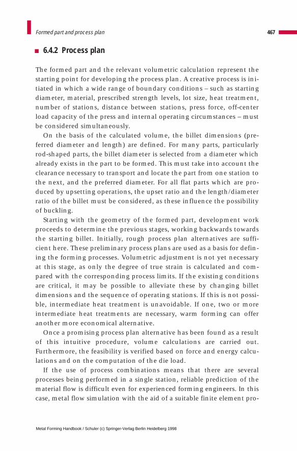
6.4.2 Process plan
The formed part and the relevant volumetric calculation represent thestarting point for developing the process plan. A creative process is ini-tiated in which a wide range of boundary conditions – such as startingdiameter, material, prescribed strength levels, lot size, heat treatment,number of stations, distance between stations, press force, off-centerload capacity of the press and internal operating circumstances – mustbe considered simultaneously.
On the basis of the calculated volume, the billet dimensions (pre-ferred diameter and length) are defined. For many parts, particularlyrod-shaped parts, the billet diameter is selected from a diameter whichalready exists in the part to be formed. This must take into account theclearance necessary to transport and locate the part from one station tothe next, and the preferred diameter. For all flat parts which are pro-duced by upsetting operations, the upset ratio and the length/diameterratio of the billet must be considered, as these influence the possibilityof buckling.
Starting with the geometry of the formed part, development workproceeds to determine the previous stages, working backwards towardsthe starting billet. Initially, rough process plan alternatives are suffi-cient here. These preliminary process plans are used as a basis for defin-ing the forming processes. Volumetric adjustment is not yet necessaryat this stage, as only the degree of true strain is calculated and com-pared with the corresponding process limits. If the existing conditionsare critical, it may be possible to alleviate these by changing billetdimensions and the sequence of operating stations. If this is not possi-ble, intermediate heat treatment is unavoidable. If one, two or moreintermediate heat treatments are necessary, warm forming can offeranother more economical alternative.
Once a promising process plan alternative has been found as a resultof this intuitive procedure, volume calculations are carried out.Furthermore, the feasibility is verified based on force and energy calcu-lations and on the computation of the die load.
If the use of process combinations means that there are severalprocesses being performed in a single station, reliable prediction of thematerial flow is difficult even for experienced forming engineers. In thiscase, metal flow simulation with the aid of a suitable finite element pro-
467Formed part and process plan
Metal Forming Handbook / Schuler (c) Springer-Verlag Berlin Heidelberg 1998
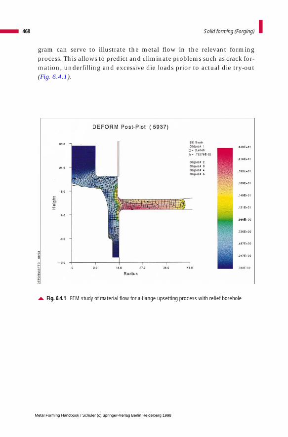
gram can serve to illustrate the metal flow in the relevant formingprocess. This allows to predict and eliminate problems such as crack for-mation, underfilling and excessive die loads prior to actual die try-out(Fig. 6.4.1).
468 Solid forming (Forging)
Fig. 6.4.1 FEM study of material flow for a flange upsetting process with relief borehole
Metal Forming Handbook / Schuler (c) Springer-Verlag Berlin Heidelberg 1998
6 Solid forming (Forging)
6.5 Force and work requirement
Determination of the force and work requirement is used as a basis forselection of the forming machine and the structural design of the form-ing dies. In practice, calculation of these characteristics simultaneouslyproduces values of process-related parameters such as the overall degreeof true strain, flow stress, forming pressure, compressive stresses on theinside wall of the extrusion container, etc. (cf. Sect. 2.2). The processlimits and the respective case of application of the forming methodmust also be taken into consideration here.
The formulae provided below are based on only one method of cal-culation and make no claim of completeness. The flow stress levels areaverage values obtained from the flow curves of VDI 3200 Sheets 2 and3. To calculate the process variables concerning machine selection, theupper limit of a flow curve should be selected. However, in making cal-culations regarding die configuration, the lower limit of a flow curveshould be selected. Table 6.5.1 provides an overall view of the processlimits for the main extrusion processes.
6.5.1 Forward rod extrusion
The forward rod extrusion method transforms a billet into a solid partwith a reduced cross section (cf. Fig. 6.1.1). The die opening whichdetermines the shape of the extruded parts is formed solely by the presscontainer. As a result of the wall friction which occurs – also during theejection process – the ratio of height to diameter of the initial billeth0/d0 [–] should be no greater than 5 to 10 (Fig. 6.5.1). If the required
Metal Forming Handbook / Schuler (c) Springer-Verlag Berlin Heidelberg 1998
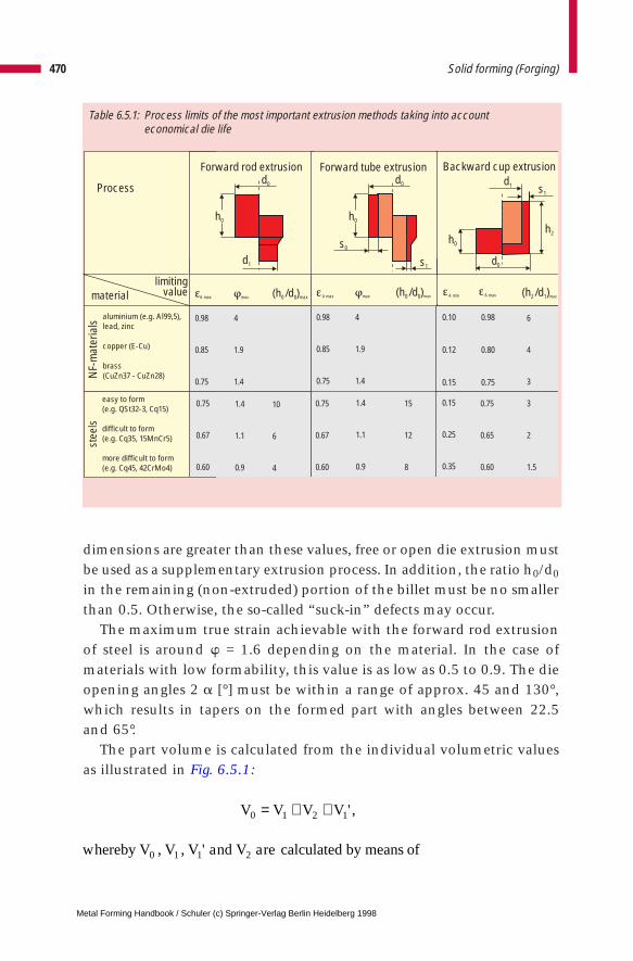
dimensions are greater than these values, free or open die extrusion mustbe used as a supplementary extrusion process. In addition, the ratio h0/d0
in the remaining (non-extruded) portion of the billet must be no smallerthan 0.5. Otherwise, the so-called “suck-in” defects may occur.
The maximum true strain achievable with the forward rod extrusionof steel is around w = 1.6 depending on the material. In the case ofmaterials with low formability, this value is as low as 0.5 to 0.9. The dieopening angles 2 a [°] must be within a range of approx. 45 and 130°,which results in tapers on the formed part with angles between 22.5and 65°.
The part volume is calculated from the individual volumetric valuesas illustrated in Fig. 6.5.1:
470 Solid forming (Forging)
Table 6.5.1: Process limits of the most important extrusion methods taking into accounteconomical die life
material
Process
NF-
mat
eria
lsst
eels
aluminium (e.g. Al99,5),lead, zinc
copper (E-Cu)
brass(CuZn37 - CuZn28)
easy to form(e.g. QSt32-3, Cq15)
difficult to form(e.g. Cq35, 15MnCr5)
more difficult to form(e.g. Cq45, 42CrMo4)
limitingA max A max A min A maxmax max(h /d )0 0 max (h /d )0 0 max (h /d )2 1 max
0.98
0.85
0.75
0.98
0.85
0.75
0.10
0.12
0.15
4
1.9
1.4
4
1.9
1.4
0.98
0.80
0.75
0.75
0.67
0.60
0.75
0.67
0.60
0.15
0.25
0.35
1.4
1.1
0.9
1.4
1.1
0.9
0.75
0.65
0.60
15
12
8
10
6
4
3
2
1.5
6
4
3
Forward rod extrusion Forward tube extrusion Backward cup extrusiond0
h0
d1
d1
h0
h2
s1
d0
d0
h0
s1
s0
value
V V V V0 1 2 1= + + ' ,
hereby V V V nd V re calculated by means of0 1 1 2, , 'w a a
Metal Forming Handbook / Schuler (c) Springer-Verlag Berlin Heidelberg 1998
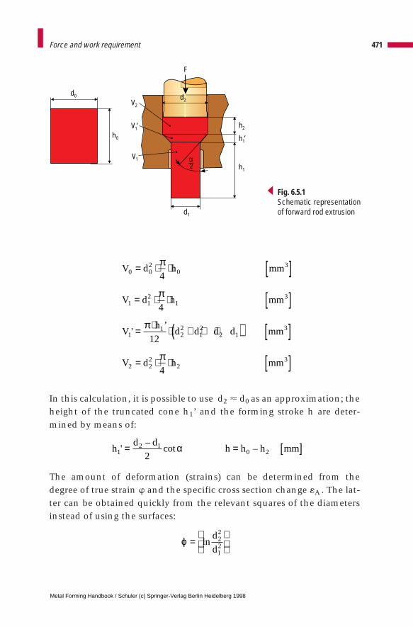
In this calculation, it is possible to use d2 < d0 as an approximation; theheight of the truncated cone h1’ and the forming stroke h are deter-mined by means of:
The amount of deformation (strains) can be determined from thedegree of true strain w and the specific cross section change «A . The lat-ter can be obtained quickly from the relevant squares of the diametersinstead of using the surfaces:
471Force and work requirement
V d h mm
V d h mm
Vh
d d d d mm
V d h mm
0 02
03
1 12
13
11
22
12
2 13
2 22
23
4
4
12
4
= ⋅ ⋅ [ ]
= ⋅ ⋅ [ ]
= ⋅ ⋅ + + ⋅( ) [ ]
= ⋅ ⋅ [ ]
'’
π
π
π
π
d0 d2
d1
F
h0
V2
V1’
h1’
h2
h1
V1 α 2
Fig. 6.5.1Schematic representationof forward rod extrusion
hd d
h h h mm12 1
0 22'
–cot –= = [ ]α
ϕ =
lnd
d22
12
Metal Forming Handbook / Schuler (c) Springer-Verlag Berlin Heidelberg 1998

The ratio between billet height h0 and billet diameter d0 and the dieopening angle are taken into account with the correction coefficientskh and k2a [–] when estimating the specific punch pressure and thusalso when calculating the forming force.
The flow stress at the start of the forming process kf0 [N/mm2] andtowards the end of the forming process kf1 can be derived from thesheets of VDI Guideline 3200 for the material used in each case. Bothvalues are used to estimate the specific and ideal forming work wid:
As the actual forming force deviates from the theoretically ideal form-ing force, it is corrected by using the effiency factor hF [–].
The average forming pressure pSt [N/mm2] and the forming force FU
[kN] are thus estimated by using:
The forming work W is the product of forming force and forming strokeh
472 Solid forming (Forging)
ε
ε
= ⋅
= ⋅
–%
–%
A A
A
d d
d
A
A
0 1
0
22
12
22
100
100
kh
dkh = ⋅ + = ⋅( ) +0 2 0 8
1
2002 0 70
02. . .α α
wk k Nmm
mmidf o f l→≈
+⋅
2 3ϕ
η εF
A= ⋅ ( )0 703125
100.
%
pw
k kN
mm
F p d kN
Stid
h
U St
= ⋅ ⋅
= ⋅ ⋅ ⋅ [ ]
η
π
α2 2
22 3
410–
W F h J resp NmU= ⋅ [ ].
Metal Forming Handbook / Schuler (c) Springer-Verlag Berlin Heidelberg 1998
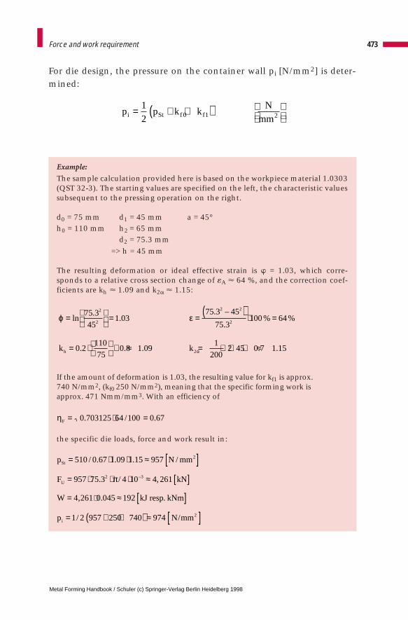
For die design, the pressure on the container wall pi [N/mm2] is deter-mined:
Example:
The sample calculation provided here is based on the workpiece material 1.0303(QST 32-3). The starting values are specified on the left, the characteristic valuessubsequent to the pressing operation on the right.
d0 = 75 mm d1 = 45 mm a = 45°h0 = 110 mm h2 = 65 mm
d2 = 75.3 mm=> h = 45 mm
The resulting deformation or ideal effective strain is w = 1.03, which corre-sponds to a relative cross section change of «A < 64 %, and the correction coef-ficients are kh < 1.09 and k2a < 1.15:
If the amount of deformation is 1.03, the resulting value for kf1 is approx. 740 N/mm2, (kf0 250 N/mm2), meaning that the specific forming work is approx. 471 Nmm/mm3. With an efficiency of
the specific die loads, force and work result in:
473Force and work requirement
p p k kN
mmi St f f= + +( )
1
2 0 1 2
ϕ ε
α
=
= =( )
⋅ =
= ⋅ + ≈ = ⋅ ⋅ + ≈
ln.
.. –
.% %
. . . . .
75 3
451 03
75 3 45
75 3100 64
0 2110
750 8 1 09
1
2002 45 0 7 1 15
2
2
2 2
2
2k kh
ηF = ⋅ =0 703125 64 100 0 67. / .
p N mm
F kN
esp
N mm
St
U
i
= ⋅ ⋅ ≈ [ ]= ⋅ ⋅ ⋅ ≈ [ ]
= ≈ [ ]= + +( ) ≈ [ ]
⋅
510 0 67 1 09 1 15 957
957 75 3 4 10 4 261
4 261 0 045 192
2 957 250 740 974
2
2 3
2
/ . . . /
. / ,
, .
/ /
–π
W kJ r . kNm
p 1
Metal Forming Handbook / Schuler (c) Springer-Verlag Berlin Heidelberg 1998
6.5.2 Forward tube extrusion
Forward tube extrusion involves the production of a tubular part with areduced wall thickness starting (cf. Fig. 6.1.1) from a cup or cylinder.The die opening, which determines the shape of the produced part, isformed by the press container and the punch. If the mandrel is perma-nently mounted in the punch, it is called a moving mandrel: As a resultof material flow, additional frictional forces occur which can lead tocritical levels of tensile stress in the mandrel. This can be avoided byusing a moving mandrel, that is moved, within certain limits, by thedeforming material. Friction-related tensile stresses occur during for-ward extrusion with the moving mandrel and during stripping of theworkpiece in both forward tube extrusion methods. Therefore, geomet-rical conditions must be set such that mandrel load does not exceed1,800 N/mm2. This is generally the case when the ratio of height todiameter in the starting material h0/d0 does not exceed 10 to 15. Theachievable levels of deformation depend on the material and corre-spond to those achievable in forward rod extrusion. Thus, comparable(shoulder) geometries can also be formed (Table 6.5.1).
6.5.3 Backward cup extrusion and centering
A (thin-walled) tubular part is produced from a solid billet. The dieopening which determines the shape of the part is formed by thepunch and container, or the die (cf. Fig. 6.1.1). In the backward cupextrusion of steel, a certain limiting ratio of penetration depth to punchdiameter h2/d1 = 3 to 3.5 cannot be exceeded. Depending on the mate-rial, the maximum achievable degree of true strain is w = 0.9 to 1.6 («A = 60 to 80 %). However, economical tool life is only achieved withsomewhat lower levels of true strain (Table 6.5.1).
Due to a maximum admissible punch stress of pSt max # 2,300 N/mm2
when processing steel, a minimum level of true strain of at least w = 0.16to 0.43 («A = 15 to 35%) must be ensured, i.e. it is not possible to back-ward extrude a cup with any optional internal diameter relative to theoutside diameter. It may be possible to produce small bores with addi-tional secondary geometries (e. g. a protrusion for extrusion piercing),provided these relieve the material flow into the cup wall.
474 Solid forming (Forging)
Metal Forming Handbook / Schuler (c) Springer-Verlag Berlin Heidelberg 1998
The minimum achievable wall thicknesses for steel are around 1 mm,for aluminium around 0.1mm. Extremely thin walls can be producedby a subsequent ironing process following backward cup extrusion. Forsteel, the minimum cup bottom thickness is 1 to 2 mm, for NF metals0.1 to 0.3 mm. The bottom thickness should always be greater than thewall thickness (underfilling). In the case of thick-walled cups which areadditionally expected to satisfy high concentricity requirements, it isadvisable to carry out a centering operation prior to cup extrusion.Centering is a process very similar to backward cup extrusion, althoughwith only a small deformation stroke. Centering is generally performedusing guided punches.
6.5.4 Reducing (open die forward extrusion)
The principle of reducing is similar to that used for forward rod extru-sion as far as the die design is concerned (cf. Fig. 6.1.2). However, incontrast to forward rod extrusion, the billet material is not pressedagainst the container wall. Thus, only a limited degree of deformationis possible without buckling. During the forming process, the materialmust neither be deformed (upset) in the container nor buckle. In thecase of starting billets with h0/d0 > 10, reductions in cross section canonly be achieved using this process. Larger amounts of deformationrequire several successive reducing operations. The achievable level ofdeformation depends on the material, the preliminary state of strainhardening and the die opening angle. An overall level of deformation(calculated from the first to the nth reducing operation) of 50 % shouldnot be exceeded due to the formation of central bursts (chevrons).Reducing or open die forward rod extrusion is a process which is notused in practical warm forming operations, as the achievable degree ofdeformation is too low due to significantly reduced flow stress in warmforming.
With a die opening angle of approx. 20°, it is possible to achieve amaximum level of deformation of w = 0.3. If the material used hasalready been strain hardened, for example as a result of a previousreducing operation, a somewhat higher degree of deformation is possi-ble. However, with an increasing die opening angle, the achievable lev-el of deformation drops substantially.
475Force and work requirement
Metal Forming Handbook / Schuler (c) Springer-Verlag Berlin Heidelberg 1998
Die angles range between 10 and 45° and generate tapers with shoul-ders between a = 5 and 22.5° on the pressed part (cf. Fig. 6.1.2). Thepunch load is of minor importance, and depends on the billet material.It should not upset the billet plastically, and cause buckling stresses inslender billets. Neither of these stress values should be exceeded. Theprocess is highly sensitive to fluctuations in the strength of the startingmaterials and to the quality of lubrication, i. e. phosphating and soaping.
6.5.5 Ironing
Ironing is a process whereby a tubular part with a bottom (e.g. backwardextruded or drawn cup) is drawn to reduce the wall thickness (cf.Fig. 6.1.2). This is a process in which the force is introduced mainlythrough the bottom of the workpiece and partially by the mandrel fric-tion force. As a result, in addition to compressive stress at the die shoulderinlet, tensile stress also occurs after exit from the die in the wall of theworkpiece (drawing process). This is in direct contrast to reducing, inwhich the force and thus also the compressive stress occurs in the work-piece cross section before the die shoulder inlet (press through process).The part shape is generated by the drawing mandrel and the ironing (die)ring. It is also possible to arrange several ironing rings one after the other.
The maximum degree of true strain achievable when ironing steel isaround w = 0.5 («A = 40 %) depending on the material characteristics.For difficult to form materials this value drops to w = 0.35 («A = 30 %).Die opening angles may range up to around 45°, which results in tapersup to 22.5° in the finished part (cf. Fig. 6.1.2) Customary die openingangles for ironing range between 5 and 36°. A minimum punch force isachieved at an ironing angle of around 12°, when the probability ofwall fracture is minimum. Ironing is a process in which an extremelygood surface quality and excellent tolerances are achieved, and it is,therefore, used frequently as a sizing operation.
6.5.6 Upsetting
Upsetting is defined as “free forming”, a process in which the partheight is reduced, generally between flat parallel die surfaces (upsetting
476 Solid forming (Forging)
Metal Forming Handbook / Schuler (c) Springer-Verlag Berlin Heidelberg 1998
dies) (cf. Fig. 6.1.2). If upsetting is carried out in a closed die withoutflash formation, for example in order to press cylindrical or lens-shapedpre-forms, this is referred to as sizing.
(Free) upsetting (cf. Fig. 2.2.1) is characterized by three process limits:Depending on the material, the maximum true strain of w = 1.6 can beachieved. The upsetting ratio h0/d0 (height to diameter of the startingworkpiece) may not exceed 2.3 for single pressing, 4.5 for dual pressingand 8.0 for triple pressing, as otherwise buckling may occur and thefiber flow is interrupted (cf. Fig. 6.2.1). The maximum die pressure is2,300 N/mm2.
In contrast to upsetting in which the exterior contour and dimen-sion are free formed, in sizing the workpiece is fully enclosed (trappeddie). The same process limiting values exist as for free upsetting.However, the same magnitude of the upsetting punch load is reached atlower levels of deformation, as the material leans against the die wall.
6.5.7 Lateral extrusion
Lateral extrusion generates shapes with flanges, collars or other geo-metric features (teeth, protrusions), whereby the die opening whichgives the workpiece its shape remains unchanged during the entireforming process (cf. Fig. 6.1.1). This is achieved by closing the dies witha high force before the slide reaches the bottom dead center. After thedies are closed, the material is pressed into the impression by the pene-trating punch. It is possible to produce for example flanges with a diam-eter ratio D1/d0 # 2.5 in a single forming operation. The ratio betweenflange thickness and starting s/d0 should not exceed 1.4 because thematerial may separate at the neutral surface.
The required forces are substantially lower than for upsetting, in par-ticular when pressing secondary geometric features. To date, the actualforce requirement has been estimated only through experimental tests.Because of the state of compressive stress, acting on all sides, local levels of true strain of up to w = 5 have been achieved using this non-stationary process.
477Force and work requirement
Metal Forming Handbook / Schuler (c) Springer-Verlag Berlin Heidelberg 1998
6 Solid forming (Forging)
6.6 Part transfer
Cold and warm forming are mass production processes whose high out-put levels and economy are achieved in particular by automation.Automation in this context includes all devices which, in addition toloading the wire coil or filling the containers with sheared billets, permitthe transfer of the billet, the preformed part between forming, and whereapplicable any scrap (piercing, trimming operations) within the press.
Installations that use wire coil have the advantage that once the wireend has been fed in, the billet material always assumes a defined posi-tion during the straightening (cf. Sect. 4.8.3), drawing and shearing (cf.Sect. 6.3). The material is transported within the press by means of amechanical transfer device, and the parts leave the press following thelast forming station by sliding down through a chute. In installationsthat use sheared billets, the billets must be fed in, oriented, possiblyweighed and conveyed to the pick-up point of the transfer device. Themain focus of investigation part handling is the transportation of work-pieces from one station to the next within the press. The objective is toutilize kinematic factors and die layout so to:
– guarantee absolutely reliable part transfer – this entails prevent-ing the part from assuming an undefined, i. e. free position at anytime –,
– ensure that no collision is possible either between the die elements orbetween die elements and grippers during idle stroking of the press(e.g. on start-up or when running the press empty), and
– minimize contact times, in particular in the case of warm forming.
Metal Forming Handbook / Schuler (c) Springer-Verlag Berlin Heidelberg 1998
There is a broad range of possible solutions for part transfer, includ-ing transport devices in the broader sense, such as tilting mechanismsfor billet containers, steep conveyors (pusher or chain conveyors),vibrating conveyors, separating devices and scales. Therefore, these willnot be dealt with here. This chapter will concentrate instead on theloading station and the transfer study for a mechanical cold formingpress with 2D transfer (cf. Sect. 4.4.6).
6.6.1 Loading station
The wide diversity of parts that must be fed into a forming press callsfor a number of different loading station concepts. Where cylindricalbillets with a length/diameter (L/D) ratio greater than 0.8 are beingprocessed, they are loaded from above into the feeding station bymeans of a feed channel (Fig. 6.6.1, top). The bottom-most parts areheld in a holder, generally cylindrical in shape, that is provided withrecesses on the side to allow for the closing movement of the gripper.Following the removal of the first part, the weight of the column caus-es it to drop onto the base plate at the level of the transport plane.Where billets with different dimensions are fed, if necessary the feedchannel and the exchangeable parts or the complete feed unit can beexchanged with the aid of quick-acting clamps. The grippers areequipped for cylindrical parts with prismatic active gripper elementswhose height should be approx. 50 % of the billet length to ensure areliable gripping action.
If the L/D ratio is below around 0.8 to 1, or if formed parts with rela-tively flat geometry are being processed (Fig. 6.6.1, bottom), then theparts are conveyed into the loading station side by side in speciallydesigned feed channels. The parts are positioned initially below thetransport plane, and are raised by a pusher to transport level in synchro-nization with the press cycle. After the pusher returns to its starting posi-tion, the next part slips into the loading station to be raised to the trans-port plane. The starting height and feed angle of the feed channels areconfigured in such a way that the billets continue to slide under theirown weight. In the case of formed parts, the grippers are designed forshaped fit if a prismatic gripper exhibits an unfavorable L/D ratio andthere is a danger that billets could rotate while being held by the gripper.
479Part transfer
Metal Forming Handbook / Schuler (c) Springer-Verlag Berlin Heidelberg 1998
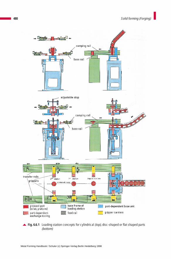
480 Solid forming (Forging)
Fig. 6.6.1 Loading station concepts for cylindrical (top), disc-shaped or flat shaped parts(bottom)
Metal Forming Handbook / Schuler (c) Springer-Verlag Berlin Heidelberg 1998
For cold forming processes, the gripper units are mounted on clamp-ing rails which are fixed in turn on a base rail (Fig. 6.6.1). When reset-ting for producing a different part, all that has to be exchanged are theclamping rails including the pre-set grippers. The front grippers areequipped with proximity switches to monitor part transfer.
Parts with a higher L/D ratio (approx. 3 to 8) must be transferredbetween stations by a 3D transfer. This involves the use of an addition-al horizontal pusher which moves the part together with its retainerinto a position from where it can be raised vertically. Here, too, the lev-el of the base plate on which the parts are positioned is located belowthe transport plane. Shaft-shaped parts with a billet L/D ratio of > 6 canalso be moved into the uplift position using special devices such asrotating sleeve retainers.
In warm forming, the loading station has the additional function ofsegregating parts which either have not been fed in correct synchro-nization with the press, or which have an incorrect temperature. Toallow these parts to be ejected, an opening is released in the base plateof the loading station through which the parts drop down into a chutefor removal.
6.6.2 Transfer study
Before conducting a transfer study, data on the kinematics of the slidemovement must be available in the form of a time-displacement dia-gram. The stroke is defined based on the range of parts, the requiredforming process and the die layout. The slide curve is given by the strokeheight and press kinematics (eccentric drive, knuckle-joint drive, modi-fied knuckle-joint drive) (cf. Fig. 3.2.3). The slide curve, whose bottomdead center is at 180°, can only be displaced vertically for transfer study.
The ejector stroke is determined by the range of parts being processedand the respective position of the forming stations in the die. Thelargest necessary ejector stroke is equal to the sum of the inlay depth ofthe part in the die and the part length. The ejector stroke can beachieved by means of a mechanical and an additional pneumatic dis-placement. The stroke covered mechanically must eject the part, whichis stuck in the tool as a result of elastic deflection of the container. Inaddition, the pneumatically generated displacement is able to raise the
481Part transfer
Metal Forming Handbook / Schuler (c) Springer-Verlag Berlin Heidelberg 1998

part. Our present example has a mechanical ejector curve with a strokeof 200 mm which is travelled through at 80° crank angle: In this case,no pneumatic ejector is required. The starting point for the ejectorcurve can be optionally selected, allowing the curve in the diagram (Fig. 6.6.2) to be displaced horizontally. The slope of the ejector curvecan be configured in such a way that it corresponds approximately tothe linear portion of the slide curve.
Starting with the transverse movement of the connecting rod, theslide ejector curve is generated by the corresponding kinematic (Fig. 6.6.2, dashed line). For the transfer study, this curve can be dis-placed only vertically.
The curve of the pneumatic ejector, whose actual distance from theslide curve must be determined with the transfer study, runs parallel tothe slide curve (Fig. 6.6.2, broken line). The slide ejector acts mechani-cally briefly after the bottom dead center and can be operated pneu-matically after that.
In addition to these main press motions, in universal transfer devicesthe curves for opening and shutting the grippers are also significant. Theopening and closing times can normally be adjusted within certain lim-its, e. g. within a 30° range, making the curves horizontally displaceablein the transfer study. The opening stroke is determined by the requireddiameter of the upper die (Fig. 6.6.2, opening stroke 100 mm). Wheremostly slender punches are used, this stroke is smaller than for femaledies used on the side of the slide, for example when producing long rod-shaped parts or parts in closing devices. Depending on the openingstroke, these movements require a smaller (approx. 30° for around 40 mm) or a larger (approx. 60° for around 100 mm) crank angle range.Through the forward and reverse movement, lateral transportationtakes place. Forward motion can be initiated as soon as the grippersengage the part, and must have been completed before the grippersopen, i. e. the upper die elements make contact with the transportedpart. The forward and return motions require a crank angle of approx.80 to 100°. The return motion takes place during the infeed and press-ing cycles. Transport studies of 3D transfer devices involve a lift-up motion inaddition to the movements previously described. This motion startsbriefly after the ejector movement and after the closing of the grippers.It ends with the lowering motion which should have been completed
482 Solid forming (Forging)
Metal Forming Handbook / Schuler (c) Springer-Verlag Berlin Heidelberg 1998
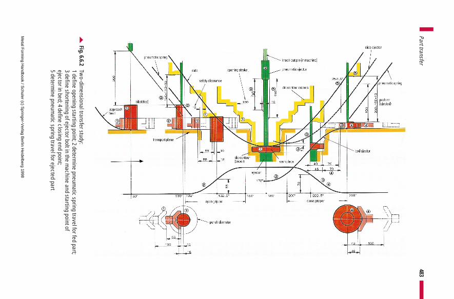
483Part transfer
Fig. 6.6.2 Tw
o-dimensional transfer study:
1 define opening starting point; 2 determine pneum
atic spring travel for fed part;3 define shortening of ejector bolt in the m
achine and starting point of ejector in bed; 4 define closing end point;5 determ
ine pneumatic spring travel for ejected part
Metal F
orming H
andbook / Schuler (c) S
pringer-Verlag B
erlin Heidelberg 1998

just before the opening of the grippers. Here, too, depending on the lift-up motion, a greater or smaller crank angle range may be required. Alift-up motion of around 100 mm can require a crank angle of around60°. All the transport motions of the press and transfer device are limit-ed by maximum allowable acceleration levels, and must be separatelydesigned for each individual case under consideration.
484 Solid forming (Forging)
Metal Forming Handbook / Schuler (c) Springer-Verlag Berlin Heidelberg 1998
6 Solid forming (Forging)
6.7 Die design
In industrial practice, extrusion or cold forging dies are frequently sub-ject to parametric designs and adaptations, making the configuration ofthe punches and dies of central importance. Less frequently, for exam-ple where a new press is used, questions related to die holder design andspare and active die sets must be addressed. Modern cold and warm forg-ing dies have a multiple-station configuration. Most of the main forgingoperations are completed within one to three stations. However, usingfour or even five-station die sets it is possible to execute other sizing,piercing and trimming operations in one and the same processing step.Thus, it is possible to approach the objective of net shape or near netshape production, and to reduce the transport and processing costsinvolved in an additional pass through the press.
Figure 6.7.1 illustrates the basic schematic layout of a modern multi-ple-station die for a universal press. An intermediate plate is mountedon the press bed and distributes the press force in the form of a pressurecone which increases in size as it acts on the press bed. The intermediateplate is equipped with recesses for connecting the shafts of the transferdevice clamping boxes, and is able to accommodate sensors for pressforce measurement or roller brackets for die set changeover. Hydraulicdie clamps for complete die change operations can also be located onthe intermediate plate.
The die base plate houses the die holding sleeves. As demonstrated inthe example, this plate can also hold hydraulic closing devices andscrap chutes. However, where these are used, the overall height of theplate must be configured to be higher. The dies themselves can bemounted in a retainer block which reaches over the entire width of the
Metal Forming Handbook / Schuler (c) Springer-Verlag Berlin Heidelberg 1998

die. However, for warm forming and in some cases also for cold form-ing, the use of single die holding sleeves is preferred. Thus, the thermalexpansion is absorbed in each individual die holder, independent ofother die stations. Using a suitable cooling device, it is possible to pre-vent the motion of die block, as a result of thermal expansion, relativeto the die halves mounted on the slide.
In principle, the layout of the upper die is similar. However, addition-al wedge adjustment devices (Fig. 6.7.2) are located in the head plate.These are used for individual height adjustment of the dies. The wedgeadjustment devices have an adjustment height of about 3 to 5 mm.
486 Solid forming (Forging)
Fig. 6.7.1 Four-station die holder with hydraulic die clamping and closing system in the second station
Metal Forming Handbook / Schuler (c) Springer-Verlag Berlin Heidelberg 1998
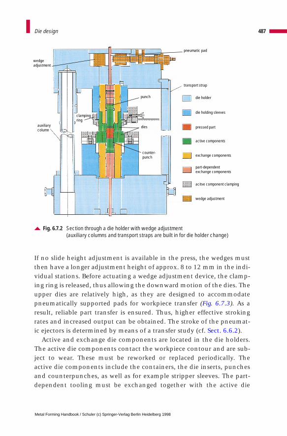
If no slide height adjustment is available in the press, the wedges mustthen have a longer adjustment height of approx. 8 to 12 mm in the indi-vidual stations. Before actuating a wedge adjustment device, the clamp-ing ring is released, thus allowing the downward motion of the dies. Theupper dies are relatively high, as they are designed to accommodatepneumatically supported pads for workpiece transfer (Fig. 6.7.3). As aresult, reliable part transfer is ensured. Thus, higher effective strokingrates and increased output can be obtained. The stroke of the pneumat-ic ejectors is determined by means of a transfer study (cf. Sect. 6.6.2).
Active and exchange die components are located in the die holders.The active die components contact the workpiece contour and are sub-ject to wear. These must be reworked or replaced periodically. Theactive die components include the containers, the die inserts, punchesand counterpunches, as well as for example stripper sleeves. The part-dependent tooling must be exchanged together with the active die
487Die design
Fig. 6.7.2 Section through a die holder with wedge adjustment (auxiliary columns and transport straps are built in for die holder change)
die holder
die holding sleeves
pressed part
active components
exchange components
part-dependentexchange components
acitve component clamping
wedge adjustment
transport strap
pneumatic pad
punch
clampingring
dies
counter-punch
auxiliary column
wedgeadjustment
Metal Forming Handbook / Schuler (c) Springer-Verlag Berlin Heidelberg 1998
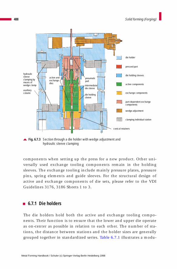
components when setting up the press for a new product. Other uni-versally used exchange tooling components remain in the holdingsleeves. The exchange tooling include mainly pressure plates, pressurepins, spring elements and guide sleeves. For the structural design ofactive and exchange components of die sets, please refer to the VDIGuidelines 3176, 3186 Sheets 1 to 3.
6.7.1 Die holders
The die holders hold both the active and exchange tooling compo-nents. Their function is to ensure that the lower and upper die operateas on-center as possible in relation to each other. The number of sta-tions, the distance between stations and the holder sizes are generallygrouped together in standardized series. Table 6.7.1 illustrates a modu-
488 Solid forming (Forging)
Fig. 6.7.3 Section through a die holder with wedge adjustment and hydraulic sleeve clamping
die holder
pressed part
die holding sleeves
active components
exchange components
part-dependent exchangecomponents
wedge adjustment
clamping individual station
active andexchangedies
auxiliarycolumn
intermediatedie sleeve
die holdingsleeve
pneumaticpad
hydraulic sleeveclamping bymeans of wedge clamp
conical retainers
Metal Forming Handbook / Schuler (c) Springer-Verlag Berlin Heidelberg 1998
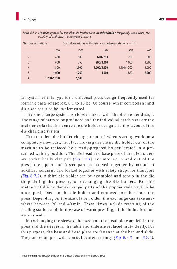
lar system of this type for a universal press design frequently used forforming parts of approx. 0.1 to 15 kg. Of course, other component anddie sizes can also be implemented.
The die change system is closely linked with the die holder design.The range of parts to be produced and the individual batch sizes are themain criteria that influence the die holder design and the layout of thedie changing system.
The complete die holder change, required when starting work on acompletely new part, involves moving the entire die holder out of themachine to be replaced by a ready-prepared holder located in a pre-scribed waiting position. The die head and base plate of the die holdersare hydraulically clamped (Fig. 6.7.1). For moving in and out of thepress, the upper and lower part are moved together by means ofauxiliary columns and locked together with safety straps for transport(Fig. 6.7.2). A third die holder can be assembled and set-up in the dieshop during the pressing or exchanging the die holders. For thismethod of die holder exchange, parts of the gripper rails have to beuncoupled, fixed on the die holder and removed together from thepress. Depending on the size of the holder, the exchange can take any-where between 20 and 40 min. These times include resetting of thefeeding station and, in the case of warm pressing, of the induction fur-nace as well.
In exchanging the sleeves, the base and the head plate are left in thepress and the sleeves in the table and slide are replaced individually. Forthis purpose, the base and head plate are fastened at the bed and slide.They are equipped with conical centering rings (Fig. 6.7.3 and 6.7.4).
489Die design
Table 6.7.1: Modular system for possible die holder sizes (widths) (bold = frequently used sizes) fornumber of and distance between stations
Number of stations Die holder widths with distances between stations in mm
200 250 300 350 400
2 400 500 600/750 700 800
3 600 750 900/1,000 1,050 1,200
4 800 1,000 1,200/1,250 1,400/1,500 1,600
5 1,000 1,250 1,500 1,850 2,000
6 1,200/1,250 1,500 – – –
Metal Forming Handbook / Schuler (c) Springer-Verlag Berlin Heidelberg 1998
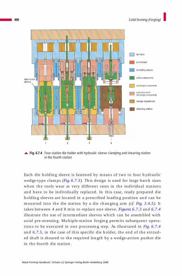
Each die holding sleeve is fastened by means of two to four hydraulicwedge-type clamps (Fig. 6.7.3). This design is used for large batch sizeswhen the tools wear at very different rates in the individual stationsand have to be individually replaced. In this case, ready prepared dieholding sleeves are located in a prescribed loading position and can bemounted into the die station by a die changing arm (cf. Fig. 3.4.5). Ittakes between 4 and 8 min to replace one sleeve. Figures 6.7.3 and 6.7.4illustrate the use of intermediate sleeves which can be assembled withaxial pre-stressing. Multiple-station forging permits subsequent opera-tions to be executed in one processing step. As illustrated in Fig. 6.7.4and 6.7.5, in the case of this specific die holder, the end of the extrud-ed shaft is sheared to the required length by a wedge-action pusher diein the fourth die station.
490 Solid forming (Forging)
Fig. 6.7.4 Four-station die holder with hydraulic sleeve clamping and shearing station in the fourth station
Metal Forming Handbook / Schuler (c) Springer-Verlag Berlin Heidelberg 1998
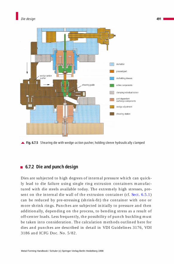
6.7.2 Die and punch design
Dies are subjected to high degrees of internal pressure which can quick-ly lead to die failure using single ring extrusion containers manufac-tured with die steels available today. The extremely high stresses, pre-sent on the internal die wall of the extrusion container (cf. Sect. 6.5.1)can be reduced by pre-stressing (shrink-fit) the container with one ormore shrink rings. Punches are subjected initially to pressure and thenadditionally, depending on the process, to bending stress as a result ofoff-center loads. Less frequently, the possibility of punch buckling mustbe taken into consideration. The calculation methods outlined here fordies and punches are described in detail in VDI Guidelines 3176, VDI3186 and ICFG Doc. No. 5/82.
491Die design
Fig. 6.7.5 Shearing die with wedge-action pusher, holding sleeve hydraulically clamped
Metal Forming Handbook / Schuler (c) Springer-Verlag Berlin Heidelberg 1998
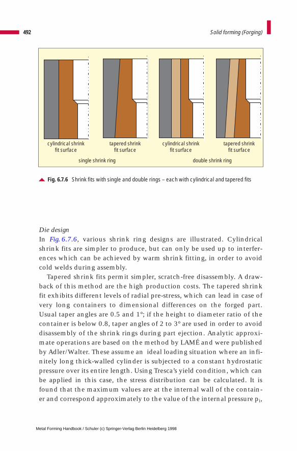
Die designIn Fig. 6.7.6, various shrink ring designs are illustrated. Cylindricalshrink fits are simpler to produce, but can only be used up to interfer-ences which can be achieved by warm shrink fitting, in order to avoidcold welds during assembly.
Tapered shrink fits permit simpler, scratch-free disassembly. A draw-back of this method are the high production costs. The tapered shrinkfit exhibits different levels of radial pre-stress, which can lead in case ofvery long containers to dimensional differences on the forged part.Usual taper angles are 0.5 and 1°; if the height to diameter ratio of thecontainer is below 0.8, taper angles of 2 to 3° are used in order to avoiddisassembly of the shrink rings during part ejection. Analytic approxi-mate operations are based on the method by LAMÉ and were publishedby Adler/Walter. These assume an ideal loading situation where an infi-nitely long thick-walled cylinder is subjected to a constant hydrostaticpressure over its entire length. Using Tresca’s yield condition, which canbe applied in this case, the stress distribution can be calculated. It isfound that the maximum values are at the internal wall of the contain-er and correspond approximately to the value of the internal pressure pi,
492 Solid forming (Forging)
Fig. 6.7.6 Shrink fits with single and double rings – each with cylindrical and tapered fits
cylindrical shrinkfit surface
cylindrical shrinkfit surface
tapered shrinkfit surface
tapered shrinkfit surface
single shrink ring double shrink ring
Metal Forming Handbook / Schuler (c) Springer-Verlag Berlin Heidelberg 1998
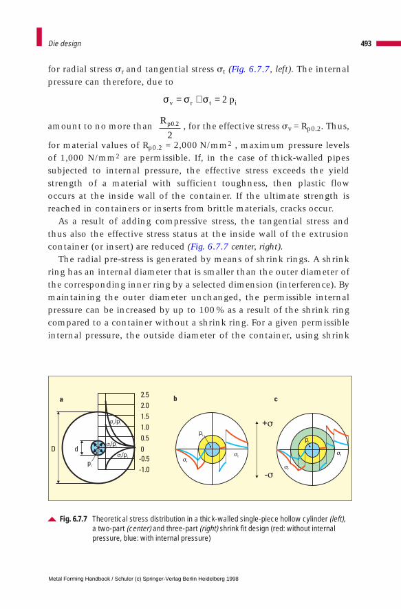
for radial stress sr and tangential stress st (Fig. 6.7.7, left). The internalpressure can therefore, due to
amount to no more than , for the effective stress sv = Rp0.2. Thus,
for material values of Rp0.2 = 2,000 N/mm2 , maximum pressure levelsof 1,000 N/mm2 are permissible. If, in the case of thick-walled pipessubjected to internal pressure, the effective stress exceeds the yieldstrength of a material with sufficient toughness, then plastic flowoccurs at the inside wall of the container. If the ultimate strength isreached in containers or inserts from brittle materials, cracks occur.
As a result of adding compressive stress, the tangential stress andthus also the effective stress status at the inside wall of the extrusioncontainer (or insert) are reduced (Fig. 6.7.7 center, right).
The radial pre-stress is generated by means of shrink rings. A shrinkring has an internal diameter that is smaller than the outer diameter ofthe corresponding inner ring by a selected dimension (interference). Bymaintaining the outer diameter unchanged, the permissible internalpressure can be increased by up to 100 % as a result of the shrink ringcompared to a container without a shrink ring. For a given permissibleinternal pressure, the outside diameter of the container, using shrink
493Die design
Fig. 6.7.7 Theoretical stress distribution in a thick-walled single-piece hollow cylinder (left),a two-part (center) and three-part (right) shrink fit design (red: without internalpressure, blue: with internal pressure)
2.5
2.0
1.5
1.0
0.5
0
-0.5
-1.0
dD
v i/p
t i/p
r i/p
pi
a b c
pi
r
t
pi
t
r
+
-
σ σ σv r t ip= + = 2
Rp0 2
2.
Metal Forming Handbook / Schuler (c) Springer-Verlag Berlin Heidelberg 1998
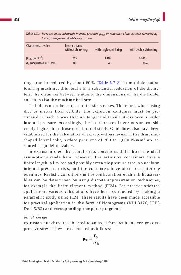
rings, can be reduced by about 60 % (Table 6.7.2). In multiple-stationforming machines this results in a substantial reduction of die diame-ters, the distances between stations, the dimensions of the die holderand thus also the machine bed size.
Carbide cannot be subject to tensile stresses. Therefore, when usingdies or inserts from carbide, the extrusion container must be pre-stressed in such a way that no tangential tensile stress occurs underinternal pressure. Accordingly, the interference dimensions are consid-erably higher than those used for tool steels. Guidelines also have beenestablished for the calculation of axial pre-stress levels; in the thin, ring-shaped lateral split, surface pressures of 700 to 1,000 N/mm2 are as-sumed as guideline values.
In extrusion dies, the actual stress conditions differ from the idealassumptions made here, however. The extrusion containers have afinite length, a limited and possibly eccentric pressure area, no uniforminternal pressure exists, and the containers have often off-center dieopenings. Realistic conditions in the configuration of shrink fit assem-blies can be determined by using discrete approximation techniques,for example the finite element method (FEM). For practice-orientedapplication, various calculations have been conducted by making aparametric study using FEM. These results have been made accessiblefor practical application in the form of Nomograms (VDI 3176, ICFGDoc. 5/82) and corresponding computer programs.
Punch designExtrusion punches are subjected to an axial force with an average com-pressive stress. They are calculated as follows:
494 Solid forming (Forging)
Table 6.7.2: Increase of the allowable internal pressure pi zul. or reduction of the outside diameter dathrough single and double shrink rings
Characteristic value Press containerwithout shrink ring with single shrink ring with double shrink ring
pi zul. [N/mm2] 690 1,160 1,395
da [mm] with di = 20 mm 100 40 36.4
pF
AStSt
St
=
Metal Forming Handbook / Schuler (c) Springer-Verlag Berlin Heidelberg 1998
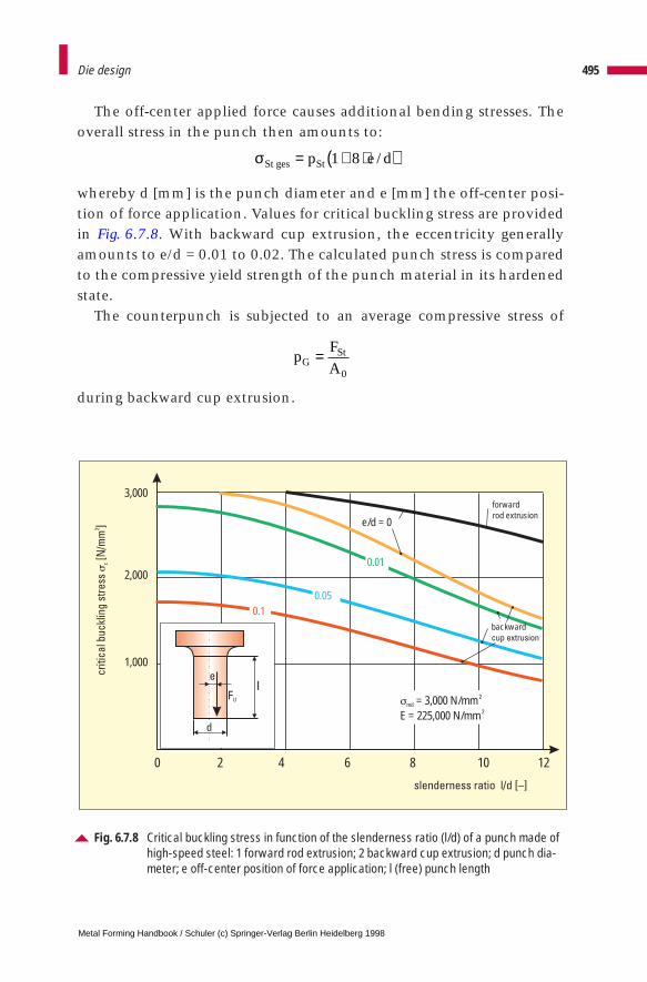
The off-center applied force causes additional bending stresses. Theoverall stress in the punch then amounts to:
whereby d [mm] is the punch diameter and e [mm] the off-center posi-tion of force application. Values for critical buckling stress are providedin Fig. 6.7.8. With backward cup extrusion, the eccentricity generallyamounts to e/d = 0.01 to 0.02. The calculated punch stress is comparedto the compressive yield strength of the punch material in its hardenedstate.
The counterpunch is subjected to an average compressive stress of
during backward cup extrusion.
495Die design
Fig. 6.7.8 Critical buckling stress in function of the slenderness ratio (l/d) of a punch made ofhigh-speed steel: 1 forward rod extrusion; 2 backward cup extrusion; d punch dia-meter; e off-center position of force application; l (free) punch length
1,000
2,000
3,000
0 2 4 6 8 10 12
0.10.05
0.01
e/d = 0
forwardrod extrusion
backwardcup extrusion
md = 3,000 N/mmE = 225,000 N/mm
2
2
d
F U
el
σSt ges Stp e d= + ⋅( )1 8 /
pF
AGSt=0
Metal Forming Handbook / Schuler (c) Springer-Verlag Berlin Heidelberg 1998
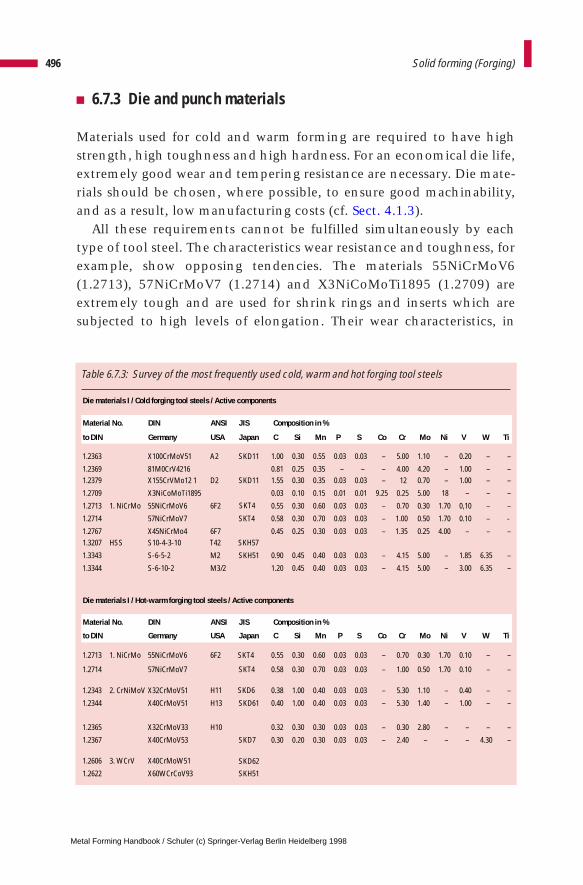
6.7.3 Die and punch materials
Materials used for cold and warm forming are required to have highstrength, high toughness and high hardness. For an economical die life,extremely good wear and tempering resistance are necessary. Die mate-rials should be chosen, where possible, to ensure good machinability,and as a result, low manufacturing costs (cf. Sect. 4.1.3).
All these requirements cannot be fulfilled simultaneously by eachtype of tool steel. The characteristics wear resistance and toughness, forexample, show opposing tendencies. The materials 55NiCrMoV6(1.2713), 57NiCrMoV7 (1.2714) and X3NiCoMoTi1895 (1.2709) areextremely tough and are used for shrink rings and inserts which aresubjected to high levels of elongation. Their wear characteristics, in
496 Solid forming (Forging)
Table 6.7.3: Survey of the most frequently used cold, warm and hot forging tool steels
Die materials I / Cold forging tool steels / Active components
Material No. DIN ANSI JIS Composition in %
to DIN Germany USA Japan C Si Mn P S Co Cr Mo Ni V W Ti
1.2363 X100CrMoV51 A2 SKD11 1.00 0.30 0.55 0.03 0.03 – 5.00 1.10 – 0.20 – –
1.2369 81M0CrV4216 0.81 0.25 0.35 – – – 4.00 4.20 – 1.00 – –1.2379 X155CrVMo12 1 D2 SKD11 1.55 0.30 0.35 0.03 0.03 – 12 0.70 – 1.00 – –
1.2709 X3NiCoMoTi1895 0.03 0.10 0.15 0.01 0.01 9.25 0.25 5.00 18 – – –
1.2713 1. NiCrMo 55NiCrMoV6 6F2 0.55 0.30 0.60 0.03 0.03 – 0.70 0.30 1.70 0,10 – –
1.2714 57NiCrMoV7 SKT4 0.58 0.30 0.70 0.03 0.03 – 1.00 0.50 1.70 0.10 – -
1.2767 X45NiCrMo4 6F7 0.45 0.25 0.30 0.03 0.03 – 1.35 0.25 4.00 – – –1.3207 HSS S10-4-3-10 T42 SKH57
1.3343 S-6-5-2 M2 SKH51 0.90 0.45 0.40 0.03 0.03 – 4.15 5.00 – 1.85 6.35 –
1.3344 S-6-10-2 M3/2 1.20 0.45 0.40 0.03 0.03 – 4.15 5.00 – 3.00 6.35 –
Die materials I / Hot-warm forging tool steels / Active components
Material No. DIN ANSI JIS Composition in %
to DIN Germany USA Japan C Si Mn P S Co Cr Mo Ni V W Ti
1.2713 1. NiCrMo 55NiCrMoV6 6F2 SKT4 0.55 0.30 0.60 0.03 0.03 – 0.70 0.30 1.70 0.10 – –
1.2714 57NiCrMoV7 SKT4 0.58 0.30 0.70 0.03 0.03 – 1.00 0.50 1.70 0.10 – –
1.2343 2. CrNiMoV X32CrMoV51 0.38 1.00 0.40 0.03 0.03 – 5.30 1.10 – 0.40 – –
1.2344 X40CrMoV51 H13
H11 SKD6
SKD61 0.40 1.00 0.40 0.03 0.03 – 5.30 1.40 – 1.00 – –
1.2365 X32CrMoV33 H10 0.32 0.30 0.30 0.03 0.03 – 0.30 2.80 – – – –
1.2367 X40CrMoV53 SKD7 0.30 0.20 0.30 0.03 0.03 – 2.40 – – – 4.30 –
1.2606 3. WCrV X40CrMoW51
1.2622 X60WCrCoV93 SKH51
SKD62
SKT4
Metal Forming Handbook / Schuler (c) Springer-Verlag Berlin Heidelberg 1998
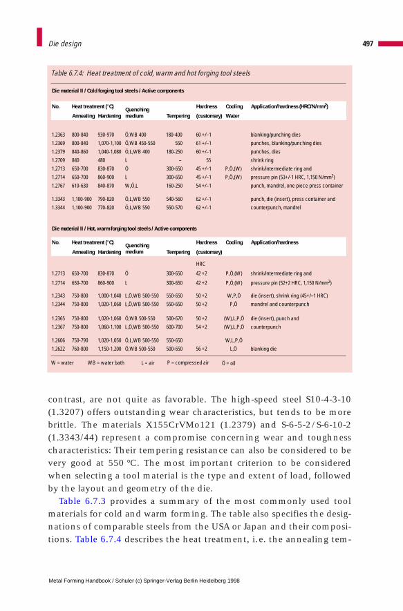
contrast, are not quite as favorable. The high-speed steel S10-4-3-10(1.3207) offers outstanding wear characteristics, but tends to be morebrittle. The materials X155CrVMo121 (1.2379) and S-6-5-2/S-6-10-2(1.3343/44) represent a compromise concerning wear and toughnesscharacteristics: Their tempering resistance can also be considered to bevery good at 550 °C. The most important criterion to be consideredwhen selecting a tool material is the type and extent of load, followedby the layout and geometry of the die.
Table 6.7.3 provides a summary of the most commonly used toolmaterials for cold and warm forming. The table also specifies the desig-nations of comparable steels from the USA or Japan and their composi-tions. Table 6.7.4 describes the heat treatment, i.e. the annealing tem-
497Die design
Table 6.7.4: Heat treatment of cold, warm and hot forging tool steels
Die material II / Cold forging tool steels / Active components
No. Heat treatment (°C) Hardness Cooling Application/hardness (HRC/N/mm2)
Annealing HardeningQuenching medium
Quenching medium
Tempering (customary) Water
1.2363 800-840 930-970 Ö,WB 400 180-400 60 +/–1 blanking/punching dies
1.2369 800-840 1,070-1,100 Ö,WB 450-550 550 61 +/–1 punches, blanking/punching dies
1.2379 840-860 1,040-1,080 Ö,L,WB 400 180-250 60 +/–1 punches, dies
1.2709 840 480 L – 55 shrink ring
1.2713 650-700 830-870 Ö 300-650 45 +/–1 P,Ö,(W) shrink/intermediate ring and
1.2714 650-700 860-900 L 300-650 45 +/–1 P,Ö,(W) pressure pin (53+/-1 HRC, 1,150 N/mm2)
1.2767 610-630 840-870 W,Ö,L 160-250 54 +/–1 punch, mandrel, one piece press container
1.3343 1,100-900 790-820 Ö,L,WB 550 540-560 62 +/–1 punch, die (insert), press container and
1.3344 1,100-900 770-820 Ö,L,WB 550 550-570 62 +/–1 counterpunch, mandrel
Die material II / Hot, warm forging tool steels / Active components
No. Heat treatment (°C) Hardness Cooling Application/hardness
Annealing Hardening Tempering (customary)
HRC
1.2713 650-700 830-870 Ö 300-650 42 +2 P,Ö,(W) shrink/intermediate ring and
1.2714 650-700 860-900 L 300-650 42 +2 P,Ö,(W) pressure pin (52+2 HRC, 1,150 N/mm2)
1.2343 750-800 1,000-1,040 L,Ö,WB 500-550 550-650 50 +2 W,P,Ö die (insert), shrink ring (45+/–1 HRC)
1.2344 750-800 1,020-1,060 L,Ö,WB 500-550 550-650 50 +2 P,Ö mandrel and counterpunch
1.2365 750-800 1,020-1,060 Ö,WB 500-550 500-670 50 +2 (W),L,P,Ö die (insert), punch and
1.2367 750-800 1,060-1,100 L,Ö,WB 500-550 600-700 54 +2 (W),L,P,Ö counterpunch
1.2606 750-790 1,020-1,050 Ö,L,WB 500-550 550-650 W,L,P,Ö
1.2622 760-800 1,150-1,200 Ö,WB 500-550 500-650 56 +2 L,Ö blanking die
W = water WB = water bath L = air P = compressed air Ö = oil
Metal Forming Handbook / Schuler (c) Springer-Verlag Berlin Heidelberg 1998
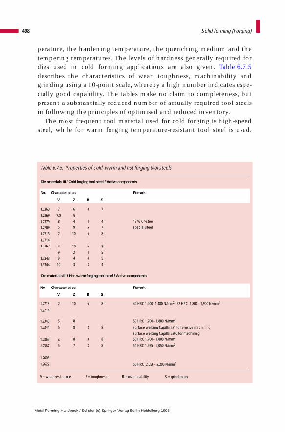
perature, the hardening temperature, the quenching medium and thetempering temperatures. The levels of hardness generally required fordies used in cold forming applications are also given. Table 6.7.5describes the characteristics of wear, toughness, machinability andgrinding using a 10-point scale, whereby a high number indicates espe-cially good capability. The tables make no claim to completeness, butpresent a substantially reduced number of actually required tool steelsin following the principles of optimised and reduced inventory.
The most frequent tool material used for cold forging is high-speedsteel, while for warm forging temperature-resistant tool steel is used.
498 Solid forming (Forging)
Table 6.7.5: Properties of cold, warm and hot forging tool steels
Die materials III / Cold forging tool steel / Active components
Characteristics Remark
V Z B S
7 6 8 7
7/8 58 4 4 4 12 % Cr-steel
5 9 5 7 special steel
2 10 6 8
4 10 6 8
9 2 4 59 4 4 5
10 3 3 4
2 10 6 8 44 HRC 1,400 -1,480 N/mm2 52 HRC 1,800 - 1,900 N/mm2
5 8 50 HRC 1,700 - 1,800 N/mm2
5 8 8 8 surface welding Capilla 521 for erosive machining
surface welding Capilla 5200 for machining
4 8 8 8 50 HRC 1,700 - 1,800 N/mm2
5 7 8 8 54 HRC 1,925 - 2,050 N/mm2
56 HRC 2,050 - 2,200 N/mm2
V = wear resistance Z = toughness B = machinability S = grindability
No.
1.2363
1.2369
1.2379
1.2709
1.2713
1.2714
1.2767
1.3343
1.3344
No.
1.2713
1.2714
1.2343
1.2344
1.2365
1.2367
1.2606
1.2622
Die materials III / Hot, warm forging tool steel / Active components
V Z B S
Characteristics Remark
Metal Forming Handbook / Schuler (c) Springer-Verlag Berlin Heidelberg 1998

Powder metal-manufactured high-speed steels demonstrate very uni-form carbide distribution and are segregation-free. This results inimproved toughness properties and extremely high compressivestrength. If a larger wear resistance is required, for example for forwardrod extrusion or ironing dies, for large-production series carbides arealso used. The carbide types used comprise tungsten carbide as a phasein a cobalt matrix. The cobalt content which determines the character-istics of the carbide, lies between 15 and 30 %. With a rising tungstencarbide content, hardness, compressive strength and wear resistance allincrease. However, at the same time toughness, notch impact strength,bending and buckling resistance are reduced. The grain size exerts aninfluence here: fine-grained carbides are unsuitable as a result of poortoughness characteristics. Table 6.7.6 provides a summary of themechanical characteristics of carbides. The strength values apply to sta-tic loads and must be reduced by 50 % for stress cycles greater than 106.
Tool steels for warm formingThe materials X40CrMoV53 (1.2367), X38CrMoV51 (1.2343), X40-CrMoV51 (1.2344) and X60WCrCoV93 (1.2622) are currently used forwarm forming and in conjunction with the water cooling method gen-erally applied today; In the case of shrink rings, 55NiCrMoV6(1.2713)/57NiCrMoV7 (1.2714) or X38CrMoV51 (1.2343)/X40CrMoV-51 (1.2344) can be used. Due to their low thermal shock resistance, car-bides, high-speed steels and cold forming tool steel 81MoCrV4216(1.2369) are only suitable when using water-free cooling methodswhich were common in the past. On closer examination, it becomesclear that materials for warm forging are generally those used in theclassical field of hot forging. Special materials for warm forging, whichare capable of withstanding relatively high pressure levels and relative-ly high temperatures simultaneously, have not yet been developed forimplementation in series production. Developments of die materialsfor warm forming are moving in the following directions:
Compared to hot forging tool steels, high-speed steels already exhib-it good wear and heat resistance properties as well as improved temper-ing resistance. By a gradual reduction of the carbon content, attemptshave been made to achieve a further improvement in thermal shockresistance of high-speed steels. With simultaneous deterioration of thewear and heat resistance, however, the thermal shock resistance level
499Die design
Metal Forming Handbook / Schuler (c) Springer-Verlag Berlin Heidelberg 1998
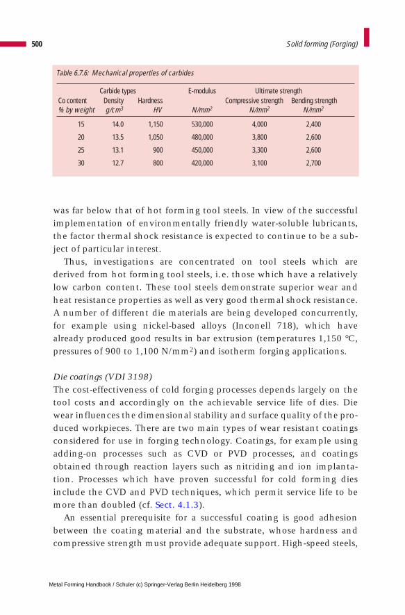
was far below that of hot forming tool steels. In view of the successfulimplementation of environmentally friendly water-soluble lubricants,the factor thermal shock resistance is expected to continue to be a sub-ject of particular interest.
Thus, investigations are concentrated on tool steels which arederived from hot forming tool steels, i.e. those which have a relativelylow carbon content. These tool steels demonstrate superior wear andheat resistance properties as well as very good thermal shock resistance.A number of different die materials are being developed concurrently,for example using nickel-based alloys (Inconell 718), which havealready produced good results in bar extrusion (temperatures 1,150 °C,pressures of 900 to 1,100 N/mm2) and isotherm forging applications.
Die coatings (VDI 3198)The cost-effectiveness of cold forging processes depends largely on thetool costs and accordingly on the achievable service life of dies. Diewear influences the dimensional stability and surface quality of the pro-duced workpieces. There are two main types of wear resistant coatingsconsidered for use in forging technology. Coatings, for example usingadding-on processes such as CVD or PVD processes, and coatingsobtained through reaction layers such as nitriding and ion implanta-tion. Processes which have proven successful for cold forming diesinclude the CVD and PVD techniques, which permit service life to bemore than doubled (cf. Sect. 4.1.3).
An essential prerequisite for a successful coating is good adhesionbetween the coating material and the substrate, whose hardness andcompressive strength must provide adequate support. High-speed steels,
500 Solid forming (Forging)
Table 6.7.6: Mechanical properties of carbides
Carbide types E-modulus Ultimate strengthCo content Density Hardness Compressive strength Bending strength% by weight g/cm3 HV N/mm2 N/mm2 N/mm2
15 14.0 1,150 530,000 4,000 2,400
20 13.5 1,050 480,000 3,800 2,600
25 13.1 900 450,000 3,300 2,600
30 12.7 800 420,000 3,100 2,700
Metal Forming Handbook / Schuler (c) Springer-Verlag Berlin Heidelberg 1998
ledeburitic 12 % chromium steels (1.2379) and carbides fully complywith these requirements.
Coatings are applied mainly by specialized companies. This meansthat particular attention must be paid to the preparation of dies by thedie manufacturer. Prior to coating, the work surfaces must be free ofgrooves and polished to a surface roughness of Rz < 1 mm. The limit foroptimum coating of internal holes is around l (length) = d (diameter)when using the PVD technique. With the CVD technique, there are noknown limitations. The limits for the ratio between the diameter D andthickness H of coated panels in cases where a “deflection” of < 0,02 mmis required after treatment, are as follows when using the CVD tech-nique:
D < 7 · H for steels and
D < 15 · H for carbides
and when using the PVD technique
D < 20 · H
It is only possible to coat pre-stressed dies in cases where the insert ispressed out, coated and pressed in again after coating. In order to pre-vent the formation of beads, sharp edges must be broken beforehand.In cases where a mean deviation of the mandrel length L and diameterD after coating of < 0.01 mm is required, the CVD process should beused in preference for the following dimensions
L < 10 . D in the case of steel
L < 15 . D in the case of carbide
and the PVD process for the length
L < 20 . D
Reliable improvement in die life, as a result of coating warm formingdies with the CVD or PVD techniques, has not been demonstrated yet,classical nitriding and welding-on techniques are generally used toenhance performance. The problem faced here is that the base materi-als have lower degrees of hardness compared to the requirements of
501Die design
Metal Forming Handbook / Schuler (c) Springer-Verlag Berlin Heidelberg 1998

cold forging, and the necessary supporting effect of the substrate mate-rial is not achieved. Once a continuous increase in the hardness of thesubstrate material through to the actual coating has been successfullyachieved, more success can be expected. It may be possible to achievethis result using plasma nitriding and subsequent coating with CrN orTiAlN, or through the development of special sandwich coatings.
6.7.4 Die closing systems (multiple-action dies)
Recent developments in the field of die closing systems have substan-tially increased the range of parts that can be produced using the coldand warm forging methods. Flashless forging of spiders, spherical hubs,tie rod ends, T-fittings for radiator construction, rotors and parts withdifferent gearing has only become possible with the development of dieclosing systems.
With an additional closing force initiated in the die set, female diesare closed before the bottom dead center of the slide is reached.Somewhat later, the material is then formed, flashless, in the closed dieby penetration of the punch. Flashless pressing is only possible if thepre-form can be completely located in the dies when these are closed.The closing force itself can be initiated by means of elastomers,hydraulic systems, or mechanically by the kinematics of the press.
Elastomers offer the advantage that their design is simple and theirspring characteristic can be adjusted within certain limits by alteringthe material composition. However, they only permit limited travel.The elastomers also have to be exchanged periodically. Hydraulic clos-ing systems generate high closing forces within a minimum of space,and can thus be positioned adjacent to each other in multiple-stationdies. By adjusting the pressure, a greater closing force range can be cov-ered. However, their design is more complex, and they call for a num-ber of safety precautions to protect both the operator as well as the dies.
In modern presses, mechanical initiation of closing motions can beachieved over a large crank angle range. However, the investment hereis substantially higher than that needed for elastomer or hydraulic sys-tems.
Figure 6.7.9 illustrates the basic layout of a hydraulic closing systemintegrated fully into the die. In the provided example, there is a closing
502 Solid forming (Forging)
Metal Forming Handbook / Schuler (c) Springer-Verlag Berlin Heidelberg 1998
system integrated into both the upper and the lower die. This type isused predominately in cases where there is only one forging step orwhen only one station of a multiple-station die is required to work witha closing system (cf. Sect. 6.7.1). Typical workpieces produced in thisdie include gearing elements which are being formed from pre-formedblanks (rings, lenses). Closing systems can also be accommodated inseparate neutral plates (Fig. 6.7.10) which always remain in the pressirrespective of the actual die in use. Depending on the die set, mountedin the press, the closing systems which are currently required can beactivated and connected by means of pressure pins to the female die. Atypical application for this system is the production of tie rod headsand T-fittings which require up to five closing systems. Additional partsinclude inner races of constant velocity joints where an additionalpiercing process is required and the grooves, formed in the previous sta-tion, must maintain this shape accurately during the piercing opera-tion.
The closing force can be individually adjusted according with the(annular) piston surfaces. The press forces which are introduced down-
503Die design
bed
bedclamping plate
hydraulic cushion lower die
hydraulic cushionupper die
annular piston
annular piston
cushion pins
cushion pins
topadvancing die
bottom
dayl
ight
slide
Fig. 6.7.9 Single-station die set withhydraulic closing system atthe top and bottom
Metal Forming Handbook / Schuler (c) Springer-Verlag Berlin Heidelberg 1998
wards into the press bed via a counterpunch are absorbed centrally.This determines the minimum inside diameter of the annular piston.As a guideline, the closing force can be estimated to be 0.6 to 0.9 timesthe punch load. The required closing force depends on whether a com-pletely closed (or trapped) die set is being used or forging takes placethrough extrusion shoulders into a free space. In the case of complete-ly closed (trapped) die sets, the closing system also serves to apply anaxial pre-stress on the parting line of the dies, that are subjected to highloads.
504 Solid forming (Forging)
dayl
ight
bed
slide
oil cushion annular piston
neutral platefor the closingsystem
neutral platefor the closingsystem
counterpunch
cushion pins
Fig. 6.7.10 Multiple-station die set with hydraulic closing systems at the top and bottom of each station
Metal Forming Handbook / Schuler (c) Springer-Verlag Berlin Heidelberg 1998
6 Solid forming (Forging)
6.8 Presses used for solid forming
6.8.1 Choice of press
The most suitable press for solid forming is selected by taking intoaccount the following factors:
– part geometry and material,– batch sizes and – the user’s existing equipment (e.g. annealing and phosphating lines).
On the basis of this information, process engineers can select the mosteconomical production method and recommend a suitable press.
As a general rule, mechanical presses are recommended for large pro-duction lots and batch sizes. The maximum possible part lengthdepends on the slide stroke and the available ejector stroke. Anotherdetermining factor is the time-motion curve of the press and the auto-matic feed system. In the case of shaft-type parts, the maximum trans-port length applies instead of the maximum part length. For the pre-liminary stages, this dimension is often greater than that of the finishedpart. For parts with an internal contour, the penetration depth of thepunch must be taken into consideration. As a rough guideline, the max-imum possible part or transport length suitable for continuous auto-matic operation of mechanical presses can be calculated using the fol-lowing formula:
for parts with internal contour: 0.35 to 0.45 times slide stroke
for shaft-type parts: 0.45 to 0.60 times slide stroke
Metal Forming Handbook / Schuler (c) Springer-Verlag Berlin Heidelberg 1998

Using special devices such as separately driven feed systems with lift-ing stroke, it is possible to manufacture lengths up to 0.8 times the slidestroke. In this case, presses operate in the automatic single-stroke modeat a production output of approx. 15 to 18 parts per minute. In general,a transfer study is required in setting up automated mechanical pressesin order to ensure a reliable sequence of motions between the slide andfeeding system (cf. Sect. 6.6.2).
In comparison to sheet metal forming, solid forming requires sub-stantially longer forming strokes in the partial and nominal load range,and accordingly a greater press energy capacity (cf. Sect. 3.2.1). In addi-tion, powerful ejector systems are generally used both in the press bedand the slide (cf. Fig. 3.2.12). When using multiple-station dies, a two-point slide drive is beneficial to enhance the off-center loading capabil-ity of the press (cf. Fig. 3.1.3).
Regarding production lot sizes, hydraulic presses operate at substan-tially lower speeds than mechanical presses. However, they havelonger slide and ejector strokes as well as high press forces and they areconsiderably simpler to implement with a lower investment volume(cf. Fig. 4.4.2). For these reasons, operation in the single stroke mode isalso economical. The application of hydraulic presses varies consider-ably. Concerning the operating sequence and necessary press force, thedifferences between mechanical and hydraulic systems are minimal.The working speed of the slide is a particularly important factor indetermining the economical application of hydraulic presses. Highapproach and return speeds of approx. 400 to 500 mm/s substantiallyincrease the press cycles (cf. Fig. 3.3.1). Even more important is thehighest possible velocity under load (approx. 40 to 60 mm/s). Thesevalues call for the use of pumps and motors with adequate capacities(cf. Fig. 3.3.3).
Equally fundamental to economical forming are reliable control sys-tems using proportional valves for precise control of the slide motion.Positive stops that can be automatically adjusted are used for sizing andcoining operations.
Figure 6.8.1 gives rough guideline values for the required press forcesdepending on the formed part, the material and the productionprocess. Material-dependent differences for the required forming forceare considerably lower for warm and hot forming than for cold forming(cf. Fig. 6.1.5).
506 Solid forming (Forging)
Metal Forming Handbook / Schuler (c) Springer-Verlag Berlin Heidelberg 1998
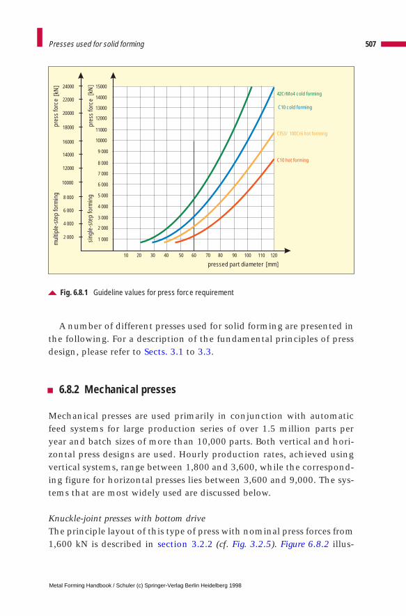
A number of different presses used for solid forming are presented inthe following. For a description of the fundamental principles of pressdesign, please refer to Sects. 3.1 to 3.3.
6.8.2 Mechanical presses
Mechanical presses are used primarily in conjunction with automaticfeed systems for large production series of over 1.5 million parts peryear and batch sizes of more than 10,000 parts. Both vertical and hori-zontal press designs are used. Hourly production rates, achieved usingvertical systems, range between 1,800 and 3,600, while the correspond-ing figure for horizontal presses lies between 3,600 and 9,000. The sys-tems that are most widely used are discussed below.
Knuckle-joint presses with bottom driveThe principle layout of this type of press with nominal press forces from1,600 kN is described in section 3.2.2 (cf. Fig. 3.2.5). Figure 6.8.2 illus-
507Presses used for solid forming
Fig. 6.8.1 Guideline values for press force requirement
pressed part diameter [mm]10 20 30 40 50 60 70 80 90 100 110 120
1 000
2 000
2 000
3 000
4 000
4 000
5 000
6 000
6 000
7 000
8 000
8 000
9 000
10000
10000
11000
12000
12000
13000
14000
20000
22000
24000
18000
16000
14000
1500042CrMo4 cold forming
C10 cold forming
C10 hot forming
Cf53/ 100Cr6 hot forming
mul
tiple
-ste
p fo
rmin
gpr
ess
forc
e
pres
s fo
rce
sing
le-s
tep
form
ing
[kN
]
[kN
]
Metal Forming Handbook / Schuler (c) Springer-Verlag Berlin Heidelberg 1998
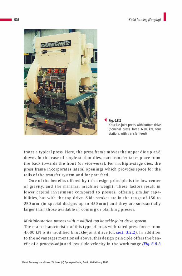
trates a typical press. Here, the press frame moves the upper die up anddown. In the case of single-station dies, part transfer takes place fromthe back towards the front (or vice-versa). For multiple-stage dies, thepress frame incorporates lateral openings which provides space for therails of the transfer system and for part feed.
One of the benefits offered by this design principle is the low centerof gravity, and the minimal machine weight. These factors result inlower capital investment compared to presses, offering similar capa-bilities, but with the top drive. Slide strokes are in the range of 150 to250 mm (in special designs up to 450 mm) and they are substantiallylarger than those available in coining or blanking presses.
Multiple-station presses with modified top knuckle-joint drive systemThe main characteristic of this type of press with rated press forces from4,000 kN is its modified knuckle-joint drive (cf. sect. 3.2.2). In additionto the advantages mentioned above, this design principle offers the ben-efit of a process-adjusted low slide velocity in the work range (Fig. 6.8.3
508 Solid forming (Forging)
Fig. 6.8.2Knuckle-joint press with bottom drive(nominal press force 6,300 kN, fourstations with transfer feed)
Metal Forming Handbook / Schuler (c) Springer-Verlag Berlin Heidelberg 1998

and cf. Fig. 3.2.3). This is supplemented by acceleration of the slidedownward and upward to achieve an overall higher stroking rate. As aresult, the velocity of the slide when impacting the workpiece materialis reduced and remains approximately constant during forming. As aresult, the dynamic loads on the press and die are reduced. For extru-sion processes particularly, this helps to extend the service life of diesand reduce the stress on the drive system. Another positive side-effect isa reduction of noise development by about 6 to 8 dB(A).
A further benefit in comparison to conventional drive systems is athree to four-fold increase in the deformation stroke, with a drivetorque value comparable to that of conventional mechanical presses.This makes production of press parts, requiring a high level of defor-mation energy and a large nominal working stroke (> 20 mm) very eco-nomical (cf. Sect. 3.2.1). The eight-track slide gib operates according tothe “fixed-loose bearing” principle, thus compensating for thermalexpansion in the slide. This makes this press ideally suited for warmand hot forming (cf. Fig. 3.1.7). The slide stroke ranges between 250 and400 mm (special designs up to 520 mm) (Fig. 6.8.4).
509Presses used for solid forming
Fig. 6.8.3 Slide velocity curves for mechanical cold forging presses
0° 90° 180° 270° 360°crank angle [°]
0
-70-60-50-40
-30-20-10
102030
40
50
eccentricdrive
modifiedknuckle-jointdrive
knuckle-jointdrive
slid
eve
loci
ty[m
/min
]
slide stroke 315 mmstroking rate 40 /min
Metal Forming Handbook / Schuler (c) Springer-Verlag Berlin Heidelberg 1998
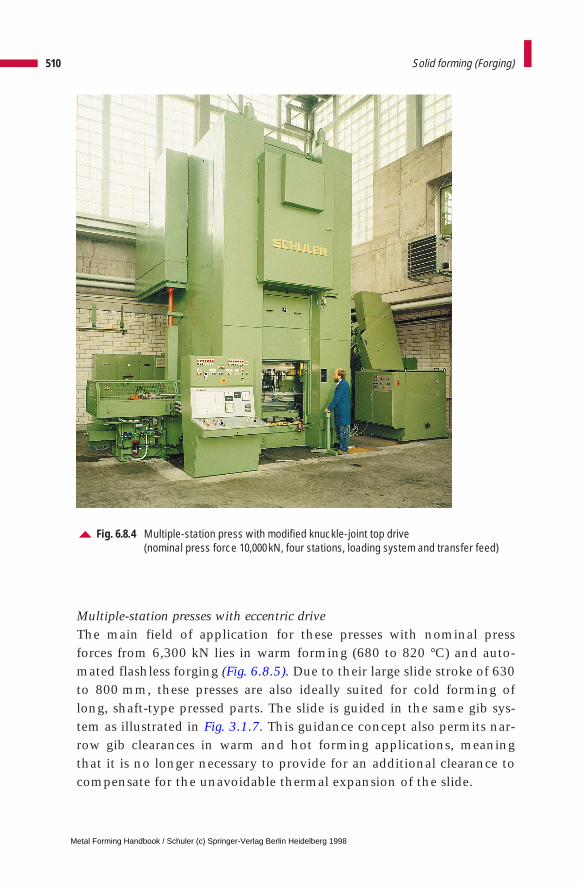
Multiple-station presses with eccentric driveThe main field of application for these presses with nominal pressforces from 6,300 kN lies in warm forming (680 to 820 °C) and auto-mated flashless forging (Fig. 6.8.5). Due to their large slide stroke of 630to 800 mm, these presses are also ideally suited for cold forming oflong, shaft-type pressed parts. The slide is guided in the same gib sys-tem as illustrated in Fig. 3.1.7. This guidance concept also permits nar-row gib clearances in warm and hot forming applications, meaningthat it is no longer necessary to provide for an additional clearance tocompensate for the unavoidable thermal expansion of the slide.
510 Solid forming (Forging)
Fig. 6.8.4 Multiple-station press with modified knuckle-joint top drive (nominal press force 10,000 kN, four stations, loading system and transfer feed)
Metal Forming Handbook / Schuler (c) Springer-Verlag Berlin Heidelberg 1998
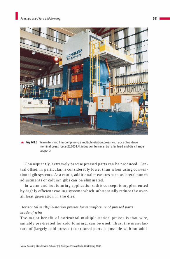
Consequently, extremely precise pressed parts can be produced. Cen-tral offset, in particular, is considerably lower than when using conven-tional gib systems. As a result, additional measures such as lateral punchadjustments or column gibs can be eliminated.
In warm and hot forming applications, this concept is supplementedby highly efficient cooling systems which substantially reduce the over-all heat generation in the dies.
Horizontal multiple-station presses for manufacture of pressed parts made of wireThe major benefit of horizontal multiple-station presses is that wire,suitably pre-treated for cold forming, can be used. Thus, the manufac-ture of (largely cold pressed) contoured parts is possible without addi-
511Presses used for solid forming
Fig. 6.8.5 Warm forming line comprising a multiple-station press with eccentric drive (nominal press force 20,000 kN, induction furnace, transfer feed and die changesupport)
Metal Forming Handbook / Schuler (c) Springer-Verlag Berlin Heidelberg 1998
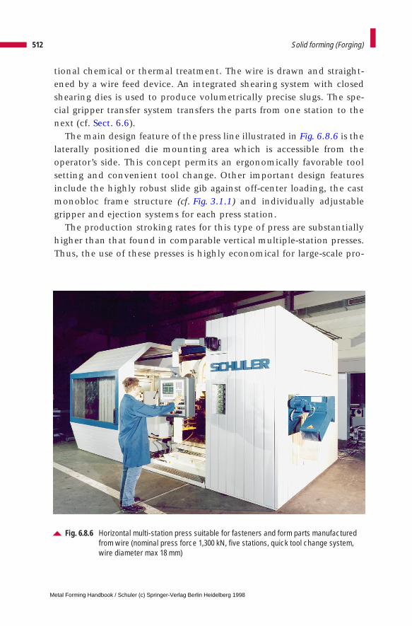
tional chemical or thermal treatment. The wire is drawn and straight-ened by a wire feed device. An integrated shearing system with closedshearing dies is used to produce volumetrically precise slugs. The spe-cial gripper transfer system transfers the parts from one station to thenext (cf. Sect. 6.6).
The main design feature of the press line illustrated in Fig. 6.8.6 is thelaterally positioned die mounting area which is accessible from theoperator’s side. This concept permits an ergonomically favorable toolsetting and convenient tool change. Other important design featuresinclude the highly robust slide gib against off-center loading, the castmonobloc frame structure (cf. Fig. 3.1.1) and individually adjustablegripper and ejection systems for each press station.
The production stroking rates for this type of press are substantiallyhigher than that found in comparable vertical multiple-station presses.Thus, the use of these presses is highly economical for large-scale pro-
512 Solid forming (Forging)
Fig. 6.8.6 Horizontal multi-station press suitable for fasteners and form parts manufacturedfrom wire (nominal press force 1,300 kN, five stations, quick tool change system,wire diameter max 18 mm)
Metal Forming Handbook / Schuler (c) Springer-Verlag Berlin Heidelberg 1998
duction despite the high initial investment costs involved. By usingsemi-automatic and automatic die resetting and die change systems, set-up times can be substantially reduced, meaning that even mediumbatch sizes of 20,000 to 40,000 parts can be economically manufactured(cf. Fig. 3.4.5). The presses are used at nominal press forces of between1,000 and 6,300 kN for wire diameters ranging from 10 to 36 mm.
Horizontal presses – single-station with knuckle-joint drive These press systems are used mainly for the production of extrudedparts made of aluminium and aluminium alloys (Fig. 6.8.7): Thesemachines are also ideally suited for pre-forming steel slugs. The pressesare fully automated and make use of simple, cam-controlled pushers forpart feed. The horizontal design, simple part feed and discharge and thesuperior forming characteristics of aluminium permit high strokingrages of up to 300/min. Compared with vertical presses, substantiallyhigher stroking rates also result when forming steel. Nominal pressforces range between 1,500 and 12,000 kN.
513Presses used for solid forming
Fig. 6.8.7 Single-station horizontal press with knuckle-joint drive (nominal press forces 1,500 to 12,000 kN)
punch
slide
connecting rod
eccentric drive
fixed link point
drive shaft
Metal Forming Handbook / Schuler (c) Springer-Verlag Berlin Heidelberg 1998
Horizontal presses with modified knuckle-jointIf longer forming strokes are necessary, a modified knuckle-joint drivesystem can be used as a special variation of the standard knuckle-jointpower unit. The force-stroke curve and the slide velocity correspond tothe vertical press shown in Fig. 6.8.3.
6.8.3 Hydraulic presses
Hydraulic presses are also designed in vertical and horizontal layouts.They enjoy extremely universal application in solid forming both on asingle-station and multiple-station basis, either with manual operationfor small batch sizes or fully automatically for production rates of up to1.8 million pressed parts per year. They are frequently used as pressesfor long shafts and shaft-type parts, or for large parts with weights of upto approx. 15 kg.
As in mechanical presses, the selection of the necessary press size ismade on the basis of part geometry, workpiece material and of therequired manufacturing process. The basic principles are described inSects. 3.3 and 6.5.
Vertical designThe hydraulic components and oil tanks are generally accommodatedin the press crown (Fig. 6.8.8). A service platform offers convenientmaintenance of the easily accessible units. The uprights are generallyconfigured in the form of a welded monobloc or panel structure (cf.Fig. 3.1.1).
In special cases (for example in the event of space problems or toreduce noise), the pumps and motors can also be mounted in the foun-dation or in a separate room. Vertical hydraulic presses are generallyused for cold forming. However, it is not unusual for them to also beused for hot forming under certain circumstances (cf. Sect. 6.8.5). Par-ticularly where large parts are involved (weights above 5 kg), hydraulicpresses are frequently used for hot forging. The usual press forces liebetween 1,600 and 36,000 kN, and presses with slide strokes of up to1.5 m have already been manufactured.
514 Solid forming (Forging)
Metal Forming Handbook / Schuler (c) Springer-Verlag Berlin Heidelberg 1998
Horizontal designLong tubular parts such as shock absorber sleeves are drawn from flat blanks or backward cup extrusions made from circular blanks (cf. Fig. 6.1.1). A subsequent ironing process over several stages thenreduces the wall thickness (cf. Fig. 6.1.2). The workpiece is held by apunch, which draws it through one or more ironing rings. The bottomthickness remains unchanged. For this process, extremely long formingstrokes are required. Therefore, in such applications hydraulic pressesare most frequently used.
A horizontal press layout has a number of benefits to offer here:
– set-up on floor level,– simple gravity feed,– simple discharge by means of synchronized conveyor belts,– simple interlinking, for example with automatic edge trimming de-
vices.
515Presses used for solid forming
Fig. 6.8.8 Hydraulic multiple-station press (nominal press force 20,000 kN, four stations, loading system, transfer feed and die change support)
Metal Forming Handbook / Schuler (c) Springer-Verlag Berlin Heidelberg 1998
Figure 6.8.9 illustrates the layout of a particularly economical press sys-tem for ironing. The slide is driven on two sides by plunger pistons. Thedie sets are located on both sides with loading chambers positioned infront. The right and left-hand punches are guided immediately in front of the workpiece loading chamber using an additional punch sup-port. With each stroke, alternatively forming and stripping of theformed part take place on either side. Each new workpiece pushes thepreviously stripped part through the workpiece holder out of the press.With the same forming process taking place in the left and right-handdie sets, it is possible to almost double the output compared to a con-ventional vertical press design. Alternatively, the part produced in oneof the die sets can be further processed in the other die set followingintermediate treatment. In the case of thick-walled blanks, an upstreamdeep-drawing process can be integrated as an initial operation. Preciseslide guidance on the press bed and precisely adjustable punch guid-ance permit to obtain extremely narrow tolerances concerning the con-centricity of dimensions.
516 Solid forming (Forging)
Fig. 6.8.9 Horizontal hydraulic press with one slide and two press beds
punch guideloading chamber punch supportironing ring
stripper
slide die chamberslide stroke
die holder die holder
Metal Forming Handbook / Schuler (c) Springer-Verlag Berlin Heidelberg 1998
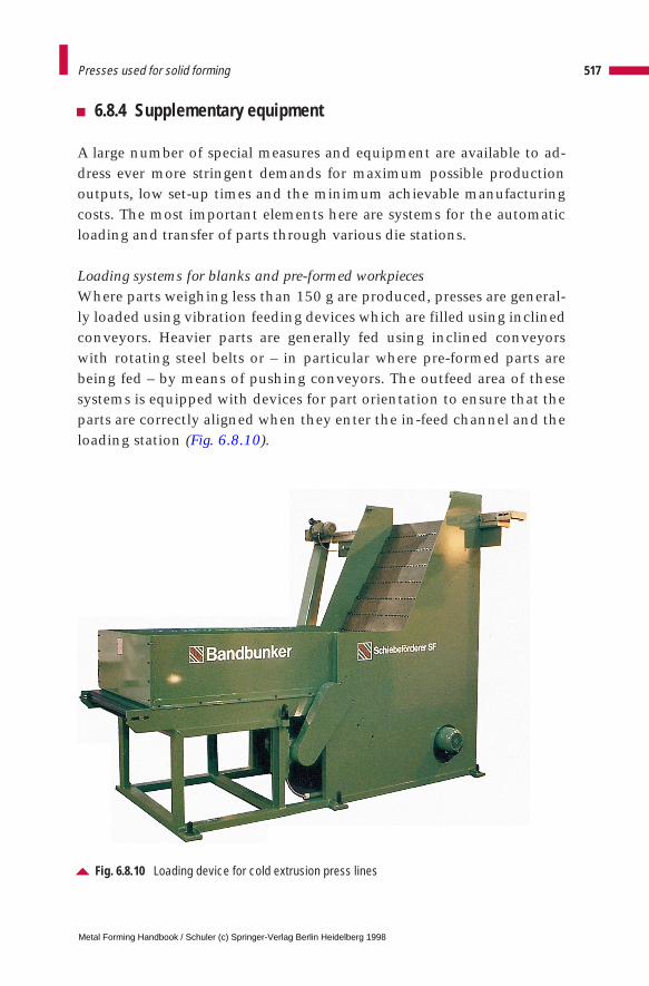
6.8.4 Supplementary equipment
A large number of special measures and equipment are available to ad-dress ever more stringent demands for maximum possible productionoutputs, low set-up times and the minimum achievable manufacturingcosts. The most important elements here are systems for the automaticloading and transfer of parts through various die stations.
Loading systems for blanks and pre-formed workpiecesWhere parts weighing less than 150 g are produced, presses are general-ly loaded using vibration feeding devices which are filled using inclinedconveyors. Heavier parts are generally fed using inclined conveyorswith rotating steel belts or – in particular where pre-formed parts arebeing fed – by means of pushing conveyors. The outfeed area of thesesystems is equipped with devices for part orientation to ensure that theparts are correctly aligned when they enter the in-feed channel and theloading station (Fig. 6.8.10).
517Presses used for solid forming
Fig. 6.8.10 Loading device for cold extrusion press lines
Metal Forming Handbook / Schuler (c) Springer-Verlag Berlin Heidelberg 1998
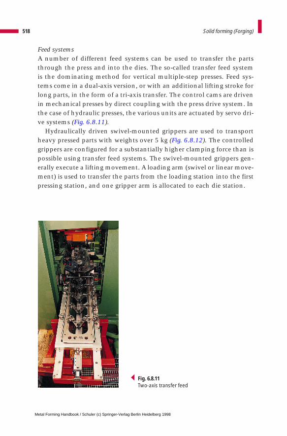
Feed systemsA number of different feed systems can be used to transfer the partsthrough the press and into the dies. The so-called transfer feed systemis the dominating method for vertical multiple-step presses. Feed sys-tems come in a dual-axis version, or with an additional lifting stroke forlong parts, in the form of a tri-axis transfer. The control cams are drivenin mechanical presses by direct coupling with the press drive system. Inthe case of hydraulic presses, the various units are actuated by servo dri-ve systems (Fig. 6.8.11).
Hydraulically driven swivel-mounted grippers are used to transportheavy pressed parts with weights over 5 kg (Fig. 6.8.12). The controlledgrippers are configured for a substantially higher clamping force than ispossible using transfer feed systems. The swivel-mounted grippers gen-erally execute a lifting movement. A loading arm (swivel or linear move-ment) is used to transfer the parts from the loading station into the firstpressing station, and one gripper arm is allocated to each die station.
518 Solid forming (Forging)
Fig. 6.8.11Two-axis transfer feed
Metal Forming Handbook / Schuler (c) Springer-Verlag Berlin Heidelberg 1998
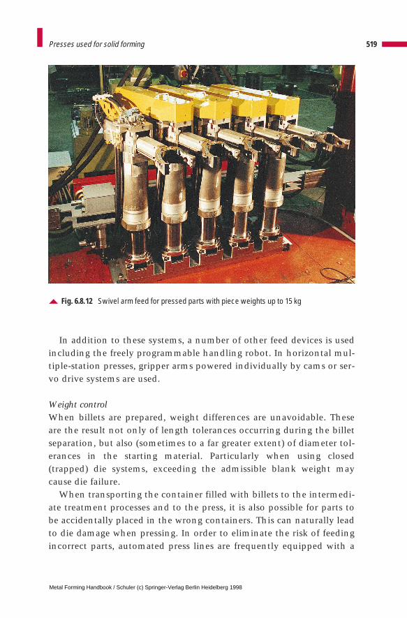
In addition to these systems, a number of other feed devices is usedincluding the freely programmable handling robot. In horizontal mul-tiple-station presses, gripper arms powered individually by cams or ser-vo drive systems are used.
Weight controlWhen billets are prepared, weight differences are unavoidable. Theseare the result not only of length tolerances occurring during the billetseparation, but also (sometimes to a far greater extent) of diameter tol-erances in the starting material. Particularly when using closed(trapped) die systems, exceeding the admissible blank weight maycause die failure.
When transporting the container filled with billets to the intermedi-ate treatment processes and to the press, it is also possible for parts tobe accidentally placed in the wrong containers. This can naturally leadto die damage when pressing. In order to eliminate the risk of feedingincorrect parts, automated press lines are frequently equipped with a
519Presses used for solid forming
Fig. 6.8.12 Swivel arm feed for pressed parts with piece weights up to 15 kg
Metal Forming Handbook / Schuler (c) Springer-Verlag Berlin Heidelberg 1998
device which checks part weight. The devices used here are electroni-cally controlled automatic scales, which are mounted between theloading system and the feeding station. Parts which are too heavy ortoo light are automatically ejected. The weighing accuracy is below 0.2 % of workpiece weight. These devices are able to weigh automati-cally up to 80 parts per minute.
Die changeFast die change can be a decisive factor when it comes to the economicviability of a press, in particular when working with small batch sizes.Both die set and individual die changing systems are used (cf. Fig. 3.4.5).The basic die change principle used in presses for sheet metal formingand solid forming are very similar. A more detailed description is pro-vided in Sect. 3.4. However, die change is only one aspect which deter-mines short set-up times in automatic press lines. Fast resetting of theloading and feed systems is equally important here.
6.8.5 Special features of hot and warm forming lines
The special supplementary equipment described in Sect. 6.8.4 is alsoused for hot forming. An additional and essential requirement of hotforming systems is an effective cooling and lubrication system.Depending on the degree of forming difficulty, basically two differentsystems are used:
FloodingDies are cooled and lubricated by continuous flooding using speciallubricants, some of which are mixed with water at a ratio of between 1 : 2 and 1 : 4. The lubricant and water mixture is fed towards the diethrough boreholes and spray rings, and drains away via generouslydimensioned channels. The lubricant is supplied from a central reservoirwith a capacity of between 400 and 1,000 l by means of medium pres-sure pumps (working at a pressure level of 10 to 20 bar) (cf. Sect. 3.2.11).Used lubricating emulsion is collected, purified and returned to thereservoir, which is equipped with a re-cooling system. Filters in thereturn and pressure circuits take care of the necessary purification. Thelubricant is mixed with bactericides in order to prevent bacterial infes-
520 Solid forming (Forging)
Metal Forming Handbook / Schuler (c) Springer-Verlag Berlin Heidelberg 1998
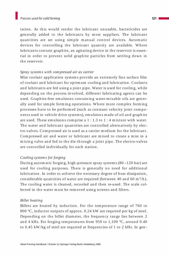
tation. As this would render the lubricant unusable, bactericides aregenerally added to the lubricants by most suppliers. The lubricantquantities are set using simple manual control devices. Automaticdevices for controlling the lubricant quantity are available. Wherelubricants contain graphite, an agitating device in the reservoir is essen-tial in order to prevent solid graphite particles from settling down inthe reservoir.
Spray systems with compressed air as carrierMist coolant application systems provide an extremely fine surface filmof coolant and lubricant for optimum cooling and lubrication. Coolantsand lubricants are fed using a joint pipe. Water is used for cooling, whiledepending on the process involved, different lubricating agents can beused. Graphite-free emulsions containing water-mixable oils are gener-ally used for simple forming operations. Where more complex formingprocesses have to be performed (such as constant velocity joint compo-nents used in vehicle drive systems), emulsions made of oil and graphiteare used. These emulsions comprise a 1 : 1.3 to 1 : 4 mixture with water.The water and lubricant quantities are controlled alternatively by elec-tro-valves. Compressed air is used as a carrier medium for the lubricant.Compressed air and water or lubricant are mixed to create a mist in amixing valve and fed to the die through a joint pipe. The electro-valvesare controlled individually for each station.
Cooling systems for forgingDuring automatic forging, high-pressure spray systems (80 –120 bar) areused for cooling purposes. There is generally no need for additionallubrication. In order to achieve the necessary degree of heat dissipation,considerable quantities of water are required (between 40 and 60 m3/h).The cooling water is cleaned, recooled and then re-used. The scale col-lected in the water must be removed using screens and filters.
Billet heatingBillets are heated by induction. For the temperature range of 760 to 800 °C, inductor outputs of approx. 0.24 kW are required per kg of steel.Depending on the billet diameter, the frequency range lies between 2and 4 kHz. For forging temperatures from 950 to 1,100 °C, around 0.40to 0.45 kW/kg of steel are required at frequencies of 1 to 2 kHz. In gen-
521Presses used for solid forming
Metal Forming Handbook / Schuler (c) Springer-Verlag Berlin Heidelberg 1998
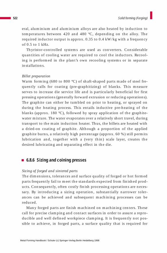
eral, aluminium and aluminium alloys are also heated by induction totemperatures between 420 and 480 °C, depending on the alloy. Therequired inductor output is approx. 0.35 to 0.4 kW/kg with a frequencyof 0.5 to 1 kHz.
Thyristor-controlled systems are used as converters. Considerablequantities of cooling water are required to cool the inductors. Recool-ing is performed in the plant’s own recooling systems or in separateinstallations.
Billet preparationWarm forming (680 to 800 °C) of shaft-shaped parts made of steel fre-quently calls for coating (pre-graphitizing) of blanks. This measureserves to increase die service life and is particularly beneficial for firstpressing operations (generally forward extrusion or reducing operations).The graphite can either be tumbled on prior to heating, or sprayed onduring the heating process. This entails inductive pre-heating of theblanks (approx. 180 °C), followed by spray application of the graphite-water mixture. The water evaporates over a relatively short travel, duringtransport to the main induction heater. Thus, the billets are heated witha dried-on coating of graphite. Although a proportion of the appliedgraphite burns, a relatively high percentage (approx. 60 %) still permitslubrication and, together with a (very thin) scale layer, creates thedesired lubricating and separating effect in the die.
6.8.6 Sizing and coining presses
Sizing of forged and sintered partsThe dimensions, tolerances and surface quality of forged or hot formedparts frequently fail to meet the standards expected from finished prod-ucts. Consequently, often costly finish processing operations are neces-sary. By introducing a sizing operation, substantially narrower toler-ances can be achieved and subsequent machining processes can bereduced.
Many forged parts are finish machined on machining centers. Thesecall for precise clamping and contact surfaces in order to assure a repro-ducible and well defined workpiece clamping. It is frequently not pos-sible to achieve, in forged parts, a surface quality that is required for
522 Solid forming (Forging)
Metal Forming Handbook / Schuler (c) Springer-Verlag Berlin Heidelberg 1998
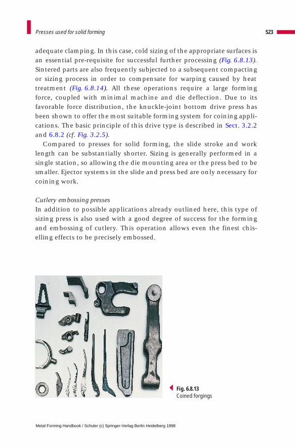
adequate clamping. In this case, cold sizing of the appropriate surfaces isan essential pre-requisite for successful further processing (Fig. 6.8.13).Sintered parts are also frequently subjected to a subsequent compactingor sizing process in order to compensate for warping caused by heattreatment (Fig. 6.8.14). All these operations require a large formingforce, coupled with minimal machine and die deflection. Due to itsfavorable force distribution, the knuckle-joint bottom drive press hasbeen shown to offer the most suitable forming system for coining appli-cations. The basic principle of this drive type is described in Sect. 3.2.2and 6.8.2 (cf. Fig. 3.2.5).
Compared to presses for solid forming, the slide stroke and worklength can be substantially shorter. Sizing is generally performed in asingle station, so allowing the die mounting area or the press bed to besmaller. Ejector systems in the slide and press bed are only necessary forcoining work.
Cutlery embossing pressesIn addition to possible applications already outlined here, this type ofsizing press is also used with a good degree of success for the formingand embossing of cutlery. This operation allows even the finest chis-elling effects to be precisely embossed.
523Presses used for solid forming
Fig. 6.8.13Coined forgings
Metal Forming Handbook / Schuler (c) Springer-Verlag Berlin Heidelberg 1998
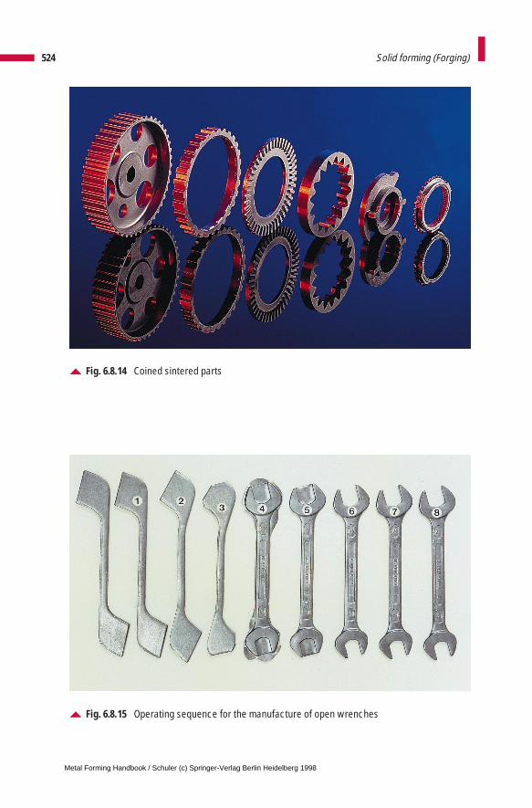
524 Solid forming (Forging)
Fig. 6.8.14 Coined sintered parts
Fig. 6.8.15 Operating sequence for the manufacture of open wrenches
Metal Forming Handbook / Schuler (c) Springer-Verlag Berlin Heidelberg 1998
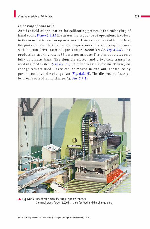
Embossing of hand toolsAnother field of application for calibrating presses is the embossing ofhand tools. Figure 6.8.15 illustrates the sequence of operations involvedin the manufacture of an open wrench. Using slugs blanked from plate,the parts are manufactured in eight operations on a knuckle-joint presswith bottom drive, nominal press force 16,000 kN (cf. Fig. 3.2.5). Theproduction stroking rate is 35 parts per minute. The plant operates on afully automatic basis. The slugs are stored, and a two-axis transfer isused as a feed system (Fig. 6.8.11). In order to assure fast die change, diechange sets are used. These can be moved in and out, controlled bypushbutton, by a die change cart (Fig. 6.8.16). The die sets are fastenedby means of hydraulic clamps (cf. Fig. 6.7.1).
525Presses used for solid forming
Fig. 6.8.16 Line for the manufacture of open wrenches (nominal press force 16,000 kN, transfer feed and die change cart)
Metal Forming Handbook / Schuler (c) Springer-Verlag Berlin Heidelberg 1998
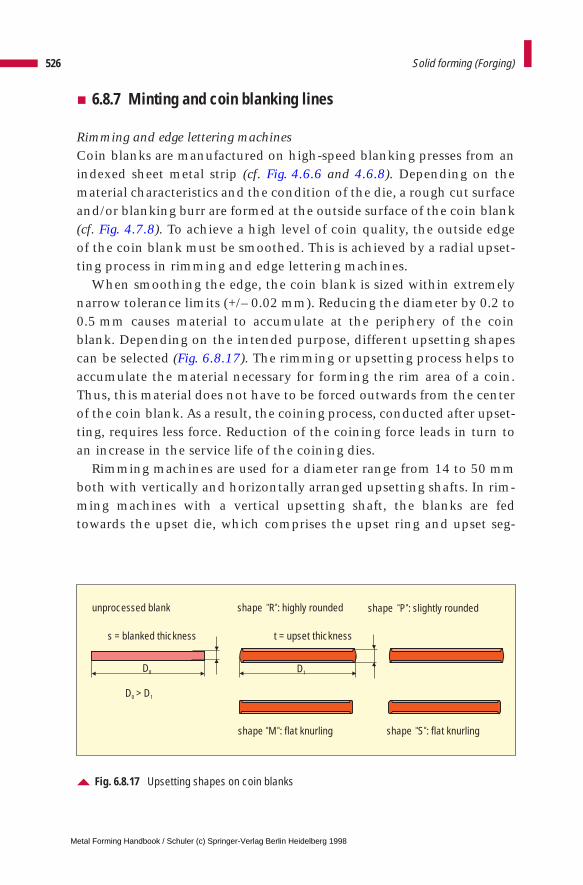
6.8.7 Minting and coin blanking lines
Rimming and edge lettering machinesCoin blanks are manufactured on high-speed blanking presses from anindexed sheet metal strip (cf. Fig. 4.6.6 and 4.6.8). Depending on thematerial characteristics and the condition of the die, a rough cut surfaceand/or blanking burr are formed at the outside surface of the coin blank(cf. Fig. 4.7.8). To achieve a high level of coin quality, the outside edgeof the coin blank must be smoothed. This is achieved by a radial upset-ting process in rimming and edge lettering machines.
When smoothing the edge, the coin blank is sized within extremelynarrow tolerance limits (+/– 0.02 mm). Reducing the diameter by 0.2 to0.5 mm causes material to accumulate at the periphery of the coinblank. Depending on the intended purpose, different upsetting shapescan be selected (Fig. 6.8.17). The rimming or upsetting process helps toaccumulate the material necessary for forming the rim area of a coin.Thus, this material does not have to be forced outwards from the centerof the coin blank. As a result, the coining process, conducted after upset-ting, requires less force. Reduction of the coining force leads in turn toan increase in the service life of the coining dies.
Rimming machines are used for a diameter range from 14 to 50 mmboth with vertically and horizontally arranged upsetting shafts. In rim-ming machines with a vertical upsetting shaft, the blanks are fedtowards the upset die, which comprises the upset ring and upset seg-
526 Solid forming (Forging)
Fig. 6.8.17 Upsetting shapes on coin blanks
t = upset thickness
unprocessed blank shape R : highly rounded shape P : slightly rounded
shape M : flat knurling shape S : flat knurling
s = blanked thickness
D0 D1
D > D0 1
Metal Forming Handbook / Schuler (c) Springer-Verlag Berlin Heidelberg 1998
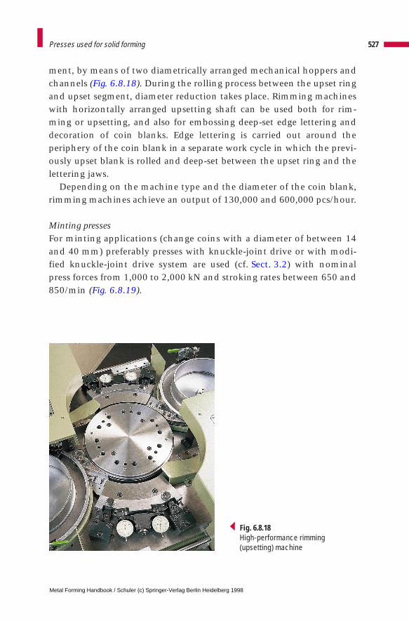
ment, by means of two diametrically arranged mechanical hoppers andchannels (Fig. 6.8.18). During the rolling process between the upset ringand upset segment, diameter reduction takes place. Rimming machineswith horizontally arranged upsetting shaft can be used both for rim-ming or upsetting, and also for embossing deep-set edge lettering anddecoration of coin blanks. Edge lettering is carried out around theperiphery of the coin blank in a separate work cycle in which the previ-ously upset blank is rolled and deep-set between the upset ring and thelettering jaws.
Depending on the machine type and the diameter of the coin blank,rimming machines achieve an output of 130,000 and 600,000 pcs/hour.
Minting pressesFor minting applications (change coins with a diameter of between 14and 40 mm) preferably presses with knuckle-joint drive or with modi-fied knuckle-joint drive system are used (cf. Sect. 3.2) with nominalpress forces from 1,000 to 2,000 kN and stroking rates between 650 and850/min (Fig. 6.8.19).
527Presses used for solid forming
Fig. 6.8.18High-performance rimming (upsetting) machine
Metal Forming Handbook / Schuler (c) Springer-Verlag Berlin Heidelberg 1998
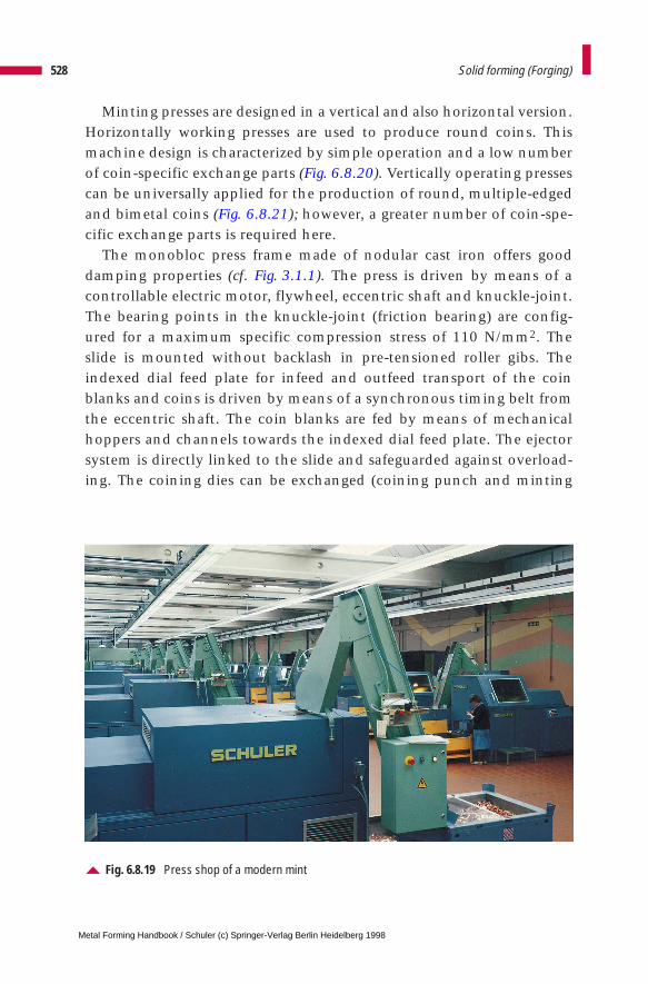
Minting presses are designed in a vertical and also horizontal version.Horizontally working presses are used to produce round coins. Thismachine design is characterized by simple operation and a low numberof coin-specific exchange parts (Fig. 6.8.20). Vertically operating pressescan be universally applied for the production of round, multiple-edgedand bimetal coins (Fig. 6.8.21); however, a greater number of coin-spe-cific exchange parts is required here.
The monobloc press frame made of nodular cast iron offers gooddamping properties (cf. Fig. 3.1.1). The press is driven by means of acontrollable electric motor, flywheel, eccentric shaft and knuckle-joint.The bearing points in the knuckle-joint (friction bearing) are config-ured for a maximum specific compression stress of 110 N/mm2. Theslide is mounted without backlash in pre-tensioned roller gibs. Theindexed dial feed plate for infeed and outfeed transport of the coinblanks and coins is driven by means of a synchronous timing belt fromthe eccentric shaft. The coin blanks are fed by means of mechanicalhoppers and channels towards the indexed dial feed plate. The ejectorsystem is directly linked to the slide and safeguarded against overload-ing. The coining dies can be exchanged (coining punch and minting
528 Solid forming (Forging)
Fig. 6.8.19 Press shop of a modern mint
Metal Forming Handbook / Schuler (c) Springer-Verlag Berlin Heidelberg 1998
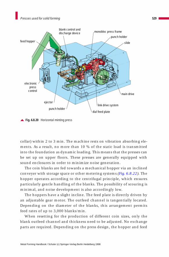
collar) within 2 to 3 min. The machine rests on vibration absorbing ele-ments. As a result, no more than 10 % of the static load is transmittedinto the foundation as dynamic loading. This means that the presses canbe set up on upper floors. These presses are generally equipped withsound enclosures in order to minimize noise generation.
The coin blanks are fed towards a mechanical hopper via an inclinedconveyer with storage space or other metering systems (Fig. 6.8.22). Thehopper operates according to the centrifugal principle, which ensuresparticularly gentle handling of the blanks. The possibility of scouring isminimal, and noise development is also accordingly low.
The hoppers have a slight incline. The feed plate is directly driven byan adjustable gear motor. The outfeed channel is tangentially located.Depending on the diameter of the blanks, this arrangement permitsfeed rates of up to 3,000 blanks/min.
When resetting for the production of different coin sizes, only theblank outfeed channel and thickness need to be adjusted. No exchangeparts are required. Depending on the press design, the hopper and feed
529Presses used for solid forming
Fig. 6.8.20 Horizontal minting press
monobloc press frame
punch holder
slide
link drive system
main drive
dial feed plate
feed hopper
blank control anddischarge device
punch holder
electronic press control
ejector
Metal Forming Handbook / Schuler (c) Springer-Verlag Berlin Heidelberg 1998
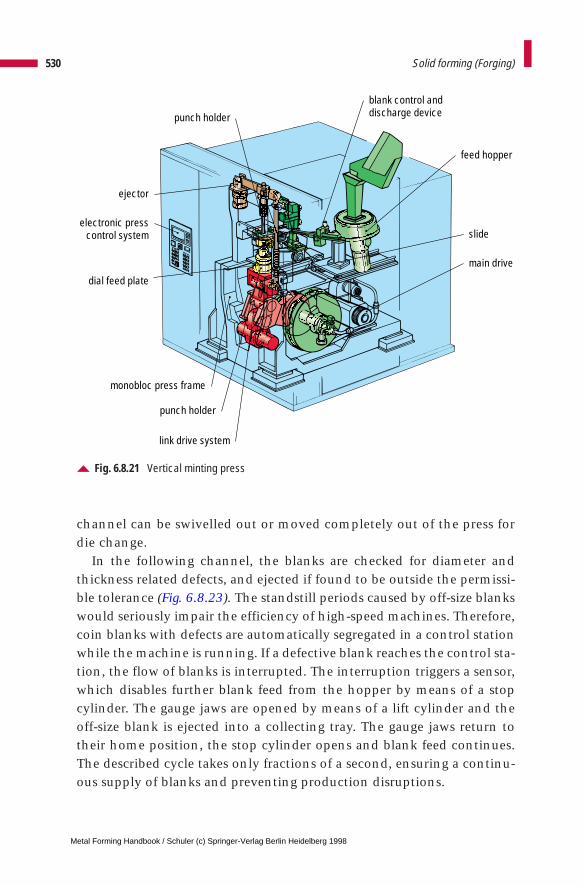
channel can be swivelled out or moved completely out of the press fordie change.
In the following channel, the blanks are checked for diameter andthickness related defects, and ejected if found to be outside the permissi-ble tolerance (Fig. 6.8.23). The standstill periods caused by off-size blankswould seriously impair the efficiency of high-speed machines. Therefore,coin blanks with defects are automatically segregated in a control stationwhile the machine is running. If a defective blank reaches the control sta-tion, the flow of blanks is interrupted. The interruption triggers a sensor,which disables further blank feed from the hopper by means of a stopcylinder. The gauge jaws are opened by means of a lift cylinder and theoff-size blank is ejected into a collecting tray. The gauge jaws return totheir home position, the stop cylinder opens and blank feed continues.The described cycle takes only fractions of a second, ensuring a continu-ous supply of blanks and preventing production disruptions.
530 Solid forming (Forging)
Fig. 6.8.21 Vertical minting press
ejector
electronic presscontrol system
punch holder
dial feed plate
punch holder
monobloc press frame
link drive system
blank control anddischarge device
feed hopper
slide
main drive
Metal Forming Handbook / Schuler (c) Springer-Verlag Berlin Heidelberg 1998
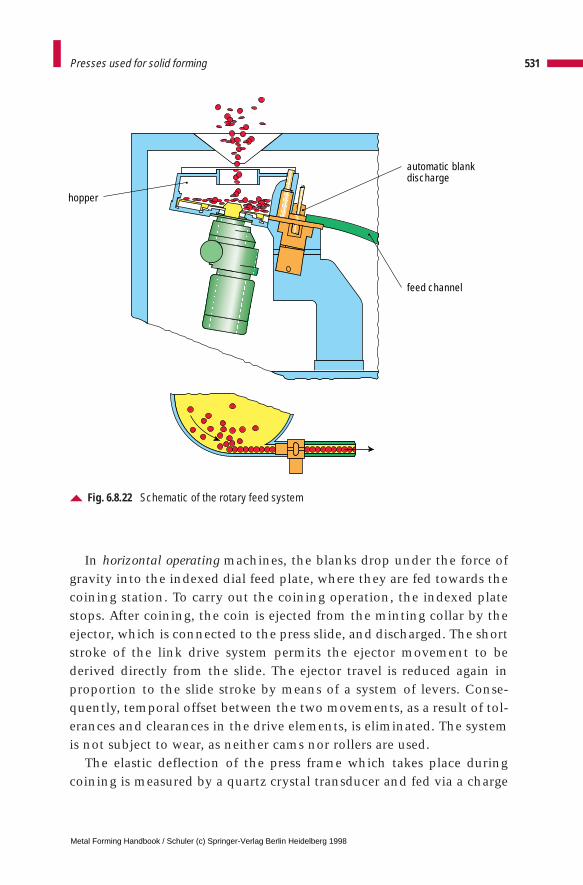
In horizontal operating machines, the blanks drop under the force ofgravity into the indexed dial feed plate, where they are fed towards thecoining station. To carry out the coining operation, the indexed platestops. After coining, the coin is ejected from the minting collar by theejector, which is connected to the press slide, and discharged. The shortstroke of the link drive system permits the ejector movement to bederived directly from the slide. The ejector travel is reduced again inproportion to the slide stroke by means of a system of levers. Conse-quently, temporal offset between the two movements, as a result of tol-erances and clearances in the drive elements, is eliminated. The systemis not subject to wear, as neither cams nor rollers are used.
The elastic deflection of the press frame which takes place duringcoining is measured by a quartz crystal transducer and fed via a charge
531Presses used for solid forming
Fig. 6.8.22 Schematic of the rotary feed system
automatic blankdischarge
feed channel
hopper
Metal Forming Handbook / Schuler (c) Springer-Verlag Berlin Heidelberg 1998
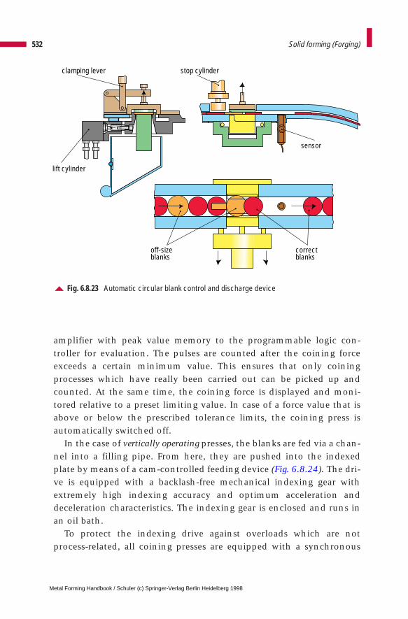
amplifier with peak value memory to the programmable logic con-troller for evaluation. The pulses are counted after the coining forceexceeds a certain minimum value. This ensures that only coiningprocesses which have really been carried out can be picked up andcounted. At the same time, the coining force is displayed and moni-tored relative to a preset limiting value. In case of a force value that isabove or below the prescribed tolerance limits, the coining press isautomatically switched off.
In the case of vertically operating presses, the blanks are fed via a chan-nel into a filling pipe. From here, they are pushed into the indexedplate by means of a cam-controlled feeding device (Fig. 6.8.24). The dri-ve is equipped with a backlash-free mechanical indexing gear withextremely high indexing accuracy and optimum acceleration anddeceleration characteristics. The indexing gear is enclosed and runs inan oil bath.
To protect the indexing drive against overloads which are notprocess-related, all coining presses are equipped with a synchronous
532 Solid forming (Forging)
Fig. 6.8.23 Automatic circular blank control and discharge device
clamping lever stop cylinder
sensor
off-sizeblanks
correctblanks
lift cylinder
Metal Forming Handbook / Schuler (c) Springer-Verlag Berlin Heidelberg 1998
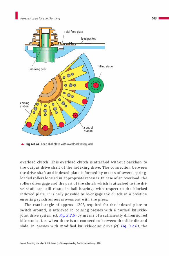
overload clutch. This overload clutch is attached without backlash tothe output drive shaft of the indexing drive. The connection betweenthe drive shaft and indexed plate is formed by means of several spring-loaded rollers located in appropriate recesses. In case of an overload, therollers disengage and the part of the clutch which is attached to the dri-ve shaft can still rotate in ball bearings with respect to the blockedindexed plate. It is only possible to re-engage the clutch in a positionensuring synchronous movement with the press.
The crank angle of approx. 120°, required for the indexed plate toswitch around, is achieved in coining presses with a normal knuckle-joint drive system (cf. Fig. 3.2.5) by means of a sufficiently dimensionedidle stroke, i. e. when there is no connection between the slide die andslide. In presses with modified knuckle-joint drive (cf. Fig. 3.2.6), the
533Presses used for solid forming
Fig. 6.8.24 Feed dial plate with overload safeguard
filling station
controlstation
coiningstation
indexing gear
feed pocket
dial feed plate
Metal Forming Handbook / Schuler (c) Springer-Verlag Berlin Heidelberg 1998
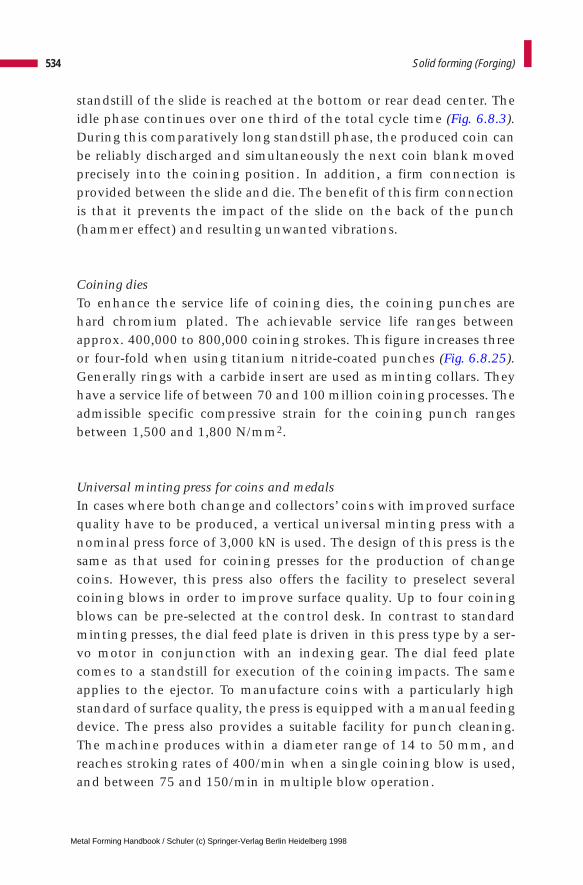
standstill of the slide is reached at the bottom or rear dead center. Theidle phase continues over one third of the total cycle time (Fig. 6.8.3).During this comparatively long standstill phase, the produced coin canbe reliably discharged and simultaneously the next coin blank movedprecisely into the coining position. In addition, a firm connection isprovided between the slide and die. The benefit of this firm connectionis that it prevents the impact of the slide on the back of the punch(hammer effect) and resulting unwanted vibrations.
Coining diesTo enhance the service life of coining dies, the coining punches arehard chromium plated. The achievable service life ranges betweenapprox. 400,000 to 800,000 coining strokes. This figure increases threeor four-fold when using titanium nitride-coated punches (Fig. 6.8.25).Generally rings with a carbide insert are used as minting collars. Theyhave a service life of between 70 and 100 million coining processes. Theadmissible specific compressive strain for the coining punch rangesbetween 1,500 and 1,800 N/mm2.
Universal minting press for coins and medalsIn cases where both change and collectors’ coins with improved surfacequality have to be produced, a vertical universal minting press with anominal press force of 3,000 kN is used. The design of this press is thesame as that used for coining presses for the production of changecoins. However, this press also offers the facility to preselect severalcoining blows in order to improve surface quality. Up to four coiningblows can be pre-selected at the control desk. In contrast to standardminting presses, the dial feed plate is driven in this press type by a ser-vo motor in conjunction with an indexing gear. The dial feed platecomes to a standstill for execution of the coining impacts. The sameapplies to the ejector. To manufacture coins with a particularly highstandard of surface quality, the press is equipped with a manual feedingdevice. The press also provides a suitable facility for punch cleaning.The machine produces within a diameter range of 14 to 50 mm, andreaches stroking rates of 400/min when a single coining blow is used,and between 75 and 150/min in multiple blow operation.
534 Solid forming (Forging)
Metal Forming Handbook / Schuler (c) Springer-Verlag Berlin Heidelberg 1998
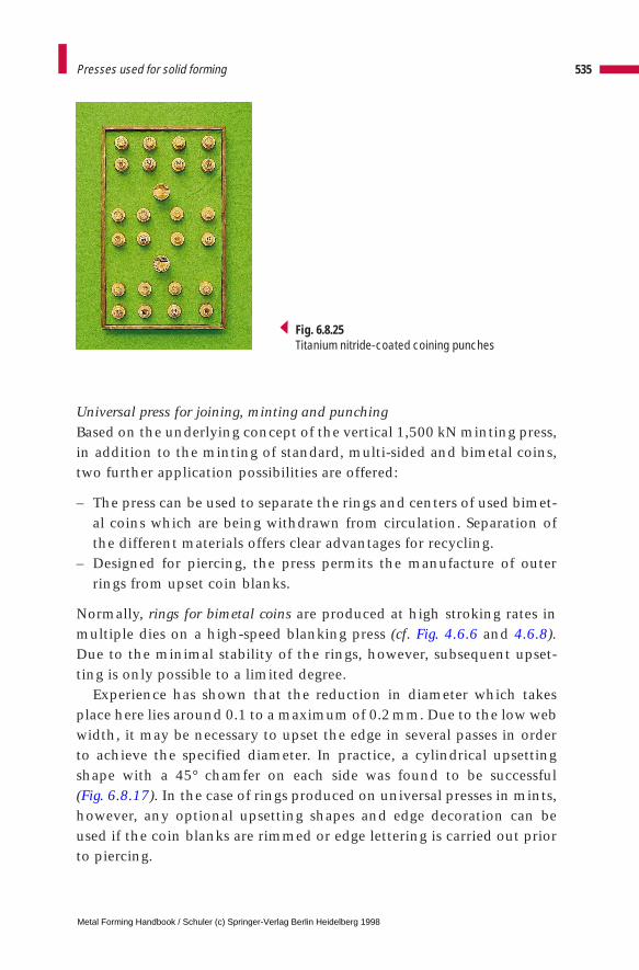
Universal press for joining, minting and punchingBased on the underlying concept of the vertical 1,500 kN minting press,in addition to the minting of standard, multi-sided and bimetal coins,two further application possibilities are offered:
– The press can be used to separate the rings and centers of used bimet-al coins which are being withdrawn from circulation. Separation ofthe different materials offers clear advantages for recycling.
– Designed for piercing, the press permits the manufacture of outerrings from upset coin blanks.
Normally, rings for bimetal coins are produced at high stroking rates inmultiple dies on a high-speed blanking press (cf. Fig. 4.6.6 and 4.6.8).Due to the minimal stability of the rings, however, subsequent upset-ting is only possible to a limited degree.
Experience has shown that the reduction in diameter which takesplace here lies around 0.1 to a maximum of 0.2 mm. Due to the low webwidth, it may be necessary to upset the edge in several passes in orderto achieve the specified diameter. In practice, a cylindrical upsettingshape with a 45° chamfer on each side was found to be successful (Fig. 6.8.17). In the case of rings produced on universal presses in mints,however, any optional upsetting shapes and edge decoration can beused if the coin blanks are rimmed or edge lettering is carried out priorto piercing.
535Presses used for solid forming
Fig. 6.8.25Titanium nitride-coated coining punches
Metal Forming Handbook / Schuler (c) Springer-Verlag Berlin Heidelberg 1998
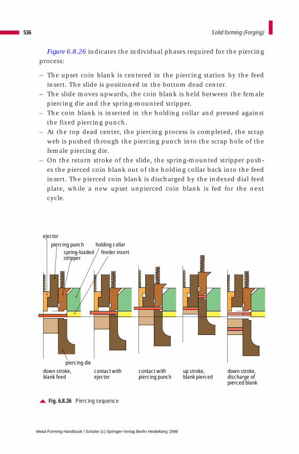
Figure 6.8.26 indicates the individual phases required for the piercingprocess:
– The upset coin blank is centered in the piercing station by the feedinsert. The slide is positioned in the bottom dead center.
– The slide moves upwards, the coin blank is held between the femalepiercing die and the spring-mounted stripper.
– The coin blank is inserted in the holding collar and pressed againstthe fixed piercing punch.
– At the top dead center, the piercing process is completed, the scrapweb is pushed through the piercing punch into the scrap hole of thefemale piercing die.
– On the return stroke of the slide, the spring-mounted stripper push-es the pierced coin blank out of the holding collar back into the feedinsert. The pierced coin blank is discharged by the indexed dial feedplate, while a new upset unpierced coin blank is fed for the nextcycle.
536 Solid forming (Forging)
Fig. 6.8.26 Piercing sequence
down stroke,blank feed
contact withejector
contact withpiercing punch
up stroke,blank pierced
down stroke, discharge ofpierced blank
holding collarspring-loadedstripper
piercing punch
ejector
piercing die
feeder insert
Metal Forming Handbook / Schuler (c) Springer-Verlag Berlin Heidelberg 1998
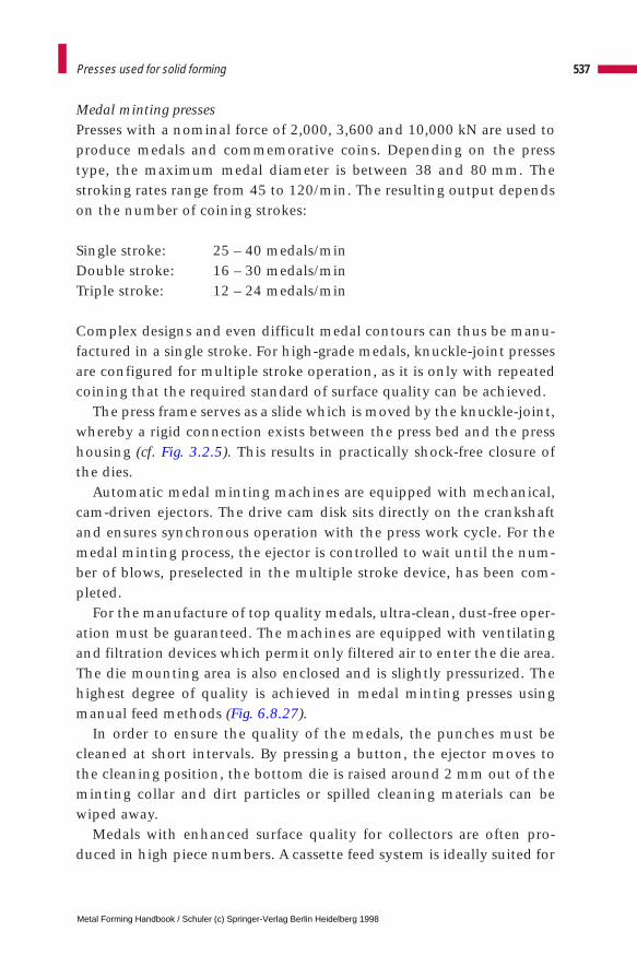
Medal minting pressesPresses with a nominal force of 2,000, 3,600 and 10,000 kN are used toproduce medals and commemorative coins. Depending on the presstype, the maximum medal diameter is between 38 and 80 mm. Thestroking rates range from 45 to 120/min. The resulting output dependson the number of coining strokes:
Single stroke: 25 – 40 medals/minDouble stroke: 16 – 30 medals/minTriple stroke: 12 – 24 medals/min
Complex designs and even difficult medal contours can thus be manu-factured in a single stroke. For high-grade medals, knuckle-joint pressesare configured for multiple stroke operation, as it is only with repeatedcoining that the required standard of surface quality can be achieved.
The press frame serves as a slide which is moved by the knuckle-joint,whereby a rigid connection exists between the press bed and the presshousing (cf. Fig. 3.2.5). This results in practically shock-free closure ofthe dies.
Automatic medal minting machines are equipped with mechanical,cam-driven ejectors. The drive cam disk sits directly on the crankshaftand ensures synchronous operation with the press work cycle. For themedal minting process, the ejector is controlled to wait until the num-ber of blows, preselected in the multiple stroke device, has been com-pleted.
For the manufacture of top quality medals, ultra-clean, dust-free oper-ation must be guaranteed. The machines are equipped with ventilatingand filtration devices which permit only filtered air to enter the die area.The die mounting area is also enclosed and is slightly pressurized. Thehighest degree of quality is achieved in medal minting presses usingmanual feed methods (Fig. 6.8.27).
In order to ensure the quality of the medals, the punches must becleaned at short intervals. By pressing a button, the ejector moves tothe cleaning position, the bottom die is raised around 2 mm out of theminting collar and dirt particles or spilled cleaning materials can bewiped away.
Medals with enhanced surface quality for collectors are often pro-duced in high piece numbers. A cassette feed system is ideally suited for
537Presses used for solid forming
Metal Forming Handbook / Schuler (c) Springer-Verlag Berlin Heidelberg 1998
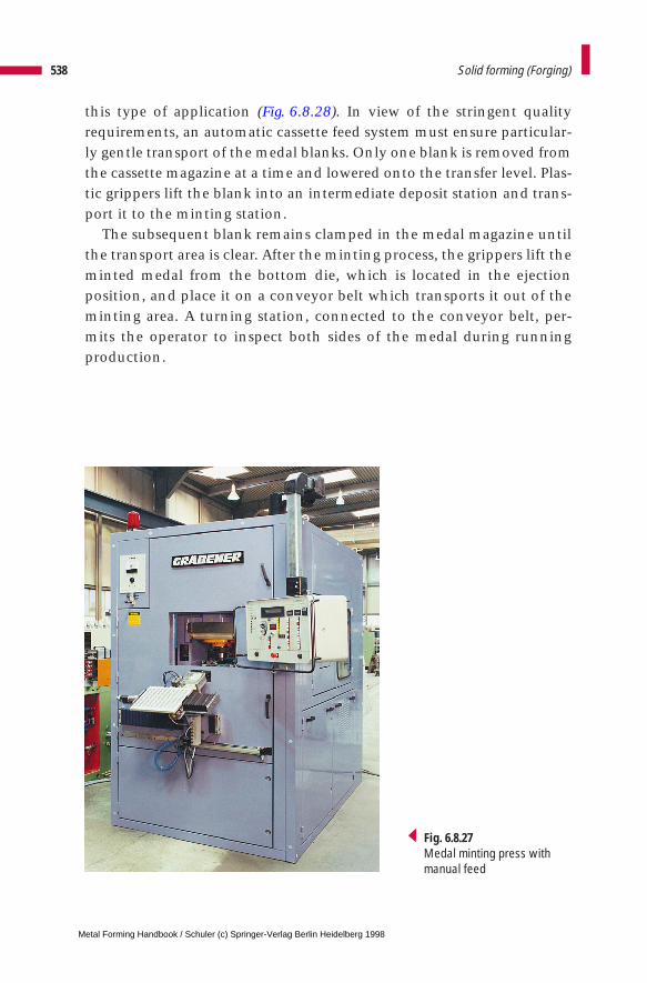
this type of application (Fig. 6.8.28). In view of the stringent qualityrequirements, an automatic cassette feed system must ensure particular-ly gentle transport of the medal blanks. Only one blank is removed fromthe cassette magazine at a time and lowered onto the transfer level. Plas-tic grippers lift the blank into an intermediate deposit station and trans-port it to the minting station.
The subsequent blank remains clamped in the medal magazine untilthe transport area is clear. After the minting process, the grippers lift theminted medal from the bottom die, which is located in the ejectionposition, and place it on a conveyor belt which transports it out of theminting area. A turning station, connected to the conveyor belt, per-mits the operator to inspect both sides of the medal during runningproduction.
538 Solid forming (Forging)
Fig. 6.8.27Medal minting press with manual feed
Metal Forming Handbook / Schuler (c) Springer-Verlag Berlin Heidelberg 1998
CNC-controlled hydraulic medal minting pressesThese presses permit path or pressure-dependent control of each strokeof the slide, as well as synchronous operation of the slide and ejector bytwo CNC axes. In case of multiple stroke operation, the die remainsclosed without opening, i. e. in contact with the medal. Only the coin-ing stress between the upper and lower die is released. As a result, pen-etration of abraded matter between the dies and the coined piece is pre-vented.
The nominal press force of the machine series ranges between 4,000and 12,000 kN. In addition to minting of medals, coins and jewellery,the machine can also be used for the cold hobbing of tools, for examplein the manufacture of coining punches, die sinks, jewellery moulds,dies for fasteners, dies for cutlery, etc. The die sinking velocity requiredfor this technique ranges between 0.01 and 4 mm/s (Fig. 6.8.29).
539Presses used for solid forming
Fig. 6.8.28 Cassette feed for medal production
Metal Forming Handbook / Schuler (c) Springer-Verlag Berlin Heidelberg 1998

To comply with the very highest quality requirements and when pro-ducing difficult and complex reliefs, it is possible to use an oscillatingtechnique with varying press forces (Fig. 6.8.30).
The hydraulic double-action press comprises a press frame with aclosed frame structure, an integrated drive cylinder and separate powerdrive. The press slide (coining cylinder) is CNC-controlled and has amultiple-surface design.
Based on the principle of differential pressure surfaces, optimum lev-els of output are achieved with low energy consumption. The ejectorcylinder, also controllable by CNC, is integrated underneath in thepress frame. The cheeks of the press yoke are positioned directly againstthe die system and are slightly larger than the piston rod, so guarantee-ing optimum rigidity. The traversing motions are controlled by meansof servo control valves with incremental setpoint inputs and mechani-cal actual value feedback.
540 Solid forming (Forging)
Fig. 6.8.29 Hydraulic medal minting press
Metal Forming Handbook / Schuler (c) Springer-Verlag Berlin Heidelberg 1998
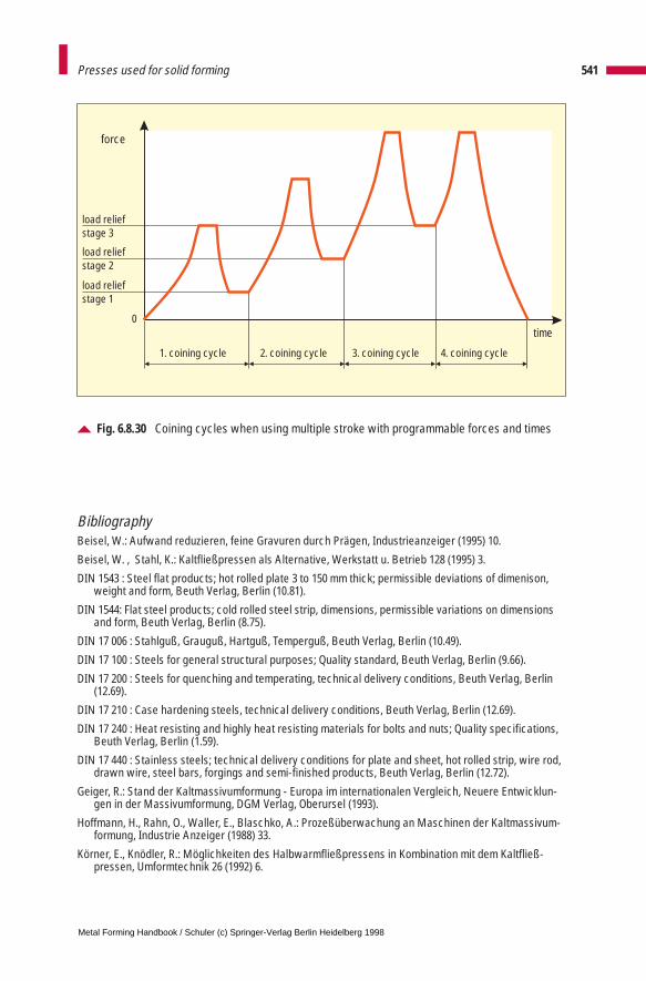
Bibliography Beisel, W.: Aufwand reduzieren, feine Gravuren durch Prägen, Industrieanzeiger (1995) 10.
Beisel, W. , Stahl, K.: Kaltfließpressen als Alternative, Werkstatt u. Betrieb 128 (1995) 3.
DIN 1543 : Steel flat products; hot rolled plate 3 to 150 mm thick; permissible deviations of dimenison,weight and form, Beuth Verlag, Berlin (10.81).
DIN 1544: Flat steel products; cold rolled steel strip, dimensions, permissible variations on dimensionsand form, Beuth Verlag, Berlin (8.75).
DIN 17 006 : Stahlguß, Grauguß, Hartguß, Temperguß, Beuth Verlag, Berlin (10.49).
DIN 17 100 : Steels for general structural purposes; Quality standard, Beuth Verlag, Berlin (9.66).
DIN 17 200 : Steels for quenching and temperating, technical delivery conditions, Beuth Verlag, Berlin(12.69).
DIN 17 210 : Case hardening steels, technical delivery conditions, Beuth Verlag, Berlin (12.69).
DIN 17 240 : Heat resisting and highly heat resisting materials for bolts and nuts; Quality specifications,Beuth Verlag, Berlin (1.59).
DIN 17 440 : Stainless steels; technical delivery conditions for plate and sheet, hot rolled strip, wire rod,drawn wire, steel bars, forgings and semi-finished products, Beuth Verlag, Berlin (12.72).
Geiger, R.: Stand der Kaltmassivumformung - Europa im internationalen Vergleich, Neuere Entwicklun-gen in der Massivumformung, DGM Verlag, Oberursel (1993).
Hoffmann, H., Rahn, O., Waller, E., Blaschko, A.: Prozeßüberwachung an Maschinen der Kaltmassivum-formung, Industrie Anzeiger (1988) 33.
Körner, E., Knödler, R.: Möglichkeiten des Halbwarmfließpressens in Kombination mit dem Kaltfließ-pressen, Umformtechnik 26 (1992) 6.
541Presses used for solid forming
Fig. 6.8.30 Coining cycles when using multiple stroke with programmable forces and times
time
force
load reliefstage 3
load reliefstage 2
load reliefstage 1
1. coining cycle 2. coining cycle 3. coining cycle 4. coining cycle
0
Metal Forming Handbook / Schuler (c) Springer-Verlag Berlin Heidelberg 1998

Körner, E., Schöck, J. A.: Rationalisierungspotentiale im Rahmen der Werkzeug- und Presseninbetrieb-nahme, Umformtechnik 26 (1992) 6.
Körner, E., u.a.: Mechanische Fließpreßanlagen für die Kalt- und Halbwarmumformung, NeuereEntwicklungen in der Massivumformung, DGM Verlag, Oberursel (1995).
Kudo, H., Takahashi, A.: Extrusion technology in the Japanese automotive industry, VDI Berichte Nr. 810, VDI-Verlag, Düsseldorf (1990).
Lange, K.: Umformtechnik, Volume 2: Massivumformung, Springer-Verlag, Heidelberg (1988).
Schwebel, R.: Prägen mit minimalen Toleranzen, Bleche Rohre Profile (1995) 4.
Sheljaskow, Sh., Dübler, A.: Entwicklungsstand und Einsatzbereich der Halbwarmumformung, Vereindeutscher Werkzeugmaschinenfabriken e. V. (VDW) Study (1991).
Stahlschlüssel-Taschenbuch, Verlag Stahlschlüssel, Wegst GmbH, Marbach/N.
VDI 3138 Bl. 1 : Kaltfließpressen von Stählen und NE-Metallen, Arbeitsbeispiele, Wirtschaftlichkeit,Beuth Verlag, Berlin (10.70).
VDI 3138 Bl. 2 : Kaltfließpressen von Stählen und NE-Metallen, Anwendung, Beuth Verlag, Berlin(10.70).
VDI 3138 Bl. 1 : Kaltfließpressen von Stählen und NE-Metallen, Grundlagen, Beuth Verlag, Berlin (10.70).
VDI 3176 : Vorgespannte Preßwerkzeuge für das Kaltumformen, Beuth Verlag, Berlin (10.86).
VDI 3186 Bl. 1 : Werkzeuge für das Kaltfließpressen von Stahl, Aufbau, Werkstoffe (ICFG Data Sheet4/70), Beuth Verlag, Berlin (12.71).
VDI 3186 Bl. 2 : Werkzeuge für das Kaltfließpressen von Stahl, Gestaltung, Herstellung, Instandhaltungvon Stempeln und Dornen (ICFG Data Sheet 5/70), Beuth Verlag, Berlin (12.71).
VDI 3186 Bl. 3 (6.74): Werkzeuge für das Kaltfließpressen von Stahl, Gestaltung, Herstellung, Instand-haltung, Berechnung von Preßbüchsen und Schrumpfverbänden (ICFG Data Sheet 6/72), Beuth Verlag, Berlin und Cologne.
VDI 3187 Bl. 3 : Scherschneiden von Stäben, Schneidfehler (ICFG Data Sheet 5/71), Beuth Verlag, Berlin (8.73).
VDI 3198 : CVD-PVD-Verfahren, Beuth Verlag, Berlin (9.91).
VDI 3200 Bl. 1 : Fließkurven metallischer Werkstoffe, Grundlagen, Beuth Verlag, Berlin (10.78).
VDI 3200 Bl. 1 : Fließkurven metallischer Werkstoffe, NE-Metalle, Beuth Verlag, Berlin (10.78).
VDI 3200 Bl. 2 : Fließkurven metallischer Werkstoffe, Stähle, Beuth Verlag, Berlin (4.82).
Verson, M. D.: Impact machining, Verson Allsteel Press Company, Chicago (1969).
Zebel, H.: Die Trennflächen von abgescherten Stababschnitten, Werkstattstechnik (1964) 54.
542 Solid forming (Forging)
Metal Forming Handbook / Schuler (c) Springer-Verlag Berlin Heidelberg 1998
A.S.T.M.-standard 451abrasion 183accelerometer 403accident prevention 106accident prevention regulation
106, 116acoustic emission 402 f.active hydro-mechanical
drawing 189-193actuator 94, 97, 326, 329adding-on process 500, 502additive 184–, EP additive 463adhesion 182AISI-standard 451all-across perforating press
314alloyed steel 174alloying technique 121alternating bending 384aluminium 178, 453aluminium alloy 178angular section 377annealing 423, 455, 458ANSI-standard 117austenitic chromium nickel
steel 174, 177automatic 257automation 478availability 320, 389, 395, 399average forming pressure 472axis control system 257 f.
backward cup extrusion 440,445, 447, 474 f.
backward extrusion 433 f.baked enamel-coated
lamination 301bake-hardening-steel 174, 176ball joint gib 39bar holder 457bar stock 455
basic section geometry 374batch size 396 f., 399beading 169, 375–, draw bead 149beading rod 22bed plate 34, 37bending 23, 425- with linear die movement 16- with rotary die movement 16–, springback 23–, overbending 23bending 431bending angle 366, 370bending die 372bending force 372bending process 366-373, 435bending punch 372bending radius 366–, minimal 368bending work 372bent leg 370bevel angle 275bevelled punch 275billet heating 521billet preparation 454-459, 522bimetal coin 528, 535 f.bite cutting 21blade holder 285blank control and discharge
device 529, 532blank diameter 162-165blank discharge 531blank feeder 226 f.blank holder 45-48, 66-70, 156-
160, 171, 185, 187, 190, 250–, force versus time profile 45–, overload safety device 67–, precision control 45–, segmented 313blank holder force 44, 47 f.,
171f.blank holder pressure 171blank holder slide 41, 158
blank length 370blank size 162blank turnover station 217-222blank welding line 311blanking 23, 268–, blanking line 20–, single-stroke 20blanking burr 337, 347, 349blanking clearance 281, 295,
334, 457 f.blanking die 143 f.–, compound cutting tool 20,
297, 299, 304, 351blanking force 274, 276 f., 332,
342, 356 f.blanking force-stroke diagram
334blanking line 284-329, 389, 398blanking plate 352-355blanking press 286-289blanking process 268-283blanking punch 354 f.blanking segment 144blanking shock 83blanking work 274, 276 f.block hydraulic system 79bolster plate 37, 88, 91-93bottom dead center (BDC) 52 f.bottom drive 57, 59, 507 f., 525bottom thickness 446bottom-driven press 37boundary friction 180boundary layer 180, 182bracket 144brake 61-63, 226–, hydraulic 293–, rotating brake system 285 f.brake frame 284 f.brass 454breaking 19, 21buckling 415, 418, 424–, free buckling length 418 f.buckling strength 189 f.
Index
Metal Forming Handbook / Schuler (c) Springer-Verlag Berlin Heidelberg 1998

buckling stress 495bursting 415, 418, 425
CAD data 131calibrating 431, 436 f.calibration 405, 407calibration pressure 406calibration process 410, 432cam operated limit switch 98,
100cam wheel 120camera monitoring system 318camping rail 480 f.camshaft 316car body panel 129carbid 499 f.carbon content 450 f.carriage 245cassette feed 539casting 120casting model/pattern 130, 136casting of dies 143-148CE mark 108, 110 f., 113CE marking 111-115center of force 278 f.centering 440, 474 f.centering device 204central burst 475central control desk 258central support 360-362certification 106-119characteristic data 49-54chevron 475circuit diagram 101circular bending 16 f.circular blade 268, 286circular shears 284clamp stripper 316clamping plate 318, 320clamping rail 92cleaning 460closed blanking 268closed contour 289closed die forming 8, 433closed section 377closed shearing guide 458 f.closing system 503 f.clutch-brake-combination 314CNC feeder 227 f.coating 5, 143, 501 f.coating method 143, 146coefficient of friction 179-181coil 194, 288, 389, 391, 398coil end welding machine 380coil guide 356 f.coil line 194-198, 229, 287, 291 f.,
305, 391coil loop 194 f., 286-288
coil thickness unit 292coiling 17coin 526-541–, bimetal 528, 535 f.–, collector’s 534coin blank 526coin blanking line 526-541coining 8, 433-436coining die 534cold coining 436cold extrusion 8 f., 433 f., 439,
445, 506–, backward cup/can extrusion
10, 440, 445, 447, 474 f.–, backwards 10, 433 f.–, forward cup/can extrusion
440–, forward rod extrusion 445,
447 f., 469-473–, forward tube extrusion 474–, forwards 10, 433 f.–, hot extrusion 445–, lateral 10, 433 f.–, warm extrusion 445cold forging flow curve 451cold forging tool steel 498 f.cold forming 26, 437-439, 450cold rinsing 462 f.cold sizing 523cold welding 182cold-rolled sheet 174collector’s coin 534collision testing 136column gib 39communication module 100communication system 97 f.,
257compact drive 63, 201compensation factor 370 f.component of a die 143compound cutting tool 20, 297,
299, 304, 351compression/upsetting 27 f.,
405, 407, 410, 435, 445, 476 f.–, free 477concentricity tolerance 446connecting rod 38, 65 f., 120–, double fork 293, 295contact condition 415contact pattern 148container 434 f., 491, 494continuous stroking 52contour blanking line 289 f.contoured blank 289control component 99 f.control concept 255control function 96control software 104control system 254-267–, architecture 101 f.
–, configuration 101 f.–, electrical 94, 97–, functional grouping 101–, functional structure 99 f.–, local 255–, programmable logic
controller (PLC) 97, 102, 257,321 f.
–, structure 97 f.control system 321–, conventional 257–, electronic 257control unit 95 f., 258, 327conventional control system
257conversion 116cooling element 121cooling system 520copper 177, 453 f.copper alloy 174, 177copper sheet 174correction factor 173corrugating 17counterbalance of masses 202,
293counter-drawing 44, 159, 161,
190, 200, 232counterforce 332, 342, 353, 355-
357, 360counterforce cylinder 426counterforce piston 361 f.counterpressure pad/punch 20,
406 f., 421, 427 f.counterpunch 434coupling 61-63, 120, 226–, hydraulic 293crack detection 122crank drive 54cropping shear 288, 316 f.cross section change 471cross section deformation 369crossbar 245 f., 249 f.crossbar transfer 245 f.–, displacement/time diagramm
246–, motion curve 245cup extrusion 433 f.cushion monitoring system
(CMS) 264cut contour perimeter 278cut out 23cut surface 274, 349cutlery embossing press 523cut-off holder 457cutting 424cut-to-length line 287, 290cut-to-length shear 286, 288,
380CVD technique 500-502cycle time 198
545Index
Metal Forming Handbook / Schuler (c) Springer-Verlag Berlin Heidelberg 1998

cylinder–, counterpressure 426–, differential 426–, displacement 250–, horizontal 406 f., 416 f., 420 f.,
426-428–, hydraulic 39, 75–, parallelism controlling 252–, plunger 426cylinder deactivation 215
d/s ratio 274damping 82 f.data acquisition 264data record 130DC asynchronous motor 100declaration of conformity
110-114decoiler 194, 284, 288deep drawing 11 f., 22, 156-193- using active energy 12- using active media 12- without blank holder 174–, blank holder 11, 22–, forming force 157–, hydro-mechanical drawing
12, 189-193–, punch motion 11–, redrawing 11–, reverse drawing 11–, single-draw 11–, telescopic punch 11– with rigid tool 11deep drawing defect 175deep drawing press 41-44deep drawing process 23defect cause 175defect prevention 175deflection tolerance 446deformation 25-28, 181, 410–, dislocation 25– faults in the arrangement of
the atomic lettice 25–, logarithmic 27–, relative 27–, sliding 25–, true strain 27–, twin crystal formation 25deformation along the vertical
axis 28deformation depth 82deformation rate 26, 28deformation resistance 29deformation work 30–, referenced 29 f.degreasing 460, 462 degree of difficulty 342degree of vibration 403descaling 455, 460
destacker 217-222, 226, 229,305, 389
dial feed plate 530diameter related defect 530diameter tolerance 446die 158-160, 171, 185, 190, 425–, assembly 136–, blanking 143 f.–, center line spacing 126–, classification 123-127–, coining 534–, compound cutting tool 20,
297, 299, 304, 351–, design 130 f.–, development 128-141, 148–, double-action 124, 245, 274,
398–, draw 143–, extrusion 485–, flanging 127, 143–, maintenance 153–, number 123–, production 421–, profile parting 380–, progressive 125, 282, 297–, progressive blanking 125,
307, 356–, progressive compound 126,
345, 351-353, 356 f.–, prototype 137 f., 421–, rolling 380–, single 124–, special 127–, step width 126–, structure 123–, swivelling 290–, timing cycle 128–, transfer 125, 345, 356–, type 124, 351–, wedge-action pusher 490die bending 16, 372die cavity insert 421die change 86-93, 97, 228, 242,
249, 257, 261, 290, 308, 520die change cart 87 f.die change synoptic 261die changing arm 490 f.die changing system 426, 489die changing time 397-399die clamp 92 f.die clamping device 91-93die coating 500die coining 16, 327die corner radius 171die data 259die design 491-495die handling 86-91die holder 488-490die holding sleeve 485-491die lubrication 358
die material 142 f., 422, 496-502die opening angle 470, 472,
475 f.– for ironing 476die set, set-up 397die stroke-dependent sensor
363die system 352die width 372die-independent pressure
sensing 363die-roll 337, 348 f.differential cylinder 426digital image generation 401digital rectifier 100directive–, EC 107-109–, EMC 107– governing Simple Pressure
Vessels 107discharge plate 306displacement 17displacement cylinder 249displacement/time diagram 55distance sleeve 284distribution of stress 140 f.dividing 5, 19 f., 457double fork connecting rod 293,
295double helical gearing 65double knuckle-joint 361double knuckle-joint system
208, 360double loop line 380double part 392double stroke 537double-action die 124, 245, 274,
398double-action drawing
operation 158 f.double-action drawing press
169double-action press 41 f., 56,
173, 185–, blank holder drive 60–, drawing press 169doubling 375 f.draft angle 465draw bead 140, 149, 171draw cushion 43, 44-48, 159 f.,
241 f., 250, 264–, hydraulic 44, 47 f.–, pneumatic 44, 47 f. –, segmented bed cushion 215draw depth limit 186draw development 130 f., 137draw die 143, 159draw energy 173draw punch 156-160, 185, 187draw ratio 166, 173, 187
547Index
Metal Forming Handbook / Schuler (c) Springer-Verlag Berlin Heidelberg 1998
drawing 10, 433–, active hydro-mechanical
189-193–, double-action 158 f.–, single-action 159drawing defect 174drawing mandrel 476drawing process 476drawing stroke 173drawn wire 455drive controller 97drive motor 60 f.drive shaft 63 f.drive system 54-60–, compact drive 63, 201–, crank drive 54–, eccentric drive 54, 510–, hydraulic drive 76–, knuckle-joint drive 55, 205,
513, 527, 534–, link drive 55 f., 223, 529–, longitudinal shaft drive 63-65–, main drive 60, 66–, overrun drive 87 f.–, pump drive 77 f.–, push-pull drive 87–, servo drive 100–, slide drive 37-41–, top drive 59–, transverse shaft drive 63 f.driver 144drum turning device 220drying 463dual production 244, 394dual stacking feeder 217dual swivel-mounted decoiler
380ductile castings 120
EC decree 107, 109EC machine directive 107-109eccentric drive 54, 510eccentric shaft 201, 293eccentric wheel 121edge lettering 527edge lettering machine 526effective stress 416efficiency factor 472eight-track block gib 39eight-track gib 39 f.– for high eccentric loads in
the y direction 39– for narrow side uprights 39– for wide side uprights 39– in cross formation 41– roller gib 40eight-track slide gib 509ejector 158 f., 231, 233, 353, 355,
537 f.
–, knock-out pins 41–, pneumatic ejector 482, 487ejector curve 482ejector force 333, 353, 356, 358ejector pin 333–, inner form ejector 353 f.ejector stroke 481electric motor lamination 296-
309electrical control system 94, 97electrical equipment 326electromagnetic compatibility
(EMC) 327, 329electronic control system 257elongation 449–, effective stress 416–, elongation limit 175–, principal strain 416–, strain rate 416–, ultimate elongation 175, 423embossing 15, 436embossing block 144embossing press 522-525EMC directive 107EN692 111EN693 111energy consumption 199EP additive 463equipment, electrical 326error 262error data 262error message 259, 323excess material 455, 466exchangeable shear 284exchanging the sleeves 489expanding 15expansion 405, 407, 425–, free expansion 418experience data base 267extrusion die 485extrusion of semi-finished
products 8-10, 433–, backwards 10–, forwards 10–, lateral 10extrusion punch 494
failure diagnostics module324 f.
Failure Mode and EffectsAnalysis (FMEA) 133
family of parts 392fanning magnet 217fast communication module
100fast communication system
104, 258fatigue wear 183fault diagnostics 97
feasibility study 413-419feed channel 479feed height adjustment 362feed hopper 529 f.feed output 194, 196feed step 272 f.feed step pilot 356 f.–, embossing punch 357feed system 518feed unit 318–, infeed roller 316feed value 386 f.feed/straightening machine 195feeder 217 f.–, blank 226 f.–, CNC 227 f.–, swing arm 226-228feeder arm 245feeding device 126female blanking die 144female die 158-160, 171, 185,
190female die retaining plate 144ferritic chromium steel 174, 176fiber flow 441field bus system 266, 329filling slide 144fine blanking 330-356–, annular serrated blank holder
20–, counterpressure pad 20fine blanking capability 339fine blanking oil 358fine blanking press 360-365finish processing 430finite element method (FEM) 37,
140, 494finite element program 467fixed punch 352, 354, 360fixed shear 287flanged blade 284flanging 13flanging die 127, 143flanging/hemming 23flashless forging 502flat radiator plate 208-210flat steel 456flexible notching system 301,
303flexible production cell 303flooding 520flow 25flow condition 25 f.flow curve 25 f., 30, 450 f.flow law 28flow piercing process 435flow stress 25 f., 29, 157, 438,
450, 453fluid lubrication, hydro-dynamic
180
549Index
Metal Forming Handbook / Schuler (c) Springer-Verlag Berlin Heidelberg 1998

flying shear 288flywheel 51-54, 60 f., 200, 293foaming 380folding 375folding die 142–, restrike edge bending die
144force 29 f., 49-51, 53–, bending force 372–, blank holder force 44, 47 f.,
171 f.–, blanking force 274, 276 f.,
332, 342, 356 f.–, counterforce 332, 342, 353,
355-357, 360–, direct/indirect application
29–, forming 168, 173, 188 f., 472–, friction force 179 f.–, mandrel friction force 476–, pressing force 506–, reaction force 188 f.–, restraining force 285–, return stroke force 274–, shearing force 458–, slide force 188 f., 342–, straightening force 388–, vee-ring force 356 f., 360force measurement 402 f.force requirement 282, 469-477force-stroke diagram 50force-time curve 292, 402forged part 522forging 91, 433, 437-439, 451f.–, flashless 502–, hammer forging 7forging hammer 38, 50fork turning device 221formability 25, 31, 450formed element 343forming 5 f.– after heating 26– with a lasting change in
strength property 26– with temporary change in
strength property 26– without heating 26amount of deformation 27, 157,
438, 449, 467, 471–, maximum 470forming by bending 6, 16forming by forcing through an
orifice 8 f., 433forming distance 50 f., 54forming efficiency factor 29forming force 168, 173, 188 f.,
472forming pressure 472–, average 472– on the container wall 473
forming process 6 f.–, classification 6forming under combined tensile
and compressive conditions6, 10-13
–, process 156forming under compressive
conditions 6-8forming under shear conditions
6, 17 f.forming under tensile
conditions 6, 14 f.–, process 156forming work 53, 472–, specific forming work 472forward cup extrusion 440forward extrusion 433 f.forward rod extrusion 469-473forward tube extrusion 474four-point configuration 39four-upright press 426 f.fracture 346frame press 426, 428free buckling length 418 f.free expansion 418free extrusion 8 f., 433, 435, 445,
448, 470, 475 f.free hydroforming 406free upsetting 477friction 179-185–, solid body 180friction force 179 f.friction modifier 184frictional shear stress 180full form casting 143full-stroke parallelism control
81 f.
gear 65 f., 519gear drive 65 f.gearing 435geometrical accuracy 443 f.geometry of the die 123geometry of workpiece 123glass fiber-reinforced
thermoplastics 251gluing 380greasing 220, 455gripper 479gripper rail 35guidance ratio 41guidance system 134guide plate 353 f.Guldin’s law 466 f.
hammer forging 7hardness 448hardness testing 122
hat section 377hazard analysis with risk
assessment 114heat ageing 453heat treatment 369, 423 f.,
449 f., 453, 457 f., 497hemming/flanging 23high speed cutting (HSC)
136high-performance transfer
press 200high-pressure spray system
521high-speed blanking line
291-297, 307, 391, 536high-speed steel 497, 499 f.hole diameter 273hole pattern 318 f.hollow face 275home try-out 130hopper 529, 531horizontal cylinder 406 f., 416 f.,
420 f., 426-428horizontal press 513 f.host computer 427hot extrusion 445hot forging flow curve 451hot forging tool steel 498-500hot forming 26, 437-439, 506hot forming line 520-522hot rinsing 462 f.hot rolling 456–, hot-rolled coil stock 456hybrid press 203-205hydraulic brake 293hydraulic coupling 293hydraulic cylinder 39, 75hydraulic drive 76hydraulic medal minting press
540hydraulic oil 77–, compressibility 78hydraulic press 38, 73-85–, cycle time 74–, displacement/time
diagram 74–, drive 73-77–, drive power 73–, slide cylinder 75hydraulic redundancy 97hydraulic system 76–, service unit 77–, valve control system 77hydro-dynamic fluid lubrication
180hydroforming 405-432–, component development
413–, cycle time 429–, fields of application 412
551Index
Metal Forming Handbook / Schuler (c) Springer-Verlag Berlin Heidelberg 1998

–, free hydroforming 406–, tool-dependent hydroforming
406Hydro-Mec forming process
187hydro-mechanical deep
drawing 185-189hydro-mechanical reverse
drawing 185hydrostatic pressure 73
image generation, digital 401image processing 401impact speed 57, 199, 204, 289,
509inclined conveyor 517indexing unit 298individual electrical control
device 97induction welding 311-313industrial PC 103, 322 f., 329infeed roller 316infeed table 316inflation limit 418initial blanking stop 356 f.inner form ejector pin 353 f.inner form punch 353, 355input weight 442input/output module 104, 266,
326input/output system 97, 257,
329intermediate annealing 423, 458intermediate heat treatment
467intermediate storage 397 f.intermediate treatment
450 f.internal pressure 417international unit system 31interrupt input 102investigation part handling 478,
481-484, 506involute gearing 466ion implantation 500iron phosphate layer 461ironing 10, 435, 440, 445, 447 f.,
475 f.ironing die 435ironing die ring 476
JIS standard 451job data acquisition 264job management 321joining 5, 23- through forming 6just-in-time production 398
knock-out pin 41knuckle-joint drive 57, 205, 513,
527, 534–, curve 59–, double knuckle-joint system
208, 360 f.–, knuckle-joint bottom drive
208, 523–, modified 58 f., 528–, modified knuckle-joint top
drive 509 f.–, pressing force 58knuckle-joint press 55, 507 f.,
525
L section 377lamination stack 301large-panel transfer press 125,
391, 393, 396– crossbar transfer 243-250,
391, 398– tri-axis transfer 234-243,
391 f., 398laser welding 311, 313lateral extrusion 433 f., 477layout 400lead 454lead press 225–, double-action 225leg length 371length 14lift beam 245 f., 249lifting bridge 45lifting edge 126light alloy 174limiting draw ratio 167, 187line operating and information
system 321line operation 259link 66link drive 55 f., 223link drive system 529link-driven press 55load, off-center 37, 80 f., 214loading 393loading station 479-481loading system 517local control unit 255locking bead 22locking device 84 f.lock-out-plate 118lock-out-procedure 117long section 380longitudinal knife 268longitudinal seam welding 380longitudinal shaft 64longitudinal shaft drive 63-65lower elongation limit 175low-voltage switchgear 97
lubricant 179, 181, 422, 460, 463lubricant film 180lubrication 72, 179-185–, hydro-dynamic fluidlubrication 180lubrication pocket 358 f.lubrication system 361 f., 520
machine and production data260 - 262
–, acquisition 262machine tool 1machining allowance 439, 465magnetic belt conveyor 217main drive 60, 66maintenance 267, 321maintenance back-up 105maintenance capability 320maintenance instruction 259maintenance interval 321maintenance module 324malfunction diagnostics system
261mandrel 434mandrel friction force 476manufacturer’s declaration 111manufacturing process 5material 174-179, 423 f., 450-454material cohesion 6, 25material feed 305material flow 26-28, 339material number 174material pair 181material saving 269material selection 338material stress 339material usage 125material utilization 271, 273, 356maximum friction condition 180maximum true strain 470mean pressure 31mechanical hydraulic press
203mechanical press 38, 49-72–, design 63medal minting press 537metal flow 140, 148, 157, 398,
400, 468metal forming technology 1, 6,
19, 123micro-alloyed steel 174, 177, 450minimal bending radius 368minting line 526-541modified knuckle-joint 514modified knuckle-joint drive 58
f., 528modified knuckle-joint top drive
509 f.
553Index
Metal Forming Handbook / Schuler (c) Springer-Verlag Berlin Heidelberg 1998

modified top drive 205-207modifying material property 5molybdenum disulphide 462molycoting 460 f.monobloc press frame 360,
528 f.monobloc structure 514moving bolster 89 f., 152, 228,
248-250, 290moving punch 352 f., 360moving stripper 316, 318multiple pressing 431multiple stroke 537multiple-point press 39multiple-station press
508-512multi-point controller 149
NC machining 134near net shape component
447necking 449net shape component 447net shape production 485networking capability 104nibbling 20nitriding 500, 502noise protection 228noise reduction 289nominal load 52 f.normal annealing 424normal contact stress 180 f.normal force 179normalization 458 f.notch impact strength 449notching 431notching device 317notching machine 297–, single notch blanking 297–, automatic notching machine
299notching system 299number of presses 224
off-center load 37, 80 f., 214offset punch 275oil flow 72oiling 220omega section 377one-point configuration 39on-line control 401on-line monitoring 105open contour 268open contour blanking 268open die forming 7, 433, 476open front press design 34open shears 458 f.opening angle 370
operating and informationsystem 324
operating and visualizationsystem 94-96, 258
operating capability 320operating instruction manual
114 f.operating mode 256operator console 95operator prompt synoptic 260operator station 95, 258optoelectronic system 401OSHA 117outfeed roller 316 f.output 394 f.overbending 23overload safety device 54, 66 f.overrun drive 87 f.
pallet changeover 383panel retaining block 144panel structure 514parallel lift mechanism 153parallelism control system 80,
215parallelism controlling cylinder
80, 252parallelism of the slide 80-82parameter 51 f.part discharge 306, 308part drawing 130part family 394, 398part transfer 131, 478-484part-dependent tooling 154,
238, 245peeling 456pendent control unit 258, 326penetration depth 294 f.penetration depth control 293-
296perforating press 314-320perforating punch 316phosphating 455, 460 f., 463phosphor-alloyed steel 174, 176pickling 460, 462piercing 23, 431, 440piercing module 214piercing process 435pilot pin 126, 356pilot series 129 f.pint holding plate 250piston rod 39pitch 273pivoting slide plate 151plasma nitriding 502plastic press 251 f.plate-type brake 285plunger 426pneumatic 70
pneumatic ejector 482, 487pneumatic pad 487pointed face/finish 275positioning module 100positive press-off pin 356 f.power 49power supply 97precision blanking 330preform 423-425, 454pre-forming 425pre-graphitizing 522pre-heat-treated steel 450preliminary drawing 455pre-production series 130,
138pre-run 136press–, blanking 286 f.–, bottom-driven 37–, characteristics 149–, deep drawing 41-44–, displacement-related 37–, double-action 41 f., 56, 173,
185–, embossing 522-525–, fine blanking 360-365–, force-related 37–, high-speed blanking line
291-297, 307, 391, 536–, horizontal 513 f.–, hybrid 203-205–, hydraulic 38, 73-85–, knuckle-joint 55, 507 f., 525–, link-driven 55–, mechanical 38, 49-72–, mechanical hydraulic 203–, perforating 314-320–, single-action 43 f., 169, 173–, sizing 522-525–, straight-sided 297–, top-driven 37–, try-out 391–, universal 198-208, 391–, work-related 38press bed 37press bus system 257 f.press construction 33 f.press control system 94-105,
320-329–, electrical equipment 94–, function 94–, functional structure 98 f.–, structure 97press crown 34, 37, 66press frame 34-37–, configuration 36–, monobloc 36–, multiple part 36press line 124, 222-228, 391 f.press load schedule 396 f.
555Index
Metal Forming Handbook / Schuler (c) Springer-Verlag Berlin Heidelberg 1998
Press Management System(PMS) 262
press synoptic 260press through process 476press type 33 f.pressing force 506pressure –, hydrostatic 73–, mean 31pressure accumulator drive
system 77 f.pressure block 127pressure column 45 f., 250pressure control system 101pressure identifier 427pressure medium 406 f.pressure medium reservoir 185pressure pad 250pressure pattern 133pressure pin 250pressure plate 144pressure point 66 f., 172, 293,
316pressure sensing, die-
independent 363pre-stretching process 190primary shaping 5principle deformation 28principle strain 416principle stress 25 f.process combination 22-24,
437, 440process control 137process data acquisition 403process monitoring 402process plan 123, 130 f.process simulation 138process visualization 95, 322processing plan 123, 467 f.processing time 394production capacity 395production cell 320production cycle 398 f.production data 262, 399production data acquisition
264, 321production die 421production log 321production log information
324production requirement 393production scope 393production stroking rate 394 f.profile 376 f.profile parting die 380profile roll changeover 381programmable logic controller
(PLC) 97, 102, 257, 321 f.programming 105–, sequentional 102
progressive blanking die 125,307, 356
progressive compound die 126,345, 351-353, 356 f.
progressive die 125, 282, 297properties of the cut surface
346prototype die 137 f., 421prototype part 130pump drive 77 f.punch 159, 353–, bending 372–, bevelled 275–, blanking 354 f.–, counterpunch 434–, draw 156-160, 185, 187–, extrusion 494–, fixed 352, 354, 360–, inner form 353, 355–, moving 352 f., 360–, offset 275–, perforating 316–, seal 406 f., 420–, specific punch pressure 472–, telescopic 11punch bundling 23, 309 f.punch control beam 316punch control unit 316punch design 491-495punch head 127punch retaining plate 144punch tightening rod 361pusher 513push-in clamp 92push-pull drive 87PVD process 500-502
quality assurance 321, 389, 400-404
quality control 122, 400-404quick die change system 192
rail section 376rated press force 52 f., 57reaction force 188 f.ready-to-run synoptic 260 f.recoiler 284recovery annealing 458 f.recrystallization 26recrystallization annealing 423,
458 f.recrystallization rate 26recrystallization temperature
26rectifier, digital 101redraw 156 f., 167reducing gear 120reduction 9, 425
redundancy, hydraulic 97reengineering 442relative blanking force 274relief 458 f.remote diagnostics 104 f.,321repair 267, 321residual risk 115residual stress 122, 369resistance to shear 274resistance to wear 121resistance welding 311, 313restraining force 285restrike block 144restriking 16, 23resuming operation 320return stroke force 274reverse drawing 159–, hydro-mechanical 185rib 170rim length 273rim width 273rimming machine 526robot 227 f.rocker element 290rod extrusion 433 f.roll bending 16roll bending radius 376roll embossing 436roll feed 194 f., 288, 292, 305roll forming 17, 373-383roll forming line 379roll stand set 380roller gib 40, 304, 314, 528roller pitch 385-387roller straightening 16, 383-389roller straightening machine
385, 387rolling 374, 433–, cold rolling 7–, hot forming 7rolling die 380rolling direction 366rolling ring 284rotary feed system 531rotating brake system 285 f.rotating shears 288round steel 455running gear 466run-up time 60
safety 106-119safety control system 97, 99,
257safety inventor level 397 f.safety measure 106safety officer 119safety requirement–, European 107-111–, USA 117-119
557Index
Metal Forming Handbook / Schuler (c) Springer-Verlag Berlin Heidelberg 1998

sand blasting 460sandwich coating 502scale formation 438scale forming 122scale layer 460scrap chute 144screw press 38SE project 130seal punch 406, 420seaming bed 127secondary contour 407section 376 f.–, basic section geometry 374–, long 380segment blank 301segmented bed cushion 215segmented blank holder 313sensor 94, 97, 326, 329separating device 479sequential programming 102series–, pilot series 129 f.–, pre-production series 130,
138series run 149series try-out 130servo drive 101set-up 257, 260 f.set-up time 86shaft hole punch 300shear 287–, circular 284–, cropping 288–, cut-to-length 286, 288, 380–, exchangeable 284–, fixed 287–, rotating 288–, separating 316 f.–, stationary 287 f.–, swivel-mounted 287shear cutting 19 f.sheared contour 274shearing 457shearing force 458shearing guide 458–, closed 458 f.shearing resistance 458shearing strength 274shearing stress hypothesis 25 f.shearing velocity 458shearing work 458shearing zone 269shears, open 458 f.sheet metal forming 433sheet metal thickness 140Sheet Molding Compound
(SMC) 251sheet, cold-rolled 174shrink fit 492 f.shrink ring 491, 493
SI unit 31 f.side cutter waste 273side member 210-216side shear 126silicon bronze 453simulation 415, 468simulator 391Simultaneous Engineering (SE)
128, 413single cycle 257single die 124single notch blanking 297single stroke 537single stroke operation 394single-acting deep drawing
press 44single-action downstream
press 225single-action drawing 159single-action press 43, 169, 173sintered part 522, 524sizing operation 476sizing press 522-525sleeve clamping 488slewing ring 299slide 37, 66-70, 144, 159–, blank holder 41, 158slide adjustment 66slide counterbalance 67slide cushion 44, 69slide drive 37-41slide force 188 f., 342slide gib 39, 360, 362–, eight-track slide gib 509–, gib type 39 f.slide impact speed 48slide locking 83-85–, non-positive acting 85–, positive acting 84slide position sensor 81slide tilt 80, 134slide velocity 180 f., 199sliding component 136sliding friction condition 179sliding insert 421slip-on gearing 466slitting device 317slitting line 284 f.slug preparation 454-459small control system 266smooth surface 334 f., 337,
347soaping 460 f., 463sodium soap 461soft annealing 458 f.software system 321solid body friction 180solid forming 91, 433-542–, choice of press 505 f.–, design rule 465
–, economic aspect 441-443–, lot size 464solid forward extrusion 445,
447 f.solutionizing 423sorting and positioning element
127sound enclosure 529special die 127specific blank holder pressure
171specific forming work 472specific punch pressure 472speed drop 51- 54, 60spindle pressure points 66spinning –, roll head 13–, spinning bush 13–, spinning mandrel 13splash ring 186spotting fixture 150spray system 521springback 23, 140, 367, 372,
415springback factor 367 f.stacking cart 290stacking channel 308stacking device 391stacking line 290stacking unit 253 f., 287stamping nut 127 f.stamping plant 389-400–, layout 389, 391stand changeover 382standstill 263standstill data 262start-stop-line 379start-up 101, 320stationary shear 287 f.steel 120, 450-452–, alloyed 174–, austenitic chromium nickel
174, 177–, bake-hardening 174, 176–, ferritic chromium 174, 176–, flat 456–, high-speed 497, 499 f.–, micro-alloyed 174, 177, 450–, phosphor-alloyed 174, 176–, pre-heat-treated 450–, round 455–, unalloyed 174, 176–, warm/hot forging tool steel
498-500steel castings 120steep conveyor 479, 529straightener 194, 288, 384straightening 383straightening by stretching 14straightening force 388
559Index
Metal Forming Handbook / Schuler (c) Springer-Verlag Berlin Heidelberg 1998

straightening roller 385, 388straight-sided press 34, 297strain hardening 415, 423, 425,
432stress–, effective 416–, largest 28–, mean 28–, principle 25 f.–, smallest 28stress relief annealing 122stretch drawing 15, 22, 156-193–, blank holder 22stretch forming 14 f.strip drawing 10strip layout 356strip length 271, 273strip perforating press 314, 318strip width 270 f., 273stripper 144, 269, 304, 315-319stripper slide 316stripping 274stripping force 333, 355 f., 358stroke adjustment 69stroke limitation 82 f., 191, 250suction cup 217surface fatigue 183surface hardening process 142,
146surface quality 443 f., 447 f.surface treatment 457, 459-463swing arm feeder 226-228switch cabinet 258, 326swivel bending 16 f.swivel mounted shear 287swivelling bracket 86swivelling die 290synchronous overload clutch
533synchronous tapered cup 365synoptic 260 f.system of measurement,
technical 32
T section 377tailored blank 309-313tapering 9team work 320tearing 19, 21, 346technical system of
measurement 32telescopic roll set 380tensile strength 174, 449tensile test specimen 175T-fitting 406 f., 409thermoplastics, glass-fiber
reinforced 251 f.thickness distribution 416thickness related defect 530
three-phase asynchronousmotor 100
tie rod 36tilt moment 81 f.tilting block 127tilting mechanism 479tin 454tin bronze 453titanium 179, 454titanium alloy 179tolerance 444tool see „die“tool breakage safety system
363tool data management 321, 323tool-dependent hydroforming
406tooling 391–, part-dependent 154, 238, 245tooling data input mask 96top drive 59top to tail arrangement 270top-driven press 37transfer 244–, electrically driven transfer
239–, motion curve 239transfer die 125, 345, 355transfer feed system 518transfer press 35, 125, 229-234,
391–, high-performance transfer
press 201–, large-panel transfer press
125, 391, 393, 396transfer simulator 154 f.transformation annealing 121transition radius 466transport length 505transportation time 198, 394transverse shaft drive 63 f.tri-axis transfer 201, 231 f., 238tribology 179trimming 23, 435trimming module 214triple stroke 537troubleshooting 101, 321try-out 136–, home try-out 130–, series try-out 130try-out center 152 f.try-out equipment 148-154try-out press 148, 391T-slot 88, 92T-slot clamp 92T-track 90, 152 f., 228, 290tube extrusion 433 f.tube section 456tubular blank 414, 416, 424 f.tumbling 460
turning device 44turnover device for blank stacks
220turnover station 227–, blank turnover station
217-222–, drum turning device 220–, fork turning device 221twisting 18two-point configuration 39two-point slide drive 506type test 111
U/C section 376ultimate elongation 175, 423ultrasound detection 122unalloyed steel 174, 176undercut 466unit of measurement 31 f.unit system, international 31universal minting press 534universal press 198-208, 391universal station 155, 228, 238,
247upright 34upset ratio 467upsetting 440, 477upsetting die 435, 476upsetting/compression 27 f.,
405, 407, 410, 435, 445, 476 f.uptime 395used machine 116utilization rate 398 f.
valve 79valve block 72variation in diameter 466vee-ring 332, 335vee-ring force 356 f., 360vee-ring piston 361 f.vee-ring plate 353 f.vibrating conveyor 479vibration characteristic 295viscosity 183visualization 96volume calculation 466volume constancy 28, 443volumetric adjustment 467V-prism gib 39
wall friction 469wall thickness 465wall thickness tolerance 446warm extrusion 445warm forging 438 f., 451warm forming 437, 506warm forming line 520-522
561Index
Metal Forming Handbook / Schuler (c) Springer-Verlag Berlin Heidelberg 1998

washing/cleaning machine 219waste chute 144water container 185, 187 f., 190wear 179-185wear at surface layer 182wear mechanism 179, 181 f.wear resistance 183wear resistant coating 500wedge adjustment 66, 486-488wedge-action cutting 19, 21wedge-action pusher die 490wedge-type clamps 490wide strip section 377wire 454 f.
wire feed device 512work 29 f., 49-54, 506 f–, bending 372–, blanking 274, 276 f.–, deformation 30–, draw energy 173–, forming 53, 472– velocity 506work hardening 339work requirement 282,
469-477working period 395, 398wrinkle bulging 13wrinkling 140 f.
X-ray detection 122
yield strength 449–, lower yield strength 175
Z section 377zinc 454zinc phosphate layer 461zinc soap layer 461zirconium 454
563Index
Metal Forming Handbook / Schuler (c) Springer-Verlag Berlin Heidelberg 1998