instructions - iis windows server
TRANSCRIPT
*V£
GEK 86132D
INSTRUCTIONSSUPERSEDES GEK 86132C
GEK 90207
y
POWER/VAC* VACUUM CIRCUIT BREAKERWITH ML-18 MECHANISM
V
i
%
A '
I
1

CONTENTS
9.2.1. PRIMARY CIRCUIT9.2.2. SECONDARY CIRCUIT
9.3. PRIMARY CIRCUIT RESISTANCE . . . .9.4. VACUUM INTERRUPTER INTEGRITY
TEST
1. INTRODUCTION . . . .1.1. SAFETY
1.1.1. GENERAL1.1.2. SPECIFIC
1 71 71 71
72. DESCRIPTION 2 9.5. INSULATION TESTS 8
3. RECEIVING, HANDLING AND STORATGE . . . 23.1. RECEIVING3.2 HANDLING3.3. STORAGE .
10. CHECKING AND INSTALLING BREAKERS . . . 82
11. MAINTENANCE11.1. GENERAL11.2. SERVICE CONDITIONS11.3. FAULT INTERRUPTIONS11.4. CONTACT EROSION11.5. TRANSFER FINGER WEAR . .U.6. MECHANISM11.7. PRIMARY INSULATION PARTSH.8. LUBRICATION11.9. RECOMMENDED MAINTENANCE . . . . 1 0
2 82 8
94. FEATURES
4.1. SAFETY PRECAUTIONS4.2. INTERLOCKS
4.2.1. RATING INTERFERENCEPLATE
4.2.2. CLOSE SPRING INTERLOCK4.2.3. NEGATIVE INTERLOCK4.2.4. POSITIVE INTERLOCK4.2.5. CLOSING SPRING GAG
INTERLOCK
2 92 93 9
93 93 1033
12. TIMING 103
13. OPENING AND CLOSING SPEED H5. OPERATION
5.1. CLOSE SPRING CHARGING5.2. CLOSING OPERATION . . . .5.3. OPENING OPERATION . . . .5.4. TRIP-FREE OPERATION . . .
314. REPAIR AND REPLACEMENT
14.1. GENERAL14.2. REPLACEMENT OF INTERRUPTER
ASSEMBLIES14.3. PRIMARY DISCONNECT FINGERS. . . .1114.4. MECHANISM14.5. CONTROL SWITCHES14.6. TRIP COIL REPLACEMENT14.7. CLOSING COIL REPLACEMENT14.8. AUXILIARY SWITCH
4 n4 1145 H
6. CONTROL CIRCUIT 5 H12
7. MECHANICAL CHECKING AND 12SLOW CLOSING . . 5 12
7.1. VISUAL INSPECTION7.2. CLOSING SPRING CHARGING7.3. CLOSING SPRING GAG7.4. SLOW CLOSING7.5. GAG PLATE REMOVAL
55 REPLACEMENT 125 14.9. MOTOR REPLACEMENT
14.10. “Y” REPLAY REPLACEMENT12
5 125
15. RENEWAL PARTS15.1. ORDERING INSTRUCTIONS
128. DIMENSIONAL CHECKS
8.1. PRIMARY CONTACT EROSION8.2. V.I. SPRING WIPE8.3. V.I. CONTACT GAP8.4. CLOSE COIL PLUNGER GAP8.5. TRIP COIL PLUNGER GAP8.6. CONTROL SWITCH ADJUSTMENT
6 1366 16. MECHANICAL ADJUSTMENTS
16.1. GENERAL16.2. WIPE ADJUSTMENT16.3. CONTACT GAP ADJUSTMENT16.4. TRIP COIL PLUNGER16.5. CLOSE COIL PLUNGER16.6. CLOSE LATCH STOP BOLT . .16.7. CLOSE SPRING INTERLOCK16.8. NEGATIVE INTERLOCK
136 136 136 136 14
149. ELECTRICAL CHECKS
9.1. ELECTRICAL OPERATION9.2. HIGH-POTENTIAL TEST .
7 147 147 14


LIST OF ILLUSTRATIONS
FIGURE 1 RATING INTERFERENCE PLATEFIGURE 2 FRONT VIEW WITH FRONT COVERFIGURE 3 FRONT VIEW WITHOUT FRONT COVERFIGURE 4 MANUAL CHARGINGFIGURE 5 MANUAL CHARGINGFIGURE 6 MECHANISM TOGGLE LINKAGEFIGURE 7 V.L CONTACT EROSION INDICATORFIGURE 8 V.I. OPERATING ROD ASSEMBLYFIGURE 9 SCHEMATIC OF MECHANISMFIGURE 10 TYPICAL WIRING DIAGRAMFIGURE H FRONT/LEFT VIEW OF BREAKERFIGURE 12 REAR/RIGHT VIEW OF BREAKERFIGURE 13 TRIP-COIL LINKAGE ADJUSTERFIGURE 14 CLOSE-COIL LINKAGE ADJUSTERFIGURE 15 BOTTOM VIEW OF MECHANISMFIGURE 16 V.I. CONTACT GAP ADJUSTMENTFIGURE 17 CLOSE SPRING DISCHARGE INTERLOCKFIGURE 18 SAMPLE OPERATING SPEED GRAPHSFIGURE 19 V.I. FLEXIBLE CABLE CONNECTIONFIGURE 20 NEGATIVE INTERLOCKFIGURE 21 CLOSE-COIL PLUNGER GAPFIGURE 22 V.I. CONTACT GAPFIGURE 23 CLOSE-LATCH STOPFIGURE 24 CONTROL SWITCHESFIGURE 25 TRIP-COIL PLUNGER GAPFIGURE 26 V.I. CONTACT SPRING WIPE
1516161717
18,192021
22,232425252627282930313232333435363737
INDEX 38
TROUBLE REPORTING FORM 39
TABLE OF MEASUREMENTS AND ADJUSTMENTS 41

POWER/VAC* VACUUM CIRCUIT BREAKERWITH ML-18 MECHANISM
1. INTRODUCTION
1.1.2. SPECIFIC1.1. SAFETY
DO NOT WORK ON AN ENERGIZED BREAKER.IF WORK HAS TO BE PERFORMED ON THEBREAKER, TAKE IT OUT OF SERVICE AND REMOVEIT FROM THE METALCLAD EQUIPMENT.
Each user has the responsibility to instruct all per-sonnel associated with this equipment on all safety pre-cautions which must be observed.
The following are recommendations to be considered ina user’s safety program. These recommendations are notintended to supplant the user’s responsibility for devising acomplete safety program and shall not be considered as such.They are rather suggestions to cover the more importantaspects of personnel safety related to circuit breakers. Sellerneither condones nor assumes any responsibility for userpractices which deviate from these recommendations.
DO NOT WORK ON ANY PART OF THE BREAKERWITH THE TEST COUPLER ENGAGED.
All spring-charged mechanisms related to a breaker mustbe serviced only by skilled and knowledgeable personnelcapable of releasing each spring load in a controlledmanner. PARTICULAR CARE MUST BE EXERCISED TOKEEP PERSONNEL CLEAR OF MECHANISMS WHICHARE TO BE OPERATED OR RELEASED. Information onconstruction of such mechanisms is provided in this instruc-tion book.
1.1.1. GENERAL
All personnel associated with installation, operationand maintenance of power circuit breakers should be thor-oughly instructed and supervised regarding power equip-ment in general as well as the particular model of equipmentwith which they are working. Instruction books and serviceadvices should be closely studied and followed, includingappropriate sections of “National Electric Safety’ Code” ANSIC2-1984 and revisions thereof.
Operational tests and checks should be made on abreaker after maintenance, before it is returned to service,to insure that it is capable of operating properly. Theextent of such tests and checks should be consistent withthe level of maintenance performed.
If maintenance on the Power/Vac* breaker is being per-formed to an extended schedule such as a 5-year or 10-yearprogram, the vacuum interrupter integrity test should be per-formed each time the breaker is removed from the metalcladswitchgear for reasons other than scheduled breaker mainte-nance if it has been more than one year since the last vacuumintegrity test.
Maintenance programs must be well planned and carriedout consistent with both customer experience and manufac-turer’s recommendations including service advices and in-struction books. Good maintenance is essential to breakerreliability and safety.
Local environment and breaker application must be con-sidered in such programs, including such variables asambient temperatures, actual continuous current, number ofoperations, type of interrupting duty, and any unusual localcondition such as corrosive atmosphere or major insect prob-lems.
Interlocks are provided for the safety of the operatorand correct operation of the breaker. If an interlock doesnot function as described DO NOT MODIFY OR DIS-FIGURE THE PARTS. DO NOT FORCE THE DEVICEINTO POSITION. CONTACT THE NEAREST GE AP-PARATUS AND ENGINEERING SERVICE OFFICE FORINSTRUCTIONS.
These instructions do not purport to cover all details or variations in equipment nor to provide forevery possible contingency to be met in connection with installation, operation or maintenance.Should further information be desired or should particular problems arise which are not coveredsufficiently for the purchaser’s purposes, the matter should be referred to the Seller.
To the extent required, the products described herein meet applicable ANSI, IEEE and NEMA standards,but no such assurance is given with respect to local codes and ordinances because they vary greatly.
*Registered Trademark of the Company.
1
3.3. STORAGE2. DESCRIPTION
The Power/Vac* vacuum circuit breaker is a horizontaldrawout removable and interchangeable interrupting ele-ment for use in metalclad switchgear to provide protectionand control of electrical apparatus and power systems. ThePower/Vac* Type VB1 circuit breaker with ML-18 mech-anism is available in continuous current ratings of 1200 and2000 amperes in accordance wih industry standards. A com-bination 1200/2000 ampere breaker is also available Refer tothe breaker nameplate for complete rating information ofany particular breaker. The nameplate also describes the con-trol power requirements for that breaker. The application ofa breaker must be such that its voltage, current and inter-rupting ratings are never exceeded. Since this book is writ-ten to include all ratings of the breaker, as well as severaldesign variations, the instructions will be of a general char-acter and all illustrations will be typical unless otherwisespecified.
It is recommended that the breaker be put into serviceimmediately in its permanent location. If this is not pos-sible, the following precautions must be taken to assure theproper storage of the breaker:
•The breaker should be carefully protected against con-densation, preferably by storing it in a warm, dry room ofmoderate temperature such as 40 to 100° F. High humiditymay have an adverse effect on the insulating parts and shouldbe avoided. Circuit breakers for outdoor metalclad switch-gear should be stored in the equipment only when power isavailable and the heaters are in operation to prevent conden-sation.
•The breaker should be stored in a clean location, freefrom corrosive gases or fumes. Particular care should betaken to protect the equipment from moisture and cementdust, as this combination has a very corrosive effect onmany parts.3. RECEIVING, HANDLING AND STORAGE
3.1. RECEIVING •Rollers, latches, etc. of the operating mechanismshould be coated with 0282A2048P009 grease to preventrusting.Each breaker is carefully inspected before shipment. Im-
mediately upon receipt of the circuit breaker, an examina-tion should be made for any damage sustained in transit. Ifinjury or rough handling is evident, a claim should be filedimmediately with the transportation company and thenearest GE Sales Office should be notified.
•If the breaker is stored for any length of time, itshould be inspected periodically to see that rusting has notstarted and to insure good mechanical condition. Should thebreaker be stored under unfavorable atmospheric conditions,it should be cleaned and dried before being placed inserviceIt is expected that due care will be exercised during
the unpacking and installation of breakers so that no damagewill occur from careless or rough handling, or from exposureto moisture or dirt. Check all parts against the packing listto be sure that no parts have been overlooked.
4. FEATURES
4.1. SAFETY PRECAUTIONS.
3.2. HANDLING This circuit breaker uses powerful springs for energy stor-age. DO NOT WORK ON THE INTERRUPTERS ORTHE MECHANISM UNLESS THE CIRCUIT BREAKERIS IN THE “OPEN” POSITION AND BOTH THECLOSING AND OPENING SPRINGS ARE EITHERDISCHARGED OR GAGGED AND ALL ELECTRICALPOWER IS REMOVED. These precautions are required toprevent accidental operation. Anyone working on the circuitbreaker should be familiar with the contents of this in-struction book.
When lifting the breaker, use of the specially-designedlift truck is recommended. It is necessary to use the truckwhen placing a breaker into or removing it from the TWO-HIGH metalclad equipment. If it is necessary to lift thebreaker with a hoist, use four Vi inch diameter hooks ratedat least 500 pounds each. Lifting locations are provided in theframe side members (2, Fig.l). Use a spreader wider than thebreaker to prevent the slings from contacting the inter-rupter supporting insulating material parts. An optional ac-cessory lifting sling is also available The circuit breaker has been shipped in the CLOSED
position. After removing packing material, open the breakerby pushing in firmly on the manual trip button (3, Fig.2),while keeping hands away from moving parts, and verifythat the operation counter advances one count.
A front swivel wheel and two rear wheels are providedfor ease of movement on flat level floors. When unattendedbreakers are left on a floor or when a lift truck is used,block both rear wheels in both directions to prevent any ac-cidental movement.
( V
V
2
4.2.4. POSITIVE INTERLOCK BARClosing and opening springs are now in their dischargedpositions. Check this by first pressing the manual closebutton, then the manual trip button. The indicator flags onthe front of the breaker should show “OPEN” and “DIS-CHARGED”. All mechanical and electrical checks should becompleted before putting breakers in service
This interlock will prevent the racking of a closedbreaker into or out of a metalclad compartment. A linkageconnected to the cross shaft extends a detente angle(3, Fig.ll) out through the left side of the mechanism framewhen the b: eaker contacts are in the closed position. If thebreaker is in the “CONNECT” or “DISCONNECT/TEST”position in the metalclad the detente angle locks into theracking mechanism to prevent access to the hex section of theracking screw.
4.2. INTERLOCKS
Each Power/Vac* vacuum circuit breaker is provided withthe following interlocks:
4.2.5. CLOSING SPRING GAG INTERLOCK4.2.1. RATING INTERFERENCE PLATE
This interlock (1, Fig.l) permits only a breaker with amatching continuous current, voltage and interrupting ratingto be inserted into a metalclad compartment of identicalrating.
This interlock is provided to prevent a breaker thathas a gagged closing spring from entering a metalclad unit.This function is accomplished by projecting an angle(1, Fig.ll) out of the left front side of the mechanism whenthe closing spring is gagged. This angle will interferewith the racking mechanism and block entry into themetalclad unit when the Closing Spring Gag Access Door isopen.
The combination 1200/2000 ampere breaker can be usedin either a 1200 or 2000 ampere compartment. The rating in-terference plate must be adjusted to match the currentrating of the compartment. This adjustment is done by posi-tioning the outer interference plate so that the edge of theplate lines up with the current indicated on the label at-tached to the breaker just above the rating interferenceplate
5. OPERATION
The Power/Vac* vacuum circuit breaker uses a sealedvacuum power interrupter to establish and interrupt aprimary7 circuit. Primary7 connections to the associatedmetalclad switchgear are made by horizontal bars and dis-connect fingers, electrically and mechanically connected tothe vacuum interrupters. Molded supports, one per pole on athree pole breaker, provide interchangeable mountings forthe primary bars, interrupters, current transfer fingers,and heat dissipation fins (where used). The operatingmechanism provides vertical motion at each pole location inorder to move the lower contact of the vacuum interruptersfrom an open position to a spring-loaded closed position andthen back to the open position on command.
4.2.2. CLOSING SPRING INTERLOCK
This racking-track operated interlock (4, Fig.12) pre-vents racking into or out of the metalclad compartment abreaker that has the closing spring charged. This action isaccomplished by a roller on the right side of the breakermechanism which contacts the racking mechanism and dis-charges the closing spring, unless the breaker is in the“DISCONNECT/TEST” position or the “CONNECT” posi-tion in the metalclad compartment. This interlock also opensthe CL/MS switch in the motor circuit to prevent electricalcharging of the closing spring when the breaker is betweenthe “DISCONNECT/TEST” and the “CONNECT’ positionin the metalclad compartment.
The ML-18 mechanism (Fig. 9) is the stored-energy typeand uses a gearmotor to charge a closing spring. Duringa closing operation, the energy stored in the closing springis used to close the vacuum interrupter contacts, charge thewipe springs which load the contacts, charge the openingsprings, and overcome bearing and other frictional forces.The energy then stored in the wipe and opening springs willopen the contacts during an opening operation.
4.2.3. NEGATIVE INTERLOCK
The function of this racking-track operated interlock(5, Fig.ll) is to remove the trip latch from the trip rollerthereby preventing a closing operation. The interlock alsoopens the LCS switch in the closing circuit thereby removingthe close circuit power. The negative trip interlock is func-tional while the breaker is being moved between the “DIS-CONNECT/TEST” and the “CONNECT” position andupon withdrawal from the metalclad compartment.
Closing and opening operations are controlled electri-cally by the control switch on the metalclad door or remoterelaying. Mechanical control is provided by manual close andtrip buttons on the circuit breaker. The closing spring may be
3
manually charged, and a method for slow closing the prima-ry contacts is available when the circuit breaker is withdrawnfrom the metalclad cubicle See MECHANICAL CHECKINGAND SLOW CLOSING. The mechanism will operate at thea-c or d-c voltage indicated on the circuit breaker nameplate
holding pawl prevents counter-rotation while the handle isreturning for another stroke Approximately eight completestrokes of the manual handle are required for one completespring-charging operation. When thespring charge indicator(9, Fig.3) shows “CHARGED”, MANUAL CHARGINGMUST BE DISCONTINUED TO AVOID MECHANISMDAMAGE.5.1. CLOSE SPRING CHARGING
Figure 9 shows a front view of the ML-18 in a schematicform. The primary contacts are open and the closing springis charged. The closing spring charging system consists of aclosing spring (1, view B) mounted on the left side of thebreaker and the electrical charging system mounted on theright side of the breaker. Both components are fastened tothe cam shaft (2, view B). A manual charging system (3, viewA) is provided so that the mechanism can be slow closed andthe closing spring can be charged if there is a loss of electricalcontrol power.
5.2. CLOSING OPERATION. (REFER TO FIG.9)
By either energizing the close solenoid or depressingthe manual close button, the close latch (8, view C) isrotated, releasing the closing spring (1, view B). Thisaction releases the energy in the closing spring and trans-mits it to the closing cam (9, view D) and closing roller(10, view D) and causes the linkage to rise until the prop(11, view D) can slip under the close roller (10, view D) andhold the linkage in place. As the linkage moves, the outputcrank (12, view D) rotates the cross shaft (13, view D) whichin turn rotates the phase bell cranks (14, view E) on allthree poles. The rotation of the phase bell cranks com-presses the two opening springs (15, view E) on poles 1 and3, closes the vacuum interrupters, and compresses the wipesprings (16, view E) on each pole. The rotation of the crossshaft (13, view D) also changes the auxiliary switch (7, viewD) position. The position flag on the front panel will thenindicate “CLOSED”. After the breaker is closed, the chargingmotor is again energized and the closing spring is chargedas described under “CLOSE SPRING CHARGING”. Springcharging is possible when the breaker is in the closed positionbecause the linkage is held in place by the prop.
Spring charging is accomplished electrically by a rotat-ing eccentric on the output shaft of the gear motor drivingpivoted charging arms (4, view C) which oscillate about thecenterline of a ratchet wheel (5, view C). A driving pawl(6, view C), mounted within the charging arms, oscillateswith the charging arms. Starting from its rear-most posi-tion, as the charging arms rotate forward, a spring forces en-gagement of the driving pawl with a tooth on the ratchetwheel. The ratchet wheel is advanced by the rotating charg-ing arms and pawl assembly. Advancement of one toothspacing is provided for each oscillation of the system. Theratchet motion is restricted to one direction by a spring-loadedholding pawl that prevents the ratchet wheel from goingbackwards as the charging arms oscillate back to pick up thenext tooth. Thirteen complete cycles of the charging arms areneeded for a full charge of the closing spring. The efficient,compact gear motor accomplishes this action in about twroseconds. When the charging cycle is complete, the ratchetwheel is positioned so that a missing tooth is adjacent tothe driving pawl and any motor overspin will not drive theratchet wheel, thus preventing damage to the system.
5.3. OPENING OPERATION. (REFER TO FIG. 9)
By either energizing the trip solenoid (18, view B) ordepressing the manual trip button (23, view B), the triplatch (19, view D) is rotated, permitting the linkage to col-lapse and the vacuum interrupter contacts to open under theforce of the wipe springs (16, view E) and opening springs(15, view E). At the end of the opening stroke, the center phasewipe spring assembly hits a stop on the frame that limitsovertravel and rebound. Rotation of the cross shaft from theclosed to the open position operates the auxiliary’ switch (17,view D) which opens the trip coil circuit. If the closing springhas been recharged, the linkage will be reset and the triplatch will be in place on the trip roller, ready for anotherclosing operation.
When the spring is completely charged, the assembly isretained in that position by the close latch, until it is desiredto close the circuit breaker.
The closing coil cannot be electrically energized unlessthe closing spring is completely charged. This action is pre-vented by the 52/CHG switch in the closing circuit.
If the closing spring has not been recharged, the trip latchmay be held out of position. A latch-checking switch(21, view C) will not close unless the latch is in its normalposition. The contacts of this latch-checking switch are inthe closing circuit so that electrical closing is blocked whenthe trip latch is not reset.
The manual charging system (3, view A) works directly onthe cam shaft where a one-way clutch (7, view’ A), driven bya manual handle, provides rotation of the ratchet wheel. Man-ual pumping of the handle advances the ratchet wheel and the
4
indicator (8, Fig. 2) will change from “DISCHARGED” to“CHARGED” and a positive snap will be heard as the springtravels over center. AFTER THE SPRING IS COM-PLETELY CHARGED, AS INDICATED ABOVE,FURTHER FORCING THE CHARGING HANDLE MAYCAUSE DAMAGE TO THE CLOSING LATCH AND ITSASSOCIATED PARTS.
5.4. TRIP-FREE OPERATION.
The linkage is mechanically trip-free in any location onthe closing stroke Electrically energizing the trip coilwhile closing will, after the auxiliary switch contactschange position, rotate the trip latch and permit thecircuit breaker to open fully. The linkage will reset as ina normal open operation and the closing spring will rechargeas described under SPRING CHARGING. 7.3. CLOSING SPRING GAG
Insert the closing spring gag plate (1, Fig. 4) by openingthe closing spring gag hole cover and inserting the tip ofthe gag plate between the end of the spring and the springguide and engaging the detentes on the gag plate into theslots in the closing spring guide. Note that when the closingspring guide is exposed for gagging, an interference angleis exposed on the left side of the breaker (1, Fig. 11).With the closing spring in the gagged position, this anglewill provide interference preventing use of the lift truckand racking of the breaker element. No attempt should bemade to alter, modify or otherwise make inoperative thissafety feature With the gag plate in position, depress themanual close button. This action will partially dischargethe closing spring and also partially close the vacuum in-terrupter contacts. Do not energize the secondary controlcircuit at this time
6. CONTROL CIRCUIT
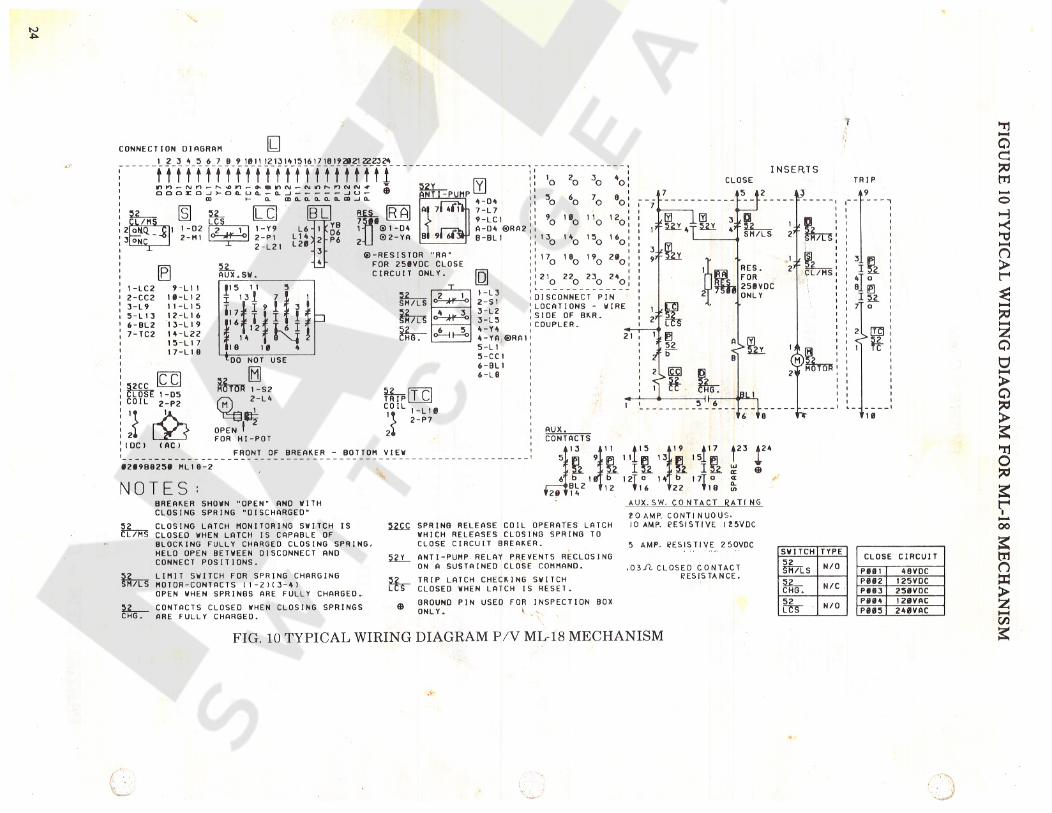
A typical POWER/VAC circuit breaker ML-18 mechanismwiring diagram is shown in Fig. 10. Check the wiring dia-gram supplied with the actual circuit breaker for its wiring.
The close spring charging motor circuit is establishedthrough the CL/MS switch if the close latch is reset and theSM/LS switch if the closing spring is discharged. When theclosing spring is charged, the SM/LS interrupts the circuit.
The close coil circuit is established through two nor-mally closed 52Y relay contacts, and the latch checkingswitch LCS, if the trip latch is reset. An auxiliary switchcontact 52b is also in series with the close coil and closeswhen the breaker is open and opens when the breaker isclosed. During a close operation, cam rotation closes theSM/LS contact allowing the 52Y relay to be energized;opening its contacts in the close coil circuit and sealing itselfin through one of its own contacts to the close signal. Thisseal-in action prevents reclosing on a sustained close com-mand as the close signal must be removed to drop out theY relay and reestablish the closing circuit, thereby provid-ing an anti-pump feature.
7.4. SLOW CLOSING
To manually slow close the breaker contacts, installthe closing spring gag, as described above, then put themanual charge handle on the manual charge lever and movethe handle up and down. The breaker will be fully closedwhen the spring charge indicator shows “CHARGED”.
CAUTION: WITH THE GAG PLATE INSTALLED,THE BREAKER CLOSED, AND OPENING SPRINGSCHARGED, THE BREAKER CAN BE TRIPPED ATFULL SPEED.
Circuit breaker-mounted auxiliary switch contacts notused in the control circuit are brought out for control andindication functions. The metalclad equipment may providea breaker-operated stationary auxiliary switch for additionalcontacts.
7.5. GAG PLATE REMOVAL7. MECHANICAL CHECKING AND SLOW CLOSING
To remove the gag plate, the closing spring must befully charged. If the spring charge indicator does not show“CHARGED” in the window, manually charge the springuntil it does. Lift up and push in on the gag plate to clearthe detentes on the gag plate from the slots in the closingspring guide While holding the gag plate up, remove it fromthe opening. Close the gag hole cover. For safety’, first closethe breaker by depressing the manual “CLOSE” button andthen depress the manual “TRIP” button. All stored energy isnow removed from the breaker.
7.1. VISUAL INSPECTION
Visually inspect the circuit breaker for any signs of damageor loose hardware.
7.2. CLOSING SPRING CHARGING
Manually charge the breaker closing spring using thecharging handle provided (1, Fig.5). The closing spring ischarged by a ratcheting mechanism that advances by oneratchet tooth at a time When the spring is fully chargedand the spring load is held by the closing latch, the spring
5
8. DIMENSIONAL CHECKS properly adjusted breaker will have more gap and wipe onthe center pole than on the outside poles.
With the breaker closed and the gag plate installed, per-form the following dimensional checks: The following dimensional checks are made in the oper-
ating mechanism which is accessible from the bottom. To ac-commodate these checks, the breaker should be turned onits right side resting on two-by-four wood blocks. DO NOTuse the portable breaker lift truck. CAUTION: Do not allowanything to come in contact with the interlock roller on theright side of the mechanism.
8.1. PRIMARY CONTACT EROSION
In the closed position, the erosion disk (5, Fig.7) belowthe operating rod insulator is aligned with a reference arm(4, Fig.7) on new interrupters. As contact erosion occurs,the erosion disk will move upward from alignment with thatreference arm. When erosion reaches1/8 inch, the POWER/VAC* interrupters should be replaced. DO NOT READJUSTTHE ALIGNMENT OF THE EROSION INDICATORARM EXCEPT WHEN INSTALLING A NEW VACUUMINTERRUPTER.
8.4. CLOSE COIL PLUNGER GAP
The close coil plunger gap is shown in Figure 21. Withthe closing spring discharged, operate the plunger to makecertain that the plunger moves freely over its full strokein the coil. To check the closing coil plunger gap thebreaker should be open and the closing spring charged andgagged. Dimension C is obtained by depressing the closeplunger button until resistance is felt. The gap between theplunger button and the coil housing should be between 0.25and 0.30 of an inch.
8.2. SPRING WIPE
With the breaker closed and the closing spring gagged,measure with a feeler gauge and record the distance betweenthe top of the wipe indicator and the bottom of the erosiondisk for each phase (see Figure 26, Dimension W). Trip thebreaker with the closing spring gag plate still installedand measure and record the distance between the wipe in-dicator and erosion disk. Subtract the closed position meas-urement from the open position measurement. The result isthe amount of wipe on each individual pole The wipe is tobe greater than 0.075 inch. Adjustment is not required untilwipe is 0.075 inch or less. If adjustment is required seeWIPE ADJUSTMENT in MECHANICAL ADJUSTMENTSsection.
8.5. TRIP COIL PLUNGER GAP
The trip coil plunger gap is shown in Figure 25. Withthe breaker in the open position and the closing spring inthe charged position, make certain that the trip linkage andtrip shaft move freely over the full plunger travel. Tocheck the trip coil plunger gap adjustment, the breaker isto be closed with the closing spring discharged. Dimension Tbetween the plunger button and the coil housing should bebetween 0.20 and 0.25 inch. This dimension is obtainedwhen the trip plunger button is depressed until resistance is
felt. If the breaker is equipped with an optional secondtrip coil, use same procedure
The ML-18 mechanism is furnished with very low gradientwipe springs so that adjustment is not a precision operationand considerable loss of wipe can be tolerated without af-fecting performance
8.6. CONTROL SWITCH ADJUSTMENT8.3. CONTACT GAPThe breaker is to be in the open position with the opening
and closing springs discharged. This results in the controlswitch plungers being in the depressed position. The switchesto be checked are shown in Figure 24. On the LCS andstacked switches (SM/LS & CHG), the plunger rod is to berecessed within the rear of the switch body and this recessis to be 0 to 1/32 inch. This is a visual check. The CL/MSswitch with wiring terminals on the side is to be adjustedas described above. For the CL/MS switch with wiringterminals on the rear the plunger is set to a dimension of0.99 to 1.01" from its mounting bracket. The breaker cannow be placed in its normal upright position.
The method of measuring the contact gap is as follows:With the breaker in the open position, the closing springscharged, and the closing spring gag plate installed, apply apiece of masking tape to the surface of the operating rodinsulator as shown in Figure 22. Using a reference block,make a mark on the tape near the top on all three poles. Itis also advisable to put a reference mark on the tape to iden-tify to which pole the tape is applied. Remove the closingspring gag plate and close the breaker. Using the sameprocedure as above, re-mark the tape This new mark will benear the bottom of the tape Trip the breaker, remove thetapes and re-apply them to a flat surface Measure thedistance between the two lines. A caliper will give an ac-curate reading of the contact gap, Dimension G. The gapsmust be between the 0.60 inch maximum and 0.54 inch min-imum. It is not necessary that all readings correspond. A
6
9.2.2. SECONDARY CIRCUIT9. ELECTRICAL CHECKS
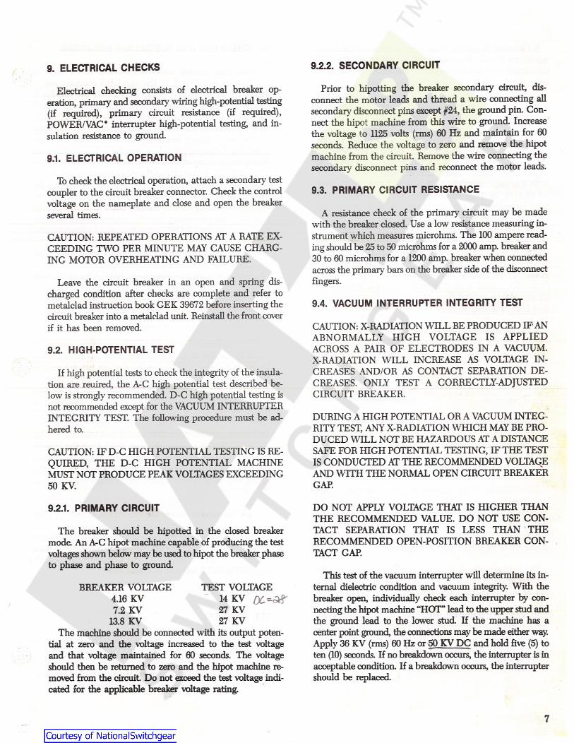
Prior to hipotting the breaker secondary circuit, dis-connect the motor leads and thread a wire connecting allsecondary disconnect pins except #24, the ground pin. Con-nect the hipot machine from this wire to ground. Increasethe voltage to 1125 volts (rms) 60 Hz and maintain for 60seconds. Reduce the voltage to zero and remove the hipotmachine from the circuit. Remove the wire connecting thesecondary disconnect pins and reconnect the motor leads.
Electrical checking consists of electrical breaker op-eration, primary and secondary wiring high-potential testing(if required), primary circuit resistance (if required),POWER/VAC* interrupter high-potential testing, and in-sulation resistance to ground.
9.1. ELECTRICAL OPERATION
To check the electrical operation, attach a secondary testcoupler to the circuit breaker connector. Check the controlvoltage on the nameplate and close and open the breakerseveral times.
9.3. PRIMARY CIRCUIT RESISTANCE
A resistance check of the primary circuit may be madewith the breaker closed. Use a low resistance measuring in-strument which measures microhms. The 100 ampere read-ing should be 25 to 50 microhms for a 2000 amp. breaker and30 to 60 microhms for a 1200 amp. breaker when connectedacross the primary bars on the breaker side of the disconnectfingers.
CAUTION: REPEATED OPERATIONS AT A RATE EX-CEEDING TWO PER MINUTE MAY CAUSE CHARG-ING MOTOR OVERHEATING AND FAILURE.
Leave the circuit breaker in an open and spring dis-charged condition after checks are complete and refer tometalclad instruction book GEK 39672 before inserting thecircuit breaker into a metalclad unit. Reinstall the front coverif it has been removed.
9.4. VACUUM INTERRUPTER INTEGRITY TEST
CAUTION: X-RADIATION WILL BE PRODUCED IF ANABNORMALLY HIGH VOLTAGE IS APPLIEDACROSS A PAIR OF ELECTRODES IN A VACUUM.X-RADIATION WILL INCREASE AS VOLTAGE IN-CREASES AND/OR AS CONTACT SEPARATION DE-CREASES. ONLY TEST A CORRECTLY-ADJUSTEDCIRCUIT BREAKER.
9.2. HIGH-POTENTIAL TEST
If high potential tests to check the integrity of the insula-tion are reuired, the A-C high potential test described be-low is strongly recommended. D-C high potential testing isnot recommended except for the VACUUM INTERRUPTERINTEGRITY TEST. The following procedure must be ad-hered to.
DURING A HIGH POTENTIAL OR A VACUUM INTEG-RITY TEST, ANY X-RADIATION WHICH MAY BE PRO-DUCED WILL NOT BE HAZARDOUS AT A DISTANCESAFE FOR HIGH POTENTIAL TESTING, IF THE TESTIS CONDUCTED AT THE RECOMMENDED VOLTAGEAND WITH THE NORMAL OPEN CIRCUIT BREAKER
CAUTION: IF D-C HIGH POTENTIAL TESTING IS RE-QUIRED, THE D-C HIGH POTENTIAL MACHINEMUST NOT PRODUCE PEAK VOLTAGES EXCEEDING50 KV. GAP.
9.2.1. PRIMARY CIRCUIT DO NOT APPLY VOLTAGE THAT IS HIGHER THANTHE RECOMMENDED VALUE. DO NOT USE CON-TACT SEPARATION THAT IS LESS THAN THERECOMMENDED OPEN-POSITION BREAKER CON-TACT GAP.
The breaker should be hipotted in the closed breakermode. An A-C hipot machine capable of producing the testvoltages shown below may be used to hipot the breaker phaseto phase and phase to ground.
This test of the vacuum interrupter will determine its in-ternal dielectric condition and vacuum integrity. With thebreaker open, individually check each interrupter by con-necting the hipot machine “HOT” lead to the upper stud andthe ground lead to the lower stud. If the machine has acenter point ground, the connections may be made either way.Apply 36 KV (rms) 60 Hz or 50 KV DC and hold five (5) toten (10) seconds. If no breakdown occurs, the interrupter is inacceptable condition. If a breakdown occurs, the interruptershould be replaced.
TEST VOLTAGE14 KV27 KV27 KV
The machine should be connected with its output poten-tial at zero and the voltage increased to the test voltageand that voltage maintained for 60 seconds. The voltageshould then be returned to zero and the hipot machine re-moved from the circuit Do not exceed the test voltage indi-cated for the applicable breaker voltage rating.
BREAKER VOLTAGE4.16 KV7.2 KV
13.8 KV
7
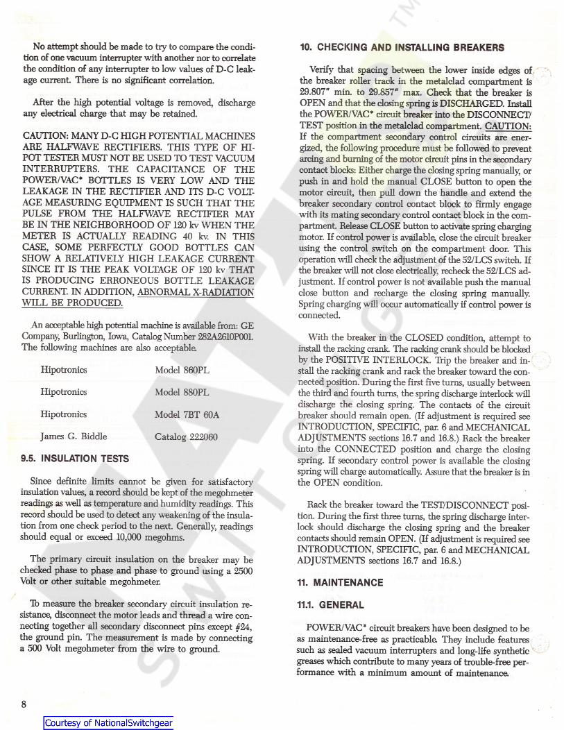
No attempt should be made to try to compare the condi-tion of one vacuum interrupter with another nor to correlatethe condition of any interrupter to low values of D-C leak-age current. There is no significant correlation.
10. CHECKING AND INSTALLING BREAKERS
Verify that spacing between the lower inside edges ofthe breaker roller track in the metalclad compartment is29.807" min. to 29.857" max. Check that the breaker isOPEN and that the closing spring is DISCHARGED. Installthe POWER/VAC* circuit breaker into the DISCONNECT/TEST position in the metalclad compartment. CAUTION:If the compartment secondary control circuits are ener-gized, the following procedure must be followed to preventarcing and burning of the motor circuit pins in the secondarycontact blocks: Either charge the closing spring manually, orpush in and hold the manual CLOSE button to open themotor circuit, then pull down the handle and extend thebreaker secondary control contact block to firmly engagewith its mating secondary control contact block in the com-partment. Release CLOSE button to activate spring chargingmotor. If control power is available, close the circuit breakerusing the control switch on the compartment door. Thisoperation will check the adjustment of the 52/LCS switch. Ifthe breaker will not close electrically, recheck the52/LCS ad-justment. If control power is not available push the manualclose button and recharge the closing spring manually.Spring charging will occur automatically if control power isconnected.
After the high potential voltage is removed, dischargeany electrical charge that may be retained.
CAUTION: MANY D-C HIGH POTENTIAL MACHINESARE HALFWAVE RECTIFIERS. THIS TYPE OF HI-POT TESTER MUST NOT BE USED TO TEST VACUUMINTERRUPTERS. THE CAPACITANCE OF THEPOWER/VAC* BOTTLES IS VERY LOW AND THELEAKAGE IN THE RECTIFIER AND ITS D-C VOLT-AGE MEASURING EQUIPMENT IS SUCH THAT THEPULSE FROM THE HALFWAVE RECTIFIER MAYBE IN THE NEIGHBORHOOD OF 120 kv WHEN THEMETER IS ACTUALLY READING 40 kv. IN THISCASE, SOME PERFECTLY GOOD BOTTLES CANSHOW A RELATIVELY HIGH LEAKAGE CURRENTSINCE IT IS THE PEAK VOLTAGE OF 120 kv THATIS PRODUCING ERRONEOUS BOTTLE LEAKAGECURRENT. IN ADDITION, ABNORMAL X-RADIATIONWILL BE PRODUCED.
An acceptable high potential machine is available from: GECompany, Burlington, Iowa, Catalog Number 282A2610P001.The following machines are also acceptable
With the breaker in the CLOSED condition, attempt toinstall the racking crank. The racking crank should be blockedby the POSITIVE INTERLOCK. Trip the breaker and in-stall the racking crank and rack the breaker toward the con-nected position. During the first five turns, usually betweenthe third and fourth turns, the spring discharge interlock willdischarge the closing spring. The contacts of the circuitbreaker should remain open. (If adjustment is required seeINTRODUCTION, SPECIFIC, par. 6 and MECHANICALADJUSTMENTS sections 16.7 and 16.8.) Rack the breakerinto the CONNECTED position and charge the closingspring. If secondary control power is available the closingspring will charge automatically. Assure that the breaker is inthe OPEN condition.
Hipotronics Model 860PL
Model 880PLHipotronics
Model 7BT 60AHipotronics
James G. Biddle Catalog 222060
9.5. INSULATION TESTS
Since definite limits cannot be given for satisfactoryinsulation values, a record should be kept of the megohmeterreadings as well as temperature and humidity readings. Thisrecord should be used to detect any weakening of the insula-tion from one check period to the next. Generally, readingsshould equal or exceed 10,000 megohms.
Rack the breaker toward the TEST/DISCONNECT posi-tion. During the first three turns, the spring discharge inter-lock should discharge the closing spring and the breakercontacts should remain OPEN. (If adjustment is required seeINTRODUCTION, SPECIFIC, par. 6 and MECHANICALADJUSTMENTS sections 16.7 and 16.8.)The primary circuit insulation on the breaker may be
checked phase to phase and phase to ground using a 2500Volt or other suitable megohmeter. 11. MAINTENANCE
To measure the breaker secondary circuit insulation re-sistance, disconnect the motor leads and thread a wire con-necting together all secondary disconnect pins except #24,the ground pin. The measurement is made by connectinga 500 Volt megohmeter from the wire to ground.
11.1. GENERAL
POWTSR/VAC* circuit breakers have been designed to beas maintenance-free as practicable They include featuressuch as sealed vacuum interrupters and long-life syntheticgreases which contribute to many years of trouble-free per-formance with a minimum amount of maintenance
8

CEDENTAL TRIPPING. DO NOT WORK ON THEBREAKER WHILE THE CLOSING SPRING ISCHARGED UNLESS IT IS SECURED IN THAT POSI-TION BY THE CLOSING-SPRING GAG.
POWER/VAC* INTERRUPTER
The POWER/VAC* interrupter used in this breaker is areliable, clean interrupting element. Since the contacts arecontained in a vacuum chamber, they remain clean and re-quire no maintenance at any time The metallic vapors erodedfrom the contact surfaces during high current interruptionremain in the chamber and are deposited on metal shieldsthus insuring a high dielectric value of the vacuum and thewalls of the interrupter.
11.3. FAULT INTERRUPTIONS
The erosion rate of the primary contacts in the vacuuminterrupters is very low for no-load and normal load switch-ing operations. However, fault current interruptions at ornear the breaker rating may result in appreciable contacterosion. With frequent fault interruptions it is necessary toperform maintenance based on the number of interruptions.After each 15 fault interruptions the following should beperformed:
TROUBLE REPORTING
Although all reputable manufacturers design their prod-ucts to perform satisfactorily with a minimum of problems,the IEEE Switchgear Committee, an organization of bothusers and manufacturers, recognized the need for a com-mon trouble reporting format. A reproducible copy of thisform is included inside the rear cover of this book and is rec-ommended for use with any manufacturer’s circuit breakers.
1. Contact erosion check.2. Wipe and gap check.3. Vacuum interrupter integrity test.
11.4. CONTACT EROSIONThe intent is for each maintenance organization to keep
specific problem files with this information documented. Ifthe problem is serious or repetitive, a summary should besent to the appropriate manufacturer for action. Thelevel of detail included on the form is considered verydesirable so that the manufacturer’s investigator may morethoroughly understand and solve the reported problem.
Check in the breaker-closed condition per PRIMARYCONTACT EROSION section 8.1. When erosion reaches1/8inch, the interrupter should be replaced.
11.5. TRANSFER FINGER WEAR
With the breaker open, examine the moving contact rodprojecting below the transfer fingers (10, Fig.8). Wipe offthe lubricant in order to see the metal surface condition. Thefinger locations should present a burnished silver contactwithout copper appearance at more than one location. Ifcopper is visible at more than one location per pole or thesilver plating is tom, the interrupter assembly should bereplaced. Relubricate with 0282A2048 P009.
11.2. SERVICE CONDITIONS
The frequency of required maintenance depends on theseverity of the service conditions of the switchgear applica-tion. If the service conditions are mild, the interval betweenmaintenance operations may be extended to 10 years or10,000 no load or normal load switching operations.
11.6. MECHANISMMild service conditions are defined as an environment inwhich the switchgear is protected from the deleterious ef-fects of conditions such as:
Salt sprayChanges in temperature that produce condensationConductive and/or abrasive dustDamaging chemicals and fumesVibration or mechanical shockHigh relative humidity (90 % )Temperature extremes (below -30 C or above + 40 C)
Check all items covered in INSTALLATION and read-just or tighten hardware as required. Lubricate as recom-mended under LUBRICATION.
11.7. PRIMARY INSULATION PARTS
Using dry, non-linting cloth or industrial-type wipers, deanaccessible insulation surfaces on the interrupter supports andoperating rod insulators. In service locations where contami-nation is heavy or external flashovers, have occurred duringinterrupter high-potential testing, remove the interrupterassemblies per the procedure in REPAIR AND REPLACE-MENT and clean the inside surfaces of the interrupter sup-ports and the outer insulation surfaces of the POWER/VAC*interrupters. Be sure to discharge the interrupter midbandring before removing the interrupter assemblies. Removal and
BEFORE ANY MAINTENANCE WORK IS PER-FORMED, MAKE CERTAIN THAT ALL CONTROLCIRCUITS ARE DE-ENERGIZED AND THAT THEBREAKER IS REMOVED FROM THE METALCLADUNIT. DO NOT WORK ON THE BREAKER OR MECH-ANISM WHILE IT IS IN THE CLOSED POSITIONWITHOUT TAKING PRECAUTIONS TO PREVENT AC-
9
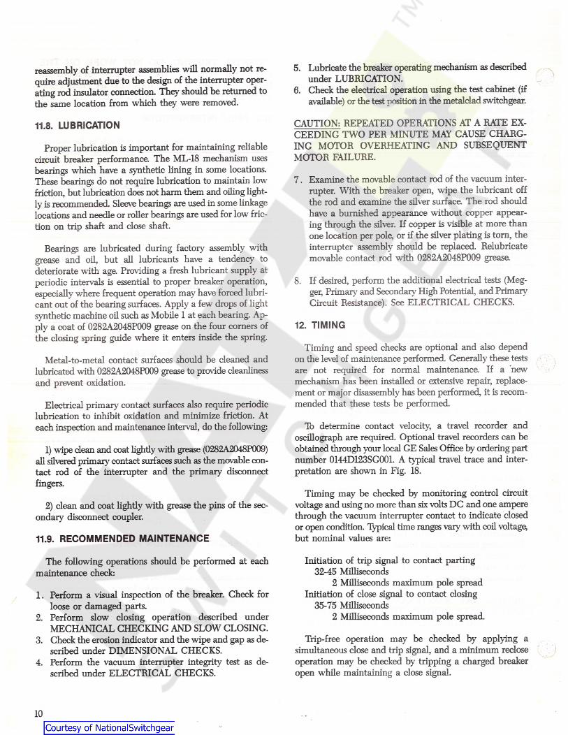
5. Lubricate the breaker operating mechanism as describedunder LUBRICATION.
6. Check the electrical operation using the test cabinet (ifavailable) or the test position in the metalclad switchgear.
reassembly of interrupter assemblies will normally not re-quire adjustment due to the design of the interrupter oper-ating rod insulator connection. They should be returned tothe same location from which they were removed.
CAUTION: REPEATED OPERATIONS AT A RATE EX-CEEDING TWO PER MINUTE MAY CAUSE CHARG-ING MOTOR OVERHEATING AND SUBSEQUENTMOTOR FAILURE.
11.8. LUBRICATION
Proper lubrication is important for maintaining reliablecircuit breaker performance. The ML-18 mechanism usesbearings which have a synthetic lining in some locations.These bearings do not require lubrication to maintain lowfriction, but lubrication does not harm them and oiling light-ly is recommended. Sleeve bearings are used in some linkagelocations and needle or roller bearings are used for low fric-tion on trip shaft and close shaft.
7. Examine the movable contact rod of the vacuum inter-rupter. With the breaker open, wipe the lubricant offthe rod and examine the silver surface. The rod shouldhave a burnished appearance without copper appear-ing through the silver. If copper is visible at more thanone location per pole, or if the silver plating is tom, theinterrupter assembly should be replaced. Relubricatemovable contact rod with 0282A2048P009 grease
Bearings are lubricated during factory7 assembly withgrease and oil, but all lubricants have a tendency todeteriorate with age Providing a fresh lubricant supply atperiodic intervals is essential to proper breaker operation,especially where frequent operation may have forced lubri-cant out of the bearing surfaces. Apply a few drops of lightsynthetic machine oil such as Mobile1 at each bearing. Ap-ply a coat of 0282A2048P009 grease on the four corners ofthe closing spring guide where it enters inside the spring.
8. If desired, perform the additional electrical tests (Meg-ger, Primary7 and Secondary7 High Potential, and PrimaryCircuit Resistance). See ELECTRICAL CHECKS.
12. TIMING
Timing and speed checks are optional and also dependon the level of maintenance performed. Generally these testsare not required for normal maintenance. If a newmechanism has been installed or extensive repair, replace-ment or major disassembly has been performed, it is recom-mended that these tests be performed.
Metal-to-metal contact surfaces should be cleaned andlubricated with 0282A2048P009 grease to provide cleanlinessand prevent oxidation.
Electrical primary7 contact surfaces also require periodiclubrication to inhibit oxidation and minimize friction. Ateach inspection and maintenance interval, do the following: To determine contact velocity, a travel recorder and
oscillograph are required. Optional travel recorders can beobtained through your local GE Sales Office by ordering partnumber 0144D123SG001. A typical travel trace and inter-pretation are shown in Fig. 18.
1) wipe dean and coat lightly with grease (0282A2048P009)all silvered primary contact surfaces such as the movable con-tact rod of the interrupter and the primary disconnectfingers.
Timing may be checked by monitoring control circuitvoltage and using no more than six volts DC and one amperethrough the vacuum interrupter contact to indicate closedor open condition. Typical time ranges vary with coil voltage,but nominal values are:
2) clean and coat lightly with grease the pins of the sec-ondary disconnect coupler.
11.9. RECOMMENDED MAINTENANCE
The following operations should be performed at eachmaintenance check:
Initiation of trip signal to contact parting32-45 Milliseconds
2 Milliseconds maximum pole spreadInitiation of close signal to contact closing
35-75 Milliseconds2 Milliseconds maximum pole spread.
1. Perform a visual inspection of the breaker. Check forloose or damaged parts.
2. Perform slow closing operation described underMECHANICAL CHECKING AND SLOW CLOSING.
3. Check the erosion indicator and the wipe and gap as de-scribed under DIMENSIONAL CHECKS.
4. Perform the vacuum interrupter integrity test as de-scribed under ELECTRICAL CHECKS.
Trip-free operation may be checked by applying asimultaneous close and trip signal, and a minimum recloseoperation may be checked by tripping a charged breakeropen while maintaining a close signal.
!
10
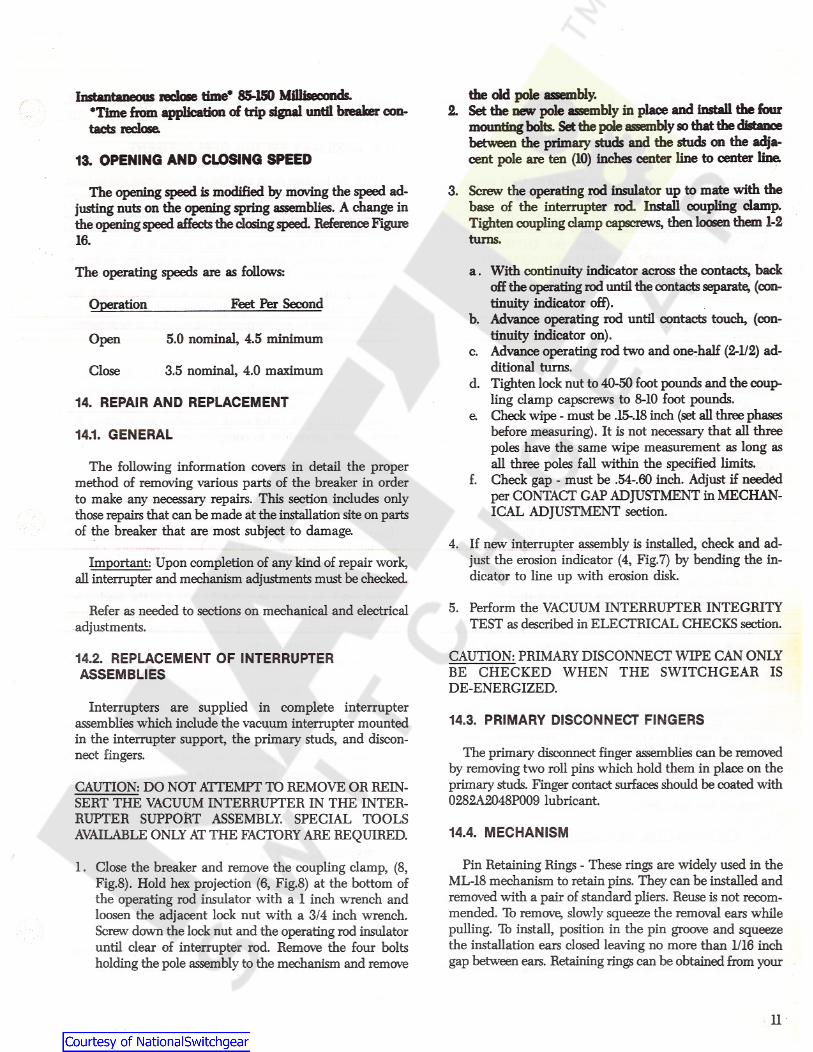
the old pole assembly.2. Set the new pole assembly in place and install the four
mounting bolts. Set die pole assembly so that the distancebetween the primary studs and the studs on the adja-cent pole are ten (10) inches center line to center line
3. Screw the operating rod insulator up to mate with thebase of the interrupter rod. Install coupling damp.Tighten coupling clamp capscrews, then loosen than 1-2turns.
Instantaneous redose time* 85-150 Milliseconds.•Time from application of trip signal until breaker con-tacts redose
13. OPENING AND CLOSING SPEED
The opening speed is modified by moving the speed ad-justing nuts on the opening spring assemblies. A change inthe openingspeed affects the dosingspeed. Reference Figure16.
a . With continuity indicator across the contacts, backoff the operating rod until the contacts separate, (con-tinuity indicator off).
b. Advance operating rod until contacts touch, (con-tinuity indicator on).
c. Advance operating rod two and one-half (2-1/2) ad-ditional turns.
d. Tighten lock nut to 40-50 foot pounds and the coup-ling clamp capscrews to 8-10 foot pounds.
e. Check wipe - must be .15-.18 inch (set all three phasesbefore measuring). It is not necessary that all threepoles have the same wipe measurement as long asall three poles fall within the specified limits.
f. Check gap - must be .54-.60 inch. Adjust if neededper CONTACT GAP ADJUSTMENT in MECHAN-ICAL ADJUSTMENT section.
The operating speeds are as follows:
Feet Per SecondOperation
5.0 nominal, 4.5 minimumOpen
3.5 nominal, 4.0 maximumClose
14. REPAIR AND REPLACEMENT
14.1. GENERAL
The following information covers in detail the propermethod of removing various parts of the breaker in orderto make any necessary repairs. This section includes onlythose repairs that can be made at the installation site on partsof the breaker that are most subject to damage.
4. If new interrupter assembly is installed, check and ad-just the erosion indicator (4, Fig.7) by bending the in-dicator to line up with erosion disk.
Important: Upon completion of any kind of repair work,all interrupter and mechanism adjustments must be checked.
5. Perform the VACUUM INTERRUPTER INTEGRITYTEST as described in ELECTRICAL CHECKS section.
Refer as needed to sections on mechanical and electricaladjustments.
CAUTION: PRIMARY DISCONNECT WIPE CAN ONLYBE CHECKED WHEN THE SWITCHGEAR ISDE-ENERGIZED.
14.2. REPLACEMENT OF INTERRUPTERASSEMBLIES
Interrupters are supplied in complete interrupterassemblies which include the vacuum interrupter mountedin the interrupter support, the primary studs, and discon-nect fingers.
14.3. PRIMARY DISCONNECT FINGERS
The primary disconnect finger assemblies can be removedby removing two roll pins which hold them in place on theprimary studs. Finger contact surfaces should be coated with0282A2048P009 lubricant.
CAUTION: DO NOT ATTEMPT TO REMOVE OR REIN-SERT THE VACUUM INTERRUPTER IN THE INTER-RUPTER SUPPORT ASSEMBLY. SPECIAL TOOLSAVAILABLE ONLY AT THE FACTORY ARE REQUIRED. 14.4. MECHANISM
Pin Retaining Rings - These rings are widely used in theML-18 mechanism to retain pins. They can be installed andremoved with a pair of standard pliers. Reuse is not recom-mended. To remove, slowly squeeze the removal ears whilepulling. To install, position in the pin groove and squeezethe installation ears closed leaving no more than 1/16 inchgap between ears. Retaining rings can be obtained from your
1. Close the breaker and remove the coupling clamp, (8,Fig.8). Hold hex projection (6, Fig.8) at the bottom ofthe operating rod insulator with a 1 inch wrench andloosen the adjacent lock nut with a 3/4 inch wrench.Screw down the lock nut and the operating rod insulatoruntil clear of interrupter rod. Remove the four boltsholding the pole assembly to the mechanism and remove
11
travel in accordance with instructions in MECHANICALADJUSTMENTS section under CLOSE COIL PLUNGER.
local GE Sales office by ordering part number0282A2015G001.
14.8. AUXILIARY SWITCH REPLACEMENT14.5. CONTROL SWITCHES
With the breaker open and the closing spring discharged,remove retaining clip from auxiliary switch shaft, or loosenclamping bolt in operating link. Observe and make note ofthe direction of the index mark on the end of the shaft andthe position of the operating link in relation to thestop screw.Remove mounting hardware securing auxiliary switch tomechanism plate. Slide auxiliary switch and shaft out ofoperating link. Before removing any wires from switch ter-minals, make sure they are properly tagged with switch ter-minal numbers to assure proper placement on new switch.Remove wires.
Control switches may be removed from their mountingbrackets by disconnecting the wires and removing themounting hardware When replacing the switches, checkthat the correct type, normally open or normally closed, isused. Reinstall, wire, and adjust per DIMENSIONALCHECKS - CONTROL SWITCH ADJUSTMENT.
14.6. TRIP COIL REPLACEMENT
TOOLS REQUIRED5 /16 " Allen wrench
Needle nose pliers7/16" Socket wrench7/16" Box/combination wrench
Square drive ratchetSquare 3" extensionLoctite #271 or equivalent
To install new switch, attach leads then install switch, orinstall switch then attach leads depending upon type ofswitch and its terminal accessibility. Install switch shaft inoperating link with index mark aligned as noted above. Re-verse above procedure to complete installation.
1/4"1/4"
14.9. MOTOR REPLACEMENTPerform the operation in the following sequence:
With the breaker open and the closing spring discharged,remove auxiliary switch as described above but do notdisconnect leads. Move switch toward side of mechanism farenough to clear motor and tie there temporarily. Discon-nect motor leads. Remove the long bolt and spacer securingthe motor to the mechanism mid-plate. Remove the twosocket head cap screws securing the motor to the mechanismtop plate using a 5/16" alien socket and a 24" extension.Disengage the motor output shaft from the charge linkagearms and withdraw motor.
To install the new motor, reverse the above procedure.
1. Charge closing spring and install gag plate.2. Depress the close and then the trip buttons.3. Pump the manual close handle 3 - 4 times.4. With the 5/16" Allen wrench, remove the pivot bolt (10,
Fig.15) on the closing spring (1, Fig.15).5. Remove the closing spring.6. Disconnect the trip linkage tension spring.7. Loosen the interlock bracket (11, Fig.15).8. Remove the 4 bolts from the coil bracket leaving the two
bolts nearest the front of the breaker in place in themechanism frame.
9. Cut coil leads and remove the coil and armature.14.10. “Y” RELAY REPLACEMENT
To install the new coil, reverse the above procedure andconnect leads with insulated butt connectors. See TRIPCOIL PLUNGER in MECHANICAL ADJUSTMENTS sec-tion for setting the stroke of the armature. Apply Loctite tothe threads of the pivot bolt (10, Fig.15) when it is replaced.Charge the breaker and electrically close and trip it to makecertain it has been reassembled correctly.
Before removing the “Y” relay, make sure all leads aremarked with terminal locations. Next, disconnect all leadsand remove the two fasteners securing the “Y” relay’s shockabsorbing mounting bracket to the mechanism rear plate.Withdraw relay and bracket. Remove fasteners securing relayto mounting bracket.
Reverse above procedure to install new relay.14.7. CLOSING COIL REPLACEMENT
15. RENEWAL PARTSDisconnect the close linkage tension spring then remove
the retaining ring from the close linkage pivot pin (17, Fig.15)and disconnect the linkage Remove the closing coil and hous-ing (6, Fig.15). Cut the leads to the closing coil and removethe coil. Reassemble the coil and housing with armature andbutt-splice the new coil into the wiring harness. Reassem-ble linkage and spring. Readjust the closing coil armature
It is recommended that sufficient renewal parts be car-ried in stock to enable the prompt replacement of any worn,broken or damaged parts. A stock of such parts minimizesservice interruptions caused by breakdowns, and saves timeand expense. When continuous operation is a primary con-sideration, more renewal parts should be carried, the amount
12
1. Loosen, but do not remove, the two capscrews (9, Fig.8)holding the interrupter clamp.
depending upon the severity of the service and the time re-quired to secure replacements.
2. Check that the interrupter clamp is loose A light pryat the clamp half-junction may be required to loosen thewedging action of the clamp.
3. Hold the hexagon projection (6, Fig.8) at the bottom ofthe operating rod insulator (1 inch wrench) and loosenthe adjacent locknut (3/4 inch wrench). (Refer to 4,Fig.8). Adjust by rotating the operating rod insulator. Thethread is1/2-13 and each turn will give about 0.078 inchchange in primary wipe. Screw the operating rod in-sulator toward the interrupter to increase wipe.
Renewal parts which are furnished may not be identicalto the original parts, but they will be interchangeable.
A separate Renewal Parts Bulletin is available from yourlocal GE Sales office by asking for GEK 90218.
15.1. ORDERING INSTRUCTIONS
1. Always specify the complete nameplate date of both thebreaker and the mechanism.
2. Specify the quantity, catalog number (if listed), referencenumber (if listed), and description of each part ordered, andthe parts bulletin number.
4. After setting the contact wipe on each phase, torque theoperating rod locknut (4, Fig.8) to 40-50 foot poundswhile holding the hex projection (6) to prevent theoperating rod insulator (7) from turning. Tighten theclamp screws (9) to 8-10 foot pounds and trip the breakeropen. This procedure prevents accidental twisting of theinterrupters operating rod by loading the contacts withthe wipe springs and forcing relative rotation to occurat the clamp interface.
3. Standard hardware, such as screws, bolts, nuts, washers,etc. is not listed in this bulletin. Such items should be pur-chased locally.
4. For prices or information on parts not listed in theRenewal Parts Bulletin, refer to the nearest GE office.
After adjustment, remeasure the wipe dimensions. If thewipe settings are within the required limits, there is an ade-quate contact closing relationship between the poles.
16. MECHANICAL ADJUSTMENTS
16.1 GENERAL
16.3. CONTACT GAP ADJUSTMENTThe ML-18 Mechanism has been designed for extendedintervals between maintenance In most cases only the wipeand gap adjustments will require re-setting throughout thelife of the circuit breaker.
The gap adjustment refers to the separation, or gap, be-tween the primary contacts within the vacuum interrupter.Before attempting to measure or set the gap adjustment,verify that the wipe settings are within acceptable limits.Any change of the wipe settings will affect the gap settings.
16.2. WIPE ADJUSTMENT
Wipe is the additional compression of a preloaded spring,used to apply force to the vacuum interrupter contacts andto provide opening kick-off force.
1. With the breaker in the open position and the closingspring discharged, locate the gap adjusting nuts on theopening spring rods connected to the outer phase bellcranks (Fig.16). Loosen the jam nut on both rods. Backoff the adjusting bolt on the center phase VI stop (Fig.16).An indicator is provided on the wipe spring assembly with
graduations given in 0.05 inch on which the wipe is indicateddirectly. See Figure 8.
2. Advance or retard the adjusting nuts depending on whichway you want to change the gap. Move both nuts thesame amount.
Improved accuracy of the wipe measurement may be ob-tained by using a feeler gauge between the top of the wipeindicator and the erosion disk. The difference in readingson each pole with the breaker closed and open is the con-tact wipe Adjustment not required if wipe is more than0.075 inch. After adjustment the wipe should be 0.15-0.18inch.
3. Lock the jam nuts after setting the adjusting nuts.Operate the breaker a few times and remeasure the gapfollowing the procedure described in DIMENSIONALCHECKS, item 3.
To adjust the primary contact wipe, close the breaker andproceed as follows:
4. Readjust the center phase VI stop (Figure 16). Set ad-justing screw for no clearance between stop and wipespring rod striker with the breaker open.
13
16.7. CLOSE SPRING DISCHARGE INTERLOCK16.4. TRIP COIL PLUNGER
THIS INTERLOCK IS FACTORY SET AND SHOULDNOT BE ROUTINELY ADJUSTED IN THE FIELD. Theadjustment for this interlock is as follows. (See Fig. 17).
To adjust trip coil plunger gap (Figure 25), lift locktabaway from adjusting nut. TUm adjusting nut until trip pinmakes contact with trip arm while maintaining dim. T. Bendlocktab to secure adjusting nut.
Reference DIMENSIONAL CHECKS for breaker posi-tion and spring status.
The breaker should be open with the closing springcharged.
1. Back off 1/4 inch linkage adjusting screw.16.5. CLOSE COIL PLUNGER
2. While holding roller at 0.995 inch dim., advance ad-justing screw to just touch interlock lever.To adjust close coil plunger gap (Figure 21), lift locktab
away from adjusting nut. Turn adjusting nut until close latchactuator makes contact with close latch while maintainingdim. C. Bend locktab to secure adjusting nut.
Reference DIMENSIONAL CHECKS for breaker posi-tion and spring status.
3. Check that spring discharges with roller at 0.561 inchmin. dim.
4. Close latch must reset as indicated.16.6. CLOSE LATCH STOP BOLT
16.8. NEGATIVE INTERLOCKSHOULD NOT BE ROUTINELY ADJUSTED - WILL
AFFECT CLOSE SPRING DISCHARGE INTERLOCKSETTING.
THIS INTERLOCK IS FACTORY-SET AND SHOULDNOT BE ROUTINELY ADJUSTED IN THE FIELD. Thenegative interlock is adjusted with the breaker closed andthe closing spring discharged. (See Fig. 20)This adjustment is shown in Figure 23 and is obtained
with the breaker in the open position and the closing springcharged. The setting is checked by advancing the adjustingscrew until the breaker closes. Back adjusting screw off 1/2turn (3 flats). Check function by opening the breaker andcharging the closing spring. If the latch slips off the rollerand the breaker closes, back the adjusting screw off 1 addi-tional flat. Check function.
1. Hold roller at 0.670 inch from mechanism side plate Ad-just linkage so the striker just makes contact with prop-erly adjusted trip linkage
2. Lock in place with 1/4 inch hardware and rivet.
3. Check that breaker trips with roller at 0.561 inch min.dim.
4. Check that linkage moves freely.
14
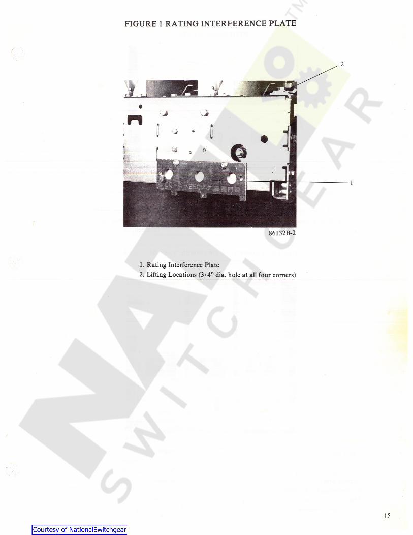
FIGURE 1 RATING INTERFERENCE PLATE
86132B-2
1. Rating Interference Plate2. Lifting Locations (3/ 4” dia. hole at all four corners)
15
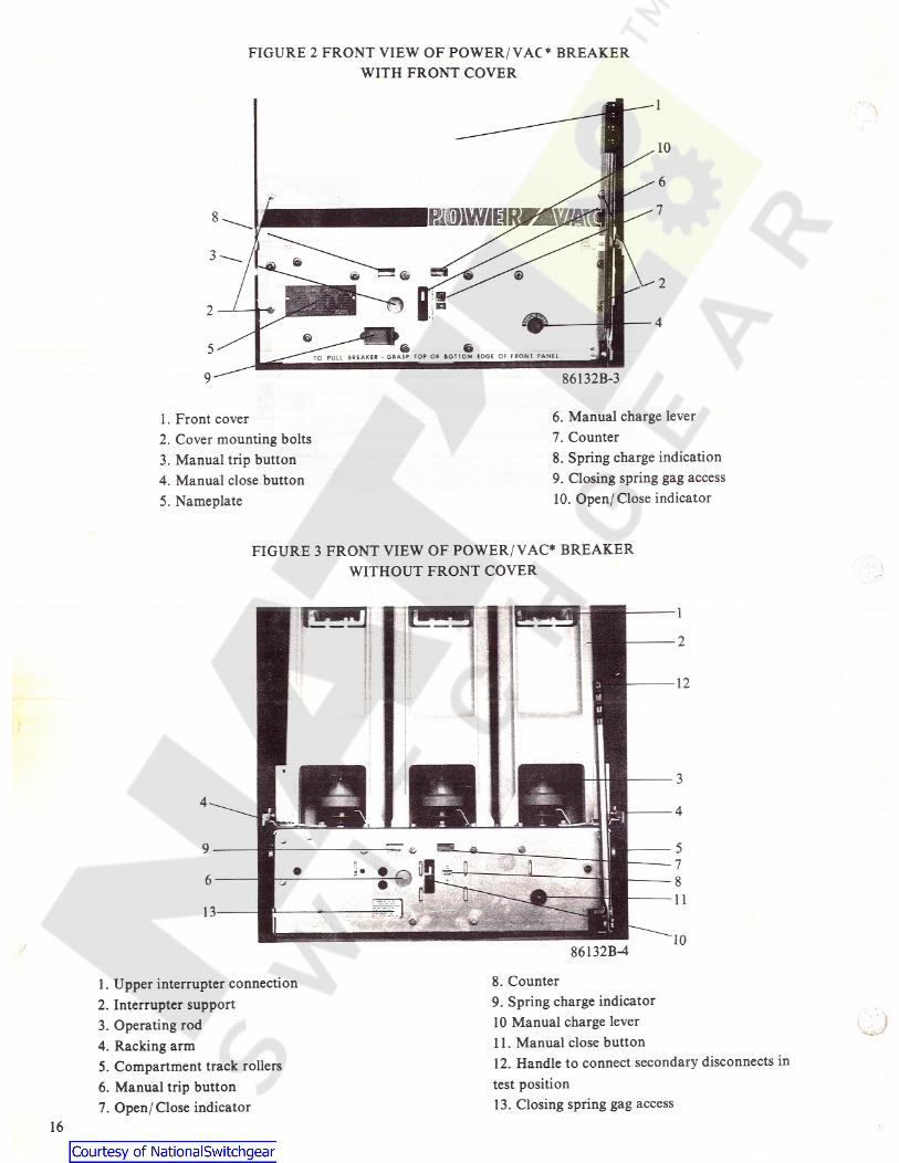
FIGURE 2 FRONT VIEW OF POWER/ VAC* BREAKERWITH FRONT COVER
8
3
2
5T O P U L L B R E A K E R - G R A S P T O P O R B O T T O M E D G E O F F R O N T P A N E L
9 86132B-3
6. Manual charge lever7. Counter8. Spring charge indication9. Closing spring gag access10. Open/ Close indicator
1. Front cover2. Cover mounting bolts3. Manual trip button4. Manual close button5. Nameplate
FIGURE 3 FRONT VIEW OF POWER/ VAC* BREAKERWITHOUT FRONT COVER
8. Counter9. Spring charge indicator10 Manual charge lever11. Manual close button12. Handle to connect secondary disconnects intest position13. Closing spring gag access
1. Upper interrupter connection2. Interrupter support3. Operating rod4. Racking arm5. Compartment track rollers6. Manual trip button7. Open/ Close indicator
j
16
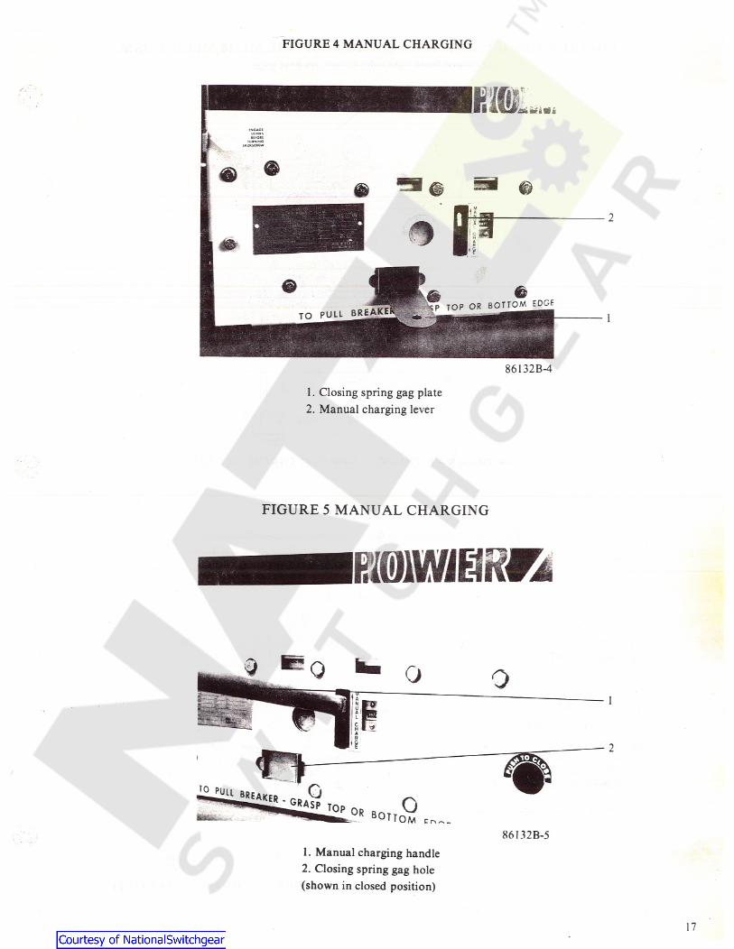
FIGURE 4 MANUAL CHARGING
2
1
86132B-41. Closing spring gag plate2. Manual charging lever
FIGURE 5 MANUAL CHARGING
niWJESRKi
o1
oB°T T O M86132B-5
1. Manual charging handle2. Closing spring gag hole(shown in closed position)
1 7
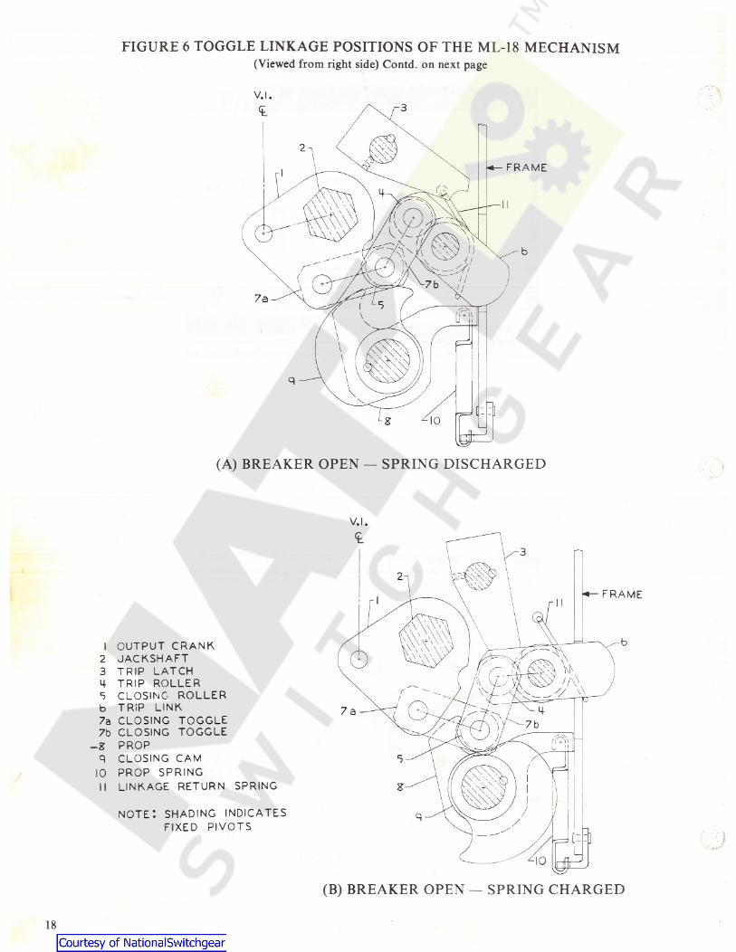
FIGURE 6 TOGGLE LINKAGE POSITIONS OF THE ML-18 MECHANISM(Viewed from right side) Contd. on next page
FRAME
(A) BREAKER OPEN — SPRING DISCHARGED }
FRAME
I OUTPUT CRANK2 JACKSHAFT3 TRIP LATCH4 TRIP ROLLER5 CLOSING ROLLERb TRIP LINK7a CLOSING TOGGLE7b CLOSING TOGGLE
-g PROPq CLOSING CAM
10 PROP SPRING11 LINKAGE RETURN SPRING
NOTE: SHADING INDICATESFIXED PIVOTS
( B) BREAKER OPEN — SPRING CHARGED
18
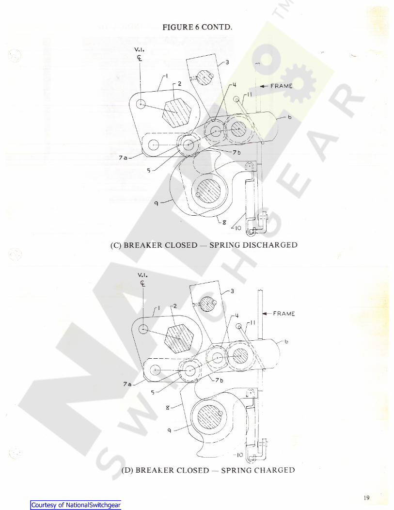
FIGURE 6 CONTD.
•*- F R A M E
(C) BREAKER CLOSED — SPRING DISCHARGED
F R A M E
(D) BREAKER CLOSED — SPRING CHARGED
19
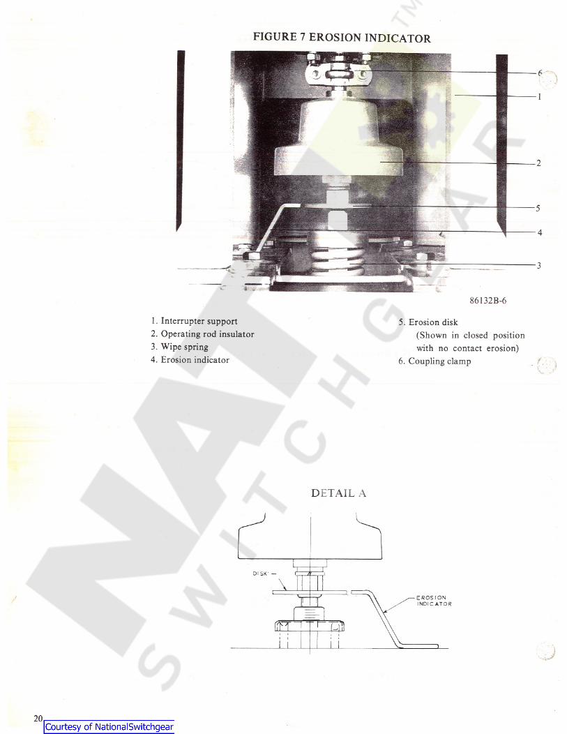
FIGURE 7 EROSION INDICATOR
6
2
5
4
3
86132B-6
1. Interrupter support2. Operating rod insulator3. Wipe spring4. Erosion indicator
5. Erosion disk(Shown in closed positionwith no contact erosion)
6. Coupling clamp
DETAIL A
DISK -
\r ] i;EROSIONINDICATOR
=nf f R iLi
20
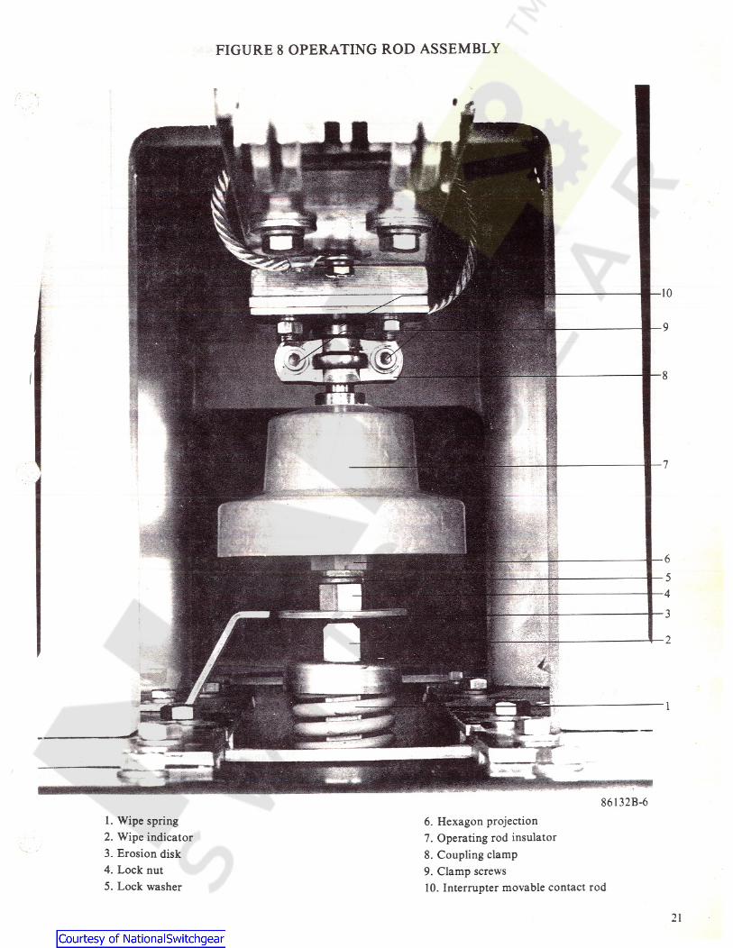
FIGURE 8 OPERATING ROD ASSEMBLY
86132B-61. Wipe spring2. Wipe indicator3. Erosion disk4. Lock nut5. Lock washer
6. Hexagon projection7. Operating rod insulator8. Coupling clamp9. Clamp screws10. Interrupter movable contact rod
21
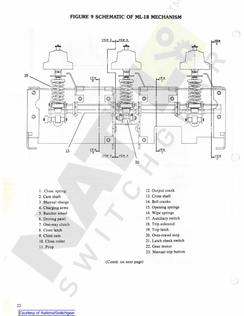
FIGURE 9 SCHEMATIC OF ML 18 MECHANISM
VIEW 0 VIEW A .VIEWEmfr
16 7PTi VIEW VIEWB C
0 ©© ©© © IdI
/ n al - -«-V f f r[ 01 1
J
© ©3a u a
; i i
CJ© ©
0VIEW VIEW13 B C/VIEW D VIEW A VIEW
E20
12. Output crank13. Cross shaft14. Bell cranks15. Opening springs16. Wipe springs17. Auxiliary switch18. Trip solenoid19. Trip latch20. Over-travel stop21. Latch check switch22. Gear motor23. Manual trip button
1. Close spring2. Cam shaft3. Manual charge4. Charging arms5. Ratchet wheel6. Driving pawl7. One-way clutch8. Close latch9. Close cam10. Close roller11. Prop
(Contd. on next page)
22
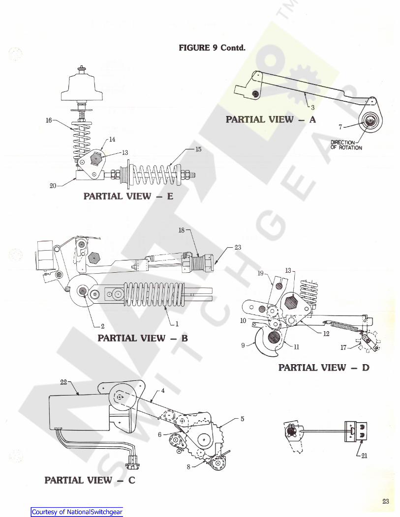
FIGURE 9 Contd.
*
3
PARTIAL VIEW - A7
DIRECTIONOF ROTATION15
I
PARTIAL VIEW - E
18V
23//
T-CHC-/ /
4: : 4
© 0
12
PARTIAL VIEW - B
PARTIAL VIEW - D22
*4
Ss“" su 5cjh ‘+ i i 9
? »i./
i\\ \\s V-t\
x
_-
•> ’i8Tire
PARTIAL VIEW - C
23
to
Y *T l0 oC O N N E C T I O N D I A G R A M
1 2 3 ^ 3 6 7 8 $ 1011 121314131617 10192021 222324 C?o*>• I N S E R T St t t t t t t t t t t t t t t t t t t t t t t t i 2_ 3 m4 T R I PC L O S E
52.1.. [Y]A N T I -P U M P 1—1
O O OOI D M — f\j n — r̂ 'o r) — ( •m e g —o o a x: o _i >- a a. u a. — a. _J 0 7 9— — _j u — 3 6 7 8C D a Q 1f l l C D J Q oC D a. 4 -D 47-L 79-L C 1A-0 4 ®R A 2B-B L 1
o o o oy r i f i^ 7
W.B3 1i f! ® i -D 4 j2-U ® 2 _ Y f i [?L
i & ra BL H3 2 .v L* S M /L S
9 1 1 1 2C L / M S2f a J A Q. r _£3 Q N C
O O OO 1' Y B1 1 - 0 2 22-M I '
1 - Y 92-P I2-L 2 1
1L6 - 11 9 7̂ 3*' 0 6O- A¥ O L 1 4 sL 2 0;
1 3 1 4 1 3 1 6P 62 O O oo3 . 4X 3 oR© - R E S I S T O R "R A "
F O R 2 5 0 V O C C L O S EC I R C U I T O N L Y .
l 7 1 8 1 9_ 2 0 9* ' 1 3iRa
O OO O4 >5 1_ 2* ’R E S .0 10 C L /M SA U X . S W . r2 1 2 2 2 3 2 4O O O O F O R 4
2 5 0 V D CO N L Y 0 1 0T9-L 1 I
1 0 -L 1 21 1-L 1 51 2-L 1 61 3-L I 91 4 -L 2 21 3-L I 71 7 -L 1 0
1 - L C22- C C 23-L 95-L 1 36-B L 27- T C 2
1-L 32-S I3-L 23-L 34- Y 44- Y A ©R A l5-L 13- C C 16- 9L 16- L 0
5 1 2 1 D I S C O N N E C T P I NL O C A T I O N S - W I R ES I D E O F B K R .C O U P L E R .
5 1o-̂ r—oS M / L S 7 o1 . 4 *342 1 "M T L S
¥ 3 26 2o—j |—o 2 1 . V i B: :; s2HOT o
^ b n oT O Rtccl2
r j f r >3 2C CH T§E 1 - o s
2-P21 - S 2
THTP |T C OIfI kO I L 3 ' 6C O I L 11 - L 1 02-P 71 r* >1 0
£A U X .O P E N TF O R H I - P O T 2 C O N T A C T S
( D C ) ( A C ) r̂ j1 3F R O N T O F B R E A K E R - B O T T O M V I E W 5;R ’ o0 2 0 9B 0 2 3 0 M L 1 8-2 *1 4' b6J b 1
N O T E S : B L 2 9 2 29 2 0 1 4A U X. S_W. C O N T A C T R A T I N G? 0 AMP. C O N T I N U O U S.1 0 AMP. R E S I S T I V E I 2 3V D C
B R E A K E R S H O W N " O P E N ' A N O W I T HC L O S I N G S P R I N G " D I S C H A R G E D *
C L O S I N G L A T C H M O N I T O R I N G S W I T C H I SL / M S C L O S E D W H E N L A T C H I S C A P A B L E O F
B L O C K I N G F U L L Y C H A R G E D C L O S I N G S P R I N G .H E L O O P E N B E T W E E N D I S C O N N E C T A N DC O N N E C T P O S I T I O N S .L I M I T S W I T C H F O R S P R I N G C H A R G I N G
/L S M O T O R - C O N T A C T S ( 1 - 2 1 ( 3- 4 )
O P E N W H E N S P R I N G S A R E F U L L Y C H A R G E D .C O N T A C T S C L O S E D W H E N C L O S I N G S P R I N G SA R E F U L L Y C H A R G E O .
r3 2 C C S P R I N G R E L E A S E C O I L O P E R A T E S L A T C H
W H I C H R E L E A S E S C L O S I N G S P R I N G T OC L O S E C I R C U I T B R E A K E R .
5 2 Y A N T I - P U M P R E L A Y P R E V E N T S R E C L O S I N BO N A S U S T A I N E D C L O S E C O M M A N D.T R I P L A T C H C H E C K I N G S W I T C HC L O S E D W H E N L A T C H I S R E S E T .G R O U N O P I N U S E O F O R I N S P E C T I O N B O XO N L Y .
00
£5 A M P. R E S I S T I V E 2 5 0V D CS W I T C H T Y P E MC L O S E C I R C U I T5 2 nN/ O.0 3 A C L O S E D C O N T A C T
R E S I S T A N C E. STTTLs 4 8 V 0CP 0 0 13f r X?hr 1 2 5 V D CP0 0 25 1C H G. N/C . >P0 0 3 2 5 0V O C
P 0 0 4 1 2 0V A C5 2 N / O01 1 LCS P0 0 5 2 4 0 V A Ck H HC H G . C/5£FIG. 10 TYPICAL WIRING DIAGRAM P/V ML-18 MECHANISM
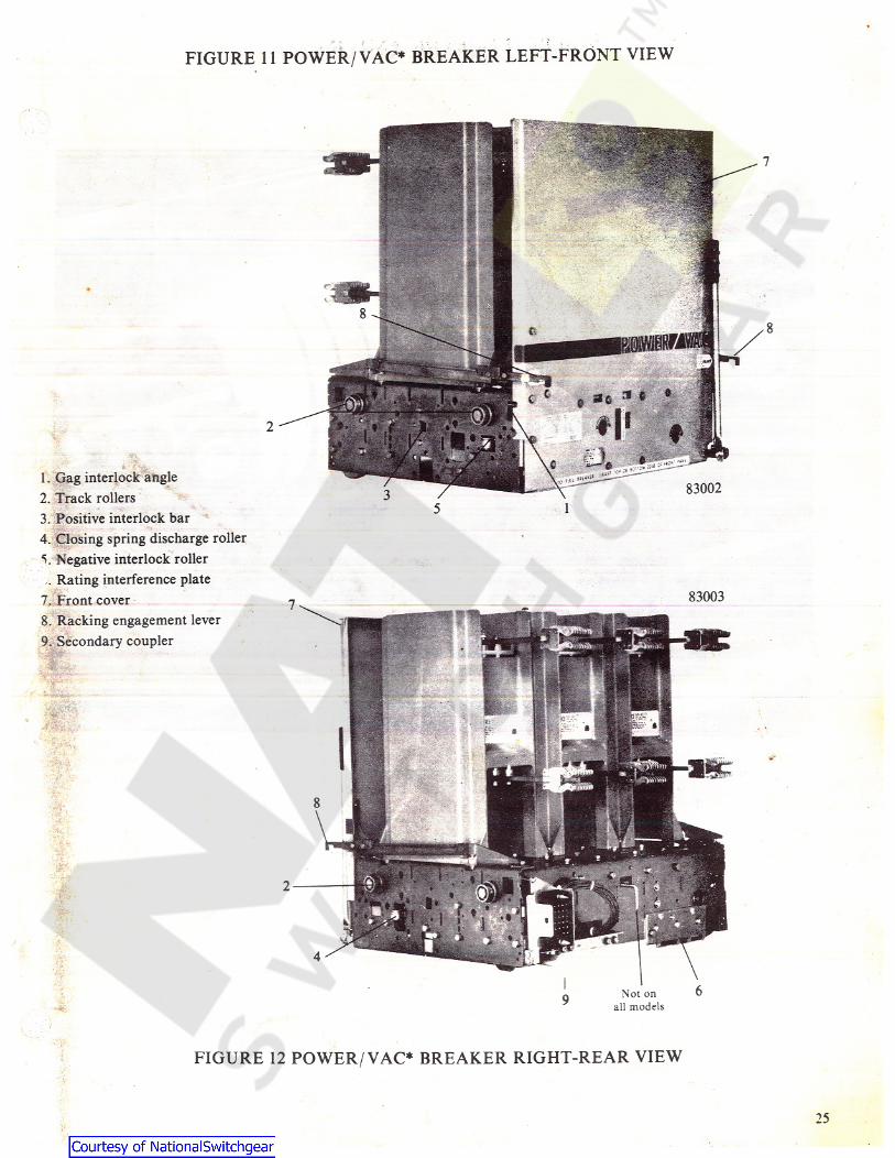
FIGURE 11 POWER / VAC* BREAKER LEFT-FRONT VIEW
1. Gag interlock angle2. Track rollers3. Positive interlock bar4. Closing spring discharge roller5. Negative interlock roller
Rating interference plate7. Front cover8. Racking engagement lever9. Secondary coupler
83002
83003
jSt
v
. ^
all models
FIGURE 12 POWER/ VAC* BREAKER RIGHT-REAR VIEW
25
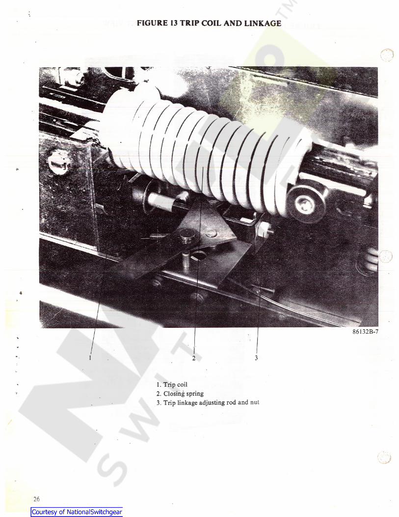
FIGURE 13 TRIP COIL AND LINKAGE
«4SSPm£
£
86132B-7
1. Trip coil2. Closing spring3. Trip linkage adjusting rod and nut
, i.. ^
26
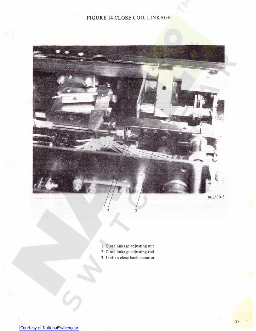
FIGURE 14 CLOSE COIL LINKAGE
1. Close linkage adjusting nut2. Close linkage adjusting rod3. Link to close latch actuator
27
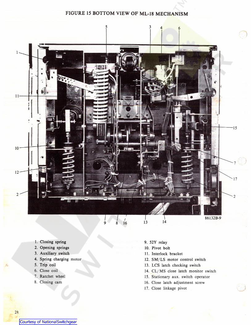
FIGURE 15 BOTTOM VIEW OF ML-18 MECHANISM
35 4 6
86132B-9
1. Closing spring2. Opening springs3. Auxiliary switch4. Spring charging motor5. Trip coil6. Close coil7. Ratchet wheel8. Closing cam
9. 52Y relay10. Pivot bolt11. Interlock bracket12. SM/ LS motor control switch13. LCS latch checking switch14. CL/ MS close latch monitor switch15. Stationary aux. switch operator16. Close latch adjustment screw17. Close linkage pivot
28
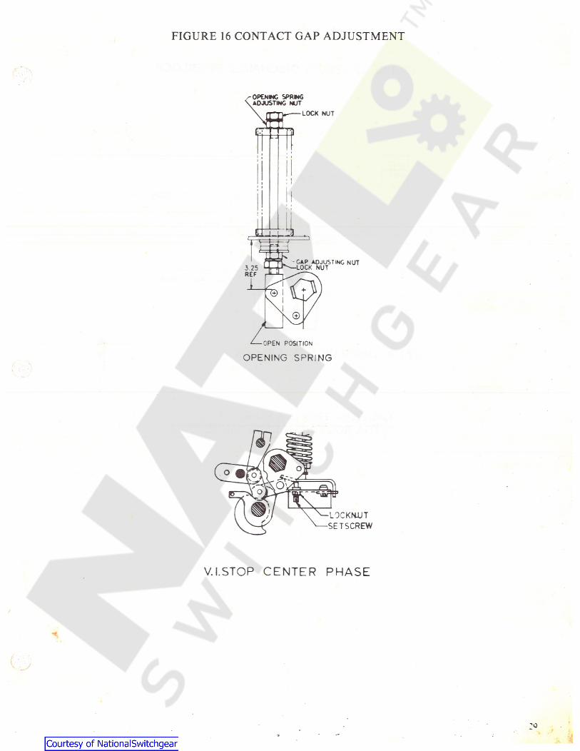
FIGURE 16 CONTACT GAP ADJUSTMENT
OPENING SPRNGADJUSTING NUT
LOCK NUT
jJr
<» i
• i• i
i •
i*
- GAP ADJUSTING NUT-LOCK NUT3 25REF
i
OPEN POSITION
OPENING SPRING
LOCKNJJTSETSCREW
V.I.STOP CENTER PHASE
'0
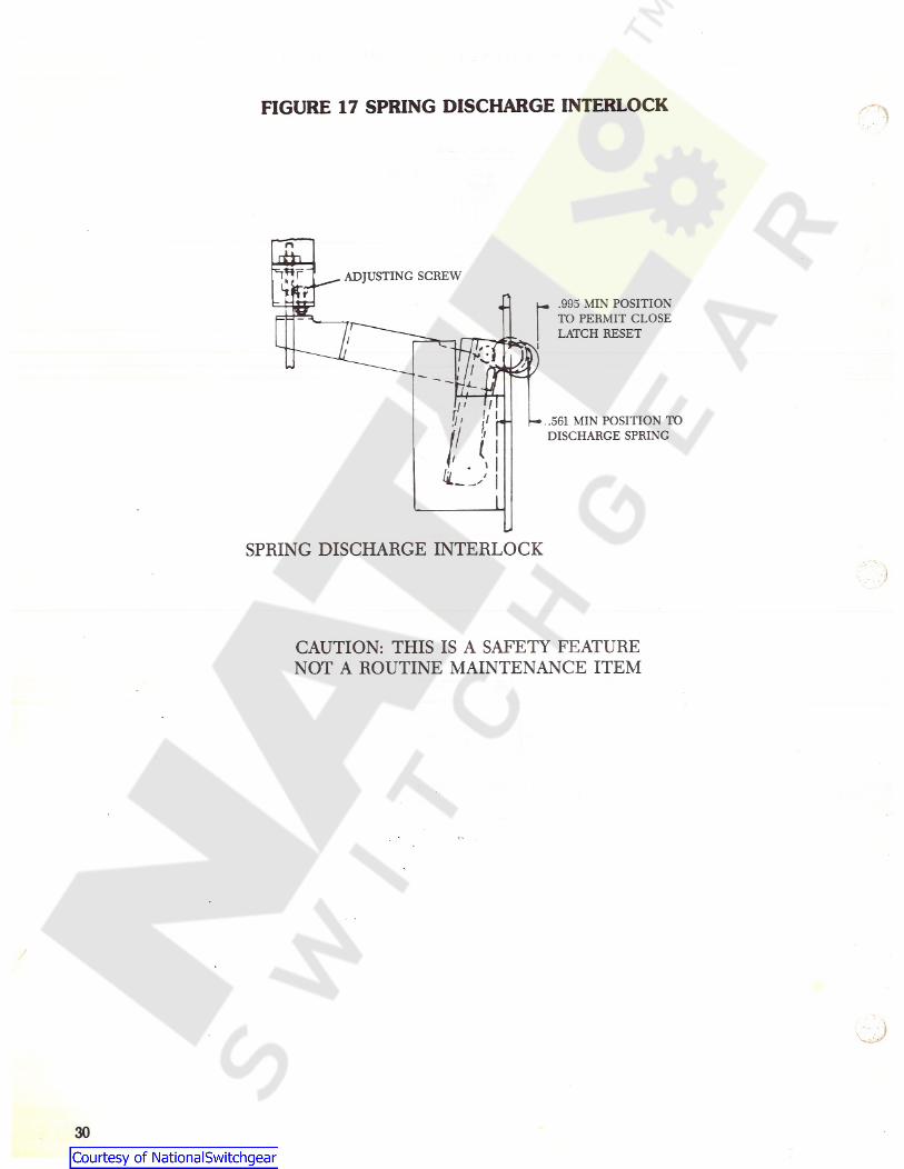
FIGURE 17 SPRING DISCHARGE INTERLOCK 7*r
n
ADJUSTING SCREWr> u, .995 MIN POSITION
TO PERMIT CLOSELATCH RESET
/ *
/< i!
l4-1 1
!/ !v h— .561 MIN POSITION TODISCHARGE SPRINGi rI! I
\
SPRING DISCHARGE INTERLOCK
CAUTION: THIS IS A SAFETY FEATURENOT A ROUTINE MAINTENANCE ITEM
30
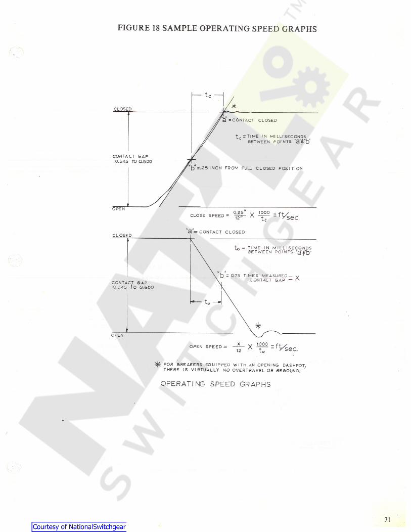
FIGURE 18 SAMPLE OPERATING SPEED GRAPHS
tC
XCLOSED
a = CONTACT CLOSED
tc = TlME ' N MILLISECONDSBETWEEN POINTS "a'fb'
CONTACT GAP0.545 TO 0.600
*t) =.25 INCH FROM FULL CLOSED POSITION
OPEN0.25° X 122° =fPiCLOSE SPEED = 12" sec.
"a= CONTACT CLOSEDCLOSED
T„ = TIME IN MILLISECONDSBETWEEN POINTS 'a'^b"
r r •»b - 0.75 TIMES MEASURED —
v CONTACT GAP = XCONTACT GAP0.545 TO 0.600
*OPEN
1000-- X - ^Vsec.OPEN SPEED = to12
^ FOR BREAKERS EOUIPPED WITH AN OPENING DASHPOT,THERE IS VIRTUALLY NO OVERTRAVEL OR REBOUND.
OPERATING SPEED GRAPHS
31
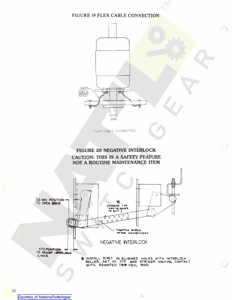
FIGURE 19 FLEX CABLE CONNECTION
etkH,*C CLIAN'ITYBASED ONSPEAKERRATING )
nrjW,
V 11I
FLEX CABLE CONNECTION
FIGURE 20 NEGATIVE INTERLOCKCAUTION: THIS IS A SAFETY FEATURENOT A ROUTINE MAINTENANCE ITEM
TI
r/
534 MIN POSITION —1TO OPEN MKR
/* /l /• ( CMOOtC I OfAWx IO MOUtSno ou »T.)
Tl&s-
'11 I * 1-/O o
l I<% * ' j.i Ii
H SC«(MMTif ft tOjOVT^lMT
NEGATIVE INTERLOCK.670 POSITION -•TO ADJU«T itffMUOCKUMK».
4 INSTALL RWET VM ALl&NEO HOLES \N \TH \NTERLOCKROLLER. , SET AT .670 AND STRIKER VAAK\NG CONTACTWITH ADJUSTED TRt* COW- ROD
32
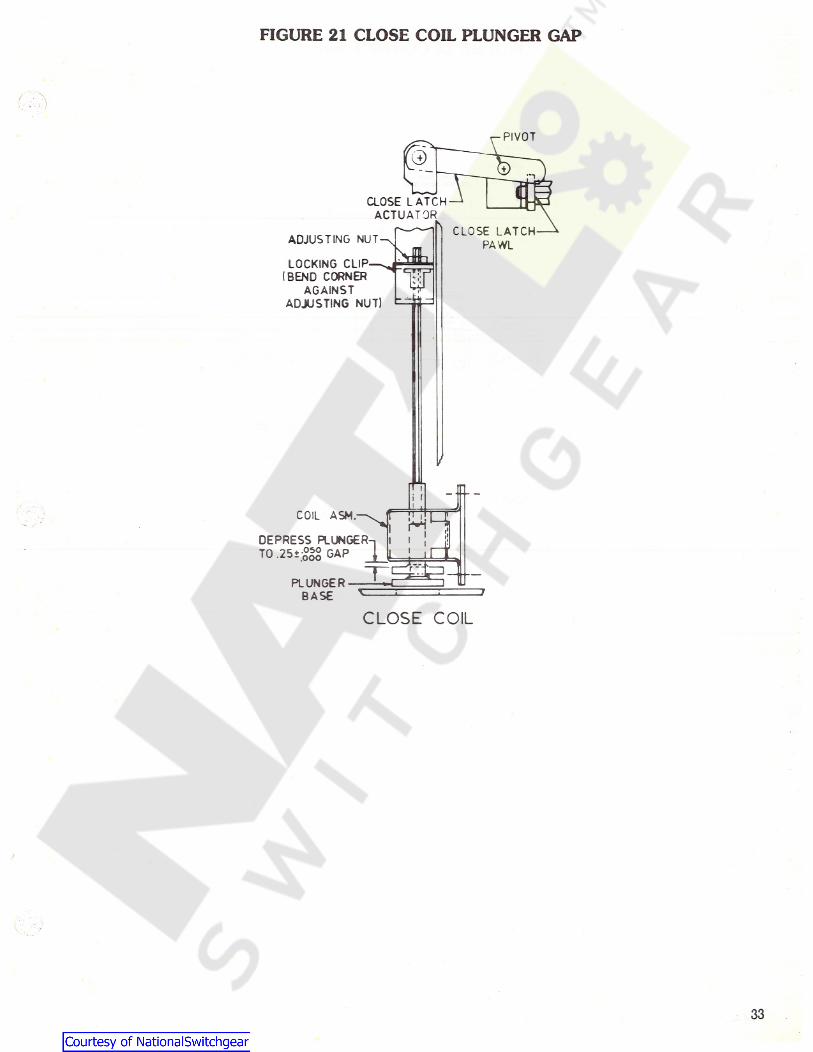
FIGURE 21 CLOSE COIL PLUNGER GAP
PIVOT
CLOSE LATCHACTUATOR
CLOSE LATCHPAWLADJUSTING NUT-̂
LOCKING CLIP—( BEND CORNER
AGAINSTADJUSTING NUT)
fi -t-COIL ASH.
i!
HDEPRESS PLUNGERTO GAP
I l1 II
1uPLUNGERBASE
CLOSE COIL
33
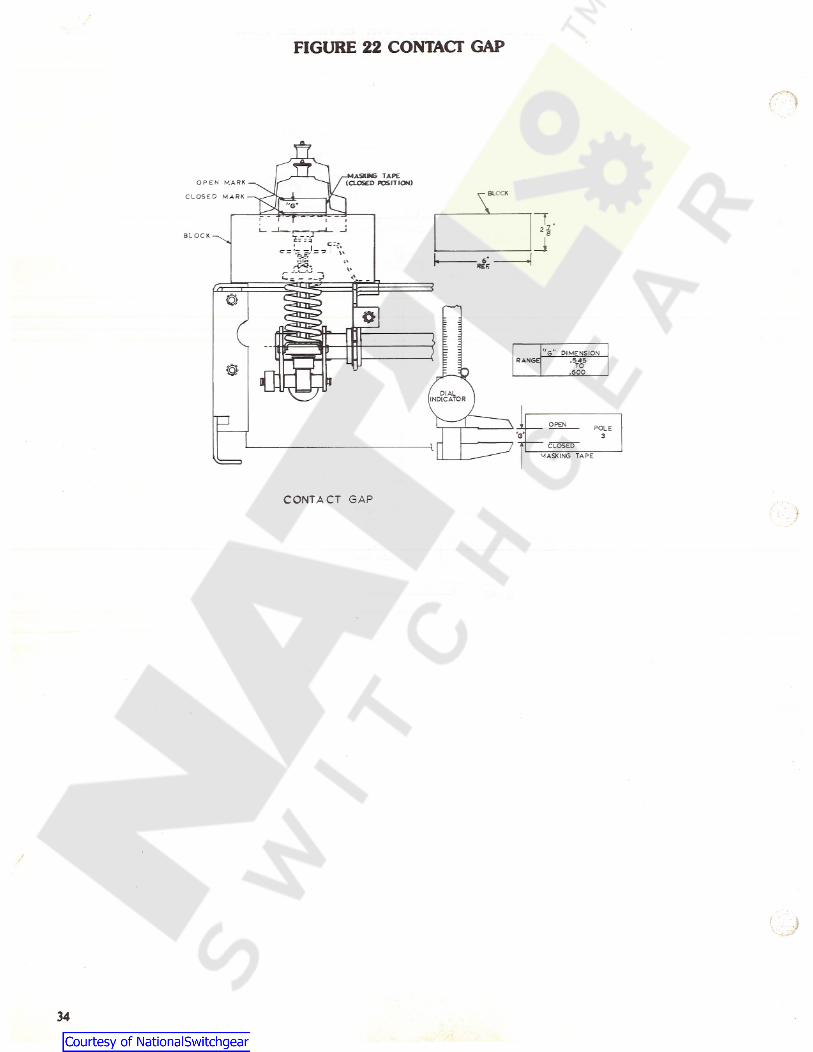
FIGURE 22 CONTACT GAP
A-MASKMS TAPE(CLOSED POSITION)O P E N M A R K
BLOCK\C L O S E D M A R K
I .i
j. 1 6B L O C K fe_rV
I L^«
c -:.REEv*J
0o
T "G DIMENSIONRANGE .545
TO© 600I
' DIALINDICATOR
m OPEN POLEV 3
* CLOSEDMASKING TAPE
CONTACT GAP)
I
34
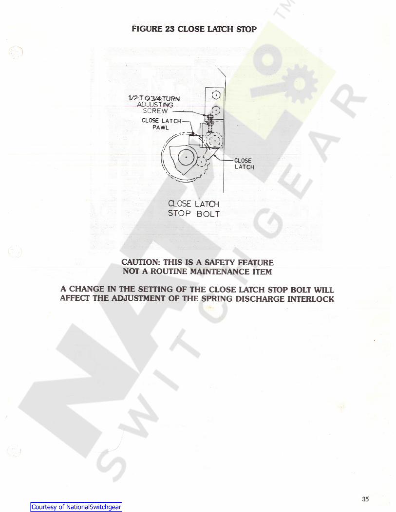
FIGURE 23 CLOSE LATCH STOP
OV2TQ3U4TURNADJUSTING
SCREW —CLOSE LATCH —PAWL
0
CLOSELATCH
CLOSE LATCHSTOP BOLT
CAUTION: THIS IS A SAFETY FEATURENOT A ROUTINE MAINTENANCE ITEM
A CHANGE IN THE SETTING OF THE CLOSE LATCH STOP BOLT WILLAFFECT THE ADJUSTMENT OF THE SPRING DISCHARGE INTERLOCK
35
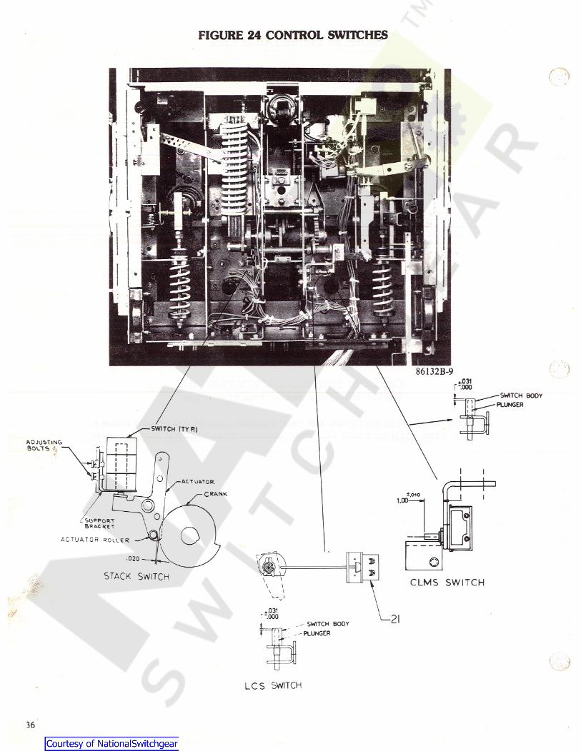
FIGURE 24 CONTROL SWITCHES
w
SWITCH BOOYPLUNGER
SWITCH ITYR )LJADJUSTING
SOCTG
I IACTUATOR
CRANK i.oio I1.00
l©_ SUPPORTBRACKET
aA C T U A T O R R O L C E R
r•020 Q\ B\<
WLiJ BSTACK SWITCH i\ CLMS SWITCH\\\\
V-N ;
-031yf^ -.000 2 Ij .- SWITCH BODYr-THT. - — PLUNGER
LCS SWITCH
36
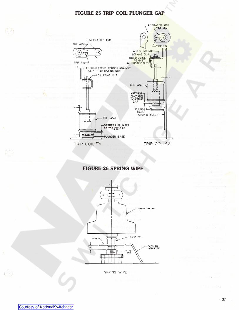
FIGURE 25 TRIP COIL PLUNGER GAP
ACTUATOR ARM
^-TRlP ARM\: AACTUATOR ARM
TRIP ARMTRIP PIN
Di ADJUSTING NUTLOCKMG CUP7( BEND CORNER 4^AGAINST W
ADJUSTING NUT]1
i 3l
TRIP PIN_
rLOCKING ( BEND CORNER AGAINSTCUP ADJUSTING NUT)
ADJUSTING NUT f-- rnCOL ASM T•"A i
U:DEPRESSPLUNGERTO 25-g?8u I
II
GAP it-.T'tA ]
PLUNGE R- =̂=BASESTOP BRACKETI I COIL ASM.
ri-UI r-DEPRESS PLUNGERI TO .25 £*.050 GAP
PLUNGER BASE
i
T
TRIP COIL "A TRIP COIL * 2
FIGURE 26 SPRING WIPE
1-t+
OPERATING ROD
I
LOCK NUTDISK —,
\iEROSIONINDICATOR
T WIPEINO.
ffR USI
Ll I I
SPRING WIPE
37
INDEX
r.iService Conditions 9Slow Closing 4, 5, 10Spring Discharge Interlock 3, 14Spring Wipe 6Storage 2
MAMaintenance
Contact Erosion 6, 9Fault Interruptions 9General 1, 9, 11, 13Lubrication 9, 10Mechanism 1, 2, 4, 9, 11Power/ Vac* Interrupter 9Primary Insulation Parts 9Service Conditions 9Transfer Finger Wear 9
Mechanical AdjustmentsClose Coil Plunger 6, 12, 14Close Latch Stop Bolt 14Contact Gap 6, 13Negative Interlock 3, 14Spring Discharge Interlock 3, 14Trip Coil Plunger 6, 14Wipe Adjustment 6, 13
Mechanical Checking and SlowClosing 4, 5, 10
Mechanism 1, 2, 4, 9, 11Motor Replacement 12
Auxiliary Switch Replacement 12CClose Coil Plunger 6, 12, 14Close Coil Plunger Gap 6Close Latch Stop Bolt 14Close Spring Charging 4Closing Coil Replacement 12Closing Operation 4Closing Spring Charging 5Closing Spring Dischaige Interlock 3Closing Spring Gag 3, 5Closing Spring Gag Interlock 3Contact Erosion 6, 9Contact Gap 6. 7, 11, 13Contact Gap Adjustment 13Control Circuit 5, 9Control Switch Adjustment 6, 12
TTiming 10
Instantaneous Reclose Time 10Trip-Free Operation 10
Transfer Finger Wear 9Trip Coil Plunger 6, 12, 14Trip Coil Plunger Gap 6Trip Coil Replacement 12Trip-Free Operation 5VVacuum Interrupter Integrity Test 7, 11WWipe Adjustment 6, 13
DYDescription 2
Dimensional Checks 6, 10, 12, 13, 14Dimensional Checks
Close Coil Plunger Gap 6Contact Gap 6, 7, 11,Control Switch Adjustment 6, 12Primary Contact Erosion 6, 9Spring Wipe 6Trip Coil Plunger Gap 6
“Y” Relay Replacement 12
NNegative Interlock 3, 14Negative Interlock Roller 3OOpening and Closing Speed 11Opening Operation 4Operation 3, 4, 5, 7, 10Ordering Instructions 13
EElectrical Checks 7, 10, 11
Electrical Operation 7High-Potential Test 7Insulation Tests 8Primary Circuit 7Primary Circuit Resistance 7Secondary Circuit 7Interrupter Integrity Test 7
Electrical Operation 7
PPositive Interlock Bar 3Power/ Vac* Interrupter 9Primary Circuit 7Primary Circuit Resistance 7Primary Contact Erosion 6, 9Primary Disconnect Fingers 11Primary Insulation Parts 9
FRFault Interruptions 9
Features 2 Rating Interference Plate 3Receiving 2Recommended Maintenance 10Renewal Parts 12
Ordering Instructions 13Repair and Replacement
“Y" Relay 12Auxiliary Switch 12Closing Coil 12Control Switches 12Interrupter Assemblies 11Motor 12Primary Disconnect Fingers 11Trip Coil 12
GGag Plate Removal 5General 1, 9, 11, 13HHandling 2High-Potential Test 7
IInstall Front Cover 7Installation 8Insulation Tests 8Interlock Functional Check 8Interlocks 1, 3
Spring Discharge Interlock 3Closing Spring Gag Interlock 3Negative Interlock Roller 3Positive Interlock Bar 3Rating Interference Plate 3
Introduction 1
SSafety 1, 2
General 1, 9, 11, 13Specific 1, 8
Safety Precautions 2Secondary Circuit 7
1
LLubrication 9, 10
38

USER REPORT NO.TROUBLE REPORTING FORM FOR POWER CIRCUIT BREAKERS
Check all appropriate blocks and provide information indicated. For major trouble provide additional information requested on backof page supplemented with additional pages if necessary.
User Identof BreakerSerial #
EQUIPMENT:Equipment Nameplate
Information
StationMfgr. Type
Inter Amps/MVAKV. Continuous Amps BilTrouble
, DateBrkr Background: ,ModernizedShipped , Maintained, Installed(Mo/Yr )(Mo/Yr ) (Mo/Yr ) (Mo/Day / Yr )
Operational Counter ReadingLocation: Indoor Outdoor
Air Blast,Enclosure: Non-metal Clad, DMetalclad, DGIS
Air Magnetic, DOil, DSFg, CD Vacuum, OtherInterrupter:ENVIRONMENT:
General: Industrial, DUrban, Suburban, Rural, Sea Coast, Above 3300', High Contamination,Other
Weather Conditions: Dry, Rain, Lightning in Area, Snow, Fog, Freezing Rain, Frost, Condensation,Temp. Trend — Rising, Falling, Steady, Extreme Cold, Temperature.
Strong—Steady, Strong-Gusty
External Mechanical Stresses Involved: Normal, Earthquake, DWind, Abnormal Terminal Loading,Other
Nominal System voltage
TROUBLE:When Discovered: Installation, In Service, Maintenance, DTest, Other .Breaker Mode at Time of Trouble: De-energized, Closed, Open, Tripping, Closing, Reclosing,
Fault Interruption, Load Switching, Line SwitchingBreaker Response at Time of Trouble: Not Called Upon to Operate, Performed as Intended, Unsatisfactory Operation,
Failed to Operate
_°F, Wind — Calm, Light,
Subsystem in Trouble:Isolating Contact, Bushing, Interrupter, Seals-Gaskets, Air System, SFg System, DC.T.,ResistorSw or Aux. Int., Voltage Grading Dev, Line Terminals, Compressor, Heater, Electrical Controls,
Wiring, Operating Mechanism, Mechanical Linkage, Other
External Insulation to Grnd, Internal Insulation to Grnd, Insulating Medium,
State Specifically What Failed (With Instr. Book Ref.):
Has it occurred before on this type of brkr? No, Yes, How many timesState How Problem was Corrected:
Design/Manufacture, Shipping, Storage, Installation, Instructions, Maintenance,Wear/Aging, Animal/Birds, Other, Not Obvious
POSSIBLE CAUSE:
Comments and Suggestions:
EFFECT:Breaker Down Time: No Interruption, 30 Min or Less, 1 Hr, 2 Hr, 6 Hr, 12 Hr, 24 Hr, OtherRepair Time: Less than 30 Min, 1 Hr, D 2 Hr, D 6 Hr, 1 Day, 2 Days, 3 Days, 1 Week, Other_Breaker Outage Status: Immediate Forced Outage, Outage Within 20 Min., Required Subsequent Outage,
Repair Deferred Until Regular Maintenance, No Outage for RepairUser PersonCompleting Report Date
User Approval Name Date
User Contact Name Telephone Number
User Company
39

ADDITIONAL INFORMATION REQUIRED FOR ANALYSIS OF MAJOR ORSYSTEM RELATED TROUBLE
(USE ADDITIONAL PAGES AS NECESSARY)
r?>(1) SINGLE- LINE STATION DIAGRAM SHOWING INVOLVED BREAKERS
( 2) OPERATION AND TIMING SEQUENCE (INCLUDING ALL ALARMS) OF THIS AND RELATED BREAKERSFROM LAST TIME THAT CONDITIONS WERE DEFINITELY NORMAL
(3) LINE CONDITIONS BEFORE, DURING, AND AFTER FAILURE
(4) OSCILLOGRAMS - ATTACH WITH EXPLANATION & INTERPRETATION
ATTACH A DESCRIPTION OF THE EXACT POSITION OF ALL MECHANICAL COMPONENTS FROM THE CONTROLSOLENOID THROUGH ALL INTERRUPTER CONTACTS AS APPLICABLE. (PHOTOGRAPH EACH IN DETAILBEFORE MECHANISMS ARE MOVED; SUPPLY COPIES OF PHOTOS WITH REPORT.)
(5)
t v 3DESCRIBE ARC DAMAGE AND LOCATION OF ARC PRODUCTS RELATIVE TO VALVE SEALS. (PHOTOGRAPHEACH IN DETAIL BEFORE ANY CLEAN UP OR POST FAILURE MECHANISM MOVEMENT;SUPPLY COPIES OFPHOTOS WITH REPORT.)
(6 )
40
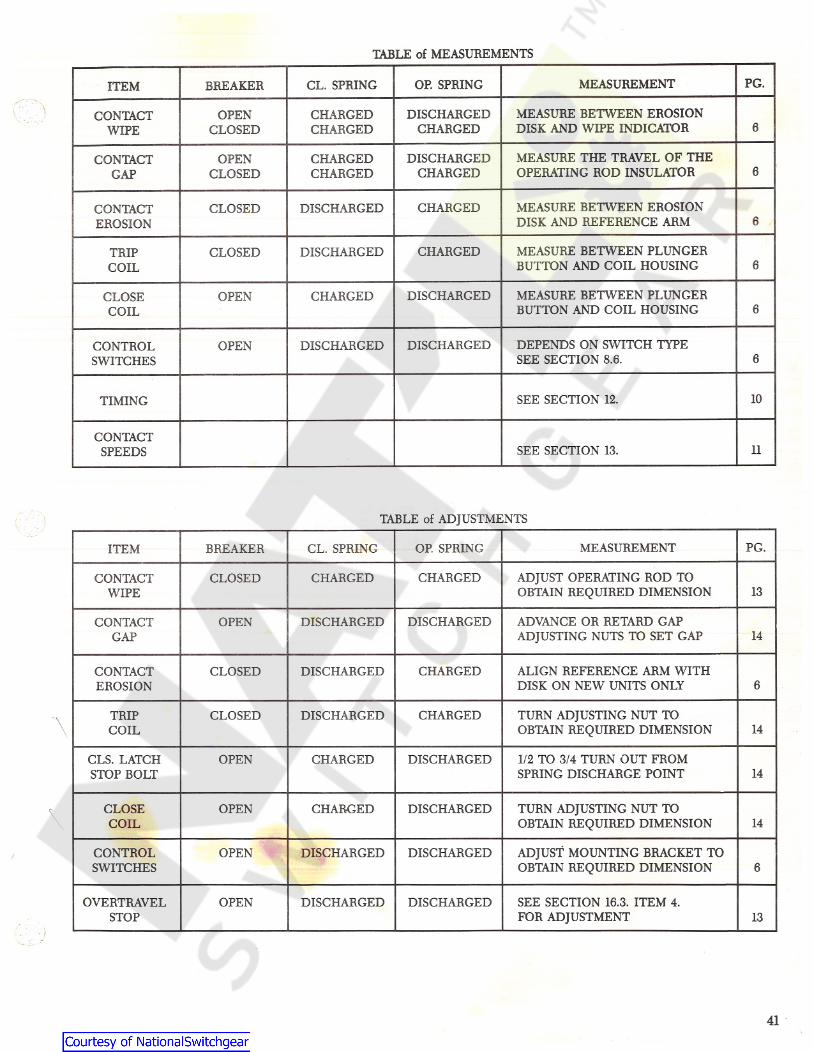
TABLE of MEASUREMENTS
PG.MEASUREMENTOP. SPRINGCL. SPRINGBREAKERITEM
MEASURE BETWEEN EROSIONDISK AND WIPE INDICATOR
DISCHARGEDCHARGED
CHARGEDCHARGED
OPENCLOSED
CONTACTWIPE 6
MEASURE THE TRAVEL OF THEOPERATING ROD INSULATOR
DISCHARGEDCHARGED
CHARGEDCHARGED
OPENCLOSED
CONTACT6GAP
MEASURE BETWEEN EROSIONDISK AND REFERENCE ARM
CHARGEDDISCHARGEDCONTACTEROSION
CLOSED6
MEASURE BETWEEN PLUNGERBUTTON AND COIL HOUSING
DISCHARGED CHARGEDCLOSEDTRIPCOIL 6
MEASURE BETWEEN PLUNGERBUTTON AND COIL HOUSING
DISCHARGEDOPEN CHARGEDCLOSECOIL 6
DEPENDS ON SWITCH TYPESEE SECTION 8.6.
DISCHARGEDDISCHARGEDCONTROLSWITCHES
OPEN6
10SEE SECTION 12.TIMING
CONTACTSPEEDS SEE SECTION 13. 11
TABLE of ADJUSTMENTS
CL. SPRING OP. SPRING MEASUREMENT PG.ITEM BREAKER
ADJUST OPERATING ROD TOOBTAIN REQUIRED DIMENSION
CONTACTWIPE
CLOSED CHARGED CHARGED13
CONTACT OPEN DISCHARGED DISCHARGED ADVANCE OR RETARD GAPADJUSTING NUTS TO SET GAPGAP 14
CONTACTEROSION
CLOSED DISCHARGED CHARGED ALIGN REFERENCE ARM WITHDISK ON NEW UNITS ONLY 6
TRIPCOIL
CLOSED DISCHARGED CHARGED TURN ADJUSTING NUT TOOBTAIN REQUIRED DIMENSION\ 14
CLS. LATCHSTOP BOLT
OPEN CHARGED DISCHARGED 1/2 TO 3/4 TURN OUT FROMSPRING DISCHARGE POINT 14
CLOSECOIL
OPEN CHARGED TURN ADJUSTING NUT TOOBTAIN REQUIRED DIMENSION
DISCHARGED14
CONTROLSWITCHES
OPEN DISCHARGED DISCHARGED ADJUST MOUNTING BRACKET TOOBTAIN REQUIRED DIMENSION 6
OVERTRAVELSTOP
OPEN DISCHARGED DISCHARGED SEE SECTION 16.3. ITEM 4.FOR ADJUSTMENT 13
41
N
Cl
it
Vr
f
i
G E ED & CSWITCHGEAR OPERATIONBURLINGTON, IOWA 52601
( ; }
Vr
4
.*
• *\J§~.,&
u>
>
2-90
%