mc5 technical reference manual - soc robotics
TRANSCRIPT
MC5 Technical Reference Guide
© Copyright 2014, SOC Robotics, Inc. 1 Manual Revision 0.93 Setpember 2014
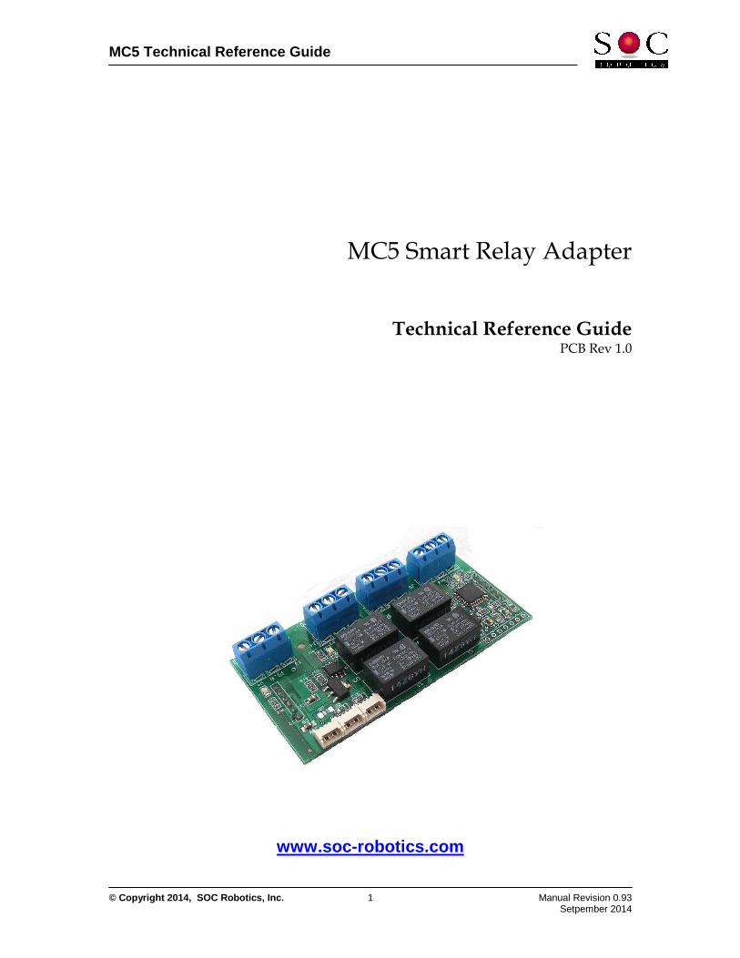
MC5 Smart Relay Adapter
Technical Reference Guide PCB Rev 1.0
www.soc-robotics.com
MC5 Technical Reference Guide
© Copyright 2014, SOC Robotics, Inc. 2 Manual Revision 0.93 Setpember 2014
Warranty Statement SOC Robotics warrants that the Product delivered hereunder shall conform to the applicable SOC Robotics Data Sheet or mutually agreed upon specifications and shall be free from defects in material and workmanship under normal use and service for a period of 30 days from the applicable date of invoice. Products that are “samples”, “design verification units”, and/or “prototypes” are sold “AS IS,” “WITH ALL FAULTS,” and without a warranty. If, during such warranty period, (i) SOC Robotics is notified promptly in writing upon discovery of any defect in the goods, including a detailed description of such defect; (ii) such goods are returned to SOC Robotics, DDP SOC Robotics facility accompanied by SOC Robotics Returned Material Authorization form; and (iii) SOC Robotics examination of such goods discloses to SOC Robotics satisfaction that such goods are defective and such defects are not caused by accident, abuse, misuse, neglect, alteration, improper installation, repair, improper testing, or use contrary to any instructions issued by SOC Robotics. SOC Robotics shall (at its sole option) either repair, replace, or credit Buyer the purchase price of such goods. No goods may be returned to SOC Robotics without SOC Robotics Returned Material Authorization form. Prior to any return of goods by Buyer pursuant to this Section, Buyer shall afford SOC Robotics the opportunity to inspect such goods at Buyer’s location, and any such goods so inspected shall not be returned to SOC Robotics without its prior written consent. SOC Robotics shall return any goods repaired or replaced under this warranty to Buyer transportation prepaid, and reimburse Buyer for the transportation charges paid by Buyer for such goods. The performance of this warranty does not extend the warranty period for any goods beyond that period applicable to the goods originally delivered.
THE FOREGOING WARRANTY CONSTITUTES SOC ROBOTICS EXCLUSIVE LIABILITY, AND THE EXCLUSIVE REMEDY OF BUYER, FOR ANY BREACH OF ANY WARRANTY OR OTHER NONCONFORMITY OF THE GOODS COVERED BY THIS AGREEMENT. THIS WARRANTY IS EXCLUSIVE, AND IN LIEU OF ALL OTHER WARRANTIES. SOC ROBOTICS MAKES NO OTHER WARRANTIES, EXPRESS, IMPLIED, OR STATUTORY, INCLUDING WITHOUT LIMITATION ANY WARRANTIES OF MERCHANTABILITY OR FITNESS FOR A PARTICULAR PURPOSE. THE SOLE AND EXCLUSIVE REMEDY FOR ANY BREACH OF THIS WARRANTY SHALL BE AS EXPRESSLY PROVIDED HEREIN. Limitation on Liability Notwithstanding anything to the contrary contained herein, SOC Robotics shall not, under any circumstances, be liable to Buyer or any third parties for consequential, incidental, indirect, exemplary, special, or other damages. SOC Robotics total liability shall not exceed the total amount paid by Buyer or SOC Robotics hereunder. SOC Robotics shall not under any circumstances be liable for excess costs of re-procurement.
© Copyright 2008. SOC Robotics, Inc. All rights reserved. SOC Robotics, Inc. makes no warranty for the use of its products, other than those expressly contained in the Company’s standard warranty which is detailed in SOC Robotics Terms and Conditions located on the Company’s web site. The Company assumes no responsibility for any errors which may appear in this document, reserves the right to change devices or specifications detailed herein at any time without notice, and does not make any commitment to update the information contained herein. No licenses to patents or other intellectual property of SOC Robotics are granted by the Company in connection with the sale of SOC Robotics products, expressly or by implication. SOC Robotics products are not authorized for use as critical components in life support devices or systems. Marks bearing ® and/or ™ are trademarks of SOC Robotics, Inc. Terms and product names in this document may be trademarks of others. 1935A–08/00/5M
MC5 Technical Reference Guide
© Copyright 2014, SOC Robotics, Inc. 3 Manual Revision 0.93 Setpember 2014
Table of Contents Warranty Statement …………………………………………………….…………2 Contents …………………………………………………………………………….…2 1.0 Introduction …………………………………………...……………...…...…4
1.1 Features……………………………………….………………………………..…….…….…4 1.2 Hardware……………………………………………………………………..………………4 1.3 Software...…………………………………….………..……………………..…..……..……5 1.4 Applications .…………..………………..……………………….……….…..….……..……5 1.5 Optional Configurations………………..……………………….……….……...……..……5
2.0 Detailed Description ………………………………...…………...….……6 2.1 Overview……………………………………………………………..…………...….…….…7 2.2 Installation…………………………………………………………..…………...….…..….…7 2.3. Digital Control Port………………………………………………..…………...….…...….…7 2.4 Power Port…………………………………………………………..…………...….…..….…8 2.5 Processor...……………………………………….………..……………………………..……8 2.6 I2C Port .………………………………...………………….……….……….…………..……8 2.7 Serial Port .……………………..………………..………………….……….…………..……8 2.8 Installed Software.……………………..………………………..….……….…………..……8 2.9 Optional Components………………..………………………..….……….……….…..……8 2.10 SPI/ ISP Programming .……………………..………………….……….………..…..……8
3.0 Software and Applications ………………………...…………..….……9 3.1 Introduction………………………………………………………….……………….…….…9 3.2 Relay Application Description…………………………………….……………….…….…9 3.3 I2C/Serial Command Description…………………………………… ……………...…….9 3.4 MK1/MK4/MK14/MK54/MK200/MK800 Interactions …………….……….…….….10 3.5 Chinook/Whistler/P0/P1 Processor Interaction…..……………………………....……10
4.0 Electrical and Mechanical Description ……………………………11
4.1 Component Layout………………………………………………………….…..…...…..…11 4.2 Electrical Specifications…………………………………………………………....…...…..11 4.3 Mechanical Dimensions ……………………………………………….………….……….11
5.0 Circuit Schematics ………………………………………………....….…12
MC5 Technical Reference Guide
© Copyright 2014, SOC Robotics, Inc. 4 Manual Revision 0.93 Setpember 2014
1.0 Introduction
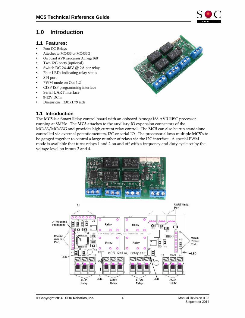
1.1 Features: • Four DC Relays • Attaches to MC433 or MC433G • On board AVR processor Atmega168 • Two I2C ports (optional) • Switch DC 24-48V @ 2A per relay • Four LEDs indicating relay status • SPI port • PWM mode on Out 1,2 • CISP ISP programming interface • Serial UART interface • 9-12V DC in • Dimensions: 2.81x1.79 inch
1.1 Introduction The MC5 is a Smart Relay control board with an onboard Atmega168 AVR RISC processor running at 8MHz. The MC5 attaches to the auxiliary IO expansion connectors of the MC433/MC433G and provides high current relay control. The MC5 can also be run standalone controlled via external potentiomenters, I2C or serial IO. The processor allows multiple MC5’s to be ganged together to control a large number of relays via the I2C interface. A special PWM mode is available that turns relays 1 and 2 on and off with a frequency and duty cycle set by the voltage level on inputs 3 and 4.
MC5 Technical Reference Guide
© Copyright 2014, SOC Robotics, Inc. 5 Manual Revision 0.93 Setpember 2014
1.2 Hardware The MC5 provides control of four on board DC relays. An onboard processor monitors the status of each auxiliary input line and actives the appropriate relay based on the state of that line. The processor may monitor the I2C line and activate relays based on commands sent to it via I2C. The processor also monitors the serial line and activates relays based on commands received on this line. The SPI port (also an ISP programming port) provides a high speed communications port for SPI peripherals.
1.3 Software The MC5 is supplied with an onboard program that monitors the state of the OUT control lines on J1 and activates each relay according to the state of the respective input. The MC5 can be shipped with an alternative operating state in which voltage levels on OUT control lines 3 and 4 set the frequency and duty cycle of OUT control 2. This mode is used to cycle devices such as pumps that deliver fluids in spurts. The MC5 can also be controlled via the I2C and Serial lines to turn the Relays on or off. A detailed description of the commands for I2C and Serial operation is provided in Section 3.
1.4 Applications The MC5 is designed to attach to the MC433 or MC433G and provide four relay contact closures or run standalone accepting digital inputs, I2C or serial IO. Multiple MC5s can be ganged together to provide control of a large number of relay-activated devices with commands sent to each MC5 on the I2C port.
1.5 Optional Configurations The MC5 is shipped without I2C connectors or serial connectors. If I2C operation is required these connectors can be installed by special order.
MC5 Technical Reference Guide
© Copyright 2014, SOC Robotics, Inc. 6 Manual Revision 0.93 Setpember 2014
2.0 Detailed Description
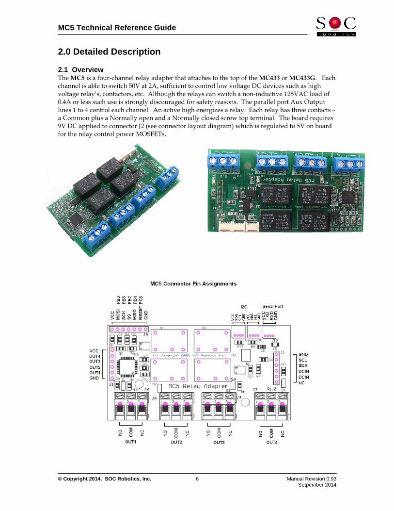
2.1 Overview The MC5 is a four-channel relay adapter that attaches to the top of the MC433 or MC433G. Each channel is able to switch 50V at 2A, sufficient to control low voltage DC devices such as high voltage relay’s, contactors, etc. Although the relays can switch a non-inductive 125VAC load of 0.4A or less such use is strongly discouraged for safety reasons. The parallel port Aux Output lines 1 to 4 control each channel. An active high energizes a relay. Each relay has three contacts – a Common plus a Normally open and a Normally closed screw top terminal. The board requires 9V DC applied to connector J2 (see connector layout diagram) which is regulated to 5V on board for the relay control power MOSFETs.
MC5 Technical Reference Guide
© Copyright 2014, SOC Robotics, Inc. 7 Manual Revision 0.93 Setpember 2014
2.2 Installation The MC5 attaches to the MC433 J17 and J23 connectors – J17 supplies the logic signals and J23 supplies power. When installing the MC5 on the MC433 or MC433G be sure to orient the board correctly as shown in the picture above. Note the MC433 is not longer available.
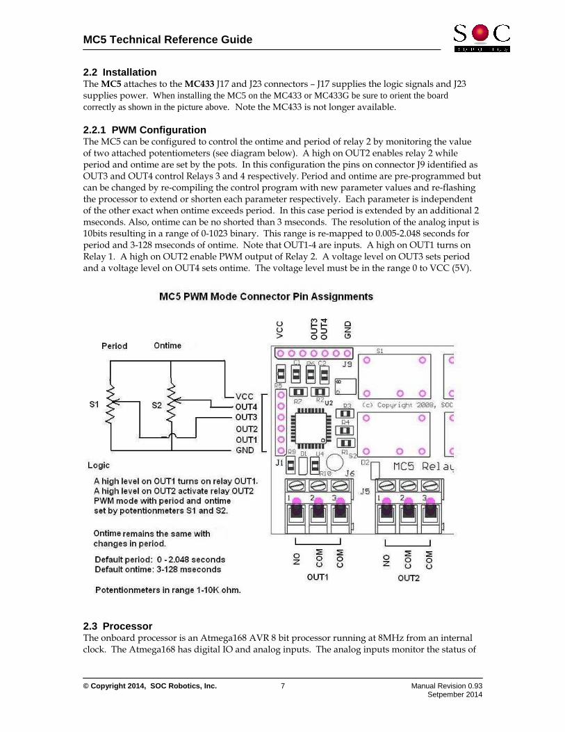
2.2.1 PWM Configuration The MC5 can be configured to control the ontime and period of relay 2 by monitoring the value of two attached potentiometers (see diagram below). A high on OUT2 enables relay 2 while period and ontime are set by the pots. In this configuration the pins on connector J9 identified as OUT3 and OUT4 control Relays 3 and 4 respectively. Period and ontime are pre-programmed but can be changed by re-compiling the control program with new parameter values and re-flashing the processor to extend or shorten each parameter respectively. Each parameter is independent of the other exact when ontime exceeds period. In this case period is extended by an additional 2 mseconds. Also, ontime can be no shorted than 3 mseconds. The resolution of the analog input is 10bits resulting in a range of 0-1023 binary. This range is re-mapped to 0.005-2.048 seconds for period and 3-128 mseconds of ontime. Note that OUT1-4 are inputs. A high on OUT1 turns on Relay 1. A high on OUT2 enable PWM output of Relay 2. A voltage level on OUT3 sets period and a voltage level on OUT4 sets ontime. The voltage level must be in the range 0 to VCC (5V).
2.3 Processor The onboard processor is an Atmega168 AVR 8 bit processor running at 8MHz from an internal clock. The Atmega168 has digital IO and analog inputs. The analog inputs monitor the status of
MC5 Technical Reference Guide
© Copyright 2014, SOC Robotics, Inc. 8 Manual Revision 0.93 Setpember 2014
the four auxiliary input lines and set the state of each respective relay based on the state of the input. An active high causes the relay to close.
2.4 Digital Control Port Digital control port J1 has four signal lines that control the state of each relay. An active high on any of these lines causes the respective relay to energize. J1 connects to the MC433 connector J17.
2.5 Power Port Power port J2 connects the MC5 to the MC433 and provides DC9-12V from the MC433 to the MC5 to run the processor and active the relays after being reduced to 5V by the onboard linear regulator. J2 connects to the MC433 connector J23.
2.6 I2C Port The MC5 has two I2C ports (J7, J8) that connect to the processors I2C lines. Connector J2 also has I2C signals lines. Connectors J7 and J8 are not installed but can be by special ordered.
2.7 Serial Port Serial port J10 attaches to the Atmega168’s UART lines and provides a serial communication feature. This connector is not installed but can be by special ordered.
2.8 Installed Software The MC5 comes with software that monitors the status of the Auxiliary Output lines on port J1. An active high on the Output lines causes the relay to energize changing the Normally Open connector to close and the Normally Closed connector to open on each relay.
2.9 Optional Components The MC5 is shipped with the I2C connectors and serial connectors not installed. These can be installed by the user or at the factory by special request.
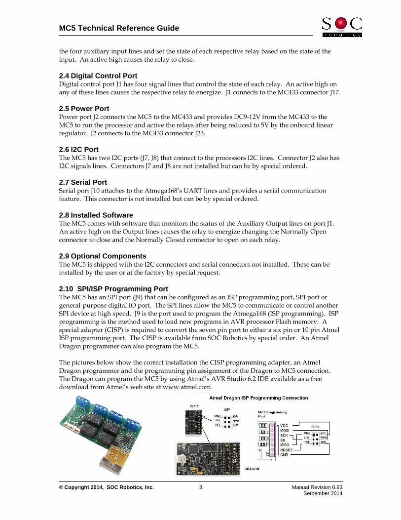
2.10 SPI/ISP Programming Port The MC5 has an SPI port (J9) that can be configured as an ISP programming port, SPI port or general-purpose digital IO port. The SPI lines allow the MC5 to communicate or control another SPI device at high speed. J9 is the port used to program the Atmega168 (ISP programming). ISP programming is the method used to load new programs in AVR processor Flash memory. A special adapter (CISP) is required to convert the seven pin port to either a six pin or 10 pin Atmel ISP programming port. The CISP is available from SOC Robotics by special order. An Atmel Dragon programmer can also program the MC5. The pictures below show the correct installation the CISP programming adapter, an Atmel Dragon programmer and the programming pin assignment of the Dragon to MC5 connection. The Dragon can program the MC5 by using Atmel’s AVR Studio 6.2 IDE available as a free download from Atmel’s web site at www.atmel.com.

MC5 Technical Reference Guide
© Copyright 2014, SOC Robotics, Inc. 9 Manual Revision 0.93 Setpember 2014
3.0 Software and Applications 3.1 Introduction The MC5 is a Smart Relay peripheral that executes a program running on the on board’s Atmega168 processor. The processor can be programmed to execute two different functions – one for standard MC433/MC433G operation that controls the state of four relays and the second that pulse width modulates relay OUT 2 given voltage levels on OUT 3 and OUT 4. Commands sent to the MC5 on the I2C lines are recognized and can be used to switch from PWM state to normal state. Custom programs can be written that control relay operation based on the status of signals not only on the OUT input port but also signals on the SPI port.
3.2 Relay Application Description MC433/MC433G The default software programmed into the board monitors the status of the four OUT input lines and controls the on/off state of each relay. A high level on any AUX input energizes the appropriate relay. A LED indicates the energized (ON) state of each relay. The OUT lines are controlled by the parallel port interface on the MC433 and the G Code processor (Atmega644) on the MC433G.
3.3 PWM Mode PWM mode converts OUT 3 and 4 inputs to PWM control signals. Voltage levels applied to pin OUT3 is interpreted as a period setting while voltage levels on OUT4 is interpreted as a duty cycle setting. The voltage levels swing between 0 and 5Volts. A voltage level of 0V sets the period to .25 seconds while a voltage level of 5V sets period to 4 seconds
3.4 I2C/Serial Command Summary Commands to control relay state are sent to the MC5 on the I2C or Serial Port. I2C Port The I2C port is a two wire party line communication protocol running at 50-400KHz (distance dependent). Each device on an I2C bus must have a unique address. The MC5’s address is 0x1A (26 decimal). Commands sent to the MC5 are either write or read commands. Write commands contain the device address followed by one or more ASCII characters. Read commands are preceded by a write command that selects the parameter of interest returned in the next read command. Sub-addressing is not supported. Most commands are printable ASCII characters to simplify high level software and allow operation with a terminal application with the USB10. The following write commands are supported: Command Function r Reset MC5 - turns all relays off css Save current settings to EEPROM cif Turn I2C mode off ciannn Change I2C address to nnn where nnn is integer address cen Enable alternate operation such as I2C operation, uart and override OUT port state recognition where 'n' is o/2-twi,a-analog,u-uart,d-digital d Set MC5 to default state - relays off all digital lines inputs g? Return copyright notice string - always 24 characters snh Set relay 'n' to state 'h' where n is 1,2,3,4 and h is f or o
MC5 Technical Reference Guide
© Copyright 2014, SOC Robotics, Inc. 10 Manual Revision 0.93 Setpember 2014
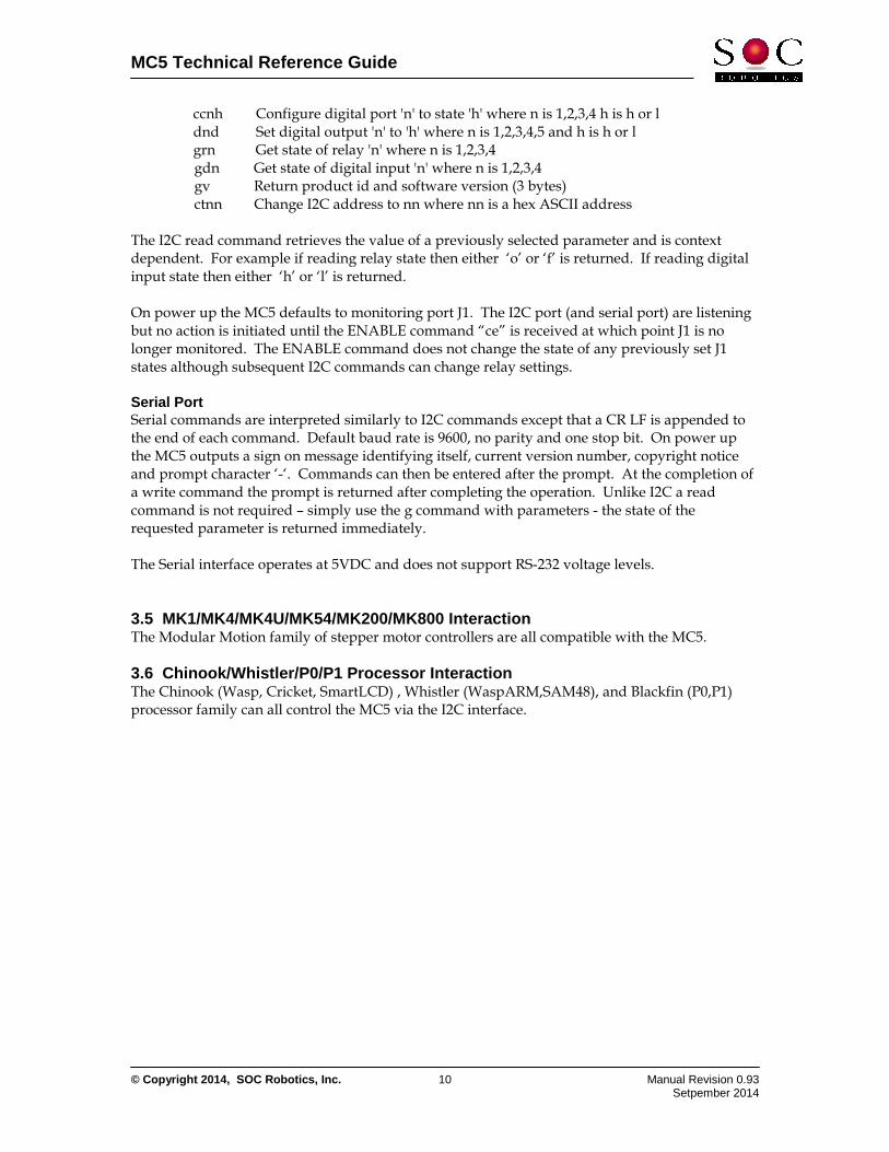
ccnh Configure digital port 'n' to state 'h' where n is 1,2,3,4 h is h or l dnd Set digital output 'n' to 'h' where n is 1,2,3,4,5 and h is h or l grn Get state of relay 'n' where n is 1,2,3,4 gdn Get state of digital input 'n' where n is 1,2,3,4 gv Return product id and software version (3 bytes) ctnn Change I2C address to nn where nn is a hex ASCII address The I2C read command retrieves the value of a previously selected parameter and is context dependent. For example if reading relay state then either ‘o’ or ‘f’ is returned. If reading digital input state then either ‘h’ or ‘l’ is returned. On power up the MC5 defaults to monitoring port J1. The I2C port (and serial port) are listening but no action is initiated until the ENABLE command “ce” is received at which point J1 is no longer monitored. The ENABLE command does not change the state of any previously set J1 states although subsequent I2C commands can change relay settings. Serial Port Serial commands are interpreted similarly to I2C commands except that a CR LF is appended to the end of each command. Default baud rate is 9600, no parity and one stop bit. On power up the MC5 outputs a sign on message identifying itself, current version number, copyright notice and prompt character ‘-‘. Commands can then be entered after the prompt. At the completion of a write command the prompt is returned after completing the operation. Unlike I2C a read command is not required – simply use the g command with parameters - the state of the requested parameter is returned immediately. The Serial interface operates at 5VDC and does not support RS-232 voltage levels.
3.5 MK1/MK4/MK4U/MK54/MK200/MK800 Interaction The Modular Motion family of stepper motor controllers are all compatible with the MC5.
3.6 Chinook/Whistler/P0/P1 Processor Interaction The Chinook (Wasp, Cricket, SmartLCD) , Whistler (WaspARM,SAM48), and Blackfin (P0,P1) processor family can all control the MC5 via the I2C interface.
MC5 Technical Reference Guide
© Copyright 2014, SOC Robotics, Inc. 11 Manual Revision 0.93 Setpember 2014
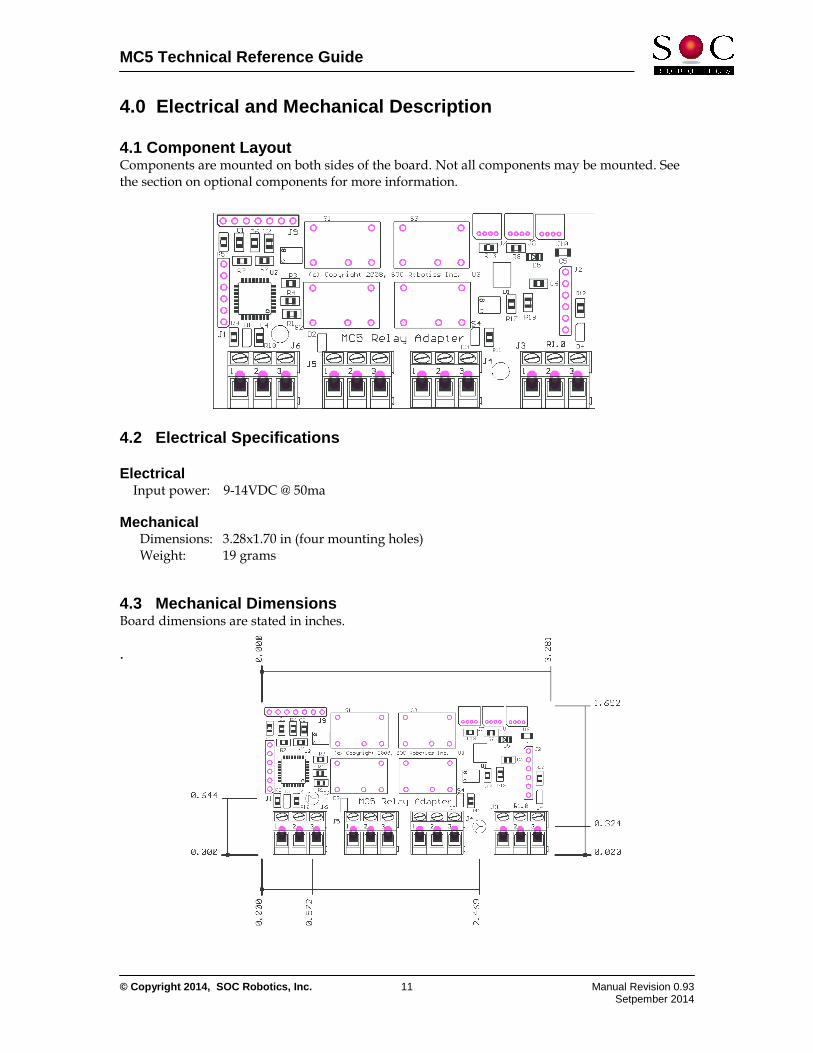
4.0 Electrical and Mechanical Description 4.1 Component Layout Components are mounted on both sides of the board. Not all components may be mounted. See the section on optional components for more information.
4.2 Electrical Specifications Electrical Input power: 9-14VDC @ 50ma Mechanical Dimensions: 3.28x1.70 in (four mounting holes) Weight: 19 grams 4.3 Mechanical Dimensions Board dimensions are stated in inches. .
MC5 Technical Reference Guide
© Copyright 2014, SOC Robotics, Inc. 12 Manual Revision 0.93 Setpember 2014
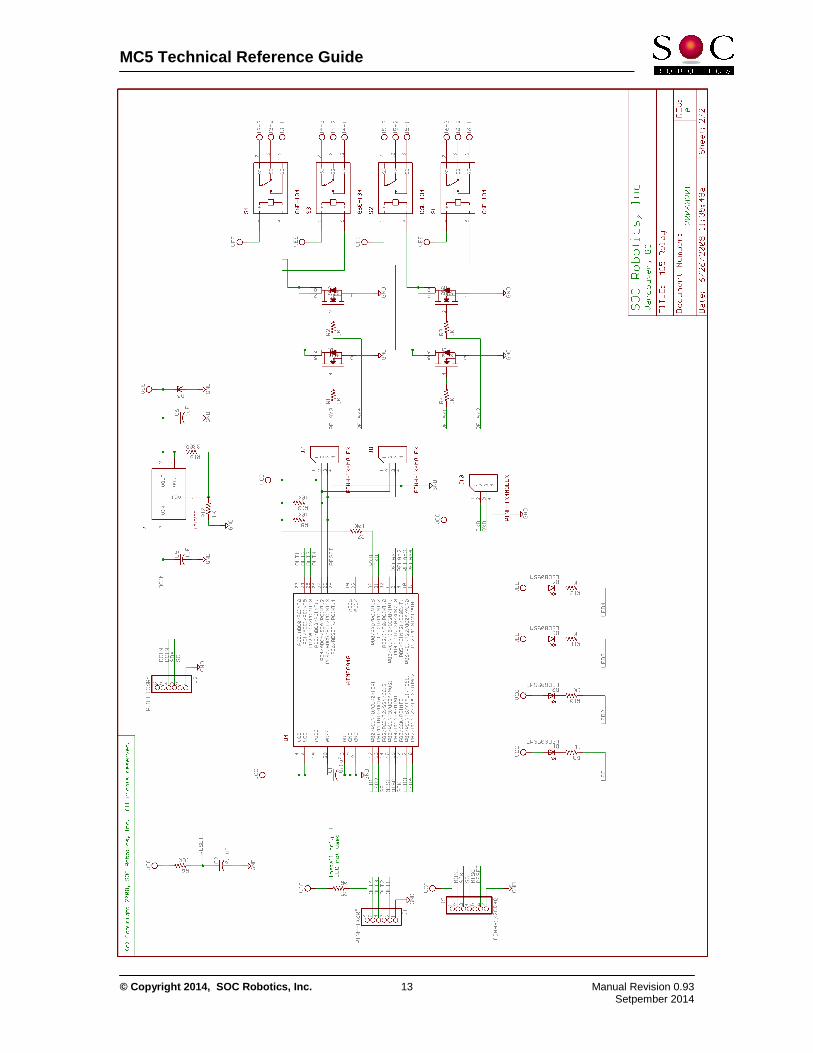
5.0 MC5 Circuit Schematics
MC5 Technical Reference Guide
© Copyright 2014, SOC Robotics, Inc. 13 Manual Revision 0.93 Setpember 2014
MC5 Technical Reference Guide
© Copyright 2014, SOC Robotics, Inc. 14 Manual Revision 0.93 Setpember 2014
Notes: