manufacturing processes 4-5 - libretexts
TRANSCRIPT
MANUFACTURING PROCESSES 4-5
Virasak

Book: Manufacturing Processes 4-5(Virasak)

This text is disseminated via the Open Education Resource (OER) LibreTexts Project (https://LibreTexts.org) and like thehundreds of other texts available within this powerful platform, it is freely available for reading, printing and"consuming." Most, but not all, pages in the library have licenses that may allow individuals to make changes, save, andprint this book. Carefully consult the applicable license(s) before pursuing such effects.
Instructors can adopt existing LibreTexts texts or Remix them to quickly build course-specific resources to meet the needsof their students. Unlike traditional textbooks, LibreTexts’ web based origins allow powerful integration of advancedfeatures and new technologies to support learning.
The LibreTexts mission is to unite students, faculty and scholars in a cooperative effort to develop an easy-to-use onlineplatform for the construction, customization, and dissemination of OER content to reduce the burdens of unreasonabletextbook costs to our students and society. The LibreTexts project is a multi-institutional collaborative venture to developthe next generation of open-access texts to improve postsecondary education at all levels of higher learning by developingan Open Access Resource environment. The project currently consists of 14 independently operating and interconnectedlibraries that are constantly being optimized by students, faculty, and outside experts to supplant conventional paper-basedbooks. These free textbook alternatives are organized within a central environment that is both vertically (from advance tobasic level) and horizontally (across different fields) integrated.
The LibreTexts libraries are Powered by MindTouch and are supported by the Department of Education Open TextbookPilot Project, the UC Davis Office of the Provost, the UC Davis Library, the California State University AffordableLearning Solutions Program, and Merlot. This material is based upon work supported by the National Science Foundationunder Grant No. 1246120, 1525057, and 1413739. Unless otherwise noted, LibreTexts content is licensed by CC BY-NC-SA 3.0.
Any opinions, findings, and conclusions or recommendations expressed in this material are those of the author(s) and donot necessarily reflect the views of the National Science Foundation nor the US Department of Education.
Have questions or comments? For information about adoptions or adaptions contact [email protected]. Moreinformation on our activities can be found via Facebook (https://facebook.com/Libretexts), Twitter(https://twitter.com/libretexts), or our blog (http://Blog.Libretexts.org).
This text was compiled on 01/14/2022
®

1 1/14/2022
TABLE OF CONTENTSThis textbook provides an introduction to the important area of manufacturing processes and explains the hows, whys, and whens ofvarious machining operations, set-ups, and procedures. Throughout this text, you will learn how machine tools operate, and when to useone particular machine instead of another. It is organized for students who plan to enter the manufacturing technology field and forthose who wish to develop the skills essential for advancement in this occupational cluster.
1: MILLING MACHINES1.1: MILLING MACHINES1.2: UNIT 1: TRAMMING THE HEAD1.3: UNIT 2: SPEEDS, FEEDS, AND TAPPING1.4: UNIT 3: SINE BAR1.5: UNIT 4: OFFSET BORING HEAD
2: LATHE MACHINES2.1: CHAPTER 2: LATHE MACHINE2.2: UNIT 2: SPEED AND FEED2.3: UNIT 3: CHUCKS2.4: UNIT 4: TURNING2.5: UNIT 5: TAPPING2.6: UNIT 6: LATHE THREADING
3: DRILL PRESSES3.1: CHAPTER 3: DRILL PRESS
4: BANDSAWS4.1: CHAPTER 4: BANDSAW
5: SURFACE GRINDERS5.1: CHAPTER 5: SURFACE GRINDER
6: HEAT TREATING6.1: CHAPTER 6: HEAT TREATING6.2: UNIT 2: HARDNESS TESTING
7: LEAN MANUFACTURING7.1: CHAPTER 7: LEAN MANUFACTURING
8: CNC8.1: CHAPTER 8: CNC8.2: UNIT 2: CNC MACHINE TOOL PROGRAMMABLE AXES AND POSITION DIMENSIONING SYSTEMS8.3: UNIT 3: VERTICAL MILLING CENTER MACHINE MOTION8.4: UNIT 4: CNC LANGUAGE AND STRUCTURE8.5: UNIT 5: CNC OPERATION8.6: UNIT 6: HAAS CONTROL8.7: UNIT 7: MASTERCAM
BACK MATTERINDEXGLOSSARY

1 1/14/2022
CHAPTER OVERVIEW1: MILLING MACHINES
1.1: MILLING MACHINES1.2: UNIT 1: TRAMMING THE HEAD1.3: UNIT 2: SPEEDS, FEEDS, AND TAPPING1.4: UNIT 3: SINE BAR1.5: UNIT 4: OFFSET BORING HEAD
1.1.1 12/3/2021 https://workforce.libretexts.org/@go/page/2268
1.1: Milling Machines
DescriptionThe milling machine is one of the most versatile machines in the shop. Usually they are used to mill flat surfaces, but theycan also be used to machine irregular surfaces. Additionally, the milling machine can be used to drill, bore, cut gears, andproduce slots into a workpiece.
The milling machine uses a multi-toothed cutter to remove metal from moving stock. There is also a quill feed lever on themill head to feed the spindle up and down. The bed can also be manually fed in the X, Y, and Z axes. Best practices are toadjust the Z axis first, then Y, then X.
When an axis is properly positioned and is no longer to be fed, use the gib locks to lock it in place.
It is common for milling machines to have a power feed on one or more axes. Normally, a forward/reverse lever and speedcontrol knob is provided to control the power feed. A power feed can produce a better surface finish than manual feedingbecause it is smoother. On long cuts, a power feed can reduce operator fatigue.
SafetyThe following procedures are suggested for the safe operation of a milling machine.
1. Have someone assist you when placing a heavy machine attachment like a rotary table, dividing head, or vise.2. Always refer to speed and feed tables.3. Always use cutting tools that are sharp and in good condition.4. Seat the workpiece against parallel bars or the bottom of the vice using a soft hammer or mallet. Check that the work is
firmly held and mounted squarely.5. Remove the wrench after tightening the vice.6. Most operations require a FORWARD spindle direction. There may be a few exceptions.7. Make sure there is enough clearance for all moving parts before starting a cut.8. Make sure to apply only the amount of feed that is necessary to form a clean chip.9. Before a drill bit breaks through the backside of the material, ease up on the drilling pressure.
10. Evenly apply and and maintain cutting fluids to prevent morphing.11. Withdraw drill bits frequently when drilling a deep hole. This helps to clear out the chips that may become trapped
within the hole.12. Do not reach near, over, or around a rotating cutter.13. Do not attempt to clean the machine or part when the spindle is in motion.14. Stop the machine before attempting to make adjustments or measurements.15. Use caution when using compressed air to remove chips and shavings. They flying particle may injure you, or those
around you.16. Use a shield or guard for protection against chips.17. Remove drill bits from the spindle before cleaning to prevent injury.18. Clean drill bits using a small brush or compressed air.19. Properly store arbors, milling cutters, collets, adapters, etc., after using them. They can be damaged if not properly
stored.20. Make sure the machine is turned off and clean before leaving the workspace.
1.2.1 1/14/2022 https://workforce.libretexts.org/@go/page/2269
1.2: Unit 1: Tramming the Head
Objective
After completing this unit, you should be able to:
Describe how to tram the mill head.Explain how to indicate the vise.Explain the use of spring collets.Describe the difference between climb vs. conventional milling.Explain how to use an edge finder.Describe how to set the quick change gearbox correctly.Describe how to square the stock.Describe face milling.Describe advanced workholding.
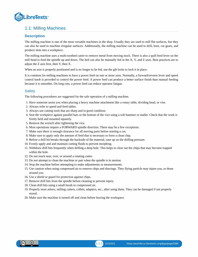
Tools For TrammingA dial indicator is a precision tool used to measure minute amounts of deflection between two surfaces.
When tramming, a dial indicator attached to the chuck is used to determine the orientation of the mill head to the milltable. The same wrench used to tighten and loosen the quill can be used to adjust the various bolts on the mill head.
Dial indicator used for tramming the head.
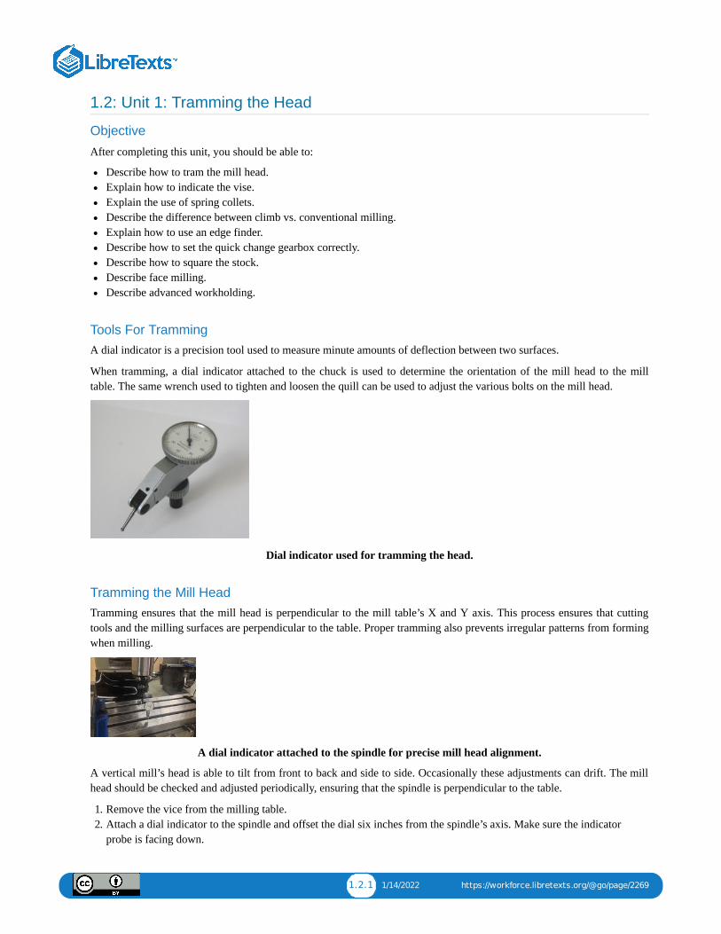
Tramming the Mill HeadTramming ensures that the mill head is perpendicular to the mill table’s X and Y axis. This process ensures that cuttingtools and the milling surfaces are perpendicular to the table. Proper tramming also prevents irregular patterns from formingwhen milling.
A dial indicator attached to the spindle for precise mill head alignment.
A vertical mill’s head is able to tilt from front to back and side to side. Occasionally these adjustments can drift. The millhead should be checked and adjusted periodically, ensuring that the spindle is perpendicular to the table.
1. Remove the vice from the milling table.2. Attach a dial indicator to the spindle and offset the dial six inches from the spindle’s axis. Make sure the indicator
probe is facing down.
1.2.2 1/14/2022 https://workforce.libretexts.org/@go/page/2269
3. Raise the mill table so that when it contacts the indicator, the indicator reads between 0.005 inches to 0.010 inches.This reading is called the preload.
4. Position the dial indicator so that it is visible, then set the bezel to zero.5. Hand-turn the spindle while watching the indicator.6. If the reading on the dial indicator stays at zero, the spindle is aligned.7. If the reading is not zero, continue tramming the head as shown below.
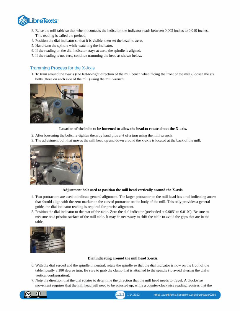
Tramming Process for the X-Axis1. To tram around the x-axis (the left-to-right direction of the mill bench when facing the front of the mill), loosen the six
bolts (three on each side of the mill) using the mill wrench.
Location of the bolts to be loosened to allow the head to rotate about the X-axis.
2. After loosening the bolts, re-tighten them by hand plus a ¼ of a turn using the mill wrench.3. The adjustment bolt that moves the mill head up and down around the x-axis is located at the back of the mill.
Adjustment bolt used to position the mill head vertically around the X-axis.
4. Two protractors are used to indicate general alignment. The larger protractor on the mill head has a red indicating arrowthat should align with the zero marker on the curved protractor on the body of the mill. This only provides a generalguide, the dial indicator reading is required for precise alignment.
5. Position the dial indicator to the rear of the table. Zero the dial indicator (preloaded at 0.005″ to 0.010″). Be sure tomeasure on a pristine surface of the mill table. It may be necessary to shift the table to avoid the gaps that are in thetable.
Dial indicating around the mill head X-axis.
6. With the dial zeroed and the spindle in neutral, rotate the spindle so that the dial indicator is now on the front of thetable, ideally a 180 degree turn. Be sure to grab the clamp that is attached to the spindle (to avoid altering the dial’svertical configuration).
7. Note the direction that the dial rotates to determine the direction that the mill head needs to travel. A clockwisemovement requires that the mill head will need to be adjusted up, while a counter-clockwise reading requires that the
1.2.3 1/14/2022 https://workforce.libretexts.org/@go/page/2269
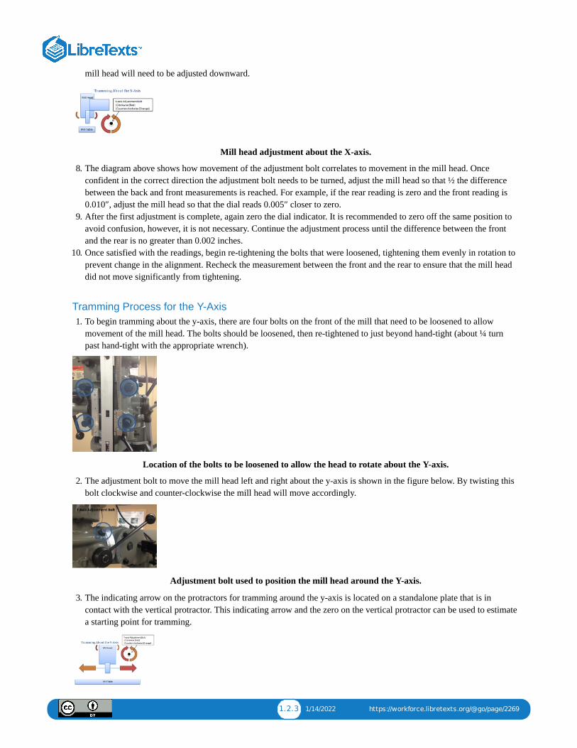
mill head will need to be adjusted downward.
Mill head adjustment about the X-axis.
8. The diagram above shows how movement of the adjustment bolt correlates to movement in the mill head. Onceconfident in the correct direction the adjustment bolt needs to be turned, adjust the mill head so that ½ the differencebetween the back and front measurements is reached. For example, if the rear reading is zero and the front reading is0.010″, adjust the mill head so that the dial reads 0.005″ closer to zero.
9. After the first adjustment is complete, again zero the dial indicator. It is recommended to zero off the same position toavoid confusion, however, it is not necessary. Continue the adjustment process until the difference between the frontand the rear is no greater than 0.002 inches.
10. Once satisfied with the readings, begin re-tightening the bolts that were loosened, tightening them evenly in rotation toprevent change in the alignment. Recheck the measurement between the front and the rear to ensure that the mill headdid not move significantly from tightening.
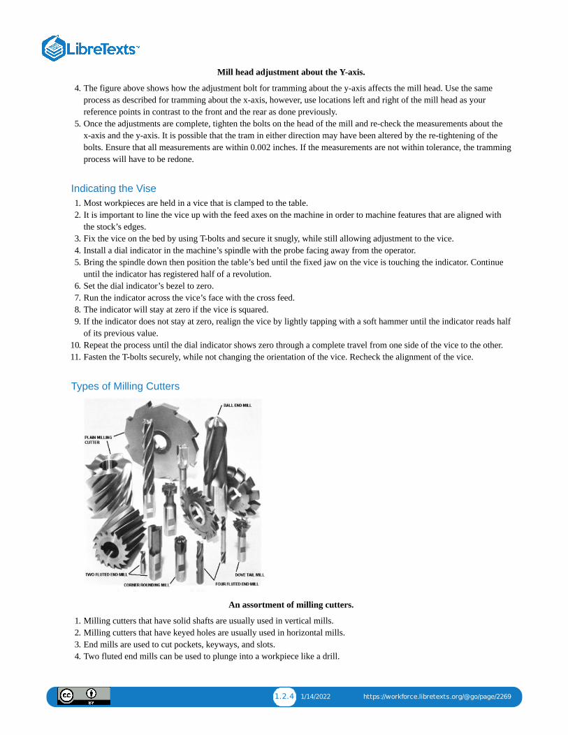
Tramming Process for the Y-Axis1. To begin tramming about the y-axis, there are four bolts on the front of the mill that need to be loosened to allow
movement of the mill head. The bolts should be loosened, then re-tightened to just beyond hand-tight (about ¼ turnpast hand-tight with the appropriate wrench).
Location of the bolts to be loosened to allow the head to rotate about the Y-axis.
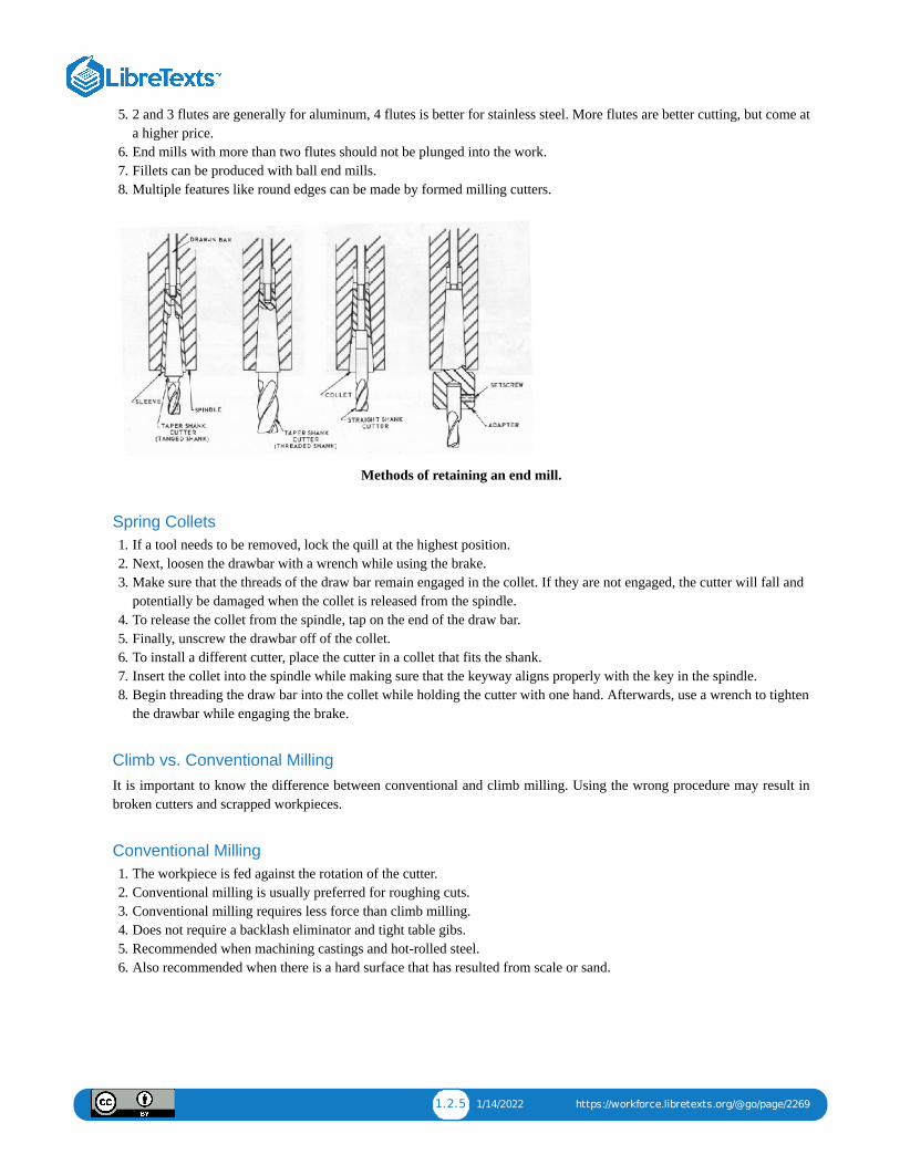
2. The adjustment bolt to move the mill head left and right about the y-axis is shown in the figure below. By twisting thisbolt clockwise and counter-clockwise the mill head will move accordingly.
Adjustment bolt used to position the mill head around the Y-axis.
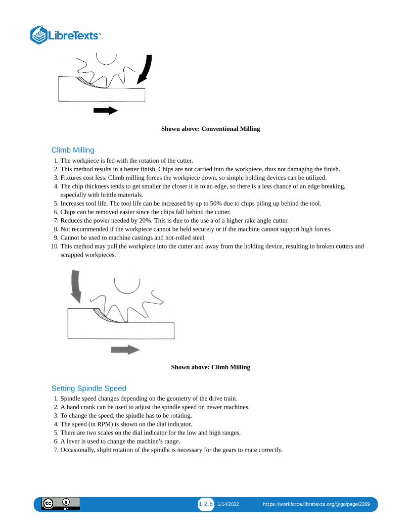
3. The indicating arrow on the protractors for tramming around the y-axis is located on a standalone plate that is incontact with the vertical protractor. This indicating arrow and the zero on the vertical protractor can be used to estimatea starting point for tramming.
1.2.4 1/14/2022 https://workforce.libretexts.org/@go/page/2269
Mill head adjustment about the Y-axis.
4. The figure above shows how the adjustment bolt for tramming about the y-axis affects the mill head. Use the sameprocess as described for tramming about the x-axis, however, use locations left and right of the mill head as yourreference points in contrast to the front and the rear as done previously.
5. Once the adjustments are complete, tighten the bolts on the head of the mill and re-check the measurements about thex-axis and the y-axis. It is possible that the tram in either direction may have been altered by the re-tightening of thebolts. Ensure that all measurements are within 0.002 inches. If the measurements are not within tolerance, the trammingprocess will have to be redone.
Indicating the Vise1. Most workpieces are held in a vice that is clamped to the table.2. It is important to line the vice up with the feed axes on the machine in order to machine features that are aligned with
the stock’s edges.3. Fix the vice on the bed by using T-bolts and secure it snugly, while still allowing adjustment to the vice.4. Install a dial indicator in the machine’s spindle with the probe facing away from the operator.5. Bring the spindle down then position the table’s bed until the fixed jaw on the vice is touching the indicator. Continue
until the indicator has registered half of a revolution.6. Set the dial indicator’s bezel to zero.7. Run the indicator across the vice’s face with the cross feed.8. The indicator will stay at zero if the vice is squared.9. If the indicator does not stay at zero, realign the vice by lightly tapping with a soft hammer until the indicator reads half
of its previous value.10. Repeat the process until the dial indicator shows zero through a complete travel from one side of the vice to the other.11. Fasten the T-bolts securely, while not changing the orientation of the vice. Recheck the alignment of the vice.
Types of Milling Cutters
An assortment of milling cutters.
1. Milling cutters that have solid shafts are usually used in vertical mills.2. Milling cutters that have keyed holes are usually used in horizontal mills.3. End mills are used to cut pockets, keyways, and slots.4. Two fluted end mills can be used to plunge into a workpiece like a drill.
1.2.5 1/14/2022 https://workforce.libretexts.org/@go/page/2269
5. 2 and 3 flutes are generally for aluminum, 4 flutes is better for stainless steel. More flutes are better cutting, but come ata higher price.
6. End mills with more than two flutes should not be plunged into the work.7. Fillets can be produced with ball end mills.8. Multiple features like round edges can be made by formed milling cutters.
Methods of retaining an end mill.
Spring Collets1. If a tool needs to be removed, lock the quill at the highest position.2. Next, loosen the drawbar with a wrench while using the brake.3. Make sure that the threads of the draw bar remain engaged in the collet. If they are not engaged, the cutter will fall and
potentially be damaged when the collet is released from the spindle.4. To release the collet from the spindle, tap on the end of the draw bar.5. Finally, unscrew the drawbar off of the collet.6. To install a different cutter, place the cutter in a collet that fits the shank.7. Insert the collet into the spindle while making sure that the keyway aligns properly with the key in the spindle.8. Begin threading the draw bar into the collet while holding the cutter with one hand. Afterwards, use a wrench to tighten
the drawbar while engaging the brake.
Climb vs. Conventional MillingIt is important to know the difference between conventional and climb milling. Using the wrong procedure may result inbroken cutters and scrapped workpieces.
Conventional Milling1. The workpiece is fed against the rotation of the cutter.2. Conventional milling is usually preferred for roughing cuts.3. Conventional milling requires less force than climb milling.4. Does not require a backlash eliminator and tight table gibs.5. Recommended when machining castings and hot-rolled steel.6. Also recommended when there is a hard surface that has resulted from scale or sand.
1.2.6 1/14/2022 https://workforce.libretexts.org/@go/page/2269
Shown above: Conventional Milling
Climb Milling1. The workpiece is fed with the rotation of the cutter.2. This method results in a better finish. Chips are not carried into the workpiece, thus not damaging the finish.3. Fixtures cost less. Climb milling forces the workpiece down, so simple holding devices can be utilized.4. The chip thickness tends to get smaller the closer it is to an edge, so there is a less chance of an edge breaking,
especially with brittle materials.5. Increases tool life. The tool life can be increased by up to 50% due to chips piling up behind the tool.6. Chips can be removed easier since the chips fall behind the cutter.7. Reduces the power needed by 20%. This is due to the use a of a higher rake angle cutter.8. Not recommended if the workpiece cannot be held securely or if the machine cannot support high forces.9. Cannot be used to machine castings and hot-rolled steel.
10. This method may pull the workpiece into the cutter and away from the holding device, resulting in broken cutters andscrapped workpieces.
Shown above: Climb Milling
Setting Spindle Speed1. Spindle speed changes depending on the geometry of the drive train.2. A hand crank can be used to adjust the spindle speed on newer machines.3. To change the speed, the spindle has to be rotating.4. The speed (in RPM) is shown on the dial indicator.5. There are two scales on the dial indicator for the low and high ranges.6. A lever is used to change the machine’s range.7. Occasionally, slight rotation of the spindle is necessary for the gears to mate correctly.
1.2.7 1/14/2022 https://workforce.libretexts.org/@go/page/2269
Using an Edge Finder1. The edges of a workpiece must be located before doing mill work that requires great accuracy. An edge finder helps in
finding the edges.2. 800-1200 spindle rpm is recommended.3. To use an edge finder, slightly offset the two halves so they wobble as they spin.4. Slowly move the workpiece towards the edge finder.5. The edge finder will center itself, then suddenly lose concentricity.6. The digital readout tells you the position of the spindle.7. The diameter of the edge finder is 0.200″. So adding or subtracting half of that (0.100″) will be the tool center.8. If centering on the top left, add 0.100″ to the X-axis and subtract 0.100″ from the Y-axis. If centering on the top right,
subtract 0.100″ from the X-axis and subtract 0.100″ from the Y-axis.9. Part Reference Zero is when the bit is zeroed on the X and X axes.
10. A pointed edge finder is a lot easier, but not as precise. Only use a pointed edge finder if precision is not necessary.
Using the Micrometer Dials1. Most manual feeds on a milling machine have micrometer dial indicators.2. If the length of the feed is known, the dial indicator should be set to that number (thousandths of an inch).3. To free the dial indicator, rotate the locking ring counterclockwise. Set the dial and re-tighten.4. Before setting the dial indicator, ensure that the table-driving mechanism backlash is taken up.5. It is common for newer machines to have digital readouts, which are preferable because they directly measure table
position. When using a digital readout, backlash concerns are negated.
Squaring Stock1. When making a square corner, vertically orient a completed edge in the vice and clamp it lightly to the part.2. Place machinist’s square against the completed edge and the base of the vice.3. Align the workpiece with the square by tapping it lightly with a rubber mallet.4. Firmly clamp the vice.5. The top edge of the part is ready to be milled.
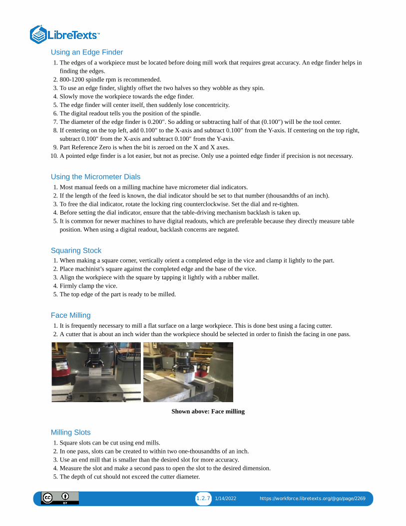
Face Milling1. It is frequently necessary to mill a flat surface on a large workpiece. This is done best using a facing cutter.2. A cutter that is about an inch wider than the workpiece should be selected in order to finish the facing in one pass.
Shown above: Face milling
Milling Slots1. Square slots can be cut using end mills.2. In one pass, slots can be created to within two one-thousandths of an inch.3. Use an end mill that is smaller than the desired slot for more accuracy.4. Measure the slot and make a second pass to open the slot to the desired dimension.5. The depth of cut should not exceed the cutter diameter.

1.2.8 1/14/2022 https://workforce.libretexts.org/@go/page/2269
Advanced Workholding1. Use a v-block to secure round stock in a vice. It can be used both horizontally and vertically.2. Clamping round stock in a v-block usually damages the stock.
Collet blocks are made to hold round workpieces.To mill features at 90 degree increments, use a square collet block.To mill features at 60 degree increments, use a hexagonal block.
3. It is easiest to set up stock when the features are perpendicular or parallel to the edges of the workpiece. It is moredifficult to set up a workpiece when features are not parallel or perpendicular to the edges. Sometimes, an angle platecan be used to mill stock at any desired angle.
4. Parts that don’t fit well in a vise can be directly secured to the table with hold-down clamps.5. Use parallels to create a gap between the work and bed.6. Slightly tilt the clamps down into the work.7. Rotary tables can be put on the bed to make circular features.
Rotary tables allow rotation of the workpiece.Use a dial indicator to precisely control the angle of rotation.
8. Use a ball for irregularly shaped workpieces. Make sure to only take a small cuts to avoid throwing the workpiece outof the vice.
UNIT TEST1. What tool is used for tramming the head?2. Explain the process for the X-axis tramming.3. Explain the process for the Y-axis tramming.4. What is the purpose of indicating the vise?5. Name three types of milling cutters.6. Explain how a spring collet works.7. What is the difference between conventional and climb milling?8. Describe briefly how a rotary table may be centered with the vertical mill spindle.9. Describe briefly how to set spindle speed on the milling machine.
10. What tool is used for milling large workpiece surfaces?

1.3.1 12/24/2021 https://workforce.libretexts.org/@go/page/2270
1.3: Unit 2: Speeds, Feeds, and Tapping
ObjectiveAfter completing this unit, you should be able to:
Identify and select vertical milling machine setups and operations for a variety of machining tasks.Select a proper cutting speed for different types of materials.Calculate cutting speeds and feeds for end milling operations.Explain how to correctly set up for power feed tapping.
Cutting SpeedCutting speed is defined as the speed at the outside edge of the tool as it is cutting. This is also known as surface speed.Surface speed, surface footage, and surface area are all directly related. If two tools of different sizes are turning at thesame revolutions per minute (RPM), the larger tool has a greater surface speed. Surface speed is measured in surface feetper minute (SFM). All cutting tools work on the surface footage principle. Cutting speeds depend primarily on the kind ofmaterial you are cutting and the kind of cutting tool you are using. The hardness of the work material has a great deal to dowith the recommended cutting speed. The harder the work material, the slower the cutting speed. The softer the workmaterial, the faster the recommended cutting speed (See Figure 1).
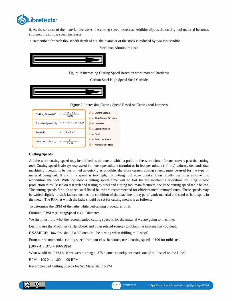
Steel Iron Aluminum Lead
Figure 1: Increasing Cutting Speed Based on work material hardness
The hardness of the cutting tool material will also have a great deal to do with the recommended cutting speed. The harderthe drill, the faster the cutting speed. The softer the drill, the slower the recommended cutting speed (See Figure 2).
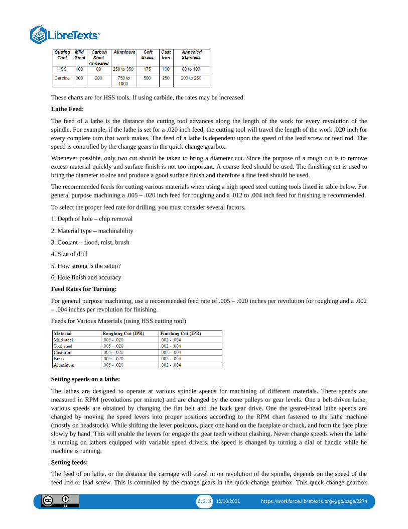
Carbon Steel High Speed Steel Carbide
Figure 2: Increasing Cutting Speed Based on Cutting tool hardness
Table 1: Cutting Speeds for Material Types
Type of Material Cutting Speed (SFM)
Low Carbon Steel 40-140
Medium Carbon Steel 70-120
High Carbon Steel 65-100
Free-machining Steel 100-150
Stainless Steel, C1 302, 304 60
Stainless Steel, C1 310, 316 70
Stainless Steel, C1 410 100
Stainless Steel, C1 416 140
Stainless Steel, C1 17-4, pH 50
Alloy Steel, SAE 4130, 4140 70
Alloy Steel, SAE 4030 90

1.3.2 12/24/2021 https://workforce.libretexts.org/@go/page/2270
Tool Steel 40-70
Cast Iron–Regular 80-120
Cast Iron–Hard 5-30
Gray Cast Iron 50-80
Aluminum Alloys 300-400
Nickel Alloy, Monel 400 40-60
Nickel Alloy, Monel K500 30-60
Nickel Alloy, Inconel 5-10
Cobalt Base Alloys 5-10
Titanium Alloy 20-60
Unalloyed Titanium 35-55
Copper 100-500
Bronze–Regular 90-150
Bronze–Hard 30-70
Zirconium 70-90
Brass and Aluminum 200-350
Silicon Free Non-Metallics 100-300
Silicon Containing Non-Metallics 30-70
Spindle SpeedOnce the SFM for a given material and tool is determined, the spindle can be calculated since this value is dependent oncutting speed and tool diameter.
RPM = (CS x 4) / DWhere:
RPM = Revolutions per minute.CS = Cutter speed in SFM.D = Tool Diameter in inches.
Milling FeedThe feed (milling machine feed) can be defined as the distance in inches per minute that the work moves into the cutter.
On the milling machines we have here at LBCC, the feed is independent of the spindle speed. This is a good arrangementand it permits faster feeds for larger, slowly rotating cutters.
The feed rate used on a milling machine depends on the following factors:
1. The depth and width of cut.2. The type of cutter.3. The sharpness of the cutter.4. The workpiece material.5. The strength and uniformity of the workpiece.6. The finish required.7. The accuracy required.8. The power and rigidity of the machine, the holding device, and the tooling setup.

1.3.3 12/24/2021 https://workforce.libretexts.org/@go/page/2270
Feed per ToothFeed per tooth, is the amount of material that should be removed by each tooth of the cutter as it revolves and advancesinto the work.
As the work advances into the cutter, each tooth of the cutter advances into the work an equal amount producing chips ofequal thickness.
This chip thickness or feed per tooth, along with the number of teeth in the cutter, form the basis for determining the rateof feed.
The ideal feed rate for milling is measured in inches per minute (IPM) and is calculated by this formula:
IPM = F x N x RPMWhere:
IPM = feed rate in inches per minuteF = feed per toothN = number of teethRPM = revolutions per minute
For Example:
Feeds for end mills used in vertical milling machines range from .001 to .002 in. feed per tooth for very small diametercutters on steel work material to .010 in. feed per tooth for large cutters in aluminum workpieces. Since the cutting speedfor mild steel is 90, the RPM for a 3/8” high-speed, two flute end mill is
RPM = CS x 4 / D = 90 x 4 / (3/8) = 360 /.375 = 960 RPMTo calculate the feed rate, we will select .002 inches per tooth
IPM = F x N x RPM = .002 x 2 x 960 = 3.84 IPM
Machine FeedThe machine movement that causes a cutting tool to cut into or along the surface of a workpiece is called feed.
The amount of feed is usually measured in thousandths of an inch in metal cutting.
Feeds are expressed in slightly different ways on various types of machines.
Drilling machines that have power feeds are designed to advance the drill a given amount for each revolution of thespindle. If we set the machine to feed at .006” the machine will feed .006” for every revolution of the spindle. This isexpressed as (IPR) inches per revolution
Tapping Procedures
Good Practices:
Using Tap Guides
Tap guides are an integral part in making a usable and straight thread. When using the lathe or the mill, the tap is alreadystraight and centered. When manually aligning a tap, be careful, as a 90° tap guide is much more accurate than the humaneye.
Using Oil
When drilling and tapping, it is crucial to use oil. It keeps the bits from squealing, makes the cut smoother, cleans out thechips, and keeps the drill and stock from overheating.
Pecking
Pecking helps ensure that bits don’t overheat and break when using them to drill or tap. Peck drilling involves drillingpartway through a part, then retracting it to remove chips, simultaneously allowing the piece to cool. Rotating the handle a

1.3.4 12/24/2021 https://workforce.libretexts.org/@go/page/2270
full turn then back a half turn is common practice. Whenever the bit or tap is backed out, remove as many chips as possibleand add oil to the surface between the drill or tap and the workpiece.
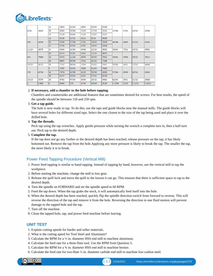
Hand Tapping Procedure1. Select a drill size from the chart.
When choosing a tap size, this chart is the first place to look.
1.3.5 12/24/2021 https://workforce.libretexts.org/@go/page/2270
2. If necessary, add a chamfer to the hole before tapping. Chamfers and countersinks are additional features that are sometimes desired for screws. For best results, the speed ofthe spindle should be between 150 and 250 rpm.
3. Get a tap guide. The hole is now ready to tap. To do this, use the taps and guide blocks near the manual mills. The guide blocks willhave several holes for different sized taps. Select the one closest to the size of the tap being used and place it over thedrilled hole.
4. Tap the threads. Peck tap using the tap wrenches. Apply gentle pressure while turning the wrench a complete turn in, then a half-turnout. Peck tap to the desired depth.
5. Complete the tap. If the tap does not go any further or the desired depth has been reached, release pressure on the tap; it has likelybottomed out. Remove the tap from the hole.Applying any more pressure is likely to break the tap. The smaller the tap,the more likely it is to break.
Power Feed Tapping Procedure (Vertical Mill)1. Power feed tapping is similar to hand tapping. Instead of tapping by hand, however, use the vertical mill to tap the
workpiece.2. Before starting the machine, change the mill to low gear.3. Release the quill lock and move the quill to the lowest it can go. This ensures that there is sufficient space to tap to the
desired depth.4. Turn the spindle on FORWARD and set the spindle speed to 60 RPM.5. Feed the tap down. When the tap grabs the stock, it will automatically feed itself into the hole.6. When the desired depth has been reached, quickly flip the spindle direction switch from forward to reverse. This will
reverse the direction of the tap and remove it from the hole. Reversing the direction in one fluid motion will preventdamage to the tapped hole and the tap.
7. Turn off the machine.8. Clean the tapped hole, tap, and power feed machine before leaving.
UNIT TEST1. Explain cutting speeds for harder and softer materials.2. What is the cutting speed for Tool Steel and Aluminum?3. Calculate the RPM for a ½ in. diameter HSS end mill to machine aluminum.4. Calculate the feed rate for a three-flute tool. Use the RPM from Question 3.5. Calculate the RPM for a ¾ in. diameter HSS end mill to machine bronze.6. Calculate the feed rate for two-flute ½ in. diameter carbide end mill to machine low-carbon steel.

1.3.6 12/24/2021 https://workforce.libretexts.org/@go/page/2270
7. What is the purpose of pecking when using them to drill or tap?8. Select a proper drill size for 5/16 – 24 tap.9. Why are cutting fluids used?
10. Describe the difference between hand and power feed tapping.
1.4.1 1/7/2022 https://workforce.libretexts.org/@go/page/2271
1.4: Unit 3: Sine Bar
Objective
After completing this unit, you should be able to:
Understand the principle of the sine bar.Explain how to use a sine bar correctly.Understand slip gauge blocks and wringing.Calculate gauge block height.
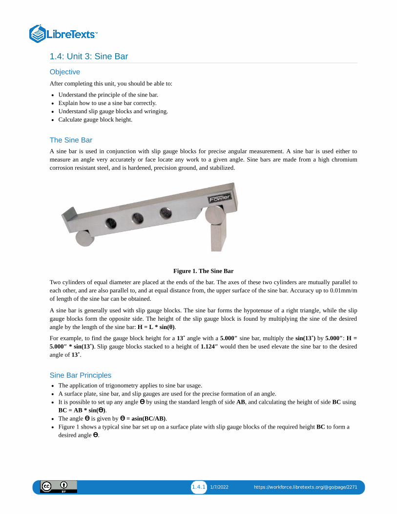
The Sine BarA sine bar is used in conjunction with slip gauge blocks for precise angular measurement. A sine bar is used either tomeasure an angle very accurately or face locate any work to a given angle. Sine bars are made from a high chromiumcorrosion resistant steel, and is hardened, precision ground, and stabilized.
Figure 1. The Sine Bar
Two cylinders of equal diameter are placed at the ends of the bar. The axes of these two cylinders are mutually parallel toeach other, and are also parallel to, and at equal distance from, the upper surface of the sine bar. Accuracy up to 0.01mm/mof length of the sine bar can be obtained.
A sine bar is generally used with slip gauge blocks. The sine bar forms the hypotenuse of a right triangle, while the slipgauge blocks form the opposite side. The height of the slip gauge block is found by multiplying the sine of the desiredangle by the length of the sine bar: H = L * sin(θ).
For example, to find the gauge block height for a 13˚ angle with a 5.000″ sine bar, multiply the sin(13˚) by 5.000″: H =5.000″ * sin(13˚). Slip gauge blocks stacked to a height of 1.124″ would then be used elevate the sine bar to the desiredangle of 13˚.
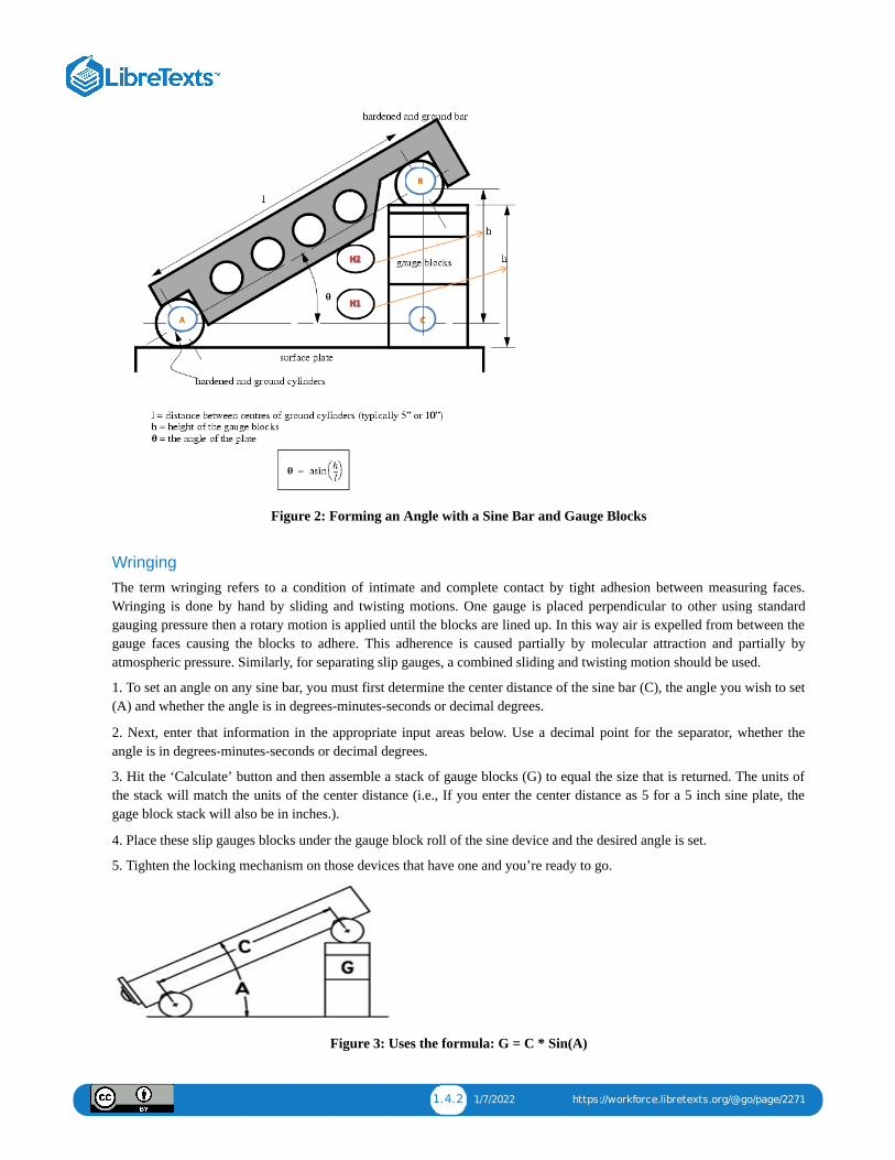
Sine Bar PrinciplesThe application of trigonometry applies to sine bar usage.A surface plate, sine bar, and slip gauges are used for the precise formation of an angle.It is possible to set up any angle ϴ by using the standard length of side AB, and calculating the height of side BC usingBC = AB * sin(ϴ).The angle ϴ is given by ϴ = asin(BC/AB).Figure 1 shows a typical sine bar set up on a surface plate with slip gauge blocks of the required height BC to form adesired angle ϴ.
1.4.2 1/7/2022 https://workforce.libretexts.org/@go/page/2271
Figure 2: Forming an Angle with a Sine Bar and Gauge Blocks
WringingThe term wringing refers to a condition of intimate and complete contact by tight adhesion between measuring faces.Wringing is done by hand by sliding and twisting motions. One gauge is placed perpendicular to other using standardgauging pressure then a rotary motion is applied until the blocks are lined up. In this way air is expelled from between thegauge faces causing the blocks to adhere. This adherence is caused partially by molecular attraction and partially byatmospheric pressure. Similarly, for separating slip gauges, a combined sliding and twisting motion should be used.
1. To set an angle on any sine bar, you must first determine the center distance of the sine bar (C), the angle you wish to set(A) and whether the angle is in degrees-minutes-seconds or decimal degrees.
2. Next, enter that information in the appropriate input areas below. Use a decimal point for the separator, whether theangle is in degrees-minutes-seconds or decimal degrees.
3. Hit the ‘Calculate’ button and then assemble a stack of gauge blocks (G) to equal the size that is returned. The units ofthe stack will match the units of the center distance (i.e., If you enter the center distance as 5 for a 5 inch sine plate, thegage block stack will also be in inches.).
4. Place these slip gauges blocks under the gauge block roll of the sine device and the desired angle is set.
5. Tighten the locking mechanism on those devices that have one and you’re ready to go.
Figure 3: Uses the formula: G = C * Sin(A)
1.4.3 1/7/2022 https://workforce.libretexts.org/@go/page/2271
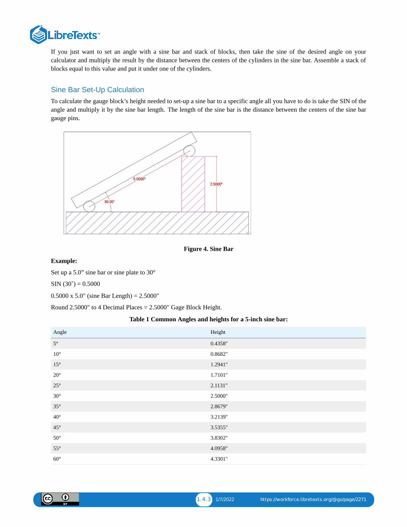
If you just want to set an angle with a sine bar and stack of blocks, then take the sine of the desired angle on yourcalculator and multiply the result by the distance between the centers of the cylinders in the sine bar. Assemble a stack ofblocks equal to this value and put it under one of the cylinders.
Sine Bar Set-Up CalculationTo calculate the gauge block’s height needed to set-up a sine bar to a specific angle all you have to do is take the SIN of theangle and multiply it by the sine bar length. The length of the sine bar is the distance between the centers of the sine bargauge pins.
Figure 4. Sine Bar
Example:
Set up a 5.0” sine bar or sine plate to 30°
SIN (30˚) = 0.5000
0.5000 x 5.0″ (sine Bar Length) = 2.5000″
Round 2.5000″ to 4 Decimal Places = 2.5000″ Gage Block Height.
Table 1 Common Angles and heights for a 5-inch sine bar:
Angle Height
5° 0.4358″
10° 0.8682″
15° 1.2941″
20° 1.7101″
25° 2.1131″
30° 2.5000″
35° 2.8679″
40° 3.2139″
45° 3.5355″
50° 3.8302″
55° 4.0958″
60° 4.3301″

1.4.4 1/7/2022 https://workforce.libretexts.org/@go/page/2271
Sine Bar UsageTo measure a known angle or locate any work to a given angle:
1. Always use a perfectly flat and clean surface plate.2. Place one roller on the surface plate and the other roller on the slip gauge block stack of height H.3. Let the sine bar be set to an angle ϴ.4. Then sin(ϴ) = H/L, where L is the distance between the center.5. Thus knowing ϴ, H can be found and any work can be set out at this angle as the top face of the sine bar is inclined at
angle ϴ to the surface plate.6. For better result both rollers must placed on slip gauge block of height H1 and H2 respectively. See above figure,7. ??? ? = (?? − ??) / L
UNIT TEST1. Describe the use of the sine bar.2. Calculate the required sine bar elevation for angle of 37˚.3. A 5.00” sine bar is elevated 1.50”. Calculate the angle.4. Determine the elevation for 30˚ using 5.00” sine bar.5. Determine the elevation for 42˚ using 5.00” sine bar.6. A 5.00” sine bar is elevated 1.25”. What angle is established?7. What gauge block stack would establish an angle of 35˚ using a 5.00” sine bar?
1.5.1 12/31/2021 https://workforce.libretexts.org/@go/page/2272
1.5: Unit 4: Offset Boring Head
OBJECTIVE
After completing this unit, you should be able to:
Identify offset Boring headExplain how to correct set up for Rotary Table.
Offset Boring HeadThe offset boring is an attachment that fits the milling machine spindle and permits most drilled holes to have a betterfinish and greater diameter accuracy. Offset boring head are used to create large hole when tolerance do not allow for adrill bit or do not have a large enough drill or reamer. A offset boring head can be used to enlarge hole, or adjust holecenterline in certain instances.
Safety:
Be sure all set screws are tight before operation. Be sure offset boring head has a clearance to fit into hole when boring.Remove Allen wrench before turning the mill one. Double check mill speed before operation.
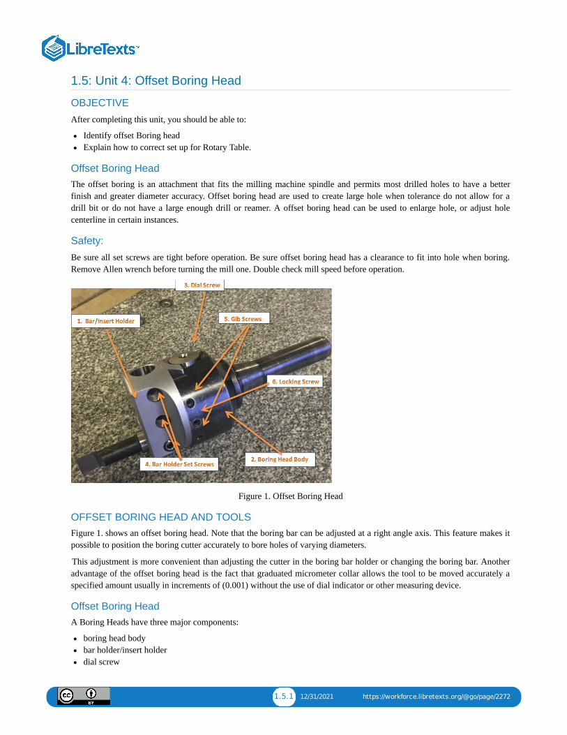
Figure 1. Offset Boring Head
OFFSET BORING HEAD AND TOOLSFigure 1. shows an offset boring head. Note that the boring bar can be adjusted at a right angle axis. This feature makes itpossible to position the boring cutter accurately to bore holes of varying diameters.
This adjustment is more convenient than adjusting the cutter in the boring bar holder or changing the boring bar. Anotheradvantage of the offset boring head is the fact that graduated micrometer collar allows the tool to be moved accurately aspecified amount usually in increments of (0.001) without the use of dial indicator or other measuring device.
Offset Boring HeadA Boring Heads have three major components:
boring head bodybar holder/insert holderdial screw
1.5.2 12/31/2021 https://workforce.libretexts.org/@go/page/2272
The boring head body has a black oxide finish for rust prevention. The bar holder or insert holder (#1) has been satinchromed for wear resistance. The dial screw (#3) has been precision ground to give accurate movement of the barholder/insert holder in the dove tail slide. The gib tension has been preset at the factory. The two gib screws (#5) shouldnot be loosened to make size adjustments. These screws are for adjusting the gib pressure only and are filled with red waxto prevent accidental adjustment. The locking screw (#6) is the only screw used for making size changes to the boringhead.
Diameter AdjustmentTo adjust the diameter of an Allied Criterion standard boring head:
1. Loosen the locking screw (#6).
2. Turn the dial screw (#3) clockwise to increase the diameter and counterclockwise to decrease the diameter.
3. Tighten the locking screw (#6). Adjusting Standard Boring Heads
Procedure:1. Set up and carefully align the work parallel to the table travel.
2. Align the center of the Milling Machine spindle with the reference point on the work.
3. Spot the location of hole with a center drill or spotting tool.
4. Drilled hole over ½ inch, Be sure offset boring head has a clearance to fit into hole when boring.
5. Install bore head into Milling Machine.
6. Install boring bar and tighten set screw and loosen lock screw and adjust boring bar to hole edge.
7. Recheck the work alignment, as well as the alignment of the spindle with the reference point, to make sure it has notshifted. If any error is evident, it will necessary to repeat procedure 6 before processing.
8. Adjust Milling Machine speed for hole size and material.
9. Engage worm feed on Mill. Bring quill to material. Pull handle out to engage power feed. When at desired depth pushhand back to disengage feed and then turn off Mill. Remove boring head from hole.
10. Finish bore hole to the required size.
NOTE: Repeat Procedures 6-9 until hole is desired size.
Rotary Table
A rotary table can be used to make arcs and circles. For example, the circular T-slot in the swivel base for a vise can bemade using a rotary table. Rotary tables can also be used for indexing, where a workpiece must be rotated an exact amountbetween operations. You can make gears on a milling machine using a rotary table. Dividing plates make indexing with arotary table easier.
Rotary tables are most commonly mounted “flat”, with the table rotating around a vertical axis, in the same plane as thecutter of a vertical milling machine. An alternate setup is to mount the rotary table on its end (or mount it “flat” on a90° angle plate), so that it rotates about a horizontal axis. In this configuration a tailstock can also be used, thus holding theworkpiece “between centers.”
With the table mounted on a secondary table, the workpiece is accurately centered on the rotary table’s axis, which in turnis centered on the cutting tool’s axis. All three axes are thus coaxial. From this point, the secondary table can be offset ineither the X or Y direction to set the cutter the desired distance from the workpiece’s center. Thisallows concentric machining operations on the workpiece. Placing the workpiece eccentrically a set distance from thecenter permits more complex curves to be cut. As with other setups on a vertical mill, the milling operation can be eitherdrilling a series of concentric, and possibly equidistant holes, or face or end milling either circular or semicircular shapesand contours.
A rotary table can be used:
1.5.3 12/31/2021 https://workforce.libretexts.org/@go/page/2272
To machine spanner flats on a boltTo drill equidistant holes on a circular flangeTo cut a round piece with a protruding tangTo create large-diameter holes, via milling in a circular toolpath, on small milling machines that don’t have the powerto drive large twist drills (>0.500″/>13 mm)To mill helixesTo cut complex curves (with proper setup)To cut straight lines at any angleTo cut arcsWith the addition of a compound table on top of the rotary table, the user can move the center of rotation to anywhereon the part being cut. This enables an arc to be cut at any place on the part.To cut circular pieces
Setting Up a Rotary TableWhen using a rotary table on a Milling Machine, whether to mill an arc or drill holes in some circular pattern, there are twothings that must be done to set up the workpiece. First, the workpiece must be centered on the rotary table. Second, therotary table must be centered under the spindle. Then the mill table can be moved some appropriate distance and you canstart cutting.
You could center the table under the spindle first, by indicating off the hole in the center of the table. Then you couldmount the workpiece on the table and indicate off the workpiece. There are two problems with this approach. First, you areassuming that the hole in the table is true and centered. That may or may not be true. Second, this approach risks a sort ofaccumulation of errors, as you’re measuring from two different features (the rotary table’s hole and some feature on theworkpiece). First center the workpiece on the rotary table, and then center the rotary table under the spindle.
To center the workpiece on the rotary table, spin the rotary table and watch for deflection of the indicator pointer. Adjustthe position of the mill table(X and Y) as required, until the needle no longer deflects.
You dial in a rotary table by placing a dial test indicator in a chuck or collet in the spindle, which is then rotated by handwith the indicator tip in contact with the hole of the rotary table. If your machine can be taken out of gear, it helps to do so,so the spindle swings freely. It’s obviously easier to use a drill chuck than a collet, too, so you have something that you canturn easily. Make your adjustments using the saddle and table hand wheels.
Once you have center located (the indicator will read the same as you rotate the spindle, it’s a very good idea to set both ofyour dials at “0”, instead of marking some random location. Make sure you have backlash set properly, too. Set the dial isreading in a positive direction so it’s easy to count off any changes, and you never have to remember which way you hadchosen to set backlash. I also always mark the table and saddle with a wax pencil so I know where center is located. Thattells you when to stop turning the handle when “0” comes around if you want to get the table back to center to load anotherpart.
Once you have located center of the table and have set dials and locked the table and saddle, you usually have some featureon your part that you desire to be centered. In some cases it may be a hole, in others it may be the outside edge of thecircular part. In a case like either of these, it’s common practice to use the same indicator and swing it inside the hole orthe perimeter of the part. The perimeter may require you to get around clamps, which can usually be accomplished byusing the quill to move the indicator up far enough to clear them. When you dial in parts to a table that has already beenlocated, you tap the part around, you do not make adjustments with the saddle or table handles. Tap the part after you’vesnugged up the clamps slightly, so it doesn’t move about wildly. You can achieve virtually perfect location that way,certainly as close as the machine is capable of working.
After the workpiece is centered on the rotary table, you now turn the spindle by hand, so the indicator tip sweeps the insideof the hole. Adjust the position of the mill table as required until no needle deflection is noted.
Setting up your Rotary TableHow to center the spindle over the center of the rotary table. Here are some of the methods to use.
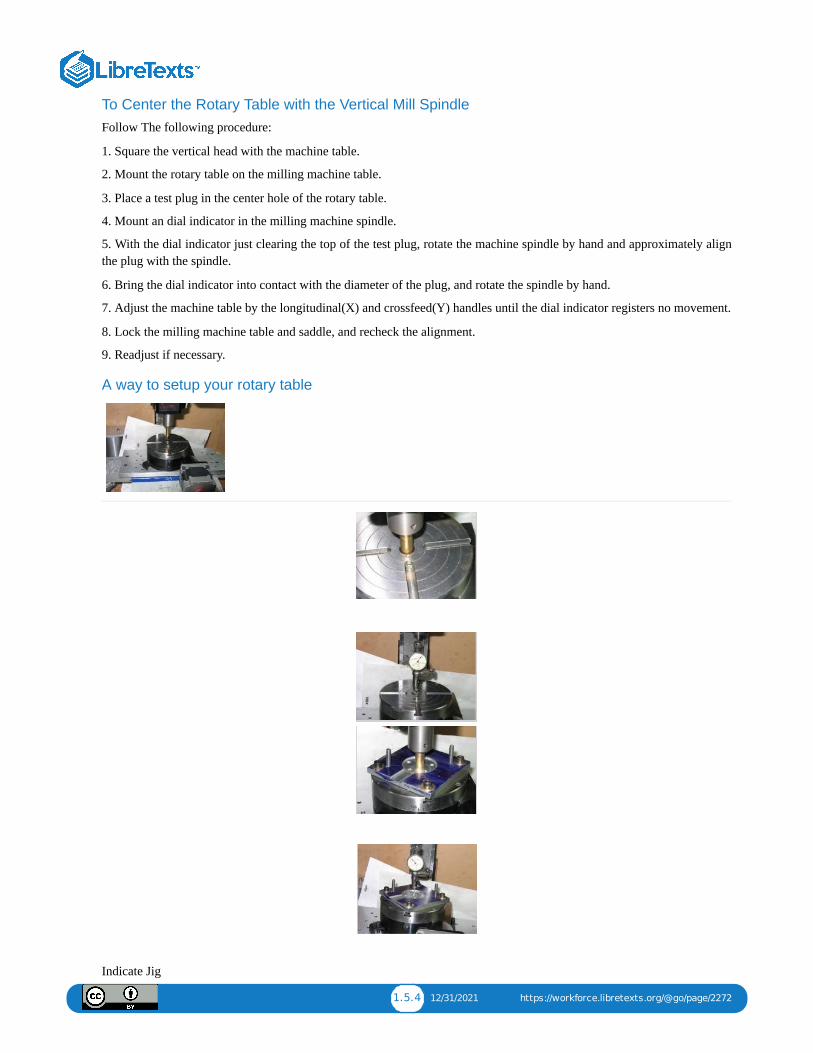
1.5.4 12/31/2021 https://workforce.libretexts.org/@go/page/2272
To Center the Rotary Table with the Vertical Mill SpindleFollow The following procedure:
1. Square the vertical head with the machine table.
2. Mount the rotary table on the milling machine table.
3. Place a test plug in the center hole of the rotary table.
4. Mount an dial indicator in the milling machine spindle.
5. With the dial indicator just clearing the top of the test plug, rotate the machine spindle by hand and approximately alignthe plug with the spindle.
6. Bring the dial indicator into contact with the diameter of the plug, and rotate the spindle by hand.
7. Adjust the machine table by the longitudinal(X) and crossfeed(Y) handles until the dial indicator registers no movement.
8. Lock the milling machine table and saddle, and recheck the alignment.
9. Readjust if necessary.
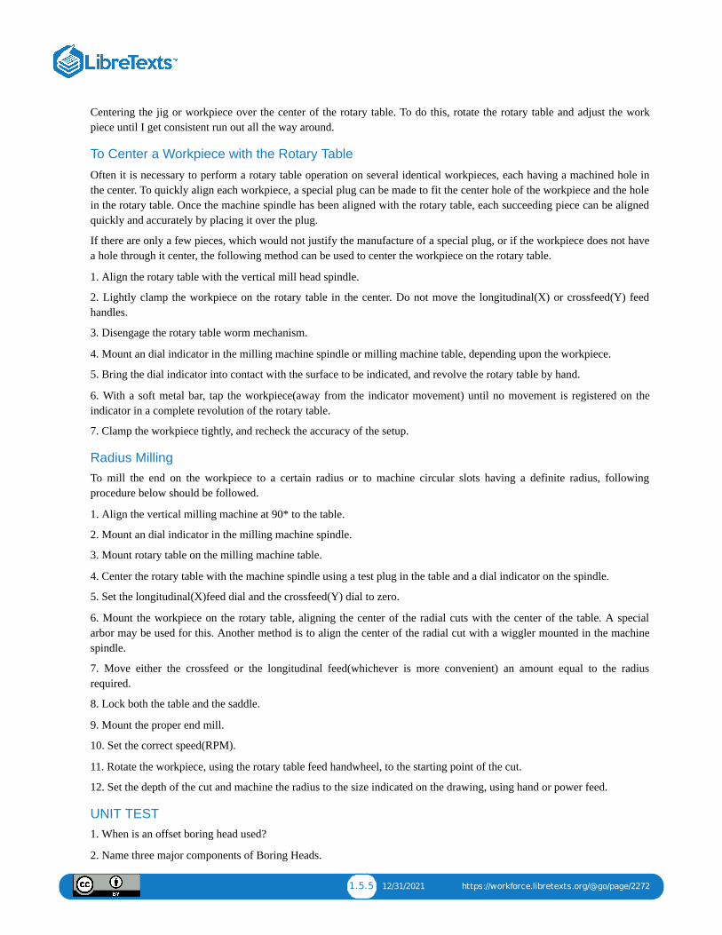
A way to setup your rotary table
Indicate Jig
1.5.5 12/31/2021 https://workforce.libretexts.org/@go/page/2272
Centering the jig or workpiece over the center of the rotary table. To do this, rotate the rotary table and adjust the workpiece until I get consistent run out all the way around.
To Center a Workpiece with the Rotary Table
Often it is necessary to perform a rotary table operation on several identical workpieces, each having a machined hole inthe center. To quickly align each workpiece, a special plug can be made to fit the center hole of the workpiece and the holein the rotary table. Once the machine spindle has been aligned with the rotary table, each succeeding piece can be alignedquickly and accurately by placing it over the plug.
If there are only a few pieces, which would not justify the manufacture of a special plug, or if the workpiece does not havea hole through it center, the following method can be used to center the workpiece on the rotary table.
1. Align the rotary table with the vertical mill head spindle.
2. Lightly clamp the workpiece on the rotary table in the center. Do not move the longitudinal(X) or crossfeed(Y) feedhandles.
3. Disengage the rotary table worm mechanism.
4. Mount an dial indicator in the milling machine spindle or milling machine table, depending upon the workpiece.
5. Bring the dial indicator into contact with the surface to be indicated, and revolve the rotary table by hand.
6. With a soft metal bar, tap the workpiece(away from the indicator movement) until no movement is registered on theindicator in a complete revolution of the rotary table.
7. Clamp the workpiece tightly, and recheck the accuracy of the setup.
Radius MillingTo mill the end on the workpiece to a certain radius or to machine circular slots having a definite radius, followingprocedure below should be followed.
1. Align the vertical milling machine at 90* to the table.
2. Mount an dial indicator in the milling machine spindle.
3. Mount rotary table on the milling machine table.
4. Center the rotary table with the machine spindle using a test plug in the table and a dial indicator on the spindle.
5. Set the longitudinal(X)feed dial and the crossfeed(Y) dial to zero.
6. Mount the workpiece on the rotary table, aligning the center of the radial cuts with the center of the table. A specialarbor may be used for this. Another method is to align the center of the radial cut with a wiggler mounted in the machinespindle.
7. Move either the crossfeed or the longitudinal feed(whichever is more convenient) an amount equal to the radiusrequired.
8. Lock both the table and the saddle.
9. Mount the proper end mill.
10. Set the correct speed(RPM).
11. Rotate the workpiece, using the rotary table feed handwheel, to the starting point of the cut.
12. Set the depth of the cut and machine the radius to the size indicated on the drawing, using hand or power feed.
UNIT TEST1. When is an offset boring head used?
2. Name three major components of Boring Heads.

1.5.6 12/31/2021 https://workforce.libretexts.org/@go/page/2272
3. Why is the locking screw tightened after tool slide adjustments have been made.
4. Why does the tool slide have multiple holes to hold boring tools?
5. What determines the cutting speed in boring?
6. For what purpose may a rotary table be used?
7. What is the purpose of the hole in the center of a rotary table?
8. Describe briefly how a rotary table may be centered with a vertical mill spindle.
9. Describe briefly how a single workpiece would be centered on a rotary table.
10. Explain how a large radius may be cut using a rotary table.
Chapter Attribution InformationThis chapter was derived from the following sources.
Tapping Procedures derived from Drilling and Tapping by the University of Idaho, CC:BY-SA 3.0.Tramming derived from Tramming Mill Head by the University of Idaho, CC:BY-SA 3.0.Dial Indicator (Photo) derived from Dial Gauge by Wikimedia, CC:BY-SA 3.0.Milling Machine Procedures derived from Mechanical Engineering Tools by the Massachusetts Institute ofTechnology, CC:BY-NC-SA 4.0.Rotary Table derived from Rotary Table by the University of Idaho, CC:BY-SA 3.0.

1 1/14/2022
CHAPTER OVERVIEW2: LATHE MACHINES
2.1: CHAPTER 2: LATHE MACHINE2.2: UNIT 2: SPEED AND FEED2.3: UNIT 3: CHUCKS2.4: UNIT 4: TURNING2.5: UNIT 5: TAPPING2.6: UNIT 6: LATHE THREADING
2.1.1 12/24/2021 https://workforce.libretexts.org/@go/page/2273
2.1: Chapter 2: Lathe MachineUnit 1: The Engine Lathe
OBJECTIVEAfter completing this unit, you should be able to:
• Identify the most important parts of the Lathe and their functions.
• Understand the Lathe safety rules. • Describe setup a cutting tool for machining.
• Describe mount workpiece in the lathe.
• Explain how to install cutting tool.
• Describe the positioning the tool.
• Describe how to centering the workpiece and tailstock center.
Description
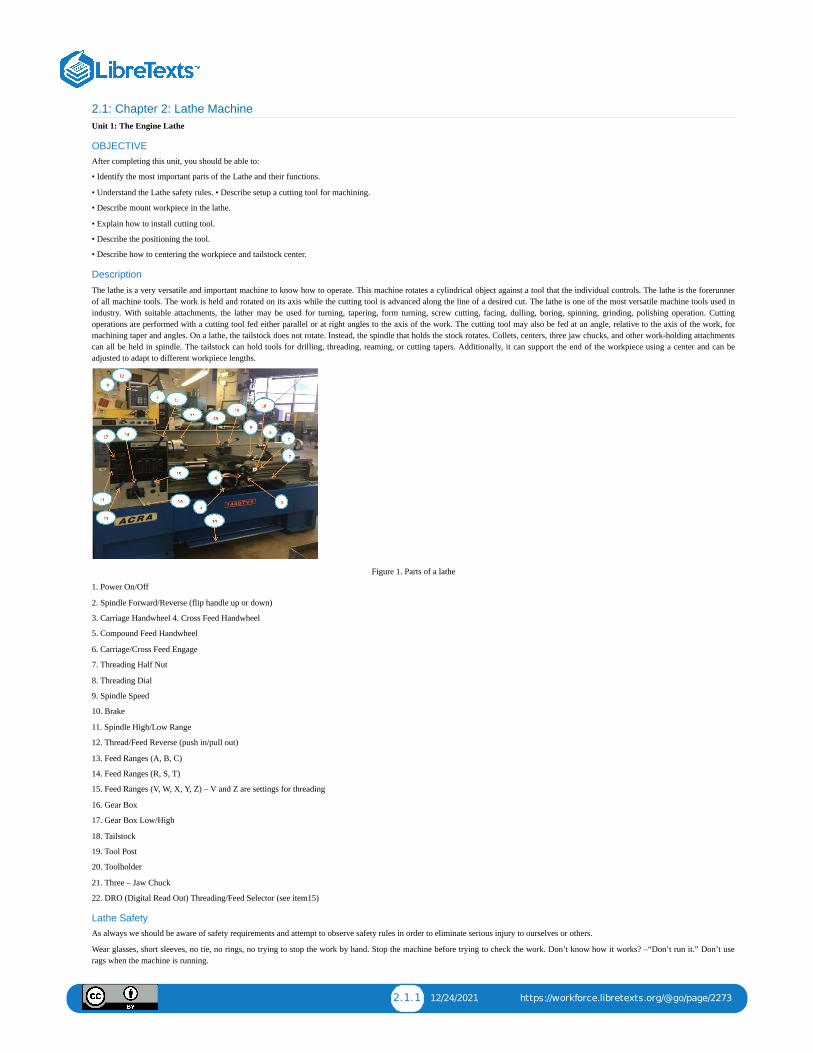
The lathe is a very versatile and important machine to know how to operate. This machine rotates a cylindrical object against a tool that the individual controls. The lathe is the forerunnerof all machine tools. The work is held and rotated on its axis while the cutting tool is advanced along the line of a desired cut. The lathe is one of the most versatile machine tools used inindustry. With suitable attachments, the lather may be used for turning, tapering, form turning, screw cutting, facing, dulling, boring, spinning, grinding, polishing operation. Cuttingoperations are performed with a cutting tool fed either parallel or at right angles to the axis of the work. The cutting tool may also be fed at an angle, relative to the axis of the work, formachining taper and angles. On a lathe, the tailstock does not rotate. Instead, the spindle that holds the stock rotates. Collets, centers, three jaw chucks, and other work-holding attachmentscan all be held in spindle. The tailstock can hold tools for drilling, threading, reaming, or cutting tapers. Additionally, it can support the end of the workpiece using a center and can beadjusted to adapt to different workpiece lengths.
Figure 1. Parts of a lathe
1. Power On/Off
2. Spindle Forward/Reverse (flip handle up or down)
3. Carriage Handwheel 4. Cross Feed Handwheel
5. Compound Feed Handwheel
6. Carriage/Cross Feed Engage
7. Threading Half Nut
8. Threading Dial
9. Spindle Speed
10. Brake
11. Spindle High/Low Range
12. Thread/Feed Reverse (push in/pull out)
13. Feed Ranges (A, B, C)
14. Feed Ranges (R, S, T)
15. Feed Ranges (V, W, X, Y, Z) – V and Z are settings for threading
16. Gear Box
17. Gear Box Low/High
18. Tailstock
19. Tool Post
20. Toolholder
21. Three – Jaw Chuck
22. DRO (Digital Read Out) Threading/Feed Selector (see item15)
Lathe SafetyAs always we should be aware of safety requirements and attempt to observe safety rules in order to eliminate serious injury to ourselves or others.
Wear glasses, short sleeves, no tie, no rings, no trying to stop the work by hand. Stop the machine before trying to check the work. Don’t know how it works? –“Don’t run it.” Don’t userags when the machine is running.

2.1.2 12/24/2021 https://workforce.libretexts.org/@go/page/2273
1. Remove the chuck key from the chuck immediately after use. Do not turn the lathe on if the chuck is still in the chuck key.
2. Turn the chuck or faceplate through by hand unless there are binding or clearance issues.
3. It is important that the chuck or faceplate is securely tightened onto the lathe’s spindle.
4. Move the tool bit to a safe distance from the chuck, collet, or face plate when inserting or removing your part.
5. Place the tool post holder to the left of the compound slide. This will ensure that the compound slide will not run into the spindle or chuck attachments.
6. When installing and removing chucks, face plates, and centers, always be sure all mating surfaces are clean and free from burrs.
7. Make sure the tool bit is sharp and has correct clearance angles.
8. Clamp the tool bit as short as possible in the tool holder to prevent it from vibrating or breaking.
9. Evenly apply and maintain cutting fluids. This will prevent morphing.
10. Do not run a threaded spindle in reverse.
11. Never run the machine faster than the recommended speed for the specific material.
12. If a chuck or faceplate is jammed on the spindle nose, contact an instructor to remove it.
13. If any filing is done on work revolving in the lathe, file left handed to prevent slipping into the chuck.
14. Always stop the machine before taking measurements.
15. Stop the machine when removing long stringy chips. Remove them with a pair of pliers.
16. Make sure that the tailstock is locked in place and that the proper adjustments are made if the work is being turned between centers.
17. When turning between centers, avoid cutting completely through the piece.
18. Do not use rags while the machine is running.
19. Remove tools from the tool post and tailstock before cleaning.
20. Do not use compressed air to clean the lathe.
21. Use care when cleaning the lathe. The cutting tools are sharp, the chips are sharp, and the workpiece may be sharp.
22. Make sure the machine is turned off and clean before leaving the workspace. Always remove the chuck wrench after use, avoid horseplay, keep floor area clean. Use care when cleaningthe lathe, the cutting tools are sharp, the chips are sharp, and the workpiece may be sharp.
Here are some questions which are important when running a lathe:
• Why is proper Cutting Speed important?
When set too high the tool breaks down quickly, time is lost replacing or reconditioning the tool. Too low of a CS results in low production.
Know:
• Depth of cut for Roughing.
• Depth of cut for Finishing.
Notice the largest roughing cuts range from .010 to .030 depending on the material being machined, and .002 to .012 for the finish feed for the different materials.
• Feedrate for Roughing cut
• Feedrate for Finishing cut
Notice the Feedrate for roughing cuts range from .005 to .020 depending on the material being machined, and .002 to .004 for the finish feed for the different materials.
Cutting Tool Terminology
There are many different tools that can be used for turning, facing, and parting operations on the lathe. Each tool is usually composed of carbide as a base material, but can include othercompounds. This section covers the different appearances and uses of lathe cutting tools.
Figure A:depicts a standard turning tool to create a semi-square shoulder. If there is enough material behind the cutting edge, the tool can also be used for roughing.
Figure B:depicts a standard turning tool with a lead angl

2.1.3 12/24/2021 https://workforce.libretexts.org/@go/page/2273
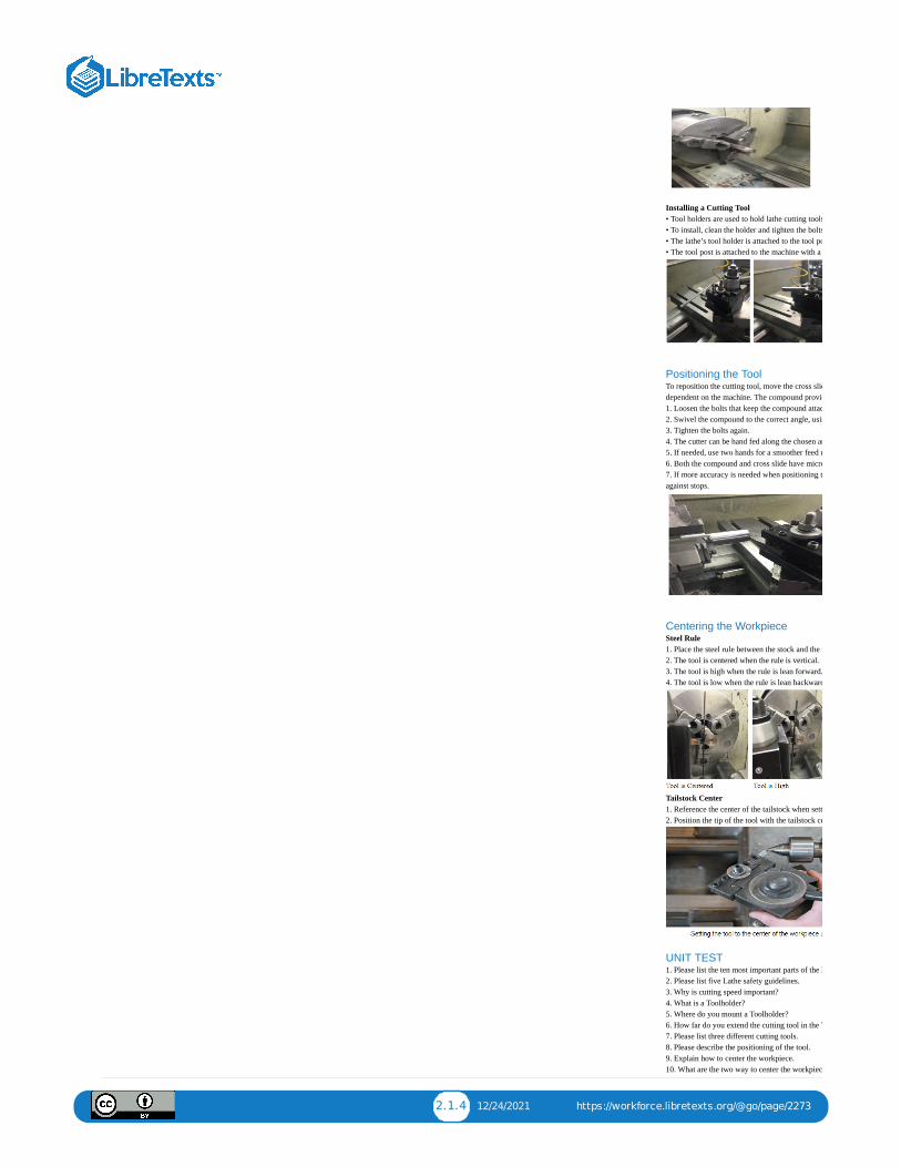
To setup a Cutting Tool for Machining• Move the toolpost to the left-hand side of the co• Mount a toolholder in the toolpost so that the se• Insert the proper cutting tool into the toolholder• Set the cutting tool point to center height. Chec• Tighten the toolpost securely to prevent it from
To Mount Workpiece in Lathe• Check that the line center is running true. If it iagain for trueness.• Clean the lathe center points and the center hole• Adjust the tailstock spindle until it projects abo• Loosen the tailstock clamp nut or lever.• Place the end of the workpiece in the chuck and• Tighten the tailstock clamp nut or level.
2.1.4 12/24/2021 https://workforce.libretexts.org/@go/page/2273
Installing a Cutting Tool• Tool holders are used to hold lathe cutting tools• To install, clean the holder and tighten the bolts• The lathe’s tool holder is attached to the tool po• The tool post is attached to the machine with a
Positioning the ToolTo reposition the cutting tool, move the cross sliddependent on the machine. The compound provid1. Loosen the bolts that keep the compound attac2. Swivel the compound to the correct angle, usin3. Tighten the bolts again.4. The cutter can be hand fed along the chosen an5. If needed, use two hands for a smoother feed r6. Both the compound and cross slide have micro7. If more accuracy is needed when positioning tagainst stops.
Centering the WorkpieceSteel Rule1. Place the steel rule between the stock and the t2. The tool is centered when the rule is vertical.3. The tool is high when the rule is lean forward.4. The tool is low when the rule is lean backward
Tailstock Center1. Reference the center of the tailstock when sett2. Position the tip of the tool with the tailstock ce
UNIT TEST1. Please list the ten most important parts of the L2. Please list five Lathe safety guidelines.3. Why is cutting speed important?4. What is a Toolholder?5. Where do you mount a Toolholder?6. How far do you extend the cutting tool in the T7. Please list three different cutting tools.8. Please describe the positioning of the tool.9. Explain how to center the workpiece.10. What are the two way to center the workpiec

2.2.1 12/10/2021 https://workforce.libretexts.org/@go/page/2274
2.2: Unit 2: Speed and Feed
OBJECTIVE
After completing this unit, you should be able to:
• Describe the Speed, Feed, and Depth of cut.
• Determine the RPM for different materials and diameters.
• Describe the federate for turning.
• Describe the setting speed.
• Describe the setting feed.
To operate any machine efficiently, the machinist must learn the importance of cutting speeds and feeds. A lot of time canbe lost if the machines are not set at the proper speed and feeds for the workpiece.
In order to eliminate this time loss, we can, and should, use recommended metal-removal rates that have been researchedand tested by steel and cutting-tool manufactures. We can find these cutting speeds and metal removal rates in ourappendix or in the Machinery’s Handbook.
We can control the feed on an engine lathe by using the change gears in the quick-change gearbox. Our textbookrecommends whenever possible, only two cuts should be taken to bring a diameter to size: a roughing cut and a finishingcut.
It has been my experience to take at least three cuts. One to remove excess material quickly: the rough cut, one cut toestablish finish and to allow for tool pressure, and one to finish the cut.
If you were cutting thread all day long: day in and day out. You might set the lathe up for only two cuts. One cut to removeall but .002 or .003 of material and the last cut to hold size and finish. This is done all the time in some shops today.
Have you noticed that when you take a very small cut on the lathe .001 to .002 that the finish is usually poor, and that onthe rough cut you made prior to this very light cut, the finish was good? The reason for this is: some tool pressure isdesirable when making finish cuts.
IPM = Inches Per Minute
RPM = Revolutions Per Minute
Feed = IPM
#T = Number of teeth in cutter
Feed/Tooth = Chip load per tooth allowed for material
Chip/Tooth = Feed per tooth allowed for material
Feed Rate = ChipTooth × #T × RPM
Example: Material = Aluminum 3” Cutter, 5 Teeth Chip Load = 0.018 per tooth RPM = 3000 IPS = 0.018 × 5 × 3000 =270 Inches Per Minute
Speed, Feed, and Depth of Cut1. Cutting speed is defined as the speed (usually in feet per minute) of a tool when it is cutting the work.
2. Feed rate is defined as tool’s distance travelled during one spindle revolution.
3. Feed rate and cutting speed determine the rate of material removal, power requirements, and surface finish.
4. Feed rate and cutting speed are mostly determined by the material that’s being cut. In addition, the deepness of the cut,size and condition of the lathe, and rigidity of the lathe should still be considered.
5. Roughing cuts (0.01 in. to 0.03 in. depth of cut) for most aluminum alloys run at a feedrate of .005 inches per minute(IPM) to 0.02 IPM while finishing cuts (0.002 in. to 0.012 in. depth of cut) run at 0.002 IPM to 0.004 IPM.
2.2.2 12/10/2021 https://workforce.libretexts.org/@go/page/2274
6. As the softness of the material decreases, the cutting speed increases. Additionally, as the cutting tool material becomesstronger, the cutting speed increases.
7. Remember, for each thousandth depth of cut, the diameter of the stock is reduced by two thousandths.
Steel Iron Aluminum Lead
Figure 1: Increasing Cutting Speed Based on work material hardness
Carbon Steel High Speed Steel Carbide
Figure 2: Increasing Cutting Speed Based on Cutting tool hardness
Cutting Speeds:
A lathe work cutting speed may be defined as the rate at which a point on the work circumference travels past the cuttingtool. Cutting speed is always expressed in meters per minute (m/min) or in feet per minute (ft/min.) industry demands thatmachining operations be performed as quickly as possible; therefore current cutting speeds must be used for the type ofmaterial being cut. If a cutting speed is too high, the cutting tool edge breaks down rapidly, resulting in time lostrecondition the tool. With too slow a cutting speed, time will be lost for the machining operation, resulting in lowproduction rates. Based on research and testing by steel and cutting tool manufacturers, see lathe cutting speed table below.The cutting speeds for high speed steel listed below are recommended for efficient metal removal rates. These speeds maybe varied slightly to shift factors such as the condition of the machine, the type of work material and sand or hard spots inthe metal. The RPM at which the lathe should be set for cutting metals is as follows:
To determine the RPM of the lathe while performing procedures on it:
Formula: RPM = (CuttingSpeed x 4) / Diameter
We first must find what the recommended cutting speed is for the material we are going to machine.
Learn to use the Machinery’s Handbook and other related sources to obtain the information you need.
EXAMPLE: How fast should a 3/8 inch drill be turning when drilling mild steel?
From our recommended cutting speed from our class handouts, use a cutting speed of 100 for mild steel.
(100 x 4) / .375 = 1066 RPM
What would the RPM be if we were turning a .375 diameter workpiece made out of mild steel on the lathe?
RPM = 100 X4 / 1.00 = 400 RPM
Recommended Cutting Speeds for Six Materials in RPM
2.2.3 12/10/2021 https://workforce.libretexts.org/@go/page/2274
These charts are for HSS tools. If using carbide, the rates may be increased.
Lathe Feed:
The feed of a lathe is the distance the cutting tool advances along the length of the work for every revolution of thespindle. For example, if the lathe is set for a .020 inch feed, the cutting tool will travel the length of the work .020 inch forevery complete turn that work makes. The feed of a lathe is dependent upon the speed of the lead screw or feed rod. Thespeed is controlled by the change gears in the quick change gearbox.
Whenever possible, only two cut should be taken to bring a diameter cut. Since the purpose of a rough cut is to removeexcess material quickly and surface finish is not too important. A coarse feed should be used. The finishing cut is used tobring the diameter to size and produce a good surface finish and therefore a fine feed should be used.
The recommended feeds for cutting various materials when using a high speed steel cutting tools listed in table below. Forgeneral purpose machining a .005 – .020 inch feed for roughing and a .012 to .004 inch feed for finishing is recommended.
To select the proper feed rate for drilling, you must consider several factors.
1. Depth of hole – chip removal
2. Material type – machinability
3. Coolant – flood, mist, brush
4. Size of drill
5. How strong is the setup?
6. Hole finish and accuracy
Feed Rates for Turning:
For general purpose machining, use a recommended feed rate of .005 – .020 inches per revolution for roughing and a .002– .004 inches per revolution for finishing.
Feeds for Various Materials (using HSS cutting tool)
Setting speeds on a lathe:
The lathes are designed to operate at various spindle speeds for machining of different materials. There speeds aremeasured in RPM (revolutions per minute) and are changed by the cone pulleys or gear levels. One a belt-driven lathe,various speeds are obtained by changing the flat belt and the back gear drive. One the geared-head lathe speeds arechanged by moving the speed levers into proper positions according to the RPM chart fastened to the lathe machine(mostly on headstock). While shifting the lever positions, place one hand on the faceplate or chuck, and form the face plateslowly by hand. This will enable the levers for engage the gear teeth without clashing. Never change speeds when the latheis running on lathers equipped with variable speed drivers, the speed is changed by turning a dial of handle while hemachine is running.
Setting feeds:
The feed of on lathe, or the distance the carriage will travel in on revolution of the spindle, depends on the speed of thefeed rod or lead screw. This is controlled by the change gears in the quick-change gearbox. This quick change gearbox
2.2.4 12/10/2021 https://workforce.libretexts.org/@go/page/2274
obtains its drive from the head stock spindle through the end gear train. A feeds and thread chart mounted on the front ofthe quick-change gearbox indicates the various feeds and metric pitches or thread per inch which may be obtained bysetting levers to the positions indicated.
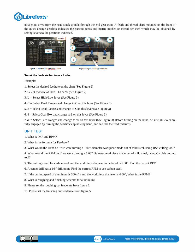
To set the feedrate for Acura Lathe:
Example:
1. Select the desired feedrate on the chart (See Figure 2)
2. Select federate of .007 – LCS8W (See Figure 2)
3. L = Select High/Low lever (See Figure 3)
4. C = Select Feed Ranges and change to C on this lever (See Figure 3)
5. S = Select Feed Ranges and change to S on this lever (See Figure 3)
6. 8 = Select Gear Box and change to 8 on this lever (See Figure 3)
7.W = Select Feed Ranges and change to W on this lever (See Figure 3) Before turning on the lathe, be sure all levers arefully engaged by turning the headstock spindle by hand, and see that the feed rod turns.
UNIT TEST1. What is IMP and RPM?
2. What is the formula for Feedrate?
3. What would the RPM be if we were turning a 1.00” diameter workpiece made out of mild steel, using HSS cutting tool?
4. What would the RPM be if we were turning a 1.00” diameter workpiece made out of mild steel, using Carbide cuttingtool?
5. The cutting speed for carbon steel and the workpiece diameter to be faced is 6.00”. Find the correct RPM.
6. A center drill has a 1/8” drill point. Find the correct RPM to use carbon steel.
7. If the cutting speed of aluminum is 300 sfm and the workpiece diameter is 4.00”, What is the RPM?
8. What is roughing and finishing federate for aluminum?
9. Please set the roughing cut feederate from figure 5.
10. Please set the finishing cut feederate from figure 5.
2.3.1 12/10/2021 https://workforce.libretexts.org/@go/page/2275
2.3: Unit 3: Chucks
OBJECTIVE
After completing this unit, you should be able to:
• Describe different type chucks.
Chucks:
Some work pieces, because of their size and shape, cannot be held and machined between lathe centers. Lather chucks areused extensively for holding work for machining operations. The most commonly used lathe chucks are the three jawuniversal, four jaw independent, and the collects chuck.
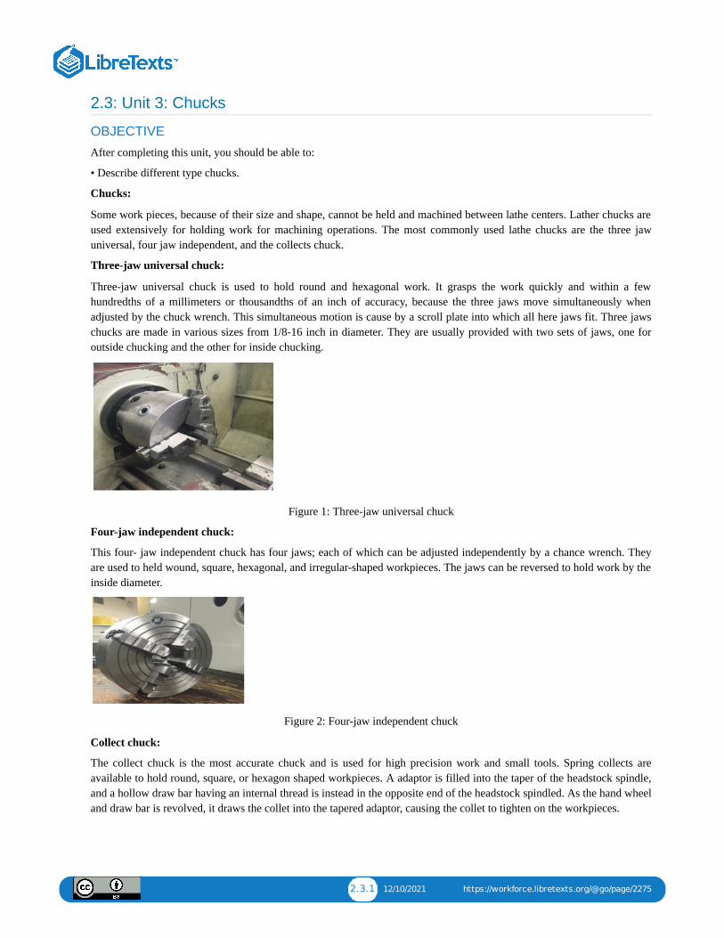
Three-jaw universal chuck:
Three-jaw universal chuck is used to hold round and hexagonal work. It grasps the work quickly and within a fewhundredths of a millimeters or thousandths of an inch of accuracy, because the three jaws move simultaneously whenadjusted by the chuck wrench. This simultaneous motion is cause by a scroll plate into which all here jaws fit. Three jawschucks are made in various sizes from 1/8-16 inch in diameter. They are usually provided with two sets of jaws, one foroutside chucking and the other for inside chucking.
Figure 1: Three-jaw universal chuck
Four-jaw independent chuck:
This four- jaw independent chuck has four jaws; each of which can be adjusted independently by a chance wrench. Theyare used to held wound, square, hexagonal, and irregular-shaped workpieces. The jaws can be reversed to hold work by theinside diameter.
Figure 2: Four-jaw independent chuck
Collect chuck:
The collect chuck is the most accurate chuck and is used for high precision work and small tools. Spring collects areavailable to hold round, square, or hexagon shaped workpieces. A adaptor is filled into the taper of the headstock spindle,and a hollow draw bar having an internal thread is instead in the opposite end of the headstock spindled. As the hand wheeland draw bar is revolved, it draws the collet into the tapered adaptor, causing the collet to tighten on the workpieces.
2.3.2 12/10/2021 https://workforce.libretexts.org/@go/page/2275
Figure 3: Collect chuck
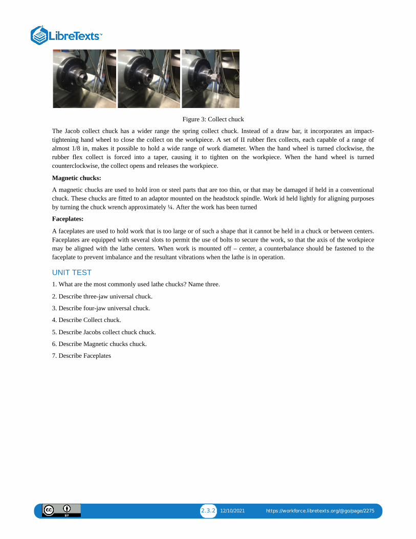
The Jacob collect chuck has a wider range the spring collect chuck. Instead of a draw bar, it incorporates an impact-tightening hand wheel to close the collect on the workpiece. A set of II rubber flex collects, each capable of a range ofalmost 1/8 in, makes it possible to hold a wide range of work diameter. When the hand wheel is turned clockwise, therubber flex collect is forced into a taper, causing it to tighten on the workpiece. When the hand wheel is turnedcounterclockwise, the collect opens and releases the workpiece.
Magnetic chucks:
A magnetic chucks are used to hold iron or steel parts that are too thin, or that may be damaged if held in a conventionalchuck. These chucks are fitted to an adaptor mounted on the headstock spindle. Work id held lightly for aligning purposesby turning the chuck wrench approximately ¼. After the work has been turned
Faceplates:
A faceplates are used to hold work that is too large or of such a shape that it cannot be held in a chuck or between centers.Faceplates are equipped with several slots to permit the use of bolts to secure the work, so that the axis of the workpiecemay be aligned with the lathe centers. When work is mounted off – center, a counterbalance should be fastened to thefaceplate to prevent imbalance and the resultant vibrations when the lathe is in operation.
UNIT TEST1. What are the most commonly used lathe chucks? Name three.
2. Describe three-jaw universal chuck.
3. Describe four-jaw universal chuck.
4. Describe Collect chuck.
5. Describe Jacobs collect chuck chuck.
6. Describe Magnetic chucks chuck.
7. Describe Faceplates

2.4.1 1/6/2022 https://workforce.libretexts.org/@go/page/2276
2.4: Unit 4: Turning
OBJECTIVE
After completing this unit, you should be able to:
• Describe the rough and finishing turning.
• Describe the turning shoulder.
• Describe the facing cut.
• Explain how to set up for center/spot drill.
• Explain how to set up for boring.
• Explain how to set up for knurling.
• Correctly set up a workpiece for parting/grooving.
• Determine the taper calculation.
• Correctly set up workpiece in a 4-jaw chuck.
Workpiece is generally machined on a lathe for two reasons: to cut it to size and to produce a true diameter. Work that mustbe cut to size and have the same diameter along the entire length of the workpiece involves the operation of parallelturning. Many factors determine the amount of materials which can be removed on a lathe. A diameter should be cut tosize in two cuts: an roughing cut and finishing cut.
To have the same diameter at each end of the workpiece, the lathe centers must be in line.
To set an accurate depth of cutProcedure:
1. Set the compound rest at 30 degrees.
2. Attach a roughing or finishing tool. Use a right-handed turning tool if feeding the saddle in the direction of theheadstock.
3. Move the tool post to the left hand side of the compound rest and set the tool bit to right height center.
4. Set the lathe to the correct speed and feed for the diameter and type of material being cut.
5. Start the lathe and take a light cut about .005 inch and .250 inch long at the right hand end of the workpiece.
6. Stop the lathe, but do not move the crossfeed screw handle.
7. Move the cutting tool to the end of the workpiece (to the right side) by turning the carriage hand wheel.
8. Measure the work and calculate the amount of material to be removed.
9. Turn the graduated collar half the amount of material to be removed. For example, if .060 inch to be removed, thegraduated collar should be turned in .030 inch, since the cut is taken off the circumference of the workpiece.
10. Remember, for each thousandth depth of cut, the diameter of the stock is reduced by two thousandths.
Rough Turning
The operation of rough turning is used to remove as much metal as possible in the shortest length of time. Accuracy andsurface finish are not important in this operation. Therefore, max depth of .030 inch and a .020 to .030 inch feed isrecommended. Workpiece is generally rough turned to within about .030 inch of the finished size in a few cuts as possible.
Procedure:
1. Set the lathe to the correct speed and feedrate for the type and size of the material being cut.

2.4.2 1/6/2022 https://workforce.libretexts.org/@go/page/2276
2. Adjust the quick change gear box for a .010 to .030 inch feed, depending on the depth of cut and condition of themachine.
3. For Example: .010
4. Move the tool holder to the left hand side of the compound rest and set the tool bit to right height to center.
5. Tighten the tool post securely to prevent the toolholder from moving during the machining operation.
6. Take a light trial cut at the right hand end of the workpiece for about .250 inch length.
7. Measure the workpiece and adjust the tool bit for the proper depth of cut.
8. Cut along for about .250 inch, stop the lathe and check the diameter for size. The diameter should be about .030 inchover the finish side.
9. Re-adjust the depth of cut, if necessary.
Finish TurningFinish turning on a lathe, which follows rough turning , produces a smooth surface finish, and cuts the workpiece to anaccurate size. Factors such as the condition of the cutting tool bit, the rigidity of the machine and workpiece and the lathespeed and feedrate, may affect the type of surface finish produced.
Procedure:
1. Check to see if the cutting edge of the tool bit is free from nicks, burns, etc. It is good practice to home the cutting edgebefore you take a finish cut.
2. Set the lathe to the recommended speed and feedrate. The feed rate used depends upon the surface finish required.
3. Take a light trial cut about .250 inch long at the right hand end of the work to produce a true diameter, set the cuttingtool bit to the diameter and set the graduated collar to the right diameter.
4. Stop the lathe, measure the diameter.
5. Set the depth of cut for half the amount of material to be removed.
6. Cut along for .250 inch, stop the lathe and check the diameter.
7. Re-adjust the depth of cut, if necessary and finish turn the diameter. In order to produce the truest diameter possible,finish turn workpiece to the required size. Should it be necessary to finish a diameter by filming or polishing, never leavemore than .002 to .003 inch for this operation.
Turning to a Shoulder
When turning more than one diameter on a workpiece. The change in diameter or step, is known as shoulder.
Three common types of shoulder:
1. Square
2. Filleted corner
3. Angular of Tapered
Procedure:
1. With a workpiece mounted in a lathe, lay out the shoulder position from the finished end of the workpiece. In case offilleted shoulders, all sufficient length to permit the proper radius to be formed on the finished shoulder.
2. Place the point of the tool bit at this mark and cut a small groove around the circumference to mark off the length.
3. With a turning tool bit, rough and finish turn the workpiece about .063 inch of the required length.
4. Set up an end facing tool. Chalk the small diameter of the workpiece, and bring the cutting tool up until it just removesthe chalk mark.
5. Note the reading on the graduated collar of the cross feed handle.
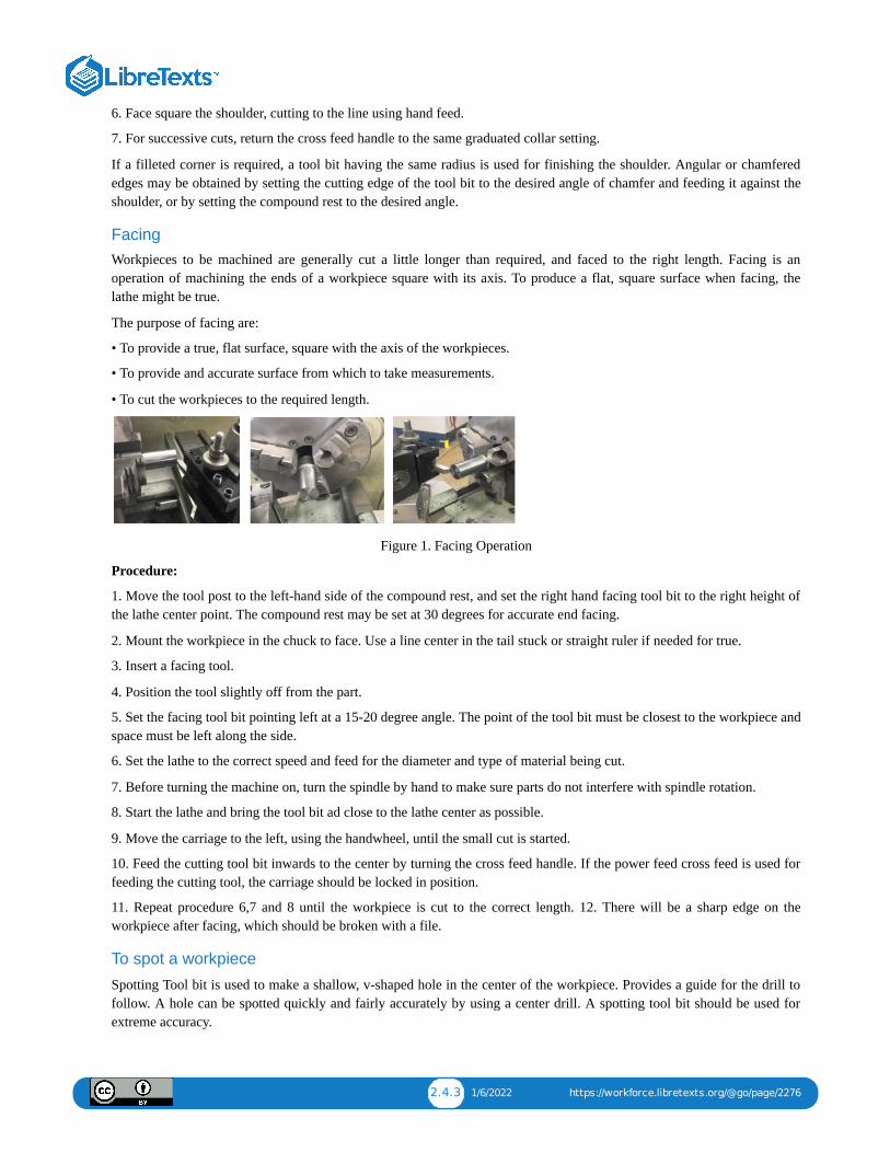
2.4.3 1/6/2022 https://workforce.libretexts.org/@go/page/2276
6. Face square the shoulder, cutting to the line using hand feed.
7. For successive cuts, return the cross feed handle to the same graduated collar setting.
If a filleted corner is required, a tool bit having the same radius is used for finishing the shoulder. Angular or chamferededges may be obtained by setting the cutting edge of the tool bit to the desired angle of chamfer and feeding it against theshoulder, or by setting the compound rest to the desired angle.
FacingWorkpieces to be machined are generally cut a little longer than required, and faced to the right length. Facing is anoperation of machining the ends of a workpiece square with its axis. To produce a flat, square surface when facing, thelathe might be true.
The purpose of facing are:
• To provide a true, flat surface, square with the axis of the workpieces.
• To provide and accurate surface from which to take measurements.
• To cut the workpieces to the required length.
Figure 1. Facing Operation
Procedure:
1. Move the tool post to the left-hand side of the compound rest, and set the right hand facing tool bit to the right height ofthe lathe center point. The compound rest may be set at 30 degrees for accurate end facing.
2. Mount the workpiece in the chuck to face. Use a line center in the tail stuck or straight ruler if needed for true.
3. Insert a facing tool.
4. Position the tool slightly off from the part.
5. Set the facing tool bit pointing left at a 15-20 degree angle. The point of the tool bit must be closest to the workpiece andspace must be left along the side.
6. Set the lathe to the correct speed and feed for the diameter and type of material being cut.
7. Before turning the machine on, turn the spindle by hand to make sure parts do not interfere with spindle rotation.
8. Start the lathe and bring the tool bit ad close to the lathe center as possible.
9. Move the carriage to the left, using the handwheel, until the small cut is started.
10. Feed the cutting tool bit inwards to the center by turning the cross feed handle. If the power feed cross feed is used forfeeding the cutting tool, the carriage should be locked in position.
11. Repeat procedure 6,7 and 8 until the workpiece is cut to the correct length. 12. There will be a sharp edge on theworkpiece after facing, which should be broken with a file.
To spot a workpiece
Spotting Tool bit is used to make a shallow, v-shaped hole in the center of the workpiece. Provides a guide for the drill tofollow. A hole can be spotted quickly and fairly accurately by using a center drill. A spotting tool bit should be used forextreme accuracy.
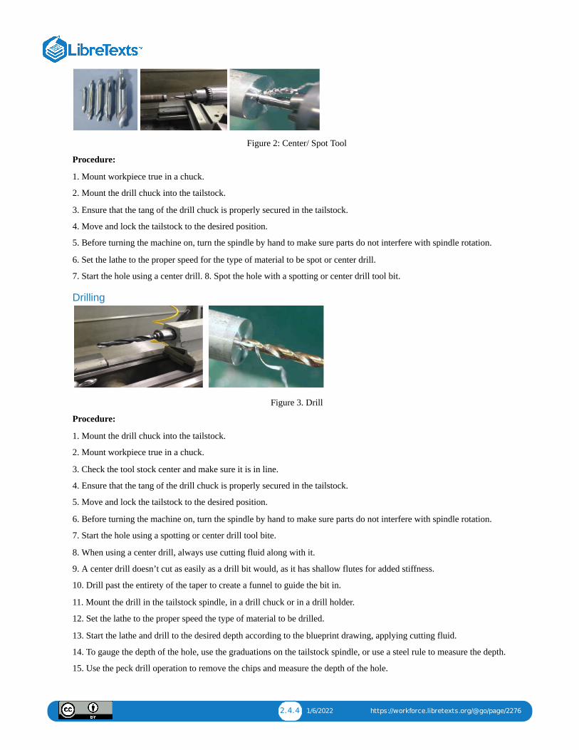
2.4.4 1/6/2022 https://workforce.libretexts.org/@go/page/2276
Figure 2: Center/ Spot Tool
Procedure:
1. Mount workpiece true in a chuck.
2. Mount the drill chuck into the tailstock.
3. Ensure that the tang of the drill chuck is properly secured in the tailstock.
4. Move and lock the tailstock to the desired position.
5. Before turning the machine on, turn the spindle by hand to make sure parts do not interfere with spindle rotation.
6. Set the lathe to the proper speed for the type of material to be spot or center drill.
7. Start the hole using a center drill. 8. Spot the hole with a spotting or center drill tool bit.
Drilling
Figure 3. Drill
Procedure:
1. Mount the drill chuck into the tailstock.
2. Mount workpiece true in a chuck.
3. Check the tool stock center and make sure it is in line.
4. Ensure that the tang of the drill chuck is properly secured in the tailstock.
5. Move and lock the tailstock to the desired position.
6. Before turning the machine on, turn the spindle by hand to make sure parts do not interfere with spindle rotation.
7. Start the hole using a spotting or center drill tool bite.
8. When using a center drill, always use cutting fluid along with it.
9. A center drill doesn’t cut as easily as a drill bit would, as it has shallow flutes for added stiffness.
10. Drill past the entirety of the taper to create a funnel to guide the bit in.
11. Mount the drill in the tailstock spindle, in a drill chuck or in a drill holder.
12. Set the lathe to the proper speed the type of material to be drilled.
13. Start the lathe and drill to the desired depth according to the blueprint drawing, applying cutting fluid.
14. To gauge the depth of the hole, use the graduations on the tailstock spindle, or use a steel rule to measure the depth.
15. Use the peck drill operation to remove the chips and measure the depth of the hole.

2.4.5 1/6/2022 https://workforce.libretexts.org/@go/page/2276
16. When drilling, take off at most one or two drill bit diameters worth of material before backing off, clearing chips, andreapplying cutting fluid.
17. If the drill bit squeaks against the stock, apply more cutting fluid.
18. To remove the drill chuck from the tailstock, draw it back by around a quarter turn more than it will easily go.
19. Use a pin to press the chuck out of the collet.
Boring
Boring is an operation to enlarge and finish holes accurately. Truing of a hole by removing material from internal surfaceswith a single point tool bit cutter. Special diameter holes, for which no drills are available, can be produced by boring.
Boring utilizes a single point cutting tool to enlarge a hole. This operation provides for more accurate and concentric hole,as opposed to drilling.
Since the cutter extends from the machine from a boring bar, the tool is not as well-supported, which can result in chatter.The deeper the boring operation, the worse the chatter. To correct this:
1. Reduce the spindle speed.
2. Increase the feed.
3. Apply more cutting fluid.
4. Shorten the overhang of the boring bar.
5. Grind a smaller radius on the tool’s nose.
Procedure:
1. Mount the workpiece in a chuck.
2. Face, spot and drill the hole on the workpiece.
3. Check to see if the boring bar has enough clearance.
If the hole is too small for the boring bar, the chips will jam while machining and move the bar off-center.
4. Make sure that the point of the boring tool is the only part of the cutter than contacts the inner surface of the workpiece.
5. If the angle does not provide sufficient end relief, replace the cutter with one that has a sharper angle.
6. Position the boring bar so the point of the cutter is positioned with the centerline of the stock.
7. A tool that is not placed in line with the center of the workpiece will drag along the surface of stock, even if there is asufficient end relief angle.
8. Select a boring bar as large as possible and have it extend beyond the holder only enough to clear the depth of the holeto be bored.
9. Mount the holder and boring tool bar with the cutter tool bit on the left hand side of the tool post and revolving theworkpiece.
10. Set the boring tool bit to center.
Note: Depending on the rigidity of the setup, the boring tool bit will have a tendency to spring downward as pressure isapplied to the cutting edge. By setting the boring tool bit slightly above center, compensation has been made for thedownward spring and the tool bit will actually be positioned on the exact center of the workpiece during machiningoperations.
11. Set the lathe to the proper cutting speed and feed. a. Note: For feedrate select a medium feed rate.
12. Apply lube to the hole before turning the machine on.
13. Turn the machine on and move the tool into the pre-drilled hole.
14. Start the lathe and slowly bring the boring tool until it touch the inside diameter of the hole.
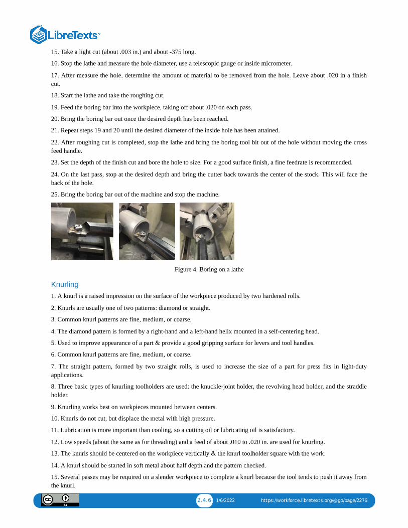
2.4.6 1/6/2022 https://workforce.libretexts.org/@go/page/2276
15. Take a light cut (about .003 in.) and about -375 long.
16. Stop the lathe and measure the hole diameter, use a telescopic gauge or inside micrometer.
17. After measure the hole, determine the amount of material to be removed from the hole. Leave about .020 in a finishcut.
18. Start the lathe and take the roughing cut.
19. Feed the boring bar into the workpiece, taking off about .020 on each pass.
20. Bring the boring bar out once the desired depth has been reached.
21. Repeat steps 19 and 20 until the desired diameter of the inside hole has been attained.
22. After roughing cut is completed, stop the lathe and bring the boring tool bit out of the hole without moving the crossfeed handle.
23. Set the depth of the finish cut and bore the hole to size. For a good surface finish, a fine feedrate is recommended.
24. On the last pass, stop at the desired depth and bring the cutter back towards the center of the stock. This will face theback of the hole.
25. Bring the boring bar out of the machine and stop the machine.
Figure 4. Boring on a lathe
Knurling1. A knurl is a raised impression on the surface of the workpiece produced by two hardened rolls.
2. Knurls are usually one of two patterns: diamond or straight.
3. Common knurl patterns are fine, medium, or coarse.
4. The diamond pattern is formed by a right-hand and a left-hand helix mounted in a self-centering head.
5. Used to improve appearance of a part & provide a good gripping surface for levers and tool handles.
6. Common knurl patterns are fine, medium, or coarse.
7. The straight pattern, formed by two straight rolls, is used to increase the size of a part for press fits in light-dutyapplications.
8. Three basic types of knurling toolholders are used: the knuckle-joint holder, the revolving head holder, and the straddleholder.
9. Knurling works best on workpieces mounted between centers.
10. Knurls do not cut, but displace the metal with high pressure.
11. Lubrication is more important than cooling, so a cutting oil or lubricating oil is satisfactory.
12. Low speeds (about the same as for threading) and a feed of about .010 to .020 in. are used for knurling.
13. The knurls should be centered on the workpiece vertically & the knurl toolholder square with the work.
14. A knurl should be started in soft metal about half depth and the pattern checked.
15. Several passes may be required on a slender workpiece to complete a knurl because the tool tends to push it away fromthe knurl.
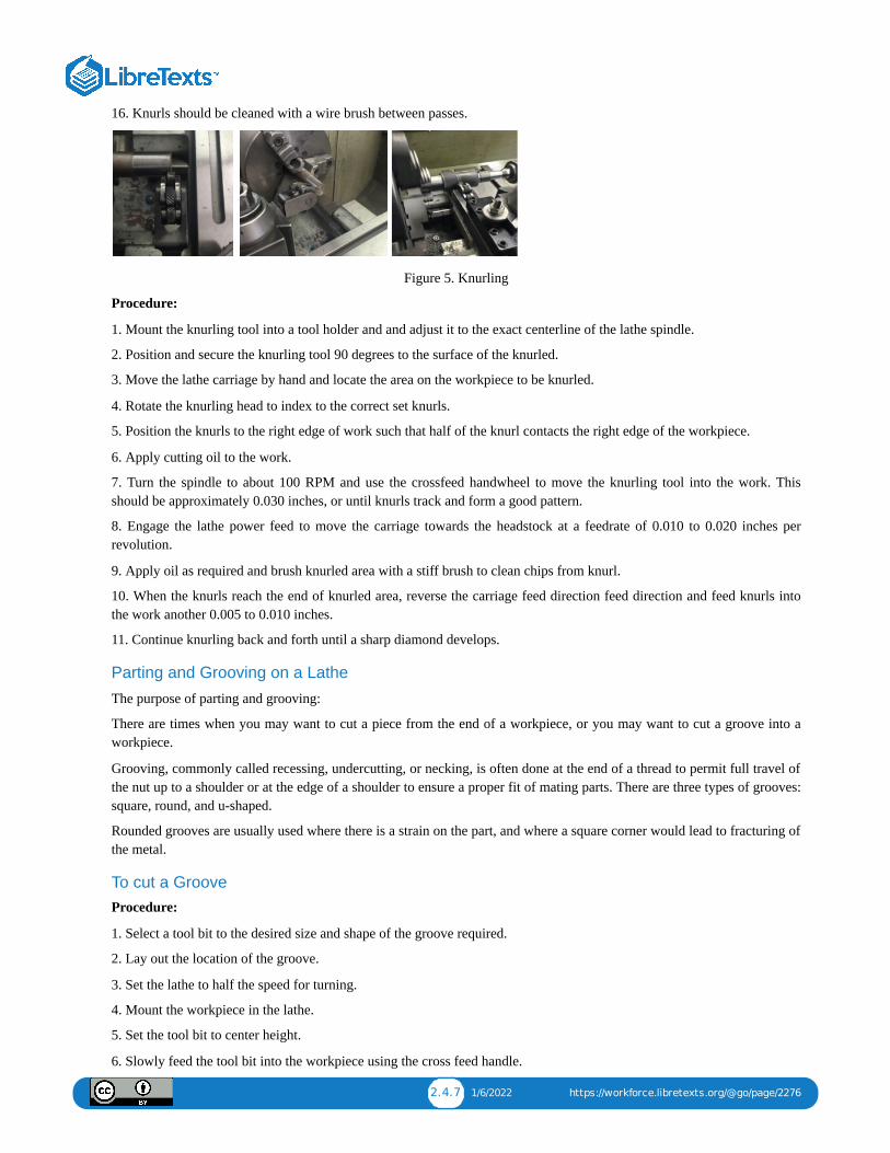
2.4.7 1/6/2022 https://workforce.libretexts.org/@go/page/2276
16. Knurls should be cleaned with a wire brush between passes.
Figure 5. Knurling
Procedure:
1. Mount the knurling tool into a tool holder and and adjust it to the exact centerline of the lathe spindle.
2. Position and secure the knurling tool 90 degrees to the surface of the knurled.
3. Move the lathe carriage by hand and locate the area on the workpiece to be knurled.
4. Rotate the knurling head to index to the correct set knurls.
5. Position the knurls to the right edge of work such that half of the knurl contacts the right edge of the workpiece.
6. Apply cutting oil to the work.
7. Turn the spindle to about 100 RPM and use the crossfeed handwheel to move the knurling tool into the work. Thisshould be approximately 0.030 inches, or until knurls track and form a good pattern.
8. Engage the lathe power feed to move the carriage towards the headstock at a feedrate of 0.010 to 0.020 inches perrevolution.
9. Apply oil as required and brush knurled area with a stiff brush to clean chips from knurl.
10. When the knurls reach the end of knurled area, reverse the carriage feed direction feed direction and feed knurls intothe work another 0.005 to 0.010 inches.
11. Continue knurling back and forth until a sharp diamond develops.
Parting and Grooving on a Lathe
The purpose of parting and grooving:
There are times when you may want to cut a piece from the end of a workpiece, or you may want to cut a groove into aworkpiece.
Grooving, commonly called recessing, undercutting, or necking, is often done at the end of a thread to permit full travel ofthe nut up to a shoulder or at the edge of a shoulder to ensure a proper fit of mating parts. There are three types of grooves:square, round, and u-shaped.
Rounded grooves are usually used where there is a strain on the part, and where a square corner would lead to fracturing ofthe metal.
To cut a GrooveProcedure:
1. Select a tool bit to the desired size and shape of the groove required.
2. Lay out the location of the groove.
3. Set the lathe to half the speed for turning.
4. Mount the workpiece in the lathe.
5. Set the tool bit to center height.
6. Slowly feed the tool bit into the workpiece using the cross feed handle.
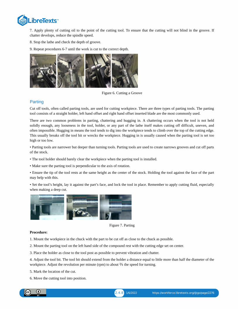
2.4.8 1/6/2022 https://workforce.libretexts.org/@go/page/2276
7. Apply plenty of cutting oil to the point of the cutting tool. To ensure that the cutting will not blind in the groove. Ifchatter develops, reduce the spindle speed.
8. Stop the lathe and check the depth of groove.
9. Repeat procedures 6-7 until the work is cut to the correct depth.
Figure 6. Cutting a Groove
PartingCut off tools, often called parting tools, are used for cutting workpiece. There are three types of parting tools. The partingtool consists of a straight holder, left hand offset and right hand offset inserted blade are the most commonly used.
There are two common problems in parting, chattering and hugging in. A chattering occurs when the tool is not heldsolidly enough, any looseness in the tool, holder, or any part of the lathe itself makes cutting off difficult, uneven, andoften impossible. Hugging in means the tool tends to dig into the workpiece tends to climb over the top of the cutting edge.This usually breaks off the tool bit or wrecks the workpiece. Hugging in is usually caused when the parting tool is set toohigh or too low.
• Parting tools are narrower but deeper than turning tools. Parting tools are used to create narrows grooves and cut off partsof the stock.
• The tool holder should barely clear the workpiece when the parting tool is installed.
• Make sure the parting tool is perpendicular to the axis of rotation.
• Ensure the tip of the tool rests at the same height as the center of the stock. Holding the tool against the face of the partmay help with this.
• Set the tool’s height, lay it against the part’s face, and lock the tool in place. Remember to apply cutting fluid, especiallywhen making a deep cut.
Figure 7. Parting
Procedure:
1. Mount the workpiece in the chuck with the part to be cut off as close to the chuck as possible.
2. Mount the parting tool on the left hand side of the compound rest with the cutting edge set on center.
3. Place the holder as close to the tool post as possible to prevent vibration and chatter.
4. Adjust the tool bit. The tool bit should extend from the holder a distance equal to little more than half the diameter of theworkpiece. Adjust the revolution per minute (rpm) to about ⅔ the speed for turning.
5. Mark the location of the cut.
6. Move the cutting tool into position.
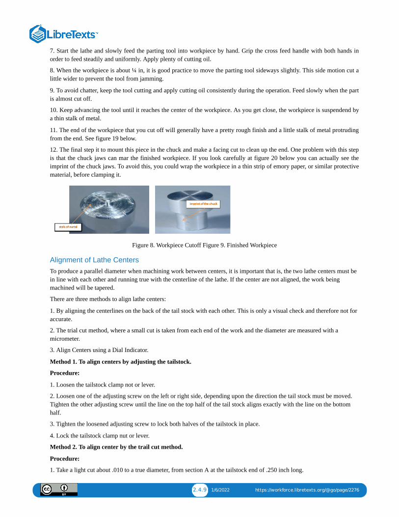
2.4.9 1/6/2022 https://workforce.libretexts.org/@go/page/2276
7. Start the lathe and slowly feed the parting tool into workpiece by hand. Grip the cross feed handle with both hands inorder to feed steadily and uniformly. Apply plenty of cutting oil.
8. When the workpiece is about ¼ in, it is good practice to move the parting tool sideways slightly. This side motion cut alittle wider to prevent the tool from jamming.
9. To avoid chatter, keep the tool cutting and apply cutting oil consistently during the operation. Feed slowly when the partis almost cut off.
10. Keep advancing the tool until it reaches the center of the workpiece. As you get close, the workpiece is suspendend bya thin stalk of metal.
11. The end of the workpiece that you cut off will generally have a pretty rough finish and a little stalk of metal protrudingfrom the end. See figure 19 below.
12. The final step it to mount this piece in the chuck and make a facing cut to clean up the end. One problem with this stepis that the chuck jaws can mar the finished workpiece. If you look carefully at figure 20 below you can actually see theimprint of the chuck jaws. To avoid this, you could wrap the workpiece in a thin strip of emory paper, or similar protectivematerial, before clamping it.
Figure 8. Workpiece Cutoff Figure 9. Finished Workpiece
Alignment of Lathe CentersTo produce a parallel diameter when machining work between centers, it is important that is, the two lathe centers must bein line with each other and running true with the centerline of the lathe. If the center are not aligned, the work beingmachined will be tapered.
There are three methods to align lathe centers:
1. By aligning the centerlines on the back of the tail stock with each other. This is only a visual check and therefore not foraccurate.
2. The trial cut method, where a small cut is taken from each end of the work and the diameter are measured with amicrometer.
3. Align Centers using a Dial Indicator.
Method 1. To align centers by adjusting the tailstock.
Procedure:
1. Loosen the tailstock clamp not or lever.
2. Loosen one of the adjusting screw on the left or right side, depending upon the direction the tail stock must be moved.Tighten the other adjusting screw until the line on the top half of the tail stock aligns exactly with the line on the bottomhalf.
3. Tighten the loosened adjusting screw to lock both halves of the tailstock in place.
4. Lock the tailstock clamp nut or lever.
Method 2. To align center by the trail cut method.
Procedure:
1. Take a light cut about .010 to a true diameter, from section A at the tailstock end of .250 inch long.
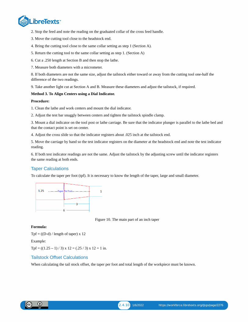
2.4.10 1/6/2022 https://workforce.libretexts.org/@go/page/2276
2. Stop the feed and note the reading on the graduated collar of the cross feed handle.
3. Move the cutting tool close to the headstock end.
4. Bring the cutting tool close to the same collar setting as step 1 (Section A).
5. Return the cutting tool to the same collar setting as step 1. (Section A)
6. Cut a .250 length at Section B and then stop the lathe.
7. Measure both diameters with a micrometer.
8. If both diameters are not the same size, adjust the tailstock either toward or away from the cutting tool one-half thedifference of the two readings.
9. Take another light cut at Section A and B. Measure these diameters and adjust the tailstock, if required.
Method 3. To Align Centers using a Dial Indicator.
Procedure:
1. Clean the lathe and work centers and mount the dial indicator.
2. Adjust the test bar snuggly between centers and tighten the tailstock spindle clamp.
3. Mount a dial indicator on the tool post or lathe carriage. Be sure that the indicator plunger is parallel to the lathe bed andthat the contact point is set on center.
4. Adjust the cross slide so that the indicator registers about .025 inch at the tailstock end.
5. Move the carriage by hand so the test indicator registers on the diameter at the headstock end and note the test indicatorreading.
6. If both test indicator readings are not the same. Adjust the tailstock by the adjusting screw until the indicator registersthe same reading at both ends.
Taper CalculationsTo calculate the taper per foot (tpf). It is necessary to know the length of the taper, large and small diameter.
Figure 10. The main part of an inch taper
Formula:
Tpf = ((D-d) / length of taper) x 12
Example:
Tpf = ((1.25 – 1) / 3) x 12 = (.25 / 3) x 12 = 1 in.
Tailstock Offset CalculationsWhen calculating the tail stock offset, the taper per foot and total length of the workpiece must be known.
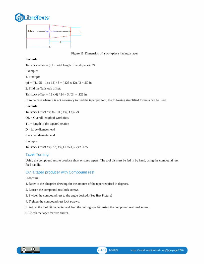
2.4.11 1/6/2022 https://workforce.libretexts.org/@go/page/2276
Figure 11. Dimension of a workpiece having a taper
Formula:
Tailstock offset = (tpf x total length of workpiece) / 24
Example:
1. Find tpf:
tpf = ((1.125 – 1) x 12) / 3 = (.125 x 12) / 3 = .50 in.
2. FInd the Tailstock offset:
Tailstock offset = (.5 x 6) / 24 = 3 / 24 = .125 in.
In some case where it is not necessary to find the taper per foot, the following simplified formula can be used.
Formula:
Tailstock Offset = (OL / TL) x ((D-d) / 2)
OL = Overall length of workpiece
TL = length of the tapered section
D = large diameter end
d = small diameter end
Example:
Tailstock Offset = (6 / 3) x ((1.125-1) / 2) = .125
Taper Turning
Using the compound rest to produce short or steep tapers. The tool bit must be fed in by hand, using the compound restfeed handle.
Cut a taper producer with Compound restProcedure:
1. Refer to the blueprint drawing for the amount of the taper required in degrees.
2. Loosen the compound rest lock screws.
3. Swivel the compound rest to the angle desired. (See first Picture)
4. Tighten the compound rest lock screws.
5. Adjust the tool bit on center and feed the cutting tool bit, using the compound rest feed screw.
6. Check the taper for size and fit.
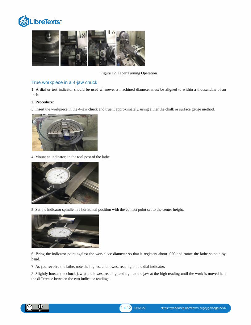
2.4.12 1/6/2022 https://workforce.libretexts.org/@go/page/2276
Figure 12. Taper Turning Operation
True workpiece in a 4-jaw chuck1. A dial or test indicator should be used whenever a machined diameter must be aligned to within a thousandths of aninch.
2. Procedure:
3. Insert the workpiece in the 4-jaw chuck and true it approximately, using either the chalk or surface gauge method.
4. Mount an indicator, in the tool post of the lathe.
5. Set the indicator spindle in a horizontal position with the contact point set to the center height.
6. Bring the indicator point against the workpiece diameter so that it registers about .020 and rotate the lathe spindle byhand.
7. As you revolve the lathe, note the highest and lowest reading on the dial indicator.
8. Slightly loosen the chuck jaw at the lowest reading, and tighten the jaw at the high reading until the work is moved halfthe difference between the two indicator readings.
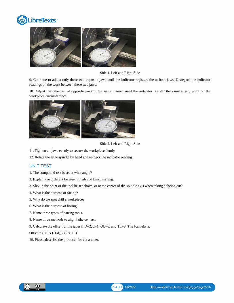
2.4.13 1/6/2022 https://workforce.libretexts.org/@go/page/2276
Side 1. Left and Right Side
9. Continue to adjust only these two opposite jaws until the indicator registers the at both jaws. Disregard the indicatorreadings on the work between these two jaws.
10. Adjust the other set of opposite jaws in the same manner until the indicator register the same at any point on theworkpiece circumference.
Side 2. Left and Right Side
11. Tighten all jaws evenly to secure the workpiece firmly.
12. Rotate the lathe spindle by hand and recheck the indicator reading.
UNIT TEST
1. The compound rest is set at what angle?
2. Explain the different between rough and finish turning.
3. Should the point of the tool be set above, or at the center of the spindle axis when taking a facing cut?
4. What is the purpose of facing?
5. Why do we spot drill a workpiece?
6. What is the purpose of boring?
7. Name three types of parting tools.
8. Name three methods to align lathe centers.
9. Calculate the offset for the taper if D=2, d=1, OL=6, and TL=3. The formula is:
Offset = (OL x (D-d)) / (2 x TL)
10. Please describe the producer for cut a taper.

2.5.1 1/14/2022 https://workforce.libretexts.org/@go/page/2277
2.5: Unit 5: Tapping
OBJECTIVE
After completing this unit, you should be able to:
• Describe the tapping procedure.
• Determine the RPM for tapping.
• Describe the filling and polishing.
• Describe the advanced workholding.
Tapping
Tapping is the process of cutting a thread inside a hole so that a cap screw or bolt can be threaded into the hole. Also, it isused to make thread on nuts.
Tapping can be done on the lathe by power feed or by hand. Regardless of the method, the hole must be drilled with theproper size tap drill and chamferred at the end.
Tapping Procedures
Good Practices
Using Tap Guides
Tap guides are an integral part in making a usable and straight tap. When using the lathe or the mill, the tap is alreadystraight and centered. When manually aligning a tap, be careful, as a 90° tap guide is much more accurate than the humaneye.
Using Oil
When drilling and tapping, it is crucial to use oil. It keeps the bits from squealing, makes the cut smoother, cleans out thechips, and keeps the drill and stock from overheating.
Pecking
Pecking helps ensure that bits don’t overheat and break when using them to drill or tap. Peck drilling involves drillingpartway through a part, then retracting it to remove chips, simultaneously allowing the piece to cool. Rotating the handle afull turn then back a half turn is common practice. Whenever the bit or tap is backed out, remove as many chips as possibleand add oil to the surface between the drill or tap and the workpiece. Hand Tapping Procedure 1. Select drill size fromchart. When choosing a tap size, this chart is the first place to look
Hand Tapping Procedure1. Select drill size from chart.
When choosing a tap size, this chart is the first place to look.
Tap & Clearance Drill Sizes

2.5.2 1/14/2022 https://workforce.libretexts.org/@go/page/2277
2. If necessary, add chamfer to the hole before tapping. Chamfers and countersinks are additional features that aresometimes desired for screws. For best results, the speed of the spindle should be between 150 and 250 rpm.
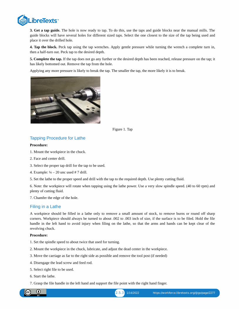
2.5.3 1/14/2022 https://workforce.libretexts.org/@go/page/2277
3. Get a tap guide. The hole is now ready to tap. To do this, use the taps and guide blocks near the manual mills. Theguide blocks will have several holes for different sized taps. Select the one closest to the size of the tap being used andplace it over the drilled hole.
4. Tap the block. Peck tap using the tap wrenches. Apply gentle pressure while turning the wrench a complete turn in,then a half-turn out. Peck tap to the desired depth.
5. Complete the tap. If the tap does not go any further or the desired depth has been reached, release pressure on the tap; ithas likely bottomed out. Remove the tap from the hole.
Applying any more pressure is likely to break the tap. The smaller the tap, the more likely it is to break.
Figure 1. Tap
Tapping Procedure for Lathe
Procedure:
1. Mount the workpiece in the chuck.
2. Face and center drill.
3. Select the proper tap drill for the tap to be used.
4. Example: ¼ – 20 unc used # 7 drill.
5. Set the lathe to the proper speed and drill with the tap to the required depth. Use plenty cutting fluid.
6. Note: the workpiece will rotate when tapping using the lathe power. Use a very slow spindle speed. (40 to 60 rpm) andplenty of cutting fluid.
7. Chamfer the edge of the hole.
Filing in a Lathe
A workpiece should be filled in a lathe only to remove a small amount of stock, to remove burns or round off sharpcorners. Workpiece should always be turned to about .002 to .003 inch of size, if the surface is to be filed. Hold the filehandle in the left hand to avoid injury when filing on the lathe, so that the arms and hands can be kept clear of therevolving chuck.
Procedure:
1. Set the spindle speed to about twice that used for turning.
2. Mount the workpiece in the chuck, lubricate, and adjust the dead center in the workpiece.
3. Move the carriage as far to the right side as possible and remove the tool post (if needed)
4. Disengage the lead screw and feed rod.
5. Select right file to be used.
6. Start the lathe.
7. Grasp the file handle in the left hand and support the file point with the right hand finger.
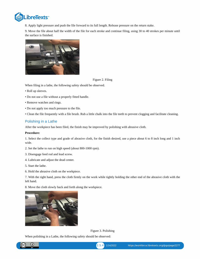
2.5.4 1/14/2022 https://workforce.libretexts.org/@go/page/2277
8. Apply light pressure and push the file forward to its full length. Release pressure on the return stake.
9. Move the file about half the width of the file for each stroke and continue filing, using 30 to 40 strokes per minute untilthe surface is finished.
Figure 2. Filing
When filing in a lathe, the following safety should be observed.
• Roll up sleeves.
• Do not use a file without a properly fitted handle.
• Remove watches and rings.
• Do not apply too much pressure to the file.
• Clean the file frequently with a file brush. Rub a little chalk into the file teeth to prevent clogging and facilitate cleaning.
Polishing in a LatheAfter the workpiece has been filed, the finish may be improved by polishing with abrasive cloth.
Procedure:
1. Select the collect type and grade of abrasive cloth, for the finish desired, use a piece about 6 to 8 inch long and 1 inchwide.
2. Set the lathe to run on high speed (about 800-1000 rpm).
3. Disengage feed rod and lead screw.
4. Lubricate and adjust the dead center.
5. Start the lathe.
6. Hold the abrasive cloth on the workpiece.
7. With the right hand, press the cloth firmly on the work while tightly holding the other end of the abrasive cloth with theleft hand.
8. Move the cloth slowly back and forth along the workpiece.
Figure 3. Polishing
When polishing in a Lathe, the following safety should be observed:
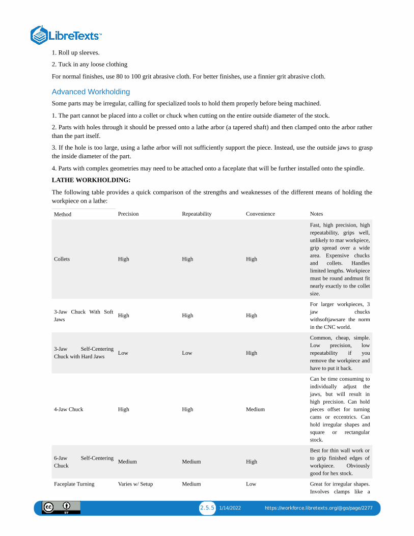
2.5.5 1/14/2022 https://workforce.libretexts.org/@go/page/2277
1. Roll up sleeves.
2. Tuck in any loose clothing
For normal finishes, use 80 to 100 grit abrasive cloth. For better finishes, use a finnier grit abrasive cloth.
Advanced WorkholdingSome parts may be irregular, calling for specialized tools to hold them properly before being machined.
1. The part cannot be placed into a collet or chuck when cutting on the entire outside diameter of the stock.
2. Parts with holes through it should be pressed onto a lathe arbor (a tapered shaft) and then clamped onto the arbor ratherthan the part itself.
3. If the hole is too large, using a lathe arbor will not sufficiently support the piece. Instead, use the outside jaws to graspthe inside diameter of the part.
4. Parts with complex geometries may need to be attached onto a faceplate that will be further installed onto the spindle.
LATHE WORKHOLDING:
The following table provides a quick comparison of the strengths and weaknesses of the different means of holding theworkpiece on a lathe:
Method Precision Repeatability Convenience Notes
Collets High High High
Fast, high precision, highrepeatability, grips well,unlikely to mar workpiece,grip spread over a widearea. Expensive chucksand collets. Handleslimited lengths. Workpiecemust be round andmust fitnearly exactly to the colletsize.
3-Jaw Chuck With SoftJaws
High High High
For larger workpieces, 3jaw chuckswithsoftjawsare the normin the CNC world.
3-Jaw Self-CenteringChuck with Hard Jaws Low Low High
Common, cheap, simple.Low precision, lowrepeatability if youremove the workpiece andhave to put it back.
4-Jaw Chuck High High Medium
Can be time consuming toindividually adjust thejaws, but will result inhigh precision. Can holdpieces offset for turningcams or eccentrics. Canhold irregular shapes andsquare or rectangularstock.
6-Jaw Self-CenteringChuck
Medium Medium High
Best for thin wall work orto grip finished edges ofworkpiece. Obviouslygood for hex stock.
Faceplate Turning Varies w/ Setup Medium Low Great for irregular shapes.Involves clamps like a
2.5.6 1/14/2022 https://workforce.libretexts.org/@go/page/2277
milling setup. May needcounterweights to keepthings balanced.
Turning Between Centers High High Low
Great precision, allowspart to be put backbetween centers with veryhigh repeatability.
Constant Face Turning High High High
The modern alternative toturning between centers.Instead of using lathedogs, which are kind of anuisance to set up, theconstant face system useshydraulic or other force togrip and drive the spindleend.
Expanding Arbors High High High
These work from theinside out rather than theoutside in but areotherwise much likecollets.
Method describes the particular technique or tooling to be used.
Precision describes how precisely the workpiece will be held, or how close to concentrically it will run with the spindlebefore taking any cuts.
Repeatability describes how easy it is to take the workpiece out and then get it back in precisely again.
UNIT TEST
1. What drill size to be used for ½ -20 tap?
2. What is the purpose of chamfer?
3. What is the best RPM for tapping?
4. What spindle speed do we set for filing?
5. What is the purpose of polishing?
6. What is the best grit abrasive cloth for normal finishes?
7. What type of work is best suited to three-jaw chucks?
8. What are the special characteristics of the three-jaw chuck?
9. Explain the different between three-jaw chuck and 4-jaw chuck.
10. What are the advantages and disadvantages of a collect chuck?

2.6.1 1/7/2022 https://workforce.libretexts.org/@go/page/2278
2.6: Unit 6: Lathe Threading
OBJECTIVE
After completing this unit, you should be able to:
• Determine the infeed depth.
• Describe how to cut a correct thread.
• Explain how to calculate the pitch, depth, and minor diameter, width of flat.
• Describe how to set the correct rpm.
• Describe how to set the correct quick change gearbox.
• Describe how to set the correct compound rest.
• Describe how to set the correct tool bit.
• Describe how to set both compound and crossfeed on both dials to zero.
• Describe the threading operation.
• Describe the reaming.
• Describe how to grind a tool bit.
Lathe ThreadingThread cutting on the lathe is a process that produces a helical ridge of uniform section on the workpiece. This isperformed by taking successive cuts with a threading toolbit the same shape as the thread form required.
Practice Exercise:
1. For this practice exercise for threading, you will need a piece of round material, turned to an outside tread Diameter.
2. Using either a parting tool or a specially ground tool, make an undercut for the tread equal to its single depth plus .005inch.
3. The formula below will give you the single depth for undertaking unified threads:
d = P x 0.750
Where d = Single Depth
P = Pitch
n = Number of threads per inch (TPI)
Infeed Depth = .75 / n
Thread CalculationsTo cut a correct thread on the lathe, it is necessary first to make calculations so that the thread will have proper dimensions.The following diagrams and formulas will be helpful when calculating thread dimensions.
Example: Calculate the pitch, depth, minor diameter, and width of flat for a ¾-10 NC thread.
P = 1 / n = 1 / 10 = 0.100 in.
Depth = .7500 x Pitch = .7500 x .100 = .0750 in.
Minor Diameter = Major Diameter – (D + D) = .750 – (.075 + .075) = 0.600 in.
Width of Flat = P / 8 = (1 / 8) x (1/10) = .0125 in.
Procedure for threading:
1. Set the speed to about one quarter of the speed used for turning.
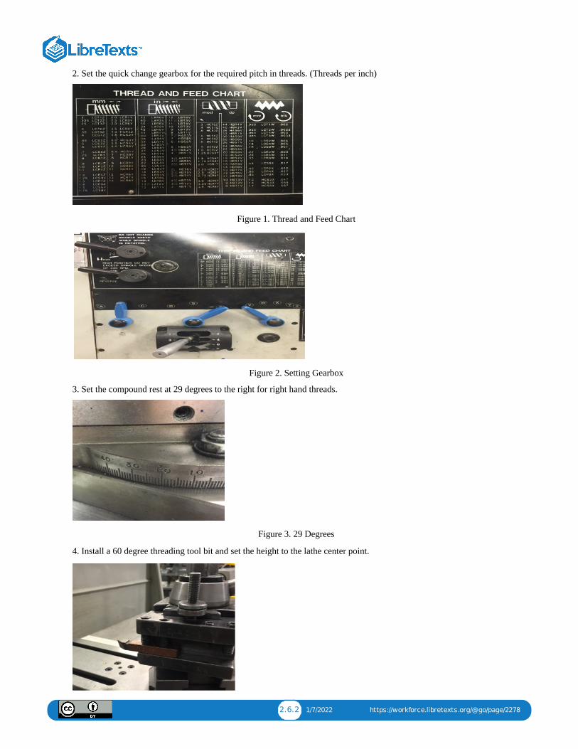
2.6.2 1/7/2022 https://workforce.libretexts.org/@go/page/2278
2. Set the quick change gearbox for the required pitch in threads. (Threads per inch)
Figure 1. Thread and Feed Chart
Figure 2. Setting Gearbox
3. Set the compound rest at 29 degrees to the right for right hand threads.
Figure 3. 29 Degrees
4. Install a 60 degree threading tool bit and set the height to the lathe center point.
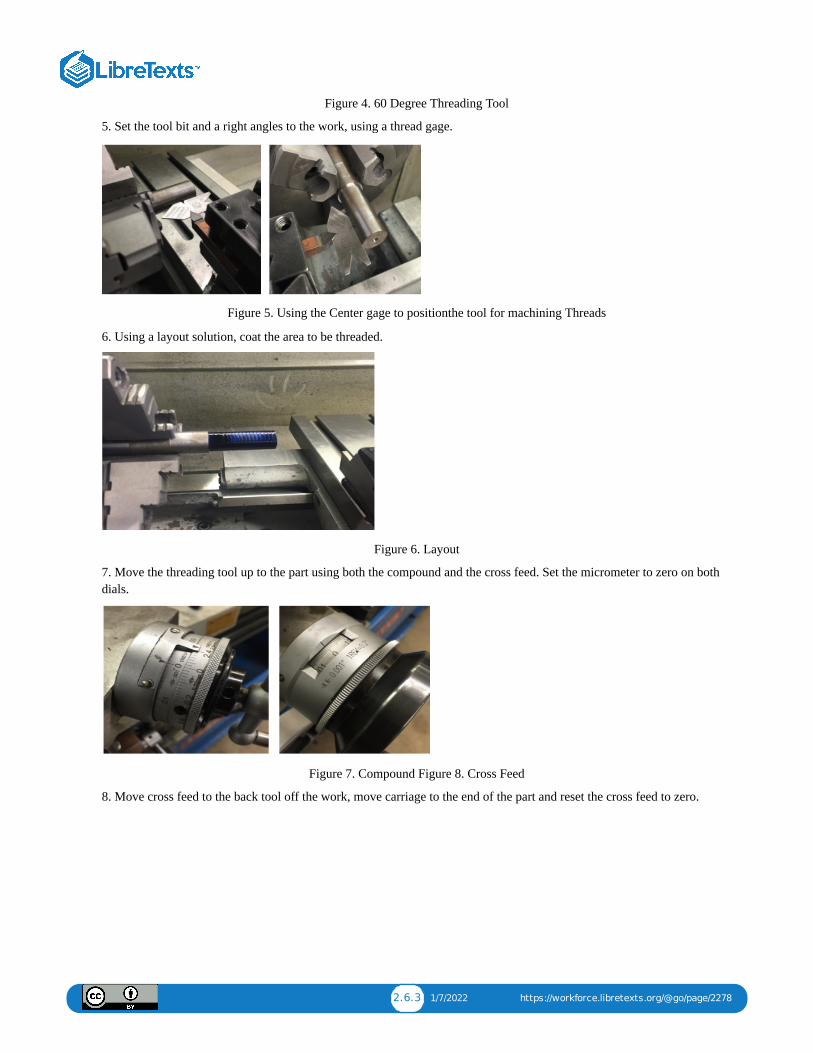
2.6.3 1/7/2022 https://workforce.libretexts.org/@go/page/2278
Figure 4. 60 Degree Threading Tool
5. Set the tool bit and a right angles to the work, using a thread gage.
Figure 5. Using the Center gage to positionthe tool for machining Threads
6. Using a layout solution, coat the area to be threaded.
Figure 6. Layout
7. Move the threading tool up to the part using both the compound and the cross feed. Set the micrometer to zero on bothdials.
Figure 7. Compound Figure 8. Cross Feed
8. Move cross feed to the back tool off the work, move carriage to the end of the part and reset the cross feed to zero.
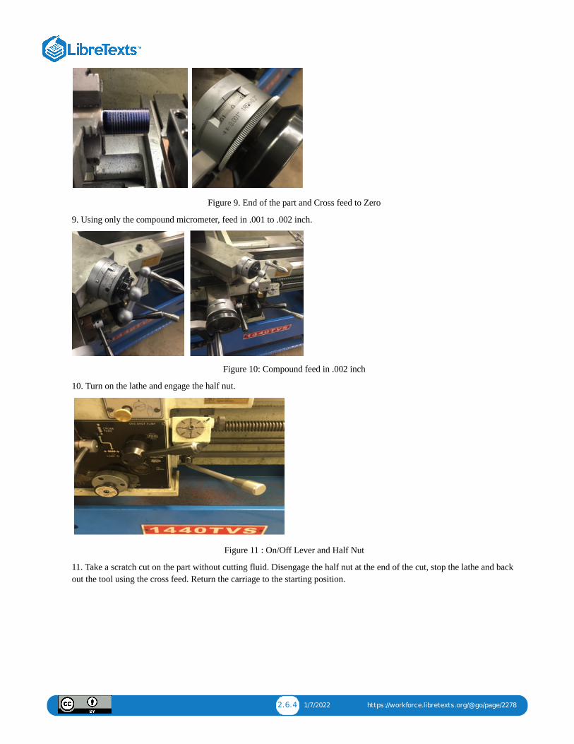
2.6.4 1/7/2022 https://workforce.libretexts.org/@go/page/2278
Figure 9. End of the part and Cross feed to Zero
9. Using only the compound micrometer, feed in .001 to .002 inch.
Figure 10: Compound feed in .002 inch
10. Turn on the lathe and engage the half nut.
Figure 11 : On/Off Lever and Half Nut
11. Take a scratch cut on the part without cutting fluid. Disengage the half nut at the end of the cut, stop the lathe and backout the tool using the cross feed. Return the carriage to the starting position.
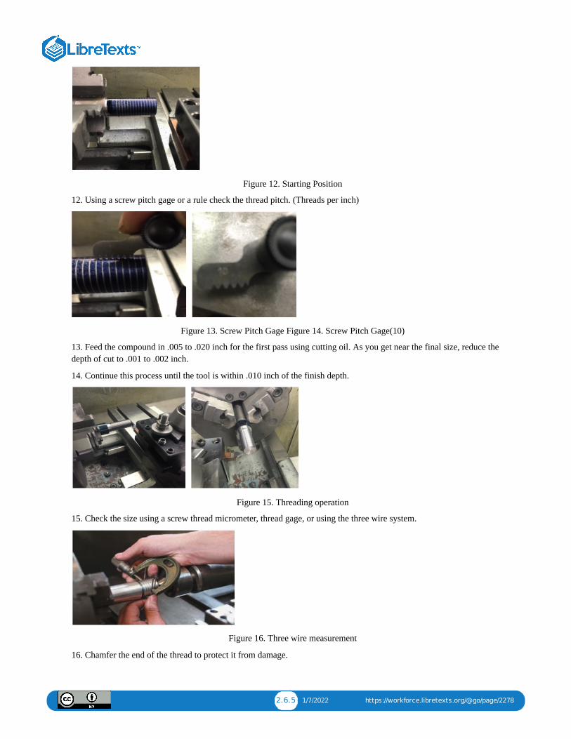
2.6.5 1/7/2022 https://workforce.libretexts.org/@go/page/2278
Figure 12. Starting Position
12. Using a screw pitch gage or a rule check the thread pitch. (Threads per inch)
Figure 13. Screw Pitch Gage Figure 14. Screw Pitch Gage(10)
13. Feed the compound in .005 to .020 inch for the first pass using cutting oil. As you get near the final size, reduce thedepth of cut to .001 to .002 inch.
14. Continue this process until the tool is within .010 inch of the finish depth.
Figure 15. Threading operation
15. Check the size using a screw thread micrometer, thread gage, or using the three wire system.
Figure 16. Three wire measurement
16. Chamfer the end of the thread to protect it from damage.
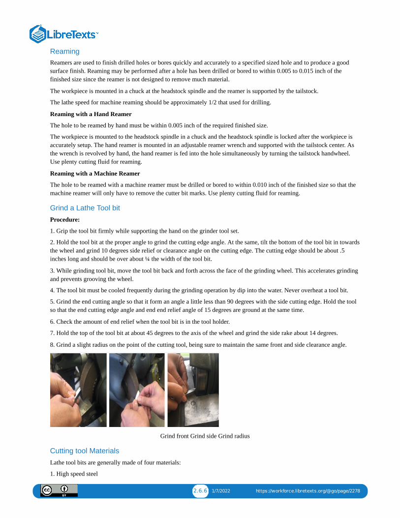
2.6.6 1/7/2022 https://workforce.libretexts.org/@go/page/2278
ReamingReamers are used to finish drilled holes or bores quickly and accurately to a specified sized hole and to produce a goodsurface finish. Reaming may be performed after a hole has been drilled or bored to within 0.005 to 0.015 inch of thefinished size since the reamer is not designed to remove much material.
The workpiece is mounted in a chuck at the headstock spindle and the reamer is supported by the tailstock.
The lathe speed for machine reaming should be approximately 1/2 that used for drilling.
Reaming with a Hand Reamer
The hole to be reamed by hand must be within 0.005 inch of the required finished size.
The workpiece is mounted to the headstock spindle in a chuck and the headstock spindle is locked after the workpiece isaccurately setup. The hand reamer is mounted in an adjustable reamer wrench and supported with the tailstock center. Asthe wrench is revolved by hand, the hand reamer is fed into the hole simultaneously by turning the tailstock handwheel.Use plenty cutting fluid for reaming.
Reaming with a Machine Reamer
The hole to be reamed with a machine reamer must be drilled or bored to within 0.010 inch of the finished size so that themachine reamer will only have to remove the cutter bit marks. Use plenty cutting fluid for reaming.
Grind a Lathe Tool bit
Procedure:
1. Grip the tool bit firmly while supporting the hand on the grinder tool set.
2. Hold the tool bit at the proper angle to grind the cutting edge angle. At the same, tilt the bottom of the tool bit in towardsthe wheel and grind 10 degrees side relief or clearance angle on the cutting edge. The cutting edge should be about .5inches long and should be over about ¼ the width of the tool bit.
3. While grinding tool bit, move the tool bit back and forth across the face of the grinding wheel. This accelerates grindingand prevents grooving the wheel.
4. The tool bit must be cooled frequently during the grinding operation by dip into the water. Never overheat a tool bit.
5. Grind the end cutting angle so that it form an angle a little less than 90 degrees with the side cutting edge. Hold the toolso that the end cutting edge angle and end end relief angle of 15 degrees are ground at the same time.
6. Check the amount of end relief when the tool bit is in the tool holder.
7. Hold the top of the tool bit at about 45 degrees to the axis of the wheel and grind the side rake about 14 degrees.
8. Grind a slight radius on the point of the cutting tool, being sure to maintain the same front and side clearance angle.
Grind front Grind side Grind radius
Cutting tool Materials
Lathe tool bits are generally made of four materials:
1. High speed steel

2.6.7 1/7/2022 https://workforce.libretexts.org/@go/page/2278
2. Cast alloys
3. Cemented Carbides
4. Ceramics
The properties that each of these materials possess are different and the application of each depends on the material beingmachined and the condition of the machine.
Lathe tool bits should possess the following properties.
1. They should be hard.
2. They should be wear resistant.
3. They should be capable of standing up to high temperatures developed during the cutting operation.
4. They should be able to withstand shock during the cutting operation.
Cutting tool Nomenclature
Cutting tools used on a lathe are generally single pointed cutting tools and although the shape of the tool is changed forvarious applications. The same nomenclature applies to all cutting tools.
Procedure:
1. Base: the bottom surface of the tool shank.
2. Cutting Edge: the leading edge of the tool bit that does the cutting.
3. Face: the surface against which the chip bears as it is separated from the work.
4. Flank: The surface of the tool which is adjacent to and below the cutting edge.
5. Nose: the tip of the cutting tool formed by the junction of the cutting edge and the front face.
6. Nose radius: The radius to which the nose is ground. The size of the radius will affect the finish. For rough cut, a 1/16inch nose radius used. For finish cut, a 1/16 to ⅛ inch nose radius is used.
7. Point: The end of the tool that has been ground for cutting purposes.
8. Shank: the body of the tool bit or the part held in the tool holder.
9. Lathe Tool bit Angles and Clearances
Proper performance of a tool bit depends on the clearance and rake angles which must be ground on the tool bit. Althoughthese angles vary for different materials, the nomenclature is the same for all tool bits.
• Side cutting edge angle: The angle which the cutting edge forms with the side of the tool shank. This angle may be from10 to 20 degrees depending on the material being cut. If angle is over 30 degrees, the tool will tend to chatter.
• End cutting edge angle. The angle formed by the end cutting edge and a line at right angle to the centerline of the tool bit.This angle may be from 5 to 30 degrees depending on the type of cut and finish desired. For roughing cuts an angle of 5 to15 degrees, angle between 15 and 30 degrees are used for general purpose turning tools. The larger angle permits thecutting tool to be swivelled to the left when taking light cuts close to the dog or chuck, or when turning to a shoulder.
• Side Relief (clearance) angle: The angle ground on the flank of the tool below the cutting edge. This angle may be from 6to 10 degrees. The side clearance on a tool bit permit the cutting tool to advance lengthwise into the rotating work andprevent the flank from rubbing against the workpiece.
• End Relief (clearance) angle: the angle ground below the nose of the tool bit which permits the cutting tool to be fed intothe work. This angle may be 10 to 15 degrees for general purpose cut. This angle must be measured when the tool bit isheld in the tool holder. The end relief angle varies with the hardness and type of material and type of cut being taken. Theend relief angle is smaller for harder materials, to provide support under the cutting edge.
• Side Rake Angle: The angle at which the face is ground away from the cutting edge. This angle may be 14 degrees forgeneral purpose tool bits. Side rake centers a keener cutting edge and allows the chip to flow away quickly. For softermaterials, the side rake angle is generally increased.

2.6.8 1/7/2022 https://workforce.libretexts.org/@go/page/2278
• Back (Top) Rake: The backward slope of the tool face away from the nose. This angle may be about 20 degrees and isprovide for in the tool holder. Back rake permits the chips to flow away from the point of the cutting tool.
UNIT TEST1. What is pitch for ¼-20 tap?
2. To what angle must the compound be turned for Unified Thread?
3. Explain why you swivel the compound in Question 2.
4. What is the depth of thread for UNF ½-20 screw?
5. How would you make a left-hand thread? This is not covered in the reading—think it out?
6. What Tool bit do we use for cutting thread?
7. Please describe Center Gage.
8. What do we use to check the thread pitch(Thread Per Inch)?
9. The first and final pass, how much do we feed the compound in?
10. Name four material that use to make Tool bits.
Chapter Attribution InformationThis chapter was derived from the following sources.
Lathe derived from Lathe by the Massachusetts Institute of Technology, CC:BY-NC-SA 4.0.Cutting Tool Terminology derived from Lathe Cutting Tools – Cutting Tool Shapes by the Wisconsin TechnicalCollege, CC:BY-NC 4.0.Cutting Tool Terminology derived from Cutter Types (Lathe) by the University of Idaho, CC:BY-SA 3.0.Centering derived from [Manual Lathes Document]

3.1 1/7/2022 https://workforce.libretexts.org/@go/page/2262
3: Drill Presses
3.1: Chapter 3: Drill Press
3.1.1 12/31/2021 https://workforce.libretexts.org/@go/page/2279
3.1: Chapter 3: Drill Press
OBJECTIVE
After completing this unit, you should be able to:
Identify Drill Press
Understand the safety rules.
Describe Tooling to be use.
Describe Reaming a hole.
Describe Drilling a hole procedure.
Describe power feed and hand feed tapping procedure.
Describe Dressing the Wheel procedures.
Description
Drilling machines, or drill presses, are primarily used to drill or enlarge a cylindrical hole in a workpiece or part. The chiefoperation performed on the drill press is drilling, but other possible operations include: reaming, countersinking,counterboring, and tapping.
The floor type drill press used in the Student Shop is a very common machine, found in both home and industrialworkshops. This style drill press is composed of four major groups of assemblies: the head, table, column, and base.
The head contains the motor and variable speed mechanism used to drive the spindle. The spindle is housed within thequill, which can be moved up or down by either manual or automatic feed. The table is mounted on the column, and isused to support the workpiece. The table may be raised or lowered on the column, depending upon the machining needs.The column is the backbone of the drill press. The head and base are clamped to it, and it serves as a guide for the table.The cast-iron base is the supporting member of the entire structure.
Safety1. Be familiar with the location of the start and stop switches. 2. The drill press table should be cleared of miscellaneoustools and materials. 3. Ensure that all drill bits are sharpened and chucks are in working condition. Any dull drill bits,battered tangs or sockets should not be used. 4. Never attempt to remove scraps from the table by hand. Use brushes orother proper tools. 5. Never attempt to perform maintenance on the machine without the power cord unplugged. 6. Neverinsert a chuck key into the chuck until the machine has been turned off and stopped completely. 7. Belts and pulleys shouldbe guarded at all times. If any are frayed, immediately report to the instructor for replacement. 8. All workpieces should besecured by a vise or clamp before starting the machining. 9. If the workpiece moves while in the vise or clamp: • Do notattempt to hold the workpiece in place by hand. • Do not try to tighten the vise or clamp while the machine is turned on. •Turn the power off and wait for the machine to stop completely before re-tightening the vise or clamp. 10. Use the properspeed settings and drill type for the material to be machined. 11. When mounting a drill bit, it should be to the full depthand centered in the chuck. 12. Eliminate the possibility of the drill bit hitting the table by using a clearance block and byadjusting the feed stroke. 13. Always feed the bit slowly into the workpiece. If the hole to be drilled is deep, draw the bitback often to remove shavings. 14. Before leaving the drill press for any amount of time, the power should be turned offand machine should be at a complete stop. 15. In any unsafe condition or movement is observed on the drill press, report itto the instructor immediately. 16. Leave the drill press cleaned and tidy at all times.
Procedures

4.1 1/7/2022 https://workforce.libretexts.org/@go/page/2263
4: Bandsaws
4.1: Chapter 4: Bandsaw

4.1.1 12/31/2021 https://workforce.libretexts.org/@go/page/2280
4.1: Chapter 4: Bandsaw
OBJECTIVE
After completing this unit, you should be able to:
Identify Bandsaw.
Understand the safety rules.
Describe operation of the Horizontal Bandsaw.
Describe operation of the Vertical Bandsaw.
Describe the Chop Saw.
Explain saw blades selection.
Describe the Tooth set.
Explain Vise loading.
Describe lubrication.
BandsawThere are two types of band saws available in the market – one is the horizontal band saw and the other is vertical bandsaw. Band saws have become fairly common in any machine shop and require no special skills to use. However,considering the nature of work involved, it is important that you familiarize yourself with the equipment and follow a fewsimple steps when using a band saw. Here are some simple instructions on how to safely use vertical band saws.

5.1 12/17/2021 https://workforce.libretexts.org/@go/page/2264
5: Surface Grinders
5.1: Chapter 5: Surface Grinder
5.1.1 1/6/2022 https://workforce.libretexts.org/@go/page/2281
5.1: Chapter 5: Surface Grinder
OBJECTIVE
After completing this unit, you should be able to:
• Identify Surface Grinder.
• Identify Procedures.
• Describe Dressing the Wheel procedures.
• Describe the Ring Test.
• Describe replacing the Grinding Wheel.
• Describe procedure select the grinding wheel.
• List principal abrasives with their general areas of best use.
• List principal bond with the types of application where they are most used.
• Identify by type number and name , from unmarked sketches, or from actual wheels.
• Interpret wheel shape and size markings together with five basic symbols of a wheel specification into description of thegrinding wheel.
• Given several standard , common grinding jobs, recommend the appropriate abrasive, approximate grit size, grade, andbond.
The Surface Grinder is mainly used in the finishing process. It is a very precise tool which uses a stationary, abrasive,rotating wheel to shave or finish a metallic surface which is held in place by a vise. This vise, which is part of a table, orcarriage is moved back and forth under the abrasive wheel. The surface grinder can cut steel in pieces no bigger than 18”long by 6” high by 8” wide. The table of the grinder is also magnetic, which aids in holding the material still. Thesemagnets can be toggled by means of a lever located on the front side of the grinder. This instrument has a maximum cut of.005 of an inch, and a minimum cut of .005 of an inch. The movement of the grinder can be an automatic, back and forthmotion, or manually moved as required.
Safety Precautions
Besides regular machine shop safety rules, these are some tips on how to use this machine safely:
• Always wear safety glasses as this machine may send shavings in all directions.
• Always wait for the wheel to reach maximum speed before using it, as there may be
• If you have long hair, you should keep it tied back, so that it does not get caught in the machine.
• Never strike the wheel against the material as this could cause faults in the wheel, which may result in a loss of integrityand it may fly apart.
• Always make sure that the guard is in place over the grinding wheel, as this protects the user from the shavings that areremoved from the material.
• Always make sure the material is securely fastened in place.
• Always make sure the magnetic table is clean before placing material on it, as shavings may scratch your material oreven cause the material to slide wheel you are using the grinder.
• Ensure that the grinder has a start/stop button within easy reach of the operator.
• Check the grinding wheel before mounting it. Make sure it is properly maintained and in good working order.
• Follow the manufacturer’s instructions for mounting grinding wheels.
• Keep face of the wheel evenly dressed.
• Ensure that the wheel guard covers at least one half of the grinding wheel.
5.1.2 1/6/2022 https://workforce.libretexts.org/@go/page/2281
• File off any burrs on the surface of work that is placed on the magnetic chuck.
• Clean the magnetic chuck with a cloth and then wipe with the palm of your hand.
• Place a piece of paper slightly larger than workpiece in the center of chuck.
• Position work on the paper and turn on the power to the magnetic chuck.
• Check that the magnetic chuck has been turned on by trying to remove work from the chuck.
• Check that the wheel clears the work before starting the grinder.
• Run a new grinding wheel for about one minute before engaging the wheel into the work.
• Wait for the wheel to reach maximum speed before using it as there may be unseen faults in the wheel.
• Stand to one side of the wheel before starting the grinder.
• Turn off coolant before stopping the wheel to avoid creating an out-of-balance condition.
• Keep the working surface clear of scraps, tools and materials.
• Keep the floor around the grinder clean and free of oil and grease.
• Use an appropriate ventilation exhaust system to reduce inhalation of dusts, debris, and coolant mists. Exhaust systemsmust be designed and maintained appropriately.
• Follow lockout procedures when performing maintenance work.
Procedure for Use
• The first step in using the surface grinder, is to make sure that the material you wish to shape can be used in the grinder.Soft materials such as aluminum or brass will clop up the abrasive wheel and stop it from performing effectively, and itwill then have to be cleaned. This process is explained in the Maintenance section. The maximum size of a material thatthe grinder can machine is 18” long by 8” wide by 6” high.
• The next step is to make sure the material is secured. This is done by use of a vice, and then by engaging the magneticclamp. Once the material is secure, it must be manually positioned under the abrasive wheel. This is done by turning thelongitude and latitude wheels located on the front of the grinder. The abrasive wheel itself can be moved slightly to get thematerial in the perfect position.
• Then the machine may be started. It should reach maximum speed before you try to use it for the safety reasons. If thewheel is working properly, manually used when very precise work needs to be done.
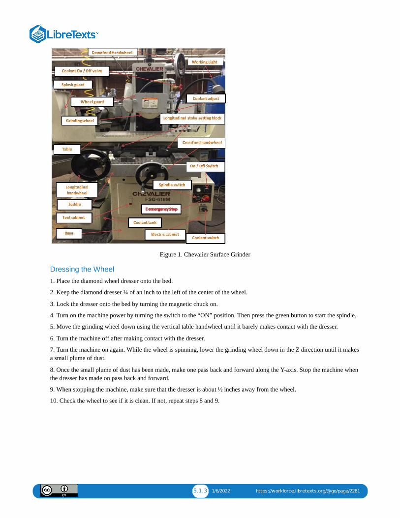
5.1.3 1/6/2022 https://workforce.libretexts.org/@go/page/2281
Figure 1. Chevalier Surface Grinder
Dressing the Wheel
1. Place the diamond wheel dresser onto the bed.
2. Keep the diamond dresser ¼ of an inch to the left of the center of the wheel.
3. Lock the dresser onto the bed by turning the magnetic chuck on.
4. Turn on the machine power by turning the switch to the “ON” position. Then press the green button to start the spindle.
5. Move the grinding wheel down using the vertical table handwheel until it barely makes contact with the dresser.
6. Turn the machine off after making contact with the dresser.
7. Turn the machine on again. While the wheel is spinning, lower the grinding wheel down in the Z direction until it makesa small plume of dust.
8. Once the small plume of dust has been made, make one pass back and forward along the Y-axis. Stop the machine whenthe dresser has made on pass back and forward.
9. When stopping the machine, make sure that the dresser is about ½ inches away from the wheel.
10. Check the wheel to see if it is clean. If not, repeat steps 8 and 9.
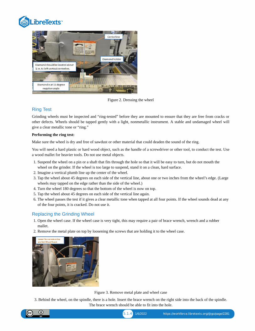
5.1.4 1/6/2022 https://workforce.libretexts.org/@go/page/2281
Figure 2. Dressing the wheel
Ring TestGrinding wheels must be inspected and “ring-tested” before they are mounted to ensure that they are free from cracks orother defects. Wheels should be tapped gently with a light, nonmetallic instrument. A stable and undamaged wheel willgive a clear metallic tone or “ring.”
Performing the ring test:
Make sure the wheel is dry and free of sawdust or other material that could deaden the sound of the ring.
You will need a hard plastic or hard wood object, such as the handle of a screwdriver or other tool, to conduct the test. Usea wood mallet for heavier tools. Do not use metal objects.
1. Suspend the wheel on a pin or a shaft that fits through the hole so that it will be easy to turn, but do not mouth thewheel on the grinder. If the wheel is too large to suspend, stand it on a clean, hard surface.
2. Imagine a vertical plumb line up the center of the wheel.3. Tap the wheel about 45 degrees on each side of the vertical line, about one or two inches from the wheel’s edge. (Large
wheels may tapped on the edge rather than the side of the wheel.)4. Turn the wheel 180 degrees so that the bottom of the wheel is now on top.5. Tap the wheel about 45 degrees on each side of the vertical line again.6. The wheel passes the test if it gives a clear metallic tone when tapped at all four points. If the wheel sounds dead at any
of the four points, it is cracked. Do not use it.
Replacing the Grinding Wheel1. Open the wheel case. If the wheel case is very tight, this may require a pair of brace wrench, wrench and a rubber
mallet.2. Remove the metal plate on top by loosening the screws that are holding it to the wheel case.
Figure 3. Remove metal plate and wheel case
3. Behind the wheel, on the spindle, there is a hole. Insert the brace wrench on the right side into the back of the spindle.The brace wrench should be able to fit into the hole.
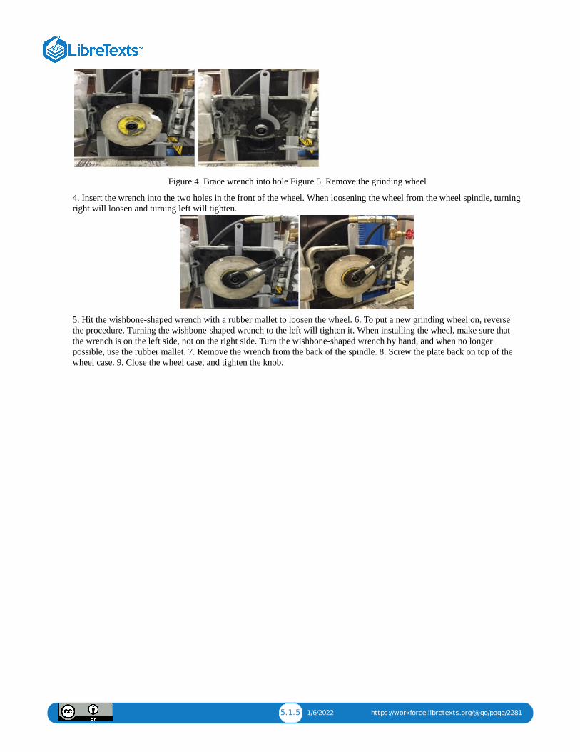
5.1.5 1/6/2022 https://workforce.libretexts.org/@go/page/2281
Figure 4. Brace wrench into hole Figure 5. Remove the grinding wheel
4. Insert the wrench into the two holes in the front of the wheel. When loosening the wheel from the wheel spindle, turningright will loosen and turning left will tighten.
5. Hit the wishbone-shaped wrench with a rubber mallet to loosen the wheel. 6. To put a new grinding wheel on, reversethe procedure. Turning the wishbone-shaped wrench to the left will tighten it. When installing the wheel, make sure thatthe wrench is on the left side, not on the right side. Turn the wishbone-shaped wrench by hand, and when no longerpossible, use the rubber mallet. 7. Remove the wrench from the back of the spindle. 8. Screw the plate back on top of thewheel case. 9. Close the wheel case, and tighten the knob.

1 1/14/2022
CHAPTER OVERVIEW6: HEAT TREATING
6.1: CHAPTER 6: HEAT TREATING6.2: UNIT 2: HARDNESS TESTING
6.1.1 12/10/2021 https://workforce.libretexts.org/@go/page/2282
6.1: Chapter 6: Heat Treating
OBJECTIVE
After completing this unit, you should be able to:
Correctly harden a piece of tool steel and evaluate your work.Correctly temper the hardened piece of the tool steel and evaluate your work.Describe the proper heat treating procedures for other tool steels.
SafetyThe following procedures are suggested for a safe heat treating operation.
1. Wear heat-resistant protective clothing, gloves, safety glasses, and a face shield to prevent exposure to hot oils, whichcan burn skin.
2. Before lighting the furnace, make sure that air switches, exhaust fans, automatic shut-off valves, and other safetyprecautions are in place.
3. Make sure that there is enough coolant for the job. Coolant will absorb heat given off by the metal as it is cooling, but ifthere is insufficient coolant, the metal will not cool at the optimal speed.
4. Make sure that there is sufficient ventilation in the quenching areas in order to maintain desired oil mist levels.
5. When lighting the furnace, obey the instructions that have been provided by the manufacturer.
6. During the process of lighting an oil or gas-fired furnace, do NOT stand directly in front of it.
7. Make sure that the quenching oil is not contaminated by water. Explosions can be results of moisture coming intocontact with the quenching oil.
8. Before taking materials out of the liquid carburizing pot, make sure that the tongs are not wet and that they are thecorrect tongs for the job.
9. Make sure that an appropriate fungicide or bacterial inhibitor has been mixed into the quenching liquid.
10. When quench tanks are not being used, always cover them.
11. Use a nonflammable absorbent to clean leaks and oil spills. This should be done immediately.
12. If possible, keep tools, baskets, jigs, and work areas free from oil contamination.
13. Before breaks and before moving on to the next task, wash your hands thoroughly.
14. If any skin trouble is shown or suspected, report to your instructor and get medical help.
15. Fumes from the molten carburizing salt bath should not be inhaled, because carbon monoxide is a product of thecarburizing process.
16. Make sure there is good ventilation in the work area.
17. Be on the lookout for contamination from pieces of carburized metal.
18. Do not take oil-soaked clothes or equipment to areas where there are food or beverages.
19. Do not take food or beverages where oils are either being used or stored.
ProcedureThe first important thing to know when heat treating a steel is its hardening temperature. Many steels, especially thecommon tool steels, have a well established temperature range for hardening. O-1 happens to have a hardeningtemperature of 1450 – 1500 degrees Fahrenheit.
To begin the process:

6.1.2 12/10/2021 https://workforce.libretexts.org/@go/page/2282
1. Safety first. Heat treating temperatures are very hot. Dress properly for the job and keep the area around the furnaceclean so that there is no risk of slipping or stumbling. Also, preheat the tongs before grasping the heated sample part.
2. Preheat the furnace to 1200 degrees Fahrenheit.
3. When the furnace has reached 1200 degrees Fahrenheit, place the sample part into the furnace. Place the sample partinto the center of the oven to help ensure even heating. Close and wait.
4. Once the sample part is placed in the furnace, heat it to 1500 degrees Fahrenheit. Upon reaching this temperature,immediately begin timing the soak for 15 minutes to an hour (soak times will very depending on steel thickness).
Table 1: Approximate Soaking Time for Hardening, Annealing and Normalizing Steel
Thickness Of Metal (inches) Time of heating to required Temperature (hr) Soaking time (hr)
up to 1/8 .06 to .12 .12 to .25
1/8 to 1/4 .12 to .25 .12 to .25
1/4 to 1/2 .25 to .50 .25 to .50
1/2 to 3/4 .50 to .75 .25 to .50
3/4 to 1 .75 to 1.25 .50 to .75
1 to 2 1.25 to 1.75 .50 to .75
2 to 3 1.75 to 2.25 .75to 1.0
3 to 4 2.25to 2.75 1 to 1.25
4 to 5 2.75 to 3.50 1 to 1.25
5 to 8 3.50 to 3.75 1 to 1.50
6.2.1 12/24/2021 https://workforce.libretexts.org/@go/page/2283
6.2: Unit 2: Hardness Testing
OBJECTIVE
After completing this unit, you should be able to:
Perform a Rockwell TestPerform a Brinell Test
Beyond verifying our in shop heat treatment, testing hardness is sometime necessary for production work as well. Eventhough it’s bad planning, occasionally a job arrives at our machine shop with an unknown alloy or maybe its compositionis known but the hardness isn’t. It is possible to use a file to roughly test the machinability of that metal, but the best wayto select cutter types, speed, and feeds is a true hardness measurement.
Brinell: Testing hardness by reading the diameter of a ball penetrator mark.
Rockwell: Testing hardness by reading a penetrator depth.
The Rockwell Hardness Test
The Rockwell is a widely accepted method for both soft and hard metals. This system gauges malleability by measuringthe depth a pointed probe known shape and size will penetrate into the material given an exact amount of force upon it.Due to Rockwell’s range it is the most popular test in tooling and small production shops and training labs.
Rockwell Numbers:
There are several different scales within the Rockwell system. We’ll use the Rockwell C scale, correctly used on thehardened steel. The C scale can be said to start at 0(annealed Steel) and run up to 68, harder than a HSS tool bit, near thatof a carbide tool. It is symbolized by a larger R with the scale subscript.
R
The two step Rockwell test:
Step 1. Calibrate Load
The test object is set upon the lower anvil such that it’s stable and won’t move when pressed down from above. Next, acone-shaped diamond penetrator is brought into contact then driven into metal to a predetermined of 20lbs. That cause theconical point to sinks into the metal from 0.003 to 0.006 inch. This is the initial calibration load. At that time, a large dialindicator is rotated to read zero.
Step 2.
Test Load Then with the calibration pressure upon the penetrator and indicator set to zero, a second addition 20lbs test loadis added. As the diamond sink farther, its added depth is translated to dial, but in an inverse relationship. The deeper thediamond penetrates, the softer the metal tests, therefore the lower number that must appear on the dial face. Inversely,when the point can’t go very deep, the metal is hard and registers higher on the dial face.
The Rockwell MethodThe Rockwell method measures the permanent depth of indentation produced by a force/load on an indenter.
1. Prepare the sample.
2. Place the test sample on the anvil.
3. A preliminary test force (commonly referred to as preload or minor load) is applied to a sample using a diamondindenter.
4. This load represents the zero or reference position that breaks through the surface to reduce the effects of surface finish.After the preload, an additional load, called the major load, is applied to reach the total required test load.
5. This force is held for a predetermined amount of time (dwell time: 10-15 seconds) to allow for elastic recovery.
C

6.2.2 12/24/2021 https://workforce.libretexts.org/@go/page/2283
6. This major load is then released and the final position is measured against the position derived from the preload, theindentation depth variance between the preload value, and the major load value. This distance is converted to a hardnessnumber.
The Brinell Hardness TestThe Brinell Hardness test is very similar to the Rockwell system in that a penetrator is forced into the sample, however,here the measured gauge is the diameter of the dent made by penetration of a hard steel ball of known size, into the work-piece surface. Hardened tool steel balls are used for testing softer material, while a carbide penetrator ball is used to testharder metals.
Due to the upper hardness, limiting factor of Brinell ball, this test it correctly used as a test of soft to medium hard metals.
The Brinell scale numbers:
The scale runs from 160 for annealed steel up to approximately 700 for very hard steel.
The Brinell hardness test is an alternative way to test the hardness of metals and alloys.
1. Prepare the sample.2. Place the test sample on the anvil.3. Move the indenter down into position on the part surface.4. A minor load is applied and a zero reference position is established.5. The major load is applied for a specified time period (10 to 15 seconds) beyond zero.6. The major load is released, leaving the minor load applied.7. Follow the process to determine the Brinell hardness of an aluminum sample.
1. Press the indenter into the sample using an accurately controlled test force.2. Maintain the force for a specific dwell time (usually 10 to 15 seconds).3. After the dwell time is complete, remove the indenter, leaving a round indent in the sample.4. The size of the indent is determined optically by measuring two diagonals of the round indent using either a
portable microscope or one that is integrated with the load application device.5. The Brinell hardness number is a function of the test force divided by the curved surface area of the indent. The
indentation is considered to be spherical, with a radius equal to half the diameter of the ball. The average of the twodiagonals is used in the following formula to calculate the Brinell hardness.
BHN=F2D(D-D2- d2)
Unit Test:1. Please lists five heat treating safety.
2. What is first important thing to know when heat treating a steel?
3. What is the soak time for 1 to 2” Thickness Of Metal?
4. Please explain Soak time.
5. After the soak time is complete, what is the next step?
6. To temper the sample part it must be placed into the furnace at what temperature?
7. Please explain Austenitize and Quench.
8. What is a Air-cool?
9. Please explain The Rockwell Method.
10. Please explain The Brinell Hardness Test.
Chapter Attribution InformationThis chapter was derived from the following sources.

6.2.3 12/24/2021 https://workforce.libretexts.org/@go/page/2283
Heat Treating derived from Heat Treatment of Plain Carbon and LowAlloy Steels by the Massachusetts Institute ofTechnology, CC:BY-NC-SA 4.0.Brinell Hardness Test Equation derived from Brinell Hardness by CORE-Materials Resource Finder, CC:BY.

7.1 12/3/2021 https://workforce.libretexts.org/@go/page/2266
7: Lean Manufacturing
7.1: Chapter 7: Lean Manufacturing
7.1.1 1/14/2022 https://workforce.libretexts.org/@go/page/2284
7.1: Chapter 7: Lean Manufacturing
OBJECTIVE
After completing this unit, you should be able to:
Apply 5S in any Machine shop.Describe Kaizen Concept.Describe Implementing Lean Manufacturing.
Lean 5S:
“5S” is a method of workplace organization that consists of five words: Sort, Set in order, Shine, Standardize, and Sustain.All of these words begin with the letter S. These five components describe how to store items and maintain the new order.When making decisions, employees discuss standardization, which will make the work process clear among the workers.By doing this, each employee will feel ownership of the process.
Phase 0: Safety
It is often assumed that a properly executed 5S program will improve workplace safety, but this is false. Safety is not anoption; it’s a priority.
Phase 1: Sort
Review all items in the workplace, keeping only what is needed.
Phase 2: Straighten
Everything should have a place and be in place. Items should be divided and labeled. Everything should be arrangedthoughtfully. Employees should not have to bend over repetitively. Place equipment near where it is used. This step is apart of why lean 5s is not considered “standardized cleanup”.
Phase 3: Shine
Make sure that the workplace is clean and neat. By doing this, it will be easier to be aware of where things are and wherethey should be. After working, clean the workspace and return everything to its former position. Keeping the workplaceclean should be integrated into the daily routine.
Phase 4: Standardize
Standardize work procedures and make them consistent. Every worker should be aware of what their responsibilities arewhen following the first three steps.
Phase 5: Sustain
Assess and maintain the standards. The aforementioned steps should become the new norm in operation. Do not graduallyrevert to the old ways. When taking part of the new procedure, think of ways to improve. Review the first four steps whennew tools or output requirements are presented.
Kaizen
While the lean 5S process focuses on the removal of waste, Kaizen focuses on the practice of continuous improvement.Like lean 5S, Kaizen identifies three main aspects of the workplace: Muda (wastes), Mura (inconsistencies) and Muri(strain on people & machines). However, the Kaizen step-by-step process is more extensive that the lean 5S process.
The Kaizen process overview:
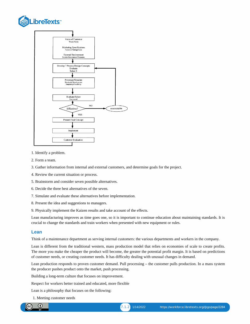
7.1.2 1/14/2022 https://workforce.libretexts.org/@go/page/2284
1. Identify a problem.
2. Form a team.
3. Gather information from internal and external customers, and determine goals for the project.
4. Review the current situation or process.
5. Brainstorm and consider seven possible alternatives.
6. Decide the three best alternatives of the seven.
7. Simulate and evaluate these alternatives before implementation.
8. Present the idea and suggestions to managers.
9. Physically implement the Kaizen results and take account of the effects.
Lean manufacturing improves as time goes one, so it is important to continue education about maintaining standards. It iscrucial to change the standards and train workers when presented with new equipment or rules.
LeanThink of a maintenance department as serving internal customers: the various departments and workers in the company.
Lean is different from the traditional western, mass production model that relies on economies of scale to create profits.The more you make the cheaper the product will become, the greater the potential profit margin. It is based on predictionsof customer needs, or creating customer needs. It has difficulty dealing with unusual changes in demand.
Lean production responds to proven customer demand. Pull processing – the customer pulls production. In a mass systemthe producer pushes product onto the market, push processing.
Building a long-term culture that focuses on improvement.
Respect for workers better trained and educated, more flexible
Lean is a philosophy that focuses on the following:
1. Meeting customer needs
7.1.3 1/14/2022 https://workforce.libretexts.org/@go/page/2284
2. Continuous, gradual improvement3. Making continuously better products4. Valuing the input of workers5. Taking the long term view6. Eliminating mistakes7. Eliminating waste
Wastes: using too many resources (materials, time, energy, space, money, human resources, poor instructions)
Wastes:
1. Overproduction2. Defects3. Unnecessary processing4. Waiting (wasting time)5. Wasting human time and talent6. Too many steps or moving aroundExcessive transportation7. Excessive inventory
Lean production includes working with suppliers, sub contractors, and sellers to stream line the whole process.
The goal is that production would flow smoothly avoiding costly starts and stops.
The idea is called just in time “produce only what is needed, when it is needed, and only in the quantity needed.”Production process must be flexible and fast.
Inventory = just what you need
In mass production = just in case. Extra supplies and products are stored just in case they are needed.
Terminology:
Process simplification – a process outside of the flow of production
Defects – the mass production system does inspection at the end of production to catch defects before they are shipped.The problem is that the resources have already been “spent” to make the waste product” Try to prevent problemsimmediately, as they happen, then prevent them. Inspection during production, at each stage of production.
Safety – hurt time is waste time
Information – need the right information at the right time (too much, too little, too late)
Principles:
Poka-yoke – mistake proof determining the cause of problems and then removing the cause to prevent further errors
Judgment errors – finding problems after the process
Informative inspections – analyzing data from inspections during the process
Source inspections – inspection before the process begins to prevent errors.
MEAN LEANOne of the terms applied to a simply cost cutting, job cutting interpretation of Lean is Mean Lean. Often modern managerthink they are doing lean without understanding the importance of workers and long term relationships.
Reliability Centered Maintenance
Reliablity centered maintenance is a system for designing a cost effective maintenance program. It can be a detailedcomplex, computer, statistically driven, but at its basics it is fairly simple. Its ideas can be applied to designing andoperating a PM system, and can also guide your learning as you do maintenance, troubleshooting, repair and energy work.
These are core principles of RCM. These nine fundamental concepts are:
Failures happen.

7.1.4 1/14/2022 https://workforce.libretexts.org/@go/page/2284
Not all failures have the same probabilityNot all failures have the same consequencesSimple components wear out, complex systems break downGood maintenance provides required functionality for lowest practicable costMaintenance can only achieve inherent design reliability of the equipmentUnnecessary maintenance takes resources away from necessary maintenanceGood maintenance programs undergo continuous improvement.
Maintenance consists of all actions taken to ensure that components, equipment, and systems provide their intendedfunctions when required.
An RCM system is based on answering the following questions:
1. What are the functions and desired standards of performance of the equipment?
2. In what ways can it fail to fulfil its functions? (Which are the most likely failures? How likely is each type of failure?Will the failures be obvious? Can it be a partial failure?)
3. What causes each failure?
4. What happens when each failure occurs? (What is the risk, danger etc.?)
5. In what way does each failure matter? What are the consequences of a full or partial failure?
6. What can be done to predict or prevent each failure? What will it cost to predict or prevent each failure?
7. What should be done if a suitable proactive task cannot be found (default actions) (no task might be available, or itmight be too costly for the risk)?
Equipment is studied in the context of where when and how it is being used
All maintenance actions can be classified into one of the following categories:
Corrective Maintenance – Restore lost or degraded functionPreventive Maintenance – Minimizes opportunity for function to failAlterative Maintenance – Eliminate unsatisfactory condition by changing system design or use
Within the category of preventive maintenance all tasks accomplished can be described as belonging to one of five (5)major task types:
Condition Directed – Renew life based on measured condition compared to a standardTime Directed – Renew life regardless of conditionFailure Finding – Determine whether failure has occurredServicing – Add/replenish consumablesLubrication – Oil, grease or otherwise lubricate
We do maintenance because we believe that hardware reliability degrades with age, but that we can do somethingto restore or maintain the original reliability that pays for itself.
RCM is reliability-centered. Its objective is to maintain the inherent reliability of the system or equipment design,recognizing that changes in inherent reliability may be achieved only through design changes. We must understand that theequipment or system must be studied in the situation in which it is working.
Implementing Lean Manufacturing
Analyze each step in the original process before making change
Lean manufacturing main focuses is on cost reduction and increases in turnover and eliminating activities that do not addvalue to the manufacturing process. Basically what lean manufacturing does is help companies to achieve targetedproduction, as well as other things, by introducing tools and techniques that are easy to apply and maintain. What thesetools and techniques are doing is reducing and eliminating waste, things that are not needed in the manufacturing process.
Manufacturing engineers set out to use the six-sigma DMAIC (Design, Measure, Analyze, Improve, Control) methodology—in conjunction with lean manufacturing—to meet customer requirements related to the production of tubes.
7.1.5 1/14/2022 https://workforce.libretexts.org/@go/page/2284
Manufacturing engineers were charged with designing a new process layout of the tube production line. The objectives forproject were including:
Improved qualityDecreased scrapDelivery to the point of useSmaller lot sizesImplementation of a pull systemBetter feedbackIncreased productionIndividual ResponsibilityDecreased WIPDine flexibility
Before making changes, the team analyze each step in the original layout of the tube production line process.
1. There try to understand the original state process, identify the problem area, unnecessary step and non value added.
2. After mapping the process, the lean team collected data from the Material Review Board (MRB) bench to measure andanalyze major types of defects . To better understand the process, the team also did a time study for 20 days periodproduction run.
In the original state, the tube line consisted of one operator and four operations, separated into two stations by a large tableusing a push system. The table acted as a separator between the second and third operation.
The first problem discovered was the line’s unbalanced . The first station was used about 70% of the time. Operators at thesecond station were spending a lot of their time waiting between cycle times. By combining stations one and two, room forimprovement became evident with respect to individual responsibility, control of inventory by the operator, and immediatefeedback when a problem occurred. The time study and the department layout reflect these findings.
A second problem was recognized. Because of the process flow, the production rate did not allow the production scheduleto be met with two stations. Because operators lost track of machine cycles, machines were waiting for operator attention.Operators also tried to push parts through the first station—the bottleneck operation in the process—and then continued tomanufacture the parts at the last two operations. Typically, long runs of WIP built up, and quality problems were notcaught until a lot number of defective pieces were produced.
The original state data were taken from the last 20 days before the change. The teams analyze each step in the original andmaking changes. The findings of the time study on the original process provided the basis for reducing cycle time,balancing the line, designing the using Just In Time kanbans and scheduling, improve quality, decrease lot size and WIP ,and improve flow. The new process data were taken starting one month after implementation. This delay gave the machineoperators an opportunity to train and get to with the new process layout system.
With the U shaped cell design; The parts meet all the customer requirement. Table in the original process was removed,almost eliminating WIP. With the reducing WIP and increasing production.
Some of the concepts used to improve the process included total employee involvement (TEI), smaller lot sizes,scheduling, point of use inventory, and improved layout. All employees and supervisors in the department were involvedin all phases of the project. Their ideas and suggestions were incorporated in the planning and implementation process togain wider acceptance of the changes to the process. Smaller lot sizes were introduced to minimize the number of partsproduced before defects were detected. Kanbans were introduced (in the form of material handling racks) to control WIPand to implement a pull system. And the cell layout decreased travel between operations.
Operators were authorized to stop the line when problems arose. In the original-state , the operators were still continuerunning parts when a operation was down. With kanban
control, the layout eliminated the ability to store WIP, requiring the operator to shut down the entire line. The cell layoutprovides excellent opportunities for improving communication between operators about problems and adjustments, toachieve better quality.

7.1.6 1/14/2022 https://workforce.libretexts.org/@go/page/2284
Day-to-day inspection of the original-state process the operators spent a lot of time either waiting for material-handlingperson, or performing as a material handling. With the U-shaped cell, delivery to the point of use is more better for theoperator. The operator places boxes of raw material on six moveable roller carts, where it’s easily to get. The six boxes areenough to last a 24-hr period.
To reduce setup times, tools needed for machine repair and adjustments are located in the cell. The screws are notstandardized; tools are set up in order of increasing size to quickly identify the proper tool.
For three months the process was monitored to verify that it was in control. Comparison of time studies from the original-state and the implemented layout demonstrated an increase in production from 300 to 514 finished products per shift. Thenew layout eliminated double handling between the second and third operations, as well as at the packing step. It alsoreduced throughout time by making it easier to cycle all four operations in a pull-system order. Customer demand was metby two shifts, which reduced the labor cost.
The results of the redesign are as follows:
WIP decreased by 97%Production increased 72%Scrap was reduced by 43%Machine utilization increased by 50%Labor utilization increased by 25%Labor costs were reduced by 33%Sigma level increased from 2.6 to 2.8
This project yielded reduced labor and scrap costs, and allowed the organization to do a better job of making deliveries ontime, while allowing a smaller finished-goods inventory. Daily production numbers and single-part cycle time served as abenchmark for monitoring progress towards the goal. Although the sigma level increase , the 43% reduction in defects,97% reduction in WIP, and production increase of 72% contributed to the project objective.
Implementing lean is a never ending process; this is what continuous improvement is all
about. When you get one aspect of lean implemented, it can always be improved. Don’t get hung up on it, but don’t letthings slip back to the starting point. There will always be time to go back and refine some of the processes.
Before Lean Manufacturing was implemented at Nypro Oregon Inc., we would operate using traditional manufacturing.Traditional manufacturing consists of producing all of a given product for the marketplace so as to never let the equipmentidle. These goods them need to be warehoused or shipped out to a customer who may not be ready for them. If more isproduced than can be sold, the products will be sold at a deep discount (often a loss) or simply scrapped. This can add upto an enormous amount waste. After implementing Lean Manufacturing concepts, our company uses just in time. Just intime refers to producing and delivering good in the amount required when the customer requires it and not before. In leanManufacturing, the manufacture only produces what the customer wants, when they want it. This often a much more costeffective way of manufacturing when compared to high priced, high volume equipment.
Unit Test:
1. What is 5S?
2. Please Explain each “S” of the 5S.
3. Please Explain Kaizen concept.
4. What is the Pull processing?
5. What is the Poka-yoke?
6. What is the six-sigma DMAIC?
7. What is the objectives for a new process layout of the tube production line?
8. Before making changes, The Manufacturing engineers team do what first?
9. Please lists the results of the redesign.

7.1.7 1/14/2022 https://workforce.libretexts.org/@go/page/2284
10. The key to implementing lean new idea or concept is to do what?
CHAPTER ATTRIBUTION INFORMATIONThis chapter was derived from the following sources.
Lean 5S derived from Lean Manufacturing by various authors, CC:BY-SA 3.0.Kaizen derived from A Kaizen Based Approach for Cellular Manufacturing System Design: A Case Study byVirginiaTech, CC:BY-SA 4.0.Kaizen (image) derived from A Kaizen Based Approach for Cellular Manufacturing System Design: A Case Study byVirginiaTech, CC:BY-SA 4.0.

1 1/14/2022
CHAPTER OVERVIEW8: CNC
8.1: CHAPTER 8: CNC8.2: UNIT 2: CNC MACHINE TOOL PROGRAMMABLE AXES AND POSITION DIMENSIONING SYSTEMS8.3: UNIT 3: VERTICAL MILLING CENTER MACHINE MOTION8.4: UNIT 4: CNC LANGUAGE AND STRUCTURE8.5: UNIT 5: CNC OPERATION8.6: UNIT 6: HAAS CONTROL8.7: UNIT 7: MASTERCAM
8.1.1 12/24/2021 https://workforce.libretexts.org/@go/page/2285
8.1: Chapter 8: CNCUnit 1: Introduction to CNC
What is CNC? CNC is a Computer Numerical Control. CNC is the automation of machine tools that are operated byprecisely programmed commands encoded and played by a computer as opposed to controlled manually via handwheels orlevers.
In modern CNC systems, end-to-end component design is highly automated using Computer-Aided Design (CAD) andComputer-Aided Manufacturing (CAM) programs. The series of steps needed to produce any part is highly automated andproduces a part that closely matches the original CAD design.
In the CNC machines the role of the operators is minimized. The operator has to merely feed the program of instructions inthe computer, load the required tools in the machine, and rest of the work is done by the computer automatically. Thecomputer directs the machine tool to perform various machining operations as per the program of instructions fed by theoperator.
The CNC technology can be applied to wide variety of operations like drafting, assembly, inspection, sheet metal working,etc. But it is more prominently used for various metal machining processes like turning, drilling, milling, shaping, etc. Dueto the CNC, all the machining operations can be performed at the fast rate resulting in bulk manufacturing becoming quitecheaper.
How It Works
The CNC machine comprises of the computer in which the program is fed for cutting of the metal of the job as per therequirements. All the cutting processes that are to be carried out and all the final dimensions are fed into the computer viathe program. The computer thus knows what exactly is to be done and carries out all the cutting processes. CNC machineworks like the Robot, which has to be fed with the program and it follows all your instructions.
You don’t have to worry about the accuracy of the job; all the CNC machines are designed to meet very close accuracies.In fact, these days for most of the precision jobs CNC machine is compulsory. When your job is finished, you don’t evenhave to remove it, the machine does that for you and it picks up the next job on its own. This way your machine can keepon doing the fabrication works all the 24 hours of the day without the need of much monitoring, of course you will have tofeed it with the program initially and supply the required raw material.
Since the earliest days of production manufacturing, ways have been sought to increase dimensional accuracy as well asspeed of production. Simply put, numerical control is a method of automatically operating a manufacturing machine basedon a code of letter, numbers, and special characters. As they developed, application of digital computers control ofmanufacturing equipment was realized. Computers were soon used to provide direct control of machine tools. Theintegrated circuit led to small computers used to control individual machines, and the computer numerical control (CNC)era was born. This Computer Numerical Control era has become so sophisticated it is the preferred method of almost everyphase of
precision manufacturing, particularly machining. Precision dimensional requirements, mainstay of the machiningprocesses, are ideal candidates for use of computer control systems. Computer numerical control now appears in manyother types of manufacturing processes. A distinct advantage of computer control of machine tools is rapid, high-precisionpositioning of workpiece and cutting tools.
Today, manual machine tools have been largely replaced by Computer numerical Control(CNC) machine tools. Themachine tool are controlled electronically rather than by hand. CNC machine tools can produce the same part over andover again with very little variation. Modern CNC machines can position cutting tools and workpieces at traverse feedrates of several hundred inches per minute, to an accuracy of .0001”. Once programming is complete and tooling is set up,they can run day or night, week after week, without getting tried, with only routine service and cutting tool maintenance.These are obvious advantage over manual machine tools, which need a great deal of human interaction in order to doanything. Cutting feed rates and spindle speeds may be optimized through program instructions. Modern CNC machinetools have turret or belt toolholders and some can hold more than 150 tools. Tool change take less than 15 seconds.

8.1.2 12/24/2021 https://workforce.libretexts.org/@go/page/2285
Computer Numerical Control machine are highly productive. They are also expensive to purchase, set up, and maintain.However, the productivity advantage can easily offset this cost if their use is properly managed. A most importantadvantage of CNC is ability to program the machine to do different jobs. Tool selection and changing under programcontrol is extremely productive, with little time wasted applying a tool to the job.
A program developed to accomplish a given task may be used for a short production run of one, or a few parts. Themachine may then be set up for a new job and used for long production runs of hundreds or thousands of production units.It can be interrupted, used for the original job or another new job, and quickly returned to the long production run. Thismakes the CNC machine tool extremely versatile and productive. Computer-aided design(CAD), has become the preferredmethod of product design & development. The connection between CAD & CNC was logical. A computer part design cango directly to program used to develop CNC machine control information. A CNC manufacturing machine can then makethe part. The computer is extremely useful for assisting the CNC programmer in developing a program to manufacture aspecific part. Computer-aided manufacturing, or CAM, systems are now the industry standard for programming. WhenCAD, CAM & CNC are blended, the greatest capability emerges, producing parts extremely difficult or impossible tomake by manual methods.
CNC motion is based on the Cartesian coordinate system. A CNC machine cannot be successfully operated without anunderstanding of the how coordinate systems are defined in CNC machine and how the systems work together.
To fully understand numerical control programming you must understand axes and coordinates. Think of a part that youwould have make. You could describe it to someone else by its geometry. For example, the part you have make is a 5 inchby 8 inch rectangle. All parts can be described in this fashion. Any point on the machined part, such as a pocket to be cutor a hole to be drilled, can be described in term of its position. The system that allows us to do this, called the CartesianCoordinate or rectangular coordinate system.
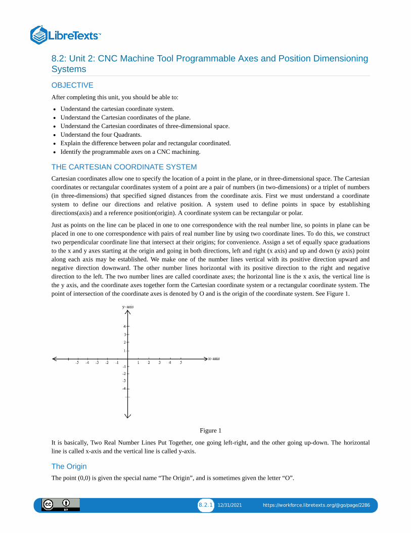
8.2.1 12/31/2021 https://workforce.libretexts.org/@go/page/2286
8.2: Unit 2: CNC Machine Tool Programmable Axes and Position DimensioningSystems
OBJECTIVE
After completing this unit, you should be able to:
Understand the cartesian coordinate system.Understand the Cartesian coordinates of the plane.Understand the Cartesian coordinates of three-dimensional space.Understand the four Quadrants.Explain the difference between polar and rectangular coordinated.Identify the programmable axes on a CNC machining.
THE CARTESIAN COORDINATE SYSTEMCartesian coordinates allow one to specify the location of a point in the plane, or in three-dimensional space. The Cartesiancoordinates or rectangular coordinates system of a point are a pair of numbers (in two-dimensions) or a triplet of numbers(in three-dimensions) that specified signed distances from the coordinate axis. First we must understand a coordinatesystem to define our directions and relative position. A system used to define points in space by establishingdirections(axis) and a reference position(origin). A coordinate system can be rectangular or polar.
Just as points on the line can be placed in one to one correspondence with the real number line, so points in plane can beplaced in one to one correspondence with pairs of real number line by using two coordinate lines. To do this, we constructtwo perpendicular coordinate line that intersect at their origins; for convenience. Assign a set of equally space graduationsto the x and y axes starting at the origin and going in both directions, left and right (x axis) and up and down (y axis) pointalong each axis may be established. We make one of the number lines vertical with its positive direction upward andnegative direction downward. The other number lines horizontal with its positive direction to the right and negativedirection to the left. The two number lines are called coordinate axes; the horizontal line is the x axis, the vertical line isthe y axis, and the coordinate axes together form the Cartesian coordinate system or a rectangular coordinate system. Thepoint of intersection of the coordinate axes is denoted by O and is the origin of the coordinate system. See Figure 1.
Figure 1
It is basically, Two Real Number Lines Put Together, one going left-right, and the other going up-down. The horizontalline is called x-axis and the vertical line is called y-axis.
The OriginThe point (0,0) is given the special name “The Origin”, and is sometimes given the letter “O”.
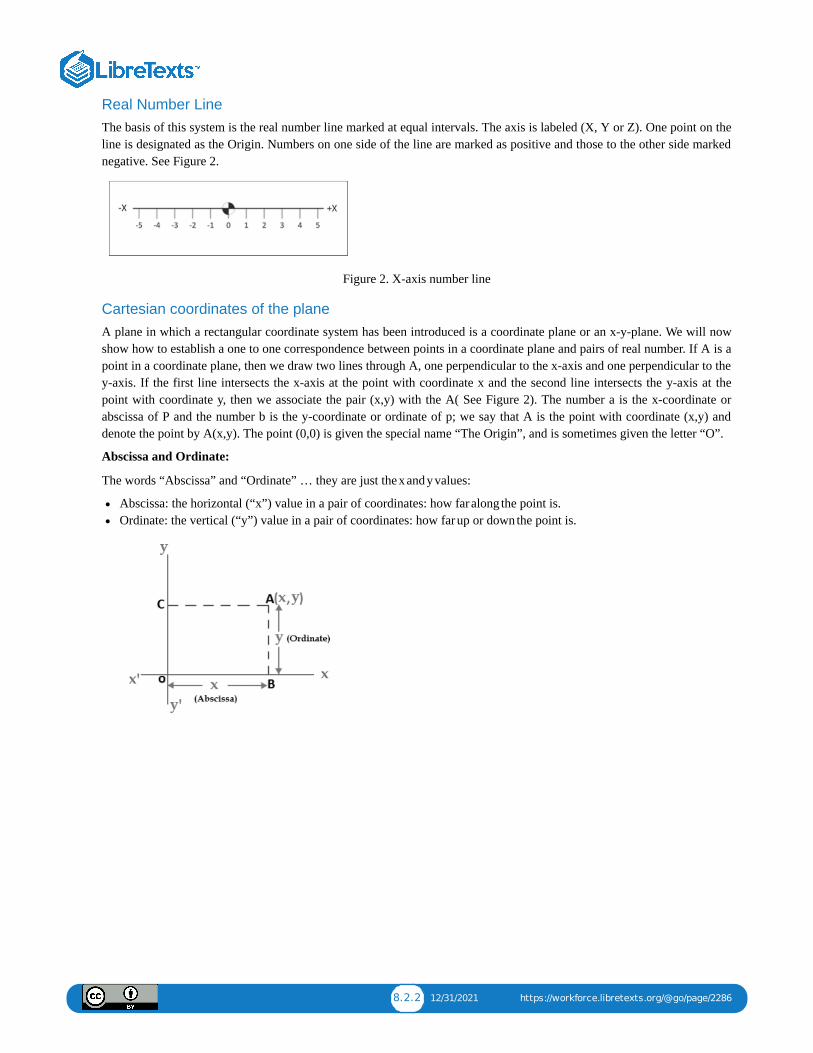
8.2.2 12/31/2021 https://workforce.libretexts.org/@go/page/2286
Real Number LineThe basis of this system is the real number line marked at equal intervals. The axis is labeled (X, Y or Z). One point on theline is designated as the Origin. Numbers on one side of the line are marked as positive and those to the other side markednegative. See Figure 2.
Figure 2. X-axis number line
Cartesian coordinates of the planeA plane in which a rectangular coordinate system has been introduced is a coordinate plane or an x-y-plane. We will nowshow how to establish a one to one correspondence between points in a coordinate plane and pairs of real number. If A is apoint in a coordinate plane, then we draw two lines through A, one perpendicular to the x-axis and one perpendicular to they-axis. If the first line intersects the x-axis at the point with coordinate x and the second line intersects the y-axis at thepoint with coordinate y, then we associate the pair (x,y) with the A( See Figure 2). The number a is the x-coordinate orabscissa of P and the number b is the y-coordinate or ordinate of p; we say that A is the point with coordinate (x,y) anddenote the point by A(x,y). The point (0,0) is given the special name “The Origin”, and is sometimes given the letter “O”.
Abscissa and Ordinate:
The words “Abscissa” and “Ordinate” … they are just the x and y values:
Abscissa: the horizontal (“x”) value in a pair of coordinates: how far along the point is.Ordinate: the vertical (“y”) value in a pair of coordinates: how far up or down the point is.
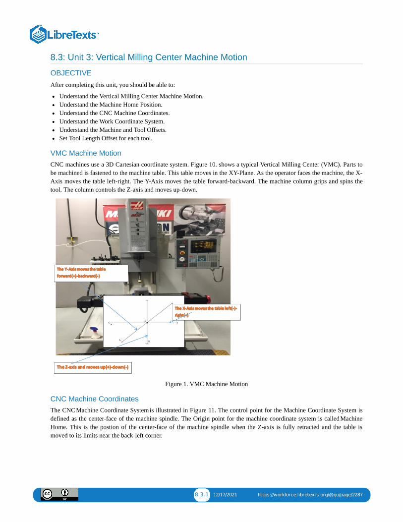
8.3.1 12/17/2021 https://workforce.libretexts.org/@go/page/2287
8.3: Unit 3: Vertical Milling Center Machine Motion
OBJECTIVE
After completing this unit, you should be able to:
Understand the Vertical Milling Center Machine Motion.Understand the Machine Home Position.Understand the CNC Machine Coordinates.Understand the Work Coordinate System.Understand the Machine and Tool Offsets.Set Tool Length Offset for each tool.
VMC Machine MotionCNC machines use a 3D Cartesian coordinate system. Figure 10. shows a typical Vertical Milling Center (VMC). Parts tobe machined is fastened to the machine table. This table moves in the XY-Plane. As the operator faces the machine, the X-Axis moves the table left-right. The Y-Axis moves the table forward-backward. The machine column grips and spins thetool. The column controls the Z-axis and moves up-down.
Figure 1. VMC Machine Motion
CNC Machine CoordinatesThe CNC Machine Coordinate System is illustrated in Figure 11. The control point for the Machine Coordinate System isdefined as the center-face of the machine spindle. The Origin point for the machine coordinate system is called MachineHome. This is the postion of the center-face of the machine spindle when the Z-axis is fully retracted and the table ismoved to its limits near the back-left corner.
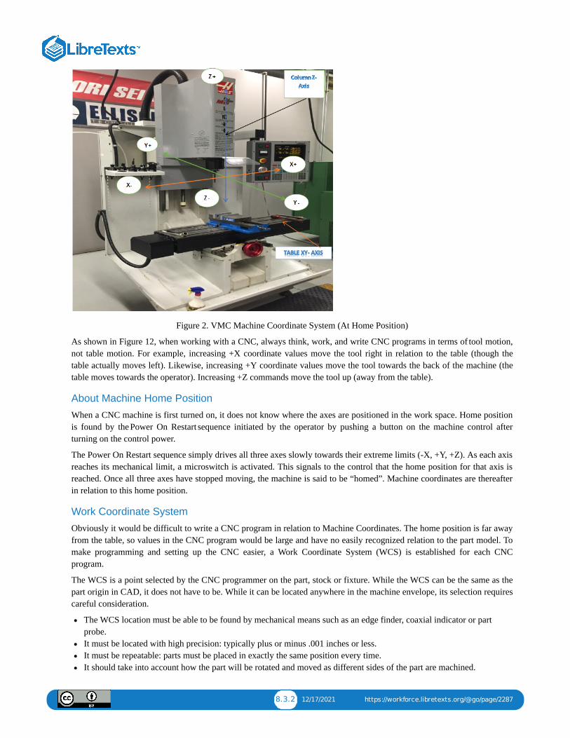
8.3.2 12/17/2021 https://workforce.libretexts.org/@go/page/2287
Figure 2. VMC Machine Coordinate System (At Home Position)
As shown in Figure 12, when working with a CNC, always think, work, and write CNC programs in terms of tool motion,not table motion. For example, increasing +X coordinate values move the tool right in relation to the table (though thetable actually moves left). Likewise, increasing +Y coordinate values move the tool towards the back of the machine (thetable moves towards the operator). Increasing +Z commands move the tool up (away from the table).
About Machine Home Position
When a CNC machine is first turned on, it does not know where the axes are positioned in the work space. Home positionis found by the Power On Restart sequence initiated by the operator by pushing a button on the machine control afterturning on the control power.
The Power On Restart sequence simply drives all three axes slowly towards their extreme limits (-X, +Y, +Z). As each axisreaches its mechanical limit, a microswitch is activated. This signals to the control that the home position for that axis isreached. Once all three axes have stopped moving, the machine is said to be “homed”. Machine coordinates are thereafterin relation to this home position.
Work Coordinate System
Obviously it would be difficult to write a CNC program in relation to Machine Coordinates. The home position is far awayfrom the table, so values in the CNC program would be large and have no easily recognized relation to the part model. Tomake programming and setting up the CNC easier, a Work Coordinate System (WCS) is established for each CNCprogram.
The WCS is a point selected by the CNC programmer on the part, stock or fixture. While the WCS can be the same as thepart origin in CAD, it does not have to be. While it can be located anywhere in the machine envelope, its selection requirescareful consideration.
The WCS location must be able to be found by mechanical means such as an edge finder, coaxial indicator or partprobe.It must be located with high precision: typically plus or minus .001 inches or less.It must be repeatable: parts must be placed in exactly the same position every time.It should take into account how the part will be rotated and moved as different sides of the part are machined.

8.3.3 12/17/2021 https://workforce.libretexts.org/@go/page/2287
For example, Figure 13 shows a part gripped in a vise. The outside dimensions of the part have already been milled to sizeon a manual machine before being set on the CNC machine.
The CNC is used to make the holes, pockets, and slot in this part. The WCS is located in the upper-left corner of the block.This corner is easily found using an Edge Finder or Probe.

8.4.1 12/3/2021 https://workforce.libretexts.org/@go/page/2288
8.4: Unit 4: CNC Language and Structure
OBJECTIVE
After completing this unit, you should be able to:
Identify the programs list instructions.Understand the Program FormatDescribe Letter Address Commands codesDescribe Special Character Code Definitions.Understand the G & M Codes.
CNC programs list instructions to be performed in the order they are written. They read like a book, left to right and top-down. Each sentence in a CNC program is written on a separate line, called a Block. Blocks are arranged in a specificsequence that promotes safety, predictability and readability, so it is important to adhere to a standard program structure.
The blocks are arranged in the following order:
Program StartLoad ToolSpindle OnCoolant OnRapid to position above partMachining operation
Coolant OffSpindle OffMove to safe positionEnd program
The steps listed above represent the simplest type of CNC program, where only one tool is used and one operationperformed. Programs that use multiple tools repeat steps two through nine for each.
Table 3 and Table 4 in section G & M Codes show the most common G and M codes that should be memorized if possible.
Like any language, the G-code language has rules. For example, some codes are modal, meaning they do not have to berepeated if they do not change between blocks. Some codes have different meanings depending on how and where thereare used.
While these rules are covered in this chapter, do not concern yourself with learning every nuance of the language. It is thejob of the job of the CAD/CAM software Post Processor to properly format and write the CNC program.
Program FormatThe program in Table 1: below machines a square contour and drills a hole.
Block Description Purpose
%O1234(T1 0.25 END MILL)G17 G20 G40 G49 G80 G90
Start of program.Program number (Program Name).Tool description for operator.Safety block to ensure machine is in safemode.
Start Program
T1 M6S9200 M3
Load Tool #1.Spindle Speed 9200 RPM, On CW.
Change Tool
G54M8G00 X-0.025 Y-0.275G43 Z1.H1Z0.1
Use Fixture Offset #1.Coolant On.Rapid above part.Rapid to safe plane, use Tool Length Offset#1.
Move to Position
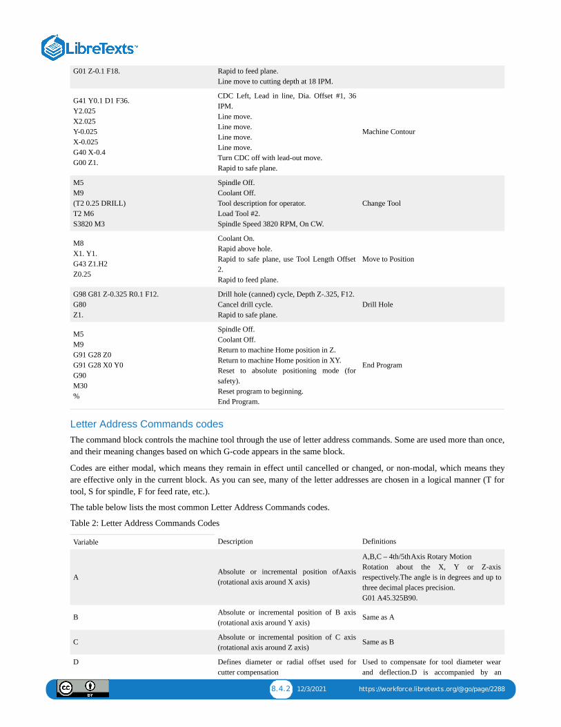
8.4.2 12/3/2021 https://workforce.libretexts.org/@go/page/2288
G01 Z-0.1 F18. Rapid to feed plane.Line move to cutting depth at 18 IPM.
G41 Y0.1 D1 F36.Y2.025X2.025Y-0.025X-0.025G40 X-0.4G00 Z1.
CDC Left, Lead in line, Dia. Offset #1, 36IPM.Line move.Line move.Line move.Line move.Turn CDC off with lead-out move.Rapid to safe plane.
Machine Contour
M5M9(T2 0.25 DRILL)T2 M6S3820 M3
Spindle Off.Coolant Off.Tool description for operator.Load Tool #2.Spindle Speed 3820 RPM, On CW.
Change Tool
M8X1. Y1.G43 Z1.H2Z0.25
Coolant On.Rapid above hole.Rapid to safe plane, use Tool Length Offset2.Rapid to feed plane.
Move to Position
G98 G81 Z-0.325 R0.1 F12.G80Z1.
Drill hole (canned) cycle, Depth Z-.325, F12.Cancel drill cycle.Rapid to safe plane.
Drill Hole
M5M9G91 G28 Z0G91 G28 X0 Y0G90M30%
Spindle Off.Coolant Off.Return to machine Home position in Z.Return to machine Home position in XY.Reset to absolute positioning mode (forsafety).Reset program to beginning.End Program.
End Program
Letter Address Commands codesThe command block controls the machine tool through the use of letter address commands. Some are used more than once,and their meaning changes based on which G-code appears in the same block.
Codes are either modal, which means they remain in effect until cancelled or changed, or non-modal, which means theyare effective only in the current block. As you can see, many of the letter addresses are chosen in a logical manner (T fortool, S for spindle, F for feed rate, etc.).
The table below lists the most common Letter Address Commands codes.
Table 2: Letter Address Commands Codes
Variable Description Definitions
AAbsolute or incremental position ofAaxis(rotational axis around X axis)
A,B,C – 4th/5th Axis Rotary MotionRotation about the X, Y or Z-axisrespectively.The angle is in degrees and up tothree decimal places precision. G01 A45.325B90.
B Absolute or incremental position of B axis(rotational axis around Y axis)
Same as A
C Absolute or incremental position of C axis(rotational axis around Z axis)
Same as B
D Defines diameter or radial offset used forcutter compensation
Used to compensate for tool diameter wearand deflection.D is accompanied by an
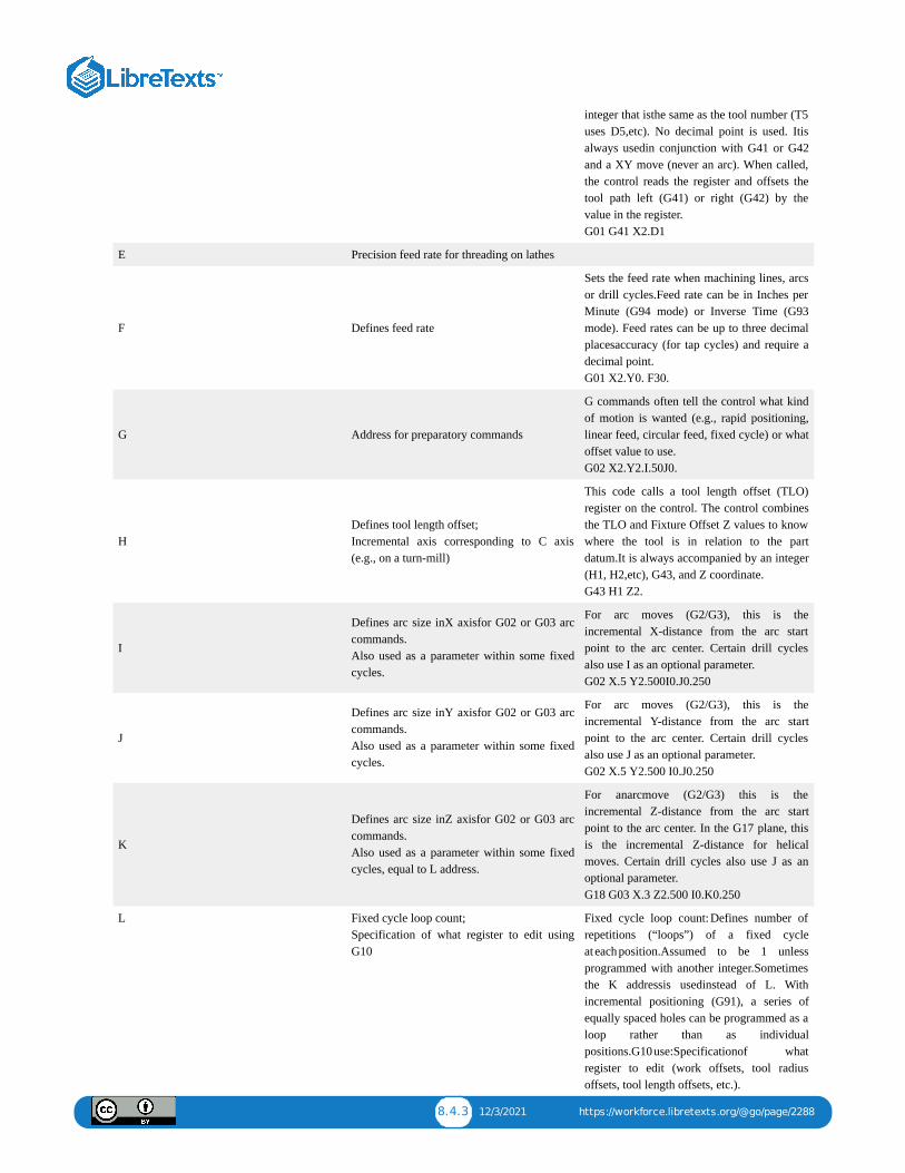
8.4.3 12/3/2021 https://workforce.libretexts.org/@go/page/2288
integer that isthe same as the tool number (T5uses D5,etc). No decimal point is used. Itisalways usedin conjunction with G41 or G42and a XY move (never an arc). When called,the control reads the register and offsets thetool path left (G41) or right (G42) by thevalue in the register. G01 G41 X2.D1
E Precision feed rate for threading on lathes
F Defines feed rate
Sets the feed rate when machining lines, arcsor drill cycles.Feed rate can be in Inches perMinute (G94 mode) or Inverse Time (G93mode). Feed rates can be up to three decimalplacesaccuracy (for tap cycles) and require adecimal point. G01 X2.Y0. F30.
G Address for preparatory commands
G commands often tell the control what kindof motion is wanted (e.g., rapid positioning,linear feed, circular feed, fixed cycle) or whatoffset value to use.G02 X2.Y2.I.50J0.
HDefines tool length offset;Incremental axis corresponding to C axis(e.g., on a turn-mill)
This code calls a tool length offset (TLO)register on the control. The control combinesthe TLO and Fixture Offset Z values to knowwhere the tool is in relation to the partdatum.It is always accompanied by an integer(H1, H2,etc), G43, and Z coordinate. G43 H1 Z2.
I
Defines arc size inX axisfor G02 or G03 arccommands.Also used as a parameter within some fixedcycles.
For arc moves (G2/G3), this is theincremental X-distance from the arc startpoint to the arc center. Certain drill cyclesalso use I as an optional parameter. G02 X.5 Y2.500I0.J0.250
J
Defines arc size inY axisfor G02 or G03 arccommands.Also used as a parameter within some fixedcycles.
For arc moves (G2/G3), this is theincremental Y-distance from the arc startpoint to the arc center. Certain drill cyclesalso use J as an optional parameter. G02 X.5 Y2.500 I0.J0.250
K
Defines arc size inZ axisfor G02 or G03 arccommands.Also used as a parameter within some fixedcycles, equal to L address.
For anarcmove (G2/G3) this is theincremental Z-distance from the arc startpoint to the arc center. In the G17 plane, thisis the incremental Z-distance for helicalmoves. Certain drill cycles also use J as anoptional parameter. G18 G03 X.3 Z2.500 I0.K0.250
L Fixed cycle loop count;Specification of what register to edit usingG10
Fixed cycle loop count: Defines number ofrepetitions (“loops”) of a fixed cycleat each position.Assumed to be 1 unlessprogrammed with another integer.Sometimesthe K addressis usedinstead of L. Withincremental positioning (G91), a series ofequally spaced holes can be programmed as aloop rather than as individualpositions.G10 use:Specificationof whatregister to edit (work offsets, tool radiusoffsets, tool length offsets, etc.).

8.4.4 12/3/2021 https://workforce.libretexts.org/@go/page/2288
M Miscellaneous function
Always accompanied by an integer thatdetermines its meaning.Only one M-codeisallowedin each block of code. Expandeddefinitions of M-codes appear later in thischapter. M08
NLine (block) number in program;System parameter number to be changedusing G10
Block numbers can make the CNC programeasier to read. They are seldom required forCAD/CAM generated programs with nosubprograms. Because they take upcontrolmemorymost 3D programs do not useblock numbers. Block numbers are integersup to five characters long with no decimalpoint. They cannot appear before the tapestart/end character (%) and usually do notappear before a comment only block. N100 T02 M06
O Program name
Programs are stored on the control by theirprogram number. Thisis an integer thatispreceded by the letter O and has no decimalplaces. O1234 (Exercise 1)
PServes as parameter address for various Gand M codes
Dwell (delay) in seconds.Accompanied byG4 unless used within certain drill cycles. G4 P.1
Q Peck increment in canned cyclesThe incremental feed distance per pass in apeck drill cycle. G83 X2.000 Y2.000 Z-.625 F20.R.2 Q.2 P9.
R Defines size of arc radius or defines retractheight in canned cycles
Arcs can be defined using the arc radius R orI,J,Kvectors. IJK’s are more reliable than R’sso itis recommendedto use them instead. Risalso usedby drill cycles as the return plane Zvalue. G83 Z-.625 F20.R.2 Q.2 P9.
SDefines speed, either spindle speed or surfacespeed depending on mode
Spindle speed in revolutions per minute(RPM). It is an integer value with no decimal,and always used in conjunction with M03(Spindle on CW) or M04 (Spindle on CCW). S2500M03
T Tool selectionSelects tool. It is an integer value alwaysaccompanied by M6 (tool change code). T01 M06
UIncremental axis corresponding to X axis(typically only lathe group A controls)Also defines dwell time on some machines.
In these controls, X and U obviate G90 andG91, respectively. On these lathes, G90 isinstead a fixed cycle address for roughing.
V Incremental axis corresponding to Y axis
Until the 2000s, the V address was veryrarely used, because most lathes that used UandWdidn’thave a Y-axis, so they didn’t useV. (Green et al 1996 did not even list V intheir table of addresses.) That is still often thecase, although the proliferation of live lathetooling and turn-mill machining has made Vaddress usage less rare than it used to be(Smid2008 shows an example).
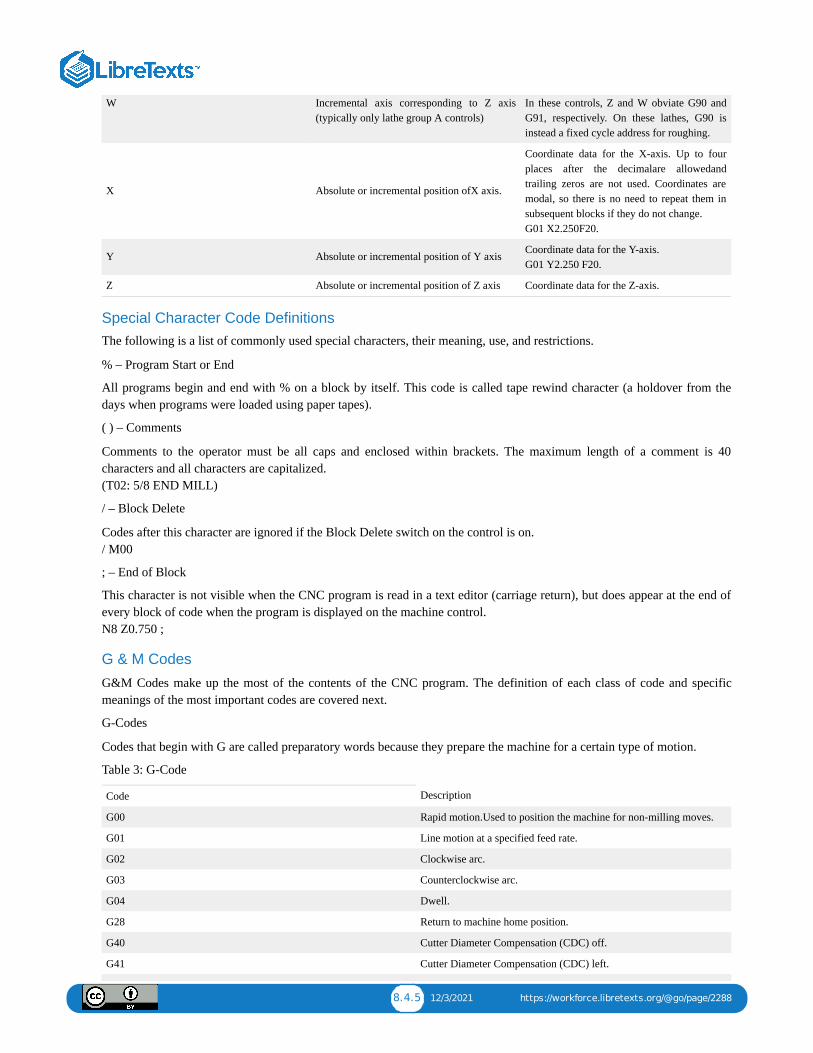
8.4.5 12/3/2021 https://workforce.libretexts.org/@go/page/2288
W Incremental axis corresponding to Z axis(typically only lathe group A controls)
In these controls, Z and W obviate G90 andG91, respectively. On these lathes, G90 isinstead a fixed cycle address for roughing.
X Absolute or incremental position ofX axis.
Coordinate data for the X-axis. Up to fourplaces after the decimalare allowedandtrailing zeros are not used. Coordinates aremodal, so there is no need to repeat them insubsequent blocks if they do not change. G01 X2.250F20.
Y Absolute or incremental position of Y axis Coordinate data for the Y-axis.G01 Y2.250 F20.
Z Absolute or incremental position of Z axis Coordinate data for the Z-axis.
Special Character Code DefinitionsThe following is a list of commonly used special characters, their meaning, use, and restrictions.
% – Program Start or End
All programs begin and end with % on a block by itself. This code is called tape rewind character (a holdover from thedays when programs were loaded using paper tapes).
( ) – Comments
Comments to the operator must be all caps and enclosed within brackets. The maximum length of a comment is 40characters and all characters are capitalized. (T02: 5/8 END MILL)
/ – Block Delete
Codes after this character are ignored if the Block Delete switch on the control is on. / M00
; – End of Block
This character is not visible when the CNC program is read in a text editor (carriage return), but does appear at the end ofevery block of code when the program is displayed on the machine control. N8 Z0.750 ;
G & M Codes
G&M Codes make up the most of the contents of the CNC program. The definition of each class of code and specificmeanings of the most important codes are covered next.
G-Codes
Codes that begin with G are called preparatory words because they prepare the machine for a certain type of motion.
Table 3: G-Code
Code Description
G00 Rapid motion.Used to position the machine for non-milling moves.
G01 Line motion at a specified feed rate.
G02 Clockwise arc.
G03 Counterclockwise arc.
G04 Dwell.
G28 Return to machine home position.
G40 Cutter Diameter Compensation (CDC) off.
G41 Cutter Diameter Compensation (CDC) left.

8.4.6 12/3/2021 https://workforce.libretexts.org/@go/page/2288
G42 Cutter Diameter Compensation (CDC) right.
G43 Tool length offset (TLO).
G54 Fixture Offset #1.
G55 Fixture Offset #2.
G56 Fixture Offset #3.
G57 Fixture Offset #4.
G58 Fixture Offset #5.
G59 Fixture Offset #6.
G80 Cancel drill cycle.
G81 Simple drill cycle.
G82 Simple drill cycle with dwell.
G83 Peck drill cycle.
G84 Tap cycle.
G90 Absolute coordinate programming mode.
G91 Incremental coordinate programming mode.
G98 Drill cycle return to Initial point (R).
G99 Drill cycle return to Reference plane (last Z Height)
M-Codes
Codes that begin with M are called miscellaneous words. They control machine auxiliary options like coolant and spindledirection. Only one M-code can appear in each block of code.
Table 4: M-Codes
Code Description
M00 Program stop.Press Cycle Start button to continue.
M01 Optional stop.
M02 End of program.
M03 Spindle on Clockwise.
M04 Spindle on Counterclockwise.
M05 Spindle stop.
M06 Change tool.
M08 Coolant on.
M09 Coolant off.
M30 End program and press Cycle Start to run it again.
Select G-Code Definitions (Expanded)
G00 – Rapid Move
This code commands the machine to move as fast as it can to a specified point. It is always used with a coordinate positionand is modal. Unlike G01, G00 does not coordinate the axes to move in a straight line. Rather, each axis moves at itsmaximum speed until it is satisfied. This results in motion as shown in Figure 18, below.
G 0 0 X 0 . Y0.

8.4.7 12/3/2021 https://workforce.libretexts.org/@go/page/2288

8.5.1 12/17/2021 https://workforce.libretexts.org/@go/page/2289
8.5: Unit 5: CNC Operation
OBJECTIVE
After completing this unit, you should be able to:
Understand the CNC Operation.List the steps to set up and operate a CNC mill.Identify the location and purpose of the operating controls on the Haas CNC Mill control.Start and home a CNC machine.Load tools into tool carousel.Set Tool Length Offsets.Set Part Offsets.Load a CNC program into the machine control.Dry runSafely run a new CNC program.Adjust offsets to account for tool wear and deflection.Shut down a CNC machine correctly.
Overview of CNC Setup and Operation
CNC machine setup and operation follows the process below:
1. Pre-Start2. Start/Home3. Load Tools4. Mount Remove Part into the vise5. Set Tool Length Offsets Z6. Set Part Offset XY7. Load CNC Program8. Dry Run9. Run Program
10. Adjust Offsets as Needed11. Shut Down
1. Pre-Start
Before starting the machine, check to ensure oil and coolant levels are full. Check the machine maintenance manual if youare unsure about how to service it. Ensure the work area is clear of any loose tools or equipment. If the machine requiresan air supply, ensure the compressor is on and pressure meets the machine requirements.
2. Start/Home
Turn power on the machine and control. The main breaker is located at the back of the machine. The machine powerbutton is located in the upper-left corner on the control face.
3. Load Tools
Load all tools into the tool carousel in the order listed in the CNC program tool list.
4. Mount the Part in the Vise
Place the Part to be machine in the vise and tighten.
5. Set Tool Length Offsets
Set Tool Length Offsets For each tool used in the order listed in the CNC program, jog the Tools to the top of the part andthen set the TLO.
6. Set Part Offset XY

8.5.2 12/17/2021 https://workforce.libretexts.org/@go/page/2289
Once the vise or other Part is properly installed and aligned on the machine, set the fixture offset to locate the part XYdatum.
7. Load CNC Program
Load your CNC program into CNC machine control using USB flash memory, or floppy disk.
8. Dry Run
Run the program in the air about 2.00 in. above the part .
9. Run Program
Run the program, using extra caution until the program is proven to be error-free.
10. Adjust Offsets as Required
Check the part features and adjust the CDC or TLO registers as needed to ensure the part is within design specifications.
11. Shut Down
Remove part from the vise and tools from the spindle, clean the work area, and properly shut down the machine. Be sure toclean the work area and leave the machine and tools in the location and condition you found them.
UNIT TEST1. Please list the CNC setup and operation process steps.
2. Describe each process.

8.6.1 1/14/2022 https://workforce.libretexts.org/@go/page/2290
8.6: Unit 6: Haas Control
OBJECTIVE
After completing this unit, you should be able to:
Identify the Haas Control.Identify the Keyboard.Describe Start/Home Machine procedure.Describe Door Override procedure.Describe Load Tools procedure.Describe Tool Length Offset (TLO) for each tool.Verify part zero offset(XY) using MDI.Describe the setting tool offset.Verify Tool Length offset using MDI.Describe the procedure of load CNC program.Describe the procedure of save CNC program.Explain how to run CNC program.Describe the use of cutter diameter compensation.Describe the shut down program.
Haas ControlThe Haas control is shown in Figures 18 and 19. Familiarize yourself with the location of buttons and controls. Detailedinstructions on the following pages show how to operate the control.

8.7.1 12/31/2021 https://workforce.libretexts.org/@go/page/2291
8.7: Unit 7: Mastercam
After completing this unit, you should be able to:
Describe save image.Describe the load image to Mastercam.Describe scaling and dragging or translate image.Describe Mastercam setup, stock setup, and Tool setting.Describe creating Toolpaths.
MastercamRaster To Vector Images Conversion:
This Worksheet walks you through how to import Raster images into Mastercam. Mastercam is a vector software, wheremost images for the internet and other sources are Raster Images. Raster images are made up of thousand of pixels ofdiffering color, where vector images are image of line that use mathematical formulas to determine their shape. In thisactivity you will learn how to convert Raster images to Vector images that Mastercam can use.
1. Using the internet search for your desired Image. Logos or images with sharp color changer work best, try to avoidpictures taken with a camera. .jpg, .gif, .bmp are the file extension currently supported by Mastercam.
2. Try to get the larges image possible. When Using Google examine the images sizing information located under theimage. The Larger the number the better.
3. Then navigate to the raw picture by clicking on the image.
4. Click on See full size image.
5. RIGHT CLICK on the image and select Save Image As…
6. Save your raster image to a location that you know.
7. Launch Mastercam 2017
8. Once it loads Press ALT-C or Run User Application (under Setting) a window will open called Chooks. This is acollection of add on file to mastercam.
9. Navigate and click on Rast2Vec.dli
10. It many ask you of you want to keep current Geometry. Then, Click Yes
11.Navigate to your saved image and click on it.
12. The Black White conversion window will open. Slide the Threshold slider in the Black White conversion dialog boxuntil the image on right shows the desired amount of detail.
13. When you like what you see. Then, click OK.
14. Rast2Vec window will popup no modification should be needed. Then, click OK.
15. When the Adjust Geometry opens. Then, click OK.
16. Your image should now be on the screen.
17. Click Yes to exit Rast2Vec.
Scaling and Dragging or Translate your imageAfter you have imported a image it often not in the right location or the proper size that you need. You need to Scale it upor down and Drag it to the position that you would like.
Scaling:
Learning OBJECTIVEs
8.7.2 12/31/2021 https://workforce.libretexts.org/@go/page/2291
1. From The ToolBar >Xform>Scale
2. Then Select all the line that part of your image. The Line you select should turn yellow. You can use a window or selecteach line individually. If you pick a line you do not what just pick it again and it should change back form yellow.
3. Once you have selected your entire image then click on the Green Ball.
4. The Scale window will open. Change To MOVE and to PERCENTAGE, and then adjust the percent up or down untilyour image is the size you would like. After typing the new percentage number hit ENTER on the keyboard. This willpreview that size change. Once the size is what you are looking for. Then, click OK.
Dragging or Translate
1. From the Tool Bar>xfrom>Drag or Translate
2. Once again select all the line that part of your image.
3. Once you have selected your entire image then click on the Green Ball.
4. Change from Copy To Move.
5. Click near your Image in the graphics screen. As you move your mouse the image will move.
6. Once the image is in the proper place LEFT Click again and it will place the image.
MASTERCAM SETUP1. Turn on the Operation Manager window by pressing Alt-O
2. Click on Machine Type – Mill, then select the HASS 3X MINI MILL – TOOLROM.MMD-5. You should see the HASS3X MINI pop up in the Operation Manager window.
STOCK SETUP
1. Click on the plus sign next to Properties to see the drop down list and click on stock setup. The Machine GroupProperties dialog box should appear. Check the box next to Display to activate it, then click on the Bounding Box button.The Bounding Box dialog box should appear. Confirm that X, Y AND Z are all be set to zero then click OK.
2. Change the value of Z to stock you are using, then click OK. On an isometric view, you should see your part go from 2Dto 3D with the image on the top surface.
TOOL SETTING1. Click on Tool Setting. Enter a program number….Feed Calculation should be “From Tool.” Under ToolpathConfiguration, check “Assign tool number sequentially” and “Warn of duplicate tool numbers.” Under AdvancedOperation, check the “Override defaults with modal values” box and then check all three selections below it. UnderSequence #, change the start number to 10. Select the material by clicking on the Select button. Click on the drop downarrow associated with Source and select “Mill – library.” From the list, select “ALUMINUM inch – 6061” then click OK.Click OK to exit the Machine Group Properties dialog box.
CREATING TOOLPATHS
1. Choose Toolpath – Contour. The chaining dialog box should appear. Select Window to choose your engraving elements,then click anywhere to establish an approximate start point (selection will change to yellow). Click OK to bring up the 2DToolpaths – Contour dialog box.
2. Toolpath Type should automatically be set to Contour.
3. Click on Tool (below Toolpath Type) then click on Select Library Tool button. A Tool Selection dialog box will appear.To limit the list to a particular type of tool (ball end mills which will use for engraving), Click on Filter then select/de-select tool types so that only Endmill2 Sphere is highlighted. Click OK. Choose the 1/32 Ball Endmill followed by clickOK. Change federate to 5.0 and Spindle Speed to 4000 then click OK.
4. Under Cut Parameters, Compensation Type should be off.

8.7.3 12/31/2021 https://workforce.libretexts.org/@go/page/2291
5. Under Lead In/Lead Out, Uncheck the Lead In/Out box as will not be using this feature.
6. Under Linking Parameters, Clearance should be set to 0.5, Retract should be 0.1, feed Plane should be 0.1, Top of stockshould be O.0 and Depth should be -0.015. Then click OK.
7. Run Verify Selected Operations in the Operations Manager to see the toolpath.
UNIT TEST1. What software is Mastercam is?
2. Please explain the Threshold Slider.
3. Lists file supported by Mastercam.
4. Describe scaling and dragging or translate image.
5. Describe stock setup.
6. Describe the tool setting.
7. Explain how to create Toolpaths.

IndexCcomputer numerical control (CNC)
8.1: Chapter 8: CNC

Glossary
Sample Word 1 | Sample Definition 1