managing dynamic requirements knowledge
TRANSCRIPT

Managing Dynamic Requirements KnowledgeAn Agent-Based Approach
Von der Fakultät für Mathematik, Informatik und Naturwissenschaftender RWTH Aachen University zur Erlangung des akademischen Grades
eines Doktors der Naturwissenschaften genehmigte Dissertation
vorgelegt vonDiplom-Informatiker
Dominik Schmitz
aus Köln
Berichter:
Professor Dr. rer. pol. Matthias JarkeProfessor Eric Yu, Ph.D.
Tag der mündlichen Prüfung: 20.Dezember 2010
Diese Dissertation ist auf den Internetseiten der Hochschulbibliothek online verfügbar.

AbstractAgent- and goal-based requirements engineering can be considered established in researchfor many years now. Also first successful applications to industrial practice have beenreported. Agent- and goal-based approaches explicate the functional and non-functionalgoals as well as various kinds of dependencies of possibly conflicting stakeholders. Thereby,they provide enhanced means to support elicitation, analysis, documentation, as well asmany other operations on requirements. The thesis strives to add to these advancedsupport facilities by addressing dynamic issues that are not yet considered in existingapproaches.
Several dynamic aspects of the requirements field have been targeted by various re-search groups. For example, use cases and scenarios have been introduced to capture theinteractive features of a system to be developed. From an entirely different perspective, thedynamics of the requirements engineering process itself has been investigated, for exampleto learn how the volatility of requirements can be addressed.
Inspired by two very different case studies – support for flexible inter-organisationalnetworks of enterprises and the elicitation and analysis of control software requirementsin small- and medium-sized enterprises (SMEs) – we address several new dynamic issuesin a number of extensions to the i* requirements modelling framework proposed by Yu.
• First, the requirements modelling language is extended to capture the dynamic in-stantiation of roles by stakeholders in a concrete project. Furthermore, these rolescan be related to each other in regard to evolutionary aspects. This allows to capturethat the characteristics of a stakeholder can change over time.
• Secondly, the capture, processing, and analysis of individual project requirementsis enhanced. The explicit representation of domain knowledge accelerates the cap-turing procedure. Model-based transformations improve the integration with laterdevelopment stages. In addition, they are used as a bridge toward agent-based sim-ulations. Simulation experiments and advanced analysis on top of these complementwell existing formal model checking approaches.
• Thirdly, we consider the inter-project management of dynamic requirements knowl-edge. A requirements-based similarity search helps to identify related historic projectsand thus to disclose potentially reusable solutions. We have also developed measuresto keep up with the fast and project-driven evolution of domain knowledge at SMEs.A partially automated feedback loop integrates repeated, consolidated project expe-riences of an SME into the earlier mentioned domain knowledge based approach.
In sum, a tailorable method with accompanying tool support is established that addressesthe raised dynamic issues. The validations within the two case studies have shown thatin particular the work within very innovative, flexible, and customer-oriented settingsbenefits from the proposed extensions and thus brings forward industrial acceptance ofagent- and goal-based approaches in these fields.

ZusammenfassungDie agenten- und zielorientierte Anforderungserfassung ist in der Forschung seit mehrerenJahren etabliert. Gleichfalls haben bereits erste erfolgreiche Einsätze in der industriellenPraxis stattgefunden. Agenten- und zielorientierte Ansätze machen die unterschiedlichenund möglicherweise konfligierenden Ziele – funktional sowie nicht-funktional – von Betei-ligten explizit. So bieten sie eine umfassendere Unterstützung für die Erfassung, Modellie-rung, Analyse, Dokumentation etc. von Anforderungen. Die vorliegende Arbeit sucht diesefortgeschrittenen Möglichkeiten weiter voranzubringen. Dazu werden dynamische Aspektefokussiert, die bisher noch keine ausreichende Berücksichtigung gefunden haben.
Hinsichtlich dynamischer Aspekte haben sich verschiedene andere Forschergruppe un-ter anderem mit Use Cases und Szenarien beschäftigt. Diese dienen der Erfassung derinteraktiven Eigenschaften eines zu entwickelnden Systems. Eine gänzlich andere Perspek-tive nehmen Ansätze ein, die die Dynamik der Anforderungserfassung selbst, beispielsweisedie Unbeständigkeit von Anforderungen, untersuchen.
Ausgehend von zwei sehr unterschiedlichen Fallstudien – der Unterstützung flexibler,organisationsübergreifender Unternehmensnetzwerke und der Erfassung regelungstechni-scher Anforderungen in kleinen und mittleren Unternehmen (KMUs) – werden in dervorliegenden Arbeit neue dynamische Aspekte aufgebracht und unter Rückgriff auf dasvon Yu entwickelte i* Rahmenwerk zur Anforderungsmodellierung unterstützt:
• Zunächst werden zwei Erweiterungen der Modellierungssprache i* vorgeschlagen.Diese zielen auf dynamische Aspekte der Stakeholdermodellierung. Die erste Er-gänzung verfeinert die Instanziierung von abstrakten Rollen durch Stakeholder. Diezweite ergänzt dies um die Möglichkeit, die Rollen Prozessbeteiligter über verschie-dene Nutzungs- und Entwicklungssituationen bzw. -zeiträume hinweg in Beziehungzu setzen.
• Des Weiteren werden die Möglichkeiten zur Erfassung, Verarbeitung und Analysevon Anforderungen eines konkreten Projekts verbessert. Die explizite Repräsentati-on von Domänenwissen beschleunigt die Erfassung. Modellbasierte Transformatio-nen verbessern die Integration mit späteren Entwicklungsschritten und ermöglichenzusätzlich die Analyse von Anforderungsmodellen mit Hilfe agentenbasierter Simu-lationen. Letztere werden dabei um weitergehende Analysemöglichkeiten für Simu-lationsläufe erweitert, die sich gut mit formalen Modelcheckingansätzen ergänzen.
• Schließlich wird das projektübergreifende Management von dynamischem Anforde-rungswissen adressiert. Eine anforderungsbasierte Ähnlichkeitssuche erlaubt es ver-wandte, frühere Projekte zu identifizieren und so potentiell wiederverwendbare Lö-sungen aufzufinden. Zudem wird eine teilautomatisierte Unterstützung für die dyna-mische, projektgetriebene Fortschreibung des Domänenwissens eines Unternehmensbereitgestellt. Eine Feedbackschleife integriert konsolidierte Projekterfahrungen un-mittelbar in den zuvor beschriebenen domänenwissenbasierten Ansatz.
Als Ergebnis steht eine werkzeugunterstützte Methode zur Verfügung, die die genann-ten dynamischen Aspekte adressiert. Die Validierung im Rahmen der zwei Fallstudienhat gezeigt, dass insbesondere die Arbeit in sehr innovativen, flexiblen und kundenorien-tierten Umgebungen von den Erweiterungen profitiert. Damit wird zugleich ein Beitragzur Verbesserung der Attraktivität von agenten- und zielorientierten Ansätzen in diesemkonkreten, industriellen Umfeld geleistet.
Thanks
Caveat
• The representation above is highly likely incomplete.
• Neither all people nor all relationships are captured.

Contents
1 Introduction 11.1 Requirements Engineering (RE) . . . . . . . . . . . . . . . . . . . . . . . . . 11.2 Dynamic Issues in Requirements Engineering . . . . . . . . . . . . . . . . . 21.3 New Dynamic Issues – Goals and Contributions . . . . . . . . . . . . . . . . 31.4 Structure of the Thesis . . . . . . . . . . . . . . . . . . . . . . . . . . . . . . 51.5 Published Results . . . . . . . . . . . . . . . . . . . . . . . . . . . . . . . . . 6
2 Foundations 72.1 Method Engineering . . . . . . . . . . . . . . . . . . . . . . . . . . . . . . . 7
2.1.1 Situational Method Engineering . . . . . . . . . . . . . . . . . . . . 82.1.2 Telos . . . . . . . . . . . . . . . . . . . . . . . . . . . . . . . . . . . . 102.1.3 ConceptBase . . . . . . . . . . . . . . . . . . . . . . . . . . . . . . . 122.1.4 Method Engineering with Telos and ConceptBase . . . . . . . . . . . 142.1.5 Example Applications of Method Engineering . . . . . . . . . . . . . 14
2.2 i* and Derivatives . . . . . . . . . . . . . . . . . . . . . . . . . . . . . . . . 182.2.1 Introduction to i* . . . . . . . . . . . . . . . . . . . . . . . . . . . . 192.2.2 The Tropos Software Development Methodology . . . . . . . . . . . 272.2.3 SNet – A Modelling and Simulation Environment . . . . . . . . . . . 282.2.4 Formal Tropos . . . . . . . . . . . . . . . . . . . . . . . . . . . . . . 392.2.5 Secure Tropos . . . . . . . . . . . . . . . . . . . . . . . . . . . . . . . 42
2.3 ConGolog . . . . . . . . . . . . . . . . . . . . . . . . . . . . . . . . . . . . . 452.3.1 Situation Calculus . . . . . . . . . . . . . . . . . . . . . . . . . . . . 452.3.2 ConGolog . . . . . . . . . . . . . . . . . . . . . . . . . . . . . . . . . 492.3.3 Implementation . . . . . . . . . . . . . . . . . . . . . . . . . . . . . . 51
2.4 Matlab/Simulink . . . . . . . . . . . . . . . . . . . . . . . . . . . . . . . . . 522.4.1 Action Diagrams . . . . . . . . . . . . . . . . . . . . . . . . . . . . . 522.4.2 Telos Representation . . . . . . . . . . . . . . . . . . . . . . . . . . . 54
2.5 OpenOMEi5 . . . . . . . . . . . . . . . . . . . . . . . . . . . . . . . . . . . . 55
3 Case Studies 573.1 Case Study 1: Inter-Organisational Networks . . . . . . . . . . . . . . . . . 57
3.1.1 Examples . . . . . . . . . . . . . . . . . . . . . . . . . . . . . . . . . 573.1.2 Basic Ingredients . . . . . . . . . . . . . . . . . . . . . . . . . . . . . 603.1.3 Dynamic Issues in Inter-Organisational Networks . . . . . . . . . . . 63
3.2 Case Study 2: Control Systems Development . . . . . . . . . . . . . . . . . 683.2.1 Examples . . . . . . . . . . . . . . . . . . . . . . . . . . . . . . . . . 683.2.2 Controller Development . . . . . . . . . . . . . . . . . . . . . . . . . 713.2.3 RE for Small- and Medium-Sized Enterprises . . . . . . . . . . . . . 76
i

Contents
3.2.4 Method Support for Control System Development . . . . . . . . . . 783.3 Common Issues of the Two Case Studies . . . . . . . . . . . . . . . . . . . . 80
3.3.1 Static Issues . . . . . . . . . . . . . . . . . . . . . . . . . . . . . . . . 803.3.2 Dynamic Issues . . . . . . . . . . . . . . . . . . . . . . . . . . . . . . 833.3.3 Summary on Characteristics and Open Issues . . . . . . . . . . . . . 85
4 Dynamic Requirements Modelling Extensions 874.1 Reconsidering Agent Instantiation . . . . . . . . . . . . . . . . . . . . . . . 87
4.1.1 Foundational and Related Work . . . . . . . . . . . . . . . . . . . . 874.1.2 Proposed Approach . . . . . . . . . . . . . . . . . . . . . . . . . . . 904.1.3 Implementation Details . . . . . . . . . . . . . . . . . . . . . . . . . 934.1.4 Case Studies . . . . . . . . . . . . . . . . . . . . . . . . . . . . . . . 974.1.5 Summary . . . . . . . . . . . . . . . . . . . . . . . . . . . . . . . . . 102
4.2 Actor Evolution . . . . . . . . . . . . . . . . . . . . . . . . . . . . . . . . . . 1034.2.1 Related Work . . . . . . . . . . . . . . . . . . . . . . . . . . . . . . . 1034.2.2 Modelling Representation . . . . . . . . . . . . . . . . . . . . . . . . 1054.2.3 Technical Details . . . . . . . . . . . . . . . . . . . . . . . . . . . . . 1074.2.4 Implementation Details . . . . . . . . . . . . . . . . . . . . . . . . . 1094.2.5 Case Study . . . . . . . . . . . . . . . . . . . . . . . . . . . . . . . . 1114.2.6 Summary . . . . . . . . . . . . . . . . . . . . . . . . . . . . . . . . . 113
4.3 Chapter Summary . . . . . . . . . . . . . . . . . . . . . . . . . . . . . . . . 114
5 Dynamic Capture, Processing, and Analysis of Requirements Models 1155.1 Domain Model-Based Requirements Engineering . . . . . . . . . . . . . . . 115
5.1.1 Related Work . . . . . . . . . . . . . . . . . . . . . . . . . . . . . . . 1165.1.2 Approach . . . . . . . . . . . . . . . . . . . . . . . . . . . . . . . . . 1185.1.3 Implementation Details . . . . . . . . . . . . . . . . . . . . . . . . . 1265.1.4 Case Studies . . . . . . . . . . . . . . . . . . . . . . . . . . . . . . . 1365.1.5 Summary and Preparation for Extensions . . . . . . . . . . . . . . . 146
5.2 Model Transformation . . . . . . . . . . . . . . . . . . . . . . . . . . . . . . 1475.2.1 Related Work . . . . . . . . . . . . . . . . . . . . . . . . . . . . . . . 1475.2.2 Supportive Telos Features . . . . . . . . . . . . . . . . . . . . . . . . 1505.2.3 Matlab/Simulink . . . . . . . . . . . . . . . . . . . . . . . . . . . . . 1545.2.4 ConGolog . . . . . . . . . . . . . . . . . . . . . . . . . . . . . . . . . 1705.2.5 Transformation Summary . . . . . . . . . . . . . . . . . . . . . . . . 176
5.3 Simulations and Their Analysis . . . . . . . . . . . . . . . . . . . . . . . . . 1775.3.1 Related Work . . . . . . . . . . . . . . . . . . . . . . . . . . . . . . . 1775.3.2 Simulations with SNet . . . . . . . . . . . . . . . . . . . . . . . . . . 1805.3.3 Analysis Questions Exemplified for the SNet Case Study . . . . . . . 1845.3.4 Formal Tropos (FT) . . . . . . . . . . . . . . . . . . . . . . . . . . . 1885.3.5 Secure Tropos (ST) . . . . . . . . . . . . . . . . . . . . . . . . . . . 1895.3.6 Time Series Analysis . . . . . . . . . . . . . . . . . . . . . . . . . . . 1905.3.7 Association Rule Mining and Clustering . . . . . . . . . . . . . . . . 1925.3.8 Social Network Analysis (SNA) . . . . . . . . . . . . . . . . . . . . . 1945.3.9 Summary . . . . . . . . . . . . . . . . . . . . . . . . . . . . . . . . . 196
5.4 Chapter Summary . . . . . . . . . . . . . . . . . . . . . . . . . . . . . . . . 197
ii

Contents
6 Dynamic Requirements Knowledge Management 1996.1 Requirements-Based Search for Similar Projects . . . . . . . . . . . . . . . . 199
6.1.1 Related Work . . . . . . . . . . . . . . . . . . . . . . . . . . . . . . . 2006.1.2 Foundational Considerations . . . . . . . . . . . . . . . . . . . . . . 2036.1.3 A Query-Based Similarity Search at Requirements Level . . . . . . . 2056.1.4 A New Similarity Measure for Project-Specific Extensions . . . . . . 2086.1.5 Problems, Improvements, Open Issues . . . . . . . . . . . . . . . . . 2156.1.6 Implementation Details . . . . . . . . . . . . . . . . . . . . . . . . . 2176.1.7 Case Studies . . . . . . . . . . . . . . . . . . . . . . . . . . . . . . . 2236.1.8 Summary . . . . . . . . . . . . . . . . . . . . . . . . . . . . . . . . . 229
6.2 Domain Model Evolution . . . . . . . . . . . . . . . . . . . . . . . . . . . . 2296.2.1 Related Work . . . . . . . . . . . . . . . . . . . . . . . . . . . . . . . 2306.2.2 Sources and a Classification for Domain Model Changes . . . . . . . 2346.2.3 Effects on the Constitution of Project-Specific Extensions . . . . . . 2366.2.4 Effects on the Similarity Search . . . . . . . . . . . . . . . . . . . . . 2376.2.5 Support for the Project-Driven Evolution of Domain Models . . . . 2436.2.6 Implementation Details . . . . . . . . . . . . . . . . . . . . . . . . . 2506.2.7 Case Studies . . . . . . . . . . . . . . . . . . . . . . . . . . . . . . . 2576.2.8 Summary . . . . . . . . . . . . . . . . . . . . . . . . . . . . . . . . . 262
6.3 Chapter Summary and Relation to SitME . . . . . . . . . . . . . . . . . . . 2636.3.1 The Domain Model Based Approach – A Situational Method? . . . 2646.3.2 Characterizing the Features of the Feedback Loop . . . . . . . . . . 265
7 Conclusions 2677.1 Summary . . . . . . . . . . . . . . . . . . . . . . . . . . . . . . . . . . . . . 2677.2 Conclusions and Outlook . . . . . . . . . . . . . . . . . . . . . . . . . . . . 269
Bibliography 271
List of Figures 295
List of Tables 299
A Telos 301A.1 Modelling Frameworks . . . . . . . . . . . . . . . . . . . . . . . . . . . . . . 301
A.1.1 i* . . . . . . . . . . . . . . . . . . . . . . . . . . . . . . . . . . . . . 301A.1.2 Sensor and Actuator Extension of i* . . . . . . . . . . . . . . . . . . 304A.1.3 Matlab/Simulink . . . . . . . . . . . . . . . . . . . . . . . . . . . . . 311
A.2 Telos Support for Domain Model Based Approach . . . . . . . . . . . . . . 313A.2.1 Implementation of Domain Model Clean-Up Support . . . . . . . . . 313
A.3 Transformation from i* to Matlab/Simulink . . . . . . . . . . . . . . . . . . 322A.3.1 Complete M2M Transformation . . . . . . . . . . . . . . . . . . . . . 322A.3.2 Prepare M2T Transformation . . . . . . . . . . . . . . . . . . . . . . 332A.3.3 Complete M2T Transformation . . . . . . . . . . . . . . . . . . . . . 333
iii

Contents
iv

Chapter 1
Introduction
This thesis addresses dynamic issues in requirements engineering (RE). Numerous studiesand researchers have stressed the importance of requirements engineering as “the successof a software system depends on how well it fits the needs of its users and its environ-ments” [CA09]. Requirements engineering has been an active research field for more than30 years now, but still remains challenging [JLL+10]. We will first give a brief outlineof requirements engineering and in particular dynamic issues therein before discussingthe goals and contributions of this thesis by identifying several new dynamic issues inrequirements engineering as well as means to tackle these.
1.1 Requirements Engineering (RE)Requirements engineering is hard since “requirements reside primarily in the problemspace” [CA09]. Cheng and Atlee have identified several consequences that “cause re-quirements engineering to be inherently difficult”. Requirements are ill-defined and oftenconflicting. Nonetheless in the end the analysts must arrive at “a single coherent, detailed,technical specification of the system”. “The requirements problem space is less constrainedthan the software solution space – in fact, it is the requirements definition that helps todelimit the solution space.” Constraining “the environmental conditions under which thesystem is expected to operate” can help to simplify the problem space but “involves rea-soning about the combined behavior of the proposed system and assumptions made aboutthe environment.” “Reasoning about the environment includes identifying not only as-sumptions about the normal behavior of the environment, but also about possible threatsor hazards that the environment could pose to the system.” Eventually, “the resultingrequirements artifacts have to be understood and usable by domain experts and otherstakeholders, who may not be knowledgeable about computing.”
Requirements Tasks
By following the presentation in [CA09] we distinguish five requirements engineering tasks:elicitation, modelling, requirements analysis, validation & verification, and requirementsmanagement.Elicitation is concerned with the understanding of the motivation and goals for building
a software system as well as the clarification of constraints the system must satisfy.Among others this step involves the identification of relevant stakeholders and theexploration of their possibly conflicting views.
1
Chapter 1. Introduction
Modelling is intended to support requirements engineering processes by adding formalityto the representation of requirements. This in particular reduces ambiguity. Furtheron, models help to pinpoint out missing details and to communicate requirementsbetween customer and developers.
Requirements Analysis support the evaluation of collected requirements and their im-pact on the system. Conflicting views may be aligned, a common prioritizing mightbe agreed upon etc. This is overall, requirements analysis help to understand re-quirements and their interactions.
Validation & Verification activities are concerned with the ultimate goal that thestakeholders’ needs are addressed. In contrast to the analysis mentioned abovethis involves a customer-driven subjective evaluation possibly supported by formalverification means.
Requirements Management takes a step back by targeting the management of re-quirements among a set of distributed developers, customers, projects, products,etc. or along time.
Our focus within this thesis will be on modelling, analysis, and management.
Agent- and Goal-Based Requirements Modelling
In [JMF08], Jureta et al. clarified the necessary constituents of any formalism intendedto support requirements engineering. They have identified domain assumptions, goals,softgoals, quality constraints, plans, and attitudes to be required. Goals have long beenidentified as a suitable measure to alleviate the communication with customers and endusers [vL01, vL04]. The ultimate goal to any software project is to have some applicationspecific problem solved. With the help of goal decomposition and the consideration ofaccompanying qualities (or softgoals, respectively) the customer is supposed to refine herproblem specification until finally concrete functional and non-functional requirements canbe stated clearly. Softgoals [CNYM00] to capture non-functional requirements and goalsto capture functional requirements have been important ingredients of many model-basedapproaches to requirements engineering developed in research over the years. Yu [Yu95,Yu01] added in his i* requirements modelling framework the notion of agent to reflectthe social aspect of requirements engineering with a focus on the various dependenciesbetween stakeholders. Recently, the User Requirements Notation has been approved asa recommendation of the international telecommunication union (ITU-T) to capture userrequirements [ITU08]. This notation includes next to use case maps also the Goal-orientedRequirement Language (GRL), a variant of i*.
1.2 Dynamic Issues in Requirements Engineering
Dynamic issues in requirements engineering can be considered in two regards. For one,we are concerned with the capture, representation, and analysis of dynamic aspects of thesoftware or system that has to be developed. For another, dynamic issues in regard to therequirements engineering process (as part of the overall software engineering process) areof interest.
2

1.3. New Dynamic Issues – Goals and Contributions
Considering Dynamics of the System-To-Be
The dynamics of a system to be developed has received attention in particular in regardto the interaction with the user. Scenarios (see [WPJH98]) as concrete, use-orientedsystem descriptions have proved to be helpful to elicit customer requirements. In particulartheir inclusion into the UML standard [OMG10b] in form of Use Cases has paved theway for industrial adoption. Still they consist to a large degree of textual descriptions.Further research has aimed at a stronger formalisation, for example, with the help of state-based approaches [HM03] that eventually enable simulations [Som06]. This work can beconsidered related to rapid prototyping approaches as already researched much earlier (see,for example, [LBH97, SRB+00]). Again, these ideas have more recently been picked upby UML in the form of executable UML [OMG10b].
Dynamics of the Requirements Engineering Process
Dynamic issues have also been considered in regard to the requirements engineering processitself. Christie and Staley [CS00] discuss the usefulness of simulation models for evaluatinga software development process. Others have researched more focused issues, for exampletraceability (see, for example, [RJ01, MGP08]) that allows to consider the effect of thechanges of requirements. Volatility and the evolving character of requirements have beenaddressed among others by Pfahl and Lebsanft [PL00] and more recently again by Ferreiraet al. [FCSM09]. Port, Olkov, and Menzies [POM08] consider various strategies towardrequirements prioritizing. Höst, Regnell, and Tringström designed a general frameworkfor simulating requirements engineering processes [HRT08]. In principal, all these ideasbuild on earlier work that concerns the investigation of the dynamics of software projectsin general [AHM91].
1.3 New Dynamic Issues – Goals and ContributionsInspired by two very different case studies – support for the governance of flexible, inter-organisational networks of enterprises and interdisciplinary requirements engineering forsoftware-based controllers at innovative and customer-oriented small- and medium-sizedenterprises (SMEs) – we investigate in this thesis the following research question.
Are there any new dynamic issues that can be addressed by building onan agent-based approach and how do these help to support developers
in interdisciplinary, flexible, innovative, and customer-oriented settings?
This is by using agent- and goal-based requirements modelling and the i* requirementsmodelling framework [Yu95] in particular as an anchor point, our research work aims ataddressing new dynamic issues. We have identified such issues in three different categories:modelling language extensions, dynamic issues in regard to the treatment of a singleproject, and inter-project dynamic knowledge management. We will provide more detailson these issues below and of course throughout the rest of this thesis.
Refined Role Instantiation and Evolving Stakeholders
Firstly, we were able to pinpoint out necessary language extensions that make use of theagent concept but go beyond existing approaches by allowing for considering more of theirdynamics.
3

Chapter 1. Introduction
While i* distinguishes abstract roles from concrete agents that play these roles,it is not concerned with capturing any detail on how the agent fills in the abstract featurescharacterizing the role. This is becoming a major obstacle in settings where a numberof similar but distinguishable individuals have to be considered. For example, a majorfeature of inter-organisational networks is that there is cooperation as well as competi-tion within the network [Pow90]. The latter certainly requires a degree of redundancy,this is capabilities that can be provided by several members but with slightly varyingcharacteristics.
In addition, i* foresees only the capture of a static snapshot of the relations betweenroles and agents. It does not account for the fact that the roles a particular stakeholderplays can change over time as do the associated connections and interactions to otherstakeholders. In particular, there are no means available to capture a certain knownpath of evolution. As a most basic example consider a typical user of a new system.She starts as a beginner but later on becomes more and more acquainted. It can beexpected that the requirements for the software evolve accordingly. Related to a moreorganisational setting, when investigating entrepreneurship networks we have learned thatan entrepreneur typically runs through different stages [Nat01]. Needing concrete businessadvice from business angels in the beginning, at later stages she mainly needs money fromventure capitalists. This is while her personal trust-based network carries over to thenext stages, the nature of a relationship might change or builds the starting point forestablishing relationships with new partners.
Dynamic Capture, Processing, and Analysis
Secondly, we consider the dynamics in regard to the treatment of a particular single project.As outlined above a model-based approach has many advantages. It enables more sophis-ticated analysis as well as better integrates with model-based development approachessuch as OMG’s Model Driven Architecture [OMG03]. We pick up on these advantages byadding more model transformations as well as simulation-based analysis techniques (seebelow).
But most elementarily we support the model-based capture by introducing domainmodels. They represent concrete domain knowledge that can be used ‘as is’ in new re-quirements models. That is, there is no need to instantiate or otherwise transform thisknowledge as in many requirements reuse approaches proposed so far (see, for exam-ple, [MS92, Jac95]). This approach immediately improves the situation for small- andmedium-sized enterprises (SMEs) in that the requirements capture is significantly faster.After choosing a suitable domain model, the SME only has to delete the parts that are notrelevant for the current project and adds its specifics. In particular, flexible, innovativeand very customer-oriented SMEs in the field of control system development benefit fromthis domain model-based approach to requirements modelling as the according case studyhas shown.
Model transformations have been considered in two regards. Concerning model baseddevelopment, the Tropos methodology [CKM02, BPG+04] foresees the application of i*concepts along the whole development and integrates also model-based transformations inthis regard. But in the field of control system development, there is already an establisheddomain specific language that accounts for the great importance of mathematics to arriveat an appropriate controller [AB06]. In order to have any chance for adoption in this field,we thus have to establish a linkage between the model-based requirements capture with
4

1.4. Structure of the Thesis
i* and mathematical modelling environments such as Matlab/Simulink [Mat10].The second regard concerns advanced model analysis. Several analysis techniques for
i* models have been developed or are still under development (see, for example, [FLP+04,GMMZ05a, HY09]). They mainly build on model checking formalisms or propositionallogic. In contrast, earlier work at the chair [GJLS05, Gan08] has already establisheda combination of i* with a dynamic, agent- and logic-based planning and simulationenvironment, ConGolog [dGLL00]. This accounts for a more exploratory analysis and isthus complementary to the above mentioned analysis. With the few modelling extensionsin this thesis, the corresponding transformation has to be slightly revisited. In addition,our work has picked up on the simulation component in that additional support to analysesimulation runs is provided. Advanced data mining, time series, as well as social networkanalysis [HK06] help to correctly and more easily interpret simulations. For one, this isneeded to validate simulations in that we can confirm that the runs indeed reflect what ishappening in the real world. On the other hand, this improves the situation for providingsupport to the governance of inter-organisational networks. The investigators can nowdevelop different strategies, for example different sets of network rules, and evaluate andcompare their potential effects as managerial choices [PK05].
Inter-Project Dynamic Requirements Management
Eventually, we took one step back by looking at not just one project but at a number ofprojects and consider the management of dynamic requirements knowledge among them.
In this regard the domain model based approach to requirements modelling has onlybeen the first step to support flexible, innovative, and very customer-oriented SMEs.Beyond this basic support, we have developed a requirements and domain model basedsimilarity search on related projects. The project-based experiences made so far are thecore asset of such SMEs [Bjø09]. Thus, the SME must be supported in identifying historicprojects that might provide components that are reusable in the new setting. To improvethe accurateness of search results we refer back to the domain model based approach byusing domain model objects as anchors for the comparison.
Yet the domain model based approach is only practical if support is provided on how toevolve the very concrete domain knowledge (cf. [SM93]). We will show how a feedback loopcan be embedded in the overall development method that takes into account the recententerprise-specific experiences in regard to the usage of domain models. This allows for thedetection of candidates for deletion as well as extension and thus helps to keep a domainmodel at a reasonable size. The developer is supported in these requirements knowledgemanagement tasks by partially automated support yielding a situational method [Har97,RDR03] that is easily and quickly tailorable to a particular enterprise.
1.4 Structure of the Thesis
Chapter 2 sets a context for the further studies by introducing (situational) method en-gineering (with Telos and ConceptBase). It further on discusses the basic formalisms i*(including several extensions and/or variants), ConGolog, and Matlab/Simulink togetherwith their implementation and tool support. Chapter 3 introduces in depth the two casestudies, abbreviated as SNet and ZAMOMO, elaborates their characteristics, and therebyclarifies what needs to be addressed and achieved in the rest of the thesis. The three fol-lowing chapters then present the results and findings to address dynamic issues in regard
5

Chapter 1. Introduction
to the three categories mentioned previously. Chapter 4 discusses two extensions to thei* formalism, namely a refined agent instantiation and actor evolution. Chapter 5 dis-cusses dynamic issues that concern a project as a whole. We introduce the domain modelbased requirements modelling approach, discuss model-based transformations to betterintegrate with later development stages (in particular in the field of control systems) aswell as to enable simulation based analysis for which further analysis support is estab-lished. Chapter 6 then concerns inter-project requirements management issues, namely arequirements based search for similar projects and how to cope with the evolution of thedomain knowledge that is at the centre of the domain model based approach mentionedbefore. Eventually, Chapter 7 summarizes the work, draws overall conclusions, and givesan outlook on future work.
1.5 Published ResultsThis thesis bases on and combines several publications. The work on the SNet case studyhas started already from my diploma thesis with the work on the deliberative planningcomponent for agents in ConGolog based simulations [GJLS03, GJLS05]. Very supportivehave been submissions to i* affiliated workshops such as the “Agent-Oriented InformationSystems” workshop in 2004 [GSA+05], 2006 [SLJ06a], and 2007 [SLJK07] and certainlythe i* workshop in 2005 (no proceedings), 2008 [JKLS08, GHS+08], and 2010 [SNJR10b].In particular, the extensions in regard to agent instantiation and actor evolution havebeen published in [GSA+05] and the workshop on “Organised Adaption in Multi-AgentSystems” [RSLJ08]. Simulation analysis issues have been addressed and clarified at theAOIS Workshop in 2006 [SLJ06b], as well as at the workshop on “Agent and Data Min-ing Interaction” [SAJL10]. An encompassing picture of the SNet approach is part of therecently published textbook on i* [GJK+11]. Model transformation issues have been ad-dressed not only in the context of the two main case studies SNet and ZAMOMO butalso within smaller projects concerning the mapping from BPEL to i* [SLGJ04], engi-neering flexible manufacturing systems’ control software [BBC+06], in regard to SpeechActs [SLJK07], but certainly also concerning the mapping to Matlab/Simulink [SZR+09].For the latter also configuration issues that are not covered in this thesis have been dis-cussed in [SDR+09]. Results from the ZAMOMO case study have been started to bepublished in 2008. In [SDH+08] the basic applicability of i* to the field of control systemdevelopment has been considered. The role of non-functional requirements has been clar-ified from a control systems engineering perspective in [DHS+08, DHH+08]. A series ofpublications at the “requirements engineering conference” (RE2008, RE2009) and the ac-companying workshop on “managing requirements knowledge” (MaRK2008, MaRK2009,MaRK2010) has established our work on the domain model based approach. Starting fromthe most basic issues in RE2008 [SNJ+08] up to the similarity search [SNJ+08, SNJR08]and domain model evolution concerned work [NSJ+09, NSJR09, SNJR10a]. An encom-passing representation has been given in [JNRS10].
6

Chapter 2
Foundations
Within this chapter, we elaborate approaches and formalisms that are foundational toour work, namely method engineering approaches, the i* formalism and several of itsderivatives, the logic-based simulation and programming language ConGolog as well asthe Matlab/Simulink tool.
2.1 Method EngineeringMethod engineering is motivated by findings [Tol98] that indicate that 65% of organi-sations that use methods develop them in-house and an even higher number (88%) oforganisations adapt existing methods in-house. As stated by Jeusfeld [Jeu09a, JJM09],there is accordingly an obvious need to support the creation of sound and useful modellingmethods for application domains where no (commercial) method exists.
Definition 2.1 (Method Engineering). Method Engineering is the activity of design-ing a collection of inter-related modelling languages (as part of methods) which can beused to represent, analyse, and transform information about a complex artifact (system,organisation, phenomena, etc.).
Definition 2.2 (Model). A model is a document that contains statements about theproperties of an artifact (object) of a real or imagined world.
Two basic usages of models are distinguished [Jeu09a]:
Models as descriptions are used to communicate information about an object. Themain purpose of modelling is then the description of real-world artifacts in order toanalyse their properties, i. e. this is mainly an empirical approach. “The more formalthe approach is the more analysis is possible”.
Models as prescriptions are in contrast a basic ingredient to a system developmentapproach. This is in this case the model(s) have to be precise enough to allow theconstruction of the object, for example, the CAD model of a house.
With an understanding of what models can deliver, we are in need of a way to (more orless) formally describe models.
Definition 2.3 (Modelling Language). A modelling language is a specification aboutthe set of allowed symbols and rules on how to combine them in order to create a modelthat conforms with the modelling language. A model is called syntactically correct if itonly uses allowed symbols and it conforms the rules of the modelling language.
7

Chapter 2. Foundations
Start
Set Method Engineering Goal
Construct a Method
Stop
“From scratch”strategy
Method-basedstrategy
Paradigm-basedstrategy
Extension-basedstrategyComparison
strategyAssembly-basedstrategy
Evaluationstrategy
Completenessstrategy
Figure 2.1: Generic process model for situational method engineering [RDR03]
Definition 2.4 (Semantically Incorrect). A model is semantically incorrect if the in-ferences drawn with the model are not backed by properties of the (observed) artifact.
It is then the task of a method engineer to specify a method using a suitable methodengineering environment (hopefully computer-supported). The modeller (or applicationengineer) then needs knowledge about her application domain as well as the method themethod engineer has established. Accordingly, she is supposed to create models in oneof the languages defined by the method engineer. In the best case, the computer-basedsupport for the modeller (application engineer) should (mostly automatically) be derivedfrom the computer-supported method engineering environment. Exactly, to support thislatter aspect is the intention of the ConceptBase system to be elaborated below.
2.1.1 Situational Method Engineering
Situational method engineering [KW92, Har97], abbreviated in the following as SitME, isconcerned with the design of a method that is suitable for a particular situation. Therebyit reflects the experience that there is no single method that is applicable in all settings.Ralyté, Deneckère, and Rolland [RDR03] have elaborated on the various strategies in-volved in the design of a situational method when proposing a generic model. Figure 2.1summarizes their findings by using the Map formalism [RPB99]. This formalisms providesonly two basic constructs: intentions (represented as ovals) that are connected to eachother via strategies. Two specific intentions, start and stop, are mandatory in any Mapmodel. The combination of a source intention, a strategy, and a destination intentionis referred to as a section. An intention achievement guideline is associated with such asection to assist the modeller in how the target intention can be achieved via the givenstrategy. This guideline can even be specified by another Map model at a lower level ofgranularity.
Figure 2.1 revolves around the two basic intentions that have been identified by Ralytéet al. as the core of their generic model for situational method engineering. These are “seta method engineering goal” and “construct a method”, evidentially starting with the firstone. They distinguish two basic strategies for achieving the first intention, this is “settinga method engineering goal”. If the method engineer assumes an existing method might,
8

2.1. Method Engineering
at least partially, be applicable to the setting at hands, a “method-based strategy” seemsappropriate. If it is assumed that a completely new method is needed the “from scratchstrategy” should be applied.
Once the “method engineering goal” has been set, Ralyté indicates three differentstrategies on how to “construct a method”.
Assembly-Based Strategy The “assembly-based strategy” refers to method compo-nents developed for or used in earlier designed methods, potentially stored in somemethod base. In fact it is one of the first proposals for SitME by Harmsen [Har97].Major intentions that are concerned in this context are to specify method require-ments, to select appropriate method chunks (applying supportive decomposition,aggregation, refinement, and evaluation activities), and eventually their assembly toconstitute the new method.
Extension-Based Strategy In the “extension-based strategy” the focus is on a partic-ular method that is extended by applying some suitable extension patterns. Themethod engineer can either immediately apply a pattern (potentially from a library)that has been identified as addressing concrete extension requirements or she can letherself be guided by first committing to a particular domain. In the latter case, adomain-related meta pattern helps identifying suitable patterns that are then appliedto extend a method.
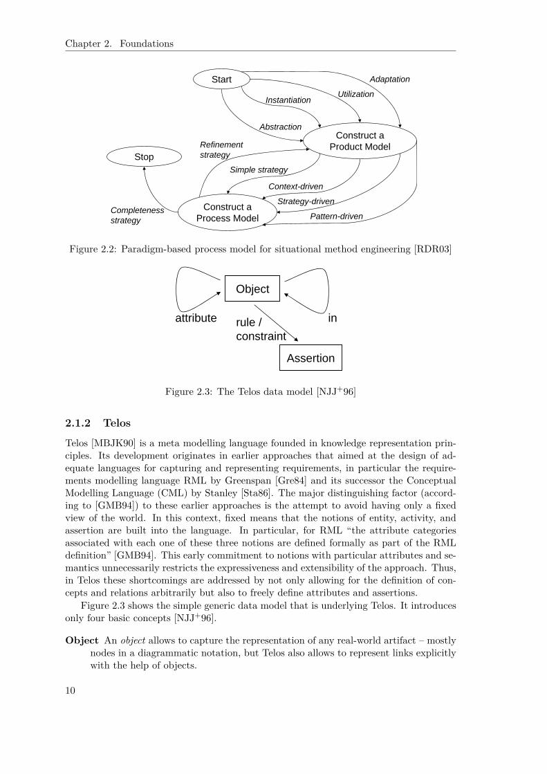
Paradigm-Based Strategy Eventually, the “paradigm-based strategy” is most suitablewhen a method needs to be designed from scratch. By building on meta modelling,it is the most generic of the three strategies described here. The core idea is to eitherabstract from an existing model or to instantiate a meta model. As Fig. 2.2 showstwo sub models are considered to be key ingredients of a method: a product modeland a process model. Accordingly, the strategies that are discussed by Ralyté et al.center around the creation of these two models (starting with the first one).
Product Model The “product model” captures the outcome of a process via con-cepts with properties and relationships. Suggested strategies are “abstraction”(raising (lowering) the level of abstraction of a given model), “instantiation”(instantiating a selected meta model), “adaptation” (adapting a meta model tosome specific circumstances), and “utilization” (adapting a model).
Process Model The “process model” covers the goals together with activities andguidelines for their execution. For the derivation of the process model fromthe product model four different strategies are discussed. A “simple strategy”might describe the process as an informal guideline. A set of ordered actionswould be captured via a “context-driven” strategy. Alternatively, the processdescription could be “driven by patterns”. Eventually, a multi-process guidelinethat combines alternative ways of working is called “strategy driven” in theirnomenclature.
The map for the “paradigm-based strategy” includes also a “refinement” feedbackloop from the “process model” to the “product model”.
Ralyté et al. [RDR03] emphasize that the above methods usually are combined toarrive at a new method and that their generic model is able to be extended to captureand include other approaches as well.
9
Chapter 2. Foundations
Start
Construct a Product Model
Construct a Process Model
Stop
Abstraction
Adaptation
Strategy-driven
Context-driven
Refinementstrategy
Simple strategy
Pattern-drivenCompletenessstrategy
UtilizationInstantiation
Figure 2.2: Paradigm-based process model for situational method engineering [RDR03]
Object
Assertion
rule / constraint
attribute in
Figure 2.3: The Telos data model [NJJ+96]
2.1.2 Telos
Telos [MBJK90] is a meta modelling language founded in knowledge representation prin-ciples. Its development originates in earlier approaches that aimed at the design of ad-equate languages for capturing and representing requirements, in particular the require-ments modelling language RML by Greenspan [Gre84] and its successor the ConceptualModelling Language (CML) by Stanley [Sta86]. The major distinguishing factor (accord-ing to [GMB94]) to these earlier approaches is the attempt to avoid having only a fixedview of the world. In this context, fixed means that the notions of entity, activity, andassertion are built into the language. In particular, for RML “the attribute categoriesassociated with each one of these three notions are defined formally as part of the RMLdefinition” [GMB94]. This early commitment to notions with particular attributes and se-mantics unnecessarily restricts the expressiveness and extensibility of the approach. Thus,in Telos these shortcomings are addressed by not only allowing for the definition of con-cepts and relations arbitrarily but also to freely define attributes and assertions.
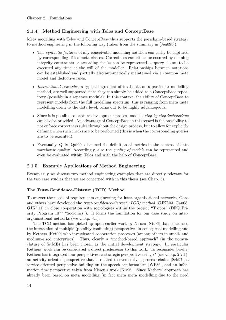
Figure 2.3 shows the simple generic data model that is underlying Telos. It introducesonly four basic concepts [NJJ+96].
Object An object allows to capture the representation of any real-world artifact – mostlynodes in a diagrammatic notation, but Telos also allows to represent links explicitlywith the help of objects.
10

2.1. Method Engineering
Attribute The attribute concept allows to detail out the characteristics of an objectincluding the relationship toward other objects. This is from the point of view of adiagrammatic notation, attributes are needed to capture links.
Assertion To enable formalization, Telos provides the concept of a logical assertion.The user can employ assertions as deductive rules to derive additional informationautomatically, or as integrity constraints to control the entry of information by users.This way it is possible to also capture more of the semantics of a customer-specificmodelling language.
Classification Eventually, we need at least one abstraction mechanism – classification –which enables us to talk about classes and their instances. The special in relationshipexpresses the classification relationship among objects. Characteristic features of thisclassification approach are:
• There is no limitation of the classification/instantiation hierarchy: classes canagain belong to other (meta) classes which themselves can belong to (metameta) classes, and so on.
• Classification in conjunction with object structuring specifies a form of typingfrom classes to instances, i. e., classes define the common structure of objectsbelonging to that class. Instances are allowed to instantiate attributes definedfor their classes. Furthermore, in combination with logical assertions, it is pos-sible to define meta-level formulae, this is formulae that capture the semantics,for example, of instances of instances (and so on). This is not easily possiblewith other approaches.
• Finally, multiple classification is allowed: an object can belong to multipleclasses.
The kernel of the Telos language is just that. All other language facilities such as general-ization hierarchies, cardinality constraints, and so on, can be bootstrapped from this kernelof objects and attributes, assertions, and classification. Furthermore, with only these fewconcepts a framework is defined that is extensible to any application- or customer-specificneeds. A complete formal definition can be found in [JEG+95].
Frame Representation Throughout the rest of the thesis, we will make use of thetextual frame representation of Telos as introduced in the following thereby abstractingfrom the technically needed propositional representation. The frame-syntax of O-Telos –a variant with object-oriented features that is the foundation for the ConceptBase systemas introduced in the next section – groups the various pieces of information on an objecttogether. Such a frame has
• a name that uniquely identifies an object,
• a number of other objects (classes) that are either super classes (isA) or of whichthe current object is an instance (in), and
• a list of named and typed attributes (including constraints).
The classical textbook example (see Figure 2.4) concerns the concepts and relation-ships within an enterprise as introduced in the ConceptBase Manual [JQJ10]. The main
11

Chapter 2. Foundations
I n d i v i d u a l Employee i n C l a s s witha t t r i bu te
name : S t r i n g ;s a l a r y : I n t e g e r ;dept : Department ;bos s : Manager
r u l ebo s sRu l e : $ f o r a l l e/Employee m/Manager
( e x i s t s d/Department( e dept d ) and ( d head m) )==> ( e boss m) $
c o n s t r a i n tsa l a ryBound : $ f o r a l l e/Employee b/Manager x , y/ I n t e g e r
( e bos s b ) and ( e s a l a r y x ) and ( b s a l a r y y )==> ( x <= y ) $
end
I n d i v i d u a l Manager i n C l a s s isA Employeeend
I n d i v i d u a l Department i n C l a s s witha t t r i bu te
head : Managerend
Figure 2.4: Classical Telos example: employees, departments, and managers [JQJ10]
concepts are Employees, Departments, and Managers. An Employee has a name, a salary ,a Department it belongs to, and a corresponding boss. The latter is in fact an informationthat can be deduced from the other information, because the two other frames introducea Manager as a specialization of an Employee and a Department with the single attributehead. Accordingly, the boss attribute only reflects the head of the Department an Employeeis associated with. In addition, Fig. 2.4 shows an example for a suitable constraint thatreflects that no Employee is supposed to earn more than her boss.
2.1.3 ConceptBase
ConceptBase [JEG+95] is a deductive object base management system for meta databasesimplementing the Telos data model. A Datalog (see [CGT89]) representation of the basicaxioms is at its core (see http://www.conceptbase.cc for details). The system has beenused in projects ranging from development support for data-intensive applications, re-quirements engineering, electronic commerce, and version and configuration managementto co-authoring of technical documents.
ConceptBase’s implementation of O-Telos provides a couple of features beyond thecore Telos. We stress the following four:
• First of all, there is a dedicated query language. Queries are formulated as classes.Accordingly, the answer is provided by the set of instances to such a query class.
12

2.1. Method Engineering
This is query classes are normal classes but “with forced class membership definedby a constraint” [NJJ+96]. From the intersection of a set of super classes thoseobjects are selected that fulfil the given constraint(s). The projection feature ofrelational query languages such as SQL is reflected by defining the attributes thatare to be retrieved from the selected objects ( retrieved_attribute ). In addition, it ispossible to define new attributes (computed_attributes) that are computed (mostly aspart of the constraint). Altogether, this approach yields a powerful query languagetogether with all the amenities of normal Telos objects, this is queries can be stored,sub classed etc. A major advantage of query classes compared to constraints isthe chance to tolerate modelling inconsistencies, while still keeping track of them.This is a much more natural and most often the only feasible approach to integrateconflicting perspectives of various stakeholders during requirements elicitation.
• A similar purpose serves the feature of modules. Especially, when it comes to theintegration of different stakeholders’ perspectives, it is highly likely that object namesoccur repeatedly and thus are not unique across all perspectives. Modules allow toavoid clashes by separating the models into different namespaces. The nesting ofmodules can be used to build a hierarchy of modelling (language) refinements. Andeventually, import and export facilities allow to – nonetheless – make connectionsbetween models in different modules.
• ConceptBase also supports a limited version of active rules to react to internaland external events. Active rules, possibly better know as Event-Condition-Action(ECA) rules [WC96], monitor interactions with the database system to detect events.Events can be the addition or deletion of knowledge as well as the execution ofqueries. If such an event is detected and a corresponding ECA rule exists, thedefined condition is checked. If this evaluates to true1, the action part of the ruleis executed. ECA rules are a suitable means, for example, to update dependingperspectives on changes in one particular perspective.
• Finally, the ConceptBase developers have early foreseen the need to create repre-sentations of the models stored in ConceptBase in forms other than the internalproposition representation or the frame representation. Answer formats allow forcomplex transformations of Telos objects. They are associated with queries. To, forexample, be able to create nested structures as they are typical for HTML or nowa-days more prominent XML documents, answer formats allow to call other queriesfrom within. This way, any complex data structure can be constructed. We willelaborate on this feature when discussing model transformations in Chapter 5.2.
We omit examples here since they will occur throughout the rest of the thesis.At the technical level, ConceptBase follows a client-server architecture. Clients and
servers run as independent processes which interact via inter-process communication chan-nels. The ConceptBase server offers programming interfaces that allow to build clientsand to exchange messages in particular for updating and querying object bases using theTelos frame syntax. ConceptBase comes with a standard graphical usage environment im-plemented in Java which supports editing, ad-hoc querying and browsing of Telos objectbases.
1Dedicated control over the situation when the check is performed in relation to the event that ismonitored is given via a backtick operator and a set of parameters. See [JEG+95] for details.
13
Chapter 2. Foundations
2.1.4 Method Engineering with Telos and ConceptBase
Meta modelling with Telos and ConceptBase thus supports the paradigm-based strategyto method engineering in the following way (taken from the summary in [Jeu09b]):
• The syntactic features of any conceivable modelling notation can easily be capturedby corresponding Telos meta classes. Correctness can either be ensured by definingintegrity constraints or according checks can be represented as query classes to beexecuted any time at the will of the modeller. Relationships between notationscan be established and partially also automatically maintained via a common metamodel and deductive rules.
• Instructional examples, a typical ingredient of textbooks on a particular modellingmethod, are well supported since they can simply be added to a ConceptBase repos-itory (possibly in a separate module). In this context, the ability of ConceptBase torepresent models from the full modelling spectrum, this is ranging from meta metamodelling down to the data level, turns out to be highly advantageous.
• Since it is possible to capture development process models, step-by-step instructionscan also be provided. An advantage of ConceptBase in this regard is the possibility tonot enforce correctness rules throughout the design process, but to allow for explicitlydefining when such checks are to be performed (this is when the corresponding queriesare to be executed).
• Eventually, Quix [Qui09] discussed the definition of metrics in the context of datawarehouse quality. Accordingly, also the quality of models can be represented andeven be evaluated within Telos and with the help of ConceptBase.
2.1.5 Example Applications of Method Engineering
Exemplarily we discuss two method engineering examples that are directly relevant forthe two case studies that we are concerned with in this thesis (see Chap. 3).
The Trust-Confidence-Distrust (TCD) Method
To answer the needs of requirements engineering for inter-organisational networks, Gansand others have developed the trust-confidence-distrust (TCD) method [GJKL03, Gan08,GJK+11] in close cooperation with sociologists within the project “Tropos” (DFG Pri-ority Program 1077 “Socionics”). It forms the foundation for our case study on inter-organisational networks (see Chap. 3.1).
The TCD method has picked up upon earlier work by Nissen [Nis96] that concernedthe interaction of multiple (possibly conflicting) perspectives in conceptual modelling andby Kethers [Ket00] who investigated cooperation processes (among others in small- andmedium-sized enterprises). Thus, clearly a “method-based approach” (in the nomen-clature of SitME) has been chosen as the initial development strategy. In particularKethers’ work can be considered a direct predecessor to this work. To reconsider briefly,Kethers has integrated four perspectives: a strategic perspective using i* (see Chap. 2.2.1),an activity-oriented perspective that is related to event-driven process chains [Sch97], aservice-oriented perspective building on the speech act formalism [WF86], and an infor-mation flow perspective taken from Nissen’s work [Nis96]. Since Kethers’ approach hasalready been based on meta modelling (in fact meta meta modelling due to the need
14

2.1. Method Engineering
to integrate four different perspectives), the “paradigm-based approach” toward methodconstruction has been chosen also for the TCD method.
Product Model In regard to the product model, the existing (meta-) meta modelfor capturing cooperation processes only had to be “adapted” to the new setting of inter-organisational networks. Since cooperations between autonomous actors are a major pointin inter-organisational networks as well, unsurprisingly the strategic perspective based oni* and providing the concepts of agents and dependencies is reused in the new setting. Asa refinement to Kethers, Gans et al. treat the two levels that are provided by i*, strategicdependency and strategic rationale, as separate perspectives as we will see later on; one fo-cusing the external view, the other the internal one. Furthermore, the inter-organisationalsetting requires to cope with delegations and interactions of various partners. Correspond-ingly, we again pick up on the positive experiences Kethers’ has made with a dedicatedservice-oriented perspective and the linguistic speech act formalism in particular. Thebasic idea is that “communicative activities induce actions and can therefore be used forworkflow modelling” [Ket00] (pp. 31). In this view, cooperation processes are consideredto consist of loops of communicative actions that are performed by a supplier to satisfya customer. In the new setting, the speech act formalism is also used for expectationmanagement related to trust-based cooperations.
The latter item hints already at the core issue that is not addressed by Kethers’approach. Due to the inherently dynamic nature of trust – for example, trust grows onlyby-and-by – the urgent need arises to address dynamic aspects. In Kethers’ approach, themodelling of processes and relationships is purely static. The execution of the processes isnot considered. To overcome this deficiency, Gans et al. [GJKL03] incorporate an explicitdynamic planning perspective as elaborated below. In turn, neither the activity-orientedperspective nor the information flow perspective of Kethers are required in the new settingdue to the focus on social, dynamic aspects.
Figure 2.5 [GJKL03, Gan08, GJK+11] gives an overview on the multi-perspective mod-elling and management method that has been developed to address the complex dependen-cies and multi-viewpoint situations that occur in inter-organisational networks. In totalfour perspectives have been established [GJKL03].
Dependencies Yu’s i* strategic dependencies are used to capture the various dependen-cies between network members. Accordingly, this perspective refers to the manysuccessful experiences of applying i* to capture social interactions as reported com-prehensively in [YGMM11]. The identified dependencies are in part preexistingfrom a priori goal and capability analysis, in part created dynamically in responseto planning (see below).
Delegation processes Secondly, the dynamics of trust, confidence, and distrust areheavily influenced by the perceived relationships between communication acts ofthe network members and actual actions performed relating to these communicationacts. From this observation, Gans et al. conclude the need to include an explicitspeech act perspective. This perspective is closely integrated with the above men-tioned strategic dependency perspective in that dependencies are treated as reasonsfor speech act based delegations, and the latter are evaluated partially with respectto the former. This ensures, for example, a strategic dependency with a specificcontract.
15

Chapter 2. Foundations
generate
coordinate
generate
operationalize
(Strategic Dependency)
(Speech Acts)(ConGolog)
Confi−denceModel
Delegation processesPlans
TrustModel
DependenciesGoals(Strategic Rationale)
agent boundary
refine
DistrustModel
Figure 2.5: A multi-perspective modelling and management method [GJK+11]
Goals While the first two perspectives focused the external view of interactions betweennetwork members, the second two perspectives concern the internal view. First of all,Gans et al. state that “the explicit modelling of goals [and dependencies] is crucialwith respect to networks in general, and to our special focus on trust, confidence,and distrust in particular.” [GJK+11] Accordingly, Yu’s strategic rationale model isincluded in the framework as well. To better integrate with the below elaboratednew planning perspective, Gans et al. made use of an extended version of i*, SNet,that will be elaborated in Chap. 2.2.3.
Plans The planning perspective eventually is the major extension compared to Kethers’work. To address dynamic aspects such as trust (confidence, and distrust) relatedbehaviour patterns of network members, a logic-based, high-level planning and sim-ulation formalism, ConGolog [dGLL00, LKMY99] (see Chap. 2.3) is included. Thisperspective plays a pivotal role in our framework since it interacts with all of theother perspectives: plans operationalize the goals of the strategic rationale perspec-tive, speech acts are refined into plans that eventually can be executed, and finally,planning can generate new dependencies if the planning member discovers that it ismore efficient to delegate certain subtasks or -goals to others.
In Fig. 2.5 the i* strategic perspectives are shown in the upper part, and the relatedoperational level models in the lower part. The left part of the figure shows the internalmodelling aspects (goals and plans), and the right part shows the external aspects (strate-gic dependencies and their implementation in delegation processes). Solid lines indicatethe nature of interrelationships between the perspectives whereas broken lines show howthe modalities of trust, confidence, and distrust shape the interactions of the four per-
16

2.1. Method Engineering
Dependency
Agent
Task/ActivityPrecond.
Postcond.
Goal
Resource
TCD Value
dependee
depender
supplier
customer
contributes+/-
refine to
due-to
input
output
controls
modifies
pursues
Figure 2.6: Partial meta meta model integrating the four perspectives [Gan08]
spectives. Figure 2.6 shows a partial view of the corresponding Telos meta meta modelas described by Gans [Gan08]. It allows the different perspective sub models and tools inour approach to exchange information or be transformed into each other. Details can befound in [Gan08].
Process Model The process model of the TCD method is available only as informalguidelines (“simple strategy”). “Goal hierarchies following Yu’s Strategic Rationale ap-proach are created and maintained dynamically for each agent, as well as mapped tooperational (base) plans using the ConGolog formalism that composes a plan from declar-ative building blocks with pre- and post-conditions. Strategic dependencies, following Yu’sStrategic Dependency modeling formalism, are in part statically derived from a priori goaland capability analysis, and in part dynamically created on the basis of a agent’s recogni-tion that certain parts of a plan are better delegated to others. Plans and dependencies,often initially based on required agent role types rather than concrete network partners,are mapped to specific communicative actions (speech acts) in order to establish a strategicdependency with a specific contract. The modalities of trust, confidence, and distrust willshape the way this is done. They then also indirectly shape how these contract patternsgradually refine the base plans into network cooperation plans” [GJK+11].
Telecommunications Service Design
As another example, we refer to the work of Eberlein (and others) [Ebe09] that appliedTelos to support the development of telecommunication services with a particular focuson the requirements engineering phase. The overall goal of this research has been to de-velop a “Requirements Assistant for Telecommunication Services (RATS)” that is tailoredto support developers – mainly requirements engineers and service designers – in thisparticular domain. Obviously, “the more domain-specific a tool is, the more support itcan provide” [Ebe09]. At the negative side, changes in the domain require correspondingadaptations of the tool.
17

Chapter 2. Foundations
The RATS tool is intended to provide two basic forms of guidance. Passive guid-ance points out mistakes in the specification whereas (instance or class-specific) activeguidance also provides hints on how to proceed with the development. The domain spe-cific knowledge on which the assistance rests is captured in a domain layer. By referringto standards, expert knowledge, and “quick models”, this layer provides several domainmodels on topics such as customer profiles, network transport capabilities, supplementaryservices, feature interactions, switches etc. These models need to be maintained to keepup with the evolution of the domain. On top of this, the development layer establishesmethodological support in regard to three dimensions: completeness, refinement, and for-mality by building on suitable intelligence, development, and negotiation models. At thenotational level, the approach makes use of a requirements model that is mainly propri-etarily defined and that exhibits features such as information, topic, goal, functionality,and implementation constraints. For parts of these features, existing formalisms are used.For example, functionality can be refined by use cases, atomic actions, or in the end evenspecifications in the Specification and Description Language (SDL) of the InternationalTelecommunication Union (ITU) [ITU99].
Originally, the tool was intended to even complement an entirely model-based approachby allowing to automatically derive an SDL specification at the end of the requirementsengineering phase. The work bears strong similarity with parts of this thesis, especiallyin regard to how domain knowledge can be provided during the development (comparefor Chap. 5.1) and the integration into an overall development process by establishingmappings and (semi-)automatic transformations to formalisms used in later developmentphases (compare for Chap. 5.2). Accordingly, we will pick up on this in these later chapters.
2.2 i* and Derivatives
i* [Yu95, YGMM11] is an agent- and goal-oriented modelling framework that emphasizessocial aspects when modelling problem representations in domains such as requirementsengineering, business process reengineering, organisational impact analysis, and softwareprocess modelling. By using few and simple modelling constructs, the formalism is in-tended to serve as a common language between customers and developers: sufficientlyexpressive to capture all relevant details, the developers need to know, but still compre-hensible for non-IT-knowledgeable customers. The approach has been particularly suc-cessful in the requirements engineering field as indicated by receiving the ten years’ mostinfluential paper award at the Requirements Engineering Conference in 2007. We will alsodiscuss four derivatives that have emerged over the years:
• a complete software development methodology, named Tropos [CKM02], that buildson this formalism and uses the basic concepts throughout the whole developmentprocess,
• the direct predecessor to our own work, SNet [Gan08], enabling logic-based simula-tions of inter-organisational networks,
• the formal requirements representation Formal Tropos [FLP+04] amenable to modelchecking-based analysis, and
• the derivative Secure Tropos [GMMZ05a] that puts the focus on the Datalog basedanalysis of security aspects.
18
2.2. i* and Derivatives
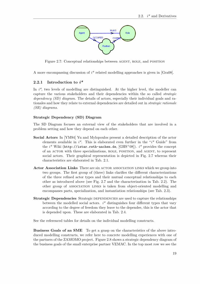
Figure 2.7: Conceptual relationships between agent, role, and position
A more encompassing discussion of i* related modelling approaches is given in [Gra08].
2.2.1 Introduction to i*In i*, two levels of modelling are distinguished. At the higher level, the modeller cancapture the various stakeholders and their dependencies within the so called strategicdependency (SD) diagram. The details of actors, especially their individual goals and ra-tionales and how they relate to external dependencies are detailed out in strategic rationale(SR) diagrams.
Strategic Dependency (SD) Diagram
The SD Diagram focuses an external view of the stakeholders that are involved in aproblem setting and how they depend on each other.
Social Actors In [YM94] Yu and Mylopoulos present a detailed description of the actorelements available in i*. This is elaborated even further in the “i* Guide” fromthe i* Wiki (http://istar.rwth-aachen.de, [GHS+08]). i* provides the conceptof an actor with three specializations, role, position, and agent, to representsocial actors. Their graphical representation is depicted in Fig. 2.7 whereas theircharacteristics are elaborated in Tab. 2.1.
Actor Association Links There are six actor association links which we group intotwo groups. The first group of (three) links clarifies the different characterizationsof the three refined actor types and their mutual conceptual relationships to eachother as introduced above (see Fig. 2.7 and the characterization in Tab. 2.2). Theother group of association links is taken from object-oriented modelling andencompasses parts, specialization, and instantiation relationships (see Tab. 2.3).
Strategic Dependencies Strategic dependencies are used to capture the relationshipsbetween the modelled social actors. i* distinguishes four different types that varyaccording to the degree of freedom they leave to the dependee, this is the actor thatis depended upon. These are elaborated in Tab. 2.4.
See the referenced tables for details on the individual modelling constructs.
Business Goals of an SME To get a grasp on the characteristics of the above intro-duced modelling constructs, we refer here to concrete modelling experiences with one ofthe partners of the ZAMOMO project. Figure 2.8 shows a strategic dependency diagram ofthe business goals of the small enterprise partner VEMAC. In the top most row we see the
19

Chapter 2. Foundations
Table 2.1: Actor concepts in i*
Construct Descriptionactor The general concept of an actor captures active entities that carry out
actions to achieve goals by resorting to their individual know-how, skills,and experiences. Such an entity can have intentional dependencies withother such entities. Generally, it is recommended to prefer the special-ized actors agent, role, and position as elaborated below over themore general actor. Especially, this helps to arrive at a higher levelof detailing and thus a more precise capture of domain knowledge. Inthis view, the actor concept should only be used if no detailed knowl-edge on the specific kind of actor is available. But at the i* Wiki itis also discussed that too many specialized actors can lead to too com-plicated models that are hard to analyse and understand. Accordingly,the modeller is supposed to decide upon the “value and additional in-formation that [the specialized actors] will add to the model” (http://istar.rwth-aachen.de/tiki-index.php?page_ref_id=308).
role A role is defined as an “abstract characterization of the behaviour ofa social actor within some specialized context or domain of endeavor”.The characteristics or features of this role are considered to be easilytransferable to other social actors. Consequently, dependencies shouldbe associated with this kind of actor only if they apply regardless of whoplays the role, this is they only concern the functionality or ability thatis provided by this particular role.
Agent In contrast, an agent is a concrete manifestation of an actor such asa human individual that essentially has individuality. Accordingly, thecharacteristics of an agent are typically not easily transferable to otherindividuals because they reflect the individual skills and experiences orthe physical limitations of the social actor. Corresponding to this un-derstanding, dependencies are to be associated with agents regardlessof what roles are played by this agent.
Position Eventually, a position is used as an intermediate abstraction in that itdescribes a set of roles which are typically assigned jointly to one agent(mostly human actors). In contrast to the agent actor, a position isstill abstract, only an amalgamation of roles.
Table 2.2: Actor association links in i* (group 1)
Construct Descriptionplays An agent plays a role. At the i* Wiki it is emphasized that the
identity of the agent should have no effect on the responsibilities of thatrole. In turn, the identity of the agent should also not be affected byplaying that role.
occupies An agent occupies a position.covers A position covers roles.
20
2.2. i* and Derivatives
Table 2.3: Actor association links in i* (group 2)
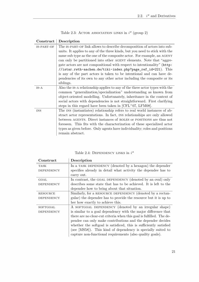
Construct Descriptionis-part-of The is-part-of link allows to describe decomposition of actors into sub-
units. It applies to any of the three kinds, but you need to stick with thesame sub type as the one of the composite actor. For example, an agentcan only be partitioned into other agent elements. Note that “aggre-gate actors are not compositional with respect to intentionality” (http://istar.rwth-aachen.de/tiki-index.php?page_ref_id=221). Thisis any of the part actors is taken to be intentional and can have de-pendencies of its own to any other actor including the composite or itssiblings.
is-a Also the is-a relationship applies to any of the three actor types with thecommon “generalization/specialization” understanding as known fromobject-oriented modelling. Unfortunately, inheritance in the context ofsocial actors with dependencies is not straightforward. First clarifyingsteps in this regard have been taken in [CFL+07, LFM08].
ins The ins (instantiates) relationship refers to real world instances of ab-stract actor representations. In fact, ins relationships are only allowedbetween agents. Direct instances of roles or positions are thus notforeseen. This fits with the characterization of these specialized actortypes as given before. Only agents have individuality; roles and positionsremain abstract.
Table 2.4: Dependency links in i*
Construct Descriptiontaskdependency
In a task dependency (denoted by a hexagon) the dependerspecifies already in detail what activity the dependee has tocarry out.
goaldependency
In contrast, the goal dependency (denoted by an oval) onlydescribes some state that has to be achieved. It is left to thedependee how to bring about that situation.
resourcedependency
Similarly, for a resource dependency (denoted by a rectan-gular) the dependee has to provide the resource but it is up toher how exactly to achieve this.
softgoaldependency
A softgoal dependency (denoted by an irregular shape)is similar to a goal dependency with the major difference thatthere are no clear-cut criteria when this goal is fulfilled. The de-pendee can only make contributions and the depender decideswhether the softgoal is satisficed, this is sufficiently satisfied(see [MS58]). This kind of dependency is specially suited tocapture non-functional requirements (also quality goals).
21
Chapter 2. Foundations
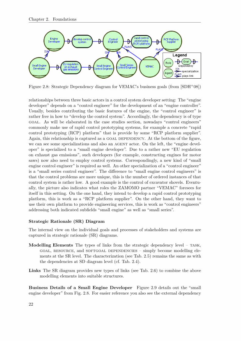
Figure 2.8: Strategic Dependency diagram for VEMAC’s business goals (from [SDH+08])
relationships between three basic actors in a control system developer setting: The “enginedeveloper” depends on a “control engineer” for the development of an “engine controller”.Usually, besides contributing the basic features of the engine, the “control engineer” israther free in how to “develop the control system”. Accordingly, the dependency is of typegoal. As will be elaborated in the case studies section, nowadays “control engineers”commonly make use of rapid control prototyping systems, for example a concrete “rapidcontrol prototyping (RCP) platform” that is provide by some “RCP platform supplier”.Again, this relationship is captured as a goal dependency. At the bottom of the figure,we can see some specializations and also an agent actor. On the left, the “engine devel-oper” is specialized to a “small engine developer”. Due to a rather new “EU regulationon exhaust gas emissions”, such developers (for example, constructing engines for motorsaws) now also need to employ control systems. Correspondingly, a new kind of “smallengine control engineer” is required as well. An other specialization of a “control engineer”is a “small series control engineer”. The difference to “small engine control engineers” isthat the control problems are more unique, this is the number of ordered instances of thatcontrol system is rather low. A good example is the control of excavator shovels. Eventu-ally, the picture also indicates what roles the ZAMOMO partner “VEMAC” foresees foritself in this setting. On the one hand, they intend to develop a rapid control prototypingplatform, this is work as a “RCP platform supplier”. On the other hand, they want touse their own platform to provide engineering services, this is work as “control engineers”addressing both indicated subfields “small engine” as well as “small series”.
Strategic Rationale (SR) Diagram
The internal view on the individual goals and processes of stakeholders and systems arecaptured in strategic rationale (SR) diagrams.
Modelling Elements The types of links from the strategic dependency level – task,goal, resource, and softgoal dependencies – simply become modelling ele-ments at the SR level. The characterization (see Tab. 2.5) remains the same as withthe dependencies at SD diagram level (cf. Tab. 2.4).
Links The SR diagram provides new types of links (see Tab. 2.6) to combine the abovemodelling elements into suitable structures.
Business Details of a Small Engine Developer Figure 2.9 details out the “smallengine developer” from Fig. 2.8. For easier reference you also see the external dependency
22

2.2. i* and Derivatives
Table 2.5: Intentional elements at Strategic Rationale level
Construct Descriptiontask A task element is used to describe some particular activity, process, or
capability of an actor that is performed in a particular way.goal A goal represents an intentional desire of an actor. In contrast to
softgoals, for (hard-)goals there are clear criteria, when the goal isfulfilled.
resource A resource describes a physical or informational entity that is needed,produced, or provided.
softgoal A softgoal is again intended to capture non-functional issues and incontrast to (hard-)goals does not have clear-cut criteria for its fulfill-ment. Instead, the notion of satisficing [MS58] is used.
Table 2.6: Links at Strategic Rationale level
Construct Descriptiondecomposition A decomposition link allows to detail out a complex task
into sub issues. This way a task can be decomposed into subtasks, sub goals, required resources, and involved soft-goals.
means-ends A means-ends link is used to model alternatives – only tasks– to achieve a goal (or provide a resource).
contribution Eventually, contribution links are a special type of means-ends links that have a qualitative argument (also called label),some positive, help, make, some negative, hurt, break,or unknown, that indicates the kind of contribution towardthe associated softgoal. In addition, the labels and and orare provided to create hierarchies of softgoals. The source forcontributions can be any other modelling element, this isgoals, softgoals, tasks, and resources.
23

Chapter 2. Foundations
Figure 2.9: Excerpt of SR diagram for small engine developer (from [SDH+08])
toward the “control engineer” on the right side of the figure. In order to meet the goalof adhering to the “EU regulation on exhaust gas emissions” two alternative paths canbe followed. Either the “small engine developer” decides to “delegate the development”of a corresponding control functionality to an external “control engineer”, in this case thespecified dependency comes into play. Or the developer decides to “internally build upthe necessary knowledge about control systems”. Figure 2.9 shows exemplarily two soft-goals that are affected by these alternatives, being “fast at the market” and establishing“additional competencies”. More precisely, the two alternatives contribute inversely tothese softgoals. The “delegation of control development” activities has positive effectson being “fast at the market” but has a rather negative effect in regard to “additionalcompetencies” that are created at the SME’s side. In the contrary, the “internal” ap-proach helps a lot in adding useful competencies but also clearly negatively contributesto being “fast at the market”.
Capturing the Syntax and Semantics of i* in Telos
As motivated extensively in the previous section (Chap. 2.1), Telos is certainly suited tocapture and represent the i* modelling language. The syntactical restrictions in regardto which objects can be connected via which kinds of links is easily captured by definingand typing the corresponding objects and attributes suitably. It has turned out to beof advantage to define additional, intermediate helping classes to group, for example,all so called intentional elements, this is task, goal, resource, and softgoal. Foractor elements, the grouping is more straightforward due to the specialization relationshipbetween actor and the other three subtypes (role, position, agent). Similarly, thelinks can be grouped suitably. Figure 2.10 and Figure 2.11 show a graphical representationof the specialization/generalization hierarchy of the Telos classes representing i* modellingconstructs. Note that for practical reasons we constitute dependencies between actorsby combining two dependency links and the dependum. This is we do not need todistinguish different dependency links but reuse the SR modelling elements for thispurpose (as the dependum). The formalization of i* as needed for this thesis is given inAppendix A.1.1.
Analysis Support
As explicitly state by Horkoff and Yu [HY08], “[d]eriving the full benefits of [i* ] modelsrequires analysis and iteration beyond initial construction.”
Already the original PhD thesis by Eric Yu [Yu95] allowed for various forms of anal-ysis. SD diagrams are supposed to help analysing opportunities by matching offers and
24

2.2. i* and Derivatives
Figure 2.10: Class hierarchy for Telos representation of i* modelling elements
Figure 2.11: Class hierarchy for Telos representation of i* modelling links
dependencies as well as vulnerabilities. The latter looks at the chain of dependencies. ForSR models, four levels of analysis are offered. Ability captures whether an actor has aplan skeleton, called a routine for something, this is she has the required knowledge. Theworkability analysis checks whether a routine is reducible to workable elements (via de-composition and/or means-ends links) or workable dependencies. Viability concernschecks with respect to desired qualitative criteria. Eventually, believability challenges theassumptions involved in reasoning about the routine, this is whether they are sufficientlyjustified. All these analysis are described without committing to a particular choice oflogic for the underlying intentional operators.
One aspect that has early received more attention concerns the satisficing conceptof softgoals. Already one of the earliest modelling environment tools, OME3 [LY00],included a corresponding label propagation algorithm. After committing to some choicesat goals, the algorithm allows to project and collect the contributions of the varioustasks and alternatives to the relevant softgoals. If possible, this allows to derive alabelling such as “satisficed”, “partially satisficed”, “denied”, “partially denied” etc.
The topic of analysing i* models has not only been picked up by the FormalTroposapproach that is elaborated later on (see Chap. 2.2.4), but also by the work of Horkoff, inclose cooperation with Eric Yu [HY08]. She works on a procedure to apply SAT solvingtechniques to backward or top-down qualitative, interactive analysis, thereby going beyondpure goal model reasoning approaches as they have been established in the Non-FunctionalRequirements framework of Chung, Nixon, Yu, and Mylopoulos [CNYM00] as well as thework within the context of KAOS by Lamsweerde (consider, for example, [vL01]). Inparticular, Horkoff has introduced an interactive component [HY09]. Starting from ananalysis question such as “How effective is this design option with respect to the desiredgoals”, the approach again makes use of qualitative evaluation labels that are assignedto elements to capture in how far they are satisficed (or denied). Initially, the labellingrepresents the analysis questions. By propagating these labels according to a set of suitable
25
Chapter 2. Foundations
rules as well as human interaction to decide in case of conflict, finally a new distribution oflabels across elements is reached that can be analysed in the light of the original question.
In [BMMZ06], an enrichment of the tool support for requirements engineering (andthe later to be discussed Secure Tropos (see Chap. 2.2.5) in particular) is proposed thatsupports the automatic generation and exploration of alternative options. Given a setof actors and goals as the input, a planner generates design alternatives by generatingalternative multi-agent plans to fulfill all given goals. By mapping to the “standard”planning language PDDL [GHK+98], a suitable off-the-shelf planner can be used.
Original Application Fields
Already in the original PhD thesis on i* [Yu95], Eric Yu addressed four different applica-tion fields:
• requirements engineering,
• business process reengineering,
• organisational impact analysis, and
• software process modelling.
In regard to requirements engineering, the crucial aspect is to capture the requirementsthat truly reflect users’ needs. According to Curtis [CKI88] and Jackson [Jac95], a majordifficulty in this regard is to gain a deep enough understanding about the applicationdomain. Yu advocates a richer model of the organisational environment to help usersidentify the different ways a new system can serve their needs.
The core idea of business process reengineering was that IT can help to put the wayprocesses are carried out in an enterprise into question. Challenging the mainly functionalview, Davenport [DJS90] and Hammer [Ham90] focus processes as they run from endto end through an enterprise. Nowadays, one would prefer the term business processmanagement but still many problems persist. Two examples that refer to i* in thiscontext are approaches to automatically configure business processes [LYM07] as well asattempts to better integrate the process space and the enterprise’s goals (motivation orstrategy, respectively) [Has09, PMHD09]. The latter work has been carried out withinthe context of the EU SUPER project (http://www.ip-super.org) and has formalizedthe business motivation model (BMM) [Bus05], a standard of the OMG (formerly of theBusiness Rules Group), by building on semantic web technology. i* is referred to mainlyin regard to the elaboration of goal refinement as well as the satisficing concept (togetherwith the corresponding label propagation algorithm).
The organisational impact analysis allows to capture the as-is social situation of anorganisation as well as the setting that is striven for. Similarly, Giorgini et al. [GMMZ05b]discuss social versus individual trust, for example, in regard to real-world backend inves-tigations in the financial sector [MZ11]. This application field has particular resemblancewith the SNet case study (see Chap. 3.1).
Eventually, Yu also intends i* to be helpful in the context of software process modelling.This idea stems from the basic, Telos related ideas to consider “four worlds” [MBJK90].Again, the major point in regard to applying i* here is to cover not only technical aspectsbut also social ones.
26

2.2. i* and Derivatives
From these early application scenarios as well as further different applications andderivatives that have evolved over the years, the usefulness of i* for capturing and mod-elling social aspects of problems has become apparent. Ultimately, the importance ofsocial aspects in i* is reflected by the title of the recently published textbook on i*,“Social Modeling for Requirements Engineering” [YGMM11].
2.2.2 The Tropos Software Development Methodology
The core idea of the Tropos project (http://troposproject.org) is to target the mis-match between the concepts suitable to capture the organisational environment of a sys-tem to be developed and the way information about the system itself and its develop-ment is represented. The latter is mostly driven by the “programming paradigm of theday” [CKM02]. The Tropos solution instead adopts the concepts available in i* such asactor, goal, and dependency, but applies them not only to the requirements phasebut to all development phases, this is from early and late requirements, to architectural,and to detailed design. This way the approach “complements well proposals for agent-oriented programming platforms”, while not enforcing an agent-based implementation inthe end [CKM02].
At least in more recent publications (see [BPG+04]), the Tropos team has slightlyadapted the concepts and naming of concepts that were taken from i*. Instead of task theyprovide for a plan feature (while maintaining most of the semantics). Also they considersoft goals and hard goals subtypes to the more general goal concept. Additionally, thecapability concept captured mainly via UML activity diagrams reflects “the ability of anactor of defining, choosing and executing a plan for the fulfillment of a goal, given certainworld conditions and in presence of a specific event” [BPG+04].
As already mentioned before, these concepts are used throughout the whole develop-ment. The early requirements engineering phase is most closely related to the originali*. The modeller is intended to identify relevant stakeholders and their relationships,this is more generally speaking the environment of the system to be developed. Late re-quirements engineering is concerned with introducing the system to be developed into theenvironmental setting captured in the previous phase. The interaction of the system withstakeholders and the environment and the resulting effects on existing or new relation-ships are considered. The dependencies of the new system actor reflect the functionaland non-functional requirements. During architectural design, the system specification isfocused. This is the global system architecture is defined by introducing sub actors thatagain can have various kinds of dependencies on each other. Especially, they are inter-connected through data and control flows. The considerations here allow also to includethe mapping to a set of software agents and their organisation, potentially following somesuitable organisational patterns [CSM03]. Eventually, the detailed design has to specifythe individual agent capabilities as well as agent interactions. It is assumed that a choicefor the implementation platform has already been made at that point in time, so that thiscan be respected, thereby alleviating the mapping into code.
Throughout the different phases elaborated above, the developer is expected to performvarious kinds of modelling. Actor modelling concerns the identification and analysis ofstakeholders (within the environment) as well as constituting components of the system tobe developed. The relationships between actors are clarified during dependency modelling.They concern not only abstract dependencies between stakeholders but also more detaileddata and control flow dependencies between system components during architectural and
27
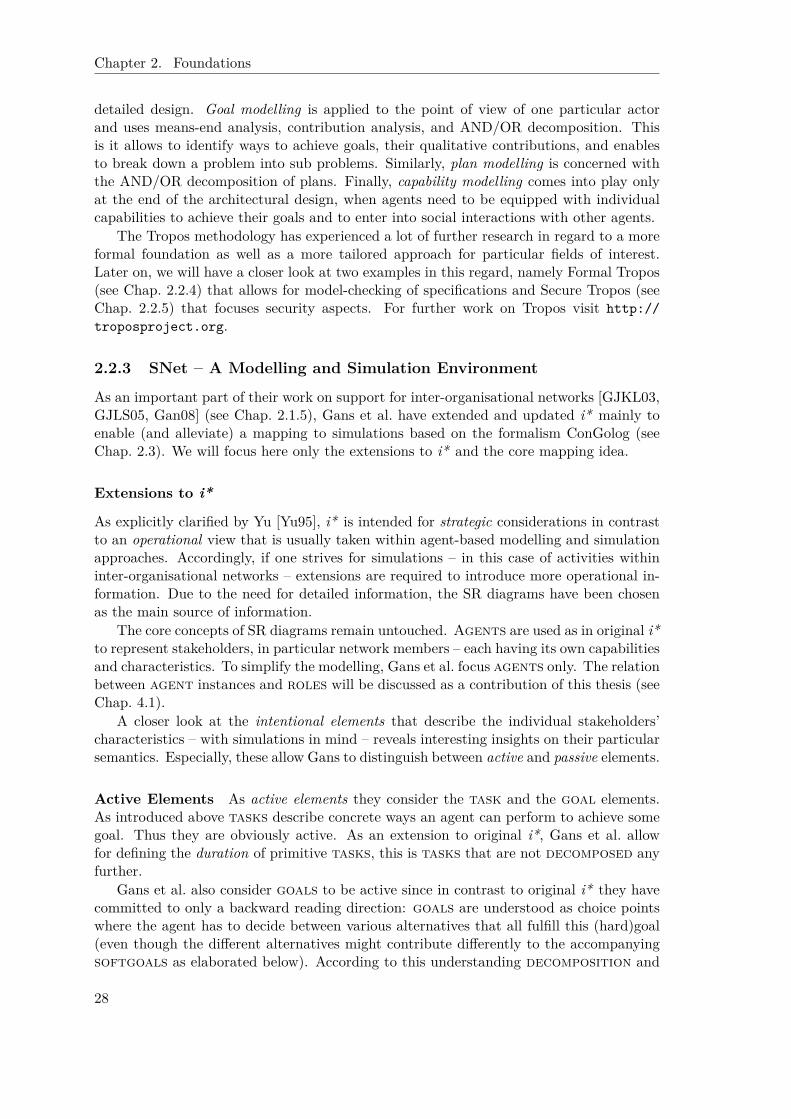
Chapter 2. Foundations
detailed design. Goal modelling is applied to the point of view of one particular actorand uses means-end analysis, contribution analysis, and AND/OR decomposition. Thisis it allows to identify ways to achieve goals, their qualitative contributions, and enablesto break down a problem into sub problems. Similarly, plan modelling is concerned withthe AND/OR decomposition of plans. Finally, capability modelling comes into play onlyat the end of the architectural design, when agents need to be equipped with individualcapabilities to achieve their goals and to enter into social interactions with other agents.
The Tropos methodology has experienced a lot of further research in regard to a moreformal foundation as well as a more tailored approach for particular fields of interest.Later on, we will have a closer look at two examples in this regard, namely Formal Tropos(see Chap. 2.2.4) that allows for model-checking of specifications and Secure Tropos (seeChap. 2.2.5) that focuses security aspects. For further work on Tropos visit http://troposproject.org.
2.2.3 SNet – A Modelling and Simulation Environment
As an important part of their work on support for inter-organisational networks [GJKL03,GJLS05, Gan08] (see Chap. 2.1.5), Gans et al. have extended and updated i* mainly toenable (and alleviate) a mapping to simulations based on the formalism ConGolog (seeChap. 2.3). We will focus here only the extensions to i* and the core mapping idea.
Extensions to i*
As explicitly clarified by Yu [Yu95], i* is intended for strategic considerations in contrastto an operational view that is usually taken within agent-based modelling and simulationapproaches. Accordingly, if one strives for simulations – in this case of activities withininter-organisational networks – extensions are required to introduce more operational in-formation. Due to the need for detailed information, the SR diagrams have been chosenas the main source of information.
The core concepts of SR diagrams remain untouched. Agents are used as in original i*to represent stakeholders, in particular network members – each having its own capabilitiesand characteristics. To simplify the modelling, Gans et al. focus agents only. The relationbetween agent instances and roles will be discussed as a contribution of this thesis (seeChap. 4.1).
A closer look at the intentional elements that describe the individual stakeholders’characteristics – with simulations in mind – reveals interesting insights on their particularsemantics. Especially, these allow Gans to distinguish between active and passive elements.
Active Elements As active elements they consider the task and the goal elements.As introduced above tasks describe concrete ways an agent can perform to achieve somegoal. Thus they are obviously active. As an extension to original i*, Gans et al. allowfor defining the duration of primitive tasks, this is tasks that are not decomposed anyfurther.
Gans et al. also consider goals to be active since in contrast to original i* they havecommitted to only a backward reading direction: goals are understood as choice pointswhere the agent has to decide between various alternatives that all fulfill this (hard)goal(even though the different alternatives might contribute differently to the accompanyingsoftgoals as elaborated below). According to this understanding decomposition and
28

2.2. i* and Derivatives
means-ends links together form a joined and/or tree-based decomposition structure: ahigh-level complex task can be decomposed into sub tasks and goals. All of them haveto be completed to complete the complex task. In contrast, only one alternative at agoal needs to be completed to fulfill the goal. Note that they do not allow a task tofulfill more than one (hard) goal. This ensures the desired tree structure.
Passive Elements on the other hand capture circumstances or side conditions of theabove mentioned activities. As such a resource is either needed to perform a particulartask (or goal) and thus a kind of precondition or it is the result of such an activity, thisis an effect. Next, a softgoal is already in original i* most often used as an accompa-nying description. Especially as a dependency it is normally used to characterize otherdependencies in regard to, for example, quality aspects. In our (simulation) setting,this role is even strengthened since softgoals are mainly used to characterize differentalternatives.
The list of passive elements is extended by Gans et al. by a generic precondition/-effect element (denoted as a triangle). Picking up on the particular understanding ofresources, the precondition/effect element allows the specification of preconditionsto task or goal elements using first order logic (a formula attribute). Similarly it allowsto capture a particular simulation relevant effect of an active element by referring to orintroducing a situation dependent variable (in ConGolog called a fluent) and by specifyinghow it is affected by the activity (via the definition of a function that computes the newvalue).
Ordering The above introduced precondition/effect element is in particular neededto define an ordering on the sub tasks and goals of complex tasks. i* does intentionallynot commit to such an ordering due to its focus on strategic considerations. But sincerather often there is knowledge on which activity has to be performed before another, wewant to respect this in simulations. Furthermore, the ability to take the effects of activ-ities into account when choosing from alternatives is a major advantage of this approachcompared to model-checking based approaches such as FormalTropos (see Chap. 2.2.4).Sequence links are available as a shortcut for sequential relationships between sub tasksand goals at the same decomposition level. This is in line with the introduction of“prior-to” links in FormalTropos (see Chap. 2.2.4). It is worth to mention that Gans etal. do not require a total ordering. If no ordering information is provided, a concurrentexecution of the activities is presumed.
Quantitative Softgoals Another adaptation and extension that has an operationalbackground concerns softgoals. In i*, a main characteristic of softgoals is the missingof clear-cut criteria. This enables their use to represent qualitative, non-functional issuesin particular of the choice between alternatives. Gans et al. pick up on this while having toreduce the vagueness of softgoals. Also in SNet, softgoals are the main foundationfor decision-making. But to allow agents in a simulations to act on their own, there isalso the need to “operationalize” softgoals. To achieve this, the agents are equippedwith a deliberative planning component based on utility theory [GJLS03, Sch03, GJLS05].Accordingly, the various qualitative contribution links are replaced by a single typecarrying a numerical value. Additionally, with each softgoal a suitable utility functionis associated that maps the sum of all contributions to a value between 0 and 1 (mostoften a sigmoid function is appropriate here). Together with an agent-specific weighting
29

Chapter 2. Foundations
Figure 2.12: SNet SR model for teacher-student management (modified from [SLJ06b])
of softgoals this yields an overall utility value that allows to compare various differentalternatives.2
Parameters At the technical level, Gans et al. have extended the intentional elementsvia parameters. This allows to introduce minor variations of, for example, tasks withoutthe need to redefine a possibly complex task decomposition structure. Consider, forexample, lecture courses at university. The basic features – given by a professor, providesan exam, is attended by students that have to hand in exercises, etc. – are so similar,that it would not make sense to enforce a different task element for each different course.Instead the “topic” of the course should be considered a parameter to this modelling. Asimilar approach is taken by FormalTropos (see Chap. 2.2.4).
Example To alleviate the subsequent relation to Formal and Secure Tropos, we use asimplified as well as slightly extended SR model (Fig. 2.12) of the course management set-ting at a university published in [FLP+04] even though it is not perfectly suited to presentall of SNet’s features. This seems acceptable since we will see more examples on the useof (extended) i* for modelling inter-organisational networks throughout the thesis. Thesetting concerns a “teacher” who “teaches a course” and provides a corresponding “exam”,while a “student” “attends the course” and aims at “passing” it. Since we focus SR dia-grams here and it is common practice in the combined use of SR and SD diagrams to attachdependency links to some internal activity of an actor, we have rewritten the exampleto adhere to these constraints. Task or goal dependencies have become delegations,i. e. they interconnect task or goal elements of different actors via decomposition ormeans-ends links (see, for example, “teach course” of the “teacher” and “attend course”of the “student”). Resources are used as constraints on the execution order of connectedtask/goal elements.
This completes the list of changes and extensions to the basic i* formalism that wereintroduced by Gans et al. In the following we will investigate how this extended i* frame-work is mapped to ConGolog to enable agent-based simulations.
2In fact, the computation is more complex because it also takes the various trust relationships intoaccount. Details can be found in [Sch03].
30

2.2. i* and Derivatives
1 proc ( giveExam ( teache r , PID , T, Course ) ,2 [ giveExam ( pre , t eache r , PID , _, Course ) ,3 conc ( runExam ( teache r , PID , _, Course ) ,4 markingExam ( teache r , PID , _, Course ) ) ,5 giveExam ( post , t eache r , PID , _, Course ) ] )6 proc ( pa s sCour s e ( s tudent , PID , T, Course ) ,7 [ pa s sCour s e ( pre , s tudent , PID , _, Course ) ,8 ndet ( passExam ( s tudent , PID , _, Course ) ,9 doRe s ea r chP ro j e c t ( s tudent , PID , _, Course ) ) ,
10 pas sCour s e ( post , s tudent , PID , _, Course ) ] )11 work load ( s tudent , do ( a , s ) ) = w ≡12 ( a = doRe s ea r chP ro j e c t ( post , s tudent , _PID , _T, _Course )13 ∧ w = work load ( s tudent , s ) + 10) % This i s 10 SWS.14 ∨ ( a = passExam ( post , s tudent , _PID , _T, _Course )15 ∧ w = work load ( s tudent , s ) + 6) % This i s 6 SWS.16 ∨ ( a 6= doRe s ea r chP ro j e c t ( post , s tudent , _PID , _T, _Course )17 ∧ a 6= passExam ( post , s tudent , _PID , _T, _Course )18 ∧ work load ( s tudent , s ) = w)19 poss ( giveExam ( post , t eache r , PID , T, Course ) , s ) ≡20 execu t ed ( runExam ( post , t eache r , PID , _, Course ) , s )21 ∧ execu t ed (markingExam ( post , t eache r , PID , _, Course ) , s )22 poss ( markingExam ( pre , t eache r , PID , T, Course ) , s ) ≡23 owner ( answer (PID , Course , s ) ) = t e a c h e r24 poss ( markingExam ( post , t eache r , PID , T, Course ) , s ) ≡25 execu t ed (markingExam ( pre , t eache r , PID , T0 , Course ) , s )26 ∧ t ime ( s ) = T0 + 327 execu t ed ( Act ion , do ( a , s ) ) ≡ a = Act ion ∨ execu t ed ( Act ion , s )
Figure 2.13: Fragment of resulting ConGolog for course management example
Mapping Extended i* to ConGolog
As to be elaborated in Chap. 2.3, ConGolog [dGLL00] is a logic-based simulation andprogramming language. Its key feature is the support for integrating planning and pro-gramming with the overall goal to reduce the search space during planning to only themost relevant issues, that is issues that really benefit from the enhanced flexibility pro-vided via planning. Accordingly, ConGolog provides a mixture of standard imperativeprogramming constructs but also non-deterministic constructs as well as constructs tocope with concurrency.
The modelling with extended i* as introduced on the previous pages can rather easilybe mapped into ConGolog code. In many cases the mapping returns non-deterministicprocedures. The simulation environment that is presented in the next section providesbasic facilities to cope with this non-determinism as well as other basic agent features, forexample, inter-agent communication. Accordingly, only the concrete application-specificcode needs to be generated from the model. We show the necessary steps by working oneby one through the SR modelling facilities of extended i*.
31

Chapter 2. Foundations
Task The active elements task and goal are at the center of the transformation. Acomplex task is transformed into a procedure whereby the body is derived from thesub tasks and goals. If existing and as far as possible, sequential relations betweenthe sub elements are reflected via the use of the sequence construct ( [...] ), otherwisethe conc construct for concurrent execution is used. Lines 1–5 of Fig. 2.13 show theresulting procedure for “give exam” with the concurrent calls for “run exam” and “markingexam”. proc introduces the definition of a procedure. Its body starts with the sequenceconstruct ( [...] ). There are primitive actions preceding and following the body, so thatthe preconditions to and effects of an element can be reflected in the program (see below).
To clarify the relationship between (i*) tasks and (ConGolog) primitive actions, it isworth to mention that we map even primitive tasks, i. e. tasks that are not decomposedany further such as “marking exam”, to a procedure. In this case, the body consists only ofthe starting primitive action and the finishing primitive action. Thereby we follow Reiter’ssuggestion [Rei01] to model activities with a duration via processes with instantaneousstarting and finishing actions.
Goal Goals are also mapped to procedures. But instead of sequence or conc constructs,the ndet construct for the non-deterministic choice between alternatives is used. Thisgives the agents a chance to deliberate about the according alternatives at run-time usingthe decision-theoretic planning component (see below). Again there are primitive actionspreceding and following the body to consider the preconditions and effects of this element.Lines 6–10 of Fig. 2.13 show the transformation of the goal “pass course”. The studenthas to either “pass an exam” or “do a research project”.
Agent and Other Parameters The code above shows that agents, e. g. “teacher”or “student” occur as parameters to the procedures and primitive actions that resultfrom the transformation (similarly for fluents reflecting resources, softgoals, etc., seebelow). This is necessary since we only require unique naming within an actor. The otherparameter PID is needed to distinguish different instantiations of the corresponding taskas they occur several times during a single run of a simulation. Eventually, T reflectsthe time when the activity is performed. Any additional parameter that is provided inthe extended i* model (e. g. “course”) will also become a parameter to the correspondingprocedures and primitive actions in order to be available within the simulations.
Softgoal Softgoals are captured by fluents. This is necessary to capture the variouscontributions that can occur anywhere within the generated ConGolog code. Accordingly,contributions are mapped to effect axioms associated with the primitive finishing actionof the corresponding i* task or goal element. Lines 11–18 of Fig. 2.13 show the definitionof a fluent representing the softgoal “workload”. Again the particular agent is used asa parameter. The two alternatives “do research project” and “pass exam” differ in regardto the “workload”. The “research project” causes higher efforts but on the other hand the“exam” might involve a higher “danger of failure” as another softgoal to be considered(not shown in Fig. 2.12 and Fig. 2.13).
Precondition/Effect, Resource, Sequence Link The precondition/effect ele-ment, the resource element, and the sequence link all describe preconditions or effects,respectively, and are thus mapped to precondition or effect axioms of primitive actions.
32

2.2. i* and Derivatives
Lines 19–26 of Fig. 2.13 show the precondition axioms of the finishing action of “giveexam” and of the starting and finishing actions of “marking exam”. The first axiom(lines 19–21) reflects the semantics of complex tasks in that it checks as a precondition tothe finishing primitive action of such a complex task (“give exam”) whether all sub tasks(and goals) are completed. For this purpose it makes use of the generic fluent executed(Action) that is parameterized by a primitive action (line 27). If a primitive action (withthe given Agent, PID, T, and possibly other parameters) has been executed, the fluent hasthe value true. This is achieved by the simple and generic effect axiom shown in line 27.Accordingly, to map sequence links there is no need to define specific effect axioms. Thecorresponding poss axioms for reflecting the ordering via preconditions can simply referto the “executed” fluent as introduced above. Similarly, the poss axiom for the finishingprimitive action of a primitive task is used to respect the defined duration of the task.The third poss axiom in Fig. 2.13 (lines 24–26) shows an example for this.
Resources are treated as special preconditions in that the current owner is checked(lines 22-23). Thus, similar to softgoals they also need to be mapped to fluents toreflect the fact that the owner might change over time.
Eventually, for a precondition/effect element the content of the assigned formula– a first order logic formula that is allowed to refer any generically or individually definedfluents, e. g. time, workload, answer – is used as the precondition. For the usage as aneffect, the corresponding effect axiom is constructed by referring to the finishing primitiveaction of the connected task or goal element, the explicitly mentioned fluent (possiblynewly introduced), as well as the function that computes the new value.
Ultimately the precondition axiom of a starting primitive action representing a (possi-bly complex) task or goal element combines the preconditions of all incoming sequencelinks to this modelling element as well as all links from resource and precondition/-effect elements via a logical “∧”.
Delegation Eventually, it has to be remarked that tasks and goals that are dele-gated, this is the connecting decomposition or means-ends link, respectively, crossesthe boundaries of an agent, are marked specially. The corresponding procedure call isenclosed by the special marker delegate(...). This allows to trigger inter-agent communi-cation at simulation run-time when an agent meets such a construct during the planningof an activity. This will be elaborated in the next paragraphs. Furthermore, for each suchdelegation a special set of fluents is created that reflects the various trust (distrust, confi-dence) related issues as they result from the Trust-Confidence-Distrust model introducedby the sociologists (see Chap. 2.1.5, detailed out in Chap. 3.1.3).
Simulations of Inter-Organisational Networks in ConGolog
The above, informally described mapping (see [Gan08] for a more formal presentation)encompasses all necessary steps to arrive at the problem-specific ConGolog code. Asindicated above, this problem-specific part is complemented by generic facilities and theoverall simulation environment.
Example For introducing the simulation features, we are referring here to another partof the course management setting. Figure 2.14 shows a “teacher” and two “teachingassistants”. The “teaching assistants” can “review” student research “projects” for the“teacher”. In this simple setting, the two agents with similar capabilities, the “teaching
33

Chapter 2. Foundations
Figure 2.14: Simple simulation setting on grading student research projects
assistants”, differ in regard to the duration of their primitive tasks (not visible in thefigure) and the (numerical) contributions to the softgoal “review quality” (“100” vs.“2000”). In addition, the simulations consider a few generic agent parameters concerningrisk attitude and trust orientation that reflect generic characteristics of stakeholders oractors (this will be detailed out in Chap. 4.1). In the most elementary case, these arevalues between 0 and 1 indicating the level of risk-loving behaviour or how importanttrust is for an agent (both affecting the overall utility computation, see below).
Initialization After generating the corresponding ConGolog code as described above,initial settings need to be specified. This is achieved by specifying initial values for flu-ents. For example as described earlier, for delegations fluents are created that reflect thecurrent level of trust with a delegation partner. They can be set to suitable initial valuespossibly reflecting the outcome of a different simulation run. For our running example,the initialization below shows that the “teacher” has already had good experiences with“teaching assistant A” reflected by a high value for their trust relationship in regard to“review project”.
i n i t i a l l y ( t r u s t ( t eache r , t e a ch i n gA s s i s t a n tA , r e v i ewP r o j e c t ) , 0 . 8 )i n i t i a l l y ( t r u s t ( t eache r , t e a ch i n gA s s i s t a n tB , r e v i ewP r o j e c t ) , 0 . 2 )
Simulation Environment Figure 2.15 shows the main program of the simulation en-vironment. In every time unit – separated by the execution of the primitive action “clock-tick” – two phases can be identified: A deliberative phase where all agents check theircurrent activities and plan future ones and an acting phase where each agent continuesexecution of its current duties.
During the deliberative phase (lines 2–4) the agents first check for unexpected delays (asa form of plan monitoring). If an unacceptable delay occurs an agent can decide to cancelthe execution to prevent future tasks from being affected. Then each agent checks fornew requests resulting from delegations from other agents or simulated proactivity (seebelow). Each such request is processed by the agent’s deliberative planning component(see below). Within its planning process an agent can send requests to other agents, ifit depends on a delegation, thus activating their planning process. Planning and hence
34

2.2. i* and Derivatives
1 proc ( ag en tS imu l a t o r ( Agents ) ,2 whi le ( t rue , [% d e l i b e r a t i v e phase3 checkCur rentTask ( Agents ) ,4 checkForNewRequests ( Agents ) ,5 % a c t i n g phase6 t a k eAc t i o n s ( Agents ) ,7 c l o c k t i c k ( system ) ] ) )
Figure 2.15: Main program of the simulation environment (simplified)
checking for requests is finished as soon as every planning process of every agent is finishedand no request remains open for any agent. Any new activity is reflected by updating theagent’s schedule (again a fluent).
During the acting phase (lines 5–7) each agent can execute primitive actions related toits current tasks. There can only be finitely many of such actions because the programsthat result from the model are restricted (see [GJLS05] for details). Thus, after each agenthas finished its acting phase for the current time unit, the fluent time is increased by 1 via“clocktick”. This initiates to loop back to the deliberative phase for the next time unit.
Deliberative Planning The two major ingredients that provide input to the delibera-tive planning component at simulation-run time are the alternatives modelled in i* and theutility model (including the consideration of trust aspects). Similar to DTGolog [BRST00],a utility model evaluates the various alternatives that are provided in a program in orderto make a “best choice”.3 This is the agent can choose from modelled alternatives dynami-cally at run-time according to its current needs and according to their actual contributionstoward relevant criteria (captured in softgoals). This includes the choice of differentdelegation partners (see Fig. 2.14).
The utility model captures how to combine several criteria, in particular trust relatedissues. The approach taken here is assumed to be adaptable by the modeller to herpreferences and the needs of the setting that is investigated. As an example, we havesuccessfully made use of a formula that combines the following aspects:
• a concrete task specific utility that accounts for the contributions of the actuallychosen alternative in regard to the criteria modelled as softgoals,
• trust into delegation partners as a measure of how reliable these partners will fulfilltheir duties (potentially combined with the agent’s risk attitude factor),
• trust into the delegator reflecting the importance of this partner for the agent, and
• the overall effect on trust and more short-term oriented gain considerations. Theformer is a combined value of all trust relationships the agent is involved in. Thisconsideration reflects that a new task might affect already planned tasks that needto be postponed or even aborted thereby affecting also other trust relationships. Theagent should take the resulting overall situation into account. In this context, theagent’s trust orientation becomes effective.
3But in contrast to them, we can limit ourselves to work on a restricted set of ConGolog constructs asa result from the transformation from i*.
35

Chapter 2. Foundations
The deliberative planning component is able to generate all alternatives an agent canchoose from by traversing the generated procedures.4 If delegation partners are involvedin a particular alternative, the planning is suspended, the delegation partner is queriedabout her contributions, and the planning is then resumed taking the provided informationinto account. The planning component also includes a simple scheduling algorithm to takeconflicts that result from requests that interfere in regard to time aspects into account.In the end, each alternative is evaluated according to the utility computation as outlinedabove. The agent chooses the best and commits to it by reporting to its delegator.
Delegation Communication As elaborated above the special marker delegate(...) thatis introduced in the transformed code of a delegation is evaluated in the deliberativeplanning component. It causes the planning to be suspended until the potential partneris queried about its commitment and detailed contributions.
A simple delegation bidding protocol consists of the following three steps:
1. The delegator sends a request to the potential delegatee. This includes the delega-tor’s preferences by mentioning a weighting for criteria (softgoals) and a desiredstarting time.
2. The delegatee answers by specifying her contributions and the expected finish-ing time. This information is certainly derived from the delegatee’s own planningprocedure.
3. Eventually, the delegator informs a delegatee about her decision by sending a “con-firm” or “cancel” message.
This simple protocol can be considered a place holder for more complex negotiationprotocols, see, for example, work by Schoop and Quix [SQ01]. The simulation environmentprovides a basic facility to enable communication between agents (similar to [LLL+95]).
Execution The SNet environment provides for interactive as well as batch simulations.Basically the modeller (or user) is intended to remain in the loop in order to trigger eventssuch as the proactivities of agents. But these triggers can also be delegated to a scriptto run larger sets of simulations unattended. The user creates a particular setting byinitiating different agents’ activities, thereby possibly generating competing requests andthus conflicts that can be analysed. The user can trigger top-level tasks or goals thatare not delegated from any other agent. In Fig. 2.14, the only such element is the task“grade research project”. The initiation of such an activity requires the instantiation ofseveral parameters that are given in Tab. 2.7. Even if the user has specified a later pointin time for execution, as an immediate effect, the planning procedure of the involved agentis triggered, thereby possibly causing inter-agent communication as described above.
The trace of a simulation run is given by the sequence of primitive actions. All inter-mediate situations can easily be derived from that by applying the effect axiom relevant tothe executed actions in the particular order to the initial simulation setting. Figure 2.16shows such a trace for our running example.5 The number in the beginning indicates the
4Remember that the programs are rather simple since they do not include loops or recursive calls. Thusthe search space is finite.
5We show only the most important technically needed primitive actions in the trace reflecting planningor communication but otherwise focus problem-specific ones.
36

2.2. i* and Derivatives
Table 2.7: Parameters to be filled for simulated proactivities
Parameter DescriptionT The point in time, when the activity is to be executed by the agent.PID A unique identifier for this instantiation that carries through all
delegations and allows to trace back the effect, for example, ontrust to the overall triggering proactivity.
softgoalweights
From the model it can easily be derived which softgoals are in-volved in the activity to be triggered. The user also has to weightthem for the current execution.
parameter Any additional parameter as indicated in the modelling element, forexample, “course” in “teach course” (omitted in the example for thesake of simplicity).
point in time, when the subsequent primitive actions are executed. At time 2, the user hasannounced “grade research project” of the “teacher” to be executed at time 4. Accord-ingly, some planning activities are initiated, then some inter-agent communication with“teaching assistant A” and “teaching assistant B” takes place. In the end, the “teacher”chooses “teaching assistant A”. In time point 4, we see the beginning of the executionof the triggered activity. Due to the sequence link between “ask review” and “decide”the “teacher” can only execute the primitive starting action of “ask review”. But withinthe same time unit also “teaching assistant A” can start its activity. The length of thatactivity is 2. Thus, after another round of “clocktick”s, the finishing primitive actions of“review project” and “ask review” can be executed as also the starting action of “decide”.The latter activity is intended to last only one time unit and thus eventually enables thecompletion of the overall triggered activity.
Tool Support
Figure 2.17 summarizes the interaction of the modeller with the simulation environmentand gives a brief overview of the architecture of the supporting tool. It consists of amodelling environment to build the extended i* model that builds on OME3 [LY00].The mapping to ConGolog is realized with the help of ConceptBase (see also Chap. 5.2).The generated code is stored in a file that encompasses the problem-specific parts of thesimulation. The simulations are run in a ConGolog implementation in Prolog that is usedat the Knowledge Based Systems Group, RWTH Aachen University (Prof. Lakemeyer).The simulation environment provides the planning component and the communicationfacilities (all implemented in ConGolog itself). To this, the problem-specific generatedcode and the initialization are added. The user can then run simulations supported via agraphical user interface. Conclusions that are derived by the user from such simulationsmight lead to modifications of the extended i* model or of scenario conditions which thenprovide the basis for new simulation runs.
Related Work
Similar in spirit to this work, Wang and Lespérance [WL01] independently also proposeto integrate i* and ConGolog, but in a quite different way. Roughly, while Gans et al.
37
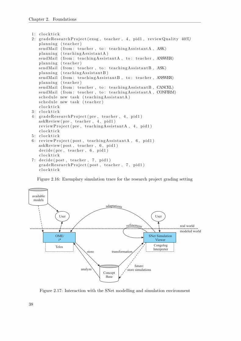
Chapter 2. Foundations
1 : c l o c k t i c k2 : gradeResearchPro ject ( exog , teacher , 4 , pid1 , rev iewQual i ty 40%)
planning ( t eacher )sendMail ( from : teacher , to : teachingAss i s tantA , ASK)planning ( teach ingAss i s tantA )sendMail ( from : teachingAss i s tantA , to : teacher , ANSWER)planning ( t eacher )sendMail ( from : teacher , to : teach ingAss i s tantB , ASK)planning ( teach ingAss i s tantB )sendMail ( from : teach ingAss i s tantB , to : teacher , ANSWER)planning ( t eacher )sendMail ( from : teacher , to : teach ingAss i s tantB , CANCEL)sendMail ( from : teacher , to : teachingAss i s tantA , CONFIRM)schedu le new task ( teach ingAss i s tantA )schedu le new task ( t eacher )c l o c k t i c k
3 : c l o c k t i c k4 : gradeResearchPro ject ( pre , teacher , 4 , pid1 )
askReview ( pre , teacher , 4 , pid1 )r ev i ewPro j e c t ( pre , teachingAss i s tantA , 4 , pid1 )c l o c k t i c k
5 : c l o c k t i c k6 : r ev i ewPro j e c t ( post , teach ingAss i s tantA , 6 , pid1 )
askReview ( post , teacher , 6 , pid1 )dec ide ( pre , teacher , 6 , pid1 )c l o c k t i c k
7 : dec ide ( post , teacher , 7 , pid1 )gradeResearchPro ject ( post , teacher , 7 , pid1 )c l o c k t i c k
Figure 2.16: Exemplary simulation trace for the research project grading setting
ConceptBase
OME/i*
Telos
SNet SimulationViewer
CongologInterpreter
adaptations
availablemodels
real world
modeled world
User User
store
analyze
transformation
future:store simulations
refinement
Figure 2.17: Interaction with the SNet modelling and simulation environment
38

2.2. i* and Derivatives
Entity CourseEntity Exam
Attribute constant c : CourseActor StudentGoal PassCourseMode achieveActor StudentAttribute constant co : CourseFulfillment definition∀ e :Exam e . c=co → ∃p : PassExamp . ex=e ∧ p . pc=s e l f ∧ Fulf i l led (p)
Task PassExamMode achieveActor StudentAttribute constant pc : PassCourse
constant ex :ExamCreation cond i t i on ¬ Fulf i l led ( pc )Invariant pc . actor=actor ∧ pc . co=e . c
Actor TeacherTask GiveExamMode achieveActor TeacherAttribute constant exam :Exam
Resource Dependency AnswerMode achieveDepender TeacherDependee StudentAttribute constant exam :Exam
Resource Dependency MarkMode achieveDepender StudentDependee TeacherAttribute constant ex :Exam
passed : booleanInvariant Ful f i l led ( s e l f )→
( passed↔ X passed )
Figure 2.18: Partial FT model of the course management example (taken from [FLP+04])
introduce a small number of elements to represent pre- and postconditions for specifyingan ordering on tasks, they annotate the original SR diagrams with ConGolog constructslike while-loops, sequential task decompositions, and the like. While this allows veryfine-grained control-flow specifications at the i*-level, it comes at the expense of burdeningthe user with choosing among the various control alternatives. Furthermore they did notintend the modelled agents to be able to cope with alternatives as SNet does with theplanning component.
2.2.4 Formal Tropos
The key idea of Formal Tropos [FLP+04] (hereafter FT) is to formalize the i*/Troposspecification of early requirements and enrich it with additional constraints in linear timelogic. This enables formal analysis, especially of dynamic issues. For example, it allows tocheck whether regarding some particular setting, a goal is satisfiable (in the future). Themain aim of these analysis is to establish and ensure the consistency of a specification,this is to debug specifications.
We combine the introduction to FT with a comparison to SNet (based on [SLJ06b]).This is also the reason why we have introduced SNet in the previous section with the help ofthe teacher-student management example (see Fig. 2.12), slightly adapted from [FLP+04].Figure 2.18 shows a partial FT representation of the example that can be derived from thegraphical i*/Tropos representation similarly to the ConGolog view in SNet automaticallyby applying some heuristics. The subsequent presentation and investigation of FormalTropos is separated into a modelling (static and dynamic) and an analysis part. Table 2.8gives an overview of the comparison’s outcome.
39

Chapter 2. Foundations
Table 2.8: Concepts in FT vs. SNet
Formal Tropos SNetstatic dependencies [only implicitly]modelling cardinality constraints [only some]
attributes, entities parameters, precondition/effectmode utility computation, planning
dynamic prior-to links sequence linksmodelling creation/fulfillment poss of starting/finishing prim. actions
invariant procedural scope, fluentstemporal operators [restricted, less expressive]trigger, condition, definition definition only
analysis debugging via model-checking experiments via simulationsfinite domain no restrictions
FT’s Outer Layer – Static Modelling
FT distinguishes an outer layer and an inner layer. The outer layer resembles a classdeclaration and defines the structure of instances together with their attributes. Theinner layer on the other hand concerns constraints on the lifetime of objects in the linear-time temporal logic mentioned before. Global properties on the whole domain complete aFT specification.
The main differences between FT’s outer layer (structure of the elements in the do-main) and SNet result from the addition of entities and attributes. Their main purpose isto set the context of elements, for example, that in Fig. 2.18 the same “Course” is refer-enced by “Pass Course” and “Pass Exam”. Our transformation into ConGolog programsensures that a sub task or goal can only be considered from within the super task orgoal, this is the super task or goal sets the scope (or context) for the sub elements.In addition, similar to attributes in FT, SNet allows the modeller to specify arbitrary pa-rameters of task and goal elements that are passed through within any sub procedures.And finally, we can specify with the help of precondition/effect elements arbitraryfluents that can be referred to from within preconditions and effects of completely differentmodelling elements. Thus altogether, SNet makes similar constructs available, except forthe strong typing and additional facets FT provides.
In the outer layer FT introduces also a distinction between different modes of inten-tional elements, this is achieve, maintain, the combination of the two, and avoid. InSNet a goal has always to be achieved, a task completed, a resource provided, andsoftgoals are supposed to be fulfilled as much as possible. Additionally, the latter areused in order to capture how well a goal was achieved or a task was completed via autility computation. In SNet this becomes much more important since a goal or task isachieved several times within one simulation. Thus implicitly, task and goal elementsin SNet have a mode between achieve (once) and maintain.
Notably with the help of precondition/effect elements and fluents, SNet can de-scribe objects that exist longer than one instantiation. Especially the representation oftrust is realized that way and affects the future agent behaviour via the deliberative plan-ning component.
40
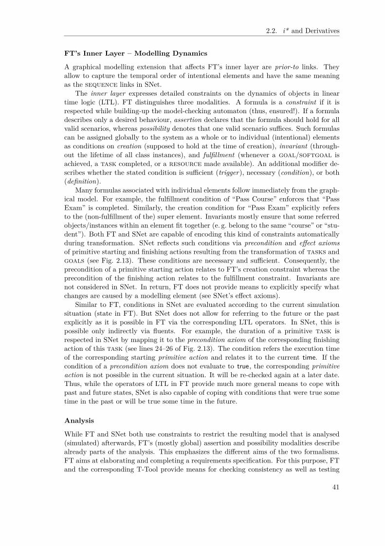
2.2. i* and Derivatives
FT’s Inner Layer – Modelling Dynamics
A graphical modelling extension that affects FT’s inner layer are prior-to links. Theyallow to capture the temporal order of intentional elements and have the same meaningas the sequence links in SNet.
The inner layer expresses detailed constraints on the dynamics of objects in lineartime logic (LTL). FT distinguishes three modalities. A formula is a constraint if it isrespected while building-up the model-checking automaton (thus, ensured!). If a formuladescribes only a desired behaviour, assertion declares that the formula should hold for allvalid scenarios, whereas possibility denotes that one valid scenario suffices. Such formulascan be assigned globally to the system as a whole or to individual (intentional) elementsas conditions on creation (supposed to hold at the time of creation), invariant (through-out the lifetime of all class instances), and fulfillment (whenever a goal/softgoal isachieved, a task completed, or a resource made available). An additional modifier de-scribes whether the stated condition is sufficient (trigger), necessary (condition), or both(definition).
Many formulas associated with individual elements follow immediately from the graph-ical model. For example, the fulfillment condition of “Pass Course” enforces that “PassExam” is completed. Similarly, the creation condition for “Pass Exam” explicitly refersto the (non-fulfillment of the) super element. Invariants mostly ensure that some referredobjects/instances within an element fit together (e. g. belong to the same “course” or “stu-dent”). Both FT and SNet are capable of encoding this kind of constraints automaticallyduring transformation. SNet reflects such conditions via precondition and effect axiomsof primitive starting and finishing actions resulting from the transformation of tasks andgoals (see Fig. 2.13). These conditions are necessary and sufficient. Consequently, theprecondition of a primitive starting action relates to FT’s creation constraint whereas theprecondition of the finishing action relates to the fulfillment constraint. Invariants arenot considered in SNet. In return, FT does not provide means to explicitly specify whatchanges are caused by a modelling element (see SNet’s effect axioms).
Similar to FT, conditions in SNet are evaluated according to the current simulationsituation (state in FT). But SNet does not allow for referring to the future or the pastexplicitly as it is possible in FT via the corresponding LTL operators. In SNet, this ispossible only indirectly via fluents. For example, the duration of a primitive task isrespected in SNet by mapping it to the precondition axiom of the corresponding finishingaction of this task (see lines 24–26 of Fig. 2.13). The condition refers the execution timeof the corresponding starting primitive action and relates it to the current time. If thecondition of a precondition axiom does not evaluate to true, the corresponding primitiveaction is not possible in the current situation. It will be re-checked again at a later date.Thus, while the operators of LTL in FT provide much more general means to cope withpast and future states, SNet is also capable of coping with conditions that were true sometime in the past or will be true some time in the future.
Analysis
While FT and SNet both use constraints to restrict the resulting model that is analysed(simulated) afterwards, FT’s (mostly global) assertion and possibility modalities describealready parts of the analysis. This emphasizes the different aims of the two formalisms.FT aims at elaborating and completing a requirements specification. For this purpose, FTand the corresponding T-Tool provide means for checking consistency as well as testing
41

Chapter 2. Foundations
De
DeDe Dp Dp
Dp O
O
delegation of permission
delegation of execution ownershipLegend
Figure 2.19: ST model of university setting (based on [GMMZ05a])
the above mentioned assertions and possibilities. In their example, they identified, forexample, the need to ensure that a “Mark” does not change its value once produced.Thus, the major focus is on detecting bugs and missing details in the specification anditerating this process until the specification seems to be complete.
SNet expects its model to be correct and functioning. Its main purpose is not to helpthe user arrive at a correct representation, although it might be the case that a modellerruns several simulations and makes updates to the model until the simulation adheres towhat is happening in the real world. Instead, once such a calibrated model exists, themain purpose of SNet is to enable the user to play around with it: What happens, whenI change this modelling aspect (e. g. a network rule)? How does this affect the networkas a whole, each agent individually, or the trust relationships between agents? Or whathappens if my view on a trust relationship is incorrect? What damages can I incur? Themodeller tries out different alternatives that are too costly to experiment with in the realworld. Thus, again similar to FT SNet aims at an exploratory analysis of the network.
A key difference that results from SNet’s strong connection to the real world is theneed to cope with many more instances than FT can (due to its reliance on finite model-checking). Consider, for example, the unlimited number of instances of tasks and goalsthat can occur within one simulation (distinguished by the parameter “PID”). This ispossible due to the fact that SNet relies on simulations backed up by progression [Rei01].On the other hand, this approach allows only statements about the single setting thathas been investigated and not about a variety of situations as it is possible with a model-checking based approach.
Furthermore, FT does not have an explicit notion of actions with pre- and postcondi-tions. Hence FT does not support deliberation about different courses of actions, whichis an essential feature of SNet. It allows the agents to decide on their internal goals (i. e.choice points) on their own but according to rules that reflect the real world (utility-based).The potential of a complementing combination of the two formalisms will be discussed inthe context of high level simulation analysis (see Chap. 5.3.4).
2.2.5 Secure Tropos
Also the discussion of Secure Tropos [GMMZ05a] (hereafter ST) is combined with a com-parison to SNet. For the example, we stick to the university domain by using the examplefrom [GMMZ05a]. It concerns information access in a setting that includes an adminis-trative officer, “Alice”, a student IT system, “Sam”, and a student, “Bob”, see Fig. 2.19.Since ST does not have a particular dynamic view, we focus the static modelling and theanalysis means only (see overview in Table 2.9).
42

2.2. i* and Derivatives
Table 2.9: Concepts in ST vs. SNet
Secure Tropos SNetstatic delegation: permission vs. exec. execution onlymodelling trust: permission vs. execution trust
negative authorization [not considered][possible] quantitative trustownership vs. provisioning [no distinction]social vs. individual trust confidence vs. individual trust
analysis detect static conflicts (Datalog) focus on dynamics, evolution of trustexploring design alternatives decision-theoretic planning componentat modelling time at simulation run-time
Static Modelling
ST’s main idea is to replace i* ’s dependency construct by a more fine-grained model.Similar to SNet, ST considers trust explicitly and thus separates a dependency into adelegation and a trust relationship to enable delegations without trust. In the example,“Bob” has to delegate to “Sam” the “provisioning of his data” although he might not beconfident that it will not be misused.
Additionally, ST distinguishes between delegation of permission and delegation of ex-ecution. The idea behind this is that, referring again to the example, the relationshipbetween Alice and Sam differs from the one of Bob and Sam. While Alice relies on Samfor providing some service and Sam can at-least provide this service (execution), Bob relieson Sam for not misusing the provided data (permission), this is that the data is at-mostused in the intended way (formal passage of authority). The flexible networks that SNetis concerned with avoid formal procedures and rely on trust instead. Thus, SNet does notconsider the notion of permission. But in [GMMZ05b], Giorgini et al. explicitly mentionthat permission relates to resources whereas execution relates to tasks and goals.SNet also treats these modelling elements differently in that only tasks and goals canbe delegated (remember that Gans et al. called them active elements) whereas resources(belonging to the passive elements) are mapped to preconditions and effects.
Concerning trust, ST introduces also the difference between permission and execution.Trust of execution denotes the belief that the trustee is capable of providing the goal,task, etc. This corresponds to the notion of competence in the nomenclature of Castel-franchi & Falcone [CF01]. SNet takes this part of trust for granted since capabilities aremodelled explicitly. Trust of permission reflects the belief that the permission will notbe misused, i. e. the trustee does not overstep its authority. And similar to SNet, theyalso consider distrust separately, but only to allow for modelling negative authorization.SNet’s understanding and use of these concepts is slightly different. While it considerstrust to be a combination of Castelfranchi & Falcone’s senses of disposition, dependence,and fulfillment, distrust reflects the belief of misuse or opportunistic behaviour. Negativeauthorization does not occur in SNet. This difference results from the different applicationdomains. ST explicitly allows for specifying relationships that should not occur. SNet hasto deal with all the relationships that are present in the real world and attributes alwaystrust and distrust relationships to them. The actual level of trust (distrust, respectively)
43

Chapter 2. Foundations
is reflected by a quantitative value that evolves during simulation. Thus in addition, SNetdoes not have a binary view on trust.
In regard to the notion of ownership the use of the more detailed strategic rationalelevel in SNet makes the owner of a task or goal explicit during modelling. Currently, wedo not allow to pass on such capabilities, thus, ownership and provisioning are coupled.But it occurs often that sub tasks or goals are delegated further. Additionally, in thisthesis we consider the extension of actor evolution (see Chap. 4.2) which means thatagents can acquire (or lose) roles during simulation. This relates to the provisioningand passage of authority.
In [GMMZ05b], the authors distinguish also between social and individual levels. Incontrast to ST, SNet considers trust relationships on an individual level only. This resultsfrom the emphasis on the dynamics of trust, i. e. how trust evolves during a simulation,which ST does not consider at all. Consequently, in this regard the two approaches arenot comparable. Furthermore, SNet supports the notion of confidence that captures trustinto the whole mesh of dependencies (the network), whereas ST allows for checking a trustrelationship on social level against the individual trust relationship on instantiated level.Altogether, these features seem complementary.
Analysis
Concerning analysis, the ST-Tool provides means to create a Datalog representation as wellas a FT representation. The latter seems to be an initial model that can be extended withLTL formulas as described in the previous section. The Datalog representation insteadprovides means to analyse specific ST issues such as trust and distrust. For this purpose,the authors give an axiomatization of intensional predicates. For example, they describetrust and distrust chains. Other axioms are used to establish the mapping from socialto individual level, or to describe whether some actor can satisfy some task, goal,etc. or has the needed permissions. With the help of the ST-Tool, the modeller can thencheck for the consistency of her model. Are the established trust and distrust relationshipssufficient to enable the execution of a service by some particular role or agent? Arethere any conflicts regarding trust on social level or between social and individual level?SNet currently does not provide any means to analyse trust relationships any further.
In [BMMZ06], an enrichment of the tool support for requirements engineering (andSecure Tropos in particular) is proposed that supports the automatic generation andexploration of alternative options. Given a set of actors and goals as the input, aplanner generates design alternatives by generating alternative multi-agent plans to fulfillall given goals. By using the “standard” planning language PDDL [GHK+98], a suitableoff-the-shelf planner can be used.
The use of planning approaches in ST and SNet is quite different. ST uses the plannerto generate and evaluate alternatives at design-time, whereas the decision-theoretic plan-ning component in SNet is used at simulation run-time. In ST, the designer remains inthe loop “to [...] refine[d], amend[ed], and approve[d]” suggestions that are generated bythe planner [BMMZ06]. Also the proposed solutions are not expected to be optimal. Incontrast, agents in SNet are supposed to exhibit real-world behaviour without requiringuser interaction for choosing from alternatives. They also strive for a best choice accordingto the modelled criteria as well as more general trust and gain related issues.
Due to the different purposes the planners serve in ST and SNet, also the actionsthat are considered are different. In ST, generic domain-independent actions concerning
44

2.3. ConGolog
delegation, satisfaction, refinement as well as special actions in regard to the absence oftrust are defined. In SNet, the actions result from the domain. The actions that areproposed in ST to cope with the absence of trust – negotiate, contract, delegate executionunder suspicion, fulfill, and evaluate – remind of the definition of speech acts [WF86]. InSNet the relation of i* and speech acts is considered explicitly (see Chap. 2.1.5).
Unsurprisingly, the main differences regarding analysis result from the fact, that STdoes not itself concern dynamic aspects. Neither the dynamics of delegation nor of trust areconsidered. For example, the chains of trust are based on the specified trust relationshipsthat are assumed to be fixed even when the planner is applied. Thus, different trustsettings have to be considered separately. SNet takes the evolution of trust into account.As with Formal Tropos, we will discuss means to combine the features of Secure Troposand SNet later on (see Chap. 5.3.5).
2.3 ConGolog
ConGolog [dGLL00] belongs to the Golog [LRL+97] family, a group of high-level pro-gramming languages suited to capture and describe agent behaviour. The most basiccharacteristic of these languages is that they allow to combine and suitably integrate im-perative programming with planning facilities. The aim is to reduce the complexity ofplanning by limiting the search space as much as possible. This is to use deterministicprogramming where possible and planning only for those parts where the resulting flexibil-ity is really needed at run-time. The many derivatives that have been developed over theyears, contribute various extensions such as coping with concurrency [dGLL00], stochasticactions [GL00], sensing [DGL99], decision-theoretic elements [BRST00] and various others.As a commonality, all of these extensions do not (yet) touch the foundation in the situationcalculus [McC63], a language for representing and reasoning about the preconditions andeffects of actions.
2.3.1 Situation Calculus
The situation calculus [McC63] is a variant of first-order logic,6 enriched with specialfunction and predicate symbols to describe and reason about dynamic domains. For thispurpose, all terms in the language are classified to belong to one of three sorts: ordinaryobjects, actions or situations.
Situation A situation describes the actual state of the world as a result of actions appliedto an initial situation denoted by the special constant S0, namely that situation inwhich no actions have yet occurred. This is a situation is characterized by the ini-tial situation S0 together with the sequence of (primitive) actions that have beenexecuted since then (also called history). There is a distinguished binary functionsymbol do where do(a,s) denotes the successor situation to s resulting from per-forming the action a.
Action An action is a defined basic activity that can be carried out in the world ascaptured in the situation calculus formalism. The modeller is absolutely free indefining what “basic” means in her context. Disregarding how complex an action
6Strictly speaking, a small dose of second-order logic is required as well, an issue which should notconcern us here.
45

Chapter 2. Foundations
might be in the real world, for the world described in the situation calculus it canbe considered to be basic (also primitive). To capture more information about anaction, the special predicate Poss(a,s) is able to capture whether an action a isexecutable in the situation s. This is it is possible to describe preconditions forthe execution of actions. Furthermore, actions can have effects in the world, thisis change it. Issues that can change in the world are captured by fluents: relationswhose truth values vary from situation to situation are called relational fluents, andare denoted by predicate symbols taking a situation term as their last argument;similarly, functions varying across situations are called functional fluents and aredenoted analogously.
Ordinary Objects Any other objects that describe, for example, objects of the realworld are classified as ordinary objects.
Basic Action Theory Within this language, we can formulate theories which describehow the world changes as the result of taking one of the available actions. One possibilityto formulate such a theory is a basic action theory of the following form [Rei01]:
• Axioms describing the initial situation, S0.
• Action precondition axioms, one for each primitive action a, characterizing Poss(a,s). For example, the fact that a robot can only pick up an object if it is next to theobject and it is not holding anything can be formalized as follows:
Poss(pickup(r,x) , s) ≡ NextTo(r,x,s) ∧∀ y. ¬ Holding(r,y,s)7
• Successor state axioms, one for each fluent F, stating its (truth) value as a functionof the current situation (history). These take the place of the so-called effect axioms,but also provide a solution to the frame problem. The latter is the problem thatresults from the fact that one does not only need to describe which actions changewhich aspects of the world but also which aspects remain unaffected (quite a largenumber)!
Consider, for example, a simple model of time which progresses in a discrete fashionby 1 unit as a result of a special action clocktick . The time of a situation can thenbe specified with the help of a fluent time(s) and the following successor state axiom:
t ime (do ( a , s ) )= t ≡ a= c l o c k t i c k ∧ t= t ime ( s )+1∨ a 6= c l o c k t i c k ∧ t= t ime ( s )
This axiom explicitly mentions that clocktick is the only operation that affects thefluent time (similar axioms for other fluents accordingly capture that clocktick forexample does not effect the color of some object).8
• Domain closure and unique-name axioms for actions.
7We use the convention that free variables are implicitly universally quantified.8In this thesis we use a temporal version of the situation calculus with discrete linear time where time
advances just as specified by this axiom (see also [Rei01]).
46

2.3. ConGolog
Table 2.10: Relevant primitive actions in the reactive elevator example
Action DescriptionBasic elevator featurescallElevator (n)* A button has been pressed on floor n.goUp, goDown The elevator can go up and down one floor.resetButton(n) The elevator can reset the call button on a floor (n).wait A no-op operation to block the elevator from doing anything else.Temperature related actionschangeTemp* An action outside the control of the elevator that changes the tem-
perature.toggleFan The elevator has a fan to influence the temperature within. It can
be turned on or off.Actions related to a fire within the elevatorstartFire *, Exogenous actions (see later on) that indicate that a fire is startedendFire* (put out, respectively) in the elevator.
ringAlarm In case of a fire the elevator can activate an alarm.resetAlarm* Allows to reset the fire alarm.* Exogenous actions (see elaboration below)
Reactive Elevator Example As an example, we consider a reactive elevator controllertaken from [Rei01] (pp. 191-193). The tables 2.10 and 2.11 show the relevant primitiveactions and fluents in this scenario. Figure 2.20 gives the corresponding precondition(lines 1–11) and successor state axioms (lines 12–27). We will not go over them in detailsince they are self-explaining. For example, the elevator can only be called if the buttonat the corresponding floor is not yet on or the elevator can only goUp if it is currently notat the topmost floor. Similarly, the temperature is affected by changeTemp but this actionin its effect also depends on whether the fan is on (temperature sinks) or off (temperaturerises).
Table 2.11: Relevant fluents in the reactive elevator example
Fluent DescriptionBasic elevator featuresbuttonOn(n,s) The call button for floor n is on.floor (s) The elevator is currently at the specified floor.Temperature related fluentstemp(s) The current temperature in the elevator.fan(s) Indicates whether the fan is currently on or not.Fire related issuesfire (s) There is a fire in the elevator.alarmOn(s) Reflects whether the alarm is on or off, respectively.
47

Chapter 2. Foundations
Precondition axioms
1 Poss ( c a l l E l e v a t o r ( n ) , s ) ≡ ¬buttonOn (n , s )2 Poss ( goUp , s ) ≡ f l o o r ( s ) < TopFloor3 Poss (goDown , s ) ≡ f l o o r ( s ) > F i r s t F l o o r4 Poss ( r e s e tBu t t on ( n ) , s ) ≡ f l o o r ( s )=n ∧ buttonOn (n , s )5 Poss ( wait , s ) ≡ t r u e6 Poss ( changeTemp , s ) ≡ t r u e7 Poss ( togg leFan , s ) ≡ t r u e8 Poss ( s t a r t F i r e , s ) ≡ ¬ f i r e ( s )9 Poss ( endF i r e , s ) ≡ f i r e ( s )
10 Poss ( r ingAlarm , s ) ≡ f i r e ( s )11 Poss ( r e se tA la rm , s ) ≡ alarmOn ( s )
Successor state axioms
12 buttonOn (n , do ( a , s ) ) ≡13 a= c a l l E l e v a t o r ( n )14 ∨ buttonOn (n , s ) ∧ a 6= r e s e tBu t t on ( n )15 f l o o r (do ( a , s ) )= f ≡16 a=goDown ∧ f l o o r ( s )= f+117 ∨ a=goUp ∧ f l o o r ( s )= f−118 ∨ f l o o r ( s )= f ∧ a 6=goDown ∧ a 6=goUp19 temp (do ( a , s ) )= t ≡20 temp ( s )=t−1 ∧ ¬ f an ( s ) ∧ a=changeTemp21 ∨ temp ( s )= t+1 ∧ f an ( s ) ∧ a=changeTemp22 ∨ temp ( s )= t ∧ a 6=changeTemp23 f an (do ( a , s ) ) ≡24 ¬ f an ( s ) ∧ a= togg l eFan ∨ f an ( s ) ∧ a 6= togg l eFan25 f i r e (do ( a , s ) ) ≡26 a= s t a r t F i r e ∨ f i r e ( s ) ∧ a 6= endF i r e27 alarmOn (do ( a , s ) ) ≡28 a= r i ngA la rm ∨ alarmOn ( s ) ∧ a 6= r e s e tA l a rm
Figure 2.20: Precondition and successor state axioms for a reactive elevator world
48
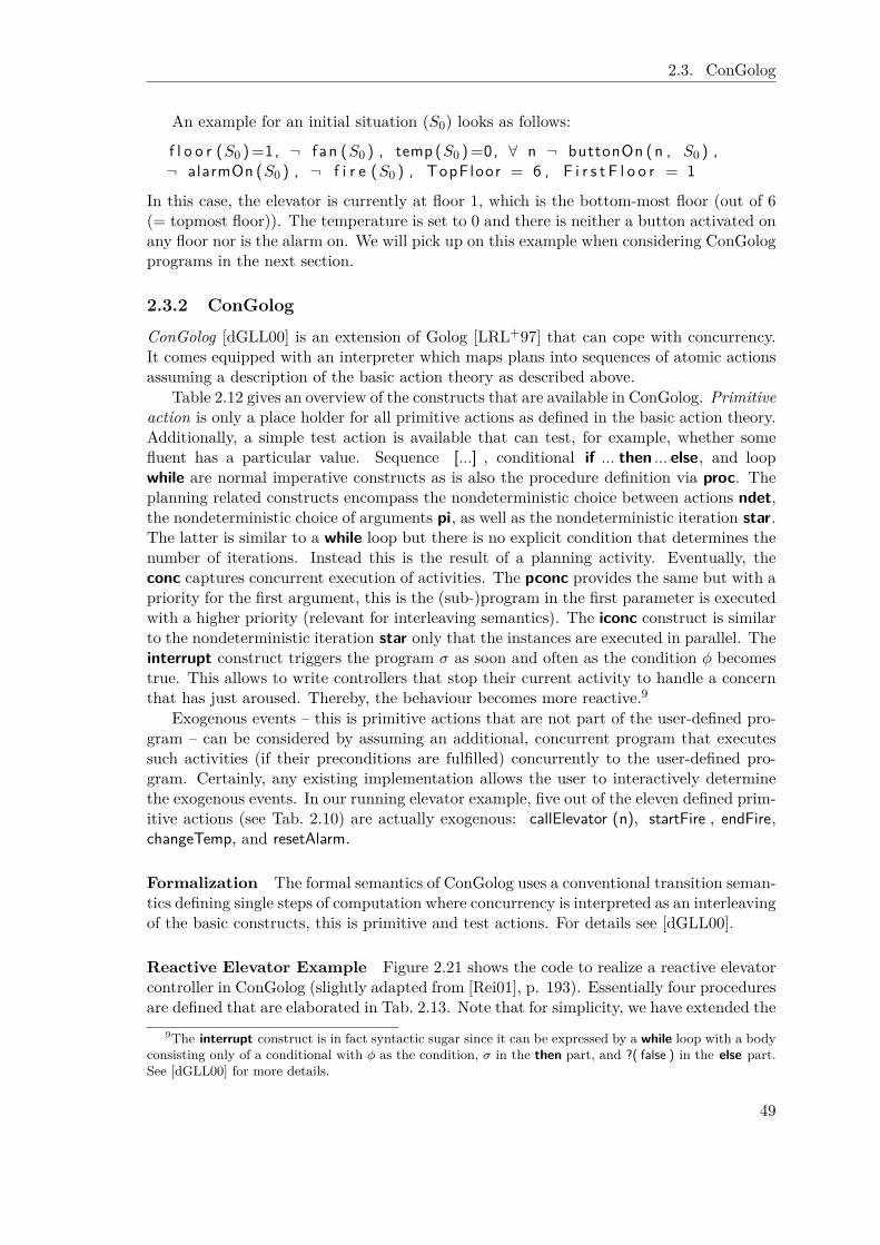
2.3. ConGolog
An example for an initial situation (S0) looks as follows:
f l o o r (S0 )=1, ¬ f an (S0 ) , temp (S0 )=0, ∀ n ¬ buttonOn (n , S0 ) ,¬ alarmOn (S0 ) , ¬ f i r e (S0 ) , TopFloor = 6 , F i r s t F l o o r = 1
In this case, the elevator is currently at floor 1, which is the bottom-most floor (out of 6(= topmost floor)). The temperature is set to 0 and there is neither a button activated onany floor nor is the alarm on. We will pick up on this example when considering ConGologprograms in the next section.
2.3.2 ConGolog
ConGolog [dGLL00] is an extension of Golog [LRL+97] that can cope with concurrency.It comes equipped with an interpreter which maps plans into sequences of atomic actionsassuming a description of the basic action theory as described above.
Table 2.12 gives an overview of the constructs that are available in ConGolog. Primitiveaction is only a place holder for all primitive actions as defined in the basic action theory.Additionally, a simple test action is available that can test, for example, whether somefluent has a particular value. Sequence [...] , conditional if ... then ... else, and loopwhile are normal imperative constructs as is also the procedure definition via proc. Theplanning related constructs encompass the nondeterministic choice between actions ndet,the nondeterministic choice of arguments pi, as well as the nondeterministic iteration star.The latter is similar to a while loop but there is no explicit condition that determines thenumber of iterations. Instead this is the result of a planning activity. Eventually, theconc captures concurrent execution of activities. The pconc provides the same but with apriority for the first argument, this is the (sub-)program in the first parameter is executedwith a higher priority (relevant for interleaving semantics). The iconc construct is similarto the nondeterministic iteration star only that the instances are executed in parallel. Theinterrupt construct triggers the program σ as soon and often as the condition φ becomestrue. This allows to write controllers that stop their current activity to handle a concernthat has just aroused. Thereby, the behaviour becomes more reactive.9
Exogenous events – this is primitive actions that are not part of the user-defined pro-gram – can be considered by assuming an additional, concurrent program that executessuch activities (if their preconditions are fulfilled) concurrently to the user-defined pro-gram. Certainly, any existing implementation allows the user to interactively determinethe exogenous events. In our running elevator example, five out of the eleven defined prim-itive actions (see Tab. 2.10) are actually exogenous: callElevator (n), startFire , endFire,changeTemp, and resetAlarm.
Formalization The formal semantics of ConGolog uses a conventional transition seman-tics defining single steps of computation where concurrency is interpreted as an interleavingof the basic constructs, this is primitive and test actions. For details see [dGLL00].
Reactive Elevator Example Figure 2.21 shows the code to realize a reactive elevatorcontroller in ConGolog (slightly adapted from [Rei01], p. 193). Essentially four proceduresare defined that are elaborated in Tab. 2.13. Note that for simplicity, we have extended the
9The interrupt construct is in fact syntactic sugar since it can be expressed by a while loop with a bodyconsisting only of a conditional with φ as the condition, σ in the then part, and ?( false ) in the else part.See [dGLL00] for more details.
49

Chapter 2. Foundations
Table 2.12: Overview of ConGolog’s constructs
Construct DescriptionBasic constructsα primitive action?(φ) test actionImperative constructs[σ1, σ2, . . . , σn] sequenceif φ then σ1 else σ2 conditionalwhile φ do σ loopproc(β (→x), σ) procedure definitionNondeterministic constructsndet(σ1, σ2) nondeterministic choice of actionspi(x,σ) nondeterministic choice of argumentsstar(σ) nondeterministic iterationConcurrency constructsconc(σ1, σ2) concurrent executionpconc(σ1, σ2) prioritized concurrent executioniconc(σ) concurrent iterationinterrupt(φ, σ) triggers σ whenever φ holds
proc ( c o n t r o l ( ) ,whi le ∃n buttonOn (n ) do
p i (n , [ ? ( buttonOn (n ) ) , s e r v e F l o o r ( n ) ] ) )
proc ( s e r v e F l o o r ( n ) ,[ whi le f l o o r 6= n do
i f n<f l o o r then goDown e l s e goUp ,r e s e tBu t t on ( n ) ] )
proc ( r u l e s ( ) ,conc ( i n t e r rup t ( f i r e ∧ ¬alarmOn ,
[ r ingAlarm , whi le alarmOn do wa i t ] ) ,i n t e r rup t ( temp>3 ∧ ¬ fan ,
togg l eFan ) ,i n t e r rup t ( temp<−3 ∧ fan ,
togg l eFan ) ) )
proc ( main ( ) ,pconc ( r u l e s ( ) ,
c o n t r o l ( ) ,whi le t r u e do wa i t ) )
Figure 2.21: Reactive elevator controller in ConGolog
50

2.3. ConGolog
Table 2.13: Clarifying procedures of the reactive elevator controller
Procedure Descriptioncontrol () This procedure is the actual controller. It consists only of a while
loop that waits for a button to be pressed and then serves the floor.serveFloor (n) Serving is separated into a procedure of its own. Here it is checked
whether the elevator is already at the requested floor. If not, itmoves up or down accordingly. Once reached, the button is reset.
rules () The rules procedure captures all exceptional situations. Threeinterrupt conditions are checked concurrently. If a fire is detectedand the alarm is not yet on, the elevator activates the alarm(ringAlarm) and then switches into a blocking waiting mode untilthe alarm is reset. The other two interrupts concern the toggling ofthe fan. A high temperature together with a fan that is switchedoff causes the fan to be switched on. Similarly, the fan is switch offif it is cool enough and the fan is still running.
main() The main program combines the rules procedure and the controlprocedure while giving higher priority to the former procedure. Inorder to have a non-terminating controller, the wait operation isexecuted with the lowest priority.
constructs (in particular conc and pconc) to an arbitrary, but finite number of arguments.This can easily be mapped to a nesting of the normal version with only two arguments.
2.3.3 Implementation
As mentioned in the beginning, ConGolog focuses dynamic domains. Thus, dynamicaspects are central. Also Borgida and Mylopoulos [BM09] mention the possibility touse ConGolog to cover dynamic issues during method engineering. But as elaboratedby Jeusfeld [Jeu09b] the capture of dynamic issues is possible in Telos only to a certaindegree. Especially, reasoning is not possible within Telos. Accordingly, we do not provide aTelos representation of ConGolog here, even though the structural features of a ConGologprogram can be represented statically as shown in Fig. 2.6. For details see [GJKL03].
Instead, we briefly touch here the implementation in Prolog that is most commonlyused. As mentioned by Reiter [Rei01], an interpreter for ConGolog program is writtenrather easily. The transition semantics mentioned above map straight into according pred-icates. An additional predicate determines the (truth) value of fluents and preconditionsaccording to the current situation, this the history that is tracked by the predicates re-flecting the transition semantics.
We make use of the IndiGolog variant [DGL99] that provides an incremental interpreterthat enables interaction with the user for exogenous events (or sensing) actions and alsointegrates progression. The latter is useful since the straightforward approach to theimplementation of (Con)Golog makes heavily use of regression. This is to determine thevalue of a single fluent, the whole history of actions is backtracked to check the effectof all actions on the fluent until the initial situation is reached. This certainly resultsin a poor performance. To counteract, the IndiGolog interpreter periodically rolls the
51

Chapter 2. Foundations
database forward. This is the accumulated history is shortened by computing the valuesof all fluents at some particular point in the history, removing the actions before that pointof time from the history, and using the computed values as the new initial database (thisis replacing the original S0). Thus, the history does no longer grow unrestrictedly. Dueto the focus on interactive and incremental execution, the missing possibility to backtrackto situations before the point when the database was rolled forward is not an issue here.
2.4 Matlab/Simulink
The tool environment Matlab/Simulink [Mat10] from The Mathworks is used among oth-ers by control system engineers to approach control problems. Simulink is a graphicalprogramming language on top of the numerical math engine Matlab. It allows for thesignal oriented, action diagram based visual capturing of complex systems and provides alarge set of libraries with predefined mathematical blocks (also called “transfer functions”).The user either selects blocks from these libraries or provides her own implementation,customizes the blocks via parameters, and connects them by signals via their input andoutput ports. The internal representation of each block and hence the model as a wholevia differential equations eventually enables simulations. We reconsider the abstract mod-elling aspects here in more detail and additionally outline a Telos representation that willbe useful when it comes to the transformation from i* to Matlab/Simulink later on (seeChap. 5.2.3).
2.4.1 Action Diagrams
The basic idea of the Simulink graphical representation follows the simple idea of actiondiagrams (also block diagrams). In this notation, blocks are connected via links thatrepresent signals. Incoming links are considered to be input signals and outgoing links tobe output signals of the corresponding block. Additionally, branching points allow to splitup a signal to use it for input to several blocks. Similarly, within addition points signalscan be combined into a new signal (usually combined by adding the signals). Most oftena block is refined into sub blocks to capture and describe its internal structure.
While Matlab/Simulink sticks with the basic idea of action diagrams, it introducessome refinements, especially a lot of specialized block elements, and certainly a libraryof instances to these specialized types. The overall aim of these extensions is to enablemathematically grounded simulations. Accordingly, the extensions allow the modeller todefine mathematically precisely the behaviour of a block, this is a prescription how theoutput signals are computed from the input signals. Most commonly, such a mathematicaldescription is provided in the form of differential equations. But before going into themathematical details, Simulink modellers usually make heavily use of decomposition. Acomplex block is first refined into simpler sub blocks. This process is continued until basicbuilding blocks are reached that can be served from Matlab/Simulink’s comprehensivelibraries (potentially extended by the modeller herself).
Input/Output Ports A refinement of Matlab/Simulink over normal Action Diagramsconcerns the connection points of signals (lines in Simulink). In Matlab/Simulink theseconnection points are explicitly modelled as in- and outports, respectively. Thereby theycan more easily be identified in the models and in particular they can nicely be represented
52
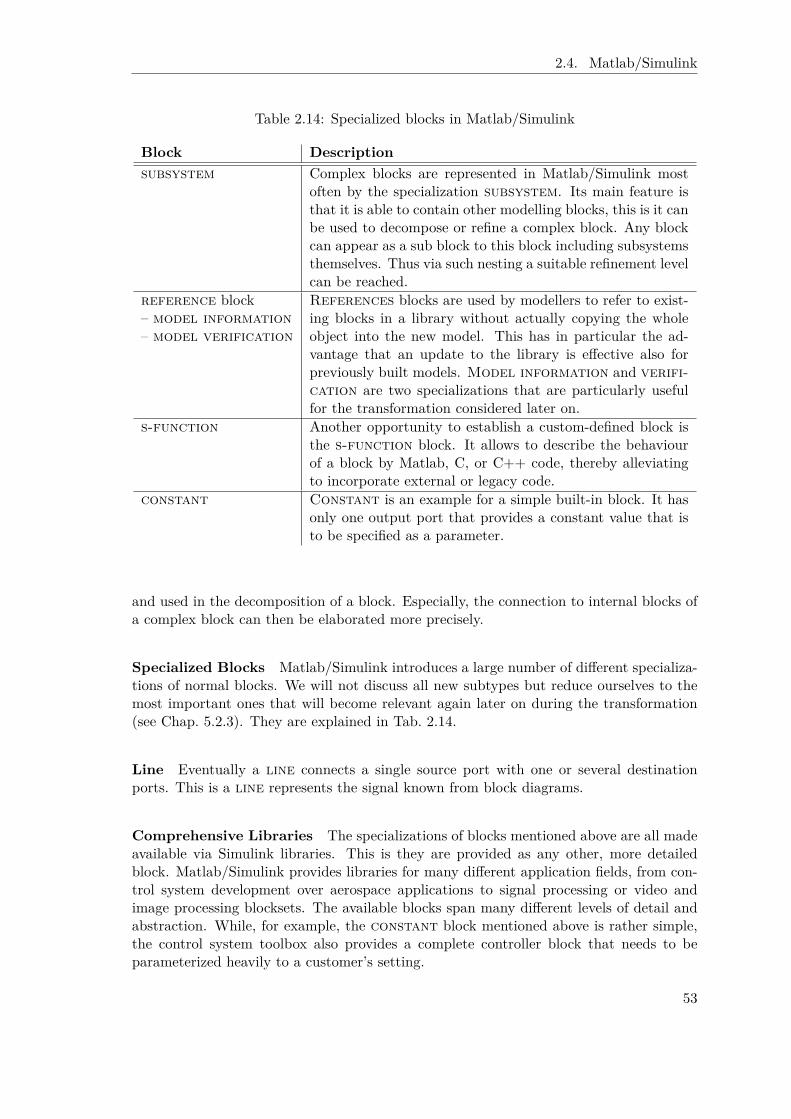
2.4. Matlab/Simulink
Table 2.14: Specialized blocks in Matlab/Simulink
Block Descriptionsubsystem Complex blocks are represented in Matlab/Simulink most
often by the specialization subsystem. Its main feature isthat it is able to contain other modelling blocks, this is it canbe used to decompose or refine a complex block. Any blockcan appear as a sub block to this block including subsystemsthemselves. Thus via such nesting a suitable refinement levelcan be reached.
reference block– model information– model verification
References blocks are used by modellers to refer to exist-ing blocks in a library without actually copying the wholeobject into the new model. This has in particular the ad-vantage that an update to the library is effective also forpreviously built models. Model information and verifi-cation are two specializations that are particularly usefulfor the transformation considered later on.
s-function Another opportunity to establish a custom-defined block isthe s-function block. It allows to describe the behaviourof a block by Matlab, C, or C++ code, thereby alleviatingto incorporate external or legacy code.
constant Constant is an example for a simple built-in block. It hasonly one output port that provides a constant value that isto be specified as a parameter.
and used in the decomposition of a block. Especially, the connection to internal blocks ofa complex block can then be elaborated more precisely.
Specialized Blocks Matlab/Simulink introduces a large number of different specializa-tions of normal blocks. We will not discuss all new subtypes but reduce ourselves to themost important ones that will become relevant again later on during the transformation(see Chap. 5.2.3). They are explained in Tab. 2.14.
Line Eventually a line connects a single source port with one or several destinationports. This is a line represents the signal known from block diagrams.
Comprehensive Libraries The specializations of blocks mentioned above are all madeavailable via Simulink libraries. This is they are provided as any other, more detailedblock. Matlab/Simulink provides libraries for many different application fields, from con-trol system development over aerospace applications to signal processing or video andimage processing blocksets. The available blocks span many different levels of detail andabstraction. While, for example, the constant block mentioned above is rather simple,the control system toolbox also provides a complete controller block that needs to beparameterized heavily to a customer’s setting.
53

Chapter 2. Foundations
Figure 2.22: Thermal model of a house (adapted from [Mat10])
Figure 2.23: Subsystem showing the internals of the “house” subsystem [Mat10]
House Thermal Example As an example we consider the “house thermal” settingadapted from the Matlab/Simulink “Getting Started” description [Mat10]. Figure 2.22gives an overview of its components. The “indoor temperature” of a “house” is affectedby the “outdoor temperature” and the “heater” functionality. A feedback loop returns the“indoor temperature” to control the “heater”. Furthermore, the heating effort is mappedto “heating costs” that are put out via some Simulink built-in “plot” facility as is the“indoor temperature”. In the background, helper components take care of the “conversion”between degree Celsius and degree Fahrenheit The “house” component is a subsystem withthe internals given in Fig 2.23. Here “outdoor temperature” and “indoor temperature”are combined and further influenced by operations to compute heat losses and the like,eventually resulting in the “indoor room temperature” provided as the output of thissubsystem.
2.4.2 Telos Representation
The Telos representation of the above mentioned constructs is straightforward, in partic-ular if the modeller watches out only for a static, structural view of a Matlab/Simulinkmodel. Since it does not make sense to aim for reestablishing the complex and efficientmathematically based simulation features of Matlab/Simulink, such a focus on structuralaspects that at least enables transformations seems reasonable.
Figure 2.24 shows the class hierarchy for the Matlab/Simulink constructs as they have
54

2.5. OpenOMEi5
Figure 2.24: Class hierarchy for Telos representation of the Simulink meta model
been discussed above. Similar to the i* Telos representation (see Chap. 2.2.1, in particularFig. 2.10 and Fig. 2.11), we have added some suitable helper classes to take advantage ofcommonalities between the different types. The top-level class Block has three subclasses:Port, further subclassed into Inport and Outport, ComplexBlock as the only block type thatcan contain arbitrary other blocks, and eventually AtomicBlock. The latter usually do notcontain arbitrary other blocks, but for representational convenience it is helpful whenthey can contain Ports to provide a common interface of all Blocks in this regard. Theonly ComplexBlock in our considerations are Subsystems whereas to an AtomicBlock thereare Reference blocks (further refined into ModelInformation and ModelVerification blocks),SFunctions, and also Constants. Eventually, the Figure shows the Line construct and somesimple attribute relationships between objects. For example, the from and to attributes ofa Line can only refer Ports. The parent of a Block can in general be a Block. But while aComplexBlock can have a child of any kind (this is Block), the AtomicBlocks can only havePorts as children . The details of the Telos representation are given in Appendix A.1.3.
2.5 OpenOMEi5
Despite of it being part of the contribution of this thesis, we introduce the tool environmentOpenOMEi5 that has been developed to support both case study settings already here.We focus on the basic issues, this is the most general features and existing tools that areused. Particular aspects and extensions that correlate with specific conceptual extensionswill then be added throughout the thesis.
Eclipse The implementation builds on OpenOME, available at http://sourceforge.net/projects/openome, an Eclipse-based redevelopment of the original OME3 too [LY00].Eclipse, http://www.eclipse.org/ is a powerful and easily extensible integrated develop-ment environment (IDE). It is a sophisticated framework that provides the basic facilitiesof a modelling and analysis environment as well as many pre-implemented extensions forspecial purposes. The graphical editing framework (GEF), for example, allows to easilyvisualize and work with graphical models.
55

Chapter 2. Foundations
Figure 2.25: Screenshot of the developed, Eclipse-based tool support OpenOMEi5
ConceptBase The other major supportive tool is the Telos implementation Concept-Base (see Chap. 2.1.3). While also the original OME3 tool was Telos-based, it used aless powerful, commercial implementation. Thus, as part of the implementation work inthis thesis we have replaced the old Telos implementation by a tighter connection to theConceptBase system that is used for various purposes such as model storage, analysis, andtransformation throughout the thesis.
OpenOMEi5 Figure 2.25 shows a screenshot of a typical usage scenario of the tool foran i* modelling situation. In combination the two foundational tools provide the basisfor a powerful and easily tailorable modelling and analysis environment as will becomeobvious in the rest of the thesis.
56

Chapter 3
Case Studies
Within the context of this thesis, two different application fields have been investigated
• support for the governance of inter-organisational networks and
• requirements engineering for control systems.
We will first elaborate each of them separately. Afterwards we will have a closer look attheir common characteristics. By relating these to existing methods and approaches wewill identify important open dynamic issues.
3.1 Case Study 1: Inter-Organisational Networks
Inter-organisational social networks promise to combine the benefits of two traditionalcoordination mechanisms of modern societies [Pow90]: the flexibility and speed of com-petitive market relationships, and the stability and long-term duration of cooperative,organisational relationships. We follow Weyer’s [Wey00] definition of a social network asan autonomous form of coordination of interactions whose essence is the trusting coopera-tion of autonomous, but interdependent agents. These agents cooperate for a limited timeand consider their partners’ interests because they can thus fulfill their individual goalsbetter than through non-coordinated activities. “Agents” in this general definition canmean organisations or people. In our case of organisational networks, the usual meaningis a combination: people representing, or working for, organisations or parts thereof.
3.1.1 Examples
We have considered inter-organisational networks in various different contexts from whichwe focus two here: high tech entrepreneurship networking and the virtual factory, a virtualenterprise in the field of production engineering.
Entrepreneurship Networks
In earlier projects at the chair [JKM03], the social networks that have evolved aroundlarge technical universities in the United States and Germany (MIT and RWTH AachenUniversity) to promote high-tech entrepreneurship and their information systems supporthave been investigated in an interdisciplinary cooperation with sociologists. In contrast tothe earlier belief that the abilities for becoming an entrepreneur are given by nature (or
57

Chapter 3. Case Studies
not), nowadays it is agreed that most of the required competences are teachable [USM95].Next to knowledge on economical and legal basics, experience reports of successful andless successful entrepreneurs, and very practical hands on experiences already as students,Jarke et al. [JKM03] named the following two network related modules as relevant for anentrepreneurial curriculum:
• networking for students potentially interested in an entrepreneurial career, for ex-ample, team building events, business plan competitions and
• mediating the connection to an external social network essential to entrepreneurship,this is enabling contact to venture capitalists, business angels, public foundation,domain experts etc.
At the MIT network, mainly the entrepreneurship center is in charge of answering theserequirements. It offers suitable events where (potential) entrepreneurs can meet relevantpeople.
• The entrepreneur can exchange experiences with other (potential) entrepreneurs thatare most relevant to the current situation or near-by future of the entrepreneur.
• Venture capitalists are often banks with a lot of financial know-how and strongfinancial power to support an entrepreneur during its money consuming later stages.Depending on the entrepreneurial stage experienced venture capitalists can eithergive rather general feedback on financial issues or more detailed feedback potentiallysetting off a cooperation.
• Business angels have less money than venture capitalists but more knowledge ofthe particular domain the entrepreneur is targeting. Accordingly, they are suited tosupport the entrepreneur during early stages. Most often they have been successfulentrepreneurs themselves before. Meeting a promising and inspiring entrepreneur atone of the events can easily become the focal point of business angel activities.
• The point of establishing an entrepreneurship network around large technical uni-versities such as MIT and RWTH Aachen is not only to use them as sources forentrepreneurs and business ideas but also to refer to their expertise when it comesto the evaluation of business plans. Accordingly, faculty members are parts of thenetwork as well and can provide potential entrepreneurs with an in depth analysisof their particular idea.
• As a particularity of the MIT network, a technology licensing office helps matchingpeople with patents and provides additional support in questions on intellectualproperty. The latter can otherwise easily hamper the successful commercialisationof an idea [JKM03].
• Other relevant people that participate in the network can be lawyers, consultants,and even students. Still this list might not be exhaustive.
Obviously, a large variety of roles and people is involved in entrepreneurship networksand they provide very many different offerings to each other. To shed some light intothese relationships, a series of interviews was taken with different kinds of members ofthe MIT network, that is with (potential) entrepreneurs, former entrepreneurs, businessangels, venture capitalists, lawyers, consultants, faculty members, and MBA students.
58

3.1. Case Study 1: Inter-Organisational Networks
Combined with general information on the network and together with social scientists,this information was used to capture and represent the network of relationships in a modelwith the ultimate goal to gain a better understanding of the network’s (mal-)functioning.
Virtual Factory
Together with colleagues from the “Laboratory for Machine Tools and Production En-gineering” (WZL, RWTH Aachen University) we have also considered the virtual fac-tory [SMG98], a specialisation of the concept of a “virtual corporation” [DM92] in thearea of production engineering. Similar to the more general virtual enterprise, the coreidea of a virtual factory is to temporarily combine several autonomous enterprises (froma pre-existing cooperation network) in order to address chances in the market by jointlydeveloping an innovative product fast and efficiently. The product under considerationcould not be built by a single enterprise either due to the lack of competencies that needto be combined and/or due to too high risks that a single enterprise could not bear. Theterm virtual factory refers here to both the concrete instance that builds one particularproduct (also “activated network”) as well as the foundational cooperation network as awhole out of which such a concrete instance is established. The key success factor of avirtual factory is that toward a customer there is no difference between the virtual fac-tory and a real factory. Thus, the customer does not have to bother with the complexityresulting from the need for inter-organisational interaction.
Schuh et al. [SMG98] identified four key ingredients pivotal to a successful virtualfactory:
• an effective cooperation network,
• a set of cooperation principles that is respected,
• marketing for the virtual factory, and
• successful instances that build the products for their customers.
The latter two items concern marketing/economical as well as engineering specific issues.Due to our interest in (inter-organisational) networks, we focus on the first two here.
The cooperation network forms the stable component of this kind of organisation. Itconsists of several enterprises whose areas of expertise usually overlap in order to haveredundancy as well as competition within the network.
To address new market chances fast and efficiently, the process for setting up andrunning a concrete virtual factory instance needs to be prepared. Schuh et al. defineseveral roles in a network and introduce cooperation principles. For example, a “broker” isresponsible for acquisition and marketing while a “network auditor” teaches the members,mediates in case of conflicts, and plays a major role in the admittance procedure for newnetwork members. The “executive committee” is an elected board defining and defendingthe strategic interests of the virtual factory as a whole. A “competence manager” plans ajob acquired by a “broker” in more detail and especially selects the individual enterprisesfor an activated network. A “task manager” is then responsible for the concrete productionof the ordered item(s) and thereby has permanent contact with the customer as well asthe “in-/outsourcing managers”, the mediators to the network within each enterprise.
Referring to these roles, Schuh et al. describe several processes and rules that arecollectively defined by the members of the network in order to enable a fast and efficient
59
Chapter 3. Case Studies
answering to a customer request. On the level of the cooperation network, there are, forexample, descriptions of the “admittance conditions and procedure” as well as how to“setup an activated network” including “task clarification” and “cost calculation” details.For an active virtual factory instance there are rules on “cooperative behaviour” and“quality assurance”.
3.1.2 Basic Ingredients
From the examples and suitable literature on networks such as [Wey00], the followingcommon features and thus basic ingredients of inter-organisational networks can be derivedand will be elaborated in the following:
• the business-independent, individual characteristics of network members,
• the organisation of the network including the specific roles, rules, processes, etc. thatare established or have been agreed upon, and
• the concrete business that is performed in or via this network including the cor-responding member-specific capabilities as well as the interdependencies betweennetwork participants that actually account for the ‘network’ character.
Network Members
Examples for the most basic constituents of a network, namely the network members are
• the individual partners of a virtual factory and
• entrepreneurs, business angels, venture capitalists etc. in entrepreneurship networks.
Contrasting with highly structured forms of organisation, Weyer [Wey00] emphasizesthe individuality and autonomy of network members, accordingly often characterized asagents. In particular any network member can freely decide to join (possibly under restric-tions specified by the network) or leave a network (see the discussion of dynamic issues inthe next section). Gans [Gan08] elaborates on the heterogeneity of actors by referring totheir “different capabilities, goals, resources, etc.” as well as the potential differences “intheir internal way of working”, this is processes (or activities). For example, members canvary in regard to their interest and/or commitment to the network (ultimately resultingfrom a (mis)fit between individual and network goals), their risk attitude that influences,for example, the planning behaviour (optimistic vs. pessimistic planning) and thereby inturn potentially the reliability as viewed by partners. Gans also mentions the double fixa-tion as a result of the micro-meso phenomenon (described below). Each network memberhas to balance and pursue her own goals as well as her position in the network. Focusingonly one of these issues “leads to a failure in [the] long run”. These individual character-istics potentially result in entirely different behaviours of members for the same technicaltask.
Organisation of the Network
The interaction of network members and the network as a whole can be considered amicro-meso phenomenon [Gan08]. This characterization derives from the well know micro-macrolink by which sociologists denote the interaction between the behaviour of individuals and
60
3.1. Case Study 1: Inter-Organisational Networks
society: society determines the scope of individual action; but individual action can inturn also influence the structure of society. For the micro-meso phenomenon, society isreplaced by a subordinate form of organisation in our case, for example, a network.
Accordingly next to the individual characteristics of each network member, a networkalso has features and characteristics of its own. We will focus the following three:
• the form or type of the network,
• the common goals that the network members strive for, and
• particular roles, processes, and rules that predefine responsibilities for recurring ac-tivities or capture how issues such as exit or admittance that concern the networkas a whole are addressed.
Form of the Network Provan and Kenis [PK05] explain that there is not a single type(or form) of network. They distinguish three pure forms or “modes of network gover-nance”: self-governed, lead-organisation governed, and network administrative organisa-tion governed, as well as hybrid forms. These modes differ in the number of participants,geographical proximity, participant dependencies, task decomposability, trust, and man-agerial choice. The latter is a moderating factor, i. e. the other factors already determinethe form but only supporting the right form from a governance perspective enables (butdoes not guarantee) a successful network.
For the entrepreneurship domain, Funken and Meister identified four different networktypes [FM03]. Matchmaking events give opportunities for initiating new business contacts.The lack of admission restrictions counteracts the professional deformation and homog-enization of business contacts. Local networks are most often derived from communitieswith a family like character (strong ties). In a university setting they can result fromsharing a hall of residence, the same graduation year, or having worked in the same lab.Participants have privileged access to information (peer group effect) but can also havea leap of faith toward outsiders depending on the reputation of the local network. Repu-tation networks emphasize the importance of individual, personal reputation for businesscontacts. Reputation increases by knowledge and experience over a longer period of time.Potential partners are tested for their credibility. Also, despite the chance for revealingbusiness secrets openness is expected. Eventually, all partners agree that any appliedrules are necessarily restricted, this is there is always an individual risk each partner hasto incur. Clearly defined rules for inter-organisational cooperation are needed to avoidimbalances. While networks have advantages in regard to flexibility, they can also createpotentially harmful dependencies from large organisations to small enterprises. In the en-trepreneurship setting, for example, questions on intellectual property need to be balancedbetween the university, the faculty, and the innovator/entrepreneur [JKM03]. Funken andMeister further elaborate that the different networks can not be treated individually, butinterfere with each other.
Obviously, the considerations above are only a very small reflection of the sociologi-cal and economic research on forms of networks. On the other hand, this thesis is notconcerned with the sociological analysis of networks but with the contributions that com-puter science can make for the analysis and support of this form of organisation. In thisregard, the above mentioned examples are already sufficient to gain an understanding ofthe wide span of aspects that need to be addressed and covered in suitable models of inter-organisational networks. It becomes apparent that we are in need of simple but generic
61

Chapter 3. Case Studies
modelling concepts that allow to capture this wide range of aspects. Thus, similar to themeans to capture a member and her behaviour, we will discuss goals, roles, processes,rules, and dependencies as the basic building blocks of a network modelling representationin the following.
Goals Remember that members participate in a network because they assume they canfulfill their individual goals better than through non-coordinated activities. In the virtualfactory setting, the network aims for highly innovative products that a single enterprisecould not provide due to technical reasons as well as due to the high financial risks thatit would have to incur all alone. Similarly, having an innovative idea unfortunately is notsufficient. Money is needed as well to become a successful entrepreneur. In turn, the highrisks that are associated with entrepreneurs result – in case of success – into high revenuesthe venture capitalists eventually strive for. The entrepreneurship center on the otherhand aims at improving the reputation of the corresponding university as a technologyleader to attract the most promising students also in the future. Thus, various individualgoals are bundled here to be achieved in an integrated way to all partners’ benefit.
Only a clear understanding of the goals of a network allows to decide whether thenetwork is successful (in achieving these goals) or not. In addition, the behaviour of anyindividual network member as well as network-wide governance activities can be evaluatedin regard to their positive (or negative) influence on the achievement of network goals. Alsothe change of a network (type), as to be discussed in the section on dynamics below, canbe expected to be preceded by a shift of the goals of the network. For example, a virtualfactory as described by Schuh et al. [SMG98] is intended to be only an add-on to anenterprise’s activities. The participating enterprises are not allowed to be dependent onthe money they are making with the virtual factory, since this could cause imbalancesbetween the network members. On the other hand, one of the innovative ideas developedin a virtual factory might become so successful that the partners core business activitiesare affected and the cooperation needs to be put on a different footing.
Roles, Processes, and Rules Network-wide developed and agreed processes and rulesare intended to foster and alleviate the interaction of network members. Especially, Schuhet al. [SMG98] emphasize the importance of dedicated roles, processes, and rules to ensurea fast setup of active networks. In their understanding predefined organisational roles,committees, and inter-organisational procedures ultimately contribute to the aim that thecustomer should not be aware of the complexity inside the virtual factory as her solutionprovider and thus to the success of the idea of a virtual factory in general. For this purpose,Schuh et al. defined quite a number of roles as described before “broker”, “competencemanager”, “task manager”, “network auditor”, etc. together with agreed procedures suchas how to perform a “cost calculation”. The latter, for example, ensures comparabilitywhen competing for subtasks of an active network. For the entrepreneurship setting,the power of the technology licensing office (TLO) is remarkable and mainly due to thedirective, that the TLO needs to be involved in any process, discussion, and decision onintellectual property to ensure reliable decisions that do not hamper the growth of a newbusiness.
In general, network level role, process, and rule definitions prescribe or at least influ-ence individual member behaviour. For example, rules can ensure the confidentiality ofinformation exchanged among partners, by supporting network culture (fair play), reputa-tion, regulation of access [JHB97, Sta00a], or by explicitly defining sanctions for breaches
62
3.1. Case Study 1: Inter-Organisational Networks
of trust [LS94, OS00]. Rules are in particular needed during the set-up of the networkto initiate the growth of trust(ful) relationships. On the other hand, as pointed out byGans et al. [GJKL03] (and elaborated below) too many rules will make the network toobureaucratic and thus let it switch to an organisation. Accordingly, the question of whatkinds of rules are currently needed is essential for the efficiency and long-term success ofsocial networks. We pick up on this in the next section again (Chap. 3.1.3).
Concrete Business Carried out in a Network
The concrete endeavour that is carried out in a network varies as well. This has becomeobvious already from the example settings introduced before.
• For entrepreneurship networks [Nat01], the main activity is to foster the formation ofsmall enterprises based on a new, innovative idea. But this is not the single activityor purpose of the network. Entrepreneurs are supported in any of their developmentstages and also in legal issues, especially questions on intellectual property can bediscussed. Thus the activities are here manifold and involve many different roles suchas the already mentioned venture capitalist, business angel, faculties, the technologylicensing office, etc.
• For the virtual factory setting, the ultimate endeavour is to build a customer-specificproduct that is not feasible for only a single partner [SMG98]. A team of partnershas to join forces and thus commit to suitable dependencies. This is there is theneed to capture/represent product- or at least production-field specific issues suchas the particular competencies needed for the product, e. g. drilling, milling, etc., aswell as according business and economic issues to arrive at a competitive offer.
Accordingly, again the particular processes (procedures) as well as corresponding roles and(business) goals need to be considered.
It is also at this level where the actual interaction between network members takesplace. The idea of a network is that the individual members can achieve their goals betterthrough coordinated activities. Accordingly, for the concrete business or task to be carriedout the partners will have various dependencies, for example, to delegate sub activities.For the entrepreneurship setting, entrepreneurs depend on faculty members and partiallybusiness angels for domain knowledge, but on venture capitalists (and partially businessangels) for money. In the virtual factory setting such dependencies might simply be thatdifferent partners manufacture different pieces that need to be combined to build theproduct the customer has requested.
3.1.3 Dynamic Issues in Inter-Organisational Networks
Inter-organisational networks have a dynamic dimension per se since they are by design lessstable than hierarchies: members continuously leave and join the network and the networktype – or at least the rules the network has given itself – evolve(s) over time. Dynamicsneed also to be considered in regard to the situational decisions which interaction partnerto choose for a collaboration or which role to play therein. We elaborate these and somemore issues here.
63

Chapter 3. Case Studies
Fluctuation of Network Members
Networks mainly derive their power from the flexibility and innovativeness due to co-operation as well as competition within the network. But these characteristics requirethat the relationships in the network do not become too stable and predictable. Ganset al. [GJKL03] describe such a malicious development as “successful failure” with theestablishment of Mafioso like structures (see Fig. 3.1). New members can easily disturbexisting relationships and initiate new opportunities and competitions.
On the other hand, most networks cannot grow unrestrictedly. For a virtual factorya size of 40 partners for the foundational cooperation network is considered to be mostadvantageous [SMG98]. There are various reasons for a member to leave a network. Ifa member is not convinced (any more) that participating in the network benefits her,she will and should leave the network [Wey00]. A change in the appraisal of benefitsfrom the network can occur due to changes in the goals of the member or in the goals(and directions) of the network, so that the two simply do not fit together any more. Amember can also be excluded from the network due to a lack of fair play or for breakingagreed network rules (see [JHB97] and the discussion of network rules below). Eventually,malicious members that are not detected as free-riders might decide to leave the networkafter sufficiently many successful cooperations.
Dynamic Assignment of Network Roles
For the virtual factory setting, Schuh et al. [SMG98] have foreseen various predefinednetwork roles such as “broker”, “competence manager”, or “task manager” that networkmembers can play in turn and besides their technical or business related roles. Whilesome roles require specific abilities and knowledge (e. g. the “competence manager” needsknowledge about the abilities of the other network members) others do not. For example,any network member that delivers a new customer is in fact a “broker”. Similarly, eachpartner can become the “face” to a customer, this is the “task manager”. Thus, thereis always the opportunity for new or unorthodox role assignments. Competing for net-work roles again helps to counteract too much stabilization and hence contributes to thenetwork’s overall flexibility and innovative force.
Transitional Mode or Stages of a Network
When discussing the work of Provan and Kenis [PK05] on the form of a network (seeChap. 3.1.2), we already mentioned that they consider the mode of a network to be tran-sitional, this is it highly likely changes over time. To stay successful the managerial choice(as the moderating factor) needs to reflect this. The work of Straßheim [Str04] supportsthis observation. He describes a life-cycle of knowledge networks to consist of five distin-guishable stages: initialisation, establishment, differentiation, stabilisation, and renewal.Each stage has varying demands and its own potential crisis. During the initialisationphase coordination structures and principles are discussed. During establishment due tocomplex interactions more decisions are delegated to the network management. In thefollowing phase of differentiation the autonomy of the members is reestablished by decen-tralisation of responsibilities. During the stabilisation phase mechanisms of formalisationand bureaucratisation are established which might lead to a stagnation crisis. Thus, aqualitative change or alteration of participants’ constellation is needed to reach the phaseof renewal.
64

3.1. Case Study 1: Inter-Organisational Networks
One straightforward means to address the evolution of a network is to adapt the setof agreed network rules [JHB97]. This set of rules a network has given itself continuouslyneeds to be monitored, reevaluated, and potentially adapted to fit with the current needsof the network. If, for example, a virtual factory has just greeted a series of new members,it might raise the admission hurdles (usually an amount of money the new partner has toinvest to be granted access) to avoid more disturbances in the near future. On the otherhand, if the network is in danger to run into a stagnation crisis, the hurdles might belowered instead to attract more new members that allow to initiate a renewal. Similarly,for many other modes, stages, and crisis corresponding reactions at the rules (and/orprocess) level can be imagined.
Individual Network Member Evolution
Not only the network evolves, also the individual network members usually do not stagnate.An enterprise organised in a virtual factory can react to experiences and/or customerrequests (either from jobs within or without the virtual factory) as well as simply to achanging market demand by advancing into new fields. Certainly, these new abilities canbe brought into the network as new competencies of this member as well. A particularevident example are entrepreneurs as we consider them in our entrepreneurship setting.As research has shown [Nat01], for entrepreneurs several stages can be distinguished thatcorrelate with financing rounds. At the first “seed stage” market studies have to takeplace and a business plan has to be developed. Correspondingly, during this phase theentrepreneur needs contact to people with knowledge in the particular application field,this is with faculty members and business angels from that domain. On the contrary,venture capitalists with their focus on revenue are less helpful here. As more and morecustomers ask for the product or solution, the entrepreneur needs to employ more staff toanswer this demand and to strengthen market activities. As a result, the need for fundingincreases as well. At this stage, venture capitalists come into play. If the entrepreneur hasidentified a promising niche at the market, a venture capitalist might be willing to invest.At the latest, a successful entrepreneur needs support from venture capitalists if she wantsto go to the stock market.
Trust, Distrust, and Confidence
Literature demonstrates that an important and distinguishing factor of social networksis their reliance on the mutual trust of the network partners as the main coordinationand reproduction mechanism [GJKL03]. Trust is defined as “the willingness of a partyto be vulnerable to the actions of another party based on the expectation that the otherwill perform a particular action important to the truster, irrespective of the ability tomonitor or control that other party” [MDS95]. In particular there is no formal agreementon reciprocity. If an expectation is not fulfilled, the truster sustains some kind of loss ordamage [Luh88]. Coleman [Col94] considers trust as a decision under risk. Any of theabove characterizations refers one way or the other to the dynamic character of trust:trust (or any related issue such as distrust or confidence discussed below) is not just thereor not, but evolves over time.
Gans et al. [GJKL03] add the consideration of trust exhibited to the network as a wholeas confidence (“Systemvertrauen” [Luh88]; see also the distinction between personal andinstitutional trust [Zuc86], and between “facework” and “faceless commitments” [Gid90];cf. also [Sch95, LS94]). Where confidence is present, significant efficiency gains ensue: if
65
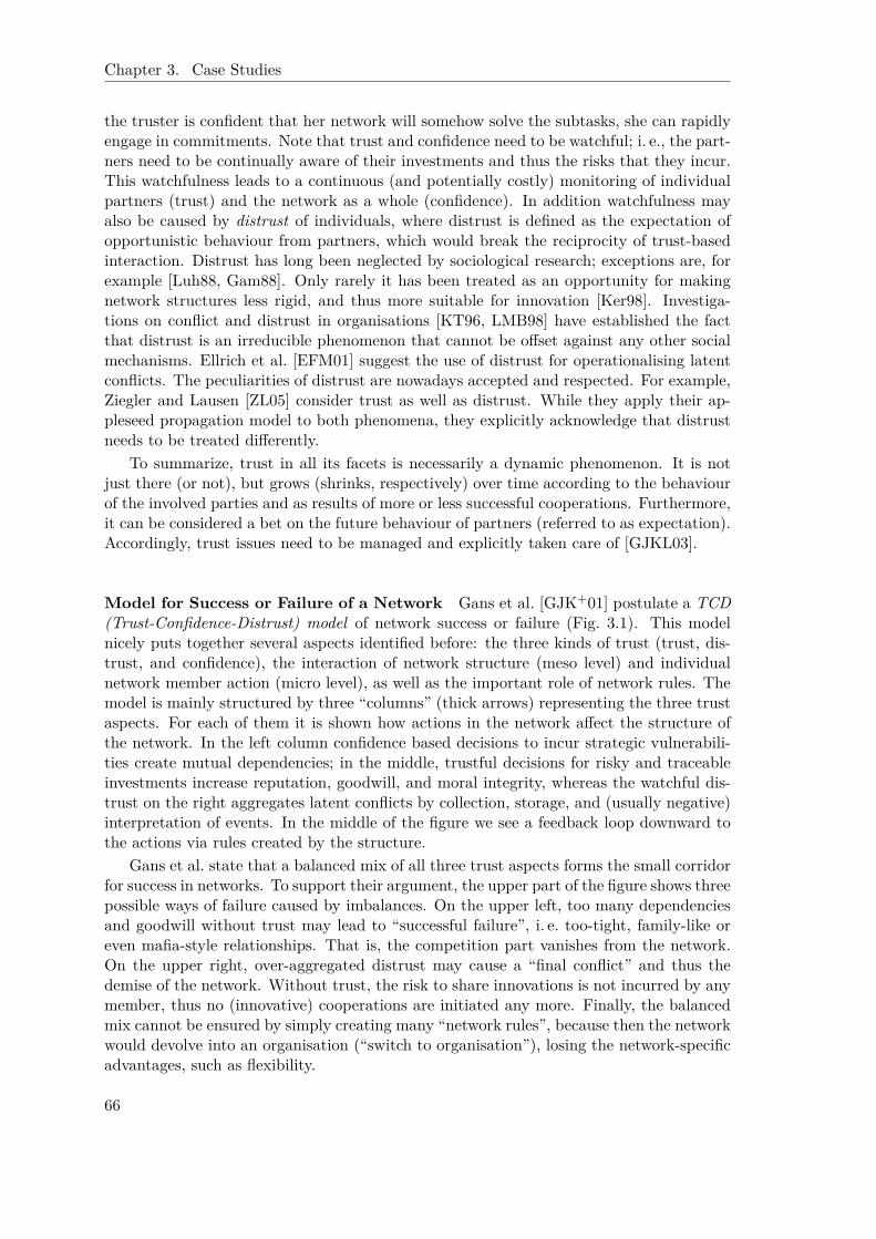
Chapter 3. Case Studies
the truster is confident that her network will somehow solve the subtasks, she can rapidlyengage in commitments. Note that trust and confidence need to be watchful; i. e., the part-ners need to be continually aware of their investments and thus the risks that they incur.This watchfulness leads to a continuous (and potentially costly) monitoring of individualpartners (trust) and the network as a whole (confidence). In addition watchfulness mayalso be caused by distrust of individuals, where distrust is defined as the expectation ofopportunistic behaviour from partners, which would break the reciprocity of trust-basedinteraction. Distrust has long been neglected by sociological research; exceptions are, forexample [Luh88, Gam88]. Only rarely it has been treated as an opportunity for makingnetwork structures less rigid, and thus more suitable for innovation [Ker98]. Investiga-tions on conflict and distrust in organisations [KT96, LMB98] have established the factthat distrust is an irreducible phenomenon that cannot be offset against any other socialmechanisms. Ellrich et al. [EFM01] suggest the use of distrust for operationalising latentconflicts. The peculiarities of distrust are nowadays accepted and respected. For example,Ziegler and Lausen [ZL05] consider trust as well as distrust. While they apply their ap-pleseed propagation model to both phenomena, they explicitly acknowledge that distrustneeds to be treated differently.
To summarize, trust in all its facets is necessarily a dynamic phenomenon. It is notjust there (or not), but grows (shrinks, respectively) over time according to the behaviourof the involved parties and as results of more or less successful cooperations. Furthermore,it can be considered a bet on the future behaviour of partners (referred to as expectation).Accordingly, trust issues need to be managed and explicitly taken care of [GJKL03].
Model for Success or Failure of a Network Gans et al. [GJK+01] postulate a TCD(Trust-Confidence-Distrust) model of network success or failure (Fig. 3.1). This modelnicely puts together several aspects identified before: the three kinds of trust (trust, dis-trust, and confidence), the interaction of network structure (meso level) and individualnetwork member action (micro level), as well as the important role of network rules. Themodel is mainly structured by three “columns” (thick arrows) representing the three trustaspects. For each of them it is shown how actions in the network affect the structure ofthe network. In the left column confidence based decisions to incur strategic vulnerabili-ties create mutual dependencies; in the middle, trustful decisions for risky and traceableinvestments increase reputation, goodwill, and moral integrity, whereas the watchful dis-trust on the right aggregates latent conflicts by collection, storage, and (usually negative)interpretation of events. In the middle of the figure we see a feedback loop downward tothe actions via rules created by the structure.
Gans et al. state that a balanced mix of all three trust aspects forms the small corridorfor success in networks. To support their argument, the upper part of the figure shows threepossible ways of failure caused by imbalances. On the upper left, too many dependenciesand goodwill without trust may lead to “successful failure”, i. e. too-tight, family-like oreven mafia-style relationships. That is, the competition part vanishes from the network.On the upper right, over-aggregated distrust may cause a “final conflict” and thus thedemise of the network. Without trust, the risk to share innovations is not incurred by anymember, thus no (innovative) cooperations are initiated any more. Finally, the balancedmix cannot be ensured by simply creating many “network rules”, because then the networkwould devolve into an organisation (“switch to organisation”), losing the network-specificadvantages, such as flexibility.
66

3.1. Case Study 1: Inter-Organisational Networks
Figure 3.1: The three trust columns (adapted from [GJK+01])
Simulation and High-Level Analysis
Due to the importance of dynamic issues as mentioned before already the project proposalfor the DFG priority program on Socionics has identified the need to run simulations. Inaddition, any meaningful analysis of simulation data (situations, runs, traces, ...) requiresappropriate high-level analysis support. First and foremost, simulations are supposed tohelp understanding the nature of inter-organisational networks, especially in regard to therole of trust. Various simulation scenarios can be investigated, for example, in regard tothe question whether trust, distrust, and confidence really are sufficient to capture thetrust dimension. Once an understanding of inter-organisational networks is established,the simulations can also be used to support individual members as well as the governanceof the network as a whole (the meso level). The latter helps, for example, to answerthe question of what is the most appropriate set of network rules in the current situation.Answering such questions asks for support in regard to the analysis of simulation data suchas initial and intermediate situations, simulation traces etc. It must be possible to searchsuch data for dedicated patterns, for example, social patterns such as hubs, structuralfeatures like cohesion, equivalence or power relationships, and the like [DF99]. Also datamining [HK06] or time-series analysis [Shn09] could provide valuable information as dospecialized analysis, for example, in regard to security [GMMZ05a] or simply specificationdebugging [FLP+04].
To tackle these issues we build on the predecessor work on SNet [GJKL03, GJLS05,Gan08] that has already been introduced in Chap. 2.1.5.
67
Chapter 3. Case Studies
3.2 Case Study 2: Control Systems Development
The second case study concerns the field of control systems development. Control prob-lems [Lun03] occur in settings where interaction and control of real world behaviour isasked for. A control problem has two major components: the controlled system, for ex-ample, a set of interconnected tanks, an engine, etc. and the controller. The task of thecontroller is to continuously compare and adapt the current value(s) of the controlled sys-tem to some desired value(s). For this purpose, the controller is connected to sensors thatdeliver information on the current situation of the controlled system and actuators to takeinfluence on the controlled system. Furthermore, there is usually some kind of (possiblychanging) set point information about what is a desired behaviour or situation. For a tanksystem as mentioned above, the control problem might be to ensure a particular level (the‘set point information’) of fluids in all or some of the tanks. Sensors report the level inthe different tanks; actuators are inlets and outlets than can be opened or closed by thecontroller. Disturbances in this setting are caused, for example, by inlets and outlets thatare not under the control of the system, for example, a natural supply such as a river orrain.
The most important characteristic of a control problem and the source of its inherentcomplexity is the closed feedback loop that results from the coupling between controlledsystem and controller via sensors and actuators. Any action taken by a controller is againobserved by it. On the one hand, this provides the basis for the power of controllers in thatthe controller can itself assess the effect of its actions including uncertainties caused bydisturbances. On the other hand, suitable measures have to be taken to avoid undesirablebehaviours such as oscillations due to overmodulation.
Engineers have developed many different solutions to control problems starting withpurely mechanistic, hydraulic etc. approaches to nowadays most often electronic controllersthat also include or are even completely realized in software, for example, on electroniccontrol units (ECUs) within the automotive domain [Bro06]. When developing software-based controllers two disciplines meet that have evolved rather independently from eachother: software engineering and control system engineering. The resulting problems areaddressed in the project ZAMOMO (funded by the BMBF under grant no. 01 IS E04)aiming at the complementing integration of software design and controller design. For therequirements engineering part, the results of this research effort are reported in this thesis.
3.2.1 Examples
Within the ZAMOMO project, controller development has been addressed mainly in regardto engine controllers and sub components thereof (such as a rail pressure controller). As asecondary application field, we looked at the experiences of the project partner EmbeddedSystems Lab (RWTH Aachen University) concerning autonomous driving, in particularan electronic parking assistant.
Engine Controller
The driver of a car specifies a desired velocity implicitly and indirectly via the positionof the accelerator (set point). But only the engine controller within the electronic controlunit computes the appropriate amount of fuel as well as the best point in time for injec-tion and ignition. Combustion engines nowadays have to perform well in regard to severalaspects such as fuel consumption, power provisioning, exhaust gas emissions, reliability,
68

3.2. Case Study 2: Control Systems Development
Figure 3.2: Air path in a diesel combustion engine (adapted from [DHH+08])
etc. [DHH+08]. Advanced techniques are needed to tackle these requirements. For exam-ple, current controllers for diesel engines do not only control injection pressure and time.Exhaust gas recirculation (EGR) allows to reintroduce exhaust gas to reduce the emissionof carbon dioxide and similar environmentally harmful particles. Another opportunityis given by turbo charging (TC). Powered by exhaust gas a turbo charger compressesthe fresh air so that more air can be treated per combustion cycle. This increases theperformance of the engine.
Figure 3.2 shows a schematic overview of the air path in a modern diesel engine. Inthe middle of the picture you can see two parallel cylinder rows that are served from acommon fresh air feeding system (lower part). The exhaust gas path is shown in the upperpart of the figure. In this concrete engine, each row has an exhaust gas recirculation of itsown (left and right of the row) that consists of a cooler and a valve to adjust the amountof exhaust gas that is fed back into the fresh air supply. The remaining exhaust gas is usedto power the turbo charger. Here a variable geometry turbine (VGT) allows to influencehow much effect the turbo charger takes on the fresh air compression.
Unfortunately, these two systems, EGR and TC (VGT), are coupled, this is theycannot be treated independently, but mutually interfere with each other. On the onehand, the position of the variable geometry turbine affects the pressure in the exhaust gasrecirculation system and thereby the amount of exhaust gas that can be reintroduced. Onthe other hand, the amount of reintroduced exhaust gas influences the exhaust gas flowthrough the turbo charger and thus in the end the boost pressure that can be achievedin the fresh air part. Accordingly, advanced controller designs are needed to tackle suchcomplex multi value control problems [Mac02, RRA+05, Ric05].
69

Chapter 3. Case Studies
pump
common rail
injectors
Figure 3.3: Common rail pressure control problem (adapted from [SDH+08])
Rail Pressure Controller
As a simpler sub problem, we also investigated the control problem concerned with thepressure of a common rail within such a diesel engine [SDH+08]. Figure 3.3 shows again aschematic view of the problem. The overall goal is to have a rather stable pressure withinthe common rail so that each opening of an injection valve has a defined and predictableeffect in regard to the amount of fuel that is emitted into a cylinder. But each suchinjection is in itself a disturbance to this control problem since it causes a drop of thecommon rail’s pressure. With the help of a pump, the controller needs to reestablish thecorrect pressure before the next injector opens.
Parking Assistant
The third example is concerned with higher-level driver assistance systems. Next to basicsystems like the electronic stability program (ESP), more advanced systems like adaptivecruise control or parking assistants are in development or even already available as packagesfor current series-production vehicles.
The Embedded Systems Lab at RWTH Aachen University has developed a fully au-tomatic parking assistant for their experimental car (ruler 1:5) [Meh06]. As visualized inFig. 3.4 once activated the car searches for a parking lot of suitable size by checking thedepth on the right side (in Germany) via a distance sensor (e. g. an ultra-sonic sensor) andintegrating the values over the covered distance. If a lot with a suitable size is found, thedriver is informed and can start the parking process. The controller computes a suitabletrajectory and then parks the car fully automatically. There are also semi-automatic sys-tems at the market, where the controller computes the trajectory and moves the steeringwheel but the driver still has to accelerate and brake.
As with any autonomous feature, severe security and reliability aspects needs to betaken into account. For example, a detection of suddenly appearing obstacles during theparking manoeuvre is mandatory for fully automated systems. On the other hand, sucha system also contributes to the comfort and partially also to the safety while driving acar. It can even be considered that there is an environmental contribution, since studieshave shown that drivers usually do not correctly assess a parking lot as suitable; mostoften a lot is considered to be too small by mistake and thus leads to a bad utilization ofparking places in congested urban areas and thus to an unnecessary continuation of thelot search [Zwe06].
70
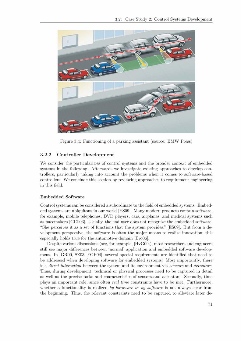
3.2. Case Study 2: Control Systems Development
Figure 3.4: Functioning of a parking assistant (source: BMW Press)
3.2.2 Controller Development
We consider the particularities of control systems and the broader context of embeddedsystems in the following. Afterwards we investigate existing approaches to develop con-trollers, particularly taking into account the problems when it comes to software-basedcontrollers. We conclude this section by reviewing approaches to requirement engineeringin this field.
Embedded Software
Control systems can be considered a subordinate to the field of embedded systems. Embed-ded systems are ubiquitous in our world [ES09]. Many modern products contain software,for example, mobile telephones, DVD players, cars, airplanes, and medical systems suchas pacemakers [GLT03]. Usually, the end user does not recognize the embedded software.“She perceives it as a set of functions that the system provides.” [ES09]. But from a de-velopment perspective, the software is often the major means to realize innovation; thisespecially holds true for the automotive domain [Bro06].
Despite various discussions (see, for example, [HvG09]), most researchers and engineersstill see major differences between ‘normal’ application and embedded software develop-ment. In [GR00, SZ03, FGP04], several special requirements are identified that need tobe addressed when developing software for embedded systems. Most importantly, thereis a direct interaction between the system and its environment via sensors and actuators.Thus, during development, technical or physical processes need to be captured in detailas well as the precise tasks and characteristics of sensors and actuators. Secondly, timeplays an important role, since often real time constraints have to be met. Furthermore,whether a functionality is realized by hardware or by software is not always clear fromthe beginning. Thus, the relevant constraints need to be captured to alleviate later de-
71
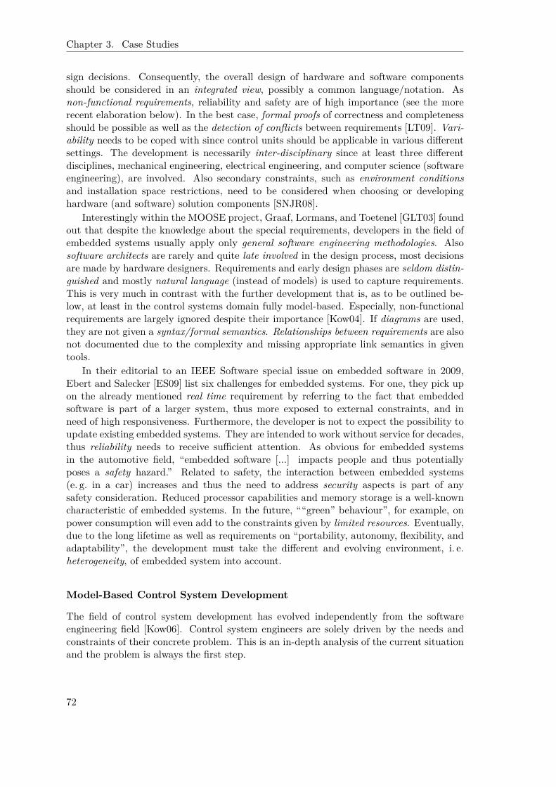
Chapter 3. Case Studies
sign decisions. Consequently, the overall design of hardware and software componentsshould be considered in an integrated view, possibly a common language/notation. Asnon-functional requirements, reliability and safety are of high importance (see the morerecent elaboration below). In the best case, formal proofs of correctness and completenessshould be possible as well as the detection of conflicts between requirements [LT09]. Vari-ability needs to be coped with since control units should be applicable in various differentsettings. The development is necessarily inter-disciplinary since at least three differentdisciplines, mechanical engineering, electrical engineering, and computer science (softwareengineering), are involved. Also secondary constraints, such as environment conditionsand installation space restrictions, need to be considered when choosing or developinghardware (and software) solution components [SNJR08].
Interestingly within the MOOSE project, Graaf, Lormans, and Toetenel [GLT03] foundout that despite the knowledge about the special requirements, developers in the field ofembedded systems usually apply only general software engineering methodologies. Alsosoftware architects are rarely and quite late involved in the design process, most decisionsare made by hardware designers. Requirements and early design phases are seldom distin-guished and mostly natural language (instead of models) is used to capture requirements.This is very much in contrast with the further development that is, as to be outlined be-low, at least in the control systems domain fully model-based. Especially, non-functionalrequirements are largely ignored despite their importance [Kow04]. If diagrams are used,they are not given a syntax/formal semantics. Relationships between requirements are alsonot documented due to the complexity and missing appropriate link semantics in giventools.
In their editorial to an IEEE Software special issue on embedded software in 2009,Ebert and Salecker [ES09] list six challenges for embedded systems. For one, they pick upon the already mentioned real time requirement by referring to the fact that embeddedsoftware is part of a larger system, thus more exposed to external constraints, and inneed of high responsiveness. Furthermore, the developer is not to expect the possibility toupdate existing embedded systems. They are intended to work without service for decades,thus reliability needs to receive sufficient attention. As obvious for embedded systemsin the automotive field, “embedded software [...] impacts people and thus potentiallyposes a safety hazard.” Related to safety, the interaction between embedded systems(e. g. in a car) increases and thus the need to address security aspects is part of anysafety consideration. Reduced processor capabilities and memory storage is a well-knowncharacteristic of embedded systems. In the future, ““green” behaviour”, for example, onpower consumption will even add to the constraints given by limited resources. Eventually,due to the long lifetime as well as requirements on “portability, autonomy, flexibility, andadaptability”, the development must take the different and evolving environment, i. e.heterogeneity, of embedded system into account.
Model-Based Control System Development
The field of control system development has evolved independently from the softwareengineering field [Kow06]. Control system engineers are solely driven by the needs andconstraints of their concrete problem. This is an in-depth analysis of the current situationand the problem is always the first step.
72

3.2. Case Study 2: Control Systems Development
controller
disturbances
–controlled
systemset point input
feedback
control deviation
actuating variable controlled variable
sensor measure
Figure 3.5: Action diagram view of a generic control cycle
Action Diagram A simple, graphical representation, so called action diagram, is quitehelpful in this regard. Figure 3.5 shows the most basic and generic representation of acontrol problem (to be found in any textbook on the topic, e. g. [MSF05]). The set pointinformation joining in from the left (i. e. from outside) is combined with the measuredsensor information. The resulting control deviation is the input to the controller thatcomputes the suitable reaction on the actuating variable. This again is affecting thecontrolled system as also do any disturbances. Accordingly, the effect on the controlledvariable might be different and is thus measured to be fed back into the control cycle inputas explained in the beginning.
Accordingly, there are only two essential concepts in action diagrams: blocks andsignals.
• A block (also called a “system”) captures some behaviour or function – most gen-erally the controller or the controlled system as in our example above. But usuallymore fine-granular models with a hierarchy of blocks and sub blocks are designed.Graphically a block is denoted by a rectangular.
• Blocks are connected to each other via signals. This is the output signal(s) of oneblock is input to (an) other block(s). Accordingly, in the graphical representationan arrow indicates the direction of the signal flow.
• Furthermore, signals can branch at a branching point – graphically represented as afilled circle (in Fig. 3.5 see after the “controlled system”) – and
• signals can be combined in an addition point – graphically denoted by an emptycircle (in Fig. 3.5 before “controller”). Here attached operators can provide detailssuch as whether the signals are to be added or subtracted from each other.
Controller Design When approaching control problems, the engineers typically takea purely functional view. They focus the characteristics of the concrete problem and itsconstraints as well as resulting functional aspects of the controller, for example, the (non-) occurrence of overshooting or oscillations, performance specifications on settling time,etc. Non-functional requirements that cannot easily be represented as mathematical con-straints are usually ignored. This clashes with typical software development approachesas elaborated later on. In particular control engineers expect the solution to a controlproblem to be derivable from a sufficiently complete and sound mathematical approx-imation of the problem and its constraints. Especially, in the most common situationwhere a so-called PID controller1 is sufficient, mathematical methods exist that allow
1A PID controller consists of three members: a proportional (P) member, an integrative (I) member,and a differential (D) member.
73

Chapter 3. Case Studies
to indeed derive the relevant solution parameters [MSF05]. For more complex controlproblems (e. g. multi value control problems such as the combined EGR and TC controlproblem from the previous section), the engineering task becomes again more individualand complex [Mac02, RRA+05, Ric05].
Simulation is the most important support for control system engineers. According toLunze [Lun03], in industrial practice a controller is developed in five steps. To understandthe controlled system, for example, an engine for which a controller is to be developed,the engineers build up an action diagram that captures the interactions and behaviourof the main components of the controlled system. This model helps identifying actuatingand controlled process variables, i. e. the controlled system’s properties in the second step.In the third phase, the controller’s functionality is designed. The fourth step concernssimulating the whole control cycle in crucial situations. If it behaves as expected anddemanded, the controller is finally implemented and put into operation in the last step.The last step includes the tedious configuration of parameters etc. to accommodate thecharacteristics of the real world controlled system, e. g. a concrete engine.
Rapid control prototyping (RCP) environments are well established in control sys-tems engineering [AB06]. They encompass modelling and simulation tools such as Mat-lab/Simulink [Mat10] that mainly builds on action diagrams and has already been cov-ered in more depth in Chap. 2.4, but also dedicated hardware, for example, from dSpace(http://www.dspace.com), to perform real time experiments. The latter is supported byappropriate software, this is according code generators, for example, the Realtime Work-shop again from The Mathworks. Altogether these environments allow the engineer tovalidate the controller design at early development stages.
Software-based Controllers This is on the one hand developing controllers requires alot of knowledge in control theory. Experiences and knowledge in physics, mathematics,and control theory are required to design a stable controller with good performance. Onthe other hand, nowadays most controllers are realized in software [Bro06, Kow06]. Thisis advanced software techniques have to be used to implement safe, reusable, and efficientsolutions. But the development of controllers is still driven by hardware-oriented controlsystem engineers. Due to their focus on functional aspects of the concrete problem setting(as described above), they do currently not take software issues into account such asconsiderations on enhancing scalability and reusability. Also non-functional requirementsare in general not treated as first-class requirements as already remarked in the sectionon ‘Embedded Software’. Neither their elicitation nor their capture has received sufficientattention [Kow04].
Furthermore, the collaboration of the two disciplines currently suffers from discrepan-cies regarding vocabulary and views on the object to develop [KAJ+05]. For example, fora software engineer a model is usually only a conceptual abstraction of the software to bedeveloped. In contrast, the control system engineer mainly builds mathematically precisemodels of the controlled system (the environment in the view of a software designer) and es-pecially expects each model to be executable (within simulations). Accordingly, the designprocesses are currently not harmonised. As indicated already when discussing embeddedsoftware in general, software architects are involved into the design rather late [GLT03].In fact, they are only foreseen to efficiently implement a control algorithm on a given plat-form respecting the limited resources of the given device. A possible reciprocal fertilisationis thus prevented.
Therefore, the combination of knowledge of both domains is necessary to design com-
74

3.2. Case Study 2: Control Systems Development
petitive control software. Steps to a better integration have been made within the projectZAMOMO [KAJ+05] and are reported in this thesis with a focus on the requirementsengineering phase.
Requirements Engineering for Control Systems
As mentioned before (see discussion of embedded software in Chap. 3.2.2), in contrast tothe further development requirements engineering for control systems is not yet model-based. Instead text-based approaches via tools such as DOORS [IBM09a] or Requi-sitePro [IBM09b] are predominating.
Text vs. Model In a broader context than the integration of software and controlsystem engineering, systems engineering [GM57] is concerned with the interdisciplinarycoordination of requirements for building large-scale complex systems. In this context,requirements management has received a lot of attention [BPKR09]. Accordingly, manybig enterprises that develop embedded software such as Siemens, Daimler etc. employ so-phisticated requirements tools such as DOORS [IBM09a] or RequisitePro [IBM09b] (bothnow IBM products). They support a textual approach to requirements capture by clearlydefining processes and document structures. In parts they even allow for the interconnec-tion with UML based models such as uses cases or sequence diagrams, but mainly onlyfor illustrative purposes. The text based presentation remains at the center of all toolfunctionality such as impact analysis or traceability support [Gon05]. While the lattercapability is typically a strong point of the above mentioned tools, it is rarely used toan enterprise’s benefits [GLT03]. This is mainly due to the “need to manually establishand maintain traceability relations, and the difficulty to achieve these tasks automati-cally” [MGP08].
The insufficient connection between text-centered tools and the later model-based de-velopment was also one of the drivers for the development of SysML [OMG07b]. SysML isa UML based modelling language for systems engineering. Besides other extensions to, forexample, better cope with hardware-related issues, SysML introduces a new requirementsdiagram. A single new modelling concept (“requirement”) allows to represent (textual)requirements in SysML models. Furthermore, means to decompose and derive require-ments, to specify a degree of satisfaction (by specific design variants), as well as to verifyrequirements via test components are available. On the other hand, this new diagramdoes not overcome that the basic approach to requirements still is text-based. Accordingto the description of its developers, requirements diagrams are only intended as a bridgeto existing text-based tools, thus to alleviate their interaction. Furthermore, Dick andChard [DC04] point out that non-functional issues are not suitably represented in SysML.
There are more researchers targeting the problem of a mainly textual requirementsdocumentation but a mostly model-based further development [CFB04, KCFG04]. Butwhile they give more emphasis to models they still propose a dual approach where a UML-based information model is set in relation to text-based requirements documents. Theirarguments for sticking with text-based requirements documents encompass insufficienciesof current modelling approaches and alleviated reuse of textual descriptions. This opinionis in contrast to our experiences with requirements modelling via goal-driven approaches(see Chap. 1.1). And again, the dual approaches mentioned above have especially defi-ciencies in regard to the consideration of non-functional issues.
Geisberger and Schätz [GS07] addressed model-based requirements management and
75
Chapter 3. Case Studies
analysis in the context of automotive embedded software. But their particular focus hasbeen functional system requirements. Grounded in a requirements engineering productmodel [GBB+06] that serves as a reference model, they developed the tool AutoRAID.It has import functionality for text-based requirements and is tightly connected to thedesign phase. Many formalisms that have been developed for the later design phase arealso applied to the capture of functional requirements. The only major extensions concernsthe admittance of modelling high-level business goals.
Connection to Later Model-Based Development The textual approach to require-ments capture is in contrast with the nearly fully model-based further development incontrol system engineering as elaborated above. This makes a direct link between require-ments and implementation hard to maintain. Accordingly, once a model-based approach torequirements engineering as promoted above is adopted, the only challenge that remains isto establish a model-based connection to the rapid control prototyping environments suchas Matlab/Simulink [Mat10] that are employed in this domain during later developmentphases. None of the approaches mentioned above currently accounts for this challenge. Ifthey provide a connection at all, it is a connection to an architectural UML model, whichis simply not typical for control system development.
3.2.3 RE for Small- and Medium-Sized Enterprises
Regarding the typical development setting, it has turned out that within the control systemdomain project-driven small- and medium sized enterprises (SMEs) are the main driversfor innovation [SNJ+08].
Characteristics of Project-Driven SMEs
The particularities of requirements engineering at small and medium-sized enterpriseshave explicitly been considered by Kamsties et al. [KHS98]. While they highlight someimportant characteristics of software development at SMEs such as overwhelming day-to-day business, large demand for know-how transfer etc., in their study only one enterpriseperformed customer-oriented (thus project-driven) development – the key characteristicthat is to be addressed here. The ReqMan project [DAE07] also targets SMEs. Buthere the emphasis is on how improvements of the development process can be achievedgradually. Additionally, they explicitly want to remain domain independent – an idea thatwe have found to be fully inadequate in our setting (see below) – even though throughoutthe project they identified the need for considering the domain context.
The following three key success factors for project-driven small and medium-sized en-terprises (SMEs) have been identified [SNJ+08]:
• Much of the power and promptness of SMEs to react to market changes and chancesis due to (output) flexibility [FK91]. Due to the smaller size there are fewer estab-lished procedures and no large teams that require tedious and complex cooperationgovernance. Instead the developers usually communicate informally. Thus, barriersto adopt recent trends and new ideas are quite low.
• Potentially as a result of the previous issue, innovation is seen as another impor-tant feature and success factor of SMEs. Especially politicians often emphasize the
76
3.2. Case Study 2: Control Systems Development
driving innovative force of SMEs (in Germany) and thus particularly set up pro-grams to support these enterprises and foster their innovativeness (see, for example,[BMB07]).
• Eventually, customer-orientation follows from both issues mentioned above. Dueto their innovativeness and flexibility, SMEs can address customer problems moreeasily and thoroughly. This is also the reason why larger enterprises such as a majorcar company approach an SME to let develop a particular solution, for example, acontroller for an engine that does not fit into their current system and development‘landscape’.
The common approach to address domain knowledge-intensive problems by setting upproduct lines [PBvdL05] is inappropriate for project-driven SMEs due to the absence of“some domain stability” [KMSW00]. Knauber et al. use the latter term in their work onproduct line approaches for SMEs to characterize a necessary prerequisite that in turnforces the SME to explicitly reduce flexibility and customer-orientation, exactly two of thethree main characteristics that we are concerned with here and intend to support.
RE during Offer Development
The three identified characteristics flexibility, innovation, and customer-orientation intro-duced above have severe impacts on the development process. As already mentioned forthe embedded system domain in general (see Chap. 3.2.2, in particular [GLT03]), the de-velopers in this field typically have to integrate the elicitation of requirements with a firstsystem design. Accordingly, timing and cost constraints are very tight.
This is especially true for project-oriented SMEs. Their requirements engineering ac-tivities are usually part of the offer development which is typically unpaid but nonethelesshas to end with a first system design as the core part of the offer to be returned to thecustomer. Neither expensive tools (see DOORS [IBM09a] or RequisitePro [IBM09b] men-tioned before) nor the heavy weight processes associated with these are affordable forthem. Consider the following short scenario from industrial practice in the control systemdomain for an illustration. Assume a major car company contacting a number of suppli-ers to provide an offer to develop a control system for a new engine. The car companydelivers a specification of the engine and the list of required control functionality. Toprepare the offer, the supplier first needs to specify the requirements on the requestedcontroller from a developers point of view. In a second step she prepares a system designin order to calculate the costs for the development. To keep the costs low and thus to winthe contract the SME must reuse as many software artifacts as possible from her alreadydeveloped control solutions. The main challenge in this regard is to avoid the followingtwo undesirable situations:
• Firstly, existing reusable artifacts are not found due to the huge set of alreadyfinalised projects. Since the time frame for offer development is short, the engineeris not able to investigate all projects. If she fails to identify the relevant projects, theoffer will include the re-development of existing artifacts and therefore will becomemore expensive than necessary; the contract might be given to another supplier.
• Secondly, the offer bases on existing artifacts which the subsequent detailed designphase – after (!) being awarded the task – identifies to be actually not reusable.The necessary development of new artifacts leads to more work than planned. The
77
Chapter 3. Case Studies
calculation of this unreliable offer becomes inappropriate and causes a loss withinthat project or can even challenge the SME’s economic viability.
Specific Needs of Project-Driven SMEs during RE
To alleviate reuse as well as to cope with the resulting complexity of very many individ-ual customer versions and variants, project-driven SMEs need means to keep track andinternally make available their extensive knowledge [KHS98, LEB+05], since it is their“core asset” [Bjø09]. Therefore approaches that do not put enough emphasis on domainknowledge (e. g. [DAE07]) are not adequate for project-oriented SMEs. Furthermore, thisknowledge must be easily adaptable and extensible in order to evolve with new innovationsand gained experiences. To decide about reuse it is important to be able to compare therequirements of a current project with the point of departure that has led to solutionswithin earlier projects. This allows to reduce the search space in order to properly inves-tigate all relevant projects within the given time constraints. The situation is complicatedfurther if the business of the SME is interdisciplinary as in our control system setting.In this case, the knowledge that needs to be captured, stored, and made accessible ischaracterized by a high degree of heterogeneity. The SME is in need of advanced analysismeans to assess how various different design alternatives contribute to the fulfillment ofnon-functional issues.
All in all, the following issues need to be supported during requirements engineeringat project-driven SMEs:
• a fast and sufficiently encompassing, interdisciplinary requirements capture,
• easy access to domain knowledge,
• efficient means to update and extend, this is evolve, the collected domain knowledge,
• project-oriented work, this is easy access to experiences from earlier projects withother customers while respecting the particularities and individuality of each newcustomer, and
• a (reliable) identification of reusable artifacts.
3.2.4 Method Support for Control System Development
As mentioned before control system development has a long tradition. But the need toincorporate software development and in particular (non-functional) requirements mod-elling approaches has arisen only recently with the advent of software-based control sys-tems [Kow06]. The goal of the interdisciplinary ZAMOMO project (BMBF project, grantno. 01 IS E04) was the design of a method that combines the existing, model-based devel-opment approaches in the two disciplines. This is we have basically applied a “paradigm-based strategy” in the nomenclature of situational method engineering (see Chap. 2.1.1).
Product Model
At the level of the product model, we combine two up to now completely independentrepresentations. For one, we need to be consistent with the established development pro-cedures in the control system domain by providing an action diagram based representationas it is common for the most dominating tools such as Matlab/Simulink.
78

3.2. Case Study 2: Control Systems Development
Figure 3.6: ZAMOMO integrated development process [PP09]
The major extension concerns the establishment of a model-based requirements cap-ture [SDH+08]. i* [Yu95] has been chosen for this purpose. The reasons for the con-sideration of this formalism are the two basic features of i*, agent- and goal-orientation,that are in particular helpful to overcome interdisciplinary boundaries. “Goals have longbeen recognized to be the essential components involved in the requirements engineer-ing (RE) process.” [vL01] Accordingly, they are also suitable as a common ground fordifferent disciplines. Secondly, disregarding any major fundamental distinctions at the de-tailed level, any stakeholder, environment, legacy, or system-to-be-developed component(irrespective whether physically, hardware, or software motivated) can be represented byan agent [Yu01] and thus be related to other components. Again, this concept is simpleenough to be amenable for any discipline and thus suited to prepare a common understand-ing of a problem. Thirdly, with softgoals i* provides an established, well understoodmeans to cope with non-functional requirements that have so far been neglected duringcontrol system development. Surprisingly, the domain of control system development doesnot ask for major adaptations of the i* modelling framework [SDH+08]. The basic mod-elling concepts of i* accommodate also the needs of this field. A minor exception to thisfinding is the importance of “sensors” and “actuators”. While these can basically be rep-resented by resource dependencies, we have developed additional support for theirautomated identification in models. The details are elaborated as an extension of the i*framework in Appendix A.1.2.
The Integrated Development Process
An integrated development process has been set up that addresses the needs of controltheory as well as software engineering (see Fig. 3.6). As a major characteristic it stressesthe importance of simulation and thus foresees this possibility in any of the four proposeddevelopment phases. Model based requirements engineering (RE) is a totally new stepin controller development intended to overcome the shortcomings of textual approaches.It allows for the combined investigation of software and control requirements. The next
79

Chapter 3. Case Studies
development step, model in the loop (MIL), refers to the requirements in order to createa simulation model in a typical development environment such as Matlab/Simulink. Toarrive at a consistent and enduring model base, project partners have introduced a newmodelling approach that uses an abstraction layer to rapid control prototyping (RCP)systems, in particular to the available sensors and actuators. To run hardware in theloop tests, this is tests where the controller is already running on the intended hardwareplatform (or at least a rather close real-time development hardware), a real-time model ofthe controlled system needs to be prepared. This allows to test the controller model earlywithout harming the possibly expensive real hardware. At the downside, this requiresa tedious parameterization of the real-time model in order to correctly reflect real-timebehaviour. Again, the existing model-based approaches are intended to be referred to inorder to alleviate the work here. Eventually, the controller needs to be brought to theparticular real-time hardware, utilising existing tool support such as the Realtime Work-shop by The Mathworks. A testbed installation is then established to finally combine thecontroller hardware and the real controlled system in order to finalize the parameterisationand conclusively validate the developed solution. The main development steps are fromleft to right and supported by automated transformations in the spirit of the Model DrivenArchitecture (OMG) [OMG03]. Still the process accounts for refinement and improvementcycles. While the entire development process has been presented here, the focus of thethesis at hands will be on the integration of the new model-based requirements engineeringphase with the more established later model-based development.
3.3 Common Issues of the Two Case Studies
Despite the rather different application fields of the two case studies – abbreviated bythe short names of the corresponding research projects SNet for the support of inter-organisational networks and ZAMOMO for requirements engineering within control systemdevelopment – several common issues can be identified.
3.3.1 Static Issues
Table 3.1 summarizes the identified static issues.
Interdisciplinarity
SNet ZAMOMOFor SNet interdisciplinarity is part of theinvestigation by design. Computer sci-ence models and methods are researchedin regard to the help they can provide tosociologists to understand and supportinter-organisational networks.
Also for control problems the require-ments in regard to interdisciplinarity areobvious, since the insufficient interactionof control system engineers and softwareengineers is the main driver of the wholeproject.
For both case studies, interdisciplinarity is addressed by referring to a multi-perspectivebased approach that allows to integrate different views of different disciplines. Addition-ally, both use i*. Due to the few and simple concepts, in particular agents, goals, anddependencies, i* is able to establish a common understanding and thereby overcomesdisciplinary boundaries.
80
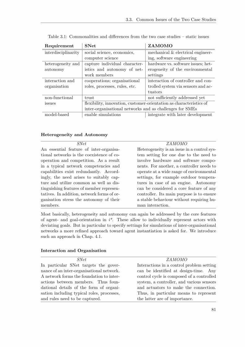
3.3. Common Issues of the Two Case Studies
Table 3.1: Commonalities and differences from the two case studies – static issues
Requirement SNet ZAMOMOinterdisciplinarity social science, economics,
computer sciencemechanical & electrical engineer-ing, software engineering
heterogeneity andautonomy
capture individual character-istics and autonomy of net-work members
hardware vs. software issues; het-erogeneity of the environmentalsettings
interaction andorganisation
cooperations; organisationalroles, processes, rules, etc.
interaction of controller and con-trolled system via sensors and ac-tuators
non-functional trust not sufficiently addressed yetissues flexibility, innovation, customer-orientation as characteristics of
inter-organisational networks and as challenges for SMEsmodel-based enable simulations integrate with later development
Heterogeneity and Autonomy
SNet ZAMOMOAn essential feature of inter-organisa-tional networks is the coexistence of co-operation and competition. As a resultin a typical network competencies andcapabilities exist redundantly. Accord-ingly, the need arises to suitably cap-ture and utilize common as well as dis-tinguishing features of member represen-tatives. In addition, network forms of or-ganisation stress the autonomy of theirmembers.
Heterogeneity is an issue in a control sys-tem setting for one due to the need toinvolve hardware and software compo-nents. For another, a controller needs tooperate at a wide range of environmentalsettings, for example outdoor tempera-tures in case of an engine. Autonomycan be considered a core feature of anycontroller. Its main purpose is to ensurea stable behaviour without requiring hu-man interaction.
Most basically, heterogeneity and autonomy can again be addressed by the core featuresof agent- and goal-orientation in i*. These allow to individually represent actors withdeviating goals. But in particular to specify settings for simulations of inter-organisationalnetworks a more refined approach toward agent instantiation is asked for. We introducesuch an approach in Chap. 4.1.
Interaction and Organisation
SNet ZAMOMOIn particular SNet targets the gover-nance of an inter-organisational network.A network forms the foundation to inter-actions between members. Thus foun-dational details of the form of organi-sation including typical roles, processes,and rules need to be captured.
Interactions in a control problem settingcan be identified at design-time. Anycontrol cycle is composed of a controlledsystem, a controller, and various sensorsand actuators to make the connection.Thus, in particular means to representthe latter are of importance.
81

Chapter 3. Case Studies
Interactions are well captured by i* dependencies. For the SNet setting, this repre-sentation is accompanied and refined by a more operational representation via SpeechActs [WF86] (see TCD method in Chap. 2.1.5). Sensors and actuators of a control prob-lem can be captured by according resource dependencies [SDH+08] (for supportiveextensions see Appendix A.1.2). Organisational aspects are dominating in the SNet casestudy and can be addressed via i* due to its ability to represent social aspects. This willbe exemplified in Chap. 5.1.4.
Non-Functional IssuesSNet ZAMOMO
Most apparently the SNet case study isconcerned with trust (distrust and confi-dence) related issues. In addition a ma-jor driver for the emergence of networksis their enhanced flexibility in combina-tion with their ability to foster continu-ous innovation. The latter is achievedby explicitly introducing disturbances:members cooperate and compete at thesame time; new members (or changednetwork rules) challenge established re-lationships and thus frequently triggerrenewals. Still the virtual factory ex-ample has emphasized that customer-orientation is another important aspect.
For control systems non-functional as-pects are of great importance, see, for ex-ample, reliability, safety, security [ES09],but have not yet received sufficient at-tention [GLT03, DC04, Gon05]. Beyondthat we have looked at the specific needsof small and medium-sized enterprises(see Chap. 3.2.3). They are successfulin their very project-oriented work dueto their flexibility, innovativeness, andcustomer-orientation. Heavy-weightedproduct-line approaches [PBvdL05] failto provide adequate support. Insteadtailorable knowledge based approachesmust be considered.
In general, non-functional aspects are addressed via the softgoal and contributionmodelling constructs of i*. This clearly improves the situation for control system develop-ment. Furthermore, softgoals are also suited to capture “control qualities” such as the“stability” of a control cycle (avoiding oscillating behaviour). Contribution links (andaccompanying supportive analysis) are of great value to consider now also the influence ofdifferent alternatives on these important features.
Flexibility, innovation, and customer-orientation receive attention in the two case stud-ies out of rather different considerations. In the SNet case study, the object of investigation– inter-organisational networks – is characterised by these features. The overall intentionof the method is to prove and elaborate these characteristics and to help identify successmeasures in this regard. In contrast, for the ZAMOMO case study these features char-acterise the applicants of our method, this is SMEs with a very project-oriented workingenvironment. Hence, we need to take these issues into account when developing adequatemethodological support (see Chap. 5.1).
Need for Model-Based Approaches
SNet ZAMOMOFor the SNet case study, the importanceof a model-based approach follows fromthe need to enable simulations that arein turn needed to address the essential,dynamic issues (to be elaborated below).
The major driver for model-based re-quirements engineering in control systemdevelopment is the fact that the later de-velopment is heavily based on (mathe-matical) models [AB06].
82

3.3. Common Issues of the Two Case Studies
Table 3.2: Commonalities and differences from the two case studies – dynamic issues
Requirement SNet ZAMOMOfluctuation andadaptation
network members join/leave;adapt network rules
[considered statically at designtime]
actor evolution model evolution of membersand consider in simulations
[considered statically at designtime]
simulation andhigh-level analysis
investigate inter-organisationalnetworks; analyse simulations
[simulations during later devel-opment]
evolving domainknowledge
[potentially make reusable net-work rules available]
SMEs need fast access to expe-rience knowledge, decide uponreuse, tackle evolution
The choice of a meta modelling approach toward method engineering (see Chap. 2.1) isthe main step toward continuous, model-based development. For the SNet case study, itenables the transformation toward agent-based simulations. For the ZAMOMO case study,the existing model-based approach is completed at the level of requirements engineering.Both concerned transformations are elaborated in Chap. 5.2.
3.3.2 Dynamic Issues
The major concern of this thesis is to address dynamic issues inspired by the two casestudies. Table 3.2 summarizes the identified issues.
Fluctuation and Adaptation
SNet ZAMOMOAs part of the core, flexible networkcharacter, in SNet we have to cope withthe fluctuation of network members aswell as the adaptation of network rules.Member leave or join the network andnetwork rules need to be adjusted to thecurrent “stage” of a network [PK05].
Fluctuation and adaptation are consid-ered in the control system setting stat-ically at design time. For example, theanticipation of changes in the environ-ment usually needs to be built in intothe controller by targeting a robust con-troller.
More dedicatedly than the predecessor work [Gan08], we address the fluctuation of mem-bers in inter-organisational networks, this is having enterprises join or leave the network.By more clearly separating between (generic) roles and particular instances (agents) duringactor modelling (Chap. 4.1), it becomes possible to introduce a new member or remove herat simulation run-time (Chap. 5.3). Furthermore, the explicit representation of networkrules (Chap. 5.1.4) alleviates the investigation of this major means to adapt and influencethe (successful) development of a network.
83

Chapter 3. Case Studies
Actor Evolution
SNet ZAMOMOKnowledge on how actors evolve shouldbe considered if available. This helps tobetter reflect the real world during sim-ulations.
Similar to “fluctuation and adaptation”,the control engineers are also aware ofchanges and evolution in the controller’senvironment, for example, due to wear-out. But yet it is sufficient to addressthese issues statically at design time.
i* is currently lacking the ability to represent evolving actors. Only snapshot situationscan be represented by indicating which roles are currently played by which agents.Hence, Chap. 4.2 introduces means to model how an agent can evolve along variousroles including conditions when to acquire (or lose) a (new) role. In order to eventuallybecome reflected in simulations, actor evolution must certainly also be considered duringtransformation (Chap. 5.2.4).
Simulation and Analysis
SNet ZAMOMOFor SNet, the entire modelling efforts arejust a pre-step to enable simulations ofinter-organisational networks in order toanalyse their dynamic features. Due tothe complexity of the setting, additionalsupport is required for the analysis of re-sulting simulation data.
In control systems engineering the im-portance of simulation for the develop-ment of controllers is undisputed, butnot yet established at the level of require-ments.
For the SNet case study, the simulation via ConGolog (Chap. 2.3) has already been atthe core of the predecessor work of Gans [Gan08]. Due to the extensions of the modellingmeans (see above), the transformation from i* to ConGolog had to be reconsidered (seeChap. 5.2.4). Beyond that more advanced support to analyse simulation runs has beenadded. Chapter 5.3 discusses how data mining, time series, and social network analysiscan be integrated into the method for analysis purposes such as the evaluation of a newset of network rules.2
2Originally, the ZAMOMO project was also intended to address simulations at the level of requirements.But up to now only minor first steps have been taken [PK09].
84

3.3. Common Issues of the Two Case Studies
Evolving Domain Knowledge
SNet ZAMOMODespite the more research oriented fo-cus of the SNet setting, it is conceiv-able that various modelling experiencesneed to be collected and made accessibleover time. In particular, various networkrules might be applicable in different set-tings. Yet, the focus of this case study ison the investigation of single individualnetworks.
The need to access, modify, and adaptdomain knowledge has become obviousin the ZAMOMO setting by consideringthe specific needs of SMEs. They ask fora fast, reliable requirements capture byexplicitly referring their particular do-main knowledge. This knowledge mustbe suitably integrated in their develop-ment process, for example to comparemodels to identify similar projects. Fur-ther on, we have to cope with changes tothis domain knowledge.
The need to collect, represent, (re-)use and evolve domain specific knowledge is addressedby developing according method support. Chapter 5.1 introduces the basic domain model-based approach while a similarity search is proposed in Chap. 6.1 and domain knowledgeevolution is addressed in Chap. 6.2.
3.3.3 Summary on Characteristics and Open Issues
Table 3.3 summarizes how the common issues that have been elicited before are addressedby existing work as well as various extensions within this thesis. As it becomes obviousfrom the “distribution” of the abbreviation letters, the static issues are to a large degreealready met simply by applying a model-based method engineering approach and the i*formalism in particular (F – foundations, Chap. 2.1 and Chap. 2.2). Only few modellingextensions (E, Chap. 4) to i* are proposed, this is “agent instantiation” (Chap. 4.1) and“actor evolution” (Chap. 4.2). This is due to their dynamic characteristics. Furthermore,we introduce a “domain model based requirements engineering” approach (Chap. 5.1)especially targeting the needs of SMEs. This integrates well with the general aim for“model-based approaches”, in particular model transformations (Chap. 5.2) to agent-basedsimulations and Matlab/Simulink. We also provide new high level analysis means forsimulations (Chap. 5.3). The consideration of “domain knowledge” adds explicit inter-project and thus requirements management concerned issues. In particular, it encompassesa similarity search on requirements models (Chap. 6.1) and techniques to cope with the(project-driven) evolution of domain knowledge (Chap. 6.2).
The rest of the thesis will tackle the identified dynamic issues by considering relatedi* modelling extensions in Chap. 4, dynamic issues related to a single project, this isdomain model-based capture, transformation, and analysis via simulations in Chap. 5,and eventually inter-project requirements management issues in Chap. 6.
85

Chapter 3. Case Studies
Table 3.3: Addressing the common issues of the two case studies
Requirement Addressed by ReferenceStatic issuesinterdisciplinarity multi-perspective methods, Chap. 2.1 (F)
i* (agents, goals) Chap. 2.2 (F)heterogeneity and i* (agents, goals), Chap. 2.2 (F)autonomy agent instantiation Chap. 4.1 (E)interaction and i* (dependencies), Chap. 2.2 (F)organisation sensor/actuator support App. A.1.2 (E)non-functional issues i* (softgoals, analysis) Chap. 2.2 (F)model-based method engineering Chap. 2.1 (F)
transformations (to ConGolog, Matlab) Chap. 5.2 (P)Dynamic issuesfluctuation and i* (agents, goals) Chap. 2.2 (F)adaptation agent instantiation Chap. 4.1 (E)actor evolution i* extension Chap. 4.2 (E)simulation and SNet, Chap. 2.2.3 (F)high-level analysis ConGolog, Chap. 2.3 (F)
transformation, Chap. 5.2 (P)advanced simulation analysis Chap. 5.3 (P)
evolving domain domain model based approach, Chap. 5.1 (P)knowledge similarity search, Chap. 6.1 (I)
domain model evolution Chap. 6.2 (I)
Legend F – foundations (Chap. 2)E – modelling extensions (Chap. 4)P – single project related dynamics (Chap. 5)I – inter project requirements management (Chap. 6)
86
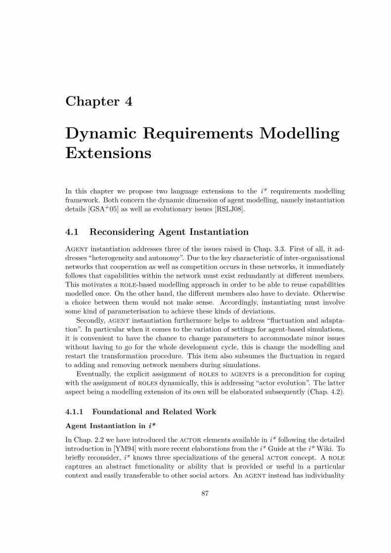
Chapter 4
Dynamic Requirements ModellingExtensions
In this chapter we propose two language extensions to the i* requirements modellingframework. Both concern the dynamic dimension of agent modelling, namely instantiationdetails [GSA+05] as well as evolutionary issues [RSLJ08].
4.1 Reconsidering Agent Instantiation
Agent instantiation addresses three of the issues raised in Chap. 3.3. First of all, it ad-dresses “heterogeneity and autonomy”. Due to the key characteristic of inter-organisationalnetworks that cooperation as well as competition occurs in these networks, it immediatelyfollows that capabilities within the network must exist redundantly at different members.This motivates a role-based modelling approach in order to be able to reuse capabilitiesmodelled once. On the other hand, the different members also have to deviate. Otherwisea choice between them would not make sense. Accordingly, instantiating must involvesome kind of parameterisation to achieve these kinds of deviations.
Secondly, agent instantiation furthermore helps to address “fluctuation and adapta-tion”. In particular when it comes to the variation of settings for agent-based simulations,it is convenient to have the chance to change parameters to accommodate minor issueswithout having to go for the whole development cycle, this is change the modelling andrestart the transformation procedure. This item also subsumes the fluctuation in regardto adding and removing network members during simulations.
Eventually, the explicit assignment of roles to agents is a precondition for copingwith the assignment of roles dynamically, this is addressing “actor evolution”. The latteraspect being a modelling extension of its own will be elaborated subsequently (Chap. 4.2).
4.1.1 Foundational and Related Work
Agent Instantiation in i*
In Chap. 2.2 we have introduced the actor elements available in i* following the detailedintroduction in [YM94] with more recent elaborations from the i* Guide at the i* Wiki. Tobriefly reconsider, i* knows three specializations of the general actor concept. A rolecaptures an abstract functionality or ability that is provided or useful in a particularcontext and easily transferable to other social actors. An agent instead has individuality
87

Chapter 4. Dynamic Requirements Modelling Extensions
(mostly representing human actors), this is individual skills and experiences that are noteasily transferable. Eventually, the position is an intermediate concept bundling severalroles that are usually played together. This is a position is still abstract, only serving asa convenient aggregate.
The different semantics of these modelling constructs is clarified by the available actorassociation links. An agent can play a role or occupy a position and the lattercovers several roles. In addition, standard OO links to indicate inheritance (is-a),aggregation (is-part-of), and instantiation (ins) are available.
A deeper investigation of these modelling constructs has revealed some inconsistenciesand shortcomings in regard to instantiation that will be elaborated in the following.
• The ins link is intended in i* only for use between agents. Its existence indicatesthat the agent construct has in fact two different interpretations: one more abstractand one concrete. The more abstract one is used to represent an actor with indi-viduality without committing to a particular individual. A concrete agent refersto a real world individual with its particular, individual skills and experiences. Buti* does not provide any means to specify these individualistic features – apart fromindividualistic goals, tasks, softgoals, and resources. In particular no refer-ences to the detailed modelling of the instantiated abstract agent is planned for.That is, it does not become clear how “instantiation” carries over to the detailedStrategic Rationale modelling level of the abstract agent that is instantiated.
• On the other hand, concrete roles and positions do not exist. These constructscannot be instantiated via ins and thus always remain abstract. While this properlyreflects their purely functionally oriented characterization, plays (and occupies)links somehow also carry a notion of instantiation. In the i* Guide at the i* Wiki inregard to the details of the plays association (item 4.2.3) it is emphasized that “theidentity of the agent who plays a role should have no effect on the responsibilitiesof that role.” But this emphasis distracts us from the consideration of how theindividuality of an agent shapes the activities that are carried out in the context ofa role (position) the agent plays (occupies). It certainly has to be expectedthat the identity of an agent has a severe influence on how the “responsibilities”are carried out.To elaborate on this argument we pick up on an example introduced by Yu [Yu95]concerning “doctors” in a clinical environment (see Fig. 2.8 in his thesis). In thiscontext an agent representing a “doctor” has, for example, particular experiencesthat make him or her individual and unique. In contrast, the position of a “physi-cian” covering roles concerning the “management of a clinic” and the “treatmentofť patients” can technically be occupied by any “doctor” irrespective of his (or her)experiences. Accordingly, the position as well as the two covered roles all havedependencies regardless of the actual experience of the “doctor”. But the details of“managing the clinic” or “treating patients” are certainly affected by whether the“doctor” has been in such a position before. This is true in particular for someonewho is doing the job for the first time. Even the concrete relationships toward other(individual) agents can be influenced if they know about the previous experiencesand value them.But similar to the instantiation of abstract agents i* does not provide any meansto capture this influence of the individuality of an agent on the abstract function-
88

4.1. Reconsidering Agent Instantiation
ality specified in roles (and positions). This problem is intensified by the typicalmodelling practice in that only more abstract agents are connected to roles orpositions. This is for a concrete agent the playing (occupying, resp.) of roles(of positions) is additionally mediated via an abstract agent.
According to our appraisal above, the need to reconsider agent instantiation does notresult solely from the “misuse” of i* to model operational agents, even though the ultimategoal to run agent-based simulations in the SNet case study stresses the need for clarifyinginstantiation as elaborated below. Also for the original application of i* to investigatestrategic aspects concerning business process reengineering, organisational impact analysis,and requirements engineering, a refined instantiation concept seems advantageous.
• First of all, specifying individual agents is not at all entirely new. Yu has also antic-ipated the need to consider individual actors, otherwise he would not have introducedthe representation of concrete agents and the ins relationship. Furthermore, alsooriginal i* allows for individual agent modelling (if only via the standard modellingfeatures tasks, goals, resources, and softgoals).
• Secondly, the details that can be captured during instantiation (e. g. via parameters)do not necessarily drop out of the “strategic level”. They can simply provide an easyway to capture and adjust some minor but still strategically relevant issues.In particular, any project manager will confirm the need to take into account theteam and each member’s individual features, in particular if social aspects are alreadyemphasized as much as it is the case for i*. A successful team highly likely combinesexperienced employees as well as newbies to balance innovation and reliability.
• Eventually, the incorporation of such information can also be considered a questionof completeness. If information on individualistic details is available, why should itbe ignored? While any piece of information must be investigated in regard to itsrelevance for the problem at hands, it is unlikely that instantiation information perse is (strategically) irrelevant.
Instantiation in Telos
As a second field of related work, the relation between the instantiation relationship ins ati* modelling level and the instantiation relationship at the foundational Telos level needs tobe clarified from a method engineering point of view. Following the standard InformationResource Dictionary System (IRDS) [Sta90], Telos would be considered at the “notationdefinition level (NDL)”, the i* formalism itself would be at the “notation level (NL)”,concrete models that make use of i* ’s modelling constructs at the “model level”, andeventually instantiations of that model at the “data level” (see Fig. 4.1 for details). Whilethe current ConceptBase implementation refrains from enforcing a strict hierarchy of data,class, meta class, meta meta class levels, etc. in favor of more flexibility, the relationshipbetween any two consecutive levels is still given via instantiation. Having an instantiationrelationship within i* obviously messes up abstraction levels that potentially better shouldbe treated separately.
Instantiation in Agent-Based Simulations
Eventually, we need to consider related work in the field of agent-based simulations asdiscussed in [GJLS05]. In many such environments, the parameterization of agents is very
89

Chapter 4. Dynamic Requirements Modelling Extensions
common and sometimes even at the core of the simulation idea. Exemplarily we considerthree environments here. For a more encompassing investigation see Chap. 5.3.1.
• In SeSAm [Klü01] agents are mainly described by variables representing the actualstate, activities that describe potential tasks the agent can execute, and a set of rulesto determine which activity to choose in which situation in response to (external)events. That is, rules refer to variables (also world variables defined in the simulationenvironment) and activate suitable activities. Agent instances that are configuredfor a concrete simulation setting can be initialized in regard to the initial values oftheir variables.
• SEAS, a Synthetic Environment for Analysis and Simulation developed at PurdueUniversity by Chaturvedi and colleagues [CM02], takes a slightly different approach.Here, a very large number of relatively simple reactive, but highly configurable agentsforms the “game board” of a management game, in which human users contributethe deliberative and strategic aspects. This system has been commercially used for awide variety of applications where the effect of different interacting (human) strate-gies on large masses of agents need to be simulated, e. g. in defense and strategicmarketing. Relevant parameters of agents are thus depending on the concrete appli-cation field but encompass, for example, age, gender, available money, educationalbackground etc. Accordingly, such large-scale experiments need, even more thantraditional simulation models, a significant amount of prior calibration and tuningof the models.
• Finally, in RePast Simphony (http://repast.sourceforge.net) a core modellingelement for describing an agent is “property”. Similar to SeSAm, such a propertycan be referred to in the behaviour specification of an agent but can also be subjectto simulation setting configurations, potentially within a “model initializer”. Inparticular, RePast prepares for the possibility to run sets of automated simulationswhere certain parameters are varied in a prespecified range of values.
As a commonality of all three agent-based simulation approaches, the concrete parametersthat are to be defined are considered to be application dependent. Thus, beyond preparingfor the means to specify such properties hardly any additional support can be provided.
4.1.2 Proposed Approach
In order to address the shortcomings in regard to agent instantiation in i* describedabove, we propose to clearly separate between the modelling of abstract functionality,this is roles and positions, and their instantiation via concrete agents. In detail, wepropose the following steps toward refining instantiation when modelling actors:
1. Consult the problem domain in order to decide for each i* modelling construct howit is to be instantiated at agent level; if instantiation information is required, definea suitable set of parameters that reflects the required information and that has tobe filled in with concrete values by a particular agent instance;
2. focus role- (and position-) based modelling first;
3. treat agent instantiation separately as an additional step:
90

4.1. Reconsidering Agent Instantiation
(a) specify agents together with their general properties and features (includingindividual softgoals and resources);
(b) use plays (and occupies) links to assign roles (and positions) to an agentand instantiate the modelling objects from these roles (and positions) byproviding values to the parameters introduced in the first step.
We elaborate the proposed solution for each of the specified steps in the following, discuss– if applicable – alternative approaches that have not been chosen, and finally report onthe formalization in Telos.
Define Instantiation Parameters (Step 1) As it is the case within any of the agent-based simulation environments that we have investigated above as well as our own expe-riences, the details of instantiation will vary from domain to domain possibly even fromproblem to problem. Accordingly, we need a flexible way of defining what instantiationmeans in a specific setting. By introducing corresponding attributes, this is at agent levelin the end in fact simple key-value pairs, the necessary large degree of freedom is given.We will discuss concrete examples for the case studies investigated in this thesis later on.But as a simple example, consider the opportunity to specify a “duration” for primitivetask elements, this is task elements that are not decomposed any further.
Role-Based Modelling (Step 2) Modelling is then restricted to roles and positionsonly. This is we describe dependencies, goals, softgoals, resources, and tasksthat potentially can exist, be achieved and be executed in a concrete problem context.For example, a dependency at this level is considered a foundational opportunity ofinteraction of individuals that instantiate the associated roles. Thus, except for theomission of (any kind of) agent and accordingly plays and occupies links, from amodelling perspective everything remains the same as in original i* (see Chap. 2.2.1).
Specify Agent Properties or Features (Step 3a) The first step to instantiation isthen to introduce an instance of the agent modelling element. As elaborated already instep 1, in contrast to original i*, this element can have several properties (or attributes)with the unique name already required in original i* being just one of them. To repeat,these properties are typically domain- or problem-specific. Examples are a measure toweight trust- against gain-orientation or an attribute that reflects the actor’s risk-attitudesuch as risk-averse vs. risk loving behaviour etc. Agent properties at this level are in-tended to represent general, characteristic attributes that influence the overall behaviourof an agent. If only particular roles (or positions) are concerned, the modelling shouldbe part of the details of these roles (positions).
Temporarily we allow for adding passive modelling elements (in the sense of the dis-tinction introduced in SNet, see Chap. 2.2.3), this is specific softgoals and resourcesthat reflect individual features and interests. For example, one agent might be interestedin “sustainability” thereby evaluating any possible activity from any role also in regardto its contribution toward the corresponding softgoal.1 Similarly, the availability ofresources can affect the behaviour of an agent in a general way. Note that we can onlyconsider general features since any role (or position) that is played (occupied) byan agent necessarily remains unaware of these characteristics to keep up the functional
1We elaborate how the necessary contribution links are introduced later on.
91

Chapter 4. Dynamic Requirements Modelling Extensions
Notation definition level (NDL)
Notation Level (NL)
Model Level (ML)
Data Level (DL)
instantiates
instantiates
instantiates
Telos
i*
role-basedmodeling
instantiationModeling levels ISO IRDS 1990
Role
Position Task Goal
Resource Softgoal
decomposition
contribution
means-ends
ObjectAssertion
attribute in
rule/constraint
Agent
plays
internally buildup knowledge
on control
VEMACduration : 2
parameter : duration
instantiates
instantiates
instantiates
risk attitude : risk-averse
Figure 4.1: Modelling levels during agent instantiation
abstraction. Active elements, this is tasks and goals, are not admitted to not harmmodelling homogeneity. This way of modelling would not add expressiveness, only a re-striction to one particular agent. Even allowing for passive modelling elements harmsthe homogeneity of modelling (as will be elaborated below). But a missing clarification ofthe generalization/specialization relationship is-a in i* prevents a clear and easy under-standing of how general roles integrate with or have an influence on specialized roles.Hopefully Clotet et al. [CFL+07] will clarify this. In the meantime the above proposedapproach allows to address and model according features as kind of a workaround.
Elaborate Plays/Occupies Links (Step 3b) To pick up on the major criticism inregard to agent instantiation in original i*, we eventually provide means to capturehow the individuality of an agent shapes the roles (and positions) that she plays (oroccupies, respectively). More precisely, we allow to tailor the behaviour defined in roles(and positions) for a particular agent by providing values to the domain- and problem-specific parameters that have been introduced in Step 1. This is the characterization ofan agent is completed by adding plays and occupies links as well as the values for theparameters occurring in the modelling of the corresponding roles and positions.
We do not consider more sophisticated kinds of refining a role during instantiationsuch as adding individual alternative tasks to achieve a goal. Again this does not fun-damentally extend modelling capabilities but harms modelling homogeneity. In particularit is by no means clear how to make such a connection. On the other hand, it is easilyconceivable to disable an alternative via suitable instantiation parameters. In the future,the clarified is-a relationship might be used for this purpose [CFL+07].
Wrap-Up of Basic Approach
Figure 4.1 clarifies the different levels at which the modelling constructs and objects ofi* reside when adopting the way agent instantiation is proposed above. Telos is used as
92

4.1. Reconsidering Agent Instantiation
the “notation definition language” (according to the ISO IRDS 1990 standard [Sta90]) fori* which then resides on the “notation level”. Role-based modelling uses the original i*modelling language (with the only exception of omitting any agent related construct) tocreate concrete, domain dependent models that are at the “model level”. Eventually, themodel level is followed by the “data level” where the concrete agent-based instantiationsof the role-based modelling are defined. As an extension to original i* attributes tothe agent construct have been introduced that reflect general agent “properties”. Fur-thermore, the use of plays and occupies links defines which roles and positions areadopted by an agent. The generic characterization of the functionality that an agentcan exhibit is tailored to the particular agent by assigning values to the previously de-fined parameters of i* modelling constructs used at the role-based modelling level. Theexplicit instantiation relationship ins is dropped due to the unclear differentiation betweenconcrete and abstract agents and positions. Temporarily we allow to add resourcesand softgoals at the agent level. Since this breaks the clear separation of modellinglevels and thus modelling homogeneity, we favor the abandoning of this approach as soonas a clear understanding of the is-a relationship at role level has evolved within the i*community.
4.1.3 Implementation Details
Modelling at Different Levels
As it becomes obvious from Fig. 4.1: while generally the lower level instantiates the con-secutive upper level, there are some deviations from this standard modelling procedure.In particular, i* ’s agent construct is instantiated in our approach only at the data level.Then the plays and occupies links traverse level boundaries by connecting the agentsat the data level with the roles defined at model level. This reveals the partially instan-tiating character of these links. Furthermore, the instantiation parameters of i* modellingconstructs such as “duration” for primitive tasks are already defined at notation levelbut instantiated only at data level (possibly depending on details of the “model level” asit is the case to know which tasks are actually primitive).
To fully meet the previously given characterization of agent instantiation, we alsoneed to consider softgoal and resource elements (and accordingly also contributionlinks) at data level. This is, for these modelling constructs we also have “instantiates” linksfrom data level to notation level as with agent. But more importantly and in contrast tothe agent construct, this causes modelling objects of these types to exist at two differentinstantiation levels – model as well as data level – even though the level of abstraction issimilar. While such kind of modelling is practically possible in Telos/ConceptBase (theseparation into a strict (meta) class hierarchy is no longer enforced, see [JQJ10], p. 13),we favor a clean separation in regard to instantiation once a clarified understanding ofthe is-a relationship at role-based modelling level is in place (see previous discussions).Accordingly, we have omitted these details in the above picture for the sake of clarity.
Technical Details of Agent Instantiation
The central components of agent instantiation are the agent element instances at “datalevel”. In particular they are the sources to the plays and occupies links toward rolesand positions at “model level”. Such a link also entails the instantiation of the cor-responding modelling details defined at the “model level”. This is for each plays (or
93

Chapter 4. Dynamic Requirements Modelling Extensions
occupies) link automatically instances of the corresponding modelling objects from therole or position details (at “model level”) are introduced at “data level” using thestandard Telos instantiation via in (and the help of suitable deductive or active rules).
By associating these instances with the plays (and occupies) links (via a corre-sponding instantiation attribute), we separate the instantiations of different roles (andpositions) and reflect the strong tie between the instantiation details and the plays (andoccupies) links. The automated support to instantiation in return to the introductionof a plays or occupies link takes also care of the proper instantiation of links at therole-based modelling level via suitable rules. There is only one situation in this contextthat needs special treatment, this is when links traverse actor boundaries. As elaboratedin Chap. 2.2.3, for decomposition and means-end links this indicates the delegation ofactivities between actors, for contribution links this concerns accompanying contribu-tions to softgoals defined at the delegator’s side (or even earlier in the delegation chain).While principally it is correct to introduce an instantiation link for any pair of possiblesource and destination agent (Cartesian product), this extensive treatment is typicallyan overkill. For example, the major characteristic of a contribution is given by theagent issuing the contribution not the one that is receiving it.2 We accommodate thisby allowing for referring to the corresponding role-based modelling objects as sources ordestinations.3
Eventually, specific softgoals and resources can be added as children to an agentelement (or more precisely via the inverse parent attribute) just as in original i* (and thedetailed modelling of roles at “model level”). Since the softgoals only make sensewith corresponding contribution links, also the latter have to be introduced. Theinstantiation parameters of these links must be filled at the same time.4
Specifying and Instantiating Parameters
The instantiation as described up to now does not explain how the additional instantiationparameters get in here. Currently, we have only ensured that for each role (position) anagent plays (or occupies), we have representatives of the modelling details available alsoat “data level”. For each of them, the standard Telos instantiation relationship identifiesthe relevant modelling object at role-based modelling level and thereby to access anyinformation that is independent from the individuality of the agent.
To specify instantiation parameters in the first place we suggest to define a hierarchyof instantiation information classes separately from the fundamental i* framework. Thestructure of the hierarchy originates in a class called InstanceInformation but is otherwiseproblem-specific. Such a hierarchy might basically follow the i* hierarchy as introducedgraphically in Fig. 2.10 and 2.11, but skips classes that are not extended by instantiationinformation. Furthermore, new classes can be added to cover particular usage scenar-ios, for example, modelling characteristics at “model level”. For instance, primitive taskelements can only be determined by considering the non-existence of outgoing decom-position links in a concrete model. The separate instance information hierarchy givesthe modeller full control over the specification of any instantiation detail while enablingreuse via standard object-oriented inheritance. In the example section, we will consider
2In addition, individualistic trust issues in SNet are treated specially anyway to also account for thefact that the level of trust cannot be set to a single fixed value in advance but evolves over time.
3The reader might find some resemblance to default values discussed later on.4Another irregularity that explains why we prefer to abolish this kind of modelling.
94
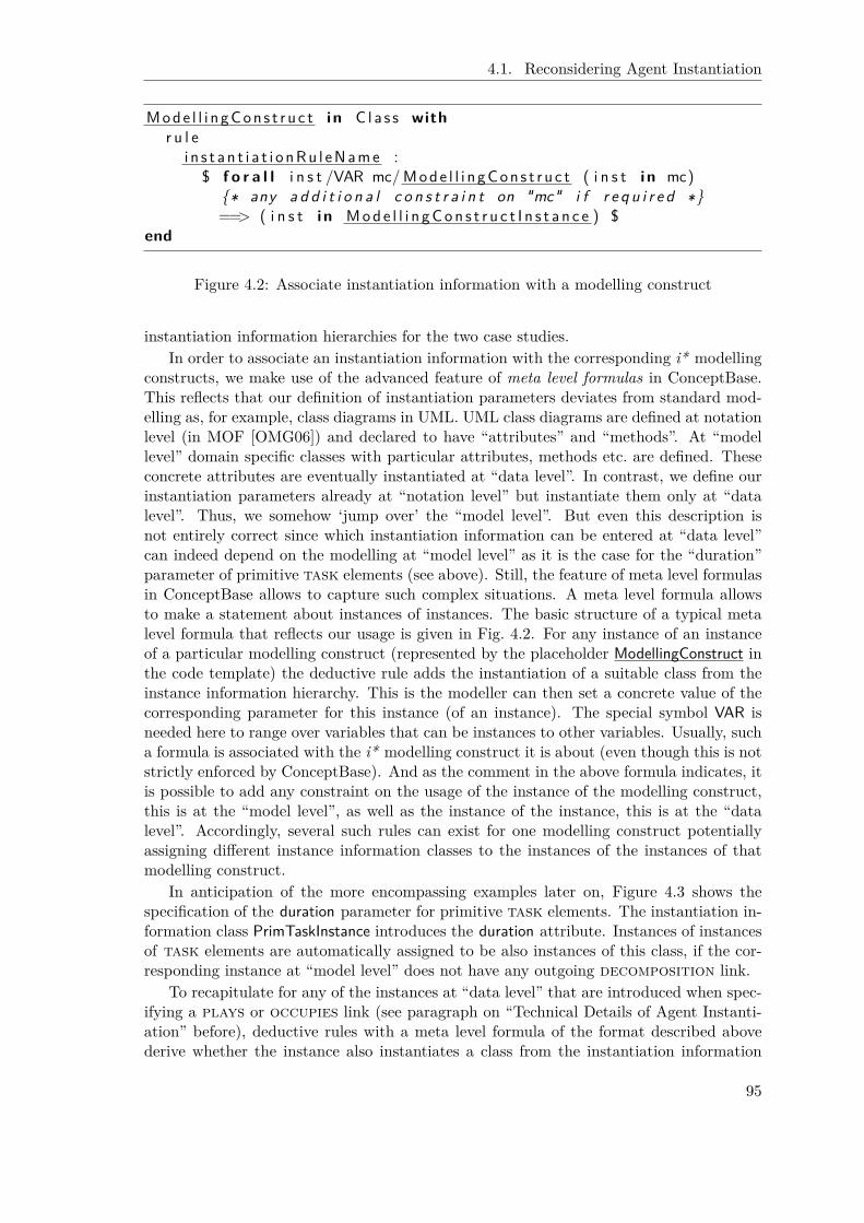
4.1. Reconsidering Agent Instantiation
Mode l l i n gCon s t r u c t i n C l a s s withr u l e
i n s t a n t i a t i o nRu l eName :$ f o r a l l i n s t /VAR mc/Mode l l i n gCon s t r u c t ( i n s t i n mc)
{∗ any a d d i t i o n a l c o n s t r a i n t on "mc" i f r e q u i r e d ∗}==> ( i n s t i n Mode l l i n gCon s t r u c t I n s t a n c e ) $
end
Figure 4.2: Associate instantiation information with a modelling construct
instantiation information hierarchies for the two case studies.In order to associate an instantiation information with the corresponding i* modelling
constructs, we make use of the advanced feature of meta level formulas in ConceptBase.This reflects that our definition of instantiation parameters deviates from standard mod-elling as, for example, class diagrams in UML. UML class diagrams are defined at notationlevel (in MOF [OMG06]) and declared to have “attributes” and “methods”. At “modellevel” domain specific classes with particular attributes, methods etc. are defined. Theseconcrete attributes are eventually instantiated at “data level”. In contrast, we define ourinstantiation parameters already at “notation level” but instantiate them only at “datalevel”. Thus, we somehow ‘jump over’ the “model level”. But even this description isnot entirely correct since which instantiation information can be entered at “data level”can indeed depend on the modelling at “model level” as it is the case for the “duration”parameter of primitive task elements (see above). Still, the feature of meta level formulasin ConceptBase allows to capture such complex situations. A meta level formula allowsto make a statement about instances of instances. The basic structure of a typical metalevel formula that reflects our usage is given in Fig. 4.2. For any instance of an instanceof a particular modelling construct (represented by the placeholder ModellingConstruct inthe code template) the deductive rule adds the instantiation of a suitable class from theinstance information hierarchy. This is the modeller can then set a concrete value of thecorresponding parameter for this instance (of an instance). The special symbol VAR isneeded here to range over variables that can be instances to other variables. Usually, sucha formula is associated with the i* modelling construct it is about (even though this is notstrictly enforced by ConceptBase). And as the comment in the above formula indicates, itis possible to add any constraint on the usage of the instance of the modelling construct,this is at the “model level”, as well as the instance of the instance, this is at the “datalevel”. Accordingly, several such rules can exist for one modelling construct potentiallyassigning different instance information classes to the instances of the instances of thatmodelling construct.
In anticipation of the more encompassing examples later on, Figure 4.3 shows thespecification of the duration parameter for primitive task elements. The instantiation in-formation class PrimTaskInstance introduces the duration attribute. Instances of instancesof task elements are automatically assigned to be also instances of this class, if the cor-responding instance at “model level” does not have any outgoing decomposition link.
To recapitulate for any of the instances at “data level” that are introduced when spec-ifying a plays or occupies link (see paragraph on “Technical Details of Agent Instanti-ation” before), deductive rules with a meta level formula of the format described abovederive whether the instance also instantiates a class from the instantiation information
95

Chapter 4. Dynamic Requirements Modelling Extensions
TaskElement i n C l a s s withr u l e
pr imTask : $ f o r a l l i n s t /VAR te /TaskElement ( i n s t i n t e )and ( not e x i s t s d/Decompos i t i onL ink ( d from te ) )==> ( i n s t i n Pr imTask In s tance ) $
end
Pr imTask In s tance isA I n s t a n c e I n f o rma t i o n witha t t r i bu te
du r a t i o n : I n t e g e rend
Figure 4.3: Duration parameter to primitive i* task elements
hierarchy. If this is the case, the modeller can then specify a value for the correspondinginstantiation parameter.
Eventually, as a (technical) extension it seems reasonable to provide the opportunityto specify default values for instantiation parameters. These can be specified at bothmore abstract modelling levels. At the “notation level” one might want, for example, tospecify that all primitive task elements have a default “duration” (e. g. 1) if no particularvalue is given. The default value could also be refined at “model level” to distinguishbetween instances of modelling constructs. A suitable example in this regard are “utilityfunctions” for softgoals. While there might not be a single utility function that matchesall softgoals, a utility function that suits one particular softgoal might be amenable toall agents that instantiate the corresponding role. Providing default values to attributesis a standard exercise and also elaborated in the ConceptBase How-To “Handle explicitattribution and default values” (see http://merkur.informatik.rwth-aachen.de/pub/bscw.cgi/2396075). The solution again involves some suitable new attribute (to storethe default value) and according rules to fall back to these defaults if no particular valueis given.
Modularization
In order to take advantage of ConceptBase’s module concept, we suggest to set up instan-tiation information details as a nested sub module to the role-based model. This allowsto have several independent instantiation details side to side as well as a hierarchy of suchinformation if nesting of modules is reapplied within an instantiation module. An updateto the role-based model is then immediately available to all instantiations.
Tool Support
With the help of suitable ConceptBase query classes it is straightforward to filter the in-stantiated objects that require additional instantiation information. Indeed it suffices tocheck for whether they instantiate (directly or indirectly) the root class InstanceInformationof the instance information hierarchy. Accordingly, masks to query the information fromthe user can be set up easily. Figure 4.4 shows an example of a corresponding user in-terface for the SNet case study. In most cases a tabular view that is suitably structured
96

4.1. Reconsidering Agent Instantiation
Figure 4.4: Agent instantiation user interface for the SNet case study
(e. g. according to modelling constructs and roles) is appropriate. But again, the repre-sentational details here are just as the instantiation parameters themselves domain- andproblem-dependent.
4.1.4 Case Studies
Inter-Organisational Networks
Agent instantiation as introduced above is of interest in particular in simulation settingsas it is the case in our SNet case study. Network members offer redundant capabilities andthus compete for becoming cooperation partners. Figure 4.5 shows the instantiation infor-mation that we have currently defined for the SNet setting. For primitive tasks we allowto specify a duration (as already mentioned before). The other major extension concernssoftgoals and contributions. Since we use softgoals as the basis for autonomous
97

Chapter 4. Dynamic Requirements Modelling Extensions
Figure 4.5: SNet related instantiation information
decisions of agents at run-time, we have introduced a quantitative interpretation for them(see also Chap. 2.2.3). This encompasses utility_functions for softgoals that map thesum of the incoming numerical contribution s to a utility value between 0 and 1 where 1indicates highest utility. The suitable range of values can be different for each softgoal.Thus, the information can be specified exactly the way it is typically given in a particulardomain (including the possibility for non-numerical contributions5).
Agent properties in the SNet setting concern the risk_attitude as well as the attitudetoward trust . Risk_attitude is intended to affect the planning behaviour by considering inhow far a delay of a current activity influences other jobs. A risk-averse agent might pre-pare for some buffering time. Weight_trust trades long-term trust considerations againstmonetary short-term profit (gain). In the latter case, the agent is more willing to cancela current job in favor of a more lucrative new one. Weight_trust is simply a value between0 and 1 that immediately serves as a weight during the utility computation.
Figure 4.6 introduces a simple excerpt of an entrepreneurship setting only involvingthe roles of a “venture capitalist”, an “entrepreneur”, and a “faculty member”. The“venture capitalist” wants to “earn money”. The only alternative to do so is to “choosea promising entrepreneur”. This complex task is decomposed into two sub activities.“suggest a business idea” is delegated to the “entrepreneur” and for the sake of simplicityprimitive here. For the goal “ask evaluation” two alternatives are modelled. Eitherthe “venture capitalist” can “do the evaluation” on its own or she can delegate it to anexternal “faculty member”. The contributions toward the accompanying softgoal“report quality” allow to capture differences between the individual characteristics, thisis between the two basic alternatives (internal vs. external) as well as different “facultymembers” and “venture capitalists”.
Table 4.1 shows exemplarily a partial instantiation of this simple setting. Two agents
5From this characterization it becomes obvious that when adopting agent instantiation as proposedhere, the concrete type of contribution (“help”, “hurt”, etc.) is in fact an instantiation information.
98
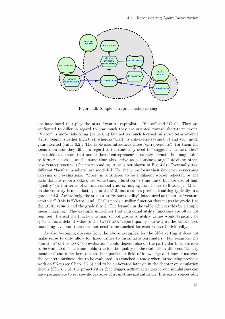
4.1. Reconsidering Agent Instantiation
Figure 4.6: Simple entrepreneurship setting
are introduced that play the role “venture capitalist”, “Victor” and “Carl”. They areconfigured to differ in regard to how much they are oriented toward short-term profit.“Victor” is more risk-loving (value 0.8) but not so much focused on short term revenue(trust weight is rather high 0.7), whereas “Carl” is risk-averse (value 0.3) and very muchgain-oriented (value 0.2). The table also introduces three “entrepreneurs”. For them thefocus is on how they differ in regard to the time they need to “suggest a business idea”.The table also shows that one of these “entrepreneurs”, namely “Ernst”, is – maybe dueto former success – at the same time also active as a “business angel” advising other,new “entrepreneurs” (the corresponding role is not shown in Fig. 4.6). Eventually, twodifferent “faculty members” are modelled. For them, we focus their deviation concerningcarrying out evaluations. “Fred” is considered to be a diligent worker reflected by thefacts that his reports take quite some time, “duration” 7 time units, but are also of high“quality” (a 1 in terms of German school grades, ranging from 1 best to 6 worst). “Mike”on the contrary is much faster, “duration” 3, but also less precise, resulting typically in agrade of 2.3. Accordingly, the softgoal “report quality” introduced at the role “venturecapitalist” (this is “Victor” and “Carl”) needs a utility function that maps the grade 1 tothe utility value 1 and the grade 6 to 0. The formula in the table achieves this by a simplelinear mapping. This example underlines that individual utility functions are often notrequired. Instead the function to map school grades to utility values would typically bespecified as a default value to the softgoal “report quality” already at the role-basedmodelling level and then does not need to be touched for each agent individually.
As also becoming obvious from the above examples, for the SNet setting it does notmake sense to only allow for fixed values to instantiate parameters. For example, the“duration” of the task “do evaluation” could depend also on the particular business ideato be evaluated. The same holds true for the quality of the evaluation: different “facultymembers” can differ here due to their particular field of knowledge and how it matchesthe concrete business idea to be evaluated. As touched already when introducing previouswork on SNet (see Chap. 2.2.3) and to be elaborated later on in the chapter on simulationdetails (Chap. 5.3), the proactivities that trigger agent activities in our simulations canhave parameters to set specific features of a run-time instantiation. It is easily conceivable
99

Chapter 4. Dynamic Requirements Modelling Extensions
Table 4.1: Partial agent instantiation for the entrepreneurship setting
Agent Role Instantiation detail ValueVictor risk attitude 0.8
trust weight 0.7venture softgoal report qualitycapitalist – utility function −0.2 · x+ 1.2 for 1 ≤ x ≤ 6
Carl risk attitude 0.3trust weight 0.2
venture softgoal report qualitycapitalist – utility function −0.2 · x+ 1.2 for 1 ≤ x ≤ 6
Emil entrepreneur task suggest business idea– duration 2
Erika entrepreneur task suggest business idea– duration 7
Ernst entrepreneur task suggest business idea– duration 5
business angel task elaborate business plan– duration 3
Fred faculty task do evaluationmember – duration 7
– quality contribution 1 (“very good”)Mike faculty task do evaluation
member – duration 3– quality contribution 2.3 (“good (minor)”)
that the values to instantiation parameters we are concerned with in this chapter are in factfunctions of run-time parameters that indicate, for example, the complexity or the basicfield of a business idea. From the technical perspective of supporting agent instantiation,this does not change anything as long as the modeller ensures that all functions that arespecified produce values that are admissible, this is within a suitable range, and thus donot cause problems for the utility computation. Accordingly, we do not go into the detailshere.
Figure 4.76 eventually shows all the details of agent instantiation at Telos level for the“faculty member” “Fred”. These encompass the agent element with filled parameters, theplays link toward “faculty member” together with the instantiation attribute that in thiscase stores the reference to the instantiation object doEvaluationInstanceFred as the onlydetail of the role “faculty member”. The actual instantiation objects are shown as wellincluding the concrete values to the instantiation parameters duration and contribution .
Chapter 5.3.2 will pick up on instantiation in the context of simulation configuration.We will extend these considerations then also to cover initial settings, for example, inregard to trust.
6To enhance readability we have used speaking identifiers for the Telos frames instead of additionallyreferring to the standard name attribute.
100
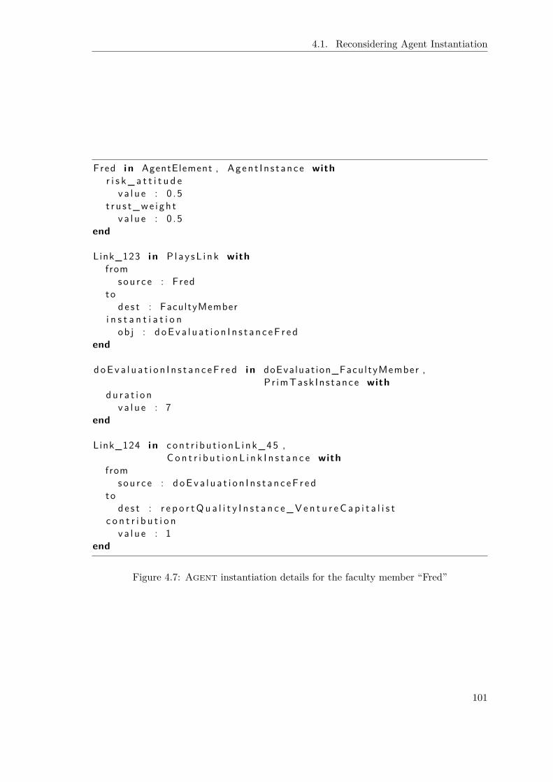
4.1. Reconsidering Agent Instantiation
Fred i n AgentElement , Agen t I n s t ance withr i s k _ a t t i t u d e
v a l u e : 0 . 5t r u s t_we i gh t
v a l u e : 0 . 5end
Link_123 i n P l a y sL i n k withfrom
sou r c e : Fredto
de s t : FacultyMemberi n s t a n t i a t i o n
ob j : d oEv a l u a t i o n I n s t a n c eF r e dend
doEva l u a t i o n I n s t a n c eF r e d i n doEvaluat ion_FacultyMember ,Pr imTask In s tance with
du r a t i o nv a l u e : 7
end
Link_124 i n con t r i bu t i onL i nk_45 ,C o n t r i b u t i o n L i n k I n s t a n c e with
fromsou r c e : d oEv a l u a t i o n I n s t a n c eF r e d
tode s t : r e p o r tQ u a l i t y I n s t a n c e_V e n t u r e C a p i t a l i s t
c o n t r i b u t i o nv a l u e : 1
end
Figure 4.7: Agent instantiation details for the faculty member “Fred”
101

Chapter 4. Dynamic Requirements Modelling Extensions
Figure 4.8: ZAMOMO related instantiation information
Control System Development
An example that the above described feature of agent instantiation is not only relevantin applications concerning simulations but can also be useful in a normal requirementsengineering setting is given by the ZAMOMO case study.
As elaborated in Chap. 3.2, the field of control system development is often charac-terized by severe environmental constraints. This is many details of the environment butalso of the possible solution components are already known in advance. For example,it is unlikely that for a typical control problem a completely new kind of sensor will bedeveloped. Instead the set of existing sensors, for example, the concrete means on howto realize a “distance sensor” or even the different vendors of the same type of “distancesensor”, need to be taken into account early since they considerably influence the realisticsolution space. In addition to this, the developers strive for reuse at Matlab/Simulinklevel (see Chap. 2.4). The power of Matlab/Simulink is mainly given by the large set oflibraries of preexisting modelling elements that can also be extended by individual usersvia libraries specific to their particular domain or application context. Accordingly, inmany cases an alternative at requirements level is strongly connected to the realizing com-ponent at the implementation level. Instantiation parameters now offer a suitable meansto directly store such connections (in particular in combination with “domain models”,see Chap. 5.1) that can then be exploited during transformation (see Chap. 5.2.3).
The instantiation information hierarchy for ZAMOMO (see Fig. 4.8) focuses the abovementioned application. It consists only of a single attribute matlabLibraryElement that isadded to the basic InstanceInformation class. Thereby it becomes possible to associatea connection to a Matlab/Simulink library element with any i* modelling construct. Itmight be worth to mention that we can make use of the corresponding Matlab/SimulinkTelos model as introduced in Chap. 2.4 (see use of type Block).
4.1.5 Summary
Yu et al. have not been concerned with how the individuality of an agent shapes theroles (positions) she plays (occupies, respectively). But as soon as the individualconcrete manifestations are gaining importance as it is the case, for example within oursimulations of inter-organisational networks, the lack of means to clearly specify how aconcrete individual fills out the abstractly described functionality is becoming a majorimpediment.
To overcome this, we have separated the more abstract role-based modelling fromagent instantiation. The latter now takes place only at the “data level” (of the IRDShierarchy [Sta90]). A parallel instance information hierarchy allows to introduce suit-able, domain-specific instantiation parameters that enable to tailor an abstract role (orposition) to the individual features of a particular agent. The according details arestored with the corresponding plays (and occupies) links. During instantiation, severalConceptBase features in particular deductive rules and meta level formula support the
102

4.2. Actor Evolution
developer in ensuring a consistent and complete instantiation. The proposed approachtoward instantiation also integrates well with the subsequently addressed extension con-cerning “actor evolution”. With the example from the ZAMOMO case study, we haveoutlined that the approach to agent instantiation as introduced here is also useful in acommon requirements engineering setting.
Nonetheless, the proposed approach cannot be considered a replacement of the ap-proach originally taken in i*. In particular in cases where concrete details of an agentare not yet available – formerly the notion of “abstract agents” – or where it becomesimportant when to associate a dependency with an agent instead of a role the originalapproach is needed. But the longer a problem is elaborated the more information also onthe participating individuals will become available. Thus, it seems reasonable to considera transition between the two kinds of addressing agent instantiation, this is to allow toderive (at least partially) the different representations from each other. This is left forfuture work.
4.2 Actor Evolution
As elaborated in Chap. 3.3.2, original i* has a purely static view in regard to the distri-bution of roles among agents. In this chapter (based on [Roe06, RSLJ08]), we proposean extension of i* that allows to model and represent relations of roles in regard totransitional and/or evolutionary aspects. This opens up the possibility to investigate notonly individual snapshot situations but also transitional aspects of a set of scenarios orsettings. In detail the extension allows to specify that if an agent has played some roleand fulfills some additional constraints, she might play some other (typically related) rolelater on. Also the loss of a role is provided for. As an example, this allows to model thatan agent runs through various mutual exclusive, evolutionary stages. We elaborate thedetails of the proposed extension in this chapter.
4.2.1 Related Work
Dynamic Adaptation of Agent Behaviour
A larger body of related work has been considered in regard to the dynamic adaptation ofagent behaviour. In such a setting, most researchers do not prespecify the path of evolutionbut instead allow for and prefer arbitrary development and an emerging distribution ofcapabilities across an agent community. AALAADIN [FG98] provides an organisationalmeta model centered around the concept of a group consisting of several agents that playroles within this group. By entering a new group or leaving a group an agent acquiresor loses the related roles. The assignment is determined by a centralized group manager.RoleEP [UT00] does not define an agent as an entity of the system at all, until an objectneeds a role to implement a task and assumes that role in its environment. But whileagents are allowed to travel to different hosts to search for a function, they do not considerdelegation. Instead all required functions are integrated until finally the agent is able toexecute the task. Magique [MRS01] initially equips agents only with the skill to learn anew skill and a communication skill. This enables the agent to search for a particular skill(communication) and learn it. But here, the evolution is limited by a pre-determined skillhierarchy. General learning techniques are applied by Stone [Sto07] in the field of roboticsoccer to, for example, adapt (restrict) the behaviour of a team to a specific opponent.
103

Chapter 4. Dynamic Requirements Modelling Extensions
Models for Role Acquisition
Odell et al. [OPBS03] use UML models to capture a generalization hierarchy and describethe associations between roles in the context of agent programming. This is intendedto increase understandability and reuse in complex, dynamic settings. For example, themodel describes that the assignment of a role to an agent must be qualified in a groupcontext to avoid conflicts of interest for the agent. Accordingly such constraints limit thepossible paths of evolution to prevent an agent from gaining inappropriate benefits for rolesshe plays. Others have also considered preconditions for acquiring (or losing, respectively)roles. Within the context of workflow modelling, Yu and Schmid [YS99] provide a detailedconceptualization of the requirements an agent needs to fulfil to acquire a new role byintroducing qualification attributes referring to organisational policies and the agent’scapabilities. But these qualifications are captured only informally via text and furthermorethey do not consider conditions that make an agent lose a role. BRAIN [CFL04] also knowsstarting requirements that represent the skill/experience level an agent must have to startusing a specific role. But again, conditions for losing a role are not considered. An agentsimply releases a role when it is no longer needed. There is no intention to model actorevolution, instead the goal is to provide means to ease maintenance (replacement) of roleimplementations.
Organisational Change and Norms
More recently, research on norms and organisational change have brought up dynamicissues in agent societies. In [HJST07, JSTY07] a framework for formal modelling andanalysis of organisations and organisational change is described. A graphical representa-tion as well as a sound formal foundation is given (in Temporal Trace Language (TTL)that is comparable to the situation calculus). While they emphasize the applicability oftheir approach to both real world as well as artificial organisations, they focus an organisa-tional view and complex, mechanistic types of organisations in particular. Organisationalchange is intended to be centralized. But in modern flat forms of organisations, such asnetworks, network rules cannot be imposed on the network members but must be adoptedand adapted by them as constraints that might or might not be adhered to [GJKL03]. Thelatter aspect is partly addressed inMoiseInst [BG07] by conceptually enabling deliberationabout the organisational model itself. Furthermore building on ideas from [EdlCS02], itis possible to define a-priori transitions between contexts (encompassing groups and rolesthat are interacting) to define varying behaviour constraints for different situations. Even-tually, the structural dimension ofMoiseInst allows for the definition of role compatibilityand cardinality constraints. Finally, DeLoach et al. [DOM08] describe an organisationmodel for adaptive computational systems (OMACS) that enables multi-agent systemsto adapt their own organisation at runtime. Thus, they do not aim at reflecting realworld behaviour of (human) actors and again have a shared organisational perspective.The assignment of roles to agents can be constrained by (application-specific) assignmentpolicies, by behavioural policies taking the relationships of agents into account (not yetfully defined) as well as reorganisation policies. But the latter is not binding and mightbe ignored if it does not help achieving the overall goal.
104
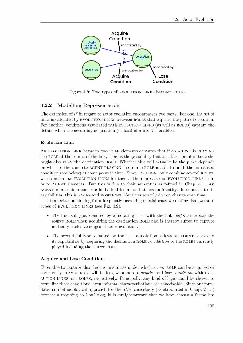
4.2. Actor Evolution
Figure 4.9: Two types of evolution links between roles
4.2.2 Modelling Representation
The extension of i* in regard to actor evolution encompasses two parts. For one, the set oflinks is extended by evolution links between roles that capture the path of evolution.For another, conditions associated with evolution links (as well as roles) capture thedetails when the according acquisition (or loss) of a role is enabled.
Evolution Link
An evolution link between two role elements captures that if an agent is playingthe role at the source of the link, there is the possibility that at a later point in time shemight also play the destination role. Whether this will actually be the place dependson whether the concrete agent playing the source role is able to fulfill the annotatedcondition (see below) at some point in time. Since positions only combine several roles,we do not allow evolution links for them. There are also no evolution links fromor to agent elements. But this is due to their semantics as refined in Chap. 4.1. Anagent represents a concrete individual instance that has an identity. In contrast to itscapabilities, this is roles and positions, identities exactly do not change over time.
To alleviate modelling for a frequently occurring special case, we distinguish two sub-types of evolution links (see Fig. 4.9).
• The first subtype, denoted by annotating “⇒” with the link, enforces to lose thesource role when acquiring the destination role and is thereby suited to capturemutually exclusive stages of actor evolution.
• The second subtype, denoted by the “→” annotation, allows an agent to extendits capabilities by acquiring the destination role in addition to the roles currentlyplayed including the source role.
Acquire and Lose Conditions
To enable to capture also the circumstances under which a new role can be acquired ora currently played role will be lost, we annotate acquire and lose conditions with evo-lution links and roles, respectively. Principally, any kind of logic could be chosen toformalize these conditions, even informal characterisations are conceivable. Since our foun-dational methodological approach for the SNet case study (as elaborated in Chap. 2.1.5)foresees a mapping to ConGolog, it is straightforward that we have chosen a formalism
105

Chapter 4. Dynamic Requirements Modelling Extensions
Table 4.2: Examples for potentially relevant features of i* modelling elements
Element Interesting features from an evolutionary perspectiverole Assignment history
- currently played- played in the past- how often played- played for how long- . . .
task, Delegationsgoal - number of offers
- number of cooperations- number of successful cooperations- number of cooperation cancellations- . . .Performance- how often executed- performance in regard to softgoals (see below)- . . .
softgoal Achievement- collected contributions (average, minimum, maximum, total)- . . .
resource Ownership/Provisioning- how often owned/provisioned- . . .
that suits this eventual transformation. Thus, similar to the formalization of precon-dition/effect elements (see Chap. 2.2.3), the expressive power of first order logic isavailable as it is used in the precondition and effect axioms of the situation calculus (seeChap. 2.3.1).
The missing piece is then what kind of information can be referred within these con-ditions. Table 4.2 lists basic features of i* modelling elements that potentially becomerelevant once evolutionary considerations are taken. For one, we are certainly concernedwith the (history of) roles that are played (or have been played): when, how often, forhow long etc. In regard to tasks and goals, in particular dependencies are of relevance:how often has an agent issued an offer to perform some delegation, how often resulted acooperation, how many of these were successful, how many not etc. But also more gener-ally for any actual execution of tasks or goals performance issues could be referred tosuch as the number of executions or the performance in regard to associated softgoals.The latter can also be considered of their own by considering the overall achievements,summing up all contributions to a softgoal, computing a maximum, minimum, oraverage for individual performances etc. Similarly, resources can be investigated inregard to how often they were asked for or provided by a particular agent.
The above considerations fit well with the reconsideration of agent instantiation aspresented in the previous chapter. For one, any of the above listed features are expectedto have different values for different agents that play the according roles (where the
106

4.2. Actor Evolution
concrete modelling is defined), ultimately reflecting the individual “experiences” as envi-sioned by Yu [Yu95]. This is any means to access these data will later on be parameterizedby a concrete agent. Another correspondence concerns the need to consider the particu-larities of a domain or an application. Just as instantiation information is domain-specific,evolutionary relevant issues are as well. To start with, the domain-specific instantiationinformation can be referenced. But eventually, the chosen backend foundation to the dy-namic perspective (e. g. ConGolog simulations) determines what kind of information isavailable for use in acquire or lose conditions. We will discuss issues specific to the SNetcase study (e. g. trust and fluents) in the according case study section later on.
Also the actual semantics of evolutionary issues is application dependent. It is equallyconceivable that a fulfilled acquire (or lose) condition automatically triggers the accordingevolution (acquisition or loss of a role) as well as that it only enables such an evolutionarystep. The latter opens up the possibility to let individuals represented by an agent decideon their own (potentially after deliberative planning, what-if analyses etc.) which of po-tentially several evolutionary paths to follow. In other settings, a stochastic choice betweenalternative paths of evolution could be appropriate. We expect the modeller to determinethese characteristics of acquire and lose conditions suitably for a particular application,domain, or individual model, at least by determining how the i* model integrates withthe dynamic perspective (see Chap. 5.2.4 for the integration of i* and ConGolog in regardto actor evolution in the context of the SNet case study).
4.2.3 Technical Details
The above introduction of basic modelling means for actor evolution leaves open somemore technical points that we want to discuss before jumping into implementation detailsand case studies.
Notion of the Passage of Time
Obviously, the extension of i* in regard to evolutionary issues presumes some notion ofthe passage of time. But this is also present in Yu’s original thesis [Yu95]. He mentions adistinction between “design-time” and “run-time” and foresees the recurrent execution ofroutines, this is process-like parts of the modelling, at run-time. Furthermore, he also ex-plicitly mentions that Telos allows to capture additional constraints on the modelling suchas temporal precedence for decompositions without committing to a particular logic.The situation is further clarified in our proposal when taking the separation of agentinstantiation and role-based modelling into account (see Chap. 4.1). The modelling atrole level allows to capture the potential relationships between actors in a setting byreferring to their abstract capabilities. The same happens in regard to evolution, thisis roles are related to form paths of evolution. How a concrete agent that is playingsome roles utilizes the potential of dependency relationships defined at the role-basedlevel to establish concrete relationships to other agents is not prespecified, but a resultof the agent’s individual behaviour. Similarly, for evolution links: irrespective of thechosen semantics – this is enforced evolution vs. opportunity to evolve (see above) – whichof the proposed paths of evolution is actually used is specific to each individual agent.Note also that once an evolutionary step is taken, it is again up to the agent to fill in thechances, for example for new kinds of relationships, this is new kinds of dependenciesthat are associated with the newly acquired role.
107

Chapter 4. Dynamic Requirements Modelling Extensions
Accordingly, the role-based modelling depicts a design-time perspective of potentialsfor role-based interaction for one in regard to dependencies and for another in regard toevolution. A (sequence of) snapshot(s) showing the concrete situation(s) for a numberof agents might make use only of a small fraction of the potential relationships that havebeen modelled. Similarly, the snapshots of a sequence might be evolutionary related inregard to the roles that are played by a particular agent.
Interference of Actor Evolution Specifications
With only the few constraints that we have given in regard to the specification of acquireand lose conditions, it is possible that paths of evolution interfere at run-time with eachother. As with any other run-time related issue mentioned before, it is up to the foundationof the dynamic perspective to cope with such situations. We thus only briefly commenton this issue here.
Note at first, that in particular if an “opportunity to evolve” semantics is aimed at,the interference of paths of evolution is actually intended. The foundation of the dynamicperspective must then provide means to let an agent decide between different paths ofevolution potentially with the help of agent-specific success criteria (possibly modelled assoftgoals). Furthermore, we emphasize the local definition of acquire and lose condi-tions. To start with the latter, there is only one lose condition for each role. Thus,the modeller needs to integrate all cases here, except for losing a role via a “mutuallyexclusive” evolution link (“⇒”). But in the latter case as with the acquisition of roles ingeneral, the acquire condition is associated with an evolution link that connects twoexplicitly named roles. When the modeller adheres to the recommendation to only (orat least mainly) refer information from the source role, the condition should not interferewith arbitrary other conditions but at most with conditions of other evolution linksthat originate in the same source role. In the end as stated already we leave it to theresponsibility of the modeller as well as the capability of the foundation of the dynamicperspective to cope with interferences in regard to evolution.
Role Instantiation at Run-Time
The accentuation of agent instantiation (Chap. 4.1) alleviates the acquisition of a newrole by an agent at run-time. In fact, the entire data structure that has been set up totailor a role to an agent must be filled. The first means to do so is to actually reusethe implementation support elaborated in the previous chapter and simply query the userinteractively for the missing information. If this approach does not meet the application’sneeds, since for example a large number of simulations has to be run unattended, theprocess can be automated by prespecifying all instantiation information. Obviously, thelatter approach has the disadvantage that the modeller in fact must know in advancewhat evolutions will occur. To overcome this, we propose to make use of instantiationfunctions. The modeller then has to define such an instantiation function for each at-tribute that needs to be set for carrying out a role (domain-/application-dependent aselaborated previously). This approach is flexible enough to accommodate different levelsof complexity. It ranges from the specification of fixed values for all agents that newlyacquire a role to complex functions that refer to the same or even more informationas the corresponding acquire condition has done. This is in this case the instantiationfunction builds on the individual history and experiences of an agent. If the approachvia instantiation functions is adopted, the modelling at role level has to be extended by
108

4.2. Actor Evolution
providing these instantiation functions for any modelling object that can be tailored to aspecific agent (see instantiation information hierarchy from the previous chapter). Anexample will be given in the case study section.
4.2.4 Implementation Details
Telos Representation
Figure 4.10 introduces the new Telos classes to accommodate the extension of i* in regardto actor evolution. EvolutionLink is declared a subclass of ActorAssociationLink suitablyrestricting source and destination to roles. The two subtypes InclusiveEvolutionLink andMutuallyExclusiveEvolutionLink allow to distinguish the mutually exclusive variant fromthe standard inclusive variant. The acquire and lose conditions – the latter is introduced asan attribute to RoleElement – are typed here as Strings. Of course, this type can be replacedby a better fitting declaration, if the modeller commits to a particular formalization andadds a Telos representation. Eventually, optionally the extension of IStarObject via anattribute capturing the instantiation function (again a String for the basic definition) isshown.
Phrasing Conditions
While in the above introduced Telos representation simply the String type is proposed tocapture conditions, we can still provide more advanced support for phrasing conditions.We suggest the following features to easily refer evolution information.
Suppress agent parameter As elaborated before, nearly any information that is refer-enced from within acquire or lose conditions (and optionally instantiation functions)is particular to some agent. Accordingly, we suggest to normally suppress theagent information to enhance the readability.
Use “.” notation from OO Many modelling objects or attributes have to be named byexplicitly naming the parent object or object name. The “.” notation, known fromobject-oriented programming, seems well suited to uniquely refer modelling elementsas exemplified below.
[ROLE.]{TASK|GOAL|SOFTGOAL|RESOURCE}.{property or attribute}
Standard operators The above introduced terms can then be combined to relationalexpressions using common operators =, <, and > as well as arithmetic computations.This allows, for example, to specify thresholds for historical achievements. Several ofsuch relational expressions can finally be combined using ∧, ∨, and ¬ and quantifiersas required. This yields the expressive power of full first-order logic.
At the implementation level, it is conceivable to provide a formula editor (similar, forexample, to the one in SeSAm, see [Klü01]), that allows to navigate a model (e. g. via atree view as provided by Eclipse) to choose operands and operators etc. In any case therepresentation in Telos should be chosen in such a way that it is easy to map it to thedynamic perspective where the effects of evolution eventually are investigated.
109

Chapter 4. Dynamic Requirements Modelling Extensions
MetaClass Evo l u t i o nL i n k i n L i n kC l a s sisA Ac t o rA s s o c i a t i o n L i n k with
a t t r i bu tefrom : RoleE lement ;to : Ro leE lement ;cond : S t r i n g {∗ a c q u i r e c o n d i t i o n ∗}
end
{∗ Mutua l l y e x c l u s i v e e v o l u t i o n , denoted by "=>" ∗}MetaClass Mutu a l l y E x c l u s i v e E v o l u t i o n L i n k i n L i n kC l a s s
isA Evo l u t i o nL i n kend
{∗ Non e x c l u s i v e e v o l u t i o n , denoted by "−>" ∗}MetaClass I n c l u s i v e E v o l u t i o n L i n k i n L i n kC l a s s
isA Evo l u t i o nL i n kend
RoleE lement witha t t r i bu te
cond : S t r i n g {∗ l o s e c o n d i t i o n ∗}end
{∗ Opt i ona l e x t e n s i o n o f ROLE−based mode l ingby i n s t a n t i a t i o n f u n c t i o n s ∗}
I S t a rOb j e c t witha t t r i bu te
i n s t a n t i a t i o n F u n c t i o n : S t r i n gend
Figure 4.10: Telos classes to capture actor evolution
110

4.2. Actor Evolution
4.2.5 Case Study
The extension in regard to actor evolution has its roots in the case study on inter-organisational networks (see Chap. 3.1). Accordingly, we will focus this application fieldbut later on also comment on the applicability to control system development as well asrequirements engineering in general.
Actor Evolution in SNet
For the SNet case study, we first of all have to extend the list of evolutionary relevantinformation by
• all fluents introduced via precondition/effect elements,
• all SNet specific instantiation information as elaborated in Chap. 4.1.4 (in particularFig. 4.5), this is agent properties such as “risk attitude” and “trust weight” aswell as “durations” for primitive tasks and “quantitative contributions”, andeventually
• the trust considerations, this is delegation-specific “trust” and “distrust” values aswell as “confidence” values.
The latter item concerning trust clarifies nicely that evolution makes only sense for roleelements but not for agent elements. In the entrepreneurship network example (seebelow), a “business angel” does not need to build up a new trust relationship only becauseits entrepreneur partner has evolved from “seed stage” to the “1st growth stage”. Instead,we expect the trust relationship to carry over from the “seed stage”.
From the foundation of our particular dynamic perspective, ConGolog simulations, thecharacterization of what can be referenced within acquire or lose conditions (as well asinstantiation functions) is simple: any fluent can be referred to. This includes also systemfluents like the current simulation “time”. The latter opens up to define evolution evensimply according to some time scale, this is at a particular point in time or when a rolehas been played for a certain time. When considering the details of simulations later on(see Chap. 5.3.2), we will give a more encompassing overview of all different kinds of datathat arise in the context of SNet simulations.
We will elaborate in Chap. 5.2.4 when updating the transformation to ConGolog theactual details of the dynamic perspective for actor evolution in SNet. At this point here,it suffices to note that we consider the conditions to be necessary and sufficient. This iswhenever a condition (acquire or lose) is fulfilled, the according evolution (role acquisitionor loss) will occur.
Stages of an Entrepreneur
Remember the analysis of dynamic issues of the entrepreneurship example in Chap. 3.1.3.By referring to economic literature [Nat01], we conducted that entrepreneurs typicallyevolve among several stages that correlate with financing rounds. Figure 4.11 shows amore detailed SD model of the various stages of an entrepreneur. Four mutually exclusivestages, “seed stage”, “1st growth stage”, “2nd growth stage”, and “consolidation stage”are present. Note that each of them can have different dependencies or SR details. Weshow only a small number of dependencies here, to keep the example simple. Duringthe early “seed stage”, the entrepreneur needs contact to a “business angel” that provides
111

Chapter 4. Dynamic Requirements Modelling Extensions
Legendmutual exclusive evolution link
normal evolution link
Figure 4.11: Stages of an entrepreneur (including some dependency relationships)
“know-how” particular to the field the entrepreneur is working in. This is they supportmarket studies and the elaboration of business plans. In contrast, at the “consolidationstage”, the entrepreneur is aiming at the stock exchange and thus mainly needs “money”from a “venture capitalist”.
Evolution links allow to explicitly indicate the path of evolution an entrepreneur isto follow along “seed stage”, “1st growth stage”, “2nd growth stage”, until finally reachingthe “consolidation stage”. Figure 4.11 also shows that there can be several ways of acquir-ing a single role. For example, the entrepreneur may arrive at the “consolidation stage”either – normally – from the “2nd growth stage” or – if she is very successful – alreadyfrom the “1st growth stage”. Furthermore, the model is also able to capture the findingthat successful entrepreneurs can become “business angels” as documented by the “→”evolution link from “consolidation stage” to “business angel”.
In this example setting, the stages of an entrepreneur are mainly sequentially con-nected and mutually exclusive (see evolution links of type “⇒”). Performing well ina particular stage and being in that stage sufficiently long triggers the evolution to thenext stage. For example, assume the existence of two softgoals “development” and“progress” to characterize the success during the “seed stage” (part of the SR diagram for“seed stage” that is not shown here). Due to the fact that in our simulations we expectthat roles are executed several times, we refer to the average of the achieved softgoalcontributions (mapped to a utility value between 0 and 1, as elaborated in Chap. 2.2.3).Furthermore, let us assume a usual “duration” of one year (12 months) of this stage. Theacquire condition for the role “1st growth stage” is then:
(Average(SeedStage.Development) > 0.6 ∨ Average(SeedStage.Progress) > 0.8)∧ SeedStage.P layDuration > 12
As an example for an instantiation function assume that the details of the role “1stgrowth stage” include the task “carrying out a business idea”. We could presume a relationin substance to the characteristics of “suggest business idea” from the “seed stage”. Thus,the following instantiation function could compute the “duration” of the task “carry outbusiness idea” by considering the average “actual duration” of “suggest business idea”
112

4.2. Actor Evolution
multiplied by a certain fixed factor:
1stGrowthStage.CarryOutBusinessIdea.Duration =Average(SeedStage.SuggestBusinessIdea.ActualDuration) · 1.5
Note that the “actual duration” of “suggest business idea” can vary from agent to agentaccording to its defined “duration” but also due to delays resulting from delegations thatare involved. Thus, the above function might yield a different value for different agentsand thus correctly helps to produce agents with diverse characteristics as motivated inChap. 4.1.
Application to Control System Development
Also control system development is concerned with the evolution of components but mainlyat design time (see Chap. 3.3.2). Nonetheless the extension in regard to actor evolutionas proposed here would allow a control system engineer to model the needs of a controllerfor example in regard to the robustness in greater depth. Robust controllers are typicallyaddressed by a particular sort of controller that takes into account the wear-out of com-ponents and that the internal functioning needs to be adapted to these wear-outs. Withactor evolution it is conceivable to model different, mutually exclusive stages of wear-outsthat can vary in regard to their internal characteristics as well as their external depen-dencies. While the corresponding conditions will in the beginning potentially be specifiedonly informally, during the later development they can evolve into suitably defined hardconditions even used to check a condition at run-time. This can then initiate to performa change on the internal modelling to accommodate a wear-out. Future work has to showwhether these conceptual ideas are indeed feasible.
Applicability to Requirements Engineering in General
Implementing a new software system in many cases involves changes to current processesat the affected organisation. Hopefully the system is able to take some burden from itsusers by automating previously manual or tedious processes, by generating documents etc.The proposed extension to model actor evolution enables an integrated consideration ofthe various evolving settings and might even be able to take transitions between theminto account. This positions the extended version of i* as a suitable formalism to supportcontinuous requirements engineering [Rob02, NJ99].
4.2.6 Summary
Evolution links together with acquire and lose conditions allow to specify evolutionaryrelationships among roles. This enables modelling and thus investigating the domain-specific evolution of an agent as well as an entire agent-based organisation as it runsthrough different stages and stations. This is a helpful extension to the i* formalism.Original i* was only able to represent in one model a single static snapshot, this is aparticular situation.
Of course, the extension comes to full power only in combination with a suitabledynamic perspective that is able to interpret the conditions correctly and thus to providea run-time view on the model. We will propose one example for such a suitable dynamicperspective by extending the mapping from i* to ConGolog to also cover actor evolution
113
Chapter 4. Dynamic Requirements Modelling Extensions
(see Chap. 5.2.4). This opens up to consider actor evolution also within simulations andthus to analyse agents along their paths of evolution.
Future research work can address the finding that evolutionary related roles mightshare a common part. This is the interference of is-part-of hierarchies with evolutionlinks might need a closer investigation leading to a conditioned understanding of is-part-of links. Also the investigations of is-a relationships [CFL+07] might become relevantagain. Furthermore, the usefulness of evolutionary issues in a standard requirementssetting has to be investigated in more depth. In this context the usage of other dynamicperspectives as for example Formal Tropos (Chap. 2.2.4) could be researched in regard tothe insights they can provide toward actor evolution.
4.3 Chapter SummaryIn this chapter, we have elaborated two moderate extensions to the agent- and goal-basedmodelling formalism i*. The missing need for more extensions emphasizes the broad appli-cability of the framework even in such different application settings as inter-organisationalnetworks and control system development. Both extensions concern the agent concept ofi* and in particular pick up on its dynamic dimension. A more refined instantiation ofabstract roles by agents allows to capture how the individuality of an agent shapesthe abstract capabilities defined within roles. The second extension has added the op-portunity to capture a known path of evolution for actors. This accommodates settingswhere we have knowledge about the evolution of involved stakeholders. While particularlyapparent for the example of entrepreneurs, even in a traditional requirements engineeringsetting applications for this modelling extension are conceivable.
114
Chapter 5
Dynamic Capture, Processing, andAnalysis of Requirements Models
In this chapter we consider dynamic issues in the context of a single project. Thisencompasses alleviation for the capture of requirements via domain models [SDH+08,SNJ+08], model transformations to the later development stages in the field of controlsystems [SZR+09], and transformations to agent-based simulations [GJLS05] with addi-tional support for the analysis of such simulations [SLJ06b, SAJL10].
5.1 Domain Model-Based Requirements Engineering
The idea to introduce domain model-based requirements engineering originates in theparticular requirements of small- and medium-sized enterprises in the domain of con-trol system development as they have been uncovered within the ZAMOMO project (seeChap. 3.2.3). The daily work of these SMEs is characterized by a high degree of innovation,the need for great flexibility, and a very customer- and thus project-oriented work. Onthe other hand, the enterprises still remain small- and medium-sized with all the typicalproblems as elaborated, for example, by Kamsties et al. [KHS98]: “the maturity level insoftware engineering is very low”, there is “[overwhelming] day-to-day business” and thus“little space for strategic issues such as [long-term] quality and process improvement[s]”, “alarge demand for know-how transfer”, etc. Nonetheless, suitable approaches that contin-uously integrate the gained knowledge and collected experiences of an SME are still rare.In the following, we will propose an approach that particularly takes the situation intoaccount that we have found during our ZAMOMO project. However, our approach is ap-plicable to other application domains exhibiting similar characteristics. We will elaborateon the latter in the case studies section by briefly introducing other potential applicationfields.
To clarify, we focus here solely the modelling part of our approach to domain modelbased requirements engineering. There are further important ingredients, namely a domainmodel based similarity search as well an extensive treatment of how domain knowledgeand thus corresponding models evolve and can be updated including automated support.Due to their essential inter-project requirements management character, these issues willbe covered in Chap. 6. Accordingly, we will also present an update to the all encompassingworking procedures within this approach in that chapter.
115

Chapter 5. Dynamic Capture, Processing, and Analysis of Requirements Models
5.1.1 Related Work
Domain Knowledge and Engineering
The importance of domain knowledge in the context of software development is far frombeing a new finding and undisputed [JH91, Jac95, BPKR09]. Already in Jackson’s semi-nal book on “Software Requirements and Specifications” [Jac95], the consideration of the“application domain” is documented as a key ingredient to any software developmentactivity. In particular he emphasizes that the application domain is “something entirelyspecific to the problem in hand”. Furthermore, Jackson contrasts the notion with “envi-ronment” – as it is, for example, used in the i* approach – by indicating that the domainis not only concerned with something outside or surrounding the problem to be solved butsomething that can even “resid[e] inside it”. This is domain is more encompassing thanenvironment. Notably Jackson issues the warning that the domain is typically defined toonarrowly if we only look at existing approaches or legacy systems that are to be replaced.Instead the background purpose of the system as a whole within the – organisational,social, administrative etc. – context needs to be considered. Eventually, the separationof the application domain from the “machine” – the term Jackson used to refer to theworking software product, the solution – is considered to be relative. While generally theapplication domain allows to capture what the machine does, the machine is the solution,this is how a particular part or problem of the application domain is supported or solved.
Similarly, Bjørner [Bjø09] sees the capture and representation of the domain character-istics as a the most important and necessary step to precede the elicitation of requirements.Earlier research (see, for example, [Fis94, KLR96, Tol98]) has addressed the importanceof the domain among others by developing domain-specific languages, environments, andtools to design such languages such as MetaEdit+ (http://www.metacase.com/mep/).These approaches stress the importance for the whole development process. Many suchlanguages have been developed [SMTS09]. Even Matlab/Simulink [Mat10] can be consid-ered a domain-specific language for the field signal processing and control system devel-opment.
Product Line Engineering
Related to the research on domain engineering is the emergence of the field of softwareproduct line engineering (SPLE) [PBvdL05]. It aims at reducing the efforts when develop-ing (software) products with many variants, for example, mobile phones. The developmentprocess is subdivided into a domain engineering part and an application engineering part.The former sets up the common features of all variants of a product line and serves asthe basis for the second part. Here the developer firstly specifies whether a particularfeature is available in the concrete project. If this is the case, she chooses from the basicalternatives on how the feature is to be realized for the given product. It has to be em-phasized that the domain engineering typically prepares for all possible variants that canbe built by introducing suitable variation points. Obviously, this requires product lines tobe well planned in advance to prepare for all possible extensions that might occur duringfuture years. Accordingly, an SME adopting a product line approach needs to have “aclear vision about the future evolution of the company’s applications and some domainstability” [KMSW00]. Unfortunately, this asks for just the opposite features to the onesthat we have derived as characteristic in our case study setting (cf. Chap. 3.2.3).
116

5.1. Domain Model-Based Requirements Engineering
Requirements Reuse
Research on reuse at the level of requirements has mainly focused generic or at least gen-eralized knowledge. Reubenstein and Waters [RW91] propose a library of “requirementsclichés” to support the formalization of requirements. “The cliché library is a declarativerepository of information relevant to requirements in general and to domains of particularinterest.” But for a particular problem, the information is still intended to come fromthe analyst, only general information from the library. Johnson and Harris [JH91] dis-cuss various reuse techniques such as “representation of multiple models”, “parameterizedspecifications”, “reuse through specialization”, and “reuse of higher-order properties” inthe context of their ARIES system. Also KAOS [DvLF93], a goal-oriented frameworkfor requirements acquisition, foresees a “requirements knowledge base [that] contains twokinds of knowledge”, namely one concerned with the domain level the other with the metalevel. But again the domain level is intended to be instantiated for a concrete system.Similarly, Sutcliffe and Maiden [MS92] applied the analogy paradigm to identify genericsolution patterns that can be re-applied in different settings. In [SM93] they explicitly ar-gued that it is “doubtful whether tools with embedded domain knowledge could ever keeppace with the development of new systems in changing domains”. Instead, patterns areidentified in a problem, abstracted, and according solutions are then to be searched thatcan be applied to the given problem. Also Jackson [Jac95] demands a deep understandingof the application domain as a major precondition for choosing “close-fitting [problem]frames”. But again the latter are rather abstract and taken from a generalized catalogue.In the same spirit Konrad and Cheng [KC02] propose dedicated patterns for the embed-ded systems domain. Only Lam et al. [LMV97] proposed “ten steps towards systematicrequirements reuse” and really considered reuse of concrete requirements. They appliedtheir approach to the domain of aero-engine control systems and identified several steps tobe “nonconformist”, this is to be deviating from usual software development. For example,they emphasize that “requirements patterns often emerge after working in a particular do-main” and “make explicit the context of reuse to prevent misuse”. The latter again refersto characterizing the domain. Unfortunately, there had rarely been successor work thatreally indicates that their approach works. A major shortcoming from today’s softwaredevelopment point of view is the lack of model-based support. But we agree with Lamet al. in that the reuse of concrete requirements is eligible at least in certain contexts.In particular, generalized domain knowledge seems to rarely benefit the narrowly focusedSMEs that we have met.
A related piece of work within the surroundings of ConceptBase has been reported byEberlein [Ebe09] (see also Chap. 2.1.5). The Requirements Assistant for Telecommunica-tion Services (RATS) together with an according, ConceptBase-based tool is intended toprovide guidance during the development of new telecommunication services. In the toolarchitecture, Eberlein separates the “development layer” from the foundational “domainlayer”. The latter consists of a large set of domain models for fields such as “customerprofile”, “customer premises equipment”, “network transport capability”, “supplementaryservices”, “feature interaction”, “network interaction”, “switch”, and “data dictionary”.1Eberlein mentions three different categories for domain models: “standards”, “expertknowledge”, and “quick models” where the latter are specialized models of the first twokinds tailored to “the bare minimum of information” that “contributes to good tool per-formance”. These different domain models serve as input to the development layer where
1In fact only the “network transport capability” has ever been filled with concrete data.
117

Chapter 5. Dynamic Capture, Processing, and Analysis of Requirements Models
“intelligence models”, “development models”, and “negotiation models” help to improvethe development process in regard to the three dimensions “completeness”, “refinement”,and “formality”. The overall approach is to support the developer in capturing the re-quirements of a customer, refining it, and in the end arriving at a formalized model as asuitable entry point to the further development. Even the derivation of an implementationwas planned for. The work of Eberlein is thus closest to our understanding of embeddingconcrete domain knowledge. The relevance of standards might be higher in the field oftelecommunications due to the necessity to inter-operate, but also control system engineerstypically need to adhere to standards like DIN.2 Apart from that, with expert knowledgeEberlein also prepares for the source of information that we presume to be dominating inour application context.
5.1.2 Approach
The central idea of the domain model based approach to requirements engineering issimple and very much related to the concept of “folders” introduced by Johnson andHarris [JH91]. Instead of starting from scratch, the developers are supposed to choose oneof potentially several pre-existing domain models as a starting point for the modelling.The choice depends on high-level characteristics easily identifiable for a new problem orproject. This initial model is then cleaned up by eliminating the parts of the model that donot occur in the current project. Eventually, project-specific extensions and refinementsare added including the possibility to step back and add another domain model.
Constituents of a Domain Model
A domain model is intended to capture the basic knowledge as well as the accumulatedexperiences of an enterprise in the corresponding (sub) field. Accordingly, sources to theknowledge that is encoded in a domain model are basic textbooks but also standardsand expert knowledge as already indicated by Eberlein [Ebe09] (see above). Furthermore,for expert knowledge we distinguish between general expert knowledge within the field,for example published in the literature, and particular knowledge that the developerswithin an enterprise have experienced and accumulated within concrete customer projectsover the years. Chapter 6.2 will pick up on these details when considering the necessaryevolution of domain models over time. At this point here we stress the importance ofembedding specific knowledge to tailor a domain model to a particular enterprise. For anew project a team of developers typically does not challenge all premises but falls backto best practices learned during earlier projects. Sticking with a particular basic platform,tooling or the like implies a certain set of constraints and restrictions that can early beintegrated in the development considerations. This tailoring toward the concrete details onhow the developers at one particular enterprise work is considered an important featureof the domain model based requirements engineering approach and a key factor for itssuccessful application. Only if these particularities are reflected, the development process(to be outlined below) is best supported and the enterprise will maximally benefit fromthe domain model based approach.
From a (requirements) modelling perspective, there is nothing special about a domainmodel. In particular, it does not reside at a different level of abstraction. It is a normal i*
2In the field of automobile control systems, the AUTOSAR initiative (http://www.autosar.org) aimsat a standardized and open automotive system architecture.
118

5.1. Domain Model-Based Requirements Engineering
requirements model as it could have been developed for any concrete problem or project.Neither new modelling constructs nor specific modelling objects are introduced. In fact,such issues, for example variation points in product line engineering, are explicitly avoidedhere to keep the development process as simple as possible and in particular just the waythe developers are accustomed to. This is also in domain models various actors representdifferent stakeholders together with their goals and capabilities, this is tasks, as wellas accompanying softgoals and resources. For example, domain-specific “problem–solution pairs” can be captured by means of goal dependencies at SD level or onSR level via means-ends connections between a problem, represented as a goal, and asolution, represented as a (potentially complex) task.
The only difference that might be observable is that the model is larger and morecomplete.3 This is one can expect more alternatives to goals, possibly applicable inrather different contexts. As a result an extensive treatment and capture of softgoalsand contributions occurs in order to more thoroughly document the qualification of asolution in different contexts. Related to this another difference is more behind the scenes.In contrast to typical requirements models in many cases the occurring softgoals andin particular the contributions are less ‘guesses’ but backed by concrete, accumulatedexperiences. As we will see later on when considering the evolution of domain models(see Chap. 6.2), contributions of a particular alternative can be expected to reflectthe concrete experiences the enterprise has made during one (or several) earlier project(s).While such information still has – as any other re-used modelling detail – to be reevaluatedin the new problem context (see the “make explicit the context of reuse to prevent misuse”issue by [LMV97]), it is a more stable and reliable basis than typically available. Altogetherthe deepened documentation of contextual and non-functional circumstances backed byconcrete experiences endows a greater guidance during and a further acceleration of themodelling.
Modularization Eventually, standard considerations on modularization apply also todomain knowledge and typically lead to not just one but several separated domain modelsreflecting different subfields an enterprise is active in. But similar to the decision on whatkind of information to put into the domain model at all, the decision whether to sepa-rate the knowledge and if yes into how many models is up to the developers’ individualpreferences and decisions. By referring to ConceptBase’s module concept (in particularits nesting capabilities), it is even possible to achieve a certain level of sharing betweendifferent domain models, for example, in regard to general aspects such as tooling. Thiswill be elaborated in the implementation section below. A general recommendation thatwe can issue is to not let a domain model grow unrestrictedly since this harms its use-fulness [NSJR09]. Due to the need to ‘clean up’ a domain model after choosing it as theinitial model for a particular project (see below), a too large model requires many deletionoperations and accordingly jeopardizes the benefits in regard to an acceleration of thecapturing process. In Chap. 6.2 we come back to the discussion of the reasonable size ofa domain model when investigating how to cope with its necessary evolution over time.
3This is an important difference to the “quick models” of Eberlein [Ebe09] that are declared to bereduced to a bare minimum.
119

Chapter 5. Dynamic Capture, Processing, and Analysis of Requirements Models
Start
Choose domain model
shared history with same customer
keyword based
clean up (tool supported)
add another domain model
Project-specific requirements model
refinementextension
… (proceed as usual)
Figure 5.1: Refined development process for domain model based RE
Method Details
We consider the domain model based approach to requirements engineering a refinementof a basic development approach as introduced in Chap. 3.2.4 for the ZAMOMO casestudy. Instead of only defining the formalisms to be used for a “product model”, themethod now includes additionally steps that capture how to arrive at a concrete i* model.Figure 5.1 shows the refined development procedure using the Map formalism [RPB99].The developer “starts” with “choosing a suitable domain model” according to some highlevel “keywords” or based on the “shared history” with the customer. This model is then“tailored to the specific project” by “cleaning up” the objects that are not relevant tothe problem at hands. This is supported by intertwining manual deletion operations andautomated adaptations according to i*-semantics or explicit domain knowledge stored inTelos rules as will be elaborated below. Furthermore the developer can of course “extend”and/or “refine” the model as usual. Eventually, another option is to “add” modellingdetails from “another domain model”, thereby looping back to the first step in the refinedprocess. This is in terms of Ralyté et al. [RDR03] we pick up on the “paradigm-basedstrategy” and therein use a “utilization” strategy where the suggested domain modelsserve as the foundations for arriving at a “product model”. The above generally describedsteps will now be elaborated in more detail.
Choosing a Domain Model
Currently, we have identified two strategies to support the decision about which domainmodel(s) to start with.
120

5.1. Domain Model-Based Requirements Engineering
Keyword-Based Strategy For the “keyword-based strategy” we assume that somesuitable high-level keywords exist that characterize the broader application field repre-sented in a domain model. For example, is the problem concerned with control systemsin the field of “engine management” or does it concern “driver assistance systems”? Thedeveloper has to identify such keywords for the new problem and then matches them withcharacterizations of existing domain models. A suitable choice of the name of a domainmodel is in many cases already quite helpful in this regard. If for more complex settingsthis piece of information falls short, it is easy to derive additional, abstracted details fromthe domain models. We presume the list of actors to be most suitable here since theycompose the major structuring means inside an i* model. If the number of actors istoo high, the list can be cut after filtering or ranking the actors. Heuristics that in ouropinion are suitable in this regard are:
• Omit all actors that are introduced at a shared level with other domain models.The point is here that these actors are not particular for the concrete domainmodel currently investigated and in particular cannot serve to distinguish betweensibling modules.
• Rank actors with more dependencies higher than others. According to socialnetwork analysis (see elaboration in Chap. 5.3.8), more dependencies can be anindicator for centrality of the corresponding actor and thus for a greater impor-tance.
• Similarly, actors with extensive internal details can be preferred. More details atSR level reflect that the developers of the domain model have put a lot of effortsinto the design of this modelling object that again can indicate its importance forthe particular domain.
While certainly more heuristics are conceivable, due to the high-level approach basedon keywords we assume that the information generated by these heuristics is sufficient.Furthermore, in any case the developer can choose the presumably best fitting domainmodel, investigate it in detail, and still decide for throwing it away afterwards.
Shared History The second strategy refers to the “shared history with the same cus-tomer”. Thus, it considers only the “customer” information from the current project andinvestigates the history of former projects carried out for the same customer. The selec-tion is then made out of the domain models that have been used in these former projects,potentially ranked by the number of occurrences – if there are many earlier projects ormany domain models used. This strategy will be successful if the customer is rather nar-rowly focused and specialized. The only two presumptions to this approach are that thecustomer information is (easily) available for an earlier project as well as which domainmodels have been used therein. These presumptions can certainly be taken for granted.We will discuss different ways to capture these pieces of information when consideringimplementation details below.
Cleaning-Up a Domain Model
The necessary step to “clean-up” and tailor a domain model to a particular project settingcan be facilitated via automated support. The tool support in this regard takes particularlyadvantage of the specific features and semantics of the i* formalism, but also refers backto Telos- and ConceptBase-based features.
121

Chapter 5. Dynamic Capture, Processing, and Analysis of Requirements Models
a)
b)
c)
d)
e)
Figure 5.2: Potential adaptations when deleting a depender
Actor Elimination First of all, the “modularization” into several actors allows toeasily remove even larger parts of the modelling. If one particular actor (this is usuallya role (or a position)) does not occur in the current setting, it can simply be discarded.The corresponding SR internals are then eliminated along with it.
Acting upon Connected Modelling Parts When discarding objects from the mod-elling, automated support can be provided to identify and act upon connected modellingparts. Fig. 5.2 and Fig. 5.3 elaborate the effects of discarding an actor in regard to outgo-ing and incoming dependency links, this is the actor either being depender (Fig. 5.2)or dependee (Fig. 5.3). For these two as well as the subsequent figure on SR details(Fig. 5.4), a solid cross is used to indicate the object that has been deleted manually,whereas automatically eliminated parts are marked with dotted crosses.
When a depending actor is deleted (Fig. 5.2), the dependency can safely be elim-inated as well. This holds true as long as a dependency is considered to be a binaryrelationship as it is the case for original i* and most derivatives. But only in the cases“a)” and “c)” this is the end. In these two cases, the connection points at the other ac-tor (be it the actor itself or an internal modelling object) have – directly or indirectly –connections to third actors (via other dependency links) and thus cannot be deleted.For case “c)”, it might be useful to mark the formerly connected element specially, toindicate at the modeller that one possible reason for the element’s existence has vanished.In several other cases, additional automated deletions can be admitted. The general in-
122

5.1. Domain Model-Based Requirements Engineering
a)
b)
Figure 5.3: Potential adaptations when deleting a dependee
tuition is that we can safely delete the hull of the connection point as long as it does nothave a connection to another actor. This is in case “b)” the actor itself serves as theconnection point but does not have any other dependency. Obviously the duty of thismodelling object was to serve the actor that has been deleted manually by the modeller.We can proceed similarly also if the connection point is an internal modelling element.All modelling objects that are connected to this connection point but not (directly or in-directly) to any other external actor can be deleted (case “d)”). The reason is the sameas the one mentioned already above: the only purpose of this modelling part has been toserve the dependency. If the computation of this hull encompasses all SR details of anactor, the actor itself can be deleted as well (case “e)”) – given that the actor elementitself also fulfills the condition, this is does not have any connection (this is dependencylink) to any other actor (see case “b)”).
When the actor is depended upon (Fig. 5.3), the situation is different. In mostof the cases (case “a)”) it is then useful to not even delete the dependum but mark it.Thereby the modeller is indicated at the need to re-investigate what has to happen with thedepending modelling parts. Only if the dependency is connected to a task representingan alternative at a goal, it is safe to assume that the modeller simply wants to discardthe whole alternative (see case “b)” as well as the elaboration of eliminating SR detailsbelow).
From the above considerations, we can issue the recommendation to start the manualdeletion of actors with dependers since more automated support is provided for them.
Figure 5.4 continues the considerations of the effects of manual deletions for the Strate-gic Rationale level. Case “a)” addresses means-ends links. If a task is deleted (case “a)i”), the corresponding means-ends link is deleted as well but the corresponding goal istypically not touched since usually there are still other alternatives. Only if no other alter-native is left, the goal should receive a marker to indicate that fact (see dotted circle) tothe modeller. If the goal itself is deleted (case “a) ii”), this typically entails to delete alsoall alternatives to achieve that goal together with corresponding links (including con-tribution links, see case “c) i”). The same applies to decomposition hierarchies (case“b)”). If a complex task is manually deleted, all subordinated modelling objects togetherwith their links can be deleted as well (case “b) ii”). But in contrast to a means-endsrelationship, the deletion of a subordinated modelling object to a task (case “b) i”) results
123

Chapter 5. Dynamic Capture, Processing, and Analysis of Requirements Models
a) i
b) i
c) i
a) ii
b) ii
c) ii
Figure 5.4: Potential adaptations when deleting an internal SR element
124

5.1. Domain Model-Based Requirements Engineering
in a marking of the complex task since due to the “and” character of a decompositionthe deletion severely impacts the characterization of the complex task. Eventually, con-tribution links are usually simply deleted if the corresponding source has been discarded(case “c) i”). Similarly to the case for the goal element, it might be reasonable to markthe softgoal specially if no other contribution remains. If the softgoal is deleted(case “c) ii”), there is a slight deviation in comparison to the cases “a) ii” and “b) ii” dueto the fact that the softgoal hierarchy typically is an accompanying hierarchy to a de-composition or means-ends hierarchy. This is if the modeller decides that a particularsoftgoal is not relevant for the problem at hands, this does not imply that all sourcesfor contributions are invalidated. Only for the rare case that the contribution wasthe only justification for an object’s existence it can be eliminated.
Certainly, the above described situations can occur within chain effects throughoutall manual and/or automated adaptations of a model. This is the deletion of an ac-tor affects its dependencies, thereby the connection points, potentially within the SRdetails of connected actors, and from there on decomposition, means-ends, and con-tribution hierarchies as well as again other dependencies and so on. The rule basedimplementation of the automated deletion support as elaborated below takes care of thisnecessary spreading.
Additional Telos-Based Deletion Support In addition to the i*-based detection ofuseful model adaptations as described above, we also allow to define reactions to changes toa model explicitly at Telos/ConceptBase-level (using the same features of deductive and/orECA rules as underlying the above described automated support, see elaboration in theimplementation section below). This is in particular helpful if – for whatever reasons – adependency between modelling objects is not explicitly reflected via corresponding linksat i* modelling level.
One application that is conceivable in this regard is the possibility to set up shortcuts,this is typical adaptations of the domain model that affect a larger part of the modellingand would thus be unnecessarily cumbersome to be repeatedly specified and executedmanually over and over again. In the context of “engine management”, for example, thedecision between “gasoline” and “diesel” has manifold effects on the existence of variouscomponents such as “injectors”, “common rail”, etc.4 Obviously, this kind of very indi-vidual treatment must be weighted against the already discussed alternative to partitiona domain model into several separate sub domain models (including the possibility tonest them into a model hierarchy with shared objects at the higher levels, see implemen-tation details below). The decision in this regard depends mainly on contextual as wellas subjective individual preferences. For the example of a “combustion engine” domainmodel, the experts on control system engineering within the ZAMOMO case study judgedthat the overlap between “diesel” and “gasoline” engines (in particular in regard to thesharing of innovations) is high enough to justify a common model (see the elaboration inChap. 5.1.4).5
The example nicely draws the reader’s attention to a major difference of this kindof support compared to the above described i*-based adaptations. While the i*-basedadaptations are uniformly applicable to any domain model using the i* formalism, concreterules at Telos level are typically referring to domain details and thus only apply for this
4Recall that diesel engines are based on self-ignition.5For example, “direct injection” that was first applied to “diesel engines” but later transferred to
“gasoline engines” as well.
125
Chapter 5. Dynamic Capture, Processing, and Analysis of Requirements Models
particular domain (model). Accordingly, they also need to be maintained explicitly. Thus,we favour the generic i*-based support.
Project-Specific Extensions and Refinements, Add Another Domain Model
After arriving at a cleaned up version of the domain model, the developer can proceed asusual by modelling the project-specific details that are not (yet) covered by the domainmodel. This is she can add new project-specific details by “extending” the model or she can“refine” details already given in it. It is also possible to go back to an earlier step if thereis “another domain model” from which modelling parts are expected to be reusable. Thetreatment of the newly chosen domain model then reoccurs as described already above,this is cleaning up and tailoring to the specifics of the concrete project.
All in all, the modeller uses the basic i* constructs as usual and accordingly also pro-ceeds as usual. This holds true in particular for the steps toward the further development,this is for the ZAMOMO case study the later development stages using Matlab/Simulinkmodels. We will consider the transformation toward Matlab/Simulink in Chap. 5.2.3.
5.1.3 Implementation Details
In the following we will investigate the provided support in more detail by referring to thecorresponding features of our Telos-, ConceptBase-, and Eclipse-based implementation.
Utilizing ConceptBase’s Module Concept
Most basically, each domain model can be stored in a separate module of its own. Thisavoids problems with overlapping namespaces and alleviates the access since only the cor-rect module context must be set. But depending on the developers’ decisions a more so-phisticated structuring of a set of related domain models can be introduced. In particular,the possibility to nest modules as provided by ConceptBase allows to easily share certainparts of the modelling between several domain models without introducing redundancyor asking for more complicated import/export facilities. Thus, similar to Franch [Fra10]we enable a modularization of i* models by referring to the corresponding feature of theunderlying Telos/ConceptBase realization. In contrast to his approach our solution doesnot take into account any of the specific semantics of i*, but on the other hand allowsalready for nested modules. For example, in many cases it can be expected that a partic-ular (software) development process is established at a working group with certain stepsthat are taken, tools that are used, and documents that are produced. Highly likely,these details are shared across the whole enterprise and thus also across several differentdomain models. Accordingly, this kind of information is a good candidate to be placedin a domain model at the very top of the model hierarchy. We will see domain-specificapplications of such a hierarchy of domain models below when elaborating the examples(in particular for the ZAMOMO case study). Shared modelling parts also alleviate main-tenance since changes to this part of the domain knowledge have to be made only onceand automatically spread to all nested sub domain modules (and thus models). Accord-ingly for a new domain model, the developer creates a new module at the most suitablelevel within the existing module hierarchy. In order to easily distinguish between domainmodels and project-/customer-specific models, we assume at least one common top-levelmodule (potentially empty) for all domain model modules entitled simply DomainModel.
126

5.1. Domain Model-Based Requirements Engineering
Support for Choosing a Suitable Domain Model
The alternative strategies to choose a suitable initial domain model must be integratedinto the day-to-day development, in particular the development environment. With theconcept of “wizards” the Eclipse environment – that is the foundation of our OpenOMEi5modelling environment (see Chap. 2.5) – provides suitable basic means in this regard.“Wizards” are intended to support the development by offering a step-by-step, dialog-based guidance. In particular the standard “New...” operation to create a new developmentartifact, e. g. a new project, a new class, a new model etc., can be elaborated via awizard. Accordingly, it is straightforward to implement a corresponding wizard in ourOpenOMEi5 tool to support the creation of a new domain model based requirementsmodel.
1. First the developer needs to be given the choice between the currently two basicstrategies “keyword-based” or “shared history based”. Brief descriptions on the re-quirements – what kind of information needs to be provided – and typical applicationscenarios can be included to help on this decision.
2. The next step depends on the chosen strategy.
• Shared history-based strategy(a) The developer is offered a list of customers that has been derived from the
contents of the project-database (sorted in an alphabetic manner). She canselect one or several of them.
(b) The provided information on the customer is then used to resolve the list ofdomain models that were involved in projects with the given customer(s).As mentioned before the list is possibly ranked by the number of times, thedomain model has been used in the former projects.
• Keyword-based strategy(a) The wizard lists all domain models that can be found in the underlying
ConceptBase database. The listing also reflects the potentially complexnested structure of the domain model hierarchy by showing a correspondingtree structure. This provides additional guidance since also the broaderfield (captured at a higher level of the domain model hierarchy) becomesvisible to the developer.
3. In either case, the developer should be able to access further information on a domainmodel. The details focus the major actors occurring in this domain model. Assuggested before this list can be sorted by various, possibly selectable heuristics thatreflect the importance of an actor.
4. The developer indicates her choice by marking one or several of the domain modelsin the list.
5. The next step continues then the “New...” dialogue as usual by asking for a name ofthe new development artifact and where to store it.
6. After eventually confirming the dialog with “OK”, the new i* model is created andfilled with the details of the chosen domain model(s).
It is obvious that the set of strategies can easily be extended by adding more strategies tothe first step and adding/updating the later steps accordingly.
127

Chapter 5. Dynamic Capture, Processing, and Analysis of Requirements Models
ConceptBase Queries While the user interface to the choice of a suitable domainmodel is part of the Eclipse wizard as outlined above, the actual support is at imple-mentation level again realized via Telos/ConceptBase. Actually, the data shown in thedifferent screens is the result of rather simple queries.
For the “keyword-based” strategy we need to find all available domain models. Since inthe previous section we asked the modeller to use a common top level module DomainModelfor all domain models, it is sufficient to start an investigation of the nested modulehierarchy starting with this module. The built-in generic query find_instances [Module/class] can be used iteratively for this purpose.
For the “shared history-based” strategy, we must look for the concrete customer projectmodels that have been built with the help of domain models. This is it must be possible touncover the concrete customer. There are various options such as using the customer forthe module name/hierarchy, building on an explicit representation as part of the i* model,or simply by extending the Module class in Telos by an additional attribute customer thatexplicitly states the customer.
A second issue concerning the “shared history based” strategy is that from a concreteproject model we need to be able to derive which domain models have been used as sources.As will be elaborated in the next paragraph, due to the high degree of adaptation wecannot reuse a common domain model representation for all derived projects but haveto make copies. The above issue then requires that the copied objects receive a specialmarking indicating the domain model source.6 Most easily this information is captured bya domain_module attribute that refers to the ConceptBase module where the object hasbeen defined. Once available, again a simple query can be used to derive all the differentdomain model modules that are referred to from within a project module.
Eventually, after a domain model of interest has been identified, its closer investigationis realized via rather basic queries as shown in Fig. 5.5. The query class DomainModelDetailsderives from ActorElement. Accordingly, it returns all actors that occur in a domainmodel. In addition, two measures dep and SR are computed. The first is a counter forthe number of (incoming or outgoing) dependencies of an actor, the other for thenumber of children . The latter can be computed simply by applying the built-in functionCOUNT_Attribute to the children attribute of an Actor. For counting the dependen-cies, we make use of a helping generic query class Dependencies. It watches out not onlyfor dependency links that are immediately connected to the actor but also for linksthat start or end at one of the internal elements of the actor (the parent). Thus, thesetwo simple query classes readily compute all the additional information to realize theheuristics and derive the ranking as described earlier.
Reusing Domain Modelling Details
To clarify right at the beginning, we suggest to make a one-to-one copy of the chosendomain model to initialize the project-specific requirements model, despite the redundancythat comes along with this approach. There are various reasons for this decision both froma conceptual as well as from an implementation-oriented perspective.
For a shared reuse of a concrete domain model within several individual customer-projects, two basic approaches would have been conceivable.
6We will use this tagging also for other purposes, in particular whether automated deletion supportapplies to an object or not, see elaboration later on.
128

5.1. Domain Model-Based Requirements Engineering
QueryClass DomainMode lDeta i l s isA ActorE lement withcomputed_at t r i bu te
dep : I n t e g e r ;SR : I n t e g e r
c o n s t r a i n tc : $ (COUNT( Dependenc i e s [ t h i s ] ) = dep ) and
( COUNT_Attribute ( ActorE lement ! c h i l d r e n , t h i s ) = SR) $end
GenericQueryClass Dependenc i e s isA DependencyLink withparamete r
p : ActorE lementc o n s t r a i n t
c : $ ( t h i s from p ) or ( t h i s to p ) or( e x i s t s i / I n t e n t i o n a l E l emen t
( ( t h i s from i ) or ( t h i s to i ) ) and( i pa r en t p ) ) $
end
Figure 5.5: Query classes to retrieve more details on a domain model
• The module capturing a customer project could be nested to the domain modelmodule. Thereby all domain model information becomes available to the specificmodel. But unfortunately, ConceptBase does not allow to eliminate or at least hideobjects from higher level modules. Thus, it would not be possible to eliminate partsof the (domain) modelling that do not apply in the current setting. Furthermore,this approach is not functioning if several domain models are to be combined. Sincethe module hierarchy in ConceptBase is a tree, it is not possible to combine domainmodels that are stored in sibling modules. Eventually, this approach would alsorequire to intertwine the module hierarchies for domain models and projects. Thislacks a clear conceptual separation and harms easy access to these different kinds ofinformation.
• As an alternative to nesting, ConceptBase’s module concept also provides an im-port/export interface. The domain model would export all of its modelling anda project-specific model could import it. Unfortunately, the import cannot be re-stricted to a subset but always refers to the complete export interface. Thus, aswith nesting, it is not possible to receive only those parts of the domain modellingthat match the individual problem. Furthermore, the export in ConceptBase is de-fined very fine-granularly. The modeller cannot simply export a whole object butmust explicitly denote what detailed information – super classes, instantiations to,attributes etc. – to export. Even though most of the information could be generatedautomatically, the representation becomes confusing and very complicated. Eventu-ally, the export interface is subject to checks for integrity violation. Thus, deletingsomething from the export interface is not possible until all importing modules havebeen updated to not make use of the deleted piece of information any more.
Apart from the above mentioned technical problems, there is also a conceptual issue.
129
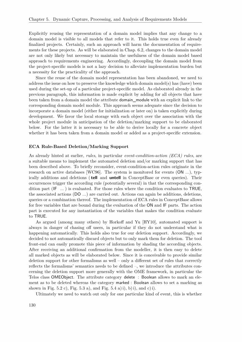
Chapter 5. Dynamic Capture, Processing, and Analysis of Requirements Models
Explicitly reusing the representation of a domain model implies that any change to adomain model is visible to all models that refer to it. This holds true even for alreadyfinalized projects. Certainly, such an approach will harm the documentation of require-ments for these projects. As will be elaborated in Chap. 6.2, changes to the domain modelare not only likely but necessary to maintain the usefulness of the domain model basedapproach to requirements engineering. Accordingly, decoupling the domain model fromthe project-specific models is not a lazy decision to alleviate implementation burden buta necessity for the practicality of the approach.
Since the reuse of the domain model representation has been abandoned, we need toaddress the issue on how to preserve the knowledge which domain model(s) has (have) beenused during the set-up of a particular project-specific model. As elaborated already in theprevious paragraph, this information is made explicit by adding for all objects that havebeen taken from a domain model the attribute domain_module with an explicit link to thecorresponding domain model module. This approach seems adequate since the decision toincorporate a domain model (either for initialization or later on) is taken explicitly duringdevelopment. We favor the local storage with each object over the association with thewhole project module in anticipation of the deletion/marking support to be elaboratedbelow. For the latter it is necessary to be able to derive locally for a concrete objectwhether it has been taken from a domain model or added as a project-specific extension.
ECA Rule-Based Deletion/Marking Support
As already hinted at earlier, rules, in particular event-condition-action (ECA) rules, area suitable means to implement the automated deletion and/or marking support that hasbeen described above. To briefly reconsider, event-condition-action rules originate in theresearch on active databases [WC96]. The system is monitored for events (ON ...), typ-ically additions and deletions ( tell and untell in ConceptBase or even queries). Theiroccurrences trigger the according rule (potentially several) in that the corresponding con-dition part (IF ... ) is evaluated. For those rules where the condition evaluates to TRUE,the associated actions (DO ...) are carried out. Actions can again be additions, deletions,queries or a combination thereof. The implementation of ECA rules in ConceptBase allowsfor free variables that are bound during the evaluation of the ON and IF parts. The actionpart is executed for any instantiation of the variables that makes the condition evaluateto TRUE.
As argued (among many others) by Horkoff and Yu [HY10], automated support isalways in danger of chasing off users, in particular if they do not understand what ishappening automatically. This holds also true for our deletion support. Accordingly, wedecided to not automatically discard objects but to only mark them for deletion. The toolfront-end can easily promote this piece of information by shading the according objects.After receiving an additional confirmation from the modeller, it is then easy to deleteall marked objects as will be elaborated below. Since it is conceivable to provide similardeletion support for other formalisms as well – only a different set of rules that correctlyreflects the formalisms’ semantics needs to be defined –, we introduce the attributes con-cerning the deletion support more generally with the OME framework, in particular theTelos class OMEObject. The attribute category delete : Boolean allows to mark an ele-ment as to be deleted whereas the category marked : Boolean allows to set a marking asshown in Fig. 5.2 c), Fig. 5.3 a), and Fig. 5.4 a) i), b) i), and c) i).
Ultimately we need to watch out only for one particular kind of event, this is whether
130
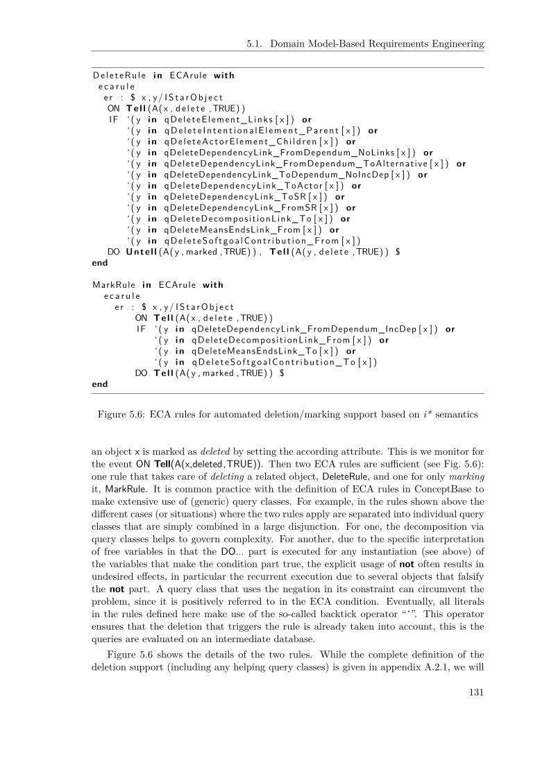
5.1. Domain Model-Based Requirements Engineering
De l e t eRu l e i n ECArule withe c a r u l ee r : $ x , y/ I S t a rOb j e c tON Tel l (A( x , d e l e t e ,TRUE) )IF ‘ ( y i n qDe le teE l ement_L inks [ x ] ) or
‘ ( y i n qDe l e t e I n t e n t i o n a l E l emen t_Pa r e n t [ x ] ) or‘ ( y i n qDe l e t eAc to rE l ement_Ch i l d r en [ x ] ) or‘ ( y i n qDeleteDependencyLink_FromDependum_NoLinks [ x ] ) or‘ ( y i n qDeleteDependencyLink_FromDependum_ToAlternat ive [ x ] ) or‘ ( y i n qDeleteDependencyLink_ToDependum_NoIncDep [ x ] ) or‘ ( y i n qDeleteDependencyLink_ToActor [ x ] ) or‘ ( y i n qDeleteDependencyLink_ToSR [ x ] ) or‘ ( y i n qDeleteDependencyLink_FromSR [ x ] ) or‘ ( y i n qDeleteDecompos i t ionL ink_To [ x ] ) or‘ ( y i n qDeleteMeansEndsLink_From [ x ] ) or‘ ( y i n qDe l e t eSo f t goa lCon t r i bu t i on_From [ x ] )
DO Unte l l (A( y , marked ,TRUE) ) , Tel l (A( y , d e l e t e ,TRUE) ) $end
MarkRule i n ECArule withe c a r u l e
e r : $ x , y/ I S t a rOb j e c tON Tel l (A( x , d e l e t e ,TRUE) )IF ‘ ( y i n qDeleteDependencyLink_FromDependum_IncDep [ x ] ) or
‘ ( y i n qDeleteDecompos i t ionL ink_From [ x ] ) or‘ ( y i n qDeleteMeansEndsLink_To [ x ] ) or‘ ( y i n qDe l e t eSo f t goa lCon t r i bu t i on_To [ x ] )
DO Tel l (A( y , marked ,TRUE) ) $end
Figure 5.6: ECA rules for automated deletion/marking support based on i* semantics
an object x is marked as deleted by setting the according attribute. This is we monitor forthe event ON Tell(A(x,deleted,TRUE)). Then two ECA rules are sufficient (see Fig. 5.6):one rule that takes care of deleting a related object, DeleteRule, and one for only markingit, MarkRule. It is common practice with the definition of ECA rules in ConceptBase tomake extensive use of (generic) query classes. For example, in the rules shown above thedifferent cases (or situations) where the two rules apply are separated into individual queryclasses that are simply combined in a large disjunction. For one, the decomposition viaquery classes helps to govern complexity. For another, due to the specific interpretationof free variables in that the DO... part is executed for any instantiation (see above) ofthe variables that make the condition part true, the explicit usage of not often results inundesired effects, in particular the recurrent execution due to several objects that falsifythe not part. A query class that uses the negation in its constraint can circumvent theproblem, since it is positively referred to in the ECA condition. Eventually, all literalsin the rules defined here make use of the so-called backtick operator “ ‘”. This operatorensures that the deletion that triggers the rule is already taken into account, this is thequeries are evaluated on an intermediate database.
Figure 5.6 shows the details of the two rules. While the complete definition of thedeletion support (including any helping query classes) is given in appendix A.2.1, we will
131

Chapter 5. Dynamic Capture, Processing, and Analysis of Requirements Models
GenericQueryClass qDe le teE l ement_L inksisA Link , NotDe leted with
paramete rx : Element
c o n s t r a i n te r : $ ( t h i s from x ) or ( t h i s to x ) $
end
QueryClass NotDeleted isA OMEObject withc o n s t r a i n t
r u l e : $ not ( t h i s d e l e t e TRUE) $end
Figure 5.7: Identify not yet deleted links of a just deleted element
focus here only a few selected query class representatives. Figure 5.7 shows the simple caseof deleting links that are associated with an element (be it an intentional or actor element)that has just been deleted. The corresponding generic query class qDeleteElement_Linksderives from Link and the query class NotDeleted to restrict the queried elements to anykind of link that is not yet deleted. The query class NotDeleted simply returns all objectswhere the delete attribute is not set to TRUE. The latter is a typical example that avoidsthe use of ‘not’ in the condition of an ECA rule to better cope with free variables. Theconstraint of qDeleteElement_Links simply checks whether the parameter x is source ordestination of the link. Only links where this is the case belong to the answer set. Asbecoming obvious when looking back at DeleteRule (Fig. 5.6), we need to define genericquery classes since queries must be parameterized (or anchored) by the actual object xthat is deleted (see ON... part) while acting in the DO... part upon all related objects ythat fulfill the condition (this is delete or mark them).
The most complex deletion support is provided in the context of dependency links(see Fig. 5.8). Remember that in the Telos representation dependency links are treatedin parts. This is a dependency link in the meaning of i* consists of three components:a link, a dependum, and another link. Thus, when referring to DependencyLink in this sec-tion, we think of the part link as introduced above. Due to the complexity, the treatmentof dependency links is split into seven query classes from which we elaborate here onlythree.
• qDeleteDependencyLink_FromDependum_NoLinks acts upon the deletion of a depen-dency link by considering the case that the source of this link was a dependum. Ifthe dependum does not have any remaining other link, it can obviously be deletedas well (see reference from within DeleteRule).
• qDeleteDependencyLink_FromDependum_IncDep acts upon the same situation butcaptures the case that the dependum does not have any outgoing dependency anymore (see reference to generic query class DelSuppNoOutLinksOfType with parameterDependencyLink) but still an incoming dependency. In this case, the dependum needsto be marked. Accordingly, this generic query class is referred to from within theMarkRule.
• Eventually, qDeleteDependencyLink_ToActor looks at the case where the destination
132

5.1. Domain Model-Based Requirements Engineering
of a just deleted dependency link is an ActorElement. Under these circumstances,the actor can be deleted if there is no (direct or indirect) incoming dependencyfrom any other actor. This is checked by asking for the instantiation of the queryclass DelSuppNotHasIncomingDependencyTransitive. This query class mainly refersto DelSuppHasIncomingDependencyTransitive where it is specified how incoming de-pendencies are suitably propagated among the i* modelling constructs:
– An ActorElement has an incoming dependency if it is directly referred towithin a DependencyLink or any of its children has an incoming dependency.
– For an IntentionalElement at SR level, again explicit incoming dependenciesare checked (via the same part of the condition as for the actor element). Fur-thermore, if a subordinate element to a task has an incoming dependency sohas the task. Similarly for goals: if an alternative has an incoming depen-dency, so has the goal.
Some Technical Remarks While all technical details are available in Appendix A.2.1,we briefly want to comment here on a few issues.
No Cycles ECA rules in general and their implementation in ConceptBase in particularbury always the danger of running into cycles. Since any of the query classes thatwe defined derive from the query class NotDeleted, we avoid cycles since the DO...part is not executed for objects that have already been deleted. Notice that objectsthat are only marked are still processed since deletion needs to override marking.But this obviously cannot cause cyclic problems as well since we do not act uponevents related to this attribute (e. g. Tell(A(x,marked,TRUE))).
Meet Graphical Characterization from above We want to argue here that the lo-cal treatment of deletion interaction matches the support described in the figuresFig. 5.2, Fig. 5.3, and Fig. 5.4. A bird’s eye view of the figures reveals that ob-jects that are affected (either deleted or marked) are indeed always directly re-lated to at least one object that is deleted. The additional constraint of not be-ing transitively related to other actors is coped with by referring the query classDelSuppHasIncomingDependencyTransitive (see above) that allows to propagate thispiece of information again to each object locally. The only exception to the aboverule is the case Fig. 5.3 b). While normally a dependum needs to be marked, if thedependency link that originates in the dependee is deleted (see Fig. 5.3 a) and thequery class qDeleteDependencyLink_FromDependum_IncDep), we suggest to deleteit if at the depender site the connection point is a task alternative at a goal.Fortunately, such more complex settings can be formalized in a query condition aswell (see qDeleteDependencyLink_FromDependum_ToAlternative in Appendix A.2.1).Once the dependum is deleted according to this special case, the necessary deletionsof the related dependency link and the task alternative result again from the lo-cal definitions and cascading re-triggering of the ECA rules for the newly markedobjects.
Restrict to Domain Model Objects For simplicity, we have omitted here the checkwhether an object that is to be acted upon is originating in a domain model. Aswith the test whether an object is already deleted, we can define a suitable query class
133

Chapter 5. Dynamic Capture, Processing, and Analysis of Requirements Models
GenericQueryClass qDeleteDependencyLink_FromDependum_NoLinksisA I n t e n t i o n a l E l emen t , Dependum , NotDeleted , DelSuppNoLinks with
paramete rx : DependencyLink
c o n s t r a i n te r : $ ( x from t h i s ) $
end
GenericQueryClass qDeleteDependencyLink_FromDependum_IncDepisA I n t e n t i o n a l E l emen t , Dependum , NotDeleted ,
DelSuppNoOutLinksOfType [ DependencyLink / type ] ,DelSuppHasIncomingDependency with
paramete rx : DependencyLink
c o n s t r a i n te r : $ ( x from t h i s ) $
end
GenericQueryClass qDeleteDependencyLink_ToActorisA ActorElement , NotDeleted ,
De lSuppNotHas IncomingDependencyTrans i t i ve withparamete r
x : DependencyLinkc o n s t r a i n t
e r : $ ( x to t h i s ) $end
QueryClass DelSuppHas IncomingDependencyTrans i t i ve isA Element withc o n s t r a i n t
inDepRule : $( ( t h i s i n DelSuppHasIncomingDependency )and ( t h i s i n NotDeleted ) ) or
( e x i s t s c h i l d / I n t e n t i o n a l E l eme n t( t h i s i n ActorE lement ) and ( c h i l d pa r en t t h i s ) and( c h i l d i n DelSuppHas IncomingDependencyTrans i t i ve ) ) or
( e x i s t s decL/Decompos i t i onL ink de s t /Element( decL from t h i s ) and ( decL to de s t ) and( decL i n NotDeleted ) and( d e s t i n DelSuppHas IncomingDependencyTrans i t i ve ) ) or
( e x i s t s meL/MeansEndsLink s r c /Element(meL to t h i s ) and (meL from s r c ) and(meL i n NotDeleted ) and( s r c i n DelSuppHas IncomingDependencyTrans i t i ve ) ) $
end
QueryClass DelSuppNotHas IncomingDependencyTrans i t i ve isA Element withc o n s t r a i n t
r u l e : $ not ( t h i s i n DelSuppHas IncomingDependencyTrans i t i ve ) $end
Figure 5.8: Partial treatment of dependency links
134
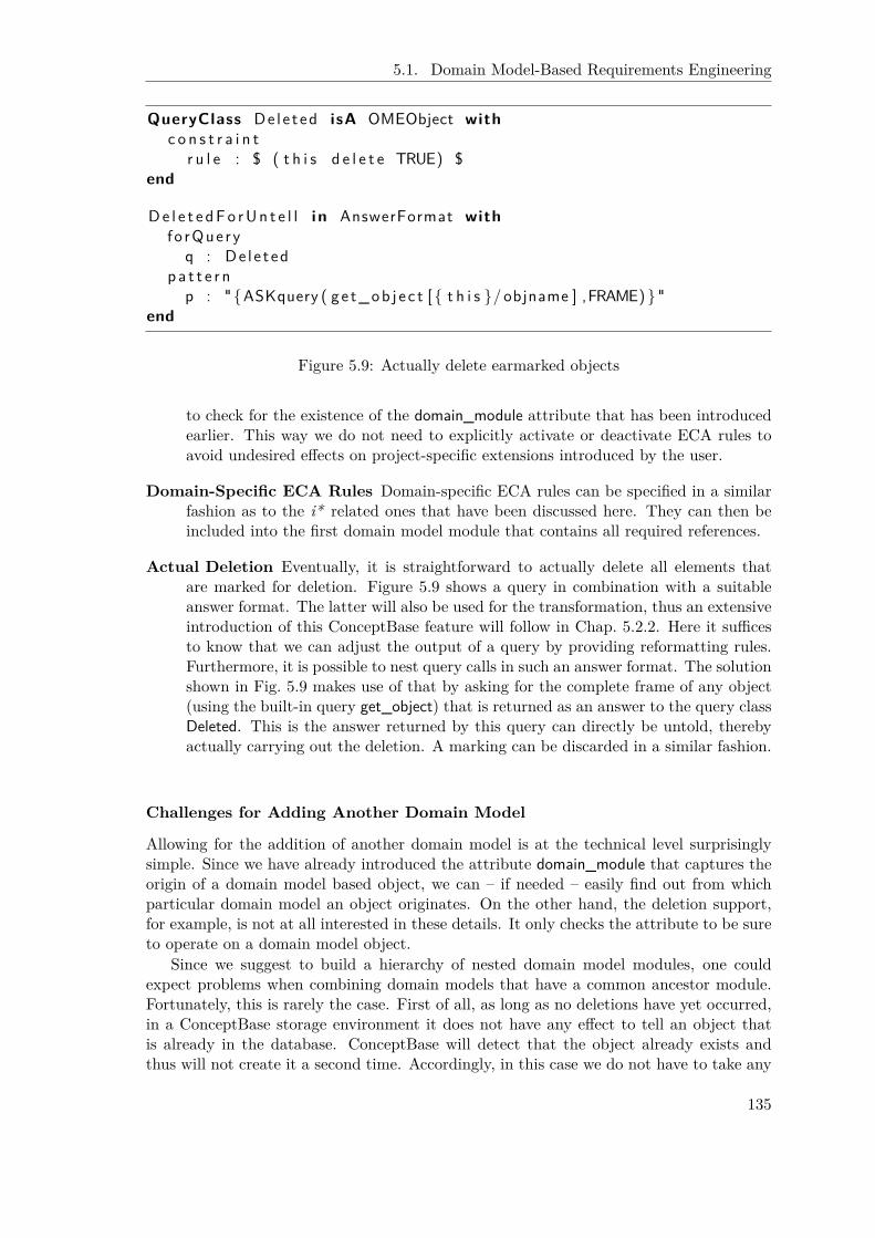
5.1. Domain Model-Based Requirements Engineering
QueryClass De le t ed isA OMEObject withc o n s t r a i n t
r u l e : $ ( t h i s d e l e t e TRUE) $end
De l e t e dFo rUn t e l l i n AnswerFormat withf o rQue ry
q : De l e t edp a t t e r n
p : "{ASKquery ( g e t_ob j e c t [ { t h i s }/ objname ] ,FRAME) }"end
Figure 5.9: Actually delete earmarked objects
to check for the existence of the domain_module attribute that has been introducedearlier. This way we do not need to explicitly activate or deactivate ECA rules toavoid undesired effects on project-specific extensions introduced by the user.
Domain-Specific ECA Rules Domain-specific ECA rules can be specified in a similarfashion as to the i* related ones that have been discussed here. They can then beincluded into the first domain model module that contains all required references.
Actual Deletion Eventually, it is straightforward to actually delete all elements thatare marked for deletion. Figure 5.9 shows a query in combination with a suitableanswer format. The latter will also be used for the transformation, thus an extensiveintroduction of this ConceptBase feature will follow in Chap. 5.2.2. Here it sufficesto know that we can adjust the output of a query by providing reformatting rules.Furthermore, it is possible to nest query calls in such an answer format. The solutionshown in Fig. 5.9 makes use of that by asking for the complete frame of any object(using the built-in query get_object) that is returned as an answer to the query classDeleted. This is the answer returned by this query can directly be untold, therebyactually carrying out the deletion. A marking can be discarded in a similar fashion.
Challenges for Adding Another Domain Model
Allowing for the addition of another domain model is at the technical level surprisinglysimple. Since we have already introduced the attribute domain_module that captures theorigin of a domain model based object, we can – if needed – easily find out from whichparticular domain model an object originates. On the other hand, the deletion support,for example, is not at all interested in these details. It only checks the attribute to be sureto operate on a domain model object.
Since we suggest to build a hierarchy of nested domain model modules, one couldexpect problems when combining domain models that have a common ancestor module.Fortunately, this is rarely the case. First of all, as long as no deletions have yet occurred,in a ConceptBase storage environment it does not have any effect to tell an object thatis already in the database. ConceptBase will detect that the object already exists andthus will not create it a second time. Accordingly, in this case we do not have to take any
135

Chapter 5. Dynamic Capture, Processing, and Analysis of Requirements Models
measure. In particular, this immediately opens up the possibility to allow for choosingmultiple domain models during the “New...” operation as mentioned earlier.
If the user has already performed deletions, this is another domain model is added onlylater on, the situation is more complicated. A first measure is to restrict the addition ofdomain model objects to objects that have been defined in modules lower than the leastcommon ancestor with any previously introduced domain model. Problematic in thiscontext is that some of these objects might refer objects defined in the common ancestormodules that have already been deleted. A defensive approach would be to add referencedobjects from the common ancestor modules until the tell operation succeeds. In the worstcase, for example a highly connected model, this will lead to a nearly full incorporation ofthe common ancestor modules’ contents. While this means that the modeller might haveto redo some cleanup steps, one can also argue that the addition of another domain modelcorrectly challenges deletion decisions that have been taken earlier. Thus, the investigationof chances for a more sophisticated approach in this regard is left for future work.
5.1.4 Case Studies
In the following, we exemplify the application of the domain model based approach in thecontext of the case study on control system development. Afterwards, we briefly outlinethe potential application to other fields as well as the SNet case study.
Control System Development
A Domain Model Hierarchy for Engine Control Problems The most basic knowl-edge in control system development is that any control problem concerns a “control cycle”compound of a “controlled system” and a “controller” that interact via “sensors” and“actuators”. Accordingly, the top level domain model “Control Problem” (see Fig. 5.10)introduces three basic roles in this regard. In particular, this is a prerequisite to theautomatic classification of whether a resource dependency (or an actor) representsa “sensor” or “actuator” (see Appendix A.1.2). By including these basic actors into thetop level domain model for control problems, this treatment is well supported. For anyspecialization of the “control problem” domain model or any tailoring to a project-specificproblem, the modeller then only needs to suitably relate the newly introduced modellingobjects to the above mentioned roles. Most likely, the top level additional actors willbe declared specializations of the above introduced roles via is-a links, refinements viais-part-of links, or will simply play these roles. The extension of the i* frameworkthat introduces the above mentioned, derived classification into “sensor” or “actuator” caneven be made part of this domain model.7 In addition to these details, the model also in-cludes already a generic “customer” representation with “costs per piece” and “reliability”as two basic goals that are typically relevant in this context. A concrete enterprise couldadd more specific issues here, if they are expected to be relevant for all of their controlproblems.
Furthermore, depending on the broadness of topics addressed, a particular enterprisecould nest a domain model that is more narrowly focused. Figure 5.11 shows, for example,a narrowing of control problems concerning “engine management”. We have highlighted
7Remember that Telos allows to add part frames, this is frames that, for example, only add an attributeor a rule. Thus if the above domain model module is incorporated, the definition of the i* modelling objectsis simply extended by these attributes.
136

5.1. Domain Model-Based Requirements Engineering
Figure 5.10: Top level domain model for control problems
the objects that are already available in the “control problem” domain model. The nesteddomain model introduces specializations of the generic “controller” and “controlled sys-tem” roles, namely “electronic control unit (ECU)” and “engine”. The latter is furtherrefined into “combustion engine block” and “air path”. The “combustion engine block”is even detailed out at the SR level. Many detailed characteristics like the type of en-gine expressed via the “cylinder positioning” (“boxer” vs. “row” vs. “V”), the “numberof cylinders”, the details of the “injection”, the kind of “cooling”, as well as the type of“fuel” are captured. Furthermore, according “actuators” for “ignition” and “injection”as well as “sensors” for “engine speed” and a “knock sensor” are introduced. Eventually,more goals (hard- as well as softgoals) are introduced for the “customer” related to“engine comfort” and “dynamics” as well as “exhaust gas restrictions” and “fuel consump-tion”. Furthermore, the “customer” is connected to the “controller” by introducing the“accelerator”.
Figure 5.12 finally shows the domain model for “combustion engines” that has actuallybeen created in collaboration with the project partners within the ZAMOMO project inparticular the Institute for Automatic Control (IRT) at RWTH Aachen University. Thefigure shows mostly only a SD level overview. More SR details in particular detailing outthe “electronic control unit” have been omitted here to improve readability but are partof the complete model. The model further refines the representation from the “enginemanagement”. Depending on the importance of sub components or their relevance from acontrol problem perspective, they can be represented explicitly as actors on their own(see, for example, “common rail” and “camshaft” in the upper left corner, that are part-ofthe “combustion engine block”). In particular if they have important sensors and actuatorsof their own, separating them out into extra actors is required for a sufficiently detailedrepresentation and improves the practicability and readability of the model. For example,the lower part of the figure is concerned with the details of the “air path”. This reflectsthe expertise of the project partner IRT concerning “exhaust gas after treatment” and“turbo charging” (a multi-value control problem, by the way). Next to the basic actors“exhaust gas after treatment” and “turbo charging” a correspondingly comprehensive setof related sensors and actuators is documented in the model.
As elaborated already before, while it would have been possible to build several sep-arate sub domain models, especially for a “gasoline” versus a “diesel engine”, a singlegood-enough model that combines all potential characteristics has evolved. This is due tothe insight that despite the conceptual differences between “gasoline” and “diesel engines”regarding, for example, the need for “ignition”, very often innovations are shared at least
137

Chapter 5. Dynamic Capture, Processing, and Analysis of Requirements Models
Figure 5.11: Specialized domain model for engine management
138

5.1. Domain Model-Based Requirements Engineering
conceptually between these two technologies. Thus, the IRT particularly decided to notseparate these things. A different enterprise or organisation (potentially with a differentfocus) could have decided differently.
As pointed out in [SDH+08], i* is also suited to capture knowledge about the qualifica-tion of control algorithms for control problems and the incorporation of knowledge aboutthe “electronic control unit platform” (or “rapid control prototyping platform”) that isavailable or limiting features thereof. Platform features constrain, for example, the set ofpotential alternatives to be considered. This is important since severe restrictions are im-posed on the “controller” by the available hardware and “electronic control unit platform”mainly due to the fact that the automotive industry is very cost sensitive. This influences,for example, the “performance” and “memory” available on the “electronic control unit”.Such circumstances and constraints as well as the suitability of control solutions to specificsettings can be captured via appropriate goals and softgoals. Figure 5.12 does notshow such details mainly due to the focus on the SD level.
In a similar fashion domain models could be introduced for fields such as “driverassistant systems”, “hybrid engines”, and the like. We do not show more examples here,since they do not differ vitally from what has been discussed already.
Exemplary Walkthrough for a New Project During an evaluation, the projectpartner VEMAC used the OpenOMEi5 tool to build basic requirements models for twocustomer projects retrospectively. One of these models is shown in Fig. 5.13 (in German).The project concerned a typical “combustion engine domain model”, accordingly, the cor-responding domain model was chosen. Since the VEMAC does not share the specializationon “exhaust gas after treatment” and “turbo charging” with the project partner IRT, largerportions of these modelling details had to be omitted. Related to the “air path” only a“throttle” component and sensors for “intake pressure”, “air temperature”, and “throttleangle” remained of interest. At the “combustion engine block”, the remaining modellingelements clearly characterize the engine: it is a “four-stroke” “gasoline” engine with only“one cylinder”. The latter option was not even foreseen in the domain model but thisalternative was added as a project-specific extension to the decomposition of the “no.of cylinders” task. Also a “testbed” actor was added indicating the major target of thecustomer project. Eventually, the VEMAC product “VeRa” was used. This is modelledby adding a plays link from the corresponding agent object to the “controller” role. Aselaborated before (see Chap. 5.1.2), such hardware restrictions narrow the solution spacein control system development much earlier than in other software engineering projects.
Potential Other Application Fields with Similar Characteristics
While the concrete domain model in the proposed approach is as a matter of coursedomain specific, the basic ideas behind the approach are applicable to other fields withsimilar characteristics as well.
Access Control and Burglary Warnings for Buildings One example for a fieldwith similar characteristics is the automation of buildings in particular in regard to accesscontrol and burglary warning. It is customer- and project-oriented since each securitysystem is specifically developed for a certain building. Nonetheless, basic components arereusable, but typically need to be adapted to the particular constraints and characteristicsof the concrete building and usage scenarios. Different kinds of burglary warning systems
139

Chapter 5. Dynamic Capture, Processing, and Analysis of Requirements Models
Figure 5.12: Domain model for combustion engine control
140
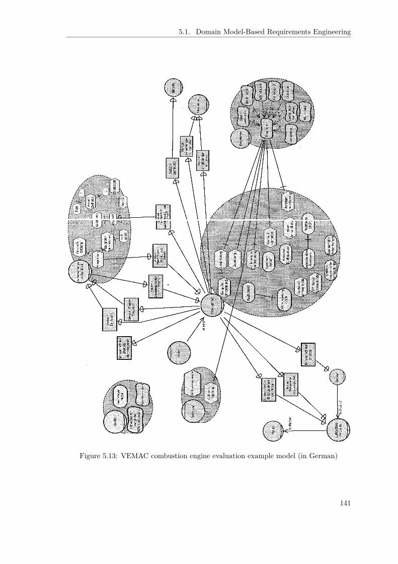
5.1. Domain Model-Based Requirements Engineering
Figure 5.13: VEMAC combustion engine evaluation example model (in German)
141
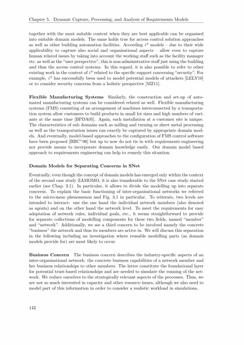
Chapter 5. Dynamic Capture, Processing, and Analysis of Requirements Models
together with the most suitable context when they are best applicable can be organisedinto suitable domain models. The same holds true for access control solution approachesas well as other building automation facilities. According i* models – due to their wideapplicability to capture also social and organisational aspects – allow even to capturehuman related issues by taking into account the working staff such as the facility manageretc. as well as the “user perspective”, this is non-administrative staff just using the buildingand thus the access control systems. In this regard, it is also possible to refer to otherexisting work in the context of i* related to the specific support concerning “security”. Forexample, i* has successfully been used to model potential models of attackers [LELY10]or to consider security concerns from a holistic perspective [MZ11].
Flexible Manufacturing Systems Similarly, the construction and set-up of auto-mated manufacturing systems can be considered related as well. Flexible manufacturingsystems (FMS) consisting of an arrangement of machines interconnected by a transporta-tion system allow customers to build products in small lot sizes and high numbers of vari-ants at the same time [BPDA05]. Again, each installation at a customer site is unique.The characteristics of sub domains such as milling and turning or sheet metal processingas well as the transportation issues can exactly be captured by appropriate domain mod-els. And eventually, model-based approaches to the configuration of FMS control softwarehave been proposed [BBC+06] but up to now do not tie in with requirements engineeringnor provide means to incorporate domain knowledge easily. Our domain model basedapproach to requirements engineering can help to remedy this situation.
Domain Models for Separating Concerns in SNet
Eventually, even though the concept of domain models has emerged only within the contextof the second case study ZAMOMO, it is also transferable to the SNet case study startedearlier (see Chap. 3.1). In particular, it allows to divide the modelling up into separateconcerns. To explain the basic functioning of inter-organisational networks we referredto the micro-meso phenomenon and Fig. 3.1 in particular. To reiterate, two levels areintended to interact: one the one hand the individual network members (also denotedas agents) and on the other hand the network level. To meet the requirements for easyadaptation of network rules, individual goals, etc., it seems straightforward to providefor separate collections of modelling components for these two fields, named “member”and “network”. Additionally, we see a third concern to be involved namely the concrete“business” the network and thus its members are active in. We will discuss this separationin the following including an investigation where reusable modelling parts (as domainmodels provide for) are most likely to occur.
Business Concern The business concern describes the industry-specific aspects of aninter-organisational network: the concrete business capabilities of a network member andher business relationships to other members. The latter constitute the foundational layerfor potential trust-based relationships and are needed to simulate the running of the net-work. We reduce ourselves to the strategically relevant aspects of the processes. Thus, weare not so much interested in capacity and other resource issues, although we also need tomodel part of this information in order to consider a realistic workload in simulations.
142

5.1. Domain Model-Based Requirements Engineering
Network Concern The network concern captures the characteristics of the chosen formof network, including behaviour immediately related to the existence of the network. Thisis processes related to the network itself (e. g. concerning the admission of new members) ornetwork-wide agreed restrictions (rules) on how to perform particular activities (e. g. a costcalculation) that affect individual member behaviour. The decision on alternatives mightalso take the current state of trust, distrust, and confidence as modalities into account,which thereby shape how delegations and communications take place. For example, withsufficient confidence a competence manager might not check for available partners beforecommitting to the client. The incorporation of trust, distrust, and confidence has beendiscussed in detail in [GJKL03, Gan08]. Furthermore, we can capture the purpose of thenetwork to ground the later simulations by specifying evaluation criteria: What is the ideabehind the network, what is the network supposed to achieve? Only once the goals areclarified, an analysis can provide insight how well or whether at all these goals are met.
Exemplarily, we show two “rules of the game” from the virtual factory [SMG98]. As-sume a “customer” has approached the virtual factory and has communicated her needsto the “broker”. After performing a first “pre-calculation”, the “broker” hands over therequest to the “competence manager” for a detailed “cost calculation” (excerpt shownin Fig. 5.14). The “competence manager” in charge (remember that any member cantake over this role in a virtual factory) has more technical knowledge and more detailedknowledge about the individual network members’ competencies and social capabilities.Thus, she analyses the task and creates detailed “checklists” for sub activities. Theyare forwarded to the appropriate network members by addressing the corresponding “in-/outsourcing managers” of the enterprises. The “checklists” are an important means toensure an efficient setup process, in particular the comparability of offers. They are verymuch appreciated by the network members due to their characteristic that they allowfor benchmarking the own enterprise against the other members of the network. Still a“selfish” network member might choose not to follow the “agreed procedure” but instead,for example, to choose a less “reliable”, in regard to scheduling more risky alternativethat makes her offer more “favorable”. In either case, any interested enterprise returnsits “cost calculation” to the “competence manager”. By analysing and comparing thesecalculations, the “competence manager” decides which “partners to select” to form “theactivated network”. Furthermore, she “appoints a task manager” responsible for the pro-duction and serving as the (single) contact for the “customer”.
The second example (modelling excerpt shown in Fig. 5.15) concerns the “admissionprocedure”. A “new member” that wants to “gain admittance” has to send an “application”to the “network coach”. She forwards this “application” to the “executive committee” andeach “in-/outsourcing member”. She is also responsible for “running an assessment”. Theindividual enterprises can either “accept” or “decline” the admittance request. For thelatter, the according “in-/outsourcing managers” can “raise objections” due to individual(bad) “business experiences”, doubts in regard to “competencies”, or “due to competition”issues. Eventually, the “executive committee” has to “decide” based on the “adherence tothe (current) admittance conditions” (agreed growth rate, number of recent admissions,etc.), the result of the “assessment”, and potentially any “veto” issued by a current networkmember. The above modelling explicates that existing members have the right to placea veto on a potential competitor’s entrance to the network. Either the network memberhas adopted the network goals (in regard to innovativeness etc.) and might allow forthe entrance of the competitor or the member emphasizes her individual goals therebyhindering the competitor to enter the network.
143
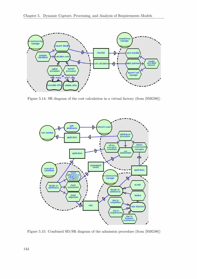
Chapter 5. Dynamic Capture, Processing, and Analysis of Requirements Models
Figure 5.14: SR diagram of the cost calculation in a virtual factory (from [SMG98])
Figure 5.15: Combined SD/SR diagram of the admission procedure (from [SMG98])
144

5.1. Domain Model-Based Requirements Engineering
For any concrete inter-organisational network, both modelling excerpts can certainlybe extended and adapted to reflect its particularities or a change in the network settingthat requires the adaptation of network rules.
Member Concern The member concern provides the general, foundational capabilitiesof a network member. For the SNet setting this encompasses mainly specific goals as wellas communication and planning facilities. Using a soft approach via softgoal contributionsand utilities correctly reflects that rules are not followed at any price. Depending onthe particular situation, an unusual option might be more appropriate and is therebyenabled via the deliberative planning component as long as it is rational. In particular,the most interesting situations arise from mismatches of individual and network goals. Forexample, the outlined approach covers also the behaviour of a “free rider” (see [GJKL03])that deliberatively harms the network (following her own selfish goals). Consequently,this ultimately enables to use simulations to challenge a network rule or check the countermeasures of a network against free riders. We do not show more examples but mentionthat we provide the formerly fixed communication protocol and planning procedure (seeChap. 2.2.3) as first contributions to this modelling concern.
Applicability of the Domain Model Based Approach It is reasonable to separatethe domain-specific business aspects from the more generic network and member aspectsto decouple reusable organisational and agent features from a concrete inter-organisationalnetwork. Treating the organisational aspect separately in particular alleviates the replace-ment and adaptation of network processes and rules, a highly likely attempt to govern anetwork. Similarly, the disentanglement of the member aspect allows for choosing a suit-able degree of detail, for example, regarding the kind of planning that is needed in aparticular setting.
Thus the highest chances for reuse can be expected at the “member” and “network”concerns. As elaborated earlier, the “member” concern is intended to provide genericcharacterisations of communication and planning facilities of a network member represen-tative. A domain model allows to provide a set of suitable starting points for individualtailorings in these regards. Similarly, the characterization of a network, for example, as an“entrepreneurship network” in contrast to a “virtual factory” has several implications onthe set of suitable or potentially relevant network rules. For example, different delegationpatterns or bidding procedures might be applicable. Accordingly, it is conceivable, thatseveral domain models are established that reflect these different circumstances. Again ahierarchy of domain model modules can be used to share modelling parts (mostly networkrules) between different kinds of networks. Eventually, the “business” concern is the onethat is depending most clearly on the individual field the enterprises within the networkare active in. Still it can make sense to build up domain knowledge here, in particular ifa particular business sector is focused, for example the IT industry.
To sum up, the domain model based approach provides a suitable means to separateconcerns as occurring in the SNet case study. They can simply be considered a top leveldistinction of domains where each concern can develop specific domain model hierarchies ofits own. As will be elaborated in Chap. 6.2, the results and experiences that are collectedwith the help of SNet simulations (see Chap. 5.3), for example on the suitability of aparticular set of network rules in a specific context, can be fed back into the evolutionof the domain models thereby providing guidance for future inter-organisational networkanalysis projects.
145

Chapter 5. Dynamic Capture, Processing, and Analysis of Requirements Models
5.1.5 Summary and Preparation for Extensions
Within this chapter we have proposed to (re-)use concrete domain knowledge alreadycaptured in models when approaching a new problem at the requirements engineeringlevel. Various strategies support the modeller in finding eligible domain models that canalso be combined to form a suitable starting point. The reference to explicit modelsavoids to reestablish experienced as well as basic knowledge in models over and overagain. Automated deletion support is available to remove parts that render irrelevantfor the concrete setting at hands. And certainly, the modeller can extend and refine themodel to match project-specific issues not yet addressed by the domain model. We haveoutlined the usefulness of domain models in various application settings, in particularcontrol system development.
Two major improvements are achieved by the proposed domain model based approachto requirements engineering. First of all, the set up of a requirements model is acceler-ated. By referring not only to previous knowledge, but the modelling of this knowledge,the developer avoids tedious modelling activities of known issues and can instead focusproject specifics. This is suitable in particular for small- and medium sized enterprises thattypically have tight time constraints as well as a narrowly focused expertise. Secondly, adomain model allows to capture the accumulated experiences of the enterprise or organisa-tion in a particular field. This is not only the experiences of one particular developer butof all people who ever contributed to customer projects are collected and made availablewithin the organisation. Thereby the domain model provides easy access to the particularmethods, tools, experiences, and expertises that are current at their site. This resource isinvaluable not only for new employees but also when experienced developers have left theenterprise. Thus, domain models also serve as a management tool for enterprise-specificexperiences and knowledge.
Furthermore, it is important to remark that the support provided via our domainmodel based approach does not end here. Instead the domain models will become im-portant again, when it comes to support inter-project dynamic requirements knowledgemanagement, as addressed separately in Chapter 6. For one, using one or several domainmodels as a common starting point reduces the heterogeneity of modelling, in particularacross several individual engineers. This is a major precondition for supporting the identi-fication of similar earlier projects at the level of requirements. Thereby, the domain modelbased approach opens up the possibility to establish a similarity search at this level (seeChap. 6.1). This in turn helps the modeller to more precisely find reusable components,thus establish a more reliable and highly likely also more competitive cost calculation.
Eventually as touched already here, the maximum benefit derived from our domainmodel based requirements engineering approach results only from a suitable tailoring tothe particular enterprise, even to the most recent situation of the enterprise. This isthe support provided from our approach depends heavily on the adequacy of the domainmodel for the day-to-day work. Neither overly large nor overly small models are helpful.Thus, in Chap. 6.2 we will address how we can support the suitable evolution of domainmodels – this is extensions and reductions – by referring back to the individual customer-and project-specific requirements models developed with their help. This results in afeedback loop that automatically tailors the domain models to the most current needs ofan enterprise or organisation.
146

5.2. Model Transformation
5.2 Model Transformation
The core advantage of a model-based approach to requirements capture is to better con-nect and integrate with the model-based development throughout the later phases. Inparticular, for control system development mathematical modelling and simulation toolssuch as Matlab/Simulink are pervasively employed during later development. Similarly,the aim of the SNet case study is to run simulations. Thus a transformation of the mod-elling to a suitable simulation formalism is an essential part of the approach. Accordingly,we consider here the related work in the field of model transformation, discuss the poten-tial support that Telos/ConceptBase can provide in this regard, and then detail out theconcrete transformations realized for the two case studies. This is we show a mappingfrom i* to Matlab/Simulink to address control system development and extend the al-ready earlier introduced mapping from i* to ConGolog (see Chap. 2.2.3) in regard to thetwo extensions “agent instantiation” and “actor evolution” from this thesis.
5.2.1 Related Work
Model Transformation according to OMG’s Model Driven Architecture®
In regard to model transformation, the work of the OMG on the Model Driven Architec-ture (MDA®, http://www.omg.org/mda) has gained highest visibility. The structuringbelow mainly follows the representation in [Che06]. It strives for placing the model at thecenter of investigation. Different abstractions during the development are intended to bederived from models of previous stages via manual or automatic transformations. Thisis intended to alleviate the development of products for various platforms, as well as toimprove the overall development quality. In case of introduced errors, previous modelscan be entered, the model is corrected and the dependent models are regenerated. This issupposed to also keep the documentation up to date, thereby alleviating or even abandon-ing future reverse engineering efforts. While the implementation of related standards suchas “Query/View/Transformation (QVT)” is not yet fully mature, the basic considerationsas given in the MDA guide [OMG03] are valid for approaches to model transformation ingeneral.
Basically two kinds of transformation are distinguished [CH03].
Model-To-Text (M2T) transformations have already been part of many early CASEtools. Their main task is to derive (program) code, documentations, configurationfiles, web service descriptions etc. from models. Typically, this is the last step in aseries of model transformation steps eventually leading to the implementation.
Model-To-Model (M2M) transformations are applicable at many different abstractionlevels, and in particular can connect models that reside at different levels of abstrac-tion. This encompasses the typical software development process from requirements,to architecture, to detailed design, to implementation. But they can also help to inte-grate models that reside at the same level of abstraction, only representing differentperspectives on the same matter using different modelling approaches.
Both kinds of transformations are needed here.The MDA stresses that the main purpose of any model based approach is to separate
the basic functioning of a system from the implementation on a concrete platform. Accord-ingly, OMG has introduced the different notions of platform independent model (PIM) and
147

Chapter 5. Dynamic Capture, Processing, and Analysis of Requirements Models
Platform independent
model
Platform specific model
Additional information (other models,
data, platform,…)
Transformation
Figure 5.16: Model transformation in MDA [OMG03]
platform specific model (PSM). The “platform” in this regard can be anything, a particularmiddleware, a programming language etc. Thus, this wording is not to be misinterpretedtoo narrowly, as for example in control system development where the platform typicallydenotes the system on which the software based controller will run eventually. Further-more, as mentioned above the platform specific model does not necessarily reside on adifferent level of abstraction. This is a model transformation can be vertical as well ashorizontal [MCG04]. Additionally, Mens et al. have introduced the orthogonal distinctioninto endogenous and exogenous denoting whether we stay within the same meta model ornot.
The basic idea of “model transformation” according to the OMG is given in Fig. 5.16.A “platform independent model” is transformed into a “platform specific model” by a“transformation” that potentially takes “additional information” such as other models,platform details, markings etc. into account. The MDA guide [OMG03] introduces also amore refined classification of model transformations into the following subtypes:
Marking Markings originate in “platform” details and are used to – manually or auto-matically – annotate a PIM. This yields an intermediate “marked PIM” that thentogether with the “mapping” details ultimately results in the corresponding PSM.
Meta model transformation It is also possible to “specify transformations” irrespec-tive of the concrete models only at the meta model level. This is in this case themapping describes relations between generic modelling elements of the modellinglanguages of PIM and PSM. This transformation specification then simply carriesover to the level of concrete models.
Model transformation If the mapping needs to watch out for concrete elements intro-duced in a particular model (instead of meta level concepts), the MDA uses the
148
5.2. Model Transformation
term “model transformation” (obviously ambiguously) to denote a transformationthat maps model-specific types with certain assumed features to concrete platform-specific types that provide these features.
Pattern application Certainly, any kind of pattern at various levels can be utilized.This is patterns at PIM level are related to patterns at PSM level. Accordingly,modelling parts from a PIM where a particular pattern applies are then transformedaccording to the corresponding PSM pattern.
Model Merging Eventually, most generally a transformation step can concern the mergeof one or several models.
The various kinds of transformations discussed above can certainly be combined to benefitfrom their different characteristics and to meet more complex transformation problems.
The OMG acknowledges that transformations are not entirely new but part of thepractice of software developers already before the specification of MDA. They also confirmthat transformations often incur design decisions and thus at least partially have to beperformed manually. But MDA emphasizes that transformations need to be represented,captured, and documented explicitly. The latter is important, for example, to reconsiderdesign decisions if a model-based developed software needs to be changed.
Three different kinds of “additional information” are distinguished and, if needed,manually or automatically added during a transformation step: patterns support generictransformation techniques, technical decisions (taken manually or by an analysis tool)control the transformation process, and quality requirements can similarly be referred todecide between different alternatives. Certainly, automated transformations are striven foras mentioned but it is widely accepted that in many situations manual decisions cannotfully be exempted.
Query/View/Transformation (QVT) The “Query/View/Transformation (QVT)”[OMG09] specification is intended to introduce a standard to capture model-to-modeltransformation. This shall support the representation, documentation, and possibly ex-ecution of model transformations. QVT provides two declarative and one imperativemanners to specify transformations. The two declaratives, “Relation” and “Core”, arerelated in that “Relation” is considered more user-friendly but can be mapped to themore technically oriented “Core” approach. Model transformations are defined by re-ferring MOF [OMG06] features and constraints specified in OCL, the object constraintlanguage [OMG10a].
Concrete Transformation Approaches
M2M In the context of Eclipse, the M2M project (http://www.eclipse.org/m2m) isconcerned with model transformations. It mainly builds on the ATL project [JLP08] thathas been around for a much longer time than the final QVT specification. Ongoing workis concerned with implementations of the three approaches defined in QVT. Since we areonly interested in the basic conceptual features of such model transformation languages,we stick with the ATL formalism.
The ATL project [JLP08] provides at the one hand a language to capture model trans-formations and on the other hand also a virtual machine to execute these transformations.ATL is able to relate two different meta models, “MMa” and “MMb”, as long as these
149

Chapter 5. Dynamic Capture, Processing, and Analysis of Requirements Models
have a common meta meta model that is also the meta meta model of ATL. In fact,MOF [OMG06] is presumed for this purpose. A concrete transformation is then specifiedas an instance to the ATL meta model and is able to work on instances of models that con-form to “MMa” and “MMb” respectively. Just as QVT, ATL has a (preferred) declarativeand an imperative part. This is mainly declarative rules are to be defined, but if necessaryrules can also be called or action blocks invoked. For navigation within the source model,OCL is used. A declarative rule encompasses a pattern to be matched in the source modelsand a pattern to be created in target models (including the initialization of newly createdelements) for each matching during the application of the rule. Patterns are defined byreferring to a labelled set of types as well as a guard to filter matches. The textual syntaxuses a frame like syntax allowing to explicitly capture the key ingredients such as sourceand target patterns. Typical object-oriented operators are available to traverse the sourcemodel or specify more complicated target patterns. There are also more advanced featuressuch as rule inheritance that are intended to help structure transformations and reuse rulesand patterns.
XML and XSLT Not only due to the promotion of XMI [OMG07a] as the primarymodel storage format to improve interoperability of modelling related tools, approaches topursue model transformation at the level of XML have been proposed. In particular XSLT,the XSL Transformation language [W3C07], is a candidate in this regard since it aims atthe transformation of XML documents. But as indicated by [TC06] and many others, thespecification of complex transformations on the basis of XML is hard. “The reasons arethat, especially when dealing with model to model transformation, the coding approachdoes not only depend on the structure of the source document, but the order of templateapplication is also dictated by target document structure. In addition to this, extensiveuse of IDREFs (i. e. references to other elements) can force developers to complicatedcomposition of recursion, variables or keys to hop around the XML tree representationlooking for some element.” We can confirm these findings from our own experiences. Dueto the availability of an XML representation of i*, called “iStarML” [CFPS08], we havetried to define the mapping to Matlab/Simulink via XSLT. As mentioned above traversingthe very flat structure of istarML required to build up a complex internal modelling of thesource model. But then any other model based transformation approach that by designprovides such more complex models has an edge over the XML based approach.
Tropos As already discussed in Chap. 2.2.2, the TROPOS methodology applies the basicconcepts of i* to the overall development of software. The tool support TAOM4E (http://sra.itc.it/tools/taom4e/) builds on Eclipse and makes in regard to transformationuse of Tefkat (http://tefkat.net). As ATL, Tefkat is a declarative model transformationlanguage based on EMF. Unfortunately, it does not seem to be researched actively anymore.
5.2.2 Supportive Telos Features
Since its genesis Telos and its implementation ConceptBase have been targeting multiformalism settings. For example, Nissen et al. [NJJ+96] have discussed how to man-age multiple requirements perspectives with meta models. Also Kethers has dedicatedlyaddressed different stakeholders and in particular the conflicts between their individual
150

5.2. Model Transformation
views that arise from cooperations [Ket00]. But transformations have not been consideredspecial first class entities in Telos.
On the other hand, current developments within the model transformation field pos-sibly eradicate this presumed shortcoming. As stated in [INR06], at least the team fromINRIA (main developer of ATL) has come to the conclusion that a more general approachtoward transformation should be chosen than just developing a particular domain spe-cific language for this purpose. Instead they promote to refer back to meta modelling.Since meta modelling is the core feature and main intention of Telos/ConceptBase, it iscertainly conceivable to formalize a meta model in Telos that captures model transforma-tions. Furthermore the “trace” capabilities that are asked for from model transformations(see above), in fact originate in work on requirements traceability [RJ01] that in turnbuilds upon Telos and ConceptBase. Accordingly, in the following we review features ofTelos and ConceptBase in regard to their potential for serving model transformations.
Queries
The advanced query facilities including the view feature [SJ00] resemble not by chancethe two important ingredients of the QVT standard, “query” and “view”. They allow todefine different perspectives on models (as long as no additional information specific toa certain perspective must be added), to work productively with conflicts by identifyingthem but also admitting to cope with them only later, or to simply query the storedmodel in any possible way. Besides the standard projection and filtering means to supporttransformations as considered also in QVT, another application of queries is to check thereadiness of a model for transformation. This is in line with the relaxed way of coping withconflicts. Certainly integrity constraints exist in ConceptBase but in many situations theseare much too strict. Any development artifact might consider ambiguities or alternativesthat need to be solved before the development can proceed, but are only to be consideredwhen the next development step is actually to be taken. Queries provide a suitable way tocheck whether the model adheres to preconditions for advancing to the next developmentphase. We will see examples for this later on in Chap. 5.2.3.
Deductive and Active Rules
If a different perspective has some additional features, it is no longer possible to main-tain only a virtual, query-based view to represent this perspective. As exemplified byKethers [Ket00] (and many others), a common meta meta model helps to clarify the rela-tions between multiple perspectives. In order to align concrete models that instantiate theperspectives’ meta models, deductive and active rules are helpful features of Telos/Con-ceptBase. As elaborated in Chap. 2.1.2, deductive rules allow to define derived attributesand instantiations. For example, the inverse of an attribute can be defined easily (seethe pair of parent/ children attributes in the i* Telos representation, Appendix A.1.1).Accordingly, deductive rules can be used to reflect dependent characteristics. But notethat you cannot edit derived attributes. This is changes to the derived characterizationwill not play back. Thus, sometimes materializing views is more appropriate. Instead ofonly building on derived information, the two modelling perspectives are then basicallyindependent. But with the help of a suitable set of active rules [WC96] any change to anyperspective can be made effective to all other perspectives involved.
In regard to transformations, deductive rules and thus derived attributes are in particu-lar helpful to capture intermediate transformation related information that is not required
151

Chapter 5. Dynamic Capture, Processing, and Analysis of Requirements Models
AnswerFormat i n C l a s s witha t t r i bu te
f o rQue ry : QueryClass ;o r d e r : Order ;o rderBy : S t r i n g ;head : S t r i n g ;p a t t e r n : S t r i n g ;t a i l : S t r i n g
end
Figure 5.17: Predefined class AnswerFormat
to materialize (e. g. a marking). Simply telling/untelling the according rule(s) during thetransformation lets the additional information appear or vanish leaving no traces behind.An example for this will follow below. Eventually, there is ongoing work to investigate thesuitability of active rules to address model transformations in general [Jeu10]. While thework is not yet completed, it seems possible to define model transformations via activerules even though tedious and rather complex since it is hard to get to know how the rulesinteract.
User-Defined Answer Formats
In Chap. 2.1.2, we briefly mentioned the feature of user-defined answer formats of Con-ceptBase as a means for complex transformations of Telos objects. Due to its obviousrelevance we elaborate this feature here.
Defining Answer Formats Answer formats are associated with queries. This is in-stead of returning a Telos frame representation, queries with an associated answer formatexperience a post-processing of the results via the specified answer format. Figure 5.17shows the essential parts of the Telos definition of AnswerFormat. The attribute forQueryestablishes the association with one (or several) query(ies). The ordering of the answerobjects is determined by specifying the relevant field and either “ascending” or “descend-ing”. The last three arguments concern the actual post-processing: head allows to specifya common introductory part, tail the same for the conclusive part. This is these two partsare evaluated only once. The core rewriting part is then pattern that is applied to eachanswer object. For all three attributes, the given String is expected to contain substringsof type expr that are replaced according standard substitution rules. Table 5.1 shows aselection of relevant substitution expressions. The possibility to call queries from withinan answer format (see ASKquery) results in the expressive power of answer formats inConceptBase. In particular, thereby it is possible to recursively traverse an entire model.
Intended Applications Two applications of answer formats are documented in theConceptBase manual [JQJ10] and the ConceptBase online forum (http://conceptbase.cc). The basic intention for the introduction of answer formats was to enable an outputthat is more appropriate for end users such as an HTML page (see http://merkur.informatik.rwth-aachen.de/pub/bscw.cgi/861833/simple_answerformats2.sml).Nowadays, the possibility to export to XML might be of greater interest. The second
152
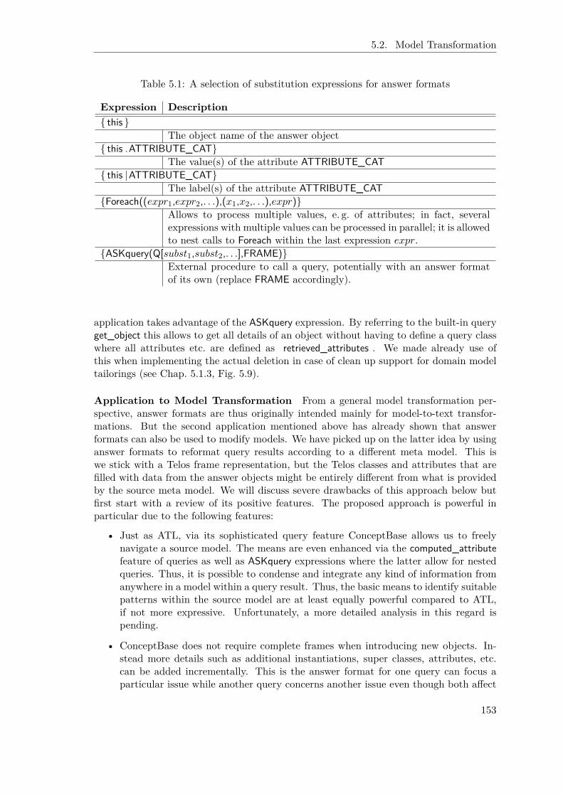
5.2. Model Transformation
Table 5.1: A selection of substitution expressions for answer formats
Expression Description{ this}
The object name of the answer object{ this .ATTRIBUTE_CAT}
The value(s) of the attribute ATTRIBUTE_CAT{ this |ATTRIBUTE_CAT}
The label(s) of the attribute ATTRIBUTE_CAT{Foreach((expr1,expr2,. . .),(x1,x2,. . .),expr)}
Allows to process multiple values, e. g. of attributes; in fact, severalexpressions with multiple values can be processed in parallel; it is allowedto nest calls to Foreach within the last expression expr.
{ASKquery(Q[subst1,subst2,. . .],FRAME)}External procedure to call a query, potentially with an answer formatof its own (replace FRAME accordingly).
application takes advantage of the ASKquery expression. By referring to the built-in queryget_object this allows to get all details of an object without having to define a query classwhere all attributes etc. are defined as retrieved_attributes . We made already use ofthis when implementing the actual deletion in case of clean up support for domain modeltailorings (see Chap. 5.1.3, Fig. 5.9).
Application to Model Transformation From a general model transformation per-spective, answer formats are thus originally intended mainly for model-to-text transfor-mations. But the second application mentioned above has already shown that answerformats can also be used to modify models. We have picked up on the latter idea by usinganswer formats to reformat query results according to a different meta model. This iswe stick with a Telos frame representation, but the Telos classes and attributes that arefilled with data from the answer objects might be entirely different from what is providedby the source meta model. We will discuss severe drawbacks of this approach below butfirst start with a review of its positive features. The proposed approach is powerful inparticular due to the following features:
• Just as ATL, via its sophisticated query feature ConceptBase allows us to freelynavigate a source model. The means are even enhanced via the computed_attributefeature of queries as well as ASKquery expressions where the latter allow for nestedqueries. Thus, it is possible to condense and integrate any kind of information fromanywhere in a model within a query result. Thus, the basic means to identify suitablepatterns within the source model are at least equally powerful compared to ATL,if not more expressive. Unfortunately, a more detailed analysis in this regard ispending.
• ConceptBase does not require complete frames when introducing new objects. In-stead more details such as additional instantiations, super classes, attributes, etc.can be added incrementally. This is the answer format for one query can focus aparticular issue while another query concerns another issue even though both affect
153

Chapter 5. Dynamic Capture, Processing, and Analysis of Requirements Models
the same target objects. The only thing that the transformation developer mustensure is that both queries use the same identifier for the target object.
• Furthermore, we want to highlight that the number and different kinds of Telosobjects (frames) that are created within an answer format is arbitrary. In particular,in contrast to a normal query, the resulting Telos frames might not have a commonstructure, super class etc. any more.
The combination of the three items from above yields a powerful, aspect-oriented approachto model transformation. A query can concentrate any information from anywhere in themodel via computed_attributes in combination with a complex query constraint that itselfrefers other query classes (and so on) or via nested query calls from within the answerformat itself (ASKquery). These details can then be evaluated and reformatted to affectarbitrary many different objects in the target model by only adding the particular aspectsnippet to their frame representation. Thus, despite of the high complexity, it is easy tolocally define transformations in an aspect-oriented manner.
But certainly, there are also severe drawbacks to this approach. First of all, it is bydefinition not fully declarative. While most of the ‘intelligence’ resides in the declarativedefinition of queries, the answer formats in the end only create strings that become validTelos objects only after retelling them to ConceptBase. Thus, if not taken care of duringthe transformation there is no explicit link between the source and the target model.But certainly, the transformation modeller can add such links manually as part of thetransformation. Still automated support in this regard would be favorable. For another,the mapping – if defined via answer formats – is necessarily unidirectional. The queriesneed to be executed on the source model and are only valid for the meta model of thesource model, while the returned Telos objects are only valid with respect to the metamodel of the target model. This is the inverse transformation has to be specified manuallyin just the same fashion. Declarative correspondences are not established.
Despite of the above mentioned drawbacks and in picking up on the tendency towardmeta model based model transformation, we see it a prolific experiment to define a model-to-model transformation with the help of answer formats, namely the transformation fromi* to Matlab/Simulink. Future work might be able to solve some of the discussed issuesby adapting this feature of ConceptBase to this yet unforeseen application.
5.2.3 Matlab/Simulink
When developing control systems software, mathematically based modelling tools suchas Matlab/Simulink [Mat10] are used for design, simulation, and implementation as ithas been introduced in Chap. 2.4 and 3.2. Thus, a continuous model-based developmentapproach in this field does not need to map requirements to, for example, UML classdiagrams but to this mathematical representation.
Basic Approach
As shown in Fig. 5.18, we have divided the transformation from i* to Matlab/Simulinkinto three steps (based on [Zha09]).
1. The first step requires manual intervention by a human developer to resolve allambiguities, this is goal alternatives, in the requirements model by taking designdecisions.
154

5.2. Model Transformation
requirements model (PIM)
refined model (PIM)
Step 1: Take design decisions
manual, support for checking readiness
automated
Step 2: Core mapping
Matlab/Simulink model (PSM – Matlab)
(PIM – RCP)
Step 3: Incorporate hardware details
specific libraries considered (PSM – RCP)
interactive, add RCP platform specific libraries
Figure 5.18: Overview of steps from i* to Matlab/Simulink
2. Secondly, the core mapping takes place by automatically generating a skeleton struc-ture in Matlab/Simulink format for the remaining solution.
3. The third step is particular to the domain of control systems development. Thedeveloper is supported by taking the intended hardware and platform details muchearlier into account as in normal software development, this is already when designingand not only when implementing.
Step 1: Take Design Decisions The intention of an i* requirements model is to cap-ture the problem characteristics and investigate various kinds of solutions. Consequently,the model is necessarily ambiguous and encompasses more than one basic solution idea.Thus before proceeding with the further development, the developer has to take designdecisions. This is unless an effective and widely accepted approach to cope with variabilityhas been established in Matlab/Simulink (as it is currently under development at variousplaces see, for example, [BPK09]), the developers have to decide for each goal whichalternative to select. To do so, the modelled softgoals and corresponding contribu-tion links certainly help as does existing tool support such as label propagation or otheralgorithms and analysis (see [HY08]). Still at its core it is a decision of the developer andthus a manual transformation step in our understanding.
We expect the developers to document their decisions in the requirements model byaccording markings. Assuming the choice (and hence marking) of one of the given alter-natives to each goal, we can easily derive an intermediate model that contains only therelevant alternatives by discarding all non-marked alternatives. This resulting intermedi-ate model serves as the input to the next transformation step.
155

Chapter 5. Dynamic Capture, Processing, and Analysis of Requirements Models
Table 5.2: Mapping i* concepts to Matlab/Simulink concepts
i* Model Matlab/Simulink Modelstakeholders actor subsystemdependencies task dependency subsystem at dependee, lines
goal dependency model information (text)softgoal dependency model information (text)resource dependency– sensor or actuator subsystem and lines– other lines only
rationale parent-child nesting of subsystemselements task subsystem
goal– no refinement model verification– refined subsystemsoftgoal model information (text)resource constant
links decomposition,means-ends, nesting of subsystemsis-part-ofcontribution – (omit)
Step 2: Core Mapping Table 5.2 shows how the concepts of i* are mapped to the con-cepts of Matlab/Simulink. Due to the simplicity of Simulink’s meta model (see Fig. 2.24)mostly a block, in Matlab called a subsystem, is the target for model transformation. Thisis especially true for all actor and task elements, whereas softgoals (dependenciesas well as SR elements) are mapped to textual hints (model information) to remindthe developer during further development of important non-functional aspects. Goalshave more varying transformation targets. As dependencies they are also mapped to amodel information element. As elements of an SR diagram they are mapped to asubsystem if they are refined. This is if an incoming means-ends link exists. If theyare not refined, they are assumed to describe hard goals that need to be achieved andtherefore are mapped to model verification elements. Resource dependencies arevery important since they are used in our approach to represent sensors and actuators(see Appendix A.1.2). In this special usage, they are also transformed in a special waysince then an additional subsystem is generated representing the sensor/actuator in Mat-lab/Simulink. Otherwise only a line, i. e. signal connection, is created from the depen-dency. Notice that due to their different semantics, the directions of an dependency andof the resulting line are opposed. This is if the “controller” depends on a “sensor” for someinformation, then we expect an incoming link to the “controller” in the Matlab/Simulinkrepresentation. At SR level, resources are mapped to blocks representing constants,since this is their most likely application. Decomposition, means-ends, and is-part-ofhierarchies are mapped to a suitable nesting of subsystems. And finally, contributionlinks can be omitted during transformation since the design decisions have already beentaken and thus their documentation is already provided for by the requirements model.
As the result of the core mapping step, we receive a Matlab/Simulink skeleton model
156

5.2. Model Transformation
that reflects the structural features of the control problem as captured in the requirementsmodel. In particular, a suitable nesting of subsystems at various levels is establishedas is the explicit representation of sensors and actuators. Line objects provide for signalconnections between the involved subsystem components. Note that by considering thespecifics of Matlab/Simulink the resulting model is platform-specific in this regard.
Step 3: Incorporate Hardware and Platform Details The mapping describedabove generically maps all functional aspects of a concrete control problem at hands toat most nested but otherwise empty subsystems. In particular, due to the missingmathematical details the resulting Simulink model is not yet executable. But the majorattraction of using Matlab/Simulink is the vast set of pre-defined and pre-implementedblocks that perform some particular computation, for example, a pre-defined “PID con-troller” with proportional, integrative, and differencing components that only need to beparameterized. Thus, the developer is expected to replace or at least detail out the emptysubsystems during the further development by more specific Matlab/Simulink compo-nents. Accordingly, the generated model is only a first initial model providing mainly asuitable structuring.
Since in control system development specifics of the underlying hardware and plat-form need to be considered much earlier than in usual software development, pieces ofinformation in this regard are possibly already part of the requirements model. This is inparticular the case if we can establish a relationship between concrete domain models ina field (see Chap. 5.1.4) and corresponding Matlab/Simulink libraries (e. g. via instantia-tion information as depicted in Fig. 4.8) or the concrete reuse at individual componentslevel resulting from the investigation of similar historic projects (see Chap. 6.1). Suchadditional knowledge should also be considered during the transformation.
As a first step in this regard, we currently assume an optional annotation of a Mat-lab/Simulink library by meta tags that categorize each element into the basic categories“sensor”, “actuator”, “controller”, and “controlled system”. In preparation to the thirdrefinement step, the modeller can specify which library(ies) to consider. By interpretingthe meta information, we can offer potential matches for the modelling elements resultingfrom the core mapping. The developer can choose interactively from these proposed con-crete Matlab/Simulink library components to replace a generic subsystem. Currently,only the categories are matched, thus for each sensor in our requirements model the devel-oper is offered all sensors from the libraries. In the future, we expect that correspondencesbetween the domain model (see Chap. 5.1.4) that is used to build up the requirementsmodel and the Matlab/Simulink libraries used for implementation in historic projects canbe exploited more extensively. Also similarity measures based on text or structural fea-tures could be taken into account (see the discussion of related work in Chap. 6.1.1).Nonetheless, already the preliminary means outlined here result in a much more tailoredand specific Matlab/Simulink model than the purely structural model skeleton that hasresulted from the core mapping of the previous transformation step.
Implementation Details
Queries to Check Readiness for Transformation We have outlined above that wecurrently presume an unambiguous requirements model when the core mapping step is tobe invoked. More explicitly, we assume that at each goal exactly one alternative is markedas chosen. Figure 5.19 shows a pair of Telos queries realizing the corresponding check. The
157

Chapter 5. Dynamic Capture, Processing, and Analysis of Requirements Models
QueryClass qCheckGoals isA GoalE lement withc o n s t r a i n t
c : $ (COUNT( qMa rk edA l t e r n a t i v e s [ t h i s ] )<>1)$end
GenericQueryClass qMa rk edA l t e r n a t i v e s isA TaskElement , Markedwith
paramete rgoa l : Goa lE lement
c o n s t r a i n tc : $ e x i s t s ml/MeansEndsLink
(ml from t h i s ) and (ml to ~ goa l ) $end
Figure 5.19: Query that checks for single alternative choice at goals
helping generic query class qMarkedAlternatives watches out for themarked alternatives (seesuper class characterization Marked) of a goal specified as the parameter to this query.The actual checking query class qCheckGoals then only has to watch out for goals wherethe number of marked alternatives as returned by qMarkedAlternatives yields a value otherthan “1”. This is similar to constructively work with conflicts (see [Ket00]) the queryreturns the goal elements where the above characterization is violated. If no element isreturned, the requirements model is in this regard ready for the core transformation step.In a similar fashion, other required properties of a requirements model to be transformedcan be checked.
Model-to-Model Transformation As mentioned above, the transformation from i*to Matlab/Simulink given in Table 5.2 is realized with the help of an ordered series ofqueries where the associated answer formats return data in accordance with the formatof the Matlab/Simulink meta model (see Appendix A.1.3). Table 5.3 names the utilisedqueries and characterizes the Matlab/Simulink data that they return. Three sub stepscan be distinguished:
1. First of all, the basic frames are created by deriving subsystem or more specializedMatlab/Simulink objects from various i* modelling constructs. Sensors and actu-ators are treated specially in that they are reflected by subsystems of their owneven if they are only represented by a resource dependency in i*.
2. Afterwards, the main structural feature of Simulink models is addressed by addingthe nesting information. This is realized by setting the parent attribute. A derivedattribute super is referred that does not only take SR parent-child relationships intoaccount but also considers decomposition, means-ends, and is-part-of relation-ships. The details of this attribute become important also in another context and arethus elaborated in Chap. 6.1.6, in particular Fig. 6.6. For the setting at hands, thischaracterization is extended by parent relationships originating in dependencies:sensor and actuator subsystems are always parented by the “control cycle” whilesubsystems resulting from other dependencies are considered subordinates to thesubsystem created for the destination modelling object at dependee side.
158
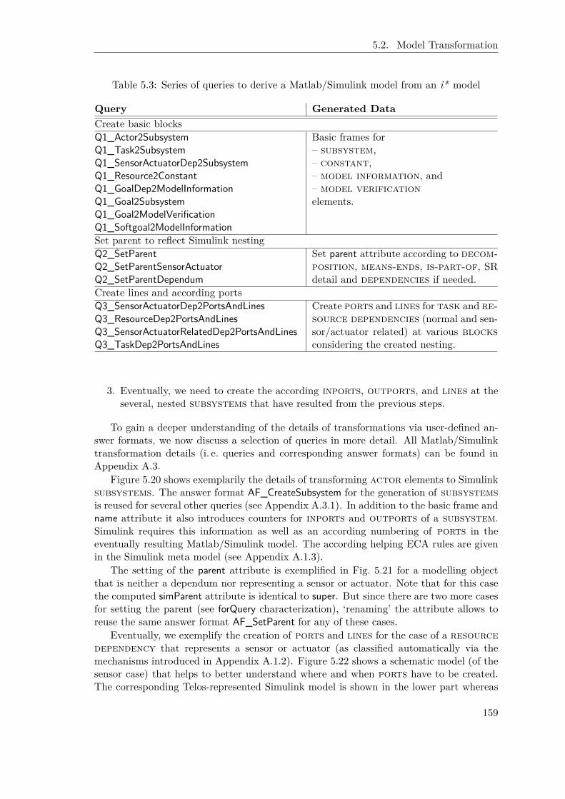
5.2. Model Transformation
Table 5.3: Series of queries to derive a Matlab/Simulink model from an i* model
Query Generated DataCreate basic blocksQ1_Actor2SubsystemQ1_Task2SubsystemQ1_SensorActuatorDep2SubsystemQ1_Resource2ConstantQ1_GoalDep2ModelInformationQ1_Goal2SubsystemQ1_Goal2ModelVerificationQ1_Softgoal2ModelInformation
Basic frames for– subsystem,– constant,– model information, and– model verificationelements.
Set parent to reflect Simulink nestingQ2_SetParentQ2_SetParentSensorActuatorQ2_SetParentDependum
Set parent attribute according to decom-position, means-ends, is-part-of, SRdetail and dependencies if needed.
Create lines and according portsQ3_SensorActuatorDep2PortsAndLinesQ3_ResourceDep2PortsAndLinesQ3_SensorActuatorRelatedDep2PortsAndLinesQ3_TaskDep2PortsAndLines
Create ports and lines for task and re-source dependencies (normal and sen-sor/actuator related) at various blocksconsidering the created nesting.
3. Eventually, we need to create the according inports, outports, and lines at theseveral, nested subsystems that have resulted from the previous steps.
To gain a deeper understanding of the details of transformations via user-defined an-swer formats, we now discuss a selection of queries in more detail. All Matlab/Simulinktransformation details (i. e. queries and corresponding answer formats) can be found inAppendix A.3.
Figure 5.20 shows exemplarily the details of transforming actor elements to Simulinksubsystems. The answer format AF_CreateSubsystem for the generation of subsystemsis reused for several other queries (see Appendix A.3.1). In addition to the basic frame andname attribute it also introduces counters for inports and outports of a subsystem.Simulink requires this information as well as an according numbering of ports in theeventually resulting Matlab/Simulink model. The according helping ECA rules are givenin the Simulink meta model (see Appendix A.1.3).
The setting of the parent attribute is exemplified in Fig. 5.21 for a modelling objectthat is neither a dependum nor representing a sensor or actuator. Note that for this casethe computed simParent attribute is identical to super. But since there are two more casesfor setting the parent (see forQuery characterization), ‘renaming’ the attribute allows toreuse the same answer format AF_SetParent for any of these cases.
Eventually, we exemplify the creation of ports and lines for the case of a resourcedependency that represents a sensor or actuator (as classified automatically via themechanisms introduced in Appendix A.1.2). Figure 5.22 shows a schematic model (of thesensor case) that helps to better understand where and when ports have to be created.The corresponding Telos-represented Simulink model is shown in the lower part whereas
159

Chapter 5. Dynamic Capture, Processing, and Analysis of Requirements Models
QueryClass Q1_Actor2SubsystemisA ActorE lement with
r e t r i e v e d _ a t t r i b u t ename : S t r i n g
end
AnswerFormat AF_CreateSubsystem withf o rQue ry
q1 : Q1_Actor2Subsystem ;q2 : Q1_Task2Subsystem ;q3 : Q1_SensorActuatorDep2Subsystem ;q4 : Q1_Goal2Subsystem
pa t t e r np : "
Token { t h i s } i n Subsystem withname n : { t h i s . name}i npo r tCoun t e r i : 0ou tpo r tCoun t e r o : 0
end"
end
Figure 5.20: Transform actors to subsystems
QueryClass Q2_SetParent isA Element , NotDependum withcomputed_at t r i bu te
s imParent : Elementc o n s t r a i n t
c : $ not ( t h i s i n Senso r ) andnot ( t h i s i n Actuato r ) and( t h i s supe r s imParent ) $
end
AnswerFormat AF_SetParent withf o rQue ry
q1 : Q2_SetParent ;q2 : Q2_SetParentSensorActuator ;q3 : Q2_SetParentDependum
pa t t e r np : "
Token { t h i s } withpa r en t p : { t h i s . s imParent }
end"
end
Figure 5.21: Set parent information by referring the deductive super attribute
160

5.2. Model Transformation
in “Sensor”
control cyclecontroller controlled system
uv
xyz
p
s
In_z_s
In_y_sIn_x_s
In_v_s
In_u_s
In_c_s Out_cs_s
Out_p_s
In_sOut_s
Figure 5.22: Transformation of a sensor resource dependency to Matlab/Simulink
161

Chapter 5. Dynamic Capture, Processing, and Analysis of Requirements Models
the implementation via the main corresponding query and related answer formats is givenin Fig. 5.23, Fig. 5.24, and Fig. 5.25. The query Q3_SensorActuatorDep2PortsAndLines(see Fig. 5.23) to identify resource dependencies that represent a sensor or actua-tor is straightforward. But while the i* representation in this particular example onlyinvolves a resource element and three dependency links, the mapping to Simulinkmust consider the nesting of generated subsystems and in particular that lines can onlyconnect subsystems that are at the same level. Explicitly representing ports helps con-quering related problems. The answer format AF_CreatePortsAndLines4SensorActuatorDep(Fig. 5.24) first addresses the source side of a dependency. Remember that for a re-source dependency due to the different semantics the direction of the resulting signalline is just the inverse. Thus, at the sensor subsystem we need to create an outportwhile at the dependency sources – in contrast to original i* we allow for more thanone source to alleviate modelling and thus have to use the Foreach expression – we needto create inports. The inports at the possibly deeply nested subsystems are createdby calling from within the answer format the query qControlParents that simply returnsall (transitive) parent elements of an object according to the previously introduced sub-system nesting. Certainly, this query has a special answer format as well that is givenin Fig. 5.25.8 It is special in that it has parameters of its own [JQJ10]. These are inparticular used to hand over ‘static’ information to uniquely label the created objects (seedependum, name) as well as to cope with the creation of in- and outports (see portType)by a single answer format only. Each intermediate inport that is created is connectedsuitably to the nested inport to arrive at a cascading information transmission. Remem-ber that it is not harmful in ConceptBase if you tell the same Telos objects twice. Thus, itmight happen, for example for In_c_s, that this frame is generated twice: once originatingfrom the task “v” in “u” and once from “z” in “x”. By taking care of deterministicallydefining the labels of objects (the common answer format AF_NestedPorts takes care ofthis), we do not run into problems and can be sure that also lines, for example, referthe correct objects. Eventually, we need to connect the sensor/actuator subsystem tothe topmost port at the “controller” and “controlled system” subsystems (see queryqControlTop). After the source side of the dependency link is processed, the same basicoperations are executed for the destination side only that we do not have to cope withseveral destinations and thus do not need the Foreach construct.
While these queries need to be posed to the i* model, the returned results must betold to a different module. For one, the target module must be prepared by providing theMatlab/Simulink meta model (see Appendix A.1.3). For another, we extensively reuseidentifiers from the i* model. In many cases, a modelling object at i* side has mainlyone corresponding object at Simulink side, in most cases a subsystem. Thus, we canuse the same identifier here. This is also a first measure to address traceability. On theother hand, this prevents us from storing an i* requirements model and the correspondingMatlab/Simulink model in the same ConceptBase module.
Interactive Addition of Hardware and Platform Details In the presentation sofar we have omitted any detail of the technical integration within the OpenOMEi5 tool.Notably the Matlab/Simulink representation specified in Appendix A.1.3 in fact also in-stantiates OME’s meta meta modelling framework. This results in the basic ability ofthe OpenOMEi5 tool to view the generated model that adheres to the Matlab/Simulink
8For convenience and to enhance readability, we have used the format {predicate :then |else} here as ashortening replacement for the actual term {IFTHENELSE(predicate ,then ,else)}.
162

5.2. Model Transformation
QueryClass Q3_SensorActuatorDep2PortsAndLinesisA ResourceElement , Dependum with
r e t r i e v e d _ a t t r i b u t ename : S t r i n g
computed_at t r i bu tes r c : Element ;d e s t : Element
c o n s t r a i n tc : $ ( ( t h i s i n Sensor ) or ( t h i s i n Actuato r ) ) and
e x i s t s dl1 , d l 2 /DependencyLink( d l 1 from ~ s r c ) and ( d l 1 to t h i s ) and( d l 2 from t h i s ) and ( d l 2 to ~ de s t ) $
end
Figure 5.23: Query resource dependencies that represent a sensor or actuator
meta model without any additional implementation efforts. Since the model does not in-clude any graphical positioning information, we only refer to the tree view provided by thefoundational GEF Eclipse framework. This is sufficient to propose alternative modellingobjects from specified Matlab/Simulink libraries according to the criteria described be-fore. The libraries are made available in OpenOMEi5 by using the below clarified Telosto XML to Matlab/Simulink transformations in just the opposite direction. Figure 5.26shows a series of screenshots that documents the features of OpenOMEi5 in regard tointeractive refinement. In particular, the user has to explicitly specify how to match theports of a Matlab/Simulink library element to the generated empty subsystem (or anyother pre-generated Matlab/Simulink block). Once this is clarified, the empty subsys-tem is replaced. When the modeller decides that any necessary refinement is taken, themodel-to-text transformation can be initiated.
Model-to-Text Transformation The above described Telos-based Matlab/Simulinkmodel is in fact only an intermediate representation. Ultimately, the transformation out-put must adhere to the specification of Simulink’s proprietary file and data format. Butthe separation into two steps allows not only to support the interactive refinement asdescribed above. In particular it disentangles the conceptual mapping from the tedioustechnical details that would have made the according answer formats much harder toread and maintain. Fortunately, we do not have to cope with all nasty details of Mat-lab/Simulink’s file format. IT Power Consult has kindly provided us with SimEx (seehttp://www.itpower.de), a tool that is able to import/export between the proprietary“.mdl” format and a corresponding XML representation. Thus, in the following we onlydiscuss means to generate output that adheres to the XML specification as provided byIT Power consult.
The transformation is again realized with the help of user-defined answer formats,now resembling much more the original intention. Table 5.4 summarizes the relevantsteps again by listing the according queries. The actual transformation query is precededby a series of queries that update the Matlab/Simulink model in place. This includesthe addition of an overall top level subsystem that integrates all subsystems that donot have a parent in the model yet. Matlab/Simulink simply requires a single top level
163

Chapter 5. Dynamic Capture, Processing, and Analysis of Requirements Models
AnswerFormat AF_CreatePortsAndLines4SensorActuatorDep withf o rQue ry
q : Q3_SensorActuatorDep2PortsAndLinesp a t t e r n
p : "
Token Out_{ t h i s } i n Outport withpa r en t p : { t h i s }
end{ Foreach ( ({ t h i s . s r c }) , ( o ) ,
Token In_{o}_{ t h i s } i n I n p o r t withpa r en t p : {o}name n : { t h i s . name}
end{ASKquery ( qCon t r o lPa r en t s [ { o}/ sou r c e ] ,
AF_NestedPorts [ In /portType , { t h i s }/dependum ,{ t h i s . name}/name ] ) }
Token LineOut_{ t h i s }_{ASKquery ( qContro lTop [ { o}/ sou r c e ] , LABEL) }i n L ine with
from f : Out_{ t h i s }to t : In_{ASKquery ( qContro lTop [ { o}/ sou r c e ] , LABEL) }_{ t h i s }pa r en t p : Con t r o lC y c l eRo l e
end ) }Token In_{ t h i s } i n I n p o r t with
pa r en t p : { t h i s }endToken Out_{ t h i s . d e s t }_{ t h i s } i n Outport with
pa r en t p : { t h i s . d e s t }name n : { t h i s . name}
end{ASKquery ( qCon t r o lPa r en t s [ { t h i s . d e s t }/ sou r c e ] ,
AF_NestedPorts [ Out/portType , { t h i s }/dependum ,{ t h i s . name}/name) }
Token L ine In_ { t h i s }_{ASKquery ( qContro lTop [ { t h i s . d e s t }/ sou r c e ] , LABEL) }i n L ine with
from f : Out_{ASKquery ( qContro lTop [ { t h i s . d e s t }/ sou r c e ] , LABEL) }_{ t h i s }to t : In_{ t h i s }pa r en t p : Con t r o lC y c l eRo l e
end"
end
Figure 5.24: Answer format for a resource dependency representing a sensor/actuator
164
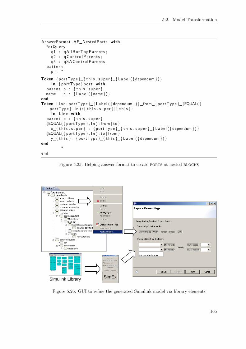
5.2. Model Transformation
AnswerFormat AF_NestedPorts withf o rQue ry
q1 : qAl lButTopParents ;q2 : qCon t r o lPa r en t s ;q3 : qSACont ro lParent s
p a t t e r np : "
Token { portType }_{ t h i s . s upe r }_{ Labe l ({ dependum}) }i n { portType } po r t with
pa r en t p : { t h i s . s upe r }name n : { Labe l ({name}) }
endToken L ine { portType }_{ Labe l ({ dependum}) }_from_{portType }_{EQUAL({
portType } , I n ) : { t h i s . s upe r } | { t h i s }}i n L ine with
pa r en t p : { t h i s . s upe r }{EQUAL({ portType } , I n ) : from | to }
x_{ t h i s . s upe r } : { portType }_{ t h i s . s upe r }_{ Labe l ({ dependum}) }{EQUAL({ portType } , I n ) : to | from}
y_{ t h i s } : { portType }_{ t h i s }_{ Labe l ({ dependum}) }end
"end
Figure 5.25: Helping answer format to create ports at nested blocks
Simulink Library SimEx
Figure 5.26: GUI to refine the generated Simulink model via library elements
165

Chapter 5. Dynamic Capture, Processing, and Analysis of Requirements Models
Table 5.4: Queries to receive an XML representation of the Telos Simulink model
Query Generated DataIn-place updates of the Matlab/Simulink modelQ4_TopSubsystemsQ4_LinesWOParentQ4_PortWOName
Introduce TopSubsystem object and set this asparent for not yet parented subsystems andlines; generate port name if non existent.
M2T Transformation Providing XML OutputQ5_Simulink_M2T_TransformationHelped by q**2XML, qLine, qPort
Recursively transfer entire model starting fromTopSubsystem.
subsystem. Similarly all lines that have not yet been assigned a parent are assignedto this subsystem. And eventually, all ports that have not yet a name, are assigned adefault name constituted from a ‘prefix’ denoting the kind, Inport vs. Outport, andthe number. Appendix A.3.2 shows all details. The actual transformation to XML isthen triggered by executing the query Q5_Simulink_M2T_Transformation (see Fig. 5.27).It traverses the entire model from the before introduced TopSubsystem onward. This isachieved by recursively working through all children and lines of a modelling object byinvoking ASKquery from within the answer formats, this is AF_TopLevel2XML for the toplevel subsystem (see Fig. 5.27). A child is transformed by choosing the suitable query andanswer format via the queries ChildType and AF_ChildType. Both identify the Simulinkmeta model class that is instantiated by the child and return the corresponding tailoredquery or answer format, respectively. Lines are processed accordingly. Full details aregiven in Appendix A.3.3.
Tool Overview Figure 5.28 summarizes the overall process of transforming i* modelsto Matlab/Simulink models. At the same time it clarifies the roles of the various tools thatare involved. The developer starts by modelling in OpenOMEi5. Also the design deci-sions are taken here. The automatic model-to-model transformation is performed withinConceptBase and results in a first Simulink model. This model can be investigated andrefined by the developer again via OpenOMEi5. In particular existing Matlab/Simulinklibrary elements can be chosen as replacements for generated subsystems. After the in-teractive refinement, the model-to-text transformation is again performed by ConceptBaseleading to an XML output that is eventually converted by the SimEx tool to arrive at an“.mdl” file ready to use in Matlab/Simulink.
Example: Parking Assistant
As an example, we pick up here on the design of a “parking assistant” as introduced inChap. 3.2.1. Figure 5.29 shows the (simplified) requirements modelling in this regard.Besides the “parking assistant” the “car” as well as the “environment” are consideredimportant stakeholders. The “parking assistant” is part of the “controller” whereas theother two stakeholders are part of the “controlled system”. In regard to actuators andsensors, Fig. 5.29 shows that the “parking assistant” depends on the “environment” for“distance” information and on the “car” for “velocity”. In turn, the “car” receives inputfrom the “parking assistant” in regard to “steering” and potentially also “acceleration” and
166

5.2. Model Transformation
View Q5_Simulink_M2T_Transformation isA Subsystem withi n h e r i t e d _ a t t r i b u t e
name : S t r i n g ;c h i l d r e n : Block ;l i n e : L i n e
c o n s t r a i n tc : $ ( t h i s = TopSubsystem ) $
end
AnswerFormat AF_TopLevel2XML withf o rQue ry
q : Q5_Simulink_M2T_Transformationhead
h : "
<S imu l i nk><Model>
<Name>" ; { cu r r en tmodu l e}" ;</Name>"
pa t t e r np : "
<System><Name>" ; {UQ({ t h i s . name})}" ;</Name>{Foreach ( ({ t h i s . c h i l d r e n }) , ( c ) ,
<Block>{ASKquery ({ ASKquery ( Chi ldType [ { c }/ c ] , LABEL) } [{ c }/ ob j ] ,
{ASKquery ( AF_ChildType [ { c }/ c ] , LABEL) }) }</Block>) }
{ Foreach ( ({ t h i s . l i n e }) , ( l ) ,<L ine>
{ASKquery ( qL ine [ { l }/ l ] , AF_Line2XML) }</ L ine>) }
</System>"
t a i lt : "
</Model></ S imu l i nk>
"end
GenericQueryClass Chi ldType isA QueryClass withparamete r c : Blockc o n s t r a i n t
r : $ ( ( c i n Subsystem ) and ( t h i s = qSubsystem2XML ) ) or( ( c i n Port ) and ( t h i s = qPort2XML) ) or( ( c i n SFunct ion ) and ( t h i s = qSFunction2XML ) ) or( ( c i n Re f e r enc e ) and ( t h i s = qReference2XML ) ) or( ( c i n Constant ) and ( t h i s = qConstant2XML ) ) $
end
Figure 5.27: Excerpt of the queries and answer formats needed to generate XML output
167

Chapter 5. Dynamic Capture, Processing, and Analysis of Requirements Models
ConceptBase
System modulei* module
query i* model, reformat results
via answer format
Model-to-model
i* models
i* framework
.mdl file
by IT Power Consult
Simulink module
Simulink models
Simulink framework
query-based XML export
Take design decisions
OpenOMEi5
SimEx
manually
Incorporate HW & Platform
OpenOMEi5
interactively
Matlab/ Simulink XML file
Model-to-text
Matlab/Simulink
Figure 5.28: Technical details for the transformation from i* to Matlab/Simulink
Figure 5.29: Combined SD and SR diagram for a parking assistant
168
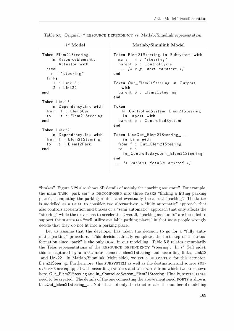
5.2. Model Transformation
Table 5.5: Original i* resource dependency vs. Matlab/Simulink representation
i* Model Matlab/Simulink Model
Token E lem21Stee r i ngi n ResourceElement ,
Ac tuato r withname
n : " s t e e r i n g "l i n k s
l 1 : L ink18 ;l 2 : L ink22
end
Token Link18i n DependencyLink with
from f : Elem6Carto t : E l em21Stee r i ng
end
Token Link22i n DependencyLink with
from f : E l em21Stee r i ngto t : Elem12Park
end
Token E lem21Stee r i ng i n Subsystem withname n : " s t e e r i n g "pa r en t p : Con t r o lC y c l e. . . {∗ e . g . po r t c o u n t e r s ∗}
end
Token Out_Elem21Steer ing i n Outportwith
pa r en t p : E l em21Stee r i ngend
TokenI n_Cont ro l l edSys t em_Elem21Stee r i ngi n I n p o r t with
pa r en t p : Con t r o l l e dSy s t emend
Token LineOut_Elem21Steer ing_ . . .i n L ine with
from f : Out_Elem21Steer ingto t :
I n_Cont ro l l edSys t em_Elem21Stee r i ngend. . . {∗ v a r i o u s d e t a i l s omi t ted ∗}
“brakes”. Figure 5.29 also shows SR details of mainly the “parking assistant”. For example,the main task “park car” is decomposed into three tasks “finding a fitting parkingplace”, “computing the parking route”, and eventually the actual “parking”. The latteris modelled as a goal to consider two alternatives: a “fully automatic” approach thatalso controls acceleration and brakes or a “semi automatic” approach that only affects the“steering” while the driver has to accelerate. Overall, “parking assistants” are intended tosupport the softgoal “well utilize available parking places” in that most people wronglydecide that they do not fit into a parking place.
Let us assume that the developer has taken the decision to go for a “fully auto-matic parking” procedure. This decision already completes the first step of the trans-formation since “park” is the only goal in our modelling. Table 5.5 relates exemplarilythe Telos representations of the resource dependency “steering”. In i* (left side),this is captured by a resource element Elem21Steering and according links, Link18and Link22. In Matlab/Simulink (right side), we get a subsystem for this actuator,Elem21Steering. Furthermore, this subsystem as well as the destination and source sub-systems are equipped with according inports and outports from which two are shownhere, Out_Elem21Steering and In_ControlledSystem_Elem21Steering. Finally, several linesneed to be created. The details of the one connecting the above mentioned ports is shown,LineOut_Elem21Steering_.... Note that not only the structure also the number of modelling
169

Chapter 5. Dynamic Capture, Processing, and Analysis of Requirements Models
Figure 5.30: “Control cycle” subsystem of resulting Matlab/Simulink model
objects that are needed to represent the information differ for the two models, suitablyreflecting the different ways the two meta models capture information. The interactiverefinement step can consider different technologies to realize “distance measures”, for ex-ample infra-red vs. ultrasonic, as well as a particular rapid control prototyping systemssuch as “VeRa” provided by our project partner VEMAC in ZAMOMO. Eventually, Fig-ure 5.30 shows the content of the “control cycle” subsystem as a result of the mapping.Next to the subsystems for “controlled system” and “controller”, you also see the sub-systems that result from sensor and actuator relationships (e. g. “distance”, “steering”,etc.) each with suitable ports. In contrast, the more detailed sub actors “parking as-sistant”, “environment”, and “car” as well as any SR detail from Fig. 5.29 are not visiblesince they are internal parts of the before mentioned subsystems.
5.2.4 ConGolog
The basic transformation from i* to ConGolog has already been introduced in Chap. 2.2.3as part of the report on previous work on the SNet simulation environment. Notablyeven though it is supported by ConceptBase, the actual transformation is realized inJava. But it seems unproblematic (only tedious) to rewrite the transformation usingthe now proposed approach via user-defined answer formats. Unfortunately, this has tobe left for future work. Instead we discuss below only the modifications to the previoustransformation that originate in extensions made within this thesis. Namely two issues arerelevant here, agent instantiation (Chap. 4.1) and actor evolution (Chap. 4.2). We do nottreat them separately since the need to dynamically assign roles to agents as requiredby actor evolution supersedes the static assignments required for agent instantiation.
170

5.2. Model Transformation
% Former t r a n s f o r m a t i o n r e s u l tr e p o r tQu a l i t y ( v e n t u r e C a p i t a l i s t , v i c t o r , do ( a , s ) ) = Val ≡
( a = doEva l ua t i on ( facultyMember , f r ed , PID , _)∧ Val = r e p o r tQu a l i t y ( v e n t u r e C a p i t a l i s t , v i c t o r , s ) + 1)
∨ ( a = doEva l ua t i on ( facultyMember , mike , PID , _)∧ Val = r e p o r tQu a l i t y ( v e n t u r e C a p i t a l i s t , v i c t o r , s ) + 2.3)
∨ ( a 6= doEva l ua t i on ( facultyMember , f r ed , PID , _)∧ a 6= doEva l ua t i on ( facultyMember , mike , PID , _)∧ Val = r e p o r tQu a l i t y ( v e n t u r e C a p i t a l i s t , v i c t o r , s ) )
% New t r a n s f o r m a t i o n r e s u l tr e p o r tQu a l i t y ( v e n t u r e C a p i t a l i s t , SuperAgent , do ( a , s ) ) = Val ≡
( a = doEva l ua t i on ( facultyMember , Agent , PID , _)∧ Val = r e p o r tQu a l i t y ( v e n t u r e C a p i t a l i s t , SuperAgent , s )
+ Repo r tQua l i t yCon t r ( facultyMember , doEva lua t i on , Agent , s ) )∨ ( a 6= doEva l ua t i on ( facultyMember , Agent , PID , _)∧ Val = r e p o r tQu a l i t y ( v e n t u r e C a p i t a l i s t , SuperAgent , s ) )
Figure 5.31: Contrasting old and new representation of contribution details
Adapting to Dynamic Agent Instantiation and Role-Based Modelling
Although there is a big conceptual difference between our previous practice of explicitagent modelling and modelling roles that are (dynamically) instantiated, this does nothave a great impact on the basic transformation of i* modelling constructs and the result-ing ConGolog programs. This is due to the fact that we have already used the identifier ofan agent as a parameter to all primitive actions, procedures, fluents, precondition, andsuccessor state axioms that result from its modelling (see Fig. 2.13). Thus, this mappingcan be adopted one-to-one for mapping the role-based modelling part. Only the agentparameter now becomes a variable that needs to be dynamically restricted to the agentsthat currently play this role.
The dynamic linkage between agents and roles is certainly captured via a suitablerelational fluent RoleCurrentlyPlayedBy(Role, Agent). It can be set to the initial instantia-tion by using the standard initially (Fluent , Value) predicate. The only missing piece toget this information respected during simulation is then to include a check of this fluent inall concerned precondition (and where appropriate successor state) axioms. Since Agent isonly a parameter, the role-based modelling provides all necessary information to do so.9
Instantiation parameters such as contribution or duration (or any future addition) canbe treated in a similar fashion. Again, the role-based transformation creates ConGologcode that simply does not refer a particular, concrete value any more but an according(functional) fluent that is parameterized by Agent. Figure 5.31 contrasts the old way(upper part) with the new representation (lower part) by referring to the instantiation(see Tab. 4.1) of the entrepreneurship setting (see Fig. 4.6, only omitting the internal “doevaluation” task of the “venture capitalist” for the sake of clarity). The need to represent
9This extension establishes at the same time the check for the suitability of a proactivity initiated bya user, since the same test is used within the precondition axiom of the corresponding exogenous action.Thus, for an entrepreneurship scenario instantiating the model shown in Fig. 4.6 the initiation of “earnmoney” succeeds only for an agent that is currently playing the role “venture capitalist”.
171

Chapter 5. Dynamic Capture, Processing, and Analysis of Requirements Models
proc ( supe r ( d e l e g a t o r , SuperAgent , PID , T) ,[ s upe r ( pre , d e l e g a t o r , SuperAgent , PID , _) ,
p i ( Agent ,[ ? ( Ro l eCu r r en t l yP l a y edBy ( de l e ga t e e , Agent ) ) ,d e l e g a t e ( sub ( d e l e ga t e e , Agent , PID , _) ) ] ) ,
s upe r ( post , d e l e g a t o r , SuperAgent , PID , _) ] )
Figure 5.32: Considering role-based modelling when mapping delegations
also the instantiation values as fluents (see ReportQualityContr in Fig. 5.31) arises fromactor evolution. An agent that is newly acquiring a role must be given accordingvalues that are provided by the instantiation functions introduced earlier. Notably thisenables that an agent that plays a role a second time can have varying instantiationcharacteristics realistically reflecting the experiences she has gained in between. Thus, thevalues of these fluents are set during the acquisition of a new role by an agent. Thiswill be discussed in more detail below.
The above introduced representation of agent instantiation also affects the mappingof delegations. Originally delegations had to be explicitly modelled as alternatives toan artificial goal in order to choose between different agents that can perform thedelegation. Figure 5.32 schematically shows the new mapping of a delegation, this isa decomposition or means-ends link that traverses actor boundaries. While for anormal, role internal decomposition or means-ends link, the transformation onlyreturns a call to the corresponding procedure resulting from the sub element (see Fig. 2.13),this call is now embedded in a pi construct where the Agent variable certainly is the valueto be picked. To avoid unnecessary communication with agents that do not play therequired role, the body of the pi construct consists of a sequence of an according test(see Fig. 5.32) and the delegation procedure call. As before, the latter is marked speciallyby delegate (...) to suitably trigger communication.10
Mapping Evolution Links, Acquire and Lose Conditions
The above introduced new relational fluent RoleCurrentlyPlayedBy(Role,Agent,s) is affectedby actor evolution via two new primitive actions acquire(Agent,Role) and lose (Agent,Role). The corresponding, straightforward successor state axiom is shown in Fig. 5.33. Moreinteresting is how evolution links as well as acquire and lose conditions are mapped.Basically, the source of an evolution link is interpreted as an additional precondition forthe according evolution. Only if an agent is currently playing the source role the detailedacquire condition needs to be considered at all. Thus, as a first part of the transformation,any acquire condition is extended by adding the term RoleCurrentlyPlayedBy(Src, Agent)∧ ...” where Src denotes the name of the source role. The conditions themselves areextended by the suppressed Agent parameter. Furthermore, any simplified reference no-
10In principal, the above test is dispensable since the poss axiom of the first primitive action resultingfrom the delegated modelling object can serve the same purpose. But as mentioned above, the explicit testsignificantly reduces the interaction overhead esp. in simulations with a large set of heterogeneous agents.
172

5.2. Model Transformation
Ro l eCu r r en t l yP l a y edBy ( Role , Agent , do ( a , s ) ) ≡( a = a c qu i r e ( Agent , Ro le ) )
∨ ( ( a 6= a c q u i r e ( Agent , Ro le ) )∧ ( a 6= l o s e ( Agent , Ro le ) )∧ Ro l eCu r r en t l yP l a y edBy ( Role , Agent , s ) )
Figure 5.33: Successor state axiom for fluent RoleCurrentlyPlayedBy
Table 5.6: Mapping evolution links, acquire, and lose conditions
Condition Resulting ConGolog Codenormal evolution(Src → Dest) i n t e r rup t ( Ro l eCu r r en t l yP l a y edBy ( Src , Agent )
∧ [acquire condition]) ,a c q u i r e ( Agent , Dest ) )
mutually exclusiveevolution(Src ⇒ Dest)
i n t e r rup t ( Ro l eCu r r en t l yP l a y edBy ( Src , Agent )∧ [acquire condition]) ,
[ l o s e ( Agent , Src ) , a c q u i r e ( Agent , Dest ) ] )
lose conditionfor role r i n t e r rup t ( Ro l eCu r r en t l yP l a y edBy ( r , Agent )
∧ [lose condition]) ,l o s e ( Agent , r ) )
tation (including the “.” notation) must be mapped to the corresponding fluents storingthe relevant information. The mapping is tedious but straightforward, thus omitted here.Without loss of generality, we can assume that each requested piece of historical informa-tion is available in the current situation since we only have to introduce a fluent to recordand provide it.
In Chap. 4.2 we anticipated already that within the SNet case study currently we as-sume the acquire and lose conditions to be both necessary and sufficient. This is wheneverthey are fulfilled the according evolution takes place. This in turn yields that the moststraightforward mapping to ConGolog are triggers, this is the interrupt construct. Threecases have to be distinguished as shown in Tab. 5.6. For normal evolution links (→) simplythe (extended) acquire condition is checked and if this holds true, the acquire primitiveaction is executed. For mutually exclusive evolution links (⇒) the condition is checkedin the same manner but before the new role is acquired, the source role is droppedby executing the lose primitive action. Accordingly, for a lose condition, the condition ischecked and if true the concerned role is dropped (again via the lose primitive action).Eventually, all the individual triggers for all evolution links and lose conditions asdescribed above only need to be combined into a single procedure using the concurrencyconstruct conc. This procedure is then called from the simulation main loop, more pre-cisely the “deliberative phase” as shown in Fig. 2.15. This yields that whenever a condition
173
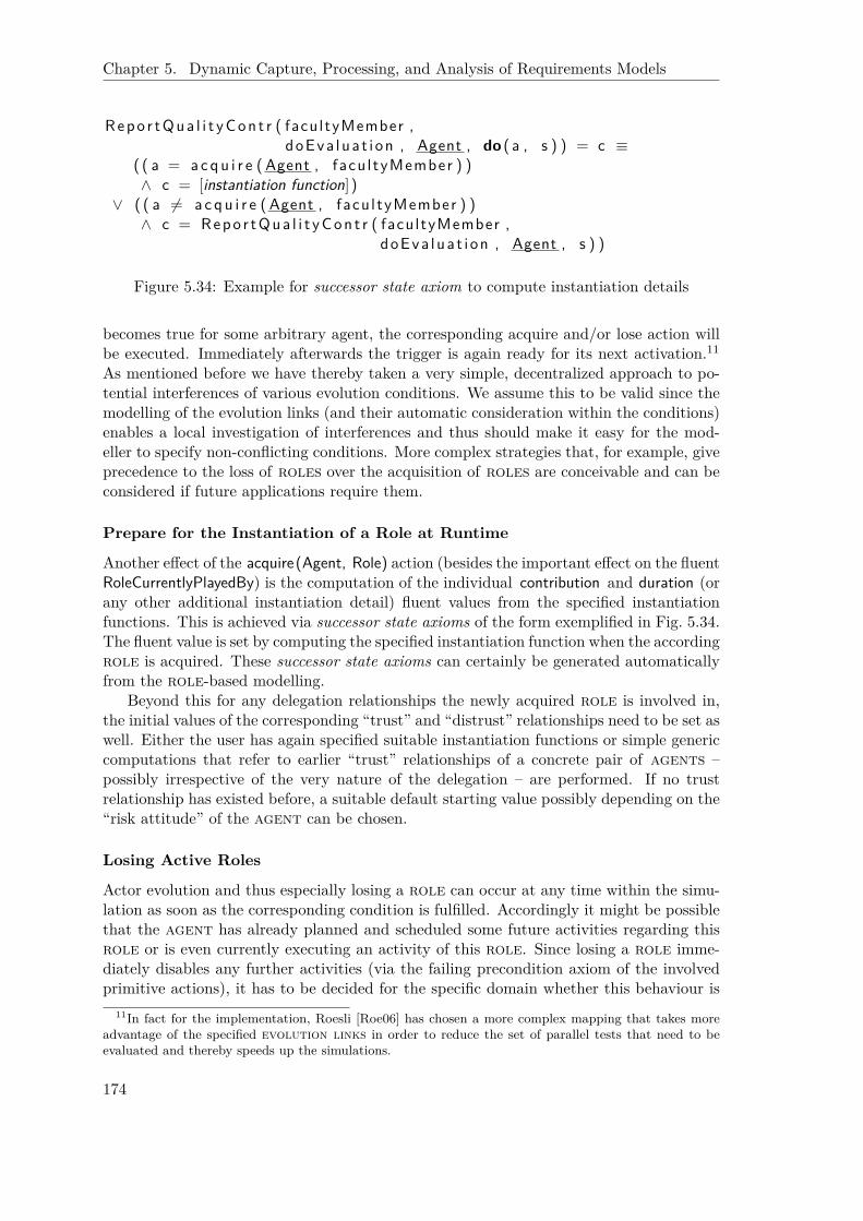
Chapter 5. Dynamic Capture, Processing, and Analysis of Requirements Models
Repo r tQua l i t yCon t r ( facultyMember ,doEva lua t i on , Agent , do ( a , s ) ) = c ≡
( ( a = a c qu i r e ( Agent , facu l tyMember ) )∧ c = [instantiation function])
∨ ( ( a 6= a c q u i r e ( Agent , facu l tyMember ) )∧ c = Repo r tQua l i t yCon t r ( facultyMember ,
doEva lua t i on , Agent , s ) )
Figure 5.34: Example for successor state axiom to compute instantiation details
becomes true for some arbitrary agent, the corresponding acquire and/or lose action willbe executed. Immediately afterwards the trigger is again ready for its next activation.11
As mentioned before we have thereby taken a very simple, decentralized approach to po-tential interferences of various evolution conditions. We assume this to be valid since themodelling of the evolution links (and their automatic consideration within the conditions)enables a local investigation of interferences and thus should make it easy for the mod-eller to specify non-conflicting conditions. More complex strategies that, for example, giveprecedence to the loss of roles over the acquisition of roles are conceivable and can beconsidered if future applications require them.
Prepare for the Instantiation of a Role at Runtime
Another effect of the acquire(Agent, Role) action (besides the important effect on the fluentRoleCurrentlyPlayedBy) is the computation of the individual contribution and duration (orany other additional instantiation detail) fluent values from the specified instantiationfunctions. This is achieved via successor state axioms of the form exemplified in Fig. 5.34.The fluent value is set by computing the specified instantiation function when the accordingrole is acquired. These successor state axioms can certainly be generated automaticallyfrom the role-based modelling.
Beyond this for any delegation relationships the newly acquired role is involved in,the initial values of the corresponding “trust” and “distrust” relationships need to be set aswell. Either the user has again specified suitable instantiation functions or simple genericcomputations that refer to earlier “trust” relationships of a concrete pair of agents –possibly irrespective of the very nature of the delegation – are performed. If no trustrelationship has existed before, a suitable default starting value possibly depending on the“risk attitude” of the agent can be chosen.
Losing Active Roles
Actor evolution and thus especially losing a role can occur at any time within the simu-lation as soon as the corresponding condition is fulfilled. Accordingly it might be possiblethat the agent has already planned and scheduled some future activities regarding thisrole or is even currently executing an activity of this role. Since losing a role imme-diately disables any further activities (via the failing precondition axiom of the involvedprimitive actions), it has to be decided for the specific domain whether this behaviour is
11In fact for the implementation, Roesli [Roe06] has chosen a more complex mapping that takes moreadvantage of the specified evolution links in order to reduce the set of parallel tests that need to beevaluated and thereby speeds up the simulations.
174

5.2. Model Transformation
appropriate. Other strategies can be implemented by specifying appropriate preconditionsand/or effects of/to the lose action or even expanding the body of the triggers definedabove. For example, for the SNet setting we prefer a strategy that allows an agent tocomplete a currently executed activity, but to simply cancel future activities, potentiallyinforming the delegator as well as the chosen sub contractors. This can easily be realizedby including a check in the precondition axiom of the lose action that blocks this actionas long as the current activity (note that this is also available as a fluent, currentJob)concerns the role to be lost. Similarly, we can associate the effect on the schedule, thisis the elimination of planned tasks, as well as the sending of messages to delegator and/orsub contractor as effects with suitable successor state axioms for the lose action.
Outlook: Deliberation about Alternative Evolutionary Paths
A shortcoming of the approach to actor evolution as it has been presented so far is itsrestriction to a purely deterministic and reactive consideration of evolutionary steps. Ourexample in Fig. 4.11 concerning entrepreneurial stages has already shown a situation wherea role can be reached via two possible evolutionary paths. To reiterate, an entrepreneurcan arrive at its “consolidation stage” either via the normal evolutionary path along “1stgrowth stage” and “2nd growth stage” or she can leave out the “2nd growth stage”. Whichof these two alternatives is taken by a particular agent in a given situation depends inour current reactive implementation only on the specified acquire conditions. But thefulfilment of these conditions refers implicitly to the agent’s performance throughout itslifetime, since the conditions are composed of the characteristics listed in Table 4.2. Thisin turn means that any or at least some choices an agent has made so far in her lifetimeinfluence the possibilities for evolution now and in the future. It is only that the agents(or their deliberative components, respectively) are currently not aware of this.
To raise the agent’s awareness of evolutionary issues and to consequently give her moreexplicit control about her own strategic evolution, it seems only natural to consider thealready existing decision-theoretic planning component (see Chap. 2.2.3). While the setof actions (or alternatives, respectively) is not necessarily affected, the utility computa-tion has to cover next to “trust”, “gain”, and business specific issues now also strategicevolutionary considerations. From a modelling perspective these can be captured simplyby another series of softgoals (at the individual “member” concern, Chap. 5.1.4) andaccording contributions from the various (“business” concern related) roles that char-acterize the roles in regard to their advantages and disadvantages. This characterizationcan then be used as the criteria according to which an agent decides which evolutionarypath to prefer. Figure 5.35 shows exemplarily the pros and cons of becoming a “businessangel” vs. simply staying an “entrepreneur”. While the work as a “business angel” is likelyto be more “enthralling & varied” as well as to yield a higher “salary” also the “workingtime” can be expected to increase. Each agent has to individually weight these criteriaagainst each other. To arrive at an encompassing assessment of an agent’s current evolu-tionary chances we should consider the set of roles that are currently played (and thuscan be lost) as well as the roles that could be played in the future. The latter set is givenby the roles that are directly or indirectly (depending on the utilised prediction horizon)connected to the current roles via evolution links. Also the partial fulfillment (see,for example, [ST07]) of the according acquire and lose conditions should be taken intoaccount. Apart from this no other adaptations, for example concerning the basic trans-formation, are required. Also the newly introduced softgoals and contributions can
175

Chapter 5. Dynamic Capture, Processing, and Analysis of Requirements Models
Figure 5.35: Softgoals and contributions concerning the evolution to a business angel
be mapped as usual and then simply be considered with their resulting utilities within theexisting deliberative planning component.
5.2.5 Transformation Summary
This section has established (or adjusted, respectively) a core aspect in regard to supportfor model-based development, namely model transformations. For one, an entirely newconnection between i* requirements models and mathematical Matlab/Simulink modelshas been established. For another, the mapping from i* to ConGolog to enable simulationsof i* models has been changed to accommodate the extensions proposed in this thesis,agent instantiation and actor evolution. Accordingly, for both case studies the develop-ment or investigation, respectively, can now be carried out in a fully model-based mannersupported by – to a large degree automated – transformations.
Notably for model transformations, a new realization with the help of user-definedanswer formats, a ConceptBase feature, has been proposed. While there is yet only onecase study, the mapping from i* to Matlab/Simulink, the approach seems feasible andworth to be researched more deeply in the future. In particular Telos-endogenous M2Mtransformations were originally not intended. This results in several shortcomings. Ifadopting the standard “query-view-transformation” nomenclature, the query and viewrepresentation of ConceptBase is certainly very powerful and comparable with ATL, forexample. The source model can be queried in any form including the possibility to returnderived or computed attributes or any other detail. But while powerful expressions, suchas nested queries, can be used within the transformation part, the returned result still isa String. Accordingly, the transformation is not aware that its ultimate result is again amodel. One consequence of this is that the transformation is necessarily unidirectional.Furthermore, the matching of concepts is captured only at a syntactical level. The in-troduction of macro-like answer format templates (not requiring a cumbersome sub querycall) could alleviate the situation as well as further simplify the overall transformationanswer formats. In particular, such templates would allow us to prescribe the constitutionof a particular target model element only once and use the according template anytimewhen such a modelling object is to be generated (only suitably parameterized by the cur-rent query result).12 Still, the appealing feature to incrementally grow a target model asprovided via the frame representation in ConceptBase should be retained since it allowsthe developers to nicely structure and simplify the mapping by separating distinct aspects.
12Templates might be realizable via the expressive “function” feature, yet details have to be untangledin future work.
176

5.3. Simulations and Their Analysis
Altogether, from a template extension as proposed above, it seems only a small step toarrive at a model-aware transformation that allows to make use of explicit correspondencesbetween (meta) models possibly defined at a (meta) meta level (including generic measuresto address traceability).
Apart from the transformation technology, future work should also concern a deeperintegration with the domain model based development approach (see Chap. 5.1). This mayresult eventually even in the foreseen possibility to simulate requirements models early alsowithin control system development. In addition due to the consolidated nature of domainrequirements models, according design and implementation artifacts typically exist. Thusthe interactive refinement step can be automated to a larger degree by utilising the knownconnections between domain requirements models and design or implementation detailssuch as dedicated Matlab/Simulink libraries. This further reduces the efforts of developersand leads to a faster arrival at a practical solution.
5.3 Simulations and Their Analysis
As motivated in the introduction (see Chap. 1.2) simulations can be helpful in requirementsengineering for various purposes. A typical reason for applying agent-based simulations– also here for the case of inter-organisational networks – is that a comprehensive un-derstanding of the overall situation is not straightforward. Accordingly, the problem isdecomposed into smaller, less complex subunits, namely agents. But obviously, we expectthe interaction of many such agents to be non-trivial but helpful in regard to understand-ing the overall problem. Not surprisingly, the simulations themselves are then hard toanalyse. Two major aspects of simulations intended to reflect real world behaviour needto be considered:
• For one, we need to ensure that the designed simulations and settings correctlyreflect the real world, this is validating them. This includes preliminary checks ofmodels (and their modifications) to avoid lengthy simulations that only result intechnical errors, for example due to the fact that the central situation of interest isnever reached.
• For another especially in complex multi stakeholder settings, support is needed toevaluate and interpret simulation runs and outcomes to advance the understandingof the investigated problem in order to eventually tackle it or at least pave the wayto its governance.
In this chapter, we discuss issues related to the core simulation abilities of the SNetmodelling and simulation environment. While the modelling with i* and the accordingtransformation to ConGolog have been topics in previous sections (see Chap. 2.2.3 andChap. 5.2.4), the outcomes of simulations and their analysis are addressed here. In par-ticular, we discuss the usefulness of various kinds of analysis, namely Formal Tropos,Secure Tropos, time series analysis, association rule mining, clustering, and social networkanalysis, to support the two issues mentioned above, validation and data interpretation.
5.3.1 Related Work
For the discussion of related work, we restrict ourselves to only two issues. For one, weagain briefly review the employment of simulations in the field of requirements engineering.
177

Chapter 5. Dynamic Capture, Processing, and Analysis of Requirements Models
For another, we more deeply discuss agent-based simulation approaches since our approachalso originates in this field.
Simulations for Requirements Engineering
Despite the before mentioned anticipated usefulness (see [Chr99]), simulation tools areonly sparsely used in the context of requirements engineering yet. Early work in this fieldas documented by an according GI working group on “simulation tools for requirementsengineering” [SRB+00] has focused on simulating the system to be developed by derivingsuitable executable models (often GUI-focused) from requirements specifications (see, forexample, [LBH97]). This can be considered a part of a rapid prototyping approach. Ina similar fashion, more recent work on state-based [HM03] as well as Use Case basedsimulations [Som06] mainly focus the developed software and in particular the interactionwith the user. Beyond that Seybold, Meier, and Glinz [SMG04] address the vaguenessand necessarily evolving character of requirements model by transferring concepts fromtesting to allow for partial simulations as the models are detailed out incrementally.
Simulations have also been used to investigate various aspects of the requirements engi-neering process itself. Already in 2000, Christie and Staley [CS00] discuss the usefulness ofsimulation models for evaluating a software development process. More recently, Ferreiraet al. [FCSM09] and earlier Pfahl and Lebsanft [PL00] focus the volatility of requirements.Port, Olkov, and Menzies [POM08] consider various strategies toward requirements pri-oritizing. Höst, Regnell, and Tringström designed a general framework for simulatingrequirements engineering processes [HRT08]. In principal, all these ideas build on earlierwork that concerns the investigation of the dynamics of software development [AHM91].
With the work at hands, we place ourselves somewhere in between of these two ex-treme positions. Just as Formal and Secure Tropos (see Chap. 2.2.4 and Chap. 2.2.5,respectively), we are indeed concerned with a particular software development (and notthe development process in general). But in contrast to earlier approaches we consider notonly the system to be developed but also the overall setting including the organisational,social, and technical environment and possibly the dynamics of evolving, designing, andadapting a new system. Our simulation based approach nicely complements the model-checking based analysis of Formal Tropos as well as the static Datalog-based inter-actoranalysis of Secure Tropos as will be elaborated in more detail below.
Multi Agent-Based Simulation
Agent-based simulations have been identified as a suitable measure to address complexmulti-stakeholder settings (see, for example, [Uhr99, CM99, Klü01]. A large number oftools and programming environments have emerged over the years. Several well-knownare summarized in Tab. 5.7 together with some characteristic features that help to figureout the specifics of our own approach, SNet, also included in the table.
In regard to the considered structures many agent-based simulation tools presumesome kind of spatial distribution of agents and thus focus 2D or 3D visualizations inwhich the agents live. Others can at least add an arbitrary network layer allowing notonly neighboured agents to interact. A few frameworks are completely general and thusdo not impose any particular structure on their agents.
From a modelling and configuration perspective, most environments still expect theagents to be programmed in some suitable, potentially special purpose programming lan-guage (or just plain Java). Thus, graphical modelling as well as model-based configurations
178
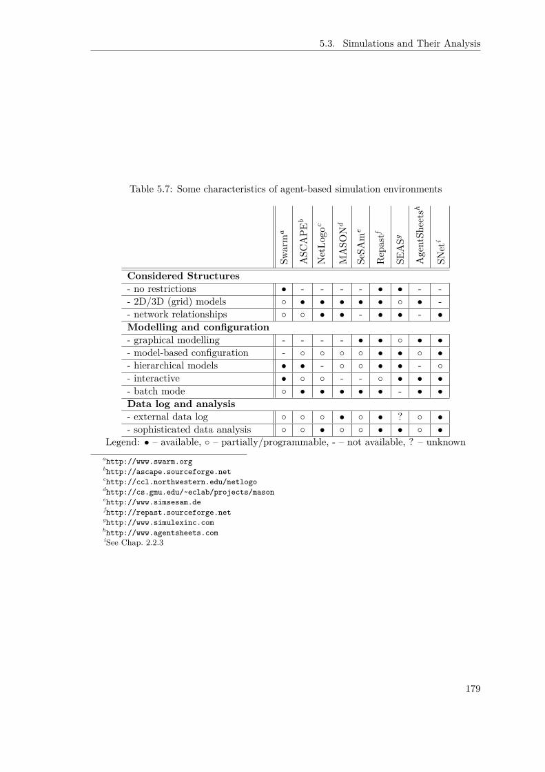
5.3. Simulations and Their Analysis
Table 5.7: Some characteristics of agent-based simulation environments
Swarm
a
ASC
APE
b
NetLo
goc
MASO
Nd
SeSA
me
Rep
astf
SEASg
AgentSh
eets
h
SNet
i
Considered Structures- no restrictions • - - - - • • - -- 2D/3D (grid) models ◦ • • • • • ◦ • -- network relationships ◦ ◦ • • - • • - •Modelling and configuration- graphical modelling - - - - • • ◦ • •- model-based configuration - ◦ ◦ ◦ ◦ • • ◦ •- hierarchical models • • - ◦ ◦ • • - ◦- interactive • ◦ ◦ - - ◦ • • •- batch mode ◦ • • • • • - • •Data log and analysis- external data log ◦ ◦ ◦ • ◦ • ? ◦ •- sophisticated data analysis ◦ ◦ • ◦ ◦ • • ◦ •
Legend: • – available, ◦ – partially/programmable, - – not available, ? – unknownahttp://www.swarm.orgbhttp://ascape.sourceforge.netchttp://ccl.northwestern.edu/netlogodhttp://cs.gmu.edu/~eclab/projects/masonehttp://www.simsesam.defhttp://repast.sourceforge.netghttp://www.simulexinc.comhhttp://www.agentsheets.comiSee Chap. 2.2.3
179

Chapter 5. Dynamic Capture, Processing, and Analysis of Requirements Models
are not yet widespread. But several systems allow to hierarchically combine models toaddress the complexity of a concrete application domain. Furthermore, many agent-basedsimulations expect a scenario to be built and then a simulation run to be initiated. Whileit is possible to pause these simulations or proceed stepwise, many only observe the be-haviour of agents. Only few provide means to directly interfere with the agents in thesimulation, with SEAS being the most extreme example in this regard since the agentsform here only the game board of a management game. On the other hand, many envi-ronments provide means to run several simulations in batch mode, for example to probea whole range of parameter settings.
Eventually, data log and analysis capabilities are of relevance to us. There are only fewenvironments that record data in such a way that they can easily be provided to externaltools. In many cases, this feature has to be programmed individually. In regard to theadditional analysis that are provided the situation is about to change. While earlier thefocus was on agent-based animations or at most graphical plots of some variables, moreand more tools add sophisticated analysis, in particular via external tools such as Matlabor Mathematica, data mining tools such as WEKA (http://www.cs.waikato.ac.nz/ml/weka/), or social network analysis frameworks such as JUNG or yFiles (discussed below).For the integration with external tools, the means to create externally readable data logsis of course a great simplification.
Thus, in sum agent-based simulations are currently turning from an observing toy orgaming experience toward just another form of experimental environment that producesdata that can be fed to and investigated by existing complex analysis software.
5.3.2 Simulations with SNet
Remember that the simulations that we have enabled by mapping i* to ConGolog (seeChap. 2.2.3 and 5.2.4) differ considerably from rapid prototyping technologies. In our SNetsimulations the user does not interact directly with the “system-to-be” but investigates thescenario from a third person’s view. Thus, both — users and developers — can see howthings are supposed to run once the intended system is in place. This emphasises nicely theenvironment of the intended system and thus picks up on the stress the original i*/Troposapproach puts on modelling the environment. Such high-level simulations might providea suitable means to help predict how a new or altered system will change the environmentespecially the processes therein, thereby revealing a misconfiguration (also in regard tosecurity) or opportunities for further improvements. The findings can be fed back intothe formal models, be analysed, for example, with Formal Tropos (see Chap. 2.2.4) andSecure Tropos (see Chap. 2.2.5) means, and provide a new starting point for another setof simulations.
Another nice feature of ConGolog that encourages this approach is the free choice ofgranularity. As detailed out in Chap. 2.3, the simulations build on a basic action the-ory that has to be specified by the modeller. While this might seem tedious at a firstglance (though automated support is provided), it is a major advantage. The modelleris free to decide about what is “primitive” in her world. Consequently, she can alwayschoose the most appropriate level of granularity for the analysis and simulations. Thus,the preciseness of the simulations follows strictly the refinements of the model. If a modelis improved and detailed out, renewed simulations might reveal different, new issues. Insum, this provides an alternative approach to address the vagueness and evolution of re-quirements compared to the one taken by Seybold, Meier, and Glinz [SMG04] (see above).
180

5.3. Simulations and Their Analysis
Analysis support snapshots, traces
ConceptBase
i* modelling role-based,
actor evolution, rules, …
OpenOMEi5
Configuration instantiation, initial setting, control dataOpenOMEi5
ConGolog simulations planning,
communication, evolution, …
IndiGolog, Prolog
Time Searcher 2, Rapid Miner, …User Refinements
Modifications (e.g. rules)
Transformation
Figure 5.36: Renewed overview of SNet concept and tool interaction
One prominent example where such a high-level simulation could be helpful concerns astrong point of the TCD approach (see Chap. 2.1.5), namely the consideration of the dy-namics of trust. The SNet modelling and simulation environment can be used to projecthow the “system-to-be” can earn the trust of its users. This can lead, for example, to agradual realization of a system leaving the users enough time to gain confidence into it.
Revisiting the SNet Tool Architecture
Figure 5.36 is a refinement of Fig. 2.17 reflecting the contributions of this thesis. Toaccommodate the extension in regard to actor evolution the modelling as well as thetransformation had to be enriched but this does not at all impact the overall architectureand interaction of the involved tools. In contrast, switching from the modelling of indi-vidual agents to a role-based modelling requires to introduce an explicit instantiationstep. As will be detailed later on, this certainly alleviates the modification of simulation“configurations”. In particular, the degree of re-initiating model transformations is re-duced. Eventually, as to be clarified in this chapter, the user is no longer left alone withthe outcome of ConGolog simulations. She is now assisted by analysis support in form oftools that allow to investigate a particular scenario as well as relating a series of simulationtraces. Altogether the contributions made within this thesis are an important step towardthe practical applicability of the approach.
We will now have a closer look at the different kinds of data that are to be provided andthat are produced when running simulations. Three different kinds can be distinguished:
1. generic role based modelling,
2. simulation configurations consisting of
(a) the instantiation of generic roles,
181

Chapter 5. Dynamic Capture, Processing, and Analysis of Requirements Models
(b) the characterization of an initial setting, e. g. by specifying values for trustrelationships, and
(c) simulation run control data to run larger sets of simulations unattended bypre-specifying proactivities of actors, and
3. run-time data to log the events and characteristics of a single simulation run resultingin a suitable simulation trace amenable to further analysis.
The first kind simply encompasses the modelling with i* (see Chap. 2.2.1) by focusingroles instead of agents. The according resulting data representation is given by thecorresponding Telos frames. Also the instantiation has already been considered and isagain captured via suitable agent related Telos frames (see Chap. 4.1). In particular,they fill in the details prescribed by the instantiation information hierarchy. In order tocomplete this modelling to arrive at the specification of an initial setting, only minor ex-tensions are needed as will be discussed below. Thus we retain the way of representing itby again assuming a suitable enrichment of the Telos details. Note that this simplifies theusage of the overall environment. Since any situation of a different simulation run mightbe taken as the initial situation of a new run, it is a nice feature, if we can store snapshots,this is current situations within a simulation, simply to ConceptBase and retrieve the rep-resentation for later runs. Next while we can derive proactivities from the generic rolebased modelling (and its instantiation) – these are simply top level activities within rolesthat do not answer a delegation – the concrete details of an individual activation at sim-ulation run-time have to be captured as well. This is also coped with below. Eventually,we must prepare for feeding the various analysis tools that we have identified to possiblybenefit our investigations. While the sum of information captured so far allows to repro-duce a particular simulation setting, the details of a simulation trace with ups and downsof characteristic features are not yet covered. Relying on only a small number of heavyweight simulation snapshots stored in Telos is insufficient, in particular the representationin Telos will highly likely become a bottleneck. Instead a suitable logging mechanism isneeded to store the run-time data along a simulation run. This is also in line with otheragent-based simulation environments, such as Repast Simphony, that similarly captures ageneric model, a simulation configuration, and run-time data analysis.
In the rest of this chapter, we continue the investigation of relevant simulation databy specifying data to characterize initial settings as well as to control the proactivitiesof agents. Afterwards we describe how the dynamic run-time data are logged. Theapplication is exemplified exclusively for our model- and logic-based simulations of inter-organisational networks; applications in the field of control system development or require-ments engineering in general have not yet been experimented with but will be commentedon in summary and outlook.
Simulation Configuration
Many agent-based simulation environments, e. g. RePast (http://repast.sourceforge.net), provide sophisticated means to configure simulations by setting ranges of inputparameters for which several simulations can be run automatically. For model-based ap-proaches (including our own), the gathering of the according data can be supported byautomatically generated input tables. For the SNet tool this has been exemplified alreadyin Chap. 4.1, in particular Fig. 4.4 by showing how to instantiate the generic role-based
182

5.3. Simulations and Their Analysis
modelling. The information covered here is prespecified by a concrete, application de-pendent “instantiation information hierarchy” as exemplified for the SNet case study inFig. 4.5. It is straightforward to reapply this approach to accommodate also the specifi-cation of initial settings. For the SNet case study, the relevant data encompass:
• initial values for trust (distrust, confidence) relationships the agents have with eachother (or exhibit toward the entire network),
• individual experience values (e. g. on overall durations or softgoal contributions)as long as they are relevant for planning (pre-scheduling of the current deliberativeplanning component), and
• other characteristic, situation-dependent features such as the level of gain or availableresources.
The details of the representation in Telos are at most tedious but otherwise straightfor-ward. An encompassing characterisation has been given in [Arz08]. The mapping toConGolog only results in predicates to set initial values for the according fluents, namelyinitially (Fluent , Value).
Simulation Control Data While in many agent-based simulation environments, theuser only specifies a range of initial settings that need to be tried out, we give the investi-gator more control. Any activity in our simulations can be traced to the proactivity of aparticular agent that is to be initiated by the user. As detailed out in Chap. 2.2.3, theinitiation encompasses not only a unique identifier PID, but also the time T when theactivity should be started, values for any parameter of the modelling element (such as thesubject to a course), and eventually a weighting of involved softgoals that is used by thedeliberative planning component to decide between different modelled alternatives. Therequired data can most suitably be stored simply as a list of exogenous primitive actions.This list is then automatically worked through by the SNet simulation environment. Notethat it is advantageous to store this information separately from the other informationdiscussed so far, since this allows to freely combine it with arbitrary different settings. Inparticular for the evaluation of different measures to overcome a problematic situation, itis helpful to only change the role-based modelling or the instantiation but otherwise donot touch the basic triggering of a simulation, since this just reflects what has happenedpotentially in the real world.
Collecting Dynamic Data
As a prerequisite for running more advanced analysis on agent-based simulations, theaccording simulation data must be accessible. In particular the user has to specify whatdata to collect. The foundation of our simulation approach in the situation calculusmakes this easy. As introduced in Chap. 2.3, relational and functional fluents representthe current state of the world. Thus, the user only has to specify the fluents that areto be logged. Then each time a primitive action is executed the corresponding successorstate axioms are checked. If a relevant fluent is affected, the execution engine createsthe according output. A flat, XML-based logging format is flexible enough to feed anytool, in particular due to the applicability of standard query and transformation languagessuch as XSLT [W3C07]. They allow for selecting, updating, and aggregating data [HK06]even after a simulation has been run. Furthermore, we have taken care that the format is
183

Chapter 5. Dynamic Capture, Processing, and Analysis of Requirements Models
defined in a way that allows for continuous analysis in parallel to long running simulations.This enables the detection of interesting intermediate situations for which branching couldbe lucrative.
Figure 5.37 shows the basic structure. Within the encompassing tag <simulationData>an individual <timepoint> is established if there is a change in a <fluentValue>. At thispoint it comes down to the individual logged data. Exemplarily, we have mentioned <trust>, <cooperation>, and <cooperationResult> here. These examples show that relevantrelated information can arise at various time points. For example, the trust relationshipsat the time of planning a cooperation might be of interest as well as which agent did notoffer its participation or was not selected. Later on, the success (or cancellation) of thecooperation needs to be recorded as well as the (possibly execution-dependent) effect ontrust and gain (if applicable).
Figure 5.38 shows an excerpt of the recorded information regarding trust issues andcooperation details in our simple entrepreneurship setting concerning the interaction of“venture capitalists” and “faculty members” in regard to the delegated task “do eval-uation” (see Chap. 4.1.4, in particular Fig. 4.6 and for the instantiation Tab. 4.1). Asto be exemplified later on with concrete examples, it can make sense to aggregate col-lected data before applying analysis [HK06]. For example, the aggregation of trust valuesacross several/all agents could make sense, if only the overall level of trust in a network isinvestigated. With the help of XSLT, this kind of preprocessing is easily possible.
5.3.3 Analysis Questions Exemplified for the SNet Case Study
The simulation models that result from the transformation from i* to ConGolog currentlyfocus investigations of strategic issues in (inter-)organisational settings. While it is con-ceivable to employ the basic transformation also to allow for the validation of controlsystem requirements, this idea has not been pursued so far. Accordingly, we will solelyconsider the SNet case study in the following. Furthermore, in contrast to previous chap-ters, we will introduce the case study including relevant questions to be investigated withthe help of high-level analysis beforehand. This allows to better relate the different kindsof analysis in regard to what kind of questions they are able to address.
Validation Questions
As simulations are nowadays becoming the third column of scientific investigation (besidesexperiments and theory), the validity of the simulation model is gaining more and moreimportance. In particular in the field of control system development [Lun03], this isalready widely accepted. To reiterate, control system engineers use a detailed model ofthe controlled system to understand the control problem and only afterwards develop asuitable controller. But before the model can be used, it has to be ensured that it correctlyreflects the real world. Thus, expensive testbed experiments are run to validate andcalibrate a model, in particular since simplifications of the precise mathematical modelsare needed for computational feasibility.
Unfortunately, validating social simulations is less easy, since the corresponding ‘realworld’ cannot simply be ‘connected’ to a testbed. Table 5.8 gives a (non-exhaustive)list of questions that we think are helpful in deciding about the validity of simulations ofinter-organisational networks. Unsurprisingly, the focus is on core aspects mentioned in thebasic introduction to the case study (see Chap. 3.1), in particular trust: whether the agentsbehave according to the intention of specified parameters (e. g. risk-averse, trust-oriented,
184

5.3. Simulations and Their Analysis
<xsd : e l emen t name=" s imu l a t i o nDa ta "><xsd:complexType>
<xsd : s e qu en c e><xsd : e l emen t name=" t imepo i n t " type=" xsd : t imePo in tType "
minOccurs="1" maxOccurs=" unbounded "/></ x sd : s e qu en c e>
</ xsd :complexType></ x sd : e l emen t><xsd:complexType name=" t imePointType ">
<x s d : a t t r i b u t e name=" va l u e " type=" x s d : i n t e g e r "/><xsd : s e qu en c e>
<xsd : e l emen t name=" f l u e n tV a l u e " type=" x s d : f l u e n tVa l u eTyp e "minOccurs="1" maxOccurs=" unbounded "/>
</ x sd : s e qu en c e></ xsd :complexType><xsd:complexType name=" f l u en tVa l u eType ">
<x s d : c h o i c e><xsd : e l emen t name=" t r u s t " type=" x s d : t r u s tTyp e " /><xsd : e l emen t name=" coop e r a t i o n " type =" x sd : c oope r a t i o nType " /><xsd : e l emen t name=" c o o p e r a t i o nR e s u l t " type =" x sd : coopResu l tType "/>. . .
</ x s d : c h o i c e></ xsd :complexType><xsd:complexType name=" t ru s tType " />
<x s d : a t t r i b u t e name=" from " va l u e=" x s d : s t r i n g "/><x s d : a t t r i b u t e name=" to " v a l u e=" x s d : s t r i n g "/><x s d : a t t r i b u t e name=" r o l e " v a l u e=" x s d : s t r i n g "/><x s d : a t t r i b u t e name=" de l e g a t e d " v a l u e=" x s d : s t r i n g "/><x s d : a t t r i b u t e name=" v a l " v a l u e=" x s d : f l o a t "/>
</ xsd :complexType><xsd:complexType name=" coope ra t i onType " />
<x s d : a t t r i b u t e name=" agent " v a l u e=" x s d : s t r i n g "/><x s d : a t t r i b u t e name=" r o l e " v a l u e=" x s d : s t r i n g "/><x s d : a t t r i b u t e name=" a c t i v i t y " v a l u e=" x s d : s t r i n g "/><x s d : a t t r i b u t e name=" p id " v a l u e=" x s d : s t r i n g "/><xsd : s e qu en c e><xsd : e l emen t name=" pa r t n e r " type=" x sd : p a r t n e rType "
minOccurs="1" maxOccurs=" unbounded "/></ x sd : s e qu en c e>
</ xsd :complexType><xsd:complexType name=" par tne rType ">
<x s d : a t t r i b u t e name=" r o l e " v a l u e=" x s d : s t r i n g "/><x s d : a t t r i b u t e name=" de l e g a t e d " v a l u e=" x s d : s t r i n g "/><x s d : a t t r i b u t e name=" v a l " v a l u e=" x s d : s t r i n g "/>
</ xsd :complexType><xsd:complexType name=" coopResu l tType " />
<x s d : a t t r i b u t e name=" from " va l u e=" x s d : s t r i n g "/><x s d : a t t r i b u t e name=" to " v a l u e=" x s d : s t r i n g "/><x s d : a t t r i b u t e name=" r o l e " v a l u e=" x s d : s t r i n g "/><x s d : a t t r i b u t e name=" de l e g a t e d " v a l u e=" x s d : s t r i n g "/><x s d : a t t r i b u t e name=" p id " v a l u e=" x s d : s t r i n g "/><x s d : a t t r i b u t e name=" v a l " v a l u e=" x s d : b o o l e a n "/>
</ xsd :complexType>
Figure 5.37: Partial XML schema of logged SNet simulation data
185
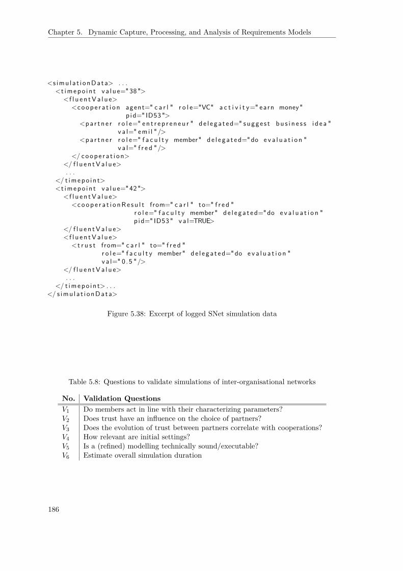
Chapter 5. Dynamic Capture, Processing, and Analysis of Requirements Models
<s imu l a t i o nDa ta> . . .<t imepo i n t v a l u e="38 ">
<f l u e n tV a l u e><coop e r a t i o n agent=" c a r l " r o l e="VC" a c t i v i t y=" earn money"
p i d=" ID53 "><pa r t n e r r o l e=" e n t r e p r e n e u r " d e l e g a t e d=" sugge s t b u s i n e s s i d e a "
v a l=" em i l " /><pa r t n e r r o l e=" f a c u l t y member" d e l e g a t e d="do e v a l u a t i o n "
v a l=" f r e d "/></ coop e r a t i o n>
</ f l u e n tV a l u e>. . .
</ t imepo i n t><t imepo i n t v a l u e="42 ">
<f l u e n tV a l u e><coop e r a t i o nR e s u l t from=" c a r l " to=" f r e d "
r o l e=" f a c u l t y member" d e l e g a t e d="do e v a l u a t i o n "p i d=" ID53 " v a l=TRUE>
</ f l u e n tV a l u e><f l u e n tV a l u e>
<t r u s t from=" c a r l " to=" f r e d "r o l e=" f a c u l t y member" d e l e g a t e d="do e v a l u a t i o n "v a l=" 0 .5 "/>
</ f l u e n tV a l u e>. . .
</ t imepo i n t> . . .</ s imu l a t i o nDa ta>
Figure 5.38: Excerpt of logged SNet simulation data
Table 5.8: Questions to validate simulations of inter-organisational networks
No. Validation QuestionsV1 Do members act in line with their characterizing parameters?V2 Does trust have an influence on the choice of partners?V3 Does the evolution of trust between partners correlate with cooperations?V4 How relevant are initial settings?V5 Is a (refined) modelling technically sound/executable?V6 Estimate overall simulation duration
186

5.3. Simulations and Their Analysis
etc.) (V1), whether trust is respected (V2), whether trust and cooperation experiencesco-evolve (V3), and regarding the robustness against the specification of the initial setting.This is how relevant are the initial settings or do (minor) adjustments have undesirablylarge impacts (V4)? But also more technical issues can be considered such as whether themodelling indeed can be executed at all (V5) or its estimated duration to plan for setsof batch simulations (V6). Similar to control system development, no behaviour is takenfor granted only because the model was designed to exhibit it. Just as the mathematicalequations used to simulate a controlled system can turn out to be inadequate (e. g. tooimprecise), a chosen trust model or cooperation protocol can be insufficient or have flawsthat are not visible at a first glance.
Managerial Support Questions
Support for understanding and governance is in particular needed in regard to trust aswell as the interplay between individual level and network level mediated via networkrules. As elaborated before, the set of network rules that fits the current needs of anetwork changes continuously [Str04]. The SNet simulation environment allows to tryout different alternatives for governance before applying them to a real world setting.Relevant questions that could probably be answered via suitable analysis of simulationruns are summarized in Tab. 5.9 and briefly explained in the following.
Regarding individual behaviour and concrete trust based interactions of agents (abbre-viated by “I”), sets of actual cooperation partners can be analysed in regard to whetherthey have similar characteristics (e. g. all are trust oriented) (I1), have a tendency to buildstrong ties, this is Mafioso-like structures emerge that favor insider deals within a smallgroup over rational choices of partners (I2), or do not really fit together thereby indicatinga lack of alternatives that needs to be addressed by opening up the network toward newmembers with redundant capabilities (I3). Also the attempt to detect free-riders that onlywork for their own profit not interested in the long-term success of the network is includedin this part of the list (I4).
Regarding network rules and monitoring (“N” and “M”, respectively), it is of interest todetect rules that are circumvented by a majority of members, indicating that the rule mightno longer be necessary or has even become hindering (N1). Furthermore, network life-cycle investigations [PK05, Str04] suggest that the introduction of new rules to overcomeshortcomings of a current network situation has a dynamic dimension of its own. Thecommunity of network members needs to commit to the new rules and adopt them. Thismight not happen immediately, but gradually, potentially depending on the role (andstanding) of “early-adopters” (N2). Thus, whether a probably helpful set of network ruleswill eventually be adopted by the network members and is really successful depends initself on the rather complex network setting/situation and thus cannot be predicted easily.Eventually, the role of distrust and monitoring needs a closer investigation. If distrust isreally helpful, it must be possible to return from a high-level of distrust (resulting inexpensive monitoring activities) to a moderate, even trustful cooperation (M1).
Eventually, in regard to success (S) first of all, suitable criteria to measure success ofindividual members as well as the network as a whole have to be identified, for example,the number of (successful) cooperations, the overall level of trust (and distrust) in thenetwork etc. (S1). These criteria can then be consulted to investigate whether it is reallyadvantageous for a member to follow the rules that a network has given itself (S2). Simi-larly, the benefit for different members can be compared in order to identify inequalities.
187

Chapter 5. Dynamic Capture, Processing, and Analysis of Requirements Models
Table 5.9: Support questions for inter-organisational networks
No. Support QuestionsI1 Do trust-oriented partners find each other?I2 Do Mafioso-like structures emerge in a network?I3 Do partners cooperate despite missing trust (lack of alternatives)?I4 Is it possible to detect free-riders?N1 Is there a network rule that is ignored/circumvented by a majority of members?N2 How is a new network rule adopted by the members?M1 Any long-term positive effect of distrust-based monitoring?S1 What are suitable measures for network (individual member, resp.) success?S2 Do members that adhere to network rules benefit?S3 How equally do the network members profit from the network?S4 How does a modified set of network rules affect the overall network situation?
For example, if only a small ‘elite’ of members benefits from the network, this can causethe network to fall apart (S3). Certainly, the success criteria are also essential to decideabout the suitability of changes to network rules or a need thereof, for example, to increasethe overall level of trust in the network (S4).
General Remarks on Proposed Analysis
The above mentioned questions ask for more sophisticated analysis since it is cumbersomeif not impossible to manually investigate the traces of ConGolog simulations that aregiven by a long history of primitive actions that have been taken. Furthermore, we arein need to specify patterns that can be searched in various simulation traces or individualsituations. Accordingly, a variety of analysis means are investigated in the followingto help finding at least partial answers to these exemplary queries. Depending on theindividual characteristics the considered analysis are amenable to either individual (initial,intermediate, and/or final) simulation situations, traces, or sets thereof. For each analysis,we introduce its basic features and if existing according tool support. We then discussin which regard the analysis is helpful for answering the previously discussed validationand/or support questions (based on [SAJL10]).
5.3.4 Formal Tropos (FT)
A basic comparison between SNet and FT has already been given in Chap. 2.2.4. Thus, inthe following the potentials and limits of a combined use of SNet and Formal Tropos arefocused and discussed in regard to the two different application areas the formalisms orig-inate in, software requirements engineering and decision support for inter-organisationalnetworks.
In an original FT setting, SNet’s simulations might be helpful simply due to the possi-bility to cope with more instances. As it has been shown in [FLP+04], the model-checkercurrently used puts severe restrictions on the number of instances per class for a given ex-ample setting. While SNet due to its reliance on simulations is not able to answer questionsabout fulfillment of assertions, possibilities can easily be generated and tested without anyrestrictions on the number of instances as we have experienced so far. Furthermore, the
188

5.3. Simulations and Their Analysis
Speech-Act perspective [WF86] of the TCD multi-perspective modelling methodology (seeChap. 2.1.5) is intended to refine the plans that result from strategic rational considera-tions in regard to strategic dependencies that are involved. Speech-Acts are also used toanalyse the interaction of business partners in regard to completeness [Sch96]. This fitsnicely with FT’s view on completing a specification.
In Chap. 2.2.4, the difference between FT and SNet regarding the aim of the analy-sis was clarified. While FT tries to analyse the specification in regard to completenessand inconsistency, SNet takes these things for granted. Consequently, the most obviouscombination is to support the capture and construction of SNet models and their in-stantiation (V5). Next to time-independent consistency issues (e. g. unique names, goaland task hierarchy analysis), FT allows to address time-dependent issues that have tobe respected in all simulations. For example, the specified preconditions can partly bechecked for whether at least one possible trace of execution exists (possibility). Further-more, the maximum/minimum duration of complex tasks can be computed to estimatethe complexity and duration of batch simulations (V6). Eventually, SNet is dedicated toan exploratory use. Accordingly, it is very likely that the user wants to make minor ad-justments to an intermediate or final simulation situation. FT (and ST, see next section)can help to ensure that the modified scenario is still valid and consistent (V5). A par-ticular application scenarios of such kind of pre-analysis concerns the evaluation of setsof network rules (see Chap. 5.1.4). While many simulations are needed to evaluate suchsets, a dynamic FT analysis of their technical interaction could avoid wasteful and costlyconstructed simulations that fail simply due to design errors, especially since we supportto model such network rules dedicatedly (see “network” concern in Chap. 5.1.4).
Also the SNet approach has to struggle with complexity issues. While the currentimplementation takes care of long simulation traces by using progression [Rei01], thenumber of fluents considerably influences the complexity. Thus, it might be possible thatthe modeller decides to omit the tracking of some particular properties, in order to makethe simulations faster (and thus more interactive). After running several of such complexsimulations, it might be possible to adapt FT to work on logs of such simulations in orderto check for some specific dynamic property that might have been violated in between.Due to the model-checking characteristic, potentially the check can be performed for awhole set of simulation traces at the same time by generalising their characteristics.
5.3.5 Secure Tropos (ST)
Similarly, the basic comparison of SNet and Secure Tropos has also already been given (seeChap. 2.2.5). Thus again, in the following only the potentials and limits of a combineduse of SNet and Secure Tropos are discussed in regard to the two different applicationareas the formalisms originate in, security issues in software requirements engineering anddecision support for inter-organisational networks.
In regard to decision support for inter-organisational networks, ST can be helpful foranalysing the outcome or any intermediate situation of simulations. The user has tointerpret the outcome by comparing trust values and by interpreting the events in thesimulation (such as re-delegations due to conflicts). High-level analysis means such as STcan be of help here. For one, ST can be used to analyse and compare the initial, anyintermediate, or the final situation in regard to the trust setting (I1 − I4). For example,has the created situation the intended effect, i. e. are planned delegation relationships aresult of the specified trust setting (V1)? What trust chains have evolved in the current
189
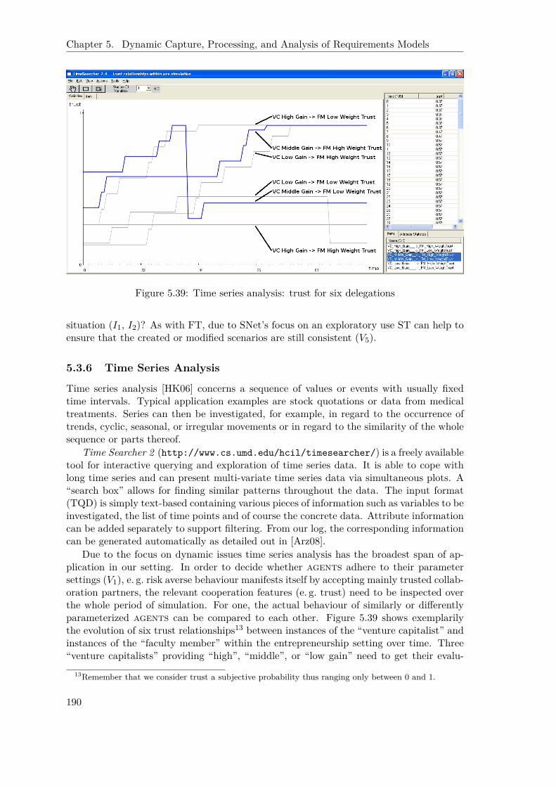
Chapter 5. Dynamic Capture, Processing, and Analysis of Requirements Models
Figure 5.39: Time series analysis: trust for six delegations
situation (I1, I2)? As with FT, due to SNet’s focus on an exploratory use ST can help toensure that the created or modified scenarios are still consistent (V5).
5.3.6 Time Series Analysis
Time series analysis [HK06] concerns a sequence of values or events with usually fixedtime intervals. Typical application examples are stock quotations or data from medicaltreatments. Series can then be investigated, for example, in regard to the occurrence oftrends, cyclic, seasonal, or irregular movements or in regard to the similarity of the wholesequence or parts thereof.
Time Searcher 2 (http://www.cs.umd.edu/hcil/timesearcher/) is a freely availabletool for interactive querying and exploration of time series data. It is able to cope withlong time series and can present multi-variate time series data via simultaneous plots. A“search box” allows for finding similar patterns throughout the data. The input format(TQD) is simply text-based containing various pieces of information such as variables to beinvestigated, the list of time points and of course the concrete data. Attribute informationcan be added separately to support filtering. From our log, the corresponding informationcan be generated automatically as detailed out in [Arz08].
Due to the focus on dynamic issues time series analysis has the broadest span of ap-plication in our setting. In order to decide whether agents adhere to their parametersettings (V1), e. g. risk averse behaviour manifests itself by accepting mainly trusted collab-oration partners, the relevant cooperation features (e. g. trust) need to be inspected overthe whole period of simulation. For one, the actual behaviour of similarly or differentlyparameterized agents can be compared to each other. Figure 5.39 shows exemplarilythe evolution of six trust relationships13 between instances of the “venture capitalist” andinstances of the “faculty member” within the entrepreneurship setting over time. Three“venture capitalists” providing “high”, “middle”, or “low gain” need to get their evalu-
13Remember that we consider trust a subjective probability thus ranging only between 0 and 1.
190

5.3. Simulations and Their Analysis
Figure 5.40: Time series analysis: trust vs. # cooperations
ation reports done by either a “faculty member” that puts a “high weight on trust” ora “low weight”, this is she is more (or less) gain oriented. After recording a successfulcooperation, the trust value grows by a certain delta until the maximal level has beenreached. Correspondingly, an observed cooperation failure causes the trust level to drop(faster than the increase in case of success). As to be expected, we can see that the “facultymember” with a “low weight on trust” prefers the “venture capitalist” that provides “highgain” whereas the “venture capitalists” that provide “low” or “middle gain” strengthentheir cooperation with the more trust oriented “faculty member” over time.
For another, noticeable deviations between the time series for level of trust and numberof cooperations can be used as indicators for inconsistencies. Figure 5.40 shows two curvesfor trust relationships in the upper part (both involving the “venture capitalist” that pro-vides “middle gain” at the one side and then the two “faculty members” (“low weighttrust” vs. “high weight trust”) at the other) and the corresponding total number of (suc-cessful or failed) cooperations in the lower part. Usually, it is to be expected that relatedcurves in the two graphs grow in accordance to each other as it is the case for the darkercurves in the figure (“venture capitalist (middle gain)” cooperating with “faculty member(high weight for trust)”). A deviation can indicate a bug concerning the co-evolution (V3)or can identify a lack of cooperation alternatives (I3). To elaborate the latter, even thougha rather low level of trust occurs repeatedly, the delegating agent continues to cooperatewith this untrusted partner since there is simply no other option. Figure 5.40 shows thatthe “venture capitalist” has again (T=46) chosen the “faculty member” with a “low weightof trust” despite of severe negative experiences (T=40). The relevant situation needs thento be investigated further for the reasons. In this case the planning for the activity (atT=40) has taken place at a very short notice and thus the other “faculty member” simplywas not available due to an already high work load. Furthermore due to her trust-orientedbehaviour, she did not consider to cancel any of her current activities. Thus, indeed theVC did not have any other option.
The effect of different initial settings (V4), for example, in regard to trust, can certainly
191

Chapter 5. Dynamic Capture, Processing, and Analysis of Requirements Models
be investigated by comparing time series of simulation runs that only deviate in this regard.In this context it could also make sense to abstract from all details by considering suitablyaggregated trust measures, e. g. combining the relationships at role level. This is insteadof analysing individual trust relationships between pairs of agents we compute one trustvalue that combines all trust relationships between, for example, all instances of “venturecapitalist” and all instances of “faculty member”. Similarly, a data set that aggregates alltrust relationships within a model could be used to investigate the effect of a modifiedset of network rules (S4), in particular if it targets the growth of trust relationships.Discontinuities in the evolution of trust over time could be considered, if network ruleshave been changed during a simulation run.
Time series are also helpful to identify criteria that indicate success (S1). After tak-ing expert advice on which simulation run or network situation can indeed be classifiedas ‘successful’, graphs of monitored characteristics can be consulted to identify a set offeatures (and particular values) that correctly and reliably characterize success. Againvalidation of these findings is of importance. Given such criteria are available, the successof individual members can be compared. By grouping agents, for example, into onesthat respect rules and ones which do not, it is possible to check whether conforming torules is beneficial (S2). Similarly, it can be checked which agents benefit more from thenetwork than others (S3).
By relating gain evolution and cooperation cancellations, it might even be possibleto detect free-riders (I4). And by evaluating the evolution of trust after distrust-basedmonitoring has taken place, the chances for returning to a normal trustful cooperationrelationship can be investigated (M1).
5.3.7 Association Rule Mining and Clustering
Association rule mining [HK06] tries to find frequent patterns in sets of data objects(originally in databases). Classical application field is a market basket analysis as anyonline dealer is performing nowadays to find out which products are most often soldtogether. The analysis has two steps. In the first step, all frequent itemsets above aprespecified threshold (minimal support) are computed. Then for each subset s of afrequent itemset l a rule is created s ⇒ (l − s), but only if the confidence of the ruleis above another threshold. Various algorithms exist to compute the rules efficiently.
Similarly, clustering groups (multi-dimensional) data objects without presuming anyclassification label by the “principle of maximizing the intraclass similarity and minimizingthe interclass similarity” [HK06]. This facilitates the organisation of observations. Forexample, online shops use cluster analysis to identify target groups for marketing.
There is consequently some kind of overlap with association rule mining, even regardingthe tool. RapidMiner (http://www.rapidminer.com) is capable of executing a large setof analysis from the field of data mining including association rule mining and clusteringas well as pre- and post-processing algorithms that all can be combined into processes toautomate the data processing. It expects two proprietarily formatted text files as input.The AML file contains the description of the attributes of the data objects (name, range ofvalues, etc.) and the DAT file the actual values for the specified attributes. Accordingly,both kinds of analysis, association rule mining as well as clustering, are applicable tosimilar questions. To reduce resulting redundancy, for each question we only discuss theapplication of one of these analysis.
To validate whether agents act according to their parameterization (V1), the set of
192

5.3. Simulations and Their Analysis
Table 5.10: Association rules for cooperating “venture capitalists” and “faculty members”
Venture Capitalist Faculty Member Confidence
agent providing
low gain
agent with
low trust weight 0.32low gain high trust weight 0.68middle gain low trust weight 0.46middle gain high trust weight 0.54high gain low trust weight 0.52high gain high trust weight 0.48
all cooperations can be investigated. RapidMiner then needs to be fed with the pairs ofcooperation partners. The data set can even be enlarged by considering the decompositionstructure within the foundational i* model and including all partners that ultimatelycontribute to a proactivity of some agent. Due to the properties of association rulesthe latter setting subsumes the former. The according data is easily retrievable fromour simulation data since for each proactivity a unique identifier (PID) is issued that ispropagated throughout all (sub) delegations. It is also possible to add further details inregard to the result of the cooperation (success vs. failure) or a categorization of the trustrelationship (high, middle, low). For example, for a trust-oriented partner associationrules should indicate that in the majority of cooperations trusted partners are chosen.Thereby, such an analysis is also able to show that trust is in fact respected during choiceof partners (V2).
In regard to the validation of the initial setting (V4), Tab. 5.10 shows some resultscomputed with RapidMiner again on the simple delegation relationship between “venturecapitalist” and “faculty member”. The configuration includes three agents playing the“venture capitalist” role differentiated by providing “low”, “middle”, and “high gain”to delegatees as well as two agents playing the “faculty member” role that vary inregard to how important trust (and accordingly gain) is for them (“low” vs. “high trustweight”). These analysis have revealed the dominating role of the initial trust relationshipsettings, at least for a simplified setting where overlapping jobs have not been admitted.Under these constraints the confidence value nearly identically reflects the initial values.Thus, for more interesting insights more complex simulations need to be run. In additionaggregated measures across several simulations might be needed to remedy the influenceof the initial setting.
Whether similar agents find each other (I1) or cooperate only locally (I2) can be de-tected by clustering. Again cooperations are the foundations but additionally the relevantcharacteristics, e. g. trust orientation, need to be added. The emerging clusters can thenbe analysed in regard to their regional size, this is how narrowly related, i. e. similar, areclustered items, as well as their pure quantitative size, this is how many items belong toone cluster. The first measure reflects the diversity of agents that cooperate and thesecond the flexibility in regard to cooperation partners and thus provide answers to thequestions I1 and I2, respectively. Similarly, outliers in regard to clustering can indicate alack of alternatives (I3). The detection of free-riders (I4) is less reliable. An idea wouldbe that such an agent only chooses cooperations that ensure the highest gain, while co-operations with lower gains are cancelled more often. Clustering (or building associationrules) in regard to these characteristics could at least indicate candidates, even though a
193
Chapter 5. Dynamic Capture, Processing, and Analysis of Requirements Models
free-rider can ‘hide’ her behaviour more intelligently.The compliance with network rules (N1) as well as the route of their adoption (N2)
can be addressed by looking for association rules that include a check on whether anagent utilizes a rule or not. Being considered a frequent item step is then already thefirst hurdle. If a network rule fails that hurdle, it might need to be abandoned or theassociated punishment has to be increased. In order to detect important stakeholders,during analysis one could watch out for association rules that consider members earlyinvolved in the adoption of a new rule that later on turns out to be successful.
Eventually, also success related issues can be addressed. For example, if some char-acteristic criteria have been determined by experts, a corresponding clustering accordingto these criteria can be carried out. If agents are clustered together that are not allsuccessful, this clearly indicates that the chosen characteristics are not yet sufficient (S1).An association rule can also presume network rule compliant behaviour and then checkwhether successful agents are on the majority (S2). Finally clustering according to (in-dividual) success gives a quick overview of inequalities in the network (S3).
5.3.8 Social Network Analysis (SNA)
To address patterns more complex than sets (see association rules) and sequences, graph-based approaches are applied increasingly [HK06]. Most importantly networks that resultfrom the investigation of various kinds of relationships between objects are of interest.Usually, a numerical value is given as a weight to the link between two graph nodes re-flecting the strength of the relationship. The most basic form of analysis provided bysuch an approach is to visualize the network in order to reveal its induced internal struc-ture. yFiles (http://www.yworks.com) and JUNG (http://jung.sourceforge.net) aretwo well-known tools that allow for such kind of analysis. They also provide additionalalgorithms, for example, to compute different types of centrality: degree centrality as alocal measure of the connectedness of a node, closeness centrality in contrast as a globalmeasure indicating the distance to any other node in the graph, and betweenness cen-trality relating the shortest path a particular node is involved in to the overall shortestpath. The latter measure thereby is a strong indicator for the influence of that node.Other relevant kinds of analysis investigate the cohesion in a graph, in particular cliques,this is subsets of nodes where each node is connected to each other. With GraphML(http://graphml.graphdrawing.org), an agreed data format is available that alleviatesintegration.
Since the objects of our investigations are in itself networks, social network analysisobviously is of interest. As kind of relationship trust, distrust, or simply the number ofcooperations can be considered. Such analysis have already been applied to staticallyanalyse i* models [KSD06]. Accordingly, we can certainly apply them to starting, in-termediate, or final situations. A match between a network in regard to trust with anetwork in regard to cooperation can provide an answer to whether similar agents findeach other (I1). Outliers to such a matching can indicate at a lack of alternative partnersas could a suitable centrality measure since the corresponding agent needs to be involvedin most of the related cooperations (I3). A high density of cooperations between a limitedset of members – also detectable via a suitable cohesion measure – hints at potentiallyMafioso-like structures (I2).
To investigate the adoption of new rules (N2), connections can be drawn that reflectprecedence when accepting a new rule. Betweenness centrality can then indicate important
194

5.3. Simulations and Their Analysis
highgain
middlegain
lowgain
lowweighttrust
highweighttrust
venturecapitalists
facultymembers
T=50
highgain
middlegain
lowgain
lowweighttrust
highweighttrust
venturecapitalists
facultymembers
T=100
0
28
4
4
3
0
15
10
104
3
8
6
7
15
6
15
14
13
20
22
Figure 5.41: Network of cooperations for two different points in time
stakeholders that have influenced success (or failure) of rule adoption. Also whether thecooperations in an inter-organisational network are equitably distributed across the wholenetwork can quite easily be derived from a visual representation as well as the computationof cohesion such as cliques and thus become a part of the set of success criteria (S1).
Even more valuable seems the extension toward dynamic SNA [Car03] simply due tothe fact that we run simulations. How the actually exhibited cooperation network evolvesover time in particular in response to network rule changes (S4) is of great interest. Whileunfortunately, a connection to existing tool support at the chair [CKSL07] has not yet beenestablished, for small examples such as the entrepreneurship example investigated here,a manual capture of the evolution of the relationships is possible. Figure 5.41 shows thenetwork of cooperations between different “venture capitalists” (providing high, middle,or low gain) and different “faculty members” (high weight for trust vs. low weight fortrust) for two different points in time within a single simulation run (T=50 and T=100).The thickness of the connecting lines indicates the number of successful cooperations (alsogiven as exact numbers) whereas the numbers at the different agents denote the totalnumber of cooperations the agent is involved in. The comparison reveals that despiteadvantages for the “faculty member” with “low trust weight” in regard to the initial trustsettings, the “venture capitalists” that provide only “middle” and “low gain” experiencedthe unreliability of this partner and thus switched to the alternative partner (with “hightrust weight”). On the other hand, the “venture capitalist” providing “high gain” does notexperience any problems since the “faculty member” with “low weight trust” is preferringher due to the high payment.
It is important to remark that when analysing network structures it is necessary totake into account which structures are induced by the modelling in particular by therole-based relationships defined in i*. For the example shown in Fig. 5.41, we do notsee but also cannot expect cooperations between “venture capitalists” or between “facultymembers” simply because the i* model (in Fig. 4.6) does not introduce such a relationship.The situation becomes more complex in a more sophisticated setting where an agent is
195
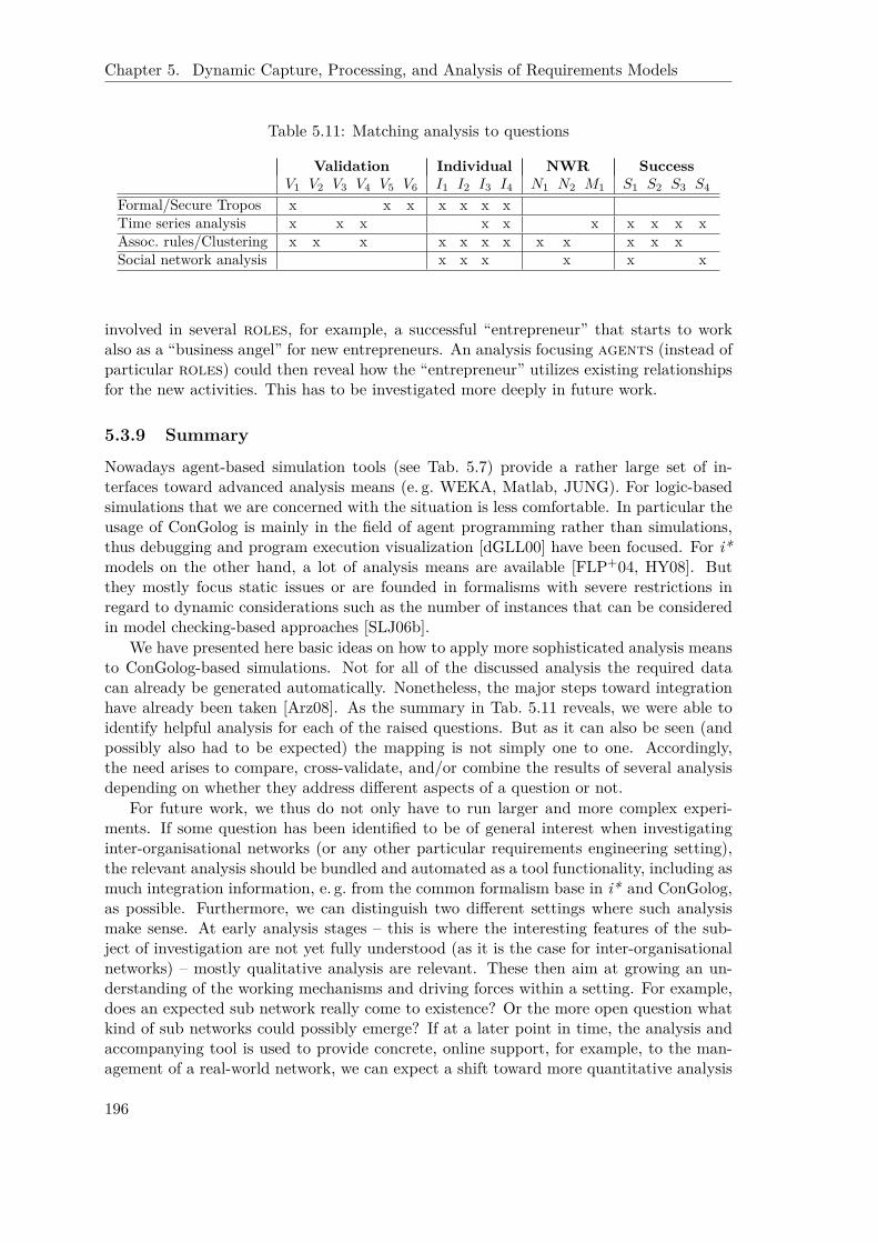
Chapter 5. Dynamic Capture, Processing, and Analysis of Requirements Models
Table 5.11: Matching analysis to questions
Validation Individual NWR SuccessV1 V2 V3 V4 V5 V6 I1 I2 I3 I4 N1 N2 M1 S1 S2 S3 S4
Formal/Secure Tropos x x x x x x xTime series analysis x x x x x x x x x xAssoc. rules/Clustering x x x x x x x x x x x xSocial network analysis x x x x x x
involved in several roles, for example, a successful “entrepreneur” that starts to workalso as a “business angel” for new entrepreneurs. An analysis focusing agents (instead ofparticular roles) could then reveal how the “entrepreneur” utilizes existing relationshipsfor the new activities. This has to be investigated more deeply in future work.
5.3.9 Summary
Nowadays agent-based simulation tools (see Tab. 5.7) provide a rather large set of in-terfaces toward advanced analysis means (e. g. WEKA, Matlab, JUNG). For logic-basedsimulations that we are concerned with the situation is less comfortable. In particular theusage of ConGolog is mainly in the field of agent programming rather than simulations,thus debugging and program execution visualization [dGLL00] have been focused. For i*models on the other hand, a lot of analysis means are available [FLP+04, HY08]. Butthey mostly focus static issues or are founded in formalisms with severe restrictions inregard to dynamic considerations such as the number of instances that can be consideredin model checking-based approaches [SLJ06b].
We have presented here basic ideas on how to apply more sophisticated analysis meansto ConGolog-based simulations. Not for all of the discussed analysis the required datacan already be generated automatically. Nonetheless, the major steps toward integrationhave already been taken [Arz08]. As the summary in Tab. 5.11 reveals, we were able toidentify helpful analysis for each of the raised questions. But as it can also be seen (andpossibly also had to be expected) the mapping is not simply one to one. Accordingly,the need arises to compare, cross-validate, and/or combine the results of several analysisdepending on whether they address different aspects of a question or not.
For future work, we thus do not only have to run larger and more complex experi-ments. If some question has been identified to be of general interest when investigatinginter-organisational networks (or any other particular requirements engineering setting),the relevant analysis should be bundled and automated as a tool functionality, including asmuch integration information, e. g. from the common formalism base in i* and ConGolog,as possible. Furthermore, we can distinguish two different settings where such analysismake sense. At early analysis stages – this is where the interesting features of the sub-ject of investigation are not yet fully understood (as it is the case for inter-organisationalnetworks) – mostly qualitative analysis are relevant. These then aim at growing an un-derstanding of the working mechanisms and driving forces within a setting. For example,does an expected sub network really come to existence? Or the more open question whatkind of sub networks could possibly emerge? If at a later point in time, the analysis andaccompanying tool is used to provide concrete, online support, for example, to the man-agement of a real-world network, we can expect a shift toward more quantitative analysis
196

5.4. Chapter Summary
that better serve as input to management decisions (in the spirit of [CM99]). Accordingly,we then need to adapt the basic analysis that are provided as well as the treatment ofsimulation settings and runs in order to compute such ‘hard’ metrics.
5.4 Chapter SummaryIn this chapter we have addressed three different dynamic issues in regard to the treatmentof a single project. The domain model based approach to requirements engineering hasintroduced domain models to make the capturing faster. The modeller now only has tochoose a suitable (set of) domain model(s) as starting point, discards the parts that arenot relevant for the current project at hands, and afterwards adds the specifics. This inparticular supports small- and medium-sized enterprises during their often time pressuredand unpaid offer development phase.
Further on, we have taken advantage of the now model-based approach to requirementscapture by introducing a model-based transformation to Matlab/Simulink with the helpof Telos/ConceptBase. This completes for the first time the already to a large degreemodel-based development of control system at the level of requirements engineering.
Additionally, we have updated the transformation to ConGolog simulations accordingto the modelling extensions introduced in the previous chapter. The investigation of arequirements situation with the help of agent-based simulations is additionally supportedby feeding advanced complex analysis tools such as time series analysis, social networkanalysis, or other data mining algorithms.
Future work should consider in particular a better integration of the domain modelbased approach with the transformation as well as simulations. Domain knowledge at levelsother than requirements should be suitably connected and utilised during transformation.Eventually, the applicability of agent-based simulations of i* requirements models shouldbe broadened to accommodate not only the special setting of inter-organisational networks.This eventually would also allow for early simulations of requirements models in the fieldof control system development, a part of the overall method for this case study (seeChap. 3.2.4) that has not yet been addressed. On the other hand, the similarity search aspart of the domain model based approach (presented in the next chapter, see Chap. 6.1),might even prove to be helpful to relate simulation snapshots, situations, or settings. Thus,synergistic chances have not fully been taken advantage of yet.
197

Chapter 5. Dynamic Capture, Processing, and Analysis of Requirements Models
198
Chapter 6
Dynamic RequirementsKnowledge Management
In this chapter we pick up on the “domain model based approach to requirements engineer-ing” (Chap. 5.1) by adding two issues related to the inter-project management of dynamicrequirements knowledge. A similarity search (Chap. 6.1) is intended to support organisa-tions when watching out for reusable components [SNJ+08, SNJR08]. Secondly, we areconcerned with how to evolve domain knowledge (Chap. 6.2) in order to keep up with theinnovations and experiences from day-to-day work in an enterprise [NSJ+09, NSJR09].Eventually, for the chapter summary we take a step back and look at the entire do-main model based approach as it has now emerged among the Chapters 5.1, 6.1, and6.2 [SNJR10a, JNRS10].
6.1 Requirements-Based Search for Similar ProjectsIn Chap. 3.2.3, we have elaborated the specific needs of project-oriented SMEs during thedevelopment. Due to the high time and costs pressure, they need support in particularduring the offer development phase to capture the project’s requirements and derive afirst system design as well as a reliable cost calculation. Chapter 3.3.2 has picked up onthe missing issues to support the capture and utilization of domain knowledge. Whilethe domain model based approach to requirements engineering (Chap. 5.1) addresses thebasic need for a fast requirements capture, it does not concern the project-driven work, inparticular the dynamic growth of experiences and knowledge over time and its utilizationfor approaching a new project.
Project-driven SMEs need an easy and fast access to experiences. When a new customerapproaches the SME, it must be able to create an appropriate and reliable offer. This iswithin the tight time and costs constraints mentioned above the engineer must decideabout reusability of solutions from earlier projects in order to arrive at a competitive costcalculation. To reiterate, two dangers are to be avoided:
• reusable artifacts are not found due to lack of time and
• artifacts are erroneously classified as reusable.
Within this chapter, we propose a requirements model-based approach to improve theidentification of relevant earlier projects. By watching out for projects with similar re-quirements we aim at more reliably hinting the engineer at projects that are relevant to
199
Chapter 6. Dynamic Requirements Knowledge Management
investigate further. Accordingly, both dangers are addressed in one fell swoop. The possi-bly huge set of historic projects is reduced to a smaller set including only relevant projectsand thus more time can be spent on these for an in-depth investigation of reusability.Additionally, the approach helps to reduce the reliance on few (even single) individualsenior engineers’ knowledge about the enterprise’s project history. Instead even a newengineer can carry out the task by focusing the small number of high-ranked projects thatare returned by the similarity search.
6.1.1 Related Work
Requirements Reuse
At the beginning we need to clarify that we are not concerned with requirements reusehere. Instead a completed requirements model of the current project – typically origi-nating in one or several domain models (see Chap. 5.1) – is the most important input toour similarity search. In particular this model is the reference base for the comparisonwith historic projects (to be elaborated later on). The aim of the search is to find rele-vant related projects that can then be inspected manually to decide about the reuse ofsolutions, this is mainly artifacts from later development steps, in particular implementa-tion. Accordingly, neither the application of the analogy paradigm [MS92] nor the “tensteps towards requirements reuse” [LMV97] or product line based approaches [DL06] aredirectly relevant here.
Case-Based Reasoning
On the other hand, the above characterisation clearly indicates a relation to case-basedreasoning (CBR) [AP94]. The standard CBR cycle as shown in Fig. 6.1 is initiated byspecifying a problem as a new case. During the “retrieve” phase, similar previous casesare searched that then can be investigated in detail for “reuse”. The outcome of thisinvestigation is a “suggested solution” that typically needs to be “revised” in order to arriveat a “confirmed solution” that is applicable for the new case and afterwards “retained”, thisis stored to the case base. We are interested here only in the first phase “retrieve” whilewe leave the details of reuse and adaptation to the developers. Besides simple syntacticalsimilarities also more advanced similarity measures that try to address semantical issuesare proposed for the identification of related cases. Still the similarity measure is prescribedby the way how cases are represented. In contrast, the only restriction that we impose inour work is that we expect i* models (that potentially originate in one or several domainmodels), but that are otherwise in no way tailored to support a similarity search.
Similarity Measures
As mentioned by Wolter, Krebs, and Hotz [WKH08], “[m]easures that capture the simi-larity of artefacts have been developed in many research communities”. In their particularwork they focused on the advanced (as well as rather particular) problem on how to iden-tify the similarity of model-based requirements and text-based requirements. Aside fromthis specific media-related problem, the most basic approaches are text-based. These ap-proaches that are typically applied in the field of information retrieval [MRS08] lack theconsideration of structural information as provided by models.
200

6.1. Requirements-Based Search for Similar Projects
NewCaseRetrieved
Case
SolvedCase
Tested/Repaired
Case
NewCase
GeneralKnowledge
PreviousCases
ConfirmedSolution
REVISE
REU
SE
Learned Case
Suggested Solution
Problem
RETRIEVE
RET
AIN
Figure 6.1: The case based reasoning (CBR) cycle (taken from [AP94])
Feature based similarity measures go one step further by characterizing an objector item via a large set of features, most often combined into a correspondingly high-dimensional feature vector [HK06]. These feature vectors (also typically used in the fieldof data mining) can then be used to define pairwise similarity, for example by computingan Euclidean or Manhattan distance. Afterwards clustering approaches partition the setof feature vectors representing the objects or items into clusters by maximizing intraclasssimilarity and minimizing interclass similarity.
First model-aware approaches were tailored to a particular meta model. For example,Ohst, Welle, and Kelter [OWK03] elaborate on how to detect and particularly visualizedifferences of versions of UML documents. They propose means to abstract from layoutmodifications and also consider structural changes such as moving a method from oneclass to another. More recently, model-aware approaches have been proposed that nolonger refer to a particular meta model, but can even compare models based on differ-ent meta models. DSMDiff [LGJ07] is a differentiation tool for domain-specific models.It builds on the formalization of a domain-specific models as “hierarchical graphs anno-tated with a set of syntactical information”. The SiDiff system [TBWK07] addresseslarge models that exist in many versions. A high-dimensional search tree is used to ef-ficiently find similar model elements. For this purpose, individual elements are mappedto a vector of numerical values that reflects several features either of the modelling el-ement itself or of its neighborhood, this is nodes that are referenced. The search treeis then exploited to reduce the number of pairwise comparisons. The EMF Compareproject (http://www.eclipse.org/modeling/emft/?project=compare) also targets ver-sion management. Here the comparison process is explicitly split into two phases: match-
201

Chapter 6. Dynamic Requirements Knowledge Management
ing and differencing. For matching, currently four metrics are used: the “type” similarityanalyses the meta model element, the “name” similarity looks for an attribute that haschances to be the name and compares it, the “value” similarity analyses the collectionof attribute values, and eventually the “relation” similarity watches out for the relationsthat the element has with others. Kolovos [Kol09] argues that these generic approachesfall short “for exploiting the semantics and particularities of each individual modellinglanguage”. He thus introduces the Epsilon Comparison Language that allows to explicitly“specify precise language-specific algorithms for establishing matches between elements”.Yet he admits that the approach comes with additional burden that might not pay off intoo many cases.
A field related to model-aware similarity that has been researched rather extensivelyis ontology matching, mainly driven by the high interest in the establishment of the socalled “Semantic Web” [BLHL01]. Ontologies are intended to help overcome the most se-vere problem of the “Semantic Web”, namely heterogeneity of terms and understandings.“[Giving] information a well-defined meaning”, for example by conceptualizing terms inontologies and identifying relations between different ontologies is seen by Berners-Leeet al. a necessary prestep to “better [enable] computers and people to work in cooper-ation”. Starting with a state of the art survey within the EU project “The KnowledgeWeb” [EBB+04], the work on “ontology matching” has been documented in [ES07]. Thecore idea is to “[find] correspondences between semantically related entities of differentontologies”. It is explicitly mentioned that not only equivalence but also consequence,subsumption, or disjointness relations between entities are considered. Furthermore, en-tities are mainly classes, properties, or individuals, but can also be of a more complexkind this is formulas, concept definitions, queries or term building expressions. The resultof ontology matching is called an alignment. It can have a varying degree of precisionand be used for various tasks such as ontology merging, answering queries, translatingdata, or, eventually, browsing the Semantic Web. The techniques that are applied in on-tology matching borrow from various fields such as statistics and data analysis, machinelearning, automated reasoning, or linguistics. Furthermore at the core, the most basictechnique is to “[assess] the similarity or dissimilarity of ontology entities” [ES07] andthus is related to the similarity measures discussed above. The survey [EBB+04] has re-vealed that so far mainly terminological, structural, or extensional properties of ontologieshave been considered. As an example for a more advanced semantics based similaritymeasure, Araújo and Pinto [AP07] propose a similarity measure that builds on character-istic concepts and computes the measure thereby indirectly from the number of models ofthe concerned ontologies. Similarly, other graph-based approaches (e. g. [Gal06]) as well asschema matching approaches (e. g. [QKL07]) provide general means to compare structuredinformation. All these approaches can be considered specializations of the rather new fieldof model management [BHP00] that will be elaborated in Chap. 6.2.1 since it covers notonly “matching” and “differencing” but also modification (and thus evolution) and othergeneral model management operations.
In sum, the basic ideas discussed here are certainly relevant for our application. Butat the same time, ontologies, for example, have a rather fixed and reduced set of relationsbetween entities, tailored to specify and clarify the terminology in a domain. Also theother approaches focus abstract concepts or features and thus a meta level. In contrast,we are concerned with models from a richer requirements formalism and in particular therelation of concrete models at instance level. Accordingly, it does not seem straightforwardto incorporate domain knowledge at the concrete modelling level into these matching
202

6.1. Requirements-Based Search for Similar Projects
approaches. Nonetheless the basic technologies should be applicable or at least supportiveas an enrichment of our approach (see elaboration later on).
Model Search
While many of the above mentioned approaches aim at support for version management –for models with the same meta model – or model transformation – for models with differentmeta models, other approaches explicitly concern model search. In [LdMFW08] Lucrédio,Fortes, and Whittle present a model search engine that incorporates meta modelling infor-mation. This allows to create more specific queries and is not committed to a particularkind of modelling language. Also suitable indexes are created. A simple search providesgeneric queries to watch out for user-defined keywords while an advanced search allows tospecify, for example, the class of the return value of a particular function. Unfortunately,complex queries have been less used by the test persons during evaluation. Besides openissues in regard to visualizing search results, they explicitly note to not consider similarity;this is only exact matches are returned. Ramos, Barais, and Jézq́uel [RBJ07] also addressthe search in model repositories. In their understanding this problem “can be rephrasedinto the ability to perform efficient pattern matching at the model level”. Accordinglythey propose to express patterns as “model-snippets”. The queries that we propose in ourapproach (see below) can also range from very simple to advanced as well as be interpretedas specifications of model-snippets.
6.1.2 Foundational Considerations
Embed Consultation of Historic Projects into the Development Process
Figure 6.2 shows an extended version of the Map representation of the domain model basedapproach as introduced in Fig. 5.1. The extension does not touch the steps described sofar, this is how to arrive at a “requirements model” for the “current project” by buildingon “domain models”, but elaborates on how to continue afterwards. The overall intentionof the offer development is to arrive at a suitable “first system design” that in particularallows for carrying out a reliable “cost calculation”.
Capturing the current requirements as considered so far is only the first step in thisregard. Given such a (preliminary) requirements model that suitably reflects the cus-tomer’s needs, the enterprise must resort to its own experiences and knowledge. Accordingto [Bjø09], experiences from “related historic projects” are the core asset, in particular forSMEs. The consultation of this knowledge helps to reliably estimate costs – vital to anSME’s economic viability –, but also to earn money. The latter is possible especially if“reusable components” can be identified.
In the following we propose a domain model based “similarity search” at the levelof requirements models as a suitable strategy to “identify related historic projects” (seemid of Fig. 6.2). But certainly, this is not the only way to address this issue; manyother strategies might be applicable as well and could (should) be combined with thesubsequently described approach. For example, a similarity search could possibly also beestablished for later development artifacts, e. g. Matlab/Simulink models in the case ofcontrol system development. Furthermore, no similarity search can replace a “manual,in-depth investigation” by an experienced engineer. At the SME that participated inthe ZAMOMO project originally the considerations on reusable components from earlierprojects were carried out manually by a senior engineer who knows the details of nearly
203

Chapter 6. Dynamic Requirements Knowledge Management
similarity search
Start
Choose domain model
shared history with same customer
keyword based
clean up (tool supported)
add another domain model
Project-specific requirements model
refinementextension
Identify related historic projects
manual, in-depth investigation
First system design & cost calculation
decide on reuse
Detailed design
Implementation
Finalize project/ reflect
Stop
add, refine
model-based transformation
Feedback via domain model updates
[Details omitted]
[Details omitted]
completeness strategy
Figure 6.2: Extended domain model based development process
204

6.1. Requirements-Based Search for Similar Projects
all projects carried out at the enterprise. Obviously, this approach is problematic since itdoes not scale up and depends on the availability of the engineer. The latter is an issuenot only if the senior engineer leaves the enterprise but also due to the fact that he isbecoming a bottleneck for the acquisition of new projects. While we have intended toovercome these issues by establishing the proposed similarity search, we never assumedto be able to replace the manual inspection entirely. Our similarity search only helps tofocus the most interesting and promising projects.
Eventually, we like to stress already here the importance of “feedback” from the ex-periences of a concrete customer project, in fact a number of projects, toward a suitable“update of the domain models” that support the capture and the identification of relatedprojects. This issue will be addressed in a chapter of its own (Chap. 6.2).
Importance of Domain Models
The domain model based approach to requirements engineering as introduced in Chap. 5.1is a necessary prerequisite to any comparison support at requirements level. As mentionedby [DvLF93, Jac95, Yu95, BPKR09] and many others, due to the fact that their captureis the first step during software development, early requirements are most often, nearlynecessarily of the most vaguest kind. They get consolidated only after lengthy discussionsbetween customers and developers, potentially even only along the implementation oreven test phase, or worse after several iterations of these. Accordingly, without taking anysuitable measure, requirements models of similar (or even the same) problems will highlylikely differ considerably if carried out by different engineers or at different points in time(by the same or different engineers).
The domain model based approach to requirements engineering (Chap. 5.1) providesa solution to overcome this problem without impeding the typically very project- andcustomer-oriented development process at the SMEs that we are concerned with. Concretedomain and experience knowledge is provided for immediate reuse at the instance level(not at the class level). This leads to a much higher homogeneity of requirements modelsdeveloped within an enterprise that utilizes the same set of domain models [SNJ+08].Furthermore, the utilized domain model part can also be employed as kind of an anchorto compute the similarity of project-specific extensions (see later on). All in all, domainmodels heavily raise the chances for the correct identification of related historic projects.
6.1.3 A Query-Based Similarity Search at Requirements Level
The basic assumption behind our similarity search is that a related project can be iden-tified by comparing requirements models. This is, we consider two projects similar if theyhave matching requirements. In accordance with Jackson [Jac95] it is important to stresshere that we consider requirements models to be encompassing, in particular including acharacterization of the application domain. This is besides the requirements for the actualsoftware to be developed we also expect its technical, social, and organisational context tobe included. This prohibits us from too narrowly focusing projects with a nearly identicalproblem question. Instead we are also able to find projects where the current problemhas been only a side constraint but nonetheless has been targeted. As proposed above, wepresume that the domain model based approach to requirements capture has been appliedto any historic and current project in the project repository in order to reduce modellingheterogeneity as much as possible.
205

Chapter 6. Dynamic Requirements Knowledge Management
Create project-specific similarity measure
domain model based queries
ad-hoc queries
weighting
ranking
Project-specific requirements model
Identify related historic projects
manual, in-depth investigation
First system design & cost calculation
decide on reuse add, refine
Figure 6.3: Detailed Map model for the domain model based similarity search
Figure 6.3 focuses and elaborates the details of the proposed “similarity search” byagain refining the Map model. The core intention is to “create a project-specific similaritymeasure”. By referring again back to the foundation of i* and the domain requirementsmodels in Telos and ConceptBase, according “queries” are considered. They can either bebased in “domain models” or project-specific, this is “ad-hoc”, issues. In both cases, theformulation of a query can be understood as the characterization of a “model snippet”while the execution is the actual model search similar to what is proposed by [RBJ07].The results of these queries are then combined via a suitable “weighting” as it is commonin the field of decision theory (utility computation, see [vN02]). This eventually resultsin a “ranking” of the historic projects. High-ranked projects can be expected to be morerelated to the current project than low-ranked projects. We will discuss the introducedsub steps in the following in more detail.
Domain Model Based Queries
It is only natural to reconsider the domain model(s) used during the establishment of thenew current requirements model also for the identification of related projects. Since thedomain model is used ‘as is’ in a concrete project-specific, requirements model (in contrastto, for example, instantiating abstract classes), it is on the one hand safe to assume thatlarger parts of the domain model actually reoccur in the concrete requirements model.At the same time we can also be rather sure that content of the domain model occurs inseveral historic projects – otherwise the modelling would not have been included into thedomain model (see Chap. 6.2). The domain model based queries thus serve to find themost foundational set of related projects.
To support this, we expect the specification of domain models to include a suitable
206
6.1. Requirements-Based Search for Similar Projects
set of corresponding query classes that refer to typical features of the domain model, inparticular to those where deviations occur most often when deriving a tailored project-specific model. For example, in the case of the “combustion engine domain model” fromChap. 5.1.4 (in particular Fig. 5.12), the kind of “fuel” that is utilized in a project is animportant indicator for a similar project setting. We expect several of such queries to beassociated with a domain model.1
It is worth to mention that domain model based queries can – within narrow limitations– also return project-specific extensions. This is the case if the modeller has only refinedthe domain modelling, for example by adding a project-specific alternative to a domainmodel goal. Adding a new kind of “fuel” is a real world example for this. Certainly,the new kind of fuel is returned by a domain model based query that watches out for thisfeature of a requirements model. The ad-hoc queries explained subsequently provide amore flexible means to address project-specific extensions.
In general the degree of similarity in regard to one particular query is defined as follows.
Definition 6.1 (Similarity for a Single Query). Let q be a query, pc, p1, . . . , pn for n ∈ Nthe current as well as all historic projects. Let Rq(p) denote the results of the query q forthe project p. The similarity Simpc
q : {p1, . . . , pn} → [0, 1] of a current project pc and ahistoric project pi for i ∈ N in regard to the query q is then defined as
Simpcq (pi) = |Rq(pc) ∩Rq(pi)|
|Rq(pc)|.
This is the similarity is computed by evaluating the query q on the requirements modelsfor the new current project pc as well as all historic projects pi, i ∈ N.2 The results for thenew current problem Rq(pc) are then taken as the reference base. This is we check for eachhistoric project pi how many of the details returned for the current project also appearin this historic project. Further returns for the historic project are simply ignored. Thepercentaged degree of coverage of the reference base is taken as the similarity measure forthis query and this particular historic project.
Ad-hoc Queries
While domain model based queries refer to modelling parts that are likely to reoccurdue to their usage and inclusion in a domain model, the engineer must nonetheless begiven the chance to add ad-hoc specific queries, reflecting a particular interest in the newproject at hands. This can be considered a situational adaptation in the understanding ofsituational method engineering (see Chap. 2.1.1 and the explicit discussion in Chap. 6.3).Ad-hoc queries can be as simple as asking for one particular modelling object that has beenintroduced as a project-specific extension. In general, such queries can refer to domainmodel based parts that are not covered by predefined domain model based queries or tofully project-specific issues as mentioned above. Apart from that they do not differ fromdomain model-based queries neither does the corresponding similarity measure.
But certainly with the reference toward project-specific modelling the problem of mod-elling variations arises. Since not covered by the domain model(s), different engineers or
1For the “combustion engine domain model” we will introduce in the case studies section below twelvedomain model based queries.
2For historic projects we can, of course, cache results as long as these projects are not touched uponany more after being finalized. More details on this will be discussed in the implementation section.
207

Chapter 6. Dynamic Requirements Knowledge Management
the same engineer at different points in time might have modelled the same aspect differ-ently. Accordingly, any of the similarity measures discussed in the related work section(see Chap. 6.1.1) might be of help here to identify best matches. We will introduce a newsimilarity measure particularly taking the feature of domain models into account in thenext subsection (see Chap. 6.1.4). At this point here, we thus simply leave it to the userto suitably formulate the query or integrate it with other supportive similarity measuresso that it correctly returns the intended projects.
Query Weighting
Besides the possibility to add project-specific queries, we provide another kind of situa-tional adaptation. Highly likely the similarity of the requirements model in regard to someaspects is more important than in regard to others. Accordingly as it is common practicewithin decision theory (see, for example, [vN02, BRST00]) as well as case-based reasoning(see [AP94]), we allow for the specification of a weighting. This weighting is consideredwhen computing the overall query-based similarity QueSimpc(pi):
Definition 6.2 (Overall Query-Based Similarity). Let {q1, . . . , qk} for k ∈ N be the set ofdomain model-based and ad-hoc queries and w1, . . . , wk the according weights with wj ∈[0, 1] and
∑kj=1wj = 1. The overall query-based similarity QueSimpc : {p1, . . . , pn} →
[0, 1] of the current project pc and a historic project pi for 1 ≤ i ≤ n is defined as
QueSimpc(pi) =k∑
j=1wj · Simpc
qj(pi).
Here Simpcqj
for 1 ≤ j ≤ k refers to the similarity value for a single query (either domainmodel based or ad-hoc).
In accordance with [vN02] for normalization purposes we require that 0 ≤ Simpcqj, wj ≤
1 holds for all 1 ≤ j ≤ k and that all weights wj sum up to 1. Note that when usingweights to reflect the relative importance of one similarity compared to another, specialmeasures need to be taken to avoid unwanted effects due to different scopes of the differentsimilarities. As elaborated in [vN02], a trade-off procedure can help to rule out this effect.If such measures are taken, we can safely assume that projects that are similar in regardto the highly weighted queries will get a higher overall similarity value.
Ranking and Manual Investigation
The computation of the similarity measures for all historic projects in regard to the newcurrent project enables to rank the historic projects according to this measure. Theprojects containing similarities within the highly weighted areas of the new project’s re-quirements model should receive a higher ranking. The engineer then starts her quest forreusable components within the high-ranked projects. The termination condition for theinvestigation can be a threshold for the similarity measure or simply the available time.
6.1.4 A New Similarity Measure for Project-Specific Extensions
The previous section has introduced a query-based approach to compute the similarityof requirements models. The reference toward domain models is intended to overcomeproblems of modelling heterogeneity. But nonetheless the need has become apparent
208

6.1. Requirements-Based Search for Similar Projects
to consider project-specific extensions. While ad-hoc queries are a first measure, theyare constituted in fact mainly from generic naming similarity measures enhanced by ref-erences to i* modelling constructs and relations to capture particular “model-snippets”(see [RBJ07]). Accordingly, they again suffer from the problem of modelling heterogeneity.
Certainly, many of the more advanced (textual and model-aware) similarity measuresthat have been discussed in the related work section – only tailored to the i* formalism– are applicable in our setting. Even though we think nearly all of them to be beneficial,we have not followed this line of research since it would have only meant to adapt thesemeasures to our particular setting. Instead we have developed an additional, new similaritymeasure that particularly takes advantage of the domain model based approach that hasbeen developed within this thesis. The core idea is to trace a project-specific extensionback to its anchor objects in the domain models and to use solely these anchor objects tocompute a similarity measure for project-specific extensions.
Definition 6.3 (Project-Specific Extension). Let DMO = ∪ni=1DMi, n ∈ N denote the
union of all domain model objects of the individual domain models DMi and O(p) allmodelling objects within a project p. Then SO(p) denotes the specific objects of a projectp given by SO(p) = O(p) \DMO.
A project-specific extension E of p is then defined as a suitable subset E ⊆ SO(p) thatencompasses a closed set of related, specific modelling objects. With Ext(p) = {E1, . . . , Ek},k ∈ N0 we denote the set of all project-specific extensions of p.
We will clarify what we consider “a suitable subset” at a later point in time, namelyin Chap. 6.2.5.
Anchor Objects and their i* Based Refinement Paths
The basic assumption of the newly proposed similarity measure is that due to the con-solidated, foundational, and encompassing nature of domain models, project-specific ex-tensions can be expected to connect to domain model objects in one or several ways. Forexample, for a “control problem” there will be at least a connection to one of the abstractroles “controller”, “controlled system”, or “control cycle”. Furthermore, since the do-main models reflect the current experiences and the evolved and accumulated knowledgeof an organisation (see Chap. 6.2) as well as are used as the common starting point forall individual customer projects, we can even expect that if two extensions in differentprojects are intended to address the same aspect they will highly likely share some at leastsuitably related anchor objects in the corresponding domain model(s).
Definition 6.4 (Anchor Objects). We define the anchor objects Anc(E) ⊆ DMO of anextension E ∈ Ext(p) to be
Anc(E) =⋃
o∈E
Anc(o)
where the anchor objects Anc(o) of an individual object o are characterised by
Anc(o) = { d ∈ DMO | o connected to−−−−−−−−−→ d ∧ path_set(o connected to−−−−−−−−−→ d) \ {d} ⊆ E }.
“connected to” refers here to any i* modelling means in particular any kind of link(irrespective of its direction) as well as the parent-child relationship between actors andtheir SR details. And path_set denotes the set of all modelling objects that are utilisedto establish the above mentioned connection. Intuitively speaking, the above definition
209

Chapter 6. Dynamic Requirements Knowledge Management
characterizes anchor objects as the ‘first’ domain modelling objects that are related to aproject-specific extension.
Unfortunately, due to modelling heterogeneity the set of anchor objects for two similarproject-specific extensions cannot be expected to be identical. This is the developershave several opportunities to connect to domain modelling parts in a sensible manner.Accordingly, we need to relax the comparison of anchor objects of two project-specificextensions in a suitable way. The similarity measure that we will introduce later onprovides two ways to do so.
• For one, we do not expect the same number of anchor objects for the two differentextensions but simply consider the available ones and their relations.
• Secondly, when comparing two anchor objects from two project-specific extensions,we do not require identity but take i* refinement relationships into account that arepart of the corresponding domain model.
The second issue requires additional elaboration.
i* Refinements for Anchor Objects Assuming that the domain model is carefullyand suitably designed, we can expect that even if not the same anchor object is chosenby different engineers, the chosen objects are at least suitably related. The most likelycase is that the different engineers have chosen different levels of refinement to connect to.While one has, for example, connected to an actor element the other might have chosena more detailed modelling element at the SR level of the same actor.
To be more precise we define the following refinements for i* models (cf. [Fra10]).
Definition 6.5 (Refinements in i*). Let x and y be two modelling elements of an i*model. x is considered a refinement r(x, y) of y iff
1. x is an intentional element, y a task, and there is a decomposition link from yto x, or
2. x is a task, y is a goal, and there is a means-ends link from x to y, or
3. x is an intentional element, y is an actor, and x is a child (this is SR detail) ofy, or
4. x and y are actors and there is an is-part-of link from x to y.
Definition 6.6 (Refinement Path). For any object x, we can compute its refinement pathby transitively following the single refinement steps r1, r2, . . . rn as defined above until nofurther step is possible. This is
r0(x, y1) ∧ r1(y1, y2) ∧ · · · ∧ rn−1(yn−1, yn) ∧ ¬∃z rn+1(yn, z),with n ∈ N0.
In addition we require to apply case 3 (parent-child relationship) only after none of thecases 1 (decomposition) and 2 (means-ends) is applicable any more.
RefPath(x) is used to denote all modelling elements (not links) on the refinementpath originating (and including) x, this is
RefPath(x) = {x, y1, y2, . . . , yn}, n ∈ N0.
210

6.1. Requirements-Based Search for Similar Projects
Note that the restricted application of case 3 is necessary since alternatives to goalsand decomposition refinements are certainly also children of an actor even thoughintermediate refinement levels exist. The restriction then yields the uniqueness of theabove defined refinement path as the following lemma shows.Lemma 6.1 (Unique Refinement Path). For any object x, its refinement path RefPath(x)is unique.Proof. By induction on the length l = |RefPath(x)| of the refinement path.l = 0 Does not exist since at least x ∈ RefPath(x).
l = 1 RefPath(x) = {x} is unique.
l→ l + 1 Assume {x, y1, . . . , yl} is known to be unique. If there is no yl+1 with r(yl, yl+1)we are finished. If there is indeed a yl+1, we will see that only one of the four casesdefined in Def. 6.5 is applicable.
• Due to the agreed semantics of i* (see Chap. 2.2.1), no cycles or shortcuts areallowed in decomposition or means-ends hierarchies nor may a task be thedestination of a decomposition as well as the source of a means-ends link atthe same time. Accordingly, the two cases (1 as well 2) are mutually exclusiveand each yields exactly one related object if applicable.
• While the parent-child relationship (case 3) is also applicable to the case that yl
is an intentional element, the definition Def. 6.6 explicitly states that this case isto be applied only if none of the before mentioned cases is applicable any more.To put it intuitively, we allow to take this refinement step only for top-levelSR modelling objects that are not part of a decomposition hierarchy or analternative to achieve a goal. This together with the fact that an intentionalelement can only be attributed to one particular actor yields a unique resultfor this case as well.
• Eventually, the last case (case 4) is applicable only to the case that yl is anactor element. Accordingly it does not interfere with the other three rules.Furthermore, as with decomposition and means-ends links, i* does not allowfor cycles or shortcuts for is-part-of links either. Accordingly, also this casehas a unique return value, if applicable.
In sum, we can guarantee that if at all only one of the four cases from Def. 6.5 isapplicable at the same time and additionally delivering a unique result. Accordingly,yl+1 is unique and so is {x, y1, . . . , yl, yl+1} and thus eventually RefPath(x).
The Anchor-Object Based Similarity Measure
With the above defined set of tools we are able to define a similarity measure that suitablyconsiders relaxations of anchor objects of two project-specific extensions, E1 and E2, thathave been developed in two separate projects, P1 and P2.
We structure the computation into two steps:1. find best pairs of anchor objects and
2. combine the individual similarity measures for each best pair of anchor objects to ameasure for the two entire extensions.
211

Chapter 6. Dynamic Requirements Knowledge Management
Find Best Pairs of Anchor Objects As introduced above the anchor objects of thetwo project-specific extensions, E1 and E2, are given by Anc(E1) and Anc(E2), respec-tively. Let the members of these sets be denoted as follows:
Anc(E1) = {a11, a
12, . . . , a
1p}, p ≥ 1
Anc(E2) = {a21, a
22, . . . , a
2q}, q ≥ 1
This is each akl represents one anchor object of the extension Ek.
For two identically modelled project-specific extensions, this is for a perfect match,Anc(E1) = Anc(E2) 6= ∅, the following characteristics holds
• p = q and
• it exists a permutation Π(i) so that a1i = a2
Π(i), 1 ≤ i ≤ p.
Starting from this consideration, we propose to find best pairs of anchor objects betweenthe two sets in the non-perfect case. ‘Best’ in this regard is reflected by the relatednessof the anchor objects taking the i* refinement relationships into account that have beenintroduced before.
Definition 6.7 (Best Match). For each a1i ∈ Anc(E1), 1 ≤ i ≤ p, the best match from
Anc(E2) is derived by computing the function matcha1i
1,2 : Anc(E2)→ [0, 1]
matcha1
i1,2(a2
j ) =
1
|RefP ath(a1i )\RefP ath(a2
j )|+1 , RefPath(a2j ) ⊆ RefPath(a1
i )1
|RefP ath(a2j )\RefP ath(a1
i )|+1 , RefPath(a1i ) ⊂ RefPath(a2
j )0 , else
and finding its maximum value (for 1 ≤ j ≤ q):
BestMatch1,2(a1i ) = max
1≤j≤q
(match
a1i
1,2(a2j )).
BestMatch2,1(a2j ) can be defined analogously.
Intuitively, BestMatch1,2 computes for each anchor object of E1 a value between 0 and1 indicating if a similar anchor object exists with E2. The value 0 indicates that no similaranchor object exists with E2, while the value 1 indicates that E2 contains exactly the sameanchor object. A value between 0 and 1 indicates that there is an anchor object a2
j in E2that is either on the refinement path of a1
i or where a1i is on the refinement path of a2
j .In fact the set operations defined above, RefPath(a1
i ) \RefPath(a2j ) and RefPath(a2
j ) \RefPath(a1
i ), together with the uniqueness of refinement paths (see Lemma 6.1) yield acomputation of the distance of the two anchor objects along the longer refinement path.In our understanding, “best” then refers to anchor objects that are closely related, this isthey are connected by a short refinement path. Eventually, BestMatch2,1 does the samefor the anchor objects of E2 with respect to the anchor objects of E1. Note that thesefunctions differ in particular if p 6= q.
Lemma 6.2 (Perfect Match). For two project-specific extensions, E1 and E2, whereAnc(E1) = Anc(E2) holds, for any x ∈ Anc(E1) and any y ∈ Anc(E2) the functionBestMatch1,2 (BestMatch2,1, resp.) yields 1:
∀x ∈ Anc(E1)∀y ∈ Anc(E2) BestMatch1,2(x) = BestMatch2,1(y) = 1.
212

6.1. Requirements-Based Search for Similar Projects
Proof. From the characterisation of the perfect match we know that if Anc(E1) = Anc(E2)indeed holds there is a permutation Π(i) so that a1
i = a2Π(i) for 1 ≤ i ≤ p. With Lemma 6.1
this yields that RefPath(a1i ) = RefPath(a2
Π(i)) for 1 ≤ i ≤ p. Accordingly, we get
matcha1
i1,2(a2
Π(i)) = 1|RefPath(a1
i ) \RefPath(a2Π(i))|+ 1
= 1|∅|+ 1 = 1
Since anything different from ∅ yields a lower match value than 1, BestMatch1,2(a1i ) = 1
indeed holds. Since Anc(E1) = Anc(E2) the same obviously holds true for BestMatch2,1as well.
Note that while for the perfect match no anchor object from Anc(E2) is used more thanonce, the measure as defined above does not ensure this. In the most degenerated case,for each a1
i ∈ Anc(E1) the same a2j ∈ Anc(E2) can be selected for the “best match”. We
consider this acceptable since enforcing non-reuse of anchor objects would be unnecessarilyhard to compute. In particular, proposing such an uninformed – this is without lookingat the connection point within the project-specific extension (e. g. modelling type, namingsimilarity etc.) – distribution of the anchor objects from Anc(E2) among the ones ofAnc(E1) could hardly be expected to strongly benefit the measure.
Combine to a Similarity Measure for the Entire Extensions The overall idea ofthe anchor object-based similarity measure is to correlate the number of similar anchorobjects with the total number of anchor objects of the two extensions. This is easy fromthe definition of BestMatch1,2 and BestMatch2,1 as introduced in the previous section.
Definition 6.8 (Anchor Object-Based Similarity Measure). Given two project-specificextensions E1 and E2 with anchor objects Anc(E1) = {a1
1, a12, . . . a
1p} and Anc(E2) =
{a21, a
22, . . . a
2q}.
The anchor object-based similarity measure AncSim(E1, E2) : Ext(p1) × Ext(p2) →[0, 1] is defined as follows:
AncSim(E1, E2) =∑p
i=1BestMatch1,2(a1i ) +
∑qj=1BestMatch2,1(a2
j )|Anc(E1)|+ |Anc(E2)|
Lemma 6.3 (Properties of AncSim). AncSim(E1, E2) has the following properties:
1. AncSim(E1, E2) = 1 for Anc(E1) = Anc(E2),
2. AncSim(E1, E2) = 0 for Anc(E1) ∩Anc(E2) = ∅, and
3. AncSim is symmetric, this is AncSim(E1, E2) = AncSim(E2, E1).
Proof. To 1. From Lemma 6.2, we already know that
∀x ∈ Anc(E1)∀y ∈ Anc(E2) BestMatch1,2(x) = BestMatch2,1(y) = 1
holds. The computation of AncSim(E1, E2) then yields
AncSim(E1, E2) =∑p
i=1BestMatch1,2(a1i ) +
∑qj=1BestMatch2,1(a2
j )|Anc(E1)|+ |Anc(E2)|
=∑p
i=1 1 +∑q
j=1 1p+ q
= p+ q
p+ q= 1
213
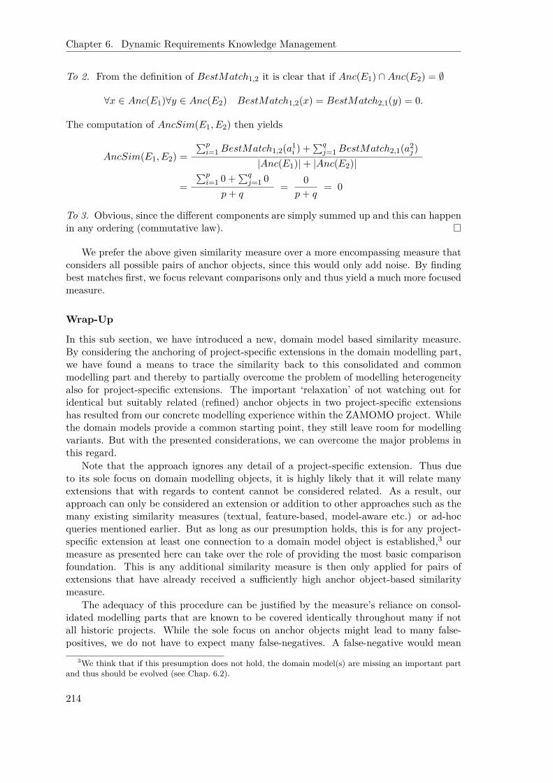
Chapter 6. Dynamic Requirements Knowledge Management
To 2. From the definition of BestMatch1,2 it is clear that if Anc(E1) ∩Anc(E2) = ∅
∀x ∈ Anc(E1)∀y ∈ Anc(E2) BestMatch1,2(x) = BestMatch2,1(y) = 0.
The computation of AncSim(E1, E2) then yields
AncSim(E1, E2) =∑p
i=1BestMatch1,2(a1i ) +
∑qj=1BestMatch2,1(a2
j )|Anc(E1)|+ |Anc(E2)|
=∑p
i=1 0 +∑q
j=1 0p+ q
= 0p+ q
= 0
To 3. Obvious, since the different components are simply summed up and this can happenin any ordering (commutative law).
We prefer the above given similarity measure over a more encompassing measure thatconsiders all possible pairs of anchor objects, since this would only add noise. By findingbest matches first, we focus relevant comparisons only and thus yield a much more focusedmeasure.
Wrap-Up
In this sub section, we have introduced a new, domain model based similarity measure.By considering the anchoring of project-specific extensions in the domain modelling part,we have found a means to trace the similarity back to this consolidated and commonmodelling part and thereby to partially overcome the problem of modelling heterogeneityalso for project-specific extensions. The important ‘relaxation’ of not watching out foridentical but suitably related (refined) anchor objects in two project-specific extensionshas resulted from our concrete modelling experience within the ZAMOMO project. Whilethe domain models provide a common starting point, they still leave room for modellingvariants. But with the presented considerations, we can overcome the major problems inthis regard.
Note that the approach ignores any detail of a project-specific extension. Thus dueto its sole focus on domain modelling objects, it is highly likely that it will relate manyextensions that with regards to content cannot be considered related. As a result, ourapproach can only be considered an extension or addition to other approaches such as themany existing similarity measures (textual, feature-based, model-aware etc.) or ad-hocqueries mentioned earlier. But as long as our presumption holds, this is for any project-specific extension at least one connection to a domain model object is established,3 ourmeasure as presented here can take over the role of providing the most basic comparisonfoundation. This is any additional similarity measure is then only applied for pairs ofextensions that have already received a sufficiently high anchor object-based similaritymeasure.
The adequacy of this procedure can be justified by the measure’s reliance on consol-idated modelling parts that are known to be covered identically throughout many if notall historic projects. While the sole focus on anchor objects might lead to many false-positives, we do not have to expect many false-negatives. A false-negative would mean
3We think that if this presumption does not hold, the domain model(s) are missing an important partand thus should be evolved (see Chap. 6.2).
214

6.1. Requirements-Based Search for Similar Projects
that two extensions that are actually related receive a too low anchor object-based sim-ilarity measure. This in turn will only happen, if too different connection points to thedomain modelling part have been chosen during modelling, this is the anchor objects ofthe two extensions might not be related at all. While in principal possible, a suitably de-signed and maintained domain model (see evolutionary considerations in Chap. 6.2) canbe expected to reduce such occurrences to a minimum.
6.1.5 Problems, Improvements, Open Issues
Integrating Query-Based Search and Anchor Object-Based Similarity
We have presented here a query-based similarity search as well as an anchor object-basedsimilarity measure. The latter is intended in particular to improve the addressing ofproject-specific extensions. Unfortunately, the integration of the two approaches has notbeen targeted here. This is mainly due to the fact that the anchor object-based similaritymeasure has originally been developed to support the evolution of domain models withrespect to project-specific extensions (see Chap. 6.2.5). While we will elaborate its usein the evolutionary context later on, the measure is certainly also relevant in the basicsimilarity search setting we are concerned with here.
A first idea to suitably integrate the anchor object-based measure in the query-basedsimilarity search is to split up the generic “ad-hoc” part into dedicated queries for eachproject-specific extension that can be identified in the current project that serves as thereference base for the similarity search. Since also the anchor object-based similaritymeasure makes use of Telos queries (see “Implementation” section below) for its realization,the basic integration is easy. The only difference is that the results need to be treateddifferently than for domain model or ad-hoc based queries. While for them we simply countthe occurrences of reference base objects in the results for historic projects, the anchorobject-based queries serve as the input to the computation of the anchor object-basedsimilarity measure as introduced above.
When following the above proposed approach, the number of queries will highly likelygrow significantly. Accordingly, it might become worth to define weights in a hierarchicalmanner. For example, weights are first distributed among domain model based queriesand queries concerning project-specific extensions. Only at a second level, the differentqueries on project-specific extensions (ad-hoc as well as anchor object-based) are weightedagainst each other. A hierarchy of weights is a typical approach also applied in generaldecision theory [vN02].
Certainly, a more thorough investigation of the integration topic can reveal that an-other approach might be preferable. In particular, if we also consider the integration of themany other, already existing measures in regard to textual, feature-based, structure-based,and model-aware similarities, more general approaches to suitably combine similarity mea-sures need to be investigated.
Extensions to the Similarity Search
Another idea to improve the overall similarity search is to precede the query-based similar-ity search described here by a high level comparison of domain models that went into themodelling of the various projects, current as well as historic. Utilizing the same domainmodel(s) could be assumed a basic precondition for being related. This is the set of historicprojects could be pre-filtered in regard to whether the same domain model(s) have been
215

Chapter 6. Dynamic Requirements Knowledge Management
used as in the current project. But on the other hand, the above introduced weighting ofqueries is able to express this while being much more flexible and precise at the same time.For example, queries in regard to one particular domain model can be classified as moreimportant than others. A weight of 0 even allows to ignore the aspects of a domain model.In the most degenerated case, this opens up the possibility to ignore all domain modelsin favor of project-specific issues only. Thus, the query-based approach presented aboveis more general. Nonetheless, a filtering according to domain models could be helpful inmany cases and thus should be provided at least as an optional convenience functionality.
Furthermore, the similarity search can be extended to not only cover requirementsmodels but also different project and development artifacts such as cost calculations,system designs, and even artifacts at implementation level. Certainly, measures must betaken to reduce the efforts when posing according queries to not overwhelm the user.
Another possible extension can derive from the work on applying the analogy paradigmto exploit reusable requirements specifications as proposed by Maiden and Sutcliffe [MS92].By abstracting from the concrete problem at hands, we might be able to identify projectsthat while not considering the same problem setting might concern a solution that is trans-ferable to the new domain. Due to the meta modelling features of Telos and ConceptBase,it is conceivable to store the derived abstractions as kind of (meta) patterns and integrateit into the realization of the similarity computation. The details need to be figured out infuture work.
Support for Cost Calculation From the perspective of SMEs, a valuable extensionwould concern the utilization of the approach to support the cost calculation at the SMEs.At the moment, we only support the identification of related projects. The engineer isthen expected to decide about reuse. If a reusable component is identified, this is intendedto reduce the costs for the new project. If the project base includes also the managementand costs perspectives of historic projects, according information, for example in regard tothe cost calculation, can be derived. Even if a particular component of an earlier projectcan in the end not directly be reused, the engineer might be able to investigate its costcalculation and thus receives a more reliable estimate for the costs of the newly to bedeveloped component. Thus, this extension joins possibly well with the consideration ofthe analogy paradigm [MS92] mentioned above. But in order to become valuable to anSME, this requires a model-based integration of the additional pieces of information (costcalculations, project plans, etc.). An at least partially automated transfer of the costsinformation into the new cost calculation must be provided while maintaining a referenceto the source to ensure traceability.
Improving the Anchor Object-Based Similarity Measure The potential of theanchor object-based similarity measure seems also to not be fully exploited yet. For one,the list of refinements that has been considered so far might need to be enlarged, inparticular in regard to actor association links, this is is-a, ins, plays, occupies,and covers links. It has to be investigated in more detail how we can still ensure theuniqueness of the refinement path (Lemma 6.1) which seems a valuable property or inwhich other way we can accommodate violations of this property in the definition of thesimilarity measure. Also an alternative definition of similar anchor objects is conceivablethat does not enforce that one refinement path is included in the other. Maybe sharinga common part would already be sufficient. This is in addition to the cases that areconsidered so far, it is then also possible to relate anchor objects that share a common
216

6.1. Requirements-Based Search for Similar Projects
part but at some point branch into different refinement hierarchies. A “penalty” couldthen be given to the part of the connecting path between the two anchor objects that istraversed inversely to the refinement definition. Furthermore, in its current form, we doneither account for how often an anchor object is referenced by a project-specific extensionnor on which refinement level it resides. For the latter, it seems valid to assume that thedeeper (and closer) two anchor objects from two project-specific extensions are nestedin the established refinement hierarchy, the more likely is their actual relatedness whileanchor objects at the highest level of refinement deliver only a weak hint on relatedness.
Accordingly, these ideas might be optional starting points for future improvements.Other improvements are mainly related to the integration of the approach with someof the existing textual, structural, and model-aware similarity measures as mentionedalready above. These are expected to strongly improve the correctness and precisenessof the similarity search for project-specific extensions. In addition, once such structuraland/or model-aware features are considered, it could also make sense to more preciselyconsider the origins within a project-specific extension that connect to the anchor objectsin the domain modelling part and include this information in the anchor object-basedsimilarity measure computation.
Eventually, we have to think about indexing (see [LdMFW08]) since pairwise compar-isons of all project-specific extensions among the whole project base will become more andmore difficult with the growth of the project base (see also Chap. 6.2.6). Again, existingapproaches from literature need to be consulted in regard to how far they are applicablein our setting as well.
Evolutionary Issues The similarity search as proposed above is also affected by evo-lutionary issues which will be discussed in depth in the next chapter (Chap. 6.2). Theaffection of the similarity search is mainly due to its reliance on domain models. As will beelaborated later on, the latter are regularly subject to change. Accordingly, in Chap. 6.2.4we investigate the effects of domain model changes on similarity search related issues.
6.1.6 Implementation Details
As becoming standard within this thesis, the main supportive activities are implementedvia suitable Telos (query) classes utilizing the Telos implementation ConceptBase. Thisis not different with similarity search related issues. Accordingly, we will introduce basicqueries that realize major parts of the similarity search as well as queries related to thecomputation of the anchor object-based similarity measure here. Examples for concretedomain models and problems are given later on in the case study section. Eventually, weshow how the support is to be integrated in our Eclipse based OpenOMEi5 tool.
Generic Base Comparison Queries
As an alleviation for users (as well as to tackle the robustness of queries as will be ad-dressed in Chap. 6.2.4), we suggest the use of generic query classes for the definition ofdomain model based or ad-hoc queries. Remember that generic query classes are queryclasses that can be instantiated or refined by setting parameters. This allows also lessexperienced users to take advantage of ConceptBase’s powerful query feature. Figure 6.4shows three such generic queries. The first two are concerned with decomposition hi-erarchies. While DecomposedElements watches out for refinements of a task (specified
217

Chapter 6. Dynamic Requirements Knowledge Management
GenericQueryClass DecomposedElements isA I n t e n t i o n a l E l emen t withparamete r
t a s k : TaskElementc o n s t r a i n t
c : $ e x i s t s l / Decompos i t i onL ink( l to t h i s ) and ( l from ~ ta s k ) $
end
GenericQueryClass DecomposedRecurs iveE lementsisA I n t e n t i o n a l E l emen t with
paramete rt a s k : TaskElement
c o n s t r a i n tc : $ e x i s t s l / Decompos i t i onL ink t /TaskElement
( l to t h i s ) and ( l from t ) and( ( t = ~ ta sk ) or( t i n DecomposedRecurs iveE lements [~ t a s k ] ) ) $
end
GenericQueryClass Ch i l d r enO f isA I n t e n t i o n a l E l emen t withparamete r
pa r en t : ActorE lementc o n s t r a i n t
c : $ ( t h i s pa r en t ~ pa r en t ) $end
Figure 6.4: Generic query classes to traverse decomposition and parent-child relations
as the parameter) only at the first decomposition level, DecomposedRecursiveElementsprocesses the hierarchy to any depth by recursively referring to itself. ChildrenOf is avery simple query that returns all children of a particular actor (again specified as theparameter) by evaluating the corresponding attribute. The existence quantifier for thedecomposition link in the two decomposition related queries clearly indicates thatproject-specific (or evolutionary) additions to or deletions from a domain model are cor-rectly considered by these generic queries. Similar query classes can be specified for theoccurrence of actors, dependencies, chains of dependencies as well as means-ends,softgoal, and is-part-of hierarchies, even combinations thereof. We omit them here,since they do not add substantial insights.
Note that all these generic queries are only related to i* modelling semantics but notparticular domain models. Accordingly, they should be associated, this is stored, with thegeneral i* framework representation in Telos. This also ensures that they are available forany user interested in specifying particular domain model based or ad-hoc queries. Thedomain model based queries (see case studies section below) instead should of course beassociated with the particular domain model module they concern.
Eventually, we would like to note two technical issues. For one, we need some kindof marker for historic projects. While the current project can be pointed at explicitly,the system should somehow be able to identify the set of historic projects with which
218

6.1. Requirements-Based Search for Similar Projects
to compare a current project. As with the indication of the “customer” for a “sharedhistory” based strategy to choose an initial domain model (see Chap. 5.1.3), the taggingis straightforward, for example, by adding a suitable Boolean attribute to the project’smodule.
The other issue concerns performance, in particular the unnecessary reevaluation of(domain model based) queries on historic projects. We mentioned already the fact that inmany cases the results to these queries can be cached for historic projects since they simpledo not change after finalization (for exceptions, see Chap. 6.2.4). While ConceptBaseprovides basic caching facilities for queries, in a productive environment we would need toelaborate on these in order to make sure that only in the (rare) case of adaptations to ahistoric project (see Chap. 6.2.4) the corresponding queries are re-evaluated. The simplestsolution would be to “materialize” the query results as part of a project model and updatethis materialization on demand. In [JQJ10], the materialization of views is discussed asan application of active rules (ECA).
Details Related to the Anchor Object-Based Similarity Measure
In regard to the anchor object-based similarity measure, the first implementation detailthat needs to be tackled is the identification of anchor objects. In Chap. 6.2.5 we willdiscuss in more depth how to identify project-specific extensions as initially defined inDef. 6.3. In particular, we will get to know a Telos class Extension that represents anextension and is referenced from the constituting objects via their partition attribute.Figure 6.5 shows the generic query class that takes an Extension object as a parameterand finds the DomainModelObjects that are referred (via a link or parent-child relation-ship) from within this Extension, this is the extension’s AnchorObjects. Remember thatDomainModelObjects are easily detectable by checking the existence of the domain_moduleattribute (as introduced in Chap. 5.1.3).
The second issue concerns the computation of refinement paths. Fortunately, we canpick up here on queries that have been developed for the transformation of i* models toMatlab/Simulink models (see Chap. 5.2.3). The basic idea is to introduce an additionaldeductive attribute super that captures the intended refinement relationships, this is itconsiders decomposition and means-ends hierarchies, parent-child relationships, andis-part-of links. Figure 6.6 shows the attribute as well as the corresponding rules thatreflect the refinements according to Def. 6.6. By referring to the deductive attribute, itis straightforward to formulate a query that computes the transitive closure of the superattribute and thereby the refinement path of a modelling object provided as the parameterstart . The corresponding generic query class, RefinementPath, is also shown in Fig. 6.6. Itreturns the object itself, its direct super attribute, or refers recursively to its own definition.
Once a suitable data structure is set up that provides for each project-specific exten-sion access to its anchor objects together with their refinement paths (see Chap. 6.2.6),the realization of the BestMatch and eventually AncSim computation is straightforwardand thus omitted here. Note that similar to the case for domain model based queries wecan cache these data for the project-specific extensions occurring in finalized projects. Ac-cordingly, only for the new current project the identification of project-specific extensions,their anchor objects, and refinement paths has to be carried out. Still the identificationis computationally expensive. So far no additional measures have been taken to computethe similarity values in a particularly efficient way.
219
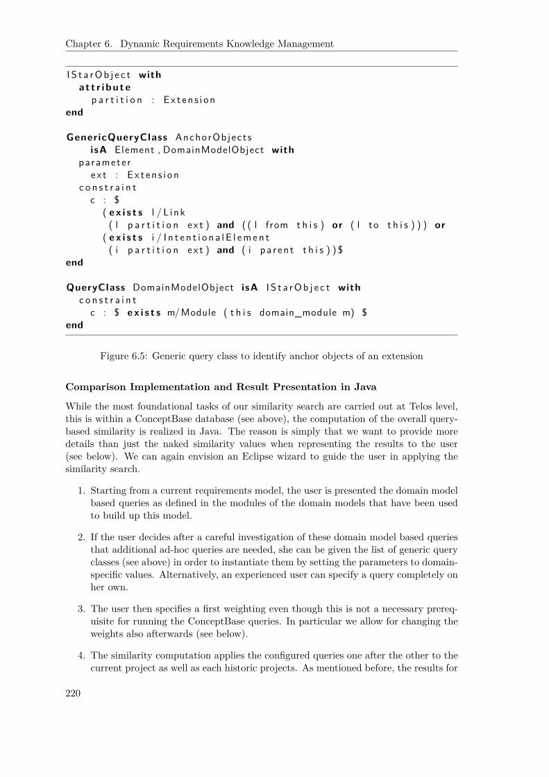
Chapter 6. Dynamic Requirements Knowledge Management
I S t a rOb j e c t witha t t r i bu te
p a r t i t i o n : Ex t en s i onend
GenericQueryClass AnchorObject sisA Element , DomainModelObject with
paramete re x t : Ex t en s i on
c o n s t r a i n tc : $
( e x i s t s l / L ink( l p a r t i t i o n ex t ) and ( ( l from t h i s ) or ( l to t h i s ) ) ) or
( e x i s t s i / I n t e n t i o n a l E l emen t( i p a r t i t i o n ex t ) and ( i pa r en t t h i s ) ) $
end
QueryClass DomainModelObject isA I S t a rOb j e c t withc o n s t r a i n t
c : $ e x i s t s m/Module ( t h i s domain_module m) $end
Figure 6.5: Generic query class to identify anchor objects of an extension
Comparison Implementation and Result Presentation in Java
While the most foundational tasks of our similarity search are carried out at Telos level,this is within a ConceptBase database (see above), the computation of the overall query-based similarity is realized in Java. The reason is simply that we want to provide moredetails than just the naked similarity values when representing the results to the user(see below). We can again envision an Eclipse wizard to guide the user in applying thesimilarity search.
1. Starting from a current requirements model, the user is presented the domain modelbased queries as defined in the modules of the domain models that have been usedto build up this model.
2. If the user decides after a careful investigation of these domain model based queriesthat additional ad-hoc queries are needed, she can be given the list of generic queryclasses (see above) in order to instantiate them by setting the parameters to domain-specific values. Alternatively, an experienced user can specify a query completely onher own.
3. The user then specifies a first weighting even though this is not a necessary prereq-uisite for running the ConceptBase queries. In particular we allow for changing theweights also afterwards (see below).
4. The similarity computation applies the configured queries one after the other to thecurrent project as well as each historic projects. As mentioned before, the results for
220
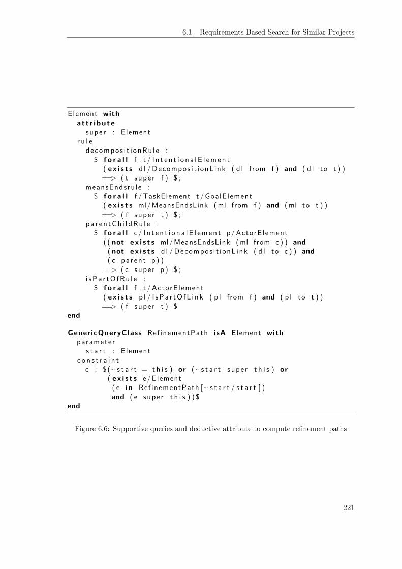
6.1. Requirements-Based Search for Similar Projects
Element witha t t r i bu te
supe r : Elementr u l e
decompos i t i onRu l e :$ f o r a l l f , t / I n t e n t i o n a l E l emen t
( e x i s t s d l / Decompos i t i onL ink ( d l from f ) and ( d l to t ) )==> ( t supe r f ) $ ;
meansEndsru le :$ f o r a l l f /TaskElement t /GoalE lement
( e x i s t s ml/MeansEndsLink (ml from f ) and (ml to t ) )==> ( f supe r t ) $ ;
p a r e n tCh i l dRu l e :$ f o r a l l c/ I n t e n t i o n a l E l emen t p/ActorE lement
( ( not e x i s t s ml/MeansEndsLink (ml from c ) ) and( not e x i s t s d l / Decompos i t i onL ink ( d l to c ) ) and( c pa r en t p ) )
==> ( c supe r p ) $ ;i sPa r tO fRu l e :
$ f o r a l l f , t / ActorE lement( e x i s t s p l / I sPa r tO fL i n k ( p l from f ) and ( p l to t ) )==> ( f supe r t ) $
end
GenericQueryClass Ref inementPath isA Element withparamete r
s t a r t : Elementc o n s t r a i n t
c : $ (~ s t a r t = t h i s ) or (~ s t a r t supe r t h i s ) or( e x i s t s e/Element( e i n Ref inementPath [~ s t a r t / s t a r t ] )and ( e supe r t h i s ) ) $
end
Figure 6.6: Supportive queries and deductive attribute to compute refinement paths
221

Chapter 6. Dynamic Requirements Knowledge Management
Overall ranking
Earlier projects stored in the database
Query weights, sum up to 1
Pre-defined queries referring to the domain model
Ad-hoc, user- defined queries
Objects from current project that occur also in the earlier project
IN ACCORDANCE: diesel MISSING: gas
Figure 6.7: Presentation of the outcome of a similarity search
the current project are taken as the reference base. This is for each of the objects inthis result set and each historic project it is checked whether the object also occursin the historic project (“in accordance”) or not (“missing”). After the queries havebeen processed and the similarity values have been computed, the user is presentedthe results as shown in Fig. 6.7. Note that the reader is explicitly given the namesof the objects from the current requirements model that occur or do not occur forthe listed historic projects as a tool tip information.
5. Since changing the weights does not entail to recompute any query, it is straight-forward to allow for the modification of weights. This enables the user to playaround with the results and thus investigate the projects more deeply. Certainly,the implementation provides support by checking whether the sum of weights indeedequals to 1 as mentioned before. Each change of the weights results in an immediateadaptation of the ranking of projects.
6. If the user has committed herself to a particular weighting, eventually the wizardshould open up the possibility to specify which (top-ranked) projects to open for amanual investigation.
222
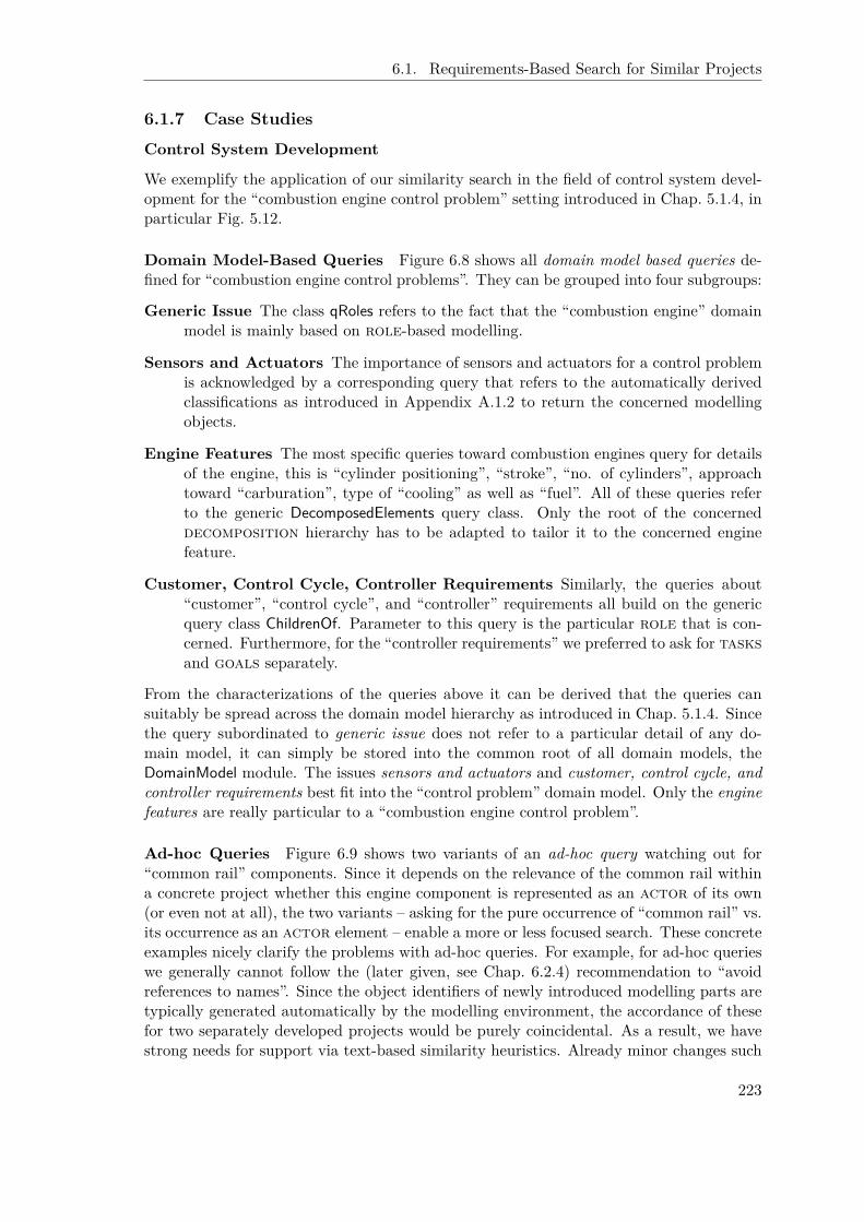
6.1. Requirements-Based Search for Similar Projects
6.1.7 Case Studies
Control System Development
We exemplify the application of our similarity search in the field of control system devel-opment for the “combustion engine control problem” setting introduced in Chap. 5.1.4, inparticular Fig. 5.12.
Domain Model-Based Queries Figure 6.8 shows all domain model based queries de-fined for “combustion engine control problems”. They can be grouped into four subgroups:
Generic Issue The class qRoles refers to the fact that the “combustion engine” domainmodel is mainly based on role-based modelling.
Sensors and Actuators The importance of sensors and actuators for a control problemis acknowledged by a corresponding query that refers to the automatically derivedclassifications as introduced in Appendix A.1.2 to return the concerned modellingobjects.
Engine Features The most specific queries toward combustion engines query for detailsof the engine, this is “cylinder positioning”, “stroke”, “no. of cylinders”, approachtoward “carburation”, type of “cooling” as well as “fuel”. All of these queries referto the generic DecomposedElements query class. Only the root of the concerneddecomposition hierarchy has to be adapted to tailor it to the concerned enginefeature.
Customer, Control Cycle, Controller Requirements Similarly, the queries about“customer”, “control cycle”, and “controller” requirements all build on the genericquery class ChildrenOf. Parameter to this query is the particular role that is con-cerned. Furthermore, for the “controller requirements” we preferred to ask for tasksand goals separately.
From the characterizations of the queries above it can be derived that the queries cansuitably be spread across the domain model hierarchy as introduced in Chap. 5.1.4. Sincethe query subordinated to generic issue does not refer to a particular detail of any do-main model, it can simply be stored into the common root of all domain models, theDomainModel module. The issues sensors and actuators and customer, control cycle, andcontroller requirements best fit into the “control problem” domain model. Only the enginefeatures are really particular to a “combustion engine control problem”.
Ad-hoc Queries Figure 6.9 shows two variants of an ad-hoc query watching out for“common rail” components. Since it depends on the relevance of the common rail withina concrete project whether this engine component is represented as an actor of its own(or even not at all), the two variants – asking for the pure occurrence of “common rail” vs.its occurrence as an actor element – enable a more or less focused search. These concreteexamples nicely clarify the problems with ad-hoc queries. For example, for ad-hoc querieswe generally cannot follow the (later given, see Chap. 6.2.4) recommendation to “avoidreferences to names”. Since the object identifiers of newly introduced modelling parts aretypically generated automatically by the modelling environment, the accordance of thesefor two separately developed projects would be purely coincidental. As a result, we havestrong needs for support via text-based similarity heuristics. Already minor changes such
223
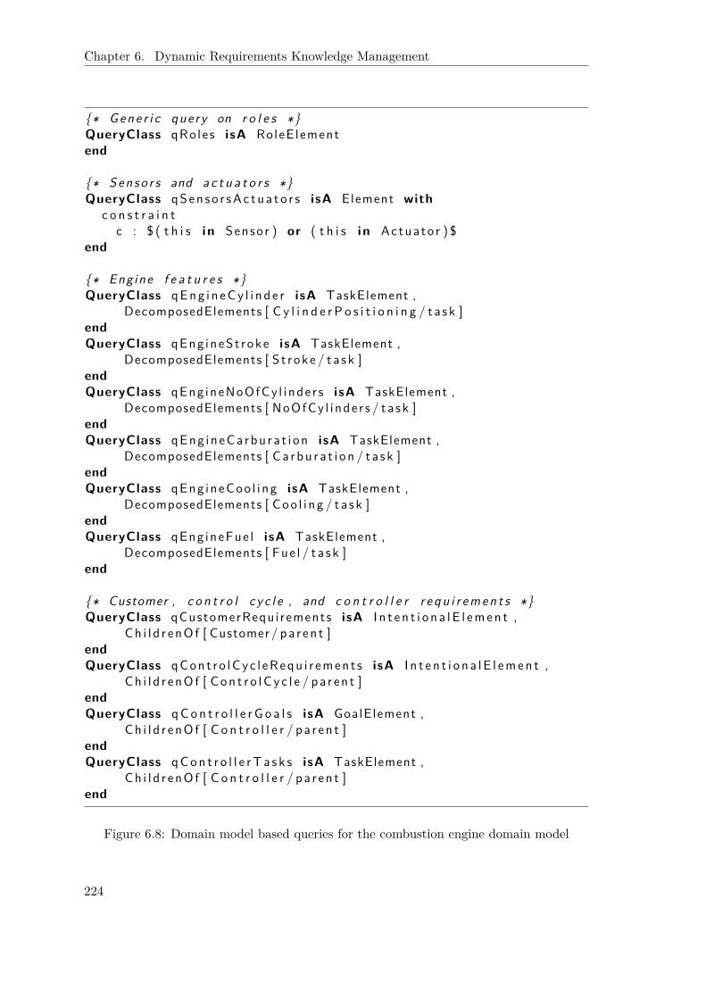
Chapter 6. Dynamic Requirements Knowledge Management
{∗ Gene r i c query on r o l e s ∗}QueryClass qRo le s isA RoleE lementend
{∗ Sen so r s and a c t u a t o r s ∗}QueryClass qSen so r sAc tua t o r s isA Element with
c o n s t r a i n tc : $ ( t h i s i n Sensor ) or ( t h i s i n Actuato r ) $
end
{∗ Engine f e a t u r e s ∗}QueryClass qEng i n eCy l i n d e r isA TaskElement ,
DecomposedElements [ C y l i n d e r P o s i t i o n i n g / t a s k ]endQueryClass qEng ineSt roke isA TaskElement ,
DecomposedElements [ S t roke / t a s k ]endQueryClass qEng ineNoOfCy l i nde r s isA TaskElement ,
DecomposedElements [ NoOfCy l i nde r s / t a s k ]endQueryClass qEng in eCa rbu ra t i on isA TaskElement ,
DecomposedElements [ Ca rbu r a t i on / t a s k ]endQueryClass qEng ineCoo l i ng isA TaskElement ,
DecomposedElements [ Coo l i ng / t a s k ]endQueryClass qEng ineFue l isA TaskElement ,
DecomposedElements [ Fue l / t a s k ]end
{∗ Customer , c o n t r o l c y c l e , and c o n t r o l l e r r e q u i r e m e n t s ∗}QueryClass qCustomerRequi rements isA I n t e n t i o n a l E l emen t ,
Ch i l d r enO f [ Customer / pa r en t ]endQueryClass qCon t r o lCyc l eRequ i r emen t s isA I n t e n t i o n a l E l emen t ,
Ch i l d r enO f [ Con t r o lC y c l e / pa r en t ]endQueryClass qCon t r o l l e r G o a l s isA GoalElement ,
Ch i l d r enO f [ C o n t r o l l e r / pa r en t ]endQueryClass qCon t r o l l e rT a s k s isA TaskElement ,
Ch i l d r enO f [ C o n t r o l l e r / pa r en t ]end
Figure 6.8: Domain model based queries for the combustion engine domain model
224

6.1. Requirements-Based Search for Similar Projects
{∗ Va r i an t 1 : e x i s t e n c e o f "common r a i l " components ∗}QueryClass qCommonRail isA Element with
c o n s t r a i n tc : $ ( t h i s name "common r a i l " ) $
end
{∗ Va r i an t 2 : "common r a i l " component mode l l ed as an a c t o r ∗}QueryClass qCommonRailActor isA ActorElement , qCommonRailend
Figure 6.9: Two variants of an ad-hoc query concerning “common rail” components
Figure 6.10: Extensions and a refinement path in a concrete project
as capitalizing words would otherwise prevent ConceptBase from finding related objectsin different projects.
Anchor Object-Based Similarity Figure 6.10 shows an excerpt of a requirementsmodel for an individual customer project. Two project-specific extensions have been iden-tified that are highlighted: one concerns the introduction of a “cylinder pressure” sensor,the other of a “biturbo”. Table 6.1 lists the anchor objects for each of these two exten-sions. Furthermore, Fig. 6.10 also includes an example of a refinement path. Originatingin “pump injection” (5) decomposition links are followed along “direct injection” (4)and “injection” (3). Then via the parent-child relationship the “controlled system” (2) isreached and from here onward via an is-part-of link the “control cycle” (1).
Now consider the case that while the project P1 captured in Fig. 6.10 has been workedupon by an “engineer A” there has been a separate project P2 dealt with by a different“engineer B”. In this project a similar extension E2.1 to E1.1, this is concerning the new“cylinder pressure” sensor, was introduced. Figure 6.11 contrasts the differences in mod-elling. While “engineer A” has simply connected the new sensor resource dependencyto the roles “controlled system” and “controller”, “engineer B” has chosen more refined
225

Chapter 6. Dynamic Requirements Knowledge Management
Table 6.1: Anchor objects of the two project-specific extensions from Fig. 6.10
Extension Anchor ObjectsExtension 1.1: a1
1: controlled system (for “sensor: cylinder pressure”)cylinder pressure a1
2: controller (for “sensor: cylinder pressure”and “measure cylinder pressure”)
Extension 1.2: a21: turbine (for “biturbo”)
biturbo a22: turbo charging (for “biturbo”)
(a)
(b)
Figure 6.11: Two project-specific extensions with differences in modelling
226

6.1. Requirements-Based Search for Similar Projects
Table 6.2: The anchor objects and their refinement paths
Engineer Anchor Objects Refinement PathsA a1: controller {controller, control cycle}
a2: controlled system {controlled system, control cycle}B b1: controller {controller, control cycle}
b2: injection {injection, controlled system, control cycle}
targets, namely the task “measure cylinder pressure” within the “controller” and thetask “injection” within the “controlled system”.
Table 6.2 shows the results regarding the identified anchor objects. For simplicity theextensions are named after the responsible engineer, this is either “A” or “B”, accordinglythe individual anchor objects. Obviously, the best match for a1 is b1 (and vice versa) sincethe refinement paths are identical.
BestMatchA,B(a1) = BestMatchB,A(b1) = 1
For a2, b2 is the best match (again also vice versa) even though the refinement paths arenot identical since the one for b2 is longer.
BestMatchA,B(a2) = 1|{inject., contr. syst., contr. cycl.} \ {contr. syst., contr. cycl.}|+ 1
= 1|{injection}|+ 1 = 1
2
The computation of the anchor object-based similarity measure AncSim(A,B) theneventually yields the following result:
AncSim(A,B) =∑2
i=1BestMatchA,B(ai) +∑2
j=1BestMatchB,A(bj)|{a1, a2}|+ |{b1, b2}|
=1 + 1
2 + 1 + 12
2 + 2 = 34
Note that the system is aware whether two anchor objects are identical because theyresult from the domain model and thus have identical (internal) names in all projects.In contrast, the two objects just sharing the same name “cylinder pressure” in differentprojects cannot be related that easily.
Inter-Organisational Networks
Also for the case study concerning inter-organisational networks examples for ad-hoc anddomain model based queries are conceivable. Figure 6.12 shows examples for domain modelbased queries for the “network” and “member” concerns since modelling components fromthese two concerns are as elaborated before (see Chap. 5.1.4) most likely to be reusable.The first “network” related query concerns the check for the existence of a particularnetwork rule regarding “network admittance”. It expects the role of a “new member” tobe part of the domain modelling and watches out for dependency relationships includingthe ones that are connecting to ChildrenOf the “new member” role. The second “network”
227

Chapter 6. Dynamic Requirements Knowledge Management
{∗ " Network " conce rn : a p a r t i c u l a r network r u l e ∗}QueryClass qNetworkAdmittance isA I n t e n t i o n a l E l emen t with
c o n s t r a i n tc : $ e x i s t s dep/DependencyLink f , t /Element
( ( dep from f ) and ( dep to t h i s ) and( ( f = NewMember) or ( f i n Ch i l d r enO f [ NewMember/ pa r en t ] ) ) ) or
( ( dep from t h i s ) and ( dep to t ) and( ( t = NewMember) or ( t i n Ch i l d r enO f [ NewMember/ pa r en t ] ) ) ) $
end
{∗ " Network " conce rn : o c c u r r e n c e o f d i s t r u s t ∗}QueryClass qD i s t r u s t isA Element with
c o n s t r a i n t c : $ ( t h i s = D i s t r u s t ) $end
{∗ "Member" conce rn : p l a n n i n g p rocedu r e ( s ) ∗}QueryClass qP lann ingProcedu re isA TaskElement ,
DecomposedElements [ P l ann ing / t a s k ] ,Ch i l d r enO f [ Gene r i cAgent / pa r en t ]
end
Figure 6.12: Domain model based queries for the network and member concerns of inter-organisational networks
query simply watches out for the actual occurrence of the Distrust modelling object. The“member” concern related query looks at the different “planning approaches” that areavailable in historic projects by again referring to assumed parts of the domain model,GenericAgent for covering the basic facilities of agents and Planning for the extension pointin regard to planning procedures (similar to the engine features for the “combustion enginedomain model”).
Figure 6.13 in contrast shows an ad-hoc query that refers to a particular industry,namely “plastics processing industry” by searching earlier models for characteristic terms.Again the need becomes apparent to cope with spelling variations and thus textual simi-larity.
QueryClass qP l a s t i c s P r o c e s s i n g I n d u s t r y isA Element withc o n s t r a i n t
c : $ ( t h i s name " p l a s t i c s " ) or( t h i s name " e x t r u d e r " ) or( t h i s name " p e l l e t s " ) or( t h i s name " f l ow hea t e r " ) or. . . $
end
Figure 6.13: Ad-hoc query to search projects in the “plastics processing industry”
228

6.2. Domain Model Evolution
6.1.8 Summary
In this section we have introduced a similarity search on requirements models intended tosupport engineers at small- and medium-sized enterprises to more reliably identify relatedhistoric projects. We referred back to the domain model based requirements engineeringapproach as introduced in Chap. 5.1. By allowing for ad-hoc queries, project-specificweights, and by taking the current project as the reference base for the comparison, wehave established means for project-specific adaptations. Together with the feedback loopto adapt domain models out of project-specific experiences (see Chap. 6.2), this results insituational features of our approach, as will be discussed in more detail in Chap. 6.3.
We have also outlined the features of an anchor object-based similarity measure that isintended to help identifying similar project-specific extensions more reliably, in particularto overcome modelling heterogeneity. Again, we have established a connection to ourdomain model based approach by using the anchoring of project-specific extensions forthe computation of our similarity measure. Despite of obvious drawbacks in regard to themany characteristics of project-specific extensions that this approach ignores, it has beenshown that it indeed can be helpful in finding related extensions. A suitable integrationwith existing textual and model-aware similarity measures as well as the query-basedapproach discussed before needs to be tackled in future work.
While large-scale real world case studies have not yet been carried out, the overallfeedback from our project partners from the ZAMOMO project have been very encour-aging. In particular the SME was rather interested in the possibility to investigate theirproject history and envisions an encompassing project documentation, not solely storingthe requirements models, but any modelling as well as project documentation artifact.This would also allow us to broaden the scope of the similarity search by incorporatingthe analogy paradigm as investigated by Maiden and Sutcliffe [MS92]. As outlined abovethis could in particular further improve the reliability of the cost calculation as the majoroutcome of the first requirements modelling phase considered here.
6.2 Domain Model EvolutionThe domain model based approach to requirements capture (Chap. 5.1) is only valu-able if the domain models correctly reflect the most recent experiences and most currentknowledge of the enterprise that applies this approach. But experiences and knowledgenecessarily evolve over time:
• new research results or technologies must be considered,
• a shift of interests at the enterprise must be reflected, and eventually
• the recent experiences within concrete projects must continuously be used to updatethe domain models.
On the other hand, the domain models are not allowed to grow unrestrictedly, since atoo large domain model requires too many clean up operations (to tailor it to a concreteproject). This jeopardizes the benefits in regard to a fast requirements capture.
Accordingly, this chapter is devoted to suitably manage domain model evolution. Inparticular we investigate the effect of domain model changes on what constitutes a project-specific extension, on the similarity search as presented in the previous chapter (Chap. 6.1),and outline support to automatically derive suggestions for domain model adaptations
229

Chapter 6. Dynamic Requirements Knowledge Management
Tacit knowledge
Explicit knowledge
Tacit knowledge Socialisation Externalisation
Explicit knowledge Internalisation Combination
Figure 6.14: The SECI cycle of knowledge creation (adapted from [NT95])
(reductions and extensions) out of concrete project-specific experiences of an applyinginstitution.
6.2.1 Related Work
At its core, domain models are a means to capture knowledge. Accordingly, knowledgemanagement needs to be considered related to domain model evolution. Furthermore,since our domain models are formalised as i* models, model management related ap-proaches need to be consulted. This includes fields such as ontology matching and similar-ity measures that have already been touched upon in the previous chapter in regard to thesimilarity search but also distributed data integration (to address the effects of evolutionon already finalized projects). Eventually, the management of domain models should beincluded in a method. Accordingly, evolutionary aspects within the context of situationalmethod engineering are investigated here as well.
Knowledge Management
Figure 6.14 shows the well-known SECI cycle of knowledge creation [NT95]. It emphasizesthe roles of explicit and tacit knowledge and knows four different conversion processes:Socialisation, Externalisation, Combination, and Internalisation. “Socialisation” createsknowledge by sharing experiences. This knowledge is articulated as conceptual knowledgethrough “externalisation”. “Combining” knowledge is seen as a way to systematise ideasand can ultimately also lead to new knowledge. Eventually, in order to actually affect thework of a particular person, the knowledge then has again to be adopted and integrated,this is “internalised”, into the activities of an individual.
According to these considerations, our domain model based approach can be consideredto concern knowledge management in two regards.
• Firstly, the project repository is supposed to document previous individual experi-ences. They are made accessible by our similarity search, in particular to identifychances for reuse.
This is the repository is at first a precondition for sharing project experiences andthus helps to “socialise” knowledge. Due to its reliance on requirements models italso prepares for “externalisation”.
230
6.2. Domain Model Evolution
• Secondly, the domain models themselves reflect consolidated knowledge that is man-aged by evolving the models according to the experiences and needs of the applyinginstitution.
This is adaptations to domain models are exactly the outcome of the dialogues anddiscussions (“externalisation”) of individual project experiences in regard to whatshould be added (or removed) from the domain models. By “combining” the bestideas from different projects, a new shared approach might arise. Furthermore viathe domain models the collected knowledge is easily available for use within the nextproject (“internalisation”).
From an organisational perspective, a major difference toward knowledge managementas it is typically applied in larger enterprises is that SMEs rarely can afford spend the nec-essary “extra time” [CC08] let alone “some full-time knowledge staffers” [DP98]. Instead“SMEs need to look into their work procedures and incorporate the knowledge captureprocess into it” [LEB+05].
Model Management
In [BHP00] Bernstein, Halevy, and Pottinger coined the term model management to cap-ture the ability of a system to cope with model changes and according data transfor-mations. They emphasize the need to treat “model” and “model mapping” as first-classobjects and propose particular operations that are intended to simplify their use suchas “copy”, “select”, “delete”, “apply-function”, “enumerate”, “compose”, “match”, and“merge”. While the foundations of the proposed theory are not yet fully settled, first(partial) implementations are already available (see [KQCJ07, KQL+09]). In the field ofdatabases, these issues have been addressed, for example by Staudt Lerner [Sta00b]. Sheproposes to compare schemata to address complex changes to a schema and produce atransformer to update the data accordingly.
Also in the context of model-driven development (see [OMG03]), the reflection of metamodel adaptations on the concrete models have been considered. Wachsmuth [Wac07] andGruschko et al. [GKP07] provide classifications for meta model modifications. Similarlyto Staudt Lerner, the intention is to be able to provide rules to automatically synchro-nize instances to the changed meta models. Also Herrmannsdoerfer (with varying col-leagues) investigated the possibility of automation for a coupled evolution of meta modelsand models. Starting with the investigation of the evolution history of industrial metamodels [HBJ08], they classified the occurring changes and investigated the potential forautomation. In particular they identified a set of reusable evolution operations, this is mi-gration operations that are not specific to a particular domain specific language. Withinlater work they elaborated the need to combine meta model-specific and -independentchanges by developing according tool support [HBJ09] but also identified limitations ofautomation [HR09]. In particular, if a meta model is refined, existing models cannotbe migrated automatically since the necessary information is simply not available in theexisting models. Some heuristics are proposed to avoid meta model erosion.
A commonality of all these approaches toward evolution is that the triggering adap-tations or changes happen at a meta level and somehow must be transferred to an in-stantiation of this meta level. In contrast, adaptations to our domain models cannot beconsidered to reside at a different level of abstraction. Since the domain models are used‘as is’ in the concrete project-specific models, we have to consider the effect of a subset
231

Chapter 6. Dynamic Requirements Knowledge Management
relationship to the (base) domain models. The effect of this difference will be discussedlater in more detail. Nonetheless, we also start our investigation by a classification ofpotential adaptations to a (concrete) domain model (see Chap. 6.2.2 below).
Ontology Matching The related work in the field of ontology matching [ES07] has al-ready been covered in the previous chapter when considering other approaches to identifysimilarities. Besides the basic matching procedures that support the identification of re-lated features in different ontologies also the merger of ontologies is of interest. While theconcrete technologies are again tailored to ontology concepts and thus less applicable in oursetting, ontology merging nicely stresses a feature that is characteristic to any ontology:an ontology is intended to represent a “shared conceptualisation of a domain of inter-est” [GHA07]. Similarly, a domain model update involves a discussion of what should becovered by the domain model as well as the mitigation of modelling variants from differentcustomer projects. Eventually, recently ontology evolution (also ontology dynamics) has re-ceived more and more attention (see, for example, http://www.ontologydynamics.org).As with our findings, the need has been identified to modify an ontology “to form a moreaccurate or adequate conceptualization of the domain” [FdA+09]. Again the technologiesare very specific, but the basic ideas seem to fit well so that we need to monitor futureresearch in this field for its application to our setting as well.
Similarity Measures The broad field of similarity measures has also already beenconsidered in the previous chapter (Chap. 6.1.1) in the context of the similarity search. Allapproaches that help to identify related modelling parts in different projects – in particularproject-specific extensions – provide a useful input to the identification of project-drivenadaptations of a domain model.
Reuse Requirements Experiences Niu and Easterbrook [NE08] explicitly consideredthe consultation of requirements of historic projects to extract product line functionalrequirements. In their argumentation, “the up-front cost and the level of manual effortassociated with [heavy-weight] domain analysis present a prohibitive adoption barrier formany organisations”, in particular SMEs. Following a proposal from Krueger [Kru01]toward mining software repositories for core assets, they focus on “[the identification of]functional requirements assets by analyzing natural language (NL) documents”. Theyfocus NL documents since they assume they correctly reflect RE practice in SMEs.
As argued in Chap. 3.2.3, the emergence of product lines is less likely in our settingof very customer-oriented, flexible, and innovative SMEs. Nonetheless, the basic ideaof deriving reusable assets from previous projects’ experiences is similar. As such ourapproach as presented in this thesis can be considered an intermediate approach since itis supportive also if only a series of related projects is carried out. If an SME later onindeed wants to switch to a product line based approach (see [KMSW00]), our approachhas the advantage to capture the requirements already in a model-based manner. Thus,there is no need to work on NL documents. In this context it is also worth to mentionthat approaches that tackle variability in goal modelling are already present [YLL+08].
Data Integration As we will see later on, the evolution of domain models will bring upissues in regard to how to cope with already finalized projects that have been built withthe help of earlier versions of a domain model. In particular the similarity search maysuffer from problems in this regard.
232
6.2. Domain Model Evolution
Data warehouses [JLVV03] can be considered related to this problem since they alsohave to tackle heterogeneity. Within data warehouses we are in need of integrating scat-tered and possibly differently structured sources of information [Qui09]. Wrappers helpto integrate the data and smoothen out their differences. We will see later on that at thecore we follow an idea that can be considered similar. But instead of working on wholesets of information (this is databases) the scale is much smaller. We need to adapt a fewsingle datasets so that they confirm with the more general (domain model based) picturethat is utilized for the queries of a similarity search.
Also the research on queries in evolving mobile and ad-hoc networks (e. g. [PJR07])can be considered related. In this setting the results of queries might vary due to changesin regard to reachability during query evaluation. While the degree of consistency thatPayton et al. consider allows statements about the validity and significance of query results,their work does not affect the actual query result. But the latter is needed in our settingto reliably identify the correct set of similar projects.
Evolution in Situational Method Engineering
Eventually, already the seminal PhD thesis on situational method engineering by Harm-sen [Har97] included a feedback loop from the application of a situational method (denotedby Harmsen as “project performance”) to “methods administration” activities. Figure 6.15shows Harmsen’s representation of his situational method engineering approach. In termsof the generic model presented by Ralyté et al. [RDR03] (see Chap. 2.1.1), this nowa-days is considered the “assembly-based strategy”. But in contrast to their representation(see Fig. 2.1), he explicitly included a representation of the “project performance” andin particular of the “method base”. Updates to the “method base”, this is insertions ofnew fragments, updates to existing ones, as well as the removal of outdated method com-ponents, are thus to be triggered by “experience accumulation” resulting from individualapplications. Furthermore, the “method base” was intended to capture not only the ba-sic method fragments and components but also “properties” to support the “meaningfulselection, comparison, and assembly of method fragments”. Again, these details are notcaptured by the Map based representation given by Ralyté et al. (see [RDR03]). We willpick up on these basic ideas and elaborate in more detail how concrete experiences fromrecent projects eventually result in adaptations of the domain models that serve as themajor source of (situational) knowledge in our approach.
While Harmsen’s approach can only be considered one variant, this is the “assembly-based strategy” to situational method engineering, also the other strategies introducedby Ralyté et al. refer to a kind of repository. As exemplified in the textual descriptions,the “extension-based strategies” presumes the existence of “patterns” to “[identify] typ-ical extension situations and provide advises to perform the required extension”. In thecase of the “paradigm-based strategy”, the repository consists of “meta models” that areabstracted, instantiated, utilized, or adapted. But unfortunately, Ralyté et al. do notdiscuss how the application of a situational method engineering in detail leads to the ex-tension of the corresponding repositories and thus the evolution of the situational methodengineering setting as a whole.
Partially this has recently been addressed by Chiniforooshan and Yu [CY10]. Theyhave proposed to include additional information in the method base repository that helpsto make the right decisions when constituting a new method. They use a goal-orientedrepresentation for agile method fragments that in particular captures the results of various
233
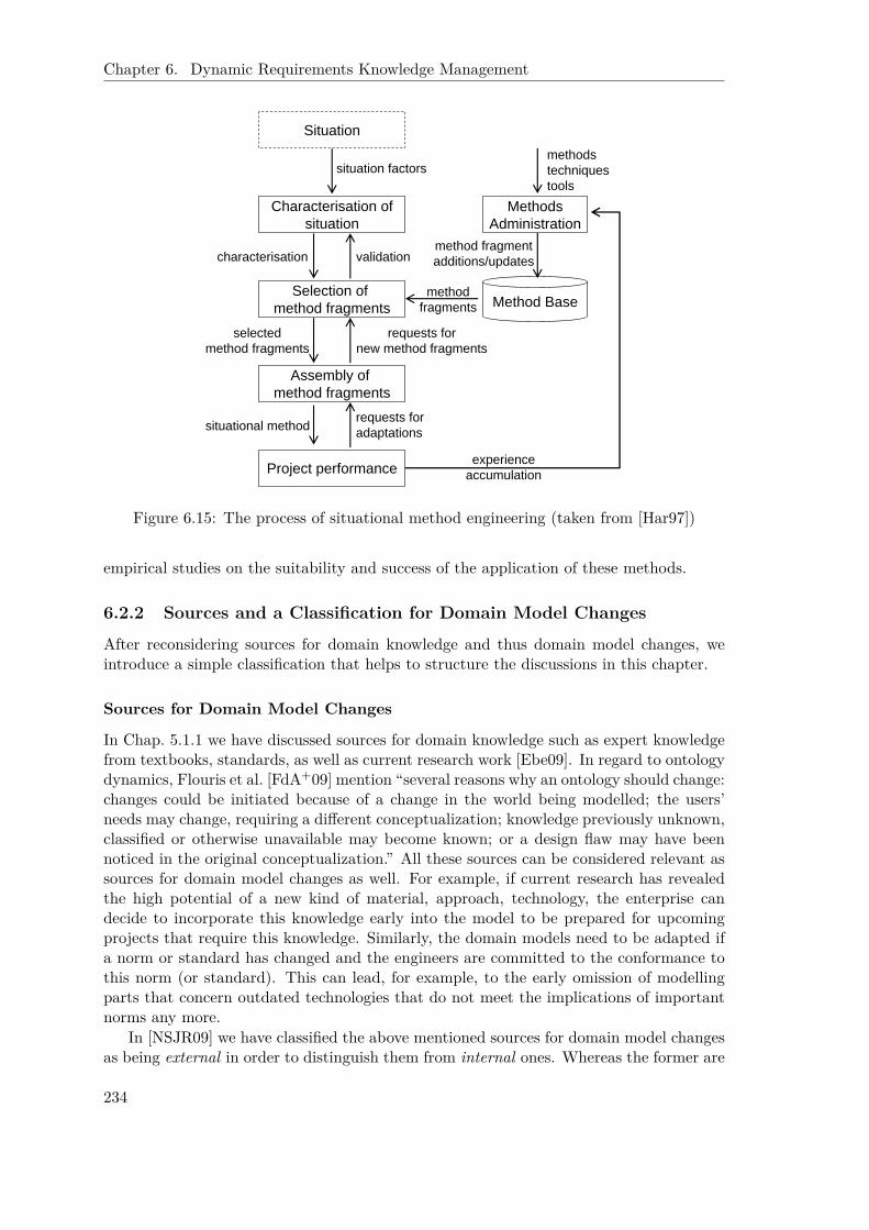
Chapter 6. Dynamic Requirements Knowledge Management
Characterisation of situation
Situation
Selection of method fragments
Assembly of method fragments
Project performance
Methods Administration
Method Base
situation factors
validationcharacterisation
requests for new method fragments
selected method fragments
requests for adaptationssituational method
experience accumulation
method fragments
method fragment additions/updates
methods techniques tools
Figure 6.15: The process of situational method engineering (taken from [Har97])
empirical studies on the suitability and success of the application of these methods.
6.2.2 Sources and a Classification for Domain Model Changes
After reconsidering sources for domain knowledge and thus domain model changes, weintroduce a simple classification that helps to structure the discussions in this chapter.
Sources for Domain Model Changes
In Chap. 5.1.1 we have discussed sources for domain knowledge such as expert knowledgefrom textbooks, standards, as well as current research work [Ebe09]. In regard to ontologydynamics, Flouris et al. [FdA+09] mention “several reasons why an ontology should change:changes could be initiated because of a change in the world being modelled; the users’needs may change, requiring a different conceptualization; knowledge previously unknown,classified or otherwise unavailable may become known; or a design flaw may have beennoticed in the original conceptualization.” All these sources can be considered relevant assources for domain model changes as well. For example, if current research has revealedthe high potential of a new kind of material, approach, technology, the enterprise candecide to incorporate this knowledge early into the model to be prepared for upcomingprojects that require this knowledge. Similarly, the domain models need to be adapted ifa norm or standard has changed and the engineers are committed to the conformance tothis norm (or standard). This can lead, for example, to the early omission of modellingparts that concern outdated technologies that do not meet the implications of importantnorms any more.
In [NSJR09] we have classified the above mentioned sources for domain model changesas being external in order to distinguish them from internal ones. Whereas the former are
234

6.2. Domain Model Evolution
used to denote direct changes to a domain model out of a separate source, internal changesoriginate in the day-to-day work of an enterprise, this is in their individual projects andexperiences. If a similar project-specific extension is occurring recurrently in the latestprojects, a corresponding consolidated modelling excerpt should possibly be included ina suitable domain model. Even a whole new domain model could emerge if a completelynew field of expertise is approached. Similarly, also the clean up operations during thetailoring of domain models to a concrete customer project need to be monitored. Ifidentical modelling parts are deleted over and over again in various recent projects, theseparts might need to be abandoned from the domain model right away. Obviously, thisis also a means to speed up the capturing. Thus, altogether we consider internal sourcesas the most important ones since they provide a feedback loop to quickly tailor domainmodels to the needs of a particular enterprise. Accordingly, we will mainly focus them inthe following.
Classifying Domain Model Changes
Quite a number of researchers have worked on the implications of meta model changeson concrete data as elaborated in the related work section. In their considerations, theytypically introduce a classification of changes. For example, Staudt Lerner[Sta00b] dis-tinguishes “simple type changes” and “compound type changes” constituted from “typedeletions”, “creations”, or “modifications”. Wachsmuth [Wac07] analyses model trans-formations in regard to their “preservation properties”, mainly “semantics-preservation”and “instance-preservation”. Gruschko, Kolovos, and Paige [GKP07] classify “M2 modelchanges” into “not breaking changes” (at the instance level), “breaking and resolvablechanges” (resolvable via automated means), and “breaking and unresolvable changes”(this is not automatically resolvable).
There are two major differences to our work.
• Firstly, a commonality of all these approaches is that the evolution occurs at a moreabstract level while the co-evolution (or synchronisation) takes place at a level thatinstantiates the adapted (meta) level. This is different in our setting. As emphasizedalready before, domain models do not reside at a different level of abstraction. Thisis they are used ‘as is’ in concrete project-specific models. Fortunately, this situationmakes the consideration of evolution in our context only easier as we will see lateron.
• Secondly, there is an additional consequence to the first finding. While in theirsettings the goal to be achieved is given by the need to co-evolve meta model andaccording model instances, in our case the situation is less clear. Generally speaking,we have to expect problems to arise if some development task spans several projectswhere the according requirements models possibly originate in different versions ofa domain model. Currently, the only such tasks are the similarity search and theidentification of project-driven adaptations to a domain model.
Accordingly, we will classify domain model changes in the following in regard to theireffects on what constitutes a project-specific extension as well as on the similarity search.While each of these applications has its particularities, at the most basic level we followthe classification given by Staudt Lerner by considering “modifications”, “additions”, and“deletions” separately (see Tab. 6.3).
235
Chapter 6. Dynamic Requirements Knowledge Management
Table 6.3: A classification of domain model changes
Change DetailsModification Changing the value of the name attribute or altering sources (desti-
nations) of links (or the parent-child relationship) as long as the newreferences have been part of the domain model already before.
Addition Any modelling object where at least one referred object (for links orparent-child relationships) has not been part of the domain model yet.
Deletion Removing a modelling object (element, link, parent-child relationship)from a domain model.
6.2.3 Effects on the Constitution of Project-Specific Extensions
Remember that a project-specific extension is defined in Def. 6.3 as “a suitable subset”of the “specific objects” of a project, this is the objects that exactly do not originatein domain models. Accordingly, changing a domain model can certainly impact what isconsidered a project-specific extension.
Modifications Neither changing the name attribute nor redirecting any link within adomain model leads to a reconsideration of what constitutes a project-specific extension.This is simply due to the fact, that the set of domain objects is not changed and thus theset of specific objects of any historic project is neither.
Additions In regard to domain model additions, we distinguish two cases. A completelynew extension (e. g. due to an external extension), this is not occurring in any form as aproject-specific extension in any historic project, does also not affect the project-specificextensions of historic projects simply by definition: the according elements do not occurin any of these projects.
This is different with a domain model addition that has already occurred at leastpartially in a historic project as a project-specific extension. While we discuss later onhow to cope with modelling variations in different projects (see Chap. 6.2.4 and 6.2.5), wepresume here that we can correctly and safely identify recurrences of such objects. A firstchance is then that the project-specific extension in its entirety is now part of the domainmodel and thus not at all considered a project-specific extension any more. Secondly, itmight be the case that only a part of the project-specific extension has been introducedto the domain model. In this case what constitutes a project-specific extension must bedecided anew. It might be the case that the project-specific extension simply shrinksby the objects that have become domain model objects. But it is also possible that asingle project-specific extension is now better split into several smaller project-specificextensions that are related to each other via the newly considered domain model objects.See Chap. 6.2.5 for a more extensive discussion on how self-contained project-specificextensions should be chosen.
Deletions The deletion of domain model objects can also lead to an update of whatpart of a project modelling is considered a project-specific extension. First of all, for allhistoric projects that utilized the deleted domain modelling parts these now are considered
236
6.2. Domain Model Evolution
project-specific extensions. This is if no further project-specific extensions (according tothe earlier version of the domain model) are present in a historic project, simply a newproject-specific extension encompassing the tailored former domain modelling part arises.If project-specific extensions that connect to the now deleted domain modelling part havebeen there before, the removal might cause a growth of the corresponding extensions.They are enlarged by the former domain model objects. Note that this enlargement canalso lead to a combination of formerly separately treated project-specific extensions if theyare connected via the concerned old domain modelling part (see again Chap. 6.2.5 for whata project-specific extension should consist of).
Measures to Be Taken As resulting from the above discussion, only additions (of atleast partially recurring objects) and deletions trigger the reconsideration of project-specificextensions. For additions Chap. 6.2.4 will elaborate the need to update historic projectsby reflecting a domain model change within concerned, already finalized projects. If suchprojects exist, the update is the result of a project-driven extension. Accordingly, we canpresume that any management activity in regard to extensions can be embedded in theactivities to derive a consolidated modelling version that forms a domain model changeas to be discussed in Chap. 6.2.5. In regard to deletions, at the technical level we have toremove the tagging of the concerned modelling objects within the historic projects thatindicates that these objects originate in a domain model. Once this has happened, wecan simply re-trigger the evaluation of what is concerned a project-specific extension andmanage the possibly newly created extensions as to be discussed in Chap. 6.2.5.
6.2.4 Effects on the Similarity Search
Modifications of a domain model can affect the similarity search as introduced in thepreceding chapter (Chap. 6.1) in three regards.
1. The predefined domain model based queries might be directly affected by a modi-fication. For example, a directly referred component has been deleted or an other-wise explicitly referred structure, e. g. a decomposition hierarchy or dependencychain, has been altered.
2. The requirement models of projects based upon the new domain model version differconsiderably from the ones for historic projects. This is due to modelling variationsthe similarity search can no longer correctly identify them as being related.
3. The refinement paths or even anchor objects of project-specific extensions havechanged and thus the anchor object-based similarity measure needs to be recom-puted.
We will investigate the effect of domain model changes on each of these cases. It will turnout that each of the them has different characteristics and thus different changes will causedifferent problems. Nonetheless we will propose suitable counter measures for all threecases with the ultimate goal to reestablish the accuracy of the similarity search.
Direct Effects on Queries
The consideration of the effects of domain model evolution on queries that refer domainmodel components – mainly, domain model-based queries – will result in a set of recom-mendations for the robust formulation of such queries (summarized in Tab. 6.4).
237
Chapter 6. Dynamic Requirements Knowledge Management
Modifications Remember that the core intention of the domain model based approachis the support for SMEs that are active in highly innovative fields. Due to the noveltyof problems addressed, the actual ‘naming’ of modelling objects might evolve over time.Consider as an example the broadness of topics that partially were coined much earlier butthat are nowadays considered part of the so called “Web 2.0” [O’R05]. Accordingly, insteadof referring to the textual representation of names of modelling objects, we recommend toutilize the unique identifier for the modelling object (that still can have a speaking name).This remains the same along changes to the name. This is any update to the actual namedue to a renewed agreement within the field or even only for a particular customer doesnot harm the similarity search.
Structural modifications such as changing decomposition or is-part-of hierarchiesneed to be addressed via suitable, generic queries as will be discussed in detail for “addi-tion” and “deletion” changes below.
Additions While certainly a non-empty i* model can be extended by any i* modellingfeature, there are several constructs that seem to have a higher ‘connecting factor’. Firstof all, the addition of more actors must be prepared for. This is queries should not onlyconcern particular, explicitly named actors but be more open in this regard. In par-ticular the is-part-of hierarchy among actors should be traversed in such a way thatextensions by adding a new sibling as well as refinements by adding children do not need aspecial treatment. Similarly, the set of dependencies between actors should easily beextensible (or reducible). Even the generic treatment of extending (or shortening) chainsof dependencies is conceivable. At the strategic rationale level, the means-ends anddecomposition hierarchies as well as the accompanying softgoal hierarchies and con-tributions need to be considered in a similar fashion as the is-part-of relationships atstrategic dependency level. In particular, the addition of another alternative to a goalis a likely extension as is the refinement of a decomposition structure. To summarize,while there might be a dedicated, domain model specific root from which onward a mod-elling structure is processed, the processing itself should be able to cope with new siblingsas well as new children to the structure without requiring manual interference.
On the other hand, if a completely new and disconnected modelling part – possiblywith a complicated internal structure (is-part-of, decomposition, etc.) that needs tobe queried in detail – is added, there is no alternative to adding related, tailored queriesexplicitly. At least generic queries (as introduced in Chap. 6.1.6) suitably parameterizedby domain model objects should be utilized.
Deletions In analogy to additions, the deletion of modelling objects (e. g. actors, com-ponents of is-part-of, means-ends, or decomposition hierarchies, etc.) needs to beaccounted for by posing queries in a suitably generic manner (see Chap. 6.1.6). Again,general considerations have their limitations. If an existing query explicitly refers a do-main model object that is no longer present, the query has manually to be adapted oreliminated as well.
Recommendations for Robust Queries As stressed above, generic queries shouldbe used wherever possible. Nonetheless it has to be acknowledged that the impact ofdomain model changes is highly particular to the concrete query. If many domain specificfeatures, structures, and modelling objects are directly referred, for example chains of
238

6.2. Domain Model Evolution
Table 6.4: Recommendations for robust queries
Recommendation DetailsRefer identifiers Refer domain modelling objects by their unique Telos identifier
instead of the name attribute.Process hierarchiesirrespective of– branching factor or– depth
For modelling hierarchies (is-part-of, decomposition, de-pendency chains, etc.) refer to generic queries that are ableto process an arbitrary number of branches or refinement levels(e. g. in a recursive manner, see Chap. 6.1.6) to accommodateadditions, deletions, or refinements of any kind.
Use generic queries Whenever possible one of the generic queries (see Chap. 6.1.6)should be utilised. Domain model specifics should occur asinstantiations of parameters to these queries.
dependencies between several concrete actors, a particular assumption on decompo-sition, softgoal, or means-ends hierarchies etc., the query update certainly requiresa manual investigation. Accordingly, Table 6.4 summarizes the above mentioned rec-ommendations and adds a last one, namely to mainly use generic queries that refer todomain model specifics only as instantiations to parameters. This simplifies the update ofqueries in case of domain model changes. Examples for such queries that adhere to theserecommendations have already been given in Chap. 6.1.7.
Overcoming Modelling Variations due to Domain Model Changes
We tackle here the problems that arise when comparing the modelling of two projects thatoriginate in different versions of a domain model. If a domain model change is (partially)present as a project-specific extension in historic projects, the similarity search might notbe able to correctly detect the similarity of projects due to modelling variations. This istrue even if (or maybe due to the fact that) the domain model based queries have beenupdated according to the domain model change. As with the effect on queries we analyseagain the specifics of modifications, additions, and deletions and propose suitable meansto overcome the problems in this regard.
Modifications/Additions If an addition is completely new (e. g. early adoption of anew technology, a changed standard/norm), this is in particular it is not in any (modified)form occurring as a project-specific extension in any historic project, no special measurehas to be taken. The rationale for this is simple: if a new project does not utilize the newextension at all, the results to the query based-similarity search are not affected in anyway. And if the the new extension is actually used and there is a (domain model-basedor ad-hoc) query that concerns this modelling part, there will simply be no results forhistoric projects that build on the former version of the domain model. But this happenswith any aspect of a current problem that does not occur in a historic project.
The situation is different, if an addition is in one way or another already part of anhistoric project or if we are concerned with a modification of a domain model as charac-terized in Tab. 6.3. The first situation arises in particular if a domain model change istriggered by own experiences of the enterprise (see Chap. 6.2.5). In this case, we know by
239

Chapter 6. Dynamic Requirements Knowledge Management
certain that the extension was present in several historic projects. But also for domainmodel modifications their earlier occurrence is highly likely. In order to reestablish theaccuracy of the similarity search, we need to make sure that the (consolidated) modellingversion that has become part of the domain model is at least compatible with the project-specific extensions in historic projects (in particular the ones that have originally formedthe foundation of this domain model change). We will detail out our approach in thisregard below but discuss the case of deletions first.
Deletions Deletions from a domain model are again not a problem due to several rea-sons. First of all, domain models are designed to serve as starting points and as such aretypically more encompassing than needed for a current project. Accordingly, the domainmodel based development process as captured in Fig. 5.1 explicitly mentions a “clean up”strategy. The engineer starts the tailoring by removing (domain) modelling parts that donot apply for the current problem at hands. This is the similarity search has been designedright from the beginning to cope with the non-occurrence of modelling parts. Secondly,if objects are deleted from the domain model, this does not touch the fact that they arepart of finalized projects. As discussed in the previous section, the only effect is that fromthe perspective of the new version of the domain model, they have become project-specificextensions (of minor relevance, see below). As such they are still accessible via suitablead-hoc queries if needed. Eventually, there is a reason to the fact that the according partsof the domain model have been deleted, namely they are not relevant for the enterpriseany more. Thus, it is less likely that future projects will make extensive references to thesemodelling parts. Accordingly, in this case no special measures need to be taken.
Approaches to Address Additions/Modifications Accordingly, the only problem-atic case are additions (or modifications) that partially have already occurred in historicprojects. Two basic approaches have been considered in this regard. For one we could tryto modify the queries in such a way that they accommodate the differences in modellingbetween the new domain model version as well as the various modelling approaches takenin historic projects (including earlier versions of the domain model). Unfortunately, itseems unlikely that we will always be able to adapt the queries of the similarity search insuch a way that they acknowledge the recent changes in the domain model while remain-ing backward compatible with all earlier modelling variants. If possible at all, at leastthe comprehensibility and thus future maintainability of the queries would suffer severelyfrom such an attempt.
The alternative approach – that we have taken – is instead of centralizing the adap-tations at the query-based similarity search to push them back to the individual originsthat actually cause the problems during the similarity search. This is if a domain modelchange cannot be accommodated suitably by changing the according query, we suggestto update already finalized historic projects. In particular, if a domain model change hasemerged from a set of projects with a high degree of modelling variability among them,only this approach seems viable. Noticeably at this point we benefit from the fact that weare not concerned with the co-evolution of meta model and model instances, but need toco-evolve models (domain model and historic requirements models) that reside at the samelevel of abstraction. In fact, the changes to a domain model simply have to be reappliedto the related individual project-specific extensions of historic projects. Attention mustonly be paid to the differences in modelling. This is the change operations might need tobe adapted to the actual historic project modelling in order to arrive at the consolidated
240

6.2. Domain Model Evolution
modelling version that is now part of the domain model. Unfortunately, we do not yetprovide further support in this regard.
Two objections can immediately be raised against the proposed approach. For one,adapting a finalized project means harming the integrity of project documentation. Fortu-nately, the formal representation in Telos is aware of the passage of time. Thus, we caneasily identify whether an adaptation to a model has been carried out after the finalizationof the corresponding project. Furthermore, it is possible to roll back the database, e. g. tothe time of its finalization and thus investigate a project’s documentation without consid-ering later adaptations. Allowing for adaptations of finalized projects is then just a meansto update or adjust knowledge to maximally benefit the future. By considering the timefeature, the later modifications to the model can be seen as kind of wrappers (from datawarehouses, see [Qui09]) to smoothly integrate the data of this particular project with thedomain model and thereby all similar data in other historic (and current) projects.
The second objection concerns the severe time and costs constraints of SMEs. Chang-ing the modelling of historic projects seem to not fit in here. Again, we want to argueagainst this objection. As discussed before, the project experiences are the core assets ofan enterprise [Bjø09]. Accordingly, it is worth to manage this knowledge actively, eventhough adaptations to already finalized projects should be kept to a minimum. But hav-ing taken the decision for a domain model adaptation is already a clear indicator that theconsidered topic is expected to be of importance for future activities (see Chap. 6.2.5).Furthermore, when proposing a domain model adaptation out of a set of related project-specific extensions, the necessary consolidation gives a clear guidance on how to adapt thehistoric projects that served as the sources to the extension.
With all these cutbacks (e. g. on additions or relevant projects) and support (e. g. viaconsolidation traces) we see it a moderate but very valuable effort to update older projectsto reestablish the accuracy of the similarity search. But certainly each enterprise has toperform its own trade-off analysis (and potentially individually for each domain modelmodification) in order to decide whether to actually perform such an update or not.
Effects on the Anchor Object-Based Similarity Measure
We also need to consider the effect of domain model changes on the computation of theanchor object-based similarity measure.
Modifications Modifying domain model object “names” does not affect the anchorobject-based similarity measure, since anchor objects are only determined by structuralissues, in particular the links and parent-child relationships. Accordingly, a modificationin this regard might affect the refinement path of anchor objects as will be elaboratedbelow for the case of additions.
Additions As for the problem to overcome modelling variations, we distinguish two caseshere. A completely new extension, this is not occurring in any form as a project-specificextension in any historic project, triggers at most the recomputation of the refinementpaths for anchor objects of older projects. A recomputation is necessary if the additionchanges the (unique) refinement hierarchy according to Def. 6.6, this is it introducesa new intermediate decomposition, means-ends, or is-part-of link or a parent-childrelationship. The anchor objects of project-specific extensions within older projects remainunaffected since only not previously occurring objects have been added.
241
Chapter 6. Dynamic Requirements Knowledge Management
If a domain model addition has already occurred in a historic project as a project-specific extension, the above considerations apply as well. But beyond that we have seen inChap. 6.2.3 that the constitution of project-specific extensions might change. Apart fromthe simple case, that an extension is no longer a project-specific extension in which casewe are also not concerned with anchor objects any more, an extension might has shrunkenor is split up. Certainly, for these shrunken/refined extensions, new anchor objects (andthus refinement paths) need to be computed. Note that in regard to modelling variations(see previous paragraphs) we have identified for modifications and additions the need toupdate finalized projects to suitably match the possibly consolidated modelling that hasbeen integrated in a domain model. The recomputation of anchor objects and refinementpaths are intended to work on these updated requirements models for historic projects.
Deletions The deletion of domain model objects can also lead to updated refinementpaths and new anchor objects. First of all, as mentioned before, for historic projectsthat utilized the deleted domain modelling parts these now are considered project-specificextensions. Accordingly, for such an entirely new extension that possibly also integratesseveral extensions formerly treated separately, again new anchor objects (and refinementpaths) need to be computed. Eventually, if the refinement hierarchy within the domainmodelling is affected by a deletion, the effect on the refinement paths of all concernedanchor objects needs to be reinvestigated as it is also the case for additions or modifications.
Comparability of Measures Before and After a Change As becoming obviousfrom the discussion above, the computation of the anchor object-based similarity betweentwo project-specific extensions before and after a domain model change can yield differentresults. First of all, what is considered a project-specific extension might has changed.That is possibly we even cannot directly compare the differences. In the most extreme sit-uations, the project-specific extensions might have ceased to exist (becoming new domainmodelling parts) or newly have come to existence (former domain modelling parts). Ina more moderate case, two newly characterized project-specific extensions might share acommon (or suitably related) anchor object now for the first time (and thus yield a simi-larity value ≥ 0 for the first time). Similarly it is possible that after the deletion of domainmodelling objects two project-specific extensions (each enlarged by the anchor objects andpossibly other formerly domain model objects) do not have a common anchor object inthe new version of the domain model any more and thus will (wrongly) be classified asnot similar.
Even if two project-specific extensions are not affected in regard to what modellingobjects they encompass – note that this implies that their anchor objects do not havechanged –, the concrete similarity value can be different. This is the case if the refinementpaths of concerned anchor objects have changed. More precisely, a change only impliesa different similarity value if the distance between two anchor objects from two differentproject-specific extensions (on a shared refinement path) has changed.
We do not consider any of the above mentioned issues a severe problem. First of all,all historic projects are affected by domain model changes in the same way. This is inparticular for changes to the refinement paths, the according changes to the similarityvalues still yield the same relative relationships as before the domain model change. Ifwhat constitutes a project-specific extension is impacted, in most cases the same argumentholds true for the new anchor objects. This is we can still expect the anchor objects oftwo project-specific extensions to be related if they have been related before. If this is
242

6.2. Domain Model Evolution
not the case, this is the deletion of domain model objects has lead to the non-detection ofsimilarity for two formerly as similar identified extensions, note that the fact that objectsrelated to these extensions have been deleted from the domain model indicates that theenterprise is less interested in these issues. The non-detection of similarity is thus highlylikely also not needed to be considered harmful.
But nonetheless, updating similarity values after a domain model change is cumber-some. Accordingly, some more research efforts should be spent to either if possible remedythe need for the recomputation or at least reduce the recomputation to the smallest num-ber possible (see also the discussion of implementation details in Chap. 6.2.6).
Summarizing the Effects on the Similarity Search
Table 6.5 summarizes the actions to be taken to reestablish the accuracy of the similaritysearch in response to the classified domain model changes:
• Modifications are met mainly by general measures such as using identifiers (Q.1) andgeneric queries that automatically traverse entire modelling hierarchies (Q.2). Onlyfor a structural modification the (potentially cached) computation of refinementpaths of anchor objects (A.1) might need to be re-triggered explicitly.
• Also additions are approached by updates to refinement paths (A.1) as well as genericqueries (Q.2). Additionally, the user might need to manually update the queries byintroducing new particular queries for added modelling parts (Q.3). If the additionencompasses a modelling detail that in one way or another has occurred already ina historic project, more complex and costly measures need to be taken. For one, anupdate of historic projects might need to be triggered to smoothen out modellingvariations (V.1). For another, the constitution of project-specific extensions is pos-sibly challenged for historic projects and accordingly new anchor objects might needto be identified (A.2).
• Deletions are met by updating refinement paths (if necessary) (A.1) as well as up-dating anchor objects (A.2). In regard to queries, again the use of generic queries(Q.2) prepares for such a change. But as with additions, the set of queries mightalso need to be updated manually (Q.3).
6.2.5 Support for the Project-Driven Evolution of Domain Models
Adaptations of domain models that arise out of the modelling for customer projects reflectthe concrete experiences of the enterprise and are thus the best means to rapidly tailordomain model(s) to a particular enterprise.
Overview
Considering the Map picture of the domain model based development approach as lastrefined in Fig. 6.2, a project-driven adaptation of a domain model is triggered in the“reflection” activity during “project finalization”. In fact, the according activities in anumber of projects are concerned, since only if several projects have recently brought upthe same (or suitably similar) issue(s), the developers need to think about an accordingdomain model change.
243

Chapter 6. Dynamic Requirements Knowledge Management
Sta
rt
Cho
ose
dom
ain
mod
el
Det
aile
d de
sign
Impl
emen
tatio
n
Fina
lize
proj
ect/
refle
ct
Sto
p
Iden
tify
cand
idat
es
for e
xten
sion
s
Exp
licit
deci
sion
to
upda
te d
omai
n m
odel
(s)
add
man
ual i
nspe
ctio
n &
con
solid
atio
n
Ext
ract
pro
ject
- sp
ecifi
c ex
tens
ions
Rel
ate
recu
rrin
g ex
tens
ions
am
ong
seve
ral p
roje
cts
text
-bas
ed
sim
ilarit
y
anch
or o
bjec
t ba
sed
sim
ilarit
y
stru
ctur
al
sim
ilarit
y
suita
bly
frequ
ent,
abov
e th
resh
old
rem
ove
proj
ect
base
dom
ain
mod
el
base
Pro
ject
-spe
cific
re
quire
men
ts m
odel
Iden
tify
proj
ect-
spec
ific
dele
tions
Iden
tify
cand
idat
es
for d
elet
ions
suita
bly
frequ
ent,
abov
e th
resh
old
man
ual i
nspe
ctio
n
Con
cern
s a
sing
le p
roje
ctC
once
rns
all (
rece
nt) h
isto
ric p
roje
cts
Dec
oupl
e vi
a da
taba
ses
Iden
tify
rela
ted
hist
oric
pro
ject
s
Sta
rt
Sto
p
com
plet
enes
s st
rate
gy
inve
stig
ate
rece
nt p
roje
ct
inve
stig
ate
rece
nt p
roje
ct
Figure 6.16: Map model of project-driven domain model reductions and extensions
244
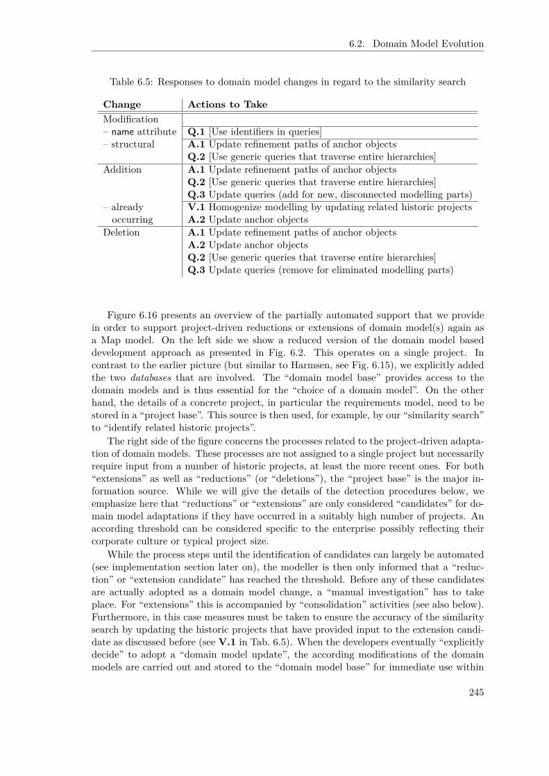
6.2. Domain Model Evolution
Table 6.5: Responses to domain model changes in regard to the similarity search
Change Actions to TakeModification– name attribute Q.1 [Use identifiers in queries]– structural A.1 Update refinement paths of anchor objects
Q.2 [Use generic queries that traverse entire hierarchies]Addition A.1 Update refinement paths of anchor objects
Q.2 [Use generic queries that traverse entire hierarchies]Q.3 Update queries (add for new, disconnected modelling parts)
– already V.1 Homogenize modelling by updating related historic projectsoccurring A.2 Update anchor objects
Deletion A.1 Update refinement paths of anchor objectsA.2 Update anchor objectsQ.2 [Use generic queries that traverse entire hierarchies]Q.3 Update queries (remove for eliminated modelling parts)
Figure 6.16 presents an overview of the partially automated support that we providein order to support project-driven reductions or extensions of domain model(s) again asa Map model. On the left side we show a reduced version of the domain model baseddevelopment approach as presented in Fig. 6.2. This operates on a single project. Incontrast to the earlier picture (but similar to Harmsen, see Fig. 6.15), we explicitly addedthe two databases that are involved. The “domain model base” provides access to thedomain models and is thus essential for the “choice of a domain model”. On the otherhand, the details of a concrete project, in particular the requirements model, need to bestored in a “project base”. This source is then used, for example, by our “similarity search”to “identify related historic projects”.
The right side of the figure concerns the processes related to the project-driven adapta-tion of domain models. These processes are not assigned to a single project but necessarilyrequire input from a number of historic projects, at least the more recent ones. For both“extensions” as well as “reductions” (or “deletions”), the “project base” is the major in-formation source. While we will give the details of the detection procedures below, weemphasize here that “reductions” or “extensions” are only considered “candidates” for do-main model adaptations if they have occurred in a suitably high number of projects. Anaccording threshold can be considered specific to the enterprise possibly reflecting theircorporate culture or typical project size.
While the process steps until the identification of candidates can largely be automated(see implementation section later on), the modeller is then only informed that a “reduc-tion” or “extension candidate” has reached the threshold. Before any of these candidatesare actually adopted as a domain model change, a “manual investigation” has to takeplace. For “extensions” this is accompanied by “consolidation” activities (see also below).Furthermore, in this case measures must be taken to ensure the accuracy of the similaritysearch by updating the historic projects that have provided input to the extension candi-date as discussed before (see V.1 in Tab. 6.5). When the developers eventually “explicitlydecide” to adopt a “domain model update”, the according modifications of the domainmodels are carried out and stored to the “domain model base” for immediate use within
245
Chapter 6. Dynamic Requirements Knowledge Management
the next individual customer project.As becoming obvious from the picture, for both kinds of processes – this is the normal
process related to a single project as well as the two concerning domain model adaptationsthat consider several projects – both databases are involved, even though operating in justopposite modes. For the single project, the “domain model base” (but also the “projectbase”) is used as a source of information, while the “project base” is used for storage.The adaptation concerned processes on the other hand use the “project base” as its majorsource and target updates of the “domain model base”. Accordingly, these databaseshelp to decouple the two processes. In particular note that not every project finalizationtriggers the execution of the entire adaptation process. As elaborated before, only if acertain threshold for an adaptation candidate is exceeded, the according process will becontinued.
Project-Driven Domain Model Reductions
Reductions can be identified quite easily due to the fact that they concern domain mod-elling objects that by definition are identical among all requirements models for current orhistoric projects. We propose to carry out the following steps to identify domain modellingparts that are recurrently eliminated within several recent projects and thus possibly canbe omitted from a domain model.
1. Identify deleted domain modelling objects for a single project and aggregate themsuitably (e. g. combine elements and links that refer them).
2. Check whether the number of deletions for such a group exceeds the defined thresholdwithin the part of the history to be considered.
3. Prompt the user (in the context of the reflection of the most recent project) with thesuggestion for a domain model reduction and wait for the resulting decision after amanual investigation.
4. Support the domain model update (and possibly the update of concerned queries).
Identify Deletions in a Single Project Remember that for creating the requirementsof a new customer project within the domain model based development approach, themodeller is intended to choose one or several domain models as a starting point, removemodelling parts that are not relevant in the current setting, and add specific modellingdetails. To identify the domain model objects that have been deleted by the modeller fora concrete project p, a simple difference operation on the sets of objects of the concerneddomain model(s) DMi (treat each domain model individually) and the objects O(p) of thesingle project p suffices:4
DeletionsDMi(p) = DMi \O(p)
Since domain model objects have a unique identifier, they can be traced among all historiccustomer projects. This is the sets DeletionDMi(p1) and DeletionDMi(p2) for two differentprojects p1 and p2 are directly comparable.
4We have omitted the corresponding link from the “domain model base” to “identify project-specificdeletions” in Fig. 6.16 for the sake of clarity.
246

6.2. Domain Model Evolution
While it would thereby be possible to identify “reductions” on a single object base, werecommend to consider suitable aggregates. In particular the deletion of an element oftenimplies the deletion of links that reference this element. Accordingly, their combinationcould be considered a suitable aggregate. It is even conceivable that objects (in particularlinks) might occur in several of such aggregates. We leave the decisions on these detailsto the individual enterprise.
Check Recurrent Deletions For each such suitable aggregate we need to record howoften these deletions have occurred within different customer projects in the consideredhistory. Due to the unique identifier this is easily possible. The representation of anaggregate is then annotated by this number of occurrences.
Prompt User and Await Decision If the number of occurrences for one “reduction”exceeds a specified threshold, the user is prompted for action. She manually inspects thesuggestion as well as the project base. Maybe the latter has been flooded by a large set ofrelated projects and accordingly the investigation phase should be prolonged by setting anew, individual threshold for this particular deletion to trigger another prompt at a laterpoint in time.
Perform Update If the modeller agrees with the suggestion, in most cases the “re-duction” simply can be applied to the domain model that is then stored as an adaptedversion to the “domain model base”. As discussed in the previous section, we might needto review the domain model based queries in order to adapt (or eliminate) the ones thatexplicitly refer to deleted modelling parts. Also the characterization of project-specificextensions for historic projects must be reconsidered. Both issues can be supported byConceptBase either via its basic integration checks or via simple queries (for details seethe implementation section below).
Project-Driven Domain Model Extensions
In contrast to “reductions”, the determination of recurring project-specific “extensions”in different projects is, as elaborated in the previous chapter (Chap. 6.1), much harderto establish due to modelling variations that are to be expected. Still the basic stepsto support domain model extensions are similar to the ones for reductions. But for onethe identification of the similarity of extensions across a set of different projects needselaboration. For another, the reaction toward user feedback needs to be extended sincethe adoption of an extension must be preceded by the creation of a consolidated modellingversion.
1. Identify suitably separated, project-specific extensions within the requirements mod-els of finalised projects.
2. Compute the similarity of project-specific extensions and build according groups ofrelated project specific extensions.
3. Prompt the user (in the context of the reflection of the most recent project) with asuggestion for a domain model extension and wait for the resulting decision after amanual investigation.
247

Chapter 6. Dynamic Requirements Knowledge Management
4. Act on user feedback:
(a) If the user commits to the proposed update, support the domain model update,the necessary update of the modelling of finalized projects, and possibly theupdate of concerned queries as far as possible, for example via the findings ofthe various similarity measures that have been utilized.
(b) Document any feedback. In particular if the user disagrees but also if she hasonly corrections to any of the earlier steps (e. g. for the similarity or grouping ofextensions), these need to be recorded to avoid bothering the developers withirrelevant proposals over and over again during future processing.
Identify Project-Specific Extensions The identification of project-specific extensionshas two steps. At first we need to separate domain modelling parts and project-specificparts. This is already established by Def. 6.3 via a simple difference operation on the setsof all project objects O(p) and the union of domain modelling objects DMO yielding thespecific objects SO(p):
SO(p) = O(p) \DMO
In Def. 6.3 we then spoke rather vaguely about a “suitable subset E ⊆ SO(p)” to forma project-specific extension. We refine this notion here by proposing a particular way onhow to suitably partition SO(p) as the second step.
Note that we do not assume that there is only one single project-specific extensionfor each project but typically several that are rather independent from each other (andas such more likely to reappear in other projects). Accordingly, we expect a suitablepartitioning of SO(p) to exist. A simple proposal to arrive at such a partitioning is toconsider reachability within SO(p). This is we group the objects by their ‘connectedness’in regard to i* modelling constructs. As a result, for each finalised project we get zero, oneor more ‘connected groups’ that then form its project-specific extensions. The proposedextensions must be reviewed by a knowledgeable engineer. Since we have solely focused onthe ‘connectedness’ it is possible that we missed that two separated connected groups infact belong to one single extension. Less likely a connected group includes two extensionsthat should be treated separately. Here the problem is how to draw the borderline sincesplitting the extension up will cause at least one link to break, i. e. in neither project specificextension the link will be included. Although we have integrated a manual decision processat a later stage in the process (see Step 4), it is worth to ask for user feedback concerningthe partitioning already here to improve the results of the similarity computation duringthe next step.
Compute Pairwise Similarities and Cluster Extensions After identifying the in-dependent project-specific extensions of a single project, we need to relate and cluster allextensions from all historic projects to be considered. As elaborated in Chap. 6.1, manysimilarity measures exist that range from pure textual, to feature- and model-aware mea-sures to the anchor object-based measure that we have defined ourselves (see Chap. 6.1.4).As it is the case for the identification of similar projects, all these measures also apply tothe smaller scale of project-specific extensions. Unfortunately, a suitably combined mea-sure has not yet been created. For the following, we thus simply assume that a suitablepairwise comparison for all considered project-specific extensions has been carried out andhas resulted in a similarity value for each pair of project-specific extensions.
248

6.2. Domain Model Evolution
In order to cluster extensions, we follow the basic idea to spectral clustering as elab-orated by von Luxburg [vL06]. She introduces a similarity graph G = (V,E) where thevertices vi represent the data points and the edge between two vertices is weighted by theirsimilarity. Transferred to our setting, each vertex represents a project-specific extensionfrom the set of all project-specific extensions in the project database; and the weight ata link between two such extensions is just the similarity that we assume to exist. As vonLuxburg states, “[t]he problem of clustering can now be reformulated using the similaritygraph: we want to find a partition of the graph such that the edges between differentgroups have a very low weight (which means that points in different clusters are dissimilarfrom each other) and the edges within a group have a high weight (which means thatpoints within the same cluster are similar to each other).”
While many advanced techniques exist (see [vL06]), we have applied only a very simpleapproach. From the fully connected graph introduced above, we remove all edges wherethe associated weight – the similarity – lies below a specified threshold. In the remaininggraph, by using breadth first search we can compute the maximal connected subgraphs.We interpret the set of extensions of such a subgraph as a cluster that describes quitesimilar real world concepts. Note that we do not require that a cluster forms a completesubgraph, this is that each extension holds a similarity measure above the threshold to allother extensions of that cluster. We just require that each extension contains a similaritymeasure above the threshold to at least one other extension in the cluster. The usercan influence the size of the clusters by choosing the threshold. A high threshold leadsto many small clusters while a low threshold results in less but larger clusters. If anSME imposes strict modelling guidelines on its developers, this possibly results into morehomogeneous modelling. Accordingly they would choose a higher threshold resulting inmore focused suggestions for extension. Others might choose a lower threshold to notaccidentally separate related extensions.
Prompt User As mentioned above, as candidates for a domain model extension weconsider only extensions that have occurred in several projects. The according thresholdis again a variable to the applying enterprise. If, for example, an SME mainly has manyrather small projects, the number should be higher than for an SME that runs only few, butinstead large projects. The size of a cluster indicates the number of times the correspondingreal world concepts have occurred. This is if such a cluster exceeds the threshold specifiedby the user, we can prompt the user with a suggestion for a new domain model extension.
Act on User Feedback After being prompted for feedback, a knowledgeable engineerhas to manually inspect the proposed extensions. First of all, she has to check whetherthe grouped extensions really fit together. This is she can manually combine several clus-ters as well as splitting a cluster up into several ones to reflect a correct grouping withregards to content. If the modeller actually adopts a proposed extension, a consolidatedmodelling version needs to be fabricated out of the different modelling variants from dif-ferent projects. The similarity measures from Step 2 provide valuable input to this. Butit depends on the concrete problem and the enterprise’s decisions how encompassing theresulting consolidated modelling will be. Two extremes are conceivable. Either the mod-elling covers all particularities of all versions and connects them via an adapted commoncore. Or the domain modelling adaptation encompasses only the common core while han-dling particularities still as (reduced) project-specific extensions. Obviously, anything inbetween is conceivable as well. Unfortunately, we will not be able to present encompassing
249

Chapter 6. Dynamic Requirements Knowledge Management
support in regard to model consolidation within this thesis. The interested reader is re-ferred to model management activities (see [BHP00, KQCJ07, KQL+09]) for a potentiallysuitable starting point. In addition to the consolidated modelling, the modelling of thefinalized historic projects that have provided input to the domain model extension mustbe updated accordingly as elaborated in Chap. 6.2.4. They have to be compatible withthe domain model version in order to reestablish the accuracy of the similarity search.Eventually, domain model-based queries might need to be updated or added.
Even if a proposal is not adopted, the developer might add manual corrections ordecisions that need to be stored for future processing to avoid making the same (wrong)suggestions for extensions over and over again. We start with the recording already inthe first step. For each project-specific extension that we identify in Step 1 we createa representative in the project documentation that links to all objects concerned withthis extension. It is then easy to consider all project-specific extensions throughout thewhole “project base” as well as relate them. The latter is achieved via suitable links thatconnect related project-specific extension representatives. In fact, this is a representationof the similarity graph as proposed by von Luxburg [vL06]. Eventually, the result ofthe clustering needs to be documented as well. While the similarity relationships andthe clustering are mainly filled by the above mentioned algorithms, they can certainly beedited explicitly by developers. Thereby the resulting structure documents the developer’sdecisions as claimed by Step 4. If a cluster of project-specific extensions is finally integratedinto the domain model, we record this decision by removing the related representativesfrom the extension management structure.
Incremental Computation
As in [NSJR09] we have described our approach here as if it runs from the first to thelast step in a single process, in particular as if it is applied to the whole historic projectbase. But it would be too time consuming to compare all project-specific extensions in asingle step and furthermore redundant. In most cases, the computation for older finalisedprojects does not change. Thus, all described steps are intended to be performed in anincremental way. Directly after a project is declared as finalised, we start to identify thespecific reductions and extensions and compute for the latter the similarity to all the otheralready identified extensions. We store these results within the above described graph-based extension management data structure. Only if as a result the size of one of theclusters for extensions or reductions exceeds the specified threshold, the user is prompted(Step 3). In this manner we keep the documentation of extensions (as well as reductions)incrementally up to date.
6.2.6 Implementation Details
We briefly discuss the most relevant implementation aspects of the effects of evolutionon the constitution of project-specific extensions, the similarity search as well as project-driven reductions and extensions, partially building on the implementation mentioned inprevious chapters.
Effects on the Constitution of Project-Specific Extensions
Two implementation issues in regard to the reconsideration of project-specific extensionsare addressed here.
250

6.2. Domain Model Evolution
Identify Projects to Be Reinvestigated For one, we can reuse the anchor object-based similarity computation (see Chap. 6.1.4) to relate a new domain model version toany earlier one. The anchor objects of the identified difference (this is the domain modelchange) can directly be compared to the anchor objects of project-specific extensions forall historic projects. A project where one of these anchor objects occurs is potentiallyimpacted by the domain model change. That is we can limit the reinvestigation of project-specific extensions to only these projects.
Remove domain_module Attribute For another, once a domain model reduction isadopted, we need to update historic projects that utilized these objects since we haveto remove the domain_module attributes for them. Only then the according objects willcorrectly be detected to have become project-specific extensions in regard to the newversion of the domain model. This correction can be carried out fully automatically.The concerned modules can easily be identified for each individual domain model objectdeletion by considering all project modules except for the ones that are explicitly listedvia the not_occurs_in attribute (introduced below to support project-driven reductions).As with the deletion support to tailor a domain model to a project-specific setting (seeChap. 5.1.3, in particular Fig. 5.9), a simple query together with a suitable answer formatis sufficient to realize the actual deletion of the attribute. We skip the details here sincethey do not provide any new insights.
Effects on the Similarity Search
Generic Queries Already in the last section on implementation details (Chap. 6.1.6),we introduced generic queries that certainly all fulfill the recommendations that we haveissued in Tab. 6.4. This is they refer identifiers instead of the name attribute to workirrespective to modifications of the latter. Furthermore, we have shown two queries relatedto decomposition hierarchies that are able to traverse hierarchies of any breadth anddepth. Similar queries for other hierarchies can be constructed analogously.
Update Historic Projects As mentioned before, we do not provide support on how tomodify historic projects given a trace of the consolidated modelling extension that has beenderived from several projects to enrich the domain model. Even though some automatedsupport is conceivable (as future work), several manual steps prevail.
Instead we briefly outline the basic feature of Telos/ConceptBase that allows for mod-ifications of finalized projects without harming the integrity of their documentation (firstobjection from the earlier discussion). With each knowledge fact, Telos/ConceptBasestores the time when it is valid. Since ConceptBase allows to operate also on parts offrames, for example particular attributes or instantiation information, all these differentfacts can have different histories of modifications (add, delete, modify). While per defaultqueries are evaluated according to the current time (“now”), any point in time can be cho-sen. Thus, the only thing that needs to be taken care of to avoid problems with projectintegrity is to store the time when the project has been finalized. This can again be addedas an explicit attribute to the encompassing project-specific module (as we have alreadyproposed for the “customer” information in Chap. 5.1.3). At the ConceptBase forum, anactive rule has been defined to update a “last modified” tag (http://merkur.informatik.rwth-aachen.de/pub/bscw.cgi/d2936786/ECA-lastmodified.sml.txt). This is easilyadaptable to the problem setting here. Once the finalization date is recorded, the project
251
Chapter 6. Dynamic Requirements Knowledge Management
can be updated in any way, accommodating the evolution of the center of interests of anenterprise as it emerges throughout the years. A simple comparison of “finalization date”and “last modified” allows to identify the projects that have been modified after theirfinalization.
Project-Driven Reductions
Concerning project-driven reductions, we consider three implementation issues here.
Record Number of Deletions For one, we need to record the number of deletionsof domain model components. For convenience, we use the domain model itself for thispurpose. Furthermore, we suggest to store not just a number but a list of referencesto all projects where the domain model object has been deleted.5 Since we can applyany kind of filtering on these references, the developer is thereby free in defining whatis considered the relevant history for deriving suggestions for domain model reductions.Most likely approaches are to filter along “finalization date”, “last modified” date, oreven “customer”. In [NSJR09] we have proposed to introduce a sequence number for eachproject and then consider projects only from an enterprise-specific “retrospective windowsize”. This is certainly possible with the implementation outlined here.
Figure 6.17 first defines a helping class DeletionInformation that introduces the newattribute not_occurs_in. This class is to be stored in the top level DomainModel module.The associated rule then takes care that any domain model object is also instantiatingthe new class. Accordingly, the new attribute becomes available and allows to store thereferences to the projects where the object has been deleted. The latter piece of informationcan be created fully automatically in response to the actual “clean up” activities of anengineer via the ECA rule StoreDeletion (also given in Fig. 6.17). It watches out for Untelloperations of a domain model object (more precisely the Untell of their domain_moduleattribute, see Chap. 5.1.3) and adds in turn an instance of the not_occurs_in attributein the domain model module. Presuming the specification of a “considered history” asa suitable query class, qDeletionsInConsideredProjects then returns all modules where aparticular object (specified as a parameter) does not occur and where all modules areincluded in the history specification (the other parameter history denoting the abovementioned query class). Counting the number of results to this query then yields theoccurrences of deletions within the considered project history (see Fig. 6.18 for how tocount in Telos).
Active Rule for Triggering the User Prompt Building on the implementation de-tails explained in the previous paragraph, the triggering of a user prompt in response toexceeding a threshold can again easily be realized via an active rule (see Fig. 6.18). TheECA rule DeletionTriggerUserPrompt is in fact triggered in chain to the previously definedECA rule StoreDeletion since it watches out for events that document deletions from do-main models by listening to the addition of instances to the not_occurs_in attribute. Itthen calls the above introduced generic query class qDeletionsInConsideredProjects with asuitable individual history definition h and the concerned object o. The COUNT built-infunction of ConceptBase returns the number of instances to this query class and thus justthe number of deletions within the considered history. The backtick operator ensures that
5By issuing a suitable sub module we reduce the data overhead. The according module can then beconsidered only if reduction related tasks need to be performed.
252
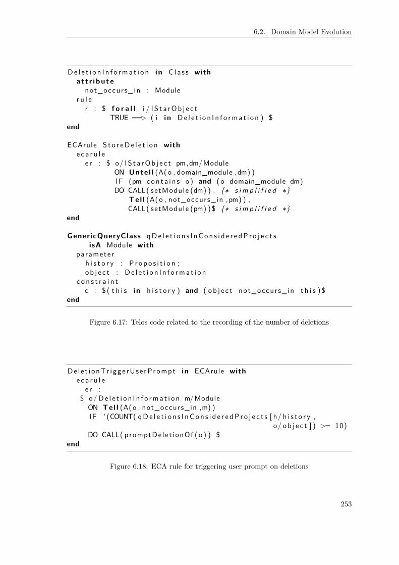
6.2. Domain Model Evolution
De l e t i o n I n f o rma t i o n i n C l a s s witha t t r i bu te
not_occur s_ in : Moduler u l e
r : $ f o r a l l i / I S t a rOb j e c tTRUE ==> ( i i n De l e t i o n I n f o rma t i o n ) $
end
ECArule S t o r eDe l e t i o n withe c a r u l e
e r : $ o/ I S t a rOb j e c t pm,dm/ModuleON Unte l l (A(o , domain_module ,dm) )IF (pm con t a i n s o ) and ( o domain_module dm)DO CALL( setModule (dm) ) , {∗ s i m p l i f i e d ∗}
Tel l (A(o , not_occurs_in ,pm) ) ,CALL( setModule (pm) ) $ {∗ s i m p l i f i e d ∗}
end
GenericQueryClass qDe l e t i o n s I nC o n s i d e r e dP r o j e c t sisA Module with
paramete rh i s t o r y : P r o p o s i t i o n ;o b j e c t : D e l e t i o n I n f o rma t i o n
c o n s t r a i n tc : $ ( t h i s i n h i s t o r y ) and ( o b j e c t not_occur s_ in t h i s ) $
end
Figure 6.17: Telos code related to the recording of the number of deletions
De l e t i onTr i gge rUse rP rompt i n ECArule withe c a r u l e
e r :$ o/ De l e t i o n I n f o rma t i o n m/Module
ON Tel l (A(o , not_occurs_in ,m) )IF ‘ (COUNT( qDe l e t i o n s I nC o n s i d e r e dP r o j e c t s [ h/ h i s t o r y ,
o/ o b j e c t ] ) >= 10)DO CALL( promptDe le t ionOf ( o ) ) $
end
Figure 6.18: ECA rule for triggering user prompt on deletions
253

Chapter 6. Dynamic Requirements Knowledge Management
QueryClass P r o j e c t S p e c i f i c E x t e n s i o n isA I S t a rOb j e c t withc o n s t r a i n t
c : $ not ( t h i s i n DomainModelObject ) $end
Figure 6.19: Identify all specific objects in a requirements model
also the most recent addition is taken into account. If the computed value exceeds theenterprise-specific threshold (here exemplarily set to 10), some Prolog code is called toprompt the user.
Project-Driven Extensions
In regard to extensions, we consider here the identification and partitioning of project-specific extensions as well as the basic extension management structure that enables torun and record automated analyses as well as manual corrections of engineers.
Identify Specific Objects of a Project In the context of the computation of anchorobjects we have introduced a query DomainModelObject (see Fig. 6.5) that identifies objectsin a project requirements model that originate in domain models by simply checking forthe existence of the domain_module attribute. Accordingly, the specific objects of a projectcan easily be identified by negating this query as shown in Fig. 6.19.
Partition Specific Objects into Extensions according to Connectedness In or-der to partition the set of all project-specific objects into independent, self-containedproject specific extensions, we consider as mentioned before connectedness in regard toany i* modelling construct, this is any kind of links or the parent-child relationships. Fig-ure 6.20 shows a basic Telos based implementation. We could of course also delegate thetask to some external tool and only incorporate the results of the analysis.
The query DirectlyConnected returns all objects that are related to the source objectprovided as a parameter by simply checking for all possibilities, this is parent-child, child-parent, link-from/to, or from/to-link. The latter refers to the deductive attribute links asintroduced for the Element class in the formalization of i* in Telos (see Appendix A.1.1).Together with the helping query class NotPartitioned, we can then easily define the queryclass PartitionProjectSpecificExtensions that gets a (non-partitioned) object as initializa-tion and returns all related, not yet partitioned project-specific objects (among others byreferring recursively to itself). Via a suitable answer format these results can easily be usedto mark them as partitioned by setting the attribute partition (as introduced in Fig. 6.5).The implementation details are (again) conceptually identical to the “actual deletion” (seeFig. 5.9 in Chap. 5.1.3). Afterwards, the query PartitionProjectSpecificExtensions can becalled iteratively again with a different initialization until all project-specific objects arepartitioned.
Data Structure for Managing Extensions and their Relations After partitioningall project-specific extensions of all projects as described above, we must have the possibil-ity to access and manage the extensions. In particular, we need to relate extensions fromdifferent projects. For this purpose, we export the individual, independent extensions of
254
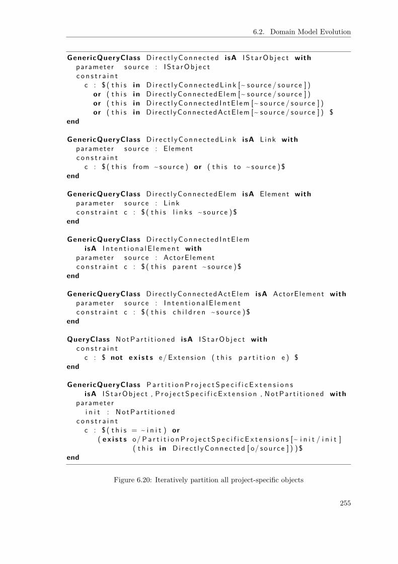
6.2. Domain Model Evolution
GenericQueryClass Di r e c t l yConne c t e d isA I S t a rOb j e c t withparamete r s ou r c e : I S t a rOb j e c tc o n s t r a i n t
c : $ ( t h i s i n Di r e c t l yConn e c t e dL i n k [~ s ou r c e / s ou r c e ] )or ( t h i s i n Di r e c t l yConnec t edE l em [~ sou r c e / sou r c e ] )or ( t h i s i n Di r e c t l yConne c t ed I n tE l em [~ sou r c e / s ou r c e ] )or ( t h i s i n Di r ec t l yConnec t edActE l em [~ sou r c e / s ou r c e ] ) $
end
GenericQueryClass Di r e c t l yConn e c t e dL i n k isA L ink withparamete r s ou r c e : Elementc o n s t r a i n t
c : $ ( t h i s from ~ sou r c e ) or ( t h i s to ~ sou r c e ) $end
GenericQueryClass Di r e c t l yConnec t edE l em isA Element withparamete r s ou r c e : L inkc o n s t r a i n t c : $ ( t h i s l i n k s ~ sou r c e ) $
end
GenericQueryClass Di r e c t l yConne c t ed I n tE l emisA I n t e n t i o n a l E l emen t with
paramete r s ou r c e : ActorE lementc o n s t r a i n t c : $ ( t h i s pa r en t ~ sou r c e ) $
end
GenericQueryClass Di r ec t l yConnec t edActE l em isA ActorE lement withparamete r s ou r c e : I n t e n t i o n a l E l emen tc o n s t r a i n t c : $ ( t h i s c h i l d r e n ~ sou r c e ) $
end
QueryClass No tPa r t i t i o n e d isA I S t a rOb j e c t withc o n s t r a i n t
c : $ not e x i s t s e/ Ex t en s i on ( t h i s p a r t i t i o n e ) $end
GenericQueryClass P a r t i t i o n P r o j e c t S p e c i f i c E x t e n s i o n sisA I S t a rOb j e c t , P r o j e c t S p e c i f i c E x t e n s i o n , No tPa r t i t i o n e d with
paramete ri n i t : No tPa r t i t i o n e d
c o n s t r a i n tc : $ ( t h i s = ~ i n i t ) or
( e x i s t s o/ P a r t i t i o n P r o j e c t S p e c i f i c E x t e n s i o n s [~ i n i t / i n i t ]( t h i s i n Di r e c t l yConne c t e d [ o/ sou r c e ] ) ) $
end
Figure 6.20: Iteratively partition all project-specific objects
255

Chapter 6. Dynamic Requirements Knowledge Management
Module ManageExtens ionsend
Ex t en s i on i n C l a s s witha t t r i bu te
o b j e c t s : I S t a rOb j e c tr u l e
e x tRu l e : $ f o r a l l o/ I S t a rOb j e c t( o p a r t i t i o n t h i s ) ==> ( t h i s o b j e c t s o ) $
end
S i m i l a r i t y R e l a t i o n witha t t r i bu te
extA : Ex t en s i on ;extB : Ex t en s i on ;s i m i l a r i t y : Rea l
end
Ex t e n s i o nC l u s t e r witha t t r i bu te
e x t e n s i o n s : Ex t en s i onend
Figure 6.21: Telos classes related to the management of project-specific extensions
each project to a separate and global module ManageExtensions. This is easy since wehave already introduced a new attribute partition (see Fig. 6.5) that assigns a commonidentifier to all project-specific objects that constitute a partitioned extension. Up to now,we have left the details of this identifier open. Figure 6.21 shows the definition of the newTelos class Extension. Each project-specific extension within a project is represented byan object of this class. Accordingly, only these objects then need to be exported to theabove mentioned global module ManageExtensions.
Figure 6.21 introduces additionally two more Telos classes to manage extensions. Theclass SimilarityRelation represents a link between two extensions that is annotated bythe computed similarity between the two. This is for any new project, the similarities ofits project-specific extensions toward the already captured (and represented) extensionshave to be computed and according objects instantiating SimilarityRelation are created.ExtensionCluster s are the outcome of the cross-project clusterings of similar extensionsthroughout the entire project base. While many efficient algorithms exist to compute sucha clustering (see [vL06]), we have implemented only a very simple approach as outlinedabove. By only considering relationships with a suitably high similarity value, we can againwatch out for connected groups just as we have elaborated above for the partitioning ofspecific objects into extensions within a single project. For each connected group, we thencreate a new ExtensionCluster object (analogously to the Extension object) referring theconstituting extensions .
Any modification or correction by the developers to the outcome of automated algo-rithms can be recorded by explicitly adapting the SimilarityRelation s or assignments to
256
6.2. Domain Model Evolution
ExtensionCluster s. With the latter we can again associate ECA rules (as with the recordingof deletions from domain models, see above) that check whether the size of an extensioncluster exceeds a threshold. If this is the case, the user is prompted with a suggesteddomain model extension. Eventually, if a group of project-specific extensions is finally in-tegrated into a domain model, we record this decision by removing the clusters, similarityrelationships, and basic extensions from the ManageExtensions module.
6.2.7 Case Studies
As outlined in the introduction to Chap. 5.1, the domain model based approach hasits origins in the case study on control system development. While applicable to inter-organisational networks as well, also the major advantages in regard to evolution becomemore apparent in a control system setting. Accordingly, we focus in the following thisapplication field, but will in the end also briefly comment on the potential for the casestudy on inter-organisational networks.
Introduce Example Settings
We consider three example settings for changes to the “combustion engine domain model”from Chap. 5.1.4 (in particular Fig. 5.12).
Cylinder Pressure vs. Knock Sensor A very typical modification in the field ofcontrol system development is the addition of a new kind of sensor or actuator. Forexample, the “cylinder pressure” sensor is a new component within combustion engines.In modern engines it replaces the “knock sensor”. Since both sensors will be in use forsome time, we add “cylinder pressure sensor” and keep “knock sensor” as well. Figure 6.22shows the resulting changed domain model (new objects are marked with “*”). Besidesthe new resource dependency “sensor: cylinder pressure” also a new correspondingtask element “measure cylinder pressure” at the “controller” side was introduced. Aftersome time it is recognized that the sensor dependency could be made more concreteby not just connect the high-level roles “controller” and “controlled system” but morededicatedly the tasks “measure cylinder pressure” and “injection” within the concernedroles. The refined model is shown in Fig. 6.23 (with changes again marked with “*”).Eventually, the last modification of the domain model in this regard is the removal of the“knock sensor”, possibly due to hardly any use within the last projects. The resultingdomain model version is shown in Fig. 6.24.
Hybrid Engines More and more cars are nowadays hybrids, this is they combine anelectrical engine with (mostly) a combustion engine. Various different variants in regardto the types of power trains (parallel, series, or their combination series-parallel) as well asin regard to the degree of hybridization (full hybrid, mild hybrid, or power assist hybrids)exist. To enable the consideration of “hybrid engines”, we need to adapt the “combustionengine” domain model (that then possibly also needs to be renamed) at least in tworegards.
At the “controlled system” side we now see two top level components, “combustion”and “electrical engine”. This is instead of equating “controlled system” with “combustionengine”, “controlled system” now is considered a hybrid engine with the two sub com-ponents “combustion engine” and “electrical engine”. Certainly, the latter needs to be
257

Chapter 6. Dynamic Requirements Knowledge Management
Figure 6.22: Add “cylinder pressure sensor”
Figure 6.23: Refine connection points for dependency “cylinder pressure sensor”
Figure 6.24: Delete dispensable “knock sensor”
258
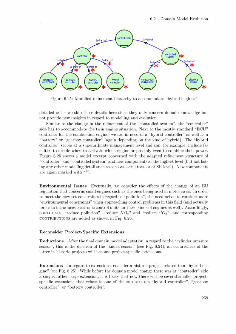
6.2. Domain Model Evolution
Figure 6.25: Modified refinement hierarchy to accommodate “hybrid engines”
detailed out – we skip these details here since they only concern domain knowledge butnot provide new insights in regard to modelling and evolution.
Similar to the change in the refinement of the “controlled system”, the “controller”side has to accommodate the twin engine situation. Next to the mostly standard “ECU”controller for the combustion engine, we are in need of a “hybrid controller” as well as a“battery” or “gearbox controller” (again depending on the kind of hybrid). The “hybridcontroller” serves at a superordinate management level and can, for example, include fa-cilities to decide when to activate which engine or possibly even to combine their power.Figure 6.25 shows a model excerpt concerned with the adapted refinement structure of“controller” and “controlled system” and new components at the highest level (but not list-ing any other modelling detail such as sensors, actuators, or at SR level). New componentsare again marked with “*”.
Environmental Issues Eventually, we consider the effects of the change of an EUregulation that concerns small engines such as the ones being used in motor saws. In orderto meet the now set constraints in regard to “pollution”, the need arises to consider more“environmental constraints” when approaching control problems in this field (and actuallyforces to introduces electronic control units for these kinds of engines as well). Accordingly,softgoals, “reduce pollution”, “reduce NOx” and “reduce CO2”, and correspondingcontributions are added as shown in Fig. 6.26.
Reconsider Project-Specific Extensions
Reductions After the final domain model adaptation in regard to the “cylinder pressuresensor”, this is the deletion of the “knock sensor” (see Fig. 6.24), all occurrences of thelatter in historic projects will become project-specific extensions.
Extensions In regard to extensions, consider a historic project related to a “hybrid en-gine” (see Fig. 6.25). While before the domain model change there was at “controller” sidea single, rather large extension, it is likely that now there will be several smaller project-specific extensions that relate to one of the sub actors “hybrid controller”, “gearboxcontroller”, or “battery controller”.
259

Chapter 6. Dynamic Requirements Knowledge Management
Figure 6.26: Extensions in regard to environmental issues
Similarity Search concerned Examples
Generic Queries and Query Adaptations Consider the example in regard to “hybridengines”. If applying (as proposed) generic queries that traverse is-part-of hierarchies,the modeller does not need to touch these queries in order to cope with the refined mod-elling hierarchy. For example, instead of processing just one “controller” component foursub actors to this actor are now consulted.
Concerning query adaptations, we have to consider that two of the domain model basedqueries as introduced in Fig. 6.8, namely qControllerGoals and qControllerTasks , explicitlyreferred to the “controller” as the object containing the goals and tasks in this regard.The modeller now has to decide how to adapt these queries. Either she can introducesuch queries for each of the four new subcomponents to “controller” by simply replacingController in the super class definition ChildrenOf[ Controller ] by ElectronicControlUnit ,GearboxController, BatteryController , or HybridController .
But it is also possible to combine some of the provided generic queries to cope with therefinement in a more general manner. Figure 6.27 shows the adapted queries to identify“controller tasks” and “goals”. They make use of a query class IsPartOfRecursiveActorsthat is defined analogously to DecomposedRecursiveElements (see Fig. 6.4) only for the
is-part-of relationship between actors instead of the decomposition links between in-tentional elements. This is this query returns recursively all sub actors to the root object,in this example certainly set to Controller . In our case this yields, “controller”, “electroniccontrol unit”, “gearbox controller”, “battery controller”, and “hybrid controller”, but theresults would have continued with any refinement of the four sub actors as well. Foreach of the identified actors within the “controller” refinement hierarchy, the ChildrenOfgeneric query class is called (while previously only for the Controller object).
Note that the adapted queries yield for the old version of the domain model the sameresults as the old queries have done. Accordingly, the adapted queries should possibly beadopted anyway. As a side remark, the processing of the different engine features (seeFig. 6.8) could be combined similarly, but of course the resolution is then also reduced,since then only one query combines all aspects that have up to now been treated separately.
260

6.2. Domain Model Evolution
QueryClass qCon t r o l l e r G o a l s isA GoalE lement withc o n s t r a i n t
c : $ e x i s t s con t rAc to r / I s P a r tO fR e c u r s i v eA c t o r s [ C o n t r o l l e r ]( t h i s i n Ch i l d r enO f [ c on t rAc to r ] ) $
end
QueryClass qCon t r o l l e rT a s k s isA TaskElement withc o n s t r a i n t
c : $ e x i s t s con t rAc to r / I s P a r tO fR e c u r s i v eA c t o r s [ C o n t r o l l e r ]( t h i s i n Ch i l d r enO f [ c on t rAc to r ] ) $
end
Figure 6.27: Adapted domain queries in regard to “controller” (tasks and goals)
Update the Anchor Object-Based Similarity Measure Also for examples to theupdate of the anchor object-based similarity computation consider the changes in regardto “hybrid engines”. The additional refinement level implies that the refinement paths forall anchor objects that are subordinated to the “controller” or the “controlled system”roles have to be updated. In addition to “controller” and the “controlled system” theynow also include the intermediate “electronic control unit” and the “combustion engine”roles. Furthermore, for any historic (pilot) project that already considered hybrid (orelectrical) engines, the anchor objects must be revisited.
Project-Driven Reductions
In regard to reductions from a domain model, note that as mentioned before the deletionof the formerly standard “knock sensor” causes all such occurrences in historic projects tobecome project-specific extensions. In this context, we can see that it is advantageous toconsider project-driven changes only for the more recent historic projects. While the num-ber of projects concerning “knock sensors” might be rather high, an according extensionproposal should indeed not be issued by the system. Setting the “retrospective windowsize” (see [NSJR09]) appropriately helps in this regard.
Project-Driven Extensions
Manually Update the Grouping of Extensions Reconsider the addition of the“cylinder pressure” (Fig. 6.22) and assume it to be a project-specific extension first. Whenapplying the proposed partitioning, the automated procedure would not have detected thatthe addition of the resource dependency “sensor: cylinder pressure” is related to theaddition of the task “measure cylinder pressure” since no (i*-based) modelling connec-tion exists between the two. Thus, in this case a knowledgeable engineer would have beenrequired to suitably combine these partitions into one (as shown in Fig. 6.10). Note thatthis would not have been a problem, if the project-specific extension has been modelled asshown in Fig. 6.23, this is where the dependency link is directly connected to “measurecylinder pressure”. Alternatively, a text-based similarity search might also have helped toavoid this situation (due to the common words “cylinder pressure”).
261

Chapter 6. Dynamic Requirements Knowledge Management
Pairwise Similarity Graph and Effects of Thresholds In regard to the pairwisesimilarity graph, we only want to hint at some particularities within the field of controlsystem development that clearly indicate the need to consider more than just the an-chor object-based similarity measure. Problematic are here the sensors and actuators inparticular if the modeller only connects them generally to “controller” and “controlledsystem”. Then, in regard to the anchor object-based similarity measure all sensors andactuators will be similar (even with a value of 1). Obviously, naming as well as additionalinternal structuring measures need to be integrated in a combined similarity measure. Fur-thermore, the thresholds (or as a different means the weight for the anchor object-basedsimilarity measure) must be chosen carefully to avoid a domination of this particular mea-sure and thus the erroneous clustering of – as regards contents – different extensions intoone cluster.
Update Finalized Projects Eventually, we want to outline the usefulness of having thepossibility to update already finalized projects by referring to the “environmental issues”example. It might make sense to the developers to update a number of finalized historicprojects in this regard even if these issues have not been considered in the historic projects,this is even if there were no project-specific extensions in regard to “pollution”. Maybeat that point in time, this topic was simply not yet of interest (as it is the case for smallengines, since the EU regulation came out only later). But for the identification of relatedsimilar projects, it is of interest how the formerly developed solutions perform in regard tothese new considerations. Thus, the engineers could decide to review older projects in thisregard and add their findings (or maybe only estimates). But these basic investigations donot need to be restarted over and over again for each new project. Instead via updates tofinalized projects, the engineers are given the possibility to document the results of theirrevisit in regard to the fulfillment of environmental considerations to the project knowledgebase. Thereby this knowledge becomes accessible via the similarity search which in turnproduces more relevant results.
Inter-Organisational Networks
For the case study on inter-organisational networks basically all of the above mentionedexamples apply as well. But due to the more experimental and exploratory work, especiallythe need to search for similar earlier projects is less important while analysis and simulation(see Chap. 5.3) and the according extension and update of domain models are more relevantfor future investigations. Nonetheless, it might be of interest to have at least a documentedway to apply changes also to former projects. This is in particular needed if simulationsare re-run within slightly modified settings. But as with the anchor object-based similaritymeasure, attention must be paid to correctly compare simulation traces across a (domain)model change.
6.2.8 Summary
The usefulness of the domain model based approach depends heavily on the domain mod-els’ adequacy for the day-to-day work of the engineers [NSJ+09]. Due to the high degreeof innovation, the great flexibility, and the very customer-oriented work of the consideredproject-oriented SMEs, domain models continuously need to be updated in order to cor-rectly reflect the state of the art as well as the relevant, collected knowledge of a particular
262

6.3. Chapter Summary and Relation to SitME
Table 6.6: Relate SitME and domain model based RE
Issue Situational ME Domain Model Based REUsage adapt for a current project prospectively adapt to future projectsTailoring adapt
– formalisms and– processes
formalisms, process fixed, but adapt– starting models– similarity search parameters
Repository meta modelling level– methods, patterns, or metamodels
concrete modelling level, two kinds– domain model base– project base
Repositoryapplication
choose from method fragments,patterns, meta models
domain model base– choose starting model(s)project base– similarity search
Feedback – add new method fragments – add/update domain model(s)– built-in evaluation
enterprise. Neither overly large nor too small domain models are helpful. In the first case,the need to delete large portions of the modelling jeopardizes the advantages in regardto a fast requirements capture. Similarly, a too small model slows down the process byrequiring to model similar details over and over again. The latter also adds (avoidably)to the inhomogeneity of the modelling.
Thus, a major concern is the viability of the approach in the face of continuous innova-tion and thus evolution of domain knowledge. While Maiden and Sutcliffe argue that thecapture of explicit and concrete domain knowledge is hardly maintainable [SM93], we haveproposed means here to actually do so. The accuracy of the similarity search is addressedby, for example, allowing to update finalized projects, but also by providing a set of genericqueries that can accommodate many typical changes. And we explicitly proposed partiallyautomated support for the most important source of domain model changes, namely adap-tations driven by the enterprise’s own projects and experiences. Thus, while an evaluationat a larger scale is still due, it seems that we have found a promisingly practicable way tocope with the evolution of domain knowledge.
Future work mainly concerns the improvement of the support for project-driven adap-tations. For example, at the user level, support for the fast visual check of extension clus-ters and resulting support to the model consolidation could be provided by graphically pre-senting the different modelling variations while indicating common parts (see [TBWK07]).Furthermore, tracing model consolidation operations would enable us to automate the up-date of finalized projects that provided input to the modelling consolidation.
6.3 Chapter Summary and Relation to SitME
While summarizing, we investigate the relationship of the domain model based approachwith all the extensions that have been made along this thesis (this is combining Chap. 5.1,6.1, and 6.2) toward situational method engineering in general (summarized in Tab. 6.6).
263

Chapter 6. Dynamic Requirements Knowledge Management
6.3.1 The Domain Model Based Approach – A Situational Method?
At a first glance we propose a fixed method: we have committed ourselves to particularformalisms and processes. But apart from the fact that the basic idea of domain modelsis not bound to the i* formalism – even though we tried to exploit as much of its partic-ularities as possible –, there are in fact several steps that allow to tailor the approach toa concrete problem at hands.
• First of all, similar to the method base for an “assembly-based strategy”, the pat-tern library of an “extension-based strategy”, or the meta model repository of a“paradigm-based strategy”, we also provide a repository, namely of domain mod-els, from which the modeller needs to make a suitable choice during the process.The core difference is the level of abstraction. While situational method engineeringis concerned with formalisms, method fragments, and meta models, our repositorystores concrete requirement models that can be used ‘as is’. Not even instantiationis required. Despite all challenges that are involved here [SM93, LMV97], this seemsto be the only reasonable approach for the small- and medium-sized enterprises thatwe are concerned with and that can hardly spend any time on non-customer-orientedengineering tasks. This is, the support that our method provides is very concrete.And certainly the choice of a domain model depends on key characteristics of theconcrete individual project at hands.
• Secondly, the similarity search is not only based on the concrete current requirementsmodel that emerged from the earlier steps of our approach as a comparison reference.Also the similarity measure itself is adjusted to the concrete problem. In the simplestcase, the modeller only specifies the “weighting” of “domain model based queries”to indicate the most important requirements’ components. But she also has thepossibility to add specific queries (“ad-hoc queries”). These can focus more detailedparts of the domain model, but also try to match project-specific extensions, thisis issues that only occurred in a rather few number of individual customer projects(including the new one to be approached). Altogether, for any two applications ofour domain model based approach the similarity computation is likely to be different.
• Eventually, the adaptation of domain models via the feedback loop (see Chap. 6.2.5)allows to adapt the process prospectively for future projects based on the currenthistory of the most recent projects. Thus, if we do not consider an individual projectas the situational context but the set of most recent activities at an enterprise, thefeedback loop, in particular if fed by project-specific experiences as presented here,provides a partially automated adaptation of the method to projects to come. Forexample, the enterprise might have run a pilot study with a customer with a new,innovative kind of technology. Due to its experiences it is quite reasonable that othercustomers with an interest in this technology will approach the enterprise. Thus,rapidly within only a few projects, the enterprise has established a new field ofexpertise. Incorporating a consolidated version of these experiences into the domainmodel, immediately improves the process if another customer with similar interestsarrives. In particular, well chosen domain model adaptations can significantly reducethe number of clean up operations or project-specific extensions and thus againaccelerate the capturing during the expensive and pressed for time offer developmentphase. Also the usage of the similarity search can benefit if less ad-hoc queries needto be specified.
264

6.3. Chapter Summary and Relation to SitME
Accordingly, we claim that our method even though fixed in many regards still providessituational features that accommodate in particular the needs of small and medium sizedenterprises that work in a project-oriented manner on innovative problems.
6.3.2 Characterizing the Features of the Feedback Loop
As discussed in the related work section, Chap. 6.2.1, already the seminal PhD thesis onsituational method engineering by Harmsen [Har97] included a feedback loop from theapplication of a situational method (denoted by Harmsen as “project performance”) to“methods administration” activities (see Fig. 6.15). Unfortunately, others give only littleattention to the update of the method base, mostly simply presuming the addition of anynew method fragment.
Within our much more narrowly focused approach, we were able to establish a largelyautomated support to feed back project experiences into the development method as elab-orated in the previous subsection. Two important characteristics can be identified wherewe differ from SitME approaches toward repository updates we have seen so far:
• Firstly, the update process has a built-in evaluation of the proposed repository mod-ification. This is achieved by not referring to only one project. Instead the proposedadaptation must emerge from a certain number of projects. Ultimately, this ensuresthe relevance of the proposed change for the situation of the particular enterprise.
• Secondly, the adaptation of the “domain model base” does not prepare for the pos-sibility to change the method for its application in the next project context – asthe extension of the method base by a new fragment does in original SitME –, butthis adaptation actually changes the method prospectively to accommodate featuresof future projects (that we do not know yet by certain!). The latter behaviour cer-tainly is credited to the particular setting we are concerned with: SMEs that needto answer a request for offers within a very short time and hardly any money tospend. Setting-up or adjusting a method within this period is just impossible. Eventhe contrary, performing the adaptation beforehand is intended to further reducethe efforts of the engineers during this phase and thus let them actually win time.
Thus, compared to the original consideration of a situational method engineering ap-proach (see, for example, [Har97]), in our case the “project base” serves as an unstructuredand unrevised “method base” to support the adaptation of a situational method. The“domain model base” in contrast needs already to be considered a part of our method, in-troducing a very narrowly focused form of situational adaptation (see previous discussion)best reflected by referring to the “utilization strategy” of the “paradigm-based methodconstruction strategy” (see Fig. 2.1). Continuing the consideration of these issues fromthe situational method engineering perspective, the prospective “update” of the “domainmodel base” can in this regard be considered another application of the “utilization strat-egy” of the “paradigm-based strategy”. An existing model is adapted to better reflect theneeds of the (future) situation of the SME.
It again has to be stressed that our investigation has taken place in the context ofa very specific and heavily narrowed focus on highly innovative, project-oriented SMEs.Nonetheless it seems conceivable to consider a broader applicability. Built-in evaluationsof method fragments seem to be a valuable approach to improve the utility and viabilityof knowledge repositories intended to support method engineering. Recent related work inthis regard (e. g. [CY10]) also indicates on the up-to-datedness of this topic. And also the
265

Chapter 6. Dynamic Requirements Knowledge Management
prospective adaptation of a method – even though at the core contradicting the basic ideaof situational method engineering – can provide an assisting means to better accommodatethe needs of industry that are typically under severe time pressure during the initializationof a project. The danger that the prospective adaptation is falling short for the nextcustomer project can be met by standard situational method engineering approaches: AlsoHarmsen has envisioned the continuous adaptation of a situational method even duringits application. In our setting, we would simply introduce a corresponding project-specificextension. Future work thus could concern investigating the relation to situational methodengineering in more depth.
266

Chapter 7
Conclusions
Due to the high degree of vagueness and impreciseness, requirements engineering benefitsfrom advanced analysis support [Jac95, BPKR09, CA09]. Agent- and goal-oriented ap-proaches such as the i* formalism that we have been using here have been acknowledgedto enable various kinds of analysis [DvLF93, Yu95, vL04]. Within this thesis we haveput the focus on dynamic issues in requirements engineering. This is in line with one ofthe four key principles that have been brought up by renown scientists within the designscience initiative [JLL+09]. Next to the need to “intertwine requirements and context”, to“manage” software development “through architectures”, and to “recognize complexity”,they in particular stress “the necessity to view design and design processes as evolvingelements in an ecology”.
7.1 Summary
Inspired by two very different case studies – support for the governance of inter-organisa-tional networks of enterprises and control requirements engineering by innovative, flexible,and customer-oriented SMEs – we have considered dynamic issues in three regards.
Language Extensions For one we have proposed two extensions of the i* formalism.Firstly, the concept of agent instantiation, in particular the playing of a role has beenreconsidered and refined. By adding explicit instantiation information it is now possibleto tailor the modelling of a role to a particular agent. In particular when i* modelsare investigated from a more dynamic perspective – as it is the case within our SNet casestudy –, the clarified relationship between roles and agents helps to manage complexscenarios. Secondly, the extension via evolution links with acquire condition and theaddition of lose conditions to roles allows to capture the evolution of stakeholders alongseveral roles. This allows for the first time to not only model snapshots in i* but a seriesof related situations where the real world evolution of agents can be reflected by adequatemodelling means. In particular evolutionary stages, for example of entrepreneurs, can becaptured this way. Of course, this extension comes to full power only if accompanied by asuitable dynamic perspective that enables the analysis of the evolutionary characteristics.
Dynamics concerning the Treatment of a Project The second set of contributionsis concerned with the enhanced treatment of a single project. By building on requirements
267

Chapter 7. Conclusions
models we have targeted requirements capture, processing, in particular the integrationwith later development stages and artifacts, and simulation-based analysis.
To speed up the capture of requirements we have introduced the concept of concretedomain models to be utilized as a starting point for customer-specific projects. In con-trast to existing reuse approaches that focus the instantiation of abstract or generalizedknowledge, our domain models are intended to become part of a project model ‘as-is’,while certainly clean-up and extension operations are supported. This picks up on theparticular needs of innovative, flexible, and customer-oriented SMEs.
Establishing model transformations from i* requirements models has been essentialto address the complex multi-perspective and to a large degree model-based developmentsettings. While the transformation from i* to ConGolog has existed already beforehandand thus only had to be adapted to the language extensions of i* made within this the-sis, a model-based capture of requirements and mathematical Matlab/Simulink modelshave been coupled for the first time. In particular, this eventually completes the oth-erwise already mature model-based development approach in the field of control systemdevelopment.
Furthermore, we have advanced the possibility to simulate i* requirements modelsvia the logic- and agent-based formalism ConGolog (adapted to the few language exten-sions, see above). In particular, we have established sophisticated means for simulationanalysis. By clarifying configuration possibilities and by introducing logging capabilitiesit becomes easy to connect to existing tools that perform data mining, time series, and(dynamic) social network analysis on these data. Also the integration with more staticallyoriented and/or formal analysis such as specification debugging with Formal Tropos andinvestigating security issues with Secure Tropos has been prepared. This improves thepracticability of logic- and agent-based simulations as an advanced and dynamics focusedform of requirements analysis.
Inter-Project Requirements Management Eventually, the earlier mentioned do-main model based approach is extended in two regards to support inter-project dynamicrequirements knowledge management.
A requirements-based similarity search allows to search for related historic projects.This raises chances for the early identification of reusable solutions from these historicprojects and thus in particular answers the needs of small- and medium-sized enterprisesin this regard. For a reliable cost calculation they must find potentially reusable solutionsand need enough time to investigate them in greater depth. The reference to domainmodels – also for project-specific extensions via the new, anchor-object based similaritymeasure – is essential to the functioning of this approach since it establishes the necessaryfoundational modelling homogeneity.
Still the domain model based approach is only practical if we can ensure that we cancope with the necessary evolution of domain knowledge. Neither the domain models areallowed to get too large – the benefits in regard to a fast capturing procedure are lost– nor too small – again, the capturing takes longer and introduces too much modellingheterogeneity. By providing partially automated support to derive proposals for domainmodel reductions and extensions that originate in the concrete, recent project experiencesof the particular enterprise, the domain models are kept up to date and are rapidly adjustedto the current focus of an enterprise.
268
7.2. Conclusions and Outlook
7.2 Conclusions and Outlook
We review the contributions in the following in regard to various aspects that have beenbrought up in the thesis either as part of the case study characterizations or from relatedwork and discuss future activities that could bring forward the concerned issues.
Support Innovative, Flexible, and Customer-Oriented Settings Within the casestudy on control systems development we have identified the particular need to supportsmall- and medium-sized enterprises that perform highly customer-oriented work in veryinnovative fields. Similarly, the SNet case study concerns inter-organisational networksthat can also be characterized by their innovative, flexible, but still customer-orientedfeatures. Agent instantiation and actor evolution address the flexibility of stakeholdersneeded in such settings. The foundation in models, in particular the domain model basedapproach and model transformations, supports any of the three characteristics by increas-ing the dynamics and flexibility when addressing a specific customer project. Eventually,agent-based simulations have already before [GJKL03, GJLS05] been identified as a suit-able measure to analyse and support enterprises that need to exhibit these features. Stillmore real world case studies have to be performed to elaborate on these findings. Highlylikely they will also lead to new findings that emerge only once preliminary support forthese particular settings as developed within this thesis is available.
Model Management The contributions of the thesis can also be related to the morefundamental ideas of model management [BHP00]. While we have not added to the foun-dational support in treating models, the foundation in models is essential to any of ourcontributions. The modelling of domain knowledge is the core means within the domainmodel based approach to achieve a speed up of the capturing. This helps to address thefinding that the product life-cycle of nowadays software products is drastically shortenedwhile more and more individual products are developed [JL10]. The explicit capture andconsideration of domain knowledge already at the level of requirements might be a possiblemeans to accommodate this development. Undisputed, model-based approaches to soft-ware development are advantageous, in particular due to related model transformations.Thus, lifting these ideas to the level of requirements and correspondingly coupling themwith later development stages is straightforward to pursue. Yet, there remain several openissues. The search for similar projects via models is not yet fully mature. While this thesishas offered some contributions, these need to be integrated with other approaches, in par-ticular long standing research on similarity measures in various fields. Also issues relatedto the evolution of models (or ontologies) are just only being started to be reconsideredfor models. Many issues have earlier already been discussed in more text-oriented settings(e. g. the requirements apprentice project [RW91] or the ARIES system [JH91]) and witha strong belief in the acceptance of expert systems. Thus it seems worth to reinvestigateearlier findings in the new much more formalised situation of model-based development.Eventually, we have to apply the proposed approach to domain model evolution in larger,more realistic case studies to investigate its practicality.
Simulation in RE Despite of existing research on simulations at the level of require-ments engineering (see e. g. [SRB+00, HRT08]), the field is considered to be only at itsinfancy. By not focusing user interactions and rapid prototyping but the developmentsetting as a whole, new kinds of insights are conceivable. With the advanced support
269

Chapter 7. Conclusions
for simulation analysis as discussed in this thesis as well as the increasing computationalpower, the consideration of more simulations of more complex settings becomes possible.An important future step concerns a better integration of the simulation facilities in thedomain model based approach. The simulation capability needs to be generalized to ac-commodate not only organisational settings but also requirements engineering settings ingeneral (e. g. possibly yielding the yet missing simulation capability at this level withincontrol system development). In particular, the language extension in regard to actorevolution seems a promising feature to be elaborated in the future. Note furthermore,that simulations and the domain model based approach can benefit mutually from eachother. While simulations may increase the reliability of a prospective domain knowledgeupdate, the similarity search in turn can also be applied to the investigation of simulationsettings. Eventually, this combination may yield a means to address the key principle onevolving designs and ecologies [JLL+09].
Relation toward Situational Method Engineering We have clarified also the re-lation of our domain model based approach to situational method engineering [Har97,RDR03]. We have stressed the situational features that reside on a much more concretelevel than otherwise typical. In particular, we have investigated the project-driven adapta-tions of domain models as a suitable means to update a situational method prospectivelyto anticipated future projects. This idea might be transferable to situational method en-gineering approaches in general. This has to be investigated more deeply in future work.
Promote Agent- and Goal-Oriented RE Agent- and goal-oriented requirements en-gineering is around for several years now. Despite of this fair research history as wellas several successful real world case studies and the acceptance as a recommendation forrequirements capture in the telecommunication sector [ITU08], the approach is not yetadopted by industry at a large scale. Next to some immaturities, in particular in regardto scalability (e. g. see [ERPM06] for an empirical evaluation of i*), industry simply doesnot yet seem to be convinced of the advantages of these approaches [EH08]. By buildingon agent- and goal-oriented approaches and by providing more advanced analysis thatcannot be provided by existing, mainly text-based approaches to requirements, we striveto gain attention and thus foster industrial adoption. Any of the dynamic issues that havebeen considered here build either directly or indirectly on particular features of agent- andgoal-based requirements modelling approaches. For the two language extensions this isstraightforward. Also the necessity to treat interdisciplinary issues has become obvious.Further on, the model-based capture is an essential prerequisite to model transformationsin particular to enable agent-based simulations where the agents indeed act autonomously.Similarly, the dynamic, inter-project treatment of requirements knowledge benefits fromthe simple but effective representation of stakeholders via agents with possibly changinggoals. Thus, the features of agents and goals are pivotal to any of the contributions de-veloped in this thesis. Yet more real world case studies need to be run to prove that theproposed advanced analysis means indeed offer relevant support and scale up. Similarly,the developed support has to be matured and ensured to also work on realistically largerequirements models.
270

Bibliography
[AB06] D. Abel and A. Bollig. Rapid Control Prototyping. Springer, 2006.
[AHM91] T. Abdel-Hamid and S. Madnick. Software Project Dynamics. Prentice Hall,Englewood Cliffs, NJ, 1991.
[AP94] A. Aamodt and E. Plaza. Case-based reasoning: Foundational issues, method-ological variations, and system approaches. AI Communications, 7(1):39–59,1994.
[AP07] R. Araújo and H. S. Pinto. SEMilarity: Towards a model-driven approach tosimilarity. In D. Calvanese, E. Franconi, V. Haarslev, D. Lembo, B. Motik,A.-Y. Turhan, and S. Tessaris, editors, Proc. of the 2007 Int. Workshop on De-scription Logics, DL2007, Brixen-Bressanone, Italy, June 8-10, CEUR Work-shop Proceedings, vol. 250. CEUR-WS.org, 2007.
[Arz08] T. Arzdorf. Analyseunterstützung für agentenbasierte Simulationen organi-sationsübergreifender Netzwerke. Master’s thesis, RWTH Aachen University,2008.
[BBC+06] C. Brecher, T. Buchner, Y. Cheng, M. Jarke, and D. Schmitz. A model drivenapproach to engineering of flexible manufacturing system control software.In A. Rensink and J. Warmer, editors, 2nd Europ. Conf. on Model-DrivenArchitecture – Foundations and Applications, ECMDA-FA, Bilbao, Spain, July10-13, LNCS 4066. Springer, 2006.
[BG07] O. Boissier and B. Gâteau. Normative multi-agent organizations: Model-ing, support and control, draft version. In Normative Multi-agent Systems,Dagstuhl, Germany, March 18-23, volume 07122 of Dagstuhl Seminar Pro-ceedings, 2007.
[BHP00] P. A. Bernstein, A. Y. Halevy, and R. Pottinger. A vision of management ofcomplex models. SIGMOD Record, 29(4):55–63, 2000.
[Bjø09] D. Bjørner. Domain engineering. Technology Management, Research and En-gineering. JAIST Press, Nomi, Japan, 2009.
[BLHL01] T. Berners-Lee, J. Hendler, and O. Lassila. The semantic web. ScientificAmerican Magazine, 284(5):34–43, May 2001.
[BM09] A. Borgida and J. Mylopoulos. A sophisticate’s guide to information modeling.In Jeusfeld et al. [JJM09].
271

Bibliography
[BMB07] BMBF. IKT 2020. Forschung für Innovationen, 2007.
[BMMZ06] V. Bryl, F. Massacci, J. Mylopoulos, and N. Zannone. Designing securityrequirements models through planning. In E. Dubois and K. Pohl, editors,Proc. of 18th Int. Conf. on Advanced Information Systems Engineering, CAiSE2006, Luxembourg, Luxembourg, June 5-9, LNCS 4001, pages 33–47. Springer,2006.
[BPDA05] C. Brecher, F. Possel-Dölken, and C. Almeida. FMS control software withprogrammable control agents. In Proc. of the 3rd CIRP Int. Conf. on Recon-figurable Manufacturing Systems, Ann Arbor, USA, 2005.
[BPG+04] P. Bresciani, A. Perini, P. Giorgini, F. Giunchiglia, and J. Mylopoulos. Tropos:An agent-oriented software development methodology. Autonomous Agentsand Multi-Agent Systems, 8(3):203–236, 2004.
[BPK09] G. Botterweck, A. Polzer, and S. Kowalewski. Using higher-order transfor-mations to derive variability mechanism for embedded systems. In S. Ghosh,editor, Models in Software Engineering, Workshops and Symposia at MODELS2009, Denver, CO, USA, October 4-9, Reports and Revised Selected Papers,LNCS 6002, pages 68–82. Springer, 2009.
[BPKR09] B. Berenbach, D. J. Paulish, J. Kazmeier, and A. Rudorfer. Software & Sys-tems Requirements Engineering In Practice. McGraw Hill, New York, 2009.
[Bro06] M. Broy. Challenges in automotive software engineering. In L. J. Osterweil,H. D. Rombach, and M. L. Soffa, editors, 28th Int. Conf. on Software Engi-neering, ICSE 2006, Shanghai, China, May 20-28, pages 33–42. ACM, 2006.
[BRST00] C. Boutilier, R. Reiter, M. Soutchanski, and S. Thrun. Decision-theoretic,high-level agent programming in the situation calculus. In AAAI-2000, 17thNational Conf. on Artificial Intelligence, Austin, Texas, 2000.
[Bus05] Business Rules Group. The business motivation model. WWW, last accessed:September 28, 2010, 2005. http://www.businessrulesgroup.org/second_paper/BRG-BMM.pdf.
[CA09] B. H. C. Cheng and J. M. Atlee. Current and future research directions inrequirements engineering. In K. Lyytinen, P. Loucopoulos, J. Mylopoulos, andB. Robinson, editors, Design Requirements Engineering: A Ten-Year Perspec-tive. Design Requirements Workshop, Cleveland, OH, USA, June 3-6, 2007,Revised and Invited Papers, LNBIP 14, pages 11–43. Springer, 2009.
[Car03] K. M. Carley. Dynamic network analysis. In K. Carley, R. Breiger, andP. Pattison, editors, Dynamic Social Network Modeling and Analysis: Work-shop Summary and Papers, pages 361–370. Committee on Human Factors,National Research Council, 2003.
[CC08] I. Chan and C.-K. Chao. Knowledge management in small and medium-sizedenterprises. Commun. ACM, 51(4):83–88, 2008.
[CF01] C. Castelfranchi and R. Falcone. Trust and Deception in Virtual Societies,chapter Social Trust: A Cognitive Approach. Kluwer, 2001.
272

Bibliography
[CFB04] M. Conrad, I. Fey, and K. Buhr. Integration of requirements into model-based development. In Workshop on Automotive Requirements Engineering(AuRE@RE), Nagoya, Japan, September 11, pages 23–31, 2004.
[CFL04] G. Cabri, L. Ferrari, and L. Leonardi. Rethinking agent roles: extendingthe role definition in the BRAIN framework. In Conf. on Systems, Man &Cybernetics (SMC), The Hague, Netherlands, October 10-13, pages 5455–5460.IEEE, 2004.
[CFL+07] R. Clotet, X. Franch, L. López, J. Marco, N. Seyff, and P. Grünbacher. Themeaning of inheritance in i*. In Proc. of Agent-Oriented Information SystemsWorkshop, Trondheim, Norway, June 11, pages 651–665, 2007.
[CFPS08] C. Cares, X. Franch, A. Perini, and A. Susi. iStarML: An XML-based modelinterchange format for i*. In J. Castro, X. Franch, A. Perini, and E. S. K.Yu, editors, Proc. of the 3rd Int. i* Workshop, Recife, Brazil, February 11-12,CEUR Workshop Proceedings, vol. 322, pages 13–16. CEUR-WS.org, 2008.
[CGT89] S. Ceri, G. Gottlob, and L. Tanca. What you always wanted to know aboutDatalog (and never dared to ask). IEEE Trans. Knowl. Data Eng., 1(1):146–166, 1989.
[CH03] K. Czarnecki and S. Helsen. Classification of model transformation approaches.In Proc. of 2nd OOPSLA’03 Workshop on Generative Techniques in the Con-text of MDA, Anaheim, USA, October 26-30. ACM, 2003.
[Che06] Y. Cheng. Entwicklung von Konzepten und Werkzeugen zum modellbasiertenProjektieren verteilter Fertigungsleitsysteme. Master’s thesis, RWTH AachenUniversity, 2006.
[Chr99] A. M. Christie. Simulation – An enabling technology in software en-gineering. WWW, last accessed: September 28, 2010, April 1999.http://www.sei.cmu.edu/publications/articles/christie-apr1999/christie-apr1999.html.
[CKI88] B. Curtis, H. Krasner, and N. Iscoe. A field study of the software designprocess for large systems. Commun. ACM, 31(11):1268–1287, 1988.
[CKM02] J. Castro, M. Kolp, and J. Mylopoulos. Towards requirements-driven in-formation systems engineering: The Tropos project. Information Systems,27(6):365–389, 2002.
[CKSL07] Y. Cao, R. Klamma, M. Spaniol, and Y. Leng. A toolkit to support dynamicsocial network visualization. In 9th Int. Conf. Advances in Visual Informa-tion Systems, VISUAL 2007, Shanghai, China, June 28-29, Revised SelectedPapers, LNCS 4781, pages 512–523. Springer, 2007.
[CM99] A. R. Chaturvedi and S. R. Mehta. Simulations in economics and management.Commun. ACM, 42(3):60–61, 1999.
[CM02] A. R. Chaturvedi and S. R. Mehta. Synthetic environment for analysis and sim-ulation for the co-design of product, market, and supply-chain for e-business.
273

Bibliography
WWW, last accessed: September 28, 2010, 2002. http://www.mgmt.purdue.edu/centers/perc/pdf/Codesign.pdf.
[CNYM00] L. Chung, B. A. Nixon, E. Yu, and J. Mylopoulos. Non-Functional Require-ments in Software Engineering. Kluwer Academic Publishers, 2000.
[Col94] J. S. Coleman. Foundations of Social Theory. Belknap Press of HarvardUniversity Press, 2nd edition, 1994.
[CS00] A. M. Christie and M. J. Staley. Organizational and social simulation of asoftware requirements development process. Software Process: Improvementand Practice, 5(2-3):103–110, 2000.
[CSM03] J. Castro, C. T. L. L. Silva, and J. Mylopoulos. Modeling organizationalarchitectural styles in UML. In J. Eder and M. Missikoff, editors, Proc. of15th Int. Conf. on Advanced Information Systems Engineering, CAiSE 2003,Klagenfurt, Austria, June 18-20, LNCS 2681, pages 111–126. Springer, 2003.
[CY10] H. Chiniforooshan and E. Yu. A repository of agile method fragments. In NewModeling Concepts for Today’s Software Processes. Proc. of the Int. Conf. onSoftware Processes, Paderborn, Germany, July 7-8, LNCS 6195, pages 163–174. Springer, 2010.
[DAE07] J. Doerr, S. Adam, and M. Eisenbarth. Bausteinartige Prozessverbesserung alsSchlüssel für erfolgreiches Anforderungsmanagement in KMUs – Erfahrungenaus dem ReqMan-Projekt. Softwaretechnik-Trends, 27:21–22, 2007.
[DC04] J. Dick and J. Chard. The systems engineering sandwich: Combining require-ments models and design. Technical report, Telelogic, 2004.
[DF99] A. Degenne and M. Forseé. Introducing Social Networks. SAGE, ThousandOaks, 1999.
[DGL99] G. De Giacomo and H. J. Levesque. An incremental interpreter for high-level programs with sensing. In H. J. Levesque and F. Pirri, editors, Logicalfoundation for cognitive agents: contributions in honor of Ray Reiter, pages86–102. Springer, 1999.
[dGLL00] G. de Giacomo, Y. Lespérance, and H. J. Levesque. ConGolog, a concurrentprogramming language based on the situation calculus: language and imple-mentation. Artificial Intelligence, 121(1-2):109–169, 2000.
[DHH+08] P. Drews, F. Hesseler, K. Hoffmann, D. Abel, D. Schmitz, A. Polzer, andS. Kowalewski. Entwicklung einer Luftpfadregelung am Dieselmotor unterBerücksichtigung nichtfunktionaler Anforderungen. In AUTOREG 2008 –Steuerung und Regelung von Fahrzeugen und Motoren. 4. Fachtagung, Baden-Baden, Germany, February 12-13, number 2009 in VDI-Berichte, pages 91–102. VDI Verlag, 2008.
[DHS+08] P. Drews, F. Hesseler, D. Schmitz, A. Polzer, S. Kowalewski, and D. Abel.Entwicklungsprozess für eine Luftpfadregelung am Dieselmotor unter Berück-sichtigung nichtfunktionaler Anforderungen. In Haus der Technik – Moderne
274
Bibliography
Elektronik im Kraftfahrzeug III; Systeme von morgen – Technische Innovatio-nen und Entwicklungstrends, pages 167–179. expert Verlag, 2008.
[DJS90] T. Davenport and J. J. Short. The new industrial engineering: Informationtechnology and business process redesign. Sloan Management Review, pages11–27, Summer 1990.
[DL06] J. Dehlinger and R. R. Lutz. A product-line approach to promote asset reusein multi-agent systems. In A. F. Garcia, R. Choren, C. J. P. de Lucena,P. Giorgini, T. Holvoet, and A. B. Romanovsky, editors, Software Engineeringfor Multi-Agent Systems IV, Research Issues and Practical Applications [thebook is a result of SELMAS 2005], LNCS 3914, pages 161–178. Springer, 2006.
[DM92] W. H. Davidow and M. S. Mallone. The virtual corporation: Structuring andrevitalizing the corporation for the 21st century. HarperBusiness, 1992.
[DOM08] S. A. DeLoach, W. H. Oyenan, and E. T. Matson. A capabilities-based modelfor adaptive organizations. Autonomous Agents and Multi-Agent Systems,16(1):13–56, 2008.
[DP98] T. H. Davenport and L. Prusak. Working Knowledge. How Organizations man-age what they know. Harvard Business School Press, Boston, Massachusetts,1998.
[DvLF93] A. Dardenne, A. van Lamsweerde, and S. Fickas. Goal-directed requirementsacquisition. Science of Computer Programming, 20(1-2):3–50, 1993.
[EBB+04] J. Euzenat, T. L. Bach, J. Barrasa, P. Bouqet, J. D. Bo, R. Dieng, M. Ehrig,M. Hauswirth, M. Jarrar, R. Lara, D. Maynard, A. Napoli, G. Stamou,H. Stuckenschmidt, P. Shvaiko, S. Tessaris, S. V. Acker, and I. Zaihrayeu.D2.2.3: State of the art on ontology alginment. Technical report, EU Projectknowledgeweb, 2004.
[Ebe09] A. Eberlein. Conceptual modeling in telecommunications service design. InJeusfeld et al. [JJM09].
[EdlCS02] M. Esteva, D. de la Cruz, and C. Sierra. ISLANDER: an electronic institutionseditor. In Conf. on Autonomous Agents and Multi-Agent Systems (AAMAS),Bologna, Italy, July 15-19, pages 1045–1052, 2002.
[EFM01] L. Ellrich, C. Funken, and M. Meister. Kultiviertes Misstrauen. Bausteine zueiner Soziologie strategischer Netzwerke. Sociologia Internationalis, 39(2):23–66, 2001.
[EH08] C. Ebert and A. M. Hickey. Requirements engineering - industry needs. InProc. of 16th IEEE Int. Requirements Engineering Conf., RE 2008, Barcelona,Catalunya, Spain, September 8-12, page 298. IEEE, 2008.
[ERPM06] H. Estrada, A. M. Rebollar, O. Pastor, and J. Mylopoulos. An empirical eval-uation of the i* framework in a model-based software generation environment.In E. Dubois and K. Pohl, editors, Proc. of 18th Int. Conf. on Advanced In-formation Systems Engineering, CAiSE 2006, Luxembourg, Luxembourg, June5-9, LNCS 4001, pages 513–527. Springer, 2006.
275

Bibliography
[ES07] J. Euzenat and P. Shvaiko. Ontology matching. Springer, 2007.
[ES09] C. Ebert and J. Salecker. Guest editors’ introduction: Embedded softwaretechnologies and trends. IEEE Software, 26(3):14–18, 2009.
[FCSM09] S. Ferreira, J. S. Collofello, D. L. Shunk, and G. T. Mackulak. Understandingthe effects of requirements volatility in software engineering by using analyticalmodeling and software process simulation. Journal of Systems and Software,82(10):1568–1577, 2009.
[FdA+09] G. Flouris, M. d’Aquin, G. Antoniou, J. Z. Pan, and D. Plexousakis. Specialissue on ontology dynamics. J. Log. Comput., 19(5):717–719, 2009.
[FG98] J. Ferber and O. Gutknecht. A meta-model for the analysis and design of or-ganizations in multi-agent systems. In Conf. on Multiagent Systems (ICMAS),Paris, France, July 3-7, pages 128–135. IEEE, 1998.
[FGP04] A. Fleischmann, E. Geisberger, and M. Pister. Herausforderungen für das Re-quirements Engineering eingebetteter Systeme. Technical report, TechnischeUniversität München, 2004.
[Fis94] G. Fischer. Domain-oriented design environments. Automated Software Engi-neering, 1:177–203, 1994.
[FK91] A. Fiegenbaum and A. Karnani. Output flexibility – a competitive advantagefor small firms. Strategic Management Journal, 12(2):101–114, 1991.
[FLP+04] A. Fuxman, L. Liu, M. Pistore, M. Roveri, and J. Mylopoulos. Specifying andanalyzing early requirements in Tropos. Requirements Engineering Journal,9(2):132–150, 2004.
[FM03] C. Funken and M. Meister. Netzwerke als Single Bars, Affinity groups und in-terorganisationales Regime – Zu einigen Schwierigkeiten, das soziale Geschehenvon Unternehmensgründungen informationstechnisch zu unterstützen. InT. Christaller and J. Wehner, editors, Autonome Maschinen. Maschinen wer-den selbständig – was kommt auf uns zu?, pages 69–93. Westdeutscher Verlag,Wiesbaden, 2003.
[Fra10] X. Franch. Incorporating modules into the i* framework. In B. Pernici, ed-itor, Proc. of 22nd Int. Conf. on Advanced Information Systems Engineer-ing, CAiSE 2010, Hammamet, Tunisia, June 7-9, LNCS 6051, pages 439–454.Springer, 2010.
[Gal06] B. Gallagher. Matching structure and semantics: A survey on graph-basedpattern matching. In AAAI Fall Symposium on Capturing and Using Patternsfor Evidence Detection, Arlington, Virginia, USA, October, pages 45–53, 2006.
[Gam88] D. Gambetta, editor. Trust: Making and Breaking Cooperative Relations.Blackwell, Oxford, 1988.
[Gan08] G. Gans. An Agent-Based Modeling- and Simulation-Methodology for StrategicInter-Organizational Networks. PhD thesis, RWTH Aachen University, 2008.
276

Bibliography
[GBB+06] E. Geisberger, M. Broy, B. Berenbach, J. Kazmeier, D. Paulish, and A. Rudor-fer. Requirements engineering reference model (REM). Technical ReportTUM-I0618, Technische Universität München, 2006.
[GHA07] S. Grimm, P. Hitzler, and A. Abecker. Knowledge representation and on-tologies. In R. Studer, S. Grimm, and A. Abecker, editors, Semantic WebServices: Concepts, Technologies and Applications, pages 51–106. Springer,Berlin, September 2007.
[GHK+98] M. Ghallab, A. Howe, C. Knoblock, D. McDermott, A. Ram, M. Veloso,D. Weld, and D. Wilkins. PDDL – the planning domain definition language.AIPS-98 Planning Committee, 1998.
[GHS+08] G. Grau, J. Horkoff, D. Schmitz, S. Abdulhadi, and E. S. K. Yu. Fosteringinvestigation, collaboration, and evaluation: the i* Wiki experience. In J. Cas-tro, X. Franch, A. Perini, and E. S. K. Yu, editors, Proc. of the 3rd Int. i*Workshop, Recife, Brazil, February 11-12, CEUR Workshop Proceedings, vol.322, pages 33–36. CEUR-WS.org, 2008.
[Gid90] A. Giddens. The Consequences of Modernity. Stanford University Press, PaloAlto, CA, 1990.
[GJK+01] G. Gans, M. Jarke, S. Kethers, G. Lakemeyer, L. Ellrich, C. Funken, andM. Meister. Towards (dis)trust-based simulations of agent networks. In Proc. ofthe 4th Workshop on Deception, Fraud, and Trust in Agent Societies, Montreal,Canada, May 29, pages 49–60, Montreal, May 2001.
[GJK+11] G. Gans, M. Jarke, S. Kethers, G. Lakemeyer, and D. Schmitz. Require-ments engineering for trust-based interorganizational networks. In Yu et al.[YGMM11].
[GJKL03] G. Gans, M. Jarke, S. Kethers, and G. Lakemeyer. Continuous requirementsmanagement for organization networks: A (dis)trust-based approach. Require-ments Engineering Journal, 8(1):4–22, 2003.
[GJLS03] G. Gans, M. Jarke, G. Lakemeyer, and D. Schmitz. Deliberation in a modelingand simulation environment for inter-organizational networks. In J. Eder andM. Missikoff, editors, Proc. of 15th Int. Conf. on Advanced Information Sys-tems Engineering, CAiSE 2003, Klagenfurt, Austria, June 18-20, LNCS 2681,pages 242–257. Springer, 2003.
[GJLS05] G. Gans, M. Jarke, G. Lakemeyer, and D. Schmitz. Deliberation in a metadata-based modeling and simulation environment for inter-organizational networks.Information Systems, 30(7):587–607, 2005.
[GKP07] B. Gruschko, D. Kolovos, and R. Paige. Towards synchronizing modelswith evolving metamodels. In Workshop on Model-driven Software Evolution(MoDSE@CSMR), Amsterdam, The Netherlands, March 21-23, 2007.
[GL00] H. Grosskreutz and G. Lakemeyer. Turning high-level plans into robot pro-grams in uncertain domains. In Proc. of 14th European Conf. on Artificial In-telligence (ECAI), Berlin, Germany, August 20-25, pages 548–552. IOS Press,2000.
277
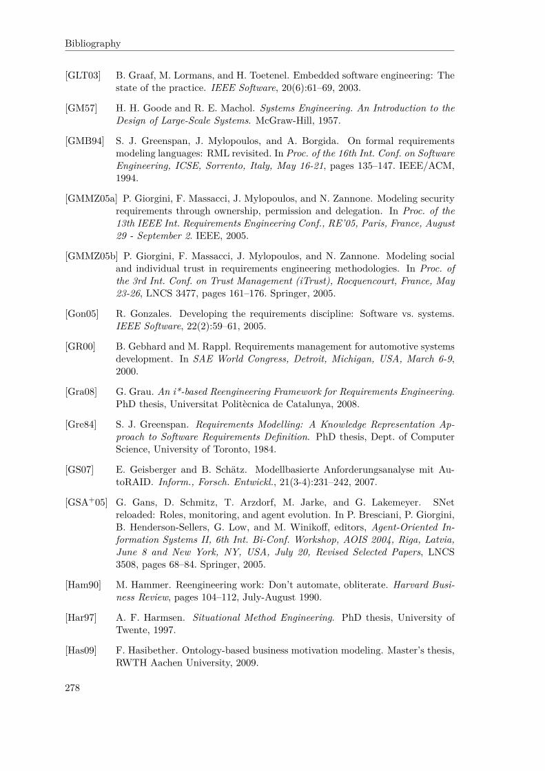
Bibliography
[GLT03] B. Graaf, M. Lormans, and H. Toetenel. Embedded software engineering: Thestate of the practice. IEEE Software, 20(6):61–69, 2003.
[GM57] H. H. Goode and R. E. Machol. Systems Engineering. An Introduction to theDesign of Large-Scale Systems. McGraw-Hill, 1957.
[GMB94] S. J. Greenspan, J. Mylopoulos, and A. Borgida. On formal requirementsmodeling languages: RML revisited. In Proc. of the 16th Int. Conf. on SoftwareEngineering, ICSE, Sorrento, Italy, May 16-21, pages 135–147. IEEE/ACM,1994.
[GMMZ05a] P. Giorgini, F. Massacci, J. Mylopoulos, and N. Zannone. Modeling securityrequirements through ownership, permission and delegation. In Proc. of the13th IEEE Int. Requirements Engineering Conf., RE’05, Paris, France, August29 - September 2. IEEE, 2005.
[GMMZ05b] P. Giorgini, F. Massacci, J. Mylopoulos, and N. Zannone. Modeling socialand individual trust in requirements engineering methodologies. In Proc. ofthe 3rd Int. Conf. on Trust Management (iTrust), Rocquencourt, France, May23-26, LNCS 3477, pages 161–176. Springer, 2005.
[Gon05] R. Gonzales. Developing the requirements discipline: Software vs. systems.IEEE Software, 22(2):59–61, 2005.
[GR00] B. Gebhard and M. Rappl. Requirements management for automotive systemsdevelopment. In SAE World Congress, Detroit, Michigan, USA, March 6-9,2000.
[Gra08] G. Grau. An i*-based Reengineering Framework for Requirements Engineering.PhD thesis, Universitat Politècnica de Catalunya, 2008.
[Gre84] S. J. Greenspan. Requirements Modelling: A Knowledge Representation Ap-proach to Software Requirements Definition. PhD thesis, Dept. of ComputerScience, University of Toronto, 1984.
[GS07] E. Geisberger and B. Schätz. Modellbasierte Anforderungsanalyse mit Au-toRAID. Inform., Forsch. Entwickl., 21(3-4):231–242, 2007.
[GSA+05] G. Gans, D. Schmitz, T. Arzdorf, M. Jarke, and G. Lakemeyer. SNetreloaded: Roles, monitoring, and agent evolution. In P. Bresciani, P. Giorgini,B. Henderson-Sellers, G. Low, and M. Winikoff, editors, Agent-Oriented In-formation Systems II, 6th Int. Bi-Conf. Workshop, AOIS 2004, Riga, Latvia,June 8 and New York, NY, USA, July 20, Revised Selected Papers, LNCS3508, pages 68–84. Springer, 2005.
[Ham90] M. Hammer. Reengineering work: Don’t automate, obliterate. Harvard Busi-ness Review, pages 104–112, July-August 1990.
[Har97] A. F. Harmsen. Situational Method Engineering. PhD thesis, University ofTwente, 1997.
[Has09] F. Hasibether. Ontology-based business motivation modeling. Master’s thesis,RWTH Aachen University, 2009.
278

Bibliography
[HBJ08] M. Herrmannsdoerfer, S. Benz, and E. Jürgens. Automatability of coupledevolution of metamodels and models in practice. In K. Czarnecki, I. Ober,J.-M. Bruel, A. Uhl, and M. Völter, editors, Proc. of 11th Int. Conf. on ModelDriven Engineering Languages and Systems, MoDELS 2008, Toulouse, France,September 28 - October 3, LNCS 5301, pages 645–659. Springer, 2008.
[HBJ09] M. Herrmannsdoerfer, S. Benz, and E. Jürgens. COPE – automating coupledevolution of metamodels and models. In S. Drossopoulou, editor, Proc. of 23rdEurop. Conf. on Object-Oriented Programming, ECOOP 2009, Genova, Italy,July 6-10, LNCS 5653, pages 52–76. Springer, 2009.
[HJST07] M. Hoogendoorn, C. M. Jonker, M. C. Schut, and J. Treur. Modeling cen-tralized organization of organizational change. Comput. Math. Organ. Theory,13(2):147–184, 2007.
[HK06] J. Han and M. Kamber. Data Mining: Concepts and Techniques. 2nd Edition.Morgan Kaufmann, 2006.
[HM03] D. Harel and R. Marelly. Come, Let’s Play: Scenario-Based ProgrammingUsing LSCs and the Play-Engine. Springer, 2003.
[HR09] M. Herrmannsdoerfer and D. Ratiu. Limitations of automating model mi-gration in response to metamodel adaptation. In S. Ghosh, editor, Modelsin Software Engineering, Workshops and Symposia at MODELS 2009, Den-ver, CO, USA, October 4-9, Reports and Revised Selected Papers, LNCS 6002,pages 205–219. Springer, 2009.
[HRT08] M. Höst, B. Regnell, and C. Tingström. A framework for simulation of require-ments engineering processes. In Proc. of 34th Euromicro Conf. on SoftwareEngineering and Advanced Applications, SEAA 2008, Parma, Italy, September3-5, pages 183–190. IEEE, 2008.
[HvG09] L. Hatton and M. van Genuchten. Point/counterpoint. IEEE Software,26(3):66–69, 2009.
[HY08] J. Horkoff and E. S. K. Yu. Qualitative, interactive, backward analysis of i*models. In J. Castro, X. Franch, A. Perini, and E. S. K. Yu, editors, Proc.of the 3rd Int. i* Workshop, Recife, Brazil, February 11-12, CEUR WorkshopProceedings, vol. 322, pages 43–46. CEUR-WS.org, 2008.
[HY09] J. Horkoff and E. S. K. Yu. Evaluating goal achievement in enterprise model-ing – an interactive procedure and experiences. In A. Persson and J. Stirna,editors, Proc. of 2nd IFIP WG 8.1 Working Conf. on the Practice of Enter-prise Modeling, PoEM 2009, Stockholm, Sweden, November 18-19, LNBIP 39,pages 145–160. Springer, 2009.
[HY10] J. Horkoff and E. Yu. A framework for iterative, interactive analysis of agent-goal models in early requirements engineering. In J. Castro, X. Franch, J. My-lopoulos, and E. S. K. Yu, editors, Proc. of the 4th Int. i* Workshop, Ham-mamet, Tunisia, June 7-8, CEUR Workshop Proceedings, vol. 586, pages 52–56. CEUR-WS.org, 2010.
279

Bibliography
[IBM09a] IBM. IBM Rational DOORS. WWW, last accessed: September 28, 2010,2009. http://www.ibm.com/software/awdtools/doors.
[IBM09b] IBM. Requisite Pro. WWW, last accessed: September 28, 2010, 2009. http://www.ibm.com/software/awdtools/reqpro.
[INR06] INRIA. Classification of model transformation approaches. WWW, last ac-cessed: August 18, 2010, 2006. http://modelware.inria.fr/rubrique21.html.
[ITU99] ITU-T (International Telecommunication Union). ITU-T Z.100 recommen-dation: Specification and description language (SDL), 1999. InternationalTelecommunication Union, Geneva, Switzerland.
[ITU08] ITU-T (International Telecommunication Union). ITU-T Z.151 recommen-dation: Formal description techniques (FDT) – User Requirements Notation(URN), 2008. International Telecommunication Union, Geneva, Switzerland.
[Jac95] M. Jackson. Software Requirements & Specifications. A lexicon of practice,principles and prejudices. ACM Press & Addison-Wesley, 1995.
[JEG+95] M. Jarke, S. Eherer, R. Gallersdörfer, M. A. Jeusfeld, and M. Staudt. Con-ceptBase – a deductive object base for meta data management. Journal ofIntelligent Information Systems, 4(2):167–192, 1995.
[Jeu09a] M. Jeusfeld. Metamodeling for method engineering (slides to lecture). WWW,last accessed: September 28, 2010, April 2009. http://merkur.informatik.rwth-aachen.de/pub/bscw.cgi/2616290.
[Jeu09b] M. A. Jeusfeld. Metmodeling and method engineering with ConceptBase. InJeusfeld et al. [JJM09].
[Jeu10] M. Jeusfeld. Personal communication, May 25 2010.
[JH91] W. L. Johnson and D. R. Harris. Sharing and reuse of requirements knowl-edge. In Proc. of the 6th Annual Knowledge-Based Software Engineering Conf.,Syracuse, New York, USA, September 22-25, pages 57–66. IEEE, 1991.
[JHB97] C. Jones, W. S. Hesterly, and S. P. Borgatti. A general theory of networkgovernance: exchange conditions and social mechanisms. The Academy ofManagement Review, 22(4):911–945, 1997.
[JJM09] M. A. Jeusfeld, M. Jarke, and J. Mylopoulous, editors. Metamodeling forMethod Engineering. Cooperative information systems. MIT Press, Cam-bridge, Massachusetts, 2009.
[JKLS08] M. Jarke, R. Klamma, G. Lakemeyer, and D. Schmitz. Continuous,requirements-driven support for organizations, networks, and communities. InJ. Castro, X. Franch, A. Perini, and E. S. K. Yu, editors, Proc. of the 3rd Int.i* Workshop, Recife, Brazil, February 11-12, CEUR Workshop Proceedings,vol. 322, pages 47–50. CEUR-WS.org, 2008.
280

Bibliography
[JKM03] M. Jarke, R. Klamma, and J. Marock. Zu den Wirkungen des regionalen Kon-texts auf Unternehmensgründungen, chapter Gründerausbildung und Grün-dernetze im Umfeld technischer Hochschulen: ein wirtschaftsinformatischerVersuch, pages 115–154. EUL-Verlag, 2003.
[JL10] M. Jarke and K. Lyytinen. High impact requirements engineering. Business& Information Systems Engineering, 2(3):123–124, 2010.
[JLL+09] M. Jarke, P. Loucopoulos, K. Lyytinen, J. Mylopoulos, and W. Robinson.08412 Manifesto – High-impact requirements for software-intensive systems.In M. Jarke, K. Lyytinen, and J. Mylopoulos, editors, Perspectives Workshop:Science of Design: High-Impact Requirements for Software-Intensive Systems,number 08412 in Dagstuhl Seminar Proceedings, Dagstuhl, Germany, 2009.Schloss Dagstuhl – Leibniz-Zentrum fuer Informatik, Germany.
[JLL+10] M. Jarke, P. Loucopoulos, K. Lyytinen, J. Mylopoulos, and W. Robinson. Thebrave new world of design requirements: Four key principles. In B. Pernici,editor, Proc. of 22nd Int. Conf. on Advanced Information Systems Engineer-ing, CAiSE 2010, Hammamet, Tunisia, June 7-9, LNCS 6051, pages 470–482.Springer, 2010.
[JLP08] F. Jouault, B.-K. Loukil, and W. Piers. Model-to-model transforma-tion with ATL. WWW, last accessed: August 18, 2010, March 2008.http://www.eclipsecon.org/2008/sub/attachments/Modeltomodel_Transformation_with_ATL.pdf.
[JLVV03] M. Jarke, M. Lenzerini, Y. Vassiliou, and P. Vassiliadis. Fundamentals of DataWarehouses. Springer, 2nd edition, 2003.
[JMF08] I. Jureta, J. Mylopoulos, and S. Faulkner. Revisiting the core ontology andproblem in requirements engineering. In Proc. of 16th IEEE Int. RequirementsEngineering Conf., RE 2008, Barcelona, Catalunya, Spain, September 8-12,pages 71–80. IEEE, 2008.
[JNRS10] M. Jarke, H. W. Nissen, T. Rose, and D. Schmitz. Goal-based domain modelingas a basis for cross-disciplinary systems engineering. In S. Nurcan, C. Salinesi,C. Souveyet, and J. Ralyté, editors, Intentional Perspectives on InformationSystems Engineering, pages 83–100. Springer, 2010.
[JQJ10] M. A. Jeusfeld, C. Quix, and M. Jarke. ConceptBase user manual, version7.2. WWW, last accessed: September 28, 2010, 2010. http://conceptbase.sourceforge.net/userManual72/.
[JSTY07] C. M. Jonker, A. Sharpanskykh, J. Treur, and P. Yolum. A framework forformal modeling and analysis of organizations. Appl. Intell., 27(1):49–66, 2007.
[KAJ+05] S. Kowalewski, D. Abel, M. Jarke, M. Düsterhöft, and H. Nonn. Verzahnungvon modellbasierter Softwareentwicklung und modellbasiertem Reglerentwurf(ZAMOMO). Vorhabensbeschreibung. ZAMOMO Project Proposal, 2005.
281

Bibliography
[KC02] S. Konrad and B. H. C. Cheng. Requirements patterns for embedded systems.In Proc. of 10th Anniversary IEEE Joint Int. Conf. on Requirements Engi-neering (RE 2002), Essen, Germany, September 9-13, pages 127–136. IEEE,2002.
[KCFG04] T. Klein, M. Conrad, I. Fey, and M. Grochtmann. Modellbasierte Entwick-lung eingebetteter Fahrzeugsoftware bei DaimlerChrysler. In B. Rumpe andW. Hesse, editors, Proc. of Modellierung 2004, Marburg, Germany, March23-26, LNI 45, pages 31–41. GI, 2004.
[Ker98] H. Kern. Lack of trust, surfeit of trust: Some causes of the innovation crisesin German industry. In C. Lane and R. Bachmann, editors, Trust Within andBetween Organisations, pages 203–213. Oxford University Press, Oxford, 1998.
[Ket00] S. Kethers. Multi-perspective modelling and analysis of cooperation processes.PhD thesis, RWTH Aachen University, Germany, 2000.
[KHS98] E. Kamsties, K. Hörmann, and M. Schlich. Requirements engineering in smalland medium enterprises. Requirements Engineering Journal, 3:84–90, 1998.
[KLR96] S. Kelly, K. Lyytinen, and M. Rossi. MetaEdit+: A fully configurable multi-user and multi-tool case and came environment. In P. Constantopoulos, J. My-lopoulos, and Y. Vassiliou, editors, Proc. of 8th Int. Conf. on Advanced Infor-mation System Engineering, CAiSE’96, Heraklion, Crete, Greece, May 20-24,LNCS 1080, pages 1–21. Springer, 1996.
[Klü01] F. Klügl. Multiagentensimulation – Konzepte, Werkzeuge, Anwendung. Addi-son Wesley, April 2001.
[KMSW00] P. Knauber, D. Muthig, K. Schmid, and T. Widen. Applying product lineconcepts in small and medium-sized companies. IEEE Software, 17(5):88–95,2000.
[Kol09] D. S. Kolovos. Establishing correspondences between models with the Epsiloncomparison language. In R. F. Paige, A. Hartman, and A. Rensink, editors,Proc. of 5th Europ. Conf. Model Driven Architecture – Foundations and Ap-plications, ECMDA-FA 2009, Enschede, The Netherlands, June 23-26, LNCS5562, pages 146–157. Springer, 2009.
[Kow04] S. Kowalewski. Discrete control systems for cars – quality is more than correctfunction. In Preprints 7th Int. Workshop on Discrete Event Systems, Reims,France, September, pages 13–14, 2004.
[Kow06] S. Kowalewski. On the relation between software development and controlfunction development in automotive embedded systems (invited talk). ARTISTWorkshop “Beyond AUTOSAR”, Innsbruck, Austria, March 2006.
[KQCJ07] D. Kensche, C. Quix, M. A. Chatti, and M. Jarke. GeRoMe: A generic rolebased metamodel for model management. J. Data Semantics, 8:82–117, 2007.
[KQL+09] D. Kensche, C. Quix, X. Li, Y. Li, and M. Jarke. Generic schema mappingsfor composition and query answering. Data Knowl. Eng., 68(7):599–621, 2009.
282
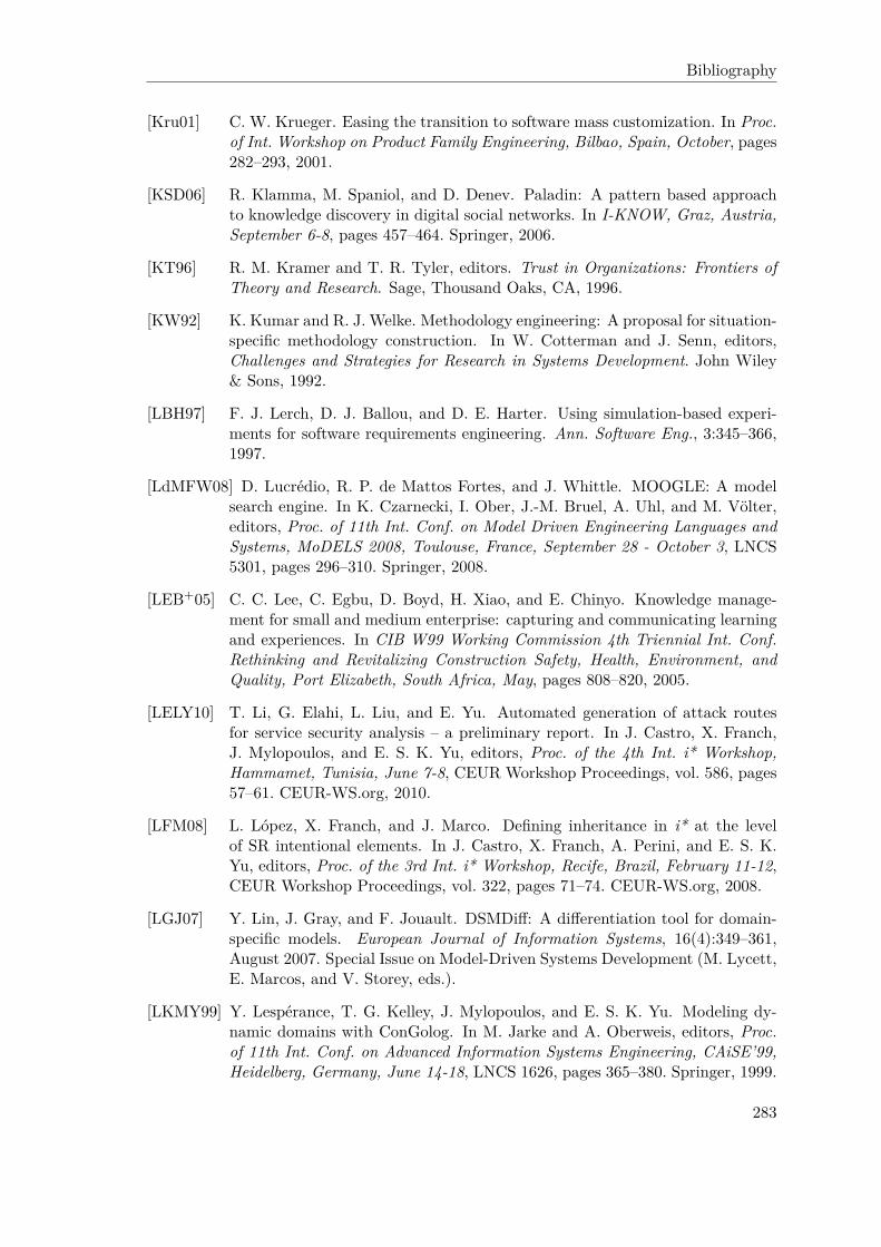
Bibliography
[Kru01] C. W. Krueger. Easing the transition to software mass customization. In Proc.of Int. Workshop on Product Family Engineering, Bilbao, Spain, October, pages282–293, 2001.
[KSD06] R. Klamma, M. Spaniol, and D. Denev. Paladin: A pattern based approachto knowledge discovery in digital social networks. In I-KNOW, Graz, Austria,September 6-8, pages 457–464. Springer, 2006.
[KT96] R. M. Kramer and T. R. Tyler, editors. Trust in Organizations: Frontiers ofTheory and Research. Sage, Thousand Oaks, CA, 1996.
[KW92] K. Kumar and R. J. Welke. Methodology engineering: A proposal for situation-specific methodology construction. In W. Cotterman and J. Senn, editors,Challenges and Strategies for Research in Systems Development. John Wiley& Sons, 1992.
[LBH97] F. J. Lerch, D. J. Ballou, and D. E. Harter. Using simulation-based experi-ments for software requirements engineering. Ann. Software Eng., 3:345–366,1997.
[LdMFW08] D. Lucrédio, R. P. de Mattos Fortes, and J. Whittle. MOOGLE: A modelsearch engine. In K. Czarnecki, I. Ober, J.-M. Bruel, A. Uhl, and M. Völter,editors, Proc. of 11th Int. Conf. on Model Driven Engineering Languages andSystems, MoDELS 2008, Toulouse, France, September 28 - October 3, LNCS5301, pages 296–310. Springer, 2008.
[LEB+05] C. C. Lee, C. Egbu, D. Boyd, H. Xiao, and E. Chinyo. Knowledge manage-ment for small and medium enterprise: capturing and communicating learningand experiences. In CIB W99 Working Commission 4th Triennial Int. Conf.Rethinking and Revitalizing Construction Safety, Health, Environment, andQuality, Port Elizabeth, South Africa, May, pages 808–820, 2005.
[LELY10] T. Li, G. Elahi, L. Liu, and E. Yu. Automated generation of attack routesfor service security analysis – a preliminary report. In J. Castro, X. Franch,J. Mylopoulos, and E. S. K. Yu, editors, Proc. of the 4th Int. i* Workshop,Hammamet, Tunisia, June 7-8, CEUR Workshop Proceedings, vol. 586, pages57–61. CEUR-WS.org, 2010.
[LFM08] L. López, X. Franch, and J. Marco. Defining inheritance in i* at the levelof SR intentional elements. In J. Castro, X. Franch, A. Perini, and E. S. K.Yu, editors, Proc. of the 3rd Int. i* Workshop, Recife, Brazil, February 11-12,CEUR Workshop Proceedings, vol. 322, pages 71–74. CEUR-WS.org, 2008.
[LGJ07] Y. Lin, J. Gray, and F. Jouault. DSMDiff: A differentiation tool for domain-specific models. European Journal of Information Systems, 16(4):349–361,August 2007. Special Issue on Model-Driven Systems Development (M. Lycett,E. Marcos, and V. Storey, eds.).
[LKMY99] Y. Lespérance, T. G. Kelley, J. Mylopoulos, and E. S. K. Yu. Modeling dy-namic domains with ConGolog. In M. Jarke and A. Oberweis, editors, Proc.of 11th Int. Conf. on Advanced Information Systems Engineering, CAiSE’99,Heidelberg, Germany, June 14-18, LNCS 1626, pages 365–380. Springer, 1999.
283

Bibliography
[LLL+95] Y. Lespérance, H. J. Levesque, F. Lin, D. Marcu, R. Reiter, and R. B. Scherl.Foundations of a logical approach to agent programming. In ATAL-95, Intel-ligent Agents II. Workshop on Agent Theories, Architectures, and Languages,1995.
[LMB98] R. J. Lewicki, D. J. McAllister, and R. J. Bies. Trust and distrust: Newrelationships and realities. The Academy of Management Review, 23(3):438–458, 1998.
[LMV97] W. Lam, J. A. McDermid, and A. Vickers. Ten steps towards systematicrequirements reuse. Requirements Engineering Journal, 2(2):102–113, 1997.
[LRL+97] H. J. Levesque, R. Reiter, Y. Lespérance, F. Lin, and R. Scherl. Golog: A logicprogramming language for dynamic domains. Journal of Logic Programming,31(1):59–84, 1997.
[LS94] A. Loose and J. Sydow. Vertrauen und Ökonomie in Netzwerkbeziehungen.Strukturationstheoretische Betrachtungen. In J. Sydow and A. Windeler, ed-itors, Management interorganisationaler Beziehungen: Vertrauen, Kontrolleund Informationstechnik, pages 160–193. Westdeutscher Verlag, Opladen, Ger-many, 1994.
[LT09] P. Liggesmeyer and M. Trapp. Trends in embedded software engineering. IEEESoftware, 26(3):19–25, 2009.
[Luh88] N. Luhmann. Familiarity, confidence, trust: Problems and alternatives. InD. Gambetta, editor, Trust: Making and Breaking Cooperative Relations,pages 94–107. Blackwell, Oxford, 1988.
[Lun03] J. Lunze. Automatisierungstechnik. Oldenbourg, 2003.
[LY00] L. Liu and E. Yu. Organization Modeling Environment (OME). WWW, lastaccessed: September 28, 2010, 2000. http://www.cs.toronto.edu/km/ome.
[LYM07] A. Lapouchnian, Y. Yu, and J. Mylopoulos. Requirements-driven design andconfiguration management of business processes. In G. Alonso, P. Dadam, andM. Rosemann, editors, Proc. of 5th Int. Conf. on Business Process Manage-ment, BPM 2007, Brisbane, Australia, September 24-28, LNCS 4714, pages246–261. Springer, 2007.
[Mac02] J. M. Maciejowski. Predictive Control with Constraints. Prentice Hall, 2002.
[Mat10] T. Mathworks. Matlab, Simulink. WWW, last accessed: September 28, 2010,2010. http://www.mathworks.com.
[MBJK90] J. Mylopoulos, A. Borgida, M. Jarke, and M. Koubarakis. Telos – representingknowledge about information systems. ACM Transactions on InformationSystems, 8(4):325–362, October 1990.
[McC63] J. McCarthy. Situations, actions and causal laws. Technical report, Stanford,1963. Reprinted 1968 in Minsky, M.(ed.): Semantic Information Processing,MIT Press.
284

Bibliography
[MCG04] T. Mens, K. Czarnecki, and P. V. Gorp. 04101 Discussion – A taxonomyof model transformations. In J. Bézivin and R. Heckel, editors, LanguageEngineering for Model-Driven Software Development, February 29 - March 5,volume 04101 of Dagstuhl Seminar Proceedings. Internationales Begegnungs-und Forschungszentrum für Informatik (IBFI), Schloss Dagstuhl, Germany,2004.
[MDS95] R. C. Mayer, J. H. Davis, and F. D. Schoorman. An integrative model oforganisational trust. The Academy of Management Review, 20(3):709–734,1995.
[Meh06] A. Mehlkopp. Entwurf und Integration eines autonomen Parkassistenten ineinem Versuchsfahrzeug für automotive Software. Master’s thesis, RWTHAachen University, 2006.
[MGP08] P. Mäder, O. Gotel, and I. Philippow. Rule-based maintenance of post-requirements traceability relations. In Proc. of 16th IEEE Int. RequirementsEngineering Conf., RE 2008, Barcelona, Catalunya, Spain, September 8-12,pages 23–32. IEEE, 2008.
[MRS01] P. Mathieu, J.-C. Routier, and Y. Secq. Dynamic skills learning: a support toagent evolution. In Symposium on Adaptive Agents and Multi-Agent Systems(AISB), York, March, pages 25–32, 2001. ISBN 1 902956 17 0.
[MRS08] C. D. Manning, P. Raghavan, and H. Schütze. Introduction to InformationRetrieval. Cambridge University Press, 2008.
[MS58] J. March and H. A. Simon. Organizations. Wiley, New York, 1958.
[MS92] N. A. M. Maiden and A. G. Sutcliffe. Exploiting reusable specifications throughanalogy. Commun. ACM, 35(4):55–64, 1992.
[MSF05] H. Mann, H. Schiffelgen, and R. Froriep. Einführung in die Regelungstechnik.Carl Hanser Verlag, München, 10th edition, 2005.
[MZ11] F. Massacci and N. Zannone. Detecting conflicts between functional and secu-rity requirements with Secure Tropos: John Rusnak and the Allied Irish Bank.In Yu et al. [YGMM11].
[Nat01] K. Nathusius. Grundlagen der Gründungsfinanzierung. Instrumente – Prozesse– Beispiele. Gabler, Wiesbaden, 2001.
[NE08] N. Niu and S. M. Easterbrook. Extracting and modeling product line func-tional requirements. In Proc. of 16th IEEE Int. Requirements EngineeringConf., RE 2008, Barcelona, Catalunya, Spain, September 8-12, pages 155–164. IEEE, 2008.
[Nis96] H. W. Nissen. Separierung und Resolution multipler Perspektiven in derkonzeptuellen Modellierung. PhD thesis, RWTH Aachen University, Germany,1996.
[NJ99] H. W. Nissen and M. Jarke. Repository support for multi-perspective require-ments engineering. Information Systems, 24(2):131–158, 1999.
285

Bibliography
[NJJ+96] H. W. Nissen, M. A. Jeusfeld, M. Jarke, G. V. Zemanek, and H. Huber. Man-aging multiple requirements perspectives with metamodels. IEEE Software,13(2):37–48, 1996.
[NSJ+09] H. W. Nissen, D. Schmitz, M. Jarke, T. Rose, P. Drews, F. J. Hesseler, andM. Reke. Evolution in domain model-based requirements engineering for con-trol systems development. In Proc. of 17th IEEE Int. Requirements Engineer-ing Conf., RE 2009, Atlanta, Georgia, USA, August 31 - September 4. IEEE,2009.
[NSJR09] H. W. Nissen, D. Schmitz, M. Jarke, and T. Rose. How to keep domain require-ments models reasonably sized. In Proc. of 2nd Int. Workshop on ManagingRequirements Knowledge, MaRK@RE, Atlanta, USA, September 1, pages 50–59. IEEE, 2009.
[NT95] I. Nonaka and H. Takeuchi. The Knowledge-Creating Company: How JapaneseCompanies Create the Dynamics of Innovation. Oxford University Press, 1995.
[OMG03] OMG. MDA guide version 1.0.1. WWW, last accessed: September 28, 2010,2003. http://www.omg.org/cgi-bin/doc?omg/03-06-01.pdf.
[OMG06] OMG. Meta object facility (MOF) core specification version 2.0. WWW, lastaccessed: September 22, 2010, 2006. http://www.omg.org/spec/MOF/2.0/PDF.
[OMG07a] OMG. MOF 2.0 / XMI mapping specification, v2.1.1. WWW, last ac-cessed: August 17, 2010, 2007. http://www.omg.org/cgi-bin/doc?formal/07-12-01.pdf.
[OMG07b] OMG. OMG Systems Modeling Language (OMG SysML), v1.0. WWW, lastaccessed: September 28, 2010, 2007. http://www.omg.org/spec/SysML/1.0/PDF.
[OMG09] OMG. Meta object facility (MOF) 2.0 query/view/transformation (QVT)version 1.1 - beta 2. WWW, last accessed: August 18, 2010, 2009. http://www.omg.org/spec/QVT/1.1/Beta2/PDF/.
[OMG10a] OMG. Object constraint language, version 2.2. WWW, last accessed: August17, 2010, 2010. http://www.omg.org/spec/OCL/2.2/PDF.
[OMG10b] OMG. OMG Unified Modeling Language (OMG UML), v2.3. WWW, lastaccessed: September 28, 2010, 2010. http://www.omg.org/spec/UML/2.3.
[OPBS03] J. Odell, H. V. D. Parunak, S. Brueckner, and J. A. Sauter. Temporal as-pects of dynamic role assignment. In Agent-Oriented Software Engineering IV(AOSE), Melbourne, Australia, July 15, LNCS 2935, pages 201–213. Springer,2003.
[O’R05] T. O’Reilly. What is web 2.0 – design patterns and business modelsfor the next generation of software. WWW, last accessed: August 9,2010, 2005. http://www.oreillynet.com/pub/a/oreilly/tim/news/2005/09/30/what-is-web-20.html.
286
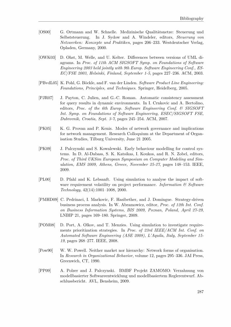
Bibliography
[OS00] G. Ortmann and W. Schnelle. Medizinische Qualitätsnetze: Steuerung undSelbststeuerung. In J. Sydow and A. Windeler, editors, Steuerung vonNetzwerken: Konzepte und Praktiken, pages 206–233. Westdeutscher Verlag,Opladen, Germany, 2000.
[OWK03] D. Ohst, M. Welle, and U. Kelter. Differences between versions of UML di-agrams. In Proc. of 11th ACM SIGSOFT Symp. on Foundations of SoftwareEngineering 2003 held jointly with 9th Europ. Software Engineering Conf., ES-EC/FSE 2003, Helsinki, Finland, September 1-5, pages 227–236. ACM, 2003.
[PBvdL05] K. Pohl, G. Böckle, and F. van der Linden. Software Product Line Engineering:Foundations, Principles, and Techniques. Springer, Heidelberg, 2005.
[PJR07] J. Payton, C. Julien, and G.-C. Roman. Automatic consistency assessmentfor query results in dynamic environments. In I. Crnkovic and A. Bertolino,editors, Proc. of the 6th Europ. Software Engineering Conf. & SIGSOFTInt. Symp. on Foundations of Software Engineering, ESEC/SIGSOFT FSE,Dubrovnik, Croatia, Sept. 3-7, pages 245–254. ACM, 2007.
[PK05] K. G. Provan and P. Kenis. Modes of network governance and implicationsfor network management. Research Colloquium at the Department of Organ-isation Studies, Tilburg University, June 21 2005.
[PK09] J. Palczynski and S. Kowalewski. Early behaviour modelling for control sys-tems. In D. Al-Dabass, S. K. Katsikas, I. Koukos, and R. N. Zobel, editors,Proc. of Third UKSim European Symposium on Computer Modeling and Sim-ulation, EMS 2009, Athens, Greece, November 25-27, pages 148–153. IEEE,2009.
[PL00] D. Pfahl and K. Lebsanft. Using simulation to analyse the impact of soft-ware requirement volatility on project performance. Information & SoftwareTechnology, 42(14):1001–1008, 2000.
[PMHD09] C. Pedrinaci, I. Markovic, F. Hasibether, and J. Domingue. Strategy-drivenbusiness process analysis. In W. Abramowicz, editor, Proc. of 12th Int. Conf.on Business Information Systems, BIS 2009, Poznan, Poland, April 27-29,LNBIP 21, pages 169–180. Springer, 2009.
[POM08] D. Port, A. Olkov, and T. Menzies. Using simulation to investigate require-ments prioritization strategies. In Proc. of 23rd IEEE/ACM Int. Conf. onAutomated Software Engineering (ASE 2008), L’Aquila, Italy, September 15-19, pages 268–277. IEEE, 2008.
[Pow90] W. W. Powell. Neither market nor hierarchy: Network forms of organisation.In Research in Organizational Behavior, volume 12, pages 295–336. JAI Press,Greenwich, CT, 1990.
[PP09] A. Polzer and J. Palczynski. BMBF Projekt ZAMOMO: Verzahnung vonmodellbasierter Softwareentwicklung und modellbasiertem Reglerentwurf. Ab-schlussbericht. AVL, Bensheim, 2009.
287

Bibliography
[QKL07] C. Quix, D. Kensche, and X. Li. Matching of ontologies with XML schemasusing a generic metamodel. In On the Move to Meaningful Internet Systems2007: ODBASE, Vilamoura, Portugal, November 25-30, LNCS 4803, pages1081–1098. Springer, 2007.
[Qui09] C. Quix. Metadatabase design for data warehouses. In Jeusfeld et al. [JJM09].
[RBJ07] R. Ramos, O. Barais, and J.-M. Jézéquel. Matching model-snippets. InG. Engels, B. Opdyke, D. C. Schmidt, and F. Weil, editors, Proc. of 10thInt. Conf. on Model Driven Engineering Languages and Systems, MoDELS2007, Nashville, USA, September 30 - October 5, LNCS 4735, pages 121–135.Springer, 2007.
[RDR03] J. Ralyté, R. Deneckère, and C. Rolland. Towards a generic model for sit-uational method engineering. In J. Eder and M. Missikoff, editors, Proc. of15th Int. Conf. on Advanced Information Systems Engineering, CAiSE 2003,Klagenfurt, Austria, June 18-20, LNCS 2681, pages 95–110. Springer, 2003.
[Rei01] R. Reiter. Knowledge in Action: Logical Foundations for Specifying and Im-plementing Dynamical Systems. MIT Press, 2001.
[Ric05] F. Richert. Objektorientierte Modellbildung und Nichtlinear PrädiktiveRegelung von Dieselmotoren. PhD thesis, RWTH Aachen University, 2005.VDI Fortschritt-Bericht Nr. 1092.
[RJ01] B. Ramesh and M. Jarke. Toward reference models of requirements traceability.IEEE Trans. Software Eng., 27(1):58–93, 2001.
[Rob02] W. N. Robinson. Monitoring software requirements using instrumented code.In IEEE, Proc. of the 35th Annual Hawaii Int. Conf. on Systems Sciences(HICSS), January 7-10, 2002.
[Roe06] A. Roesli. Agent evolution in a modeling and simulation environment for inter-organizational networks. Master’s thesis, RWTH Aachen University, 2006.
[RPB99] C. Rolland, N. Prakash, and A. Benjamen. A multi-model view of processmodelling. Requirements Engineering Journal, 4(4):169–187, 1999.
[RRA+05] J. Rückert, F. Richert, D. Abel, O. E. Herrmann, A. Pfeifer, A. Schloßer, andS. Pischinger. A model based attempt to control boost pressure and EGR-Ratefor a heavy duty engine. at – Automatisierungstechnik, 53(2):79–86, February2005.
[RSLJ08] A. Roesli, D. Schmitz, G. Lakemeyer, and M. Jarke. Modelling actor evolutionin agent-based simulations. In G. A. Vouros, A. Artikis, K. Stathis, and J. V.Pitt, editors, 1st Int. Workshop on Organized Adaption in Multi-Agent Sys-tems, OAMAS@AAMAS 2008, Estoril, Portugal, May 13, Revised and InvitedPapers, LNCS 5368, pages 126–144. Springer, 2008.
[RW91] H. B. Reubenstein and R. C. Waters. The requirements apprentice: Automatedassistance for requirements acquisition. IEEE Trans. Software Eng., 17(3):226–240, 1991.
288

Bibliography
[SAJL10] D. Schmitz, T. Arzdorf, M. Jarke, and G. Lakemeyer. Analyzing agent-basedsimulations of inter-organizational networks. In L. Cao, A. L. C. Bazzan,V. Gorodetsky, P. A. Mitkas, G. Weiss, and P. S. Yu, editors, 6th Int. Workshopon Agents and Data Mining Interaction (ADMI@AAMAS), Toronto, Canada,May 11, Revised Selected Papers, LNCS 5980, pages 87–102. Springer, 2010.
[Sch95] B. Scheidt. Die Einbindung junger Technologieunternehmen in Unternehmens-und Politiknetzwerke. Number 447 in Volkswirtschaftliche Schriften. Duncker& Humblot, Berlin, 1995.
[Sch96] T. Schäl. Workflow management systems for process organisations. LNCS1096. Springer, Berlin, Heidelberg, 2nd edition, 1996.
[Sch97] A.-W. Scheer. Business Process Engineering – Reference Models for IndustrialEnterprises. Springer Verlag, Berlin, 2nd edition, 1997.
[Sch03] D. Schmitz. Eine Erweiterung des Agentenmodells in SNet um eine Pla-nungskomponente unter Verwendung von Nutzentheorie. Master’s thesis,RWTH Aachen University, 2003.
[SDH+08] D. Schmitz, P. Drews, F. Hesseler, M. Jarke, S. Kowalewski, J. Palczynski,A. Polzer, M. Reke, and T. Rose. Modellbasierte Anforderungserfassung fürsoftwarebasierte Regelungen. In K. Herrmann and B. Brügge, editors, SoftwareEngineering 2008. Fachtagung des GI-Fachbereichs Softwaretechnik, Munich,Germany, February 18-22, LNI 121, pages 257–271. GI, 2008.
[SDR+09] D. Schmitz, W. Deng, T. Rose, M. Jarke, H. Nonn, and K. Sanguanpiyapan.Configuration management for realtime simulation software. In 35th EuromicroSEAA Conf., Track on Software Process and Product Improvements (SPPI),Patras, Greece, August 27-29. IEEE, 2009.
[Shn09] B. Shneiderman. Time searcher 2. WWW, last accessed: September 28, 2010,2009. http://www.cs.umd.edu/hcil/timesearcher/.
[SJ00] M. Staudt and M. Jarke. View management support in advanced knowledgebase servers. J. Intell. Inf. Syst., 15(3):253–285, 2000.
[SLGJ04] D. Schmitz, G. Lakemeyer, G. Gans, and M. Jarke. Using BPEL processdescriptions for building up strategic models of inter-organizational networks.In R. Meersman, Z. Tari, and A. Corsaro, editors, On the Move to MeaningfulInternet Systems 2004: OTM 2004 Workshops. Workshop on Modeling Inter-Organizational Systems (MIOS), Agia Napa, Cyprus, October 25-29, LNCS3292, pages 520–532. Springer, 2004.
[SLJ06a] D. Schmitz, G. Lakemeyer, and M. Jarke. Comparing TCD/SNet with twoother formal analysis approaches based on i*: Formal Tropos and SecureTropos. In Proc. of the 8th Workshop on Agent-Oriented Information Systems(AOIS @ CAiSE), Luxembourg, Luxembourg, June 6, 2006.
[SLJ06b] D. Schmitz, G. Lakemeyer, and M. Jarke. Comparing three formal analysisapproaches of the Tropos family. In M. Kolp, B. Henderson-Sellers, H. Moura-tidis, A. Garcia, A. Ghose, and P. Bresciani, editors, Agent-Oriented Informa-tion Systems IV, 8th Int. Bi-Conf. Workshop, AOIS 2006, Hakodate, Japan,
289
Bibliography
May 9, 2006 and Luxembourg, Luxembourg, June 6, 2006, Revised SelectedPapers, LNCS 4898, pages 164–182. Springer, 2006.
[SLJK07] D. Schmitz, G. Lakemeyer, M. Jarke, and H. Karanfil. How to model inter-organisational networks to enable dynamic analyses via simulations. In Proc.of Agent-Oriented Information Systems Workshop, Trondheim, Norway, June11, pages 697–711, 2007.
[SM93] A. G. Sutcliffe and N. A. M. Maiden. Use of domain knowledge for requirementsvalidation. In Proc. of IFIP WG8.1 Conf. on Information System DevelopmentProcess, Como, Italy, September 1-3, pages 99–115. Elsevier, 1993.
[SMG98] G. Schuh, K. Millarg, and Å. Göransson. Virtuelle Fabrik. Neue Marktchancendurch dynamische Netzwerke. Hanser, München, Wien, 1998.
[SMG04] C. Seybold, S. Meier, and M. Glinz. Evolution of requirements models bysimulation. In Proc. of 7th Int. Workshop on Principles of Software Evolution(IWPSE 2004), Kyoto, Japan, September 6-7, pages 43–48. IEEE, 2004.
[SMTS09] J. Sprinkle, M. Mernik, J.-P. Tolvanen, and D. Spinellis. Guest editors’ intro-duction: What kinds of nails need a domain-specific hammer? IEEE Software,26(4):15–18, 2009.
[SNJ+08] D. Schmitz, H. W. Nissen, M. Jarke, T. Rose, P. Drews, F. J. Hesseler, andM. Reke. Requirements engineering for control systems development in smalland medium-sized enterprises. In Proc. of 16th IEEE Int. Requirements Engi-neering Conf., RE 2008, Barcelona, Catalunya, Spain, September 8-12, pages229–234. IEEE, 2008.
[SNJR08] D. Schmitz, H. W. Nissen, M. Jarke, and T. Rose. Telos: Representing knowl-edge about control systems? In Proc. of 1st Int. Workshop on ManagingRequirements Knowledge, MaRK@RE 2008, Barcelona, Spain, September 8,pages 16–24. IEEE, 2008.
[SNJR10a] D. Schmitz, H. W. Nissen, M. Jarke, and T. Rose. Relating domain modelbased requirements management and situational method engineering. In Proc.of 3rd Int. Workshop on Managing Requirements Knowledge, MaRK@RE, Syd-ney, Australia, September 27, pages 7–15. IEEE, 2010.
[SNJR10b] D. Schmitz, H. W. Nissen, M. Jarke, and T. Rose. Requirements engineeringfor control systems. In J. Castro, X. Franch, J. Mylopoulos, and E. S. K.Yu, editors, Proc. of the 4th Int. i* Workshop, Hammamet, Tunisia, June 7-8,CEUR Workshop Proceedings, vol. 586, pages 87–91. CEUR-WS.org, 2010.
[Som06] S. S. Somé. Supporting use case based requirements engineering. Information& Software Technology, 48(1):43–58, 2006.
[SQ01] M. Schoop and C. Quix. DOC.COM: a framework for effective negotiationsupport in electronic marketplaces. Computer Networks, 37(2):153–170, 2001.
[SRB+00] R. Schmid, J. Ryser, S. Berner, M. Glinz, R. Reutemann, and E. Fahr. A surveyof simulation tools for requirements engineering. final report of the work group
290

Bibliography
“Simulationswerkzeuge für das Requirements Engineering”. Technical report,German Informatics society (GI), 2000.
[ST07] S. Schiffel and M. Thielscher. Fluxplayer: A successful general game player.In 22nd AAAI Conf. on Artificial Intelligence, Vancouver, British Columbia,Canada, July 22-26, pages 1191–1196, 2007.
[Sta86] M. Stanley. CML: A knowledge representation language with application to re-quirements modelling. Master’s thesis, Dept. of Computer Science, Universityof Toronto, 1986.
[Sta90] I. I. Standard. Information Resource Dictionary System (IRDS) – FrameworkISO/IEC 10027, 1990.
[Sta00a] U. Staber. Steuerung von Unternehmensnetzwerken: Organisations-theoretische Perspektiven und soziale Mechanismen. In J. Sydow andA. Windeler, editors, Steuerung von Netzwerken: Konzepte und Praktiken,pages 58–87. Westdeutscher Verlag, Opladen, Germany, 2000.
[Sta00b] B. Staudt Lerner. A model for compound type changes encountered in schemaevolution. ACM Trans. Database Syst., 25(1):83–127, 2000.
[Sto07] P. Stone. Learning and multiagent reasoning for autonomous agents. In M. M.Veloso, editor, Proc. of the 20th Int. Joint Conf. on Artificial Intelligence,IJCAI 2007, Hyderabad, India, January 6-12, pages 12–30, 2007.
[Str04] H. Straßheim. Power in intercommunal knowledge networks. Discussion PaperSP III 2004-104. Wissenschaftszentrum Berlin für Sozialforschung, 2004.
[SZ03] J. Schäuffele and T. Zurawka. Automotive Software Engineering. Vieweg,Wiesbaden, 2003.
[SZR+09] D. Schmitz, M. Zhang, T. Rose, M. Jarke, A. Polzer, J. Palczynski,S. Kowalewski, and M. Reke. Mapping requirement models to mathemati-cal models in control system development. In R. F. Paige, A. Hartman, andA. Rensink, editors, Proc. of 5th Europ. Conf. Model Driven Architecture –Foundations and Applications, ECMDA-FA 2009, Enschede, The Netherlands,June 23-26, LNCS 5562, pages 253–264. Springer, 2009.
[TBWK07] C. Treude, S. Berlik, S. Wenzel, and U. Kelter. Difference computation oflarge models. In I. Crnkovic and A. Bertolino, editors, Proc. of the 6th Eu-rop. Software Engineering Conf. & SIGSOFT Int. Symp. on Foundations ofSoftware Engineering, ESEC/SIGSOFT FSE, Dubrovnik, Croatia, Sept. 3-7,pages 295–304. ACM, 2007.
[TC06] G. Taentzer and G. T. Carughi. A graph-based approach to transform XMLdocuments. In L. Baresi and R. Heckel, editors, Proc. of 9th Int. Conf. onFundamental Approaches to Software Engineering, FASE 2006, Held as Partof the Joint European Conf.s on Theory and Practice of Software, ETAPS2006, Vienna, Austria, March 27-28, LNCS 3922, pages 48–62. Springer, 2006.
291

Bibliography
[The08] S. Theissen. Weiterentwicklung einer Softwarearchitektur für ein Rapid-Control-Prototyping-System für den Einsatz als Motorsteuerung. Master’sthesis, RWTH Aachen University, 2008.
[Tol98] J.-P. Tolvanen. Incremental Method Engineering with Modeling Tools. Theo-retical Principles and Empirical Evidence. PhD thesis, University of Jyväskylä,1998.
[Uhr99] A. M. Uhrmacher. Agent-oriented simulation. Habilitationsschrift, Universityof Ulm, Juni 1999.
[USM95] N. Upton, D. Sexton, and C. Moore. Have we made a difference? An examina-tion of career activity of entrepreneurship majors since 1981. Technical report,Baylor University, 1995.
[UT00] N. Ubayashi and T. Tamai. RoleEP: Role based evolutionary programming forcooperative mobile agent applications. In Symposium on Principles of SoftwareEvolution (ISPSE), Kanazawa, Japan, November 1-2, pages 243–251. IEEE,2000.
[vL01] A. van Lamsweerde. Goal-oriented requirements engineering: A guided tour. InProc. of 5th IEEE Int. Symp. on Requirements Engineering, RE 2001, Toronto,Canada, August 27-31, pages 249–262. IEEE, August 2001.
[vL04] A. van Lamsweerde. Goal-oriented requirements enginering: A roundtrip fromresearch to practice. In Proc. of 12th IEEE Int. Conf. on Requirements Engi-neering, RE 2004, Kyoto, Japan, September 6-10, pages 4–7. IEEE, 2004.
[vL06] U. von Luxburg. A tutorial on spectral clustering. Technical Report TR-149,Max Planck Institute for Biological Cybernetics, 2006.
[vN02] R. von Nitzsch. Entscheidungslehre. Wie Menschen entscheiden und wie sieentscheiden sollten. Schäffer-Poeschel, 2002.
[W3C07] W3C. XSL Transformations (XSLT) version 2.0. WWW, last accessed: August17, 2010, January 2007. http://www.w3.org/TR/xslt20/.
[Wac07] G. Wachsmuth. Metamodel adaptation and model co-adaptation. In E. Ernst,editor, Proc. of 21st Europ. Conf. on Object-Oriented Programming, ECOOP2007, Berlin, Germany, July 30 - August 3, LNCS 4609, pages 600–624.Springer, 2007.
[WC96] J. Widom and S. Ceri. Active Database Systems: Triggers and Rules forAdvanced Applications. Morgan-Kaufmann, 1996.
[Wey00] J. Weyer. Soziale Netzwerke. Oldenbourg Verlag, München, 2000.
[WF86] T. Winograd and C. F. Flores. Understanding computers and cognition – a newfoundation for design. Ablex Publishing Corporation, Norwood, New Jersey,1986.
292

Bibliography
[WKH08] K. Wolter, T. Krebs, and L. Hotz. A combined similarity measure for deter-mining similarity of model-based and descriptive requirements. In I. Stamelosand M. Vazirgiannis, editors, Artificial Intelligence Techniques in SoftwareEngineering – AISEW 2008 (ECAI 2008 Workshop), Patras, Greece, July 21,pages 11–15, 2008.
[WL01] X. Wang and Y. Lespérance. Agent-oriented requirements engineering usingConGolog and i*. In Working Notes of the Agent-Oriented Information Sys-tems Workshop, AOIS, Montreal, QC, Canada, May 28, 2001.
[WPJH98] K. Weidenhaupt, K. Pohl, M. Jarke, and P. Haumer. Scenarios in systemdevelopment: Current practice. IEEE Software, 15(2):34–45, 1998.
[YGMM11] E. Yu, P. Giorgini, N. Maiden, and J. Mylopoulos, editors. Social Modelingfor Requirements Engineering. MIT Press, Cambridge, MA, 2011.
[YLL+08] Y. Yu, A. Lapouchnian, S. Liaskos, J. Mylopoulos, and J. C. S. do Prado Leite.From goals to high-variability software design. In A. An, S. Matwin, Z. W.Ras, and D. Slezak, editors, Proc. of 17th Int. Symposium on Foundations ofIntelligent Systems, ISMIS 2008, Toronto, Canada, May 20-23, LNCS 4994,pages 1–16. Springer, 2008.
[YM94] E. Yu and J. Mylopoulos. Understanding “why” in software process modelling,analysis and design. In Proc. of the 16th Int. Conf. on Software Engineering,ICSE, Sorrento, Italy, May 16-21, pages 159–168. IEEE/ACM, 1994.
[YS99] L. Yu and B. F. Schmid. A conceptual framework for agent-oriented and role-based workflow modeling. In Agent-Oriented Information Systems Workshop,Heidelberg, Germany, June 14-15. WWW, last accessed: August 9, 2010, 1999.http://www.aois.org/99.
[Yu95] E. Yu. Modelling Strategic Relationships for Process Reengineering. PhDthesis, University of Toronto, 1995.
[Yu01] E. Yu. Agent orientation as a modelling paradigm. Wirtschaftsinformatik,43(2):123–132, April 2001.
[Zha09] M. Zhang. Conception and implementation of the transformation of i* require-ments models to mathematical design models in Matlab (in German). Master’sthesis, RWTH Aachen University, 2009.
[ZL05] C.-N. Ziegler and G. Lausen. Propagation models for trust and distrust insocial networks. Information System Frontiers, 7(4/5):337–385, 2005.
[Zuc86] L. G. Zucker. Production of trust: Institutional sources of economic structure.In Research in Organizational Behavior, volume 8, pages 53–111. JAI Press,Greenwich, CT, 1986.
[Zwe06] S. Zwerschke. Study on awareness, acceptance and willingness to buy ofdriver assistance systems (in german). In Integrierte Sicherheit und Fahreras-sistenzsysteme mit CD-ROM, Wolfsburg, Germany, October 12-13, VDI-Berichte/VDI-Tagungsbände 1960, pages 343–358. VDI Verlag, 2006.
293

Bibliography
294

List of Figures
2.1 Generic process model for situational method engineering [RDR03] . . . . . 82.2 Paradigm-based process model for situational method engineering [RDR03] 102.3 The Telos data model [NJJ+96] . . . . . . . . . . . . . . . . . . . . . . . . . 102.4 Classical Telos example: employees, departments, and managers [JQJ10] . . 122.5 A multi-perspective modelling and management method [GJK+11] . . . . . 162.6 Partial meta meta model integrating the four perspectives [Gan08] . . . . . 172.7 Conceptual relationships between agent, role, and position . . . . . . . 192.8 Strategic Dependency diagram for VEMAC’s business goals (from [SDH+08]) 222.9 Excerpt of SR diagram for small engine developer (from [SDH+08]) . . . . . 242.10 Class hierarchy for Telos representation of i* modelling elements . . . . . . 252.11 Class hierarchy for Telos representation of i* modelling links . . . . . . . . 252.12 SNet SR model for teacher-student management (modified from [SLJ06b]) . 302.13 Fragment of resulting ConGolog for course management example . . . . . . 312.14 Simple simulation setting on grading student research projects . . . . . . . 342.15 Main program of the simulation environment (simplified) . . . . . . . . . . 352.16 Exemplary simulation trace for the research project grading setting . . . . . 382.17 Interaction with the SNet modelling and simulation environment . . . . . . 382.18 Partial FT model of the course management example (taken from [FLP+04]) 392.19 ST model of university setting (based on [GMMZ05a]) . . . . . . . . . . . . 422.20 Precondition and successor state axioms for a reactive elevator world . . . . 482.21 Reactive elevator controller in ConGolog . . . . . . . . . . . . . . . . . . . . 502.22 Thermal model of a house (adapted from [Mat10]) . . . . . . . . . . . . . . 542.23 Subsystem showing the internals of the “house” subsystem [Mat10] . . . . . 542.24 Class hierarchy for Telos representation of the Simulink meta model . . . . 552.25 Screenshot of the developed, Eclipse-based tool support OpenOMEi5 . . . 56
3.1 The three trust columns (adapted from [GJK+01]) . . . . . . . . . . . . . . 673.2 Air path in a diesel combustion engine (adapted from [DHH+08]) . . . . . . 693.3 Common rail pressure control problem (adapted from [SDH+08]) . . . . . . 703.4 Functioning of a parking assistant (source: BMW Press) . . . . . . . . . . . 713.5 Action diagram view of a generic control cycle . . . . . . . . . . . . . . . . . 733.6 ZAMOMO integrated development process [PP09] . . . . . . . . . . . . . . 79
4.1 Modelling levels during agent instantiation . . . . . . . . . . . . . . . . . . 924.2 Associate instantiation information with a modelling construct . . . . . . . 954.3 Duration parameter to primitive i* task elements . . . . . . . . . . . . . . 964.4 Agent instantiation user interface for the SNet case study . . . . . . . . . 974.5 SNet related instantiation information . . . . . . . . . . . . . . . . . . . . . 98
295

List of Figures
4.6 Simple entrepreneurship setting . . . . . . . . . . . . . . . . . . . . . . . . . 994.7 Agent instantiation details for the faculty member “Fred” . . . . . . . . . 1014.8 ZAMOMO related instantiation information . . . . . . . . . . . . . . . . . . 1024.9 Two types of evolution links between roles . . . . . . . . . . . . . . . . 1054.10 Telos classes to capture actor evolution . . . . . . . . . . . . . . . . . . . . . 1104.11 Stages of an entrepreneur (including some dependency relationships) . . . . 112
5.1 Refined development process for domain model based RE . . . . . . . . . . 1205.2 Potential adaptations when deleting a depender . . . . . . . . . . . . . . . . 1225.3 Potential adaptations when deleting a dependee . . . . . . . . . . . . . . . . 1235.4 Potential adaptations when deleting an internal SR element . . . . . . . . . 1245.5 Query classes to retrieve more details on a domain model . . . . . . . . . . 1295.6 ECA rules for automated deletion/marking support based on i* semantics . 1315.7 Identify not yet deleted links of a just deleted element . . . . . . . . . . . . 1325.8 Partial treatment of dependency links . . . . . . . . . . . . . . . . . . . 1345.9 Actually delete earmarked objects . . . . . . . . . . . . . . . . . . . . . . . 1355.10 Top level domain model for control problems . . . . . . . . . . . . . . . . . 1375.11 Specialized domain model for engine management . . . . . . . . . . . . . . . 1385.12 Domain model for combustion engine control . . . . . . . . . . . . . . . . . 1405.13 VEMAC combustion engine evaluation example model (in German) . . . . 1415.14 SR diagram of the cost calculation in a virtual factory (from [SMG98]) . . . 1445.15 Combined SD/SR diagram of the admission procedure (from [SMG98]) . . . 1445.16 Model transformation in MDA [OMG03] . . . . . . . . . . . . . . . . . . . . 1485.17 Predefined class AnswerFormat . . . . . . . . . . . . . . . . . . . . . . . . . . 1525.18 Overview of steps from i* to Matlab/Simulink . . . . . . . . . . . . . . . . 1555.19 Query that checks for single alternative choice at goals . . . . . . . . . . . 1585.20 Transform actors to subsystems . . . . . . . . . . . . . . . . . . . . . . . 1605.21 Set parent information by referring the deductive super attribute . . . . . . 1605.22 Transformation of a sensor resource dependency to Matlab/Simulink . . 1615.23 Query resource dependencies that represent a sensor or actuator . . . . 1635.24 Answer format for a resource dependency representing a sensor/actuator1645.25 Helping answer format to create ports at nested blocks . . . . . . . . . . 1655.26 GUI to refine the generated Simulink model via library elements . . . . . . 1655.27 Excerpt of the queries and answer formats needed to generate XML output 1675.28 Technical details for the transformation from i* to Matlab/Simulink . . . . 1685.29 Combined SD and SR diagram for a parking assistant . . . . . . . . . . . . 1685.30 “Control cycle” subsystem of resulting Matlab/Simulink model . . . . . . 1705.31 Contrasting old and new representation of contribution details . . . . . . . 1715.32 Considering role-based modelling when mapping delegations . . . . . . . . 1725.33 Successor state axiom for fluent RoleCurrentlyPlayedBy . . . . . . . . . . . . 1735.34 Example for successor state axiom to compute instantiation details . . . . . 1745.35 Softgoals and contributions concerning the evolution to a business angel1765.36 Renewed overview of SNet concept and tool interaction . . . . . . . . . . . 1815.37 Partial XML schema of logged SNet simulation data . . . . . . . . . . . . . 1855.38 Excerpt of logged SNet simulation data . . . . . . . . . . . . . . . . . . . . 1865.39 Time series analysis: trust for six delegations . . . . . . . . . . . . . . . . . 1905.40 Time series analysis: trust vs. # cooperations . . . . . . . . . . . . . . . . . 1915.41 Network of cooperations for two different points in time . . . . . . . . . . . 195
296

List of Figures
6.1 The case based reasoning (CBR) cycle (taken from [AP94]) . . . . . . . . . 2016.2 Extended domain model based development process . . . . . . . . . . . . . 2046.3 Detailed Map model for the domain model based similarity search . . . . . 2066.4 Generic query classes to traverse decomposition and parent-child relations 2186.5 Generic query class to identify anchor objects of an extension . . . . . . . . 2206.6 Supportive queries and deductive attribute to compute refinement paths . . 2216.7 Presentation of the outcome of a similarity search . . . . . . . . . . . . . . . 2226.8 Domain model based queries for the combustion engine domain model . . . 2246.9 Two variants of an ad-hoc query concerning “common rail” components . . 2256.10 Extensions and a refinement path in a concrete project . . . . . . . . . . . . 2256.11 Two project-specific extensions with differences in modelling . . . . . . . . . 2266.12 Domain model based queries for the network and member concerns of inter-
organisational networks . . . . . . . . . . . . . . . . . . . . . . . . . . . . . 2286.13 Ad-hoc query to search projects in the “plastics processing industry” . . . . 2286.14 The SECI cycle of knowledge creation (adapted from [NT95]) . . . . . . . . 2306.15 The process of situational method engineering (taken from [Har97]) . . . . . 2346.16 Map model of project-driven domain model reductions and extensions . . . 2446.17 Telos code related to the recording of the number of deletions . . . . . . . . 2536.18 ECA rule for triggering user prompt on deletions . . . . . . . . . . . . . . . 2536.19 Identify all specific objects in a requirements model . . . . . . . . . . . . . . 2546.20 Iteratively partition all project-specific objects . . . . . . . . . . . . . . . . 2556.21 Telos classes related to the management of project-specific extensions . . . . 2566.22 Add “cylinder pressure sensor” . . . . . . . . . . . . . . . . . . . . . . . . . 2586.23 Refine connection points for dependency “cylinder pressure sensor” . . . . 2586.24 Delete dispensable “knock sensor” . . . . . . . . . . . . . . . . . . . . . . . 2586.25 Modified refinement hierarchy to accommodate “hybrid engines” . . . . . . 2596.26 Extensions in regard to environmental issues . . . . . . . . . . . . . . . . . 2606.27 Adapted domain queries in regard to “controller” (tasks and goals) . . . 261
A.1 Basic representation of sensors and actuators as resource dependencies 305A.2 Extended representation of sensors and actuators via actors . . . . . . . . 305A.3 Automatic classification of “controller” and “controlled system” components 307A.4 Automatic classification of “sensor” and “actuator” components . . . . . . . 308A.5 Combined SD/SR diagram for a common rail injection system [SDH+08] . . 309A.6 SD level view on a requirements model for a WEBER-MOTOR engine . . . 310
297

List of Figures
298

List of Tables
2.1 Actor concepts in i* . . . . . . . . . . . . . . . . . . . . . . . . . . . . . . 202.2 Actor association links in i* (group 1) . . . . . . . . . . . . . . . . . . 202.3 Actor association links in i* (group 2) . . . . . . . . . . . . . . . . . . 212.4 Dependency links in i* . . . . . . . . . . . . . . . . . . . . . . . . . . . . 212.5 Intentional elements at Strategic Rationale level . . . . . . . . . . . . . . . . 232.6 Links at Strategic Rationale level . . . . . . . . . . . . . . . . . . . . . . . . 232.7 Parameters to be filled for simulated proactivities . . . . . . . . . . . . . . . 372.8 Concepts in FT vs. SNet . . . . . . . . . . . . . . . . . . . . . . . . . . . . . 402.9 Concepts in ST vs. SNet . . . . . . . . . . . . . . . . . . . . . . . . . . . . . 432.10 Relevant primitive actions in the reactive elevator example . . . . . . . . . 472.11 Relevant fluents in the reactive elevator example . . . . . . . . . . . . . . . 472.12 Overview of ConGolog’s constructs . . . . . . . . . . . . . . . . . . . . . . . 502.13 Clarifying procedures of the reactive elevator controller . . . . . . . . . . . . 512.14 Specialized blocks in Matlab/Simulink . . . . . . . . . . . . . . . . . . . . . 53
3.1 Commonalities and differences from the two case studies – static issues . . . 813.2 Commonalities and differences from the two case studies – dynamic issues . 833.3 Addressing the common issues of the two case studies . . . . . . . . . . . . 86
4.1 Partial agent instantiation for the entrepreneurship setting . . . . . . . . . 1004.2 Examples for potentially relevant features of i* modelling elements . . . . . 106
5.1 A selection of substitution expressions for answer formats . . . . . . . . . . 1535.2 Mapping i* concepts to Matlab/Simulink concepts . . . . . . . . . . . . . . 1565.3 Series of queries to derive a Matlab/Simulink model from an i* model . . . 1595.4 Queries to receive an XML representation of the Telos Simulink model . . . 1665.5 Original i* resource dependency vs. Matlab/Simulink representation . . 1695.6 Mapping evolution links, acquire, and lose conditions . . . . . . . . . . . 1735.7 Some characteristics of agent-based simulation environments . . . . . . . . . 1795.8 Questions to validate simulations of inter-organisational networks . . . . . . 1865.9 Support questions for inter-organisational networks . . . . . . . . . . . . . . 1885.10 Association rules for cooperating “venture capitalists” and “faculty members”1935.11 Matching analysis to questions . . . . . . . . . . . . . . . . . . . . . . . . . 196
6.1 Anchor objects of the two project-specific extensions from Fig. 6.10 . . . . . 2266.2 The anchor objects and their refinement paths . . . . . . . . . . . . . . . . 2276.3 A classification of domain model changes . . . . . . . . . . . . . . . . . . . . 2366.4 Recommendations for robust queries . . . . . . . . . . . . . . . . . . . . . . 239
299

List of Tables
6.5 Responses to domain model changes in regard to the similarity search . . . 2456.6 Relate SitME and domain model based RE . . . . . . . . . . . . . . . . . . 263
300

Appendix A
Telos
A.1 Modelling Frameworks
A.1.1 i*
MetametaClass I S t a r C l a s send
MetametaClass L i n kC l a s s isA I S t a r C l a s send
MetametaClass E lementC la s s isA I S t a r C l a s send
MetametaClass Acto rE l ementC l a s s isA E lementC la s send
MetametaClass I n t e n t i o n a l E l em e n tC l a s s isA E lementC la s send
MetaClass I S t a rOb j e c t i n I S t a r C l a s s witha t t r i bu te
name : S t r i n gend
MetaClass Element i n ElementC las s , C l a s s isA I S t a rOb j e c t witha t t r i bu te
l i n k s : L inkr u l e
l i n k R u l e : $ f o r a l l l / L ink( l from t h i s ) or ( l to t h i s ) ==> ( t h i s l i n k s l ) $
end
MetaClass ActorE lement i n Acto rE l ementC la s s , C l a s s isA Element witha t t r i bu te
c h i l d r e n : I n t e n t i o n a l E l eme n tr u l e
c h i l d r e nR u l e : $ f o r a l l i / I n t e n t i o n a l E l emen t( i pa r en t t h i s ) ==> ( t h i s c h i l d r e n i ) $
end
301

Appendix A. Telos
Dependumend
MetaClass I n t e n t i o n a l E l emen t i n I n t e n t i o n a l E l emen tC l a s s , C l a s sisA Element with
a t t r i bu tepa r en t : ActorE lement
r u l edependumRule : $ ( not e x i s t s a/ActorE lement ( t h i s pa r en t a ) )
==> ( t h i s i n Dependum) $end
QueryClass NotDependum isA Element withc o n s t r a i n t
cNd : $ not ( t h i s i n Dependum) $end
MetaClass RoleE lement i n Acto rE l ementC l a s s isA ActorE lementend
MetaClass Pos i t i o nE l emen t i n Acto rE l ementC l a s s isA ActorE lementend
MetaClass AgentElement i n Acto rE l ementC l a s s isA ActorE lementend
MetaClass GoalE lement i n I n t e n t i o n a l E l em e n tC l a s sisA I n t e n t i o n a l E l emen t
end
MetaClass TaskElement i n I n t e n t i o n a l E l em e n tC l a s sisA I n t e n t i o n a l E l emen t
end
MetaClass Sof tGoa lE l ement i n I n t e n t i o n a l E l em e n tC l a s sisA I n t e n t i o n a l E l emen t
end
MetaClass ResourceE lement i n I n t e n t i o n a l E l em e n tC l a s sisA I n t e n t i o n a l E l emen t
end
MetaClass L ink i n L i n kC l a s s isA I S t a rOb j e c t witha t t r i bu te
from : Element ;to : Element
end
MetaClass DependencyLink i n L i n kC l a s s isA L inkend
MetaClass Decompos i t i onL ink i n L i n kC l a s s isA L ink witha t t r i bu te
302

A.1. Modelling Frameworks
from : TaskElement ;to : I n t e n t i o n a l E l emen t
end
MetaClass MeansEndsLink i n L i n kC l a s s isA L ink witha t t r i bu te
to : Goa lE lement ;from : TaskElement
end
MetaClass Ac t o rA s s o c i a t i o n L i n k i n L i n kC l a s s isA L ink witha t t r i bu te
to : ActorE lement ;from : ActorE lement
end
MetaClass I sAL i nk i n L i n kC l a s s isA Ac t o rA s s o c i a t i o n L i n kend
MetaClass I n s L i n k i n L i n kC l a s s isA Ac t o rA s s o c i a t i o n L i n kend
MetaClass I s P a r tO fL i n k i n L i n kC l a s s isA Ac t o rA s s o c i a t i o n L i n kend
MetaClass P l a y sL i n k i n L i n kC l a s s isA Ac t o rA s s o c i a t i o n L i n k witha t t r i bu te
to : Ro leE lement ;from : AgentElement
end
MetaClass Occup i e sL ink i n L i n kC l a s s isA Ac t o rA s s o c i a t i o n L i n k witha t t r i bu te
to : Po s i t i o nE l emen t ;from : AgentElement
end
MetaClass Cove r sL i nk i n L i n kC l a s s isA Ac t o rA s s o c i a t i o n L i n k witha t t r i bu te
to : Ro leE lement ;from : Po s i t i o nE l emen t
end
MetaClass So f t g o a l C o n t r i b u t i o n i n L i n kC l a s s isA L inkend
MetaClass BreakCon t r i b u t i o n i n L i n kC l a s s isA So f t g o a l C o n t r i b u t i o nend
MetaClass MakeCont r ibut ion i n L i n kC l a s s isA So f t g o a l C o n t r i b u t i o nend
MetaClass Hur tCon t r i b u t i o n i n L i n kC l a s s isA So f t g o a l C o n t r i b u t i o nend
303

Appendix A. Telos
MetaClass He l pCon t r i b u t i o n i n L i n kC l a s s isA So f t g o a l C o n t r i b u t i o nend
MetaClass SomePo s i t i v eCon t r i b u t i o n i n L i n kC l a s sisA So f t g o a l C o n t r i b u t i o n
end
MetaClass SomeNegat i v eCont r i bu t i on i n L i n kC l a s sisA So f t g o a l C o n t r i b u t i o n
end
MetaClass OrCon t r i bu t i on i n L i n kC l a s s isA So f t g o a l C o n t r i b u t i o nend
MetaClass AndCont r i bu t i on i n L i n kC l a s s isA So f t g o a l C o n t r i b u t i o nend
MetaClass UnknownContr ibut ion i n L i n kC l a s s isA So f t g o a l C o n t r i b u t i o nend
A.1.2 Sensor and Actuator Extension of i*For a control problem, “sensors” and “actuators” close the loop between the “controlledsystem” at the one side and the “controller” at the other side (see Chap. 3.2). A “sensor”allows the “controller” to get input from the “controlled system” by measuring a property.An “actuator” in turn is under the control of a “controller” with the ultimate goal toaffect the real world, in particular the “controlled system”. Accordingly, both sensors aswell as actuators have tight connections to the hardware (either to measure or to affect).Furthermore, the characterization of the value of a sensor or the influence of an actuatorcan typically be specified as a physical value with a suitable unit.
Modelling Representation
Basic Representation Due to the fact that in both cases basically only (physical)value-based information is exchanged, in i* the resource dependency is obviously areasonable choice to capture these concepts. The only downside to this approach is that thereading direction of the necessary arrows is then – due to the semantics of dependencyand signal links (lines) – just the opposite to the representation in a block diagram. Ifa signal is passed from the source to a destination, for i* this means that the destinationdepends on the source. Accordingly, a resource dependency representing a sensoris directed from the “controller” to the “controlled system” since the “controller” needsthe provided information from the “controlled system”. In the case of an actuator, thisis just the other way round. Since the “controller” influences the “controlled system”,the latter depends on the “controller”. Figure A.1 shows the basic i* representation ofsensors and actuators. Fortunately, due to the different levels of abstraction and the muchmore encompassing perspective provided by i*, we did not experience any problems withour project partners out of this inversion of the reading direction.
Extended Representation Sometimes sensors and actuators are much more complexin control system development. A sensor might measure a physical entity but applies com-plicated computations before handing over a completely different value to the “controller”.
304

A.1. Modelling Frameworks
Figure A.1: Basic representation of sensors and actuators as resource dependencies
Figure A.2: Extended representation of sensors and actuators via actors
The same can hold true for actuators. If a sensor or actuator is becoming complex likethat, representing it only by a resource dependency is insufficient. No details on theinternals of the sensor or actuator can be given. Thus, alternatively we offer the possibilityto represent a sensor or an actuator by an actor of its own. Figure A.2 exemplifies therepresentation in this regard. The modeller then has the full i* modelling means avail-able to specify sub actors, add specific dependencies or strategic rationale details. Thefoundational characteristic of a sensor and actuator is then provided by suitable resourcedependencies that connect the sensor/actuator actor with “controller” and “controlledsystem” components.
Automatic Classification
Instead of requiring the user to explicitly classify a modelling object as representing a“sensor” or “actuator”, we can provide automatic classification support in this regardwith the help of Telos and ConceptBase. To achieve this, we only need to ensure that
305
Appendix A. Telos
we know for modelling objects whether they belong to the “controller” or the “controlledsystem” side of a “control cycle” (or none of these two). This can easily be achieved byconnecting actor objects to the basic roles representing “controller” and “controlledsystem”, respectively (see Fig. A.1 and Fig. A.2 and the control problem domain modelfrom Fig. 5.10) via an appropriate actor association link. Once this is ensured, weonly need to look at the direction of the involved dependency links (see above) to derivewhether the mediating object represents an actuator or a sensor. To simplify matters forthe extended representation – remember here a sensor or actuator is represented by atleast one actor object together with two resource dependencies that establish theconnection to “controller” and “controlled system”, respectively –, we require a simplenaming convention, namely that the same name is used for these modelling objects asindicated in Fig. A.2.
Implementation Details The implementation of the automatic classification makesuse of the deductive features of ConceptBase. For this purpose we introduce severalclasses only used for classification that are otherwise completely independent from thei* modelling framework. Figure A.3 introduces two of them, namely Controller andControlledSystem. With the help of deductive rules for the basic classes ActorElement andIntentionalElement , we automatically assign these classifications to i* modelling objects ifthe corresponding conditions are fulfilled. For example, an intentional element belongs tothe “controller” side, if its “parent” belongs to it. An actor in turn is “controller” relatedif there is a transitive connection to a “controller” object via an actor association link(this is an is-a, is-part-of, ins, plays, occupies, or covers link). The relation toward“controlled system” is defined analogously. The anchoring is achieved by specifying twobasic roles ControllerRole and ControlledSystemRole (as defined in the related domainmodel, see Fig. 5.10) and assign them explicitly to be “controller” or “controlled system”related. Figure A.3 shows the necessary helping classes as well as the details of thecorresponding deductive rules. This part of the modelling can easily be included in thetop level domain model for “control problems” (see above).
Once the classification into Controller and ControlledSystem is established, it is straight-forward to derive whether a resource dependency or actor represents a sensor oractuator. Figure A.4 shows the corresponding classification classes Sensor and Actuator to-gether with two helping query classes, namely qSensorActuatorAsResourceDep andqSensorActuatorAsActor, that exactly cope with the two possible representations, basicvs. extended.1 The rules regarding Sensor and Actuator within IntentionalElement andActorElement then simply refer to these query classes. The sensor and the actuator rulediffer only in whether the (ultimate) source (f for from) is “controller” or “controlledsystem” related (analogously for the (ultimate) destination (t for to)).
The derivation via deductive rules accommodates the normal modelling setting, wherea model is build up and corrected incrementally. The classification is adjusted automat-ically. Due to the realization of the classification as standard Telos classes, it is easy toexploit the classification within other query classes, for example to restrict searches inthe model (see domain model based queries for the combustion engine domain, Fig. 6.8).Similarly, the editor can easily be adjusted to graphically reflect the derived classification.
1For the sake of simplicity we have omitted here to check for the naming convention.
306

A.1. Modelling Frameworks
C o n t r o l l e rend
Cont r o l l e dSy s t emend
SimpleClass Con t r o lC y c l eRo l e i n RoleE lementend
SimpleClass Con t r o l l e dSy s t emRo l e i n RoleElement , Con t r o l l e dSy s t emend
SimpleClass Co n t r o l l e r R o l e i n RoleElement , C o n t r o l l e rend
SimpleClass Con t r o l l e r I s P a r tO f C o n t r o l C y c l e i n I s P a r tO fL i n k withfrom f : C o n t r o l l e r R o l eto t : Con t r o lC y c l eRo l e
end
SimpleClass Con t r o l l e dS y s t em I sPa r tO fCon t r o lC y c l e i n I s P a r tO fL i n k withfrom f : Con t r o l l e dSy s t emRo l eto t : Con t r o lC y c l eRo l e
end
I n t e n t i o n a l E l emen t i n C l a s s withr u l e
co : $ ( e x i s t s a/ActorE lement( t h i s pa r en t a ) and ( a i n C o n t r o l l e r ) )
==> ( t h i s i n C o n t r o l l e r ) $ ;c s : $ ( e x i s t s a/ActorE lement
( t h i s pa r en t a ) and ( a i n Cont r o l l e dSy s t em ) )==> ( t h i s i n Cont r o l l e dSy s t em ) $
end
ActorE lement i n C l a s s withr u l e
co : $ ( e x i s t s a/ActorE lement l / A c t o rA s s o c i a t i o n L i n k( a i n C o n t r o l l e r ) and ( l to a ) and ( l from t h i s ) )
==> ( t h i s i n C o n t r o l l e r ) $ ;c s : $ ( e x i s t s a/ActorE lement l / A c t o rA s s o c i a t i o n L i n k
( a i n Cont r o l l e dSy s t em ) and ( l to a ) and ( l from t h i s ) )==> ( t h i s i n Cont r o l l e dSy s t em ) $
end
Figure A.3: Automatic classification of “controller” and “controlled system” components
307

Appendix A. Telos
Senso r endActuato r end
GenericQueryClass qSensorActuatorAsResourceDepisA ResourceElement , Dependum with
paramete rf : Element ;t : Element
c o n s t r a i n tc : $ e x i s t s dl1 , d l 2 /DependencyLink
( d l 1 from f ) and ( d l 1 to t h i s ) and( d l 2 from t h i s ) and ( d l 2 to t ) $
end
GenericQueryClass qSenso rActua to rAsActo r isA ActorE lement withparamete r
f : Element ;t : Element
c o n s t r a i n tc : $ e x i s t s dl1 , d l2 , d l3 , d l 4 /DependencyLink e x i s t s d1 , d2/Dependum
( d l 1 from f ) and ( d l 1 to d1 ) and( d l 2 from d1 ) and ( d l 2 to t h i s ) and( d l 3 from t h i s ) and ( d l 3 to d2 ) and( d l 4 from d2 ) and ( d l 4 to t ) $
end
I n t e n t i o n a l E l emen t i n C l a s s withr u l e
a c t u a t o r : $ ( e x i s t s a , b/Element( a i n Cont r o l l e dSy s t em ) and ( b i n C o n t r o l l e r ) and( t h i s i n qSensorActuatorAsResourceDep [ a/ f , b/ t ] ) )
==> ( t h i s i n Actuato r ) $ ;s e n s o r : $ ( e x i s t s a , b/Element
( a i n C o n t r o l l e r ) and ( b i n Cont r o l l e dSy s t em ) and( t h i s i n qSensorActuatorAsResourceDep [ a/ f , b/ t ] ) )
==> ( t h i s i n Senso r ) $end
ActorE lement i n C l a s s withr u l e
a c t u a t o r : $ ( e x i s t s a , b/Element( a i n Cont r o l l e dSy s t em ) and ( b i n C o n t r o l l e r ) and( t h i s i n qSenso rActua to rAsActo r [ a/ f , b/ t ] ) )
==> ( t h i s i n Actuato r ) $ ;s e n s o r : $ ( e x i s t s a , b/Element
( a i n C o n t r o l l e r ) and ( b i n Cont r o l l e dSy s t em ) and( t h i s i n qSenso rActua to rAsActo r [ a/ f , b/ t ] ) )
==> ( t h i s i n Senso r ) $end
Figure A.4: Automatic classification of “sensor” and “actuator” components
308
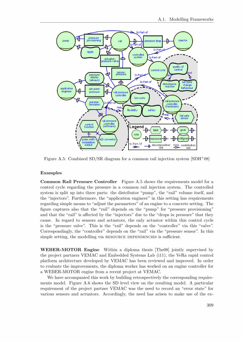
A.1. Modelling Frameworks
Figure A.5: Combined SD/SR diagram for a common rail injection system [SDH+08]
Examples
Common Rail Pressure Controller Figure A.5 shows the requirements model for acontrol cycle regarding the pressure in a common rail injection system. The controlledsystem is split up into three parts: the distributor “pump”, the “rail” volume itself, andthe “injectors”. Furthermore, the “application engineer” in this setting has requirementsregarding simple means to “adjust the parameters” of an engine to a concrete setting. Thefigure captures also that the “rail” depends on the “pump” for “pressure provisioning”and that the “rail” is affected by the “injectors” due to the “drops in pressure” that theycause. In regard to sensors and actuators, the only actuator within this control cycleis the “pressure valve”. This is the “rail” depends on the “controller” via this “valve”.Correspondingly, the “controller” depends on the “rail” via the “pressure sensor”. In thissimple setting, the modelling via resource dependencies is sufficient.
WEBER-MOTOR Engine Within a diploma thesis [The08] jointly supervised bythe project partners VEMAC and Embedded Systems Lab (i11), the VeRa rapid controlplatform architecture developed by VEMAC has been reviewed and improved. In orderto evaluate the improvements, the diploma worker has worked on an engine controller fora WEBER-MOTOR engine from a recent project at VEMAC.
We have accompanied this work by building retrospectively the corresponding require-ments model. Figure A.6 shows the SD level view on the resulting model. A particularrequirement of the project partner VEMAC was the need to record an “error state” forvarious sensors and actuators. Accordingly, the need has arisen to make use of the ex-
309

Appendix A. Telos
Figure A.6: SD level view on a requirements model for a WEBER-MOTOR engine
tended representation for sensors and actuators as elaborated above. This allowed tocapture the “error state” of the actuators “ignition time” and “injection duration” as wellas the sensor “engine speed”. This piece of information is then utilized by the “crankangle” sensor. Another deviation from standard modelling occurs from the sensor “intakemanifold pressure” that needs the “crank angle” information to perform its job correctly.Thus, while not providing SR details, the extended sensor/actuator representation allowedto capture the needed information more precisely than the basic representation.
Summary
In this short section, we have briefly reviewed the fortunately non-existing need to extendthe i* framework in order to capture control system development related issue. Only theimportance of sensors and actuators has been reported. Still both can be met by existingi* modelling concepts. Beyond a basic representation that simply builds on resourcedependencies, we have elaborated on the possibility to use an extended version where thesensors and actuators are represented as actors and thus can have dependencies and SRdetails of their own. A valuable development support is the automatic classification of thecorresponding modelling objects to be “sensor” or “actuator” by building on ConceptBase’sreasoning capabilities, in particular deductive rules. The suitability of the two modellingrepresentations has been documented with two real world examples from the ZAMOMOcase study.
310

A.1. Modelling Frameworks
A.1.3 Matlab/Simulink
The listing below shows the complete Telos representation of Matlab/Simulink togetherwith all attributes of the various objects that are relevant in our context. The formalizationfurthermore includes two event-condition-action rules that are provided for convenience.Since Matlab/Simulink requires ports to have unique numbers within a block, the tworules monitor the addition of input and output ports, respectively. For each according,Tell operation the corresponding counter of the parent block is increased and used as theunique number to identify the added port. The number of in- and outports of a blockcould also have been computed by a suitable deductive rule, but then the assignment of anumber to a port would not have been straightforward. Altogether, these rules provide anice example for the usefulness of ConceptBase’s and Telos’s advanced features to supportthe application engineer.
MetaClass Block witha t t r i bu te
pa r en t : Block ;i n po r tCoun t e r : I n t e g e r ;ou tpo r tCoun t e r : I n t e g e r ;name : S t r i n g
end
MetaClass Port isA Block witha t t r i bu te
number : I n t e g e rend
MetaClass I n p o r t isA Portend
MetaClass Outport isA Portend
ComplexBlock i n MetaClass , C l a s s isA Block witha t t r i bu te
c h i l d r e n : Blockr u l e
c h i l d r e nR u l e : $ f o r a l l i / Block( i pa r en t t h i s ) ==> ( t h i s c h i l d r e n i ) $
end
Subsystem i n MetaClass , C l a s s isA ComplexBlock witha t t r i bu te
l i n e : L i n er u l e
l i n e R u l e : $ f o r a l l l / L i ne( l pa r en t t h i s ) ==> ( t h i s l i n e l ) $
end
311

Appendix A. Telos
AtomicBlock i n MetaClass , C l a s s isA Block witha t t r i bu te
c h i l d r e n : Portr u l e
c h i l d r e nR u l e : $ f o r a l l i / Port( i pa r en t t h i s ) ==> ( t h i s c h i l d r e n i ) $
end
MetaClass Re f e r enc e isA AtomicBlock witha t t r i bu te
d i s p l a y s t r i n g w i t h t a g s : S t r i n g ;s ou r c eB l o ck : S t r i n g ;s ou r c eTa rge t : S t r i n g
end
MetaClass Mod e l V e r i f i c a t i o n isA Re f e r en c eend
MetaClass Mode l I n fo rmat i on isA Re f e r en c eend
MetaClass SFunct ion isA AtomicBlock witha t t r i bu te
funct ionName : S t r i n g ;funct ionMask : S t r i n g
end
MetaClass Constant isA AtomicBlockend
MetaClass L ine witha t t r i bu te
pa r en t : Subsystem ;from : Port ;to : Port
end
i n po r t c oun t e rECAru l e i n ECArule withmode m : De f e r r ede c a r u l e
e r : $ y/Block x/ I n p o r t i , i 1 / I n t e g e rON Tel l ( In ( x , I n p o r t ) )IF ‘ ( x pa r en t y ) and ‘ ( y i n po r tCoun t e r i )
and ( i 1 = i +1)DO Unte l l ( y i n po r tCoun t e r i ) ,
Tel l ( y i n po r tCoun t e r i 1 ) ,Tel l ( x number i 1 ) $
end
312

A.2. Telos Support for Domain Model Based Approach
ou tpo r t coun t e rECAru l e i n ECArule withmode m : De f e r r ede c a r u l e
e r : $ y/Block x/Outport i , i 1 / I n t e g e rON Tel l ( In ( x , Outport ) )IF ‘ ( x pa r en t y ) and ‘ ( y ou tpo r tCoun te r i )
and ( i 1 = i +1)DO Unte l l ( y ou tpo r tCoun te r i ) ,
Tel l ( y ou tpo r tCoun te r i 1 ) ,Tel l ( x number i 1 ) $
end
A.2 Telos Support for Domain Model Based Approach
A.2.1 Implementation of Domain Model Clean-Up Support
{∗FRAMEWORK ADAPTATIONS=====================− a t t r i b u t e c a t e g o r i e s f o r marking an o b j e c t to be d e l e t e d /marked∗}I S t a rOb j e c t with
a t t r i bu ted e l e t e : Boolean ;marked : Boolean
end
{∗He lp ing QUERY CLASSES
=====================He lp ing query c l a s s e s t ha t a l l o w (among o t h e r s ) to avo i d " not e x i s t s "i n c o n d i t i o n s o f ECA r u l e s :− not ye t marked as d e l e t e d (" De l e t ed " and " Marked " f o r e a s i l y
d e l e t i n g such o b j e c t s a f t e r c o n f i r m a t i o n )− a c t o r s w i thout c h i l d r e n− e l ement s w i thout l i n k s ( i n g e n e r a l )− g e n e r i c query c l a s s f o r i n t e n t i o n a l e l ement s w i thout s p e c i f i c k i nd
o f l i n k s ( incoming or ou tgo ing )− e l ement wi th at l e a s t one d i r e c t l y incoming dependency ( t h i s i s
∗ not ∗ t r a n s i t i v e l y r e l a t e d )− e l ement s w i thout incoming dependenc i e s ( b u i l d i n g on the above
d e f i n d e d t r a n s i t i v e h e l p e r c l a s s )− h e l p e r c l a s s to compute t r a n s i t i v e incoming dependenc i e s∗}QueryClass De le t ed isA I S t a rOb j e c t with
c o n s t r a i n tr u l e : $ ( t h i s d e l e t e TRUE) $
end
QueryClass NotDeleted isA I S t a rOb j e c t with
313
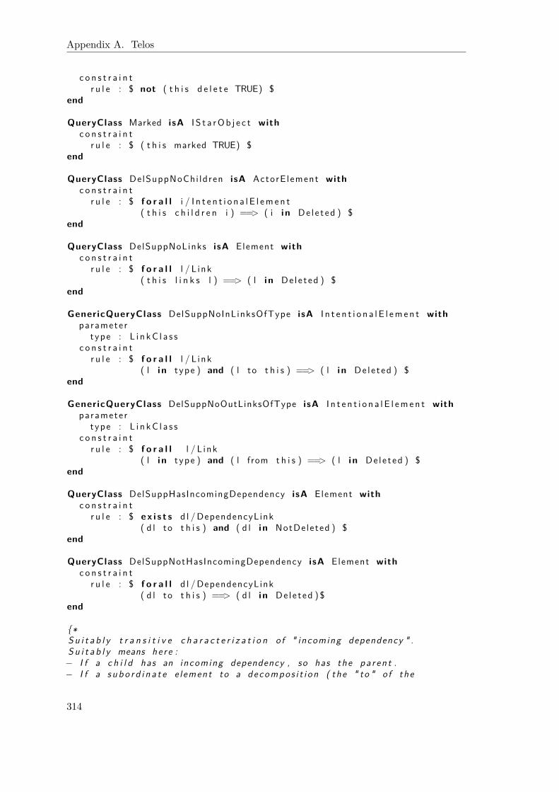
Appendix A. Telos
c o n s t r a i n tr u l e : $ not ( t h i s d e l e t e TRUE) $
end
QueryClass Marked isA I S t a rOb j e c t withc o n s t r a i n t
r u l e : $ ( t h i s marked TRUE) $end
QueryClass DelSuppNoChi ldren isA ActorE lement withc o n s t r a i n t
r u l e : $ f o r a l l i / I n t e n t i o n a l E l emen t( t h i s c h i l d r e n i ) ==> ( i i n De le t ed ) $
end
QueryClass DelSuppNoLinks isA Element withc o n s t r a i n t
r u l e : $ f o r a l l l / L ink( t h i s l i n k s l ) ==> ( l i n De le t ed ) $
end
GenericQueryClass DelSuppNoInLinksOfType isA I n t e n t i o n a l E l emen t withparamete r
type : L i n kC l a s sc o n s t r a i n t
r u l e : $ f o r a l l l / L ink( l i n type ) and ( l to t h i s ) ==> ( l i n De le t ed ) $
end
GenericQueryClass DelSuppNoOutLinksOfType isA I n t e n t i o n a l E l emen t withparamete r
type : L i n kC l a s sc o n s t r a i n t
r u l e : $ f o r a l l l / L ink( l i n type ) and ( l from t h i s ) ==> ( l i n De le t ed ) $
end
QueryClass DelSuppHasIncomingDependency isA Element withc o n s t r a i n t
r u l e : $ e x i s t s d l /DependencyLink( d l to t h i s ) and ( d l i n NotDeleted ) $
end
QueryClass DelSuppNotHasIncomingDependency isA Element withc o n s t r a i n t
r u l e : $ f o r a l l d l /DependencyLink( d l to t h i s ) ==> ( d l i n De le t ed ) $
end
{∗S u i t a b l y t r a n s i t i v e c h a r a c t e r i z a t i o n o f " incoming dependency " .S u i t a b l y means he r e :− I f a c h i l d has an incoming dependency , so has the pa r en t .− I f a s u b o r d i n a t e e l ement to a decompos i t i on ( the " to " o f the
314
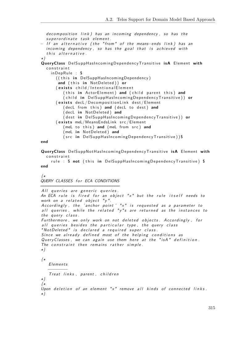
A.2. Telos Support for Domain Model Based Approach
decompos i t i on l i n k ) has an incoming dependency , so has thes u p e r o r d i n a t e t a s k e l ement .
− I f an a l t e r n a t i v e ( the " from " o f the means−ends l i n k ) has anincoming dependency , so has the goa l t ha t i s a ch i e v ed wi tht h i s a l t e r n a t i v e .
∗}QueryClass DelSuppHas IncomingDependencyTrans i t i ve isA Element with
c o n s t r a i n tinDepRule : $
( ( t h i s i n DelSuppHasIncomingDependency )and ( t h i s i n NotDeleted ) ) or
( e x i s t s c h i l d / I n t e n t i o n a l E l emen t( t h i s i n ActorE lement ) and ( c h i l d pa r en t t h i s ) and( c h i l d i n DelSuppHas IncomingDependencyTrans i t i ve ) ) or
( e x i s t s decL/Decompos i t i onL ink de s t /Element( decL from t h i s ) and ( decL to de s t ) and( decL i n NotDeleted ) and( d e s t i n DelSuppHas IncomingDependencyTrans i t i ve ) ) or
( e x i s t s meL/MeansEndsLink s r c /Element(meL to t h i s ) and (meL from s r c ) and(meL i n NotDeleted ) and( s r c i n DelSuppHas IncomingDependencyTrans i t i ve ) ) $
end
QueryClass DelSuppNotHas IncomingDependencyTrans i t i ve isA Element withc o n s t r a i n t
r u l e : $ not ( t h i s i n DelSuppHas IncomingDependencyTrans i t i ve ) $end
{∗QUERY CLASSES f o r ECA CONDITIONS================================A l l q u e r i e s a r e g e n e r i c q u e r i e s .An ECA r u l e i s f i r e d f o r an o b j e c t " x " but the r u l e i t s e l f needs towork on a r e l a t e d o b j e c t " y " .Acco rd i ng l y , the ’ anchor po in t ’ " x " i s r e q u e s t e d as a paramete r toa l l q u e r i e s , w h i l e the r e l a t e d " y " s a r e r e t u r n e d as the i n s t a n c e s tothe query c l a s s .Furthermore , we on l y work on not d e l e t e d o b j e c t s . Acco rd i ng l y , f o ra l l q u e r i e s b e s i d e s the p a r t i c u l a r type , the query c l a s s" NotDe leted " i s d e c l a r e d a r e q u i r e d supe r c l a s s .S i n c e we a l r e a d y d e f i n e d most o f the h e l p i n g c o n d i t i o n s asQueryC la s se s , we can aga in use them he re at the " i sA " d e f i n i t i o n .The c o n s t r a i n t then rema ins r a t h e r s im p l e .∗}
{∗Elements−−−−−−−−Treat l i n k s , parent , c h i l d r e n
∗}{∗Upon d e l e t i o n o f an e lement " x " remove a l l k i n d s o f connected l i n k s .∗}
315
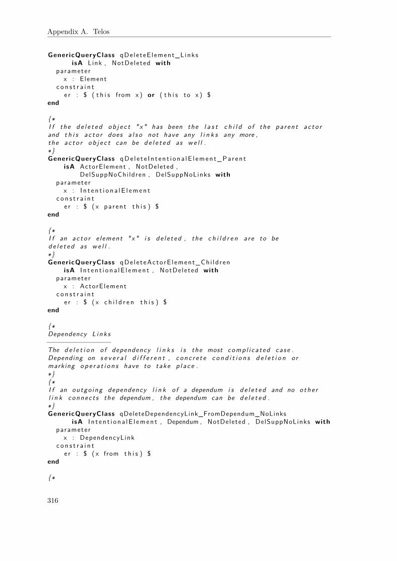
Appendix A. Telos
GenericQueryClass qDe le teE l ement_L inksisA Link , NotDe leted with
paramete rx : Element
c o n s t r a i n te r : $ ( t h i s from x ) or ( t h i s to x ) $
end
{∗I f the d e l e t e d o b j e c t " x " has been the l a s t c h i l d o f the pa r en t a c t o rand t h i s a c t o r does a l s o not have any l i n k s any more ,the a c t o r o b j e c t can be d e l e t e d as w e l l .∗}GenericQueryClass qDe l e t e I n t e n t i o n a l E l emen t_Pa r en t
isA ActorElement , NotDeleted ,DelSuppNoChi ldren , DelSuppNoLinks with
paramete rx : I n t e n t i o n a l E l emen t
c o n s t r a i n te r : $ ( x pa r en t t h i s ) $
end
{∗I f an a c t o r e l ement " x " i s d e l e t ed , the c h i l d r e n a r e to bed e l e t e d as w e l l .∗}GenericQueryClass qDe l e t eAc to rE l ement_Ch i l d r en
isA I n t e n t i o n a l E l emen t , NotDe leted withparamete r
x : ActorE lementc o n s t r a i n t
e r : $ ( x c h i l d r e n t h i s ) $end
{∗Dependency L i nk s−−−−−−−−−−−−−−−−The d e l e t i o n o f dependency l i n k s i s the most comp l i c a t ed ca se .Depending on s e v e r a l d i f f e r e n t , c o n c r e t e c o n d i t i o n s d e l e t i o n ormarking o p e r a t i o n s have to take p l a c e .∗}{∗I f an ou tgo ing dependency l i n k o f a dependum i s d e l e t e d and no o th e rl i n k connec t s the dependum , the dependum can be d e l e t e d .∗}GenericQueryClass qDeleteDependencyLink_FromDependum_NoLinks
isA I n t e n t i o n a l E l emen t , Dependum , NotDeleted , DelSuppNoLinks withparamete r
x : DependencyLinkc o n s t r a i n t
e r : $ ( x from t h i s ) $end
{∗
316
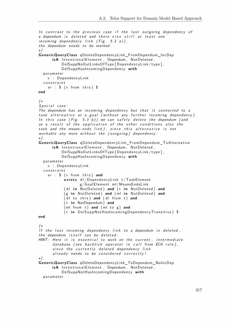
A.2. Telos Support for Domain Model Based Approach
I n c o n t r a s t to the p r e v i o u s ca se i f the l a s t ou tgo ing dependency o fa dependum i s d e l e t e d and t h e r e ∗ i s ∗ s t i l l a t l e a s t oneincoming dependency l i n k ( F ig . 5 . 3 a ) ) ,the dependum needs to be marked .∗}GenericQueryClass qDeleteDependencyLink_FromDependum_IncDep
isA I n t e n t i o n a l E l emen t , Dependum , NotDeleted ,DelSuppNoOutLinksOfType [ DependencyLink / type ] ,DelSuppHasIncomingDependency with
paramete rx : DependencyLink
c o n s t r a i n te r : $ ( x from t h i s ) $
end
{∗S p e c i a l ca s e :The dependum has an incoming dependency but tha t i s connected to at a s k a l t e r n a t i v e at a goa l ( w i thout any f u r t h e r incoming dependency ) .I n t h i s ca s e ( F ig . 5 . 3 b ) ) we can s a f e l y d e l e t e the dependum ( andas a r e s u l t o f the a p p l i c a t i o n o f the o th e r c o n d i t i o n s a l s o thet a s k and the means−ends l i n k ) , s i n c e t h i s a l t e r n a t i v e i s notworkab l e any more w i thout the ( ou tgo ing ) dependency .∗}GenericQueryClass qDeleteDependencyLink_FromDependum_ToAlternat ive
isA I n t e n t i o n a l E l emen t , Dependum , NotDeleted ,DelSuppNoOutLinksOfType [ DependencyLink / type ] ,DelSuppHasIncomingDependency with
paramete rx : DependencyLink
c o n s t r a i n te r : $ ( x from t h i s ) and
e x i s t s d l /DependencyLink t /TaskElementg/GoalE lement ml/MeansEndsLink
( d l i n NotDeleted ) and ( t i n NotDeleted ) and( g i n NotDeleted ) and (ml i n NotDeleted ) and( d l to t h i s ) and ( d l from t ) and( t i n NotDependum) and(ml from t ) and (ml to g ) and( t i n DelSuppNotHas IncomingDependencyTrans i t i ve ) $
end
{∗I f the l a s t incoming dependency l i n k to a dependum i s d e l e t ed ,the dependum i t s e l f can be d e l e t e d .HINT : Here i t i s e s s e n t i a l to work on the cu r r en t , i n t e r m e d i a t e
da tabase ( s e e b a c k t i c k o p e r a t o r i n c a l l from ECA r u l e ) ,s i n c e the c u r r e n t l y d e l e t e d dependency l i n ka l r e a d y needs to be c o n s i d e r e d c o r r e c t l y !
∗}GenericQueryClass qDeleteDependencyLink_ToDependum_NoIncDep
isA I n t e n t i o n a l E l emen t , Dependum , NotDeleted ,DelSuppNotHasIncomingDependency with
paramete r
317

Appendix A. Telos
x : DependencyLinkc o n s t r a i n t
e r : $ ( x to t h i s ) $end
{∗I f the t a r g e t o f a dependency l i n k i s an a c t o r e lement ,t h i s can be d e l e t e d i f the a c t o r does n e i t h e r have anyc h i l d r e n nor l i n k s connected to i t ( F ig . 5 . 2 b ) ) .∗}GenericQueryClass qDeleteDependencyLink_ToActor
isA ActorElement , NotDeleted ,De lSuppNotHas IncomingDependencyTrans i t i ve with
paramete rx : DependencyLink
c o n s t r a i n te r : $ ( x to t h i s ) $
end
{∗I f the t a r g e t o f a dependency l i n k i s a t SR l e v e l ( t h i s i snot a dependum ! ) , the c o r r e s p o n d i n g o b j e c t i s d e l e t e di f t h e r e i s no t r a n s i t i v e conne c t i on to ano the r dependency l i n knor any ou tgo ing s o f t g o a l c o n t r i b u t i o n .∗}GenericQueryClass qDeleteDependencyLink_ToSR
isA I n t e n t i o n a l E l emen t , NotDeleted , NotDependum ,De lSuppNotHas IncomingDependencyTrans i t i ve ,DelSuppNoOutLinksOfType [ S o f t g o a l C o n t r i b u t i o n / type ] with
paramete rx : DependencyLink
c o n s t r a i n te r : $ ( x to t h i s ) $
end
{∗S p e c i a l ca s e ( s e e above ) :Whi le no rma l l y we do not ac t upon SR l e v e l s o u r c e s o f dependencyl i n k s , the on l y e x c e p t i o n conce rn s F ig . 5 . 3 b ) , t h i s i s when thedependency tha t i s d e l e t e d i s connected as s ou r c e to a t a s ka l t e r n a t i v e at a goa l . The t a s k i s then to be d e l e t e d .∗}GenericQueryClass qDeleteDependencyLink_FromSR
isA TaskElement , NotDeleted , NotDependum ,De lSuppNotHas IncomingDependencyTrans i t i ve ,DelSuppNoOutLinksOfType [ S o f t g o a l C o n t r i b u t i o n / type ] with
paramete rx : DependencyLink
c o n s t r a i n te r : $ ( x from t h i s ) and
e x i s t s ml/MeansEndsLink g/GoalE lement(ml i n NotDeleted ) and ( g i n NotDeleted ) and(ml from t h i s ) and (ml to g ) $
end
318

A.2. Telos Support for Domain Model Based Approach
{∗Decompos i t ion L i nk s−−−−−−−−−−−−−−−−−−−I f a decompos i t i on l i n k i s d e l e t ed ,the complex t a s k (" from ") i s markedw h i l e the s u b o r d i n a t e e l ement (" to " ) i s d e l e t ed ,i f i t i s not t r a n s i t i v e l y connected to someo th e r ( b a c k t i c k o p e r a t o r ! ) dependency .HINT : The t e s t c on c e r n i n g t r a n s i t i v e l y r e l a t e d incoming
dependenc i e s o c cu r s r a r e l y and on l y i f the u s e r hase x p l i c i t l y d e l e t e d a decompos i t i on ( or means−ends ) l i n k .Othe rw i s e the dependency would have been t r a n s i t i v e l ya s s o c i a t e d a l s o a l r e a d y wi th the complex t a s kor goa l e l ement .
∗}GenericQueryClass qDeleteDecompos i t ionL ink_From
isA TaskElement , NotDe leted withparamete r
x : Decompos i t i onL inkc o n s t r a i n t
e r : $ ( x from t h i s ) $end
GenericQueryClass qDeleteDecompos i t ionL ink_ToisA I n t e n t i o n a l E l emen t , NotDeleted ,
De lSuppNotHas IncomingDependencyTrans i t i ve withparamete r
x : Decompos i t i onL inkc o n s t r a i n t
e r : $ ( x to t h i s ) $end
{∗Means−Ends L i nk s−−−−−−−−−−−−−−−−I f a means−ends l i n k i s d e l e t ed ,the goa l ( " to " ) i s markedi f no o th e r a l t e r n a t i v e i s l e f t ( b a c k t i c k o p e r a t o r ! ) ,w h i l e the a l t e r n a t i v e t a s k (" from ") i s s imp l y d e l e t e d( aga in i f not t r a n s i t i v e l y connect to someo th e r dependency ) .HINT : See HINT with Decompos i t i onL inkHINT : Decompos i t ion l i n k s and means ends l i n k s have o p p o s i t e
d i r e c t i o n s as to what i s sub and what i s supe r pa r t !∗}GenericQueryClass qDeleteMeansEndsLink_To
isA GoalElement , NotDeleted ,DelSuppNoInLinksOfType [ MeansEndsLink/ type ] with
paramete rx : MeansEndsLink
c o n s t r a i n te r : $ ( x to t h i s ) $
end
319

Appendix A. Telos
GenericQueryClass qDeleteMeansEndsLink_FromisA TaskElement , NotDeleted ,
De lSuppNotHas IncomingDependencyTrans i t i ve withparamete r
x : MeansEndsLinkc o n s t r a i n t
e r : $ ( x from t h i s ) $end
{∗S o f t g o a l C o n t r i b u t i o n−−−−−−−−−−−−−−−−−−−−−I f a s o f t g o a l c o n t r i b u t i o n l i n k i s d e l e t ed ,the s o f t g o a l ( " to " ) i s markedi f no o th e r c o n t r i b u t i o n i s l e f t ( b a c k t i c k o p e r a t o r ! ) .For the s o u r c e s o f a s o f t g o a l c o n t r i b u t i o nwe need to check s e v e r a l o t h e r k i n d s o f l i n k s ,s i n c e the s o f t g o a l c o n t r i b u t i o n i s t y p i c a l l ya ’ secondary ’ k ind o f l i n k .HINT : Regard ing the "From" case not a l l k i n d s o f l i n k s a r e
v a l i d f o r a l l k i n d s o f i n t e n t i o n a l e l ement s .But s i n c e the q u e r i e s a r e s u i t a b l y d e f i n e da s k i n g ’ too much ’ does not hu r t he r e !
∗}GenericQueryClass qDe l e t eSo f t goa lCon t r i bu t i on_To
isA Sof tGoa lE lement , NotDeleted ,DelSuppNoInLinksOfType [ S o f t g o a l C o n t r i b u t i o n / type ] with
paramete rx : S o f t g o a l C o n t r i b u t i o n
c o n s t r a i n te r : $ ( x to t h i s ) $
end
GenericQueryClass qDe l e t eSo f t goa lCon t r i bu t i on_FromisA I n t e n t i o n a l E l emen t , NotDeleted ,
DelSuppNoOutLinksOfType [ MeansEndsLink/ type ] ,DelSuppNoInLinksOfType [ Decompos i t i onL ink / type ] ,DelSuppNoOutLinksOfType [ S o f t g o a l C o n t r i b u t i o n / type ] ,De lSuppNotHas IncomingDependencyTrans i t i ve with
paramete rx : S o f t g o a l C o n t r i b u t i o n
c o n s t r a i n te r : $ ( x from t h i s ) $
end
{∗ECA RULES=========HINT : To be s u r e we remove any marking i f an o b j e c t i s to be
tagged f o r d e l e t i o n even though the o b j e c t might nothave been marked at a l l .But depend ing on the o r d e r i n g o f the d e l e t i o n o p e r a t i o n schosen by the use r , such a s i t u a t i o n can occu r .
320

A.2. Telos Support for Domain Model Based Approach
Obv ious l y , a d e l e t i o n shou ld o v e r r i d e a marking .HINT : Ac tua l l y , the r u l e s shou l d on l y work on mode l ing o b j e c t s
t ha t o r i g i n a t e from a domain model ( to not a c c i d e n t i a l l yd e l e t e p r o j e c t−s p e c i f i c e x t e n s i o n s i n t r o d u c e d by the u s e r ) .Th i s can e a s i l y be a ch i e v ed by i n t r o d u c i n g a query c l a s st ha t checks the c o r r e s p o n d i n g a t t r i b u t e " domain_module "and to add t h i s query c l a s s ( namely v i a " i sA ") to a l lq u e r i e s d e f i n e d above .
∗}
De l e t eRu l e i n ECArule withe c a r u l ee r : $ x , y/ I S t a rOb j e c tON Tel l (A( x , d e l e t e ,TRUE) )IF ‘ ( y i n qDe le teE l ement_L inks [ x ] ) or
‘ ( y i n qDe l e t e I n t e n t i o n a l E l emen t_Pa r e n t [ x ] ) or‘ ( y i n qDe l e t eAc to rE l ement_Ch i l d r en [ x ] ) or‘ ( y i n qDeleteDependencyLink_FromDependum_NoLinks [ x ] ) or‘ ( y i n qDeleteDependencyLink_FromDependum_ToAlternat ive [ x ] ) or‘ ( y i n qDeleteDependencyLink_ToDependum_NoIncDep [ x ] ) or‘ ( y i n qDeleteDependencyLink_ToActor [ x ] ) or‘ ( y i n qDeleteDependencyLink_ToSR [ x ] ) or‘ ( y i n qDeleteDependencyLink_FromSR [ x ] ) or‘ ( y i n qDeleteDecompos i t ionL ink_To [ x ] ) or‘ ( y i n qDeleteMeansEndsLink_From [ x ] ) or‘ ( y i n qDe l e t eSo f t goa lCon t r i bu t i on_From [ x ] )
DO Unte l l (A( y , marked ,TRUE) ) , Tel l (A( y , d e l e t e ,TRUE) ) $end
MarkRule i n ECArule withe c a r u l e
e r : $ x , y/ I S t a rOb j e c tON Tel l (A( x , d e l e t e ,TRUE) )IF ‘ ( y i n qDeleteDependencyLink_FromDependum_IncDep [ x ] ) or
‘ ( y i n qDeleteDecompos i t ionL ink_From [ x ] ) or‘ ( y i n qDeleteMeansEndsLink_To [ x ] ) or‘ ( y i n qDe l e t eSo f t goa lCon t r i bu t i on_To [ x ] )
DO Tel l (A( y , marked ,TRUE) ) $end
{∗He lp ing Que r i e s and AnswerFormats to r e s e t a s e t t i n g where ECA r u l e shave f i r e d .∗}
De l e t e dWi t hA t t r i b u t e i n QueryClass isA I S t a rOb j e c t withr e t r i e v e d _ a t t r i b u t e
d e l e t e : Booleanc o n s t r a i n t
r u l e : $ ( t h i s d e l e t e TRUE) $end
De l e t e dFo rUn t e l lD e l e t i o nMa r k i n g i n AnswerFormat withf o rQue ry
321

Appendix A. Telos
q : De l e t e dWi t hA t t r i b u t ep a t t e r n
p : "{ t h i s } w i th \\n d e l e t e \\n { t h i s | d e l e t e } : TRUE\\nend\\n"end
De l e t e dFo rUn t e l l i n AnswerFormat withf o rQue ry
q : De l e t edp a t t e r n
p : "{ASKquery ( ge t_ob j e c t [ { t h i s }/ objname ] ,FRAME) }"end
MarkedWithAtt r ibute i n QueryClass isA I S t a rOb j e c t withr e t r i e v e d _ a t t r i b u t e
marked : Booleanc o n s t r a i n t
r u l e : $ ( t h i s marked TRUE) $end
MarkedForUnte l lMarkedMark ing i n AnswerFormat withf o rQue ry
q : MarkedWithAtt r ibutep a t t e r n
p : "{ t h i s } w i th \\n marked\\n { t h i s | marked} : TRUE\\nend\\n"end
A.3 Transformation from i* to Matlab/Simulink
A.3.1 Complete M2M Transformation
{∗ ACTOR ∗}QueryClass Q1_Actor2Subsystem
isA ActorE lement withr e t r i e v e d _ a t t r i b u t e
name : S t r i n gend
{∗ TASK dependency & SR d e t a i l ∗}QueryClass Q1_Task2Subsystem
isA TaskElement withr e t r i e v e d _ a t t r i b u t e
name : S t r i n gend
{∗ RESOURCE dependency ( on l y f o r a s e n s o r / a c t u a t o r ) ∗}QueryClass Q1_SensorActuatorDep2Subsystem
isA ResourceElement , Dependum withr e t r i e v e d _ a t t r i b u t e
name : S t r i n gc o n s t r a i n t
c : $ ( t h i s i n Senso r ) or ( t h i s i n Actuato r ) $end
{∗ RESOURCE as SR d e t a i l ∗}
322

A.3. Transformation from i* to Matlab/Simulink
QueryClass Q1_Resource2ConstantisA ResourceElement , NotDependum with
r e t r i e v e d _ a t t r i b u t ename : S t r i n g
end
AnswerFormat AF_CreateConstant withf o rQue ry
q : Q1_Resource2Constantp a t t e r n
p : "Token { t h i s } i n Constant w i th \\n\\ t name\\n\\ t \\ t n : { t h i s . name}\\n\\ t i n po r tCoun t e r \\n\\ t \\ t i : 0\\n\\ t ou tpo r tCoun te r \\n\\ t \\ t o : 0\\nend\\n
"end
{∗ GOAL dependency ∗}QueryClass Q1_GoalDep2Model Information
isA GoalElement , Dependum withr e t r i e v e d _ a t t r i b u t e
name : S t r i n gend
{∗ Re f i n ed GOAL as SR d e t a i l ∗}QueryClass Q1_Goal2Subsystem
isA GoalElement , NotDependum withr e t r i e v e d _ a t t r i b u t e
name : S t r i n gc o n s t r a i n t
c : $ e x i s t s ml/MeansEndsLink (ml to t h i s ) $end
{∗ Not r e f i n e d GOAL as SR d e t a i l ∗}QueryClass Q1_Goa l2Mode lVe r i f i c a t i on
isA GoalElement , NotDependum withr e t r i e v e d _ a t t r i b u t e
name : S t r i n gc o n s t r a i n t
c : $ not e x i s t s ml/MeansEndsLink (ml to t h i s ) $end
AnswerFormat AF_Crea t eMode lVe r i f i c a t i on withf o rQue ry
q : Q1_Goa l2Mode lVe r i f i c a t i onp a t t e r n
p : "Token { t h i s } i n Mod e l V e r i f i c a t i o n wi th \\n\\ t name\\n
323

Appendix A. Telos
\\ t \\ t n : { t h i s . name}\\n\\ t sou r c eB l o ck \\n\\ t \\ t sb : {QT( s imu l i n k \/Model \\\ n V e r i f i c a t i o n \/Check S t a t i c \\\ nUpper
Bound ) }\\n\\ t sou r c eTa rge t \\n\\ t \\ t s t : {QT(Checks_SMax ) }\\n\\ t i n po r tCoun t e r \\n\\ t \\ t i : 0\\n\\ t ou tpo r tCoun te r \\n\\ t \\ t o : 0\\nend\\n
"end
{∗ SOFTGOAL dependency or SR d e t a i l ∗}QueryClass Q1_Sof tgoa l2Mode l In fo rmat ion
isA Sof tGoa lE l ement withr e t r i e v e d _ a t t r i b u t e
name : S t r i n gend
AnswerFormat AF_CreateMode l In format ion withf o rQue ry
q1 : Q1_GoalDep2Model Information ;q2 : Q1_Sof tgoa l2Mode l In fo rmat ion
p a t t e r np : "
Token { t h i s } i n Mode l I n fo rmat i on wi th \\n\\ t d i s p l a y s t r i n g w i t h t a g s \\n\\ t \\ t t : { t h i s . name}\\n\\ t name\\n\\ t \\ t n : {QT(Model I n f o ) }\\n\\ t sou r c eB l o ck \\n\\ t \\ t sb : {QT( s imu l i n k \/Model−Wide\\\ n U t i l i t i e s \/Model I n f o ) }\\n\\ t sou r c eTa rge t \\n\\ t \\ t s t : {QT(CMBlock ) }\\n\\ t i n po r tCoun t e r \\n\\ t \\ t i : 0\\n\\ t ou tpo r tCoun te r \\n\\ t \\ t o : 0\\nend\\n
"end
AnswerFormat AF_CreateSubsystem withf o rQue ry
q1 : Q1_Actor2Subsystem ;q2 : Q1_Task2Subsystem ;q3 : Q1_SensorActuatorDep2Subsystem ;q4 : Q1_Goal2Subsystem
pa t t e r np : "
Token { t h i s } i n Subsystem with \\n\\ t name\\n
324

A.3. Transformation from i* to Matlab/Simulink
\\ t \\ t n : { t h i s . name}\\n\\ t i n po r tCoun t e r \\n\\ t \\ t i : 0\\n\\ t ou tpo r tCoun te r \\n\\ t \\ t o : 0\\nend\\n
"end
{∗ Set S imu l i nk PARENT i n f o r m a t i o n ∗}QueryClass Q2_SetParent isA Element , NotDependum with
computed_at t r i bu tes imParent : Element
c o n s t r a i n tc : $ not ( t h i s i n Senso r ) and
not ( t h i s i n Actuato r ) and( t h i s supe r s imParent ) $
end
QueryClass Q2_SetParentSensorActuator isA Element withcomputed_at t r i bu te
s imParent : Elementc o n s t r a i n t
c : $ ( s imParent = Con t r o lC y c l eRo l e ) and( ( t h i s i n Senso r ) or ( t h i s i n Actuato r ) ) $
end
{∗ Except f o r ResourceE l ement s s i n c e they a r e e i t h e r s e n s o r s o ra c t u a t o r s o r need a d e d i c a t e d t r ea tment ( as a dependency ) ∗}
QueryClass Q2_SetParentDependumisA I n t e n t i o n a l E l emen t , Dependum with
computed_at t r i bu tes imParent : Element
c o n s t r a i n tc : $ not ( t h i s i n ResourceE lement ) and
not ( t h i s i n Senso r ) andnot ( t h i s i n Actuato r ) ande x i s t s dlA , dlB/DependencyLink
f /Element( dlA from f ) and ( dlA to t h i s ) and( dlB from t h i s ) and ( dlB to ~ s imParent ) andnot ( f i n Actuato r ) andnot ( f i n Senso r ) andnot (~ s imParent i n Senso r ) andnot (~ s imParent i n Actuato r ) $
end
AnswerFormat AF_SetParent withf o rQue ry
q1 : Q2_SetParent ;q2 : Q2_SetParentSensorActuator ;q3 : Q2_SetParentDependum
pa t t e r np : "
325

Appendix A. Telos
Token { t h i s } w i th \\n\\ t pa r en t \\n\\ t \\ t p : { t h i s . s imParent }\\nend\\n
"end
{∗ Crea te p o r t s and l i n k s f o r d ependenc i e s ( ma in l y RESOURCE) ∗}QueryClass Q3_SensorActuatorDep2PortsAndLines
isA ResourceElement , Dependum withr e t r i e v e d _ a t t r i b u t e
name : S t r i n gcomputed_at t r i bu te
s r c : Element ;d e s t : Element
c o n s t r a i n tc : $ ( ( t h i s i n Senso r ) or ( t h i s i n Actuato r ) ) and
e x i s t s dl1 , d l 2 /DependencyLink( d l 1 from ~ s r c ) and ( d l 1 to t h i s ) and( d l 2 from t h i s ) and ( d l 2 to ~ de s t ) $
end
AnswerFormat AF_CreatePortsAndLines4SensorActuatorDep withf o rQue ry
q : Q3_SensorActuatorDep2PortsAndLinesp a t t e r n
p : "Token Out_{ t h i s } i n Outport w i th \\n\\ t pa r en t \\n\\ t \\ t p : { t h i s }\\nend\\n{ Foreach ( ({ t h i s . s r c }) , ( o ) ,
Token In_{o}_{ t h i s } i n I n p o r t w i th \\n\\ t pa r en t \\n\\ t \\ t p : {o}\\n\\ t name\\n\\ t \\ t n : { t h i s . name}\\nend\\n{ASKquery ( qCon t r o lPa r en t s [ { o}/ sou r c e ] ,
AF_NestedPorts [ I n / portType , { t h i s }/dependum ,{ t h i s . name}/name ] ) }
Token LineOut_{ t h i s }_{ASKquery ( qContro lTop [ { o}/ sou r c e ] , LABEL) }i n L ine wi th \\n
\\ t from\\n\\ t \\ t f : Out_{ t h i s }\\n\\ t to \\n\\ t \\ t t : In_{ASKquery ( qContro lTop [ { o}/ sou r c e ] , LABEL) }_{ t h i s }\\n\\ t pa r en t \\n\\ t \\ t p : Con t r o lC y c l eRo l e \\nend\\n ) }
Token In_{ t h i s } i n I n p o r t w i th \\n\\ t pa r en t \\n\\ t \\ t p : { t h i s }\\nend\\n
326

A.3. Transformation from i* to Matlab/Simulink
Token Out_{ t h i s . d e s t }_{ t h i s } i n Outport w i th \\n\\ t pa r en t \\n\\ t \\ t p : { t h i s . d e s t }\\n\\ t name\\n\\ t \\ t n : { t h i s . name}\\nend\\n{ASKquery ( qCon t r o lPa r en t s [ { t h i s . d e s t }/ sou r c e ] ,
AF_NestedPorts [ Out/portType , { t h i s }/dependum ,{ t h i s . name}/name ] ) }
Token L ine In_ { t h i s }_{ASKquery ( qContro lTop [ { t h i s . d e s t }/ sou r c e ] , LABEL) }i n L ine wi th \\n
\\ t from\\n\\ t \\ t f : Out_{ASKquery ( qContro lTop [ { t h i s . d e s t }/ sou r c e ] , LABEL) }_{ t h i s
}\\n\\ t to \\n\\ t \\ t t : In_{ t h i s }\\n\\ t pa r en t \\n\\ t \\ t p : Con t r o lC y c l eRo l e \\nend\\n
"end {∗ Repea t ed l y s i m i l a r s t r u c t u r e s , but s im p l e r e u s e o f
t emp l a t e s i s not f o r e s e e n ∗}
GenericQueryClass qParent s isA Element withcomputed_at t r ibute , paramete r
s ou r c e : Elementc o n s t r a i n t
c : $ (~ sou r c e supe r t h i s ) or( e x i s t s e/Element( e i n qParent s [~ s ou r c e / sou r c e ] ) and( e supe r t h i s ) ) $
end
GenericQueryClass qA l l P a r e n t s isA Element withcomputed_at t r ibute , paramete r
s ou r c e : Elementc o n s t r a i n t
c : $ ( t h i s = ~ sou r c e ) or( t h i s i n qParent s [~ s ou r c e / sou r c e ] ) $
end
View qAl lButTopParents isA Element withcomputed_at t r ibute , paramete r
s ou r c e : Elementi n h e r i t e d _ a t t r i b u t e
supe r : Elementc o n s t r a i n t
c : $ ( t h i s i n qA l l P a r e n t s [~ s ou r c e / sou r c e ] ) ande x i s t s p/Element ( t h i s supe r p ) $
end
GenericQueryClass qAl lTop isA Element withcomputed_at t r ibute , paramete r
s ou r c e : Element
327

Appendix A. Telos
c o n s t r a i n tc : $ ( t h i s i n qA l l P a r e n t s [~ s ou r c e / sou r c e ] ) and
( not e x i s t s e/Element ( t h i s supe r e ) ) $end
GenericQueryClass qContro lTop isA Element withcomputed_at t r ibute , paramete r
s ou r c e : Elementc o n s t r a i n t
c : $ ( t h i s i n qA l l P a r e n t s [~ s ou r c e / sou r c e ] ) andnot ( t h i s = Con t r o lC y c l eRo l e ) and( ( t h i s i n qAl lTop [~ sou r c e / sou r c e ] ) or( t h i s supe r Con t r o lC y c l eRo l e ) ) $
end
{∗ RESOURCE dependency _not_ r e l a t e d wi th a s e n s o r / a c t u a t o r ∗}QueryClass Q3_ResourceDep2PortsAndLines
isA ResourceElement , Dependum withr e t r i e v e d _ a t t r i b u t e
name : S t r i n gcomputed_at t r i bu te
s r c : Element ;d e s t : Element
c o n s t r a i n tc : $ not ( t h i s i n Senso r ) and not ( t h i s i n Actuato r ) and
e x i s t s dl1 , d l 2 /DependencyLink( d l 1 from ~ s r c ) and ( d l 1 to t h i s ) and( d l 2 from t h i s ) and ( d l 2 to ~ de s t ) andnot ( s r c i n Senso r ) and not ( s r c i n Actuato r ) andnot ( d e s t i n Senso r ) and not ( d e s t i n Actuato r ) $
end
AnswerFormat AF_CreatePortsAndLines4ResourceDep withf o rQue ry
q : Q3_ResourceDep2PortsAndLinesp a t t e r n
p : "Token Out_{ t h i s . d e s t }_{ t h i s } i n Outport w i th \\n\\ t pa r en t \\n\\ t \\ t p : { t h i s . d e s t }\\n\\ t name\\n\\ t \\ t n : { t h i s . name}\\nend\\n{ASKquery ( qAl lButTopParents [ { t h i s . d e s t }/ sou r c e ] ,
AF_NestedPorts [ Out/portType , { t h i s }/dependum ,{ t h i s . name}/name ] ) }
Token Line_{ASKquery ( qAl lTop [ { t h i s . d e s t }/ sou r c e ] , LABEL) }_{ t h i s }i n L ine wi th \\n
\\ t from\\n\\ t \\ t f : Out_{ASKquery ( qAl lTop [ { t h i s . d e s t }/ sou r c e ] , LABEL) }_{ t h i s }\\nend\\n{ Foreach ( ({ t h i s . s r c }) , ( from ) ,
Token In_{ from}_{ t h i s } i n I n p o r t w i th \\n\\ t pa r en t \\n
328

A.3. Transformation from i* to Matlab/Simulink
\\ t \\ t p : { from }\\n\\ t name\\n\\ t \\ t n : { t h i s . name}\\nend\\n{ASKquery ( qAl lButTopParents [ { from}/ sou r c e ] ,
AF_NestedPorts [ I n / portType , { t h i s }/dependum ,{ t h i s . name}/name ] ) }
Token Line_{ASKquery ( qAl lTop [ { t h i s . d e s t }/ sou r c e ] , LABEL) }_{ t h i s }w i th \\n
\\ t to \\n\\ t \\ t t_{ASKquery ( qAl lTop [ { from}/ sou r c e ] , LABEL) } :In_{ASKquery ( qAl lTop [ { from}/ sou r c e ] , LABEL) }_{ t h i s }\\nend\\n ) }
"end
View qCon t r o lPa r en t s isA Element withcomputed_at t r ibute , paramete r
s ou r c e : Elementi n h e r i t e d _ a t t r i b u t e
supe r : Elementc o n s t r a i n t
c : $ ( t h i s i n qA l l P a r e n t s [~ s ou r c e / sou r c e ] ) andnot ( t h i s i n qA l l P a r e n t s [ Con t r o l l e dSy s t emRo l e / s ou r c e ] ) andnot ( t h i s i n qA l l P a r e n t s [ C o n t r o l l e r R o l e / s ou r c e ] ) $
end
View qSACont ro lParent s isA Element withcomputed_at t r ibute , paramete r
s ou r c e : Elementi n h e r i t e d _ a t t r i b u t e
supe r : Elementc o n s t r a i n t
c : $ ( t h i s i n qCon t r o lPa r en t s [~ s ou r c e / sou r c e ] ) andnot (~ sou r c e i n Senso r ) and not (~ sou r c e i n Actuato r ) $
end
{∗ RESOURCE dependency not r e p r e s e n t i n g a s e n s o r / a c t u a t o rbut r e l a t e d to one ∗}
QueryClass Q3_SensorActuatorRe latedDep2PortsAndL inesisA ResourceElement , Dependum with
r e t r i e v e d _ a t t r i b u t ename : S t r i n g
computed_at t r i bu tes r c : Element ;d e s t : Element
c o n s t r a i n tc : $ not ( t h i s i n Senso r ) and not ( t h i s i n Actuato r ) and
e x i s t s dl1 , d l 2 /DependencyLink( d l 1 from ~ s r c ) and ( d l 1 to t h i s ) and( d l 2 from t h i s ) and ( d l 2 to ~ de s t ) and( ( s r c i n Senso r ) or ( s r c i n Actuato r ) or( d e s t i n Senso r ) or ( d e s t i n Actuato r ) ) $
end
329

Appendix A. Telos
AnswerFormat AF_CreatePor t sAndL ines4SensorActuato rRe la tedDep withf o rQue ry
q : Q3_SensorActuatorRe latedDep2PortsAndL inesp a t t e r n
p : "Token Out_{ t h i s . d e s t }_{ t h i s } i n Outport w i th \\n\\ t pa r en t \\n\\ t \\ t p : { t h i s . d e s t }\\n\\ t name\\n\\ t \\ t n : { t h i s . name}\\nend\\n{ASKquery ( qSACont ro lParent s [ { t h i s . d e s t }/ sou r c e ] ,
AF_NestedPorts [ Out/portType , { t h i s }/dependum ,{ t h i s . name}/name ] ) }
Token Line_{ASKquery ( qContro lTop [ { t h i s . d e s t }/ sou r c e ] , LABEL) }_{ t h i s }i n L ine wi th \\n
\\ t pa r en t \\n\\ t \\ t p : Con t r o lC y c l eRo l e \\n\\ t f rom \\n\\ t \\ t f : Out_{ASKquery ( qContro lTop [ { t h i s . d e s t }/ sou r c e ] , LABEL) }_{ t h i s
}\\nend\\n{ Foreach ( ({ t h i s . s r c }) , ( from ) ,
Token In_{ from}_{ t h i s } i n I n p o r t w i th \\n\\ t pa r en t \\n\\ t \\ t p : { from }\\n\\ t name\\n\\ t \\ t n : { t h i s . name}\\nend\\n{ASKquery ( qSACont ro lParent s [ { from}/ sou r c e ] ,
AF_NestedPorts [ I n / portType , { t h i s }/dependum ,{ t h i s . name}/name ] ) }
Token Line_{ASKquery ( qContro lTop [ { t h i s . d e s t }/ sou r c e ] , LABEL) }_{ t h i s }w i th \\n
\\ t to \\n\\ t \\ t t_{ASKquery ( qContro lTop [ { from}/ sou r c e ] , LABEL) } :In_{ASKquery ( qContro lTop [ { from}/ sou r c e ] , LABEL) }_{ t h i s }\\nend\\n ) }
"end
AnswerFormat AF_NestedPorts withf o rQue ry
q1 : qAl lButTopParents ;q2 : qCon t r o lPa r en t s ;q3 : qSACont ro lParent s
p a t t e r np : "
Token { portType }_{ t h i s . s upe r }_{ Labe l ({ dependum}) }i n { portType } po r t w i th \\n
\\ t pa r en t \\n\\ t \\ t p : { t h i s . s upe r }\\n\\ t name\\n
330

A.3. Transformation from i* to Matlab/Simulink
\\ t \\ t n : { Labe l ({name}) }\\nend\\nToken L ine { portType }_{ Labe l ({ dependum}) }_from_{portType }_{IFTHENELSE({
EQUAL({ portType } , I n ) } ,{ t h i s . s upe r } ,{ t h i s }) }i n L ine wi th \\n
\\ t pa r en t\\ t \\ t p : { t h i s . s upe r }\\n\\ t {IFTHENELSE({EQUAL({ portType } , I n ) } , from , to ) }\\n\\ t \\ t x_{ t h i s . s upe r } :
{ portType }_{ t h i s . s upe r }_{ Labe l ({ dependum}) }\\n\\ t {IFTHENELSE({EQUAL({ portType } , I n ) } , to , from ) }\\n\\ t \\ t y_{ t h i s } : { portType }_{ t h i s }_{ Labe l ({ dependum}) }\\nend\\n
"end
{∗ TASK dependency ( note tha t he r e the s i g n a l d i r e c t i o n i sthe same as f o r the dependency l i n k ! ) ∗}
QueryClass Q3_TaskDep2PortsAndLines isA TaskElement , Dependum withr e t r i e v e d _ a t t r i b u t e
name : S t r i n gcomputed_at t r i bu te
s r c : Element ;d e s t : Element
c o n s t r a i n tc : $ e x i s t s dl1 , d l 2 /DependencyLink
( d l 1 from ~ s r c ) and ( d l 1 to t h i s ) and( d l 2 from t h i s ) and ( d l 2 to ~ de s t ) $
end
AnswerFormat AF_CreatePortsAndLines4TaskDep withf o rQue ry
q : Q3_TaskDep2PortsAndLinesp a t t e r n
p : "Token In_{ t h i s } i n I n p o r t w i th \\n\\ t pa r en t \\n\\ t \\ t p : { t h i s }\\n\\ t name\\n\\ t \\ t n : { t h i s . name}\\nend\\nToken In_{ t h i s . d e s t }_{ t h i s } i n I n p o r t w i th \\n\\ t pa r en t \\n\\ t \\ t p : { t h i s . d e s t }\\n\\ t name\\n\\ t \\ t n : { t h i s . name}\\nend\\nToken L ine In_ { t h i s }_{ t h i s . d e s t } i n L ine wi th \\n\\ t to \\n\\ t \\ t t : In_{ t h i s }\\n\\ t from\\n\\ t \\ t f : In_{ t h i s . d e s t }_{ t h i s }\\n\\ t pa r en t \\n\\ t \\ t p : { t h i s . d e s t }\\n
331
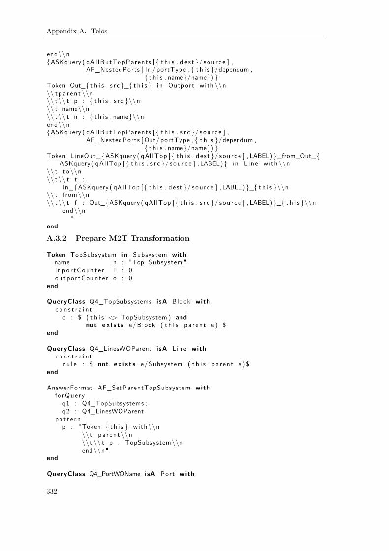
Appendix A. Telos
end\\n{ASKquery ( qAl lButTopParents [ { t h i s . d e s t }/ sou r c e ] ,
AF_NestedPorts [ I n / portType , { t h i s }/dependum ,{ t h i s . name}/name ] ) }
Token Out_{ t h i s . s r c }_{ t h i s } i n Outport w i th \\n\\ t p a r e n t \\n\\ t \\ t p : { t h i s . s r c }\\n\\ t name\\n\\ t \\ t n : { t h i s . name}\\nend\\n{ASKquery ( qAl lButTopParents [ { t h i s . s r c }/ sou r c e ] ,
AF_NestedPorts [ Out/portType , { t h i s }/dependum ,{ t h i s . name}/name ] ) }
Token LineOut_{ASKquery ( qAl lTop [ { t h i s . d e s t }/ sou r c e ] , LABEL) }_from_Out_{ASKquery ( qAl lTop [ { t h i s . s r c }/ sou r c e ] , LABEL) } i n L ine wi th \\n
\\ t to \\n\\ t \\ t t :
In_{ASKquery ( qAl lTop [ { t h i s . d e s t }/ sou r c e ] , LABEL) }_{ t h i s }\\n\\ t from\\n\\ t \\ t f : Out_{ASKquery ( qAl lTop [ { t h i s . s r c }/ sou r c e ] , LABEL) }_{ t h i s }\\n
end\\n"
end
A.3.2 Prepare M2T Transformation
Token TopSubsystem i n Subsystem withname n : "Top Subsystem "i npo r tCoun t e r i : 0ou tpo r tCoun t e r o : 0
end
QueryClass Q4_TopSubsystems isA Block withc o n s t r a i n t
c : $ ( t h i s <> TopSubsystem ) andnot e x i s t s e/Block ( t h i s pa r en t e ) $
end
QueryClass Q4_LinesWOParent isA L ine withc o n s t r a i n t
r u l e : $ not e x i s t s e/Subsystem ( t h i s pa r en t e ) $end
AnswerFormat AF_SetParentTopSubsystem withf o rQue ry
q1 : Q4_TopSubsystems ;q2 : Q4_LinesWOParent
p a t t e r np : "Token { t h i s } w i th \\n
\\ t pa r en t \\n\\ t \\ t p : TopSubsystem\\nend\\n"
end
QueryClass Q4_PortWOName isA Port with
332

A.3. Transformation from i* to Matlab/Simulink
r e t r i e v e d _ a t t r i b u t enumber : I n t e g e r
c o n s t r a i n tr u l e : $ not e x i s t s s / S t r i n g ( t h i s name s ) $
end
AnswerFormat AF_SetName4Ports withf o rQue ry
q : Q4_PortWONamepa t t e r n
pt : "Token { t h i s } w i th \\n\\ t name\\n\\ t \\ t n :
{QT({ IFTHENELSE({ASKquery ( ISINSTANCE [{ t h i s }/ obj , I n p o r t / c l a s s ] , LABEL)} , In , Out ) }{ t h i s . number }) }\\n
end\\n"end
A.3.3 Complete M2T Transformation
View Q5_Simulink_M2T_Transformation isA Subsystem withi n h e r i t e d _ a t t r i b u t e
name : S t r i n g ;c h i l d r e n : Block ;l i n e : L i n e
c o n s t r a i n tc : $ ( t h i s = TopSubsystem ) $
end
AnswerFormat AF_TopLevel2XML withf o rQue ry
q : Q5_Simulink_M2T_Transformationhead
h : "<Simu l ink >\\n
<Model>\\n<Name>" ; { cu r r en tmodu l e}" ;</Name>\\n
"p a t t e r n
p : "<System>\\n\\ t <Name>" ; {UQ({ t h i s . name})}" ;</Name>\\n{ Foreach ( ({ t h i s . c h i l d r e n }) , ( c ) ,
<Block >\\n{ASKquery ({ ASKquery ( Ch i ldType [ { c }/ c ] , LABEL) } [{ c }/ ob j ] , { ASKquery (
AF_ChildType [ { c }/ c ] , LABEL) }) }</Block >\\n ) }
{ Foreach ( ({ t h i s . l i n e }) , ( l ) ,<Line >\\n
{ASKquery ( qL ine [ { l }/ l ] , AF_Line2XML) }</Line >\\n ) }
</System>\\n"
t a i lt : "
333
Appendix A. Telos
</Model>\\n</S imu l ink >\\n
"end
View qSubsystem2XML isA Subsystem withparamete r
ob j : Blocki n h e r i t e d _ a t t r i b u t e
name : S t r i n g ;i n po r tCoun t e r : I n t e g e r ;ou tpo r tCoun t e r : I n t e g e r ;c h i l d r e n : Block ;l i n e : L i n e
c o n s t r a i n tcon : $ (~ ob j = t h i s ) $
end
AnswerFormat AF_Subsystem2XML withpa t t e r n
p : "<BlockType>SubSystem</BlockType>\\n<Name>" ; {UQ({ t h i s . name})}" ;</Name>\\n<Ports >[{ t h i s . i n po r tCoun t e r } , { t h i s . ou tpo r tCoun te r }]</Ports >\\n<System>\\n
<Name>" ; {UQ({ t h i s . name})}" ;</Name>\\n{ Foreach ( ({ t h i s . c h i l d r e n }) , ( c ) ,
<Block >\\n{ASKquery ({ ASKquery ( Ch i ldType [ { c }/ c ] , LABEL) } [{ c }/ ob j ] , { ASKquery (
AF_ChildType [ { c }/ c ] , LABEL) }) }</Block >\\n ) }
{ Foreach ( ({ t h i s . l i n e }) , ( l ) ,<Line >\\n
{ASKquery ( qL ine [ { l }/ l ] , AF_Line2XML) }</Line >\\n ) }
</System>\\n"
end
View qConstant2XML isA Constant withparamete r
ob j : Blocki n h e r i t e d _ a t t r i b u t e
name : S t r i n gc o n s t r a i n t
con : $ (~ ob j = t h i s ) $end
AnswerFormat AF_Constant2XML withpa t t e r n
p : "<BlockType>Constant </BlockType>\\n<Name>" ; {UQ({ t h i s . name})}" ;</Name>\\n
"
334

A.3. Transformation from i* to Matlab/Simulink
end
View qPort2XML isA Port withparamete r
ob j : Blocki n h e r i t e d _ a t t r i b u t e
name : S t r i n g ;number : I n t e g e r
c o n s t r a i n tcon : $ (~ ob j = t h i s ) $
end
AnswerFormat AF_Inport2XML withpa t t e r n
pt : "<BlockType>Inpo r t </BlockType>\\n<Name>" ; IN {UQ({ t h i s . name})}" ;</Name>\\n<Port>" ; { t h i s . number}" ;</Port >\\n
"end
AnswerFormat AF_Outport2XML withpa t t e r n
p : "<BlockType>Outport</BlockType>\\n<Name>" ;OUT {UQ({ t h i s . name})}" ;</Name>\\n<Port>" ; { t h i s . number}" ;</Port >\\n
"end
View qReference2XML isA Re f e r enc e withparamete r
ob j : Blocki n h e r i t e d _ a t t r i b u t e
name : S t r i n g ;i n po r tCoun t e r : I n t e g e r ;ou tpo r tCoun t e r : I n t e g e r ;s ou r c eB l o ck : S t r i n g ;s ou r c eTa rge t : S t r i n g ;d i s p l a y s t r i n g w i t h t a g s : S t r i n g
c o n s t r a i n tcon : $ (~ ob j = t h i s ) $
end
AnswerFormat AF_Reference2XML withpa t t e r n
p : "<BlockType>Refe rence </BlockType>\\n<Name>" ; {UQ({ t h i s . name})}" ;</Name>\\n<Ports >[{ t h i s . i n po r tCoun t e r } , { t h i s . ou tpo r tCoun te r }]</Ports >\\n<SourceBlock>" ; {UQ({ t h i s . s ou r c eB l o ck })}" ;</SourceBlock >\\n<SourceType>" ; {UQ({ t h i s . s ou r c eTa rge t })}" ;</SourceType>\\n{IFTHENELSE({ASKquery ( ISINSTANCE [{ t h i s }/ obj , Mode l I n fo rmat i on / c l a s s ] ,
LABEL)},<Di sp l aySt r i ngWi thTags>
335
Appendix A. Telos
" ; {UQ({ t h i s . d i s p l a y s t r i n g w i t h t a g s })}" ;</Di sp l aySt r i ngWi thTags >\\n<MaskDi sp l aySt r i ng>
" ; {UQ({ t h i s . d i s p l a y s t r i n g w i t h t a g s })}" ;</MaskD i sp l aySt r i ng >\\n , \ 0 ) }
"end
View qSFunction2XML isA SFunct ion withparamete r
ob j : Blocki n h e r i t e d _ a t t r i b u t e
name : S t r i n g ;i n po r tCoun t e r : I n t e g e r ;ou tpo r tCoun t e r : I n t e g e r ;funct ionName : S t r i n g ;funct ionMask : S t r i n g
c o n s t r a i n tcon : $ (~ ob j = t h i s ) $
end
AnswerFormat AF_SFunction2XML withpa t t e r n
p : "<BlockType>" ; S−Funct i on" ;</BlockType>\\n<Name>" ; {UQ({ t h i s . name})}" ;</Name>\\n<Ports >[{ t h i s . i n po r tCoun t e r } , { t h i s . ou tpo r tCoun te r }]</Ports >\\n<FunctionName>" ; {UQ({ t h i s . funct ionName })}" ;</FunctionName>\\n<MaskDisplay>" ; {UQ({ t h i s . funct ionMask })}" ;</MaskDisplay >\\n
"end
GenericQueryClass Chi ldType isA QueryClass withparamete r c : Blockc o n s t r a i n t
r : $ ( ( c i n Subsystem ) and ( t h i s = qSubsystem2XML ) ) or( ( c i n Port ) and ( t h i s = qPort2XML) ) or( ( c i n SFunct ion ) and ( t h i s = qSFunction2XML ) ) or( ( c i n Re f e r enc e ) and ( t h i s = qReference2XML ) ) or( ( c i n Constant ) and ( t h i s = qConstant2XML ) ) $
end
GenericQueryClass AF_ChildType isA AnswerFormat withparamete r c : Blockc o n s t r a i n t
r : $ ( ( c i n Subsystem ) and ( t h i s = AF_Subsystem2XML) ) or( ( c i n I n p o r t ) and ( t h i s = AF_Inport2XML ) ) or( ( c i n Outport ) and ( t h i s = AF_Outport2XML) ) or( ( c i n SFunct ion ) and ( t h i s = AF_SFunction2XML ) ) or( ( c i n Re f e r enc e ) and ( t h i s = AF_Reference2XML ) ) or( ( c i n Constant ) and ( t h i s = AF_Constant2XML ) ) $
end
GenericQueryClass qL ine isA L ine with
336

A.3. Transformation from i* to Matlab/Simulink
paramete r l : L i n er e t r i e v e d _ a t t r i b u t e
from : Port ;to : Port ;pa r en t : Subsystem
c o n s t r a i n tc : $ ( t h i s = ~ l ) $
end
AnswerFormat AF_Line2XML withf o rQue ry q : qL inep a t t e r n
p : "{ASKquery ( qPort [ { t h i s . from}/p ] ,
AF_Port2XML [{ t h i s . pa r en t }/ lp , Src / type ] ) }\\n{ Foreach ( ({ t h i s . to }) , ( t ) ,
<Branch>\\n{ASKquery ( qPort [ { t }/p ] ,
AF_Port2XML [{ t h i s . pa r en t }/ lp , Dst/ type ] ) }\\n</Branch>)}\\n
"end
View qPort isA Port withcomputed_at t r ibute , paramete r
p : Portcomputed_at t r i bu te
pname : S t r i n gi n h e r i t e d _ a t t r i b u t e
name : S t r i n g ;pa r en t : Block ;number : I n t e g e r
c o n s t r a i n tc : $ (~ t h i s = ~p ) and e x i s t s par /Block
( t h i s pa r en t par ) and ( par name ~pname ) $end
AnswerFormat AF_Port2XML withf o rQue ry q : qPortp a t t e r n
p : "<{type }Block>
" ; { IFTHENELSE({EQUAL({ Labe l ({ l p }) } ,{ Labe l ({ t h i s . pa r en t }) }) } ,{IFTHENELSE({ASKquery ( ISINSTANCE [{ t h i s }/ obj , I n p o r t / c l a s s ] , LABEL) } ,IN ,OUT) } {UQ({ t h i s . name}) } ,{UQ({ t h i s . pname}) })}" ;
</{type }Block >\\n<{type }Port>
{IFTHENELSE({EQUAL({ Labe l ({ l p }) } ,{ Labe l ({ t h i s . pa r en t }) }) } ,1 ,{ t h i s .number }) }
</{type }Port >\\n"
end
337

C.V.Personal Data
Name Dominik Schmitz
Date of Birth 14.10.1976
Place of Birth Cologne, Germany
Qualifications
1987–1996 Gymnasium Liebfrauenschule Köln, Cologne, GermanyDegree: Abitur
1997–2003 Study of Computer Science (dt. Informatik)RWTH Aachen University, GermanyDegree: Diplom-Informatiker
2003–2006 Ph.D. student in the Graduate School 643“Software for mobile communication systems”RWTH Aachen University, Germany
2006–2009 Research assistantFraunhofer FIT, Sankt Augustin, Germany
Since 2009 Research assistantChair of Information SystemsRWTH Aachen University, Germany