lower and upper shakedown bounds for fatigue limit in two phase materials
TRANSCRIPT

International Journal of Fracture 119: 65-81, 2003. �9 2003 Kluwer Academic Publishers. Printed in the Netherlands.
Lower and upper shakedown bounds for fatigue limit in two phase materials
J. T I R O S H and S. PELES Faculty of mechanical engineering, Technion, Haifa, Israel
Received 9 July 2002, accepted in revised form 24 February 2003
Abstract, The goal of this study is to find the 'safe' long term behavior of elasto-plastic structural materials sub- jected to fluctuating load (shortly 'fatigue limit'). The materials whose fatigue limits are checked are: (a) materials reinforced with unidirectional stiff fibers; (b) materials with dilute amount of inclusions; (c) materials with minute porosity. To reach this goal we employ two different shakedown theorems: Melan's static shakedown theorem (1936) as the lower bound and Koiter's kinematic shakedown theorem (1960) as the upper bound. The solutions to the lower and upper bounds for the prescribed stress amplitude, (A~th) l'b" and (ACrth) u'b', are expressed in a rigorous form with three parametric entities: (i) the volume fraction of the second phase in the base matrix phase, f, (ii) the quality of the 'bond' between the two phases 'm', (iii) the magnitude of the residual stress, 'p', pre-existed in the material. The deviation between the two bounds represents the 'uncertainty' in our knowledge of the actual safe/unsafe state, where the materials fail to withstand the alternating load. It is shown that in the considered three types of materials, at certain amount of residual stresses, the safe load amplitudes based on shakedown analysis are indeed higher than their corresponding elastic limits (at least by 5%, 10% and 25% respectively). The apparent advantage of using shakedown bounds to predict the safe/unsafe loading amplitude is that no prior information on the actual complex failure mechanisms is required and no empiricism is needed. However, empirical data which were found in the open literature are 'falling' satisfactorily between the computed dual bounds.
Key words: Shakedown theorems, fatigue limit, dual bounds, upper bound, lower bound, fibrous materials, porous materials, inclusions.
1. In troduct ion
Materials which are composed of two (or more) phases (like fiber reinforced composi te , porous materials, etc.) can be regarded as structural materials. When such structures are subjected to fluctuating load, the different phases interact and consequently affect the overall structural response. The interaction between the phases (heavily related to the manufactur ing
process) may accelerate or postponed the growth of structural damages , a matter which will be considered here. A damage is defined here as an accumulat ion of plastic strain, in particular at highly stressed areas in the material. It may eventually leads to failure by disintegration of the structure (which is a ' fatigue unsafe s tate ' ) or else, to sustain the load variation between prescribe limits for infinite number of cycles (which is a ' fat igue safe state ') . The critical stress ampli tude which distinguishes between fat igue-unsafe and fat igue-sate conditions is called ' fat igue threshold ampli tude ' or ' fat igue l imit ' . The a im of this study is to utilize the shakedown theorems to formulate bounds to fatigue threshold ampli tudes in terms of tile volume fraction of the second phase, with an indirect link (via the residual stresses) to the manufacturing process of the structure.
In the sequel we will describe briefly the lower bound and the upper bound o f the stress amplitude, ( A a t h ) t b and ( A a # y b , to two known cases o f dilute second phase material in
66 J. Tirosh and S. Peles
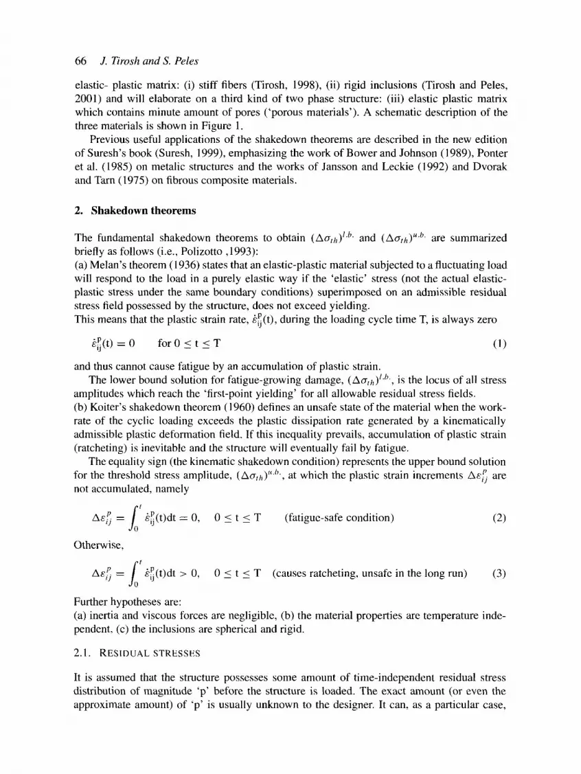
elastic- plastic matrix: (i) stiff fibers (Tirosh, 1998), (ii) rigid inclusions (Tirosh and Peles, 2001) and will elaborate on a third kind of two phase structure: (iii) elastic plastic matrix which contains minute amount of pores ('porous materials'). A schematic description of the three materials is shown in Figure 1.
Previous useful applications of the shakedown theorems are described in the new edition of Suresh's book (Suresh, 1999), emphasizing the work of Bower and Johnson (1989), Ponter et al. (1985) on metalic structures and the works of Jansson and Leckie (1992) and Dvorak and Tarn (1975) on fibrous composite materials.
2. Shakedown theorems
The fundamental shakedown theorems to obtain (Aath) lb and (AtTth) u'b" are summarized briefly as follows (i.e., Polizotto, 1993): (a) Melan's theorem (1936) states that an elastic-plastic material subjected to a fluctuating load will respond to the load in a purely elastic way if the 'elastic' stress (not the actual elastic- plastic stress under the same boundary conditions) superimposed on an admissible residual stress field possessed by the structure, does not exceed yielding. This means that the plastic strain rate, kP(t), during the loading cycle time T, is always zero
kP(t) = 0 for 0 < t < Y (1)
and thus cannot cause fatigue by an accumulation of plastic strain. The lower bound solution for fatigue-growing damage, (Aath)/'b', is the locus of all stress
amplitudes which reach the 'first-point yielding' for all allowable residual stress fields. (b) Koiter's shakedown theorem (1960) defines an unsafe state of the material when the work- rate of the cyclic loading exceeds the plastic dissipation rate generated by a kinematically admissible plastic deformation field. If this inequality prevails, accumulation of plastic strain (ratcheting) is inevitable and the structure will eventually fail by fatigue.
The equality sign (the kinematic shakedown condition) represents the upper bound solution for the threshold stress amplitude, (Aath) "'b', at which the plastic strain increments Ae/~ are not accumulated, namely
1' Ae~ = kP(t)dt = 0, 0 < t < T (fatigue-safe condition) (2)
Otherwise,
f' Ae~. = ~P(t)dt > 0, 0 < t < T (causes ratcheting, unsafe in the long run) (3)
Further hypotheses are: (a) inertia and viscous forces are negligible, (b) the material properties are temperature inde- pendent, (c) the inclusions are spherical and rigid.
2.1. RESIDUAL STRESSES
It is assumed that the structure possesses some amount of time-independent residual stress distribution of magnitude 'p' before the structure is loaded. The exact amount (or even the approximate amount) of 'p' is usually unknown to the designer. It can, as a particular case,

L o w e r and upper shakedown bounds 67
be zero, as is otherwise presumed by structural designers, but it leads to a more conservative design in regard to prevention of fatigue failure, as will be shown.
The Melan's shakedown theorem (1936) 'allows' to assume any admissible background stress field (shortly- residual stress) to reside in the material but nowhere to cause yielding. If exists, it tends to redistribute the overall stresses in the solid such as to postpone early yielding (proved by Melan, ibid.).
From a physical view-point the residual stress can be produced, for example, by the thermal mismatch of the two material phases (during, say, their manufacturing process or else). Thus, the magnitude of the residual stress 'p' is a computable value if the thermal history can be traced (i.e., Wietzman, 1979). However, to maintain generality in the forthcoming analysis the magnitude of p is neither assumed nor computed, but stays throughout the analysis as an independent variable.
3. Melan's static shakedown solution (the lower bound)
The outcome of Melan's theorem is that the structure subjected to cyclic loading will shake down if the sum of the two stress distributions (the residual stress and the applied stress), ey(res) i/ + ~ri~ ) (t), does not exceed plastic yielding anywhere. It reads
F+ (,'es) tcr 0 + aiT)(t)) < CYo in V, for any time t, 0 < t < T, (4)
where F ( . . . ) is any applicable yield function in the volume V of the material. Let us define, for convenience, the instantaneous sum of the elastic stress and the residual
s t r e s s a s
r (e)(t _(re~') ij ~t) ~-" Grij ,..) + o i j 0 < t < T . ( 5 )
Now, if we choose F ( . . . ) to be presented by von-Mises yield criterion (written here in spherical coordinates), the equality sign in (4) produces the shakedown lower bound condition a s ;
1 [(_(sum) _(sum)x2 + (sum) (sum)j2 (<T(sum) (sum) 2 F = ~ , u r r --Oo o I + t a o o --erie , +,_++ --or,.,. ) ]
(6) +3_(sum)z
.L,. 0 = a<~
The presentation of (6) for fibrous composite and for materials with inclusion will be given briefly in the following sections. For porous material the classical yon Mises yield criterion is replaced by a more suitable one akin to pressure dependent materials. We chose the Gurson's yield criterion (Gurson, 1977). It reads
..(sum) ^(sum) (7 (sum) (3/2)~ij aij + 2q~ f cosh(q2 kk -- [1 + q3f2], (7)
O~c 2 O- o
where the deviatoric stress in (7) is
(sum) _(s~,m) 1 ~ (sum) Sij -~- Oij ~ -~Oij(Ykk �9
The parameter f is the porosity content defined as the volume fraction of the voids in the matrix. The scalars [q~, q2 and q3] in (7) are chosen as [1.5, 1.1 and 2.25], respectively, suggested by Tveregard (1981, 1982a, b) in order to match more closely experimental data.
68 J. Tirosh and S. Peles
3.1. A P P L I C A T I O N S OF M E L A N ' S STATIC L O W E R B O U N D
In order to utilize Melan's theorem the exact elastic stress field of the considered problem (assuming an infinite yield strength rather than an actual elasto-plastic field) needs to be solved first. It is solved as if the structure does not yield under the same loading and geometry. Such solutions are already given in classical papers for a single fiber (Muskhelishvily, 1963), rigid inclusion (Goodier, 1933) and a spherical pore (Southwell and Gough, 1926) and will not be repeated here.
3.1.1. Case 1: Lower bound for fatigue threshold of fibrous composite Since the composite is in plane strain situation, one gets the out-of-plane stress component as a function of the in-plane stresses which simplifies (6). The input stresses for the yield function (6) are given in Muskhelishvily (1963). The outcome is (Tirosh, 1998)
o2 2p)p_2 ~-~{[(y - + (I - D) cos(20)] 2 + [(1 + D) sin(20)] 2} = 1, (8) O 0 0-oo
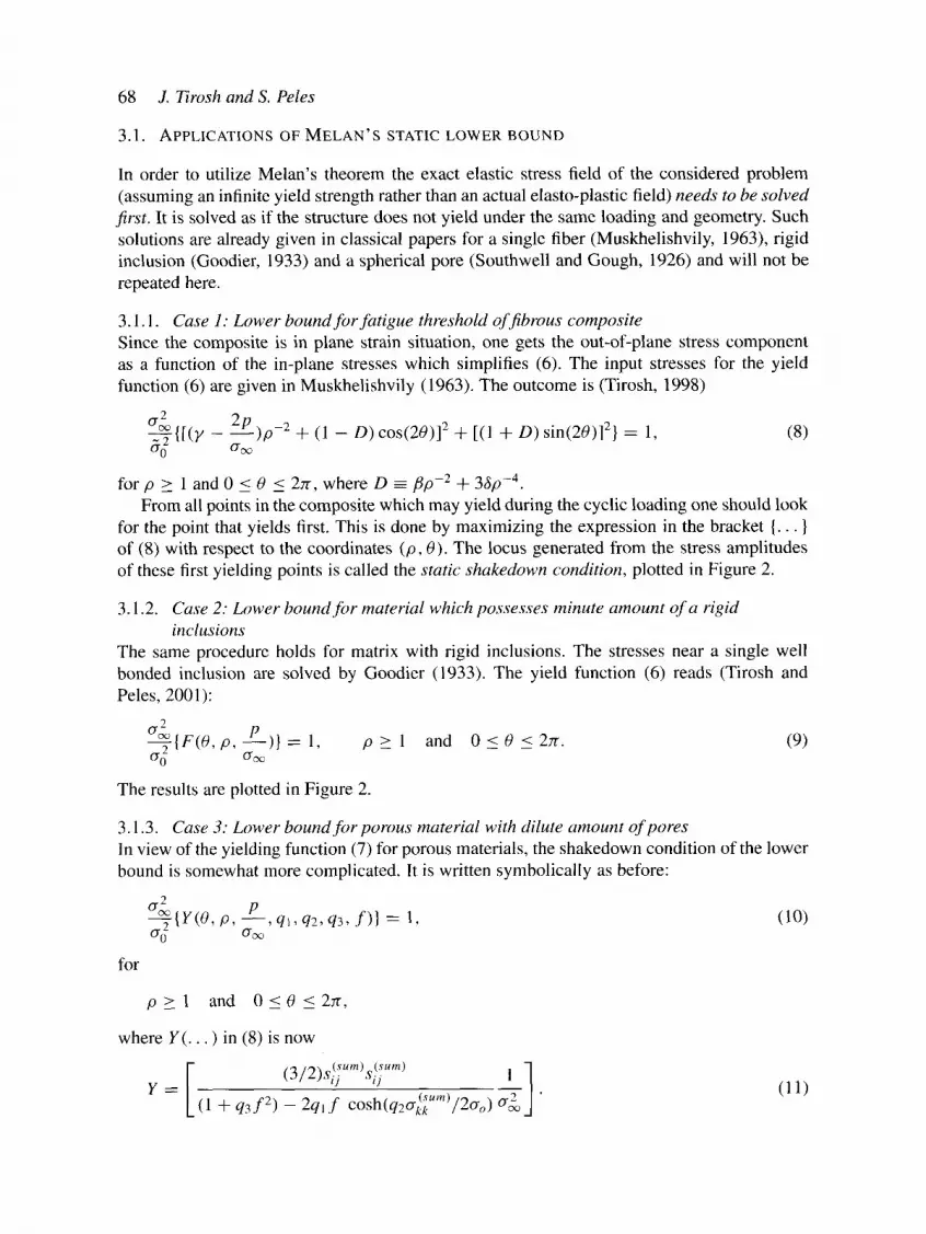
for p > 1 and 0 < 0 < 2Jr, where D --/~p-2 + 3~p-4. From all points in the composite which may yield during the cyclic loading one should look
for the point that yields first. This is done by maximizing the expression in the bracket {... } of (8) with respect to the coordinates (p, 0). The locus generated from the stress amplitudes of these first yielding points is called the static shakedown condition, plotted in Figure 2.
3. i.2. Case 2: Lower bound for material which possesses minute amount of a rigid inclusions
The same procedure holds for matrix with rigid inclusions. The stresses near a single well bonded inclusion are solved by Goodier (1933). The yield function (6) reads (Tirosh and Peles, 2001):
2 p ~ { F ( 0 , p, ) } = 1, p > 1 and 0 < 0 <2zr. (9) 0 -2 O '~ --
The results are plotted in Figure 2.
3.1.3. Case 3: Lower bound for porous material with dilute amount of pores In view of the yielding function (7) for porous materials, the shakedown condition of the lower bound is somewhat more complicated. It is written symbolically as before:
{Y(O, p, - - , q l , q2, q3, f)} ---- 1, (10) O'cx )
for
p > 1 and 0 < 0 <2r r ,
where Y(. . . ) in (8) is now
t .)/ )Sij Sij l
Y = (1 + q3f 2) - 2ql f cosh(q2cr22"m)/20-o) " (11)

~D
r ~
Aa~
Lower and upper shakedown bounds 69
�9 T [time]
(c) Pore (r, 0, (p) (b) Rigid inclusion (r, 0, (p) (a) Fiber (r,O,z))
j
Ao"
Acr~
l l Ao-~
Ao'~
Z
X
Figure la, b, c. Schematic view of an elastic-plastic materials under cyclic loading in three cases: Materials with unidirectional rigid fibers, materials with minute amount of inclusions, and dilute porous materials.
~(sum) is structured by the solution of the elastic stresses near a spherical pore The function ~ij solved by Southwell and Gough (1926) and Rice and Tracey (1969).
As stated previously, by maximizing the expression in the above bracket with respect to the coordinates (p, 0) one finds the locus of the 'first yielding point' for all allowable values of the residual stress magnitude 'p'. The outcome appears as an ellipse-like curve shown in

70 J. Tirosh and S. Peles
Materials with inclusions
J
(~ sigma4
0.2
O" a
Fibrous composite
-13.2
Porous material
0 . 5 , ao
I! Y
Figure 2~ The lower bound [Melan's shakedown theoreml for threshold of fatigue limit for the three materials: Materials with unidirectional fibers, materials with minute amount of inclusions, and dilute porous materials. Inside the closed curves the cyclic load is fatigue-safe. The "elastic limit" is recognizable as the stress at zero residual stress (p=0). It is lower than the shakedown limit in all three considered cases by about 5%, I0% and 25%, respectively,
Figure 2. In all three case above, the fatigue-safe domain lies in the ctostlre of the ellipse. The boundary of the ellipse is called the "static shakedown condition'.
4. Koiter's kinematic shakedown theorem (the upper bound)
Koiter (1960) proved that a structure will shakedown under cyclic loading if the rate of plastic dissipation (and the associated frictional loss) exceeds the sum of the work rates due to the applied traction and the internal body force Xi. This inequality takes the form
> uids , (12) [ J V f ors T
where the summation convention for repeated indices has been employed, The vector u~ is the velocity field of the plastic flow. JAu[ is the relative slippage of the material flow on the surface sf of the second phase. Ti(t) is the fluctuating traction on portion ST of the remote surface, S.
The first term (on the left side) represents the strain energy rate loss during the plastic flow. The second term is the energy rate loss due to frictional shear, r f, acting along the interfaces with the second phase with a relative slip of IAu t- The magnitude of the shear stress is considered to be a fraction (denoted by 'm') of the yield stress in shear (k), say
rf ----- mk (0 < m < t) (13)

Lower and upper shakedown bounds 71
The value of 'm' is used here to assess the 'bonding' quality of the second phase to its surrounding material. It spans from free slip (m=0) to well-bonded contact ( re=l) . The first term on the right hand side is the work rate due to the body force in the material volume V. In our case the 'body force' is the residual stress distribution formulated beforehand (see next paragraph). The last term is the work rate of the fluctuating prescribed traction.
4.1. BODY FORCE
The body force X i (force/volume) is the permanent residual stress field in the structure. When it is originated, for example, from the geometrical mismatch of the second phase, then it clearly not uniformly distributed. It is still calculable as the overall traction on an area s at a distance p from the center of the second phase, normalized by the volume of the second phase (of radius/9o). That is
f~ _ ( res ) l ^', o i j t D ) n.jds
X i ( p ) = (source volume) (nj = an outward unit normal to s). (14)
Using admissible residual stress distribution in the integrand of (14) one gets: (i) The body force components in fibrous composite material (Tirosh, 1998):
X r = 2 p Xo = - 2 p--p-- (p > 1) (15) pro ' pro
(ii) The body force components for materials with inclusions (Tirosh and Peles, 2001):
p 3 p 3 p Xr = 3 , XO = - - - - , X~0-- (/9 > 1) (16)
pro 2 pro 2 pro -
(iii) The body force components for materials with pores (Peles, 2001):
:2) X ~ = - - 3 P 1 1 , X o - - + , X, t , - + (p>_ 1) ro ro 2 ro
(17)
By considering (12) it is seen that the first term on the left-hand side represents the plastic dis- sipation rate in the deformable volume V of the non-hardening material. For porous materials that obey Gurson's yield function, this dissipation is altered to be (Shirizly et al., 2000)
"W = L o'ij,~ijdV = L (sij~,ij--1-(l/3)Okk,~ii ) dV, (18)
where the last term denotes the dilatational work rate. The outcome expression for the first term reads
L sij'~ijdV = 2k~ L (1 + q3f2 -- 2qlf cosh(q2crm)) ~ 2 d g (19)
~/1 + q3f e - 2q~f cosh(q2am) + (fqlq2/v/2) 2 sinh2(q2Crm)
and the expression for the second term is
f v amqJ qzf sinh(qzcrm)~2 dV. (1/3)Crkk~iidV 2ko (20) V/1 + q3f 2 - 2 q l fcosh(qzo'm) Jr- (fqlq2/~/'2) 2 sinh2(qzO'm)

72 J. Tirosh and S. Peles
5. Kinematically admissible velocity fields
In order to compute the overall plastic dissipation in the deformable structure one needs to assume a kinematically admissible flow field in the vicinity of the second phase. This is a fundamental issue in Koiter's shakedown theorem which comprises, generally, relatively heavy mathematical procedures. For brevity we will give here only the scalar functions from which the velocity field and the associated strain rate are derived. They are either the stream function, f , ( . . . ), or its velocity-potential conjugate ~b(... ). For the procedures by which the functions are structured one should consult Peles (2001). Case (i): The stream function which was found to describe the kinematics of the flow near a single fiber (Tirosh, 1998) is
~p(r, 0, t ) = 1" (t)r2 ( p 2 ~ 2 ) sin(20), 0 < t < T (21) 7 ,900
r p = , p > 1, 0 < 0 < 2 7 r ,
ro
where k~(t) is the remote strain rate, in phase with the fluctuating load. The velocity field which resulting from (2 l) is, by definition,
a~ ag, 1 J r - rO0' u o - Jr (22)
hence
ur(r, 0, t) = - k ~ ( t ) r o p - cos(20)
(23) u0(r, 0, t) = e~(t)ro p + sin(20).
I The associated strain rate components (using kij = 7 (uij + uj,i)) is therefore
kr -- OUr - - k ~ ( t ) 1 + cos(20) Or
r 00 + - r = k~(t) 1 + cos(20) (24)
l(0u0 u0 ( ) ) = + - = k~(t) 1 - sin(20).
kr0 ~ Or r r O0 ,/
Case (ii): The velocity potential function which describes the plastic flow near a single inclu- sion was found to be (Tirosh and Peles, 2001):
4~ (r, 0, t) = ~ p2 1
for
p > l , 0 < 0 < 2 7 r , 0 < t < T .
As above, the symbol [kz(t)]~ in (25) stands for the remote strain-rate amplitude and will be abbreviated further on as k.
The velocity field ui (r, O) is derived from (25) by the relations
Lower and upper shakedown bounds
Oq~ 10~b u r - - Or u o - - r 0 0
and found to be;
' ( _ ' ) Ur(r, 0, t) = ~kro p - ~-g (3cos2(0) - 1),
u0(r, 0, t) = -3kro ~p + cos(0) sin(0).
1 The associated strain rate components, (using ~ij = ~(Ui,j q- U j , i ) ) yield
- kr~ OUr __ 1 b 1 + (3 COS2(0) - - 1) Or 2
1 0u0 ur 1 { 3 cos2 (0 ) '~ boo -- + - - - - k - 2 + 3 c o s 2 ( 0 ) - - - - 7 + � 9 ---x l
08 r 2 r p~ p~ /
u r cot(0) l ( c o s 2 ( 0 ) l ) sr = - - + u 0 - - - - r r ~k 1 + 5 - ~ p5
1 (0__U_U0 u0 10Ur ] 1 ( P : 8 ) �9 = + = -kcos (0 ) sin(0) - 3 + --x �9 '~r0 2 \ Or r r 00 J 2
73
(26)
(27)
(28)
Case (iii): The plastic flow around a traction-free single pore was suggested by Rice and Tracey (1969) employing two free parameters D and E according to
fii = fiu.c. + D �9 rid + E . l[le, (29)
where fib.~, is a velocity field resulting in a uniform strain rate field @ij)oo, so as to meet remote boundary conditions; rio is a spherically symmetric velocity field corresponding to a change in the volume of the void, but no change in shape; fis is a velocity field, decaying at remote distances, which changes the void shape but not its volume.
By a proper variational procedure, Rice and Tracey (1969) concluded (and later used by Gurson (1977)) that in such a case
D ---- 0.283e 3~'~/2~'' (30)
E ~ -0 .00087 �9 D 3 + 0.0066 �9 0 2 -t- 0.052 �9 D + 0.496. (31)
Based on the admissible velocity field (30) and (31) one can formulate, for convenience, the scalar stream function 7t(r, 0, t) as
1 E r3o kcos(0) + - 4 E - p3 ro3kCOS(30) (32) ~ = g P 3 - a D + 4 E - 3 p - 2 ~ p-~
and the associated velocity components by:
1 07t 1 0~p (33) U 0 ~ , U r - -
r s in0 Or r 2 s in0 00

74 J. Tirosh and S. Peles
So that
(3 3 ; ~9~) (~-~2 ~ p Ur = ~p + rokCOS(20) + + +
and
1 -3/9 - rok sin(20). u0 = ~ ~-7
The associated strain rate components are
8rr
~
p2 4
OUr - ~r -- (9p~5 - 6 E - 75 + ~ ) k cos(20) + (~ - 2Dp3 + 3 E~-g - 2 E~---~) i"
1Ou0 U r (3~33 2 1 E 3 ) (~33 1 D 3~5 ) 500 -- r O0 + --r = 4 /)5 ~ cos(20) + + ~ -I- /93 4
u r cot(0) ( 3 6pEs) �9 = - - + u0 - -- k cot(0) sin(20) (35)
(3 3E3 9 E ) (~33 1 D 3 pE__~.~ ) + + - - 4 p5 kcos(20) + + 4 + p3 4 k
3 sin(20)(8 E E ) = 4 7 - 4 7 - l '
1 (0U0 00 1 0Ur'~ ~r0 : ~ ~ Or r + r ~ }
where p = r/ro.
6 . L o w e r a n d u p p e r b o u n d s
Now, that all the terms in (12) are defined and expressed, one uses the equality sign of (12) to generate the upper bound condition for the fatigue threshold stress amplitude. The end results are:
6.1. MATERIALS WITH MINUTE UNIDIRECTIONAL FIBERS
The final expression for the upper bound of the fatigue threshold stress amplitudes in terms of the fibers volume fraction 'f' and the bonding quality 'm' is shown in Figure 3a (Tirosh, 1998)
1cr~ ( l - f ) p 1 - f + 4mf - - - + - ( 3 6 ) 4 Cro zr 2 Cro zr v/-3
(0< f << 1), ( 0 < m < 1).
6.2. MATERIALS WITH DILUTE AMOUNT OF INCLUSIONS
The final expression for the upper bound of the fatigue threshold stress amplitudes in terms of the inclusion volume fraction 'f' and the bonding quality 'm' is shown in Figure 3b (Tirosh and Peles, 2001)
Lower and upper shakedown bounds 75
24 aoo 3 2~v/-3(1 -- f ) + 5 m f 4-5 a,--( + ~(1 - f ) P = (37)
ao 2.v/-3
for (0 < f < < 1), (0 < m < 1).
6.3. MATERIALS WITH DILUTE AMOUNT OF PORES
The expressions (19), (20) along with (34), (35) etc. could not render a closed form solution as in previous cases. The solutions were obtained numerically (see Figure 3c). The outcome carries similar trends to previous two-phase materials (i.e., straight: lines, w)lume fraction as a sole variable, etc.). For convenient comparison, the three cases together (at a common second phase fraction-volume of f = 0.01 ) is plotted in Figure 3d.
7. Onset of fatigue failure by crack propagation
It is most likely that random micro-flows exist in the structure (if not proved otherwise we can imagine that they exist). Such flows, if resided in a highly stressed zone, may be the first to grow when the prescribed stress amplitude reaches its critical (threshold) stress amplitude. This kind of 'stress dominated crack growth' is akin to 'short cracks' (flaws whose length are comparable to the size of the material grains). For 'long cracks' (flows whose length '2a" are longer than the size of the material grains) their growth may starts earlier (i.e., when Kx ~ Ktc) , since they are dominated by the stress intensity factor at their tip [recall that: KI = cree~"a , Cree < < 0"o].
The average grain size in most engineering metals (Steel, Aluminum, Copper, etc.) is a measurable quantity. However, to avoid this actual measurement it has been suggested, and checked by Peles (2001), that for several materials the grain size can be approximated by the maximum length of the plastic zone near a growing fatigue crack (Budiansky and Hutchinson, 1978):
l X2c ( 3 8 ) Rrp ~ 30 7rao 2
which is a simple computable parameter. In the present analysis, the threshold stress amplitude is assessed by the lower and upper
bounds, (ACrth) tb' and (Aath) u'b" for short cracks where a < R~p. When a = Rrp and onward, a > R,.p, the key parameter becomes Akli~ b" and Akth b'. They stay constant during the cracks growth with values that are determined at the point a = Rrp, namely
(Akth)l'b" ~. (Z~O'th) l'b" ~ - a at a = R~p. (39a)
(Akth)U'b' = (A O'th) tLb'.x/~a
From here on (as a > Rrp), the respective stress amplitudes (AO'th) l'b' and (ACrth) u'b" become the dependent variables of equation (39a), namely:
Zxk h u- ACrtkb'=- ~ k l ~ and AO't~ "b'= for a > Rrp. (39b) -
In order to relate (39a) and (39b) to numerous published Fatigue data (see a list of refer- ences in, i.e., Suresh, 1999) the actual semi-crack length at its initial growth, a, was needed. It was approximated via (40) as

76 J. Tirosh and S. Peles
A) Acr__ 0,1 cro 0.05 0.01
........... ~ _ . . . J " _ - . , / ' - - r
-O.4 -0.2 0
-1
0.2 0.4 P__ O" ~
Figure 3a. The upper bound solution for the fiber composite with volume fraction of f = 0.01, 0.05 and 0.1.
C ) AG=
0.01 cr o 0.05 0.1
-0.4 -0.2 0 0.2 0.4 Go
Figure 3c. The upper bound solution for the porous materials with volume fraction o f f = 0.01, 0.05 and 0.1.
B) Ao-~ 0 . I 0.05 G
f -0.6 -0 .4 -0 .2 02 0.4 0.6
P O" ~
Figure 3b. The upper bound solution for the material with rigid inclusions, with volume fraction of f = 0.01, 0.05 and 0. I.
D) �9 ~ C r
fibers composite ....... O"
Porous materials
I ..,__.__..__ , ~ 1 r ~ ,
-05 - 0 . 4 - 0 . 2 0 , 0 . 2 - 0 . 4 0 , 6
Materials with inclusions
P t3" o
Figure 3d. The upper bound solution for the three different cases (fiber, inclusion and porous material) all of which have volume fraction of f = 0.01.

Lower and upper shakedown bounds" 77
O )
, , - i
E t ~
101
100
10 ~
1 0 .2 10 -2
.,)l *
+
O
' 7
o
S20c ~J $20c Lc HT80 SM-50 SM-41 H P - S t e e l D o c o l 3 5 0 8 A 3 8 7 - 2 . 2 2 2 1 4 C r - l M o
10 -1 10 o Normal ized crack length
. . . . . . i . . . . . . . . i . . . . . . . .
Upper bound P = 0
V " ~ v ~ o 0 A ''"
Lower bound ~ 0
. . . . . . . i
101 a/Rrp
7 . . . . . . . i
102
101
10 0 " 0
Q .
E
I l l
co 10-1
i
i
10 -21 10 -2
+
0
L ~
~+
$ 2 0 c $ 2 0 c HT80 SM-50 SM-41 HP-Stee l Doco l350 8 A 3 8 7 - 2 . 2 2 2 1 4 C r - l M o
Upper bound p = 0.2o- 0
L o w e r b o u n d
. . . . . i . . . . . . . . i . . . . . . . . i . . . . . . . .
10 1 10 ~ 101 10 2 N o r m a l i z e d crack length aJRrp
Figure 4. The dual bounds for threshold stress amplitudes for metals with minute inclusions. The metals are presumed to contain no residual stress (p=0) for the top figure and p = 0.2~ro for the bottom figure. Experimental data are taken from Suresh and Ritchie (1984) and Stein and Huang (1995) where the actual residual stresses are not known.
1 ( Akth )2 a ~ ~ ~ . (40)
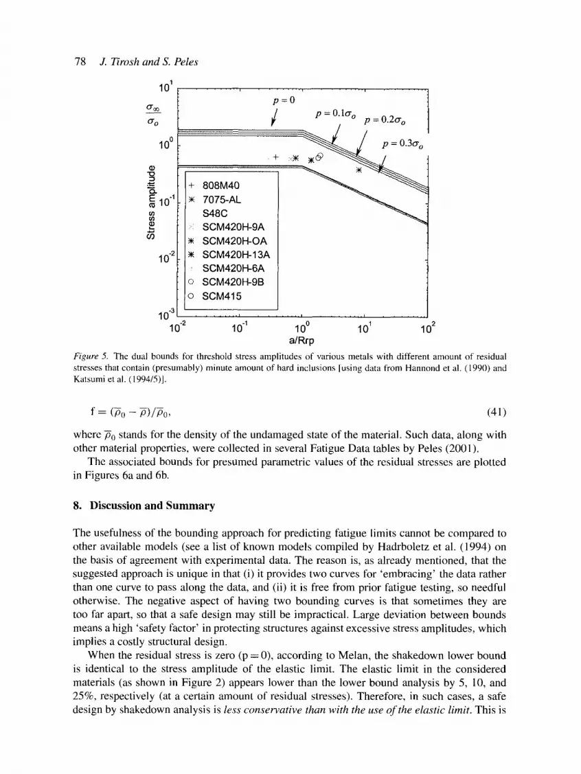
Representative data, plotted in Figures 4 and 5, are in agreement with the shakedown bounds. For materials with dilute amount of pores, one can assess the volume fraction of the pores,
f, as a measure of the material internal 'damage'. It is measured indirectly via the reduction in the material density, ~, using the following relation
78 J. Tirosh and S. Peles
101
o"o
100
"o
10 "I
ct)
10 -2
+
Y~
�9
�9
10 -3
808M40 7075-AL $48C SCM420H-9A SCM420H-OA SCM420H-13A SCM420H-6A SCM420H-9B SCM415
p=O
/ p = 0:lo- o p = 0.2o" 0
~ ~ ~ - ~ / P=0"3o-o
. . . . . . . . L . . . . . . . . I , , , , . . . . i . . . . . . . .
10 .2 10 "1 100 101 102 a/Rrp
Figure 5. The dual bounds for threshold stress amplitudes of various metals with different amount of residual stresses that contain (presumably) minute amount of hard inclusions [using data from Hannond et al. (1990) and Katsumi et al. (1994/5)].
f = (P0 - P)/P0, (41 )
where P0 stands for the density of the undamaged state of the material. Such data, along with other material properties, were collected in several Fatigue Data tables by Peles (2001).
The associated bounds for presumed parametric values of the residual stresses are plotted in Figures 6a and 6b.
8. D i s c u s s i o n a n d S u m m a r y
The usefulness of the bounding approach for predicting fatigue limits cannot be compared to other available models (see a list of known models compiled by Hadrboletz et al. (1994) on the basis of agreement with experimental data. The reason is, as already mentioned, that the suggested approach is unique in that (i) it provides two curves for 'embracing' the data rather than one curve to pass along the data, and (ii) it is free from prior fatigue testing, so needful otherwise. The negative aspect of having two bounding curves is that sometimes they are too far apart, so that a safe design may still be impractical. Large deviation between bounds means a high 'safety factor' in protecting structures against excessive stress amplitudes, which implies a costly structural design.
When the residual stress is zero (p = 0), according to Melan, the shakedown lower bound is identical to the stress amplitude of the elastic limit. The elastic limit in the considered materials (as shown in Figure 2) appears lower than the lower bound analysis by 5, 10, and 25%, respectively (at a certain amount of residual stresses). Therefore, in such cases, a safe design by shakedown analysis is less conservative than with the use of the elastic limit. This is

Lower and upper shakedown bounds 79
1
0.9
-8 = o.e .9, =
.. 0.7
~ 0 . 6 Ih
"~ 0.5 ffl
0.4 ._N
0 . 3
o z 0.2
0.1
I ~ fully plastic flow
•
�9 mN m u mm mam x
| mmm R mu | ~ k wmm m m �9 l~m m mmm �9 am m mm �9 ~ mmm �9 mmm �9 mmm| i
•
0.62 o. 4 0.66 0.68 Void volume fraction
0.1
1
0.9
0.8 "Io
~_ 0.7 E ~ 0 . 6
~ 0.5
N
~ 0.3: o z 0.2
0.1
I . - ~ fully plastic flow
�9 o
o 0.62 0.64 o.G6 o.68 o.1 Void volume fraction
Figure 6. The dual bounds for threshold stress amplitudes of various porous materials with different amount of residual stresses [using data from Sundrow et al, (1997)]. In the top figure the residual stress is p = 0.3or 0 and in the bottom figure it is p = 0.6~r 0. The upper bound plotted here is based on a smooth plastic flow around voids (rather than a flow with rigid zones as suggested by Gurson (1977) since it yields lower values for the upper bound.

80 J. Tirosh and S. Peles
not always guaranteed since, as is seen in Figure 2, excessive residual stress (say, beyond 25% of the yield stress in the materials with fibers or inclusions) can be detrimental by accelerating the fatigue process.
Admittedly, the solution of the lower and upper bounds given here, does not provide a new physical insight into the mechanics of fatigue processes. It can be considered just as a (nearly) rigorous technique for predicting a safe structural design. The closeness between bounds may reflect on the success of the solution solver. The solution depends on the ingenuity of the solver in choosing an appropriate admissible field for the residual stresses in order to maximize the lower bound, and an appropriate admissible velocity fields to minimize the upper bound.
As a matter of convenience, it is noted that the bounds are mostly computable functions without a need for a substantial numerical methods (relying largely on the kind of geometry of the second phase). Therefore the bounds are useful supplement to the well established (but highly time-consuming) empiricism in searching fatigue limits of structural two-phase materials.
Acknowledgement
This research was supported by the funds for the promotion of research at the Technion via the Smoler Research Fund and by the National Academy of Science in Israel.
References
Bower A.E and Johnson K.L. (1989). The influence of strain hardening on cumulative plastic deformation in rolling and sliding line contact. Journal of the Mechanics and Physics Solids 37(4), 471-493.
Budianski, B. and Hutchinson, J.W. (1978). Analysis of closure in fatigue crack growth. Journal of Applied Mechanics and Transactions (ASME) 45, 267-276.
Dvorak, G.J. and Tam, J.Q. (1975). Fatigue and shakedown in metal matrix composite. In Fatigue of composite materials (ASTM, STP) 569, 145-168.
Goodier, J.N. (1933). Concentration of stress around spherical and cylindrical inclusions and flaws. Journal of Applied Mechanics APM-55-7, 39-44.
Gurson, A.L. (1977). Continuum theory of ductile rupture by void nucleation and growth. Part I -Yield criteria and flow rules for porous ductile media. Journal of Engineering Materials and Technology, (ASME Transaction) 114, 2-15.
Hadrboletz, A., Weiss, B. and Stickler, R. (1994). Fatigue Threshold of Metallic Materials - A Review. Handbook af Fatigue Crack Propagation in Metallic Structures. (Edited by Andrea Carpinteri), 847-882.
Huang, Y.J. and Stein, E. (1995). Prediction of the fatigue threshold fo r a cracked body using shakedown theory. Fatigue and Fracture of Engineering Materials ans Structures 18(3), 363-370.
Jansson, S. and Leckie, EA. (1992). Mechanical behavior of a continuous fiber-reinforced aluminum matrix composite subjected to transverse and thermal loading. Journal of the Mechanics and Physics of Solids 40(3), 593-612.
Koiter, W.T. (1960). General theorems for elastic-plastic solids. Progress in Solid Mechanics 1, 6, 203-313. (Edited by I.N. Sneddon and R. Hill), North-Holland, Amsterdam.
Melan, E. (1936). Theorie statisch unbestimmter Systeme aus idealplastischem Baustoff. Sitzungsbericht der Akademie der Wissenschaften, Wien, Abt. IIa, 145, 195-218.
Miller, K.J. (1989). The two thresholds of fatigue behavior. Fatigue and Fracture Engineerinng Materials and Structures 16(9), 931-939.
Muskhelishvili, N.I. (1963). Some basic problems of the mathematical theory of elasticity. E Noordhoff Ltd. Groningen, The Netherlands.
Peles, S. (2001). Crack propagation models and shakedown bound in fatigue of metals. Ph.D dissertation, Faculty of Mech., Eng., Technion, Haifa, Israel.

Lower and upper shakedown bounds 8 |
Polizzotto, C. (1993a). On the conditions to prevent plastic shakedown of structures: Part I - theory, Part II - the plastic shakedown limit load. Journal of Applied Mechanics (ASME Trans.) 60, 15-25.
Polizzotto, C. (1993b). A study on plastic shakedown of structures: Part I - basic properties, Part II - theorems. Journal of Applied Mechanics (ASME Trans.) 60, 318-330.
Ponter, A.R.S and Engelhardt, M. (2000). Shakedown limits for a general yield condition: Implementation and application for a Von Mises yield condition. European Journal of Mechanics and Solids 19, 423-425.
Ponter, A.R.S. and Karadeniz, S. (1985a). An extended shakedown theory for structures that suffer cyclic thermal loading, Part 1: Theory. Journal of Applied Mechanics (ASME Trans.) 52, 877-882.
Ponter, A.R.S. and Karadeniz, S. (1985b). An extended shakedown theory for structures that suffer cyclic thermal loading, Part 2: Applications. Journal of Applied Mechanics (ASME Trans.) 52, 883-889.
Ponter, A.R.S., Hearle, A.D. and Johnson, K.L. (1985). Application of the kinematic shakedown theorem to rolling and sliding point contacts. Journal of the Mechancis and Physics Solids 33, 339-362.
Rice, J.R. (1967). The mechanics of crack tip deformation and extension by fatigue. In: 'Fatigue Crack Propagation', ASTM, STP 415,247-311.
Rice, J.R. and Tracey, D. (1969). On the ductile enlargement of voids in triaxial stress field. Journal of the Mechancis and Physics Solids 17, 201-217.
Shirizly, A., Tirosh, J. and Rubinski, L. (1998). Open die forging of porous materials. Materials Science and Engineering (A) 249, 55~51.
Southwell, R.V. and Gough, H.J. (1926). On the concentration of stress in the neighborhood of a small spherical flaw and the propagation of fatigue fracture in 'Statistically Isotropic' materials. Phil. Mag. Jan, 71-96.
Suresh, S. (1999). 'Fatigue of Materials', Solid state science series, Cambridge Press. Tirosh, J. (1998). The dual shakedown conditions for dilute fibrous composites. Journal Mechancis and Physics
of Solids 46, 167-185. Tirosh, J. and Peles, S. (2001). Bounds on the fatigue threshold in Metals. Journal of the Mechancis and Physics
of Solids 49, 1301-1322. Tvergaard, V. (1981). Influence of voids on shear band instabilities under plain strain conditions. International
Journal of Fracture 17, 389-407. Tvergaard, V. (1982a). Ductile fracture by cavity nucleation between larger Voids. International Journal of
Fracture 18, 237-251. Tvergaard, V. (1982b). On localization in ductile materials containing spherical voids. Journal of the Mechancis
and Physics Solids 30, 265-286. Weitsman, Y. (1979). Residual thermal stresses due to cool-down of epoxy-resin composite. Journal ~'Applied
Mechanics (Trans. ASME) 46, 563-567.