low crosstalk address encodings for optical message switching systems
TRANSCRIPT

Low Crosstalk Address Encodings forOptical Message Switching Systems�Yosi Ben-Asher y Assaf Schuster zAbstractAn optical message switching system delivers messages from N sources to N destinationsusing beams of light. The redirection of the beams involves vector - matrix multiplication and athreshold operation. The input vectors are set by the sources and may be viewed as the addressesof the desired destinations. In a massively parallel system, it is highly desirable to reduce thenumber of threshold (non-linear) elements, which require extra wiring and increase clock skew.Moreover, the threshold devices have a sensitivity parameter (implied by the technology) de�nedas the gap in which the outcome of the device is not determined. This gap is largely e�ected bythe crosstalk which is the maximum number of joint set bits in any pair of addresses, implyinga lower bound on the maximum intensity for which the outcome of the threshold operation isdetermined.In this work we consider the design of addresses which are both short (so that the number ofthreshold devices is reduced) and have low crosstalk (so that the sensitivity gap may grow). Weshow that addresses of O(logN ) bits exist, for which the crosstalk is a constant fraction of thenumber of set bits in each address, hence allowing for a �(logN ) sized sensitivity gap. Moregenerally, we show the precise coe�cient which depends on the desired gap. It is establishedthat when using O(logN ) bit addresses, the crosstalk cannot be further reduced. An exactconstruction of O(log2N ) bit addresses is given, where the involved constant depends on thedesired crosstalk. Finally we describe brie y the basic optical elements that can be used in orderto construct a message switching system which use these address schemes.1 IntroductionThe communication between the processors is the most crucial issue in a massively parallel archi-tecture. Free space optics avoids this bottleneck which has to do with the time needed to relaya message in the network, collisions of messages, and the complicated topologies which requirelong wires. The main advantage of free space optics is that light beams are used to communicatemessages to their destinations, and these can cross each other with no interaction. In this way therouting of one message becomes oblivious to the routing of any other message.The general problem that is considered here is the parallel communication of N processors, orsources, sending messages to N destinations. Three modes of communication are supported by amessage switching system.Point-to-point - A processor may send a message to a certain destination.�A preliminary version of this work appeared in proc. Intl. Par. Processing Symp., 1993yDepartment of Mathematics and Computer Science, Haifa University, Haifa, ISRAEL, [email protected] Science Department, Technion, Haifa, ISRAEL 32000, [email protected]

Broadcast-to-all - A processor may broadcast a message to all the destinations simultaneously.Broadcast-to-some - A processor can send one message to any subset of up to t processors(where t is a positive integer which is a �xed parameter of the system).The optical realization of such an interconnection system involves for each source a device whichis capable of directing a light beam to any one of the desired destinations. This mechanism maybe viewed as an optical analogue of a multiplexor, called the optical multiplexor. It is a box havingan input address of at least logN bits as its input. The output of the multiplexor is a light beamdirected towards one of N distinct destinations. Such an optical device can also serve as a basiccomponent in the realization of optical memory, truth-tables and ALU operations [Fei88]. Whena collection of N multiplexors share the same set of N destinations then the system is called anoptical crossbar (see also [MJR89, Rei89] and [Fei88] Sec. 3.6.4 and 7.6.2). The collection of allN addresses is called the address space of the system. The number of bits constituting an addressis called the address size. We shall later formulate the notion of an address space as a set system[BF].Previous suggestions for the realization of optical multiplexors, have used either acousto-opticdevices or vector - matrix product systems. Although systems involving acousto-optic devicesare being studied extensively, they experience some severe restrictions.1 In this paper we focuson message switching systems which involve vector - matrix products [Nef85, McA85, DKGS88].Implementing these typically make use of spatial light modulators (SLMs) to construct opticalcrossbars. The crossbar multiplexors use N address bits each. For routing every bit is associatedwith one destination, and is controlled by a di�erent SLM. By setting a single bit to 1, the processorblocks all other destinations and hence only one light beam is transmitted. This method, however,uses very large addresses of size N , hence both the complexity of the electronic circuitry controllingthe SLMs and the light energy that is required to illuminate them are very high [YCH88]. It is thusextremely important to �nd address spaces of smaller sizes, for which all other system requirementsare kept.The problem of reducing the number of address bits used to control the optical multiplexor,lies in the di�culty of achieving a good \separation" of two address words that are encoded by ashort description. Clearly, if the system cannot distinguish between two addresses, a message toone of the destinations associated with these addresses may mistakenly reach the other destinationas well. This problem was posed by Manilo� et. al. in [MJR89]. They introduced a quantitythat measures this di�culty of separation, namely the crosstalk. In the context of this work, thecrosstalk is the maximal number of bits set to '1' which two di�erent addresses have in common.We later view addresses as set systems, so that the crosstalk becomes the size of the intersectionof two di�erent sets (the intersection size).The crosstalk varies between two extreme values: at one extreme, the crosstalk may vanish tozero. This situation, easily achieved when the address size is N , appears when every two addresses,viewed as binary vectors, are orthogonal. On the other hand, we shall see in section 3 that whenthe address size is asymptotically optimal, �(logN), then the crosstalk is (logN). Manilo� et.al. presented an architecture that uses pN address bits with crosstalk of at most one [MJR89].How is the crosstalk related to the complexity and the performance of a free space imple-mentation of an optical multiplexor? Free-space optical systems consist of linear and non-linearcomponents. A linear component outputs a linear combination of its inputs, while a non-linearcomponent outputs a non-linear function of its inputs. Linear components (such as lenses or mir-1In principle the time taken to set an acousto-optic device can be as small as a few nanosec, however it is limitedby the time taken for a sound wave to propagate across the device and hence depends on the size of the system. Forsmall constructions microseconds can be achieved. A major problem with these devices is that one can only de ectthe beam to about 30 di�erent spots. Finally, the RF power required is large, 100 mW to 1 W. See also [FRS90].2

rors) are ideal for free-space optical systems, since they are passive elements (i.e., they do not usean external source of energy). Thus, they do not employ extra wiring and do not contribute to theclock skew, which are two of the major bottlenecks of parallel architectures. On the other handnon-linear components, such as SLMs, or bistable devices require an external source of energy andadjustment time. Therefore we wish to reduce the use of non-linear elements in the realizationof a multiplexor. When the crosstalk is high the optical system has to perform highly non-linearthreshold operations in order to distinguish between two di�erent address words. The problemthen is to design a free-space optical multiplexor with a small address size, while minimizing theuse of non-linear components.Consider the non-linear components of a message switching system. Typically, these wouldconsist of some threshold element with �xed sensitivity. In other words, the problem is to designa message switching system with any number N of processors, and a given, �xed parameter ofsensitivity Dth of the non-linear components. For example, consider some threshold device whichcan distinguish between a level X of beam intensity and level X + Dth, say it outputs a 0 whenthe beam intensity is � X and a 1 when the beam intensity is � X +Dth. Once the system grows(N increases), it is customary to assume that X increases too.2 However, once the input intensityis scaled down, the threshold gap Dth is scaled down, too. This would typically require this gap togrow with the crosstalk.Reif [Rei89] considered address spaces with address size 2 logN and crosstalk logN � 2, wherethe crosstalk may get up to logN � 2 while the threshold gap stays constant Dth = 2. Here wepresent address spaces of size �(logN), where the crosstalk does not exceed a constant fraction ofthe address size, and the sensitivity parameter Dth increases together with the crosstalk so that toallow the distinction of any two address words, regardless of the size of the system.The rest of the paper is organized as follows: Section 1.1 introduces the notion of linearity inoptical systems. Section 2 uses Cherno� bounds in order to show the existence of low crosstalk,small sized address spaces. Similar analysis holds for the construction of address spaces supportingthe broadcast-to-some communication mode (Section 2.1). In Section 3 we show that the crosstalkof small sized address spaces is large, thus proving the optimality of the result from the previoussection. Section 4 gives an explicit construction of address spaces. For small (\practical") Ns thisconstruction may beat the probabilistic one as the involved constant is small. In Section 5 a briefdescription of the structure of an optical multiplexor is given.1.1 Non-Linearity in MultiplexorsWe brie y introduce the non-linearity which is inherent in optical multiplexors.De�nition 1 A linear system (device) is a system (device) where the intensity of light at everyoutput beam is a linear combination of the intensities of the input beams.Clearly, any combination of linear systems (devices) is a linear system.We shall think of an optical multiplexor as having two possible light intensities for an inputbeam, � and �, representing the '1' and '0' binary values, correspondingly (obviously, �; � > 0). Afolk theorem shows the impossibility of realizing an optical multiplexor by a linear system havinga small address size.2The reason for this is that X re ects the noise in the system. In a working system the noise comes from actualphysical crosstalk. Here we consider the noise coming from a \combinatorial crosstalk" which, we show, cannot beavoided in optical multiplexors having small address sizes. 3
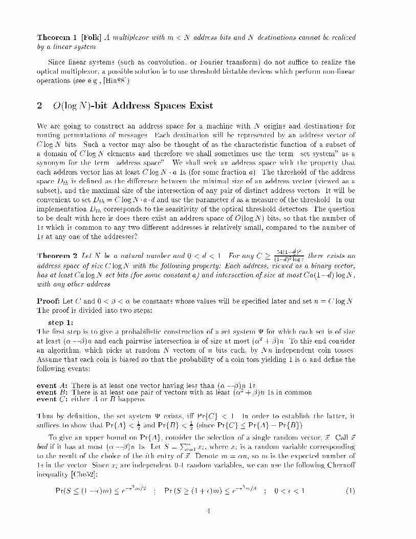
Theorem 1 [Folk] A multiplexor with m < N address bits and N destinations cannot be realizedby a linear system.Since linear systems (such as convolution, or Fourier transform) do not su�ce to realize theoptical multiplexor, a possible solution is to use threshold bistable devices which perform non-linearoperations (see e.g., [Hin88]).2 O(logN)-bit Address Spaces ExistWe are going to construct an address space for a machine with N origins and destinations forrouting permutations of messages. Each destination will be represented by an address vector ofC logN bits. Such a vector may also be thought of as the characteristic function of a subset ofa domain of C logN elements and therefore we shall sometimes use the term \set system" as asynonym for the term \address space". We shall seek an address space with the property thateach address vector has at least C logN � a 1s (for some fraction a). The threshold of the addressspace Dth is de�ned as the di�erence between the minimal size of an address vector (viewed as asubset), and the maximal size of the intersection of any pair of distinct address vectors. It will beconvenient to set Dth = C logN �a �d and use the parameter d as a measure of the threshold. In ourimplementation Dth corresponds to the sensitivity of the optical threshold detectors. The questionto be dealt with here is does there exist an address space of O(logN) bits, so that the number of1s which is common to any two di�erent addresses is relatively small, compared to the number of1s at any one of the addresses?Theorem 2 Let N be a natural number and 0 < d < 1. For any C � 54(1� d2 )2(1�d)3 log e there exists anaddress space of size C logN with the following property: Each address, viewed as a binary vector,has at least Ca logN set bits (for some constant a) and intersection of size at most Ca(1�d) logN ,with any other address.Proof: Let C and 0 < � < � be constants whose values will be speci�ed later and set n = C logN .The proof is divided into two steps:step 1:The �rst step is to give a probabilistic construction of a set system for which each set is of sizeat least (�� �)n and each pairwise intersection is of size at most (�2 + �)n. To this end consideran algorithm, which picks at random N vectors of n bits each, by Nn independent coin tosses.Assume that each coin is biased so that the probability of a coin toss yielding 1 is � and de�ne thefollowing events:event A: There is at least one vector having less than (�� �)n 1s.event B: There is at least one pair of vectors with at least (�2 + �)n 1s in common.event C: either A or B happens.Thus by de�nition, the set system exists, i� PrfCg < 1. In order to establish the latter, itsu�ces to show that PrfAg < 12 and PrfBg < 12 (since PrfCg � PrfAg+ PrfBg).To give an upper bound on PrfAg, consider the selection of a single random vector, ~x. Call ~xbad if it has at most (� � �)n 1s. Let S = Pni=1 xi, where xi is a random variable correspondingto the result of the choice of the ith entry of ~x. Denote m = �n, so m is the expected number of1s in the vector. Since xi are independent 0-1 random variables, we can use the following Cherno�inequality [Che52]:Pr(S � (1� �)m) � e��2m=2 ; Pr (S � (1 + �)m) � e��2m=3 ; 0 < � < 1 (1)4

Putting m = �n, n = C logN and � = �� we getPrf~x is bad g = Pr(S � (�� �)n) � e��2�n2� = N�C�2 log e2�Thus, with a judicious choice of �, �, C, the probability that ~x is bad, can be made rather small.The probability that any of the N random vectors is bad can be estimated by:PrfAg < N �N�C�2 log e2� (2)To give an upper bound on PrfBg, consider the random choice of a pair of random vectors,~x; ~y. Let S =Pni=1 zi, where zi is a random variable corresponding to the result of the choice of theith entry of ~x and ~y: zi = ( 1 if xi = yi = 10 otherwise . Denote m = �2n, so m is the expected numberof 1s which are common to ~x and ~y. Since zi are independent 0-1 random variables, we can use theCherno� inequality (1). Putting � = �=�2, m = �2n and n = C logN we getPrf~x; ~y is a bad pairg � Pr(S � (�2 + �)m) � e��2�2n3�4 = N�C�2 log e3�2Thus one gets:PrfBg � N2 !N�C�2 log e3�2 < 12N2�C�2 log e3�2 (3)Finally, if we require that PrfAg < 12 and PrfBg < 12 and use (2) and (3), we get the followingsu�cient conditions for the existence of a set system :C�2 log e � 6�2 and C�2 log e � (2 + 1logN )� (4)step 2:The second and last step of the proof is to set a = (� � �) and require that the maximal size ofpairwise intersection is at most a(1 � d)n. This imposes the following condition on the maximalpossible value of d: (�� �)n � (�2 + �)n = (�� �)d � n. This shows that for a given value of d �must be chosen so as to satisfy � + d < 1. Rearranging and squaring both sides of the resultingequation, one gets:�2 (1� d� �)2 = 4�2(1� d2)2 (5)There are now two cases to consider:� � 13In this case the two inequalities (4) are satis�ed i� the left one is satis�ed. Thus we may choose �such that: �2 = 6�2C log e . Upon plugging this in (5) and rearranging one obtains: C = 24(1� d2 )2(1�d��)2 log e .Since �+ d < 1 and � � 13 C is minimized for � = 13 and we get:C = 24(1� d2)2(23 � d)2 log e (6)5

� � 13In this case the two inequalities (4) are satis�ed i� the right one is satis�ed. Thus we may chooseany � such that: �2 > 2�C log e . Using this in (5) and rearranging we get that a solution can befound for any C satisfying C > 8(1� d2 )2�(1�d��)2 log e , which is minimized for � = 1�d3 . Thus we get thata solution can be found for any C satisfying:C > 54(1� d2)2�(1� d)3 log e (7)Finally we show that (7) gives smaller bounds than (6). To this end it su�ces to show that forall allowed values of �; �; d, one cannot have: 4( 23�d)2 < 9�(1�d)3 . Setting x = 1�d this is equivalentto: 4x3� 9x2+6x� 1 < 0. But since 4x3� 9x2+6x� 1 = 4(x� 1)2(x� 14) this holds only if x < 14i.e., if d > 34 . However since one must have � < 1 � d one has in this case � < 13 and (6) is notvalid.2.1 Broadcast-to-SomeIn order to implement the broadcast-to-some communication mode we de�ne the following concept:De�nition 2 A ( ; t)-robust address space is an address space for N addresses, of size n = C logNbits, such that every vector has at least Ca logN 1s and each set of t vectors satisfy:j ( t[i=1Vi)\Vj j� C(1� )a logN for Vj 6= V1; : : : ; Vt (8)When the underlying address space of a message switching system is ( ; t)-robust, a very e�cientalgorithm creates a joint address of up to t di�erent destinations, simply by bitwise OR-ing thecorresponding addresses. Hence the importance of the following corollary.Corollary 1 Let N be a natural number. For any C � 54( 12+ 1� 2t )2( 1� t )3 log e there exists a ( ; t)-robustaddress space of size C logN .Proof: The corollary follows from Theorem 2 and the following upper bound:j ( t[i=1Vi)\Vj j=j t[i=1Vi \ Vj j� t� jmax(Vi \ Vj) j (9)since by (9) a set system with d satisfying t(1� d) = 1� is a ( ; t)-robust address space.3 Intersection of Two Addresses is LargeIn section 2 it was shown that there exist sets of N vectors of O(logN) bits, where each vector hasmany 1s but fewer 1s in common with each of the other vectors in the set. In these constructions,the maximum 1s that two vectors share at the same positions is taken to be O(logN). A naturalquestion is whether we can do better than this. That is, can we construct an address space of Nvectors of O(logN) bits, but the largest number of common positions for any pair of vectors whichcontain 1s is �(N) where �(N)logN N!1�! 0? This section answers this question negatively.We reformulate the problem as follows: 6

De�nition 3 A set F of subsets of f1; 2; � � � ; ng is called a set - system. Let L be a set of non-negative integers, a set - system F = fA1; A2; � � � ; ANg is L-intersecting if for each i; j (i 6= j),j Ai \Aj j2 L.A set of N 0-1 vectors of n entries each may be viewed as a set - system of size N . Each vector ~xcorresponds to a single set s~x from the set - system, where s~x is the set of indices of the set entries in~x. As an example of such a set system, consider the following 3-bit vectors, where every two vectorshave no more than one set entry in common: Set System = f 000; 001; 010; 011; 100; 101; 110 g.Thus, if we choose L = f0; 1g then the above set system is L intersecting.There is a rich literature concerning upper bounds on the size of set - systems with restrictedintersections. Here we use a strengthened version of the well known Ray-Chaudhuri - Wilsontheorem:Theorem 3 [BF][Ex. 4.4.1] Let K = fk1; � � � ; krg and L = fl1; � � � ; lsg be two sets of nonnegativeintegers and assume ki > lj for every i; j. Let F be an L-intersecting family of subsets of a set ofn elements. Assume the size of every set in F is a number from K. Thenj F j� ns !+ ns� 1 !+ � � �+ ns� r + 1 ! (10)Putting n = C logN , s � n=2 and H(�) = �� log � � (1� �) log(1� �) for 0 < � < 1, the entropyfunction, we getj F j � ns !+ ns � 1 !+ � � �+ ns � r + 1 !� nn � s !+ nn � s + 1 !+ � � �+ nn !� �n � sn ��(n�s) � sn��s= 2nH( sn ) = NCH( sn ) (11)Thus, for an address space of N vectors we need CH( sn) � 1. However C is constant, so ifsn = �(N)C logN N!1�! 0then H( sn) N!1�! 0, so we cannot always have N vectors intersecting in so few entries. This provesthat, asymptotically, the result from section 2 is the best possible.4 O(log2N)-bit Addresses ConstructionWe have seen that the result from section 2 is asymptotically optimal. However it has severalfundamental aws: �rst, it proves the existence of an appropriate address space, rather than givea speci�c construction. In systems that need to �nd on-line a new address space (say, for a givenN) the time required for the construction is large. Suppose that the randomized algorithm that isgiven is used, and suppose that we want high probability of success in small number of iterations.Then n = C logN becomes larger than the minimum possible, since the probability is dependenton the deviation from the average, which in turn, depends on C.7

Even when the set of vectors is already found, it has an irregular structure and needs to bestored at the local memory of each of the processors using it. I.e., a local memory of CN logN bitsis required for each processor.Another problem is that for moderate values of N , the C that we have guaranteed, might behigher than (say) logN . Thus, for some practical cases, log2N � C logN . One may claim that,since the proof of Theorem 2 is a simple counting sieve, it is probably possible to �nd addressspaces with \shorter" vectors. Alas, this is not guaranteed.In this section we show that if the asymptotic requirements of the algorithm are loosened a bit,then all the above problems are immediately solved. We use the formalism of section 3, where anaddress space corresponds to a set - system, and sets belonging to the set - system correspond toaddress 0-1 vectors. Only that it is not necessary that sets in the set - system are built of elementsof f1; 2; � � � ; ng. In this section, for example, the world from which elements are taken is the set ofpoints of the integral plane.De�nition 4 A set - system for which all sets contain exactly k elements, is called k - uniform.Theorem 4 [BF], pp. 47 For every k � s � 1 and n � 2k2, there exists a k-uniform family Fof size > (n=2k)s on a world of n points, such that j E1 \ E2 j� s � 1 for any two distinct setsE1; E2 2 F .In our setting k � s � 1 + Dth, so given N and Dth we are interested in the minimal s for which(s� 1 +Dth)s � N . It is easy to see that for any Dth = O(logN), s = O( logNlog logN ) is su�cient, sofor Dth = O( logNlog logN ) it holds that n = O�� logNlog logN �2�. The constant is rather small and becomeseven smaller when N grows. For Dth = D logN we have n = O((1 +D)2 log2N), which, for manyNs and Ds, is much better than what is guaranteed in Theorem 2.The address space construction is a set system consisting of subsets of points in the plane. Eachsubset consists of all the points that are spanned by some polynomial of a certain degree, as wenow describe.Let p be the greatest prime � n=k, so n=2k < p � n=k. Fix a k-subset A of the �eld GF (p).Recall that n � 2k2, so p � k.Let X be a set of n points containing A � GF (p). For any function f : A �! GF (p), the\graph" G(f) = f(�; f(�)) : � 2 Ag is a k - points subset of X . Our set - system consists of allthe graphs of the polynomials of degree � s � 1 over GF (p), restricted to A. For two di�erentpolynomials of degree � s � 1, their graphs have at most s� 1 points in common. The number ofsuch polynomials is ps > (n=2k)s.5 Optical Realization of Message Switching SystemsIn the previous sections it has been established that a set-system of N vectors (each of size C logNbits) can be devised, such that the size of the intersection of any two di�erent vectors does notexceed a certain threshold. But how can such a set system be used to construct a free spaceoptical multiplexor? In this section we present a schematic design of such a system using simpleoptical components. In order to simplify the description we only show how processor i lights upthe detector of destination j. In order to transmit a message a data path should also be activated,parallel to the control mechanism.An address is used to select one of the N destinations through the following sequence of oper-ations (see Fig. 1): 8

1. The input vector is set to the destination address. Optically, the input vector is a source oflight beams (one for every bit set to one). For example, laser-diod arrays may be used (seee.g., [Cha92]).2. The intersection of the input vector with all the vectors of the set system is carried as follows.The set system is realized by a simple transparency (or a hologram), in which '0' bits aredark and '1' bits are transparent. The intersection operation is a direct illumination of theset-system transparency (hologram) by light rays corresponding to the '1' bits of the inputvector.3. By the properties of the address space it is guaranteed that only the intersection of the inputvector with the destination address exceeds a prespeci�ed threshold. All outcomes of theprevious step whose intensity is less than the threshold are blocked. The threshold operationcan be carried either electrically, using a detector and a common comparator gate, or optically,using non-linear bistable devices (see [Hin88] or [Fei88] sec. 6.2).We remark that the above is only a schematic description of an optical realization. As such, itignores many lower-level implementation details (such as how to focus the light on the thresholddevices).to destination
threshold devices
input vector
(address source array)
address space transparency (or a hologram)
Figure 1: Optical Multiplexor Schema. Note light and dark areas signify 1s and 0s (respectively) in thecorresponding binary vectors, broken lines stand for light rays in free space.The optical multiplexor described above can be used to implement the three broadcast modes,i.e., point-to-point, broadcast-to-some, and broadcast-to-all. When the input vector matches onlyone vector of the set system, one message will reach the appropriate destination. This correspondsto the point-to-point communication mode. On the other hand, a processor may broadcast-to-allother processors by using the input vector ~1 whose bits are all set to '1'. In order for a processor tobe able to send a message to t di�erent locations, one may either use t di�erent optical multiplexorsfor each processor, and hence pay with t �N threshold devices, or use the multi set-system whoseexistence is proved by Corollary 1. In the latter case, the entries of the input vector are set to9
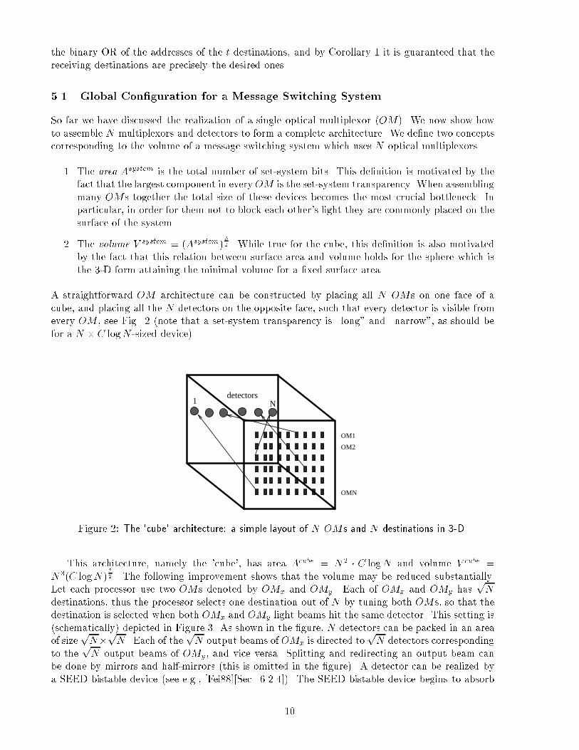
the binary OR of the addresses of the t destinations, and by Corollary 1 it is guaranteed that thereceiving destinations are precisely the desired ones.5.1 Global Con�guration for a Message Switching SystemSo far we have discussed the realization of a single optical multiplexor (OM). We now show howto assemble N multiplexors and detectors to form a complete architecture. We de�ne two conceptscorresponding to the volume of a message switching system which uses N optical multiplexors.1. The area Asystem is the total number of set-system bits. This de�nition is motivated by thefact that the largest component in everyOM is the set-system transparency. When assemblingmany OMs together the total size of these devices becomes the most crucial bottleneck. Inparticular, in order for them not to block each other's light they are commonly placed on thesurface of the system.2. The volume V system = (Asystem) 32 . While true for the cube, this de�nition is also motivatedby the fact that this relation between surface area and volume holds for the sphere which isthe 3-D form attaining the minimal volume for a �xed surface area.A straightforward OM architecture can be constructed by placing all N OMs on one face of acube, and placing all the N detectors on the opposite face, such that every detector is visible fromevery OM , see Fig. 2 (note that a set-system transparency is \long" and \narrow", as should befor a N � C logN -sized device).N1
detectors
OM1
OM2
OMNFigure 2: The 'cube' architecture: a simple layout of N OMs and N destinations in 3-D.This architecture, namely the 'cube', has area Acube = N2 � C logN and volume V cube =N3(C logN) 32 . The following improvement shows that the volume may be reduced substantially.Let each processor use two OMs denoted by OMx and OMy . Each of OMx and OMy has pNdestinations, thus the processor selects one destination out of N by tuning both OMs, so that thedestination is selected when both OMx and OMy light beams hit the same detector. This setting is(schematically) depicted in Figure 3. As shown in the �gure, N detectors can be packed in an areaof size pN�pN . Each of the pN output beams of OMx is directed topN detectors correspondingto the pN output beams of OMy , and vice versa. Splitting and redirecting an output beam canbe done by mirrors and half-mirrors (this is omitted in the �gure). A detector can be realized bya SEED bistable device (see e.g., [Fei88][Sec. 6.2.4]). The SEED bistable device begins to absorb10

OMy
OMx
detector
triggeredFigure 3: Using two OMs to select a given detector.light when the intensity exceeds a certain threshold. In our case a SEED detector will absorb lightonly when it has been hit by both OMx and OMy .The whole architecture, namely the 'sqrt' architecture, is shown in Figure 4. Basically, eachdestination is activated by a vertical column detector consisting of N sub-detectors. In order totrigger the detectors, processor i uses twoOMs, OM ix and OM iy , each havingpN output directions.OM ix and OM iy are placed in a horizontal plane. When sub-detector i of column j is hit by lightbeams from both OM ix and OM iy , the column detector is triggered, so that a one-bit message is sentfrom processor i to destination j. Note that setting the destination address locally and in parallelmay sometimes cause collisions. For algorithms in which this is the case resolution protocols arerequired. Obviously Asqrt = 2N � pN �C logpN = CN 32 logN and V sqrt = N 94 (C logN) 32 .6 ConclusionWe have discussed the asymptotic behind the design of small sized address spaces. The results showthat all three communication modes, namely point-to-point, broadcast-to-some, and broadcast-to-all, may be supported by O(logN)-sized addresses while keeping the cross-talk low.This work calls for many extensions, involving the inclusion of various optical parameters suchas energy loss, di�raction and volume minimization, of which the abstract treatment in computerscience forums is rather immature.References[BF] L. Babai and P. Frankl. Linear algebra methods in combinatorics (part 1). PreliminaryVersion.[Cha92] C. Chang-Hasnain. Vertical-cavity surface emitting lasers: 2-d arrays. In Optical FiberCommun. conf., page 100, 1992.[Che52] H. Cherno�. A measure of asymptotic e�ciency for tests of a hypothesis based on thesum of observations. Annals of Math. Stat., 23:493{507, 1952.11

to destinationsN column
detectors
N input
vectors
sqrt(N) dest’s
Figure 4: The 'sqrt' architecture OM sqrt.[DKGS88] A.R. Dias, R.F. Kalman, J.W. Goodman, and A.A. Sawchuck. Fiber optic crossbarswitch with broadcast capability. Opt. Eng., 27:955{965, 1988.[Fei88] D.G. Feitelson. Optical computing. MIT press, 1988.[FRS90] D.G. Feitelson, L. Rudolph, and E. Schenfeld. Limitations on optical free-space crossbar-like interconnection networks. In Optical Interconnection and Networks, SPIE, volume1281, March 1990.[Hin88] H.S. Hinton. Architectural considerations for photonic switching networks. special issueof IEEE J. Selected areas in commun., pages 1209{1226, Aug. 1988.[McA85] A. McAulay. Optical crossbar interconnected digital signal processor with basic algo-rithms. In Real Time Signal Processing conf. VIII, 29th SPIE, August 1985.[MJR89] E.S. Manilo�, K.M. Johnson, and J. Reif. Holographic routing network for parallelprocessing machines. In EPS/EUROPTICA/SPIE International Congress on opticalScience and Engineering, April 1989.[Nef85] J.A. Ne�. Optical crossbar switch to be developed for strategic computers. In Intl. SolidState Circuits conf., February 1985.[Rei89] J. Reif. Optical expanders give constant time holographic message routing usingO(N logN) switches. Unpublished Manuscript, 1989.[YCH88] P. Yeh, A. Chiou, and J. Hong. Optical interconnections using photorefractive dynamicholograms. Appl. Opt., 27(2093), 1988. 12