local resonance and bragg bandgaps in sandwich beams
TRANSCRIPT
1
LOCAL RESONANCE AND BRAGG BANDGAPS IN SANDWICH BEAMS
CONTAINING PERIODICALLY INSERTED RESONATORS
B. Sharmaa* and C.T. Sunb
a School of Industrial Engineering, Purdue University, West Lafayette, Indiana, 47907, USA
b School of Aeronautics and Astronautics, Purdue University, West Lafayette, Indiana, 47907,
USA
ABSTRACT
We study the low frequency wave propagation behavior of sandwich beams containing
periodically embedded internal resonators. A closed form expression for the propagation constant
is obtained using a phased array approach and verified using finite element simulations. We show
that local resonance and Bragg bandgaps coexist in such a system and that the width of both
bandgaps is a function of resonator parameters as well as their periodicity. The interaction between
the two bandgaps is studied by varying the local resonance frequency. We find that a single
combined bandgap does not exist for this system and that the Bragg bandgaps transition into sub-
wavelength bandgaps when the local resonance frequency is above their associated classical Bragg
frequency.
KEYWORDS: Flexural wave attenuation, periodic structure, local resonance bandgap, Bragg
bandgap, bandgap interaction.
* Corresponding author. School of Industrial Engineering, Purdue University, West Lafayette, Indiana, 47907, USA
Tel.: +1 765 404 0565.
E-mail address: [email protected] (B. Sharma).
2
INTRODUCTION:
The creation of wave attenuation frequency bands due to addition of substructures to a host
medium was first demonstrated in the context of acoustic waves by Liu et al. [1]. Various
researchers have since studied the attenuation of acoustic and elastic waves by utilizing such
locally resonating elements [2]. The localized resonance of the added substructures causes energy
sequestering and prohibits the propagation of incident waves [3]. These local resonance bandgaps
are distinct from those obtained due to multiple scattering and interference effects occurring
between periodic elements in a propagation medium, classically referred to as Bragg bandgaps [4],
[5], and [6]. Due to the nature of the mechanism involved in their creation, Bragg bandgaps are
generated at wavelengths comparable to the spatial scale of the periodicities [5]. Local resonance
bandgaps, on the other hand, are independent of the spatial organization of the resonant
substructures and are solely governed by the unit cell resonance frequency [7].
Recently, researchers have investigated various systems containing periodically placed local
resonators and demonstrated the coexistence of both bandgaps in the same system [8 - 20]. Still et
al. [8] experimentally demonstrated the existence of hypersonic Bragg as well as local resonance
bandgaps in three dimensional colloidal films of nanospheres and also showed that for a
structurally disordered system, the Bragg bandgap disappears while the local resonance bandgap
persists. Croënne et al. [9] reported their coexistence as well as an overlap between the two
bandgaps for a 2D crystal of nylon rods in water. Similarly, Achaoui et al. [10] showed the
presence of local resonance bandgaps at low frequencies and Bragg bandgaps at high frequencies
for surface guided waves in a lithium niobate substrate with nickel pillars, while Bretagne et al.
[11] reported similar results for acoustic wave propagation through a 3D bubble phononic crystal.
Kaina et al. [12], Chen et al. [13], and Yuan et al. [14] have recently reported results demonstrating
3
coupling between the two bandgaps and creation of a single combined ‘resonant-Bragg’ bandgap
extending over a wide frequency range. For flexural wave propagation, Liu et al [15] utilized a
transfer matrix method to study the effect of various periodicities and their combination on the
bandgap characteristics of a beam. Specifically, for the case of suspended mass periodicity they
showed that local resonance and Bragg bandgaps coexist in the system and also provided a
transition criterion for the two bandgaps in terms of the group velocity gradient. Others have used
a similar transfer matrix approach to study different beam structures with periodically placed
resonators [16], [17], [18]. Xiao et al used the plane wave expansion method [19] and a spectral
element formulation [20] to obtain the propagation constant for an Euler-Bernoulli beam with
attached local resonators, and demonstrated a super-wide combined pseudo gap when a resonance
gap was nearly coupled with a Bragg bandgap.
The idea of the utilization of space available in thick sandwich cores to accommodate locally
resonating elements was first proposed by Chen et al. [21]. The high stiffness to weight ratio of
sandwich structures makes them an ideal solution to save energy through weight reduction.
Consequently, sandwich beams have gradually found increased applications in the aerospace,
marine as well as the automotive sectors [22]. However, a major roadblock to further adoption of
composite sandwich designs is their susceptibility under dynamic loading [23]. Chen et al. [24]
demonstrated that embedding resonators inside the sandwich core generates local resonance wave
attenuation bandgaps which help improve their dynamic flexural performance without a significant
weight penalty. To analyze the effect of resonators embedded inside the core, they assumed the
resonators to be uniformly distributed over the entire length of the beam using a volume averaging
technique. Doing so allows the description of such a resonator-embedded beam using continuous
field variables and the equations of motion were derived using Hamilton’s principle. However,
4
this model did not account for discrete resonators inserted in the core with a spatial periodicity and
was unable to capture the effect of such a periodicity on the dispersion behavior of the system.
In this study, we adopt the phased array method to obtain the propagation constants for a sandwich
beam with resonator embedded core. The phased array method was developed by Mead [25] to
obtain closed form solutions for the propagation constants of various periodic systems. Since we
are primarily interested in the low frequency behavior of the system, we model the sandwich beam
as an equivalent Timoshenko beam [21], [26] and treat the resonators as a phased array of forces.
Dispersion curves obtained by this method are compared with volume averaging method and finite
element results and it is shown that local resonance and Bragg bandgaps coexist. The relationship
between bandgap bounding frequencies, resonator stiffness and mass, and the periodic distance is
analyzed in the context of modal frequencies of simple unit cell models [6]. Finally, the interaction
between local resonance and Bragg bandgaps is studied and the possibility of creating a single
combined bandgap is considered.
METHOD
The conventional sandwich construction involves bonding two thin facesheets on either side of a
thicker, lightweight core material. Typically, facesheets provide the bending rigidity while the
shear stiffness is provided by the core.
5
(a)
(b)
(c)
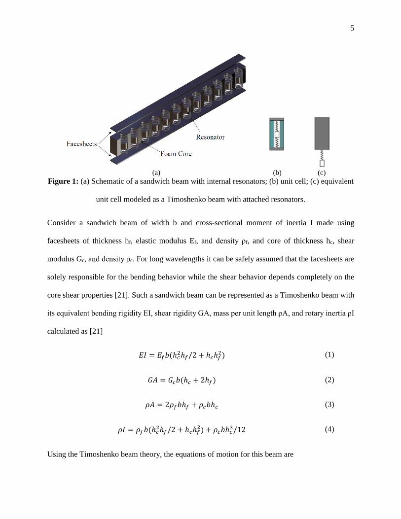
Figure 1: (a) Schematic of a sandwich beam with internal resonators; (b) unit cell; (c) equivalent
unit cell modeled as a Timoshenko beam with attached resonators.
Consider a sandwich beam of width b and cross-sectional moment of inertia I made using
facesheets of thickness hf, elastic modulus Ef, and density ρf, and core of thickness hc, shear
modulus Gc, and density ρc. For long wavelengths it can be safely assumed that the facesheets are
solely responsible for the bending behavior while the shear behavior depends completely on the
core shear properties [21]. Such a sandwich beam can be represented as a Timoshenko beam with
its equivalent bending rigidity EI, shear rigidity GA, mass per unit length ρA, and rotary inertia ρI
calculated as [21]
𝐸𝐼 = 𝐸𝑓𝑏(ℎ𝑐2ℎ𝑓/2 + ℎ𝑐ℎ𝑓
2) (1)
𝐺𝐴 = 𝐺𝑐𝑏(ℎ𝑐 + 2ℎ𝑓) (2)
𝜌𝐴 = 2𝜌𝑓𝑏ℎ𝑓 + 𝜌𝑐𝑏ℎ𝑐 (3)
𝜌𝐼 = 𝜌𝑓𝑏(ℎ𝑐2ℎ𝑓/2 + ℎ𝑐ℎ𝑓
2) + 𝜌𝑐𝑏ℎ𝑐3/12 (4)
Using the Timoshenko beam theory, the equations of motion for this beam are
6
𝐺𝐴[𝑣′′(𝑥, 𝑡) + 𝜑′(𝑥, 𝑡)] − 𝜌𝐴(𝑥, 𝑡) = 0 (5)
𝐸𝐼𝜑′′(𝑥, 𝑡) − 𝐺𝐴[𝑣′(𝑥, 𝑡) + 𝜑(𝑥, 𝑡)] − 𝜌𝐴(𝑥, 𝑡) = 0 (6)
where 𝑣 is the transverse displacement of the sandwich beam and 𝜑 is the cross-sectional rotation.
Assume harmonic solutions of the form:
𝑣 = 𝑣𝑜𝑒−𝑖(𝑘𝑥−𝜔𝑡), 𝜑 = 𝜑𝑜𝑒−𝑖(𝑘𝑥−𝜔𝑡) (10)
Then, the characteristic equation can be derived to be [27]:
𝑘4 − [𝜌𝐼
𝐸𝐼+
𝜌𝐴
𝐺𝐴] 𝜔2𝑘2 + [
𝜌𝐼𝜌𝐴
𝐸𝐼𝐺𝐴−
𝜌𝐴
𝐸𝐼] 𝜔2 = 0
(11)
In the frequency domain, the general solution may be written as:
𝑣(𝑥) = 𝐴𝑒−𝑖𝑘1𝑥 + 𝐵𝑒−𝑖𝑘2𝑥 + 𝐶𝑒𝑖𝑘1𝑥 + 𝐷𝑒𝑖𝑘2𝑥
(𝑥) = 𝑒−𝑖𝑘1𝑥 + 𝑒−𝑖𝑘2𝑥 + 𝑒𝑖𝑘1𝑥 + 𝑒𝑖𝑘2𝑥
(12)
For an infinitely long Timoshenko beam excited by a point harmonic force at x = 0, using
symmetry and antisymmetry conditions, we write the displacements and rotations to the right and
left-hand parts of the beam as
𝑣(𝑥) = 𝐵1𝑒−𝑖𝑘1𝑥 + 𝐵2𝑒−𝑖𝑘2𝑥 (𝑥 ≥ 0), 𝑣(𝑥) = 𝐵1𝑒𝑖𝑘1𝑥 + 𝐵2𝑒𝑖𝑘2𝑥 (𝑥 ≤ 0) (13)
𝜑(𝑥) = 𝐶1𝑒−𝑖𝑘1𝑥 + 𝐶2𝑒−𝑖𝑘2𝑥 (𝑥 ≥ 0), 𝜑(𝑥) = 𝐶1𝑒𝑖𝑘1𝑥 + 𝐶2𝑒𝑖𝑘2𝑥 (𝑥 ≤ 0) (14)
where the amplitude coefficients are related as
𝐶𝑗 = 𝑖 [𝐺𝐴𝑘𝑗
2 − 𝜌𝐴𝜔2
𝐺𝐴𝑘𝑗] 𝐵𝑗, for 𝑗 = 1,2
(15)
7
The boundary conditions to be satisfied are as follows: (a) due to antisymmetry of φ about x = 0;
the rotations 𝜑𝑅(0) = 𝜑𝐿(0) = 0; and (b) the shear force, V, on the beam cross-section just to the
right or left of x = 0 is equal to half the applied force. The application of the first boundary
condition leads to C1 = - C2. To apply the other boundary condition we use the expression for the
shear force on the beam cross-section:
𝑉 = −𝐺𝐴 [𝜕𝑣
𝜕𝑥− 𝜑]
(16)
These boundary conditions lead to
𝐵1 =𝑃
2𝑖𝐺𝐴
𝑘1
𝑘𝑠2
[𝑘2
2 − 𝑘𝑠2
𝑘22 − 𝑘1
2], 𝐵2 =−𝑃
2𝑖𝐺𝐴
𝑘2
𝑘𝑠2
[𝑘1
2 − 𝑘𝑠2
𝑘22 − 𝑘1
2] (17)
where 𝑘𝑠 = 𝜔√𝜌𝐴
𝐺𝐴 , and P is the applied load.
Thus, the transverse displacement at any point is:
𝑣(𝑥) =𝑃
2𝑖𝐺𝐴[𝑘1
𝑘𝑠2
[𝑘2
2 − 𝑘𝑠2
𝑘22 − 𝑘1
2] 𝑒−𝑖𝑘1𝑥 −𝑘2
𝑘𝑠2
[𝑘1
2 − 𝑘𝑠2
𝑘22 − 𝑘1
2] 𝑒−𝑖𝑘2𝑥] (18)
An infinite beam with periodically placed resonators can be viewed as a uniform structure on
which the resonators impose forces at regular intervals. The force applied by one attached spring-
mass system on the infinite beam is easily calculated and can be conveniently used to compute and
study the wave motion in the whole periodic structure under free or forced harmonic conditions.
Since the response of a point in a periodic structure is related to a corresponding point in the
adjacent section through the propagation constant [4], it follows that the forces and moment
exerted by the periodic constraints are similarly related to each other through the propagation
8
constant. Thus, they can be considered to be an array of forces phased through e-iµ, where µ is the
propagation constant [4]. In general, µ is complex and written as
µ = 𝛿 + 𝑖𝛾 (19)
where the real part of µ (i.e. δ) carries information about the phase difference between the
responses measured at two points one periodic length apart (L), while the imaginary part (i.e. γ)
describes the rate of decay of the amplitude between these two points. The wavenumber of a
propagating wave (k), i.e. for a wave with γ = 0, is given as
𝑘 = δ/L (20)
and the corresponding wavelength λ is
λ = 2π/k = 2πL/δ (21)
Consider the above beam to be subjected to a phased array of harmonic forces, Pj = P0e-ijµe-iωt,
applied with periodicity L. Assuming only the force P0 to be active, the transverse displacement to
the right, vr(x), and to the left, vl(x), of the force can be expressed as:
𝑣𝑟(𝑥) = 𝑃0 ∑ [𝑎𝑗𝑒−𝑖𝑘𝑗𝑥]2𝑗=1 , 𝑣𝑙(𝑥) = 𝑃0 ∑ [𝑎𝑗𝑒𝑖𝑘𝑗𝑥] 2
𝑗=1 (22)
where k1 and k2 are solutions of the characteristic equation (Eq. 11), and using Eq. 18, a1 and a2
are written as:
𝑎1 =1
2𝑖𝐺𝐴
𝑘1
𝑘𝑠2
[𝑘2
2 − 𝑘𝑠2
𝑘22 − 𝑘1
2], 𝑎2 =−1
2𝑖𝐺𝐴
𝑘2
𝑘𝑠2
[𝑘1
2 − 𝑘𝑠2
𝑘22 − 𝑘1
2] (23)
The transverse displacement at the location x=0, due to the force acting at that point is
𝑣(0) = 𝑃0[𝑎1 + 𝑎2] (24)
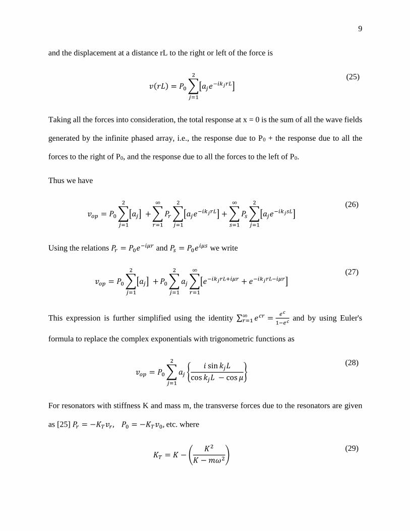
9
and the displacement at a distance rL to the right or left of the force is
𝑣(𝑟𝐿) = 𝑃0 ∑[𝑎𝑗𝑒−𝑖𝑘𝑗𝑟𝐿]
2
𝑗=1
(25)
Taking all the forces into consideration, the total response at x = 0 is the sum of all the wave fields
generated by the infinite phased array, i.e., the response due to P0 + the response due to all the
forces to the right of P0, and the response due to all the forces to the left of P0.
Thus we have
𝑣𝑜𝑝 = 𝑃0 ∑[𝑎𝑗] +
2
𝑗=1
∑ 𝑃𝑟 ∑[𝑎𝑗𝑒−𝑖𝑘𝑗𝑟𝐿] + ∑ 𝑃𝑠 ∑[𝑎𝑗𝑒−𝑖𝑘𝑗𝑠𝐿]
2
𝑗=1
∞
𝑠=1
2
𝑗=1
∞
𝑟=1
(26)
Using the relations 𝑃𝑟 = 𝑃0𝑒−𝑖𝜇𝑟 and 𝑃𝑠 = 𝑃0𝑒𝑖𝜇𝑠 we write
𝑣𝑜𝑝 = 𝑃0 ∑[𝑎𝑗] +
2
𝑗=1
𝑃0 ∑ 𝑎𝑗 ∑[𝑒−𝑖𝑘𝑗𝑟𝐿+𝑖𝜇𝑟 + 𝑒−𝑖𝑘𝑗𝑟𝐿−𝑖𝜇𝑟]
∞
𝑟=1
2
𝑗=1
(27)
This expression is further simplified using the identity ∑ 𝑒𝑐𝑟 =𝑒𝑐
1−𝑒𝑐∞𝑟=1 and by using Euler's
formula to replace the complex exponentials with trigonometric functions as
𝑣𝑜𝑝 = 𝑃0 ∑ 𝑎𝑗
2
𝑗=1
𝑖 sin 𝑘𝑗𝐿
cos 𝑘𝑗𝐿 − cos 𝜇
(28)
For resonators with stiffness K and mass m, the transverse forces due to the resonators are given
as [25] 𝑃𝑟 = −𝐾𝑇𝑣𝑟 , 𝑃0 = −𝐾𝑇𝑣0, etc. where
𝐾𝑇 = 𝐾 − (𝐾2
𝐾 − 𝑚𝜔2)
(29)
10
Thus, the effective force at x = 0 due to the array of resonators is obtained as the sum:
𝑃0 = 𝐾𝑇𝑃0 ∑ 𝑎𝑗
2
𝑗=1
𝑖 sin 𝑘𝑗𝐿
cos 𝑘𝑗𝐿 − cos 𝜇
(30)
Plugging in the values of a1 and a2 derived above and solving for cosµ, we obtain the quadratic
equation:
cos2 𝜇 − 𝛽1 cos 𝜇 + 𝛽2 = 0 (31)
where,
𝛽1 = 𝑖𝐾𝑇[𝑎1 sin 𝑘1𝐿 + 𝑎2 sin 𝑘2𝐿] − [cos 𝑘1𝐿 + cos 𝑘2𝐿] (32)
𝛽2 = 𝑖𝐾𝑇[𝑎1 sin 𝑘1𝐿 cos 𝑘2𝐿 + 𝑎2 sin 𝑘2𝐿 cos 𝑘1𝐿] + [cos 𝑘1𝐿 cos 𝑘2𝐿] (33)
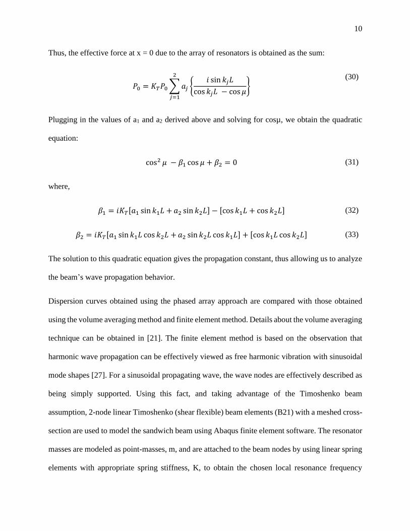
The solution to this quadratic equation gives the propagation constant, thus allowing us to analyze
the beam’s wave propagation behavior.
Dispersion curves obtained using the phased array approach are compared with those obtained
using the volume averaging method and finite element method. Details about the volume averaging
technique can be obtained in [21]. The finite element method is based on the observation that
harmonic wave propagation can be effectively viewed as free harmonic vibration with sinusoidal
mode shapes [27]. For a sinusoidal propagating wave, the wave nodes are effectively described as
being simply supported. Using this fact, and taking advantage of the Timoshenko beam
assumption, 2-node linear Timoshenko (shear flexible) beam elements (B21) with a meshed cross-
section are used to model the sandwich beam using Abaqus finite element software. The resonator
masses are modeled as point-masses, m, and are attached to the beam nodes by using linear spring
elements with appropriate spring stiffness, K, to obtain the chosen local resonance frequency
11
which is given as, 𝜔𝑟 = √𝐾 𝑚⁄ . Using an eigenvalue analysis, the natural frequencies, ωn, and
the characteristic wavelengths, λn, are obtained. The obtained wavelengths are then used to
calculate the wavenumber (k = 2π/λ) and the dispersion curve is subsequently plotted. Note that
only the real part of the wavenumber can be obtained using such a finite element model, which is
used to visualize the bandgap region. Attenuation of harmonic waves in the predicted wave
attenuation bandgaps is further verified using transient simulations performed using
Abaqus/Explicit. A 100 m long beam, with the length chosen so as to avoid end reflection
interference effects, is subjected to a single frequency harmonic displacement at one end while the
other end is kept free. To achieve accuracy and ensure convergence a double precision analysis is
employed and each unit cell is modeled using ten Timoshenko beam elements. The output
displacement histories for different loading frequencies are subsequently obtained and compared
with the input displacement to assess the attenuation of the waves.
RESULTS AND DISCUSSION
Verification and comparison
The dispersion curves obtained using the phased array and the volume averaging methods are
compared with those obtained using finite element simulations in Figure 2, where Ω is the
frequency normalized with respect to the local resonance frequency, while kL is the wavenumber
normalized with respect to the unit cell length. To maintain validity of the equivalent Timoshenko
beam theory assumption, the analysis was restricted to low frequencies and local resonance
frequency of 200 Hz was chosen. The beam material and geometrical properties, and the resonator
12
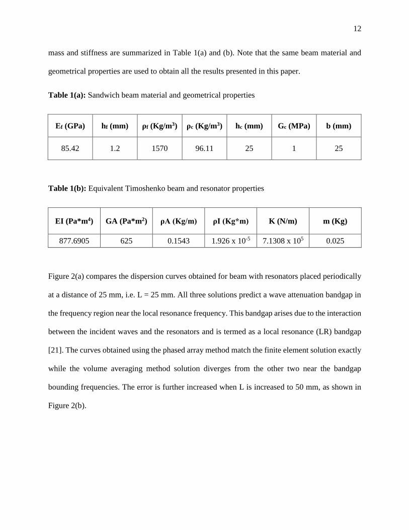
mass and stiffness are summarized in Table 1(a) and (b). Note that the same beam material and
geometrical properties are used to obtain all the results presented in this paper.
Table 1(a): Sandwich beam material and geometrical properties
Ef (GPa) hf (mm) ρf (Kg/m3) ρc (Kg/m3) hc (mm) Gc (MPa) b (mm)
85.42 1.2 1570 96.11 25 1 25
Table 1(b): Equivalent Timoshenko beam and resonator properties
EI (Pa*m4) GA (Pa*m2) ρA (Kg/m) ρI (Kg*m) K (N/m) m (Kg)
877.6905 625 0.1543 1.926 x 10⁻⁵ 7.1308 x 10⁵ 0.025
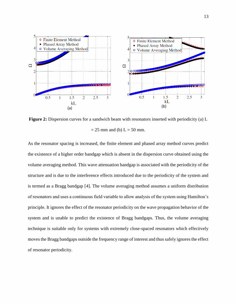
Figure 2(a) compares the dispersion curves obtained for beam with resonators placed periodically
at a distance of 25 mm, i.e. L = 25 mm. All three solutions predict a wave attenuation bandgap in
the frequency region near the local resonance frequency. This bandgap arises due to the interaction
between the incident waves and the resonators and is termed as a local resonance (LR) bandgap
[21]. The curves obtained using the phased array method match the finite element solution exactly
while the volume averaging method solution diverges from the other two near the bandgap
bounding frequencies. The error is further increased when L is increased to 50 mm, as shown in
Figure 2(b).
13
(a)
(b)
Figure 2: Dispersion curves for a sandwich beam with resonators inserted with periodicity (a) L
= 25 mm and (b) L = 50 mm.
As the resonator spacing is increased, the finite element and phased array method curves predict
the existence of a higher order bandgap which is absent in the dispersion curve obtained using the
volume averaging method. This wave attenuation bandgap is associated with the periodicity of the
structure and is due to the interference effects introduced due to the periodicity of the system and
is termed as a Bragg bandgap [4]. The volume averaging method assumes a uniform distribution
of resonators and uses a continuous field variable to allow analysis of the system using Hamilton’s
principle. It ignores the effect of the resonator periodicity on the wave propagation behavior of the
system and is unable to predict the existence of Bragg bandgaps. Thus, the volume averaging
technique is suitable only for systems with extremely close-spaced resonators which effectively
moves the Bragg bandgaps outside the frequency range of interest and thus safely ignores the effect
of resonator periodicity.
14
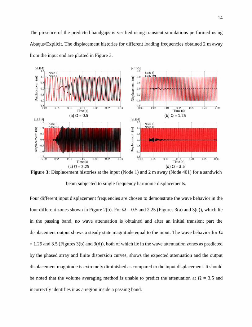
The presence of the predicted bandgaps is verified using transient simulations performed using
Abaqus/Explicit. The displacement histories for different loading frequencies obtained 2 m away
from the input end are plotted in Figure 3.
(a) Ω = 0.5
(b) Ω = 1.25
(c) Ω = 2.25
(d) Ω = 3.5
Figure 3: Displacement histories at the input (Node 1) and 2 m away (Node 401) for a sandwich
beam subjected to single frequency harmonic displacements.
Four different input displacement frequencies are chosen to demonstrate the wave behavior in the
four different zones shown in Figure 2(b). For Ω = 0.5 and 2.25 (Figures 3(a) and 3(c)), which lie
in the passing band, no wave attenuation is obtained and after an initial transient part the
displacement output shows a steady state magnitude equal to the input. The wave behavior for Ω
= 1.25 and 3.5 (Figures 3(b) and 3(d)), both of which lie in the wave attenuation zones as predicted
by the phased array and finite dispersion curves, shows the expected attenuation and the output
displacement magnitude is extremely diminished as compared to the input displacement. It should
be noted that the volume averaging method is unable to predict the attenuation at Ω = 3.5 and
incorrectly identifies it as a region inside a passing band.
15
Representation of bandgap bounding frequencies
Often, when analyzing the wave propagation behavior of a structure, the wave attenuation start
and stop frequencies are of the primary concern. Mead [28] demonstrated that these frequencies,
commonly referred to as bounding frequencies, of a periodic system are equal to the modal
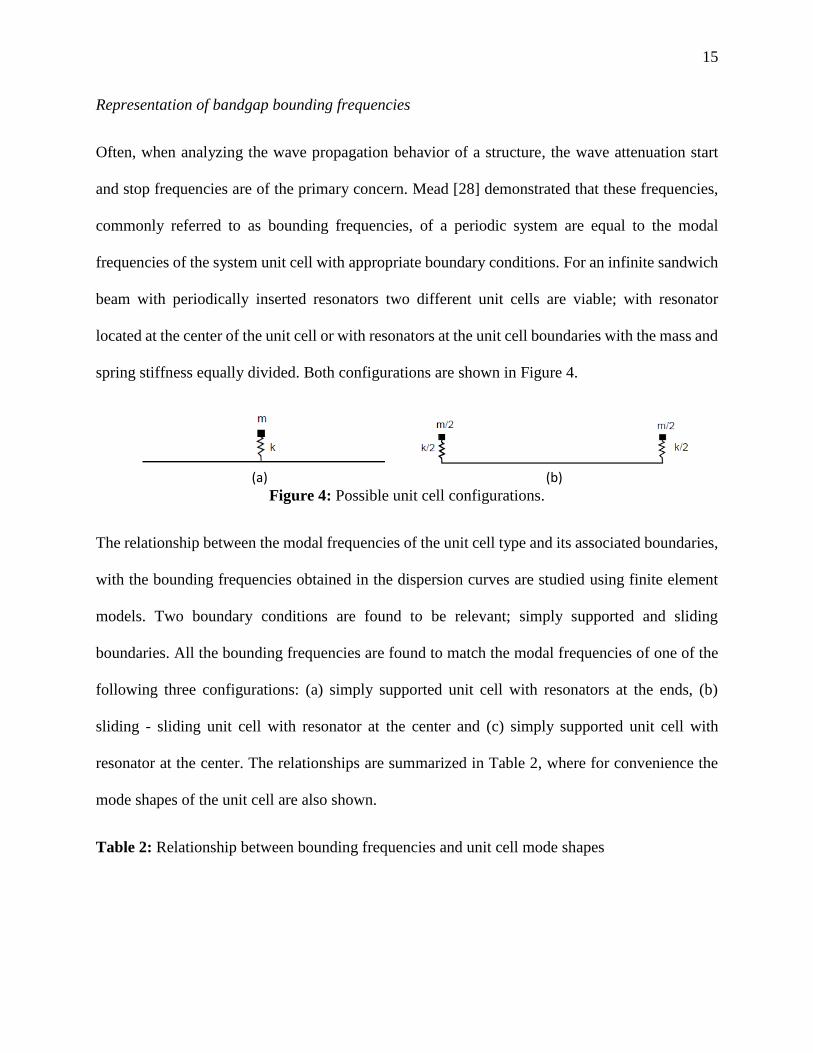
frequencies of the system unit cell with appropriate boundary conditions. For an infinite sandwich
beam with periodically inserted resonators two different unit cells are viable; with resonator
located at the center of the unit cell or with resonators at the unit cell boundaries with the mass and
spring stiffness equally divided. Both configurations are shown in Figure 4.
(a)
(b)
Figure 4: Possible unit cell configurations.
The relationship between the modal frequencies of the unit cell type and its associated boundaries,
with the bounding frequencies obtained in the dispersion curves are studied using finite element
models. Two boundary conditions are found to be relevant; simply supported and sliding
boundaries. All the bounding frequencies are found to match the modal frequencies of one of the
following three configurations: (a) simply supported unit cell with resonators at the ends, (b)
sliding - sliding unit cell with resonator at the center and (c) simply supported unit cell with
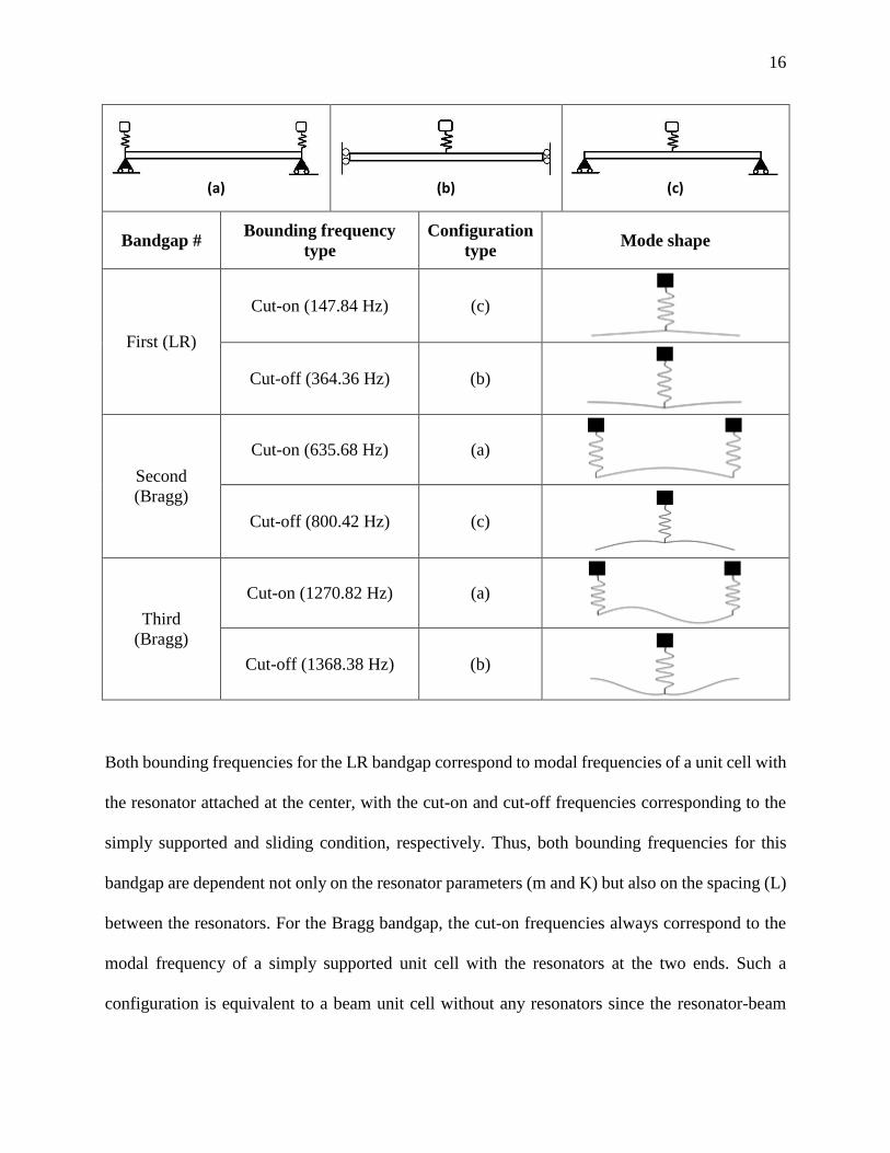
resonator at the center. The relationships are summarized in Table 2, where for convenience the
mode shapes of the unit cell are also shown.
Table 2: Relationship between bounding frequencies and unit cell mode shapes
16
(a)
(b) (c)
Bandgap # Bounding frequency
type
Configuration
type Mode shape
First (LR)
Cut-on (147.84 Hz) (c)
Cut-off (364.36 Hz) (b)
Second
(Bragg)
Cut-on (635.68 Hz) (a)
Cut-off (800.42 Hz) (c)
Third
(Bragg)
Cut-on (1270.82 Hz) (a)
Cut-off (1368.38 Hz) (b)
Both bounding frequencies for the LR bandgap correspond to modal frequencies of a unit cell with
the resonator attached at the center, with the cut-on and cut-off frequencies corresponding to the
simply supported and sliding condition, respectively. Thus, both bounding frequencies for this
bandgap are dependent not only on the resonator parameters (m and K) but also on the spacing (L)
between the resonators. For the Bragg bandgap, the cut-on frequencies always correspond to the
modal frequency of a simply supported unit cell with the resonators at the two ends. Such a
configuration is equivalent to a beam unit cell without any resonators since the resonator-beam
17
attachment points act as nodes and the resonators remain stationary. Thus, as reported for other
similar systems [28], the cut-on frequency of the Bragg bandgap is dependent solely on the
periodicity of the system (L) and is independent of the resonator parameters. Conversely, the Bragg
bandgap cut-off frequencies always correspond to a unit cell with resonators attached at the center
with the end conditions alternating between simply supported and sliding configurations. Hence,
the Bragg bandgap cut-off frequencies are influenced by the system periodicity as well as the
resonator parameters. This allows the possibility of tailoring not only the LR bandgap, but also the
width of the Bragg gaps introduced into the system due to the resonator periodicity.
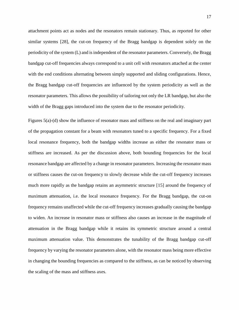
Figures 5(a)-(d) show the influence of resonator mass and stiffness on the real and imaginary part
of the propagation constant for a beam with resonators tuned to a specific frequency. For a fixed
local resonance frequency, both the bandgap widths increase as either the resonator mass or
stiffness are increased. As per the discussion above, both bounding frequencies for the local
resonance bandgap are affected by a change in resonator parameters. Increasing the resonator mass
or stiffness causes the cut-on frequency to slowly decrease while the cut-off frequency increases
much more rapidly as the bandgap retains an asymmetric structure [15] around the frequency of
maximum attenuation, i.e. the local resonance frequency. For the Bragg bandgap, the cut-on
frequency remains unaffected while the cut-off frequency increases gradually causing the bandgap
to widen. An increase in resonator mass or stiffness also causes an increase in the magnitude of
attenuation in the Bragg bandgap while it retains its symmetric structure around a central
maximum attenuation value. This demonstrates the tunability of the Bragg bandgap cut-off
frequency by varying the resonator parameters alone, with the resonator mass being more effective
in changing the bounding frequencies as compared to the stiffness, as can be noticed by observing
the scaling of the mass and stiffness axes.
18
(a) (b)
(c) (d)
Figure 5 (a - d): Effect of resonator mass and stiffness on the bandgap behavior with the local
resonance frequency kept fixed (200 Hz). Figures 5(a) and 5(b) show the effect of mass variation
on the phase (real) and attenuation (imaginary) part of the phase constant, respectively, while
Figures 5(c) and 5(d) show the effect of stiffness variation on the phase (real) and attenuation
(imaginary) part of the phase constant, respectively. Note that the mass axis is normalized with
respect to the beam unit cell mass, while the stiffness axis is normalized with respect to the beam
bending stiffness.
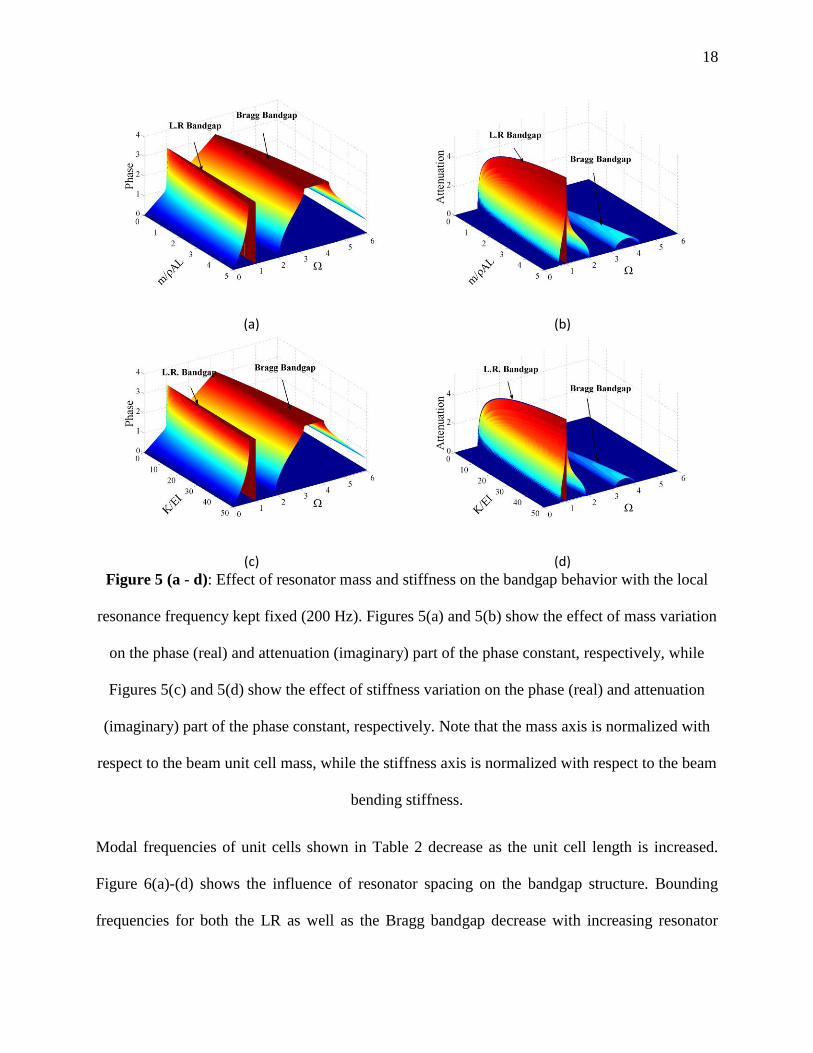
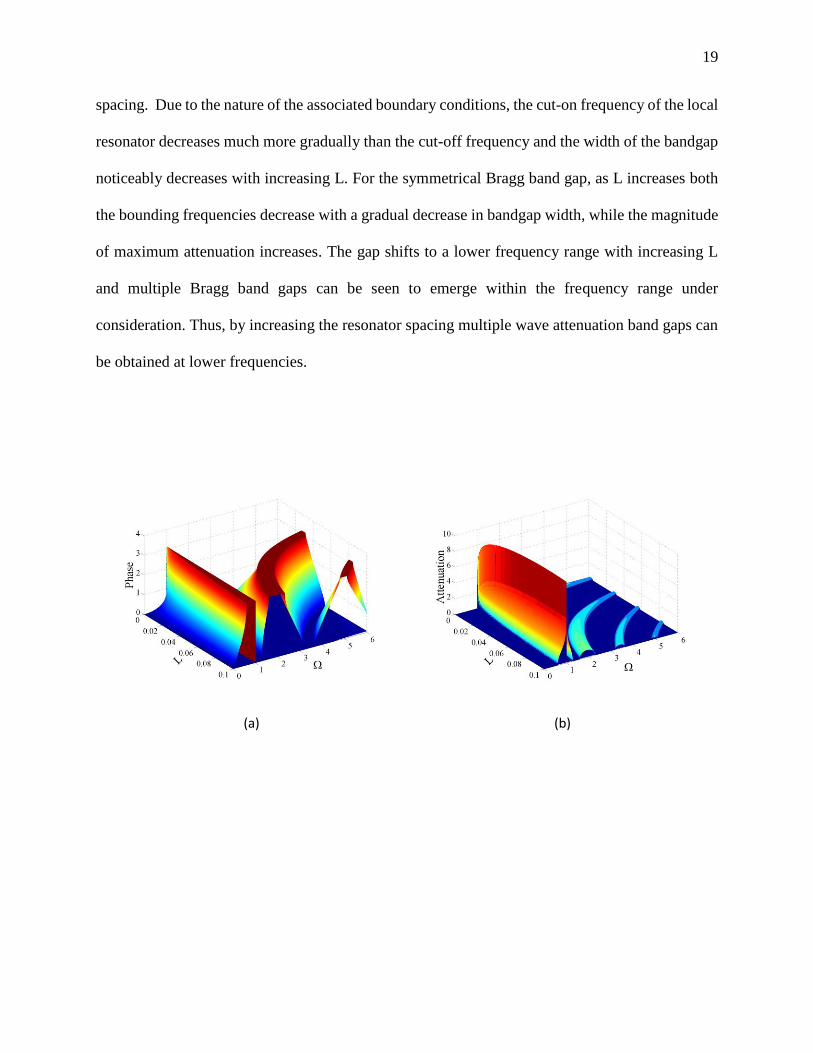
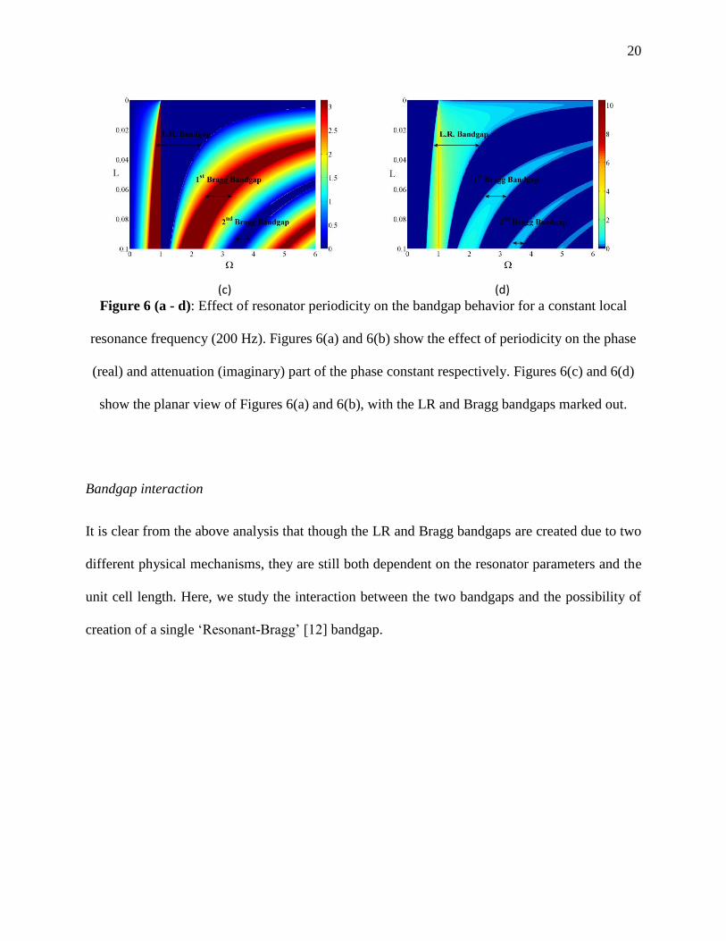
Modal frequencies of unit cells shown in Table 2 decrease as the unit cell length is increased.
Figure 6(a)-(d) shows the influence of resonator spacing on the bandgap structure. Bounding
frequencies for both the LR as well as the Bragg bandgap decrease with increasing resonator
19
spacing. Due to the nature of the associated boundary conditions, the cut-on frequency of the local
resonator decreases much more gradually than the cut-off frequency and the width of the bandgap
noticeably decreases with increasing L. For the symmetrical Bragg band gap, as L increases both
the bounding frequencies decrease with a gradual decrease in bandgap width, while the magnitude
of maximum attenuation increases. The gap shifts to a lower frequency range with increasing L
and multiple Bragg band gaps can be seen to emerge within the frequency range under
consideration. Thus, by increasing the resonator spacing multiple wave attenuation band gaps can
be obtained at lower frequencies.
(a) (b)
20
(c) (d)
Figure 6 (a - d): Effect of resonator periodicity on the bandgap behavior for a constant local
resonance frequency (200 Hz). Figures 6(a) and 6(b) show the effect of periodicity on the phase
(real) and attenuation (imaginary) part of the phase constant respectively. Figures 6(c) and 6(d)
show the planar view of Figures 6(a) and 6(b), with the LR and Bragg bandgaps marked out.
Bandgap interaction
It is clear from the above analysis that though the LR and Bragg bandgaps are created due to two
different physical mechanisms, they are still both dependent on the resonator parameters and the
unit cell length. Here, we study the interaction between the two bandgaps and the possibility of
creation of a single ‘Resonant-Bragg’ [12] bandgap.
21
(a) (b)
(c) (d)
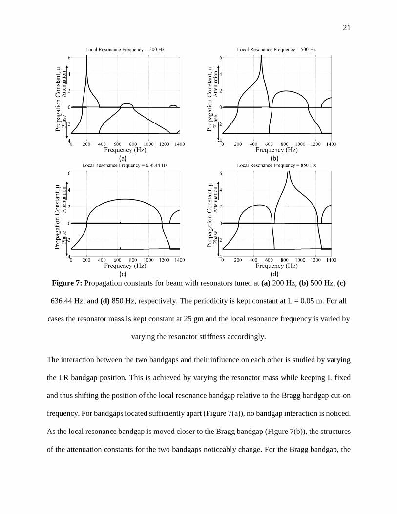
Figure 7: Propagation constants for beam with resonators tuned at (a) 200 Hz, (b) 500 Hz, (c)
636.44 Hz, and (d) 850 Hz, respectively. The periodicity is kept constant at L = 0.05 m. For all
cases the resonator mass is kept constant at 25 gm and the local resonance frequency is varied by
varying the resonator stiffness accordingly.
The interaction between the two bandgaps and their influence on each other is studied by varying
the LR bandgap position. This is achieved by varying the resonator mass while keeping L fixed
and thus shifting the position of the local resonance bandgap relative to the Bragg bandgap cut-on
frequency. For bandgaps located sufficiently apart (Figure 7(a)), no bandgap interaction is noticed.
As the local resonance bandgap is moved closer to the Bragg bandgap (Figure 7(b)), the structures
of the attenuation constants for the two bandgaps noticeably change. For the Bragg bandgap, the
22
attenuation constant is no longer symmetric around the mid-gap frequency and attains a maximum
attenuation value at a lower frequency. Also, the nature of asymmetry associated with the LR
bandgap changes and it now spreads out more towards frequencies below the local resonance
frequency. Figure 7(c) shows the band structure obtained when the local resonance frequency
matches the first Bragg bandgap cut-on frequency. Under this condition, researchers investigating
other systems, [9], [12], [13], and [14], have reported merging of the two bandgaps causing a very
wide and strongly attenuating single hybrid ‘Resonance-Bragg’ bandgap. However, in our studies,
such a single bandgap was not found to exist. Though the two bandgaps seem to couple together
and create an almost-symmetric, wide bandgap, a narrow passing band separating the two gaps
still exists. As the local resonance frequency is increased further and located inside the original
Bragg bandgap, the band structure noticeably changes. The Bragg bandgap ‘flips’ around the
original cut-on frequency, which is the new Bragg bandgap cut-off frequency, and cut-on at a much
lower frequency. As the local resonance frequency is increased further, the Bragg cut-off
frequency remains unaffected while the cut-on frequency gradually increases. Thus, the new cut-
off frequency is independent of resonator mass and stiffness and hence equivalent to the cut-on
frequency for the Bragg bandgap obtained when the local resonance frequency is below the
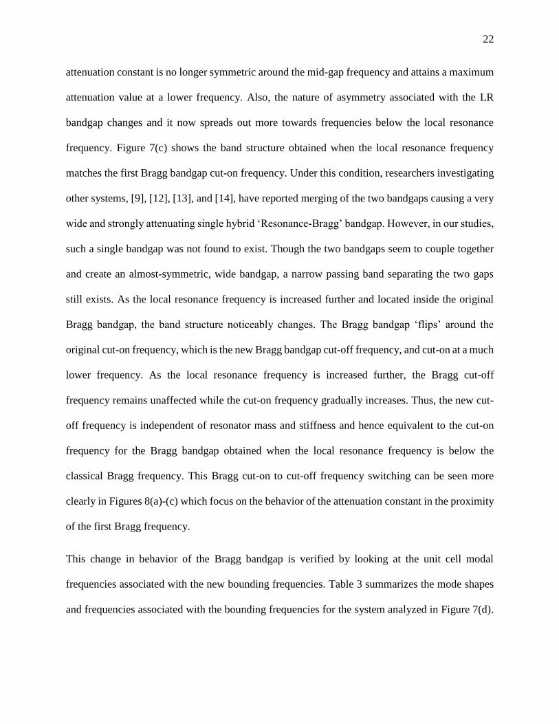
classical Bragg frequency. This Bragg cut-on to cut-off frequency switching can be seen more
clearly in Figures 8(a)-(c) which focus on the behavior of the attenuation constant in the proximity
of the first Bragg frequency.
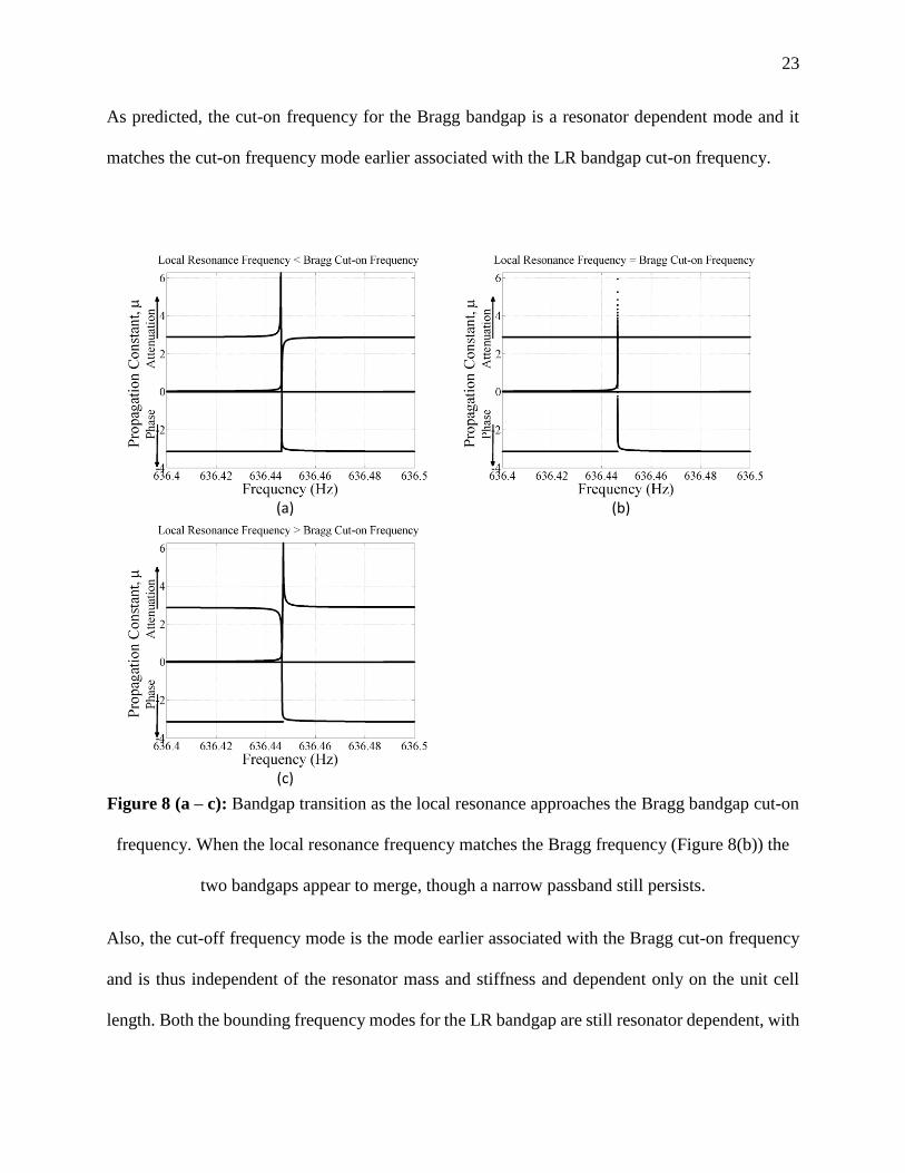
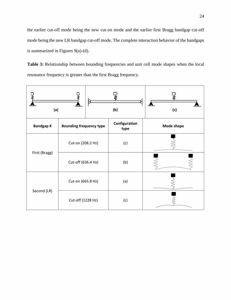
This change in behavior of the Bragg bandgap is verified by looking at the unit cell modal
frequencies associated with the new bounding frequencies. Table 3 summarizes the mode shapes
and frequencies associated with the bounding frequencies for the system analyzed in Figure 7(d).
23
As predicted, the cut-on frequency for the Bragg bandgap is a resonator dependent mode and it
matches the cut-on frequency mode earlier associated with the LR bandgap cut-on frequency.
(a) (b)
(c)
Figure 8 (a – c): Bandgap transition as the local resonance approaches the Bragg bandgap cut-on
frequency. When the local resonance frequency matches the Bragg frequency (Figure 8(b)) the
two bandgaps appear to merge, though a narrow passband still persists.
Also, the cut-off frequency mode is the mode earlier associated with the Bragg cut-on frequency
and is thus independent of the resonator mass and stiffness and dependent only on the unit cell
length. Both the bounding frequency modes for the LR bandgap are still resonator dependent, with
24
the earlier cut-off mode being the new cut-on mode and the earlier first Bragg bandgap cut-off
mode being the new LR bandgap cut-off mode. The complete interaction behavior of the bandgaps
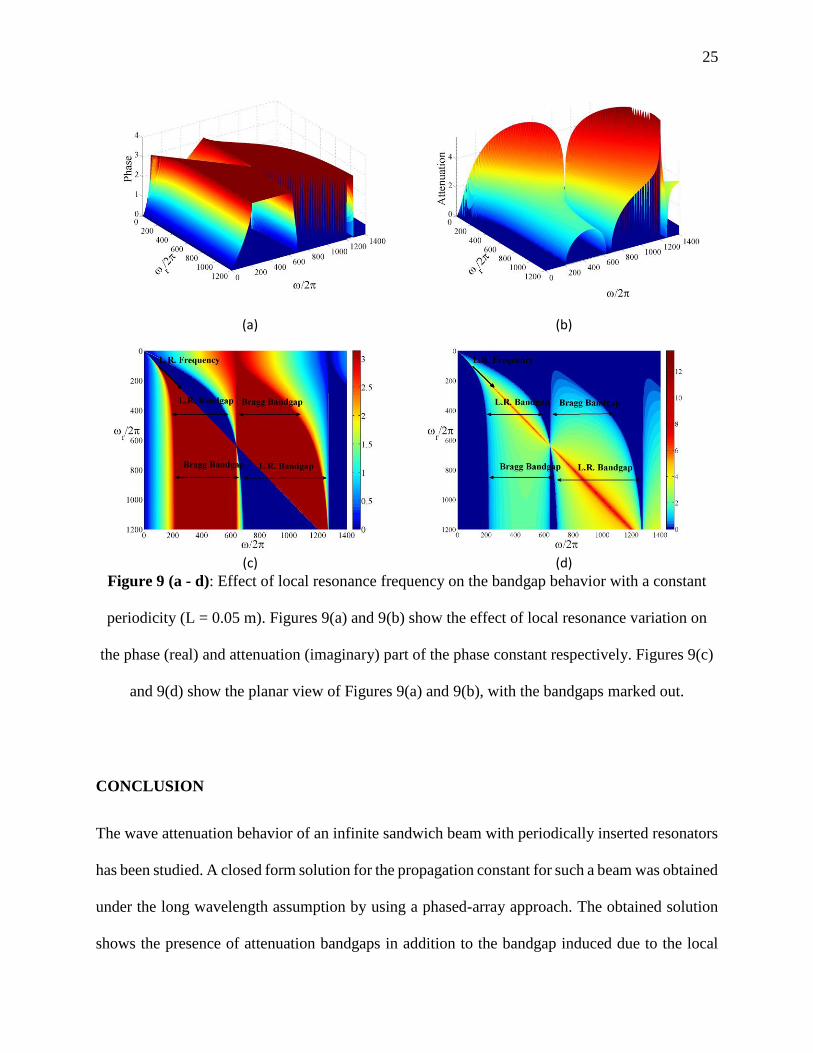
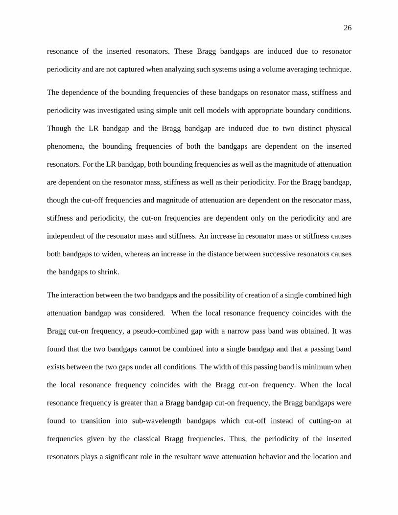
is summarized in Figures 9(a)-(d).
Table 3: Relationship between bounding frequencies and unit cell mode shapes when the local
resonance frequency is greater than the first Bragg frequency.
(a)
(b) (c)
Bandgap # Bounding frequency type Configuration
type Mode shape
First (Bragg)
Cut-on (208.2 Hz) (c)
Cut-off (636.4 Hz) (b)
Second (LR)
Cut-on (665.8 Hz) (a)
Cut-off (1228 Hz) (c)
25
(a) (b)
(c) (d)
Figure 9 (a - d): Effect of local resonance frequency on the bandgap behavior with a constant
periodicity (L = 0.05 m). Figures 9(a) and 9(b) show the effect of local resonance variation on
the phase (real) and attenuation (imaginary) part of the phase constant respectively. Figures 9(c)
and 9(d) show the planar view of Figures 9(a) and 9(b), with the bandgaps marked out.
CONCLUSION
The wave attenuation behavior of an infinite sandwich beam with periodically inserted resonators
has been studied. A closed form solution for the propagation constant for such a beam was obtained
under the long wavelength assumption by using a phased-array approach. The obtained solution
shows the presence of attenuation bandgaps in addition to the bandgap induced due to the local
26
resonance of the inserted resonators. These Bragg bandgaps are induced due to resonator
periodicity and are not captured when analyzing such systems using a volume averaging technique.
The dependence of the bounding frequencies of these bandgaps on resonator mass, stiffness and
periodicity was investigated using simple unit cell models with appropriate boundary conditions.
Though the LR bandgap and the Bragg bandgap are induced due to two distinct physical
phenomena, the bounding frequencies of both the bandgaps are dependent on the inserted
resonators. For the LR bandgap, both bounding frequencies as well as the magnitude of attenuation
are dependent on the resonator mass, stiffness as well as their periodicity. For the Bragg bandgap,
though the cut-off frequencies and magnitude of attenuation are dependent on the resonator mass,
stiffness and periodicity, the cut-on frequencies are dependent only on the periodicity and are
independent of the resonator mass and stiffness. An increase in resonator mass or stiffness causes
both bandgaps to widen, whereas an increase in the distance between successive resonators causes
the bandgaps to shrink.
The interaction between the two bandgaps and the possibility of creation of a single combined high
attenuation bandgap was considered. When the local resonance frequency coincides with the
Bragg cut-on frequency, a pseudo-combined gap with a narrow pass band was obtained. It was
found that the two bandgaps cannot be combined into a single bandgap and that a passing band
exists between the two gaps under all conditions. The width of this passing band is minimum when
the local resonance frequency coincides with the Bragg cut-on frequency. When the local
resonance frequency is greater than a Bragg bandgap cut-on frequency, the Bragg bandgaps were
found to transition into sub-wavelength bandgaps which cut-off instead of cutting-on at
frequencies given by the classical Bragg frequencies. Thus, the periodicity of the inserted
resonators plays a significant role in the resultant wave attenuation behavior and the location and
27
width of Bragg bandgaps may also be tailored by choosing appropriate resonator properties and
periodicity.
FUNDING
This work was supported by the Office of Naval Research [grant number N00014-11-1-0580]. Dr.
Yapa D.S. Rajapakse was the program manager.
REFERENCES
[1] Z. Liu, X. Zhang, Y. Mao, Y. Y. Zhu, Z. Yang, C. T. Chan, P. Sheng, Locally resonant sonic
materials. Science, 289 (5485) (2000), 1734-1736. doi:10.1126/science.289.5485.1734.
[2] M. I. Hussein, M. J. Leamy, M. Ruzzene, Dynamics of phononic materials and structures:
Historical origins, recent progress and future outlook. Applied Mechanics Reviews, 66 (2014),
040802. doi:10.1115/1.40262911.
[3] H. H. Huang, C. T. Sun, Wave attenuation mechanism in an acoustic metamaterial with
negative effective mass density. New Journal of Physics, 11 (2009), 013003. doi:10.1088/1367-
2630/11/1/013003.
[4] L. Brillouin, Wave propagation in periodic structures, Dover Publications, New York, 1953.
[5] Lord Rayleigh, On the maintenance of vibrations by forces of double frequency, and on the
propagation of waves through a medium endowed with a periodic structure. Philosophical
Magazine XXIV (1887), 145-159.
28
[6] D. J. Mead, Wave propagation in continuous periodic structures: Research contributions from
Southampton, 1964 – 1995. Journal of Sound and Vibration, 190 (3) (1996), 495-524.
doi:10.1006/jsvi.1996.0076.
[7] M. Rupin, F. Lemoult, G. Lerosey, P. Roux, Experimental demonstration of ordered and
disordered multiresonant metamaterials for lamb waves, Physics Review Letters, 112 (2014),
234301. doi:10.1103/PhysRevLett.112.234301.
[8] T. Still, W .Cheng, M. Retsch, R. Sainidou, J. Wang, U. Jonas, N. Stefanou, G. Fytas,
Simultaneous occurrence of structure-directed and particle-resonance-induced phononic gaps in
colloidal films. Physical Review Letters, 100 (2008), 194301.
doi:10.1103/PhysRevLett.100.194301.
[9] C. Croënne, E. J. S. Lee, H. Hu, J. H. Page, Band gaps in phononic crystals: Generation
mechanisms and interaction effects. AIP Advances 1 (2001), 041401. doi:10.1063/1.3675797.
[10] Y. Achaoui, A. Khelif, S. Benchabane, L. Robert, V. Laude, Experimental observation of
locally-resonant and Bragg band gaps for surface guided waves in a phononic crystal of pillars.
Physical Review B 83 (2011), 104201. doi:10.1103/PhysRevB.83.104201.
[11] A. Bretagne, B. Venzac, V. Leroy, A. Tourin, Bragg and hybridization gaps in bubble
phononic crystals. AIP Conference Proceedings 1433 (2012), 317. doi:10.1063/1.3703196.
[12] N. Kaina, M Fink, G. Lerosey, Composite media mixing Bragg and local resonances for
highly attenuating and broad bandgaps. Scientific Reports 3 (2013), 3240. doi:10.1038/srep03240.
[13] Y. Chen, L. Wang, Periodic co-continuous acoustic metamaterials with overlapping resonant
and Bragg band gaps. Applied Physics Letters 105 (2014), 191907. doi:10.1063/1.4902129.
29
[14] B. Yuan, V. F. Humphrey, J. Wen, X. Wen, On the coupling of resonance and Bragg scattering
effects in three-dimensional local resonant sonic materials. Ultrasonics 53 (2013), 1332-1343.
doi:10.1016/j.ultras.2013.03.019.
[15] L. Liu, M. I. Hussein, Wave motion in periodic flexural beams and characterization of the
transition between Bragg scattering and local resonance. Journal of Applied Mechanics 79 (1)
(2011), 011003. doi:10.1115/1.4004592.
[16] L. Raghavan, A. S. Phani, Local resonance bandgaps in periodic media: Theory and
experiment. Journal of Acoustical Society of America 134 (3) (2013), 1950.
doi:10.1121/1.4817894.
[17] R. Chen, T. Wu, Vibration reduction in a periodic truss beam carrying locally resonant
oscillators. Journal of Vibration and Control 05 (13) (2014), 1077546314528020.
doi:10.1177/1077546314528929.
[18] M. Y. Wang, X. Wang, Frequency band structure of locally resonant periodic flexural beams
suspended with force-moment resonators. Journal of Physics D: Applied Physics 46 (2013),
255502. doi:10.1088/0022-3727/46/25/255502.
[19] Y. Xiao, J. Wen, X. Wen, Broadband locally resonant beams containing multiple periodic
arrays of attached resonators. Physics Letters A 376 (2012), 1384 – 1390.
doi:10.1016/j.physleta.2012.02.059
[20] Y. Xiao, J. Wen, D. Yu, X. Wen, Flexural wave propagation in beams with periodically
attached vibration absorbers: Band-gap behavior and band formation mechanisms. Journal of
Sound and Vibration 332 (2013), 867-893. doi:10.1016/j.jsv.2012.09.035.
30
[21] J. S. Chen, C. T. Sun, Dynamic behavior of a sandwich beam with internal resonators. Journal
of Sandwich Structures and Materials 13 (4) (2010), 391 – 408. doi:10.1177/1099636210391124.
[22] J. R. Vinson, Sandwich Structures, Applied Mechanics Reviews 54 (3) (2001), 201 – 214.
doi:10.1115/1.3097295.
[23] S. Abrate, B. Castanié, Y. D. S. Rajapakse, Dynamic failure of composite and sandwich
structures, Series Solid Mechanics and Its Applications, Volume 192, Springer Science + Business
Media, Dordrecht, 2013. doi:10.1007/978-94-007-5329-7.
[24] J. S. Chen, B. Sharma, C. T. Sun, Dynamic behavior of sandwich structure containing spring-
mass resonators. Composite Structures 93 (2011), 2120 – 2125.
doi:10.1016/j.compstruct.2011.02.007.
[25] D. J. Mead, A new method of analyzing wave propagation in periodic structures; applications
to periodic Timoshenko beams and stiffened plates. Journal of Sound and Vibration 104 (1) (1986),
9 – 27. doi: 10.1016/S0022-460X(86)80128-6.
[26] L Liu, K. Bhattacharya, Wave propagation in a sandwich structure. International Journal of
Solids and Structures 46 (2009), 3290 – 3300. doi:10.1016/j.ijsolstr.2009.04.023.
[27] J. F. Doyle, Wave propagation in structures, Springer, New York, 1998. doi: 10.1007/978-1-
4612-1832-6.
[28] D. J. Mead, Wave propagation and natural modes in periodic systems: II. Multi-coupled
systems, with and without damping, Journal of Sound and Vibration 40 (1975) 19-39. doi:
10.1016/S0022-460X(75)80228-8