lnx74-525.2 - lennox international -
TRANSCRIPT

1LNX74-525.2
August, 2021
CONTROLS SYSTEM MANUALPackaged Ventilation/Dedicated Outside Air System (DOAS)
model DLV
LNX74-525.25H0837230002
THIS MANUAL IS THE PROPERTY OF THE OWNER. PLEASE BE SURE TO LEAVE IT WITH THE OWNER WHEN YOU LEAVE THE JOB.
1. Improper installation, adjustment, alteration, service or maintenance can cause property damage, injury or death. Read the installation, operating and maintenance instructions thoroughly before installing or servicing this equipment.
2. Disconnect power supply before making wiring connections or working on this equipment. Follow all applicable safety procedures to prevent accidental power up. Failure to do so can result in injury or death from electrical shock or moving parts and may cause equipment damage.
3. For units equipped for dual power supply sources, both sources of power must be disconnected to prevent electrical shock and equipment damage.
4. Improper control adjustments and manual mode control can cause property damage, injury or death. Read the installation, operating and maintenance instructions thoroughly before making adjustments.
WARNING
Carel pCO5+ Microprocessor Controller
IMPORTANT1. The use of this manual is specifically intended
for a qualified installation and service agency. All installation and service of this unit must be performed by a qualified installation and service agency.
2. These instructions must also be used in conjunction with the Installation and Service Manual originally shipped with the unit, in addition to any other accompanying component supplier literature.
3. This manual applies to the control system program version series 7.xxx. For any other version, please contact the Service Department. The program version that resides in the unit controller can be found in the Information section of the Installer Sub Menu. Refer to the manual for instructions on accessing this screen.
As with any mechanical equipment, personal injury can result from contact with sharp sheet metal edges. Be careful when you handle this equipment.
CAUTION

2 LNX74-525.2
Table of ContentsGeneral Information ............................................................. 2Special Design Requests .................................................... 2Model Nomenclature Note................................................... 2Acronyms Used ................................................................... 2Controller Overview ............................................................. 3Digital Scroll Compressor Operation ................................... 4Electronic Expansion Valve Operation ................................ 5Sequence of Operation ..................................................6-17 1. Unit On/Off ................................................................6 2. Occupancy Mode...................................................... 6 3. Damper Control Sequences ..................................6-8 4. Supply Fan Control Sequences ............................8-9 5. Exhaust Fan Control Sequences ........................9-10 6. Temperature Control Sequences .......................10-14 7. Dehumidification Control Sequences ................14-16 8. Energy Recovery Sequences ............................16-17 9. Dual Power (Stand-By Power) Sequences ............ 17pCO5+ Large Controller Layout ........................................ 18pCOe Expansion Board Controller Layout ........................ 18pCO5+ Input/Output (I/O) List ...........................................19pCOe Input/Output (I/O) List .............................................20Controller Display/Keypad Functions ................................ 21Menu Navigation ............................................................... 22Password Protection ......................................................... 23Controller Menus ..........................................................24-67 Menu Tree. .................................................................24 Main Status Screen ...............................................25-28 A. On/Off Unit Sub Menu ............................................29 B. Setpoints Sub Menu ..........................................30-31 C. Clock/Scheduler Sub Menu ................................... 33 D. Input/Output Sub Menu .....................................34-35 E. Alarm Logger Sub Menu and Alarm Listing ......36-41 F. Board Switch Sub Menu .........................................42 Programming the Remote Display Keypad ............ 43 G. Service Sub Menu ............................................44-62 H. Manufacturer Sub Menu ........................................63 ERV Units - Main Status Screen ................................ 63 ERV Units - Service Sub Menu .............................64-67Typical BMS System Variables ....................................68-73 Analog....................................................................68-69 Integer. ...................................................................70-71 Digital .....................................................................71-73
CONTROLS SYSTEM MANUAL
Acronym MeaningBMS Building Management SystemBPS Bits Per SecondCCS Capacity Control Solenoid CF Condenser Fan
CFM Cubic Feet per MinuteComp or CP Compressor
CT Current TransformerCV Constant Volume
Dehum DehumidificationDiff Difference
DOAS Dedicated Outside Air System EA Exhaust Air
EEV Electronic Expansion ValveERV Energy Recovery VentilatorEVD Electronic Valve DriverEx Exhaust
HGRH Hot Gas Re-HeatHOAS High Outside Air system
LL Liquid Line m "Minutes" or "Minimum"
Mod ModulationOA Outside Airpsig Pounds per Square Inch gaugeRA Return AirRH Relative HumiditySA Supply Air
SetPt or SP SetpointStd-by StandbyTemp Temperature Vlv Valve VT Voltage Transformer
Model Nomenclature NoteWhile the entire model nomenclature should be reviewed, there are several key digits that will help identify the primary characteristics of the unit referred to in this manual:• Digits 4-5 = Unit Nominal Cooling Tons• Digit 6 = Unit Cabinet Size• Digit 7 = Unit Air Control Configuration
Some key characteristics of Digit 7 that are helpful to know:Dampers
○ A, B, C, R have OA and RA dampers ○ D, E, F are 100% OA only
Exhaust ○ A, D have no exhaust ○ B, E have energy recovery exhaust (referred to in this
manual as ERV units) ○ C, F have non-energy recovery exhaust (referred to in
this manual as PEM units)• Digit 17 = Heat Type• Digit 18 = Heat Rating
For the most current model nomenclature descriptions, please refer to the Model Nomenclature section in the Installation and Service Manual that shipped with the equipment.
Acronyms Used
Special Design RequestsUnits are sometimes built units with special features as requested by the customer. This manual only covers standard features and does not include any changes made for special feature requests by the customer. Units built with special features are noted with a 5-digit SPO (Special Product Order) Number on the Serial Plate.

3LNX74-525.2
CONTROLS SYSTEM MANUAL
pCO5+ Large Main Features:
● 10 Analog Inputs ○ Uses 10K NTC temperature sensors ○ 4-20ma Humidity and CO2 sensors for reliability
● 6 Analog Outputs ○ 0-10vdc for easy fault finding
● 18 Digital inputs ○ Used to monitor all aspects of the unit
● 18 Digital Outputs ○ True relayed outputs for reliability
● Real Time Clock ○ With battery backup and day light savings adjustment
● pLAN Communication ○ To allow connectivity to space sensors and other
controllers ● Built In Display
○ Backlit easy to use and easy to read ● Alarm Logging
○ With a snapshot of the unit sensors ● Run Hours logging
○ With maintenance setpoints ● Password Protection
○ Three levels of password protection ● Manual Control
○ For easy startup and service ● Simple Interface
○ Easy to understand menus and settings ● Built in Scheduler
○ Up to 7 periods per day – Either On/Off control or Occupied/Unoccupied
○ Holiday Scheduler with up to 20 holiday periods ● Remote Display option
○ Can be 100ft from unit using standard RJ12 cable ● All reset points fully adjustable
Controller OverviewControls are one of the most important components of specialized HVAC equipment. The control system is designed and engineered specifically for the model DLV Packaged Ventilation/Dedicated Outside Air System (DOAS) unit to ensure the unit operates safely, reliably, with optimized performance, and maintaining maximum energy efficiency.
The control system utilizes a Carel pCO5+ Large programmable microprocessor controller. Highly advanced with a powerful microprocessor and fast processing speed, the controller features a number of I/O’s for complex HVAC/R applications.
The main controller board is housed in a plastic case that ensures a high index of protection and reduces the risk of electrostatic discharges due to incorrect handling. The controller offers greater safety due to the optical isolation of the serial pLAN, protection of the analog inputs in the event of incorrect connections, and an extended range of operating temperatures. Given the increasing demand for integration, pCO5+ can interface with BMS systems via many of the most commonly-used serial communication standards, using optional boards.

4 LNX74-525.2
CONTROLS SYSTEM MANUAL
Copeland Digital Scroll™ compressor technology is used to provide seamless modulating capacity over a wide operating range. The Digital Scroll compressor is capable of modulating capacity from 25 to 100%, however when combined with additional compressors, the system modulation range can be significantly greater. The following compressor combinations with modulation range are shown:
The capacity modulation is achieved by timed loading of the compressor on a repeating 12 second cycle. The compressor is supplied with an external solenoid valve. This “normally closed” (de-energized) solenoid valve is a key component for achieving modulation. When the solenoid valve is in its normally closed position, the compressor operates at full capacity or in the “loaded state”. When the solenoid valve is energized, the two scroll elements move apart axially, or into the “unloaded state”. During the unloaded state, the compressor motor continues running, but since the scrolls are separated, there is no compression. During the “loaded state”, the compressor delivers 100% capacity and during the “unloaded state”, the compressor delivers 0% capacity. A cycle consists of “loaded state” and “unloaded state”. By varying the time of “loaded state” and “unloaded state”, an average capacity is obtained to precisely match the load demand of the system.
Digital Scroll Capacity Modulation Examples:
Starting Frequency and Minimum Compressor Running Time
The following default values are used for compressor protection:
● Compressor Minimum Run-Time: This is the time required to ensure adequate oil return and sufficient motor cooling from the suction gas upon start-up of the compressor. The time is set for 60 seconds.
● Compressor Minimum Off-Time: This is the time used to provide a measure of hysteresis to the system to stop the compressor from starting immediately after it has stopped. The time is set for 30 seconds.
● Inter-Stage Delay: This is the time required between successive compressors. For example, when compressor 1 starts, compressor 2 cannot start until the inter-stage delay has timed out. The time is set for 120 seconds.
Example 1:On Time = 3 secondsOff Time = 9 secondsAverage Capacity = 25%
Example 2On Time = 6 secondsOff Time = 6 secondsAverage Capacity = 50%
Example 3On Time = 9 secondsOff Time = 3 secondsAverage Capacity = 75%
0
100
0 1 2 3 4 5 6 7 8 9 10 11 12
Cap
acity
(%)
Time (seconds)
25% Output
0
100
0 1 2 3 4 5 6 7 8 9 10 11 12
Cap
acity
(%)
Time (seconds)
50% Output
0
100
0 1 2 3 4 5 6 7 8 9 10 11 12
Cap
acity
(%)
Time (seconds)
75% Output
Compressor Example(D-Cabinet Shown)
Digital Scroll Compressor Operation
Casing Size
Nominal Tons
Compressor Description System Modulation RangeCircuit 1 Circuit 2
B 7 Single Modulating Digital Scroll n/a 25.0-100%B and C 10 to 30 Tandem Modulating Digital Scroll/On-Off n/a 12.5-100%
D 30 to 60 Tandem Modulating Digital Scroll/On-Off Tandem On-Off/On-Off 6.3-100%

5LNX74-525.2
CONTROLS SYSTEM MANUAL
The unit uses electronic expansion valves to enable the correct metering of refrigerant. The valve uses both a pressure transducer and temperature probe to ensure that the superheat of the refrigeration system remains correct.
Electronic expansion valves differ from thermostatic expansion valves in their ability to maintain control of the suction superheat at reduced head pressures. This can lead to significant energy savings, particularly at reduced loading and low ambient temperatures.
EEV step position, superheat setpoint, head pressure set point, and other features can be viewed and adjusted via the microprocessor display - far easier than having to manually adjust thermostatic expansion valves.
The electronic expansion valve(s) are driven by the Carel EVD Evolution Twin controller, comprised of two stepper motor drivers that can independently manage two electronic expansion valves. Each driver controls refrigerant superheat and optimises refrigerant circuit performance. Each circuit has one expansion valve for the evaporator coil. For units that include optional modulating hot gas reheat, another expansion valve is included for hot gas reheat capacity control.
Also included for each EVD Evolution Twin controller is a Carel EVD Ultracap which provides emergency power supply to ensure complete closing of the valves even when there is a sudden loss of main unit power supply.
Electronic Expansion Valve Operation

6 LNX74-525.2
The model DLV Packaged Ventilation unit is designed for both Dedicated Outdoor Air Systems (DOAS) and High Outdoor Air Systems (HOAS) applications, allowing space ventilation or make-up air with accurate control of temperature and humidity via mechanical cooling, heating and dehumidification during year round outdoor ambient conditions.
The unit is also available with an Energy Recovery Ventilation option with standard economizer bypass (for all energy recovery wheel sizes except 81”) to provide for reduced operating costs and increased energy savings.
The unit is intelligently managed by the factory installed programmable microprocessor controller with control operating sequences detailed below. The controls are pre-configured at the factory for the customer selected control strategy so the unit is ready when it reaches the jobsite.
1. Unit On/OffIn order for the unit to run, power must be applied and the controller display/keypad used to enable the unit via the “ON/OFF UNIT” sub menu.
• If the unit is “ON”, control will be determined by the current occupancy mode of the unit and control configuration/setpoints.
• If the unit is “OFF”, no setpoint control will take place and the unit will remain in stand-by with all control devices disabled.
In addition, the following control sources are also available as secondary means to turn the unit on and off:
a) On/Off by Digital Input: Available when Remote On/Off Switch wired to unit controller
b) On/Off by BMS: Available when BMS Interface Card installed in unit controller
c) On/Off by pAD Thermostat: Available when a pAD Thermostat wired to unit controller
d) On/Off by Clock/Schedule: Always available from schedule within the unit controller
2. Occupancy ModeWhen the unit is “ON”, there are two modes of occupancy – occupied and unoccupied. Occupancy can be determined by any of the following:
a) Occupancy by Digital Input: Set via the replacement of jumper wire on controller input ID7 where:
• 0V = Unoccupied
• 24V = Occupied
a) BMS Call: Available when BMS Interface Card installed in unit controller
b) Time Schedule: Configured via the “CLOCK/SCHEDULER” menu.
c) Space Occupancy Override: Set via the override button found on the pAD thermostat. Note: To utilize space occupancy control, a space pAD device must be installed. If there is no space pAD installed there will be no option to use occupied and unoccupied control setpoints.
3. Damper SequencesDOAS Damper Configuration
Utilizes outside air dampers only with a 2-position on/off actuator. The available damper controls are as follows:
A. Two Position Control: Outside air dampers are open to 100% outside air position when in the occupied mode. Outside air dampers are closed in the unoccupied mode.
HOAS Damper Configuration
Utilizes outside and return dampers with a modulating 2-10V damper actuator controlled by a modulated signal from an analog output on the controller to drive both the outdoor air damper and return air damper simultaneous in opposing directions. The outside air damper and return air damper positions always total 100%. For example, if the outside air damper is at 70%, the return air damper will be at 30%.
The available damper controls are described below for the occupied mode of operation with minimum 20% outside air (80% return air) for base rate ventilation. In all cases, outside air dampers are closed and return air dampers open in the unoccupied mode.
CONTROLS SYSTEM MANUAL
Sequence of Operation
(continued next page)

7LNX74-525.2
A. Two Position Control: Dampers open to a customer defined minimum position between 20% and 100% outside air.
B. Digital Input (Multi-Position) Control: The unit controller sends the damper actuator to one of up to four position setpoints determined by the combinational logic at one or two of the digital inputs on the controller(s), as shown in the following table. Each of the four setpoint values can be modified between limits of 20% and 100% outside air.
CONTROLS SYSTEM MANUAL
Sequence of Operation (continued)
(continued next page)
Control Type Digital Input 15 pCOe Digital Input 1 Position (Default)
Two Position via Digital Input Open (0V) Not Used 1 (50.0%)Closed (24V) Not Used 2 (100.0%)
Three Position via Digit InputOpen (0V) Open (0V) 1 (50.0%)Open (0V) Closed (24V) 2 (75.0%)
Closed (24V) OP or CL 3 (100.0%)
C. Building Pressure Control: Dampers open to a customer defined minimum position between 20% and 100% outside air. A building pressure sensor installed in the space monitors the pressure relative to atmospheric pressure outside the space and sends a proportional 4-20mA signal back to the main unit controller. The controller will then compare that pressure reading against the building pressure setpoint (default value is 0.100” W.C., adjustable between limits of 0.000” and 5.000” W.C.) and control as follows:
a) If the building pressure is below the setpoint, the dampers will modulate to increase the volume of outside air, increasing the building pressure. The dampers will modulate to the maximum outside air setpoint, up to 100%.
b) If the building pressure is above the setpoint, the dampers will modulate to reduce the volume of outside air, decreasing the building pressure. The dampers will modulate to the minimum outside air setpoint, down to 20%.
D. Differential Enthalpy Economizer with Dew Point Offset Control: Dampers open to a customer defined minimum position between 20% and 100% outside air. Outdoor and return air enthalpy sensors are monitored by the controller and will control as follows:
a) If the outdoor enthalpy and dew point is higher than the return air enthalpy and dew point, the dampers will modulate to the minimum position setpoint to decrease the volume of outside air to avoid placing additional load on the mechanical cooling/dehumidification system.
b) If the outdoor enthalpy or dew point is lower than the return air enthalpy or dew point, the dampers will modulate to increase the volume of outside air to maintain a dry bulb temperature based on the intersection of the mixed air process line and target dew point temperature setpoint. The target dew point is control setup selected and can be mixed air, space (requires a space pAD), or mixed air and space (requires a space pAD). The mechanical heating/cooling/dehumidification will then modulate as needed to maintain the active supply air temperature setpoint.
E. Demand Controlled Ventilation (CO2) Control: Dampers open to a customer defined minimum position between 20% and 100% outside air. A space mounted CO2 sensor monitors the space CO2 level and sends a corresponding proportional 4-20mA signal back to the main unit controller The controller will then compare that CO2 reading against the CO2 setpoint (default value is 800PPM, adjustable between limits of 0 and 2000PPM) and the dampers are controlled as follows:
a) If the CO2 level is below the setpoint, the dampers will modulate to the minimum outside air position.
b) If the CO2 level is above the setpoint, the dampers will modulate to increase the volume of outside air to dilute the CO2 levels below the setpoint. The dampers will modulate to the maximum outside air setpoint, up to 100%.
F. Differential Enthalpy Economizer with Dew Point Offset Control and CO2 Override: Dampers open to a customer defined minimum position between 20% and 100% outside air. Outdoor and return air enthalpy sensors and a space mounted CO2 sensor are monitored by the controller. The dampers are controlled as follows:
a) If the outdoor enthalpy and dew point is higher than the return air enthalpy and dew point, the dampers will modulate to the minimum position setpoint to decrease the volume of outside air to avoid placing additional load on the mechanical cooling/dehumidification system.
b) If the outdoor enthalpy or dew point is lower than the return air enthalpy or dew point, the dampers will modulate to increase the volume of outside air to maintain a dry bulb temperature based on the intersection of the mixed air process line and target dew point temperature setpoint. The target dew point is control setup selected and can be mixed air, space (requires a space pAD), or mixed air and space (requires a
Note: For all cases, the combinational logic does not activate the unit. The logic determines which position the dampers are in if in the OCCUPIED mode. Occupied can be via schedule or occupancy digital input.

8 LNX74-525.2
space pAD). The mechanical heating/cooling/dehumidification will then modulate as needed to maintain the active supply air temperature setpoint.
c) Concurrently with conditions (a) and (b) above, the space mounted CO2 sensor monitors the space CO2 level and sends a corresponding proportional 4-20mA signal back to the main unit controller The controller will then compare that CO2 reading against the CO2 setpoint (default value is 800PPM, adjustable between limits of 0 and 2000PPM) and control as follows:
i. If the CO2 level is below the setpoint, the dampers will control to steps (a) and (b) above.
ii. If the CO2 level is above the setpoint, the controller will override the enthalpy economizer dew point control steps (a) and (b) and the dampers will modulate to increase the volume of outside air to dilute the CO2 levels below the setpoint. The dampers will modulate to the maximum outside air setpoint, up to 100%.
G. Building Management System (BMS) Control: Dampers will open or close based on a command from the customer BMS. There are no internal control setpoints or sensors for this mode of operation.
4. Supply Fan SequencesThe unit features direct drive fans with motor controlled by variable frequency drive(s). Supply fan controls are coordinated with damper controls to avoid control conflicts. For example, you cannot have building pressure control on both dampers and supply fan.
The available supply fan controls are described below for the occupied mode of operation. In all cases, the fan is either off during unoccupied or intermittent on a call for space heating, cooling, or dehumidification if equipped with a space pAD and configured for unoccupied setback operation. The fan speed will be based on the occupied control point.
For variable air volume applications described below, there are operating range limitations to protect the equipment. Minimum speed is based on the greater of 50% of design airflow or minimum design airflow. Consider the following scenarios for the B-cabinet size unit which has an allowable airflow range of 1,100 to 6,000CFM:
• If the design airflow is 3,000CFM, 50% airflow is 1,500CFM, which is greater than the 1,100CFM minimum, therefore 1,500CFM (50%) is the minimum airflow.
• If the design airflow is 1,800CFM, 50% airflow is 900CFM. In this case, the minimum 1,100CFM of the allowable airflow range is greater, so the minimum airflow is 1,100CFM (≈61%).
The available supply fan control options are as follows:
A. Constant Speed: The supply fan operates at a constant speed that does not dynamically change. The default setpoint is 100% but can be adjusted within the allowable range described above.
B. Digital Input (Multi-Speed) Control: The unit controller sends the supply fan VFD to one of up to four speed setpoints determined by the combinational logic at one or two of the digital inputs on the controller(s), as shown in the following table. Each of the four setpoint values can be modified between the range described above.
CONTROLS SYSTEM MANUAL
Sequence of Operation (continued)
Control Type Digital Input 15 pCOe Digital Input 1 Speed (Default)
Two Speed via Digital Input Open (0V) Not Used 1 (50.0%)Closed (24V) Not Used 2 (100.0%)
Three Speed via Digit InputOpen (0V) Open (0V) 1 (50.0%)Open (0V) Closed (24V) 2 (75.0%)
Closed (24V) OP or CL 3 (100.0%)Note: For all cases, the combinational logic does not activate the unit. The logic determines which speed the fan is in if in the OCCUPIED mode. Occupied can be via schedule or occupancy digital input.
C. Building Pressure Control: The supply fan VFD will ramp up to the minimum speed setpoint. A building pressure sensor installed in the space monitors the pressure relative to atmospheric pressure outside the space and sends a proportional 4-20mA signal back to the main unit controller. The controller will then compare that pressure reading against the building pressure setpoint (default value is 0.100” W.C., adjustable between limits of 0.000” and 5.000” W.C.) and control as follows:
a) If the building pressure is below the setpoint, the VFD will modulate to increase the volume of outside air, increasing the building pressure. The VFD will modulate up within the allowable range described above.
b) If the building pressure is above the setpoint, the VFD will modulate to reduce the volume of outside air, decreasing the building pressure. The VFD will modulate down with the allowable range described above.
(continued next page)

9LNX74-525.2
D. Duct Pressure Control: The supply fan VFD will ramp up to the minimum speed setpoint. A duct pressure sensor installed downstream in the supply duct monitors the pressure in the duct and sends a proportional 4-20mA signal back to the main unit controller. The controller will then compare that pressure reading against the duct pressure setpoint (default value is 1.500” W.C., adjustable between limits of 0.000” and 5.000” W.C.) and control as follows:
a) If the duct pressure is below the setpoint, the VFD will modulate to increase the volume of supply air, increasing the duct pressure. The VFD will modulate up within the allowable range described above.
b) If the duct pressure is above the setpoint, the VFD will modulate to reduce the volume of supply air, decreasing the duct pressure. The VFD will modulate down with the allowable range described above.
In order to prevent over pressurization of the duct work, if the duct pressure sensor detects a pressure above 5.000” W.C. then the unit is immediately shutdown via the high static pressure alarm. The unit will remain shut down in alarm until the alarm condition is cleared via the handheld display or BMS reset call.
E. Demand Controlled Ventilation (CO2) Control: The supply fan VFD will ramp up to the minimum speed setpoint. A CO2 sensor installed in the space monitors the CO2 level and sends a proportional 4-20mA signal back to the main unit controller. The controller will then compare that CO2 reading against the CO2 setpoint (default value is 800PPM, adjustable between limits of 0 and 2000PPM) and control as follows:
a) If the CO2 level is below the setpoint, the VFD will modulate to reduce the volume of outside air. The VFD will modulate down with the allowable range described above.
b) If the CO2 level is above the setpoint, the VFD will modulate to increase the volume of outside air to dilute the CO2 levels below the setpoint. The VFD will modulate up with the allowable range described above.
F. Building Management System (BMS) Control: The supply fan VFD will modulate within the range described above based on a command from the customer BMS. There are no internal control setpoints or sensors for this mode of operation.
Note for Units with Energy Recovery: Energy Recovery equipped units include an economizer bypass (units with 74” wheels or smaller), whose function is described in the Energy Recovery section. When the economizer bypass damper opens, the total static pressure that the supply fan must overcome is reduced, which will cause the airflow to increase, increasing energy consumption. For all control types above, there is a setting called “Bypass Offset” (default is 10%, adjustable from 0% to 20%) that reduces the fan speed in an attempt to maintain approximately the same airflow as when the bypass is closed. With the default 10% setting, the supply fan speed will be reduced by 10% when the bypass is opened.
5. Exhaust Fan SequencesWhen equipped with an exhaust fan option, the unit features motors controlled by either a motor starter or a variable frequency drive. Exhaust fan controls are coordinated with supply fan controls to avoid control conflicts. For example, you cannot have building pressure control on both supply and exhaust fans.
There are three different exhaust fan configurations that can be enabled. Depending on which exhaust fan configuration is selected determines which control sequences are available. The exhaust fan configurations are:
a) ON/OFF – Relay: The exhaust fan is enabled by a relay output on the PRTU controller. The enable signal is sent to the exhaust fan when the unit is in occupied mode and supply fan is active. This is used with either PEM (non-energy recovery Power Exhaust Module) equipped units that are single speed motor starter controlled or for activating remote exhaust fans by others.
b) ERV (Energy Recovery Ventilation): This option is for units configured with Energy Recovery Exhaust and is only available with an exhaust fan variable frequency drive for motor control as described below.
c) PEM (Power Exhaust Module): This option is for units configured with Non-Energy Recovery Exhaust with variable frequency drive motor control as described below.
For variable air volume exhaust applications described below, there are operating range limitations to provide proper equipment function. For units with an ERV, the allowable range is up to 50% to 100% of design airflow. For units with a PEM, the allowable range is 20% to 100% of design airflow.
The available exhaust fan controls are described below for the occupied mode of operation. In all cases, the fan is off during the unoccupied mode of operation.
A. Constant Speed: The supply fan operates at a constant speed that does not dynamically change. There are two options available for Constant Speed:
1. Variable Frequency Drive (ERV or PEM Units): The unit includes a variable frequency drive. The default setpoint is 100% but can be adjusted within the allowable range described above.
CONTROLS SYSTEM MANUAL
Sequence of Operation (continued)
(continued next page)

10 LNX74-525.2
2. Single Speed Motor Starter (PEM Units Only): The unit includes a single speed motor starter. The unit exhaust fan operates at 100% speed and is non-adjustable through the motor starter control.
B. Digital Input (Multi-Speed) Control (PEM Units Only): The unit controller sends the exhaust fan VFD to one of up to four speed setpoints determined by the combinational logic at one or two of the digital inputs on the controller(s), as shown in the following table. Each of the four setpoint values can be modified between the range described above.
CONTROLS SYSTEM MANUAL
Sequence of Operation (continued)
C. Supply Fan Offset (ERV or PEM Units): The exhaust fan will run at a constant speed determined by the supply fan speed and a configurable offset value (default -10%, adjustable from -20% to 20%). For example, if the supply fan is operating at 70% and the offset is -10%, then the exhaust fan operate at 60% (70% - 10% = 60%).
D. Building Pressure Control (ERV or PEM Units): The exhaust fan VFD will ramp up to the minimum speed setpoint. A building pressure sensor installed in the space monitors the pressure relative to atmospheric pressure outside the space and sends a proportional 4-20mA signal back to the main unit controller. The controller will then compare that pressure reading against the building pressure setpoint (default value is 0.100” W.C., adjustable between limits of 0.000” and 5.000” W.C.) and control as follows:
a) If the building pressure is below the setpoint, the VFD will modulate to decrease the volume of exhaust air, increasing the building pressure. The VFD will modulate down within the allowable range described above.
b) If the building pressure is above the setpoint, the VFD will modulate to increase the volume of exhaust air, increasing the building pressure. The VFD will modulate up with the allowable range described above.
E. Building Management System (BMS) Control (ERV or PEM Units): The exhaust fan VFD will modulate within the range described above based on a command from the customer BMS. There are no internal control setpoints or sensors for this mode of operation.
Note for Units with Energy Recovery: Energy Recovery equipped units include an economizer bypass (units with 74” wheels or smaller), whose function is described in the Energy Recovery section. When the economizer bypass damper opens, the total static pressure that the exhaust fan must overcome is reduced, which will cause the airflow to increase, increasing energy consumption. For all control types above, there is a setting called “Bypass Offset” (default is 10%, adjustable from 0% to 20%) that reduces the fan speed in an attempt to maintain approximately the same airflow as when the bypass is closed. With the default 10% setting, the exhaust fan speed will be reduced by 10% when the bypass is opened.
6. Temperature Control SequencesSupply Air Temperature Control
The temperature control sequences maintain the required supply air temperature with heating, cooling, and economizer modes of operation. The supply air temperature is monitored by a factory supplied, field installed supply air sensor that is mounted downstream of the unit discharge in the supply duct. Temperature is maintained by modulation of cooling and heating systems to meet the supply air temperature setpoint.
The active supply air temperature control will be one of three possible setpoints:
A. Cooling: The setpoint will be 55.0°F (adjustable from 45°F to 90°F). Cooling operation requires a supply air reset be used to create a call for cooling, as discussed in the “Supply Air Reset Controls” section.
B. Heating: The setpoint will be 85.0°F (adjustable from 60°F to either 100°F [condensing gas heat or electric] or 130°F [non-condensing gas heat]). Heating operation requires a supply air reset be used to create a call for heating, as discussed in the “Supply Air Reset Controls” section.
C. Neutral Air: The setpoint will be 70°F (adjustable from 50°F to 90°F). The neutral air setpoint is active if there is no call for heating or cooling from a supply air reset.
Dehumidification is not covered in this section. It will be detailed in a separate section called “Dehumidification Control Sequences”.
Control Type Digital Input 15 pCOe Digital Input 1 Speed (Default)
Two Speed via Digital Input Open (0V) Not Used 1 (50.0%)Closed (24V) Not Used 2 (100.0%)
Three Speed via Digit InputOpen (0V) Open (0V) 1 (50.0%)Open (0V) Closed (24V) 2 (75.0%)
Closed (24V) OP or CL 3 (100.0%)Note: For all cases, the combinational logic does not activate the unit. The logic determines which speed the fan is in if in the OCCUPIED mode. Occupied can be via schedule or occupancy digital input.
(continued next page)

11LNX74-525.2
Economizer Operation
There are two modes of operation that are economizer based control, and will be indicated as such on the controller status screen. The two possible modes indicated on the controller screen are as follows:
A. Econ: Econ will be displayed when the Enthalpy Economizer damper control (if equipped) is active without any mechanical cooling active. For more information on the Enthalpy Economizer damper control, refer to the “Damper Sequences” section.
B. Fan Only: Fan-Only will be displayed whenever mechanical cooling/dehumidification or heating is not required and the supply air temperature is within +/- 5°F (adjustable) of the active setpoint.
Supply Air Temperature Resets
While the basic control for supply air temperature control is neutral air, reset of the supply air temperature for heating or cooling can be configured using either a space temperature sensor (pAD), the outdoor air temperature sensor, or a combination of both. Each is described as follows:
A. Space Temperature Reset: The space reset call comes from the pAD mounted in the conditioned space. This call is generated based on the space temperature and space cooling and heating setpoints. The default space temperature setpoint values are as follows:
1. Occupied Mode
• Cooling: 74.0°F (adjustable from 50.0°F to 90.0°F)
• Heating: 70.0°F (determined by the Heat Offset, see next item)
• Heating Offset: 4.0°F (adjustable from 2.0°F to 20.0°F)
• Heating Differential: 1.0°F (adjustable from 1.0°F to 10°F)
• Cooling Differential: 1.0°F (adjustable from 1.0°F to 10°F)
The Heating Offset determines how far below the cooling setpoint the temperature must fall before the unit enters the heating mode. The Heating and Cooling differentials prevent short cycling. Graphically, the occupied mode setpoints above are as follows:
Note the bottom row displays the Heating, Neutral Air, and Cooling supply air reset temperature setpoints.
For example, with a cooling setpoint of 74.0°F the space must exceed 75.0°F (74.0°F + 1.0°F) before a cooling reset call is sent to the unit. The space must fall below 74°F before the cooling reset condition is cleared. On a call for space cooling, the supply air temperature setpoint will be reset to 55°F. Once the call for cooling is satisfied, the unit will return to the neutral air active setpoint which is 70°F.
2. Unoccupied Mode
• Cooling: 85.0°F (adjustable from 70.0°F to 90.0°F)
• Heating: 62.0°F (adjustable from 50.0°F to 70.0°F)
• Heating Differential: 2.0°F (adjustable from 1.0°F to 10°F)
• Cooling Differential: 2.0°F (adjustable from 1.0°F to 10°F)
Graphically, the unoccupied mode setpoints above are as follows:
CONTROLS SYSTEM MANUAL
Sequence of Operation (continued)
(continued next page)

12 LNX74-525.2
Note the bottom row displays the Heating and Cooling supply air reset temperature setpoints. For space temperatures between the Heating and Cooling setpoints, the unit is in Stand-By mode.
For example, with a heating setpoint of 62.0°F the space must fall below 60.0°F (62.0°F - 2.0°F) before a heating reset call is sent to the unit. The space must rise above 62°F before the heating reset condition is cleared. On a call for space heating, the supply air temperature setpoint will be reset to 80°F (was adjusted from the default reset setting of 85°F in this example). Once the call for heating is satisfied, the unit will return to the Stand-By mode of operation.
B. Outdoor Air Temperature Reset: The outdoor reset calls comes from the outdoor air temperature sensor. This call is generated based on the outdoor temperature and outdoor cooling and heating setpoints. The resulting supply air temperature setpoint is proportionally increased in the heating reset mode or decreased in the cooling reset mode. This is only active in the occupied mode. This method of temperature control is best suited to preventing the space temperature rising too high during high ambient conditions or falling too low during low ambient conditions. The default temperature setpoint values are as follows:
1. Heating Neutral Air Reset (values below on Setpoints S1 screen)
• OA (top left value): 30.0°F (adjustable from 0.0°F to 50.0°F)
• HTG (top right value): 78.0°F (adjustable from 60.0°F to 100.0°F)
• OA (bottom left value): 68.0°F (adjustable from 50.0°F to 75.0°F)
• NA (bottom right value): 70.0°F (adjustable from 60.0°F to 80.0°F)
2. Cooling Neutral Air Reset (values shown below on Setpoints S2 screen)
• OA (top left value): 72.0°F (adjustable from 65.0°F to 75.0°F)
• NA (top right value): 70.0°F (adjustable from 60.0°F to 80.0°F)
• OA (bottom left value): 85.0°F (adjustable from 75.0°F - 100.0°F)
• CLG (bottom right value): 55.0°F (adjustable from 50.0°F - 80.0°F)
The Outdoor Air Temperature Reset sequence is much easier to understand if viewed graphically. Reviewing the setpoints and the graphic below, the following is the sequence:
• Outside Air between 68°F and 72°F: The neutral air setpoint will be 70.0°F.
• Outside Air below 68°F: The neutral air setpoint is adjusted as follows:
o From 68°F down to 30°F: The setpoint will be proportionally increased from 70.1°F to 77.9°F.
o Below 30°F: The setpoint will be 78.0°F.
• Outside Air above 72°F: The neutral air setpoint is adjusted as follows:
o From 72°F up to 85°F: The setpoint will be proportionally decreased from 69.9°F to 54.9°F.
o Above 85°F: The setpoint will be 55.0°F.
CONTROLS SYSTEM MANUAL
Sequence of Operation (continued)
(continued next page)

13LNX74-525.2
Mechanical Cooling/Heating System Response to Cooling/Heating Resets
With supply air heating and cooling resets detailed above, the following describes the control of mechanical cooling and heating to maintain the active supply air setpoint.
A. Cooling: On receiving a call for cooling the unit controller compares the supply air temperature from the duct sensor with the active supply air temperature setpoint in order to generate a cooling demand, ranging from 0-100%, using a proprietary PI control loop. Up to four scroll compressors (CP1 through CP4) are used on up to two refrigeration circuits. All cabinet sizes have CP1 and CP 2 located on circuit 1. The D-Cabinet unit adds an additional circuit with CP3 and CP4. In all cases, CP1 is always a modulated digital scroll compressor while the remaining compressors are fixed speed scroll compressors. The combination of a digitally modulated and fixed speed scroll compressors allows precise capacity modulation at lower loads.
Compressor enabling logic includes the required minimum on/off compressor anti-cycle times in order to ensure mechanical protection of the compressors. Compressor lockout alarms, and temperature lockouts, and compressor envelope control are also managed by the unit controller, inhibiting compressor usage if required, in order to protect the compressor. Compressor envelope control monitors operation to ensure minimum and maximum evaporating and condensing temperatures to ensure the operating limits based of the compressor are not exceeded. The following alarms will inhibit a compressor from being used in the compressor rotation and activation calculation.
Common Compressor Lockouts – Applicable to all units.
1. Supply Air Temperature Sensor Fault or Disconnected.
2. Low Outdoor Air Temperature DX Cool Lockout (45.0°F)
3. Unit Door Open
4. Condensate Float Switch
Circuit 1 Compressor Lockouts – Applicable to all cabinet unit sizes.
1. HP Switch
2. LP Switch
3. Digital Scroll Compressor Discharge Temperature High
4. Low Superheat CCT1
5. Low Suction Temperature CCT1
6. Condenser Fan VFD Alarm
7. EVD1 Motor “A” Alarm
8. EVD1 Not Ready
9. CP1/CP2 Operating Outside Envelope
Circuit 2 Compressor Lockouts – Applicable to D cabinet unit sizes.
1. HP Switch
2. LP Switch
3. Low Superheat CCT2
4. Low Suction Temperature CCT2
5. Condenser Fan VFD Alarm
6. EVD2 Motor “A” Alarm
7. EVD2 Not Ready
8. pCOe Expansion Board Offline
9. CP3/CP4 Operating Outside Envelope
CONTROLS SYSTEM MANUAL
Sequence of Operation (continued)
(continued next page)

14 LNX74-525.2
B. Heating: On receiving a call for heating the unit controller compares the supply air temperature from the duct sensor with the active supply air temperature in order to generate a heating demand, ranging from 0-100%, using a proprietary PI control loop. The unit is available with Gas, Electric, or Hot Water heating options. Each of these options are available individually, however the Gas is available with Auxiliary Electric Heat that can be used separately or simultaneously. The sequence of each is as follows:
a) Gas Heating: Gas burner operation is regulated by a separate microprocessor control board. The unit controller sends a 0-10VDC modulating signal to that controller to indicate heating demand. The control board interprets this demand signal and uses its own internal control scheme to manage the required capacity modulation to maintain the required active supply air temperature setpoint.
b) Electric Heating: Electric heating element operation is regulated by separate contactor(s) and SCR controller. The unit controller uses relay output(s) to close the contactor(s) and sends a 0-10VDC modulating signal to the SCR controller to manage the required capacity modulation to maintain the active supply air temperature setpoint.
c) Gas with Auxiliary Electric Heating: The gas heating control previously detailed is paired with 20kW or 40kW (nominal) of fully modulated SCR controlled electric heat as detailed for electric heating. The gas and electric heating are staged based on demand as follows:
i. Aux electric heating is activated when heating demand begins to build and is above 1% but less than the heating demand required to enable a furnace. When the unit heating demand exceeds the minimum percentage to turn on the gas furnace system, then the furnace heat is turned on and the aux electric heat is turned off. The aux electric heat is then locked out until the total heating demand reaches 0% once again.
ii. Aux electric heating is also activated when heating demand exceeds the capacity of the gas heating system. This is referred to as “Aux. Elec. Heat Boost” mode. This function is enabled by default and allows the aux electric heating to assist the gas furnace heating if the furnace heating is active at 100.0% (configurable) for a time period of 20 minutes (configurable). The boost mode will then be exited once the heating demand falls below 90.0% (configurable).
d) Hot Water Heating: A fully modulated 2-10VDC analog signal from the unit controller is sent directly to a modulating hot water valve by others.
7. Dehumidification Control SequencesThe dehumidification (dehum) control is sequenced to maintain supply air that has a dew point below the setpoint to reduce or avoid adding to the space relative humidity. Dehum can be initiated based on space relative humidity (RH), mixed air dew point (MADP), outdoor air dew point (OADP), or a combination of space RH / OADP. If the dehum mode is set to none, there is no dehum sequence initiated.
Temperature control is not covered in this section. It is detailed in a separate section called “Temperature Control Sequences”.
Dehum Initiation Options
A. Space RH Control: This option requires a space pAD with humidity sensing be installed in the space. The call for dehum comes from the pAD and is generated based on the space RH and the space RH setpoints. The default space humidity setpoints are as follows:
• Occupied Mode: 60% RH (adjustable from 0% to 100% RH)
• Unoccupied Mode: 70% RH (adjustable from 0% to 100% RH)
A 5% RH offset is applied to the space dehum setpoints to prevent short cycling of a dehum call from the space pAD. For example, with an occupied humidity setpoint of 60% RH, the space must be dehumidified to 55% RH before the dehum call is ended.
B. Outdoor Air DP Control: This option requires an outdoor temperature/humidity sensor be installed, which is factory installed on all DOAS and HOAS units. The call for dehum comes from the outdoor sensor and is generated based on the calculated outdoor air dew point and comparing against the outdoor air dew point setpoint. This cannot call for dehum in unoccupied. See Combination Outdoor DP/Space RH control option. The default dew point setpoint is
• Occupied Mode: 55°F (adjustable from 45.0°F to 65.0°F).
• Unoccupied Mode: Not Applicable
CONTROLS SYSTEM MANUAL
Sequence of Operation (continued)
(continued next page)

15LNX74-525.2
C. Combination Outdoor Air DP and Space RH Control: This option is a combination of both Outdoor Air DP and Space RH controls described above with all the same hardware requirements. In addition to adding occupied space RH dehum initiation, it also adds unoccupied space RH dehum initiation, as outdoor air DP control alone does not permit unoccupied operation. The default dew point setpoints are:
• Occupied Mode: 55°F (adjustable from 45.0°F to 65.0°F).
• Unoccupied Mode: 60.0°F (adjustable from 45.0°F to 65.0°F)
D. Mixed Air DP Control: This option requires a return air temperature/humidity sensor, an outdoor air temperature/humidity sensor, and mixed air dry bulb temperature sensor be installed. These sensors are standard with all HOAS units. The call for dehum comes from the calculated mixed air DP value and compared against the mixed air DP setpoint. This cannot call for dehum in unoccupied. See Combination Mixed Air DP/Space RH control option. The default mixed air DP setpoints are as follows:
• Occupied Mode: 55°F (adjustable from 45.0°F to 65.0°F).
• Unoccupied Mode: Not Applicable
E. Combination Mixed Air DP and Space RH Control: This option is a combination of both Mixed Air DP and Space RH controls described above with all the same hardware requirements. In addition to adding occupied space RH dehum initiation, it also adds unoccupied space RH dehum initiation, as mixed air DP control alone does not permit unoccupied operation. The default mixed air DP setpoints are as follows:
• Occupied Mode: 55°F (adjustable from 45.0°F to 65.0°F).
• Unoccupied Mode: 60.0°F (adjustable from 45.0°F to 65.0°F)
Dehum/Cooling Control Priority
Dehumidification is given priority over cooling as follows:
• No Cooling Demand: When a call for dehum is received, the unit will transition into dehum mode immediately.
• Cooling Demand: When a call for dehum is received while the unit is in cooling mode, the unit will transition from cooling to dehum mode, via a demand transfer process. The demand transfer process allows both cooling and dehum demand to build simultaneously so that compressors already operational from cooling can remain active and modulation changes based on dehum demand in place of cooling demand, without the need to restart the compressor or compressor rotation calculation. This results in more precise supply air temperature control and less cycling of the units compressors as it transitions from one mode to the other.
Mechanical Cooling/Heating System Response to Dehum Initiation
With dehum initiation controls and dehum/cooling control priority detailed above, the following describes the control of the mechanical cooling system, including hot gas reheat and condenser fans, to maintain the active supply air setpoint required to achieve dehumidification.
A. Compressor Control: Compressor(s) are controlled to decreased and hold the evaporator coil temperature below the dew point of the air passing through the evaporator coil to enable dehumidification of the air. The compressor control is handled in one of two ways:
1. Single Circuit Configurations (B & C-Cabinet): Compressors are controlled to maintain a suction line pressure. The suction line pressure default setpoint is 130.0 PSI (adjustable from 110.0 to 155.0 PSI). This suction pressure equates to an evaporating temperature of 45.0°F. The average air off coil temperature is slightly higher than the evaporating temperature.
2. Dual Circuit Configurations (D-Cabinet): Compressors are controlled to maintain an evaporator coil leaving air temperature. The evaporator coil leaving air temperature default setpoint is 50.0°F (adjustable from 45.0°F to 70.0°F).
B. Hot Gas Reheat (HGRH) Control: The supply air temperature sensor mounted in the supply duct is monitored by the unit controller. The HGRH modulating valves are controlled to maintain the active supply air setpoint, as described in Section “6. Temperature Control Sequences” (see Note). For example, if there is a call for cooling reset, it will control to that supply air setpoint, typically 55°F. If there is a call for heating, it will control to that supply air setpoint, typically 85°F. If there is neither a call for heating or cooling, it will control to the neutral air setpoint, typically 70°F.
CONTROLS SYSTEM MANUAL
Sequence of Operation (continued)
(continued next page)

16 LNX74-525.2
Notes:
1. The HGRH control can be configured to control to a single supply air setpoint that is different than the Neutral Air, Cooling Reset, or Heating Reset setpoints. It is called the HGRH setpoint and can be set in the Service Settings CS16 screen. The range of adjustability on that setpoint is 50.0°F to 90.0°F and would be maintained in dehum mode, even if there is a call for cooling or heating reset. This control is not normally used.
2. In some cases, especially low load conditions, HGRH capacity may be reduced and the supply air temperature may fall short of the active setpoint. This is usually a transient issue that is resolved once the load increases. In select cases, if equipped with a natural gas heating option, space pAD enabled gas heating can be used as an auxiliary reheat source to prevent overcooling of the space. The use of this setting must be reviewed by the Service Department.
C. Condenser Fan (Head Pressure) Control: The liquid line pressure transducer for each circuit is monitored by the unit controller. All condenser fans are modulated together to control the air volume passing through the condenser coil to maintain head pressure, or liquid line pressure for each circuit. The default liquid line setpoint is 310.0 PSI.
8. Energy Recovery SequencesIf the unit is equipped with optional Energy Recovery (ERV), the ERV is active in the occupied mode. The unit controller manages sequencing of the exhaust fan, energy recovery wheel, economizer wheel bypass damper (if applicable), and entering air pre-heater, if equipped. The control sequence for the ERV is as follows:
Exhaust Fan: The exhaust fan control sequence is described above in the “Exhaust Fan Sequences” section.
Energy Recover Wheel: The energy recovery wheel is active when required based on the current operating mode:
A. Cooling Mode: Return air (RA) and outdoor air (OA) enthalpy sensors are actively monitored and will control as follows:
1. If the OA enthalpy is 3.0 BTU/lb. (adjustable from 2.0 to 10.0 BTU/lb.) or more higher than the RA enthalpy, the wheel operates to pre-condition the outside air before it reaches the DX coil.
2. If the OA enthalpy is less than 2.0 BTU/lb. (adjustable from 0.0 to 2.0 BTU/lb.) higher than the RA enthalpy, the wheel is stopped, as energy recovery is minimal or may actually add load to the mechanical cooling system. The economizer bypass damper is opened as described below.
B. Dehumidification Mode: Return air (RA) and outdoor air (OA) enthalpy sensors are actively monitored and will control as follows:
1. If the OA humidity ratio is 10Gr/lb. or more higher than the RA humidity ratio, the wheel operates to pre-condition the outside air before it reaches the DX coil.
2. If the OA humidity ratio is less than 10Gr/lb. higher than the RA humidity ratio, the wheel is stopped, as energy recovery is minimal or may actually add load to the mechanical cooling system. The economizer bypass damper is opened as described below.
C. Heating Mode: Return air (RA) and outdoor air (OA) dry bulb temperature sensors are actively monitored and will control as follows:
1. If the RA temperature is higher than the OA temperature, the wheel operates to pre-condition the air before it reaches the heating system.
2. If the RA temperature is below the OA temperature, the wheel is stopped, as energy recovery is minimal or may actually add load to the heating system. The economizer bypass damper is opened as described below.
Energy Wheel Economizer Bypass Damper (units with 74” wheels and smaller): The energy recovery module includes an economizer bypass damper that opens when the energy recovery wheel is not being used. Opening the bypass reduces airside pressure drop and resulting fan power. The controller monitors outside air, return air, and energy recovery wheel supply air conditions. If the use of the wheel is adding load to the mechanical cooling or heating system (mode dependent), the wheel is stopped and the bypass damper is opened. The supply fan VFD speed is reduced by 10% (adjustable) to prevent the supply air volume from increasing due to the drop in static pressure when the air is bypassed around the wheel.
Economizer Bypass Jog Mode: The module shall include energy recovery wheel start-stop-jog control to periodically rotate the wheel position during economizer mode to avoid wheel contamination from the airstream. When the wheel is stopped in this mode, the wheel is run for 5 seconds every 20 minutes to prevent a buildup of dirt or dust on the face of the wheel.
CONTROLS SYSTEM MANUAL
Sequence of Operation (continued)
(continued next page)

17LNX74-525.2
Wheel Defrost: If the temperature of the wheel falls below the dew point of the exhaust air stream, condensation can form on the wheel and form frost that significantly degrades performance. There are two methods used for frost control:
A. Wheel Start/Stop: The standard sequence on all energy recovery wheel equipped units that do not have the optional electric preheat option is a wheel start/stop sequence. If the outside ambient temperature is above 20°F, the wheel defrost sequence is not active. If the outside ambient temperature is below 20°F, the following is the defrost sequence:1. Run energy wheel for 30 minutes.2. Stop energy wheel for 60 seconds to allow the exhaust air to defrost one half of the wheel.3. Run energy wheel for 6 seconds to rotate the wheel ½ turn.4. Stop energy wheel for 60 seconds to all the exhaust air to defrost the other half of the wheel.5. Check the outside air temperature. If the temperature is still below the 20°F, the control will repeat sequence until
the outside temperature rises above 22°F.B. Entering Air Preheater: The energy recovery wheel entering air preheater is used to avoid frost build up on the
energy recovery wheel during low ambient temperatures. The preheater is a single stage, on-off control based on a dynamically calculated frost threshold temperature. The controller monitors outside ambient temperature, return air temperature, and return air humidity and dynamically calculates the frost threshold temperature, which is the line tangent to the psychrometric saturation curve that passes through the actual indoor temperature/humidity condition. The preheater is then turned on to maintain an incoming airflow temperature that is above the frost threshold temperature. A 5.0°F band is used for enabling and disabling of the output.
Exhaust Air Damper: The exhaust air damper is not motorized and therefore is not managed by the unit controller. This damper opens when there is sufficient differential pressure across it from the exhaust fan operation.
9. Dual Power SequenceAll units as standard have a single set of 3-phase power terminals to which the power feed conductors are landed from a single power source. The Dual Power option is for applications where the unit may be required to run in a low power mode from a stand-by power source, such as a backup generator. With this option, the unit has two sets of 3-phase power terminals to which the power feed conductors are landed. The unit electrical systems are separated into two separate circuits as follows:
Circuit 1: Compressors, Condenser Fan Motors, Primary or Aux Electric Heat
Circuit 2: Unit Controls, Supply Fan Motor(s), Dampers, Gas Heating, Exhaust Fan Motor, Energy Recovery Wheel Motor
NOTE: Items in italics apply only if selected.
The mode of operation is dependent on the state of digital inputs as shown in the following table.
CONTROLS SYSTEM MANUAL
Sequence of Operation (continued)
Dual Power Mode Digital Input 12 (Dual Power)
Digital Input 16 (Phase Fail Relay 1)
Normal (Main Utility Feed) Open Closed
Low Power (Stand-By Power Feed) Closed Open or ClosedOpen or Closed Closed
The changeover of power source control, switching, and circuit protection is by others and external to the HVAC unit. The changeover must be communicated to the Carel controller on the unit by the customer via closure at Digital Input DI12 and/or by the unit Phase Failure Relay 1 opening at DI16.
If Dl12 is open (normal operation) but DI16 is open (power failure on Circuit 1), the unit will go into the Stand-By Power mode. If a stand-by power source is not active, the unit will be shutdown from lack of power on Circuit 2.
The sequence of operation is as follows:A. Normal Power Mode: Both Circuits 1 and 2 are fed from the utility feed and all systems operate normally.B. Stand-By Power Mode: The utility feed is removed from Circuits 1 and 2 and the stand-by power feed is applied to
Circuit 2 only. In this low power mode of operation, the unit can be configured to run in one of the following modes (configurable in the Service Settings):1. Minimum Output: Any on/off components are on, any modulating components (ex: dampers) are at minimum.2. Maximum Output: Any on/off components are on, any modulating components (ex: dampers) are at maximum.3. Auto Output: Any on/off components are on, any modulating components (ex: dampers) are based on one of the
following settings (configurable in the Service Settings):i. Lock: The modulated component is locked at the output based on the demand when the unit went into the
Stand-By Power mode.ii. Auto: The modulated component modulates based on ongoing demand.
18 LNX74-525.2
C1
NO
1
NO
2
NO
3
C1 C4
NO
4
NO
5
NO
6
C4 C7
NO
7
C7
NO
8
C8
NC8
NO
12
C12
NC1
2
NO
13
C13
NC1
3
C9
NO
9
NO
10
NO
11 C9
G G0
U1
U2
U3
GN
D
+VD
C
+Vte
rm
GN
D
+5 V R
EF
U4
GN
D
U5
GN
D
VG VG0
Y1 Y2 Y3 Y4 ID1
ID2
ID3
ID4
ID5
ID6
ID7
ID8
IDC1
U6
U7
U8
GN
D
ID9
ID10
ID11
ID12
IDC9
ID13
H
ID13
IDC1
3
ID14
ID14
H
J1 J24 J2 J3 J4 J5 J7
J8
J20
J21
J14
J10
J13J12
J22
J16 J17 J18J15
J6
J19
NO
14
C14
NC1
4
NO
15
C15
NC1
5
C16
NO
16
NO
17
NO
18
C16
ID15
H
ID15
IDC1
5
ID16
ID16
H
Y5 Y6 ID17
ID18
IDC1
7
U9
GN
D
U10
GN
Ddrac SMBdrac suBdleiF
J23 FBus2
J11 pLAN
J25 BMS2 J26 FBus2
4 3 2 1
4 51 62 3 3 3 8 97 8
10 11 12 15
1816 17 1915 15
9 7 3 8
13 14
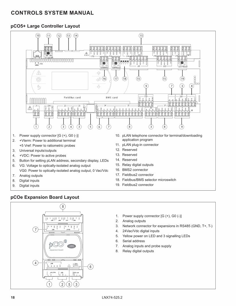
pCO5+ Large Controller Layout
CONTROLS SYSTEM MANUAL
1. Power supply connector [G (+), G0 (-)]2. +Vterm: Power to additional terminal
+5 Vref: Power to ratiometric probes3. Universal inputs/outputs4. +VDC: Power to active probes5. Button for setting pLAN address, secondary display, LEDs6. VG: Voltage to optically-isolated analog output
VG0: Power to optically-isolated analog output, 0 Vac/Vdc7. Analog outputs8. Digital inputs9. Digital inputs
10. pLAN telephone connector for terminal/downloading application program
11. pLAN plug-in connector12. Reserved13. Reserved14. Reserved15. Relay digital outputs16. BMS2 connector17. Fieldbus2 connector18. Fieldbus/BMS selector microswitch19. Fieldbus2 connector
24Vac tLAN
G0G VG0
VG Y1 T+GND
1 2 3 4
T-
J2J1
NO1 C1 NC1
J5
NO2 C2 NC2
J6
NO3 C3 NC3
J7
NO4 C4 NC4
J8
J3
J4 SerialAddress
ID1
ID2
ID3
ID4
IDC1
B1 B2
GND
J9 +5V
Ref
+Vdc B3 B4
GND
J10 +5V
Ref
+Vdc
8
7
1 2 5 3
46
expansion board
pCOe Expansion Board Layout
1. Power supply connector [G (+), G0 (-)]2. Analog outputs3. Network connector for expansions in RS485 (GND, T+, T-)4. 24Vac/Vdc digital inputs5. Yellow power on LED and 3 signalling LEDs6. Serial address7. Analog inputs and probe supply8. Relay digital outputs

19LNX74-525.2
CONTROLS SYSTEM MANUAL
pCO5+ Large Controller Input/Output (I/O) List
For the pCOe Expansion Board I/O List, please see next page.
I/O TypepCO5+ Large
Description Notes Standard or OptionalI/O # Type/Voltage
Universal
U1 4-20mA Return Air Humidity OA/RA units, units with ERV O
U2 PT1000 Evaporator Air Off Temp (D-Cabinet only) D-Cabinet only with dehum S
U3 4-20mA Building Pressure Only if control selected O
U4 PT1000 Outdoor Air Temp OR ERV Off Wheel Temp Includes humidity probe S
U5 PT1000 Return Air Temp OA/RA units, units with ERV O
U6 NTC HT Discharge Line Temp (CCT1 on D-Cabinet) All units S
U7 4-20mA Outdoor Air Humidity OR ERV Off Wheel Humidity Includes humidity probe S
U8 0-10vDC BPP Gas Furnace Stage 1 Status Gas Heat Units Only O
U9 PT1000 Mixed Air Temp OA/RA Units Only O
U10 PT1000 Supply Air Temp All units S
Digital Input
DI1 24vAC HP Switch (CCT1 on D-Cabinet) Open = High Pressure S
DI2 24vAC LP Switch (CCT1 on D-Cabinet) Open = Low Pressure S
DI3 24vAC Supply Air Flow Switch Open = Improper Airflow S
DI4 24vAC Smoke Detector Open = Smoke Alarm O
DI5 24vAC Dirty Filter Switch Closed = High Pressure O
DI6 24vAC Damper End Switch Closed = Running S
DI7 24vAC Occupied Closed = Occupied O
DI8 24vAC Supply Fan VFD Status Open = VFD Fault O
DI9 24vAC Condensate Float Switch Open = High Condensate S
DI10 24vAC UT Gas Valve 1 Status Closed = Gas Valve On O
DI11 24vAC UT Gas Valve 2 Status Closed = Gas Valve On O
DI12 24vAC Dual Power Open = Normal Power, Closed = Auxillary Power O
DI13 24vAC Door Switch Open = Open Door S
DI14 24vAC Remote Unit Initiation Open = OFF, Closed = ON S
DI15 24vAC Damper Position DI1 OR Supply Fan Speed DI1 Only if control selected O
DI16 24vAC Phase Fail Relay 1 Only if control selected O
DI17 24vAC Exhaust Air Flow Switch (Not used on D-Cabinet) Closed = Running O
DI18 24vAC Condenser Fan VFD Status (CCT1 on D-Cabinet) Open = VFD Fault S
Analog Input
AO1 0 - 10vDC Dampers OA/RA Units Only O
AO2 0 - 10vDC Condenser Fans (CCT on D-Cabinet) S
AO3 0 - 10vDC Aux. Electric Heat O
AO4 0 - 10vDC Furnace 1 Signal OR Main Electric Heat OR Hot Water Heat Units with heat option O
AO5 0 - 10vDC Supply Fan S
AO6 0 - 10vDC Exhaust Fan Only on units with exhaust O
Digital Output
DO1 NO Relay Gas Boost Heat Unit 24vac O
DO2 - Furnace 2 Stage 2 OR Furnace 3 Enable Units with heat option O
DO3 NO Relay Compressor 1 Unit 24vac S
DO4 NO Relay Compressor 2 Unit 24vac S
DO5 NO Relay Outdoor Air Damper Unit 24vac (100% OA Only) S
DO6 NO Relay HGRH Close Off Valve (CCT1 on D-Cabinet) Unit 24vac O
DO7 NO Relay Condenser Fan VFD Enable (CCT1 on D-Cabinet) VFD isolated 24vac S
DO8 NO Relay Supply Fan VFD Enable VFD isolated 24vac S
DO9 NO Relay Heat 1 OR Furnace 1 Ignit. Initiation OR Main Electric Heat Enable Units with heat option O
DO10 NO Relay Heat 2 OR Furnace 2 Stage 1 OR Furnace 2 Enable Units with heat option O
DO11 NO Relay HGRH Stage 2 Valve (Not used on D-Cabinet) Unit 24vac O
DO12 - Not Used - -
DO13 NO Relay Exhaust Fan Enable Units with exhaust O
DO14 NO Relay CP1 Unloader Valve S
DO15 NO Relay General Alarm S
DO16 NO Relay Aux. Electric Heat Enable Units with aux heat option O
DO17 NO Relay Furnace 4 Enable (D-Cabinet only) Units with heat option O
DO18 - Not Used - -

20 LNX74-525.2
CONTROLS SYSTEM MANUAL
pCOe Expansion Board Input/Output (I/O) List(used with certain control options and all D-Cabinet units)
I/O TypepCOe
Description Notes Standard or OptionalI/O # Type/Voltage
Universal Input
B1 4-20mA CO2 Content Only if control selected O
B2 4-20mA Duct Pressure Only if control selected O
B3 - Not Used - -
B4 - Not Used - -
Digital Input
DI1 24vAC Damper Position DI2 OR Supply Fan Speed DI2 OR HW Coil Freeze Stat Only if control selected O
DI2 24vAC Condenser Fan VFD Status CCT2 (D-Cabinet only) Open = VFD Fault S
DI3 24vAC HP Switch CCT2 (D-Cabinet only) Open = High Pressure S
DI4 24vAC LP Switch CCT2 (D-Cabinet only) Open = Low Pressure S
Analog Output AO1 Condenser Fans CCT2 (D-Cabinet only) S
Digital Output
DO1 NO Condenser Fan VFD Enable CCT2 (D-Cabinet only) D-Cabinet only S
DO2 NO Compressor 3 (D-Cabinet only) D-Cabinet only S
DO3 NO Compressor 4 (D-Cabinet only) D-Cabinet only S
DO4 NO HGRH Close Off Valve CCT2 (D-Cabinet only) D-Cabinet only O
I/O TypepCOxs
Description Notes Standard or OptionalI/O # Type/Voltage
Heartbeat SYNC - Wheel Proximity Only if option selected O
Universal
B1 4-20mA Outdoor Air Humidity All units S
B2 4-20mA Outdoor Air Temperature All units S
B3 - Not Used - -
B4 - Not Used - -
Digital Input
DI1 24vAC Exhaust Air Filter Switch Only if option selected O
DI2 24vAC Wheel Pressure Switch Only if option selected O
DI3 24vAC Outdoor Air Filter Switch Only if option selected O
DI4 24vAC Exhaust Air Flow Switch (or VFD status on D-Cabinet) All units S
DI5 24vAC ERV Door Switch All units S
DI6 24vAC Wheel VFD Status (D-Cabinet only) Only if option selected O
Analog OutputAO1 0 - 10vDC Wheel Speed (D-Cabinet only) Only if option selected O
AO2 0 - 10vDC Exhaust Fan All units S
AO3 - Not Used - -
Digital Output
DO1 NO Relay Outdoor Air Bypass Damper All units except with 81” wheel S
DO2 NO Relay Wheel Enable (or Wheel VFD Enable for D-Cabinet) All units S
DO3 NO Relay Electric Preheat Enable (or Preheat Stage 1 on D-Cabinet) Only if option selected O
DO4 NO Relay Exhaust Fan Enable All units S
DO5 NO Relay Electric Preheat Stage 2 (D-Cabinet only) Only if option selected O
pCOxs Controller Input/Output (I/O) List(used on units with Energy Recovery option)

21LNX74-525.2
pCO5+ Built-In Keypad
pGD1 Remote User Interface
Module Function Button Function
ALARM Illuminated when there is an active alarm, pressing once will allow viewing of active alarms, pressing twice will reset active manual-reset alarms.
PRG Selects the main navigation menu screen.
ESC Returns to the main unit status display screen.
UP Scroll through display screens, settings, or increase the setpoint value.
ENTER Confirm point adjustments or move the cursor to the next available set point.
DOWN Scroll through display screens, settings, or decrease the setpoint value.
CONTROLS SYSTEM MANUAL
Carel pCO5+ Large Display and Keypad
Display/Keypad Functions
The controller features a built-in user interface with LCD display and keypad. Additionally, all functions of the display/keypad can be replicated using the remote user interface module, pGD1 or pGDE.
B- and C-Cabinet units are available with an optional unit mounted remote user interface data port to allow access without opening the control cabinet or disconnecting unit supply power. D-Cabinet sized units feature a dedicated low voltage control compartment that allows access while the unit is powered.
Optional Remote User Interface Data Port
Remote User Interface Module
Standard Keypad Button Functions
Extra Function Keypad Button Sequences
Refer to the literature included with the pGD1 for installation instructions. Refer to the Board Settings section for instructions on programming the remote display keypad to the controller.
pCO5+ Built-In Keypad
pGD1 Remote User Interface Module
Function Button Function
UP + DOWN+ ENTER Accesses controller address.
ENTER + UP Change unit displayed on remote keypad. (ERV Only)
+
+
+ +
+
+
If using the pGDE remote user interface module, the keypad keys match the pCO5+ built-in keypad.

22 LNX74-525.2
4. Press the ENTER key to enter the sub menu.
5. Once within the sub menu, if the blinking cursor is located in top line of the screen, pressing the UP or DOWN keys will scroll through available Clock/Sched-uler sub menus.
6. If the user wants to change a parameter on the dis-played sub menu, pressing the ENTER key will move the cursor to the parameter settings and successive presses of ENTER will move the cursor to the next item. To change any item, the UP or DOWN arrow keys can be used to make the changes. Note that some selections are read only and cannot be changed.
7. To revert back to the previous sub menu level, press the ESC key.
Menu Navigation
The Main Status Screen is displayed when the unit is first turned on or after one minute of keypad inactivity. From this Main Status Screen, eight sub menus can be accessed. Details on the Main Status Screen and each sub menu shown below will be detailed in the following sections of this manual.
CONTROLS SYSTEM MANUAL
Sub Menu DescriptionA. On/Off Unit Switch unit on or off.B. Setpoints View the user setpoints.C. Clock/Scheduler View the current time and date and occupancy schedule.D. Input/Output View the status of the controller inputs and outputs.E. Alarm Logger View the alarm log.F. Board Switch Change the controller pLAN board address.G. Service View maintenance related parameters, such as hours run, sensor calibration and manual overrides.
H. ManufacturerManufacturer menu and adjustment of various manufacturer related parameters, such as unit configuration and timing settings.
Sub Menu Selections
Example Sub Menu Navigation
The following example shows how to navigate to and enter the Clock/Scheduler sub menu, however the process is similar for all sub menu selections.
1. Starting from the Main Status Screen:
2. Press the PRG key to access the sub menu. Note that the sub menu starts with On/Off Unit highlighted.
3. Press the UP or DOWN key repeatedly until the Clock/Scheduler sub menu is selected.

23LNX74-525.2
CONTROLS SYSTEM MANUAL
To prevent unauthorized adjustments, a password is required to gain access to certain menus. When a password is required, the following screen will be displayed:
The password can be entered by using the UP or DOWN key to scroll through the values for each digit, then pressing ENTER to move the cursor to the next digit. Repeat this process until all four digits of the password are entered.The password for appropriate Service sub menu selections is 1500. The password for the Manufacturer sub menu is a custom, one-time password that is only available by contacting the Service Department.
WARNINGWARNING Improper control adjustments and manual mode control can cause property damage, injury or death. Read the installation, operating and maintenance instructions thoroughly before making adjustments.
Password Protection

24 LNX74-525.2
MAIN SCREEN MAIN SUB MENU SUB MENU SCREENS SCREEN #
Unit Status A. On/Off Unit On/Off Unit -
B. Setpoints Outdoor Air Reset S1-4Space Supply Air Resets S5-6Neutral Air S7Occupied Setpoints S8-11Unoccupied Setpoints S12-14Occupied S15Unoccupied S16DeHum Dewpt Setpoints S17-18
C. Clock/ Scheduler Clock L1-2Scheduler L3-4Holidays L5-9
D. Input/Output Analog Inputs R1-13Digital Inputs T1-20Relay Outputs V1-15Analog Output W1-6Relay Output (pCOe) B1-4Analog Output (pCOe) B5Digital Input (pCOe) B6-9Analog Input (pCOe) B10
E. Alarm Logger Alarm Log -
F. Board Switch -
G. Service a. Information A1-7b. Running Hours X1-19
Shad
ed A
rea
Req
uire
s Pa
ssw
ord
for A
cces
s
c. Power Meter PM1-8d. BMS Config. U1-8e. Fieldbus Config. FB1-11f. Service Settings / a. Maintenance Hours M1-18f. Service Settings / b. Probe Adjustment P1-18f. Service Settings / c. Control Settings CS1-20f. Service Settings / d. P/PI/PID Loops D1-20f. Service Settings / e. Alarm Management AM1-24g. Manual Management / a. Manual Control MN1-6g. Manual Management / b. Analog Inputs C1-13g. Manual Management / c. Digital Inputs D1-20g. Manual Management / d. Relay Outputs G1-17g. Manual Management / e. Analog Outputs H1-6g. Manual Management / f. Exp. Board (pCOe) F1-9i. pAD Config. PC1-4j. ERV Config. E1-10
H. Manufacturer Contact Service Department for Guidance
Menu Tree
Regardless of the current screen displayed, pressing the PRG key main sub menu listing, indicated on page 8 and as shown below. The sub menu screens shown are condensed on this page and are detailed further in this manual. Depending on the configuration of the unit, not all sub menu screens are available.
CONTROLS SYSTEM MANUAL
Menu tree listing is condensed and may show selections that are not available on all units.

25LNX74-525.2
CONTROLS SYSTEM MANUAL
SCREEN NAME SCREEN # PARAMETER DESCRIPTION FACTORY VALUE RANGE UNITS
Main Screen -
Time/Date: Actual Value Hr:Min MM/DD/YY -
SA: Actual Value - °FSupply Set: Actual Value - °F
Status: (Off/On) Actual Value
WAITING UNIT ON
OFF by ALARM OFF by pLAN OFF by BMS
OFF by CLOCK OFF by DIG-IN OFF-KEYPAD
OFF-OPEN DOOR WAIT SUP FAN WAIT-DAMPER
-
(Mode) Actual Value
Fan-Only Econ
Heating Cooling
Dehumid
-
(Occupancy) Actual Value
UNOCCUPIED OCCUPIED-BMS OCCUPIED-CLK OCCUPIED-DIG OCCUPIED-PAD
OCCUPIED
-
pAD Thermostat (Visible only if pAD is
Enabled) M1
pAD Thermostat: (Address) Actual Value - -Temperature: Actual Value - °FpAD Humidity: (If Available on pAD) Actual Value - %rHDew Point: Actual Value - °FEnthalpy: Actual Value - BTU/Lb.
Main Status Screen
The Main Status Screen is displayed when the unit is first turned on or after one minute of keypad inactivity.
The following information is displayed on the Main Status Screen:• Time/date• Unit number• Supply Air Temperature• Current Supply Air Setpoint• Unit Status• Unit Mode Once this screen is displayed, the user can navigate up and down through the list of Main Status Screen Parameters by using the UP or DOWN buttons. These screens are described in further detail in the next section.
Note that the main unit controller will always show as Unit: 01. If the unit is also equipped with an ERV module, it has its own controller, which is Unit: 02. The keypad at the main controller or the remote key pad can be used to change the Main Status Screen to display either Unit 01 or 02.
To change the controller being displayed, press the ENTER + UP buttons. If you are viewing the main controller display, pressing those buttons will switch to displaying the ERV controller. Pressing those buttons again will revert back to displaying the main controller.
Main Status Screen Parameters
The following table describes the menu parameters:
(continued next page)

26 LNX74-525.2
SCREEN NAME SCREEN # PARAMETER DESCRIPTION FACTORY VALUE RANGE UNITS
Serial Probe (Probes 1 - 4 if enabled) M2 - M5
Location: Actual Value - -Temperature: Actual Value - °FHumidity: Actual Value - %rHDew Point: Actual Value - °FSerial Probe Number: Actual Value - -
Conrol Temp/Hum (Visible only if Serial Probes
are enabled) M6
Temperature: Actual Value - °FHumidity: Actual Value - %rHDew Point: Actual Value - °FEnthalpy: Actual Value - BTU/Lb.
Status of Outside Air M7 & M8
Temperature: Actual Value - °FHumidity: Actual Value - %rHDew Point: Actual Value - °FEnthalpy: Actual Value - BTU/Lb.
Status of Return Air
(Visible only with HOASUnits)
M9
Temperature: Actual Value - °FHumidity: Actual Value - %rHDew Point: Actual Value - °FEnthalpy: Actual Value - BTU/Lb.
Status of ERV leaving Air
(Visible only with ERV Units) M10
Temperature: Actual Value - °FHumidity: Actual Value - %rHDew Point: Actual Value - °FEnthalpy: Actual Value - BTU/Lb.
Mixed Air (Visible only with HOAS
Units) M11
Temperature: Actual Value - °FHumidity: Actual Value - %rHDew Point: Actual Value - °FEnthalpy: Actual Value - BTU/Lb.
Evaporator Off Temp M12 Temperature: Actual Value - °FStatus of Space CO2 (Visible only with CO2
Sensor)M13
CO2 level: Actual Value - ppm
CO2 setpoint: Actual Value - ppmStatus of
Building Pressure (Visible only with building
pressure sensor)
M16Pressure: Actual Value - iwc
Setpoint: Actual Value - iwc
Status of Duct Pressure
(Visible only with duct pressure sensor)
M17Pressure: Actual Value - iwc
Setpoint Actual Value - iwc
Main Dampers M18OA Damper Pos: Actual Value OPEN or CLOSED
0 - 100 -
RA Damper Pos: (if enabled) Actual Value 0 - 100 %
Fan Status M19
Supply: (On/Off) Actual Value 0 - 100 %Exhaust: (On/Off) Actual Value 0 - 100 %Cond Fan Circuit 1: (On/Off) Actual Value 0 - 100 %Cond Fan Circuit 2: (On/Off) Actual Value 0 - 100 %
Status of ERV
(Visible only with ERV Units)M20
ERV Wheel: Actual Value OFF or ON -
Wheel Status: Actual Value STOPPED RUNNING -
Bypass Damper: Actual Value CLOSED or OPEN -Preheater On/Off: (if enabled) Actual Value OFF or ON -
CONTROLS SYSTEM MANUAL
Main Status Screen Parameters (continued)
(continued next page)

27LNX74-525.2
SCREEN NAME SCREEN # PARAMETER DESCRIPTION FACTORY VALUE RANGE UNITS
Demand Status M21
Cooling Demand: Actual Value 0 - 100 %Heating Demand: Actual Value 0 - 100 %Dehum Demand: (if enabled) Actual Value 0 - 100 %Hot Gas Reheat: (if enabled) Actual Value 0 - 100 %
Aux. Electric Heat Status M22 Modulation: Actual Value 0 - 100 %Primary Electric Heat
Status M23 Modulation: Actual Value 0 - 100 %
Gas Heat Status M24
Gas Stages On:(United Tech. Board) Actual Value 0 - 2 -
Gas Stage 1 Status: (Beckett Control Board) Actual Value
Primary Limit Failure Loss of inducer Motor No Firing Rate Input Gas Sensor Failure Air Sensor Failure
Low Combustion Air Mod Valve Failure
Weak Flame Signal Limiting Low Fire
Failed Ignition Improper Flame
Lost Flame COM Error
Running Retry OFF
-
Gas Stage 2 Status: (Beckett Control Board) Actual Value -
Digital Scroll Status M25
Status Actual Value
Off On
Start Up Forced Off
Alarm Off by time On by time
-
Countdown Actual Value - (s)econdsMaxpower Admit Actual Value 0 - 100 %Requested Cap.: Actual Value 0.0 - 100.0 %Current Capac.: Actual Value 0.0 - 100.0 %
DX Circuit 1 (Graphical Display) M26/27
SH: (Super Heat) Actual Value - °FSuction Temperature Actual Value - °FEEV Position percent Actual Value 0 - 100 %
EVD: (EVD Status) Actual Value
__ On
Close Std-by
Pos Wait Init
-
Digital Compressor Status (On/Off) (Graphic) - -
Unloader Valve status (Graphic) - -Compressor 2 Status (On/Off) (Graphic)
Protection Status Actual ValueLoSH LOP MOP
-
SP: (Suction Pressure) Actual Value - psig
CONTROLS SYSTEM MANUAL
Main Status Screen Parameters (continued)
(continued next page)

28 LNX74-525.2
SCREEN NAME SCREEN # PARAMETER DESCRIPTION FACTORY VALUE RANGE UNITS
DX Circuit 2 (Graphical Display) M28
SH: (Super Heat) Actual Value - °FSuction Temperature Actual Value - °FEEV Position percent Actual Value 0 - 100 %
EVD: (EVD Status) Actual Value
__ On
Close Std-by
Pos Wait Init
-
Compressor 3 Status (On/Off) (Graphic) - -Compressor 4 Status (On/Off) (Graphic) - -
Protection Status Actual ValueLoSH LOP MOP
-
SP: (Suction Pressure) Actual Value - psig
DX Circuit 1 M29Discharge Pressure: Actual Value - psigDischarge Temperature: Actual Value - °FSuction Pressure: Actual Value - psig
DX Circuit 2 M30Discharge Pressure: Actual Value psig
Suction Pressure: Actual Value psig
DX Circuit 1 M31LL Temp.: Actual Value - °FLL Cond Temp.: Actual Value - °FSubcool: Actual Value - °F
DX Circuit 2 M32LL Temp.: Actual Value - °FLL Cond Temp.: Actual Value - °FSubcool: Actual Value - °F
Lockouts M33
DX System Lockout: Actual Value OFF or ON -Circuit 1: Actual Value OFF or ON -Circuit 2: Actual Value OFF or ON -Heating Lockout: Actual Value OFF or ON -
Temperature Lockouts: Actual ValueNone
DX Cooling Heating
-
Scheduler M34Clock Override: Actual Value OFF or ON -Override Time: Actual Value 1 - 3 (hr)hours
Manual I/O Status M35Unit Operating Mode: Actual Value Auto or Manual -Reset unit to auto mode: NO NO or YES -
CONTROLS SYSTEM MANUAL
Main Status Screen Parameters (continued)

29LNX74-525.2
CONTROLS SYSTEM MANUAL
SCREEN NAME SCREEN # PARAMETER DESCRIPTION FACTORY VALUE RANGE UNITS
On/Off Unit
Unit Address: Actual Value 1 - 32 -
Power by Display: OFF OFF ON -
Status: OFF by KEYPAD
WAITING UNIT ON
OFF by ALARM OFF by pLAN OFF by BMS
OFF by CLOCK OFF by DIG-IN OFF-KEYPAD
OFF-OPEN DOOR WAIT SUP FAN WAIT-DAMPER
-
On/Off Unit (Visible only if pAD enabled)
pAD n° 1 1 - 32 -
On/Off ALWAYS ON ALWAYS ON pLAN ON/OFF -
A. On/Off Unit Sub Menu Parameters
The On/Off Unit menu allows the user to view the detailed On/Off status of the controller.

30 LNX74-525.2
CONTROLS SYSTEM MANUAL
SCREEN NAME SCREEN # PARAMETER DESCRIPTION FACTORY VALUE RANGE UNITS
Outdoor Air Reset Heating S1
OA (Top Left Value) 30.0 0.0 - 50.0 °FNA High (Top Right Value) 78.0 60.0 - 100.0 °FOA (Bottom Left Value) 68.0 50.0 - 75.0 °FNA Low (Bottom Right Value) (Same as Cooling NA High) 70.0 60.0 - 80.0 °F
NA Granularity:(Rate at which change occurs) 0.5 0.5 or 1.0 °F
Outdoor Air Reset Cooling S2
OA (Top Left Value) 72.0 65.0 - 75.0 °FNA High (Top Right Value) (Same as Heating NA Low) 70.0 60.0 - 80.0 °F
OA (Bottom Left Value) 85.0 75.0 - 100.0 °FNA Low (Bottom Right Value) 55.0 50.0 - 80.0 °FSA/NA Granularity:(Rate at which change occurs) 0.5 0.5 or 1.0 °F
Outdoor Air Reset Heating Setpoints
(Graphical Display of S1 Outdoor Air Reset
Setpoints, if configured)
S3 Actual Value - °F
Outdoor Air Reset Cooling Setpoints
(Graphical Display of S2 Outdoor Air Reset
Setpoints, if configured)
S4 Actual Value - °F
Space Supply Air Reset Cooling
(Graphical Display of Space Reset Setpoints, if
configured)
S5
Reference Only
(These correlate to the settings in S8 through S11 with actual values seen in screens S15
and S16)
- -
Space Supply Air Reset Heating
(Graphical Display of Space Reset Setpoints, if
configured)
S6
Reference Only
(These correlate to the settings in S8 through S11 with actual values seen in screens S15
and S16)
- -
Neutral Air (Reset type NONE)
S7 Neutral Air: 70.0 50.0 - 90.0 °F
pAD Thermostat Occupied Setpoints
(Screen Visble with pAD)S8
pAD Thermostat (Address) Actual Value 1 - 32 -Cool Setpoint: 74.0 60 - 90 °FHeat Offset: 4.0 2 - 20 °FHeat Setpoint: Actual Value Actual Value °F
Differentials Occupied S9Cool Diff:: 1.0 1.0 - 10.0 °FHeat Diff: 1.0 1.0 - 10.0 °F
Supply Air Reset Occupied
S10
Cooling Reset: 55.0 45.0 - 100.0 °FNeutral Air: (Space Reset Only)
70.0 50.0 - 90.0 °F
Heating Reset: (81% eff. Furnace) (90+%/hybrid eff. Furnace) (Electric Heat)
80.0
60.0 - 130.0 60.0 - 100.0 60.0 - 100.0
°F
B. Setpoints Sub Menu Parameters
The Setpoint menu allows the user to view and adjust temperature related parameters.
(continued next page)

31LNX74-525.2
SCREEN NAME SCREEN # PARAMETER DESCRIPTION FACTORY VALUE RANGE UNITSpAD Thermostat Occupied
Setpoints (Screen Visble with pAD)
S11pAD Thermostat (Address) Actual Value 1 - 32 -Space Humidity 60 0 - 100 %rhHumidity Offset 5 0 - 99 %rh
pAD Thermostat Unoccupied Setpoints
S12
pAD Thermostat (Address) Actual Value 1 - 32 -Cool Setpoint: 85.0 70.0 - 90.0 °FHeat Setpoint: 62.0 50.0 - 70.0 °FSpace Humidity: 70 0 - 100 %rhHumidity Diff: 5 0 - 99 %rh
Supply Air Reset Unoccupied
S13
Cooling Reset: 55.0 45.0 - 100.0 °FHeating Reset: (81% eff. Furnace) (90+%/hybrid eff. Furnace) (Electric Heat)
80.0
60.0 - 130.0 60.0 - 100.0 60.0 - 100.0
°F
Differentials Unoccupied S14Cool Diff:: 2.0 1.0 - 10.0 °FHeat Diff: 2.0 1.0 - 10.0 °F
Occupied (Graphical Display of
S8-S11 Outdoor Air Reset Setpoints, if configured)
S15 Actual Value - °F
Unoccupied (Graphical Display of
Setpoints)S16 Actual Value - °F
DeHum Dewpt Setpoints (Screen Visible with
Dewpoint Dehumidification and DOAS configuration)
S17
Occupied OA Dewpoint: (OA & Space Selected)
55.0 Adjusted from pAD
45.0 - 65.0 -
°F
Occupied Diff Off: 5.0 0.0 - 10.0 °FUnoccupied Space Dewpoint: (Visible only with pAD)
60.0 45.0 - 65.0 °F
Unoccupied Diff Off: (Visible only with pAD)
5.0 0.0 - 10.0 °F
DeHum Dewpt Setpoints (Screen Visible with
Dewpoint Dehumidification)S18
Occupied MA Dewpoint: (MA & Space Selected)
55.0 Adjusted from pAD
45.0 - 65.0 -
°F
Occupied Diff Off: 5.0 0.0 - 10.0 °FUnoccupied Space Dewpoint: (Visible only with pAD)
60.0 45.0 - 65.0 °F
Unoccupied Diff Off: (Visible only with pAD)
5.0 0.0 - 10.0 °F
CONTROLS SYSTEM MANUAL
B. Setpoints Sub Menu Parameters (continued)

32 LNX74-525.2
CONTROLS SYSTEM MANUAL
PAGE INTENTIONALLY LEFT BLANK

33LNX74-525.2
CONTROLS SYSTEM MANUAL
SCREEN NAME SCREEN # PARAMETER DESCRIPTION FACTORY VALUE RANGE UNITS
Clock L1Day: Actual Day SUNDAY - SATURDAY -Date: Actual Date MM/DD/YY -Hour: (Military Time) Actual Time HH:MM -
Clock L2
DST: (daylight Savings Time) ENABLE ENABLE or DISABLE -Transition Time: 60 0-60 (min)utes
Start: (Date placement in month) SECOND
LAST FIRST
SECOND THIRD
FOURTH
-
Start: (Day) SUNDAY SUNDAY - SATURDAY DayStart: (Month) March JANUARY - DECEMBER MonthStart: (Time) 2 0 - 23 Hour
End: (Date placement in month) FIRST
LAST FIRST
SECOND THIRD
FOURTH
-
End: (Day) SUNDAY SUNDAY - SATURDAY DayEnd: (Month) NOVEMBER JANUARY - DECEMBER MonthEnd: (Time) 2 0 - 23 Hour
Scheduler L3 Number of Schedules 0 0 - 7 -
Scheduler L4
Schedule #: 0 1-7 -Time On: 00:00 00:00 - 23:59 Hrs:MinTime Off: 00:00 00:00 - 23:59 Hrs:Min
Days Enabled:
* * * * * * *
M T W T F S S
-
Holidays L5 Number: 0 0, 4, 8, 12, 16 -
Holidays (Screen will show only if
Holidays = 4 or more)L6
Holiday 1 Start - Stop 00/00-00/00 1/1-12/31 DaysHoliday 2 Start - Stop 00/00-00/00 1/1-12/31 DaysHoliday 3 Start - Stop 00/00-00/00 1/1-12/31 DaysHoliday 4 Start - Stop 00/00-00/00 1/1-12/31 Days
Holidays (Screen will show only if
Holidays = 8 or more)L7
Holiday 5 Start - Stop 00/00-00/00 1/1-12/31 DaysHoliday 6 Start - Stop 00/00-00/00 1/1-12/31 DaysHoliday 7 Start - Stop 00/00-00/01 1/1-12/31 DaysHoliday 7 Start - Stop 00/00-00/00 1/1-12/31 DaysHoliday 8 Start - Stop 00/00-00/00 1/1-12/31 Days
Holidays (Screen will show only if Holidays = 12 or more)
L8
Holiday 9 Start - Stop 00/00-00/00 1/1-12/31 DaysHoliday 10 Start - Stop 00/00-00/00 1/1-12/31 DaysHoliday 11 Start - Stop 00/00-00/00 1/1-12/31 DaysHoliday 12 Start - Stop 00/00-00/00 1/1-12/31 Days
Holidays (Screen will show only if
Holidays = 16)L9
Holiday 13 Start - Stop 00/00-00/00 1/1-12/31 DaysHoliday 14 Start - Stop 00/00-00/00 1/1-12/31 DaysHoliday 15 Start - Stop 00/00-00/00 1/1-12/31 DaysHoliday 16 Start - Stop 00/00-00/00 1/1-12/31 Days
C. Clock/Scheduler Sub Menu Parameters
The Clock/Scheduler menu allows the user to view and alter the time and date. The user can also add up to seven schedules for occupancy requirements as well as up to sixteen holidays.

34 LNX74-525.2
CONTROLS SYSTEM MANUAL
D. Input/Output Sub Menu Parameters
The Input/Output menu allows the user to quickly view the status of the controller inputs and outputs.
SCREEN NAME SCREEN # PARAMETER DESCRIPTION CHANNEL RANGE UNITS
a. Analog Inputs (Screens are visible based
on unit configuration)
R1 Return Air Humidity U01 - %rHR2 CO2 Sensor U02 - ppmR3 Furnace Stage 2 Status U02 - vdcR4 Evaporator Off Temp U02 - °FR5 Building Pressure U03 - iwcR6 Static Pressure U03 - iwcR7 Outside Air Temp U04 - °FR8 Return Air Temp U05 - °FR9 Discharge Line Temp U06 - °FR10 Outside Air Humidity U07 - %rHR11 Furnace Stage 1 Status U08 - vdcR12 Mixed Air Temp U09 - °FR13 Supply Air Temp U10 - °F
b. Digital Inputs (Screens are visible based
on unit configuration)
T1 High Pressure SW CCT1 DI1 CLOSED or OPEN -T2 Low Pressure SW CCT1 DI2 CLOSED or OPEN -T3 S.F. Airflow Switch DI3 CLOSED or OPEN -T4 Smoke Dectector DI4 CLOSED or OPEN -T5 Dirty Filter Switch DI5 CLOSED or OPEN -T6 Damper End Switch DI6 CLOSED or OPEN -T7 Occupied DI7 CLOSED or OPEN -T8 Supply Fan CFD Status DI8 CLOSED or OPEN -T9 Condensate Pan Float DI9 CLOSED or OPEN -T10 Gas Valve 1 DI10 CLOSED or OPEN -T11 Gas Valve 2 DI11 CLOSED or OPEN -T12 Dual Point Power DI12 CLOSED or OPEN -T13 Door Switch DI13 CLOSED or OPEN -T14 Remote On/Off DI14 CLOSED or OPEN -T15 Damper Position 2 DI15 CLOSED or OPEN -T16 Supply Fan Speed 2 DI15 CLOSED or OPEN -T17 Damper Position 3 DI16 CLOSED or OPEN -T18 Supply Fan Speed 3 DI16 CLOSED or OPEN -T19 E.F. Airflow Switch DI17 CLOSED or OPEN -T20 C.F. VFD Status CCT1 DI18 CLOSED or OPEN -
(continued next page)

35LNX74-525.2
SCREEN NAME SCREEN # PARAMETER DESCRIPTION CHANNEL RANGE UNITS
c. Relay Outputs (Screens are visible based
on unit configuration)
V1 Heat 3 1 OFF or ON -V2 Gas Boost Heat 1 OFF or ON -V3 Heat 4 2 OFF or ON -V4 Compressor 1 3 OFF or ON -V5 Compressor 2 4 OFF or ON -V6 OA Damper Open 5 OFF or ON -V7 HGRH Solenoid CCT1 6 OFF or ON -V8 Condenser Fans CCT1 7 OFF or ON -V9 Supply Fan 8 OFF or ON -V10 Heat 1 9 OFF or ON -V11 Heat 2 10 OFF or ON -V12 HGRH Stage 2 CCT1 11 OFF or ON -V13 Exhaust Fan 13 OFF or ON -V14 General Alarm 15 OFF or ON -V15 Aux. Electric Heat 16 OFF or ON -
d. Analog Output (Screens are visible based
on unit configuration)
W1 Damper Modulation Y1 0.0 - 10.0 vdcW2 Condenser Fans CCT1 Y2 0.0 - 10.0 vdcW3 Aux. Electric Heat Y3 0.0 - 10.0 vdcW4 Modulated Heat Y4 0.0 - 10.0 vdcW5 Supply Fan Y5 0.0 - 10.0 vdcW6 Exhaust Fan Y6 0.0 - 10.0 vdc
e. Exp Board Relay Output
B1 Condenser Fans CCT2 1 OFF or ON -B2 Compressor 3 2 OFF or ON -B3 Compressor 4 3 OFF or ON -B4 HGRH Solenoid CCT2 4 OFF or ON -
e. Exp Board Analog Output
B5 Condenser Fans CCT2 Y1 0.0 - 10.0 vdc
e. Exp Board Digital Input
B6 Freeze Stat ID1 OPEN or CLOSED
B7 C.F. VFD Status CCT2 ID2 OPEN or CLOSED
B8 High Pressure SW CCT2 ID3 OPEN or CLOSED
B9 Low Pressure SW CCT2 ID4 OPEN or CLOSEDe. Exp Board Analog Input B10 CO2 Sensor B1 - ppm
CONTROLS SYSTEM MANUAL
D. Input/Output Sub Menu Parameters (continued)

36 LNX74-525.2
CONTROLS SYSTEM MANUAL
E. Alarm Logger Sub Menu Parameters
The Alarm Logger menu allows the user to view up to 100 past alarms.
To access the contents of the Alarm Logger, start by pressing the ALARM button, followed by the DOWN button. Displayed will be the most recent alarm, as shown in the following example:
To get to the log, press the DOWN arrow key until the following screen is shown, then press the ENTER key:
The most recent alarms will be displayed, as shown in the following example:
SCREEN NAME SCREEN # PARAMETER DESCRIPTION FACTORY VALUE RANGE UNITS
Alarm Log -
Time Date CT: (Alarm Count)
Actual ValueHH:MM
MM/DD/YY 0 - 100
-
(Alarm Description) (If no alarm is stored in the log “NO ALARMS” will be displayed)
Actual Value See Below -
Supply Temp: Actual Value - -Outside Temp: Actual Value - -Outside Hum: Actual Value - -Return Temp: Actual Value - -Suction P.: Actual Value - -Liquid Line P.: Actual Value - -

37LNX74-525.2
CONTROLS SYSTEM MANUAL
E. Alarm Logger Sub Menu - Alarm Listing
AR = Auto Reset, UD = Unit Disabled, CD = Component Disabled (continued next page)
ALARM/LOGGED EVENTS AR
UD
CD
CAUSE ACTION
Clock Alarm • •Indicates an error with the real time clock on-board the controller. During alarm any schedules may not work properly.
Once the clock returns to functioning correctly the alarm will be automatically reset. The clock time may need to be reset.
BMS Offline • BMS/BAS has lost communication with controller. Unit will operate as is until communication can be reestablished.
Beckett Control Board 1 Fail • • Health Status Signal is less than 1.0 vdc.
If shutdown unit on furnace alarm is selected, unit will shutdown if only 1 furnace is available. Otherwise unit will continue to run without heat.
Beckett Control Board 2 Fail • • Health Status Signal is less than 1.0 vdc.
If shutdown unit on furnace alarm is selected, unit will shutdown if neither furnaces is available. Otherwise unit will continue to run without heat.
Building Pressure Sensor Failure • • Building Pressure Sensor faulty or not connected. Alarm is generated – Building Pressure control is locked out.
CO2 Sensor • • CO2 Sensor faulty or not connected. Alarm is generated – Demand ventilation is locked out.
Condensate Float Al (Al=Alarm) • Unable to drain condensation after trap priming/purge sequence.
This input has two strikes, if two trips occur within an hour an alarm will be generated and the compressor is locked out.
Condenser Fan Al CCT1 • • Circuit 1 VFD fault perserved.
If shutdown unit on cooling alarm is selected, unit will shutdown on single circuit units otherwise circuit 2 could continue to run. Cooling circuit 1 permanently disabled. Does not apply to units with EC condenser fans.
Condenser Fan Al CCT2 • Circuit 2 VFD fault perserved.
If shutdown unit on cooling alarm is selected, unit will continue to run unless Circuit 1 critical alarm is also present. Cooling circuit 2 permanently disabled. Does not apply to units with EC condenser fans.
Condenser Fan CCT1 • • Circuit 1 VFD fault detected. Cooling circuit 1 temporarily locked out.
Condenser Fan CCT2 • • Circuit 2 VFD fault detected. Cooling circuit 2 temporarily locked out.
Cooling Diff Alarm (if enabled) • If there is a call for cooling and the supply air does
not drop below the outside temperature. Alarm is generated – No other action taken.
Daily PW ActiveNot an alarm, notification only that the Daily Password (obtained from Factory Service Department) is active.
None.
Disch. Temp Probe CCT1 • • • Discharge Temperature Sensor for Circuit 1 disconnected or faulty.
If shutdown unit on cooling alarm is selected, unit will shutdown on single circuit units otherwise circuit 2 could continue to run. If not shutdown unit on cooling alarm Circuit 1 critical alarm is set and unit will run with cooling/dehumidification permanently disabled.
Door Switch LO (LO=Lockout) • • • Evaporator fan door open. Unit is disabled.
Duct Static Pressure • • Pressure sensor disconnected or broken.
If DSP Fail action is set to Min Speed fan will continue to operate at minimum. If DSP Fail is set to Unit Shutdown, unit will shutdown.
Envelope Code1 Al CCT1 •During normal working mode compressor running outside safe operating conditions multiple times within the hour.
Circuit permanently locked out.
Envelope Code1 Al CCT2 •During normal working mode compressor running outside safe operating conditions multiple times within the hour.
Circuit permanently locked out.
Envelope Code1 LO CCT1 • During normal working mode compressor running outside safe operating conditions. Circuit temporarily locked out.
Envelope Code1 LO CCT2 • During normal working mode compressor running outside safe operating conditions. Circuit temporarily locked out.

38 LNX74-525.2
CONTROLS SYSTEM MANUAL
E. Alarm Logger Sub Menu - Alarm Listing (continued)
AR = Auto Reset, UD = Unit Disabled, CD = Component Disabled (continued next page)
ALARM/LOGGED EVENTS AR
UD
CD
CAUSE ACTION
Envelope Code2 Al CCT1 •Working in a conditional zone where the maximum admitted power is 0% multiple times within the hour.
Circuit permanently locked out.
Envelope Code2 Al CCT2 •Working in a conditional zone where the maximum admitted power is 0% multiple times within the hour.
Circuit permanently locked out.
Envelope Code2 LO CCT1 • Working in a conditional zone where the maximum admitted power is 0%. Circuit temporarily locked out.
Envelope Code2 LO CCT2 • Working in a conditional zone where the maximum admitted power is 0%. Circuit temporarily locked out.
Envelope Code3 Al CCT1 • During startup procedure exceeded maximum startup zone limit within the hour. Circuit permanently locked out.
Envelope Code3 Al CCT2 • During startup procedure exceeded maximum startup zone limit within the hour. Circuit permanently locked out.
Envelope Code3 LO CCT1 • During startup procedure exceeded maximum startup zone limit. Circuit temporarily locked out.
Envelope Code3 LO CCT2 • During startup procedure exceeded maximum startup zone limit. Circuit temporarily locked out.
ERV Comms Alarm • • • Communication between main controller and ERV controller disconnected or broken. ERV shutdown.
ERV Door Open • • • ERV exhaust fan door open. ERV/Exhaust fan shutdown.
ERV OA Filters Dirty • ERV outside air filters are dirty . Alarm generated – No further action taken.
Evap Off Temp • Evap off temp sensor disconnected or broken. Alarm generated.
EVD1 Config Error • • EVD parameter transmission error. Circuit permanently locked out.
EVD1 EPROM Alarm • • EVD memory fault. Circuit permanently locked out.
EVD1 Exv Motor "A" • • Electronic expansion valve disconnected or faulty. Circuit temporarily locked out.
EVD1 Exv Motor "A" Al • Electronic expansion valve disconnected or faulty condition persists. Circuit permanently locked out.
EVD1 Exv Motor "B" • • HGRH valve(s) disconnected or faulty. Circuit permanently locked out.
EVD1 Firmware Error • • EVD firmware not compatible with main controller. Circuit permanently locked out.
EVD1 Offline Al • EVD expansion valve drive not communicating with main controller. Exceeded hourly limit. Circuit permanently locked out.
EVD1 Offline LO • • EVD expansion valve drive not communicating with main controller. Circuit temporarily locked out.
EVD2 Config Error • • EVD parameter transmission error. Circuit permanently locked out.
EVD2 EPROM Alarm • • EVD memory fault. Circuit permanently locked out.
EVD2 Exv Motor "A" • • Electronic expansion valve disconnected or faulty. Circuit temporarily locked out.
EVD2 Exv Motor "A" Al • Electronic expansion valve disconnected or faulty condition persists. Circuit permanently locked out.
EVD2 Exv Motor "B" Al • HGRH valve(s) disconnected or faulty. Circuit permanently locked out.
EVD2 Firmware Error • • EVD firmware not compatible with main controller. Circuit permanently locked out.
EVD2 Offline Al • EVD expansion valve drive not communicating with main controller. Exceeded hourly limit. Circuit permanently locked out.
EVD2 Offline LO • • EVD expansion valve drive not communicating with main controller. Circuit temporarily locked out.
Exhaust Fan Al • Airflow proving switch not indicating healthy status. Alarm is generated.
Exhaust Fan SD • Airflow proving switch not indicating healthy status after extended period of time.
Exhaust Fan call ended to prevent any further damage.
Extended memory fault • • Controller memory fault. Alarm is generated.

39LNX74-525.2
CONTROLS SYSTEM MANUAL
E. Alarm Logger Sub Menu - Alarm Listing (continued)
AR = Auto Reset, UD = Unit Disabled, CD = Component Disabled (continued next page)
ALARM/LOGGED EVENTS AR
UD
CD
CAUSE ACTION
Furnace Stage1 Signal (Beckett Control Board units only) • Health Status Signal not being received by the
controller input or furnace board broken.
If shutdown unit on furnace alarm is selected, unit will shutdown if only 1 furnace is available. Otherwise unit will continue to run without heat.
Furnace Stage2 Signal (Beckett Control Board units only) • Health Status Signal not being received by the
controller input or furnace board broken.
If shutdown unit on furnace alarm is selected, unit will shutdown if neither furnaces is available. Otherwise unit will continue to run without heat.
Gas Valve 1 (United Technologies Control Board units only)
• The unit is calling for Gas heat but the main gas valve has not been energized. Alarm is generated – No other action taken.
Gas Valve 2 (United Technologies Control Board units only)
• The unit is calling for Gas heat but the main gas valve has not been energized. Alarm is generated – No other action taken.
H.W. Freeze Stat • • • Freeze condition indicated on HW coil. Alarm will be generated – Unit will be Off by Alarm.
Heating Diff Alarm (if enabled) • If there is a call for heat and the supply air does
not rise above the outside air temperature. Alarm is generated – No other action taken.
High Disch. Temp Al •Discharge temperature has exceeded upper limit through the capacity reduction for 60s and exceeded the allowable number of trips per hour.
If shutdown unit on cooling alarm is selected, unit will shutdown on single circuit units otherwise circuit 2 could continue to run. If not shutdown unit on cooling alarm Circuit 1 critical alarm is set and unit will run with cooling/dehumidification permanently disabled.
High Disch. Temp CCT1 • • Discharge temperature has exceeded upper limit through the capacity reduction for 60s.
Incident logged. Temporary lockout of the circuit.
High Duct Pressure Al • Duct pressure has exceeded upper limit setpoint. Alarm generated – Unit will be Off by Alarm.
High Pressure Al CCT1 • • Compressor tripped on high pressure limit switch .This input has two strikes, if two trips occur within an hour an alarm will be generated and Circuit 1 is locked out.
High Pressure Al CCT2 • • Compressor tripped on high pressure limit switch .This input has two strikes, if two trips occur within an hour an alarm will be generated and Circuit 2 is locked out.
High Pressure LO CCT1 • • Compressor tripped on high pressure limit switch .This is temporary lockout, a logged event, no alarm generated and is part of High Pressure Al CCT1.
High Pressure LO CCT2 • • Compressor tripped on high pressure limit switch .This is temporary lockout, a logged event, no alarm generated and is part of High Pressure Al CCT2.
Liquid Line Press CCT1 • • Liquid Line Pressure Sensor faulty or not connected.
If two trips occur within an hour an alarm will be generated and Circuit 1 is locked out.
Liquid Line Press CCT2 • • Liquid Line Pressure Sensor faulty or not connected.
If two trips occur within an hour an alarm will be generated and Circuit 2 is locked out.
Liquid Line Temp CCT1 • • Liquid Line Temperature sensor disconnected or faulty. Alarm is generated - Circuit 1 locked out.
Liquid Line Temp CCT2 • • Liquid Line Temperature sensor disconnected or faulty. Alarm is generated - Circuit 2 locked out.
Low Pressure Al CCT1 • Low pressure status received by Carel controller and exceeded allowable number of trips per hour.
If shutdown unit on cooling alarm is selected, unit will shutdown on single circuit units otherwise circuit 2 could continue to run. If not shutdown unit on cooling alarm Circuit 1 critical alarm is set and unit will run with cooling/dehumidification permanently disabled. Alarm generated.
Low Pressure Al CCT2 • Low pressure status received by Carel controller and exceeded allowable number of trips per hour.
If shutdown unit on cooling alarm is selected, unit will continue to run unless Circuit 1 critical alarm is also present. Cooling circuit 2 permanently disabled. Alarm generated.

40 LNX74-525.2
CONTROLS SYSTEM MANUAL
E. Alarm Logger Sub Menu - Alarm Listing (continued)
AR = Auto Reset, UD = Unit Disabled, CD = Component Disabled (continued next page)
ALARM/LOGGED EVENTS AR
UD
CD
CAUSE ACTION
Low Pressure LO CCT1 • Low pressure status received by Carel controller.This is temporary lockout, a logged event, no alarm generated and is part of Low Pressure Al CCT1.
Low Pressure LO CCT2 • Low pressure status received by Carel controller.This is temporary lockout, a logged event, no alarm generated and is part of Low Pressure Al CCT2.
Low Pressure Sensor Failure • • Suction Line Pressure Sensor faulty or not connected. Alarm is generated – Dehum is locked out.
Low Suct. Temp AL CCT1 • Suction temperature has fallen below low limit threshold and exceeded number of trips per hour.
If shutdown unit on cooling alarm is selected, unit will shutdown on single circuit units otherwise circuit 2 could continue to run. If not shutdown unit on cooling alarm Circuit 1 critical alarm is set and unit will run with cooling/dehumidification permanently disabled. Alarm generated.
Low Suct. Temp LO CCT1 • • Suction temperature has fallen below low limit threshold.
Incident logged. Temporary lockout of the circuit.
Low Superheat Al CCT1 •Superheat value below threshold longer than allowabe time and exceeded allowed number of trips per hour.
If shutdown unit on cooling alarm is selected, unit will shutdown on single circuit units otherwise circuit 2 could continue to run. If not shutdown unit on cooling alarm Circuit 1 critical alarm is set and unit will run with cooling/dehumidification permanently disabled. Alarm generated.
Low Superheat Al CCT2 •Superheat value below threshold longer than allowabe time and exceeded allowed number of trips per hour.
If shutdown unit on cooling alarm is selected, unit will continue to run unless Circuit 1 critical alarm is also present. Cooling circuit 2 permanently disabled. Alarm generated.
Low Superheat LO CCT1 • • Superheat value below threshold longer than allowable time.
Incident logged. Temporary lockout of the circuit.
Low Superheat LO CCT2 • • Superheat value below threshold longer than allowable time.
Incident logged. Temporary lockout of the circuit.
Main Filters Dirty • Main filters are dirty. Alarm is generated – No action taken.
Mixed Air Temp • • Mixed Air Sensor is either faulty or not connected. Alarm is generated - No action taken.
Outside Air Hum • • Outside Air Sensor is either faulty or not connected. Alarm is generated - Dehum is locked out.
Outside Air Temp • • Outside Air Sensor is either faulty or not connected.
Alarm is generated – Heating and Cooling are locked out.
P-Type Mem Fault • Permanent memory fault in controller. Alarm is generated – replace controller.
Return/Exh Air Hum • • Return Air Sensor faulty or not connected. Alarm is generated - Wheel shutdown.
Return/Exh Air Temp • • Return Air Sensor faulty or not connected. Alarm is generated - Wheel shutdown.
Smoke Alarm - Auto Res • • The smoke detector input has been triggered. Alarm is generated - Unit is Off by Alarm.
Smoke Alarm - Man. Res • • The smoke detector input has been triggered. Alarm is generated – Unit is shut down.
Static Pressure Sensor Failure • • Static Pressure Sensor faulty or not connected. Alarm is generated – Static Pressure control is locked out.
Suction Pressure CCT1 • Suction pressure sensor disconnected or faulty. Alarm is generated – Circuit is locked out.
Suction Pressure CCT2 • Suction pressure sensor disconnected or faulty. Alarm is generated – Circuit is locked out.
Suction Temp CCT1 • Suction temperature sensor disconnected or faulty. Alarm is generated – Circuit is locked out.
Suction Temp CCT2 • Suction temperature sensor disconnected or faulty. Alarm is generated – Circuit is locked out.

41LNX74-525.2
AR = Auto Reset, UD = Unit Disabled, CD = Component Disabled
CONTROLS SYSTEM MANUAL
E. Alarm Logger Sub Menu - Alarm Listing (continued)
ALARM/LOGGED EVENTS AR
UD
CD
CAUSE ACTION
Supply Air Temp • • Supply Air temperature sensor disconnected or faulty. Alarm is generated – Unit is Off by Alarm.
Supply Fan Airflow • Supply fan is running but the air flow proving switch has not made. Logged condition.
Supply Fan Airflow Al • • Supply fan is running but the air flow proving switch has not made.
Alarm is generated (after 15 sec) – All heating and cooling is stopped. After 180 seconds the supply fan will be turned off.
Supply Fan VFD(s) • Health signal from the Supply Fan VFD has indicated a fault. Alarm generated - Unit will be Off by Alarm.
Supply High Limit • • The supply air temperature has exceeded its maximum setting. Alarm will be generated – Unit Shutdown.
Supply Low Limit • • • If the supply air does not get above 40F within 5 min the unit will shut down. Alarm will be generated – Unit Shutdown.
The Supply Fan has exceeded the set number of run hours • The Supply Fan has gone over the hour’s setpoint. Maintenance alarm generated – No other
action taken.Note: The following applies only to optional gas and 20kw electric heat option is enabled and the unit is fitted with a pCOe expansion module
pCOe Offline • • The pCOe is not connected or incorrectly setup and is not communicating to the pCO5. Alarm generated – Circuit 2 Locked out.
Note: The following applies only to units with an Energy Recovery Section with a pCOxs controller
ERV Hum Probe • • ERV humidity sensor is either faulty or not connected. Alarm generated – Wheel Shutdown.
ERV Temp Probe • • ERV Temperature sensor is either faulty or not connected. Alarm generated – Wheel Shutdown.
ERV Exhaust Fan Airflow Failure • • ERV Fan running but the air proving switch has not made.
Alarm generated – Fan will shut down after 180 sec.
ERV Exhaust Fan Shutdown • • ERV Exhaust Fan has shut down to lack of air flow. Alarm generated – Fan shuts down.
ERV Wheel Al (only applicable if the unit includes the optional rotation detector)
• • Wheel is on but no rotation being detected . Alarm generated – Wheel will shut down after 120 sec.
ERV Wheel SD (SD=Shut Down) • • Wheel has shut down due to lack of rotation. Alarm generated.
ERV Exh Filters Dirty • ERV exhaust filters are dirty . Alarm generated – No further action taken.
ERV Wheel Press Drop • ERV Wheel is either dirty, frozen or air flow too high. Alarm generated – No further action taken.
pLAN Communication Down with ERV unit • • • ERV’s controller is not communicating with the
main controller. Alarm generated – ERV section will not run.
Note: The following only applies if the unit has a pAD Wall thermostat
pAD Offline • • pAD is either faulty or not connected. Alarm generated - pAD functions will be disabled.
pAD Hum Probe • • pAD Humidity Sensor is faulty. Alarm generated – Space Dehum functions disabled.
pAD Temp Probe • • pAD Temperature Sensor is faulty. Alarm generated – Space heating and cooling will be disabled.
AR = Auto Reset, UD = Unit Disabled, CD = Component Disabled

42 LNX74-525.2
CONTROLS SYSTEM MANUAL
F. Board Switch Sub Menu Parameters
The Board Switch menu allows the user to jump between different controllers with a remote display. This requires a remote display, along with additional controllers, setup in a pLAN network. A pLAN can consist of up to 32 devices, in different combinations,but a maximum of 31 controllers.
The menu displays the following selections:
• Unit Address: The pLAN address of the controller the display is currently accessing.• Switch to unit: The pLAN address of the controller the display would like to access.
The Board Switch screen will indicate the current devices connected to the pLAN network (Keypad, pAD Wall Stat, and/or ERV unit). In the screen below, the main controller is on address 1.
The pCO5+ main unit controller is factory defaulted to the following addresses for modules communicated with on the pLAN:
SCREEN NAME SCREEN # PARAMETER DESCRIPTION FACTORY VALUE RANGE ADDRESS
Board Switch BS1Unit Address: Actual Value
pCO5+ Controller ERV
Remote Wall Stat (pAD) Superheat Control (EVD1) Superheat Control (EVD2) Remote Display (pGD1)
1 2 4 30 31 32
Switch to Unit: Actual Value See Above See Above

43LNX74-525.2
CONTROLS SYSTEM MANUAL
Programming the Remote Display Keypad to the Carel Controller
Once the pGD1 is connected to the Carel controller, the address must be set as follows:
1. Press and hold down the UP+DOWN+ENTER buttons simultaneously until “Display Address” screen is shown. The address settings should be:• Display: 32• I/O Board: 1 (for PCO5) or 2 (for PCOxs)
2. If the settings are not as shown, press the ENTER button to go to the “Terminal Config” screen as follows:
3. Press the ENTER button again. The display will show the following terminal configuration screen:
4. Press the ENTER button until the cursor is underneath the Trm1 setting. Press the UP or DOWN buttons to change the value to 32.
5. Press the ENTER button until the cursor is underneath Pr or Sh. Press the UP or DOWN buttons to change the value to Pr for units without an ERV (Energy Recovery) or Sh for units with an ERV.
6. Press the ENTER button until the cursor is underneath No. Press the UP or DOWN buttons to change the value to Yes and press the ENTER button to complete the programming.

44 LNX74-525.2
SCREEN NAME SCREEN # PARAMETER DESCRIPTION FACTORY VALUE RANGE UNITSa. Information
INFORMATION A1
Project Name Actual Value - -Ver. (Software Version) Actual Value - #.#.###Date (Software Release Date) Actual Value - MM/DD/YYBios Version & Date Actual Value - MM/DD/YYBoot Version & Date Actual Value - MM/DD/YY
SPO INFORMATION (if unit has special
program)A2
SPO Number Actual Value Actual Value -Date: Actual Value - MM/DD/YYSoftware Changes - - -
INFORMATION A3
pCO Type - - -Total flash Actual Value - KbRAM Actual Value - KbBuilt-In Type (Display) Actual Value - -T Memory Writes Actual Value - -Main Cycle: Actual Value - Cycles/secCycle Time Actual Value - ms
INFORMATION A4
Board Temp: - - °FBoard Voltage: Actual Value - VacBoard Current: Actual Value - mA
Frequency: Actual Value 50 60 Hz
INFORMATION A5T-Memory Writes: Actual Value - -
pLAN Online: Actual Value ON OFF -
Control Power Status A6Last Off Time: Actual Value - MM/DD/YY
HH/MM/SS
Last On Time: Actual Value - MM/DD/YY HH/MM/SS
Restore Dates A7Factory Save: Actual Value - MM/DD/YY
HH/MM/SS
Last Customer Save: Actual Value - MM/DD/YY HH/MM/SS
b. Running Hours
Supply Fan X1
Run Hours: Actual Value 0 - 350,000 (h)oursNumber of Starts: Actual Value 0 - 350,000 -
Reset: OFF OFF ON -
Condenser Fan CCT 1 X2
Run Hours: Actual Value 0 - 350,000 (h)oursNumber of Starts: Actual Value 0 - 350,000 -
Reset: OFF OFF ON -
Condenser Fan CCT 2 X3
Run Hours: Actual Value 0 - 350,000 (h)oursNumber of Starts: Actual Value 0 - 350,000 -
Reset: OFF OFF ON -
CONTROLS SYSTEM MANUAL
G. Service Sub Menu Parameters
The Service menu allows the user to access several sub-menus regarding controller information, controller overrides, operating hours, BMS configuration, I/O manual management and BMS protocol settings (BACnet® or LonWorks®).
Certain screens within the Service Sub Menus require a password for access. Refer to the section titled “Password Protection” for additional guidance.
(continued next page)

45LNX74-525.2
SCREEN NAME SCREEN # PARAMETER DESCRIPTION FACTORY VALUE RANGE UNITS
Compressor 1 X4
Run Hours: Actual Value 0 - 350,000 (h)oursNumber of Starts: Actual Value 0 - 350,000 -
Reset: OFF OFF ON -
Compressor 2 X5
Run Hours: Actual Value 0 - 350,000 (h)oursNumber of Starts: Actual Value 0 - 350,000 -
Reset: OFF OFF ON -
Compressor 3 X6
Run Hours: Actual Value 0 - 350,000 (h)oursNumber of Starts: Actual Value 0 - 350,000 -
Reset: OFF OFF ON -
Compressor 4 X7
Run Hours: Actual Value 0 - 350,000 (h)oursNumber of Starts: Actual Value 0 - 350,000 -
Reset: OFF OFF ON -
Gas Heater 1 X8
Run Hours: Actual Value 0 - 350,000 (h)oursNumber of Starts: Actual Value 0 - 350,000 -
Reset: OFF OFF ON -
Gas Heater 2 X9
Run Hours: Actual Value 0 - 350,000 (h)oursNumber of Starts: Actual Value 0 - 350,000 -
Reset: OFF OFF ON -
Exhaust Fan X10
Run Hours: Actual Value 0 - 350,000 (h)oursNumber of Starts: Actual Value 0 - 350,000 -
Reset: OFF OFF ON -
Electric Heat 1 X11
Run Hours: Actual Value 0 - 350,000 (h)oursNumber of Starts: Actual Value 0 - 350,000 -
Reset: OFF OFF ON -
Electric Heat 2 X12
Run Hours: Actual Value 0 - 350,000 (h)oursNumber of Starts: Actual Value 0 - 350,000 -
Reset: OFF OFF ON -
Electric Heat 3 X13
Run Hours: Actual Value 0 - 350,000 (h)oursNumber of Starts: Actual Value 0 - 350,000 -
Reset: OFF OFF ON -
Electric Heat 4 X14
Run Hours: Actual Value 0 - 350,000 (h)oursNumber of Starts: Actual Value 0 - 350,000 -
Reset: OFF OFF ON -
ERV Exhaust Fan X15
Run Hours: Actual Value 0 - 350,000 (h)oursNumber of Starts: Actual Value 0 - 350,000 -
Reset: OFF OFF ON -
ERV Wheel X16
Run Hours: Actual Value 0 - 350,000 (h)oursNumber of Starts: Actual Value 0 - 350,000 -
Reset: OFF OFF ON -
CONTROLS SYSTEM MANUAL
G. Service Sub Menu Parameters (continued)
(continued next page)

46 LNX74-525.2
SCREEN NAME SCREEN # PARAMETER DESCRIPTION FACTORY VALUE RANGE UNITS
ERV Preheater X17
Run Hours: Actual Value 0 - 350,000 (h)oursNumber of Starts: Actual Value 0 - 350,000 -
Reset: OFF OFF ON -
Aux-Electric Heat X18
Run Hours: Actual Value 0 - 350,000 (h)oursNumber of Starts: Actual Value 0 - 350,000 -
Reset: OFF OFF ON -
Running Hours X19Hours Save: OFF OFF
ON -
Hours Restore: OFF OFF ON -
c. Power Meter
Power Meter PM1
PM Address: 001 0 - 254 -
VT Wiring Type: 3LL
3Ln 2Ln 2LL 3LL
-
CT Wiring Type: 3CT3CT 1CT 2CT
-
Primary VT: 400.0 0.0 - 999.9 -Secondary VT: 400.0 0.0 -999.9 -Primary CT: 150 0 - 9999 -Secondary CT: 5 - -
Power Meter PM2
Primary CT: Actual Value - (A)mpsSecondary CT: Actual Value - (A)mpsPrimary VT: Actual Value - (V)oltsSecondary VT: Actual Value - (V)olts
Reset Counters: No No Yes -
Voltages (V) PM3L1 - L2: Actual Value - VoltsL2 - L3: Actual Value - VoltsL3 - L1: Actual Value - Volts
Current (A) PM4
Line 1: Actual Value - AmpsLine 2: Actual Value - AmpsLine 3: Actual Value - AmpsPower Factor: Actual Value - -Frequency (Hz) Actual Value - Hz
Total System Energy PM5
Active (kW) Actual Value - kWReactive (kVAR) Actual Value - kVARApparent(kVA) Actual Value - kVA
Load Type: -Capacitive Inductive Resistive
-
Import Energy PM6Active (kWh) Actual Value - kWhReactive (kVArh) Actual Value - kVArh
Export Energy PM7Active (kWh) Actual Value - kWhReactive (kVArh) Actual Value - kVArh
CONTROLS SYSTEM MANUAL
G. Service Sub Menu Parameters (continued)
(continued next page)

47LNX74-525.2
SCREEN NAME SCREEN # PARAMETER DESCRIPTION FACTORY VALUE RANGE UNITS
THD (%) PM8
L1 - L2: Actual Value - %L2 - L3: Actual Value - %L3 - L1: Actual Value - %Line 1: Actual Value - %Line 2: Actual Value - %Line 3: Actual Value - %
d. BMS Config.
BMS Configuration (Control System
Supports the Following Protocols:
Lon BACnet IP/Eth BACnet MSTP)
U1
BMS-1 Protocol: BACnet MSTP
N/A CAREL MODEM MODBUS PCOLOAD
BACnet MSTP BACnet IP/Eth
LON
-
BACnet PlugIn? NO NO YES -
BMS-2 Protocol: PCOLOAD
N/A PCOLOAD
CAREL MODBUS
-
BMS Configuration U2
Address 1 0 - 999 -
Baud rate 2400
1200 2400 4800 9600 19200
-
BMS Configuration U3
Enable Heartbeat: OFF OFF ON -
Thresholds: 5 0 - 999 -Timeout: 300s 0 - 9999 (s)econdsPeriod: Actual Value 0.0 -999.9 (s)econds
BMS Configuration U4 If BMS Offline Turn Unit: OFF OFF ON -
MSTP SETUP (Screen only Visible
When BACnet MSTP is Selected and BACnet
PlugIn is Enabled.)
U5
Instance 0 0 - 4194999 -
Baud rate N/A
N/A 9600 19200 38400 76800
bps
MAC Address: 0 0 - 127 -MaxMasters: 0 0 - 127 -MaxInfoFrames: 0 0 - 99 -
TCP/IP Setup (Screen Only Visible
when BACnet IP/Eth is Selected and BACnet
Plugin is Enabled.)
U6
Instance: Actual Value 0 to 99,000 -
IP: Actual Value 0.0.0.0 to 255.255.255.255 -
SubNet: Actual Value 255.0.0.0 to 255.255.255.0 -
Gateway: Actual Value 0.0.0.0 to 255.255.255.255 -
TCP/IP Setup (Page 2) (Screen Only Visible
when BACnet IP/Eth is Selected and BACnet
Plugin is Enabled.)
U7
DNS 1 Actual Value 0.0.0.0 to 255.255.255.255 -
DNS 2 Actual Value 0.0.0.0 to 255.255.255.255 -
Type Actual Value IP Ethernet -
CONTROLS SYSTEM MANUAL
G. Service Sub Menu Parameters (continued)
(continued next page)

48 LNX74-525.2
SCREEN NAME SCREEN # PARAMETER DESCRIPTION FACTORY VALUE RANGE UNITSBACnet Read/Write
(Screen Only Visible when BACnet IP/Eth or
BACnet MSTP is Selected and BACnet Plugin is
Enabled.)
U8
Function: Read Read Write -
Update? NO NO YES -
e. Fieldbus Config.
Fieldbus 1 Config. FB1
Fieldbus 1 Config. Protpcol: WinLoad - -
Fieldbus 2 Config. Protpcol: MODBUS MODBUS
WinLoad -
Modbus Status FB2 Modbus CMD Result: -
Modbus General Error Invalid Com Config Com Config Done
No Error
-
Configuration of Modbus Settings 1st Master FB3
Baudrate: 19200
1200 2400 4800 9600 19200
Bits/s
Stop Bit: 1 1,2 -
Parity Mode: NoneNone Even Odd
-
Timeout 180ms 100 - 5000 ms
Error Status: None“Nothing”
Generic Error Bios Error
-
Configuration of Modbus Settings 2nd Master FB4
Baudrate: 19200
1200 2400 4800 9600 19200
Bits/s
Stop Bit: 1 1,2 -
Parity Mode: NoneNone Even Odd
-
Timeout 180ms 100 - 5000 ms
Error Status: None“Nothing”
Generic Error Bios Error
-
Power Meter Settings FB3
Enable Power Meter: Off ON/OFF -Modbus Address: 001 001 - 255 -
BaudRate: 19200
1200 2400 4800 9600 19200
Bits/s
Serial Probe n°01 - 04 FB6 - FB9
Serial Probe n°01 - 04 OFF ON OFF -
Location: (Alphanumeric description used for front screen)
- - -
Address: 128 - 131 128 - 159 -
Type: TEMPERATURE TEMPERATURE TEMP.+HUMID. -
Default Inst. NO NO YES -
CONTROLS SYSTEM MANUAL
G. Service Sub Menu Parameters (continued)
(continued next page)

49LNX74-525.2
SCREEN NAME SCREEN # PARAMETER DESCRIPTION FACTORY VALUE RANGE UNITS
Temperature and Humidity control FB10
Temperature process control for all space readings: AVERAGE
AVERAGE MAXIMUM pAD ONLY
-
Humidity process control for all space readings: AVERAGE
AVERAGE MAXIMUM pAD ONLY
-
pAD Control FB11INCLUDE/EXCLUDE pAD in temperature and humidity averaging or maximum reading.
INCLUDE INCLUDE EXCLUDE -
f. Service Settings / a. Maintenance Hours
Supply Fan M1
Maint Hours: Actual Value 0 - 350,000 (h)oursSetpoint: 0 0 - 350,000 (h)ours
Reset to Zero? NO NO YES -
Condenser Fan CCT 1 M2
Maint Hours: Actual Value 0 - 350,000 (h)oursSetpoint: 0 0 - 350,000 (h)ours
Reset to Zero? NO NO YES -
Condenser Fan CCT 2 M3
Maint Hours: Actual Value 0 - 350,000 (h)oursSetpoint: 0 0 - 350,000 (h)ours
Reset to Zero? NO NO YES -
Compressor 1 M4
Maint Hours: Actual Value 0 - 350,000 (h)oursSetpoint: 0 0 - 350,000 (h)ours
Reset to Zero? NO NO YES -
Compressor 2 M5
Maint Hours: Actual Value 0 - 350,000 (h)oursSetpoint: 0 0 - 350,000 (h)ours
Reset to Zero? NO NO YES -
Compressor 3 M6
Maint Hours: Actual Value 0 - 350,000 (h)oursSetpoint: 0 0 - 350,000 (h)ours
Reset to Zero? NO NO YES -
Compressor 4 M7
Maint Hours: Actual Value 0 - 350,000 (h)oursSetpoint: 0 0 - 350,000 (h)ours
Reset to Zero? NO NO YES -
Gas Heater 1 M8
Maint Hours: Actual Value 0 - 350,000 (h)oursSetpoint: 0 0 - 350,000 (h)ours
Reset to Zero? NO NO YES -
Gas Heater 2 M9
Maint Hours: Actual Value 0 - 350,000 (h)oursSetpoint: 0 0 - 350,000 (h)ours
Reset to Zero? NO NO YES -
Exhaust Fan M10
Maint Hours: Actual Value 0 - 350,000 (h)oursSetpoint: 0 0 - 350,000 (h)ours
Reset to Zero? NO NO YES -
Electric Heat 1 M11
Maint Hours: Actual Value 0 - 350,000 (h)oursSetpoint: 0 0 - 350,000 (h)ours
Reset to Zero? NO NO YES -
CONTROLS SYSTEM MANUAL
G. Service Sub Menu Parameters (continued)
(continued next page)

50 LNX74-525.2
SCREEN NAME SCREEN # PARAMETER DESCRIPTION FACTORY VALUE RANGE UNITS
Electric Heat 2 M12
Maint Hours: Actual Value 0 - 350,000 (h)oursSetpoint: 0 0 - 350,000 (h)ours
Reset to Zero? NO NO YES -
Electric Heat 3 M13
Maint Hours: Actual Value 0 - 350,000 (h)oursSetpoint: 0 0 - 350,000 (h)ours
Reset to Zero? NO NO YES -
Electric Heat 4 M14
Maint Hours: Actual Value 0 - 350,000 (h)oursSetpoint: 0 0 - 350,000 (h)ours
Reset to Zero? NO NO YES -
ERV Exhaust Fan M15
Maint Hours: Actual Value 0 - 350,000 (h)oursSetpoint: 0 0 - 350,000 (h)ours
Reset to Zero? NO NO YES -
ERV Wheel M16
Maint Hours: Actual Value 0 - 350,000 (h)oursSetpoint: 0 0 - 350,000 (h)ours
Reset to Zero? NO NO YES -
ERV Preheater M17
Maint Hours: Actual Value 0 - 350,000 (h)oursSetpoint: 0 0 - 350,000 (h)ours
Reset to Zero? NO NO YES -
Aux-Electric Heat M18
Maint Hours: Actual Value 0 - 350,000 (h)oursSetpoint: 0 0 - 350,000 (h)ours
Reset to Zero? NO NO YES -
f. Service Settings / b. Probe Adjustment
Return Air Humidity P1
Input: U01 - -Offset: Calibration Offset 0 -99.9 - 99.9 %rH
Value: (including Offset) Actual Value - %rH
CO2 P2
Input: U02 - -Offset: Calibration Offset 0 -99.9 - 99.9 ppm
Value: (including Offset) Actual Value - ppm
Furnace Stage 2 P3
Input: U02 - -Offset: Calibration Offset 0 -99.9 - 99.9 vdc
Value: (including Offset) Actual Value - vdc
Evaporator Off Temp P4
Input: U02 - -Offset: Calibration Offset 0 -99.9 - 99.9 °F
Value: (including Offset) Actual Value - °F
Duct Static Pressure P5
Input: U03 - -Offset: Calibration Offset 0 -99.9 - 99.9 iwc
Value: (including Offset) Actual Value - iwc
CONTROLS SYSTEM MANUAL
G. Service Sub Menu Parameters (continued)
(continued next page)

51LNX74-525.2
SCREEN NAME SCREEN # PARAMETER DESCRIPTION FACTORY VALUE RANGE UNITS
Building Pressure P6
Input: U03 -Offset: Calibration Offset 0 -99.9 - 99.9 iwc
Value: (including Offset) Actual Value - iwc
Outside Air Temperature P7
Input: U04 - -Offset: Calibration Offset 0 -99.9 - 99.9 °F
Value: (including Offset) Actual Value - °F
Return Air Temperature P8
Input: U05 - -Offset: Calibration Offset 0 -99.9 - 99.9 °F
Value: (including Offset) Actual Value - °F
Discharge Line Temperature P9
Input: U06 - -Offset: Calibration Offset 0 -99.9 - 99.9 °F
Value: (including Offset) Actual Value - °F
Outside Air Humidity P10
Input: U07 - -Offset: Calibration Offset 0 -99.9 - 99.9 %rH
Value: (including Offset) Actual Value - %rH
Furnace Stage 1 P11
Input: U08 - -Offset: Calibration Offset 0 -99.9 - 99.9 vdc
Value: (including Offset) Actual Value - vdc
Mixed Air Temperature P12
Input: U09 - -Offset: Calibration Offset 0 -99.9 - 99.9 °F
Value: (including Offset) Actual Value - °F
Supply Air Temperature P13
Input: U10 - -Offset: Calibration Offset 0 -99.9 - 99.9 °F
Value: (including Offset) Actual Value - °F
pCOe P14
pCOe number: Actual Value - -Offset Ch 1: 0 -999.9 - 999.9 -Offset Ch 2: 0 -999.9 - 999.9 -Offset Ch 3: 0 -999.9 - 999.9 -Offset Ch 4: 0 -999.9 - 999.9 -
EVD 1 P15
EVD n° 01.a - -S1 Offset: 0 -870 - 870 psigS1 Probe: Actual Value - psigS2 Offset: 0 -36.0 - 36.0 °FS2 Probe: Actual Value - °F
EVD 1 P16
EVD n° 01.b - -S3 Offset: 0 -870 - 870 psigS3 Probe: Actual Value - psigS4 Offset: 0 -36.0 - 36.0 °FS4 Probe: Actual Value - °F
CONTROLS SYSTEM MANUAL
G. Service Sub Menu Parameters (continued)
(continued next page)

52 LNX74-525.2
SCREEN NAME SCREEN # PARAMETER DESCRIPTION FACTORY VALUE RANGE UNITS
EVD 2 P17
EVD n° 02.a - -S1 Offset: 0 -870 - 870 psigS1 Probe: Actual Value - psigS2 Offset: 0 -36.0 - 36.0 °FS2 Probe: Actual Value - °F
EVD 2 P18
EVD n° 02.b - -S3 Offset: 0 -870 - 870 psigS3 Probe: Actual Value - psigS4 Offset: 0 -36.0 - 36.0 °FS4 Probe: Actual Value - °F
f. Service Settings / c. Control Settings
pGD1 Settings CS1Disable Buzzer: YES NO
YES -
Backlight Delay: 5 5 - 100 (m)inutes
Control Settings CS2Temperature Units: °F °F -Barometric Pressure: 29.92 28.00 - 30.99 inHg
Enable Unit On/Off CS3
By Digital Input: OFF OFF ON -
By Supervisor: OFF OFF ON -
By pLAN network: OFF OFF ON -
By Schedule: OFF OFF ON -
Control Settings CS4
pAD Thermostat: OFF OFF ON -
Reset Type: NONE
NONE SPACE
OUTSIDE AIR SPACE & OA
-
Dehum Mode: NONE
NONE OA DEWPOINT OA & SPACE
SPACE MA & SPACE
MA DEWPOINT
-
Control Settings CS5
Allow pAD Setpoint to be Neutral Air Setpoint: (Screen shown if pAD is ON and Reset Type is set to NONE)
NO NO YES -
Control Settings CS6 Supply Air Reset Filtering Time: 10 0 - 999 (s)econds
Supply Fan Control (Parameters depend on
Supply Fan configuration type)
CS7
Air Balance Adj. 0 -20 - 20 -Constant Speed: Speed 1: Press Setpt: (Building or Duct Static Pressure) CO2 Setpoint BMS Modulation:
100.0 50.0 0.100 1.500 800
(Min Output)
Min - Max Output 0 - 100.0
0.000 - 0.500 0.000 - 5.000
0 - 2000 Min - Max Output
% % iwc iwc ppm %
Speed 2: 70.0 0 - 100.0 %Speed 3: Minimum Output:
85.0 50
0 - 100.0 Design Min Limits
% %
Speed 4: Maximum Output:
100.0 100
0 - 100.0 Design Max Limits
% %
CONTROLS SYSTEM MANUAL
G. Service Sub Menu Parameters (continued)
(continued next page)

53LNX74-525.2
SCREEN NAME SCREEN # PARAMETER DESCRIPTION FACTORY VALUE RANGE UNITS
Exhaust Fan Control (Parameters depend
on Exhaust Fan configuration type)
CS8
Constant Speed: Speed 1: Press Setpt: (Building Pressure) Sup Fan Offset: BMS Modulation:
50.0 20.0 0.100
-10.0
(Min Output)
20.0 - 100.0 0 - 100
0.000 - 0.500
-20.0 - 20.0 Min - Max Output
% % iwc
% %
Speed 2: 40.0 0 - 100 %Speed 3: Minimum Output:
70.0 20.0
0 - 100 40 - 100
% %
Speed 4: Maximum Output:
100.0 100.0
0 - 100 40 - 100
% %
OA Damper Control (Parameters depend on Damper configuration
type. Screen not shown on DOAS units)
CS9
OA Position: OA Damp Pos 1: CO2 Setpoint: Building Pressure Setpoint: BMS OA Damper Pos:
50 50 800
0.100 (Min Open)
Min - Max Output 0 - 100 0 - 2000
0.000 - 0.500 0 - 100
% %
ppm iwc %
OA Damp Pos 2: 50 0 - 100 %OA Damp Pos 3: OA Damp Min Opent:
50 0
0 - 100 Design Min Limits
% %
OA Damp Pos 4: OA Damp Max Open:
50 100
0 - 100 Design Max Limits
% %
Gas and Electric Staging Setup CS10
Gas OR Electric C/O: ON OFF ON -
OA Setpoint: 50.0 0 - 100.0 °FOA On Differential: 5.0 1.0 - 10.0 °F
Gas and Electric Staging Setup CS11
Gas AND Electric: OFF OFF ON -
OA Setpoint: 10.0 -50.0 - 100.0 °FOA On Differential: 5.0 1.0 - 10.0 °F
Boost Heater (for control of external
heater)CS12
Boost Heat En: OFF OFF ON -
OA Setpoint: 10.0 -50.0 - 100.0 °FOA On Differential: 5.0 1.0 - 10.0 °F
Temperature Lockouts CS13 Compressor and Furnace Lockouts Reference: OUTSIDE AIR OUTSIDE AIR
RETURN AIR -
Mechanical Lockouts CS14Cooling Below: 45.0 0.0 - 99.9 °FHeating Above: 65.0 1.0 - 99.9 °F
Fan-Only Mode Diff. CS15
Above Setpoint: 5.0 0.0 - 99.9 °FCurrent Setpoint: Actual Value - °FBelow Setpoint: -5.0 -10.0 - 0.0 °FTemp/Time Delay: 30 10 - 180 (s)econdsHeat/Cool Change over Delay: 5.0 5 - 60 (m)inutes
HGRH Settings CS16Control HGRH to: SUPPLY AIR
SETPOINT
SUPPLY AIR SETPOINT
HGRH SETPOINT-
HGRH Setpoint: 50.0 50.0 - 90.0 °F
Hot Water Settings CS17Un-occupied Bleed OA Setpoint: 40.0 0.0 - 99.9 °FUn-occupied Bleed HW Valve Position: 20 0 - 100 %
Hot Water Settings CS18Occupied Bleed OA Setpoint: 50.0 0.0 - 99.0 °FOccupied Bleed HW Valve Position: 10 0 - 100 %
Dual Point Power CS19Enable: OFF OFF
ON -
Enable Furnace in Standby: OFF OFF ON -
CONTROLS SYSTEM MANUAL
G. Service Sub Menu Parameters (continued)
(continued next page)

54 LNX74-525.2
SCREEN NAME SCREEN # PARAMETER DESCRIPTION FACTORY VALUE RANGE UNITS
Standby Power Mode Operation CS20
Exhaust Fan Speed: CURRENT SPEED CURRENT SPEED OFF -
Damper Position: CURRENT POS CURRENT POS 100% OA -
Customer Parameters -Customer Save: NO NO
YES -
Customer Restore: NO NO YES -
f. Service Settings / d. P/PI/PID Loops
Cooling Control D1
Proportional Gain: 3.0 0 - 99.9 -Integration Time: 100 0 - 999.9 (s)econdsDerivative Time: 0 0 - 999 (s)econds
Anti-Bump Xfer: ON OFF ON -
Output Period: 500 - ms
Dehum Control D2
Proportional Gain: - (B & C Cabinet Sizes) - (D Cabinet Size)
1.0 3.0
0 - 99.9 -
Integration Time: - (B & C Cabinet Sizes) - (D Cabinet Size)
225 125
0 - 999.9 (s)econds
Derivative Time: 0 0 - 999 (s)econds
Anti-Bump Xfer: ON OFF ON -
Output Period: 500 - ms
Heating Control D3
Proportional Gain: 3.5 0 - 99.9 -Integration Time: 160 0 - 999.9 (s)econdsDerivative Time: 0 0 - 999 (s)econds
Anti-Bump Xfer: ON OFF ON -
Output Period: 500 - ms
Hot Gas Reheat (Screen visible on HGRH
units)D4
Control Type:
REVDIR REV
BOTH-
P+IP
P+I PID
-
Bd: FULL FULL HALF -
Band: 100.0 0 - 999.9 -Integration Time: (if control type is P+I) 80 0 - 999 (s)econds
Derivative Time: (if control type is PID) 0 0 - 999 (s)econds
Output Period: 500 0 - 9999 ms
Hot Gas Reheat (Screen visible on HGRH
units)D5
Dead Band: OFF OFF ON -
Above Set Point: 0.0 0 - 99.9 -Below Set Point: 0.0 0 - 99.9 -
Condenser Fan CCT 1 D6
Proportional Gain: 1.0 0 - 99.9 -Integration Time: 100 0 - 999.9 (s)econdsDerivative Time: 0 0 - 999 (s)econds
Anti-Bump Xfer: ON OFF ON -
CONTROLS SYSTEM MANUAL
G. Service Sub Menu Parameters (continued)
(continued next page)

55LNX74-525.2
SCREEN NAME SCREEN # PARAMETER DESCRIPTION FACTORY VALUE RANGE UNITS
Condenser Fan CCT 2 (D-Cabinet only) D7
Proportional Gain: 1.0 0 - 99.9 -Integration Time: 100 0 - 999.9 (s)econdsDerivative Time: 0 0 - 999 (s)econds
Anti-Bump Xfer: ON OFF ON -
Economizer Control (Enthalpy Economizer
Selected)D8
Proportional Gain: 1.0 0 - 99.9 -Integration Time: 100 0 - 999.9 (s)econdsDerivative Time: 0 0 - 999 (s)econds
Anti-Bump Xfer: ON OFF ON -
CO2 Damper Control D9
Control Type:
DIRDIR REV
BOTH-
P+IP
P+I PID
-
Band: 20.0 0 - 999.9 -Integration Time: (if control type is P+I) 100 0 - 999 (s)econds
Derivative Time: (if control type is PID) 0 0 - 999 (s)econds
Min: (if control type is PID) 0 -1000 - 1000 -Max: (if control type is PID) 0 -1000 - 1000 -Output Period: 500 0 - 9999 ms
CO2 Damper Control D10Dead Band: OFF OFF
ON -
Above Set Point: 0 0 - 99.9 -Below Set Point: 0 0 - 99.9 -
ERV Preheater Control (Screen Visible with ERV) D11
Control Type:
REVDIR REV
BOTH-
P+IP
P+I PID
-
Bd: FULL FULL HALF -
Band: 20.0 0 - 999.9 -Integration Time: (if control type is P+I) 100 0 - 999 (s)econds
Derivative Time: (if control type is PID) 0 0 - 999 (s)econds
Min: (if control type is PID) 0 -1000 - 1000 -Max: (if control type is PID) 0 -1000 - 1000 -Output Period: 500 0 - 9999 ms
ERV Preheater Control (Screen Visible with ERV) D12
Dead Band: OFF OFF ON -
Above Set Point: 0 0 - 99.9 -Below Set Point: 0 0 - 99.9 -
CONTROLS SYSTEM MANUAL
G. Service Sub Menu Parameters (continued)
(continued next page)

56 LNX74-525.2
SCREEN NAME SCREEN # PARAMETER DESCRIPTION FACTORY VALUE RANGE UNITS
ERV Exhaust Fan Control (Screen Visible with ERV) D13
Control Type:
DIRDIR REV
BOTH-
P+IP
P+I PID
-
Bd: FULL FULL HALF -
Band: 50.0 0 - 999.9 -Integration Time: (if control type is P+I) 100 0 - 999 (s)econds
Derivative Time: (if control type is PID) 0 0 - 999 (s)econds
Min: (if control type is PID) 0 -1000 - 1000 -Max: (if control type is PID) 0 -1000 - 1000 -Output Period: 500 0 - 9999 ms
ERV Exhaust Fan (Screen Visible with ERV) D14
Dead Band: OFF OFF ON -
Above Set Point: 0 0 - 99.9 -Below Set Point: 0 0 - 99.9 -
Supply Fan Building Pressure Control
(Screen Visible with Building Pressure
Sensor)
D15
Control Type:
REVDIR REV
BOTH-
P+IP
P+I PID
-
Band: 10.0 0 - 999.9 -Integration Time: (if control type is P+I) 120 0 - 999 (s)econds
Derivative Time: (if control type is PID) 0 0 - 999 (s)econds
Min: (if control type is PID) 0 -1000 - 1000 -Max: (if control type is PID) 0 -1000 - 1000 -Output Period: 500 0 - 9999 ms
Supply Fan Building Pressure Control
(Screen Visible with Building Pressure
Sensor)
D16
Dead Band: OFF OFF ON -
Above Set Point: 0 0 - 99.9 -
Below Set Point: 0 0 - 99.9 -
Supply Fan Static Pressure Control
(Screen Visible with Static Pressure Sensor)
D17
Control Type:
REVDIR REV
BOTH-
P+IP
P+I PID
-
Band: 30.0 0 - 999.9 -Integration Time: (if control type is P+I) 120 0 - 999 (s)econds
Derivative Time: (if control type is PID) 0 0 - 999 (s)econds
Min: (if control type is PID) 0 -1000 - 1000 -Max: (if control type is PID) 0 -1000 - 1000 -Output Period: 500 0 - 9999 ms
Supply Fan Static Pressure Control
(Screen Visible with Static Pressure Sensor)
D18Dead Band: OFF OFF
ON -
Above Set Point: 0 0 - 99.9 -Below Set Point: 0 0 - 99.9 -
CONTROLS SYSTEM MANUAL
G. Service Sub Menu Parameters (continued)
(continued next page)

57LNX74-525.2
SCREEN NAME SCREEN # PARAMETER DESCRIPTION FACTORY VALUE RANGE UNITS
Exhaust Fan Building Pressure Control
(Screen Visible on HOAS units with Building Pressure Sensors)
D19
Control Type:
DIRDIR REV
BOTH-
P+IP
P+I PID
-
Band: 5.0 0 - 999.9 -Integration Time: (if control type is P+I) 100 0 - 999 (s)econds
Derivative Time: (if control type is PID) 0 0 - 999 (s)econds
Min: (if control type is PID) 0 -1000 - 1000 -Max: (if control type is PID) 0 -1000 - 1000 -Output Period: 500 0 - 9999 ms
Exhaust Fan Building Pressure Control
(Screen Visible on HOAS units with Building Pressure Sensors)
D20
Dead Band: OFF OFF ON -
Above Set Point: 0 0 - 99.9 -
Below Set Point: 0 0 - 99.9 -
f. Service Settings / e. Alarm Management
Temperature Differential Alarms AM1
Differential Alarm Enable: NO NO YES -
Cooling Differential: 1.0 0 - 10.0 °FCooling Alarm Delay: 10 0 - 30 (m)inutesHeating Differential: 5.0 0 - 10.0 °FHeating Alarm Delay 3 0 - 30 (m)inutes
Supply Fan Alarm AM2Startup Delay: 15 0 - 999 (s)econdsShut Down Delay: 180 0 - 999 (s)econds
Exhaust Fan Alarm AM3
Alarm Delay: 30 0 - 999 (s)econdsShut Down Delay: 180 0 - 999 (s)econds
Enable Airflow Proving Switch NO NO YES -
Duct Static Pressure (Screen Visible with
Static Pressure Sensor)AM4 Sensor Failure Action: Sup-Fan Min Speed Sup-Fan Min Speed
Unit Shutdown -
Duct Static Pressure (Screen Visible with
Static Pressure Sensor)AM5 High Static Alarm Shutdown
Pressure: 5.000 0 - 9.999 iwc
Supply Fan Alarm AM6Shutdown Unit on a Compressor Alarm NO NO
YES -
High Limit Alarm 610.0 500.0 - 700.0 psig
Force Off Comps AM7
Comp 1 (Dig): OFF OFF ON -
Comp 2: OFF OFF ON -
Comp 3: (Dual circuit system) OFF OFF
ON -
Comp 4: (Dual circuit system) OFF OFF
ON -
Furnace Alarms AM8
Shut Down Unit on a Beckett Board Failure: (Stage 1 or Stage 1 and Stage 2) (Beckett furnace control board)
NO NO YES -
Furnace Alarms AM9Gas Alarm Delay: (United Tech. furnace control board)
240 0 - 500 (m)inutes
Smoke Detector Alarm AM10 Reset Type: AUTO AUTO MANUAL -
CONTROLS SYSTEM MANUAL
G. Service Sub Menu Parameters (continued)
(continued next page)

58 LNX74-525.2
SCREEN NAME SCREEN # PARAMETER DESCRIPTION FACTORY VALUE RANGE UNITS
Retry Status AM11Condensate Float Status: 0/
0 - trips/ (m)inute
Supply Fan Shutdown Status: 0/ 0 - trips/
(m)inute
Retry Status AM12 Supply Air Temperature Status: 0/ 0 - trips/
(m)inute
Retry Status AM13EVD1 Offline Status: 0/
0 - trips/ (m)inute
EVD1 Valve A Status: 0/ 0 - trips/
(m)inute
Retry Status AM14Low Pressure CCT1 Status: 0/
0 - trips/ (m)inute
High Pressure CCT1 Status: 0/ 0 - trips/
(m)inute
Retry Status AM15Low Superheat CCT1 Status: 0/
0 - trips/ (m)inute
Low Suction Temp CCT1 Status: 0/ 0 - trips/
(m)inute
Retry Status AM16Discharge Line Temp Status: 0/
0 - trips/ (m)inute
Condenser Fans CCT1 Status: 0/ 0 - trips/
(m)inute
Retry Status AM17Comp Env. CCT1 Status: 0/
0 - trips/ (m)inute
Comp Avoid Zone CCT1 Status: 0/ 0 - trips/
(m)inute
Retry Status AM18 Max Restarts CCT1 Status: 0/ 0 - trips/
(m)inute
Retry Status AM19EVD2 Offline Status: 0/
0 - trips/ (m)inute
EVD2 Valve A Status: 0/ 0 - trips/
(m)inute
Retry Status AM20Low Pressure CCT2 Status: 0/
0 - trips/ (m)inute
High Pressure CCT2 Status: 0/ 0 - trips/
(m)inute
Retry Status AM21Low Superheat CCT2 Status: 0/
0 - trips/ (m)inute
Low Suction Temp CCT2 Status: 0/ 0 - trips/
(m)inute
Retry Status AM22 Condenser Fan CCT2 Status: 0/ 0 - trips/
(m)inute
Retry Status AM23Comp Env. CCT2 Status: 0/
0 - trips/ (m)inute
Comp Avoid Zone CCT2 Status: 0/ 0 - trips/
(m)inute
Retry Status AM24 Max Restarts CCT2 Status: 0/ 0 - trips/
(m)inute
CONTROLS SYSTEM MANUAL
G. Service Sub Menu Parameters (continued)
(continued next page)

59LNX74-525.2
SCREEN NAME SCREEN # PARAMETER DESCRIPTION FACTORY VALUE RANGE UNITSg. Manual Management / a. Manual Control
Manual Override MN1 Time: 30 0 - 480 (m)inutes
Demand Control MN2
Enable Demand Control: OFF OFF ON -
Select Mode: (Unit Specific) FAN-ONLY
FAN-ONLY ECON
HEATING COOLI NG
DEHUM
-
Cool: 0 0 - 100 %Dehum: 0 0 - 100 %Heat: 0 0 - 100 %Aux Heat: 0 0 - 100 %Econ: 0 0 - 100 %
EVD n°01.a Carel EEV MN3
Enable Manual Valve Position: OFF OFF ON -
Manual Position: 0 0 - 480 steps
Current Position: Actual Value Actual Value
Actual Value Actual Value
steps %
EVD n°02.a Carel EEV (Dual Circuit Unit) MN4
Enable Manual Valve Position: OFF OFF ON -
Manual Position: 0 0 - 480 steps
Current Position: Actual Value Actual Value
Actual Value Actual Value
steps %
EVD n°01.b HGRH Valve MN5Enable Manual Valve Position: OFF OFF
ON -
Manual Position: 0 0 - 100 %Current Position: Actual Value Actual Value %
EVD n°02.b HGRH Valve (Dual Circuit Unit) MN6
Enable Manual Valve Position: OFF OFF ON -
Manual Position: 0 0 - 100 %Current Position: Actual Value Actual Value %
g. Manual Management / b. Analog Inputs
Return Air Humidity (As the analog inputs have been listed under
“Inputs/Outputs” section, only the Return Air
Humidity sensor has been detailed.)
C1 to C13
Manual Control U “XX”: Puts the input into manual mode OFF OFF
ON -
Manual Position: Sets the Manual Value for this input (only has an affect when the input is in manual control, item above is ON).
0 - °F
U “XX” Value: If Manual Control is OFF it is the actual value of the Sensor. If Manual Control is ON it is the value of the Manual Position.
Actual Value - °F
CONTROLS SYSTEM MANUAL
G. Service Sub Menu Parameters (continued)
Improper control adjustments and manual mode control can cause property damage, injury or death. Read the installation, operating and maintenance instructions thoroughly before making adjustments.
WARNING
(continued next page)

60 LNX74-525.2
SCREEN NAME SCREEN # PARAMETER DESCRIPTION FACTORY VALUE RANGE UNITSg. Manual Management / c. Digital Inputs
Digital Input High Pressure
(As the digital inputs have been listed under
“Inputs/Outputs” section, only the High
Pressure switch has been detailed.)
D1 to D20
Manual Control DI “XX”: Puts the input into manual mode OFF OFF
ON -
Manual Position: Sets the Manual Value for this input (only has an affect when the input is in manual control, item above is ON).
Actual Value CLOSED OPEN -
DI “XX” Status: If Manual Control is OFF it is the actual status of the input. If Manual Control is ON it is the status of the Manual Position.
Actual Value CLOSED OPEN -
g. Manual Management / d. Relay Outputs
Relay Output Heat 1 (As the digital outputs have been listed under
“Inputs/Outputs” section, Only Heat 1 has been
detailed.)
G1 To G17
Manual Relay “XX”: Puts the output into manual mode OFF OFF
ON -
Manual Position: Sets the Manual Value for this output (only has an affect when the output is in manual control, item above is ON).
Actual Value OFF ON -
Relay “XX” Status: If Manual Control is OFF it is the actual status of the output. If Manual Control is ON it is the status of the Manual Position.
Actual Value OFF ON -
g. Manual Management / e. Analog Outputs
Damper Modulation (As the analog outputs have been listed under
“Inputs/Outputs” section, Only the Damper
Modulation value has been detailed.)
H1 to H6
Manual Y “X”: Puts the output into manual mode AUTO AUTO
HAND -
Manual Value Sets the Manual Value for this output (only has an affect when the output is in manual control, item above is HAND).
Actual Value 0.00 - 10.00 vdc
Y “X” Output: If Manual Control is AUTO it is the actual value of the output. If Manual Control is HAND it is the value of Manual Value.
Actual Value 0.00 - 10.00 vdc
g. Manual Management / f. Exp. Board (pCOe)
Condenser Fans CCT2 (As the expansion board digital outputs have been
listed under “Inputs/Outputs” section, Only Condenser Fans CCT2
has been detailed for the expansion board.)
F1 to F4
pCOe Number: Actual Value 0 - 256 -Manual Relay “X”: Puts the output into manual mode AUTO AUTO
HAND -
Manual Position: Sets the Manual Value for this output (only has an affect when the output is in manual control, item above is HAND).
Actual Value -
Relay “X” Status: If Manual Control is AUTO it is the actual value of the output. If Manual Control is HAND it is the value of Manual Value.
Actual Value -
CONTROLS SYSTEM MANUAL
G. Service Sub Menu Parameters (continued)
(continued next page)

61LNX74-525.2
SCREEN NAME SCREEN # PARAMETER DESCRIPTION FACTORY VALUE RANGE UNITS
Condenser Fan Modulation CCT2
(As the expansion board analog outputs have
been listed under “Inputs/Outputs” section, Only
the Cond Fan Mod CCT2 value has been detailed
for the expansion board.)
F5
pCOe Number: Actual Value 0 - 256 -Mode: Puts the output into manual mode AUTO AUTO
HAND -
Manual Value: Sets the Manual Value for this output (only has an affect when the output is in manual control, item above is HAND).
Actual Value 0.00 - 100.0 %
Output: If Manual Control is AUTO it is the actual value of the output. If Manual Control is HAND it is the value of Manual Value.
Actual Value 0.00 - 100.0 %
Freeze Stat (As the expansion board digital inputs have been
listed under “Inputs/Outputs” section, only
the Freeze Stat has been detailed for the
expansion board.)
F6 to F9
pCOe Number: Actual Value 0 - 256 -Manual Control DI “X”: Puts the input into manual mode AUTO AUTO
HAND -
Manual Position: Sets the Manual Value for this input (only has an affect when the input is in manual control, item above is HAND).
Actual Value CLOSED OPEN -
Input Status: If Manual Control is AUTO it is the actual status of the input. If Manual Control is HAND it is the status of the Manual Position.
Actual Value CLOSED OPEN -
i. pAD Config.
pAD Configuration PC1
pAD n°01 Actual Value - -Plan Address 4 0 - 256 -Firmware Version Actual Value - -
HW Options Actual ValueNone (Temp Only)
Humid (Humidity probe installed)
-
pAD Configuration PC2
pAD n°01 Actual Value - -
Large Display (Change what appears on the thermostat)
Temp
NA T.Set Temp H.Set Hum
-
Small Display (Change what appears on the thermostat)
Hum
Time T.Set Temp H.Set Hum
-
pAD Configuration Set Point Limits PC3
Temperature Min: 60.0°F 45 - 100°F °FTemperature Max: 90.0°F 60 - 100°F °FHumidity Min: 0% 0 - 100% %Humidity Max: 100% 0 - 100% %
pAD Configuration Key Functions PC4
Key 1: 1 = ON/OFF 0 = DISABLE 1 = ON/OFF 2 = MODE 3 = HUM
4 = NIGHT/SLEEP 5=CLOCK 6 = TMEP 7 = PROG 8 = FAN
9 = ALARM
-Key 2: 9 = ALARM -Key 3: 3 = HUM -Key 4: 4 = NIGHT/SLEEP -Key 5: 0 = DISABLE -
Key 6: 6 = TEMP -
CONTROLS SYSTEM MANUAL
G. Service Sub Menu Parameters (continued)
(continued next page)

62 LNX74-525.2
SCREEN NAME SCREEN # PARAMETER DESCRIPTION FACTORY VALUE RANGE UNITSj. ERV Config.
ERV Configuration E1
En. Bypass Damper: YES NO YES -
Bypass Offset: -10.0 -30.0 - 30.0 %Bypass Lockout OA Temp <: 30.0 0.0 - 150.0 °FBypass Lockout Differential: 5.0 2.0 - 10.0 °F
ERV Wheel Configuration E2Rotation Detection: OFF OFF
ON -
Cleaning Rotation Delay: 20 0 - 999 (m)inutesDuration: 5 0 - 999 (s)econds
ERV Preheater E3
Preheater Enable: NO NO YES -
Set Point: MANUAL CALCULATED MANUAL -
Mode: ON/OFF ON/OFF PWM -
Calculated Setpoint: Actual Value - °FCalculation Differential: 0.5 0 - 10.0 °F
ERV Wheel Defrost (Screen Visible when
Preheater is set to NO)E4
OA Setpoint: 20.0 0.0 - 40 °FOA Setpoint Differential: 2.0 0.0 - 40 °FDefrost Cyc Time: 30 0 - 99 (m)inutesDefrost Off Time: 60 0 - 99 (s)econdsDefrost Bmp Time: 6 0 - 99 (s)econds
ERV Wheel Temperature Check E5
Delay: 60 0 - 180 (m)inutesDuration: 4 0 - 9 (m)inutes
ERV Wheel Cooling Control E6
RA Enthalpy: Actual Value - btuOA Enthalpy: Actual Value - btuWheel ON Offset: 3.0 0.0 - 10.0 btuOA BTU Turns Wheel On Actual Value - btu
ERV Wheel Cooling Control E7
RA Enthalpy: Actual Value - btuOA Enthalpy: Actual Value - btuWheel OFF Offset: 2.0 0.0 - 10.0 btuOA BTU Turns Wheel OFF Actual Value - btu
ERV Wheel Dehum Control E8
RA Humidity Ratio: Actual Value - Gr/lbOA Humidity Ratio: Actual Value - Gr/lbWheel ON Offset: 10 0 - 20 Gr/lbOA Humidity Ratio Turn Wheen ON: Actual Value - Gr/lb
ERV Wheel Dehum Control E9
RA Humidity Ratio: Actual Value - Gr/lbOA Humidity Ratio: Actual Value - Gr/lbWheel OFF Offset: 0 0 to 20 Gr/lbOA Humidity Ratio Turn Wheen OFF: Actual Value - Gr/lb
ERV Wheel Alarm Times E10
Exh Fan Warning: 30 0 - 999 (s)econdsExh Fan Shutdown: 180 0 - 999 (s)econdsWheel Warning: 100 0 - 999 (s)econdsWheel Shutdown: 180 0 - 999 (s)econdsWheel Pressure: 120 0 - 999 (s)econdsOA / Exh Filters 120 0 - 999 (s)econds
CONTROLS SYSTEM MANUAL
G. Service Sub Menu Parameters (continued)

63LNX74-525.2
CONTROLS SYSTEM MANUAL
The Manufacturer sub menu is for factory setup of the unit and is not accessible without contacting the factory for guidance.
Main Status Screen (ERV UNITS)
The Main Status Screen for ERV equipped units is displayed when the display is changed to address 2 as described in the “F. Board Switch Sub Menu Parameters” section.
Once this screen is displayed, the user can navigate up and down through the list of Main Status Screen Parameters by using the UP or DOWN buttons. These screens are described in further detail in the next section.
Note that the main unit controller will always show as Unit: 01. If the unit is also equipped with an ERV module, it has its own controller, which is Unit: 02. The keypad at the main controller or the remote key pad can be used to change the Main Status Screen to display either Unit 01 or 02.
To change the controller being displayed, press the ENTER + UP buttons. If you are viewing the main controller display, pressing those buttons will switch to displaying the ERV controller. Pressing those buttons again will revert back to displaying the main controller.
Main Status Screen Parameters (ERV UNITS)
The following table describes the menu parameters:
THE FOLLOWING SECTIONS APPLY ONLY TO UNITS EQUIPPED WITH ENERGY RECOVERY (MODEL DIGIT 7= B OR E). FOR ALL OTHER UNITS, PROCEED TO PAGE 68.
(continued next page)
H. Manufacturer Sub Menu Parameters
SCREEN NAME SCREEN # PARAMETER DESCRIPTION FACTORY VALUE RANGE UNITS
ERV -
Unit: 2 - -
Entering Temperature: Actual Value - °F
Entering Humidity Actual Value - %rh
Status: (Off/On) Actual ValueUNIT ON
ERV DOOR OPEN OFF by pLAN
-

64 LNX74-525.2
CONTROLS SYSTEM MANUAL
Service Sub Menu Parameters (ERV UNITS)
The Service menu for units equipped with energy recovery allows the user to access several sub-menus regarding controller information, controller overrides, and I/O manual management.
Certain screens within the Service Sub Menus require a password for access. Refer to the section titled “Password Protection” for additional guidance.
(continued next page)
SCREEN NAME SCREEN # PARAMETER DESCRIPTION FACTORY VALUE RANGE UNITSA. Input/Output
Digital Inputs
ID1 Exhaust Air filter DI1 Open Closed -
ID2 Wheel Pressure Drop DI2 Open Closed -
ID3 Outdoor Air Filter DI3 Open Closed -
ID4 Exhaust fan Status DI4 Open Closed -
ID5 ERV Door Switch DI5 Open Closed -
Analog InputsB1 Entering Humidity B1 Actual Value %rh
B2 Entering Temperature B2 Actual Value °F
Relay Outputs
NO1 OA Bypass Damper 1 OFF ON -
NO2 Wheel Enable 2 OFF ON -
NO3 Preheater Enable 3 OFF ON -
NO4 Exhaust Fan Enable 4 OFF ON -
Analog OutputsY1 Wheel Speed Y1 0.0 - 10.0 RPM
Y2 Exhaust Fan Speed Y2 0.0 - 10.0 RPMB. Service / a. Information
ERV A1
Code (Name of Program) Actual Value - -
Ver. (Software Version) & Date (Release Date) Actual Value - MM/DD/YY
Bios Version & Date Actual Value - MM/DD/YY
Boot Version & Date Actual Value - MM/DD/YY
Information A2
pCO Type pCOXS - -
Total FLASH Actual Value - Kb
RAM Actual Value - Kb
Built to In Type Actual Value - -
T Memory Writes Actual Value - -
Main Cycle: Actual Value - Cycles/s
Cycle Time Actual Value - msB. Service / b. Working Hours
System (ERV) X1 Run Hours Actual Value 0 to 350,000 (h)ours
Number of starts Actual Value 0 to 350,000 -

65LNX74-525.2
CONTROLS SYSTEM MANUAL
Service Sub Menu Parameters (ERV UNITS) (continued)
(continued next page)
SCREEN NAME SCREEN # PARAMETER DESCRIPTION FACTORY VALUE RANGE UNITSB. Service / c. Manual Management
Manual Override MN1 Time: 30 30 - 500 (m)inutes
Exhaust Air Filter MN2
Manual DI 1 (Puts the input into manual mode) OFF OFF
ON -
Manual Position Sets the Manual Value for this input (only has an affect when the input is in Manual Control, item above is ON).
- CLOSED OPEN -
DI 1 Status If Manual Control is OFF it is the actual status of the input. If Manual Control is ON it is the status of the Manual Position.
Actual Value CLOSED OPEN -
Wheel Pressure Drop MN3
Manual DI 2 (Puts the input into manual mode) OFF OFF
ON -
Manual Position Sets the Manual Value for this input (only has an affect when the input is in Manual Control, item above is ON).
- CLOSED OPEN -
DI 2 Status If Manual Control is OFF it is the actual status of the input. If Manual Control is ON it is the status of the Manual Position.
Actual Value CLOSED OPEN -
Outdoor Air Filter MN4
Manual DI 3 (Puts the input into manual mode) OFF OFF
ON -
Manual Position Sets the Manual Value for this input (only has an affect when the input is in Manual Control, item above is ON).
- CLOSED OPEN -
DI 3 Status If Manual Control is OFF it is the actual status of the input. If Manual Control is ON it is the status of the Manual Position.
Actual Value CLOSED OPEN -
Exhaust Fan Status MN5
Manual DI 4 (Puts the input into manual mode) OFF OFF
ON -
Manual Position Sets the Manual Value for this input (only has an affect when the input is in Manual Control, item above is ON).
- CLOSED OPEN -
DI 4 Status If Manual Control is OFF it is the actual status of the input. If Manual Control is ON it is the status of the Manual Position.
Actual Value CLOSED OPEN -
ERV Door Switch MN6
Manual DI 5 (Puts the input into manual mode) OFF OFF
ON -
Manual Position Sets the Manual Value for this input (only has an affect when the input is in Manual Control, item above is ON).
- CLOSED OPEN -
DI 5 Status If Manual Control is OFF it is the actual status of the input. If Manual Control is ON it is the status of the Manual Position.
Actual Value CLOSED OPEN -

66 LNX74-525.2
CONTROLS SYSTEM MANUAL
Service Sub Menu Parameters (ERV UNITS) (continued)SCREEN NAME SCREEN # PARAMETER DESCRIPTION FACTORY VALUE RANGE UNITS
Entering Humidity MN7
Manual Control B01 (Puts the input into manual mode) OFF OFF
ON -
Manual Position Set the Manual Value for this input (only has an affect when the input is in manual control, item above is ON).
- 0 - 100 %rh
Value If Manual Control is OFF it is the actual value of the Sensor. If Manual Control is ON it is the value of the Manual Position.
Actual Value 0 - 100 %rh
Entering Temperature MN8
Manual Control B02 (Puts the input into manual mode) OFF OFF
ON -
Manual Position Set the Manual Value for this input (only has an affect when the input is in manual control, item above is ON).
- -40.0 - 140.0 °F
Value If Manual Control is OFF it is the actual value of the Sensor. If Manual Control is ON it is the value of the Manual Position.
Actual Value 0 - 100 °F
OA Bypass Damper MN9
Manual Relay 1 (Puts the output into manual mode) OFF OFF
ON -
Manual Position Set the Manual Value for this output (only has an affect when the output is in manual control, item above is ON).
- OFF ON -
Relay 1 Status If Manual Control is OFF it is the actual status of the output. If Manual Control is ON it is the status of the Manual Position.
Actual Value OFF ON -
Wheel Enable MN10
Manual Relay 2 (Puts the output into manual mode) OFF OFF
ON -
Manual Position Set the Manual Value for this output (only has an affect when the output is in manual control, item above is ON).
- OFF ON -
Relay 2 Status If Manual Control is OFF it is the actual status of the output. If Manual Control is ON it is the status of the Manual Position.
Actual Value OFF ON -
Preheater Enable MN11
Manual Relay 3 (Puts the output into manual mode) OFF OFF
ON -
Manual Position Set the Manual Value for this output (only has an affect when the output is in manual control, item above is ON).
- OFF ON -
Relay 3 Status If Manual Control is OFF it is the actual status of the output. If Manual Control is ON it is the status of the Manual Position.
Actual Value OFF ON -
(continued next page)

67LNX74-525.2
CONTROLS SYSTEM MANUAL
Service Sub Menu Parameters (ERV UNITS) (continued)SCREEN NAME SCREEN # PARAMETER DESCRIPTION FACTORY VALUE RANGE UNITS
Exhaust Fan Enable MN12
Manual Relay 4 (Puts the output into manual mode) OFF OFF
ON -
Manual Position Set the Manual Value for this output (only has an affect when the output is in manual control, item above is ON).
- OFF ON -
Relay 4 Status If Manual Control is OFF it is the actual status of the output. If Manual Control is ON it is the status of the Manual Position.
Actual Value OFF ON -
Wheel Speed MN13
Mode Puts the output into manual mode AUTO AUTO
HAND -
Manual Value Set the Manual Value for this output (only has an affect when the output is in manual control, item above is HAND).
- 0.00 - 10.00 vdc
Output If Manual Control is AUTO it is the actual value of the output. If Manual Control is HAND it is the value of the Manual Position.
Actual Value 0.00 - 10.00 vdc
Exhaust Fan Speed MN14
Mode Puts the output into manual mode AUTO AUTO
HAND -
Manual Value Set the Manual Value for this output (only has an affect when the output is in manual control, item above is HAND).
- 0.00 - 10.00 vdc
Output If Manual Control is AUTO it is the actual value of the output. If Manual Control is HAND it is the value of the Manual Position.
Actual Value 0.00 - 10.00 vdc

68 LNX74-525.2
CONTROLS SYSTEM MANUAL
Typical BMS System Variables - Analog
(continued next page)
Variable Description Variable Name Read/Write
Data Type BACNet Lon Name SNVT # Direction
Supply Air Temperature Supply_Temp_BMS R A AV1 Supply_Temp 105 outSpace Temperature pAD_Temp1_BMS R A AV2 pAD_Temp 105 outOutside Air Temperature OA_Temp_BMS R A AV3 OA_Temp 105 outOutside Air Humidity OA_Hum_BMS R A AV4 OA_Hum 81 outOff Wheel Temperature Off_Wheel_Temp_BMS R A AV5 Off_Wheel_Tem 105 outOff Wheel Humidity Off_Wheel_Hum_BMS R A AV6 Off_Wheel_Hum 81 outReturn Air Temperature RA_Temp_BMS R A AV7 - - -Return Air Humidity RA_Hum_BMS R A AV8 - - -OA & RA Mixed Temperature Mixed_Temp_BMS R A AV9 Mixed_Temp 105 outMixed Air Humidity MA_Hum_BMS R A AV10 - - -Temperature Off the Evaporator Coil Evap_Off_Temp_BMS R A AV11 Evap_Off_Temp 105 outBuilding Pressure Build_Press_BMS R A AV12 Buildin_Press 8 outDuct Static Pressure Static_Pressure_BMS R A AV13 Duct_Press 8 outTemperature reading by serial probe 1 Serial_Probe_Temp_1_BMS R A AV14 - - -
Temperature reading by serial probe 2 Serial_Probe_Temp_2_BMS R A AV15 - - -
Temperature reading by serial probe 3 Serial_Probe_Temp_3_BMS R A AV16 - - -
Temperature reading by serial probe 4 Serial_Probe_Temp_4_BMS R A AV17 - - -
Humidity reading by serial probe 1 Serial_Probe_Hum_1_BMS R A AV18 - - -Humidity reading by serial probe 2 Serial_Probe_Hum_2_BMS R A AV19 - - -Humidity reading by serial probe 3 Serial_Probe_Hum_3_BMS R A AV20 - - -Humidity reading by serial probe 4 Serial_Probe_Hum_4_BMS R A AV21 - - -blank nu_bms_A_22 R A AV22 - - -Actual Supply Air Temp. Setpoint SA_Setp_BMS R A AV23 SA_Setpoint 105 outSpace Cooling Occupied Temperature Setpoint pAD_Setp_Temp_occ_BMS R/W A AV24 pAD_Setp_Temp 105 in/out
Space Heating Setpoint Offset Space_Heat_Offset_BMS R/W A AV25 - - -Actual Occupied Space Heating Setpoint space_ht_sp_occ_BMS R A AV26 - - -
space cooling differential space_cl_diff_occ_BMS R/W A AV27 - - -Space Heating Differential space_ht_diff_occ_BMS R/W A AV28 - - -Occupied - Supply Air Cooling Setpoint space_cl_sa_sp_occ_BMS R/W A AV29 - - -
Neutral Air Temperature Setpoint NA_Setp_BMS R/W A AV30 NA_Setpoint 105 in/outOccupied - Supply Air Heating Setpoint space_ht_sa_sp_occ_BMS R/W A AV31 - - -
Unoccupied - Space Cooling Setpoint space_cl_sp_unocc_BMS R/W A AV32 - - -Unoccupied - Spcae Heating Setpoint space_ht_sp_unocc_BMS R/W A AV33 - - -space cooling differential space_cl_diff_unocc_BMS R/W A AV34 - - -Space Heating Differential space_ht_diff_unocc_BMS R/W A AV35 - - -Supply Air Cooling Setpoint Unoccupied space_cl_sa_sp_unocc_BMS R/W A AV36 - - -
Supply Air Heating Setpoint Unoccupied space_ht_sa_sp_unocc_BMS R/W A AV37 - - -
blank nu_bms_A_38 R A AV38 - - -pAD Wall Stat Minimum allowed Temp setpoint adjustment pAD_SetMin_Temp_BMS R/W A AV39 - - -
pAD Wall Stat Maximum allowed Temp setpoint adjustment pAD_SetMax_Temp_BMS R/W A AV40 - - -
blank nu_bms_A_41 R A AV41 - - -55F (0-100) SA_Reset_Heat_High_BMS R/W A AV42 - - -
70F (50-100) SA_Reset_Heat_Low_Cool_High_BMS R/W A AV43 - - -
78F (50-100) SA_Reset_Cool_Low_BMS R/W A AV44 - - -

69LNX74-525.2
CONTROLS SYSTEM MANUAL
Typical BMS System Variables - Analog (continued)
(continued next page)
Variable Description Variable Name Read/Write
Data Type BACNet Lon Name SNVT # Direction
70F (50-100) OA_Reset_Heat_Low_BMS R/W A AV45 - - -85F (50-100) OA_Reset_Heat_High_BMS R/W A AV46 - - -30F (0-100) OA_Reset_Cool_Low_BMS R/W A AV47 - - -60F (50-100) OA_Reset_Cool_High_BMS R/W A AV48 - - -blank nu_bms_A_49 R A AV49 - - -Outdoor Dewpoint Setpoint OA_Dp_Sp_BMS R/W A AV50 OA_Dewpt_Setp 105 in/outMixed Air Dewpoint Setpoint MA_Dp_Sp_BMS R/W A AV51 MA_Dewpt_Setp 105 in/outUnoccupied Dehum. Dewpoint Setpoint Un_Dehum_DP_SP_BMS R/W A AV52 - - -
Dewpoint differential Dewpoint_Diff_BMS R/W A AV53 Dewpoint_Diff 147 in/outUnoccupied Dehum Dew Point Un_Dehum_DP_Diff_BMS R/W A AV54 - - -blank nu_bms_A_55 R A AV55 - - -Offset to which unit will exit Fan Only and enter Heating based on SA Temp
SA_Vent_Mode_Heating_Offset_BMS R/W A AV56 - - -
Offset to which unit will exit Econ and enter Cooling based on SA Temp
SA_Vent_Mode_Cooling_Offset_BMS R/W A AV57 - - -
SA Heating Changeover Temperature SA_Vent_Mode_Heating_CO_Temp_BMS R A AV58 - - -
SA Cooling Changeover Temperature SA_Vent_Mode_Cooling_CO_Temp_BMS R/W A AV59 - - -
blank nu_bms_A_60 R A AV60 - - -Current capacity of C1 (Digital Scroll Compressor) Digital_Capacity_Cur R A AV61 - - -
Liquid Line Pressure Circuit 1 LL_Press_CCT1_BMS R A AV62 - - -Suction Pressure Circuit 1 Evap_Press_CCT1_BMS R A AV63 - - -Liquid Line Pressure Circuit 2 LL_Press_CCT2_BMS R A AV64 - - -Suction Pressure Circuit 2 Evap_Press_CCT2_BMS R A AV65 - - -Discharge Line Temperature Discharge_Temp_BMS R A AV66 - - -Refrigeration Circuit 1 - Superheat Superheat_CCT1_BMS R A AV67 - - -Refrigeration Circuit 1 - Subcool Subcool_CCT1_BMS R A AV68 - - -Refrigeration Circuit 2 - Superheat Superheat_CCT2_BMS R A AV69 - - -Refrigeration Circuit 2 - Subcool Subcool_CCT2_BMS R A AV70 - - -Suction Line Temperature - From Driver Probe S2 Suction_Temp_CCT1_BMS R A AV71 - - -
Suction Line Temperature - From Driver Probe S2 Suction_Temp_CCT2_BMS R A AV72 - - -
Supply Fan Speed Adjust Supply_Fan_BMS R/W A AV73 Sup_Fan_Mod 81 inExhaust Fan Speed Adjust Exhaust_Fan_BMS R/W A AV74 Exh_Fan_Mod 81 inblank nu_bms_A_75 R A AV75 - - -Power Monitor. Voltage L1 - L2 Voltage_L1_L2_MSK R A AV76 - - -Power Monitor. Voltage L2 - L3 Voltage_L2_L3_MSK R A AV77 - - -Power Monitor. Voltage L3 - L1 Voltage_L3_L1_MSK R A AV78 - - -Power Monitor. Line 1 Current Current_1_BMS R A AV79 - - -Power Monitor. Line 2 Current Current_2_BMS R A AV80 - - -Power Monitor. Line 3 Current Current_3_BMS R A AV81 - - -Power Monitor. Mains Frequency Frequency_W R A AV82 - - -

70 LNX74-525.2
CONTROLS SYSTEM MANUAL
Typical BMS System Variables - Integer
(continued next page)
Variable Description Variable Name Read/Write
Data Type BACNet Lon Name SNVT # Direction
Unit Status Unit_Status R I AV1001 Unit_Status 8 outOccupied Mode Occupied_disp R I AV1002 - - -Current Mode of Operation Unit_Mode R I AV1003 Unit_Mode 8 outTemperature Lockouts Mechanical_Temp_Lockouts R I AV1004 - - -Number of compressors ON Comp_Status_BMS R I AV1005 Comp_Status 8 outSupply Fan Modulation Supply_Fan_mod_disp R I AV1006 Sup_Fan_mod_d 8 outExhaust Fan Modulation Ex_Fan_mod_disp R I AV1007 Exh_Fan_mod_d 8 outERV Exhaust Fan Modulation ERV_Ex_Fan_mod_disp R I AV1008 - - -Condenser Fan Modulation CCT1 Cond_Fan_mod_disp_CCT1 R I AV1009 CF_CCT1_mod_d 8 outCondenser Fan Modulation CCT2 Cond_Fan_mod_disp_CCT2 R I AV1010 CF_CCT2_mod_d 8 outERV Wheel Modulation Wheel_mod_disp R I AV1011 - - -blank nu_bms_I_12 R I AV1012 - - -Outside Air Damper Position BMS OA_Damp_pos_BMS R/W I AV1013 OA_Damper_Pos 8 inOutside Air Damper Position OA_Damper R I AV1014 OA_Damper_d 8 outReturn Air Damper Position RA_Damper R I AV1015 - - -Outside Air Minimum Open Position OA_Damp_min_pos_BMS R/W I AV1016 - - -Outside Air Maximum Open Position OA_Damp_max_pos_BMS R/W I AV1017 - - -blank nu_bms_I_18 R I AV1018 - - -Cooling Demand Cooling_Demand_disp R I AV1019 Coolin_Demand 8 outHeat Demand Heating_Demand_disp R I AV1020 Heatin_Demand 8 outDehumidification Demand Dehum_Demand_disp R I AV1021 Dehum_Demand 8 outHot Gas Reheat Modulation HGRH_mod_disp R I AV1022 HGRH_mod_d 8 outGas or Electric Heat Modulation Heat_mod_disp R I AV1023 - - -20kw Supplementary Electric Heat Modulation Aux_Heat_mod_disp R I AV1024 - - -
blank nu_bms_I_25 R I AV1025 - - -Space Humidity pAD_Hum R I AV1026 pAD_Hum 8 outMinimum allowable Humidity setpoint on the wall stat pAD_SetMin_Hum R/W I AV1027 - - -
Maximum allowable Humidity setpoint on the wall stat pAD_SetMax_Hum R/W I AV1028 - - -
Space Humidity Setpoint pAD_Setp_Humid R/W I AV1029 pAD_Setp_Hum 8 in/outSpace Unoccupied Dehum Humidity Setpoint Un_Dehum_Space_Hum_SP R/W I AV1030 - - -
Space CO2 Level CO2 R I AV1031 CO2 8 outSpace CO2 Setpoint CO2_Setp_BMS R/W I AV1032 - - -Expansion Valve CCT1 percent open EEV_Percent_CCT1 R I AV1033 - - -Expansion Valve CCT2 percent open EEV_Percent_CCT2 R I AV1034 - - -blank nu_bms_I_35 R I AV1035 - - -Power Factor (divide by 1000) Power_Factor_Int R I AV1036 - - -System Power Power_BMS R I AV1037 - - -System Apparent Power Apparent_Power_BMS R I AV1038 - - -System Reactive Power Reactive_Power_BMS R I AV1039 - - -blank nu_bms_I_40 R I AV1040 - - -Alarm Code Number Variable 1 Alarm_Code_1 R I AV1041 Alarm_Code_1 8 outAlarm Code Number Variable 2 Alarm_Code_2 R I AV1042 Alarm_Code_2 8 outAlarm Code Number Variable 3 Alarm_Code_3 R I AV1043 Alarm_Code_3 8 outAlarm Code Number Variable 4 Alarm_Code_4 R I AV1044 Alarm_Code_4 8 outAlarm Code Number Variable 5 Alarm_Code_5 R I AV1045 Alarm_Code_5 8 outAlarm Code Number Variable 6 (Maintenance) Alarm_Code_6 R I AV1046 Alarm_Code_6 8 out
Software Version High BMS_Sw_Ver_H R I AV1047 - - -Software Version Low BMS_Sw_Ver_L R I AV1048 - - -SPO Number SPO_Number R I AV1049 - - -

71LNX74-525.2
CONTROLS SYSTEM MANUAL
Typical BMS System Variables - Integer (continued)
(continued next page)
Variable Description Variable Name Read/Write
Data Type BACNet Lon Name SNVT # Direction
Current day CURRENT_DAY R I AV1080 - - -Current month CURRENT_MONTH R I AV1081 - - -Current year CURRENT_YEAR R I AV1082 - - -Current hour CURRENT_HOUR R I AV1083 - - -Current minute CURRENT_MINUTE R I AV1084 - - -
Variable Description Variable Name Read/Write
Data Type BACNet Lon Name SNVT # Direction
Occupied Mode 0= Unoccupied 1= Occupied Occupied R D BV1 Occ_Status 95 out
BMS Occupied Command Occupied_BMS R/W D BV2 Occ_Command 95 in/outStandby Power Active Standby_Power R D BV3 Standby_Power 95 outGeneral Alarm Output General_Alarm R D BV4 General_Al 95 outManual reset alarm Critical_Alarm R D BV5 - - -Auto reset alarm Non_Critical_Alarm R D BV6 - - -Maintenance Alarm Maint_Alarm R D BV7 - - -Alarm Reset by BMS Command BMS_Reset R/W D BV8 AL_Reset_Cmd 95 in/outBMS On-Off Command BMS_OnOff R/W D BV9 OnOff_Command 95 in/outUnit Is In Manual Mode Manual_OnOff R D BV10 - - -Heartbeat signal From BMS heartbeat R/W D BV11 - - -Standby Power BMS switch Standby_Power_sw_BMS R/W D BV12 Stdby_Pwr_sw 95 in/outblank nu_bms_D_13 R D BV13 - - -shutdown unit based on alarm inputs unit_shutdown R D BV14 - - -Faulty Supply Sensor Shutdown Alarm Supply_Sensor_Alarm R D BV15 - - -
Low Supply Air Temperature Shutdown Alarm Low_SA_SD_Alarm R D BV16 - - -
Supply Fan Alarm Supply_Fan_SD R D BV17 - - -Smoke Detector Alarm Unit Shutdown Smoke_Detector_Shutdown R D BV18 - - -
Supply Fan Duct Static Pressure Alarm Sup_Fan_DSP_al R D BV19 - - -
Duct Static Pressure - Sensor Failure DSP_fail_unit_SD R D BV20 - - -Compressor Alarm Shuts Down Unit DX_Cooling_Alarm_Unit_Shutdown R D BV21 - - -Supply Air High Temp Alarm SA_Hi_Temp_AL R D BV22 - - -Supply Fan Status Switch Supply_Fan_VFD_AL R D BV23 - - -Gas Board Fail - Stage 1 BPP_board_failure_1 R D BV24 - - -Gas Board Fail - Stage 2 BPP_board_failure_2 R D BV25 - - -Hot Water Coil Freeze Protection Switch Freeze_Stat_sw R D BV26 - - -
OA Temperature Probe Fault OA_Temp_Fail R D BV27 - - -ERV temp probe failure ERV_OA_Temp_Fail R D BV28 - - -blank nu_bms_D_29 R D BV29 - - -Alarm condition present on DX circuit 1 Circuit_1_Alarm R D BV30 - - -
Alarm condition present on DX circuit 2 Circuit_2_Alarm R D BV31 - - -
General Alarm present on Valve Driver 1 EVD1_General_Alarm R D BV32 - - -
Critical Alarm on Valve Driver 1 EVD1_Critical_Alarm R D BV33 - - -Compressor High Pressure Alarm on Circuit 1 HP_Alarm_CCT1 R D BV34 - - -
Compressor Low Pressure Alarm Circuit 1 LP_Alarm_CCT1 R D BV35 - - -
Typical BMS System Variables - Digital

72 LNX74-525.2
CONTROLS SYSTEM MANUAL
Typical BMS System Variables - Digital (continued)
(continued next page)
Variable Description Variable Name Read/Write
Data Type BACNet Lon Name SNVT # Direction
Condenser Fan Alarm on Circuit 1 CF_Alarm_CCT1 R D BV36 - - -General Alarm present on Valve Driver 2 EVD2_General_Alarm R D BV37 - - -
Critical Alarm on Valve Driver 2 EVD2_Critical_Alarm R D BV38 - - -Compressor High Pressure Alarm circuit 2 HP_Alarm_CCT2 R D BV39 - - -
Compressor Low Pressure Alarm Circuit 2 LP_Alarm_CCT2 R D BV40 - - -
Condenser Fan Alarm on Circuit 2 CF_Alarm_CCT2 R D BV41 - - -Condensate Float Switch Alarm CFS_Alarm R D BV42 - - -blank nu_bms_D_43 R D BV43 - - -System DX Cooling Alarm DX_Cooling_Alarm R D BV44 - - -DX locked out due to outside temperature DX_temperature_LO R D BV45 - - -
Heating Locked Out Heating_Lockout R D BV46 - - -Heating locked out due to outside temperature Heating_temperature_LO R D BV47 - - -
Main Filter Dirty Alarm Main_Filter_AL R D BV48 - - -Supply Fan Door Switch Door_sw R D BV49 - - -Damper End Switch Damper_End_sw R D BV50 - - -Supply Fan Airflow Switch Airflow_sw R D BV51 - - -Gas Valve 1 Alarm Gas_Valve1_al R D BV52 - - -Gas Valve 2 Alarm Gas_Valve2_al R D BV53 - - -Exhaust Fan VFD Alarm Exhaust_Fan_VFD_AL R D BV54 - - -Exhaust Fan Shutdown Alarm Exh_Fan_SD R D BV55 - - -Economizer Fault Detection Alarm Econ_FDD_AL R D BV56 - - -Unit On - Off Control Status Dig_In_OnOff R D BV57 - - -Supply Fan Speed 2 Status DI_Sup_Fan_Speed2 R D BV58 - - -Supply Fan Speed 3 Status DI_Sup_Fan_Speed3 R D BV59 - - -blank nu_bms_D_60 R D BV60 - - -pAD Thermostat not communicating with controller pAD1_Offline R D BV61 - - -
Serial Probe 1 Offline - Modbus Serial_Probe_1_Offline R D BV62 - - -Serial Probe 2 Offline - Modbus Serial_Probe_2_Offline R D BV63 - - -Serial Probe 3 Offline - Modbus Serial_Probe_3_Offline R D BV64 - - -Serial Probe 4 Offline - Modbus Serial_Probe_4_Offline R D BV65 - - -Expansion Valve Driver 1 Offline EVD1_Offline R D BV66 - - -Expansion Valve Driver 2 Offline EVD2_Offline R D BV67 - - -pCOe expansion board not communicating with main controller pCOe_Offline R D BV68 - - -
ERV not communicating with main controller ERV_Offline R D BV69 - - -
Power Meter Offline EM_Offline R D BV70 - - -blank nu_bms_D_71 R D BV71 - - -ERV running ERV_on R D BV72 - - -ERV Exhaust Fan Output On ERV_Ex_Fan_out R D BV73 - - -ERV Exhaust Fan Status Switch ERV_Ex_Fan_Status R D BV74 - - -ERV Wheel Output On ERV_Wheel_on R D BV75 ERV_Wheel_on 95 outERV Wheel Rotation Alarm ERV_Wheel_AL R D BV76 - - -ERV Wheel Pressure Drop Alarm ERV_Wheel_Press_AL R D BV77 - - -ERV Wheel Rotation Status ERV_Wheel_Status R D BV78 - - -ERV Wheel Shut Down Alarm ERV_Wheel_SD R D BV79 - - -ERV Outdoor Air Filter Alarm ERV_OA_Filter_AL R D BV80 - - -ERV Ehaust Air Filter Alarm ERV_EX_Filter_AL R D BV81 - - -ERV Door Switch ERV_Door_sw R D BV82 - - -

73LNX74-525.2
CONTROLS SYSTEM MANUAL
Typical BMS System Variables - Digital (continued)
(continued next page)
Variable Description Variable Name Read/Write
Data Type BACNet Lon Name SNVT # Direction
ERV By-Pass Damper Output On ERV_Bypass_Damp R D BV83 - - -ERV Preheater Output On ERV_Preheater_On R D BV84 - - -blank nu_bms_D_85 R D BV85 - - -Evaporator Off Temperature Probe Fault Evap_Off_Temp_Fail R D BV86 - - -
Mixed Air Temperature Probe Fault Mixed_Temp_Fail R D BV87 - - -Discharge Line Temperature Probe Fault Disc_Temp_Fail R D BV88 - - -
Return Air Temperature Probe Fault RA_Temp_Fail R D BV89 - - -Return Air Humidity Probe Fault RA_Hum_Fail R D BV90 - - -Outside Air Humidity Probe Fault OA_Hum_Fail R D BV91 - - -ERV Entering Humidity Probe Fault ERV_OA_Hum_Fail R D BV92 - - -pAD Thermostat Temperature Probe Fault pAD1_Temperature_Fail R D BV93 - - -
pAD Thermostat Humidity Probe Fault pAD1_Humidity_Fail R D BV94 - - -
CO2 Probe Fault CO2_Fail R D BV95 - - -Building Pressure Probe Fault Building_Pressure_Fail R D BV96 - - -Duct Pressure Probe Fault Static_Pressure_Fail R D BV97 - - -Status signal from BPP furnace board fault BPP_Status_Signal_Fail R D BV98 - - -
blank nu_bms_D_99 R D BV99 - - -Supply fan on and airflow switch made Supply_Fan_On R D BV100 - - -
Compressor 1 Output C1_On R D BV101 - - -Compressor 2 Output C2_On R D BV102 - - -Compressor 3 Output C3_On R D BV103 - - -Compressor 4 Output C4_On R D BV104 - - -Exhaust Fan Running Exh_Fan_On R D BV105 - - -Condenser Fan Circuit 1 Output Cond_Fan_CCT1_On R D BV106 - - -Condenser Fan Circuit 2 Output Cond_Fan_CCT2_On R D BV107 - - -Outside Air Damper Opening OA_Damper_open R D BV108 - - -Return Air Damper Opening RA_Damper_open R D BV109 - - -Hot Gas Reheat Close Off Valve Output for circuit 1 HGRH_CV_CCT1 R D BV110 - - -
Hot Gas Reheat Stage 2 Output HGRH_S2 R D BV111 - - -Hot Gas Reheat Close Off Valve Output for circuit 2 HGRH_CV_CCT2 R D BV112 - - -
Gas Heat or Electric Heat Stage 1 Output GH_EH1_On R D BV113 GASorELE_H_on 95 out
Gas Heat or Electric Heat Stage 2 Output GH_EH2_On R D BV114 - - -
Electric Stage 3 or Boost Heat Output EH3_BoostHT_On R D BV115 - - -
Electric Heat Stage 4 Output EH4_On R D BV116 - - -Auxiliary Electric Heat Output Aux_Heat_On R D BV117 - - -ERV Wheel VFD Status Alarm ERM_Wh_VFD_AL R D BV118 - - -ERV Exhaust Fan VFD Status Alarm ERM_Exh_Fan_VFD_AL R D BV119 - - -Furnace Lockout Alarm - See Lockout Alarm Code General_Furnace_Alarm R D BV120 - - -

74 LNX74-525.2
CONTROLS SYSTEM MANUAL
PAGE INTENTIONALLY LEFT BLANK

75LNX74-525.2
CONTROLS SYSTEM MANUAL
PAGE INTENTIONALLY LEFT BLANK

Lennox Industries, Inc. • P.O. Box 799900 • Dallas, TX 75379-9900 • Phone: 1.800.4LENNOX (1.800.453.6669)www.lennoxcommercial.com
© Lennox Industries, Inc. 2021
Lennox Industries, Inc. has a continuous product improvement program and reserves the right to change design and specifications without notice.