friga-bohn catalogue (en).pdf - lennox emea
TRANSCRIPT

Commercial & industrial
refrigeration
products and systems
UNIT COOLERS | CONDENSERS | DRY COOLERSREFRIGERATION MONOBLOCKS | SPLIT SYSTEMS | CONDENSING UNITS
COMPRESSOR RACKS | CHILLED WATER PRODUCTION
REFRIGERATION CATALOG2021 EDITION
RE
FR
IGE
RA
TIO
N C
AT
AL
OG
- 2
021
ED
ITIO
N

www.lennoxemea.com
www.linkedin.com/company/lennox-emea
www.youtube.com/channel/lennox-emea
STAY TUNED! DON’T MISS ANY INFORMATION

WHO ARE WE? 5
A WORLD OF APPLICATIONS 6
REGULATIONS AND CERTIFICATIONS 8
COOLER & CONDENSER SELECTION COEFFICIENTS 12
UNIT COOLERS | Commercial ranges Refrigerants Market segments Page
Under-counter unit cooler EVB 17
Ceiling unit coolers
XR 21
MF | MFE 25
MR | MRE 29
MH | MHE 35
Refrigeration cassette KRS | KRS-W 41
Dual-discharge unit coolers NTA 47
Cubic unit coolers 3C-A 53
Electronic expansion valve EXTronic 61
UNIT COOLERS | Industrial ranges Refrigerants Market segments Page
Dual-discharge unit cooler GTI | GTA 63
Cubic unit cooler NK 71
Blast freezing and rapid cooling tunnel unit coolers
NW 83
NF 93
Centrifugal unit cooler NC 97
CONDENSERS Refrigerants Market segments Page
Axial fan condensers
MA 103
WA 107
NEOSTAR 113
MXW 119
Centrifugal fan condensersCCT 125
CCV 131
CAFÉS | RESTAURANTS STORAGE & LOGISTICS ENERGY SECTOR
CONVENIENCE STORES FOOD PROCESSING
SUPERMARKETS | HYPERMARKETS CENTRAL KITCHENS
Contents | Exchanger products 1/2
1

Contents | Compressorized products 2/2
REFRIGERATION MONOBLOCKS Refrigerants Market segments Page
Compact ceiling monoblock MONOTOP R290 139
SPLIT SYSTEMS Refrigerants Market segments Page
CO2 split system eCO2Boost XS 143
CONDENSING UNITS Refrigerants Market segments Page
1 or 2 compressor(s)
VANGUARD 149
MAXI 157
DUO CU 163
MEGA 171
MONOHAVANE 177
Multicompressors MULTIHAVANE 181
COMPRESSOR RACKS Refrigerants Market segments Page
Scroll compressor unit DUO MR 187
Semi-Hermetic Reciprocating and Scroll
COMPACT 191
MOPSH | MOSC 199
CAFÉS | RESTAURANTS STORAGE & LOGISTICS ENERGY SECTOR
CONVENIENCE STORES FOOD PROCESSING
SUPERMARKETS | HYPERMARKETS CENTRAL KITCHENS
2

OUR KEY FIGURES
900 employees in Europe
3 European production sites: Genas, Longvic and Burgos
Quality certification: ISO 9001 - 14001 - OHSAS 18001
1 European training centre
1 European HVAC&R development centre
9 subsidiaries and sales offices
Commercial presence over 46 countries
WHO ARE WE?
LENNOX EMEA (Europe, Middle-East, Africa), a division of Lennox International Incorporated (LII), is a leading provider of refrigeration, heating, air conditioning and air handling solutions. We are committed to assisting our clients in their projects in order to provide optimal and sustainable solutions.
At LENNOX EMEA, we ensure that every employee develops within the group and contributes to our customers' projects success. Our reputation grows every day by providing maximum comfort and efficiency through our air conditioning and refrigeration solutions.
Our reputation as a leading market player is based on simple principles that guide our actions: the ability to listen to our customers, knowledge of their business and understanding of their needs.
The commitment and expertise of all LENNOX EMEA employees are key to the trust our customers place in us every day and to ensuring the continuity of our relationships.
More than ever, LENNOX EMEA is committed to meeting tomorrow's challenges by your side.
Ricardo FREITASVP, Managing Director LENNOX EMEA
5

CAFÉS | RESTAURANTS
Our systems and associated services will be a real asset for offering optimized solutions, in terms of both comfort and food preservation.
CONVENIENCE STORES
The location of local businesses in urban areas must meet specific acoustic requirements and optimize the available space. Attentive to these needs, we offer a collection of systems and services adapted to these requirements.
SUPERMARKETS | HYPERMARKETS
Our refrigeration systems ensure that your energy costs are optimized, while ensuring preservation of your foodstuffs.
A world of applications
6

CAFÉS | RESTAURANTS
Our systems and associated services will be a real asset for offering optimized solutions, in terms of both comfort and food preservation.
CONVENIENCE STORES
The location of local businesses in urban areas must meet specific acoustic requirements and optimize the available space. Attentive to these needs, we offer a collection of systems and services adapted to these requirements.
SUPERMARKETS | HYPERMARKETS
Our refrigeration systems ensure that your energy costs are optimized, while ensuring preservation of your foodstuffs.
STORAGE & LOGISTICS
Precise control of the humidity and quality of the air generated by our systems allows you to store your different products under the best possible conditions according to your needs.
FOOD PROCESSING
We offer highly reliable, tailor-made solutions, suitable for food processing, in compliance with the regulations in force and the quality requirements of your company.
CENTRAL KITCHENS
Our solutions will ensure the comfort of your employees, while preserving your foodstuffs.
ENERGY SECTOR
In terms of energy and cogeneration, our systems are designed to offer sustainable and optimum performance: your operation will benefit from adapted noise levels, small footprint, low energy consumption and ease of maintenance.
7

ECODESIGN Directive 2009/125/EC
The KYOTO Agreement (1997), the COP 21 (Paris 2015) and the COP 22 (Marrakech 2016) set targets for limiting global warming to 1.5 °C. The Ecodesign Directive 2009/125/EC defines a framework for all energy-consuming equipment. Voted on in 2007, and implemented since 2008, it aims to reduce the power consumption of electronic devices through better design (ecodesign). For example, products that use energy must meet minimum energy efficiency criteria to limit negative environmental impacts throughout the product's life cycle.
It is mandatory for all products marketed and used in the European Union (CE marking).
REGULATION EU 2015/1095 for condensing units and industrial chillers
The regulations arising from the Ecodesign of each product family set minimum efficiencies to be achieved in 2 steps:Step 1 > 1 July 2016 Step 2 > 1 July 2018
The following are not affected: # Condensing units where the condenser part does not use air as the heat transfer medium. # Split systems (combination of a condensing unit and one or more unit coolers, monoblocks or splits). # Compressor racks without condensers.
Regulations and Certifications
CE
The CE marking was created within the framework of European technical harmonization legislation. It represents a manufacturer's commitment that its product complies with the regulatory requirements for free movement throughout the European Union. This marking is mandatory for all products covered by one or more European regulatory texts that explicitly provide for it. As a manufacturer, and in order to allow the circulation of our products, we rigorously ensure the conformity of our products with regard to the essential requirements defined by European legislation.
Our declaration of conformity specifies the applicable guidelines for the entire catalogue by product range.
It can be found on our website under "downloads > certificates > CE".
8

ISO A guarantee of quality
The ISO family of standards has been developed to address various aspects of quality management. ISO certification enables us to guarantee the circulation of safe and quality products on the market. The various ISO standards also contribute to the fact that companies such as ours optimize their production methods, while guaranteeing our employees' safety. Our company is ISO-certified and thus meets quality assurance criteria:
ISO 9001 - lays down the criteria applicable to a quality management system. ISO 14001 - lays down the criteria applicable to an environmental management system. OHSAS 18001 - establishes the method for setting up an occupational health and safety management system.
PEDPressure Equipment Directive
In the event of failure, pressure equipment can cause significant physical and material damage. The design, construction, operation and monitoring of this equipment is therefore essential to ensure its safe operation. The PED provides for classification of pressure equipment according to category.
COMPRESSORIZED PRODUCTS
Compressorized products are governed by the Pressure Equipment Directive (PED) 2014/68/EU and have the marking CE0094 indicating their compliance with this Directive. Our declaration of conformity can be downloaded from our website under "downloads > certificates > PED". The operating pressure of our products is indicated in the technical data sheets, which are also available on our website.
HEAT EXCHANGERS
Unit coolers and condensers have the CE mark according to the Low Voltage Directive 2014/35/EU and are therefore excluded from the scope of Directive 2014/68/EU as they fall within category I at most, heat exchangers consisting of pipes, intended for air cooling or the condensation of a refrigerant.
The operating pressure and temperature values of our products are available through our declaration of conformity. This is available for download on our website under "downloads > certificates > CE".
9
WHAT IS F-GAS?The chlorofluorocarbon (CF) and hydrofluorocarbon (HCFC) refrigerants used in cooling systems today are considered to be powerful greenhouse gases. To prevent climate changes and global warming, the European Commission has adopted a roadmap to reduce global emissions by 2050.
EU Regulation No. 517/2014, known as F-Gas:# Lays down rules regarding the containment, use, recovery and destruction of fluorinated greenhouse gases and the related measures. # Lays down the conditions for marketing certain products and equipment containing HFCs. # Imposes conditions on certain specific uses of fluorinated greenhouse gases. # Sets quantitative limits (quotas) for marketing HFCs.
This Regulation is for all companies that install, maintain and sell equipment containing refrigerants, as well as those that handle and distribute them.
DESIGN & MAINTENANCE OF EQUIPMENT All equipment must be designed to prevent accidental discharge of greenhouse gases. Technical measures are taken upstream in order to minimize these leaks (refer to Regulation (EU) No. 517/2014 specifying the procedures for leakage checks).The F-Gas regulation on fluorinated fluids imposes:
# Frequent inspections. # Qualification of companies & their agents.
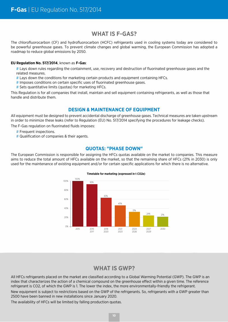
QUOTAS: "PHASE DOWN"The European Commission is responsible for assigning the HFCs quotas available on the market to companies. This measure aims to reduce the total amount of HFCs available on the market, so that the remaining share of HFCs (21% in 2030) is only used for the maintenance of existing equipment and/or for certain specific applications for which there is no alternative.
31%
93%
63%
45%
24% 21%
100%100%
80%
60%
40%
20%
0%2015 2016
201720182020
20212023
20242026
20272029
2030
Timetable for marketing (expressed in t CO2e)
WHAT IS GWP?All HFCs refrigerants placed on the market are classified according to a Global Warming Potential (GWP). The GWP is an index that characterizes the action of a chemical compound on the greenhouse effect within a given time. The reference refrigerant is CO2, of which the GWP is 1. The lower the index, the more environmentally-friendly the refrigerant. New equipment is subject to restrictions based on the GWP of the refrigerants. So, refrigerants with a GWP greater than 2500 have been banned in new installations since January 2020.The availability of HFCs will be limited by falling production quotas.
F-Gas | EU Regulation No. 517/2014
10

, THE ECO-FRIENDLY REFRIGERANTIn the pursuit of alternative solutions to this HFCs quota reduction, the choice of CO2 may, depending on the application, seem obvious.
Naturally present in the atmosphere, CO2 (R744) has an OPD of 0 and a GWP of 1. It is therefore 1,300 to 4,000 times less harmful to the planet than HFCs type refrigerants can be. CO2 has many advantages: it is not toxic or flammable, it is not governed by legislation on fluorinated refrigerants or subject to the associated taxes, it is inexpensive and it is not subject to a charge limitation.
The good thermophysical properties of CO2 also help reduce energy consumption, enabling the use of more compact components than for a system operating with a conventional refrigerant.
EMERGENCE OF REFRIGERANTSWhile CO2 is of course an alternative to HFCs, it may not be the most suitable solution for your application. Therefore, other
solutions exist, such as A2L refrigerants.
WHAT ARE A2L REFRIGERANTS? Refrigerants are classified according to their flammability and toxicity. These factors then determine a safety class.
Non-flammable Moderately flammable Flammable Highly flammable
Low toxicity A1 A2L A2 A3
High toxicity B1 B2L B2 B3
A2L refrigerants are non-toxic and slightly flammable. 'Slightly flammable' means they are harder to ignite and less capable of propagating a flame than A2 or A3 refrigerants.
Refrigerants
R50
7A
R40
4A
R45
2A
R40
7A
R41
0A
R40
7F
R40
7C
R13
4a
R44
9A
R44
8A
R32
R51
3A
R45
0A
R45
4C
R45
5A
R15
2a
1234
ze
1234
yf
R29
0 (
Prop
ane)
R74
4 (C
O2)
R71
7 (N
H3)
GWP 3985 3922 2141 2107 2088 1825 1774 1430 1397 1273 675 631 600 148 145 124 6 4 3 1 0
Safety class A1 A1 A1 A1 A1 A1 A1 A1 A1 A1 A2L A1 A1 A2L A2L A2 A2L A2L A3 A1 B2
A2L refrigerants are interesting because they offer a similar technology to HFCs, but they have a lower GWP.
Refrigerants and limits of use according to their GWP
RefrigerantsR
507A
R40
4A
R45
2A
R40
7A
R41
0A
R40
7F
R40
7C
R13
4a
R44
9A
R44
8A
R32
R51
3A
R45
0A
R45
4C
R45
5A
R15
2a
1234
ze
1234
yf
R29
0 (
Prop
ane)
R74
4 (C
O2)
R71
7 (N
H3)
GWP2 500 1 500 150
3985 3922 2141 2107 2088 1825 1774 1430 1397 1273 675 631 600 148 145 124 6 4 3 1 0
Authorization for use
before
2020
up to
2022
11

F-Gas | Impact of F-Gas according to installation type
NEW INSTALLATION
COMMERCIAL APPLICATION"Storage, presentation or distribution of products
for retail and catering, for sale to end users"
Examples: Restaurants and supermarkets
STANDALONE Hermetically sealed
and charged
Examples of products:
EUROMON
GWP< 2500
2020
GWP< 150
2022
MULTIPACK CENTRALIZED SYSTEM (2 or more compressors)
Examples of products concerned: DUO CU - MULTIHAVANE MOPSH MR - NTA - 3C-A
< 40 kW*
GWP< 2500
2020
≥ 40 kW** LT -35 °C/32 °C MT -10 °C / 32 °C
GWP< 2500
2020
GWP< 150
2022
Primary circuit of cascade
Primary refrigerant
GWP< 1500
2022
Secondary refrigerant
GWP< 150
2022
SINGLE-COMPRESSOR SYSTEM
Examples of products concerned:
MAXI VANGUARD MR - NTA - 3C-A
GWP< 2500
2020
NON-COMMERCIAL"Storage of products not intended for sale to end users and process"
Examples: Data centre, agricultural storage
GWP< 2500
2020
EXISTING INSTALLATION
< 40 t CO2e *
* 40 t CO2e = 10 kg R404A
No restrictions
≥ 40 t CO2e *
* 40 t CO2e = 10 kg R404A
R404A regenerated or recycled
Specific refrigerant labelling
2020
Remodelling New
installation
New installation
Retrofit
GWP< 2500
2020
1 62
6 3 5
7
4
Examples of products concerned: MONO and
MULTIHAVANE 3C-A GTA - NK
1 2 3 see text: Annex 1 F-Gas Regulation (EU) No. 517/20141 Refrigerators and freezers for commercial use (hermetically sealed equipment)2 Stationary refrigeration equipment, that contains, or whose functioning relies upon, HFCs with GWP of 2 500 or more except equipment intended
for application designed to cool products to temperatures below – 50 °C 3 Multipack centralized refrigeration systems for commercial use with a rated capacity of 40 kW or more that contain, or whose functioning
relies upon, fluorinated greenhouse gases with GWP of 150 or more, except in the primary refrigerant circuit of cascade systems where fluorinated greenhouse gases with a GWP of less than 1 500 may be used
4 see text: F-Gas Regulation (EU) No. 517/2014 Article 13 §3
5 6 7 see text: C (2017) 5230 Final 4.08.2017 + Annexes 1 and 25 If two completely independent refrigeration circuits separately guarantee MT and LT in direct expansion systems, then the prohibition only applies
to one or the other independent circuit, if it alone exceeds the capacity threshold. If one of the refrigeration circuits can guarantee both MT and LT at the same time, the sum of the capacities is relevant for the calculation of the system capacity. If not, the highest capacity is used to see if the 40 kW threshold has been exceeded. In the case of multi-functional systems, only the refrigeration capacities are taken into consideration, not the air conditioning or heating capacities.6 "Centralized systems" are understood to be systems where the ability to refrigerate an entire store is produced centrally in one location, often in a
separate machine room. The majority of refrigeration systems currently installed in larger supermarkets and hypermarkets are "centralized multipack refrigeration systems".
In addition, other, more decentralized refrigeration systems are commonly used, especially in smaller supermarkets and convenience stores. These systems include the use of multiple distributed condensers and/or standalone units, which will not be affected by the 2022 requirement.
Condensing units are likely to be affected if they fall under the definition of centralized multipack systems referred to in Article 2(37) of Regulation (EU) No 517/2014, for example if they have two or more compressors operating in parallel; and if their cooling capacity is greater than 40 kW.7 This definition implies the division of the medium temperature circuit into a primary and a secondary circuit. However, a simple cascade with R134a
in the primary circuit, which meets the requirements for medium temperature cooling in a direct expansion system (DX system) and absorbs the heat from a CO2 circuit for the low temperature, is not covered by this definition.
It is important to emphasize that the requirement set for 2022 does not allow the presence, in the primary circuit, of a simple cascade, for example with HFCs R134a (of which the global warming potential is 1,430 times higher than that of CO2), which satisfies all the requirements for medium temperature cooling while absorbing the heat from a CO2 circuit for the low temperature. This requirement, on the other hand, requires that the medium temperature itself be divided into two circuits, where only the primary circuit would be allowed to use HFCs < 1,500, such as R134a.
12
CO2 A2L A2L
60 bar 80 bar 60 bar 60 bar 80 bar
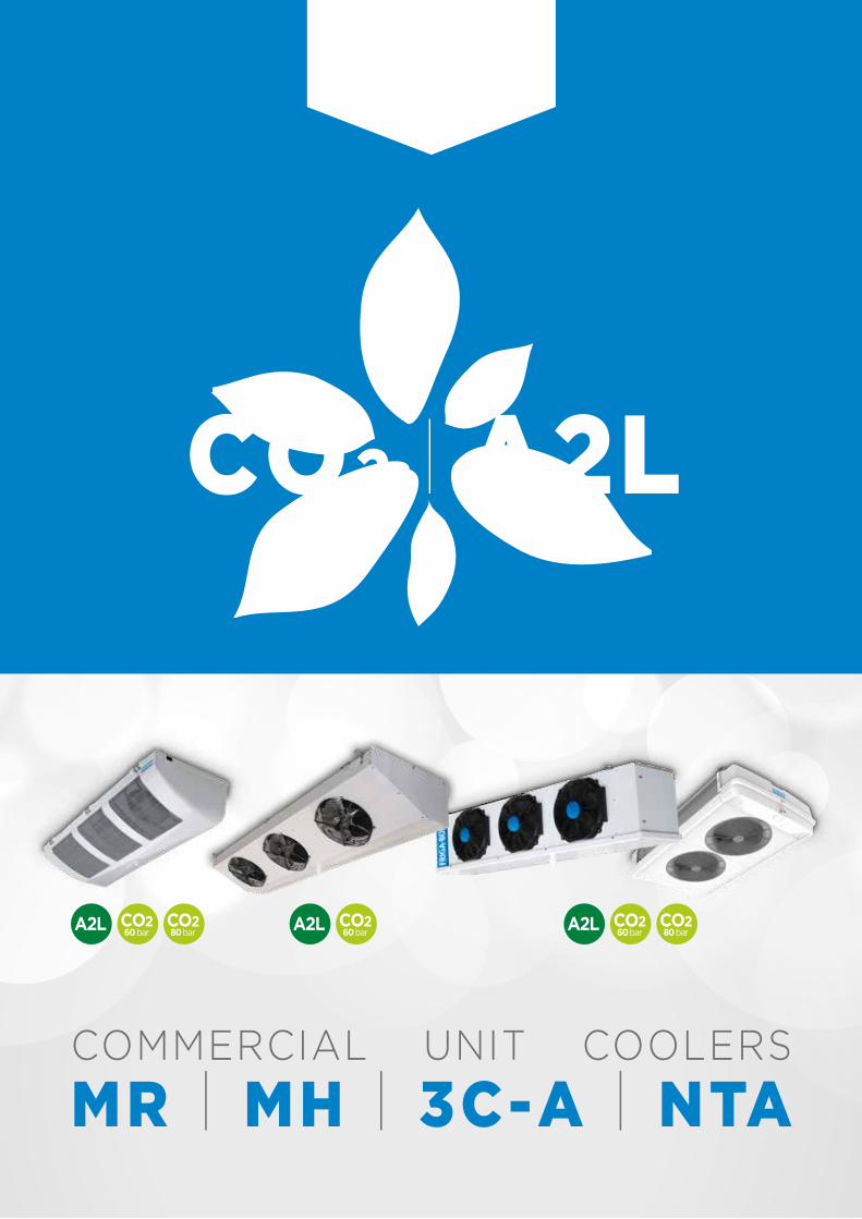
COMMERCIAL UNIT COOLERS
MR | MH | 3C-A | NTA
REFRIGERANTSNEW

Unit Coolers | Selection coefficients
Embedded equipment
Our machines are static. Included in a refrigeration system, they can be excited by motors, compressors, diesel generators, vehicles or other devices and be subjected to vibration.
It is the responsibility of the system's prime contractor to verify that the excitation frequencies cannot, under any circumstances, put the components in resonance, under penalty of inevitable breakage (especially in the case of an embedded system).
Standard conditions
Standard conditions
tA1 Air inlet temp.tem Evaporating
temp.Standard DTM
SC 1 +10°C 0°C 10K
SC 2 0°C - 8°C 8K
SC 3 -18°C -25°C 7K
SC 4 -25°C -31°C 6K
SC 5 -34°C -40°C 6K
Humidity coefficient
Standard conditions Relative humidityRated power /
Standard power
SC 1 85% 1,35
SC 2 85% 1,15
SC 3 95% 1,05
SC 4 95% 1,01
1,40
1,35
1,30
1,25
1,20
1,15
1,10
1,05
1,00
0,95
-35°C -30°C -25°C -20°C -15°C -10°C -5°C 0°C +5°C +10°C
Air inlet temperature
Humidity coefficient +2 °C Example
DTM correction coefficientFor refrigerants with low glide (less than 1K), or without glide, it is assumed that the power is directly proportional to the difference between the air inlet temperature and the evaporating temperature (DTM), namely:
Desired power = Rated power x DTM desired ________________________________
Standard DTM
Refrigerant coefficientStandard conditions
R449A R134a R407A R407C R407F R410A R448A R450A R452A R507A R513A R1234yf R454C R455A
SC 1 1 0,90 0,94 0,94 0,94 0,95 0,99 0,89 0,97 0,94 0,96 0,96 0,97 1,08
SC 2 1 0,89 0,95 0,95 0,94 0,96 0,99 0,87 0,99 0,95 0,95 0,96 0,93 1,08
SC 3 1 0,90 1,02 1,03 1,02 1,03 0,97 0,88 1,06 1,03 0,97 0,98 0,91 1,08
SC 4 1 - 1,02 1,04 1,04 1,04 0,95 0,83 1,07 1,04 0,91 0,93 0,88 1,06
Example
Or:Desired power Q = 6,000 WAir inlet temperature tA1 = +2 °CEvaporating temperature tem = -8 °CRefrigerant R 22
hence:DTM = tA1 - tem = (+2)-(-8) = 10K
To select under standard conditions, the following correction coefficients should be applied:
- humidity coefficient 1.15/1.23 = 0.935- correction coefficient of DTM 8/10 = 0.8- refrigerant coefficient 1/0.95 = 1.05
Expressed under the standard conditions given, the desired power of 6,000 W becomes:
6000 x 0,935 x 0,8 x 1,05 = 4712 W
Therefore we select a 3C-A 3245 L R448A
For more information, consult our software
14

C1 : Altitude coefficientC1 = (1 - 0.000075 x H*) *H = Altitude in meters above sea level
C2 : DTM coefficient
DTM 8 9 10 11 12 13 14 15 16 17 18
C2 0,53 0,60 0,67 0,73 0,80 0,87 0,93 1 1,07 1,13 1,20
C3 : Ambient temperature coefficient tA.1
t1.1 15 20 25 30 35 40 45 50
C3 1,03 1,02 1 0,98 0,96 0,94 0,92 0,91
C4 : Refrigerant coefficient
R449A R134a R407A R407C R407F R410A R448A R450A R452A R507A R513A
C4 DTM = 15K 1 0,92 1,01 1,01 1,01 0,98 1,01 0,89 0,97 0,93 0,92
Sound pressure correction according to number of fans
Fan Nb 1 2 3 4 5 6 8 10 12
Correction dB(A) 0 3 5 6 7 8 9 10 11
Sound pressure correction according to distance
Distance m 5 6 8 10 12 16 32 64 128
Correction dB(A) +6 +4,5 +2 0 -1,5 -4 -10 -16 -22
Selection
“P” = power at the condenser.
To determine a model, the application conditions must be brought into line with the selection conditions. To do this, divide the desired power "P" by the 5 coefficients below:
C1 altitude coefficientC2 DTM coefficientC3 ambient temperature coefficientC4 refrigerant coefficient
according to the formula : P1 = P ________________
C1 x C2 x C3 x C4
Select a model from the table corresponding to the selected rotation speed and check that the noise level meets the required level. Where the selection can lead to an L or P model being selected, with no dimensional constraints, choose the most economical model. Similarly, to find out the power "P" of a module under conditions other than those in the documentation, apply the formula:
P = P1 x (C1 x C2 x C3 x C4)
Example
Desired power “P” 58 kWAltitude 200 mDTM 14 KAmbient temperature +30 °CRefrigerant R134aSound pressure at 5 m 37 dB(A)(parallelepiped measuring surface)
Or: C1 = 0,99 - C2 = 0,93 - C3 = 0,98 - C4 = 0,92
hence:
58_____________________ = 69,9 kW0,99 x 0,93 x 0,98 x 0,92
Basic noise level - Distance correction: 37 - 6 = 31 dB(A)Sound pressure at = 31 dB(A)
Note: if the noise level is very different, look for the appropriate model in the other tables.
Condensers | Dry Coolers | Selection coefficients
Noise levels
Noise level LpA:The sound pressure Lp indicated in the specification tables was measured at 10 meters in a free field over a reflecting plane, in accordance with standard EN 13487 (parallelepiped reference surface). The relationship between sound pressure Lp and sound power Lw is given by the following formula:
SiLpA = LwA- 10 log __
So
Si = parallelepiped surface for d = 10 mSo = reference area 1 m2
Only the sound power spectrum and the LwA value are contractually binding. For a distance other than 10 m, see the correction factors below. For an accurate calculation of the sound pressure on site, take into account the sound power of each fan and its position as well as the characteristics of the environment (directivity, reflections, etc.).
d
d
d
d
d
15

NOTES

EVBUnder-counter unit cooler Commercial range
240 - 410 W

COIL
# Coils completely covered with polyester protection as standard.
# Low refrigerant volume: Ø 5/16" tubes.
CASING
# Robust, made of white pre-painted galvanized sheet steel and stainless steel fasteners.
# ABS drain pan with rounded corners and no retention zone for perfect hygiene.
DEFROST
OPTION
E1K Electric defrost. KIT TO INSTALL
VENTILATION
# Aluminium turbine.
M1 - M2 - M3 C1 - C2
For easy installation, the casing and drain pan
are reversible according to the constraints of the bar.
# Compact design for perfect integration into bar counters.
# Hygienic unit, with anti-corrosion components.
# Easy maintenance: the EVB is fully accessible by removing the fan panel and the clip-on drain pan.
M1 - M2 - M3 C1 - C2INSTALLATION
# For wall mounting, choose models M1, M2 and M3. They have a small footprint and provide excellent air distribution.
# For central mounting, choose models C1 and C2. They ensure an optimized airflow as well as partitioning of the space into two parts.
EVB | Under-counter unit cooler
18

EVB 3.63 mm
CONDITIONS REFRIGERANTS EVB ... M1 M2 M3 C1 C2
SC1 R449A W 240 300 380 240 410
Circuit volume dm3 0,3 0,3 0,4 0,3 0,4
Fan (1)230V/1/50Hz2,200 rpmØ 45 mm
Airflow m3/h 60 100 100 60 110
Air throw (2) m 3,5 3,5 3,5 2x 3,5 2x 3,5
Num. 1 1 1 2 2
W total 15 22 22 26 30
A total 0,15 0,22 0,22 0,26 0,30
Electric defrost 230V/1/50Hz W 210 210 290 210 290
ConnectionsInlet Ø E 5/16" 5/16" 5/16" 5/16" 5/16"
Outlet Ø S 5/16" 5/16" 5/16" 5/16" 5/16"
Net weight kg 4 4 5 5 6
(1) Motor, class B, long life bearings.(2) When the section of the room allows air circulation.
EVB M(A) 1(B)
(A) M = wall mounting C = central mounting(B) Model
M1 - M2 - M3 C1 - C2
440
398
Ø 16
V
L
X
8
T
50
65
80
70
Ø S
Ø E
M1 M2 M3L mm 370 370 490
X mm 340 340 460
T mm 386 386 506
V mm 120 180 180
440
398
Ø 16
L
X
8
T
V
50
65
89
70
Ø S
Ø E
C1 C2L mm 370 490
X mm 340 460
T mm 386 506
V mm 60 120
EVB | Nomenclature, technical data and dimensions
The EVB is available with HFCs. For more information,
please consult our software.
19

NOTES
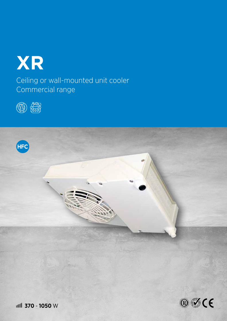
370 - 1050 W
XRCeiling or wall-mounted unit cooler Commercial range

CASING
# Galvanized sheet steel and plastic drain pan, white colour.# Intermediate drain pan for ceiling mounting, limiting water condensation.
VENTILATION
# Single-phase motor fans, 230 V, 50-60 Hz, Ø 200 mm, protected by an enclosed casing, delivered with cable 3 x 0.75 mm² length 1 m: - 4P / 1,500 rpm (low noise level). - 2P / 3,000 rpm, motor with built-in thermal protection (high performance).
XR | Ceiling or wall-mounted unit cooler
# Compact design and ceiling or wall mounting possible for perfect integration in small spaces and optimization of the storage area.
# "Keyhole" fixing and drilling template printed on the cardboard packaging to save installation time.
# Access to all components from the front for easy maintenance.
COILS
# Aluminium fins with 4.23 mm spacing and sinusoidal profile.# Combined with copper tubes with a grooved internal structure,
the coils are very efficient and compact.# Coils completely covered with polyester protection as standard.
ADVANTAGES
# "Keyhole" fixing requiring only one operator. # Drilling template printed on the cardboard packaging. # 8 pre-cut holes for the tubes and cables. # Factory delivered for ceiling mounting, simple conversion for wall
mounting. # 4 possible drain tube positions with ceiling mounting (2 with wall
mounting) to offer the user the maximum available volume. # Access to all components from the front.
DEFROST
+10 +2 -5 -25°C
tA1 XR ... +E1K + E1K (1)
OPTION
E1K Electric defrost. KIT TO INSTALL
(1) ATTENTION use SC3 for ceiling mounting only: E1K kit must be mounted.
Ceiling mounting
Wall mounting
22

EVB M(A) 1(B)
(A) M = wall mounting C = central mounting(B) Model
Le 3C-A est disponible au CO2, aux HFC et à l’eau glycolée.
Pour plus d’informations, veuillez consulter notre logiciel.
XR(A) 60(B)
(A) Ceiling or wall-mounted unit cooler(B) Model
The XR is available with HFCs. For more information,
please consult our software.
XR 4.23 mm
CONDITIONS REFRIGERANTS XR ... 60 72 80 85 90 100 105 122
SC2 R449A W 470 600 660 680 770 820 900 1050
CONDITIONS REFRIGERANTS XR ... 60 72 80 85 90 100 105 122
SC3 R449A W 370 490 560 570 650 670 730 870
60 72 80 85 90 100 105 122
Surface area m2 1,5 2,0 2,5 2,0 3,0 2,5 3,0 3,8
Circuit volume dm3 0,3 0,3 0,4 0,3 0,5 0,4 0,5 0,7
Fan 230V/1/50-60 HzØ 200 mm
Airflow m3/h 270 250 230 440 360 410 500 480
Air throw (2) m 2,5 2,0 2,0 3,0 2,0 3,0 2,5 2,5
Nb 1 1 1 1 1 1 1 1
tr/min 1500 1500 1500 3000 1500 3000 3000 3000
230V/1/50HzW total 43 43 43 80 43 80 80 80
A total 0,25 0,25 0,25 0,50 0,25 0,50 0,50 0,50
Electric defrost E1K (3)
Nb 1 1 1 1 1 1 1 1
230V/1/50HzW total 400 400 400 400 600 400 600 600
A total 1,8 1,8 1,8 1,8 2,7 1,8 2,7 2,7
Connections
Inlet (4) Ø ODF3/8" 3/8" 3/8" 3/8" 3/8" 3/8" 3/8" 3/8"
10mm 10mm 10mm 10mm 10mm 10mm 10mm 10mm
Outlet (4) Ø ODF3/8" 3/8" 3/8" 3/8" 3/8" 3/8" 3/8" 3/8"
10mm 10mm 10mm 10mm 10mm 10mm 10mm 10mm
Net weight kg 7 8 8 8 10 8 10 10
(1) Standard conditions: SC2 / 0 °C (air inlet temp.) / -8 °C (evaporating temp.) / DT1 = 8K SC3 / -18 °C (air inlet temp.) / -25 °C (evaporating temp.) / DT1 = 7K
(2) When the section allows air circulation (see CECOMAF GT 6001, DIN8955, ENV328).(3) ATTENTION use SC3 for ceiling mounting only: E1K kit must be mounted.(4) ODF: female to receive the tube of the same diameter.
XR | Nomenclature and technical data
23

XR | Ceiling mounting
30 30
27, 527, 5 Y
= =
D31 31
30 30
485
16030
461
210200
30
Ø 13
210
15
5, 2
Ø 5, 2
27, 5
30
Y
XR | Wall mounting
200
160
G 1/2”
30
30 30
27, 527, 5 Y
= =
D
Ø 1631 31
30
200
210
650
Ø 13
210
15
5, 2
Ø 5, 2
27, 530
Y
XR
XR ... 4.23 mm
60 72 80 85 90 100 105 122
D mm 399 399 399 399 560 399 560 560
Y mm 330 330 330 330 485 330 485 485
XR | Dimensions
24

140 - 790 W
MF | MFECeiling unit cooler Commercial range
Certificate of conformity
"Hygiene& Security"
CASING
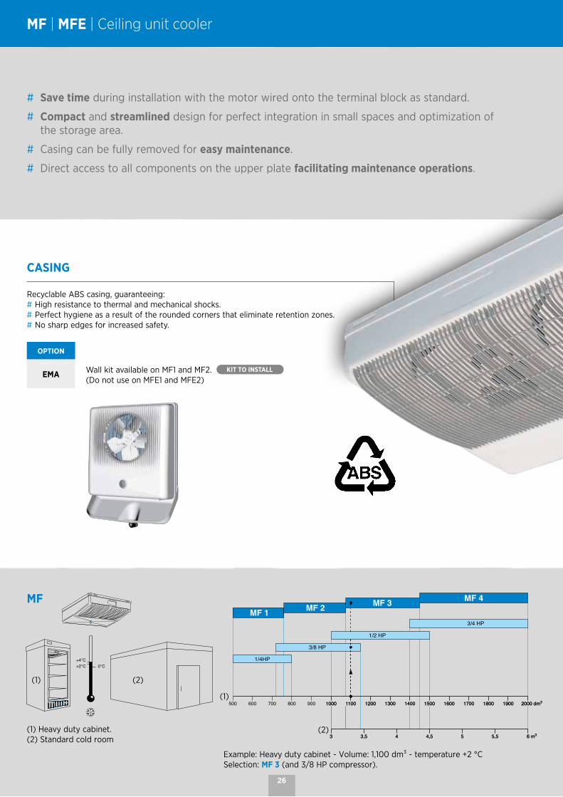
Recyclable ABS casing, guaranteeing:# High resistance to thermal and mechanical shocks.# Perfect hygiene as a result of the rounded corners that eliminate retention zones.# No sharp edges for increased safety.
OPTION
EMA Wall kit available on MF1 and MF2. KIT TO INSTALL
(Do not use on MFE1 and MFE2)
MF | MFE | Ceiling unit cooler
# Save time during installation with the motor wired onto the terminal block as standard.
# Compact and streamlined design for perfect integration in small spaces and optimization of the storage area.
# Casing can be fully removed for easy maintenance.
# Direct access to all components on the upper plate facilitating maintenance operations.
Example: Heavy duty cabinet - Volume: 1,100 dm³ - temperature +2 °CSelection: MF 3 (and 3/8 HP compressor).
(1) Heavy duty cabinet.(2) Standard cold room
MF
(1)
(2)
(1) (2)
26

COILS
# Aluminium fins with 4.23 mm spacing and sinusoidal profile.
# Combined with copper tubes with a grooved internal structure, the coils are very efficient and compact.
# Completely covered with polyester protection as standard.
# Low refrigerant volume.
VENTILATION
# 4-pole motor(s), polypropylene blade.# Corrosion resistant blade and grille.
Data provided for information purposes only.
(1) Heavy duty cabinet.(2) Standard cold room
MFE
+10 +2 0 -10 -25°C
tA1MF ... MFE ...
MFE ...
(1) (2)
(1)
(2)
27

MF | MFE 4.23 mm
CONDITIONS REFRIGERANT MF ... 1 2 3 4
SC2 (1) R449A W 300 380 740 790
CONDITIONS REFRIGERANT MFE ... 1 2 3 4
SC3 (1) R449A W 220 270 520 600
SC4 (1) R449A W 140 200 380 400
Electric defrost 230V/1/50 HzW 140 160 330 330
A 0.64 0.73 1.5 1.5
1 2 3 4
Surface area m2 1,1 1,4 2,3 2,8
Circuit volume dm3 0,2 0,3 0,5 0,6
Fan (3) 230V/1/50-60HzØ 200 mm1,500 rpm
Airflow m3/h 270 250 460 430
Air throw (2) m 3,5 3,0 6,0 5,5
Num. 1 1 2 2
230 V/1/50 HzW total 38 38 76 76
A total 0,33 0,33 0,66 0,66
Connections Inlet Ø ODF 5/16" 5/16" 5/16" 5/16"
Outlet Ø ODF 5/16" 5/16" 5/16" 5/16"
Net Weight kg 4 4 8 9
(1) Standard conditions: SC2 / 0 °C (air inlet temp.) / -8 °C (evaporating temp.) / DT1 = 8K SC3 / -18 °C (air inlet temp.) / -25 °C (evaporating temp.) / DT1 = 7K SC4 / -25 °C (air inlet temp.) / -31 °C (evaporating temp.) / DT1 = 6K(2) When the section of the room allows air circulation.(3) Closed motor, class B, protected by its impedance, long-lasting lubrication.
MF(A) 1(B)
(A) MF = positive temperature without defrost MFE = negative temperature with defrost(B) Number of fans
The MF | MFE is available with HFCs. For more information,
please consult our software.
MF | MFE | Nomenclature, technical data and dimensions
MF 1-2 | MFE 1-2 MF 1-2 - EMA kit MF 3-4 | MFE 3-4
121
26418285.5
37.5
37.5
327
160
121
435
148
29
Ø 20 m m
Wall mounting with EMA kit for MF 1-2160121 121
182
85.5
409
327
Ø 20 m m
152
569
Ø 20 mm
599
527
150
429
21257
29
28
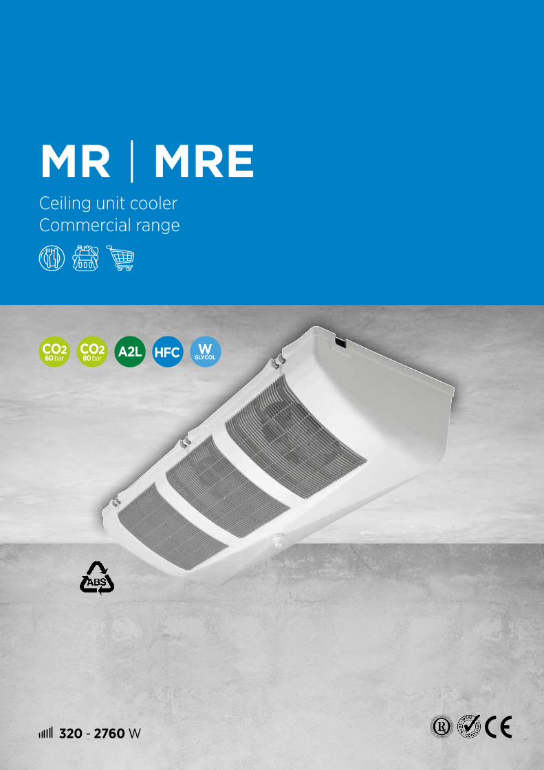
320 - 2760 W
60 bar
80 bar
MR | MRECeiling unit cooler Commercial range

VENTILATION
# Motor fan 50-60 Hz, Ø 200 mm, protected by a closed casing, connected to terminal box (except MR 75/65).
MR | MRE | Ceiling unit cooler
CASING
Recyclable ABS casing, guaranteeing:# High resistance to thermal and mechanical shocks.# Perfect hygiene as a result of the rounded corners that eliminate retention zones.# No sharp edges for increased safety.
# Compact and streamlined design for perfect integration in small spaces and optimization of the storage area.
# Easy installation and maintenance with easy access to all components.
# Harmonious integration into the environment thanks to the aesthetic design.
# Robust unit with polyester coil protection.
OPTIONS
DMP Expansion valve fitted
EEC Unit cooler completely assembled in the factory with:- Expansion valve- Solenoid valve- Pipework equipped with a ball valve (role of the siphon performed by the manifold).
Save time during installation by choosing these additional options.
30
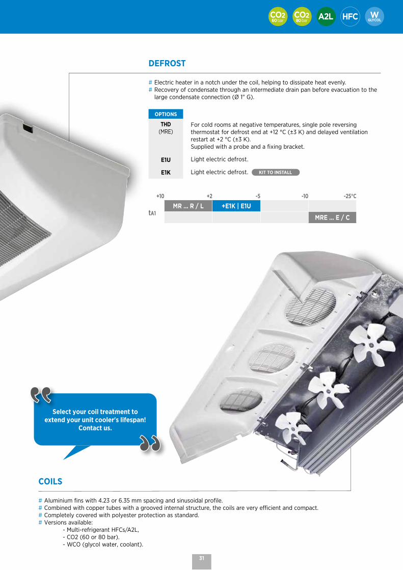
COILS
# Aluminium fins with 4.23 or 6.35 mm spacing and sinusoidal profile.# Combined with copper tubes with a grooved internal structure, the coils are very efficient and compact.# Completely covered with polyester protection as standard.# Versions available: - Multi-refrigerant HFCs/A2L, - CO2 (60 or 80 bar). - WCO (glycol water, coolant).
DEFROST
# Electric heater in a notch under the coil, helping to dissipate heat evenly.# Recovery of condensate through an intermediate drain pan before evacuation to the
large condensate connection (Ø 1" G).
OPTIONS
THD(MRE)
For cold rooms at negative temperatures, single pole reversing thermostat for defrost end at +12 °C (±3 K) and delayed ventilation restart at +2 °C (±3 K). Supplied with a probe and a fixing bracket.
E1U Light electric defrost.
E1K Light electric defrost. KIT TO INSTALL
+10 +2 -5 -10 -25°C
tA1MR ... R / L +E1K | E1U
MRE ... E / C
60 bar 80 bar
Select your coil treatment to extend your unit cooler's lifespan!
Contact us.
31
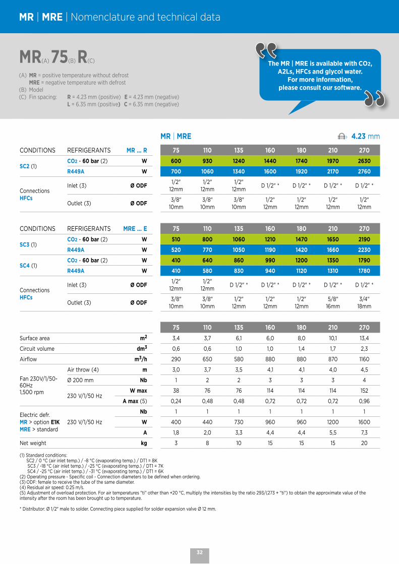
MR | MRE 4.23 mm
CONDITIONS REFRIGERANTS MR ... R 75 110 135 160 180 210 270
SC2 (1) CO2 - 60 bar (2) W 600 930 1240 1440 1740 1970 2630
R449A W 700 1060 1340 1600 1920 2170 2760
ConnectionsHFCs
Inlet (3) Ø ODF1/2"
12mm1/2"
12mm1/2"
12mmD 1/2" * D 1/2" * D 1/2" * D 1/2" *
Outlet (3) Ø ODF3/8"
10mm 3/8"
10mm 3/8"
10mm 1/2"
12mm 1/2"
12mm 1/2"
12mm 1/2"
12mm
CONDITIONS REFRIGERANTS MRE ... E 75 110 135 160 180 210 270
SC3 (1) CO2 - 60 bar (2) W 510 800 1060 1210 1470 1650 2190
R449A W 520 770 1050 1190 1420 1660 2230
SC4 (1) CO2 - 60 bar (2) W 410 640 860 990 1200 1350 1790
R449A W 410 580 830 940 1120 1310 1780
ConnectionsHFCs
Inlet (3) Ø ODF1/2"
12mm1/2"
12mmD 1/2" * D 1/2" * D 1/2" * D 1/2" * D 1/2" *
Outlet (3) Ø ODF3/8"
10mm 3/8"
10mm 1/2"
12mm 1/2"
12mm 1/2"
12mm 5/8"
16mm 3/4"
18mm
75 110 135 160 180 210 270
Surface area m2 3,4 3,7 6,1 6,0 8,0 10,1 13,4
Circuit volume dm3 0,6 0,6 1,0 1,0 1,4 1,7 2,3
Airflow m3/h 290 650 580 880 880 870 1160
Fan 230V/1/50-60Hz1,500 rpm
Air throw (4) m 3,0 3,7 3,5 4,1 4,1 4,0 4,5
Ø 200 mm Nb 1 2 2 3 3 3 4
230 V/1/50 HzW max 38 76 76 114 114 114 152
A max (5) 0,24 0,48 0,48 0,72 0,72 0,72 0,96
Electric defr.MR > option E1K MRE > standard
230 V/1/50 Hz
Nb 1 1 1 1 1 1 1
W 400 440 730 960 960 1200 1600
A 1,8 2,0 3,3 4,4 4,4 5,5 7,3
Net weight kg 3 8 10 15 15 15 20
(1) Standard conditions: SC2 / 0 °C (air inlet temp.) / -8 °C (evaporating temp.) / DT1 = 8K SC3 / -18 °C (air inlet temp.) / -25 °C (evaporating temp.) / DT1 = 7K SC4 / -25 °C (air inlet temp.) / -31 °C (evaporating temp.) / DT1 = 6K(2) Operating pressure - Specific coil - Connection diameters to be defined when ordering.(3) ODF: female to receive the tube of the same diameter.(4) Residual air speed: 0.25 m/s.(5) Adjustment of overload protection. For air temperatures "ti" other than +20 °C, multiply the intensities by the ratio 293/(273 + "ti") to obtain the approximate value of the intensity after the room has been brought up to temperature.
* Distributor: Ø 1/2" male to solder. Connecting piece supplied for solder expansion valve Ø 12 mm.
MR(A) 75(B) R(C)
(A) MR = positive temperature without defrost MRE = negative temperature with defrost(B) Model(C) Fin spacing: R = 4.23 mm (positive) E = 4.23 mm (negative) L = 6.35 mm (positive) C = 6.35 mm (negative)
MR | MRE | Nomenclature and technical data
The MR | MRE is available with CO2,A2Ls, HFCs and glycol water.
For more information, please consult our software.
32

60 bar 80 bar
MR | MRE 6.35 mm
CONDITIONS REFRIGERANTS MR ... L 65 100 120 140 170 190 250
SC2 (1)
CO2 - 60 bar (2) W 540 780 1130 1290 1560 1780 2390
CO2 - 80 bar W 470 680 1010 - 1430 1640 2220
R449A W 620 880 1230 1380 1690 1940 2550
ConnectionsHFCs
Inlet (3) Ø ODF1/2"
12mm1/2"
12mm1/2"
12mmD 1/2" * D 1/2" * D 1/2" * D 1/2" *
Outlet (3) Ø ODF3/8"
10mm 3/8"
10mm 3/8"
10mm 1/2"
12mm 1/2"
12mm 1/2"
12mm 1/2"
12mm
CONDITIONS REFRIGERANTS MRE ... C 65 100 120 140 170 190 250
SC3 (1)
CO2 - 60 bar (2) W 460 670 960 1090 1320 1500 2000
CO2 - 80 bar W 410 590 870 - 1210 1390 1850
R449A W 450 610 900 1040 1260 1460 1950
SC4 (1)
CO2 - 60 bar (2) W 370 540 780 890 1080 1230 1640
CO2 - 80 bar W 320 450 690 - 970 1120 1480
R449A W 350 490 720 820 1000 1170 1590
ConnectionsHFCs
Inlet (3) Ø ODF1/2"
12mm1/2"
12mmD 1/2" * D 1/2" * D 1/2" * D 1/2" * D 1/2" *
Outlet (3) Ø ODF3/8"
10mm 3/8"
10mm 1/2"
12mm 1/2"
12mm 1/2"
12mm 5/8"
16mm 3/4"
18mm
65 100 120 140 170 190 250
Surface area m2 2,3 2,5 4,2 4,2 5,6 7,0 9,3
Circuit volume dm3 0,6 0,6 1,0 1,0 1,4 1,7 2,3
Airflow m3/h 310 660 620 960 960 930 1240
Fan 230 V/1/50-60 Hz1,500 rpm
Air throw (4) m 3,0 3,7 3,5 4,1 4,1 4,0 4,5
Ø 200 mm Nb 1 2 2 3 3 3 4
230 V/1/50 HzW max 38 76 76 114 114 114 152
A max (5) 0,24 0,48 0,48 0,72 0,72 0,72 0,96
Electric defr.MR > option E1K MRE > standard
230 V/1/50 Hz
Nb 1 1 1 1 1 1 1
W 400 440 730 960 960 1200 1600
A 1,8 2,0 3,3 4,4 4,4 5,5 7,3
Net weight (6) kg 3 8 10 15 15 15 20
(1) Standard conditions: SC2 / 0 °C (air inlet temp.) / -8 °C (evaporating temp.) / DT1 = 8K SC3 / -18 °C (air inlet temp.) / -25 °C (evaporating temp.) / DT1 = 7K SC4 / -25 °C (air inlet temp.) / -31 °C (evaporating temp.) / DT1 = 6K(2) Operating pressure - Specific coil - Connection diameters to be defined when ordering.(3) ODF: female to receive the tube of the same diameter.(4) Residual air speed: 0.25 m/s.(5) Adjustment of overload protection. For air temperatures "ti" other than +20 °C, multiply the intensities by the ratio 293/(273 + "ti") to obtain the approximate value of the intensity after the room has been brought up to temperature.(6) Standard net weight - Specific net weight for CO2 80 bar: contact us.
* Distributor: Ø 1/2" male to solder. Connecting piece supplied for solder expansion valve Ø 12 mm.
MRE(A) 65(B) C(C)
(A) MR = positive temperature without defrost MRE = negative temperature with defrost(B) Model(C) Fin spacing: R = 4.23 mm (positive) E = 4.23 mm (negative) L = 6.35 mm (positive) C = 6.35 mm (negative)
The MR | MRE is available with CO2,A2Ls, HFCs and glycol water.
For more information, please consult our software.
33

MR | MRE | Dimensions
BA
==
= BA
=B
209
438
20851
Ø = 1” G
180 mini90 *
* 90 min.: Casing swivel - 160 min.: Casing removal
MR
MR ... R 4.23 mm
75 110 135 160 180 210 270
A mm 514 784 784 1174 1174 1174 1504
B mm 326 596 596 493 493 493 658
MR ... L 6.35 mm
65 100 120 140 170 190 250
A mm 514 784 784 1174 1174 1174 1504
B mm 326 596 596 493 493 493 658
MRE
MRE ... E 4.23 mm
75 110 135 160 180 210 270
A mm 514 784 784 1174 1174 1174 1504
B mm 326 596 596 493 493 493 658
MRE ... C 6.35 mm
65 100 120 140 170 190 250
A mm 514 784 784 1174 1174 1174 1504
B mm 326 596 596 493 493 493 658
34

1310 - 7390 W
60 bar
MH | MHECeiling unit cooler
Commercial range
OPTIONS
DMP Expansion valve fitted.
EEC Unit cooler completely assembled in the factory with:- Expansion valve.- Solenoid valve.- Pipework equipped with a ball valve (role of the siphon performed by the manifold).
Save time during installation by choosing these additional options.
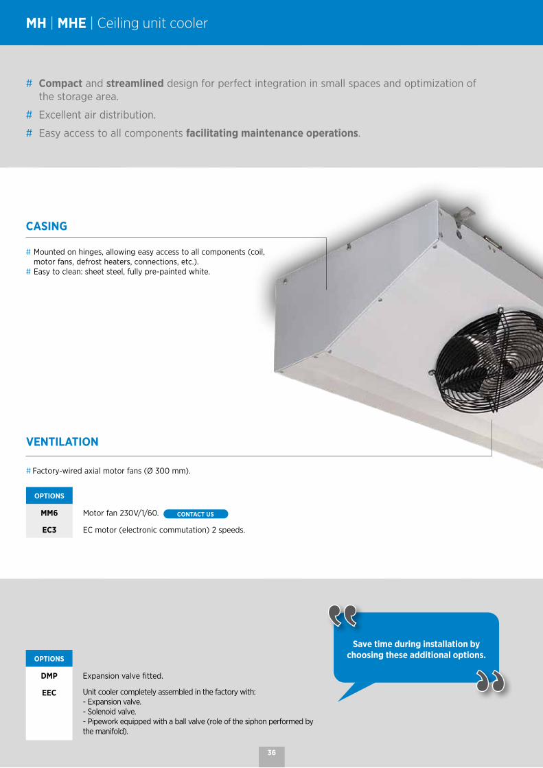
MH | MHE | Ceiling unit cooler
CASING
# Mounted on hinges, allowing easy access to all components (coil, motor fans, defrost heaters, connections, etc.).
# Easy to clean: sheet steel, fully pre-painted white.
# Compact and streamlined design for perfect integration in small spaces and optimization of the storage area.
# Excellent air distribution.
# Easy access to all components facilitating maintenance operations.
VENTILATION
# Factory-wired axial motor fans (Ø 300 mm).
OPTIONS
MM6 Motor fan 230V/1/60. CONTACT US
EC3 EC motor (electronic commutation) 2 speeds.
36

COILS
# Aluminium fins with 4.23 or 6.35 mm spacing.# Combined with copper tubes with a grooved internal structure, the coils are very efficient and compact.# Versions available: - Multi-refrigerant HFCs. - CO2 (60 bar). - WCO (glycol water, coolant). CONTACT US
DEFROST
# Shielded electrical heaters housed in notches on the front and back of the coil.# Homogeneous heat dissipation thanks to an electrical heater under the coil.# Defrost heaters connected in the factory, on the terminal box (MHE range only).# Power supply 230V single phase for models MHE 320E, 380E and 250C, 310C.# 400V three-phase power supply for models MHE 460E, 550E, 640E, 770E and 370C, 450C, 510C, 630C.
OPTIONS
THD(MHE)
For cold rooms at negative temperatures, single pole reversing thermostat for defrost end at +12 °C (±3 K) and delayed ventilation restart at +2 °C (±3 K). Supplied with a probe and a fixing bracket.
E1U Light electric defrost.
E1K Light electric defrost (kit to install).
+10 +2 -5 -10 -25°C
tA1MH ... R / L +E1K | E1U
MHE ... E / C
Select your coil treatment to extend your unit cooler's lifespan!
Contact us.
37

MH | MHE | Nomenclature and technical data
MH(A) 320(B) R(C)
(A) MH = positive temperature without defrost MHE = negative temperature with defrost (B) Model(C) Fin spacing: R = 4.23 mm (positive) E = 4.23 mm (negative)
L = 6.35 mm (positive) C = 6.35 mm (negative)
The MH | MHE is available with CO2, A2Ls, HFCs and glycol water.
For more information, please consult our software.
MH | MHE 4,23 mm
CONDITIONS REFRIGERANTS MH ... R 320 380 460 550 640 770
SC2 (1) CO2 - 60 bar (2) W 3210 3670 4770 5300 6130 7390
R449A W 2860 3420 4460 5230 6040 7060
CONDITIONS REFRIGERANTS MHE ... E 320 380 460 550 640 770
SC3 (1) CO2 - 60 bar (2) W 2670 3000 3840 4160 5370 6070
R449A W 2090 2480 2970 3820 4180 5040
SC4 (1) CO2 - 60 bar (2) W 2150 2430 3080 3310 4340 4920
R449A W 1630 1970 2270 3020 3290 3990
320 380 460 550 640 770
Surface area m2 9,7 13,0 14,6 19,5 19,6 26,2
Circuit volume dm3 1,7 2,2 2,5 3,3 3,4 4,5
airflow m3/h 2290 2070 3430 3110 4600 4160
Fan230 V/1/50-60 Hz1,500 rpm
Air throw (3) m 16 16 16 16 16 16
Ø 300 mm Nb 2 2 3 3 4 4
230 V/1/50 HzW max 234 234 351 351 468 468
A max (4) 1,54 1,54 2,31 2,31 3,08 3,08
Electric defrost MH > E1K optionalMHE > standard *
Coil Nb 2 2 2 2 2 2
Drain pan Nb 1 1 1 1 1 1
W total 1800 1800 2700 2700 3600 3600
230 V/1/50Hz A total 7,83 * 7,83 * 11,7 11,7 15,7 15,7
400 V/3/50Hz A total - - 3,9 * 3,9 * 5,2 * 5,2 *
ConnectionsHFCs
Inlet (5) Ø ODF D 1/2" D 1/2" D 1/2" D 1/2" D 5/8" D 5/8"
Outlet (5) Ø ODF 5/8" 5/8" 3/4" 3/4" 7/8" 7/8"
Net weight kg 34 35 46 48 54 57
(1) Standard conditions: * Factory assembled (MHE) SC2 / 0 °C (air inlet temp.) / -8 °C (evaporating temp.) / DT1 = 8K SC3 / -18 °C (air inlet temp.) / -25 °C (evaporating temp.) / DT1 = 7K SC4 / -25 °C (air inlet temp.) / -31 °C (evaporating temp.) / DT1 = 6K(2) Operating pressure - Specific coil - Connection diameters to be defined when ordering.(3) Residual air speed: 0.25 m/s.(4) Adjustment of overload protection. For air temperatures "ti" other than +20 °C, multiply the intensities by the ratio 293/(273 + "ti") to obtain the approximate value of the intensity after the room has been brought up to temperature.(5) ODF: female to receive the tube of the same diameter.
38

MHE(A) 250(B) C(C)
(A) MH = positive temperature without defrost MHE = negative temperature with defrost (B) Model(C) Fin spacing: R = 4.23 mm (positive) E = 4.23 mm (negative)
L = 6.35 mm (positive) C = 6.35 mm (negative)
The MH | MHE is available with CO2, A2Ls, HFCs and glycol water.
For more information, please consult our software.
MH | MHE 6,35 mm
CONDITIONS REFRIGERANTS MH ... L 250 310 370 450 510 630
SC2 (1) CO2 - 60 bar (2) W 2780 3320 4190 4860 5440 6690
R449A W 2280 2810 3520 4300 4670 5160
CONDITIONS REFRIGERANTS MHE ... C 250 310 370 450 510 630
SC3 (1) CO2 - 60 bar (2) W 2320 2740 3400 3850 4680 5520
R449A W 1650 2000 2450 3020 3360 4150
SC4 (1) CO2 - 60 bar (2) W 1880 2230 2750 3080 3800 4490
R449A W 1310 1590 1920 2500 2670 3320
250 310 370 450 510 630
Surface area m2 6,7 9,0 10,1 13,5 13,6 18,1
Circuit volume dm3 1,7 2,2 2,5 3,3 3,4 4,5
airflow m3/h 2450 2290 3680 3430 4920 4590
Fan 230 V/1/50-60 Hz1,500 rpm
Air throw (3) m 17 17 17 17 17 17
Ø 300 mm Nb 2 2 3 3 4 4
230 V/1/50 HzW max 234 234 351 351 468 468
A max (4) 1,54 1,54 2,31 2,31 3,08 3,08
Electric defrost MH > E1K optionalMHE > standard *
Coil Nb 2 2 2 2 2 2
Drain pan Nb 1 1 1 1 1 1
W total 1800 1800 2700 2700 3600 3600
230 V/1/50Hz A total 7,83 * 7,83 * 11,7 11,7 15,7 15,7
400 V/3/50Hz A total - - 3,9 * 3,9 * 5,2 * 5,2 *
ConnectionsHFCs
Inlet (5) Ø ODF D 1/2" D 1/2" D 1/2" D 1/2" D 5/8" D 5/8"
Outlet (5) Ø ODF 5/8" 5/8" 3/4" 3/4" 7/8" 7/8"
Net weight kg 34 35 46 48 54 57
(1) Standard conditions: * Factory assembled (MHE) SC2 / 0 °C (air inlet temp.) / -8 °C (evaporating temp.) / DT1 = 8K SC3 / -18 °C (air inlet temp.) / -25 °C (evaporating temp.) / DT1 = 7K SC4 / -25 °C (air inlet temp.) / -31 °C (evaporating temp.) / DT1 = 6K(2) Operating pressure - Specific coil - Connection diameters to be defined when ordering.(3) Residual air speed: 0.25 m/s.(4) Adjustment of overload protection. For air temperatures "ti" other than +20 °C, multiply the intensities by the ratio 293/(273 + "ti") to obtain the approximate value of the intensity after the room has been brought up to temperature.(5) ODF: female to receive the tube of the same diameter.
39

==
A
B
C
571
607
531Ø = 1” G
MH
MH ... R 4.23 mm
320 380 460 550 640 770
A mm 1531 1531 2197 2197 2499 2499
B mm 1372 1372 2038 2038 2340 2340
C mm 228 228 228 228 260 260
MH ... L 6.35 mm
250 310 370 450 510 630
A mm 1531 1531 2197 2197 2499 2499
B mm 1372 1372 2038 2038 2340 2340
C mm 228 228 228 228 260 260
MHE
MHE ... E 4.23 mm
320 380 460 550 640 770
A mm 1531 1531 2197 2197 2499 2499
B mm 1372 1372 2038 2038 2340 2340
C mm 228 228 228 228 260 260
MHE ... C 6.35 mm
250 310 370 450 510 630
A mm 1531 1531 2197 2197 2499 2499
B mm 1372 1372 2038 2038 2340 2340
C mm 228 228 228 228 260 260
MH | MHE | Dimensions
40
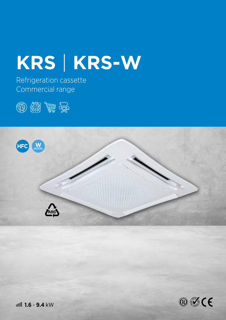
1.6 - 9.4 kW
KRS | KRS-WRefrigeration cassette Commercial range

ROOM
# Made from galvanized sheet steel with double insulation: inside by a polystyrene shell, and outside by a thick layer of closed-cell insulating foam.
COILS
# Aluminium fins crimped on copper tubes:
Aluminium fins KRS KRS-W
Spacing 2,81 mm2.1 mm (KRS-W1)
1.81 mm (KRS-W2)
Epoxy protection yes no
Grooved copper tubes yes no
KRS | KRS-W | Refrigeration cassette
# Quiet operation ensured by anti-vibration mounts on the motor.
# Adjustable airflow to ensure occupant comfort.
# Access to all components facilitating maintenance operations.
# Easy cleaning as a result of easy access to the washable filter, clipped on the diffuser.
VENTILATION
# 6-speed centrifugal motor fans with high static pressure and high airflow performance.# 3 speeds are factory pre-wired on each model. Three other intermediate speeds can be selected depending
on the power and noise level requirements (see table on next page).# Single-phase motors, 230V, 50Hz, class B, with internal thermal protection.# The turbine blades, specially designed for this range, ensure high airflow rates while guaranteeing low noise
levels.
42

DIFFUSER
# Aesthetically pleasing, it adapts perfectly to all environments.# Made of smooth white ABS and lined on the inside with insulation to prevent condensation.# Manually adjustable damper system that provides air diffusion in four directions.
CONDENSATE LIFT PUMP
# Cassette delivered with a drain pan, a condensate lift pump and a float for starting the pump.
# The maximum lift height is 650 mm from the pump level.
1. 2. 3. 4.
INSTALLATION | MAINTENANCE
43
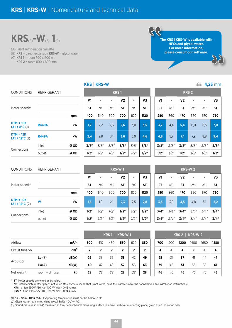
KRS(A)-W(B) 1(C)
(A) Silent refrigeration cassette(B) KRS = direct expansion KRS-W = glycol water(C) KRS 1 = room 600 x 600 mm KRS 2 = room 800 x 800 mm
KRS | KRS-W | Nomenclature and technical data
The KRS | KRS-W is available with HFCs and glycol water. For more information,
please consult our software.
KRS | KRS-W 4,23 mm
CONDITIONS REFRIGERANT KRS 1 KRS 2
Motor speeds*
V1 - - V2 - V3 V1 - V2 - - V3
ST NC NC ST NC ST ST NC ST NC NC ST
rpm. 400 540 600 700 820 1120 280 360 470 560 670 750
DTM = 10KtA1 = 8°C (1)
R449A kW 1,7 2,2 2,3 2,6 3,0 3,5 3,7 4,4 5,4 6,0 6,5 7,0
DTM = 12KtA1 = 12°C (1)
R449A kW 2,4 2,8 3,1 3,6 3,9 4,6 4,8 5,7 7,1 7,9 8,8 9,4
Connectionsinlet Ø OD 3/8" 3/8" 3/8" 3/8" 3/8" 3/8" 3/8" 3/8" 3/8" 3/8" 3/8" 3/8"
outlet Ø OD 1/2" 1/2" 1/2" 1/2" 1/2" 1/2" 1/2" 1/2" 1/2" 1/2" 1/2" 1/2"
CONDITIONS REFRIGERANT KRS-W 1 KRS-W 2
Motor speeds*
V1 - - V2 - V3 V1 - V2 - - V3
ST NC NC ST NC ST ST NC ST NC NC ST
rpm. 400 540 600 700 820 1120 280 360 470 560 670 750
DTM = 10KtA1 = 12°C (2)
W kW 1,6 1,9 2,1 2,3 2,5 2,8 3,3 3,9 4,5 4,8 5,1 5,2
Connectionsinlet Ø OD 1/2" 1/2" 1/2" 1/2" 1/2" 1/2" 3/4" 3/4" 3/4" 3/4" 3/4" 3/4"
outlet Ø OD 1/2" 1/2" 1/2" 1/2" 1/2" 1/2" 3/4" 3/4" 3/4" 3/4" 3/4" 3/4"
KRS 1 | KRS-W 1 KRS 2 | KRS-W 2
Airflow m3/h 300 410 450 530 620 850 700 900 1200 1400 1680 1880
Circuit tube vol. dm3 2 2 2 2 2 2 4 4 4 4 4 4
AcousticsLp (3) dB(A) 26 33 35 38 42 49 25 31 37 41 44 47
Lw(A) dB(A) 40 47 49 52 56 63 39 45 51 55 58 61
Net weight room + diffuser kg 28 28 28 28 28 28 46 46 46 46 46 46
* ST: Motor speeds pre-wired as standard NC: Intermediate motor speeds not wired (to choose a speed that is not wired, have the installer make the connection > see installation instructions). KRS 1 : 1 fan 230V/1/50 Hz - 100 W max - 0.45 A max KRS 2 : 1 fan 230V/1/50 Hz - 170 W max - 0.74 A max
(1) DX - Q0m - HR = 85% - Evaporating temperature must not be below -3 °C.(2) Glycol water regime (ethylene glycol 30%) = 0 / +4 °C.(3) Sound pressure in dB(A) measured at 2 m, hemispherical measuring surface, in a free field over a reflecting plane, given as an indication only.
44

KRS | KRS-W | Dimensions
KRS | KRS-W 1
KRS | KRS-W 2
45

NOTES
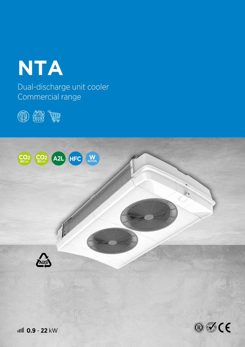
0.9 - 22 kW
NTADual-discharge unit cooler Commercial range
60 bar
80 bar
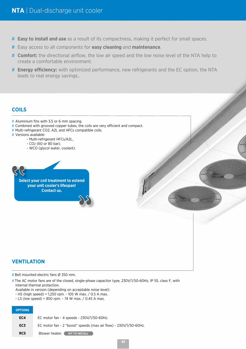
NTA | Dual-discharge unit cooler
# Easy to install and use as a result of its compactness, making it perfect for small spaces.
# Easy access to all components for easy cleaning and maintenance.
# Comfort: the directional airflow, the low air speed and the low noise level of the NTA help to create a comfortable environment.
# Energy efficiency: with optimized performance, new refrigerants and the EC option, the NTA leads to real energy savings..
COILS
# Aluminium fins with 3.5 or 6 mm spacing.# Combined with grooved copper tubes, the coils are very efficient and compact.# Multi-refrigerant CO2, A2L and HFCs compatible coils.# Versions available: - Multi-refrigerant HFCs/A2L, - CO2 (60 or 80 bar). - WCO (glycol water, coolant).
Select your coil treatment to extend your unit cooler's lifespan!
Contact us.
VENTILATION
# Bell mounted electric fans Ø 350 mm.
# The AC motor fans are of the closed, single-phase capacitor type, 230V/1/50-60Hz, IP 55, class F, with internal thermal protection. Available in version (depending on acceptable noise level): - HS (high speed) = 1,250 rpm. - 105 W max. / 0.5 A max. - LS (low speed) = 850 rpm. - 74 W max. / 0.45 A max.
OPTIONS
EC4 EC motor fan - 4 speeds - 230V/1/50-60Hz.
EC3 EC motor fan - 2 "boost" speeds (max air flow) - 230V/1/50-60Hz.
RCS Blower heater. KIT TO INSTALL
48

60 bar 80 bar
CASING
# Removable grille and retractable casing made from recyclable ABS.# High resistance to thermal shock.# Horizontal condensate drain plug 1"G with screw thread.# Perfect hygiene as a result of the rounded corners that eliminate retention areas and through
the use of protected steel and stainless steel fastening screws.# Internal drain pans avoiding condensation on the casing.# Increased safety due to the absence of sharp edges.
OPTIONS
AFD Deflectors to direct the air flow
DEFROST
OPTIONS
E1U Light electric defrost.
E1K Light electric defrost. KIT TO INSTALL
2TH TH 5709L: single-pole reversing thermostat for defrost end at +12 °C (±3 °C) and delayed ventilation restart at +2 °C (±3 °C) (kit to install).THS 5708L: single-pole safety thermostat for heaters at +24 °C (±3 °C), recommended with electric defrost (kit to install).
+15 +2 -1
tA1 NTA ... +E1K | E1U
OPTIONS
PRK Condensate lift pump. KIT TO INSTALL
EXT Electronic expansion valve fitted. CONTACT US
DMP Expansion valve fitted.
EEC Complete factory-assembled unit cooler:- Expansion valve.- Solenoid valve.- Pipework equipped with a fitted ball valve (role of the siphon performed by the manifold).
KVP Pressostatic valve kit. KIT TO INSTALL
Save time during installation by choosing these additional options.
49

NTA M(A) 0R(B) 1(C)-AC(D)
(A) M = multi-refrigerant - C = CO2 - W = glycol water(B) Fin spacing: R = 3.5 mm - L = 6 mm (C) Number of fans(D) AC = AC motor - EC4 = EC motor - EC3 = EC+ motor
NTA | Nomenclature and technical data
The NTA is available with CO2, A2Ls, HFCs and glycol water.
For more information, please consult our software.
NTA M .. R .. -AC / NTA C .. R .. -AC 3.5 mm
CONDITIONS REFRIGERANTS NTA ... -AC 0R 1 1R 1 2R 2 3R 2 4R 2 5R 3 6R 3 7R 4 8R 4 9R 5
SC1 (1)CO2 - 60 bar (2)
HS* kW 2,7 4,0 5,3 7,1 8,3 10,7 13,1 15,7 16,3 18,6
LS* kW 2,1 3,0 4,2 5,5 6,2 8,3 9,9 12,2 12,6 14,8
R449AHS* kW 2,4 3,8 5,0 6,7 7,9 9,9 12,9 16,1 17,7 21,6
LS* kW 2,0 2,9 4,1 5,3 6,1 7,9 9,8 12,3 13,3 16,3
SC2 (1) CO2 - 60 bar (2)
HS* kW 1,9 2,8 3,7 4,9 5,7 7,4 8,9 10,6 10,9 12,1
LS* kW 1,5 2,1 2,9 3,8 4,4 5,8 6,8 8,3 8,5 9,8
R449AHS* kW 1,6 2,5 3,3 4,5 5,3 6,5 8,4 10,7 11,8 14,2
LS* kW 1,3 2,0 2,7 3,6 4,1 5,3 6,5 8,3 8,9 10,9
NTA ... -AC 0R 1 1R 1 2R 2 3R 2 4R 2 5R 3 6R 3 7R 4 8R 4 9R 5
Sound pressure Lp 4 m (3)HS* dB(A) 38 38 41 41 41 42 42 44 44 44
LS* dB(A) 29 29 32 32 32 34 34 35 35 36
FanØ 350 mm
Nb 1 1 2 2 2 3 3 4 4 5
AirflowHS* m3/h 1630 1460 3250 3070 2920 4610 4180 5840 5570 6960
LS* m3/h 1120 980 2230 2090 1970 3130 2810 3940 3740 4680
Air throw (4)HS* m 2 x 14 2 x 12 2 x 14 2 x 13 2 x 12 2 x 13 2 x 12 2 x 12 2 x 12 2 x 12
LS* m 2 x 10 2 x 10 2 x 10 2 x 10 2 x 10 2 x 10 2 x 9 2 x 10 2 x 9 2 x 9
230 V/150-60 Hz (5)
HS* W max 125 125 250 250 250 375 375 500 500 625
LS* W max 74 74 148 148 148 222 222 296 296 370
HS* A max 0,60 0,60 1,20 1,20 1,20 1,80 1,80 2,40 2,40 3,00
LS* A max 0,52 0,52 1,04 1,04 1,04 1,56 1,56 2,08 2,08 2,60
Surface area m2 5,8 11,6 11,6 17,4 23,2 26,2 43,6 46,5 58,1 72,7
Circuit volume dm3 0,8 1,7 1,7 2,5 3,3 3,8 6,3 6,7 8,4 10,5
Electric defrost E1K (6)
230 V/1/50 HzW total 350 800 800 1200 1600 1800 3000 3200 3200 3440
A total 1,5 3,5 3,5 5,2 7,0 7,8 13,0 13,9 13,9 14,8
ConnectionsHFCs
Inlet (7) Ø D 3/8" D 1/2" D 1/2" D 1/2" D 1/2" D 1/2" D 1/2" D 1/2" D 5/8" D 5/8"
Outlet (7) Ø ODF 3/8" 5/8" 5/8" 5/8" 5/8" 5/8" 7/8" 7/8" 1"1/8 1"1/8
Net weight kg 18 20 27 30 32 42 49 59 63 77
* HS = high speed: 1,250 rpm / LS = low speed: 850 rpm
(1) Standard conditions: SC1 : +10 °C (air inlet temp.) / 0 °C (evaporating temp.) / DT1 = 10K SC2 : 0 °C (air inlet temp.) / -8 °C (evaporating temp.) / DT1 = 8K(2) Operating pressure - Specific coil - Connection diameters to be defined when ordering.(3) Average sound pressure level in dB(A) calculated at 4 m, level with the blades, in a free field over a reflecting plane, given as an indication only.(4) Residual air speed: 0.25 m/s.(5) Adjustment of overload protection. For air temperatures "ti" other than +20 °C, multiply the intensities by the ratio 293/(273 + "ti") to obtain the approximate value of the intensity after heating the room.(6) Electric defrost option.(7) Distributor: male to solder - ODF: female to receive the tube of the same diameter.(8) Standard net weight - Specific net weight For CO2 80 bar: contact us.
50

60 bar 80 bar
NTA M(A) 0L(B) 1(C)-AC(D)
(A) M = multi-refrigerant - C = CO2 - W = glycol water(B) Fin spacing: R = 3.5 mm - L = 6 mm (C) Number of fans(D) AC = AC motor - EC4 = EC motor - EC3 = EC+ motor
The NTA is available with CO2, A2Ls, HFCs and glycol water.
For more information, please consult our software.
NTA M .. L .. -AC / NTA C .. L .. -AC 6 mm
CONDITIONS REFRIGERANTS NTA ... -AC 0L 1 1L 1 2L 2 3L 2 4L 2 5L 3 6L 3 7L 4 9L 5
SC1 (1)
CO2 - 60 bar (2)HS* kW 2,0 3,7 5,6 6,8 7,7 10,2 11,4 14,4 16,9
LS* kW 1,6 2,8 4,4 5,2 5,8 7,9 8,7 11,3 13,5
CO2 - 80 bar (2)HS* kW 1,7 3,3 4,9 6,1 - - - - -
LS* kW 1,4 2,5 3,9 4,7 - - - - -
R449AHS* kW 1,7 3,3 4,7 5,9 6,8 8,7 10,3 13,3 17,3
LS* kW 1,4 2,6 3,8 4,7 5,4 7,0 8,0 10,4 13,4
SC2 (1)
CO2 - 60 bar (2)HS* kW 1,4 2,6 3,9 4,7 5,3 7,0 7,8 9,7 11,1
LS* kW 1,1 2,0 3,0 3,6 4,1 5,5 6,0 7,7 9,1
CO2 - 80 bar (2)HS* kW 1,2 2,3 3,4 4,3 - - - - -
LS* kW 1,0 1,8 2,7 3,3 - - - - -
R449AHS* kW 1,1 2,2 3,1 4,0 4,6 5,8 6,9 8,8 11,7
LS* kW 0,9 1,8 2,5 3,2 3,6 4,7 5,5 7,0 9,2
NTA ... -AC 0L 1 1L 1 2L 2 3L 2 4L 2 5L 3 6L 3 7L 4 9L 5
Sound pressure Lp 4 m (3)HS* dB(A) 38 38 41 41 41 42 42 44 44
LS* dB(A) 29 29 32 32 32 34 34 35 36
FanØ 350 mm
Nb 1 1 2 2 2 3 3 4 5
AirflowHS* m3/h 1700 1500 3250 3120 3010 4680 4520 6020 7520
LS* m3/h 1170 1020 2230 2130 2040 3190 3060 4080 5100
Air throw (4)HS* m 2 x 15 2 x 13 2 x 14 2 x 13 2 x 13 2 x 13 2 x 13 2 x 13 2 x 13
LS* m 2 x 11 2 x 10 2 x 10 2 x 10 2 x 10 2 x 10 2 x 10 2 x 10 2 x 10
230 V/150-60 Hz (5)
HS* W max 125 125 250 250 250 375 375 500 625
LS* W max 74 74 148 148 148 222 222 296 370
HS* A max 0,60 0,60 1,20 1,20 1,20 1,80 1,80 2,40 3,00
LS* A max 0,52 0,52 1,04 1,04 1,04 1,56 1,56 2,08 2,60
Surface area m2 3,5 8,9 10,6 14,2 17,7 21,3 26,6 35,5 44,3
Circuit volume dm3 0,8 2,1 2,5 3,3 4,2 5,0 6,3 8,4 10,5
Electric defrost E1K (6)
230 V/1/50 HzW total 350 800 800 1200 1600 1800 3000 3200 3440
A total 1,5 3,5 3,5 5,2 7,0 7,8 13,0 13,9 14,8
ConnectionsHFCs
Inlet (7) Ø D 3/8" D 1/2" D 1/2" D 1/2" D 1/2" D 1/2" D 1/2" D 1/2" D 5/8"
Outlet (7) Ø ODF 3/8" 5/8" 5/8" 5/8" 5/8" 5/8" 7/8" 7/8" 1"1/8
Net weight (8) kg 18 20 29 31 33 44 47 60 73
* HS = high speed: 1250 rpm / LS = low speed: 850 rpm
(1) Standard conditions: SC1 : +10 °C (air inlet temp.) / 0 °C (evaporating temp.) / DT1 = 10K SC2 : 0 °C (air inlet temp.) / -8 °C (evaporating temp.) / DT1 = 8K(2) Operating pressure - Specific coil - Connection diameters to be defined when ordering.(3) Average sound pressure level in dB(A) calculated at 4 m, level with the blades, in a free field over a reflecting plane, given as an indication only.(4) Residual air speed: 0.25 m/s.(5) Adjustment of overload protection. For air temperatures "ti" other than +20 °C, multiply the intensities by the ratio 293/(273 + "ti") to obtain the approximate value of the intensity after heating the room.(6) Electric defrost option.(7) Distributor: male to solder - ODF: female to receive the tube of the same diameter.(8) Standard net weight - Specific net weight For CO2 80 bar: contact us.
51
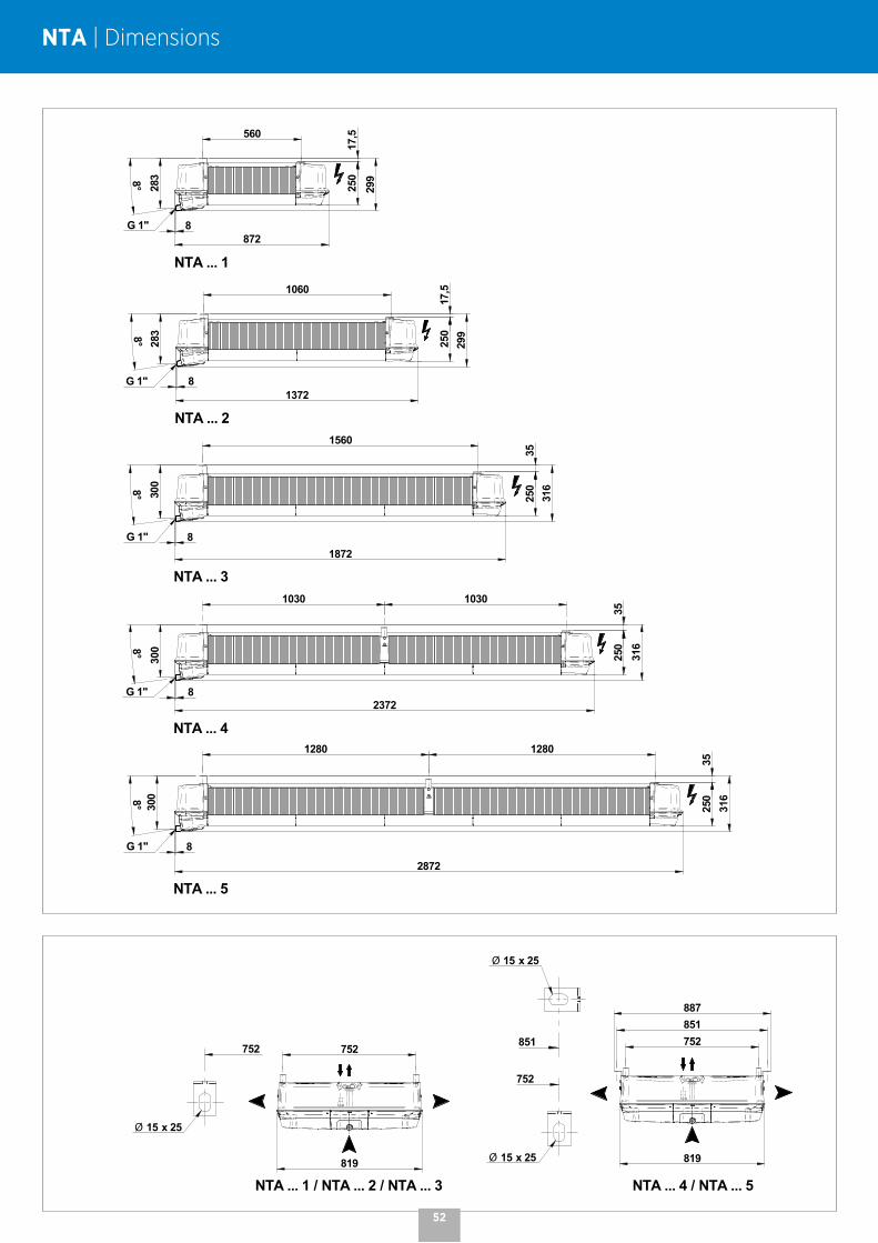
NTA | Dimensions
1280 1280
3525
0
2872
8G 1"
316
NTA ... 5
3008°
1030103035
250
23728
316
G 1"
NTA ... 4
3008°
1560
3525
0
187231
68G 1"
NTA ... 3
3008°
560
17,5
250
8728G 1"
NTA ... 1
283
2998°
1060
17,5
250
13728G 1"
NTA ... 2
283
2998°
752851887
752
Ø 15 x 25
851
Ø 15 x 25
819
NTA ... 4 / NTA ... 5819
752752
Ø 15 x 25
NTA ... 1 / NTA ... 2 / NTA ... 3
1280 1280
3525
0
2872
8G 1"
316
NTA ... 5
3008°
10301030
3525
0
23728
316
G 1"
NTA ... 4
3008°
1560
3525
0
1872
316
8G 1"
NTA ... 3
3008°
560
17,5
250
8728G 1"
NTA ... 1
283
2998°
1060
17,5
250
13728G 1"
NTA ... 2
283
2998°
752851887
752
Ø 15 x 25
851
Ø 15 x 25
819
NTA ... 4 / NTA ... 5819
752752
Ø 15 x 25
NTA ... 1 / NTA ... 2 / NTA ... 3
52
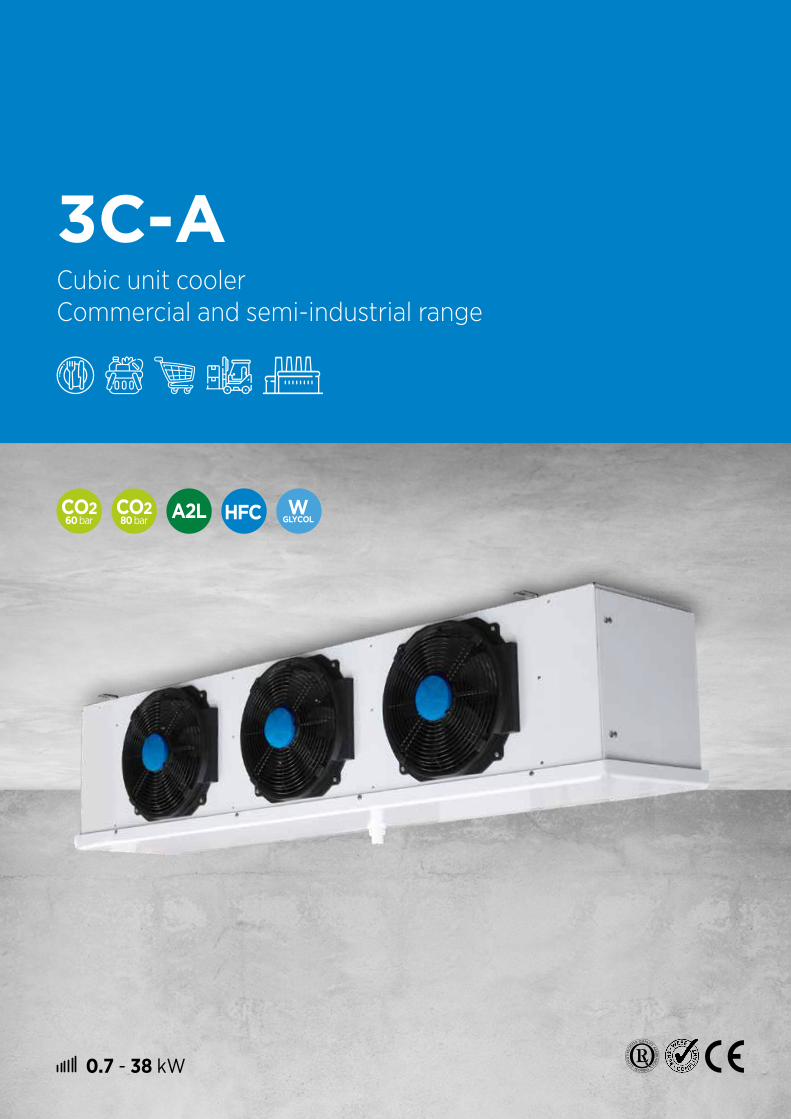
0.7 - 38 kW
3C-ACubic unit cooler Commercial and semi-industrial range
60 bar
80 bar

Save time during installation by choosing these additional options.
3C-A | Cubic unit cooler
CASING
# Easy to clean: galvanized sheet steel, fully pre-painted white.# Pivoting, hinged drain pan with rounded corners, made from pre-painted
aluminium, eliminating retention zones and ensuring complete safety through the absence of sharp corners.
OPTIONS
PEI White painted casing.CIN 316L stainless steel casing.EIS Insulated drain pan.
DPK Intermediate drain pan (3C-A .. R/L). KIT TO INSTALL
# Easy maintenance; the design of the 3C-A allows quick access to all components.
# The optimized coil design, high-efficiency motors, and the ability to select an EC motor (optional) allow an improved energy efficiency.
# Versatile product with components, design and options that adapt to all your needs.
VENTILATION
# High-performance, factory-wired motors.# Axial motor fans not requiring systematic maintenance:
models temp. fan voltage freq. IP class
Ø 300 mm4P - 1,320 rpm
3C-A 3XXX R/L + Standard 230V/1 50/60Hz 44 B3C-A 3XXX E/C - Standard + RFA 230V/1 50/60Hz 44 B
Ø 450 mm*4P/6P - 1,320/1,070 rpm
3C-A 4XXX R/L + Standard 400V/3 50Hz 54 F3C-A 4XXX E/C - Standard 400V/3 50Hz 54 F
* Two-speed motor fans, high-speed wired (∆) by default.
OPTIONS
M23 Motor fan 230-400V/3/50Hz (Ø 450 mm). CONTACT US
MM5 Motor fan 230V/1/50Hz (Ø 450 mm).M60 Motor fan 230-400V/3/60Hz (Ø 450 mm).MP5 Air pressure motor fan (available pressure 50 Pa - Ø 450 mm).RFA Shell / airflow straightener (streamer). KIT TO INSTALL
VGT RFA + fixing parts for textile duct (Ø 450 mm). KIT TO INSTALL
VPM VGT + flexible defrost cuff. (Ø 450 mm). KIT TO INSTALL
EC2 EC motor (electronic commutation) 0-10V - Ø 450 mm.EC3 EC motor (electronic commutation) 2 speeds - Ø 300 mm.
OPTIONS
EXT Electronic expansion valve fitted.DMP Expansion valve fitted.EVL DMP + Solenoid valve fitted.EEC EVL + copper siphon equipped with a ball valve delivered not fitted.
54
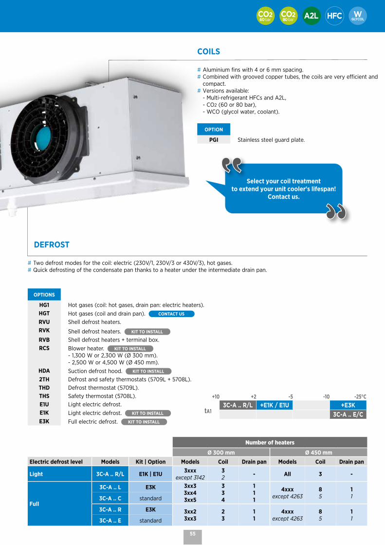
DEFROST
# Two defrost modes for the coil: electric (230V/1, 230V/3 or 430V/3), hot gases.# Quick defrosting of the condensate pan thanks to a heater under the intermediate drain pan.
OPTIONS
HG1 Hot gases (coil: hot gases, drain pan: electric heaters).HGT Hot gases (coil and drain pan). CONTACT US
RVU Shell defrost heaters.RVK Shell defrost heaters. KIT TO INSTALL RVB Shell defrost heaters + terminal box.RCS Blower heater. KIT TO INSTALL
- 1,300 W or 2,300 W (Ø 300 mm).- 2,500 W or 4,500 W (Ø 450 mm).
HDA Suction defrost hood. KIT TO INSTALL
2TH Defrost and safety thermostats (5709L + 5708L).THD Defrost thermostat (5709L).THS Safety thermostat (5708L).E1U Light electric defrost.E1K Light electric defrost. KIT TO INSTALL
E3K Full electric defrost. KIT TO INSTALL
Number of heaters
Ø 300 mm Ø 450 mmElectric defrost level Models Kit | Option Models Coil Drain pan Models Coil Drain pan
Light 3C-A .. R/L E1K | E1U 3xxxexcept 3142
32 - All 3 -
Full
3C-A .. L E3K 3xx33xx43xx5
334
111
4xxxexcept 4263
85
113C-A .. C standard
3C-A .. R E3K 3xx23xx3
23
11
4xxxexcept 4263
85
113C-A .. E standard
60 bar 80 bar
COILS
# Aluminium fins with 4 or 6 mm spacing.# Combined with grooved copper tubes, the coils are very efficient and
compact.# Versions available: - Multi-refrigerant HFCs and A2L, - CO2 (60 or 80 bar), - WCO (glycol water, coolant).
OPTION
PGI Stainless steel guard plate.
Select your coil treatment to extend your unit cooler's lifespan!
Contact us.
+10 +2 -5 -10 -25°C
tA13C-A .. R/L +E1K / E1U +E3K
3C-A .. E/C
55

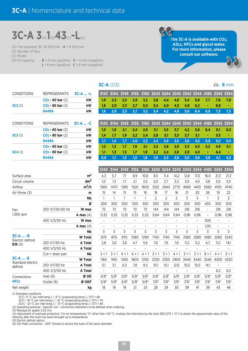
3C-A (1/2) 4 mm
CONDITIONS REFRIGERANTS 3C-A ... -R 3142 3143 3145 3155 3165 3243 3245 3343 3344 3345 4165 4166 3354
SC2 (1) CO2 - 60 bar (2) kW 1,6 2,2 2,8 3,2 3,6 4,4 5,6 6,6 7,7 8,2 8,7 9,4 8,8
R449A kW 1,4 2,0 2,5 3,0 3,4 4,0 5,3 6,2 7,3 8,0 7,9 8,2 8,6
CONDITIONS REFRIGERANTS 3C-A ....-E 3142 3143 3145 3155 3165 3243 3245 3343 3344 3345 4165 4166 3354
SC3 (1) CO2 - 60 bar (2) kW 1,3 1,8 2,3 2,6 2,9 3,5 4,6 5,5 6,2 6,6 7,2 7,7 7,0
R449A kW 1,0 1,3 1,9 2,2 2,5 2,9 4,0 4,5 5,4 5,8 5,7 6,2 6,4
SC4 (1) CO2 - 60 bar (2) kW 1,1 1,5 1,8 2,1 2,3 2,8 3,7 4,4 5,0 5,3 5,8 6,2 5,6
R449A kW 0,7 1,0 1,4 1,7 2,0 2,3 3,1 3,5 4,2 4,6 4,3 4,9 5,1
3142 3143 3145 3155 3165 3243 3245 3343 3344 3345 4165 4166 3354
Surface area m2 4,1 6,2 10,3 12,8 15,4 12,3 20,5 18,5 24,6 30,8 23,1 27,7 30,8
Circuit volume dm3 0,7 1,0 1,7 2,1 2,5 2,0 3,3 3,0 4,0 5,0 3,8 4,5 5,0
Airflow m3/h 1600 1480 1270 1420 1530 2950 2530 4420 4100 3800 5160 4130 4510
Air throw (3) m 15 14 12 14 15 17 15 20 19 18 25 24 21
Fan1,350 rpm
Nb 1 1 1 1 1 2 2 3 3 3 1 1 3
Ø 300 300 300 300 300 300 300 300 300 300 450 450 300
230 V/1/50-60 Hz W max 72 72 72 72 72 144 144 216 216 216 - - 216
A max (4) 0,32 0,32 0,32 0,32 0,32 0,64 0,64 0,96 0,96 0,96 - - 0,96
400 V/3/50 Hz W max - - - - - - - - - - 500 500 -
A max (4) - - - - - - - - - - 1,00 1,00 -
3C-A ... -RElectric defrostE1K (5)
Nb 2 3 3 3 3 3 3 3 3 3 3 3 3
W Total 580 870 870 1080 1290 1740 1740 2580 2580 2580 1080 1080 3240
230 V/1/50 Hz A Total 2,5 3,8 3,8 4,7 5,6 7,6 7,6 11,2 11,2 11,2 4,7 4,7 14,1
400 V/3/50 Hz A Total - - - - - - - - - - - - -
3C-A ... -EStandard electric defrost
Coil + drain pan Nb 2 + 1 3 + 1 5 + 1 5 + 1 5 + 1 3 + 1 5 + 1 3 + 1 5 + 1 5 + 1 8 + 1 8 + 1 5 + 1
W Total 870 1160 1740 2160 2580 2320 3480 3440 5160 5160 3240 3240 6480
230 V/1/50 Hz A Total 3,8 5,1 7,6 9,4 11,2 10,1 15,1 15,0 - - 14,1 14,1 -
400 V/3/50 Hz A Total - - - - - - - - 7,4 7,4 - - 9,4
ConnectionsHFCs
Inlet (6) Ø OD 3/8" 5/8" 5/8" 5/8" 5/8" 5/8" 5/8" 5/8" 5/8" 5/8" 7/8" 7/8" 5/8"
Outlet (6) Ø ODF 3/8" 5/8" 5/8" 5/8" 5/8" 7/8" 7/8" 7/8" 7/8" 7/8" 7/8" 7/8" 7/8"
Net weight kg 17 18 20 22 24 28 32 41 43 45 41 43 48
(1) Standard conditions:
SC2 / 0 °C (air inlet temp.) / -8 °C (evaporating temp.) / DT1 = 8K
SC3 / -18 °C (air inlet temp.) / -25 °C (evaporating temp.) / DT1 = 7K
SC4 / -25 °C (air inlet temp.) / -31 °C (evaporating temp.) / DT1 = 6K
(2) Operating pressure - Specific coil - Connection diameters to be defined when ordering.
(3) Residual air speed: 0.25 m/s.
(4) Adjustment of overload protection. For air temperatures "ti" other than +20 °C, multiply the intensities by the ratio 293/(273 + "ti") to obtain the approximate value of the intensity after the room has been brought up to temperature.
(5) Electric defrost option.
(6) OD: Male connection - ODF: female to receive the tube of the same diameter.
3C-A 3(A)1(B)42(C)-R(D)
(A) Fan diameter: 3 = Ø 300 mm - 4 = Ø 450 mm(3) Number of fans(C) Model(D) Fin spacing: R = 4 mm (positive) E = 4 mm (negative) L = 6 mm (positive) C = 6 mm (negative)
3C-A | Nomenclature and technical data
The 3C-A is available with CO2, A2Ls, HFCs and glycol water.
For more information, please consult our software.
56

60 bar 80 bar
3C-A (2/2) 4 mm
CONDITIONS REFRIGERANTS 3C-A ... -R 3444 3445 4263 3455 3545 4264 4265 4266 4364 4366 4386 4466
SC2 (1) CO2 - 60 bar (2) kW 10,3 11,1 12,7 12,8 13,6 15,4 17,4 18,9 23,1 28,0 34,8 37,7
R449A kW 9,7 10,9 11,2 12,5 13,7 13,8 15,9 17,6 20,9 26,1 33,2 34,4
CONDITIONS REFRIGERANTS 3C-A ... -E 3444 3445 4263 3455 3545 4264 4265 4266 4364 4366 4386 4466
SC3 (1) CO2 - 60 bar (2) kW 8,4 9,0 10,3 10,1 10,7 12,6 14,3 15,6 18,9 22,3 28,3 30,5
R449A kW 7,2 8,0 8,0 9,3 9,6 9,7 11,6 12,8 15,0 19,8 23,7 25,6
SC4 (1) CO2 - 60 bar (2) kW 6,8 7,3 8,2 8,2 8,6 10,1 11,5 12,6 15,2 17,8 22,8 24,5
R449A kW 5,7 6,4 6,2 7,2 7,6 7,5 9,0 10,1 11,6 15,5 18,5 19,9
3444 3445 4263 3455 3545 4264 4265 4266 4364 4366 4386 4466
Surface area m2 32,8 41,1 27,7 51,3 51,3 37,0 46,2 55,4 55,4 83,1 110,9 110,9
Circuit volume dm3 5,4 6,7 4,5 8,4 8,4 6,0 7,5 9,0 9,0 13,5 18,1 18,1
Airflow m3/h 5460 5070 11740 5700 6340 10990 10310 8270 16480 12400 16780 16540
Air throw (3) m 22 21 32 23 24 31 30 29 35 33 35 36
Fan1,350 rpm
Nb 4 4 2 4 5 2 2 2 3 3 3 4
Ø 300 300 450 300 300 450 450 450 450 450 450 450
230 V/1/50-60 Hz W max 288 288 - 288 360 - - - - - - -
A max (4) 1,28 1,28 - 1,28 1,60 - - - - - - -
400 V/3/50 Hz W max - - 1000 - - 1000 1000 1000 1500 1500 1500 2000
A max (4) - - 2,00 - - 2,00 2,00 2,00 3,00 3,00 3,00 4,00
3C-A ... -RElectric defrostE1K (5)
Nb 3 3 3 3 3 3 3 3 3 3 3 3
W Total 3450 3450 2160 4320 4320 2160 2160 2160 3240 3240 3960 3960
230 V/1/50 Hz A Total 15,0 15,0 9,4 - - 9,4 9,4 9,4 14,1 14,1 - -
400 V/3/50 Hz A Total - - - 6,2 6,2 - - - - - 5,7 5,7
3C-A ... -EElectric defroststandard
Coil + drain pan Nb 5 + 1 5 + 1 5 + 1 5 + 1 5 + 1 8 + 1 8 + 1 8 + 1 8 + 1 8 + 1 8 + 1 8 + 1
W Total 6900 6900 4320 8640 8640 6480 6480 6480 9720 9720 11880 11880
230 V/1/50 Hz A Total - - - - - - - - - - - -
400 V/3/50 Hz A Total 10,0 10,0 6,3 12,5 12,5 9,4 9,4 9,4 14,0 14,0 17,1 17,1
ConnectionsHFCs
Inlet (6) Ø OD 5/8" 7/8" 7/8" 7/8" 7/8" 1"1/8 1"1/8 1"1/8 1"1/8 1"1/8 1"3/8 1"3/8
Outlet (6) Ø ODF 7/8" 1"1/8 1"3/8 1"3/8 1"3/8 1"3/8 1"3/8 1"3/8 1"5/8 1"5/8 2"1/8 2"1/8
Net weight kg 54 57 58 65 70 62 65 69 84 95 114 123
(1) Standard conditions: SC2 / 0 °C (air inlet temp.) / -8 °C (evaporating temp.) / DT1 = 8K SC3 / -18 °C (air inlet temp.) / -25 °C (evaporating temp.) / DT1 = 7K SC4 / -25 °C (air inlet temp.) / -31 °C (evaporating temp.) / DT1 = 6K(2) Operating pressure - Specific coil - Connection diameters to be defined when ordering.(3) Residual air speed: 0.25 m/s.(4) Adjustment of overload protection. For air temperatures "ti" other than +20 °C, multiply the intensities by the ratio 293/(273 + "ti") to obtain the approximate value of the intensity after the room has been brought up to temperature.(5) Electric defrost option.(6) OD: Male connection - ODF: female to receive the tube of the same diameter.
3C-A 3(A)4(B)44(C)-R(D)
(A) Fan diameter: 3 = Ø 300 mm - 4 = Ø 450 mm(3) Number of fans(C) Model(D) Fin spacing: R = 4 mm (positive) E = 4 mm (negative) L = 6 mm (positive) C = 6 mm (negative)
The 3C-A is available with CO2, A2Ls, HFCs and glycol water.
For more information, please consult our software.
57
3C-A (1/2) 6 mm
CONDITIONS REFRIGERANTS 3C-A ... -L 3143 3144 3145 3155 3165 3243 3244 3245 3343 3344 4165 3345 3354
SC2 (1)
CO2 - 60 bar (2) kW 1,9 2,3 2,5 2,9 3,2 3,8 4,4 4,8 5,4 6,8 7,7 7,6 7,8
CO2 - 80 bar (2) kW 1,6 2,0 2,3 2,7 3,0 3,4 4,0 4,3 4,9 6,2 - 6,9 -
R449A kW 1,6 2,0 2,3 2,7 3,2 3,4 4,2 4,8 5,6 6,4 6,9 7,3 7,5
CONDITIONS REFRIGERANTS 3C-A ... -C 3143 3144 3145 3155 3165 3243 3244 3245 3343 3344 4165 3345 3354
SC3 (1)
CO2 - 60 bar (2) kW 1,5 1,9 2,1 2,4 2,6 3,1 3,5 3,7 4,2 5,6 6,4 6,1 6,3
CO2 - 80 bar (2) kW 1,4 1,7 1,9 2,2 2,4 2,8 3,1 3,3 3,7 5,1 - 5,5 -
R449A kW 1,1 1,4 1,7 2,0 2,3 2,4 2,9 3,5 3,8 4,5 4,9 5,2 5,4
SC4 (1)
CO2 - 60 bar (2) kW 1,2 1,5 1,7 1,9 2,1 2,5 2,8 2,9 3,3 4,5 5,2 4,9 5,1
CO2 - 80 bar (2) kW 1,1 1,3 1,5 1,7 1,9 2,2 2,4 2,6 2,9 4,0 - 4,4 -
R449A kW 0,9 1,1 1,3 1,5 1,8 1,9 2,3 2,8 3,0 3,6 3,8 4,1 4,2
3143 3144 3145 3155 3165 3243 3244 3245 3343 3344 4165 3345 3354
Surface area m2 4,3 5,7 7,1 8,9 10,6 8,5 11,4 14,2 12,8 17,0 16,0 21,3 21,3
Circuit volume dm3 1,0 1,3 1,7 2,1 2,5 2,0 2,7 3,3 3,0 4,0 3,8 5,0 5,0
Airflow m3/h 1560 1470 1380 1520 1600 3120 2940 2770 4680 4410 5560 4150 4740
Air throw (3) m 15 14 13 15 16 18 17 16 21 20 26 19 22
Fan1,350 rpm
Nb 1 1 1 1 1 2 2 2 3 3 1 3 3
Ø 300 300 300 300 300 300 300 300 300 300 450 300 300
230 V/1/50-60 Hz W max 72 72 72 72 72 144 144 144 216 216 - 216 216
A max (4) 0,32 0,32 0,32 0,32 0,32 0,64 0,64 0,64 0,96 0,96 - 0,96 0,96
400 V/3/50 Hz W max - - - - - - - - - - 500 - -
A max (4) - - - - - - - - - - 1,00 - -
3C-A ... -RElectric defrostE1K (5)
Nb 3 3 3 3 3 3 3 3 3 3 3 3 3
W Total 870 870 870 1080 1290 1740 1740 1740 2580 2580 1080 2580 3240
230 V/1/50 Hz A Total 3,8 3,8 3,8 4,7 5,6 7,6 7,6 7,6 11,2 11,2 4,7 11,2 14,1
400 V/3/50 Hz A Total - - - - - - - - - - - - -
3C-A ... -EStandard electric defrost
Coil + drain pan Nb 3 + 1 3 + 1 4 + 1 4 + 1 4 + 1 3 + 1 3 + 1 4 + 1 3 + 1 3 + 1 8 + 1 4 + 1 3 + 1
W Total 1160 1160 1450 1800 2150 2320 2320 2900 3440 3440 3240 4300 4320
230 V/1/50 Hz A Total 5,1 5,1 6,3 7,8 9,3 10,1 10,1 12,6 15,0 15,0 14,1 - -
400 V/3/50 Hz A Total - - - - - - - - - - - 6,2 6,2
ConnectionsHFCs
Inlet (6) Ø OD 5/8" 5/8" 5/8" 5/8" 5/8" 5/8" 5/8" 5/8" 5/8" 5/8" 5/8" 5/8" 5/8"
Outlet (6) Ø ODF 5/8" 5/8" 5/8" 5/8" 5/8" 7/8" 7/8" 7/8" 7/8" 7/8" 7/8" 7/8" 7/8"
Net weight kg 18 19 19 21 23 28 29 30 39 41 39 43 46
(1) Standard conditions: SC2 / 0 °C (air inlet temp.) / -8 °C (evaporating temp.) / DT1 = 8K SC3 / -18 °C (air inlet temp.) / -25 °C (evaporating temp.) / DT1 = 7K SC4 / -25 °C (air inlet temp.) / -31 °C (evaporating temp.) / DT1 = 6K(2) Operating pressure - Specific coil - Connection diameters to be defined when ordering.(3) Residual air speed: 0.25 m/s.(4) Adjustment of overload protection. For air temperatures "ti" other than +20 °C, multiply the intensities by the ratio 293/(273 + "ti") to obtain the approximate value of the intensity after the room has been brought up to temperature.(5) Electric defrost option.(6) OD: Male connection - ODF: female to receive the tube of the same diameter.
3C-A 3(A)1(B)43(C)-L(D)
(A) Fan diameter: 3 = Ø 300 mm - 4 = Ø 450 mm(3) Number of fans(C) Model(D) Fin spacing: R = 4 mm (positive) E = 4 mm (negative) L = 6 mm (positive) C = 6 mm (negative)
3C-A | Nomenclature and technical data
The 3C-A is available with CO2, A2Ls, HFCs and glycol water. For more information, please
consult our software.
58

60 bar 80 bar
3C-A (2/2) 6 mm
CONDITIONS REFRIGERANTS 3C-A ... -L 4166 3444 3445 4263 3455 3545 4264 4266 4364 4366 4386 4466
SC2 (1)
CO2 - 60 bar (2) kW 8,6 9,1 10,2 10,9 11,7 12,6 13,5 17,3 20,3 25,7 31,6 34,6
CO2 - 80 bar (2) kW - - - - - - - - - - - -
R449A kW 7,9 8,5 9,8 9,8 11,4 12,6 12,2 16,0 18,6 24,3 29,5 32,0
CONDITIONS REFRIGERANTS 3C-A ... -C 4166 3444 3445 4263 3455 3545 4264 4266 4364 4366 4386 4466
SC3 (1)
CO2 - 60 bar (2) kW 7,1 7,5 8,3 8,9 9,4 10,0 11,1 14,3 16,6 20,7 25,8 28,1
CO2 - 80 bar (2) kW - - - - - - - - - - - -
R449A kW 5,4 6,0 7,2 6,8 8,1 8,8 8,4 11,2 12,8 17,0 20,7 22,1
SC4 (1)
CO2 - 60 bar (2) kW 5,7 6,1 6,7 7,2 7,6 8,1 8,9 11,5 13,4 16,6 20,8 22,6
CO2 - 80 bar (2) kW - - - - - - - - - - - -
R449A kW 4,2 4,7 5,7 5,3 6,5 6,9 6,5 8,8 9,9 13,5 16,2 17,2
4166 3444 3445 4263 3455 3545 4264 4266 4364 4366 4386 4466
Surface area m2 19,2 22,7 28,4 19,2 35,5 35,5 25,5 38,3 38,3 57,5 76,6 76,6
Circuit volume dm3 4,5 5,4 6,7 4,5 8,4 8,4 6,0 9,0 9,0 13,5 18,1 18,1
Airflow m3/h 5290 5880 5540 12300 6060 6920 11690 10580 17540 15870 17780 21160
Air throw (3) m 25 23 22 33 24 25 32 31 36 34 36 37
Fan1,350 rpm
Nb 1 4 4 2 4 5 2 2 3 3 3 4
Ø 450 300 300 450 300 300 450 450 450 450 450 450
230 V/1/50-60 Hz W max - 288 288 - 288 360 - - - - - -
A max (4) - 1,28 1,28 - 1,28 1,60 - - - - - -
400 V/3/50 Hz W max 500 - - 1000 - - 1000 1000 1500 1500 1500 2000
A max (4) 1,00 - - 2,00 - - 2,00 2,00 3,00 3,00 3,00 4,00
3C-A ... -RElectric defrostE1K (5)
Nb 3 3 3 3 3 3 3 3 3 3 3 3
W Total 1080 3450 3450 2160 4320 4320 2160 2160 3240 3240 3960 3960
230 V/1/50 Hz A Total 4,7 15,0 15,0 9,4 - - 9,4 9,4 14,1 14,1 - -
400 V/3/50 Hz A Total - - - - 6,2 6,2 - - - - 5,7 5,7
3C-A ... -EElectric defroststandard
Coil + drain pan Nb 8 + 1 3 + 1 4 + 1 5 + 1 4 + 1 4 + 1 8 + 1 8 + 1 8 + 1 8 + 1 8 + 1 8 + 1
W Total 3240 4600 5750 4320 7200 7200 6480 6480 9720 9720 11880 11880
230 V/1/50 Hz A Total 14,1 - - - - - - - - - - -
400 V/3/50 Hz A Total - 6,6 8,3 6,3 10,4 10,4 9,4 9,4 14,0 14,0 17,1 17,1
ConnectionsHFCs
Inlet (6) Ø OD 7/8" 5/8" 7/8" 7/8" 7/8" 7/8" 1"1/8 1"1/8 1"1/8 1"1/8 1"3/8 1"3/8
Outlet (6) Ø ODF 7/8" 7/8" 1"1/8 1"3/8 1"3/8 1"3/8 1"3/8 1"3/8 1"5/8 1"5/8 2"1/8 2"1/8
Net weight kg 41 52 55 56 62 66 59 65 81 90 108 117
(1) Standard conditions: SC2 / 0 °C (air inlet temp.) / -8 °C (evaporating temp.) / DT1 = 8K SC3 / -18 °C (air inlet temp.) / -25 °C (evaporating temp.) / DT1 = 7K SC4 / -25 °C (air inlet temp.) / -31 °C (evaporating temp.) / DT1 = 6K(2) Operating pressure - Specific coil - Connection diameters to be defined when ordering.(3) Residual air speed: 0.25 m/s.(4) Adjustment of overload protection. For air temperatures "ti" other than +20 °C, multiply the intensities by the ratio 293/(273 + "ti") to obtain the approximate value of the intensity after the room has been brought up to temperature.(5) Electric defrost option.(6) OD: Male connection - ODF: female to receive the tube of the same diameter.
3C-A 4(A)1(B)66(C)-L(D)
(A) Fan diameter: 3 = Ø 300 mm - 4 = Ø 450 mm(3) Number of fans(C) Model(D) Fin spacing: R = 4 mm (positive) E = 4 mm (negative) L = 6 mm (positive) C = 6 mm (negative)
The 3C-A is available with CO2, A2Ls, HFCs and glycol water. For more information, please
consult our software.
59
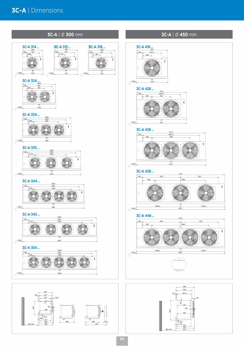
3C-A | Dimensions
60
3C-A 314 .. 3C-A 315 .. 3C-A 316 ..
672
138 401160
638
1000 772
138 501210
738
1000 872
138 601260
838
1000
3C-A 324 ..
1072
138 801160 400
1038
1000
3C-A 334 ..
1567
1533185 1201
160 800
1000
3C-A 335 ..
1867
1833185 1501
210 1000
1000
3C-A 344 ..
1967
1933185 1601
160 1200
1000
3C-A 345 ..
2367
185 2001210 1500
1000
2333
3C-A 354 ..
2367
2333185 2001
160 1600
1000
3C-A 416 ..
1011
972
185 601,5
299
1000
3C-A 426 ..
1611
1572185 1201,5
299 600
1000
3C-A 436 ..
2211
2172185 1801,5
299 1200
1000
3C-A 438 ..
2811
2772185
399 1600
1201 1201
10001380,5 1430,5
3C-A 446 ..
2811
2772
185
299 1800
1201 1201
10001380,5 1430,5
3C-A | Ø 300 mm 3C-A | Ø 450 mm
461
377
428
7
52,5357
458
67
484
20 421
400 mini
Ø 1’’96
438
484 456 75
+
531
502
118
447
580
635
557
576
6,5
427
610
23
20 461,5
600 mini
Ø 1’’40

EXTronicMounted electronic expansion valve solution for unit coolers

EXTronic | Mounted electronic expansion valve solution for unit coolers
TECHNIQUES# Mounted directly on the unit cooler.# Multi-refrigerant: several refrigerants in a single controller.# Adapted to the constraints of a cold room: - Temperature: withstands extreme temperature conditions
(-40 °C to +60 °C). - Humidity: IP 65.# Easy to set up.# Max. power supply: 15W.# Facilitates retrofitting when changing refrigerant.# Safetronic option > no solenoid valve.
EFFICIENT UNIT COOLER# Rapid temperature drop compared to thermostatic expansion
> energy savings.# More efficient and faster
than the thermostatic expansion valve > economical.# Quality of products preserved.# Safety guaranteed by Safetronic.
ENVIRONMENTALLY FRIENDLY# Use of low GWP refrigerants.# Multi-refrigerant: allows you to have a single expansion valve
regardless of the refrigerant used.# Installation retrofit and expansion valve function retained.
Port dimensioned and compatible with all selection refrigerants: R449A, R448A, R407A, R407F, R452A, R450A and R513A.
# Faster - More efficient - More economical.
# Efficient unit cooler.
# Mounted directly on the 3C-A and NTA unit cooler (for other unit coolers, contact us).
# Environmentally friendly.
OPTIONS
SAFETRONIC# An optional Safetronic kit by EXTronic.
This Safetronic kit guarantees closure of the connected electronic valve in the event of a power failure.
POSSIBILITY OF CONNECTION TO BMS# Possibility of direct connection (RS 485 Modbus).# Possibility of connecting EXTronic to a BMS (all makes
possible) > to monitor or modify the parameters.# Easy to install and configure.# Better control of the cold room.# Better unit cooler + EXTronic monitoring.
DESCRIPTION
# Superheat regulator for electronic expansion valve.# Superheat setting according to the refrigerant.# Optimizes the refrigeration circuit.# Control and automatic closing of the valve.# Superheat probe to be installed on the pipe.# Safety > alarms in case of overheating or other problems.# Multi-refrigerant > an expansion valve compatible with several
refrigerants in a single unit cooler.
WIDE CHOICE OF REFRIGERANTS# R407A, R407C, R407F, R452A, R449A, R448A, R450A, R513A.# R744 (CO2) : Driver compatible, but please note that a specific
pressure sensor is required. CONTACT US
# A2L refrigerants. CONTACT US
# Possibility of adding a refrigerant by updating the Driver (via RS485 input and a computer).
WIDE CHOICE OF REFRIGERANTS# LowSH (low superheat) > change of reactivity
below 5 °C superheat.
4 START-UP PARAMETERS# Type of refrigerant.# Application mode: cold room / display case.# Super heat setpoint.# MOP for negative applications (CS setting).
PRODUCT ADVANTAGES
Electronic expansion valve Driver
Pressure sensor
Temperature sensor
62

11 - 87 kW
GTI | GTADual-discharge unit coolers Industrial range
GTA | GTA-W GTI | GTI-W
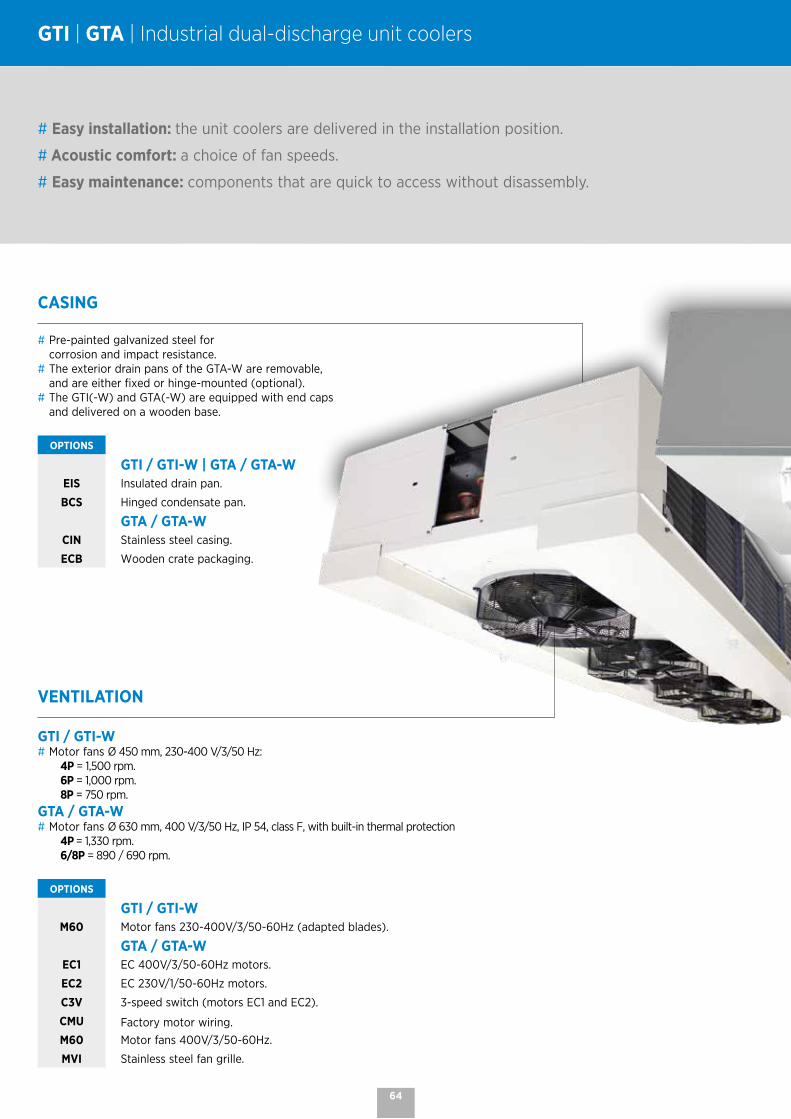
GTI | GTA | Industrial dual-discharge unit coolers
CASING
# Pre-painted galvanized steel for corrosion and impact resistance.
# The exterior drain pans of the GTA-W are removable, and are either fixed or hinge-mounted (optional).
# The GTI(-W) and GTA(-W) are equipped with end caps and delivered on a wooden base.
OPTIONS
GTI / GTI-W | GTA / GTA-WEIS Insulated drain pan.
BCS Hinged condensate pan.
GTA / GTA-WCIN Stainless steel casing.
ECB Wooden crate packaging.
# Easy installation: the unit coolers are delivered in the installation position.
# Acoustic comfort: a choice of fan speeds.
# Easy maintenance: components that are quick to access without disassembly.
VENTILATION
GTI / GTI-W# Motor fans Ø 450 mm, 230-400 V/3/50 Hz:
4P = 1,500 rpm. 6P = 1,000 rpm. 8P = 750 rpm.
GTA / GTA-W# Motor fans Ø 630 mm, 400 V/3/50 Hz, IP 54, class F, with built-in thermal protection 4P = 1,330 rpm. 6/8P = 890 / 690 rpm.
OPTIONS
GTI / GTI-WM60 Motor fans 230-400V/3/50-60Hz (adapted blades).
GTA / GTA-WEC1 EC 400V/3/50-60Hz motors.
EC2 EC 230V/1/50-60Hz motors.
C3V 3-speed switch (motors EC1 and EC2).
CMU Factory motor wiring. M60 Motor fans 400V/3/50-60Hz.
MVI Stainless steel fan grille.
64

COILS
# Aluminium fins with 4.23 or 6.35 mm spacing.# Combined with copper tubes, the coils are very efficient and compact.# Versions available:
- Multi-refrigerant HFCs. - CO2 (50 bar). - WCO (glycol water, coolant).
OPTIONS
EGK Glycol water and heat transfer refrigerant extension. KIT TO INSTALL
DEFROST
# Three defrost modes for the coil: electric (230V/1, 230V/3 or 400V/3), hot water, hot gas.
# Quick defrosting of the condensate pan thanks to a heater under the intermediate drain pan. .
OPTIONS
GTI / GTI-WE1U Light electric defrost.
HGB Hot gas defrost (coil only).
GTA / GTA-WE1U Light electric defrost
E1K Light electric defrost. KIT TO INSTALL
ELU Electric defrost (coil+ drain pan)
HG1 Hot gas defrost (coil: hot gases, drain pan: heaters).
EEK Drain pan electric defrost. KIT TO INSTALL
ECU Additional electric coil defrost. CONTACT US
ECK Additional electric coil defrost. KIT TO INSTALL
DEG Hot glycol water defrost (coil).
Look after your coils to extend
their service life!Contact us.
INSTALLATION | MAINTENANCE
# Easy access to the drain pans and motorized fans facilitating installation and maintenance.
# Delivered in assembly position, the GTA(-W) is designed to be installed on the ceiling.
# To facilitate installation of the glycol water version, a connection kit is available as an option (option EGK).
65

GTI(A) 3(B)44(C) 4P(D)
(A) GTI: direct expansion unit cooler GTI-W: glycol water unit cooler (B) Number of fans(C) Fin spacing: 4 = 4,23 mm - 7 = 6,35 mm(D) 4P = 1,500 rpm. - 6P = 1,000 rpm. - 8P = 750 rpm.
GTI | Nomenclature and technical data
The GTI is available with CO2, HFCs and glycol water.
For more information, please consult our software.
GTI ... 4P/6P/8P - 1,500/1,000/750 rpm. 4,23 mm
CONDITIONS REFRIGERANTS GTI ... 344 364 444 464 484 564 584
SC1 (1)
CO2 - 50 bar (2)
4P kW 33,4 42,8 46,7 55,5 62,3 71,0 75,9
6P kW 26,7 32,4 36,7 42,6 46,0 54,0 56,7
8P kW 21,6 25,1 29,2 33,1 34,8 41,8 43,2
R449A
4P kW 34,8 44,6 46,0 60,2 70,5 73,0 77,9
6P kW 29,2 36,7 39,1 49,1 55,1 59,4 64,1
8P kW 24,8 29,8 33,5 39,9 43,4 48,5 52,9
SC2 (1)
CO2 - 50 bar (2)
4P kW 22,5 29,5 32,2 37,7 42,9 48,7 51,7
6P kW 18,2 22,5 25,4 29,2 31,9 37,3 39,0
8P kW 14,8 17,4 20,3 22,9 24,2 29,0 29,9
R449A
4P kW 21,1 27,0 28,6 36,6 38,0 44,3 49,8
6P kW 17,2 20,8 23,3 28,0 29,3 34,4 37,5
8P kW 14,0 16,3 18,8 21,9 22,6 27,1 28,7
344 364 444 464 484 564 584
Surface area m2 98,4 147,5 131,2 196,7 262,3 245,9 327,9
Circuit tube vol. dm3 19,0 28,5 25,4 38,1 50,8 47,6 63,4
Airflow
4P m3/h 13950 13350 18600 17800 17000 22250 21250
6P m3/h 9360 8960 12480 11950 11410 14930 14260
8P m3/h 6670 6390 8900 8500 8130 10650 10170
Fan *Ø 630 mm400V/3/50Hz
Nb 3 3 4 4 4 5 5
Air throw (3)
4P m 2x7 2x7 2x7 2x7 2x7 2x7 2x7
6P m 2x5 2x5 2x6 2x5 2x5 2x5 2x5
8P m 2x4 2x4 2x4 2x4 2x4 2x4 2x4
AcousticsLw = Lp +30 dB(A)
Lp 4m (4)
4P dB(A) 50 50 51 51 51 52 52
6P dB(A) 40 40 41 41 41 42 42
8P dB(A) 33 33 34 34 34 35 35
Electric defrost E1U
Coil Nb 6 6 6 6 6 6 6
400 V/3/50 HzW Total 6000 6000 9240 9240 9240 12000 12000
A Total 9 9 14 14 14 18 18
ConnectionsHFCs
Inlet (5) Ø 7/8" 1"1/8 1"1/8 1"1/8 1"1/8 1"1/8 1"3/8
Outlet (6) Ø 1"5/8 1"5/8 2"1/8 2"1/8 2"1/8 2"5/8 2"5/8
Net weight kg 181 215 228 264 307 326 379
* 4P : 360 W max - 1 A max (7). 6P : 115 W max - 0.6 A max (7). 8P : 72 W max - 0.4 A max (7).
(1) Standard conditions: SC1 / +10 °C (air inlet temp.) / 0 °C (evaporating temp.) / DT1 = 10K SC2 / 0 °C (air inlet temp.) / -8 °C (evaporating temp.) / DT1 = 8K(2) Operating pressure - Specific coil - Connection diameters to be defined when ordering.(3) Residual air speed: 0.25 m/s, in accordance with the standard.(4) Average sound pressure level in dB(A) calculated at 4 m, level with the blades, in a free field over a reflecting plane, given as an indication only.(5) Distributor: male to solder. (6) ODF = female, to receive the tube of the same diameter.(7) Adjustment of overload protection.
66

GTI(A) 3(B)44(C) 4P(D)
(A) GTI: direct expansion unit cooler GTI-W: glycol water unit cooler (B) Number of fans(C) Fin spacing: 4 = 4,23 mm - 7 = 6,35 mm(D) 4P = 1,500 rpm. - 6P = 1,000 rpm. - 8P = 750 rpm.
The GTI is available with CO2, HFCs and glycol water.
For more information, please consult our software.
GTI ... 4P/6P/8P - 1,500/1,000/750 rpm. 6,35 mm
CONDITIONS REFRIGERANTS GTI ... 347 367 387 467 487 567 587
SC1 (1)
CO2 - 50 bar (2)
4P kW 27,4 36,2 41,3 47,6 55,6 60,3 68,4
6P kW 22,3 28,2 31,6 37,4 42,3 47,1 52,4
8P kW 18,3 22,3 24,5 29,7 32,8 37,3 40,8
R449A
4P kW 28,3 38,8 49,5 55,6 66,4 67,6 77,3
6P kW 24,8 31,2 38,6 44,4 51,8 54,5 60,8
8P kW 21,7 27,7 31,2 37,1 41,8 48,2 51,9
SC2 (1)
CO2 - 50 bar (2)
4P kW 18,6 25,0 28,4 32,5 38,3 41,6 46,7
6P kW 15,3 19,6 21,8 25,7 29,3 32,6 36,1
8P kW 12,6 15,5 17,0 20,6 22,8 25,9 28,2
R449A
4P kW 17,0 22,7 25,8 29,3 34,6 38,0 44,6
6P kW 14,0 18,2 20,2 23,6 27,0 30,2 34,5
8P kW 11,6 14,5 15,9 19,1 21,3 24,1 27,0
347 367 387 467 487 567 587
Surface area m2 67,7 101,5 135,3 135,3 180,4 169,1 225,5
Circuit tube vol. dm3 19,0 28,5 38,1 38,1 50,8 47,6 63,4
Airflow
4P m3/h 14160 13680 13260 18240 17680 22800 22100
6P m3/h 9500 9180 8900 12240 11860 15300 14830
8P m3/h 6770 6540 6340 8730 8460 10910 10570
Fan *Ø 630 mm400V/3/50Hz
Nb 3 3 3 4 4 5 5
Air throw (3)
4P m 2x7 2x7 2x7 2x7 2x7 2x7 2x7
6P m 2x5 2x5 2x5 2x5 2x5 2x5 2x5
8P m 2x4 2x4 2x4 2x4 2x4 2x4 2x4
AcousticsLw = Lp +30 dB(A)
Lp 4m (4)
4P dB(A) 50 50 50 51 51 52 52
6P dB(A) 40 40 40 41 41 42 42
8P dB(A) 33 33 33 34 34 35 35
Defrost defrost E1U
Coil Nb 6 6 6 6 6 6 6
400 V/3/50 HzW Total 6000 6000 6000 9240 9240 12000 12000
A Total 9 9 9 14 14 18 18
ConnectionsHFCs
Inlet (5) Ø 7/8" 1"1/8 1"1/8 1"1/8 1"1/8 1"1/8 1"3/8
Outlet (6) Ø 1"5/8 1"5/8 1"5/8 2"1/8 2"1/8 2"1/8 2"5/8
Net weight kg 171 198 217 241 280 298 347
* 4P : 360 W max - 1 A max (7). 6P : 115 W max - 0.6 A max (7). 8P : 72 W max - 0.4 A max (7).
(1) Standard conditions: SC1 / +10 °C (air inlet temp.) / 0 °C (evaporating temp.) / DT1 = 10K SC2 / 0 °C (air inlet temp.) / -8 °C (evaporating temp.) / DT1 = 8K(2) Operating pressure - Specific coil - Connection diameters to be defined when ordering.(3) Residual air speed: 0.25 m/s, in accordance with the standard.(4) Average sound pressure level in dB(A) calculated at 4 m, level with the blades, in a free field over a reflecting plane, given as an indication only.(5) Distributor: male to solder. (6) ODF = female, to receive the tube of the same diameter.(7) Adjustment of overload protection.
67

GTI | Nomenclature and technical data
GTI(A) 3(B)44(C) 4P(D)
(A) GTI: direct expansion unit cooler GTI-W: glycol water unit cooler (B) Number of fans(C) Fin spacing: 4 = 4,23 mm - 7 = 6,35 mm(D) 4P = 1,500 rpm. - 6P = 1,000 rpm. - 8P = 750 rpm.
The GTI is available with CO2, HFCs and glycol water.
For more information, please consult our software.
GTA ... R 4D/6D/6Y - 1,330/890/690 rpm. 4,23 mm
CONDITIONS REFRIGERANTS GTA ... R ... 24 26 28 34 36 38 44 46 48
SC2 (1)
CO2 - 50 bar (2)
4D kW 35,7 44,7 49,0 53,6 66,6 72,2 71,6 89,7 98,4
6D kW 31,3 36,3 40,9 47,0 56,8 60,5 62,7 73,1 82,0
6Y kW 26,8 30,5 31,0 38,5 45,9 49,0 52,5 61,3 62,4
R449A
4D kW 31,6 41,2 42,7 47,0 60,8 64,5 63,7 82,8 86,6
6D kW 27,9 32,5 36,6 41,7 52,3 55,1 56,3 65,4 73,9
6Y kW 24,4 27,5 30,3 36,6 43,8 45,5 49,1 55,6 61,0
24 26 28 34 36 38 44 46 48
Surface area m2 130 195 260 195 292 390 260 390 520
Circuit tube vol. dm3 25,1 37,7 50,3 37,7 56,6 75,4 50,3 75,4 100,5
Airflow
4D m3/h 22680 21660 20750 34020 32480 31130 45360 43310 41500
6D m3/h 17770 16780 15920 26650 25180 23880 35540 33570 31840
6Y m3/h 13700 12750 11930 20540 19130 17900 27390 25510 23860
Fan *Ø 630 mm400V/3/50Hz
Nb 2 2 2 3 3 3 4 4 4
Air throw (3)
4D m 2x17 2x15 2x14 2x17 2x15 2x14 2x17 2x15 2x14
6D m 2x12 2x11 2x10 2x12 2x11 2x10 2x12 2x11 2x10
6Y m 2x10 2x9 2x8 2x10 2x9 2x8 2x10 2x9 2x8
AcousticsLw = Lp +30 dB(A)
Lp 4m (4)
4D dB(A) 57 57 57 59 59 59 60 60 60
6D dB(A) 48 48 48 50 50 50 51 51 51
6Y dB(A) 41 41 41 43 43 43 44 44 44
Electric defrost E1U (5)
Coil Nb 12 12 12 12 12 12 12 12 12
400 V/3/50 HzW Total 9000 9000 9000 13800 13800 13800 18000 18000 18000
A Total 13 13 13 20 20 20 26 26 26
Electric defrost ELU+EEK (5)
Coil + drain pan Nb 12+6 12+6 12+6 12+6 12+6 12+6 12+6 12+6 12+6
400 V/3/50 HzW Total 13500 13500 13500 20700 20700 20700 27000 27000 27000
A Total 19,5 19,5 19,5 30 30 30 39 39 39
Kit ECKorKit EEK
Coil Nb 6 6 6 6 6 6 6 6 6
400 V/3/50 HzW Total 4500 4500 4500 6900 6900 6900 9000 9000 9000
A Total 6,5 6,5 6,5 10 10 10 13 13 13
Max. nb kitECK 1 1 2 1 1 2 1 1 2
EEK 1 1 1 1 1 1 1 1 1
ConnectionsHFCs
Inlet (6)4D Ø 1"1/8 1"3/8 1"3/8 1"3/8 1"5/8 1"5/8 1"5/8 2x1"3/8 2x1"3/8
6D/Y Ø 1"1/8 1"1/8 1"3/8 1"3/8 1"5/8 1"5/8 1"5/8 1"5/8 2x1"3/8
Outlet (7)4D Ø 1"5/8 1"5/8 1"5/8 2"1/8 2"1/8 2"1/8 2"1/8 2"5/8 2"5/8
6D/Y Ø 1"3/8 1"5/8 1"5/8 2"1/8 2"1/8 2"1/8 2"1/8 2"1/8 2"5/8
Net weight kg 260 292 316 349 395 433 457 506 549
* 4D : 1,250 W max - 2.48 A max (8) - 6D : 600 W max - 1.20 A max (8) - 6Y: 400 W max - 0.68 A max (8).
(1) Standard conditions: SC2 / 0 °C (air inlet temp.) / -8 °C (evaporating temp.) / DT1 = 8K(2) Operating pressure - Specific coil - Connection diameters to be defined when ordering.(3) Residual air speed: 0.25 m/s, in accordance with the standard.(4) Average sound pressure level in dB(A) calculated at 4 m, level with the blades,
in a free field over a reflecting plane, given as an indication only.(5) Option and electric defrost kit.(6) Distributor: male to solder. (7) ODF = female, to receive the tube of the same diameter.(8) Adjustment of overload protection.
68

GTI(A) 3(B)44(C) 4P(D)
(A) GTI: direct expansion unit cooler GTI-W: glycol water unit cooler (B) Number of fans(C) Fin spacing: 4 = 4,23 mm - 7 = 6,35 mm(D) 4P = 1,500 rpm. - 6P = 1,000 rpm. - 8P = 750 rpm.
The GTI is available with CO2, HFCs and glycol water.
For more information, please consult our software.
GTA ... L 4D/6D/6Y - 1,330/890/690 rpm. 6,35 mm
CONDITIONS REFRIGERANTS GTA ... L ... 24 26 28 34 36 38 44 46 48
SC2 (1)
CO2 - 50 bar (2)
4D kW 28,6 36,1 43,3 42,9 56,1 64,2 57,2 72,7 86,8
6D kW 25,4 31,7 37,0 36,9 47,7 55,0 50,0 63,7 74,2
6Y kW 22,2 27,2 29,4 32,5 40,9 45,9 43,9 54,6 59,1
R449A
4D kW 25,0 33,7 38,6 37,5 50,6 58,4 50,3 67,8 77,8
6D kW 22,4 28,7 33,5 33,7 43,2 50,4 45,1 57,9 67,5
6Y kW 19,7 24,9 28,3 29,6 37,4 42,5 39,7 50,1 56,8
24 26 28 34 36 38 44 46 48
Surface area m2 89 134 179 134 201 268 179 268 357
Circuit tube vol. dm3 25,1 37,7 50,3 37,7 56,6 75,4 50,3 75,4 100,5
Airflow
4D m3/h 23260 22410 21650 34890 33610 32480 46520 44810 43310
6D m3/h 18300 17510 16780 27440 26270 25180 36590 35020 33570
6Y m3/h 14210 13450 12750 21320 20180 19130 28420 26900 25510
Fan *Ø 630 mm400V/3/50Hz
Nb 2 2 2 3 3 3 4 4 4
Air throw (2)
4D m 2x18 2x16 2x15 2x18 2x16 2x15 2x18 2x16 2x15
6D m 2x13 2x12 2x11 2x13 2x12 2x11 2x13 2x12 2x11
6Y m 2x11 2x10 2x9 2x11 2x10 2x9 2x11 2x10 2x9
AcousticsLw = Lp +30 dB(A)
Lp 4m (3)
4D dB(A) 57 57 57 59 59 59 60 60 60
6D dB(A) 48 48 48 50 50 50 51 51 51
6Y dB(A) 41 41 41 43 43 43 44 44 44
Electric defrost E1U (4)
Coil Nb 12 12 12 12 12 12 12 12 12
400 V/3/50 HzW Total 9000 9000 9000 13800 13800 13800 18000 18000 18000
A Total 13 13 13 20 20 20 26 26 26
Electric defrost ELU+EEK (4)
Coil + drain pan Nb 12+6 12+6 12+6 12+6 12+6 12+6 12+6 12+6 12+6
400 V/3/50 HzW Total 13500 13500 13500 20700 20700 20700 27000 27000 27000
A Total 19,5 19,5 19,5 30 30 30 39 39 39
Kit ECKorKit EEK
Coil Nb 6 6 6 6 6 6 6 6 6
400 V/3/50 HzW Total 4500 4500 4500 6900 6900 6900 9000 9000 9000
A Total 6,5 6,5 6,5 10 10 10 13 13 13
Max. nb kitECK 1 1 2 1 1 2 1 1 2
EEK 1 1 1 1 1 1 1 1 1
ConnectionsHFCs
Inlet (6)4D Ø 1"1/8 1"3/8 1"3/8 1"3/8 1"5/8 1"5/8 1"5/8 2x1"3/8 2x1"3/8
6D/Y Ø 1"1/8 1"1/8 1"3/8 1"3/8 1"3/8 1"5/8 1"5/8 1"5/8 2x1"3/8
Outlet (7)4D Ø 1"5/8 1"5/8 1"5/8 2"1/8 2"1/8 2"1/8 2"1/8 2"5/8 2"5/8
6D/Y Ø 1"3/8 1"3/8 1"3/8 1"5/8 1"5/8 2"1/8 2"1/8 2"1/8 2"5/8
Net weight kg 260 292 316 349 395 433 457 506 549
* 4D : 1,250 W max - 2.48 A max (8) - 6D : 600 W max - 1.20 A max (8) - 6Y: 400 W max - 0.68 A max (8).
(1) Standard conditions: SC2 / 0 °C (air inlet temp.) / -8 °C (evaporating temp.) / DT1 = 8K(2) Operating pressure - Specific coil - Connection diameters to be defined when ordering.(3) Residual air speed: 0.25 m/s, in accordance with the standard.(4) Average sound pressure level in dB(A) calculated at 4 m, level with the blades, in a
free field over a reflecting plane, given as an indication only.(5) Option and electric defrost kit.(6) Distributor: male to solder. (7) ODF = female, to receive the tube of the same diameter.(8) Adjustment of overload protection.
69

GTI | GTA | Dimensions
GTI / GTI-W
2554
1910
1630
35G 1"
850 *
140 140
322
989
1024
8525
407
142 1422690
1071 1619
301681
G1”
850
2121
1818 1126
676
40
1078
1818 1266
676
40
1218142 1422160
1071 1089
244460
G1”
850
142 1421630
191460
G1”
850
1280
224,5 224,51052 1052
G1”
1500224,5 1052 1052 224,51052
G1”12803604
1500
1500
G1”1280
4658
224,5 1052 1052 1052 224,51052
663
18,5
60
1430
1535
1500
1500
1500
GTI (-W) 344 - 347364 - 367444 - 464 - 467564 - 567
GTI (-W) 387484 - 487584 - 587
GTI (-W) 387 - 344 - 347 - 364 - 367
GTI (-W) 484 - 487 - 444 - 464 -
GTI (-W) 584 - 587 - 564 - 567
GTA / GTA-W
2554
1910
1630
35G 1"
850 *
140 140
322
989
1024
8525
407
142 1422690
1071 1619
301681
G1”
850
2121
1818 1126
676
40
1078
1818 1266
676
40
1218142 1422160
1071 1089
244460
G1”
850
142 1421630
191460
G1”
850
1280
224,5 224,51052 1052
G1”
1500224,5 1052 1052 224,51052
G1”12803604
1500
1500
G1”1280
4658
224,5 1052 1052 1052 224,51052
663
18,5
60
1430
1535
1500
1500
1500
GTA (-W) 24 - 26 - 28
GTA (-W) 34 - 36 - 38
GTA (-W) 44 - 46 - 48
70

6 - 155 kW
40 bar
50 bar
NKCubic unit cooler Industrial range

COILS
# Aluminium fins with 4.23, 6.35, 9 or 12 mm spacing.# Combined with copper tubes, the coils are very efficient and compact.# Two types of fins available:
- High efficiency H-type fins, particularly suitable for the storage of packaged products, allow fast defrosting. - T-type fins, for a large exchange surface, allow energy savings by limiting the number of daily defrosts, ideal for limiting product dehydration.
# Versions available: - Multi-refrigerant HFCs. - CO2 (40 bar NKT & 50 bar NKH). - WCO (glycol water, coolant). CONTACT US
OPTIONS
EGU Glycol water extension. KIT TO INSTALL CONTACT US
NK | Cubic unit cooler
# Highly adaptable product with many options available.
# A T version, for a large exchange surface, and an H version, with high efficiency, to best suit your application.
# Easy installation: the NKs are delivered in the installation position.
VENTILATION
# 2 types of motor fans on the NK range: - Ø 630 mm 4/6 Poles (1,500/1,000 rpm) - Ø 800 mm 6/8 Poles (870/630 rpm).
# Three-phase motors, 400V, 50 Hz, IP54, class F.
# The numerous "fan number/fan diameter" combinations ensure the right air throw for perfect adaptability to the cold room.
OPTIONS
CMU Factory motor wiring.C2V 2-speed motor wiring.M60 Motor fans 230-400V/3/60Hz (Ø 800 mm).VPA Air pressure shell also allowing
connection of a textile duct. KIT TO INSTALL
VGT Textile duct shell with grille.VSC Hinged fan panel.MVI Stainless steel fan grille.
CASING
# Pre-painted galvanized steel for corrosion and impact resistance.# Limited condensation: presence of an aluminium interior drain pan under the main drain pan.
OPTIONS
CIN Stainless steel casing.ECB Wooden crate packaging.EIS Insulated drain pan.
KMS Feet for floor mounting. KIT TO INSTALL
RAL White polyester paint.
Select your coil treatment to extend your unit cooler's lifespan!
Contact us.
72

DEFROST
NKH ... C, NKH ... S, NKT ... C, NKT ... S, and NKT ... T
# The product design allows even heat dissipation, by the presence of shielded electrical heaters, allowing fast and efficient defrosting.
# The heaters are connected in the factory, for a 400V/3 power supply, on a terminal block housed in a terminal box.
# Hot gas defrost (total or partial) available as an option.
NKH ... R, NKH ... L, and NKT ... L
# Water defrost available as an option for a room with a temperature greater than or equal to +4 °C. The height of the unit cooler is then increased by 40 mm.
+10 +2 0 -5 -30°C
tA1NKH ... R/L - NKT ... L +E1U +ELU
NKH ... C/S - NKT ... C/S/T
OPTIONS
DAE Water defrost (spraying).DEG Hot glycol water defrost (coil).E1U Light electric defrost (coil + drain pan).ELU Electric defrost for "low temperature" models (coil + drain pan).ECU Additional electric coil defrost.
ECK Additional electric coil defrost. KIT TO INSTALL
HDA Suction defrost hood. KIT TO INSTALL
VPM Flexible defrost sleeve + air pressure shell. KIT TO INSTALL
HG1 Partial hot gas defrost (coil: hot gases, drain pan: heaters).HGT Total hot gas defrost (coil and drain pan).RVU Shell defrost heaters.
RVK Shell defrost heaters. KIT TO INSTALL
40 bar 50 bar
C2V | Two-speed wiring VPA | Air pressure shell
Suitable ventilation and noise levelHigh speed after the charging phase requiring high power.Low speed during long storage phase or when staff are present for reduced noise level.
Even airflow distributionIncreased air reach, optimizes airflow and allows efficient air distribution in the cold room.
HDA + VPM | Defrost hood + flexible sleeve
Defrost in negative application Avoids hot air circulation during defrost cycles. Reduced defrost cycle time for energy savings.
Application requiring the installation of a textile ductShell for textile duct with airflow straightening blades (duct not supplied).
73

NKT(A) 1x6(B)Y(C) B2(D) L(E)
(A) Fin type: T = Large heat exchange surface - H = High-efficiency fin(B) Number of fans x Ø: 6 = Ø 630 mm - 8 = Ø 800 mm(C) Motor connection: D = Triangle - Y = Star(D) Module(E) Fin spacing: R = 4.23 mm (positive) - L = 6.35 mm (positive) - C = 6.35 mm (negative) - S = 9 mm (negative) - T = 12 mm (negative)
NKT | Nomenclature and technical data
The NK is available with CO2, HFCs and glycol water.
For more information, please consult our software.
NKT ... L | T = Large exchange surface 6.35 mm
NKT
... L
Power Coil Ventilation Electric defrost Connections
Net
wei
ght
DT 8K - SC2 (1)
Surfa
ce a
rea
Circ
uit v
olum
e
Nb
x Ø
Airf
low
Air
thro
w (3
)St
anda
rd
Acou
stic
sLp
4m
(4)
E1U (5)400 V/3/50 Hz
ELU (5)400 V/3/50 Hz
ECK kit (6)400 V/3/50 Hz
HFCs
CO2
(2)
40 b
ar
R449
A
Num
ber
Num
ber
Num
ber
Inle
t
Out
let
kW kW m2 dm3 mm m3/h m dB(A) W A W A W A Ø D Ø kg
1x6Y B2 16,8 15,0 96 27 1x630 10600 34 51 6 6900 10 9 10350 14,9 3 3450 5 5/8" 1"3/8 1801x6D B2 18,7 17,1 96 27 1x630 13330 45 59 6 6900 10 9 10350 14,9 3 3450 5 5/8" 1"3/8 1801x6Y B3 19,8 18,3 128 36 1x630 10120 33 51 10 10350 19,1 12 13800 19,9 3 3450 5 7/8" 1"5/8 2001x6Y B4 21,5 20,6 160 45 1x630 9680 32 51 13 13800 19,9 15 17250 24,9 3 3450 5 1"1/8 1"5/8 2201x6D B3 22,5 21,0 128 36 1x630 12610 43 59 10 10350 19,1 12 13800 19,9 3 3450 5 7/8" 1"5/8 2001x8Y C2 24,7 22,8 154 44 1x800 14740 33 42 6 9000 13 9 13500 19,5 3 4500 6,5 7/8" 1"5/8 2701x6D B4 24,6 23,9 160 45 1x630 11940 42 59 13 13800 19,9 15 17250 24,9 3 3450 5 1"1/8 1"5/8 2201x8Y C3 28,4 26,8 205 58 1x800 13940 31 42 10 13500 19,1 12 18000 26 3 4500 6,5 1"1/8 2"1/8 3001x8D C2 28,8 26,6 154 44 1x800 19580 45 48 6 9000 13 9 13500 19,5 3 4500 6,5 7/8" 1"5/8 2702x6Y B2 34,1 31,2 192 54 2x630 21200 35 54 6 13200 19,1 9 19800 28,6 3 6600 9,5 1"1/8 2"1/8 3101x8D C3 33,9 31,7 205 58 1x800 18690 43 48 10 13500 19,1 12 18000 26 3 4500 6,5 1"1/8 2"1/8 3002x6D B2 37,8 35,2 192 54 2x630 26660 46 62 6 13200 19,1 9 19800 28,6 3 6600 9,5 1"1/8 2"1/8 3102x6Y B3 39,7 37,1 256 73 2x630 20230 34 54 10 19800 28,6 12 26400 38,1 3 6600 9,5 1"3/8 2"1/8 3502x6Y B4 43,2 41,9 320 91 2x630 19350 33 54 13 26400 38,1 15 33000 47,6 3 6600 9,5 1"5/8 2"1/8 3902x6D B3 44,9 42,7 256 73 2x630 25220 45 62 10 19800 28,6 12 26400 38,1 3 6600 9,5 1"3/8 2"1/8 3502x8Y C2 49,5 46,1 308 87 2x800 29470 34 45 6 17400 25,1 9 26100 37,7 3 8700 12,6 1"3/8 2"1/8 4803x6Y B2 51,2 46,6 288 82 3x630 31800 40 56 6 19500 28,1 9 29250 42,2 3 9750 14,1 1"3/8 2"1/8 4402x6D B4 50,6 48,7 320 91 2x630 23880 43 62 13 26400 38,1 15 33000 47,6 3 6600 9,5 1"5/8 2"1/8 3902x8Y C3 57,1 54,2 410 116 2x800 27880 32 45 10 26100 37,7 12 34800 50,2 3 8700 12,6 1"5/8 2"5/8 5403x6D B2 56,9 53,2 288 82 3x630 39990 52 64 6 19500 28,1 9 29250 42,2 3 9750 14,1 1"3/8 2"1/8 4402x8D C2 57,3 53,5 308 87 2x800 39170 46 51 6 17400 25,1 9 26100 37,7 3 8700 12,6 1"3/8 2"1/8 4803x6Y B3 59,3 56,6 385 109 3x630 30350 39 56 10 29250 42,2 12 39000 56,3 3 9750 14,1 1"5/8 2"5/8 5003x6Y B4 63,6 62,5 481 136 3x630 29030 37 56 13 39000 56,3 15 48750 70,4 3 9750 14,1 1"5/8 2"5/8 5504x6Y B2 68,3 62,3 385 109 4x630 42390 44 57 6 25800 37,2 9 38700 55,9 3 12900 18,6 1"5/8 2"5/8 5602x8D C3 67,7 64,2 410 116 2x800 37380 44 51 10 26100 37,7 12 34800 50,2 3 8700 12,6 1"5/8 2"5/8 5403x6D B3 67,1 65,1 385 109 3x630 37830 51 64 10 29250 42,2 12 39000 56,3 3 9750 14,1 1"5/8 2"5/8 5003x8Y C2 74,3 69,7 461 130 3x800 44210 39 47 6 25800 37,2 9 38700 55,9 3 12900 18,6 1"5/8 2"5/8 6803x6D B4 73,0 72,8 481 136 3x630 35820 49 64 13 39000 56,3 15 48750 70,4 3 9750 14,1 1"5/8 2"5/8 5504x6D B2 75,8 71,1 385 109 4x630 53320 58 65 6 25800 37,2 9 38700 55,9 3 12900 18,6 1"5/8 2"5/8 5604x6Y B3 78,3 74,9 513 145 4x630 40470 43 57 10 38700 55,9 12 51600 74,5 3 12900 18,6 1"5/8 2"5/8 6403x8Y C3 85,4 82,0 615 174 3x800 41810 37 47 10 38700 55,9 12 51600 74,5 3 12900 18,6 1"5/8 2"5/8 7704x6Y B4 87,1 83,7 641 181 4x630 38710 41 57 13 51600 74,5 15 64500 93,1 3 12900 18,6 1"5/8 2"5/8 7203x8D C2 87,1 81,1 461 130 3x800 58750 53 53 6 25800 37,2 9 38700 55,9 3 12900 18,6 1"5/8 2"5/8 6804x6D B3 90,5 86,1 513 145 4x630 50440 56 65 10 38700 55,9 12 51600 74,5 3 12900 18,6 1"5/8 2"5/8 6404x8Y C2 99,2 92,0 615 174 4x800 58940 43 48 6 34200 49,4 9 51300 74 3 17100 18,6 2x1"3/8 2x2"1/8 8704x6D B4 101,3 97,1 641 181 4x630 47770 54 65 13 51600 74,5 15 64500 93,1 3 12900 18,6 1"5/8 2"5/8 7203x8D C3 101,5 97,6 615 174 3x800 56070 50 53 10 38700 55,9 12 51600 74,5 3 12900 18,6 1"5/8 2"5/8 7704x8Y C3 110,2 108,7 820 232 4x800 55750 41 48 10 51300 74 12 68400 98,7 3 17100 24,7 2x1"5/8 2x2"5/8 9904x8D C2 114,9 106,9 615 174 4x800 78330 59 54 6 34200 49,4 9 51300 74 3 17100 18,6 2x1"3/8 2x2"1/8 8704x8D C3 136,3 128,5 820 232 4x800 74760 56 54 10 51300 74 12 68400 98,7 3 17100 24,7 2x1"5/8 2x2"5/8 990
* Ø 630 mm : 400 V/3/50 Hz - ∆ = 1,500 rpm. - 1,900 W max - 3.2 A max - Y = 1,000 rpm. - 1,350 W max - 2.2 A max (7)* Ø 800 mm : 400 V/3/50 Hz - ∆ = 870 rpm. - 1,900 W max - 3.9 A max - Y = 630 rpm. - 1,100 W max - 2 A max (7)
(1) Standard conditions: SC2 / 0 °C (air inlet temp.) / -8 °C (evaporating temp.) / DT1 = 8K SC3 / -18 °C (air inlet temp.) / -25 °C (evaporating temp.) / DT1 = 7K SC4 / -25 °C (air inlet temp.) / -31 °C (evaporating temp.) / DT1 = 6K(2) Operating pressure: 40 bar - Connection diameters to be defined when ordering.(3) Residual air speed: 0.25 m/s. - Air throw with VPA option = Standard +15 m
74
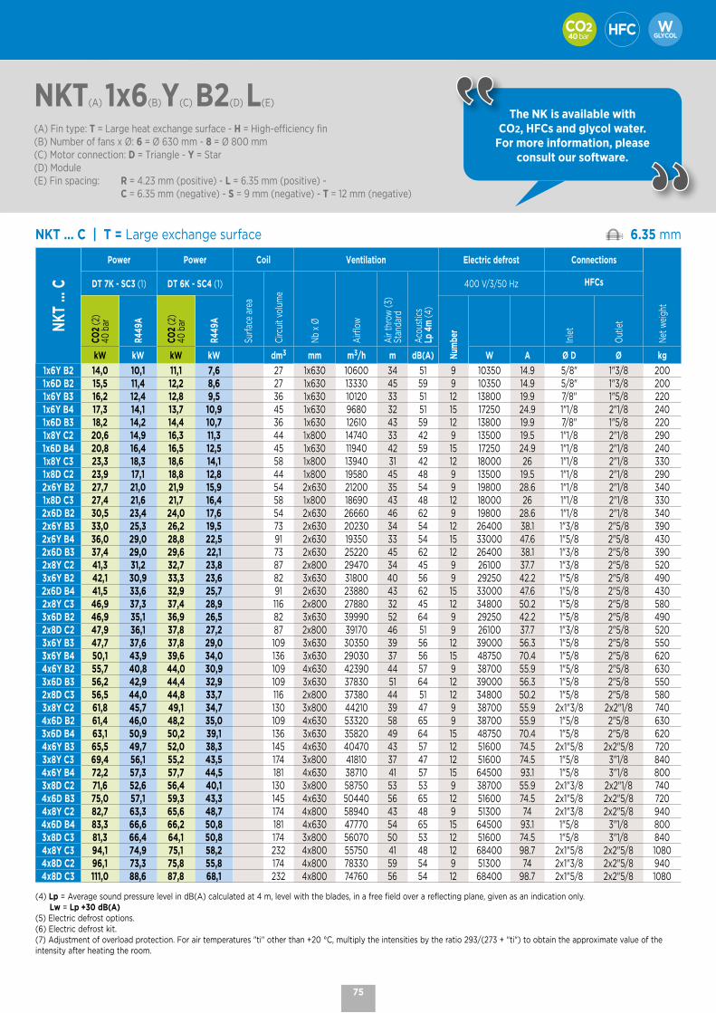
40 bar
NKT(A) 1x6(B)Y(C) B2(D) L(E)
(A) Fin type: T = Large heat exchange surface - H = High-efficiency fin(B) Number of fans x Ø: 6 = Ø 630 mm - 8 = Ø 800 mm(C) Motor connection: D = Triangle - Y = Star(D) Module(E) Fin spacing: R = 4.23 mm (positive) - L = 6.35 mm (positive) - C = 6.35 mm (negative) - S = 9 mm (negative) - T = 12 mm (negative)
The NK is available with CO2, HFCs and glycol water.
For more information, please consult our software.
NKT ... C | T = Large exchange surface 6.35 mm
NKT
... C
Power Power Coil Ventilation Electric defrost Connections
Net
wei
ght
DT 7K - SC3 (1) DT 6K - SC4 (1)
Surfa
ce a
rea
Circ
uit v
olum
e
Nb
x Ø
Airf
low
Air
thro
w (3
)St
anda
rd
Acou
stic
sLp
4m
(4)
400 V/3/50 Hz HFCs
CO2
(2)
40 b
ar
R449
A
CO2
(2)
40 b
ar
R449
A
Num
ber
Inle
t
Out
let
kW kW kW kW dm3 mm m3/h m dB(A) W A Ø D Ø kg
1x6Y B2 14,0 10,1 11,1 7,6 27 1x630 10600 34 51 9 10350 14.9 5/8" 1"3/8 2001x6D B2 15,5 11,4 12,2 8,6 27 1x630 13330 45 59 9 10350 14.9 5/8" 1"3/8 2001x6Y B3 16,2 12,4 12,8 9,5 36 1x630 10120 33 51 12 13800 19.9 7/8" 1"5/8 2201x6Y B4 17,3 14,1 13,7 10,9 45 1x630 9680 32 51 15 17250 24.9 1"1/8 2"1/8 2401x6D B3 18,2 14,2 14,4 10,7 36 1x630 12610 43 59 12 13800 19.9 7/8" 1"5/8 2201x8Y C2 20,6 14,9 16,3 11,3 44 1x800 14740 33 42 9 13500 19.5 1"1/8 2"1/8 2901x6D B4 20,8 16,4 16,5 12,5 45 1x630 11940 42 59 15 17250 24.9 1"1/8 2"1/8 2401x8Y C3 23,3 18,3 18,6 14,1 58 1x800 13940 31 42 12 18000 26 1"1/8 2"1/8 3301x8D C2 23,9 17,1 18,8 12,8 44 1x800 19580 45 48 9 13500 19.5 1"1/8 2"1/8 2902x6Y B2 27,7 21,0 21,9 15,9 54 2x630 21200 35 54 9 19800 28.6 1"1/8 2"1/8 3401x8D C3 27,4 21,6 21,7 16,4 58 1x800 18690 43 48 12 18000 26 1"1/8 2"1/8 3302x6D B2 30,5 23,4 24,0 17,6 54 2x630 26660 46 62 9 19800 28.6 1"1/8 2"1/8 3402x6Y B3 33,0 25,3 26,2 19,5 73 2x630 20230 34 54 12 26400 38.1 1"3/8 2"5/8 3902x6Y B4 36,0 29,0 28,8 22,5 91 2x630 19350 33 54 15 33000 47.6 1"5/8 2"5/8 4302x6D B3 37,4 29,0 29,6 22,1 73 2x630 25220 45 62 12 26400 38.1 1"3/8 2"5/8 3902x8Y C2 41,3 31,2 32,7 23,8 87 2x800 29470 34 45 9 26100 37.7 1"3/8 2"5/8 5203x6Y B2 42,1 30,9 33,3 23,6 82 3x630 31800 40 56 9 29250 42.2 1"5/8 2"5/8 4902x6D B4 41,5 33,6 32,9 25,7 91 2x630 23880 43 62 15 33000 47.6 1"5/8 2"5/8 4302x8Y C3 46,9 37,3 37,4 28,9 116 2x800 27880 32 45 12 34800 50.2 1"5/8 2"5/8 5803x6D B2 46,9 35,1 36,9 26,5 82 3x630 39990 52 64 9 29250 42.2 1"5/8 2"5/8 4902x8D C2 47,9 36,1 37,8 27,2 87 2x800 39170 46 51 9 26100 37.7 1"3/8 2"5/8 5203x6Y B3 47,7 37,6 37,8 29,0 109 3x630 30350 39 56 12 39000 56.3 1"5/8 2"5/8 5503x6Y B4 50,1 43,9 39,6 34,0 136 3x630 29030 37 56 15 48750 70.4 1"5/8 2"5/8 6204x6Y B2 55,7 40,8 44,0 30,9 109 4x630 42390 44 57 9 38700 55.9 1"5/8 2"5/8 6303x6D B3 56,2 42,9 44,4 32,9 109 3x630 37830 51 64 12 39000 56.3 1"5/8 2"5/8 5502x8D C3 56,5 44,0 44,8 33,7 116 2x800 37380 44 51 12 34800 50.2 1"5/8 2"5/8 5803x8Y C2 61,8 45,7 49,1 34,7 130 3x800 44210 39 47 9 38700 55.9 2x1"3/8 2x2"1/8 7404x6D B2 61,4 46,0 48,2 35,0 109 4x630 53320 58 65 9 38700 55.9 1"5/8 2"5/8 6303x6D B4 63,1 50,9 50,2 39,1 136 3x630 35820 49 64 15 48750 70.4 1"5/8 2"5/8 6204x6Y B3 65,5 49,7 52,0 38,3 145 4x630 40470 43 57 12 51600 74.5 2x1"5/8 2x2"5/8 7203x8Y C3 69,4 56,1 55,2 43,5 174 3x800 41810 37 47 12 51600 74.5 1"5/8 3"1/8 8404x6Y B4 72,2 57,3 57,7 44,5 181 4x630 38710 41 57 15 64500 93.1 1"5/8 3"1/8 8003x8D C2 71,6 52,6 56,4 40,1 130 3x800 58750 53 53 9 38700 55.9 2x1"3/8 2x2"1/8 7404x6D B3 75,0 57,1 59,3 43,3 145 4x630 50440 56 65 12 51600 74.5 2x1"5/8 2x2"5/8 7204x8Y C2 82,7 63,3 65,6 48,7 174 4x800 58940 43 48 9 51300 74 2x1"3/8 2x2"5/8 9404x6D B4 83,3 66,6 66,2 50,8 181 4x630 47770 54 65 15 64500 93.1 1"5/8 3"1/8 8003x8D C3 81,3 66,4 64,1 50,8 174 3x800 56070 50 53 12 51600 74.5 1"5/8 3"1/8 8404x8Y C3 94,1 74,9 75,1 58,2 232 4x800 55750 41 48 12 68400 98.7 2x1"5/8 2x2"5/8 10804x8D C2 96,1 73,3 75,8 55,8 174 4x800 78330 59 54 9 51300 74 2x1"3/8 2x2"5/8 9404x8D C3 111,0 88,6 87,8 68,1 232 4x800 74760 56 54 12 68400 98.7 2x1"5/8 2x2"5/8 1080
(4) Lp = Average sound pressure level in dB(A) calculated at 4 m, level with the blades, in a free field over a reflecting plane, given as an indication only. Lw = Lp +30 dB(A)(5) Electric defrost options.(6) Electric defrost kit. (7) Adjustment of overload protection. For air temperatures "ti" other than +20 °C, multiply the intensities by the ratio 293/(273 + "ti") to obtain the approximate value of the intensity after heating the room.
75
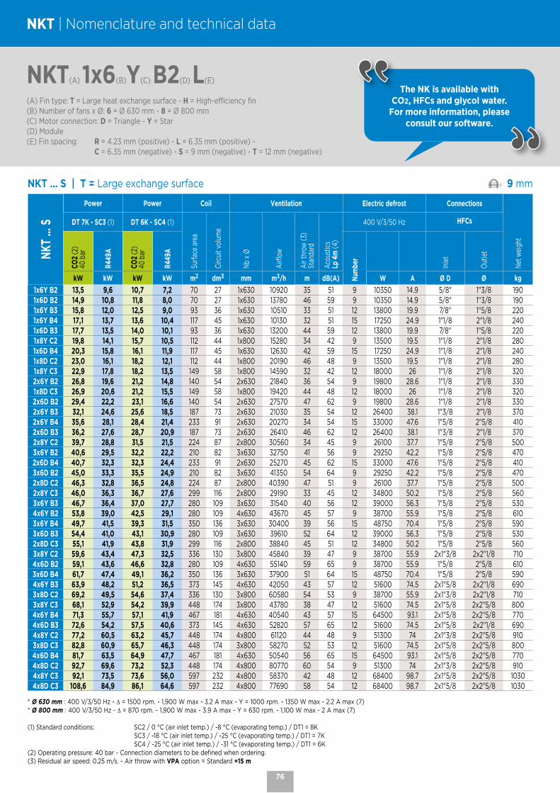
NKT ... S | T = Large exchange surface 9 mm
NKT
... S
Power Power Coil Ventilation Electric defrost Connections
Net
wei
ght
DT 7K - SC3 (1) DT 6K - SC4 (1)
Surfa
ce a
rea
Circ
uit v
olum
e
Nb
x Ø
Airf
low
Air
thro
w (3
)St
anda
rd
Acou
stic
sLp
4m
(4)
400 V/3/50 Hz HFCs
CO2
(2)
40 b
ar
R449
A
CO2
(2)
40 b
ar
R449
A
Num
ber
Inle
t
Out
let
kW kW kW kW m2 dm3 mm m3/h m dB(A) W A Ø D Ø kg
1x6Y B2 13,5 9,6 10,7 7,2 70 27 1x630 10920 35 51 9 10350 14.9 5/8" 1"3/8 1901x6D B2 14,9 10,8 11,8 8,0 70 27 1x630 13780 46 59 9 10350 14.9 5/8" 1"3/8 1901x6Y B3 15,8 12,0 12,5 9,0 93 36 1x630 10510 33 51 12 13800 19.9 7/8" 1"5/8 2201x6Y B4 17,1 13,7 13,6 10,4 117 45 1x630 10130 32 51 15 17250 24.9 1"1/8 2"1/8 2401x6D B3 17,7 13,5 14,0 10,1 93 36 1x630 13200 44 59 12 13800 19.9 7/8" 1"5/8 2201x8Y C2 19,8 14,1 15,7 10,5 112 44 1x800 15280 34 42 9 13500 19.5 1"1/8 2"1/8 2801x6D B4 20,3 15,8 16,1 11,9 117 45 1x630 12630 42 59 15 17250 24.9 1"1/8 2"1/8 2401x8D C2 23,0 16,1 18,2 12,1 112 44 1x800 20190 46 48 9 13500 19.5 1"1/8 2"1/8 2801x8Y C3 22,9 17,8 18,2 13,5 149 58 1x800 14590 32 42 12 18000 26 1"1/8 2"1/8 3202x6Y B2 26,8 19,6 21,2 14,8 140 54 2x630 21840 36 54 9 19800 28.6 1"1/8 2"1/8 3301x8D C3 26,9 20,6 21,2 15,5 149 58 1x800 19420 44 48 12 18000 26 1"1/8 2"1/8 3202x6D B2 29,4 22,2 23,1 16,6 140 54 2x630 27570 47 62 9 19800 28.6 1"1/8 2"1/8 3302x6Y B3 32,1 24,6 25,6 18,5 187 73 2x630 21030 35 54 12 26400 38.1 1"3/8 2"1/8 3702x6Y B4 35,6 28,1 28,4 21,4 233 91 2x630 20270 34 54 15 33000 47.6 1"5/8 2"5/8 4102x6D B3 36,2 27,6 28,7 20,9 187 73 2x630 26410 46 62 12 26400 38.1 1"3/8 2"1/8 3702x8Y C2 39,7 28,8 31,5 21,5 224 87 2x800 30560 34 45 9 26100 37.7 1"5/8 2"5/8 5003x6Y B2 40,6 29,5 32,2 22,2 210 82 3x630 32750 41 56 9 29250 42.2 1"5/8 2"5/8 4702x6D B4 40,7 32,3 32,3 24,4 233 91 2x630 25270 45 62 15 33000 47.6 1"5/8 2"5/8 4103x6D B2 45,0 33,3 35,5 24,9 210 82 3x630 41350 54 64 9 29250 42.2 1"5/8 2"5/8 4702x8D C2 46,3 32,8 36,5 24,8 224 87 2x800 40390 47 51 9 26100 37.7 1"5/8 2"5/8 5002x8Y C3 46,0 36,3 36,7 27,6 299 116 2x800 29190 33 45 12 34800 50.2 1"5/8 2"5/8 5603x6Y B3 46,7 36,4 37,0 27,7 280 109 3x630 31540 40 56 12 39000 56.3 1"5/8 2"5/8 5304x6Y B2 53,8 39,0 42,5 29,1 280 109 4x630 43670 45 57 9 38700 55.9 1"5/8 2"5/8 6103x6Y B4 49,7 41,5 39,3 31,5 350 136 3x630 30400 39 56 15 48750 70.4 1"5/8 2"5/8 5903x6D B3 54,4 41,0 43,1 30,9 280 109 3x630 39610 52 64 12 39000 56.3 1"5/8 2"5/8 5302x8D C3 55,1 41,9 43,8 31,9 299 116 2x800 38840 45 51 12 34800 50.2 1"5/8 2"5/8 5603x8Y C2 59,6 43,4 47,3 32,5 336 130 3x800 45840 39 47 9 38700 55.9 2x1"3/8 2x2"1/8 7104x6D B2 59,1 43,6 46,6 32,8 280 109 4x630 55140 59 65 9 38700 55.9 1"5/8 2"5/8 6103x6D B4 61,7 47,4 49,1 36,2 350 136 3x630 37900 51 64 15 48750 70.4 1"5/8 2"5/8 5904x6Y B3 63,9 48,2 51,2 36,5 373 145 4x630 42050 43 57 12 51600 74.5 2x1"5/8 2x2"1/8 6903x8D C2 69,2 49,5 54,6 37,4 336 130 3x800 60580 54 53 9 38700 55.9 2x1"3/8 2x2"1/8 7103x8Y C3 68,1 52,9 54,2 39,9 448 174 3x800 43780 38 47 12 51600 74.5 2x1"5/8 2x2"5/8 8004x6Y B4 71,3 55,7 57,1 41,9 467 181 4x630 40540 43 57 15 64500 93.1 2x1"5/8 2x2"5/8 7704x6D B3 72,6 54,2 57,5 40,6 373 145 4x630 52820 57 65 12 51600 74.5 2x1"5/8 2x2"1/8 6904x8Y C2 77,2 60,5 63,2 45,7 448 174 4x800 61120 44 48 9 51300 74 2x1"3/8 2x2"5/8 9103x8D C3 82,8 60,9 65,7 46,3 448 174 3x800 58270 52 53 12 51600 74.5 2x1"5/8 2x2"5/8 8004x6D B4 81,7 63,5 64,9 47,7 467 181 4x630 50540 56 65 15 64500 93.1 2x1"5/8 2x2"5/8 7704x8D C2 92,7 69,6 73,2 52,3 448 174 4x800 80770 60 54 9 51300 74 2x1"3/8 2x2"5/8 9104x8Y C3 92,1 73,5 73,6 56,0 597 232 4x800 58370 42 48 12 68400 98.7 2x1"5/8 2x2"5/8 10304x8D C3 108,6 84,9 86,1 64,6 597 232 4x800 77690 58 54 12 68400 98.7 2x1"5/8 2x2"5/8 1030
* Ø 630 mm : 400 V/3/50 Hz - ∆ = 1500 rpm. - 1,900 W max - 3.2 A max - Y = 1000 rpm. - 1350 W max - 2.2 A max (7)* Ø 800 mm : 400 V/3/50 Hz - ∆ = 870 rpm. - 1,900 W max - 3.9 A max - Y = 630 rpm. - 1,100 W max - 2 A max (7)
(1) Standard conditions: SC2 / 0 °C (air inlet temp.) / -8 °C (evaporating temp.) / DT1 = 8K SC3 / -18 °C (air inlet temp.) / -25 °C (evaporating temp.) / DT1 = 7K SC4 / -25 °C (air inlet temp.) / -31 °C (evaporating temp.) / DT1 = 6K(2) Operating pressure: 40 bar - Connection diameters to be defined when ordering.(3) Residual air speed: 0.25 m/s. - Air throw with VPA option = Standard +15 m
NKT(A) 1x6(B)Y(C) B2(D) L(E)
(A) Fin type: T = Large heat exchange surface - H = High-efficiency fin(B) Number of fans x Ø: 6 = Ø 630 mm - 8 = Ø 800 mm(C) Motor connection: D = Triangle - Y = Star(D) Module(E) Fin spacing: R = 4.23 mm (positive) - L = 6.35 mm (positive) - C = 6.35 mm (negative) - S = 9 mm (negative) - T = 12 mm (negative)
The NK is available with CO2, HFCs and glycol water.
For more information, please consult our software.
NKT | Nomenclature and technical data
76
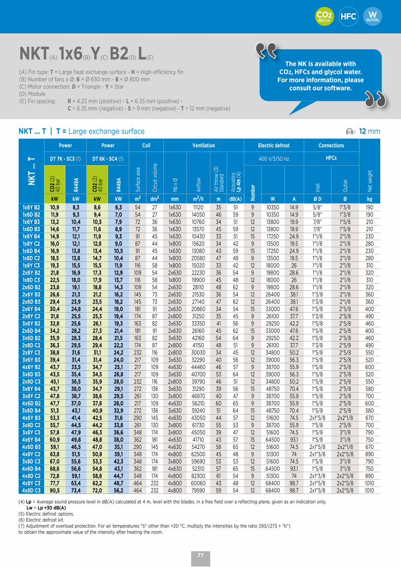
40 bar
NKT ... T | T = Large exchange surface 12 mm
NKT
... T
Power Power Coil Ventilation Electric defrost Connections
Net
wei
ght
DT 7K - SC3 (1) DT 6K - SC4 (1)
Surfa
ce a
rea
Circ
uit v
olum
e
Nb
x Ø
Airf
low
Air
thro
w (3
)St
anda
rd
Acou
stic
sLp
4m
(4)
400 V/3/50 Hz HFCs
CO2
(2)
40 b
ar
R449
A
CO2
(2)
40 b
ar
R449
A
Num
ber
Inle
t
Out
let
kW kW kW kW m2 dm3 mm m3/h m dB(A) W A Ø D Ø kg
1x6Y B2 10,9 8,3 8,6 6,3 54 27 1x630 11120 35 51 9 10350 14.9 5/8" 1"3/8 1901x6D B2 11,9 9,3 9,4 7,0 54 27 1x630 14050 46 59 9 10350 14.9 5/8" 1"3/8 1901x6Y B3 13,2 10,4 10,5 7,9 72 36 1x630 10760 34 51 12 13800 19.9 7/8" 1"5/8 2101x6D B3 14,6 11,7 11,6 8,9 72 36 1x630 13570 45 59 12 13800 19.9 7/8" 1"5/8 2101x6Y B4 14,9 12,1 11,9 9,3 91 45 1x630 10430 33 51 15 17250 24.9 1"1/8 2"1/8 2301x8Y C2 16,0 12,1 12,8 9,0 87 44 1x800 15620 34 42 9 13500 19.5 1"1/8 2"1/8 2801x6D B4 16,9 13,8 13,4 10,5 91 45 1x630 13080 43 59 15 17250 24.9 1"1/8 2"1/8 2301x8D C2 18,5 13,8 14,7 10,4 87 44 1x800 20580 47 48 9 13500 19.5 1"1/8 2"1/8 2801x8Y C3 19,3 15,5 15,5 11,9 116 58 1x800 15020 33 42 12 18000 26 1"1/8 2"1/8 3102x6Y B2 21,8 16,9 17,3 12,9 109 54 2x630 22230 36 54 9 19800 28.6 1"1/8 2"1/8 3201x8D C3 22,5 18,0 17,9 13,7 116 58 1x800 19900 45 48 12 18000 26 1"1/8 2"1/8 3102x6D B2 23,8 19,1 18,8 14,3 109 54 2x630 28110 48 62 9 19800 28.6 1"1/8 2"1/8 3202x6Y B3 26,6 21,3 21,2 16,2 145 73 2x630 21530 36 54 12 26400 38.1 1"3/8 2"1/8 3602x6D B3 29,4 23,9 23,5 18,2 145 73 2x630 27140 47 62 12 26400 38.1 1"3/8 2"1/8 3602x6Y B4 30,4 24,8 24,4 19,0 181 91 2x630 20860 34 54 15 33000 47.6 1"5/8 2"5/8 4002x8Y C2 31,8 25,5 25,3 19,4 174 87 2x800 31250 35 45 9 26100 37.7 1"3/8 2"5/8 4903x6Y B2 32,8 25,6 26,1 19,3 163 82 3x630 33350 41 56 9 29250 42.2 1"5/8 2"5/8 4602x6D B4 34,2 28,2 27,3 21,4 181 91 2x630 26160 45 62 15 33000 47.6 1"5/8 2"5/8 4003x6D B2 35,9 28,3 28,4 21,5 163 82 3x630 42160 54 64 9 29250 42.2 1"5/8 2"5/8 4602x8D C2 36,3 29,5 29,4 22,2 174 87 2x800 41150 48 51 9 26100 37.7 1"3/8 2"5/8 4902x8Y C3 38,8 31,6 31,1 24,2 232 116 2x800 30030 34 45 12 34800 50.2 1"5/8 2"5/8 5503x6Y B3 39,4 31,4 31,4 24,0 217 109 3x630 32290 40 56 12 39000 56.3 1"5/8 2"5/8 5204x6Y B2 43,7 33,5 34,7 25,1 217 109 4x630 44460 46 57 9 38700 55.9 1"5/8 2"5/8 6003x6D B3 43,5 35,4 34,5 26,8 217 109 3x630 40700 53 64 12 39000 56.3 1"5/8 2"5/8 5202x8D C3 45,1 36,5 35,9 28,0 232 116 2x800 39790 46 51 12 34800 50.2 1"5/8 2"5/8 5503x6Y B4 43,7 38,0 34,7 29,1 272 136 3x630 31290 39 56 15 48750 70.4 1"5/8 2"5/8 5803x8Y C2 47,8 38,7 38,6 29,5 261 130 3x800 46870 40 47 9 38700 55.9 1"5/8 2"5/8 7004x6D B2 47,7 37,0 37,8 28,0 217 109 4x630 56210 60 65 9 38700 55.9 1"5/8 2"5/8 6003x6D B4 51,3 43,1 40,9 32,9 272 136 3x630 39240 51 64 15 48750 70.4 1"5/8 2"5/8 5804x6Y B3 53,3 41,4 42,5 31,6 290 145 4x630 43050 44 57 12 51600 74.5 2x1"5/8 2x2"1/8 6703x8D C2 55,7 44,5 44,2 33,8 261 130 3x800 61730 55 53 9 38700 55.9 1"5/8 2"5/8 7003x8Y C3 57,8 47,9 46,3 36,6 348 174 3x800 45050 39 47 12 51600 74.5 1"5/8 3"1/8 7904x6Y B4 60,9 49,8 48,8 38,0 362 181 4x630 41710 43 57 15 64500 93.1 1"5/8 3"1/8 7504x6D B3 59,1 46,5 47,0 35,1 290 145 4x630 54270 58 65 12 51600 74.5 2x1"5/8 2x2"1/8 6704x8Y C2 63,8 51,5 50,8 39,1 348 174 4x800 62500 45 48 9 51300 74 2x1"3/8 2x2"5/8 8903x8D C3 67,0 55,6 53,3 42,3 348 174 3x800 59690 53 53 12 51600 74.5 1"5/8 3"1/8 7904x6D B4 68,6 56,6 54,8 43,1 362 181 4x630 52310 57 65 15 64500 93.1 1"5/8 3"1/8 7504x8D C2 72,8 59,1 58,8 44,7 348 174 4x800 82300 61 54 9 51300 74 2x1"3/8 2x2"5/8 8904x8Y C3 77,7 63,4 62,2 48,7 464 232 4x800 60060 43 48 12 68400 98.7 2x1"5/8 2x2"5/8 10104x8D C3 90,5 73,4 72,0 56,2 464 232 4x800 79590 59 54 12 68400 98.7 2x1"5/8 2x2"5/8 1010
(4) Lp = Average sound pressure level in dB(A) calculated at 4 m, level with the blades, in a free field over a reflecting plane, given as an indication only. Lw = Lp +30 dB(A)(5) Electric defrost options.(6) Electric defrost kit. (7) Adjustment of overload protection. For air temperatures "ti" other than +20 °C, multiply the intensities by the ratio 293/(273 + "ti") to obtain the approximate value of the intensity after heating the room.
NKT(A) 1x6(B)Y(C) B2(D) L(E)
(A) Fin type: T = Large heat exchange surface - H = High-efficiency fin(B) Number of fans x Ø: 6 = Ø 630 mm - 8 = Ø 800 mm(C) Motor connection: D = Triangle - Y = Star(D) Module(E) Fin spacing: R = 4.23 mm (positive) - L = 6.35 mm (positive) - C = 6.35 mm (negative) - S = 9 mm (negative) - T = 12 mm (negative)
The NK is available with CO2, HFCs and glycol water.
For more information, please consult our software.
77

NKH | Nomenclature and technical data
NKH ... R | H = High-efficiency fin 4.23 mm
NKH
... R
Power Coil Ventilation Electric defrost Connections
Net
wei
ght
DT 8K - SC2 (1)
Surfa
ce a
rea
Circ
uit v
olum
e
Nb
x Ø
Airf
low
Air
thro
w (3
)St
anda
rd
Acou
stic
sLp
4m
(4)
E1U (5)400 V/3/50 Hz
ELU (5)400 V/3/50 Hz
ECK kit (6)400 V/3/50 Hz
HFCs
CO2
(2)
50 b
ar
R449
A
Num
ber
Num
ber
Num
ber
Inle
t
Out
let
kW kW m2 dm3 mm m3/h m dB(A) W A W A W A Ø D Ø kg
1x6Y B1 18,5 17,3 74 14 1x630 10270 33 51 6 6900 10 6 6900 10 - - - 7/8" 1"5/8 1601x6D B1 20,3 19,7 74 14 1x630 12770 43 59 6 6900 10 6 6900 10 - - - 7/8" 1"5/8 1601x6Y B2 22,7 22,2 111 22 1x630 9480 30 51 7 10350 14,9 9 10350 14,9 3 3450 5 1"1/8 1"5/8 1801x6Y B3 25,0 23,6 149 29 1x630 8830 29 51 10 13800 19,9 12 13800 19,9 3 3450 5 1"1/8 1"5/8 2001x6D B2 26,0 25,5 111 22 1x630 11580 40 59 7 10350 14,9 9 10350 14,9 3 3450 5 1"1/8 1"5/8 1801x8Y C1 28,1 26,1 124 24 1x800 15260 31 42 6 9000 13 6 9000 13 - - - 1"3/8 2"1/8 2401x6D B3 29,6 27,8 149 29 1x630 10670 38 59 10 13800 19,9 12 13800 19,9 3 3450 5 1"1/8 1"5/8 2001x8Y C2 33,2 31,9 186 36 1x800 14220 29 42 7 9000 13 9 13500 19,5 3 4500 6,5 1"3/8 2"1/8 2701x8D C1 32,9 30,5 124 24 1x800 20260 43 48 6 9000 13 6 9000 13 - - - 1"3/8 2"1/8 2402x6Y B1 37,2 34,6 149 29 2x630 20530 36 54 6 13200 19,1 6 13200 19,1 - - - 1"3/8 2"1/8 2701x8D C2 40,2 38,9 186 36 1x800 19130 40 48 7 9000 13 9 13500 19,5 3 4500 6,5 1"3/8 2"1/8 2702x6D B1 41,0 39,9 149 29 2x630 25540 44 62 6 13200 19,1 6 13200 19,1 - - - 1"3/8 2"1/8 2702x6Y B2 45,7 43,2 223 43 2x630 18970 32 54 7 19800 28,6 9 19800 28,6 3 6600 9,5 1"3/8 2"1/8 3002x6Y B3 48,6 47,9 297 58 2x630 17650 30 54 10 26400 38,1 12 26400 38,1 3 6600 9,5 1"5/8 2"1/8 3402x6D B2 52,3 50,2 223 43 2x630 23160 42 62 7 19800 28,6 9 19800 28,6 3 6600 9,5 1"3/8 2"1/8 3003x6Y B1 55,9 52,6 223 43 3x630 30800 38 56 6 19500 28,1 6 19500 28,1 - - - 1"5/8 2"1/8 3702x8Y C1 55,0 52,9 248 48 2x800 30520 32 45 6 17400 25,1 6 17400 25,1 - - - 1"5/8 2"5/8 4202x6D B3 59,5 56,3 297 58 2x630 21340 39 62 10 26400 38,1 12 26400 38,1 3 6600 9,5 1"5/8 2"1/8 3403x6D B1 63,2 60,1 223 43 3x630 38310 50 64 6 19500 28,1 6 19500 28,1 - - - 1"5/8 2"1/8 3702x8Y C2 65,1 62,7 371 72 2x800 28440 30 45 7 17400 25,1 9 26100 37,7 3 8700 12,6 1"5/8 2"5/8 4802x8D C1 63,9 61,6 248 48 2x800 40530 44 51 6 17400 25,1 6 17400 25,1 - - - 1"5/8 2"5/8 4203x6Y B2 67,8 67,4 334 65 3x630 28450 36 56 7 19500 28,1 9 29250 42,2 3 9750 14,1 2x1"3/8 2x2"1/8 4304x6Y B1 74,6 68,4 297 58 4x630 41070 44 57 6 25800 37,2 6 25800 37,2 - - - 1"5/8 2"5/8 4803x6Y B3 71,3 70,4 445 86 3x630 26480 33 56 10 29250 42,2 12 39000 56,3 3 9750 14,1 1"5/8 2"5/8 4903x8Y C1 83,7 72,4 371 72 3x800 45780 37 47 6 25800 37,2 6 25800 37,2 - - - 1"5/8 2"5/8 5702x8D C2 80,7 76,5 371 72 2x800 38260 41 51 7 17400 25,1 9 26100 37,7 3 8700 12,6 1"5/8 2"5/8 4803x6D B2 77,4 77,9 334 65 3x630 34750 47 64 7 19500 28,1 9 29250 42,2 3 9750 14,1 2x1"3/8 2x2"1/8 4303x6D B3 89,4 82,8 445 86 3x630 32010 44 64 10 29250 42,2 12 39000 56,3 3 9750 14,1 1"5/8 2"5/8 4904x6D B1 82,5 78,3 297 58 4x630 51080 55 65 6 25800 37,2 6 25800 37,2 - - - 2x1"5/8 2x2"1/8 4803x8D C1 97,6 84,4 371 72 3x800 60790 50 53 6 25800 37,2 6 25800 37,2 - - - 1"5/8 2"5/8 5704x6Y B2 91,7 86,3 445 86 4x630 37930 40 57 7 25800 37,2 9 38700 55,9 3 12900 18,6 2x1"3/8 2x2"1/8 5503x8Y C2 100,1 92,8 557 108 3x800 42650 34 47 7 25800 37,2 9 38700 55,9 3 12900 18,6 2x1"5/8 2x2"1/8 6704x6Y B3 97,5 95,6 594 115 4x630 35310 37 57 10 38700 55,9 12 51600 74,5 3 12900 18,6 2x1"5/8 2x2"1/8 6304x6D B2 105,0 100,3 445 86 4x630 46330 52 65 7 25800 37,2 9 38700 55,9 3 12900 18,6 2x1"3/8 2x2"1/8 5504x8Y C2 129,3 109,8 742 144 4x800 56870 38 48 7 34200 49,4 9 51300 74 3 17100 24,7 2x1"5/8 2x2"5/8 8404x8Y C1 110,3 106,2 495 96 4x800 61040 41 48 6 34200 49,4 6 34200 49,4 - - - 2x1"5/8 2x2"5/8 7404x6D B3 119,3 112,5 594 115 4x630 42680 49 65 10 38700 55,9 12 51600 74,5 3 12900 18,6 2x1"5/8 2x2"1/8 6303x8D C2 121,3 113,2 557 108 3x800 57390 47 53 7 25800 37,2 9 38700 55,9 3 12900 18,6 2x1"5/8 2x2"1/8 6704x8D C1 131,8 123,7 495 96 4x800 81060 56 54 6 34200 49,4 6 34200 49,4 - - - 2x1"5/8 2x2"5/8 7404x8D C2 154,6 133,9 742 144 4x800 76520 52 54 7 34200 49,4 9 51300 74 3 17100 24,7 2x1"5/8 2x2"5/8 840
* Ø 630 mm : 400 V/3/50 Hz - ∆ = 1500 rpm. - 1,900 W max - 3.2 A max - Y = 1000 rpm. - 1350 W max - 2.2 A max (7)* Ø 800 mm : 400 V/3/50 Hz - ∆ = 870 rpm. - 1,900 W max - 3.9 A max - Y = 630 rpm. - 1,100 W max - 2 A max (7)
(1) Standard conditions: SC2 / 0 °C (air inlet temp.) / -8 °C (evaporating temp.) / DT1 = 8K SC3 / -18 °C (air inlet temp.) / -25 °C (evaporating temp.) / DT1 = 7K SC4 / -25 °C (air inlet temp.) / -31 °C (evaporating temp.) / DT1 = 6K(2) Operating pressure: 50 bar - Connection diameters to be defined when ordering.(3) Residual air speed: 0.25 m/s. - Air throw with VPA option = Standard +15 m
NKT(A) 1x6(B)Y(C) B2(D) L(E)
(A) Fin type: T = Large heat exchange surface - H = High-efficiency fin(B) Number of fans x Ø: 6 = Ø 630 mm - 8 = Ø 800 mm(C) Motor connection: D = Triangle - Y = Star(D) Module(E) Fin spacing: R = 4.23 mm (positive) - L = 6.35 mm (positive) - C = 6.35 mm (negative) - S = 9 mm (negative) - T = 12 mm (negative)
The NK is available with CO2, HFCs and glycol water.
For more information, please consult our software.
78

50 bar
NKH ... L | H = High-efficiency fin 6.35 mm
NKH
... L
Power Coil Ventilation Electric defrost Connections
Net
wei
ght
DT 8K - SC2 (1)
Surfa
ce a
rea
Circ
uit v
olum
e
Nb
x Ø
Airf
low
Air
thro
w (3
)St
anda
rd
Acou
stic
sLp
4m
(4)
E1U (5)400 V/3/50 Hz
ELU (5)400 V/3/50 Hz
ECK kit (6)400 V/3/50 Hz
HFCs
CO2
(2)
50 b
ar
R449
A
Num
ber
Num
ber
Num
ber
Inle
t
Out
let
kW kW m2 dm3 mm m3/h m dB(A) W A W A W A Ø D Ø kg
1x6Y B1 15,1 15,0 51 14 1x630 10720 34 51 6 6900 10 6 6900 10 - - - 7/8" 1"3/8 1601x6D B1 16,4 17,1 51 14 1x630 13450 45 59 6 6900 10 6 6900 10 - - - 7/8" 1"3/8 1601x6Y B2 19,5 19,5 77 22 1x630 10070 32 51 7 6900 10 9 10350 14,9 3 3450 5 1"1/8 1"5/8 1801x6Y B3 21,9 22,5 102 29 1x630 9490 30 51 10 10350 14,9 12 13800 19,9 3 3450 5 1"1/8 1"5/8 1901x6D B2 21,8 22,8 77 22 1x630 12460 42 59 7 6900 10 9 10350 14,9 3 3450 5 1"1/8 1"5/8 1801x8Y C1 22,7 22,7 85 24 1x800 15830 33 42 6 9000 13 6 9000 13 - - - 1"3/8 1"5/8 2301x6D B3 25,8 26,8 102 29 1x630 11600 40 59 10 10350 14,9 12 13800 19,9 3 3450 5 1"1/8 1"5/8 1901x8D C1 25,9 26,8 85 24 1x800 20870 45 48 6 9000 13 6 9000 13 - - - 1"3/8 1"5/8 2301x8Y C2 27,1 29,1 128 36 1x800 14990 31 42 7 9000 13 9 13500 19,5 3 4500 6,5 1"3/8 2"1/8 2602x6Y B1 26,0 30,7 102 29 2x630 21440 37 54 6 13200 19,1 6 13200 19,1 - - - 1"3/8 2"1/8 2601x8D C2 34,2 35,0 128 36 1x800 19970 43 48 7 9000 13 9 13500 19,5 3 4500 6,5 1"3/8 2"1/8 2602x6D B1 33,0 34,8 102 29 2x630 26910 46 62 6 13200 19,1 6 13200 19,1 - - - 1"3/8 2"1/8 2602x6Y B2 39,2 39,1 153 43 2x630 20140 33 54 7 13200 19,1 9 19800 28,6 3 6600 9,5 1"3/8 2"1/8 2902x6Y B3 44,1 45,1 204 58 2x630 18990 32 54 10 19800 28,6 12 26400 38,1 3 6600 9,5 1"5/8 2"1/8 3302x6D B2 43,8 45,5 153 43 2x630 24930 44 62 7 13200 19,1 9 19800 28,6 3 6600 9,5 1"3/8 2"1/8 2902x8Y C1 45,6 47,6 170 48 2x800 31660 34 45 6 17400 25,1 6 17400 25,1 - - - 1"3/8 2"1/8 4003x6Y B1 45,5 46,0 153 43 3x630 32160 40 56 6 19500 28,1 6 19500 28,1 - - - 1"5/8 2"1/8 3602x6D B3 51,7 53,7 204 58 2x630 23200 42 62 10 19800 28,6 12 26400 38,1 3 6600 9,5 1"5/8 2"1/8 3303x6D B1 50,0 52,4 153 43 3x630 40360 52 64 6 19500 28,1 6 19500 28,1 - - - 1"5/8 2"1/8 3602x8D C1 52,1 53,7 170 48 2x800 41740 46 51 6 17400 25,1 6 17400 25,1 - - - 1"5/8 2"1/8 4002x8Y C2 57,3 58,4 255 72 2x800 29980 31 45 7 17400 25,1 9 26100 37,7 3 8700 12,6 1"5/8 2"5/8 4603x6Y B2 58,4 59,4 230 65 3x630 30200 37 56 7 19500 28,1 9 29250 42,2 3 9750 14,1 2x1"3/8 2x2"1/8 4104x6Y B1 60,7 61,4 204 58 4x630 42880 46 57 6 25800 37,2 6 25800 37,2 - - - 1"5/8 2"5/8 4703x8Y C1 68,9 63,0 255 72 3x800 47490 39 47 6 25800 37,2 6 25800 37,2 - - - 1"5/8 2"5/8 5503x6Y B3 65,2 67,0 306 86 3x630 28480 36 56 10 29250 42,2 12 39000 56,3 3 9750 14,1 1"5/8 2"5/8 4602x8D C2 68,6 70,3 255 72 2x800 39940 43 51 7 17400 25,1 9 26100 37,7 3 8700 12,6 1"5/8 2"5/8 4603x6D B2 65,1 69,2 230 65 3x630 37390 49 64 7 19500 28,1 9 29250 42,2 3 9750 14,1 2x1"3/8 2x2"1/8 4104x6D B1 66,1 68,1 204 58 4x630 53820 58 65 6 25800 37,2 6 25800 37,2 - - - 2x1"5/8 2x2"1/8 4703x8D C1 79,0 74,5 255 72 3x800 62620 53 53 6 25800 37,2 6 25800 37,2 - - - 1"5/8 2"5/8 5504x6Y B2 78,5 78,5 306 86 4x630 40270 42 57 7 25800 37,2 9 38700 55,9 3 12900 18,6 2x1"3/8 2x2"1/8 5303x6D B3 77,7 79,8 306 86 3x630 34800 47 64 10 29250 42,2 12 39000 56,3 3 9750 14,1 1"5/8 2"5/8 4603x8Y C2 87,3 86,6 383 108 3x800 44960 37 47 7 25800 37,2 9 38700 55,9 3 12900 18,6 2x1"5/8 2x2"1/8 6504x6Y B3 88,6 90,6 409 115 4x630 37980 40 57 10 38700 55,9 12 51600 74,5 3 12900 18,6 2x1"5/8 2x2"1/8 6004x6D B2 87,7 91,4 306 86 4x630 49860 55 65 7 25800 37,2 9 38700 55,9 3 12900 18,6 2x1"3/8 2x2"1/8 5304x8Y C1 91,3 91,6 340 96 4x800 63320 43 48 6 34200 49,4 6 34200 49,4 - - - 2x1"5/8 2x2"1/8 7204x8Y C2 114,2 103,3 511 144 4x800 59950 40 48 7 34200 49,4 9 51300 74 3 17100 24,7 2x1"5/8 2x2"1/8 8003x8D C2 103,1 104,3 383 108 3x800 59900 50 53 7 25800 37,2 9 38700 55,9 3 12900 18,6 2x1"5/8 2x2"1/8 6504x6D B3 103,7 107,8 409 115 4x630 46390 52 65 10 38700 55,9 12 51600 74,5 3 12900 18,6 2x1"5/8 2x2"1/8 6004x8D C1 106,0 108,0 340 96 4x800 83490 59 54 6 34200 49,4 6 34200 49,4 - - - 2x1"5/8 2x2"1/8 7204x8D C2 133,7 126,0 511 144 4x800 79870 55 54 7 34200 49,4 9 51300 74 3 17100 24,7 2x1"5/8 2x2"1/8 800
(4) Lp = Average sound pressure level in dB(A) calculated at 4 m, level with the blades, in a free field over a reflecting plane, given as an indication only. Lw = Lp +30 dB(A)(5) Electric defrost options.(6) Electric defrost kit. (7) Adjustment of overload protection. For air temperatures "ti" other than +20 °C, multiply the intensities by the ratio 293/(273 + "ti") to obtain the approximate value of the intensity after heating the room.
NKT(A) 1x6(B)Y(C) B2(D) L(E)
(A) Fin type: T = Large heat exchange surface - H = High-efficiency fin(B) Number of fans x Ø: 6 = Ø 630 mm - 8 = Ø 800 mm(C) Motor connection: D = Triangle - Y = Star(D) Module(E) Fin spacing: R = 4.23 mm (positive) - L = 6.35 mm (positive) - C = 6.35 mm (negative) - S = 9 mm (negative) - T = 12 mm (negative)
The NK is available with CO2, HFCs and glycol water.
For more information, please consult our software.
79

NKH | Nomenclature and technical data
NKT(A) 1x6(B)Y(C) B2(D) L(E)
(A) Fin type: T = Large heat exchange surface - H = High-efficiency fin(B) Number of fans x Ø: 6 = Ø 630 mm - 8 = Ø 800 mm(C) Motor connection: D = Triangle - Y = Star(D) Module(E) Fin spacing: R = 4.23 mm (positive) - L = 6.35 mm (positive) - C = 6.35 mm (negative) - S = 9 mm (negative) - T = 12 mm (negative)
The NK is available with CO2, HFCs and glycol water.
For more information, please consult our software.
NKH ... C | H = High-efficiency fin 6.35 mm
NKH
... C
Power Power Coil Ventilation Electric defrost Connections
Net
wei
ght
DT 7K - SC3 (1) DT 6K - SC4 (1)
Surfa
ce a
rea
Circ
uit v
olum
e
Nb
x Ø
Airf
low
Air
thro
w (3
)St
anda
rd
Acou
stic
sLp
4m
(4)
400 V/3/50 Hz HFCs
CO2
(2)
50 b
ar
R449
A
CO2
(2)
50 b
ar
R449
A
Num
ber
Inle
t
Out
let
kW kW kW kW m2 dm3 mm m3/h m dB(A) W A Ø D Ø kg
1x6Y B1 12,1 10,6 9,7 8,3 51 14 1x630 10720 34 51 6 6900 10 7/8" 1"5/8 1701x6D B1 13,1 12,0 10,4 9,4 51 14 1x630 13450 45 59 6 6900 10 7/8" 1"5/8 1701x6Y B2 15,8 14,0 12,8 11,1 77 22 1x630 10070 32 51 9 10350 14.9 1"1/8 2"1/8 1901x6Y B3 18,4 16,7 14,9 13,4 102 29 1x630 9490 30 51 12 13800 19.9 1"3/8 2"1/8 2101x6D B2 17,5 16,2 14,1 12,8 77 22 1x630 12460 42 59 9 10350 14.9 1"1/8 2"1/8 1901x8Y C1 18,8 16,3 15,2 13,0 85 24 1x800 15830 33 42 6 9000 13 1"3/8 2"1/8 2501x6D B3 20,9 19,5 16,9 15,6 102 29 1x630 11600 40 59 12 13800 19.9 1"3/8 2"1/8 2101x8D C1 21,5 19,1 17,3 15,1 85 24 1x800 20870 45 48 6 9000 13 1"3/8 2"1/8 2501x8Y C2 23,7 21,0 19,2 16,8 128 36 1x800 14990 31 42 9 13500 19.5 1"3/8 2"1/8 2802x6Y B1 24,4 21,9 19,6 17,3 102 29 2x630 21440 37 54 6 13200 19.1 1"3/8 2"1/8 2901x8D C2 27,7 25,0 22,3 19,8 128 36 1x800 19970 43 48 9 13500 19.5 1"3/8 2"1/8 2802x6D B1 26,4 24,5 21,1 19,3 102 29 2x630 26910 46 62 6 13200 19.1 1"3/8 2"1/8 2902x6Y B2 31,9 28,8 25,7 23,1 153 43 2x630 20140 36 54 9 19800 28.6 1"5/8 2"1/8 3202x6Y B3 37,0 33,7 30,1 27,3 204 58 2x630 18990 32 54 12 26400 38.1 1"5/8 2"5/8 3603x6Y B1 37,7 32,5 30,5 25,8 153 43 3x630 32160 40 56 6 19500 28.1 1"5/8 2"5/8 4102x6D B2 36,3 33,1 29,4 26,2 153 43 2x630 24930 44 62 9 19800 28.6 1"5/8 2"5/8 3202x8Y C1 36,6 33,0 29,4 26,3 170 48 2x800 31660 34 45 6 17400 25.1 1"5/8 2"5/8 4402x8Y C2 46,0 37,3 37,1 29,7 255 72 2x800 29980 31 45 9 26100 37.7 1"5/8 2"5/8 5003x6D B1 41,0 37,0 33,0 29,1 153 43 3x630 40360 52 64 6 19500 28.1 1"5/8 2"5/8 4102x6D B3 42,1 39,7 34,1 31,7 204 58 2x630 23200 42 62 12 26400 38.1 1"5/8 2"5/8 3602x8D C1 41,4 38,8 33,1 30,8 170 48 2x800 41740 46 51 6 17400 25.1 1"5/8 2"5/8 4403x6Y B2 47,0 42,9 37,9 34,5 230 65 3x630 30200 37 56 9 29250 42.2 2x1"3/8 2x2"1/8 4603x8Y C1 55,9 42,9 45,1 33,5 255 72 3x800 47490 39 47 6 25800 37.2 1"5/8 2"5/8 6002x8D C2 55,7 44,8 44,9 35,1 255 72 2x800 39940 43 51 9 26100 37.7 1"5/8 2"5/8 5004x6Y B1 49,0 43,2 39,4 34,4 204 58 4x630 42880 44 57 6 25800 37.2 2x1"5/8 2x2"1/8 5203x6Y B3 55,6 50,9 45,2 41,0 306 86 3x630 28480 36 56 12 39000 56.3 2x1"5/8 2x2"1/8 5203x6D B2 52,0 49,9 41,7 39,7 230 65 3x630 37390 49 64 9 29250 42.2 2x1"3/8 2x2"1/8 4603x8D C1 63,6 50,3 51,0 39,0 255 72 3x800 62620 53 53 6 25800 37.2 1"5/8 2"5/8 6004x6D B1 53,0 48,9 42,5 38,8 204 58 4x630 53820 58 65 6 25800 37.2 2x1"5/8 2x2"1/8 5203x8Y C2 71,5 55,4 58,1 44,2 383 108 3x800 44960 37 47 9 38700 55.9 2x1"5/8 2x2"5/8 7004x6Y B3 70,8 60,3 57,0 47,5 409 115 4x630 37980 40 57 12 51600 74.5 2x1"5/8 2x2"5/8 6703x6D B3 63,3 59,9 51,2 47,9 306 86 3x630 34800 47 64 12 39000 56.3 2x1"5/8 2x2"1/8 5203x8D C2 83,7 67,3 67,6 52,1 383 108 3x800 59900 50 53 9 38700 55.9 2x1"5/8 2x2"5/8 7004x8Y C1 73,4 66,2 59,1 52,9 340 96 4x800 63320 43 48 6 34200 49.4 2x1"5/8 2x2"5/8 7804x6D B3 84,5 70,1 68,4 55,5 409 115 4x630 46390 52 65 12 51600 74.5 2x1"5/8 2x2"5/8 6704x8D C1 86,2 77,9 69,4 61,9 340 96 4x800 83490 59 54 6 34200 49.4 2x1"5/8 2x2"5/8 780
* Ø 630 mm : 400 V/3/50 Hz - ∆ = 1500 rpm. - 1,900 W max - 3.2 A max - Y = 1000 rpm. - 1350 W max - 2.2 A max (7)* Ø 800 mm : 400 V/3/50 Hz - ∆ = 870 rpm. - 1,900 W max - 3.9 A max - Y = 630 rpm. - 1,100 W max - 2 A max (7)
(1) Standard conditions: SC2 / 0 °C (air inlet temp.) / -8 °C (evaporating temp.) / DT1 = 8K SC3 / -18 °C (air inlet temp.) / -25 °C (evaporating temp.) / DT1 = 7K SC4 / -25 °C (air inlet temp.) / -31 °C (evaporating temp.) / DT1 = 6K(2) Operating pressure: 50 bar - Connection diameters to be defined when ordering.(3) Residual air speed: 0.25 m/s. - Air throw with VPA option = Standard +15 m
80

50 bar
NKT(A) 1x6(B)Y(C) B2(D) L(E)
(A) Fin type: T = Large heat exchange surface - H = High-efficiency fin(B) Number of fans x Ø: 6 = Ø 630 mm - 8 = Ø 800 mm(C) Motor connection: D = Triangle - Y = Star(D) Module(E) Fin spacing: R = 4.23 mm (positive) - L = 6.35 mm (positive) - C = 6.35 mm (negative) - S = 9 mm (negative) - T = 12 mm (negative)
The NK is available with CO2, HFCs and glycol water.
For more information, please consult our software.
NKH ... S | H = High-efficiency fin 9 mm
NKH
... S
Power Power Coil Ventilation Electric defrost Connections
Net
wei
ght
DT 7K - SC3 (1) DT 6K - SC4 (1)
Surfa
ce a
rea
Circ
uit v
olum
e
Nb
x Ø
Airf
low
Air
thro
w (3
)St
anda
rd
Acou
stic
sLp
4m
(4)
400 V/3/50 Hz HFCs
CO2
(2)
50 b
ar
R449
A
CO2
(2)
50 b
ar
R449
A
Num
ber
Inle
t
Out
let
kW kW kW kW m2 dm3 mm m3/h m dB(A) W A Ø D Ø kg
1x6Y B1 11,4 9,2 9,1 7,1 37 14 1x630 11000 35 51 6 6900 10 7/8" 1"5/8 1701x6D B1 12,3 10,2 9,9 7,9 37 14 1x630 13860 46 59 6 6900 10 7/8" 1"5/8 1701x6Y B2 15,1 12,4 12,2 9,7 56 22 1x630 10450 33 51 9 10350 14.9 1"1/8 1"5/8 1901x6D B2 16,6 14,1 13,4 11,0 56 22 1x630 13050 44 59 9 10350 14.9 1"1/8 1"5/8 1901x8Y C1 17,6 14,0 14,3 11,0 62 24 1x800 16180 34 42 6 9000 13 1"3/8 2"1/8 2501x6Y B3 17,8 15,1 14,5 11,9 75 29 1x630 9950 32 51 12 13800 19.9 1"1/8 2"1/8 2101x8D C1 20,2 16,1 16,3 8,1 62 24 1x800 21230 47 48 6 9000 13 1"3/8 2"1/8 2501x6D B3 20,1 17,3 16,2 13,7 75 29 1x630 12280 42 59 12 13800 19.9 1"1/8 2"1/8 2101x8Y C2 22,6 18,8 18,3 14,8 94 36 1x800 15470 32 42 9 13500 19.5 1"3/8 2"1/8 2802x6Y B1 22,9 18,5 18,5 14,5 75 29 2x630 22010 38 54 6 13200 19.1 1"3/8 2"1/8 2802x6D B1 24,8 20,8 19,9 16,2 75 29 2x630 27720 47 62 6 13200 19.1 1"3/8 2"1/8 2801x8D C2 26,4 21,9 21,3 17,2 94 36 1x800 20490 44 48 9 13500 19.5 1"3/8 2"1/8 2802x6Y B2 30,3 25,0 25,1 19,8 112 43 2x630 20900 37 54 9 19800 28.6 1"3/8 2"1/8 3203x6Y B1 35,2 28,2 28,5 22,1 112 43 3x630 33010 41 56 6 19500 28.1 1"5/8 2"5/8 4002x6D B2 34,4 28,7 27,9 22,5 112 43 2x630 26100 45 62 9 19800 28.6 1"5/8 2"5/8 3202x8Y C1 34,3 28,3 27,7 22,3 125 48 2x800 32350 35 45 6 17400 25.1 1"5/8 2"5/8 4302x6Y B3 34,2 30,6 29,1 24,3 150 58 2x630 19890 33 54 12 26400 38.1 1"5/8 2"5/8 3603x6D B1 38,3 31,4 31,0 24,5 112 43 3x630 41580 54 64 6 19500 28.1 1"5/8 2"5/8 4002x8Y C2 44,0 33,9 35,6 26,2 187 72 2x800 30950 33 45 9 26100 37.7 1"5/8 2"5/8 4802x8D C1 39,0 32,6 33,1 16,4 125 48 2x800 42460 48 51 6 17400 25.1 1"5/8 2"5/8 4302x6D B3 40,4 35,1 32,7 27,8 150 58 2x630 24560 44 62 12 26400 38.1 1"5/8 2"5/8 3604x6Y B1 46,0 36,1 37,1 27,9 150 58 4x630 44020 47 57 6 25800 37.2 1"5/8 2"5/8 5103x8Y C1 52,3 37,5 42,3 28,6 187 72 3x800 48530 40 47 6 25800 37.2 1"5/8 2"5/8 5903x6Y B2 44,9 38,0 36,2 30,0 169 65 3x630 31350 39 56 9 29250 42.2 2x1"1/8 2x2"1/8 4502x8D C2 53,1 39,4 42,9 30,3 187 72 2x800 40990 45 51 9 26100 37.7 1"5/8 2"5/8 4804x6D B1 49,8 40,9 40,0 32,1 150 58 4x630 55450 59 65 6 25800 37.2 2x1"3/8 2x2"1/8 5103x6D B2 49,5 43,3 39,8 34,0 169 65 3x630 39150 51 64 9 29250 42.2 2x1"1/8 2x2"1/8 4503x8D C1 59,8 43,3 48,1 21,9 187 72 3x800 63700 55 53 6 25800 37.2 1"5/8 2"5/8 5904x6Y B2 60,9 44,9 49,4 34,1 225 86 4x630 41800 43 57 9 38700 55.9 2x1"3/8 2x2"1/8 5703x6Y B3 53,7 46,2 43,8 36,7 225 86 3x630 29840 37 56 12 39000 56.3 2x1"3/8 2x2"1/8 5103x8Y C2 68,1 50,3 55,4 38,8 281 108 3x800 46420 38 47 9 38700 55.9 2x1"5/8 2x2"1/8 6704x6D B2 67,3 50,9 54,4 38,8 225 86 4x630 52200 57 65 9 38700 55.9 2x1"3/8 2x2"1/8 5703x6D B3 60,7 52,9 49,2 42,0 225 86 3x630 36840 49 64 12 39000 56.3 2x1"3/8 2x2"1/8 5104x6Y B3 68,7 54,9 58,4 42,2 300 115 4x630 39790 42 57 12 51600 74.5 2x1"3/8 2x2"5/8 6403x8D C2 79,7 58,6 64,5 44,9 281 108 3x800 61480 52 53 9 38700 55.9 2x1"5/8 2x2"1/8 6704x8Y C1 68,8 57,1 55,5 44,9 250 96 4x800 64700 45 48 6 34200 49.4 2x1"5/8 2x2"5/8 7704x6D B3 81,1 62,8 65,7 48,5 300 115 4x630 49120 55 65 12 51600 74.5 2x1"3/8 2x2"5/8 6404x8Y C2 87,2 64,6 73,0 48,4 375 144 4x800 61890 42 48 9 51300 74 2x1"5/8 2x2"5/8 8604x8D C1 80,9 65,7 65,3 33,1 250 96 4x800 84930 61 54 6 34200 49.4 2x1"5/8 2x2"5/8 7704x8D C2 104,8 75,1 84,6 56,8 375 144 4x800 81970 58 54 9 51300 74 2x1"5/8 2x2"5/8 860
(4) Lp = Average sound pressure level in dB(A) calculated at 4 m, level with the blades, in a free field over a reflecting plane, given as an indication only. Lw = Lp +30 dB(A)(5) Electric defrost options.(6) Electric defrost kit. (7) Adjustment of overload protection. For air temperatures "ti" other than +20 °C, multiply the intensities by the ratio 293/(273 + "ti") to obtain the approximate value of the intensity after heating the room.
81

NK | Dimensions
NK | Ø 630 mm
28
256 1200 256
1712= =
NK ... 1x6 ...
256 1200 1200 256
2812002912
815 815NK ... 2x6 ...
256 1200 1200 256
28
1200
12004112
815 8151200
NK ... 3x6 ...
256 1200 1200 2561200
28
1200
12005312
815 8151200 1200
NK ... 4x6 ...
67525 A25
H
542
Dmini
800
¯ 11/2Ó61
A
¯ 16
25
60
D1 5502 7003 8004 850
H1115111511581158
NK | Ø 800 mm
= 1630 =
40
2115= =
NK ... 1x8 ...
= 1615 =1615
40
3715= =1600
NK ... 2x8 ...
5315= =1600 1600
= 1615 1600 =1615
40
NK ... 3x8 ...
16006915
= =1600 1600
= 1615 1600 =1600 1615
40
NK ... 4x8 ...
106069
¯ 11/2Ó
Dmini
84030 A3013
75
660
A
¯ 19
30
90
D1 7002 9003 10004 1050
82

3.5 - 66 kW
40 bar
50 bar
NWUnit cooler for blast freezing and rapid cooling tunnel Industrial range

NW | Unit cooler for blast freezing and rapid cooling tunnel
# The NW is an asset for ensuring fast, even freezing of foodstuffs.
# The design of the product and the selection of its components allow for easy installation and maintenance.
THE PRINCIPLE OF A BLAST
FREEZING AND RAPID COOLING
TUNNEL
1
2
3
4

INSTALLATION | MAINTENANCE
# Installed against a wall, it allows maximum charging of the cold room.
# Height-adjustable support feet promote even air distribution over the products.
# Floor mounting for easy installation and maintenance.# Two possible blowing positions: horizontal (H2) and vertical
(H4) for centrifugal pressure only.# Easy maintenance: easily removable aluminium main drain
pan, hinged side panels for quick access to electrical and refrigeration connections.
40 bar 50 bar
Height-adjustable feet:3 positionsrange 240 mm
Accessibility
CASING
# Pre-painted galvanized steel for corrosion and impact resistance.
# Limited condensation: presence of an aluminium interior drain pan under the main drain pan.
OPTIONS
ECB Wooden crate packaging.
COILS
# Aluminium fins with 6.35, 9 or 12 mm spacing.
# Combined with copper tubes, the coils are very efficient and compact.
# Versions available: - Multi-refrigerant HFCs. - CO2 (40 and 50 bar).
- WCO (glycol water, coolant). CONTACT US
VENTILATION
There are two types of motor fans on the NW range:
Axial fans # A models, externally mounted, equipped with
protective grilles.# Three-phase external rotor motors, 400 V, 50
Hz, IP54, class F, 4P (1,500 rpm), internal thermal protection.
# Air pressure available up to 100 Pa.
Centrifugal motor fans # C models, double inlet direct drive.# Three-phase motors protected by an enclosed
casing, 230/400 V, 50 Hz, IP54, class F, 4P (1,000 rpm), internal thermal protection.
# Air pressure available up to 200 Pa.
OPTIONS
CMU Factory motor wiring.
DEFROST
OPTIONS
DAE Water defrost (spraying).
E1U Light electric defrost.
ECU Additional electric coil defrost.
ECK Additional electric coil defrost. KIT TO INSTALL
HGT Hot gases (coil and drain pan).
RVU Shell defrost heaters.
RVK Shell defrost heaters. KIT TO INSTALL
1
3
4
2

NW 12(A) A1(B) R(C) 100Pa(D)
(A) Model(B) A = Axial fan - C = Centrifugal fan / 1 = Number(D) Fin spacing: R = 6.35 mm (positive) C = 6.35 mm (negative)
L = 9 mm (positive) S = 9 mm (negative)M = 12 mm (positive) T = 12 mm (negative)
(D) Available pressure
The NW is available with CO2, HFCs and glycol water.
For more information, please consult our software.
NW | Nomenclature and technical data
NW ... R - Axial fans 6.35 mmCONDITIONS REFRIGERANTS NW ... R 12 A1 14 A1 25 A2 30 A2 45 A3 60 A4
0 P
a (1
) SC2 (2) CO2 - 50 bar (3) kW 12,8 14,7 25,2 29,6 44,6 59,5
R449A kW 13,4 16,1 27,4 32,7 49,5 66,2Airflow m3/h 7920 7590 15840 15190 22780 30380Air throw (4) m 19 18 22 21 26 30
CONDITIONS REFRIGERANTS NW ... R 12 A1 14 A1 25 A2 30 A2 45 A3 60 A4
100
Pa
(1)
SC2 (2) CO2 - 50 bar (3) kW 11,0 12,3 21,7 24,7 37,2 49,7
R449A kW 11,7 13,8 23,9 28,0 42,2 56,3Airflow m3/h 6000 5640 12000 11290 16940 22580Air throw (4) m 15 14 17 16 20 23
12 A1 14 A1 25 A2 30 A2 45 A3 60 A4Surface area m2 44,7 59,6 89,4 119,1 178,7 238,3Circuit volume dm3 12,6 16,8 25,1 33,5 50,3 67,0
Fan1,500 rpm
Ø 560 mm Nb 1 1 2 2 3 4
400 V/3/50 HzW max 1200 1200 2400 2400 3600 4800A max 2,4 2,4 4,8 4,8 7,2 9,6
AcousticsLp 4m (5) dB(A) 52 52 55 55 57 58Lw dB(A) 82 82 85 85 87 88
Electric defrostE1U (6)
Coil + drain pan Nb 4+2 7+2 4+2 7+2 7+2 7+2
230-400 V/3/50 HzW Total 3900 5850 6600 9900 14400 22500A Total 9.8/5.6 14.7/8.4 16.6/9.5 24.9/14.3 36.1/20.8 56.5/32.5
Connections HFCsInlet Ø 5/8" 5/8" 7/8" 7/8" 1"1/8 1"3/8Outlet Ø 1"3/8 1"3/8 1"5/8 1"5/8 2"1/8 2"1/8
Net weight kg 180 195 280 305 420 530
NW ... R - Centrifugal 6.35 mmCONDITIONS REFRIGERANTS NW ... R 12 C1 14 C1 24 C2 28 C2 43 C3 58 C4
200
Pa
(1)
SC2 (2) CO2 - 50 bar (3) kW 10,7 12,3 21,3 24,8 33,8 47,1R449A kW 12,0 14,6 24,8 29,5 44,4 59,4
Airflow m3/h 5770 5770 11880 11540 17300 23070Air throw (4) m 18 18 22 21 25 28
12 C1 14 C1 24 C2 28 C2 43 C3 58 C4Surface area m2 44,7 59,6 89,4 119,1 178,7 238,3Circuit volume dm3 12,6 16,8 25,1 33,5 50,3 67,0
Turbine1,000 rpm
12/12 Nb 1 1 2 2 3 4
230-400 V/3/50 HzW max 1300 1300 2600 2600 3900 5200A max 3,4 3,4 3,4 3,4 3,4 3,4
AcousticsLp 4m (5) dB(A) 51 52 55 55 56 58Lw dB(A) 81 82 85 85 86 88
Electric defrost E1U (6)
Coil + drain pan Nb 4+2 7+2 4+2 7+2 7+2 7+2
230-400 V/3/50 HzW Total 3900 5850 6600 9900 14400 22500A Total 9.8/5.6 14.7/8.4 16.6/9.5 24.9/14.3 36.1/20.8 56.5/32.5
Connections HFCsInlet Ø 5/8" 5/8" 7/8" 7/8" 1"1/8 1"3/8Outlet Ø 1"1/8 1"3/8 1"5/8 1"5/8 2"1/8 2"1/8
Net weight kg 180 195 280 305 420 530

NW 12(A) A1(B) C(C) 100Pa(D)
(A) Model(B) A = Axial fan - C = Centrifugal fan / 1 = Number(D) Fin spacing: R = 6.35 mm (positive) C = 6.35 mm (negative)
L = 9 mm (positive) S = 9 mm (negative)M = 12 mm (positive) T = 12 mm (negative)
(D) Available pressure
The NW is available with CO2, HFCs and glycol water.
For more information, please consult our software.
50 bar
NW ... C - Axial fans 6.35 mmCONDITIONS REFRIGERANTS NW ... C 12 A1 14 A1 25 A2 29 A2 45 A3 60 A4
0 P
a (1
)
SC3 (2) CO2 - 50 bar (3) kW 10,4 12,4 21,0 24,9 37,2 47,7
R449A kW 9,5 11,5 19,5 23,6 35,3 47,4
SC4 (2) CO2 - 50 bar (3) kW 8,4 10,0 16,9 20,3 30,2 38,4
R449A kW 7,4 9,0 15,3 18,6 27,5 37,1Airflow m3/h 7920 7590 15840 15190 22780 30380Air throw (4) m 19 18 22 21 26 30
CONDITIONS REFRIGERANTS NW ... C 12 A1 14 A1 25 A2 29 A2 45 A3 60 A4
100
Pa
(1) SC3 (2)
CO2 - 50 bar (3) kW 9,0 9,9 18,1 20,0 31,1 40,3
R449A kW 8,4 9,9 17,2 20,4 30,9 41,6
SC4 (2) CO2 - 50 bar (3) kW 7,3 8,4 14,7 16,2 25,4 32,7
R449A kW 6,6 7,9 13,5 16,2 24,3 32,7Airflow m3/h 6000 5640 12000 11290 16940 22580Air throw (4) m 15 14 17 16 20 23
12 A1 14 A1 25 A2 29 A2 45 A3 60 A4Surface area m2 44,7 59,6 89,4 119,1 178,7 238,3Circuit volume dm3 12,6 16,8 25,1 33,5 50,3 67,0
Fan1,500 rpm
Ø 560 mm Nb 1 1 2 2 3 4
400 V/3/50 HzW max 1200 1200 2400 2400 3600 4800A max 2,4 2,4 4,8 4,8 7,2 9,6
AcousticsLp 4m (5) dB(A) 52 52 55 55 57 58Lw dB(A) 82 82 85 85 87 88
Electric defroststandard
Coil + drain pan Nb 7+2 10+2 7+2 10+2 10+2 10+2
230-400 V/3/50 HzW Total 5850 7800 9900 13200 19200 30000A Total 8.4 11.3 14.3 19.1 27.7 43.3
Connections HFCsInlet Ø 5/8" 7/8" 1"1/8 1"1/8 1"1/8 1"3/8Outlet Ø 1"3/8 1"5/8 2"1/8 2"1/8 2"1/8 2"5/8
Net weight kg 180 195 280 305 420 530
(1) Additional available air pressure in pascals.(2) Standard conditions:
SC2 / 0 °C (air inlet temp.) / -8 °C (evaporating temp.) / DT1 = 8K SC3 / -18 °C (air inlet temp.) / -25 °C (evaporating temp.) / DT1 = 7K SC4 / -25 °C (air inlet temp.) / -31 °C (evaporating temp.) / DT1 = 6K
(3) Operating pressure - Specific coil - Connection diameters to be defined when ordering. (4) Residual air speed: 0.25 m/s.(5) Average sound pressure level in dB(A) calculated at 4 m, level with the blades, in a free field over a reflecting plane, given as an indication only.(6) Electric defrost option.(5) Average sound pressure level in dB(A) calculated at 4 m, level with the blades, in a free field over a reflecting plane, given as an indication only.
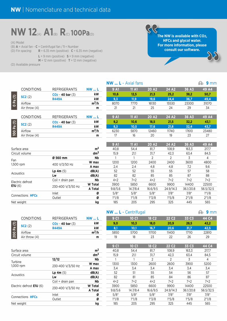
NW | Nomenclature and technical data
NW 12(A) A1(B) R(C) 100Pa(D)
(A) Model(B) A = Axial fan - C = Centrifugal fan / 1 = Number(D) Fin spacing: R = 6.35 mm (positive) C = 6.35 mm (negative)
L = 9 mm (positive) S = 9 mm (negative)M = 12 mm (positive) T = 12 mm (negative)
(D) Available pressure
The NW is available with CO2, HFCs and glycol water.
For more information, please consult our software.
NW ... L - Axial fans 9 mmCONDITIONS REFRIGERANTS NW ... L 9 A1 11 A1 20 A2 24 A2 36 A3 49 A4
0 P
a (1
)
SC2 (2) CO2 - 40 bar (3) kW 10,6 12,5 21,3 25,2 38,2 50,7
R449A kW 9,3 11,9 19,6 24,4 36,7 49,4Airflow m3/h 8070 7770 16130 15530 23300 31070Air throw (4) m 21 21 25 24 29 34
CONDITIONS REFRIGERANTS NW ... L 9 A1 11 A1 20 A2 24 A2 36 A3 49 A4
100
Pa
(1)
SC2 (2) CO2 - 40 bar (3) kW 9,2 10,6 18,5 21,5 32,2 43,1
R449A kW 8,3 10,5 17,6 21,6 32,4 43,7Airflow m3/h 6230 5870 12460 11740 17610 23480Air throw (4) m 17 16 20 19 23 27
9 A1 11 A1 20 A2 24 A2 36 A3 49 A4Surface area m2 40,8 54,4 81,7 108,9 163,3 217,7Circuit volume dm3 15,9 21,1 31,7 42,3 63,4 84,5
Fan1,500 rpm
Ø 560 mm Nb 1 1 2 2 3 4
400 V/3/50 HzW max 1200 1200 2400 2400 3600 4800A max 2,4 2,4 4,8 4,8 7,2 9,6
AcousticsLp 4m (5) dB(A) 52 52 55 55 57 58Lw dB(A) 82 82 85 85 87 88Coil + drain pan Nb 4+2 7+2 4+2 7+2 7+2 7+2
230-400 V/3/50 HzW Total 3900 5850 6600 9900 14400 22500A Total 9.8/5.6 14.7/8.4 16.6/9.5 24.9/14.3 36.1/20.8 56.5/32.5
Connections HFCsInlet Ø 5/8" 5/8" 5/8" 7/8" 7/8" 1"1/8Outlet Ø 1"1/8 1"1/8 1"3/8 1"5/8 2"1/8 2"1/8
Net weight kg 185 205 295 325 445 565
NW ... L - Centrifugal 9 mmCONDITIONS REFRIGERANTS NW ... L 9 C1 10 C1 18 C2 22 C2 33 C3 44 C4
200
Pa
(1)
SC2 (2) CO2 - 40 bar (3) kW 9,0 10,3 18,0 20,9 28,5 42,2
R449A kW 8,1 10,1 16,7 20,6 31,7 42,5Airflow m3/h 5850 5700 11700 11400 17110 22810Air throw (4) m 19 18 23 22 26 29
9 C1 10 C1 18 C2 22 C2 33 C3 44 C4Surface area m2 40,8 54,4 81,7 108,9 163,3 217,7Circuit volume dm3 15,9 21,1 31,7 42,3 63,4 84,5
Turbine1,000 rpm
12/12 Nb 1 1 2 2 3 4
230-400 V/3/50 HzW max 1300 1300 2600 2600 3900 5200A max 3,4 3,4 3,4 3,4 3,4 3,4
AcousticsLp 4m (5) dB(A) 52 51 55 54 56 57Lw dB(A) 82 81 85 84 86 87
Electric defrost E1U (6)Coil + drain pan Nb 4+2 7+2 4+2 7+2 7+2 7+2
230-400 V/3/50 HzW Total 3900 5850 6600 9900 14400 22500A Total 9.8/5.6 14.7/8.4 16.6/9.5 24.9/14.3 36.1/20.8 56.5/32.5
Connections HFCsInlet Ø 5/8" 5/8" 5/8" 7/8" 7/8" 7/8"Outlet Ø 1"1/8 1"1/8 1"3/8 1"5/8 1"5/8 2"1/8
Net weight kg 185 205 295 325 445 565
Electric defrostE1U (6)
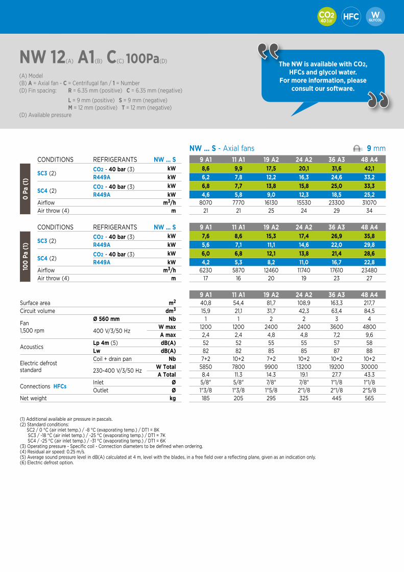
40 bar
NW 12(A) A1(B) C(C) 100Pa(D)
(A) Model(B) A = Axial fan - C = Centrifugal fan / 1 = Number(D) Fin spacing: R = 6.35 mm (positive) C = 6.35 mm (negative)
L = 9 mm (positive) S = 9 mm (negative)M = 12 mm (positive) T = 12 mm (negative)
(D) Available pressure
The NW is available with CO2, HFCs and glycol water.
For more information, please consult our software.
NW ... S - Axial fans 9 mmCONDITIONS REFRIGERANTS NW ... S 9 A1 11 A1 19 A2 24 A2 36 A3 48 A4
0 P
a (1
)
SC3 (2) CO2 - 40 bar (3) kW 8,6 9,9 17,5 20,1 31,6 42,1
R449A kW 6,2 7,8 12,2 16,3 24,6 33,2
SC4 (2) CO2 - 40 bar (3) kW 6,8 7,7 13,8 15,8 25,0 33,3
R449A kW 4,6 5,8 9,0 12,3 18,5 25,2Airflow m3/h 8070 7770 16130 15530 23300 31070Air throw (4) m 21 21 25 24 29 34
CONDITIONS REFRIGERANTS NW ... S 9 A1 11 A1 19 A2 24 A2 36 A3 48 A4
100
Pa
(1) SC3 (2)
CO2 - 40 bar (3) kW 7,6 8,6 15,3 17,4 26,9 35,8
R449A kW 5,6 7,1 11,1 14,6 22,0 29,8
SC4 (2) CO2 - 40 bar (3) kW 6,0 6,8 12,1 13,8 21,4 28,6
R449A kW 4,2 5,3 8,2 11,0 16,7 22,8Airflow m3/h 6230 5870 12460 11740 17610 23480Air throw (4) m 17 16 20 19 23 27
9 A1 11 A1 19 A2 24 A2 36 A3 48 A4Surface area m2 40,8 54,4 81,7 108,9 163,3 217,7Circuit volume dm3 15,9 21,1 31,7 42,3 63,4 84,5
Fan1,500 rpm
Ø 560 mm Nb 1 1 2 2 3 4
400 V/3/50 HzW max 1200 1200 2400 2400 3600 4800A max 2,4 2,4 4,8 4,8 7,2 9,6
AcousticsLp 4m (5) dB(A) 52 52 55 55 57 58Lw dB(A) 82 82 85 85 87 88
Electric defroststandard
Coil + drain pan Nb 7+2 10+2 7+2 10+2 10+2 10+2
230-400 V/3/50 HzW Total 5850 7800 9900 13200 19200 30000A Total 8.4 11.3 14.3 19.1 27.7 43.3
Connections HFCsInlet Ø 5/8" 5/8" 7/8" 7/8" 1"1/8 1"1/8Outlet Ø 1"3/8 1"3/8 1"5/8 2"1/8 2"1/8 2"5/8
Net weight kg 185 205 295 325 445 565
(1) Additional available air pressure in pascals.(2) Standard conditions:
SC2 / 0 °C (air inlet temp.) / -8 °C (evaporating temp.) / DT1 = 8K SC3 / -18 °C (air inlet temp.) / -25 °C (evaporating temp.) / DT1 = 7K SC4 / -25 °C (air inlet temp.) / -31 °C (evaporating temp.) / DT1 = 6K
(3) Operating pressure - Specific coil - Connection diameters to be defined when ordering. (4) Residual air speed: 0.25 m/s.(5) Average sound pressure level in dB(A) calculated at 4 m, level with the blades, in a free field over a reflecting plane, given as an indication only.(6) Electric defrost option.

NW | Nomenclature and technical data
NW 12(A) A1(B) R(C) 100Pa(D)
(A) Model(B) A = Axial fan - C = Centrifugal fan / 1 = Number(D) Fin spacing: R = 6.35 mm (positive) C = 6.35 mm (negative)
L = 9 mm (positive) S = 9 mm (negative)M = 12 mm (positive) T = 12 mm (negative)
(D) Available pressure
The NW is available with CO2, HFCs and glycol water.
For more information, please consult our software.
NW ... M - Axial fans 12 mmCONDITIONS REFRIGERANTS NW ... M 9 A1 11 A1 19 A2 23 A2 34 A3 47 A4
0 P
a (1
)
SC2 (2) CO2 - 40 bar (3) kW 8,5 10,4 17,0 20,9 29,8 41,9
R449A kW 8,4 10,5 17,2 21,5 32,3 43,7Airflow m3/h 8230 7950 16460 15900 23840 31790Air throw (4) m 22 21 26 25 30 34
CONDITIONS REFRIGERANTS NW ... M 9 A1 11 A1 19 A2 23 A2 34 A3 47 A4
100
Pa
(1)
SC2 (2) CO2 - 40 bar (3) kW 7,5 9,0 15,0 18,1 26,2 36,3
R449A kW 7,5 9,3 15,4 19,1 28,6 38,6Airflow m3/h 6420 6080 12850 12170 18250 24340Air throw (4) m 17 17 21 20 24 27
9 A1 11 A1 19 A2 23 A2 34 A3 47 A4Surface area m2 31,7 42,3 63,4 84,5 126,8 169,0Circuit volume dm3 15,9 21,1 31,7 42,3 63,4 84,5
Fan1,500 rpm
Ø 560 mm Nb 1 1 2 2 3 4
400 V/3/50 HzW max 1200 1200 2400 2400 3600 4800A max 2,4 2,4 4,8 4,8 7,2 9,6
AcousticsLp 4m (5) dB(A) 52 52 55 55 57 58Lw dB(A) 82 82 85 85 87 88Coil + drain pan Nb 4+2 7+2 4+2 7+2 7+2 7+2
230-400 V/3/50 HzW Total 3900 5850 6600 9900 14400 22500A Total 9.8/5.6 14.7/8.4 16.6/9.5 24.9/14.3 36.1/20.8 56.5/32.5
Connections HFCsInlet Ø 5/8" 5/8" 5/8" 7/8" 7/8" 1"1/8Outlet Ø 1"1/8 1"1/8 1"3/8 1"5/8 1"5/8 2"1/8
Net weight kg 185 200 290 320 435 555
NW ... M - Centrifugal 12 mmCONDITIONS REFRIGERANTS NW ... M 8 C1 10 C1 17 C2 21 C2 31 C3 42 C4
200
Pa
(1)
SC2 (2) CO2 - 40 bar (3) kW 7,2 8,7 13,3 17,6 24,8 35,3
R449A kW 7,0 8,7 14,3 17,8 27,5 36,9Airflow m3/h 5900 5770 11800 11530 17300 23070Air throw (4) m 19 19 23 23 26 30
8 C1 10 C1 17 C2 21 C2 31 C3 42 C4Surface area m2 31,7 42,3 63,4 84,5 126,8 169,0Circuit volume dm3 15,9 21,1 31,7 42,3 63,4 84,5
Turbine1,000 rpm
12/12 Nb 1 1 2 2 3 4
230-400 V/3/50 HzW max 1300 1300 2600 2600 3900 5200A max 3,4 3,4 3,4 3,4 3,4 3,4
AcousticsLp 4m (5) dB(A) 52 52 55 55 56 57Lw dB(A) 82 82 85 85 86 87
Electric defrost E1U (6)
Coil + drain pan Nb 4+2 7+2 4+2 7+2 7+2 7+2
230-400 V/3/50 HzW Total 3900 5850 6600 9900 14400 22500A Total 9.8/5.6 14.7/8.4 16.6/9.5 24.9/14.3 36.1/20.8 56.5/32.5
Connections HFCsInlet Ø 5/8" 5/8" 5/8" 7/8" 7/8" 7/8"Outlet Ø 1"1/8 1"1/8 1"3/8 1"3/8 1"5/8 2"1/8
Net weight kg 185 200 290 320 435 555
Electric defrostE1U (6)
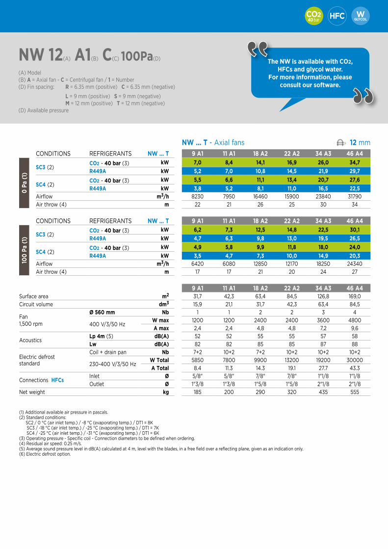
40 bar
NW 12(A) A1(B) C(C) 100Pa(D)
(A) Model(B) A = Axial fan - C = Centrifugal fan / 1 = Number(D) Fin spacing: R = 6.35 mm (positive) C = 6.35 mm (negative)
L = 9 mm (positive) S = 9 mm (negative)M = 12 mm (positive) T = 12 mm (negative)
(D) Available pressure
The NW is available with CO2, HFCs and glycol water.
For more information, please consult our software.
NW ... T - Axial fans 12 mm
CONDITIONS REFRIGERANTS NW ... T 9 A1 11 A1 18 A2 22 A2 34 A3 46 A4
0 P
a (1
)
SC3 (2) CO2 - 40 bar (3) kW 7,0 8,4 14,1 16,9 26,0 34,7
R449A kW 5,2 7,0 10,8 14,5 21,9 29,7
SC4 (2) CO2 - 40 bar (3) kW 5,5 6,6 11,1 13,4 20,7 27,6
R449A kW 3,8 5,2 8,1 11,0 16,5 22,5Airflow m3/h 8230 7950 16460 15900 23840 31790
Air throw (4) m 22 21 26 25 30 34
CONDITIONS REFRIGERANTS NW ... T 9 A1 11 A1 18 A2 22 A2 34 A3 46 A4
100
Pa
(1) SC3 (2)
CO2 - 40 bar (3) kW 6,2 7,3 12,5 14,8 22,5 30,1
R449A kW 4,7 6,3 9,8 13,0 19,5 26,5
SC4 (2) CO2 - 40 bar (3) kW 4,9 5,8 9,9 11,8 18,0 24,0
R449A kW 3,5 4,7 7,3 10,0 14,9 20,3Airflow m3/h 6420 6080 12850 12170 18250 24340
Air throw (4) m 17 17 21 20 24 27
9 A1 11 A1 18 A2 22 A2 34 A3 46 A4Surface area m2 31,7 42,3 63,4 84,5 126,8 169,0
Circuit volume dm3 15,9 21,1 31,7 42,3 63,4 84,5
Fan1,500 rpm
Ø 560 mm Nb 1 1 2 2 3 4
400 V/3/50 HzW max 1200 1200 2400 2400 3600 4800
A max 2,4 2,4 4,8 4,8 7,2 9,6
AcousticsLp 4m (5) dB(A) 52 52 55 55 57 58
Lw dB(A) 82 82 85 85 87 88
Electric defroststandard
Coil + drain pan Nb 7+2 10+2 7+2 10+2 10+2 10+2
230-400 V/3/50 HzW Total 5850 7800 9900 13200 19200 30000
A Total 8.4 11.3 14.3 19.1 27.7 43.3
Connections HFCsInlet Ø 5/8" 5/8" 7/8" 7/8" 1"1/8 1"1/8
Outlet Ø 1"3/8 1"3/8 1"5/8 1"5/8 2"1/8 2"1/8
Net weight kg 185 200 290 320 435 555
(1) Additional available air pressure in pascals.(2) Standard conditions:
SC2 / 0 °C (air inlet temp.) / -8 °C (evaporating temp.) / DT1 = 8K SC3 / -18 °C (air inlet temp.) / -25 °C (evaporating temp.) / DT1 = 7K SC4 / -25 °C (air inlet temp.) / -31 °C (evaporating temp.) / DT1 = 6K
(3) Operating pressure - Specific coil - Connection diameters to be defined when ordering. (4) Residual air speed: 0.25 m/s.(5) Average sound pressure level in dB(A) calculated at 4 m, level with the blades, in a free field over a reflecting plane, given as an indication only.(6) Electric defrost option.
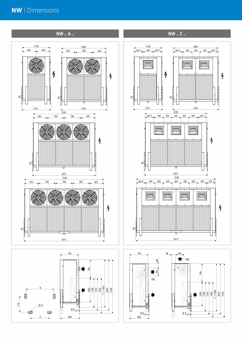
NW | Dimensions
NW .. A .. NW .. C ..
5651130
565
1215
1830565 565700
19152530
2615
565 565700 700
3230
3315
565 565700 700 700
367. 5 3951130
367. 5
1215
1830367.5 395 367. 5305 395
19152530
2615
367.5 395 367. 5305 395395 305
3230
3315
367.5 395 367. 5305 395 305 395 305 395
B
718
A
Ø 15
2070
2190
805
755
Ø D
C =
1950
1430
1310
1190
1020
760
H2
805
755
342
88
Ø D
H4
34288
Ø D
2070
2190
C =
1950
1430
1310
1190
1020
760

35 - 130 kW
40 bar
NFUnit cooler for blast freezing and rapid cooling tunnel Industrial range

INSTALLATION | MAINTENANCE
# Because of the height, the NF is delivered in 2 parts: - an assembly comprising coil, frame, drain pan and heaters, - a motor fan assembly.# Drain pan tilted towards the large drain pipe (Ø 1 1/2" G) to avoid dirt accumulation and
facilitate cleaning.
VENTILATION
# Ventilation assembly delivered separately, to be positioned above the coil.
# Motor fans Ø 710 mm, 230-400V/3/50Hz, IP 55, class F.
OPTIONS
ECB Wooden crate packaging.
NF | Industrial unit cooler for blast freezing tunnel
# High speed air circulation ensures very rapid cooling of foodstuffs.
# Large exchange surface for optimal energy efficiency.
DEFROST
# Drain pan under the exchanger assembly.# Electric defrost.
OPTIONS
DAE Water defrost (spraying).
THE PRINCIPLE OF A BLAST
FREEZING AND RAPID COOLING
TUNNEL
COILS
# Embossed aluminium fins with 9 mm spacing.
# Combined with staggered copper tubes, the coils are very efficient and compact.
# Versions available: - Multi refrigerants HFCs
- CO2 (40 bar) - WCO (glycol water, coolant)
94
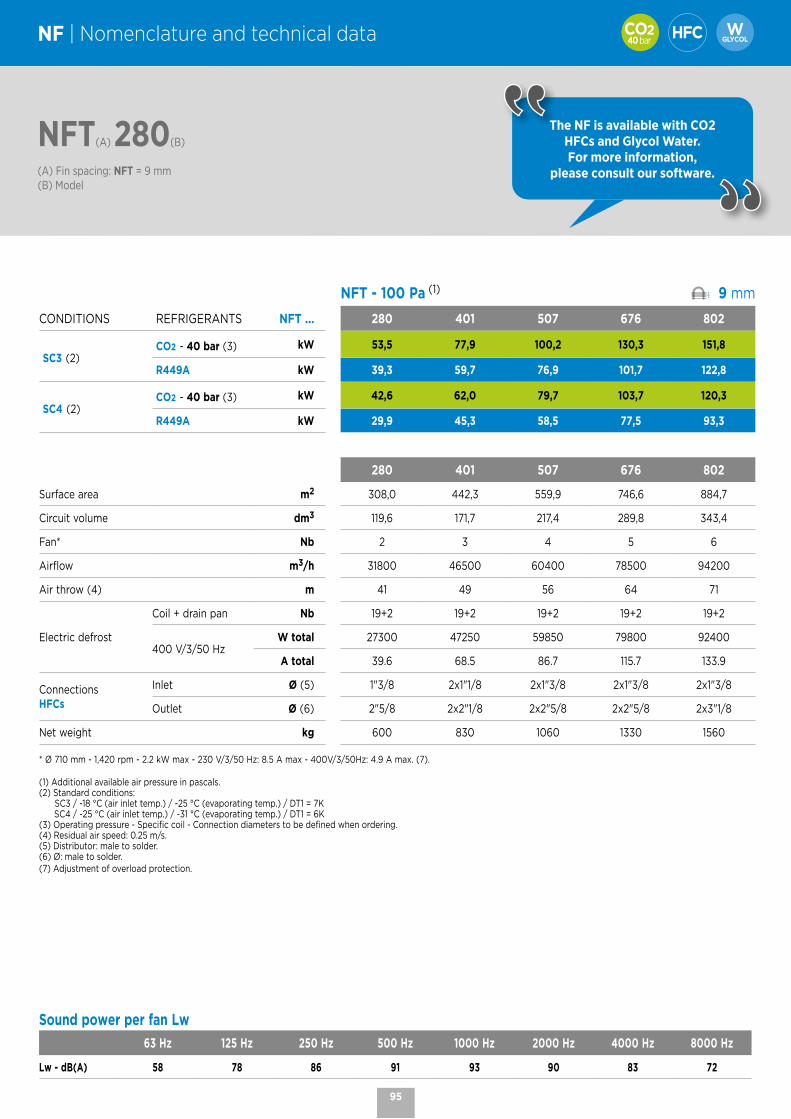
40 bar
NFT(A) 280(B)
(A) Fin spacing: NFT = 9 mm(B) Model
The NF is available with CO2HFCs and Glycol Water. For more information,
please consult our software.
NF | Nomenclature and technical data
NFT - 100 Pa (1) 9 mm
CONDITIONS REFRIGERANTS NFT ... 280 401 507 676 802
SC3 (2) CO2 - 40 bar (3) kW 53,5 77,9 100,2 130,3 151,8
R449A kW 39,3 59,7 76,9 101,7 122,8
SC4 (2) CO2 - 40 bar (3) kW 42,6 62,0 79,7 103,7 120,3
R449A kW 29,9 45,3 58,5 77,5 93,3
280 401 507 676 802
Surface area m2 308,0 442,3 559,9 746,6 884,7
Circuit volume dm3 119,6 171,7 217,4 289,8 343,4
Fan* Nb 2 3 4 5 6
Airflow m3/h 31800 46500 60400 78500 94200
Air throw (4) m 41 49 56 64 71
Electric defrost
Coil + drain pan Nb 19+2 19+2 19+2 19+2 19+2
400 V/3/50 HzW total 27300 47250 59850 79800 92400
A total 39.6 68.5 86.7 115.7 133.9
Connections HFCs
Inlet Ø (5) 1"3/8 2x1"1/8 2x1"3/8 2x1"3/8 2x1"3/8
Outlet Ø (6) 2"5/8 2x2"1/8 2x2"5/8 2x2"5/8 2x3"1/8
Net weight kg 600 830 1060 1330 1560
* Ø 710 mm - 1,420 rpm - 2.2 kW max - 230 V/3/50 Hz: 8.5 A max - 400V/3/50Hz: 4.9 A max. (7).
(1) Additional available air pressure in pascals.(2) Standard conditions: SC3 / -18 °C (air inlet temp.) / -25 °C (evaporating temp.) / DT1 = 7K SC4 / -25 °C (air inlet temp.) / -31 °C (evaporating temp.) / DT1 = 6K(3) Operating pressure - Specific coil - Connection diameters to be defined when ordering.(4) Residual air speed: 0.25 m/s.(5) Distributor: male to solder.(6) Ø: male to solder.(7) Adjustment of overload protection.
Sound power per fan Lw
63 Hz 125 Hz 250 Hz 500 Hz 1000 Hz 2000 Hz 4000 Hz 8000 Hz
Lw - dB(A) 58 78 86 91 93 90 83 72
95
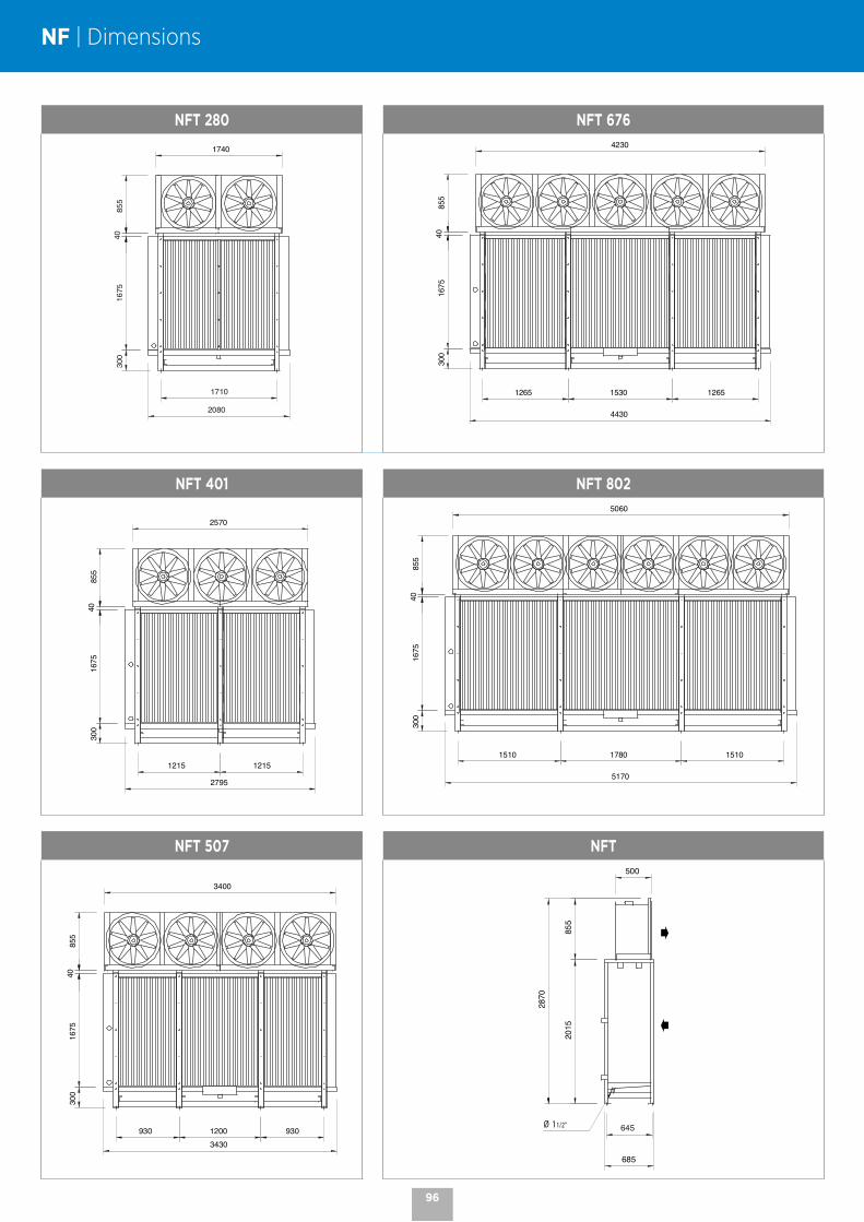
NF | Dimensions
NFT 280 NFT 676
NFT 401 NFT 802
NFT 507 NFT
Ø 11/2”
96

5 - 95 kW
NCCentrifugal unit cooler Industrial range

COILS
# Aluminium fins with 4.23 or 6.35 mm spacing.# Combined with copper tubes, the coils are very efficient and compact. # Versions available:
- Multi-refrigerant HFCs. - CO2 (50 bar). - WCO (glycol water, coolant).
OPTIONS
HGT Hot gases (coil and drain pan).
NC | Industrial centrifugal unit cooler
CASING
# Robust, made of white pre-painted galvanized sheet steel.# Limited condensation: presence of an exterior drain pan
and an aluminium intermediate drain pan.
OPTIONS
IPH Noise insulation (M1*).
FLA Suction filters (M1*).
CFA Suction filter box (M1*).
ECB Wooden crate packaging.
* M1: Non-flammable.
# With many options available, the NC adapts to the needs of your application as closely as possible.
# Adaptable, you can choose to install the NC on the floor or ceiling, depending on the requirements of the environment, thanks to its 4 modular blowing positions.
# Easy maintenance with easy access to all components.
PRODUCT ADVANTAGES
# Can be installed on the floor or ceiling.# 4 blowing positions (H1 to H4) can be selected; can be easily changed at a later date.
H1
H2
H3
H4
Select your coil treatment to extend your unit cooler's lifespan!
Contact us.
98
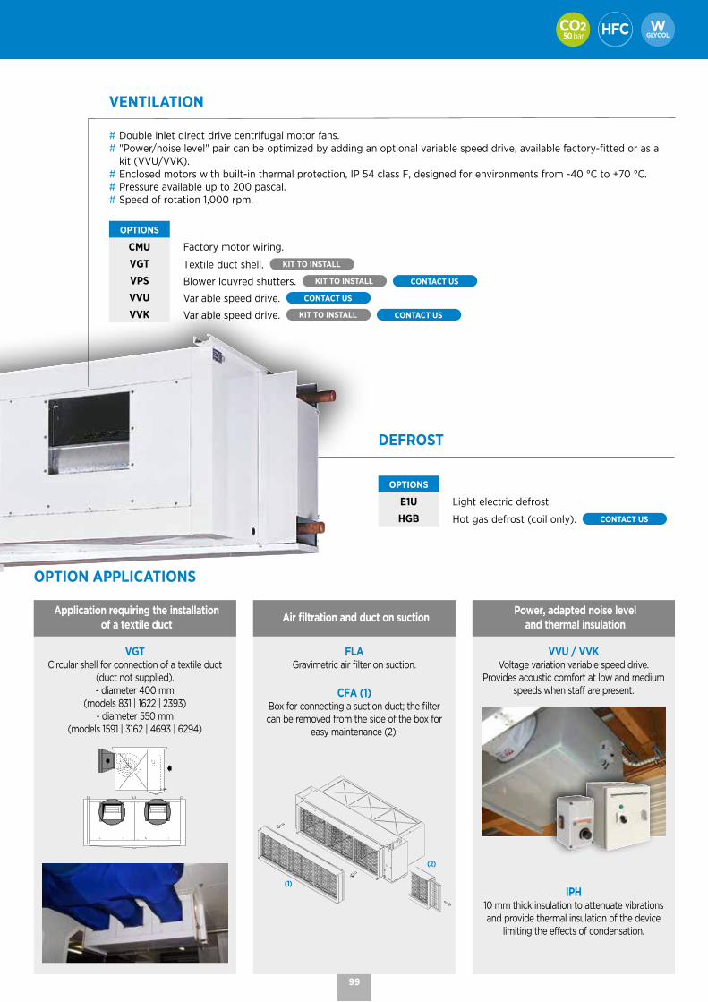
DEFROST
OPTIONS
E1U Light electric defrost.
HGB Hot gas defrost (coil only). CONTACT US
OPTION APPLICATIONS
Application requiring the installation of a textile duct
Air filtration and duct on suctionPower, adapted noise level
and thermal insulation
VGT Circular shell for connection of a textile duct
(duct not supplied). - diameter 400 mm
(models 831 | 1622 | 2393)- diameter 550 mm
(models 1591 | 3162 | 4693 | 6294)
FLAGravimetric air filter on suction.
CFA (1) Box for connecting a suction duct; the filter can be removed from the side of the box for
easy maintenance (2).
(1)
(2)
VVU / VVKVoltage variation variable speed drive.
Provides acoustic comfort at low and medium speeds when staff are present.
IPH10 mm thick insulation to attenuate vibrations and provide thermal insulation of the device
limiting the effects of condensation.
VENTILATION
# Double inlet direct drive centrifugal motor fans.# "Power/noise level" pair can be optimized by adding an optional variable speed drive, available factory-fitted or as a
kit (VVU/VVK).# Enclosed motors with built-in thermal protection, IP 54 class F, designed for environments from -40 °C to +70 °C.# Pressure available up to 200 pascal.# Speed of rotation 1,000 rpm.
OPTIONS
CMU Factory motor wiring.
VGT Textile duct shell. KIT TO INSTALL
VPS Blower louvred shutters. KIT TO INSTALL CONTACT US
VVU Variable speed drive. CONTACT US
VVK Variable speed drive. KIT TO INSTALL CONTACT US
99

NCP(A) 831(B) H3(C)
(A) Fin spacing: NCP = 4.23 mm (positive) NCN = 6.35 mm (negative)(B) Model(C) Air direction
NC | Nomenclature and technical data
The NC is available with CO2, HFCs and glycol water.
For more information, please consult our software.
NCP 4,23 mm
CONDITIONS REFRIGERANTS NCP ... 831 1622 1591 2393 3162 4693 6294
100
Pa
(1)
SC1 (2) CO2 - 50 bar (3) kW 12,1 23,6 23,4 35,2 44,1 68,9 88,1
R449A kW 11,6 22,3 22,3 32,8 45,0 66,9 87,7
SC2 (2) CO2 - 50 bar (3) kW 8,2 16,2 16,0 24,2 29,7 47,3 59,6
R449A kW 7,5 14,6 15,1 21,5 29,7 43,9 59,2
Airflow m3/h 3200 6310 6680 9420 13270 19870 26460
AcousticsLp 4 m (4) dB(A) 44 47 55 49 58 59 61
Lw dB(A) 74 77 85 79 88 89 91
CONDITIONS REFRIGERANTS NCP ... 831 1622 1591 2393 3162 4693 6294
150
Pa
(1)
SC1 (2) CO2 - 50 bar (3) kW 10,8 21,2 22,5 31,5 42,5 66,1 84,8
R449A kW 10,2 19,8 21,5 29,1 42,6 64,1 84,4
SC2 (2) CO2 - 50 bar (3) kW 7,4 14,6 15,4 21,8 28,7 45,5 57,4
R449A kW 6,7 12,9 14,6 19,0 28,5 42,3 57,0
Airflow m3/h 2740 5400 6280 8060 12460 18640 24820
AcousticsLp 4 m (4) dB(A) 42 45 53 46 56 58 59
Lw dB(A) 72 75 83 76 86 88 89
CONDITIONS REFRIGERANTS NCP ... 831 1622 1591 2393 3162 4693 6294
200
Pa
(1)
SC1 (2) CO2 - 50 bar (3) kW - - 21,2 - 40,2 62,2 80,1
R449A kW - - 20,3 - 40,3 60,2 79,8
SC2 (2) CO2 - 50 bar (3) kW - - 14,5 - 27,2 42,8 54,4
R449A kW - - 13,8 - 26,9 39,9 53,7
Airflow m3/h - - 5740 - 11380 17000 22630
AcousticsLp 4 m (4) dB(A) - - 51 - 54 56 57
Lw dB(A) - - 81 - 84 86 87
NCP ... 831 1622 1591 2393 3162 4693 6294
Surface area m2 47,0 86,6 75,2 126,2 142,0 208,8 275,6
Circuit volume dm3 9,1 16,8 14,5 24,4 27,5 40,4 53,3
Turbine
Nb 1 2 1 3 2 3 4
230V/1/50 HzW 670 1340 - 2010 - - -
A max (5) 2,9 5,8 - 8,7 - - -
230-400V/3/50 HzW - - 1300 - 2600 3900 5200
A max (5) - - 3,4 - 6,8 10,2 13,6
ConnectionsInlet Ø 5/8" 5/8" 7/8" 7/8" 7/8" 1"1/8 1"1/8
Outlet Ø 7/8" 1"1/8 1"1/8 1"3/8 1"3/8 1"5/8 2"1/8
Net weight kg 88 151 118 200 241 305 463
(1) Additional available air pressure in pascals.(2) Standard conditions: SC1 / +10 °C (air inlet temp.) / 0 °C (evaporating temp.) / DT1 = 10K SC2 / 0 °C (air inlet temp.) / -8 °C (evaporating temp.) / DT1 = 8K(3) Operating pressure - Specific coil - Connection diameters to be defined when ordering. (4) Average sound pressure level in dB(A) calculated at 4 m, level with the turbines, in a free field over a reflecting plane, given as an indication only.(5) Adjustment of overload protection. For air temperatures "ti" other than +20 °C, multiply the intensities by the ratio 293/(273 + "ti")to obtain the approximate value of the intensity after the room has been brought up to temperature.
100
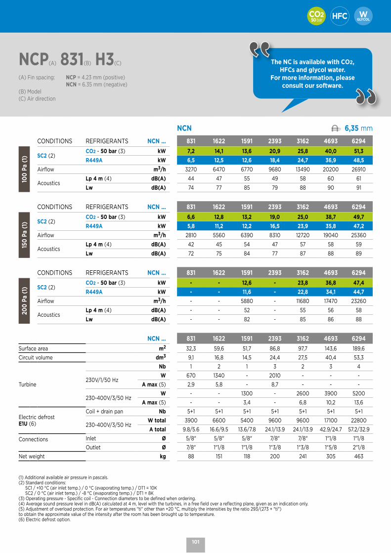
NCP(A) 831(B) H3(C)
(A) Fin spacing: NCP = 4.23 mm (positive) NCN = 6.35 mm (negative)(B) Model(C) Air direction
The NC is available with CO2, HFCs and glycol water.
For more information, please consult our software.
NCN 6,35 mm
CONDITIONS REFRIGERANTS NCN ... 831 1622 1591 2393 3162 4693 6294
100
Pa
(1) SC2 (2)
CO2 - 50 bar (3) kW 7,2 14,1 13,6 20,9 25,8 40,0 51,3
R449A kW 6,5 12,5 12,6 18,4 24,7 36,9 48,5
Airflow m3/h 3270 6470 6770 9680 13490 20200 26910
AcousticsLp 4 m (4) dB(A) 44 47 55 49 58 60 61
Lw dB(A) 74 77 85 79 88 90 91
CONDITIONS REFRIGERANTS NCN ... 831 1622 1591 2393 3162 4693 6294
150
Pa
(1) SC2 (2)
CO2 - 50 bar (3) kW 6,6 12,8 13,2 19,0 25,0 38,7 49,7
R449A kW 5,8 11,2 12,2 16,5 23,9 35,8 47,2
Airflow m3/h 2810 5560 6390 8310 12720 19040 25360
AcousticsLp 4 m (4) dB(A) 42 45 54 47 57 58 59
Lw dB(A) 72 75 84 77 87 88 89
CONDITIONS REFRIGERANTS NCN ... 831 1622 1591 2393 3162 4693 6294
200
Pa
(1) SC2 (2)
CO2 - 50 bar (3) kW - - 12,6 - 23,8 36,8 47,4
R449A kW - - 11,6 - 22,8 34,1 44,7
Airflow m3/h - - 5880 - 11680 17470 23260
AcousticsLp 4 m (4) dB(A) - - 52 - 55 56 58
Lw dB(A) - - 82 - 85 86 88
NCN ... 831 1622 1591 2393 3162 4693 6294
Surface area m2 32,3 59,6 51,7 86,8 97,7 143,6 189,6
Circuit volume dm3 9,1 16,8 14,5 24,4 27,5 40,4 53,3
Turbine
Nb 1 2 1 3 2 3 4
230V/1/50 HzW 670 1340 - 2010 - - -
A max (5) 2,9 5,8 - 8,7 - - -
230-400V/3/50 HzW - - 1300 - 2600 3900 5200
A max (5) - - 3,4 - 6,8 10,2 13,6
Electric defrostE1U (6)
Coil + drain pan Nb 5+1 5+1 5+1 5+1 5+1 5+1 5+1
230-400V/3/50 HzW total 3900 6600 5400 9600 9600 17100 22800
A total 9.8/5.6 16.6/9.5 13.6/7.8 24.1/13.9 24.1/13.9 42.9/24.7 57.2/32.9
Connections Inlet Ø 5/8" 5/8" 5/8" 7/8" 7/8" 1"1/8 1"1/8
Outlet Ø 7/8" 1"1/8 1"1/8 1"3/8 1"3/8 1"5/8 2"1/8
Net weight kg 88 151 118 200 241 305 463
(1) Additional available air pressure in pascals.(2) Standard conditions: SC1 / +10 °C (air inlet temp.) / 0 °C (evaporating temp.) / DT1 = 10K SC2 / 0 °C (air inlet temp.) / -8 °C (evaporating temp.) / DT1 = 8K(3) Operating pressure - Specific coil - Connection diameters to be defined when ordering. (4) Average sound pressure level in dB(A) calculated at 4 m, level with the turbines, in a free field over a reflecting plane, given as an indication only.(5) Adjustment of overload protection. For air temperatures "ti" other than +20 °C, multiply the intensities by the ratio 293/(273 + "ti")to obtain the approximate value of the intensity after the room has been brought up to temperature.(6) Electric defrost option.
101

NC | Dimensions
NC
X
YY
F GE Ø 16
B
Ø R
20
CD
1075
1115
20
A
30
995
831 1622 1591 2393 3162 4693 6294A mm 760 760 870 765 875 880 880
B mm 1170 1810 1490 2450 2450 3410 4370
C mm 290 290 342 290 342 342 342
D mm 152 152 197 152 197 197 197
E mm 234 234 363 234 363 363 363
F mm 331 331 395 331 395 395 395
G mm - 306 - 306 564 564 564
X mm 790 1430 1110 2070 2070 3030 3990
Y mm - - - - - - 1995
Ø R mm 1” 1” 1” 1"1/2 1"1/2 1"1/2 1"1/2
NC | Blower positions
H1
H2
H3
H4
102

2.8 - 12.4 kW
MAAxial fan condenser Commercial range
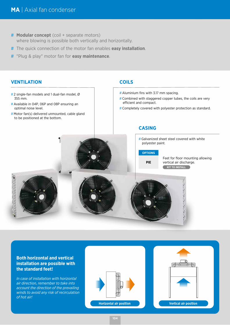
COILS
# Aluminium fins with 3.17 mm spacing.
# Combined with staggered copper tubes, the coils are very efficient and compact.
# Completely covered with polyester protection as standard.
MA | Axial fan condenser
CASING
# Galvanized sheet steel covered with white polyester paint.
OPTIONS
PIEFeet for floor mounting allowing vertical air discharge.
KIT TO INSTALL
# Modular concept (coil + separate motors) where blowing is possible both vertically and horizontally.
# The quick connection of the motor fan enables easy installation.
# "Plug & play" motor fan for easy maintenance.
VENTILATION
# 2 single-fan models and 1 dual-fan model, Ø 355 mm.
# Available in 04P, 06P and 08P ensuring an optimal noise level.
# Motor fan(s) delivered unmounted, cable gland to be positioned at the bottom.
Both horizontal and vertical installation are possible with the standard feet!
In case of installation with horizontal air direction, remember to take into account the direction of the prevailing winds to avoid any risk of recirculation of hot air!
Horizontal air position Vertical air position
104
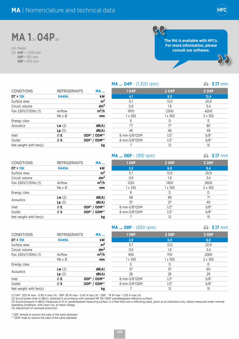
CASING
# Galvanized sheet steel covered with white polyester paint.
OPTIONS
PIEFeet for floor mounting allowing vertical air discharge.
KIT TO INSTALL
The MA is available with HFCs. For more information, please
consult our software.
MA 1(A) 04P(B)
(A) Model(B) 04P = 1,300 rpm 06P = 910 rpm 08P = 650 rpm
MA | Nomenclature and technical data
MA ... 04P - (1,300 rpm) 3.17 mm
CONDITIONS REFRIGERANTS sMA ... 1 04P 2 04P 3 04PDT = 15K R449A kW 4,1 8,0 12,4Surface area m2 5,7 13,0 20,9Circuit volume dm3 0,9 1,9 3,4Fan 230V/1/50Hz (1) Airflow m3/h 1970 2300 4200
Nb x Ø mm 1 x 355 1 x 355 2 x 355Energy class E D EAcoustics Lw (2) dB(A) 77 77 80
Lp (3) dB(A) 46 46 49Inlet Ø E ODF* / ODM** 8 mm-3/8"ODM 1/2" 5/8"Outlet Ø S ODF* / ODM** 8 mm-3/8"ODM 1/2" 5/8"Net weight with fan(s) kg 7 12 15
1 04P 2 04P 3 04PMA ... 06P - (910 rpm) 3.17 mm
CONDITIONS REFRIGERANTS sMA ... 1 06P 2 06P 3 06PDT = 15K R449A kW 3,2 6,0 9,4Surface area m2 5,7 13,0 20,9Circuit volume dm3 0,9 1,9 3,4Fan 230V/1/50Hz (1) Airflow m3/h 1220 1450 2650
Nb x Ø mm 1 x 355 1 x 355 2 x 355Energy class E D D
AcousticsLw (2) dB(A) 68 68 71Lp (3) dB(A) 37 37 40
Inlet Ø E ODF* / ODM** 8 mm-3/8"ODM 1/2" 5/8"Outlet Ø S ODF* / ODM** 8 mm-3/8"ODM 1/2" 5/8"Net weight with fan(s) kg 7 12 15
1 04P 2 04P 3 04PMA ... 08P - (650 rpm) 3.17 mm
CONDITIONS REFRIGERANTS sMA ... 1 08P 2 08P 3 08PDT = 15K R449A kW 2,9 5,0 8,0Surface area m2 5,7 13,0 20,9Circuit volume dm3 0,9 1,9 3,4Fan 230V/1/50Hz (1) Airflow m3/h 950 1110 2060
Nb x Ø mm 1 x 355 1 x 355 2 x 355Energy class E D D
AcousticsLw (2) dB(A) 57 57 60Lp (3) dB(A) 26 26 29
Inlet Ø E ODF* / ODM** 8 mm-3/8"ODM 1/2" 5/8"Outlet Ø S ODF* / ODM** 8 mm-3/8"ODM 1/2" 5/8"Net weight with fan(s) kg 7 12 15
(1) 04P : 205 W max - 0.90 A max (4) - 06P: 95 W max - 0.45 A max (4) - 08P: 74 W max - 0.35 A max (4)(2) Sound power level in dB(A), obtained in accordance with standard NF EN 13487 (parallelepiped reference surface).(3) Sound pressure in dB(A) measured at 10 m, parallelepiped measuring surface, in a free field over a reflecting plane, given as an indication only. Values measured under nominal operating conditions, with clean coil, at rated voltage.(4) Adjustment of overload protection.
* ODF: female to receive the tube of the same diameter. ** ODM: male to receive the tube of the same diameter.
105

MA | Dimensions
MA 1 MA 1 - 2 - 3
9 94221139
29 440
21Ø S
9
272
B
A
118156
415,
5
18, 54017, 5 40 40
Ø E
F F
F - F
G G
G - G
440,
5
295
9
32, 531, 54 6 46
Ø 8
420
40
==9, 5
12,5
MA 2
99 7021839
7
22 720
72
Ø S
MA 3
99 1122
397
24 1140
18
74
Ø S
MA 1 ... MA 2 ... MA 3 ...
A mm 125 122 122
B mm 34 15 15
Packing mm 570 x 430 x 185 880 x 430 x 185 1280 x 460 x 185
Fan package mm 460 x 460 x 185 (x1) 460 x 460 x 185 (x1) 460 x 460 x 185 (x2)
106
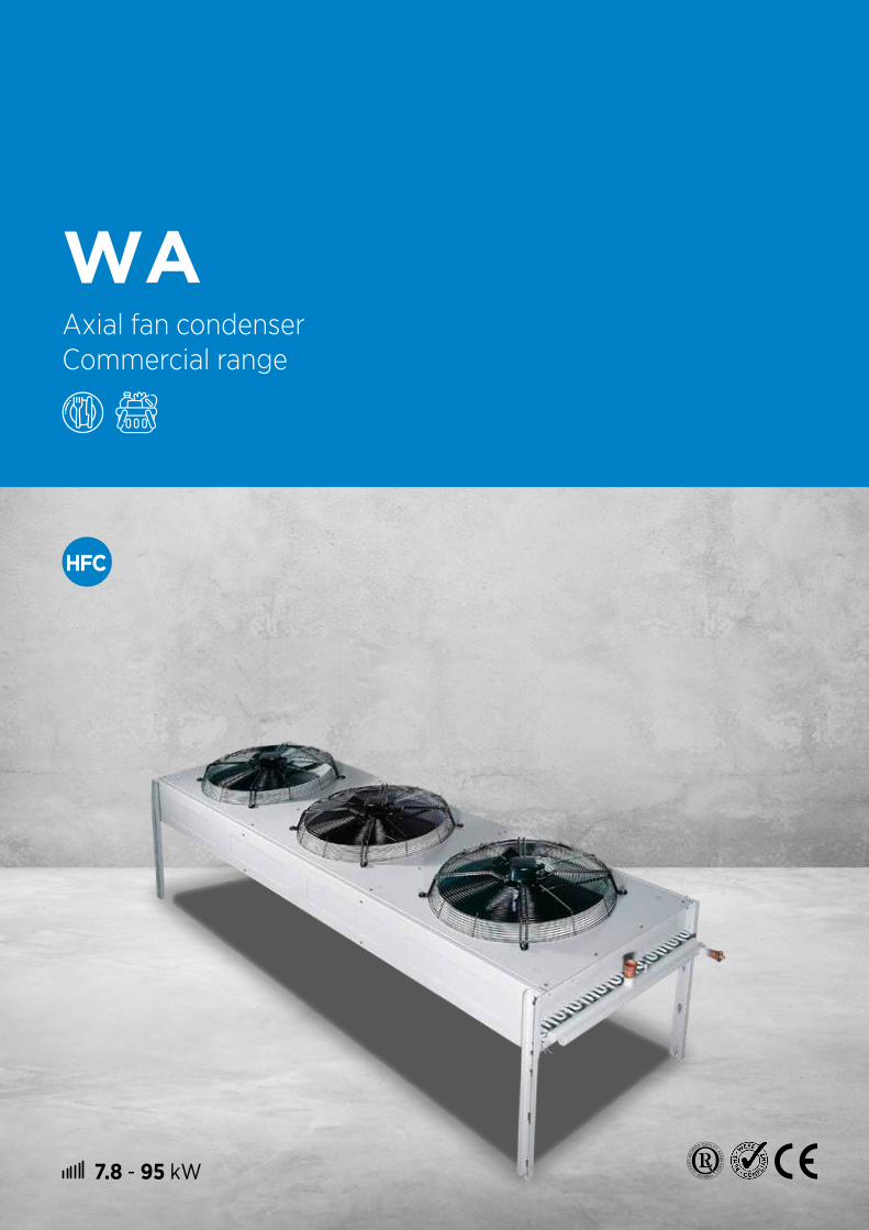
7.8 - 95 kW
WAAxial fan condenser Commercial range
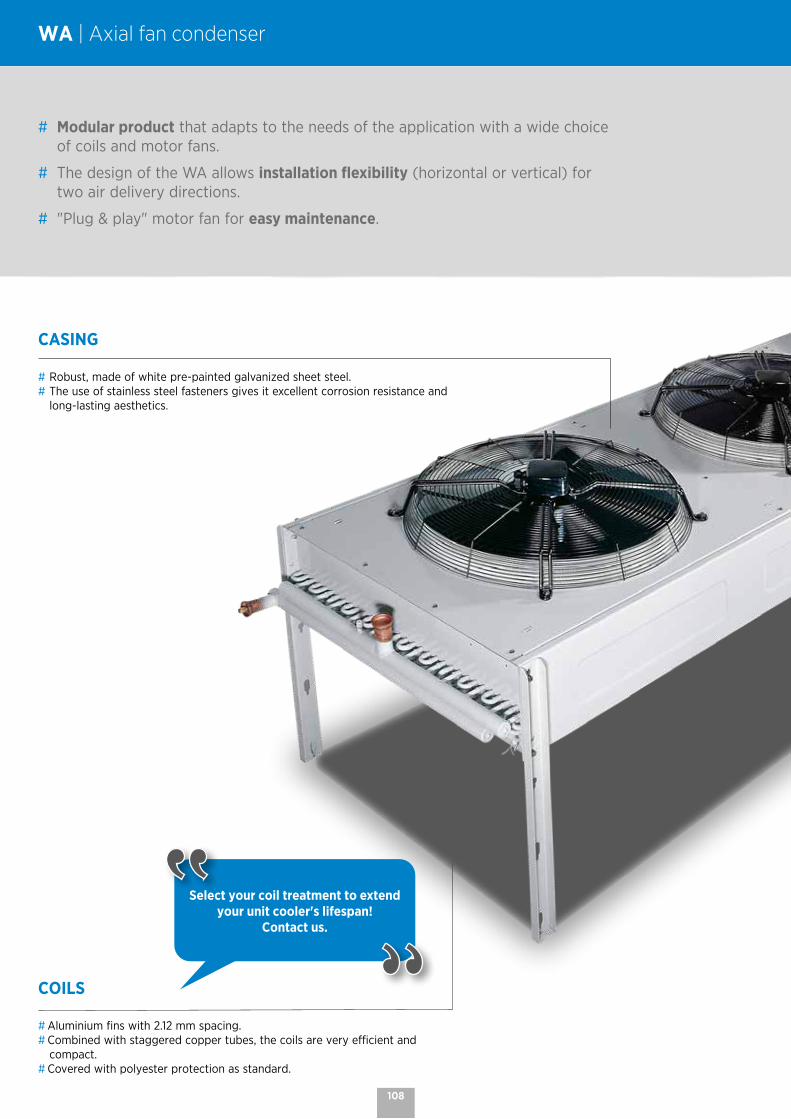
COILS
# Aluminium fins with 2.12 mm spacing.# Combined with staggered copper tubes, the coils are very efficient and
compact.# Covered with polyester protection as standard.
CASING
# Robust, made of white pre-painted galvanized sheet steel.# The use of stainless steel fasteners gives it excellent corrosion resistance and
long-lasting aesthetics.
WA | Axial fan condenser
# Modular product that adapts to the needs of the application with a wide choice of coils and motor fans.
# The design of the WA allows installation flexibility (horizontal or vertical) for two air delivery directions.
# "Plug & play" motor fan for easy maintenance.
Select your coil treatment to extend your unit cooler's lifespan!
Contact us.
108

VENTILATION
# Axial motor fans with external rotor requiring no specific maintenance: Ø 500 mm, 2 speeds: - 04/06P = 1,500/1,000 rpm - 08/12P = 750/500 rpm Ø 630 mm, 2 speeds: - 04/06P = 1,500/1,000 rpm - 06/08P = 1,000/750 rpm - 08/12P = 750/500 rpm - 16P = 375 rpm
400V, three-phase, 50Hz, monoblock, with external rotor, with built-in thermal protector, IP 54, class F.
# High efficiency, low noise profiled blades.# 2-speed motor connection:
= high speed, Y = low speed.# "Plug & play" motor fans for easy maintenance.
OPTIONS
IRP Rotary proximity switch(es).
M60 Motor fan 400V/3/60Hz (Ø 630 mm).
MM5 Motor fan 230V/1/50Hz - 04P - 06P - 08P.
M24* Motor fan 230V/3/50-60Hz - 08/12P.
* Motor fans not held in stock.
Both horizontal and vertical installation are possible with the standard feet!
In case of installation with horizontal air direction, remember to take into account the direction of the prevailing winds to avoid any risk of hot air recirculation!
Coils and motor fans can be supplied separately. Horizontal air position Vertical air position
109
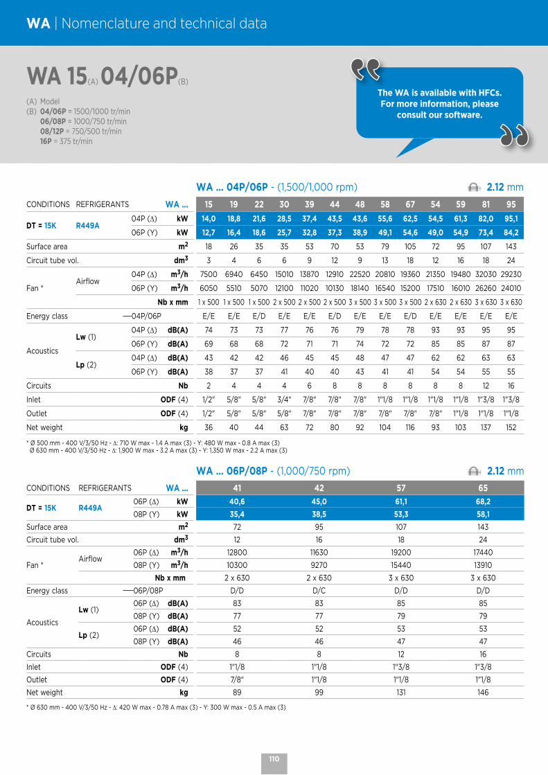
WA 15(A) 04/06P(B)
(A) Model(B) 04/06P = 1500/1000 tr/min 06/08P = 1000/750 tr/min 08/12P = 750/500 tr/min 16P = 375 tr/min
WA | Nomenclature and technical data
WA .. WA ... 04P/06P - (1,500/1,000 rpm) 2.12 mm
CONDITIONS REFRIGERANTS WA ... 15 19 22 30 39 44 48 58 67 54 59 81 95
DT = 15K R449A04P (∆) kW 14,0 18,8 21,6 28,5 37,4 43,5 43,6 55,6 62,5 54,5 61,3 82,0 95,1
06P (Y) kW 12,7 16,4 18,6 25,7 32,8 37,3 38,9 49,1 54,6 49,0 54,9 73,4 84,2
Surface area m2 18 26 35 35 53 70 53 79 105 72 95 107 143
Circuit tube vol. dm3 3 4 6 6 9 12 9 13 18 12 16 18 24
Fan *Airflow
04P (∆) m3/h 7500 6940 6450 15010 13870 12910 22520 20810 19360 21350 19480 32030 29230
06P (Y) m3/h 6050 5510 5070 12100 11020 10130 18140 16540 15200 17510 16010 26260 24010
Nb x mm 1 x 500 1 x 500 1 x 500 2 x 500 2 x 500 2 x 500 3 x 500 3 x 500 3 x 500 2 x 630 2 x 630 3 x 630 3 x 630
Energy class 04P/06P E/E E/E E/D E/E E/E E/D E/E E/E E/D E/E E/E E/E E/E
Acoustics
Lw (1)04P (∆) dB(A) 74 73 73 77 76 76 79 78 78 93 93 95 95
06P (Y) dB(A) 69 68 68 72 71 71 74 72 72 85 85 87 87
Lp (2)04P (∆) dB(A) 43 42 42 46 45 45 48 47 47 62 62 63 63
06P (Y) dB(A) 38 37 37 41 40 40 43 41 41 54 54 55 55
Circuits Nb 2 4 4 4 6 8 8 8 8 8 8 12 16
Inlet ODF (4) 1/2" 5/8" 5/8" 3/4" 7/8" 7/8" 7/8" 1"1/8 1"1/8 1"1/8 1"1/8 1"3/8 1"3/8
Outlet ODF (4) 1/2" 5/8" 5/8" 5/8" 7/8" 7/8" 7/8" 7/8" 7/8" 7/8" 1"1/8 1"1/8 1"1/8
Net weight kg 36 40 44 63 72 80 92 104 116 93 103 137 152
* Ø 500 mm - 400 V/3/50 Hz - ∆: 710 W max - 1.4 A max (3) - Y: 480 W max - 0.8 A max (3) Ø 630 mm - 400 V/3/50 Hz - ∆: 1,900 W max - 3.2 A max (3) - Y: 1,350 W max - 2.2 A max (3)
WA .. WA ... 06P/08P - (1,000/750 rpm) 2.12 mm
CONDITIONS REFRIGERANTS WA ... 41 42 57 65
DT = 15K R449A06P (∆) kW 40,6 45,0 61,1 68,2
08P (Y) kW 35,4 38,5 53,3 58,1
Surface area m2 72 95 107 143
Circuit tube vol. dm3 12 16 18 24
Fan *Airflow
06P (∆) m3/h 12800 11630 19200 17440
08P (Y) m3/h 10300 9270 15440 13910
Nb x mm 2 x 630 2 x 630 3 x 630 3 x 630
Energy class 06P/08P D/D D/C D/D D/D
Acoustics
Lw (1)06P (∆) dB(A) 83 83 85 85
08P (Y) dB(A) 77 77 79 79
Lp (2)06P (∆) dB(A) 52 52 53 53
08P (Y) dB(A) 46 46 47 47
Circuits Nb 8 8 12 16
Inlet ODF (4) 1"1/8 1"1/8 1"3/8 1"3/8
Outlet ODF (4) 7/8" 1"1/8 1"1/8 1"1/8
Net weight kg 89 99 131 146
* Ø 630 mm - 400 V/3/50 Hz - ∆: 420 W max - 0.78 A max (3) - Y: 300 W max - 0.5 A max (3)
The WA is available with HFCs. For more information, please
consult our software.
110

WA 10(A) 08/12P(B)
(A) Model(B) 04/06P = 1500/1000 tr/min 06/08P = 1000/750 tr/min 08/12P = 750/500 tr/min 16P = 375 tr/min
WA .. WA ... 08P/12P - (750/500 rpm) 2.12 mm
CONDITIONS REFRIGERANTS WA ... 10 13 14 21 26 27 32 37 40 34 36 47 51
DT = 15K R449A08P (∆) kW 8,9 10,9 11,9 18,1 22,0 24,1 27,1 32,9 35,9 35,1 38,8 52,9 58,7
12P (Y) kW 7,9 9,4 10,2 15,9 19,0 20,3 23,8 28,6 30,5 28,8 30,7 43,3 46,0
Surface area m2 18 26 35 35 53 70 53 79 105 72 95 107 143
Circuit tube vol. dm3 3 4 6 6 9 12 9 13 18 12 16 18 24
Fan *Airflow
08P (∆) m3/h 3230 2940 2710 6460 5880 5420 9690 8820 8130 10170 9400 15250 14100
12P (Y) m3/h 2620 2390 2180 5250 4780 4360 7880 7170 6550 7540 6800 11300 10200
Nb x mm 1 x 500 1 x 500 1 x 500 2 x 500 2 x 500 2 x 500 3 x 500 3 x 500 3 x 500 2 x 630 2 x 630 3 x 630 3 x 630
Energy class08P/12P C/C C/B C/B C/C C/B C/B C/C C/B C/B C/C C/C C/C C/C
12P (Y) C B B C B B C B B C C C C
Acoustics
Lw (1)08P (∆) dB(A) 66 66 66 69 69 69 71 71 71 67 67 69 69
12P (Y) dB(A) 58 58 58 61 61 61 63 63 63 60 60 62 62
Lp (2)08P (∆) dB(A) 35 35 35 38 38 38 40 40 40 36 36 37 37
12P (Y) dB(A) 27 27 27 30 30 30 32 32 32 29 29 30 30
Circuits Nb 2 4 4 4 6 8 8 8 8 8 8 12 16
Inlet ODF (4) 1/2" 5/8" 5/8" 3/4" 7/8" 7/8" 7/8" 1"1/8 1"1/8 1"1/8 1"1/8 1"3/8 1"3/8
Outlet ODF (4) 1/2" 5/8" 5/8" 5/8" 7/8" 7/8" 7/8" 7/8" 7/8" 7/8" 1"1/8 1"1/8 1"1/8
Net weight kg 36 40 44 63 72 80 92 104 116 89 99 131 146
* Ø 500 mm - 400 V/3/ 50-60 Hz - ∆: 120 W max - 0.35 A max (3) - Y: 80 W max - 0.16 A max (3) Ø 630 mm - 400 V/3/50-60 Hz - ∆: 235 W max - 0.55 A max (3) - Y: 140 W max - 0.27 A max (3)
WA .. WA ... 16P - (375 rpm) 2.12 mm
CONDITIONS REFRIGERANTS WA ... 23 24 28 29
DT = 15K R449A 16P (Y) kW 21,5 22,6 32,4 33,8
Surface area m2 72 95 107 143
Circuit tube vol. dm3 12 16 18 24
Fan *Airflow 16P (Y) m3/h 5000 4560 7500 6840
Nb x mm 2 x 630 2 x 630 3 x 630 3 x 630
Energy class 16P B B B B
AcousticsLw (1) 16P (Y) dB(A) 57 57 59 59
Lp (2) 16P (Y) dB(A) 26 26 27 27
Circuits Nb 8 8 12 16
Inlet ODF (4) 1"1/8 1"1/8 1"3/8 1"3/8
Outlet ODF (4) 7/8" 1"1/8 1"1/8 1"1/8
Net weight kg 89 99 131 146
* Ø 630 mm - 400 V/3/50-60 Hz - Y: 90 W max - 0.2 A max (3)
(1) Sound power level in dB(A), obtained in accordance with standard NF EN 13487 (parallelepiped reference surface).(2) Sound pressure in dB(A) measured at 10 m, parallelepiped measuring surface, in a free field over a reflecting plane, given as an indication only. Values measured under nominal operating conditions, with clean coil, at rated voltage.(3) Adjustment of overload protection.(4) ODF = Female to receive the tube of the same diameter
The WA is available with HFCs. For more information, please
consult our software.
111
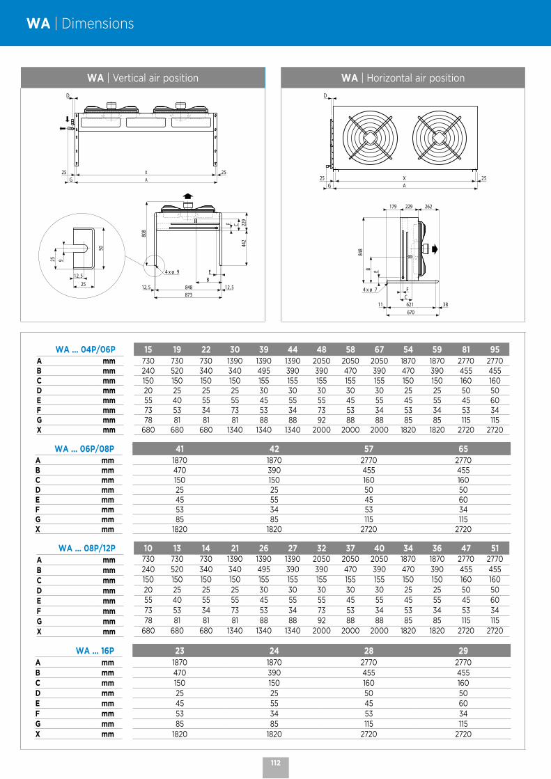
WA | Dimensions
WA | Vertical air position WA | Horizontal air position
25 25G
D
A
X
12, 5 12, 5848873
808
4 x ø 9
F C44
2
BE
229
12, 525
25 9
50
25 25XAG
D
67011 38621
848
4 x ø 7 FC
B E
229 262179
WA ... 04P/06P 15 19 22 30 39 44 48 58 67 54 59 81 95A mm 730 730 730 1390 1390 1390 2050 2050 2050 1870 1870 2770 2770B mm 240 520 340 340 495 390 390 470 390 470 390 455 455C mm 150 150 150 150 155 155 155 155 155 150 150 160 160D mm 20 25 25 25 30 30 30 30 30 25 25 50 50E mm 55 40 55 55 45 55 55 45 55 45 55 45 60F mm 73 53 34 73 53 34 73 53 34 53 34 53 34G mm 78 81 81 81 88 88 92 88 88 85 85 115 115X mm 680 680 680 1340 1340 1340 2000 2000 2000 1820 1820 2720 2720
WA ... 06P/08P 41 42 57 65A mm 1870 1870 2770 2770B mm 470 390 455 455C mm 150 150 160 160D mm 25 25 50 50E mm 45 55 45 60F mm 53 34 53 34G mm 85 85 115 115X mm 1820 1820 2720 2720
WA ... 08P/12P 10 13 14 21 26 27 32 37 40 34 36 47 51A mm 730 730 730 1390 1390 1390 2050 2050 2050 1870 1870 2770 2770
B mm 240 520 340 340 495 390 390 470 390 470 390 455 455C mm 150 150 150 150 155 155 155 155 155 150 150 160 160D mm 20 25 25 25 30 30 30 30 30 25 25 50 50E mm 55 40 55 55 45 55 55 45 55 45 55 45 60F mm 73 53 34 73 53 34 73 53 34 53 34 53 34G mm 78 81 81 81 88 88 92 88 88 85 85 115 115X mm 680 680 680 1340 1340 1340 2000 2000 2000 1820 1820 2720 2720
WA ... 16P 23 24 28 29A mm 1870 1870 2770 2770B mm 470 390 455 455C mm 150 150 160 160D mm 25 25 50 50E mm 45 55 45 60F mm 53 34 53 34G mm 85 85 115 115X mm 1820 1820 2720 2720
112
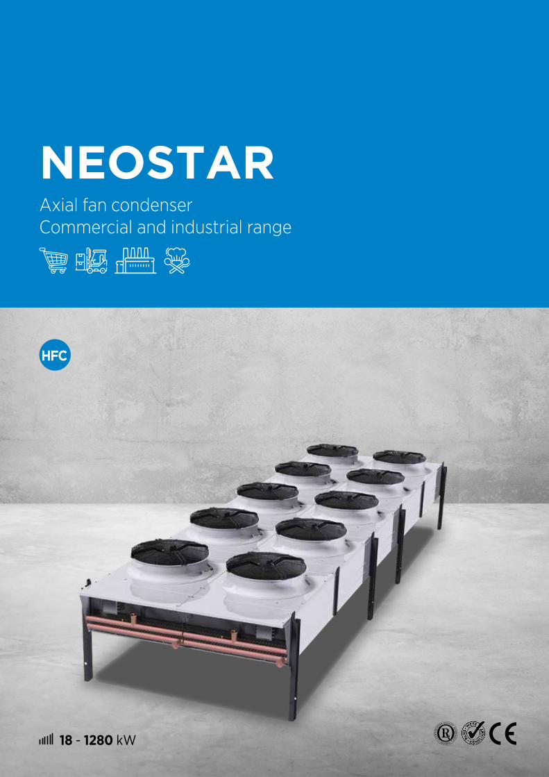
18 - 1280 kW
NEOSTARAxial fan condenser Commercial and industrial range
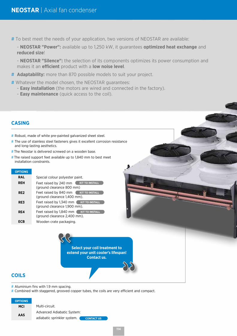
COILS
# Aluminium fins with 1.9 mm spacing.# Combined with staggered, grooved copper tubes, the coils are very efficient and compact.
OPTIONS
MCI Multi-circuit.
AASAdvanced Adiabatic System:
adiabatic sprinkler system. CONTACT US
CASING
# Robust, made of white pre-painted galvanized sheet steel.
# The use of stainless steel fasteners gives it excellent corrosion resistance and long-lasting aesthetics.
# The Neostar is delivered screwed on a wooden base.
# The raised support feet available up to 1,840 mm to best meet installation constraints.
OPTIONS
RAL Special colour polyester paint.
REH Feet raised by 240 mm KIT TO INSTALL (ground clearance 800 mm)
RE2 Feet raised by 840 mm KIT TO INSTALL (ground clearance 1,400 mm).
RE3 Feet raised by 1,340 mm KIT TO INSTALL (ground clearance 1,900 mm).
RE4 Feet raised by 1,840 mm KIT TO INSTALL (ground clearance 2,400 mm).
ECB Wooden crate packaging.
NEOSTAR | Axial fan condenser
# To best meet the needs of your application, two versions of NEOSTAR are available:
- NEOSTAR "Power": available up to 1,250 kW, it guarantees optimized heat exchange and reduced size!
- NEOSTAR "Silence": the selection of its components optimizes its power consumption and makes it an efficient product with a low noise level.
# Adaptability: more than 870 possible models to suit your project.
# Whatever the model chosen, the NEOSTAR guarantees: - Easy installation (the motors are wired and connected in the factory). - Easy maintenance (quick access to the coil).
Select your coil treatment to extend your unit cooler's lifespan!
Contact us.
114
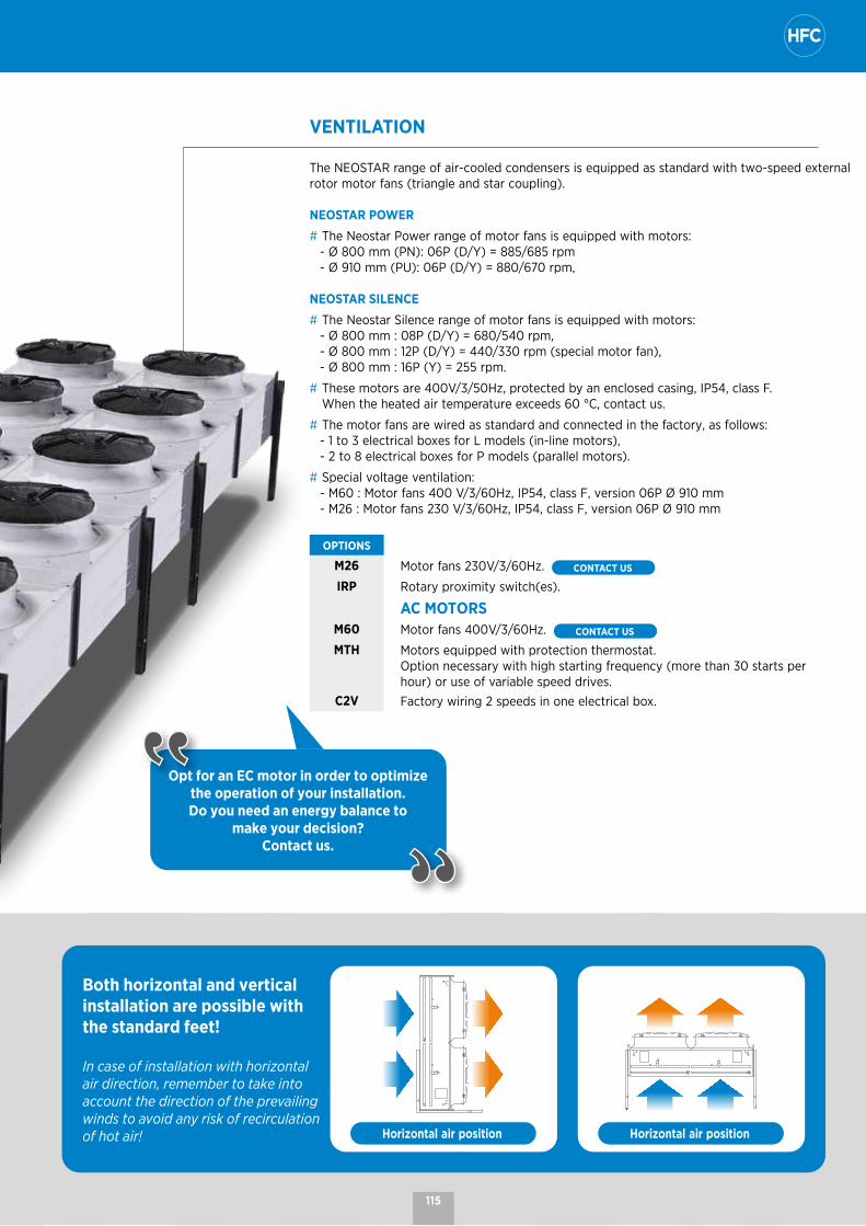
VENTILATION
The NEOSTAR range of air-cooled condensers is equipped as standard with two-speed external rotor motor fans (triangle and star coupling).
NEOSTAR POWER
# The Neostar Power range of motor fans is equipped with motors: - Ø 800 mm (PN): 06P (D/Y) = 885/685 rpm - Ø 910 mm (PU): 06P (D/Y) = 880/670 rpm,
NEOSTAR SILENCE
# The Neostar Silence range of motor fans is equipped with motors: - Ø 800 mm : 08P (D/Y) = 680/540 rpm, - Ø 800 mm : 12P (D/Y) = 440/330 rpm (special motor fan), - Ø 800 mm : 16P (Y) = 255 rpm.
# These motors are 400V/3/50Hz, protected by an enclosed casing, IP54, class F. When the heated air temperature exceeds 60 °C, contact us.
# The motor fans are wired as standard and connected in the factory, as follows: - 1 to 3 electrical boxes for L models (in-line motors), - 2 to 8 electrical boxes for P models (parallel motors).
# Special voltage ventilation: - M60 : Motor fans 400 V/3/60Hz, IP54, class F, version 06P Ø 910 mm - M26 : Motor fans 230 V/3/60Hz, IP54, class F, version 06P Ø 910 mm
OPTIONS
M26 Motor fans 230V/3/60Hz. CONTACT US
IRP Rotary proximity switch(es).
AC MOTORSM60 Motor fans 400V/3/60Hz. CONTACT US
MTH Motors equipped with protection thermostat. Option necessary with high starting frequency (more than 30 starts per hour) or use of variable speed drives.
C2V Factory wiring 2 speeds in one electrical box.
Both horizontal and vertical installation are possible with the standard feet!
In case of installation with horizontal air direction, remember to take into account the direction of the prevailing winds to avoid any risk of recirculation of hot air! Horizontal air position Horizontal air position
Opt for an EC motor in order to optimize the operation of your installation. Do you need an energy balance to
make your decision? Contact us.
115

NEOSTAR | AC and EC motors
TECHNICAL DETAILS OF OPTIONS ON AC MOTORS
AC MOTORpossible options
WIR
ING
AN
D B
OX Power
Standard: Power wiring on terminals (no protection option integrated into this option).
SCU Without motor wiring (note that no regulation is possible with this option).
Protection
CMPMotor protection box IP54, including one circuit breaker per motor, a fault summary and a main switch. Possibility of floor mounting support kit (MSK).
MSK Floor support for cabinets above H = 800 x W = 1,000
REG
ULA
TIO
N
Simple cascade on/off
RP1 (including CMP)
Pressure regulation in cascade in an IP54 enclosure allowing different regulation stages to be managed:
From 1 to 4 regulation stages > possibility of managing 2 circuits. From 4 to 10 regulation stages
• Configuration of day/night operation possible. • Integrated clock.
1 or 2 pressure sensors depending on the number of separate circuits present.
Advanced control by
variation
RP3 (including CMP)
Variable frequency drive
An IP54 ventilated control cabinet with a variable frequency drive including its fuse protection. A pressure sensor to manage a circuit.
TECHNICAL DETAILS OF OPTIONS ON EC MOTORS
EC MOTORpossible options
WIR
ING
AN
D B
OX
Power
Standard:Power wiring on terminals. The power, fault, bus and control wiring is carried out.
SCM Without motor wiring.
CCEPower wiring in IP54 box and protection by stage included (in L for each fan and in P for 2 fans). The power, fault, bus and control wiring is carried out.
REG
ULA
TIO
N
Simple
SE1 *Direct control of the motors by customer 0-10 V signal: only one circuit possible (contact us in case of multiple circuits, or 4-20 mA control signal).
SE2Automatic speed control by pressure (setpoint can only be changed via a computer): pressure sensor included. Only one circuit possible.
Advanced control
CE4Automatic speed control by pressure (setpoint can be changed via the PLC) / 1 circuit:a pressure sensor and a single circuit possible (contact us in case of multiple circuits).
CE5Automatic speed control by pressure (setpoint can be changed via the PLC) / 2 circuits: 2 pressure sensors and 2 separate circuits possible (contact us in case of multiple circuits).
CE6Automatic speed control by pressure (setpoint can be changed via the PLC) / signal comparison: 2 pressure sensors and signal comparison (contact us in case of multiple circuits).
ADDITIONAL FUNCTIONS
VMAMaximum speed setting (configuration done on each fan, via a computer).Only with standard or CCE.
MJNPossibility of setting a maximum night speed (clock by signal 0/10). Only with SE1 or CE4.
* Default option if no customer choice. 116
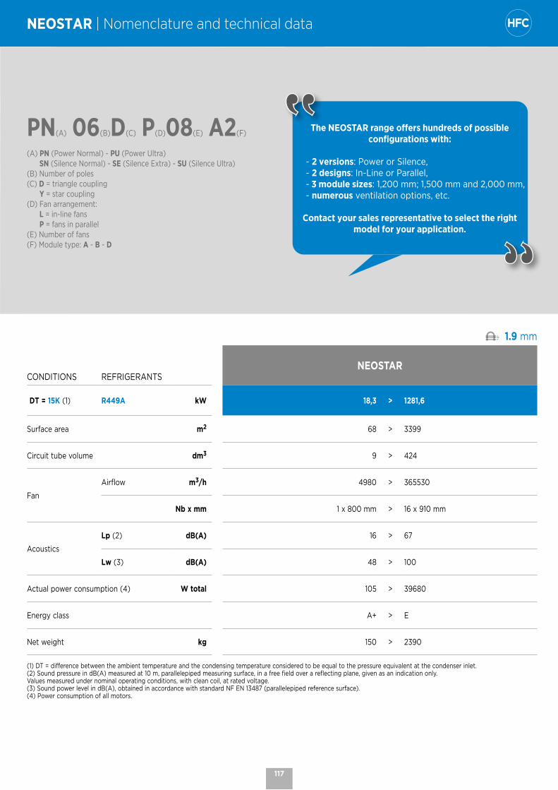
PN(A) 06(B)D(C) P(D)08(E) A2(F)
(A) PN (Power Normal) - PU (Power Ultra) SN (Silence Normal) - SE (Silence Extra) - SU (Silence Ultra)
(B) Number of poles(C) D = triangle coupling Y = star coupling(D) Fan arrangement:
L = in-line fans P = fans in parallel(E) Number of fans(F) Module type: A - B - D
NEOSTAR | Nomenclature and technical data
The NEOSTAR range offers hundreds of possible configurations with:
- 2 versions: Power or Silence,- 2 designs: In-Line or Parallel,- 3 module sizes: 1,200 mm; 1,500 mm and 2,000 mm,- numerous ventilation options, etc.
Contact your sales representative to select the right model for your application.
WA .. 1.9 mm
CONDITIONS REFRIGERANTSNEOSTAR
DT = 15K (1) R449A kW 18,3 > 1281,6
Surface area m2 68 > 3399
Circuit tube volume dm3 9 > 424
Fan
Airflow m3/h 4980 > 365530
Nb x mm 1 x 800 mm > 16 x 910 mm
Acoustics
Lp (2) dB(A) 16 > 67
Lw (3) dB(A) 48 > 100
Actual power consumption (4) W total 105 > 39680
Energy class A+ > E
Net weight kg 150 > 2390
(1) DT = difference between the ambient temperature and the condensing temperature considered to be equal to the pressure equivalent at the condenser inlet. (2) Sound pressure in dB(A) measured at 10 m, parallelepiped measuring surface, in a free field over a reflecting plane, given as an indication only. Values measured under nominal operating conditions, with clean coil, at rated voltage.(3) Sound power level in dB(A), obtained in accordance with standard NF EN 13487 (parallelepiped reference surface).(4) Power consumption of all motors.
117

NOTES

130 - 1670 kW
MXWAxial fan condenser Commercial and industrial range

COILS
# Aluminium microchannel coils, offering reliability and sturdiness.# Lightweight, they allow a significant reduction in the quantity of refrigerant and the weight of the condenser.# Intensive quality control to minimize the risk of leakage.
OPTIONS
MCI Multi-circuit..
MXW | Axial fan condenser
CASING
# Galvanized sheet steel covered with white polyester paint.# State-of-the-art aesthetics and reduced height (< 2 m)
for harmonious integration on the site.
OPTIONS
ACR SilenTop (photo 1).
G2F Side protection grilles (2 sides).
PAV Anti-vibration pads.
CON Packaging for container
# A range designed for installations where space may be a problem.
# High performance density ensuring optimized energy consumption.
# Microchannel technology allowing a significant reduction in refrigerant charge.
# State of the art aesthetics for harmonious integration on the site.
REGULATION AND PROTECTION CASING
OPTIONS
CMP Motor protection cabinet.
RP2 CMP + condensation pressure regulation by speed variation (voltage).
RP3 CMP + condensation pressure regulation by speed variation (frequency).
CSC Signal comparators (multi-circuit configuration).
1
120
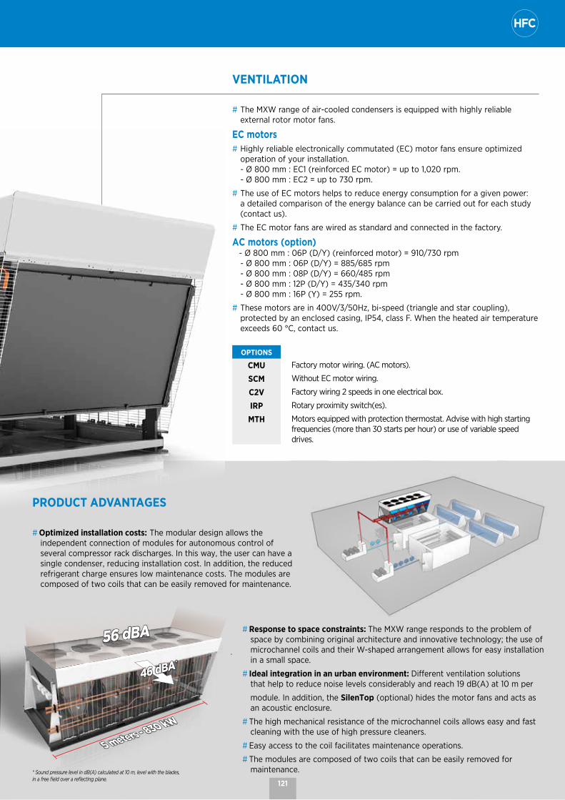
VENTILATION
# The MXW range of air-cooled condensers is equipped with highly reliable external rotor motor fans.
EC motors# Highly reliable electronically commutated (EC) motor fans ensure optimized
operation of your installation. - Ø 800 mm : EC1 (reinforced EC motor) = up to 1,020 rpm. - Ø 800 mm : EC2 = up to 730 rpm.
# The use of EC motors helps to reduce energy consumption for a given power: a detailed comparison of the energy balance can be carried out for each study (contact us).
# The EC motor fans are wired as standard and connected in the factory.
AC motors (option) - Ø 800 mm : 06P (D/Y) (reinforced motor) = 910/730 rpm
- Ø 800 mm : 06P (D/Y) = 885/685 rpm - Ø 800 mm : 08P (D/Y) = 660/485 rpm - Ø 800 mm : 12P (D/Y) = 435/340 rpm - Ø 800 mm : 16P (Y) = 255 rpm.
# These motors are in 400V/3/50Hz, bi-speed (triangle and star coupling), protected by an enclosed casing, IP54, class F. When the heated air temperature exceeds 60 °C, contact us.
OPTIONS
CMU Factory motor wiring. (AC motors).
SCM Without EC motor wiring.
C2V Factory wiring 2 speeds in one electrical box.
IRP Rotary proximity switch(es).
MTH Motors equipped with protection thermostat. Advise with high starting frequencies (more than 30 starts per hour) or use of variable speed drives.
PRODUCT ADVANTAGES
# Optimized installation costs: The modular design allows the independent connection of modules for autonomous control of several compressor rack discharges. In this way, the user can have a single condenser, reducing installation cost. In addition, the reduced refrigerant charge ensures low maintenance costs. The modules are composed of two coils that can be easily removed for maintenance.
56 dBA56 dBA
5 meters - 830 kW
5 meters - 830 kW
46 dBA46 dBA * *
# Response to space constraints: The MXW range responds to the problem of space by combining original architecture and innovative technology; the use of microchannel coils and their W-shaped arrangement allows for easy installation in a small space.
# Ideal integration in an urban environment: Different ventilation solutions that help to reduce noise levels considerably and reach 19 dB(A) at 10 m per
module. In addition, the SilenTop (optional) hides the motor fans and acts as an acoustic enclosure.
# The high mechanical resistance of the microchannel coils allows easy and fast cleaning with the use of high pressure cleaners.
# Easy access to the coil facilitates maintenance operations.
# The modules are composed of two coils that can be easily removed for maintenance.* Sound pressure level in dB(A) calculated at 10 m, level with the blades,
in a free field over a reflecting plane.121

MXW EC1(A) 8(D) P04(E)
MXW 06(B) D(C) 8(D) P04(E)
(A) EC motors: EC1 (reinforced EC motor) = up to 1,020 rpm. - EC2 = up to 730 rpm.(B) AC motors: Number of poles(C) AC motors: D = triangle coupling - Y = star coupling(D) Fan diameter(E) Number of fans
MXW | Nomenclature and technical data
The MXW is available with HFCs. For more information,
please consult our software.
MXW EC1 | Reinforced EC motor Microchannels
CONDITIONS REFRIGERANTS MXW EC1 ... 8P04 8P06 8P08 8P10 8P12 8P14 8P16 8P18 8P20
1020
rpm
DT = 15K (1) R449A kW 358,5 537,8 717,0 896,2 1075,5 1254,8 1434,1 1613,3 1792,5
Power consumption kW 8,49 12,74 16,98 21,23 25,48 29,72 33,97 38,21 42,46
Airflow m3/h 93360 140040 186720 233400 280080 326760 373440 420120 466800
Energy class D D D D D D D D D
AcousticsLw (2) dB(A) 95 97 98 99 100 100 101 102 102
Lp (3) dB(A) 63 65 66 67 68 67 68 69 69
CONDITIONS REFRIGERANTS MXW EC1 ... 8P04 8P06 8P08 8P10 8P12 8P14 8P16 8P18 8P20
800
rpm
DT = 15K (1) R449A kW 310,3 465,4 620,6 775,7 930,8 1086,0 1241,1 1396,3 1551,4
Power consumption kW 4,26 6,39 8,52 10,65 12,78 14,91 17,04 19,17 21,30
Airflow m3/h 71880 107820 143770 179710 215650 251590 287530 323470 359420
Energy class D D D D D D D D D
AcousticsLw (2) dB(A) 89 91 92 93 94 94 95 96 96
Lp (3) dB(A) 57 59 60 61 62 61 62 63 63
CONDITIONS REFRIGERANTS MXW EC1 ... 8P04 8P06 8P08 8P10 8P12 8P14 8P16 8P18 8P20
500
rpm
DT = 15K (1) R449A kW 203,2 304,8 406,4 508,0 609,6 711,2 812,8 914,4 1016,0
Power consumption kW 1,16 1,74 2,32 2,90 3,48 4,06 4,64 5,22 5,80
Airflow m3/h 41380 62070 82760 103450 124140 144830 165520 186210 206900
Energy class B B B B B B B B B
AcousticsLw (2) dB(A) 73 75 76 77 78 78 79 80 80
Lp (3) dB(A) 41 43 44 45 46 45 46 47 47
CONDITIONS REFRIGERANTS MXW EC1 ... 8P04 8P06 8P08 8P10 8P12 8P14 8P16 8P18 8P20
400
rpm
DT = 15K (1) R449A kW 171,8 257,7 343,6 429,5 515,4 601,3 687,2 773,1 858,9
Power consumption kW 0,65 0,98 1,30 1,63 1,95 2,28 2,60 2,93 3,25
Airflow m3/h 31740 47610 63470 79340 95210 111080 126950 142820 158680
Energy class A+ A+ A+ A+ A+ A+ A+ A+ A+
AcousticsLw (2) dB(A) 66 68 69 70 71 71 72 73 73
Lp (3) dB(A) 34 36 37 38 39 38 39 40 40
CONDITIONS REFRIGERANTS MXW EC1 ... 8P04 8P06 8P08 8P10 8P12 8P14 8P16 8P18 8P20
200
rpm
DT = 15K (1) R449A kW 136,5 204,7 272,9 341,1 409,3 477,6 545,8 614,0 682,2
Power consumption kW 0,17 0,26 0,34 0,43 0,52 0,60 0,69 0,77 0,86
Airflow m3/h 14450 21680 28900 36130 43360 50580 57810 65030 72260
Energy class A+ A+ A+ A+ A+ A+ A+ A+ A+
AcousticsLw (2) dB(A) 48 50 51 52 53 53 54 55 55
Lp (3) dB(A) 16 18 19 20 21 20 21 22 22
122

MXW EC1(A) 8(D) P04(E)
MXW 06(B) D(C) 8(D) P04(E)
(A) EC motors: EC1 (reinforced EC motor) = up to 1,020 rpm. - EC2 = up to 730 rpm.(B) AC motors: Number of poles(C) AC motors: D = triangle coupling - Y = star coupling(D) Fan diameter(E) Number of fans
The MXW is available with HFCs. For more information,
please consult our software.
MXW EC1 | Reinforced EC motor MicrochannelsMXW EC1 ... 8P04 8P06 8P08 8P10 8P12 8P14 8P16 8P18 8P20
Circuit volume dm3 22,5 36,1 50,7 70,7 87,4 102,0 121,7 131,8 141,3
Fan
Nb 4 6 8 10 12 14 16 18 20
400V/3 W max 9600 14400 19200 24000 28800 33600 38400 43200 48000
50-60 Hz A max 15,2 22,8 30,4 38,0 45,6 53,2 60,8 68,4 76,0
Inlet
Inlet 1 Ø 2"1/8 2"5/8 2"5/8 2''5/8 2''5/8 2''5/8 2''5/8 2''5/8 2''5/8
Inlet 2 Ø - - - 2"1/8 2"5/8 2"5/8 2"5/8 2"5/8 2"5/8
Inlet 3 Ø - - - - - - - 1''3/8 2''1/8
Outlet
Outlet 1 Ø 2''1/8 2''1/8 2''5/8 2''1/8 2''1/8 2''5/8 2''5/8 2''5/8 2''5/8
Outlet 2 Ø - - - 2''1/8 2''1/8 2''1/8 2''5/8 2''5/8 2''5/8
Outlet 3 Ø - - - - - - - 1'' 3/8 2'' 1/8
Net weight
kg 575 846 1117 1388 1659 1930 2201 2472 2743
(1) DT = difference between the ambient temperature and the condensing temperature considered to be equal to the pressure equivalent at the condenser inlet. (2) Sound power level in dB(A), obtained in accordance with standard NF EN 13487 (parallelepiped reference surface).(3) Sound pressure in dB(A) measured at 10 m, parallelepiped measuring surface, in a free field over a reflecting plane, given as an indication only. Values measured under nominal operating conditions, with clean coil, at rated voltage.
123
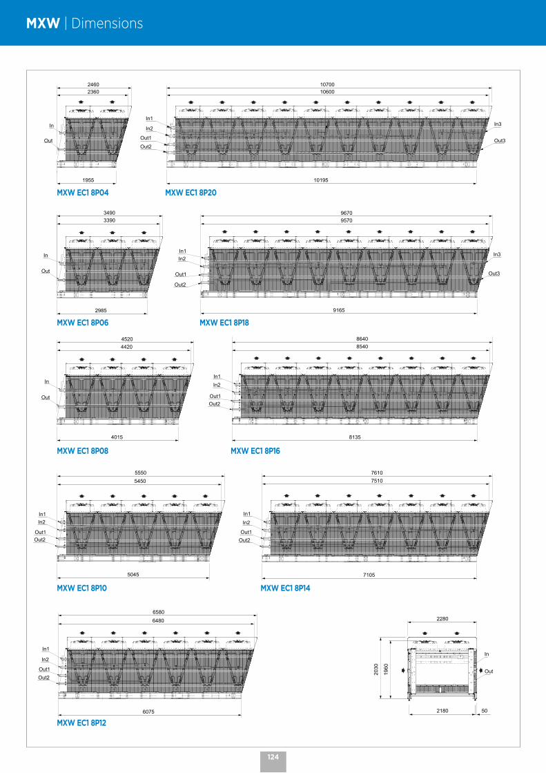
MXW | Dimensions
1955
2460
In
Out
2360
2985
3490
In
Out
3390
4015
4520
In
Out
4420
5045
5550
In1
Out1
In2
Out2
5450
6075
6580
In1
Out1
In2
Out2
6480
7105
7610
In1
Out1
In2
Out2
7510
10195
10700
In1
Out1
In2
Out2
In3
Out3
10600
9165
9670
In1
Out1
In2
Out2
In3
Out3
9570
8135
8640
In1
Out1
In2
Out2
8540
2180 50
2030
2280
In
Out1960
MXW EC1 8P04
MXW EC1 8P06
MXW EC1 8P08
MXW EC1 8P10
MXW EC1 8P12
MXW EC1 8P20
MXW EC1 8P18
MXW EC1 8P16
MXW EC1 8P14
124

11 - 130 kW
CCTCentrifugal fan condenser Commercial range
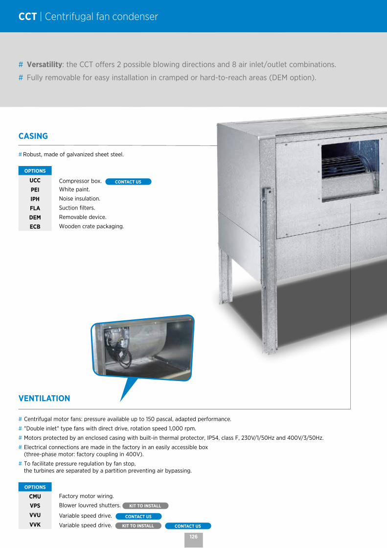
CCT | Centrifugal fan condenser
CASING
# Robust, made of galvanized sheet steel.
OPTIONS
UCC Compressor box. CONTACT US
PEI White paint.
IPH Noise insulation.
FLA Suction filters.
DEM Removable device.
ECB Wooden crate packaging.
# Versatility: the CCT offers 2 possible blowing directions and 8 air inlet/outlet combinations.
# Fully removable for easy installation in cramped or hard-to-reach areas (DEM option).
VENTILATION
# Centrifugal motor fans: pressure available up to 150 pascal, adapted performance.
# "Double inlet" type fans with direct drive, rotation speed 1,000 rpm.
# Motors protected by an enclosed casing with built-in thermal protector, IP54, class F, 230V/1/50Hz and 400V/3/50Hz.
# Electrical connections are made in the factory in an easily accessible box (three-phase motor: factory coupling in 400V).
# To facilitate pressure regulation by fan stop, the turbines are separated by a partition preventing air bypassing.
OPTIONS
CMU Factory motor wiring.
VPS Blower louvred shutters. KIT TO INSTALL
VVU Variable speed drive. CONTACT US
VVK Variable speed drive. KIT TO INSTALL CONTACT US
126

PRODUCT ADVANTAGES
# The two positions of the unit, vertical air or horizontal air, each offer four possibilities for orientation of the air outlets (to be specified when ordering):
V 1 V 2 V 3 V 4
H 1 H 2 H 3 H 4
# Possibility on site of changing the position of the air outlet.# For installation that is difficult to access, condensers can be disassembled and reassembled on site. DEM OPTION
COILS
# Aluminium fins with 2.12 mm spacing.# Combined with staggered copper tubes, the coils are very efficient and
compact.
OPTIONS
MCI Multi-circuit.
Select your coil treatment to extend your unit cooler's lifespan!
Contact us.
127

CCT 1x(A)10M(B) A3(C)
(A) Number of turbines(B) 12T = Three-phase - 10M = Single-phase(C) Type of module
CCT | Nomenclature and technical data
The CCT is available with HFCs. For more information, please consult
our software.
CCT ... - 1,000 rpm 2.12 mm
CONDITIONS CCT ... 1x10M A3
1x10M B5
1x12T B2
1x12T B5
2x10M B5
2x12T B2
2x12T B5
3x12T B2
3x12T B5
4x12T B3
4x12T B5
0 P
a (2
)
DT = 15K (1) R449A kW 14,8 20,1 24,5 33,7 40,1 49,1 67,5 73,8 101,1 115,2 135,0
Power consumption kW 0,59 0,63 2,10 1,92 1,26 4,20 3,84 6,29 5,76 8,14 7,68
Airflow m3/h 3540 3630 7080 6750 7260 14160 13500 21240 20250 27880 27000
AcousticsLp (3) dB(A) 44 44 55 54 46 58 56 59 58 60 59
Lw dB(A) 75 75 86 85 78 90 88 91 90 92 91
CONDITIONS CCT ... 1x10M A3
1x10M B5
1x12T B2
1x12T B5
2x10M B5
2x12T B2
2x12T B5
3x12T B2
3x12T B5
4x12T B3
4x12T B5
50 P
a (2
)
DT = 15K (1) R449A kW 14,2 19,6 24,1 32,7 38,9 48,3 65,5 72,5 98,0 112,7 130,9
Power consumption kW 0,54 0,58 1,98 1,79 1,15 3,97 3,58 5,95 5,36 7,69 7,15
Airflow m3/h 3340 3480 6880 6480 6960 13760 12960 20640 19440 27020 25920
AcousticsLp (3) dB(A) 44 44 55 53 46 57 55 58 57 59 58
Lw dB(A) 75 75 86 84 78 89 87 90 89 91 90
CONDITIONS CCT ... 1x10M A3
1x10M B5
1x12T B2
1x12T B5
2x10M B5
2x12T B2
2x12T B5
3x12T B2
3x12T B5
4x12T B3
4x12T B5
100
Pa
(2)
DT = 15K (1) R449A kW 13,2 18,3 23,9 31,1 36,5 48,0 62,1 72,0 93,2 108,8 124,7
Power consumption kW 0,49 0,52 1,85 1,60 1,04 3,70 3,20 5,56 4,80 7,10 6,40
Airflow m3/h 3010 3210 6810 6100 6420 13620 12200 20440 18290 25820 24390
AcousticsLp (3) dB(A) 42 42 53 51 44 56 54 57 55 58 57
Lw dB(A) 73 73 84 82 76 88 86 89 87 90 89
CONDITIONS CCT ... 1x10M A3
1x10M B5
1x12T B2
1x12T B5
2x10M B5
2x12T B2
2x12T B5
3x12T B2
3x12T B5
4x12T B3
4x12T B5
150
Pa
(2)
DT = 15K (1) R449A kW 12,0 16,0 22,6 29,0 32,2 45,3 57,8 68,1 86,8 103,6 115,7
Power consumption kW 0,43 0,45 1,66 1,40 0,90 3,32 2,80 4,99 4,19 6,26 5,59
Airflow m3/h 2590 2770 6220 5540 5540 12450 11070 18670 16610 23990 22140
AcousticsLp (3) dB(A) 40 40 52 50 42 54 52 56 54 56 55
Lw dB(A) 71 71 83 81 74 86 84 88 86 88 87
(1) DT = difference between the ambient temperature and the condensing temperature considered to be equal to the pressure equivalent at the condenser inlet. (2) Additional available pressure in pascals.(3) Sound pressure in dB(A) measured at 10 m, parallelepiped measuring surface, in a free field over a reflecting plane, given as an indication only. (4) Multi-circuit condensers: M = maximum number of circuits.
128
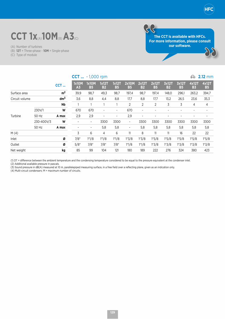
CCT 1x(A)10M(B) A3(C)
(A) Number of turbines(B) 12T = Three-phase - 10M = Single-phase(C) Type of module
The CCT is available with HFCs. For more information, please consult
our software.
CCT ... - 1,000 rpm 2.12 mm
CCT ... 1x10M A3
1x10M B5
1x12T B2
1x12T B5
2x10M B5
2x12T B2
2x12T B5
3x12T B2
3x12T B5
4x12T B3
4x12T B5
Surface area m2 39,9 98,7 49,3 98,7 197,4 98,7 197,4 148,0 296,1 263,2 394,7
Circuit volume dm3 3,6 8,8 4,4 8,8 17,7 8,8 17,7 13,2 26,5 23,6 35,3
Turbine
Nb 1 1 1 1 2 2 2 3 3 4 4
230V/1 W 670 670 - - 670 - - - - - -
50 Hz A max 2,9 2,9 - - 2,9 - - - - - -
230-400V/3 W - - 3300 3300 - 3300 3300 3300 3300 3300 3300
50 Hz A max - - 5,8 5,8 - 5,8 5,8 5,8 5,8 5,8 5,8
M (4) 3 6 4 6 11 8 11 11 16 22 22
Inlet Ø 7/8" 1"1/8 1"1/8 1"1/8 1"3/8 1"3/8 1"5/8 1"5/8 1"5/8 1"5/8 1"5/8
Outlet Ø 5/8" 7/8" 7/8" 7/8" 1"1/8 1"1/8 1"3/8 1"3/8 1"3/8 1"3/8 1"3/8
Net weight kg 85 99 104 121 180 189 222 276 324 380 423
(1) DT = difference between the ambient temperature and the condensing temperature considered to be equal to the pressure equivalent at the condenser inlet. (2) Additional available pressure in pascals.(3) Sound pressure in dB(A) measured at 10 m, parallelepiped measuring surface, in a free field over a reflecting plane, given as an indication only. (4) Multi-circuit condensers: M = maximum number of circuits.
129

CCT | Dimensions
CCT | Vertical airflow direction
J
E
I
B
CD
W
F
X
A
KL
Ø 13
V 1 V 2
V 3 V 4
CCT | Horizontal airflow direction
30J
Y
C
I
H
J
G
I
Z X
A
KL
Ø 13
H 1 H 2
H 3 H 4
CCT
CCT ... 1x10M A3
1x10M B5
1x12T B2
1x12T B5
2x10M B5
2x12T B2
2x12T B5
3x12T B2
3x12T B5
4x12T B3
4x12T B5
A mm 830 1150 1150 1150 2110 2110 2110 3070 3070 4030 4030
B mm 695 795 795 795 795 795 795 795 795 795 795
C mm 835 835 835 835 835 835 835 835 835 835 835
D mm 400 400 400 400 400 400 400 400 400 400 400
E mm 1235 1235 1235 1235 1235 1235 1235 1235 1235 1235 1235
F mm 1500 1600 1600 1600 1600 1600 1600 - - - -
G mm 1530 1630 1630 1630 1630 1630 1630 - - - -
H mm 725 825 825 825 825 825 825 825 825 825 825
I (V) mm 120 173 170 170 173 170 170 170 170 170 170
I (H) mm 94 97 94 94 97 94 94 94 94 94 94
J mm 290 290 342 342 290 342 342 342 342 342 342
K mm 331 331 395 395 331 395 395 395 395 395 395
L mm 250 410 377 377 410 377 377 377 377 377 377
W mm 725 825 825 825 825 825 825 825 825 825 825
X mm 735 1055 1055 1055 2015 2015 2015 2975 2975 3935 3935
Y mm 900 900 900 900 900 900 900 900 900 900 900
Z mm 1575 1675 1675 1675 1675 1675 1675 - - - -
130

60 - 290 kW
CCVCentrifugal fan condenser Commercial range
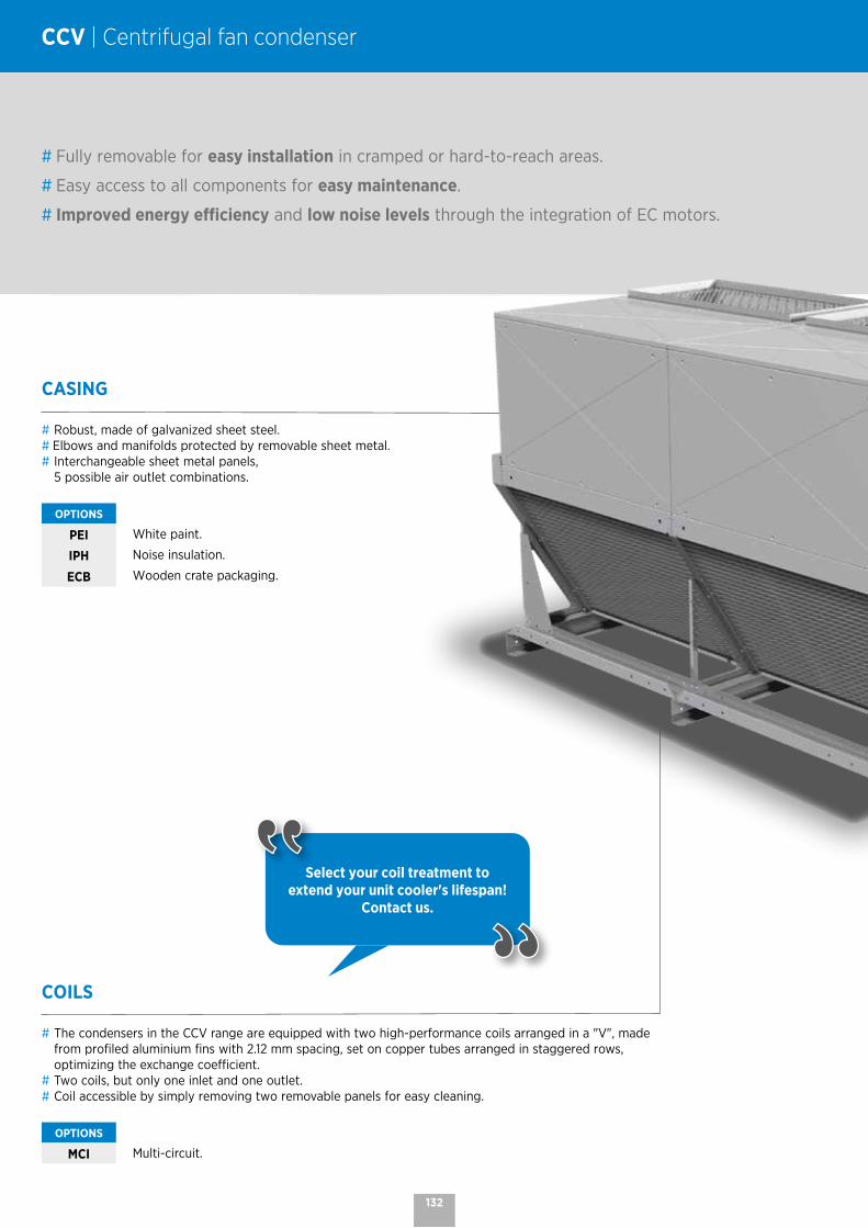
CCV | Centrifugal fan condenser
CASING
# Robust, made of galvanized sheet steel.# Elbows and manifolds protected by removable sheet metal.# Interchangeable sheet metal panels,
5 possible air outlet combinations.
OPTIONS
PEI White paint.
IPH Noise insulation.
ECB Wooden crate packaging.
# Fully removable for easy installation in cramped or hard-to-reach areas.
# Easy access to all components for easy maintenance.
# Improved energy efficiency and low noise levels through the integration of EC motors.
Select your coil treatment to extend your unit cooler's lifespan!
Contact us.
COILS
# The condensers in the CCV range are equipped with two high-performance coils arranged in a "V", made from profiled aluminium fins with 2.12 mm spacing, set on copper tubes arranged in staggered rows, optimizing the exchange coefficient.
# Two coils, but only one inlet and one outlet. # Coil accessible by simply removing two removable panels for easy cleaning.
OPTIONS
MCI Multi-circuit.
132
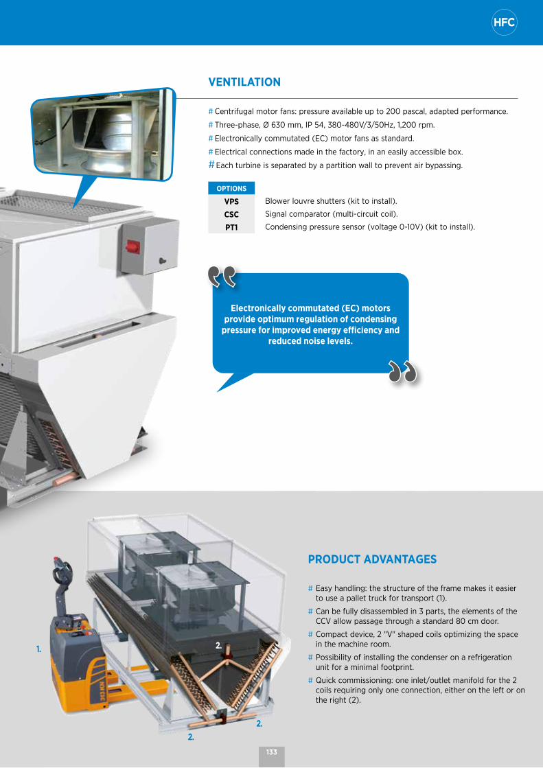
PRODUCT ADVANTAGES
# Easy handling: the structure of the frame makes it easier to use a pallet truck for transport (1).
# Can be fully disassembled in 3 parts, the elements of the CCV allow passage through a standard 80 cm door.
# Compact device, 2 "V" shaped coils optimizing the space in the machine room.
# Possibility of installing the condenser on a refrigeration unit for a minimal footprint.
# Quick commissioning: one inlet/outlet manifold for the 2 coils requiring only one connection, either on the left or on the right (2).
1.
2.
2.
2.
Electronically commutated (EC) motors provide optimum regulation of condensing
pressure for improved energy efficiency and reduced noise levels.
VENTILATION
# Centrifugal motor fans: pressure available up to 200 pascal, adapted performance.
# Three-phase, Ø 630 mm, IP 54, 380-480V/3/50Hz, 1,200 rpm.
# Electronically commutated (EC) motor fans as standard.
# Electrical connections made in the factory, in an easily accessible box.
# Each turbine is separated by a partition wall to prevent air bypassing.
OPTIONS
VPS Blower louvre shutters (kit to install).
CSC Signal comparator (multi-circuit coil).
PT1 Condensing pressure sensor (voltage 0-10V) (kit to install).
133

CCV 1(A) V1(B)
(A) Number of fans(B) Air direction
CCV | Nomenclature and technical data
The CCV is available with HFCs. For more information, please
consult our software.
CCV ... - 1,200 rpm* 2.12 mm
CCV 1 CCV 2 CCV 3 CCV 4
CONDITIONS V1 / V4 V1 + V4 V2 / V3 V1 / V4 V1 + V4 V2 / V3 V1 / V4 V1 + V4 V2 / V3 V1 / V4 V1 + V4 V2 / V3
0 P
a (2
)
DT = 15K (1) R449A kW 69,3 73,2 76,0 138,0 146,4 151,9 206,1 218,1 227,3 277,7 293,8 302,9Power consumption kW 2,55 2,37 2,23 5,10 4,74 4,46 7,65 7,11 6,69 10,20 9,48 8,92
Airflow m3/h 13800 14850 15700 27600 29700 31400 41400 44550 47100 55200 59400 62800
AcousticsLp (3) dB(A) 55 56 57 57 58 59 59 60 61 60 61 62
Lw dB(A) 86 87 88 89 90 91 91 92 93 92 93 94
CCV 1 CCV 2 CCV 3 CCV 4
CONDITIONS V1 / V4 V1 + V4 V2 / V3 V1 / V4 V1 + V4 V2 / V3 V1 / V4 V1 + V4 V2 / V3 V1 / V4 V1 + V4 V2 / V3
50 P
a (2
)
DT = 15K (1) R449A kW 68,3 71,9 74,8 136,6 144,1 148,3 204,0 216,0 223,3 274,2 286,4 300,4Power consumption kW 2,59 2,43 2,29 5,18 4,86 4,58 7,77 7,29 6,87 10,36 9,72 9,16
Airflow m3/h 13500 14500 15350 27000 29000 30700 40500 43500 46050 54000 58000 61400
AcousticsLp (3) dB(A) 54 56 57 56 58 59 58 60 61 59 61 62
Lw dB(A) 85 87 88 88 90 91 90 92 93 91 93 94
CCV 1 CCV 2 CCV 3 CCV 4
CONDITIONS V1 / V4 V1 + V4 V2 / V3 V1 / V4 V1 + V4 V2 / V3 V1 / V4 V1 + V4 V2 / V3 V1 / V4 V1 + V4 V2 / V3
100
Pa
(2) DT = 15K (1) R449A kW 67,1 70,3 73,5 134,3 139,5 147,1 201,0 212,5 219,2 267,1 281,6 295,3
Power consumption kW 2,65 2,49 2,35 5,30 4,98 4,70 7,95 7,47 7,05 10,60 9,96 9,40
Airflow m3/h 13150 14150 14950 26300 28300 29900 39450 42450 44850 52600 56600 59800
AcousticsLp (3) dB(A) 54 56 56 56 58 58 58 60 60 59 61 61
Lw dB(A) 85 87 87 88 90 90 90 92 92 91 93 93
CCV 1 CCV 2 CCV 3 CCV 4
CONDITIONS V1 / V4 V1 + V4 V2 / V3 V1 / V4 V1 + V4 V2 / V3 V1 / V4 V1 + V4 V2 / V3 V1 / V4 V1 + V4 V2 / V3
150
Pa
(2) DT = 15K (1) R449A kW 64,9 69,5 71,9 130,4 138,5 144,4 197,4 206,9 216,4 262,7 279,5 286,9
Power consumption kW 2,71 2,53 2,42 5,42 5,06 4,84 8,13 7,59 7,26 10,84 10,12 9,68
Airflow m3/h 12800 13900 14550 25600 27800 29100 38400 41700 43650 51200 55600 58200
AcousticsLp (3) dB(A) 53 55 56 55 57 58 57 59 60 58 60 61
Lw dB(A) 84 86 87 87 89 90 89 91 92 90 92 93
CCV 1 CCV 2 CCV 3 CCV 4
CONDITIONS V1 / V4 V1 + V4 V2 / V3 V1 / V4 V1 + V4 V2 / V3 V1 / V4 V1 + V4 V2 / V3 V1 / V4 V1 + V4 V2 / V3
200
Pa
(2) DT = 15K (1) R449A kW 63,7 68,6 70,3 127,4 137,0 139,5 190,0 204,8 212,5 256,6 275,9 281,6
Power consumption kW 2,78 2,58 2,49 5,56 5,16 4,98 8,34 7,74 7,47 11,12 10,32 9,96
Airflow m3/h 12350 13600 14150 24700 27200 28300 37050 40800 42450 49400 54400 56600
AcousticsLp (3) dB(A) 53 54 56 55 56 58 57 58 60 58 59 61
Lw dB(A) 84 85 87 87 88 90 89 90 92 90 91 93
* Technical specifications given at full speed (1,200 rpm)
(1) DT = difference between the ambient temperature and the condensing temperature considered to be equal to the pressure equivalent at the condenser inlet.(2) Additional available pressure in pascals.(3) Sound pressure in dB(A) measured at 10 m, parallelepiped measuring surface, in a free field over a reflecting plane, given as an indication only.
134

CCV 1(A) V1(B)
(A) Number of fans(B) Air direction
The CCV is available with HFCs. For more information, please
consult our software.
CCV ... - 1,200 rpm* 2.12 mm
CCV 1 CCV 2 CCV 3 CCV 4V1 / V4 V1 + V4 V2 / V3 V1 / V4 V1 + V4 V2 / V3 V1 / V4 V1 + V4 V2 / V3 V1 / V4 V1 + V4 V2 / V3
Surface area m2 206 206 206 411 411 411 617 617 617 822 822 822
Circuit volume dm3 18,4 18,4 18,4 36,8 36,8 36,8 55,2 55,2 55,2 73,6 73,6 73,6
Turbine
Nb 1 1 1 2 2 2 3 3 3 4 4 4
380-480V/3 W max 2900 2900 2900 5800 5800 5800 8700 8700 8700 11600 11600 11600
3/50-60 Hz A max 4,6 4,6 4,6 9,2 9,2 9,2 13,8 13,8 13,8 18,4 18,4 18,4
Inlet Ø 1"1/8 1"1/8 1"1/8 1"3/8 1"3/8 1"3/8 1"5/8 1"5/8 1"5/8 2"1/8 2"1/8 2"1/8
Outlet Ø 1"1/8 1"1/8 1"1/8 1"3/8 1"3/8 1"3/8 1"5/8 1"5/8 1"5/8 2"1/8 2"1/8 2"1/8
Net weight kg 270 270 270 450 450 450 650 650 650 830 830 830
* Technical specifications given at full speed (1,200 rpm)
CCV ... Airflow direction Noise level** Lp at 10 m
CCV ... - 1,200/900/600 rpm 2.12 mm
CCV 1 CCV 2 CCV 3 CCV 4
V1 / V4 V1 + V4 V2 / V3 V1 / V4 V1 + V4 V2 / V3 V1 / V4 V1 + V4 V2 / V3 V1 / V4 V1 + V4 V2 / V3
dB(A) dB(A) dB(A) dB(A) dB(A) dB(A) dB(A) dB(A) dB(A) dB(A) dB(A) dB(A)
Speed of rotation
100 % 1,200 rpm 54 55 56 57 58 59 59 60 61 60 61 62
75 % 900 rpm 47 48 49 50 51 52 52 53 54 53 54 55
50 % 600 rpm 37 38 39 40 41 42 42 43 44 43 44 45
** Noise level given for different rotation speeds as an indication only (for 0 Pa)
135
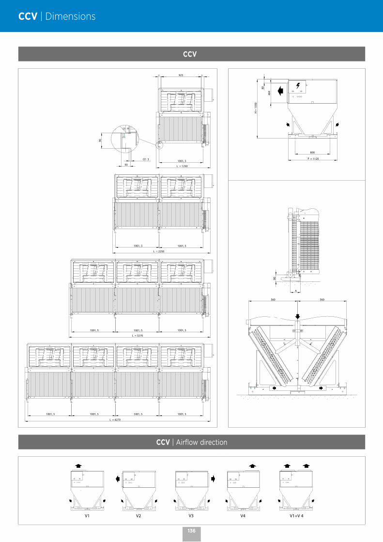
CCV | Dimensions
CCV
1001, 5O1 3
90
50 L = 1250
= 925 =
1001, 5 1001, 5
L = 2250
L = 3270
1001, 51001, 51001, 5
L = 4270
1001, 51001, 51001, 51001, 5
800
H =
135
0
464
80
P = 1120
A
80
560 560
CCV | Airflow direction
V1 V2 V3 V4 V1+V 4
136

MT 1400 - 2800 W LT 1050 - 2100 W
PED 2014/68/UE
MONOTOPCompact ceiling refrigeration monoblock
R290
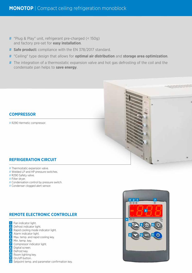
MONOTOP | Compact ceiling refrigeration monoblock
REMOTE ELECTRONIC CONTROLLER
1 Fan indicator light.2 Defrost indicator light.3 Rapid cooling mode indicator light.4 Alarm indicator light.5 Max. temp. and rapid cooling key.6 Min. temp. key.7 Compressor indicator light.8 Digital screen.9 Defrost key.10 Room lighting key.11 On/off button.12 Setpoint temp. and parameter confirmation key.
5
6 1112
9 10
3 2 1 7
4
8
COMPRESSOR
# R290 Hermetic compressor.
REFRIGERATION CIRCUIT
# Thermostatic expansion valve.# Welded LP and HP pressure switches.# R290 Safety valve.# Filter dryer.# Condensation control by pressure switch.# Condenser clogged alert sensor.
# "Plug & Play" unit, refrigerant pre-charged (< 150g) and factory pre-set for easy installation.
# Safe product: compliance with the EN 378/2017 standard.
# "Ceiling" type design that allows for optimal air distribution and storage area optimization.
# The integration of a thermostatic expansion valve and hot gas defrosting of the coil and the condensate pan helps to save energy.
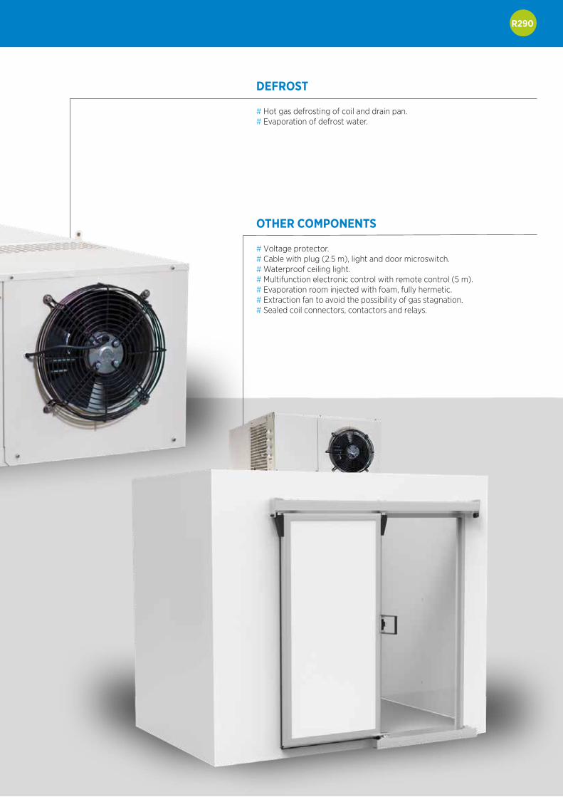
R290
DEFROST
# Hot gas defrosting of coil and drain pan.# Evaporation of defrost water.
OTHER COMPONENTS
# Voltage protector.# Cable with plug (2.5 m), light and door microswitch.# Waterproof ceiling light.# Multifunction electronic control with remote control (5 m).# Evaporation room injected with foam, fully hermetic.# Extraction fan to avoid the possibility of gas stagnation.# Sealed coil connectors, contactors and relays.

MONOTO(A)P(B) 07(C) P(D)
(A) MONOTO = Compact ceiling refrigeration monoblock(B) P = positive range - N = negative range(C) Model(D) P = R290
MONOTOP | Nomenclature and technical data
C
200 m
mmi
ni
300 mmmini
B
120 mm
40 mm
A
MONOTOP MONOTON07P 13P 14P 26P
Cooling capacity (1) W 1400 2800 1050 2100
Hermetic compressorCV 3/4 3/4 (2) 1 1/4 1 1/4 (2)
Power consumption kW 0,5 1,0 0,7 1,4
Refrigerant charge (per circuit) g < 150 < 150 < 150 < 150
Standard room volume (2) m3 12 37 7 27
Room volume without precise data (3) m3 9 30 5 19
AirflowCondenser m3/h 1100 2270 1100 2270
Unit cooler m3/h 1100 3300 1100 3300
Max. input current 230V/1/50Hz (4) A 5,1 10,5 5,7 11,8
Dimensions
A mm 400 500 400 500
B mm 695 950 695 950
C mm 975 1180 975 1180
Panel cut-outHeight mm 615 865 615 865
Width mm 405 405 405 405
Net weight kg 70 125 90 140
(1) Cooling capacity: 10K superheating - 3K subcooling MONOTOP: room temperature 0 °C / outside temperature +32 °C - MONOTON: room temperature -20 °C / outside temperature +32 °C
(2) Standard: Insulation 100 mm for refrigerated and 120 mm for frozen (including floor); load density 250 kg/m³; movement of goods 10%; ambient temperature 32 °C; maximum temperature of incoming goods 25 °C for refrigerated and -15 °C for frozen; specific heat of the goods 3.2 kJ/kg-K frozen; compressor operating hours 18 h/day.
(3) Recommended volume for cases where there is no starting data for the calculation, when for example conditions are more extreme than standard: low thermal insulation capacity of the room, uninsulated floor, high outside temperature, destination and use of the room in non-standard conditions, etc.
Outside temperature limit: 43 °C. If the temperature is higher, contact us. With fruit and vegetables, multiply the power of the unit by 0.65; or contact us.

PED 2014/68/
eCO2Boost XSCO2 split system
MT 1 - 10 kW LT 1 - 6 kW
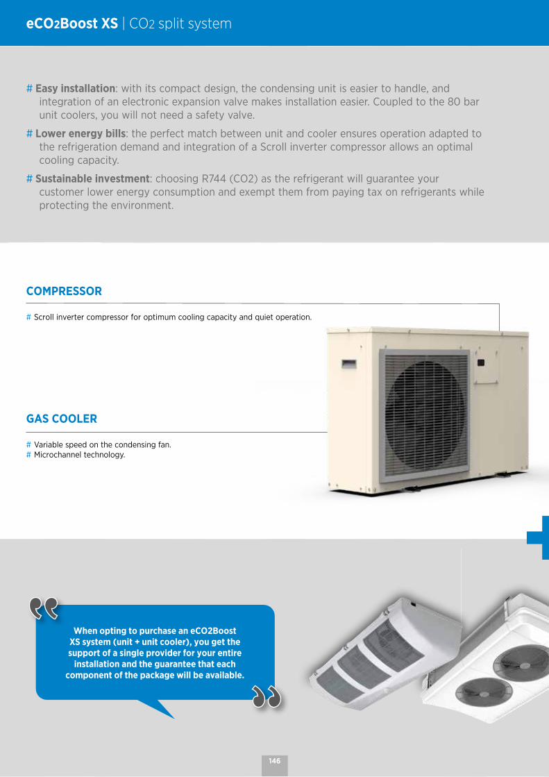
When opting to purchase an eCO2Boost XS system (unit + unit cooler), you get the support of a single provider for your entire
installation and the guarantee that each component of the package will be available.
eCO2Boost XS | CO2 split system
# Easy installation: with its compact design, the condensing unit is easier to handle, and integration of an electronic expansion valve makes installation easier. Coupled to the 80 bar unit coolers, you will not need a safety valve.
# Lower energy bills: the perfect match between unit and cooler ensures operation adapted to the refrigeration demand and integration of a Scroll inverter compressor allows an optimal cooling capacity.
# Sustainable investment: choosing R744 (CO2) as the refrigerant will guarantee your customer lower energy consumption and exempt them from paying tax on refrigerants while protecting the environment.
COMPRESSOR
# Scroll inverter compressor for optimum cooling capacity and quiet operation.
GAS COOLER
# Variable speed on the condensing fan.# Microchannel technology.
146
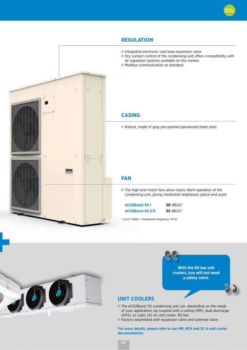
REGULATION
# Integrated electronic cold loop expansion valve# Dry contact control of the condensing unit offers compatibility with
all regulation systems available on the market.# Modbus communication as standard.
UNIT COOLERS# The eCO2Boost XS condensing unit can, depending on the needs
of your application, be coupled with a ceiling (MR), dual-discharge (NTA), or cubic (3C-A) unit cooler, 80 bar.
# Factory-assembled with expansion valve and solenoid valve.
For more details, please refer to our MR, NTA and 3C-A unit cooler documentation.
With the 80 bar unit coolers, you will not need
a safety valve.
FAN
# The high-end motor fans allow nearly silent operation of the condensing unit, giving residential neighbours peace and quiet:
eCO2Boost XS 1 50 dB(A)*
eCO2Boost XS 2/3 53 dB(A)*
* Lp at 1 meter - Compressor frequency: 70 Hz
CASING
# Robust, made of gray pre-painted galvanized sheet steel.
147

eCO2Boost XS 1 eCO2Boost XS 2 eCO2Boost XS 31 circuit 1 circuit 2 circuits
CO2 UNIT COOLERS (80 bar)1 unit cooler / circuit
MR NTA3C-A
MT cold chambers
LT cold chambers -
MT cold chamber
+ LT cold chamber- -
LP
H
LP
H
LP
H
Dimensions H x L x D 670 x 950 x 285 mm 1300 x 1105 x 285 mm
MT capacity 1 - 10 kW
LT capacity - 1 - 6 kW
Compressor Scroll Inverter 1 compressor 2 compressors 3 compressors
Noise level 50 dB(A)* 53 dB(A)*
Power supply 230 V/1/50 Hz o 60 Hz 400 V/3/50 Hz o 60 Hz
Weight 58 kg 113 kg 141 kg
* Lp at 1 meter - Compressor frequency: 70 Hz
eCO2Boost XS | Simplified selections
148

SAMPLE CONFIGURATIONS UNIT/UNIT COOLER FOR MT CHAMBERConditions SC2 | 0 °C - DT = 8K | -8 °C / 32 °C
1.0 1.5 2.0 2.5 3.0 3.5 4.0 4.5 5.0 5.5
SAMPLE CONFIGURATIONS UNIT/UNIT COOLER FOR LT CHAMBERConditions SC3 | -18 °C - DT = 7K | -25 °C / 32 °C 1.0 1.5 2.0 2.5 3.0
1.2 kW (30 Hz) eCO2Boost XS 1 3.2 kW (80 Hz)
MR 250 L* 3C-A 3243 L
2.4 kW (30 Hz)
2.4 kW (30 Hz)
Circuit 1 Chamber 1
eCO2Boost XS 3 Circuit 2 Chamber 2
5.1 kW (80 Hz)
5.1 kW (80 Hz)
1.1 kW (30 Hz) eCO2Boost XS 2 2.7 kW (80 Hz)
3C-A 3145 C 3C-A 3165 C 3C-A 3244 C
1 kW (30 Hz)
1 kW (30 Hz)
Circuit 1 Chamber 1
eCO2Boost XS 3 Circuit 2 Chamber 2
3 kW (80 Hz)
3 kW (80 Hz)
3C-A 3145 C 3C-A 3165 C 3C-A 3244 C
3C-A 3145 C 3C-A 3165 C 3C-A 3244 C
2.1 kW (30 Hz) eCO2Boost XS 2 5.4 kW (80 Hz)
3C-A 3243 L 3C-A 3343 L 3C-A 3344 L
3C-A 3243 L 3C-A 3343 L3C-A
3344 L
3C-A 3243 L 3C-A 3343 L3C-A
3344 L
149

NOTES
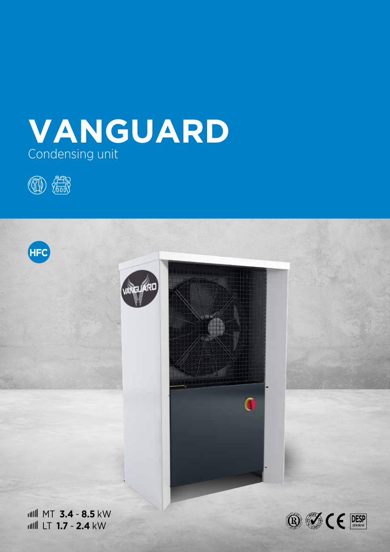
MT 3.4 - 8.5 kW LT 1.7 - 2.4 kW
DESP 2014/68/UE
VANGUARD Condensing unit

UNIT COOLER# The Vanguard can be coupled with ceiling unit coolers (MR or MH), the dual-discharge unit cooler (NTA), or the cubic
unit cooler (3C-A).# The maximum distance between the Vanguard and the unit cooler is 20 m.# In the case of the SPLIT VANGUARD, the unit cooler is factory-assembled with expansion valve and solenoid valve.
For more details on our unit coolers, please refer to the MR, MH, NTA and 3C-A documentations.
# Quick installation: complete electrical supply pre-wired in the factory
# Easy maintenance: All the sheet metal elements are easy to remove and allow total accessibility to all the unit's components.
# Condensing unit adaptable to the needs of the application with 18 existing models (13 for high temperature applications, 5 for low temperature applications)
VANGUARD | Condensing unit
The VANGUARD condensing unit can be coupled to a unit
cooler, according to your needs, to form a split system known as
the SPLIT VANGUARD
3
1
2
4
5
152
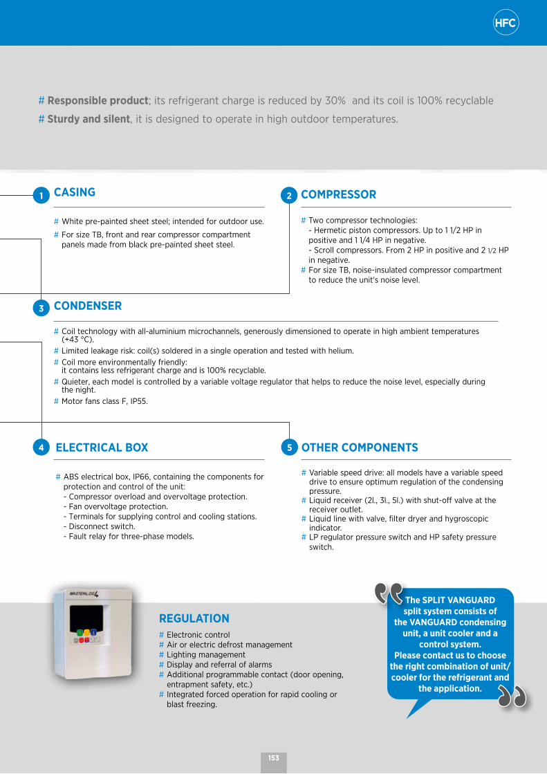
# Responsible product; its refrigerant charge is reduced by 30% and its coil is 100% recyclable
# Sturdy and silent, it is designed to operate in high outdoor temperatures.
REGULATION# Electronic control# Air or electric defrost management# Lighting management# Display and referral of alarms# Additional programmable contact (door opening,
entrapment safety, etc.)# Integrated forced operation for rapid cooling or
blast freezing.
The SPLIT VANGUARD split system consists of
the VANGUARD condensing unit, a unit cooler and a
control system.Please contact us to choose
the right combination of unit/cooler for the refrigerant and
the application.
CASING
# White pre-painted sheet steel; intended for outdoor use.
# For size TB, front and rear compressor compartment panels made from black pre-painted sheet steel.
COMPRESSOR
# Two compressor technologies: - Hermetic piston compressors. Up to 1 1/2 HP in
positive and 1 1/4 HP in negative. - Scroll compressors. From 2 HP in positive and 2 1/2 HP
in negative.# For size TB, noise-insulated compressor compartment
to reduce the unit's noise level.
CONDENSER
# Coil technology with all-aluminium microchannels, generously dimensioned to operate in high ambient temperatures (+43 °C).
# Limited leakage risk: coil(s) soldered in a single operation and tested with helium.# Coil more environmentally friendly:
it contains less refrigerant charge and is 100% recyclable.# Quieter, each model is controlled by a variable voltage regulator that helps to reduce the noise level, especially during
the night. # Motor fans class F, IP55.
ELECTRICAL BOX
# ABS electrical box, IP66, containing the components for protection and control of the unit:
- Compressor overload and overvoltage protection. - Fan overvoltage protection. - Terminals for supplying control and cooling stations. - Disconnect switch. - Fault relay for three-phase models.
OTHER COMPONENTS
# Variable speed drive: all models have a variable speed drive to ensure optimum regulation of the condensing pressure.
# Liquid receiver (2l., 3l., 5l.) with shut-off valve at the receiver outlet.
# Liquid line with valve, filter dryer and hygroscopic indicator.
# LP regulator pressure switch and HP safety pressure switch.
1 2
3
4 5
153

VANGUARD | Nomenclature and technical data
VG H(A)P(B)012(C)
(A) H = hermetic compressor SC = Scroll compressor(B) P = positive range N = negative range(C) Model
The VANGUARD is available with HFCs. For more information, please consult
our software.
VANGUARD Positive range
VG ... HP 012
HP 014
HP 017
HP 020
HP 024
HP 030
HP 038
ScP 043
ScP 050
ScP 065
ScP 075
ScP 086
ScP 103
Power (1) R449A kW Contact us 3,40 3,90 5,20 6,00 7,00 8,50
Power consumption (1)
R449A kW Contact us 1,63 1,95 2,40 2,80 3,20 4,10
Compressor power Cv 3/8 1/2 5/8 3/4 1 1 1/4 1 1/2 2 2 1/2 3 4 5 6
Voltage 50Hz 230V/1 230V/1 230V/1 230V/1 230V/1 230V/1 230V/1 400V/3 400V/3 400V/3 400V/3 400V/3 400V/3
Current drawn A max. 5,0 5,6 6,6 6,0 6,8 8,7 12,9 4,6 5,6 9,8 10,7 12,5 14,5
Acoustics (2) Lp at 10 m dB(A) 38 38 39 39 39 39 36 36 36 41 41 41 41
Ventilation - 230V/1/50Hz mm 1x300 1x300 1x300 1x300 1x300 1x300 1x400 1x400 1x400 1x560 1x560 1x560 1x560
Liquid capacity l. 2 2 2 2 2 2 2 3 3 3 5 5 5
Connections Suction Ø 3/8" 1/2" 1/2" 1/2" 1/2" 5/8" 5/8" 5/8" 7/8" 7/8" 7/8" 7/8" 1"1/8
Liquid Ø 1/4" 3/8" 3/8" 3/8" 3/8" 3/8" 3/8" 3/8" 3/8" 1/2" 1/2" 1/2" 1/2"
Casing Size TA TA TA TA TA TB TB TB TB TB TB TB TB
Net weight kg 100 100 100 100 100 150 150 150 160 170 170 180 180
(1) Evaporating temperature -10 °C / Ambient temperature +32 °C - Superheat: 10K - Subcool: 3K.(2) Sound pressure in dB(A) measured at 10 m, in a free field over a reflecting plane, in accordance with standard EN 13487 (parallelepiped reference surface).
920 605
710
920 605
1465
200
240
93
TA
TB
154

VG H(A)P(B)012(C)
(A) H = hermetic compressor SC = Scroll compressor(B) P = positive range N = negative range(C) Model
The VANGUARD is available with HFCs. For more information, please consult
our software.
VANGUARD Negative range
VG ... HN 008
HN 013
ScN 022
ScN 027
ScN 031
Power (1) R449A kW Contact us 1,70 2,10 (3) 2,40 (3)
Power consumption (1)
R449A kW Contact us 1,90 2,30 2,60
Compressor power Cv 3/4 1 1/4 2 1/2 3 4
Voltage 50Hz 230V/1 230V/1 400V/3 400V/3 400V/3
Current drawn A max. 5,0 7,9 6,1 6,9 7,1
Acoustics (2) Lp at 10 m dB(A) 38 39 39 39 40
Ventilation - 230V/1/50Hz mm 1x300 1x300 1x400 1x400 1x400
Liquid capacity l. 2 2 2 5 5
Connections Suction Ø 1/2" 1/2" 7/8" 7/8" 7/8"
Liquid Ø 3/8" 3/8" 3/8" 3/8" 3/8"
Casing Size TA TA TB TB TB
Net weight kg 100 100 150 160 170
(1) Evaporating temperature -35 °C / Ambient temperature +32 °C - Superheat: 10K - Subcool: 3K.(2) Sound pressure in dB(A) measured at 10 m, in a free field over a reflecting plane, in accordance with standard EN 13487 (parallelepiped reference surface).(3) Product only available in split system.
920 605
710
920 605
1465
200
240
93
TA
TB
155

VANGUARD | Nomenclature and technical data
VG H(A)P(B)012(C) MR 100L(D)
(A) H = hermetic compressor SC = Scroll compressor(B) P = positive range N = negative range(C) Model (D) Split system SPLIT VANGUARD > unit coolers: MR (ceiling) MH (ceiling) NTA (dual-discharge) 3CA (cubic)
The SPLIT VANGUARD is available with HFCs. Please contact us to choose the right
combination of unit/cooler for the refrigerant and the application.
SPLIT VANGUARD ti = +8 °C - DT1 = 10K
VG ...
HP 012MR
100L
HP 014MR
110R
HP 017MR
135R
HP 020MR
160R
HP 024MR
180R
HP 030MR
210R
HP 038NTA M1R 1-AC GV
ScP 043NTA M3R 2-AC PV
ScP 050NTA M3R 2-AC GV
ScP 065NTA M4R 2-AC GV
ScP 075NTA M5R 3-AC GV
ScP 086NTA M6R 3-AC PV
ScP 103NTA M6R 3-AC GV
Power (1) kW 1,33 1,57 1,88 2,21 2,57 3,34 4,24 4,71 5,57 7,30 8,30 9,62 11,44
Power consumption (1) kW 0,75 0,87 1,07 1,21 1,32 1,59 2,19 1,94 2,42 2,95 3,38 3,86 5,00
Room volume (indicative) m3 12 14 17 20 24 32 42 48 58 81 96 116 146
SPLIT VANGUARD ti = +6 °C - DT1 = 6K
VG ...
HP 012MR
160R
HP 014MR
180R
HP 017MR
210R
HP 020MR
270R
HP 024MH
320R
HP 030MH
380R
HP 0383CA
3245R
ScP 0433CA
3343R
ScP 0503CA
3344R
ScP 0653CA
3354R
ScP 0753CA
3444R
ScP 0863CA
4263R
ScP 1033CA
4264R
Power (1) kW 1,43 1,69 2,03 2,37 2,75 3,59 4,53 5,04 5,94 7,83 8,90 10,29 12,21
Power consumption (1) kW 0,81 0,92 1,13 1,28 1,48 1,75 2,53 2,16 2,69 3,21 3,66 4,40 5,49
Room volume (indicative) m3 17 20 24 28 33 44 56 63 75 102 117 138 169
SPLIT VANGUARD ti = +2 °C - DT1 = 8K
VG ...
HP 012MR
110R
HP 014MR
135R
HP 017MR
160R
HP 020MR
180R
HP 024MR
210R
HP 030MR
270R
HP 038MH
380R
ScP 0433CA
3243R
ScP 0503CA
3245R
ScP 0653CA
3343R
ScP 0753CA
3344R
ScP 0863CA
3354R
ScP 1033CA
3444R
Power (1) kW 1,13 1,35 1,62 1,91 2,22 2,88 3,69 4,08 4,86 6,33 7,19 8,34 9,98
Power consumption (1) kW 0,72 0,83 1,05 1,15 1,25 1,54 2,19 2,03 2,54 3,17 3,61 4,04 5,05
Room volume (indicative) m3 10 12 14 17 19 25 33 36 43 57 65 77 93
SPLIT VANGUARD ti = 0 °C - DT1 = 8K
VG ...
HP 012MR
110R
HP 014MR
135R
HP 017MR
160R
HP 020MR
180R
HP 024MR
210R
HP 030MR
270R
HP 0383CA
3165R
ScP 0433CA
3243R
ScP 0503CA
3245R
ScP 0653CA
3343R
ScP 0753CA
3344R
ScP 0863CA
3354R
ScP 1033CA
3444R
Power (1) kW 1,05 1,24 1,50 1,77 2,05 2,67 3,43 3,78 4,53 5,87 6,68 7,75 9,31
Power consumption (1) kW 0,71 0,85 1,03 1,12 1,25 1,57 2,24 2,15 2,63 3,16 3,59 4,02 5,28
Room volume (indicative) m3 8 9 12 14 16 21 28 31 38 50 58 69 86
(1) Ambient temperature +32 °C - Superheat: 10K - Subcool: 3K.
All the information on the unit coolers can be found in the MR, MH, NTA and 3C-A documentation
156
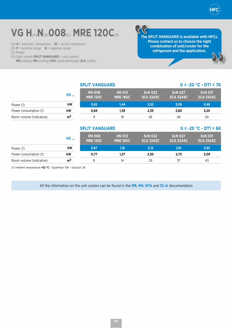
VG H(A)N(B)008(C) MRE 120C(D)
(A) H = hermetic compressor SC = Scroll compressor(B) P = positive range N = negative range(C) Model (D) Split system SPLIT VANGUARD > unit coolers: MR (ceiling) MH (ceiling) NTA (dual-discharge) 3CA (cubic)
The SPLIT VANGUARD is available with HFCs. Please contact us to choose the right
combination of unit/cooler for the refrigerant and the application.
SPLIT VANGUARD ti = -20 °C - DT1 = 7K
VG ...HN 008
MRE 120CHN 013
MRE 190CScN 022
3CA 3243CScN 027
3CA 3244CScN 031
3CA 3343C
Power (1) kW 0,82 1,44 2,52 3,08 3,48
Power consumption (1) kW 0,84 1,39 2,35 2,80 3,20
Room volume (indicative) m3 9 18 36 46 54
SPLIT VANGUARD ti = -25 °C - DT1 = 6K
VG ...HN 008
MRE 120CHN 013
MRE 190CScN 022
3CA 3243CScN 027
3CA 3244CScN 031
3CA 3343C
Power (1) kW 0,67 1,18 2,12 2,61 2,93
Power consumption (1) kW 0,77 1,27 2,30 2,73 3,09
Room volume (indicative) m3 8 14 29 37 43
(1) Ambient temperature +32 °C - Superheat: 10K - Subcool: 3K.
All the information on the unit coolers can be found in the MR, MH, NTA and 3C-A documentation
157

NOTES

MT 3 - 16.6 kW LT 1.5 - 5.7 kW
PED 2014/68/
MAXI Condensing unit
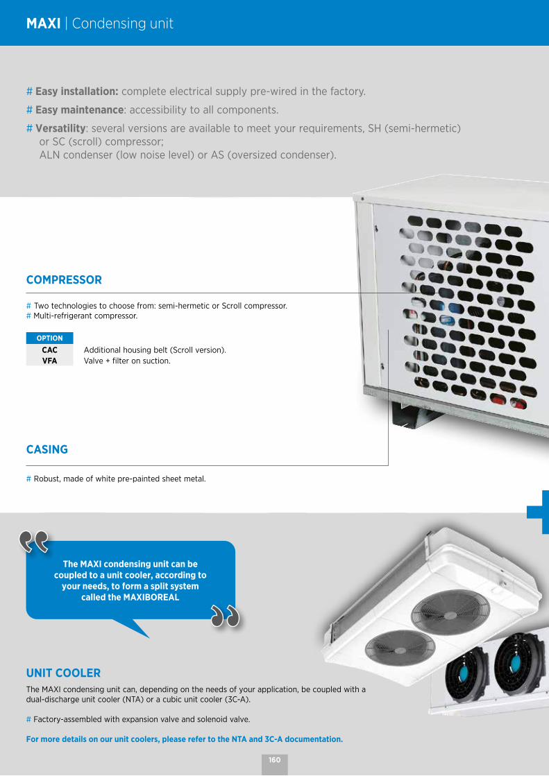
COMPRESSOR
# Two technologies to choose from: semi-hermetic or Scroll compressor.# Multi-refrigerant compressor.
OPTION
CAC Additional housing belt (Scroll version).VFA Valve + filter on suction.
CASING
# Robust, made of white pre-painted sheet metal.
UNIT COOLERThe MAXI condensing unit can, depending on the needs of your application, be coupled with a dual-discharge unit cooler (NTA) or a cubic unit cooler (3C-A).
# Factory-assembled with expansion valve and solenoid valve.
For more details on our unit coolers, please refer to the NTA and 3C-A documentation.
# Easy installation: complete electrical supply pre-wired in the factory.
# Easy maintenance: accessibility to all components.
# Versatility: several versions are available to meet your requirements, SH (semi-hermetic) or SC (scroll) compressor; ALN condenser (low noise level) or AS (oversized condenser).
The MAXI condensing unit can be coupled to a unit cooler, according to
your needs, to form a split system called the MAXIBOREAL
MAXI | Condensing unit
160

CONDENSER
# 1 to 4 fans.# Variable speed of rotation.
OPTION
RPC Condensing pressure regulation.GPC Condenser protection grille.
ELECTRICAL BOX
# Fully integrated electrical cabinet.# General disconnector switch.
OPTION
SPE Wiring on terminal block (without electric board).
REGULATION# Piloting by electronic regulation.# Air or electric defrost management.# Lighting management.# Display and referral of alarms.# Additional programmable contact (door opening, entrapment safety, etc.).# Integrated forced operation for rapid cooling or blast freezing.
The MAXIBOREAL split system consists of the MAXI condensing unit, a unit cooler and a control system.
Please contact us to choose the right combination of unit/cooler for the refrigerant and the application.
OTHER COMPONENTS
# Receiver supplied with valve.# The liquid line consists as standard of a filter dryer, a liquid indicator and a
service valve.# LP control by adjustable pressure switch.# HP safety by cartridge pressure switch with automatic reset.
161
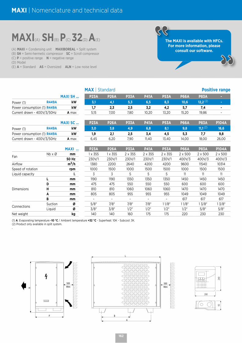
MAXI(A) SH(B) P(C) 32(D) A(E)
(A) MAXI = Condensing unit MAXIBOREAL = Split system(B) SH = Semi-hermetic compressor SC = Scroll compressor(C) P = positive range N = negative range(D) Model (E) A = Standard AS = Oversized ALN = Low noise level
MAXI | Nomenclature and technical data
The MAXI is available with HFCs. For more information, please
consult our software.
MAX | Standard Positive rangeMAXI SH ... P23A P26A P33A P41A P53A P66A P83A -
Power (1) R449A kW 3,1 4,1 5,3 6,5 8,3 10,6 12,2 (2) -
Power consumption (1) R449A kW 1,7 2,3 2,5 3,2 4,2 5,7 7,4 -Current drawn - 400V/3/50Hz A max 5,15 7,00 7,80 10,20 13,20 15,20 19,86 -
MAXI SC ... P23A P26A P33A P41A P53A P66A P83A P104A
Power (1) R449A kW 3,0 3,8 4,9 6,8 8,1 9,8 11,1 (2) 16,6
Power consumption (1) R449A kW 1,9 2,1 2,5 3,4 4,5 5,3 7,7 9,8Current drawn - 400V/3/50Hz A max 6,45 6,20 7,90 11,40 13,40 14,00 18,00 26,00
MAXI ... P23A P26A P33A P41A P53A P66A P83A P104A
FanNb x Ø mm 1 x 355 1 x 355 2 x 355 2 x 355 2 x 355 2 x 500 2 x 500 2 x 500
50 Hz 230V/1 230V/1 230V/1 230V/1 230V/1 400V/3 400V/3 400V/3
Airflow m3/h 1380 2200 2640 4200 4200 9600 11540 10314
Speed of rotation rpm 1000 1500 1000 1500 1500 1000 1500 1500
Liquid capacity l. 3 3 5 5 5 11 11 11
Dimensions
L mm 1190 1190 1350 1350 1350 1450 1450 1450
D mm 475 475 550 550 550 600 600 600
H mm 810 810 1060 1060 1060 1470 1470 1470
A mm 805 805 955 955 955 1049 1049 1049
B mm - - - - - 617 617 617
ConnectionsSuction Ø 5/8" 7/8" 7/8" 7/8" 1 1/8" 1 1/8" 1 3/8" 1 3/8"
Liquid Ø 3/8" 3/8" 1/2" 1/2" 1/2" 1/2" 5/8" 5/8"
Net weight kg 140 140 160 175 175 220 230 230
(1) A: Evaporating temperature -10 °C / Ambient temperature +32 °C - Superheat: 10K - Subcool: 3K.(2) Product only available in split system..
P
H
500Mini
500Mini
A
L
B
200
240
93
162

MAXI(A) SH(B) P(C) 32(D) A(E)
(A) MAXI = Condensing unit MAXIBOREAL = Split system(B) SH = Semi-hermetic compressor SC = Scroll compressor(C) P = positive range N = negative range(D) Model (E) A = Standard AS = Oversized ALN = Low noise level
The MAXI is available with HFCs. For more information, please
consult our software.
MAX | Standard Negative rangeMAXI SH ... N24A N34A N42A N73A -
Power (1) R449A kW 1,5 2,2 (2) 2,7 4,1 -
Power consumption (1) R449A kW 1,4 2,0 2,3 3,7 -Current drawn A max 7,35 10,40 11,60 18,30 -
MAXI SC ... - N34A N42A N73A N84A
Power (1) R449A kW - 1,7 (2) 2,9 (2) 4,3 5,7 (2)
Power consumption (1) R449A kW - 2,0 3,4 4,4 6,3Current drawn - 400V/3/50Hz A max - 8,20 11,90 19,40 25,00
MAXI ... N24A N34A N42A N73A N84A
FanNb x Ø mm 1 x 355 1 x 355 2 x 355 2 x 355 2 x 500
50 Hz 230V/1 230V/1 230V/1 230V/1 400V/3
Airflow m3/h 1380 2200 2640 4200 9600
Speed of rotation rpm 1000 1500 1000 1500 1000
Liquid capacity l. 5 5 5 5 5
Dimensions
L mm 1190 1190 1350 1350 1450
D mm 475 475 550 550 600
H mm 810 810 1060 1060 1470
A mm 805 805 955 955 1049
B mm - - - - 617
ConnectionsSuction Ø 7/8" 7/8" 1 1/8" 1 1/8" 1 3/8"
Liquid Ø 3/8" 3/8" 3/8" 1/2" 1/2"
Net weight kg 140 140 175 175 230
(1) A: Evaporating temperature -35 °C / Ambient temperature +32 °C - Superheat: 10K - Subcool: 3K.(2) Product only available in split system.
P
H
500Mini
500Mini
A
L
B
200
240
93
163

NOTES

MT 7 - 48 kW LT 6 - 15 kW
PED 2014/68/
DUO CUEncased outdoor condensing unit

COMPRESSORS
# Multi-refrigerant compressors: R134a, R407F, R407A, R448A, R449A, R450A and R513A.
# Two Scroll compressors including one Digital™ (except DUO CU LT 26).
# Suction and delivery shut-off valves, crankcase heater and rigid suspension elements.
# Compressors equipped with noise insulation casings.
DUO CU | Encased outdoor condensing unit
CASING
# Galvanized sheet steel covered with white polyester paint.# Easy removal of front and side panels. # IP21 casing.
MANIFOLDS
# Copper suction and delivery.# Filter on the suction.
OIL LINE
# HP oil separator with integrated oil reserve with high and low indicator.# HP oil return line with filter.# Electronic oil controller per compressor.
LIQUID RECEIVER
# Vertical receiver with a capacity of 18 or 45 l. with safety valve.
# Two inlet/outlet shut-off valves.# Liquid outlet equipped with a filter dryer, an indicator and a
liquid outlet valve.
# Compact design for perfect integration in small spaces.
# Suitable for residential areas thanks to its low noise level.
# Ready to install: factory pre-equipped unit with complete refrigeration and electrical supply.
# Easy maintenance: accessibility to all components.
The integration of a Digital™ compressor ensures power modulation from 10 to
100% and makes the DUO CU unit perfectly suited to multi-station applications.
166

REGULATION AND SAFETY
# Complete integrated electrical cabinet IP54.# Electronic regulation by PLC with pressostatic back-up mode.# "Floating" HP control with external probe.# Icc 15 kA.# General disconnect switch.# Switchover to back-up mode: - Automatic by LPE/HPE support pressure switches. - Manual by switch on cabinet door.# 2 condenser fan protection outlets.# 4 cooling station outputs 2x10A.
In order to best meet your needs, the DUO CU is available in 6 models:
CONDENSER
# Microchannel technology coil, Epoxy treated (13-18-25-29-45-57).# Aluminium finned coil and copper tubes (76-114).# Axial or centrifugal condenser fan(s) with speed variation or
EC motors depending on model.# Heat recovery (only on DUO CU MT): - Tapping points with valves on standby upstream of the condenser. - Optional heat recovery module for hot water production at 55 °C or heating. CONTACT US - Integrated control.
OPTIONS Epoxy fins or Ozkem coil treatment available.
T1CT1A T2A/C
T3A
T3C
T4A
75% reduction of the refrigerant charge thanks to the
microchannel technology.
CONTROL DEVICES
# 1 LP general safety pressure switch.# 1 LPE support pressure switch (switchover to back-up mode).# 1 LP regulator pressure switch per compressor.# 1 HP cartridge pressure switch with automatic reset per compressor.# 1 HPE support pressure switch (switchover to back-up mode).# 1 HP and LP sensor.
167

DUO CU(A) MT(B) 29(C) A(D)
(A) Condensing unit(B) MT = positive range - LT = negative range(C) Model (compressor)(D) A = fans without available pressure - C = fans with available pressure
The DUO CU is available with HFCs. For a precise selection, please
consult our software.
DUO CU | Nomenclature and technical data
Fans without available pressure Positive range
CONDITIONS REFRIGERANTS DUO CU MT ... A 29 45 57 76 114
Power (1)
R407F kW 14,1 20,0 - 36,3 -
R407A kW 13,6 19,9 - 35,0 45,6*
R448A kW 13,3 19,9 25,0* 35,0 45,6*
R449A kW 13,6 19,9 24,8* 35,0 45,5*
R450A kW 7,5 11,4 (5) 13,8 19,5 (5) -
R513A kW 9,0 13,6 16,7 23,2 31,6
R134a kW 8,4 12,9 16,1 22,1 31,6
Power consumption (1)
R407F kW 6,8 10,0 - 17,7 -
R407A kW 6,2 9,4 - 16,7 26,1*
R448A kW 6,3 9,3 11,5* 16,6 27,9*
R449A kW 6,3 9,3 11,5* 16,6 27,9*
R450A kW 3,5 5,1 6,4 9,4 14,1
R513A kW 4,0 5,9 7,5 10,7 16,4
R134a kW 3,8 5,6 7,7 10,2 15,2
29 45 57 76 114
Compressor Nb 2 2 2 2 2
Input Current (1) A max. 17,5 24,4 29,5 37,4 58,4
FanType AC AC AC AC AC
Nb x Ø mm 2x 450 2x 450 2x 450 2x 710 2x 710
Noise level Lp 10m (2) dB(A) 41 42 45 44 46
Max. airflow m3/h 11500 11500 11500 26000 26000
Liquid capacity l. 18 18 18 45 45
ConnectionsSuction Ø 1"3/8 1"3/8 1"5/8 2"1/8 2"1/8
Liquid Ø 5/8" 5/8" 7/8" 7/8" 1"1/8
Casing Size T1A T1A T1A T2A T2A
Dimensions
L mm 1195 1195 1195 1960 1960
D mm 660 660 660 1195 1195
H mm 1504 1504 1504 1635 1635
Net weight kg 290 300 310 530 540
Max. outside temperature: -10 °C (R449A) +43°C +40°C +36°C +41°C +37°C
Coil (4)
* New options - Please note: outside temperature limited to +34 °C
(1) Evaporating temperature: -10 °C / Ambient temperature: +32 °C - Total superheat 10K and subcool 3K.(2) Sound pressure in dB(A) measured at 10 m, parallelepiped measuring surface, in a free field over a reflecting plane, given as an indication only. (3) Additional available pressure in pascals.(4) Aluminium finned coil and copper tubes (optional epoxy fins or Ozkem coil treatment available) Coil with microchannel technology Coil with Epoxy treated microchannel technology.(5) Product only available in split system.
168

DUO CU(A) MT(B) 29(C) A(D)
(A) Condensing unit(B) MT = positive range - LT = negative range(C) Model (compressor)(D) A = fans without available pressure - C = fans with available pressure
The DUO CU is available with HFCs. For a precise selection, please
consult our software.
Fans with available pressure Positive range
CONDITIONS REFRIGERANTS DUO CU MT ... C 29 45 57 76 114
Power (1)150 Pa (3)
R407F kW 14,2 20,1 - 36,6 -
R407A kW 13,7 19,3 - 34,4 45,2*
R448A kW 13,7 20,0 25,0* 35,3 46,3*
R449A kW 13,7 20,0 25,0* 35,3 45,5*
R450A kW 7,5 11,4 13,8 19,5 26,3
R513A kW 9,0 13,6 16,8 23,2 31,7
R134a kW 8,4 12,9 16,1 22,1 31,6
Power consumption (1)
R407F kW 8,2 11,4 - 21,1 -
R407A kW 7,7 10,9 - 20,1 29,3*
R448A kW 7,7 10,7 12,9* 20 31,0*
R449A kW 7,7 10,7 12,9* 20 31,0*
R450A kW 4,4 6,3 7,7 12,5 17,0
R513A kW 4,9 7,2 8,9 14,0 19,7
R134a kW 4,6 6,7 9,1 13,1 18,1
29 45 57 76 114
Compressor Nb 2 2 2 2 2
Input current (1) A max. 19,5 26,4 28,9 43,9 64,9
FanType AC AC AC AC AC
Nb x Ø mm 2x 346x314 2x 346x314 2x 346x314 2x 630 2x 630
Noise level Lp 10m (2) dB(A) 56 56 56 57 57
Max. airflow m3/h 11900 11900 11900 28400 28400
Liquid capacity l. 18 18 18 45 45
ConnectionsSuction Ø 1"3/8 1"3/8 1"5/8 2"1/8 2"1/8
Liquid Ø 5/8" 5/8" 7/8" 7/8" 1"1/8
Casing Size T1C T1C T1C T2C T2C
Dimensions
L mm 1195 1195 1195 1960 1960
D mm 660 660 660 1195 1195
H mm 1407 1407 1407 1622 1622
Net weight kg 330 340 350 540 550
Max. outside temperature: -10 °C (R449A) +43°C +40°C +37°C +42°C +37°C
Coil (4)
* New options - Please note: outside temperature limited to +34 °C
(1) Evaporating temperature: -10 °C / Ambient temperature: +32 °C - Total superheat 10K and subcool 3K.(2) Sound pressure in dB(A) measured at 10 m, parallelepiped measuring surface, in a free field over a reflecting plane, given as an indication only. (3) Additional available pressure in pascals.(4) Aluminium finned coil and copper tubes (optional epoxy fins or Ozkem coil treatment available) Coil with microchannel technology Coil with Epoxy treated microchannel technology.
169

DUO CU | Nomenclature and technical data
DUO CU(A) LT(B) 13(C) 1F(D) A(E)
(A) Condensing unit(B) MT = positive range - LT = negative range(C) Model (compressor)(D) 1F = 1 fan - 2F = 2 fans(E) A = fans without available pressure - C = fans with available pressure
The DUO CU is available with HFCs. For a precise selection, please
consult our software.
Fans without available pressure Negative range
CONDITIONS REFRIGERANTS DUO CU LT ... A 13 18 25 13 1F 18 1F 25 1F 13 2F 18 2F 25 2F
Power (1)
R407F kW - - - 6,9 10,1 13,1 6,8 10,1 13,1
R448A kW - - - 6,5 9,9 12,3 6,4 9,9 12,3
R449A kW - - - 6,5 9,8 12,3 6,4 9,8 12,3
Power consumption (1)
R407F kW - - - 6,7 8,9 10,7 6,5 9,3 11,1
R448A kW - - - 6,4 8,1 9,1 5,8 8,6 9,5
R449A kW - - - 6,4 8,2 9,1 5,8 8,6 9,5
13 18 25 13 1F 18 1F 25 1F 13 2F 18 2F 25 2F
Compressor Nb 2 2 2 2 2 2 2 2 2
Input current (1) A max. 19,6 25,2 29,2 17,9 26,3 27,1 19,9 26,6 27,4
FanType AC AC AC AC AC AC AC EC EC
Nb x Ø mm 2x 450 2x 450 2x 450 1 x 800 1 x 800 1 x 800 2 x 450 2 x 500 2 x 500
Noise level Lp 10m (2) dB(A) 42 44 46 46 45 46 43 56 53
Max. airflow m3/h 11500 11500 11500 20000 20000 20000 11500 19000 19000
Liquid capacity l. 18 18 18 18 18 18 18 18 18
ConnectionsSuction Ø 1"1/8 1"3/8 1"3/8 1"1/8 1"3/8 1"3/8 1"1/8 1"3/8 1"3/8
Liquid Ø 1/2" 5/8" 5/8" 1/2" 5/8" 5/8" 1/2" 5/8" 5/8"
Casing Size T1A T1A T1A T3A T3A T3A T1A T4A T4A
Dimensions
L mm 1195 1195 1195 1320 1320 1320 1195 1320 1320
D mm 660 660 660 1128 1128 1128 660 1128 1128
H mm 1504 1504 1504 1560 1560 1560 1504 1965 1965
Net weight kg 290 300 310 320 325 325 320 325 325
Max. outside temperature: -35 °C (R449A) +43°C +43°C +40°C +42°C +40°C +38°C +37°C +40°C +38°C
Coil (4)
* New options - Please note: outside temperature limited to +34 °C
(1) Evaporating temperature: -35 °C / Ambient temperature: +32 °C - Total superheat 10K and subcool 3K.(2) Sound pressure in dB(A) measured at 10 m, parallelepiped measuring surface, in a free field over a reflecting plane, given as an indication only. (3) Additional available pressure in pascals.(4) Aluminium finned coil and copper tubes (optional epoxy fins or Ozkem coil treatment available) Coil with microchannel technology Coil with Epoxy treated microchannel technology.
170
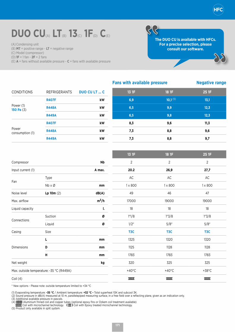
DUO CU(A) LT(B) 13(C) 1F(D) C(E)
(A) Condensing unit(B) MT = positive range - LT = negative range(C) Model (compressor)(D) 1F = 1 fan - 2F = 2 fans(E) A = fans without available pressure - C = fans with available pressure
The DUO CU is available with HFCs. For a precise selection, please
consult our software.
Fans with available pressure Negative range
CONDITIONS REFRIGERANTS DUO CU LT ... C 13 1F 18 1F 25 1F
Power (1)150 Pa (3)
R407F kW 6,9 10,1 (5) 13,1
R448A kW 6,5 9,9 12,3
R449A kW 6,5 9,8 12,3
Power consumption (1)
R407F kW 8,3 9,6 11,3
R448A kW 7,3 8,8 9,6
R449A kW 7,3 8,8 9,7
13 1F 18 1F 25 1F
Compressor Nb 2 2 2
Input current (1) A max. 20.2 26,9 27,7
FanType AC AC AC
Nb x Ø mm 1 x 800 1 x 800 1 x 800
Noise level Lp 10m (2) dB(A) 49 46 47
Max. airflow m3/h 17000 19000 19000
Liquid capacity l. 18 18 18
ConnectionsSuction Ø 1"1/8 1"3/8 1"3/8
Liquid Ø 1/2" 5/8" 5/8"
Casing Size T3C T3C T3C
Dimensions
L mm 1325 1320 1320
D mm 1125 1128 1128
H mm 1783 1783 1783
Net weight kg 320 325 325
Max. outside temperature: -35 °C (R449A) +40°C +40°C +38°C
Coil (4)
* New options - Please note: outside temperature limited to +34 °C
(1) Evaporating temperature: -35 °C / Ambient temperature: +32 °C - Total superheat 10K and subcool 3K.(2) Sound pressure in dB(A) measured at 10 m, parallelepiped measuring surface, in a free field over a reflecting plane, given as an indication only. (3) Additional available pressure in pascals.(4) Aluminium finned coil and copper tubes (optional epoxy fins or Ozkem coil treatment available) Coil with microchannel technology Coil with Epoxy treated microchannel technology.(5) Product only available in split system.
171
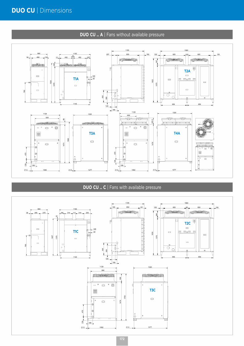
DUO CU | Dimensions
DUO CU .. A | Fans without available pressure
35945
4
189
120
1195
207 805 182
1375
100 805 105 805 100
1960
956 956
247
1622
1195
12 49232
492 167
1375
129
42105
1145
1504
660
765
54 114492
928
195
1082
470
139
21.5
1320
127721.5
1128
1474
86
1560
1474
245.
3
470
139
195
21.5 1082
656
1128 1320
127721.5
T1A
T2A
T3A T4A
DUO CU .. C | Fans with available pressure
1195
195 314 117 314 255
1375
32
1407
1145
42105
660
27934636
765
21.5
1320
1277
470
139
195
21.5 1082
1474
309
990
1128
1783
35945
4
189
120
1195
185 850 161
1635
1375
260
100 850 60 850 100
1960
956 956
T1C
T2C
T3C
172

MT 11 - 72 kW LT 3.3 - 22.5 kW
PED 2014/68/
MEGA Condensing unit
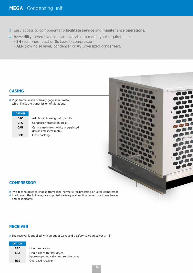
CASING
# Rigid frame, made of heavy gage sheet metal, which limits the transmission of vibrations.
OPTION
CAC Additional housing belt (Scroll).
GPC Condenser protection grille.
CAR Casing made from white pre-painted galvanized sheet metal.
ECC Crate packing.
# Easy access to components to facilitate service and maintenance operations.
# Versatility; several versions are available to match your requirements: - SH (semi-hermetic) or Sc (scroll) compressor, - ALN (low noise level) condenser or AS (oversized condenser).
MEGA | Condensing unit
COMPRESSOR
# Two technologies to choose from: semi-hermetic reciprocating or Scroll compressor.# In all cases, the following are supplied: delivery and suction valves, crankcase heater
and oil indicator.
RECEIVER
# The receiver is supplied with an outlet valve and a safety valve (receiver ≥ 11 l.).
OPTION
BAC Liquid separator.
LIQ Liquid line with filter dryer,hygroscopic indicator and service valve.
RLS Oversized receiver.
174
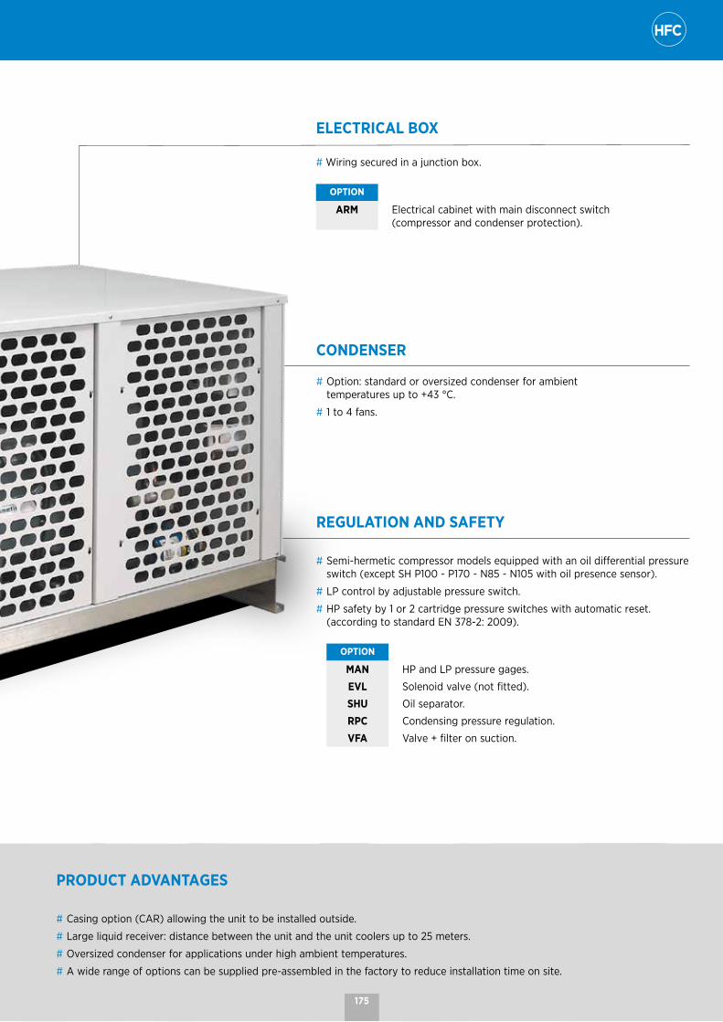
ELECTRICAL BOX
# Wiring secured in a junction box.
OPTION
ARM Electrical cabinet with main disconnect switch (compressor and condenser protection).
CONDENSER
# Option: standard or oversized condenser for ambient temperatures up to +43 °C.
# 1 to 4 fans.
PRODUCT ADVANTAGES
# Casing option (CAR) allowing the unit to be installed outside.
# Large liquid receiver: distance between the unit and the unit coolers up to 25 meters.
# Oversized condenser for applications under high ambient temperatures.
# A wide range of options can be supplied pre-assembled in the factory to reduce installation time on site.
REGULATION AND SAFETY
# Semi-hermetic compressor models equipped with an oil differential pressure switch (except SH P100 - P170 - N85 - N105 with oil presence sensor).
# LP control by adjustable pressure switch.
# HP safety by 1 or 2 cartridge pressure switches with automatic reset. (according to standard EN 378-2: 2009).
OPTION
MAN HP and LP pressure gages.
EVL Solenoid valve (not fitted).
SHU Oil separator.
RPC Condensing pressure regulation.
VFA Valve + filter on suction.
175

MEGA SH(A) P(B)80(C)A(D)
(A) SH = Semi-hermetic compressor Sc = Scroll compressor(B) P = positive range N = negative range(C) Model (D) A = Standard AS = Oversized
MEGA | Nomenclature and technical data
The MEGA is available with HFCs. For more information, please
consult our software.
MEGA | Standard Positive range
MEGA ... ASH P 80
SH P 85
SH P 100
Sc P100
SH P 170
Sc P170
SH P 200
SH P 250
SH P 300
SH P 350
SH P 400
SH P 500
Power (1) R449A kW 12,3 15,6 19,7 20,3 22,3 23,8 27,8 35,0 43,9 51,8 60,3 71,9
Power consumption R449A kW 6,2 8,1 9,4 11,4 10,4 13,4 14,0 18,2 23,1 26,7 32,1 37,5
Current drawn A max. 15,9 19,8 23,5 25,3 26,9 31,0 35,7 44,7 57,9 67,8 79,6 99,7
Fan 1,500 rpm mm 1x500 2x500 2x500 2x500 2x500 2x500 2x630 2x630 4x630 4x630 4x630 4x630
Airflow m3/h 5315 11950 11270 11268 10630 10630 21300 21300 46400 46400 46400 42600
Liquid capacity l. 11 11 15 15 24 24 30 30 40 40 40 40
ConnectionsSuction Ø 1''3/8 1''3/8 1''3/8 1''3/8 1''5/8 1''5/8 1''5/8 2''1/8 2''1/8 2''1/8 2''1/8 2''1/8
Liquid Ø 5/8'' 5/8'' 5/8'' 5/8'' 7/8'' 7/8'' 7/8'' 7/8'' 7/8'' 7/8'' 1''1/8 1''1/8
Weight without CAR option kg 264 313 337 272 362 277 418 470 558 597 600 623
Weight with CAR option kg 339 398 422 357 447 362 538 590 718 757 760 783
MEGA | Oversized condenser Positive range
MEGA ... ASSH P 80
SH P 85
SH P 100
Sc P 100
SH P 170
SH P 200
SH P 250
SH P 300
SH P 350
SH P 400
Power (1) R449A kW 11,0 13,7 16,8 16,7 19,4 24,7 (2) 32,3 (2) 37,0 44,0 51,1
Power consumption R449A kW 7,0 8,5 9,9 13,4 12,9 18,0 22,2 24,5 28,3 33,8
Current drawn A max. 16,9 19,8 23,5 25,3 31,6 42,5 51,5 57,9 67,8 79,6
Fan 1,500 rpm mm 2x500 2x500 2x500 2x500 2x630 4x630 4x630 4x630 4x630 4x630
Airflow m3/h 11950 11270 10630 10630 21300 46400 46400 42600 42600 42600
Liquid capacity l. 11 11 15 15 24 40 40 40 40 40
ConnectionsSuction Ø 1''3/8 1''3/8 1''3/8 1''3/8 1''5/8 1''5/8 2''1/8 2''1/8 2''1/8 2''1/8
Liquid Ø 5/8'' 5/8'' 5/8'' 5/8'' 7/8'' 7/8'' 7/8'' 7/8'' 7/8'' 1''1/8
Weight without CAR option kg 294 322 419 280 415 501 553 578 617 620
Weight with CAR option kg 379 407 504 365 535 661 713 738 777 780
(1) A: Evaporating temperature -10 °C / Ambient temperature +32 °C - Superheat: 10K - Subcool: 3K.AS: Evaporating temperature -10 °C / Ambient temperature +42 °C - Superheat: 10K - Subcool: 3K.
(2) Product only available in split system.
176

MEGA SH(A) N(B)55(C)A(D)
(A) SH = Semi-hermetic compressor Sc = Scroll compressor(B) P = positive range N = negative range(C) Model (D) A = Standard AS = Oversized
The MEGA is available with HFCs. For more information, please
consult our software.
MEGA | Standard Negative range
MEGA ... ASH N
55SH N
85SH N 105
Sc N 105
Sc N 155
SH N 155
SH N 205
SH N 255
SH N 305
SH N 405
Power (1) R449A kW 4,2 4,9 6,8 (2) 7,1 (2) 8,8 (2) 9,9 (2) 11,9 13,8 18,2 20,5
Power consumption R449A kW 3,9 4,2 6,0 7,1 9,0 8,5 10,0 11,7 16,0 19,4
Current drawn A max. 13,8 14,5 19,6 21,1 26,5 26,6 30,9 38,5 52,0 63,0
Fan 1,500 rpm mm 1x500 1x500 2x500 2x500 2x500 2x500 2x500 2x500 2x630 2x630
Airflow m3/h 5635 5635 11950 11948 11268 11270 10630 10630 21300 21300
Liquid capacity l. 11 11 15 15 15 15 24 24 30 30
ConnectionsSuction Ø 1''1/8 1''3/8 1''3/8 1''3/8 1''5/8 1''5/8 2''1/8 2''1/8 2''1/8 2''1/8
Liquid Ø 1/2'' 1/2'' 5/8'' 5/8'' 5/8'' 5/8'' 7/8'' 7/8'' 7/8'' 7/8''
Weight without CAR option kg 269 277 326 253 293 359 385 417 497 508
Weight with CAR option kg 332 340 400 327 367 433 459 491 727 738
MEGA | Oversized condenser Negative range
MEGA ... ASSH N
55SH N
85SH N 105
Sc N 105
Sc N 155
SH N 155
SH N 205
SH N 255
SH N 305
SH N 405
Power (1) R449A kW 3,3 3,4 (2) 4,6 6,2 (2) 7,5 (2) 6,6 7,8 9,5 (2) 11,8 14,7
Power consumption R449A kW 3,9 4,8 5,9 8,4 11,1 8,1 9,5 13,2 16,2 22
Current drawn A max. 13,8 15,5 19,6 21,1 26,5 26,6 30,9 43,2 52,0 69,8
Fan 1,500 rpm mm 1x500 2x500 2x500 2x500 2x500 2x500 2x500 2x630 2x630 4x630
Airflow m3/h 5315 11950 11270 11270 10630 10630 10630 21300 21300 46400
Liquid capacity l. 11 11 15 15 15 15 24 24 30 40
ConnectionsSuction Ø 1''1/8 1''3/8 1''3/8 1''3/8 1''5/8 1''5/8 2''1/8 2''1/8 2''1/8 2''1/8
Liquid Ø 1/2'' 1/2'' 5/8'' 5/8'' 5/8'' 5/8'' 7/8'' 7/8'' 7/8'' 7/8''
Weight without CAR option kg 273 311 355 272 303 367 385 489 497 591
Weight with CAR option kg 368 369 370 346 377 441 459 719 727 881
(1) A: Evaporating temperature -35 °C / Ambient temperature +32 °C - Superheat: 10K - Subcool: 3K.AS: Evaporating temperature -35 °C / Ambient temperature +42 °C - Superheat: 10K - Subcool: 3K.
(2) Product only available in split system.
177

MEGA | Dimensions
MEGA | 1 x Ø 500 mm
1350
1000
500Mini
500Mini
850
MEGA | 2 x Ø 500 mm
1700
1000
500Mini
950
500Mini
MEGA | 2 x Ø 630 mm
500Mini
2300
1150
1000
1200
500Mini
MEGA | 4 x Ø 630 mm
1838
2300
1150
500Mini
500Mini
1200
178
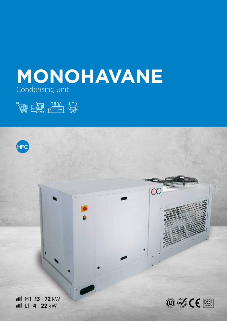
MT 13 - 72 kW LT 4 - 22 kW
DESP 2014/68/UE
MONOHAVANE Condensing unit
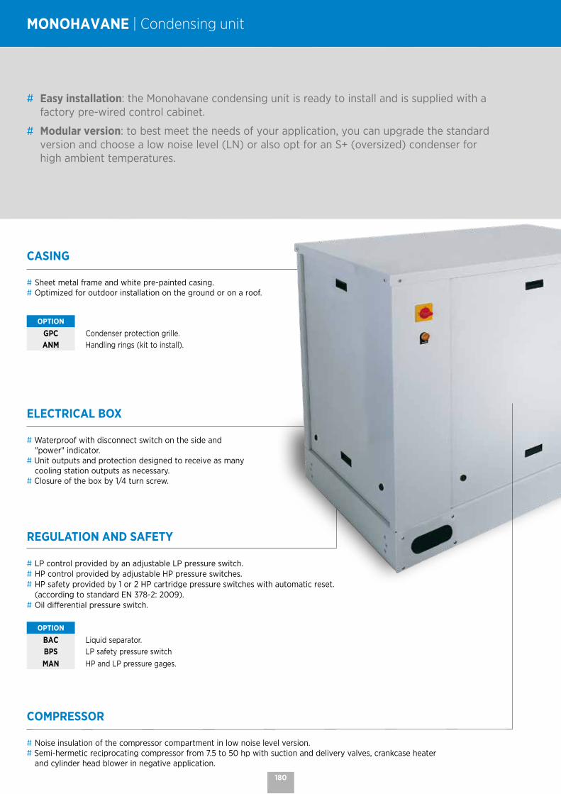
ELECTRICAL BOX
# Waterproof with disconnect switch on the side and "power" indicator.
# Unit outputs and protection designed to receive as many cooling station outputs as necessary.
# Closure of the box by 1/4 turn screw.
CASING
# Sheet metal frame and white pre-painted casing.# Optimized for outdoor installation on the ground or on a roof.
OPTION
GPC Condenser protection grille.
ANM Handling rings (kit to install).
# Easy installation: the Monohavane condensing unit is ready to install and is supplied with a factory pre-wired control cabinet.
# Modular version: to best meet the needs of your application, you can upgrade the standard version and choose a low noise level (LN) or also opt for an S+ (oversized) condenser for high ambient temperatures.
MONOHAVANE | Condensing unit
REGULATION AND SAFETY
# LP control provided by an adjustable LP pressure switch.# HP control provided by adjustable HP pressure switches.# HP safety provided by 1 or 2 HP cartridge pressure switches with automatic reset.
(according to standard EN 378-2: 2009).# Oil differential pressure switch.
OPTION
BAC Liquid separator.
BPS LP safety pressure switch
MAN HP and LP pressure gages.
COMPRESSOR
# Noise insulation of the compressor compartment in low noise level version.# Semi-hermetic reciprocating compressor from 7.5 to 50 hp with suction and delivery valves, crankcase heater
and cylinder head blower in negative application.
180

CONDENSER
# Choice of condenser: A (standard) or AS and AS+ (oversized). The oversized condenser of the AS version allows installation in high ambient temperatures, up to +42 °C, and up to +45 °C on consultation.
# The ALN low noise level version is ideal for urban areas.# From 2 to 4 fans with elbow protection by housing.
MAINTENANCE
# Easily removable side maintenance panels for easy access to all components.
# The door can be placed in hood position to facilitate work on the electrical cabinet.
LIQUID RECEIVER AND LINE
# Receiver equipped with valves and a safety valve.# Liquid line consisting of a cartridge filter dryer, a hygroscopic indicator and a service valve.
OPTION
RLS Oversized receiver.
SHU Oil separator.
VFA Valve + filter on suction.
EVL Solenoid valve (kit to install).
181

MONOHV P(A)75(B)AS(C)
(A) P = positive range N = negative range(B) Model (C) A = Standard AS = Oversized AS+ = Oversized plus ALN = Low noise level
MONOHAVANE | Nomenclature and technical data
The MONOHAVANE is available with HFCs. For precise selection,
please consult our software.
MONOHAVANE Positive range
MONOHV P... A AS AS+ ALN
Power (1) R449A kW 15,6 > 69,8 14,0 > 63,2 13,4 > 44,1 15,6 > 48,5
Power consumption* R449A kW 8,1 > 35,5 8,5 > 36,7 8,6 > 26,0 7,1 > 21,6
Current drawn A max. 19,8 > 99,8 19,8 > 99,8 19,8 > 70,0 18,3 > 60,4
Acoustics (2) dB(A) - - - 39 > 50
Fan Nb x Ø mm 2x 500 > 2x 910 2x 500 > 2x 910 2x 500 > 2x 910 2x 630 > 2x 800
Airflow m3/h 15000 > 45000 10630 > 42620 10630 > 42620 6060 > 21776
Liquid capacity l. 21 > 50 21 > 50 21 > 50 21 > 50
Net weight kg 480 > 980 500 > 1100 500 > 1090 530 > 1030
(1) A: Evaporating temperature -10 °C / Ambient temperature +32 °C - Superheat: 10K - Subcool: 3K.AS: Evaporating temperature -10 °C / Ambient temperature +42 °C - Superheat: 10K - Subcool: 3K.AS+: Evaporating temperature -10 °C / Ambient temperature +44 °C - Superheat: 10K - Subcool: 3K.ALN: Evaporating temperature -10 °C / Ambient temperature +32 °C - Superheat: 10K - Subcool: 3K.
(2) Lp at 10 m: Sound pressure in dB(A) measured at 10 m, in a free field over a reflecting plane, in accordance with standard EN 13487 (parallelepiped reference surface).
MONOHAVANE Negative range
MONOHV N... A AS AS+ ALN
Power (1) R449A kW 5,2 > 20,5 3,4 > 14,3 3,2 > 13,9 4,8 > 20,7
Power consumption* R449A kW 4,9 > 19,4 4,8 > 20,3 4,8 > 19,6 3,7 > 16,5
Current drawn A max. 15,5 > 63,0 15,5 > 66,4 15,5 > 68,2 17,8 > 80,3
Acoustics (2) dB(A) - - - 42 > 51
Fan Nb x Ø mm 2x 500 > 2x 630 2x 500 > 3x 630 2x 500 > 2x 910 2x 500 > 2x 800
Airflow m3/h 11948 > 21300 11948 > 31950 10630 > 42620 4066 > 16247
Liquid capacity l. 21 > 40 21 > 50 21 > 50 21 > 50
Net weight kg 520 > 700 520 > 840 540 > 980 550 > 980
(1) A: Evaporating temperature -35 °C / Ambient temperature +32 °C - Superheat: 10K - Subcool: 3K.AS: Evaporating temperature -35 °C / Ambient temperature +42 °C - Superheat: 10K - Subcool: 3K.AS+: Evaporating temperature -35 °C / Ambient temperature +44 °C - Superheat: 10K - Subcool: 3K.ALN: Evaporating temperature -35 °C / Ambient temperature +32 °C - Superheat: 10K - Subcool: 3K.
(2) Lp at 10 m: Sound pressure in dB(A) measured at 10 m, in a free field over a reflecting plane, in accordance with standard EN 13487 (parallelepiped reference surface).
182

DESP
2014/68/
HT 100 - 275 kW MT 15 - 225 kW LT 5 - 65 kW
MULTIHAVANE Condensing unit

CASING
# Base of frame in high-strength folded galvanized sheet metal.
# White sheet metal casing.# Removable panels with 1/4 turn latches. # Designed for easy handling by crane (lifting rings as
standard).# Low noise level: noise insulation of the compressor
compartment.
COMPRESSOR
# The compressors are charged with ester oil and are equipped as shown in the table below:
SH Octagon Scroll SHNumber of compressors 2-3-4 2-3-4 2-3
Crankcase heater Yes Yes Yes
Suction and delivery valves Yes Yes Yes
HP safety pressure switch Yes Yes Yes
Oil pump From 4VC No Yes
Cylinder head fan Negative No Negative
OPTION
COQ Noise insulation casing on Scroll (except ZF15, ZB38 and ZB45).
CONDENSER
# NEOSTAR (L or P) and WA type condensers, regulated by cascade stop.
# Low noise level: silent condenser.# Oversized condenser: for operation in high ambient
temperatures, up to 43 °C.
OPTION
GPC Condenser protection grille.
# Unit ready to use and pre-wired in the factory to save time on installation.
# Versatile unit that be adapted to the needs of your application: - Outdoor installation, on the ground or a roof. - Two compressor technologies available: Scroll or semi-hermetic. - Possibility of adjusting the noise level with the low noise level (LN) option. - Optional oversized condenser for high ambient temperatures.
# Easy access to all components for easy maintenance.
MULTIHAVANE | Condensing unit
184

REGULATION AND SAFETY
# For Scroll or Octagon 2-compressor racks: Pressure regulation with 1 LP regulator pressure switch per compressor and 1 HP regulator pressure switch per condenser fan.
# For other racks: Electronic regulation by controller with LP/HP sensors signal 4/20 mA.# A LP general safety pressure switch.# One oil differential pressure switch per compressor for semi-hermetic compressors and from the 4VC compressor for OCT).# 1 or 2 HP cartridge pressure switches with automatic reset per compressor.# Two pressure gages (LP+HP).# Connection of each element in 1/4" flexible tube.
OPTION
BP1 Additional LP pressure switch.BPS LP safety pressure switch per compressor (automatic reset).CDP LP/HP pressure sensor signal 4/20 mA.HPG HP general pressure switch.HPS Additional HP pressure switch.
ELECTRICAL BOX
# Electrical cabinet with latch-locked double door.# Front panel disconnect switch and power indicator.# All the electrical equipment is connected to the circuit
board, which includes protection and control of the condensing unit.
OIL LINE# LP oil return with a removable oil separator and a receiver
equipped with a high and low indicator, shut-off valves and a calibrated degassing valve in the LP manifold with a shut-off valve.
# Float oil level regulators and shut-off valve per compressor for SH and electronic for Scroll.
LIQUID LINE# Liquid line with filter dryer(s) with removable cartridge(s), 3/8''
SAE charging valve(s) and a hygroscopic indicator and shut-off valve(s).
RECEIVER# Horizontal liquid receiver with 2 inlet/outlet shut-off valves. # Single or double safety valve with 3-way valve if the capacity is
> or = 100 l.
MANIFOLDS# Suction and delivery manifolds in 304L stainless steel for SH
and copper for Sc and OCT, fixed with polypropylene collars on the suction side and high temperature resistant polyamide on the delivery side.
# General filter unit on the suction or per compressor depending on model with removable cartridge(s).
CONNECTION VALVES# Suction valve and liquid outlet valve depending on the model.
OPTION
SIL Delivery muffler (only for SH version).
TXL Electronic oil level controllers.
ALR Optoelectronic refrigerant level alarm.
SSD Double safety valve with 3-way valve only for receivers with a capacity of less than 100 L (standard for the others).
PR2 2 return suction valves and 2 liquid outlet valves (only for SH version).
BAC Liquid separator (except SC), with oil return system by suction or gravity depending on model.
RLS Oversized liquid receiver.
185
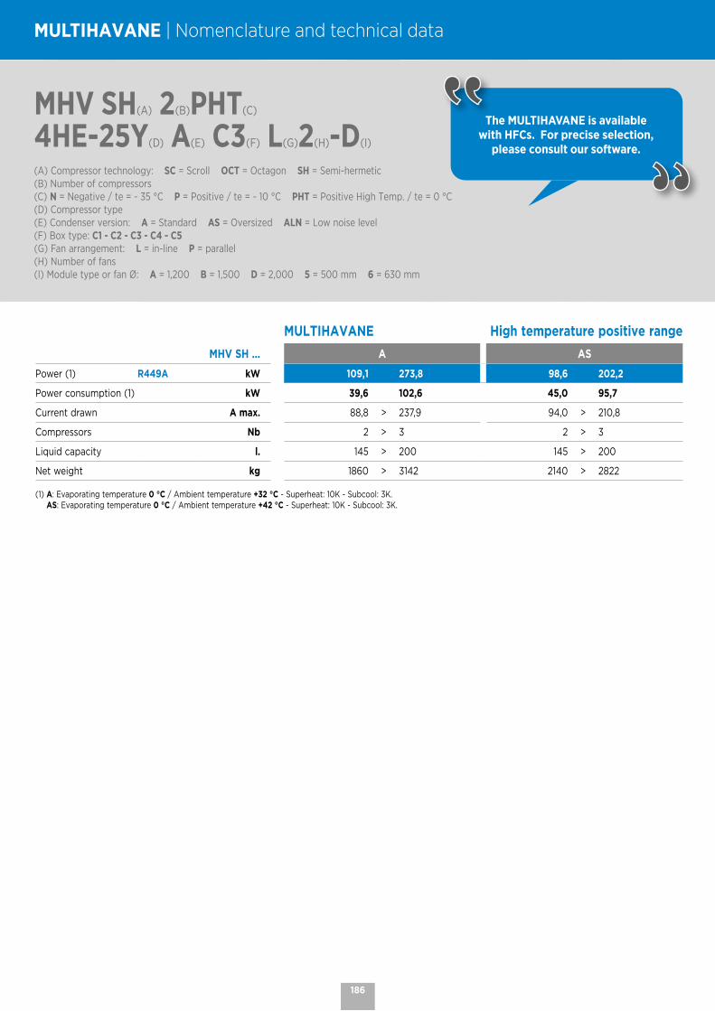
MHV SH(A) 2(B)PHT(C)
4HE-25Y(D) A(E) C3(F) L(G)2(H)-D(I)
(A) Compressor technology: SC = Scroll OCT = Octagon SH = Semi-hermetic(B) Number of compressors(C) N = Negative / te = - 35 °C P = Positive / te = - 10 °C PHT = Positive High Temp. / te = 0 °C(D) Compressor type(E) Condenser version: A = Standard AS = Oversized ALN = Low noise level(F) Box type: C1 - C2 - C3 - C4 - C5(G) Fan arrangement: L = in-line P = parallel(H) Number of fans(I) Module type or fan Ø: A = 1,200 B = 1,500 D = 2,000 5 = 500 mm 6 = 630 mm
MULTIHAVANE | Nomenclature and technical data
The MULTIHAVANE is available with HFCs. For precise selection,
please consult our software.
MULTIHAVANE High temperature positive range
MHV SH ... A AS
Power (1) R449A kW 109,1 273,8 98,6 202,2
Power consumption (1) kW 39,6 102,6 45,0 95,7
Current drawn A max. 88,8 > 237,9 94,0 > 210,8
Compressors Nb 2 > 3 2 > 3
Liquid capacity l. 145 > 200 145 > 200
Net weight kg 1860 > 3142 2140 > 2822
(1) A: Evaporating temperature 0 °C / Ambient temperature +32 °C - Superheat: 10K - Subcool: 3K.AS: Evaporating temperature 0 °C / Ambient temperature +42 °C - Superheat: 10K - Subcool: 3K.
186
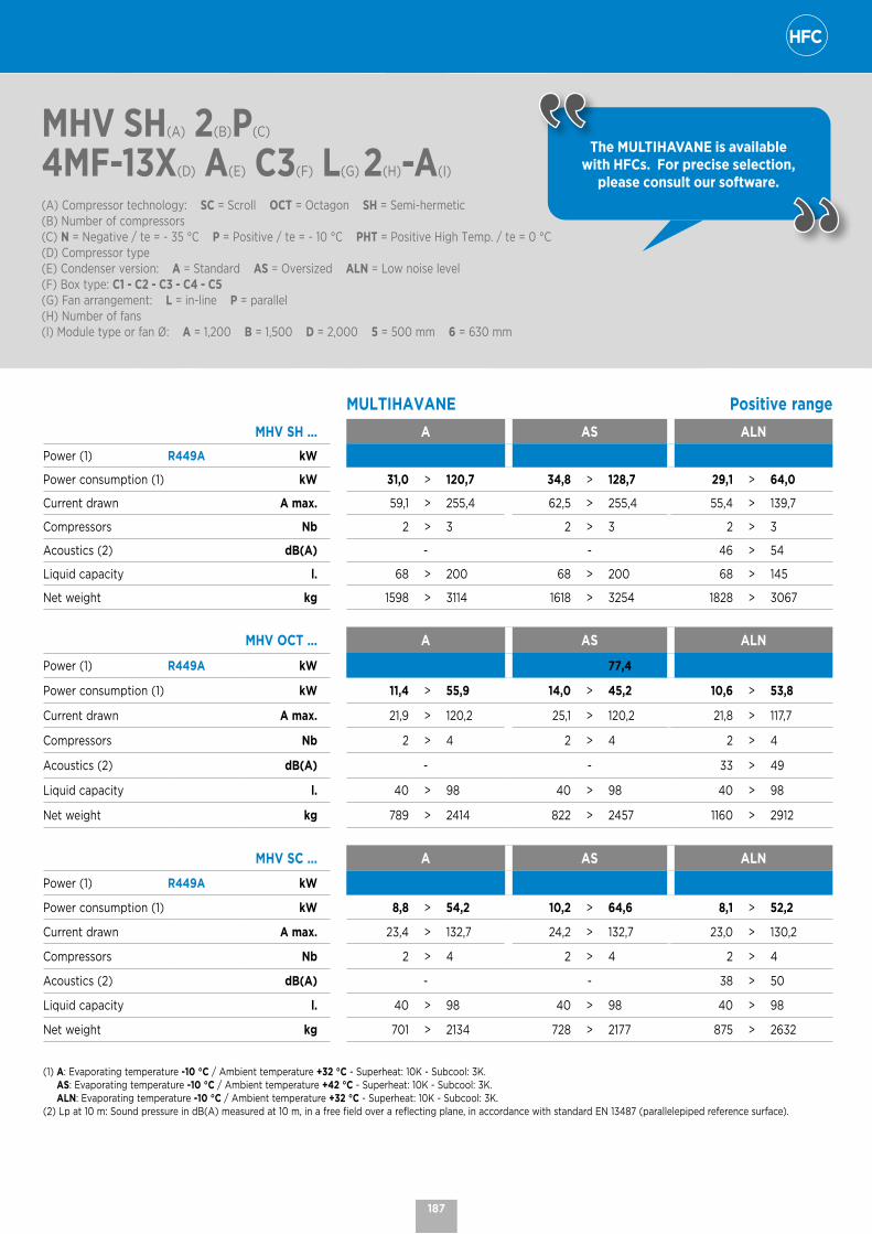
MHV SH(A) 2(B)P(C)
4MF-13X(D) A(E) C3(F) L(G) 2(H)-A(I)
(A) Compressor technology: SC = Scroll OCT = Octagon SH = Semi-hermetic(B) Number of compressors(C) N = Negative / te = - 35 °C P = Positive / te = - 10 °C PHT = Positive High Temp. / te = 0 °C(D) Compressor type(E) Condenser version: A = Standard AS = Oversized ALN = Low noise level(F) Box type: C1 - C2 - C3 - C4 - C5(G) Fan arrangement: L = in-line P = parallel(H) Number of fans(I) Module type or fan Ø: A = 1,200 B = 1,500 D = 2,000 5 = 500 mm 6 = 630 mm
The MULTIHAVANE is available with HFCs. For precise selection,
please consult our software.
MULTIHAVANE Positive range
MHV SH ... A AS ALN
Power (1) R449A kW
Power consumption (1) kW 31,0 > 120,7 34,8 > 128,7 29,1 > 64,0
Current drawn A max. 59,1 > 255,4 62,5 > 255,4 55,4 > 139,7
Compressors Nb 2 > 3 2 > 3 2 > 3
Acoustics (2) dB(A) - - 46 > 54
Liquid capacity l. 68 > 200 68 > 200 68 > 145
Net weight kg 1598 > 3114 1618 > 3254 1828 > 3067
MHV OCT ... A AS ALN
Power (1) R449A kW 77,4
Power consumption (1) kW 11,4 > 55,9 14,0 > 45,2 10,6 > 53,8
Current drawn A max. 21,9 > 120,2 25,1 > 120,2 21,8 > 117,7
Compressors Nb 2 > 4 2 > 4 2 > 4
Acoustics (2) dB(A) - - 33 > 49
Liquid capacity l. 40 > 98 40 > 98 40 > 98
Net weight kg 789 > 2414 822 > 2457 1160 > 2912
MHV SC ... A AS ALN
Power (1) R449A kW
Power consumption (1) kW 8,8 > 54,2 10,2 > 64,6 8,1 > 52,2
Current drawn A max. 23,4 > 132,7 24,2 > 132,7 23,0 > 130,2
Compressors Nb 2 > 4 2 > 4 2 > 4
Acoustics (2) dB(A) - - 38 > 50
Liquid capacity l. 40 > 98 40 > 98 40 > 98
Net weight kg 701 > 2134 728 > 2177 875 > 2632
(1) A: Evaporating temperature -10 °C / Ambient temperature +32 °C - Superheat: 10K - Subcool: 3K.AS: Evaporating temperature -10 °C / Ambient temperature +42 °C - Superheat: 10K - Subcool: 3K.ALN: Evaporating temperature -10 °C / Ambient temperature +32 °C - Superheat: 10K - Subcool: 3K.
(2) Lp at 10 m: Sound pressure in dB(A) measured at 10 m, in a free field over a reflecting plane, in accordance with standard EN 13487 (parallelepiped reference surface).
187
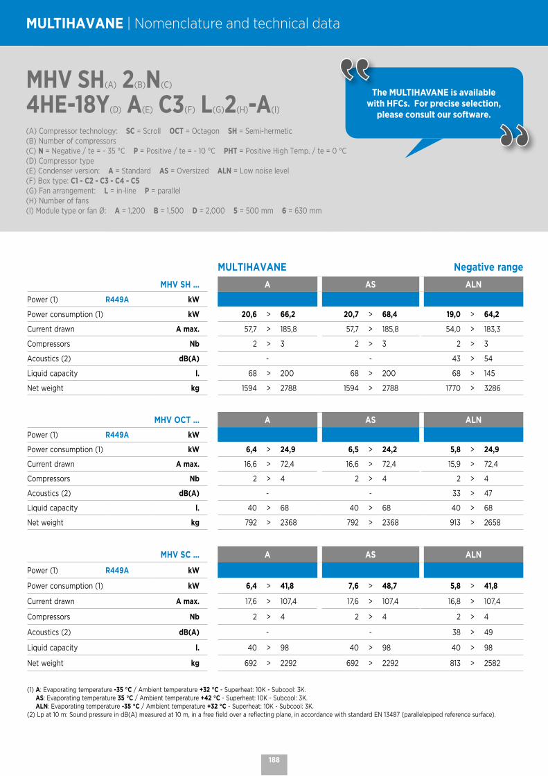
MULTIHAVANE | Nomenclature and technical data
The MULTIHAVANE is available with HFCs. For precise selection,
please consult our software.
MHV SH(A) 2(B)N(C)
4HE-18Y(D) A(E) C3(F) L(G)2(H)-A(I) (A) Compressor technology: SC = Scroll OCT = Octagon SH = Semi-hermetic(B) Number of compressors(C) N = Negative / te = - 35 °C P = Positive / te = - 10 °C PHT = Positive High Temp. / te = 0 °C(D) Compressor type(E) Condenser version: A = Standard AS = Oversized ALN = Low noise level(F) Box type: C1 - C2 - C3 - C4 - C5(G) Fan arrangement: L = in-line P = parallel(H) Number of fans(I) Module type or fan Ø: A = 1,200 B = 1,500 D = 2,000 5 = 500 mm 6 = 630 mm
MULTIHAVANE Negative range
MHV SH ... A AS ALN
Power (1) R449A kW
Power consumption (1) kW 20,6 > 66,2 20,7 > 68,4 19,0 > 64,2
Current drawn A max. 57,7 > 185,8 57,7 > 185,8 54,0 > 183,3
Compressors Nb 2 > 3 2 > 3 2 > 3
Acoustics (2) dB(A) - - 43 > 54
Liquid capacity l. 68 > 200 68 > 200 68 > 145
Net weight kg 1594 > 2788 1594 > 2788 1770 > 3286
MHV OCT ... A AS ALN
Power (1) R449A kW
Power consumption (1) kW 6,4 > 24,9 6,5 > 24,2 5,8 > 24,9
Current drawn A max. 16,6 > 72,4 16,6 > 72,4 15,9 > 72,4
Compressors Nb 2 > 4 2 > 4 2 > 4
Acoustics (2) dB(A) - - 33 > 47
Liquid capacity l. 40 > 68 40 > 68 40 > 68
Net weight kg 792 > 2368 792 > 2368 913 > 2658
MHV SC ... A AS ALN
Power (1) R449A kW
Power consumption (1) kW 6,4 > 41,8 7,6 > 48,7 5,8 > 41,8
Current drawn A max. 17,6 > 107,4 17,6 > 107,4 16,8 > 107,4
Compressors Nb 2 > 4 2 > 4 2 > 4
Acoustics (2) dB(A) - - 38 > 49
Liquid capacity l. 40 > 98 40 > 98 40 > 98
Net weight kg 692 > 2292 692 > 2292 813 > 2582
(1) A: Evaporating temperature -35 °C / Ambient temperature +32 °C - Superheat: 10K - Subcool: 3K.AS: Evaporating temperature 35 °C / Ambient temperature +42 °C - Superheat: 10K - Subcool: 3K.ALN: Evaporating temperature -35 °C / Ambient temperature +32 °C - Superheat: 10K - Subcool: 3K.
(2) Lp at 10 m: Sound pressure in dB(A) measured at 10 m, in a free field over a reflecting plane, in accordance with standard EN 13487 (parallelepiped reference surface).
188
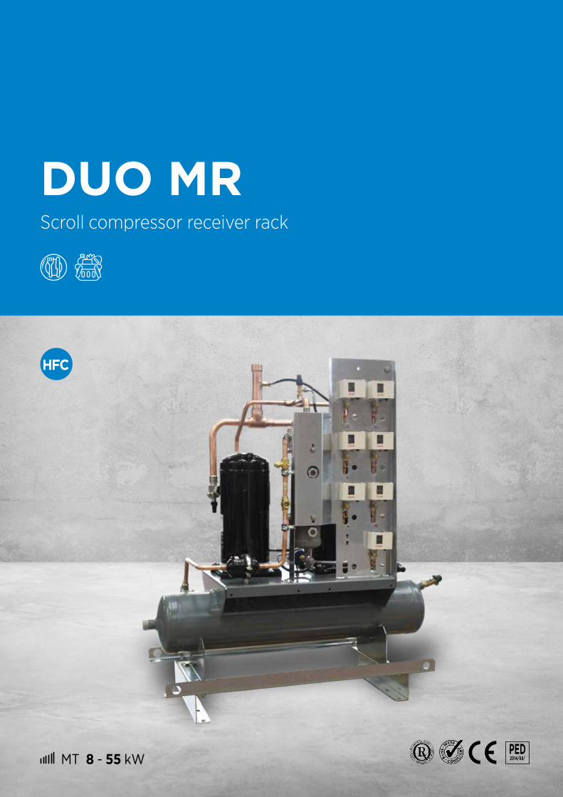
MT 8 - 55 kW PED 2014/68/
DUO MRScroll compressor receiver rack
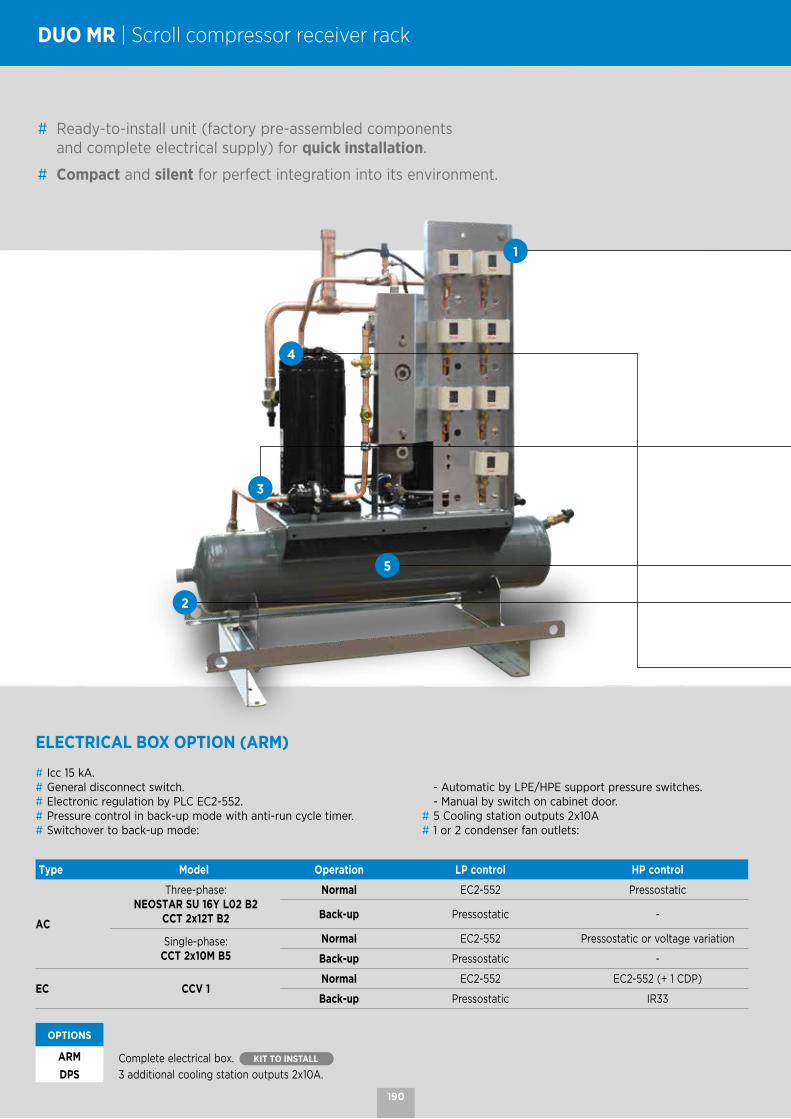
DUO MR | Scroll compressor receiver rack
# Ready-to-install unit (factory pre-assembled components and complete electrical supply) for quick installation.
# Compact and silent for perfect integration into its environment.
Type Model Operation LP control HP control
AC
Three-phase:NEOSTAR SU 16Y L02 B2
CCT 2x12T B2
Normal EC2-552 Pressostatic
Back-up Pressostatic -
Single-phase:CCT 2x10M B5
Normal EC2-552 Pressostatic or voltage variation
Back-up Pressostatic -
EC CCV 1 Normal EC2-552 EC2-552 (+ 1 CDP)
Back-up Pressostatic IR33
OPTIONS ARM Complete electrical box. KIT TO INSTALL DPS 3 additional cooling station outputs 2x10A.
ELECTRICAL BOX OPTION (ARM)
# Icc 15 kA.# General disconnect switch.# Electronic regulation by PLC EC2-552.# Pressure control in back-up mode with anti-run cycle timer.# Switchover to back-up mode:
- Automatic by LPE/HPE support pressure switches. - Manual by switch on cabinet door.# 5 Cooling station outputs 2x10A# 1 or 2 condenser fan outlets:
1
4
3
5
2
190

PRODUCT ADVANTAGES
# Integrated pressostatic back-up operation.# Supports for easy handling of the unit.
LIQUID RECEIVER
# Horizontal receiver with a capacity of 40 L.
# 2 inlet/outlet shut-off valves.
# Liquid outlet equipped with a filter dryer, an indicator and a liquid outlet valve.
# Simple safety valve.
OIL LINE
# HP oil separator with integrated oil reserve with high and low indicator.
# HP oil return line with filter.# Electronic oil level controller.
MANIFOLDS
# Copper suction and delivery.
CONTROL DEVICES
# 1 LP general safety pressure switch.# 1 LP regulator pressure switch per compressor.# 1 HP cartridge pressure switch with automatic reset per compressor.# 2 HP regulator pressure switches.# 1 LPE and HPE support pressure switch (switchover to back-up mode).# 1 LP sensor.
OPTIONS
CDPHP pressure sensors 4-20 mA signal
(EC condenser – CCV 1). KIT TO INSTALL
RPCCondensing pressure control by voltage variation
(condenser CCT 2x10M B5). KIT TO INSTALL
COMPRESSORS
# 2 Scroll technology compressors, one of which has DIGITAL™ power variation.
# Equipped with suction and delivery shut-off valves, crankcase heater and rigid suspension elements.
# Rack pre-wired in the factory with 3 m of cable available.
OPTIONS COQ Noise insulation casings. KIT TO INSTALL
1
2
4
3
5
191

DUO MR(A) 30(B)
(A) Compressor unit on bottle(B) Compressor model
DUO MR | Nomenclature and technical data
L P
H
DUO MR ... 30 45 57 76 114
L mm 1200 1200 1200 1200 1260
P mm 530 530 610 600 600
H mm 1330 1330 1330 1286 1296
DUO MR | Dimensions
The DUO MR is available with HFCs. For more information, please
consult our software.
DUO MR Positive range
DUO MR ... 30 45 57 76 114
Compressor type ZB30+ZBD30 ZB45+ZBD45 ZB57+ZBD57 ZB76+ZBD76 ZB114+ZBD114
Power (1)
R407F kW 14,2 20,8 27,0 38,2 54,7
R407A kW 13,9 19,8 27,0 35,6 50,0
R448A kW 14,1 20,7 26,7 36,6 52,9
R449A kW 14,1 20,6 26,7 36,6 52,8
R134a kW 8,6 12,5 15,7 21,3 31,6
Power consumption*
R407F kW 6,0 8,7 11,0 15,2 22,8
R407A kW 5,8 8,2 11,0 14,5 21,7
R448A kW 5,7 8,0 9,9 14,2 22,2
R449A kW 5,7 8,0 9,9 14,2 22,2
R134a kW 3,7 5,2 7,2 9,6 13,9
Compressor Nb 2 2 2 2 2
Input current* A max. 15,8 24,2 28,0 40,8 66,6
Receiver volume l. 40 40 40 40 40
Noise level Lp 10m (2) dB(A) 41 43 50 48 53
Connections
Suction Ø 1"5/8 1"5/8 1"5/8 2"1/8 2"1/8
Delivery Ø 7/8" 7/8" 7/8" 1"1/8 1"1/8
Liquid inlet Ø 7/8" 7/8" 7/8" 7/8" 1"1/8
Liquid outlet Ø 5/8" 5/8" 5/8" 1"1/8 1"1/8
Weight kg 196 200 210 260 275
(1) Evaporating temperature -10 °C / Ambient temperature +42 °C - Superheat: 10K - Subcool: 3K.(2) Sound pressure level at 10 m given as an indication only.
192
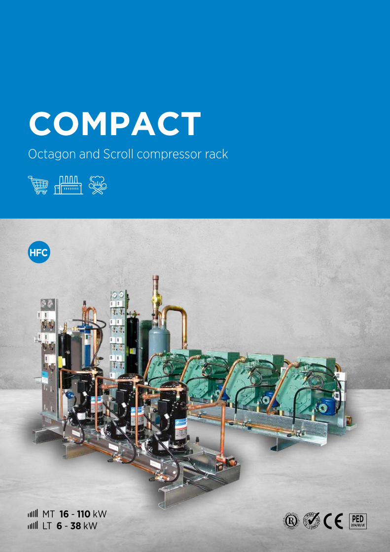
MT 16 - 110 kW LT 6 - 38 kW
PED 2014/68/UE
COMPACTOctagon and Scroll compressor rack

COMPACT | Octagon and Scroll compressor rack
MCONTROL DEVICES
# 1 LP general safety pressure switch# 1 or 2 HP cartridge pressure switch(es) with automatic reset per
compressor (according to standard EN 378-2: 2009).# 2 pressure gages (LP+HP)# 1 oil differential pressure switch per compressor for semi-hermetic
piston models of compressor 4TC to 4NC.
OPTIONS
Safety packBPS LP safety pressure switch per compressor.
HPG HP general safety pressure switch.
Regulation packBP1 LP pressure switch (automatic reset).
HPS Additional HP pressure switches.
CDP HP/LP pressure sensors signal 4-20 mA.
ALF Height-adjustable float coolant level alarm.
ALR Optoelectronic refrigerant level alarm.
# Modular rack to best meet the needs of your application, available with Scroll or Semi-Hermetic Octagon compressors.
# Compact to save space.
FRAME
# One-piece frame designed to avoid vibration problems.
OPTIONS
PAV Anti-vibration pads. KIT TO INSTALL
ARM Electrical cabinet. CONTACT US
CONNECTION PACK
# 1 connecting valve on the suction, the delivery and the liquid outlet.
194

LIQUID STATION
# Liquid station delivered separately.# 2 inlet/outlet shut-off valves.# Liquid outlet equipped with a removable filter dryer box and an indicator.# Single or double safety valve (according to PED).
OPTIONS
BAC Liquid separator (only for semi-hermetic compressor).
RLS Oversized liquid receiver.
SSD Double safety valve with 3-way valve (for receivers < 120 litres).
OIL LINE
# Oil separator and receiver with high and low indicator.# Oil manifold with flexible connection at the ends.# LP oil return line with filter and indicator.# Float oil level regulator with shut-off valve per compressor for SH and electronic for Scroll.# Degassing valve.
OPTIONS
TXL Electronic oil level controllers (Compact Octagon).
COMPRESSORS
# Scroll technology (Copeland) or Octagon semi-hermetic piston technology (Bitzer).
# Equipped with suction and delivery shut-off valves, crankcase heater and rigid suspension elements.
# Cylinder head fan for semi-hermetic reciprocating models in negative application.
MANIFOLDS
# Copper suction and delivery.
# Polypropylene collar on the suction side and high temperature resistant polyamide on the delivery side.
# A general filter unit on the suction side.
OPTIONS
BDR Condensate drain pan under suction manifolds.
Do you have a specific request? Contact us to design the unit
that meets your needs.
195

COM 2(A)P(B) 4EES-4Y(C)
(A) Number of compressors(B) P = Positive range - N = Negative range(C) Compressor type
COMPACT Octagon | Nomenclature and technical data
The COMPACT is available with HFCs. For more information, please consult
our software.
COMPACT | Octagon Positive range
COM ...2P
4EES-4Y2P
4DES-5Y2P
4CES-6Y3P
4EES-4Y3P
4DES-5Y2P
4TES-9Y4P
4EES-4Y2P
4PES-12Y3P
4CES-6Y
Power (1) R449A kW 21,6 25,4 31,4 32,4 38,0 39,3 43,2 44,4 47,1
Power consumption (1) kW 9,5 11,1 13,6 14,3 16,7 16,6 19,1 18,4 20,5
Compressor Nb 2 2 2 3 3 2 4 2 3
Max. current drawn A 20 25 32 31 38 39 41 43 48
Receiver volume l. 45 45 60 60 60 60 60 60 60
Connection pack standard option
Delivery Ø 1"1/8 1"1/8 1"1/8 1"1/8 1"1/8 1"1/8 1"1/8 1"1/8 1"1/8
Suction Ø 1"5/8 1"5/8 1"5/8 1"5/8 2"1/8 2"1/8 2"1/8 2"1/8 2"1/8
Liquid Ø 7/8" 7/8" 7/8" 7/8" 1"1/8 1"1/8 1"1/8 1"1/8 1"1/8
Rack weight kg 374 383 390 472 482 481 573 491 498
Receiver size
L mm 666 666 666 666 666 666 666 666 666
D mm 402 402 402 402 402 402 402 402 402
H mm 1137 1137 1338 1338 1338 1338 1338 1338 1338
Receiver weight kg 60 60 80 80 80 80 80 80 80
COM ...4P
4DES-5Y2P
4NES-14Y3P
4TES-9Y4P
4CES-6Y3P
4PES-12Y4P
4TES-9Y3P
4NES-14Y4P
4PES-12Y4P
4NES-14Y
Power (1) R449A kW 50,7 53,4 58,9 62,8 66,7 78,6 80,2 88,9 106,9
Power consumption (1) kW 22,2 22,3 24,9 27,3 27,5 33,2 33,4 36,7 44,5
Compressor Nb 4 2 3 4 3 4 3 4 4
Max. current drawn A 50 52 59 64 65 78 77 86 103
Receiver volume l. 60 60 60 60 120 120 120 120 120
Connection pack standard option
Delivery Ø 1"3/8 1"3/8 1"3/8 1"3/8 1"3/8 1"5/8 1"5/8 1"5/8 1"5/8
Suction Ø 2"1/8 2"1/8 2"1/8 2"1/8 2"5/8 2"5/8 2"5/8 2"5/8 2"5/8
Liquid Ø 1"1/8 1"1/8 1"1/8 1"1/8 1"3/8 1"3/8 1"3/8 1"3/8 1"3/8
Rack weight kg 589 504 637 608 656 794 670 815 823
Receiver size
L mm 666 666 666 666 714 714 714 714 714
D mm 402 402 402 402 455 455 455 455 455
H mm 1338 1338 1338 1338 1834 1834 1834 1834 1834
Receiver weight kg 80 80 80 80 120 120 120 120 120
(1) Evaporating temperature -10 °C / Ambient temperature +45 °C - Superheat: 10K - Subcool: 3K.
196

COM 2(A)P(B) 4EES-4Y(C)
(A) Number of compressors(B) P = Positive range - N = Negative range(C) Compressor type
The COMPACT is available with HFCs. For more information, please consult
our software.
COMPACT | Octagon Negative range
COM ...2N
4EES-4Y2N
4DES-5Y2N
4CES-6Y3N
4EES-4Y2N
4TES-9Y3N
4DES-5Y2N
4PES-12Y4N
4EES-4Y3N
4CES-6Y
Power (1) R449A kW 5,6 6,5 8,4 8,4 9,9 9,8 10,5 11,2 12,6
Power consumption (1) kW 4,3 5,0 6,5 6,4 7,2 7,5 7,5 8,5 9,7
Compressor Nb 2 2 2 3 2 3 2 4 3
Max. current drawn A 15 19 25 23 27 29 29 30 38
Receiver volume l. 45 45 45 45 45 45 45 45 45
Connection pack standard option
Delivery Ø 1"1/8 1"1/8 1"1/8 1"1/8 1"1/8 1"1/8 1"1/8 1"1/8 1"1/8
Suction Ø 1"3/8 1"3/8 1"5/8 1"5/8 1"5/8 1"5/8 1"5/8 1"5/8 1"5/8
Liquid Ø 5/8" 5/8" 5/8" 5/8" 5/8" 5/8" 5/8" 5/8" 5/8"
Rack weight kg 371 376 388 470 474 476 484 566 492
Receiverdimensions
L mm 666 666 666 666 666 666 666 666 666
D mm 402 402 402 402 402 402 402 402 402
H mm 1137 1137 1137 1137 1137 1137 1137 1137 1137
Receiver weight kg 60 60 60 60 60 60 60 60 60
COM ...2N
4NES-14Y4N
4DES-5Y3N
4TES-9Y3N
4PES-12Y4N
4CES-6Y4N
4TES-9Y3N
4NES-14Y4N
4PES-12Y4N
4NES-14Y
Power (1) R449A kW 13,6 13,1 14,9 15,8 16,9 19,9 20,3 21,0 27,1
Power consumption (1) kW 9,4 10,1 10,8 11,2 13,0 14,4 14,2 14,9 18,9
Compressor Nb 2 4 3 3 4 4 3 4 4
Max. current drawn A 35 39 40 44 51 54 52 58 70
Receiver volume l. 60 60 60 60 60 60 60 60 60
Connection pack standard option
Delivery Ø 1"1/8 1"1/8 1"1/8 1"1/8 1"1/8 1"1/8 1"1/8 1"1/8 1"1/8
Suction Ø 2"1/8 2"1/8 2"1/8 2"1/8 2"1/8 2"1/8 2"1/8 2"5/8 2"5/8
Liquid Ø 7/8" 7/8" 7/8" 7/8" 7/8" 7/8" 7/8" 1"1/8 1"1/8
Rack weight kg 490 577 624 634 597 769 646 796 805
Receiver size
L mm 666 666 666 666 666 666 666 666 666
D mm 402 402 402 402 402 402 402 402 402
H mm 1338 1338 1338 1338 1338 1338 1338 1338 1338
Receiver weight kg 80 80 80 80 80 80 80 80 80
(1) Evaporating temperature -35 °C / Ambient temperature +40 °C - Superheat: 10K - Subcool: 3K.
197

COM 2(A)P(B) ZB38(C)
(A) Number of compressors (B) P = Positive range - N = Negative range(C) Compressor type
COMPACT Scroll | Nomenclature and technical data
The COMPACT is available with HFCs. For more information, please consult
our software.
COMPACT | Scroll Positive range
COM ...2P
ZB382P
ZB452P
ZB503P
ZB382P
ZB663P
ZB453P
ZB502P
ZB762P
ZB953P
ZB66
Power (1) R449A kW 16,7 19,6 23,0 25,1 28,7 29,4 34,5 34,0 41,4 43,0
Power consumption (1) kW 7,7 8,8 10,5 11,6 13,2 13,1 15,7 15,1 19,7 19,7
Compressor Nb 2 2 2 3 2 3 3 2 2 3
Max. current drawn A 22 22 25 33 31 34 38 36 46 47
Receiver volume l. 45 45 45 45 45 45 60 60 60 60
Connection pack standard option
Delivery Ø 1"1/8 1"1/8 1"1/8 1"1/8 1"1/8 1"1/8 1"1/8 1"1/8 1"1/8 1"1/8
Suction Ø 1"5/8 1"5/8 1"5/8 1"5/8 1"5/8 1"5/8 2"1/8 2"1/8 2"1/8 2"1/8
Liquid Ø 7/8" 7/8" 7/8" 7/8" 7/8" 7/8" 1"1/8 7/8" 1"1/8 1"1/8
Rack weight kg 287 292 328 340 334 346 403 338 348 408
Receiver size
L mm 666 666 666 666 666 666 666 666 666 666
D mm 402 402 402 402 402 402 402 402 402 402
H mm 1137 1137 1137 1137 1137 1137 1338 1338 1338 1338
Receiver weight kg 60 60 60 60 60 60 80 80 80 80
COM ...4P
ZB502P
ZB1143P
ZB764P
ZB663P
ZB954P
ZB763P
ZB1144P
ZB954P
ZB114
Power (1) R449A kW 46,0 49,0 50,9 57,4 62,1 67,9 73,4 82,8 97,9
Power consumption (1) kW 21,0 23,4 22,7 26,3 29,6 30,3 35,1 39,5 46,9
Compressor Nb 4 2 3 4 3 4 3 4 4
Max. current drawn A 50 58 53 62 70 71 87 93 115
Receiver volume l. 60 60 60 60 60 60 120 120 120
Connection pack standard option
Delivery Ø 1"1/8 1"3/8 1"3/8 1"3/8 1"3/8 1"3/8 1"3/8 1"5/8 1"5/8
Suction Ø 2"1/8 2"1/8 2"1/8 2"1/8 2"5/8 2"5/8 2"5/8 2"5/8 2"5/8
Liquid Ø 1"1/8 1"1/8 1"1/8 1"1/8 1"1/8 1"1/8 1"3/8 1"3/8 1"3/8
Rack weight kg 474 361 425 491 438 506 448 526 533
Receiver size
L mm 666 666 666 666 666 666 714 714 714
D mm 402 402 402 402 402 402 455 455 455
H mm 1338 1338 1338 1338 1338 1338 1834 1834 1834
Receiver weight kg 80 80 80 80 80 80 120 120 120
(1) Evaporating temperature -10 °C / Ambient temperature +45 °C - Superheat: 10K - Subcool: 3K.
198
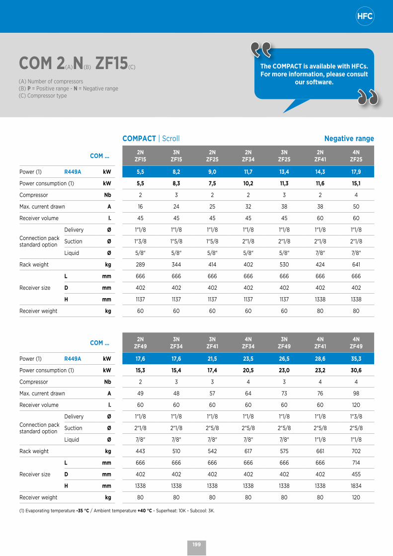
COM 2(A)N(B) ZF15(C)
(A) Number of compressors(B) P = Positive range - N = Negative range(C) Compressor type
The COMPACT is available with HFCs. For more information, please consult
our software.
COMPACT | Scroll Negative range
COM ...2N
ZF153N
ZF152N
ZF252N
ZF343N
ZF252N
ZF414N
ZF25
Power (1) R449A kW 5,5 8,2 9,0 11,7 13,4 14,3 17,9
Power consumption (1) kW 5,5 8,3 7,5 10,2 11,3 11,6 15,1
Compressor Nb 2 3 2 2 3 2 4
Max. current drawn A 16 24 25 32 38 38 50
Receiver volume l. 45 45 45 45 45 60 60
Connection pack standard option
Delivery Ø 1"1/8 1"1/8 1"1/8 1"1/8 1"1/8 1"1/8 1"1/8
Suction Ø 1"3/8 1"5/8 1"5/8 2"1/8 2"1/8 2"1/8 2"1/8
Liquid Ø 5/8" 5/8" 5/8" 5/8" 5/8" 7/8" 7/8"
Rack weight kg 289 344 414 402 530 424 641
Receiver size
L mm 666 666 666 666 666 666 666
D mm 402 402 402 402 402 402 402
H mm 1137 1137 1137 1137 1137 1338 1338
Receiver weight kg 60 60 60 60 60 80 80
COM ...2N
ZF493N
ZF343N
ZF414N
ZF343N
ZF494N
ZF414N
ZF49
Power (1) R449A kW 17,6 17,6 21,5 23,5 26,5 28,6 35,3
Power consumption (1) kW 15,3 15,4 17,4 20,5 23,0 23,2 30,6
Compressor Nb 2 3 3 4 3 4 4
Max. current drawn A 49 48 57 64 73 76 98
Receiver volume l. 60 60 60 60 60 60 120
Connection pack standard option
Delivery Ø 1"1/8 1"1/8 1"1/8 1"1/8 1"1/8 1"1/8 1"3/8
Suction Ø 2"1/8 2"1/8 2"5/8 2"5/8 2"5/8 2"5/8 2"5/8
Liquid Ø 7/8" 7/8" 7/8" 7/8" 7/8" 1"1/8 1"1/8
Rack weight kg 443 510 542 617 575 661 702
Receiver size
L mm 666 666 666 666 666 666 714
D mm 402 402 402 402 402 402 455
H mm 1338 1338 1338 1338 1338 1338 1834
Receiver weight kg 80 80 80 80 80 80 120
(1) Evaporating temperature -35 °C / Ambient temperature +40 °C - Superheat: 10K - Subcool: 3K.
199

COMPACT | Dimensions
COMPACT | Octagon COMPACT | Octagon
without BAC option with BAC option
460 11581790
478 6531320
478 12792240
580825
1255
630 11581955
648 12792440
648 6531520
580825
1255
COMPACT | Scroll Liquid station
478 12792230
580825
1255
460 11581785
478 6531310
L
H
P
45 l. 60 l. 120 l.
L mm 666 666 714
D mm 402 402 455
H mm 1137 1338 1834
Weight kg 60 80 120
200
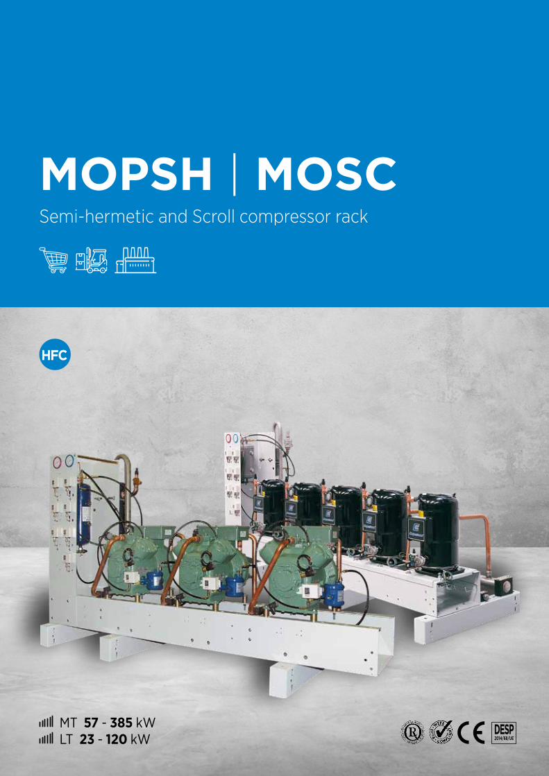
MT 57 - 385 kW LT 23 - 120 kW
DESP 2014/68/UE
MOPSH | MOSCSemi-hermetic and Scroll compressor rack

MOPSH | MOSC | Semi-hermetic and Scroll compressor rack
# Modular rack to best meet the needs of your application, available with Scroll (Copeland), Semi-Hermetic (Copeland or Bitzer) compressors.
# Compact design (width from 800 to 1,000 mm) that fits perfectly in restricted and hard-to-access areas.
CONTROL AND SAFETY DEVICES
# 1 LP general safety pressure switch# 1 or 2 HP cartridge pressure switch(s) with automatic reset per compressor.# 2 pressure gages (LP + HP).# Differential oil pressure switch per compressor. MOPSH
OPTIONS
ALF Height-adjustable float coolant level alarm.
ALR Optoelectronic refrigerant level alarm.
BAC Liquid separator. MOPSH
VFA Suction valve and filter on each compressor. MOPSH
SIL Delivery muffler (1 per compressor). MOPSH
LIQUID STATION
# Liquid station delivered separately.# Inlet/outlet shut-off valves.# Liquid outlet equipped with a removable filter dryer unit ≤ 150 l. and 2 parallel units with shut-off
valves > 150 l.# Indicator and general shut-off valve on outlet.# Single or double safety valve (according to PED).
OPTIONS
RLS Oversized liquid receiver.
SSD Double safety valve with 3-way valve (for receivers < 120 litres).
BD1 Single liquid drier bypass (1 filter unit) in operation.
MANIFOLDS
# Suction and delivery all stainless steel 304 L.# One Schrader pressure port with shut-off valve per manifold (mano pressure switch connection, etc.).# Polypropylene collars on the suction and high temperature resistant polyamide on the delivery.# A general suction filter unit with removable cartridge up to 186 kW cooling capacity in positive and 47 kW in negative.
One unit per compressor on top. MOPSH # A removable cartridge filter unit
mounted on the suction manifold. MOSC
OPTION
BDR Condensate drain pan under suction manifolds.
202
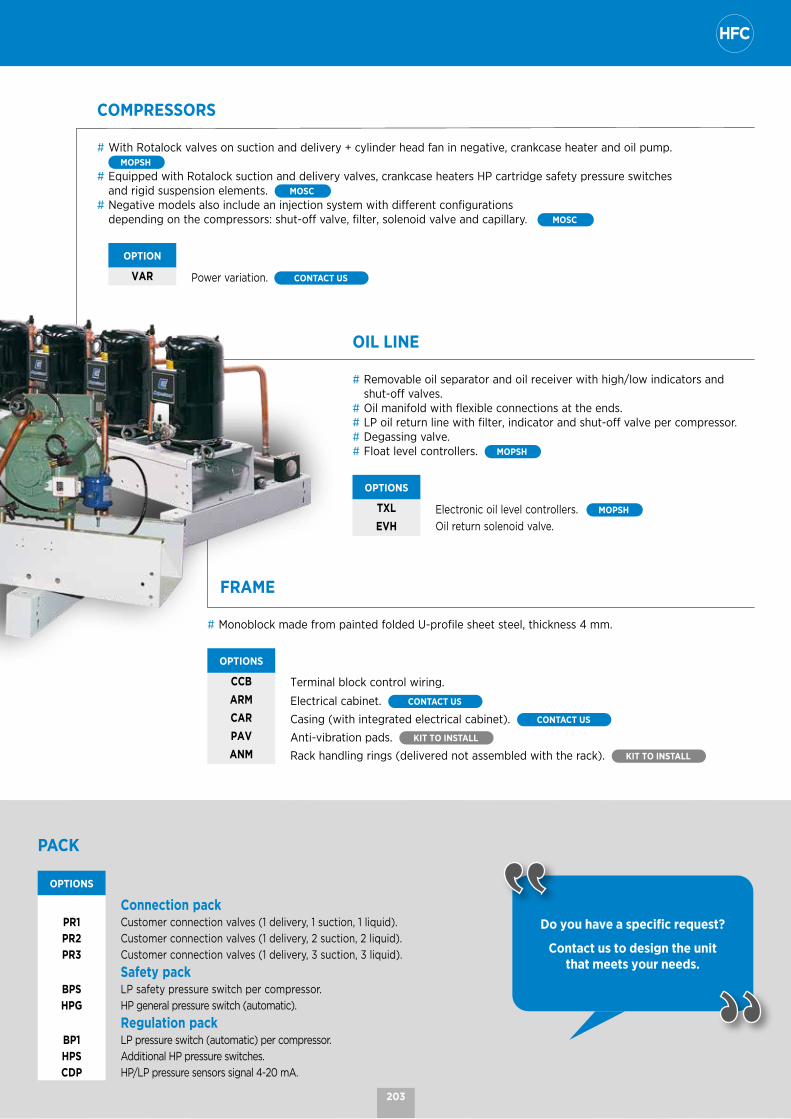
PACK
OPTIONS
Connection packPR1 Customer connection valves (1 delivery, 1 suction, 1 liquid).
PR2 Customer connection valves (1 delivery, 2 suction, 2 liquid).
PR3 Customer connection valves (1 delivery, 3 suction, 3 liquid).
Safety packBPS LP safety pressure switch per compressor.
HPG HP general pressure switch (automatic).
Regulation packBP1 LP pressure switch (automatic) per compressor.
HPS Additional HP pressure switches.
CDP HP/LP pressure sensors signal 4-20 mA.
Do you have a specific request? Contact us to design the unit
that meets your needs.
COMPRESSORS
# With Rotalock valves on suction and delivery + cylinder head fan in negative, crankcase heater and oil pump. MOPSH
# Equipped with Rotalock suction and delivery valves, crankcase heaters HP cartridge safety pressure switches and rigid suspension elements. MOSC
# Negative models also include an injection system with different configurations depending on the compressors: shut-off valve, filter, solenoid valve and capillary. MOSC
OPTION
VAR Power variation. CONTACT US
OIL LINE
# Removable oil separator and oil receiver with high/low indicators and shut-off valves.
# Oil manifold with flexible connections at the ends.# LP oil return line with filter, indicator and shut-off valve per compressor.# Degassing valve.# Float level controllers. MOPSH
OPTIONS
TXL Electronic oil level controllers. MOPSH
EVH Oil return solenoid valve.
FRAME
# Monoblock made from painted folded U-profile sheet steel, thickness 4 mm.
OPTIONS
CCB Terminal block control wiring.ARM Electrical cabinet. CONTACT US
CAR Casing (with integrated electrical cabinet). CONTACT US
PAV Anti-vibration pads. KIT TO INSTALL ANM Rack handling rings (delivered not assembled with the rack). KIT TO INSTALL
203
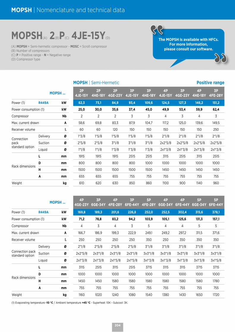
MOPSH(A) 2(B)P(C) 4JE-15Y(D)
(A) MOPSH = Semi-hermetic compressor - MOSC = Scroll compressor(B) Number of compressors (C) P = Positive range - N = Negative range(D) Compressor type
MOPSH | Nomenclature and technical data
MOPSH | Semi-Hermetic Positive range
MOPSH ...2P
4JE-15Y2P
4HE-18Y2P
4GE-23Y3P
4JE-15Y3P
4HE-18Y4P
4JE-15Y3P
4GE-23Y4P
4HE-18Y3P
4FE-28Y
Power (1) R449A kW 62,3 73,1 84,9 93,4 109,6 124,5 127,3 146,2 151,2
Power consumption (1) kW 25,0 30,0 35,6 37,4 45,0 49,9 53,4 59,9 62,4
Compressor Nb 2 2 2 3 3 4 3 4 3
Max. current drawn A 58,6 69,8 83,3 87,9 104,7 117,2 125,0 139,6 149,5
Receiver volume l. 60 60 120 150 150 150 150 150 250
Connectionpackstandard option
Delivery Ø 1"3/8 1"5/8 1"5/8 1"5/8 1"5/8 2"1/8 2"1/8 2"1/8 2"1/8
Suction Ø 2"5/8 2"5/8 3"1/8 3"1/8 3"1/8 2x2"5/8 2x2"5/8 2x2"5/8 2x2"5/8
Liquid Ø 1"1/8 1"1/8 1"3/8 1"3/8 1"3/8 2x1"3/8 2x1"3/8 2x1"3/8 2x1"3/8
Rack dimensions
L mm 1915 1915 1915 2515 2515 3115 2515 3115 2515
D mm 800 800 800 800 1000 1000 1000 1000 1000
H mm 1500 1500 1500 1500 1500 1450 1450 1450 1450
A mm 655 655 655 755 755 755 755 755 755
Weight kg 610 620 630 850 860 1100 900 1140 960
MOPSH ...4P
4GE-23Y3P
6GE-34Y4P
4FE-28Y3P
6FE-44Y5P
4FE-28Y4P
6GE-34Y4P
6FE-44Y5P
6GE-34Y5P
6FE-44Y
Power (1) R449A kW 169,8 189,3 201,6 226,8 252,0 252,5 302,4 315,6 378,1
Power consumption (1) kW 71,2 78,8 83,2 94,2 103,9 105,1 125,6 131,3 157,1
Compressor Nb 4 3 4 3 5 4 4 5 5
Max. current drawn A 166,7 186,9 199,3 222,9 249,1 249,2 297,2 311,5 371,6
Receiver volume l. 250 250 250 250 350 250 350 350 350
Connection pack standard option
Delivery Ø 2"1/8 2"5/8 2"5/8 2"5/8 3"1/8 3"1/8 3"1/8 3"1/8 3"1/8
Suction Ø 2x2"5/8 2x3"1/8 2x3"1/8 2x3"1/8 3x3"1/8 3x3"1/8 3x3"1/8 3x3"1/8 3x3"1/8
Liquid Ø 2x1"3/8 2x1"3/8 2x1"5/8 2x1"5/8 3x1"3/8 3x1"3/8 3x1"3/8 3x1"3/8 3x1"5/8
Rack dimensions
L mm 3115 2515 3115 2515 3715 3115 3115 3715 3715
D mm 1000 1000 1000 1000 1000 1000 1000 1000 1000
H mm 1450 1450 1580 1580 1580 1580 1580 1580 1780
A mm 755 755 755 755 755 755 755 755 755
Weight kg 1160 1020 1240 1080 1540 1380 1430 1650 1720
(1) Evaporating temperature -10 °C / Ambient temperature +45 °C - Superheat: 10K - Subcool: 3K.
The MOPSH is available with HFCs. For more information,
please consult our software.
204

MOPSH(A) 2(B)N(C) / 4HE-18Y(D)
(A) MOPSH = Semi-hermetic compressor - MOSC = Scroll compressor(B) Number of compressors (C) P = Positive range - N = Negative range(D) Compressor type
MOPSH | Semi-Hermetic Negative range
MOPSH ...2N
4HE-18Y2N
4GE-23Y2N
4FE-28Y3N
4HE-18Y3N
4GE-23Y2N
6GE-34Y4N
4HE-18Y2N
6FE-44Y3N
4FE-28Y
Power (1) R449A kW 20,0 24,2 29,0 30,1 36,4 37,4 40,1 43,4 43,4
Power consumption (1) kW 14,4 17,4 20,7 21,6 26,1 25,1 28,8 31,7 31,0
Compressor Nb 2 2 2 3 3 2 4 2 3
Max. current drawn A 49,1 57,7 72,8 73,6 86,5 90,4 98,2 112,4 109,2
Receiver volume l. 60 60 120 120 150 120 150 150 150
Connection pack standard option
Delivery Ø 1"3/8 1"3/8 1"3/8 1"3/8 1"3/8 1"3/8 1"3/8 1"3/8 1"5/8
Suction Ø 2"5/8 2"5/8 2"5/8 2"5/8 2x2"5/8 2x2"1/8 2x2"5/8 2x2"5/8 2x2"5/8
Liquid Ø 7/8" 1"1/8 1"3/8 1"3/8 2x7/8" 2x7/8" 2x7/8" 2x7/8" 2x7/8"
Rackdimensions
L mm 1915 1915 1915 2515 2515 1915 3115 1915 2515
D mm 800 800 800 800 800 800 800 800 1000
H mm 1500 1500 1500 1500 1450 1450 1450 1450 1450
A mm 655 655 655 655 755 755 755 755 755
Weight kg 600 610 640 820 840 690 1060 720 930
MOPSH ...3N
6GE-34Y4N
4FE-28Y3N
6FE-44Y5N
4FE-28Y4N
6GE-34Y4N
6FE-44Y5N
6GE-34Y5N
6FE-44Y
Power (1) R449A kW 56,0 57,9 65,2 72,4 74,7 86,9 93,4 108,6
Power consumption (1) kW 37,7 41,4 47,6 51,7 50,3 63,4 62,9 79,3
Compressor Nb 3 4 3 5 4 4 5 5
Max. current drawn A 135,6 145,6 168,6 182,0 180,8 224,8 226,0 281,0
Receiver volume l. 150 250 250 250 250 250 350 350
Connection pack standard option
Delivery Ø 1"5/8 1"5/8 1"5/8 1''5/8 1"5/8 2"1/8 2"1/8 2''1/8
Suction Ø 2x2"5/8 2x3"1/8 2x3"1/8 3x2"5/8 2x3"1/8 3x2"5/8 3x3"1/8 3x3"1/8
Liquid Ø 2x1"1/8 2x1"1/8 2x1"1/8 3x1"1/8 2x1"3/8 3x1"1/8 3x1"1/8 3x1"1/8
Rack dimensions
L mm 2515 3115 2515 3715 3115 3115 3715 3715
D mm 1000 1000 1000 1000 1000 1000 1000 1000
H mm 1580 1580 1580 1580 1580 1580 1580 1780
A mm 755 755 755 755 755 755 755 755
Weight kg 1000 1200 1050 1470 1290 1370 1610 1680
(1) Evaporating temperature -35 °C / Ambient temperature +40 °C - Superheat: 10K - Subcool: 3K.
The MOPSH is available with HFCs. For more information,
please consult our software.
205
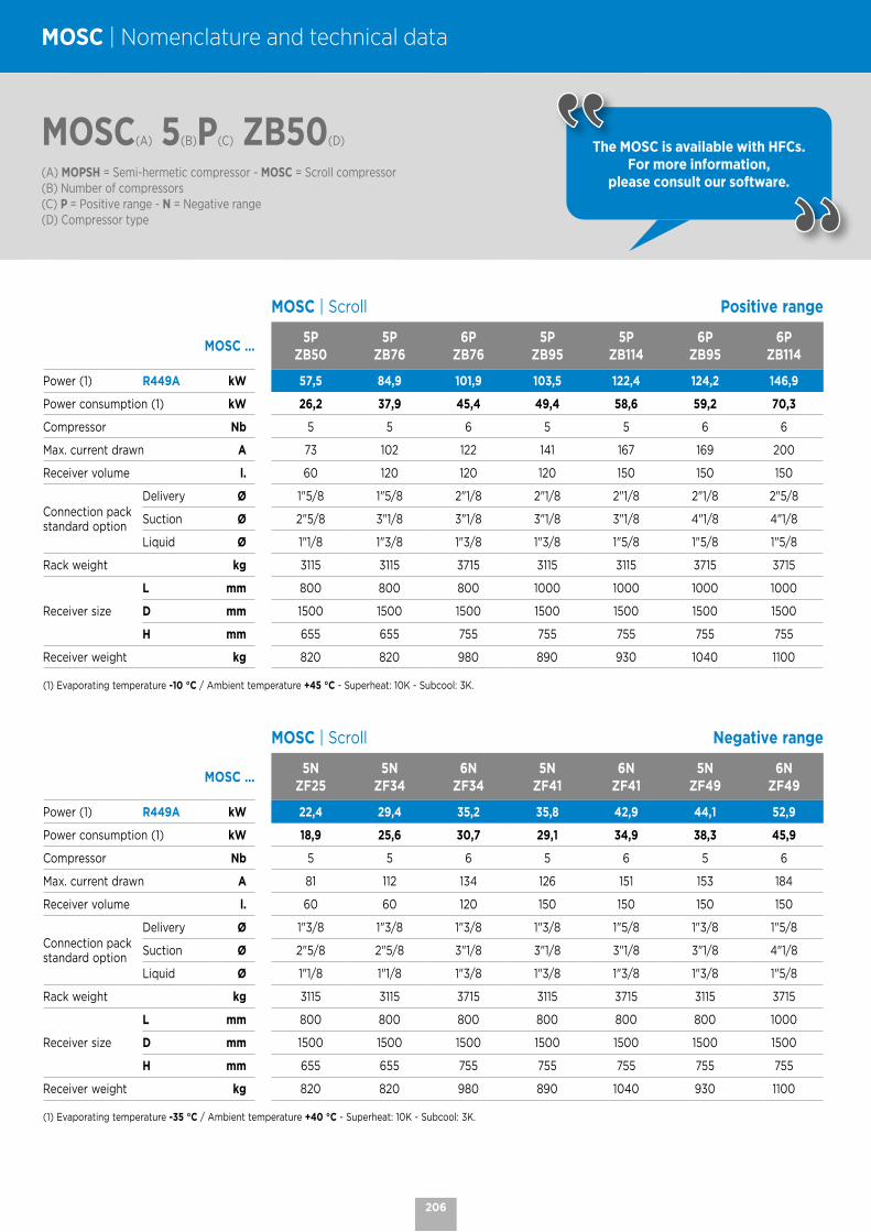
MOSC(A) 5(B)P(C) ZB50(D)
(A) MOPSH = Semi-hermetic compressor - MOSC = Scroll compressor(B) Number of compressors (C) P = Positive range - N = Negative range(D) Compressor type
MOSC | Nomenclature and technical data
The MOSC is available with HFCs. For more information,
please consult our software.
MOSC | Scroll Positive range
MOSC ...5P
ZB505P
ZB766P
ZB765P
ZB955P
ZB1146P
ZB956P
ZB114
Power (1) R449A kW 57,5 84,9 101,9 103,5 122,4 124,2 146,9
Power consumption (1) kW 26,2 37,9 45,4 49,4 58,6 59,2 70,3
Compressor Nb 5 5 6 5 5 6 6
Max. current drawn A 73 102 122 141 167 169 200
Receiver volume l. 60 120 120 120 150 150 150
Connection pack standard option
Delivery Ø 1"5/8 1"5/8 2"1/8 2"1/8 2"1/8 2"1/8 2"5/8
Suction Ø 2"5/8 3"1/8 3"1/8 3"1/8 3"1/8 4"1/8 4"1/8
Liquid Ø 1"1/8 1"3/8 1"3/8 1"3/8 1"5/8 1"5/8 1"5/8
Rack weight kg 3115 3115 3715 3115 3115 3715 3715
Receiver size
L mm 800 800 800 1000 1000 1000 1000
D mm 1500 1500 1500 1500 1500 1500 1500
H mm 655 655 755 755 755 755 755
Receiver weight kg 820 820 980 890 930 1040 1100
(1) Evaporating temperature -10 °C / Ambient temperature +45 °C - Superheat: 10K - Subcool: 3K.
MOSC | Scroll Negative range
MOSC ...5N
ZF255N
ZF346N
ZF345N
ZF416N
ZF415N
ZF496N
ZF49
Power (1) R449A kW 22,4 29,4 35,2 35,8 42,9 44,1 52,9
Power consumption (1) kW 18,9 25,6 30,7 29,1 34,9 38,3 45,9
Compressor Nb 5 5 6 5 6 5 6
Max. current drawn A 81 112 134 126 151 153 184
Receiver volume l. 60 60 120 150 150 150 150
Connection pack standard option
Delivery Ø 1"3/8 1"3/8 1"3/8 1"3/8 1"5/8 1"3/8 1"5/8
Suction Ø 2"5/8 2"5/8 3"1/8 3"1/8 3"1/8 3"1/8 4"1/8
Liquid Ø 1"1/8 1"1/8 1"3/8 1"3/8 1"3/8 1"3/8 1"5/8
Rack weight kg 3115 3115 3715 3115 3715 3115 3715
Receiver size
L mm 800 800 800 800 800 800 1000
D mm 1500 1500 1500 1500 1500 1500 1500
H mm 655 655 755 755 755 755 755
Receiver weight kg 820 820 980 890 1040 930 1100
(1) Evaporating temperature -35 °C / Ambient temperature +40 °C - Superheat: 10K - Subcool: 3K.
206

MOPSH | MOSC | Dimensions
MOPSH | Semi-Hermetic
648 1157L
648 1157L
H
PA
648 1225L
1132
648 1225L
1132
648 1225L
1125 1108
MOSC | Scroll Liquid station
648 1225L
1132
H
PA
648 1225L
1225
L�
H�
P�
L�
H�
P�
60 l. 120 l. 150 l. 250 l. 350 l.
L’ mm 666 714 790 739 993
P’ mm 402 455 538 638 856
H’ mm 1366 1834 1605 2010 1942
Weight kg 90 130 150 250 290
207

NOTES
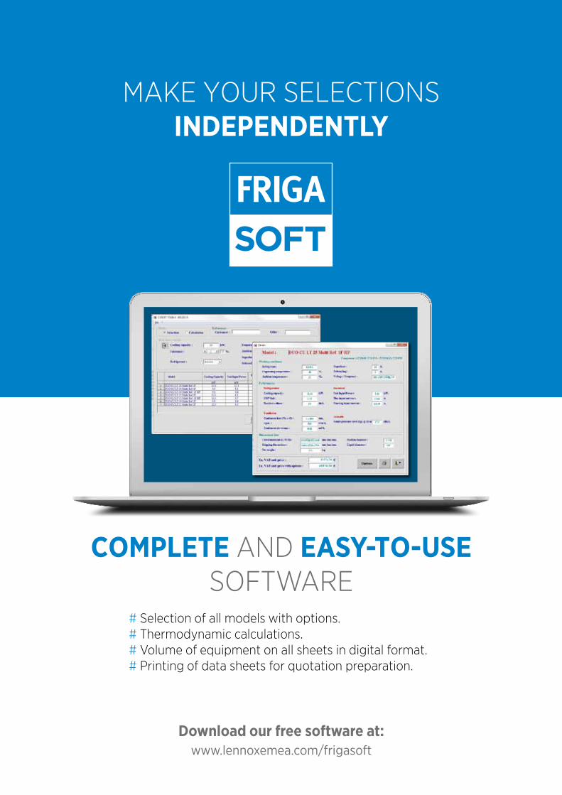
www.lennoxemea.com/frigasoft
COMPLETE AND EASY-TO-USE SOFTWARE
# Selection of all models with options. # Thermodynamic calculations. # Volume of equipment on all sheets in digital format. # Printing of data sheets for quotation preparation.
Download our free software at:
MAKE YOUR SELECTIONS INDEPENDENTLY
One number for all services:
+33 (0) 472 471 444
CUSTOMER SERVICE
Dial 1 2 3or
TECHNICAL SELECTIONS
Dial 1 2 3or [email protected]
AFTER-SALES & TECHNICAL SUPPORT
Dial 1 2 3or [email protected]
www.lennoxemea.com
RE
FR
IGE
RA
TIO
N C
AT
AL
OG
- 2
021
ED
ITIO
N