original instructions d series forklift truck - baoli emea
TRANSCRIPT
Original instructionsD series Forklift Truck
KBD50–70

Baoli - Your partner
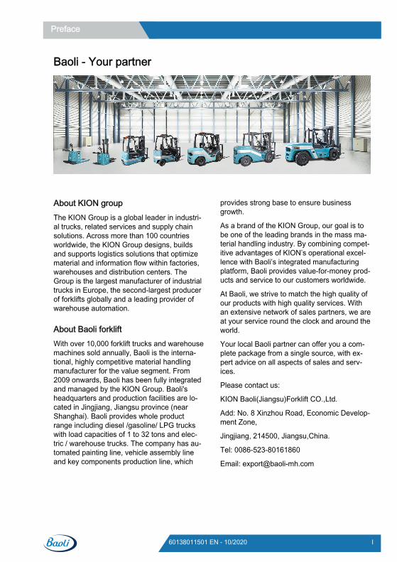
About KION groupThe KION Group is a global leader in industri-al trucks, related services and supply chainsolutions. Across more than 100 countriesworldwide, the KION Group designs, buildsand supports logistics solutions that optimizematerial and information flow within factories,warehouses and distribution centers. TheGroup is the largest manufacturer of industrialtrucks in Europe, the second-largest producerof forklifts globally and a leading provider ofwarehouse automation.
About Baoli forkliftWith over 10,000 forklift trucks and warehousemachines sold annually, Baoli is the interna-tional, highly competitive material handlingmanufacturer for the value segment. From2009 onwards, Baoli has been fully integratedand managed by the KION Group. Baoli'sheadquarters and production facilities are lo-cated in Jingjiang, Jiangsu province (nearShanghai). Baoli provides whole productrange including diesel /gasoline/ LPG truckswith load capacities of 1 to 32 tons and elec-tric / warehouse trucks. The company has au-tomated painting line, vehicle assembly lineand key components production line, which
provides strong base to ensure businessgrowth.
As a brand of the KION Group, our goal is tobe one of the leading brands in the mass ma-terial handling industry. By combining compet-itive advantages of KION’s operational excel-lence with Baoli’s integrated manufacturingplatform, Baoli provides value-for-money prod-ucts and service to our customers worldwide.
At Baoli, we strive to match the high quality ofour products with high quality services. Withan extensive network of sales partners, we areat your service round the clock and around theworld.
Your local Baoli partner can offer you a com-plete package from a single source, with ex-pert advice on all aspects of sales and serv-ices.
Please contact us:
KION Baoli(Jiangsu)Forklift CO.,Ltd.
Add: No. 8 Xinzhou Road, Economic Develop-ment Zone,
Jingjiang, 214500, Jiangsu,China.
Tel: 0086-523-80161860
Email: [email protected]
Preface
I60138011501 EN - 10/2020

1 Introduction Introduction . . . . . . . . . . . . . . . . . . . . . . . . . . . . . . . . . . . . . . . . . . . . . . . . . . . . . . . . . 2
Intended use . . . . . . . . . . . . . . . . . . . . . . . . . . . . . . . . . . . . . . . . . . . . . . . . . . . . . . . . 4
Impermissible use . . . . . . . . . . . . . . . . . . . . . . . . . . . . . . . . . . . . . . . . . . . . . . . . . . . . 5
Description of use and climatic conditions. . . . . . . . . . . . . . . . . . . . . . . . . . . . . . . . . . 6
Symbols used . . . . . . . . . . . . . . . . . . . . . . . . . . . . . . . . . . . . . . . . . . . . . . . . . . . . . . . 6
CE labelling . . . . . . . . . . . . . . . . . . . . . . . . . . . . . . . . . . . . . . . . . . . . . . . . . . . . . . . . . 7
EMC – Electromagnetic compatibility . . . . . . . . . . . . . . . . . . . . . . . . . . . . . . . . . . . . . 8
EC declaration of conformity in accordance with Machinery Directive . . . . . . . . . . . . 9
2 Safety Definition of terms used for responsible persons. . . . . . . . . . . . . . . . . . . . . . . . . . . . . 12Operating company . . . . . . . . . . . . . . . . . . . . . . . . . . . . . . . . . . . . . . . . . . . . . . . . . . . . . 12Specialist . . . . . . . . . . . . . . . . . . . . . . . . . . . . . . . . . . . . . . . . . . . . . . . . . . . . . . . . . . . . . 12Competent person . . . . . . . . . . . . . . . . . . . . . . . . . . . . . . . . . . . . . . . . . . . . . . . . . . . . . . 12Drivers . . . . . . . . . . . . . . . . . . . . . . . . . . . . . . . . . . . . . . . . . . . . . . . . . . . . . . . . . . . . . . . 12
Safety regulations . . . . . . . . . . . . . . . . . . . . . . . . . . . . . . . . . . . . . . . . . . . . . . . . . . . . 14General safety regulations. . . . . . . . . . . . . . . . . . . . . . . . . . . . . . . . . . . . . . . . . . . . . . . . 14Exhaust gases . . . . . . . . . . . . . . . . . . . . . . . . . . . . . . . . . . . . . . . . . . . . . . . . . . . . . . . . . 15
Ground condition for using the truck . . . . . . . . . . . . . . . . . . . . . . . . . . . . . . . . . . . . . . 15
Safety Regulations Relative to Forklift Use . . . . . . . . . . . . . . . . . . . . . . . . . . . . . . . . . 15
Residual dangers, residual risks . . . . . . . . . . . . . . . . . . . . . . . . . . . . . . . . . . . . . . . . . 16
Safety regulations when driving. . . . . . . . . . . . . . . . . . . . . . . . . . . . . . . . . . . . . . . . . . 17
Safety regulations in case of accidental lateral tipping . . . . . . . . . . . . . . . . . . . . . . . . 18
Exercise caution when handling gas springs and accumulators . . . . . . . . . . . . . . . . . 18
Safety regulations for handling consumables . . . . . . . . . . . . . . . . . . . . . . . . . . . . . . . 19Permissible consumables . . . . . . . . . . . . . . . . . . . . . . . . . . . . . . . . . . . . . . . . . . . . . . . . 19Hydraulic fluid . . . . . . . . . . . . . . . . . . . . . . . . . . . . . . . . . . . . . . . . . . . . . . . . . . . . . . . . . 19Oils . . . . . . . . . . . . . . . . . . . . . . . . . . . . . . . . . . . . . . . . . . . . . . . . . . . . . . . . . . . . . . . . . 20Battery acid . . . . . . . . . . . . . . . . . . . . . . . . . . . . . . . . . . . . . . . . . . . . . . . . . . . . . . . . . . . 21Disposal of consumables. . . . . . . . . . . . . . . . . . . . . . . . . . . . . . . . . . . . . . . . . . . . . . . . . 21
Environmental considerations . . . . . . . . . . . . . . . . . . . . . . . . . . . . . . . . . . . . . . . . . . . 22Disposal of components and batteries . . . . . . . . . . . . . . . . . . . . . . . . . . . . . . . . . . . . . . 22Packaging . . . . . . . . . . . . . . . . . . . . . . . . . . . . . . . . . . . . . . . . . . . . . . . . . . . . . . . . . . . . 23
Emissions . . . . . . . . . . . . . . . . . . . . . . . . . . . . . . . . . . . . . . . . . . . . . . . . . . . . . . . . . . 23
Table of contents
III60138011501 EN - 10/2020
3 Overview General View . . . . . . . . . . . . . . . . . . . . . . . . . . . . . . . . . . . . . . . . . . . . . . . . . . . . . . . . 26
Operating controls . . . . . . . . . . . . . . . . . . . . . . . . . . . . . . . . . . . . . . . . . . . . . . . . . . . . 27
Display instrument . . . . . . . . . . . . . . . . . . . . . . . . . . . . . . . . . . . . . . . . . . . . . . . . . . . . 29
Truck identification. . . . . . . . . . . . . . . . . . . . . . . . . . . . . . . . . . . . . . . . . . . . . . . . . . . . 33Forklift Identification Plate . . . . . . . . . . . . . . . . . . . . . . . . . . . . . . . . . . . . . . . . . . . . . . . . 33Production number . . . . . . . . . . . . . . . . . . . . . . . . . . . . . . . . . . . . . . . . . . . . . . . . . . . . . 33Mast serial numbers . . . . . . . . . . . . . . . . . . . . . . . . . . . . . . . . . . . . . . . . . . . . . . . . . . . . 34
Location of decals . . . . . . . . . . . . . . . . . . . . . . . . . . . . . . . . . . . . . . . . . . . . . . . . . . . . 35
4 Operation Instructions for running-in . . . . . . . . . . . . . . . . . . . . . . . . . . . . . . . . . . . . . . . . . . . . . . 40
Checks and inspection. . . . . . . . . . . . . . . . . . . . . . . . . . . . . . . . . . . . . . . . . . . . . . . . . 41Pre-shift checks . . . . . . . . . . . . . . . . . . . . . . . . . . . . . . . . . . . . . . . . . . . . . . . . . . . . . . . . 41Daily checks before use . . . . . . . . . . . . . . . . . . . . . . . . . . . . . . . . . . . . . . . . . . . . . . . . . 41Seat belt status and performance checks . . . . . . . . . . . . . . . . . . . . . . . . . . . . . . . . . . . . 42Check the wheel nuts for correct tightness . . . . . . . . . . . . . . . . . . . . . . . . . . . . . . . . . . . 43Check the condition and operation of chain . . . . . . . . . . . . . . . . . . . . . . . . . . . . . . . . . . 44
Refuelling. . . . . . . . . . . . . . . . . . . . . . . . . . . . . . . . . . . . . . . . . . . . . . . . . . . . . . . . . . . 46
Diesel fuel - Specifications. . . . . . . . . . . . . . . . . . . . . . . . . . . . . . . . . . . . . . . . . . . . . . 46
Engine coolant - Specifications . . . . . . . . . . . . . . . . . . . . . . . . . . . . . . . . . . . . . . . . . . 48
Climbing on/off the forklift . . . . . . . . . . . . . . . . . . . . . . . . . . . . . . . . . . . . . . . . . . . . . . 49
Seat belt. . . . . . . . . . . . . . . . . . . . . . . . . . . . . . . . . . . . . . . . . . . . . . . . . . . . . . . . . . . . 50Adjustment of the driver’s seat . . . . . . . . . . . . . . . . . . . . . . . . . . . . . . . . . . . . . . . . . . . . 50Adjustment of the driver’s seat*. . . . . . . . . . . . . . . . . . . . . . . . . . . . . . . . . . . . . . . . . . . . 51Seat belt . . . . . . . . . . . . . . . . . . . . . . . . . . . . . . . . . . . . . . . . . . . . . . . . . . . . . . . . . . . . . 51
Switches . . . . . . . . . . . . . . . . . . . . . . . . . . . . . . . . . . . . . . . . . . . . . . . . . . . . . . . . . . . 53
DPF light and switch . . . . . . . . . . . . . . . . . . . . . . . . . . . . . . . . . . . . . . . . . . . . . . . . . . 55
Adjusting the steering column . . . . . . . . . . . . . . . . . . . . . . . . . . . . . . . . . . . . . . . . . . . 56
Starting the engine . . . . . . . . . . . . . . . . . . . . . . . . . . . . . . . . . . . . . . . . . . . . . . . . . . . 57Start the engine . . . . . . . . . . . . . . . . . . . . . . . . . . . . . . . . . . . . . . . . . . . . . . . . . . . . . . . . 57Engine shutdown. . . . . . . . . . . . . . . . . . . . . . . . . . . . . . . . . . . . . . . . . . . . . . . . . . . . . . . 57
Driving . . . . . . . . . . . . . . . . . . . . . . . . . . . . . . . . . . . . . . . . . . . . . . . . . . . . . . . . . . . . . 58Driving . . . . . . . . . . . . . . . . . . . . . . . . . . . . . . . . . . . . . . . . . . . . . . . . . . . . . . . . . . . . . . . 58Forward . . . . . . . . . . . . . . . . . . . . . . . . . . . . . . . . . . . . . . . . . . . . . . . . . . . . . . . . . . . . . . 60Reversing . . . . . . . . . . . . . . . . . . . . . . . . . . . . . . . . . . . . . . . . . . . . . . . . . . . . . . . . . . . . 60
Table of contents
IV 60138011501 EN - 10/2020
Changing the drive direction . . . . . . . . . . . . . . . . . . . . . . . . . . . . . . . . . . . . . . . . . . . . . . 61Inching control . . . . . . . . . . . . . . . . . . . . . . . . . . . . . . . . . . . . . . . . . . . . . . . . . . . . . . . . . 61Start on an incline . . . . . . . . . . . . . . . . . . . . . . . . . . . . . . . . . . . . . . . . . . . . . . . . . . . . . . 62Parking . . . . . . . . . . . . . . . . . . . . . . . . . . . . . . . . . . . . . . . . . . . . . . . . . . . . . . . . . . . . . . 63
Steering system. . . . . . . . . . . . . . . . . . . . . . . . . . . . . . . . . . . . . . . . . . . . . . . . . . . . . . 63
Brake System . . . . . . . . . . . . . . . . . . . . . . . . . . . . . . . . . . . . . . . . . . . . . . . . . . . . . . . 64
lifting system and attachments . . . . . . . . . . . . . . . . . . . . . . . . . . . . . . . . . . . . . . . . . . 66Operating the lifting device . . . . . . . . . . . . . . . . . . . . . . . . . . . . . . . . . . . . . . . . . . . . . . . 66Operating attachments . . . . . . . . . . . . . . . . . . . . . . . . . . . . . . . . . . . . . . . . . . . . . . . . . . 67
Handling loads . . . . . . . . . . . . . . . . . . . . . . . . . . . . . . . . . . . . . . . . . . . . . . . . . . . . . . . 69Load centre distance and load capacity . . . . . . . . . . . . . . . . . . . . . . . . . . . . . . . . . . . . . 69Capacity chart . . . . . . . . . . . . . . . . . . . . . . . . . . . . . . . . . . . . . . . . . . . . . . . . . . . . . . . . . 70Picking up a load . . . . . . . . . . . . . . . . . . . . . . . . . . . . . . . . . . . . . . . . . . . . . . . . . . . . . . . 70Transporting pallets . . . . . . . . . . . . . . . . . . . . . . . . . . . . . . . . . . . . . . . . . . . . . . . . . . . . . 71Adjusting the fork spacing . . . . . . . . . . . . . . . . . . . . . . . . . . . . . . . . . . . . . . . . . . . . . . . . 72Loading . . . . . . . . . . . . . . . . . . . . . . . . . . . . . . . . . . . . . . . . . . . . . . . . . . . . . . . . . . . . . . 72Driving with a load . . . . . . . . . . . . . . . . . . . . . . . . . . . . . . . . . . . . . . . . . . . . . . . . . . . . . . 73Transport of swinging loads. . . . . . . . . . . . . . . . . . . . . . . . . . . . . . . . . . . . . . . . . . . . . . . 74Driving on loading bridges . . . . . . . . . . . . . . . . . . . . . . . . . . . . . . . . . . . . . . . . . . . . . . . . 75Unloading . . . . . . . . . . . . . . . . . . . . . . . . . . . . . . . . . . . . . . . . . . . . . . . . . . . . . . . . . . . . 76Towed load . . . . . . . . . . . . . . . . . . . . . . . . . . . . . . . . . . . . . . . . . . . . . . . . . . . . . . . . . . . 77Forklift towing . . . . . . . . . . . . . . . . . . . . . . . . . . . . . . . . . . . . . . . . . . . . . . . . . . . . . . . . . 79
Cleaning. . . . . . . . . . . . . . . . . . . . . . . . . . . . . . . . . . . . . . . . . . . . . . . . . . . . . . . . . . . . 80Cleaning the truck . . . . . . . . . . . . . . . . . . . . . . . . . . . . . . . . . . . . . . . . . . . . . . . . . . . . . . 80Cleaning the electrical system. . . . . . . . . . . . . . . . . . . . . . . . . . . . . . . . . . . . . . . . . . . . . 81Cleaning lifting chains . . . . . . . . . . . . . . . . . . . . . . . . . . . . . . . . . . . . . . . . . . . . . . . . . . . 81After washing. . . . . . . . . . . . . . . . . . . . . . . . . . . . . . . . . . . . . . . . . . . . . . . . . . . . . . . . . . 82
Before exiting the truck . . . . . . . . . . . . . . . . . . . . . . . . . . . . . . . . . . . . . . . . . . . . . . . . 82
Truck transport. . . . . . . . . . . . . . . . . . . . . . . . . . . . . . . . . . . . . . . . . . . . . . . . . . . . . . . 83
Truck Storage . . . . . . . . . . . . . . . . . . . . . . . . . . . . . . . . . . . . . . . . . . . . . . . . . . . . . . . 84
Disposal of old trucks. . . . . . . . . . . . . . . . . . . . . . . . . . . . . . . . . . . . . . . . . . . . . . . . . . 85
5 Maintenance Summary . . . . . . . . . . . . . . . . . . . . . . . . . . . . . . . . . . . . . . . . . . . . . . . . . . . . . . . . . . . 88
General information . . . . . . . . . . . . . . . . . . . . . . . . . . . . . . . . . . . . . . . . . . . . . . . . . . . 88
Pre-service preparatory work. . . . . . . . . . . . . . . . . . . . . . . . . . . . . . . . . . . . . . . . . . . . 89
Supply table . . . . . . . . . . . . . . . . . . . . . . . . . . . . . . . . . . . . . . . . . . . . . . . . . . . . . . . . . 90
Table of contents
V60138011501 EN - 10/2020
Preventive maintenance service schedule . . . . . . . . . . . . . . . . . . . . . . . . . . . . . . . . . 91Service schedule for Weichai WP4.1 engine. . . . . . . . . . . . . . . . . . . . . . . . . . . . . . . . . . 91Service schedule for ISUZU 6BG1-02 engine . . . . . . . . . . . . . . . . . . . . . . . . . . . . . . . . . 92Maintenance table for Cummins QSB4.5 engine . . . . . . . . . . . . . . . . . . . . . . . . . . . . . . 94Maintenance table for Doosan D34 engine . . . . . . . . . . . . . . . . . . . . . . . . . . . . . . . . . . . 96Checking list for IC Truck . . . . . . . . . . . . . . . . . . . . . . . . . . . . . . . . . . . . . . . . . . . . . . . . 98
Preparations . . . . . . . . . . . . . . . . . . . . . . . . . . . . . . . . . . . . . . . . . . . . . . . . . . . . . . . . 102Cleaning the truck . . . . . . . . . . . . . . . . . . . . . . . . . . . . . . . . . . . . . . . . . . . . . . . . . . . . . . 102
Weichai WP4.1 Engine . . . . . . . . . . . . . . . . . . . . . . . . . . . . . . . . . . . . . . . . . . . . . . . . 103Changing the engine oil. . . . . . . . . . . . . . . . . . . . . . . . . . . . . . . . . . . . . . . . . . . . . . . . . . 103Check the engine oil level . . . . . . . . . . . . . . . . . . . . . . . . . . . . . . . . . . . . . . . . . . . . . . . . 104Changing the engine oil filter . . . . . . . . . . . . . . . . . . . . . . . . . . . . . . . . . . . . . . . . . . . . . . 105Change air filter insert . . . . . . . . . . . . . . . . . . . . . . . . . . . . . . . . . . . . . . . . . . . . . . . . . . . 106Cleaning the air filter insert . . . . . . . . . . . . . . . . . . . . . . . . . . . . . . . . . . . . . . . . . . . . . . . 106Emptying water separator . . . . . . . . . . . . . . . . . . . . . . . . . . . . . . . . . . . . . . . . . . . . . . . . 108Replacing the fine fuel filter . . . . . . . . . . . . . . . . . . . . . . . . . . . . . . . . . . . . . . . . . . . . . . . 109Fuel system air bleeding . . . . . . . . . . . . . . . . . . . . . . . . . . . . . . . . . . . . . . . . . . . . . . . . . 110Adjustment of valve clearance. . . . . . . . . . . . . . . . . . . . . . . . . . . . . . . . . . . . . . . . . . . . . 111Clean and check the injection nozzle . . . . . . . . . . . . . . . . . . . . . . . . . . . . . . . . . . . . . . . 111
Isuzu 6BG1 Engine . . . . . . . . . . . . . . . . . . . . . . . . . . . . . . . . . . . . . . . . . . . . . . . . . . . 113Changing the engine oil. . . . . . . . . . . . . . . . . . . . . . . . . . . . . . . . . . . . . . . . . . . . . . . . . . 113Check the engine oil level . . . . . . . . . . . . . . . . . . . . . . . . . . . . . . . . . . . . . . . . . . . . . . . . 114Changing the engine oil filter . . . . . . . . . . . . . . . . . . . . . . . . . . . . . . . . . . . . . . . . . . . . . . 115Change air filter insert . . . . . . . . . . . . . . . . . . . . . . . . . . . . . . . . . . . . . . . . . . . . . . . . . . . 116Cleaning the air filter insert . . . . . . . . . . . . . . . . . . . . . . . . . . . . . . . . . . . . . . . . . . . . . . . 116Replacing the fine fuel filter . . . . . . . . . . . . . . . . . . . . . . . . . . . . . . . . . . . . . . . . . . . . . . . 118Removal of water from the fuel . . . . . . . . . . . . . . . . . . . . . . . . . . . . . . . . . . . . . . . . . . . . 118Fuel system air bleeding . . . . . . . . . . . . . . . . . . . . . . . . . . . . . . . . . . . . . . . . . . . . . . . . . 118Feed pump strainer cleaning . . . . . . . . . . . . . . . . . . . . . . . . . . . . . . . . . . . . . . . . . . . . . . 119Checking and adjusting the radiator fan V-belt . . . . . . . . . . . . . . . . . . . . . . . . . . . . . . . . 120
Cummins QSB4.5 Engine . . . . . . . . . . . . . . . . . . . . . . . . . . . . . . . . . . . . . . . . . . . . . . 122Unusual System Noise . . . . . . . . . . . . . . . . . . . . . . . . . . . . . . . . . . . . . . . . . . . . . . . . . . 122Changing the engine oil. . . . . . . . . . . . . . . . . . . . . . . . . . . . . . . . . . . . . . . . . . . . . . . . . . 122Check the engine oil level . . . . . . . . . . . . . . . . . . . . . . . . . . . . . . . . . . . . . . . . . . . . . . . . 124Changing the engine oil filter . . . . . . . . . . . . . . . . . . . . . . . . . . . . . . . . . . . . . . . . . . . . . . 125Change air filter insert . . . . . . . . . . . . . . . . . . . . . . . . . . . . . . . . . . . . . . . . . . . . . . . . . . . 126Cleaning the air filter insert . . . . . . . . . . . . . . . . . . . . . . . . . . . . . . . . . . . . . . . . . . . . . . . 127Replacing the fine fuel filter . . . . . . . . . . . . . . . . . . . . . . . . . . . . . . . . . . . . . . . . . . . . . . . 128Removal of water from the fuel . . . . . . . . . . . . . . . . . . . . . . . . . . . . . . . . . . . . . . . . . . . . 129Inspect the intake piping . . . . . . . . . . . . . . . . . . . . . . . . . . . . . . . . . . . . . . . . . . . . . . . . . 130
Table of contents
VI 60138011501 EN - 10/2020
Doosan D34 Engine. . . . . . . . . . . . . . . . . . . . . . . . . . . . . . . . . . . . . . . . . . . . . . . . . . . 131Checking the Engine Oil . . . . . . . . . . . . . . . . . . . . . . . . . . . . . . . . . . . . . . . . . . . . . . . . . 131Replacing Engine Oil . . . . . . . . . . . . . . . . . . . . . . . . . . . . . . . . . . . . . . . . . . . . . . . . . . . . 132Replacing the engine oil filter . . . . . . . . . . . . . . . . . . . . . . . . . . . . . . . . . . . . . . . . . . . . . 134Clean the air filter insert. . . . . . . . . . . . . . . . . . . . . . . . . . . . . . . . . . . . . . . . . . . . . . . . . . 134Change the air filter . . . . . . . . . . . . . . . . . . . . . . . . . . . . . . . . . . . . . . . . . . . . . . . . . . . . 136Replacing the Fuel Filter . . . . . . . . . . . . . . . . . . . . . . . . . . . . . . . . . . . . . . . . . . . . . . . . . 138Bleeding Air From the Fuel Delivery Line . . . . . . . . . . . . . . . . . . . . . . . . . . . . . . . . . . . . 140Draining Water From the Fuel Filter . . . . . . . . . . . . . . . . . . . . . . . . . . . . . . . . . . . . . . . . 141Checking the belt tension . . . . . . . . . . . . . . . . . . . . . . . . . . . . . . . . . . . . . . . . . . . . . . . . 142
Cooling system . . . . . . . . . . . . . . . . . . . . . . . . . . . . . . . . . . . . . . . . . . . . . . . . . . . . . . 145Checking and cleaning the cooling fins . . . . . . . . . . . . . . . . . . . . . . . . . . . . . . . . . . . . . . 145Changing the coolant. . . . . . . . . . . . . . . . . . . . . . . . . . . . . . . . . . . . . . . . . . . . . . . . . . . . 146Checking the coolant level. . . . . . . . . . . . . . . . . . . . . . . . . . . . . . . . . . . . . . . . . . . . . . . . 148
Transmission system . . . . . . . . . . . . . . . . . . . . . . . . . . . . . . . . . . . . . . . . . . . . . . . . . . 149Changing the hydraulic transmission oil filter . . . . . . . . . . . . . . . . . . . . . . . . . . . . . . . . . 149Checking the oil level of the hydraulic transmission . . . . . . . . . . . . . . . . . . . . . . . . . . . . 150Changing the oil of the hydraulic transmission . . . . . . . . . . . . . . . . . . . . . . . . . . . . . . . . 150Checking the drive axle gearbox oil. . . . . . . . . . . . . . . . . . . . . . . . . . . . . . . . . . . . . . . . . 151Changing the drive axle gearbox oil . . . . . . . . . . . . . . . . . . . . . . . . . . . . . . . . . . . . . . . . 151
Steering axle and wheels. . . . . . . . . . . . . . . . . . . . . . . . . . . . . . . . . . . . . . . . . . . . . . . 153Cleaning and lubricating the steering axle. . . . . . . . . . . . . . . . . . . . . . . . . . . . . . . . . . . . 153Checking the tyres for damage and foreign matter . . . . . . . . . . . . . . . . . . . . . . . . . . . . . 153Check the tyre inflation pressure . . . . . . . . . . . . . . . . . . . . . . . . . . . . . . . . . . . . . . . . . . . 153Checking the condition of the tyres . . . . . . . . . . . . . . . . . . . . . . . . . . . . . . . . . . . . . . . . . 154Tighten the tyre nuts . . . . . . . . . . . . . . . . . . . . . . . . . . . . . . . . . . . . . . . . . . . . . . . . . . . . 154
Chassis frame . . . . . . . . . . . . . . . . . . . . . . . . . . . . . . . . . . . . . . . . . . . . . . . . . . . . . . . 155Check the seat belt for condition and correct operation . . . . . . . . . . . . . . . . . . . . . . . . . 155Checking the fastening of the engine bracket, overhead guard, tilt cylinder, steering axleand wheel drive . . . . . . . . . . . . . . . . . . . . . . . . . . . . . . . . . . . . . . . . . . . . . . . . . . . . . . . . 156
Control system. . . . . . . . . . . . . . . . . . . . . . . . . . . . . . . . . . . . . . . . . . . . . . . . . . . . . . . 157Checking the operation of the parking brake. . . . . . . . . . . . . . . . . . . . . . . . . . . . . . . . . . 157Checking that the driving brake is operating normally. . . . . . . . . . . . . . . . . . . . . . . . . . . 158Checking that the inching controls are operating normally . . . . . . . . . . . . . . . . . . . . . . . 158Checking the driving brake and adjusting if necessary . . . . . . . . . . . . . . . . . . . . . . . . . . 158
Electrics . . . . . . . . . . . . . . . . . . . . . . . . . . . . . . . . . . . . . . . . . . . . . . . . . . . . . . . . . . . . 159Checking battery charging status . . . . . . . . . . . . . . . . . . . . . . . . . . . . . . . . . . . . . . . . . . 159Check the control box . . . . . . . . . . . . . . . . . . . . . . . . . . . . . . . . . . . . . . . . . . . . . . . . . . . 160
Hydraulics . . . . . . . . . . . . . . . . . . . . . . . . . . . . . . . . . . . . . . . . . . . . . . . . . . . . . . . . . . 161Hydraulic diagram-with 3691 function . . . . . . . . . . . . . . . . . . . . . . . . . . . . . . . . . . . . . . . 161Hydraulic diagram-priority valve with 3691 function for Doosan D34 engine . . . . . . . . . 162
Table of contents
VII60138011501 EN - 10/2020
Hydraulic diagram-without 3691 function . . . . . . . . . . . . . . . . . . . . . . . . . . . . . . . . . . . . 163Changing the crude filter . . . . . . . . . . . . . . . . . . . . . . . . . . . . . . . . . . . . . . . . . . . . . . . . . 164Replacing the breather filter . . . . . . . . . . . . . . . . . . . . . . . . . . . . . . . . . . . . . . . . . . . . . . 164Fill up the hydraulic oil . . . . . . . . . . . . . . . . . . . . . . . . . . . . . . . . . . . . . . . . . . . . . . . . . . . 165Checking the hydraulic oil level . . . . . . . . . . . . . . . . . . . . . . . . . . . . . . . . . . . . . . . . . . . . 165
Load lifting system . . . . . . . . . . . . . . . . . . . . . . . . . . . . . . . . . . . . . . . . . . . . . . . . . . . . 167Checking the fork arms and the fork arm quick release apparatus . . . . . . . . . . . . . . . . . 167Checking the operation and installation of the lift mast, lifting chain and limit block . . . . 167Lubricate the lift mast and chains with chain spray . . . . . . . . . . . . . . . . . . . . . . . . . . . . . 168Lubricating the lift mast and tilt cylinder bearings . . . . . . . . . . . . . . . . . . . . . . . . . . . . . . 168Adjusting the length of the lift chains, and lubricating using chain spray. . . . . . . . . . . . . 170
6 Technical data Dimensions . . . . . . . . . . . . . . . . . . . . . . . . . . . . . . . . . . . . . . . . . . . . . . . . . . . . . . . . . 174
Datasheet for KBD50. . . . . . . . . . . . . . . . . . . . . . . . . . . . . . . . . . . . . . . . . . . . . . . . . . 175
Datasheet for KBD60. . . . . . . . . . . . . . . . . . . . . . . . . . . . . . . . . . . . . . . . . . . . . . . . . . 178
Datasheet for KBD70. . . . . . . . . . . . . . . . . . . . . . . . . . . . . . . . . . . . . . . . . . . . . . . . . . 181
Mast specification . . . . . . . . . . . . . . . . . . . . . . . . . . . . . . . . . . . . . . . . . . . . . . . . . . . . 184
Annex
7 Electrical diagrams with ISO3691 function . . . . . . . . . . . . . . . . . . . . . . . . . . . . . . . . . . . . . . . . . . . . . . . . . 195Electric schematic diagram - Cummins QSB4.5 with ISO3691 . . . . . . . . . . . . . . . . . . . . 195Electric schematic diagram-Doosan D24 with ISO3691 function . . . . . . . . . . . . . . . . . . 196
without ISO3691 function. . . . . . . . . . . . . . . . . . . . . . . . . . . . . . . . . . . . . . . . . . . . . . . 197Electric schematic diagram-Weichai WP4.1 w/o ISO3691 . . . . . . . . . . . . . . . . . . . . . . . 197Electric schematic diagram - Isuzu 6BG1QC-02 w/o ISO3691 . . . . . . . . . . . . . . . . . . . . 198
Table of contents
VIII 60138011501 EN - 10/2020

1
Introduction
IntroductionYour Baoli forklift truckWith maximum economic efficiency, safetyand driving comfort. Yet, it is up to you, theforklift truck operator, to take good care whenworking and use its potential to the fullest.
During the manufacturing process (if affixedwith CE mark):
We adhered to all CE safety requirements.
We carried out all compliance tests requiredby law.
This is proven by the CE stamp shown on theidentification plates.
The manual provides you important informa-tion on activating, driving, operating and main-taining a Baoli forklift truck.
Regularly and promptly complete the mainte-nance checklists in accordance with the truckoperating instructions and use the specifiedtools, cleaning products etc.
In order to maintain valid warranty service foryour forklift truck, please keep and save acomplete, detailed record of the maintenanceprocess.
All maintenance procedures must be recor-ded; otherwise you will lose the warranty.
Users, especially forklift truck drivers andmaintenance personnel, must strictly follow"national regulation and guidelines".
User shall be responsible for any loss causedby improper use. Manufacturer Baoli, will notbe responsible for such loss.
If you want to use the forklift truck for purpo-ses that are not mentioned in the user manual,please contact dealers accredited by Baoli.
Any modification of your truck, in particular fit-ting of equipment or conversion of the truck, isprohibited without the permission of the manu-facturer.
CAUTIONTaking into account stability and the specified mini-mum braking distance, do not carry out stacking/destacking operations on a slope.The climbing degrees in the model parameters tableare ascertained from the forklift truck traction, andonly apply when going over small obstacles and driv-ing on relatively flat surfaces.
Technical notesThis user manual must not be copied, transla-ted or sent to a third party without the manu-facturer's written consent.
Baoli’s business philosophy is to constantlyimprove its products in terms of design andstructure. Hence, Baoli reserves the right tochange a forklift truck's design and technicalparameters at any time.
Hence, the company may refuse to take re-sponsibility for any complaint with respect tothe technical parameters, illustrations, and in-structions of this user manual.
Use dedicated work supplies according tochecking and maintenance overviews. Per-form specified work regularly at the anticipatedtime. To comply with warranty conditions,please ensure that work carried out is recor-ded in the registration documents for the in-dustrial forklift truck.
Daily checks has to be performed by the cus-tomer. Periodic service/maintenance work willrequire specialist knowledge, measuring devi-ces and often also special tools. Please con-tact an authorized dealer to carry out thiswork.
Service should only be carried out by qualifiedpersonnel approved by Baoli (specialists).
For questions about the forklift truck and or-ders for spare parts, please contact your localBaoli dealer and leave an accurate shippingaddress.
In order to maintain the original technical effi-ciency of the forklift truck, please use authen-tic Baoli spare parts when repairing.
Introduction1Introduction
2 60138011501 EN - 10/2020
When ordering spare parts, in addition to partnumbers, please provide the following infor-mation:
Forklift model number:
Serial number/Year of manufacturing:
Delivery date:
Part numbers should be specified when order-ing parts.
Part number of the lift mast:
Lifting height of the lift mast [mm]:
When taking delivery of the forklift truck, copydata from the component identification platesinto this user manual.The relevant informationcan be found on the identification plates onthe forklift truck.We recommend you writedown this information in the manual for futurereference.
Forklift truck handoverBefore leaving the factory, every forklift truckis carefully examined so that it is completely
up to standard and can be delivered to theuser in perfect condition.
In order to guarantee the forklift truck workscorrectly, Baoli dealers are obliged to checkthe following items before the handover:
Check whether the driving wheel nuts aretightenedCheck the battery statusChecking the hydraulic oil levelCheck the braking functionCheck the steering functionCheck the traction functionCheck the mast lift and attachments op-erating function
To avoid the inconvenience of making a claimafter use, check the forklift truck is in perfectcondition and repair, and confirm your satis-faction with the vehicle on the manufacturer'sproduct qualification certificate upon hand-over.
NOTE
Every forklift truck is provided with the follow-ing technical documents:
● Operating instructions for the truck● EC Declaration of Conformity (applicable for
CE certified forklift trucks)
Introduction 1Introduction
360138011501 EN - 10/2020
Intended useThe industrial truck may only be used as per-mitted.
The industrial truck is used for moving and lift-ing the loads indicated on the capacity ratingplate.
Damages and defectsDamages and other defects to industrial trucksor to attachments must be reported to the Su-pervisor immediately. Industrial trucks and at-tachments which are not safe to operate maynot be used until they have been properly re-paired.
Safety installations and switches may not beremoved or rendered unusable. Specified set-tings may only be changed with the approvalof the manufacturer.
Danger areasDanger areas are those areas in which per-sons are in danger as a result of the move-ments of industrial trucks, their operatingequipment, their load carrying devices (e.g.their attachments) or the loaded goods. Thisalso includes the area which can be reachedby falling goods or lowering or falling operatingequipment and devices.
People must not stand in the danger area ofan industrial truck.
Working areasOnly the areas approved by the operatingcompany or its representative may be used fortransportation purposes. Loads may only bedeposited or stored at the intended places.
In operating areas with magnetic fields thathave a magnetic flux density greater than5 mT, unintentional truck and lift mast move-ments cannot be entirely excluded under un-favourable circumstances. Components devel-oped especially for use in such operatingareas must be used.
Driving routesDriving routes shall be sufficiently paved, leveland free of objects. Drain channels and rail-ways crossings, etc., shall be levelled and, ifnecessary, covered with ramps in such a waythat they can be driven over without bumps asfar as possible.
Industrial trucks shall only be used on routeswithout sharp curves, excessive slopes andgates which are too narrow or too low.
Inclines used by industrial trucks shall not ex-ceed the limits specified by the manufacturerand must have an adequately rough surface.Level and smooth transitions at the upper andlower end shall prevent the load from touchingthe floor or causing damages to the chassis.
The admissible area and point load of drivinglanes or routes may not be exceeded. Thereshall be an adequate clearance between thehighest parts of industrial trucks or the loadand the fixed parts of the surrounding areas.
The EU Directive 89/654/EEC (Minimum Reg-ulations for Health and Safety at Work) shallbe observed. The respective national regula-tions apply for non-EU countries.
Danger points on driving lanes or routes shallbe secured or marked by the customary roadtraffic signs and by additional warning signs, ifnecessary.
When driving on public roads, the correspond-ing regulations must be observed, as well ascountry-specific restrictions for winter roadconditions.
Fire protectionThe operating company is responsible for ade-quate fire protection in the vicinity of the indus-trial truck. Depending on the form of use, it isresponsible for additional fire protection on theindustrial truck. Enquiries should be directedto the responsible supervisory authority incase of doubt.
Introduction1Intended use
4 60138011501 EN - 10/2020
AttachmentsAttachments shall only be used as permitted.The driver shall be instructed in the handlingof attachments.
The attachment operating instructions are en-closed for trucks that are delivered from thefactory with an attachment. Before commis-sioning a truck with an attachment, you mustcheck that loads are handled securely. De-pending on the type of attachment, it may benecessary to make adjustments, e.g. pressuresettings or adjusting stops and operatingspeeds. See the attachment operating instruc-tions for the corresponding instructions.
If attachments are not supplied with the indus-trial truck, the specifications of the industrialtruck manufacturer and the attachment manu-facturer must be observed.
The attachments and the connection of powersupplies for powered attachments may only bemade by specialists in accordance with thespecifications of the manufacturer. The properfunctioning of the attachments shall bechecked after each installation before initialuse.
The permissible carrying capacity of the at-tachments and the permitted load of the indus-trial truck (carrying capacity and load moment)combined with the attachments shall not beexceeded., refer to additional capacity ratingplate.
Modifications, in particular attachments orconversions, are not permitted to be made tothe industrial truck without the manufacturer’sapproval.
TrailersIndustrial trucks may only be used to tow trail-ers if they are intended for this purpose by themanufacturer and if they are fitted with the ap-propriate trailer coupling. The maximum towedload specified in the operating instructions forunbraked or braked trailers must not be ex-ceeded.
The towing industrial truck must be operatedin such away that safe driving and braking ofthe towed vehicle is ensured for all drivingmovements.
Impermissible use DANGER
High risk of property damage, injury and death.Avoid impermissible use.
The operating company or driver, and not themanufacturer, is liable if the truck is used in amanner that is not permitted.
The following list is exemplary and is not in-tended to be exhaustive.
It is not permitted:● To use the truck to transport people (if the
truck is not designed for this purpose)● in areas where there is a risk of fire of ex-
plosion
● for stacking/unstacking operations onslopes
● To stand on the fork arms when raised● To exceed the truck's maximum load ca-
pacity● To increase the truck's load capacity, e.g.
by attaching an additional weight.
Introduction 1Impermissible use
560138011501 EN - 10/2020
Description of use and climat-ic conditions● Indoor and outdoor use● Ambient temperature of -15°C ~ +45°C
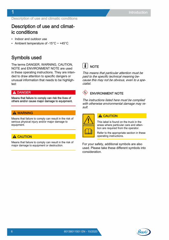
Symbols usedThe terms DANGER, WARNING, CAUTION,NOTE and ENVIRONMENT NOTE are usedin these operating instructions. They are inten-ded to draw attention to specific dangers orunusual information that needs to be highligh-ted:
DANGERMeans that failure to comply can risk the lives ofothers and/or cause major damage to equipment.
WARNINGMeans that failure to comply can result in the risk ofserious physical injury and/or major damage toequipment.
CAUTIONMeans that failure to comply can result in the risk ofmajor damage to equipment or destruction.
NOTE
This means that particular attention must bepaid to the specific technical meaning be-cause this may not be obvious, even to a spe-cialist.
ENVIRONMENT NOTE
The instructions listed here must be compliedwith otherwise environmental damage may re-sult.
CAUTION
This label is found on the truck in theareas where particular care and atten-tion are required from the operator.Refer to the appropriate section in theseoperating instructions.
For your safety, additional symbols are alsoused. Please take these different symbols intoconsideration.
Introduction1Description of use and climatic conditions
6 60138011501 EN - 10/2020
CE labellingThe manufacturer uses CE labelling to indi-cate that the truck complies with the standardsand regulations valid at the time of marketing.This is confirmed by the issued EC declarationof conformity. The CE labelling is attached tothe nameplate.
An independent structural change or additionto the truck can compromise safety, thus inva-lidating the EC declaration of conformity.
The EC declaration of conformity must becarefully stored and made available to the re-sponsible authorities.
CE-Symbol
Introduction 1CE labelling
760138011501 EN - 10/2020
EMC – Electromagnetic compatibilityElectromagnetic compatibility (EMC) is a keyquality feature of the truck.
EMC involves● limiting the emission of electromagnetic in-
terference to a level that ensures the trou-blefree operation of other equipment in theenvironment.
● ensuring sufficient resistance to externalelectromagnetic interference so as to guar-antee proper operation at the planned us-age location under the electromagnetic in-terference conditions to be expected there .
An EMC test thus firstly measures the electro-magnetic interference emitted by the truck and
secondly checks it for sufficient resistance toelectromagnetic interference with reference tothe planned usage location . A number ofelectrical measures are taken to ensure theelectromagnetic compatibility of the truck .
CAUTIONThe EMC regulations for the truck must be observed.When replacing truck components the protectiveEMC components must be installed and connectedagain.
Introduction1EMC – Electromagnetic compatibility
8 60138011501 EN - 10/2020
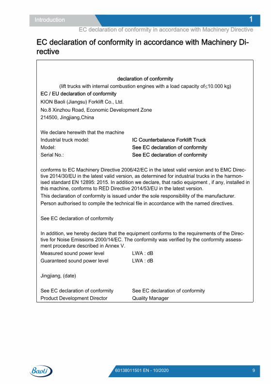
EC declaration of conformity in accordance with Machinery Di-rective
declaration of conformity
(lift trucks with internal combustion engines with a load capacity of≤10.000 kg)EC / EU declaration of conformityKION Baoli (Jiangsu) Forklift Co., Ltd.No.8 Xinzhou Road, Economic Development Zone214500, Jingjiang,China We declare herewith that the machineIndustrial truck model: IC Counterbalance Forklift TruckModel: See EC declaration of conformitySerial No.: See EC declaration of conformity conforms to EC Machinery Directive 2006/42/EC in the latest valid version and to EMC Direc-tive 2014/30/EU in the latest valid version, as determined for industrial trucks in the harmon-ised standard EN 12895: 2015. In addition we declare, that radio equipment , if any, installed inthis machine, conforms to RED Directive 2014/53/EU in the latest version.This declaration of conformity is issued under the sole responsibility of the manufacturer.Person authorised to compile the technical file in accordance with the named directives. See EC declaration of conformity In addition, we hereby declare that the equipment conforms to the requirements of the Direc-tive for Noise Emissions 2000/14/EC. The conformity was verified by the conformity assess-ment procedure described in Annex V.Measured sound power level LWA : dBGuaranteed sound power level LWA : dB Jingjiang, (date) See EC declaration of conformity See EC declaration of conformityProduct Development Director Quality Manager
Introduction 1EC declaration of conformity in accordance with Machinery Directive
960138011501 EN - 10/2020

Introduction1EC declaration of conformity in accordance with Machinery Directive
10 60138011501 EN - 10/2020

2
Safety

Definition of terms used for responsible personsOperating companyThe operating company is the natural or legalperson or group who operates the truck or onwhose authority the truck is used.
The operating company must ensure that thetruck is only used for its proper purpose and incompliance with the safety regulations set outin these operating instructions.
The operating company must ensure that allusers read and understand the safety informa-tion.
The operating company is responsible for thescheduling and correct performance of regularsafety checks.
We recommend that the national performancespecifications are adhered to.
SpecialistA qualified person is defined as a service en-gineer or a person who fulfils the following re-quirements:● A completed vocational qualification that
demonstrably proves their professional ex-pertise. This proof should consist of a voca-tional qualification or a similar document.
● Professional experience indicating that thequalified person has gained practical expe-rience of industrial trucks over a proven pe-riod during their career During this time, thisperson has become familiar with a widerange of symptoms that require checks to
be carried out, such as based on the resultsof a hazard assessment or a daily inspec-tion
● Recent professional involvement in the fieldof the industrial truck test in question andan appropriate further qualification are es-sential. The qualified person must have ex-perience of carrying out the test in questionor of carrying out similar tests. Moreover,this person must be aware of the latesttechnological developments regarding theindustrial truck to be tested and the risk be-ing assessed
Competent personA competent person is a specialist in the fieldof industrial trucks who has:● Successfully completed training, as at least
a service engineer for industrial trucks● Many years of professional experience with
industrial trucks● Knowledge of the accident prevention regu-
lations● Knowledge of the relevant national techni-
cal regulations
The competent person is able to assess thecondition of industrial trucks in terms of healthand safety.
DriversThis truck may only be driven by suitable per-sons who are at least 18 years of age, havebeen trained in driving, have demonstrated
their skills in driving and handling loads to theoperating company or an authorised represen-tative, and have been specifically instructed to
Safety2Definition of terms used for responsible persons
12 60138011501 EN - 10/2020
drive the truck. Specific knowledge of the truckto be operated is also required.
The training requirements under §3 of theHealth and Safety at Work Act and §9 of theplant safety regulations are deemed to havebeen satisfied if the driver has been trained inaccordance with BGG (General Employers' Li-ability Insurance Association Act) 925. Ob-serve the national regulations for your country.
Driver rights, duties and rules of behav-iourThe driver must be trained in his rights andduties.
The driver must be granted the required rights.
The driver must wear protective equipment(protection suit, safety footwear, safety hel-met, industrial goggles and gloves) that is ap-propriate for the conditions, the job and theload to be lifted. Solid footwear should beworn to ensure safe driving and braking.
The driver must be familiar with the operatinginstructions and have access to them at alltimes.
The driver must:● have read and understood the operating
manual● have familiarised himself with safe opera-
tion of the truck● be physically and mentally able to drive the
truck safely
DANGERThe use of drugs, alcohol or medications that affectreactions impair the ability to drive the truck!Individuals under the influence of the aforementionedsubstances are not permitted to perform work of anykind on or with the truck.
Prohibition of use by unauthorised per-sonsThe driver is responsible for the truck duringworking hours. He must not allow unauthor-ised persons to operate the truck.
When leaving the truck, the driver must secureit against unauthorised use, e.g. by pulling outthe key.
Safety 2Definition of terms used for responsible persons
1360138011501 EN - 10/2020
Safety regulationsGeneral safety regulations● Only allow qualified, trained and authorised
personnel to operate the truck.● Do not install any equipment on the truck
that has not been supplied and/or recom-mended by the manufacturer.
● Ensure the truck is always kept in a condi-tion that guarantees full working efficiency,in order to keep all types of risk to a mini-mum.
● Do not operate the truck when the hoods ordoors are open or if the protective deviceshave been removed.
● Close the rear window of the driver's cabbefore moving the truck. When open, therear window extends beyond the truck con-tour and may collide with persons or ob-jects.
● The identification plates fitted to the truckmust be kept in a good, legible condition,and must be replaced if damaged.
● Carefully read and follow all of the safety in-formation found on the truck.
● Make sure that there is always sufficientoverhead clearance above the truck.
● Do not park the truck in front of fire extin-guishers, escape routes or anywhere whereit would block traffic.
● If the forklift shows signs of defects or dam-age, or if it appears to be unsafe for anyother reason, safely park the truck and noti-fy the authorised service centre.
● Maintain appropriate distances from highvoltage overhead cables. Comply with the
safety distances established by the compe-tent authorities.
● Never raise loads using just one fork arm.● Position the load on the fork carriage or in
such a way that the centre of gravity of theload is as close as possible to the fork car-riage.
● The load must be positioned on the forkarms such that the centre of gravity falls be-tween the fork arms.
● Do not drive with a load that is laterally dis-placed from the truck's axle beam. Failureto comply with this regulation may adverse-ly affect the stability of the truck.
● Make sure that the surface on which theload rests is able to support its weight.
● Wear a protection suit that is compliant withcurrent national regulations at all times, anduse any personal protective equipment thatmay be necessary for the application inquestion.
● Do not drive the truck on loose or hillyground or on steps.
● Do not drive with loads raised more than300 mm off the ground.
● Do not turn or stack on slopes.● Reduce the speed on slopes.● Do not load the truck to the extent that the
load capacity limits indicated on the capaci-ty plates are exceeded.
● Always make use of the driver restraint sys-tems present on the truck.
Safety2Safety regulations
14 60138011501 EN - 10/2020
Exhaust gases
CAUTIONRisk to health from exhaust gases! Exhaust gasesfrom internal combustion engines are harmful to yourhealth. In particular, the soot particles contained inthe diesel exhaust gas can cause cancer. Letting thecombustion engine idle runs a risk of poisoning fromthe CO, CH and NOx components contained in theexhaust gasModern exhaust gas treatment systems (e.g. catalyt-ic converters, particle filters or comparable systems)can clean exhaust gases in a way that reduces thehealth hazard and risk of poisoning when operatingthe truck. Observe the national laws and regulations when
using trucks with an internal combustion engine inentirely or partially enclosed working areas.
Always ensure sufficient ventilation.
Ground condition for usingthe truckIn order for the truck to be used, suitableground must have the following characteris-tics:● Even and level● Hard● Sturdy● Free of obstacles● Properly prepared for the purpose
Safety Regulations Relative to Forklift Use● The operator must familiarize himself with
the forklift to be able to better describe anydefects and assist maintenance personnel.The operator, trained and authorized to usethe forklift, must be familiar with the controlsand performances of the forklift.
● Any defect (squeaking, leaks, etc.) must bepromptly reported because, if neglected, itcould cause more serious failures/defects.
● Carry out the inspections indicated in thechapter on "Daily Inspections".
ENVIRONMENT NOTE
Report any oil and/or battery fluid leaks: theyare dangerous and highly polluting.
CAUTIONIf you notice a burning smell, stop the forklift and turnoff the engine, then disconnect the battery.
Safety 2Ground condition for using the truck
1560138011501 EN - 10/2020

Residual dangers, residual risksDespite careful working and compliance withstandards and regulations, the occurrence ofother risks when using the truck cannot be en-tirely excluded.
The truck and all other system componentscomply with current safety requirements. Nev-ertheless, even when the truck is used for itsproper purpose and all instructions are fol-lowed, some residual risk cannot be excluded.
Even beyond the narrow danger areas of thetruck itself, a residual risk cannot be excluded.Persons in this area around the truck must ex-ercise a heightened degree of awareness, sothat they can react immediately in the event ofany malfunction, incident or breakdown etc.
WARNINGAll persons that are in the vicinity of the truck mustbe instructed regarding these risks that arise throughuse of the truck.In addition, we draw attention to the safety regula-tions in these operating instructions.
Risks can include:● Escape of consumables due to leakages,
rupture of lines and containers etc.● Risk of accident when driving over difficult
ground such as gradients, smooth or irregu-lar surfaces, or with poor visibility etc.
● Falling, tripping etc. when moving on thetruck, especially in wet weather, with leak-ing consumables or on icy surfaces
● Fire and explosion risks due to batteriesand electrical voltages
● Human error resulting from failure to ob-serve the safety regulations,
● Unrepaired damage or defective and worncomponents,
● Insufficient maintenance and testing● Use of incorrect consumables● Exceeding test intervals
The manufacturer is not held responsible foraccidents involving the truck caused by the
failure of the operating company to complywith these regulations either intentionally orcarelessly.
StabilityThe stability of the truck has been tested tothe latest technological standards and is guar-anteed provided that the truck is used properlyand according to its intended purpose. Thesestandards only take into account the dynamicand static tipping forces that can arise duringspecified use in accordance with the operatingrules and intended purpose. However, thedanger of exceeding the moment of tilt due toimproper use or incorrect operation and losingstability can never be excluded.
The loss of stability can be avoided or mini-mised by the following actions:
Always secure the load against slipping,e.g. by lashing.
Always transport unstable loads in suitablecontainers.
Always drive slowly when cornering.
Drive with the load lowered.
Even with sideshifts, align the load as cen-trally as possible with the truck and trans-port in this position.
Avoid turning and diagonally driving acrossslopes or gradients.
Never have the load facing downhill whentravelling on slopes or gradients.
Pick up only loads of the approved width.
Always take great care when transportingsuspended loads.
Do not drive over ramp edges or steps.
Safety2Residual dangers, residual risks
16 60138011501 EN - 10/2020
Safety regulations when drivingDriving conductThe driver must follow the public rules of theroad when driving in company traffic.
The speed must be appropriate to the localconditions.
For example, the driver must drive slowlyaround corners, in tight passageways, whendriving through swing-doors, at blind spots, oron uneven surfaces.
The driver must always maintain a safe brak-ing distance from vehicles and persons infront, and must always have the truck undercontrol. Stopping suddenly, turning quicklyand overtaking at dangerous or blind spotsmust be avoided.
Initial driving practice must be carried out inan empty space or on a clear roadway.
The following are forbidden during driving:● Allowing arms and legs to hang outside the
truck● Leaning the body over the outer contour of
the truck● Climbing out of the truck● Moving the driver's seat● Adjusting the steering column● Releasing the seat belt● Disabling the restraint system● Raising the load higher than 300 mm above
the ground (with the exception of manoeu-vring processes during the placement intostock/removal from stock of loads)
● Using electronic devices, for example ra-dios, mobile phones etc.
WARNINGThe use of multimedia and communication equip-ment as well as playing these devices at an exces-sive volume during travel or when handling loads canaffect the operator's attention. There is a risk of acci-dent! Do not use devices during travel or when handling
loads. Set the volume so that warning signals can still be
heard.
WARNINGIn areas where use of mobile phones is prohibited,use of a mobile phone or radio telephone is not per-mitted. Switch off the devices.
Visibility when drivingThe driver must look in the drive direction andhave a sufficient view of the driving lane.
Particularly for reverse travel, the driver mustbe sure that the driving lane is clear.
When transporting goods that impair visibility,the driver must drive the truck in reverse.
If this is not possible, a second person actingas a guide must walk in front of the truck.
In this case the driver must only move at walk-ing pace and with extra care. The truck mustbe stopped immediately if eye contact with theguide is lost.
Rear-view mirrors are only to be used for ob-serving the road area behind the truck and notfor reverse travel. If visual aids (mirror, moni-tor) are necessary to achieve sufficient visibili-ty, it is necessary to practise using them. Forreverse travel using visual aids, extra careshould be taken.
When using attachments, special conditionsapply; see the chapter entitled "Fitting attach-ments".
Any glass (variant, e.g. windscreen) and mir-rors must always be clean and free of ice.
Safety 2Safety regulations when driving
1760138011501 EN - 10/2020
Safety regulations in case of accidental lateral tippingIf as a result of incorrect manoeuvring thetruck appears to be tipping over sideways,carefully follow the instructions below:
a) Do not leave the forklift truck.
b) Tilt your head forward and move your bodyin the opposite direction to which the forklift istipping.
c) Remain firmly seated, grip the steeringwheel and dig your heels in. Wait until thetruck has reached a stable position beforeleaving the truck.
Exercise caution when handling gas springs and accumulators WARNING
Gas springs are under high pressure. Improper re-moval results in an elevated risk of injury.For ease of operation, various functions on the truckcan be supported by gas springs. Gas springs arecomplex components that are subject to high internalpressures (up to 300 bar). They may under no cir-cumstances be opened unless instructed to do so,and may be installed only when not under pressure.If required, the authorised service centre will de-pressurise the gas spring in accordance with the reg-ulations before removal. Gas springs must be dep-ressurised before recycling. Avoid damage, lateral forces, buckling, tempera-
tures over 80°C and heavy contamination. Damaged or defective gas springs must be
changed immediately. Contact the authorised service centre.
WARNINGAccumulators are under high pressure. Improper in-stallation of an accumulator results in an elevatedrisk of injury.Before starting work on the accumulator it must bedepressurised. Contact the authorised service centre.
Safety2Safety regulations in case of accidental lateral tipping
18 60138011501 EN - 10/2020
Safety regulations for handling consumablesPermissible consumables
DANGERFailure to observe the safety regulations relating toconsumables may result in a risk of injury, death ordamage to the environment. Observe the safety regulations when handling
such materials.
The permissible materials required for opera-tion can be found in the supply table in thechapter entitled "Maintenance".
Hydraulic fluid
WARNING
These fluids are pressurised during op-eration of the truck and are hazardous toyour health. Do not spill the fluids. Follow the statutory regulations. Do not allow the fluids to come into
contact with hot engine parts.
WARNING
These fluids are pressurised during op-eration of the truck and are hazardous toyour health. Do not allow the fluids to come into
contact with the skin. Avoid inhaling spray. Penetration of pressurised fluids into
the skin is particularly dangerous ifthese fluids escape at high pressuredue to leaks in the hydraulic system.In case of such injury, immediatemedical assistance is required.
To avoid injury, use appropriate per-sonal protective equipment (e.g. pro-tective gloves, industrial goggles, skinprotection and skin care products).
ENVIRONMENT NOTE
Hydraulic fluid is a water-polluting substance.
● Always store hydraulic fluid in containersthat comply with regulations
● Avoid spills● Spilt hydraulic fluid should be removed im-
mediately with oil-binding agents and dis-posed of according to the regulations
● Dispose of old hydraulic fluid according tothe regulations
Safety 2Safety regulations for handling consumables
1960138011501 EN - 10/2020
Oils DANGER
Oils are flammable! Follow the statutory regulations. Do not allow oils to come into contact
with hot engine parts. No smoking, fires or naked flames!
DANGER
Oils are toxic! Avoid contact and consumption. If vapour or fumes are inhaled, move
to fresh air immediately. In the event of contact with the eyes,
rinse thoroughly (for at least 10 mi-nutes) with water and then consult aneye specialist.
If swallowed, do not induce vomiting.Seek immediate medical attention.
WARNING
Prolonged intensive contact with the skincan result in dryness and irritate theskin! Avoid contact and consumption. Wear protective gloves. After any contact, wash the skin with
soap and water, and then apply a skincare product.
Immediately change soaked clothingand shoes.
WARNINGThere is a risk of slipping on spilled oil, particularlywhen combined with water! Spilt oil should be removed immediately with oil-
binding agents and disposed of according to theregulations.
ENVIRONMENT NOTE
Oil is a water-polluting substance!
● Always store oil in containers that complywith the applicable regulations.
● Avoid spilling oils.● Spilt oil should be removed immediately
with oil-binding agents and disposed of ac-cording to the regulations.
● Dispose of old oils according to the regula-tions.
Safety2Safety regulations for handling consumables
20 60138011501 EN - 10/2020
Battery acid
WARNING
Battery acid contains dissolved sulphuricacid. This is toxic. Avoid touching or swallowing the bat-
tery acid at all costs. In case of injury, seek medical advice
immediately.
WARNING
Battery acid contains dissolved sulphuricacid. This is corrosive. When working with battery acid, use
appropriate PSA (rubber gloves,apron, protection goggles).
When working with battery acid, nev-er wear a watch or jewellery.
Do not allow any acid to get ontoclothing or skin or into the eyes. If thisdoes happen, rinse immediately withplenty of clean water.
In case of injury, seek medical adviceimmediately.
Immediately rinse away spilt batteryacid with plenty of water.
Follow the statutory regulations.
ENVIRONMENT NOTE
Dispose of used battery acid in line with theapplicable regulations.
Disposal of consumables
ENVIRONMENT NOTE
Materials that accumulate during repair, main-tenance and cleaning must be collected prop-erly and disposed of in accordance with thenational regulations for the country in whichthe truck is being used. Work must only becarried out in areas designated for the pur-pose. Care must be taken to minimise any en-vironmental pollution.
Soak up any spilt fluids such as hydraulicoil, brake fluid or gearbox oil using an oil-binding agent.
Neutralise any spilt battery acid immediate-ly.
Always observe national regulations con-cerning the disposal of used oil.
Safety 2Safety regulations for handling consumables
2160138011501 EN - 10/2020
Environmental considerationsDisposal of components and batter-iesThe truck is composed of different materials. Ifcomponents or batteries need to be replacedand disposed of, they must be:● disposed of,● treated or● recycled in accordance with regional and
national regulations.
NOTE
The documentation provided by the batterymanufacturer must be observed when dispos-ing of batteries.
ENVIRONMENT NOTE
We recommend working with a waste man-agement company for disposal purposes.
Safety2Environmental considerations
22 60138011501 EN - 10/2020
PackagingDuring delivery of the truck, certain parts arepackaged to provide protection during trans-port. This packaging must be removed com-pletely prior to initial start-up.
ENVIRONMENT NOTE
The packaging material must be disposed ofproperly after delivery of the truck.
EmissionsThe values specified apply to a standard truck(compare the specifications in the "Technicaldata" chapter). Different tyres, lift masts, addi-tional units etc. may produce different values.
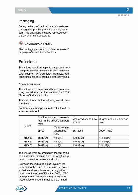
Noise emissionsThe values were determined based on meas-uring procedures from the standard EN 12053"Safety of industrial trucks.
This machine emits the following sound pres-sure level:
Continuous sound pressure level in the driv-er’s compartment
Model
Continuous sound pressurelevel in the driver’s compart-ment
Measured sound pow-er level
Guaranteed sound powerlevel
LpAZMeasurementuncertaintyKpA
EN12053 2000/14/EC
KBD 50 85 dB(A) 4 dB(A) 109 dB(A) 111 dB(A)KBD 60 85 dB(A) 4 dB(A) 110 dB(A) 111 dB(A)KBD 70 86 dB(A) 4 dB(A) 110 dB(A) 111 dB(A)
The values were determined in the test cycleon an identical machine from the weighted val-ues for operating statuses and idling.
However, the indicated noise levels at thetruck cannot be used to determine the noiseemissions at workplaces according to themost recent version of Directive 2003/10/EC(daily personal noise pollution). If required,these noise emissions must be determined
Safety 2Emissions
2360138011501 EN - 10/2020
directly at the workplaces under the actualconditions present (further sources of noise,particular application conditions, sound reflec-tions) by the operating company.
NOTE
Please note the definition of "operating com-pany" in the sense of responsible persons!
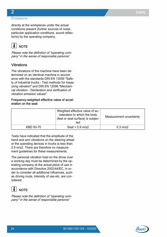
VibrationsThe vibrations of the machine have been de-termined on an identical machine in accord-ance with the standards DIN EN 13059 "Safe-ty of industrial trucks - Test methods for meas-uring vibration" and DIN EN 12096 "Mechani-cal vibration - Declaration and verification ofvibration emission values".
Frequency-weighted effective value of accel-eration on the seat
Weighted effective value of ac-celeration to which the body
(feet or seat surface) is subjec-ted
Measurement uncertainty
KBD 50-70 Seat < 0.9 m/s2 0.3 m/s2
Tests have indicated that the amplitude of thehand and arm vibrations on the steering wheelor the operating devices in trucks is less than2.5 m/s2. There are therefore no measure-ment guidelines for these measurements.
The personal vibration load on the driver overa working day must be determined by the op-erating company at the actual place of use inaccordance with Directive 2002/44/EC, in or-der to consider all additional influences, suchas driving route, intensity of use etc. are con-sidered.
NOTE
Please note the definition of "operating com-pany" in the sense of responsible persons!
Safety2Emissions
24 60138011501 EN - 10/2020

3
Overview

General View
MastOverhead guardTowing pinSteering wheelsDriving wheels
12345
CounterweightLoad backrestForksEngine hood
6789
Overview3General View
26 60138011501 EN - 10/2020
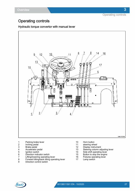
Operating controlsHydraulic torque convertor with manual lever
Parking brake leverInching pedalBrake pedalAccelerator pedalIgnition switchDirection indicator switchLifting/lowering operating leverForward tilting/back tilting operating leverDirection control switch
123456789
Horn buttonsteering wheelDisplay instrumentSteering column adjusting leverSide shift operating leverButton to stop the engineFixtures operating leverLamp switch
1011121314151617
Overview 3Operating controls
2760138011501 EN - 10/2020
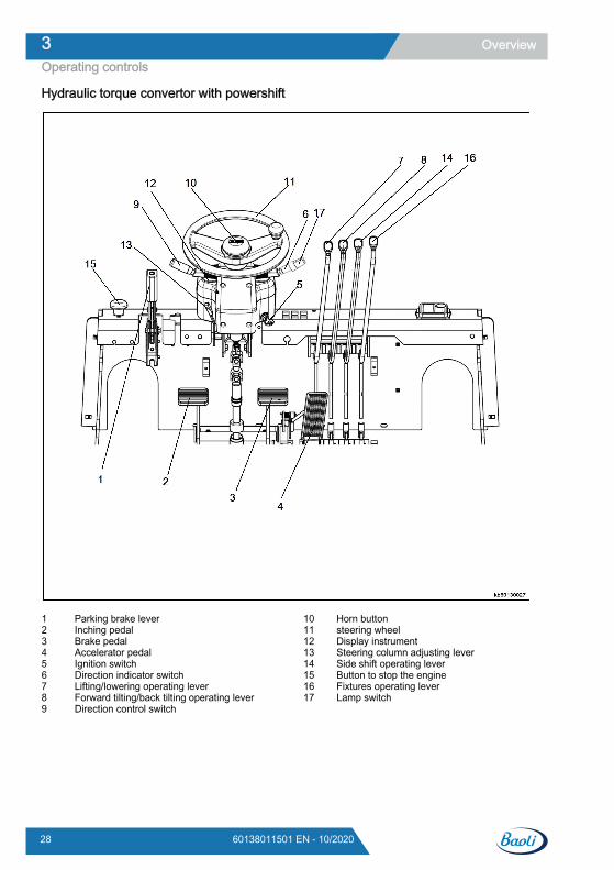
Hydraulic torque convertor with powershift
Parking brake leverInching pedalBrake pedalAccelerator pedalIgnition switchDirection indicator switchLifting/lowering operating leverForward tilting/back tilting operating leverDirection control switch
123456789
Horn buttonsteering wheelDisplay instrumentSteering column adjusting leverSide shift operating leverButton to stop the engineFixtures operating leverLamp switch
1011121314151617
Overview3Operating controls
28 60138011501 EN - 10/2020
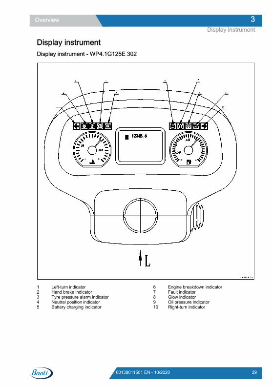
Display instrumentDisplay instrument - WP4.1G125E 302
Left-turn indicatorHand brake indicatorTyre pressure alarm indicatorNeutral position indicatorBattery charging indicator
12345
Engine breakdown indicatorFault indicatorGlow indicatorOil pressure indicatorRight-turn indicator
678910
Overview 3Display instrument
2960138011501 EN - 10/2020
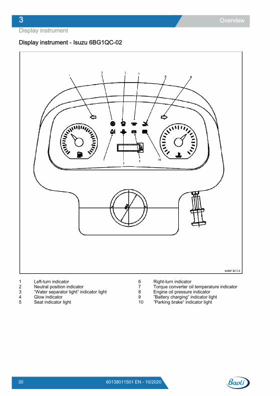
Display instrument - Isuzu 6BG1QC-02
Left-turn indicatorNeutral position indicator“Water separator light” indicator lightGlow indicatorSeat indicator light
12345
Right-turn indicatorTorque converter oil temperature indicatorEngine oil pressure indicator”Battery charging“ indicator light”Parking brake“ indicator light
678910
Overview3Display instrument
30 60138011501 EN - 10/2020
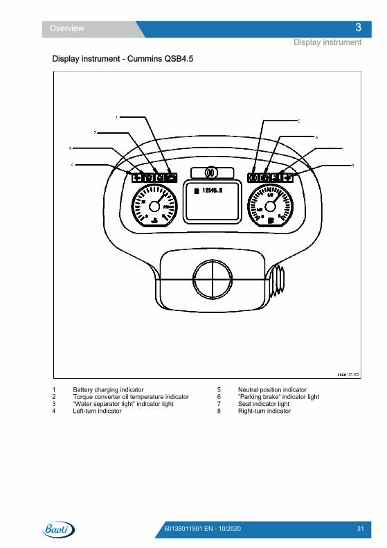
Display instrument - Cummins QSB4.5
Battery charging indicatorTorque converter oil temperature indicator“Water separator light” indicator lightLeft-turn indicator
1234
Neutral position indicator”Parking brake“ indicator lightSeat indicator lightRight-turn indicator
5678
Overview 3Display instrument
3160138011501 EN - 10/2020
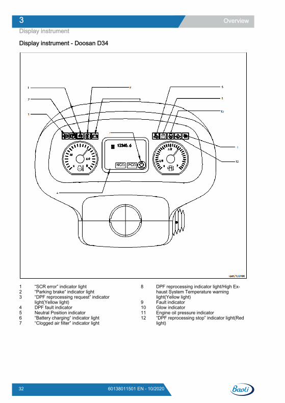
Display instrument - Doosan D34
“SCR error” indicator light“Parking brake“ indicator light“DPF reprocessing request” indicatorlight(Yellow light)DPF fault indicatorNeutral Position indicator“Battery charging“ indicator light“Clogged air filter” indicator light
123
4567
DPF reprocessing indicator light/High Ex-haust System Temperature warninglight(Yellow light)Fault indicatorGlow indicatorEngine oil pressure indicator“DPF reprocessing stop” indicator light(Redlight)
8
9101112
Overview3Display instrument
32 60138011501 EN - 10/2020
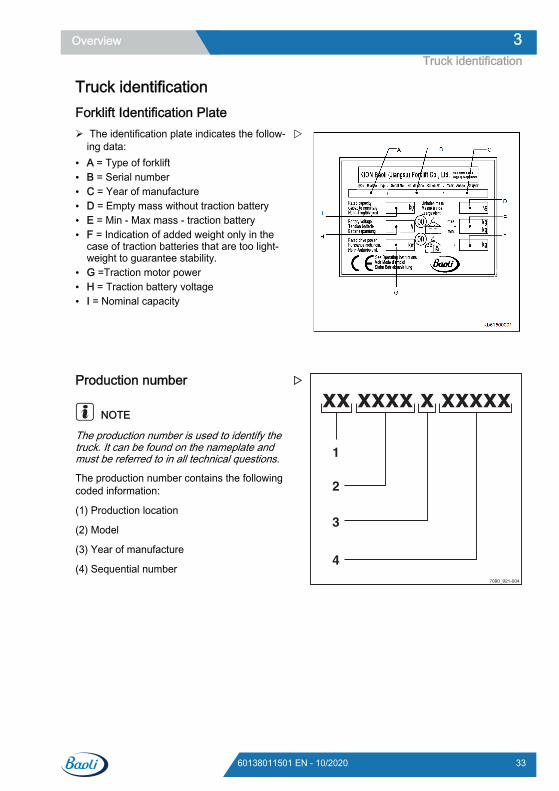
Truck identificationForklift Identification Plate The identification plate indicates the follow-
ing data:● A = Type of forklift● B = Serial number● C = Year of manufacture● D = Empty mass without traction battery● E = Min - Max mass - traction battery● F = Indication of added weight only in the
case of traction batteries that are too light-weight to guarantee stability.
● G =Traction motor power● H = Traction battery voltage● I = Nominal capacity
Production number
NOTE
The production number is used to identify thetruck. It can be found on the nameplate andmust be referred to in all technical questions.
The production number contains the followingcoded information:
(1) Production location
(2) Model
(3) Year of manufacture
(4) Sequential number
7090_921-004
xx xxxx x xxxxx
1
2
3
4
Overview 3Truck identification
3360138011501 EN - 10/2020
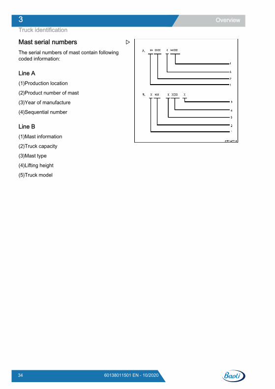
Mast serial numbersThe serial numbers of mast contain followingcoded information:
Line A(1)Production location
(2)Product number of mast
(3)Year of manufacture
(4)Sequential number
Line B(1)Mast information
(2)Truck capacity
(3)Mast type
(4)Lifting height
(5)Truck model
Overview3Truck identification
34 60138011501 EN - 10/2020
Location of decals
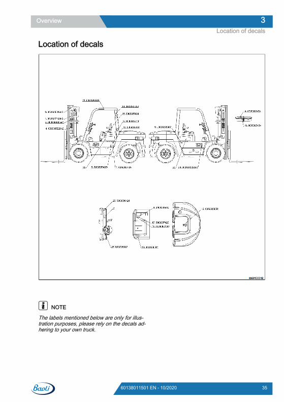
NOTE
The labels mentioned below are only for illus-tration purposes, please rely on the decals ad-hering to your own truck.
Overview 3Location of decals
3560138011501 EN - 10/2020
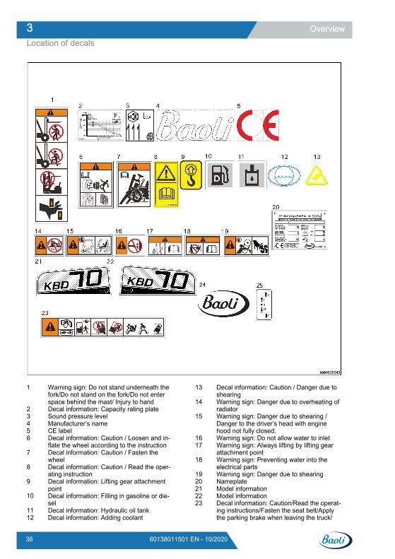
Warning sign: Do not stand underneath thefork/Do not stand on the fork/Do not enterspace behind the mast/ Injury to handDecal information: Capacity rating plateSound pressure levelManufacturer’s nameCE labelDecal information: Caution / Loosen and in-flate the wheel according to the instructionDecal information: Caution / Fasten thewheelDecal information: Caution / Read the oper-ating instructionDecal information: Lifting gear attachmentpointDecal information: Filling in gasoline or die-selDecal information: Hydraulic oil tankDecal information: Adding coolant
1
23456
7
8
9
10
1112
Decal information: Caution / Danger due toshearingWarning sign: Danger due to overheating ofradiatorWarning sign: Danger due to shearing /Danger to the driver’s head with enginehood not fully closed.Warning sign: Do not allow water to inletWarning sign: Always lifting by lifting gearattachment pointWarning sign: Preventing water into theelectrical partsWarning sign: Danger due to shearingNameplateModel informationModel informationDecal information: Caution/Read the operat-ing instructions/Fasten the seat belt/Applythe parking brake when leaving the truck/
13
14
15
1617
18
1920212223
Overview3Location of decals
36 60138011501 EN - 10/2020
Passengers are not allowed/Do not jump offif the truck is tipping over/Brace feet/Hold ontight/Lean in the opposite direction to whichthe truck is tipping
Manufacturer’s nameDecal information: Forward/Reverse
2425
Overview 3Location of decals
3760138011501 EN - 10/2020

Overview3Location of decals
38 60138011501 EN - 10/2020

4
Operation
Instructions for running-inThe truck can be operated quickly immediate-ly.
However, when driving during the first 100 op-erating hours, avoid subjecting both the work-ing hydraulics and the drive unit to high contin-uous loads.
The wheel screws must be tightened beforestarting the truck prior to testing and aftereach wheel replacement.
The wheel nuts should be tightened at leastonce every 100 operating hours. The wheelscrews must be tightened in a diagonal se-quence.
Tightening torque:
Front tyres(double front tyres): Ball nut(M30x1.5 ), 1844 ±5% Nm ; Column nut(M20x1.5), 525 ±5% Nm
Rear tyres: Ball nut ( M20x1.5 ), 525 ±5% Nm
Operation4Instructions for running-in
40 60138011501 EN - 10/2020
Checks and inspectionPre-shift checksCarrying out the following checks as part ofyour daily routine will help to keep the forklifttruck in good condition. These checks aresupplemental and do not replace periodicmaintenance work.
NOTE
If, when carrying out the daily checks, you dis-cover a defect or you are unsure whether thetruck will function properly, do not use thetruck and contact the technical service depart-ment.
Daily checks before useThe following checks must be performed on adaily basis in order to keep your truck in goodcondition and to operate safely. These checkssupplement and do not replace the scheduledmaintenance operations.● Check the correct position and fastening, in-
tactness and operation of the various safetycomponents installed on the truck.
● Make sure that "seat switch" is working cor-rectly.
● Check that the brakes work correctly,checking their travel and efficiency.
● Check the tyre pressure and wear condi-tions.
● Visually inspect wheels for correct tight-ness.
● Make sure that the lights work correctly (ifapplicable).
● Visually check that the chains are taut.● Make sure that the start/stop key works cor-
rectly.
● Check that the fork arms are in good condi-tion;
● Check that the fork arm control levers workcorrectly
● Check the fuel filter water trap● Check engine coolant level.● Check brake oil level.● Check transmission oil level.● Check axle oil level.● Engine oil level checking procedure● Check the area under the forklift truck for
leaking consumables.
CAUTIONDO NOT use the truck, but call the technical servicedepartment, if you notice any malfunctions or if youhave any doubts about its correct operation.
Operation 4Checks and inspection
4160138011501 EN - 10/2020
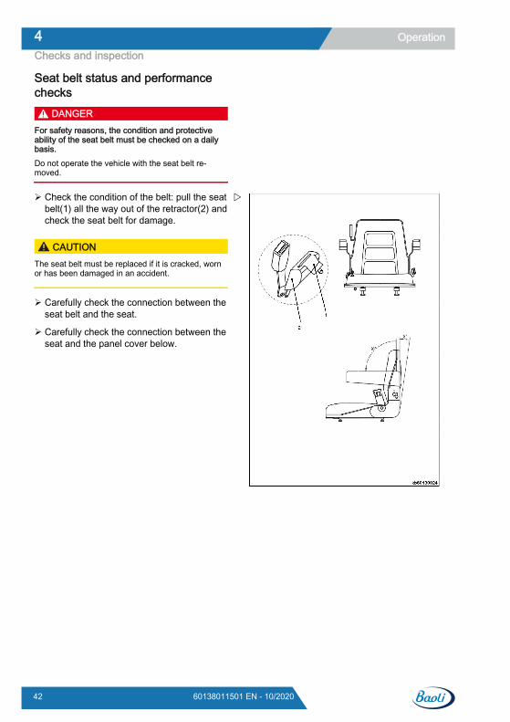
Seat belt status and performancechecks
DANGERFor safety reasons, the condition and protectiveability of the seat belt must be checked on a dailybasis.Do not operate the vehicle with the seat belt re-moved.
Check the condition of the belt: pull the seatbelt(1) all the way out of the retractor(2) andcheck the seat belt for damage.
CAUTIONThe seat belt must be replaced if it is cracked, wornor has been damaged in an accident.
Carefully check the connection between theseat belt and the seat.
Carefully check the connection between theseat and the panel cover below.
Operation4Checks and inspection
42 60138011501 EN - 10/2020
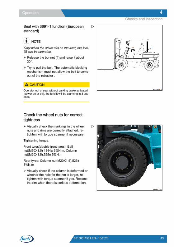
Seat with 3691-1 function (Europeanstandard)
NOTE
Only when the driver sits on the seat, the fork-lift can be operated.
Release the bonnet (1)and raise it about30°.
Try to pull the belt. The automatic blockingmechanism must not allow the belt to comeout of the retractor .
CAUTIONOperator out of seat without parking brake activated(power on or off), the forklift will be alarming in 3 sec-onds.
Check the wheel nuts for correcttightness Visually check the markings in the wheel
nuts and rims are correctly attached, re-tighten with torque spanner if necessary.
Tightening torque:
Front tyres(double front tyres): Ballnut(M30X1.5) 1844± 5%N.m, Columnnut(M20X1.5),525± 5%N.m
Rear tyres: Column nut(M20X1.5),525±5%N.m
Visually check if the column is deformed orwhether the hole for the rim is larger, re-tighten with torque spanner if yes. Replacethe rim when there is serious deformation.
Operation 4Checks and inspection
4360138011501 EN - 10/2020
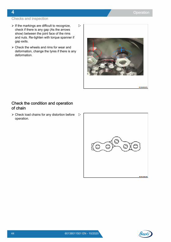
If the markings are difficult to recognize,check if there is any gap (As the arrowsshow) between the joint face of the rimsand nuts. Re-tighten with torque spanner ifgap exits.
Check the wheels and rims for wear anddeformation, change the tyres if there is anydeformation.
Check the condition and operationof chain Check load chains for any distortion before
operation.
Operation4Checks and inspection
44 60138011501 EN - 10/2020
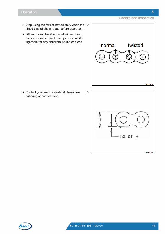
Stop using the forklift immediately when thehinge pins of chain rotate before operation.
Lift and lower the lifting mast without loadfor one round to check the operation of lift-ing chain for any abnormal sound or block.
Contact your service center if chains aresuffering abnormal force.
Operation 4Checks and inspection
4560138011501 EN - 10/2020
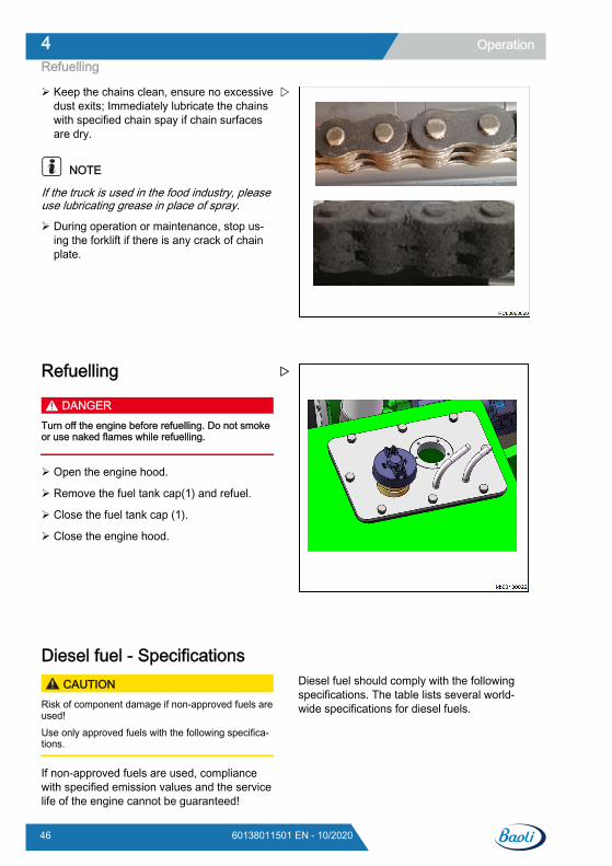
Keep the chains clean, ensure no excessivedust exits; Immediately lubricate the chainswith specified chain spay if chain surfacesare dry.
NOTE
If the truck is used in the food industry, pleaseuse lubricating grease in place of spray.
During operation or maintenance, stop us-ing the forklift if there is any crack of chainplate.
Refuelling
DANGERTurn off the engine before refuelling. Do not smokeor use naked flames while refuelling.
Open the engine hood.
Remove the fuel tank cap(1) and refuel.
Close the fuel tank cap (1).
Close the engine hood.
Diesel fuel - Specifications CAUTION
Risk of component damage if non-approved fuels areused!Use only approved fuels with the following specifica-tions.
If non-approved fuels are used, compliancewith specified emission values and the servicelife of the engine cannot be guaranteed!
Diesel fuel should comply with the followingspecifications. The table lists several world-wide specifications for diesel fuels.
Operation4Refuelling
46 60138011501 EN - 10/2020
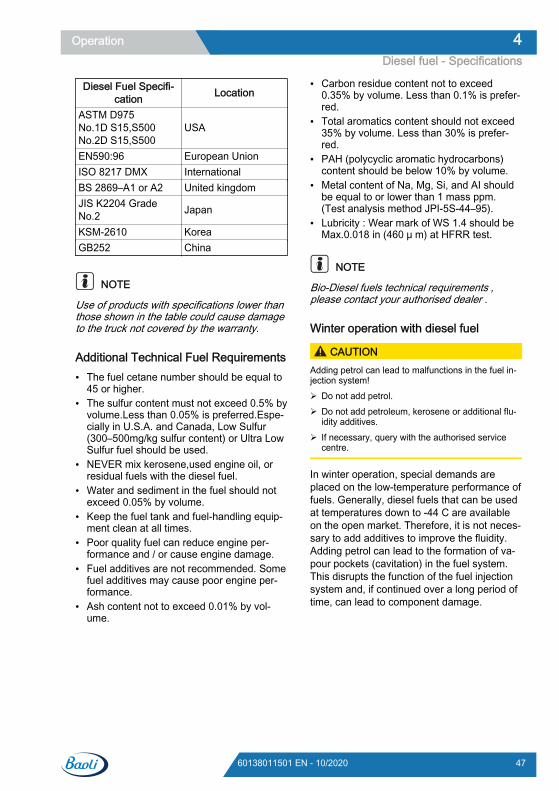
Diesel Fuel Specifi-cation Location
ASTM D975No.1D S15,S500No.2D S15,S500
USA
EN590:96 European UnionISO 8217 DMX InternationalBS 2869–A1 or A2 United kingdomJIS K2204 GradeNo.2 Japan
KSM-2610 KoreaGB252 China
NOTE
Use of products with specifications lower thanthose shown in the table could cause damageto the truck not covered by the warranty.
Additional Technical Fuel Requirements● The fuel cetane number should be equal to
45 or higher.● The sulfur content must not exceed 0.5% by
volume.Less than 0.05% is preferred.Espe-cially in U.S.A. and Canada, Low Sulfur(300–500mg/kg sulfur content) or Ultra LowSulfur fuel should be used.
● NEVER mix kerosene,used engine oil, orresidual fuels with the diesel fuel.
● Water and sediment in the fuel should notexceed 0.05% by volume.
● Keep the fuel tank and fuel-handling equip-ment clean at all times.
● Poor quality fuel can reduce engine per-formance and / or cause engine damage.
● Fuel additives are not recommended. Somefuel additives may cause poor engine per-formance.
● Ash content not to exceed 0.01% by vol-ume.
● Carbon residue content not to exceed0.35% by volume. Less than 0.1% is prefer-red.
● Total aromatics content should not exceed35% by volume. Less than 30% is prefer-red.
● PAH (polycyclic aromatic hydrocarbons)content should be below 10% by volume.
● Metal content of Na, Mg, Si, and AI shouldbe equal to or lower than 1 mass ppm.(Test analysis method JPI-5S-44–95).
● Lubricity : Wear mark of WS 1.4 should beMax.0.018 in (460 μ m) at HFRR test.
NOTE
Bio-Diesel fuels technical requirements ,please contact your authorised dealer .
Winter operation with diesel fuel
CAUTIONAdding petrol can lead to malfunctions in the fuel in-jection system! Do not add petrol. Do not add petroleum, kerosene or additional flu-
idity additives. If necessary, query with the authorised service
centre.
In winter operation, special demands areplaced on the low-temperature performance offuels. Generally, diesel fuels that can be usedat temperatures down to -44 C are availableon the open market. Therefore, it is not neces-sary to add additives to improve the fluidity.Adding petrol can lead to the formation of va-pour pockets (cavitation) in the fuel system.This disrupts the function of the fuel injectionsystem and, if continued over a long period oftime, can lead to component damage.
Operation 4Diesel fuel - Specifications
4760138011501 EN - 10/2020
Engine coolant - Specifications DANGER
Scald hazard ! NEVER remove the radiator cap if the engine is
hot. Steam and hot engine coolant will spurt outand seriously burn you. Allow the engine to cooldown before you attempt to remove the radiatorcap.
Securely tighten the radiator cap after you checkthe radiator. Steam can spurt our during engineoperation if the cap is loose.
ALWAYS check the level of engine coolant by ob-serving the reserve tank.
Failure to comply will result in death or serious in-jury.
WARNINGBurn hazard ! Wait until the engine cools before you drain the
engine coolant. Hot engine coolant may splashand burn you.
Failure to comply will result in death or serious in-jury.
CAUTION
Coolant hazard ! Wear eye protection and rubber
gloves when you handle Long Life orExtended Life engine coolant. If con-tact with the eyes or skin should oc-cur, wash with clean water.
Failure to comply may result in minoror moderate injury.
NOTE
● Only use the engine coolant specified. Oth-er engine coolants may affect warranty cov-erage, cause an internal build up of rust andscale and / or shorten engine life.
● Prevent dirt and debris from contaminatingengine coolant. Carefully clean the radiatorcap and the surrounding area before youremove the cap.
● NEVER mix different types of engine cool-ants. This may adversely affect the proper-ties of the engine coolant.
Engine coolant specificationsUse a Long Life Coolant (LLC) or an ExtendedLife Coolant (ELC) that meets or exceeds thefollowing guidelines and specifications.
Alternative engine coolantIf an Extended or Long Life Coolant is notavailable, alternatively ,you may use an ethyl-ene glycol or propylene glycol based conven-tional coolant (green).
Notes:1 ALWAYS use a mix of coolant and wa-
ter.NEVER use water only.2 Mix coolant and water per the mixing in-
structions on the coolant container.3 Water quality is important to coolant per-
formance. We recommends that soft, dis-tilled, or demineralized water be used tomix with coolants.
4 NEVER mix extended or long life cool-ants and conventional (green) coolants.
5 NEVER mix different types and / or col-ors of extended life coolants.
6 Replace the coolant according to "Sched-uled maintenance."
Additional technical coolant specifica-tions:● ASTM D6210,D4985 (US)● JIS K-2234 (Japan)● SAE J814C, J1941, J1034 or J2036 (Inter-
national)
Operation4Engine coolant - Specifications
48 60138011501 EN - 10/2020
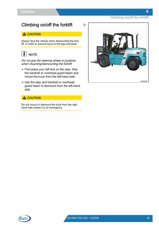
Climbing on/off the forklift
CAUTION
Always face the vehicle when dismounting the fork-lift, in order to prevent injury to the legs and back.
NOTE
Do not grip the steering wheel or joystickswhen mounting/dismounting the forklift.
First place your left foot on the step. Gripthe handrail or overhead guard beam andmount the truck from the left-hand side.
Use the step and handrail or overheadguard beam to dismount from the left-handside.
CAUTION
Do not mount or dismount the truck from the righthand side unless it is an emergency.
Operation 4Climbing on/off the forklift
4960138011501 EN - 10/2020
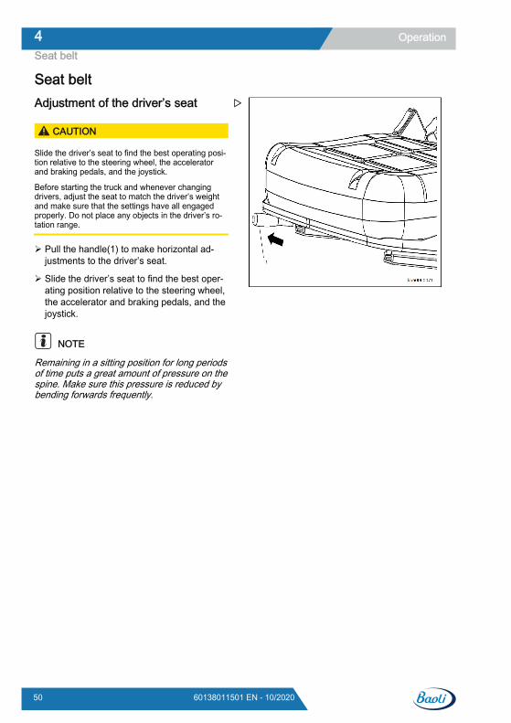
Seat beltAdjustment of the driver’s seat
CAUTION
Slide the driver’s seat to find the best operating posi-tion relative to the steering wheel, the acceleratorand braking pedals, and the joystick.
Before starting the truck and whenever changingdrivers, adjust the seat to match the driver’s weightand make sure that the settings have all engagedproperly. Do not place any objects in the driver’s ro-tation range.
Pull the handle(1) to make horizontal ad-justments to the driver’s seat.
Slide the driver’s seat to find the best oper-ating position relative to the steering wheel,the accelerator and braking pedals, and thejoystick.
NOTE
Remaining in a sitting position for long periodsof time puts a great amount of pressure on thespine. Make sure this pressure is reduced bybending forwards frequently.
Operation4Seat belt
50 60138011501 EN - 10/2020
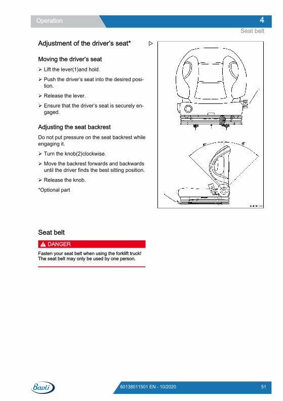
Adjustment of the driver’s seat*
Moving the driver’s seat Lift the lever(1)and hold.
Push the driver’s seat into the desired posi-tion.
Release the lever.
Ensure that the driver’s seat is securely en-gaged.
Adjusting the seat backrestDo not put pressure on the seat backrest whileengaging it.
Turn the knob(2)clockwise.
Move the backrest forwards and backwardsuntil the driver finds the best sitting position.
Release the knob.
*Optional part
Seat belt DANGER
Fasten your seat belt when using the forklift truck!The seat belt may only be used by one person.
Operation 4Seat belt
5160138011501 EN - 10/2020
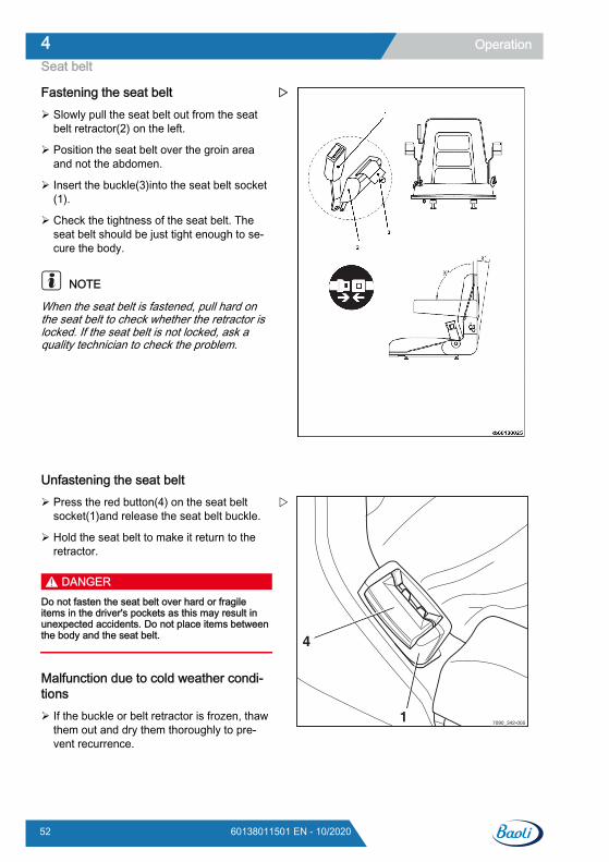
Fastening the seat belt Slowly pull the seat belt out from the seat
belt retractor(2) on the left.
Position the seat belt over the groin areaand not the abdomen.
Insert the buckle(3)into the seat belt socket(1).
Check the tightness of the seat belt. Theseat belt should be just tight enough to se-cure the body.
NOTE
When the seat belt is fastened, pull hard onthe seat belt to check whether the retractor islocked. If the seat belt is not locked, ask aquality technician to check the problem.
Unfastening the seat belt Press the red button(4) on the seat belt
socket(1)and release the seat belt buckle.
Hold the seat belt to make it return to theretractor.
DANGERDo not fasten the seat belt over hard or fragileitems in the driver's pockets as this may result inunexpected accidents. Do not place items betweenthe body and the seat belt.
Malfunction due to cold weather condi-tions If the buckle or belt retractor is frozen, thaw
them out and dry them thoroughly to pre-vent recurrence.
7090_342-0051
4
Operation4Seat belt
52 60138011501 EN - 10/2020
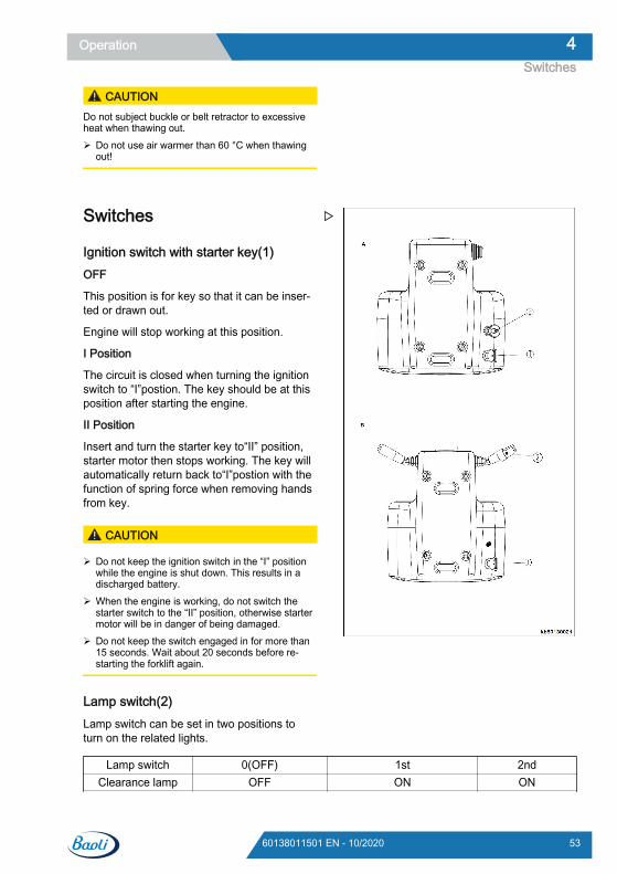
CAUTIONDo not subject buckle or belt retractor to excessiveheat when thawing out. Do not use air warmer than 60 °C when thawing
out!
Switches
Ignition switch with starter key(1)OFF
This position is for key so that it can be inser-ted or drawn out.
Engine will stop working at this position.
I Position
The circuit is closed when turning the ignitionswitch to “Ⅰ”postion. The key should be at thisposition after starting the engine.
II Position
Insert and turn the starter key to“Ⅱ” position,starter motor then stops working. The key willautomatically return back to“Ⅰ”postion with thefunction of spring force when removing handsfrom key.
CAUTION
Do not keep the ignition switch in the “I” positionwhile the engine is shut down. This results in adischarged battery.
When the engine is working, do not switch thestarter switch to the “II” position, otherwise startermotor will be in danger of being damaged.
Do not keep the switch engaged in for more than15 seconds. Wait about 20 seconds before re-starting the forklift again.
Lamp switch(2)Lamp switch can be set in two positions toturn on the related lights.
Lamp switch 0(OFF) 1st 2ndClearance lamp OFF ON ON
Operation 4Switches
5360138011501 EN - 10/2020
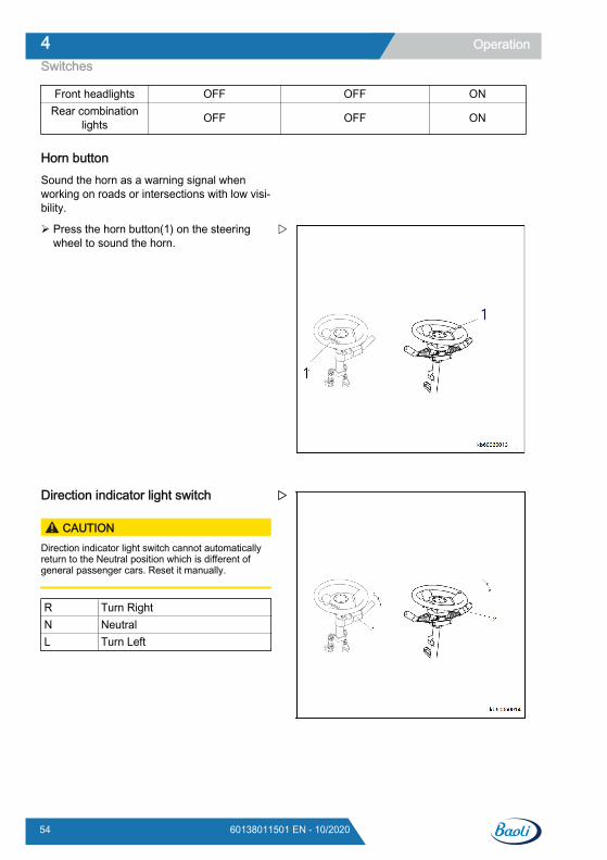
Front headlights OFF OFF ONRear combination
lights OFF OFF ON
Horn buttonSound the horn as a warning signal whenworking on roads or intersections with low visi-bility.
Press the horn button(1) on the steeringwheel to sound the horn.
Direction indicator light switch
CAUTIONDirection indicator light switch cannot automaticallyreturn to the Neutral position which is different ofgeneral passenger cars. Reset it manually.
R Turn RightN NeutralL Turn Left
Operation4Switches
54 60138011501 EN - 10/2020
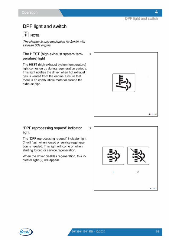
DPF light and switch
NOTE
The chapter is only application for forklift withDoosan D34 engine.
The HEST (high exhaust system tem-perature) lightThe HEST (high exhaust system temperature)light comes on up during regeneration periods.This light notifies the driver when hot exhaustgas is vented from the engine. Ensure thatthere is no combustible material around theexhaust pipe.
“DPF reprocessing request” indicatorlightThe “DPF reprocessing request” indicator light(1)will flash when forced or service regenera-tion is needed. This light will come on whenstarting forced or service regeneration.
When the driver disables regeneration, this in-dicator light (2) will appear.
Operation 4DPF light and switch
5560138011501 EN - 10/2020
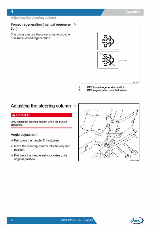
Forced regeneration (manual regenera-tion)The driver can use these switches to activateor disable forced regeneration.
Adjusting the steering column
DANGER
Only adjust the steering column when the truck isstationary.
Angle adjustment Pull down the handle(1) clockwise.
Move the steering column into the requiredposition.
Pull back the handle anti-clockwise to itsoriginal position.
DPF forced regeneration switchDPF regeneration disabled switch
12
Operation4Adjusting the steering column
56 60138011501 EN - 10/2020
Starting the engineStart the engine
DANGERRisk of poisoning!Do not allow the engine to run in unventilated areas.
NOTE
Where possible, avoid frequently starting andstopping the engine over short periods of time,since this prevents the internal combustion en-gine from reaching its operating temperature.Frequent cold starts increase wear and tear.
Sit down in the driver’s seat.
Fasten the seat belt.
All joysticks and levers must be in the neu-tral position.
Insert the ignition key in the ignition switchand turn it from the “0” to the “Ⅰ” position.
At this point the electrical system will switchon.
Watch the display unit.(Refer to Instrument declaration for detailed informat
NOTE
When the ignition switch is turned on, the dis-play unit will perform a self-test, during whichthe whole of the display screen will illuminatefor about 2 seconds.
The following display elements will illuminate:● the battery charging indicator● oil pressure warning light
Wait until the preheat indicator goes out.
Turn the ignition key to the “Ⅱ” position.
After the engine starts:
Immediately release the ignition key.
Engine shutdown
CAUTION
Do not stop the engine when it is running at full load,instead let it run at low speed for a few minutes first.
Release the accelerator pedal.
Depress the brake pedal.
Place the direction lever in the neutral posi-tion.
Turn the ignition key from “II” position to the“0” position.
Apply the parking brake.
Remove the ignition key when leaving thetruck.
Operation 4Starting the engine
5760138011501 EN - 10/2020
DrivingDriving
CAUTION
When using mirrors, ensure that the rear-view mirroris only used for monitoring the traffic behind the vehi-cle. Reverse travel is therefore only permitted whenlooking directly behind you.
CAUTION
Always tilt the mast backwards and lower the forkarms to the ground around 300mm-400mm..
CAUTION
Check the safety around the forklift and sound thehorn before starting the truck.
Sit in the driver's seat and fasten the safetybelt.
Start the engine.
Operation4Driving
58 60138011501 EN - 10/2020
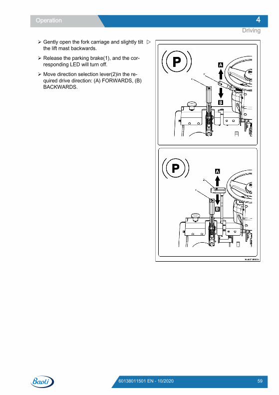
Gently open the fork carriage and slightly tiltthe lift mast backwards.
Release the parking brake(1), and the cor-responding LED will turn off.
Move direction selection lever(2)in the re-quired drive direction: (A) FORWARDS, (B)BACKWARDS.
Operation 4Driving
5960138011501 EN - 10/2020
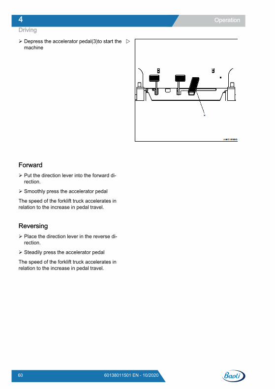
Depress the accelerator pedal(3)to start themachine
Forward Put the direction lever into the forward di-
rection.
Smoothly press the accelerator pedal
The speed of the forklift truck accelerates inrelation to the increase in pedal travel.
Reversing Place the direction lever in the reverse di-
rection.
Steadily press the accelerator pedal
The speed of the forklift truck accelerates inrelation to the increase in pedal travel.
Operation4Driving
60 60138011501 EN - 10/2020
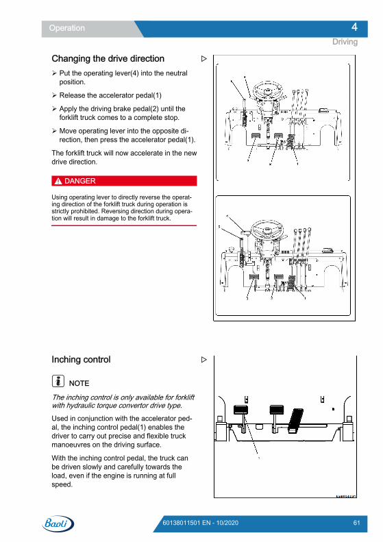
Changing the drive direction Put the operating lever(4) into the neutral
position.
Release the accelerator pedal(1)
Apply the driving brake pedal(2) until theforklift truck comes to a complete stop.
Move operating lever into the opposite di-rection, then press the accelerator pedal(1).
The forklift truck will now accelerate in the newdrive direction.
DANGER
Using operating lever to directly reverse the operat-ing direction of the forklift truck during operation isstrictly prohibited. Reversing direction during opera-tion will result in damage to the forklift truck.
Inching control
NOTE
The inching control is only available for forkliftwith hydraulic torque convertor drive type.
Used in conjunction with the accelerator ped-al, the inching control pedal(1) enables thedriver to carry out precise and flexible truckmanoeuvres on the driving surface.
With the inching control pedal, the truck canbe driven slowly and carefully towards theload, even if the engine is running at fullspeed.
Operation 4Driving
6160138011501 EN - 10/2020
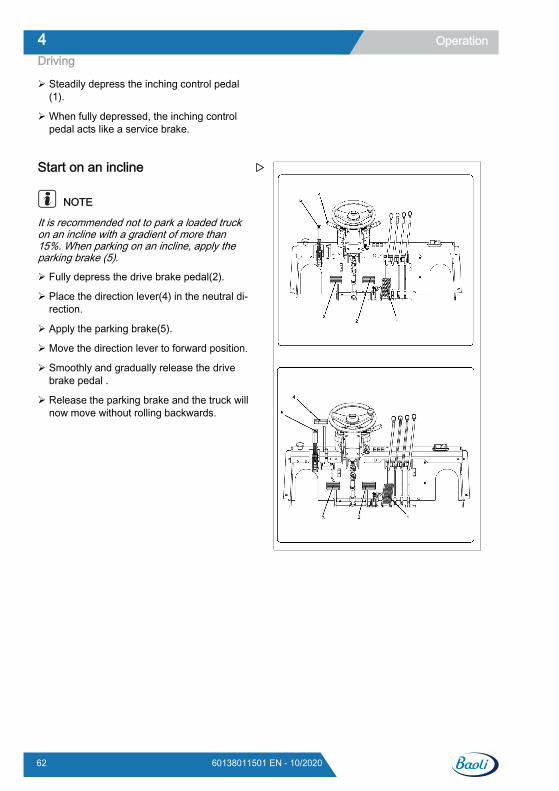
Steadily depress the inching control pedal(1).
When fully depressed, the inching controlpedal acts like a service brake.
Start on an incline
NOTE
It is recommended not to park a loaded truckon an incline with a gradient of more than15%. When parking on an incline, apply theparking brake (5).
Fully depress the drive brake pedal(2).
Place the direction lever(4) in the neutral di-rection.
Apply the parking brake(5).
Move the direction lever to forward position.
Smoothly and gradually release the drivebrake pedal .
Release the parking brake and the truck willnow move without rolling backwards.
Operation4Driving
62 60138011501 EN - 10/2020
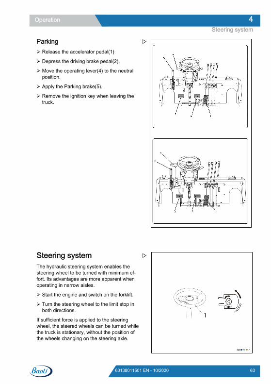
Parking Release the accelerator pedal(1)
Depress the driving brake pedal(2).
Move the operating lever(4) to the neutralposition.
Apply the Parking brake(5).
Remove the ignition key when leaving thetruck.
Steering systemThe hydraulic steering system enables thesteering wheel to be turned with minimum ef-fort. Its advantages are more apparent whenoperating in narrow aisles.
Start the engine and switch on the forklift.
Turn the steering wheel to the limit stop inboth directions.
If sufficient force is applied to the steeringwheel, the steered wheels can be turned whilethe truck is stationary, without the position ofthe wheels changing on the steering axle.
Operation 4Steering system
6360138011501 EN - 10/2020
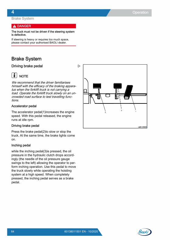
DANGERThe truck must not be driven if the steering systemis defective.If steering is heavy or requires too much space,please contact your authorised BAOLI dealer.
Brake SystemDriving brake pedal
NOTE
We recommend that the driver familiariseshimself with the efficacy of the braking appara-tus when the forklift truck is not carrying aload. Operate the forklift truck slowly on an un-crowded road surface to test travelling func-tions.
Accelerator pedal
The accelerator pedal(1)increases the enginespeed. With this pedal released, the engineruns at idle rpm.
Driving brake pedal
Press the brake pedal(2)to slow or stop thetruck. At the same time, the brake lights comeon.
Inching pedal
while the inching pedal(3)is pressed, the oilpressure in the hydraulic clutch drops accord-ingly (the needle of the oil pressure gaugeswings to the left) allowing the operator to per-form inching operation. Use this pedal to movethe truck slowly while operating the hoistingsystem at a high speed. When completelypressed, the inching pedal serves as a brakepedal.
Operation4Brake System
64 60138011501 EN - 10/2020
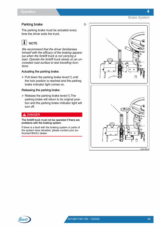
Parking brakeThe parking brake must be actuated everytime the driver exits the truck.
NOTE
We recommend that the driver familiariseshimself with the efficacy of the braking appara-tus when the forklift truck is not carrying aload. Operate the forklift truck slowly on an un-crowded road surface to test travelling func-tions.
Actuating the parking brake:
Pull down the parking brake lever(1) untilthe lock position is reached and the parkingbrake indicator light comes on.
Releasing the parking brake:
Release the parking brake lever(1).Theparking brake will return to its original posi-tion and the parking brake indicator light willturn off.
DANGERThe forklift truck must not be operated if there areproblems with the braking system.If there is a fault with the braking system or parts ofthe system have abraded, please contact your au-thorised BAOLI dealer.
Operation 4Brake System
6560138011501 EN - 10/2020
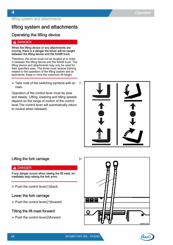
lifting system and attachmentsOperating the lifting device
DANGERWhen the lifting device or any attachments aremoving, there is a danger the driver will be caughtbetween the lifting device and the forklift truck.Therefore, the driver must not be located at or enterin between the lifting device and the forklift truck. Thelifting device and attachments may only be used fortheir specified uses. The driver must receive trainingrelated to the operation of the lifting system and at-tachments. Keep in mind the maximum lift height.
Take note of the switching symbols with ar-rows.
Operation of the control lever must be slowand steady. Lifting, lowering and tilting speedsdepend on the range of motion of the controllevel.The control lever will automatically returnto neutral when released.
Lifting the fork carriage
DANGERIf any danger occurs when raising the lift mast, im-mediately stop raising the fork arms.
Push the control lever(1))back.
Lower the fork carriage Push the control lever((1)forward.
Tilting the lift mast forward Push the control lever(2)forward.
Operation4lifting system and attachments
66 60138011501 EN - 10/2020
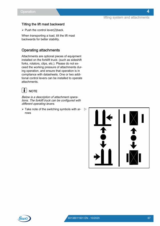
Tilting the lift mast backward Push the control lever(2)back.
When transporting a load, tilt the lift mastbackwards for better stability.
Operating attachmentsAttachments are optional pieces of equipmentinstalled on the forklift truck: (such as sideshiftforks, rotators, clips, etc.). Please do not ex-ceed the working pressure of attachments dur-ing operation, and ensure that operation is incompliance with datasheets. One or two addi-tional control levers can be installed to operateattachments.
NOTE
Below is a description of attachment opera-tions. The forklift truck can be configured withdifferent operating levers.
Take note of the switching symbols with ar-rows
Operation 4lifting system and attachments
6760138011501 EN - 10/2020
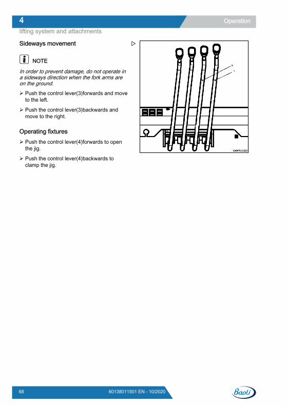
Sideways movement
NOTE
In order to prevent damage, do not operate ina sideways direction when the fork arms areon the ground.
Push the control lever(3)forwards and moveto the left.
Push the control lever(3)backwards andmove to the right.
Operating fixtures Push the control lever(4)forwards to open
the jig.
Push the control lever(4)backwards toclamp the jig.
Operation4lifting system and attachments
68 60138011501 EN - 10/2020
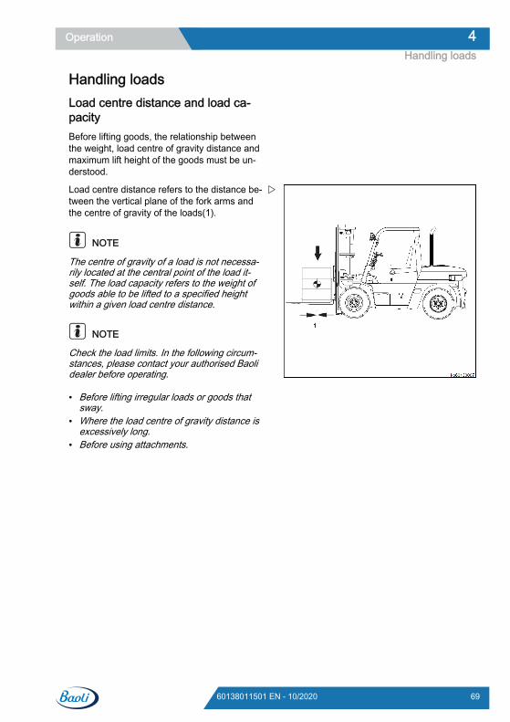
Handling loadsLoad centre distance and load ca-pacityBefore lifting goods, the relationship betweenthe weight, load centre of gravity distance andmaximum lift height of the goods must be un-derstood.
Load centre distance refers to the distance be-tween the vertical plane of the fork arms andthe centre of gravity of the loads(1).
NOTE
The centre of gravity of a load is not necessa-rily located at the central point of the load it-self. The load capacity refers to the weight ofgoods able to be lifted to a specified heightwithin a given load centre distance.
NOTE
Check the load limits. In the following circum-stances, please contact your authorised Baolidealer before operating.
● Before lifting irregular loads or goods thatsway.
● Where the load centre of gravity distance isexcessively long.
● Before using attachments.
Operation 4Handling loads
6960138011501 EN - 10/2020
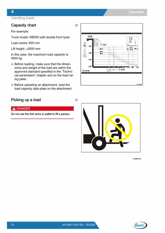
Capacity chartFor example:
Truck model: KBD50 with double front tyres
Load centre: 600 mm
Lift height: ≤5000 mm
In this case, the maximum load capacity is:4500 kg
Before loading, make sure that the dimen-sions and weight of the load are within theapproved standard specified in the “Techni-cal parameters” chapter and on the load rat-ing plate.
Before operating an attachment, read theload capacity data plate on the attachment.
Picking up a load
DANGERDo not use the fork arms or pallet to lift a person.
Operation4Handling loads
70 60138011501 EN - 10/2020
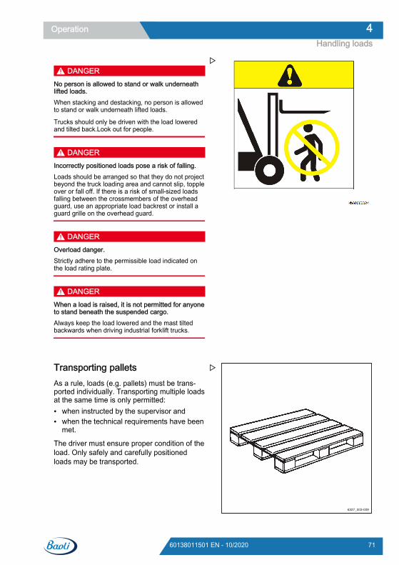
DANGERNo person is allowed to stand or walk underneathlifted loads.When stacking and destacking, no person is allowedto stand or walk underneath lifted loads.
Trucks should only be driven with the load loweredand tilted back.Look out for people.
DANGERIncorrectly positioned loads pose a risk of falling.Loads should be arranged so that they do not projectbeyond the truck loading area and cannot slip, toppleover or fall off. If there is a risk of small-sized loadsfalling between the crossmembers of the overheadguard, use an appropriate load backrest or install aguard grille on the overhead guard.
DANGEROverload danger.Strictly adhere to the permissible load indicated onthe load rating plate.
DANGERWhen a load is raised, it is not permitted for anyoneto stand beneath the suspended cargo.Always keep the load lowered and the mast tiltedbackwards when driving industrial forklift trucks.
Transporting palletsAs a rule, loads (e.g. pallets) must be trans-ported individually. Transporting multiple loadsat the same time is only permitted:● when instructed by the supervisor and● when the technical requirements have been
met.
The driver must ensure proper condition of theload. Only safely and carefully positionedloads may be transported.
6327_003-009
Operation 4Handling loads
7160138011501 EN - 10/2020
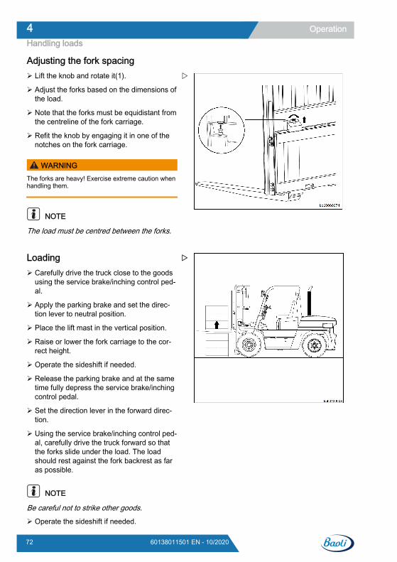
Adjusting the fork spacing Lift the knob and rotate it(1).
Adjust the forks based on the dimensions ofthe load.
Note that the forks must be equidistant fromthe centreline of the fork carriage.
Refit the knob by engaging it in one of thenotches on the fork carriage.
WARNINGThe forks are heavy! Exercise extreme caution whenhandling them.
NOTE
The load must be centred between the forks.
Loading Carefully drive the truck close to the goods
using the service brake/inching control ped-al.
Apply the parking brake and set the direc-tion lever to neutral position.
Place the lift mast in the vertical position.
Raise or lower the fork carriage to the cor-rect height.
Operate the sideshift if needed.
Release the parking brake and at the sametime fully depress the service brake/inchingcontrol pedal.
Set the direction lever in the forward direc-tion.
Using the service brake/inching control ped-al, carefully drive the truck forward so thatthe forks slide under the load. The loadshould rest against the fork backrest as faras possible.
NOTE
Be careful not to strike other goods.
Operate the sideshift if needed.
Operation4Handling loads
72 60138011501 EN - 10/2020
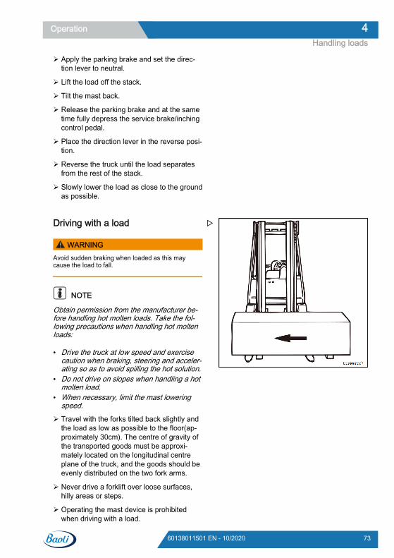
Apply the parking brake and set the direc-tion lever to neutral.
Lift the load off the stack.
Tilt the mast back.
Release the parking brake and at the sametime fully depress the service brake/inchingcontrol pedal.
Place the direction lever in the reverse posi-tion.
Reverse the truck until the load separatesfrom the rest of the stack.
Slowly lower the load as close to the groundas possible.
Driving with a load
WARNINGAvoid sudden braking when loaded as this maycause the load to fall.
NOTE
Obtain permission from the manufacturer be-fore handling hot molten loads. Take the fol-lowing precautions when handling hot moltenloads:
● Drive the truck at low speed and exercisecaution when braking, steering and acceler-ating so as to avoid spilling the hot solution.
● Do not drive on slopes when handling a hotmolten load.
● When necessary, limit the mast loweringspeed.
Travel with the forks tilted back slightly andthe load as low as possible to the floor(ap-proximately 30cm). The centre of gravity ofthe transported goods must be approxi-mately located on the longitudinal centreplane of the truck, and the goods should beevenly distributed on the two fork arms.
Never drive a forklift over loose surfaces,hilly areas or steps.
Operating the mast device is prohibitedwhen driving with a load.
Operation 4Handling loads
7360138011501 EN - 10/2020
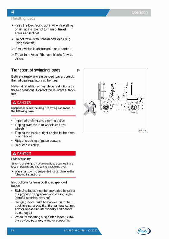
Keep the load facing uphill when travellingon an incline. Do not turn on or travelacross an incline!
Do not travel with unbalanced loads (e.g.using sideshift).
If your vision is obstructed, use a spotter.
Travel in reverse if the load blocks forwardvision.
Transport of swinging loadsBefore transporting suspended loads, consultthe national regulatory authorities.
National regulations may place restrictions onthese operations. Contact the relevant authori-ties.
DANGERSuspended loads that begin to swing can result inthe following risks:
● Impaired braking and steering action● Tipping over the load wheels or drive
wheels● Tipping the truck at right angles to the direc-
tion of travel● Risk of crushing of guide persons● Reduced visibility.
DANGERLoss of stability.Slipping or swinging suspended loads can lead to aloss of stability and cause the truck to tip over. When transporting suspended loads, observe the
following instructions
Instructions for transporting suspendedloads:● Swinging loads must be prevented by using
the proper driving speed and driving style(careful steering, braking)
● Hanging loads must be hooked on to thetruck in such a way that the harness cannotshift or release unintentionally and cannotbe damaged
● When transporting suspended loads, suita-ble devices (e.g. guy wires or supporting
Operation4Handling loads
74 60138011501 EN - 10/2020
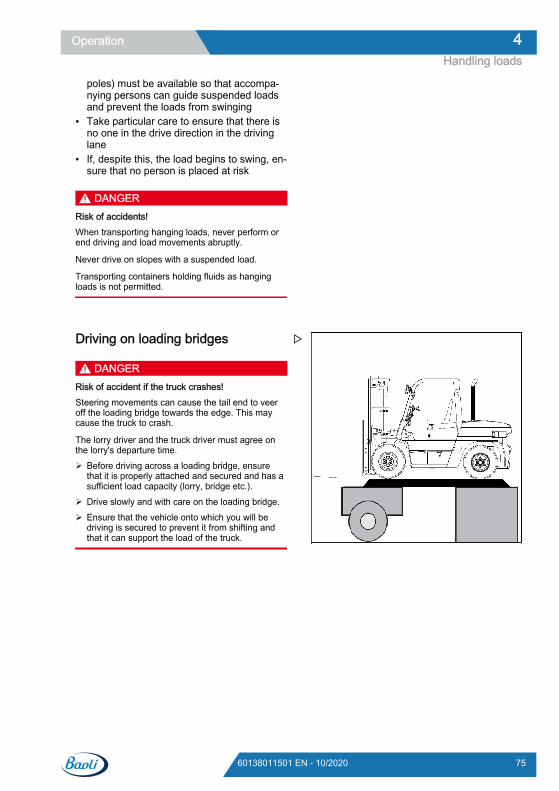
poles) must be available so that accompa-nying persons can guide suspended loadsand prevent the loads from swinging
● Take particular care to ensure that there isno one in the drive direction in the drivinglane
● If, despite this, the load begins to swing, en-sure that no person is placed at risk
DANGERRisk of accidents!When transporting hanging loads, never perform orend driving and load movements abruptly.
Never drive on slopes with a suspended load.
Transporting containers holding fluids as hangingloads is not permitted.
Driving on loading bridges
DANGERRisk of accident if the truck crashes!Steering movements can cause the tail end to veeroff the loading bridge towards the edge. This maycause the truck to crash.
The lorry driver and the truck driver must agree onthe lorry's departure time. Before driving across a loading bridge, ensure
that it is properly attached and secured and has asufficient load capacity (lorry, bridge etc.).
Drive slowly and with care on the loading bridge. Ensure that the vehicle onto which you will be
driving is secured to prevent it from shifting andthat it can support the load of the truck.
Operation 4Handling loads
7560138011501 EN - 10/2020
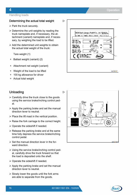
Determining the actual total weight Park the truck securely.
Determine the unit weights by reading thetruck nameplate and, if necessary, the at-tachment (variant) nameplate and, if neces-sary, by weighing the load to be lifted.
Add the determined unit weights to obtainthe actual total weight of the truck:
Tare weight (1)
+ Ballast weight (variant) (2)
+ Attachment net weight (variant)
+ Weight of the load to be lifted+ 100 kg allowance for driver= Actual total weight
Unloading Carefully drive the truck close to the goods
using the service brake/inching control ped-al.
Apply the parking brake and set the manualdirection lever to neutral.
Place the lift mast in the vertical position.
Raise the fork carriage to the correct height.
Operate the sideshift if needed.
Release the parking brake and at the sametime fully depress the service brake/inchingcontrol pedal.
Set the manual direction lever in the for-ward direction.
Using the service brake/inching control ped-al, carefully drive the truck forward so thatthe load is deposited onto the shelf.
Operate the sideshift if needed.
Apply the parking brake and set the manualdirection lever to neutral.
Slowly lower the goods until the fork armsare able to separate from the goods.
Operation4Handling loads
76 60138011501 EN - 10/2020
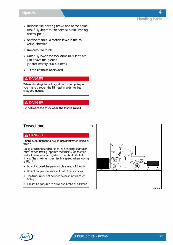
Release the parking brake and at the sametime fully depress the service brake/inchingcontrol pedal.
Set the manual direction lever in the re-verse direction.
Reverse the truck.
Carefully lower the fork arms until they arejust above the ground(approximately 300-400mm).
Tilt the lift mast backward.
DANGERWhen stacking/destacking, do not attempt to putyour hand through the lift mast in order to freesnagged goods.
DANGERDo not leave the truck while the load is raised.
Towed load
DANGERThere is an increased risk of accident when using atrailer.Using a trailer changes the truck handling character-istics. When towing, operate the truck such that thetrailer train can be safely driven and braked at alltimes. The maximum permissible speed when towingis 5 km/h. Do not exceed the permissible speed of 5 km/h. Do not couple the truck in front of rail vehicles. The truck must not be used to push any kind of
trolley. It must be possible to drive and brake at all times.
Operation 4Handling loads
7760138011501 EN - 10/2020
CAUTIONRisk of damage to components!The maximum towed load for occasional towing isthe rated capacity specified on the nameplate. Over-loading can lead to component damage on the truck.The sum of the actual towed load and the actual loadon the fork must not exceed the rated capacity. If theexisting towed load corresponds to the rated capacityof the truck, no load may be transported on the forkat the same time. The load can be distributedbetween the fork and the trailer. Check the load distribution and adjust it to corre-
spond to the rated capacity. Observe the permissible rigidity value of the tow
coupling.
CAUTIONRisk of damage to components!The maximum towed load only applies when towingunbraked trailers on a level surface (maximum devia-tion +/- 1%) and on firm ground. The towed loadmust be reduced if towing on gradients. If necessary,notify the authorised service centre of the applicationconditions. The service centre will provide the re-quired data. Inform the authorised service centre.
CAUTIONRisk of damage to components!A support load is not permitted. Do not use trailers with tillers supported by the
tow coupling.
This truck is suitable for the occasional towingof trailers. If the truck is equipped with a tow-ing device, this occasional towing must not ex-ceed 2% of the daily operating time. If thetruck is to be used for towing on a more regu-lar basis, the manufacturer should be consul-ted.
Operation4Handling loads
78 60138011501 EN - 10/2020
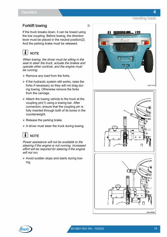
Forklift towingIf the truck breaks down, it can be towed usingthe tow coupling. Before towing, the directionlever must be placed in the neutral position(2).And the parking brake must be released.
NOTE
When towing, the driver must be sitting in theseat to steer the truck, actuate the brakes andoperate other controls, and the engine mustbe running.
Remove any load from the forks.
If the hydraulic system still works, raise theforks if necessary so they will not drag dur-ing towing. Otherwise remove the forksfrom the carriage.
Attach the towing vehicle to the truck at thecoupling pin(1) using a towing bar. Afterconnection, ensure that the coupling pin isfully inserted through both of its bores in thecounterweight.
Release the parking brake.
A driver must steer the truck during towing.
NOTE
Power assistance will not be available to thesteering if the engine is not running. Increasedeffort will be required for steering if the enginewill not run.
Avoid sudden stops and starts during tow-ing.
Operation 4Handling loads
7960138011501 EN - 10/2020
CleaningCleaning the truck Park the truck securely.
Switch the electrical system off beforecleaning.
WARNING
There is a risk of injury due to fallingwhen climbing onto the truck!When climbing onto the truck, you canget stuck or slip on components and fall.Higher points on the truck should only beaccessed using the appropriate equip-ment. Strictly adhere to the following steps.
Use only the steps provided to climb ontothe truck.
Use equipment such as stepladders or plat-forms to reach inaccessible areas.
Washing the truck exterior
CAUTIONThere is a risk of short circuit if water penetrates theelectrical system! Strictly adhere to the following steps.
Prior to cleaning, switch off the power sup-ply to the electrical system.
Do not spray electrical components and thecovers on these components directly withwater.
WARNINGFailure to follow these instructions could result indamaged components!The engine must be switched off during washing.Water should not be used to clean the area aroundthe central electrical system; instead, only clean witha dry cloth or clean compressed air.
WARNINGExcessive water pressure or water and steam thatare too hot can damage truck components. Strictly adhere to the following steps.
Only use high-pressure cleaners with amaximum output power of 50 bar and at amaximum temperature of 85°C.
When using high-pressure cleaners, makesure there is a distance of at least 20 cmbetween the nozzle and the object beingcleaned.
Do not aim the cleaning jet directly at adhe-sive labels or information signs.
DANGER
Risk of fire! Deposits/accumulations ofcombustible materials may ignite in thevicinity of hot components (e.g. exhaustpipes). Strictly adhere to the following steps.
Regularly remove all deposits/accumula-tions of foreign materials in the vicinity ofhot components.
Do not place combustible materials in theengine compartment.
DANGER
Risk of fire! Flammable fluids can be ig-nited by hot components on the truck. Strictly adhere to the following steps.
Do not use flammable fluids for cleaning.
Observe the manufacturer's guidelines forworking with cleaning materials
CAUTIONAbrasive cleaning materials can damage componentsurfaces!Using abrasive cleaning materials that are unsuitablefor plastics may dissolve plastic parts or make thembrittle. The screen on the display operating unit maybecome cloudy. The procedures outlined below must be followed
in all cases.
Clean plastic parts only with cleaning mate-rials intended for plastic parts.
Operation4Cleaning
80 60138011501 EN - 10/2020
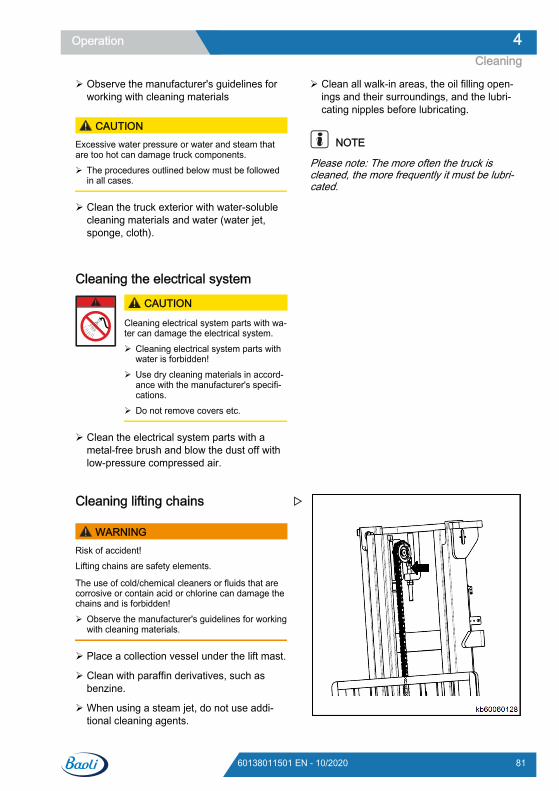
Observe the manufacturer's guidelines forworking with cleaning materials
CAUTIONExcessive water pressure or water and steam thatare too hot can damage truck components. The procedures outlined below must be followed
in all cases.
Clean the truck exterior with water-solublecleaning materials and water (water jet,sponge, cloth).
Clean all walk-in areas, the oil filling open-ings and their surroundings, and the lubri-cating nipples before lubricating.
NOTE
Please note: The more often the truck iscleaned, the more frequently it must be lubri-cated.
Cleaning the electrical system
CAUTION
Cleaning electrical system parts with wa-ter can damage the electrical system. Cleaning electrical system parts with
water is forbidden! Use dry cleaning materials in accord-
ance with the manufacturer's specifi-cations.
Do not remove covers etc.
Clean the electrical system parts with ametal-free brush and blow the dust off withlow-pressure compressed air.
Cleaning lifting chains
WARNINGRisk of accident!Lifting chains are safety elements.
The use of cold/chemical cleaners or fluids that arecorrosive or contain acid or chlorine can damage thechains and is forbidden! Observe the manufacturer's guidelines for working
with cleaning materials.
Place a collection vessel under the lift mast.
Clean with paraffin derivatives, such asbenzine.
When using a steam jet, do not use addi-tional cleaning agents.
Operation 4Cleaning
8160138011501 EN - 10/2020
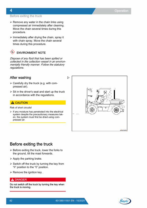
Remove any water in the chain links usingcompressed air immediately after cleaning.Move the chain several times during thisprocedure.
Immediately after drying the chain, spray itwith chain spray. Move the chain severaltimes during this procedure.
ENVIRONMENT NOTE
Dispose of any fluid that has been spilled orcollected in the collection vessel in an environ-mentally friendly manner. Follow the statutoryregulations.
After washing Carefully dry the truck (e.g. with com-
pressed air).
Sit in the driver's seat and start up the truckin accordance with the regulations.
CAUTIONRisk of short circuits! If any moisture has penetrated into the electrical
system despite the precautionary measures tak-en, the system must first be dried using com-pressed air.
Before exiting the truck Before exiting the truck, lower the forks to
the ground, tilt the mast forwards.
Apply the parking brake.
Switch off the truck by turning the key from“II” position to the “0” position.
Remove the ignition key .
DANGERDo not switch off the truck by turning the key whenthe truck is moving.
Operation4Before exiting the truck
82 60138011501 EN - 10/2020

Truck transportUse a truck or flatbed trailer to carry theforklift truck Lower the lift mast completely.
Tilt the lift mast forward.
NOTE
The fork arms must be resting on the ground.
Apply the parking brake.
Place wedges underneath the forklift truck.
Use ropes to secure the mast in the casethat the mast shall be dismounted duringtransport.
Hoisting the truck
DANGERWhen lifting the truck with a crane, there is a risk ofaccident and fatal injury if personnel are in theworking area of the crane.When using a crane to lift the truck, pay particular at-tention to ensure that no personnel are in the vicinityof the crane. Comply with the load capacity ratingmarked on the crane nameplate. Never walk under asuspended load!
CAUTIONUse a spreader and crane with sufficient load capaci-ty to lift the truck. For the weight of the truck, see themanufacturer’s nameplate.
NOTE
Before hoisting the truck, fasten the slings tothe given lifting points. These lifting points arenot specifically marked on the truck.
Lower the lift mast completely, and tilt it fullybackwards.
Remove the rubber grommets from theopenings (6) in the counterweight.
Remove the counterweight grid(5).
Attach a sling (2) (able to at least bear theweight of the forklift truck ) to the two open-ings in the counterweight.
Operation 4Truck transport
8360138011501 EN - 10/2020
Attach two shackles (7) to the two openingsin the upper beam of the outer lift mast.
Attach a sling (3) (able to at least bear theweight of the forklift truck ) to the two shack-les.
Prevent the slings from rubbing against anysharp edges on the truck.
Attach the ends of all the slings to the cranehook (1).
CAUTION
After hanging the slings from the lifting hook, thesafety lock (4) must be fastened. The slings must nottouch the overhead guard or any other installedequipment when the truck is being lifted.
DANGER
The overhead guard will be damaged if it is contac-ted by lifting equipment that is under tension from lift-ing. This can result in later failure of the overheadguard and the risk of severe injury or death. Ensurethat no part of any lifting equipment contacts theoverhead guard during lifting.
Truck StorageBefore storageBefore storing your forklift truck, clean it thor-oughly and perform inspection as the followingprocedures.
Wipe away grease, oil, etc. covering thebody of the truck with waste cloth, if needed
While washing the body of the truck, checkgeneral condition of the truck. Especiallycheck the truck’s body for recess or dam-age and tires for wear and nails or stones inthe tread.
Fill the oil tank with the appointed fuel.
Check for leakage of hydraulic oil, engineoil, fuel or coolant.
Apply grease to where needed.
Check for looseness of hub nuts and cylin-der piston rod joints. Check the surface ofpiston rod for damage.
Check mast rollers to see that they rotatesmoothly.
Fill up enough oil into the lift cylinders bylifting the lift cylinders fully.
In winter or cold season, don’t drain long-acting antifreeze, while cooling water shallbe drained.
Daily storage Park the forklift truck at a specified place
and block the wheels.
Place the direction lever in the neutral posi-tion and apply the parking brake by de-pressing the parking brake pedal.
Operation4Truck Storage
84 60138011501 EN - 10/2020
Turn the ignition key to “OFF” position andturn off the engine, operate joystick of con-trol valve several times to release residualpressure in the hydraulic system.
Remove the key and keep it in a safe place.
Long-term storagePerform the following service and checks inaddition to the “Daily storage” service:
Clean the truck thoroughly.
Park the truck in a well-ventilated, frost-free,clean and dry place.
Both raise and lower the fork carriage andtilt the lift mast forwards and backwardsseveral times. If equipped with attachments,operate the attachments several times.
Lower the fork onto a support mounting sothat the lift chain does not continue to expe-rience stress.
Apply a light film of oil or grease to exposedunpainted parts such as piston rods andmast rollers.
Lubricate the truck per the scheduled main-tenance procedure.
The truck should be operated at least oncea week. Check coolant level and replenish if
necessary. Start the engine and warm upthoroughly. Move the truck slowly forwardsand backwards. Operate the hydraulic con-trols several times.
Start-up after storage Clean the truck thoroughly.
Change the engine oil, transmission oil, andgear lubricant.
Discharge foreign matter and water fromthe hydraulic reservoir and fuel tank.
Remove the cylinder cap, the valves andthe rocker shafts, check for the clearance innormal data.
Add cooling fluid to specified level.
Perform pre-operation checks carefully.
Check coolant level and replenish if neces-sary. Start the engine and warm up thor-oughly before operation.
WARNINGAt any time your lift truck is found to be in need of re-pair, defective, or in any way unsafe, the conditionshould be reported to be supervisor immediately, andthe truck should be taken out of service until it hasbeen restored to safe operating condition.
Disposal of old trucksThe disposal of old trucks is regulated in direc-tive 2000/53/EC from the European Parlia-ment and Council.
We therefore recommend having this workcarried out in an approved recycling plant. Ifyou would like to carry out this work yourself,you must obtain approval from the relevantauthorities as per articles 9, 10 and 11 of di-rective 75/442/EEC.
In addition, the following minimum require-ments must be observed:● The locations in which old trucks are stored
before treatment must be areas suited tothis task with impervious surfaces. Theseareas are also to be equipped with collec-tion devices and separators for leaking flu-ids and degreasing cleaning materials
● The locations for treatment must be areassuited to this task with impervious surfaces.These areas must also be equipped withcollection devices and separators for leak-ing fluids and degreasing cleaning materi-als. Suitable storage areas must be availa-ble for disassembled and partially oil-smeared parts, as well as for tyres includingfire protection measures. Suitable storagetanks for fluids such as fuel, AdBlue® (urea
Operation 4Disposal of old trucks
8560138011501 EN - 10/2020
solution), engine oil, hydraulic oil, coolingfluid and fluids from air conditioning sys-tems must also be provided
● In order to dispose of harmful substancesfrom the old trucks, the batteries and LPGcontainer must be removed. The followingmust also be removed, collected and storedseparately: fuel, AdBlue® (urea solution),engine oil, cooling fluid, hydraulic oil andfluids from air conditioning systems
● The following parts are to be collected sep-arately and recycled: catalytic converters,
metal components containing copper andaluminium, tyres, large plastic components(consoles, fluid containers) and glass
NOTE
The operating company is responsible for ad-herence to the directives as well as additionalcountry-specific regulations.
Operation4Disposal of old trucks
86 60138011501 EN - 10/2020

5
Maintenance
SummaryFollowing the instructions in the user manualand conducting regular checks and mainte-nance are essential for ensuring that the fork-lift truck remains in proper working order.Maintenance should only be carried out byBaoli-accredited technicians, or by authorisedBaoli dealers in accordance with a signedmaintenance contract.
Modifying or installing additional equipment onthe forklift truck is prohibited without theagreement of the manufacturer.
NOTE
If the data plates or affixed labels are incom-plete or damaged, they should be replacedwith new ones. For locations and referencenumbers, please see the spare parts cata-logue.
The forklift must undergo functional testingand a trial run after each inspection.
CAUTIONIf the forklift truck is used in an extreme environment(such as excessive heat, excessive cold or areaswith high dust concentrations), the time intervals giv-en in the maintenance tables should be reduced ac-cordingly.
ENVIRONMENT NOTE
Please comply with regulations regarding theuse, handling and disposal of fuel and lubricat-ing oil.
General informationIn order to keep the forklift truck in good work-ing condition, it must undergo regular serviceand maintenance. All service and mainte-nance operations, such as oil changes, mustbe performed strictly in accordance with theindications below. Maintenance work must berecorded in the warranty booklet. Please re-tain maintenance records in order to ensurethe validity of the warranty.
DANGERMaintenance must be carried out by professionaltechnical personnel authorised by the manufactur-er, in order to guarantee the operating performanceof the truck as well as compliance with all technicalspecifications.
CAUTIONThe manufacture shall assume no liability for theconsequences of maintenance carried out by unau-thorised personnel.
NOTE
In order to meet your specific needs you maysign a maintenance contract with an author-ised service centre.
CAUTIONIf the forklift truck is used in an extreme environment(such as excessive heat, excessive cold or areaswith high dust concentration), the time intervals givenin the maintenance tables should be reduced accord-ingly.
Maintenance5Summary
88 60138011501 EN - 10/2020
Pre-service preparatory work Before commencing maintenance work, the
forklift truck should be stopped on a flat sur-face. A wedge should also be placed infront of the wheels to prevent accidentalmovement.
Lower the fork arms to the ground.
Apply the parking brake.
Turn off the power supply to the forklift truckand remove the ignition key.
When maintenance needs to be carried outunder the lifted fork carriage and mast,
measures must be taken to prevent the forkcarriage or mast from accidentally falling.
When work needs to be carried out at thefront end of the forklift truck, the mastshould be secured to prevent backwardstilting.
DANGERThe negative electrode of the rechargeable batterymust be disconnected before working on the elec-trical system.
Maintenance 5Pre-service preparatory work
8960138011501 EN - 10/2020
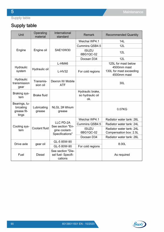
Supply table
Unit Operatingmaterial
Internationalstandard Remark Recommended Quantity
Engine Engine oil SAE10W30
Weichai WP4.1 14LCummins QSB4.5 12L
ISUZU6BG1QC-02 12L
Doosan D34 12L
Hydraulicsystem Hydraulic oil
L-HM46 125L for mast below4500mm mast
130L for mast exceeding4500mm mast
L-HV32 For cold regions
Hydraulictransmission
gear
Transmis-sion oil
Dexron Ⅲ/ MobileATF 30L
Braking sys-tem Brake fluid
Hydraulic brake,so hydraulic oil
ok.
Bearings, lu-bricating
grease fit-tings
Lubricatinggrease
NLGL 2# lithiumgrease 0.07KG
Cooling sys-tem Coolant fluid
LLC PD-2ASee section "En-
gine coolant-Specifications"
Weichai WP4.1 Radiator water tank: 26LCummins QSB4.5 Radiator water tank: 24L
ISUZU6BG1QC-02
Radiator water tank: 24LCompensation box: 2.5L
Doosan D34 Radiator water tank: 26L
Drive axle gear oilGL-5 85W-90
8.00LGL-5 80W-90 For cold regions
Fuel DieselSee section "Die-sel fuel- Specifi-
cations As required
Maintenance5Supply table
90 60138011501 EN - 10/2020
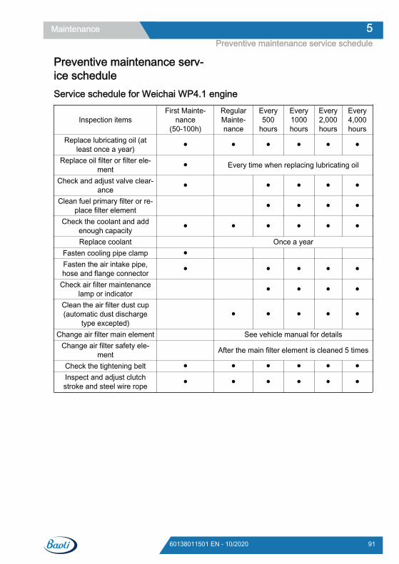
Preventive maintenance serv-ice scheduleService schedule for Weichai WP4.1 engine
Inspection itemsFirst Mainte-
nance(50-100h)
RegularMainte-nance
Every500
hours
Every1000hours
Every2,000hours
Every4,000hours
Replace lubricating oil (atleast once a year) ● ● ● ● ● ●
Replace oil filter or filter ele-ment ● Every time when replacing lubricating oil
Check and adjust valve clear-ance ● ● ● ● ●
Clean fuel primary filter or re-place filter element ● ● ● ●
Check the coolant and addenough capacity ● ● ● ● ● ●
Replace coolant Once a yearFasten cooling pipe clamp ● Fasten the air intake pipe,hose and flange connector ● ● ● ● ●
Check air filter maintenancelamp or indicator ● ● ● ●
Clean the air filter dust cup(automatic dust discharge
type excepted) ● ● ● ● ●
Change air filter main element See vehicle manual for detailsChange air filter safety ele-
ment After the main filter element is cleaned 5 times
Check the tightening belt ● ● ● ● ● ●Inspect and adjust clutchstroke and steel wire rope ● ● ● ● ● ●
Maintenance 5Preventive maintenance service schedule
9160138011501 EN - 10/2020
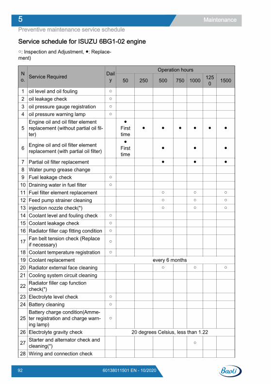
Service schedule for ISUZU 6BG1-02 engine○: Inspection and Adjustment, ●: Replace-ment)
No. Service Required Dail
y
Operation hours
50 250 500 750 1000 1250 1500
1 oil level and oil fouling ○ 2 oil leakage check ○ 3 oil pressure gauge registration ○ 4 oil pressure warning lamp ○
5Engine oil and oil filter elementreplacement (without partial oil fil-ter)
●
Firsttime
● ● ● ● ● ●
6 Engine oil and oil filter elementreplacement (with partial oil filter)
●Firsttime
● ● ●
7 Partial oil filter replacement ● ● ●8 Water pump grease change 9 Fuel leakage check ○
10 Draining water in fuel filter ○ 11 Fuel filter element replacement ○ ○ ○12 Feed pump strainer cleaning ○ ○ ○13 injection nozzle check(*) ○ ○ ○14 Coolant level and fouling check ○ 15 Coolant leakage check ○ 16 Radiator filler cap fitting condition ○
17 Fan belt tension check (Replaceif necessary) ○
18 Coolant temperature registration ○ 19 Coolant replacement every 6 months20 Radiator external face cleaning ○ ○ ○21 Cooling system circuit cleaning
22 Radiator filler cap functioncheck(*)
23 Electrolyte level check ○ 24 Battery cleaning ○
25Battery charge condition(Amme-ter registration and charge warn-ing lamp)
○
26 Electrolyte gravity check 20 degrees Celsius, less than 1.22
27 Starter and alternator check andcleaning(*) ○
28 Wiring and connection check
Maintenance5Preventive maintenance service schedule
92 60138011501 EN - 10/2020
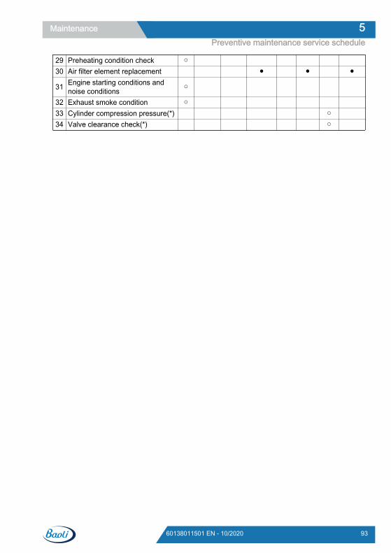
29 Preheating condition check ○ 30 Air filter element replacement ● ● ●
31 Engine starting conditions andnoise conditions ○
32 Exhaust smoke condition ○ 33 Cylinder compression pressure(*) ○ 34 Valve clearance check(*) ○
Maintenance 5Preventive maintenance service schedule
9360138011501 EN - 10/2020
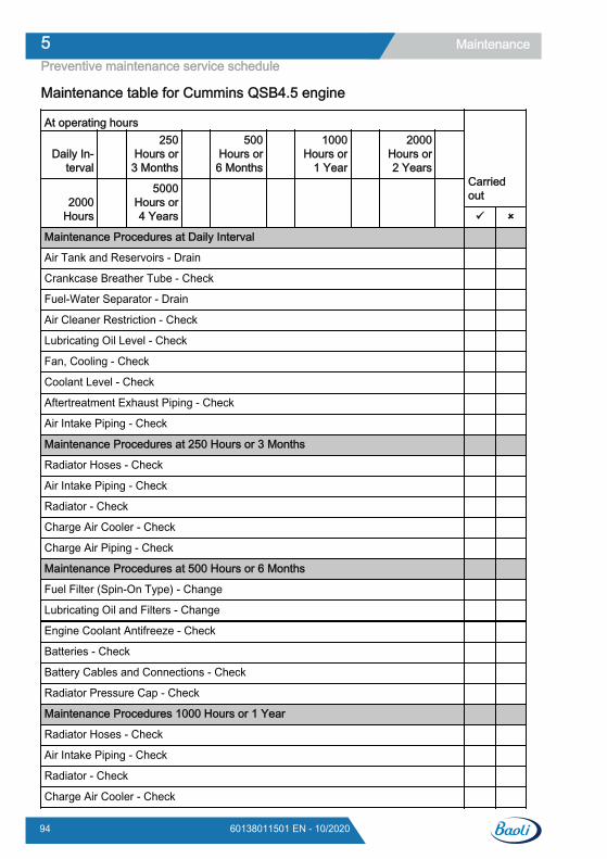
Maintenance table for Cummins QSB4.5 engine
At operating hours
Daily In-terval
250Hours or
3 Months
500Hours or
6 Months
1000Hours or
1 Year
2000Hours or2 Years
2000Hours
5000Hours or4 Years
Carriedout
Maintenance Procedures at Daily Interval
Air Tank and Reservoirs - Drain
Crankcase Breather Tube - Check
Fuel-Water Separator - Drain
Air Cleaner Restriction - Check
Lubricating Oil Level - Check
Fan, Cooling - Check
Coolant Level - Check
Aftertreatment Exhaust Piping - Check
Air Intake Piping - Check
Maintenance Procedures at 250 Hours or 3 Months
Radiator Hoses - Check
Air Intake Piping - Check
Radiator - Check
Charge Air Cooler - Check
Charge Air Piping - Check
Maintenance Procedures at 500 Hours or 6 Months
Fuel Filter (Spin-On Type) - Change
Lubricating Oil and Filters - Change
Engine Coolant Antifreeze - Check
Batteries - Check
Battery Cables and Connections - Check
Radiator Pressure Cap - Check
Maintenance Procedures 1000 Hours or 1 Year
Radiator Hoses - Check
Air Intake Piping - Check
Radiator - Check
Charge Air Cooler - Check
Maintenance5Preventive maintenance service schedule
94 60138011501 EN - 10/2020
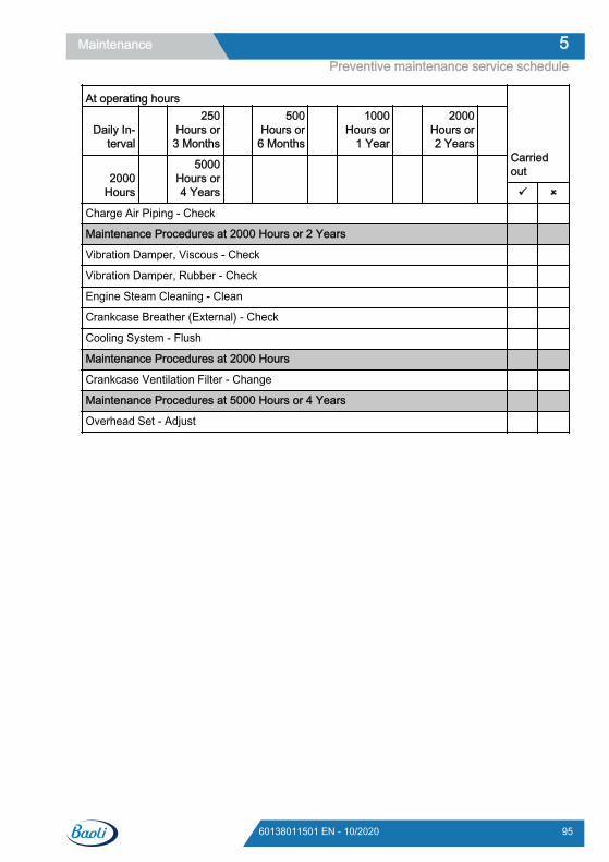
At operating hours
Daily In-terval
250Hours or
3 Months
500Hours or
6 Months
1000Hours or
1 Year
2000Hours or2 Years
2000Hours
5000Hours or4 Years
Carriedout
Charge Air Piping - Check
Maintenance Procedures at 2000 Hours or 2 Years
Vibration Damper, Viscous - Check
Vibration Damper, Rubber - Check
Engine Steam Cleaning - Clean
Crankcase Breather (External) - Check
Cooling System - Flush
Maintenance Procedures at 2000 Hours
Crankcase Ventilation Filter - Change
Maintenance Procedures at 5000 Hours or 4 Years
Overhead Set - Adjust
Maintenance 5Preventive maintenance service schedule
9560138011501 EN - 10/2020
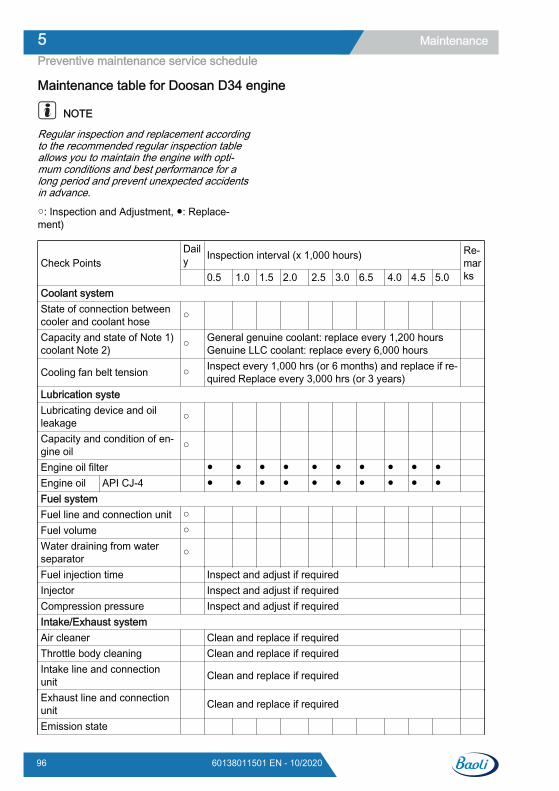
Maintenance table for Doosan D34 engine
NOTE
Regular inspection and replacement accordingto the recommended regular inspection tableallows you to maintain the engine with opti-mum conditions and best performance for along period and prevent unexpected accidentsin advance.
○: Inspection and Adjustment, ●: Replace-ment)
Check PointsDaily Inspection interval (x 1,000 hours) Re-
marks 0.5 1.0 1.5 2.0 2.5 3.0 6.5 4.0 4.5 5.0
Coolant systemState of connection betweencooler and coolant hose ○
Capacity and state of Note 1)coolant Note 2) ○ General genuine coolant: replace every 1,200 hours
Genuine LLC coolant: replace every 6,000 hours
Cooling fan belt tension ○ Inspect every 1,000 hrs (or 6 months) and replace if re-quired Replace every 3,000 hrs (or 3 years)
Lubrication systeLubricating device and oilleakage ○
Capacity and condition of en-gine oil ○
Engine oil filter ● ● ● ● ● ● ● ● ● ● Engine oil API CJ-4 ● ● ● ● ● ● ● ● ● ● Fuel systemFuel line and connection unit ○ Fuel volume ○ Water draining from waterseparator ○
Fuel injection time Inspect and adjust if required Injector Inspect and adjust if required Compression pressure Inspect and adjust if required Intake/Exhaust systemAir cleaner Clean and replace if required Throttle body cleaning Clean and replace if required Intake line and connectionunit Clean and replace if required
Exhaust line and connectionunit Clean and replace if required
Emission state
Maintenance5Preventive maintenance service schedule
96 60138011501 EN - 10/2020
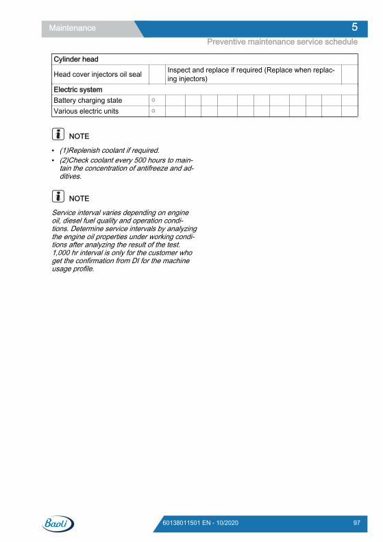
Cylinder head
Head cover injectors oil seal Inspect and replace if required (Replace when replac-ing injectors)
Electric systemBattery charging state ○ Various electric units ○
NOTE
● (1)Replenish coolant if required.● (2)Check coolant every 500 hours to main-
tain the concentration of antifreeze and ad-ditives.
NOTE
Service interval varies depending on engineoil, diesel fuel quality and operation condi-tions. Determine service intervals by analyzingthe engine oil properties under working condi-tions after analyzing the result of the test.1,000 hr interval is only for the customer whoget the confirmation from DI for the machineusage profile.
Maintenance 5Preventive maintenance service schedule
9760138011501 EN - 10/2020
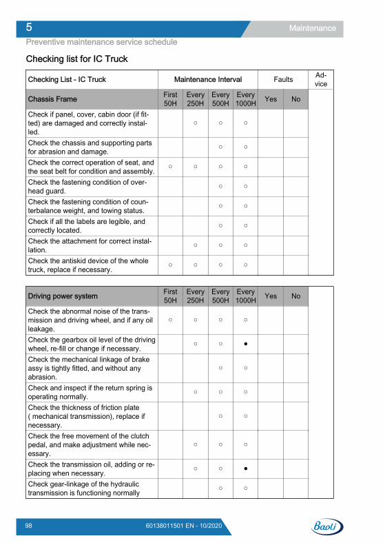
Checking list for IC Truck
Checking List - IC Truck Maintenance Interval Faults Ad-vice
Chassis Frame First50H
Every250H
Every500H
Every1000H Yes No
Check if panel, cover, cabin door (if fit-ted) are damaged and correctly instal-led.
○ ○ ○
Check the chassis and supporting partsfor abrasion and damage. ○ ○
Check the correct operation of seat, andthe seat belt for condition and assembly. ○ ○ ○ ○
Check the fastening condition of over-head guard. ○ ○
Check the fastening condition of coun-terbalance weight, and towing status. ○ ○
Check if all the labels are legible, andcorrectly located. ○ ○
Check the attachment for correct instal-lation. ○ ○ ○
Check the antiskid device of the wholetruck, replace if necessary. ○ ○ ○ ○
Driving power system First50H
Every250H
Every500H
Every1000H Yes No
Check the abnormal noise of the trans-mission and driving wheel, and if any oilleakage.
○ ○ ○ ○
Check the gearbox oil level of the drivingwheel, re-fill or change if necessary. ○ ○ ●
Check the mechanical linkage of brakeassy is tightly fitted, and without anyabrasion.
○ ○
Check and inspect if the return spring isoperating normally. ○ ○ ○
Check the thickness of friction plate( mechanical transmission), replace ifnecessary.
○ ○
Check the free movement of the clutchpedal, and make adjustment while nec-essary.
○ ○ ○
Check the transmission oil, adding or re-placing when necessary. ○ ○ ●
Check gear-linkage of the hydraulictransmission is functioning normally ○ ○
Maintenance5Preventive maintenance service schedule
98 60138011501 EN - 10/2020
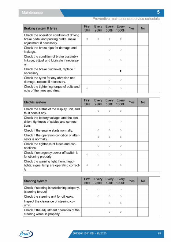
Braking system & tyres First50H
Every250H
Every500H
Every1000H Yes No
Check the operation condition of drivingbrake pedal and parking brake, makeadjustment if necessary.
○ ○ ○ ○
Check the brake pipe for damage andleakage. ○ ○
Check the condition of brake assemblylinkage, adjust and lubricate if necessa-ry.
○ ○
Check the brake fluid level, replace ifnecessary. ●
Check the tyres for any abrasion anddamage, replace if necessary. ○ ○
Check the tightening torque of bolts andnuts of the tyres and rims. ○ ○ ○
Electric system First50H
Every250H
Every500H
Every1000H Yes No
Check the status of the display unit, andfault code if any. ○ ○ ○
Check the battery voltage, and the con-dition, tightness of cables and connec-tions.
○ ○
Check if the engine starts normally. ○ ○ ○ Check if the operation condition of alter-nator is normally. ○ ○ ○
Check the tightness of fuses and con-nections. ○ ○ ○
Check if emergency power off switch isfunctioning properly. ○ ○ ○ ○
Check the warning light, horn, head-lights, signal lamp are operating correct-ly.
○ ○ ○ ○
Steering system First50H
Every250H
Every500H
Every1000H Yes No
Check if steering is functioning properly.(steering torque) ○ ○ ○ ○
Check the steering unit for oil leaks. ○ ○ ○ Inspect the clearance of steering col-umn. ○ ○
Check if the adjustment operation of thesteering wheel is properly. ○ ○
Maintenance 5Preventive maintenance service schedule
9960138011501 EN - 10/2020
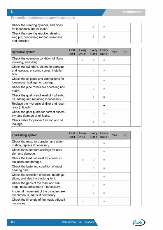
Check the steering cylinder, and pipesfor looseness and oil leaks. ○ ○
Check the steering knuckle, steeringking pin, connecting rod for loosenessand abrasion.
○ ○
Hydraulic system First50H
Every250H
Every500H
Every1000H Yes No
Check the operation condition of lifting,lowering, and tilting. ○ ○ ○
Check the cylinders, piston for damageand leakage, ensuring correct installa-tion.
○ ○
Check the oil pipes and connections forlooseness, leakage, or damage. ○ ○
Check the pipe rollers are operating nor-mally. ○ ○
Check the quality and level of hydraulicoil, adding and replacing if necessary. ○ ●
Replace the hydraulic oil filter and respi-rator (if fitted). ○ ●
Check the gear pump for correct assem-bly, any damage or oil leaks. ○ ○
Check valve for proper function and oilleakage. ○ ○
Load lifting system First50H
Every250H
Every500H
Every1000H Yes No
Check the mast for abrasion and defor-mation, replace if necessary. ○ ○
Check forks and fork carriage for abra-sion and damage. ○
Check the load backrest for correct in-stallation and damage. ○ ○ ○
Check the fastening condition of mastbearing pad. ○ ○
Check the condition of rollers, bearings,slider, and also the blocking limit. ○ ○
Check the gaps of the mast and car-riage, make adjustment if necessary. ○ ○
Inspect if movement of the cylinders aresynchronous, adjust if necessary. ○ ○
Check the tilt angle of the mast, adjust ifnecessary. ○ ○ ○
Maintenance5Preventive maintenance service schedule
100 60138011501 EN - 10/2020
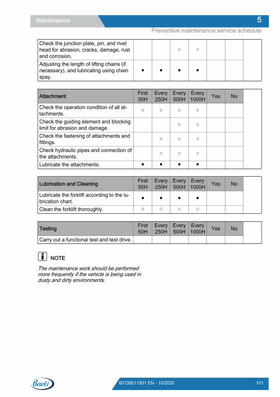
Check the junction plate, pin, and rivethead for abrasion, cracks, damage, rustand corrosion.
○ ○
Adjusting the length of lifting chains (ifnecessary), and lubricating using chainspay.
● ● ● ●
Attachment First50H
Every250H
Every500H
Every1000H Yes No
Check the operation condition of all at-tachments. ○ ○ ○ ○
Check the guiding element and blockinglimit for abrasion and damage. ○ ○
Check the fastening of attachments andfittings. ○ ○ ○
Check hydraulic pipes and connection ofthe attachments. ○ ○ ○
Lubricate the attachments. ● ● ● ●
Lubrication and Cleaning First50H
Every250H
Every500H
Every1000H Yes No
Lubricate the forklift according to the lu-brication chart. ● ● ● ●
Clean the forklift thoroughly. ○ ○ ○ ○
Testing First50H
Every250H
Every500H
Every1000H Yes No
Carry out a functional test and test drive.
NOTE
The maintenance work should be performedmore frequently if the vehicle is being used industy and dirty environments.
Maintenance 5Preventive maintenance service schedule
10160138011501 EN - 10/2020
PreparationsCleaning the truckThe length of truck cleaning intervals dependson what the truck is used for and where it isused. For example, in environments where thetruck comes into contact with irritants such assalt water, fertilizer or chemical products, itneeds to be thoroughly cleaned after eachuse.
Compressed air and a mixture of cold waterand detergent may be used for cleaning.
CAUTIONDo not direct water jets at the truck. Do not use sol-vents or petrol-based fluids for cleaning, as this maydamage electrical components or plastic parts.
Maintenance5Preparations
102 60138011501 EN - 10/2020
Weichai WP4.1 EngineChanging the engine oil
WARNINGDanger of burn injury!If it is necessary to bleed the engine oil when the oilis still hot, avoid contact with the oil and wear eyeprotection to avoid burn injuries.
Failure to comply with regulations may result in deathor serious injury.
CAUTION
Only use designated oil. Other types of oil may affectquality of use and shorten the service life of the en-gine or internal parts.
Avoid contamination of the engine by dirt or dust. Be-fore removing the oil cap, carefully clean the oil cap/dipstick and surrounding areas.
Avoid mixing different brands of oil. Mixing differentbrands of oil will seriously affect lubrication.
Avoid overfilling. Overfilling may result in whitesmoke, overspeed or internal damage.
CAUTION
Please pay attention to environmental protection.Dispose of used oil according to related laws andregulations. Failure to comply with laws and regula-tions will result in serious damage to the environ-ment.
Comply with EPA guidelines or government meas-ures for the correct handling of hazardous materials(such as oil, diesel and engine coolant).
Irresponsible handling of hazardous materials, suchas dumping hazardous waste into water channels, onthe ground, into groundwater or drainage ditches, isprohibited.
Drain the oil using the following steps: Ensure that the engine is in a horizontal po-
sition.
Start the engine and run until it reaches op-erating temperature.
Stop the engine.
Maintenance 5Weichai WP4.1 Engine
10360138011501 EN - 10/2020
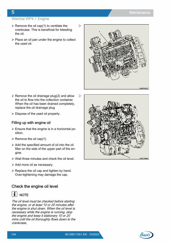
Remove the oil cap(1) to ventilate thecrankcase. This is beneficial for bleedingthe oil.
Place an oil pan under the engine to collectthe used oil.
Remove the oil drainage plug(2) and allowthe oil to flow into the collection container.When the oil has been drained completely,replace the oil drainage plug
Dispose of the used oil properly.
Filling up with engine oil Ensure that the engine is in a horizontal po-
sition.
Remove the oil cap(1).
Add the specified amount of oil into the oilfiller on the side of the upper part of the en-gine.
Wait three minutes and check the oil level.
Add more oil as necessary.
Replace the oil cap and tighten by hand.Over-tightening may damage the cap.
Check the engine oil level
NOTE
The oil level must be checked before startingthe engine, or at least 10 or 20 minutes afterthe engine is shut down. When the oil level isnecessary while the engine is running, stopthe engine and keep it stationary 10 or 20mins until the oil thoroughly flows down to thecrankcase,
Maintenance5Weichai WP4.1 Engine
104 60138011501 EN - 10/2020
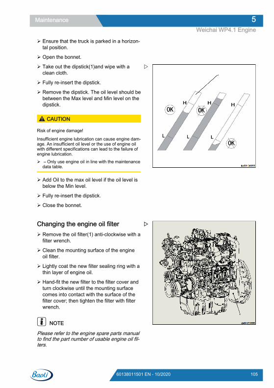
Ensure that the truck is parked in a horizon-tal position.
Open the bonnet.
Take out the dipstick(1)and wipe with aclean cloth.
Fully re-insert the dipstick.
Remove the dipstick. The oil level should bebetween the Max level and Min level on thedipstick.
CAUTION
Risk of engine damage!
Insufficient engine lubrication can cause engine dam-age. An insufficient oil level or the use of engine oilwith different specifications can lead to the failure ofengine lubrication. – Only use engine oil in line with the maintenance
data table.
Add Oil to the max oil level if the oil level isbelow the Min level.
Fully re-insert the dipstick.
Close the bonnet.
Changing the engine oil filter Remove the oil filter(1) anti-clockwise with a
filter wrench.
Clean the mounting surface of the engineoil filter.
Lightly coat the new filter sealing ring with athin layer of engine oil.
Hand-fit the new filter to the filter cover andturn clockwise until the mounting surfacecomes into contact with the surface of thefilter cover; then tighten the filter with filterwrench.
NOTE
Please refer to the engine spare parts manualto find the part number of usable engine oil fil-ters.
Maintenance 5Weichai WP4.1 Engine
10560138011501 EN - 10/2020
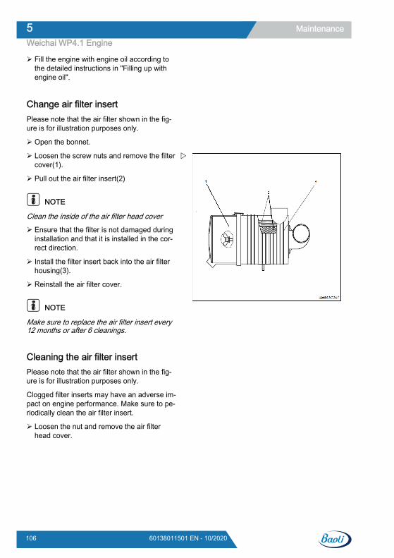
Fill the engine with engine oil according tothe detailed instructions in "Filling up withengine oil".
Change air filter insertPlease note that the air filter shown in the fig-ure is for illustration purposes only.
Open the bonnet.
Loosen the screw nuts and remove the filtercover(1).
Pull out the air filter insert(2)
NOTE
Clean the inside of the air filter head cover
Ensure that the filter is not damaged duringinstallation and that it is installed in the cor-rect direction.
Install the filter insert back into the air filterhousing(3).
Reinstall the air filter cover.
NOTE
Make sure to replace the air filter insert every12 months or after 6 cleanings.
Cleaning the air filter insertPlease note that the air filter shown in the fig-ure is for illustration purposes only.
Clogged filter inserts may have an adverse im-pact on engine performance. Make sure to pe-riodically clean the air filter insert.
Loosen the nut and remove the air filterhead cover.
Maintenance5Weichai WP4.1 Engine
106 60138011501 EN - 10/2020

Pull out the air filter insert (1)
Remove dust from the filter by blowing out-ward through the filter using compressed air(2). Remove dust using minimum air pres-sure in order to avoiding damaging the in-sert
CAUTION
Flying object hazard!
Wear eye protection when carrying out maintenanceon the engine and using compressed air or pressur-ised water jets, in order to prevent dust, flying debris,compressed air or pressurised water or gas fromdamaging your eyes.
Failure to follow this instruction may result in injury.
If the filter insert is damaged, heavily soiledor oily, replace it with a new insert.
CAUTION
The air filter insert requires more frequent cleaningwhen the engine is running in dusty environments.
Clean the inside of the air filter head cover(1).
Fit the filter insert(2)in the air filter housing(3).
Refit the air filter cover, and tighten the airfilter head cover onto the air filter housing.
Maintenance 5Weichai WP4.1 Engine
10760138011501 EN - 10/2020
Emptying water separator DANGER
High pressure hazard!
Avoid fuel spraying onto the skin due to fuel systemleakages, such as a ruptured fuel injection line. Fuelsprayed onto the skin can cause serious injury. In theevent of spray injuries, seek medical attention imme-diately. Do not check for fuel leaks with your hands;instead use a wooden board or cardboard.
Failure to comply with regulations may result in deathor serious injury.
CAUTION
Please pay attention to environmental protection.Dispose of used oil according to related laws andregulations. Failure to comply with laws and regula-tions will result in serious damage to the environ-ment.
Comply with EPA guidelines or government meas-ures for the correct handling of hazardous materials(such as oil, diesel and engine coolant).
Irresponsible handling of hazardous materials, suchas dumping hazardous waste into water channels, onthe ground, into groundwater or drainage ditches, isprohibited.
Carry out the following steps to drainwater in the fuel filter
NOTE
The fuel filter/water trap in the below contentis for illustration purpose only.
The water trap contains a sensor that detectsthe quantity of water and pollutants. The sen-sor will transmit a signal to the indicator in or-der to alert the operator.
Maintenance5Weichai WP4.1 Engine
108 60138011501 EN - 10/2020
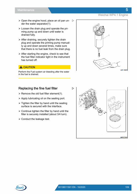
Open the engine hood, place an oil pan un-der the water separator(1).
Loosen the drain plug and operate the pri-ming pump up and down until water isdrained fully.
After draining, securely tighten the drainplug and operate the priming pump manual-ly up and down several times, make surethat there is no fuel leak from the drain plug.
After starting the engine, check to see thatthe fuel filter indicator light in the instrumenthas turned off.
CAUTIONPerform the Fuel system air bleeding after the waterin the fuel is drained.
Replacing the fine fuel filter Remove the old fuel filter element(1).
Apply lubricating oil on the sealing port.
Tighten the filter by hand until the sealingsurface is secured with the interface.
Continue tighten the filter by hand until thefilter is securely installed (about 3/4 turn).
Conduct the leakage test.
Maintenance 5Weichai WP4.1 Engine
10960138011501 EN - 10/2020
Fuel system air bleedingThe entry of air into the fuel system will causehard engine starting or engine malfunction.
WARNING
Risk of fire and explosion!
Diesel fuel is highly flammable and explosive undercertain conditions.
When air bleeding, place an oil pan underneath thevent port. Avoid using workshop rags to collect fuel.Wipe away droplets of fuel immediately. After airbleeding, close the vent port.
Wear eye protection. The fuel system is pressurised,which means that fuel may spray out when you openthe vent port.
Conduct the air bleeding until the fuel coming out ofthe vent port contains no bubbles, which indicatesthat the system is fully charged.
Failure to comply with safety precautions could resultin death or serious injury.
CAUTION
Please pay attention to environmental protection.Waste engine oil should be disposed of in accord-ance with relevant laws and regulations. Non-compli-ance may cause serious damage to the environment.
Comply with EPA guidelines or other governmentmeasures for correct disposal of hazardous materials(such as engine oil, diesel and coolant). Please con-tact your local authority or recycling facility.
Irresponsible disposal of hazardous materials, suchas pouring hazardous waste down drains, onto theground or into groundwater or drainage ditches, isprohibited.
The fuel system requires air bleeding underthe following circumstances:
Before starting the engine for the first time.
After running out of fuel and adding fuel tothe tank.
After carrying out maintenance on the fuelsystem, such as changing the fuel filter/water trap, or replacing fuel system compo-nents.
Maintenance5Weichai WP4.1 Engine
110 60138011501 EN - 10/2020
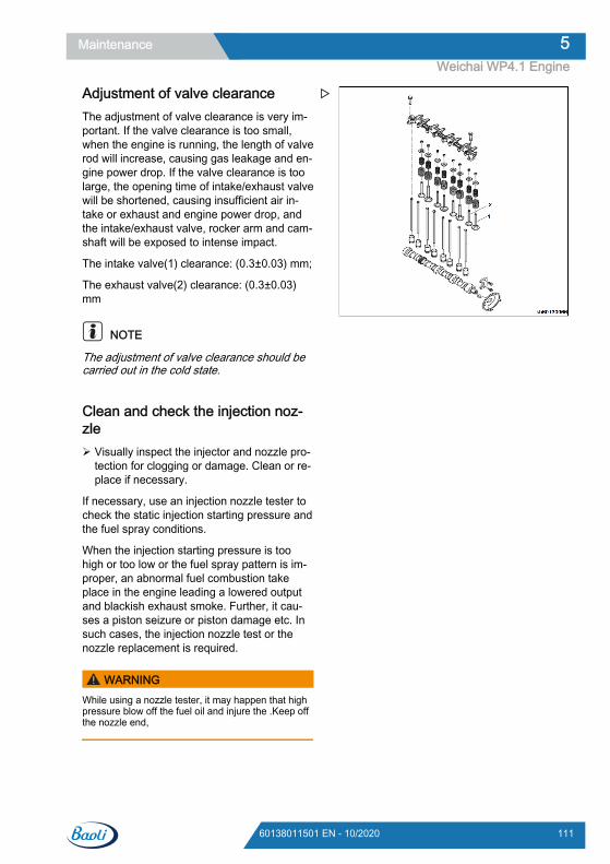
Adjustment of valve clearanceThe adjustment of valve clearance is very im-portant. If the valve clearance is too small,when the engine is running, the length of valverod will increase, causing gas leakage and en-gine power drop. If the valve clearance is toolarge, the opening time of intake/exhaust valvewill be shortened, causing insufficient air in-take or exhaust and engine power drop, andthe intake/exhaust valve, rocker arm and cam-shaft will be exposed to intense impact.
The intake valve(1) clearance: (0.3±0.03) mm;
The exhaust valve(2) clearance: (0.3±0.03)mm
NOTE
The adjustment of valve clearance should becarried out in the cold state.
Clean and check the injection noz-zle Visually inspect the injector and nozzle pro-
tection for clogging or damage. Clean or re-place if necessary.
If necessary, use an injection nozzle tester tocheck the static injection starting pressure andthe fuel spray conditions.
When the injection starting pressure is toohigh or too low or the fuel spray pattern is im-proper, an abnormal fuel combustion takeplace in the engine leading a lowered outputand blackish exhaust smoke. Further, it cau-ses a piston seizure or piston damage etc. Insuch cases, the injection nozzle test or thenozzle replacement is required.
WARNINGWhile using a nozzle tester, it may happen that highpressure blow off the fuel oil and injure the .Keep offthe nozzle end,
Maintenance 5Weichai WP4.1 Engine
11160138011501 EN - 10/2020
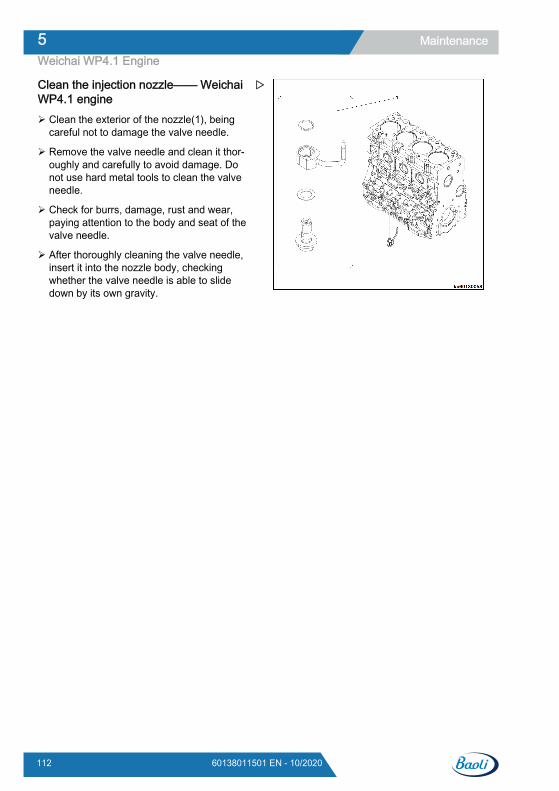
Clean the injection nozzle—— WeichaiWP4.1 engine Clean the exterior of the nozzle(1), being
careful not to damage the valve needle.
Remove the valve needle and clean it thor-oughly and carefully to avoid damage. Donot use hard metal tools to clean the valveneedle.
Check for burrs, damage, rust and wear,paying attention to the body and seat of thevalve needle.
After thoroughly cleaning the valve needle,insert it into the nozzle body, checkingwhether the valve needle is able to slidedown by its own gravity.
Maintenance5Weichai WP4.1 Engine
112 60138011501 EN - 10/2020
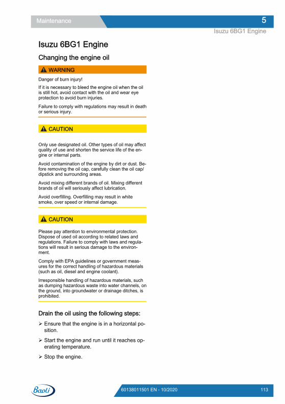
Isuzu 6BG1 EngineChanging the engine oil
WARNINGDanger of burn injury!If it is necessary to bleed the engine oil when the oilis still hot, avoid contact with the oil and wear eyeprotection to avoid burn injuries.
Failure to comply with regulations may result in deathor serious injury.
CAUTION
Only use designated oil. Other types of oil may affectquality of use and shorten the service life of the en-gine or internal parts.
Avoid contamination of the engine by dirt or dust. Be-fore removing the oil cap, carefully clean the oil cap/dipstick and surrounding areas.
Avoid mixing different brands of oil. Mixing differentbrands of oil will seriously affect lubrication.
Avoid overfilling. Overfilling may result in whitesmoke, over speed or internal damage.
CAUTION
Please pay attention to environmental protection.Dispose of used oil according to related laws andregulations. Failure to comply with laws and regula-tions will result in serious damage to the environ-ment.
Comply with EPA guidelines or government meas-ures for the correct handling of hazardous materials(such as oil, diesel and engine coolant).
Irresponsible handling of hazardous materials, suchas dumping hazardous waste into water channels, onthe ground, into groundwater or drainage ditches, isprohibited.
Drain the oil using the following steps: Ensure that the engine is in a horizontal po-
sition.
Start the engine and run until it reaches op-erating temperature.
Stop the engine.
Maintenance 5Isuzu 6BG1 Engine
11360138011501 EN - 10/2020

Remove the oil cap(1) to ventilate thecrankcase. This is beneficial for bleedingthe oil.
Place an oil pan under the engine to collectthe used oil.
Remove the oil drainage plug(3) and allowthe oil to flow into the collection container.When the oil has been drained completely,replace the oil drainage plug
Dispose of the used oil properly.
Filling up with engine oil Ensure that the engine is in a horizontal po-
sition.
Remove the oil cap(1).
Add the specified amount of oil into the oilfiller on the side of the upper part of the en-gine.
Wait three minutes and check the oil level.
Add more oil as necessary.
Replace the oil cap and tighten by hand.Over-tightening may damage the cap.
Check the engine oil level
NOTE
The oil level must be checked before startingthe engine, or at least 10 or 20 minutes afterthe engine is shut down. When the oil level isnecessary while the engine is running, stopthe engine and keep it stationary 10 or 20mins until the oil thoroughly flows down to thecrankcase,
Maintenance5Isuzu 6BG1 Engine
114 60138011501 EN - 10/2020
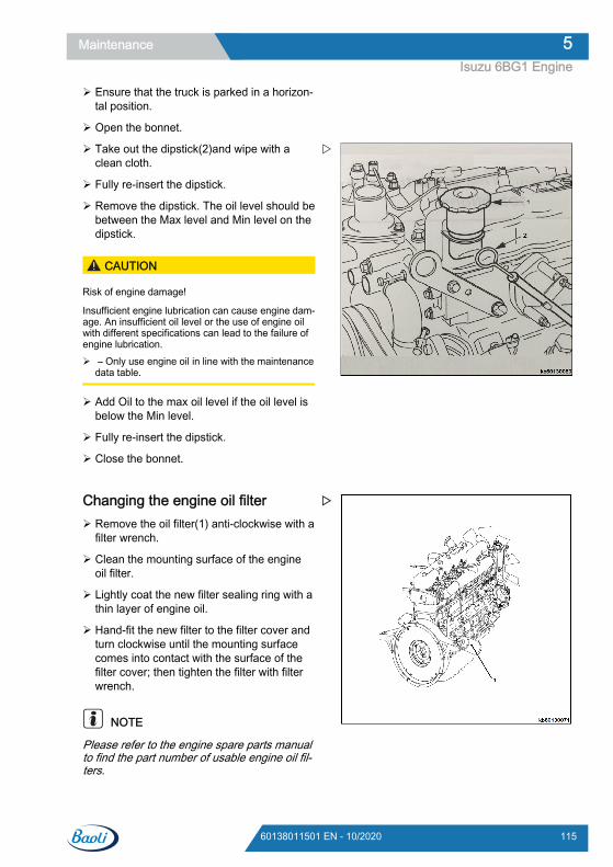
Ensure that the truck is parked in a horizon-tal position.
Open the bonnet.
Take out the dipstick(2)and wipe with aclean cloth.
Fully re-insert the dipstick.
Remove the dipstick. The oil level should bebetween the Max level and Min level on thedipstick.
CAUTION
Risk of engine damage!
Insufficient engine lubrication can cause engine dam-age. An insufficient oil level or the use of engine oilwith different specifications can lead to the failure ofengine lubrication. – Only use engine oil in line with the maintenance
data table.
Add Oil to the max oil level if the oil level isbelow the Min level.
Fully re-insert the dipstick.
Close the bonnet.
Changing the engine oil filter Remove the oil filter(1) anti-clockwise with a
filter wrench.
Clean the mounting surface of the engineoil filter.
Lightly coat the new filter sealing ring with athin layer of engine oil.
Hand-fit the new filter to the filter cover andturn clockwise until the mounting surfacecomes into contact with the surface of thefilter cover; then tighten the filter with filterwrench.
NOTE
Please refer to the engine spare parts manualto find the part number of usable engine oil fil-ters.
Maintenance 5Isuzu 6BG1 Engine
11560138011501 EN - 10/2020

Fill the engine with engine oil according tothe detailed instructions in "Filling up withengine oil".
Change air filter insertPlease note that the air filter shown in the fig-ure is for illustration purposes only.
Open the bonnet.
Loosen the screw nuts and remove the filtercover(1).
Pull out the air filter insert(2)
NOTE
Clean the inside of the air filter head cover
Ensure that the filter is not damaged duringinstallation and that it is installed in the cor-rect direction.
Install the filter insert back into the air filterhousing(3).
Reinstall the air filter cover.
NOTE
Make sure to replace the air filter insert every12 months or after 6 cleanings.
Cleaning the air filter insertPlease note that the air filter shown in the fig-ure is for illustration purposes only.
Clogged filter inserts may have an adverse im-pact on engine performance. Make sure to pe-riodically clean the air filter insert.
Loosen the nut and remove the air filterhead cover.
Maintenance5Isuzu 6BG1 Engine
116 60138011501 EN - 10/2020
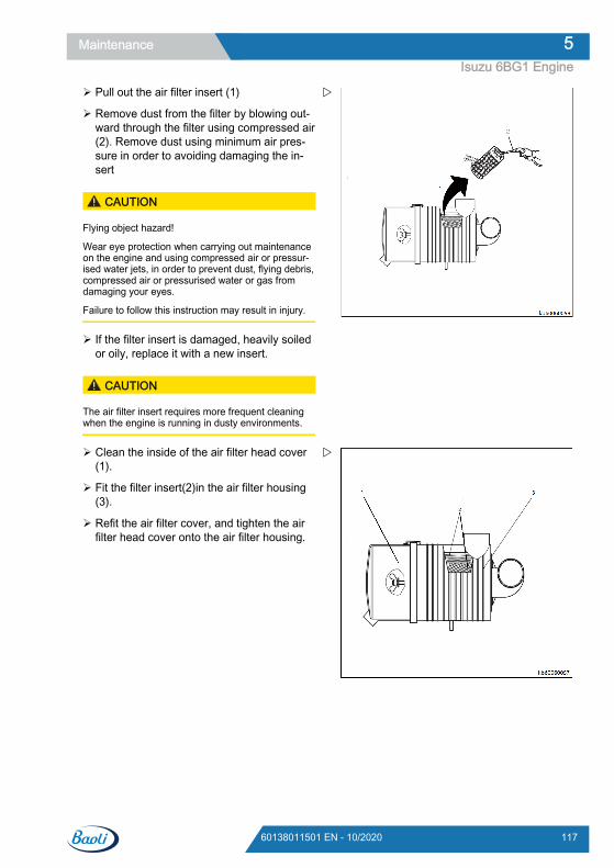
Pull out the air filter insert (1)
Remove dust from the filter by blowing out-ward through the filter using compressed air(2). Remove dust using minimum air pres-sure in order to avoiding damaging the in-sert
CAUTION
Flying object hazard!
Wear eye protection when carrying out maintenanceon the engine and using compressed air or pressur-ised water jets, in order to prevent dust, flying debris,compressed air or pressurised water or gas fromdamaging your eyes.
Failure to follow this instruction may result in injury.
If the filter insert is damaged, heavily soiledor oily, replace it with a new insert.
CAUTION
The air filter insert requires more frequent cleaningwhen the engine is running in dusty environments.
Clean the inside of the air filter head cover(1).
Fit the filter insert(2)in the air filter housing(3).
Refit the air filter cover, and tighten the airfilter head cover onto the air filter housing.
Maintenance 5Isuzu 6BG1 Engine
11760138011501 EN - 10/2020
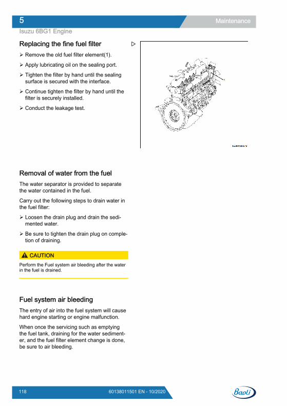
Replacing the fine fuel filter Remove the old fuel filter element(1).
Apply lubricating oil on the sealing port.
Tighten the filter by hand until the sealingsurface is secured with the interface.
Continue tighten the filter by hand until thefilter is securely installed.
Conduct the leakage test.
Removal of water from the fuelThe water separator is provided to separatethe water contained in the fuel.
Carry out the following steps to drain water inthe fuel filter:
Loosen the drain plug and drain the sedi-mented water.
Be sure to tighten the drain plug on comple-tion of draining.
CAUTIONPerform the Fuel system air bleeding after the waterin the fuel is drained.
Fuel system air bleedingThe entry of air into the fuel system will causehard engine starting or engine malfunction.
When once the servicing such as emptyingthe fuel tank, draining for the water sediment-er, and the fuel filter element change is done,be sure to air bleeding.
Maintenance5Isuzu 6BG1 Engine
118 60138011501 EN - 10/2020
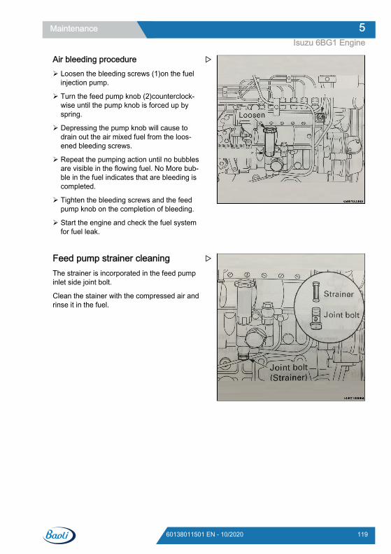
Air bleeding procedure Loosen the bleeding screws (1)on the fuel
injection pump.
Turn the feed pump knob (2)counterclock-wise until the pump knob is forced up byspring.
Depressing the pump knob will cause todrain out the air mixed fuel from the loos-ened bleeding screws.
Repeat the pumping action until no bubblesare visible in the flowing fuel. No More bub-ble in the fuel indicates that are bleeding iscompleted.
Tighten the bleeding screws and the feedpump knob on the completion of bleeding.
Start the engine and check the fuel systemfor fuel leak.
Feed pump strainer cleaningThe strainer is incorporated in the feed pumpinlet side joint bolt.
Clean the stainer with the compressed air andrinse it in the fuel.
Maintenance 5Isuzu 6BG1 Engine
11960138011501 EN - 10/2020
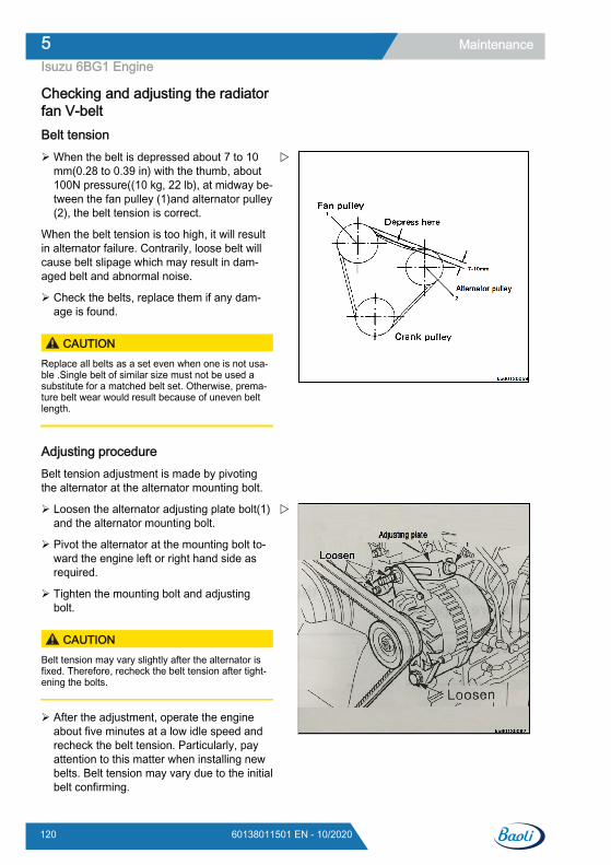
Checking and adjusting the radiatorfan V-beltBelt tension When the belt is depressed about 7 to 10
mm(0.28 to 0.39 in) with the thumb, about100N pressure((10 kg, 22 lb), at midway be-tween the fan pulley (1)and alternator pulley(2), the belt tension is correct.
When the belt tension is too high, it will resultin alternator failure. Contrarily, loose belt willcause belt slipage which may result in dam-aged belt and abnormal noise.
Check the belts, replace them if any dam-age is found.
CAUTIONReplace all belts as a set even when one is not usa-ble .Single belt of similar size must not be used asubstitute for a matched belt set. Otherwise, prema-ture belt wear would result because of uneven beltlength.
Adjusting procedureBelt tension adjustment is made by pivotingthe alternator at the alternator mounting bolt.
Loosen the alternator adjusting plate bolt(1)and the alternator mounting bolt.
Pivot the alternator at the mounting bolt to-ward the engine left or right hand side asrequired.
Tighten the mounting bolt and adjustingbolt.
CAUTIONBelt tension may vary slightly after the alternator isfixed. Therefore, recheck the belt tension after tight-ening the bolts.
After the adjustment, operate the engineabout five minutes at a low idle speed andrecheck the belt tension. Particularly, payattention to this matter when installing newbelts. Belt tension may vary due to the initialbelt confirming.
Maintenance5Isuzu 6BG1 Engine
120 60138011501 EN - 10/2020

Fan belt changeUse of fan belt with poor quality will result inpremature belt wear or belt elongation leadingto engine damage such as overheat. There-fore use of genuine fan belts are highly recom-mended.
Maintenance 5Isuzu 6BG1 Engine
12160138011501 EN - 10/2020
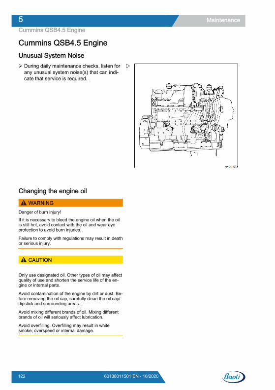
Cummins QSB4.5 EngineUnusual System Noise During daily maintenance checks, listen for
any unusual system noise(s) that can indi-cate that service is required.
Changing the engine oil
WARNINGDanger of burn injury!If it is necessary to bleed the engine oil when the oilis still hot, avoid contact with the oil and wear eyeprotection to avoid burn injuries.
Failure to comply with regulations may result in deathor serious injury.
CAUTION
Only use designated oil. Other types of oil may affectquality of use and shorten the service life of the en-gine or internal parts.
Avoid contamination of the engine by dirt or dust. Be-fore removing the oil cap, carefully clean the oil cap/dipstick and surrounding areas.
Avoid mixing different brands of oil. Mixing differentbrands of oil will seriously affect lubrication.
Avoid overfilling. Overfilling may result in whitesmoke, overspeed or internal damage.
Maintenance5Cummins QSB4.5 Engine
122 60138011501 EN - 10/2020
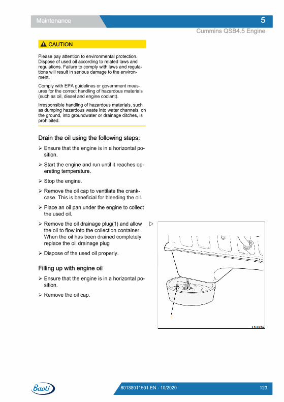
CAUTION
Please pay attention to environmental protection.Dispose of used oil according to related laws andregulations. Failure to comply with laws and regula-tions will result in serious damage to the environ-ment.
Comply with EPA guidelines or government meas-ures for the correct handling of hazardous materials(such as oil, diesel and engine coolant).
Irresponsible handling of hazardous materials, suchas dumping hazardous waste into water channels, onthe ground, into groundwater or drainage ditches, isprohibited.
Drain the oil using the following steps: Ensure that the engine is in a horizontal po-
sition.
Start the engine and run until it reaches op-erating temperature.
Stop the engine.
Remove the oil cap to ventilate the crank-case. This is beneficial for bleeding the oil.
Place an oil pan under the engine to collectthe used oil.
Remove the oil drainage plug(1) and allowthe oil to flow into the collection container.When the oil has been drained completely,replace the oil drainage plug
Dispose of the used oil properly.
Filling up with engine oil Ensure that the engine is in a horizontal po-
sition.
Remove the oil cap.
Maintenance 5Cummins QSB4.5 Engine
12360138011501 EN - 10/2020
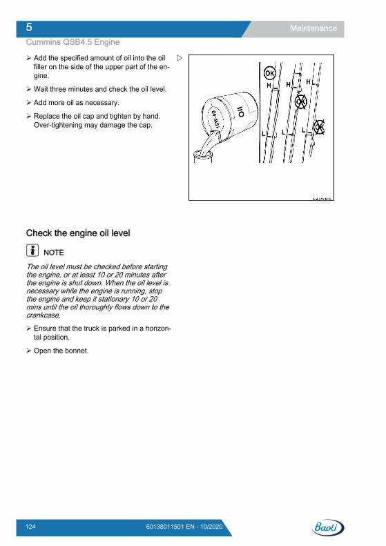
Add the specified amount of oil into the oilfiller on the side of the upper part of the en-gine.
Wait three minutes and check the oil level.
Add more oil as necessary.
Replace the oil cap and tighten by hand.Over-tightening may damage the cap.
Check the engine oil level
NOTE
The oil level must be checked before startingthe engine, or at least 10 or 20 minutes afterthe engine is shut down. When the oil level isnecessary while the engine is running, stopthe engine and keep it stationary 10 or 20mins until the oil thoroughly flows down to thecrankcase,
Ensure that the truck is parked in a horizon-tal position.
Open the bonnet.
Maintenance5Cummins QSB4.5 Engine
124 60138011501 EN - 10/2020
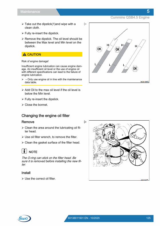
Take out the dipstick(1)and wipe with aclean cloth.
Fully re-insert the dipstick.
Remove the dipstick. The oil level should bebetween the Max level and Min level on thedipstick.
CAUTION
Risk of engine damage!
Insufficient engine lubrication can cause engine dam-age. An insufficient oil level or the use of engine oilwith different specifications can lead to the failure ofengine lubrication. – Only use engine oil in line with the maintenance
data table.
Add Oil to the max oil level if the oil level isbelow the Min level.
Fully re-insert the dipstick.
Close the bonnet.
Changing the engine oil filterRemove Clean the area around the lubricating oil fil-
ter head.
Use oil filter wrench, to remove the filter.
Clean the gasket surface of the filter head.
NOTE
The O-ring can stick on the filter head. Besure it is removed before installing the new fil-ter.
Install Use the correct oil filter.
Maintenance 5Cummins QSB4.5 Engine
12560138011501 EN - 10/2020
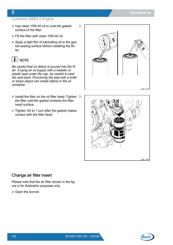
Use clean 15W-40 oil to coat the gasketsurface of the filter.
Fill the filter with clean 15W-40 oil.
Apply a light film of lubricating oil to the gas-ket sealing surface before installing the filt-ter.
NOTE
Be careful that no debris is poured into the fil-ter. If using an oil supply with a metallic orplastic seal under the cap, be careful to peelthe seal back. Puncturing the seal with a knifeor sharp object can create debris in the oilcontainer.
Install the filter on the oil filter head. Tightenthe filter until the gasket contacts the filterhead surface.
Tighten 3/4 to 1 turn after the gasket makescontact with the filter head.
Change air filter insertPlease note that the air filter shown in the fig-ure is for illustration purposes only.
Open the bonnet.
Maintenance5Cummins QSB4.5 Engine
126 60138011501 EN - 10/2020
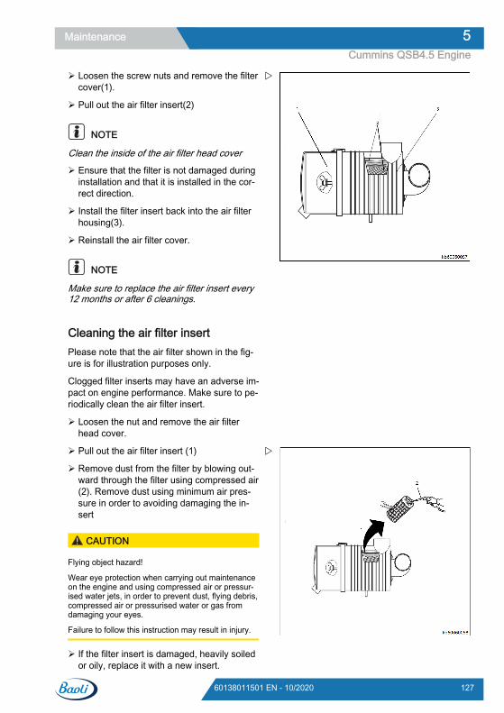
Loosen the screw nuts and remove the filtercover(1).
Pull out the air filter insert(2)
NOTE
Clean the inside of the air filter head cover
Ensure that the filter is not damaged duringinstallation and that it is installed in the cor-rect direction.
Install the filter insert back into the air filterhousing(3).
Reinstall the air filter cover.
NOTE
Make sure to replace the air filter insert every12 months or after 6 cleanings.
Cleaning the air filter insertPlease note that the air filter shown in the fig-ure is for illustration purposes only.
Clogged filter inserts may have an adverse im-pact on engine performance. Make sure to pe-riodically clean the air filter insert.
Loosen the nut and remove the air filterhead cover.
Pull out the air filter insert (1)
Remove dust from the filter by blowing out-ward through the filter using compressed air(2). Remove dust using minimum air pres-sure in order to avoiding damaging the in-sert
CAUTION
Flying object hazard!
Wear eye protection when carrying out maintenanceon the engine and using compressed air or pressur-ised water jets, in order to prevent dust, flying debris,compressed air or pressurised water or gas fromdamaging your eyes.
Failure to follow this instruction may result in injury.
If the filter insert is damaged, heavily soiledor oily, replace it with a new insert.
Maintenance 5Cummins QSB4.5 Engine
12760138011501 EN - 10/2020
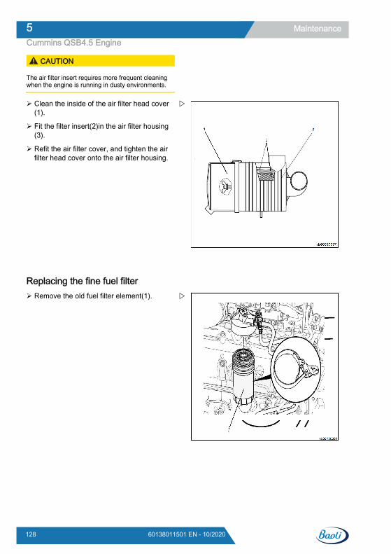
CAUTION
The air filter insert requires more frequent cleaningwhen the engine is running in dusty environments.
Clean the inside of the air filter head cover(1).
Fit the filter insert(2)in the air filter housing(3).
Refit the air filter cover, and tighten the airfilter head cover onto the air filter housing.
Replacing the fine fuel filter Remove the old fuel filter element(1).
Maintenance5Cummins QSB4.5 Engine
128 60138011501 EN - 10/2020
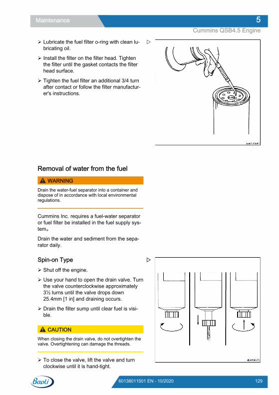
Lubricate the fuel filter o-ring with clean lu-bricating oil.
Install the filter on the filter head. Tightenthe filter until the gasket contacts the filterhead surface.
Tighten the fuel filter an additional 3/4 turnafter contact or follow the filter manufactur-er's instructions.
Removal of water from the fuel
WARNINGDrain the water-fuel separator into a container anddispose of in accordance with local environmentalregulations.
Cummins Inc. requires a fuel-water separatoror fuel filter be installed in the fuel supply sys-tem。
Drain the water and sediment from the sepa-rator daily.
Spin-on Type Shut off the engine.
Use your hand to open the drain valve. Turnthe valve counterclockwise approximately3½ turns until the valve drops down25.4mm [1 in] and draining occurs.
Drain the filter sump until clear fuel is visi-ble.
CAUTIONWhen closing the drain valve, do not overtighten thevalve. Overtightening can damage the threads.
To close the valve, lift the valve and turnclockwise until it is hand-tight.
Maintenance 5Cummins QSB4.5 Engine
12960138011501 EN - 10/2020
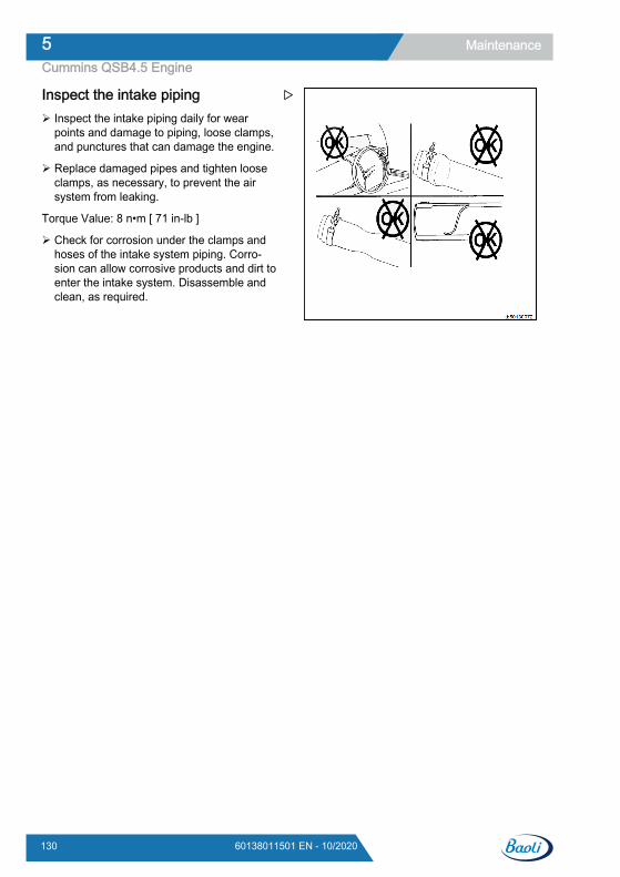
Inspect the intake piping Inspect the intake piping daily for wear
points and damage to piping, loose clamps,and punctures that can damage the engine.
Replace damaged pipes and tighten looseclamps, as necessary, to prevent the airsystem from leaking.
Torque Value: 8 n•m [ 71 in-lb ]
Check for corrosion under the clamps andhoses of the intake system piping. Corro-sion can allow corrosive products and dirt toenter the intake system. Disassemble andclean, as required.
Maintenance5Cummins QSB4.5 Engine
130 60138011501 EN - 10/2020
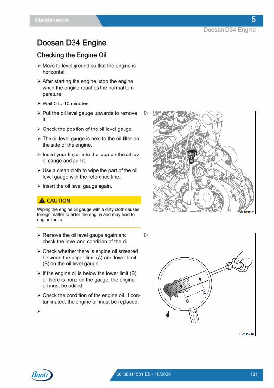
Doosan D34 EngineChecking the Engine Oil Move to level ground so that the engine is
horizontal.
After starting the engine, stop the enginewhen the engine reaches the normal tem-perature.
Wait 5 to 10 minutes.
Pull the oil level gauge upwards to removeit.
Check the position of the oil level gauge.
The oil level gauge is next to the oil filter onthe side of the engine.
Insert your finger into the loop on the oil lev-el gauge and pull it.
Use a clean cloth to wipe the part of the oillevel gauge with the reference line.
Insert the oil level gauge again.
CAUTIONWiping the engine oil gauge with a dirty cloth causesforeign matter to enter the engine and may lead toengine faults.
Remove the oil level gauge again andcheck the level and condition of the oil.
Check whether there is engine oil smearedbetween the upper limit (A) and lower limit(B) on the oil level gauge.
If the engine oil is below the lower limit (B)or there is none on the gauge, the engineoil must be added.
Check the condition of the engine oil. If con-taminated, the engine oil must be replaced.
Maintenance 5Doosan D34 Engine
13160138011501 EN - 10/2020
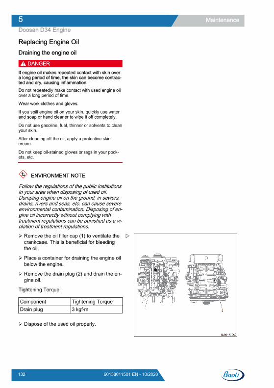
Replacing Engine OilDraining the engine oil
DANGERIf engine oil makes repeated contact with skin overa long period of time, the skin can become contrac-ted and dry, causing inflammation.Do not repeatedly make contact with used engine oilover a long period of time.
Wear work clothes and gloves.
If you spill engine oil on your skin, quickly use waterand soap or hand cleaner to wipe it off completely.
Do not use gasoline, fuel, thinner or solvents to cleanyour skin.
After cleaning off the oil, apply a protective skincream.
Do not keep oil-stained gloves or rags in your pock-ets, etc.
ENVIRONMENT NOTE
Follow the regulations of the public institutionsin your area when disposing of used oil.Dumping engine oil on the ground, in sewers,drains, rivers and seas, etc. can cause severeenvironmental contamination. Disposing of en-gine oil incorrectly without complying withtreatment regulations can be punished as a vi-olation of treatment regulations.
Remove the oil filler cap (1) to ventilate thecrankcase. This is beneficial for bleedingthe oil.
Place a container for draining the engine oilbelow the engine.
Remove the drain plug (2) and drain the en-gine oil.
Tightening Torque:
Component Tightening TorqueDrain plug 3 kgf·m
Dispose of the used oil properly.
Maintenance5Doosan D34 Engine
132 60138011501 EN - 10/2020
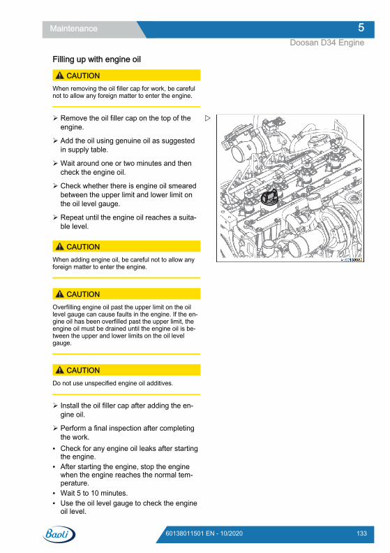
Filling up with engine oil
CAUTIONWhen removing the oil filler cap for work, be carefulnot to allow any foreign matter to enter the engine.
Remove the oil filler cap on the top of theengine.
Add the oil using genuine oil as suggestedin supply table.
Wait around one or two minutes and thencheck the engine oil.
Check whether there is engine oil smearedbetween the upper limit and lower limit onthe oil level gauge.
Repeat until the engine oil reaches a suita-ble level.
CAUTIONWhen adding engine oil, be careful not to allow anyforeign matter to enter the engine.
CAUTIONOverfilling engine oil past the upper limit on the oillevel gauge can cause faults in the engine. If the en-gine oil has been overfilled past the upper limit, theengine oil must be drained until the engine oil is be-tween the upper and lower limits on the oil levelgauge.
CAUTIONDo not use unspecified engine oil additives.
Install the oil filler cap after adding the en-gine oil.
Perform a final inspection after completingthe work.
● Check for any engine oil leaks after startingthe engine.
● After starting the engine, stop the enginewhen the engine reaches the normal tem-perature.
● Wait 5 to 10 minutes.● Use the oil level gauge to check the engine
oil level.
Maintenance 5Doosan D34 Engine
13360138011501 EN - 10/2020
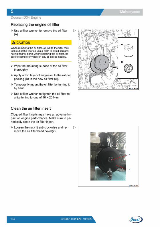
Replacing the engine oil filter Use a filter wrench to remove the oil filter
(A).
CAUTIONWhen removing the oil filter, oil inside the filter mayleak out of the filter so use a cloth to avoid contami-nating nearby parts. After replacing the oil filter, besure to completely wipe off any oil spilled nearby.
Wipe the mounting surface of the oil filterthoroughly.
Apply a thin layer of engine oil to the rubberpacking (B) in the new oil filter (A).
Temporarily mount the oil filter by turning itby hand.
Use a filter wrench to tighten the oil filter toa tightening torque of 16 ~ 20 N·m.
Clean the air filter insertClogged filter inserts may have an adverse im-pact on engine performance. Make sure to pe-riodically clean the air filter insert.
Loosen the nut (1) anti-clockwise and re-move the air filter head cover(2).
Maintenance5Doosan D34 Engine
134 60138011501 EN - 10/2020
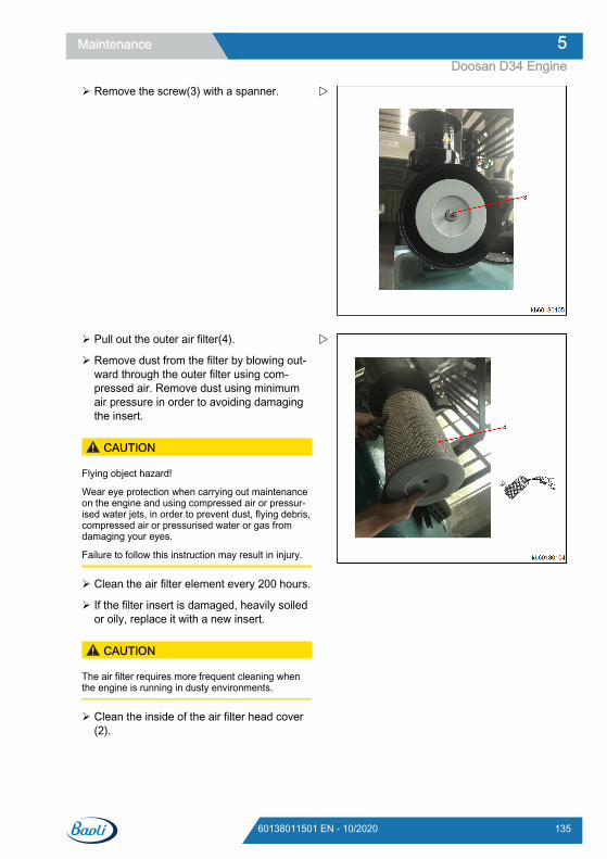
Remove the screw(3) with a spanner.
Pull out the outer air filter(4).
Remove dust from the filter by blowing out-ward through the outer filter using com-pressed air. Remove dust using minimumair pressure in order to avoiding damagingthe insert.
CAUTION
Flying object hazard!
Wear eye protection when carrying out maintenanceon the engine and using compressed air or pressur-ised water jets, in order to prevent dust, flying debris,compressed air or pressurised water or gas fromdamaging your eyes.
Failure to follow this instruction may result in injury.
Clean the air filter element every 200 hours.
If the filter insert is damaged, heavily soiledor oily, replace it with a new insert.
CAUTION
The air filter requires more frequent cleaning whenthe engine is running in dusty environments.
Clean the inside of the air filter head cover(2).
Maintenance 5Doosan D34 Engine
13560138011501 EN - 10/2020
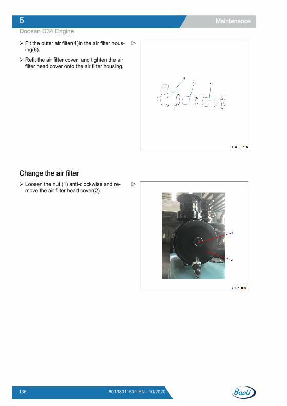
Fit the outer air filter(4)in the air filter hous-ing(6).
Refit the air filter cover, and tighten the airfilter head cover onto the air filter housing.
Change the air filter Loosen the nut (1) anti-clockwise and re-
move the air filter head cover(2).
Maintenance5Doosan D34 Engine
136 60138011501 EN - 10/2020
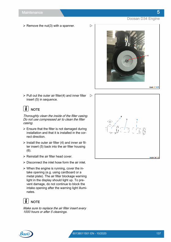
Remove the nut(3) with a spanner.
Pull out the outer air filter(4) and inner filterinsert (5) in sequence.
NOTE
Thoroughly clean the inside of the filter casing.Do not use compressed air to clean the filtercasing.
Ensure that the filter is not damaged duringinstallation and that it is installed in the cor-rect direction.
Install the outer air filter (4) and inner air fil-ter insert (5) back into the air filter housing(6).
Reinstall the air filter head cover.
Disconnect the inlet hose form the air inlet.
When the engine is running, cover the in-take opening (e.g. using cardboard or ametal plate). The air filter blockage warninglight in the display should light up. To pre-vent damage, do not continue to block theintake opening after the warning light illumi-nates.
NOTE
Make sure to replace the air filter insert every1000 hours or after 5 cleanings.
Maintenance 5Doosan D34 Engine
13760138011501 EN - 10/2020
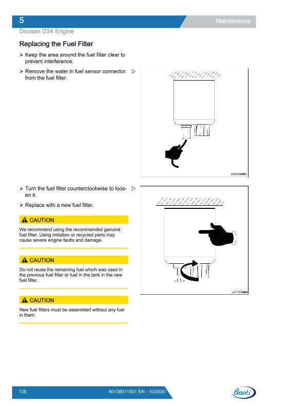
Replacing the Fuel Filter Keep the area around the fuel filter clear to
prevent interference.
Remove the water in fuel sensor connectorfrom the fuel filter.
Turn the fuel filter counterclockwise to loos-en it.
Replace with a new fuel filter.
CAUTIONWe recommend using the recommended genuinefuel filter. Using imitation or recycled parts maycause severe engine faults and damage.
CAUTIONDo not reuse the remaining fuel which was used inthe previous fuel filter or fuel in the tank in the newfuel filter.
CAUTIONNew fuel filters must be assembled without any fuelin them.
Maintenance5Doosan D34 Engine
138 60138011501 EN - 10/2020
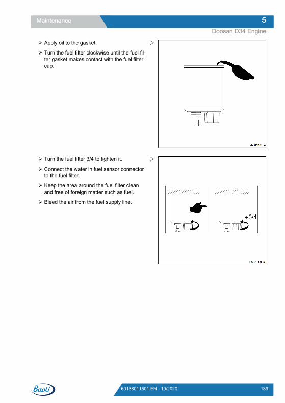
Apply oil to the gasket.
Turn the fuel filter clockwise until the fuel fil-ter gasket makes contact with the fuel filtercap.
Turn the fuel filter 3/4 to tighten it.
Connect the water in fuel sensor connectorto the fuel filter.
Keep the area around the fuel filter cleanand free of foreign matter such as fuel.
Bleed the air from the fuel supply line.
Maintenance 5Doosan D34 Engine
13960138011501 EN - 10/2020
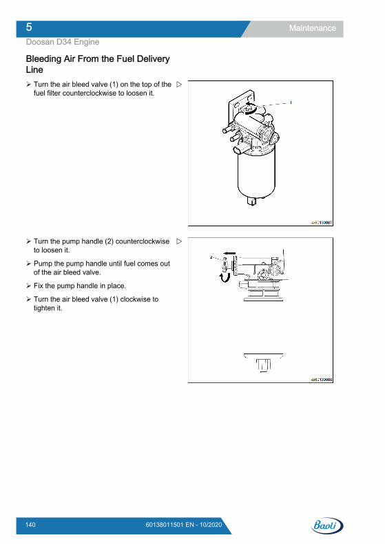
Bleeding Air From the Fuel DeliveryLine Turn the air bleed valve (1) on the top of the
fuel filter counterclockwise to loosen it.
Turn the pump handle (2) counterclockwiseto loosen it.
Pump the pump handle until fuel comes outof the air bleed valve.
Fix the pump handle in place.
Turn the air bleed valve (1) clockwise totighten it.
Maintenance5Doosan D34 Engine
140 60138011501 EN - 10/2020

Draining Water From the Fuel Filter Turn the drain valve (1) at the bottom of the
fuel filter to loosen it.
CAUTIONDo not use a tool to loosen the drain valve. Other-wise, the drain valve may be damaged.
Drain the water in the fuel filter with thedrain valve (1) for around 10 seconds.
Maintenance 5Doosan D34 Engine
14160138011501 EN - 10/2020
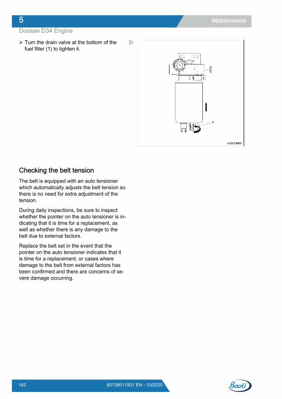
Turn the drain valve at the bottom of thefuel filter (1) to tighten it.
Checking the belt tensionThe belt is equipped with an auto tensionerwhich automatically adjusts the belt tension sothere is no need for extra adjustment of thetension.
During daily inspections, be sure to inspectwhether the pointer on the auto tensioner is in-dicating that it is time for a replacement, aswell as whether there is any damage to thebelt due to external factors.
Replace the belt set in the event that thepointer on the auto tensioner indicates that itis time for a replacement, or cases wheredamage to the belt from external factors hasbeen confirmed and there are concerns of se-vere damage occurring.
Maintenance5Doosan D34 Engine
142 60138011501 EN - 10/2020
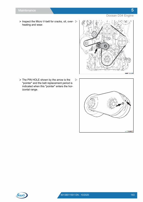
Inspect the Micro V-belt for cracks, oil, over-heating and wear.
The PIN HOLE shown by the arrow is the"pointer" and the belt replacement period isindicated when this "pointer" enters the hor-izontal range.
Maintenance 5Doosan D34 Engine
14360138011501 EN - 10/2020
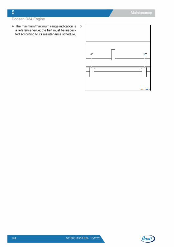
The minimum/maximum range indication isa reference value; the belt must be inspec-ted according to its maintenance schedule.
Maintenance5Doosan D34 Engine
144 60138011501 EN - 10/2020
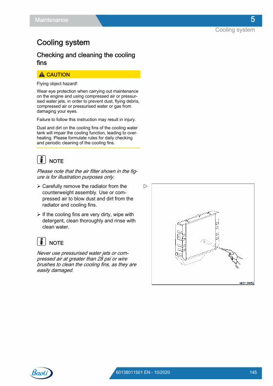
Cooling systemChecking and cleaning the coolingfins
CAUTIONFlying object hazard!Wear eye protection when carrying out maintenanceon the engine and using compressed air or pressur-ised water jets, in order to prevent dust, flying debris,compressed air or pressurised water or gas fromdamaging your eyes.
Failure to follow this instruction may result in injury.
Dust and dirt on the cooling fins of the cooling watertank will impair the cooling function, leading to over-heating. Please formulate rules for daily checkingand periodic cleaning of the cooling fins.
NOTE
Please note that the air filter shown in the fig-ure is for illustration purposes only.
Carefully remove the radiator from thecounterweight assembly. Use or com-pressed air to blow dust and dirt from theradiator and cooling fins.
If the cooling fins are very dirty, wipe withdetergent, clean thoroughly and rinse withclean water.
NOTE
Never use pressurised water jets or com-pressed air at greater than 28 psi or wirebrushes to clean the cooling fins, as they areeasily damaged.
Maintenance 5Cooling system
14560138011501 EN - 10/2020
Changing the coolant DANGER
Risk of burn injury!When the engine is at working temperature, pleasedo not open the radiator water tank cover. Steamand hot engine coolant will spray out and cause burninjuries. Please only open the radiator water tankcover after the engine has cooled down. After check-ing the radiator water tank, tighten the radiator watertank cover until secure. If the radiator water tank cov-er is loose, steam may spray out when the engine isrunning.
Check the engine coolant level via the compensationbox.
Failure to comply with the above operating guidancemay result in death or serious injury.
CAUTIONRisk of freezing injury!When handling long-life or premium grade coolant,please wear eye protection and rubber gloves. Ifcoolant accidentally makes contact with eyes or skin,please rinse with clean water.
Failure to comply with the above operating guidancemay result in minor injuries.
ENVIRONMENT NOTE
Please pay attention to environmental protec-tion. Please comply with these procedureswhen handling hazardous waste. Failure tocomply with these procedures may result inserious damage to the environment.
● Handle hazardous waste such as engineoil, diesel or engine coolant appropriatelyaccording to guidelines from the Environ-mental Protection Agency or other govern-ment organizations. Please contact your lo-cal authorities or recycling organization.
● Irresponsible handling of hazardous materi-als, such as dumping hazardous waste intowater channels, on the ground, or intogroundwater or drainage ditches, is prohibi-ted.
Maintenance5Cooling system
146 60138011501 EN - 10/2020
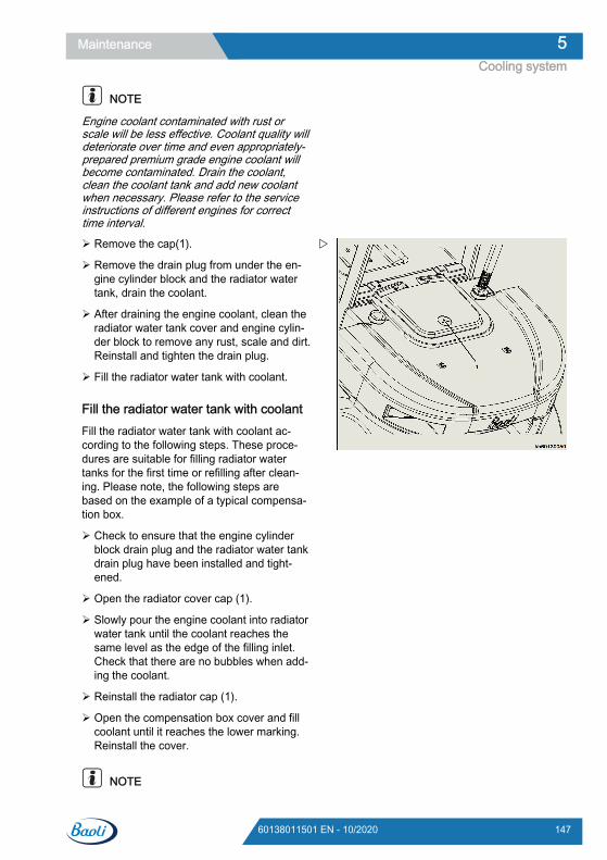
NOTE
Engine coolant contaminated with rust orscale will be less effective. Coolant quality willdeteriorate over time and even appropriately-prepared premium grade engine coolant willbecome contaminated. Drain the coolant,clean the coolant tank and add new coolantwhen necessary. Please refer to the serviceinstructions of different engines for correcttime interval.
Remove the cap(1).
Remove the drain plug from under the en-gine cylinder block and the radiator watertank, drain the coolant.
After draining the engine coolant, clean theradiator water tank cover and engine cylin-der block to remove any rust, scale and dirt.Reinstall and tighten the drain plug.
Fill the radiator water tank with coolant.
Fill the radiator water tank with coolantFill the radiator water tank with coolant ac-cording to the following steps. These proce-dures are suitable for filling radiator watertanks for the first time or refilling after clean-ing. Please note, the following steps arebased on the example of a typical compensa-tion box.
Check to ensure that the engine cylinderblock drain plug and the radiator water tankdrain plug have been installed and tight-ened.
Open the radiator cover cap (1).
Slowly pour the engine coolant into radiatorwater tank until the coolant reaches thesame level as the edge of the filling inlet.Check that there are no bubbles when add-ing the coolant.
Reinstall the radiator cap (1).
Open the compensation box cover and fillcoolant until it reaches the lower marking.Reinstall the cover.
NOTE
Maintenance 5Cooling system
14760138011501 EN - 10/2020
Check the hose connecting the compensa-tion box to the radiator. Ensure that the fas-teners are connected and are not torn ordamaged. If the hose is damaged, enginecoolant will leak our and will not flow intothe compensation box.
Start the engine and run until it reaches op-erating temperature. Check the engine cool-ant level in the compensation box. Whenthe engine is running and the engine cool-ant is at normal temperature, the coolantlevel should be at the level of the uppermarking. If the coolant level is not at the up-per marking, add more coolant to the com-pensation box until the coolant level rea-ches the upper marking.
Checking the coolant levelFrequently check the engine coolant level byobserving the compensation box. Fill the com-pensation box with coolant when necessary.
NOTE
Only use coolant with the recommended spec-ifications.
Maintenance5Cooling system
148 60138011501 EN - 10/2020
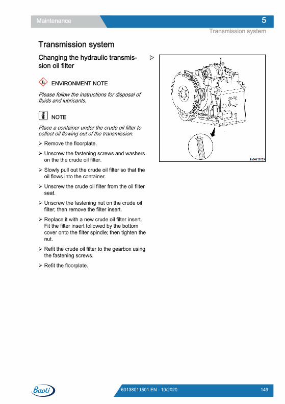
Transmission systemChanging the hydraulic transmis-sion oil filter
ENVIRONMENT NOTE
Please follow the instructions for disposal offluids and lubricants.
NOTE
Place a container under the crude oil filter tocollect oil flowing out of the transmission.
Remove the floorplate.
Unscrew the fastening screws and washerson the the crude oil filter.
Slowly pull out the crude oil filter so that theoil flows into the container.
Unscrew the crude oil filter from the oil filterseat.
Unscrew the fastening nut on the crude oilfilter; then remove the filter insert.
Replace it with a new crude oil filter insert.Fit the filter insert followed by the bottomcover onto the filter spindle; then tighten thenut.
Refit the crude oil filter to the gearbox usingthe fastening screws.
Refit the floorplate.
Maintenance 5Transmission system
14960138011501 EN - 10/2020
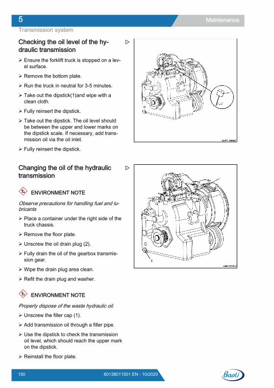
Checking the oil level of the hy-draulic transmission Ensure the forklift truck is stopped on a lev-
el surface.
Remove the bottom plate.
Run the truck in neutral for 3-5 minutes.
Take out the dipstick(1)and wipe with aclean cloth.
Fully reinsert the dipstick.
Take out the dipstick. The oil level shouldbe between the upper and lower marks onthe dipstick scale. If necessary, add trans-mission oil via the oil inlet.
Fully reinsert the dipstick.
Changing the oil of the hydraulictransmission
ENVIRONMENT NOTE
Observe precautions for handling fuel and lu-bricants
Place a container under the right side of thetruck chassis.
Remove the floor plate.
Unscrew the oil drain plug (2).
Fully drain the oil of the gearbox transmis-sion gear.
Wipe the drain plug area clean.
Refit the drain plug and washer.
ENVIRONMENT NOTE
Properly dispose of the waste hydraulic oil.
Unscrew the filler cap (1).
Add transmission oil through a filler pipe.
Use the dipstick to check the transmissionoil level, which should reach the upper markon the dipstick.
Reinstall the floor plate.
Maintenance5Transmission system
150 60138011501 EN - 10/2020
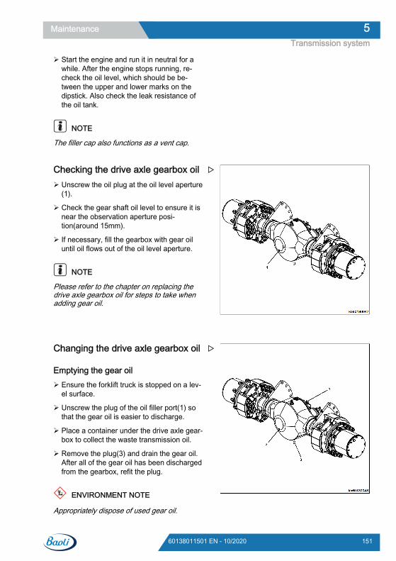
Start the engine and run it in neutral for awhile. After the engine stops running, re-check the oil level, which should be be-tween the upper and lower marks on thedipstick. Also check the leak resistance ofthe oil tank.
NOTE
The filler cap also functions as a vent cap.
Checking the drive axle gearbox oil Unscrew the oil plug at the oil level aperture
(1).
Check the gear shaft oil level to ensure it isnear the observation aperture posi-tion(around 15mm).
If necessary, fill the gearbox with gear oiluntil oil flows out of the oil level aperture.
NOTE
Please refer to the chapter on replacing thedrive axle gearbox oil for steps to take whenadding gear oil.
Changing the drive axle gearbox oil
Emptying the gear oil Ensure the forklift truck is stopped on a lev-
el surface.
Unscrew the plug of the oil filler port(1) sothat the gear oil is easier to discharge.
Place a container under the drive axle gear-box to collect the waste transmission oil.
Remove the plug(3) and drain the gear oil.After all of the gear oil has been dischargedfrom the gearbox, refit the plug.
ENVIRONMENT NOTE
Appropriately dispose of used gear oil.
Maintenance 5Transmission system
15160138011501 EN - 10/2020
Filling gear oil Unscrew the plugs of the oil filler port(1)
and oil level hole(2).
Fill the gearbox with new gear oil, until oilflows out of the oil level hole..
NOTE
● The high viscosity of gear oil means that ittakes time for new oil to fill the gaps in thegearing. It is therefore preferable to use apressurised filling tool; otherwise the fillingprocess will take a relatively long time.Even when oil flows out of the filler port, thisdoes not mean that the oil level is full; wait5-8 minutes until the gear oil fills the gaps inthe gearing.
● Use gear oil in accordance with the referredinstructions only.
Refit the plugs of the filler port and oil levelhole.
Maintenance5Transmission system
152 60138011501 EN - 10/2020
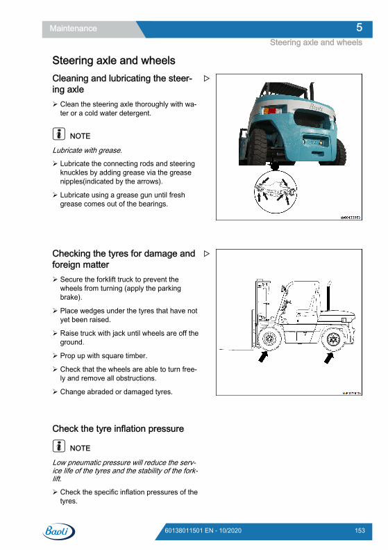
Steering axle and wheelsCleaning and lubricating the steer-ing axle Clean the steering axle thoroughly with wa-
ter or a cold water detergent.
NOTE
Lubricate with grease.
Lubricate the connecting rods and steeringknuckles by adding grease via the greasenipples(indicated by the arrows).
Lubricate using a grease gun until freshgrease comes out of the bearings.
Checking the tyres for damage andforeign matter Secure the forklift truck to prevent the
wheels from turning (apply the parkingbrake).
Place wedges under the tyres that have notyet been raised.
Raise truck with jack until wheels are off theground.
Prop up with square timber.
Check that the wheels are able to turn free-ly and remove all obstructions.
Change abraded or damaged tyres.
Check the tyre inflation pressure
NOTE
Low pneumatic pressure will reduce the serv-ice life of the tyres and the stability of the fork-lift.
Check the specific inflation pressures of thetyres.
Maintenance 5Steering axle and wheels
15360138011501 EN - 10/2020
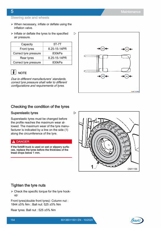
When necessary, inflate or deflate using theinflation valve.
Inflate or deflate the tyres to the specifiedair pressure.
Capacity 5T-7TFront tyres 8.25-15-14PR
Correct tyre pressure 830kPaRear tyres 8.25-15-14PR
Correct tyre pressure 830kPa
NOTE
Due to different manufacturers’ standards,correct tyre pressure shall refer to differentconfigurations and requirements of tyres.
Checking the condition of the tyresSuperelastic tyresSuperelastic tyres must be changed beforethe profile reaches the maximum wear al-lowed. The maximum wear of the tyre manu-facturer is indicated by a line on the side (1)along the circumference of the tyre.
DANGERIf the forklift truck is used on wet or slippery surfa-ces, replace the tyres before the thickness of thetread drops below 1 mm.
Tighten the tyre nuts Check the specific torque for the tyre hook-
up:
Front tyres(double front tyres): Column nut :1844 ±5% Nm ; Ball nut: 525 ±5% Nm
Rear tyres: Ball nut : 525 ±5% Nm
1 OM1156
Maintenance5Steering axle and wheels
154 60138011501 EN - 10/2020
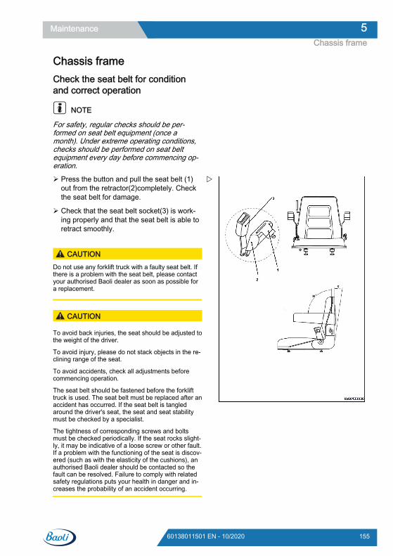
Chassis frameCheck the seat belt for conditionand correct operation
NOTE
For safety, regular checks should be per-formed on seat belt equipment (once amonth). Under extreme operating conditions,checks should be performed on seat beltequipment every day before commencing op-eration.
Press the button and pull the seat belt (1)out from the retractor(2)completely. Checkthe seat belt for damage.
Check that the seat belt socket(3) is work-ing properly and that the seat belt is able toretract smoothly.
CAUTIONDo not use any forklift truck with a faulty seat belt. Ifthere is a problem with the seat belt, please contactyour authorised Baoli dealer as soon as possible fora replacement.
CAUTION
To avoid back injuries, the seat should be adjusted tothe weight of the driver.
To avoid injury, please do not stack objects in the re-clining range of the seat.
To avoid accidents, check all adjustments beforecommencing operation.
The seat belt should be fastened before the forklifttruck is used. The seat belt must be replaced after anaccident has occurred. If the seat belt is tangledaround the driver's seat, the seat and seat stabilitymust be checked by a specialist.
The tightness of corresponding screws and boltsmust be checked periodically. If the seat rocks slight-ly, it may be indicative of a loose screw or other fault.If a problem with the functioning of the seat is discov-ered (such as with the elasticity of the cushions), anauthorised Baoli dealer should be contacted so thefault can be resolved. Failure to comply with relatedsafety regulations puts your health in danger and in-creases the probability of an accident occurring.
Maintenance 5Chassis frame
15560138011501 EN - 10/2020
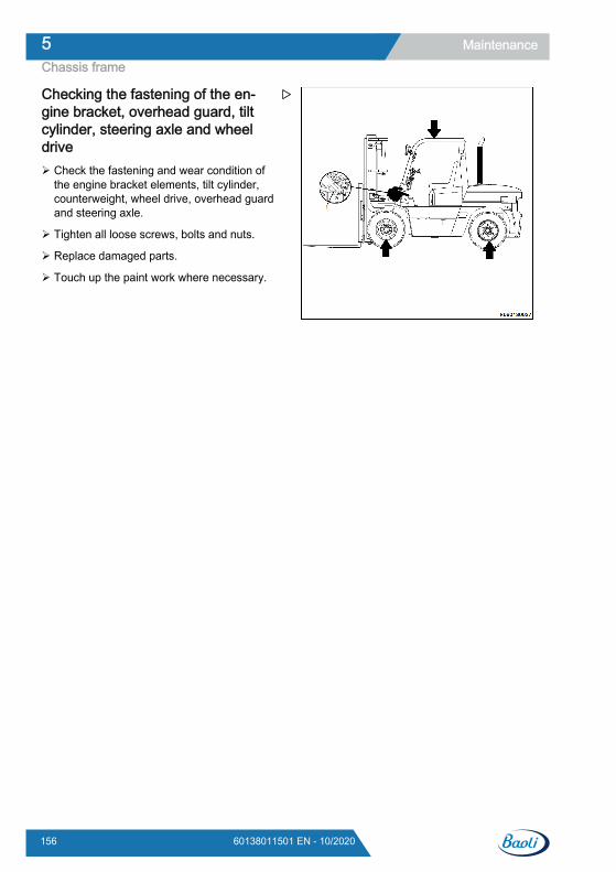
Checking the fastening of the en-gine bracket, overhead guard, tiltcylinder, steering axle and wheeldrive Check the fastening and wear condition of
the engine bracket elements, tilt cylinder,counterweight, wheel drive, overhead guardand steering axle.
Tighten all loose screws, bolts and nuts.
Replace damaged parts.
Touch up the paint work where necessary.
Maintenance5Chassis frame
156 60138011501 EN - 10/2020
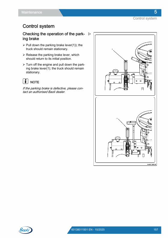
Control systemChecking the operation of the park-ing brake Pull down the parking brake lever(1)); the
truck should remain stationary.
Release the parking brake lever, whichshould return to its initial position.
Turn off the engine and pull down the park-ing brake lever(1); the truck should remainstationary.
NOTE
If the parking brake is defective, please con-tact an authorised Baoli dealer.
Maintenance 5Control system
15760138011501 EN - 10/2020
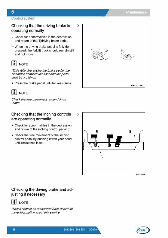
Checking that the driving brake isoperating normally Check for abnormalities in the depression
and return of the(1)driving brake pedal.
When the driving brake pedal is fully de-pressed, the forklift truck should remain stilland not move.
NOTE
While fully depressing the brake pedal, theclearance between the floor and the pedalshall be ≥ 110mm
Press the brake pedal until felt resistance.
NOTE
Check the free movement: around 5mm-8mm.
Checking that the inching controlsare operating normally Check for abnormalities in the depression
and return of the inching control pedal(3).
Check the free movement of the inchingcontrol pedal by pushing it with your handuntil resistance is felt.
Checking the driving brake and ad-justing if necessary
NOTE
Please contact an authorized Baoli dealer formore information about this service.
Maintenance5Control system
158 60138011501 EN - 10/2020
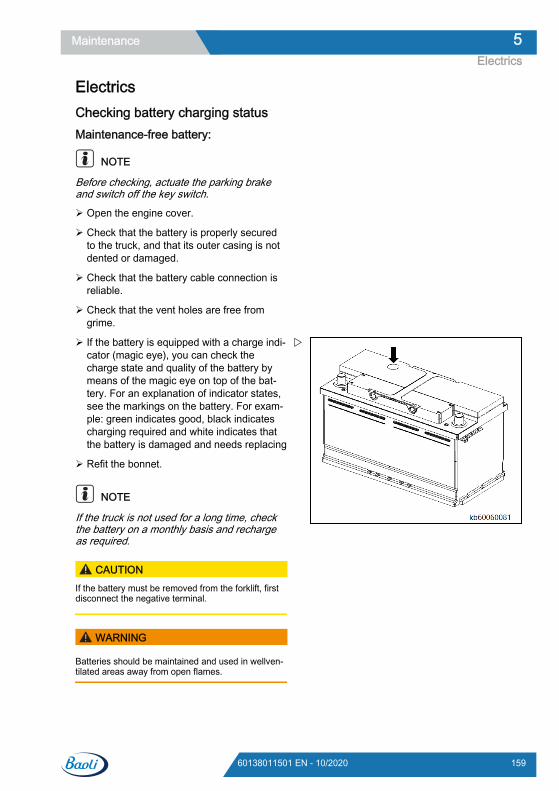
ElectricsChecking battery charging statusMaintenance-free battery:
NOTE
Before checking, actuate the parking brakeand switch off the key switch.
Open the engine cover.
Check that the battery is properly securedto the truck, and that its outer casing is notdented or damaged.
Check that the battery cable connection isreliable.
Check that the vent holes are free fromgrime.
If the battery is equipped with a charge indi-cator (magic eye), you can check thecharge state and quality of the battery bymeans of the magic eye on top of the bat-tery. For an explanation of indicator states,see the markings on the battery. For exam-ple: green indicates good, black indicatescharging required and white indicates thatthe battery is damaged and needs replacing
Refit the bonnet.
NOTE
If the truck is not used for a long time, checkthe battery on a monthly basis and rechargeas required.
CAUTIONIf the battery must be removed from the forklift, firstdisconnect the negative terminal.
WARNING
Batteries should be maintained and used in wellven-tilated areas away from open flames.
Maintenance 5Electrics
15960138011501 EN - 10/2020
Check the control boxIf a lamp doesn’t come on or an electrical de-vice does not function, the corresponding fusemay be burnt. Check the fuses accordingly.
Check and replace the fuses as the followingschedule:
Set the ignition switch to the OFF position.
Remove the fuse box cover and check thefuse.
If the fuse is burnt, replace it with a newfuse.
CAUTIONUse the fuse of the same specification as the originalone.
Maintenance5Electrics
160 60138011501 EN - 10/2020
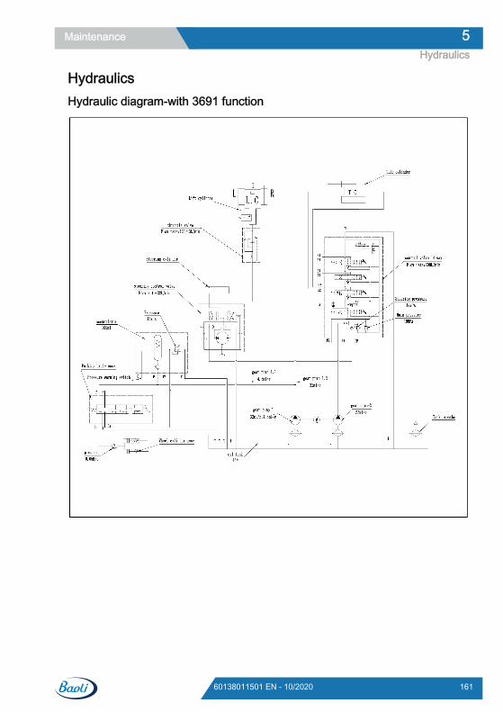
HydraulicsHydraulic diagram-with 3691 function
Maintenance 5Hydraulics
16160138011501 EN - 10/2020
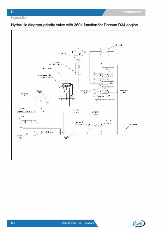
Hydraulic diagram-priority valve with 3691 function for Doosan D34 engine
Maintenance5Hydraulics
162 60138011501 EN - 10/2020
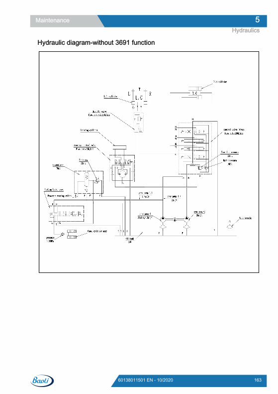
Hydraulic diagram-without 3691 function
Maintenance 5Hydraulics
16360138011501 EN - 10/2020
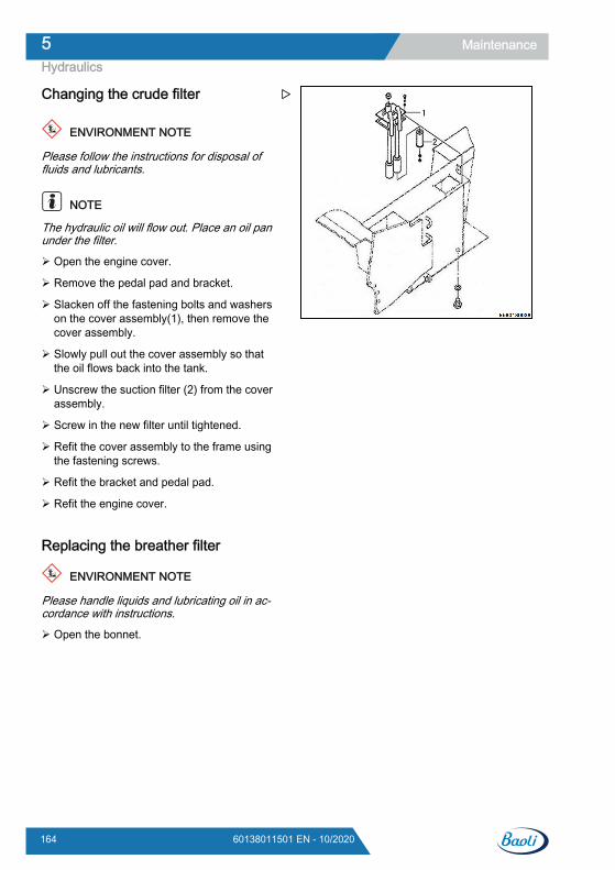
Changing the crude filter
ENVIRONMENT NOTE
Please follow the instructions for disposal offluids and lubricants.
NOTE
The hydraulic oil will flow out. Place an oil panunder the filter.
Open the engine cover.
Remove the pedal pad and bracket.
Slacken off the fastening bolts and washerson the cover assembly(1), then remove thecover assembly.
Slowly pull out the cover assembly so thatthe oil flows back into the tank.
Unscrew the suction filter (2) from the coverassembly.
Screw in the new filter until tightened.
Refit the cover assembly to the frame usingthe fastening screws.
Refit the bracket and pedal pad.
Refit the engine cover.
Replacing the breather filter
ENVIRONMENT NOTE
Please handle liquids and lubricating oil in ac-cordance with instructions.
Open the bonnet.
Maintenance5Hydraulics
164 60138011501 EN - 10/2020
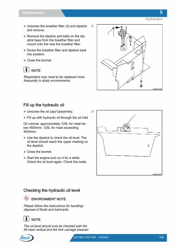
Unscrew the breather filter (3) and dipstickand remove.
Remove the dipstick and balls on the dip-stick base from the breather filter andmount onto the new the breather filter.
Screw the breather filter and dipstick backinto position.
Close the bonnet.
NOTE
Respirators may need to be replaced morefrequently in dusty environments.
Fill up the hydraulic oil Unscrew the oil cap(1)assembly.
Fill up with hydraulic oil through the oil inlet
Oil volume: approximately 120L for mast be-low 4500mm; 125L for mast exceeding4500mm.
Use the dipstick to check the oil level. Theoil level should reach the upper marking onthe dipstick.
Close the bonnet.
Start the engine and run it for a while.Check the oil level again. Check the seals.
Checking the hydraulic oil level
ENVIRONMENT NOTE
Please follow the instructions for handling/disposal of fluids and lubricants.
NOTE
The oil level should only be checked with thelift mast vertical and the fork carriage lowered.
Maintenance 5Hydraulics
16560138011501 EN - 10/2020
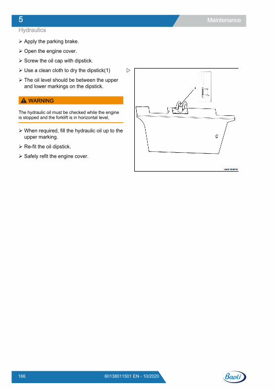
Apply the parking brake.
Open the engine cover.
Screw the oil cap with dipstick.
Use a clean cloth to dry the dipstick(1)
The oil level should be between the upperand lower markings on the dipstick.
WARNING
The hydraulic oil must be checked while the engineis stopped and the forklift is in horizontal level,
When required, fill the hydraulic oil up to theupper marking.
Re-fit the oil dipstick.
Safely refit the engine cover.
Maintenance5Hydraulics
166 60138011501 EN - 10/2020
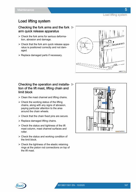
Load lifting systemChecking the fork arms and the forkarm quick release apparatus Check the fork arms for serious deforma-
tion, abrasion and damage.
Check that the fork arm quick release appa-ratus is positioned correctly and not dam-aged.
Replace damaged parts if necessary.
Checking the operation and installa-tion of the lift mast, lifting chain andlimit block Clean the mast channel and lifting chains.
Check the working status of the liftingchains, along with any signs of abrasion,paying particular attention to the areaaround the chain wheels.
Check that the chain fixed pins are secure.
Replace damaged lifting chains.
Check the status and tightness of the liftmast column, mast channel surfaces androller.
Check the status and working condition ofthe limit block.
Check the tightness of the elastic retainingrings at the piston rod connections on top ofthe lift mast.
Maintenance 5Load lifting system
16760138011501 EN - 10/2020
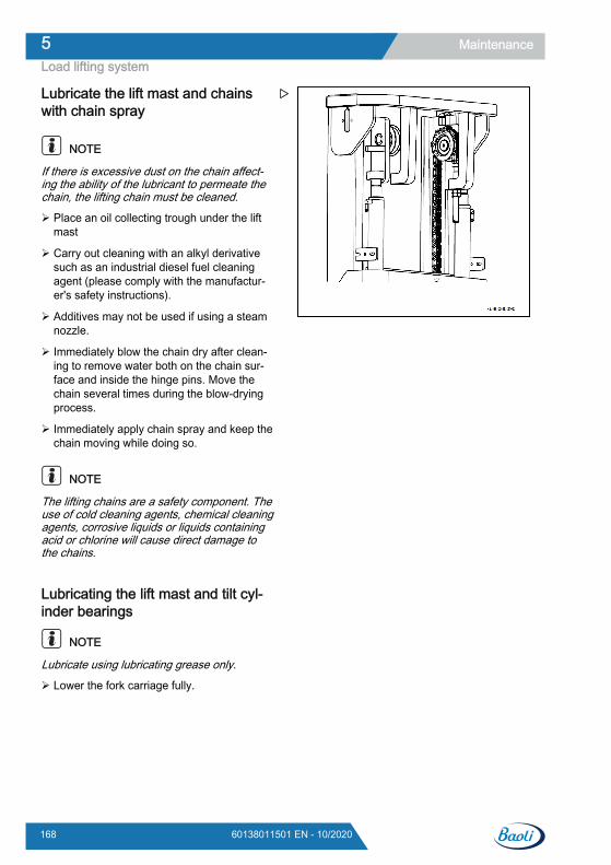
Lubricate the lift mast and chainswith chain spray
NOTE
If there is excessive dust on the chain affect-ing the ability of the lubricant to permeate thechain, the lifting chain must be cleaned.
Place an oil collecting trough under the liftmast
Carry out cleaning with an alkyl derivativesuch as an industrial diesel fuel cleaningagent (please comply with the manufactur-er's safety instructions).
Additives may not be used if using a steamnozzle.
Immediately blow the chain dry after clean-ing to remove water both on the chain sur-face and inside the hinge pins. Move thechain several times during the blow-dryingprocess.
Immediately apply chain spray and keep thechain moving while doing so.
NOTE
The lifting chains are a safety component. Theuse of cold cleaning agents, chemical cleaningagents, corrosive liquids or liquids containingacid or chlorine will cause direct damage tothe chains.
Lubricating the lift mast and tilt cyl-inder bearings
NOTE
Lubricate using lubricating grease only.
Lower the fork carriage fully.
Maintenance5Load lifting system
168 60138011501 EN - 10/2020
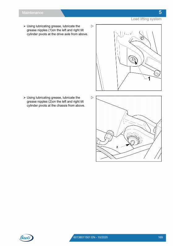
Using lubricating grease, lubricate thegrease nipples (1)on the left and right tiltcylinder pivots at the drive axle from above.
Using lubricating grease, lubricate thegrease nipples (2)on the left and right tiltcylinder pivots at the chassis from above.
Maintenance 5Load lifting system
16960138011501 EN - 10/2020
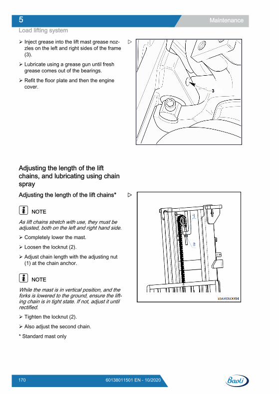
Inject grease into the lift mast grease noz-zles on the left and right sides of the frame(3).
Lubricate using a grease gun until freshgrease comes out of the bearings.
Refit the floor plate and then the enginecover.
Adjusting the length of the liftchains, and lubricating using chainsprayAdjusting the length of the lift chains*
NOTE
As lift chains stretch with use, they must beadjusted, both on the left and right hand side.
Completely lower the mast.
Loosen the locknut (2).
Adjust chain length with the adjusting nut(1) at the chain anchor.
NOTE
While the mast is in vertical position, and theforks is lowered to the ground, ensure the lift-ing chain is in tight state. If not, adjust it untilrectified.
Tighten the locknut (2).
Also adjust the second chain.
* Standard mast only
Maintenance5Load lifting system
170 60138011501 EN - 10/2020
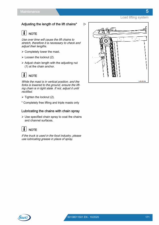
Adjusting the length of the lift chains*
NOTE
Use over time will cause the lift chains tostretch, therefore it is necessary to check andadjust their lengths.
Completely lower the mast.
Loosen the locknut (2).
Adjust chain length with the adjusting nut(1) at the chain anchor.
NOTE
While the mast is in vertical position, and theforks is lowered to the ground, ensure the lift-ing chain is in tight state. If not, adjust it untilrectified.
Tighten the locknut (2).
* Completely free lifting and triple masts only
Lubricating the chains with chain spray Use specified chain spray to coat the chains
and channel surfaces.
NOTE
If the truck is used in the food industry, pleaseuse lubricating grease in place of spray.
Maintenance 5Load lifting system
17160138011501 EN - 10/2020

Maintenance5Load lifting system
172 60138011501 EN - 10/2020

6
Technical data
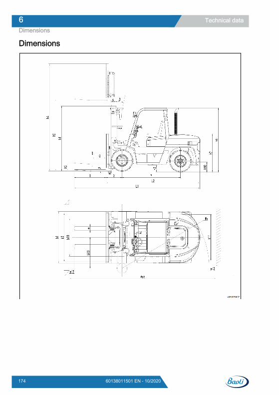
Dimensions
Technical data6Dimensions
174 60138011501 EN - 10/2020
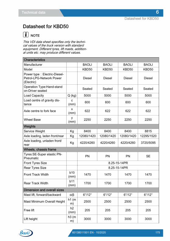
Datasheet for KBD50
NOTE
This VDI data sheet specifies only the techni-cal values of the truck version with standardequipment. Different tyres, lift masts, addition-al units etc. may produce different values.
CharacteristicsManufacturer BAOLI BAOLI BAOLI BAOLIModel KBD50 KBD50 KBD50 KBD50Power type:Electric-Diesel-Petrol-LPG-Network Power(Electric)
Diesel Diesel Diesel Diesel
Operation Type:Hand-standon-Driver seated Seated Seated Seated Seated
Load Capacity Q (kg) 5000 5000 5000 5000Load centre of gravity dis-tance
c(mm) 600 600 600 600
Axle centre to fork face x(mm) 622 622 622 622
Wheel Base y(mm) 2250 2250 2250 2250
WeightsService Weight Kg 8400 8400 8400 8815Axle loading, laden front/rear Kg 12080/1420 12080/1420 12080/1420 12295/1520Axle loading, unladen front/rear Kg 4220/4260 4220/4260 4220/4260 3720/5095
Wheels, chassis frameTyres:SE-Super elastic PN-Pneumatic PN PN PN SE
Front Tyres Size 8.25-15-14PRRear Tyres Size 8.25-15-14PR
Front Track Width b10(mm) 1470 1470 1470 1470
Rear Track Width b11(mm) 1700 1700 1700 1700
Dimension and overall sizesMast lift, forward/backward α/β 6°/12° 6°/12° 6°/12° 6°/12°
Mast Minimum Overall Height h1 (mm) 2500 2500 2500 2500
Free lift h2(mm) 205 205 205 205
Lift height h3 (mm) 3000 3000 3000 3000
Technical data 6Datasheet for KBD50
17560138011501 EN - 10/2020
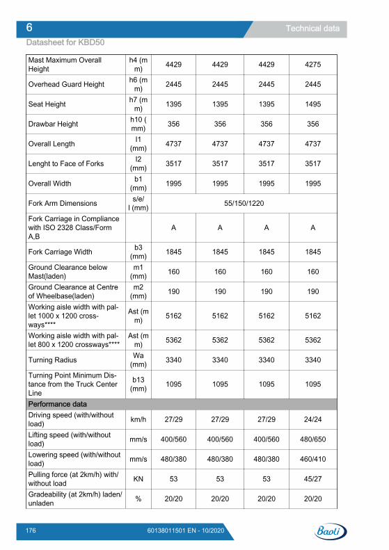
Mast Maximum OverallHeight
h4 (mm) 4429 4429 4429 4275
Overhead Guard Height h6 (mm) 2445 2445 2445 2445
Seat Height h7 (mm) 1395 1395 1395 1495
Drawbar Height h10 (mm) 356 356 356 356
Overall Length I1(mm) 4737 4737 4737 4737
Lenght to Face of Forks I2(mm) 3517 3517 3517 3517
Overall Width b1(mm) 1995 1995 1995 1995
Fork Arm Dimensions s/e/l (mm) 55/150/1220
Fork Carriage in Compliancewith ISO 2328 Class/FormA,B
A A A A
Fork Carriage Width b3(mm) 1845 1845 1845 1845
Ground Clearance belowMast(laden)
m1(mm) 160 160 160 160
Ground Clearance at Centreof Wheelbase(laden)
m2(mm) 190 190 190 190
Working aisle width with pal-let 1000 x 1200 cross-ways****
Ast (mm) 5162 5162 5162 5162
Working aisle width with pal-let 800 x 1200 crossways****
Ast (mm) 5362 5362 5362 5362
Turning Radius Wa(mm) 3340 3340 3340 3340
Turning Point Minimum Dis-tance from the Truck CenterLine
b13(mm) 1095 1095 1095 1095
Performance dataDriving speed (with/withoutload) km/h 27/29 27/29 27/29 24/24
Lifting speed (with/withoutload) mm/s 400/560 400/560 400/560 480/650
Lowering speed (with/withoutload) mm/s 480/380 480/380 480/380 460/410
Pulling force (at 2km/h) with/without load KN 53 53 53 45/27
Gradeability (at 2km/h) laden/unladen % 20/20 20/20 20/20 20/20
Technical data6Datasheet for KBD50
176 60138011501 EN - 10/2020

Service Brake hydraulic hydraulic hydraulic hydraulicEngine
Engine Type Isuzu6BG1QC-02
WP4.1G125E302
CumminsQSB4.5 Doosan D34
Engine Power in compliancewith ISO 1585 kW 82.5 92 82 85.8
Rated Number of Revolutions rpm 2000 2200 2200 2300Cylinder Number/Displace-ment cm3 6/6494 4/4090 4/4500 4/3400
On-board voltage 24 24 24 24Others
Drive Control Type Hydraulic
torque con-verter
Hydraulic tor-que converter
Hydraulictorque con-
verter
Hydraulic tor-que converter
Noise at Operator's Ear dB(A) 100 100 100 88Volume fuel tank L/Kg 140/117 140/117 140/117 125/104Towing coupling, type DIN Pin Pin Pin Pin
Technical data 6Datasheet for KBD50
17760138011501 EN - 10/2020
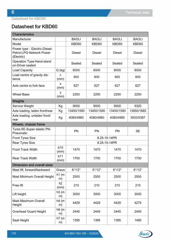
Datasheet for KBD60CharacteristicsManufacturer BAOLI BAOLI BAOLI BAOLIModel KBD60 KBD60 KBD60 KBD60Power type:Electric-Diesel-Petrol-LPG-Network Power(Electric)
Diesel Diesel Diesel Diesel
Operation Type:Hand-standon-Driver seated Seated Seated Seated Seated
Load Capacity Q (kg) 6000 6000 6000 6000Load centre of gravity dis-tance
c(mm) 600 600 600 600
Axle centre to fork face x(mm) 627 627 627 627
Wheel Base y(mm) 2250 2250 2250 2250
WeightsService Weight Kg 9000 9000 9000 9320Axle loading, laden front/rear Kg 13450/1590 13450/1590 13450/1590 13650/1685Axle loading, unladen front/rear Kg 4080/4960 4080/4960 4080/4960 3933/5387
Wheels, chassis frameTyres:SE-Super elastic PN-Pneumatic PN PN PN SE
Front Tyres Size 8.25-15-14PRRear Tyres Size 8.25-15-14PR
Front Track Width b10(mm) 1470 1470 1470 1470
Rear Track Width b11(mm) 1700 1700 1700 1700
Dimension and overall sizesMast lift, forward/backward Graus 6°/12° 6°/12° 6°/12° 6°/12°
Mast Minimum Overall Height h1 (mm) 2500 2500 2500 2500
Free lift h2(mm) 210 210 210 210
Lift height h3 (mm) 3000 3000 3000 3000
Mast Maximum OverallHeight
h4 (mm) 4429 4429 4429 4275
Overhead Guard Height h6 (mm) 2445 2445 2445 2445
Seat Height h7 (mm) 1395 1395 1395 1495
Technical data6Datasheet for KBD60
178 60138011501 EN - 10/2020
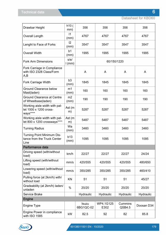
Drawbar Height h10 (mm) 356 356 356 356
Overall Length I1(mm) 4767 4767 4767 4767
Lenght to Face of Forks I2(mm) 3547 3547 3547 3547
Overall Width b1(mm) 1995 1995 1995 1995
Fork Arm Dimensions s/e/l (mm) 60/150/1220
Fork Carriage in Compliancewith ISO 2328 Class/FormA,B
A A A A
Fork Carriage Width b3(mm) 1845 1845 1845 1845
Ground Clearance belowMast(laden)
m1(mm) 160 160 160 160
Ground Clearance at Centreof Wheelbase(laden)
m2(mm) 190 190 190 190
Working aisle width with pal-let 1000 x 1200 cross-ways****
Ast (mm) 5287 5287 5287 5287
Working aisle width with pal-let 800 x 1200 crossways****
Ast (mm) 5487 5487 5487 5487
Turning Radius Wa(mm) 3460 3460 3460 3460
Turning Point Minimum Dis-tance from the Truck CenterLine
b13(mm) 1095 1095 1095 1095
Performance dataDriving speed (with/withoutload) km/h 22/27 22/27 22/27 24/24
Lifting speed (with/withoutload) mm/s 420/555 420/555 420/555 480/650
Lowering speed (with/withoutload) mm/s 350/285 350/285 350/285 460/410
Pulling force (at 2km/h) with/without load KN 51 51 51 45/27
Gradeability (at 2km/h) laden/unladen % 20/20 20/20 20/20 20/20
Service Brake Hydraulic Hydraulic Hydraulic HydraulicEngine
Engine Type Isuzu6BG1QC-02
WP4.1G125E302
CumminsQSB4.5 Doosan D34
Engine Power in compliancewith ISO 1585 kW 82.5 92 82 85.8
Technical data 6Datasheet for KBD60
17960138011501 EN - 10/2020
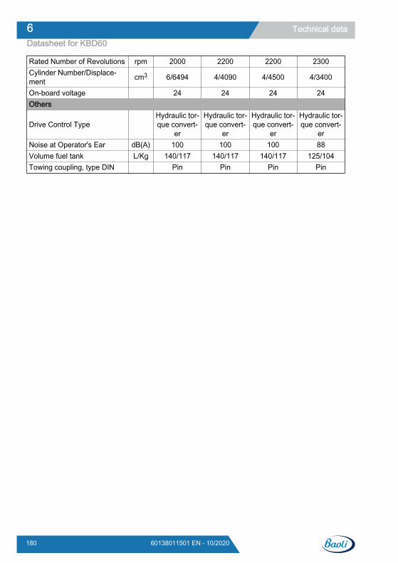
Rated Number of Revolutions rpm 2000 2200 2200 2300Cylinder Number/Displace-ment cm3 6/6494 4/4090 4/4500 4/3400
On-board voltage 24 24 24 24Others
Drive Control Type Hydraulic tor-que convert-
er
Hydraulic tor-que convert-
er
Hydraulic tor-que convert-
er
Hydraulic tor-que convert-
erNoise at Operator's Ear dB(A) 100 100 100 88Volume fuel tank L/Kg 140/117 140/117 140/117 125/104Towing coupling, type DIN Pin Pin Pin Pin
Technical data6Datasheet for KBD60
180 60138011501 EN - 10/2020
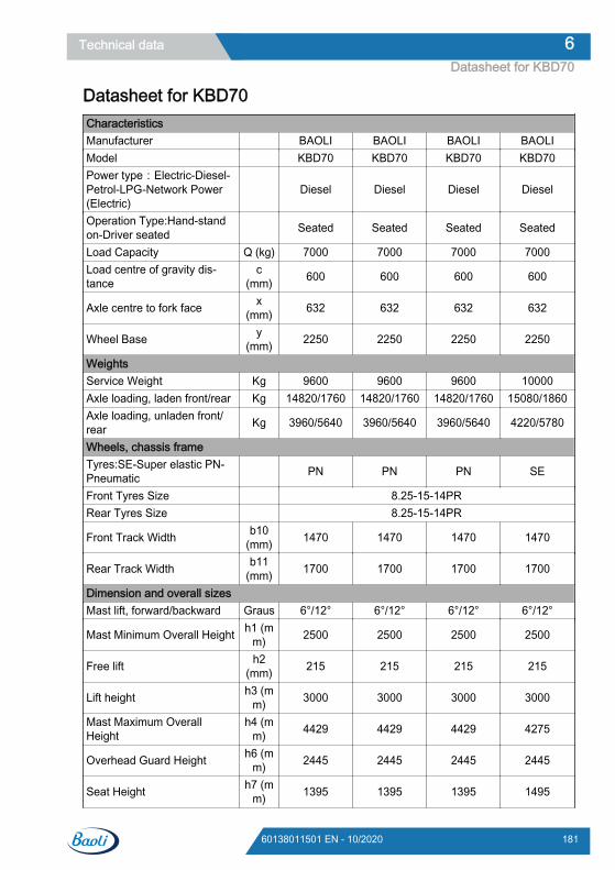
Datasheet for KBD70CharacteristicsManufacturer BAOLI BAOLI BAOLI BAOLIModel KBD70 KBD70 KBD70 KBD70Power type:Electric-Diesel-Petrol-LPG-Network Power(Electric)
Diesel Diesel Diesel Diesel
Operation Type:Hand-standon-Driver seated Seated Seated Seated Seated
Load Capacity Q (kg) 7000 7000 7000 7000Load centre of gravity dis-tance
c(mm) 600 600 600 600
Axle centre to fork face x(mm) 632 632 632 632
Wheel Base y(mm) 2250 2250 2250 2250
WeightsService Weight Kg 9600 9600 9600 10000Axle loading, laden front/rear Kg 14820/1760 14820/1760 14820/1760 15080/1860Axle loading, unladen front/rear Kg 3960/5640 3960/5640 3960/5640 4220/5780
Wheels, chassis frameTyres:SE-Super elastic PN-Pneumatic PN PN PN SE
Front Tyres Size 8.25-15-14PRRear Tyres Size 8.25-15-14PR
Front Track Width b10(mm) 1470 1470 1470 1470
Rear Track Width b11(mm) 1700 1700 1700 1700
Dimension and overall sizesMast lift, forward/backward Graus 6°/12° 6°/12° 6°/12° 6°/12°
Mast Minimum Overall Height h1 (mm) 2500 2500 2500 2500
Free lift h2(mm) 215 215 215 215
Lift height h3 (mm) 3000 3000 3000 3000
Mast Maximum OverallHeight
h4 (mm) 4429 4429 4429 4275
Overhead Guard Height h6 (mm) 2445 2445 2445 2445
Seat Height h7 (mm) 1395 1395 1395 1495
Technical data 6Datasheet for KBD70
18160138011501 EN - 10/2020
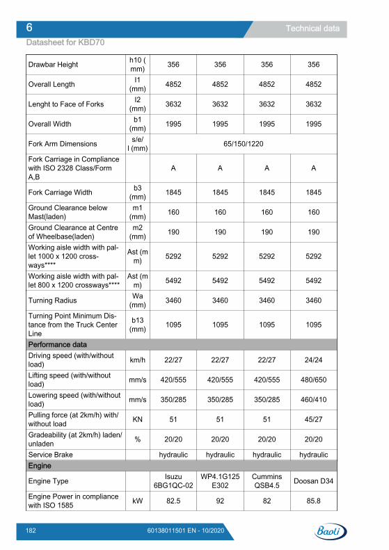
Drawbar Height h10 (mm) 356 356 356 356
Overall Length I1(mm) 4852 4852 4852 4852
Lenght to Face of Forks I2(mm) 3632 3632 3632 3632
Overall Width b1(mm) 1995 1995 1995 1995
Fork Arm Dimensions s/e/l (mm) 65/150/1220
Fork Carriage in Compliancewith ISO 2328 Class/FormA,B
A A A A
Fork Carriage Width b3(mm) 1845 1845 1845 1845
Ground Clearance belowMast(laden)
m1(mm) 160 160 160 160
Ground Clearance at Centreof Wheelbase(laden)
m2(mm) 190 190 190 190
Working aisle width with pal-let 1000 x 1200 cross-ways****
Ast (mm) 5292 5292 5292 5292
Working aisle width with pal-let 800 x 1200 crossways****
Ast (mm) 5492 5492 5492 5492
Turning Radius Wa(mm) 3460 3460 3460 3460
Turning Point Minimum Dis-tance from the Truck CenterLine
b13(mm) 1095 1095 1095 1095
Performance dataDriving speed (with/withoutload) km/h 22/27 22/27 22/27 24/24
Lifting speed (with/withoutload) mm/s 420/555 420/555 420/555 480/650
Lowering speed (with/withoutload) mm/s 350/285 350/285 350/285 460/410
Pulling force (at 2km/h) with/without load KN 51 51 51 45/27
Gradeability (at 2km/h) laden/unladen % 20/20 20/20 20/20 20/20
Service Brake hydraulic hydraulic hydraulic hydraulicEngine
Engine Type Isuzu6BG1QC-02
WP4.1G125E302
CumminsQSB4.5 Doosan D34
Engine Power in compliancewith ISO 1585 kW 82.5 92 82 85.8
Technical data6Datasheet for KBD70
182 60138011501 EN - 10/2020
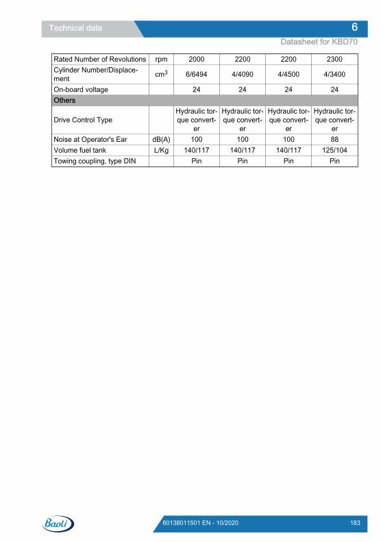
Rated Number of Revolutions rpm 2000 2200 2200 2300Cylinder Number/Displace-ment cm3 6/6494 4/4090 4/4500 4/3400
On-board voltage 24 24 24 24Others
Drive Control Type Hydraulic tor-que convert-
er
Hydraulic tor-que convert-
er
Hydraulic tor-que convert-
er
Hydraulic tor-que convert-
erNoise at Operator's Ear dB(A) 100 100 100 88Volume fuel tank L/Kg 140/117 140/117 140/117 125/104Towing coupling, type DIN Pin Pin Pin Pin
Technical data 6Datasheet for KBD70
18360138011501 EN - 10/2020
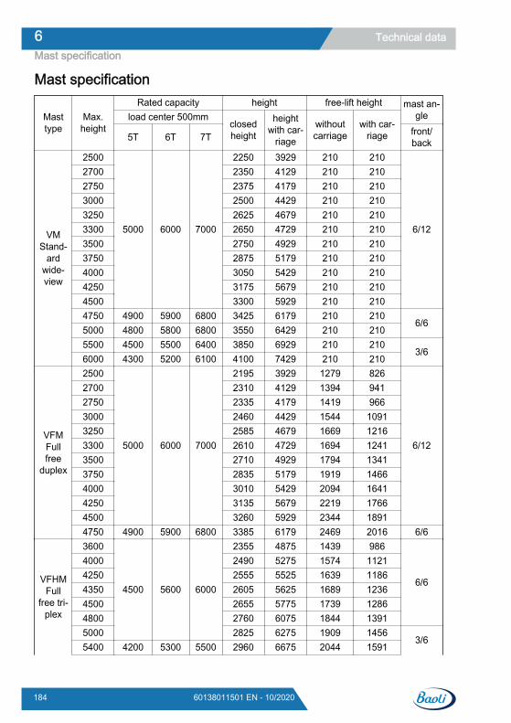
Mast specification
Masttype
Max.height
Rated capacity height free-lift height mast an-gleload center 500mm
closedheight
heightwith car-
riage
withoutcarriage
with car-riage5T 6T 7T front/
back
VMStand-
ardwide-view
2500
5000 6000 7000
2250 3929 210 210
6/12
2700 2350 4129 210 2102750 2375 4179 210 2103000 2500 4429 210 2103250 2625 4679 210 2103300 2650 4729 210 2103500 2750 4929 210 2103750 2875 5179 210 2104000 3050 5429 210 2104250 3175 5679 210 2104500 3300 5929 210 2104750 4900 5900 6800 3425 6179 210 210
6/65000 4800 5800 6800 3550 6429 210 2105500 4500 5500 6400 3850 6929 210 210
3/66000 4300 5200 6100 4100 7429 210 210
VFMFullfree
duplex
2500
5000 6000 7000
2195 3929 1279 826
6/12
2700 2310 4129 1394 9412750 2335 4179 1419 9663000 2460 4429 1544 10913250 2585 4679 1669 12163300 2610 4729 1694 12413500 2710 4929 1794 13413750 2835 5179 1919 14664000 3010 5429 2094 16414250 3135 5679 2219 17664500 3260 5929 2344 18914750 4900 5900 6800 3385 6179 2469 2016 6/6
VFHMFull
free tri-plex
3600
4500 5600 6000
2355 4875 1439 986
6/6
4000 2490 5275 1574 11214250 2555 5525 1639 11864350 2605 5625 1689 12364500 2655 5775 1739 12864800 2760 6075 1844 13915000 2825 6275 1909 1456
3/65400 4200 5300 5500 2960 6675 2044 1591
Technical data6Mast specification
184 60138011501 EN - 10/2020

6000 4000 5000 5300 3160 7275 2244 1791
Technical data 6Mast specification
18560138011501 EN - 10/2020

Technical data6Mast specification
186 60138011501 EN - 10/2020
AAdjusting the fork spacing. . . . . . . . . . . . . 72Adjusting the length of the lift chains, and
lubricating using chain spray. . . . . . . . . 170Adjusting the steering column. . . . . . . . . . 56Adjustment of the driver’s seat. . . . . . 50, 51Adjustment of valve clearance —— Wei-
chai WP4.1 engine. . . . . . . . . . . . . . . . 111After washing. . . . . . . . . . . . . . . . . . . . . . . 82
BBattery
Disposal. . . . . . . . . . . . . . . . . . . . . . . . 22Battery acid. . . . . . . . . . . . . . . . . . . . . . . . 21Before exiting the truck. . . . . . . . . . . . . . . 82Bleeding Air From the Fuel Delivery Line. 140Brake System. . . . . . . . . . . . . . . . . . . . . . 64
CCapacity chart. . . . . . . . . . . . . . . . . . . . . . 70CE labelling. . . . . . . . . . . . . . . . . . . . . . . . . 7Change air filter insert,. . . . . . . 106, 116, 126Change the air filter. . . . . . . . . . . . . . . . . 136Changing the coolant. . . . . . . . . . . . . . . . 146Changing the crude filter. . . . . . . . . . . . . 164Changing the drive axle gearbox oil. . . . 151Changing the drive direction. . . . . . . . . . . 61Changing the engine oil. . . . . . . . . . 103, 113Changing the engine oil-Cummins QDB4.5
engine. . . . . . . . . . . . . . . . . . . . . . . . . . 122Changing the engine oil filter. . . . . . 105, 115Changing the engine oil filter-Cummins
QSB4.5. . . . . . . . . . . . . . . . . . . . . . . . . 125Changing the hydraulic transmission oil fil-
ter. . . . . . . . . . . . . . . . . . . . . . . . . . . . . 149Changing the oil of the hydraulic transmis-
sion. . . . . . . . . . . . . . . . . . . . . . . . . . . . 150Checking and adjusting the radiator fan V-
belt——Isuzu 6BG1 engine. . . . . . . . . . 120Checking and cleaning the cooling fins. . 145Checking battery charging status. . . . . . 159Checking list-IC Truck. . . . . . . . . . . . . . . . 98Checking that the driving brake is operat-
ing normally. . . . . . . . . . . . . . . . . . . . . . 158Checking that the inching controls are op-
erating normally. . . . . . . . . . . . . . . . . . . 158Checking the coolant level. . . . . . . . . . . . 148Checking the drive axle gearbox oil. . . . . 151
Checking the Engine Oil. . . . . . . . . . . . . 131Checking the fastening of the engine
bracket, overhead guard, tilt cylinder,steering axle and wheel drive. . . . . . . . 156
Checking the fork arms and the fork armquick release apparatus. . . . . . . . . . . . 167
Checking the hydraulic oil level. . . . . . . . 165Checking the oil level of the hydraulic
transmission. . . . . . . . . . . . . . . . . . . . . 150Checking the operation and installation of
the lift mast, lifting chain and limit block. 167Checking the operation of the parking
brake. . . . . . . . . . . . . . . . . . . . . . . . . . . 157Checking the tyres for damage and foreign
matter. . . . . . . . . . . . . . . . . . . . . . . . . . 153Check the condition and operation of chain. 44check the control box. . . . . . . . . . . . . . . . 160Check the engine oil level. . . . 104, 114, 124Check the lap seat belt for condition and
correct operation. . . . . . . . . . . . . . . . . . 155Check the tyre inflation pressure. . . . . . . 153Check the wheel nuts for correct tightness. 43Clean and check the injection nozzle. . . 111Cleaning and lubricating the steering axle. 153Cleaning the air filter insert. . . 106, 116, 127Cleaning the electrical system. . . . . . . . . . 81Cleaning the truck. . . . . . . . . . . . . . . 80, 102Clean the air filter insert,. . . . . . . . . . . . . 134Climbing on/off the forklift. . . . . . . . . . . . . 49Competent person. . . . . . . . . . . . . . . . . . . 12Consumables
Disposal. . . . . . . . . . . . . . . . . . . . . . . . 21Safety information for handling battery
acid. . . . . . . . . . . . . . . . . . . . . . . . . . 21Safety information for handling oils. . . 20Safety information for hydraulic fluid. . 19
DDaily checks before use. . . . . . . . . . . . . . . 41Datasheet for KBD50. . . . . . . . . . . . . . . . 175Datasheet for KBD60. . . . . . . . . . . . . . . . 178Datasheet for KBD70. . . . . . . . . . . . . . . . 181Definition of terms used for responsible
persons. . . . . . . . . . . . . . . . . . . . . . . . . . 12Description of use and climatic conditions. . 6Diesel fuel
Specifications. . . . . . . . . . . . . . . . . . . . 46Winter operation. . . . . . . . . . . . . . . . . . 47
Index
18760138011501 EN - 10/2020
Dimensions. . . . . . . . . . . . . . . . . . . . . . . 174Display instrument. . . . . . . . . . . . . . . . . . . 29Disposal
Battery. . . . . . . . . . . . . . . . . . . . . . . . . 22Components. . . . . . . . . . . . . . . . . . . . . 22
Disposal of old trucks. . . . . . . . . . . . . . . . . 85DPF light and switch. . . . . . . . . . . . . . . . . 55Draining Water From the Fuel Filter. . . . 141Driver rights, duties and rules of behaviour. 13Drivers. . . . . . . . . . . . . . . . . . . . . . . . . . . . 12Driving on loading bridges. . . . . . . . . . . . . 75Driving with a load. . . . . . . . . . . . . . . . . . . 73
EEC declaration of conformity in accordance
with Machinery Directive. . . . . . . . . . . . . . 9Electric schematic diagram - Cummins
QSB4.5 with 3691. . . . . . . . . . . . . . . . . 195Electric schematic diagram-Doosan D24
with ISO3691 function. . . . . . . . . . . . . . 196Electric schematic diagram - Isuzu
6BG1QC-02 w/o ISO3691. . . . . . . . . . . 198Electric schematic diagram-Weichai WP4.1
w/o ISO3691. . . . . . . . . . . . . . . . . . . . . 197EMC – Electromagnetic compatibility. . . . . 8Emissions. . . . . . . . . . . . . . . . . . . . . . . . . 23emoval of water from the fuel-Cummins
QSB4.5. . . . . . . . . . . . . . . . . . . . . . . . . 129Emptying water separator——Weichai
WP4.1 engine. . . . . . . . . . . . . . . . . . . . 108Engine coolant - Specifications. . . . . . . . . 48Engine shutdown. . . . . . . . . . . . . . . . . . . . 57
FFan belt change. . . . . . . . . . . . . . . . . . . . 121Feed pump strainer cleaning——Isuzu
6BG1. . . . . . . . . . . . . . . . . . . . . . . . . . . 119Fill up the hydraulic oil. . . . . . . . . . . . . . . 165Forklift towing. . . . . . . . . . . . . . . . . . . . . . . 79Forward. . . . . . . . . . . . . . . . . . . . . . . . . . . 60Fuel system air bleeding. . . . . . . . . 110, 118
GGeneral information. . . . . . . . . . . . . . . . . . 88General View. . . . . . . . . . . . . . . . . . . . . . . 26
HHandling gas springs and accumulators. . 18
Hydraulic diagram-priority valve with 3691function for Doosan D34 engine. . . . . . 162
Hydraulic diagram-without 3691 function. 163Hydraulic fluid. . . . . . . . . . . . . . . . . . . . . . 19
IImpermissible use. . . . . . . . . . . . . . . . . . . . 5Inching control. . . . . . . . . . . . . . . . . . . . . . 61Inspect the intake piping-Cummings
QSB4..5. . . . . . . . . . . . . . . . . . . . . . . . . 130Instructions for running-in. . . . . . . . . . . . . 40Intended use. . . . . . . . . . . . . . . . . . . . . . . . 4
LLifting chains
Cleaning. . . . . . . . . . . . . . . . . . . . . . . . 81Load centre distance and load capacity. . 69Loading. . . . . . . . . . . . . . . . . . . . . . . . . . . 72Location of decals. . . . . . . . . . . . . . . . . . . 35Lubricate the lift mast and chains with
chain spray. . . . . . . . . . . . . . . . . . . . . . 168Lubricating the lift mast and tilt cylinder
bearings. . . . . . . . . . . . . . . . . . . . . . . . 168
MMaintenance table for Doosan D34 engine. 96Mast serial numbers. . . . . . . . . . . . . . . . . 34Mast specification. . . . . . . . . . . . . . . . . . 184
OOils. . . . . . . . . . . . . . . . . . . . . . . . . . . . . . . 20Operating attachments. . . . . . . . . . . . . . . 67Operating company. . . . . . . . . . . . . . . . . . 12Operating controls. . . . . . . . . . . . . . . . . . . 27Operating the lifting device. . . . . . . . . . . . 66
PPackaging. . . . . . . . . . . . . . . . . . . . . . . . . 23parking. . . . . . . . . . . . . . . . . . . . . . . . . . . . 63Picking up a load. . . . . . . . . . . . . . . . . . . . 70Pre-service preparatory work. . . . . . . . . . . 89Pre-shift checks. . . . . . . . . . . . . . . . . . . . . 41Production number. . . . . . . . . . . . . . . . . . 33Prohibition of use by unauthorised persons. 13
RReception of truck. . . . . . . . . . . . . . . . . . . . 3Refuelling. . . . . . . . . . . . . . . . . . . . . . . . . . 46
Index
188 60138011501 EN - 10/2020
Removal of water from the fuel —— Isuzu6BG1. . . . . . . . . . . . . . . . . . . . . . . . . . . 118
Replacing Engine Oil. . . . . . . . . . . . . . . . 132Replacing the breather filter. . . . . . . . . . . 164Replacing the engine oil filter. . . . . . . . . . 134Replacing the fine fuel filter ——- Cum-
mins QSB4.5 engine. . . . . . . . . . . . . . . 128Replacing the fine fuel filter ——- Isuzu
6BG1 engine. . . . . . . . . . . . . . . . . . . . . 118Replacing the fine fuel filter ——- Weichai
WP4.1 engine. . . . . . . . . . . . . . . . . . . . 109Replacing the Fuel Filter. . . . . . . . . . . . . 138Residual dangers. . . . . . . . . . . . . . . . . . . . 16Residual risks. . . . . . . . . . . . . . . . . . . . . . 16Reversing. . . . . . . . . . . . . . . . . . . . . . . . . . 60
SSafety regulations when driving. . . . . . . . . 17Seat belt. . . . . . . . . . . . . . . . . . . . . . . . . . . 51
Fastening. . . . . . . . . . . . . . . . . . . . . . . 52Malfunction due to cold weather condi-
tions. . . . . . . . . . . . . . . . . . . . . . . . . . 52Releasing. . . . . . . . . . . . . . . . . . . . . . . 52
Seat belt status and performance checks. 42Service schedule for ISUZU 6BG1-02 en-
gine. . . . . . . . . . . . . . . . . . . . . . . . . . . . . 92
Service schedule for Weichai WP4.1 en-gine. . . . . . . . . . . . . . . . . . . . . . . . . . . . . 91
Stability. . . . . . . . . . . . . . . . . . . . . . . . . . . 16Start on an incline. . . . . . . . . . . . . . . . . . . 62Steering system. . . . . . . . . . . . . . . . . . . . . 63Summary. . . . . . . . . . . . . . . . . . . . . . . . . . 88supply table. . . . . . . . . . . . . . . . . . . . . . . . 90Switches. . . . . . . . . . . . . . . . . . . . . . . . . . 53Symbols. . . . . . . . . . . . . . . . . . . . . . . . . . . . 6
TTechnical notes. . . . . . . . . . . . . . . . . . . . . . 2Tighten the tyre nuts. . . . . . . . . . . . . . . . 154Towed load. . . . . . . . . . . . . . . . . . . . . . . . 77Transporting pallets. . . . . . . . . . . . . . . . . . 71Transport of swinging loads. . . . . . . . . . . . 74Truck Storage. . . . . . . . . . . . . . . . . . . . . . 84Truck transport. . . . . . . . . . . . . . . . . . . . . . 83
UUnloading. . . . . . . . . . . . . . . . . . . . . . . . . . 76Unusual System Noise-Cummins
QSB4.5. . . . . . . . . . . . . . . . . . . . . . . . . 122
WWarnings. . . . . . . . . . . . . . . . . . . . . . . . . . . 6
Index
18960138011501 EN - 10/2020


KION Baoli (Jiangsu) Forklift Co., Ltd.Add: No. 8 Xinzhou Road,Economic Development Zone,Jingjiang, 214500, Jiangsu, [email protected]
60138011501-EN-10/2020-3
Original instructionsD series Forklift Truck
KBD50–70
Annex
7
Electrical diagrams
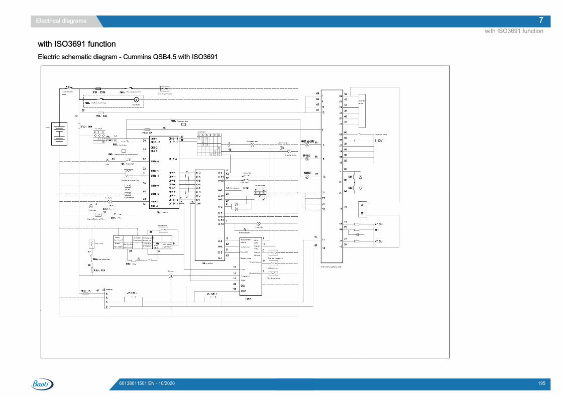
with ISO3691 functionElectric schematic diagram - Cummins QSB4.5 with ISO3691
Electrical diagrams 7with ISO3691 function
19560138011501 EN - 10/2020
Electric schematic diagram-Doosan D24 with ISO3691 function
Electrical diagrams7with ISO3691 function
196 60138011501 EN - 10/2020
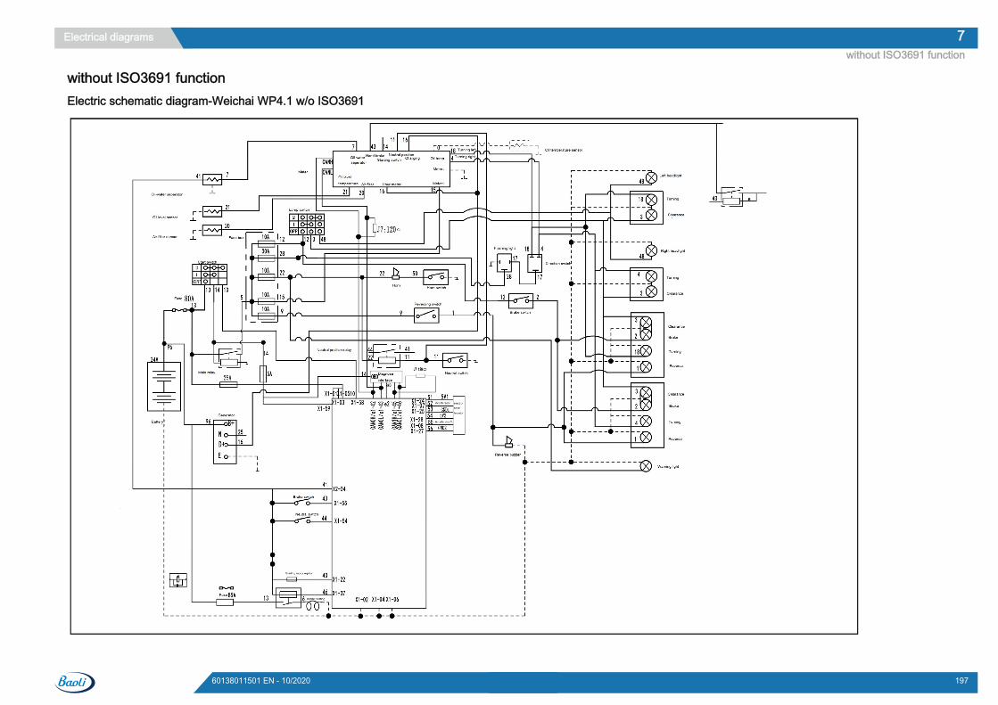
without ISO3691 functionElectric schematic diagram-Weichai WP4.1 w/o ISO3691
Electrical diagrams 7without ISO3691 function
19760138011501 EN - 10/2020
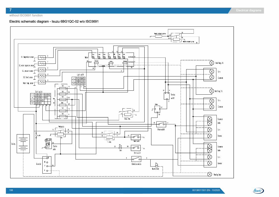
Electric schematic diagram - Isuzu 6BG1QC-02 w/o ISO3691
Electrical diagrams7without ISO3691 function
198 60138011501 EN - 10/2020

KION Baoli (Jiangsu) Forklift Co., Ltd.Add: No. 8 Xinzhou Road,Economic Development Zone,Jingjiang, 214500, Jiangsu, [email protected]
60138011501-EN-10/2020-3