ip phones fundamentals (nn43001-368) - michael mcnamara
TRANSCRIPT
Nortel Communication Server 1000
IP Phones FundamentalsRelease: UNIStim 4.x for Rls 5.x and 6.0Document Revision: 06.07
www.nortel.com
NN43001-368.
Nortel Communication Server 1000Release: UNIStim 4.x for Rls 5.x and 6.0Publication: NN43001-368Document release date: 30 April 2010
Copyright © 2003-2010 Nortel Networks. All Rights Reserved.
While the information in this document is believed to be accurate and reliable, except as otherwise expresslyagreed to in writing NORTEL PROVIDES THIS DOCUMENT "AS IS" WITHOUT WARRANTY OR CONDITION OFANY KIND, EITHER EXPRESS OR IMPLIED. The information and/or products described in this document aresubject to change without notice.
Nortel, Nortel Networks, the Nortel logo, and the Globemark are trademarks of Nortel Networks.
The Bluetooth® word mark and logos are owned by the Bluetooth® SIG, Inc. and any use of such marks by NortelNetworks is under license.
All other trademarks are the property of their respective owners.
.
3.
ContentsNew in this release 21Features 21
Navigation 21Revision history 22Subject 26
How to get Help 29Getting help from the Nortel Web site 29Getting help over the phone from a Nortel Solutions Center 29Getting help from a specialist by using an Express Routing Code 30Getting help through a Nortel distributor or reseller 30
Nortel IP Phone 2001 31Contents 31Introduction 31Description 32Components and functions 32
Keys and functions 33Services menu 33
Features 34Display characteristics 35
Cleaning the IP Phone display screen 35Information line display 35Soft key label display 36
Package components 36Installation and configuration 38
Before you begin 38First-time installation 39Configuring the IP Phone 2001 39Connecting the components 40Startup sequence 41
Redeploying an IP Phone 2001 42Replacing an IP Phone 2001 43Removing an IP Phone 2001 from service 43
Nortel Communication Server 1000IP Phones Fundamentals
NN43001-368 06.07 30 April 2010
Copyright © 2003-2010 Nortel Networks. All Rights Reserved.
.

4
Nortel IP Phone 2002 45Contents 45Introduction 45Description 46Components and functions 46
Keys and functions 47Services menu 48
Features 49Display characteristics 50
Cleaning the IP Phone display screen 50Programmable line (DN)/feature key label display 50Information line display 51Soft key label display 51
Package components 51Installation and configuration 53
Before you begin 54First-time installation 54Configuring the IP Phone 2002 54Connecting the components 55Startup sequence 57
Redeploying an IP Phone 2002 57Replacing an IP Phone 2002 58Removing an IP Phone 2002 from service 59
Nortel IP Phone 2004 61Contents 61Introduction 61Description 62Components and functions 62
Keys and functions 63Services menu 64
Features 65Central Answering Position 66Display characteristics 66
Cleaning the IP Phone display screen 67Programmable line (DN)/feature key label display 67Information line display 67Soft key label display 68
Package components 68Installation and configuration 70
Before you begin 71First-time installation 71Configuring the IP Phone 2004 71
Nortel Communication Server 1000IP Phones Fundamentals
NN43001-368 06.07 30 April 2010
Copyright © 2003-2010 Nortel Networks. All Rights Reserved.
.
5
Connecting the components 72Startup sequence 74
Redeploying an IP Phone 2004 74Replacing an IP Phone 2004 75Removing an IP Phone 2004 from service 76
IP Phone Key Expansion Module (KEM) 77Contents 77Description 77Features 78Display characteristics 78Key number assignments 79Package components 79Configuration 79Installation 82IP Phone KEM startup initialization 83Operating parameters 84
General 84IP Phone 2002 84IP Phone 2004 85Virtual Office 85Firmware 85
Nortel IP Audio Conference Phone 2033 87Contents 87Introduction 87Description 88Extension microphones 89Components and functions 90
Keys and functions 90Services menu 91
Features 92Display characteristics 93
Cleaning the IP Phone display screen 93Information line display 94Soft key label display 94
Package components 95Installation and configuration 97
Before you begin 97First-time installation 98Configuring the IP Audio Conference Phone 2033 98Connecting the components 99Startup sequence 101
Redeploying an IP Audio Conference Phone 2033 101Replacing an IP Audio Conference Phone 2033 102
Nortel Communication Server 1000IP Phones Fundamentals
NN43001-368 06.07 30 April 2010
Copyright © 2003-2010 Nortel Networks. All Rights Reserved.
.
6
Removing an IP Audio Conference Phone 2033 from service 103Connecting an extension microphone 103
Nortel IP Phone 2007 105Contents 105Introduction 105Description 106Components and functions 106
Keys and functions 107Services menu 108Local Tools menu 109
Features 110Touch panel 110
Calibrate the touch panel 111Stylus 111
Dialpad entry 112Cleaning the IP Phone display screen 113Display characteristics 113
Phone mode 114Application area 115Tools/Navigation area 117
Package components 118Installation and configuration 119
Before you begin 119First-time installation 120Configuring the IP Phone 2007 120Connecting the components 121Startup sequence 121
Redeploying an IP Phone 2007 121Replacing an IP Phone 2007 122Removing an IP Phone 2007 from service 123
Nortel IP Phone 1210 125Contents 125Introduction 125Description 126Components and functions 127
Keys and functions 127Services menu 128Local Tools menu 129
Features 130Display characteristics 130
Cleaning the IP Phone display screen 131Information line display 131Soft key label display 131
Nortel Communication Server 1000IP Phones Fundamentals
NN43001-368 06.07 30 April 2010
Copyright © 2003-2010 Nortel Networks. All Rights Reserved.
.
7
Package components 132Installation and configuration 133
Before you begin 133First-time installation 134Configuring the IP Phone 1210 134Connecting the components 135Startup sequence 137
Redeploying an IP Phone 1210 138Replacing an IP Phone 1210 139Removing an IP Phone 1210 from service 139
Nortel IP Phone 1220 141Contents 141Introduction 141Description 142Components and functions 143
Keys and functions 143Services menu 145Local Tools menu 146
Features 147Display characteristics 147
Cleaning the IP Phone display screen 148Programmable line (DN)/feature key label display 148Information line display 148Soft key label display 149
Package components 149Installation and configuration 151
Before you begin 151First-time installation 151Configuring the IP Phone 1220 152Connecting the components 152Startup sequence 155
Redeploying an IP Phone 1220 155Replacing an IP Phone 1220 156Removing an IP Phone 1220 from service 157
Nortel IP Phone 1230 159Contents 159Introduction 159Description 160Components and functions 161
Keys and functions 161Services menu 163Local Tools menu 164
Features 165
Nortel Communication Server 1000IP Phones Fundamentals
NN43001-368 06.07 30 April 2010
Copyright © 2003-2010 Nortel Networks. All Rights Reserved.
.
8
Display characteristics 165Cleaning the IP Phone display screen 166Programmable line (DN)/feature key label display 166Information line display 166Soft key label display 167
Package components 167Installation and configuration 169
Before you begin 169First-time installation 169Configuring the IP Phone 1230 170Connecting the components 170Startup sequence 173
Redeploying an IP Phone 1230 173Replacing an IP Phone 1230 174Removing an IP Phone 1230 from service 175
Nortel IP Phones 1200 Series LCD Expansion Module 177Contents 177Description 177Features 181Display characteristics 182Package components 182Configuration 182Installation 184IP Phones 1200 Series LCD Expansion Module startup initialization 185Operating parameters 186
IP Phone 1220 186IP Phone 1230 187
Services key operation 189Display diagnostics 189
Firmware 191
Nortel IP Softphone 2050 193Contents 193Introduction 193Description 194
Features 194Additional features 196Language support 197
Components 197Call Control window 197
Display characteristics 200Information display area 201System Tray 201USB audio adapters 202
Nortel Communication Server 1000IP Phones Fundamentals
NN43001-368 06.07 30 April 2010
Copyright © 2003-2010 Nortel Networks. All Rights Reserved.
.
9
USB Headset Adapter 202Registration 202GIPS 202Echo cancellation 204Clock synchronization 204Jitter buffer 204QoS 204i2050QosSvc.exe 206DiffSERV (DSCP) 207802.1p 207Ethereal traces 207GXAS 207
Licenses 207Check out license 208Cached license 208Evaluation period 208License restrictions 208License types 209License Server 210How to configure ports for licensing 210License Server components 211Provisioning a License Server 211Starting the License Server Manager 213Server Redundancy 214License file 214FLEXnet licensing error codes 215Troubleshooting 215
Key number assignments 224Minimum system requirements 225System components 226Before you begin 227First-time installation 228
Installing the IP Softphone 2050 for the first time 228Installing or upgrading the IP Softphone 2050 229
Remote installation 230Silent installation 235Upgrading 236Windows QoS Packet Scheduler 238
Running the IP Softphone 2050 for the first time 239Redeploying the IP Softphone 2050 239Removing an IP Softphone 2050 from service 240Maintenance 240
System data 241User data 241
Nortel Communication Server 1000IP Phones Fundamentals
NN43001-368 06.07 30 April 2010
Copyright © 2003-2010 Nortel Networks. All Rights Reserved.
.
10
Ethernet statistics 242IP Networking Statistics 243ICMP Statistics 244Audio Connection Data 244USB Headset Data 246Telchemy VQMon 246PC System Information 247Personal Call Recording Data 248Duplicate Media Stream Call Recording Data 248Licensing Data 248
Nortel Mobile Voice Client 2050 249Contents 249Introduction 249Description 250System requirements 250Supported features 250Application software 251
ClearType 252MVC 2050 components 252
Compatible PDAs 252Headsets 252Automatic Gain Control and feedback 252Audio quality 253
MVC 2050 Call Handling screen 253Display 253Dialpad 253Soft keys (self-labeled) 253Programmable line/feature keys 254Menus 254MVC 2050 graphical interface (skins) components 256Icons 257
Operation 259MVC 2050 installation 260
MVC 2050 installation method 260MVC 2050 removal 261Configuration 262
Settings 262802.1p and DiffServ 269
Global Packet Loss Concealment algorithm 269MVC 2050 and WLAN 269
802.11b wireless ethernet networking 269Wireless Fidelity 270Roaming and handover 270
Nortel Communication Server 1000IP Phones Fundamentals
NN43001-368 06.07 30 April 2010
Copyright © 2003-2010 Nortel Networks. All Rights Reserved.
.
11
Expansion Module for IP Softphone 2050 271Contents 271Description 271Features 272Display characteristics 272Configuration 273Installation 274Operation 274
Nortel IP Phone 1110 275Contents 275Introduction 275Description 276Components and functions 277
Keys and functions 277Services menu 278Local Tools menu 279
Features 279Display characteristics 280
Context-sensitive soft key label display 280Information line display 281
Cleaning the IP Phone display screen 281Package components 281Installation and configuration 283
Before you begin 283First-time installation 283Configuring the IP Phone 1110 283Connecting the components 284Startup sequence 289
TFTP firmware upgrade 289Redeploying an IP Phone 1110 289Replacing an IP Phone 1110 290Removing an IP Phone 1110 from service 291
Nortel IP Phone 1120E 293Contents 293Introduction 293Description 294Components and functions 294
Keys and functions 295Services menu 296Local Tools menu 297
Features 298Dialpad entry 299
Nortel Communication Server 1000IP Phones Fundamentals
NN43001-368 06.07 30 April 2010
Copyright © 2003-2010 Nortel Networks. All Rights Reserved.
.
12
Display characteristics 300Self-labeled line/programmable feature key label display 301Information line display 301Context-sensitive soft key label display 301
Cleaning the IP Phone display screen 302Package components 302Installation and configuration 303
Before you begin 304First-time installation 304Configuring the IP Phone 1120E 304Connecting the components 305Startup sequence 309
TFTP firmware upgrade 310Redeploying an IP Phone 1120E 310Replacing an IP Phone 1120E 311Removing an IP Phone 1120E from service 311
Nortel IP Phone 1140E 313Contents 313Introduction 313Description 314Components and functions 315
Keys and functions 315Services menu 317Local Tools menu 318
Features 318Dialpad entry 319Display characteristics 320
Self-labeled line/programmable feature key label display 321Information line display 321Context-sensitive soft key label display 322
Cleaning the IP Phone display screen 322Package components 322Installation and configuration 324
Before you begin 324First-time installation 324Configuring the IP Phone 1140E 324Connecting the components 325Startup sequence 330
TFTP firmware upgrade 330Bluetooth® wireless technology 330Redeploying an IP Phone 1140E 330Replacing an IP Phone 1140E 331Removing an IP Phone 1140E from service 332
Nortel Communication Server 1000IP Phones Fundamentals
NN43001-368 06.07 30 April 2010
Copyright © 2003-2010 Nortel Networks. All Rights Reserved.
.
13
Nortel IP Phone 1150E 333Contents 333Introduction 333Description 334Components and functions 336
Services menu 339Local Tools menu 340
Features 341Dialpad entry 343Display characteristics 344
Self-labeled line/programmable feature key label 344Information line display 345Context-sensitive soft key label 345Cleaning the IP Phone display screen 345
Headset support 345Package components 346Installation and configuration 347
Before you begin 347First-time installation 348Configuring the IP Phone 1150E 348Connecting the components 349Startup sequence 354
TFTP firmware upgrade 354Bluetooth® wireless technology 354Redeploying an IP Phone 1150E 355Replacing an IP Phone 1150E 356Removing an IP Phone 1150E from service 356
Nortel IP Phone 1165E 357Contents 357Description 357Components and functions 358
Keys and functions 358Services menu 360Local Tools menu 361
Features 361Dialpad entry 362Display characteristics 363
Self-labeled line/programmable feature key label display 364Information line display 364Soft key label display 365
Cleaning the IP Phone display screen 365Package components 365
Nortel Communication Server 1000IP Phones Fundamentals
NN43001-368 06.07 30 April 2010
Copyright © 2003-2010 Nortel Networks. All Rights Reserved.
.
14
Installation and configuration 366Before you begin 367First-time installation 367Configuring the IP Phone 1165E 367Connecting the components 368Startup sequence 373
TFTP firmware upgrade 373Bluetooth® wireless technology 373Redeploying an IP Phone 1165E 373Replacing an IP Phone 1165E 374Removing an IP Phone 1165E from service 375
Expansion Module for IP Phones 1100 Series 377Contents 377Description 377Features 378Display characteristics 379Package components 379Configuration 379Installation 381Expansion Module startup initialization 384Operating parameters 385
IP Phone 1120E 385IP Phone 1140E and IP Phone 1150E, and IP Phone 1165E 385
Services key operation 386Display diagnostics 387
Firmware 388
Nortel IP Phones with SIP firmware 389
Features 391Contents 391Telephony features 391
Corporate Directory 392Personal Directory 392Redial List 392Callers List 393Password Administration 393IP Call Recording 393Secure IP Call Recording 394Virtual Office 395Emergency Services for Virtual Office 395Active Call Failover 395Enhanced UNIStim Firmware download 396Media security 397
Nortel Communication Server 1000IP Phones Fundamentals
NN43001-368 06.07 30 April 2010
Copyright © 2003-2010 Nortel Networks. All Rights Reserved.
.
15
UNIStim Security DTLS 402UNIStim signalling security 403Live Dialpad 404Normal Mode Indication 404Caller ID display order 405Languages 405Screen Saver Slideshow IP Phone 2007 406Screen Saver Slideshow for IP Phone 1165E 410Background image for IP Phone 1165E 413Key number assignments 416Record on Demand 418
Network features 419Full Duplex 420802.1x Port-based network access control 426802.1ab Link Layer Discovery Protocol 427Dynamic Host Configuration Protocol 429Gratuitous Address Resolution Protocol 453Automatic QoS 453
X.509 Certificates 455Certificate management 455Root certificate 456Device certificate 456Certificate installation 456
Root certificates 456Certificates on redeployed IP Phones 470Security log 471
Regulatory and safety information 473Warnings: 474
Other compliancies 475For those devices equipped with Bluetooth® wireless technology 475
DenAn regulatory notice for Japan 476
Local Tools menu 477Contents 477Introduction 477Local Tools menu password protection 477
Local Tools menu password feature limitations 479Controlling the menu lock 479
Controlling the menu lock for IP Phone 2007 479Controlling the menu lock for IP Phone 1165E 479Controlling the menu lock for other IP Phones 480
Configuring Secure Local Menu using Network provisioning 481Accessing the Local Tools menu 481
Nortel Communication Server 1000IP Phones Fundamentals
NN43001-368 06.07 30 April 2010
Copyright © 2003-2010 Nortel Networks. All Rights Reserved.
.
16
Local Tools options 482Local Tools menu for IP Phone 2007 482Local Tools menu for IP Phones 1100 Series 484Diagnostics 486Local Tools menu for IP Phone 1165E 488Local Tools menu for IP Phone 1110, IP Phone 1210, IP Phone 1220, and IP
Phone 1230 493
Provisioning the IP Phones 497Contents 497Introduction 497Description 498Manual provisioning 498Automatic provisioning 499
Configuration 500Provisioning IP Phone parameters 501Auto Provisioning page for graphical user interface 502Automatic configuration 508Automatic provisioning parameters 509Provisioning Info Block 536
Operation 537Precedence rule and stickiness control 537IP Phone reset 539Factory default 539
Manual provisioning of IP Phones 1110 and 1200 Series 543Contents 543Introduction 543Provisioning parameters 543
Manual provisioning of IP Phones 2007 and 1100 Series 553Contents 553Introduction 553Provision parameters 553
Manual provisioning of IP Phones 2000 Series 563Contents 563Introduction 563Provision parameters 563
Provisioning the IP Phone 2001, IP Phone 2002, and IP Phone 2004 564Provisioning the IP Audio Conference Phone 2033 569
Headset support 573Introduction 573Supported wired and wireless headsets 573Bluetooth® wireless technology 573
Enabling Bluetooth® wireless technology 573
Nortel Communication Server 1000IP Phones Fundamentals
NN43001-368 06.07 30 April 2010
Copyright © 2003-2010 Nortel Networks. All Rights Reserved.
.
17
Manual configuration 574Configure the headsets 575
Active Headset Device 576Enable HID Commands 576Headset Type 576
USB audio support 576Nortel USB adapters 577USB Analog Terminal Adapter 577Wireless USB headsets 578USB audio limitations and restrictions 578
Datagram Transport Layer Security 581Overview 581
Operating modes 581Certificates 582
Virtual Private Network 583Description 583
VPN tunnel status 584VPN Security banner 587Licensing 587Languages 587Address assignment 588Listening Mode 588Limitations 589
Design for Operability 591Introduction 591
Auto Recovery/Overload protection 591Common alarming 593Common logging 594Flight Recorder 596Secure remote access 596
Licensing 597Node locked licensing 597Licensing notification 599
IP Phone diagnostic utilities 601Contents 601Introduction 601Text-based diagnostic utilities 601
Network diagnostic utilities 602Accessing Network Diagnostic utilities from the IP Phone 604Network Diagnostic Utilities data display pages 616Network Address Translation Traversal 627
Nortel Communication Server 1000IP Phones Fundamentals
NN43001-368 06.07 30 April 2010
Copyright © 2003-2010 Nortel Networks. All Rights Reserved.
.
18
General Information 627Using CLI Commands 629
Graphic-based diagnostics utilities 632Diagnostics for the IP Phones 1120E/1140E/1150E 638Diagnostics for the IP Phone 1165E 649
Language enhancement 667Contents 667Description 667
UTF-8 character encoding 667TFTP Server support 668Synchronizing the language 668
Expansion Module for IP Phones 1100 Series font support 668
DHCP server configuration 669Install a Windows NT 4 or Windows 2000 server 669Configure a Windows NT 4 server with DHCP 669Configure a Windows 2000 server with DHCP 672Install ISC DHCP Server 675Configure ISC DHCP Server 676
Configure ISC DHCP to work with the IP Phones 676Install and configure a Solaris 2 server 679
TFTP Server 683Contents 683Introduction 683TFTP Server planning 683
Pre-download checklist 685Updating IP Phones firmware 685
Updating the firmware 686Expansion Module for IP Phones 691
Downloading and configuring fonts 692
802.1Q VLAN description 697Contents 697Introduction 697Description 698IP Phone support 699
IP Softphone 2050 support 699Three-port switch support 699VLAN IDs 700
Automatic VOICE VLAN ID configuration 701VLAN Configuration Choices 702
Enhanced Data VLAN 702
Nortel Communication Server 1000IP Phones Fundamentals
NN43001-368 06.07 30 April 2010
Copyright © 2003-2010 Nortel Networks. All Rights Reserved.
.
19
Port numbers 705
Bluetooth® and Wireless Fidelity interference 707
Power requirements and environmental specifications 709Contents 709
IP Phone power requirements 709Environmental specifications 711
IP Phone context-sensitive soft keys 713
Call features 715
FLEXnet licensing error codes 719
Nortel IP Softphone 2050 license information 725Download Open Source modules 725GNU GENERAL PUBLIC LICENSE 725
Nortel Communication Server 1000IP Phones Fundamentals
NN43001-368 06.07 30 April 2010
Copyright © 2003-2010 Nortel Networks. All Rights Reserved.
.

20
Nortel Communication Server 1000IP Phones Fundamentals
NN43001-368 06.07 30 April 2010
Copyright © 2003-2010 Nortel Networks. All Rights Reserved.
.
21.
New in this releaseThe following sections detail what’s new in IP Phones Fundamentals(NN43001-368) for Nortel Communication Server 1000 (CS 1000).
Because of the similarity between Communication Server 1000 Release6.0 and CS 1000 Release 5.5 UNIStim features, CS 1000 Release 6.0documentation is also used for CS 1000 Release 5.5.
FeaturesNavigation
Communication Server Release 6.0 includes the following additions:
• Two-line mode for IP Phones 1110 and 1210—IP Phone displaychanges from three-line mode to two-line mode to display languagecharacters that require more space. See Figure 75 " Three-line andtwo-line displays" (page 406).
• Dynamic IP Line localization with support of 25 languages —dynamiclocalization means that prompt translations can be easily updatedand new translations can be added. New translations are regionallycontrolled. See “Languages” (page 405).
• New features:
— “Caller ID display order” (page 405)
— “Normal Mode Indication” (page 404) (with configurable NormalMode Display)
— “Record on Demand” (page 418)
• “UNIStim Security DTLS” (page 402)
• “Screen Saver Slideshow IP Phone 2007” (page 406)—photo slideshow feature. You can download images onto the phone for sequentialdisplay after the screen saver activates.
UNIStim 4.x includes the following additions:
• “Virtual Private Network” (page 583)
• “Licensing” (page 597)
Nortel Communication Server 1000IP Phones Fundamentals
NN43001-368 06.07 30 April 2010
Copyright © 2003-2010 Nortel Networks. All Rights Reserved.
.
22 New in this release
• “Design for Operability” (page 591)
• “Datagram Transport Layer Security” (page 581)
• “Secure IP Call Recording” (page 394)
This document also introduces the IP Phone 1165E.
The IP Phone 1165E is a color display version of the IP Phone 1140E withtwo additional feature key buttons. For more information on the featurerelated changes of IP Phone 1165E, see “Nortel IP Phone 1165E” (page357).
The IP Phone 1165E also supports the Screen Saver Slideshow feature.This feature allows you to download images onto the phone for sequentialdisplay after the screen saver activates. For more information about theScreen Saver Slideshow feature, see “Screen Saver Slideshow for IPPhone 1165E” (page 410).
Revision historyApril 2010 Standard 06.07. This document is up-issued to support CS
1000 Release 5.5 and CS 1000 Release 6.0. The productrelease has been updated to reflect UNIStim 4.x for Rls5.x and 6.0.
April 2010 Standard 06.06. This document is up-issued to support CS1000 Release 5.5 and CS 1000 Release 6.0 for UNIStim4.1, which includes support for the IP Phone 1165E.
April 2010 Standard 06.05. This document is up-issued to support CS1000 Release 5.5 and CS 1000 Release 6.0 for UNIStim4.0. This document is up-issued to correct IP Phonedescriptions and to clean up profiles.
February 2010 Standard 06.04. This document is up-issued to support CS1000 Release 5.5 and CS 1000 Release 6.0 for UNIStim4.0. This document is up-issued to correct IP Phonedescriptions and to clean up profiles.
December 2009 Standard 06.03. This document is up-issued to support CS1000 Release 5.5 and CS 1000 Release 6.0.
November 2009 Standard 06.02. This document is up-issued to support CS1000 Release 5.5 and CS 1000 Release 6.0.
October 2009 Standard 06.01. This document is up-issued to support CS1000 Release 5.5 and CS 1000 Release 6.0.
April 2010 Standard 05.04. This document is up-issued to support IPSoftphone 2050 Release 3.3 for CS 1000 Release 6.0.
July 2009 Standard 05.03. This document is up-issued to support IPSoftphone 2050 Release 3.3 for CS 1000 Release 6.0.
Nortel Communication Server 1000IP Phones Fundamentals
NN43001-368 06.07 30 April 2010
Copyright © 2003-2010 Nortel Networks. All Rights Reserved.
.
Revision history 23
May 2009 Standard 05.02. This document is up-issued to supportCS 1000 Release 6.0.
May 2009 Standard 05.01. This document is up-issued to supportCS 1000 Release 6.0.
December 2009 Standard 04.11. This document is up-issued to support theNortel IP Phone 1535 for CS 1000 Release 6.0.
December 2009 Standard 04.10. This document is up-issued to support theNortel IP Phone 1165E for CS 1000 Release 6.0.
November 2009 Standard 04.09. This document is up-issued to support theNortel IP Phone 1165E for CS 1000 Release 6.0.
November 2009 Standard 04.08. This document is up-issued to support theNortel 1165E IP Phone and UNIStim 3.x for both CS 1000Release 5.x and CS 1000 Release 6.0.
February 2009 Standard 04.07. This document is up-issued to changeCAT5 to CAT5e cable in the chapters Nortel IP AudioConference Phone 2033, Nortel IP Phone 1210, Nortel IPPhone 1220, and Nortel IP Phone 1230.
February 2009 Standard 04.06. This document is up-issued to changeCAT5 to CAT5e cable, which is currently shipped with IPPhones.
January 2009 Standard 04.05. This document is up-issued to reflectchanges in the IP Phone 2001 and 2004 component list.
October 2008 Standard 04.04. This document is up-issued to supportCS 1000 Release 5.5. This document contains anupdate on functionality of IP port numbers used in IPSoftphone 2050 application and the steps involved insession establishment between IP Softphone 2050 client,Call Server, Signalling Server, Media cards, Licensingserver, Duplicate Media Stream, Application Gateway andSignaling Encryption.
August 2008 Standard 04.03. This document is up-issued to supportUNIStim Release 3.0 for CS 1000 Release 5.5.
August 2008 Standard 04.02. This document is up-issued to support anupdate to technical content for the IP Softphone 2050.
July 2008
Standard 04.01. This document is up-issued to support IPSoftphone 2050 Release 3.1 for Communication Server1000 Release 5.5. This document also contains updates totechnical content for UNIStim 3.0.
May 2008 Standard 03.07. This document is up-issued to supportCommunication Server 1000 Release 5.5. This documentcontains an update to technical content within the IPPhones 1200 Series sections.
Nortel Communication Server 1000IP Phones Fundamentals
NN43001-368 06.07 30 April 2010
Copyright © 2003-2010 Nortel Networks. All Rights Reserved.
.
24 New in this release
April 2008 Standard 03.06. This document is up-issued to supportCommunication Server 1000 Release 5.5. This documentcontains support for UNIStim 3.0.
April 2008 Standard 03.05. This document is up-issued to supportCommunication Server 1000 Release 5.5. This documentcontains an update to technical content.
March 2008 Standard 03.04. This document is up-issued to supportCommunication Server 1000 Release 5.5. This documentcontains an update to technical content for IP Softphone2050 Release 3 and an update to technical content forTFTP server firmware download.
February 2008 Standard 03.03. This document is up-issued to supportCommunication Server 1000 Release 5.5. This documentcontains updates to technical content.
December 2007 Standard 03.02. This document is up-issued to supportCommunication Server 1000 Release 5.5. This documentcontains updates to technical content.
December 2007 Standard 03.01. This document is up-issued to supportCommunication Server 1000 Release 5.5.
December 2007 Standard 02.01. This document is up-issued to supportCommunication Server 1000 Release 5.0. This documentcontains support for IP Softphone 2050 Release 3.
June 2007 Standard 01.02. This document is up-issued to supportCommunication Server 1000 Release 5.0.
May 2007 Standard 01.01. This document is up-issued to supportCommunication Server 1000 Release 5.0. This documentis renamed IP Phones Fundamentals (NN43001-368) andcontains information previously contained in the followinglegacy document, now retired: (553-3001-368).
March 2007 Standard 23.00. This document is up-issued to supportCommunication Server 1000 Release 4.5. This documentis up-issued to include updated information for MobileVoice Client (MVC) 2050.
March 2007 Standard 22.00. This document is up-issued to supportCommunication Server 1000 Release 4.5. This documentis up-issued to support the addition of the IP Phone 1110.
January 2007 Standard 21.00. Not issued.
November 2006 Standard 20.00. This document is up-issued to support CS1000 Release 4.5. This document is up-issued to supportthe addition of the Expansion Module for IP Phones 1100Series.
Nortel Communication Server 1000IP Phones Fundamentals
NN43001-368 06.07 30 April 2010
Copyright © 2003-2010 Nortel Networks. All Rights Reserved.
.
Revision history 25
October 2006 Standard 19.00. This document is up-issued to supportCommunication Server 1000 Release 4.5.
October 2006 Standard 18.00. This document is up-issued to support CS1000 Release 4.5. This document is up-issued to supportthe addition of the IP Phone 1150E.
August 2006 Standard 17.00. This document is up-issued to support CS1000 Release 4.5.
July 2006 Standard 16.00. This document is up-issued to support CS1000 Release 4.5.
June 2006 Standard 15.00. This document is up-issued to includeUNIStim firmware up-version.
April 2006 Standard 14.00. This document is up-issued to support CS1000 Release 4.5. This document is up-issued to includecontent for the IP Audio Conference Phone 2033 Release2.
April 2006 Standard 13.00. Not issued.
March 2006 Standard 12.00. This document is up-issued to support CS1000 Release 4.5. This document is up-issued to includeupdated content for the IP Softphone 2050 V2.
January 2006 Standard 11.00. This document is up-issued to support CS1000 Release 4.5. This document is up-issued to includeupdated content for the IP Phone 1120E and IP Phone1140E.
January 2006 Standard 10.00. This document is up-issued to support CS1000 Release 4.5. This document is up-issued to includeupdated content for the IP Phone 1140E.
January 2006 Standard 9.00. This document is up-issued to support CS1000 Release 4.5.
November 2005 Standard 8.00. This document is up-issued to support theaddition of IP Phone 1140E.
August 2005 Standard 7.00. This document is up-issued to support CS1000 Release 4.5.
April 2005 Standard 6.00. This document is up-issued to support theaddition of the IP Phone 2007.
April 2005 Standard 5.00. This document is up-issued to support theaddition of the IP Audio Conference Phone 2033.
February 2005 Standard 4.00. This document is up-issued to support the8.x Firmware Upgrade for IP Phones.
September 2004 Standard 3.00. This document is up-issued to supportCommunication Server 1000 Release 4.0.
Nortel Communication Server 1000IP Phones Fundamentals
NN43001-368 06.07 30 April 2010
Copyright © 2003-2010 Nortel Networks. All Rights Reserved.
.
26 New in this release
June 2004 Standard 2.00. This document is up-issued to include theNortel Networks Mobile Voice Client 2050.
October 2003 Standard 1.00. This document is a new NTP forSuccession 3.0 Software. It was created to supporta restructuring of the Documentation Library. Thisdocument contains information previously contained in thefollowing legacy document, now retired: Internet TerminalsDescription (553-3001-217).
SubjectThis document contains description, installation, and administrationinformation for the following:
• Nortel IP Audio Conference Phone 2033
• Nortel IP Phone 2001, IP Phone 2002, IP Phone 2004, and IP Phone2007
• Nortel IP Phone Key Expansion Module (KEM)
• Nortel IP Softphone 2050
• Nortel Mobile Voice Client 2050 for Personal Digital Assistants (PDA)
• Nortel IP Phone 1110
• Nortel IP Phone 1120E
• Nortel IP Phone 1140E
• Nortel IP Phone 1150E
• Nortel IP Phone 1165E
• Expansion Module for IP Phones 1100 Series
• Nortel IP Phone 1535
• Nortel IP Phone 1210
• Nortel IP Phone 1220
• Nortel IP Phone 1230
• Nortel IP Phones 1200 Series Expansion Module (EM)
Note on legacy products and releasesThis NTP contains information about systems, components, and featuresthat are compatible with Nortel Communication Server 1000 Release 6.0software. For more information about legacy products and releases, clickthe Technical Documentation link under Support on the Nortel homepage:
Nortel Communication Server 1000IP Phones Fundamentals
NN43001-368 06.07 30 April 2010
Copyright © 2003-2010 Nortel Networks. All Rights Reserved.
.
Subject 27
www.nortel.com
NTPs, User Guides, and other document referencesThis document references the following:
• Features and Services Fundamentals (NN43001-106)
• Signaling Server IP Line Applications Fundamentals (NN43001-125)
• Converging the Data Network with VoIP Fundamentals (NN43001-260)
• IP Peer Networking Installation and Commissioning (NN43001-313)
• Secure Multimedia Controller Implementation Guide (NN43001-325)
• Automatic Call Distribution Fundamentals (NN43001-551)
• Security Management Fundamentals (NN43001-604)
• Software Input Output Reference - Administration (NN43001-611)
• Emergency Service Access Fundamentals (NN43001-613)
• Element Manager System Reference - Administration (NN43001-632)
• Software Input Output Reference - Maintenance (NN43001-711)
• Central Answering Position Implementation Guide (NN43011-501)
• IP Phone 1110 User Guide (NN43110-101)
• IP Phone 1110 Getting Started Card (NN43110-300)
• IP Phone 1120E Getting Started Card (NN43112-100)
• IP Phone 1120E User Guide (NN43112-103)
• IP Phone 1140E Getting Started Card (NN43113-103)
• IP Phone 1140E User Guide (NN43113-106)
• IP Phone 1150E Getting Started Card (NN43114-103)
• IP Phone 1150E User Guide (NN43114-100)
• IP Phone 1165E User Guide (NN43101-102)
• IP Phone 2001 User Guide (NN43115-102)
• IP Phone 2002 User Guide (NN43116-104)
• IP Phone 2004 User Guide (NN43117-102)
• IP Phone 2007 User Guide (NN43118-100)
• IP Phone Audio Conference Phone 2033 User Guide (NN43111-100)
• IP Softphone 2050 User Guide (NN43119-101)
• IP Phone Key Expansion Module User Guide (NN43119-102)
• Mobile Voice Client 2050 User Guide (NN43119-103)
Nortel Communication Server 1000IP Phones Fundamentals
NN43001-368 06.07 30 April 2010
Copyright © 2003-2010 Nortel Networks. All Rights Reserved.
.
28 New in this release
• Expansion Module for IP Phones 1100 Series User Guide(NN43130-101)
• IP Phone 1210 User Guide (NN43140-101)
• IP Phone 1220 User Guide (NN43141-101)
• IP Phone 1230 User Guide (NN43142-101)
• Nortel Application Gateway 1000/2000 Administration Guide(NN42360-600)
For information about WLAN Handset 2210, WLAN Handset 2211, WLANHandset 2212, WLAN Handset 6120, and WLAN Handset 6140, seeWLAN IP Telephony Installation and Commissioning (NN43001-504).
OnlineTo access Nortel documentation online, click the TechnicalDocumentation link under Support on the Nortel home page:
www.nortel.com
CD-ROMTo obtain Nortel documentation on CD-ROM, contact your Nortel customerrepresentative.
Nortel Communication Server 1000IP Phones Fundamentals
NN43001-368 06.07 30 April 2010
Copyright © 2003-2010 Nortel Networks. All Rights Reserved.
.
29.
How to get HelpThis chapter explains how to get help for Nortel products and services.
Getting help from the Nortel Web siteThe best way to get technical support for Nortel products is from the NortelTechnical Support Web site:
www.nortel.com/support
This site provides quick access to software, documentation, bulletins, andtools to address issues with Nortel products. From this site, you can:
• download software, documentation, and product bulletins
• search the Technical Support Web site and the Nortel Knowledge Basefor answers to technical issues
• sign up for automatic notification of new software and documentationfor Nortel equipment
• open and manage technical support cases
Getting help over the phone from a Nortel Solutions CenterIf you do not find the information you require on the Nortel TechnicalSupport Web site, and you have a Nortel support contract, you can alsoget help over the telephone from a Nortel Solutions Center.
In North America, call 1-800-4NORTEL (1-800-466-7835).
Outside North America, go to the following Web site to obtain thetelephone number for your region:
www.nortel.com/callus
Nortel Communication Server 1000IP Phones Fundamentals
NN43001-368 06.07 30 April 2010
Copyright © 2003-2010 Nortel Networks. All Rights Reserved.
.
30 How to get Help
Getting help from a specialist by using an Express Routing CodeTo access some Nortel Technical Solutions Centers, you can use anExpress Routing Code (ERC) to quickly route your call to a specialist inyour Nortel product or service. To locate the ERC for your product orservice, go to:
www.nortel.com/erc
Getting help through a Nortel distributor or resellerIf you purchased a service contract for your Nortel product from adistributor or authorized reseller, contact the technical support staff for thatdistributor or reseller.
Nortel Communication Server 1000IP Phones Fundamentals
NN43001-368 06.07 30 April 2010
Copyright © 2003-2010 Nortel Networks. All Rights Reserved.
.
31.
Nortel IP Phone 2001
ContentsThis section contains the following topics:
• “Introduction” (page 31)
• “Description” (page 32)
• “Components and functions” (page 32)
• “Features” (page 34)
• “Display characteristics” (page 35)
• “Package components” (page 36)
• “Installation and configuration” (page 38)
• “Redeploying an IP Phone 2001” (page 42)
• “Replacing an IP Phone 2001” (page 43)
• “Removing an IP Phone 2001 from service” (page 43)
IntroductionThis section explains how to install and maintain the IP Phone 2001. Forinformation about using the IP Phone 2001, see the IP Phone 2001 UserGuide (NN43115-102).
This section contains the following procedures:
• Procedure 1 “Configuring the IP Phone 2001” (page 39)
• Procedure 2 “Connecting the components” (page 40)
• Procedure 3 “Changing the TN of an existing IP Phone 2001” (page42)
• Procedure 4 “Replacing an IP Phone 2001” (page 43)
• Procedure 5 “Removing an IP Phone 2001 from service” (page 43)
Nortel Communication Server 1000IP Phones Fundamentals
NN43001-368 06.07 30 April 2010
Copyright © 2003-2010 Nortel Networks. All Rights Reserved.
.
32 Nortel IP Phone 2001
If power to the phone is interrupted after you install and configure an IPphone, you are not required to reenter the IP Parameters, Node Numbers,or Terminal Number (TN). There is also no need to again acquire thefirmware.
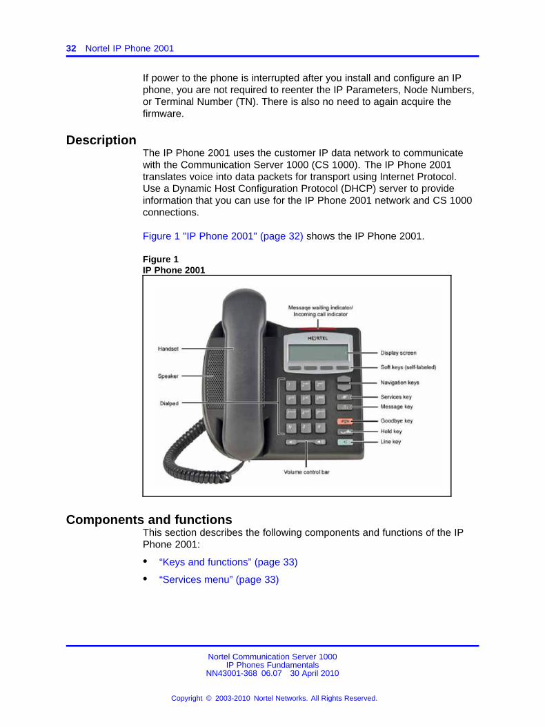
DescriptionThe IP Phone 2001 uses the customer IP data network to communicatewith the Communication Server 1000 (CS 1000). The IP Phone 2001translates voice into data packets for transport using Internet Protocol.Use a Dynamic Host Configuration Protocol (DHCP) server to provideinformation that you can use for the IP Phone 2001 network and CS 1000connections.
Figure 1 "IP Phone 2001" (page 32) shows the IP Phone 2001.
Figure 1IP Phone 2001
Components and functionsThis section describes the following components and functions of the IPPhone 2001:
• “Keys and functions” (page 33)
• “Services menu” (page 33)
Nortel Communication Server 1000IP Phones Fundamentals
NN43001-368 06.07 30 April 2010
Copyright © 2003-2010 Nortel Networks. All Rights Reserved.
.
Components and functions 33
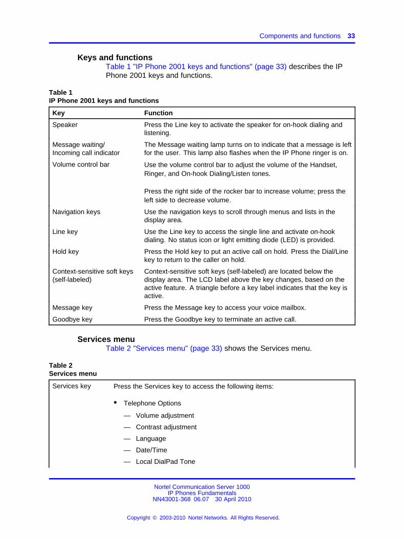
Keys and functionsTable 1 "IP Phone 2001 keys and functions" (page 33) describes the IPPhone 2001 keys and functions.
Table 1IP Phone 2001 keys and functions
Key Function
Speaker Press the Line key to activate the speaker for on-hook dialing andlistening.
Message waiting/Incoming call indicator
The Message waiting lamp turns on to indicate that a message is leftfor the user. This lamp also flashes when the IP Phone ringer is on.
Volume control bar Use the volume control bar to adjust the volume of the Handset,Ringer, and On-hook Dialing/Listen tones.
Press the right side of the rocker bar to increase volume; press theleft side to decrease volume.
Navigation keys Use the navigation keys to scroll through menus and lists in thedisplay area.
Line key Use the Line key to access the single line and activate on-hookdialing. No status icon or light emitting diode (LED) is provided.
Hold key Press the Hold key to put an active call on hold. Press the Dial/Linekey to return to the caller on hold.
Context-sensitive soft keys(self-labeled)
Context-sensitive soft keys (self-labeled) are located below thedisplay area. The LCD label above the key changes, based on theactive feature. A triangle before a key label indicates that the key isactive.
Message key Press the Message key to access your voice mailbox.
Goodbye key Press the Goodbye key to terminate an active call.
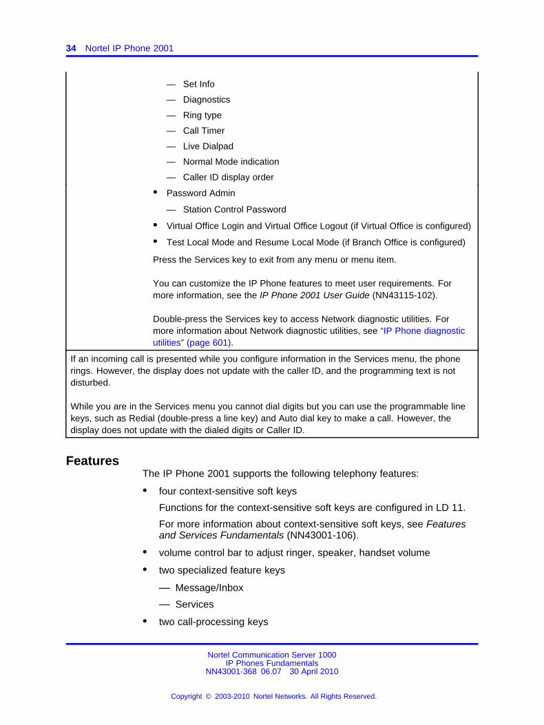
Services menuTable 2 "Services menu" (page 33) shows the Services menu.
Table 2Services menu
Services key Press the Services key to access the following items:
• Telephone Options
— Volume adjustment
— Contrast adjustment
— Language
— Date/Time
— Local DialPad Tone
Nortel Communication Server 1000IP Phones Fundamentals
NN43001-368 06.07 30 April 2010
Copyright © 2003-2010 Nortel Networks. All Rights Reserved.
.
34 Nortel IP Phone 2001
— Set Info
— Diagnostics
— Ring type
— Call Timer
— Live Dialpad
— Normal Mode indication
— Caller ID display order
• Password Admin
— Station Control Password
• Virtual Office Login and Virtual Office Logout (if Virtual Office is configured)
• Test Local Mode and Resume Local Mode (if Branch Office is configured)
Press the Services key to exit from any menu or menu item.
You can customize the IP Phone features to meet user requirements. Formore information, see the IP Phone 2001 User Guide (NN43115-102).
Double-press the Services key to access Network diagnostic utilities. Formore information about Network diagnostic utilities, see “IP Phone diagnosticutilities” (page 601).
If an incoming call is presented while you configure information in the Services menu, the phonerings. However, the display does not update with the caller ID, and the programming text is notdisturbed.
While you are in the Services menu you cannot dial digits but you can use the programmable linekeys, such as Redial (double-press a line key) and Auto dial key to make a call. However, thedisplay does not update with the dialed digits or Caller ID.
FeaturesThe IP Phone 2001 supports the following telephony features:
• four context-sensitive soft keys
Functions for the context-sensitive soft keys are configured in LD 11.
For more information about context-sensitive soft keys, see Featuresand Services Fundamentals (NN43001-106).
• volume control bar to adjust ringer, speaker, handset volume
• two specialized feature keys
— Message/Inbox
— Services
• two call-processing keys
Nortel Communication Server 1000IP Phones Fundamentals
NN43001-368 06.07 30 April 2010
Copyright © 2003-2010 Nortel Networks. All Rights Reserved.
.
Display characteristics 35
— Goodbye
— Hold
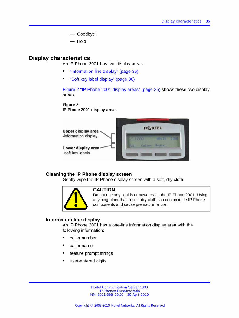
Display characteristicsAn IP Phone 2001 has two display areas:
• “Information line display” (page 35)
• “Soft key label display” (page 36)
Figure 2 "IP Phone 2001 display areas" (page 35) shows these two displayareas.
Figure 2IP Phone 2001 display areas
Cleaning the IP Phone display screenGently wipe the IP Phone display screen with a soft, dry cloth.
CAUTIONDo not use any liquids or powders on the IP Phone 2001. Usinganything other than a soft, dry cloth can contaminate IP Phonecomponents and cause premature failure.
Information line displayAn IP Phone 2001 has a one-line information display area with thefollowing information:
• caller number
• caller name
• feature prompt strings
• user-entered digits
Nortel Communication Server 1000IP Phones Fundamentals
NN43001-368 06.07 30 April 2010
Copyright © 2003-2010 Nortel Networks. All Rights Reserved.
.
36 Nortel IP Phone 2001
• date and time information (if the IP Phone is in an idle state) or CallTimer (if provisioned in the Telephone options menu)
• set information
The information area changes according to the call-processing state andactive features.
Soft key label displayThe soft key label has a maximum six characters. Each soft key includesthe soft key label and an icon. When a soft key is in use, a triangle iconappears at the beginning of the soft key label, and the label shifts onecharacter to the right. (If the label is six characters in length, the last orrightmost character is truncated.) If a feature is enabled, the icon stateturns to On. The icon remains in the on state until the feature key ispressed again. This cancels the enabled feature and turns the icon off,and returns the soft key label to its original state.
Use the More soft key to navigate the layers of functions. If only fourfunctions are assigned to the soft keys, the More key does not appear,and all four functions are displayed.
Package componentsThe following information applies to IP Phone 2001, IP Phone 2002, andIP Phone 2004. Product codes for IP Phone 2001, IP Phone 2002, and IPPhone 2004 are different from previous IP Phones.
See the product code on the back of the phone to confirm whether it is anIP Phone 2001, IP Phone 2002, and IP Phone 2004. The product code forIP Phone 2001, IP Phone 2002, and IP Phone 2004 appears as IP Phone200x. The product code for previous versions of the IP Phones appearswith an i in front of the model number (for example, i200x).
You must order the global power supply separately if local power using theglobal power supply is required, because IP Phone 2001, IP Phone 2002,and IP Phone 2004 include integrated support for a number of power overLAN options, including support for IEEE 802.3af standard power.
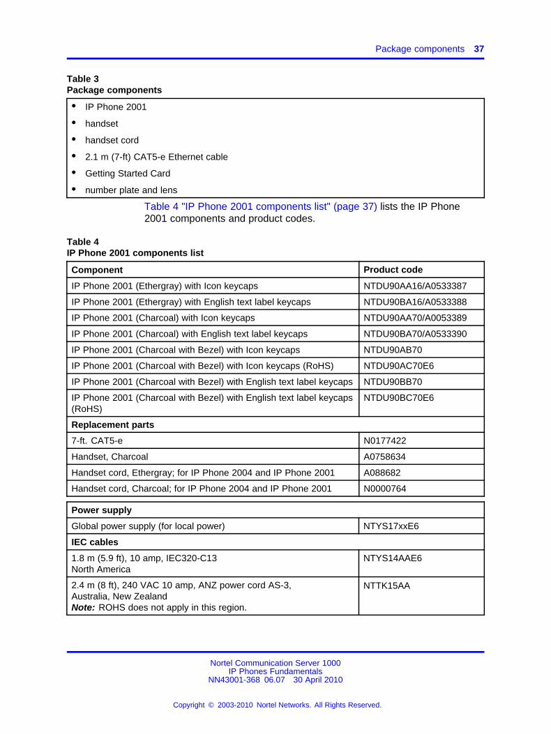
Table 3 "Package components" (page 37) lists the IP Phone 2001 packagecomponents.
Nortel Communication Server 1000IP Phones Fundamentals
NN43001-368 06.07 30 April 2010
Copyright © 2003-2010 Nortel Networks. All Rights Reserved.
.
Package components 37
Table 3Package components
• IP Phone 2001
• handset
• handset cord
• 2.1 m (7-ft) CAT5-e Ethernet cable
• Getting Started Card
• number plate and lens
Table 4 "IP Phone 2001 components list" (page 37) lists the IP Phone2001 components and product codes.
Table 4IP Phone 2001 components list
Component Product code
IP Phone 2001 (Ethergray) with Icon keycaps NTDU90AA16/A0533387
IP Phone 2001 (Ethergray) with English text label keycaps NTDU90BA16/A0533388
IP Phone 2001 (Charcoal) with Icon keycaps NTDU90AA70/A0053389
IP Phone 2001 (Charcoal) with English text label keycaps NTDU90BA70/A0533390
IP Phone 2001 (Charcoal with Bezel) with Icon keycaps NTDU90AB70
IP Phone 2001 (Charcoal with Bezel) with Icon keycaps (RoHS) NTDU90AC70E6
IP Phone 2001 (Charcoal with Bezel) with English text label keycaps NTDU90BB70
IP Phone 2001 (Charcoal with Bezel) with English text label keycaps(RoHS)
NTDU90BC70E6
Replacement parts
7-ft. CAT5-e N0177422
Handset, Charcoal A0758634
Handset cord, Ethergray; for IP Phone 2004 and IP Phone 2001 A088682
Handset cord, Charcoal; for IP Phone 2004 and IP Phone 2001 N0000764
Power supply
Global power supply (for local power) NTYS17xxE6
IEC cables
1.8 m (5.9 ft), 10 amp, IEC320-C13North America
NTYS14AAE6
2.4 m (8 ft), 240 VAC 10 amp, ANZ power cord AS-3,Australia, New ZealandNote: ROHS does not apply in this region.
NTTK15AA
Nortel Communication Server 1000IP Phones Fundamentals
NN43001-368 06.07 30 April 2010
Copyright © 2003-2010 Nortel Networks. All Rights Reserved.
.
38 Nortel IP Phone 2001
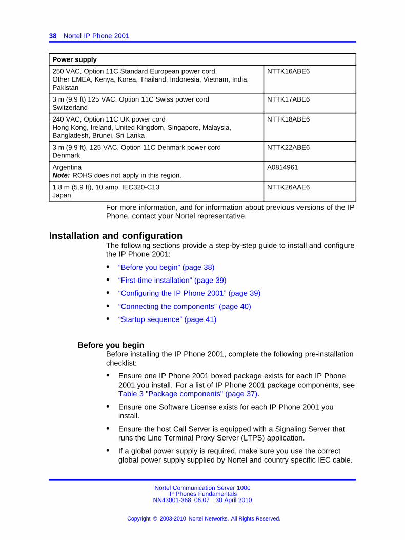
Power supply
250 VAC, Option 11C Standard European power cord,Other EMEA, Kenya, Korea, Thailand, Indonesia, Vietnam, India,Pakistan
NTTK16ABE6
3 m (9.9 ft) 125 VAC, Option 11C Swiss power cordSwitzerland
NTTK17ABE6
240 VAC, Option 11C UK power cordHong Kong, Ireland, United Kingdom, Singapore, Malaysia,Bangladesh, Brunei, Sri Lanka
NTTK18ABE6
3 m (9.9 ft), 125 VAC, Option 11C Denmark power cordDenmark
NTTK22ABE6
ArgentinaNote: ROHS does not apply in this region.
A0814961
1.8 m (5.9 ft), 10 amp, IEC320-C13Japan
NTTK26AAE6
For more information, and for information about previous versions of the IPPhone, contact your Nortel representative.
Installation and configurationThe following sections provide a step-by-step guide to install and configurethe IP Phone 2001:
• “Before you begin” (page 38)
• “First-time installation” (page 39)
• “Configuring the IP Phone 2001” (page 39)
• “Connecting the components” (page 40)
• “Startup sequence” (page 41)
Before you beginBefore installing the IP Phone 2001, complete the following pre-installationchecklist:
• Ensure one IP Phone 2001 boxed package exists for each IP Phone2001 you install. For a list of IP Phone 2001 package components, seeTable 3 "Package components" (page 37).
• Ensure one Software License exists for each IP Phone 2001 youinstall.
• Ensure the host Call Server is equipped with a Signaling Server thatruns the Line Terminal Proxy Server (LTPS) application.
• If a global power supply is required, make sure you use the correctglobal power supply supplied by Nortel and country specific IEC cable.
Nortel Communication Server 1000IP Phones Fundamentals
NN43001-368 06.07 30 April 2010
Copyright © 2003-2010 Nortel Networks. All Rights Reserved.
.
Installation and configuration 39
The voltage rating of the global power supply must match the walloutlet voltage. See Table 4 "IP Phone 2001 components list" (page37).
• Ensure the latest IP Phone firmware is deployed to the IP telephonynode. For more information, see Signaling Server IP Line ApplicationsFundamentals (NN43001-125).
First-time installationYou must first install an IP telephony node with the Communication Server.For information about installing an IP telephony node, see Signaling ServerIP Line Applications Fundamentals (NN43001-125).
CAUTIONDo not plug your IP Phone 2001 into an ISDN connection.Severe damage can result.
Configuring the IP Phone 2001Use Procedure 1 “Configuring the IP Phone 2001” (page 39) to configurethe IP Phone 2001 for the first time.
Procedure 1Configuring the IP Phone 2001
Step Action
1 Configure a virtual loop on the Call Server using LD 97. Formore information about configuring a virtual loop, see SignalingServer IP Line Applications Fundamentals (NN43001-125) andSoftware Input Output Reference-Administration (NN43001-611).
2 Configure the IP Phone 2001 on the Call Server using LD 11. Atthe prompt, enter the following:
REQ:newTYPE:2001P2
For more information about configuring the IP Phone 2001 usingLD 11, see Software Input Output Reference-Administration(NN43001-611).
3 Configure the IP Phone 2001 in Element Manager. IP Phonesare configured using the Phones section in the ElementManager navigation tree. For more information about configuringthe IP Phone 2001 using Element Manager, see ElementManager System Reference - Administration (NN43001-632).
--End--
Nortel Communication Server 1000IP Phones Fundamentals
NN43001-368 06.07 30 April 2010
Copyright © 2003-2010 Nortel Networks. All Rights Reserved.
.
40 Nortel IP Phone 2001
Connecting the componentsUse “Connecting the components” (page 40) to connect the IP Phone2001 components.
Procedure 2Connecting the components
Step Action
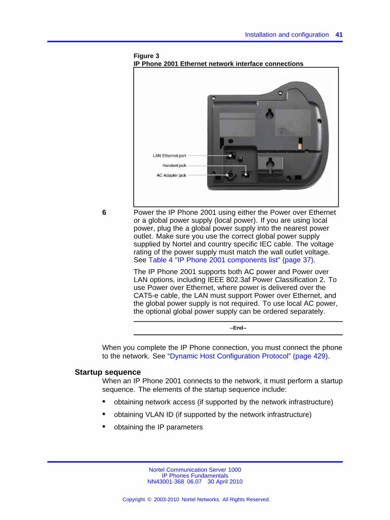
1 Connect one end of the handset cord to the handset jack on theback of the IP Phone identified with a handset icon. See Figure 3"IP Phone 2001 Ethernet network interface connections" (page41).
2 Connect the other end of the handset cord to the handset.
3 Connect one end of the CAT5-e Ethernet cable to the networkinterface located on the back of the IP Phone (identified witha LAN icon, see Figure 3 "IP Phone 2001 Ethernet networkinterface connections" (page 41)). The other end of the CAT5-eEthernet cable plugs into the IP network.
The LAN Ethernet port supports Auto-Media Dependent InterfaceCrossover (MDIX). Auto-MDIX is supported only when theEthernet port is configured for autonegotiation.
4 Connect the global power supply (optional). Leave the globalpower supply unplugged from the power outlet, connect theglobal power supply to the AC adapter jack in the bottom ofthe phone. Form a small bend in the cable and then thread theglobal power supply cord through the channels in the stand.
5 Secure the IP Phone footstand to the base of the IP Phone. Usethe angle adjustment grip on the top back of the IP Phone toadjust the position.
CAUTIONDamage to EquipmentDo not plug any device into your IP Phone 2001Ethernet port other than an IEEE 802.3 Ethernetnetwork connection.
Nortel Communication Server 1000IP Phones Fundamentals
NN43001-368 06.07 30 April 2010
Copyright © 2003-2010 Nortel Networks. All Rights Reserved.
.
Installation and configuration 41
Figure 3IP Phone 2001 Ethernet network interface connections
6 Power the IP Phone 2001 using either the Power over Ethernetor a global power supply (local power). If you are using localpower, plug the a global power supply into the nearest poweroutlet. Make sure you use the correct global power supplysupplied by Nortel and country specific IEC cable. The voltagerating of the power supply must match the wall outlet voltage.See Table 4 "IP Phone 2001 components list" (page 37).
The IP Phone 2001 supports both AC power and Power overLAN options, including IEEE 802.3af Power Classification 2. Touse Power over Ethernet, where power is delivered over theCAT5-e cable, the LAN must support Power over Ethernet, andthe global power supply is not required. To use local AC power,the optional global power supply can be ordered separately.
--End--
When you complete the IP Phone connection, you must connect the phoneto the network. See “Dynamic Host Configuration Protocol” (page 429).
Startup sequenceWhen an IP Phone 2001 connects to the network, it must perform a startupsequence. The elements of the startup sequence include:
• obtaining network access (if supported by the network infrastructure)
• obtaining VLAN ID (if supported by the network infrastructure)
• obtaining the IP parameters
Nortel Communication Server 1000IP Phones Fundamentals
NN43001-368 06.07 30 April 2010
Copyright © 2003-2010 Nortel Networks. All Rights Reserved.
.
42 Nortel IP Phone 2001
• connecting to the Call Server
• obtaining the provisioning parameters
For information about provisioning the IP Phone, see “Manual provisioningof IP Phones 2000 Series” (page 563).
Redeploying an IP Phone 2001You can redeploy an existing previously configured IP Phone 2001 onthe same system. For example, the IP Phone 2001 can be assigned toa new user (new TN) or to an existing user who moved to a new subnetby changing the TN of the IP Phone 2001. For further information, seeConverging the Data Network with VoIP Fundamentals (NN43001-260).
Procedure 3Changing the TN of an existing IP Phone 2001
Step Action
1 Repower the IP Phone 2001.
During the reboot sequence of a previously configured IPPhone, the IP Phone 2001 displays the existing node numberfor approximately five seconds.
2 If the node password is enabled and NULL, choose one of thefollowing:
a Disable the password.
b Set the password as non-NULL.
3 Press OK when the node number displays.
If Then
the node password is enabledand is not NULL
a password screen displays. Goto Step 4.
the node password is disabled a TN screen displays. Go to Step5.
4 Enter password at the password screen, and press OK.
A TN screen displays.
To obtain the password, enter the nodePwdShow command inElement Manager. For further information, see Element ManagerSystem Reference - Administration (NN43001-632).
5 Select the Clear soft key to clear the existing TN.
6 Enter the new TN.
--End--
Nortel Communication Server 1000IP Phones Fundamentals
NN43001-368 06.07 30 April 2010
Copyright © 2003-2010 Nortel Networks. All Rights Reserved.
.
Removing an IP Phone 2001 from service 43
Replacing an IP Phone 2001ATTENTIONTwo IP Phones cannot share the same TN. You must remove the IP Phone2001 that currently uses the TN.
Procedure 4Replacing an IP Phone 2001
Step Action
1 Obtain the node and TN information of the phone you want toreplace.
2 Disconnect the IP Phone 2001 that you want to replace.
3 Follow “Configuring the IP Phone 2001” (page 39) to install theIP Phone 2001. To configure the IP Phone, “Manual provisioningof IP Phones 2000 Series” (page 563).
4 Enter the same TN and Node Number as the IP Phone 2001 youreplaced. The system associates the new IP Phone 2001 withthe existing TN.
--End--
Removing an IP Phone 2001 from serviceProcedure 5Removing an IP Phone 2001 from service
Step Action
1 Disconnect the IP Phone 2001 from the network or turn off thepower.
If the IP Phone 2001 was automatically configured, the DHCPlease expires and the IP address returns to the available pool.
2 In LD 11, enter the following:REQ: OUTTYPE: 2001P2TN: LLL S CC UU
--End--
Nortel Communication Server 1000IP Phones Fundamentals
NN43001-368 06.07 30 April 2010
Copyright © 2003-2010 Nortel Networks. All Rights Reserved.
.

44 Nortel IP Phone 2001
Nortel Communication Server 1000IP Phones Fundamentals
NN43001-368 06.07 30 April 2010
Copyright © 2003-2010 Nortel Networks. All Rights Reserved.
.
45.
Nortel IP Phone 2002
ContentsThis section contains the following topics:
• “Introduction” (page 45)
• “Description” (page 46)
• “Components and functions” (page 46)
• “Features” (page 49)
• “Display characteristics” (page 50)
• “Package components” (page 51)
• “Installation and configuration” (page 53)
• “Redeploying an IP Phone 2002” (page 57)
• “Replacing an IP Phone 2002” (page 58)
• “Removing an IP Phone 2002 from service” (page 59)
IntroductionThis section explains how to install and maintain the IP Phone 2002. Forinformation about using the IP Phone 2002, see the IP Phone 2002 UserGuide (NN43116-104).
This section contains the following procedures:
• Procedure 6 “Configuring the IP Phone 2002” (page 54)
• Procedure 7 “Connecting the components” (page 55)
• Procedure 8 “Changing the TN of an existing IP Phone 2002” (page57).
• Procedure 9 “Replacing an IP Phone 2002” (page 58).
• Procedure 10 “Removing an IP Phone 2002 from service” (page 59).
Nortel Communication Server 1000IP Phones Fundamentals
NN43001-368 06.07 30 April 2010
Copyright © 2003-2010 Nortel Networks. All Rights Reserved.
.
46 Nortel IP Phone 2002
If power to the phone is interrupted after you install and configure an IPphone, you are not required to reenter the IP Parameters, Node Numbers,or Terminal Number (TN). There is also no need to again acquire thefirmware.
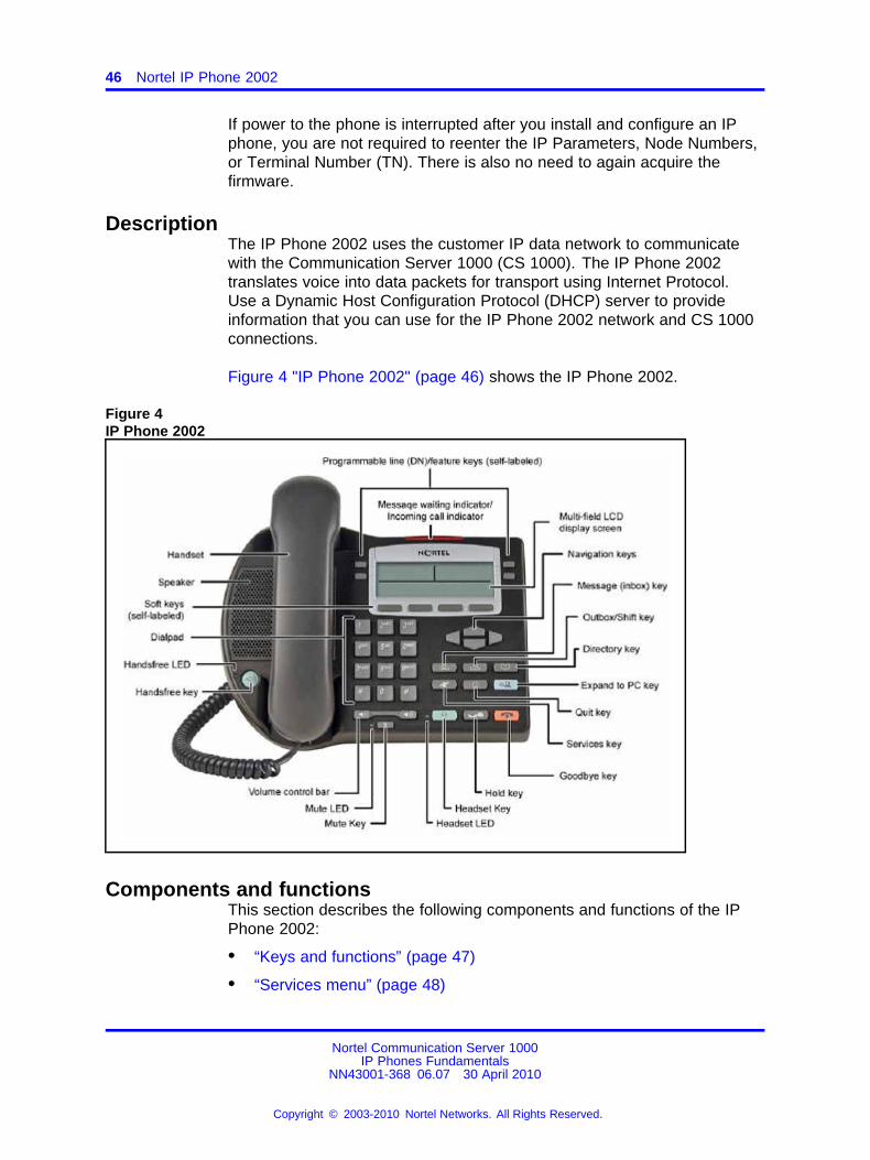
DescriptionThe IP Phone 2002 uses the customer IP data network to communicatewith the Communication Server 1000 (CS 1000). The IP Phone 2002translates voice into data packets for transport using Internet Protocol.Use a Dynamic Host Configuration Protocol (DHCP) server to provideinformation that you can use for the IP Phone 2002 network and CS 1000connections.
Figure 4 "IP Phone 2002" (page 46) shows the IP Phone 2002.
Figure 4IP Phone 2002
Components and functionsThis section describes the following components and functions of the IPPhone 2002:
• “Keys and functions” (page 47)
• “Services menu” (page 48)
Nortel Communication Server 1000IP Phones Fundamentals
NN43001-368 06.07 30 April 2010
Copyright © 2003-2010 Nortel Networks. All Rights Reserved.
.
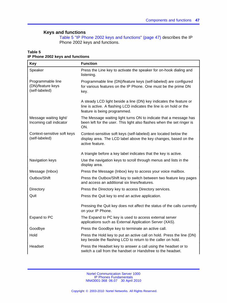
Components and functions 47
Keys and functionsTable 5 "IP Phone 2002 keys and functions" (page 47) describes the IPPhone 2002 keys and functions.
Table 5IP Phone 2002 keys and functions
Key Function
Speaker Press the Line key to activate the speaker for on-hook dialing andlistening.
Programmable line(DN)/feature keys(self-labeled)
Programmable line (DN)/feature keys (self-labeled) are configuredfor various features on the IP Phone. One must be the prime DNkey.
A steady LCD light beside a line (DN) key indicates the feature orline is active. A flashing LCD indicates the line is on hold or thefeature is being programmed.
Message waiting light/Incoming call indicator
The Message waiting light turns ON to indicate that a message hasbeen left for the user. This light also flashes when the set ringer isON.
Context-sensitive soft keys(self-labeled)
Context-sensitive soft keys (self-labeled) are located below thedisplay area. The LCD label above the key changes, based on theactive feature.
A triangle before a key label indicates that the key is active.
Navigation keys Use the navigation keys to scroll through menus and lists in thedisplay area.
Message (Inbox) Press the Message (Inbox) key to access your voice mailbox.
Outbox/Shift Press the Outbox/Shift key to switch between two feature key pagesand access an additional six lines/features.
Directory Press the Directory key to access Directory services.
Quit Press the Quit key to end an active application.
Pressing the Quit key does not affect the status of the calls currentlyon your IP Phone.
Expand to PC The Expand to PC key is used to access external serverapplications such as External Application Server (XAS).
Goodbye Press the Goodbye key to terminate an active call.
Hold Press the Hold key to put an active call on hold. Press the line (DN)key beside the flashing LCD to return to the caller on hold.
Headset Press the Headset key to answer a call using the headset or toswitch a call from the handset or Handsfree to the headset.
Nortel Communication Server 1000IP Phones Fundamentals
NN43001-368 06.07 30 April 2010
Copyright © 2003-2010 Nortel Networks. All Rights Reserved.
.
48 Nortel IP Phone 2002
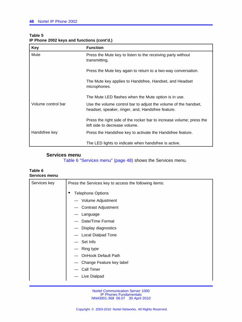
Table 5IP Phone 2002 keys and functions (cont’d.)
Key Function
Mute Press the Mute key to listen to the receiving party withouttransmitting.
Press the Mute key again to return to a two-way conversation.
The Mute key applies to Handsfree, Handset, and Headsetmicrophones.
The Mute LED flashes when the Mute option is in use.
Volume control bar Use the volume control bar to adjust the volume of the handset,headset, speaker, ringer, and, Handsfree feature.
Press the right side of the rocker bar to increase volume; press theleft side to decrease volume.
Handsfree key Press the Handsfree key to activate the Handsfree feature.
The LED lights to indicate when handsfree is active.
Services menuTable 6 "Services menu" (page 48) shows the Services menu.
Table 6Services menu
Services key Press the Services key to access the following items:
• Telephone Options
— Volume Adjustment
— Contrast Adjustment
— Language
— Date/Time Format
— Display diagnostics
— Local Dialpad Tone
— Set Info
— Ring type
— OnHook Default Path
— Change Feature key label
— Call Timer
— Live Dialpad
Nortel Communication Server 1000IP Phones Fundamentals
NN43001-368 06.07 30 April 2010
Copyright © 2003-2010 Nortel Networks. All Rights Reserved.
.
Features 49
— Normal Mode indication
— Caller ID display order
• Password Administration
• Virtual Office Login and Virtual Office Logout (if Virtual Office is configured)
• Test Local Mode and Resume Local Mode (if Branch Office is configured)
You can customize the IP Phone features to meet user requirements. Formore information, see the IP Phone 2002 User Guide (NN43116-104).
Double-press the Services key to access Network diagnostic utilities. For more information aboutNetwork diagnostic utilities, see “IP Phone diagnostic utilities” (page 601).
If an incoming call is presented while you configure information in the Services menu, the phonerings. However, the display does not update with the caller ID, and the programming text is notdisturbed.
While you are in the Services menu you cannot dial digits but you can use the programmable linekeys, such as Redial (double-press a line key) and Auto dial key to make a call. However, thedisplay does not update with the dialed digits or Caller ID.
FeaturesThe IP Phone 2002 supports the following telephony features:
• four programmable line (DN)/feature keys (self-labeled)
• four context-sensitive soft keys (self-labeled)
Functions for the context-sensitive soft keys are configured in LD 11.
For more information about context-sensitive soft keys, see Featuresand Services Fundamentals (NN43001-106).
• volume control bar to adjust ringer, speaker, handset, handsfree, andheadset volume
• ability to change the programmable line (DN)/feature key labels
• six specialized feature keys
— Quit
— Directory
— Message/Inbox
— Shift/Outbox
— Services
— Expand to PC
• five call-processing fixed keys:
Nortel Communication Server 1000IP Phones Fundamentals
NN43001-368 06.07 30 April 2010
Copyright © 2003-2010 Nortel Networks. All Rights Reserved.
.
50 Nortel IP Phone 2002
— Mute
— Handsfree
— Goodbye
— Headset
— Hold
For more information about IP Phone features, see “Features” (page 391).
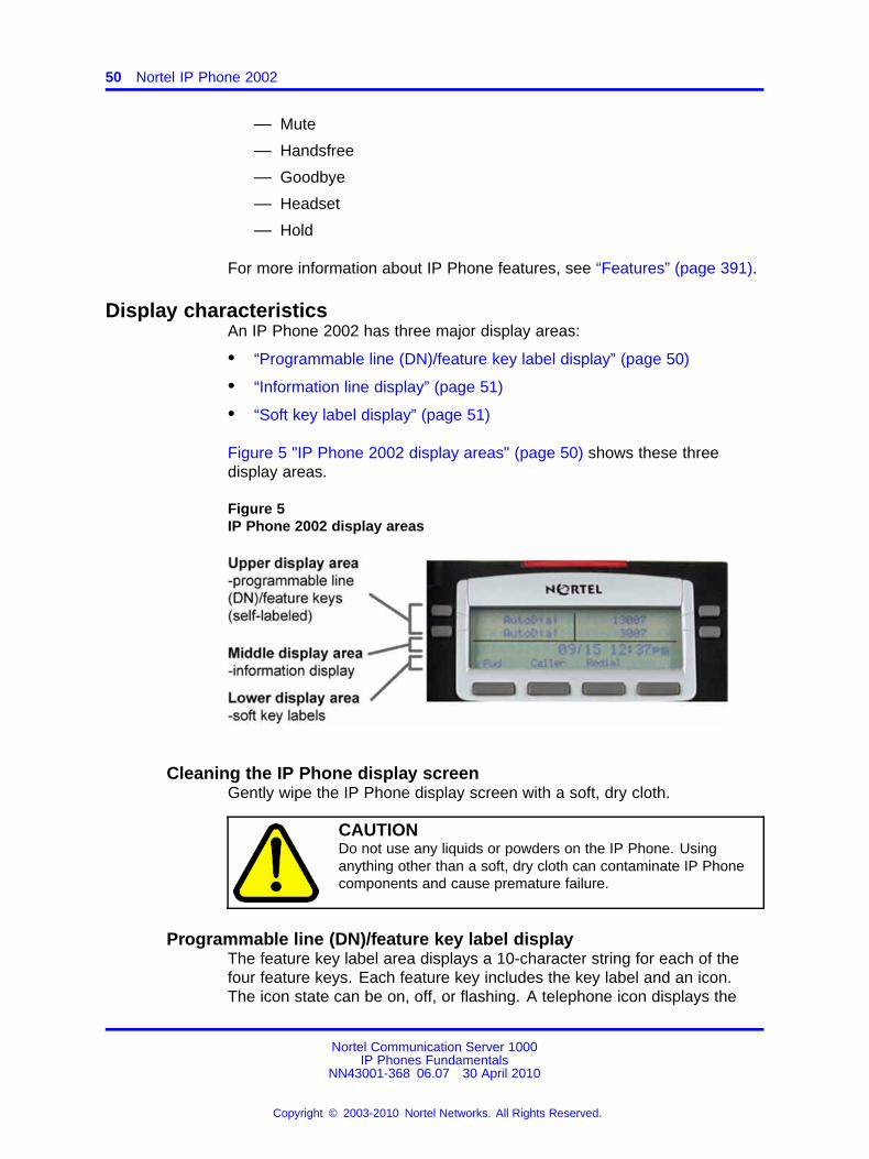
Display characteristicsAn IP Phone 2002 has three major display areas:
• “Programmable line (DN)/feature key label display” (page 50)
• “Information line display” (page 51)
• “Soft key label display” (page 51)
Figure 5 "IP Phone 2002 display areas" (page 50) shows these threedisplay areas.
Figure 5IP Phone 2002 display areas
Cleaning the IP Phone display screenGently wipe the IP Phone display screen with a soft, dry cloth.
CAUTIONDo not use any liquids or powders on the IP Phone. Usinganything other than a soft, dry cloth can contaminate IP Phonecomponents and cause premature failure.
Programmable line (DN)/feature key label displayThe feature key label area displays a 10-character string for each of thefour feature keys. Each feature key includes the key label and an icon.The icon state can be on, off, or flashing. A telephone icon displays the
Nortel Communication Server 1000IP Phones Fundamentals
NN43001-368 06.07 30 April 2010
Copyright © 2003-2010 Nortel Networks. All Rights Reserved.
.
Package components 51
status of the configured DN. Key labels are left-aligned for keys on theleft side of the screen, and right-aligned for keys on the right side of thescreen.
If a label is longer than 10 characters, the last 10 characters are displayedand the excess characters are deleted from the beginning of the string.
Information line displayAn IP Phone 2002 has a one-line information display area with thefollowing information:
• caller number
• caller name
• feature prompt strings
• user-entered digits
• date and time information (if the IP Phone is in an idle state) or CallTimer (if provisioned in the Telephone options menu)
The information in the display area changes, according to thecall-processing state and active features.
Because the IP Phone 2002 only has a one-line information display area,you are prompted to scroll through any additional lines of information.
Soft key label displayThe soft key label has a maximum six characters. Each soft key includesthe soft key label and an icon. When a soft key is in use, a triangle iconappears at the beginning of the soft key label, and the label shifts onecharacter to the right. (If the label is six characters in length, the last orrightmost character is truncated.) If a feature is enabled, the icon stateturns to On. The icon remains in the on state until the feature key ispressed again. This cancels the enabled feature and turns the icon off,and returns the soft key label to its original state.
Use the More soft key to navigate the layers of functions. If only fourfunctions are assigned to the soft keys, the More key does not appear,and all four functions are displayed.
Package componentsThe following information applies to IP Phone 2001, IP Phone 2002, andIP Phone 2004. Product codes for these IP Phones are different fromprevious sets.
Nortel Communication Server 1000IP Phones Fundamentals
NN43001-368 06.07 30 April 2010
Copyright © 2003-2010 Nortel Networks. All Rights Reserved.
.
52 Nortel IP Phone 2002
See the product code on the back of the phone to confirm whether it is anIP Phone 2001, IP Phone 2002, and IP Phone 2004. The product code forIP Phone 2001, IP Phone 2002, and IP Phone 2004 appears as IP Phone200x. The product code for previous versions of the IP Phone appearswith an i in front of the model number (for example, i200x).
You must order the global power supply separately if local power using theglobal power supply is required, because IP Phone 2001, IP Phone 2002,and IP Phone 2004 include integrated support for a number of power overLAN options, including support for IEEE 802.3af standard power.
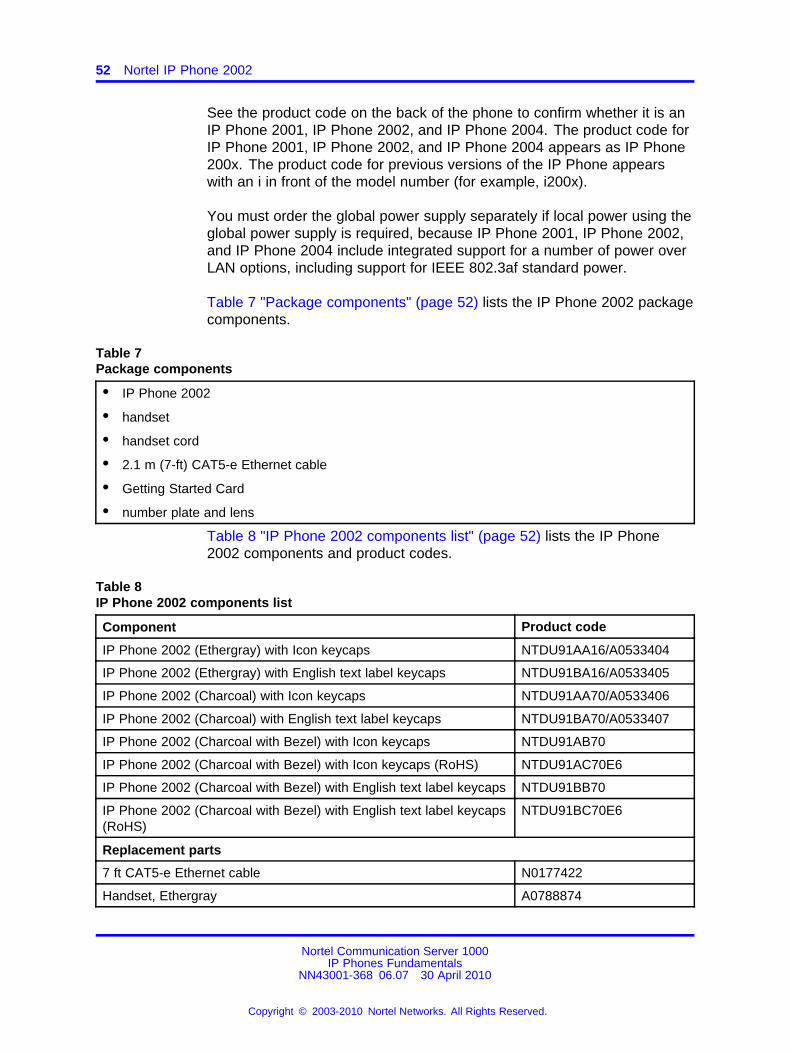
Table 7 "Package components" (page 52) lists the IP Phone 2002 packagecomponents.
Table 7Package components
• IP Phone 2002
• handset
• handset cord
• 2.1 m (7-ft) CAT5-e Ethernet cable
• Getting Started Card
• number plate and lens
Table 8 "IP Phone 2002 components list" (page 52) lists the IP Phone2002 components and product codes.
Table 8IP Phone 2002 components list
Component Product code
IP Phone 2002 (Ethergray) with Icon keycaps NTDU91AA16/A0533404
IP Phone 2002 (Ethergray) with English text label keycaps NTDU91BA16/A0533405
IP Phone 2002 (Charcoal) with Icon keycaps NTDU91AA70/A0533406
IP Phone 2002 (Charcoal) with English text label keycaps NTDU91BA70/A0533407
IP Phone 2002 (Charcoal with Bezel) with Icon keycaps NTDU91AB70
IP Phone 2002 (Charcoal with Bezel) with Icon keycaps (RoHS) NTDU91AC70E6
IP Phone 2002 (Charcoal with Bezel) with English text label keycaps NTDU91BB70
IP Phone 2002 (Charcoal with Bezel) with English text label keycaps(RoHS)
NTDU91BC70E6
Replacement parts
7 ft CAT5-e Ethernet cable N0177422
Handset, Ethergray A0788874
Nortel Communication Server 1000IP Phones Fundamentals
NN43001-368 06.07 30 April 2010
Copyright © 2003-2010 Nortel Networks. All Rights Reserved.
.
Installation and configuration 53
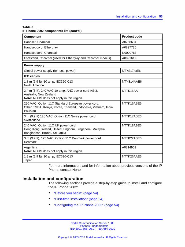
Table 8IP Phone 2002 components list (cont’d.)
Component Product code
Handset, Charcoal A0758634
Handset cord, Ethergray A0897725
Handset cord, Charcoal N0000763
Footstand, Charcoal (used for Ethergray and Charcoal models) A0891619
Power supply
Global power supply (for local power) NTYS17xxE6
IEC cables
1.8 m (5.9 ft), 10 amp, IEC320-C13North America
NTYS14AAE6
2.4 m (8 ft), 240 VAC 10 amp, ANZ power cord AS-3,Australia, New ZealandNote: ROHS does not apply in this region.
NTTK15AA
250 VAC, Option 11C Standard European power cord,Other EMEA, Kenya, Korea, Thailand, Indonesia, Vietnam, India,Pakistan
NTTK16ABE6
3 m (9.9 ft) 125 VAC, Option 11C Swiss power cordSwitzerland
NTTK17ABE6
240 VAC, Option 11C UK power cordHong Kong, Ireland, United Kingdom, Singapore, Malaysia,Bangladesh, Brunei, Sri Lanka
NTTK18ABE6
3 m (9.9 ft), 125 VAC, Option 11C Denmark power cordDenmark
NTTK22ABE6
ArgentinaNote: ROHS does not apply in this region.
A0814961
1.8 m (5.9 ft), 10 amp, IEC320-C13Japan
NTTK26AAE6
For more information, and for information about previous versions of the IPPhone, contact Nortel.
Installation and configurationThe following sections provide a step-by-step guide to install and configurethe IP Phone 2002:
• “Before you begin” (page 54)
• “First-time installation” (page 54)
• “Configuring the IP Phone 2002” (page 54)
Nortel Communication Server 1000IP Phones Fundamentals
NN43001-368 06.07 30 April 2010
Copyright © 2003-2010 Nortel Networks. All Rights Reserved.
.
54 Nortel IP Phone 2002
• “Connecting the components” (page 55)
• “Startup sequence” (page 57)
Before you beginBefore installing the IP Phone 2002, complete the following pre-installationchecklist:
• Ensure one IP Phone 2002 boxed package exists for each IP Phone2002 you install. For a list of IP Phone 2002 package components, seeTable 7 "Package components" (page 52).
• Ensure one Software License exists for each IP Phone 2002 youinstall.
• Ensure the host Call Server is equipped with a Signaling Server thatruns the Line Terminal Proxy Server (LTPS) application.
• If a global power supply is required, make sure you use the correctglobal power supply supplied by Nortel and country specific IEC cable.The voltage rating of the global power supply must match the walloutlet voltage. See Table 8 "IP Phone 2002 components list" (page52).
• Ensure the latest IP Phone firmware is deployed to the IP telephonynode. For more information, see Signaling Server IP Line ApplicationsFundamentals (NN43001-125).
First-time installationYou must first install an IP telephony node with the Communication Server.For information about installing an IP telephony node, see Signaling ServerIP Line Applications Fundamentals (NN43001-125).
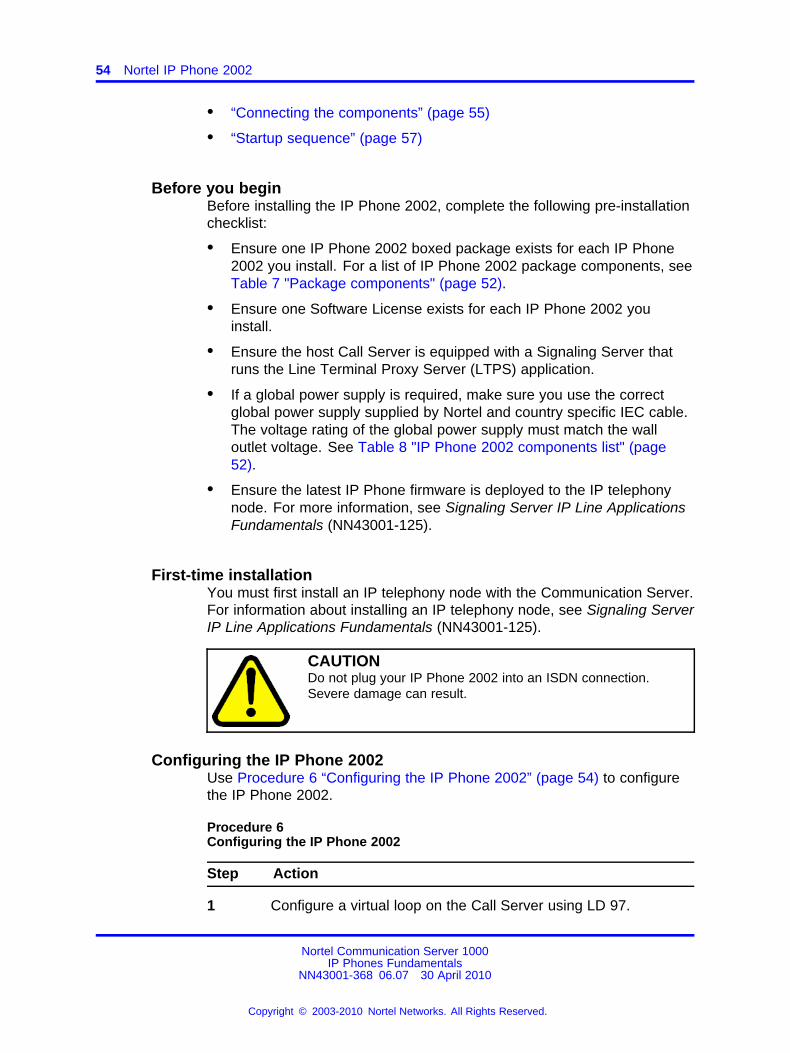
CAUTIONDo not plug your IP Phone 2002 into an ISDN connection.Severe damage can result.
Configuring the IP Phone 2002Use Procedure 6 “Configuring the IP Phone 2002” (page 54) to configurethe IP Phone 2002.
Procedure 6Configuring the IP Phone 2002
Step Action
1 Configure a virtual loop on the Call Server using LD 97.
Nortel Communication Server 1000IP Phones Fundamentals
NN43001-368 06.07 30 April 2010
Copyright © 2003-2010 Nortel Networks. All Rights Reserved.
.
Installation and configuration 55
For more information about configuring a virtual loop, seeSignaling Server IP Line Applications Fundamentals (NN43001-125) and Software Input Output Reference-Administration(NN43001-611).
2 Configure the IP Phone 2002 on the Call Server using LD 11. Atthe prompt, enter the following:
REQ:newTYPE:2002P1,2002P2
For more information about configuring the IP Phone 2002 usingLD 11, see Software Input Output Reference-Administration(NN43001-611).
3 Configure the IP Phone 2002 in Element Manager. IP Phonesare configured using the Phones section in the ElementManager navigation tree. For more information about configuringthe IP Phone 2002 using Element Manager, see ElementManager System Reference - Administration (NN43001-632).
--End--
Connecting the componentsUse Procedure 7 “Connecting the components” (page 55) to connect thecomponents for the IP Phone.
Procedure 7Connecting the components
Step Action
1 Connect one end of the handset cord to the handset jack on theback of the IP Phone (identified with a handset icon). See Figure6 "IP Phone 2002 Ethernet network interface connections" (page56)
2 Connect the other end of the handset cord to the handset.
3 Choose one of the following connections:
• For an IP Phone not sharing LAN access with a PC:Connect one end of the CAT5-e Ethernet cable to thenetwork interface located on the back of the IP Phone(identified with a LAN icon). The other end of the CAT5-eEthernet cable plugs into the IP network.
• For an IP Phone sharing LAN access with a PC:Connect one end of the CAT5-e Ethernet cable to thenetwork interface located on the back of the IP Phone(identified with a LAN icon) and the other end to the IPnetwork. Insert on end of a second CAT5-e Ethernet cableinto the PC network interface located on the back of the IP
Nortel Communication Server 1000IP Phones Fundamentals
NN43001-368 06.07 30 April 2010
Copyright © 2003-2010 Nortel Networks. All Rights Reserved.
.
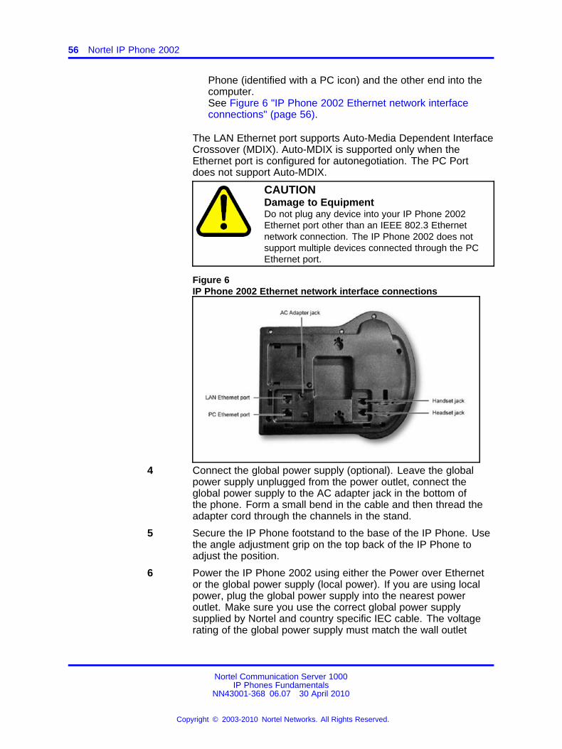
56 Nortel IP Phone 2002
Phone (identified with a PC icon) and the other end into thecomputer.See Figure 6 "IP Phone 2002 Ethernet network interfaceconnections" (page 56).
The LAN Ethernet port supports Auto-Media Dependent InterfaceCrossover (MDIX). Auto-MDIX is supported only when theEthernet port is configured for autonegotiation. The PC Portdoes not support Auto-MDIX.
CAUTIONDamage to EquipmentDo not plug any device into your IP Phone 2002Ethernet port other than an IEEE 802.3 Ethernetnetwork connection. The IP Phone 2002 does notsupport multiple devices connected through the PCEthernet port.
Figure 6IP Phone 2002 Ethernet network interface connections
4 Connect the global power supply (optional). Leave the globalpower supply unplugged from the power outlet, connect theglobal power supply to the AC adapter jack in the bottom ofthe phone. Form a small bend in the cable and then thread theadapter cord through the channels in the stand.
5 Secure the IP Phone footstand to the base of the IP Phone. Usethe angle adjustment grip on the top back of the IP Phone toadjust the position.
6 Power the IP Phone 2002 using either the Power over Ethernetor the global power supply (local power). If you are using localpower, plug the global power supply into the nearest poweroutlet. Make sure you use the correct global power supplysupplied by Nortel and country specific IEC cable. The voltagerating of the global power supply must match the wall outlet
Nortel Communication Server 1000IP Phones Fundamentals
NN43001-368 06.07 30 April 2010
Copyright © 2003-2010 Nortel Networks. All Rights Reserved.
.
Redeploying an IP Phone 2002 57
voltage. See Table 8 "IP Phone 2002 components list" (page52).
The IP Phone 2002 supports both AC power and Power overLAN options, including IEEE 802.3af Power Classification 2. Touse Power over Ethernet, where power is delivered over theCAT5-e cable, the LAN must support Power over Ethernet, and aglobal power supply is not required. To use local AC power, theoptional global power supply can be ordered separately.
--End--
When you complete the IP Phone connection, you must connect the phoneto the network. See “Dynamic Host Configuration Protocol” (page 429).
Startup sequenceWhen an IP Phone 2002 connects to the network, it must perform a startupsequence. The elements of the startup sequence include:
• obtaining network access (if supported by the network infrastructure)
• obtaining VLAN ID (if supported by the network infrastructure)
• obtaining the IP parameters
• connecting to the Call Server
• obtaining provisioning parameters
For information about provisioning the IP Phone, see “Manual provisioningof IP Phones 2000 Series” (page 563).
Redeploying an IP Phone 2002You can redeploy an existing previously configured IP Phone 2002 on thesame Call Server. For example, the IP Phone 2002 can be assigned toa new user (new TN) or to an existing user who moved to a new subnetby changing the TN of the IP Phone 2002. For further information, seeConverging the Data Network with VoIP Fundamentals (NN43001-260).
Procedure 8Changing the TN of an existing IP Phone 2002
Step Action
1 Repower the IP Phone 2002.
During the reboot sequence of a previously configured IPPhone, the IP Phone 2002 displays the existing node numberfor approximately 5 seconds.
2 If the node password is enabled and NULL, choose one of thefollowing:
Nortel Communication Server 1000IP Phones Fundamentals
NN43001-368 06.07 30 April 2010
Copyright © 2003-2010 Nortel Networks. All Rights Reserved.
.
58 Nortel IP Phone 2002
a Disable the password.
b Set the password as non-NULL.
3 Press OK when the node number displays.
If Then
the node password is enabledand is not NULL
a password screen displays. Goto Step 4.
the node password is disabled a TN screen displays. Go to Step5.
4 Enter the password at the password screen and press OK.
A TN screen displays.
To obtain the password, enter the nodePwdShow command inElement Manager. For further information, see Element ManagerSystem Reference - Administration (NN43001-632).
5 Select the Clear soft key to clear the existing TN.
6 Enter the new TN.
--End--
Replacing an IP Phone 2002ATTENTIONTwo IP Phones cannot share the same TN. You must remove the IP Phone2002 that currently uses the TN.
Procedure 9Replacing an IP Phone 2002
Step Action
1 Obtain the node and TN information of the phone you want toreplace.
2 Disconnect the IP Phone 2002 that you want to replace.
3 Follow “Configuring the IP Phone 2002” (page 54) to installthe IP Phone 2002. To configure the IP Phone, see “Manualprovisioning of IP Phones 2000 Series” (page 563).
4 Enter the same TN and Node Number as the IP Phone 2002 youreplaced. The Call Server associates the new IP Phone 2002with the existing TN.
--End--
Nortel Communication Server 1000IP Phones Fundamentals
NN43001-368 06.07 30 April 2010
Copyright © 2003-2010 Nortel Networks. All Rights Reserved.
.
Removing an IP Phone 2002 from service 59
Removing an IP Phone 2002 from serviceProcedure 10Removing an IP Phone 2002 from service
Step Action
1 Disconnect the IP Phone 2002 from the network or turn off thepower.
The service to the PC is disconnected as well if the PC connectsto the IP Phone 2002.
If the IP Phone 2002 was automatically configured, the DHCPlease expires and the IP address returns to the available pool.
2 In LD 11, enter the following:REQ: OUTTYPE: 2002P1, 2002P2TN: LLL S CC UU
--End--
Nortel Communication Server 1000IP Phones Fundamentals
NN43001-368 06.07 30 April 2010
Copyright © 2003-2010 Nortel Networks. All Rights Reserved.
.

60 Nortel IP Phone 2002
Nortel Communication Server 1000IP Phones Fundamentals
NN43001-368 06.07 30 April 2010
Copyright © 2003-2010 Nortel Networks. All Rights Reserved.
.
61.
Nortel IP Phone 2004
ContentsThis section contains the following topics:
• “Introduction” (page 61)
• “Description” (page 62)
• “Components and functions” (page 62)
• “Features” (page 65)
• “Package components” (page 68)
• “Installation and configuration” (page 70)
• “Redeploying an IP Phone 2004” (page 74)
• “Replacing an IP Phone 2004” (page 75)
• “Removing an IP Phone 2004 from service” (page 76)
IntroductionThis section explains how to install and maintain the IP Phone 2004. Forinformation about using the IP Phone 2004, see the IP Phone 2004 UserGuide (NN43117-102).
This section contains the following procedures:
• Procedure 11 “Configuring the IP Phone 2004” (page 71)
• Procedure 12 “Connecting the components” (page 72)
• Procedure 13 “Changing the TN of an existing IP Phone 2004” (page74).
• Procedure 14 “Replacing an IP Phone 2004” (page 75).
• Procedure 15 “Removing an IP Phone 2004 from service” (page 76).
Nortel Communication Server 1000IP Phones Fundamentals
NN43001-368 06.07 30 April 2010
Copyright © 2003-2010 Nortel Networks. All Rights Reserved.
.
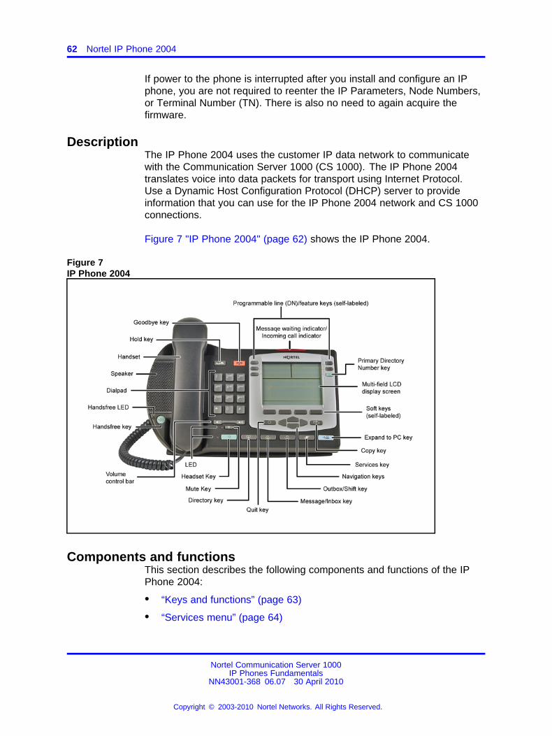
62 Nortel IP Phone 2004
If power to the phone is interrupted after you install and configure an IPphone, you are not required to reenter the IP Parameters, Node Numbers,or Terminal Number (TN). There is also no need to again acquire thefirmware.
DescriptionThe IP Phone 2004 uses the customer IP data network to communicatewith the Communication Server 1000 (CS 1000). The IP Phone 2004translates voice into data packets for transport using Internet Protocol.Use a Dynamic Host Configuration Protocol (DHCP) server to provideinformation that you can use for the IP Phone 2004 network and CS 1000connections.
Figure 7 "IP Phone 2004" (page 62) shows the IP Phone 2004.
Figure 7IP Phone 2004
Components and functionsThis section describes the following components and functions of the IPPhone 2004:
• “Keys and functions” (page 63)
• “Services menu” (page 64)
Nortel Communication Server 1000IP Phones Fundamentals
NN43001-368 06.07 30 April 2010
Copyright © 2003-2010 Nortel Networks. All Rights Reserved.
.
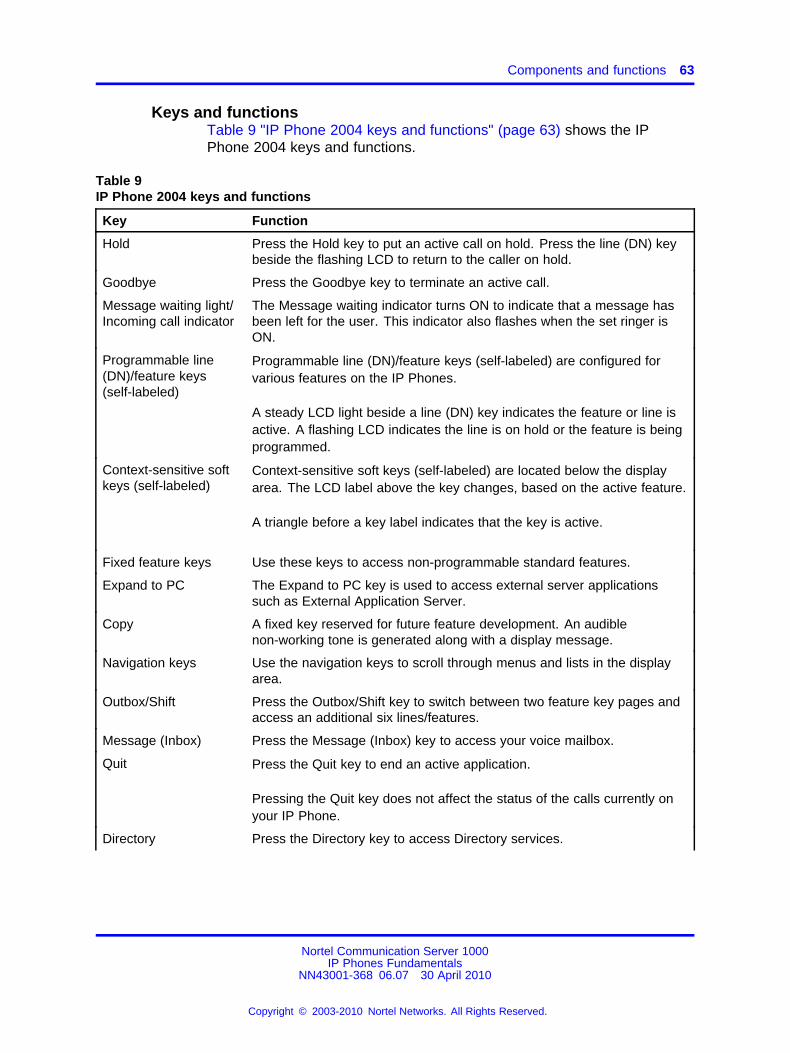
Components and functions 63
Keys and functionsTable 9 "IP Phone 2004 keys and functions" (page 63) shows the IPPhone 2004 keys and functions.
Table 9IP Phone 2004 keys and functions
Key Function
Hold Press the Hold key to put an active call on hold. Press the line (DN) keybeside the flashing LCD to return to the caller on hold.
Goodbye Press the Goodbye key to terminate an active call.
Message waiting light/Incoming call indicator
The Message waiting indicator turns ON to indicate that a message hasbeen left for the user. This indicator also flashes when the set ringer isON.
Programmable line(DN)/feature keys(self-labeled)
Programmable line (DN)/feature keys (self-labeled) are configured forvarious features on the IP Phones.
A steady LCD light beside a line (DN) key indicates the feature or line isactive. A flashing LCD indicates the line is on hold or the feature is beingprogrammed.
Context-sensitive softkeys (self-labeled)
Context-sensitive soft keys (self-labeled) are located below the displayarea. The LCD label above the key changes, based on the active feature.
A triangle before a key label indicates that the key is active.
Fixed feature keys Use these keys to access non-programmable standard features.
Expand to PC The Expand to PC key is used to access external server applicationssuch as External Application Server.
Copy A fixed key reserved for future feature development. An audiblenon-working tone is generated along with a display message.
Navigation keys Use the navigation keys to scroll through menus and lists in the displayarea.
Outbox/Shift Press the Outbox/Shift key to switch between two feature key pages andaccess an additional six lines/features.
Message (Inbox) Press the Message (Inbox) key to access your voice mailbox.
Quit Press the Quit key to end an active application.
Pressing the Quit key does not affect the status of the calls currently onyour IP Phone.
Directory Press the Directory key to access Directory services.
Nortel Communication Server 1000IP Phones Fundamentals
NN43001-368 06.07 30 April 2010
Copyright © 2003-2010 Nortel Networks. All Rights Reserved.
.
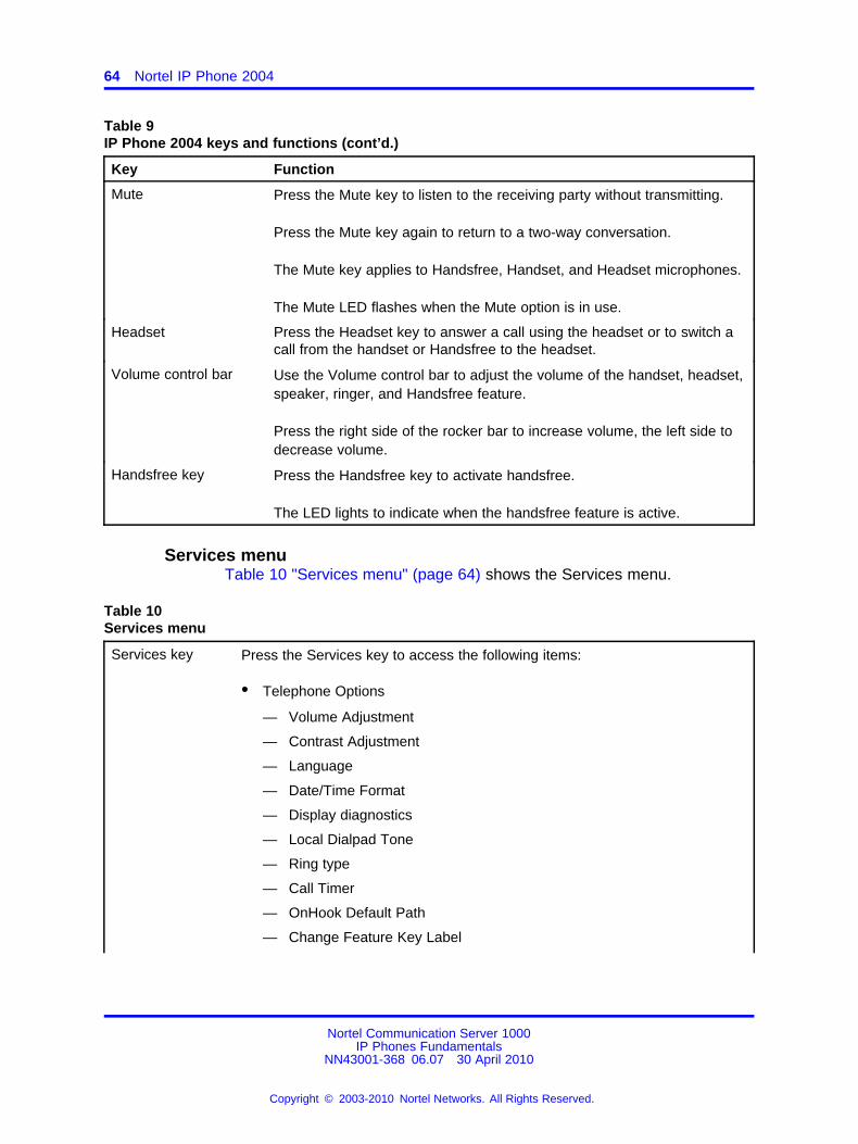
64 Nortel IP Phone 2004
Table 9IP Phone 2004 keys and functions (cont’d.)
Key Function
Mute Press the Mute key to listen to the receiving party without transmitting.
Press the Mute key again to return to a two-way conversation.
The Mute key applies to Handsfree, Handset, and Headset microphones.
The Mute LED flashes when the Mute option is in use.
Headset Press the Headset key to answer a call using the headset or to switch acall from the handset or Handsfree to the headset.
Volume control bar Use the Volume control bar to adjust the volume of the handset, headset,speaker, ringer, and Handsfree feature.
Press the right side of the rocker bar to increase volume, the left side todecrease volume.
Handsfree key Press the Handsfree key to activate handsfree.
The LED lights to indicate when the handsfree feature is active.
Services menuTable 10 "Services menu" (page 64) shows the Services menu.
Table 10Services menu
Services key Press the Services key to access the following items:
• Telephone Options
— Volume Adjustment
— Contrast Adjustment
— Language
— Date/Time Format
— Display diagnostics
— Local Dialpad Tone
— Ring type
— Call Timer
— OnHook Default Path
— Change Feature Key Label
Nortel Communication Server 1000IP Phones Fundamentals
NN43001-368 06.07 30 April 2010
Copyright © 2003-2010 Nortel Networks. All Rights Reserved.
.
Features 65
— Set Info
— Live Dialpad
• Password Administration
• Virtual Office Login and Virtual Office Logout (if Virtual Office is configured)
• Test Local Mode and Resume Local Mode (if Branch Office is configured)
You can customize the IP Phone features to meet user requirements. Formore information, see the IP Phone 2004 User Guide (NN43117-102).
Double-press the Services key to access Network diagnostic utilities. For more information aboutNetwork diagnostic utilities, see “IP Phone diagnostic utilities” (page 601).
If an incoming call is presented while you configure information in the Services menu, the phonerings. However, the display does not update with the caller ID, and the programming text is notdisturbed.
While you are in the Services menu you cannot dial digits but you can use the programmable linekeys, such as Redial (double-press a line key) and Auto dial key to make a call. However, thedisplay does not update with the dialed digits or Caller ID.
During an incoming call, if the selected feature page does not contain the flashing DN line key, thedisplay reverts to the active feature key page. This enables the user to answer the call withoutpressing the Shift key.
FeaturesThe IP Phone 2004 supports the following telephony features:
• six programmable line (DN)/feature keys (self-labeled)
• four context-sensitive soft keys (self-labeled)
Functions for the context-sensitive soft keys are configured in LD 11.
For more information about context-sensitive soft keys, see Featuresand Services Fundamentals (NN43001-106).
• volume control bar to adjust ringer, speaker, handset, handsfree, andheadset volume
• ability to change the programmable line (DN)/feature key labels
• seven specialized feature keys
— Quit
— Directory
— Message/Inbox
— Shift/Outbox
— Services
Nortel Communication Server 1000IP Phones Fundamentals
NN43001-368 06.07 30 April 2010
Copyright © 2003-2010 Nortel Networks. All Rights Reserved.
.
66 Nortel IP Phone 2004
— Copy
— Expand to PC
• five call-processing fixed keys
— Mute
— Handsfree
— Goodbye
— Headset
— Hold
For more information about IP Phone features, see “Features” (page 391).
Central Answering PositionThe Central Answering Position (CAP) operates as an AutomaticCall Distribution (ACD) agent on the IP Phone 2004. A CAP providescall-handling features, such as transferring a call, parking a call, andanswering a call. You can add an IP Phone Key Expansion Module (KEM)to provide additional lines and features, Direct Station Select, and BusyLamp Field functionality.
For further information about Central Answering Position, see CentralAnswering Position Implementation Guide (NN43011-501).
Display characteristicsAn IP Phone 2004 has three major display areas:
• “Programmable line (DN)/feature key label display” (page 67)
• “Information line display” (page 67)
• “Soft key label display” (page 68)
Figure 8 "IP Phone 2004 display areas" (page 67) shows display areas.
Nortel Communication Server 1000IP Phones Fundamentals
NN43001-368 06.07 30 April 2010
Copyright © 2003-2010 Nortel Networks. All Rights Reserved.
.
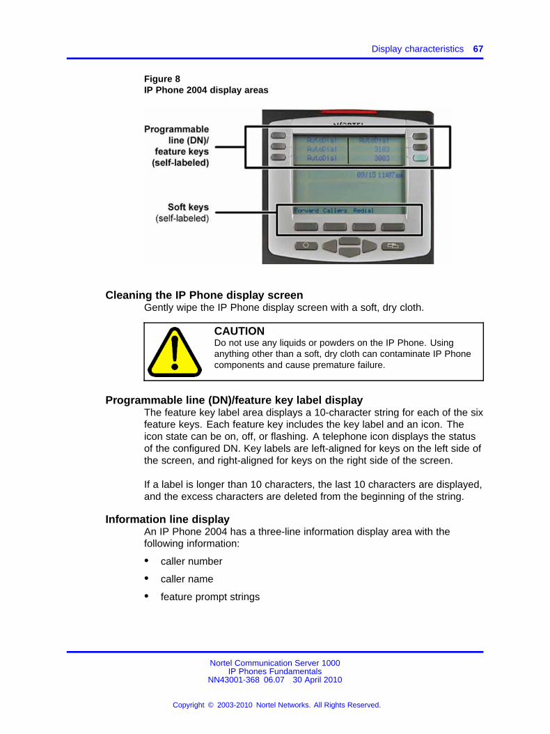
Display characteristics 67
Figure 8IP Phone 2004 display areas
Cleaning the IP Phone display screenGently wipe the IP Phone display screen with a soft, dry cloth.
CAUTIONDo not use any liquids or powders on the IP Phone. Usinganything other than a soft, dry cloth can contaminate IP Phonecomponents and cause premature failure.
Programmable line (DN)/feature key label displayThe feature key label area displays a 10-character string for each of the sixfeature keys. Each feature key includes the key label and an icon. Theicon state can be on, off, or flashing. A telephone icon displays the statusof the configured DN. Key labels are left-aligned for keys on the left side ofthe screen, and right-aligned for keys on the right side of the screen.
If a label is longer than 10 characters, the last 10 characters are displayed,and the excess characters are deleted from the beginning of the string.
Information line displayAn IP Phone 2004 has a three-line information display area with thefollowing information:
• caller number
• caller name
• feature prompt strings
Nortel Communication Server 1000IP Phones Fundamentals
NN43001-368 06.07 30 April 2010
Copyright © 2003-2010 Nortel Networks. All Rights Reserved.
.
68 Nortel IP Phone 2004
• user-entered digits
• date and time information (if the IP Phone is in an idle state) or CallTimer (if provisioned in the Telephone options menu)
The information in the display area changes, according to thecall-processing state and active features.
Soft key label displayThe soft key label has a maximum six characters. Each soft key includesthe soft key label and an icon. When a soft key is in use, a triangle iconappears at the beginning of the soft key label, and the label shifts onecharacter to the right. (If the label is seven characters in length, the last orrightmost character is truncated.) If a feature is enabled, the icon stateturns to On. The icon remains in the on state until the feature key ispressed again. This cancels the enabled feature and turns the icon off,and returns the soft key label to its original state.
Use the More soft key to navigate the layers of functions. If there are onlyfour functions assigned to the soft keys, the More key does not appear,and all four functions are displayed.
Package componentsThe following information applies to IP Phone 2001, IP Phone 2002, andIP Phone 2004. Product codes for these IP Phones are different fromprevious sets.
See the product code on the back of the phone to confirm whether it is aIP Phone 2001, IP Phone 2002, or IP Phone 2004. The product code forIP Phone 2001, IP Phone 2002, and IP Phone 2004 appears as IP Phone200x. The product code for previous versions of the IP Phone appearswith an i in front of the model number (for example, i200x).
You must order the global power supply separately if local power using theglobal power supply is required, because IP Phone 2001, IP Phone 2002,and IP Phone 2004 include integrated support for a number of power overLAN options, including support for IEEE 802.3af standard power.
Table 11 "Package components" (page 69) lists the IP Phone 2004package components.
Nortel Communication Server 1000IP Phones Fundamentals
NN43001-368 06.07 30 April 2010
Copyright © 2003-2010 Nortel Networks. All Rights Reserved.
.
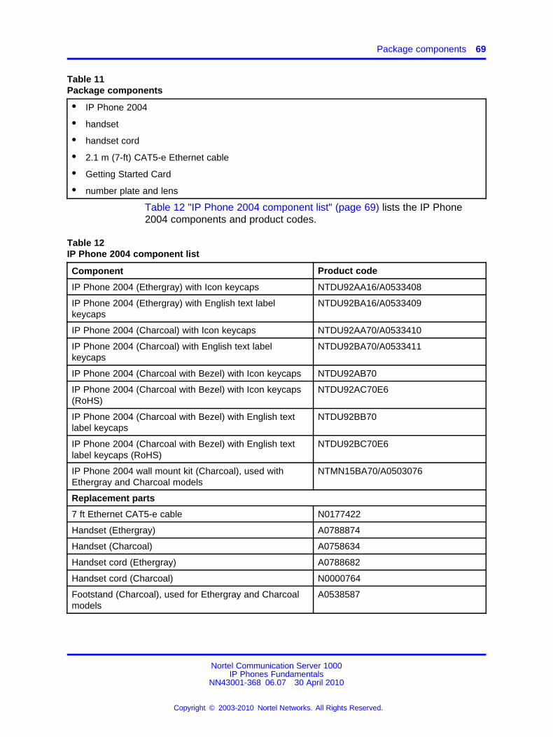
Package components 69
Table 11Package components
• IP Phone 2004
• handset
• handset cord
• 2.1 m (7-ft) CAT5-e Ethernet cable
• Getting Started Card
• number plate and lens
Table 12 "IP Phone 2004 component list" (page 69) lists the IP Phone2004 components and product codes.
Table 12IP Phone 2004 component list
Component Product code
IP Phone 2004 (Ethergray) with Icon keycaps NTDU92AA16/A0533408
IP Phone 2004 (Ethergray) with English text labelkeycaps
NTDU92BA16/A0533409
IP Phone 2004 (Charcoal) with Icon keycaps NTDU92AA70/A0533410
IP Phone 2004 (Charcoal) with English text labelkeycaps
NTDU92BA70/A0533411
IP Phone 2004 (Charcoal with Bezel) with Icon keycaps NTDU92AB70
IP Phone 2004 (Charcoal with Bezel) with Icon keycaps(RoHS)
NTDU92AC70E6
IP Phone 2004 (Charcoal with Bezel) with English textlabel keycaps
NTDU92BB70
IP Phone 2004 (Charcoal with Bezel) with English textlabel keycaps (RoHS)
NTDU92BC70E6
IP Phone 2004 wall mount kit (Charcoal), used withEthergray and Charcoal models
NTMN15BA70/A0503076
Replacement parts
7 ft Ethernet CAT5-e cable N0177422
Handset (Ethergray) A0788874
Handset (Charcoal) A0758634
Handset cord (Ethergray) A0788682
Handset cord (Charcoal) N0000764
Footstand (Charcoal), used for Ethergray and Charcoalmodels
A0538587
Nortel Communication Server 1000IP Phones Fundamentals
NN43001-368 06.07 30 April 2010
Copyright © 2003-2010 Nortel Networks. All Rights Reserved.
.
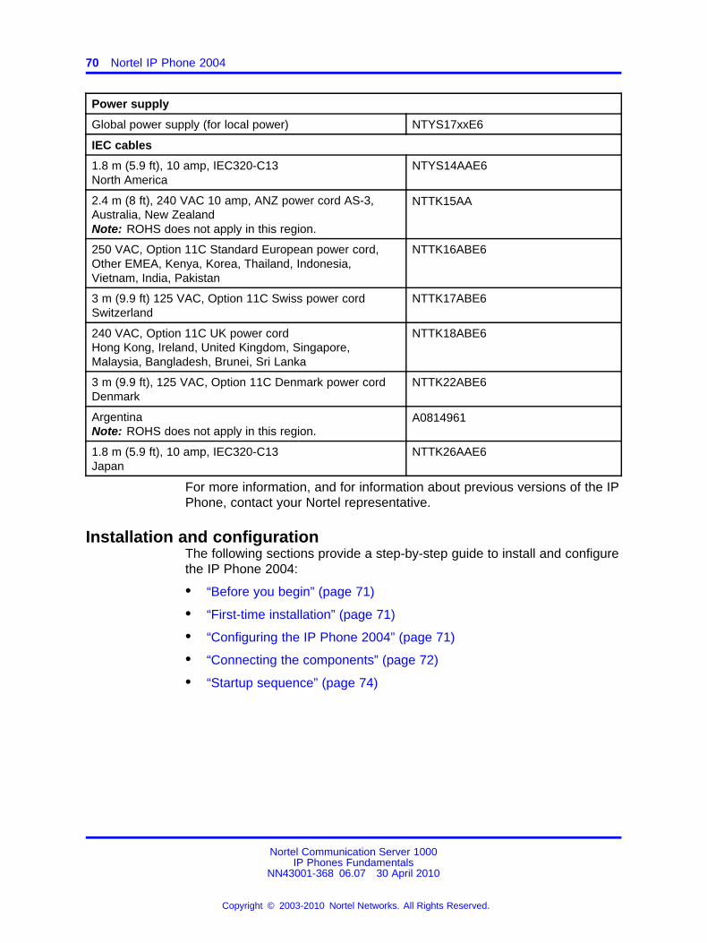
70 Nortel IP Phone 2004
Power supply
Global power supply (for local power) NTYS17xxE6
IEC cables
1.8 m (5.9 ft), 10 amp, IEC320-C13North America
NTYS14AAE6
2.4 m (8 ft), 240 VAC 10 amp, ANZ power cord AS-3,Australia, New ZealandNote: ROHS does not apply in this region.
NTTK15AA
250 VAC, Option 11C Standard European power cord,Other EMEA, Kenya, Korea, Thailand, Indonesia,Vietnam, India, Pakistan
NTTK16ABE6
3 m (9.9 ft) 125 VAC, Option 11C Swiss power cordSwitzerland
NTTK17ABE6
240 VAC, Option 11C UK power cordHong Kong, Ireland, United Kingdom, Singapore,Malaysia, Bangladesh, Brunei, Sri Lanka
NTTK18ABE6
3 m (9.9 ft), 125 VAC, Option 11C Denmark power cordDenmark
NTTK22ABE6
ArgentinaNote: ROHS does not apply in this region.
A0814961
1.8 m (5.9 ft), 10 amp, IEC320-C13Japan
NTTK26AAE6
For more information, and for information about previous versions of the IPPhone, contact your Nortel representative.
Installation and configurationThe following sections provide a step-by-step guide to install and configurethe IP Phone 2004:
• “Before you begin” (page 71)
• “First-time installation” (page 71)
• “Configuring the IP Phone 2004” (page 71)
• “Connecting the components” (page 72)
• “Startup sequence” (page 74)
Nortel Communication Server 1000IP Phones Fundamentals
NN43001-368 06.07 30 April 2010
Copyright © 2003-2010 Nortel Networks. All Rights Reserved.
.
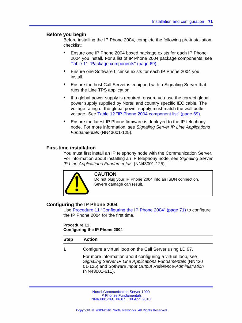
Installation and configuration 71
Before you beginBefore installing the IP Phone 2004, complete the following pre-installationchecklist:
• Ensure one IP Phone 2004 boxed package exists for each IP Phone2004 you install. For a list of IP Phone 2004 package components, seeTable 11 "Package components" (page 69).
• Ensure one Software License exists for each IP Phone 2004 youinstall.
• Ensure the host Call Server is equipped with a Signaling Server thatruns the Line TPS application.
• If a global power supply is required, ensure you use the correct globalpower supply supplied by Nortel and country specific IEC cable. Thevoltage rating of the global power supply must match the wall outletvoltage. See Table 12 "IP Phone 2004 component list" (page 69).
• Ensure the latest IP Phone firmware is deployed to the IP telephonynode. For more information, see Signaling Server IP Line ApplicationsFundamentals (NN43001-125).
First-time installationYou must first install an IP telephony node with the Communication Server.For information about installing an IP telephony node, see Signaling ServerIP Line Applications Fundamentals (NN43001-125).
CAUTIONDo not plug your IP Phone 2004 into an ISDN connection.Severe damage can result.
Configuring the IP Phone 2004Use Procedure 11 “Configuring the IP Phone 2004” (page 71) to configurethe IP Phone 2004 for the first time.
Procedure 11Configuring the IP Phone 2004
Step Action
1 Configure a virtual loop on the Call Server using LD 97.
For more information about configuring a virtual loop, seeSignaling Server IP Line Applications Fundamentals (NN43001-125) and Software Input Output Reference-Administration(NN43001-611).
Nortel Communication Server 1000IP Phones Fundamentals
NN43001-368 06.07 30 April 2010
Copyright © 2003-2010 Nortel Networks. All Rights Reserved.
.
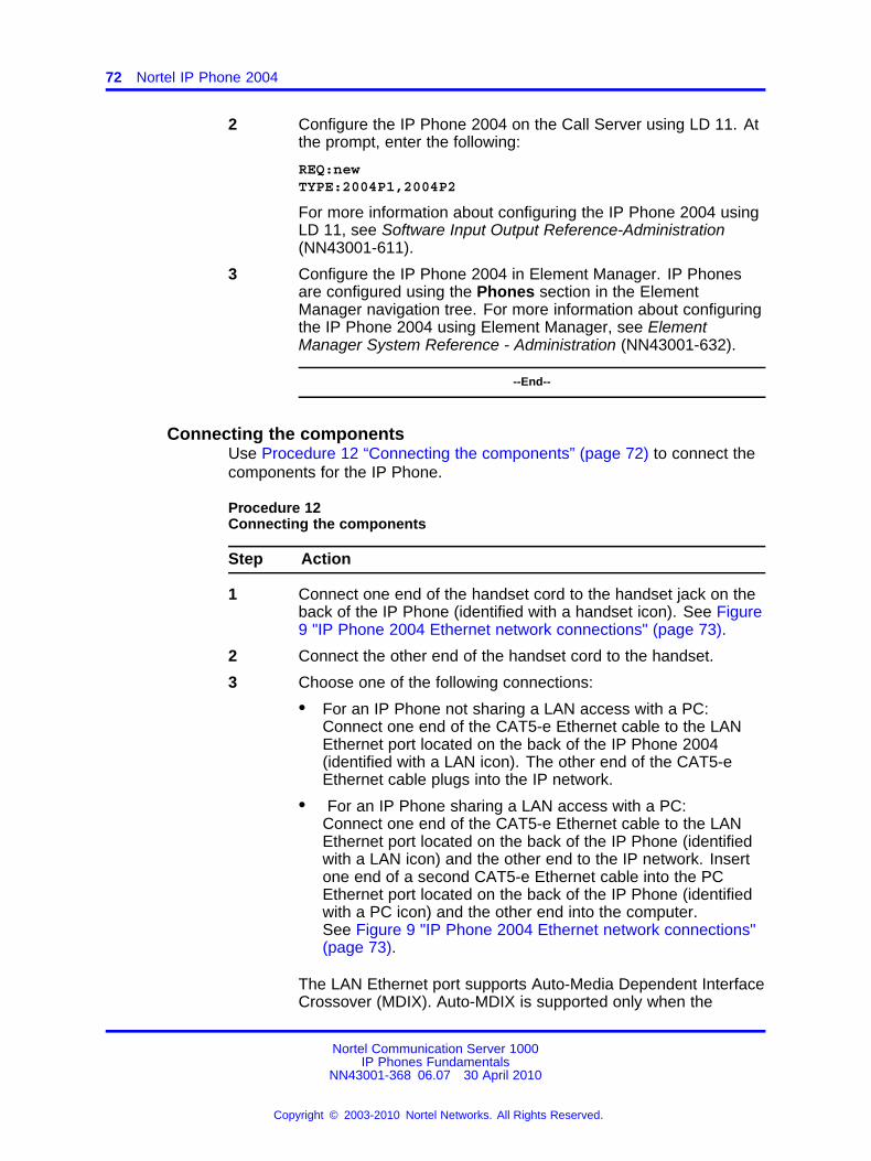
72 Nortel IP Phone 2004
2 Configure the IP Phone 2004 on the Call Server using LD 11. Atthe prompt, enter the following:
REQ:newTYPE:2004P1,2004P2
For more information about configuring the IP Phone 2004 usingLD 11, see Software Input Output Reference-Administration(NN43001-611).
3 Configure the IP Phone 2004 in Element Manager. IP Phonesare configured using the Phones section in the ElementManager navigation tree. For more information about configuringthe IP Phone 2004 using Element Manager, see ElementManager System Reference - Administration (NN43001-632).
--End--
Connecting the componentsUse Procedure 12 “Connecting the components” (page 72) to connect thecomponents for the IP Phone.
Procedure 12Connecting the components
Step Action
1 Connect one end of the handset cord to the handset jack on theback of the IP Phone (identified with a handset icon). See Figure9 "IP Phone 2004 Ethernet network connections" (page 73).
2 Connect the other end of the handset cord to the handset.
3 Choose one of the following connections:
• For an IP Phone not sharing a LAN access with a PC:Connect one end of the CAT5-e Ethernet cable to the LANEthernet port located on the back of the IP Phone 2004(identified with a LAN icon). The other end of the CAT5-eEthernet cable plugs into the IP network.
• For an IP Phone sharing a LAN access with a PC:Connect one end of the CAT5-e Ethernet cable to the LANEthernet port located on the back of the IP Phone (identifiedwith a LAN icon) and the other end to the IP network. Insertone end of a second CAT5-e Ethernet cable into the PCEthernet port located on the back of the IP Phone (identifiedwith a PC icon) and the other end into the computer.See Figure 9 "IP Phone 2004 Ethernet network connections"(page 73).
The LAN Ethernet port supports Auto-Media Dependent InterfaceCrossover (MDIX). Auto-MDIX is supported only when the
Nortel Communication Server 1000IP Phones Fundamentals
NN43001-368 06.07 30 April 2010
Copyright © 2003-2010 Nortel Networks. All Rights Reserved.
.
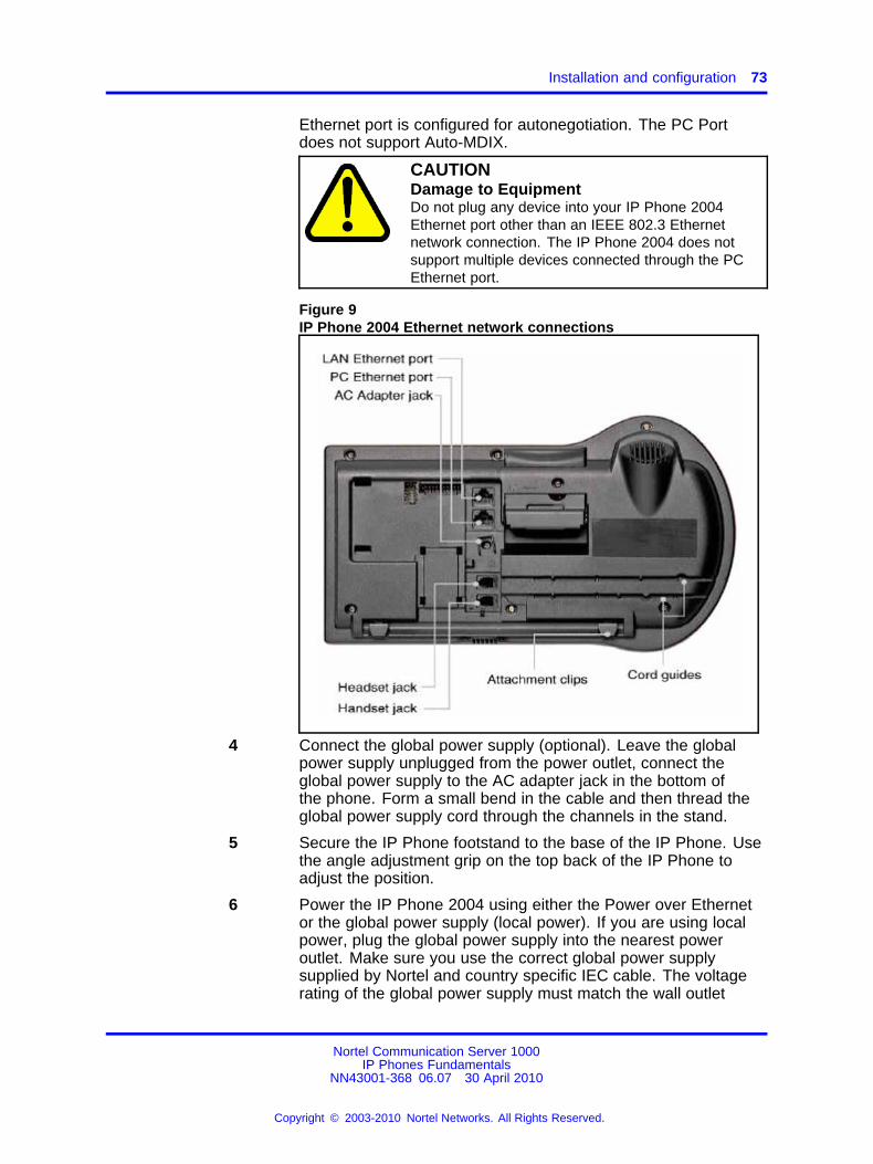
Installation and configuration 73
Ethernet port is configured for autonegotiation. The PC Portdoes not support Auto-MDIX.
CAUTIONDamage to EquipmentDo not plug any device into your IP Phone 2004Ethernet port other than an IEEE 802.3 Ethernetnetwork connection. The IP Phone 2004 does notsupport multiple devices connected through the PCEthernet port.
Figure 9IP Phone 2004 Ethernet network connections
4 Connect the global power supply (optional). Leave the globalpower supply unplugged from the power outlet, connect theglobal power supply to the AC adapter jack in the bottom ofthe phone. Form a small bend in the cable and then thread theglobal power supply cord through the channels in the stand.
5 Secure the IP Phone footstand to the base of the IP Phone. Usethe angle adjustment grip on the top back of the IP Phone toadjust the position.
6 Power the IP Phone 2004 using either the Power over Ethernetor the global power supply (local power). If you are using localpower, plug the global power supply into the nearest poweroutlet. Make sure you use the correct global power supplysupplied by Nortel and country specific IEC cable. The voltagerating of the global power supply must match the wall outlet
Nortel Communication Server 1000IP Phones Fundamentals
NN43001-368 06.07 30 April 2010
Copyright © 2003-2010 Nortel Networks. All Rights Reserved.
.
74 Nortel IP Phone 2004
voltage. See Table 12 "IP Phone 2004 component list" (page69).
The IP Phone 2004 supports both AC power and Power overLAN options, including IEEE 802.3af Power Classification 2. Touse Power over Ethernet, where power is delivered over theCAT5-e cable, the LAN must support Power over Ethernet, and aglobal power supply is not required. To use local AC power, theoptional global power supply can be ordered separately.
--End--
When you complete the IP Phone connection, you must connect the phoneto the network. See “Dynamic Host Configuration Protocol” (page 429).
Startup sequenceWhen an IP Phone 2004 connects to the network, it must perform a startupsequence. The elements of the startup sequence include:
• obtaining network access (if supported by the network infrastructure)
• obtaining VLAN ID (if supported by the network infrastructure)
• obtaining the IP parameters
• connecting to the Call Server
• obtaining the provisioning parameters
For information about provisioning the IP Phone, see “Manual provisioningof IP Phones 2000 Series” (page 563).
Redeploying an IP Phone 2004You can redeploy an existing previously configured IP Phone 2004 on thesame Call Server. For example, the IP Phone 2004 can be assigned toa new user (new TN) or to an existing user who moved to a new subnetby changing the TN of the IP Phone 2004. For further information, seeConverging the Data Network with VoIP Fundamentals (NN43001-260).
Procedure 13Changing the TN of an existing IP Phone 2004
Step Action
1 Repower the IP Phone 2004.
During the reboot sequence of a previously configured IPPhone, the IP Phone 2004 displays the existing node numberfor approximately five seconds.
2 If the node password is enabled and NULL, choose one of thefollowing:
Nortel Communication Server 1000IP Phones Fundamentals
NN43001-368 06.07 30 April 2010
Copyright © 2003-2010 Nortel Networks. All Rights Reserved.
.
Replacing an IP Phone 2004 75
a Disable the password.
b Set the password as non-NULL.
3 Press OK when the node number displays.
If Then
the node password is enabledand is not NULL
a password screen displays. Goto Step 4.
the node password is disabled a TN screen displays. Go to Step5.
4 Enter the password at the password screen, and press OK.
A TN screen displays.
To obtain the password, enter the nodePwdShow command inElement Manager. For further information, see Element ManagerSystem Reference - Administration (NN43001-632).
5 Select the Clear soft key to clear the existing TN.
6 Enter the new TN.
--End--
Replacing an IP Phone 2004ATTENTIONTwo IP Phones cannot share the same TN. You must remove the IP Phone2004 that currently uses the TN.
Procedure 14Replacing an IP Phone 2004
Step Action
1 Obtain the node and TN information of the phone you want toreplace.
2 Disconnect the IP Phone 2004 that you want to replace.
3 Follow “Configuring the IP Phone 2004” (page 71) to installthe IP Phone 2004. To configure the IP Phone, see “Manualprovisioning of IP Phones 2000 Series” (page 563).
4 Enter the same TN and Node Number as the IP Phone 2004 youreplaced. The Call Server associates the new IP Phone 2004with the existing TN.
--End--
Nortel Communication Server 1000IP Phones Fundamentals
NN43001-368 06.07 30 April 2010
Copyright © 2003-2010 Nortel Networks. All Rights Reserved.
.
76 Nortel IP Phone 2004
Removing an IP Phone 2004 from serviceProcedure 15Removing an IP Phone 2004 from service
Step Action
1 Disconnect the IP Phone 2004 from the network or turn thepower off.
The service to the PC is disconnected as well if the PC connectsto the IP Phone 2004.
If the IP Phone 2004 was automatically configured, the DHCPlease expires and the IP address returns to the available pool.
2 In LD 11, enter the following:REQ: OUTTYPE: 2004P1, 2004P2TN: LLL S CC UU
--End--
Nortel Communication Server 1000IP Phones Fundamentals
NN43001-368 06.07 30 April 2010
Copyright © 2003-2010 Nortel Networks. All Rights Reserved.
.
77.
IP Phone Key Expansion Module (KEM)
ContentsThis section contains the following topics
• “Description” (page 77)
• “Features” (page 78)
• “Display characteristics” (page 78)
• “Key number assignments” (page 79)
• “Package components” (page 79)
• “Configuration” (page 79)
• “Installation” (page 82)
• “IP Phone KEM startup initialization” (page 83)
• “Operating parameters” (page 84)
DescriptionThe Nortel IP Phone Key Expansion Module (KEM) is a hardwarecomponent that connects to IP Phone 2002 and IP Phone 2004 andprovides additional line appearances and feature keys (see Figure 10 "IPPhone 2002 with one IP Phone KEM attached" (page 78)).
Up to two IP Phone KEMs can be connected to an IP Phone 2002 or IPPhone 2004. With two IP Phone KEMs connected, the IP Phone can haveup to 48 additional line/feature keys.
The IP Phone 2004 can also have up to 48 additional line/feature keysusing the Shift key functionality and one IP Phone KEM. With two IPPhone KEMs connected, the Shift key functionality does not affect the IPPhone KEMs since the maximum number of line/feature keys is alreadyavailable. The IP Phone 2002 does not support Shift key functionality.
Nortel Communication Server 1000IP Phones Fundamentals
NN43001-368 06.07 30 April 2010
Copyright © 2003-2010 Nortel Networks. All Rights Reserved.
.
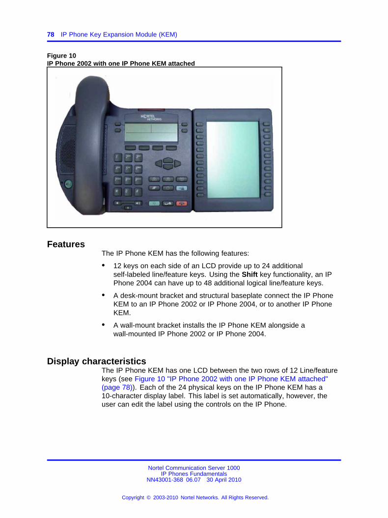
78 IP Phone Key Expansion Module (KEM)
Figure 10IP Phone 2002 with one IP Phone KEM attached
FeaturesThe IP Phone KEM has the following features:
• 12 keys on each side of an LCD provide up to 24 additionalself-labeled line/feature keys. Using the Shift key functionality, an IPPhone 2004 can have up to 48 additional logical line/feature keys.
• A desk-mount bracket and structural baseplate connect the IP PhoneKEM to an IP Phone 2002 or IP Phone 2004, or to another IP PhoneKEM.
• A wall-mount bracket installs the IP Phone KEM alongside awall-mounted IP Phone 2002 or IP Phone 2004.
Display characteristicsThe IP Phone KEM has one LCD between the two rows of 12 Line/featurekeys (see Figure 10 "IP Phone 2002 with one IP Phone KEM attached"(page 78)). Each of the 24 physical keys on the IP Phone KEM has a10-character display label. This label is set automatically, however, theuser can edit the label using the controls on the IP Phone.
Nortel Communication Server 1000IP Phones Fundamentals
NN43001-368 06.07 30 April 2010
Copyright © 2003-2010 Nortel Networks. All Rights Reserved.
.
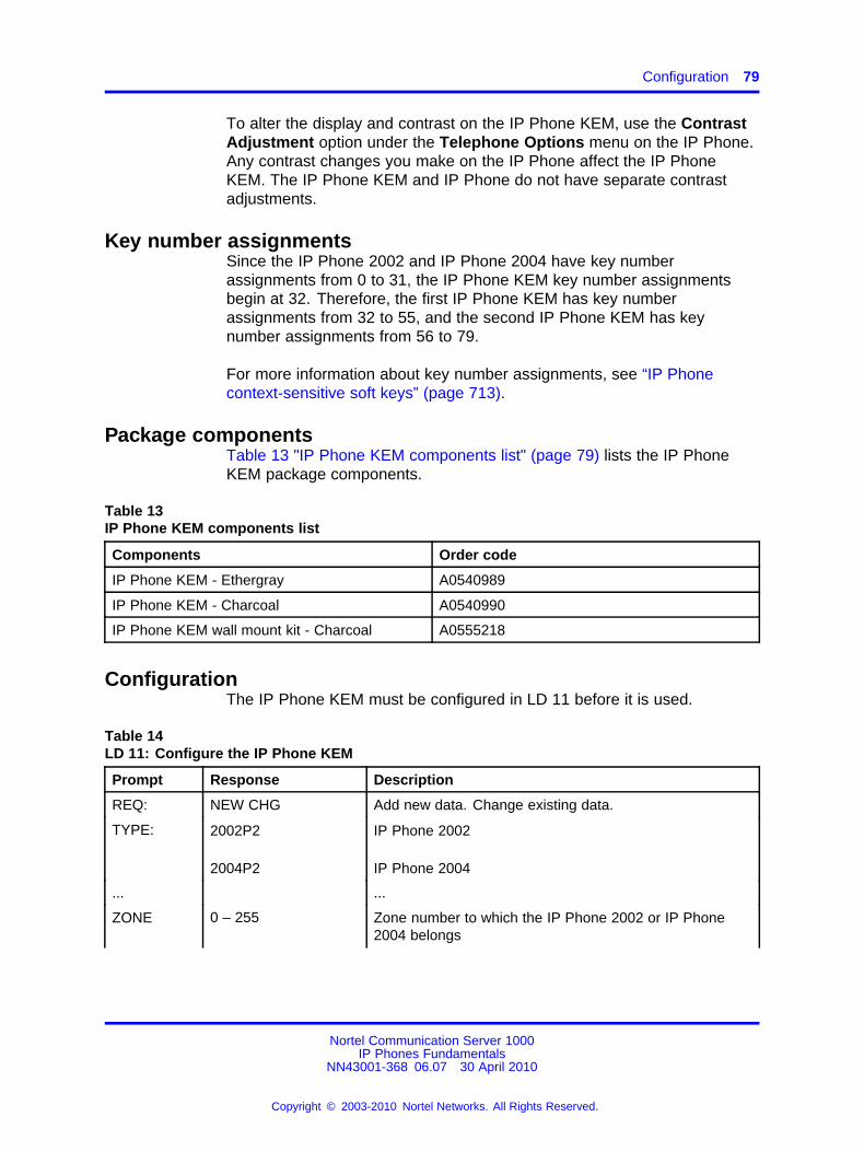
Configuration 79
To alter the display and contrast on the IP Phone KEM, use the ContrastAdjustment option under the Telephone Options menu on the IP Phone.Any contrast changes you make on the IP Phone affect the IP PhoneKEM. The IP Phone KEM and IP Phone do not have separate contrastadjustments.
Key number assignmentsSince the IP Phone 2002 and IP Phone 2004 have key numberassignments from 0 to 31, the IP Phone KEM key number assignmentsbegin at 32. Therefore, the first IP Phone KEM has key numberassignments from 32 to 55, and the second IP Phone KEM has keynumber assignments from 56 to 79.
For more information about key number assignments, see “IP Phonecontext-sensitive soft keys” (page 713).
Package componentsTable 13 "IP Phone KEM components list" (page 79) lists the IP PhoneKEM package components.
Table 13IP Phone KEM components list
Components Order code
IP Phone KEM - Ethergray A0540989
IP Phone KEM - Charcoal A0540990
IP Phone KEM wall mount kit - Charcoal A0555218
ConfigurationThe IP Phone KEM must be configured in LD 11 before it is used.
Table 14LD 11: Configure the IP Phone KEM
Prompt Response Description
REQ: NEW CHG Add new data. Change existing data.
TYPE: 2002P2
2004P2
IP Phone 2002
IP Phone 2004
... ...
ZONE 0 – 255 Zone number to which the IP Phone 2002 or IP Phone2004 belongs
Nortel Communication Server 1000IP Phones Fundamentals
NN43001-368 06.07 30 April 2010
Copyright © 2003-2010 Nortel Networks. All Rights Reserved.
.
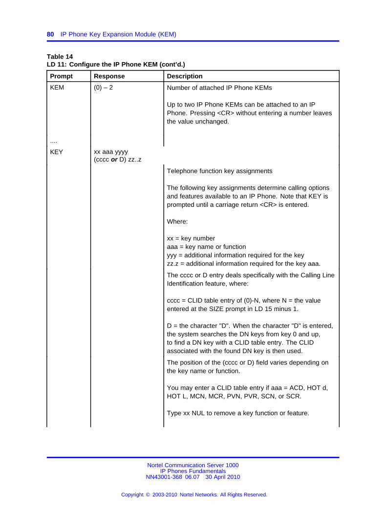
80 IP Phone Key Expansion Module (KEM)
Table 14LD 11: Configure the IP Phone KEM (cont’d.)
Prompt Response Description
KEM (0) – 2 Number of attached IP Phone KEMs
Up to two IP Phone KEMs can be attached to an IPPhone. Pressing <CR> without entering a number leavesthe value unchanged.
....
KEY xx aaa yyyy(cccc or D) zz..z
Telephone function key assignments
The following key assignments determine calling optionsand features available to an IP Phone. Note that KEY isprompted until a carriage return <CR> is entered.
Where:
xx = key numberaaa = key name or functionyyy = additional information required for the keyzz.z = additional information required for the key aaa.
The cccc or D entry deals specifically with the Calling LineIdentification feature, where:
cccc = CLID table entry of (0)-N, where N = the valueentered at the SIZE prompt in LD 15 minus 1.
D = the character "D". When the character "D" is entered,the system searches the DN keys from key 0 and up,to find a DN key with a CLID table entry. The CLIDassociated with the found DN key is then used.
The position of the (cccc or D) field varies depending onthe key name or function.
You may enter a CLID table entry if aaa = ACD, HOT d,HOT L, MCN, MCR, PVN, PVR, SCN, or SCR.
Type xx NUL to remove a key function or feature.
Nortel Communication Server 1000IP Phones Fundamentals
NN43001-368 06.07 30 April 2010
Copyright © 2003-2010 Nortel Networks. All Rights Reserved.
.
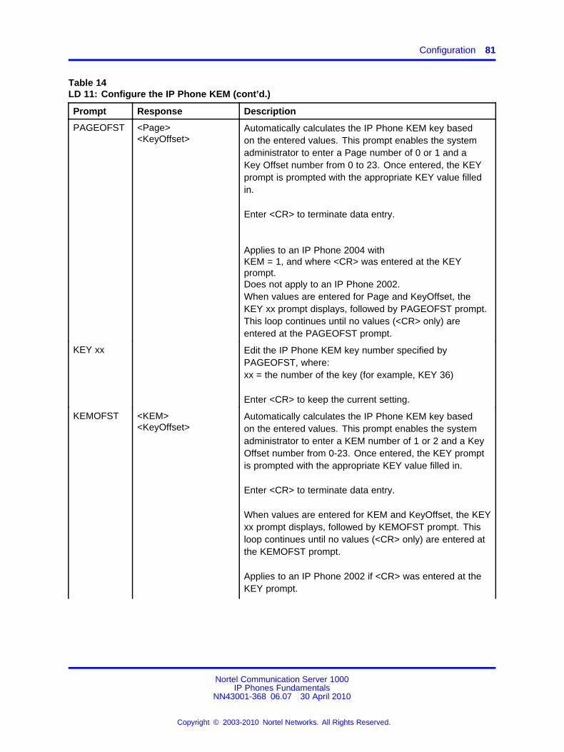
Configuration 81
Table 14LD 11: Configure the IP Phone KEM (cont’d.)
Prompt Response Description
PAGEOFST <Page><KeyOffset>
Automatically calculates the IP Phone KEM key basedon the entered values. This prompt enables the systemadministrator to enter a Page number of 0 or 1 and aKey Offset number from 0 to 23. Once entered, the KEYprompt is prompted with the appropriate KEY value filledin.
Enter <CR> to terminate data entry.
Applies to an IP Phone 2004 withKEM = 1, and where <CR> was entered at the KEYprompt.Does not apply to an IP Phone 2002.When values are entered for Page and KeyOffset, theKEY xx prompt displays, followed by PAGEOFST prompt.This loop continues until no values (<CR> only) areentered at the PAGEOFST prompt.
KEY xx Edit the IP Phone KEM key number specified byPAGEOFST, where:xx = the number of the key (for example, KEY 36)
Enter <CR> to keep the current setting.
KEMOFST <KEM><KeyOffset>
Automatically calculates the IP Phone KEM key basedon the entered values. This prompt enables the systemadministrator to enter a KEM number of 1 or 2 and a KeyOffset number from 0-23. Once entered, the KEY promptis prompted with the appropriate KEY value filled in.
Enter <CR> to terminate data entry.
When values are entered for KEM and KeyOffset, the KEYxx prompt displays, followed by KEMOFST prompt. Thisloop continues until no values (<CR> only) are entered atthe KEMOFST prompt.
Applies to an IP Phone 2002 if <CR> was entered at theKEY prompt.
Nortel Communication Server 1000IP Phones Fundamentals
NN43001-368 06.07 30 April 2010
Copyright © 2003-2010 Nortel Networks. All Rights Reserved.
.
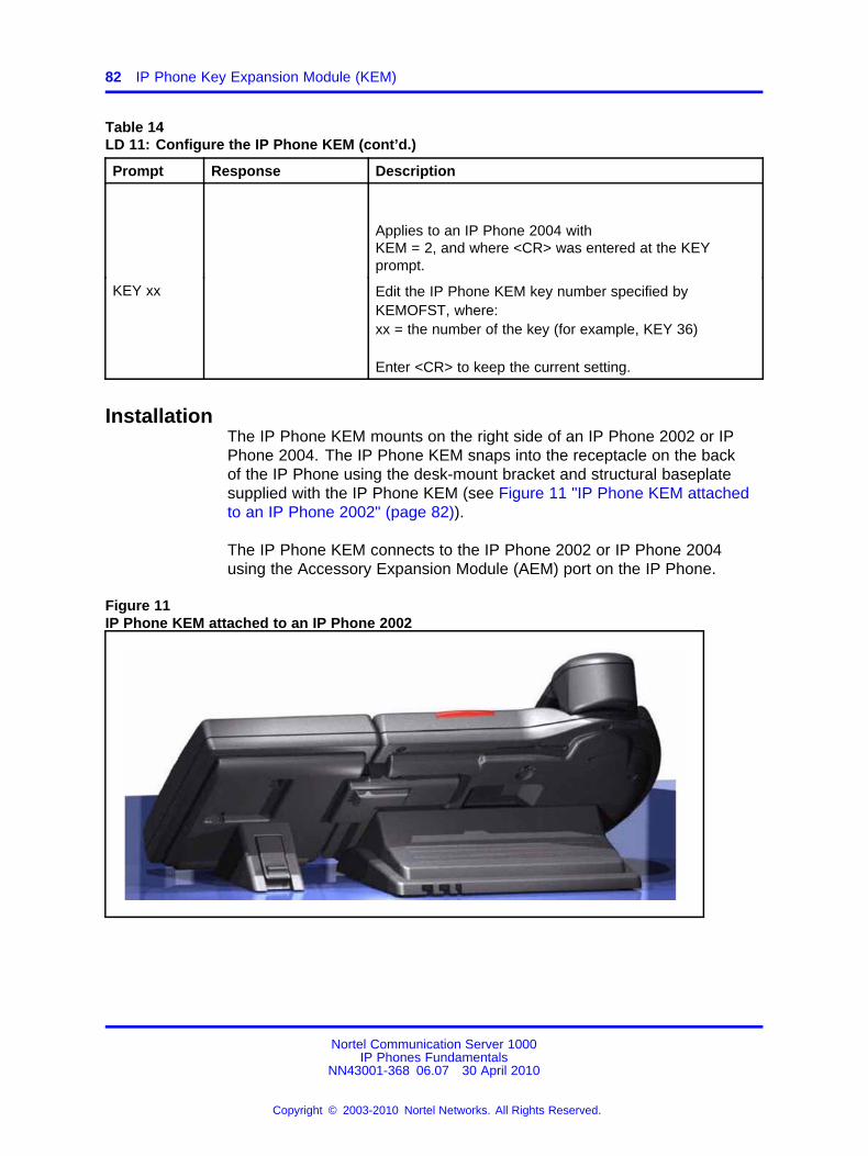
82 IP Phone Key Expansion Module (KEM)
Table 14LD 11: Configure the IP Phone KEM (cont’d.)
Prompt Response Description
Applies to an IP Phone 2004 withKEM = 2, and where <CR> was entered at the KEYprompt.
KEY xx Edit the IP Phone KEM key number specified byKEMOFST, where:xx = the number of the key (for example, KEY 36)
Enter <CR> to keep the current setting.
InstallationThe IP Phone KEM mounts on the right side of an IP Phone 2002 or IPPhone 2004. The IP Phone KEM snaps into the receptacle on the backof the IP Phone using the desk-mount bracket and structural baseplatesupplied with the IP Phone KEM (see Figure 11 "IP Phone KEM attachedto an IP Phone 2002" (page 82)).
The IP Phone KEM connects to the IP Phone 2002 or IP Phone 2004using the Accessory Expansion Module (AEM) port on the IP Phone.
Figure 11IP Phone KEM attached to an IP Phone 2002
Nortel Communication Server 1000IP Phones Fundamentals
NN43001-368 06.07 30 April 2010
Copyright © 2003-2010 Nortel Networks. All Rights Reserved.
.
IP Phone KEM startup initialization 83
Procedure 16Connecting the IP Phone KEM to an IP Phone 2002 or IP Phone 2004
Step Action
1 Remove the IP Phone from the stand by pressing the IP Phonetilt handle, and pulling the IP Phone away from the stand.
For the IP Phone 2004, you can also adjust the stand angle tomaximum, instead of removing the stand.
2 Place the connecting arm of the IP Phone KEM behind the IPPhone and align the IP Phone KEM connection plug to the AEMport on the back of the IP Phone.
The IP Phones 2002 with the product codes: NTDU76AB34,NTDU76BB34, NTDU76AB70, and NTDU76BB70 have shorterconnector pins than the other IP Phone 2002. Therefore, theribbon cable connector of the IP Phone KEM must be detachedfrom the retaining clip and pressed manually into the headerconnector before attaching the IP Phone KEM.
3 Press the IP Phone KEM and IP Phone firmly together until theIP Phone KEM locks into place.
4 If connecting a second IP Phone KEM, repeat steps 1 to 3.
The second IP Phone KEM is attached to the right side of thefirst IP Phone KEM.
5 Attach the IP Phone stand and the IP Phone KEM stand, ifremoved. Adjust each IP Phone KEM stand to the same angleas the IP Phone.
The IP Phone KEM powers up.
The IP Phone KEM uses the electrical connection of the IPPhone 2002 or IP Phone 2004 for power. It does not have itsown power source.
--End--
IP Phone KEM startup initializationOnce the IP Phone KEM has been installed and powered up on your IPPhone 2002 or IP Phone 2004, the IP Phone KEM initializes (see Table 15"Startup initialization process for the IP Phone KEM" (page 84)).
Nortel Communication Server 1000IP Phones Fundamentals
NN43001-368 06.07 30 April 2010
Copyright © 2003-2010 Nortel Networks. All Rights Reserved.
.
84 IP Phone Key Expansion Module (KEM)
Table 15Startup initialization process for the IP Phone KEM
Phase Description
1. IP Phone KEM performsself-test
The self-test confirms the operation of the IP Phone KEM localmemory, CPU, and other circuitry. While undergoing this self-test,the IP Phone KEM display lights up.
If the IP Phone KEM display does not light up, or lights up and thengoes blank, or fails to begin flashing, check that the IP Phone KEMis correctly installed and configured.
2. IP Phone KEMestablishes communicationwith the IP Phone
The IP Phone KEM display flashes until it establishescommunication with the IP Phone.
If the IP Phone KEM display does not stop flashing, communicationhas not been established with the IP Phone. Check that the IPPhone KEM is correctly installed and configured.
3. IP Phone KEMdownloads keymaps
The key labels download to the IP Phone KEM. During thedownload, the display is blank.
When the three phases complete successfully, you are ready to use theadditional line/feature keys on your IP Phone KEM.
If you have a second IP Phone KEM installed on your IP Phone, the one tothe immediate right of the IP Phone must be functional for the subsequentIP Phone KEM to work. This is because the second IP Phone KEMreceives its power, and communicates with the IP Phone, through the firstIP Phone KEM.
Operating parametersGeneral
If an IP Phone KEM is not responding, and lines or features are configuredon keys 32 to 79, calls can be directed to those keys which the usercannot access. This means the IP Phone 2002 or IP Phone 2004 rings butthe call cannot be answered. In such cases, the incoming call receivesCall Forward No Answer (CFNA) treatment.
IP Phone 2002If only one IP Phone KEM is configured in LD 11, but two IP Phone KEMsare detected on an IP Phone 2002, the second IP Phone KEM is ignored.An error message displays to alert the administrator that the hardwareconfiguration does not match the administered configuration.
If two IP Phone KEMs are configured in LD 11, but only one IP PhoneKEM is responding, the keys on the second IP Phone KEM are availablefor call processing but are not accessible to the user. This means that
Nortel Communication Server 1000IP Phones Fundamentals
NN43001-368 06.07 30 April 2010
Copyright © 2003-2010 Nortel Networks. All Rights Reserved.
.
Operating parameters 85
lines and features on keys 56 to 79 can cause the IP Phone 2002 toring, but there is no way to answer it. An error message displays to alertthe administrator that the hardware configuration does not match theadministered configuration.
IP Phone 2004If only one IP Phone KEM is configured in LD 11, but two IP Phone KEMsare detected on an IP Phone 2004, the Terminal Proxy Server (TPS)assigns keys 56 to 79 to the second IP Phone KEM. An error messagedisplays to alert the administrator that the hardware configuration does notmatch the administered configuration.
If two IP Phone KEMs are configured in LD 11 but only one IP PhoneKEM is responding, the TPS assigns keys 32 to 79 to the single IP PhoneKEM (using the Shift key functionality). An error message displays toalert the administrator that the hardware configuration does not match theadministered configuration. When a second IP Phone KEM is detected,the TPS changes the key assignments to display across both IP PhoneKEMs, as expected.
Virtual OfficeWhen a Virtual Office (VO) login occurs from an IP Phone 2002 or IPPhone 2004 that does not have the same number of IP Phone KEMsresponding as configured on the IP Phone used to log in, call processingmay terminate on a key that is not physically available. In other words, theIP Phone rings but the call cannot be answered.
During the VO login process, the existence of any IP Phone KEM isverified. If a mismatch is detected, the login proceeds normally; however,an error message is generated to alert the administrator of the mismatch.
FirmwareThe IP Phone KEM firmware is not downloadable. If the IP Phone KEMfirmware must be upgraded or changed, the IP Phone KEM must bereplaced with a new IP Phone KEM containing the updated firmware.
Nortel Communication Server 1000IP Phones Fundamentals
NN43001-368 06.07 30 April 2010
Copyright © 2003-2010 Nortel Networks. All Rights Reserved.
.

86 IP Phone Key Expansion Module (KEM)
Nortel Communication Server 1000IP Phones Fundamentals
NN43001-368 06.07 30 April 2010
Copyright © 2003-2010 Nortel Networks. All Rights Reserved.
.
87.
Nortel IP Audio Conference Phone2033
Contents• “Introduction” (page 87)
• “Description” (page 88)
• “Extension microphones” (page 89)
• “Components and functions” (page 90)
• “Features” (page 92)
• “Display characteristics” (page 93)
• “Package components” (page 95)
• “Installation and configuration” (page 97)
• “Redeploying an IP Audio Conference Phone 2033” (page 101)
• “Replacing an IP Audio Conference Phone 2033” (page 102)
• “Removing an IP Audio Conference Phone 2033 from service” (page103)
• “Connecting an extension microphone” (page 103)
IntroductionThis section explains how to install and maintain the IP Audio ConferencePhone 2033. For information about using the IP Audio Conference Phone2033, see the IP Phone Audio Conference Phone 2033 User Guide(NN43111-100).
This section contains the following procedures:
• Procedure 17 “Configuring the IP Audio Conference Phone 2033”(page 98)
• Procedure 18 “Connecting the components” (page 99)
Nortel Communication Server 1000IP Phones Fundamentals
NN43001-368 06.07 30 April 2010
Copyright © 2003-2010 Nortel Networks. All Rights Reserved.
.
88 Nortel IP Audio Conference Phone 2033
• Procedure 19 “Changing the TN of an existing IP Audio ConferencePhone 2033” (page 102)
• Procedure 20 “Replacing an IP Audio Conference Phone 2033” (page102)
• Procedure 21 “Removing an IP Audio Conference Phone 2033 fromservice” (page 103)
If power to the phone is interrupted after you install and configure an IPphone, you are not required to reenter the IP Parameters, Node Numbers,or Terminal Number (TN). There is also no need to again acquire thefirmware.
DescriptionThe IP Audio Conference Phone 2033 uses the customer IP data networkto communicate with the Communication Server 1000 (CS 1000). TheIP Audio Conference Phone 2033 translates voice into data packets fortransport using Internet Protocol. Use a Dynamic Host ConfigurationProtocol (DHCP) server to provide information that you can use for the IPAudio Conference Phone 2033 network and CS 1000 connections.
Figure 12 "IP Audio Conference Phone 2033" (page 89) shows the IPAudio Conference Phone 2033.
Nortel Communication Server 1000IP Phones Fundamentals
NN43001-368 06.07 30 April 2010
Copyright © 2003-2010 Nortel Networks. All Rights Reserved.
.
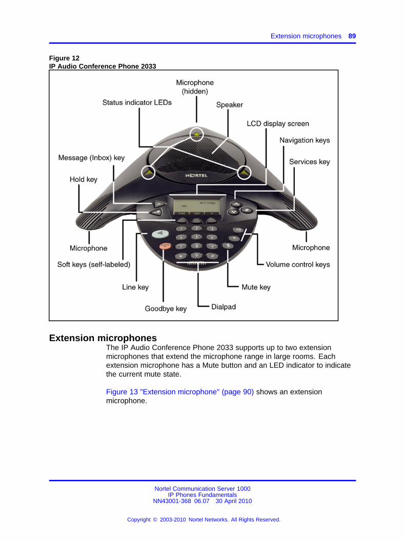
Extension microphones 89
Figure 12IP Audio Conference Phone 2033
Extension microphonesThe IP Audio Conference Phone 2033 supports up to two extensionmicrophones that extend the microphone range in large rooms. Eachextension microphone has a Mute button and an LED indicator to indicatethe current mute state.
Figure 13 "Extension microphone" (page 90) shows an extensionmicrophone.
Nortel Communication Server 1000IP Phones Fundamentals
NN43001-368 06.07 30 April 2010
Copyright © 2003-2010 Nortel Networks. All Rights Reserved.
.
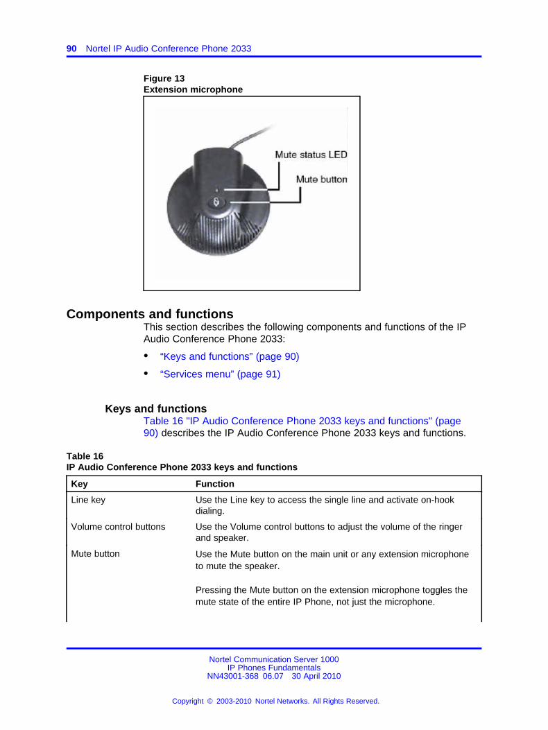
90 Nortel IP Audio Conference Phone 2033
Figure 13Extension microphone
Components and functionsThis section describes the following components and functions of the IPAudio Conference Phone 2033:
• “Keys and functions” (page 90)
• “Services menu” (page 91)
Keys and functionsTable 16 "IP Audio Conference Phone 2033 keys and functions" (page90) describes the IP Audio Conference Phone 2033 keys and functions.
Table 16IP Audio Conference Phone 2033 keys and functions
Key Function
Line key Use the Line key to access the single line and activate on-hookdialing.
Volume control buttons Use the Volume control buttons to adjust the volume of the ringerand speaker.
Mute button Use the Mute button on the main unit or any extension microphoneto mute the speaker.
Pressing the Mute button on the extension microphone toggles themute state of the entire IP Phone, not just the microphone.
Nortel Communication Server 1000IP Phones Fundamentals
NN43001-368 06.07 30 April 2010
Copyright © 2003-2010 Nortel Networks. All Rights Reserved.
.
Components and functions 91
Table 16IP Audio Conference Phone 2033 keys and functions (cont’d.)
Key Function
Goodbye key Use the Goodbye key to terminate an active call.
Hold key Press the Hold key to put an active call on hold. Press the Line (DN)key to return to the caller on hold.
Message (Inbox) key Press the Message (Inbox) key to access your voice mailbox.
Navigation keys Use the Navigation keys to scroll through menus and lists thatappear on the LCD display screen.
Arrows appear on the left side of display screen to indicate there ismore information to be displayed.
Context-sensitive soft keys Context-sensitive soft keys (self-labeled) are located below the LCDscreen display. The LCD screen display above the key changes,based on the active feature. See “Soft key label display” (page94) for further information.
Press the Shift soft key labelled >> to access the second row of softkeys.
When a triangle appears before a key label, the feature is active.
Services menuTable 17 "Services menu" (page 91) shows the Services menu.
Table 17Services menu
Services key Press the Services key to access the following items:
• Telephone Options
— Volume adjustment
— Contrast adjustment
— Language
— Date/Time
— Local DialPad Tone
— Set Info
— Diagnostics
— Ring type
Nortel Communication Server 1000IP Phones Fundamentals
NN43001-368 06.07 30 April 2010
Copyright © 2003-2010 Nortel Networks. All Rights Reserved.
.
92 Nortel IP Audio Conference Phone 2033
— Call Timer
— Live Dialpad
• Password Admin
• Station Control Password
• Virtual Office Login and Virtual Office Logout (if Virtual Office isconfigured)
• Test Local Mode and Resume Local Mode (if Media Gateway 1000Bis configured)
Press the Services key to exit from any menu or menu item.
You can customize the IP Phone features to meet user requirements.For more information, see the IP Phone Audio Conference Phone 2033User Guide (NN43111-100).
Double-press the Services key to access Network diagnostic utilities. For more information aboutNetwork diagnostic utilities, see “IP Phone diagnostic utilities” (page 601).
Network diagnostic utilities is available in Remote Mode only.
If an incoming call is presented while you configure information in the Services menu, the phonerings. However, the display does not update with the caller ID, and the programming text is notdisturbed.
While you are in the Services menu you cannot dial digits but you can use the programmable linekeys, such as Redial (double-press a line key) and Auto dial key to make a call. However, thedisplay does not update with the dialed digits or Caller ID.
FeaturesThe Nortel IP Audio Conference Phone 2033 supports the followingtelephony features:
• three context-sensitive soft keys
Functions for the context-sensitive soft keys are configured in LD 11.
For more information about context-sensitive soft keys, see Featuresand Services Fundamentals (NN43001-106).
• volume control keys to adjust ringer, speaker volume
• two specialized feature keys
— Message/Inbox
— Services
• three call processing keys
Nortel Communication Server 1000IP Phones Fundamentals
NN43001-368 06.07 30 April 2010
Copyright © 2003-2010 Nortel Networks. All Rights Reserved.
.
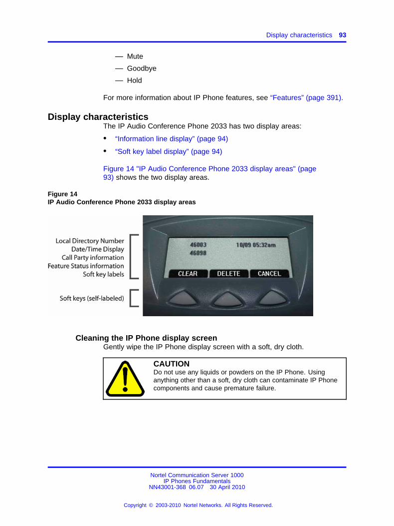
Display characteristics 93
— Mute
— Goodbye
— Hold
For more information about IP Phone features, see “Features” (page 391).
Display characteristicsThe IP Audio Conference Phone 2033 has two display areas:
• “Information line display” (page 94)
• “Soft key label display” (page 94)
Figure 14 "IP Audio Conference Phone 2033 display areas" (page93) shows the two display areas.
Figure 14IP Audio Conference Phone 2033 display areas
Cleaning the IP Phone display screenGently wipe the IP Phone display screen with a soft, dry cloth.
CAUTIONDo not use any liquids or powders on the IP Phone. Usinganything other than a soft, dry cloth can contaminate IP Phonecomponents and cause premature failure.
Nortel Communication Server 1000IP Phones Fundamentals
NN43001-368 06.07 30 April 2010
Copyright © 2003-2010 Nortel Networks. All Rights Reserved.
.
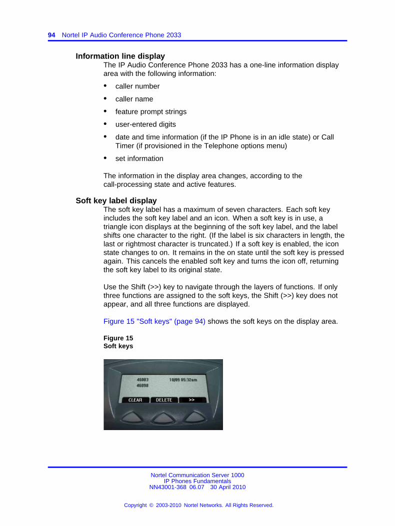
94 Nortel IP Audio Conference Phone 2033
Information line displayThe IP Audio Conference Phone 2033 has a one-line information displayarea with the following information:
• caller number
• caller name
• feature prompt strings
• user-entered digits
• date and time information (if the IP Phone is in an idle state) or CallTimer (if provisioned in the Telephone options menu)
• set information
The information in the display area changes, according to thecall-processing state and active features.
Soft key label displayThe soft key label has a maximum of seven characters. Each soft keyincludes the soft key label and an icon. When a soft key is in use, atriangle icon displays at the beginning of the soft key label, and the labelshifts one character to the right. (If the label is six characters in length, thelast or rightmost character is truncated.) If a soft key is enabled, the iconstate changes to on. It remains in the on state until the soft key is pressedagain. This cancels the enabled soft key and turns the icon off, returningthe soft key label to its original state.
Use the Shift (>>) key to navigate through the layers of functions. If onlythree functions are assigned to the soft keys, the Shift (>>) key does notappear, and all three functions are displayed.
Figure 15 "Soft keys" (page 94) shows the soft keys on the display area.
Figure 15Soft keys
Nortel Communication Server 1000IP Phones Fundamentals
NN43001-368 06.07 30 April 2010
Copyright © 2003-2010 Nortel Networks. All Rights Reserved.
.
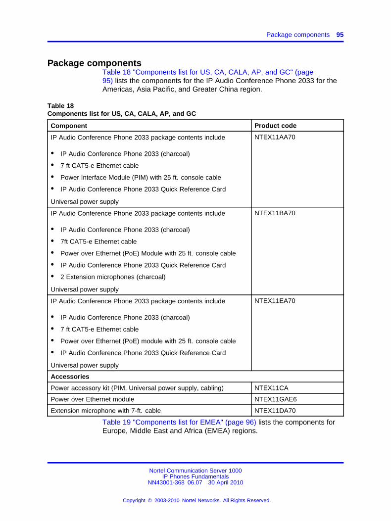
Package components 95
Package componentsTable 18 "Components list for US, CA, CALA, AP, and GC" (page95) lists the components for the IP Audio Conference Phone 2033 for theAmericas, Asia Pacific, and Greater China region.
Table 18Components list for US, CA, CALA, AP, and GC
Component Product code
IP Audio Conference Phone 2033 package contents include
• IP Audio Conference Phone 2033 (charcoal)
• 7 ft CAT5-e Ethernet cable
• Power Interface Module (PIM) with 25 ft. console cable
• IP Audio Conference Phone 2033 Quick Reference Card
Universal power supply
NTEX11AA70
IP Audio Conference Phone 2033 package contents include
• IP Audio Conference Phone 2033 (charcoal)
• 7ft CAT5-e Ethernet cable
• Power over Ethernet (PoE) Module with 25 ft. console cable
• IP Audio Conference Phone 2033 Quick Reference Card
• 2 Extension microphones (charcoal)
Universal power supply
NTEX11BA70
IP Audio Conference Phone 2033 package contents include
• IP Audio Conference Phone 2033 (charcoal)
• 7 ft CAT5-e Ethernet cable
• Power over Ethernet (PoE) module with 25 ft. console cable
• IP Audio Conference Phone 2033 Quick Reference Card
Universal power supply
NTEX11EA70
Accessories
Power accessory kit (PIM, Universal power supply, cabling) NTEX11CA
Power over Ethernet module NTEX11GAE6
Extension microphone with 7-ft. cable NTEX11DA70
Table 19 "Components list for EMEA" (page 96) lists the components forEurope, Middle East and Africa (EMEA) regions.
Nortel Communication Server 1000IP Phones Fundamentals
NN43001-368 06.07 30 April 2010
Copyright © 2003-2010 Nortel Networks. All Rights Reserved.
.
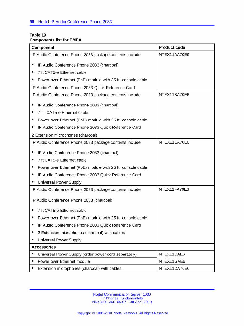
96 Nortel IP Audio Conference Phone 2033
Table 19Components list for EMEA
Component Product code
IP Audio Conference Phone 2033 package contents include
• IP Audio Conference Phone 2033 (charcoal)
• 7 ft CAT5-e Ethernet cable
• Power over Ethernet (PoE) module with 25 ft. console cable
IP Audio Conference Phone 2033 Quick Reference Card
NTEX11AA70E6
IP Audio Conference Phone 2033 package contents include
• IP Audio Conference Phone 2033 (charcoal)
• 7-ft. CAT5-e Ethernet cable
• Power over Ethernet (PoE) module with 25 ft. console cable
• IP Audio Conference Phone 2033 Quick Reference Card
2 Extension microphones (charcoal)
NTEX11BA70E6
IP Audio Conference Phone 2033 package contents include
• IP Audio Conference Phone 2033 (charcoal)
• 7 ft CAT5-e Ethernet cable
• Power over Ethernet (PoE) module with 25 ft. console cable
• IP Audio Conference Phone 2033 Quick Reference Card
• Universal Power Supply
NTEX11EA70E6
IP Audio Conference Phone 2033 package contents include
IP Audio Conference Phone 2033 (charcoal)
• 7 ft CAT5-e Ethernet cable
• Power over Ethernet (PoE) module with 25 ft. console cable
• IP Audio Conference Phone 2033 Quick Reference Card
• 2 Extension microphones (charcoal) with cables
• Universal Power Supply
NTEX11FA70E6
Accessories
• Universal Power Supply (order power cord separately) NTEX11CAE6
• Power over Ethernet module NTEX11GAE6
• Extension microphones (charcoal) with cables NTEX11DA70E6
Nortel Communication Server 1000IP Phones Fundamentals
NN43001-368 06.07 30 April 2010
Copyright © 2003-2010 Nortel Networks. All Rights Reserved.
.
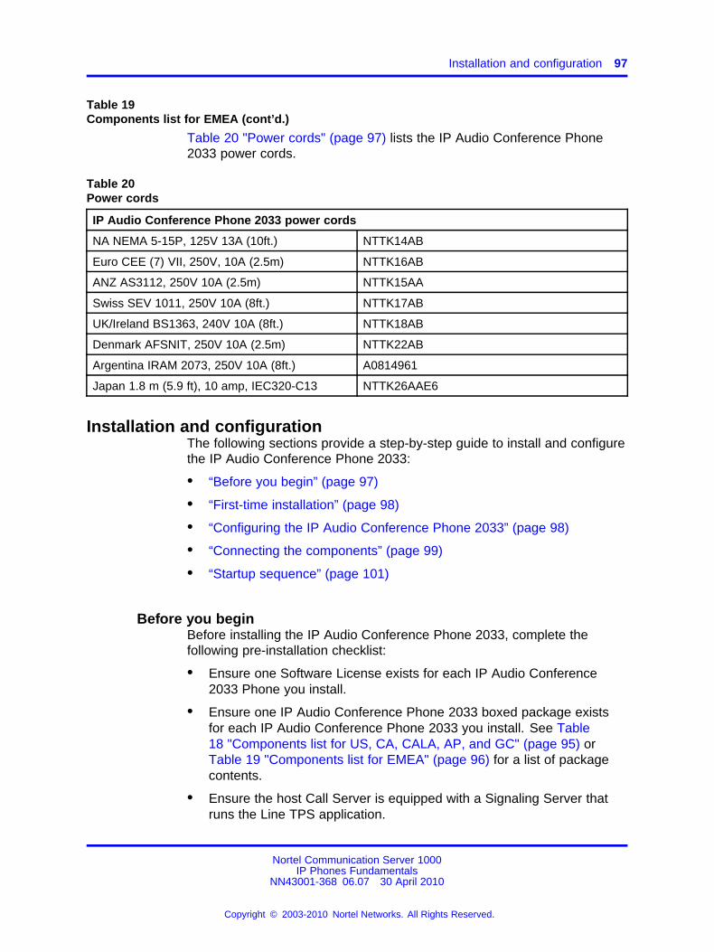
Installation and configuration 97
Table 19Components list for EMEA (cont’d.)
Table 20 "Power cords" (page 97) lists the IP Audio Conference Phone2033 power cords.
Table 20Power cords
IP Audio Conference Phone 2033 power cords
NA NEMA 5-15P, 125V 13A (10ft.) NTTK14AB
Euro CEE (7) VII, 250V, 10A (2.5m) NTTK16AB
ANZ AS3112, 250V 10A (2.5m) NTTK15AA
Swiss SEV 1011, 250V 10A (8ft.) NTTK17AB
UK/Ireland BS1363, 240V 10A (8ft.) NTTK18AB
Denmark AFSNIT, 250V 10A (2.5m) NTTK22AB
Argentina IRAM 2073, 250V 10A (8ft.) A0814961
Japan 1.8 m (5.9 ft), 10 amp, IEC320-C13 NTTK26AAE6
Installation and configurationThe following sections provide a step-by-step guide to install and configurethe IP Audio Conference Phone 2033:
• “Before you begin” (page 97)
• “First-time installation” (page 98)
• “Configuring the IP Audio Conference Phone 2033” (page 98)
• “Connecting the components” (page 99)
• “Startup sequence” (page 101)
Before you beginBefore installing the IP Audio Conference Phone 2033, complete thefollowing pre-installation checklist:
• Ensure one Software License exists for each IP Audio Conference2033 Phone you install.
• Ensure one IP Audio Conference Phone 2033 boxed package existsfor each IP Audio Conference Phone 2033 you install. See Table18 "Components list for US, CA, CALA, AP, and GC" (page 95) orTable 19 "Components list for EMEA" (page 96) for a list of packagecontents.
• Ensure the host Call Server is equipped with a Signaling Server thatruns the Line TPS application.
Nortel Communication Server 1000IP Phones Fundamentals
NN43001-368 06.07 30 April 2010
Copyright © 2003-2010 Nortel Networks. All Rights Reserved.
.
98 Nortel IP Audio Conference Phone 2033
• If a global power supply is required, ensure you use the correct globalpower supply supplied by Nortel and country specific IEC cable. Thevoltage rating of the global power supply must match the wall outletvoltage. See Table 18 "Components list for US, CA, CALA, AP, andGC" (page 95) or Table 19 "Components list for EMEA" (page 96).
• Ensure the latest IP Phone firmware is deployed to the IP telephonynode. For more information, see Signaling Server IP Line ApplicationsFundamentals (NN43001-125).
First-time installationYou must first install an IP telephony node with the Communication Server.For information about installing an IP telephony node, see Signaling ServerIP Line Applications Fundamentals (NN43001-125).
CAUTIONService InterruptionDo not plug your IP Audio Conference Phone 2033 into an ISDNconnection. Severe damage can result.
Configuring the IP Audio Conference Phone 2033Use Procedure 17 “Configuring the IP Audio Conference Phone 2033”(page 98) to configure the IP Audio Conference Phone 2033 for the firsttime.
Procedure 17Configuring the IP Audio Conference Phone 2033
Step Action
1 Configure a virtual loop on the system using LD 97.
For more information about configuring a virtual loop, seeSignaling Server IP Line Applications Fundamentals (NN43001-125) and Software Input Output Reference-Administration(NN43001-611).
2 Configure the IP Audio Conference Phone 2033 on the systemusing LD 11. At the prompts, enter the following:
REQ:newTYPE:2033TN lll s cc uuECHG yesITEM clsITEM
For more information about configuring the IP Audio ConferencePhone 2033 using LD 11, see Software Input OutputReference-Administration (NN43001-611).
Nortel Communication Server 1000IP Phones Fundamentals
NN43001-368 06.07 30 April 2010
Copyright © 2003-2010 Nortel Networks. All Rights Reserved.
.
Installation and configuration 99
3 Configure the IP Audio Conference Phone 2033 in ElementManager. IP Phones are configured using the Phones sectionin the Element Manager navigation tree. For more informationabout configuring the IP Audio Conference Phone 2033 usingElement Manager, see Element Manager System Reference -Administration (NN43001-632).
--End--
Connecting the componentsUse Procedure 18 “Connecting the components” (page 99) to connect thecomponents for the IP Phone.
Procedure 18Connecting the components
Step Action
1 Connect one end of the CAT5-e Ethernet cable to the networkinterface located on the back of the Power over Ethernet (PoE)module. See Figure 16 "POE module" (page 100). Plug theother end of the CAT5-e Ethernet cable into your IP networkinterface.
2 Connect the CAT5-e Ethernet cable attached to the PoE moduleto the IP Phone. Thread the CAT5-e Ethernet cable through thechannel on the bottom of the IP Phone and plug it into the PoEmodule port on the IP Phone.
The PoE module port supports Auto-Media Dependent InterfaceCrossover (MDIX). Auto-MDIX is supported only when theEthernet port is configured for autonegotiation.
3 Connect the global power supply (optional) to the power supplyport located on the back of the PoE module. Leave the globalpower supply unplugged from the power outlet. Thread the cordthrough the channel on the bottom of the PoE module thenplug the other end into the AC power source. Ensure you usethe correct global power supply supplied by Nortel and countryspecific IEC cable. The voltage rating of the global power supplymust match the wall outlet voltage. See Table 18 "Componentslist for US, CA, CALA, AP, and GC" (page 95) or Table 19"Components list for EMEA" (page 96).
Figure 16 "POE module" (page 100) shows the Power overEthernet (PoE) module.
Nortel Communication Server 1000IP Phones Fundamentals
NN43001-368 06.07 30 April 2010
Copyright © 2003-2010 Nortel Networks. All Rights Reserved.
.
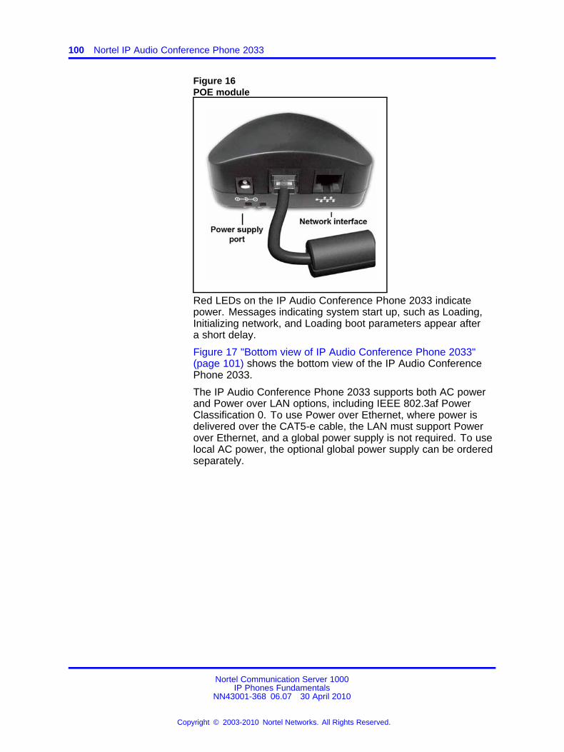
100 Nortel IP Audio Conference Phone 2033
Figure 16POE module
Red LEDs on the IP Audio Conference Phone 2033 indicatepower. Messages indicating system start up, such as Loading,Initializing network, and Loading boot parameters appear aftera short delay.
Figure 17 "Bottom view of IP Audio Conference Phone 2033"(page 101) shows the bottom view of the IP Audio ConferencePhone 2033.
The IP Audio Conference Phone 2033 supports both AC powerand Power over LAN options, including IEEE 802.3af PowerClassification 0. To use Power over Ethernet, where power isdelivered over the CAT5-e cable, the LAN must support Powerover Ethernet, and a global power supply is not required. To uselocal AC power, the optional global power supply can be orderedseparately.
Nortel Communication Server 1000IP Phones Fundamentals
NN43001-368 06.07 30 April 2010
Copyright © 2003-2010 Nortel Networks. All Rights Reserved.
.
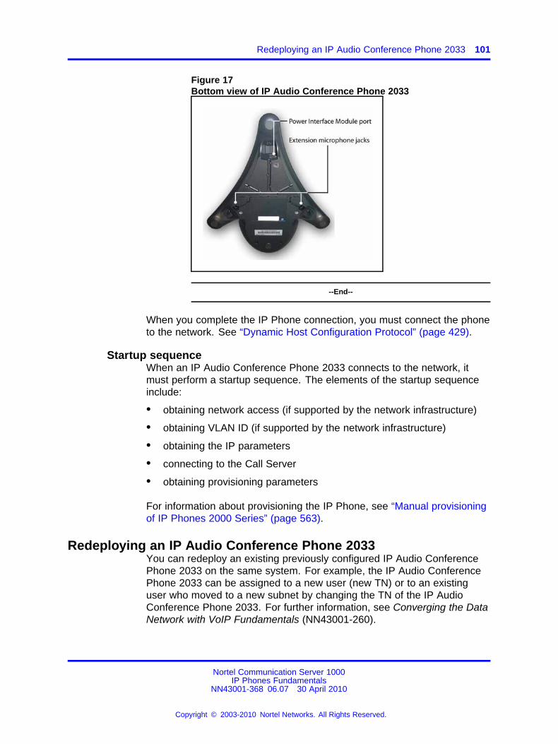
Redeploying an IP Audio Conference Phone 2033 101
Figure 17Bottom view of IP Audio Conference Phone 2033
--End--
When you complete the IP Phone connection, you must connect the phoneto the network. See “Dynamic Host Configuration Protocol” (page 429).
Startup sequenceWhen an IP Audio Conference Phone 2033 connects to the network, itmust perform a startup sequence. The elements of the startup sequenceinclude:
• obtaining network access (if supported by the network infrastructure)
• obtaining VLAN ID (if supported by the network infrastructure)
• obtaining the IP parameters
• connecting to the Call Server
• obtaining provisioning parameters
For information about provisioning the IP Phone, see “Manual provisioningof IP Phones 2000 Series” (page 563).
Redeploying an IP Audio Conference Phone 2033You can redeploy an existing previously configured IP Audio ConferencePhone 2033 on the same system. For example, the IP Audio ConferencePhone 2033 can be assigned to a new user (new TN) or to an existinguser who moved to a new subnet by changing the TN of the IP AudioConference Phone 2033. For further information, see Converging the DataNetwork with VoIP Fundamentals (NN43001-260).
Nortel Communication Server 1000IP Phones Fundamentals
NN43001-368 06.07 30 April 2010
Copyright © 2003-2010 Nortel Networks. All Rights Reserved.
.
102 Nortel IP Audio Conference Phone 2033
Procedure 19Changing the TN of an existing IP Audio Conference Phone 2033
Step Action
1 Repower the IP Audio Conference Phone 2033.
During the reboot sequence of a previously configured theIP Audio Conference Phone 2033 displays the existing nodenumber for approximately five seconds.
2 If the node password is enabled and NULL, choose one of thefollowing:
a Disable the password.
b Set the password as non-NULL.
3 Press OK when the node number displays.
If Then
the node password is enabledand is not NULL
a password screen displays. Goto Step 4.
the node password is disabled a TN screen displays. Go to Step5.
4 Enter the password at the password screen, and press OK.
A TN screen displays.
To obtain the password, enter the nodePwdShow command inElement Manager. For further information, see Element ManagerSystem Reference - Administration (NN43001-632).
5 Select the Shift soft key labeled (>>) and press Clear to edit theTN field. The IP Audio Conference Phone 2033 by default placesyou in the units field of the TN. You cannot use backspace tomove to the loop, shelf or card fields.
6 Enter the new TN.
--End--
Replacing an IP Audio Conference Phone 2033ATTENTIONTwo IP Phones cannot share the same TN. You must remove the IP AudioConference Phone 2033 that currently uses the TN.
Procedure 20Replacing an IP Audio Conference Phone 2033
Nortel Communication Server 1000IP Phones Fundamentals
NN43001-368 06.07 30 April 2010
Copyright © 2003-2010 Nortel Networks. All Rights Reserved.
.
Connecting an extension microphone 103
Step Action
1 Obtain the node and TN information of the phone you want toreplace.
2 Disconnect the IP Audio Conference Phone 2033 that you wantto replace.
3 Follow “Configuring the IP Audio Conference Phone 2033” (page98) to install the IP Audio Conference Phone 2033. To configurethe IP Phone, see “Manual provisioning of IP Phones 2000Series” (page 563).
4 Enter the same TN and Node Number as the IP AudioConference Phone 2033 you replaced. The system associatesthe new IP Audio Conference Phone 2033 with the existing TN.
--End--
Removing an IP Audio Conference Phone 2033 from serviceProcedure 21Removing an IP Audio Conference Phone 2033 from service
Step Action
1 Disconnect the IP Audio Conference Phone 2033 from thenetwork or turn off the power.
If the IP Audio Conference Phone 2033 was automaticallyconfigured, the DHCP lease expires and the IP address returnsto the available pool.
2 In LD 11, enter the following:REQ: OUTTYPE: 2033TN: LLL S CC UU
--End--
Connecting an extension microphoneProcedure 22Connecting an extension microphone to the IP Audio Conference Phone2033
Step Action
1 Thread the microphone cord through the channels on the bottomof the IP Phone.
Nortel Communication Server 1000IP Phones Fundamentals
NN43001-368 06.07 30 April 2010
Copyright © 2003-2010 Nortel Networks. All Rights Reserved.
.

104 Nortel IP Audio Conference Phone 2033
A maximum of two microphone jacks are supported on the IPAudio Conference Phone 2033.
2 Connect the microphone cord to one of the microphone jacks onthe bottom of the IP Phone.
--End--
Nortel Communication Server 1000IP Phones Fundamentals
NN43001-368 06.07 30 April 2010
Copyright © 2003-2010 Nortel Networks. All Rights Reserved.
.
105.
Nortel IP Phone 2007
ContentsThis section contains the following topics:
• “Introduction” (page 105)
• “Description” (page 106)
• “Components and functions” (page 106)
• “Features” (page 110)
• “Touch panel” (page 110)
• “Dialpad entry” (page 112)
• “Cleaning the IP Phone display screen” (page 113)
• “Display characteristics” (page 113)
• “Package components” (page 118)
• “Installation and configuration” (page 119)
• “Redeploying an IP Phone 2007” (page 121)
• “Replacing an IP Phone 2007” (page 122)
• “Removing an IP Phone 2007 from service” (page 123)
IntroductionThis section explains how to install and maintain the IP Phone 2007. Forinformation about using the IP Phone 2007, see the IP Phone 2007 UserGuide (NN43118-100).
This section contains the following procedures:
• Procedure 24 “Configuring the IP Phone 2007” (page 120)
• “Connecting the components” (page 121)
• Procedure 25 “Changing the TN of an existing IP Phone 2007” (page121).
Nortel Communication Server 1000IP Phones Fundamentals
NN43001-368 06.07 30 April 2010
Copyright © 2003-2010 Nortel Networks. All Rights Reserved.
.
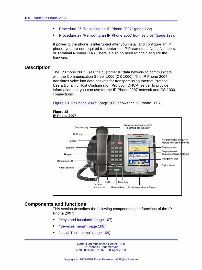
106 Nortel IP Phone 2007
• Procedure 26 “Replacing an IP Phone 2007” (page 122).
• Procedure 27 “Removing an IP Phone 2007 from service” (page 123).
If power to the phone is interrupted after you install and configure an IPphone, you are not required to reenter the IP Parameters, Node Numbers,or Terminal Number (TN). There is also no need to again acquire thefirmware.
DescriptionThe IP Phone 2007 uses the customer IP data network to communicatewith the Communication Server 1000 (CS 1000). The IP Phone 2007translates voice into data packets for transport using Internet Protocol.Use a Dynamic Host Configuration Protocol (DHCP) server to provideinformation that you can use for the IP Phone 2007 network and CS 1000connections.
Figure 18 "IP Phone 2007" (page 106) shows the IP Phone 2007.
Figure 18IP Phone 2007
Components and functionsThis section describes the following components and functions of the IPPhone 2007:
• “Keys and functions” (page 107)
• “Services menu” (page 108)
• “Local Tools menu” (page 109)
Nortel Communication Server 1000IP Phones Fundamentals
NN43001-368 06.07 30 April 2010
Copyright © 2003-2010 Nortel Networks. All Rights Reserved.
.
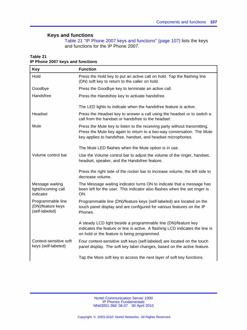
Components and functions 107
Keys and functionsTable 21 "IP Phone 2007 keys and functions" (page 107) lists the keysand functions for the IP Phone 2007.
Table 21IP Phone 2007 keys and functions
Key Function
Hold Press the Hold key to put an active call on hold. Tap the flashing line(DN) soft key to return to the caller on hold.
Goodbye Press the Goodbye key to terminate an active call.
Handsfree Press the Handsfree key to activate handsfree.
The LED lights to indicate when the handsfree feature is active.
Headset Press the Headset key to answer a call using the headset or to switch acall from the handset or handsfree to the headset.
Mute Press the Mute key to listen to the receiving party without transmitting.Press the Mute key again to return to a two-way conversation. The Mutekey applies to handsfree, handset, and headset microphones.
The Mute LED flashes when the Mute option is in use.
Volume control bar Use the Volume control bar to adjust the volume of the ringer, handset,headset, speaker, and the Handsfree feature.
Press the right side of the rocker bar to increase volume, the left side todecrease volume.
Message waitinglight/incoming callindicator
The Message waiting indicator turns ON to indicate that a message hasbeen left for the user. This indicator also flashes when the set ringer isON.
Programmable line(DN)/feature keys(self-labeled)
Programmable line (DN)/feature keys (self-labeled) are located on thetouch panel display and are configured for various features on the IPPhones.
A steady LCD light beside a programmable line (DN)/feature keyindicates the feature or line is active. A flashing LCD indicates the line ison hold or the feature is being programmed.
Context-sensitive softkeys (self-labeled)
Four context-sensitive soft keys (self-labeled) are located on the touchpanel display. The soft key label changes, based on the active feature.
Tap the More soft key to access the next layer of soft key functions.
Nortel Communication Server 1000IP Phones Fundamentals
NN43001-368 06.07 30 April 2010
Copyright © 2003-2010 Nortel Networks. All Rights Reserved.
.
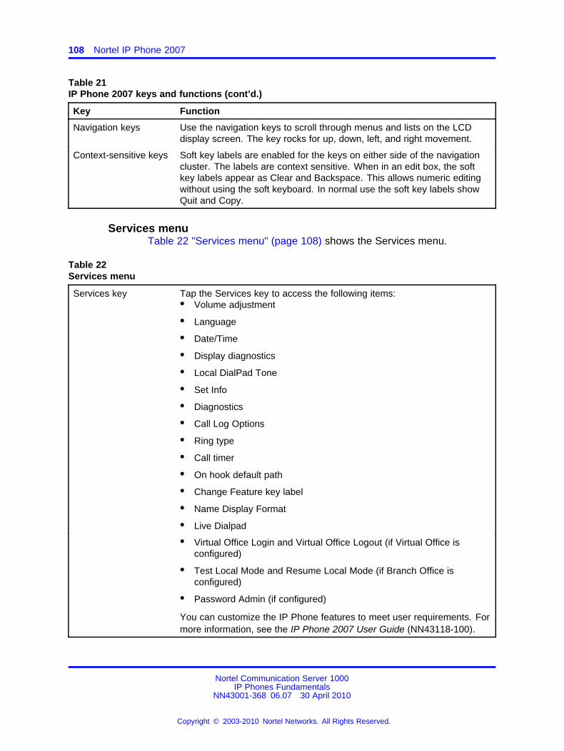
108 Nortel IP Phone 2007
Table 21IP Phone 2007 keys and functions (cont’d.)
Key Function
Navigation keys Use the navigation keys to scroll through menus and lists on the LCDdisplay screen. The key rocks for up, down, left, and right movement.
Context-sensitive keys Soft key labels are enabled for the keys on either side of the navigationcluster. The labels are context sensitive. When in an edit box, the softkey labels appear as Clear and Backspace. This allows numeric editingwithout using the soft keyboard. In normal use the soft key labels showQuit and Copy.
Services menuTable 22 "Services menu" (page 108) shows the Services menu.
Table 22Services menu
Services key Tap the Services key to access the following items:• Volume adjustment
• Language
• Date/Time
• Display diagnostics
• Local DialPad Tone
• Set Info
• Diagnostics
• Call Log Options
• Ring type
• Call timer
• On hook default path
• Change Feature key label
• Name Display Format
• Live Dialpad
• Virtual Office Login and Virtual Office Logout (if Virtual Office isconfigured)
• Test Local Mode and Resume Local Mode (if Branch Office isconfigured)
• Password Admin (if configured)
You can customize the IP Phone features to meet user requirements. Formore information, see the IP Phone 2007 User Guide (NN43118-100).
Nortel Communication Server 1000IP Phones Fundamentals
NN43001-368 06.07 30 April 2010
Copyright © 2003-2010 Nortel Networks. All Rights Reserved.
.
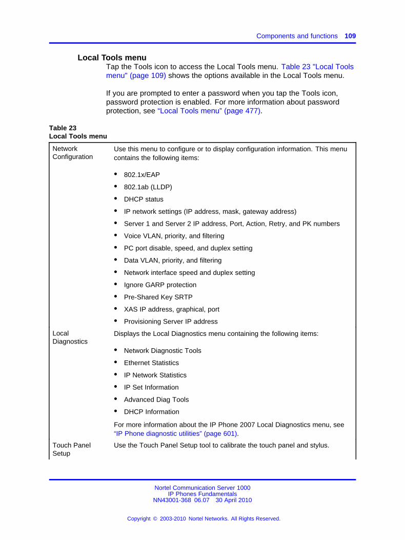
Components and functions 109
Local Tools menuTap the Tools icon to access the Local Tools menu. Table 23 "Local Toolsmenu" (page 109) shows the options available in the Local Tools menu.
If you are prompted to enter a password when you tap the Tools icon,password protection is enabled. For more information about passwordprotection, see “Local Tools menu” (page 477).
Table 23Local Tools menu
NetworkConfiguration
Use this menu to configure or to display configuration information. This menucontains the following items:
• 802.1x/EAP
• 802.1ab (LLDP)
• DHCP status
• IP network settings (IP address, mask, gateway address)
• Server 1 and Server 2 IP address, Port, Action, Retry, and PK numbers
• Voice VLAN, priority, and filtering
• PC port disable, speed, and duplex setting
• Data VLAN, priority, and filtering
• Network interface speed and duplex setting
• Ignore GARP protection
• Pre-Shared Key SRTP
• XAS IP address, graphical, port
• Provisioning Server IP address
LocalDiagnostics
Displays the Local Diagnostics menu containing the following items:
• Network Diagnostic Tools
• Ethernet Statistics
• IP Network Statistics
• IP Set Information
• Advanced Diag Tools
• DHCP Information
For more information about the IP Phone 2007 Local Diagnostics menu, see“IP Phone diagnostic utilities” (page 601).
Touch PanelSetup
Use the Touch Panel Setup tool to calibrate the touch panel and stylus.
Nortel Communication Server 1000IP Phones Fundamentals
NN43001-368 06.07 30 April 2010
Copyright © 2003-2010 Nortel Networks. All Rights Reserved.
.
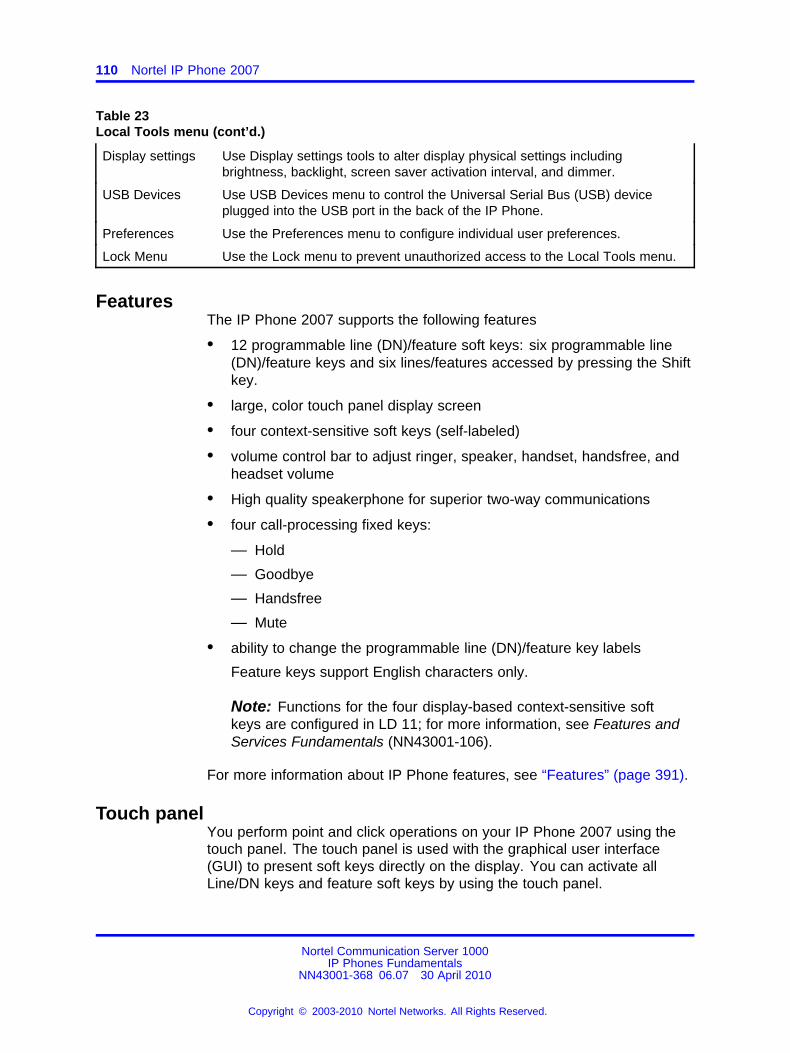
110 Nortel IP Phone 2007
Table 23Local Tools menu (cont’d.)
Display settings Use Display settings tools to alter display physical settings includingbrightness, backlight, screen saver activation interval, and dimmer.
USB Devices Use USB Devices menu to control the Universal Serial Bus (USB) deviceplugged into the USB port in the back of the IP Phone.
Preferences Use the Preferences menu to configure individual user preferences.
Lock Menu Use the Lock menu to prevent unauthorized access to the Local Tools menu.
FeaturesThe IP Phone 2007 supports the following features
• 12 programmable line (DN)/feature soft keys: six programmable line(DN)/feature keys and six lines/features accessed by pressing the Shiftkey.
• large, color touch panel display screen
• four context-sensitive soft keys (self-labeled)
• volume control bar to adjust ringer, speaker, handset, handsfree, andheadset volume
• High quality speakerphone for superior two-way communications
• four call-processing fixed keys:
— Hold
— Goodbye
— Handsfree
— Mute
• ability to change the programmable line (DN)/feature key labels
Feature keys support English characters only.
Note: Functions for the four display-based context-sensitive softkeys are configured in LD 11; for more information, see Features andServices Fundamentals (NN43001-106).
For more information about IP Phone features, see “Features” (page 391).
Touch panelYou perform point and click operations on your IP Phone 2007 using thetouch panel. The touch panel is used with the graphical user interface(GUI) to present soft keys directly on the display. You can activate allLine/DN keys and feature soft keys by using the touch panel.
Nortel Communication Server 1000IP Phones Fundamentals
NN43001-368 06.07 30 April 2010
Copyright © 2003-2010 Nortel Networks. All Rights Reserved.
.
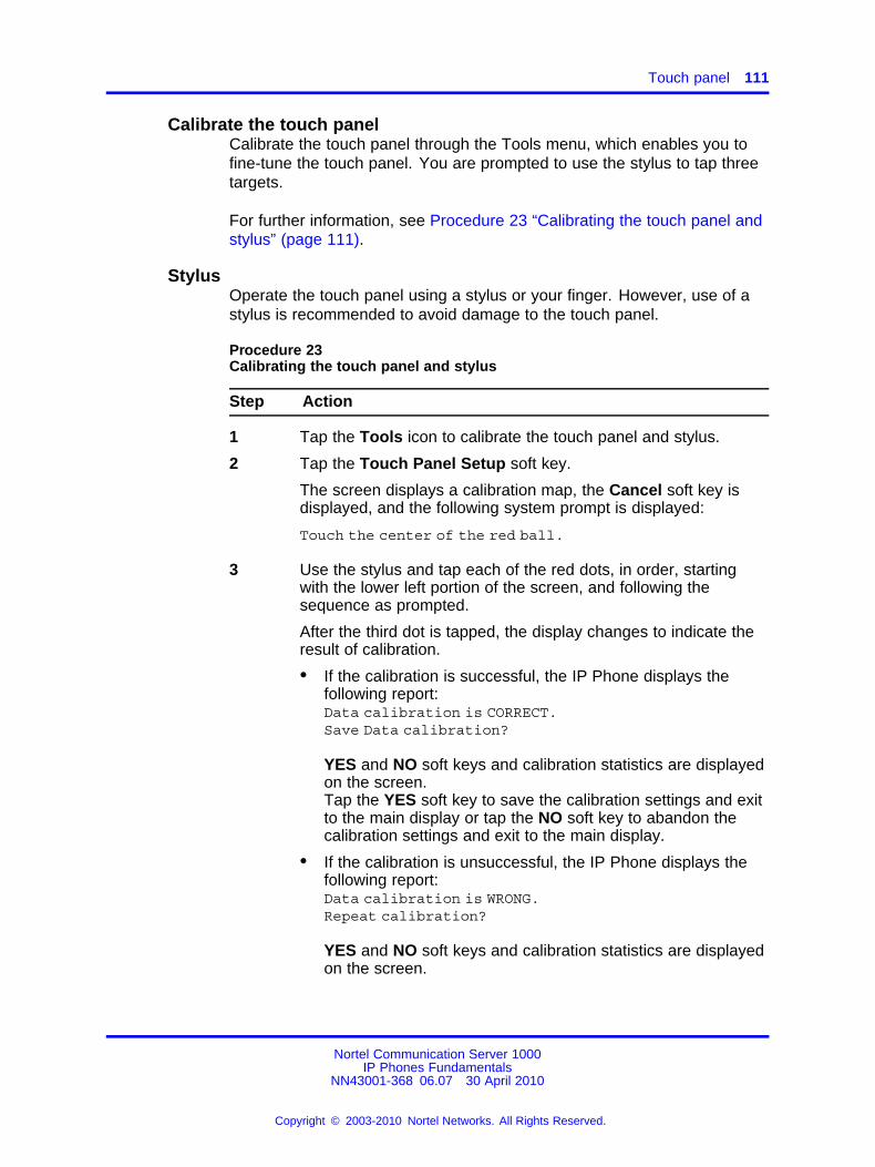
Touch panel 111
Calibrate the touch panelCalibrate the touch panel through the Tools menu, which enables you tofine-tune the touch panel. You are prompted to use the stylus to tap threetargets.
For further information, see Procedure 23 “Calibrating the touch panel andstylus” (page 111).
StylusOperate the touch panel using a stylus or your finger. However, use of astylus is recommended to avoid damage to the touch panel.
Procedure 23Calibrating the touch panel and stylus
Step Action
1 Tap the Tools icon to calibrate the touch panel and stylus.
2 Tap the Touch Panel Setup soft key.
The screen displays a calibration map, the Cancel soft key isdisplayed, and the following system prompt is displayed:
Touch the center of the red ball.
3 Use the stylus and tap each of the red dots, in order, startingwith the lower left portion of the screen, and following thesequence as prompted.
After the third dot is tapped, the display changes to indicate theresult of calibration.
• If the calibration is successful, the IP Phone displays thefollowing report:Data calibration is CORRECT.Save Data calibration?
YES and NO soft keys and calibration statistics are displayedon the screen.Tap the YES soft key to save the calibration settings and exitto the main display or tap the NO soft key to abandon thecalibration settings and exit to the main display.
• If the calibration is unsuccessful, the IP Phone displays thefollowing report:Data calibration is WRONG.Repeat calibration?
YES and NO soft keys and calibration statistics are displayedon the screen.
Nortel Communication Server 1000IP Phones Fundamentals
NN43001-368 06.07 30 April 2010
Copyright © 2003-2010 Nortel Networks. All Rights Reserved.
.
112 Nortel IP Phone 2007
Tap the YES soft key to retry the calibration or tap the NOsoft key to abandon the calibration and return to the maindisplay.
--End--
Dialpad entryCertain configuration items on the phone require alpha-numeric, specialcharacters or hex input, depending on the input field. For ease of use,Nortel recommends the use of the external USB keyboard. Nortel IPPhone 2007 also provides an on-screen touch keyboard to facilitate datainput. However, dialpad may also be used for entering alpha-numeric orspecial characters.
The following rules apply when you enter text and special characters usingthe dialpad.
• Press a key from 0 to 9 once to enter the corresponding number.
• Press a key from 2 to 9 repeatedly to cycle through the lettersassigned to that key, first in lower case and then in upper case.
For example, if you press the 5 key repeatedly, the followingcharacters are displayed, one at a time:
j -> k -> l -> J -> K -> L -> 5 ->
See Table 24 "Character key mappings" (page 113) for character keymappings.
• The insertion point remains in its current position as long as youcontinue to press the same key.
• The entry is accepted if either a new key is pressed or if two secondspass with no entry. The insertion point moves 1 space to the right.
For example, to enter the word Nortel, press the following keysequence:
6 [2 second delay] 6 7 8 3 5
Although special characters are not required, key 1 generatescommonly used special characters, such as the period (.), at symbol(@), and underscore (_).
• Double press the asterisk key ** to generate a period (.). This is auseful shortcut when entering IP addresses.
Nortel Communication Server 1000IP Phones Fundamentals
NN43001-368 06.07 30 April 2010
Copyright © 2003-2010 Nortel Networks. All Rights Reserved.
.
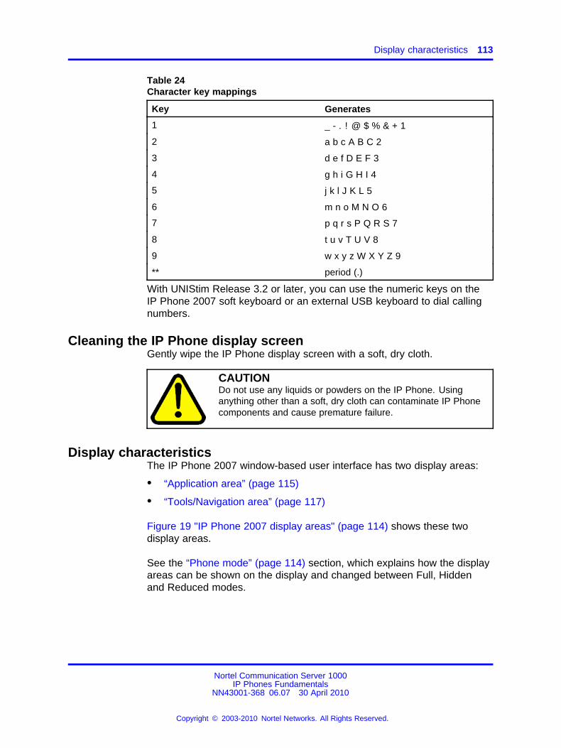
Display characteristics 113
Table 24Character key mappings
Key Generates
1 _ - . ! @ $ % & + 1
2 a b c A B C 2
3 d e f D E F 3
4 g h i G H I 4
5 j k l J K L 5
6 m n o M N O 6
7 p q r s P Q R S 7
8 t u v T U V 8
9 w x y z W X Y Z 9
** period (.)
With UNIStim Release 3.2 or later, you can use the numeric keys on theIP Phone 2007 soft keyboard or an external USB keyboard to dial callingnumbers.
Cleaning the IP Phone display screenGently wipe the IP Phone display screen with a soft, dry cloth.
CAUTIONDo not use any liquids or powders on the IP Phone. Usinganything other than a soft, dry cloth can contaminate IP Phonecomponents and cause premature failure.
Display characteristicsThe IP Phone 2007 window-based user interface has two display areas:
• “Application area” (page 115)
• “Tools/Navigation area” (page 117)
Figure 19 "IP Phone 2007 display areas" (page 114) shows these twodisplay areas.
See the “Phone mode” (page 114) section, which explains how the displayareas can be shown on the display and changed between Full, Hiddenand Reduced modes.
Nortel Communication Server 1000IP Phones Fundamentals
NN43001-368 06.07 30 April 2010
Copyright © 2003-2010 Nortel Networks. All Rights Reserved.
.
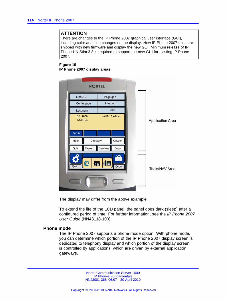
114 Nortel IP Phone 2007
ATTENTIONThere are changes to the IP Phone 2007 graphical user interface (GUI),including color and icon changes on the display. New IP Phone 2007 units areshipped with new firmware and display the new GUI. Minimum release of IPPhone UNIStim 3.3 is required to support the new GUI for existing IP Phone2007.
Figure 19IP Phone 2007 display areas
The display may differ from the above example.
To extend the life of the LCD panel, the panel goes dark (sleep) after aconfigured period of time. For further information, see the IP Phone 2007User Guide (NN43118-100).
Phone modeThe IP Phone 2007 supports a phone mode option. With phone mode,you can determine which portion of the IP Phone 2007 display screen isdedicated to telephony display and which portion of the display screenis controlled by applications, which are driven by external applicationgateways.
Nortel Communication Server 1000IP Phones Fundamentals
NN43001-368 06.07 30 April 2010
Copyright © 2003-2010 Nortel Networks. All Rights Reserved.
.
Display characteristics 115
The following three phone modes are available with the IP Phone 2007:
• Full— default screen mode, which displays the full telephony screen.
Full screen phone mode can be hidden behind applications controlledby an application gateway (for example, the Nortel ApplicationGateway 2000) and automatically appears in the foreground when youreceive an incoming call, pick up the handset, or press the hands freeor headset key.
If the toolbar at the bottom of the IP Phone display screen is visible,you can force the telephony screen to appear in the foreground bytouching the telephone icon.
• Hidden—telephony screen remains hidden behind applicationscontrolled by an application gateway and does not automaticallyappear in the foreground when you receive an incoming call, pick upthe handset, or press the hands free or headset key.
When you select Hidden screen phone mode, the toolbar at the bottomof the IP Phone display screen is not visible and the Hold key isdisabled.
You can force the telephony screen (with the toolbar) to appearby entering the special key sequence, **26344##. By forcing thetelephony screen to appear, you can perform configurations thatrequire the IP Phone display screen interface (for example, Node andTN entry or access to the toolbar).
• Reduced—IP Phone telephony screen appears as a small window witha reduced number of telephony items displayed. In Reduced screenphone mode, the following apply:
— Information messages and caller ID remain displayed.
— You can access only two line appearance Auto Dial keys.
— You cannot access any soft keys (including, Inbox, Directory,Services, and Copy).
The remainder of the IP Phone display screen is controlled by anapplication gateway application, including the section at the bottom ofthe screen, where the toolbar typically appears.
You can force the toolbar to appear by entering the special keysequence, **26344##.
The Reduced screen phone mode is useful when you require basicphone functionality and application access at the same time.
Application areaThe Application area provides:
• “Programmable line (DN)/feature key label display” (page 116)
• “Information line display ” (page 116)
Nortel Communication Server 1000IP Phones Fundamentals
NN43001-368 06.07 30 April 2010
Copyright © 2003-2010 Nortel Networks. All Rights Reserved.
.
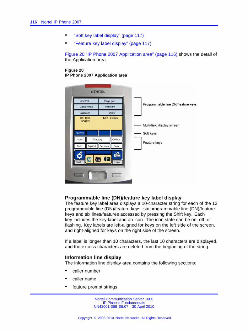
116 Nortel IP Phone 2007
• “Soft key label display” (page 117)
• “Feature key label display” (page 117)
Figure 20 "IP Phone 2007 Application area" (page 116) shows the detail ofthe Application area.
Figure 20IP Phone 2007 Application area
Programmable line (DN)/feature key label displayThe feature key label area displays a 10-character string for each of the 12programmable line (DN)/feature keys: six programmable line (DN)/featurekeys and six lines/features accessed by pressing the Shift key. Eachkey includes the key label and an icon. The icon state can be on, off, orflashing. Key labels are left-aligned for keys on the left side of the screen,and right-aligned for keys on the right side of the screen.
If a label is longer than 10 characters, the last 10 characters are displayed,and the excess characters are deleted from the beginning of the string.
Information line displayThe information line display area contains the following sections:
• caller number
• caller name
• feature prompt strings
Nortel Communication Server 1000IP Phones Fundamentals
NN43001-368 06.07 30 April 2010
Copyright © 2003-2010 Nortel Networks. All Rights Reserved.
.
Display characteristics 117
• user-entered digits
• date and time information or Call Timer (if provisioned in the Telephoneoptions menu)
• set information
Soft key label displayUse the More key to navigate through the layers of functions. If only fourfunctions are assigned to the soft keys, the More key does not appear,and all four functions are displayed.
The soft key label has a maximum of seven characters. Each soft keyincludes the soft key label and an icon. When a soft key is in use, atriangle icon displays at the beginning of the soft key label, and the labelshifts one character to the right. (If the label is six characters in length, thelast or rightmost character is truncated.) If a soft key is enabled, the iconstate changes to on. It remains in the on state until the soft key is pressedagain. This cancels the enabled soft key and turns the icon off, returningthe soft key label to its original state.
Soft key labels support different languages.
Feature key label displayThe feature key labels may show either text or icons. The text labels aredisplayed by default and are changed using the Tools menu. For furtherinformation about the feature keys and their icon equivalents, see the IPPhone 2007 User Guide (NN43118-100).
Tools/Navigation areaThe Tools/Navigation area provides controls for navigating betweenfeatures and selecting tools.
The following five main elements are presented as touchable keys:
• Tools
• Primary application
• Applications
• Telephone
• Keyboard
Figure 21 "IP Phone 2007 Tools/Navigation area" (page 118) shows theTools/Navigation area.
Nortel Communication Server 1000IP Phones Fundamentals
NN43001-368 06.07 30 April 2010
Copyright © 2003-2010 Nortel Networks. All Rights Reserved.
.
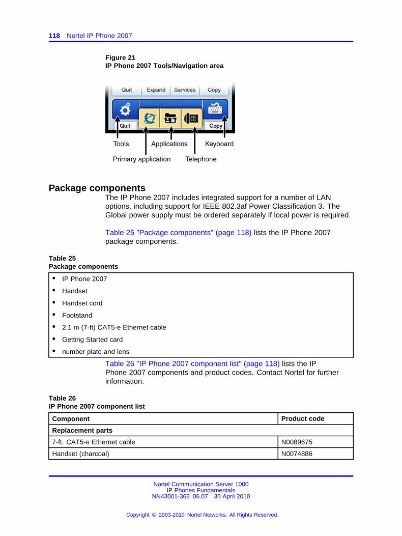
118 Nortel IP Phone 2007
Figure 21IP Phone 2007 Tools/Navigation area
Package componentsThe IP Phone 2007 includes integrated support for a number of LANoptions, including support for IEEE 802.3af Power Classification 3. TheGlobal power supply must be ordered separately if local power is required.
Table 25 "Package components" (page 118) lists the IP Phone 2007package components.
Table 25Package components
• IP Phone 2007
• Handset
• Handset cord
• Footstand
• 2.1 m (7-ft) CAT5-e Ethernet cable
• Getting Started card
• number plate and lens
Table 26 "IP Phone 2007 component list" (page 118) lists the IPPhone 2007 components and product codes. Contact Nortel for furtherinformation.
Table 26IP Phone 2007 component list
Component Product code
Replacement parts
7-ft. CAT5-e Ethernet cable N0089675
Handset (charcoal) N0074886
Nortel Communication Server 1000IP Phones Fundamentals
NN43001-368 06.07 30 April 2010
Copyright © 2003-2010 Nortel Networks. All Rights Reserved.
.
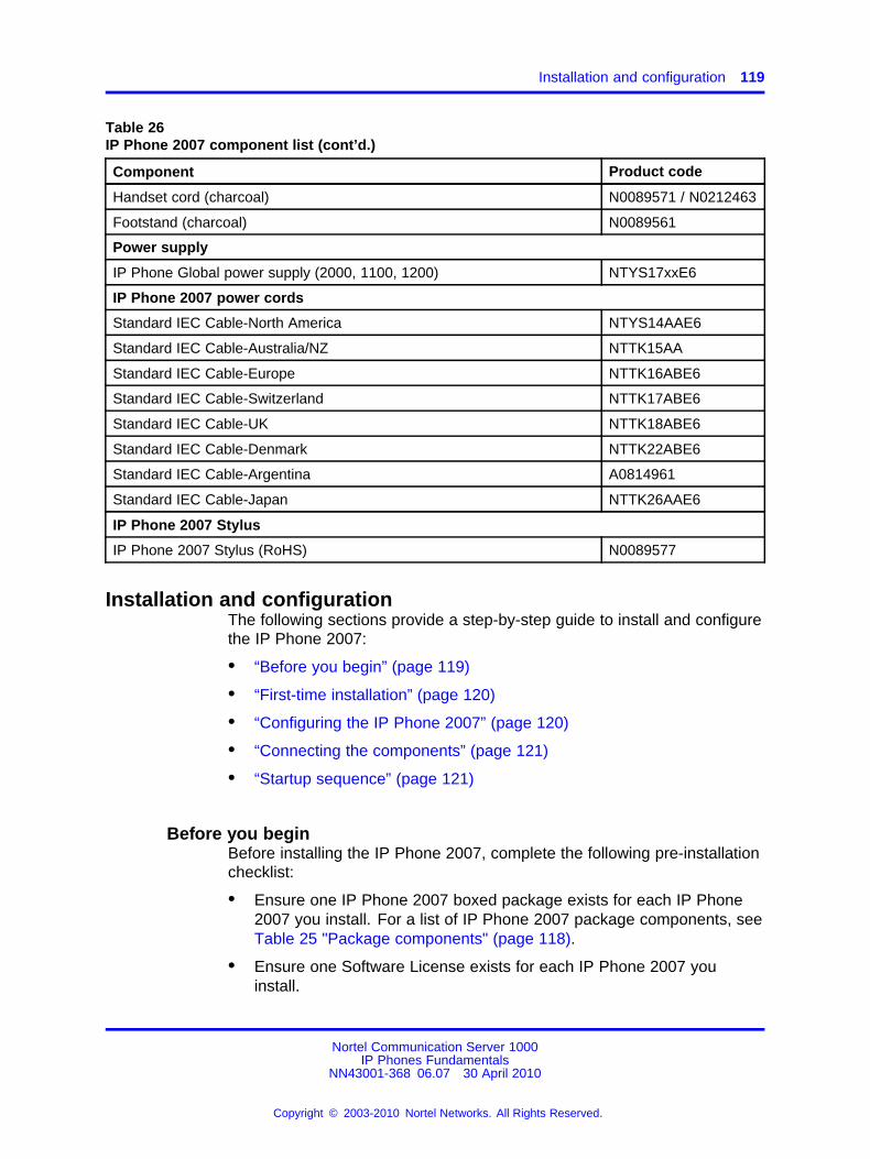
Installation and configuration 119
Table 26IP Phone 2007 component list (cont’d.)
Component Product code
Handset cord (charcoal) N0089571 / N0212463
Footstand (charcoal) N0089561
Power supply
IP Phone Global power supply (2000, 1100, 1200) NTYS17xxE6
IP Phone 2007 power cords
Standard IEC Cable-North America NTYS14AAE6
Standard IEC Cable-Australia/NZ NTTK15AA
Standard IEC Cable-Europe NTTK16ABE6
Standard IEC Cable-Switzerland NTTK17ABE6
Standard IEC Cable-UK NTTK18ABE6
Standard IEC Cable-Denmark NTTK22ABE6
Standard IEC Cable-Argentina A0814961
Standard IEC Cable-Japan NTTK26AAE6
IP Phone 2007 Stylus
IP Phone 2007 Stylus (RoHS) N0089577
Installation and configurationThe following sections provide a step-by-step guide to install and configurethe IP Phone 2007:
• “Before you begin” (page 119)
• “First-time installation” (page 120)
• “Configuring the IP Phone 2007” (page 120)
• “Connecting the components” (page 121)
• “Startup sequence” (page 121)
Before you beginBefore installing the IP Phone 2007, complete the following pre-installationchecklist:
• Ensure one IP Phone 2007 boxed package exists for each IP Phone2007 you install. For a list of IP Phone 2007 package components, seeTable 25 "Package components" (page 118).
• Ensure one Software License exists for each IP Phone 2007 youinstall.
Nortel Communication Server 1000IP Phones Fundamentals
NN43001-368 06.07 30 April 2010
Copyright © 2003-2010 Nortel Networks. All Rights Reserved.
.
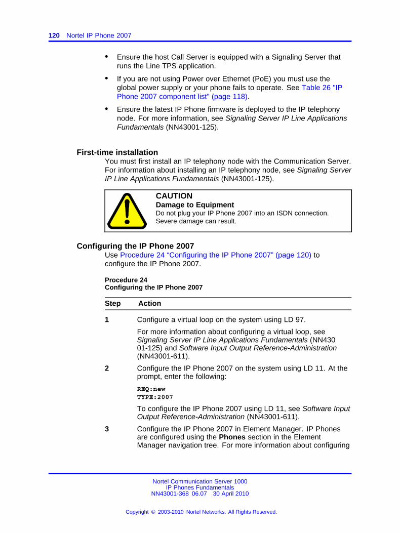
120 Nortel IP Phone 2007
• Ensure the host Call Server is equipped with a Signaling Server thatruns the Line TPS application.
• If you are not using Power over Ethernet (PoE) you must use theglobal power supply or your phone fails to operate. See Table 26 "IPPhone 2007 component list" (page 118).
• Ensure the latest IP Phone firmware is deployed to the IP telephonynode. For more information, see Signaling Server IP Line ApplicationsFundamentals (NN43001-125).
First-time installationYou must first install an IP telephony node with the Communication Server.For information about installing an IP telephony node, see Signaling ServerIP Line Applications Fundamentals (NN43001-125).
CAUTIONDamage to EquipmentDo not plug your IP Phone 2007 into an ISDN connection.Severe damage can result.
Configuring the IP Phone 2007Use Procedure 24 “Configuring the IP Phone 2007” (page 120) toconfigure the IP Phone 2007.
Procedure 24Configuring the IP Phone 2007
Step Action
1 Configure a virtual loop on the system using LD 97.
For more information about configuring a virtual loop, seeSignaling Server IP Line Applications Fundamentals (NN43001-125) and Software Input Output Reference-Administration(NN43001-611).
2 Configure the IP Phone 2007 on the system using LD 11. At theprompt, enter the following:
REQ:newTYPE:2007
To configure the IP Phone 2007 using LD 11, see Software InputOutput Reference-Administration (NN43001-611).
3 Configure the IP Phone 2007 in Element Manager. IP Phonesare configured using the Phones section in the ElementManager navigation tree. For more information about configuring
Nortel Communication Server 1000IP Phones Fundamentals
NN43001-368 06.07 30 April 2010
Copyright © 2003-2010 Nortel Networks. All Rights Reserved.
.
Redeploying an IP Phone 2007 121
the IP Phone 2007 using Element Manager, see ElementManager System Reference - Administration (NN43001-632).
--End--
Connecting the componentsSee the IP Phone 2007 User Guide (NN43118-100) or IP Phone 2007Getting Started card (NN43118-110) for instructions to connect the IPPhone 2007 components.
When you complete the IP Phone connection, you must connect the phoneto the network. See “Dynamic Host Configuration Protocol” (page 429).
Startup sequenceWhen an IP Phone 2007 connects to the network, it must perform a startupsequence. The elements of the startup sequence include:
• obtaining network access (if supported by the network infrastructure)
• obtaining VLAN ID (if supported by the network infrastructure)
• obtaining the IP parameters
• obtaining the automatic provisioning parameters
• connecting to the Call Server
The IP Phone is configured for automatic provisioning by default. Formore information about provisioning the IP Phone automatically, see“Provisioning the IP Phones” (page 497).
You can manually configure all or some parameters. For informationabout provisioning the IP Phone manually, see “Manual provisioning of IPPhones 2007 and 1100 Series” (page 553).
Redeploying an IP Phone 2007You can redeploy an existing, previously-configured IP Phone 2007 onthe same system. For example, the IP Phone 2007 can be assigned toa new user (new TN) or to an existing user who moved to a new subnetby changing the TN of the IP Phone 2007. For further information, seeConverging the Data Network with VoIP Fundamentals (NN43001-260).
Procedure 25Changing the TN of an existing IP Phone 2007
Step Action
1 Repower the IP Phone 2007.
Nortel Communication Server 1000IP Phones Fundamentals
NN43001-368 06.07 30 April 2010
Copyright © 2003-2010 Nortel Networks. All Rights Reserved.
.
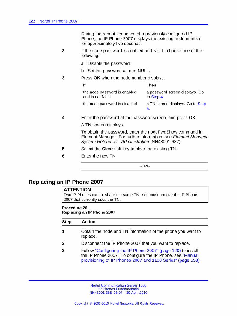
122 Nortel IP Phone 2007
During the reboot sequence of a previously configured IPPhone, the IP Phone 2007 displays the existing node numberfor approximately five seconds.
2 If the node password is enabled and NULL, choose one of thefollowing:
a Disable the password.
b Set the password as non-NULL.
3 Press OK when the node number displays.
If Then
the node password is enabledand is not NULL
a password screen displays. Goto Step 4.
the node password is disabled a TN screen displays. Go to Step5.
4 Enter the password at the password screen, and press OK.
A TN screen displays.
To obtain the password, enter the nodePwdShow command inElement Manager. For further information, see Element ManagerSystem Reference - Administration (NN43001-632).
5 Select the Clear soft key to clear the existing TN.
6 Enter the new TN.
--End--
Replacing an IP Phone 2007ATTENTIONTwo IP Phones cannot share the same TN. You must remove the IP Phone2007 that currently uses the TN.
Procedure 26Replacing an IP Phone 2007
Step Action
1 Obtain the node and TN information of the phone you want toreplace.
2 Disconnect the IP Phone 2007 that you want to replace.
3 Follow “Configuring the IP Phone 2007” (page 120) to installthe IP Phone 2007. To configure the IP Phone, see “Manualprovisioning of IP Phones 2007 and 1100 Series” (page 553).
Nortel Communication Server 1000IP Phones Fundamentals
NN43001-368 06.07 30 April 2010
Copyright © 2003-2010 Nortel Networks. All Rights Reserved.
.
Removing an IP Phone 2007 from service 123
Enter the same TN and Node Number as the IP Phone 2007 youreplaced. The system associates the new IP Phone 2007 withthe existing TN.
--End--
Removing an IP Phone 2007 from serviceProcedure 27Removing an IP Phone 2007 from service
Step Action
1 Disconnect the IP Phone 2007 from the network or turn thepower off.
The service to the PC is disconnected as well if the PC connectsto the IP Phone 2007.
If the IP Phone 2007 was automatically configured, the DHCPlease expires and the IP address returns to the available pool.
2 In LD 11, enter the following:REQ: OUTTYPE: 2007TN: LLL S CC UU
--End--
Nortel Communication Server 1000IP Phones Fundamentals
NN43001-368 06.07 30 April 2010
Copyright © 2003-2010 Nortel Networks. All Rights Reserved.
.

124 Nortel IP Phone 2007
Nortel Communication Server 1000IP Phones Fundamentals
NN43001-368 06.07 30 April 2010
Copyright © 2003-2010 Nortel Networks. All Rights Reserved.
.
125.
Nortel IP Phone 1210
ContentsThis section contains the following topics:
• “Introduction” (page 125)
• “Description” (page 126)
• “Components and functions” (page 127)
• “Features” (page 130)
• “Display characteristics” (page 130)
• “Package components” (page 132)
• “Installation and configuration” (page 133)
• “Redeploying an IP Phone 1210” (page 138)
• “Replacing an IP Phone 1210” (page 139)
• “Removing an IP Phone 1210 from service” (page 139)
IntroductionThis section explains how to install and maintain the IP Phone 1210. Forinformation about using the IP Phone 1210, see the IP Phone 1210 UserGuide (NN43140-101).
This section contains the following procedures:
• Procedure 28 “Configuring the IP Phone 1210” (page 134)
• Procedure 29 “Connecting the components” (page 135)
• Procedure 30 “Redeploying the TN of an existing IP Phone 1210”(page 138)
• Procedure 31 “Replacing an IP Phone 1210” (page 139)
• Procedure 32 “Removing an IP Phone 1210 from service” (page 139)
Nortel Communication Server 1000IP Phones Fundamentals
NN43001-368 06.07 30 April 2010
Copyright © 2003-2010 Nortel Networks. All Rights Reserved.
.
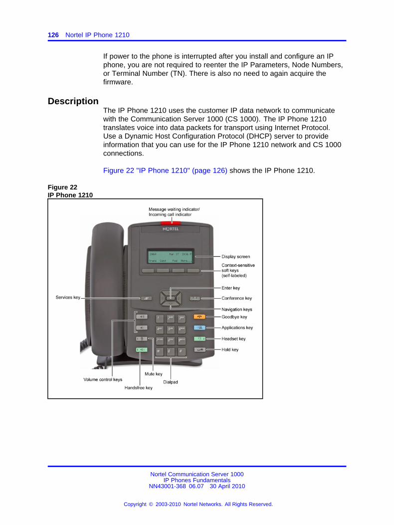
126 Nortel IP Phone 1210
If power to the phone is interrupted after you install and configure an IPphone, you are not required to reenter the IP Parameters, Node Numbers,or Terminal Number (TN). There is also no need to again acquire thefirmware.
DescriptionThe IP Phone 1210 uses the customer IP data network to communicatewith the Communication Server 1000 (CS 1000). The IP Phone 1210translates voice into data packets for transport using Internet Protocol.Use a Dynamic Host Configuration Protocol (DHCP) server to provideinformation that you can use for the IP Phone 1210 network and CS 1000connections.
Figure 22 "IP Phone 1210" (page 126) shows the IP Phone 1210.
Figure 22IP Phone 1210
Nortel Communication Server 1000IP Phones Fundamentals
NN43001-368 06.07 30 April 2010
Copyright © 2003-2010 Nortel Networks. All Rights Reserved.
.
Components and functions 127
Components and functionsThis section describes the following components and functions of the IPPhone 1210:
• “Keys and functions” (page 127)
• “Services menu” (page 128)
• “Local Tools menu” (page 129)
Keys and functionsTable 27 "IP Phone 1210 keys and functions" (page 127) describes theIP Phone 1210 keys and functions.
Table 27IP Phone 1210 keys and functions
Key Function
Handsfree Press the Handsfree key to activate handsfree mode.
The Handsfree light emitting diode (LED) indicator, located on theHandsfree key, lights to indicate that the headset is in use.
Visual Alerter/MessageWaiting indicator
If a message is waiting, the red Visual Alerter/Message Waitingindicator LED at the top center of the phone flashes. The indicatoralso flashes to indicate an incoming call. The flash cadences forboth alerts are different.
Volume control buttons Use the Volume control buttons to adjust the volume of the ringer,handset, headset, speaker, and Handsfree features. Press theupper button to increase the volume, and press the lower button todecrease the volume.
Hold key Press the Hold key to place an active call on hold. Press the Holdkey again to return to the caller on hold.
Conference key Press the Conference key (programmable memory button) to initiateconference.
Applications key Press the Applications key to access external server applications,such as Nortel Application Server.
Navigation keys Use the Navigation keys to scroll through menus and lists thatappear on the LCD screen. The Navigation keys to move up, down,left, and right.
Use Up and Down keys to scroll up and down in lists, and the Leftand Right keys to position the cursor. You can also use the Left andRight keys to select editable fields that appear on the phone. Pressthe Right key to select the field below the current position, or pressthe Left key to select the field above the current position.
Nortel Communication Server 1000IP Phones Fundamentals
NN43001-368 06.07 30 April 2010
Copyright © 2003-2010 Nortel Networks. All Rights Reserved.
.
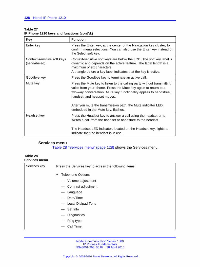
128 Nortel IP Phone 1210
Table 27IP Phone 1210 keys and functions (cont’d.)
Key Function
Enter key Press the Enter key, at the center of the Navigation key cluster, toconfirm menu selections. You can also use the Enter key instead ofthe Select soft key.
Context-sensitive soft keys(self-labeled)
Context-sensitive soft keys are below the LCD. The soft key label isdynamic and depends on the active feature. The label length is amaximum of six characters.A triangle before a key label indicates that the key is active.
Goodbye key Press the Goodbye key to terminate an active call.
Mute key Press the Mute key to listen to the calling party without transmittingvoice from your phone. Press the Mute key again to return to atwo-way conversation. Mute key functionality applies to handsfree,handset, and headset modes.
After you mute the transmission path, the Mute indicator LED,embedded in the Mute key, flashes.
Headset key Press the Headset key to answer a call using the headset or toswitch a call from the handset or handsfree to the headset.
The Headset LED indicator, located on the Headset key, lights toindicate that the headset is in use.
Services menuTable 28 "Services menu" (page 128) shows the Services menu.
Table 28Services menu
Services key Press the Services key to access the following items:
• Telephone Options
— Volume adjustment
— Contrast adjustment
— Language
— Date/Time
— Local Dialpad Tone
— Set Info
— Diagnostics
— Ring type
— Call Timer
Nortel Communication Server 1000IP Phones Fundamentals
NN43001-368 06.07 30 April 2010
Copyright © 2003-2010 Nortel Networks. All Rights Reserved.
.
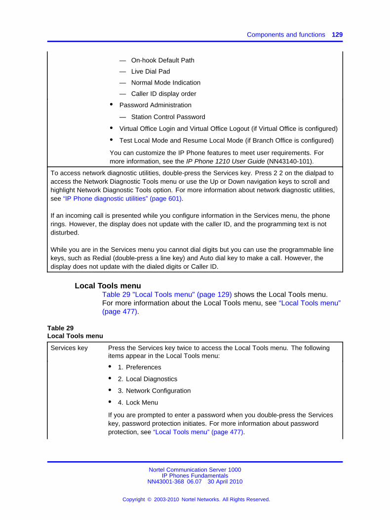
Components and functions 129
— On-hook Default Path
— Live Dial Pad
— Normal Mode Indication
— Caller ID display order
• Password Administration
— Station Control Password
• Virtual Office Login and Virtual Office Logout (if Virtual Office is configured)
• Test Local Mode and Resume Local Mode (if Branch Office is configured)
You can customize the IP Phone features to meet user requirements. Formore information, see the IP Phone 1210 User Guide (NN43140-101).
To access network diagnostic utilities, double-press the Services key. Press 2 2 on the dialpad toaccess the Network Diagnostic Tools menu or use the Up or Down navigation keys to scroll andhighlight Network Diagnostic Tools option. For more information about network diagnostic utilities,see “IP Phone diagnostic utilities” (page 601).
If an incoming call is presented while you configure information in the Services menu, the phonerings. However, the display does not update with the caller ID, and the programming text is notdisturbed.
While you are in the Services menu you cannot dial digits but you can use the programmable linekeys, such as Redial (double-press a line key) and Auto dial key to make a call. However, thedisplay does not update with the dialed digits or Caller ID.
Local Tools menuTable 29 "Local Tools menu" (page 129) shows the Local Tools menu.For more information about the Local Tools menu, see “Local Tools menu”(page 477).
Table 29Local Tools menu
Services key Press the Services key twice to access the Local Tools menu. The followingitems appear in the Local Tools menu:
• 1. Preferences
• 2. Local Diagnostics
• 3. Network Configuration
• 4. Lock Menu
If you are prompted to enter a password when you double-press the Serviceskey, password protection initiates. For more information about passwordprotection, see “Local Tools menu” (page 477).
Nortel Communication Server 1000IP Phones Fundamentals
NN43001-368 06.07 30 April 2010
Copyright © 2003-2010 Nortel Networks. All Rights Reserved.
.
130 Nortel IP Phone 1210
To make a selection, press the number associated with the menu item, or usethe navigation keys to scroll through the menu items. Press the Enter key toselect the highlighted menu item.
Press the Cancel key to exit from a menu or menu item.
FeaturesThe IP Phone 1210 supports the following telephony features:
• four context-sensitive soft keys
Functions for the context-sensitive soft keys are configured in LD 11.
• volume control buttons to adjust ringer, speaker, handset, and headsetvolume
• three specialized feature keys
— Conference
— Services
— Applications
• five call-processing keys
— Goodbye
— Hold
— Handsfree
— Mute
— Headset
For more information about IP Phone features, see “Features” (page 391).
Display characteristicsAn IP Phone 1210 has two display areas:
• “Information line display” (page 131)
• “Soft key label display” (page 131)
Figure 23 "IP Phone 1210 display areas" (page 131) shows these twodisplay areas.
Nortel Communication Server 1000IP Phones Fundamentals
NN43001-368 06.07 30 April 2010
Copyright © 2003-2010 Nortel Networks. All Rights Reserved.
.
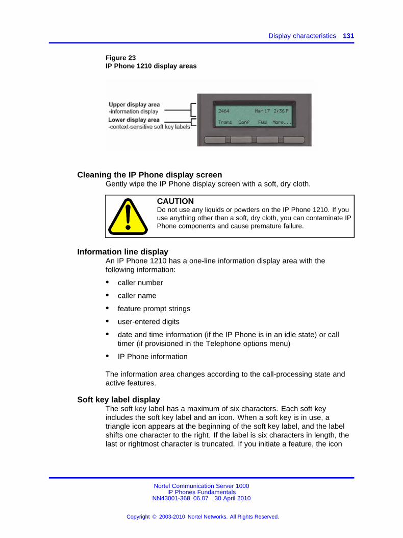
Display characteristics 131
Figure 23IP Phone 1210 display areas
Cleaning the IP Phone display screenGently wipe the IP Phone display screen with a soft, dry cloth.
CAUTIONDo not use any liquids or powders on the IP Phone 1210. If youuse anything other than a soft, dry cloth, you can contaminate IPPhone components and cause premature failure.
Information line displayAn IP Phone 1210 has a one-line information display area with thefollowing information:
• caller number
• caller name
• feature prompt strings
• user-entered digits
• date and time information (if the IP Phone is in an idle state) or calltimer (if provisioned in the Telephone options menu)
• IP Phone information
The information area changes according to the call-processing state andactive features.
Soft key label displayThe soft key label has a maximum of six characters. Each soft keyincludes the soft key label and an icon. When a soft key is in use, atriangle icon appears at the beginning of the soft key label, and the labelshifts one character to the right. If the label is six characters in length, thelast or rightmost character is truncated. If you initiate a feature, the icon
Nortel Communication Server 1000IP Phones Fundamentals
NN43001-368 06.07 30 April 2010
Copyright © 2003-2010 Nortel Networks. All Rights Reserved.
.
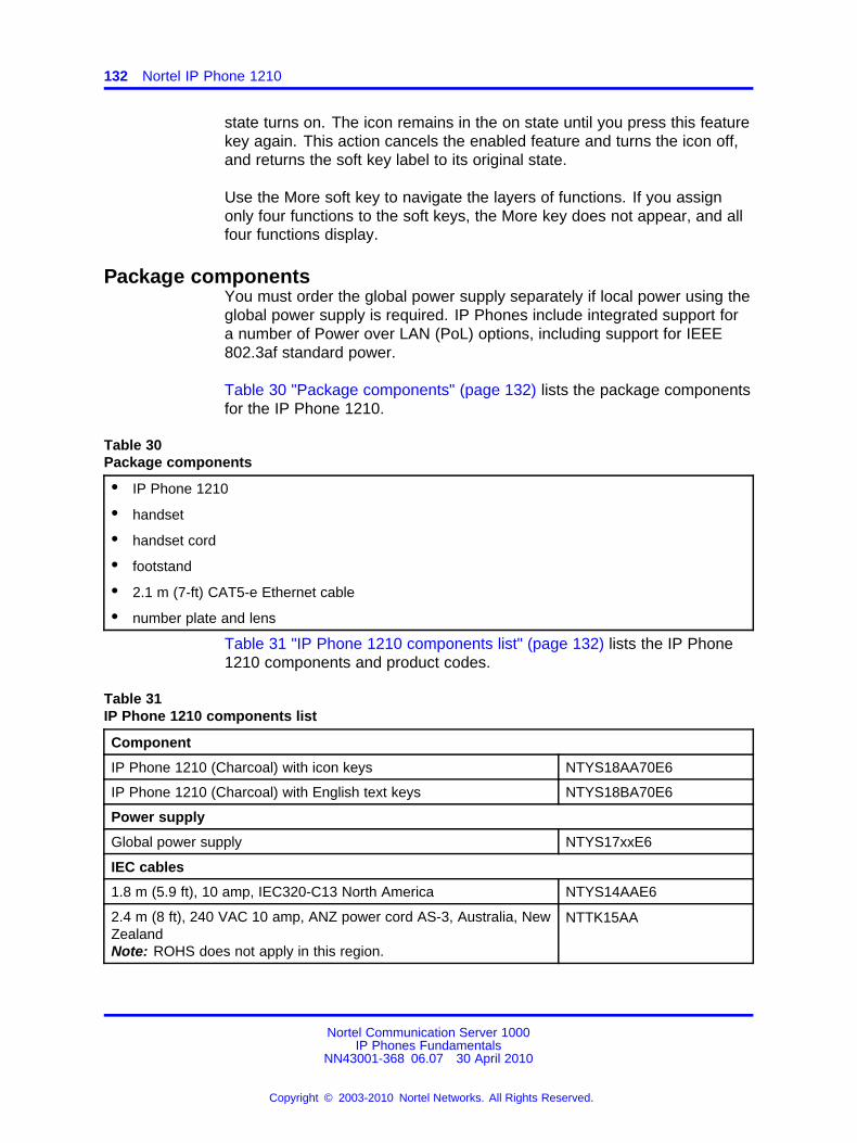
132 Nortel IP Phone 1210
state turns on. The icon remains in the on state until you press this featurekey again. This action cancels the enabled feature and turns the icon off,and returns the soft key label to its original state.
Use the More soft key to navigate the layers of functions. If you assignonly four functions to the soft keys, the More key does not appear, and allfour functions display.
Package componentsYou must order the global power supply separately if local power using theglobal power supply is required. IP Phones include integrated support fora number of Power over LAN (PoL) options, including support for IEEE802.3af standard power.
Table 30 "Package components" (page 132) lists the package componentsfor the IP Phone 1210.
Table 30Package components
• IP Phone 1210
• handset
• handset cord
• footstand
• 2.1 m (7-ft) CAT5-e Ethernet cable
• number plate and lens
Table 31 "IP Phone 1210 components list" (page 132) lists the IP Phone1210 components and product codes.
Table 31IP Phone 1210 components list
Component
IP Phone 1210 (Charcoal) with icon keys NTYS18AA70E6
IP Phone 1210 (Charcoal) with English text keys NTYS18BA70E6
Power supply
Global power supply NTYS17xxE6
IEC cables
1.8 m (5.9 ft), 10 amp, IEC320-C13 North America NTYS14AAE6
2.4 m (8 ft), 240 VAC 10 amp, ANZ power cord AS-3, Australia, NewZealandNote: ROHS does not apply in this region.
NTTK15AA
Nortel Communication Server 1000IP Phones Fundamentals
NN43001-368 06.07 30 April 2010
Copyright © 2003-2010 Nortel Networks. All Rights Reserved.
.
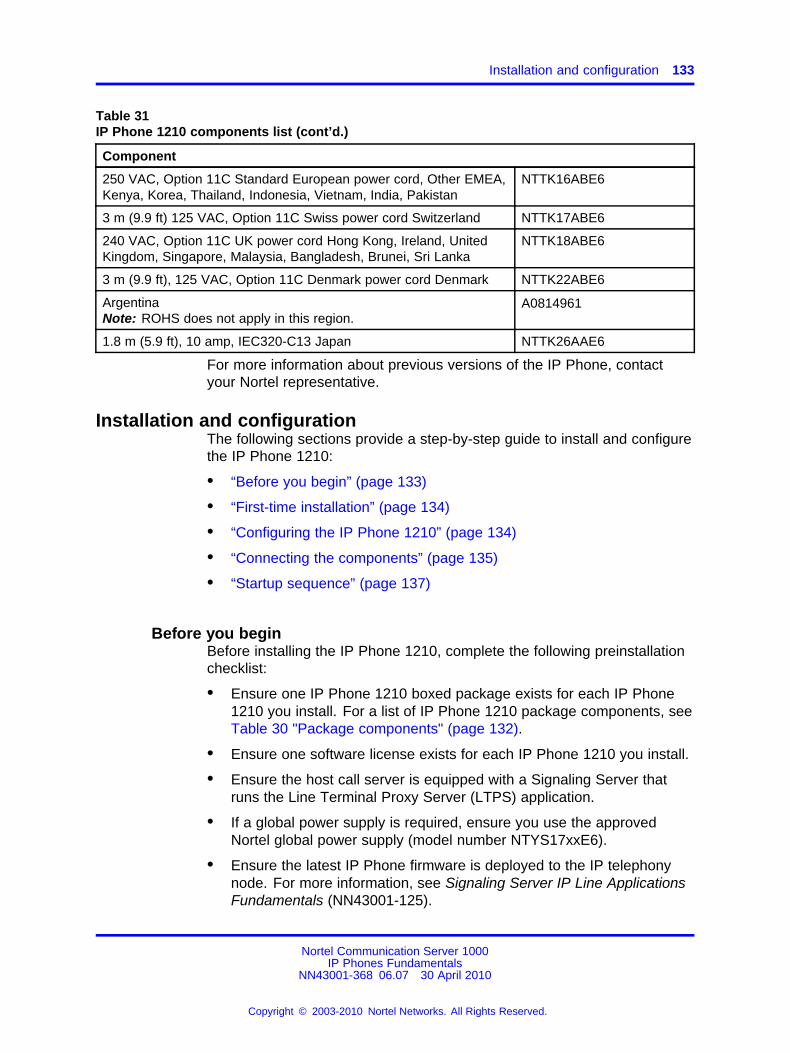
Installation and configuration 133
Table 31IP Phone 1210 components list (cont’d.)
Component
250 VAC, Option 11C Standard European power cord, Other EMEA,Kenya, Korea, Thailand, Indonesia, Vietnam, India, Pakistan
NTTK16ABE6
3 m (9.9 ft) 125 VAC, Option 11C Swiss power cord Switzerland NTTK17ABE6
240 VAC, Option 11C UK power cord Hong Kong, Ireland, UnitedKingdom, Singapore, Malaysia, Bangladesh, Brunei, Sri Lanka
NTTK18ABE6
3 m (9.9 ft), 125 VAC, Option 11C Denmark power cord Denmark NTTK22ABE6
ArgentinaNote: ROHS does not apply in this region.
A0814961
1.8 m (5.9 ft), 10 amp, IEC320-C13 Japan NTTK26AAE6
For more information about previous versions of the IP Phone, contactyour Nortel representative.
Installation and configurationThe following sections provide a step-by-step guide to install and configurethe IP Phone 1210:
• “Before you begin” (page 133)
• “First-time installation” (page 134)
• “Configuring the IP Phone 1210” (page 134)
• “Connecting the components” (page 135)
• “Startup sequence” (page 137)
Before you beginBefore installing the IP Phone 1210, complete the following preinstallationchecklist:
• Ensure one IP Phone 1210 boxed package exists for each IP Phone1210 you install. For a list of IP Phone 1210 package components, seeTable 30 "Package components" (page 132).
• Ensure one software license exists for each IP Phone 1210 you install.
• Ensure the host call server is equipped with a Signaling Server thatruns the Line Terminal Proxy Server (LTPS) application.
• If a global power supply is required, ensure you use the approvedNortel global power supply (model number NTYS17xxE6).
• Ensure the latest IP Phone firmware is deployed to the IP telephonynode. For more information, see Signaling Server IP Line ApplicationsFundamentals (NN43001-125).
Nortel Communication Server 1000IP Phones Fundamentals
NN43001-368 06.07 30 April 2010
Copyright © 2003-2010 Nortel Networks. All Rights Reserved.
.
134 Nortel IP Phone 1210
CAUTIONEnsure that the protective rubber cap on the AccessoryExpansion Module (AEM) port is in place when the port is notin use. An improper connector can cause damage to the IPPhone.
First-time installationYou must first install an IP telephony node with the Communication Server.For information about installing an IP telephony node, see Signaling ServerIP Line Applications Fundamentals (NN43001-125).
CAUTIONDo not plug your IP Phone 1210 into an ISDN connection.Severe damage can result.
Configuring the IP Phone 1210Use Procedure 28 “Configuring the IP Phone 1210” (page 134) toconfigure the IP Phone 1210 for the first time.
Procedure 28Configuring the IP Phone 1210
Step Action
1 Configure a virtual loop on the Call Server using LD 97.
For more information about configuring a virtual loop, seeSignaling Server IP Line Applications Fundamentals (NN43001-125) and Software Input Output Reference-Administration(NN43001-611).
2 Configure the IP Phone 1210 on the Call Server using LD 11. Atthe prompt, enter the following command:
REQ:newTYPE:1210
For more information about configuring the IP Phone 1210 usingLD 11, see Software Input Output Reference-Administration(NN43001-611).
3 Configure the IP Phone 1210 in Element Manager. IP Phonesare configured using the Phones section in the ElementManager navigation tree. For more information about configuringthe IP Phone 1210 using Element Manager, see ElementManager System Reference - Administration (NN43001-632).
--End--
Nortel Communication Server 1000IP Phones Fundamentals
NN43001-368 06.07 30 April 2010
Copyright © 2003-2010 Nortel Networks. All Rights Reserved.
.
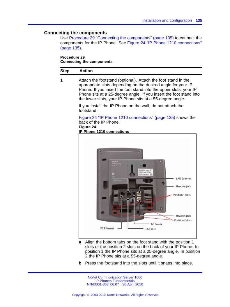
Installation and configuration 135
Connecting the componentsUse Procedure 29 “Connecting the components” (page 135) to connect thecomponents for the IP Phone. See Figure 24 "IP Phone 1210 connections"(page 135).
Procedure 29Connecting the components
Step Action
1 Attach the footstand (optional). Attach the foot stand in theappropriate slots depending on the desired angle for your IPPhone. If you insert the foot stand into the upper slots, your IPPhone sits at a 25-degree angle. If you insert the foot stand intothe lower slots, your IP Phone sits at a 55-degree angle.
If you install the IP Phone on the wall, do not attach thefootstand.
Figure 24 "IP Phone 1210 connections" (page 135) shows theback of the IP Phone.Figure 24IP Phone 1210 connections
a Align the bottom tabs on the foot stand with the position 1slots or the position 2 slots on the back of your IP Phone. Inposition 1 the IP Phone sits at a 25-degree angle. In position2 the IP Phone sits at a 55-degree angle.
b Press the footstand into the slots until it snaps into place.
Nortel Communication Server 1000IP Phones Fundamentals
NN43001-368 06.07 30 April 2010
Copyright © 2003-2010 Nortel Networks. All Rights Reserved.
.
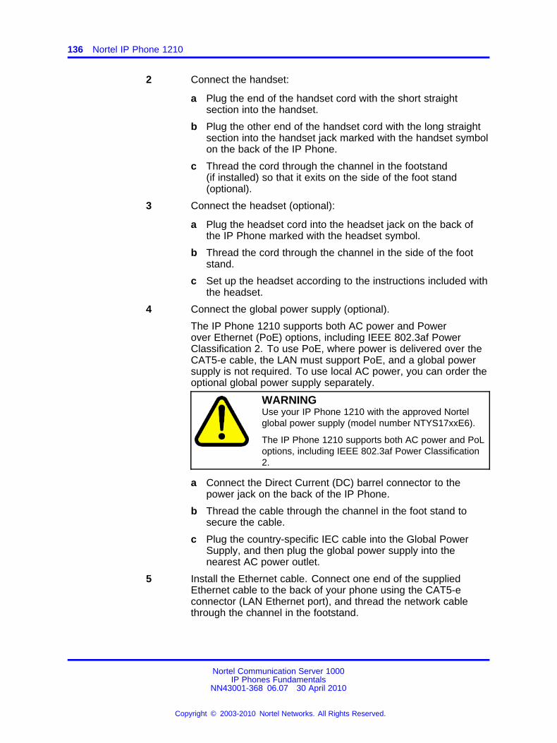
136 Nortel IP Phone 1210
2 Connect the handset:
a Plug the end of the handset cord with the short straightsection into the handset.
b Plug the other end of the handset cord with the long straightsection into the handset jack marked with the handset symbolon the back of the IP Phone.
c Thread the cord through the channel in the footstand(if installed) so that it exits on the side of the foot stand(optional).
3 Connect the headset (optional):
a Plug the headset cord into the headset jack on the back ofthe IP Phone marked with the headset symbol.
b Thread the cord through the channel in the side of the footstand.
c Set up the headset according to the instructions included withthe headset.
4 Connect the global power supply (optional).
The IP Phone 1210 supports both AC power and Powerover Ethernet (PoE) options, including IEEE 802.3af PowerClassification 2. To use PoE, where power is delivered over theCAT5-e cable, the LAN must support PoE, and a global powersupply is not required. To use local AC power, you can order theoptional global power supply separately.
WARNINGUse your IP Phone 1210 with the approved Nortelglobal power supply (model number NTYS17xxE6).
The IP Phone 1210 supports both AC power and PoLoptions, including IEEE 802.3af Power Classification2.
a Connect the Direct Current (DC) barrel connector to thepower jack on the back of the IP Phone.
b Thread the cable through the channel in the foot stand tosecure the cable.
c Plug the country-specific IEC cable into the Global PowerSupply, and then plug the global power supply into thenearest AC power outlet.
5 Install the Ethernet cable. Connect one end of the suppliedEthernet cable to the back of your phone using the CAT5-econnector (LAN Ethernet port), and thread the network cablethrough the channel in the footstand.
Nortel Communication Server 1000IP Phones Fundamentals
NN43001-368 06.07 30 April 2010
Copyright © 2003-2010 Nortel Networks. All Rights Reserved.
.
Installation and configuration 137
6 Connect the other end of the cable to your LAN Ethernetconnection. The LAN LED on the back of the IP Phone lightswhen a LAN connection is established.
7 If you connect your PC through the phone, a second CAT5-ecable is required. Only one cable is included with the IP Phone1210 package. Install the Ethernet cable connecting the PC tothe phone (optional). Connect one end of the PC Ethernet cableto your phone using the CAT5-e connector (PC Ethernet port),and thread it through channel in the footstand. Connect the otherend to the LAN connector on the back of your PC.
The LAN Ethernet port supports Auto-Media Dependent InterfaceCrossover (MDIX). Auto-MDIX is supported only when theEthernet port is configured for autonegotiation. The PC Portdoes not support Auto-MDIX.
8 Wall mount the IP Phone 1210 (optional):
a Remove the footstand.
b Ensure all cables are properly routed and the IP Phone isfunctioning.
c Make small marks on the wall where you want to align eachof the two keyhole slots.
d Insert the screws (not provided), so that they protrude slightlyfrom the wall.
e Align the keyholes on the back of the IP Phone with thescrews in the wall.
f Slide the IP Phone down on the screws to secure the IPPhone in position.
--End--
When you complete the IP Phone connection, you must connect the phoneto the network. See “Dynamic Host Configuration Protocol” (page 429).
Startup sequenceWhen you connect an IP Phone 1210 to the network, it must perform astartup sequence. The elements of the startup sequence include
• obtaining network access (if supported by the network infrastructure)
• obtaining VLAN ID (if supported by the network infrastructure)
• obtaining the IP parameters
• obtaining the provisioning parameters
• connecting to the Call Server
Nortel Communication Server 1000IP Phones Fundamentals
NN43001-368 06.07 30 April 2010
Copyright © 2003-2010 Nortel Networks. All Rights Reserved.
.
138 Nortel IP Phone 1210
The IP Phone is configured for automatic provisioning by default. Formore information about provisioning the IP Phone automatically, see“Provisioning the IP Phones” (page 497).
You can manually configure all or some parameters. For informationabout manually provisioning the IP Phone, see “Manual provisioning of IPPhones 1110 and 1200 Series” (page 543).
Redeploying an IP Phone 1210You can redeploy an existing previously-configured IP Phone 1210 onthe same system. For example, you can assign the IP Phone 1210 to anew user (new TN) or to an existing user who moved to a new subnetby changing the TN of the IP Phone 1210. For further information, seeConverging the Data Network with VoIP Fundamentals (NN43001-260).
Procedure 30Redeploying the TN of an existing IP Phone 1210
Step Action
1 Repower the IP Phone 1210.
During the reboot sequence of a previously configured IPPhone, the IP Phone 1210 displays the existing node numberfor approximately 5 seconds.
2 If you configure the node password to NULL, choose one of thefollowing:
a Disable the password.
b Set the password as nonNULL.
3 Press OK when the node number displays.
If Then
you configure the node passwordto NULL
a password screen displays. Goto Step 4.
the node password is disabled a TN screen displays. Go to Step5.
4 Enter password at the password screen, and press OK.
A TN screen displays.
To obtain the password, enter the nodePwdShow command inElement Manager. For more information, see Element ManagerSystem Reference - Administration (NN43001-632).
5 Select the Clear soft key to clear the existing TN.
6 Enter the new TN.
Nortel Communication Server 1000IP Phones Fundamentals
NN43001-368 06.07 30 April 2010
Copyright © 2003-2010 Nortel Networks. All Rights Reserved.
.
Removing an IP Phone 1210 from service 139
7 Click OK to save and accept changes.
--End--
Replacing an IP Phone 1210ATTENTIONTwo IP Phones cannot share the same TN. You must remove the IP Phone1210 that currently uses the TN.
Procedure 31Replacing an IP Phone 1210
Step Action
1 Obtain the node and TN information of the phone you want toreplace.
2 Disconnect the IP Phone 1210 that you want to replace.
3 Follow “Configuring the IP Phone 1210” (page 134) to installthe IP Phone 1210. To configure the IP Phone, see “Manualprovisioning of IP Phones 1110 and 1200 Series” (page 543).
4 Enter the same TN and node number as the IP Phone 1210 youreplaced. The system associates the new IP Phone 1210 withthe existing TN.
--End--
Removing an IP Phone 1210 from serviceProcedure 32Removing an IP Phone 1210 from service
Step Action
1 Disconnect the IP Phone 1210 from the network or turn off thepower.
If the IP Phone 1210 was automatically configured, the DHCPlease expires and the IP address returns to the available pool.
2 In LD 11, enter the following:REQ: OUTTYPE: 1210TN: LLL S CC UU
--End--
Nortel Communication Server 1000IP Phones Fundamentals
NN43001-368 06.07 30 April 2010
Copyright © 2003-2010 Nortel Networks. All Rights Reserved.
.

140 Nortel IP Phone 1210
Nortel Communication Server 1000IP Phones Fundamentals
NN43001-368 06.07 30 April 2010
Copyright © 2003-2010 Nortel Networks. All Rights Reserved.
.
141.
Nortel IP Phone 1220
ContentsThis section contains the following topics:
• “Introduction” (page 141)
• “Description” (page 142)
• “Components and functions” (page 143)
• “Features” (page 147)
• “Display characteristics” (page 147)
• “Package components” (page 149)
• “Installation and configuration” (page 151)
• “Redeploying an IP Phone 1220” (page 155)
• “Replacing an IP Phone 1220” (page 156)
• “Removing an IP Phone 1220 from service” (page 157)
IntroductionThis section explains how to install and maintain the IP Phone 1220. Forinformation about using the IP Phone 1220, see the IP Phone 1220 UserGuide (NN43141-101).
This section contains the following procedures:
• Procedure 33 “Configuring the IP Phone” (page 152)
• Procedure 34 “Connecting the components” (page 152)
• Procedure 35 “Redeploying the TN of an existing IP Phone 1220”(page 155).
• Procedure 36 “Replacing an IP Phone 1220” (page 156).
• Procedure 37 “Removing an IP Phone 1220 from service” (page 157).
Nortel Communication Server 1000IP Phones Fundamentals
NN43001-368 06.07 30 April 2010
Copyright © 2003-2010 Nortel Networks. All Rights Reserved.
.
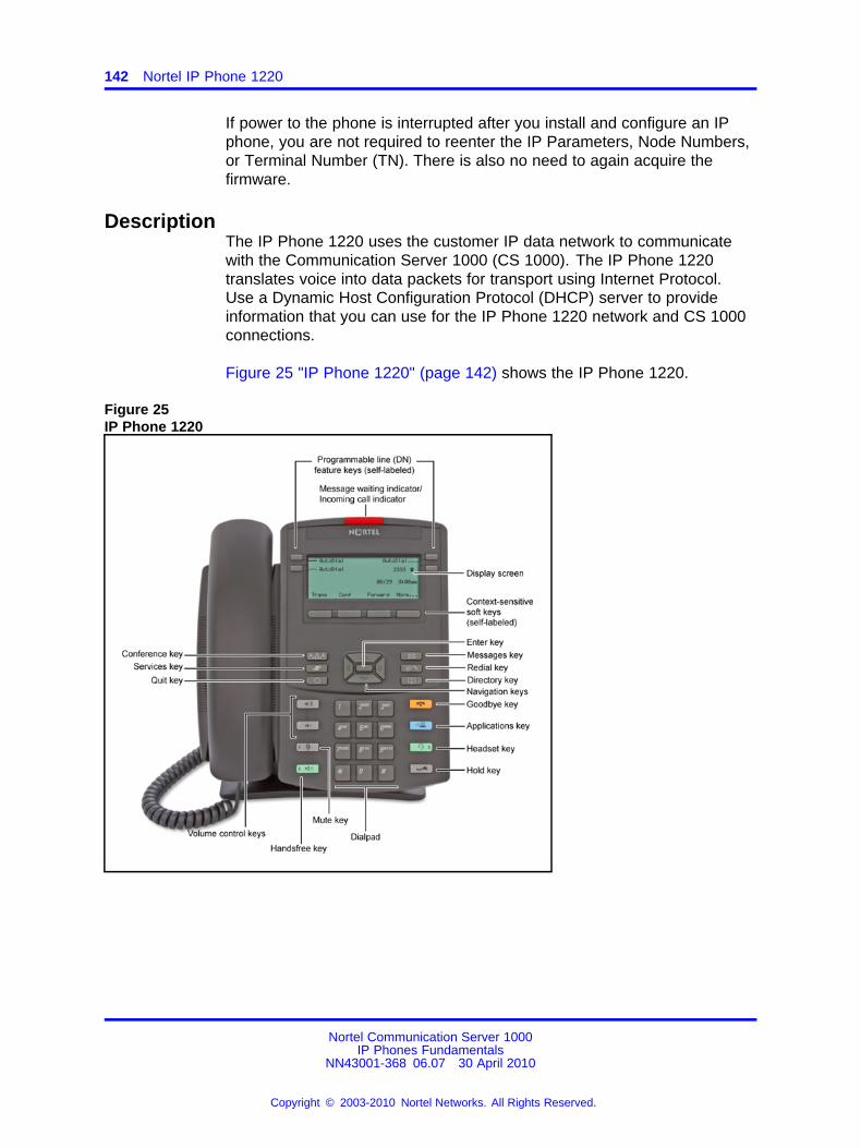
142 Nortel IP Phone 1220
If power to the phone is interrupted after you install and configure an IPphone, you are not required to reenter the IP Parameters, Node Numbers,or Terminal Number (TN). There is also no need to again acquire thefirmware.
DescriptionThe IP Phone 1220 uses the customer IP data network to communicatewith the Communication Server 1000 (CS 1000). The IP Phone 1220translates voice into data packets for transport using Internet Protocol.Use a Dynamic Host Configuration Protocol (DHCP) server to provideinformation that you can use for the IP Phone 1220 network and CS 1000connections.
Figure 25 "IP Phone 1220" (page 142) shows the IP Phone 1220.
Figure 25IP Phone 1220
Nortel Communication Server 1000IP Phones Fundamentals
NN43001-368 06.07 30 April 2010
Copyright © 2003-2010 Nortel Networks. All Rights Reserved.
.
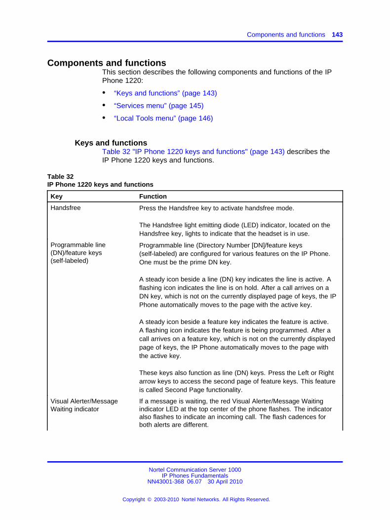
Components and functions 143
Components and functionsThis section describes the following components and functions of the IPPhone 1220:
• “Keys and functions” (page 143)
• “Services menu” (page 145)
• “Local Tools menu” (page 146)
Keys and functionsTable 32 "IP Phone 1220 keys and functions" (page 143) describes theIP Phone 1220 keys and functions.
Table 32IP Phone 1220 keys and functions
Key Function
Handsfree Press the Handsfree key to activate handsfree mode.
The Handsfree light emitting diode (LED) indicator, located on theHandsfree key, lights to indicate that the headset is in use.
Programmable line(DN)/feature keys(self-labeled)
Programmable line (Directory Number [DN]/feature keys(self-labeled) are configured for various features on the IP Phone.One must be the prime DN key.
A steady icon beside a line (DN) key indicates the line is active. Aflashing icon indicates the line is on hold. After a call arrives on aDN key, which is not on the currently displayed page of keys, the IPPhone automatically moves to the page with the active key.
A steady icon beside a feature key indicates the feature is active.A flashing icon indicates the feature is being programmed. After acall arrives on a feature key, which is not on the currently displayedpage of keys, the IP Phone automatically moves to the page withthe active key.
These keys also function as line (DN) keys. Press the Left or Rightarrow keys to access the second page of feature keys. This featureis called Second Page functionality.
Visual Alerter/MessageWaiting indicator
If a message is waiting, the red Visual Alerter/Message Waitingindicator LED at the top center of the phone flashes. The indicatoralso flashes to indicate an incoming call. The flash cadences forboth alerts are different.
Nortel Communication Server 1000IP Phones Fundamentals
NN43001-368 06.07 30 April 2010
Copyright © 2003-2010 Nortel Networks. All Rights Reserved.
.

144 Nortel IP Phone 1220
Table 32IP Phone 1220 keys and functions (cont’d.)
Key Function
Context-sensitive soft keys(self-labeled)
Context-sensitive soft keys are below the LCD. The soft key label isdynamic and depends on the active feature. The label length is amaximum of six characters.
A triangle before a key label indicates that the key is active.
Navigation keys Use the Navigation keys to scroll through menus and lists thatappear on the LCD screen. The Navigation keys to move up, down,left, and right.
Use Up and Down keys to scroll up and down in lists, and the Leftand Right keys to position the cursor. You can also use the Left andRight keys to select editable fields that appear on the phone. Pressthe Right key to select the field below the current position, or pressthe Left key to select the field above the current position.
Enter Press the Enter key, at the center of the Navigation key cluster, toconfirm menu selections. You can also use the Enter key instead ofthe Select soft key.
Messages (Inbox) Press the Messages (Inbox) key to access your voice mailbox whenthe message waiting indicator flashes.
Redial (Outbox) Press the Redial (Outbox) key to access your Redial list.
Directory Press the Directory key to access Directory services.
Quit Press the Quit key to end an active application.
Pressing the Quit key does not affect the status of the calls currentlyon your IP Phone.
Conference Press the Conference key to initiate conference.
Applications Press the Applications key to access external server applications,such as Nortel Application Server.
Goodbye Press the Goodbye key to terminate an active call.
Hold Press the Hold key to place an active call on hold. Press theflashing line (DN) key to return to the caller on hold.
Headset Press the Headset key to answer a call using the headset or toswitch a call from the handset or handsfree to the headset.The Headset LED indicator, located on the Headset key, lights toindicate that the headset is in use.
Nortel Communication Server 1000IP Phones Fundamentals
NN43001-368 06.07 30 April 2010
Copyright © 2003-2010 Nortel Networks. All Rights Reserved.
.
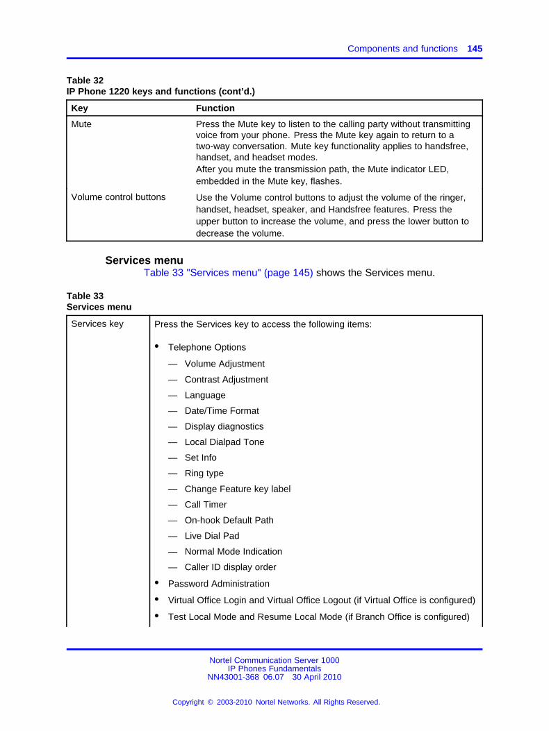
Components and functions 145
Table 32IP Phone 1220 keys and functions (cont’d.)
Key Function
Mute Press the Mute key to listen to the calling party without transmittingvoice from your phone. Press the Mute key again to return to atwo-way conversation. Mute key functionality applies to handsfree,handset, and headset modes.After you mute the transmission path, the Mute indicator LED,embedded in the Mute key, flashes.
Volume control buttons Use the Volume control buttons to adjust the volume of the ringer,handset, headset, speaker, and Handsfree features. Press theupper button to increase the volume, and press the lower button todecrease the volume.
Services menuTable 33 "Services menu" (page 145) shows the Services menu.
Table 33Services menu
Services key Press the Services key to access the following items:
• Telephone Options
— Volume Adjustment
— Contrast Adjustment
— Language
— Date/Time Format
— Display diagnostics
— Local Dialpad Tone
— Set Info
— Ring type
— Change Feature key label
— Call Timer
— On-hook Default Path
— Live Dial Pad
— Normal Mode Indication
— Caller ID display order
• Password Administration
• Virtual Office Login and Virtual Office Logout (if Virtual Office is configured)
• Test Local Mode and Resume Local Mode (if Branch Office is configured)
Nortel Communication Server 1000IP Phones Fundamentals
NN43001-368 06.07 30 April 2010
Copyright © 2003-2010 Nortel Networks. All Rights Reserved.
.
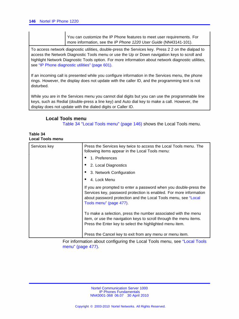
146 Nortel IP Phone 1220
You can customize the IP Phone features to meet user requirements. Formore information, see the IP Phone 1220 User Guide (NN43141-101).
To access network diagnostic utilities, double-press the Services key. Press 2 2 on the dialpad toaccess the Network Diagnostic Tools menu or use the Up or Down navigation keys to scroll andhighlight Network Diagnostic Tools option. For more information about network diagnostic utilities,see “IP Phone diagnostic utilities” (page 601).
If an incoming call is presented while you configure information in the Services menu, the phonerings. However, the display does not update with the caller ID, and the programming text is notdisturbed.
While you are in the Services menu you cannot dial digits but you can use the programmable linekeys, such as Redial (double-press a line key) and Auto dial key to make a call. However, thedisplay does not update with the dialed digits or Caller ID.
Local Tools menuTable 34 "Local Tools menu" (page 146) shows the Local Tools menu.
Table 34Local Tools menu
Services key Press the Services key twice to access the Local Tools menu. Thefollowing items appear in the Local Tools menu:
• 1. Preferences
• 2. Local Diagnostics
• 3. Network Configuration
• 4. Lock Menu
If you are prompted to enter a password when you double-press theServices key, password protection is enabled. For more informationabout password protection and the Local Tools menu, see “LocalTools menu” (page 477).
To make a selection, press the number associated with the menuitem, or use the navigation keys to scroll through the menu items.Press the Enter key to select the highlighted menu item.
Press the Cancel key to exit from any menu or menu item.
For information about configuring the Local Tools menu, see “Local Toolsmenu” (page 477).
Nortel Communication Server 1000IP Phones Fundamentals
NN43001-368 06.07 30 April 2010
Copyright © 2003-2010 Nortel Networks. All Rights Reserved.
.
Display characteristics 147
FeaturesThe IP Phone 1220 supports the following telephony features:
• four programmable line (DN)/feature keys (self-labeled)
• four context-sensitive soft keys (self-labeled)
Functions for the context-sensitive soft keys are configured in LD 11.
• volume control bar to adjust ringer, speaker, handset, and headsetvolume
• ability to change the programmable line (DN)/feature key labels
• six specialized feature keys
— Quit
— Directory
— Message/Inbox
— Redial (Outbox)
— Services
— Conference
• six call-processing fixed keys:
— Mute
— Handsfree
— Goodbye
— Applications
— Headset
— Hold
For more information about IP Phone features, see “Features” (page 391).
Display characteristicsAn IP Phone 1220 has three major display areas:
• “Programmable line (DN)/feature key label display” (page 148)
• “Information line display” (page 148)
• “Soft key label display” (page 149)
Figure 26 "IP Phone 1220 display areas" (page 148) shows these threedisplay areas.
Nortel Communication Server 1000IP Phones Fundamentals
NN43001-368 06.07 30 April 2010
Copyright © 2003-2010 Nortel Networks. All Rights Reserved.
.
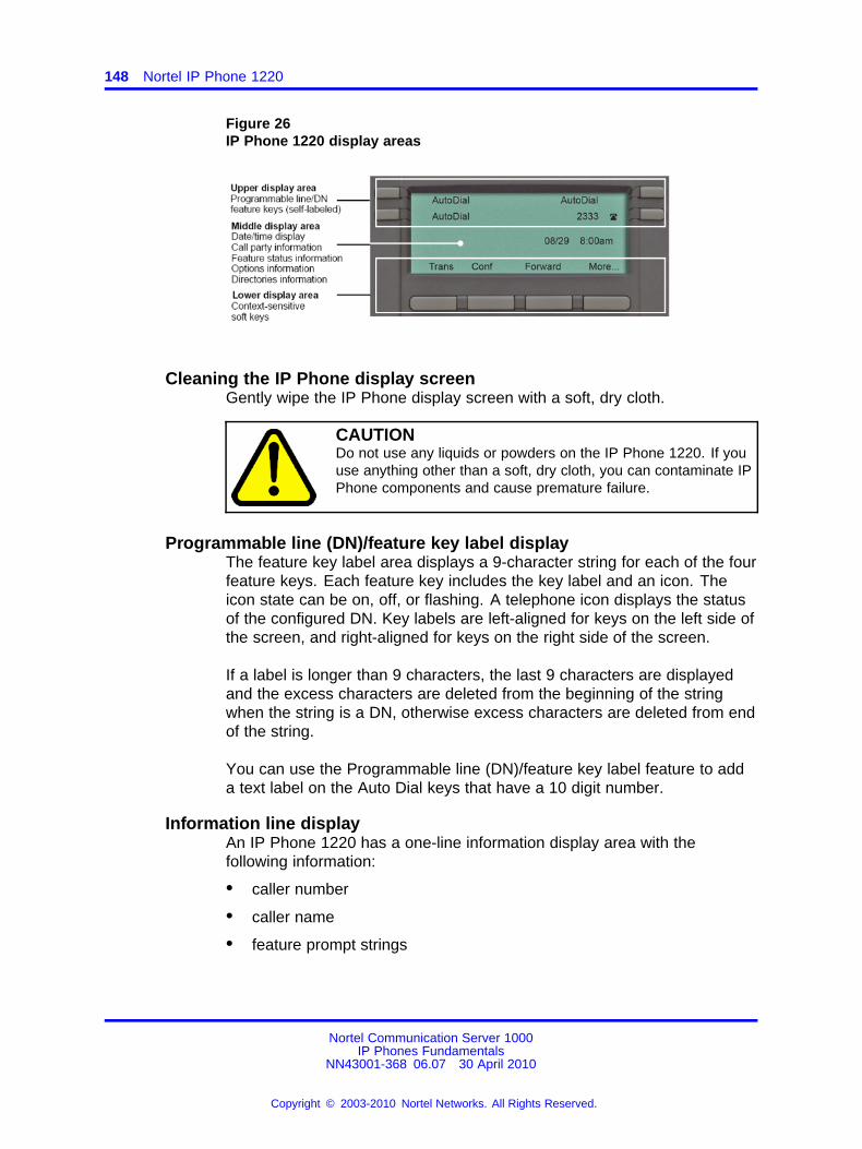
148 Nortel IP Phone 1220
Figure 26IP Phone 1220 display areas
Cleaning the IP Phone display screenGently wipe the IP Phone display screen with a soft, dry cloth.
CAUTIONDo not use any liquids or powders on the IP Phone 1220. If youuse anything other than a soft, dry cloth, you can contaminate IPPhone components and cause premature failure.
Programmable line (DN)/feature key label displayThe feature key label area displays a 9-character string for each of the fourfeature keys. Each feature key includes the key label and an icon. Theicon state can be on, off, or flashing. A telephone icon displays the statusof the configured DN. Key labels are left-aligned for keys on the left side ofthe screen, and right-aligned for keys on the right side of the screen.
If a label is longer than 9 characters, the last 9 characters are displayedand the excess characters are deleted from the beginning of the stringwhen the string is a DN, otherwise excess characters are deleted from endof the string.
You can use the Programmable line (DN)/feature key label feature to adda text label on the Auto Dial keys that have a 10 digit number.
Information line displayAn IP Phone 1220 has a one-line information display area with thefollowing information:
• caller number
• caller name
• feature prompt strings
Nortel Communication Server 1000IP Phones Fundamentals
NN43001-368 06.07 30 April 2010
Copyright © 2003-2010 Nortel Networks. All Rights Reserved.
.
Package components 149
• user-entered digits
• date and time information (if the IP Phone is in an idle state) or CallTimer (if provisioned in the Telephone options menu)
The information in the display area changes, according to thecall-processing state and active features.
Because the IP Phone 1220 only has a one-line information display area,you are prompted to scroll through any additional lines of information.
During an incoming call, only the Directory Number (DN) displays if thecaller name is greater than 9 characters. Press the flashing arrow todisplay the caller name.
Soft key label displayThe soft key label has a maximum of six characters. Each soft keyincludes the soft key label and an icon. When a soft key is in use, atriangle icon appears at the beginning of the soft key label, and the labelshifts one character to the right. If the label is six characters in length, thelast or rightmost character is truncated. If you initiate a feature, the iconstate turns on. The icon remains in the on state until you press this featurekey again. This action cancels the enabled feature and turns the icon off,and returns the soft key label to its original state.
Use the More soft key to navigate the layers of functions. If you assignonly four functions to the soft keys, the More key does not appear, and allfour functions display.
Package componentsYou must order the global power supply separately if local power using theglobal power supply is required. IP Phones include integrated support fora number of Power over LAN (PoL) options, including support for IEEE802.3af standard power.
Table 35 "Package components" (page 150) lists the IP Phone 1220package components.
Nortel Communication Server 1000IP Phones Fundamentals
NN43001-368 06.07 30 April 2010
Copyright © 2003-2010 Nortel Networks. All Rights Reserved.
.

150 Nortel IP Phone 1220
Table 35Package components
• IP Phone 1220
• handset
• handset cord
• footstand
• 2.1 m (7-ft) CAT5-e Ethernet cable
• number plate and lens
Table 36 "IP Phone 1220 components list" (page 150) lists the IP Phone1220 package components and product codes.
Table 36IP Phone 1220 components list
Component Product code
IP Phone 1220 (Charcoal with icon keys) NTYS19AA70E6
IP Phone 1220 (Charcoal with English text keys) NTYS19BA70E6
Power supply
Global power supply NTYS17xxE6
IEC cables
1.8 m (5.9 ft), 10 amp, IEC320-C13 North America NTYS14AAE6
2.4 m (8 ft), 240 VAC 10 amp, ANZ power cord AS-3, Australia,New ZealandNote: ROHS does not apply in this region.
NTTK15AA
250 VAC, Option 11C Standard European power cord, Other EMEA,Kenya, Korea, Thailand, Indonesia, Vietnam, India, Pakistan
NTTK16ABE6
3 m (9.9 ft) 125 VAC, Option 11C Swiss power cord Switzerland NTTK17ABE6
240 VAC, Option 11C UK power cord Hong Kong, Ireland, UnitedKingdom, Singapore, Malaysia, Bangladesh, Brunei, Sri Lanka
NTTK18ABE6
3 m (9.9 ft), 125 VAC, Option 11C Denmark power cord Denmark NTTK22ABE6
ArgentinaNote: ROHS does not apply in this region.
A0814961
1.8 m (5.9 ft), 10 amp, IEC320-C13 Japan NTTK26AAE6
For more information about previous versions of the IP Phone, contactNortel.
Nortel Communication Server 1000IP Phones Fundamentals
NN43001-368 06.07 30 April 2010
Copyright © 2003-2010 Nortel Networks. All Rights Reserved.
.
Installation and configuration 151
Installation and configurationThe following sections provide a step-by-step guide to install and configurethe IP Phone 1220:
• “Before you begin” (page 151)
• “First-time installation” (page 151)
• “Configuring the IP Phone 1220” (page 152)
• “Connecting the components” (page 152)
• “Startup sequence” (page 155)
Before you beginBefore installing the IP Phone 1220, complete the following pre-installationchecklist:
• Ensure one IP Phone 1220 boxed package exists for each IP Phone1220 you install. For a list of IP Phone 1220 package components, seeTable 35 "Package components" (page 150).
• Ensure one software license exists for each IP Phone 1220 you install.
• Ensure the host call server is equipped with a Signaling Server thatruns the Line Terminal Proxy Server (LTPS) application.
• If a global power supply is required, ensure you use the approvedNortel global power supply (model number NTYS17xxE6).
• Ensure the latest IP Phone firmware is deployed to the IP telephonynode. For more information, see Signaling Server IP Line ApplicationsFundamentals (NN43001-125).
CAUTIONEnsure that the protective rubber cap on the AccessoryExpansion Module (AEM) port is in place when the port is notin use. An improper connector can cause damage to the IPPhone.
First-time installationYou must first install an IP telephony node with the Communication Server.For information about installing an IP telephony node, see Signaling ServerIP Line Applications Fundamentals (NN43001-125).
CAUTIONDo not plug your IP Phone 1220 into an ISDN connection.Severe damage can result.
Nortel Communication Server 1000IP Phones Fundamentals
NN43001-368 06.07 30 April 2010
Copyright © 2003-2010 Nortel Networks. All Rights Reserved.
.
152 Nortel IP Phone 1220
Configuring the IP Phone 1220Use Procedure 33 “Configuring the IP Phone” (page 152) to configure theIP Phone 1220 for the first time.
Procedure 33Configuring the IP Phone
Step Action
1 Configure a virtual loop on the Call Server using LD 97.
For more information about configuring a virtual loop, seeSignaling Server IP Line Applications Fundamentals (NN43001-125) and Software Input Output Reference-Administration(NN43001-611).
2 Configure the IP Phone 1220 on the Call Server using LD 11. Atthe prompt, enter the following command:
REQ:newTYPE:1220
For more information about configuring the IP Phone 1220 usingLD 11, see Software Input Output Reference-Administration(NN43001-611).
3 Configure the IP Phone 1220 in Element Manager. IP Phonesare configured using the Phones section in the ElementManager navigation tree. For more information about configuringthe IP Phone 1220 using Element Manager, see ElementManager System Reference - Administration (NN43001-632).
--End--
Connecting the componentsUse Procedure 34 “Connecting the components” (page 152) to connect thecomponents for the IP Phone. See Figure 27 "IP Phone 1220 connections"(page 153).
Procedure 34Connecting the components
Step Action
1 Attach the footstand (optional). Attach the foot stand in theappropriate slots depending on the desired angle for your IPPhone. If you insert the foot stand into the upper slots, your IPPhone sits at a 25-degree angle. If you insert the foot stand intothe lower slots, your IP Phone sits at a 55-degree angle.
If you install the IP Phone on the wall, do not attach thefootstand.
Nortel Communication Server 1000IP Phones Fundamentals
NN43001-368 06.07 30 April 2010
Copyright © 2003-2010 Nortel Networks. All Rights Reserved.
.

Installation and configuration 153
Figure 27 "IP Phone 1220 connections" (page 153) shows the IPPhone 1220 connections.Figure 27IP Phone 1220 connections
a Align the bottom tabs on the foot stand with the position 1slots or the position 2 slots on the back of your IP Phone. Inposition 1 the IP Phone sits at a 25-degree angle. In position2 the IP Phone sits at a 55-degree angle.
b Press the footstand into the slots until it snaps into place.
2 Connect the handset:
a Plug the end of the handset cord with the short straightsection into the handset.
b Plug the other end of the handset cord with the long straightsection into the handset jack marked with the handset symbolon the back of the IP Phone.
c Thread the cord through the channel in the footstand(if installed) so that it exits on the side of the foot stand(optional).
3 Connect the headset (optional):
a Plug the headset cord into the headset jack on the back ofthe IP Phone marked with the headset symbol.
b Thread the cord through the channel in the side of the footstand.
Nortel Communication Server 1000IP Phones Fundamentals
NN43001-368 06.07 30 April 2010
Copyright © 2003-2010 Nortel Networks. All Rights Reserved.
.
154 Nortel IP Phone 1220
c Set up the headset according to the instructions included withthe headset.
4 Connect the global power supply (optional).
The IP Phone 1220 supports both AC power and Power overLAN options, including IEEE 802.3af Power Classification 2.To use PoE, where power is delivered over the CAT5-e cable,the LAN must support PoE, and the global power supply is notrequired. To use local AC power, you can order the optionalglobal power supply separately.
WARNINGUse your IP Phone 1220 with the approved Nortelglobal power supply (model number NTYS17xxE6).
The IP Phone 1220 supports both AC power and PoLoptions, including IEEE 802.3af Power Classification2.
a Connect the Direct Current (DC) barrel connector to thepower jack on the back of the IP Phone.
b Thread the cable through the channel in the foot stand tosecure the cable.
c Plug the country-specific IEC cable into the global powersupply, and then plug the global power supply into thenearest AC power outlet.
5 Install the Ethernet cable. Connect one end of the suppliedEthernet cable to the back of your phone using the CAT5-econnector (LAN Ethernet port), and thread the network cablethrough the channel in the footstand.
6 Connect the other end of the cable to your LAN Ethernetconnection. The LAN LED on the back of the IP Phone lightswhen a LAN connection is established.
7 If you connect your PC through the phone, a second CAT5-ecable is required. Only one cable is included with the IP Phone1220 package. Install the Ethernet cable connecting the PC tothe phone (optional). Connect one end of the PC Ethernet cableto your phone using the CAT5-e connector (PC Ethernet port),and thread it through channel in the footstand. Connect the otherend to the LAN connector on the back of your PC.
The LAN Ethernet port supports Auto-Media Dependent InterfaceCrossover (MDIX). Auto-MDIX is supported only when theEthernet port is configured for autonegotiation. The PC Portdoes not support Auto-MDIX.
8 Wall mount the IP Phone 1220 (optional):
a Remove the footstand.
Nortel Communication Server 1000IP Phones Fundamentals
NN43001-368 06.07 30 April 2010
Copyright © 2003-2010 Nortel Networks. All Rights Reserved.
.
Redeploying an IP Phone 1220 155
b Ensure all cables are properly routed and the IP Phone isfunctioning.
c Make small marks on the wall where you want to align eachof the two keyhole slots.
d Insert the screws (not provided), so that they protrude slightlyfrom the wall.
e Align the keyholes on the back of the IP Phone with thescrews in the wall.
f Slide the IP Phone down on the screws to secure the IPPhone in position.
--End--
When you complete the IP Phone connection, you must connect the phoneto the network. See “Dynamic Host Configuration Protocol” (page 429).
Startup sequenceWhen you connect an IP Phone 1220 to the network, it must perform astartup sequence. The elements of the startup sequence include
• obtaining network access (if supported by the network infrastructure)
• obtaining VLAN ID (if supported by the network infrastructure)
• obtaining the IP parameters
• obtaining the provisioning parameters
• connecting to the Call Server
The IP Phone is configured for automatic provisioning by default. Formore information about provisioning the IP Phone automatically, see“Provisioning the IP Phones” (page 497).
You can manually configure all or some parameters. For informationabout manually provisioning the IP Phone, see “Manual provisioning of IPPhones 1110 and 1200 Series” (page 543).
Redeploying an IP Phone 1220You can redeploy a previously-configured IP Phone 1220 on the same CallServer. For example, the IP Phone 1220 can be assigned to a new user(new TN) or to an existing user who moved to a new subnet by changingthe TN of the IP Phone 1220. For more information, see Converging theData Network with VoIP Fundamentals (NN43001-260).
Procedure 35Redeploying the TN of an existing IP Phone 1220
Nortel Communication Server 1000IP Phones Fundamentals
NN43001-368 06.07 30 April 2010
Copyright © 2003-2010 Nortel Networks. All Rights Reserved.
.

156 Nortel IP Phone 1220
Step Action
1 Repower the IP Phone 1220.
During the reboot sequence of a previously-configured IPPhone, the IP Phone 1220 displays the existing node numberfor approximately 5 seconds.
2 If you configure the node password to NULL, choose one of thefollowing:
a Disable the password.
b Set the password as nonNULL.
3 Press OK when the node number displays.
If Then
you configure the node passwordto NULL
a password screen displays. Goto Step 4.
the node password is disabled a TN screen displays. Go to Step5.
4 Enter the password at the password screen and press OK.
A TN screen displays.
To obtain the password, enter the nodePwdShow command inElement Manager. For more information, see Element ManagerSystem Reference - Administration (NN43001-632).
5 Select the Clear soft key to clear the existing TN.
6 Enter the new TN.
7 Click OK to save and accept changes.
--End--
Replacing an IP Phone 1220ATTENTIONTwo IP Phones cannot share the same TN. You must remove the IP Phone1220 that currently uses the TN.
Procedure 36Replacing an IP Phone 1220
Step Action
1 Obtain the node and TN information of the phone you want toreplace.
2 Disconnect the IP Phone 1220 that you want to replace.
Nortel Communication Server 1000IP Phones Fundamentals
NN43001-368 06.07 30 April 2010
Copyright © 2003-2010 Nortel Networks. All Rights Reserved.
.
Removing an IP Phone 1220 from service 157
3 Follow “Configuring the IP Phone 1220” (page 152) to installthe IP Phone 1220. To configure the IP Phone, see “Manualprovisioning of IP Phones 1110 and 1200 Series” (page 543).
4 Enter the same TN and node number as the IP Phone 1220 youreplaced. The Call Server associates the new IP Phone 1220with the existing TN.
--End--
Removing an IP Phone 1220 from serviceProcedure 37Removing an IP Phone 1220 from service
Step Action
1 Disconnect the IP Phone 1220 from the network or turn off thepower.
The service to the PC is disconnected as well if the PC connectsto the IP Phone 1220.
If the IP Phone 1220 was automatically configured, the DHCPlease expires and the IP address returns to the available pool.
2 In LD 11, enter the following:REQ: OUTTYPE: 1220TN: LLL S CC UU
--End--
Nortel Communication Server 1000IP Phones Fundamentals
NN43001-368 06.07 30 April 2010
Copyright © 2003-2010 Nortel Networks. All Rights Reserved.
.

158 Nortel IP Phone 1220
Nortel Communication Server 1000IP Phones Fundamentals
NN43001-368 06.07 30 April 2010
Copyright © 2003-2010 Nortel Networks. All Rights Reserved.
.

159.
Nortel IP Phone 1230
ContentsThis section contains the following topics:
• “Introduction” (page 159)
• “Description” (page 160)
• “Components and functions” (page 161)
• “Features” (page 165)
• “Display characteristics” (page 165)
• “Package components” (page 167)
• “Installation and configuration” (page 169)
• “Redeploying an IP Phone 1230” (page 173)
• “Replacing an IP Phone 1230” (page 174)
• “Removing an IP Phone 1230 from service” (page 175)
IntroductionThis section explains how to install and maintain the IP Phone 1230. Forinformation about using the IP Phone 1230, see the IP Phone 1230 UserGuide (NN43142-101).
This section contains the following procedures:
• Procedure 38 “Configuring the IP Phone 1230” (page 170)
• Procedure 39 “Connecting the components” (page 170)
• Procedure 40 “Redeploying the TN of an existing IP Phone 1230”(page 173).
• Procedure 41 “Replacing an IP Phone 1230” (page 174).
• Procedure 42 “Removing an IP Phone 1230 from service” (page 175).
Nortel Communication Server 1000IP Phones Fundamentals
NN43001-368 06.07 30 April 2010
Copyright © 2003-2010 Nortel Networks. All Rights Reserved.
.
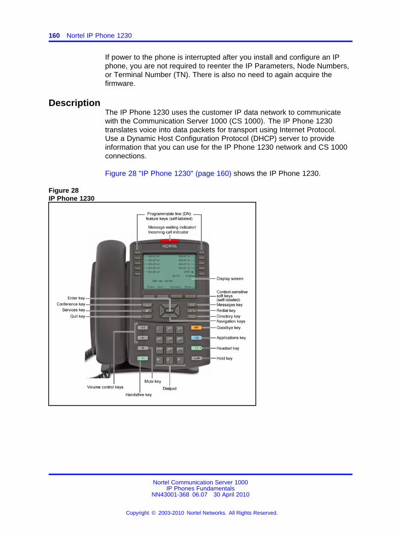
160 Nortel IP Phone 1230
If power to the phone is interrupted after you install and configure an IPphone, you are not required to reenter the IP Parameters, Node Numbers,or Terminal Number (TN). There is also no need to again acquire thefirmware.
DescriptionThe IP Phone 1230 uses the customer IP data network to communicatewith the Communication Server 1000 (CS 1000). The IP Phone 1230translates voice into data packets for transport using Internet Protocol.Use a Dynamic Host Configuration Protocol (DHCP) server to provideinformation that you can use for the IP Phone 1230 network and CS 1000connections.
Figure 28 "IP Phone 1230" (page 160) shows the IP Phone 1230.
Figure 28IP Phone 1230
Nortel Communication Server 1000IP Phones Fundamentals
NN43001-368 06.07 30 April 2010
Copyright © 2003-2010 Nortel Networks. All Rights Reserved.
.

Components and functions 161
Components and functionsThis section describes the following components and functions of the IPPhone 1230:
• “Keys and functions” (page 161)
• “Services menu” (page 163)
• “Local Tools menu” (page 164)
Keys and functionsTable 37 "IP Phone 1230 keys and functions" (page 161) describes theIP Phone 1230 keys and functions.
Table 37IP Phone 1230 keys and functions
Key Function
Handsfree Press the Handsfree key to activate handsfree mode.The Handsfree light emitting diode (LED) indicator, located on theHandsfree key, lights to indicate that the headset is in use.
Programmable line(DN)/feature keys(self-labeled)
Programmable line (Directory Number [DN]/feature keys(self-labeled) are configured for various features on the IP Phone.One must be the prime DN key.
A steady icon beside a line (DN) key indicates the line is active. Aflashing icon indicates the line is on hold. After a call arrives on aDN key, which is not on the currently displayed page of keys, the IPPhone automatically moves to the page with the active key.
A steady icon beside a feature key indicates the feature is active.A flashing icon indicates the feature is being programmed. After acall arrives on a feature key, which is not on the currently displayedpage of keys, the IP Phone automatically moves to the page withthe active key.
These keys also function as line (DN) keys. Press the Left or Rightarrow keys to access the second page of feature keys. This featureis called Second Page functionality.
Visual Alerter/MessageWaiting indicator
If a message is waiting, the red Visual Alerter/Message Waitingindicator LED at the top center of the phone flashes. The indicatoralso flashes to indicate an incoming call. The flash cadences forboth alerts are different.
Nortel Communication Server 1000IP Phones Fundamentals
NN43001-368 06.07 30 April 2010
Copyright © 2003-2010 Nortel Networks. All Rights Reserved.
.
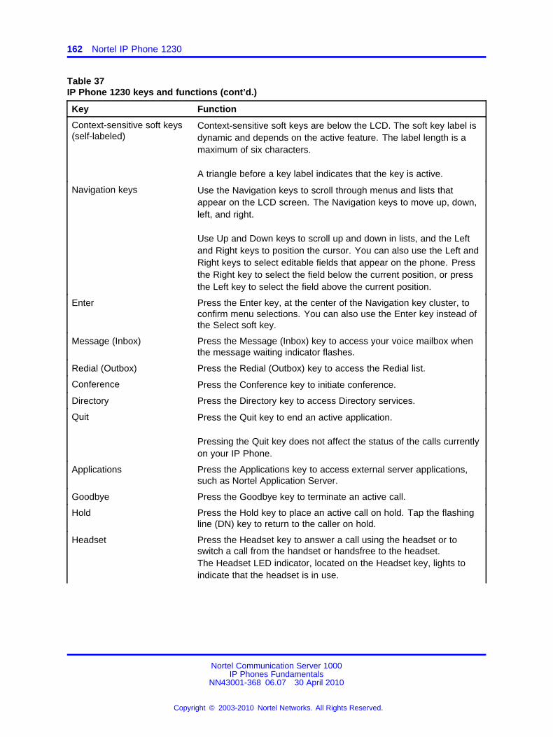
162 Nortel IP Phone 1230
Table 37IP Phone 1230 keys and functions (cont’d.)
Key Function
Context-sensitive soft keys(self-labeled)
Context-sensitive soft keys are below the LCD. The soft key label isdynamic and depends on the active feature. The label length is amaximum of six characters.
A triangle before a key label indicates that the key is active.
Navigation keys Use the Navigation keys to scroll through menus and lists thatappear on the LCD screen. The Navigation keys to move up, down,left, and right.
Use Up and Down keys to scroll up and down in lists, and the Leftand Right keys to position the cursor. You can also use the Left andRight keys to select editable fields that appear on the phone. Pressthe Right key to select the field below the current position, or pressthe Left key to select the field above the current position.
Enter Press the Enter key, at the center of the Navigation key cluster, toconfirm menu selections. You can also use the Enter key instead ofthe Select soft key.
Message (Inbox) Press the Message (Inbox) key to access your voice mailbox whenthe message waiting indicator flashes.
Redial (Outbox) Press the Redial (Outbox) key to access the Redial list.
Conference Press the Conference key to initiate conference.
Directory Press the Directory key to access Directory services.
Quit Press the Quit key to end an active application.
Pressing the Quit key does not affect the status of the calls currentlyon your IP Phone.
Applications Press the Applications key to access external server applications,such as Nortel Application Server.
Goodbye Press the Goodbye key to terminate an active call.
Hold Press the Hold key to place an active call on hold. Tap the flashingline (DN) key to return to the caller on hold.
Headset Press the Headset key to answer a call using the headset or toswitch a call from the handset or handsfree to the headset.The Headset LED indicator, located on the Headset key, lights toindicate that the headset is in use.
Nortel Communication Server 1000IP Phones Fundamentals
NN43001-368 06.07 30 April 2010
Copyright © 2003-2010 Nortel Networks. All Rights Reserved.
.
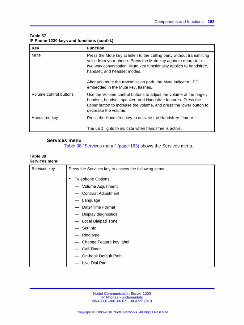
Components and functions 163
Table 37IP Phone 1230 keys and functions (cont’d.)
Key Function
Mute Press the Mute key to listen to the calling party without transmittingvoice from your phone. Press the Mute key again to return to atwo-way conversation. Mute key functionality applies to handsfree,handset, and headset modes.
After you mute the transmission path, the Mute indicator LED,embedded in the Mute key, flashes.
Volume control buttons Use the Volume control buttons to adjust the volume of the ringer,handset, headset, speaker, and Handsfree features. Press theupper button to increase the volume, and press the lower button todecrease the volume.
Handsfree key Press the Handsfree key to activate the Handsfree feature.
The LED lights to indicate when handsfree is active.
Services menuTable 38 "Services menu" (page 163) shows the Services menu.
Table 38Services menu
Services key Press the Services key to access the following items:
• Telephone Options
— Volume Adjustment
— Contrast Adjustment
— Language
— Date/Time Format
— Display diagnostics
— Local Dialpad Tone
— Set Info
— Ring type
— Change Feature key label
— Call Timer
— On-hook Default Path
— Live Dial Pad
Nortel Communication Server 1000IP Phones Fundamentals
NN43001-368 06.07 30 April 2010
Copyright © 2003-2010 Nortel Networks. All Rights Reserved.
.
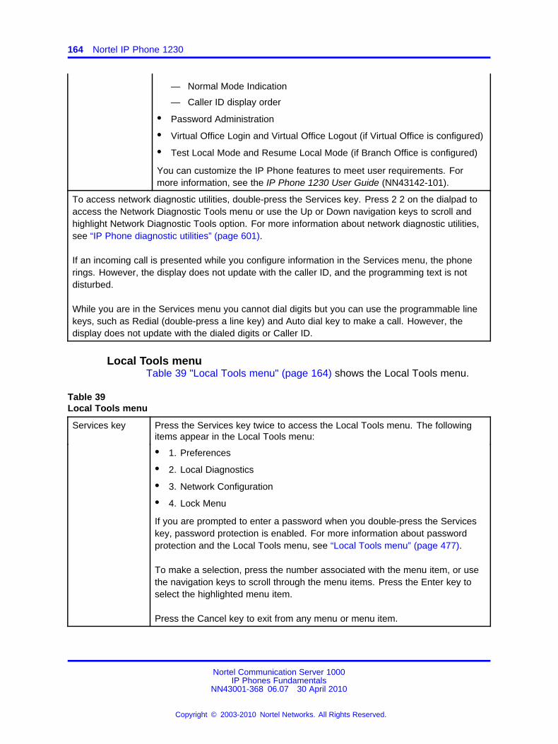
164 Nortel IP Phone 1230
— Normal Mode Indication
— Caller ID display order
• Password Administration
• Virtual Office Login and Virtual Office Logout (if Virtual Office is configured)
• Test Local Mode and Resume Local Mode (if Branch Office is configured)
You can customize the IP Phone features to meet user requirements. Formore information, see the IP Phone 1230 User Guide (NN43142-101).
To access network diagnostic utilities, double-press the Services key. Press 2 2 on the dialpad toaccess the Network Diagnostic Tools menu or use the Up or Down navigation keys to scroll andhighlight Network Diagnostic Tools option. For more information about network diagnostic utilities,see “IP Phone diagnostic utilities” (page 601).
If an incoming call is presented while you configure information in the Services menu, the phonerings. However, the display does not update with the caller ID, and the programming text is notdisturbed.
While you are in the Services menu you cannot dial digits but you can use the programmable linekeys, such as Redial (double-press a line key) and Auto dial key to make a call. However, thedisplay does not update with the dialed digits or Caller ID.
Local Tools menuTable 39 "Local Tools menu" (page 164) shows the Local Tools menu.
Table 39Local Tools menu
Services key Press the Services key twice to access the Local Tools menu. The followingitems appear in the Local Tools menu:
• 1. Preferences
• 2. Local Diagnostics
• 3. Network Configuration
• 4. Lock Menu
If you are prompted to enter a password when you double-press the Serviceskey, password protection is enabled. For more information about passwordprotection and the Local Tools menu, see “Local Tools menu” (page 477).
To make a selection, press the number associated with the menu item, or usethe navigation keys to scroll through the menu items. Press the Enter key toselect the highlighted menu item.
Press the Cancel key to exit from any menu or menu item.
Nortel Communication Server 1000IP Phones Fundamentals
NN43001-368 06.07 30 April 2010
Copyright © 2003-2010 Nortel Networks. All Rights Reserved.
.
Display characteristics 165
FeaturesThe IP Phone 1230 supports the following telephony features:
• 20 programmable line (DN)/feature keys (self-labeled) on two pages
Use the Left or Right key to access the second page of DNs orfeatures.
• four context-sensitive soft keys (self-labeled)
Functions for the context-sensitive soft keys are configured in LD 11.
• volume control bar to adjust ringer, speaker, handset, and headsetvolume
• Call Duration Timer
• ability to change the programmable line (DN)/feature key labels
• seven specialized feature keys
— Quit
— Directory
— Message/Inbox
— Redial (Outbox)
— Services
— Conference
— Expand
• five call-processing fixed keys:
— Mute
— Handsfree
— Goodbye
— Headset
— Hold
For more information about IP Phone features, see “Features” (page 391).
Display characteristicsAn IP Phone 1230 has three major display areas:
• “Programmable line (DN)/feature key label display” (page 166)
• “Information line display” (page 166)
• “Soft key label display” (page 167)
Figure 29 "IP Phone 1230 display areas" (page 166) shows these threedisplay areas.
Nortel Communication Server 1000IP Phones Fundamentals
NN43001-368 06.07 30 April 2010
Copyright © 2003-2010 Nortel Networks. All Rights Reserved.
.
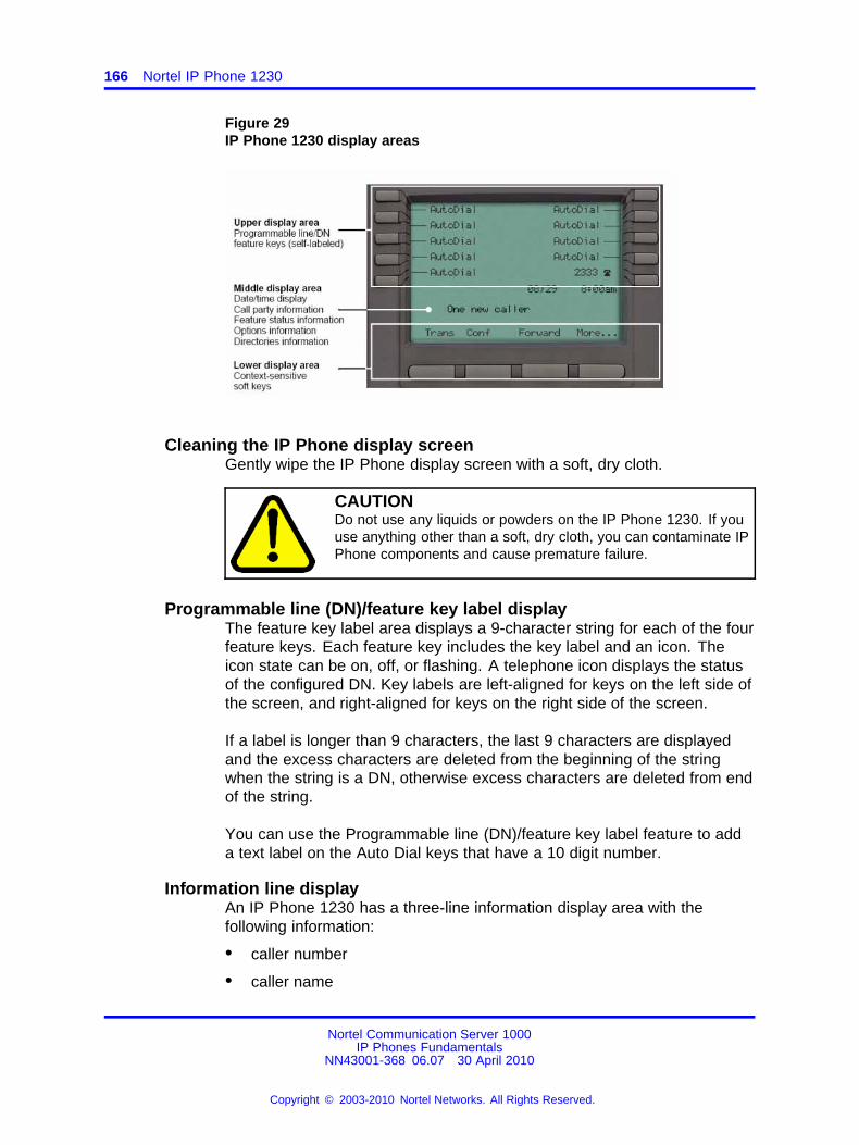
166 Nortel IP Phone 1230
Figure 29IP Phone 1230 display areas
Cleaning the IP Phone display screenGently wipe the IP Phone display screen with a soft, dry cloth.
CAUTIONDo not use any liquids or powders on the IP Phone 1230. If youuse anything other than a soft, dry cloth, you can contaminate IPPhone components and cause premature failure.
Programmable line (DN)/feature key label displayThe feature key label area displays a 9-character string for each of the fourfeature keys. Each feature key includes the key label and an icon. Theicon state can be on, off, or flashing. A telephone icon displays the statusof the configured DN. Key labels are left-aligned for keys on the left side ofthe screen, and right-aligned for keys on the right side of the screen.
If a label is longer than 9 characters, the last 9 characters are displayedand the excess characters are deleted from the beginning of the stringwhen the string is a DN, otherwise excess characters are deleted from endof the string.
You can use the Programmable line (DN)/feature key label feature to adda text label on the Auto Dial keys that have a 10 digit number.
Information line displayAn IP Phone 1230 has a three-line information display area with thefollowing information:
• caller number
• caller name
Nortel Communication Server 1000IP Phones Fundamentals
NN43001-368 06.07 30 April 2010
Copyright © 2003-2010 Nortel Networks. All Rights Reserved.
.
Package components 167
• feature prompt strings
• user-entered digits
• date and time information (if the IP Phone is in an idle state) or CallTimer (if provisioned in the Telephone options menu)
The information in the display area changes, according to thecall-processing state and active features.
Because the IP Phone 1230 only has a one-line information display area,you are prompted to scroll through any additional lines of information.
During an incoming call, only the Directory Number (DN) displays if thecaller name is greater than 9 characters. Press the flashing arrow todisplay the caller name.
Soft key label displayThe soft key label has a maximum of six characters. Each soft keyincludes the soft key label and an icon. When a soft key is in use, atriangle icon appears at the beginning of the soft key label, and the labelshifts one character to the right. If the label is six characters in length, thelast or rightmost character is truncated. If you initiate a feature, the iconstate turns on. The icon remains in the on state until you press this featurekey again. This action cancels the enabled feature and turns the icon off,and returns the soft key label to its original state.
Use the More soft key to navigate the layers of functions. If you assignonly four functions to the soft keys, the More key does not appear, and allfour functions display.
Package componentsYou must order the global power supply separately if local power using theglobal power supply is required. IP Phones include integrated support fora number of Power over LAN (PoL) options, including support for IEEE802.3af standard power.
Table 40 "Package components" (page 168) lists the IP Phone 1230package components.
Nortel Communication Server 1000IP Phones Fundamentals
NN43001-368 06.07 30 April 2010
Copyright © 2003-2010 Nortel Networks. All Rights Reserved.
.
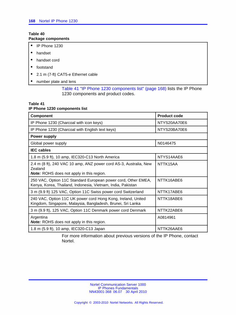
168 Nortel IP Phone 1230
Table 40Package components
• IP Phone 1230
• handset
• handset cord
• footstand
• 2.1 m (7-ft) CAT5-e Ethernet cable
• number plate and lens
Table 41 "IP Phone 1230 components list" (page 168) lists the IP Phone1230 components and product codes.
Table 41IP Phone 1230 components list
Component Product code
IP Phone 1230 (Charcoal with icon keys) NTYS20AA70E6
IP Phone 1230 (Charcoal with English text keys) NTYS20BA70E6
Power supply
Global power supply N0146475
IEC cables
1.8 m (5.9 ft), 10 amp, IEC320-C13 North America NTYS14AAE6
2.4 m (8 ft), 240 VAC 10 amp, ANZ power cord AS-3, Australia, NewZealandNote: ROHS does not apply in this region.
NTTK15AA
250 VAC, Option 11C Standard European power cord, Other EMEA,Kenya, Korea, Thailand, Indonesia, Vietnam, India, Pakistan
NTTK16ABE6
3 m (9.9 ft) 125 VAC, Option 11C Swiss power cord Switzerland NTTK17ABE6
240 VAC, Option 11C UK power cord Hong Kong, Ireland, UnitedKingdom, Singapore, Malaysia, Bangladesh, Brunei, Sri Lanka
NTTK18ABE6
3 m (9.9 ft), 125 VAC, Option 11C Denmark power cord Denmark NTTK22ABE6
ArgentinaNote: ROHS does not apply in this region.
A0814961
1.8 m (5.9 ft), 10 amp, IEC320-C13 Japan NTTK26AAE6
For more information about previous versions of the IP Phone, contactNortel.
Nortel Communication Server 1000IP Phones Fundamentals
NN43001-368 06.07 30 April 2010
Copyright © 2003-2010 Nortel Networks. All Rights Reserved.
.
Installation and configuration 169
Installation and configurationThe following sections provide a step-by-step guide to install and configurethe IP Phone 1230:
• “Before you begin” (page 169)
• “First-time installation” (page 169)
• “Configuring the IP Phone 1230” (page 170)
• “Connecting the components” (page 170)
• “Startup sequence” (page 173)
Before you beginBefore installing the IP Phone 1230, complete the following pre-installationchecklist:
• Ensure one IP Phone 1230 boxed package exists for each IP Phone1230 you install. For a list of IP Phone 1230 package components, seeTable 40 "Package components" (page 168).
• Ensure one software license exists for each IP Phone 1230 you install.
• Ensure the host call server is equipped with a Signaling Server thatruns the Line Terminal Proxy Server (LTPS) application.
• If a global power supply is required, ensure you use the approvedNortel global power supply (model number NTYS17xxE6).
• Ensure the latest IP Phone firmware is deployed to the IP telephonynode. For more information, see Signaling Server IP Line ApplicationsFundamentals (NN43001-125).
CAUTIONEnsure that the protective rubber cap on the AccessoryExpansion Module (AEM) port is in place when the port is notin use. An improper connector can cause damage to the IPPhone.
First-time installationYou must first install an IP telephony node with the Communication Server.For information about installing an IP telephony node, see Signaling ServerIP Line Applications Fundamentals (NN43001-125).
CAUTIONDo not plug your IP Phone 1230 into an ISDN connection.Severe damage can result.
Nortel Communication Server 1000IP Phones Fundamentals
NN43001-368 06.07 30 April 2010
Copyright © 2003-2010 Nortel Networks. All Rights Reserved.
.
170 Nortel IP Phone 1230
Configuring the IP Phone 1230Use Procedure 38 “Configuring the IP Phone 1230” (page 170) toconfigure the IP Phone 1230 for the first time.
Procedure 38Configuring the IP Phone 1230
Step Action
1 Configure a virtual loop on the Call Server using LD 97.
For more information about configuring a virtual loop, seeSignaling Server IP Line Applications Fundamentals (NN43001-125) and Software Input Output Reference-Administration(NN43001-611).
2 Configure the IP Phone 1230 on the Call Server using LD 11. Atthe prompt, enter the following commands:
REQ:newTYPE:1230
For more information about configuring the IP Phone 1230 usingLD 11, see Software Input Output Reference-Administration(NN43001-611).
3 Configure the IP Phone 1230 in Element Manager. IP Phonesare configured using the Phones section in the ElementManager navigation tree. For more information about configuringthe IP Phone 1230 using Element Manager, see ElementManager System Reference - Administration (NN43001-632).
--End--
Connecting the componentsUse Procedure 39 “Connecting the components” (page 170) to connect thecomponents for the IP Phone. See Figure 30 "IP Phone 1230 connections"(page 171).
Procedure 39Connecting the components
Step Action
1 Attach the footstand (optional). Attach the foot stand in theappropriate slots depending on the desired angle for your IPPhone. If you insert the foot stand into the upper slots, your IPPhone sits at a 25-degree angle. If you insert the foot stand intothe lower slots, your IP Phone sits at a 55-degree angle.
If you install the IP Phone on the wall, do not attach thefootstand.
Nortel Communication Server 1000IP Phones Fundamentals
NN43001-368 06.07 30 April 2010
Copyright © 2003-2010 Nortel Networks. All Rights Reserved.
.
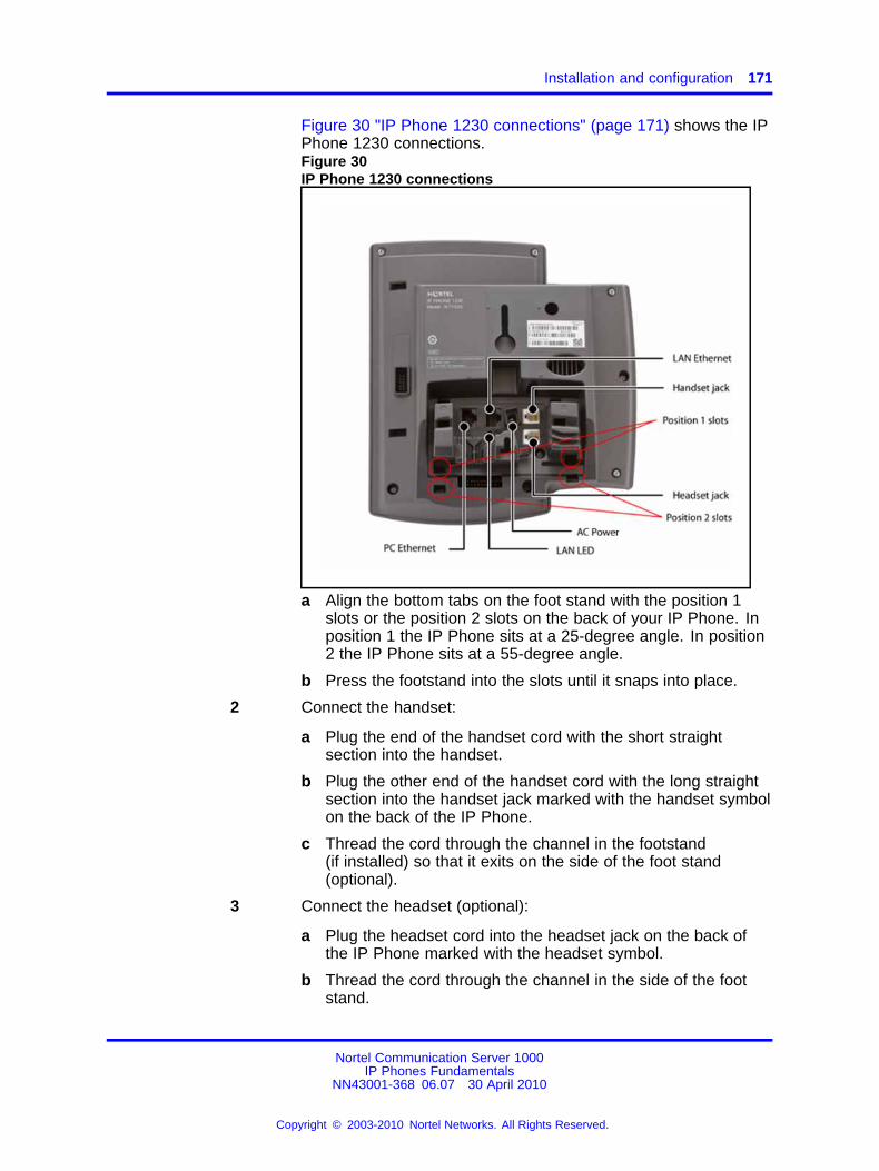
Installation and configuration 171
Figure 30 "IP Phone 1230 connections" (page 171) shows the IPPhone 1230 connections.Figure 30IP Phone 1230 connections
a Align the bottom tabs on the foot stand with the position 1slots or the position 2 slots on the back of your IP Phone. Inposition 1 the IP Phone sits at a 25-degree angle. In position2 the IP Phone sits at a 55-degree angle.
b Press the footstand into the slots until it snaps into place.
2 Connect the handset:
a Plug the end of the handset cord with the short straightsection into the handset.
b Plug the other end of the handset cord with the long straightsection into the handset jack marked with the handset symbolon the back of the IP Phone.
c Thread the cord through the channel in the footstand(if installed) so that it exits on the side of the foot stand(optional).
3 Connect the headset (optional):
a Plug the headset cord into the headset jack on the back ofthe IP Phone marked with the headset symbol.
b Thread the cord through the channel in the side of the footstand.
Nortel Communication Server 1000IP Phones Fundamentals
NN43001-368 06.07 30 April 2010
Copyright © 2003-2010 Nortel Networks. All Rights Reserved.
.
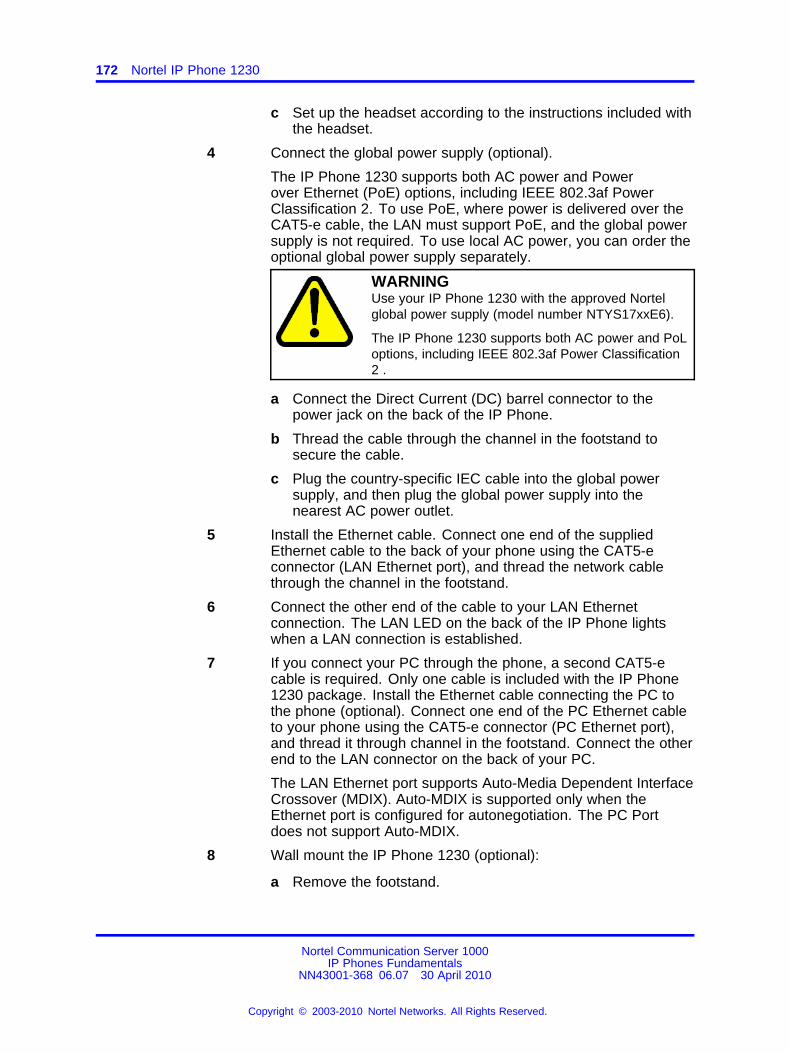
172 Nortel IP Phone 1230
c Set up the headset according to the instructions included withthe headset.
4 Connect the global power supply (optional).
The IP Phone 1230 supports both AC power and Powerover Ethernet (PoE) options, including IEEE 802.3af PowerClassification 2. To use PoE, where power is delivered over theCAT5-e cable, the LAN must support PoE, and the global powersupply is not required. To use local AC power, you can order theoptional global power supply separately.
WARNINGUse your IP Phone 1230 with the approved Nortelglobal power supply (model number NTYS17xxE6).
The IP Phone 1230 supports both AC power and PoLoptions, including IEEE 802.3af Power Classification2 .
a Connect the Direct Current (DC) barrel connector to thepower jack on the back of the IP Phone.
b Thread the cable through the channel in the footstand tosecure the cable.
c Plug the country-specific IEC cable into the global powersupply, and then plug the global power supply into thenearest AC power outlet.
5 Install the Ethernet cable. Connect one end of the suppliedEthernet cable to the back of your phone using the CAT5-econnector (LAN Ethernet port), and thread the network cablethrough the channel in the footstand.
6 Connect the other end of the cable to your LAN Ethernetconnection. The LAN LED on the back of the IP Phone lightswhen a LAN connection is established.
7 If you connect your PC through the phone, a second CAT5-ecable is required. Only one cable is included with the IP Phone1230 package. Install the Ethernet cable connecting the PC tothe phone (optional). Connect one end of the PC Ethernet cableto your phone using the CAT5-e connector (PC Ethernet port),and thread it through channel in the footstand. Connect the otherend to the LAN connector on the back of your PC.
The LAN Ethernet port supports Auto-Media Dependent InterfaceCrossover (MDIX). Auto-MDIX is supported only when theEthernet port is configured for autonegotiation. The PC Portdoes not support Auto-MDIX.
8 Wall mount the IP Phone 1230 (optional):
a Remove the footstand.
Nortel Communication Server 1000IP Phones Fundamentals
NN43001-368 06.07 30 April 2010
Copyright © 2003-2010 Nortel Networks. All Rights Reserved.
.

Redeploying an IP Phone 1230 173
b Ensure all cables are properly routed and the IP Phone isfunctioning.
c Make small marks on the wall where you want to align eachof the two keyhole slots.
d Insert the screws (not provided), so that they protrude slightlyfrom the wall.
e Align the keyholes on the back of the IP Phone with thescrews in the wall.
f Slide the IP Phone down on the screws to secure the IPPhone in position.
--End--
When you complete the IP Phone connection, you must connect the phoneto the network. See “Dynamic Host Configuration Protocol” (page 429).
Startup sequenceWhen you connect an IP Phone 1230 to the network, it must perform astartup sequence. The elements of the startup sequence include
• obtaining network access (if supported by the network infrastructure)
• obtaining VLAN ID (if supported by the network infrastructure)
• obtaining the IP parameters
• obtaining the provisioning parameters
• connecting to the Call Server
The IP Phone is configured for automatic provisioning by default. Formore information about provisioning the IP Phone automatically, see“Provisioning the IP Phones” (page 497).
You can manually configure all or some parameters. For informationabout manually provisioning the IP Phone, see “Manual provisioning of IPPhones 1110 and 1200 Series” (page 543).
Redeploying an IP Phone 1230You can redeploy a previously-configured IP Phone 1230 on the same CallServer. For example, you can assign the IP Phone 1230 to a new user(new TN) or to an existing user who moved to a new subnet by changingthe TN of the IP Phone 1230. For more information, see Converging theData Network with VoIP Fundamentals (NN43001-260).
Procedure 40Redeploying the TN of an existing IP Phone 1230
Nortel Communication Server 1000IP Phones Fundamentals
NN43001-368 06.07 30 April 2010
Copyright © 2003-2010 Nortel Networks. All Rights Reserved.
.
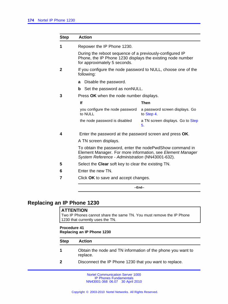
174 Nortel IP Phone 1230
Step Action
1 Repower the IP Phone 1230.
During the reboot sequence of a previously-configured IPPhone, the IP Phone 1230 displays the existing node numberfor approximately 5 seconds.
2 If you configure the node password to NULL, choose one of thefollowing:
a Disable the password.
b Set the password as nonNULL.
3 Press OK when the node number displays.
If Then
you configure the node passwordto NULL
a password screen displays. Goto Step 4.
the node password is disabled a TN screen displays. Go to Step5.
4 Enter the password at the password screen and press OK.
A TN screen displays.
To obtain the password, enter the nodePwdShow command inElement Manager. For more information, see Element ManagerSystem Reference - Administration (NN43001-632).
5 Select the Clear soft key to clear the existing TN.
6 Enter the new TN.
7 Click OK to save and accept changes.
--End--
Replacing an IP Phone 1230ATTENTIONTwo IP Phones cannot share the same TN. You must remove the IP Phone1230 that currently uses the TN.
Procedure 41Replacing an IP Phone 1230
Step Action
1 Obtain the node and TN information of the phone you want toreplace.
2 Disconnect the IP Phone 1230 that you want to replace.
Nortel Communication Server 1000IP Phones Fundamentals
NN43001-368 06.07 30 April 2010
Copyright © 2003-2010 Nortel Networks. All Rights Reserved.
.
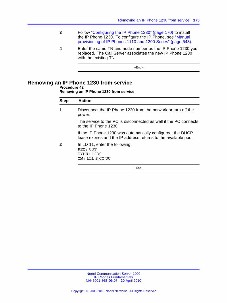
Removing an IP Phone 1230 from service 175
3 Follow “Configuring the IP Phone 1230” (page 170) to installthe IP Phone 1230. To configure the IP Phone, see “Manualprovisioning of IP Phones 1110 and 1200 Series” (page 543).
4 Enter the same TN and node number as the IP Phone 1230 youreplaced. The Call Server associates the new IP Phone 1230with the existing TN.
--End--
Removing an IP Phone 1230 from serviceProcedure 42Removing an IP Phone 1230 from service
Step Action
1 Disconnect the IP Phone 1230 from the network or turn off thepower.
The service to the PC is disconnected as well if the PC connectsto the IP Phone 1230.
If the IP Phone 1230 was automatically configured, the DHCPlease expires and the IP address returns to the available pool.
2 In LD 11, enter the following:REQ: OUTTYPE: 1230TN: LLL S CC UU
--End--
Nortel Communication Server 1000IP Phones Fundamentals
NN43001-368 06.07 30 April 2010
Copyright © 2003-2010 Nortel Networks. All Rights Reserved.
.

176 Nortel IP Phone 1230
Nortel Communication Server 1000IP Phones Fundamentals
NN43001-368 06.07 30 April 2010
Copyright © 2003-2010 Nortel Networks. All Rights Reserved.
.
177.
Nortel IP Phones 1200 Series LCDExpansion Module
ContentsThis section contains the following topics:
• “Description” (page 177)
• “Features” (page 181)
• “Display characteristics” (page 182)
• “Package components” (page 182)
• “Configuration” (page 182)
• “Installation” (page 184)
• “IP Phones 1200 Series LCD Expansion Module startup initialization”(page 185)
• “Operating parameters” (page 186)
• “Services key operation” (page 189)
• “Firmware” (page 191)
DescriptionThe IP Phones 1200 Series LCD Expansion Module (12-key self-labeling)is supported on the following IP Phones
• IP Phone 1220
• IP Phone 1230
CS 1000 does not support the IP Phones 1200 Series LCD ExpansionModule on the IP Phone 1210.
The LCD Expansion Module is classified as KEM 4 in the class of service.
The LCD Expansion Module is a hardware component that connects to theIP Phones and provides additional line appearances and feature keys.
Nortel Communication Server 1000IP Phones Fundamentals
NN43001-368 06.07 30 April 2010
Copyright © 2003-2010 Nortel Networks. All Rights Reserved.
.
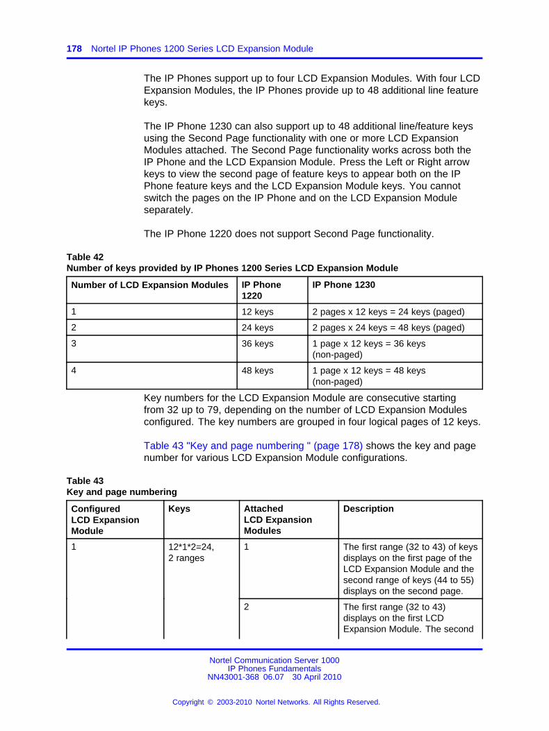
178 Nortel IP Phones 1200 Series LCD Expansion Module
The IP Phones support up to four LCD Expansion Modules. With four LCDExpansion Modules, the IP Phones provide up to 48 additional line featurekeys.
The IP Phone 1230 can also support up to 48 additional line/feature keysusing the Second Page functionality with one or more LCD ExpansionModules attached. The Second Page functionality works across both theIP Phone and the LCD Expansion Module. Press the Left or Right arrowkeys to view the second page of feature keys to appear both on the IPPhone feature keys and the LCD Expansion Module keys. You cannotswitch the pages on the IP Phone and on the LCD Expansion Moduleseparately.
The IP Phone 1220 does not support Second Page functionality.
Table 42Number of keys provided by IP Phones 1200 Series LCD Expansion Module
Number of LCD Expansion Modules IP Phone1220
IP Phone 1230
1 12 keys 2 pages x 12 keys = 24 keys (paged)
2 24 keys 2 pages x 24 keys = 48 keys (paged)
3 36 keys 1 page x 12 keys = 36 keys(non-paged)
4 48 keys 1 page x 12 keys = 48 keys(non-paged)
Key numbers for the LCD Expansion Module are consecutive startingfrom 32 up to 79, depending on the number of LCD Expansion Modulesconfigured. The key numbers are grouped in four logical pages of 12 keys.
Table 43 "Key and page numbering " (page 178) shows the key and pagenumber for various LCD Expansion Module configurations.
Table 43Key and page numbering
ConfiguredLCD ExpansionModule
Keys AttachedLCD ExpansionModules
Description
1 The first range (32 to 43) of keysdisplays on the first page of theLCD Expansion Module and thesecond range of keys (44 to 55)displays on the second page.
2 The first range (32 to 43)displays on the first LCDExpansion Module. The second
1 12*1*2=24,2 ranges
Nortel Communication Server 1000IP Phones Fundamentals
NN43001-368 06.07 30 April 2010
Copyright © 2003-2010 Nortel Networks. All Rights Reserved.
.
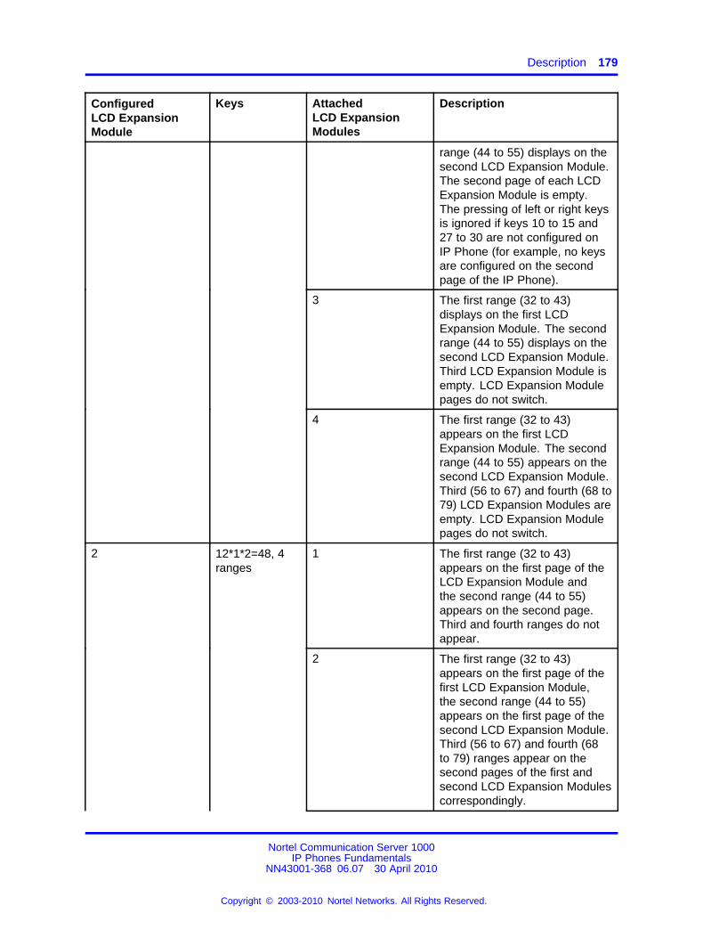
Description 179
ConfiguredLCD ExpansionModule
Keys AttachedLCD ExpansionModules
Description
range (44 to 55) displays on thesecond LCD Expansion Module.The second page of each LCDExpansion Module is empty.The pressing of left or right keysis ignored if keys 10 to 15 and27 to 30 are not configured onIP Phone (for example, no keysare configured on the secondpage of the IP Phone).
3 The first range (32 to 43)displays on the first LCDExpansion Module. The secondrange (44 to 55) displays on thesecond LCD Expansion Module.Third LCD Expansion Module isempty. LCD Expansion Modulepages do not switch.
4 The first range (32 to 43)appears on the first LCDExpansion Module. The secondrange (44 to 55) appears on thesecond LCD Expansion Module.Third (56 to 67) and fourth (68 to79) LCD Expansion Modules areempty. LCD Expansion Modulepages do not switch.
1 The first range (32 to 43)appears on the first page of theLCD Expansion Module andthe second range (44 to 55)appears on the second page.Third and fourth ranges do notappear.
2 The first range (32 to 43)appears on the first page of thefirst LCD Expansion Module,the second range (44 to 55)appears on the first page of thesecond LCD Expansion Module.Third (56 to 67) and fourth (68to 79) ranges appear on thesecond pages of the first andsecond LCD Expansion Modulescorrespondingly.
2 12*1*2=48, 4ranges
Nortel Communication Server 1000IP Phones Fundamentals
NN43001-368 06.07 30 April 2010
Copyright © 2003-2010 Nortel Networks. All Rights Reserved.
.
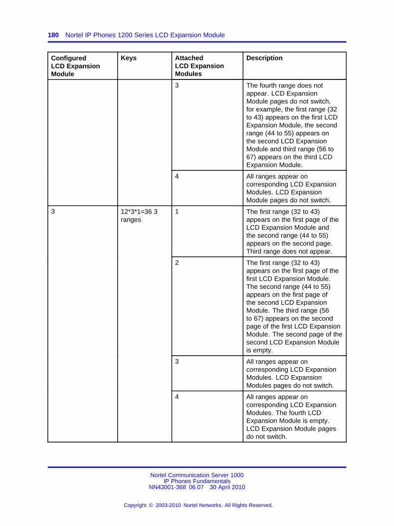
180 Nortel IP Phones 1200 Series LCD Expansion Module
ConfiguredLCD ExpansionModule
Keys AttachedLCD ExpansionModules
Description
3 The fourth range does notappear. LCD ExpansionModule pages do not switch,for example, the first range (32to 43) appears on the first LCDExpansion Module, the secondrange (44 to 55) appears onthe second LCD ExpansionModule and third range (56 to67) appears on the third LCDExpansion Module.
4 All ranges appear oncorresponding LCD ExpansionModules. LCD ExpansionModule pages do not switch.
1 The first range (32 to 43)appears on the first page of theLCD Expansion Module andthe second range (44 to 55)appears on the second page.Third range does not appear.
2 The first range (32 to 43)appears on the first page of thefirst LCD Expansion Module.The second range (44 to 55)appears on the first page ofthe second LCD ExpansionModule. The third range (56to 67) appears on the secondpage of the first LCD ExpansionModule. The second page of thesecond LCD Expansion Moduleis empty.
3 All ranges appear oncorresponding LCD ExpansionModules. LCD ExpansionModules pages do not switch.
3 12*3*1=36 3ranges
4 All ranges appear oncorresponding LCD ExpansionModules. The fourth LCDExpansion Module is empty.LCD Expansion Module pagesdo not switch.
Nortel Communication Server 1000IP Phones Fundamentals
NN43001-368 06.07 30 April 2010
Copyright © 2003-2010 Nortel Networks. All Rights Reserved.
.
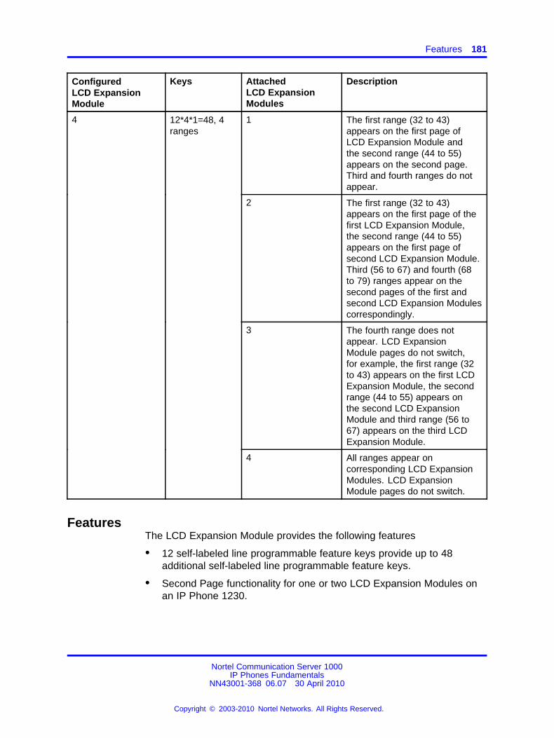
Features 181
ConfiguredLCD ExpansionModule
Keys AttachedLCD ExpansionModules
Description
1 The first range (32 to 43)appears on the first page ofLCD Expansion Module andthe second range (44 to 55)appears on the second page.Third and fourth ranges do notappear.
2 The first range (32 to 43)appears on the first page of thefirst LCD Expansion Module,the second range (44 to 55)appears on the first page ofsecond LCD Expansion Module.Third (56 to 67) and fourth (68to 79) ranges appear on thesecond pages of the first andsecond LCD Expansion Modulescorrespondingly.
3 The fourth range does notappear. LCD ExpansionModule pages do not switch,for example, the first range (32to 43) appears on the first LCDExpansion Module, the secondrange (44 to 55) appears onthe second LCD ExpansionModule and third range (56 to67) appears on the third LCDExpansion Module.
4 12*4*1=48, 4ranges
4 All ranges appear oncorresponding LCD ExpansionModules. LCD ExpansionModule pages do not switch.
FeaturesThe LCD Expansion Module provides the following features
• 12 self-labeled line programmable feature keys provide up to 48additional self-labeled line programmable feature keys.
• Second Page functionality for one or two LCD Expansion Modules onan IP Phone 1230.
Nortel Communication Server 1000IP Phones Fundamentals
NN43001-368 06.07 30 April 2010
Copyright © 2003-2010 Nortel Networks. All Rights Reserved.
.
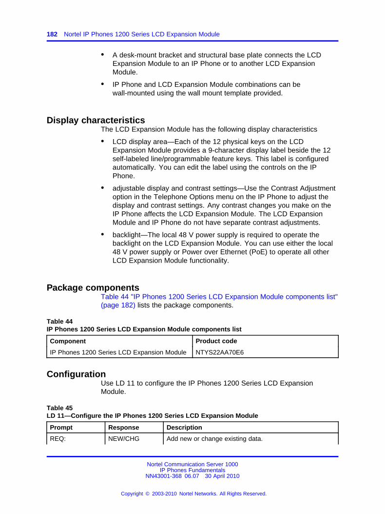
182 Nortel IP Phones 1200 Series LCD Expansion Module
• A desk-mount bracket and structural base plate connects the LCDExpansion Module to an IP Phone or to another LCD ExpansionModule.
• IP Phone and LCD Expansion Module combinations can bewall-mounted using the wall mount template provided.
Display characteristicsThe LCD Expansion Module has the following display characteristics
• LCD display area—Each of the 12 physical keys on the LCDExpansion Module provides a 9-character display label beside the 12self-labeled line/programmable feature keys. This label is configuredautomatically. You can edit the label using the controls on the IPPhone.
• adjustable display and contrast settings—Use the Contrast Adjustmentoption in the Telephone Options menu on the IP Phone to adjust thedisplay and contrast settings. Any contrast changes you make on theIP Phone affects the LCD Expansion Module. The LCD ExpansionModule and IP Phone do not have separate contrast adjustments.
• backlight—The local 48 V power supply is required to operate thebacklight on the LCD Expansion Module. You can use either the local48 V power supply or Power over Ethernet (PoE) to operate all otherLCD Expansion Module functionality.
Package componentsTable 44 "IP Phones 1200 Series LCD Expansion Module components list"(page 182) lists the package components.
Table 44IP Phones 1200 Series LCD Expansion Module components list
Component Product code
IP Phones 1200 Series LCD Expansion Module NTYS22AA70E6
ConfigurationUse LD 11 to configure the IP Phones 1200 Series LCD ExpansionModule.
Table 45LD 11—Configure the IP Phones 1200 Series LCD Expansion Module
Prompt Response Description
REQ: NEW/CHG Add new or change existing data.
Nortel Communication Server 1000IP Phones Fundamentals
NN43001-368 06.07 30 April 2010
Copyright © 2003-2010 Nortel Networks. All Rights Reserved.
.
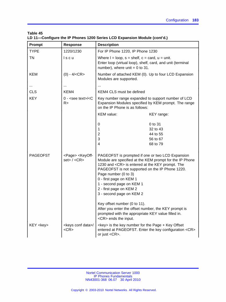
Configuration 183
Table 45LD 11—Configure the IP Phones 1200 Series LCD Expansion Module (cont’d.)
Prompt Response Description
TYPE 1220/1230 For IP Phone 1220, IP Phone 1230
TN l s c u Where l = loop, s = shelf, c = card, u = unit.Enter loop (virtual loop), shelf, card, and unit (terminalnumber), where unit = 0 to 31.
KEM (0) - 4/<CR> Number of attached KEM (0). Up to four LCD ExpansionModules are supported.
... ... ...
CLS KEM4 KEM4 CLS must be defined
KEY 0 - <see text>/<CR>
Key number range expanded to support number of LCDExpansion Modules specified by KEM prompt. The rangeon the IP Phone is as follows:
KEM value:
01234
KEY range:
0 to 3132 to 4344 to 5556 to 6768 to 79
PAGEOFST <Page> <KeyOff-set> / <CR>
PAGEOFST is prompted if one or two LCD ExpansionModule are specified at the KEM prompt for the IP Phone1230 and <CR> is entered at the KEY prompt. ThePAGEOFST is not supported on the IP Phone 1220.Page number (0 to 3)0 - first page on KEM 11 - second page on KEM 12 - first page on KEM 23 - second page on KEM 2
Key offset number (0 to 11).After you enter the offset number, the KEY prompt isprompted with the appropriate KEY value filled in.<CR> ends the input.
KEY <key> <keys conf data>/<CR>
<key> is the key number for the Page + Key Offsetentered at PAGEOFST. Enter the key configuration <CR>or just <CR>.
Nortel Communication Server 1000IP Phones Fundamentals
NN43001-368 06.07 30 April 2010
Copyright © 2003-2010 Nortel Networks. All Rights Reserved.
.
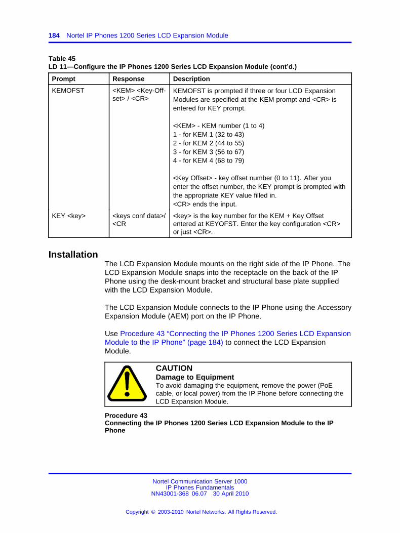
184 Nortel IP Phones 1200 Series LCD Expansion Module
Table 45LD 11—Configure the IP Phones 1200 Series LCD Expansion Module (cont’d.)
Prompt Response Description
KEMOFST <KEM> <Key-Off-set> / <CR>
KEMOFST is prompted if three or four LCD ExpansionModules are specified at the KEM prompt and <CR> isentered for KEY prompt.
<KEM> - KEM number (1 to 4)1 - for KEM 1 (32 to 43)2 - for KEM 2 (44 to 55)3 - for KEM 3 (56 to 67)4 - for KEM 4 (68 to 79)
<Key Offset> - key offset number (0 to 11). After youenter the offset number, the KEY prompt is prompted withthe appropriate KEY value filled in.<CR> ends the input.
KEY <key> <keys conf data>/<CR
<key> is the key number for the KEM + Key Offsetentered at KEYOFST. Enter the key configuration <CR>or just <CR>.
InstallationThe LCD Expansion Module mounts on the right side of the IP Phone. TheLCD Expansion Module snaps into the receptacle on the back of the IPPhone using the desk-mount bracket and structural base plate suppliedwith the LCD Expansion Module.
The LCD Expansion Module connects to the IP Phone using the AccessoryExpansion Module (AEM) port on the IP Phone.
Use Procedure 43 “Connecting the IP Phones 1200 Series LCD ExpansionModule to the IP Phone” (page 184) to connect the LCD ExpansionModule.
CAUTIONDamage to EquipmentTo avoid damaging the equipment, remove the power (PoEcable, or local power) from the IP Phone before connecting theLCD Expansion Module.
Procedure 43Connecting the IP Phones 1200 Series LCD Expansion Module to the IPPhone
Nortel Communication Server 1000IP Phones Fundamentals
NN43001-368 06.07 30 April 2010
Copyright © 2003-2010 Nortel Networks. All Rights Reserved.
.
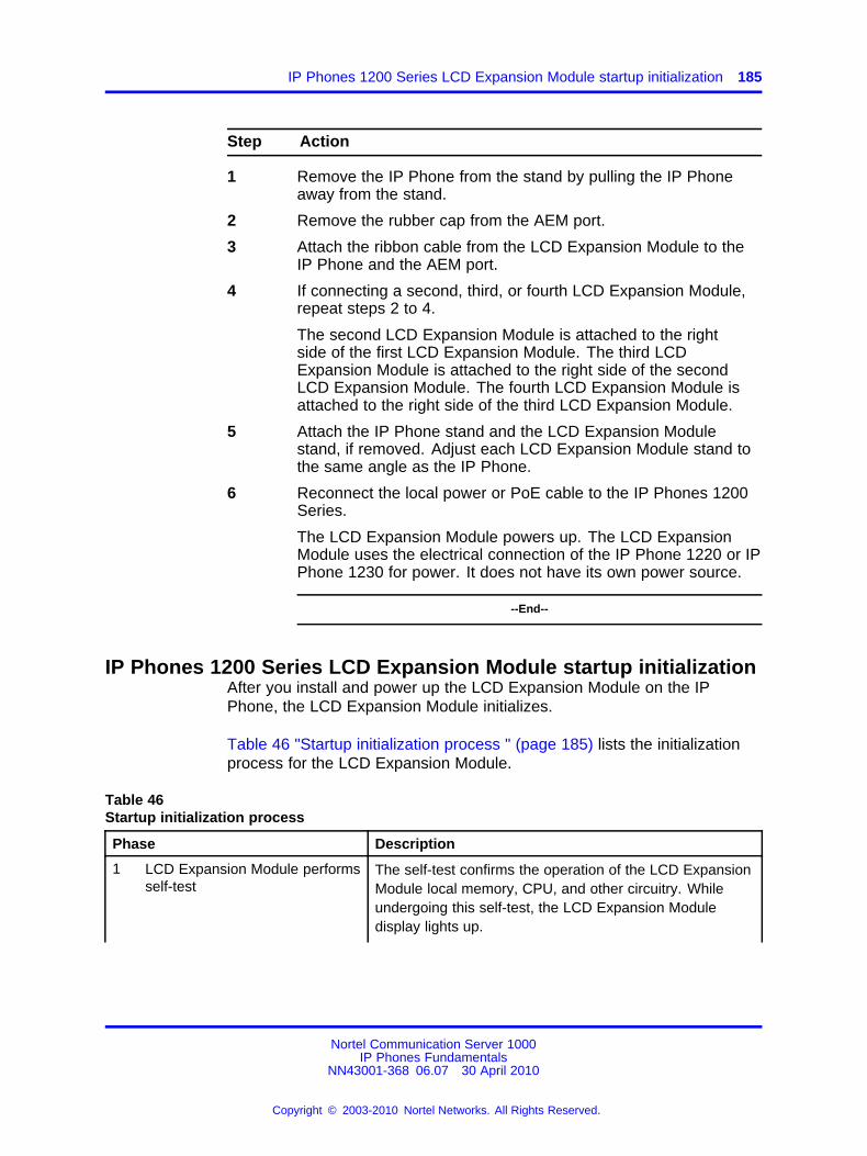
IP Phones 1200 Series LCD Expansion Module startup initialization 185
Step Action
1 Remove the IP Phone from the stand by pulling the IP Phoneaway from the stand.
2 Remove the rubber cap from the AEM port.
3 Attach the ribbon cable from the LCD Expansion Module to theIP Phone and the AEM port.
4 If connecting a second, third, or fourth LCD Expansion Module,repeat steps 2 to 4.
The second LCD Expansion Module is attached to the rightside of the first LCD Expansion Module. The third LCDExpansion Module is attached to the right side of the secondLCD Expansion Module. The fourth LCD Expansion Module isattached to the right side of the third LCD Expansion Module.
5 Attach the IP Phone stand and the LCD Expansion Modulestand, if removed. Adjust each LCD Expansion Module stand tothe same angle as the IP Phone.
6 Reconnect the local power or PoE cable to the IP Phones 1200Series.
The LCD Expansion Module powers up. The LCD ExpansionModule uses the electrical connection of the IP Phone 1220 or IPPhone 1230 for power. It does not have its own power source.
--End--
IP Phones 1200 Series LCD Expansion Module startup initializationAfter you install and power up the LCD Expansion Module on the IPPhone, the LCD Expansion Module initializes.
Table 46 "Startup initialization process " (page 185) lists the initializationprocess for the LCD Expansion Module.
Table 46Startup initialization process
Phase Description
1 LCD Expansion Module performsself-test
The self-test confirms the operation of the LCD ExpansionModule local memory, CPU, and other circuitry. Whileundergoing this self-test, the LCD Expansion Moduledisplay lights up.
Nortel Communication Server 1000IP Phones Fundamentals
NN43001-368 06.07 30 April 2010
Copyright © 2003-2010 Nortel Networks. All Rights Reserved.
.
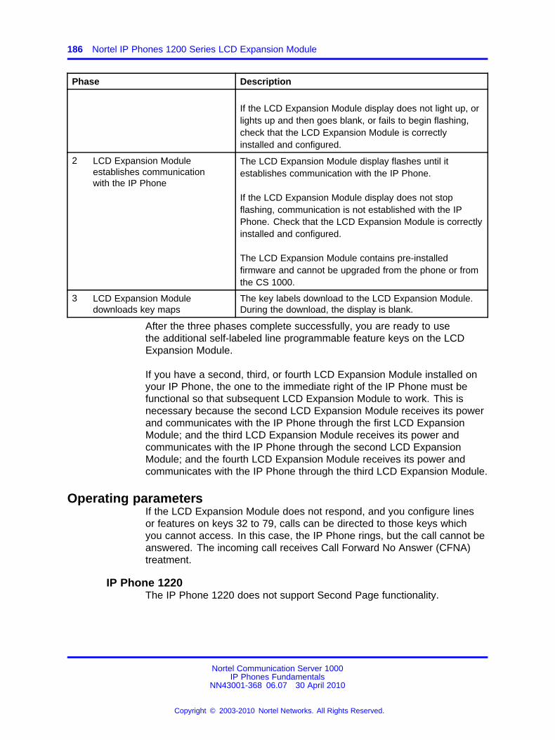
186 Nortel IP Phones 1200 Series LCD Expansion Module
Phase Description
If the LCD Expansion Module display does not light up, orlights up and then goes blank, or fails to begin flashing,check that the LCD Expansion Module is correctlyinstalled and configured.
2 LCD Expansion Moduleestablishes communicationwith the IP Phone
The LCD Expansion Module display flashes until itestablishes communication with the IP Phone.
If the LCD Expansion Module display does not stopflashing, communication is not established with the IPPhone. Check that the LCD Expansion Module is correctlyinstalled and configured.
The LCD Expansion Module contains pre-installedfirmware and cannot be upgraded from the phone or fromthe CS 1000.
3 LCD Expansion Moduledownloads key maps
The key labels download to the LCD Expansion Module.During the download, the display is blank.
After the three phases complete successfully, you are ready to usethe additional self-labeled line programmable feature keys on the LCDExpansion Module.
If you have a second, third, or fourth LCD Expansion Module installed onyour IP Phone, the one to the immediate right of the IP Phone must befunctional so that subsequent LCD Expansion Module to work. This isnecessary because the second LCD Expansion Module receives its powerand communicates with the IP Phone through the first LCD ExpansionModule; and the third LCD Expansion Module receives its power andcommunicates with the IP Phone through the second LCD ExpansionModule; and the fourth LCD Expansion Module receives its power andcommunicates with the IP Phone through the third LCD Expansion Module.
Operating parametersIf the LCD Expansion Module does not respond, and you configure linesor features on keys 32 to 79, calls can be directed to those keys whichyou cannot access. In this case, the IP Phone rings, but the call cannot beanswered. The incoming call receives Call Forward No Answer (CFNA)treatment.
IP Phone 1220The IP Phone 1220 does not support Second Page functionality.
Nortel Communication Server 1000IP Phones Fundamentals
NN43001-368 06.07 30 April 2010
Copyright © 2003-2010 Nortel Networks. All Rights Reserved.
.
Operating parameters 187
If you configure only one LCD Expansion Module in LD 11, but two, three,or four LCD Expansion Modules are detected on an IP Phone 1220, thesecond, third, and fourth LCD Expansion Modules are ignored. An errormessage alerts the administrator that the hardware configuration does notmatch the administered configuration.
If you configure two LCD Expansion Modules in LD 11, but only one LCDExpansion Module responds, the keys on the second LCD ExpansionModule are available for call processing but you cannot answer them. Thelines and features on keys 44 to 55 can cause the IP Phone 1220 to ring,but there is no way to answer it. An error message alerts the administratorthat the hardware configuration does not match the administeredconfiguration.
If you configure three LCD Expansion Modules in LD 11, but only oneor two LCD Expansion Modules respond, the keys on the third LCDExpansion Module are available for call processing but you cannot accessthem. The lines and features on keys 56 to 67 can cause the IP Phone1220 to ring, but there is no way to answer it. An error message alertsthe administrator that the hardware configuration does not match theadministered configuration.
If you configure four LCD Expansion Modules in LD 11, but only one,two, or three LCD Expansion Modules respond, the keys on the fourthLCD Expansion Module are available for call processing but you cannotaccess them. The lines and features on keys 68 to 79 can cause the IPPhone 1220 to ring, but there is no way to answer it. An error messagealerts the administrator that the hardware configuration does not match theadministered configuration.
IP Phone 1230The IP Phone 1230 supports Second Page functionality.
If you configure only one LCD Expansion Module in LD 11, but two,three, or four LCD Expansion Modules are detected on the IP Phone, theTerminal Proxy Server (TPS) assigns keys 44 to 55 to the second page.The third and fourth LCD Expansion Modules do not have keys assigneduntil they are configured in LD 11.An error message alerts the administrator that the hardware configurationdoes not match the administered configuration.
If you configure two LCD Expansion Modules in LD 11 but only one LCDExpansion Module responds, the TPS assigns keys 32 to 55 to the singleLCD Expansion Module (using the Second Page functionality). An errormessage alerts the administrator that the hardware configuration does not
Nortel Communication Server 1000IP Phones Fundamentals
NN43001-368 06.07 30 April 2010
Copyright © 2003-2010 Nortel Networks. All Rights Reserved.
.
188 Nortel IP Phones 1200 Series LCD Expansion Module
match the administered configuration. When a second LCD ExpansionModule is detected, the TPS changes the key assignments to displayacross both LCD Expansion Modules.
If you configure two LCD Expansion Modules in LD 11 but three LCDExpansion Modules respond, the TPS assigns the keys 32 to 55 to thefirst two LCD Expansion Modules. The third LCD Expansion Module doesnot have keys assigned until it is configured in LD 11. An error messagealerts the administrator that the hardware configuration does not match theadministered configuration.
If you configure two LCD Expansion Modules in LD 11 but four LCDExpansion Modules respond, the TPS assigns the keys 32 to 55 to the firsttwo LCD Expansion Modules. The fourth LCD Expansion Module doesnot have keys assigned until it is configured in LD 11. An error messagealerts the administrator that the hardware configuration does not match theadministered configuration.
If you configure three LCD Expansion Modules but only one LCDExpansion Module responds, the TPS assigns the keys 32 to 55 to thesingle LCD Expansion Module (using the Second Page functionality).When a second then the third LCD Expansion Module is detected, the TPSchanges the key assignments to display across all three LCD ExpansionModules.
If you configure three Expansion Modules in LD 11 but two LCD ExpansionModules respond, the TPS assigns keys 32 to 67 to the first two LCDExpansion Modules. An error message alerts the administrator that thehardware configuration does not match the administered configuration.When a third LCD Expansion Module is detected, the TPS changes thekey assignments to display across all three LCD Expansion Modules.
If you configure three LCD Expansion Modules in LD 11 but four LCDExpansion Modules respond, the TPS assigns keys 32 to 67 to the firstthree LCD Expansion Modules. The fourth LCD Expansion Module doesnot have keys assigned until it is configured in LD 11. An error messagealerts the administrator that the hardware configuration does not match theadministered configuration.
If you configure four LCD Expansion Modules but only one LCD ExpansionModule responds, the TPS assigns the keys 32 to 55 to the single LCDExpansion Module (using the Second Page functionality). When a second,third, and fourth LCD Expansion Modules are detected, the TPS changesthe key assignments to display across all four LCD Expansion Modules.
Nortel Communication Server 1000IP Phones Fundamentals
NN43001-368 06.07 30 April 2010
Copyright © 2003-2010 Nortel Networks. All Rights Reserved.
.
Services key operation 189
If you configure four LCD Expansion Modules in LD 11 but two LCDExpansion Modules respond, the TPS assigns keys 32 to 79 to the firsttwo LCD Expansion Modules. An error message alerts the administratorthat the hardware configuration does not match the administeredconfiguration. When a third LCD Expansion Module is detected, the TPSchanges the key assignments to display across all three LCD ExpansionModules.
Services key operationUse the Services key to access user settings and certain features on theIP Phone. When one or more LCD Expansion Modules are attached tothe IP Phone, the actions of the display diagnostics for the IP PhonesDN/feature key display area are duplicated for the LCD Expansion Module.
If an incoming call occurs when in the diagnostic mode, answer thecall by pressing the DN feature key, handsfree, or headset key, or bypicking up the handset. The display area remains in diagnostic mode untileither you exit the diagnostic more, or the idle timeout clears the mode.Once cleared, the normal display for the current state of the IP Phone isdisplayed.
For information about the Services menu, see “Services menu” (page145) for the IP Phone 1220 or “Services menu” (page 163) for the IPPhone 1230.
Display diagnosticsUse the Up or Down navigation keys to scroll the Display diagnosticsmenu to access the following diagnostic operations
• “Initial screen” (page 189)
• “Full contrast” (page 189)
• “LED test” (page 190)
• “Character test” (page 190)
Initial screenInstructions appear on the display area of the IP Phone and the LCDExpansion Module. The DN feature key display areas are blank.
Full contrastThe IP Phone and the LCD Expansion Module display areas are set tomaximum (dark) contrast, including the DN feature key areas. All LEDsare off.
Nortel Communication Server 1000IP Phones Fundamentals
NN43001-368 06.07 30 April 2010
Copyright © 2003-2010 Nortel Networks. All Rights Reserved.
.
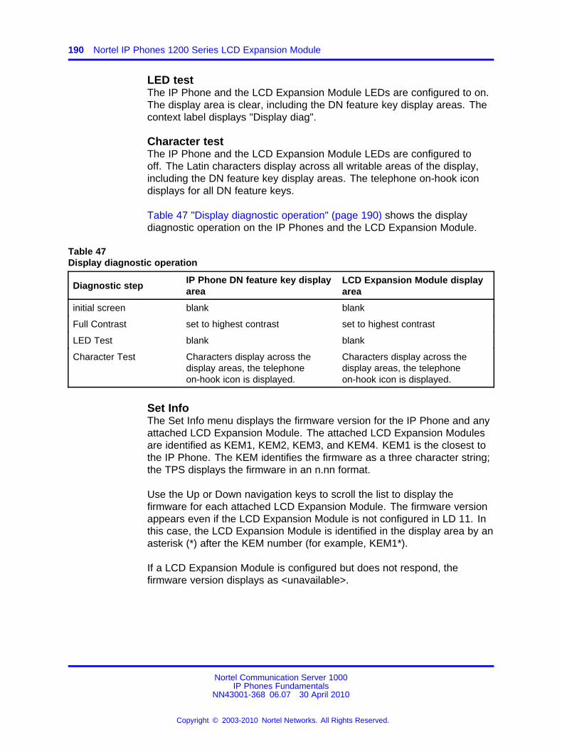
190 Nortel IP Phones 1200 Series LCD Expansion Module
LED testThe IP Phone and the LCD Expansion Module LEDs are configured to on.The display area is clear, including the DN feature key display areas. Thecontext label displays "Display diag".
Character testThe IP Phone and the LCD Expansion Module LEDs are configured tooff. The Latin characters display across all writable areas of the display,including the DN feature key display areas. The telephone on-hook icondisplays for all DN feature keys.
Table 47 "Display diagnostic operation" (page 190) shows the displaydiagnostic operation on the IP Phones and the LCD Expansion Module.
Table 47Display diagnostic operation
Diagnostic stepIP Phone DN feature key displayarea
LCD Expansion Module displayarea
initial screen blank blank
Full Contrast set to highest contrast set to highest contrast
LED Test blank blank
Character Test Characters display across thedisplay areas, the telephoneon-hook icon is displayed.
Characters display across thedisplay areas, the telephoneon-hook icon is displayed.
Set InfoThe Set Info menu displays the firmware version for the IP Phone and anyattached LCD Expansion Module. The attached LCD Expansion Modulesare identified as KEM1, KEM2, KEM3, and KEM4. KEM1 is the closest tothe IP Phone. The KEM identifies the firmware as a three character string;the TPS displays the firmware in an n.nn format.
Use the Up or Down navigation keys to scroll the list to display thefirmware for each attached LCD Expansion Module. The firmware versionappears even if the LCD Expansion Module is not configured in LD 11. Inthis case, the LCD Expansion Module is identified in the display area by anasterisk (*) after the KEM number (for example, KEM1*).
If a LCD Expansion Module is configured but does not respond, thefirmware version displays as <unavailable>.
Nortel Communication Server 1000IP Phones Fundamentals
NN43001-368 06.07 30 April 2010
Copyright © 2003-2010 Nortel Networks. All Rights Reserved.
.
Firmware 191
FirmwareThe LCD Expansion Module firmware is not downloadable. If the LCDExpansion Module firmware must be upgraded or changed, the LCDExpansion Module must be replaced with a new LCD Expansion Modulecontaining the updated firmware.
Nortel Communication Server 1000IP Phones Fundamentals
NN43001-368 06.07 30 April 2010
Copyright © 2003-2010 Nortel Networks. All Rights Reserved.
.

192 Nortel IP Phones 1200 Series LCD Expansion Module
Nortel Communication Server 1000IP Phones Fundamentals
NN43001-368 06.07 30 April 2010
Copyright © 2003-2010 Nortel Networks. All Rights Reserved.
.
193.
Nortel IP Softphone 2050
ContentsThis section contains the following topics:
• “Introduction” (page 193)
• “Description” (page 194)
• “Components” (page 197)
• “Display characteristics” (page 200)
• “Licenses” (page 207)
• “Key number assignments” (page 224)
• “Minimum system requirements” (page 225)
• “System components” (page 226)
• “Before you begin” (page 227)
• “First-time installation” (page 228)
• “Installing or upgrading the IP Softphone 2050” (page 229)
• “Running the IP Softphone 2050 for the first time” (page 239)
• “Redeploying the IP Softphone 2050” (page 239)
• “Removing an IP Softphone 2050 from service” (page 240)
• “Maintenance” (page 240)
IntroductionThis section explains how to install and maintain the IP Softphone 2050.For information about using the IP Softphone 2050, see IP Softphone 2050User Guide (NN43119-101).
Nortel Communication Server 1000IP Phones Fundamentals
NN43001-368 06.07 30 April 2010
Copyright © 2003-2010 Nortel Networks. All Rights Reserved.
.
194 Nortel IP Softphone 2050
This section contains the following procedures:
• Procedure 57 “Configuring an IP Softphone 2050 ” (page 228).
• Procedure 64 “Upgrading the IP Softphone 2050 on your PC” (page236).
• Procedure 65 “Removing IP Softphone 2050 (Version 1)” (page 237).
• Procedure 66 “Removing IP Softphone 2050 (Version 2 or Release3)” (page 237).
• Procedure 67 “Installing the Accessibility Interface” (page 237)
• Procedure 68 “Installing the Windows QoS Packet Scheduler” (page238)
• Procedure 69 “Redeploying the TN of an existing IP Softphone 2050”(page 240).
• Procedure 70 “Removing an IP Softphone 2050 from service” (page240).
DescriptionThe IP Softphone 2050 is a Windows-based application that providesvoice services for Personal Computers (PC). The IP Softphone 2050operates on PC that run Windows Vista, Windows XP, and Windows 2000Professional.
Designed to work with IP-based phone systems, the IP Softphone 2050provides Voice Over IP (VoIP) services using a telephony server and anenterprise Local Area Network (LAN). The VoIP application is comprised ofthe following components:
• Settings—used to configure the IP Softphone
• IP Softphone 2050—the IP Softphone user interface
• IP Softphone 2050 QoS
FeaturesThe IP Softphone 2050 supports the following features:
• 12 user-defined feature keys: six programmable line (DN)/feature keysand six lines/features accessed by pressing the Shift key
• four context-sensitive soft keys that provide access to a maximum ofnine features
For more information about context-sensitive soft keys, see Featuresand Services Fundamentals (NN43001-106).
• four-line display
Nortel Communication Server 1000IP Phones Fundamentals
NN43001-368 06.07 30 April 2010
Copyright © 2003-2010 Nortel Networks. All Rights Reserved.
.
Description 195
• directory capabilities stored locally on the PC or linked to externaldirectories, such as LDAP, Microsoft Outlook, and Windows AddressBook Directory
• one-click direct dialing from various windows and applications
• user-selected ringer lets the PC speakers or the headset ring forincoming calls
• choice of two window themes, as well as an Accessibility Interfaceoption for the visually-impaired
The Accessibility Interface operates with screen reading software,such as JAWS® for Windows from Freedom Scientific, which enablesvisually-impaired users to access the full range of IP Softphone 2050features. Visually-impaired users can follow Procedure 67 “Installingthe Accessibility Interface” (page 237) to install the AccessibilityInterface from the IP Softphone 2050 CD ROM.
• Secure Real-time Transport Protocol (SRTP) media encryption.
For more information about SRTP media encryption, see “Features”(page 391).
• UNIStim Security (USec) signaling encryption
ATTENTIONUSec signaling encryption requires a Secure Multimedia Controller.
• Global IP Sound (GIPS) Voice Engine
• headset support (for example, Bluetooth® wireless technology andUSB)
• client-side licensing
• quality monitoring
• programmable hot keys allow single-key access to user-definablefeatures
• two supported input modes: Digit and Alpha
Native mode appears dimmed in the list because it is not supported.For more information about Native mode, see IP Softphone 2050 UserGuide (NN43119-101).
• macro functions available for programming long dialing patterns
• support for G.711 and G.729 codecs for operation at a variety ofnetwork connection speeds
Nortel Communication Server 1000IP Phones Fundamentals
NN43001-368 06.07 30 April 2010
Copyright © 2003-2010 Nortel Networks. All Rights Reserved.
.
196 Nortel IP Softphone 2050
Additional featuresThe IP Softphone 2050 supports the following additional features:
• Call Duration Timer
• ability to change the feature key labels
• Corporate Directory
• Personal Directory
• Redial List
• Callers List
• Password Administration
• Virtual office
• Branch Office
• Call Recording
• Active Call Failover
• language support: English, French, Swedish, Danish, Norwegian,German, Dutch, Traditional Chinese, Simplified Chinese, JapaneseKanji, Japanese Katakana, Korean, Arabic, Greek, Hebrew,Portuguese, Czech, Finnish, Hungarian, Italian, Polish, Spanish,Russian, Latvian, and Turkish
• Graphical External Application Server (GXAS)
• IP Client cookie mechanism (requires patch MPLR 24248 for CS 1000Release 5.0 and earlier)
• Call Notification (requires patch MPLR 24100 for CS 1000 Release 5.0and earlier)
• Call Notification pop up screen for incoming calls feature requiresMPLR25221 for CS 1000 Release 4.50.88, MPLR24100 for CS 1000Release 4.5 and CS 1000 Release 5.0, MPLR24248 for CS 1000Release 5.00.31, and CNDA and DNDA defined as CLS in LD 11.MPLR222796 is required to support UBS call pickup.
• Call Disconnect Notification
• drag and drop dialing
• Telephony Application Programming Interface (TAPI) 3
The Telephony Service Provider (TSP) supports basic telephonylevel functions only, such as making and answering a call and endingan active call. The IP Softphone 2050 Call Recording feature is notaccessible from the TAPI feature.
• Expansion Module for IP Softphone 2050
• network diagnostic utilities
Nortel Communication Server 1000IP Phones Fundamentals
NN43001-368 06.07 30 April 2010
Copyright © 2003-2010 Nortel Networks. All Rights Reserved.
.
Components 197
For more information about IP Softphone 2050 features and the IPSoftphone 2050 Expansion Module, see IP Softphone 2050 User Guide(NN43119-101).
Language supportThe IP Softphone 2050 is affected by the following language controls:
• Operating system language
• IP Softphone 2050 language selection—sets the language displayedin the help screens and in the menus (select the IP Softphone 2050language from the Application menu or during installation)
ComponentsThe IP Softphone 2050 supports the following main components:
• Call Control window
• Local Directory window
• Settings window
• System tray icon and menu
• third-party supported applications
• 2050.exe application
Call Control windowYou can use the 1140 Call Control Window (see Figure 31 "1140 CallControl window" (page 198) to make and manage IP Phone calls.
Nortel Communication Server 1000IP Phones Fundamentals
NN43001-368 06.07 30 April 2010
Copyright © 2003-2010 Nortel Networks. All Rights Reserved.
.
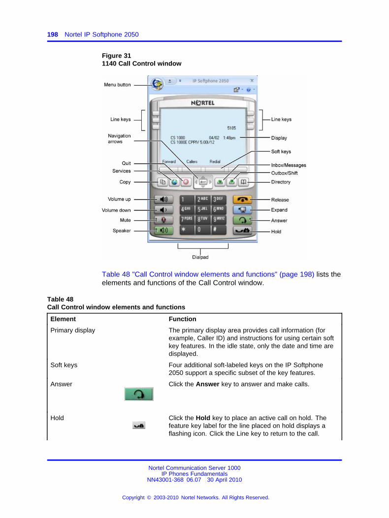
198 Nortel IP Softphone 2050
Figure 311140 Call Control window
Table 48 "Call Control window elements and functions" (page 198) lists theelements and functions of the Call Control window.
Table 48Call Control window elements and functions
Element Function
Primary display The primary display area provides call information (forexample, Caller ID) and instructions for using certain softkey features. In the idle state, only the date and time aredisplayed.
Soft keys Four additional soft-labeled keys on the IP Softphone2050 support a specific subset of the key features.
Answer Click the Answer key to answer and make calls.
Hold Click the Hold key to place an active call on hold. Thefeature key label for the line placed on hold displays aflashing icon. Click the Line key to return to the call.
Nortel Communication Server 1000IP Phones Fundamentals
NN43001-368 06.07 30 April 2010
Copyright © 2003-2010 Nortel Networks. All Rights Reserved.
.
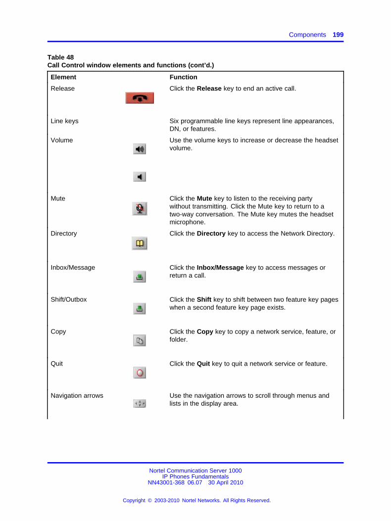
Components 199
Table 48Call Control window elements and functions (cont’d.)
Element Function
Release Click the Release key to end an active call.
Line keys Six programmable line keys represent line appearances,DN, or features.
Volume Use the volume keys to increase or decrease the headsetvolume.
Mute Click the Mute key to listen to the receiving partywithout transmitting. Click the Mute key to return to atwo-way conversation. The Mute key mutes the headsetmicrophone.
Directory Click the Directory key to access the Network Directory.
Inbox/Message Click the Inbox/Message key to access messages orreturn a call.
Shift/Outbox Click the Shift key to shift between two feature key pageswhen a second feature key page exists.
Copy Click the Copy key to copy a network service, feature, orfolder.
Quit Click the Quit key to quit a network service or feature.
Navigation arrows Use the navigation arrows to scroll through menus andlists in the display area.
Nortel Communication Server 1000IP Phones Fundamentals
NN43001-368 06.07 30 April 2010
Copyright © 2003-2010 Nortel Networks. All Rights Reserved.
.
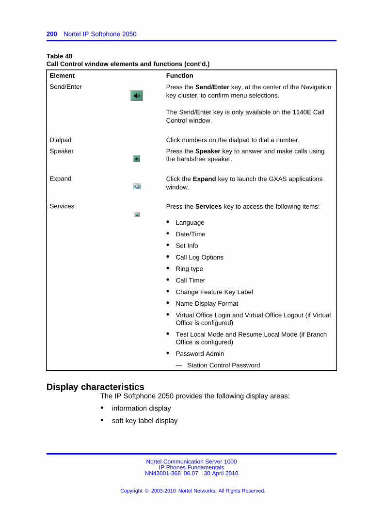
200 Nortel IP Softphone 2050
Table 48Call Control window elements and functions (cont’d.)
Element Function
Send/Enter Press the Send/Enter key, at the center of the Navigationkey cluster, to confirm menu selections.
The Send/Enter key is only available on the 1140E CallControl window.
Dialpad Click numbers on the dialpad to dial a number.
Speaker Press the Speaker key to answer and make calls usingthe handsfree speaker.
Expand Click the Expand key to launch the GXAS applicationswindow.
Services Press the Services key to access the following items:
• Language
• Date/Time
• Set Info
• Call Log Options
• Ring type
• Call Timer
• Change Feature Key Label
• Name Display Format
• Virtual Office Login and Virtual Office Logout (if VirtualOffice is configured)
• Test Local Mode and Resume Local Mode (if BranchOffice is configured)
• Password Admin
— Station Control Password
Display characteristicsThe IP Softphone 2050 provides the following display areas:
• information display
• soft key label display
Nortel Communication Server 1000IP Phones Fundamentals
NN43001-368 06.07 30 April 2010
Copyright © 2003-2010 Nortel Networks. All Rights Reserved.
.
Display characteristics 201
• keypad dialing keys display
• feature keys display
Information display areaThe information display area can contain four lines of text, up to amaximum of twenty four characters for each line. The display areaconsists of 2 areas: Info line and Info window.
Info lineThe Info Line is the first (top) line of display text. The left 10-characterarea shows the Call Server type. The right part of the Info Line shows thecurrent time and date.
Info windowThe Info Window display area that shows prompts and information aboutcalls. During a call the information area is used to display dialed digits,calling line ID, called party name, application-specific information, andvarious messages such as Release and Try Again.
When the information exceeds 3 x 24 characters, a scroll icon tells theuser to press the scroll keys to view the second line of the display.
Soft key label displayA maximum of 10 functions can be assigned to the soft keys. Functionsare assigned to the soft keys in layers in LD 11.
Use the More soft key to navigate through the layers of functions. If only4 functions are assigned to the soft keys, the More key does not appearand all four functions are displayed.
The soft key label has a maximum of 7 characters. Each soft key includesthe soft key label and an icon. When a soft key is in use, a flashing icondisplays at the beginning of the soft key label, and the label shifts onecharacter to the right. (If the label is six characters in length, the last, orrightmost, character is truncated.) If a feature is enabled, the icon stateturns to ON. It remains in the ON state until the feature key is pressedagain. This cancels the enabled feature and turns the icon off, returningthe soft key label to its original state.
System TrayThe System Tray provides fast access to most of the IP Softphone 2050functionality. The user can make, answer, and manage a call, as well asaccess macros and features from the System Tray without opening theCall Control window.
Nortel Communication Server 1000IP Phones Fundamentals
NN43001-368 06.07 30 April 2010
Copyright © 2003-2010 Nortel Networks. All Rights Reserved.
.
202 Nortel IP Softphone 2050
USB audio adaptersThe USB audio adapter enables the user to speak and hear callers andalso provides call control features, such as answer a call and place a call.The USB Audio Kit includes the following
• USB Headset Adapter (desktop or mobile)
• Installation Guide
• USB cord
The following USB adapters are supported on the IP Softphone 2050
• Nortel Enhanced USB Adapter (desktop)
• Nortel Mobile USB Adapter (mobile)
• Plantronics USB wireless headsets (digital cordless and Bluetooth®
wireless technology)
• Algo Analog Terminal Adapter (ATA) is a USB adapter that lets youuse analog terminals instead of headsets. With an Algo ATA userscan, for example, use a cordless headset with their IP Softphone 2050.
The IP Softphone 2050 is compatible with the Algo ATA. For support, seewww.algosolutions.com
USB Headset AdapterThe USB Headset Adapter provides a controlled high-quality audioenvironment. For more about USB headset adapters, see IP Softphone2050 User Guide (NN43119-101).
RegistrationWhen you add an IP Softphone 2050 to the network, depending onconfiguration, the IP Softphone 2050 can connect to a predefined IPaddress or can request an IP address from a DHCP server. The IPSoftphone 2050 then contacts the Connect Server, which instructs the IPSoftphone 2050 to display a message on its display screen requesting thecustomer node number and TN.
After you enter this information, the IP Softphone 2050 contacts theNode Master, which selects a TPS with sufficient capacity to register theIP Softphone 2050. The IP Softphone 2050 contacts the chosen TPSand, if the IP Softphone 2050 is valid, registers it with the system. Theregistration information saves to the IP Softphone 2050.
GIPSGIPS provides the following abilities
• voice encoding and decoding
• sound devices handling
Nortel Communication Server 1000IP Phones Fundamentals
NN43001-368 06.07 30 April 2010
Copyright © 2003-2010 Nortel Networks. All Rights Reserved.
.
Display characteristics 203
• network voice data flow processing
• voice quality improvement
• Dual-tone Multifrequency
• Telchemy VQMon library
For more information about configurable settings in the Sound Settingstab, see IP Softphone 2050 User Guide (NN43119-101).
Voice encoding and decodingGIPS supports G.711 A-law, G.711 µ-law, and g.729 codecs.
Sound devices handlingYou can change the volume level for input and output devices in theSound devices tab.
Network voice data flow processingGIPS uses GQoS API to modify the DiffSERV code point and the 802.1pmarker bits (when supported) by setting a GQoS service level that theWindows operating system maps to a Diffserv code point and to a 802.1psetting. According to Microsoft Developer Network (MSDN), these settingsare set to the following recommended values for voice applications
• ToS DSCP field is set to 0x28
• 802.1p priority field is set to 5
Voice qualityGIPS implements NetEQ, Echo Cancellation, and Noise Suppressionfeatures. NetEQ feature is an integral part of all GIPS codecs. GIPSNetEq software compensates for up to 30% lost packets in a LAN or WANenvironment.
The GIPS Echo Cancellation and Noise Suppression features improve thequality of conversations by removing echo and background noise.
You can enable or disable Echo Cancellation and Noise Suppressionfeatures in the Sound Settings tab.
Dual-tone MultifrequencyGIPS implements Dual-tone Multifrequency (DTMF) tones playing andsends in accordance to RFC 2833. DTMF supports event numbers from1 to 16.
Telchemy VQMonGIPS includes Telchemy VQMon library. The Telchemy VQMon librarycollects and provides Voice Quality statistics information.
Nortel Communication Server 1000IP Phones Fundamentals
NN43001-368 06.07 30 April 2010
Copyright © 2003-2010 Nortel Networks. All Rights Reserved.
.
204 Nortel IP Softphone 2050
Echo cancellationEcho can generate electrically when an impedance mismatch occurs,or can generate acoustically by feedback from a speaker or ear piece toa microphone. Any echo that returns to the IP Softphone 2050 is morenoticeable to the listener because of the additional delay the IP connectionintroduces.
The Voice Gateway Media Card includes echo cancelers as part ofits function cancels echo which the TDM side of the Media Gatewaygenerates. Echo cancellers enable when audio passes through the VoiceGateway Media Card.
Because the IP Softphone 2050 does not provide an echo canceller, aslight echo from acoustic coupling on the headset can occur in some callsituations.
Clock synchronizationBuffer underruns and overruns can occur since no sample clock is at thereceiving end of an IP audio stream synchronized to the transmitting clock.The buffer overruns and underruns are corrected by two mechanisms,both of which apply to the IP Phones and the DSPs on the Voice GatewayMedia Card.
Jitter bufferUse the default value sent from the TPS (the value configured in TM–[Nortel recommends that you use the default value]) to configure the IPSoftphone 2050 jitter buffer.
The jitter buffer has a desired size and a maximum allowable size. If thejitter buffer exceeds its maximum allowable size, sufficient frames arediscarded to reduce the contents of the jitter buffer to the desired setting.If the jitter buffer underruns, frames are held in the jitter buffer until it fillsto the desired level. Both underrun and overrun result in a discontinuityin the audio.
For codecs that support silence suppression, the jitter buffer isresynchronized at the beginning of each talk spurt.
QoSA combination of codec selection, jitter buffer and packet time, and theuse of the DiffServ Code Point (DSCP) of the network contributes to theend-to-end Quality of Service (QoS).
However, the IP Softphone 2050 is an application within the contextof the PC operating system, so the operating system has an effecton the end-to-end QoS for the IP Softphone 2050. Functionality,which is commonly handled in DSP hardware (such as, the codec
Nortel Communication Server 1000IP Phones Fundamentals
NN43001-368 06.07 30 April 2010
Copyright © 2003-2010 Nortel Networks. All Rights Reserved.
.
Display characteristics 205
packetization implementation from within the Voice Gateway Media Card)is implemented in software for the IP Softphone 2050. It runs as part of theapplication code on the PC CPU. If the CPU is busy with other tasks, voicequality can be negatively affected.
The number of buffers used to buffer audio data between the applicationand PC audio hardware device driver is adjustable from the Settings >Sound Devices window. Using fewer buffers reduces the audio path delaybut increases the chances of dropouts and choppy speech, depending onthe speed and utilization of the PC CPU.
This system-wide registry key setting affects other applications andoperating system components but is only effective if Windows QoS PacketScheduler is installed. For more information about Windows QoS PacketScheduler, see “Windows QoS Packet Scheduler” (page 238).
For Windows 2000 the Windows QoS Packet Scheduler is not installed bydefault and the EnablePriorityBoost registry setting is not created.
For Windows XP the Windows QoS Packet Scheduler is installed bydefault and the EnablePriorityBoost registry setting is created. The defaultsetting is 1 (enable QoS).
Windows 2000 and Windows XP require a system-wide registry key toenable QoS capabilities. You must have Administrator privileges to createor modify the following value:
HKEY_LOCAL_MACHINE/SYSTEM/CurrentControlSet/Services/Qossp/EnablePriorityBoostValue 0—do not enable QoSValue1—enable QoS
Trace utilities can be used to verify QoS settings. See “Ethereal traces”(page 207).
QoS settingsThe IP Softphone Version 1 includes a QoS tab in the Configuration utility.You can enable or disable 802.1Q/p settings. The QoS tab provides thefollowing settings:
• Enable—sends 802.1Q/p whether it is supported by the network or not
• Disable—does not send 802.1Q/p whether it is supported by thenetwork or not
• Automatic Detection—sends 802.1Q/p packet, which requires aresponse from the TPS. If the TPS replies, 802.1Q.p is used. If the
Nortel Communication Server 1000IP Phones Fundamentals
NN43001-368 06.07 30 April 2010
Copyright © 2003-2010 Nortel Networks. All Rights Reserved.
.
206 Nortel IP Softphone 2050
TPS does not reply, the same packet is sent without 802.1Q/p. If theTPS replies, then 802.1Q/p is not used.
To prevent improper assignment of these settings, this tab is removed inIP Softphone Version 2. The 802.1Q p settings are automatically detected.
QoS is otherwise supported in IP Softphone 2050 Version 2 as it was in IPSoftphone 2050 Version 1.
Application thread prioritiesPriorities are determined by thread priorities. The i2050QosSvc.exeapplication consists of threads, which run the Graphical User Interface(GUI) and audio threads. Thread priorities increase from the base priorityof the process, as needed. The audio threads boost to high priority, asrecommended by Microsoft, while the GUI maintains a normal priority.Increasing the process priority implies that the operating system may notperform properly. This concern restrains the IP Softphone 2050 to useWindows recommended priorities to avoid an unpredictable degradationin general OS performance.
CodecThe IP Softphone 2050 provides the following codecs:
• G.711 provides the highest quality (if the network facilities can handlethe packet flow) because there is no compression.
• G.729 is ranked best; it has 8:1 compression but no voice activitydetection.
Frame sizeThe IP Softphone 2050 supports the following range of frame sizes
• G.711-64 A-law and µlaw: 10-960—10 ms increments
• G.729A: 10-960—10 ms frames
• G.729AB: 10-960—10 ms frames
i2050QosSvc.exei2050QosSvc.exe provides QoS tagging to outgoing 2050 IP packets.When the IP Softphone 2050 application opens a socket, the i2050QosSvcsoftware monitors traffic destined for the specified IP address and port.i2050QosSvc software sets DiffServ QoS priority bits.
802.1 p priority bits in the 802.1Q header can be set. 802.1Q headersmust be enabled by the Network Interface Card (NIC) or NIC driver.The i2050QosSvc does not fill in other fields in the 802.1Q header (forexample, no values are assigned to the VLAN ID field).
Nortel Communication Server 1000IP Phones Fundamentals
NN43001-368 06.07 30 April 2010
Copyright © 2003-2010 Nortel Networks. All Rights Reserved.
.
Licenses 207
ATTENTIONVLAN IDThe default VLAN ID value in Windows is 0. This can be overwritten for NetworkInterface Cards (NIC) that support 802,1Q. The 2050 processes do not assignvalues to the VLAN ID field. This setting is documented with the NIC or the NICdriver.
The VLAN ID for an application must match the VLAN ID for the PC because thePC has only one IP stack for each NIC. A second IP stack is required to assigna specific VLAN ID tag for an application which is different than the PC tag.
You can use two different IP cards, each with different VLAN ID values on asingle PC; however, this can cause security gaps on the voice VLAN, which isnormally a more secure network than the data LAN.
DiffSERV (DSCP)The IP Softphone 2050 uses DSCP settings assigned by the TPS. TheIP Softphone 2050 supports DSCP on Windows 2000 Professional andWindows XP. For information about configuring DiffServ values, seeSignaling Server IP Line Applications Fundamentals (NN43001-125).
802.1pFor information about configuring 802.1p values, see Signaling Server IPLine Applications Fundamentals (NN43001-125).
Ethereal tracesCurrent versions of Ethereal show 802.1Q headers, if they are present.802.1Q must be enabled on the NIC for the headers, which includes802.1p to be captured.
GXASThe IP Softphone 2050 Release 3.1 supports GXAS, which enables theuser to start applications that are available on the GXAS server. You mustmanually configure the CSV file on the GXAS server to support the IPSoftphone 2050. For more information, see Nortel Application Gateway1000/2000 Administration Guide (NN42360-600).
LicensesThe IP Softphone 2050 Release 3.0 requires a license to operate. If thephone cannot obtain a license from one of the licensing schemes then itcannot connect to a Call Server and an error message appears on thephone screen.
While the IP Softphone 2050 runs, it first goes through three licensingschemes before it connects to Call Server. After the phone obtains alicense, it repeats the procedure at a random interval. If the licensing
Nortel Communication Server 1000IP Phones Fundamentals
NN43001-368 06.07 30 April 2010
Copyright © 2003-2010 Nortel Networks. All Rights Reserved.
.
208 Nortel IP Softphone 2050
scheme fails then the IP Softphone 2050 disconnects from the Call Serverunless you are on an active call, in which case the phone does notdisconnect until the call ends.
The licensing schemes are as follows:
• “Check out license” (page 208)
• “Cached license” (page 208)
• “Evaluation period ” (page 208)
Check out licenseThe IP Softphone 2050 tries to obtain or checkout a license from a LicenseServer. These licenses are stored on a License Server machine locatedon your network. For information about how to install and configure aLicensing Server, see “Provisioning a License Server” (page 211). Aftera client successfully checks out a license from the License Server aheartbeat mechanism activates to validate the license every 2 minutes. Ifthe heartbeat is lost then the client attempts to reconnect to the server 5times before it loses the checked out license.
Cached licenseAfter the IP Softphone 2050 successfully checks out a license from theLicense Server, it records the license details in a secure location. You canrefer to this license as a backup license. The cached license is availablefor 5 days.
Evaluation periodAfter you install the IP Softphone 2050, it can run without a license for aperiod of 30 days. After the expiration date passes, you must run the IPSoftphone 2050 Settings tool to specify a License Server. Otherwise, thephone cannot connect to the Call Server.
License restrictionsThe following license restrictions apply to the IP Softphone 2050 Release3.0.
• If at any time you rewind the system date by more than 24 hours, theIP Softphone 2050 evaluation period license and cached license areboth invalidated.
• Software reinstallation does not reset the license to provide another30-day evaluation period.
• After you receive a valid license, you cannot return to the evaluationlicense even if the evaluation period has not expired.
Nortel Communication Server 1000IP Phones Fundamentals
NN43001-368 06.07 30 April 2010
Copyright © 2003-2010 Nortel Networks. All Rights Reserved.
.
Licenses 209
• The IP Softphone 2050 requires a connection to the License Server, acached license, or time remaining for the evaluation period to placean emergency call.
• If you configure redundant license servers, the licenses sold are lockedto the Fully Qualified Domain Name (FQDN) of the license server hostmachine. If the host machine fails, you can reconfigure a computerwith the same host domain name to host the licenses (license file). Forinformation about configuring redundant license servers, see “ServerRedundancy” (page 214).
License typesThe following two types of licenses exist:
• “Upgrade licenses” (page 209)
• “Normal R3 licenses” (page 209)
• “Post-R3 licenses” (page 209)
Upgrade licensesAn IP Softphone 2050 that upgrades from the IP Softphone 2050 V2 orlower attempts to check out an Upgrade License before it checks out aNormal R3 license from the License Server. In other words, if you upgradeyour IP Softphone 2050 from a previous release then you can use anupgrade license instead of a Normal R3 License.
If you upgrade your IP Softphone 2050 R3 to a later release, use Post-R3licenses.
Normal R3 licensesA Normal R3 License is a regular license that non-upgrade clients attemptto check out from the server.
The distinction should be made when you request licenses from yourdistributor. If your site has prior releases of the IP Softphone 2050 you canbe eligible to purchase Upgrade Licenses instead of Normal R3 Licenses.
Post-R3 licensesPost-R3 (upgrade) licenses convert licenses from a major license versionto a later version.
Nortel Communication Server 1000IP Phones Fundamentals
NN43001-368 06.07 30 April 2010
Copyright © 2003-2010 Nortel Networks. All Rights Reserved.
.
210 Nortel IP Softphone 2050
License ServerThe License Server Manager and the vendor daemon make up theLicense Server system. The License Server Manager is the main point ofcontact for FLEX-enabled applications, which require license certificates.These applications then redirect to the appropriate vendor daemon.
Note: License Server must not be a member of a workgroup
The License Server contains Licenses certificates.
Because the License Server components are lightweight, you can installthe components on any machine, which runs one of the following operatingsystems
• Microsoft Windows 2000
• Microsoft Windows 2000 Server
• Microsoft Windows XP
• Microsoft Windows 2003 Server
• Microsoft Windows Vista
The Licensing Server requires ports 27000 and 27001 to be accessible.You can modify the TCP/IP port number of the License Server Manager(lmgrd) in the Server line. For information about modifying the Server line,see “License file” (page 214).
How to configure ports for licensingThe following are the steps to configure ports for licensing:
1. The 2050 starts to send the TCP packets to the license server. The IPaddress and port are retrieved from the 2050 settings (License Serversprop page). If no port information is typed, the default range (27000- 27009) is used. If you need to change this port range, you need tomake changes on both sides: 2050 settings and license file (SERVERline). Make sure that this port is opened and listened on by server.
SettingsThe settings -> License Servers prop page: 172.2.2.2:27001
the counted.lic file: SERVER this_host HOSTNAME=host-1.corp.nortel.com PORT=27001
2. The vendor daemon starts to work and uses the random port for server(it is not random always). The vendor information is transmitted to2050 client by the Server Manager and the 2050 starts to send theTCP packets to this port.To control the port for vendor daemon you need to change theVENDOR line in counted.lic file.
Nortel Communication Server 1000IP Phones Fundamentals
NN43001-368 06.07 30 April 2010
Copyright © 2003-2010 Nortel Networks. All Rights Reserved.
.
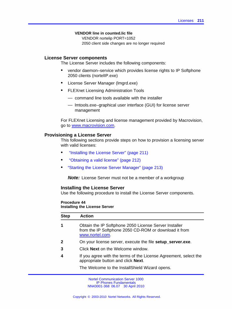
Licenses 211
VENDOR line in counted.lic fileVENDOR nortelip PORT=10522050 client side changes are no longer required
License Server componentsThe License Server includes the following components:
• vendor daemon–service which provides license rights to IP Softphone2050 clients (nortelIP.exe)
• License Server Manager (lmgrd.exe)
• FLEXnet Licensing Administration Tools
— command line tools available with the installer
— lmtools.exe–graphical user interface (GUI) for license servermanagement
For FLEXnet Licensing and license management provided by Macrovision,go to www.macrovision.com.
Provisioning a License ServerThis following sections provide steps on how to provision a licensing serverwith valid licenses:
• “Installing the License Server” (page 211)
• “Obtaining a valid license” (page 212)
• “Starting the License Server Manager” (page 213)
Note: License Server must not be a member of a workgroup
Installing the License ServerUse the following procedure to install the License Server components.
Procedure 44Installing the License Server
Step Action
1 Obtain the IP Softphone 2050 License Server Installerfrom the IP Softphone 2050 CD-ROM or download it fromwww.nortel.com.
2 On your license server, execute the file setup_server.exe.
3 Click Next on the Welcome window.
4 If you agree with the terms of the License Agreement, select theappropriate button and click Next.
The Welcome to the InstallShield Wizard opens.
Nortel Communication Server 1000IP Phones Fundamentals
NN43001-368 06.07 30 April 2010
Copyright © 2003-2010 Nortel Networks. All Rights Reserved.
.
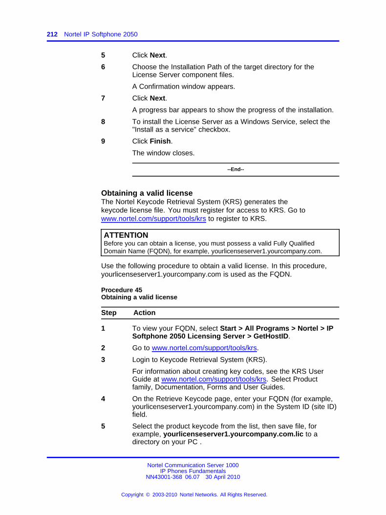
212 Nortel IP Softphone 2050
5 Click Next.
6 Choose the Installation Path of the target directory for theLicense Server component files.
A Confirmation window appears.
7 Click Next.
A progress bar appears to show the progress of the installation.
8 To install the License Server as a Windows Service, select the"Install as a service" checkbox.
9 Click Finish.
The window closes.
--End--
Obtaining a valid licenseThe Nortel Keycode Retrieval System (KRS) generates thekeycode license file. You must register for access to KRS. Go towww.nortel.com/support/tools/krs to register to KRS.
ATTENTIONBefore you can obtain a license, you must possess a valid Fully QualifiedDomain Name (FQDN), for example, yourlicenseserver1.yourcompany.com.
Use the following procedure to obtain a valid license. In this procedure,yourlicenseserver1.yourcompany.com is used as the FQDN.
Procedure 45Obtaining a valid license
Step Action
1 To view your FQDN, select Start > All Programs > Nortel > IPSoftphone 2050 Licensing Server > GetHostID.
2 Go to www.nortel.com/support/tools/krs.
3 Login to Keycode Retrieval System (KRS).
For information about creating key codes, see the KRS UserGuide at www.nortel.com/support/tools/krs. Select Productfamily, Documentation, Forms and User Guides.
4 On the Retrieve Keycode page, enter your FQDN (for example,yourlicenseserver1.yourcompany.com) in the System ID (site ID)field.
5 Select the product keycode from the list, then save file, forexample, yourlicenseserver1.yourcompany.com.lic to adirectory on your PC .
Nortel Communication Server 1000IP Phones Fundamentals
NN43001-368 06.07 30 April 2010
Copyright © 2003-2010 Nortel Networks. All Rights Reserved.
.
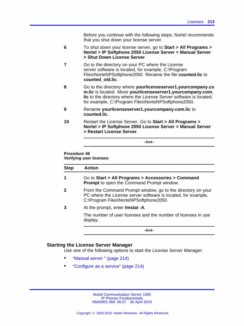
Licenses 213
Before you continue with the following steps, Nortel recommendsthat you shut down your license server.
6 To shut down your license server, go to Start > All Programs >Nortel > IP Softphone 2050 License Server > Manual Server> Shut Down License Server.
7 Go to the directory on your PC where the Licenseserver software is located, for example, C:\ProgramFiles\Nortel\IPSoftphone2050. Rename the file counted.lic tocounted_old.lic.
8 Go to the directory where yourlicenseserver1.yourcompany.com.lic is located. Move yourlicenseserver1.yourcompany.com.lic to the directory where the License Server software is located,for example, C:\Program Files\Nortel\IPSoftphone2050.
9 Rename yourlicenseserver1.yourcompany.com.lic tocounted.lic.
10 Restart the License Server. Go to Start > All Programs >Nortel > IP Softphone 2050 License Server > Manual Server> Restart License Server.
--End--
Procedure 46Verifying user licenses
Step Action
1 Go to Start > All Programs > Accessories > CommandPrompt to open the Command Prompt window.
2 From the Command Prompt window, go to the directory on yourPC where the License server software is located, for example,C:\Program Files\Nortel\IPSoftphone2050.
3 At the prompt, enter lmstat -A.
The number of user licenses and the number of licenses in usedisplay.
--End--
Starting the License Server ManagerUse one of the following options to start the License Server Manager:
• “Manual server ” (page 214)
• “Configure as a service” (page 214)
Nortel Communication Server 1000IP Phones Fundamentals
NN43001-368 06.07 30 April 2010
Copyright © 2003-2010 Nortel Networks. All Rights Reserved.
.
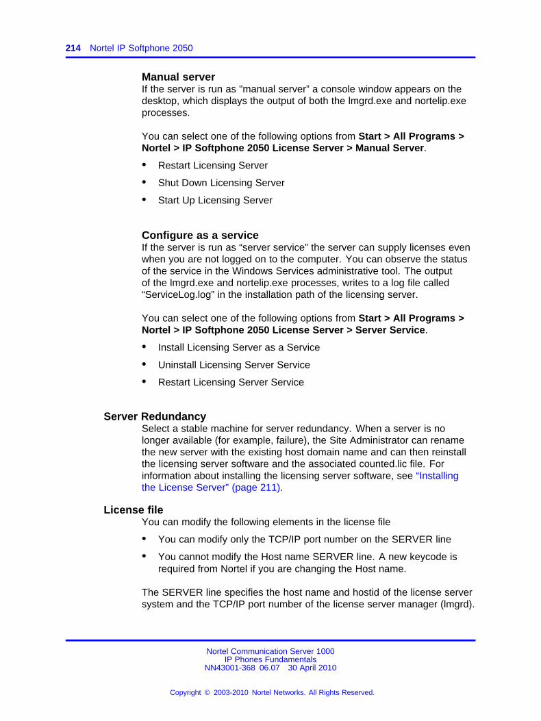
214 Nortel IP Softphone 2050
Manual serverIf the server is run as "manual server” a console window appears on thedesktop, which displays the output of both the lmgrd.exe and nortelip.exeprocesses.
You can select one of the following options from Start > All Programs >Nortel > IP Softphone 2050 License Server > Manual Server.
• Restart Licensing Server
• Shut Down Licensing Server
• Start Up Licensing Server
Configure as a serviceIf the server is run as “server service” the server can supply licenses evenwhen you are not logged on to the computer. You can observe the statusof the service in the Windows Services administrative tool. The outputof the lmgrd.exe and nortelip.exe processes, writes to a log file called“ServiceLog.log” in the installation path of the licensing server.
You can select one of the following options from Start > All Programs >Nortel > IP Softphone 2050 License Server > Server Service.
• Install Licensing Server as a Service
• Uninstall Licensing Server Service
• Restart Licensing Server Service
Server RedundancySelect a stable machine for server redundancy. When a server is nolonger available (for example, failure), the Site Administrator can renamethe new server with the existing host domain name and can then reinstallthe licensing server software and the associated counted.lic file. Forinformation about installing the licensing server software, see “Installingthe License Server” (page 211).
License fileYou can modify the following elements in the license file
• You can modify only the TCP/IP port number on the SERVER line
• You cannot modify the Host name SERVER line. A new keycode isrequired from Nortel if you are changing the Host name.
The SERVER line specifies the host name and hostid of the license serversystem and the TCP/IP port number of the license server manager (lmgrd).
Nortel Communication Server 1000IP Phones Fundamentals
NN43001-368 06.07 30 April 2010
Copyright © 2003-2010 Nortel Networks. All Rights Reserved.
.
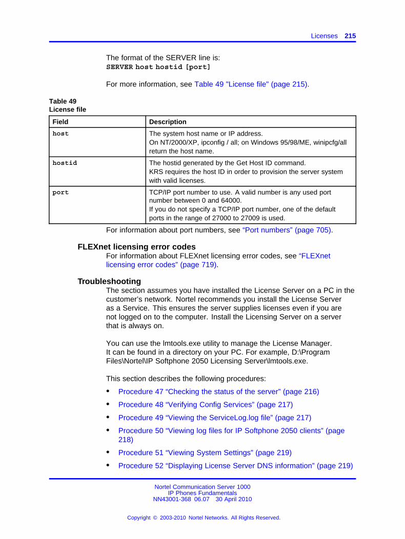
Licenses 215
The format of the SERVER line is:SERVER host hostid [port]
For more information, see Table 49 "License file" (page 215).
Table 49License file
Field Description
host The system host name or IP address.On NT/2000/XP, ipconfig / all; on Windows 95/98/ME, winipcfg/allreturn the host name.
hostid The hostid generated by the Get Host ID command.KRS requires the host ID in order to provision the server systemwith valid licenses.
port TCP/IP port number to use. A valid number is any used portnumber between 0 and 64000.If you do not specify a TCP/IP port number, one of the defaultports in the range of 27000 to 27009 is used.
For information about port numbers, see “Port numbers” (page 705).
FLEXnet licensing error codesFor information about FLEXnet licensing error codes, see “FLEXnetlicensing error codes” (page 719).
TroubleshootingThe section assumes you have installed the License Server on a PC in thecustomer’s network. Nortel recommends you install the License Serveras a Service. This ensures the server supplies licenses even if you arenot logged on to the computer. Install the Licensing Server on a serverthat is always on.
You can use the lmtools.exe utility to manage the License Manager.It can be found in a directory on your PC. For example, D:\ProgramFiles\Nortel\IP Softphone 2050 Licensing Server\lmtools.exe.
This section describes the following procedures:
• Procedure 47 “Checking the status of the server” (page 216)
• Procedure 48 “Verifying Config Services” (page 217)
• Procedure 49 “Viewing the ServiceLog.log file” (page 217)
• Procedure 50 “Viewing log files for IP Softphone 2050 clients” (page218)
• Procedure 51 “Viewing System Settings” (page 219)
• Procedure 52 “Displaying License Server DNS information” (page 219)
Nortel Communication Server 1000IP Phones Fundamentals
NN43001-368 06.07 30 April 2010
Copyright © 2003-2010 Nortel Networks. All Rights Reserved.
.
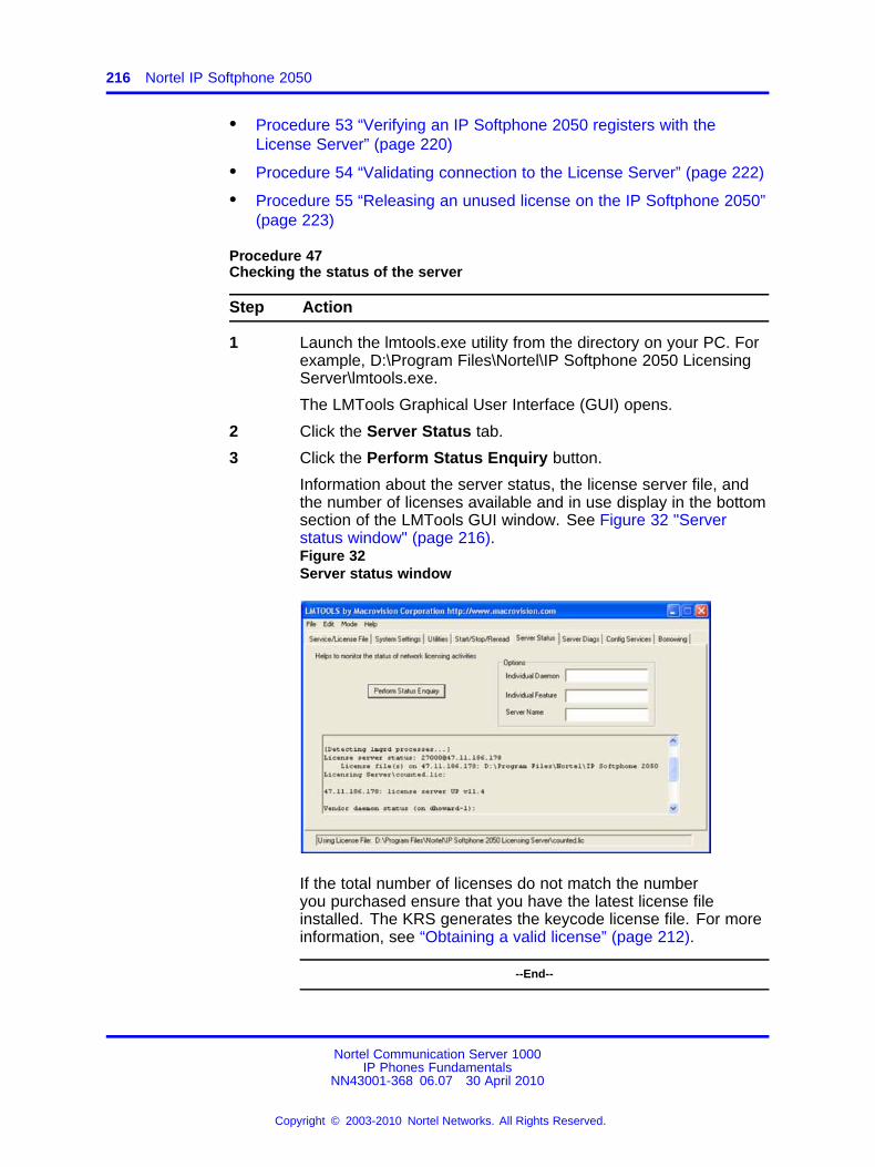
216 Nortel IP Softphone 2050
• Procedure 53 “Verifying an IP Softphone 2050 registers with theLicense Server” (page 220)
• Procedure 54 “Validating connection to the License Server” (page 222)
• Procedure 55 “Releasing an unused license on the IP Softphone 2050”(page 223)
Procedure 47Checking the status of the server
Step Action
1 Launch the lmtools.exe utility from the directory on your PC. Forexample, D:\Program Files\Nortel\IP Softphone 2050 LicensingServer\lmtools.exe.
The LMTools Graphical User Interface (GUI) opens.
2 Click the Server Status tab.
3 Click the Perform Status Enquiry button.
Information about the server status, the license server file, andthe number of licenses available and in use display in the bottomsection of the LMTools GUI window. See Figure 32 "Serverstatus window" (page 216).Figure 32Server status window
If the total number of licenses do not match the numberyou purchased ensure that you have the latest license fileinstalled. The KRS generates the keycode license file. For moreinformation, see “Obtaining a valid license” (page 212).
--End--
Nortel Communication Server 1000IP Phones Fundamentals
NN43001-368 06.07 30 April 2010
Copyright © 2003-2010 Nortel Networks. All Rights Reserved.
.
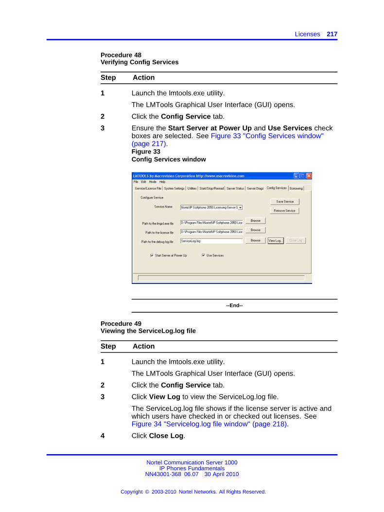
Licenses 217
Procedure 48Verifying Config Services
Step Action
1 Launch the lmtools.exe utility.
The LMTools Graphical User Interface (GUI) opens.
2 Click the Config Service tab.
3 Ensure the Start Server at Power Up and Use Services checkboxes are selected. See Figure 33 "Config Services window"(page 217).Figure 33Config Services window
--End--
Procedure 49Viewing the ServiceLog.log file
Step Action
1 Launch the lmtools.exe utility.
The LMTools Graphical User Interface (GUI) opens.
2 Click the Config Service tab.
3 Click View Log to view the ServiceLog.log file.
The ServiceLog.log file shows if the license server is active andwhich users have checked in or checked out licenses. SeeFigure 34 "Servicelog.log file window" (page 218).
4 Click Close Log.
Nortel Communication Server 1000IP Phones Fundamentals
NN43001-368 06.07 30 April 2010
Copyright © 2003-2010 Nortel Networks. All Rights Reserved.
.
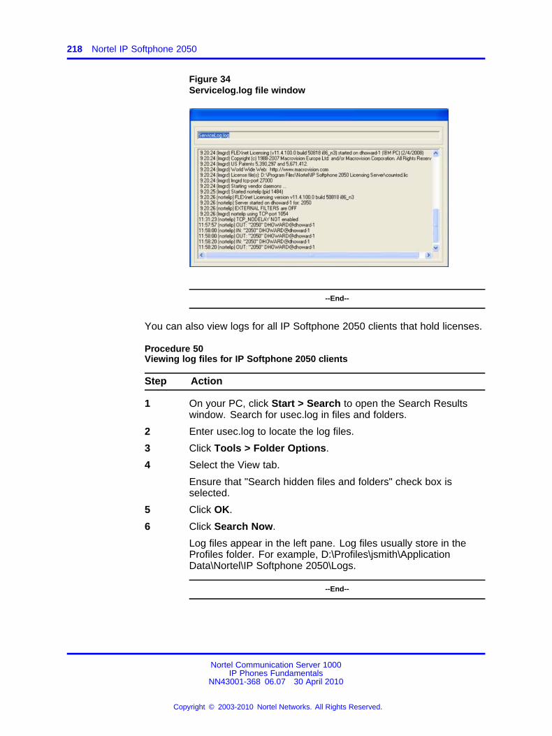
218 Nortel IP Softphone 2050
Figure 34Servicelog.log file window
--End--
You can also view logs for all IP Softphone 2050 clients that hold licenses.
Procedure 50Viewing log files for IP Softphone 2050 clients
Step Action
1 On your PC, click Start > Search to open the Search Resultswindow. Search for usec.log in files and folders.
2 Enter usec.log to locate the log files.
3 Click Tools > Folder Options.
4 Select the View tab.
Ensure that "Search hidden files and folders" check box isselected.
5 Click OK.
6 Click Search Now.
Log files appear in the left pane. Log files usually store in theProfiles folder. For example, D:\Profiles\jsmith\ApplicationData\Nortel\IP Softphone 2050\Logs.
--End--
Nortel Communication Server 1000IP Phones Fundamentals
NN43001-368 06.07 30 April 2010
Copyright © 2003-2010 Nortel Networks. All Rights Reserved.
.
Licenses 219
Procedure 51Viewing System Settings
Step Action
1 Launch the lmtools.exe utility.
The LMTools Graphical User Interface (GUI) opens.
2 Click the System Settings tab.
The System Settings tab displays basic information, such asServer IP address and HostID. Select the "Include Domain"checkbox to display the Fully Qualified Domain Name (FQDN)Host ID. Ensure the Host ID is a FQDN. Also, ensure it is exactlythe same as the name registered with KRS that was used togenerate the keycode. If the names do not match the serverdoes not come up.
--End--
Procedure 52Displaying License Server DNS information
Step Action
1 Go to Start > All Programs > Accessories > CommandPrompt to open the Command Prompt window.
2 From the Command Prompt window, enter ipconfig -all.
The Host Name and Primary DNS Suffix display. Ensure youconfigure the Primary DNS Suffix with the registered domainname; otherwise, your FQDN license keycode file does not work.
Nortel Communication Server 1000IP Phones Fundamentals
NN43001-368 06.07 30 April 2010
Copyright © 2003-2010 Nortel Networks. All Rights Reserved.
.
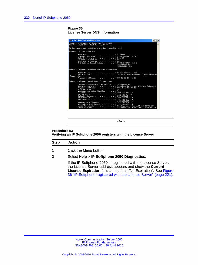
220 Nortel IP Softphone 2050
Figure 35License Server DNS information
--End--
Procedure 53Verifying an IP Softphone 2050 registers with the License Server
Step Action
1 Click the Menu button.
2 Select Help > IP Softphone 2050 Diagnostics.
If the IP Softphone 2050 is registered with the License Server,the License Server address appears and show the CurrentLicense Expiration field appears as “No Expiration”. See Figure36 "IP Softphone registered with the License Server" (page 221).
Nortel Communication Server 1000IP Phones Fundamentals
NN43001-368 06.07 30 April 2010
Copyright © 2003-2010 Nortel Networks. All Rights Reserved.
.
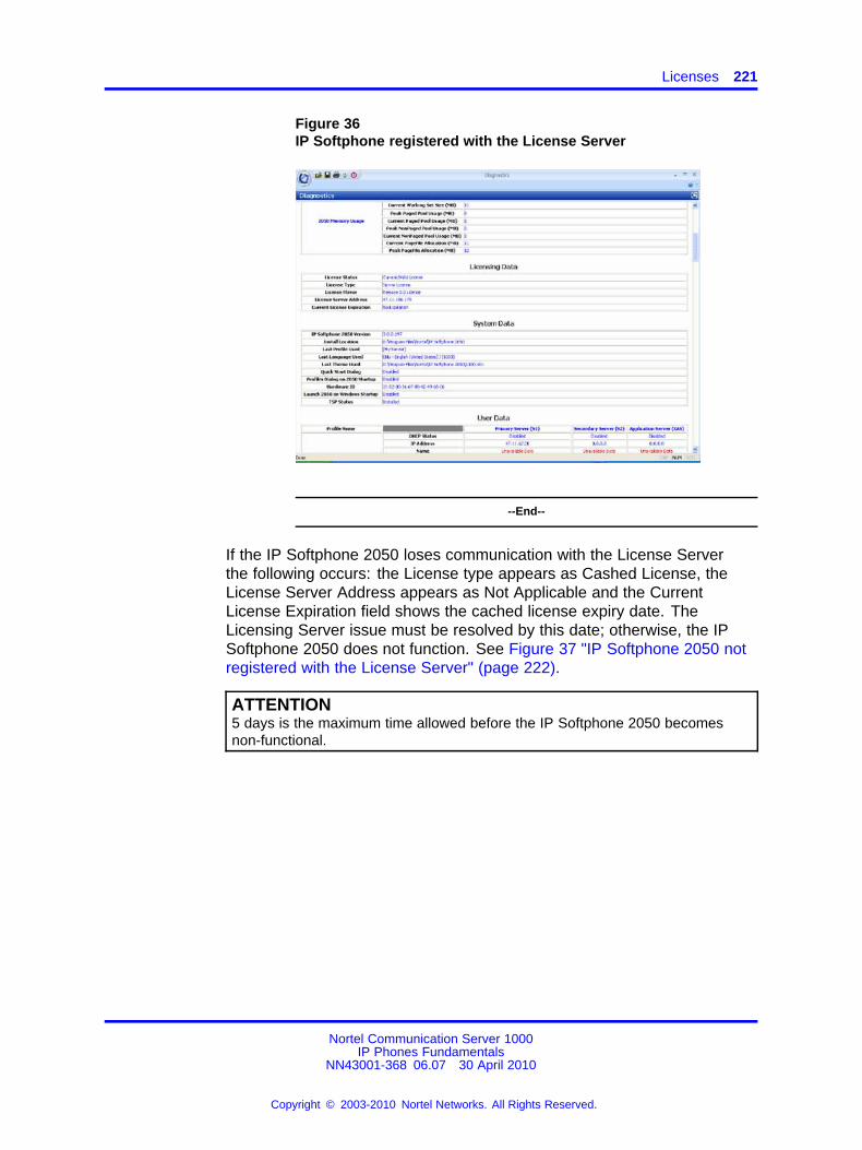
Licenses 221
Figure 36IP Softphone registered with the License Server
--End--
If the IP Softphone 2050 loses communication with the License Serverthe following occurs: the License type appears as Cashed License, theLicense Server Address appears as Not Applicable and the CurrentLicense Expiration field shows the cached license expiry date. TheLicensing Server issue must be resolved by this date; otherwise, the IPSoftphone 2050 does not function. See Figure 37 "IP Softphone 2050 notregistered with the License Server" (page 222).
ATTENTION5 days is the maximum time allowed before the IP Softphone 2050 becomesnon-functional.
Nortel Communication Server 1000IP Phones Fundamentals
NN43001-368 06.07 30 April 2010
Copyright © 2003-2010 Nortel Networks. All Rights Reserved.
.
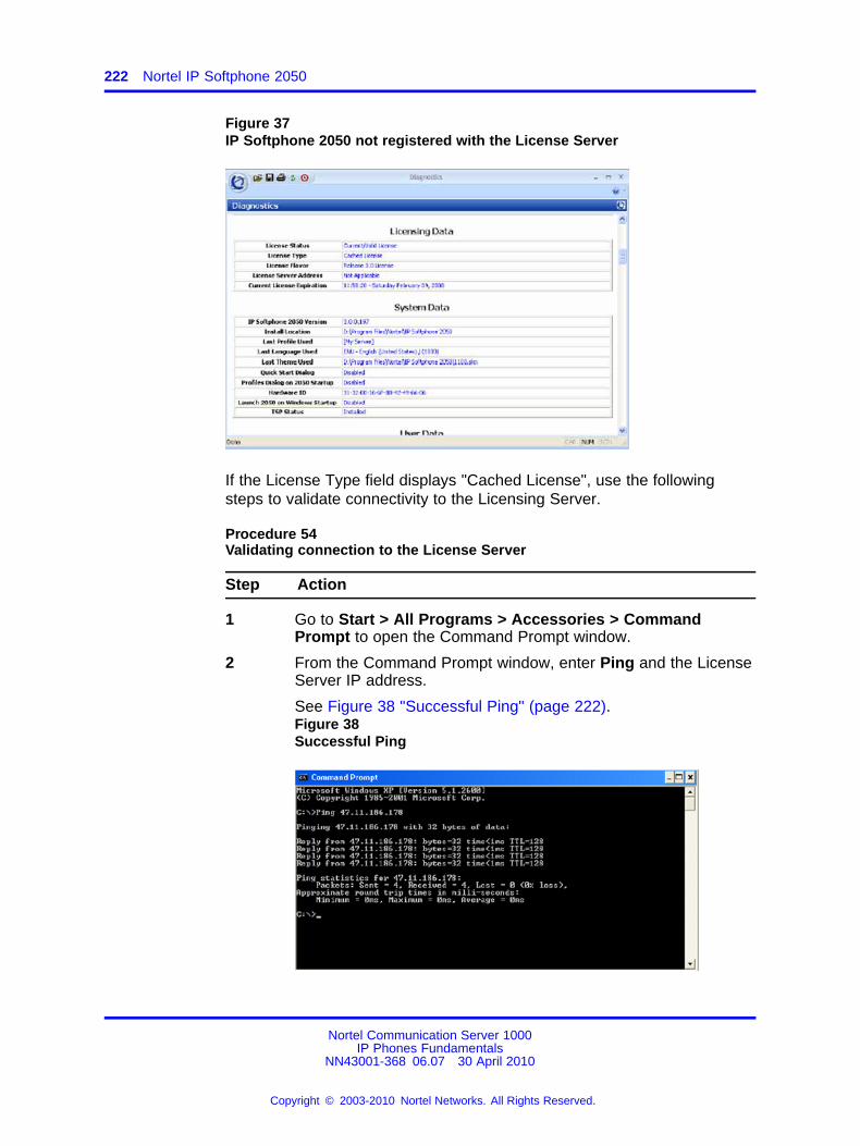
222 Nortel IP Softphone 2050
Figure 37IP Softphone 2050 not registered with the License Server
If the License Type field displays "Cached License", use the followingsteps to validate connectivity to the Licensing Server.
Procedure 54Validating connection to the License Server
Step Action
1 Go to Start > All Programs > Accessories > CommandPrompt to open the Command Prompt window.
2 From the Command Prompt window, enter Ping and the LicenseServer IP address.
See Figure 38 "Successful Ping" (page 222).Figure 38Successful Ping
Nortel Communication Server 1000IP Phones Fundamentals
NN43001-368 06.07 30 April 2010
Copyright © 2003-2010 Nortel Networks. All Rights Reserved.
.
Licenses 223
3 Validate License Server settings. Use one of the followingoptions to open the Settings window:
• From the Windows operating system:
— Select Start > Programs > Nortel > IP Softphone 2050> IP Softphone 2050 Settings.
— Select Start > Control Panel > IP Softphone 2050. (InWindows XP, select Switch to Classic View to view thelist of settings.)
• From the IP Softphone 2050 Call Control window:
— Click the Menu button and select File > Settings.
4 Select Server from the list in the left pane of the Settingswindow. Validate that the correct IP address or host name isconfigured.
--End--
Also, check with the system administrator that the port used for theLicense Server is open and is not blocked. If you are using a VPNconnection, make sure it is connected and there are no port restrictionsthat can block access to the Licensing Server.
When two or more licenses are being used by the IP Softphone 2050, youcan release the unused licenses.
Procedure 55Releasing an unused license on the IP Softphone 2050
Step Action
1 Press Ctrl + Alt + Delete simultaneously on your keyboard.
The Window Security window opens.
2 Press Task Manager.
The Windows Task Manager window opens.
3 Select the Applications tab.
4 Select the i2050.exe application(s) that you want to release.
5 Click End Task.
--End--
Nortel Communication Server 1000IP Phones Fundamentals
NN43001-368 06.07 30 April 2010
Copyright © 2003-2010 Nortel Networks. All Rights Reserved.
.
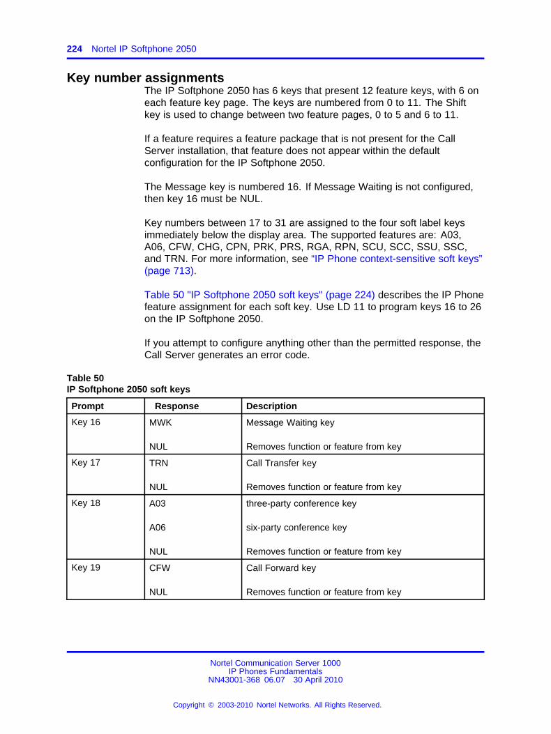
224 Nortel IP Softphone 2050
Key number assignmentsThe IP Softphone 2050 has 6 keys that present 12 feature keys, with 6 oneach feature key page. The keys are numbered from 0 to 11. The Shiftkey is used to change between two feature pages, 0 to 5 and 6 to 11.
If a feature requires a feature package that is not present for the CallServer installation, that feature does not appear within the defaultconfiguration for the IP Softphone 2050.
The Message key is numbered 16. If Message Waiting is not configured,then key 16 must be NUL.
Key numbers between 17 to 31 are assigned to the four soft label keysimmediately below the display area. The supported features are: A03,A06, CFW, CHG, CPN, PRK, PRS, RGA, RPN, SCU, SCC, SSU, SSC,and TRN. For more information, see “IP Phone context-sensitive soft keys”(page 713).
Table 50 "IP Softphone 2050 soft keys" (page 224) describes the IP Phonefeature assignment for each soft key. Use LD 11 to program keys 16 to 26on the IP Softphone 2050.
If you attempt to configure anything other than the permitted response, theCall Server generates an error code.
Table 50IP Softphone 2050 soft keys
Prompt Response Description
Key 16 MWK
NUL
Message Waiting key
Removes function or feature from key
Key 17 TRN
NUL
Call Transfer key
Removes function or feature from key
Key 18 A03
A06
NUL
three-party conference key
six-party conference key
Removes function or feature from key
Key 19 CFW
NUL
Call Forward key
Removes function or feature from key
Nortel Communication Server 1000IP Phones Fundamentals
NN43001-368 06.07 30 April 2010
Copyright © 2003-2010 Nortel Networks. All Rights Reserved.
.
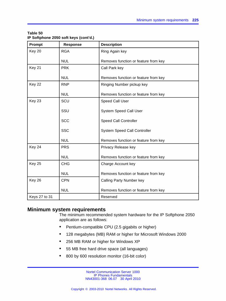
Minimum system requirements 225
Table 50IP Softphone 2050 soft keys (cont’d.)
Prompt Response Description
Key 20 RGA
NUL
Ring Again key
Removes function or feature from key
Key 21 PRK
NUL
Call Park key
Removes function or feature from key
Key 22 RNP
NUL
Ringing Number pickup key
Removes function or feature from key
Key 23 SCU
SSU
SCC
SSC
NUL
Speed Call User
System Speed Call User
Speed Call Controller
System Speed Call Controller
Removes function or feature from key
Key 24 PRS
NUL
Privacy Release key
Removes function or feature from key
Key 25 CHG
NUL
Charge Account key
Removes function or feature from key
Key 26 CPN
NUL
Calling Party Number key
Removes function or feature from key
Keys 27 to 31 Reserved
Minimum system requirementsThe minimum recommended system hardware for the IP Softphone 2050application are as follows:
• Pentium-compatible CPU (2.5 gigabits or higher)
• 128 megabytes (MB) RAM or higher for Microsoft Windows 2000
• 256 MB RAM or higher for Windows XP
• 55 MB free hard drive space (all languages)
• 800 by 600 resolution monitor (16-bit color)
Nortel Communication Server 1000IP Phones Fundamentals
NN43001-368 06.07 30 April 2010
Copyright © 2003-2010 Nortel Networks. All Rights Reserved.
.
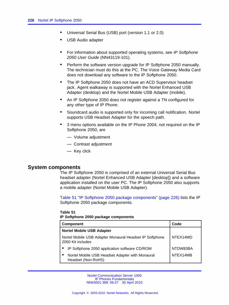
226 Nortel IP Softphone 2050
• Universal Serial Bus (USB) port (version 1.1 or 2.0)
• USB Audio adapter
• For information about supported operating systems, see IP Softphone2050 User Guide (NN43119-101).
• Perform the software version upgrade for IP Softphone 2050 manually.The technician must do this at the PC. The Voice Gateway Media Carddoes not download any software to the IP Softphone 2050.
• The IP Softphone 2050 does not have an ACD Supervisor headsetjack. Agent walkaway is supported with the Nortel Enhanced USBAdapter (desktop) and the Nortel Mobile USB Adapter (mobile).
• An IP Softphone 2050 does not register against a TN configured forany other type of IP Phone.
• Soundcard audio is supported only for incoming call notification. Nortelsupports USB Headset Adapter for the speech path.
• 3 menu options available on the IP Phone 2004, not required on the IPSoftphone 2050, are
— Volume adjustment
— Contrast adjustment
— Key click
System componentsThe IP Softphone 2050 is comprised of an external Universal Serial Busheadset adapter (Nortel Enhanced USB Adapter [desktop]) and a softwareapplication installed on the user PC. The IP Softphone 2050 also supportsa mobile adapter (Nortel Mobile USB Adapter).
Table 51 "IP Softphone 2050 package components" (page 226) lists the IPSoftphone 2050 package components.
Table 51IP Softphone 2050 package components
Component Code
Nortel Mobile USB Adapter
Nortel Mobile USB Adapter Monaural Headset IP Softphone2050 Kit includes
NTEX14MD
• IP Softphone 2050 application software CD/ROM NTDW83BA
• Nortel Mobile USB Headset Adapter with MonauralHeadset (Non-RoHS)
NTEX14MB
Nortel Communication Server 1000IP Phones Fundamentals
NN43001-368 06.07 30 April 2010
Copyright © 2003-2010 Nortel Networks. All Rights Reserved.
.
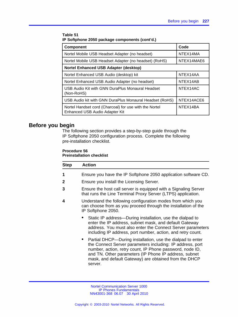
Before you begin 227
Table 51IP Softphone 2050 package components (cont’d.)
Component Code
Nortel Mobile USB Headset Adapter (no headset) NTEX14MA
Nortel Mobile USB Headset Adapter (no headset) (RoHS) NTEX14MAE6
Nortel Enhanced USB Adapter (desktop)
Nortel Enhanced USB Audio (desktop) kit NTEX14AA
Nortel Enhanced USB Audio Adapter (no headset) NTEX14AB
USB Audio Kit with GNN DuraPlus Monaural Headset(Non-RoHS)
NTEX14AC
USB Audio kit with GNN DuraPlus Monaural Headset (RoHS) NTEX14ACE6
Nortel Handset cord (Charcoal) for use with the NortelEnhanced USB Audio Adapter Kit
NTEX14BA
Before you beginThe following section provides a step-by-step guide through theIP Softphone 2050 configuration process. Complete the followingpre-installation checklist.
Procedure 56Preinstallation checklist
Step Action
1 Ensure you have the IP Softphone 2050 application software CD.
2 Ensure you install the Licensing Server.
3 Ensure the host call server is equipped with a Signaling Serverthat runs the Line Terminal Proxy Server (LTPS) application.
4 Understand the following configuration modes from which youcan choose from as you proceed through the installation of theIP Softphone 2050.
• Static IP address—During installation, use the dialpad toenter the IP address, subnet mask, and default Gatewayaddress. You must also enter the Connect Server parametersincluding IP address, port number, action, and retry count.
• Partial DHCP—During installation, use the dialpad to enterthe Connect Server parameters including: IP address, portnumber, action, retry count, IP Phone password, node ID,and TN. Other parameters (IP Phone IP address, subnetmask, and default Gateway) are obtained from the DHCPserver.
Nortel Communication Server 1000IP Phones Fundamentals
NN43001-368 06.07 30 April 2010
Copyright © 2003-2010 Nortel Networks. All Rights Reserved.
.
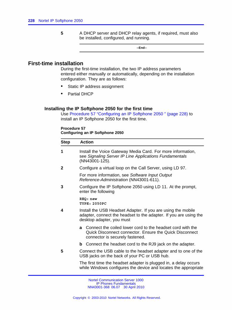
228 Nortel IP Softphone 2050
5 A DHCP server and DHCP relay agents, if required, must alsobe installed, configured, and running.
--End--
First-time installationDuring the first-time installation, the two IP address parametersentered either manually or automatically, depending on the installationconfiguration. They are as follows:
• Static IP address assignment
• Partial DHCP
Installing the IP Softphone 2050 for the first timeUse Procedure 57 “Configuring an IP Softphone 2050 ” (page 228) toinstall an IP Softphone 2050 for the first time.
Procedure 57Configuring an IP Softphone 2050
Step Action
1 Install the Voice Gateway Media Card. For more information,see Signaling Server IP Line Applications Fundamentals(NN43001-125).
2 Configure a virtual loop on the Call Server, using LD 97.
For more information, see Software Input OutputReference-Administration (NN43001-611).
3 Configure the IP Softphone 2050 using LD 11. At the prompt,enter the following
REQ: newTYPE: 2050PC
4 Install the USB Headset Adapter. If you are using the mobileadapter, connect the headset to the adapter. If you are using thedesktop adapter, you must
a Connect the coiled lower cord to the headset cord with theQuick Disconnect connector. Ensure the Quick Disconnectconnector is securely fastened.
b Connect the headset cord to the RJ9 jack on the adapter.
5 Connect the USB cable to the headset adapter and to one of theUSB jacks on the back of your PC or USB hub.
The first time the headset adapter is plugged in, a delay occurswhile Windows configures the device and locates the appropriate
Nortel Communication Server 1000IP Phones Fundamentals
NN43001-368 06.07 30 April 2010
Copyright © 2003-2010 Nortel Networks. All Rights Reserved.
.
Installing or upgrading the IP Softphone 2050 229
driver software . During the installation, you are prompted tosupply the original Windows CD-ROM so Windows can locatethe required drivers.
6 Install the IP Softphone 2050.
7 Configure the IP Softphone 2050 parameters. Click the Servertab in the Settings window and choose one of the following
• To manually configure the IP Softphone 2050 parameters,enter the IP address of the Signaling Server type, portnumber, and retries.
• For DHCP, select the check box beside Automatic (DHCP).The IP address, Server type, port number, and retries areautomatically retrieved from the DHCP Server.
For more information about using partial DHCP, see “DynamicHost Configuration Protocol” (page 429).
8 Click Apply.
--End--
Installing or upgrading the IP Softphone 2050Use the following options to obtain Version 1 and Version 2 software forthe IP Softphone 2050
• new installation—installing the IP Softphone 2050 for the first time
• upgrade—upgrading the IP Softphone 2050 to the latest version
IP Softphone Version 1 and IP Softphone Version 2 can coexist on a PC,although both versions cannot run at the same time.
After you install Release 3.0, you must remove previous versions ofsoftware. License certificates issued for the IP Softphone 2050 work for allminor version variations in the same major release. But when you plan amajor software upgrade, you must purchase new license certificates. Forinformation about upgrading to Release 3, see “Licenses” (page 207).
IP Softphone 2050 Release 3.1 supports remote installation, whichenables you to deploy the software without the need to install it on eachPC.
Before performing a new installation or an upgrade, check the version of IPSoftphone 2050 software.
Nortel Communication Server 1000IP Phones Fundamentals
NN43001-368 06.07 30 April 2010
Copyright © 2003-2010 Nortel Networks. All Rights Reserved.
.
230 Nortel IP Softphone 2050
ATTENTIONBefore you upgrade an IP Softphone 2050, record the information found in theServer window. You may require this information later.
Remote installationIP Softphone 2050 Release 3.1 uses Active Directory to perform theremote installation. The Microsoft Installer Package (.MSI file) publishes orassigns the application. The Group Policy Object distributes the softwareto the groups you specify.
This section describes the following tasks:
• Procedure 58 “Creating a distribution point ” (page 230)
• Procedure 59 “Creating a Group Policy Object” (page 230)
• Procedure 60 “Assigning software ” (page 231)
• Procedure 61 “Publishing software” (page 232)
• Procedure 62 “Redeploying software” (page 233)
• Procedure 63 “Removing software” (page 234)
Procedure 58Creating a distribution point
Step Action
1 Log on to the server computer as an administrator.
2 Create a shared network folder, in which to place the MicrosoftSoftware Installer (MSI) package that you want to distribute.
3 Configure permissions on the shared network folder to allowaccess to the distribution package.
4 Copy or install the MSI package to the distribution point.
--End--
Procedure 59Creating a Group Policy Object
Step Action
1 Click Start > Programs > Administrative Tools > ActiveDirectory Users and Computers to start the Active DirectoryUsers and Computers snap-in.
2 In the console tree, right-click on your domain name.
3 Click Properties.
4 Click the Group Policy tab.
Nortel Communication Server 1000IP Phones Fundamentals
NN43001-368 06.07 30 April 2010
Copyright © 2003-2010 Nortel Networks. All Rights Reserved.
.
Installing or upgrading the IP Softphone 2050 231
5 Click New.
6 Enter a name for this policy.
For example, Office distribution.
7 Press Enter.
8 Click Properties.
9 Click the Security tab.
10 Select the Apply Group Policy check box to clear it and toprevent the security groups from having this policy applied.Select the Apply Group Policy check box for the groups towhich you want to apply this policy.
--End--
Procedure 60Assigning software
Step Action
1 Click Start > Programs > Administrative Tools > ActiveDirectory Users and Computers to start the Active DirectoryUsers and Computers snap-in.
2 In the console tree, right-click on your domain name.
3 Click Properties.
4 Click the Group Policy tab.
5 Select the group policy object.
6 Click Edit.
7 Press the plus (+) sign beside Computer Configuration, toexpand it.
8 Press + beside Software Settings to expand it.
9 Right-click on Software Installation.
10 Select New.
11 Click Package.
12 In the Open dialog box, enter the full Universal NamingConvention (UNC) path to the shared folder that contains theMSI package that you want.
For example, \\file server\share\file name.msi.
ATTENTIONDo not browse to the location. Ensure that you use the UNC path tothe shared folder.
13 Click Open.
Nortel Communication Server 1000IP Phones Fundamentals
NN43001-368 06.07 30 April 2010
Copyright © 2003-2010 Nortel Networks. All Rights Reserved.
.
232 Nortel IP Softphone 2050
14 Click Assigned.
15 Click OK.
The package lists in the right pane of the Group Policy window.
16 Close the Group Policy snap-in.
17 Click OK.
The package lists in the right pane of the Group Policy window.
18 Exit the Active Directory Users and Computers snap-in.
When the client computer starts, the managed software packageautomatically installs.
--End--
Procedure 61Publishing software
Step Action
1 Click Start > Programs > Administrative Tools > ActiveDirectory Users and Computers to start the Active DirectoryUsers and Computers snap-in.
2 In the console tree, right-click on your domain name.
3 Click Properties.
4 Click the Group Policy tab.
5 Select the group policy object.
6 Click Edit.
7 Press the plus (+) sign beside Computer Configuration, toexpand it.
8 Press + beside Software Settings to expand it.
9 Right-click on Software Installation.
10 Select New.
11 Click Package.
12 In the Open dialog box, enter the full Universal NamingConvention (UNC) path to the shared folder that contains theMSI package that you want.
For example, \\file server\share\file name.msi.
ATTENTIONDo not browse to the location. Ensure that you use the UNC path tothe shared folder.
13 Click Open.
Nortel Communication Server 1000IP Phones Fundamentals
NN43001-368 06.07 30 April 2010
Copyright © 2003-2010 Nortel Networks. All Rights Reserved.
.
Installing or upgrading the IP Softphone 2050 233
14 Click Published.
15 Click OK.
The package lists in the right pane of the Group Policy window.
16 Exit the Active Directory Users and Computers snap-in.
When the client computer starts, the managed software packageautomatically installs.
17 To test the package, perform the following steps:
1. Log on to a workstation that is running Windows 2000Professional or Windows XP Professional by using anaccount to which you published the package.
2. In Windows 2000, click Start > Settings > Control Panel. InWindows XP, click Start > Control Panel.
3. Double-click Add/Remove Programs (Windows 2000) orAdd or Remove Programs (Windows XP).
4. Click Add New Programs.
5. In the Add Programs from your network list, click the programthat you published.
6. Click Add. The program is installed.
7. Click OK.
8. Close the program.
--End--
Procedure 62Redeploying software
Step Action
1 Click Start > Programs > Administrative Tools > ActiveDirectory Users and Computers to start the Active DirectoryUsers and Computers snap-in.
2 In the console tree, right-click on your domain name.
3 Click Properties.
4 Click the Group Policy tab.
5 Select the group policy object.
6 Click Edit.
7 Press the plus (+) sign beside Computer Configuration, toexpand it.
Nortel Communication Server 1000IP Phones Fundamentals
NN43001-368 06.07 30 April 2010
Copyright © 2003-2010 Nortel Networks. All Rights Reserved.
.
234 Nortel IP Softphone 2050
8 Press + beside Software Settings that contains the Softwareinstallation item with which you deployed the package.
9 Click the Software installation container that contains thepackage.
The package lists in the right pane of the Group Policy window.
10 Right-click the program and select All Tasks.
11 Click Redeploy application.
The following message displays: "Redeploying this applicationwill reinstall the application everywhere it is already installed. Doyou want to continue?"
12 Click Yes.
13 Close the Group Policy snap-in.
14 Click OK.
15 Exit the Active Directory Users and Computers snap-in.
--End--
Procedure 63Removing software
Step Action
1 Click Start > Programs > Administrative Tools > ActiveDirectory Users and Computers to start the Active DirectoryUsers and Computers snap-in.
2 In the console tree, right-click on your domain name.
3 Click Properties.
4 Click the Group Policy tab.
5 Select the group policy object.
6 Click Edit.
7 Press the plus (+) sign beside Computer Configuration, toexpand it.
8 Press + beside Software Settings that contains the Softwareinstallation item with which you deployed the package.
9 Click the Software installation container that contains thepackage.
The package lists in the right pane of the Group Policy window.
10 Right-click the program and select All Tasks.
11 Click Remove.
12 Perform one of the following actions:
Nortel Communication Server 1000IP Phones Fundamentals
NN43001-368 06.07 30 April 2010
Copyright © 2003-2010 Nortel Networks. All Rights Reserved.
.
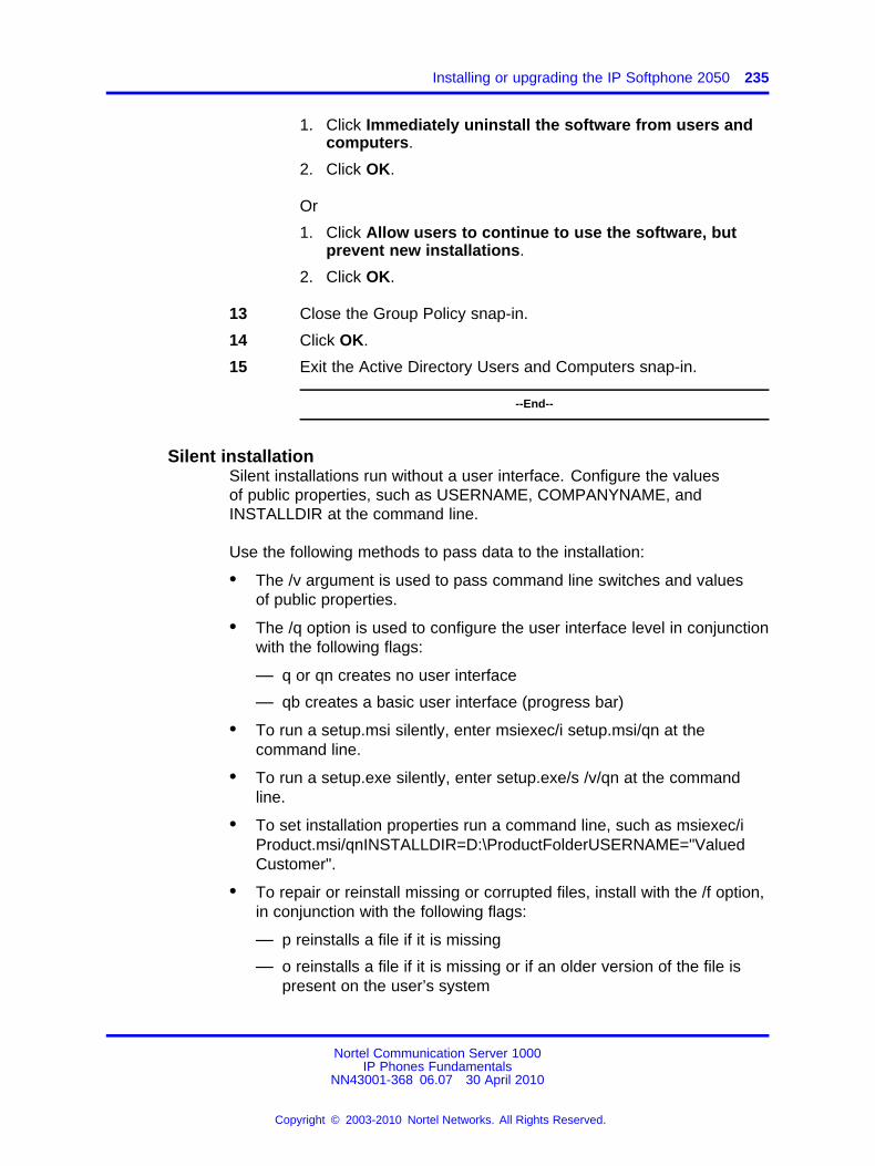
Installing or upgrading the IP Softphone 2050 235
1. Click Immediately uninstall the software from users andcomputers.
2. Click OK.
Or
1. Click Allow users to continue to use the software, butprevent new installations.
2. Click OK.
13 Close the Group Policy snap-in.
14 Click OK.
15 Exit the Active Directory Users and Computers snap-in.
--End--
Silent installationSilent installations run without a user interface. Configure the valuesof public properties, such as USERNAME, COMPANYNAME, andINSTALLDIR at the command line.
Use the following methods to pass data to the installation:
• The /v argument is used to pass command line switches and valuesof public properties.
• The /q option is used to configure the user interface level in conjunctionwith the following flags:
— q or qn creates no user interface
— qb creates a basic user interface (progress bar)
• To run a setup.msi silently, enter msiexec/i setup.msi/qn at thecommand line.
• To run a setup.exe silently, enter setup.exe/s /v/qn at the commandline.
• To set installation properties run a command line, such as msiexec/iProduct.msi/qnINSTALLDIR=D:\ProductFolderUSERNAME="ValuedCustomer".
• To repair or reinstall missing or corrupted files, install with the /f option,in conjunction with the following flags:
— p reinstalls a file if it is missing
— o reinstalls a file if it is missing or if an older version of the file ispresent on the user’s system
Nortel Communication Server 1000IP Phones Fundamentals
NN43001-368 06.07 30 April 2010
Copyright © 2003-2010 Nortel Networks. All Rights Reserved.
.
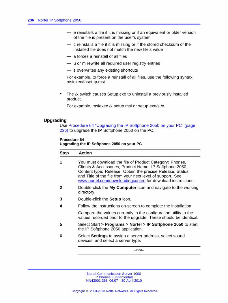
236 Nortel IP Softphone 2050
— e reinstalls a file if it is missing or if an equivalent or older versionof the file is present on the user’s system
— c reinstalls a file if it is missing or if the stored checksum of theinstalled file does not match the new file’s value
— a forces a reinstall of all files
— u or m rewrite all required user registry entries
— s overwrites any existing shortcuts
For example, to force a reinstall of all files, use the following syntax:msiexec/fasetup.msi
• The /x switch causes Setup.exe to uninstall a previously installedproduct.
For example, msiexec /x setup.msi or setup.exe/s /x.
UpgradingUse Procedure 64 “Upgrading the IP Softphone 2050 on your PC” (page236) to upgrade the IP Softphone 2050 on the PC.
Procedure 64Upgrading the IP Softphone 2050 on your PC
Step Action
1 You must download the file of Product Category: Phones,Clients & Accessories, Product Name: IP Softphone 2050,Content type: Release. Obtain the precise Release, Status,and Title of the file from your next level of support. Seewww.nortel.com/downloadingconten for download instructions.
2 Double-click the My Computer icon and navigate to the workingdirectory.
3 Double-click the Setup icon.
4 Follow the instructions on-screen to complete the installation.
Compare the values currently in the configuration utility to thevalues recorded prior to the upgrade. These should be identical.
5 Select Start > Programs > Nortel > IP Softphone 2050 to startthe IP Softphone 2050 application.
6 Select Settings to assign a server address, select sounddevices, and select a server type.
--End--
Nortel Communication Server 1000IP Phones Fundamentals
NN43001-368 06.07 30 April 2010
Copyright © 2003-2010 Nortel Networks. All Rights Reserved.
.
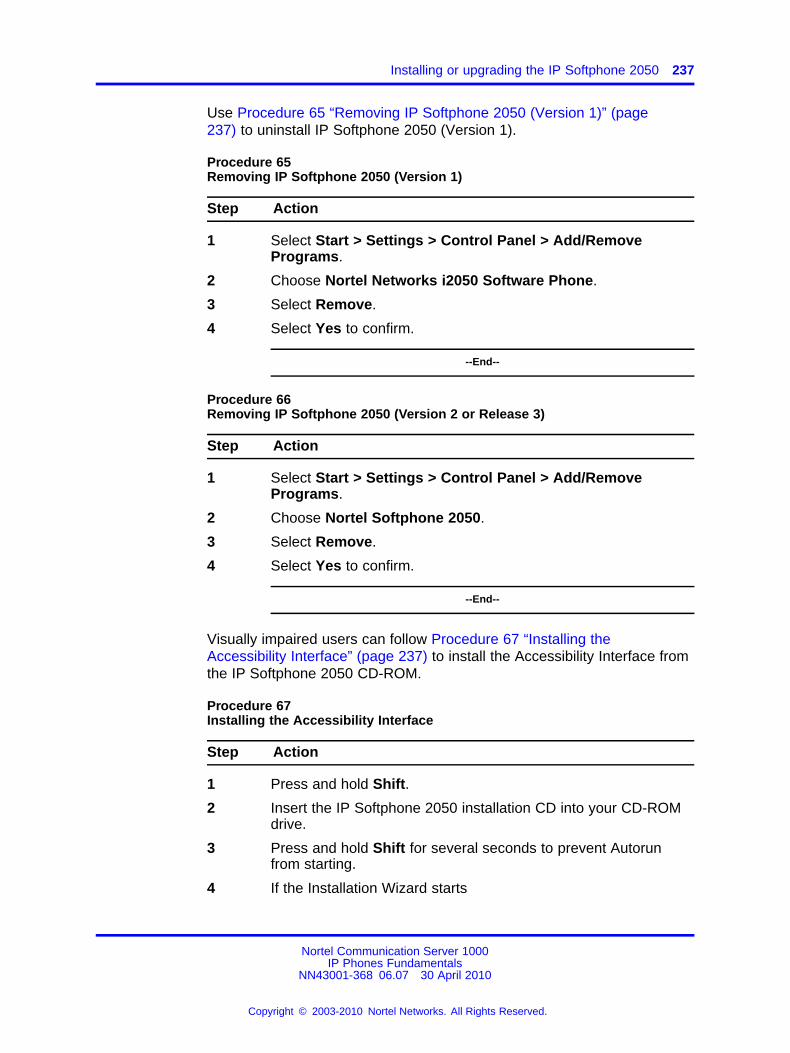
Installing or upgrading the IP Softphone 2050 237
Use Procedure 65 “Removing IP Softphone 2050 (Version 1)” (page237) to uninstall IP Softphone 2050 (Version 1).
Procedure 65Removing IP Softphone 2050 (Version 1)
Step Action
1 Select Start > Settings > Control Panel > Add/RemovePrograms.
2 Choose Nortel Networks i2050 Software Phone.
3 Select Remove.
4 Select Yes to confirm.
--End--
Procedure 66Removing IP Softphone 2050 (Version 2 or Release 3)
Step Action
1 Select Start > Settings > Control Panel > Add/RemovePrograms.
2 Choose Nortel Softphone 2050.
3 Select Remove.
4 Select Yes to confirm.
--End--
Visually impaired users can follow Procedure 67 “Installing theAccessibility Interface” (page 237) to install the Accessibility Interface fromthe IP Softphone 2050 CD-ROM.
Procedure 67Installing the Accessibility Interface
Step Action
1 Press and hold Shift.
2 Insert the IP Softphone 2050 installation CD into your CD-ROMdrive.
3 Press and hold Shift for several seconds to prevent Autorunfrom starting.
4 If the Installation Wizard starts
Nortel Communication Server 1000IP Phones Fundamentals
NN43001-368 06.07 30 April 2010
Copyright © 2003-2010 Nortel Networks. All Rights Reserved.
.
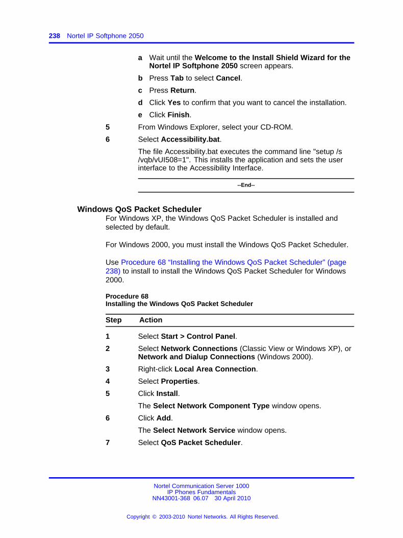
238 Nortel IP Softphone 2050
a Wait until the Welcome to the Install Shield Wizard for theNortel IP Softphone 2050 screen appears.
b Press Tab to select Cancel.
c Press Return.
d Click Yes to confirm that you want to cancel the installation.
e Click Finish.
5 From Windows Explorer, select your CD-ROM.
6 Select Accessibility.bat.
The file Accessibility.bat executes the command line "setup /s/vqb/vUI508=1". This installs the application and sets the userinterface to the Accessibility Interface.
--End--
Windows QoS Packet SchedulerFor Windows XP, the Windows QoS Packet Scheduler is installed andselected by default.
For Windows 2000, you must install the Windows QoS Packet Scheduler.
Use Procedure 68 “Installing the Windows QoS Packet Scheduler” (page238) to install to install the Windows QoS Packet Scheduler for Windows2000.
Procedure 68Installing the Windows QoS Packet Scheduler
Step Action
1 Select Start > Control Panel.
2 Select Network Connections (Classic View or Windows XP), orNetwork and Dialup Connections (Windows 2000).
3 Right-click Local Area Connection.
4 Select Properties.
5 Click Install.
The Select Network Component Type window opens.
6 Click Add.
The Select Network Service window opens.
7 Select QoS Packet Scheduler.
Nortel Communication Server 1000IP Phones Fundamentals
NN43001-368 06.07 30 April 2010
Copyright © 2003-2010 Nortel Networks. All Rights Reserved.
.
Redeploying the IP Softphone 2050 239
8 Click OK.
--End--
To verify Windows QoS Packet Scheduler is installed, go to Control Panel> Network Connections (Windows XP) or Network and Dialup Connections(Windows 2000) > Local Area Connection > Properties > QoS PacketScheduler.
Running the IP Softphone 2050 for the first timeStart the IP Softphone 2050 in one of the following ways
• Select Start > Programs > Nortel > IP Softphone 2050.
• Click the desktop shortcut (if one was created during the installation).
• Click Automatic startup sequence.
If you want the IP Softphone 2050 to start automatically when the PCstarts, create a shortcut to the application in the Startup folder
When an IP Softphone 2050 is started for the first time and connects to thenetwork, the IP Softphone executes the following start-up sequence
1. Obtain the IP parameters.
2. Find a Media Gateway server and authenticate the user.
As the IP Softphone 2050 registers with the Signaling Server, one of thefollowing occurs
• If a non-null node password is enabled, you are prompted to enter thenode number and password. Use the keyboard or numeric keypadto enter the prompts for a node number and password. After thepassword is verified, enter the TN of the IP Softphone 2050. SeeSignaling Server IP Line Applications Fundamentals (NN43001-125) forfurther information about the password feature.
• If the null node password is configured and enabled, these screens areskipped and no option is provided to change the password.
• If the node password is disabled or not configured, it prompts fora node number and TN. Enter the node number and TN using thekeyboard or numeric keypad.
Redeploying the IP Softphone 2050This procedure is required for a new user of the IP Softphone 2050application.
Nortel Communication Server 1000IP Phones Fundamentals
NN43001-368 06.07 30 April 2010
Copyright © 2003-2010 Nortel Networks. All Rights Reserved.
.
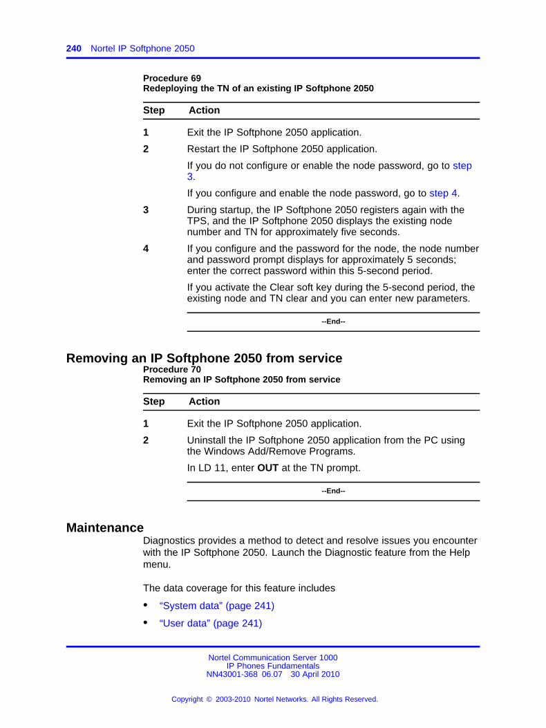
240 Nortel IP Softphone 2050
Procedure 69Redeploying the TN of an existing IP Softphone 2050
Step Action
1 Exit the IP Softphone 2050 application.
2 Restart the IP Softphone 2050 application.
If you do not configure or enable the node password, go to step3.
If you configure and enable the node password, go to step 4.
3 During startup, the IP Softphone 2050 registers again with theTPS, and the IP Softphone 2050 displays the existing nodenumber and TN for approximately five seconds.
4 If you configure and the password for the node, the node numberand password prompt displays for approximately 5 seconds;enter the correct password within this 5-second period.
If you activate the Clear soft key during the 5-second period, theexisting node and TN clear and you can enter new parameters.
--End--
Removing an IP Softphone 2050 from serviceProcedure 70Removing an IP Softphone 2050 from service
Step Action
1 Exit the IP Softphone 2050 application.
2 Uninstall the IP Softphone 2050 application from the PC usingthe Windows Add/Remove Programs.
In LD 11, enter OUT at the TN prompt.
--End--
MaintenanceDiagnostics provides a method to detect and resolve issues you encounterwith the IP Softphone 2050. Launch the Diagnostic feature from the Helpmenu.
The data coverage for this feature includes
• “System data” (page 241)
• “User data” (page 241)
Nortel Communication Server 1000IP Phones Fundamentals
NN43001-368 06.07 30 April 2010
Copyright © 2003-2010 Nortel Networks. All Rights Reserved.
.
Maintenance 241
• “Ethernet statistics” (page 242)
• “IP Networking Statistics” (page 243)
• “ICMP Statistics” (page 244)
• “Audio Connection Data” (page 244)
• “USB Headset Data” (page 246)
• “Telchemy VQMon” (page 246)
• “PC System Information” (page 247)
• “Personal Call Recording Data” (page 248)
• “Licensing Data” (page 248)
• “Duplicate Media Stream Call Recording Data” (page 248)
The Diagnostics feature uses an Hyper Text Markup Language (HTML)view, which splits each category of data into tables.
If diagnostics are not available for a specific parameter, the labelUnavailable Data appears.
System dataThe system data displays the following information which is consistentacross all users.
• 2050 Version
• Install Path
• Last Profile Used
• Last Language Used
• Last Theme Used
• Status of the Quick Start & Profiles Dialog
• Auto-Hide Menu
• Hardware ID
• Launch 2050 on Windows Startup
User dataThe user data displays the profile configuration for all profiles of the IPSoftphone 2050. The user configures the following data by browsing toFile > Settings from the main application window:
• DHCP status
• Server IP Address
Nortel Communication Server 1000IP Phones Fundamentals
NN43001-368 06.07 30 April 2010
Copyright © 2003-2010 Nortel Networks. All Rights Reserved.
.
242 Nortel IP Softphone 2050
• Server Name
• Node
• Large System TN
• TN
• Server Port
• Server Type
• Number of Retries
• Symposium Status
• Modem Status
• Listener IP Address
• Listener Port
• Echo Cancellation
• NetEq Status
• Language
• Theme Selected
• Action
• FingerPrint
• Expansion Module Display Format (Number, Name/Name, Number)
• Expansion Module View Style (Group/Spatial)
• Show Number on Expansion Module Buttons (Enabled/Disabled)
• Show Annotation on Expansion Module Buttons (Enabled/Disabled)
Ethernet statisticsThe Ethernet statistics displays information regarding the state of thenetwork interface card. The Windows Operating system collects andprovides the following Ethernet data:
• Adapter Name
• Adapter Description
• Physical Address
• Adaptor Type
• Link Status
• Speed
• MTU
Nortel Communication Server 1000IP Phones Fundamentals
NN43001-368 06.07 30 April 2010
Copyright © 2003-2010 Nortel Networks. All Rights Reserved.
.
Maintenance 243
• DHCP Status
• Current IP Address
• Subnet Mask
• Default Gateway
ATTENTIONA maximum of 5 IP addresses display but it is possible to assign more than 5 IPaddresses to one NIC.
IP Networking StatisticsThe IP Network statistics displays information regarding the state of theIP Network. The Windows Operating system collects and provides thefollowing IP Network data:
• Host Name (for the local PC)
• Domain Name (Domain PC is registered to)
• DNS Servers
• Node Type (Broadcast/P2P/Mixed/Hybrid)
• IP Routing Status
• IP Forwarding Status
• Default Packet Time-to-Live
• Packets Received
• Received Packets with Header Errors
• Received Packets with Address Errors
• Packets Forwarded
• Packet Received with an Unknown Protocol
• Incoming Packets Discarded
• Received Packets Delivered
• Outgoing Packets Requested
• Outgoing Packets Discarded
• Transmitted Packets Discarded
• Number of Network Interfaces for this PC
• Number of IP Addresses for this PC
• Number of Routes in the IP Routing Table
ATTENTIONA maximum of 5 DNS Server addresses display.
Nortel Communication Server 1000IP Phones Fundamentals
NN43001-368 06.07 30 April 2010
Copyright © 2003-2010 Nortel Networks. All Rights Reserved.
.
244 Nortel IP Softphone 2050
ICMP StatisticsICMP Statistics display information regarding the Internet Control MessageProtocol for the PC. ICMP messages send and receive when no errorsoccur in the packet or in network routing. The following ICMP statisticsdisplay:
• Messages Received
• Messages Sent
• Destination-Unreachable Messages Received
• Destination-Unreachable Messages Sent
• Time-To-Live Exceeded Messages Received
• Time-To-Live Exceeded Messages Sent
• Parameter Problem Messages Received (IP Header)
• Parameter Problem Messages Sent (IP Header)
• Redirect Packets Sent
• Redirect Packets Received
Audio Connection DataThe Audio Connection data displays information pertinent to the last call,as well as other general audio parameters, such as:
• PC Audio Buffer
• PC Audio Buffer Range
• Audio Attenuation Percentage
• Jitter
• High Water Mark
• Early Packet Resync
• Late Packet Resync
• Supported codecs
• Echo Cancellation Mode
• Echo Cancellation Type
• Noise Reduction Level
• Microphone Auto Gain Control Status
• SRTP Status for Last Call (Enabled/Disabled)
The last call parameters for both the RX and TX displayed are as follows:
Nortel Communication Server 1000IP Phones Fundamentals
NN43001-368 06.07 30 April 2010
Copyright © 2003-2010 Nortel Networks. All Rights Reserved.
.
Maintenance 245
• Time of Connection
• Codec Used
• Frames per Packet
• Local/Remote RTP Port Used
• Local/Remote RTCP Port Used
• RTCP Type of Service (ToS)/Diffserv Codepoint
• RTCP 802.1p
• Remote IP Address
Last call parametersThe last call parameters for both the RX and TX displays the followingparameters:
• Time of Connection
• Codec Used
• Frames per Packet
• Local/Remote RTP Port Used
• Local/Remote RTCP Port Used
• RTCP Type of Service (ToS)/Diffserv Codepoint
• RTP/RTCP 802.1p
• Remote IP Address
General audio parametersThe general audio parameters displays the following parameters:
• PC Audio Buffer
• PC Audio Buffer Range
• Audio Attenuation Percentage
• Jitter
• High Water Mark
• Early Packet Resync
• Late Packet Resync
• Supported codecs
• Echo Cancellation Mode
• Echo Cancellation Type
Nortel Communication Server 1000IP Phones Fundamentals
NN43001-368 06.07 30 April 2010
Copyright © 2003-2010 Nortel Networks. All Rights Reserved.
.
246 Nortel IP Softphone 2050
• Noise Reduction Level
• Microphone Auto Gain Control Status
• SRTP Status for Last Call (Enabled/Disabled)
USB Headset DataThe USB headset data displays the following information on the currentand all other supported headsets:
• Default Audio Device
• USB Adapter Status
• USB Adapter Type (Nortel/Algo USB Audio Adapter/Nortel USBIP-ATA)
• Adapter Firmware Version
• Headset Type
• Active Call Indication
• Alert Condition Indication
• Message Waiting Indication
• Headset Disconnected Indication
• Use Backlight
• Supported USB Headsets
Telchemy VQMonThe Telchemy VQMon section displays the following information, whichgenerates using the libraries currently implemented for the IP Softphone2050:
• Packet Loss Rate
• Packet Discard Rate
• Burst Density Average
• Burst Duration
• Gap Density
• Round Trip Delay
• End System Delay
• RERL
• MOS LQ
• MOS CQ
Nortel Communication Server 1000IP Phones Fundamentals
NN43001-368 06.07 30 April 2010
Copyright © 2003-2010 Nortel Networks. All Rights Reserved.
.
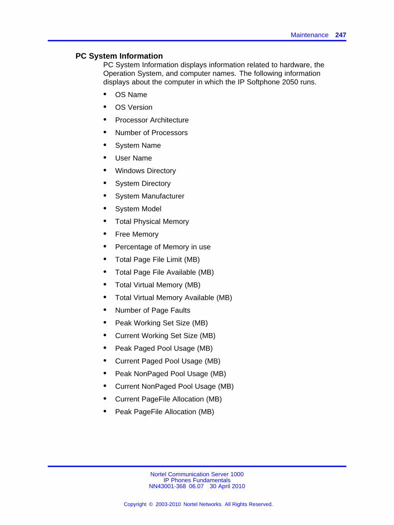
Maintenance 247
PC System InformationPC System Information displays information related to hardware, theOperation System, and computer names. The following informationdisplays about the computer in which the IP Softphone 2050 runs.
• OS Name
• OS Version
• Processor Architecture
• Number of Processors
• System Name
• User Name
• Windows Directory
• System Directory
• System Manufacturer
• System Model
• Total Physical Memory
• Free Memory
• Percentage of Memory in use
• Total Page File Limit (MB)
• Total Page File Available (MB)
• Total Virtual Memory (MB)
• Total Virtual Memory Available (MB)
• Number of Page Faults
• Peak Working Set Size (MB)
• Current Working Set Size (MB)
• Peak Paged Pool Usage (MB)
• Current Paged Pool Usage (MB)
• Peak NonPaged Pool Usage (MB)
• Current NonPaged Pool Usage (MB)
• Current PageFile Allocation (MB)
• Peak PageFile Allocation (MB)
Nortel Communication Server 1000IP Phones Fundamentals
NN43001-368 06.07 30 April 2010
Copyright © 2003-2010 Nortel Networks. All Rights Reserved.
.
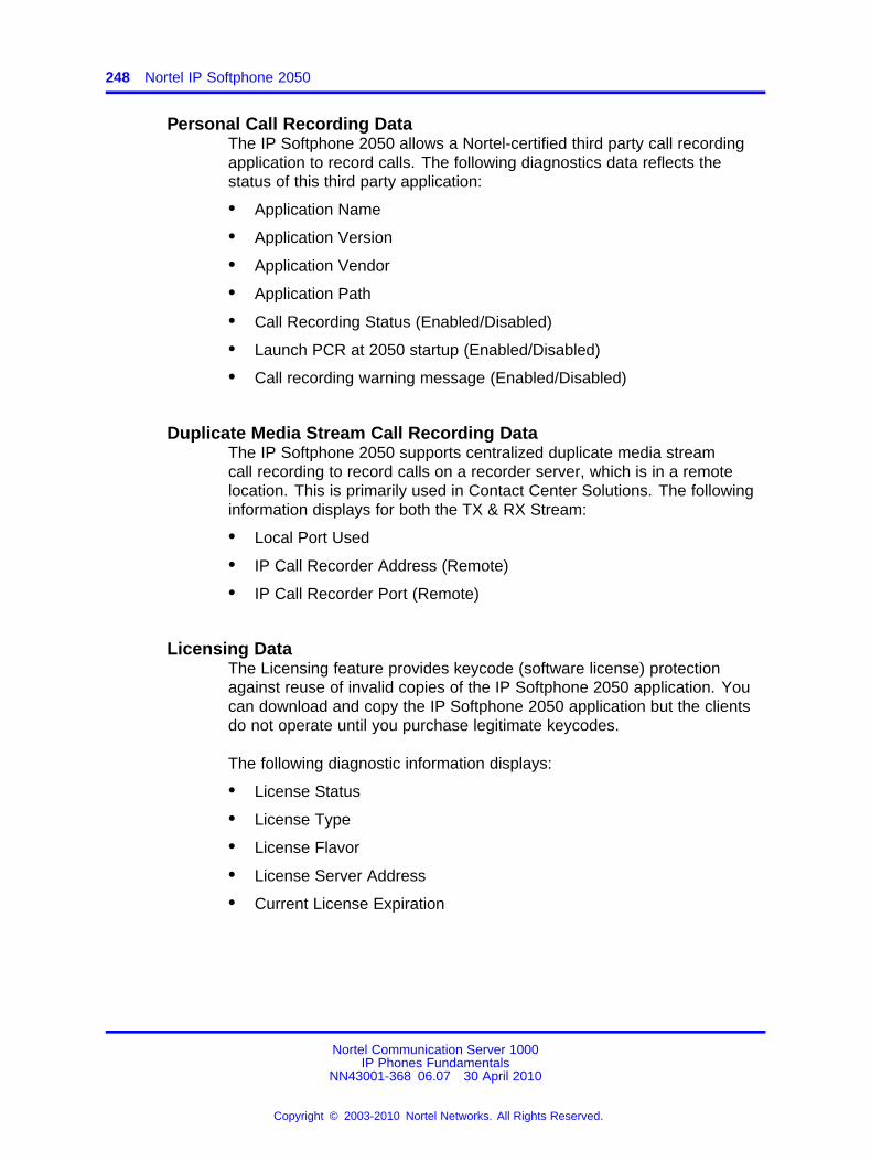
248 Nortel IP Softphone 2050
Personal Call Recording DataThe IP Softphone 2050 allows a Nortel-certified third party call recordingapplication to record calls. The following diagnostics data reflects thestatus of this third party application:
• Application Name
• Application Version
• Application Vendor
• Application Path
• Call Recording Status (Enabled/Disabled)
• Launch PCR at 2050 startup (Enabled/Disabled)
• Call recording warning message (Enabled/Disabled)
Duplicate Media Stream Call Recording DataThe IP Softphone 2050 supports centralized duplicate media streamcall recording to record calls on a recorder server, which is in a remotelocation. This is primarily used in Contact Center Solutions. The followinginformation displays for both the TX & RX Stream:
• Local Port Used
• IP Call Recorder Address (Remote)
• IP Call Recorder Port (Remote)
Licensing DataThe Licensing feature provides keycode (software license) protectionagainst reuse of invalid copies of the IP Softphone 2050 application. Youcan download and copy the IP Softphone 2050 application but the clientsdo not operate until you purchase legitimate keycodes.
The following diagnostic information displays:
• License Status
• License Type
• License Flavor
• License Server Address
• Current License Expiration
Nortel Communication Server 1000IP Phones Fundamentals
NN43001-368 06.07 30 April 2010
Copyright © 2003-2010 Nortel Networks. All Rights Reserved.
.
249.
Nortel Mobile Voice Client 2050
ContentsThis section contains the following topics:
• “Introduction” (page 249)
• “Description” (page 250)
• “System requirements” (page 250)
• “Supported features” (page 250)
• “MVC 2050 components” (page 252)
• “Operation” (page 259)
• “MVC 2050 installation” (page 260)
• “MVC 2050 removal” (page 261)
• “Configuration” (page 262)
• “802.1p and DiffServ” (page 269)
• “MVC 2050 and WLAN” (page 269)
IntroductionThis section describes how to install, configure, and remove the NortelMobile Voice Client 2050 for Release 2.0. For information about using theMVC 2050, see Mobile Voice Client 2050 User Guide (NN43119-103).
This section contains the following procedures
• Procedure 71 “Starting MVC 2050” (page 259).
• Procedure 72 “Synchronizing a PDA with a desktop PC usingActiveSync” (page 260).
• Procedure 73 “Installing MVC 2050” (page 261).
• Procedure 74 “Removing MVC 2050 from your PDA” (page 261).
• Procedure 75 “Enabling Auto-Create” (page 264).
Nortel Communication Server 1000IP Phones Fundamentals
NN43001-368 06.07 30 April 2010
Copyright © 2003-2010 Nortel Networks. All Rights Reserved.
.
250 Nortel Mobile Voice Client 2050
DescriptionMobile Voice Client (MVC) 2050 adds wireless IP Phone services to theconvenience of Personal Digital Assistants (PDAs). MVC 2050 functionslike an IP Softphone 2050. However, MVC 2050 cannot be used as anAgent or Supervisor in Call Center Portal applications.
MVC 2050 is UNIStim-based software that provide real-time voicecommunication, over a WLAN, to PDAs.
MVC 2050 operates on PDAs running the following operating systems
• Pocket PC 2003
• Windows Mobile 5.0
WLAN 802.11b can interwork with various enterprise communicationservers. MVC 2050 can also interwork with WLAN Access Points (WAP)and can use the WSS 2250 WLAN Security Switch. MVC 2050 can coexistwith a secure Virtual Private Network (VPN) client on the same PDA.
MVC 2050 requires access to an enterprise or public WLAN Access Point(WAP).
System requirementsMVC 2050 requires PDAs to meet the following minimum specifications
• 240 x 320 screen size
• 624 MHz CPU speed
• 64 MB RAM
Supported featuresMVC 2050 supports the following telephony features
• six programmable line/feature keys
• four soft keys (self-labeled)
• seven specialized feature keys
— Messages
— Directory
— Shift
— Copy
— Quit
— Services
— Expand
Nortel Communication Server 1000IP Phones Fundamentals
NN43001-368 06.07 30 April 2010
Copyright © 2003-2010 Nortel Networks. All Rights Reserved.
.
Application software 251
• four call-processing keys
— Hold
— Goodbye
— Mute
— Answer
• volume Up/Down keys
• navigation keys
• online help
• 12-button dialpad
• multifield display
• audible notification of connection or disconnection to the server
• macro functions available for programming lengthy dialing patterns
Pause is available to build into the macro to introduce a delay whichmay be required to access some Interactive Voice Response (IVR)applications and voice mail systems.
• Redial List
• Callers List
• profiles
• skins
• connection to user-supplied headsets for the speech path features andservices provided by the network (such as call features and voice mail)
• run-in-background application (MVC 2050 interface is closed but theapplication runs in the background to allow incoming calls)
• 802.11b WLAN interface
• automatic network configuration through DHCP
• G.711 codec for operation without compression
Application softwareMVC 2050 is a software application that enables voice communicationsover a WLAN from a PDA.
The MVC 2050 software application is comprised of the followingcomponents
• MVC 2050 software
• NetEQ software (included in MVC 2050 software)
Nortel Communication Server 1000IP Phones Fundamentals
NN43001-368 06.07 30 April 2010
Copyright © 2003-2010 Nortel Networks. All Rights Reserved.
.
252 Nortel Mobile Voice Client 2050
ClearTypeMVC 2050 uses a special screen font which requires that MicrosoftClearType® be enabled on your PDA. ClearType software improves theappearance and readability of text on liquid crystal display (LCD), pocketPC screens, and flat panel monitors.
MVC 2050 componentsMVC 2050 includes the following components
• MVC 2050 application software, including Global IP Sound NetEQ™software
• user-supplied compatible PDA
• user-supplied headset
Compatible PDAsBecause the PDA industry evolves at a rapid pace, go to www.nortel.com.Select Products > Phones, Clients, and Accessories > IP Phones andClients > Mobile Voice Client 2050 > Technical Specifications to determinethe latest PDA models tested and supported, along with any known issues.
HeadsetsA headset is required in order to send and receive telephone calls usingthe MVC 2050 and your PDA. The headset is an important part of audioquality.
PDAs that support stereo headphones with microphones arerecommended.
The Dell specific headset with a button on the wire, when used with theX51v, allows the MVC 2050 to answer an incoming call or release anactive call by pressing the button.
ATTENTIONBluetooth® and 802.11b operate on the same frequency band and use the sameWLAN hardware on the PDA. Therefore, the use of Bluetooth® accessories withMVC 2050 can lead to poor call quality.
Contact your PDA vendor to obtain headset recommendations.
Automatic Gain Control and feedbackBecause MVC 2050 requires a headset to operate properly, disableAutomatic Gain Control. Refer to your PDA documentation to disableAutomatic Gain Control.
Nortel Communication Server 1000IP Phones Fundamentals
NN43001-368 06.07 30 April 2010
Copyright © 2003-2010 Nortel Networks. All Rights Reserved.
.
MVC 2050 Call Handling screen 253
When the PDA is used in handsfree mode, without a headset, the PDAmicrophone picks up sounds from the speaker, which creates a feedbackloop. Automatic Gain Control is used in this instance to avoid feedback.
ATTENTIONWhen the PDA is used in handsfree mode, without a headset, the PDAmicrophone picks up sounds from the speaker, creating a feedback loop.
Audio qualityMVC 2050 provides a high-quality audio environment, which includes
• NetEQ software (included with the software package)
• Interworking with G.711 codec that provide high audio quality withoutcompression; MVC 2050 supports G.711-64 A-law and U-law
• Audio selection tab that provide a user-selectable quality slider
• Advanced Audio tab for expert users
For more information about Audio quality, see “Audio Quality” (page 266).
MVC 2050 Call Handling screenYou can access and operate most MVC 2050 features from the CallHandling screen. Select Answer from the Keys menu or use theHeadset/Answer icon to answer calls or obtain a dial tone.
The Call Handling screen contains the telephone dialpad. The appearanceof the Call Handling screen differs with each available skin. Use theSettings > Skin dialog box to determine the current skin. All skins sharecommon components.
You can use the up, down, left, and right cursor control arrow keys on yourPDA as navigation buttons to navigate around the skin and move throughthe menu items.
DisplayThe display is located in the central area of the skin. View messages andtext on the display.
DialpadThe 12-button dialpad is located on the left side of the skin.
Soft keys (self-labeled)Four soft keys (self-labeled) are located in the bottom row of the display.The labels on these keys depend on the call server.
Nortel Communication Server 1000IP Phones Fundamentals
NN43001-368 06.07 30 April 2010
Copyright © 2003-2010 Nortel Networks. All Rights Reserved.
.
254 Nortel Mobile Voice Client 2050
Programmable line/feature keysSix programmable line/feature keys are located on the right side of theskin. They are aligned vertically and are the same color as the display.The number of features available depends on the call server.
MenusMVC 2050 provides the following menus
• File
• Keys
• Help
FileThe File menu provides the following items
• Run-in-background
• Paste
• Contacts
• Settings
• Exit
Run-in-background Select Run-in-background to close MVC 2050 butallow it to continue running in the background so that incoming calls canring on your PDA.
After you complete your call, press the X in the upper right-hand cornerof the PDA display to close the MVC 2050 application and return it to thebackground.
Paste Select Paste to paste a telephone number into your PDA fromanother application rather than entering an existing telephone numberthrough your Call Handling screen dialpad.
Contacts Select Contacts to launch the Contacts dialog box. TheContacts application reads a list of contacts from the PDA Contacts list orfrom a list, which you synchronized onto your PDA from Microsoft Outlook.
Settings Select Settings to provide access to the Settings submenu. TheSettings menu provides windows for Personal settings, System settings,and Connections settings.
Nortel Communication Server 1000IP Phones Fundamentals
NN43001-368 06.07 30 April 2010
Copyright © 2003-2010 Nortel Networks. All Rights Reserved.
.
MVC 2050 Call Handling screen 255
The System settings window provides access to settings for memory,power, remove programs, screen and regional settings, iTask settings, andself test.
You must restart MVC 2050 for changes to Profiles, Hardware ID, Sounds,Servers, and Listener IP to take effect.
Exit Select Exit to close MVC 2050. Calls cannot be received until theapplication restarts.
Select Exit to free up PDA-processing resources.
KeysThe Keys menu provides the following items
• Headset
• Answer
• Goodbye
• Hold
• Features
• Macros
Headset Select Headset to answer an incoming call or to obtain a dialtone. You can also use the Headset/Answer icon located at the top centerof the Call Handling screen.
Answer Select Answer to answer an incoming call or to obtain dial toneto place a call. You can also use the Headset/Answer icon located at thetop center of the Call Handling screen.
Goodbye Select Goodbye to end a call. You can also use the Goodbyeicon located at the top right of the screen.
Hold Select Hold to place a call on hold. You can also use the Hold iconlocated at the top left of the screen.
Features Select Features from the Keys menu to access a menu ofinterface keys.
To re-arrange items in the Features list, open the Settings menu andselect the Features tab. Items in the Features list cannot be added orremoved.
Nortel Communication Server 1000IP Phones Fundamentals
NN43001-368 06.07 30 April 2010
Copyright © 2003-2010 Nortel Networks. All Rights Reserved.
.
256 Nortel Mobile Voice Client 2050
Macros Select Macros from the Keys > Features submenu to accessmacros (also available through the Settings > Macros dialog box). Macrosare used to make speed-dials, access voice mail, and other routinefunctions quickly and easily. For more information about macros see“Macros” (page 268)
HelpSelect Help to access the MVC 2050 PDA-specific version of Help. TheHelp menu provides the following items
• Contents
• Diagnostics
• About MVC 2050
Contents Select the Contents menu item to access the Help system.
Diagnostics Select Diagnostics to access to a list of methods todetermine server connection state.
Diagnostic methods are as follows
• Ping
• TraceRoute
• RUDP Ping
See “Profiles” (page 265) for information about importing and exportingprofiles to assist in troubleshooting.
About MVC 2050 About MVC 2050 identifies the MVC 2050 application.Select About MVC 2050 to view configuration information for your MVC2050 (such as system product name, version number, copyright indication,manufacturer name and logo, and Global IP Sound name and logo). MVC2050 uses packet loss concealment provided by Global IP Sound NetEQsoftware.
MVC 2050 graphical interface (skins) componentsMVC 2050 provides alternative graphical images known as skins. Thedialpad, menu, and icon buttons on the skin. Skins are available in severalcolors and arrangements.
All skins share the following common components
• programmable line/feature keys
• soft keys (self-labeled)
• dialpad
Nortel Communication Server 1000IP Phones Fundamentals
NN43001-368 06.07 30 April 2010
Copyright © 2003-2010 Nortel Networks. All Rights Reserved.
.
MVC 2050 Call Handling screen 257
• display
• Call Handling icons
• Toolbar icons
• Menu Bar icons
• retractable toolbar
• Message Waiting light
• System Input Panel icon
IconsThe MVC 2050 Call Handling screen presents icon equivalents for menuitems.
Icons are divided into three types
• Call Handling icons
• Toolbar icons
• Menu Bar icons
Call Handling iconsThe following three Call Handling icons appear across the top of the CallHandling screen
• Hold
• Headset/Answer
• Release
Menu Bar iconsMVC 2050 provides the following icons, which is used instead of text menuequivalents
• Paste
• Contacts
• Settings
• Toolbar switch
• System Input icon
Nortel Communication Server 1000IP Phones Fundamentals
NN43001-368 06.07 30 April 2010
Copyright © 2003-2010 Nortel Networks. All Rights Reserved.
.
258 Nortel Mobile Voice Client 2050
Toolbar iconsThe retractable toolbar contains icons, which are not present on theremainder of the display. The icons at the bottom of the skin and arevisible when the Toolbar is retracted. Use the Toolbar switch icon at thebottom of the screen to retract the Toolbar.
The following are the icons visible on the Toolbar
• Mute
• Volume Down
• Volume Up
The following icons are visible when the Toolbar is retracted
• Mute
• Volume Down
• Volume Up
• Directory
• Messages
• Shift
• Services
• Expand
• Copy
• Quit
System Input PanelTo access the System Input Panel from MVC 2050, tap the System InputPanel icon on the Menu Bar on the bottom right-hand corner of the PDA.Consult the PDA documentation for a description of the System InputPanel.
You can use the System Input Panel to enter data for MVC 2050 and otherapplications. Use the keyboard to enter data.
The default System Input Panels are as follows
• Block Recognizer
• Keyboard
• Letter Recognizer
Nortel Communication Server 1000IP Phones Fundamentals
NN43001-368 06.07 30 April 2010
Copyright © 2003-2010 Nortel Networks. All Rights Reserved.
.
Operation 259
The MVC 2050 application enables the keyboard to act like a dialpad,interpreting the alphabetical keys as numbers. For example, J, K, or L, areinterpreted as the number five (5). Nonalphanumeric keys are ignored.
OperationUse Procedure 71 “Starting MVC 2050” (page 259) to start MVC 2050.
Procedure 71Starting MVC 2050
Step Action
1 From the Main Application screen, select Programs.
2 Select Start.
3 Select Mobile Voice Client 2050. The Call Handling screenappears.
--End--
CAUTIONPDA processor models, speed, and amount of memory vary.To maintain audio quality, do not overload the processor withintensive tasks while using MVC 2050. For example, Norteldoes not recommend using your PDA version of InternetExplorer while using MVC 2050.
PDA processor speed can have adverse effects on MVC 2050performance.
ATTENTIONSet the PDA processor speed to the highest setting or to auto, which changesthe processor speed according to system status. To set the PDA processorspeed. Refer to the PDA user guide.
ATTENTIONIf the Wireless Fidelity (WiFi) application goes down while your PDA is set toStandby mode, you cannot receive incoming calls on your device. To continuethe WiFi application running and receive incoming calls, disable the powersettings for Standby mode. Go to the Settings option on your PDA.
PDA battery life can affect the MVC 2050 call duration and the call volume.
Nortel Communication Server 1000IP Phones Fundamentals
NN43001-368 06.07 30 April 2010
Copyright © 2003-2010 Nortel Networks. All Rights Reserved.
.
260 Nortel Mobile Voice Client 2050
ATTENTIONPDA vendors offer two types of rechargeable battery: standard andextended-life. The extended-life battery is recommended. It provides longer callduration and increased call volume than the standard-life battery.
MVC 2050 installationIf an older version of MCV 2050 is installed on the PDA, remove it prior toinstalling a newer version. See “MVC 2050 removal” (page 261).
To install MVC 2050 on the PDA
1. Place the PDA in its cradle.
2. Synchronize the PDA with a desktop PC running Microsoft®
ActiveSync® using Procedure 72 “Synchronizing a PDA with a desktopPC using ActiveSync” (page 260).
3. Install the MVC 2050 from a Desktop using Procedure 73 “InstallingMVC 2050” (page 261).
MVC 2050 installation methodMVC 2050 supports installation from a docked PDA with a MicrosoftActiveSync connection to a desktop PC.
Synchronizing a PDA with a desktop PCUse Procedure 72 “Synchronizing a PDA with a desktop PC usingActiveSync” (page 260) to synchronize your PDA with your desktop PC.
Procedure 72Synchronizing a PDA with a desktop PC using ActiveSync
Step Action
1 Place the PDA in its cradle.
2 Ensure that ActiveSync is running.
3 Wait for the PDA and the PC to synchronize.
--End--
For details about synchronizing a PDA with a desktop PC, see the PDAUsers Manual.
Installing MVC 2050 from a Desktop PC using ActiveSyncUse the following procedure to install MVC 2050 using the product CD.
Nortel Communication Server 1000IP Phones Fundamentals
NN43001-368 06.07 30 April 2010
Copyright © 2003-2010 Nortel Networks. All Rights Reserved.
.
MVC 2050 removal 261
Procedure 73Installing MVC 2050
Step Action
1 Synchronize the PC and PDA. See Procedure 72 “Synchronizinga PDA with a desktop PC using ActiveSync” (page 260).
2 Insert the MVC 2050 CD into the CD-ROM drive of your desktopPC.
3 Go to your desktop and double-click My Computer. The PC filesand folders menu appears.
4 Select the CD Drive.
5 Select Setup.
6 Follow the instructions on the screen until the Install Wizard asksyou if you want to modify, install, or remove MVC 2050.
7 Select Install. The Install Wizard installs MVC 2050. Wheninstallation finishes, Attend to your device (PDA) messagedisplays on the PC and Do you want to perform a soft restart?message displays on the PDA.
8 Select Yes to restart your PDA.
--End--
MVC 2050 removalUse the following procedure to remove MVC 2050 from your PDA.
Procedure 74Removing MVC 2050 from your PDA
Step Action
1 Select Start. A drop-down menu appears.
2 Select Settings. A Windows folder with a number of programs,usually shown as icons with names and a row of tabs across thebottom, opens.
3 Select the System tab. Another Windows program folder opens.
4 Select Remove Programs. A list of programs opens.
5 Select Nortel MVC 2050.
6 Select Remove. A confirmation dialog box opens.
7 Select Yes. There is a brief pause during removal of MVC 2050.After the pause, a confirmation dialog box opens.
Nortel Communication Server 1000IP Phones Fundamentals
NN43001-368 06.07 30 April 2010
Copyright © 2003-2010 Nortel Networks. All Rights Reserved.
.
262 Nortel Mobile Voice Client 2050
8 Select Yes. Your PDA restarts and MVC 2050 has beenremoved.
--End--
ConfigurationMVC 2050 has a flexible interface which enables end users to customizeconfigurations for a variety of connections.
SettingsFor information about settings, see “Settings” (page 254) .
ServerThe Server tab, accessible from the Settings screen, contains all thesettings necessary for MVC 2050 to contact a server. On the Server tab,you can perform the following
• change the settings on the Server tab to access a different server
• implement the profile containing the desired server
For more information about Profiles, see “Profiles” (page 265).
Connection historyConnection history writes connection and disconnection indicationmessages to the registry key HKCU\Software\Nortel \MVC2050\Log. Thisis a circular queue of 29 entries. Each time a connection or disconnectionevent occurs, a log entry containing a date, time, and a description of theconnection or disconnection event is written.
The descriptions of the connection and disconnection events are as follows
• Soft reset, server n
• Server connected
• Recovering: Server unreachable
• Hard reset
• Hardware ID
Soft reset, server n
Server n indicates that the server has instructed MVC 2050 to reset andconnect to a server n where n and its value is determined, and possiblywritten, by the server. This message maps directly to a UNIStim message.
Server connected
Nortel Communication Server 1000IP Phones Fundamentals
NN43001-368 06.07 30 April 2010
Copyright © 2003-2010 Nortel Networks. All Rights Reserved.
.
Configuration 263
Server connected indicates that MVC 2050 has successfully connectedto the server. It means that MVC 2050 received the Assign TerminalIDUNIStim message, which is the last message received by MVC 2050before a normal session is started.
Recovering: Server unreachable
The Recovering: Server unreachable message generates after MVC 2050loses connection with the server. It indicates that the UNIStim watchdogtimer has expired and indicates loss of network connection.
Hard Reset
The Hard Reset message indicates that the server has instructed MVC2050 to reset and clear its UNIStim-related memory. This message mapsdirectly to a UNIStim message.
Hardware IDThe Hardware ID screen is used to select the MAC address that MVC2050 reports to the communication server. The MAC address can bereset.
View the Hardware ID in the MVC 2050 Settings on the Hardware ID tab.
Hardware IDs are generated by reading MAC addresses from the PDANetwork Interface Card (NIC). When MVC 2050 is used with most servertypes, the Hardware ID must be unique.
Some software, such as VPN client software, creates artificial networkinterfaces with MAC addresses, which are not unique. Without a uniqueMAC address, the following conflicts can occur
• MVC 2050 cannot connect to a server
• MVC 2050 connects to the server but another device with the sameHardware ID is disconnected from the server
• MVC 2050 disconnects from the server then automatically attemptsto reconnect
To prevent conflicts with other devices, enable Auto-Create. Auto-Createfabricates a MAC address with a random value that is unlikely to berepeated by another device.
Use Procedure 75 “Enabling Auto-Create” (page 264) to enableAuto-Create.
Nortel Communication Server 1000IP Phones Fundamentals
NN43001-368 06.07 30 April 2010
Copyright © 2003-2010 Nortel Networks. All Rights Reserved.
.
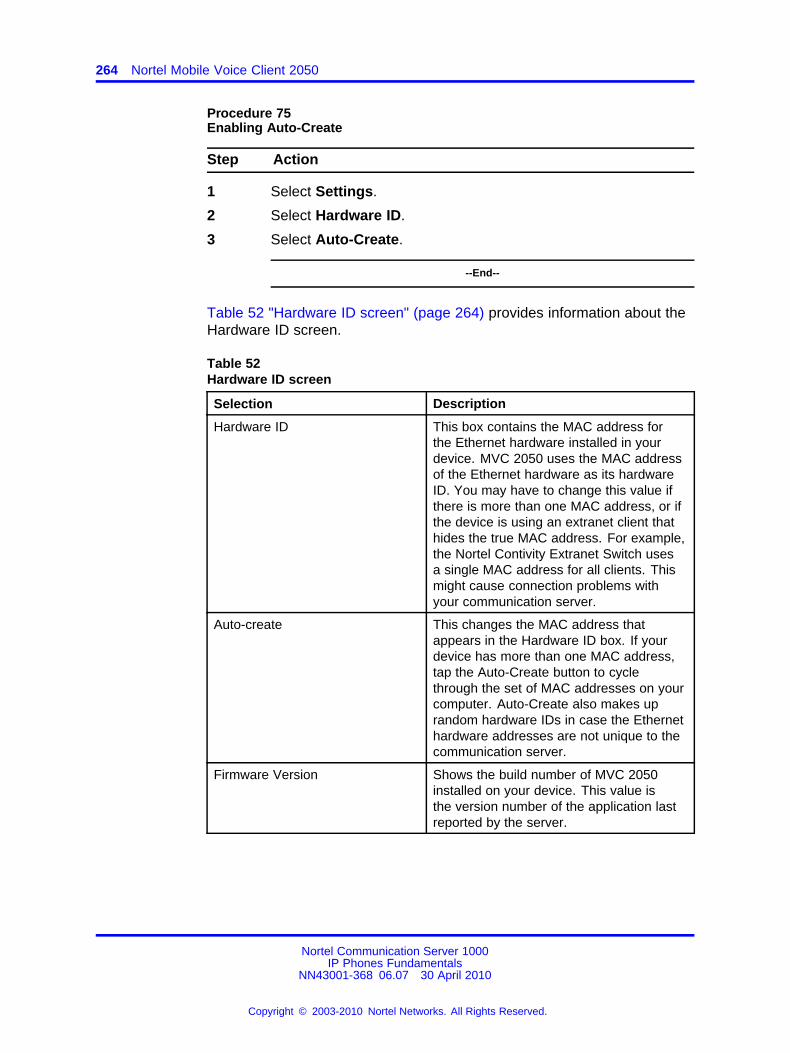
264 Nortel Mobile Voice Client 2050
Procedure 75Enabling Auto-Create
Step Action
1 Select Settings.
2 Select Hardware ID.
3 Select Auto-Create.
--End--
Table 52 "Hardware ID screen" (page 264) provides information about theHardware ID screen.
Table 52Hardware ID screen
Selection Description
Hardware ID This box contains the MAC address forthe Ethernet hardware installed in yourdevice. MVC 2050 uses the MAC addressof the Ethernet hardware as its hardwareID. You may have to change this value ifthere is more than one MAC address, or ifthe device is using an extranet client thathides the true MAC address. For example,the Nortel Contivity Extranet Switch usesa single MAC address for all clients. Thismight cause connection problems withyour communication server.
Auto-create This changes the MAC address thatappears in the Hardware ID box. If yourdevice has more than one MAC address,tap the Auto-Create button to cyclethrough the set of MAC addresses on yourcomputer. Auto-Create also makes uprandom hardware IDs in case the Ethernethardware addresses are not unique to thecommunication server.
Firmware Version Shows the build number of MVC 2050installed on your device. This value isthe version number of the application lastreported by the server.
Nortel Communication Server 1000IP Phones Fundamentals
NN43001-368 06.07 30 April 2010
Copyright © 2003-2010 Nortel Networks. All Rights Reserved.
.
Configuration 265
Dialing formatsDialing Locations settings set the dialing rules to be applied to properlyroute a call when an end user dials a number. The dialing rules establishprefixes to access local and long-distance numbers using the location ofthe user server. To establish the dialing rules and dialing patterns, seeMobile Voice Client 2050 User Guide (NN43119-103).
ProfilesEach profile is a named file, which contains a combination of servers andother attributes that control connection, behavior, and appearance of theMVC 2050.
A number of profiles can be created and saved to allow easy switchingamong different servers, feature programming, and audio programming.
Profiles can be created, selected, modified, or deleted. When you selectprofile you can change the name, modify it, or delete it.
When a profile is selected, all other Settings tabs see the selected profile.The name of the selected profile is shown in the lower right corner on eachtab.
From the Profiles screen you can do the following
• create profiles
• delete profiles
• modify a profile name
• change the profile used by the application
• export profiles
• import profiles
When a new profile is created and selected, the values on all of the othertabs are set to the defaults for this profile. Any value modified on anyof the other tabs are associated with this profile until another profile isselected. To change settings on other tabs for this profile, select thetab you wish to change. For example, go to the Server tab to modify theserver settings.
SoundsMVC 2050 can make sounds to indicate server connection ordisconnection.
Nortel Communication Server 1000IP Phones Fundamentals
NN43001-368 06.07 30 April 2010
Copyright © 2003-2010 Nortel Networks. All Rights Reserved.
.
266 Nortel Mobile Voice Client 2050
Sound files and sound settings are not saved when Profiles are saved,so the use must program the sounds. Up to three sounds can beprogrammed for use with audible notification of server connection ordisconnection.
Following are descriptions of the events for which the sounds are used.
Descriptions of the events for which the sounds are used are as follows
• Server unreachable
• Server unresponsive
• Server connected
Server unreachable
The sound you select for this event plays when MVC 2050 loses contactwith the server. The message "Server unreachable" displays on the PDAscreen.
Server unresponsive
The sound you select for this event plays if MVC 2050 fails to connectto the server. The message Server unresponsive displays on the PDAscreen.
Server connected
The sound you select for this event plays when MVC 2050 connects to aserver.
Audio QualityAudio quality is controlled from the following screens
• Audio quality slider tab
• Advanced Audio
To control audio quality, use the slider tab to reduce audio delay andincrease audio clarity. control audio quality. This slider controls thenumber of audio buffers the PDA uses to smooth out incoming audiostreams.
If you experience audio delay, use the slider on the Audio screen todecrease the number of buffers.
Nortel Communication Server 1000IP Phones Fundamentals
NN43001-368 06.07 30 April 2010
Copyright © 2003-2010 Nortel Networks. All Rights Reserved.
.
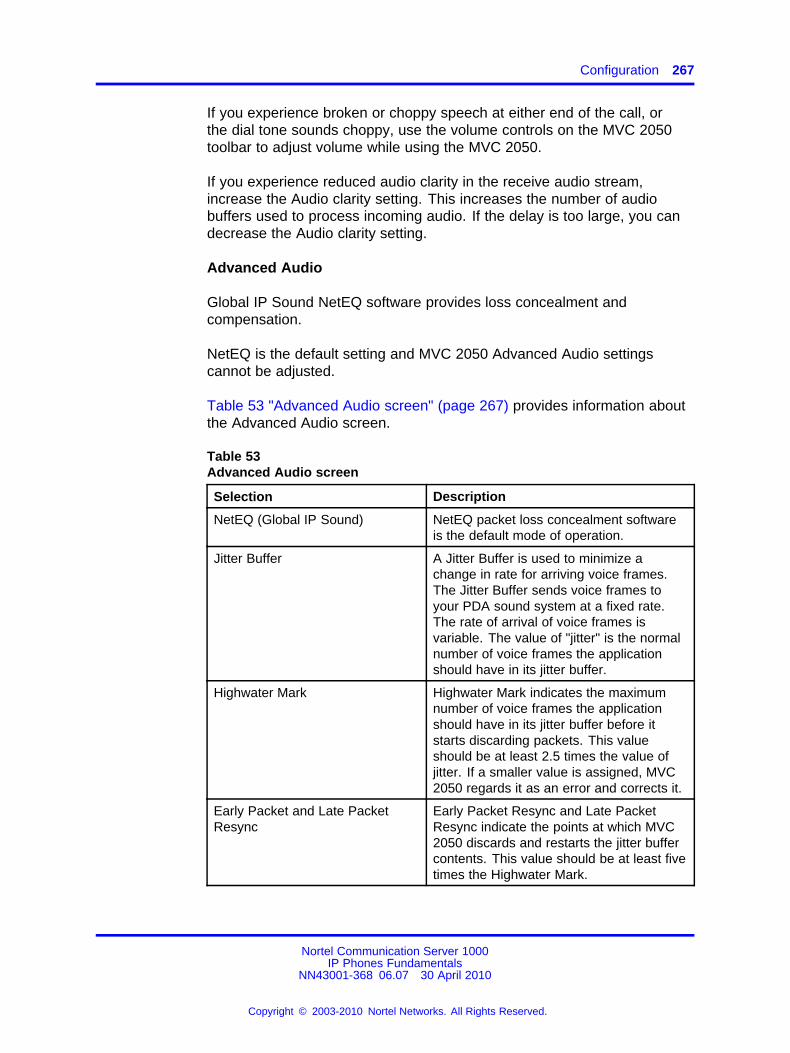
Configuration 267
If you experience broken or choppy speech at either end of the call, orthe dial tone sounds choppy, use the volume controls on the MVC 2050toolbar to adjust volume while using the MVC 2050.
If you experience reduced audio clarity in the receive audio stream,increase the Audio clarity setting. This increases the number of audiobuffers used to process incoming audio. If the delay is too large, you candecrease the Audio clarity setting.
Advanced Audio
Global IP Sound NetEQ software provides loss concealment andcompensation.
NetEQ is the default setting and MVC 2050 Advanced Audio settingscannot be adjusted.
Table 53 "Advanced Audio screen" (page 267) provides information aboutthe Advanced Audio screen.
Table 53Advanced Audio screen
Selection Description
NetEQ (Global IP Sound) NetEQ packet loss concealment softwareis the default mode of operation.
Jitter Buffer A Jitter Buffer is used to minimize achange in rate for arriving voice frames.The Jitter Buffer sends voice frames toyour PDA sound system at a fixed rate.The rate of arrival of voice frames isvariable. The value of "jitter" is the normalnumber of voice frames the applicationshould have in its jitter buffer.
Highwater Mark Highwater Mark indicates the maximumnumber of voice frames the applicationshould have in its jitter buffer before itstarts discarding packets. This valueshould be at least 2.5 times the value ofjitter. If a smaller value is assigned, MVC2050 regards it as an error and corrects it.
Early Packet and Late PacketResync
Early Packet Resync and Late PacketResync indicate the points at which MVC2050 discards and restarts the jitter buffercontents. This value should be at least fivetimes the Highwater Mark.
Nortel Communication Server 1000IP Phones Fundamentals
NN43001-368 06.07 30 April 2010
Copyright © 2003-2010 Nortel Networks. All Rights Reserved.
.

268 Nortel Mobile Voice Client 2050
Listener IPUse the Listener IP screen to override the port assignments when there isa conflicting application on the PDA.
See Table 54 "Listener IP screen" (page 268) for information aboutselections available on the Listener IP screen .
Table 54Listener IP screen
Selection Description
Use a specific address MVC 2050 normally listens to allIP addresses on the device forcommunication server-to-terminal(UNIStim) messaging on all thenetwork interface cards on the device.This is the default mode of operation.To override this behavior, select thecheck box and enter a specific IPaddress.
Use a specific port MVC 2050 listens to IP port 5000on the device for communicationserver-to-terminal (UNIStim)messaging.
MacrosThe Mobile Voice Client (MVC) 2050 Macros tab enables you to recordand use macros. A macro is a recorded sequence of steps that saves youkeystrokes.
For example, you can create macros that select a particular line and thendials the telephone number automatically, or program voice mail accessnumbers and codes for faster access.
Macro screen
To enter a new macro name, or to select an existing macro to modify ordelete, select the New icon to the right of the list box.
To select an existing macro, tap the down arrow in the Macro list box andmake your selection.
To delete a selected macro, tap the Delete icon (the button to the right ofthe list box).
Keys
Nortel Communication Server 1000IP Phones Fundamentals
NN43001-368 06.07 30 April 2010
Copyright © 2003-2010 Nortel Networks. All Rights Reserved.
.
MVC 2050 and WLAN 269
Once you have selected a macro name, tap the down arrow in the Keysdrop-down list to select a key to add to the macro. Press the Add buttonto add the key.
Use the Pause key to insert a short pause in the macro. A pauseintroduces a delay which may be required to access some InteractiveVoice Response (IVR) applications and the voice mail systems.
Contents
A list of the macro contents appears in the Contents list box. Once thereare two or more entries in this box, use the up and down buttons, whichappear on the right of the box to move around the keystrokes.
To remove keystrokes from the Contents box, select the keystroke andpress the Remove button.
Preview
To preview your macro in a single view, view the read-only field under theContents box.
Dialpad
To enter numbers into your macro, select the Keys list box, press the Addbutton, or use the numbers on the dialpad.
802.1p and DiffServMVC 2050 does not support 802.1p and DiffServ.
Global Packet Loss Concealment algorithmThe Global Packet Loss Concealment (GIPS) algorithm searches formissing incoming packets. When one is found, GIPS algorithm stretchesthe previous packet to conceal the loss and to remove noises associatedwith the audio system starting and stopping at volume. Part of thisconcealment alters the pitch of the sound to make it appear more natural.It assumes that human is the type of sound, which permits better pitchchanges. For more information, see www.globalipsound.com
MVC 2050 and WLAN802.11b wireless ethernet networking
MVC 2050 uses an 802.11b WLAN interface.
Nortel Communication Server 1000IP Phones Fundamentals
NN43001-368 06.07 30 April 2010
Copyright © 2003-2010 Nortel Networks. All Rights Reserved.
.

270 Nortel Mobile Voice Client 2050
Audio quality is affected by the distance from the AP and enclosed spaces.Audio quality is also affected by using Bluetooth® accessories while on avoice call due to interference and contention.
QoSDue to device constraints, 802.11 p/q is not supported.
Wireless FidelityActiveSync of a PDA with a PC can be accomplished using WirelessFidelity (WiFi).
CAUTIONWhen you return the PDA to its cradle, if you want to maintainthe MVC 2050 connection to the server, deactivate ActiveSync.Otherwise the connection is lost because ActiveSync usesPoint-to-Point Protocol (PPP). This causes the PDA connectionto the voice network to be dropped and connected to the PC.
Roaming and handoverIf you experience slight gaps and pauses in transmission and receptionduring calls, MVC 2050 may be experiencing roaming/handover difficultiesattributable to the wireless network.
Nortel Communication Server 1000IP Phones Fundamentals
NN43001-368 06.07 30 April 2010
Copyright © 2003-2010 Nortel Networks. All Rights Reserved.
.
271.
Expansion Module for IP Softphone2050
ContentsThis section contains the following topics:
• “Description” (page 271)
• “Features” (page 272)
• “Display characteristics” (page 272)
• “Configuration” (page 273)
• “Installation” (page 274)
DescriptionThe Nortel Expansion Module for the IP Softphone 2050 is a stimulusdevice, which provides additional line appearances and feature keys.
You can connect up to three Expansion Module for IP Softphone 2050.With three Expansion Modules connected, the IP Softphone 2050 providesup to 54 additional line/feature keys.
Figure 39 "IP Softphone 2050 with Expansion Module" (page 272) showsthe IP Softphone 2050 1140 theme with the Expansion Module.
Nortel Communication Server 1000IP Phones Fundamentals
NN43001-368 06.07 30 April 2010
Copyright © 2003-2010 Nortel Networks. All Rights Reserved.
.
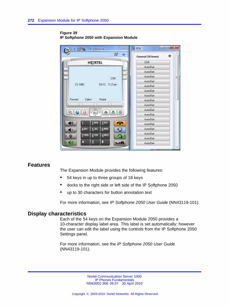
272 Expansion Module for IP Softphone 2050
Figure 39IP Softphone 2050 with Expansion Module
FeaturesThe Expansion Module provides the following features:
• 54 keys in up to three groups of 18 keys
• docks to the right side or left side of the IP Softphone 2050
• up to 30 characters for button annotation text
For more information, see IP Softphone 2050 User Guide (NN43119-101).
Display characteristicsEach of the 54 keys on the Expansion Module 2050 provides a10-character display label area. This label is set automatically; howeverthe user can edit the label using the controls from the IP Softphone 2050Settings panel.
For more information, see the IP Softphone 2050 User Guide(NN43119-101).
Nortel Communication Server 1000IP Phones Fundamentals
NN43001-368 06.07 30 April 2010
Copyright © 2003-2010 Nortel Networks. All Rights Reserved.
.
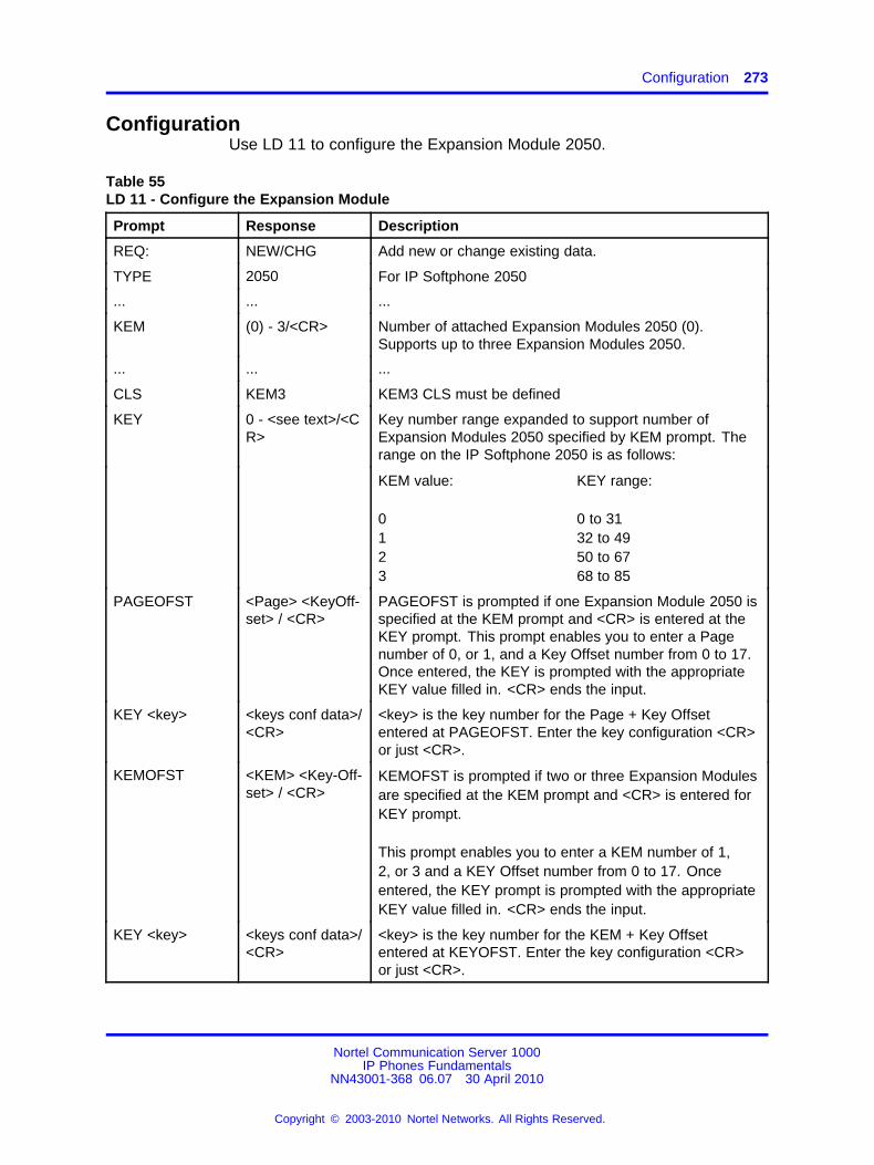
Configuration 273
ConfigurationUse LD 11 to configure the Expansion Module 2050.
Table 55LD 11 - Configure the Expansion Module
Prompt Response Description
REQ: NEW/CHG Add new or change existing data.
TYPE 2050 For IP Softphone 2050
... ... ...
KEM (0) - 3/<CR> Number of attached Expansion Modules 2050 (0).Supports up to three Expansion Modules 2050.
... ... ...
CLS KEM3 KEM3 CLS must be defined
KEY 0 - <see text>/<CR>
Key number range expanded to support number ofExpansion Modules 2050 specified by KEM prompt. Therange on the IP Softphone 2050 is as follows:
KEM value:
0123
KEY range:
0 to 3132 to 4950 to 6768 to 85
PAGEOFST <Page> <KeyOff-set> / <CR>
PAGEOFST is prompted if one Expansion Module 2050 isspecified at the KEM prompt and <CR> is entered at theKEY prompt. This prompt enables you to enter a Pagenumber of 0, or 1, and a Key Offset number from 0 to 17.Once entered, the KEY is prompted with the appropriateKEY value filled in. <CR> ends the input.
KEY <key> <keys conf data>/<CR>
<key> is the key number for the Page + Key Offsetentered at PAGEOFST. Enter the key configuration <CR>or just <CR>.
KEMOFST <KEM> <Key-Off-set> / <CR>
KEMOFST is prompted if two or three Expansion Modulesare specified at the KEM prompt and <CR> is entered forKEY prompt.
This prompt enables you to enter a KEM number of 1,2, or 3 and a KEY Offset number from 0 to 17. Onceentered, the KEY prompt is prompted with the appropriateKEY value filled in. <CR> ends the input.
KEY <key> <keys conf data>/<CR>
<key> is the key number for the KEM + Key Offsetentered at KEYOFST. Enter the key configuration <CR>or just <CR>.
Nortel Communication Server 1000IP Phones Fundamentals
NN43001-368 06.07 30 April 2010
Copyright © 2003-2010 Nortel Networks. All Rights Reserved.
.
274 Expansion Module for IP Softphone 2050
InstallationThe Expansion Module 2050 can dock to the right side or the left sideof the IP Softphone 2050 main window. You can move the ExpansionModule 2050 close the IP Softphone 2050 and it snaps into place.
OperationBefore you can operate the Expansion Module 2050, you must configuresettings in IP Softphone 2050 Settings. You can set the default valueeither to Spatial or Group, set the Expansion Module 2050 back to thedefault state, and configure annotated labels.
For further information about IP Softphone 2050 Settings, see IPSoftphone 2050 User Guide (NN43119-101).
Nortel Communication Server 1000IP Phones Fundamentals
NN43001-368 06.07 30 April 2010
Copyright © 2003-2010 Nortel Networks. All Rights Reserved.
.
275.
Nortel IP Phone 1110
ContentsThis section contains the following topics:
• “Introduction” (page 275)
• “Description” (page 276)
• “Components and functions” (page 277)
• “Features” (page 279)
• “Display characteristics” (page 280)
• “Cleaning the IP Phone display screen” (page 281)
• “Package components” (page 281)
• “Installation and configuration” (page 283)
• “TFTP firmware upgrade ” (page 289)
• “Redeploying an IP Phone 1110” (page 289)
• “Replacing an IP Phone 1110” (page 290)
• “Removing an IP Phone 1110 from service” (page 291)
IntroductionThis section explains how to install and maintain the IP Phone 1110.For information about using the IP Phone 1110, see the IP Phone 1110User Guide (NN43110-101) or the IP Phone 1110 Getting Started Card(NN43100-300).
This section contains the following procedures
• Procedure 76 “Configuring the IP Phone 1110” (page 284)
• Procedure 77 “Connecting the components” (page 284)
• Procedure 78 “Changing the TN of an existing IP Phone 1110” (page289)
Nortel Communication Server 1000IP Phones Fundamentals
NN43001-368 06.07 30 April 2010
Copyright © 2003-2010 Nortel Networks. All Rights Reserved.
.
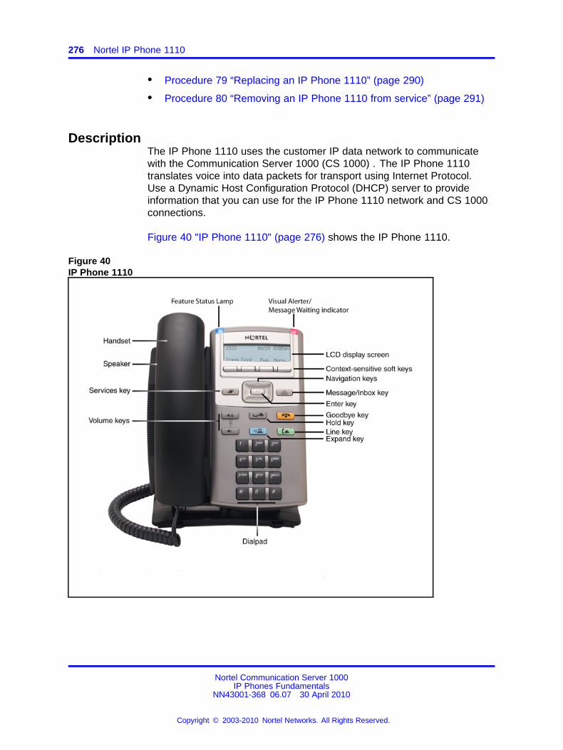
276 Nortel IP Phone 1110
• Procedure 79 “Replacing an IP Phone 1110” (page 290)
• Procedure 80 “Removing an IP Phone 1110 from service” (page 291)
DescriptionThe IP Phone 1110 uses the customer IP data network to communicatewith the Communication Server 1000 (CS 1000) . The IP Phone 1110translates voice into data packets for transport using Internet Protocol.Use a Dynamic Host Configuration Protocol (DHCP) server to provideinformation that you can use for the IP Phone 1110 network and CS 1000connections.
Figure 40 "IP Phone 1110" (page 276) shows the IP Phone 1110.
Figure 40IP Phone 1110
Nortel Communication Server 1000IP Phones Fundamentals
NN43001-368 06.07 30 April 2010
Copyright © 2003-2010 Nortel Networks. All Rights Reserved.
.
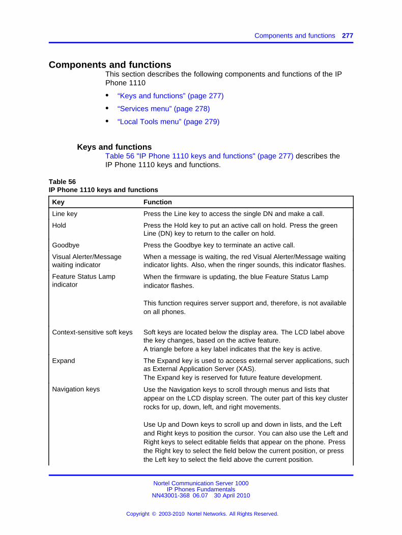
Components and functions 277
Components and functionsThis section describes the following components and functions of the IPPhone 1110
• “Keys and functions” (page 277)
• “Services menu” (page 278)
• “Local Tools menu” (page 279)
Keys and functionsTable 56 "IP Phone 1110 keys and functions" (page 277) describes theIP Phone 1110 keys and functions.
Table 56IP Phone 1110 keys and functions
Key Function
Line key Press the Line key to access the single DN and make a call.
Hold Press the Hold key to put an active call on hold. Press the greenLine (DN) key to return to the caller on hold.
Goodbye Press the Goodbye key to terminate an active call.
Visual Alerter/Messagewaiting indicator
When a message is waiting, the red Visual Alerter/Message waitingindicator lights. Also, when the ringer sounds, this indicator flashes.
Feature Status Lampindicator
When the firmware is updating, the blue Feature Status Lampindicator flashes.
This function requires server support and, therefore, is not availableon all phones.
Context-sensitive soft keys Soft keys are located below the display area. The LCD label abovethe key changes, based on the active feature.A triangle before a key label indicates that the key is active.
Expand The Expand key is used to access external server applications, suchas External Application Server (XAS).The Expand key is reserved for future feature development.
Navigation keys Use the Navigation keys to scroll through menus and lists thatappear on the LCD display screen. The outer part of this key clusterrocks for up, down, left, and right movements.
Use Up and Down keys to scroll up and down in lists, and the Leftand Right keys to position the cursor. You can also use the Left andRight keys to select editable fields that appear on the phone. Pressthe Right key to select the field below the current position, or pressthe Left key to select the field above the current position.
Nortel Communication Server 1000IP Phones Fundamentals
NN43001-368 06.07 30 April 2010
Copyright © 2003-2010 Nortel Networks. All Rights Reserved.
.
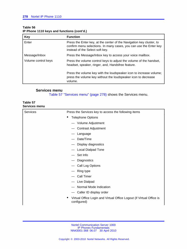
278 Nortel IP Phone 1110
Table 56IP Phone 1110 keys and functions (cont’d.)
Key Function
Enter Press the Enter key, at the center of the Navigation key cluster, toconfirm menu selections. In many cases, you can use the Enter keyinstead of the Select soft key.
Message/Inbox Press the Message/Inbox key to access your voice mailbox.
Volume control keys Press the volume control keys to adjust the volume of the handset,headset, speaker, ringer, and, Handsfree feature.
Press the volume key with the loudspeaker icon to increase volume;press the volume key without the loudspeaker icon to decreasevolume.
Services menuTable 57 "Services menu" (page 278) shows the Services menu.
Table 57Services menu
Services Press the Services key to access the following items
• Telephone Options
— Volume Adjustment
— Contrast Adjustment
— Language
— Date/Time
— Display diagnostics
— Local Dialpad Tone
— Set Info
— Diagnostics
— Call Log Options
— Ring type
— Call Timer
— Live Dialpad
— Normal Mode Indication
— Caller ID display order
• Virtual Office Login and Virtual Office Logout (if Virtual Office isconfigured)
Nortel Communication Server 1000IP Phones Fundamentals
NN43001-368 06.07 30 April 2010
Copyright © 2003-2010 Nortel Networks. All Rights Reserved.
.
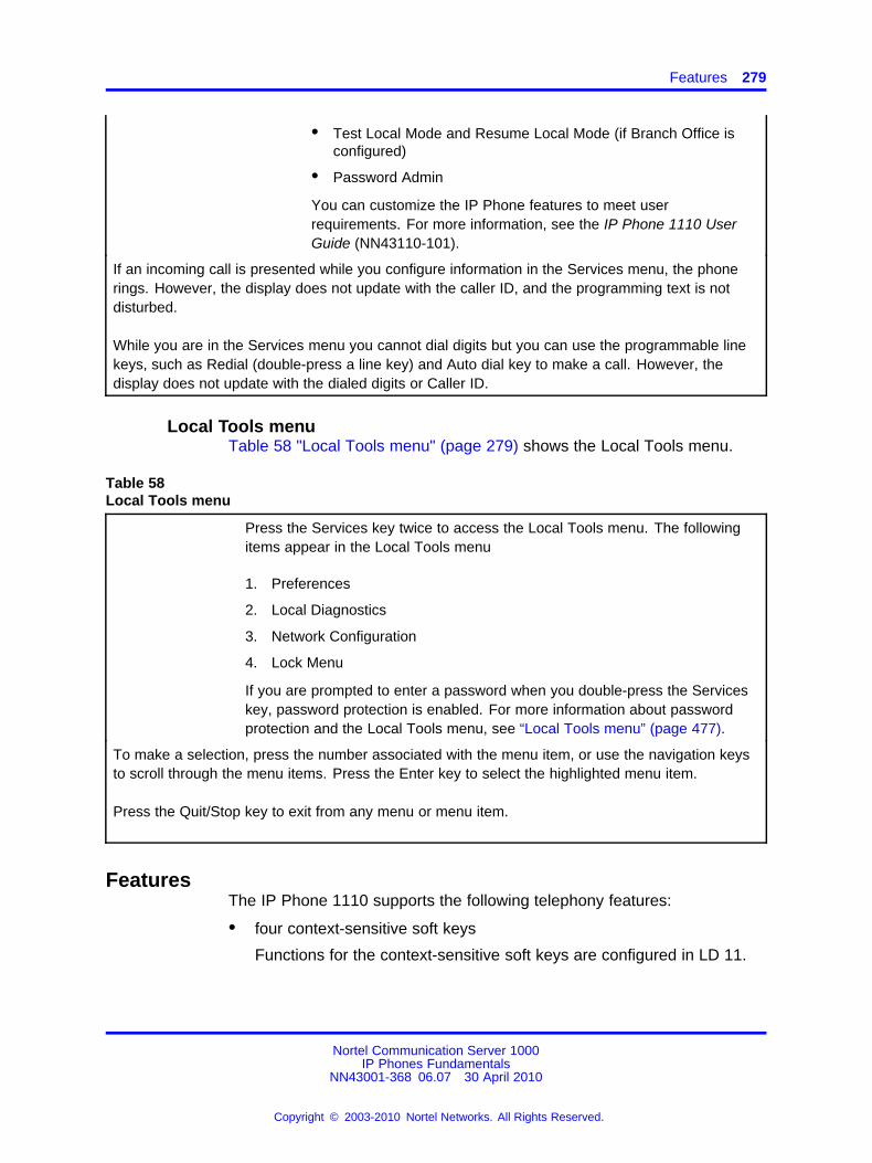
Features 279
• Test Local Mode and Resume Local Mode (if Branch Office isconfigured)
• Password Admin
You can customize the IP Phone features to meet userrequirements. For more information, see the IP Phone 1110 UserGuide (NN43110-101).
If an incoming call is presented while you configure information in the Services menu, the phonerings. However, the display does not update with the caller ID, and the programming text is notdisturbed.
While you are in the Services menu you cannot dial digits but you can use the programmable linekeys, such as Redial (double-press a line key) and Auto dial key to make a call. However, thedisplay does not update with the dialed digits or Caller ID.
Local Tools menuTable 58 "Local Tools menu" (page 279) shows the Local Tools menu.
Table 58Local Tools menu
Press the Services key twice to access the Local Tools menu. The followingitems appear in the Local Tools menu
1. Preferences
2. Local Diagnostics
3. Network Configuration
4. Lock Menu
If you are prompted to enter a password when you double-press the Serviceskey, password protection is enabled. For more information about passwordprotection and the Local Tools menu, see “Local Tools menu” (page 477).
To make a selection, press the number associated with the menu item, or use the navigation keysto scroll through the menu items. Press the Enter key to select the highlighted menu item.
Press the Quit/Stop key to exit from any menu or menu item.
FeaturesThe IP Phone 1110 supports the following telephony features:
• four context-sensitive soft keys
Functions for the context-sensitive soft keys are configured in LD 11.
Nortel Communication Server 1000IP Phones Fundamentals
NN43001-368 06.07 30 April 2010
Copyright © 2003-2010 Nortel Networks. All Rights Reserved.
.
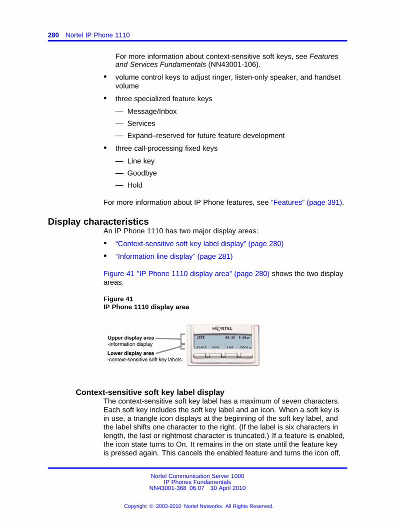
280 Nortel IP Phone 1110
For more information about context-sensitive soft keys, see Featuresand Services Fundamentals (NN43001-106).
• volume control keys to adjust ringer, listen-only speaker, and handsetvolume
• three specialized feature keys
— Message/Inbox
— Services
— Expand–reserved for future feature development
• three call-processing fixed keys
— Line key
— Goodbye
— Hold
For more information about IP Phone features, see “Features” (page 391).
Display characteristicsAn IP Phone 1110 has two major display areas:
• “Context-sensitive soft key label display” (page 280)
• “Information line display” (page 281)
Figure 41 "IP Phone 1110 display area" (page 280) shows the two displayareas.
Figure 41IP Phone 1110 display area
Context-sensitive soft key label displayThe context-sensitive soft key label has a maximum of seven characters.Each soft key includes the soft key label and an icon. When a soft key isin use, a triangle icon displays at the beginning of the soft key label, andthe label shifts one character to the right. (If the label is six characters inlength, the last or rightmost character is truncated.) If a feature is enabled,the icon state turns to On. It remains in the on state until the feature keyis pressed again. This cancels the enabled feature and turns the icon off,
Nortel Communication Server 1000IP Phones Fundamentals
NN43001-368 06.07 30 April 2010
Copyright © 2003-2010 Nortel Networks. All Rights Reserved.
.
Package components 281
returning the soft key label to its original state. Use the More soft key tonavigate through the layers of functions. If only four functions are assignedto the soft keys, the More key does not appear and all four functions aredisplayed.
Information line displayAn IP Phone 1110 has a one-line information display area with thefollowing information:
• caller number
• caller name
• feature prompt strings
• user-entered digits
• date and time information (if the IP Phone is in an idle state), or CallTimer (if provisioned in the Telephone options menu)
The information in the display area changes, according to thecall-processing state and active features.
Cleaning the IP Phone display screenGently wipe the IP Phone display with a soft, dry cloth.
ATTENTIONDo not use any liquids or powders on the IP Phone. Using anything other thana soft, dry cloth can contaminate IP Phone components and cause prematurefailure.
Package componentsThe IP Phone 1110 includes integrated support for a number of Powerover Ethernet options, including support for IEEE 802.3af PowerClassification 2.
Table 59 "Package components" (page 281) lists the IP Phone 1110package components.
Table 59Package components
• IP Phone 1110
• handset
• handset cord
• 2.1 m (7-ft) CAT5-e Ethernet cable
Nortel Communication Server 1000IP Phones Fundamentals
NN43001-368 06.07 30 April 2010
Copyright © 2003-2010 Nortel Networks. All Rights Reserved.
.
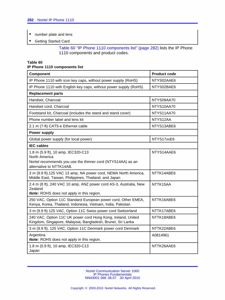
282 Nortel IP Phone 1110
• number plate and lens
• Getting Started Card
Table 60 "IP Phone 1110 components list" (page 282) lists the IP Phone1110 components and product codes.
Table 60IP Phone 1110 components list
Component Product code
IP Phone 1110 with icon key caps, without power supply (RoHS) NTYS02AAE6
IP Phone 1110 with English key caps, without power supply (RoHS) NTYS02BAE6
Replacement parts
Handset, Charcoal NTYS09AA70
Handset cord, Charcoal NTYS10AA70
Footstand kit, Charcoal (includes the stand and stand cover) NTYS11AA70
Phone number label and lens kit NTYS12AA
2.1 m (7-ft) CAT5-e Ethernet cable NTYS13ABE6
Power supply
Global power supply (for local power) NTYS17xxE6
IEC cables
1.8 m (5.9 ft), 10 amp, IEC320-C13North AmericaNortel recommends you use the thinner cord (NTYS14AA) as analternative to NTTK14AB.
NTYS14AAE6
3 m (9.9 ft),125 VAC 13 amp, NA power cord, NEMA North America,Middle East, Taiwan, Philippines, Thailand, and Japan
NTTK14ABE6
2.4 m (8 ft), 240 VAC 10 amp, ANZ power cord AS-3, Australia, NewZealandNote: ROHS does not apply in this region.
NTTK15AA
250 VAC, Option 11C Standard European power cord, Other EMEA,Kenya, Korea, Thailand, Indonesia, Vietnam, India, Pakistan
NTTK16ABE6
3 m (9.9 ft) 125 VAC, Option 11C Swiss power cord Switzerland NTTK17ABE6
240 VAC, Option 11C UK power cord Hong Kong, Ireland, UnitedKingdom, Singapore, Malaysia, Bangladesh, Brunei, Sri Lanka
NTTK18ABE6
3 m (9.9 ft), 125 VAC, Option 11C Denmark power cord Denmark NTTK22ABE6
ArgentinaNote: ROHS does not apply in this region.
A0814961
1.8 m (5.9 ft), 10 amp, IEC320-C13Japan
NTTK26AAE6
Nortel Communication Server 1000IP Phones Fundamentals
NN43001-368 06.07 30 April 2010
Copyright © 2003-2010 Nortel Networks. All Rights Reserved.
.
Installation and configuration 283
Installation and configurationThe following sections provide a step-by-step guide to install and configurethe IP Phone 1110
• “Before you begin” (page 283)
• “First-time installation” (page 283)
• “Configuring the IP Phone 1110” (page 283)
• “Connecting the components” (page 284)
• “Startup sequence” (page 289)
Before you beginBefore installing the IP Phone 1110, complete the following pre-installationchecklist
• Ensure one IP Phone 1110 boxed package exists for each IP Phone1110 you install. For a list of IP Phone 1110 package components, seeTable 59 "Package components" (page 281).
• Ensure one Software License exists for each IP Phone 1110 youinstall.
• Ensure the host Call Server is equipped with a Signaling Server thatruns the Line TPS application.
• If a global power supply is required, ensure the approved Nortel globalpower supply (model number NTYS17xxE6) is used. See Table 60 "IPPhone 1110 components list" (page 282).
• Ensure the latest IP Phone firmware is deployed to the IP telephonynode. For more information, see Signaling Server IP Line ApplicationsFundamentals (NN43001-125).
First-time installationYou must first install an IP telephony node with the Communication Server.For information about installing an IP telephony node, see Signaling ServerIP Line Applications Fundamentals (NN43001-125).
CAUTIONDo not plug your IP Phone 1110 into an ISDN connection.Severe damage can result.
Configuring the IP Phone 1110Use Procedure 76 “Configuring the IP Phone 1110” (page 284) toconfigure the IP Phone 1110 for the first time.
Nortel Communication Server 1000IP Phones Fundamentals
NN43001-368 06.07 30 April 2010
Copyright © 2003-2010 Nortel Networks. All Rights Reserved.
.
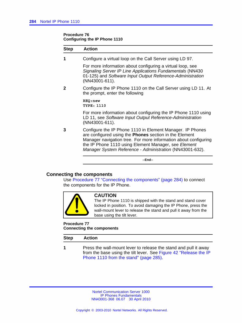
284 Nortel IP Phone 1110
Procedure 76Configuring the IP Phone 1110
Step Action
1 Configure a virtual loop on the Call Server using LD 97.
For more information about configuring a virtual loop, seeSignaling Server IP Line Applications Fundamentals (NN43001-125) and Software Input Output Reference-Administration(NN43001-611).
2 Configure the IP Phone 1110 on the Call Server using LD 11. Atthe prompt, enter the following
REQ:newTYPE: 1110
For more information about configuring the IP Phone 1110 usingLD 11, see Software Input Output Reference-Administration(NN43001-611).
3 Configure the IP Phone 1110 in Element Manager. IP Phonesare configured using the Phones section in the ElementManager navigation tree. For more information about configuringthe IP Phone 1110 using Element Manager, see ElementManager System Reference - Administration (NN43001-632).
--End--
Connecting the componentsUse Procedure 77 “Connecting the components” (page 284) to connectthe components for the IP Phone.
CAUTIONThe IP Phone 1110 is shipped with the stand and stand coverlocked in position. To avoid damaging the IP Phone, press thewall-mount lever to release the stand and pull it away from thebase using the tilt lever.
Procedure 77Connecting the components
Step Action
1 Press the wall-mount lever to release the stand and pull it awayfrom the base using the tilt lever. See Figure 42 "Release the IPPhone 1110 from the stand" (page 285).
Nortel Communication Server 1000IP Phones Fundamentals
NN43001-368 06.07 30 April 2010
Copyright © 2003-2010 Nortel Networks. All Rights Reserved.
.
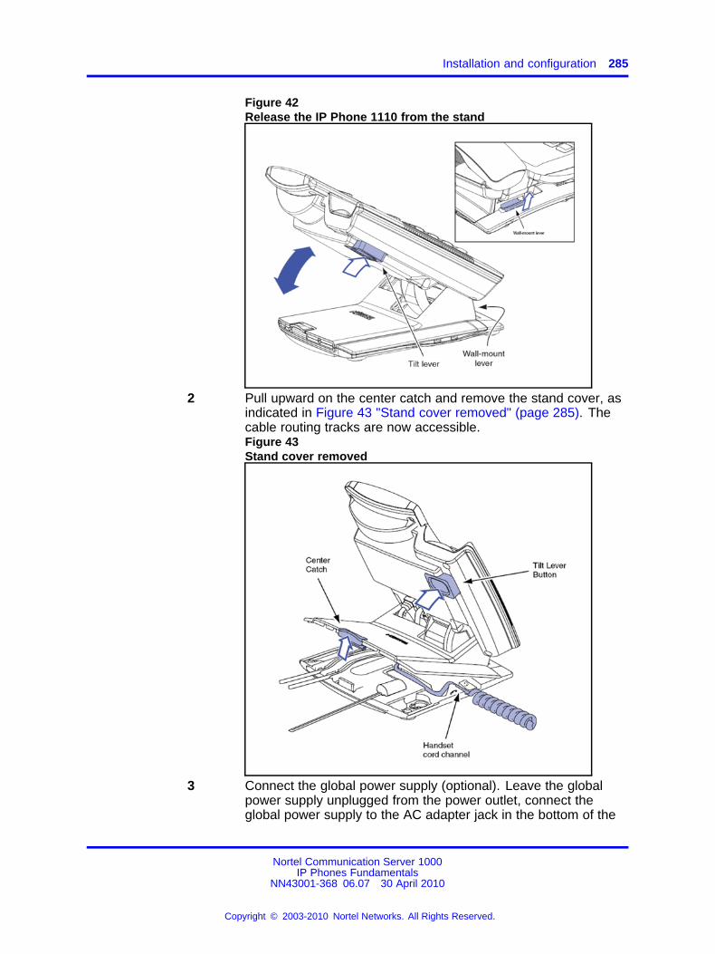
Installation and configuration 285
Figure 42Release the IP Phone 1110 from the stand
2 Pull upward on the center catch and remove the stand cover, asindicated in Figure 43 "Stand cover removed" (page 285). Thecable routing tracks are now accessible.Figure 43Stand cover removed
3 Connect the global power supply (optional). Leave the globalpower supply unplugged from the power outlet, connect theglobal power supply to the AC adapter jack in the bottom of the
Nortel Communication Server 1000IP Phones Fundamentals
NN43001-368 06.07 30 April 2010
Copyright © 2003-2010 Nortel Networks. All Rights Reserved.
.
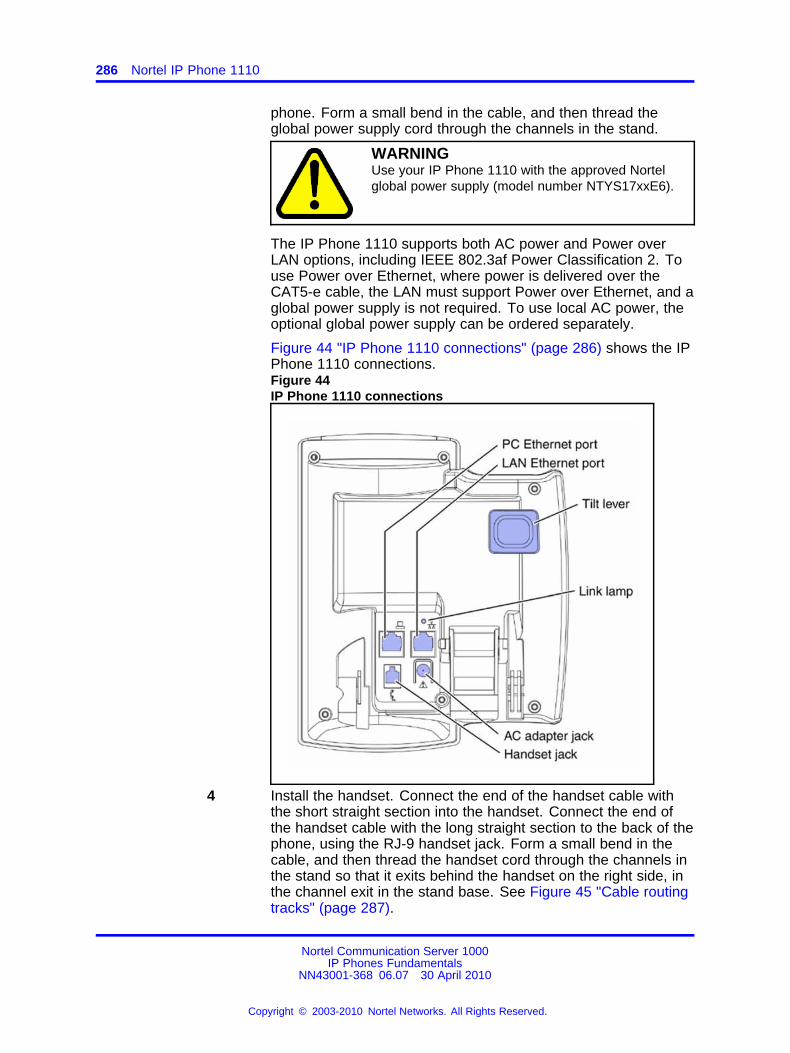
286 Nortel IP Phone 1110
phone. Form a small bend in the cable, and then thread theglobal power supply cord through the channels in the stand.
WARNINGUse your IP Phone 1110 with the approved Nortelglobal power supply (model number NTYS17xxE6).
The IP Phone 1110 supports both AC power and Power overLAN options, including IEEE 802.3af Power Classification 2. Touse Power over Ethernet, where power is delivered over theCAT5-e cable, the LAN must support Power over Ethernet, and aglobal power supply is not required. To use local AC power, theoptional global power supply can be ordered separately.
Figure 44 "IP Phone 1110 connections" (page 286) shows the IPPhone 1110 connections.Figure 44IP Phone 1110 connections
4 Install the handset. Connect the end of the handset cable withthe short straight section into the handset. Connect the end ofthe handset cable with the long straight section to the back of thephone, using the RJ-9 handset jack. Form a small bend in thecable, and then thread the handset cord through the channels inthe stand so that it exits behind the handset on the right side, inthe channel exit in the stand base. See Figure 45 "Cable routingtracks" (page 287).
Nortel Communication Server 1000IP Phones Fundamentals
NN43001-368 06.07 30 April 2010
Copyright © 2003-2010 Nortel Networks. All Rights Reserved.
.
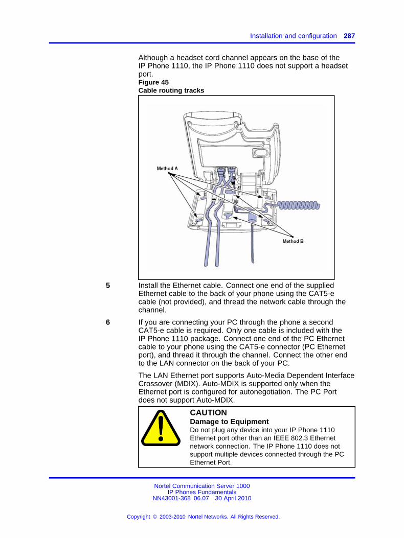
Installation and configuration 287
Although a headset cord channel appears on the base of theIP Phone 1110, the IP Phone 1110 does not support a headsetport.Figure 45Cable routing tracks
5 Install the Ethernet cable. Connect one end of the suppliedEthernet cable to the back of your phone using the CAT5-ecable (not provided), and thread the network cable through thechannel.
6 If you are connecting your PC through the phone a secondCAT5-e cable is required. Only one cable is included with theIP Phone 1110 package. Connect one end of the PC Ethernetcable to your phone using the CAT5-e connector (PC Ethernetport), and thread it through the channel. Connect the other endto the LAN connector on the back of your PC.
The LAN Ethernet port supports Auto-Media Dependent InterfaceCrossover (MDIX). Auto-MDIX is supported only when theEthernet port is configured for autonegotiation. The PC Portdoes not support Auto-MDIX.
CAUTIONDamage to EquipmentDo not plug any device into your IP Phone 1110Ethernet port other than an IEEE 802.3 Ethernetnetwork connection. The IP Phone 1110 does notsupport multiple devices connected through the PCEthernet Port.
Nortel Communication Server 1000IP Phones Fundamentals
NN43001-368 06.07 30 April 2010
Copyright © 2003-2010 Nortel Networks. All Rights Reserved.
.
288 Nortel IP Phone 1110
Complete steps 1 to 6, as needed, before wall-mounting the IPPhone.
7 Wall-mount your phone (optional). Use Method A or Method B towall-mount the IP Phone. See Method A—using the mountingholes on the bottom of the phone stand, or Method B—using thetraditional-style wall-mount box with a CAT5-e connector anda 15 cm (6 inch) CAT5-e cord (not provided). See Figure 45"Cable routing tracks" (page 287).
• Method A: Press the wall-mount lever, and pull away fromthe stand. Using the stand cover (see step 2), mark thewall-mount holes by pressing the bottom of the stand coverfirmly against the wall in the location where you wish to installthe phone. Four small pins on the bottom of the stand covermake the marks on the wall. Use the marks as a guideline toinstall the wall-mount screws (not provided).Install the screws so that they protrude 3 mm (1/8 inch) fromthe wall, and then install the phone stand mounting holesover the screw heads. You may need to remove the phonefrom the wall to adjust the lower screws. When the lowerscrews are snug, install the phone on the mounting screws,and then tighten the top screws.
• Method B: Attach the 15 cm (6 inch) CAT5-e cable (notprovided), position the stand over the mounting rivets, andslide the phone down the wall so that the rivets fit into theslots on the stand.
8 Replace the stand cover. Ensure that all cables are neatly routedand press the stand cover into place until you hear a click.
9 If you wall-mount the phone, put it in the wall-mount position byholding the tilt lever and press the phone towards the base untilthe phone is parallel with the base. Release the tilt lever andcontinue to push the phone towards the base until you hear anaudible click. Ensure the phone is securely locked in to position.
10 Connect additional cables. Connect the Ethernet cable to theLAN Ethernet connection. If you are using a global power supply,plug the global power supply into an AC outlet.
--End--
When you complete the IP Phone connection, you must connect the phoneto the network. See “Dynamic Host Configuration Protocol” (page 429).
Nortel Communication Server 1000IP Phones Fundamentals
NN43001-368 06.07 30 April 2010
Copyright © 2003-2010 Nortel Networks. All Rights Reserved.
.
Redeploying an IP Phone 1110 289
Startup sequenceWhen an IP Phone 1110 connects to the network, it must perform a startupsequence. The elements of the startup sequence include
• obtaining network access (if supported by the network infrastructure)
• obtaining VLAN ID (if supported by the network infrastructure)
• obtaining the IP parameters
• obtaining the provisioning parameters
• connecting to the Call Server
The IP Phone is configured for automatic provisioning by default. Formore information about provisioning the IP Phone automatically, see“Provisioning the IP Phones” (page 497).
You can manually configure all or some parameters. For informationabout manually provisioning the IP Phone, see “Manual provisioning of IPPhones 1110 and 1200 Series” (page 543).
TFTP firmware upgradeWhen you enter Cfg TFTP = 1 (for yes), and enter an IP address, the IPPhone searches for an upgrade file on the TFTP Server.
Users of CS 1000 Release 4.5 or later do not need to enter a TFTP IPaddress.
For further information about TFTP firmware upgrade, see “TFTP Server”(page 683).
Redeploying an IP Phone 1110You can redeploy an existing previously configured IP Phone 1110 on thesame Call Server. For example, the IP Phone 1110 can be assigned toa new user (new TN) or to an existing user who moved to a new subnetby changing the TN of the IP Phone 1110. For further information, seeConverging the Data Network with VoIP Fundamentals (NN43001-260).
Procedure 78Changing the TN of an existing IP Phone 1110
Step Action
1 Repower the IP Phone 1110.
During the reboot sequence of a previously configured IPPhone, the IP Phone 1110 displays the existing node numberfor approximately 5 seconds.
Nortel Communication Server 1000IP Phones Fundamentals
NN43001-368 06.07 30 April 2010
Copyright © 2003-2010 Nortel Networks. All Rights Reserved.
.
290 Nortel IP Phone 1110
2 If the node password is enabled and NULL, choose one of thefollowing
a Disable the password.
b Set the password as non-NULL.
3 Press OK when the node number displays.
If Then
the node password is enabledand is not NULL
a password screen displays. Goto Step 4.
the node password is disabled a TN screen displays. Go to Step5.
4 Enter the password at the password screen and press OK.
A TN screen displays.
To obtain the password, enter the nodePwdShow command inElement Manager. For further information, see Element ManagerSystem Reference - Administration (NN43001-632).
5 Select the Clear soft key to clear the existing TN.
6 Enter the new TN.
--End--
Replacing an IP Phone 1110ATTENTIONTwo IP Phones cannot share the same TN. You must remove the IP Phone1110 that currently uses the TN.
Procedure 79Replacing an IP Phone 1110
Step Action
1 Obtain the node and TN information of the phone you want toreplace.
2 Disconnect the IP Phone 1110 that you want to replace.
3 Follow “Configuring the IP Phone 1110” (page 283) to installthe IP Phone 1110. To configure the IP Phone, see “Manualprovisioning of IP Phones 1110 and 1200 Series” (page 543).
4 Enter the same TN and Node Number as the IP Phone 1110 youreplaced. The Call Server associates the new IP Phone 1110with the existing TN.
--End--
Nortel Communication Server 1000IP Phones Fundamentals
NN43001-368 06.07 30 April 2010
Copyright © 2003-2010 Nortel Networks. All Rights Reserved.
.
Removing an IP Phone 1110 from service 291
Removing an IP Phone 1110 from serviceProcedure 80Removing an IP Phone 1110 from service
Step Action
1 Disconnect the IP Phone 1110 from the network or turn off thepower.
The service to the PC is disconnected as well if the PC connectsto the IP Phone 1110.
If the IP Phone 1110 was automatically configured, the DHCPlease expires and the IP address returns to the available pool.
2 In LD 11, enter the following:REQ: OUTTYPE: 1110TN: LLL S CC UU
--End--
Nortel Communication Server 1000IP Phones Fundamentals
NN43001-368 06.07 30 April 2010
Copyright © 2003-2010 Nortel Networks. All Rights Reserved.
.

292 Nortel IP Phone 1110
Nortel Communication Server 1000IP Phones Fundamentals
NN43001-368 06.07 30 April 2010
Copyright © 2003-2010 Nortel Networks. All Rights Reserved.
.
293.
Nortel IP Phone 1120E
ContentsThis section contains the following topics:
• “Introduction” (page 293)
• “Description” (page 294)
• “Components and functions” (page 294)
• “Features” (page 298)
• “Dialpad entry” (page 299)
• “Display characteristics” (page 300)
• “Package components” (page 302)
• “Installation and configuration” (page 303)
• “Redeploying an IP Phone 1120E” (page 310)
• “Replacing an IP Phone 1120E” (page 311)
• “Removing an IP Phone 1120E from service” (page 311)
IntroductionThis section explains how to install and maintain the IP Phone 1120E. Forinformation about using the IP Phone 1120E, see the IP Phone 1120EUser Guide (NN43112-103) or the IP Phone 1120E Getting Started Card(NN43112-100).
This section contains the following procedures
• Procedure 81 “Configuring the IP Phone 1120E” (page 304)
• Procedure 82 “Connecting the components” (page 305)
• Procedure 83 “Changing the TN of an existing IP Phone 1120E” (page310).
• Procedure 84 “Replacing an IP Phone 1120E” (page 311).
• Procedure 85 “Removing an IP Phone 1120E from service” (page 311).
Nortel Communication Server 1000IP Phones Fundamentals
NN43001-368 06.07 30 April 2010
Copyright © 2003-2010 Nortel Networks. All Rights Reserved.
.
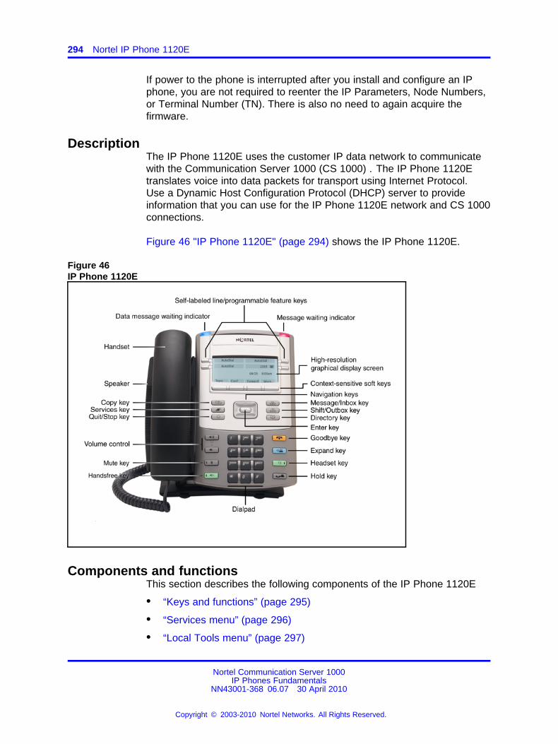
294 Nortel IP Phone 1120E
If power to the phone is interrupted after you install and configure an IPphone, you are not required to reenter the IP Parameters, Node Numbers,or Terminal Number (TN). There is also no need to again acquire thefirmware.
DescriptionThe IP Phone 1120E uses the customer IP data network to communicatewith the Communication Server 1000 (CS 1000) . The IP Phone 1120Etranslates voice into data packets for transport using Internet Protocol.Use a Dynamic Host Configuration Protocol (DHCP) server to provideinformation that you can use for the IP Phone 1120E network and CS 1000connections.
Figure 46 "IP Phone 1120E" (page 294) shows the IP Phone 1120E.
Figure 46IP Phone 1120E
Components and functionsThis section describes the following components of the IP Phone 1120E
• “Keys and functions” (page 295)
• “Services menu” (page 296)
• “Local Tools menu” (page 297)
Nortel Communication Server 1000IP Phones Fundamentals
NN43001-368 06.07 30 April 2010
Copyright © 2003-2010 Nortel Networks. All Rights Reserved.
.
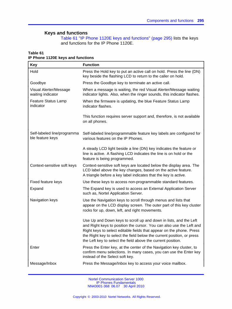
Components and functions 295
Keys and functionsTable 61 "IP Phone 1120E keys and functions" (page 295) lists the keysand functions for the IP Phone 1120E.
Table 61IP Phone 1120E keys and functions
Key Function
Hold Press the Hold key to put an active call on hold. Press the line (DN)key beside the flashing LCD to return to the caller on hold.
Goodbye Press the Goodbye key to terminate an active call.
Visual Alerter/Messagewaiting indicator
When a message is waiting, the red Visual Alerter/Message waitingindicator lights. Also, when the ringer sounds, this indicator flashes.
Feature Status Lampindicator
When the firmware is updating, the blue Feature Status Lampindicator flashes.
This function requires server support and, therefore, is not availableon all phones.
Self-labeled line/programmable feature keys
Self-labeled line/programmable feature key labels are configured forvarious features on the IP Phones.
A steady LCD light beside a line (DN) key indicates the feature orline is active. A flashing LCD indicates the line is on hold or thefeature is being programmed.
Context-sensitive soft keys Context-sensitive soft keys are located below the display area. TheLCD label above the key changes, based on the active feature.A triangle before a key label indicates that the key is active.
Fixed feature keys Use these keys to access non-programmable standard features.
Expand The Expand key is used to access an External Application Serversuch as, Nortel Application Server.
Navigation keys Use the Navigation keys to scroll through menus and lists thatappear on the LCD display screen. The outer part of this key clusterrocks for up, down, left, and right movements.
Use Up and Down keys to scroll up and down in lists, and the Leftand Right keys to position the cursor. You can also use the Left andRight keys to select editable fields that appear on the phone. Pressthe Right key to select the field below the current position, or pressthe Left key to select the field above the current position.
Enter Press the Enter key, at the center of the Navigation key cluster, toconfirm menu selections. In many cases, you can use the Enter keyinstead of the Select soft key.
Message/Inbox Press the Message/Inbox key to access your voice mailbox.
Nortel Communication Server 1000IP Phones Fundamentals
NN43001-368 06.07 30 April 2010
Copyright © 2003-2010 Nortel Networks. All Rights Reserved.
.
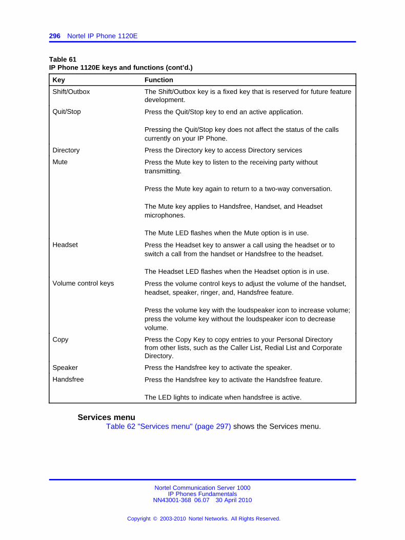
296 Nortel IP Phone 1120E
Table 61IP Phone 1120E keys and functions (cont’d.)
Key Function
Shift/Outbox The Shift/Outbox key is a fixed key that is reserved for future featuredevelopment.
Quit/Stop Press the Quit/Stop key to end an active application.
Pressing the Quit/Stop key does not affect the status of the callscurrently on your IP Phone.
Directory Press the Directory key to access Directory services
Mute Press the Mute key to listen to the receiving party withouttransmitting.
Press the Mute key again to return to a two-way conversation.
The Mute key applies to Handsfree, Handset, and Headsetmicrophones.
The Mute LED flashes when the Mute option is in use.
Headset Press the Headset key to answer a call using the headset or toswitch a call from the handset or Handsfree to the headset.
The Headset LED flashes when the Headset option is in use.
Volume control keys Press the volume control keys to adjust the volume of the handset,headset, speaker, ringer, and, Handsfree feature.
Press the volume key with the loudspeaker icon to increase volume;press the volume key without the loudspeaker icon to decreasevolume.
Copy Press the Copy Key to copy entries to your Personal Directoryfrom other lists, such as the Caller List, Redial List and CorporateDirectory.
Speaker Press the Handsfree key to activate the speaker.
Handsfree Press the Handsfree key to activate the Handsfree feature.
The LED lights to indicate when handsfree is active.
Services menuTable 62 "Services menu" (page 297) shows the Services menu.
Nortel Communication Server 1000IP Phones Fundamentals
NN43001-368 06.07 30 April 2010
Copyright © 2003-2010 Nortel Networks. All Rights Reserved.
.
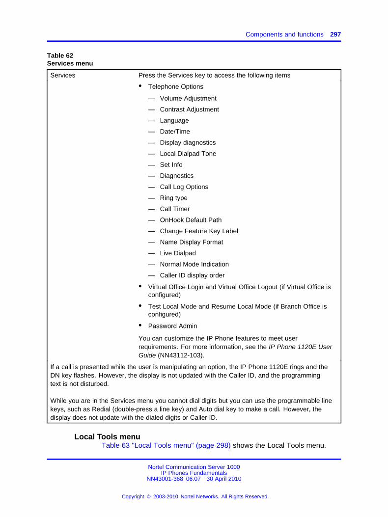
Components and functions 297
Table 62Services menu
Services Press the Services key to access the following items
• Telephone Options
— Volume Adjustment
— Contrast Adjustment
— Language
— Date/Time
— Display diagnostics
— Local Dialpad Tone
— Set Info
— Diagnostics
— Call Log Options
— Ring type
— Call Timer
— OnHook Default Path
— Change Feature Key Label
— Name Display Format
— Live Dialpad
— Normal Mode Indication
— Caller ID display order
• Virtual Office Login and Virtual Office Logout (if Virtual Office isconfigured)
• Test Local Mode and Resume Local Mode (if Branch Office isconfigured)
• Password Admin
You can customize the IP Phone features to meet userrequirements. For more information, see the IP Phone 1120E UserGuide (NN43112-103).
If a call is presented while the user is manipulating an option, the IP Phone 1120E rings and theDN key flashes. However, the display is not updated with the Caller ID, and the programmingtext is not disturbed.
While you are in the Services menu you cannot dial digits but you can use the programmable linekeys, such as Redial (double-press a line key) and Auto dial key to make a call. However, thedisplay does not update with the dialed digits or Caller ID.
Local Tools menuTable 63 "Local Tools menu" (page 298) shows the Local Tools menu.
Nortel Communication Server 1000IP Phones Fundamentals
NN43001-368 06.07 30 April 2010
Copyright © 2003-2010 Nortel Networks. All Rights Reserved.
.
298 Nortel IP Phone 1120E
Table 63Local Tools menu
Press the Services key twice to access the Local Tools menu. The followingitems appear in the Local Tools menu
1. Preferences
2. Local Diagnostics
3. Network Configuration
4. Lock Menu
To make a selection, press the number associated with the menu item, or use the navigation keysto scroll through the menu items. Press the Enter key to select the highlighted menu item.
If you are prompted to enter a password when you double-press the Services key, passwordprotection is enabled. For more information about password protection and the Local Tools menu,see “Local Tools menu” (page 477).
Press the Quit/Stop key to exit from any menu or menu item.
FeaturesThe IP Phone 1120E supports the following telephony features
• four self-labeled line/programmable feature keys with labels andindicators
• four context-sensitive soft keys
Functions for the context-sensitive soft keys are configured in LD 11.
For more information about context-sensitive soft keys, see Featuresand Services Fundamentals (NN43001-106).
• high quality speaker phone
• volume control keys to adjust ringer, speaker, handset, and headsetvolume
• ability to change the self-labeled line/programmable feature key labels
• seven specialized feature keys
— Quit
— Directory
— Message/Inbox
— Shift/Outbox
— Services
Nortel Communication Server 1000IP Phones Fundamentals
NN43001-368 06.07 30 April 2010
Copyright © 2003-2010 Nortel Networks. All Rights Reserved.
.
Dialpad entry 299
— Copy
— Expand
• five call-processing fixed keys
— Mute
— Handsfree
— Goodbye
— Headset
— Hold
For more information about the Expansion Module, see “ExpansionModule for IP Phones 1100 Series” (page 377).
For more information about IP Phone features, see “Features” (page 391).
Dialpad entryThe following rules apply when you enter text and special characters usingthe dialpad.
• Press a key from 0 to 9 once to enter the corresponding number.
• Press a key from 2 to 9 repeatedly to cycle through the lettersassigned to that key, first in lower case and then in upper case.
For example, if you press the 5 key repeatedly, the followingcharacters are displayed, one at a time:
j -> k -> l -> J -> K -> L -> 5 ->
See Table 70 "Character key mappings" (page 320) for character keymappings.
• The insertion point remains in its current position as long as youcontinue to press the same key.
• The entry is accepted if either a new key is pressed or if two secondspass with no entry. The insertion point moves 1 space to the right.
For example, to enter the word Nortel, press the following keysequence:
6 [2 second delay] 6 7 8 3 5
Although special characters are not required, key 1 generatescommonly used special characters, such as the period (.), at symbol(@), and underscore (_).
Nortel Communication Server 1000IP Phones Fundamentals
NN43001-368 06.07 30 April 2010
Copyright © 2003-2010 Nortel Networks. All Rights Reserved.
.
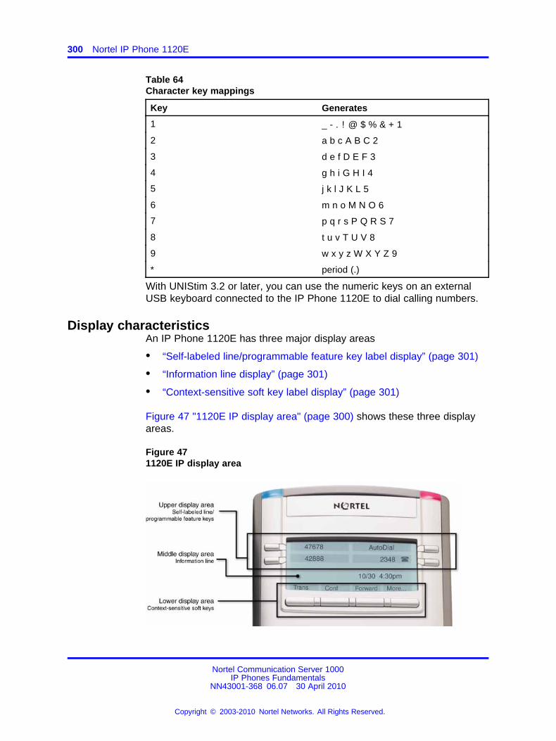
300 Nortel IP Phone 1120E
Table 64Character key mappings
Key Generates
1 _ - . ! @ $ % & + 1
2 a b c A B C 2
3 d e f D E F 3
4 g h i G H I 4
5 j k l J K L 5
6 m n o M N O 6
7 p q r s P Q R S 7
8 t u v T U V 8
9 w x y z W X Y Z 9
* period (.)
With UNIStim 3.2 or later, you can use the numeric keys on an externalUSB keyboard connected to the IP Phone 1120E to dial calling numbers.
Display characteristicsAn IP Phone 1120E has three major display areas
• “Self-labeled line/programmable feature key label display” (page 301)
• “Information line display” (page 301)
• “Context-sensitive soft key label display” (page 301)
Figure 47 "1120E IP display area" (page 300) shows these three displayareas.
Figure 471120E IP display area
Nortel Communication Server 1000IP Phones Fundamentals
NN43001-368 06.07 30 April 2010
Copyright © 2003-2010 Nortel Networks. All Rights Reserved.
.
Display characteristics 301
Self-labeled line/programmable feature key label displayThe feature key label area displays a 10-character string for each of thefour feature keys. Each feature key includes the key label and an icon.The icon state can be on, off, or flashing. A telephone icon displays thestatus of the configured DN. Key labels are left-aligned for keys on theleft side of the screen, and right-aligned for keys on the right side ofthe screen. To change the feature key label, press the Services key toaccess Telephone Options > Change Feature key label option. For moreinformation about changing the feature key label, see the IP Phone 1120EUser Guide (NN43112-103).
If a label is longer than 10 characters, the last 10 characters are displayedand the excess characters are deleted from the beginning of the string.
Information line displayAn IP Phone 1120E has a one-line information display area with thefollowing information
• caller number
• caller name
• feature prompt strings
• user-entered digits
• date and time information (if the IP Phone is in an idle state) or CallTimer (if provisioned in the Telephone options menu)
The information in the display area changes, according to thecall-processing state and active features.
Because the IP Phone 1120E only has a one-line information display area,you are prompted to scroll through any additional lines of information.
During an incoming call, only the Directory Number (DN) displays if thecaller name is greater than 10 characters. Press the flashing arrow todisplay the caller name.
Context-sensitive soft key label displayThe context-sensitive soft key label has a maximum of seven characters.Each soft key includes the soft key label and an icon. When a soft key isin use, a triangle icon displays at the beginning of the soft key label, andthe label shifts one character to the right. (If the label is six characters inlength, the last or rightmost character is truncated.) If a feature is enabled,the icon state turns to On. It remains in the on state until the feature keyis pressed again. This cancels the enabled feature and turns the icon off,returning the soft key label to its original state.
Nortel Communication Server 1000IP Phones Fundamentals
NN43001-368 06.07 30 April 2010
Copyright © 2003-2010 Nortel Networks. All Rights Reserved.
.
302 Nortel IP Phone 1120E
Use the More soft key to navigate through the layers of functions. If onlyfour functions are assigned to the soft keys, the More key does not appear,and all four functions are displayed.
Cleaning the IP Phone display screenGently wipe the IP Phone display screen with a soft, dry cloth.
CAUTIONDo not use any liquids or powders on the IP Phone. Usinganything other than a soft, dry cloth can contaminate IP Phonecomponents and cause premature failure.
Package componentsThe IP Phone 1120E includes integrated support for a number ofPower over Ethernet options, including support for IEEE 802.3af PowerClassification 3.
Table 65 "Package components" (page 302) lists the IP Phone 1120Epackage components.
Table 65Package components
• IP Phone 1120E
• handset
• handset cord
• 2.1 m (7-ft) CAT5-e Ethernet cable
• number plate and lens
• Getting Started Card
Table 66 "IP Phone 1120E components list" (page 302) lists the IP Phone1120E components and product codes.
Table 66IP Phone 1120E components list
Component Product code
IP Phone 1120E with icon key caps (Graphite) NTYS03AC
IP Phone 1120E with English key caps (Graphite) NTYS03BC
IP Phone 1120E with icon key caps (Graphite) RoHS NTYS03ACE6
IP Phone 1120E with English key caps (Graphite) RoHS NTYS03BCE6
Replacement parts
Handset, Charcoal NTYS09AA70
Nortel Communication Server 1000IP Phones Fundamentals
NN43001-368 06.07 30 April 2010
Copyright © 2003-2010 Nortel Networks. All Rights Reserved.
.
Installation and configuration 303
Table 66IP Phone 1120E components list (cont’d.)
Component Product code
Handset cord, Charcoal NTYS10AA70
Footstand kit, Charcoal NTYS11AA70
Phone number label and lens kit NTYS12AA
2.1 m (7-ft) CAT5-e Ethernet cable NTYS13ABE
Power supply
Global power supply (for local power) NTYS17xxE6
IEC cables
1.8 m (5.9 ft), 10 amp, IEC320-C13North America
NTYS14AAE6
2.4 m (8 ft), 240 VAC 10 amp, ANZ power cord AS-3,Australia, New ZealandNote: ROHS does not apply in this region.
NTTK15AA
250 VAC, Option 11C Standard European power cord,Other EMEA, Kenya, Korea, Thailand, Indonesia, Vietnam, India,Pakistan
NTTK16ABE6
3 m (9.9 ft) 125 VAC, Option 11C Swiss power cordSwitzerland
NTTK17ABE6
240 VAC, Option 11C UK power cordHong Kong, Ireland, United Kingdom, Singapore, Malaysia,Bangladesh, Brunei, Sri Lanka
NTTK18ABE6
3 m (9.9 ft), 125 VAC, Option 11C Denmark power cordDenmark
NTTK22ABE6
ArgentinaNote: ROHS does not apply in this region.
A0814961
1.8 m (5.9 ft), 10 amp, IEC320-C13Japan
NTTK26AAE6
Installation and configurationThe following sections provide a step-by-step guide to install and configurethe IP Phone 1120E
• “Before you begin” (page 304)
• “First-time installation” (page 304)
• “Configuring the IP Phone 1120E” (page 304)
• “Connecting the components” (page 305)
• “Startup sequence” (page 309)
Nortel Communication Server 1000IP Phones Fundamentals
NN43001-368 06.07 30 April 2010
Copyright © 2003-2010 Nortel Networks. All Rights Reserved.
.
304 Nortel IP Phone 1120E
Before you beginBefore installing the IP Phone 1120E, complete the followingpre-installation checklist
• Ensure one IP Phone 1120E boxed package exists for each IP Phone1120E you install. For a list of IP Phone 1120E package components,see Table 65 "Package components" (page 302).
• Ensure one Software License exists for each IP Phone 1120E youinstall.
• Ensure the host Call Server is equipped with the a voice GatewayMedia Card and a Signaling Server with the Line TPS application.
• If a global power supply is required, ensure the approved Nortel globalpower supply (model number NTYS17xxE6) is used. See Table 66 "IPPhone 1120E components list" (page 302).
• Ensure the latest IP Phone firmware is deployed to the IP telephonynode. For more information, see Signaling Server IP Line ApplicationsFundamentals (NN43001-125).
First-time installationYou must first install an IP telephony node with the Communication Server.For information about installing an IP telephony node, see Signaling ServerIP Line Applications Fundamentals (NN43001-125).
CAUTIONDamage to EquipmentDo not plug your IP Phone 1120E into an ISDN connection.Severe damage can result. The IP Phone 1120E does notsupport multiple devices connected through the PC Ethernetport.
Configuring the IP Phone 1120EUse Procedure 81 “Configuring the IP Phone 1120E” (page 304) toconfigure the IP Phone 1120E for the first time.
Procedure 81Configuring the IP Phone 1120E
Step Action
1 Configure a virtual loop on the Call Server using LD 97.
For more information about configuring a virtual loop, seeSignaling Server IP Line Applications Fundamentals (NN43001-125) and Software Input Output Reference-Administration(NN43001-611).
Nortel Communication Server 1000IP Phones Fundamentals
NN43001-368 06.07 30 April 2010
Copyright © 2003-2010 Nortel Networks. All Rights Reserved.
.
Installation and configuration 305
2 Configure the IP Phone 1120E on the Call Server using LD 11.At the prompt, enter the following
REQ:newTYPE: 1120
For more information about configuring the IP Phone 1120E using LD 11, see Software Input Output Reference-Administration(NN43001-611).
3 Configure the IP Phone 1120E in Element Manager. IP Phonesare configured using the Phones section in the ElementManager navigation tree. For more information about configuringthe IP Phone 1120E using Element Manager, see ElementManager System Reference - Administration (NN43001-632).
--End--
Connecting the componentsUse Procedure 82 “Connecting the components” (page 305) to connectthe components for the IP Phone.
CAUTIONThe IP Phone 1120E is shipped with the stand locked inposition. To avoid damaging the IP Phone, press the wall-mountlever located under the Handsfree key to release the stand andpull it away from the phone.
Procedure 82Connecting the components
Step Action
1 Press the wall-mount lever located under the Handsfree key torelease the stand and pull it away from the phone. See Figure 48"Release the IP Phone 1120E from the stand" (page 306).
Nortel Communication Server 1000IP Phones Fundamentals
NN43001-368 06.07 30 April 2010
Copyright © 2003-2010 Nortel Networks. All Rights Reserved.
.
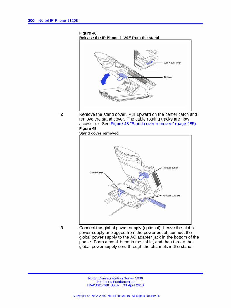
306 Nortel IP Phone 1120E
Figure 48Release the IP Phone 1120E from the stand
2 Remove the stand cover. Pull upward on the center catch andremove the stand cover. The cable routing tracks are nowaccessible. See Figure 43 "Stand cover removed" (page 285).Figure 49Stand cover removed
3 Connect the global power supply (optional). Leave the globalpower supply unplugged from the power outlet, connect theglobal power supply to the AC adapter jack in the bottom of thephone. Form a small bend in the cable, and then thread theglobal power supply cord through the channels in the stand.
Nortel Communication Server 1000IP Phones Fundamentals
NN43001-368 06.07 30 April 2010
Copyright © 2003-2010 Nortel Networks. All Rights Reserved.
.
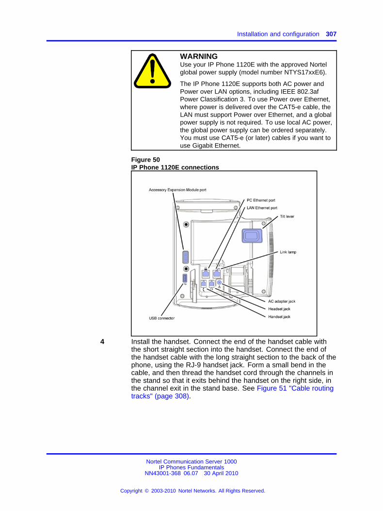
Installation and configuration 307
WARNINGUse your IP Phone 1120E with the approved Nortelglobal power supply (model number NTYS17xxE6).
The IP Phone 1120E supports both AC power andPower over LAN options, including IEEE 802.3afPower Classification 3. To use Power over Ethernet,where power is delivered over the CAT5-e cable, theLAN must support Power over Ethernet, and a globalpower supply is not required. To use local AC power,the global power supply can be ordered separately.You must use CAT5-e (or later) cables if you want touse Gigabit Ethernet.
Figure 50IP Phone 1120E connections
4 Install the handset. Connect the end of the handset cable withthe short straight section into the handset. Connect the end ofthe handset cable with the long straight section to the back of thephone, using the RJ-9 handset jack. Form a small bend in thecable, and then thread the handset cord through the channels inthe stand so that it exits behind the handset on the right side, inthe channel exit in the stand base. See Figure 51 "Cable routingtracks" (page 308).
Nortel Communication Server 1000IP Phones Fundamentals
NN43001-368 06.07 30 April 2010
Copyright © 2003-2010 Nortel Networks. All Rights Reserved.
.
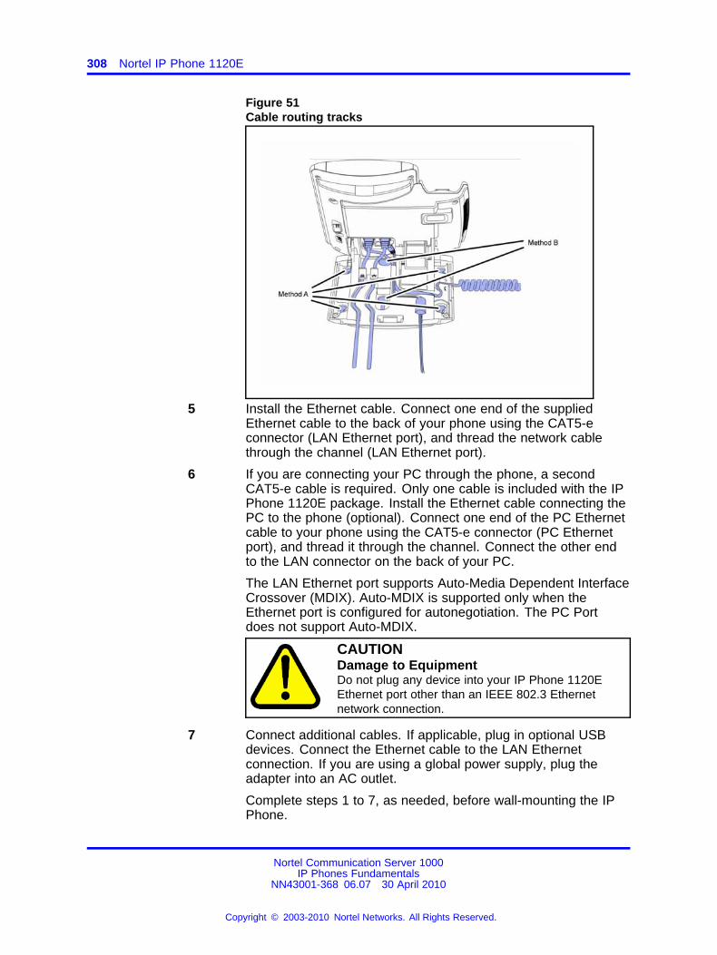
308 Nortel IP Phone 1120E
Figure 51Cable routing tracks
5 Install the Ethernet cable. Connect one end of the suppliedEthernet cable to the back of your phone using the CAT5-econnector (LAN Ethernet port), and thread the network cablethrough the channel (LAN Ethernet port).
6 If you are connecting your PC through the phone, a secondCAT5-e cable is required. Only one cable is included with the IPPhone 1120E package. Install the Ethernet cable connecting thePC to the phone (optional). Connect one end of the PC Ethernetcable to your phone using the CAT5-e connector (PC Ethernetport), and thread it through the channel. Connect the other endto the LAN connector on the back of your PC.
The LAN Ethernet port supports Auto-Media Dependent InterfaceCrossover (MDIX). Auto-MDIX is supported only when theEthernet port is configured for autonegotiation. The PC Portdoes not support Auto-MDIX.
CAUTIONDamage to EquipmentDo not plug any device into your IP Phone 1120EEthernet port other than an IEEE 802.3 Ethernetnetwork connection.
7 Connect additional cables. If applicable, plug in optional USBdevices. Connect the Ethernet cable to the LAN Ethernetconnection. If you are using a global power supply, plug theadapter into an AC outlet.
Complete steps 1 to 7, as needed, before wall-mounting the IPPhone.
Nortel Communication Server 1000IP Phones Fundamentals
NN43001-368 06.07 30 April 2010
Copyright © 2003-2010 Nortel Networks. All Rights Reserved.
.
Installation and configuration 309
8 Wall-mount your phone (optional). Use Method A or Method B towall-mount the IP Phone. See Method A—using the mountingholes on the bottom of the phone stand, or Method B—using thetraditional-style wall-mount box with a CAT5-e connector and a15 cm (6 inch) CAT5-e cord (not provided).
• Method A: Press the wall-mount lever, and pull away fromthe stand. Using the stand cover (see step 2), mark thewall-mount holes by pressing the bottom of the stand coverfirmly against the wall in the location where you wish to installthe phone. Four small pins on the bottom of the stand covermake the marks on the wall. Use the marks as a guideline toinstall the wall-mount screws (not provided).Install the screws so that they protrude 3 mm (1/8 inch) fromthe wall, and then install the phone stand mounting holesover the screw heads. You may need to remove the phonefrom the wall to adjust the lower screws. When the lowerscrews are snug, install the phone on the mounting screws,and then tighten the top screws.
• Method B: Attach the 15 cm (6 inch) CAT5-e cable, positionthe stand over the mounting rivets, and slide the phone downthe wall so that the rivets fit into the slots on the stand.
9 Replace the stand cover. Ensure that all cables are neatly routedand press the stand cover into place until you hear a click.
10 If you wall-mount the phone, put it in the wall-mount position byholding the tilt lever and press the phone towards the base untilthe phone is parallel with the base. Release the tilt lever andcontinue to push the phone towards the base until you hear aclick. Ensure the phone is securely locked in to position.
--End--
When you complete the IP Phone connection, you must connect the phoneto the network. See “Dynamic Host Configuration Protocol” (page 429).
Startup sequenceWhen an IP Phone 1120E connects to the network, it must perform astartup sequence. The elements of the startup sequence include
• obtaining network access (if supported by the network infrastructure)
• obtaining VLAN ID (if supported by the network infrastructure)
• obtaining the IP parameters
• obtaining the provisioning parameters
• connecting to the Call Server
Nortel Communication Server 1000IP Phones Fundamentals
NN43001-368 06.07 30 April 2010
Copyright © 2003-2010 Nortel Networks. All Rights Reserved.
.
310 Nortel IP Phone 1120E
The IP Phone is configured for automatic provisioning by default. Formore information about provisioning the IP Phone automatically, see“Provisioning the IP Phones” (page 497).
You can manually configure all or some parameters. For informationabout manually provisioning the IP Phone, see “Manual provisioning of IPPhones 2007 and 1100 Series” (page 553).
TFTP firmware upgradeWhen you enter Cfg TFTP = 1 (for yes), and enter an IP address, the IPPhone searches for an upgrade file on the TFTP Server.
Users of CS 1000 Release 4.5, or later do not need to enter a TFTP IPaddress.
For further information about TFTP firmware upgrade, see “TFTP Server”(page 683).
Redeploying an IP Phone 1120EYou can redeploy an existing previously configured IP Phone 1120E onthe same Call Server. For example, the IP Phone 1120E can be assignedto a new user (new TN) or to an existing user who moved to a new subnetby changing the TN of the IP Phone 1120E. For further information, seeConverging the Data Network with VoIP Fundamentals (NN43001-260).
Procedure 83Changing the TN of an existing IP Phone 1120E
Step Action
1 Repower the IP Phone 1120E.
During the reboot sequence of a previously configured IP Phone,the IP Phone 1120E displays the existing node number forapproximately 5 seconds.
2 If the node password is enabled and NULL, choose one of thefollowing
a Disable the password.
b Set the password as non-NULL.
3 Press OK when the node number displays.
If Then
the node password is enabledand is not NULL
a password screen displays. Goto Step 4.
the node password is disabled a TN screen displays. Go to Step5.
Nortel Communication Server 1000IP Phones Fundamentals
NN43001-368 06.07 30 April 2010
Copyright © 2003-2010 Nortel Networks. All Rights Reserved.
.
Removing an IP Phone 1120E from service 311
4 Enter the password at the password screen and press OK.
A TN screen displays.
To obtain the password, enter the nodePwdShow command inElement Manager. For further information, see Element ManagerSystem Reference - Administration (NN43001-632).
5 Select the Clear soft key to clear the existing TN.
6 Enter the new TN.
--End--
Replacing an IP Phone 1120EATTENTIONTwo IP Phones cannot share the same TN. You must remove the IP Phone1120E that currently uses the TN.
Procedure 84Replacing an IP Phone 1120E
Step Action
1 Obtain the node and TN information of the phone you want toreplace.
2 Disconnect the IP Phone 1120E that you want to replace.
3 Follow “Configuring the IP Phone 1120E” (page 304) to installthe IP Phone 1120E. To configure the IP Phone, see “Manualprovisioning of IP Phones 2007 and 1100 Series” (page 553).
4 Enter the same TN and Node Number as the IP Phone 1120Eyou replaced. The Call Server associates the new IP Phone1120E with the existing TN.
--End--
Removing an IP Phone 1120E from serviceProcedure 85Removing an IP Phone 1120E from service
Step Action
1 Disconnect the IP Phone 1120E from the network or turn off thepower.
The service to the PC is disconnected as well if the PC connectsto the IP Phone 1120E.
Nortel Communication Server 1000IP Phones Fundamentals
NN43001-368 06.07 30 April 2010
Copyright © 2003-2010 Nortel Networks. All Rights Reserved.
.
312 Nortel IP Phone 1120E
If the IP Phone 1120E was automatically configured, the DHCPlease expires and the IP address returns to the available pool.
2 In LD 11, enter the following:REQ: OUTTYPE: 1120TN: LLL S CC UU
--End--
Nortel Communication Server 1000IP Phones Fundamentals
NN43001-368 06.07 30 April 2010
Copyright © 2003-2010 Nortel Networks. All Rights Reserved.
.
313.
Nortel IP Phone 1140E
ContentsThis section contains the following topics:
• “Introduction” (page 313)
• “Description” (page 314)
• “Components and functions” (page 315)
• “Features” (page 318)
• “Dialpad entry” (page 319)
• “Display characteristics” (page 320)
• “Cleaning the IP Phone display screen” (page 322)
• “Package components” (page 322)
• “Installation and configuration” (page 324)
• “TFTP firmware upgrade ” (page 330)
• “Bluetooth® wireless technology” (page 330)
• “Redeploying an IP Phone 1140E” (page 330)
• “Replacing an IP Phone 1140E” (page 331)
• “Removing an IP Phone 1140E from service” (page 332)
IntroductionThis section explains how to install and maintain the IP Phone 1140E. Forinformation about using the IP Phone 1140E, see the IP Phone 1140EUser Guide (NN43113-106) or IP Phone 1140E Getting Started Card(NN43113-103).
This section contains the following procedures
• Procedure 86 “Configuring the IP Phone 1140E” (page 325)
• Procedure 87 “Connecting the components” (page 325)
Nortel Communication Server 1000IP Phones Fundamentals
NN43001-368 06.07 30 April 2010
Copyright © 2003-2010 Nortel Networks. All Rights Reserved.
.
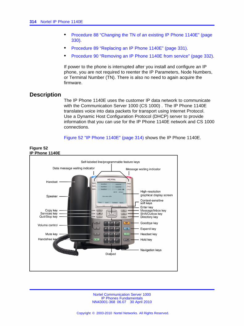
314 Nortel IP Phone 1140E
• Procedure 88 “Changing the TN of an existing IP Phone 1140E” (page330).
• Procedure 89 “Replacing an IP Phone 1140E” (page 331).
• Procedure 90 “Removing an IP Phone 1140E from service” (page 332).
If power to the phone is interrupted after you install and configure an IPphone, you are not required to reenter the IP Parameters, Node Numbers,or Terminal Number (TN). There is also no need to again acquire thefirmware.
DescriptionThe IP Phone 1140E uses the customer IP data network to communicatewith the Communication Server 1000 (CS 1000) . The IP Phone 1140Etranslates voice into data packets for transport using Internet Protocol.Use a Dynamic Host Configuration Protocol (DHCP) server to provideinformation that you can use for the IP Phone 1140E network and CS 1000connections.
Figure 52 "IP Phone 1140E" (page 314) shows the IP Phone 1140E.
Figure 52IP Phone 1140E
Nortel Communication Server 1000IP Phones Fundamentals
NN43001-368 06.07 30 April 2010
Copyright © 2003-2010 Nortel Networks. All Rights Reserved.
.
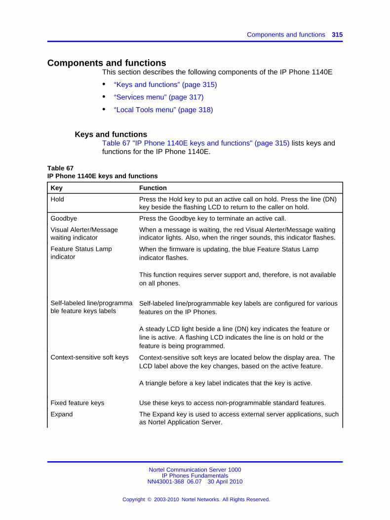
Components and functions 315
Components and functionsThis section describes the following components of the IP Phone 1140E
• “Keys and functions” (page 315)
• “Services menu” (page 317)
• “Local Tools menu” (page 318)
Keys and functionsTable 67 "IP Phone 1140E keys and functions" (page 315) lists keys andfunctions for the IP Phone 1140E.
Table 67IP Phone 1140E keys and functions
Key Function
Hold Press the Hold key to put an active call on hold. Press the line (DN)key beside the flashing LCD to return to the caller on hold.
Goodbye Press the Goodbye key to terminate an active call.
Visual Alerter/Messagewaiting indicator
When a message is waiting, the red Visual Alerter/Message waitingindicator lights. Also, when the ringer sounds, this indicator flashes.
Feature Status Lampindicator
When the firmware is updating, the blue Feature Status Lampindicator flashes.
This function requires server support and, therefore, is not availableon all phones.
Self-labeled line/programmable feature keys labels
Self-labeled line/programmable key labels are configured for variousfeatures on the IP Phones.
A steady LCD light beside a line (DN) key indicates the feature orline is active. A flashing LCD indicates the line is on hold or thefeature is being programmed.
Context-sensitive soft keys Context-sensitive soft keys are located below the display area. TheLCD label above the key changes, based on the active feature.
A triangle before a key label indicates that the key is active.
Fixed feature keys Use these keys to access non-programmable standard features.
Expand The Expand key is used to access external server applications, suchas Nortel Application Server.
Nortel Communication Server 1000IP Phones Fundamentals
NN43001-368 06.07 30 April 2010
Copyright © 2003-2010 Nortel Networks. All Rights Reserved.
.
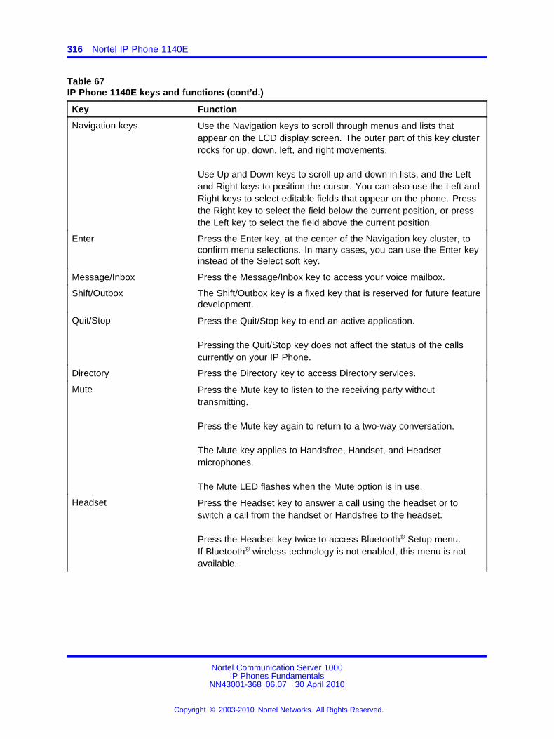
316 Nortel IP Phone 1140E
Table 67IP Phone 1140E keys and functions (cont’d.)
Key Function
Navigation keys Use the Navigation keys to scroll through menus and lists thatappear on the LCD display screen. The outer part of this key clusterrocks for up, down, left, and right movements.
Use Up and Down keys to scroll up and down in lists, and the Leftand Right keys to position the cursor. You can also use the Left andRight keys to select editable fields that appear on the phone. Pressthe Right key to select the field below the current position, or pressthe Left key to select the field above the current position.
Enter Press the Enter key, at the center of the Navigation key cluster, toconfirm menu selections. In many cases, you can use the Enter keyinstead of the Select soft key.
Message/Inbox Press the Message/Inbox key to access your voice mailbox.
Shift/Outbox The Shift/Outbox key is a fixed key that is reserved for future featuredevelopment.
Quit/Stop Press the Quit/Stop key to end an active application.
Pressing the Quit/Stop key does not affect the status of the callscurrently on your IP Phone.
Directory Press the Directory key to access Directory services.
Mute Press the Mute key to listen to the receiving party withouttransmitting.
Press the Mute key again to return to a two-way conversation.
The Mute key applies to Handsfree, Handset, and Headsetmicrophones.
The Mute LED flashes when the Mute option is in use.
Headset Press the Headset key to answer a call using the headset or toswitch a call from the handset or Handsfree to the headset.
Press the Headset key twice to access Bluetooth® Setup menu.If Bluetooth® wireless technology is not enabled, this menu is notavailable.
Nortel Communication Server 1000IP Phones Fundamentals
NN43001-368 06.07 30 April 2010
Copyright © 2003-2010 Nortel Networks. All Rights Reserved.
.
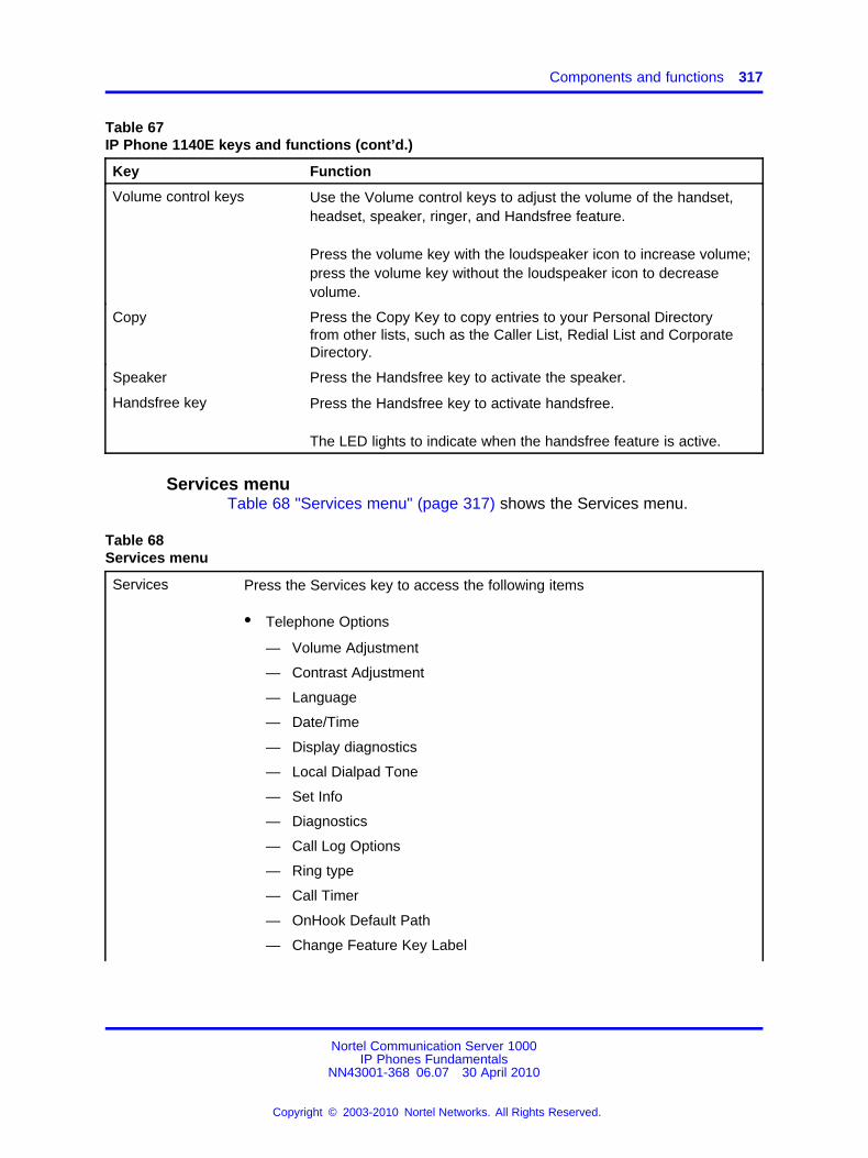
Components and functions 317
Table 67IP Phone 1140E keys and functions (cont’d.)
Key Function
Volume control keys Use the Volume control keys to adjust the volume of the handset,headset, speaker, ringer, and Handsfree feature.
Press the volume key with the loudspeaker icon to increase volume;press the volume key without the loudspeaker icon to decreasevolume.
Copy Press the Copy Key to copy entries to your Personal Directoryfrom other lists, such as the Caller List, Redial List and CorporateDirectory.
Speaker Press the Handsfree key to activate the speaker.
Handsfree key Press the Handsfree key to activate handsfree.
The LED lights to indicate when the handsfree feature is active.
Services menuTable 68 "Services menu" (page 317) shows the Services menu.
Table 68Services menu
Services Press the Services key to access the following items
• Telephone Options
— Volume Adjustment
— Contrast Adjustment
— Language
— Date/Time
— Display diagnostics
— Local Dialpad Tone
— Set Info
— Diagnostics
— Call Log Options
— Ring type
— Call Timer
— OnHook Default Path
— Change Feature Key Label
Nortel Communication Server 1000IP Phones Fundamentals
NN43001-368 06.07 30 April 2010
Copyright © 2003-2010 Nortel Networks. All Rights Reserved.
.
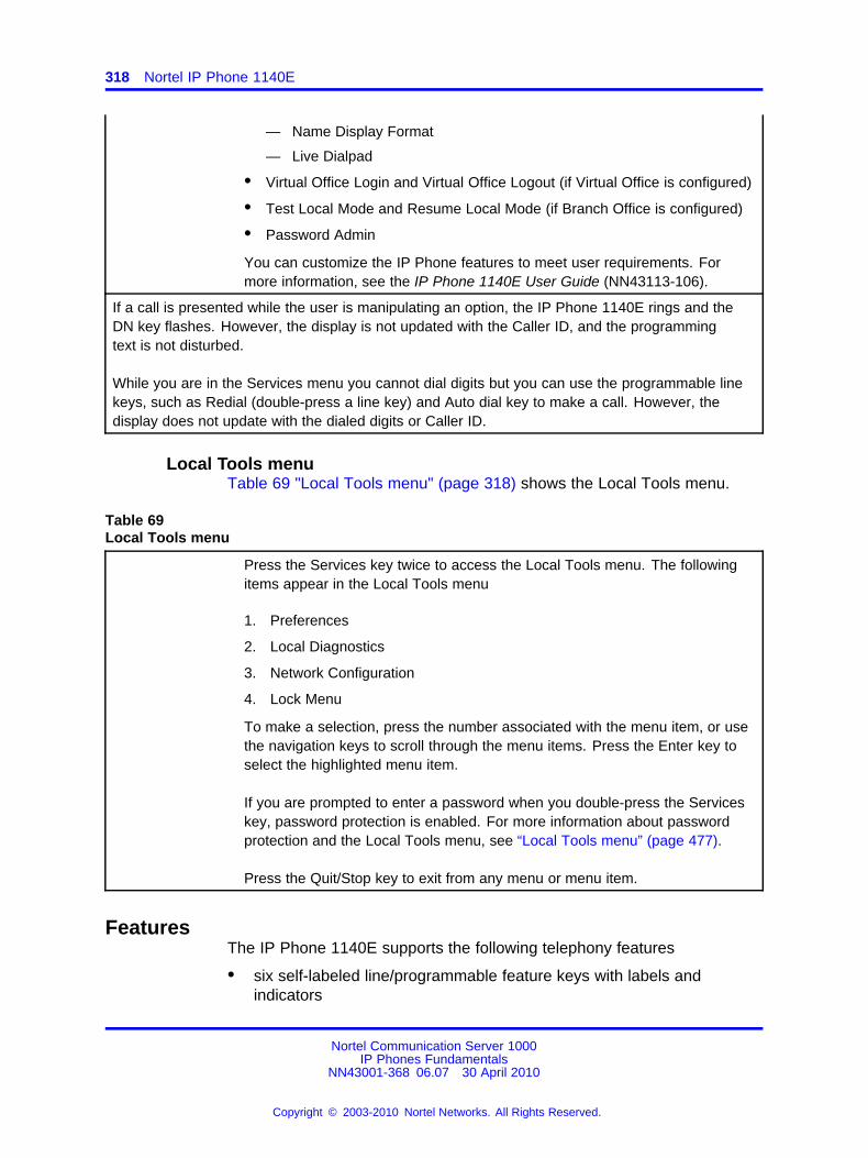
318 Nortel IP Phone 1140E
— Name Display Format
— Live Dialpad
• Virtual Office Login and Virtual Office Logout (if Virtual Office is configured)
• Test Local Mode and Resume Local Mode (if Branch Office is configured)
• Password Admin
You can customize the IP Phone features to meet user requirements. Formore information, see the IP Phone 1140E User Guide (NN43113-106).
If a call is presented while the user is manipulating an option, the IP Phone 1140E rings and theDN key flashes. However, the display is not updated with the Caller ID, and the programmingtext is not disturbed.
While you are in the Services menu you cannot dial digits but you can use the programmable linekeys, such as Redial (double-press a line key) and Auto dial key to make a call. However, thedisplay does not update with the dialed digits or Caller ID.
Local Tools menuTable 69 "Local Tools menu" (page 318) shows the Local Tools menu.
Table 69Local Tools menu
Press the Services key twice to access the Local Tools menu. The followingitems appear in the Local Tools menu
1. Preferences
2. Local Diagnostics
3. Network Configuration
4. Lock Menu
To make a selection, press the number associated with the menu item, or usethe navigation keys to scroll through the menu items. Press the Enter key toselect the highlighted menu item.
If you are prompted to enter a password when you double-press the Serviceskey, password protection is enabled. For more information about passwordprotection and the Local Tools menu, see “Local Tools menu” (page 477).
Press the Quit/Stop key to exit from any menu or menu item.
FeaturesThe IP Phone 1140E supports the following telephony features
• six self-labeled line/programmable feature keys with labels andindicators
Nortel Communication Server 1000IP Phones Fundamentals
NN43001-368 06.07 30 April 2010
Copyright © 2003-2010 Nortel Networks. All Rights Reserved.
.
Dialpad entry 319
Supports up to 12 DNs or features on 2 pages. Use the Shift/Outboxkey to access the second page of DNs or features.
• four context-sensitive soft keys
Functions for the context-sensitive soft keys are configured in LD 11.
For more information about context-sensitive soft keys, see Featuresand Services Fundamentals (NN43001-106).
• high quality speaker phone
• volume control keys to adjust ringer, speaker, handset, and headsetvolume
• ability to change user-defined feature key labels
• seven specialized feature keys
— Quit/Stop
— Directory
— Message/Inbox
— Shift/Outbox
— Services
— Copy
— Expand
• five call-processing fixed keys
— Mute
— Handsfree
— Goodbye
— Headset
— Hold
For more information about the Expansion Module, see “ExpansionModule for IP Phones 1100 Series” (page 377).
For more information about IP Phone features, see “Features” (page 391).
Dialpad entryThe following rules apply when you enter text and special characters usingthe dialpad.
• Press a key from 0 to 9 once to enter the corresponding number.
• Press a key from 2 to 9 repeatedly to cycle through the lettersassigned to that key, first in lower case and then in upper case.
Nortel Communication Server 1000IP Phones Fundamentals
NN43001-368 06.07 30 April 2010
Copyright © 2003-2010 Nortel Networks. All Rights Reserved.
.
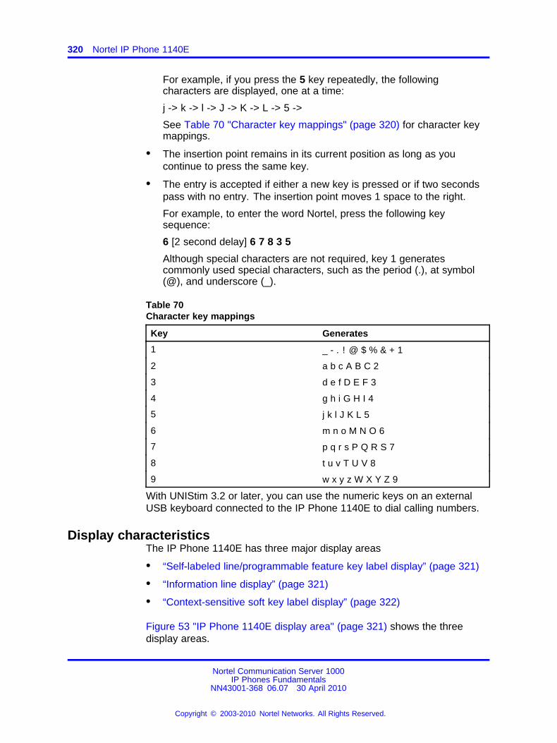
320 Nortel IP Phone 1140E
For example, if you press the 5 key repeatedly, the followingcharacters are displayed, one at a time:
j -> k -> l -> J -> K -> L -> 5 ->
See Table 70 "Character key mappings" (page 320) for character keymappings.
• The insertion point remains in its current position as long as youcontinue to press the same key.
• The entry is accepted if either a new key is pressed or if two secondspass with no entry. The insertion point moves 1 space to the right.
For example, to enter the word Nortel, press the following keysequence:
6 [2 second delay] 6 7 8 3 5
Although special characters are not required, key 1 generatescommonly used special characters, such as the period (.), at symbol(@), and underscore (_).
Table 70Character key mappings
Key Generates
1 _ - . ! @ $ % & + 1
2 a b c A B C 2
3 d e f D E F 3
4 g h i G H I 4
5 j k l J K L 5
6 m n o M N O 6
7 p q r s P Q R S 7
8 t u v T U V 8
9 w x y z W X Y Z 9
With UNIStim 3.2 or later, you can use the numeric keys on an externalUSB keyboard connected to the IP Phone 1140E to dial calling numbers.
Display characteristicsThe IP Phone 1140E has three major display areas
• “Self-labeled line/programmable feature key label display” (page 321)
• “Information line display” (page 321)
• “Context-sensitive soft key label display” (page 322)
Figure 53 "IP Phone 1140E display area" (page 321) shows the threedisplay areas.
Nortel Communication Server 1000IP Phones Fundamentals
NN43001-368 06.07 30 April 2010
Copyright © 2003-2010 Nortel Networks. All Rights Reserved.
.
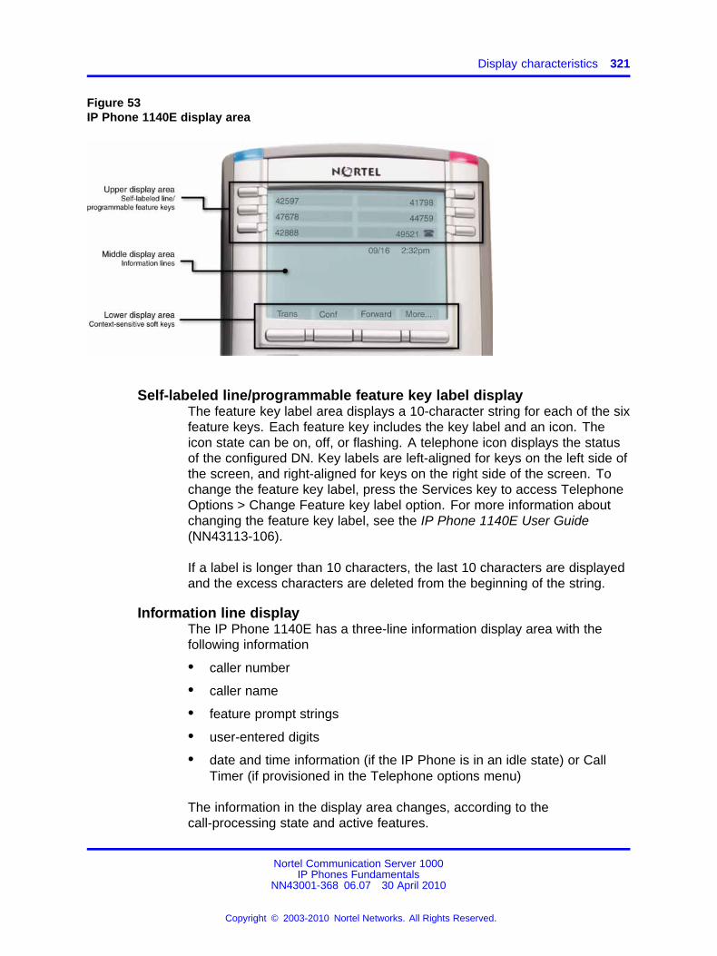
Display characteristics 321
Figure 53IP Phone 1140E display area
Self-labeled line/programmable feature key label displayThe feature key label area displays a 10-character string for each of the sixfeature keys. Each feature key includes the key label and an icon. Theicon state can be on, off, or flashing. A telephone icon displays the statusof the configured DN. Key labels are left-aligned for keys on the left side ofthe screen, and right-aligned for keys on the right side of the screen. Tochange the feature key label, press the Services key to access TelephoneOptions > Change Feature key label option. For more information aboutchanging the feature key label, see the IP Phone 1140E User Guide(NN43113-106).
If a label is longer than 10 characters, the last 10 characters are displayedand the excess characters are deleted from the beginning of the string.
Information line displayThe IP Phone 1140E has a three-line information display area with thefollowing information
• caller number
• caller name
• feature prompt strings
• user-entered digits
• date and time information (if the IP Phone is in an idle state) or CallTimer (if provisioned in the Telephone options menu)
The information in the display area changes, according to thecall-processing state and active features.
Nortel Communication Server 1000IP Phones Fundamentals
NN43001-368 06.07 30 April 2010
Copyright © 2003-2010 Nortel Networks. All Rights Reserved.
.
322 Nortel IP Phone 1140E
Context-sensitive soft key label displayThe context-sensitive soft key label has a maximum of seven characters.Each soft key includes the soft key label and an icon. When a soft key isin use, a triangle icon displays at the beginning of the soft key label, andthe label shifts one character to the right. (If the label is six characters inlength, the last or rightmost character is truncated.) If a feature is enabled,the icon state turns to On. It remains in the on state until the feature keyis pressed again. This cancels the enabled feature and turns the icon off,returning the soft key label to its original state.
Use the More soft key to navigate through the layers of functions. If onlyfour functions are assigned to the soft keys, the More key does not appear,and all four functions are displayed.
Cleaning the IP Phone display screenGently wipe the IP Phone display screen with a soft, dry cloth.
CAUTIONDo not use any liquids or powders on the IP Phone. Usinganything other than a soft, dry cloth can contaminate IP Phonecomponents and cause premature failure.
Package componentsThe IP Phone 1140E includes integrated support for a number ofPower over Ethernet options, including support for IEEE 802.3af PowerClassification 3.
Table 71 "Package components" (page 322) lists the IP Phone 1140Epackage components.
Table 71Package components
• IP Phone 1140E
• handset
• handset cord
• 2.1 m (7-ft) CAT5-e Ethernet cable
• number plate and lens
• Getting Started Card
Table 72 "IP Phone 1140E component list" (page 323) lists the IP Phone1140E components and product codes.
Nortel Communication Server 1000IP Phones Fundamentals
NN43001-368 06.07 30 April 2010
Copyright © 2003-2010 Nortel Networks. All Rights Reserved.
.
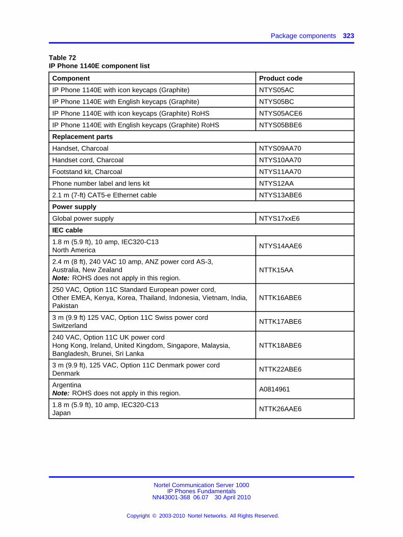
Package components 323
Table 72IP Phone 1140E component list
Component Product code
IP Phone 1140E with icon keycaps (Graphite) NTYS05AC
IP Phone 1140E with English keycaps (Graphite) NTYS05BC
IP Phone 1140E with icon keycaps (Graphite) RoHS NTYS05ACE6
IP Phone 1140E with English keycaps (Graphite) RoHS NTYS05BBE6
Replacement parts
Handset, Charcoal NTYS09AA70
Handset cord, Charcoal NTYS10AA70
Footstand kit, Charcoal NTYS11AA70
Phone number label and lens kit NTYS12AA
2.1 m (7-ft) CAT5-e Ethernet cable NTYS13ABE6
Power supply
Global power supply NTYS17xxE6
IEC cable
1.8 m (5.9 ft), 10 amp, IEC320-C13North America
NTYS14AAE6
2.4 m (8 ft), 240 VAC 10 amp, ANZ power cord AS-3,Australia, New ZealandNote: ROHS does not apply in this region.
NTTK15AA
250 VAC, Option 11C Standard European power cord,Other EMEA, Kenya, Korea, Thailand, Indonesia, Vietnam, India,Pakistan
NTTK16ABE6
3 m (9.9 ft) 125 VAC, Option 11C Swiss power cordSwitzerland
NTTK17ABE6
240 VAC, Option 11C UK power cordHong Kong, Ireland, United Kingdom, Singapore, Malaysia,Bangladesh, Brunei, Sri Lanka
NTTK18ABE6
3 m (9.9 ft), 125 VAC, Option 11C Denmark power cordDenmark
NTTK22ABE6
ArgentinaNote: ROHS does not apply in this region.
A0814961
1.8 m (5.9 ft), 10 amp, IEC320-C13Japan
NTTK26AAE6
Nortel Communication Server 1000IP Phones Fundamentals
NN43001-368 06.07 30 April 2010
Copyright © 2003-2010 Nortel Networks. All Rights Reserved.
.
324 Nortel IP Phone 1140E
Installation and configurationThe following sections provide a step-by-step guide to install and configurethe IP Phone 1140E
• “Before you begin” (page 324)
• “First-time installation” (page 324)
• “Configuring the IP Phone 1140E” (page 324)
• “Connecting the components” (page 325)
• “Startup sequence” (page 330)
Before you beginBefore installing the IP Phone 1140E, complete the followingpre-installation checklist
• Ensure one IP Phone 1140E boxed package exists for each IP Phone1140E you install. For a list of IP Phone 1140E package components,see Table 71 "Package components" (page 322).
• Ensure one Software License exists for each IP Phone 1140E youinstall.
• Ensure the host Call Server is equipped with a Voice Gateway MediaCard and a Signaling Server with the Line TPS application.
• If a global power supply is required, ensure the approved Nortel globalpower supply (model number NTYS17xxE6) is used. See Table 72 "IPPhone 1140E component list" (page 323).
• Ensure the latest IP Phone firmware is deployed to the IP telephonynode. For more information, see Signaling Server IP Line ApplicationsFundamentals (NN43001-125).
First-time installationYou must first install an IP telephony node with the Communication Server.For information about installing an IP telephony node, see Signaling ServerIP Line Applications Fundamentals (NN43001-125).
CAUTIONDamage to EquipmentDo not plug your IP Phone 1140E into an ISDN connection.Severe damage can result.
Configuring the IP Phone 1140EUse Procedure 86 “Configuring the IP Phone 1140E” (page 325) toconfigure the IP Phone 1140E.
Nortel Communication Server 1000IP Phones Fundamentals
NN43001-368 06.07 30 April 2010
Copyright © 2003-2010 Nortel Networks. All Rights Reserved.
.
Installation and configuration 325
Procedure 86Configuring the IP Phone 1140E
Step Action
1 Configure a virtual loop on the Call Server using LD 97.
For more information about configuring a virtual loop, seeSignaling Server IP Line Applications Fundamentals (NN43001-125) and Software Input Output Reference-Administration(NN43001-611).
2 Configure the IP Phone 1140E on the Call Server using LD 11.At the prompt, enter the following
REQ: newTYPE: 1140
For more information about configuring the IP Phone 1140E using LD 11, see Software Input Output Reference-Administration(NN43001-611).
3 Configure the IP Phone 1140E in Element Manager. IP Phonesare configured using the Phones section in the ElementManager navigation tree. For more information about configuringthe IP Phone 1140E using Element Manager, see ElementManager System Reference - Administration (NN43001-632).
--End--
Connecting the componentsUse Procedure 87 “Connecting the components” (page 325) to connectthe components for the IP Phone.
CAUTIONThe IP Phone 1140E is shipped with the stand locked inposition. To avoid damaging the IP Phone, press the wall-mountlever located under the Handsfree key to release the stand andpull it away from the phone.
Procedure 87Connecting the components
Step Action
1 Press the wall-mount lever located under the Handsfree key torelease the stand and pull it away from the phone. See Figure 54"Release the IP Phone 1140E from the stand" (page 326).
Nortel Communication Server 1000IP Phones Fundamentals
NN43001-368 06.07 30 April 2010
Copyright © 2003-2010 Nortel Networks. All Rights Reserved.
.

326 Nortel IP Phone 1140E
Figure 54Release the IP Phone 1140E from the stand
2 Remove the stand cover. Pull upward on the center catch andremove the stand cover. The cable routing tracks are nowaccessible. See Figure 55 "Stand cover removed" (page 326).Figure 55Stand cover removed
3 Connect the global power supply (optional). Leave the globalpower supply unplugged from the power outlet, connect theglobal power supply to the AC adapter jack in the bottom of thephone. Form a small bend in the cable, and then thread theglobal power supply cord through the channels in the stand.
Nortel Communication Server 1000IP Phones Fundamentals
NN43001-368 06.07 30 April 2010
Copyright © 2003-2010 Nortel Networks. All Rights Reserved.
.
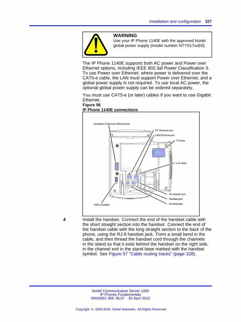
Installation and configuration 327
WARNINGUse your IP Phone 1140E with the approved Nortelglobal power supply (model number NTYS17xxE6).
The IP Phone 1140E supports both AC power and Power overEthernet options, including IEEE 802.3af Power Classification 3.To use Power over Ethernet, where power is delivered over theCAT5-e cable, the LAN must support Power over Ethernet, and aglobal power supply is not required. To use local AC power, theoptional global power supply can be ordered separately.
You must use CAT5-e (or later) cables if you want to use GigabitEthernet.Figure 56IP Phone 1140E connections
4 Install the handset. Connect the end of the handset cable withthe short straight section into the handset. Connect the end ofthe handset cable with the long straight section to the back of thephone, using the RJ-9 handset jack. Form a small bend in thecable, and then thread the handset cord through the channelsin the stand so that it exits behind the handset on the right side,in the channel exit in the stand base marked with the handsetsymbol. See Figure 57 "Cable routing tracks" (page 328).
Nortel Communication Server 1000IP Phones Fundamentals
NN43001-368 06.07 30 April 2010
Copyright © 2003-2010 Nortel Networks. All Rights Reserved.
.
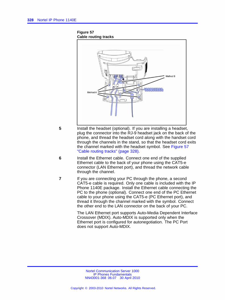
328 Nortel IP Phone 1140E
Figure 57Cable routing tracks
5 Install the headset (optional). If you are installing a headset,plug the connector into the RJ-9 headset jack on the back of thephone, and thread the headset cord along with the handset cordthrough the channels in the stand, so that the headset cord exitsthe channel marked with the headset symbol. See Figure 57"Cable routing tracks" (page 328).
6 Install the Ethernet cable. Connect one end of the suppliedEthernet cable to the back of your phone using the CAT5-econnector (LAN Ethernet port), and thread the network cablethrough the channel.
7 If you are connecting your PC through the phone, a secondCAT5-e cable is required. Only one cable is included with the IPPhone 1140E package. Install the Ethernet cable connecting thePC to the phone (optional). Connect one end of the PC Ethernetcable to your phone using the CAT5-e (PC Ethernet port), andthread it through the channel marked with the symbol. Connectthe other end to the LAN connector on the back of your PC.
The LAN Ethernet port supports Auto-Media Dependent InterfaceCrossover (MDIX). Auto-MDIX is supported only when theEthernet port is configured for autonegotiation. The PC Portdoes not support Auto-MDIX.
Nortel Communication Server 1000IP Phones Fundamentals
NN43001-368 06.07 30 April 2010
Copyright © 2003-2010 Nortel Networks. All Rights Reserved.
.
Installation and configuration 329
CAUTIONDamage to EquipmentDo not plug any device into your IP Phone 1140EEthernet port other than an IEEE 802.3 Ethernetnetwork connection. The IP Phone 1140E does notsupport multiple devices connected through the PCEthernet port.
8 Connect additional cables. If applicable, plug in optional USBdevices. Connect the Ethernet cable to the LAN Ethernetconnection. If you are using a global power supply, plug theadapter into an AC outlet.
Complete steps 1 to 8, as needed, before wall-mounting the IPPhone.
9 Wall-mount your phone (optional). Use Method A or Method B towall-mount the IP Phone. See Method A—using the mountingholes on the bottom of the phone stand, or Method B—using thetraditional-style wall-mount box with a CAT5-e connector and a15 cm (6 inch) CAT5-e cord (not provided).
• Method A: Press the wall-mount lever, and pull away fromthe stand. Using the stand cover (see step 2), mark thewall-mount holes by pressing the bottom of the stand coverfirmly against the wall in the location where you wish to installthe phone. Four small pins on the bottom of the stand covermake the marks on the wall. Use the marks as a guideline toinstall the wall-mount screws (not provided).Install the screws so that they protrude 3 mm (1/8 inch) fromthe wall, and then install the phone stand mounting holesover the screw heads. You may need to remove the phonefrom the wall to adjust the lower screws. When the lowerscrews are snug, install the phone on the mounting screws,and then tighten the top screws.
• Method B: Attach the 15 cm (6 inch) CAT5-e cable, positionthe stand over the mounting rivets, and slide the phone downthe wall so that the rivets fit into the slots on the stand.
10 Replace the stand cover. Ensure that all cables are neatly routedand press the stand cover into place until you hear a click.
11 If you wall-mount the phone, put it in the wall-mount position byholding the tilt lever and press the phone towards the base untilthe phone is parallel with the base. Release the tilt lever andcontinue to push the phone towards the base until you hear aclick. Ensure the phone is securely locked in to position.
--End--
Nortel Communication Server 1000IP Phones Fundamentals
NN43001-368 06.07 30 April 2010
Copyright © 2003-2010 Nortel Networks. All Rights Reserved.
.
330 Nortel IP Phone 1140E
When you complete the IP Phone connection, you must connect the phoneto the network. See “Dynamic Host Configuration Protocol” (page 429).
Startup sequenceWhen an IP Phone 1140E connects to the network, it must perform astartup sequence. The elements of the startup sequence include
• obtaining network access (if supported by the network infrastructure)
• obtaining VLAN ID (if supported by the network infrastructure)
• obtaining the IP parameters
• obtaining the provisioning parameters
• connecting to the Call Server
The IP Phone is configured for automatic provisioning by default. Formore information about provisioning the IP Phone automatically, see“Provisioning the IP Phones” (page 497).
You can manually configure all or some parameters. For informationabout manually provisioning the IP Phone, see “Manual provisioning of IPPhones 2007 and 1100 Series” (page 553).
TFTP firmware upgradeWhen you enter Cfg TFTP = 1 (for yes), and enter an IP address, the IPPhone searches for an upgrade file on the TFTP Server.
Users of CS 1000 Release 4.5, or later do not need to enter a TFTP IPaddress.
For further information about TFTP firmware upgrade, see “TFTP Server”(page 683).
Bluetooth® wireless technologyThe IP Phone 1140E supports Bluetooth® wireless technology. Forinformation about configuring Bluetooth® wireless technology on the IPPhone 1140E, see Headset “Headset support” (page 573).
Redeploying an IP Phone 1140EYou can redeploy an existing previously configured IP Phone 1140E onthe same Call Server. For example, the IP Phone 1140E can be assignedto a new user (new TN) or to an existing user who moved to a new subnetby changing the TN of the IP Phone 1140E. For further information, seeConverging the Data Network with VoIP Fundamentals (NN43001-260).
Procedure 88Changing the TN of an existing IP Phone 1140E
Nortel Communication Server 1000IP Phones Fundamentals
NN43001-368 06.07 30 April 2010
Copyright © 2003-2010 Nortel Networks. All Rights Reserved.
.
Replacing an IP Phone 1140E 331
Step Action
1 Repower the IP Phone 1140E.
During the reboot sequence of a previously configured IP Phone,the IP Phone 1140E displays the existing node number forapproximately five seconds.
2 If the node password is enabled and NULL, choose one of thefollowing
a Disable the password.
b Set the password as non-NULL.
3 Press OK when the node number displays.
If Then
the node password is enabledand is not NULL
a password screen displays. Goto Step 4.
the node password is disabled a TN screen displays. Go to Step5.
4 Enter the password at the password screen, and press OK.
A TN screen displays.
To obtain the password, enter the nodePwdShow command inElement Manager. For further information, see Element ManagerSystem Reference - Administration (NN43001-632).
5 Select the Clear soft key to clear the existing TN.
6 Enter the new TN.
--End--
Replacing an IP Phone 1140EATTENTIONTwo IP Phones cannot share the same TN. You must remove the IP Phone1140E that currently uses the TN.
Procedure 89Replacing an IP Phone 1140E
Step Action
1 Obtain the node and TN information of the phone you want toreplace.
2 Disconnect the IP Phone 1140E that you want to replace.
Nortel Communication Server 1000IP Phones Fundamentals
NN43001-368 06.07 30 April 2010
Copyright © 2003-2010 Nortel Networks. All Rights Reserved.
.
332 Nortel IP Phone 1140E
3 Follow “Configuring the IP Phone 1140E” (page 324) to installthe IP Phone 1140E. To configure the IP Phone, see “Manualprovisioning of IP Phones 2007 and 1100 Series” (page 553).
4 Enter the same TN and Node Number as the IP Phone 1140Eyou replaced. The Call Server associates the new IP Phone1140E with the existing TN.
--End--
Removing an IP Phone 1140E from serviceProcedure 90Removing an IP Phone 1140E from service
Step Action
1 Disconnect the IP Phone 1140E from the network or turn thepower off.
The service to the PC is disconnected as well if the PC connectsto the IP Phone 1140E.
If the IP Phone 1140E was automatically configured, the DHCPlease expires and the IP address returns to the available pool.
2 In LD 11, enter the following:REQ: OUTTYPE: 1140TN: LLL S CC UU
--End--
Nortel Communication Server 1000IP Phones Fundamentals
NN43001-368 06.07 30 April 2010
Copyright © 2003-2010 Nortel Networks. All Rights Reserved.
.
333.
Nortel IP Phone 1150E
ContentsThis section contains the following topics:
• “Introduction” (page 333)
• “Description” (page 334)
• “Components and functions” (page 336)
• “Features” (page 341)
• “Dialpad entry” (page 343)
• “Display characteristics” (page 344)
• “Headset support” (page 345)
• “Package components” (page 346)
• “Installation and configuration” (page 347)
• “TFTP firmware upgrade ” (page 354)
• “Bluetooth® wireless technology” (page 354)
• “Redeploying an IP Phone 1150E” (page 355)
• “Replacing an IP Phone 1150E” (page 356)
• “Removing an IP Phone 1150E from service” (page 356)
IntroductionThis section explains how to install and maintain the IP Phone 1150E. Forinformation about using the IP Phone 1150E, see the IP Phone 1150EUser Guide (NN43114-100) or IP Phone 1150E Getting Started Card(NN43114-103).
This section contains the following procedures
• Procedure 91 “Configuring the IP Phone 1150E” (page 348)
• Procedure 92 “Connecting the components” (page 349)
Nortel Communication Server 1000IP Phones Fundamentals
NN43001-368 06.07 30 April 2010
Copyright © 2003-2010 Nortel Networks. All Rights Reserved.
.
334 Nortel IP Phone 1150E
• Procedure 93 “Changing the TN of an existing IP Phone 1150E” (page355).
• Procedure 94 “Replacing an IP Phone 1150E” (page 356).
• Procedure 95 “Removing an IP Phone 1150E from service” (page 356).
If power to the phone is interrupted after you install and configure an IPphone, you are not required to reenter the IP Parameters, Node Numbers,or Terminal Number (TN). There is also no need to again acquire thefirmware.
DescriptionThe IP Phone 1150E uses the customer IP data network to communicatewith the Communication Server 1000 (CS 1000) . The IP Phone 1150Etranslates voice into data packets for transport using Internet Protocol.Use a Dynamic Host Configuration Protocol (DHCP) server to provideinformation that you can use for the IP Phone 1150E network and CS 1000connections.
The IP Phone 1150E is configured for either an Agent, or a Supervisor.The IP Phone 1150E is shipped with Agent key configuration but can bemodified to support Supervisor key configuration by replacing the keycaps. Remove the key caps using the Key Cap removal tool (productnumber NTNM19AA). For information about IP Phone 1150E components,see “Package components” (page 346).
Figure 58 "IP Phone 1150E default Agent key configuration" (page335) shows the IP Phone 1150E default Agent key configuration.
Nortel Communication Server 1000IP Phones Fundamentals
NN43001-368 06.07 30 April 2010
Copyright © 2003-2010 Nortel Networks. All Rights Reserved.
.
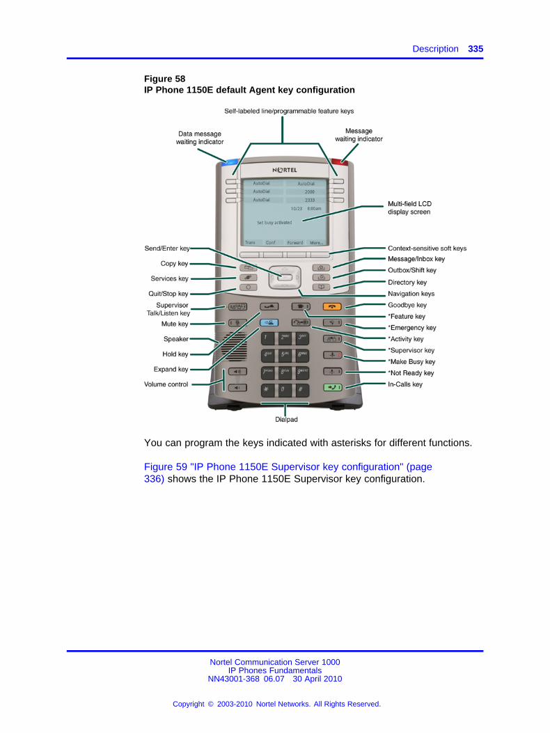
Description 335
Figure 58IP Phone 1150E default Agent key configuration
You can program the keys indicated with asterisks for different functions.
Figure 59 "IP Phone 1150E Supervisor key configuration" (page336) shows the IP Phone 1150E Supervisor key configuration.
Nortel Communication Server 1000IP Phones Fundamentals
NN43001-368 06.07 30 April 2010
Copyright © 2003-2010 Nortel Networks. All Rights Reserved.
.
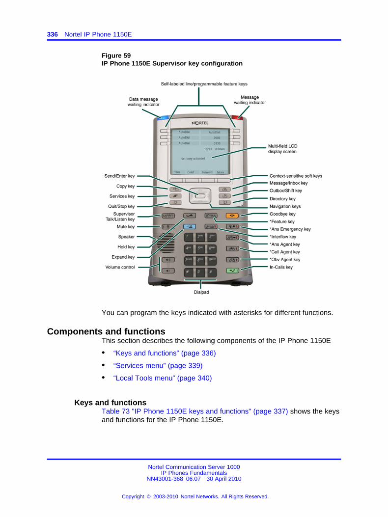
336 Nortel IP Phone 1150E
Figure 59IP Phone 1150E Supervisor key configuration
You can program the keys indicated with asterisks for different functions.
Components and functionsThis section describes the following components of the IP Phone 1150E
• “Keys and functions” (page 336)
• “Services menu” (page 339)
• “Local Tools menu” (page 340)
Keys and functionsTable 73 "IP Phone 1150E keys and functions" (page 337) shows the keysand functions for the IP Phone 1150E.
Nortel Communication Server 1000IP Phones Fundamentals
NN43001-368 06.07 30 April 2010
Copyright © 2003-2010 Nortel Networks. All Rights Reserved.
.
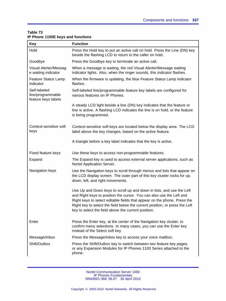
Components and functions 337
Table 73IP Phone 1150E keys and functions
Key Function
Hold Press the Hold key to put an active call on hold. Press the Line (DN) keybeside the flashing LCD to return to the caller on hold.
Goodbye Press the Goodbye key to terminate an active call.
Visual Alerter/Message waiting indicator
When a message is waiting, the red Visual Alerter/Message waitingindicator lights. Also, when the ringer sounds, this indicator flashes.
Feature Status Lampindicator
When the firmware is updating, the blue Feature Status Lamp indicatorflashes.
Self-labeledline/programmablefeature keys labels
Self-labeled line/programmable feature key labels are configured forvarious features on IP Phones.
A steady LCD light beside a line (DN) key indicates that the feature orline is active. A flashing LCD indicates the line is on hold, or the featureis being programmed.
Context-sensitive softkeys
Context-sensitive soft keys are located below the display area. The LCDlabel above the key changes, based on the active feature.
A triangle before a key label indicates that the key is active.
Fixed feature keys Use these keys to access non-programmable features.
Expand The Expand key is used to access external server applications, such asNortel Application Server.
Navigation keys Use the Navigation keys to scroll through menus and lists that appear onthe LCD display screen. The outer part of this key cluster rocks for up,down, left, and right movements.
Use Up and Down keys to scroll up and down in lists, and use the Leftand Right keys to position the cursor. You can also use the Left andRight keys to select editable fields that appear on the phone. Press theRight key to select the field below the current position, or press the Leftkey to select the field above the current position.
Enter Press the Enter key, at the center of the Navigation key cluster, toconfirm menu selections. In many cases, you can use the Enter keyinstead of the Select soft key.
Message/Inbox Press the Message/Inbox key to access your voice mailbox.
Shift/Outbox Press the Shift/Outbox key to switch between two feature key pages,or any Expansion Modules for IP Phones 1100 Series attached to thephone.
Nortel Communication Server 1000IP Phones Fundamentals
NN43001-368 06.07 30 April 2010
Copyright © 2003-2010 Nortel Networks. All Rights Reserved.
.
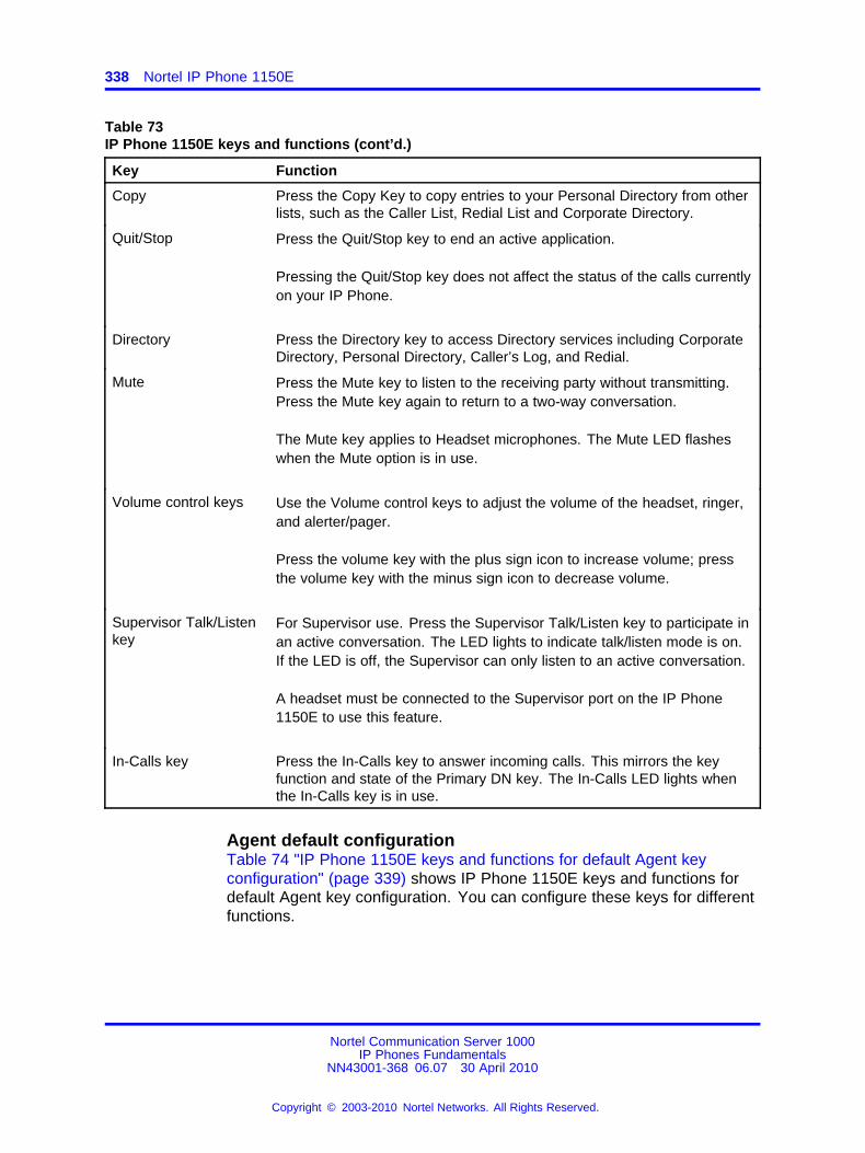
338 Nortel IP Phone 1150E
Table 73IP Phone 1150E keys and functions (cont’d.)
Key Function
Copy Press the Copy Key to copy entries to your Personal Directory from otherlists, such as the Caller List, Redial List and Corporate Directory.
Quit/Stop Press the Quit/Stop key to end an active application.
Pressing the Quit/Stop key does not affect the status of the calls currentlyon your IP Phone.
Directory Press the Directory key to access Directory services including CorporateDirectory, Personal Directory, Caller’s Log, and Redial.
Mute Press the Mute key to listen to the receiving party without transmitting.Press the Mute key again to return to a two-way conversation.
The Mute key applies to Headset microphones. The Mute LED flasheswhen the Mute option is in use.
Volume control keys Use the Volume control keys to adjust the volume of the headset, ringer,and alerter/pager.
Press the volume key with the plus sign icon to increase volume; pressthe volume key with the minus sign icon to decrease volume.
Supervisor Talk/Listenkey
For Supervisor use. Press the Supervisor Talk/Listen key to participate inan active conversation. The LED lights to indicate talk/listen mode is on.If the LED is off, the Supervisor can only listen to an active conversation.
A headset must be connected to the Supervisor port on the IP Phone1150E to use this feature.
In-Calls key Press the In-Calls key to answer incoming calls. This mirrors the keyfunction and state of the Primary DN key. The In-Calls LED lights whenthe In-Calls key is in use.
Agent default configurationTable 74 "IP Phone 1150E keys and functions for default Agent keyconfiguration" (page 339) shows IP Phone 1150E keys and functions fordefault Agent key configuration. You can configure these keys for differentfunctions.
Nortel Communication Server 1000IP Phones Fundamentals
NN43001-368 06.07 30 April 2010
Copyright © 2003-2010 Nortel Networks. All Rights Reserved.
.
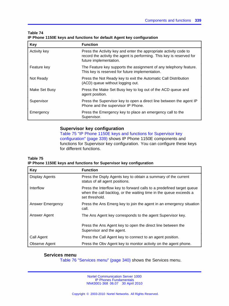
Components and functions 339
Table 74IP Phone 1150E keys and functions for default Agent key configuration
Key Function
Activity key Press the Activity key and enter the appropriate activity code torecord the activity the agent is performing. This key is reserved forfuture implementation.
Feature key The Feature key supports the assignment of any telephony feature.This key is reserved for future implementation.
Not Ready Press the Not Ready key to exit the Automatic Call Distribution(ACD) queue without logging out.
Make Set Busy Press the Make Set Busy key to log out of the ACD queue andagent position.
Supervisor Press the Supervisor key to open a direct line between the agent IPPhone and the supervisor IP Phone.
Emergency Press the Emergency key to place an emergency call to theSupervisor.
Supervisor key configurationTable 75 "IP Phone 1150E keys and functions for Supervisor keyconfiguration" (page 339) shows IP Phone 1150E components andfunctions for Supervisor key configuration. You can configure these keysfor different functions.
Table 75IP Phone 1150E keys and functions for Supervisor key configuration
Key Function
Display Agents Press the Dsply Agents key to obtain a summary of the currentstatus of all agent positions.
Interflow Press the Interflow key to forward calls to a predefined target queuewhen the call backlog, or the waiting time in the queue exceeds aset threshold.
Answer Emergency Press the Ans Emerg key to join the agent in an emergency situationcall.
Answer Agent The Ans Agent key corresponds to the agent Supervisor key.
Press the Ans Agent key to open the direct line between theSupervisor and the agent.
Call Agent Press the Call Agent key to connect to an agent position.
Observe Agent Press the Obv Agent key to monitor activity on the agent phone.
Services menuTable 76 "Services menu" (page 340) shows the Services menu.
Nortel Communication Server 1000IP Phones Fundamentals
NN43001-368 06.07 30 April 2010
Copyright © 2003-2010 Nortel Networks. All Rights Reserved.
.
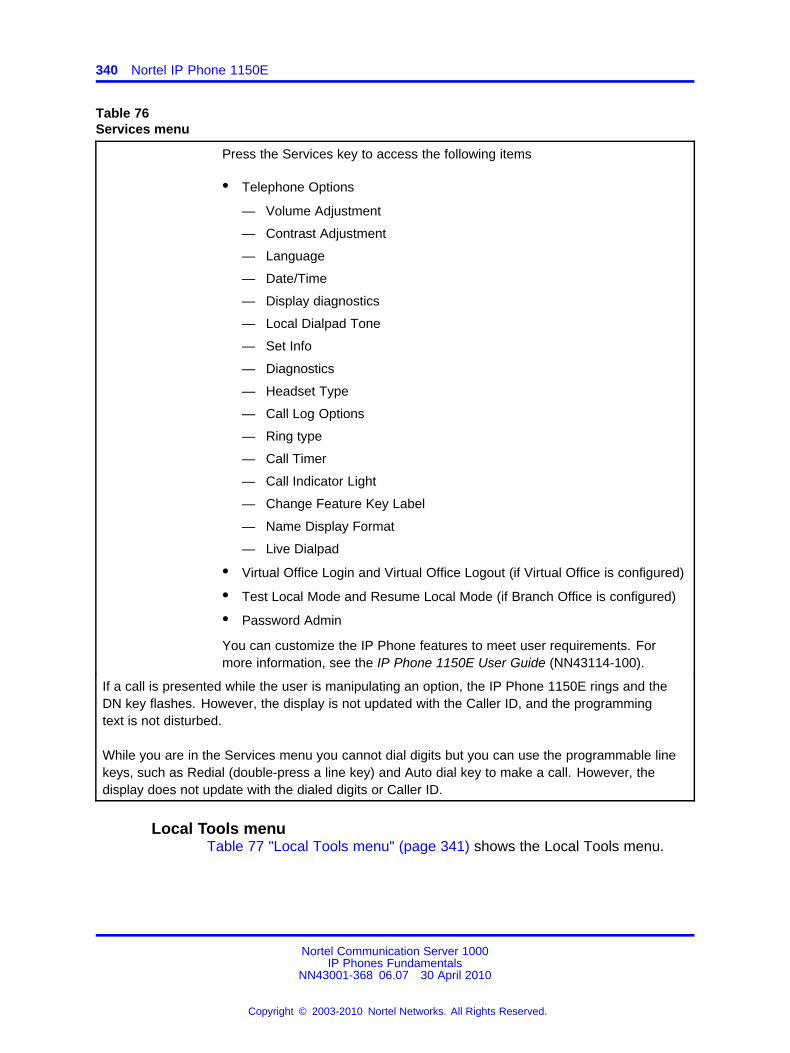
340 Nortel IP Phone 1150E
Table 76Services menu
Press the Services key to access the following items
• Telephone Options
— Volume Adjustment
— Contrast Adjustment
— Language
— Date/Time
— Display diagnostics
— Local Dialpad Tone
— Set Info
— Diagnostics
— Headset Type
— Call Log Options
— Ring type
— Call Timer
— Call Indicator Light
— Change Feature Key Label
— Name Display Format
— Live Dialpad
• Virtual Office Login and Virtual Office Logout (if Virtual Office is configured)
• Test Local Mode and Resume Local Mode (if Branch Office is configured)
• Password Admin
You can customize the IP Phone features to meet user requirements. Formore information, see the IP Phone 1150E User Guide (NN43114-100).
If a call is presented while the user is manipulating an option, the IP Phone 1150E rings and theDN key flashes. However, the display is not updated with the Caller ID, and the programmingtext is not disturbed.
While you are in the Services menu you cannot dial digits but you can use the programmable linekeys, such as Redial (double-press a line key) and Auto dial key to make a call. However, thedisplay does not update with the dialed digits or Caller ID.
Local Tools menuTable 77 "Local Tools menu" (page 341) shows the Local Tools menu.
Nortel Communication Server 1000IP Phones Fundamentals
NN43001-368 06.07 30 April 2010
Copyright © 2003-2010 Nortel Networks. All Rights Reserved.
.
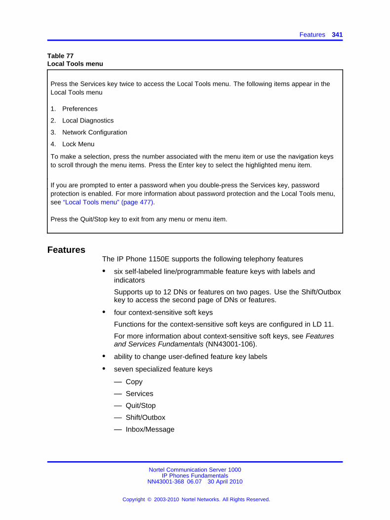
Features 341
Table 77Local Tools menu
Press the Services key twice to access the Local Tools menu. The following items appear in theLocal Tools menu
1. Preferences
2. Local Diagnostics
3. Network Configuration
4. Lock Menu
To make a selection, press the number associated with the menu item or use the navigation keysto scroll through the menu items. Press the Enter key to select the highlighted menu item.
If you are prompted to enter a password when you double-press the Services key, passwordprotection is enabled. For more information about password protection and the Local Tools menu,see “Local Tools menu” (page 477).
Press the Quit/Stop key to exit from any menu or menu item.
FeaturesThe IP Phone 1150E supports the following telephony features
• six self-labeled line/programmable feature keys with labels andindicators
Supports up to 12 DNs or features on two pages. Use the Shift/Outboxkey to access the second page of DNs or features.
• four context-sensitive soft keys
Functions for the context-sensitive soft keys are configured in LD 11.
For more information about context-sensitive soft keys, see Featuresand Services Fundamentals (NN43001-106).
• ability to change user-defined feature key labels
• seven specialized feature keys
— Copy
— Services
— Quit/Stop
— Shift/Outbox
— Inbox/Message
Nortel Communication Server 1000IP Phones Fundamentals
NN43001-368 06.07 30 April 2010
Copyright © 2003-2010 Nortel Networks. All Rights Reserved.
.
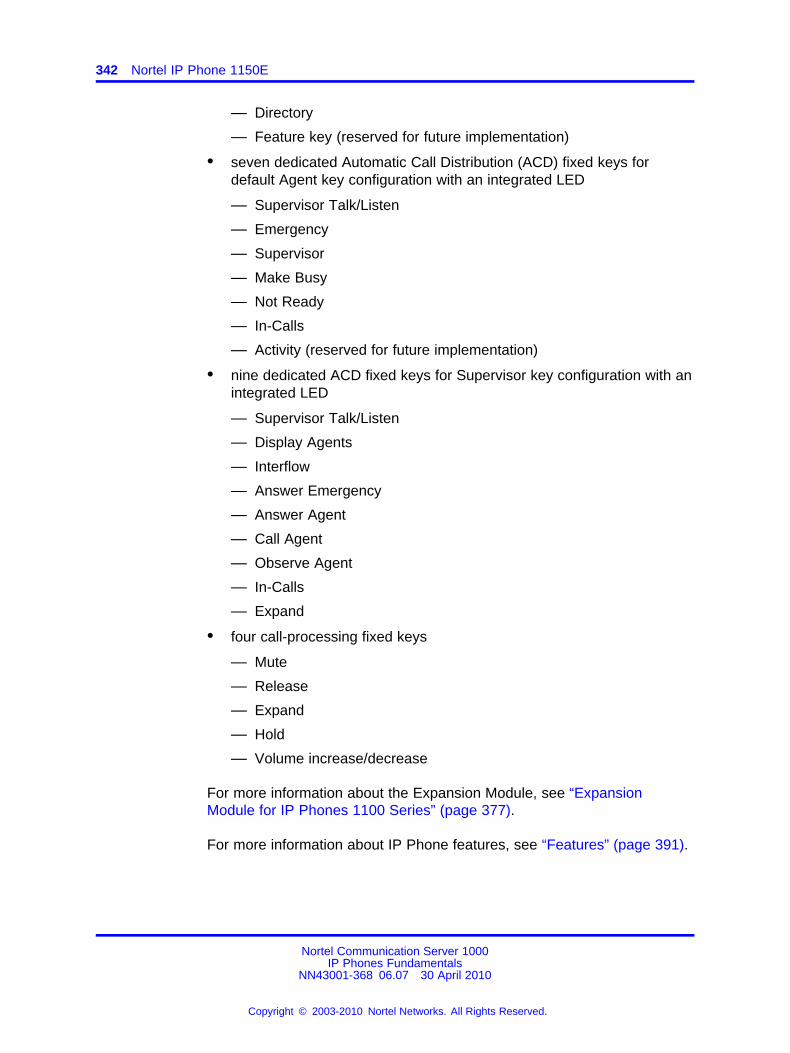
342 Nortel IP Phone 1150E
— Directory
— Feature key (reserved for future implementation)
• seven dedicated Automatic Call Distribution (ACD) fixed keys fordefault Agent key configuration with an integrated LED
— Supervisor Talk/Listen
— Emergency
— Supervisor
— Make Busy
— Not Ready
— In-Calls
— Activity (reserved for future implementation)
• nine dedicated ACD fixed keys for Supervisor key configuration with anintegrated LED
— Supervisor Talk/Listen
— Display Agents
— Interflow
— Answer Emergency
— Answer Agent
— Call Agent
— Observe Agent
— In-Calls
— Expand
• four call-processing fixed keys
— Mute
— Release
— Expand
— Hold
— Volume increase/decrease
For more information about the Expansion Module, see “ExpansionModule for IP Phones 1100 Series” (page 377).
For more information about IP Phone features, see “Features” (page 391).
Nortel Communication Server 1000IP Phones Fundamentals
NN43001-368 06.07 30 April 2010
Copyright © 2003-2010 Nortel Networks. All Rights Reserved.
.
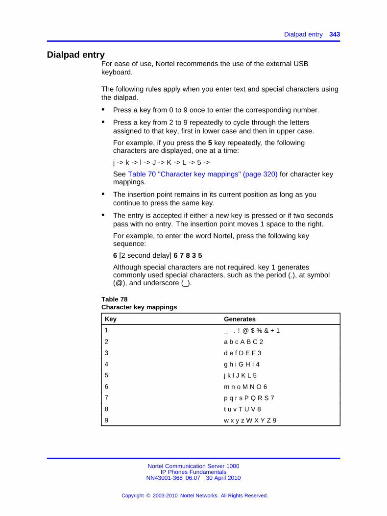
Dialpad entry 343
Dialpad entryFor ease of use, Nortel recommends the use of the external USBkeyboard.
The following rules apply when you enter text and special characters usingthe dialpad.
• Press a key from 0 to 9 once to enter the corresponding number.
• Press a key from 2 to 9 repeatedly to cycle through the lettersassigned to that key, first in lower case and then in upper case.
For example, if you press the 5 key repeatedly, the followingcharacters are displayed, one at a time:
j -> k -> l -> J -> K -> L -> 5 ->
See Table 70 "Character key mappings" (page 320) for character keymappings.
• The insertion point remains in its current position as long as youcontinue to press the same key.
• The entry is accepted if either a new key is pressed or if two secondspass with no entry. The insertion point moves 1 space to the right.
For example, to enter the word Nortel, press the following keysequence:
6 [2 second delay] 6 7 8 3 5
Although special characters are not required, key 1 generatescommonly used special characters, such as the period (.), at symbol(@), and underscore (_).
Table 78Character key mappings
Key Generates
1 _ - . ! @ $ % & + 1
2 a b c A B C 2
3 d e f D E F 3
4 g h i G H I 4
5 j k l J K L 5
6 m n o M N O 6
7 p q r s P Q R S 7
8 t u v T U V 8
9 w x y z W X Y Z 9
Nortel Communication Server 1000IP Phones Fundamentals
NN43001-368 06.07 30 April 2010
Copyright © 2003-2010 Nortel Networks. All Rights Reserved.
.
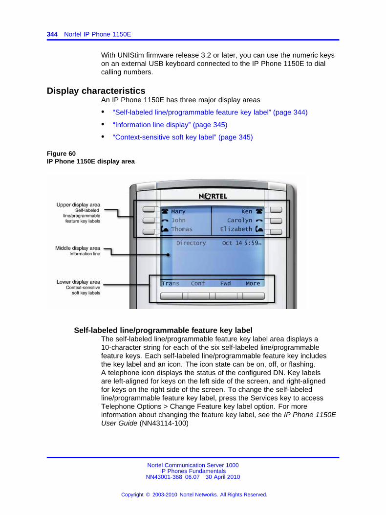
344 Nortel IP Phone 1150E
With UNIStim firmware release 3.2 or later, you can use the numeric keyson an external USB keyboard connected to the IP Phone 1150E to dialcalling numbers.
Display characteristicsAn IP Phone 1150E has three major display areas
• “Self-labeled line/programmable feature key label” (page 344)
• “Information line display” (page 345)
• “Context-sensitive soft key label” (page 345)
Figure 60IP Phone 1150E display area
Self-labeled line/programmable feature key labelThe self-labeled line/programmable feature key label area displays a10-character string for each of the six self-labeled line/programmablefeature keys. Each self-labeled line/programmable feature key includesthe key label and an icon. The icon state can be on, off, or flashing.A telephone icon displays the status of the configured DN. Key labelsare left-aligned for keys on the left side of the screen, and right-alignedfor keys on the right side of the screen. To change the self-labeledline/programmable feature key label, press the Services key to accessTelephone Options > Change Feature key label option. For moreinformation about changing the feature key label, see the IP Phone 1150EUser Guide (NN43114-100)
Nortel Communication Server 1000IP Phones Fundamentals
NN43001-368 06.07 30 April 2010
Copyright © 2003-2010 Nortel Networks. All Rights Reserved.
.
Headset support 345
If a label is longer than 10 characters, the last 10 characters are displayed,and the excess characters are deleted from the beginning of the string.
Information line displayAn IP Phone 1150E has a four-line information display area with thefollowing information
• caller number
• caller name
• feature prompt strings
• user-entered digits
• date and time information (if the IP Phone is in an idle state), or CallTimer (if provisioned in the Telephone options menu)
The information in the display area changes, according to thecall-processing state and active features.
Context-sensitive soft key labelThe context-sensitive soft key label has a maximum of seven characters.Each soft key includes the soft key label and an icon. When a soft key isin use, a triangle icon displays at the beginning of the soft key label, andthe label shifts one character to the right. (If the label is six characters inlength, the last, or rightmost character is truncated.) If a feature is enabled,the icon state turns to On. It remains in the on state until the feature keyis pressed again. This cancels the enabled feature and turns the icon off,returning the soft key label to its original state.
Use the More soft key to navigate through the layers of functions. If thereare only four functions assigned to the soft keys, the More key does notappear, and all four functions are displayed.
Cleaning the IP Phone display screenGently wipe the IP Phone display screen with a soft, dry cloth.
CAUTIONDo not use any liquids or powders on the IP Phone. Usinganything other than a soft, dry cloth can contaminate IP Phonecomponents and cause premature failure.
Headset supportPress the Services key to open the Telephone Options menu and toaccess the Headset Type menu item.
Nortel Communication Server 1000IP Phones Fundamentals
NN43001-368 06.07 30 April 2010
Copyright © 2003-2010 Nortel Networks. All Rights Reserved.
.
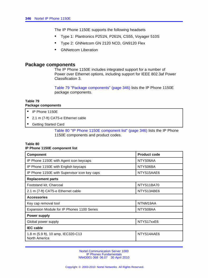
346 Nortel IP Phone 1150E
The IP Phone 1150E supports the following headsets
• Type 1: Plantronics P251N, P261N, CS55, Voyager 510S
• Type 2: GNNetcom GN 2120 NCD, GN9120 Flex
• GNNetcom Liberation
Package componentsThe IP Phone 1150E includes integrated support for a number ofPower over Ethernet options, including support for IEEE 802.3af PowerClassification 3.
Table 79 "Package components" (page 346) lists the IP Phone 1150Epackage components.
Table 79Package components
• IP Phone 1150E
• 2.1 m (7-ft) CAT5-e Ethernet cable
• Getting Started Card
Table 80 "IP Phone 1150E component list" (page 346) lists the IP Phone1150E components and product codes.
Table 80IP Phone 1150E component list
Component Product code
IP Phone 1150E with Agent icon keycaps NTYS06AA
IP Phone 1150E with English keycaps NTYS06BA
IP Phone 1150E with Supervisor icon key caps NTYS15AAE6
Replacement parts
Footstand kit, Charcoal NTYS11BA70
2.1 m (7-ft) CAT5-e Ethernet cable NTYS13ABE6
Accessories
Key cap removal tool NTNM19AA
Expansion Module for IP Phones 1100 Series NTYS08AA
Power supply
Global power supply NTYS17xxE6
IEC cable
1.8 m (5.9 ft), 10 amp, IEC320-C13North America
NTYS14AAE6
Nortel Communication Server 1000IP Phones Fundamentals
NN43001-368 06.07 30 April 2010
Copyright © 2003-2010 Nortel Networks. All Rights Reserved.
.
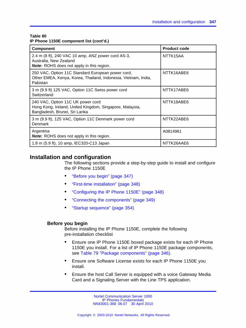
Installation and configuration 347
Table 80IP Phone 1150E component list (cont’d.)
Component Product code
2.4 m (8 ft), 240 VAC 10 amp, ANZ power cord AS-3,Australia, New ZealandNote: ROHS does not apply in this region.
NTTK15AA
250 VAC, Option 11C Standard European power cord,Other EMEA, Kenya, Korea, Thailand, Indonesia, Vietnam, India,Pakistan
NTTK16ABE6
3 m (9.9 ft) 125 VAC, Option 11C Swiss power cordSwitzerland
NTTK17ABE6
240 VAC, Option 11C UK power cordHong Kong, Ireland, United Kingdom, Singapore, Malaysia,Bangladesh, Brunei, Sri Lanka
NTTK18ABE6
3 m (9.9 ft), 125 VAC, Option 11C Denmark power cordDenmark
NTTK22ABE6
ArgentinaNote: ROHS does not apply in this region.
A0814961
1.8 m (5.9 ft), 10 amp, IEC320-C13 Japan NTTK26AAE6
Installation and configurationThe following sections provide a step-by-step guide to install and configurethe IP Phone 1150E
• “Before you begin” (page 347)
• “First-time installation” (page 348)
• “Configuring the IP Phone 1150E” (page 348)
• “Connecting the components” (page 349)
• “Startup sequence” (page 354)
Before you beginBefore installing the IP Phone 1150E, complete the followingpre-installation checklist
• Ensure one IP Phone 1150E boxed package exists for each IP Phone1150E you install. For a list of IP Phone 1150E package components,see Table 79 "Package components" (page 346).
• Ensure one Software License exists for each IP Phone 1150E youinstall.
• Ensure the host Call Server is equipped with a voice Gateway MediaCard and a Signaling Server with the Line TPS application.
Nortel Communication Server 1000IP Phones Fundamentals
NN43001-368 06.07 30 April 2010
Copyright © 2003-2010 Nortel Networks. All Rights Reserved.
.
348 Nortel IP Phone 1150E
• If a global power supply is required, ensure the approved Nortel globalpower supply (model number NTYS17xxE6) is used. See Table 80 "IPPhone 1150E component list" (page 346).
• Ensure the latest IP Phone firmware is deployed to the IP telephonynode. For more information, see Signaling Server IP Line ApplicationsFundamentals (NN43001-125).
First-time installationYou must first install an IP telephony node with the Communication Server.For information about installing an IP telephony node, see Signaling ServerIP Line Applications Fundamentals (NN43001-125).
CAUTIONDamage to EquipmentDo not plug your IP Phone 1150E into an ISDN connection.Severe damage can result.
Configuring the IP Phone 1150EUse Procedure 91 “Configuring the IP Phone 1150E” (page 348) toconfigure the IP Phone 1150E.
Procedure 91Configuring the IP Phone 1150E
Step Action
1 Configure a virtual loop on the Call Server using LD 97.
For more information about configuring a virtual loop, seeSignaling Server IP Line Applications Fundamentals (NN43001-125) and Software Input Output Reference-Administration(NN43001-611).
2 Configure the IP Phone 1150E on the Call Server using LD 11.At the prompt, enter the following:
REQ: newTYPE: 1150
For more information about configuring the IP Phone 1150E using LD 11, see Software Input Output Reference-Administration(NN43001-611).
3 Configure the IP Phone 1150E in Element Manager. IP Phonesare configured using the Phones section in the ElementManager navigation tree. For more information about configuring
Nortel Communication Server 1000IP Phones Fundamentals
NN43001-368 06.07 30 April 2010
Copyright © 2003-2010 Nortel Networks. All Rights Reserved.
.
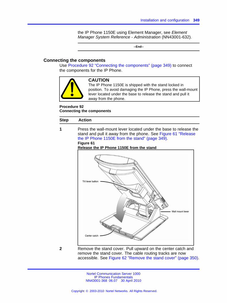
Installation and configuration 349
the IP Phone 1150E using Element Manager, see ElementManager System Reference - Administration (NN43001-632).
--End--
Connecting the componentsUse Procedure 92 “Connecting the components” (page 349) to connectthe components for the IP Phone.
CAUTIONThe IP Phone 1150E is shipped with the stand locked inposition. To avoid damaging the IP Phone, press the wall-mountlever located under the base to release the stand and pull itaway from the phone.
Procedure 92Connecting the components
Step Action
1 Press the wall-mount lever located under the base to release thestand and pull it away from the phone. See Figure 61 "Releasethe IP Phone 1150E from the stand" (page 349).Figure 61Release the IP Phone 1150E from the stand
2 Remove the stand cover. Pull upward on the center catch andremove the stand cover. The cable routing tracks are nowaccessible. See Figure 62 "Remove the stand cover" (page 350).
Nortel Communication Server 1000IP Phones Fundamentals
NN43001-368 06.07 30 April 2010
Copyright © 2003-2010 Nortel Networks. All Rights Reserved.
.
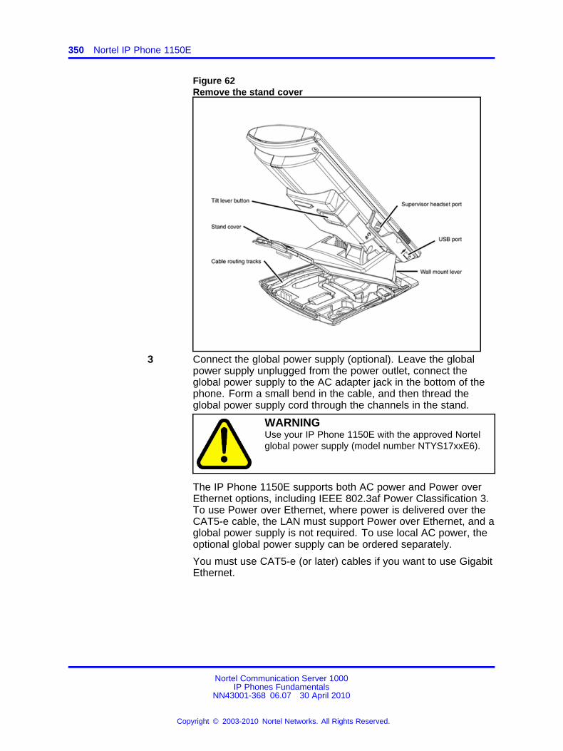
350 Nortel IP Phone 1150E
Figure 62Remove the stand cover
3 Connect the global power supply (optional). Leave the globalpower supply unplugged from the power outlet, connect theglobal power supply to the AC adapter jack in the bottom of thephone. Form a small bend in the cable, and then thread theglobal power supply cord through the channels in the stand.
WARNINGUse your IP Phone 1150E with the approved Nortelglobal power supply (model number NTYS17xxE6).
The IP Phone 1150E supports both AC power and Power overEthernet options, including IEEE 802.3af Power Classification 3.To use Power over Ethernet, where power is delivered over theCAT5-e cable, the LAN must support Power over Ethernet, and aglobal power supply is not required. To use local AC power, theoptional global power supply can be ordered separately.
You must use CAT5-e (or later) cables if you want to use GigabitEthernet.
Nortel Communication Server 1000IP Phones Fundamentals
NN43001-368 06.07 30 April 2010
Copyright © 2003-2010 Nortel Networks. All Rights Reserved.
.
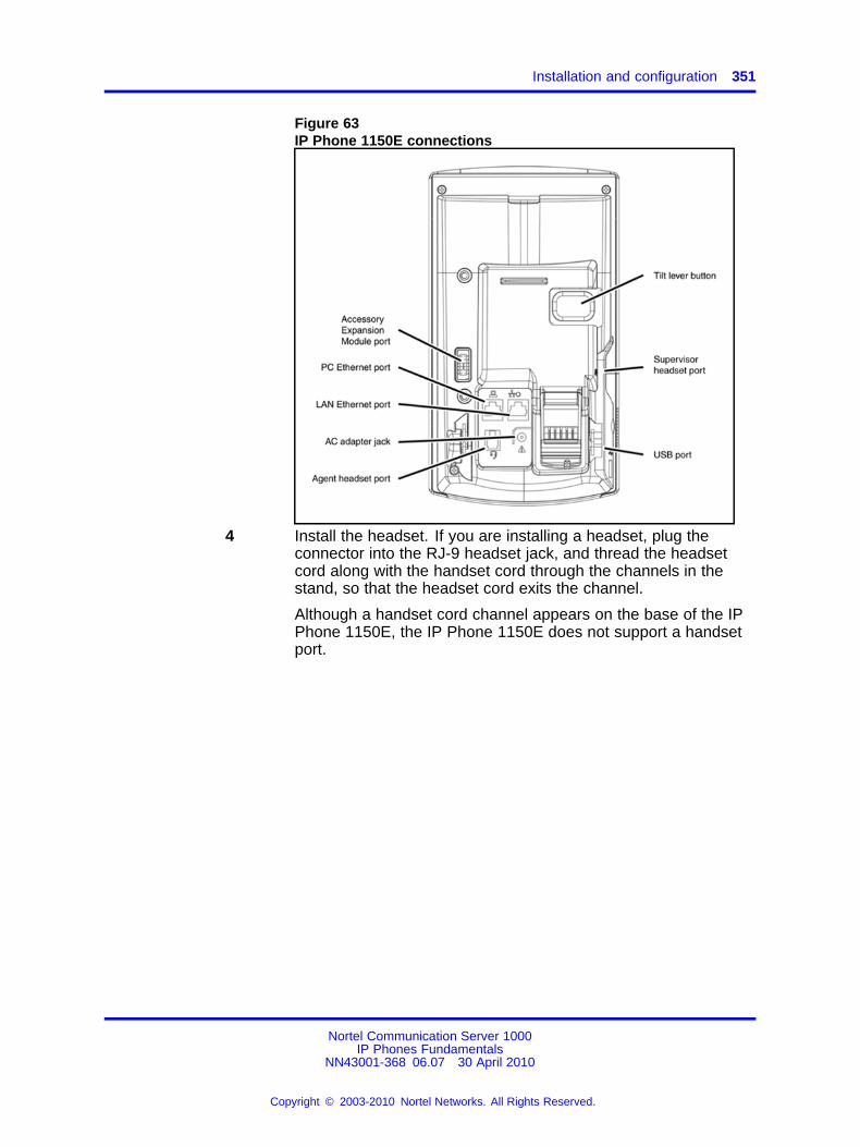
Installation and configuration 351
Figure 63IP Phone 1150E connections
4 Install the headset. If you are installing a headset, plug theconnector into the RJ-9 headset jack, and thread the headsetcord along with the handset cord through the channels in thestand, so that the headset cord exits the channel.
Although a handset cord channel appears on the base of the IPPhone 1150E, the IP Phone 1150E does not support a handsetport.
Nortel Communication Server 1000IP Phones Fundamentals
NN43001-368 06.07 30 April 2010
Copyright © 2003-2010 Nortel Networks. All Rights Reserved.
.
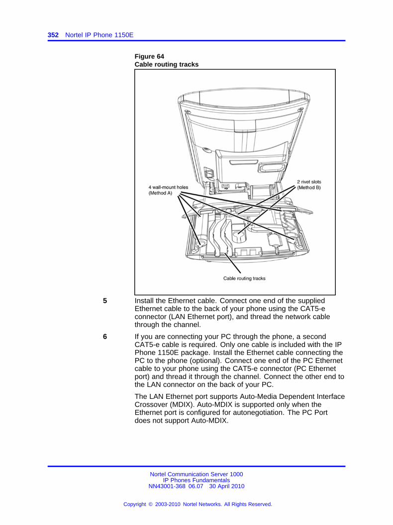
352 Nortel IP Phone 1150E
Figure 64Cable routing tracks
5 Install the Ethernet cable. Connect one end of the suppliedEthernet cable to the back of your phone using the CAT5-econnector (LAN Ethernet port), and thread the network cablethrough the channel.
6 If you are connecting your PC through the phone, a secondCAT5-e cable is required. Only one cable is included with the IPPhone 1150E package. Install the Ethernet cable connecting thePC to the phone (optional). Connect one end of the PC Ethernetcable to your phone using the CAT5-e connector (PC Ethernetport) and thread it through the channel. Connect the other end tothe LAN connector on the back of your PC.
The LAN Ethernet port supports Auto-Media Dependent InterfaceCrossover (MDIX). Auto-MDIX is supported only when theEthernet port is configured for autonegotiation. The PC Portdoes not support Auto-MDIX.
Nortel Communication Server 1000IP Phones Fundamentals
NN43001-368 06.07 30 April 2010
Copyright © 2003-2010 Nortel Networks. All Rights Reserved.
.
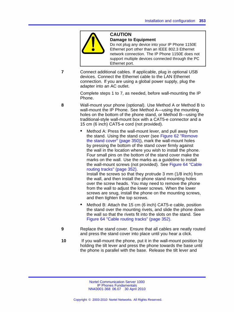
Installation and configuration 353
CAUTIONDamage to EquipmentDo not plug any device into your IP Phone 1150EEthernet port other than an IEEE 802.3 Ethernetnetwork connection. The IP Phone 1150E does notsupport multiple devices connected through the PCEthernet port.
7 Connect additional cables. If applicable, plug in optional USBdevices. Connect the Ethernet cable to the LAN Ethernetconnection. If you are using a global power supply, plug theadapter into an AC outlet.
Complete steps 1 to 7, as needed, before wall-mounting the IPPhone.
8 Wall-mount your phone (optional). Use Method A or Method B towall-mount the IP Phone. See Method A—using the mountingholes on the bottom of the phone stand, or Method B—using thetraditional-style wall-mount box with a CAT5-e connector and a15 cm (6 inch) CAT5-e cord (not provided).
• Method A: Press the wall-mount lever, and pull away fromthe stand. Using the stand cover (see Figure 62 "Removethe stand cover" (page 350)), mark the wall-mount holesby pressing the bottom of the stand cover firmly againstthe wall in the location where you wish to install the phone.Four small pins on the bottom of the stand cover make themarks on the wall. Use the marks as a guideline to installthe wall-mount screws (not provided). See Figure 64 "Cablerouting tracks" (page 352).Install the screws so that they protrude 3 mm (1/8 inch) fromthe wall, and then install the phone stand mounting holesover the screw heads. You may need to remove the phonefrom the wall to adjust the lower screws. When the lowerscrews are snug, install the phone on the mounting screws,and then tighten the top screws.
• Method B: Attach the 15 cm (6 inch) CAT5-e cable, positionthe stand over the mounting rivets, and slide the phone downthe wall so that the rivets fit into the slots on the stand. SeeFigure 64 "Cable routing tracks" (page 352).
9 Replace the stand cover. Ensure that all cables are neatly routedand press the stand cover into place until you hear a click.
10 If you wall-mount the phone, put it in the wall-mount position byholding the tilt lever and press the phone towards the base untilthe phone is parallel with the base. Release the tilt lever and
Nortel Communication Server 1000IP Phones Fundamentals
NN43001-368 06.07 30 April 2010
Copyright © 2003-2010 Nortel Networks. All Rights Reserved.
.
354 Nortel IP Phone 1150E
continue to push the phone towards the base until you hear aclick. Ensure the phone is securely locked in to position.
--End--
When you complete the IP Phone connection, you must connect the phoneto the network. See “Dynamic Host Configuration Protocol” (page 429).
Startup sequenceWhen an IP Phone 1150E connects to the network, it must perform astartup sequence. The elements of the startup sequence include
• obtaining network access (if supported by the network infrastructure)
• obtaining VLAN ID (if supported by the network infrastructure)
• obtaining the IP parameters
• obtaining the provisioning parameters
• connecting to the Call Server
The IP Phone is configured for automatic provisioning by default. Formore information about provisioning the IP Phone automatically, see“Provisioning the IP Phones” (page 497).
You can manually configure all or some parameters. For informationabout manually provisioning the IP Phone, see “Manual provisioning of IPPhones 2007 and 1100 Series” (page 553).
TFTP firmware upgradeWhen you enter the IP address of the TFTP Server, the IP Phonesearches for an upgrade file on the TFTP Server.
Users of CS 1000 Release 4.5 or later do not need to enter a TFTP IPaddress.
For further information about TFTP firmware upgrade, see “TFTP Server”(page 683).
Bluetooth® wireless technologyThe IP Phone 1150E supports Bluetooth® wireless technology . Forinformation about configuring Bluetooth® wireless technology on the IPPhone 1150E, see “Headset support” (page 573).
Nortel Communication Server 1000IP Phones Fundamentals
NN43001-368 06.07 30 April 2010
Copyright © 2003-2010 Nortel Networks. All Rights Reserved.
.
Redeploying an IP Phone 1150E 355
Redeploying an IP Phone 1150EYou can redeploy an existing previously configured IP Phone 1150E onthe same system. For example, the IP Phone 1150E can be assigned toa new user (new TN) or to an existing user who moved to a new subnetby changing the TN of the IP Phone 1150E. For further information, seeConverging the Data Network with VoIP Fundamentals (NN43001-260).
Procedure 93Changing the TN of an existing IP Phone 1150E
Step Action
1 Repower the IP Phone 1150E.
During the reboot sequence of a previously configured IP Phone,the IP Phone 1150E displays the existing node number forapproximately five seconds.
2 If the node password is enabled and NULL, choose one of thefollowing
a Disable the password.
b Set the password as non-NULL.
3 Press OK when the node number displays.
If Then
the node password is enabledand is not NULL
a password screen displays. Goto Step 4.
the node password is disabled a TN screen displays. Go to Step5.
4 Enter the password at the password screen, and press OK.
A TN screen displays.
To obtain the password, enter the nodePwdShow command inElement Manager. For further information, see Element ManagerSystem Reference - Administration (NN43001-632).
5 Select the Clear soft key to clear the existing TN.
6 Enter the new TN.
--End--
Nortel Communication Server 1000IP Phones Fundamentals
NN43001-368 06.07 30 April 2010
Copyright © 2003-2010 Nortel Networks. All Rights Reserved.
.
356 Nortel IP Phone 1150E
Replacing an IP Phone 1150EATTENTIONTwo IP Phones cannot share the same TN. You must remove the IP Phone1150E that currently uses the TN.
Procedure 94Replacing an IP Phone 1150E
Step Action
1 Obtain the node and TN information of the phone you want toreplace.
2 Disconnect the IP Phone 1150E that you want to replace.
3 Follow “Configuring the IP Phone 1150E” (page 348) to installthe IP Phone 1150E. To configure the IP Phone, see “Manualprovisioning of IP Phones 2007 and 1100 Series” (page 553).
4 Enter the same TN and Node Number as the IP Phone 1150Eyou replaced. The system associates the new IP Phone 1150Ewith the existing TN.
--End--
Removing an IP Phone 1150E from serviceProcedure 95Removing an IP Phone 1150E from service
Step Action
1 Disconnect the IP Phone 1150E from the network or turn thepower off.
The service to the PC is disconnected as well if the PC connectsto the IP Phone 1150E.
If the IP Phone 1150E was automatically configured, the DHCPlease expires and the IP address returns to the available pool.
2 In LD 11, enter the following:REQ: OUTTYPE: 1150TN: LLL S CC UU
--End--
Nortel Communication Server 1000IP Phones Fundamentals
NN43001-368 06.07 30 April 2010
Copyright © 2003-2010 Nortel Networks. All Rights Reserved.
.
357.
Nortel IP Phone 1165E
ContentsThis section contains the following topics:
• “Description” (page 357)
• “Components and functions” (page 358)
• “Features” (page 361)
• “Dialpad entry” (page 362)
• “Display characteristics” (page 363)
• “Cleaning the IP Phone display screen” (page 365)
• “Package components” (page 365)
• “Installation and configuration” (page 366)
• “TFTP firmware upgrade ” (page 373)
• “Bluetooth® wireless technology” (page 373)
• “Redeploying an IP Phone 1165E” (page 373)
• “Replacing an IP Phone 1165E” (page 374)
• “Removing an IP Phone 1165E from service” (page 375)
DescriptionThe IP Phone 1165E is a multi-line professional-level deskset with ahigh-resolution, fully-backlit, QVGA color LCD display, superior navigationexperience, integrated Bluetooth® Audio gateway and integrated phoneswitch with Gigabit Ethernet LAN and PC ports.
Figure 65 "IP Phone 1165E" (page 358) shows the IP Phone 1165E.
Nortel Communication Server 1000IP Phones Fundamentals
NN43001-368 06.07 30 April 2010
Copyright © 2003-2010 Nortel Networks. All Rights Reserved.
.
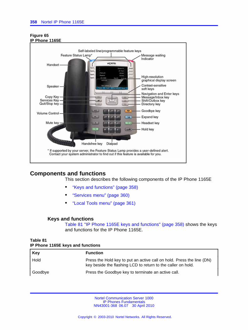
358 Nortel IP Phone 1165E
Figure 65IP Phone 1165E
Components and functionsThis section describes the following components of the IP Phone 1165E
• “Keys and functions” (page 358)
• “Services menu” (page 360)
• “Local Tools menu” (page 361)
Keys and functionsTable 81 "IP Phone 1165E keys and functions" (page 358) shows the keysand functions for the IP Phone 1165E.
Table 81IP Phone 1165E keys and functions
Key Function
Hold Press the Hold key to put an active call on hold. Press the line (DN)key beside the flashing LCD to return to the caller on hold.
Goodbye Press the Goodbye key to terminate an active call.
Nortel Communication Server 1000IP Phones Fundamentals
NN43001-368 06.07 30 April 2010
Copyright © 2003-2010 Nortel Networks. All Rights Reserved.
.
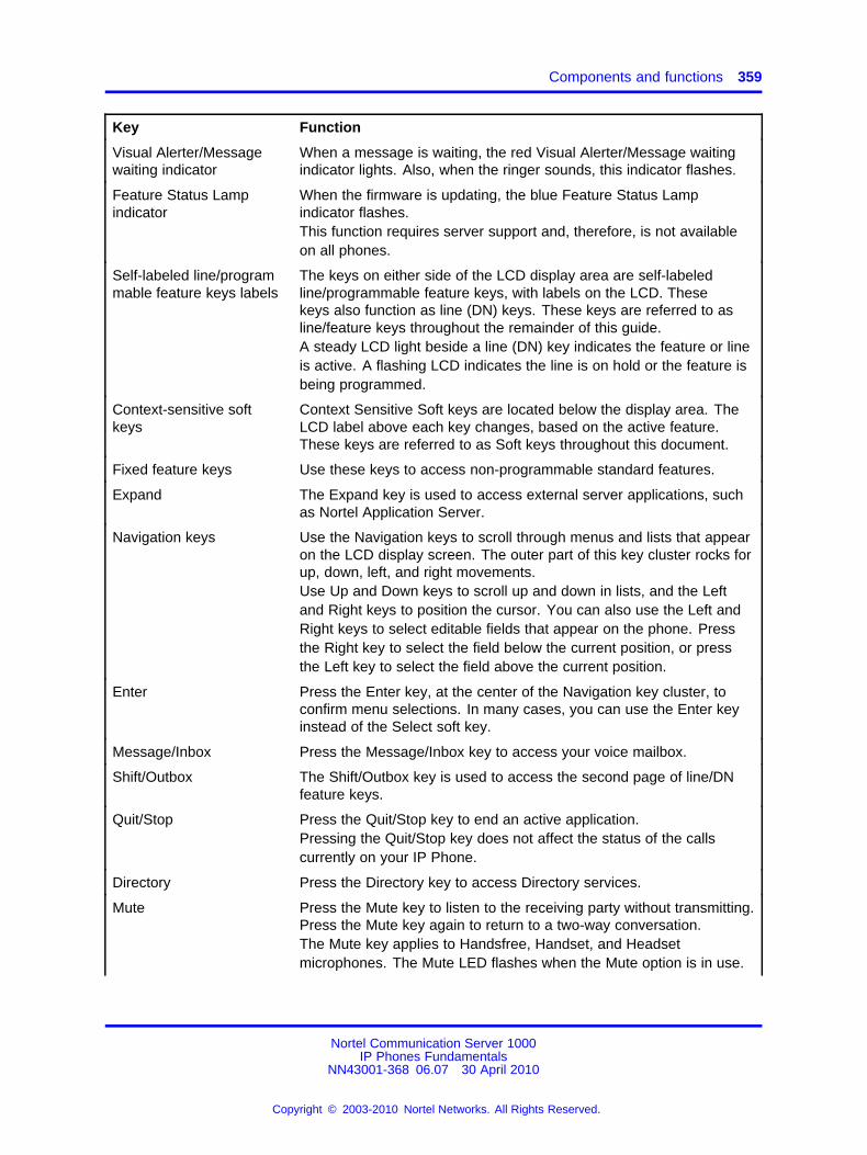
Components and functions 359
Key Function
Visual Alerter/Messagewaiting indicator
When a message is waiting, the red Visual Alerter/Message waitingindicator lights. Also, when the ringer sounds, this indicator flashes.
Feature Status Lampindicator
When the firmware is updating, the blue Feature Status Lampindicator flashes.This function requires server support and, therefore, is not availableon all phones.
Self-labeled line/programmable feature keys labels
The keys on either side of the LCD display area are self-labeledline/programmable feature keys, with labels on the LCD. Thesekeys also function as line (DN) keys. These keys are referred to asline/feature keys throughout the remainder of this guide.A steady LCD light beside a line (DN) key indicates the feature or lineis active. A flashing LCD indicates the line is on hold or the feature isbeing programmed.
Context-sensitive softkeys
Context Sensitive Soft keys are located below the display area. TheLCD label above each key changes, based on the active feature.These keys are referred to as Soft keys throughout this document.
Fixed feature keys Use these keys to access non-programmable standard features.
Expand The Expand key is used to access external server applications, suchas Nortel Application Server.
Navigation keys Use the Navigation keys to scroll through menus and lists that appearon the LCD display screen. The outer part of this key cluster rocks forup, down, left, and right movements.Use Up and Down keys to scroll up and down in lists, and the Leftand Right keys to position the cursor. You can also use the Left andRight keys to select editable fields that appear on the phone. Pressthe Right key to select the field below the current position, or pressthe Left key to select the field above the current position.
Enter Press the Enter key, at the center of the Navigation key cluster, toconfirm menu selections. In many cases, you can use the Enter keyinstead of the Select soft key.
Message/Inbox Press the Message/Inbox key to access your voice mailbox.
Shift/Outbox The Shift/Outbox key is used to access the second page of line/DNfeature keys.
Quit/Stop Press the Quit/Stop key to end an active application.Pressing the Quit/Stop key does not affect the status of the callscurrently on your IP Phone.
Directory Press the Directory key to access Directory services.
Mute Press the Mute key to listen to the receiving party without transmitting.Press the Mute key again to return to a two-way conversation.The Mute key applies to Handsfree, Handset, and Headsetmicrophones. The Mute LED flashes when the Mute option is in use.
Nortel Communication Server 1000IP Phones Fundamentals
NN43001-368 06.07 30 April 2010
Copyright © 2003-2010 Nortel Networks. All Rights Reserved.
.
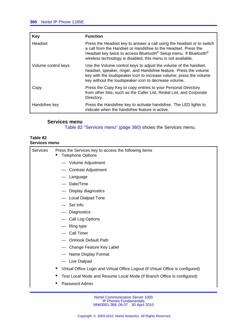
360 Nortel IP Phone 1165E
Key Function
Headset Press the Headset key to answer a call using the headset or to switcha call from the Handset or Handsfree to the Headset. Press theHeadset key twice to access Bluetooth® Setup menu. If Bluetooth®
wireless technology is disabled, this menu is not available.
Volume control keys Use the Volume control keys to adjust the volume of the handset,headset, speaker, ringer, and Handsfree feature. Press the volumekey with the loudspeaker icon to increase volume; press the volumekey without the loudspeaker icon to decrease volume.
Copy Press the Copy Key to copy entries to your Personal Directoryfrom other lists, such as the Caller List, Redial List, and CorporateDirectory.
Handsfree key Press the Handsfree key to activate handsfree. The LED lights toindicate when the handsfree feature is active.
Services menuTable 82 "Services menu" (page 360) shows the Services menu.
Table 82Services menu
Services Press the Services key to access the following items• Telephone Options
— Volume Adjustment
— Contrast Adjustment
— Language
— Date/Time
— Display diagnostics
— Local Dialpad Tone
— Set Info
— Diagnostics
— Call Log Options
— Ring type
— Call Timer
— OnHook Default Path
— Change Feature Key Label
— Name Display Format
— Live Dialpad
• Virtual Office Login and Virtual Office Logout (if Virtual Office is configured)
• Test Local Mode and Resume Local Mode (if Branch Office is configured)
• Password Admin
Nortel Communication Server 1000IP Phones Fundamentals
NN43001-368 06.07 30 April 2010
Copyright © 2003-2010 Nortel Networks. All Rights Reserved.
.
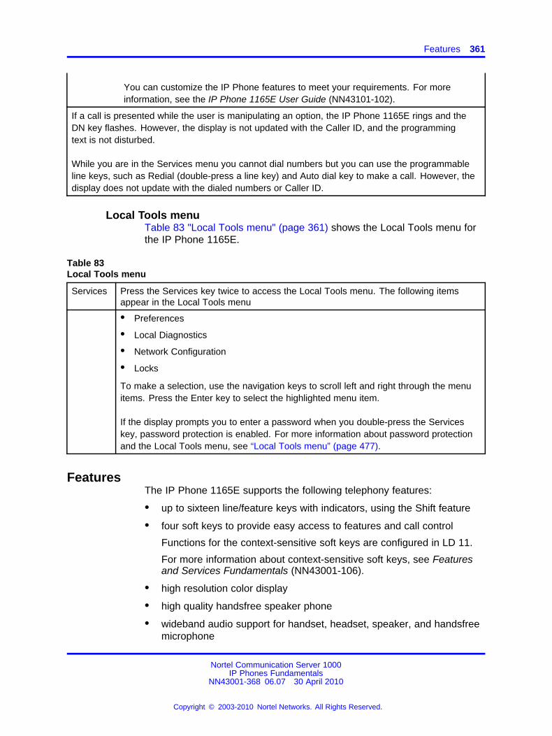
Features 361
You can customize the IP Phone features to meet your requirements. For moreinformation, see the IP Phone 1165E User Guide (NN43101-102).
If a call is presented while the user is manipulating an option, the IP Phone 1165E rings and theDN key flashes. However, the display is not updated with the Caller ID, and the programmingtext is not disturbed.
While you are in the Services menu you cannot dial numbers but you can use the programmableline keys, such as Redial (double-press a line key) and Auto dial key to make a call. However, thedisplay does not update with the dialed numbers or Caller ID.
Local Tools menuTable 83 "Local Tools menu" (page 361) shows the Local Tools menu forthe IP Phone 1165E.
Table 83Local Tools menu
Services Press the Services key twice to access the Local Tools menu. The following itemsappear in the Local Tools menu
• Preferences
• Local Diagnostics
• Network Configuration
• Locks
To make a selection, use the navigation keys to scroll left and right through the menuitems. Press the Enter key to select the highlighted menu item.
If the display prompts you to enter a password when you double-press the Serviceskey, password protection is enabled. For more information about password protectionand the Local Tools menu, see “Local Tools menu” (page 477).
FeaturesThe IP Phone 1165E supports the following telephony features:
• up to sixteen line/feature keys with indicators, using the Shift feature
• four soft keys to provide easy access to features and call control
Functions for the context-sensitive soft keys are configured in LD 11.
For more information about context-sensitive soft keys, see Featuresand Services Fundamentals (NN43001-106).
• high resolution color display
• high quality handsfree speaker phone
• wideband audio support for handset, headset, speaker, and handsfreemicrophone
Nortel Communication Server 1000IP Phones Fundamentals
NN43001-368 06.07 30 April 2010
Copyright © 2003-2010 Nortel Networks. All Rights Reserved.
.
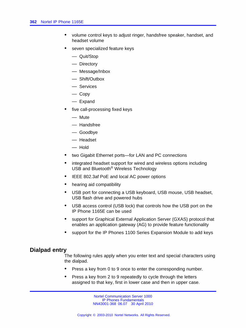
362 Nortel IP Phone 1165E
• volume control keys to adjust ringer, handsfree speaker, handset, andheadset volume
• seven specialized feature keys
— Quit/Stop
— Directory
— Message/Inbox
— Shift/Outbox
— Services
— Copy
— Expand
• five call-processing fixed keys
— Mute
— Handsfree
— Goodbye
— Headset
— Hold
• two Gigabit Ethernet ports—for LAN and PC connections
• integrated headset support for wired and wireless options includingUSB and Bluetooth® Wireless Technology
• IEEE 802.3af PoE and local AC power options
• hearing aid compatibility
• USB port for connecting a USB keyboard, USB mouse, USB headset,USB flash drive and powered hubs
• USB access control (USB lock) that controls how the USB port on theIP Phone 1165E can be used
• support for Graphical External Application Server (GXAS) protocol thatenables an application gateway (AG) to provide feature functionality
• support for the IP Phones 1100 Series Expansion Module to add keys
Dialpad entryThe following rules apply when you enter text and special characters usingthe dialpad.
• Press a key from 0 to 9 once to enter the corresponding number.
• Press a key from 2 to 9 repeatedly to cycle through the lettersassigned to that key, first in lower case and then in upper case.
Nortel Communication Server 1000IP Phones Fundamentals
NN43001-368 06.07 30 April 2010
Copyright © 2003-2010 Nortel Networks. All Rights Reserved.
.
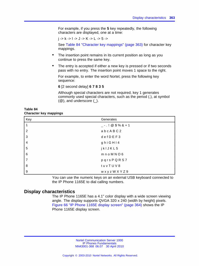
Display characteristics 363
For example, if you press the 5 key repeatedly, the followingcharacters are displayed, one at a time:
j -> k -> l -> J -> K -> L -> 5 ->
See Table 84 "Character key mappings" (page 363) for character keymappings.
• The insertion point remains in its current position as long as youcontinue to press the same key.
• The entry is accepted if either a new key is pressed or if two secondspass with no entry. The insertion point moves 1 space to the right.
For example, to enter the word Nortel, press the following keysequence:
6 [2 second delay] 6 7 8 3 5
Although special characters are not required, key 1 generatescommonly used special characters, such as the period (.), at symbol(@), and underscore (_).
Table 84Character key mappings
Key Generates
1 _ - . ! @ $ % & + 1
2 a b c A B C 2
3 d e f D E F 3
4 g h i G H I 4
5 j k l J K L 5
6 m n o M N O 6
7 p q r s P Q R S 7
8 t u v T U V 8
9 w x y z W X Y Z 9
You can use the numeric keys on an external USB keyboard connected tothe IP Phone 1165E to dial calling numbers.
Display characteristicsThe IP Phone 1165E has a 4.1" color display with a wide screen viewingangle. The display supports QVGA 320 x 240 (width by height) pixels.Figure 66 "IP Phone 1165E display screen" (page 364) shows the IPPhone 1165E display screen.
Nortel Communication Server 1000IP Phones Fundamentals
NN43001-368 06.07 30 April 2010
Copyright © 2003-2010 Nortel Networks. All Rights Reserved.
.
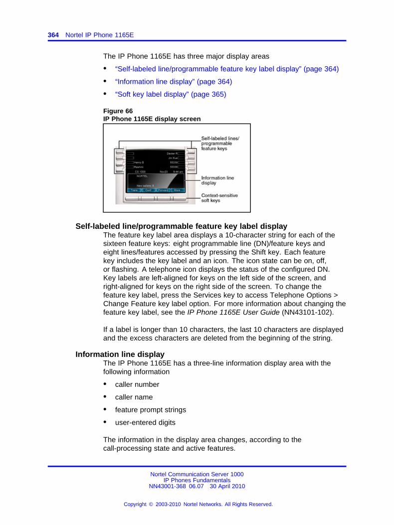
364 Nortel IP Phone 1165E
The IP Phone 1165E has three major display areas
• “Self-labeled line/programmable feature key label display” (page 364)
• “Information line display” (page 364)
• “Soft key label display” (page 365)
Figure 66IP Phone 1165E display screen
Self-labeled line/programmable feature key label displayThe feature key label area displays a 10-character string for each of thesixteen feature keys: eight programmable line (DN)/feature keys andeight lines/features accessed by pressing the Shift key. Each featurekey includes the key label and an icon. The icon state can be on, off,or flashing. A telephone icon displays the status of the configured DN.Key labels are left-aligned for keys on the left side of the screen, andright-aligned for keys on the right side of the screen. To change thefeature key label, press the Services key to access Telephone Options >Change Feature key label option. For more information about changing thefeature key label, see the IP Phone 1165E User Guide (NN43101-102).
If a label is longer than 10 characters, the last 10 characters are displayedand the excess characters are deleted from the beginning of the string.
Information line displayThe IP Phone 1165E has a three-line information display area with thefollowing information
• caller number
• caller name
• feature prompt strings
• user-entered digits
The information in the display area changes, according to thecall-processing state and active features.
Nortel Communication Server 1000IP Phones Fundamentals
NN43001-368 06.07 30 April 2010
Copyright © 2003-2010 Nortel Networks. All Rights Reserved.
.
Package components 365
Soft key label displayThe soft key label has a maximum of seven characters. Each soft keyincludes the soft key label and an icon. When a soft key is in use, atriangle icon displays at the beginning of the soft key label, and the labelshifts one character to the right. (If the label is six characters in length, thelast or rightmost character is truncated.) If a feature is enabled, the iconstate turns to On. It remains in the on state until the feature key is pressedagain. This cancels the enabled feature and turns the icon off, returningthe soft key label to its original state.
Use the More soft key to navigate through the layers of functions. If onlyfour functions are assigned to the soft keys, the More key does not appear,and all four functions are displayed.
For more information about context-sensitive soft keys, see Features andServices Fundamentals (NN43001-106).
Cleaning the IP Phone display screenGently wipe the IP Phone display screen with a soft, dry cloth.
CAUTIONDo not use any liquids or powders on the IP Phone. Usinganything other than a soft, dry cloth can contaminate IP Phonecomponents and cause premature failure.
Package componentsComponents included in the packaged IP Phone 1165E are listed in Table85 "Package components" (page 365).
Table 85Package components
• IP Phone 1165E
• handset
• handset cord
• 2.1 m (7-ft) CAT5-e Ethernet cable
• number plate and lens
• Getting Started Card - English/French
• Important Read First document
Table 86 "IP Phone 1165E component list" (page 366) lists the IP Phone1165E components and product codes.
Nortel Communication Server 1000IP Phones Fundamentals
NN43001-368 06.07 30 April 2010
Copyright © 2003-2010 Nortel Networks. All Rights Reserved.
.
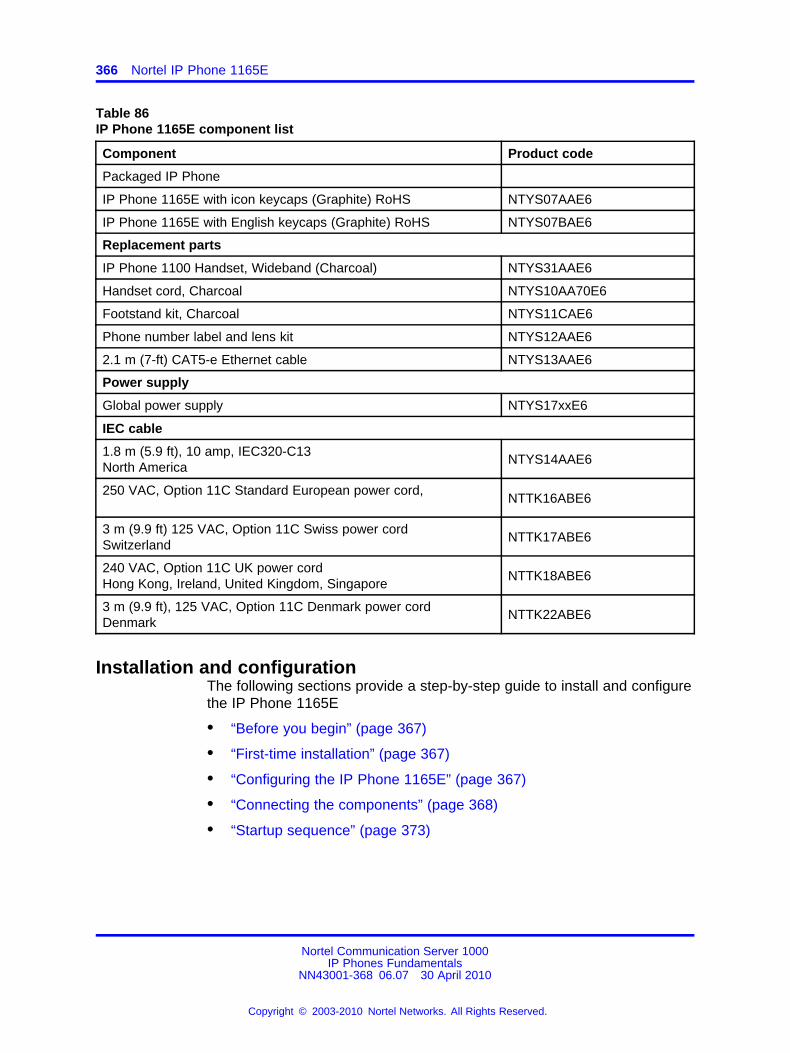
366 Nortel IP Phone 1165E
Table 86IP Phone 1165E component list
Component Product code
Packaged IP Phone
IP Phone 1165E with icon keycaps (Graphite) RoHS NTYS07AAE6
IP Phone 1165E with English keycaps (Graphite) RoHS NTYS07BAE6
Replacement parts
IP Phone 1100 Handset, Wideband (Charcoal) NTYS31AAE6
Handset cord, Charcoal NTYS10AA70E6
Footstand kit, Charcoal NTYS11CAE6
Phone number label and lens kit NTYS12AAE6
2.1 m (7-ft) CAT5-e Ethernet cable NTYS13AAE6
Power supply
Global power supply NTYS17xxE6
IEC cable
1.8 m (5.9 ft), 10 amp, IEC320-C13North America
NTYS14AAE6
250 VAC, Option 11C Standard European power cord,NTTK16ABE6
3 m (9.9 ft) 125 VAC, Option 11C Swiss power cordSwitzerland
NTTK17ABE6
240 VAC, Option 11C UK power cordHong Kong, Ireland, United Kingdom, Singapore
NTTK18ABE6
3 m (9.9 ft), 125 VAC, Option 11C Denmark power cordDenmark
NTTK22ABE6
Installation and configurationThe following sections provide a step-by-step guide to install and configurethe IP Phone 1165E
• “Before you begin” (page 367)
• “First-time installation” (page 367)
• “Configuring the IP Phone 1165E” (page 367)
• “Connecting the components” (page 368)
• “Startup sequence” (page 373)
Nortel Communication Server 1000IP Phones Fundamentals
NN43001-368 06.07 30 April 2010
Copyright © 2003-2010 Nortel Networks. All Rights Reserved.
.
Installation and configuration 367
Before you beginBefore installing the IP Phone 1165E, complete the followingpre-installation checklist
• Ensure one IP Phone 1165E boxed package exists for each IP Phone1165E you install. For a list of IP Phone 1165E package components,see Table 71 "Package components" (page 322).
• Ensure one Software License exists for each IP Phone 1165E youinstall.
• Ensure the host Call Server is equipped with a Voice Gateway MediaCard and a Signaling Server with the Line TPS application.
• Ensure a LAN is properly configured and operational
• If a global power supply is required, ensure the approved Nortel globalpower supply (model number NTYS17xxE6) is used. See Table 86 "IPPhone 1165E component list" (page 366).
• Ensure the latest IP Phone firmware is deployed to the IP telephonynode. For more information, see Signaling Server IP Line ApplicationsFundamentals (NN43001-125).
First-time installationYou must first install an IP telephony node with the Communication Server.For information about installing an IP telephony node, see Signaling ServerIP Line Applications Fundamentals (NN43001-125).
CAUTIONDamage to EquipmentDo not plug your IP Phone 1165E into an ISDN connection.Severe damage can result.
Configuring the IP Phone 1165EUse the following procedure to configure the IP Phone 1165E.
Procedure 96Configuring the IP Phone 1165E
Step Action
1 Configure a virtual loop on the Call Server using LD 97.
For more information about configuring a virtual loop, seeSignaling Server IP Line Applications Fundamentals (NN43001-125) and Software Input Output Reference-Administration(NN43001-611).
Nortel Communication Server 1000IP Phones Fundamentals
NN43001-368 06.07 30 April 2010
Copyright © 2003-2010 Nortel Networks. All Rights Reserved.
.
368 Nortel IP Phone 1165E
2 Configure the IP Phone 1165E on the Call Server using LD 11.At the prompt, enter the following
REQ: newTYPE: 1165
For more information about configuring the IP Phone 1165E using LD 11, see Software Input Output Reference-Administration(NN43001-611).
3 Configure the IP Phone 1165E in Element Manager. IP Phonesare configured using the Phones section in the ElementManager navigation tree. For more information about configuringthe IP Phone 1165E using Element Manager, see ElementManager System Reference - Administration (NN43001-632).For additional product and deployment information, including anyrequired Call Server patches, refer to the Partner InformationCenter for any related Product Bulletins.
--End--
Connecting the componentsUse the following procedure to connect the components for the IP Phone.
CAUTIONThe IP Phone 1165E is shipped with the stand locked in thewall-mount position. To avoid damaging the IP Phone, press thewall-mount lever located under the Handsfree key to release thestand and gently rotate it away from the IP phone.
Procedure 97Connecting the components
Step Action
1 Press the wall-mount lever located under the Handsfree key torelease the stand and gently rotate it away from the IP phone.See Figure 67 "Release the IP Phone 1165E from the stand"(page 369).
Nortel Communication Server 1000IP Phones Fundamentals
NN43001-368 06.07 30 April 2010
Copyright © 2003-2010 Nortel Networks. All Rights Reserved.
.
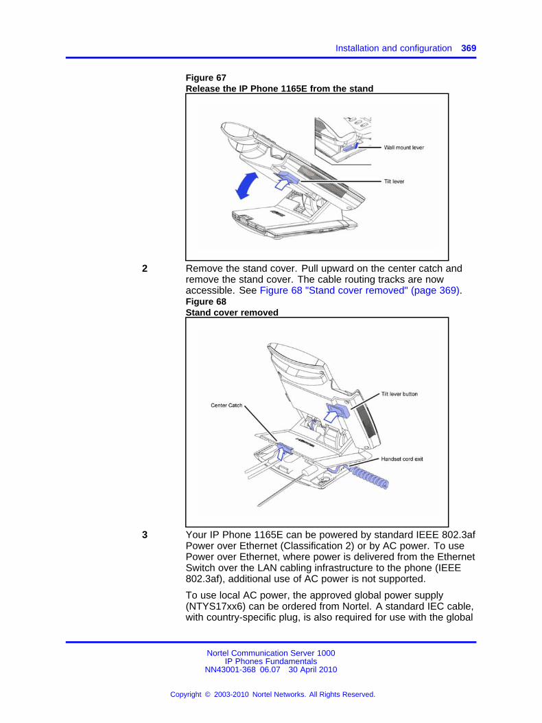
Installation and configuration 369
Figure 67Release the IP Phone 1165E from the stand
2 Remove the stand cover. Pull upward on the center catch andremove the stand cover. The cable routing tracks are nowaccessible. See Figure 68 "Stand cover removed" (page 369).Figure 68Stand cover removed
3 Your IP Phone 1165E can be powered by standard IEEE 802.3afPower over Ethernet (Classification 2) or by AC power. To usePower over Ethernet, where power is delivered from the EthernetSwitch over the LAN cabling infrastructure to the phone (IEEE802.3af), additional use of AC power is not supported.
To use local AC power, the approved global power supply(NTYS17xx6) can be ordered from Nortel. A standard IEC cable,with country-specific plug, is also required for use with the global
Nortel Communication Server 1000IP Phones Fundamentals
NN43001-368 06.07 30 April 2010
Copyright © 2003-2010 Nortel Networks. All Rights Reserved.
.
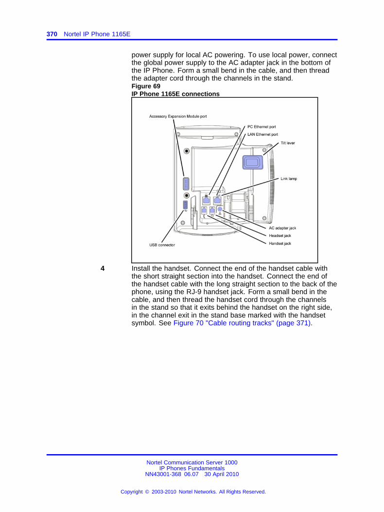
370 Nortel IP Phone 1165E
power supply for local AC powering. To use local power, connectthe global power supply to the AC adapter jack in the bottom ofthe IP Phone. Form a small bend in the cable, and then threadthe adapter cord through the channels in the stand.Figure 69IP Phone 1165E connections
4 Install the handset. Connect the end of the handset cable withthe short straight section into the handset. Connect the end ofthe handset cable with the long straight section to the back of thephone, using the RJ-9 handset jack. Form a small bend in thecable, and then thread the handset cord through the channelsin the stand so that it exits behind the handset on the right side,in the channel exit in the stand base marked with the handsetsymbol. See Figure 70 "Cable routing tracks" (page 371).
Nortel Communication Server 1000IP Phones Fundamentals
NN43001-368 06.07 30 April 2010
Copyright © 2003-2010 Nortel Networks. All Rights Reserved.
.
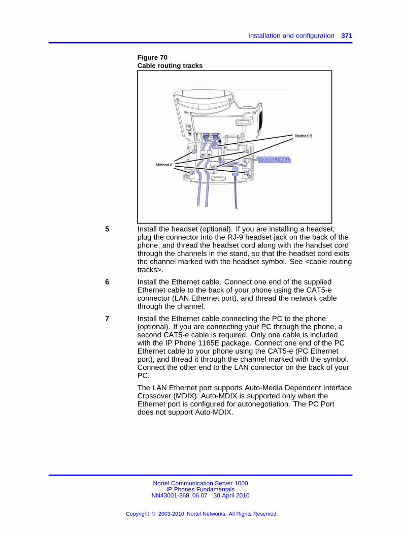
Installation and configuration 371
Figure 70Cable routing tracks
5 Install the headset (optional). If you are installing a headset,plug the connector into the RJ-9 headset jack on the back of thephone, and thread the headset cord along with the handset cordthrough the channels in the stand, so that the headset cord exitsthe channel marked with the headset symbol. See <cable routingtracks>.
6 Install the Ethernet cable. Connect one end of the suppliedEthernet cable to the back of your phone using the CAT5-econnector (LAN Ethernet port), and thread the network cablethrough the channel.
7 Install the Ethernet cable connecting the PC to the phone(optional). If you are connecting your PC through the phone, asecond CAT5-e cable is required. Only one cable is includedwith the IP Phone 1165E package. Connect one end of the PCEthernet cable to your phone using the CAT5-e (PC Ethernetport), and thread it through the channel marked with the symbol.Connect the other end to the LAN connector on the back of yourPC.
The LAN Ethernet port supports Auto-Media Dependent InterfaceCrossover (MDIX). Auto-MDIX is supported only when theEthernet port is configured for autonegotiation. The PC Portdoes not support Auto-MDIX.
Nortel Communication Server 1000IP Phones Fundamentals
NN43001-368 06.07 30 April 2010
Copyright © 2003-2010 Nortel Networks. All Rights Reserved.
.
372 Nortel IP Phone 1165E
CAUTIONDamage to EquipmentDo not plug any device into your IP Phone 1165EEthernet port other than an IEEE 802.3 Ethernetnetwork connection. The IP Phone 1165E does notsupport multiple devices connected through the PCEthernet port.
8 Connect additional cables. If applicable, plug in optional USBdevices. Connect the Ethernet cable to the LAN Ethernetconnection. If you are using a global power supply, plug theadapter into an AC outlet.
Complete steps 1 to 8, as needed, before wall-mounting the IPPhone.
9 Wall-mount your phone (optional). Use Method A or Method B towall-mount the IP Phone. See Method A—using the mountingholes on the bottom of the phone stand, or Method B—using thetraditional-style wall-mount box with a CAT5-e connector and a15 cm (6 inch) CAT5-e cord (not provided).
• Method A: Press the wall-mount lever, and pull away fromthe stand. Using the stand cover (see step 2), mark thewall-mount holes by pressing the bottom of the stand coverfirmly against the wall in the location where you wish to installthe phone. Four small pins on the bottom of the stand covermake the marks on the wall. Use the marks as a guidelineto install the wall-mount screws (not provided). Due to thewide variety of materials and construction techniques, theuser is advised to select an appropriate fastener or anchortype for the wall. Consult your local hardware store or otherexpert assistance in selecting the correct fastener for yourapplication."Install the screws so that they protrude 3 mm (1/8 inch) fromthe wall, and then install the phone stand mounting holesover the screw heads. You may need to remove the phonefrom the wall to adjust the lower screws. When the lowerscrews are snug, install the phone on the mounting screws,and then tighten the top screws.
• Method B: Attach the 15 cm (6 inch) CAT5-e cable (notincluded), position the stand over the mounting rivets, andslide the phone down the wall so that the rivets fit into theslots on the stand.
10 Replace the stand cover. Ensure that all cables are neatly routedand press the stand cover into place until you hear a click.
11 If you wall-mount the phone, put it in the wall-mount position byholding the tilt lever and press the phone towards the base untilthe phone is parallel with the base. Release the tilt lever and
Nortel Communication Server 1000IP Phones Fundamentals
NN43001-368 06.07 30 April 2010
Copyright © 2003-2010 Nortel Networks. All Rights Reserved.
.
Redeploying an IP Phone 1165E 373
continue to push the phone towards the base until you hear aclick. Ensure the phone is securely locked in to position.
--End--
When you complete the IP Phone connection, you must connect the phoneto the network. See “DHCP server configuration” (page 669).
Startup sequenceWhen an IP Phone 1165E connects to the network, it must perform astartup sequence. The elements of the startup sequence include
• obtaining network access (if supported by the network infrastructure)
• obtaining VLAN ID (if supported by the network infrastructure)
• obtaining the IP parameters
• obtaining the provisioning parameters
• connecting to the Call Server
The IP Phone is configured for automatic provisioning by default. Formore information about provisioning the IP Phone automatically, see“Provisioning the IP Phones” (page 497).
You can manually configure all or some parameters. For informationabout manually provisioning the IP Phone, see “Manual provisioning of IPPhones 2007 and 1100 Series” (page 553).
TFTP firmware upgradeWhen you enter an IP address or a server name in the Provision: item ofNetwork Configuration dialog, the IP Phone searches for an upgrade fileon the stated server.
For further information about TFTP firmware upgrade, see “TFTP Server”(page 683).
Bluetooth® wireless technologyThe IP Phone 1165E supports Bluetooth® wireless technology. Forinformation about configuring Bluetooth® wireless technology on the IPPhone 1165E, see “Headset support” (page 573).
Redeploying an IP Phone 1165EYou can redeploy an existing previously configured IP Phone 1165E onthe same Call Server. For example, the IP Phone 1165E can be assignedto a new user (new TN) or to an existing user who moved to a new subnetby changing the TN of the IP Phone 1165E. For further information, seeConverging the Data Network with VoIP Fundamentals (NN43001-260).
Nortel Communication Server 1000IP Phones Fundamentals
NN43001-368 06.07 30 April 2010
Copyright © 2003-2010 Nortel Networks. All Rights Reserved.
.
374 Nortel IP Phone 1165E
Procedure 98Changing the TN of an existing IP Phone 1165E
Step Action
1 Repower the IP Phone 1165E.
During the reboot sequence of a previously configured IP Phone,the IP Phone 1165E displays the existing node number forapproximately five seconds.
2 If the node password is enabled and NULL, choose one of thefollowing
a Disable the password.
b Set the password as non-NULL.
3 Press OK when the node number displays.
If Then
the node password is enabledand is not NULL
a password screen displays. Goto step 4.
the node password is disabled a TN screen displays. Go to step5.
4 Enter the password at the password screen, and press OK.
A TN screen displays.
To obtain the password, enter the nodePwdShow command inElement Manager. For further information, see Element ManagerSystem Reference - Administration (NN43001-632).
5 Select the Clear soft key to clear the existing TN.
6 Enter the new TN.
--End--
Replacing an IP Phone 1165EATTENTIONTwo IP Phones cannot share the same TN. You must remove the IP Phone1165E that currently uses the TN.
Procedure 99Replacing an IP Phone 1165E
Step Action
1 Obtain the node and TN information of the phone you want toreplace.
2 Disconnect the IP Phone 1165E that you want to replace.
Nortel Communication Server 1000IP Phones Fundamentals
NN43001-368 06.07 30 April 2010
Copyright © 2003-2010 Nortel Networks. All Rights Reserved.
.
Removing an IP Phone 1165E from service 375
3 To install the IP Phone 1165E, complete Procedure 96“Configuring the IP Phone 1165E” (page 367). To configure theIP Phone 1165E, see “Manual provisioning of IP Phones 2007and 1100 Series” (page 553).
4 Enter the same TN and Node Number as the IP Phone 1165Eyou replaced. The Call Server associates the new IP Phone1165E with the existing TN.
--End--
Removing an IP Phone 1165E from serviceProcedure 100Removing an IP Phone 1165E from service
Step Action
1 Disconnect the IP Phone 1165E from the network or turn thepower off.
The service to the PC is disconnected as well if the PC connectsto the IP Phone 1165E.
If the IP Phone 1165E was automatically configured, the DHCPlease expires and the IP address returns to the available pool.
2 In LD 11, enter the following:REQ: OUTTYPE: 1165TN: LLL S CC UU
--End--
Nortel Communication Server 1000IP Phones Fundamentals
NN43001-368 06.07 30 April 2010
Copyright © 2003-2010 Nortel Networks. All Rights Reserved.
.

376 Nortel IP Phone 1165E
Nortel Communication Server 1000IP Phones Fundamentals
NN43001-368 06.07 30 April 2010
Copyright © 2003-2010 Nortel Networks. All Rights Reserved.
.
377.
Expansion Module for IP Phones 1100Series
ContentsThis section contains the following topics:
• “Description” (page 377)
• “Features” (page 378)
• “Display characteristics” (page 379)
• “Package components” (page 379)
• “Configuration” (page 379)
• “Installation” (page 381)
• “Expansion Module startup initialization” (page 384)
• “Operating parameters” (page 385)
• “Services key operation” (page 386)
• “Firmware” (page 388)
DescriptionThe Expansion Module for IP Phones 1100 Series (Expansion Module) issupported on the following IP Phones
• IP Phone 1120E
• IP Phone 1140E
• IP Phone 1150E
• IP Phone 1165E
The Expansion Module is a hardware component that connects to the IPPhones and provides additional line appearances and feature keys.
Nortel Communication Server 1000IP Phones Fundamentals
NN43001-368 06.07 30 April 2010
Copyright © 2003-2010 Nortel Networks. All Rights Reserved.
.
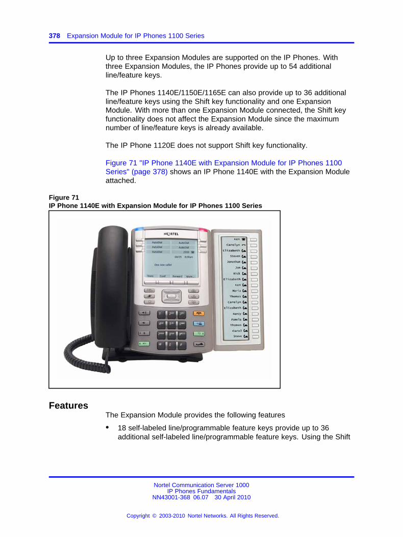
378 Expansion Module for IP Phones 1100 Series
Up to three Expansion Modules are supported on the IP Phones. Withthree Expansion Modules, the IP Phones provide up to 54 additionalline/feature keys.
The IP Phones 1140E/1150E/1165E can also provide up to 36 additionalline/feature keys using the Shift key functionality and one ExpansionModule. With more than one Expansion Module connected, the Shift keyfunctionality does not affect the Expansion Module since the maximumnumber of line/feature keys is already available.
The IP Phone 1120E does not support Shift key functionality.
Figure 71 "IP Phone 1140E with Expansion Module for IP Phones 1100Series" (page 378) shows an IP Phone 1140E with the Expansion Moduleattached.
Figure 71IP Phone 1140E with Expansion Module for IP Phones 1100 Series
FeaturesThe Expansion Module provides the following features
• 18 self-labeled line/programmable feature keys provide up to 36additional self-labeled line/programmable feature keys. Using the Shift
Nortel Communication Server 1000IP Phones Fundamentals
NN43001-368 06.07 30 April 2010
Copyright © 2003-2010 Nortel Networks. All Rights Reserved.
.
Configuration 379
key functionality, an IP Phone 1140E, for example, can have up to 66additional logical self-labeled line/programmable feature keys.
• Upgradeable firmware using a TFTP or UFTP Server.
• A desk-mount bracket and structural baseplate connect the ExpansionModule to an IP Phone or to another Expansion Module.
• IP Phone and Expansion Module combination can be wall-mountedusing the wall mount template provided.
Display characteristicsThe Expansion Module has the following display characteristics
• LCD display area—Each of the 18 line/feature keys on the ExpansionModule has a 10-character display label (see Figure 71 "IP Phone1140E with Expansion Module for IP Phones 1100 Series" (page 378)).This label is set automatically; however, the user can edit the labelusing the controls on the IP Phone.
• adjustable display and contrast settings—Use the Contrast Adjustmentoption in the Telephone Options menu on the IP Phone to adjust thedisplay and contrast settings. Any contrast changes you make on theIP Phone affect the Expansion Module. The Expansion Module and IPPhone do not have separate contrast adjustments.
• backlight—The local 48 V power supply is required to operate thebacklight on the Expansion Module; however, you can use either thelocal 48 V power supply or Power over Ethernet (PoE) to operate allother Expansion Module functionality.
Package componentsTable 87 "Expansion Module components list" (page 379) lists theExpansion Module package components.
Table 87Expansion Module components list
Expansion Module for IP Phones 1100 Series NTYS08AAE6
ConfigurationUse LD 11 to configure the Expansion Module.
Table 88LD 11 - Configure the Expansion Module
Prompt Response Description
REQ: NEW/CHG Add new or change existing data.
Nortel Communication Server 1000IP Phones Fundamentals
NN43001-368 06.07 30 April 2010
Copyright © 2003-2010 Nortel Networks. All Rights Reserved.
.
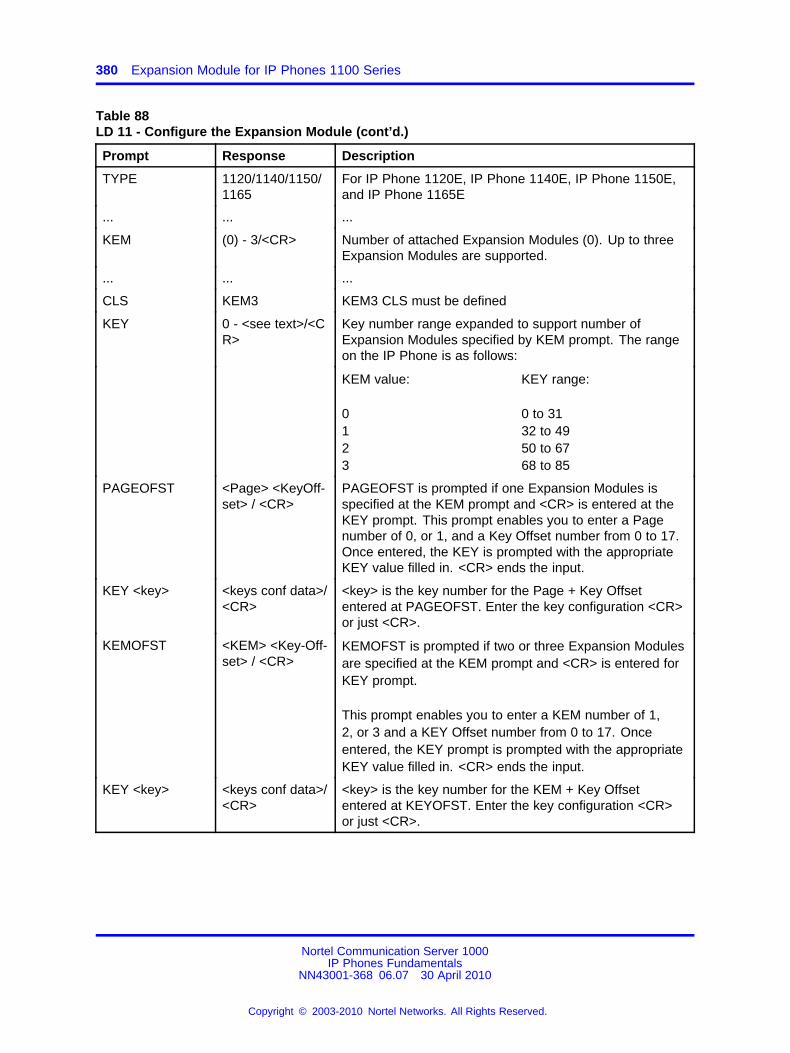
380 Expansion Module for IP Phones 1100 Series
Table 88LD 11 - Configure the Expansion Module (cont’d.)
Prompt Response Description
TYPE 1120/1140/1150/1165
For IP Phone 1120E, IP Phone 1140E, IP Phone 1150E,and IP Phone 1165E
... ... ...
KEM (0) - 3/<CR> Number of attached Expansion Modules (0). Up to threeExpansion Modules are supported.
... ... ...
CLS KEM3 KEM3 CLS must be defined
KEY 0 - <see text>/<CR>
Key number range expanded to support number ofExpansion Modules specified by KEM prompt. The rangeon the IP Phone is as follows:
KEM value:
0123
KEY range:
0 to 3132 to 4950 to 6768 to 85
PAGEOFST <Page> <KeyOff-set> / <CR>
PAGEOFST is prompted if one Expansion Modules isspecified at the KEM prompt and <CR> is entered at theKEY prompt. This prompt enables you to enter a Pagenumber of 0, or 1, and a Key Offset number from 0 to 17.Once entered, the KEY is prompted with the appropriateKEY value filled in. <CR> ends the input.
KEY <key> <keys conf data>/<CR>
<key> is the key number for the Page + Key Offsetentered at PAGEOFST. Enter the key configuration <CR>or just <CR>.
KEMOFST <KEM> <Key-Off-set> / <CR>
KEMOFST is prompted if two or three Expansion Modulesare specified at the KEM prompt and <CR> is entered forKEY prompt.
This prompt enables you to enter a KEM number of 1,2, or 3 and a KEY Offset number from 0 to 17. Onceentered, the KEY prompt is prompted with the appropriateKEY value filled in. <CR> ends the input.
KEY <key> <keys conf data>/<CR>
<key> is the key number for the KEM + Key Offsetentered at KEYOFST. Enter the key configuration <CR>or just <CR>.
Nortel Communication Server 1000IP Phones Fundamentals
NN43001-368 06.07 30 April 2010
Copyright © 2003-2010 Nortel Networks. All Rights Reserved.
.
Installation 381
InstallationThe Expansion Module mounts on the right side of the IP Phone. TheExpansion Module snaps into the receptacle on the back of the IP Phoneusing the desk-mount bracket and structural baseplate supplied with theExpansion Module.
The Expansion Module connects to the IP Phone using the AccessoryExpansion Module (AEM) port on the IP Phone.
Use Procedure 101 “Connecting the Expansion Module to the IP Phone”(page 381) to connect the Expansion Module for IP Phones 1100 Seriesto the IP Phone.
CAUTIONDamage to EquipmentTo avoid damaging the equipment, remove the power (PoEcable, or local power) from the IP Phone before connecting theExpansion Module.
CAUTIONThe Expansion Module is shipped with the base locked inposition. To avoid damaging the Expansion Module, pressthe wall-mount lever, located on the base at the front of theExpansion Module.
Procedure 101Connecting the Expansion Module to the IP Phone
Step Action
1 Press the tilt lever to adjust the stand angle on the IP Phone.See Figure 72 "Wall-mount lever" (page 382). You can adjustthe stand angle to maximum, instead of removing the stand. SeeFigure 73 "Adjusting the stand angle on the IP Phone" (page382).
Nortel Communication Server 1000IP Phones Fundamentals
NN43001-368 06.07 30 April 2010
Copyright © 2003-2010 Nortel Networks. All Rights Reserved.
.
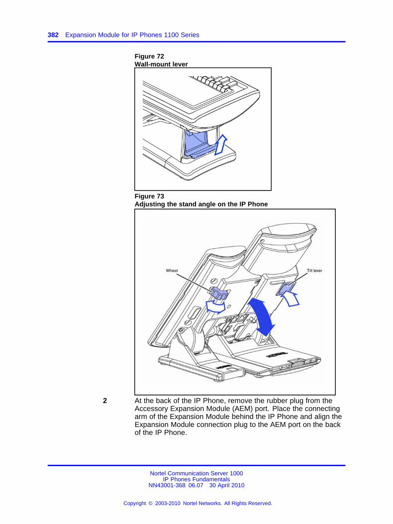
382 Expansion Module for IP Phones 1100 Series
Figure 72Wall-mount lever
Figure 73Adjusting the stand angle on the IP Phone
2 At the back of the IP Phone, remove the rubber plug from theAccessory Expansion Module (AEM) port. Place the connectingarm of the Expansion Module behind the IP Phone and align theExpansion Module connection plug to the AEM port on the backof the IP Phone.
Nortel Communication Server 1000IP Phones Fundamentals
NN43001-368 06.07 30 April 2010
Copyright © 2003-2010 Nortel Networks. All Rights Reserved.
.
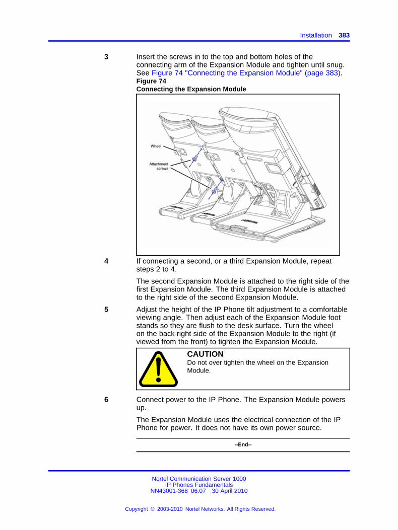
Installation 383
3 Insert the screws in to the top and bottom holes of theconnecting arm of the Expansion Module and tighten until snug.See Figure 74 "Connecting the Expansion Module" (page 383).Figure 74Connecting the Expansion Module
4 If connecting a second, or a third Expansion Module, repeatsteps 2 to 4.
The second Expansion Module is attached to the right side of thefirst Expansion Module. The third Expansion Module is attachedto the right side of the second Expansion Module.
5 Adjust the height of the IP Phone tilt adjustment to a comfortableviewing angle. Then adjust each of the Expansion Module footstands so they are flush to the desk surface. Turn the wheelon the back right side of the Expansion Module to the right (ifviewed from the front) to tighten the Expansion Module.
CAUTIONDo not over tighten the wheel on the ExpansionModule.
6 Connect power to the IP Phone. The Expansion Module powersup.
The Expansion Module uses the electrical connection of the IPPhone for power. It does not have its own power source.
--End--
Nortel Communication Server 1000IP Phones Fundamentals
NN43001-368 06.07 30 April 2010
Copyright © 2003-2010 Nortel Networks. All Rights Reserved.
.
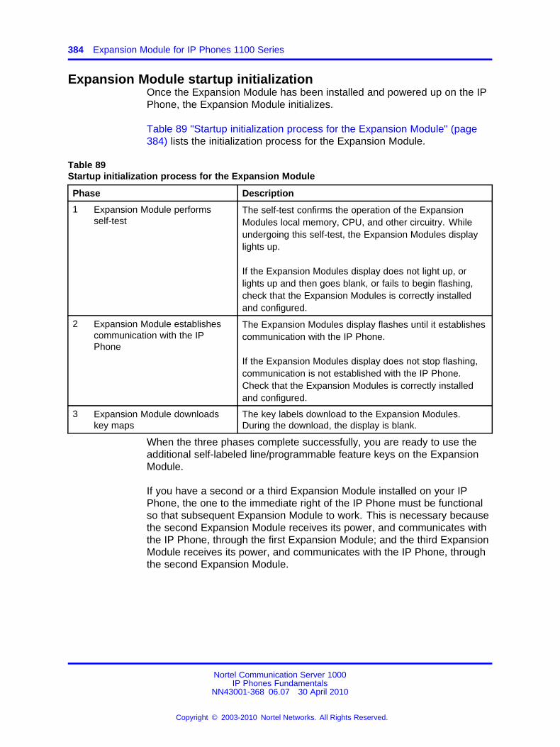
384 Expansion Module for IP Phones 1100 Series
Expansion Module startup initializationOnce the Expansion Module has been installed and powered up on the IPPhone, the Expansion Module initializes.
Table 89 "Startup initialization process for the Expansion Module" (page384) lists the initialization process for the Expansion Module.
Table 89Startup initialization process for the Expansion Module
Phase Description
1 Expansion Module performsself-test
The self-test confirms the operation of the ExpansionModules local memory, CPU, and other circuitry. Whileundergoing this self-test, the Expansion Modules displaylights up.
If the Expansion Modules display does not light up, orlights up and then goes blank, or fails to begin flashing,check that the Expansion Modules is correctly installedand configured.
2 Expansion Module establishescommunication with the IPPhone
The Expansion Modules display flashes until it establishescommunication with the IP Phone.
If the Expansion Modules display does not stop flashing,communication is not established with the IP Phone.Check that the Expansion Modules is correctly installedand configured.
3 Expansion Module downloadskey maps
The key labels download to the Expansion Modules.During the download, the display is blank.
When the three phases complete successfully, you are ready to use theadditional self-labeled line/programmable feature keys on the ExpansionModule.
If you have a second or a third Expansion Module installed on your IPPhone, the one to the immediate right of the IP Phone must be functionalso that subsequent Expansion Module to work. This is necessary becausethe second Expansion Module receives its power, and communicates withthe IP Phone, through the first Expansion Module; and the third ExpansionModule receives its power, and communicates with the IP Phone, throughthe second Expansion Module.
Nortel Communication Server 1000IP Phones Fundamentals
NN43001-368 06.07 30 April 2010
Copyright © 2003-2010 Nortel Networks. All Rights Reserved.
.
Operating parameters 385
Operating parametersIf the Expansion Module does not respond, and lines or features areconfigured on keys 32 to 85, calls can be directed to those keys whichthe user cannot access. This means that the IP Phone rings, but thecall cannot be answered. In such cases, the incoming call receives CallForward No Answer (CFNA) treatment.
IP Phone 1120EThe IP Phone 1120E does not support Shift key functionality.
If only one Expansion Module is configured in LD 11, but two or threeExpansion Modules are detected on an IP Phone 1120E, the second andthird Expansion Modules are ignored. An error message displays to alertthe administrator that the hardware configuration does not match theadministered configuration.
If two Expansion Modules are configured in LD 11, but only one ExpansionModule responds, the keys on the second Expansion Module are availablefor call processing but are not accessible to the user. This means thatlines and features on keys 32 to 67 can cause the IP Phone 1120E toring, but there is no way to answer it. An error message displays to alertthe administrator that the hardware configuration does not match theadministered configuration.
If three Expansion Modules are configured in LD 11, but only one or twoExpansion Modules respond, the keys on the third Expansion Module areavailable for call processing but are not accessible to the user. This meansthat lines and features on keys 68 to 85 can cause the IP Phone 1120Eto ring, but there is no way to answer it. An error message displays toalert the administrator that the hardware configuration does not match theadministered configuration.
IP Phone 1140E and IP Phone 1150E, and IP Phone 1165EIf only one Expansion Module is configured in LD 11, but two or threeExpansion Modules are detected on the IP Phone, the Terminal ProxyServer (TPS) assigns keys 50 to 67 to the second Expansion Module. Thethird Expansion Module does not have keys assigned until it is configuredin LD 11.An error message displays to alert the administrator that the hardwareconfiguration does not match the administered configuration.
If two Expansion Modules are configured in LD 11 but only one ExpansionModule responds, the TPS assigns keys 32 to 67 to the single ExpansionModule (using the Shift key functionality). An error message displays toalert the administrator that the hardware configuration does not match the
Nortel Communication Server 1000IP Phones Fundamentals
NN43001-368 06.07 30 April 2010
Copyright © 2003-2010 Nortel Networks. All Rights Reserved.
.
386 Expansion Module for IP Phones 1100 Series
administered configuration. When a second Expansion Module is detected,the TPS changes the key assignments to display across both ExpansionModules.
If two Expansion Modules are configured in LD 11 but three ExpansionModule respond, the TPS assigns the keys 32 to 67 to the first twoExpansion Modules. The third Expansion Module does not have keysassigned until it is configured in LD 11. An error message displays toalert the administrator that the hardware configuration does not match theadministered configuration.
If three Expansion Modules are configured but only one Expansion Moduleresponds, the TPS assigns the keys 32 to 67 to the single ExpansionModule (using the Shift key functionality). When a second ExpansionModule is detected, the TPS changes the key assignments to displayacross both Expansion Modules. Keys on the third Expansion Module areinaccessible.
If three Expansion Modules are configured in LD 11 but two ExpansionModules respond, the TPS assigns keys 32 to 85 to the first twoExpansion Modules. An error message displays to alert the administratorthat the hardware configuration does not match the administeredconfiguration. When a third Expansion Module is detected, the TPSchanges the key assignments to display across all three ExpansionModules.
Services key operationThe Services key is used to access user settings and certain featureson the IP Phone. When one or more Expansion Modules are attachedto the IP Phone, the actions of the display diagnostics for the IP PhonesDN/feature key display area are duplicated for the Expansion Modules.
If an incoming call occurs when in the diagnostic mode, the call isanswered by pressing the DN/feature key, handsfree, or headset key, orby picking up the handset. The display area remains in diagnostic modeuntil either the user exits the diagnostic more, or the idle timeout clearsthe mode. Once cleared, the normal display for the current state of the IPPhone is displayed.
Press the Services key to access the following menu items
• Display diagnostics
• Set Info
Nortel Communication Server 1000IP Phones Fundamentals
NN43001-368 06.07 30 April 2010
Copyright © 2003-2010 Nortel Networks. All Rights Reserved.
.
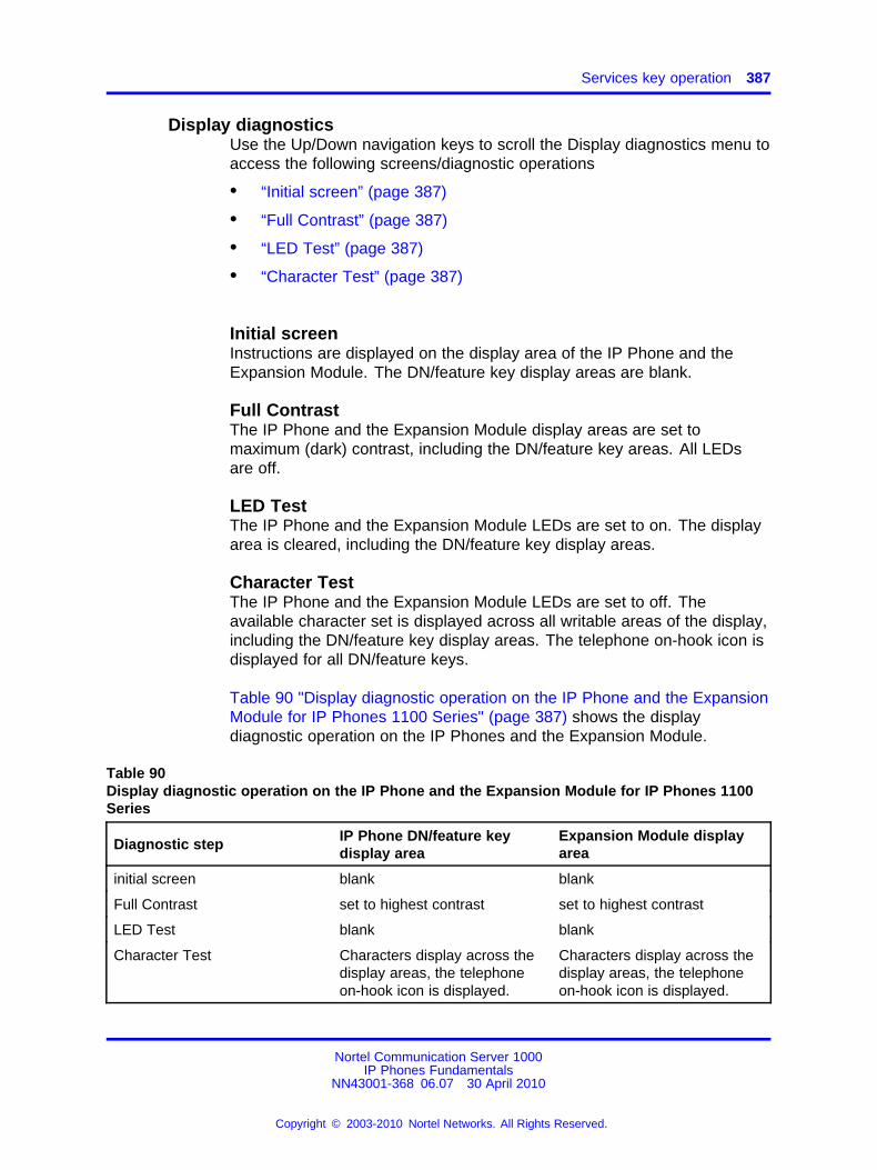
Services key operation 387
Display diagnosticsUse the Up/Down navigation keys to scroll the Display diagnostics menu toaccess the following screens/diagnostic operations
• “Initial screen” (page 387)
• “Full Contrast” (page 387)
• “LED Test” (page 387)
• “Character Test” (page 387)
Initial screenInstructions are displayed on the display area of the IP Phone and theExpansion Module. The DN/feature key display areas are blank.
Full ContrastThe IP Phone and the Expansion Module display areas are set tomaximum (dark) contrast, including the DN/feature key areas. All LEDsare off.
LED TestThe IP Phone and the Expansion Module LEDs are set to on. The displayarea is cleared, including the DN/feature key display areas.
Character TestThe IP Phone and the Expansion Module LEDs are set to off. Theavailable character set is displayed across all writable areas of the display,including the DN/feature key display areas. The telephone on-hook icon isdisplayed for all DN/feature keys.
Table 90 "Display diagnostic operation on the IP Phone and the ExpansionModule for IP Phones 1100 Series" (page 387) shows the displaydiagnostic operation on the IP Phones and the Expansion Module.
Table 90Display diagnostic operation on the IP Phone and the Expansion Module for IP Phones 1100Series
Diagnostic step IP Phone DN/feature keydisplay area
Expansion Module displayarea
initial screen blank blank
Full Contrast set to highest contrast set to highest contrast
LED Test blank blank
Character Test Characters display across thedisplay areas, the telephoneon-hook icon is displayed.
Characters display across thedisplay areas, the telephoneon-hook icon is displayed.
Nortel Communication Server 1000IP Phones Fundamentals
NN43001-368 06.07 30 April 2010
Copyright © 2003-2010 Nortel Networks. All Rights Reserved.
.
388 Expansion Module for IP Phones 1100 Series
Set InfoThe Set Info menu displays the firmware version for the IP Phone andany attached Expansion Modules. The attached Expansion Modules areidentified as KEM1, KEM2, and KEM3. KEM1 is the closest to the IPPhone. The Expansion Module identifies the firmware as a three characterstring; the TPS displays the firmware in an n.nn format.
Use the Up/Down navigation keys to scroll the list to display the firmwarefor each attached Expansion Module. The firmware version is displayedeven if the Expansion Module is not configured in LD 11. In this case, theExpansion Module is identified in the display area by an asterisk (*) afterthe Expansion Module number (for example, KEM1*).
If an Expansion Module is configured but does not respond, the firmwareversion displays as <unknown>.
FirmwareThe Expansion Module uses a TFTP or UFTP Server to upgrade thefirmware. The firmware is downloaded to the IP Phone, then distributedto each attached Expansion Module, one at a time. After the ExpansionModule confirms to the IP Phone that the firmware file is downloaded andsaved successfully, the IP Phone starts the download to the next attachedExpansion Module.
If any error causes the firmware download to fail, or if the saved firmwarefile is corrupted, the Expansion Module reverts to the factory installedfirmware. The factory installed firmware file is always available to facilitatefirmware download in case the downloaded firmware is unusable.
For more information about TFTP Server firmware upgrade, see “TFTPServer” (page 683).
For more information about Expansion Module, see Expansion Module forIP Phones 1100 Series User Guide (NN43130-101).
Nortel Communication Server 1000IP Phones Fundamentals
NN43001-368 06.07 30 April 2010
Copyright © 2003-2010 Nortel Networks. All Rights Reserved.
.
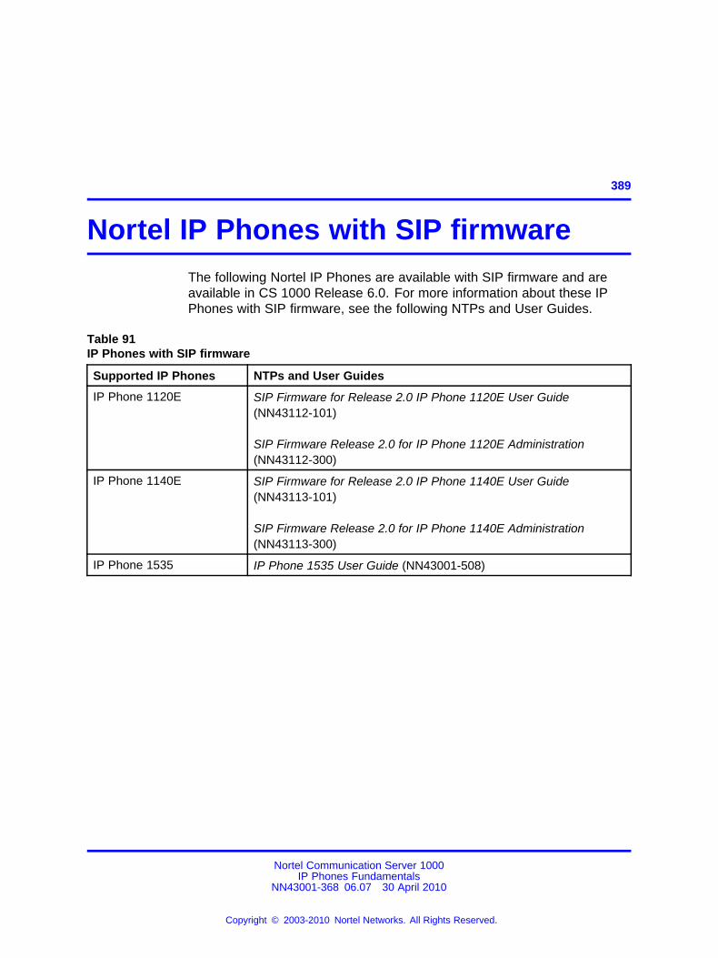
389.
Nortel IP Phones with SIP firmwareThe following Nortel IP Phones are available with SIP firmware and areavailable in CS 1000 Release 6.0. For more information about these IPPhones with SIP firmware, see the following NTPs and User Guides.
Table 91IP Phones with SIP firmware
Supported IP Phones NTPs and User Guides
IP Phone 1120E SIP Firmware for Release 2.0 IP Phone 1120E User Guide(NN43112-101)
SIP Firmware Release 2.0 for IP Phone 1120E Administration(NN43112-300)
IP Phone 1140E SIP Firmware for Release 2.0 IP Phone 1140E User Guide(NN43113-101)
SIP Firmware Release 2.0 for IP Phone 1140E Administration(NN43113-300)
IP Phone 1535 IP Phone 1535 User Guide (NN43001-508)
Nortel Communication Server 1000IP Phones Fundamentals
NN43001-368 06.07 30 April 2010
Copyright © 2003-2010 Nortel Networks. All Rights Reserved.
.

390 Nortel IP Phones with SIP firmware
Nortel Communication Server 1000IP Phones Fundamentals
NN43001-368 06.07 30 April 2010
Copyright © 2003-2010 Nortel Networks. All Rights Reserved.
.
391.
Features
ContentsThis section contains the following topics:
• “Telephony features” (page 391)
• “Network features” (page 419)
Telephony featuresThe IP Phones support the following features (unless otherwise stated).
• “Corporate Directory” (page 392)
• “Personal Directory” (page 392)
• “Redial List” (page 392)
• “Callers List” (page 393)
• “Password Administration” (page 393)
• “IP Call Recording” (page 393)
• “Secure IP Call Recording” (page 394)
• “Virtual Office” (page 395)
• “ Emergency Services for Virtual Office” (page 395)
• “Active Call Failover” (page 395)
• “Enhanced UNIStim Firmware download” (page 396)
• “Media security” (page 397)
• “UNIStim Security DTLS” (page 402)
• “UNIStim signalling security” (page 403)
• “Live Dialpad” (page 404)
• “Normal Mode Indication” (page 404)
• “Caller ID display order” (page 405)
• “Languages” (page 405)
Nortel Communication Server 1000IP Phones Fundamentals
NN43001-368 06.07 30 April 2010
Copyright © 2003-2010 Nortel Networks. All Rights Reserved.
.
392 Features
• “Screen Saver Slideshow IP Phone 2007” (page 406)
• “Screen Saver Slideshow for IP Phone 1165E” (page 410)
• “Background image for IP Phone 1165E” (page 413)
• “Key number assignments” (page 416)
• “Record on Demand” (page 418)
Personal Directory, Redial List, Callers List, Application ServerAdministration, Password Administration are software on the SignalingServer. An IP Phone must be registered to a Signaling Server to accessthese features.
Corporate DirectoryYou must press the Directory key to access the Corporate Directory. TheCorporate Directory feature extends the use of a system database, createdfrom Telephony Manager 4.0 information, to the IP Phones. This databaseis downloaded and stored on the system CPU platform. For informationabout using Corporate Directory from IP Phones, see the appropriate userguide. For details about Corporate Directory, see Features and ServicesFundamentals (NN43001-106).
Corporate Directory is not supported on the IP Phone 2001, IP AudioConference Phone 2033, IP Phone 1110, or IP Phone 1210.
Personal DirectoryYou must press the Directory key to access the Personal Directory.Personal Directory allows an end user to create and control a personaldirectory. Up to 100 Personal Directory entries can be created, edited,copied from other sources, or deleted. (For information about usingPersonal Directory on IP Phones, see the appropriate user guide. Formore information about the Personal Directory feature, see Featuresand Services Fundamentals (NN43001-106). Personal Directory uses aseparate central database, called the Application Server, to store directorydata and end-user profile options.
Personal Directory is not supported on the IP Phone 2001, IP AudioConference Phone 2033, IP Phone 1110, or IP Phone 1210.
Redial ListYou must press the Directory key to access the Redial List. Redial Listis a call log feature whose content is generated by the system duringcall processing. The list resides on the Application Server. An end usercan scroll through a list of up to 20 entries of the most recent calls dialedfrom the IP Phone and redial a selected telephone number. For more
Nortel Communication Server 1000IP Phones Fundamentals
NN43001-368 06.07 30 April 2010
Copyright © 2003-2010 Nortel Networks. All Rights Reserved.
.
Telephony features 393
information about using Redial List with IP Phones, see the appropriateuser guide. For more information about the Redial List feature, seeFeatures and Services Fundamentals (NN43001-106).
Redial List is not supported on the IP Phone 2001, IP Audio ConferencePhone 2033, IP Phone 1110, or IP Phone 1210.
Callers ListYou must press the Directory key to access the Callers List. Callers Listis a call log feature whose content is generated by the system duringcall processing. The list resides in the Application Server. An end usercan scroll through a list of up to 100 entries of the most recent callsreceived by the IP Phone and call a selected telephone number. For moreinformation about using Callers List with IP Phones, see the appropriateuser guide. For more information about the Callers List feature, seeFeatures and Services Fundamentals (NN43001-106).
Callers List is not supported on the IP Phone 2001, IP Audio ConferencePhone 2033, IP Phone 1110, or IP Phone 1210.
Password AdministrationOnce the Station Control password (SCPW) has been set by the systemadministrator on the Call Server, end users can operate this feature fromIP Phones to protect private directory information stored on the ApplicationServer. For more information about using Password Administration fromIP Phones, see the appropriate user guide. For information about thePassword Administration feature, see Signaling Server IP Line ApplicationsFundamentals (NN43001-125).
IP Call RecordingIP Call Recording enables an IP Call Recording Server to monitor themedia stream for the active call and record it by providing the IP addressand port information for an IP Phone on an active call. The followingrecording models are supported
• bulk call recording — records all calls on an IP Phone
• quality monitor recording — records individual calls on an IP Phone
If the network connection between the IP Call Recording Server and the IPPhone is lost, active calls cannot be recorded.
For more information about the IP Call Recording feature, see SignalingServer IP Line Applications Fundamentals (NN43001-125) and AutomaticCall Distribution Fundamentals (NN43001-551).
Nortel Communication Server 1000IP Phones Fundamentals
NN43001-368 06.07 30 April 2010
Copyright © 2003-2010 Nortel Networks. All Rights Reserved.
.
394 Features
Secure IP Call RecordingThe Secure IP Call Recording feature adds security to the duplicatedmedia stream from the IP Phone to the call recorder. This feature usesDatagram Transport Layer Security (DTLS) protocol to negotiate SecureReal-time Transport Protocol (SRTP) keys for the duplicated mediastream. This feature requires a call recorder with secure call recordingsupport.
The Secure IP Call Recording feature requires tokens to license thefeature on the phone. The number of tokens required is determined bythe call recorder vendor type. Four tokens are required for third-partycall recorders. The call recorder is configured in the provisioning file. Formore information about configuring the parameters for this feature, see“Provisioning the IP Phones” (page 497)
This feature requires root certificates to be installed on the phone toauthenticate the call recorder and a license. For information about rootcertificates, see “Root certificates” (page 456). For information aboutlicenses, see “Licensing” (page 597).
ATTENTIONEnable Secure Call Recording after the call recorder is upgraded to UNIStim 4.0;otherwise delays in duplicated media stream recording can result.
You can collect debug information from the PDT tools. To show the last orcurrent status of the secure call recording, including the duplicated mediaencryption setting, use listsecuritylogs and scrStatusShow at thePDT level.
The Secure IP Call Recording feature operates in two modes:
• Mirror mode
• UNIStim mode
Mirror modeThe Secure Call Recording feature operates in Mirror mode when theCall Server does not support Secure Call Recording. The call recordingsecurity mirrors the security setting of the primary media stream while theprimary media stream SRTP keys are provided using the secure UNIStimmessage.
Mirror mode is configured in the provisioning file. The default option is noencryption. If there is no encryption, the phone sends unencrypted Realtime Transfer Protocol (RTP) stream to the call recorder. If encryption
Nortel Communication Server 1000IP Phones Fundamentals
NN43001-368 06.07 30 April 2010
Copyright © 2003-2010 Nortel Networks. All Rights Reserved.
.
Telephony features 395
is enabled and the primary media stream is secure then the duplicatedmedia stream from the IP Phone to the call recorder is secured usingDTLS-SRTP.
The Call Recorder vendors are also configured in the provisioning file.
For more information about configuring the parameters for this feature, see“Provisioning the IP Phones” (page 497).
UNIStim modeIf the Call Server supports the Secure Call Recording feature, thesecurity setting of the secure call recording is under the Call Servercontrol. UNIStim mode is configured using Element Manager, UnifiedCommunications Management, or Telephony Manager.
The following list provides the three encryption options for this mode:
• Not to be encrypted
• Absolutely must be encrypted
• Encryption is best effort
Virtual OfficeThe Virtual Office feature enables end users to log into any IP Phone usingtheir own user ID and password. This redirects the telephone calls andother features to the Virtual Office logged-in IP Phone. For informationabout using Virtual Office on an IP Phone, see the appropriate user guide.For more information about the Virtual Office feature, see Signaling ServerIP Line Applications Fundamentals (NN43001-125) and Features andServices Fundamentals (NN43001-106).
Emergency Services for Virtual OfficeThe E911 for Virtual Office feature allows Virtual Office users to placean emergency call to the correct Public Safety Answering Point (PSAP)for their geographic location. For more information about the E911 forVirtual Office feature, see Emergency Service Access Fundamentals(NN43001-613).
Active Call FailoverThe Active Call Failover (ACF) feature enables an IP Phone to reregister inthe ACF mode during a Signaling Server failure.
Nortel Communication Server 1000IP Phones Fundamentals
NN43001-368 06.07 30 April 2010
Copyright © 2003-2010 Nortel Networks. All Rights Reserved.
.
396 Features
The ACF mode preserves the following
• active media stream
• LED status of the Mute, Handsfree, and Headset keys
• DRAM content
All other elements (feature keys, soft keys and text areas) are retaineduntil the user presses a key or the connection with the Signaling Serveris resumed. If the user presses a key during the failover, the display iscleared and a localized "Server Unreachable" message is displayed.
The IP Phone uses this new mode of reregistration only when theSignaling Server explicitly tells the IP Phone to do so. IP Phones clearall call information if they register to a Signaling Server or Line TerminalProxy Server (LTPS) that does not support the ACF feature.
For more information about Active Call Failover, see Signaling Server IPLine Applications Fundamentals (NN43001-125).
Enhanced UNIStim Firmware downloadEnhanced UNIStim firmware download feature provides the followingfunctionality for IP Phones
• Enhanced firmware file header that includes the IT_TYPE and namestring for each IP Phone type.
• Revised definition of the IP Phone identification of the IP Phone Client.
• Maintenance Mode for the Signaling Server that allows moresimultaneous firmware downloads.
Maintenance Mode is not applicable to Voice Media Gateway Cards.
• Identification of the registered IP Phones using string names anddetailed identification of IP Phones that register as emulations of thebase IP Phone 2001, IP Phone 2002, and IP Phone 2004.
• UNIStim IP Phones are able to register with older versions of firmwarewhen the UFTP servers are busy, and are periodically offered anoption to start the firmware upgrade to the IP Phone.
Enhanced UNIStim Firmware download feature requires a Signaling Serverto be present on the node. Without a Signaling Server, the only firmwarefiles available for downloading are the three available in CS Release 4.0for the Phase 0/1/2 IP Phone 2001, IP Phone 2002, and IP Phone 2004.
For further information about Enhanced UNIStim Firmware download andIP Phone firmware upgrade using Element Manager, see Signaling ServerIP Line Applications Fundamentals (NN43001-125).
Nortel Communication Server 1000IP Phones Fundamentals
NN43001-368 06.07 30 April 2010
Copyright © 2003-2010 Nortel Networks. All Rights Reserved.
.
Telephony features 397
Media securityMedia security normally shares keys using a secure UNIStim channel. Insituations where CS 1000 Release 5.0 or later is not available, you canuse Pre-Shared keys (PSK).
For CS 1000 Release 5.0 and later, the controlling Call Server provides allof the keying material and control of the SRTP operation.
For CS 1000 Release 4.5 or earlier, the key is protected by a presharedsecret embedded in the IP Phone to generate and exchange encryptionparameters.
For more information about the Media Security feature, see SecurityManagement Fundamentals (NN43001-604).
The Media Security feature is supported on the following IP Phones:
• IP Phone 2001
• IP Phone 2002
• IP Phone 2004
• IP Phone 2007
• IP Phone 1110
• IP Phone 1120E
• IP Phone 1140E
• IP Phone 1150E
• IP Phone 1165E
• IP Softphone 2050
• IP Phone 1210
• IP Phone 1220
• IP Phone 1230
ATTENTIONThe IP Softphone 2050 supports media security for CS 1000 Release 5.0and later. The IP Softphone 2050 supports UNIStim key (USK) SRTP mediaencryption only.
Media security is not available on the IP Phones 1210, 1220, and 1230 for thefollowing payloads: G.711 10ms, G.723 10ms, and G.729 10ms
Nortel Communication Server 1000IP Phones Fundamentals
NN43001-368 06.07 30 April 2010
Copyright © 2003-2010 Nortel Networks. All Rights Reserved.
.
398 Features
Operating parametersThe Media Security feature has the following operating parameters
• During a firmware upgrade, the Media security is automaticallydisabled.
• Media security does not support duplicate media streams encryption,such as IP Call Recording.
• Pre-Shared key (PSK) SRTP media encryption negotiates after thecall is setup. The first few seconds of the call can sometimes beunsecured; after the lock icon displays the call is secure. UNIStim key(USK) SRTP media encryption is negotiated before the call is setupso no delays occur. In both versions of SRTP the call is secure whenthe lock displays.
When USK SRTP negotiates, an outlined lock icon and Encryptedappears on the display. When PSK SRTP negotiates, a solid lock icondisplays but Encrypted does not display.
ATTENTIONA maximum of 24 characters for a name in the Personal Directory, CallersList, or Redial List can appear in the display area. If PSK SRTP is enabledand the name has the maximum of 24 characters, the last character in thename truncates to display the secure lock icon.
• SRTP PSK does not negotiate if you use 10ms G.729, due to thesmall payload size. The call remains in RTP. All other payloads aresupported for PSK SRTP. USK SRTP supports all payloads.
ATTENTIONThe IP Phone 1210, IP Phone 1220, and IP Phone 1230 do not support 10msG.729.
ConfigurationFor CS 1000 Release 5.0 or later, you can configure a system-wideconfiguration setting (USK SRTP), which controls whether or not the CS1000 system is capable of providing Media Security.
It is possible to enable both PSK SRTP on the IP Phone and configureUSK SRTP at the Call Server. If USK SRTP does not negotiate for a call,PSK SRTP attempts to negotiate during a call. If the two endpoints for thecall have PSK SRTP enabled, the call is encrypted using PSK SRTP.
By default, Media Security is enabled on the system. To configure USKSRTP, see “USK SRTP configuration” (page 399) . To configure PSKSRTP on the IP Phone, see “PSK SRTP configuration” (page 399) .
Nortel Communication Server 1000IP Phones Fundamentals
NN43001-368 06.07 30 April 2010
Copyright © 2003-2010 Nortel Networks. All Rights Reserved.
.
Telephony features 399
USK SRTP configuration Use LD 17 to configure a system-wide Classof Service parameter for IP Phones called Media Security System Default(MSSD). The system default value is one of the following:
• Always Secure IP (MSAW)
• Best Effort (MSBT)
• Never (MSNV)
When you change the MSSD parameter, the system updates any IPPhones that have a Class of Service value of MSSD to use the new MSSDparameter.
Use LD 11 to configure the Media Security Class of Service on each IPPhone. The IP Phone can have any of the following values:
• MSSD
• Best Effort
• Always
• Never
For more information about configuring system-wide Media Security andconfiguring Class of Service, see Security Management Fundamentals(NN43001-604).
PSK SRTP configuration The SRTP PSK (Pre-Shared Key) mediaencryption feature provides encrypted media. A preshared secret isembedded in the Nortel IP Phone to generate and to exchange encryptionparameters without any Call Server involvement. This feature providesSRTP capabilities to IP Phones managed by call servers, which do notsupport SRTP USK (UNIStim Key). The SRTP PSK feature must not beused in networks where phone-to-phone one-way delay is greater than200 ms.
You can configure an SRTP PSK payload type ID for exchanging SRTPPSK encryption parameters, either manually or by using automaticprovisioning. You cannot manually configure the SRTP PSK payload typeID when it is provisioned automatically. The payload type ID values are 96,115, and 120. The default value is 96. SRTP PSK must be enabled beforeyou can change the payload type ID.
SRTP PSK uses RTP packets with Payload Type ID of 96 to exchange theencryption parameters. With UNIStim firmware Release 3.2, three PayloadType IDs can be selected to exchange the encryption parameters: 96, 115,and 120.
Nortel Communication Server 1000IP Phones Fundamentals
NN43001-368 06.07 30 April 2010
Copyright © 2003-2010 Nortel Networks. All Rights Reserved.
.
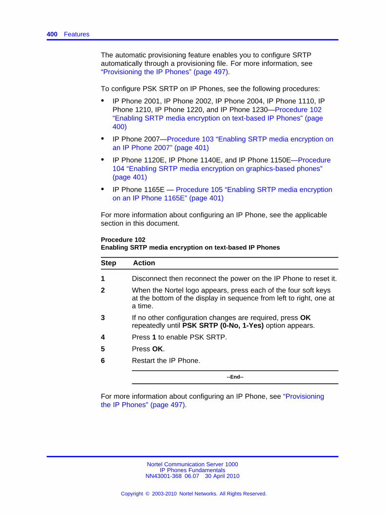
400 Features
The automatic provisioning feature enables you to configure SRTPautomatically through a provisioning file. For more information, see“Provisioning the IP Phones” (page 497).
To configure PSK SRTP on IP Phones, see the following procedures:
• IP Phone 2001, IP Phone 2002, IP Phone 2004, IP Phone 1110, IPPhone 1210, IP Phone 1220, and IP Phone 1230—Procedure 102“Enabling SRTP media encryption on text-based IP Phones” (page400)
• IP Phone 2007—Procedure 103 “Enabling SRTP media encryption onan IP Phone 2007” (page 401)
• IP Phone 1120E, IP Phone 1140E, and IP Phone 1150E—Procedure104 “Enabling SRTP media encryption on graphics-based phones”(page 401)
• IP Phone 1165E — Procedure 105 “Enabling SRTP media encryptionon an IP Phone 1165E” (page 401)
For more information about configuring an IP Phone, see the applicablesection in this document.
Procedure 102Enabling SRTP media encryption on text-based IP Phones
Step Action
1 Disconnect then reconnect the power on the IP Phone to reset it.
2 When the Nortel logo appears, press each of the four soft keysat the bottom of the display in sequence from left to right, one ata time.
3 If no other configuration changes are required, press OKrepeatedly until PSK SRTP (0-No, 1-Yes) option appears.
4 Press 1 to enable PSK SRTP.
5 Press OK.
6 Restart the IP Phone.
--End--
For more information about configuring an IP Phone, see “Provisioningthe IP Phones” (page 497).
Nortel Communication Server 1000IP Phones Fundamentals
NN43001-368 06.07 30 April 2010
Copyright © 2003-2010 Nortel Networks. All Rights Reserved.
.
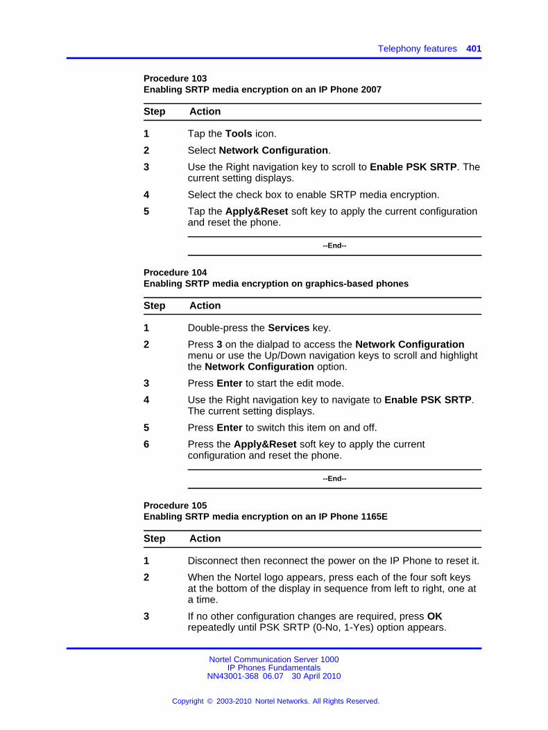
Telephony features 401
Procedure 103Enabling SRTP media encryption on an IP Phone 2007
Step Action
1 Tap the Tools icon.
2 Select Network Configuration.
3 Use the Right navigation key to scroll to Enable PSK SRTP. Thecurrent setting displays.
4 Select the check box to enable SRTP media encryption.
5 Tap the Apply&Reset soft key to apply the current configurationand reset the phone.
--End--
Procedure 104Enabling SRTP media encryption on graphics-based phones
Step Action
1 Double-press the Services key.
2 Press 3 on the dialpad to access the Network Configurationmenu or use the Up/Down navigation keys to scroll and highlightthe Network Configuration option.
3 Press Enter to start the edit mode.
4 Use the Right navigation key to navigate to Enable PSK SRTP.The current setting displays.
5 Press Enter to switch this item on and off.
6 Press the Apply&Reset soft key to apply the currentconfiguration and reset the phone.
--End--
Procedure 105Enabling SRTP media encryption on an IP Phone 1165E
Step Action
1 Disconnect then reconnect the power on the IP Phone to reset it.
2 When the Nortel logo appears, press each of the four soft keysat the bottom of the display in sequence from left to right, one ata time.
3 If no other configuration changes are required, press OKrepeatedly until PSK SRTP (0-No, 1-Yes) option appears.
Nortel Communication Server 1000IP Phones Fundamentals
NN43001-368 06.07 30 April 2010
Copyright © 2003-2010 Nortel Networks. All Rights Reserved.
.
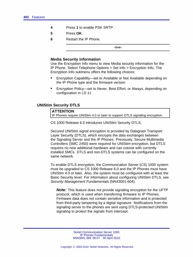
402 Features
4 Press 1 to enable PSK SRTP.
5 Press OK.
6 Restart the IP Phone.
--End--
Media Security informationUse the Encryption Info menu to view Media security information for theIP Phone. Select Telephone Options > Set Info > Encryption Info. TheEncryption Info submenu offers the following choices:
• Encryption Capability—set to Available or Not Available depending onthe IP Phone type and the firmware version
• Encryption Policy—set to Never, Best Effort, or Always, depending onconfiguration in LD 11
UNIStim Security DTLS
ATTENTIONIP Phones require UNIStim 4.0 or later to support DTLS signaling encryption.
CS 1000 Release 6.0 introduces UNIStim Security DTLS.
Secured UNIStim signal encryption is provided by Datagram TransportLayer Security (DTLS), which encrypts the data exchanges betweenthe Signaling Server and the IP Phones. Previously, Secure MultimediaControllers (SMC 2450) were required for UNIStim encryption, but DTLSrequires no new additional hardware and can coexist with currentlyinstalled SMCs. DTLS and non-DTLS systems can be configured on thesame network.
To enable DTLS encryption, the Communication Server (CS) 1000 systemmust be upgraded to CS 1000 Release 6.0 and the IP Phones must haveUNIStim 4.0 or later. Also, the system must be configured with at least theBasic Security level. For information about configuring UNIStim DTLS, seeSecurity Management Fundamentals (NN43001-604).
Note: This feature does not provide signaling encryption for the UFTPprotocol, which is used when transferring firmware to IP Phones.Firmware data does not contain sensitive information and is protectedfrom third-party tampering by a digital signature. Notifications from thesignaling server to the phones are sent using DTLS-protected UNIStimsignaling to protect the signals from intercept.
Nortel Communication Server 1000IP Phones Fundamentals
NN43001-368 06.07 30 April 2010
Copyright © 2003-2010 Nortel Networks. All Rights Reserved.
.
Telephony features 403
DTLS and IP Phone registrationThere are two modes of IP Phone registration:
• Secure Handshake mode—the IP phone is configured to initiate aDTLS session immediately upon beginning registration.
• Switchover mode—the IP phone is configured to first establish anunencrypted RUDP session to the LTPS, then switchover to DTLSdepending on the DTLS Policy.
IP Phones supporting DTLSCurrently, the following IP Phones support DTLS signaling encryption(after applicable firmware upgrade):
• IP Phones 1200 Series (IP Phone 1210/1220/1230)
• IP Phones 1100 Series (IP Phone 1110/1120E/1140E/1150E/1165E)
• IP Phones 2000 Series (IP Phone 2001/2002/2004/2007)
UNIStim signalling securityWith UNIStim 3.1, IP Phone 1120E, IP Phone 1140E, and IP Phone 2007can secure a connection with the Graphical External Application Server(GXAS) using TLS. Securing the connection validates the authenticity ofthe GXAS, using the certificate the server provides the IP Phone.
If the authenticity of the GXAS is not validated and the application gatewaysends a dial command to the IP Phone, a prompt is displayed requestingthat the user confirm dialing. When the connection to the GXAS is securedand the server authenticity is validated, the confirm prompt is not requiredand the number is automatically dialed.
When the IP Phone connection to the GXAS is secure, a security iconappears at the top right corner of the IP Phone 1120E and IP Phone1140E display screen, and at the bottom of the IP Phone 2007 displayscreen, just above the application button. The security icon appearswhether the GXAS application or the telephony screen is displayed onthe IP Phone. If the IP Phone connection to the GXAS is not secure, thesecurity icon does not appear.
To establish a secure connection between a GXAS that supports securemode and IP Phones 1120E, IP Phone 1140E, and IP Phone 2007, youmust provision the secure mode on the IP Phone manually or by using InfoBlock.
Nortel Communication Server 1000IP Phones Fundamentals
NN43001-368 06.07 30 April 2010
Copyright © 2003-2010 Nortel Networks. All Rights Reserved.
.
404 Features
To provision secure support on the IP Phone manually, you mustconfigure the XAS Mode menu item to Secure Graphical in the IPPhone configuration menu. For more information about provisioningsecure support on the IP Phone manually with XAS Mode, see Table 136"Provisioning parameters for graphic-based IP Phones" (page 556).
To provision secure support on the IP Phone using Info Block, you mustinclude s in the xa parameter character string. For more information aboutprovisioning secure support on the IP Phone using Info Block, see Table122 "Provisioning info block format" (page 520).
When secure GXAS support is configured, the GXAS must assign acertificate to the Application Server, which is then presented to the IPPhone for authentication. For the IP Phone to authenticate this servercertificate, the Certificate Authority (CA) root certificate that issued theserver certificate must be in the IP Phone trusted store. For informationabout installing and validating root certificates, see “Root certificate” (page456).
Live DialpadThe primary Directory Number (DN) key is activated when the user makesa call by dialing a DN on the dialpad without picking up the handset orpressing the Handsfree key. To set the Live Dialpad feature to On or Off,select Telephone Options > Live Dialpad. By default, Live Dialpad is set toOff.
For more information about configuring Live Dialpad, see the applicableIP Phone User Guide.
Normal Mode IndicationCS 1000 Release 6.0 introduces Normal Mode Indication.
The Normal Mode Display notification can be on or off for IP Phonesregistered in normal mode. This feature prevents the Branch User ID(BUID) overwriting the date and time on the IP Phone 2002, IP Phone1120E, and IP Phone 1220. This feature also stops infinite scrolling on theIP Phone 2001, IP Phone 1110, IP Phone 1210, and IP Audio ConferencePhone 2033.
The Normal Mode Indication menu item is only available for single-linephones with cookie support.
To turn notification on, select Telephone Options > Normal ModeIndication, and then change Normal Mode Display to On.
To turn notification off, select Telephone Options > Normal ModeIndication, and then change Normal Mode Display to Off.
Nortel Communication Server 1000IP Phones Fundamentals
NN43001-368 06.07 30 April 2010
Copyright © 2003-2010 Nortel Networks. All Rights Reserved.
.

Telephony features 405
Caller ID display orderCS 1000 Release 6.0 introduces Caller ID display order.
The Caller ID can appear in two formats:
• Number, name (Default)
• Name, number
To select the format, select Telephone Options > Caller ID display order.
If you select Number, name, then the Caller ID number always appears onthe first line. If the number and name (Calling Party Name Display [CPND]or Proffered Name Match [PNM]) cannot fit on one line, then the nameappears on the second or third line.
If you select Name, number, then the Caller ID name always appears onthe first line and the number is displayed on the second line. If the namedoes not exist, the number appears on the first line.
The Caller ID display order menu item is only available for single-linephones with cookie support.
LanguagesThe IP Phones support the following languages:
• Arabic
• Chinese Simplified
• Chinese Traditional
• Czech
• Danish
• Dutch
• English
• Finnish
• French
• German
• Greek
• Hebrew
• Hungarian
• Italian
• Japan Kanji
Nortel Communication Server 1000IP Phones Fundamentals
NN43001-368 06.07 30 April 2010
Copyright © 2003-2010 Nortel Networks. All Rights Reserved.
.
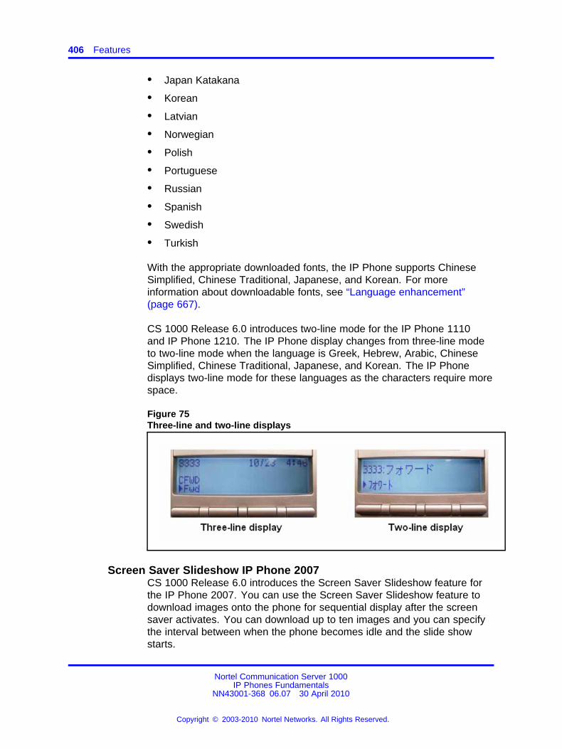
406 Features
• Japan Katakana
• Korean
• Latvian
• Norwegian
• Polish
• Portuguese
• Russian
• Spanish
• Swedish
• Turkish
With the appropriate downloaded fonts, the IP Phone supports ChineseSimplified, Chinese Traditional, Japanese, and Korean. For moreinformation about downloadable fonts, see “Language enhancement”(page 667).
CS 1000 Release 6.0 introduces two-line mode for the IP Phone 1110and IP Phone 1210. The IP Phone display changes from three-line modeto two-line mode when the language is Greek, Hebrew, Arabic, ChineseSimplified, Chinese Traditional, Japanese, and Korean. The IP Phonedisplays two-line mode for these languages as the characters require morespace.
Figure 75Three-line and two-line displays
Screen Saver Slideshow IP Phone 2007CS 1000 Release 6.0 introduces the Screen Saver Slideshow feature forthe IP Phone 2007. You can use the Screen Saver Slideshow feature todownload images onto the phone for sequential display after the screensaver activates. You can download up to ten images and you can specifythe interval between when the phone becomes idle and the slide showstarts.
Nortel Communication Server 1000IP Phones Fundamentals
NN43001-368 06.07 30 April 2010
Copyright © 2003-2010 Nortel Networks. All Rights Reserved.
.
Telephony features 407
Minimum release IP Phone UNIStim software 3.3 is required to support thenew GUI for existing IP Phone 2007.
The following sections describe the operation of the Screen SaverSlideshow feature:
• “General operation” (page 407)
• “Screen saver images” (page 408)
• “Storing screen saver images” (page 408)
• “Deleting screen saver images” (page 409)
General operationThe screen saver slideshow cycles through a list of user-supplied imagesin the phone.
The default value for the Screen Saver Slideshow feature is Off.
You can use the ScreenSaver option in the Display Settings dialog todelay the start of the slide show after the phone becomes idle. Use theDown and Up soft keys in the Display Settings dialog, ScreenSaver option,to configure a delay of
• 1 minute
• 5 minutes
• 10 minutes
• 15 minutes
• 30 minutes
• 1 hour
• 2 hours
After the slide show starts, each image displays for 10 seconds. Imagesdisplay continuously, and rotate sequentially, until the backlight timerdeactivates the backlight. If you select Display Dim Enabled, the slideshow remains visible after the backlight dims.
If you enable the screen saver and there are no images to display, yourphone does not display a screen saver.
Nortel Communication Server 1000IP Phones Fundamentals
NN43001-368 06.07 30 April 2010
Copyright © 2003-2010 Nortel Networks. All Rights Reserved.
.
408 Features
Screen saver imagesImages for use with the screen saver must be 320 x 240 pixels (heightx width) and can be either portable network graphic (PNG) or JointPhotographic Experts Group (JPEG) format. (JPEG is Recommended)Your Trivial File Transfer Protocol (TFTP) Server image directory cancontain both formats.
Name image files as screensaverN.png or screensaverN.jpg, dependingon the file format. N is a number from 0 to 9 inclusive. Because thesystem ignores file extensions, ensure that you do not duplicate filenames.
You can store up to 10 screen saver images, either in the same folderTFTP Server folder as the i2007.cfg file or in a sub-folder. If you storethe images in a sub-folder, ensure that the file path is included at thebeginning of each file name.
The following list provides examples of the image files names.
• screensaver0.png is an image file stored in the i2007.cfg file
• 2007pics/screensaver1.jpg is an image file stored in a sub-foldernamed 2007pics
Storing screen saver imagesTo send screen saver images to your phone, add a new section, called[IMAGES], to the i2007.cfg file. The [IMAGES] section can reside by itselfor with the [FW] and [FONT0N] sections. Configure the section using thecommand lines and specify the files you want to copy. Then use a TFTPserver to send images to the configuration file.
Following are the command lines you can use in the [IMAGES] sectionof the i2007.cfg file:
• DOWNLOAD_MODE (required)
• VERSION (required)
• DELETE_FILES (optional)
• FILENAME (one file name per image file)
• PROTOCOL (required; value = TFTP)
• SERVER_IP (optional if the address is the same as the one sendingthe .cfg file)
Following are the download modes that determine how the phone softwareprocesses the [IMAGES] section:
Nortel Communication Server 1000IP Phones Fundamentals
NN43001-368 06.07 30 April 2010
Copyright © 2003-2010 Nortel Networks. All Rights Reserved.
.
Telephony features 409
• DOWNLOAD_MODE=FORCED
• DOWNLOAD_MODE=AUTO when the VERSION value is greater thanthe current version value stored in the telephone
If you specify the forced download mode, your phone downloads the imageregardless of version number.
If you specify auto download mode, then VERSION specifies the version ofthe images to download. Version applies to all files listed in the [IMAGES]section. The factory default version value is 0. When images are written tothe software, the version value in the configuration file becomes the newstored version value.
Deleting screen saver imagesYou can delete screen saver image files in the following ways:
• overwrite the file
• delete all the image files
To overwrite an image file, download an image file with an identical name.
To delete all images, add a line called DELETE_FILES to the configurationfile. Follow the command with a space and the character Y or y, or thenumeral 1. If you specify any other character or numeral, or leave thespace blank, the command is ignored and the system processes theremainder of the [IMAGE] file contents.
If the [IMAGES] file contains a valid DELETE_FILES command andFILENAME parameters, the system deletes the currently stored image filesfirst and then downloads the new images.
Table 92 "Valid delete command lines" (page 409) provides an example ofvalid delete command lines.
Table 92Valid delete command lines
DELETE_FILES 1
DELETE_FILES Y
DELETE_FILES y
DELETE_FILES Yes
Table 93 "Delete image files and load new images" (page 410) provides anexample of an [IMAGES] section containing commands to delete imagefiles with a version of less than 2 and to load new images and save theversion value 2.
Nortel Communication Server 1000IP Phones Fundamentals
NN43001-368 06.07 30 April 2010
Copyright © 2003-2010 Nortel Networks. All Rights Reserved.
.
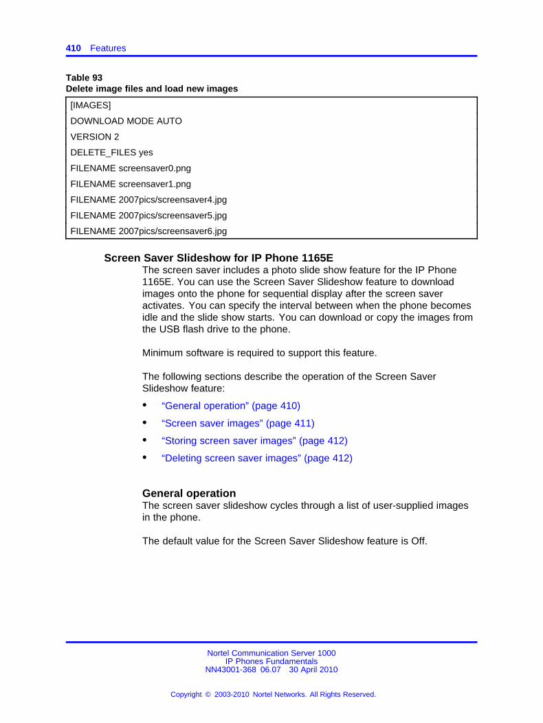
410 Features
Table 93Delete image files and load new images
[IMAGES]
DOWNLOAD MODE AUTO
VERSION 2
DELETE_FILES yes
FILENAME screensaver0.png
FILENAME screensaver1.png
FILENAME 2007pics/screensaver4.jpg
FILENAME 2007pics/screensaver5.jpg
FILENAME 2007pics/screensaver6.jpg
Screen Saver Slideshow for IP Phone 1165EThe screen saver includes a photo slide show feature for the IP Phone1165E. You can use the Screen Saver Slideshow feature to downloadimages onto the phone for sequential display after the screen saveractivates. You can specify the interval between when the phone becomesidle and the slide show starts. You can download or copy the images fromthe USB flash drive to the phone.
Minimum software is required to support this feature.
The following sections describe the operation of the Screen SaverSlideshow feature:
• “General operation” (page 410)
• “Screen saver images” (page 411)
• “Storing screen saver images” (page 412)
• “Deleting screen saver images” (page 412)
General operationThe screen saver slideshow cycles through a list of user-supplied imagesin the phone.
The default value for the Screen Saver Slideshow feature is Off.
Nortel Communication Server 1000IP Phones Fundamentals
NN43001-368 06.07 30 April 2010
Copyright © 2003-2010 Nortel Networks. All Rights Reserved.
.
Telephony features 411
You can use the ScreenSaver option in the Display Settings dialog todelay the start of the slide show after the phone becomes idle. Use theDown and Up soft keys in the Display Settings dialog, ScreenSaver option,to configure a delay of
• 1 minute
• 5 minutes
• 10 minutes
• 15 minutes
• 30 minutes
• 1 hour
• 2 hours
After the slide show starts, the phone displays the slideshow images fromthe /image directory. Images display continuously, and rotate sequentially,until the backlight timer deactivates the backlight. If you select Display DimEnabled, the slide show remains visible after the backlight dims.
If you enable the screen saver and there are no images to display, yourphone does not display a screen saver.
Screen saver imagesImages for use with the screen saver must be 240 x 320 pixels (height xwidth) and can be either 24-bit portable network graphic (PNG) or JointPhotographic Experts Group (JPEG) format. (JPEG is Recommended)Your Trivial File Transfer Protocol (TFTP) Server image directory cancontain both formats.
Name image files as screensaverN.png or screensaverN.jpg, dependingon the file format. N is a number from 0 to 99 inclusive. Because thesystem ignores file extensions, ensure that you do not duplicate filenames.
You can store images either in the same folder TFTP Server folder as the1165e.cfg file or in a sub-folder. If you store the images in a sub-folder,ensure that the file path is included at the beginning of each file name.
The following list provides examples of the image files names.
• screensaver0.png is an image file stored in the 1165e.cfg file
• 1165Epics/screensaver1.jpg is an image file stored in a sub-foldernamed 1165Epics
Nortel Communication Server 1000IP Phones Fundamentals
NN43001-368 06.07 30 April 2010
Copyright © 2003-2010 Nortel Networks. All Rights Reserved.
.
412 Features
Storing screen saver imagesTo send screen saver images to your phone, add a new section, called[IMAGES], to the 1165e.cfg file. The [IMAGES] section can reside by itselfor with the [FW] and [FONT0N] sections. Configure the section using thecommand lines and specify the files you want to copy. Then use a TFTPserver to send images to the configuration file.
Following are the command lines you can use in the [IMAGES] sectionof the 1165e.cfg file:
• DOWNLOAD_MODE (required)
• VERSION (required)
• DELETE_FILES (optional)
• REPLACE_BKGRND (optional)
• FILENAME (one file name per image file)
• PROTOCOL (required; value = TFTP)
• SERVER_IP (optional if the address is the same as the one sendingthe .cfg file)
Following are the download modes that determine how the phone softwareprocesses the [IMAGES] section:
• DOWNLOAD_MODE=FORCED
• DOWNLOAD_MODE=AUTO when the VERSION value is greater thanthe current version value stored in the telephone
If you specify the forced download mode, your phone downloads the imageregardless of version number.
If you specify auto download mode, then VERSION specifies the version ofthe images to download. Version applies to all files listed in the [IMAGES]section. The factory default version value is 0. When images are written tothe software, the version value in the configuration file becomes the newstored version value.
Deleting screen saver imagesYou can delete screen saver image files in the following ways:
• overwrite the file
• delete all the image files
To overwrite an image file, download an image file with an identical name.
Nortel Communication Server 1000IP Phones Fundamentals
NN43001-368 06.07 30 April 2010
Copyright © 2003-2010 Nortel Networks. All Rights Reserved.
.
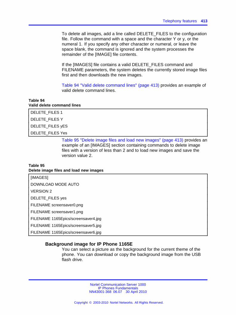
Telephony features 413
To delete all images, add a line called DELETE_FILES to the configurationfile. Follow the command with a space and the character Y or y, or thenumeral 1. If you specify any other character or numeral, or leave thespace blank, the command is ignored and the system processes theremainder of the [IMAGE] file contents.
If the [IMAGES] file contains a valid DELETE_FILES command andFILENAME parameters, the system deletes the currently stored image filesfirst and then downloads the new images.
Table 94 "Valid delete command lines" (page 413) provides an example ofvalid delete command lines.
Table 94Valid delete command lines
DELETE_FILES 1
DELETE_FILES Y
DELETE_FILES yES
DELETE_FILES Yes
Table 95 "Delete image files and load new images" (page 413) provides anexample of an [IMAGES] section containing commands to delete imagefiles with a version of less than 2 and to load new images and save theversion value 2.
Table 95Delete image files and load new images
[IMAGES]
DOWNLOAD MODE AUTO
VERSION 2
DELETE_FILES yes
FILENAME screensaver0.png
FILENAME screensaver1.png
FILENAME 1165Epics/screensaver4.jpg
FILENAME 1165Epics/screensaver5.jpg
FILENAME 1165Epics/screensaver6.jpg
Background image for IP Phone 1165EYou can select a picture as the background for the current theme of thephone. You can download or copy the background image from the USBflash drive.
Nortel Communication Server 1000IP Phones Fundamentals
NN43001-368 06.07 30 April 2010
Copyright © 2003-2010 Nortel Networks. All Rights Reserved.
.
414 Features
You can use the background image of the theme by using the Use ThemeBackground check box. This check box is selected by default. If the UseTheme Background check box is not selected, you can browse the imagesor download the image to set as background.
Note: The background image replaces the background image of thetheme only for the telephone screen. The background of the colortheme is still used for all menus and dialogs. That ensures menus willalways be readable and usable.
The following sections describe the operation of the background imagefeature:
• “Background images” (page 414)
• “Storing background images” (page 414)
• “Deleting background images” (page 415)
Background imagesImages for use with the screen saver must be 240 x 320 pixels (height xwidth) and can be either 24 bit portable network graphic (PNG) or JointPhotographic Experts Group (JPEG) format. (JPEG is recommended)Your Trivial File Transfer Protocol (TFTP) Server image directory cancontain both formats.
There can be one FILENAME entry in the [IMAGES] section for thebackground image. The image file must be named background.png orbackground.jpg. The phone ignores the filename extension once the file iscopied to it, so there can be only one background image file.
The following list provides examples of the image files names.
• background.jpg is an image file stored in the 1165e.cfg file
Storing background imagesYou can store images either in the same folder TFTP Server folder as the1165e.cfg file or in a sub-folder. If you store the images in a sub-folder,ensure that the file path is included at the beginning of each file name.
To send background images to your phone, add a new line to the section,called [IMAGES], to the 1165e.cfg file. Then use a TFTP server to sendimages to the configuration file.
Nortel Communication Server 1000IP Phones Fundamentals
NN43001-368 06.07 30 April 2010
Copyright © 2003-2010 Nortel Networks. All Rights Reserved.
.
Telephony features 415
Following are the command lines you can use in the [IMAGES] sectionof the 1165e.cfg file:
• DOWNLOAD_MODE (required)
• VERSION (required)
• DELETE_FILES (optional)
• REPLACE_BKGRND (optional)
• FILENAME (one file name per image file)
• PROTOCOL (required; value = TFTP)
• SERVER_IP (optional if the address is the same as the one sendingthe .cfg file)
Following are the download modes that determine how the phone softwareprocesses the [IMAGES] section:
• DOWNLOAD_MODE=FORCED
• DOWNLOAD_MODE=AUTO when the VERSION value is greater thanthe current version value stored in the telephone
If you specify the forced download mode, your phone downloads the imageregardless of version number.
If you specify auto download mode, then VERSION specifies the version ofthe images to download. Version applies to all files listed in the [IMAGES]section. The factory default version value is 0. When images are written tothe software, the version value in the configuration file becomes the newstored version value.
Deleting background imagesYou can delete screen saver image files in the following ways:
• overwrite the file by transferring another background file
• delete the file via the File Manager
• delete all the image files using the DELETE_FILES line
To overwrite an image file, download an image file with an identical name.
To delete all images, add a line called DELETE_FILES to the configurationfile. Follow the command with a space and the character Y or y, or thenumeral 1. If you specify any other character or numeral, or leave thespace blank, the command is ignored and the system processes theremainder of the [IMAGE] file contents.
Nortel Communication Server 1000IP Phones Fundamentals
NN43001-368 06.07 30 April 2010
Copyright © 2003-2010 Nortel Networks. All Rights Reserved.
.
416 Features
If the [IMAGES] file contains a valid DELETE_FILES command andFILENAME parameters, the system deletes the currently stored image filesfirst and then downloads the new images.
Table 96 "Valid delete command lines" (page 416) provides an example ofvalid delete command lines.
Table 96Valid delete command lines
DELETE_FILES 1
DELETE_FILES Y
DELETE_FILES yES
DELETE_FILES Yes
Table 97 "New section in 1165E.cfg file" (page 416) provides an exampleof the new section in the 1165E.cfg file. The background image in thisexample file is in a subdirectory named “1165Epics”.
Table 97New section in 1165E.cfg file
[IMAGES]
DOWNLOAD MODE AUTO
VERSION 000005
FILENAME 1165Epics/background.png
REPLACE_BKGRND yes
FILENAME screensaver0.png
Key number assignmentsThis section describes the key number assignments for the IP Phone2001, IP Phone 2002, IP Phone 2004, IP Phone 2007, IP Phone 1110,IP Phone 1120E, IP Phone 1140E, IP Phone 1150E, IP Phone 1165E IPPhone 1210, IP Phone 1220, and IP Phone 1230. The IP Phone 1150Efeature key number assignments are described in “IP Phone 1150E featurekey number assignments” (page 417).
Programmable line/feature keysKey numbers 1 to 15 are used for programmable line/feature keys. Thesekeys can be any DN or feature except for Message Waiting and thoseconfigured on keys 17 to 26.
Nortel Communication Server 1000IP Phones Fundamentals
NN43001-368 06.07 30 April 2010
Copyright © 2003-2010 Nortel Networks. All Rights Reserved.
.
Telephony features 417
Soft keysYou can assign a maximum of nine functions to the four soft-labeled,predefined soft keys. Because the soft keys are predefined, the usercannot change the key number assignment. Functions are assigned to thesoft keys in layers in LD 11.
The Message Waiting key is numbered 16.
Functions mapped to key numbers 17 to 26 are assigned to the four softkeys. Labels for the soft keys appear in the display area.
For a description of the IP Phone function assignment for each soft key,see “IP Phone context-sensitive soft keys” (page 713).
IP Phone 1150E feature key number assignmentsThis section describes the following keys supported on the IP Phone1150E
• “Self-labeled line/programmable feature keys” (page 417)
• “ACD fixed feature keys” (page 417)
• “Soft keys” (page 418)
Self-labeled line/programmable feature keys The IP Phone 1150E hassix self-labeled line/programmable feature keys, which can support up to12 DNs or features on two pages. When a call is presented on a featurekey which is not currently shown, the message Shift for Call appears in thedisplay area. Press the Shift/Outbox key to access the second page of afeature or DNs, or to access any Expansion Module 1100s attached to thephone.
The six self-labeled line/programmable feature keys are numbered 0 to 5for the first key page, and 6 to 11 for the second key page.
When key 0 is programmed as the ACD In-Calls key, the default featuresare assigned to the Automatic Call Distribution (ACD) fixed keys.
ACD fixed feature keys
Key numbers 12 to 15 are used for the ACD fixed features. See Table 98"ACD default Agent fixed feature keys" (page 418) for a list of the ACDdefault Agent fixed feature keys or Table 99 "Supervisor fixed featurekeys" (page 418) for a list of Supervisor fixed feature keys.
For a description of supported call features, see “Call features” (page 715).
Nortel Communication Server 1000IP Phones Fundamentals
NN43001-368 06.07 30 April 2010
Copyright © 2003-2010 Nortel Networks. All Rights Reserved.
.
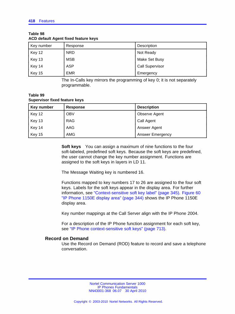
418 Features
Table 98ACD default Agent fixed feature keys
Key number Response Description
Key 12 NRD Not Ready
Key 13 MSB Make Set Busy
Key 14 ASP Call Supervisor
Key 15 EMR Emergency
The In-Calls key mirrors the programming of key 0; it is not separatelyprogrammable.
Table 99Supervisor fixed feature keys
Key number Response Description
Key 12 OBV Observe Agent
Key 13 RAG Call Agent
Key 14 AAG Answer Agent
Key 15 AMG Answer Emergency
Soft keys You can assign a maximum of nine functions to the foursoft-labeled, predefined soft keys. Because the soft keys are predefined,the user cannot change the key number assignment. Functions areassigned to the soft keys in layers in LD 11.
The Message Waiting key is numbered 16.
Functions mapped to key numbers 17 to 26 are assigned to the four softkeys. Labels for the soft keys appear in the display area. For furtherinformation, see “Context-sensitive soft key label” (page 345). Figure 60"IP Phone 1150E display area" (page 344) shows the IP Phone 1150Edisplay area.
Key number mappings at the Call Server align with the IP Phone 2004.
For a description of the IP Phone function assignment for each soft key,see “IP Phone context-sensitive soft keys” (page 713).
Record on DemandUse the Record on Demand (ROD) feature to record and save a telephoneconversation.
Nortel Communication Server 1000IP Phones Fundamentals
NN43001-368 06.07 30 April 2010
Copyright © 2003-2010 Nortel Networks. All Rights Reserved.
.
Network features 419
The ROD feature is supported on the following phones:
• IP Phone 2002
• IP Phone 2004
• IP Phone 2007
• IP Softphone 2050
• Mobile Voice Client 2050
• IP Phone 1120E
• IP Phone 1140E
• IP Phone 1150E
• IP Phone 1165E
The ROD feature has two functions:
• Record an active telephone conversation on demand
• Save an active recording
When you press the ROD key, the Call Recording (CR) application isnotified on the key press event and starts the telephone conversationrecording (as for any basic IP call recording). To stop the recording, pressthe ROD key again. You can start or stop the recording by pressing theROD key anytime time during an active call. The Save/Delete key saves ordeletes the current recording.
Record and SaveCall are displayed on the phone for ROD and SAVE keysrespectively.
For more information about the Record on Demand feature, see Featuresand Services Fundamentals (NN43001-106).
Network featuresThis section provides a description of the following IP Phone networkcapabilities
• “Full Duplex ” (page 420)
• “802.1x Port-based network access control” (page 426)
• “802.1ab Link Layer Discovery Protocol” (page 427)
• “Dynamic Host Configuration Protocol” (page 429)
• “Gratuitous Address Resolution Protocol” (page 453)
• “Automatic QoS” (page 453)
Nortel Communication Server 1000IP Phones Fundamentals
NN43001-368 06.07 30 April 2010
Copyright © 2003-2010 Nortel Networks. All Rights Reserved.
.
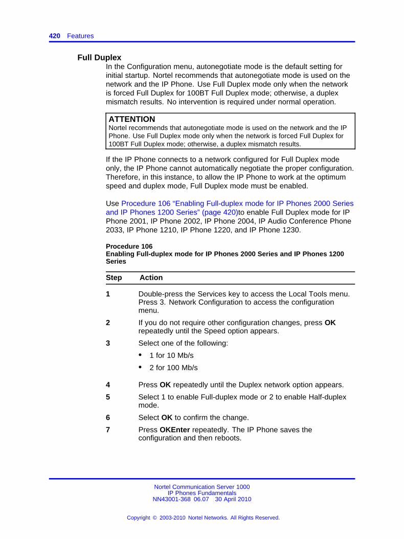
420 Features
Full DuplexIn the Configuration menu, autonegotiate mode is the default setting forinitial startup. Nortel recommends that autonegotiate mode is used on thenetwork and the IP Phone. Use Full Duplex mode only when the networkis forced Full Duplex for 100BT Full Duplex mode; otherwise, a duplexmismatch results. No intervention is required under normal operation.
ATTENTIONNortel recommends that autonegotiate mode is used on the network and the IPPhone. Use Full Duplex mode only when the network is forced Full Duplex for100BT Full Duplex mode; otherwise, a duplex mismatch results.
If the IP Phone connects to a network configured for Full Duplex modeonly, the IP Phone cannot automatically negotiate the proper configuration.Therefore, in this instance, to allow the IP Phone to work at the optimumspeed and duplex mode, Full Duplex mode must be enabled.
Use Procedure 106 “Enabling Full-duplex mode for IP Phones 2000 Seriesand IP Phones 1200 Series” (page 420)to enable Full Duplex mode for IPPhone 2001, IP Phone 2002, IP Phone 2004, IP Audio Conference Phone2033, IP Phone 1210, IP Phone 1220, and IP Phone 1230.
Procedure 106Enabling Full-duplex mode for IP Phones 2000 Series and IP Phones 1200Series
Step Action
1 Double-press the Services key to access the Local Tools menu.Press 3. Network Configuration to access the configurationmenu.
2 If you do not require other configuration changes, press OKrepeatedly until the Speed option appears.
3 Select one of the following:
• 1 for 10 Mb/s
• 2 for 100 Mb/s
4 Press OK repeatedly until the Duplex network option appears.
5 Select 1 to enable Full-duplex mode or 2 to enable Half-duplexmode.
6 Select OK to confirm the change.
7 Press OKEnter repeatedly. The IP Phone saves theconfiguration and then reboots.
Nortel Communication Server 1000IP Phones Fundamentals
NN43001-368 06.07 30 April 2010
Copyright © 2003-2010 Nortel Networks. All Rights Reserved.
.
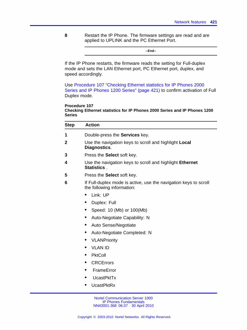
Network features 421
8 Restart the IP Phone. The firmware settings are read and areapplied to UPLINK and the PC Ethernet Port.
--End--
If the IP Phone restarts, the firmware reads the setting for Full-duplexmode and sets the LAN Ethernet port, PC Ethernet port, duplex, andspeed accordingly.
Use Procedure 107 “Checking Ethernet statistics for IP Phones 2000Series and IP Phones 1200 Series” (page 421) to confirm activation of FullDuplex mode.
Procedure 107Checking Ethernet statistics for IP Phones 2000 Series and IP Phones 1200Series
Step Action
1 Double-press the Services key.
2 Use the navigation keys to scroll and highlight LocalDiagnostics.
3 Press the Select soft key.
4 Use the navigation keys to scroll and highlight EthernetStatistics .
5 Press the Select soft key.
6 If Full-duplex mode is active, use the navigation keys to scrollthe following information:
• Link: UP
• Duplex: Full
• Speed: 10 (Mb) or 100(Mb)
• Auto-Negotiate Capability: N
• Auto Sense/Negotiate
• Auto-Negotiate Completed: N
• VLANPriority
• VLAN ID
• PktColl
• CRCErrors
• FrameError
• UcastPktTx
• UcastPktRx
Nortel Communication Server 1000IP Phones Fundamentals
NN43001-368 06.07 30 April 2010
Copyright © 2003-2010 Nortel Networks. All Rights Reserved.
.
422 Features
• BcastPktRx
• McastPktRx
• 802.1x Status
• EAP Status
--End--
Use the following procedure to enable Full Duplex mode for the IP Phone2007.
Procedure 108Enabling Full-Duplex mode for IP Phone 2007
Step Action
1 Tap the Tools icon.
2 Enter the Tools menu password (if Password protection isenabled). For information about Password Protection, see “LocalTools menu” (page 477).
3 Tap the Network Configuration menu entry.
4 Use the Right navigation key to scroll and highlight the Duplexlist.
5 Press the Down navigation key to open list box.
6 Use the Up/Down navigation keys to scroll and highlight one ofthe following options:
• 10BT Full—10 BT Full Duplex mode
• 100BT Full—100 BT Full Duplex mode
7 Tap the Apply&Reset soft key to save the changes and torestart the IP Phone. The firmware settings are read and areapplied to UPLINK and the PC Ethernet Port.
--End--
When the IP Phone restarts, the firmware reads the setting for Full Duplexmode and sets the LAN Ethernet port, PC Ethernet port, duplex, andspeed accordingly.
Use the following procedure to confirm activation of Full Duplex mode.
Nortel Communication Server 1000IP Phones Fundamentals
NN43001-368 06.07 30 April 2010
Copyright © 2003-2010 Nortel Networks. All Rights Reserved.
.
Network features 423
Procedure 109Checking Ethernet Statistics for IP Phone 2007
Step Action
1 Tap the Tools icon.
2 Tap the Local Diagnostics soft key.
3 Tap the Ethernet Statistics soft key.
The following statistics are displayed:
• Link: Up
• Duplex: Full
• Speed: 10 (Mb) or 100 (Mb)
• Auto-Negotiate Capability: N
• Auto-Negotiate Completed: N
--End--
UseProcedure 110 “Enabling Full Duplex mode for IP Phone1120E/1140E/1150E” (page 423) to enable Full Duplex mode on the IPPhone 1110, IP Phone 1120E, IP Phone 1140E, and IP Phone 1150E.
Procedure 110Enabling Full Duplex mode for IP Phone 1120E/1140E/1150E
Step Action
1 Double-press the Services key to open the Local Tools menu.
2 Press 3 on the dialpad to access the Network Configurationdialog.
3 Press the right navigation key until the Ntwk Port Duplex itemis highlighted.
Note: The Ntwk Port Speed item must be set to 10BT or100BT first.
4 Press Enter to start the edit mode.
5 Press the Down navigation key to open list box.
6 Use the Up/Down navigation keys to scroll and highlight one ofthe following options
• Force Full - forced full duplex mode
• Force Half - forced half duplex mode
Nortel Communication Server 1000IP Phones Fundamentals
NN43001-368 06.07 30 April 2010
Copyright © 2003-2010 Nortel Networks. All Rights Reserved.
.
424 Features
7 Press Enter to select the setting and exit the list.
8 Press Apply to save the settings and restart the IP Phone. Thesaved setting is read and applied to the NI ethernet port.
--End--
Use Procedure 111 “Checking Ethernet Statistics for IP Phone1120E/1140E/1150E ” (page 424) to confirm activation of Full Duplexmode.
Procedure 111Checking Ethernet Statistics for IP Phone 1120E/1140E/1150E
Step Action
1 Double-press the Services key.
2 Press 2 to select Local Diagnostics, then press 3 to open theEthernet Statistics menu.
If Full Duplex mode is active, the following is displayed
• Link Status: UP
• Duplex Mode: Full
• Network Speed: 10 Mb, 100 Mb, or 1 G
• Auto Sense/Negotiate
— Auto-Negotiate Capability: No
— Auto-Negotiate Completed: No
--End--
Use Procedure 112 “Enabling Full-Duplex mode for IP Phone 1165E”(page 424)to enable Full Duplex mode on the IP Phone 1165E.
Procedure 112Enabling Full-Duplex mode for IP Phone 1165E
Step Action
1 Double-press the Services key to open the Local Tools menu.
2 Press the left navigation key to access the Configuration menu.Then press 1 on the dialpad to open the Network Configurationdialog.
Nortel Communication Server 1000IP Phones Fundamentals
NN43001-368 06.07 30 April 2010
Copyright © 2003-2010 Nortel Networks. All Rights Reserved.
.
Network features 425
3 Press the down navigation key until the Ntwk Port Duplex itemis highlighted.
Note: The Ntwk Port Speed item must be set to 10BT or100BT first.
4 Press Enter to start the edit mode.
5 Press the Down navigation key to highlight one of the followingoptions
• Force Full - forced full duplex mode
• Force Half - forced half duplex mode
6 Press Enter to select the setting and exit the list.
7 Press Apply to save the settings and restart the IP Phone. Thesaved setting is read and applied to the NI ethernet port.
--End--
Use Procedure 113 “Checking Ethernet Statistics for IP Phone 1165E”(page 425)to confirm activation of Full Duplex mode.
Procedure 113Checking Ethernet Statistics for IP Phone 1165E
Step Action
1 Double-press the Services key to open the Local Tools menu.
2 Press the left/right navigation keys to scroll to the Diagnosticsmenu. Then press 3 on the dialpad to open the EthernetStatistics dialog.
3 If Full Duplex mode is active, the following is displayed:
• Link Status: UP
• Duplex Mode: Full
• Network Speed: 10 Mb, 100 Mb, or 1 G
• Auto Sense/Negotiate
— Auto-Negotiate Capability: No
— Auto-Negotiate Completed: No
--End--
Nortel Communication Server 1000IP Phones Fundamentals
NN43001-368 06.07 30 April 2010
Copyright © 2003-2010 Nortel Networks. All Rights Reserved.
.
426 Features
802.1x Port-based network access control802.1x defines the following three roles
• Supplicant—an IP Phone which requires access to the network to usenetwork services.
• Authenticator—the network entry point to which the supplicantphysically connects (typically a Layer 2/3 switch). The authenticatoracts as the proxy between the supplicant and the authenticationserver. The authenticator controls access to the network based on theauthentication status of the supplicant.
• Authentication server—performs authentication of the supplicant.
Extensible Authentication ProtocolExtensible Authentication Protocol (EAP) supports multiple authenticationmethods, such as EAP-PEAP, EAP-MD5, and EAP-TLS and representsa technology framework that facilitates the adoption of Authentication,Authorization, and Accounting (AAA) schemes, such as RemoteAuthentication Dial In User Service (RADIUS). RADIUS is defined in RFC2865.
Authorization If 802.1x is configured and the IP Phone is physicallyconnected to the network, the IP Phone (supplicant) initiates 802.1xauthentication by contacting the Layer 2/3 switch (authenticator). The IPPhone also initiates 802.1x authentication after the Ethernet connection(network interface only) is restored following a network link failure.However, if the phone resets, the IP Phone resets then reinitiates areauthentication. The IP Phone fails to authorize if the credentials that theIP Phone presents do not authenticate. Each EAP type requires differentcredentials. The Layer 2 switch (authenticator) locks out the IP Phoneand network access is denied. If this happens during reauthorization, allIP Phone services are lost.
The connected PC operates as normal if MHMA is properly configured onthe Layer 2 switch and if the PC successfully authenticates using EAP.Otherwise, the PC disconnects from the network, as well.
If EAP is enabled, multihost must be configured on the Layer 2 switchor PC cannot connect. If MHMA is properly configured, the PC mustauthenticate, as well. If MHSA is configured, the IP Phone and the PCcannot authenticate and the PC is blocked.
Authentication methods Table 100 "IP Phone authentication methods"(page 427) shows the authentication methods and the IP Phone itsupports.
Nortel Communication Server 1000IP Phones Fundamentals
NN43001-368 06.07 30 April 2010
Copyright © 2003-2010 Nortel Networks. All Rights Reserved.
.
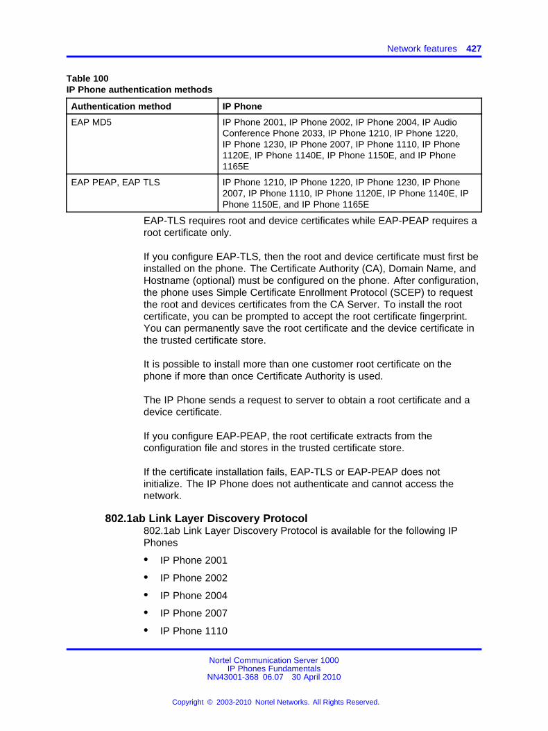
Network features 427
Table 100IP Phone authentication methods
Authentication method IP Phone
EAP MD5 IP Phone 2001, IP Phone 2002, IP Phone 2004, IP AudioConference Phone 2033, IP Phone 1210, IP Phone 1220,IP Phone 1230, IP Phone 2007, IP Phone 1110, IP Phone1120E, IP Phone 1140E, IP Phone 1150E, and IP Phone1165E
EAP PEAP, EAP TLS IP Phone 1210, IP Phone 1220, IP Phone 1230, IP Phone2007, IP Phone 1110, IP Phone 1120E, IP Phone 1140E, IPPhone 1150E, and IP Phone 1165E
EAP-TLS requires root and device certificates while EAP-PEAP requires aroot certificate only.
If you configure EAP-TLS, then the root and device certificate must first beinstalled on the phone. The Certificate Authority (CA), Domain Name, andHostname (optional) must be configured on the phone. After configuration,the phone uses Simple Certificate Enrollment Protocol (SCEP) to requestthe root and devices certificates from the CA Server. To install the rootcertificate, you can be prompted to accept the root certificate fingerprint.You can permanently save the root certificate and the device certificate inthe trusted certificate store.
It is possible to install more than one customer root certificate on thephone if more than once Certificate Authority is used.
The IP Phone sends a request to server to obtain a root certificate and adevice certificate.
If you configure EAP-PEAP, the root certificate extracts from theconfiguration file and stores in the trusted certificate store.
If the certificate installation fails, EAP-TLS or EAP-PEAP does notinitialize. The IP Phone does not authenticate and cannot access thenetwork.
802.1ab Link Layer Discovery Protocol802.1ab Link Layer Discovery Protocol is available for the following IPPhones
• IP Phone 2001
• IP Phone 2002
• IP Phone 2004
• IP Phone 2007
• IP Phone 1110
Nortel Communication Server 1000IP Phones Fundamentals
NN43001-368 06.07 30 April 2010
Copyright © 2003-2010 Nortel Networks. All Rights Reserved.
.
428 Features
• IP Phone 1120E
• IP Phone 1140E
• IP Phone 1150E
• IP Phone 1165E
• IP Phone 1210
• IP Phone 1220
• IP Phone 1230
DescriptionThe IEEE 802.1ab Link Layer Discovery Protocol (LLDP) defines astandard method for Ethernet network devices, such as IP Phones,switches, and routers to exchange information about their capabilities withother devices and to store this information in a Management InformationBase (MIB).
LLDP also enables the system administrator to view the entire networkinfrastructure.
The Telecommunications Industry Association (TIA) developed theLink Layer Discovery Protocol (LLDP)-Media Endpoint Discovery(LLDP-MED) extension of 802.1ab LLDP for VoIP networks, as defined byANSI/TIA-1057. This extension enables media devices such as IP Phones,IP media gateways, IP media servers, and IP media controllers to transmitand receive media related information.
LLDP provides the following functionality
• periodic transmission of advertisements containing device information
• device capabilities and media specific configuration information toneighbors in the same network
• implementation of behavioral requirements specified by LLDP-MED
LLDP devices advertise their information by sending Type-Length-Value(TLV) messages to their neighbors. The TLVs supported in the IP phonesinclude:
• Basic Management TLV
• IEEE 802.1 Organizationally Specific TLV
• IEEE 802.3 Organizationally Specific TLV
• TIA Media Endpoint Discovery (LLDP-MED) TLV - TheTelecommunications Industry Association (TIA) has developed anextension to LLDP for VoIP networks. VoIP-related extensions to
Nortel Communication Server 1000IP Phones Fundamentals
NN43001-368 06.07 30 April 2010
Copyright © 2003-2010 Nortel Networks. All Rights Reserved.
.
Network features 429
LLDP, known as LLDP-Media Endpoint Discovery (LLDP-MED)enables media devices to transmit and receive media relatedinformation.
The 802.1ab feature provides automatic configuration of the IP Phonenetwork policy parameters, such as VLAN ID, as well as, automaticdetection of misconfigurations, such as Duplex discrepancies.
The 802.1ab feature is enabled by default. However, you can disable thefeature during manual configuration.
For information about 802.1ab configuration, see “Provisioning the IPPhones” (page 497).
Dynamic Host Configuration ProtocolThis section provides information about Dynamic Host ConfigurationProtocol (DHCP) server installation, configuration, and operation.
If you are not familiar with DHCP, Nortel recommends reading Request forComments (RFC) 2131 "Dynamic Host Configuration Protocol", RFC 1533"DHCP Options and BOOTP Vendor Extensions", and the Help manual forthe DHCP server on the host.
IP PhonesIP Phones function as a telephone to the Meridian 1 and CS 1000systems. The IP Phone encodes voice as binary data and packetizes thedata for transmission over an IP network to the Call Server, to the TerminalProxy Server (TPS), or to another IP Phone.
IP Phone 2001, IP Phone 2002, and IP Phone 2004, IP Audio ConferencePhone 2033, and IP Softphone 2050 can act as a DHCP client in one oftwo modes:
• partial DHCP mode
• full DHCP mode
The IP Phone 2007, IP Phones 1110 Series, and IP Phones 1200 Seriesact as a DHCP client in auto DHCP mode.
IP Phone parameters can be entered manually or obtained automatically.For more information, see “Provisioning the IP Phones” (page 497).
All the IP Phone configuration parameters can be entered manually. EachIP Phone requires the network configuration parameters, Connect Serverparameters, IP Telephony node ID, and Virtual TN. If there are a numberof IP Phones to configure, manual configuration is time-consuming and
Nortel Communication Server 1000IP Phones Fundamentals
NN43001-368 06.07 30 April 2010
Copyright © 2003-2010 Nortel Networks. All Rights Reserved.
.
430 Features
prone to error. Using full or partial DHCP or auto DHCP to automaticallyconfigure the IP Phones is more efficient and flexible. This ensures thatcurrent information is used.
Auto DHCP mode
When an IP Phone 2007, IP Phones 1110 Series, or IP Phones 1200Series is configured to operate in Auto DHCP mode, the DHCP Serverprovides the network configuration parameters from the DHCP server.
Partial DHCP mode
When IP Phone 2001, IP Phone 2002, IP Phone 2004, IP AudioConference Phone 2033, or IP Softphone 2050 is configured to operatein partial DHCP mode, the DHCP server needs no special configurationto support IP Phones. The IP Phone receives the following networkconfiguration parameters from the DHCP server:
• IP address configuration for the IP Phone
• subnet mask for the IP Phone IP address
• default gateway for the IP Phone LAN segment
In partial DHCP mode the Connect Server parameters, node ID, andVirtual TN must be entered manually.
Full DHCP mode
When IP Phone 2001, IP Phone 2002, IP Phone 2004, IP AudioConference Phone 2033, or IP Softphone 2050 is configured to operatein full DHCP mode, the DHCP server requires special configuration. TheIP Phone obtains network configuration parameters and Connect Serverconfiguration parameters from specially-configured DHCP servers.
The following parameters are provided for the primary and secondaryConnect Servers:
• Connect Server IP address — for IP Line, the Connect Server IPaddress is the IP Telephony node IP address.
• port number = 4100
• command value = 1; identifies the request to the Connect Serveras originating from an In partial DHCP mode the Connect Serverparameters, node ID and Virtual TN must be entered manually.
• retry count = 10 (typically)
The IP Telephony node ID and Virtual TN must always be configuredmanually even in full DHCP mode.
Nortel Communication Server 1000IP Phones Fundamentals
NN43001-368 06.07 30 April 2010
Copyright © 2003-2010 Nortel Networks. All Rights Reserved.
.
Network features 431
Configuring the DHCP server to support full DHCP modeThe DHCP capability of the IP Phone enables the phone to receivenetwork configuration parameters and specific Connect Server parameters.This section describes the IP Phone unique class identifier and requestednetwork configuration and Connect Server parameters for automaticconfiguration.
IP Phone class identifier
The IP Phone is designed with a unique class identifier that the DHCPserver can use to identify the telephone. All Nortel IP Phones use the textstring Nortel-i2004-A or Nortel-i2004-B. The ASCII string is sent inside theClass Identifier option of the IP Phone DHCP messages.
The DHCP server also includes the string in its responses to the IP PhoneDHCP client. This makes it possible to notify the IP Phone that the serveris IP Phone-aware, and that it is safe to accept the server’s offer. Thisstring appears in the beginning of a list of specific Call Server or TPSinformation that the IP Phone DHCP client requests.
When the DHCP server is configured to recognize the IP Phone as aspecial class, the DHCP server can treat the IP Phone differently thanother DHCP clients. DHCP host configuration parameters can then begrouped by class to supply only information relevant to the IP PhoneDHCP client, such as the Connect Server parameters. The administratorcan also design the network according to the client’s class, if necessary,making maintenance easier.
Depending on the capabilities and limitations of the DHCP server usedand the design of the network, some of these advanced functions are notavailable.
Requested network configuration parameters
In full DHCP mode, an IP Phone-aware DHCP server can automaticallyconfigure Nortel IP Phones by requesting a list of Connect Serverconfiguration parameters. The IP Phone uses DHCP to request andreceive the information.
Table 101 "IP Phone network configuration parameters" (page 432) liststhe network configuration parameters requested by the IP Phone in theParameter Request List option (Option Code 55) in the DHCPDISCOVERand DHCPREQUEST messages. The DHCPOFFER and the DHCPACKreply messages from the DHCP server must contain the options in Table101 "IP Phone network configuration parameters" (page 432).
Nortel Communication Server 1000IP Phones Fundamentals
NN43001-368 06.07 30 April 2010
Copyright © 2003-2010 Nortel Networks. All Rights Reserved.
.
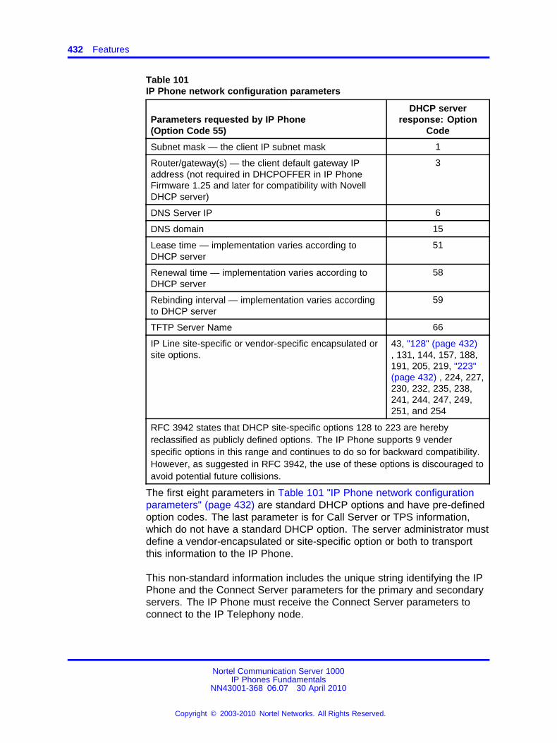
432 Features
Table 101IP Phone network configuration parameters
Parameters requested by IP Phone(Option Code 55)
DHCP serverresponse: Option
Code
Subnet mask — the client IP subnet mask 1
Router/gateway(s) — the client default gateway IPaddress (not required in DHCPOFFER in IP PhoneFirmware 1.25 and later for compatibility with NovellDHCP server)
3
DNS Server IP 6
DNS domain 15
Lease time — implementation varies according toDHCP server
51
Renewal time — implementation varies according toDHCP server
58
Rebinding interval — implementation varies accordingto DHCP server
59
TFTP Server Name 66
IP Line site-specific or vendor-specific encapsulated orsite options.
43, "128" (page 432), 131, 144, 157, 188,191, 205, 219, "223"(page 432) , 224, 227,230, 232, 235, 238,241, 244, 247, 249,251, and 254
RFC 3942 states that DHCP site-specific options 128 to 223 are herebyreclassified as publicly defined options. The IP Phone supports 9 venderspecific options in this range and continues to do so for backward compatibility.However, as suggested in RFC 3942, the use of these options is discouraged toavoid potential future collisions.
The first eight parameters in Table 101 "IP Phone network configurationparameters" (page 432) are standard DHCP options and have pre-definedoption codes. The last parameter is for Call Server or TPS information,which do not have a standard DHCP option. The server administrator mustdefine a vendor-encapsulated or site-specific option or both to transportthis information to the IP Phone.
This non-standard information includes the unique string identifying the IPPhone and the Connect Server parameters for the primary and secondaryservers. The IP Phone must receive the Connect Server parameters toconnect to the IP Telephony node.
Nortel Communication Server 1000IP Phones Fundamentals
NN43001-368 06.07 30 April 2010
Copyright © 2003-2010 Nortel Networks. All Rights Reserved.
.
Network features 433
The administrator must use one of the site-specific or vendor-encapsulatedoption codes to implement the Call Server or TPS information. Thisuser-defined option can then be sent as-is, or encapsulated in a VendorEncapsulated option with Option Code 43. The method used depends onthe DHCP server’s capabilities and what options are already in use byother vendors.
The IP Phone rejects any DHCPOFFER and DHCPACK messages thatdo not contain the following options:
• a router option — IP Phone requires a default gateway (router)
• a subnet mask option
• a vendor-specific option or a site-specific option
The vendor-specific option code is 43. A Windows NT DHCP Server(up to SR4) supports only 16 octets of data for the vendor-specificoption, which is insufficient to support the minimum length of the IPPhone-specific string. If you use a Windows NT DHCP Server, selectthe Site Specific option to accommodate the IP Phone-specific string.
The site-specific options are all DHCP options between 128 (0x80)and 254 (0xFE). These options are reserved for site-specific use bythe DHCP RFCs.
ATTENTIONPhase 0 and Phase I IP Phones cannot accept a DHCPOFFER that contains alist of OPTIONS larger than 312 bytes. If the total size of the DHCP OPTIONS islarger than 312 bytes the Phase 0 and Phase I 1 IP Phones do not successfullyboot and register to the TPS.
ATTENTIONIn an environment that combines IP Phones that support the Nortel-i2004-Boption with the Phase 0 IP Phone 2004, Phase 1 IP Phone 2002, or Phase 1 IPPhone 2004, you must ensure one of the following:
• the Nortel-i2004-B option string does not exceed 590 bytes
• the Phase 0 or Phase 1 IP Phones are serviced with a DHCPOFFER thatexcludes the Nortel-i2004-B option
Format for IP Phone DHCP Class Identifier option All IP Phones fillin the Class ID option of the DHCPDISCOVER and DHCPREQUESTmessages with the null-terminated, ASCII-encoded string Nortel-i2004-Aor Nortel-i-2004-B, where A or B identifies the version number of theinformation format of the IP Phone.
The Class Identifier Nortel-i2004-A and Nortel-i-2004-B must be unique inthe DHCP server domain.
Nortel Communication Server 1000IP Phones Fundamentals
NN43001-368 06.07 30 April 2010
Copyright © 2003-2010 Nortel Networks. All Rights Reserved.
.
434 Features
The following definition describes the Nortel-specific, encapsulatedIP Phone Vendor Specific Option for the Nortel-i2004-A string. Forinformation about the Nortel-i2004-B string, see “Automatic provisioningusing DHCP” (page 517). This option must be encapsulated in a DHCPvendor-specific option (refer to RFC 1533) and returned by the DHCPserver as part of each DHCPOFFER and DHCPACK message for the IPPhone to accept these messages as valid. The IP Phone extracts therelevant information from this option and uses it to configure the ConnectServer IP address, the port number (4100), a command value (1), and theretry count for the primary and secondary Connect Servers.
Either this encapsulated Vendor Specific Option or a similarly encodedsite-specific option must be sent. The DHCP server must be configuredto send one or the other, but not both. The choice of using thevendor-specific or the site-specific option is provided to enable WindowsNT DHCP servers to support the IP Phone. Windows NT servers do notproperly implement the Vendor Specific Option, and as a result, WindowsNT implementations must use the Site Specific version.
The format of the encapsulated Vendor Specific option is Type, Length,and Data, described in the following sections.
There are five types:
• 0x80 (Site Specific option 128)
• 0x90 (Site Specific option 144)
• 0x9d (Site Specific option 157)
• 0xbf (Site Specific option 191)
• 0xfb (Site Specific option 251)
The choice of five types enables the IP Phone to work one or more valuesare already in use by a different vendor. Select one value for the Typebyte.
Length (1 octet) The Length value is variable. Count only the number ofoctets in the data field. See “Data (variable number of octets)” (page 434) .
Data (variable number of octets) The Data field contains anASCII-encoded character string as follows:
Nortel-i2004-A,iii.jjj.kkk.lll:ppppp,aaa,rrr;iii.jjj.kkk.lll:ppppp,aaa,rrr.
Nortel Communication Server 1000IP Phones Fundamentals
NN43001-368 06.07 30 April 2010
Copyright © 2003-2010 Nortel Networks. All Rights Reserved.
.
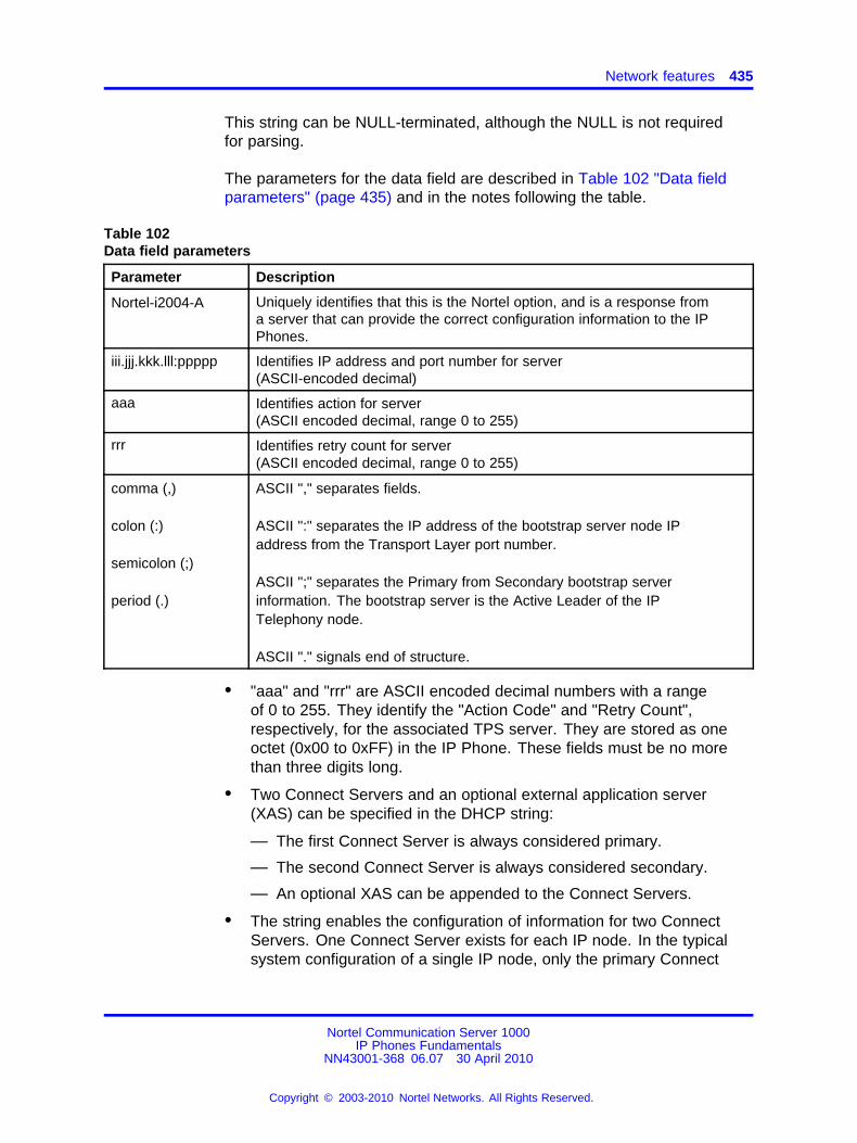
Network features 435
This string can be NULL-terminated, although the NULL is not requiredfor parsing.
The parameters for the data field are described in Table 102 "Data fieldparameters" (page 435) and in the notes following the table.
Table 102Data field parameters
Parameter Description
Nortel-i2004-A Uniquely identifies that this is the Nortel option, and is a response froma server that can provide the correct configuration information to the IPPhones.
iii.jjj.kkk.lll:ppppp Identifies IP address and port number for server(ASCII-encoded decimal)
aaa Identifies action for server(ASCII encoded decimal, range 0 to 255)
rrr Identifies retry count for server(ASCII encoded decimal, range 0 to 255)
comma (,)
colon (:)
semicolon (;)
period (.)
ASCII "," separates fields.
ASCII ":" separates the IP address of the bootstrap server node IPaddress from the Transport Layer port number.
ASCII ";" separates the Primary from Secondary bootstrap serverinformation. The bootstrap server is the Active Leader of the IPTelephony node.
ASCII "." signals end of structure.
• "aaa" and "rrr" are ASCII encoded decimal numbers with a rangeof 0 to 255. They identify the "Action Code" and "Retry Count",respectively, for the associated TPS server. They are stored as oneoctet (0x00 to 0xFF) in the IP Phone. These fields must be no morethan three digits long.
• Two Connect Servers and an optional external application server(XAS) can be specified in the DHCP string:
— The first Connect Server is always considered primary.
— The second Connect Server is always considered secondary.
— An optional XAS can be appended to the Connect Servers.
• The string enables the configuration of information for two ConnectServers. One Connect Server exists for each IP node. In the typicalsystem configuration of a single IP node, only the primary Connect
Nortel Communication Server 1000IP Phones Fundamentals
NN43001-368 06.07 30 April 2010
Copyright © 2003-2010 Nortel Networks. All Rights Reserved.
.
436 Features
Server is required. In this case, the primary Connect Server string mustend with a period (.) instead of a semi-colon (;). For example:Nortel-i2004-A,iii.jjj.kkk.lll:ppppp,aaa,rrr
If the secondary Connect Server portion of the string is specified, thenthe string information is typically the same as the primary ConnectServer information. For example:Nortel-i2004-A,iii.jjj.kkk.lll:ppppp,aaa,rrr;iii.jjj.kkk.lll:ppppp,aaa,rrr
When the Enhanced Redundancy for IP Line Nodes feature is used,two different Connect Server strings can be configured, separated witha semi-colon (;). This enables the telephone to register to two differentnodes. For more information about the Enhanced Redundancy forIP Line Nodes feature, see Signaling Server IP Line ApplicationsFundamentals (NN43001-125).
• Action code values:
— 0 — reserved
— 1 — Establish UNIStim connection
— 2 to 5— reserved
— 6— Establish secure UNIStim connection
— 7 to 255 — reserved
• iii.jjj.kkk.lll are ASCII-encoded decimal numbers representingthe IP address of the server. They do not need to be three digits longbecause the . and : delimiters guarantee parsing. For example, ’001’,’01’, and ’1’ would be parsed correctly and interpreted as value 0x01internal to the IP Phone. These fields must be no longer than threedigits.
• ppppp is the port number in ASCII-encoded decimal. It does not needto be five digits long as the : and , delimiters guarantee parsing. Forexample, ’05001’, ’5001’, ’1’, ’00001’ would be parsed correctly andaccepted as correct. The valid range is 0 to 65535 (stored internally inthe IP Phone as hexadecimal in range 0 to 0xFFFF). This field must beno longer than five digits.
• In all cases, the ASCII-encoded numbers are treated as decimal valuesand all leading zeros are ignored. Specifically, a leading zero doesnot change the interpretation of the value to be OCTAL-encoded. Forexample, 0021, 021, and 21 are all parsed and interpreted as decimal21.
• When using the Full DHCP option, the XAS IP address can beprovided. To do this, append the XAS IP address and port to the NortelDHCP option currently used to specify the first and second serverIP address, ports, and retry and action codes. For Graphical XAS
Nortel Communication Server 1000IP Phones Fundamentals
NN43001-368 06.07 30 April 2010
Copyright © 2003-2010 Nortel Networks. All Rights Reserved.
.
Network features 437
(GXAS), the action code (aaa) and retry count (rrr) must be appended.For Text XAS, it is not necessary to append these values.
The format of the exchange application server IP address and port is:iii.jjj.kkk.lll:ppppp,aaa,rrr
The XAS port action code (aaa) byte values are:
— 0 = Text XAS
— 1 = Graphical XAS
— 2 = Graphical XAS Full Screen
— 4 = Graphical XAS Secure
— 8 = Graphical XAS Reduced
— 16 = Graphical XAS Hidden
The port field is processed if GXAS is selected, but ignored for TextXAS (the fixed text port is used). XAS always uses port 5000.
If the XAS port action code (aaa) byte value is 0 (Text XAS), then theport action code and retry count fields are not required. If the XAS portaction code (aaa) byte value is 1 (Graphical XAS), then the port actioncode and retry count fields are not optional and must be included in theconfiguration string.
For example, the format of the option used to specify Connect Server1, Connect Server 2, and the exchange application server (XAS),where the XAS port action code (aaa) byte value is 1 (Graphical XAS)is:Nortel-i2004A,iii.jjj.kkk.lll:ppppp,aaa,rrr;iii.jjj.kkk.lll:ppppp,aaa,rrr;iii.jjj.kkk.lll:ppppp,aaa,rrr.
If the XAS port action code (aaa) byte value is 0 (Text XAS), the formatof the option used to specify Connect Server 1 , Connect Server 2, andthe exchange application server (XAS) is:Nortel-i2004A,iii.jjj.kkk.lll:ppppp,aaa,rrr;iii.jjj.kkk.lll:ppppp,aaa,rrr;iii.jjj.kkk.lll:ppppp.
Configuration string examples
The following examples show configuration strings with one or moreConnect Servers and exchange application servers
• Table 103 "Configuration string for one Connect Server" (page 438)
• Table 104 "Configuration string for two Connect Servers" (page 438)
• Table 105 "Configuration string for one Connect Server and an XAS(Text)" (page 438)
• Table 106 "Configuration string for one Connect Server and an XAS(Graphical)" (page 439)
Nortel Communication Server 1000IP Phones Fundamentals
NN43001-368 06.07 30 April 2010
Copyright © 2003-2010 Nortel Networks. All Rights Reserved.
.
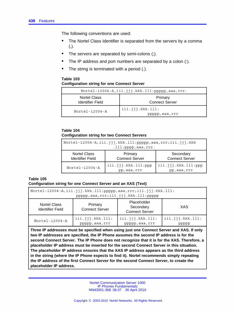
438 Features
The following conventions are used:
• The Nortel Class Identifier is separated from the servers by a comma(,).
• The servers are separated by semi-colons (;).
• The IP address and port numbers are separated by a colon (:).
• The string is terminated with a period (.).
Table 103Configuration string for one Connect Server
Nortel-i2004-A,iii.jjj.kkk.lll:ppppp,aaa,rrr.
Nortel ClassIdentifier Field
PrimaryConnect Server
Nortel-i2004-Aiii.jjj.kkk.lll:
ppppp,aaa,rrr
Table 104Configuration string for two Connect Servers
Nortel-i2004-A,iii.jjj.kkk.lll:ppppp,aaa,rrr;iii.jjj.kkk.lll:pppp,aaa,rrr.
Nortel ClassIdentifier Field
PrimaryConnect Server
SecondaryConnect Server
Nortel-i2004-Aiii.jjj.kkk.lll:ppp
pp,aaa,rrriii.jjj.kkk.lll:ppp
pp,aaa,rrr
Table 105Configuration string for one Connect Server and an XAS (Text)
Nortel-i2004-A,iii.jjj.kkk.lll:ppppp,aaa,rrr;iii.jjj.kkk.lll:ppppp,aaa,rrr;iii.jjj.kkk.lll:ppppp
Nortel ClassIdentifier Field
PrimaryConnect Server
PlaceholderSecondary
Connect ServerXAS
Nortel-i2004-Aiii.jjj.kkk.lll:
ppppp,aaa,rrriii.jjj.kkk.lll:
ppppp,aaa,rrriii.jjj.kkk.lll:
ppppp
Three IP addresses must be specified when using just one Connect Server and XAS. If onlytwo IP addresses are specified, the IP Phone assumes the second IP address is for thesecond Connect Server. The IP Phone does not recognize that it is for the XAS. Therefore, aplaceholder IP address must be inserted for the second Connect Server in this situation.The placeholder IP address ensures that the XAS IP address appears as the third addressin the string (where the IP Phone expects to find it). Nortel recommends simply repeatingthe IP address of the first Connect Server for the second Connect Server, to create theplaceholder IP address.
Nortel Communication Server 1000IP Phones Fundamentals
NN43001-368 06.07 30 April 2010
Copyright © 2003-2010 Nortel Networks. All Rights Reserved.
.
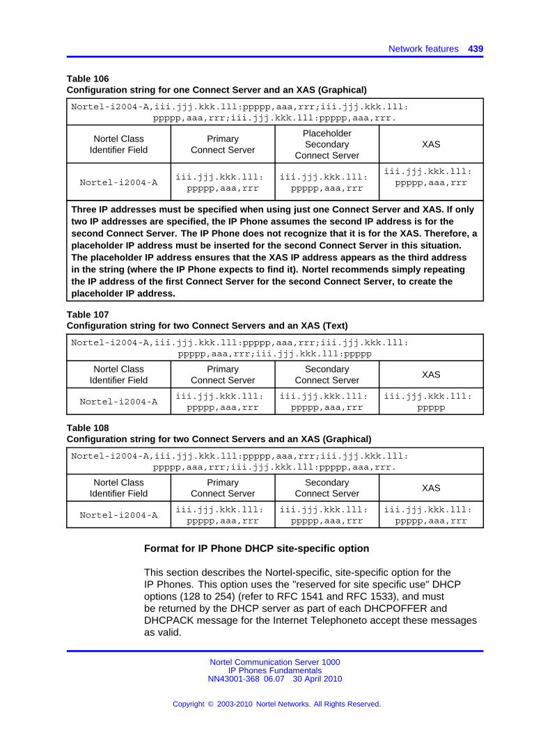
Network features 439
Table 106Configuration string for one Connect Server and an XAS (Graphical)
Nortel-i2004-A,iii.jjj.kkk.lll:ppppp,aaa,rrr;iii.jjj.kkk.lll:ppppp,aaa,rrr;iii.jjj.kkk.lll:ppppp,aaa,rrr.
Nortel ClassIdentifier Field
PrimaryConnect Server
PlaceholderSecondary
Connect ServerXAS
Nortel-i2004-Aiii.jjj.kkk.lll:
ppppp,aaa,rrriii.jjj.kkk.lll:
ppppp,aaa,rrr
iii.jjj.kkk.lll:ppppp,aaa,rrr
Three IP addresses must be specified when using just one Connect Server and XAS. If onlytwo IP addresses are specified, the IP Phone assumes the second IP address is for thesecond Connect Server. The IP Phone does not recognize that it is for the XAS. Therefore, aplaceholder IP address must be inserted for the second Connect Server in this situation.The placeholder IP address ensures that the XAS IP address appears as the third addressin the string (where the IP Phone expects to find it). Nortel recommends simply repeatingthe IP address of the first Connect Server for the second Connect Server, to create theplaceholder IP address.
Table 107Configuration string for two Connect Servers and an XAS (Text)
Nortel-i2004-A,iii.jjj.kkk.lll:ppppp,aaa,rrr;iii.jjj.kkk.lll:ppppp,aaa,rrr;iii.jjj.kkk.lll:ppppp
Nortel ClassIdentifier Field
PrimaryConnect Server
SecondaryConnect Server
XAS
Nortel-i2004-Aiii.jjj.kkk.lll:
ppppp,aaa,rrriii.jjj.kkk.lll:
ppppp,aaa,rrriii.jjj.kkk.lll:
ppppp
Table 108Configuration string for two Connect Servers and an XAS (Graphical)
Nortel-i2004-A,iii.jjj.kkk.lll:ppppp,aaa,rrr;iii.jjj.kkk.lll:ppppp,aaa,rrr;iii.jjj.kkk.lll:ppppp,aaa,rrr.
Nortel ClassIdentifier Field
PrimaryConnect Server
SecondaryConnect Server
XAS
Nortel-i2004-Aiii.jjj.kkk.lll:
ppppp,aaa,rrriii.jjj.kkk.lll:
ppppp,aaa,rrriii.jjj.kkk.lll:
ppppp,aaa,rrr
Format for IP Phone DHCP site-specific option
This section describes the Nortel-specific, site-specific option for theIP Phones. This option uses the "reserved for site specific use" DHCPoptions (128 to 254) (refer to RFC 1541 and RFC 1533), and mustbe returned by the DHCP server as part of each DHCPOFFER andDHCPACK message for the Internet Telephoneto accept these messagesas valid.
Nortel Communication Server 1000IP Phones Fundamentals
NN43001-368 06.07 30 April 2010
Copyright © 2003-2010 Nortel Networks. All Rights Reserved.
.
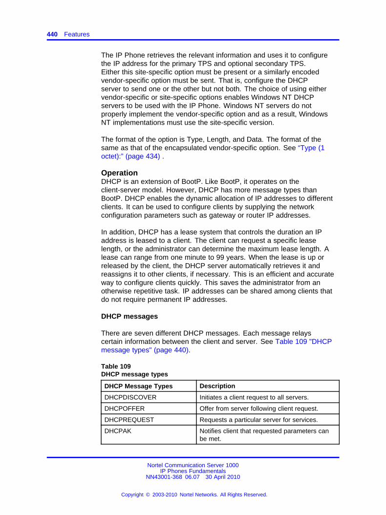
440 Features
The IP Phone retrieves the relevant information and uses it to configurethe IP address for the primary TPS and optional secondary TPS.Either this site-specific option must be present or a similarly encodedvendor-specific option must be sent. That is, configure the DHCPserver to send one or the other but not both. The choice of using eithervendor-specific or site-specific options enables Windows NT DHCPservers to be used with the IP Phone. Windows NT servers do notproperly implement the vendor-specific option and as a result, WindowsNT implementations must use the site-specific version.
The format of the option is Type, Length, and Data. The format of thesame as that of the encapsulated vendor-specific option. See “Type (1octet):” (page 434) .
OperationDHCP is an extension of BootP. Like BootP, it operates on theclient-server model. However, DHCP has more message types thanBootP. DHCP enables the dynamic allocation of IP addresses to differentclients. It can be used to configure clients by supplying the networkconfiguration parameters such as gateway or router IP addresses.
In addition, DHCP has a lease system that controls the duration an IPaddress is leased to a client. The client can request a specific leaselength, or the administrator can determine the maximum lease length. Alease can range from one minute to 99 years. When the lease is up orreleased by the client, the DHCP server automatically retrieves it andreassigns it to other clients, if necessary. This is an efficient and accurateway to configure clients quickly. This saves the administrator from anotherwise repetitive task. IP addresses can be shared among clients thatdo not require permanent IP addresses.
DHCP messages
There are seven different DHCP messages. Each message relayscertain information between the client and server. See Table 109 "DHCPmessage types" (page 440).
Table 109DHCP message types
DHCP Message Types Description
DHCPDISCOVER Initiates a client request to all servers.
DHCPOFFER Offer from server following client request.
DHCPREQUEST Requests a particular server for services.
DHCPAK Notifies client that requested parameters canbe met.
Nortel Communication Server 1000IP Phones Fundamentals
NN43001-368 06.07 30 April 2010
Copyright © 2003-2010 Nortel Networks. All Rights Reserved.
.
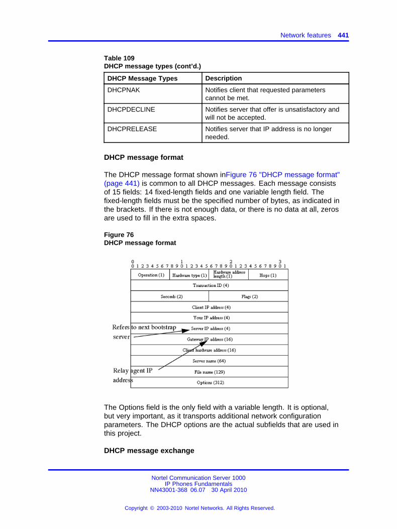
Network features 441
Table 109DHCP message types (cont’d.)
DHCP Message Types Description
DHCPNAK Notifies client that requested parameterscannot be met.
DHCPDECLINE Notifies server that offer is unsatisfactory andwill not be accepted.
DHCPRELEASE Notifies server that IP address is no longerneeded.
DHCP message format
The DHCP message format shown inFigure 76 "DHCP message format"(page 441) is common to all DHCP messages. Each message consistsof 15 fields: 14 fixed-length fields and one variable length field. Thefixed-length fields must be the specified number of bytes, as indicated inthe brackets. If there is not enough data, or there is no data at all, zerosare used to fill in the extra spaces.
Figure 76DHCP message format
The Options field is the only field with a variable length. It is optional,but very important, as it transports additional network configurationparameters. The DHCP options are the actual subfields that are used inthis project.
DHCP message exchange
Nortel Communication Server 1000IP Phones Fundamentals
NN43001-368 06.07 30 April 2010
Copyright © 2003-2010 Nortel Networks. All Rights Reserved.
.
442 Features
For a client to receive services from a DHCP server, an exchange ofDHCP messages between the client and server must take place. Thesequence and types of DHCP message exchanged can differ, but themechanism of acquiring and supplying information remains the same.
Usually the client initiates the exchange with a DHCP message broadcast.Using a broadcast enables the client to send messages to all servers onthe network without having an associated IP address. The broadcast islocal to the LAN, unless a DHCP relay agent is present to forward thepacket.
At this point, the client has no information about the server or the IPaddress it is going to receive (unless it is requesting a renewal), so thefields in the DHCP message are empty. However, the client knows its ownMAC address and includes it in the Client hardware address field. Theclient can also have a list of parameters it would like to acquire and canrequest them from the DHCP server by including the Parameter RequestList option (Option Code 55) in the DHCPDISCOVER message.
When the DHCP server sees the broadcast, it responds by broadcastingits own DHCP message. The server, since it knows more about thenetwork, is able to fill in most of the information in the message. Forexample, information such as the server IP address and gateway IPaddress are included in their respective fields. Since the client does nothave an IP address yet, the server uses the client’s MAC address touniquely identify it. When the client sees the broadcast, it matches its MACaddress against the one in the message.
DHCP options
DHCP options are the sub-fields of the Options field. They carry additionalnetwork configuration information requested by the client such as the IPaddress lease length and the subnet mask.
Each DHCP option has an associated option code and a format forcarrying data. Usually the format is as follows:
Option code Length Data
There are two categories of DHCP options: standard and non-standard.The standard options are predefined by the industry. The non-standardoptions are user-defined to fit the needs of a particular vendor or site.
Nortel Communication Server 1000IP Phones Fundamentals
NN43001-368 06.07 30 April 2010
Copyright © 2003-2010 Nortel Networks. All Rights Reserved.
.
Network features 443
There are a total of 255 DHCP option codes where option codes 0 and255 are reserved, 1 to 77 are predefined, 1 to 254 can be used for VendorSpecific Options, and 128 to 254 are designated for Site Specific Options.This arrangement enables future expansion and is used as a guidelinefor choosing option codes.
Vendor Specific/Encapsulated option
The Vendor Specific DHCP options are vendor-defined options for carryingvendor-related information. It is possible to override predefined standardoptions; however, doing so can cause conflict when used with componentsthat follow the industry standard.
A useful option is the standard Vendor Encapsulated option – code 43. Itis used to encapsulate other DHCP options as sub-options. For example,the IP Phone 2004 requires vendor specific Voice Gateway Media Cardinformation. The vendor, Nortel, decided to carry this information in one ofseveral Site Specific options and then encapsulate it into option 43. Sincethe information is specific to a Nortel product, it is vendor-specific. Onceencapsulated, the information appears as one or more sub-options insideoption 43, which the IP Phone decodes.
Site Specific option
Another way to transport the Voice Gateway Media Card information isthrough Site Specific options. These are unused DHCP options that havenot been predefined to carry standard information. Unlike the VendorSpecific options, the information transported is "site" specific and optioncodes 128 to 254 are used for encoding.
For Nortel IP Phones, the Voice Gateway Media Card information involvesthe location of the Voice Gateway Media Card in the network. This variesfor different sites and can be implemented in a Site Specific option. If theVendor Encapsulation option is used, the information is first encoded in aSite Specific option. Nortel has provided a list of five possible Site Specificoption codes to implement the Voice Gateway Media Card information.Only one of the five codes must be configured to carry the information, butthe choice is available to offset the possibility that the option code chosenhas been used for other purposes.
IP acquisition sequenceThis section focuses on the mechanics and sequence of the DHCPmessage exchange as the IP Phone uses DHCP for IP acquisition.Although the IP Phone requests many network configuration parametersas well as an IP address, the following cases focus on the concept of"how" instead of "what" information is acquired. Also, the IP Phone is usedas the sample client but the situations apply to other DHCP clients as well.
Nortel Communication Server 1000IP Phones Fundamentals
NN43001-368 06.07 30 April 2010
Copyright © 2003-2010 Nortel Networks. All Rights Reserved.
.
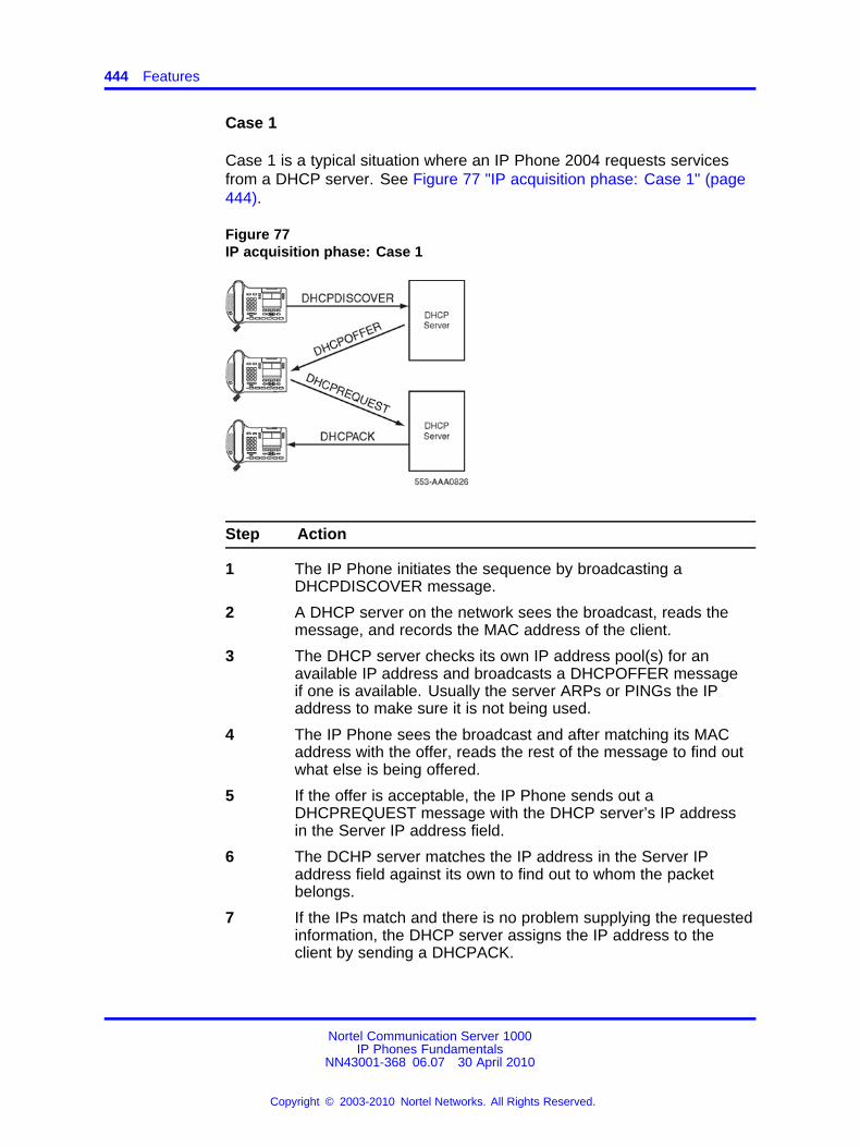
444 Features
Case 1
Case 1 is a typical situation where an IP Phone 2004 requests servicesfrom a DHCP server. See Figure 77 "IP acquisition phase: Case 1" (page444).
Figure 77IP acquisition phase: Case 1
Step Action
1 The IP Phone initiates the sequence by broadcasting aDHCPDISCOVER message.
2 A DHCP server on the network sees the broadcast, reads themessage, and records the MAC address of the client.
3 The DHCP server checks its own IP address pool(s) for anavailable IP address and broadcasts a DHCPOFFER messageif one is available. Usually the server ARPs or PINGs the IPaddress to make sure it is not being used.
4 The IP Phone sees the broadcast and after matching its MACaddress with the offer, reads the rest of the message to find outwhat else is being offered.
5 If the offer is acceptable, the IP Phone sends out aDHCPREQUEST message with the DHCP server’s IP addressin the Server IP address field.
6 The DCHP server matches the IP address in the Server IPaddress field against its own to find out to whom the packetbelongs.
7 If the IPs match and there is no problem supplying the requestedinformation, the DHCP server assigns the IP address to theclient by sending a DHCPACK.
Nortel Communication Server 1000IP Phones Fundamentals
NN43001-368 06.07 30 April 2010
Copyright © 2003-2010 Nortel Networks. All Rights Reserved.
.
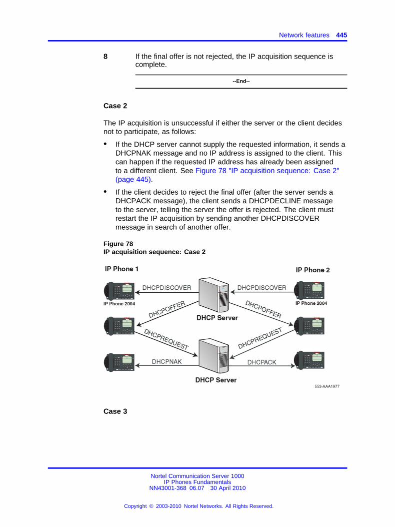
Network features 445
8 If the final offer is not rejected, the IP acquisition sequence iscomplete.
--End--
Case 2
The IP acquisition is unsuccessful if either the server or the client decidesnot to participate, as follows:
• If the DHCP server cannot supply the requested information, it sends aDHCPNAK message and no IP address is assigned to the client. Thiscan happen if the requested IP address has already been assignedto a different client. See Figure 78 "IP acquisition sequence: Case 2"(page 445).
• If the client decides to reject the final offer (after the server sends aDHCPACK message), the client sends a DHCPDECLINE messageto the server, telling the server the offer is rejected. The client mustrestart the IP acquisition by sending another DHCPDISCOVERmessage in search of another offer.
Figure 78IP acquisition sequence: Case 2
Case 3
Nortel Communication Server 1000IP Phones Fundamentals
NN43001-368 06.07 30 April 2010
Copyright © 2003-2010 Nortel Networks. All Rights Reserved.
.
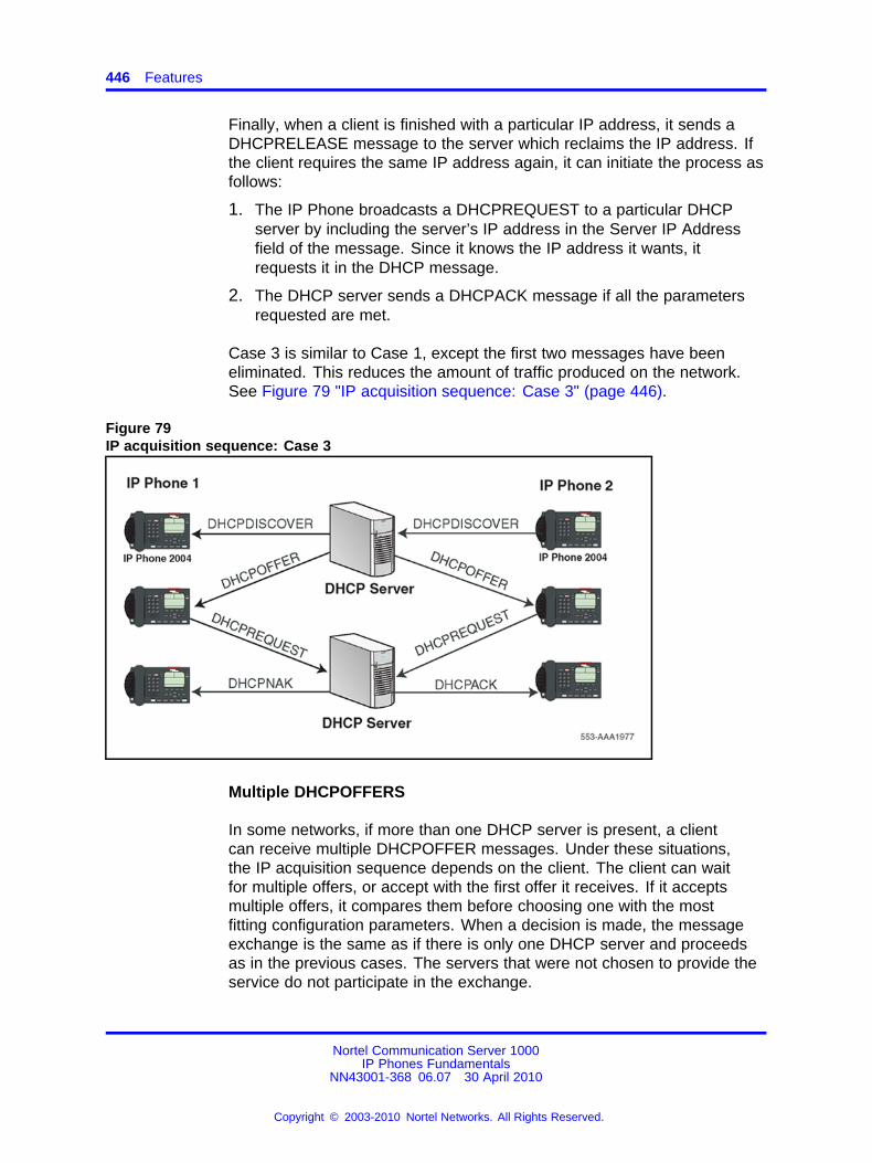
446 Features
Finally, when a client is finished with a particular IP address, it sends aDHCPRELEASE message to the server which reclaims the IP address. Ifthe client requires the same IP address again, it can initiate the process asfollows:
1. The IP Phone broadcasts a DHCPREQUEST to a particular DHCPserver by including the server’s IP address in the Server IP Addressfield of the message. Since it knows the IP address it wants, itrequests it in the DHCP message.
2. The DHCP server sends a DHCPACK message if all the parametersrequested are met.
Case 3 is similar to Case 1, except the first two messages have beeneliminated. This reduces the amount of traffic produced on the network.See Figure 79 "IP acquisition sequence: Case 3" (page 446).
Figure 79IP acquisition sequence: Case 3
Multiple DHCPOFFERS
In some networks, if more than one DHCP server is present, a clientcan receive multiple DHCPOFFER messages. Under these situations,the IP acquisition sequence depends on the client. The client can waitfor multiple offers, or accept with the first offer it receives. If it acceptsmultiple offers, it compares them before choosing one with the mostfitting configuration parameters. When a decision is made, the messageexchange is the same as if there is only one DHCP server and proceedsas in the previous cases. The servers that were not chosen to provide theservice do not participate in the exchange.
Nortel Communication Server 1000IP Phones Fundamentals
NN43001-368 06.07 30 April 2010
Copyright © 2003-2010 Nortel Networks. All Rights Reserved.
.
Network features 447
For example, the IP Phone 2004 responds only to DHCPOFFERs thathave the same unique string identifier, "Nortel-i2004-A", as the IP Phone2004. This string must appear in the beginning of the list of Voice GatewayMedia Card parameters. Without this string, the IP Phone 2004 does notaccept the DHPCOFFER, even if all parameters requested and VoiceGateway Media Card information are present. If no valid DHCPOFFERsare sent then, the IP Phone 2004 keeps broadcasting in search of a validoffer.
With multiple DHCP servers on the same network, a problem can occurif any two of the servers have overlapping IP address range and noredundancy. DHCP redundancy is a property of DHCP servers. Thisredundancy enables different DHCP servers to serve the same IP addressranges simultaneously. Administrators must be aware that not all DHCPservers have this capability.
IP Phone support for DHCPThis section covers the three uses of DHCP (Full, Partial, and VLAN AutoDiscovery).
An "IP Phone 2004-aware" DHCP server is needed only for the Full DHCPand VLAN Auto discovery. An IP Phone can obtain its IP address andsubnet mask using Partial DHCP. The "IP Phone 2004 aware" part returnsthe Node IP and registration port number. In the case of the DHCP AutoDiscovery, it returns the VLAN IDs. Separate DHCP vendor-specificentries are needed for the Full DHCP data and the VLAN Auto Discoverydata. When using the VLAN Auto Discovery, both Full DHCP and VLANAuto Discovery must be configured. Full DHCP and Auto VLAN areimplemented as separate functions in the IP Phone firmware. However, inpractice, Full DHCP and Auto VLAN are frequently used together.
DHCP support in the IP Phone requires sending a "Class Identifier"option with the value "Nortel-i2004-A" in each DHCP DHCPOFFER andDHCPACK message. Additionally, the telephone checks for either aVendor Specific option message with a specific, unique to Nortel IP Phone2004, encapsulated sub-type, or a Site Specific DHCP option.
In either case, an IP Phone 2004-specific option must be returned by theIP Phone 2004 aware DHCP server in all Offer and Acknowledgement(ACK) messages. The IP Phone uses this option’s data it to configure theinformation required to connect to the TPS.
The DHCP response is parsed to extract the IP Phone’s IP address,subnet mask, and gateway IP address. The vendor specific field is thenparsed to extract the Server 1 (minimum) and optionally Server 2. Bydefault, Server 1 is always assumed to be the "primary" server after aDHCP session.
Nortel Communication Server 1000IP Phones Fundamentals
NN43001-368 06.07 30 April 2010
Copyright © 2003-2010 Nortel Networks. All Rights Reserved.
.
448 Features
For the IP Phone to accept Offers/Acks, the messages must contain allof the following:
• A router option (needs a default router to function)
• A subnet mask option
• A Vendor Specific option as specified below or a Site Specific optionas specified below.
— The initial DHCP implementation required only the Vendor Specificencapsulated sub-option. In inter-op testing with Windows NT (upto Service Release 4), it was discovered that Windows NT doesnot properly adhere to RFC 1541. As a result this option is notpossible. The implementation was changed to add support foreither Vendor Specific sub-ops or Site Specific options. This newextension has been tested and verified to work with Windows NT.
— The site-specific options are all DHCP options between 128 (0x80)and 254 (0xFE). These options are reserved for site specific useby the DHCP RFCs.
Format for IP Phone DHCP Class Identifier Field
All IP Phones fill in the Class ID field of the DHCP Discovery and Requestmessages with the following:
"Nortel-i2004-A", where:
• ASCII encoded, NULL (0x00) terminated
• unique to IP Phone 2004
• "-A" uniquely identifies this version
Format for IP Phone DHCP Encapsulated Vendor Specific Field
This sub-option must be encapsulated in a DHCP Vendor Specific Option(refer to RFC 1541 and RFC 1533) and returned by the DHCP server aspart of each DHCP OFFER and ACK message in order for the IP Phoneto accept these messages as valid.
The IP Phone parses this option’s data and uses it to configure theinformation required to connect to the TPS. The sub-option must bepresent, or a similarly encoded site-specific option must be sent. See“Format of the Encapsulated Vendor Specific Sub-option field” (page 449) .Configure the DHCP server to send one or the other – not both.
Nortel Communication Server 1000IP Phones Fundamentals
NN43001-368 06.07 30 April 2010
Copyright © 2003-2010 Nortel Networks. All Rights Reserved.
.
Network features 449
The choice of using either Vendor Specific or Site Specific options isprovided to enable Windows NT DHCP servers to be used with the IPPhone. Windows NT servers do not properly implement the VendorSpecific Option and as a result, Windows NT implementations must usethe Site Specific version.
Format of the Encapsulated Vendor Specific Sub-option field
The format of the field is as follows:
• Type (1 octet): 5 choices are provided (0x80, 0x90, 0x9d, 0xbf, 0xfb[128, 144, 157, 191, 251]), allowing the IP Phone to operate when oneor more values is already in use by a different vendor. Select only oneTYPE byte.
• Length (1 octet): variable – depends on message content.
• Data (length octets): ASCII based with the following format:Nortel-i2004 -A,iii.jjj.kkk.lll:ppppp,aaa,rrr;iii.jjj.kkk.lll:pppp,aaa,rrr.
The components in this string are described inTable 110"Encapsulated Vendor Specific Sub-option field" (page 449) .
Table 110Encapsulated Vendor Specific Sub-option field
Parameter Description
Nortel-i2004-A Uniquely identifies this as the Nortel option
Signifies this version of this specification
iii.jjj.kkk.lll:ppppp Identifies IP address:port for server (ASCII encoded decimal)
aaa Identifies Action for server (ASCII encoded decimal, range 0 to 255)
rrr Identifies retry count for server (ASCII encoded decimal, range 0 to 255). Thisstring can be NULL terminated although the NULL is not required for parsing.
ACSII symbols The comma "," is used to separate fields
The semicolon ";" is used to separate Primary from Secondary serverinformation
The period "." is used to signal end of structure
Table 111 "Nortel option string" (page 450) shows the "pieces" of theNortel option string. The Nortel designator Nortel-i2004-A is separatedfrom the Connect Server strings using a comma. The Connect Serversare separated using a semi-colon.
Nortel Communication Server 1000IP Phones Fundamentals
NN43001-368 06.07 30 April 2010
Copyright © 2003-2010 Nortel Networks. All Rights Reserved.
.
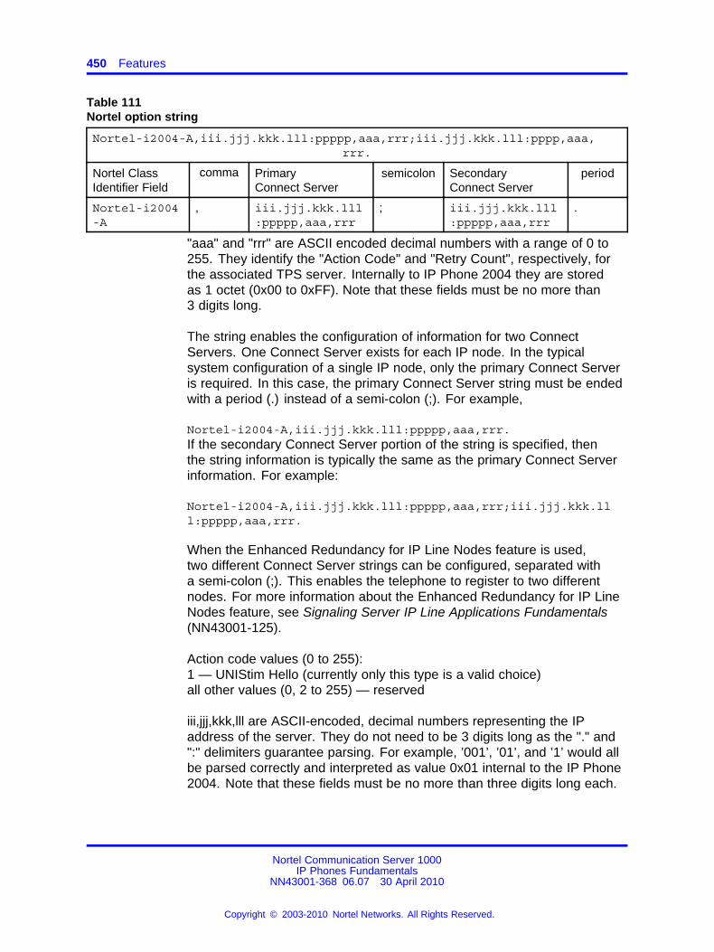
450 Features
Table 111Nortel option string
Nortel-i2004-A,iii.jjj.kkk.lll:ppppp,aaa,rrr;iii.jjj.kkk.lll:pppp,aaa,rrr.
Nortel ClassIdentifier Field
comma PrimaryConnect Server
semicolon SecondaryConnect Server
period
Nortel-i2004-A
, iii.jjj.kkk.lll:ppppp,aaa,rrr
; iii.jjj.kkk.lll:ppppp,aaa,rrr
.
"aaa" and "rrr" are ASCII encoded decimal numbers with a range of 0 to255. They identify the "Action Code" and "Retry Count", respectively, forthe associated TPS server. Internally to IP Phone 2004 they are storedas 1 octet (0x00 to 0xFF). Note that these fields must be no more than3 digits long.
The string enables the configuration of information for two ConnectServers. One Connect Server exists for each IP node. In the typicalsystem configuration of a single IP node, only the primary Connect Serveris required. In this case, the primary Connect Server string must be endedwith a period (.) instead of a semi-colon (;). For example,
Nortel-i2004-A,iii.jjj.kkk.lll:ppppp,aaa,rrr.If the secondary Connect Server portion of the string is specified, thenthe string information is typically the same as the primary Connect Serverinformation. For example:
Nortel-i2004-A,iii.jjj.kkk.lll:ppppp,aaa,rrr;iii.jjj.kkk.lll:ppppp,aaa,rrr.
When the Enhanced Redundancy for IP Line Nodes feature is used,two different Connect Server strings can be configured, separated witha semi-colon (;). This enables the telephone to register to two differentnodes. For more information about the Enhanced Redundancy for IP LineNodes feature, see Signaling Server IP Line Applications Fundamentals(NN43001-125).
Action code values (0 to 255):1 — UNIStim Hello (currently only this type is a valid choice)all other values (0, 2 to 255) — reserved
iii,jjj,kkk,lll are ASCII-encoded, decimal numbers representing the IPaddress of the server. They do not need to be 3 digits long as the "." and":" delimiters guarantee parsing. For example, ’001’, ’01’, and ’1’ would allbe parsed correctly and interpreted as value 0x01 internal to the IP Phone2004. Note that these fields must be no more than three digits long each.
Nortel Communication Server 1000IP Phones Fundamentals
NN43001-368 06.07 30 April 2010
Copyright © 2003-2010 Nortel Networks. All Rights Reserved.
.
Network features 451
ppppp is the port number in ASCII encoded decimal. The port numbermust be set to 4100.
In all cases, the ASCII encoded numbers are treated as decimal valuesand all leading zeros are ignored. More specifically, a leading zero doesnot change the interpretation of the value to be OCTAL encoded. Forexample, 0021, 021, and 21 are all parsed and interpreted as decimal 21.
Format for IP Phone DHCP Site Specific Option
This option uses the "reserved for site specific use" DHCP options(number 128 to 254 – refer to RFC 1541 and RFC 1533) and must bereturned by the DHCP server as part of each DHCP OFFER and ACKmessage for the IP Phone to accept these messages as valid.
The IP Phone pulls the relevant information out of this option and usesit to configure the IP address and so on for the primary and (optionally)secondary TPS.
Either this site specific option must be present or a similarly encodedvendor-specific option must be sent (as previously described). Forexample, configure the DHCP server to send one or the other – not both.
The choice of using either Vendor Specific or Site Specific options isprovided to enable Windows NT DHCP servers to be used with the IPPhone. Windows NT servers do not properly implement the VendorSpecific Option and as a result, Windows NT implementations must usethe Site Specific version.
Format of the DHCP Site Specific field
The format of the DHCP Site Specific field is the same as the format ofthe Encapsulated Vendor Specific Sub-option field. See “Format of theEncapsulated Vendor Specific Sub-option field” (page 449) .
DHCP Auto Discovery must be used only if the telephone and PC are:
• connected to the same Layer 2 switch port through a three-port switch
• on separate sub-nets
The DHCP server can be configured to supply the VLAN information tothe IP Phones. The server uses the Site Specific option in the DHCP offermessage to convey the VLAN information to the IP Phone.
Configuring a DHCP Server for VLAN Discovery is optional. Thisconfiguration is done in addition to any done for Full DHCP configurationand it is required only when configuring the VLAN Auto Discovery.
Nortel Communication Server 1000IP Phones Fundamentals
NN43001-368 06.07 30 April 2010
Copyright © 2003-2010 Nortel Networks. All Rights Reserved.
.
452 Features
802.1Q VLAN support is configured using the display interface of the IPPhones during the initial configuration procedure of the IP Phone.
This method is based on the assumption that the default VLAN will bethe data VLAN and the tagged VLAN will be the voice VLAN. Enter thevoice VLAN information into the data VLAN and subnet’s DHCP server.Enter the standard IP Phone configuration string into the voice VLAN andsubnet’s DHCP server pool.
The following definition describes the IP Phone 2004-specific, Site Specificoption. This option uses the "reserved for Site Specific use" DHCP options(DHCP option values 128 to 254) and must be returned by the DHCPserver as part of each DHCPOFFER and DHCPACK message for the IPPhone to accept these messages as valid. The IP Phone extracts therelevant information and uses the information to configure itself.
Format of the field
The format of the field is: Type, Length, Data.
Type (1 octet):
There are five choices:
• 0x80 (128)
• 0x90 (144)
• 0x9d (157)
• 0xbf (191)
• 0xfb (251)
Providing a choice of five types enables the IP Phones to operate if avalue is already in use by a different vendor. Select only one Type byte.
Length (1 octet):
This is variable; it depends on message content.
Data (length octets):
ASCII based format: "VLAN-A:XXX+YYY+ZZZ." where,
• "VLAN–A:" – uniquely identifies this as the Nortel DHCP VLANdiscovery. Additionally, the "–A" signifies this version of this spec.Future enhancements could use "–B" for example.
• ASCII "+" or "," is used to separate fields.
Nortel Communication Server 1000IP Phones Fundamentals
NN43001-368 06.07 30 April 2010
Copyright © 2003-2010 Nortel Networks. All Rights Reserved.
.
Network features 453
• ASCII "." is used to signal end of structure.
• XXX, YYY and ZZZ are ASCII encoded decimal numbers with a rangeof 0-4095. The number is used to identify the VLAN Ids. There are amaximum of 10 VLAN IDs can be configured in the current version.String "none" or "NONE" means no VLAN (default VLAN).
The DHCP OFFER message carrying VLAN information is sent out fromthe DHCP server without a VLAN tag. However, the switch port addsa VLAN tag to the packet. The packet is untagged at the port of the IPPhone.
Gratuitous Address Resolution ProtocolGratuitous Address Resolution Protocol (GARP) Protection prevents theIP Phone from GARP Spoof attacks on the network. In a GARP Spoofattack, a malicious device on the network takes over an IP address(usually the default gateway) by sending unsolicited (or Gratuitous) ARPmessages, thus manipulating the ARP table of the victim machine. Themalicious device launches a variety of attacks on the network, that resultsin undesired traffic routing. For example, a GARP attack can convince thevictim machine that the malicious device is the default gateway. In thisscenario, all traffic from the victim machine flows through the maliciousdevice.
Automatic QoSNortel Automatic Quality of Service (QoS) simplifies the configurationof QoS in a network to ensure that different types of network traffic areproperly prioritized and forwarded. When enabled, Nortel Automatic QoSsupport automatically sets the Differentiated Services Code Point (DSCP)field in the IP packets of the supported devices. You can continue to selectyour own DSCP values.
Nortel Automatic QoS does not use a specific end point device type orspecific VLAN to define the QoS setting, which simplifies the provisioningof QoS and guarantees that Nortel applications receive the desired QoStreatment. With DSCP values automatically assigned, Nortel applicationscan receive the desired QoS administration.
You can enable Nortel Automatic QoS on the IP Phone by provisioning thefeature in Communication Server 1000 Element Manager or provisioningthe feature directly on the phone using auto or manual provisioning.For more information about provisioning the Nortel Automatic QoS inCS 1000 Element Manager, see Element Manager System Reference -Administration (NN43001-632). For more information about provisioningthe feature directly on the phone using auto or manual provisioning, seeAuto provisioning the IP Phones.
Nortel Communication Server 1000IP Phones Fundamentals
NN43001-368 06.07 30 April 2010
Copyright © 2003-2010 Nortel Networks. All Rights Reserved.
.

454 Features
For more information about Nortel Automatic QoS, see Nortel AutomaticQoS Technical Configuration Guide for the ERS 4500, 5000, BCM 50, 450,CS1000, CS2100 and SRG 50 (NN48500-576).
Nortel Communication Server 1000IP Phones Fundamentals
NN43001-368 06.07 30 April 2010
Copyright © 2003-2010 Nortel Networks. All Rights Reserved.
.
455.
X.509 CertificatesThis section contains the following topics:
• “Certificate management” (page 455)
• “Root certificate” (page 456)
• “Device certificate” (page 456)
• “Certificate installation” (page 456)
Certificate managementSSL/TLS for protecting HTTP management traffic supports only serverside certificate-based authentication. TLS for SIP supports bothserver side and client side certificate-based authentication (mutualauthentication). DTLS-capable IP Phones can validate certificates on theSignaling Servers and Media Cards.
Unified Communications Manager provides a centralized console formanaging X.509 certificates, including issuing certificates, distributingcertificates to Communication Server 1000 devices (for example, a SIPGateway), revoking certificates, and managing the trusted CA certificatelist on Communication Server 1000 devices.
For example, from the certificate management console, X.509 certificatescan be assigned remotely to Web SSL and SIP TLS services on SIPGateways, as well as NRS and Element Manager servers. Differentservices on the same device can have their own certificates, such asDTLS, or share a common certificate. For example, Web SSL and SIPTLS services that are active on the same device can share the sameX.509 certificate.
ATTENTIONIP Phones require UNIStim 4.0 or later to support DTLS signaling encryption.
Nortel Communication Server 1000IP Phones Fundamentals
NN43001-368 06.07 30 April 2010
Copyright © 2003-2010 Nortel Networks. All Rights Reserved.
.
456 X.509 Certificates
Root certificateThis root certificate is the customers root certificate. It is installed as partof a configuration file or as part of the SCEP process.
Device certificateThis certificate is assigned specifically to the phone. It is installed usingthe SCEP process when the phone is configured prior to the installationprocess.
Certificate installationRoot certificates
The IP Phones require root certificates.
After the IP Phone powers up for the first time the Nortel root certificatesautomatically configure.
Customer Certificates must be validated and signed. For more informationabout validating Customer Certificates, see “Validating certificates”(page 458). After you install the root certificates on the IP Phone, allcustomer-created installable files, such as Customer Certificates orCertificate Revocation Lists (CRL) must be properly signed or the IPPhone rejects the files. The signature attached to a file must be created bya certificate with a valid certificate chain that is rooted in the customer rootcertificate. Device Configuration and Security Policy installable files arealso supported although they are rarely used. For more information aboutsigning the files, see “File signing” (page 460).
Zero-touch customer certificate installation is possible if signatures ondownloaded files are authenticated using the embedded Nortel certificate.Also, the phone software can now support multiple signatures on a file,which can be signed by Nortel certificate and a customer certificate, or bytwo different customer certificates. If a file requires multiple signatures tobe authenticated, only one of the signatures must be validated.
ATTENTIONWhen multiple signatures are present all signatures must be generated from theoriginal, unsigned date file and must not include any other signatures.
Installing the first customer certificate on the IP PhoneYou must install customer certificates if you use EAP-TLS or EAP-PEAP.Install a customer root certificate on the phone to provide a trust anchorto verify a signature on a signed configuration file or to verify a certificatepresented by the server end of a TLS connection. The trust anchor musteither have issued the presented certificate or there must be a valid
Nortel Communication Server 1000IP Phones Fundamentals
NN43001-368 06.07 30 April 2010
Copyright © 2003-2010 Nortel Networks. All Rights Reserved.
.
Certificate installation 457
certificate chain that can validate to the trust anchor. In other words, theinstalled certificate is the customer’s Certificate Authority (CA). The CA canbe a third party CA or a self-signed root certificate.
For certificate chaining, the TLS server or the digital file signing processmust ensure that all certificates in the chain up to, but not including, thetrust anchor are provided. Otherwise, the certificate chain cannot bevalidated by the phone. After one customer root certificate installs on thephone, all customer configuration files (including additional certificatefiles) must be signed or they reject without any user input or options. It ispossible to install more than one customer root certificate on the phone ifmore than once Certificate Authority is used.
Use the following procedure to install the first customer certificate on the IPPhone.
Procedure 114Installing the first customer certificate on the IP Phone
Step Action
1 Export the public CA certificate in Privacy Enhanced Mail (PEM)format.
The exporting process depends on the management certificateprogram (for example, Microsoft CA Server, OpenSSL, EJBCA).Keep the private key secure and do not install the private keyon the phone.
2 If you store more than one certificate in PEM format in this file,insert a blank line to separate the certificates. See Figure 84"Certificate file with more than one certificate" (page 470).
3 Add a section to the configuration file for each IP Phone whereFILENAME is the name of the file created in step 1. For moreinformation about the configuration file, see “Configuration file”(page 464) .
4 Use DHCP or manual configuration to properly set theProvisioning Server address.
5 Reboot the IP Phone.
6 When the phone connects to the provisioning server, the[USER_KEYS] section is read and the file(s) downloads.
7 Select Install to proceed.
The phone displays the fingerprint of the certificate file.
8 Select Accept to install the certificate on the IP Phone.
Nortel Communication Server 1000IP Phones Fundamentals
NN43001-368 06.07 30 April 2010
Copyright © 2003-2010 Nortel Networks. All Rights Reserved.
.
458 X.509 Certificates
For more information about certificate validation options, see“Validating certificates” (page 458).
--End--
It is possible to change the default behavior described inProcedure 114“Installing the first customer certificate on the IP Phone” (page 457) sothat the user must enter the fingerprint of the certificate file rather thanjust accept a displayed value. To do this, you must change the SecurityPolicy on the phone. For more information about the Security Policy, see“Security Policy” (page 465).
Validating certificatesAll new certificates that are received and are meant to be stored on the IPPhone must be validated. Certificates that are digitally signed and can beauthenticated using one of the certificates in the trusted certificate storeare considered validated and do not require user input. If one or moreCustomer Certificates are installed in the IP Phone trusted certificate store,any certificate that does not pass the digital authentication is rejected andan error is logged.
If Customer Certificates are not installed in the trusted certificate storeon the IP Phone, you can use one of the following methods to manuallyvalidate an unsigned certificate
• Manual A (default)
• Manual B
Manual A
If the file containing a Customer Certificate is not signed a prompt appearson the screen with a fingerprint for the file as a whole, regardless ofthe number of certificates contained in the file. If you confirm that thefingerprint is correct, all certificates in the file validate and save. Youcannot use this method to validate Nortel certificates.
Manual A uses a 20 digit (64 bit) fingerprint. You must confirm thefingerprint, which appears on the screen. See Figure 80 "Fingerprintverification" (page 459).
The screen shows the file type and a prompt to install or reject the file.After 30 seconds, the prompt times out and the certificate is automaticallyrejected.
Nortel Communication Server 1000IP Phones Fundamentals
NN43001-368 06.07 30 April 2010
Copyright © 2003-2010 Nortel Networks. All Rights Reserved.
.
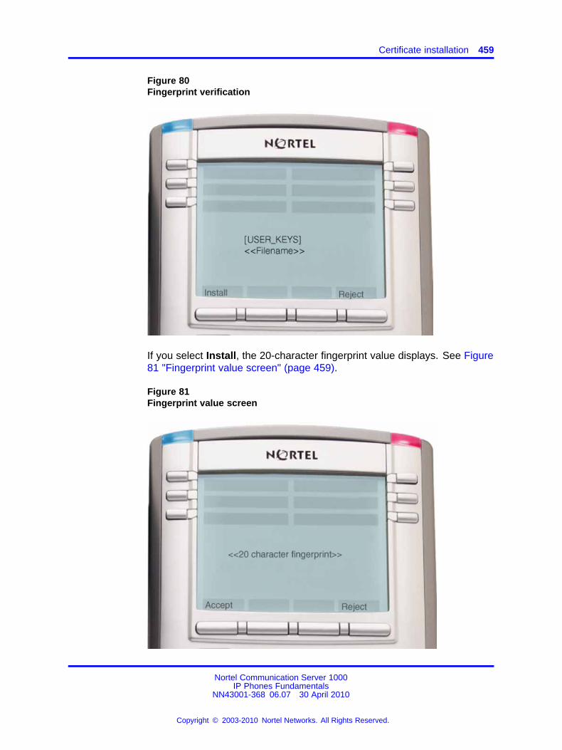
Certificate installation 459
Figure 80Fingerprint verification
If you select Install, the 20-character fingerprint value displays. See Figure81 "Fingerprint value screen" (page 459).
Figure 81Fingerprint value screen
Nortel Communication Server 1000IP Phones Fundamentals
NN43001-368 06.07 30 April 2010
Copyright © 2003-2010 Nortel Networks. All Rights Reserved.
.
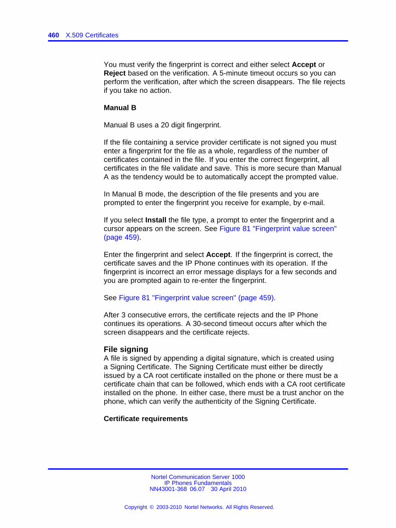
460 X.509 Certificates
You must verify the fingerprint is correct and either select Accept orReject based on the verification. A 5-minute timeout occurs so you canperform the verification, after which the screen disappears. The file rejectsif you take no action.
Manual B
Manual B uses a 20 digit fingerprint.
If the file containing a service provider certificate is not signed you mustenter a fingerprint for the file as a whole, regardless of the number ofcertificates contained in the file. If you enter the correct fingerprint, allcertificates in the file validate and save. This is more secure than ManualA as the tendency would be to automatically accept the prompted value.
In Manual B mode, the description of the file presents and you areprompted to enter the fingerprint you receive for example, by e-mail.
If you select Install the file type, a prompt to enter the fingerprint and acursor appears on the screen. See Figure 81 "Fingerprint value screen"(page 459).
Enter the fingerprint and select Accept. If the fingerprint is correct, thecertificate saves and the IP Phone continues with its operation. If thefingerprint is incorrect an error message displays for a few seconds andyou are prompted again to re-enter the fingerprint.
See Figure 81 "Fingerprint value screen" (page 459).
After 3 consecutive errors, the certificate rejects and the IP Phonecontinues its operations. A 30-second timeout occurs after which thescreen disappears and the certificate rejects.
File signingA file is signed by appending a digital signature, which is created usinga Signing Certificate. The Signing Certificate must either be directlyissued by a CA root certificate installed on the phone or there must be acertificate chain that can be followed, which ends with a CA root certificateinstalled on the phone. In either case, there must be a trust anchor on thephone, which can verify the authenticity of the Signing Certificate.
Certificate requirements
Nortel Communication Server 1000IP Phones Fundamentals
NN43001-368 06.07 30 April 2010
Copyright © 2003-2010 Nortel Networks. All Rights Reserved.
.
Certificate installation 461
The file signing certificate requires the following minimum attributes
• Version—3
• Key Usage—Digital signature
• Extended Key Usage—Code signing, secure e-mail
• Key—1024 bits
In addition, the Signing Certificate cannot be a self-signed root certificateand must have a valid Subject Key Identifier and an Authority Key Identifier(which uniquely identifies the issuing certificate).
Certificate authority requirements
You can use many commercial CAs, Open source CAs, such as OpenSSL,and EJBCA to create and manage these certificates. The CA must meetthe following requirements:
• The root certificate must be exportable in PEM format without theprivate key.
• The CA must be capable of issuing a Signing Certificate with the aboveattributes and an exportable private key.
This requirement can require additional CA configuration. Often incommercial CAs the private key is not exportable by default. However,the Signing Certificate private key only required if the CA does notprovide built-in support for the creation of detached PKCS7 signatures.
Signed file structure
A signed file consists of the following two parts
• original unsigned file content
• digital signature
The two parts are appended together with the original unsigned file contentfirst, followed by the digital signature.
The signature must be in the form of a PKCS7 detached signature of thefile in PEM format. A detached signature is a signature that does notembed the content that is signed. Figure 82 "Signed certificate file" (page462) provides an example of a signed file.
ATTENTIONDo not insert additional characters between the two parts. Otherwise thevalidation fails.
Nortel Communication Server 1000IP Phones Fundamentals
NN43001-368 06.07 30 April 2010
Copyright © 2003-2010 Nortel Networks. All Rights Reserved.
.
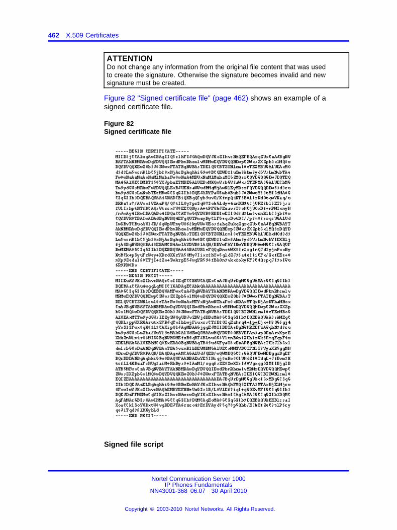
462 X.509 Certificates
ATTENTIONDo not change any information from the original file content that was usedto create the signature. Otherwise the signature becomes invalid and newsignature must be created.
Figure 82 "Signed certificate file" (page 462) shows an example of asigned certificate file.
Figure 82Signed certificate file
Signed file script
Nortel Communication Server 1000IP Phones Fundamentals
NN43001-368 06.07 30 April 2010
Copyright © 2003-2010 Nortel Networks. All Rights Reserved.
.
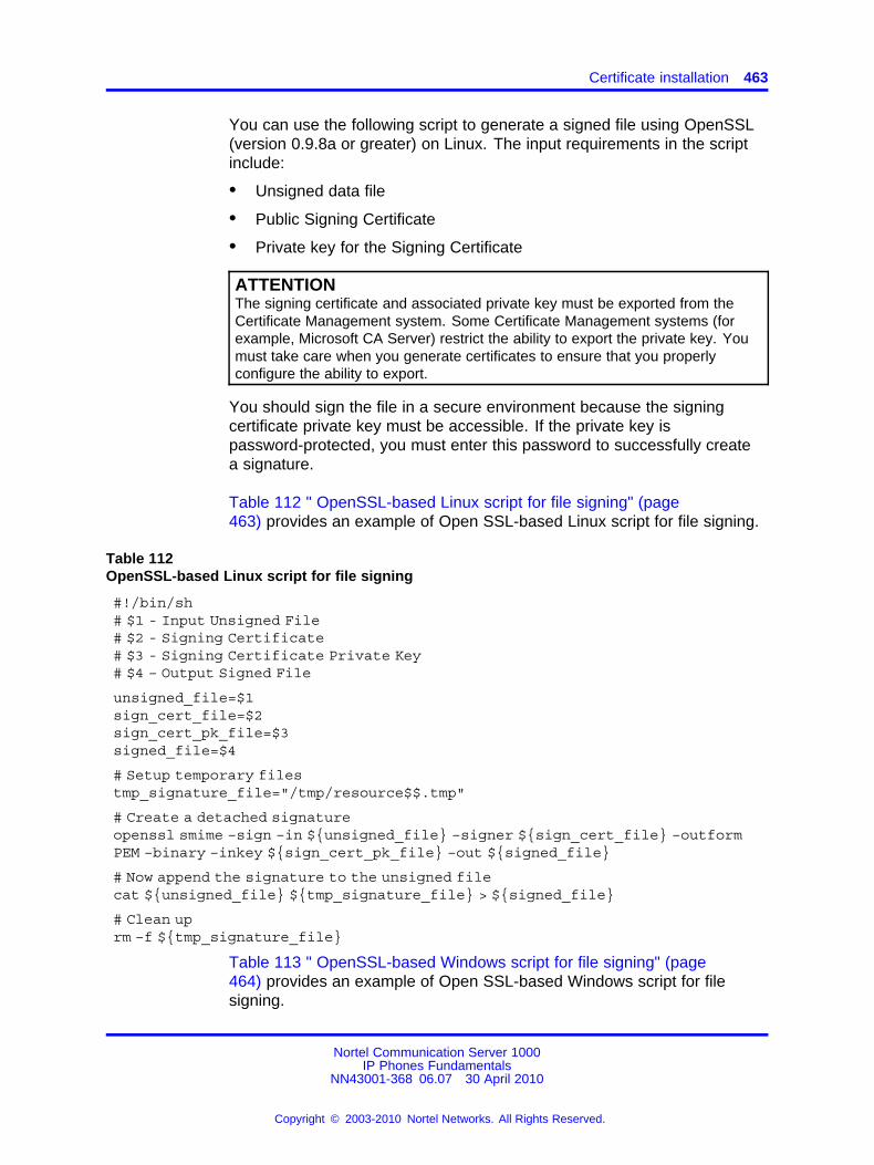
Certificate installation 463
You can use the following script to generate a signed file using OpenSSL(version 0.9.8a or greater) on Linux. The input requirements in the scriptinclude:
• Unsigned data file
• Public Signing Certificate
• Private key for the Signing Certificate
ATTENTIONThe signing certificate and associated private key must be exported from theCertificate Management system. Some Certificate Management systems (forexample, Microsoft CA Server) restrict the ability to export the private key. Youmust take care when you generate certificates to ensure that you properlyconfigure the ability to export.
You should sign the file in a secure environment because the signingcertificate private key must be accessible. If the private key ispassword-protected, you must enter this password to successfully createa signature.
Table 112 " OpenSSL-based Linux script for file signing" (page463) provides an example of Open SSL-based Linux script for file signing.
Table 112OpenSSL-based Linux script for file signing
#!/bin/sh# $1 - Input Unsigned File# $2 - Signing Certificate# $3 - Signing Certificate Private Key# $4 – Output Signed File
unsigned_file=$1sign_cert_file=$2sign_cert_pk_file=$3signed_file=$4
# Setup temporary filestmp_signature_file="/tmp/resource$$.tmp"
# Create a detached signatureopenssl smime –sign –in ${unsigned_file} –signer ${sign_cert_file} –outformPEM –binary –inkey ${sign_cert_pk_file} –out ${signed_file}
# Now append the signature to the unsigned filecat ${unsigned_file} ${tmp_signature_file} > ${signed_file}
# Clean uprm –f ${tmp_signature_file}
Table 113 " OpenSSL-based Windows script for file signing" (page464) provides an example of Open SSL-based Windows script for filesigning.
Nortel Communication Server 1000IP Phones Fundamentals
NN43001-368 06.07 30 April 2010
Copyright © 2003-2010 Nortel Networks. All Rights Reserved.
.
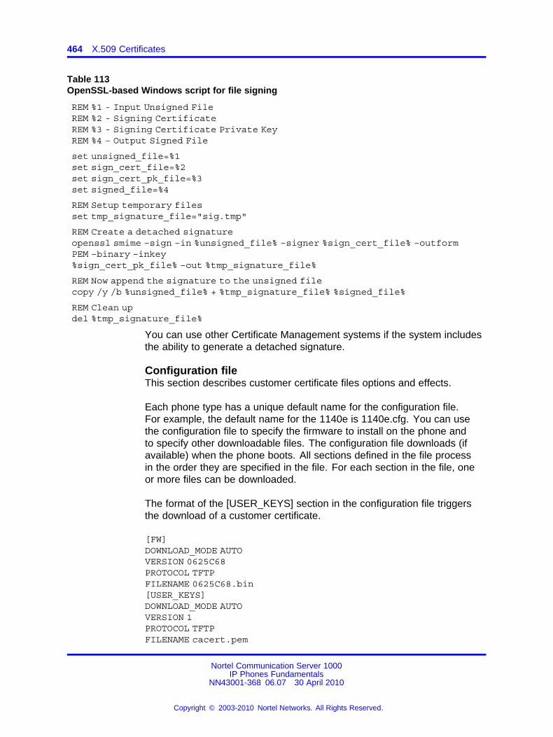
464 X.509 Certificates
Table 113OpenSSL-based Windows script for file signing
REM %1 - Input Unsigned FileREM %2 - Signing CertificateREM %3 - Signing Certificate Private KeyREM %4 – Output Signed File
set unsigned_file=%1set sign_cert_file=%2set sign_cert_pk_file=%3set signed_file=%4
REM Setup temporary filesset tmp_signature_file="sig.tmp"
REM Create a detached signatureopenssl smime –sign –in %unsigned_file% –signer %sign_cert_file% –outformPEM –binary –inkey%sign_cert_pk_file% –out %tmp_signature_file%
REM Now append the signature to the unsigned filecopy /y /b %unsigned_file% + %tmp_signature_file% %signed_file%
REM Clean updel %tmp_signature_file%
You can use other Certificate Management systems if the system includesthe ability to generate a detached signature.
Configuration fileThis section describes customer certificate files options and effects.
Each phone type has a unique default name for the configuration file.For example, the default name for the 1140e is 1140e.cfg. You can usethe configuration file to specify the firmware to install on the phone andto specify other downloadable files. The configuration file downloads (ifavailable) when the phone boots. All sections defined in the file processin the order they are specified in the file. For each section in the file, oneor more files can be downloaded.
The format of the [USER_KEYS] section in the configuration file triggersthe download of a customer certificate.
[FW]DOWNLOAD_MODE AUTOVERSION 0625C68PROTOCOL TFTPFILENAME 0625C68.bin[USER_KEYS]DOWNLOAD_MODE AUTOVERSION 1PROTOCOL TFTPFILENAME cacert.pem
Nortel Communication Server 1000IP Phones Fundamentals
NN43001-368 06.07 30 April 2010
Copyright © 2003-2010 Nortel Networks. All Rights Reserved.
.
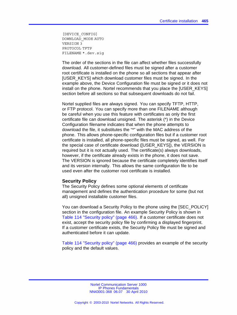
Certificate installation 465
[DEVICE_CONFIG]DOWNLOAD_MODE AUTOVERSION 3PROTOCOL TFTPFILENAME *.dev.sig
The order of the sections in the file can affect whether files successfullydownload. All customer-defined files must be signed after a customerroot certificate is installed on the phone so all sections that appear after[USER_KEYS] which download customer files must be signed. In theexample above, the Device Configuration file must be signed or it does notinstall on the phone. Nortel recommends that you place the [USER_KEYS]section before all sections so that subsequent downloads do not fail.
Nortel supplied files are always signed. You can specify TFTP, HTTP,or FTP protocol. You can specify more than one FILENAME althoughbe careful when you use this feature with certificates as only the firstcertificate file can download unsigned. The asterisk (*) in the DeviceConfiguration filename indicates that when the phone attempts todownload the file, it substitutes the “*” with the MAC address of thephone. This allows phone-specific configuration files but if a customer rootcertificate is installed, all phone-specific files must be signed, as well. Forthe special case of certificate download ([USER_KEYS]), the VERSION isrequired but it is not actually used. The certificate(s) always downloads,however, if the certificate already exists in the phone, it does not save.The VERSION is ignored because the certificate completely identifies itselfand its version internally. This allows the same configuration file to beused even after the customer root certificate is installed.
Security PolicyThe Security Policy defines some optional elements of certificatemanagement and defines the authentication procedure for some (but notall) unsigned installable customer files.
You can download a Security Policy to the phone using the [SEC_POLICY]section in the configuration file. An example Security Policy is shown inTable 114 "Security policy" (page 466). If a customer certificate does notexist, accept the security policy file by confirming a displayed fingerprint.If a customer certificate exists, the Security Policy file must be signed andauthenticated before it can update.
Table 114 "Security policy" (page 466) provides an example of the securitypolicy and the default values.
Nortel Communication Server 1000IP Phones Fundamentals
NN43001-368 06.07 30 April 2010
Copyright © 2003-2010 Nortel Networks. All Rights Reserved.
.
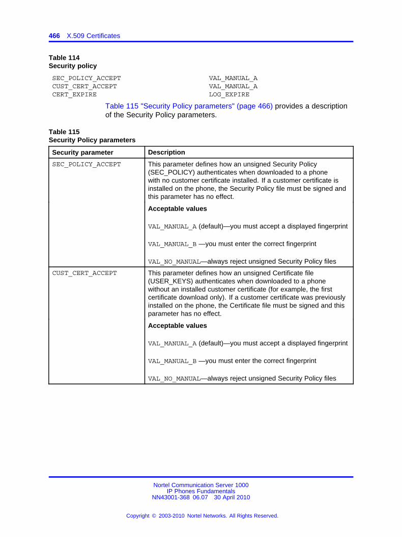
466 X.509 Certificates
Table 114Security policy
SEC_POLICY_ACCEPTCUST_CERT_ACCEPTCERT_EXPIRE
VAL_MANUAL_AVAL_MANUAL_ALOG_EXPIRE
Table 115 "Security Policy parameters" (page 466) provides a descriptionof the Security Policy parameters.
Table 115Security Policy parameters
Security parameter Description
SEC_POLICY_ACCEPT This parameter defines how an unsigned Security Policy(SEC_POLICY) authenticates when downloaded to a phonewith no customer certificate installed. If a customer certificate isinstalled on the phone, the Security Policy file must be signed andthis parameter has no effect.
Acceptable values
VAL_MANUAL_A (default)—you must accept a displayed fingerprint
VAL_MANUAL_B —you must enter the correct fingerprint
VAL_NO_MANUAL—always reject unsigned Security Policy files
CUST_CERT_ACCEPT This parameter defines how an unsigned Certificate file(USER_KEYS) authenticates when downloaded to a phonewithout an installed customer certificate (for example, the firstcertificate download only). If a customer certificate was previouslyinstalled on the phone, the Certificate file must be signed and thisparameter has no effect.
Acceptable values
VAL_MANUAL_A (default)—you must accept a displayed fingerprint
VAL_MANUAL_B —you must enter the correct fingerprint
VAL_NO_MANUAL—always reject unsigned Security Policy files
Nortel Communication Server 1000IP Phones Fundamentals
NN43001-368 06.07 30 April 2010
Copyright © 2003-2010 Nortel Networks. All Rights Reserved.
.
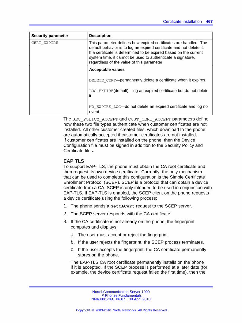
Certificate installation 467
Security parameter Description
CERT_EXPIRE This parameter defines how expired certificates are handled. Thedefault behavior is to log an expired certificate and not delete it.If a certificate is determined to be expired based on the currentsystem time, it cannot be used to authenticate a signature,regardless of the value of this parameter.
Acceptable values
DELETE_CERT—permanently delete a certificate when it expires
LOG_EXPIRE(default)—log an expired certificate but do not deleteit
NO_EXPIRE_LOG—do not delete an expired certificate and log noevent
The SEC_POLICY_ACCEPT and CUST_CERT_ACCEPT parameters definehow these two file types authenticate when customer certificates are notinstalled. All other customer created files, which download to the phoneare automatically accepted if customer certificates are not installed.If customer certificates are installed on the phone, then the DeviceConfiguration file must be signed in addition to the Security Policy andCertificate files.
EAP TLSTo support EAP-TLS, the phone must obtain the CA root certificate andthen request its own device certificate. Currently, the only mechanismthat can be used to complete this configuration is the Simple CertificateEnrollment Protocol (SCEP). SCEP is a protocol that can obtain a devicecertificate from a CA. SCEP is only intended to be used in conjunction withEAP-TLS. If EAP-TLS is enabled, the SCEP client on the phone requestsa device certificate using the following process:
1. The phone sends a GetCACert request to the SCEP server.
2. The SCEP server responds with the CA certificate.
3. If the CA certificate is not already on the phone, the fingerprintcomputes and displays.
a. The user must accept or reject the fingerprint.
b. If the user rejects the fingerprint, the SCEP process terminates.
c. If the user accepts the fingerprint, the CA certificate permanentlystores on the phone.
The EAP-TLS CA root certificate permanently installs on the phoneif it is accepted. If the SCEP process is performed at a later date (forexample, the device certificate request failed the first time), then the
Nortel Communication Server 1000IP Phones Fundamentals
NN43001-368 06.07 30 April 2010
Copyright © 2003-2010 Nortel Networks. All Rights Reserved.
.
468 X.509 Certificates
user is not prompted to accept the CA root certificate because it isalready on the phone and is trusted.
4. The phone creates a certificate request using the CA certificate and alocally generated private key.
5. The phone sends PKCSReq to the SCEP server which includes thecertificate request.
6. The SCEP server responds with either a failure status or with aproperly signed device certificate.
7. If a device certificate returns, it installs on the phone.
ATTENTIONAfter the EAP-TLS CA root certificate installs on the phone during the SCEPprocess, installable customer files (Security Policy, Certificates, DeviceConfiguration) must be signed or they reject.
If you use the same CA for EAP-TLS and for the file signing, which Nortelrecommends, it is not necessary to install any other certificates. Thismeans that you are not required to add [USER_KEYS] to the configurationfile. However, if EAP-TLS is not configured, use [USER_KEYS] to install aCA root certificate rather than SCEP.
If you use different CAs for EAP-TLS and file signing, it is necessary toinstall the CA root certificate for file signing on the phone, as well. In thiscase, the order in which you perform the configuration is important. If theEAP-TLS CA root certificate is installed first using SCEP, it is necessary toinstall the file signing CA root certificate on the phone by signing it with acertificate from the EAP-TLS certificate chain. Otherwise, it is not possibleto install the file signing root certificate on the phone.
Nortel recommends that you install the file signing certificate first becauseno additional requirements are imposed on the installation of the EAP-TLScertificate, provided it is retrieved using SCEP.
Figure 83 "Certificate file with one certificate" (page 469) provides anexample of the certificate file with one certificate.
Nortel Communication Server 1000IP Phones Fundamentals
NN43001-368 06.07 30 April 2010
Copyright © 2003-2010 Nortel Networks. All Rights Reserved.
.
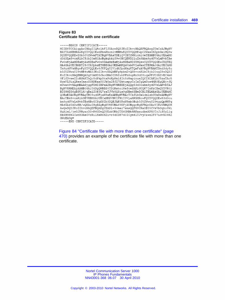
Certificate installation 469
Figure 83Certificate file with one certificate
Figure 84 "Certificate file with more than one certificate" (page470) provides an example of the certificate file with more than onecertificate.
Nortel Communication Server 1000IP Phones Fundamentals
NN43001-368 06.07 30 April 2010
Copyright © 2003-2010 Nortel Networks. All Rights Reserved.
.
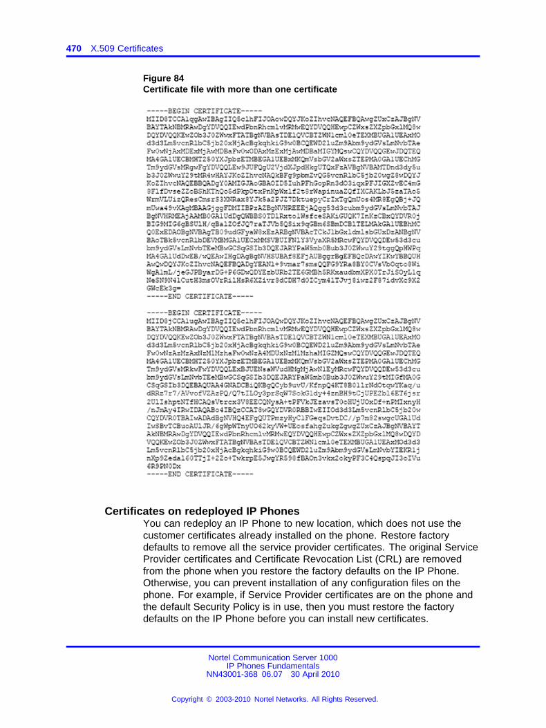
470 X.509 Certificates
Figure 84Certificate file with more than one certificate
Certificates on redeployed IP PhonesYou can redeploy an IP Phone to new location, which does not use thecustomer certificates already installed on the phone. Restore factorydefaults to remove all the service provider certificates. The original ServiceProvider certificates and Certificate Revocation List (CRL) are removedfrom the phone when you restore the factory defaults on the IP Phone.Otherwise, you can prevent installation of any configuration files on thephone. For example, if Service Provider certificates are on the phone andthe default Security Policy is in use, then you must restore the factorydefaults on the IP Phone before you can install new certificates.
Nortel Communication Server 1000IP Phones Fundamentals
NN43001-368 06.07 30 April 2010
Copyright © 2003-2010 Nortel Networks. All Rights Reserved.
.
Certificate installation 471
Restore factory defaultsIf you invoke Restore factory default, the security settings restore to thefollowing default values:
• Delete all non-Nortel certificates and non-Nortel CRLs from the phone
• Purge all security log entries on the phone
• Restore the “last-known-time” to the factory default value
• Reset all Security Policy values to their defaults
• Add a security log entry to indicate that restore to factory defaults wasinvoked
Security logAll security related events log in the security log. For example, thefollowing list provides some events that log in the security log.
• Import a certificate
• Update a certificate
• Update the security policy
• Revoke a certificate
• Certificate expiry
• File authentication fail - firmware, resource, configuration
• Manual file authentication rejection
Nortel Communication Server 1000IP Phones Fundamentals
NN43001-368 06.07 30 April 2010
Copyright © 2003-2010 Nortel Networks. All Rights Reserved.
.

472 X.509 Certificates
Nortel Communication Server 1000IP Phones Fundamentals
NN43001-368 06.07 30 April 2010
Copyright © 2003-2010 Nortel Networks. All Rights Reserved.
.
473.
Regulatory and safety informationThis equipment has been tested and found to comply with the limits fora Class B digital device, pursuant to part 15 of the FCC Rules. Theselimits are designed to provide reasonable protection against harmfulinterference in a residential installation. This equipment generates, usesand can radiate radio frequency energy and, if not installed and used inaccordance with the instructions, may cause harmful interference to radiocommunications. However, there is no guarantee that interference willnot occur in a particular installation. If this equipment does cause harmfulinterference to radio or television reception, which can be determined byturning the equipment off and on, the user is encouraged to try to correctthe interference by one or more of the following measures
• Reorient or relocate the receiving antenna.
• Increase the separation between the equipment and receiver.
• Connect the equipment into an outlet on a circuit different from that towhich the receiver connects.
• Consult the dealer or an experienced radio/TV technician for help.
The user should not make changes or modifications not expresslyapproved by Nortel Networks. Any such changes could void the userauthority to operate the equipment.
This Class B digital apparatus complies with Canadian ICES-003. Cetappareil numérique de la classe B est conforme à la norme NMB-003 duCanada.
For information on Regulatory compliance coverage by region, pleasecontact your Nortel representative.
Nortel Communication Server 1000IP Phones Fundamentals
NN43001-368 06.07 30 April 2010
Copyright © 2003-2010 Nortel Networks. All Rights Reserved.
.
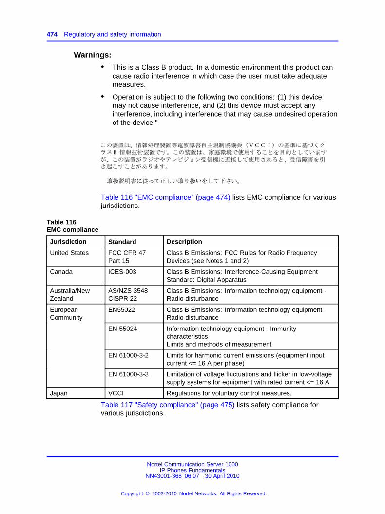
474 Regulatory and safety information
Warnings:
• This is a Class B product. In a domestic environment this product cancause radio interference in which case the user must take adequatemeasures.
• Operation is subject to the following two conditions: (1) this devicemay not cause interference, and (2) this device must accept anyinterference, including interference that may cause undesired operationof the device."
Table 116 "EMC compliance" (page 474) lists EMC compliance for variousjurisdictions.
Table 116EMC compliance
Jurisdiction Standard Description
United States FCC CFR 47Part 15
Class B Emissions: FCC Rules for Radio FrequencyDevices (see Notes 1 and 2)
Canada ICES-003 Class B Emissions: Interference-Causing EquipmentStandard: Digital Apparatus
Australia/NewZealand
AS/NZS 3548CISPR 22
Class B Emissions: Information technology equipment -Radio disturbance
EN55022 Class B Emissions: Information technology equipment -Radio disturbance
EN 55024 Information technology equipment - ImmunitycharacteristicsLimits and methods of measurement
EN 61000-3-2 Limits for harmonic current emissions (equipment inputcurrent <= 16 A per phase)
EuropeanCommunity
EN 61000-3-3 Limitation of voltage fluctuations and flicker in low-voltagesupply systems for equipment with rated current <= 16 A
Japan VCCI Regulations for voluntary control measures.
Table 117 "Safety compliance" (page 475) lists safety compliance forvarious jurisdictions.
Nortel Communication Server 1000IP Phones Fundamentals
NN43001-368 06.07 30 April 2010
Copyright © 2003-2010 Nortel Networks. All Rights Reserved.
.
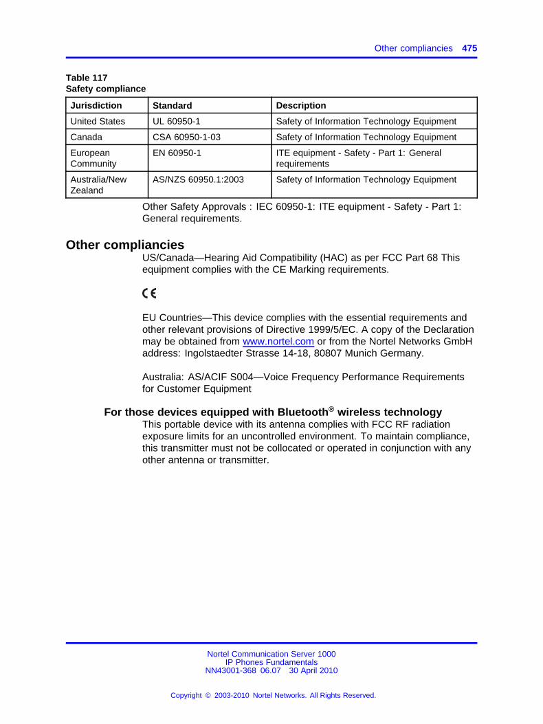
Other compliancies 475
Table 117Safety compliance
Jurisdiction Standard Description
United States UL 60950-1 Safety of Information Technology Equipment
Canada CSA 60950-1-03 Safety of Information Technology Equipment
EuropeanCommunity
EN 60950-1 ITE equipment - Safety - Part 1: Generalrequirements
Australia/NewZealand
AS/NZS 60950.1:2003 Safety of Information Technology Equipment
Other Safety Approvals : IEC 60950-1: ITE equipment - Safety - Part 1:General requirements.
Other complianciesUS/Canada—Hearing Aid Compatibility (HAC) as per FCC Part 68 Thisequipment complies with the CE Marking requirements.
EU Countries—This device complies with the essential requirements andother relevant provisions of Directive 1999/5/EC. A copy of the Declarationmay be obtained from www.nortel.com or from the Nortel Networks GmbHaddress: Ingolstaedter Strasse 14-18, 80807 Munich Germany.
Australia: AS/ACIF S004—Voice Frequency Performance Requirementsfor Customer Equipment
For those devices equipped with Bluetooth® wireless technologyThis portable device with its antenna complies with FCC RF radiationexposure limits for an uncontrolled environment. To maintain compliance,this transmitter must not be collocated or operated in conjunction with anyother antenna or transmitter.
Nortel Communication Server 1000IP Phones Fundamentals
NN43001-368 06.07 30 April 2010
Copyright © 2003-2010 Nortel Networks. All Rights Reserved.
.
476 Regulatory and safety information
DenAn regulatory notice for Japan
Nortel Communication Server 1000IP Phones Fundamentals
NN43001-368 06.07 30 April 2010
Copyright © 2003-2010 Nortel Networks. All Rights Reserved.
.
477.
AppendixLocal Tools menu
ContentsThis section contains the following topics:
• “Introduction” (page 477)
• “Local Tools menu password protection” (page 477)
• “Controlling the menu lock” (page 479)
• “Configuring Secure Local Menu using Network provisioning” (page481)
• “Accessing the Local Tools menu” (page 481)
• “Local Tools options” (page 482)
IntroductionThis section describes the Local Tools menu for the IP Phone 1110, IPPhone 1120E, IP Phone 1140E, IP Phone 1150E, IP Phone 1165E, IPPhone 2007, IP Phone 1210, IP Phone 1220, IP Phone 1230.
For more information about the IP Phone 2007 Local Tools menu, see“Local Tools menu” (page 109).
Local Tools menu password protectionYou can lock the IP Phone local menu to prevent accidental or unwantedchanges. When you lock the local menu, you are prompted to enter apassword to access areas of the local menu. You enter the passwordfrom the IP Phone dialpad and press the center of the navigation cluster(press the OK softkey for the IP Phone 2007) to access the Local Toolsmenu. You can provision a unique Local Tools menu password that canbe a character string between 1 and 21 characters, using only charactersavailable on the IP Phone dialpad (numbers 0 to 9, asterisks [*], and
Nortel Communication Server 1000IP Phones Fundamentals
NN43001-368 06.07 30 April 2010
Copyright © 2003-2010 Nortel Networks. All Rights Reserved.
.
478 Local Tools menu
number signs [#]). For more information about provisioning the Local Toolsmenu password, see the menupwd parameter in Table 122 "Provisioninginfo block format" (page 520).
The Local Tools menu password protects the following local menus on IPPhones
• Preferences
• Local Diagnostics
• Network Configuration
• Touch Panel Setup (IP Phone 2007 only)
• Display Settings (varies by phone type)
• USB Devices (varies by phone type)
If an incorrect password is entered, the areas of the local menu do notopen and you are permitted a maximum of two more attempts to enterthe correct password. After three consecutive failed password attempts,the IP Phone ignores the password entry for five minutes. During thistime period, the IP Phone ignores even a correct password entry. The IPPhone displays the password prompt, and password entries appear to beaccepted, but the password prompt window closes. This process limitsthe possibility of an unauthorized user guessing the correct password byreducing the guess entry rate to three guesses every five minutes.
When the correct password is entered, menu access remains active forfive minutes. During this time period, you can freely navigate, exit, andenter the menu be without being prompted again for the password. Whenthe five minutes expires, the menu closes and you must reenter thepassword to access the menu.
When the full menu lock is active, you are prompted to enter the menulock password whenever you double-press the Services key. Whenthe partial menu lock is active you are prompted to enter the menulock password whenever you access the Local Diagnostics or NetworkConfiguration menu items from the Local Tools menu. You are alwaysprompted to enter the fixed password whenever you access the LockMenu sub menu.
You can control the local menu lock manually using the Local Menu,DHCP, or automatic provisioning features. The DHCP or automaticprovisioning methods are only processed if the menu lock is configured to"Auto Lock" in the Local Menu page. Select "Menu Lock Enable" on theAuto page to automatically select the Auto Lock mode or select the AutoLock item from the Lock Menu.
Nortel Communication Server 1000IP Phones Fundamentals
NN43001-368 06.07 30 April 2010
Copyright © 2003-2010 Nortel Networks. All Rights Reserved.
.
Controlling the menu lock 479
Local Tools menu password feature limitationsThe following feature limitations exist with Local Tools menu passwordprotection:
• You cannot encrypt the Local Tools menu password in the Info Block.
• You cannot change the Local Tools menu password manually, it canonly be changed using the Info Block.
• The Local Tools menu password does not lock the menu structurepresented by the call server, including Telephone Options, PasswordAdmin, and Virtual Office Login.
Controlling the menu lockControlling the menu lock for IP Phone 2007
You can control the menu lock for the IP Phone 2007 in the followingways:
• Auto Config menu option—Tap the Tools icon on the display. TapNetwork Configuration and then tap Auto. Select Menu LockEnable to configure the menu lock to Auto Lock .
• Lock Menu option—Tap the Tools icon on the display. To enable themenu lock, select the Enable Menu Lock check box. From the LockOptions drop down list, select one of the following options
— Secure Local Menu—You are prompted to enter the fixed passwordwhenever the Services key is double-pressed.
— Partial Secure Menu—You are prompted to enter the fixedpassword whenever you access the Local Diagnostics and theNetwork Configuration sub menus.
— Auto Lock—If the DHCP or automatic provisioning parametersare configured to enable partial or full menu lock then you areprompted to enter the fixed password as described above.
The manual parameters configured in the Lock Menu sub menuoverride the configuration received from the DHCP or automaticprovisioning features.
Controlling the menu lock for IP Phone 1165EYou can control the menu lock for the IP Phone 1165E in the followingways:
• Menu lock option—double-press the Services key to access theLocal Tools menu. Press left or right navigation keys to accessConfiguration menu. Press 1 to select Network Configuration and
Nortel Communication Server 1000IP Phones Fundamentals
NN43001-368 06.07 30 April 2010
Copyright © 2003-2010 Nortel Networks. All Rights Reserved.
.
480 Local Tools menu
then press Auto. Select Menu Lock Enable to configure the menulock to Auto Lock .
• Lock Menu option—Double-press the Services key to access the LocalTools menu. Press the left navigation key to access Locks menu.Press 1 to select the Lock Menu dialog. You will be prompted forthe Admin. Password. Enter the password and the Lock Menu dialogappears. To enable the menu lock, select the Enable Menu Lockcheck box. You can then choose the lock mode from the radio buttonlist. Select one of the following options:
— Auto Lock—If the DHCP or automatic provisioning parametersare configured to enable partial or full menu lock then you areprompted to enter the fixed password as described above.
— Full Menu lock—You are prompted to enter the fixed passwordwhenever the Services key is double-pressed.
— Partial Menu lock—You are prompted to enter the fixed passwordwhenever you access the Diagnostics and the Configuration submenus.
The manual parameters configured in the Lock Menu sub menuoverride the configuration received from the DHCP or automaticprovisioning features.
Controlling the menu lock for other IP PhonesYou can control the menu lock for other IP Phones in the following ways:
• Menu lock option—double-press the Services key to access the LocalTools menu. Press the right or left navigation keys to access theConfiguration menu. Press 1 to select Network Configuration submenu, and then press the Auto soft key. Select Menu Lock Enable toconfigure the menu lock to Auto Lock.
• Lock Menu option—Double-press the Services key to access the LocalTools menu. Press the left navigation key to access Locks menu.Press 1 to select the Lock Menu dialog. You will be prompted for theAdmin. Password. Enter the password and the Lock Menu dialogappears. To enable the menu lock, select the Enable Menu Lockcheck box. You can then choose the lock mode from the radio buttonlist. Select one of the following options:
— Full Menu Lock
— Partial Menu Lock
— Disable Menu Lock
— Auto Lock
— Lock Now
Nortel Communication Server 1000IP Phones Fundamentals
NN43001-368 06.07 30 April 2010
Copyright © 2003-2010 Nortel Networks. All Rights Reserved.
.
Accessing the Local Tools menu 481
The manual parameters configured in the Lock Menu sub menuoverride the configuration received from the DHCP or automaticprovisioning features.
Configuring Secure Local Menu using Network provisioningWith DHCP, you can use the SECUREMENU, PARTSECURE, or menulock parameters to enable the menu lock. Alternatively, you can use themenu lock item in any of the provisioning files.
If the IP Phone is configured for Auto Lock, the IP Phone processes anyof the menu lock configuration items when they are received using DHCPor a provisioning file. The menu lock items are ignored if the IP Phone isconfigured to one of the manual menu lock modes.
For more information about configuring DHCP, see “Dynamic HostConfiguration Protocol” (page 429).
For more information about the provisioning file, see “Provisioning the IPPhones” (page 497).
Accessing the Local Tools menuAfter you enter the password, the Local Tools menu remains active for 5minutes. You can freely navigate, exit and reenter the Local Tools menuwithout being prompted to reenter the password. To reset the timer beforethe 5-minute time expires, double-press the Services key.
You can also press the 5 key to select the Lock Now item from the LockMenu. The Lock Now item immediately exits the Local Tools menu,closes any open Local Tools menu pages, and locks the Local Toolsmenu. Alternatively, when time expires, the Local Tools menu and anyopen submenus are closed. Double-press the Services key to open thepassword prompt window to reaccess the Local Tools menu.
If you enter an incorrect password, the Local Tools menu does not open.Double-press the Services key to open the password prompt window. Onlythree incorrect password entries are allowed. Any entry after the threeattempts is ignored for 5 minutes. The password prompt window is visibleand you can reenter the password but the password is not processed untilthe 5-minute time expires.
Some text appears dimmed depending on the current state of the menulock and the configuration of the IP Phone. Only configuration options thatare enabled from the current state appear active. Menu options that arenot available appear dimmed.
Nortel Communication Server 1000IP Phones Fundamentals
NN43001-368 06.07 30 April 2010
Copyright © 2003-2010 Nortel Networks. All Rights Reserved.
.
482 Local Tools menu
Local Tools optionsThe Local Tools menu provides dialogs for configuration, diagnostics andadministration of the IP phone. Double press the Services key to accessthe Local Tools menu. To make a menu selection, you can press thenumber associated with the menu item (for example, press 2 1 to showthe IP Set & DHCP Information menu on the IP Phone 1140E) or you canuse the navigation keys to scroll through the list of menu items and pressthe Enter key.
For information about the Local Tools menu for the IP Phone 1120E, IPPhone 1140E, and IP Phone 1150E, see “Local Tools menu for IP Phones1100 Series” (page 484).
For information about the Local Tools menu for the IP Phone 1165E, see“Local Tools menu for IP Phone 1165E” (page 488)
For information about the Local Tools menu for the IP Phone 1110, IPPhone 1210, IP Phone 1220, and IP Phone 1230, see “Local Tools menufor IP Phone 1110, IP Phone 1210, IP Phone 1220, and IP Phone 1230”(page 493) .
Local Tools menu for IP Phone 2007This section shows the Local Tools menu options for the IP Phone 2007.
Tap the Tools icon to access the Local Tools menu. If you are promptedto enter a password when you tap the Tools icon, password protection isenabled. For more information about password protection, see “Controllingthe menu lock for IP Phone 2007” (page 479). Entering text in the LocalTools menu items is easier with a USB keyboard.
Network ConfigurationUse this menu to configure or to display configuration information. Thismenu contains the following items:
• 802.1x/EAP
• 802.1ab (LLDP)
• DHCP status
• IP network settings (IP address, mask, gateway address)
• DNS server settings, domain and hostname
• Server 1 and Server 2 IP address, Port, Action, Retry, and PK numbers
• Voice VLAN, control and media priority bits, and filtering
• Control and media DSCP settings
• PC port disable, speed, and duplex setting
Nortel Communication Server 1000IP Phones Fundamentals
NN43001-368 06.07 30 April 2010
Copyright © 2003-2010 Nortel Networks. All Rights Reserved.
.
Local Tools options 483
• Data VLAN, priority, and filtering
• Network interface speed and duplex setting
• GARP protection
• Pre-Shared Key SRTP
• XAS IP address, Graphical mode, Port, Phone Screen mode
• Provisioning server and Zone ID
Local diagnosticsDisplays the Local Diagnostics menu containing the following items:
• Network Diagnostic Tools
• Ethernet Statistics
• IP Network Statistics
• IP Set Information
• Advanced Diag Tools
• DHCP Information
For more information about the IP Phone 2007 Local Diagnostics menu,see “IP Phone diagnostic utilities” (page 601)
Touch Panel SetupUse the Touch Panel Setup tool to calibrate the touch panel and stylus.
Display SettingsThe Display Settings menu provides access to the Brightness and ScreenSaver tools. Brightness adjusts the display’s backlight brightness. Thescreen saver settings control how long the display remains lit (either fullyon or dimmed) once the phone is inactive and the delay before the digitalpicture slideshow starts.
USB DevicesUse the USB Devices menu to view the Universal Serial Bus (USB) deviceplugged into the USB port in the back of the IP Phone.
PreferencesUse the Preferences menu to customize the button labels and to select thelanguage of the IP Phone.
Lock MenuUse the Lock Menu to prevent unauthorized access to the Local Toolsmenu.
Nortel Communication Server 1000IP Phones Fundamentals
NN43001-368 06.07 30 April 2010
Copyright © 2003-2010 Nortel Networks. All Rights Reserved.
.
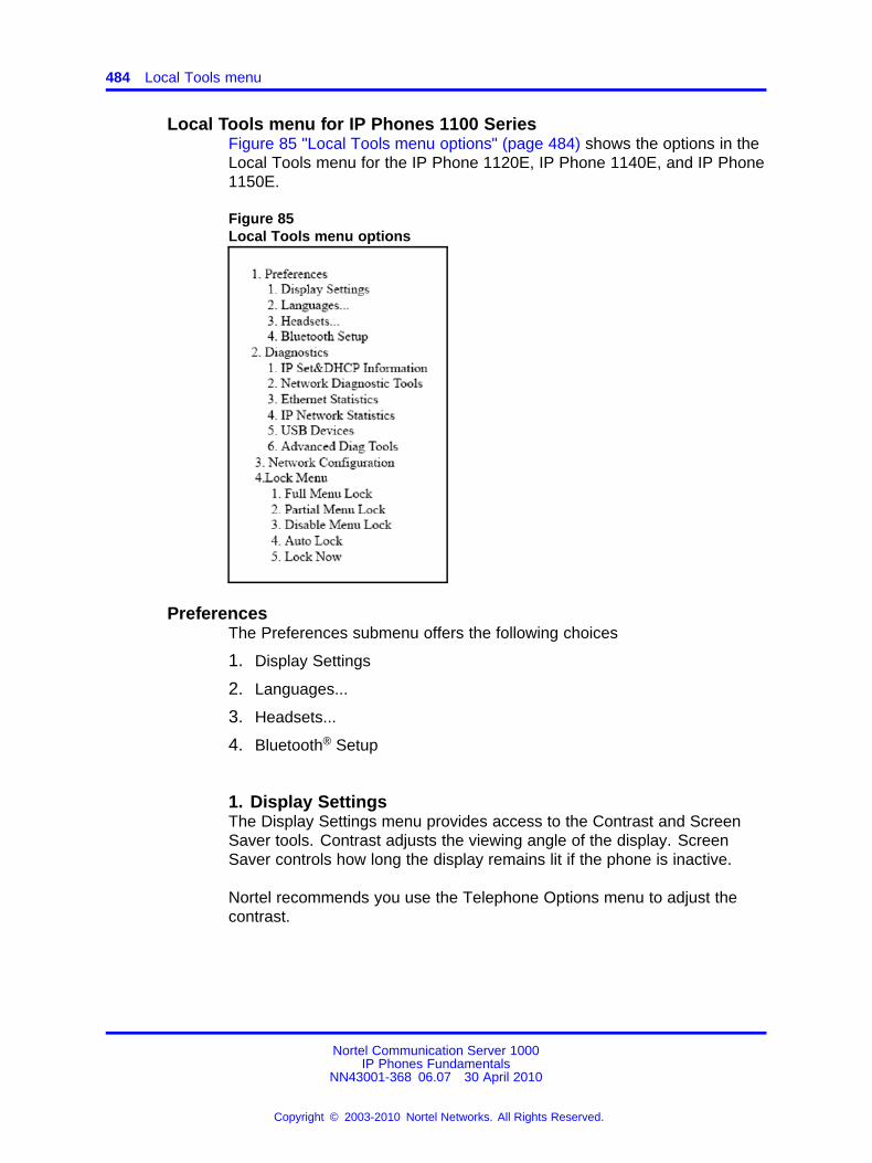
484 Local Tools menu
Local Tools menu for IP Phones 1100 SeriesFigure 85 "Local Tools menu options" (page 484) shows the options in theLocal Tools menu for the IP Phone 1120E, IP Phone 1140E, and IP Phone1150E.
Figure 85Local Tools menu options
PreferencesThe Preferences submenu offers the following choices
1. Display Settings
2. Languages...
3. Headsets...
4. Bluetooth® Setup
1. Display SettingsThe Display Settings menu provides access to the Contrast and ScreenSaver tools. Contrast adjusts the viewing angle of the display. ScreenSaver controls how long the display remains lit if the phone is inactive.
Nortel recommends you use the Telephone Options menu to adjust thecontrast.
Nortel Communication Server 1000IP Phones Fundamentals
NN43001-368 06.07 30 April 2010
Copyright © 2003-2010 Nortel Networks. All Rights Reserved.
.
Local Tools options 485
2. LanguagesUse this item to select the language of the IP Phone.
Note: Hebrew can only be configured on the Call Server.
3. Headsets...Use this item to configure the following headset preferences:
• Active Headset Device: Selects an active headset device (wired,USB, or Bluetooth®).
You can select and configure a headset type as the active headsetdevice and connect the headset at a later time.
• Enable HID Commands: When the box is selected, full HumanInterface Device (HID) for supported headsets is provided. If the boxis not selected, only audio is provided for all devices. By default thebox is selected.
• Headset type: When enabled, you can select a headset supported bythe Nortel USB headset adapter from a list. The default is the NortelMobile Kit.
This option is available only when the IP Phone detects a Nortel USBheadset adapter.
ATTENTIONThe IP Phone tunes the audio specifically to the selected headset type.Nortel recommends that you ensure the correct headset type is selected toachieve the optimum performance.
• Back Light: When the box is selected, the buttons on the NortelEnhanced USB Headset adapter are illuminated or the blue LEDs onthe Nortel Mobile USB Headset Adapter are illuminated. By default thebox is selected.
This option is available only when the IP Phone detects a Nortel USBheadset adapter.
When you make changes in the Headset menu, press the Apply buttonto permanently commit changes or press Cancel to restore the previousheadset preferences.
Nortel Communication Server 1000IP Phones Fundamentals
NN43001-368 06.07 30 April 2010
Copyright © 2003-2010 Nortel Networks. All Rights Reserved.
.
486 Local Tools menu
4. Bluetooth® SetupYou can access the Bluetooth® Setup options (IP Phone 1140E, IP Phone1150E) using either of the following two methods
• Double press the Headset key to open the Bluetooth® Setup dialogbox.
• Double press the Services key to open the Local Tools menu, press1 on the dialpad to select Preferences and press 4 on the dialpad toopen the Bluetooth® Setup dialog box.
The Bluetooth® Setup item is not available on all phones. If theBluetooth® Setup menu item appears dimmed, or fails to open whenyou double press the Headset key, Bluetooth® wireless technology isnot enabled on your phone. To configure the administration setting forBluetooth® wireless technology, see “Headset support” (page 573).
DiagnosticsFor information about Diagnostics, see “IP Phone diagnostic utilities” (page601).
Network ConfigurationUse the Network Configuration menu item to configure the IP Phone1120E, IP Phone 1140E, IP Phone 1150E and to display information,which was configured during installation. You can access the NetworkConfiguration menu using one of the following methods
• Reboot the IP Phone and press the four soft keys at the bottom of thedisplay in sequence from left to right.
• Select 3. Network Configuration from the Local Tools menu.
For more information, see “Provisioning the IP Phones” (page 497) and“Manual provisioning of IP Phones 2007 and 1100 Series” (page 553).
Lock MenuYou must enter the fixed password whenever the Lock Menu sub menuis accessed. Use the dialpad and enter the fixed password 26567*738(color*set).
The settings configured in the Lock Menu sub menu override the settingsreceived from the DHCP string.
The Lock Menu offers the following choices
• 1. Full Menu Lock
• 2. Partial Menu Lock
• 3. Disable Menu Lock
Nortel Communication Server 1000IP Phones Fundamentals
NN43001-368 06.07 30 April 2010
Copyright © 2003-2010 Nortel Networks. All Rights Reserved.
.
Local Tools options 487
• 4. Auto Lock
• 5. Lock Now
1. Full Menu LockWhen this option is selected, you are prompted to enter the fixed passwordwhenever the Services key is double-pressed.
2. Partial Menu LockWhen this option is selected, you are prompted to enter the fixed passwordwhenever you access the Local Diagnostics and the Network Configurationsub menus.
3. Disable Menu LockWhen this option is selected, the Lock Menu is disabled.
4. Auto LockThe IP Phone follows the menu lock configuration received from the FullDHCP string during DHCP configuration
• if SECUREMENU is present, you are prompted to enter a passwordafter you double-press the Services key
• if PARTSECURE is present, you are prompted to enter a passwordwhenever you select Local Diagnostics and Network Configuration
• if neither SECUREMENU nor PARTSECURE is present, then themenu is not locked
For information about Password Protection of the Local Tools menu, see“Local Tools menu password protection” (page 477).
5. Lock NowThe Lock Now item immediately exits the Tools menu, closes any openTools menu pages, and locks the Tools menu.
Procedure 115Locking the Tools menu
Step Action
1 Press the Services key twice.
2 Press 4 on the dialpad to access the Lock Menu item or use theUp/Down navigation keys to scroll and highlight the Lock Menuoptions.
Nortel Communication Server 1000IP Phones Fundamentals
NN43001-368 06.07 30 April 2010
Copyright © 2003-2010 Nortel Networks. All Rights Reserved.
.
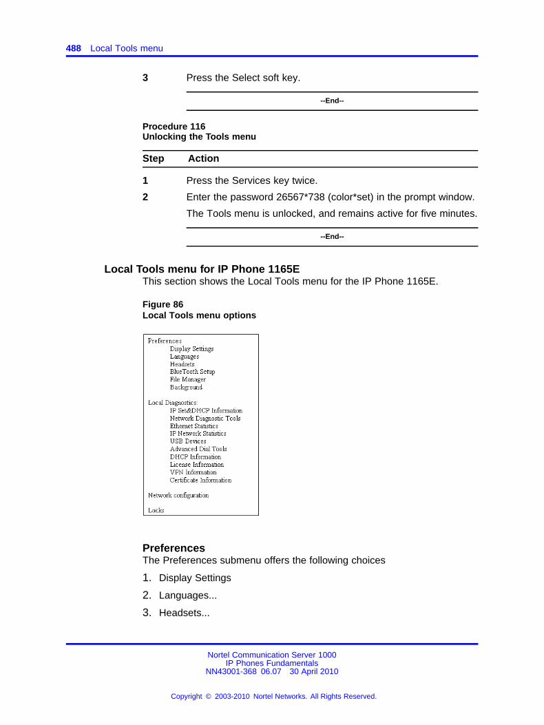
488 Local Tools menu
3 Press the Select soft key.
--End--
Procedure 116Unlocking the Tools menu
Step Action
1 Press the Services key twice.
2 Enter the password 26567*738 (color*set) in the prompt window.
The Tools menu is unlocked, and remains active for five minutes.
--End--
Local Tools menu for IP Phone 1165EThis section shows the Local Tools menu for the IP Phone 1165E.
Figure 86Local Tools menu options
PreferencesThe Preferences submenu offers the following choices
1. Display Settings
2. Languages...
3. Headsets...
Nortel Communication Server 1000IP Phones Fundamentals
NN43001-368 06.07 30 April 2010
Copyright © 2003-2010 Nortel Networks. All Rights Reserved.
.
Local Tools options 489
4. Bluetooth® Setup
5. File Manager
6. Background...
1. Display Settings The Display Settings menu provides control forthe Contrast and Brightness, backlight timer, slideshow start delay,background images and themes used on the phone.
The Display Settings dialog displays the following items:
• Contrast: Sets the contrast of the display.
• Brightness: Sets the brightness of the display.
• Backlight: Sets the duration for which the backlight remains when theIP Phone is idle.
• Slideshow: Sets the delay time for the slideshow to begin after theIP Phone is idle.
• Display Dim Enabled: When the backlight timer expires, the displaywill dim instead of turning completely off.
• Theme: : Allows the selection of a pre-defined theme for the display.
• Use Theme Background: The background image of the theme isused instead of a user selected background.
• Use Font Smoothing: Makes the curves of the font appear smoother.Disabling this may improve the appearance of some text of languageon the display.
• Use Outlined Font: Changes the screen font of telephone to a whitefont with black outline. Helps to make the text readable when a userbackground is enabled.
• GEM Bold Font: Controls whether the font in the Expansion Module(s)(GEM) is bolded or not.
• Use Simple Icons: Changes the line or feature key icons to onessimilar to those on the earlier IP phones.
2. Languages Use this item to select the language of the IP Phone.
3. Headsets... Headsets sub menu controls which headset is enabled foruse on the phone. IP Phone 1165E supports headsets with wired, USB,
Nortel Communication Server 1000IP Phones Fundamentals
NN43001-368 06.07 30 April 2010
Copyright © 2003-2010 Nortel Networks. All Rights Reserved.
.
490 Local Tools menu
and Bluetooth® interfaces. Use this item to configure the following headsetpreferences:
• Active Headset Device: Selects an active headset device (wired,USB, or Bluetooth®).
You can select and configure a headset type as the active headsetdevice and connect the headset at a later time.
• Enable HID Commands: When the box is selected, full HumanInterface Device (HID) for supported headsets is provided. If the boxis not selected, the USB headset cannot communicate things like onor off hook or volume adjustment.
• Headset type: When enabled, you can select a headset supported bythe Nortel USB headset adapter from a list. The default is the NortelMobile Kit.
This option is available only when the IP Phone detects a Nortel USBheadset adapter.
ATTENTIONThe IP Phone tunes the audio specifically to the selected headset type.Nortel recommends that you ensure the correct headset type is selected toachieve the optimum performance.
• Back Light: When the box is selected, the buttons on the NortelEnhanced USB Headset adapter are illuminated or the blue LEDs onthe Nortel Mobile USB Headset Adapter are illuminated. By default thebox is selected.
When you make changes in the Headset menu, press the Ok button topermanently commit changes or press Exit to restore the previous headsetpreferences.
4. Bluetooth® Setup The Bluetooth® setup screen enables you tomanage the pairing and selection of Bluetooth® devices used with theIP Phone 1165E. At this time only headset type Bluetooth® devices aresupported. The Bluetooth® Setup dialog displays the following sub menuitems:
• Enable Bluetooth®: This checkbox allows the user to controlenablement of the Bluetooth® feature on the IP Phone.
• Found: This is a drop down list of found devices. It is inactive until asearch is performed.
• Paired: This is a drop down list of paired devices. It is inactive until adevice is paired.
• Active: This shows the name of the active headset. It is initially blank.The active headset is the Bluetooth® headset used for originating and
Nortel Communication Server 1000IP Phones Fundamentals
NN43001-368 06.07 30 April 2010
Copyright © 2003-2010 Nortel Networks. All Rights Reserved.
.
Local Tools options 491
terminating calls when the Active Headset Device is set to Bluetooth®
in the Headsets…sub menu.
5. File Manager The File Manager menu enables you to manage files onyour IP Phone. The file manager supports the copying of image files toand from a USB Flash Drive to the /images directory in the phone’s FFSand browsing files in the phone’s /images directory. The File Managermenu lists the phone and any USB drives that are currently plugged in. Anicon appears to the left of the name of each device.
• Send operations: The Send soft key appears when you highlight afile. Press the Send soft key to copy a file to the phone or USB FlashDrive. If a file is going to the phone, the destination is automaticallyset by the file type. Pressing Send soft key takes the following actiondepending on the file highlighted:
— When a file on a USB device is selected: This allows you tosend or copy the selected file to the phone. The destination folderis automatically selected based on the file extension (e.g: .jpg and.png files are sent directly to the /Images folder on the IP phone).
— When a file on the IP phone is selected but no USB FlashDrive: This displays an error. Sending files from the IP phone toanother location on the IP phone is not allowed.
— When a file on the IP phone is selected while a USB FlashDrive is plugged in: This allows the user to navigate to the USBfolder they wish to send the file to.
Note: If you do not respond to the confirmation prompt in 15seconds, the send action is cancelled.
• Delete operation: The Delete soft key appears when you highlight afile or directory.
— If a file is selected, you are prompted for the confirmation of deleteoperation and then the file is deleted.
— If a folder is selected on the phone, you are prompted forconfirmation to delete all contents of the folder. You cannot deletethe folder.
— If the folder is on USB device, you are prompted for confirmation todelete the folder. All contents are deleted with the folder.
Note: If you do not respond to the confirmation prompt in 15seconds, the delete action is cancelled.
Nortel Communication Server 1000IP Phones Fundamentals
NN43001-368 06.07 30 April 2010
Copyright © 2003-2010 Nortel Networks. All Rights Reserved.
.
492 Local Tools menu
6. Background The IP Phone 1165E has the ability to display abackground image on its telephone screen. You can browse the imagesin the /images directory of the IP Phone and select one to be used as abackground image for the UI. The filenames of all image files stored in thephone’s /images directory are listed here.
As the highlight is moved on the list of filenames, the currently highlightedimage is displayed as the background of the dialog. If you press OK, theimage filename is saved and becomes the background image.
DiagnosticsFor more information about Diagnostics, see “Diagnostics for the IP Phone1165E” (page 649).
Network ConfigurationThe Network Configuration tool is used to configure the IP Phone’snetwork features and displays information that was configured when the IPPhone was installed. Press the Auto soft key to access the Auto Provisionpage.
Note: For more information, see “Provisioning the IP Phones” (page497) and “Manual provisioning of IP Phones 2007 and 1100 Series”(page 553).
LocksYou must enter the fixed password whenever you access the Lock Menu.Use the dialpad and enter the fixed password 26567*738 (color*set), or,if an auto provisioned password string (menupwd) has been sent to thephone, enter it.
The settings configured in the Lock Menu sub menu override the settingsreceived from the DHCP string.
The Enable Menu Lock checkbox provides overall control of whether themenu lock is active or not. Unchecking the box disables the menu lockfeature.
The Locks menu offers the following choices
• 1. Lock Menu: Lock Menu sub menu offers the following choices:
— Auto Lock: The IP Phone 1165E follows the menu lockconfiguration to be received from the DHCP option string duringDHCP configuration or from a provisioning file’s menulockparameter.
Nortel Communication Server 1000IP Phones Fundamentals
NN43001-368 06.07 30 April 2010
Copyright © 2003-2010 Nortel Networks. All Rights Reserved.
.
Local Tools options 493
– if SECUREMENU is present, you are prompted to enter apassword after you double-press the Services key
– if PARTSECURE is present, you are prompted to enter apassword whenever you select Local Diagnostics and NetworkConfiguration
– if neither SECUREMENU nor PARTSECURE is present, thenthe menu is not locked
For information about Password Protection of the Local Toolsmenu, see “Local Tools menu password protection” (page 477).
— Full Menu Lock: When this option is selected, you are promptedto enter the fixed password whenever the Services key isdouble-pressed.
— Partial Menu Lock: When this option is selected, you areprompted to enter the fixed password whenever you access theLocal Diagnostics and the Network Configuration sub menus.
• 2. USB Locks: The USB locks is a new feature on the IP Phone1165E. It controls which device you can use on the USB port of thephone. USB Locks sub menu offers the following choices.
— AutoProvision USB locks: This check box decides whether theUSB locks are manually controlled or set by zero touch provisioningfeature.
— Enable USB Port: This check box allows you to enable or disablethe USB port.
— Lock USB mouse:This check box allows you to lock or unlock theUSB mouse support.
— Lock USB keyboard: This check box allows you to lock or unlockthe USB keyboard support.
— Lock USB headset: This check box allows you to enable ordisable the USB headset support.
— Lock USB Flash Drive: This check box allows you to lock orunlock the USB flash drive support.
Local Tools menu for IP Phone 1110, IP Phone 1210, IP Phone 1220,and IP Phone 1230
This section shows the Local Tools menu for the IP Phone 1110, IP Phone1210, IP Phone 1220, and IP Phone 1230.
• 1. Preferences
Nortel Communication Server 1000IP Phones Fundamentals
NN43001-368 06.07 30 April 2010
Copyright © 2003-2010 Nortel Networks. All Rights Reserved.
.
494 Local Tools menu
— 1. Contrast
— 2. Language
— 3. Backlight Timer
• 2. Local Diagnostics
— 1. IP Set&DHCP Information
— 2. Network Diagnostic Tools
— 3. Ethernet Statistics
— 4. IP Network Statistics
• 3. Network Configuration
• 4. Lock Menu
— 1. Full Menu Lock
— 2. Partial Menu Lock
— 3. Disable Menu Lock
— 4. Auto Lock
— 5. Lock Now
ATTENTIONOnly the IP Phone 1110 supports the Backlight Timer option.
PreferencesThe Preferences submenu offers the following choices
• 1. Contrast
• 2. Language
• 3. Backlight Timer (available only on the IP Phone 1110)
1. Contrast
The Contrast tool adjusts the contrast of the LCD display screen on the IPPhone.
The initial Contrast level for the LCD display screen is downloaded whenthe IP Phone is configured. Selecting the Contrast tool automatically setsthe LCD display screen contrast to the IP Phone local contrast setting.
2. Language
Nortel Communication Server 1000IP Phones Fundamentals
NN43001-368 06.07 30 April 2010
Copyright © 2003-2010 Nortel Networks. All Rights Reserved.
.
Local Tools options 495
Use this item to select the language in the local menus of the IP Phone.To access the language used by the server-based features, press Services> Telephone Options > Languages.
To access the local language tool, double-press the Services key, selectthe Preferences menu, or press 1 on the dialpad to open the Preferencesmenu, then press 2 to select the Language tool.
3. Backlight Timer
This item displays on the IP Phone 1110 only.
Use this item to adjust how long the LCD display screen remains lit whenthe IP Phone is inactive.
The backlight time is displayed in the format xxx, where xxx is the timein minutes or hours.
Local DiagnosticsFor information about Local Diagnostics, see “IP Phone diagnostic utilities”(page 601).
Network ConfigurationUse the Network Configuration menu item to configure the IP Phoneand to display information, which you configured during installation. Youcan access the Network Configuration menu using one of the followingmethods
• Reboot the IP Phone and press the four soft keys at the bottom of thedisplay in sequence from left to right.
• Select 3. Network Configuration from the Local Tools menu.
For information about Network Configuration, see “Provisioning the IPPhones” (page 497) and “Manual provisioning of IP Phones 1110 and1200 Series” (page 543).
Lock MenuFor information about the Lock Menu item, see “Lock Menu” (page 486).
Nortel Communication Server 1000IP Phones Fundamentals
NN43001-368 06.07 30 April 2010
Copyright © 2003-2010 Nortel Networks. All Rights Reserved.
.

496 Local Tools menu
Nortel Communication Server 1000IP Phones Fundamentals
NN43001-368 06.07 30 April 2010
Copyright © 2003-2010 Nortel Networks. All Rights Reserved.
.
497.
AppendixProvisioning the IP Phones
ContentsThis section contains the following topics:
• “Introduction” (page 497)
• “Description” (page 498)
• “Manual provisioning” (page 498)
• “Automatic provisioning” (page 499)
• “Operation” (page 537)
IntroductionThe following IP Phones support manual provisioning
• IP Phone 2001
• IP Phone 2002
• P Phone 2004
• IP Audio Conference Phone 2033
• IP Phone 2007
• IP Phone 1210
• IP Phone 1220
• IP Phone 1230
• IP Phone 1110
• IP Phone 1120E
• IP Phone 1140E
• IP Phone 1150E
• IP Phone 1165E
Nortel Communication Server 1000IP Phones Fundamentals
NN43001-368 06.07 30 April 2010
Copyright © 2003-2010 Nortel Networks. All Rights Reserved.
.
498 Provisioning the IP Phones
The following IP Phones also support automatic provisioning
• IP Phone 2007
• IP Phone 1210
• IP Phone 1220
• IP Phone 1230
• IP Phone 1110
• IP Phone 1120E
• IP Phone 1140E
• IP Phone 1150E
• IP Phone 1165E
DescriptionThe IP Phone supports the following provisioning modes:
• Manual provisioning
• Automatic provisioning
— Automatic provisioning using 802.1ab Link Layer DiscoveryProtocol (LLDP)
— Automatic provisioning using Dynamic Host Configuration Protocol(DHCP)
— Automatic provisioning using configuration files
— Automatic provisioning using Unified Networks IP Stimulus Protocol(UNIStim)
Manual provisioningThe manual provisioning of IP Phone parameters overrides theconfiguration of parameters by any other provisioning source. Technicianscan use manual provisioning to override system wide parameters fortroubleshooting purposes or to provide special needs configurations for asmall group of users.
Nortel Communication Server 1000IP Phones Fundamentals
NN43001-368 06.07 30 April 2010
Copyright © 2003-2010 Nortel Networks. All Rights Reserved.
.
Automatic provisioning 499
The following sections provide information about the applicable IP Phone.
• “Manual provisioning of IP Phones 1110 and 1200 Series” (page543)—IP Phone 1110, IP Phone 1210, IP Phone 1220, and IP Phone1230
• “Manual provisioning of IP Phones 2007 and 1100 Series” (page553)—IP Phone 2007, IP Phone 1120E, IP Phone 1140E, IP Phone1150E, and IP Phone 1165E
• “Manual provisioning of IP Phones 2000 Series” (page 563)—IP Phone2001, IP Phone 2002, IP Phone 2004, and IP Audio Conference Phone2033
Automatic provisioningThe Automatic provisioning feature creates a flexible provisioning method,which
• covers the existing provisioning parameters
• supports the extension of the provisioning parameters
• supports provisioning parameters in automatic provisioning modes,when possible
• creates a common provisioning information format that supportsDHCP, Trivial File Transfer Protocol (TFTP), and HyperText TransportProtocol (HTTP) provisioning
Figure 87 "Provisioning life cycle" (page 500) provides an example of theprovisioning life cycle.
Nortel Communication Server 1000IP Phones Fundamentals
NN43001-368 06.07 30 April 2010
Copyright © 2003-2010 Nortel Networks. All Rights Reserved.
.
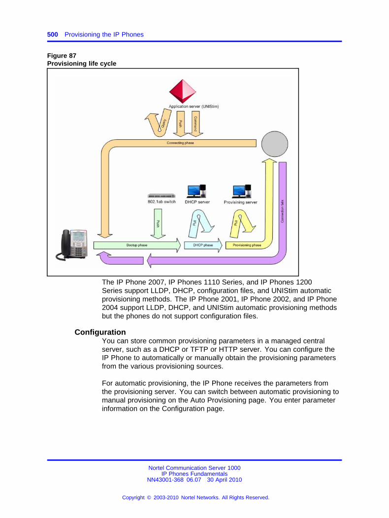
500 Provisioning the IP Phones
Figure 87Provisioning life cycle
The IP Phone 2007, IP Phones 1110 Series, and IP Phones 1200Series support LLDP, DHCP, configuration files, and UNIStim automaticprovisioning methods. The IP Phone 2001, IP Phone 2002, and IP Phone2004 support LLDP, DHCP, and UNIStim automatic provisioning methodsbut the phones do not support configuration files.
ConfigurationYou can store common provisioning parameters in a managed centralserver, such as a DHCP or TFTP or HTTP server. You can configure theIP Phone to automatically or manually obtain the provisioning parametersfrom the various provisioning sources.
For automatic provisioning, the IP Phone receives the parameters fromthe provisioning server. You can switch between automatic provisioning tomanual provisioning on the Auto Provisioning page. You enter parameterinformation on the Configuration page.
Nortel Communication Server 1000IP Phones Fundamentals
NN43001-368 06.07 30 April 2010
Copyright © 2003-2010 Nortel Networks. All Rights Reserved.
.
Automatic provisioning 501
Provisioning IP Phone parametersBy default, the IP Phone can automatically provision most parameters.However, you can manually provision parameters. The Auto Provisioningpage provides the selection to manually override the parameter. Use theNetwork Configuration menu item to configure IP Phone parameters.Double-press the Services key to open the Local Tools menu and press 3on the dial pad to open the Network Configuration menu.
The automatic provisioning menu supports both the graphical userinterface (GUI) and text-based user interface.
The following IP Phones support a GUI:
• IP Phone 2007
• IP Phone 1120E
• IP Phone 1140E
• IP Phone 1150E
• IP Phone 1165E
The Configuration page appears when you select the NetworkConfiguration menu item. Any automatic provisioned parameters appeardimmed.
For more information about the Auto Provisioning page for GUI, see“Auto Provisioning page for graphical user interface” (page 502). Forinformation about the Configuration page for GUI, see “Configuration pagefor graphical user interface” (page 505).
The following IP Phones support a text-based user interface:
• IP Phone 1110
• IP Phone 1210
• IP Phone 1220
• IP Phone 1230
The Network Configuration menu shows the configuration parameters thatare configured as Manual on the Auto Provisioning page. Use the Up andDown navigation keys to scroll through the main configuration options andthe Right or Left navigation keys to scroll through the sub configurationoptions.
For information about the Auto Provisioning page for text user interface,see “Auto Provisioning page for text user interface” (page 505).For information the Configuration page for text user interface, see“Configuration page for text user interface” (page 508).
Nortel Communication Server 1000IP Phones Fundamentals
NN43001-368 06.07 30 April 2010
Copyright © 2003-2010 Nortel Networks. All Rights Reserved.
.
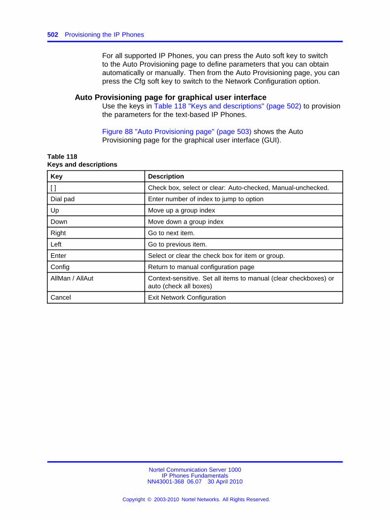
502 Provisioning the IP Phones
For all supported IP Phones, you can press the Auto soft key to switchto the Auto Provisioning page to define parameters that you can obtainautomatically or manually. Then from the Auto Provisioning page, you canpress the Cfg soft key to switch to the Network Configuration option.
Auto Provisioning page for graphical user interfaceUse the keys in Table 118 "Keys and descriptions" (page 502) to provisionthe parameters for the text-based IP Phones.
Figure 88 "Auto Provisioning page" (page 503) shows the AutoProvisioning page for the graphical user interface (GUI).
Table 118Keys and descriptions
Key Description
[ ] Check box, select or clear: Auto-checked, Manual-unchecked.
Dial pad Enter number of index to jump to option
Up Move up a group index
Down Move down a group index
Right Go to next item.
Left Go to previous item.
Enter Select or clear the check box for item or group.
Config Return to manual configuration page
AllMan / AllAut Context-sensitive. Set all items to manual (clear checkboxes) orauto (check all boxes)
Cancel Exit Network Configuration
Nortel Communication Server 1000IP Phones Fundamentals
NN43001-368 06.07 30 April 2010
Copyright © 2003-2010 Nortel Networks. All Rights Reserved.
.
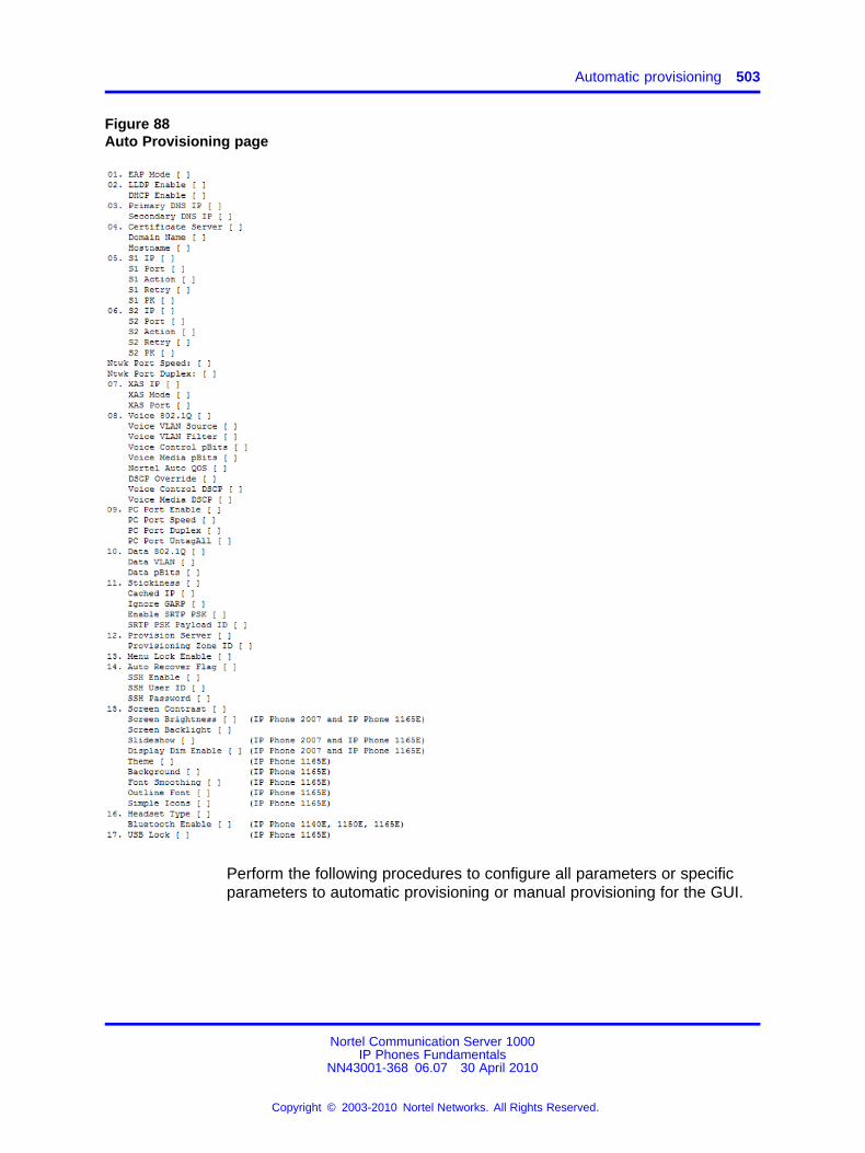
Automatic provisioning 503
Figure 88Auto Provisioning page
Perform the following procedures to configure all parameters or specificparameters to automatic provisioning or manual provisioning for the GUI.
Nortel Communication Server 1000IP Phones Fundamentals
NN43001-368 06.07 30 April 2010
Copyright © 2003-2010 Nortel Networks. All Rights Reserved.
.
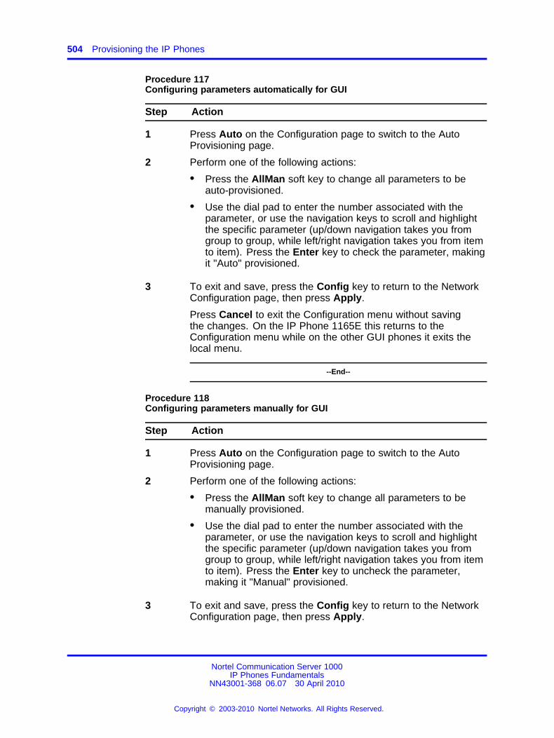
504 Provisioning the IP Phones
Procedure 117Configuring parameters automatically for GUI
Step Action
1 Press Auto on the Configuration page to switch to the AutoProvisioning page.
2 Perform one of the following actions:
• Press the AllMan soft key to change all parameters to beauto-provisioned.
• Use the dial pad to enter the number associated with theparameter, or use the navigation keys to scroll and highlightthe specific parameter (up/down navigation takes you fromgroup to group, while left/right navigation takes you from itemto item). Press the Enter key to check the parameter, makingit "Auto" provisioned.
3 To exit and save, press the Config key to return to the NetworkConfiguration page, then press Apply.
Press Cancel to exit the Configuration menu without savingthe changes. On the IP Phone 1165E this returns to theConfiguration menu while on the other GUI phones it exits thelocal menu.
--End--
Procedure 118Configuring parameters manually for GUI
Step Action
1 Press Auto on the Configuration page to switch to the AutoProvisioning page.
2 Perform one of the following actions:
• Press the AllMan soft key to change all parameters to bemanually provisioned.
• Use the dial pad to enter the number associated with theparameter, or use the navigation keys to scroll and highlightthe specific parameter (up/down navigation takes you fromgroup to group, while left/right navigation takes you from itemto item). Press the Enter key to uncheck the parameter,making it "Manual" provisioned.
3 To exit and save, press the Config key to return to the NetworkConfiguration page, then press Apply.
Nortel Communication Server 1000IP Phones Fundamentals
NN43001-368 06.07 30 April 2010
Copyright © 2003-2010 Nortel Networks. All Rights Reserved.
.
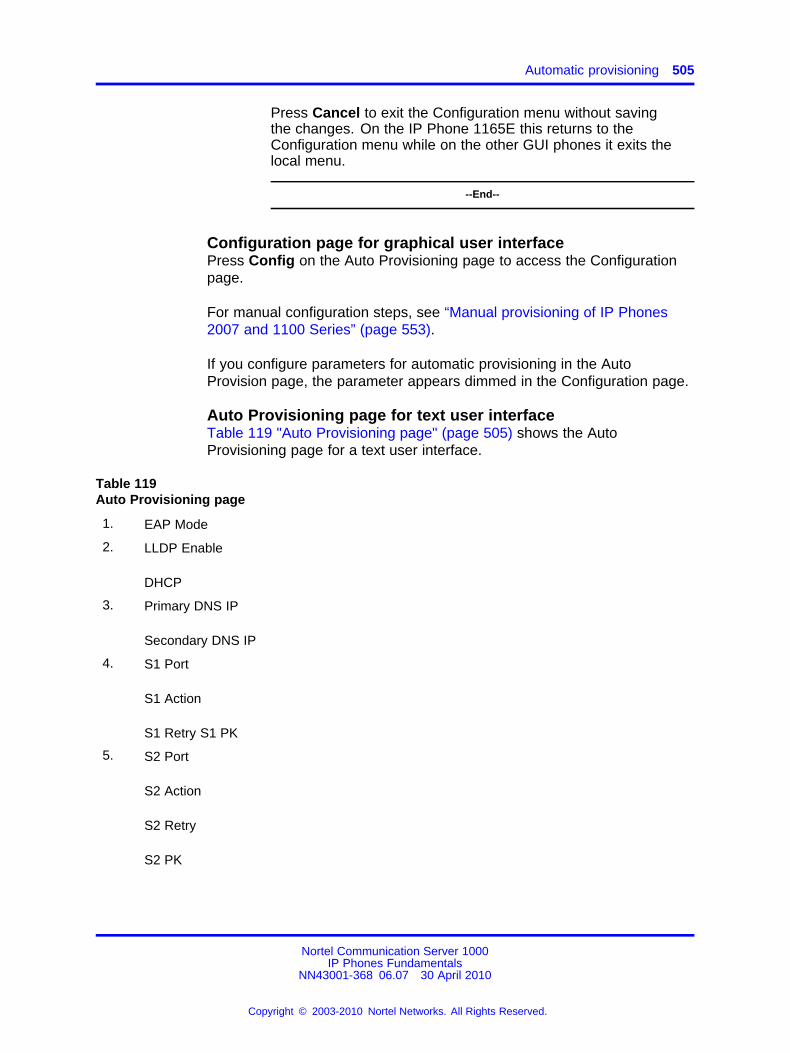
Automatic provisioning 505
Press Cancel to exit the Configuration menu without savingthe changes. On the IP Phone 1165E this returns to theConfiguration menu while on the other GUI phones it exits thelocal menu.
--End--
Configuration page for graphical user interfacePress Config on the Auto Provisioning page to access the Configurationpage.
For manual configuration steps, see “Manual provisioning of IP Phones2007 and 1100 Series” (page 553).
If you configure parameters for automatic provisioning in the AutoProvision page, the parameter appears dimmed in the Configuration page.
Auto Provisioning page for text user interfaceTable 119 "Auto Provisioning page" (page 505) shows the AutoProvisioning page for a text user interface.
Table 119Auto Provisioning page
1. EAP Mode
2. LLDP Enable
DHCP
3. Primary DNS IP
Secondary DNS IP
4. S1 Port
S1 Action
S1 Retry S1 PK
5. S2 Port
S2 Action
S2 Retry
S2 PK
Nortel Communication Server 1000IP Phones Fundamentals
NN43001-368 06.07 30 April 2010
Copyright © 2003-2010 Nortel Networks. All Rights Reserved.
.
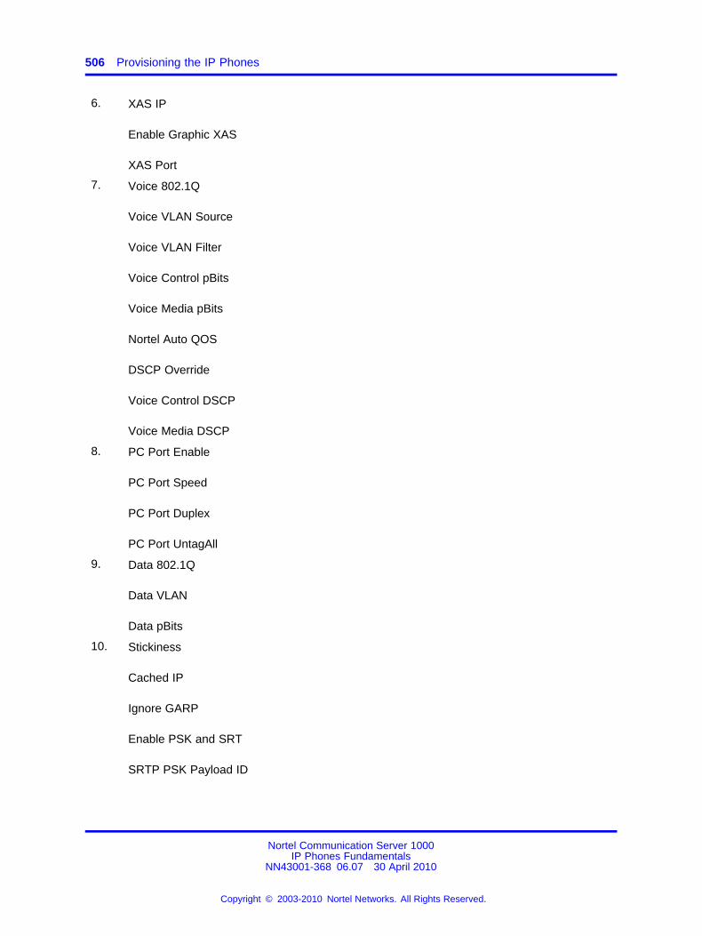
506 Provisioning the IP Phones
6. XAS IP
Enable Graphic XAS
XAS Port
7. Voice 802.1Q
Voice VLAN Source
Voice VLAN Filter
Voice Control pBits
Voice Media pBits
Nortel Auto QOS
DSCP Override
Voice Control DSCP
Voice Media DSCP
8. PC Port Enable
PC Port Speed
PC Port Duplex
PC Port UntagAll
9. Data 802.1Q
Data VLAN
Data pBits
10. Stickiness
Cached IP
Ignore GARP
Enable PSK and SRT
SRTP PSK Payload ID
Nortel Communication Server 1000IP Phones Fundamentals
NN43001-368 06.07 30 April 2010
Copyright © 2003-2010 Nortel Networks. All Rights Reserved.
.
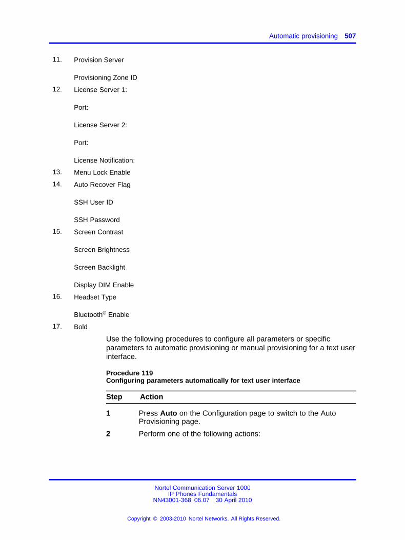
Automatic provisioning 507
11. Provision Server
Provisioning Zone ID
12. License Server 1:
Port:
License Server 2:
Port:
License Notification:
13. Menu Lock Enable
14. Auto Recover Flag
SSH User ID
SSH Password
15. Screen Contrast
Screen Brightness
Screen Backlight
Display DIM Enable
16. Headset Type
Bluetooth® Enable
17. Bold
Use the following procedures to configure all parameters or specificparameters to automatic provisioning or manual provisioning for a text userinterface.
Procedure 119Configuring parameters automatically for text user interface
Step Action
1 Press Auto on the Configuration page to switch to the AutoProvisioning page.
2 Perform one of the following actions:
Nortel Communication Server 1000IP Phones Fundamentals
NN43001-368 06.07 30 April 2010
Copyright © 2003-2010 Nortel Networks. All Rights Reserved.
.
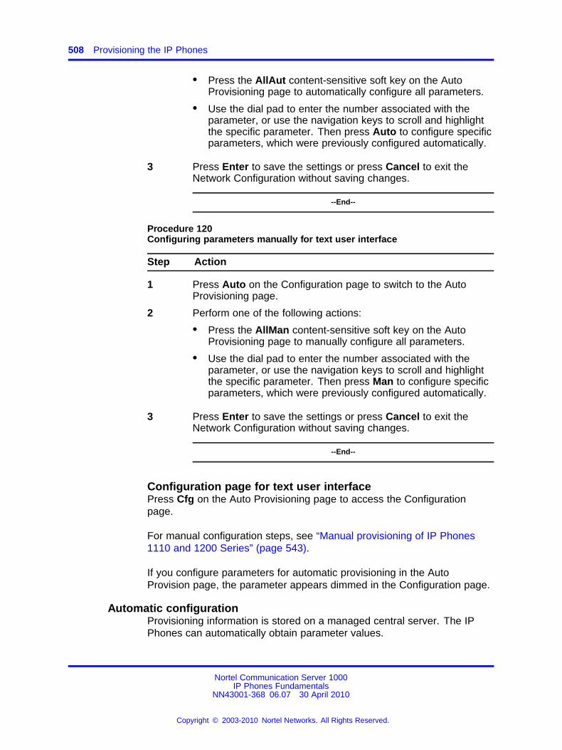
508 Provisioning the IP Phones
• Press the AllAut content-sensitive soft key on the AutoProvisioning page to automatically configure all parameters.
• Use the dial pad to enter the number associated with theparameter, or use the navigation keys to scroll and highlightthe specific parameter. Then press Auto to configure specificparameters, which were previously configured automatically.
3 Press Enter to save the settings or press Cancel to exit theNetwork Configuration without saving changes.
--End--
Procedure 120Configuring parameters manually for text user interface
Step Action
1 Press Auto on the Configuration page to switch to the AutoProvisioning page.
2 Perform one of the following actions:
• Press the AllMan content-sensitive soft key on the AutoProvisioning page to manually configure all parameters.
• Use the dial pad to enter the number associated with theparameter, or use the navigation keys to scroll and highlightthe specific parameter. Then press Man to configure specificparameters, which were previously configured automatically.
3 Press Enter to save the settings or press Cancel to exit theNetwork Configuration without saving changes.
--End--
Configuration page for text user interfacePress Cfg on the Auto Provisioning page to access the Configurationpage.
For manual configuration steps, see “Manual provisioning of IP Phones1110 and 1200 Series” (page 543).
If you configure parameters for automatic provisioning in the AutoProvision page, the parameter appears dimmed in the Configuration page.
Automatic configurationProvisioning information is stored on a managed central server. The IPPhones can automatically obtain parameter values.
Nortel Communication Server 1000IP Phones Fundamentals
NN43001-368 06.07 30 April 2010
Copyright © 2003-2010 Nortel Networks. All Rights Reserved.
.
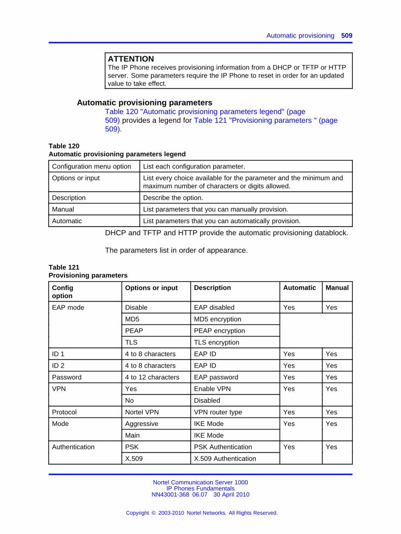
Automatic provisioning 509
ATTENTIONThe IP Phone receives provisioning information from a DHCP or TFTP or HTTPserver. Some parameters require the IP Phone to reset in order for an updatedvalue to take effect.
Automatic provisioning parametersTable 120 "Automatic provisioning parameters legend" (page509) provides a legend for Table 121 "Provisioning parameters " (page509).
Table 120Automatic provisioning parameters legend
Configuration menu option List each configuration parameter.
Options or input List every choice available for the parameter and the minimum andmaximum number of characters or digits allowed.
Description Describe the option.
Manual List parameters that you can manually provision.
Automatic List parameters that you can automatically provision.
DHCP and TFTP and HTTP provide the automatic provisioning datablock.
The parameters list in order of appearance.
Table 121Provisioning parameters
Configoption
Options or input Description Automatic Manual
EAP mode Disable EAP disabled Yes Yes
MD5 MD5 encryption
PEAP PEAP encryption
TLS TLS encryption
ID 1 4 to 8 characters EAP ID Yes Yes
ID 2 4 to 8 characters EAP ID Yes Yes
Password 4 to 12 characters EAP password Yes Yes
Yes Enable VPNVPN
No Disabled
Yes Yes
Protocol Nortel VPN VPN router type Yes Yes
Aggressive IKE ModeMode
Main IKE Mode
Yes Yes
PSK PSK AuthenticationAuthentication
X.509 X.509 Authentication
Yes Yes
Nortel Communication Server 1000IP Phones Fundamentals
NN43001-368 06.07 30 April 2010
Copyright © 2003-2010 Nortel Networks. All Rights Reserved.
.
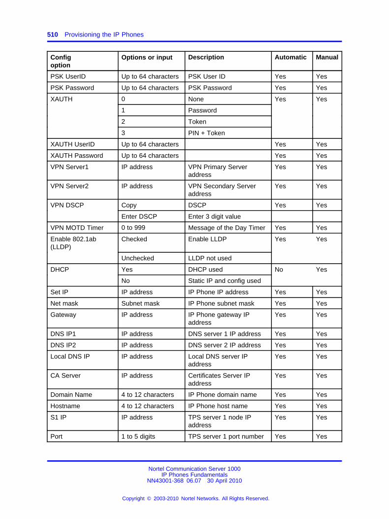
510 Provisioning the IP Phones
Configoption
Options or input Description Automatic Manual
PSK UserID Up to 64 characters PSK User ID Yes Yes
PSK Password Up to 64 characters PSK Password Yes Yes
0 None
1 Password
2 Token
XAUTH
3 PIN + Token
Yes Yes
XAUTH UserID Up to 64 characters Yes Yes
XAUTH Password Up to 64 characters Yes Yes
VPN Server1 IP address VPN Primary Serveraddress
Yes Yes
VPN Server2 IP address VPN Secondary Serveraddress
Yes Yes
Copy DSCP Yes YesVPN DSCP
Enter DSCP Enter 3 digit value
VPN MOTD Timer 0 to 999 Message of the Day Timer Yes Yes
Enable 802.1ab(LLDP)
Checked Enable LLDP Yes Yes
Unchecked LLDP not used
DHCP Yes DHCP used No Yes
No Static IP and config used
Set IP IP address IP Phone IP address Yes Yes
Net mask Subnet mask IP Phone subnet mask Yes Yes
Gateway IP address IP Phone gateway IPaddress
Yes Yes
DNS IP1 IP address DNS server 1 IP address Yes Yes
DNS IP2 IP address DNS server 2 IP address Yes Yes
Local DNS IP IP address Local DNS server IPaddress
Yes Yes
CA Server IP address Certificates Server IPaddress
Yes Yes
Domain Name 4 to 12 characters IP Phone domain name Yes Yes
Hostname 4 to 12 characters IP Phone host name Yes Yes
S1 IP IP address TPS server 1 node IPaddress
Yes Yes
Port 1 to 5 digits TPS server 1 port number Yes Yes
Nortel Communication Server 1000IP Phones Fundamentals
NN43001-368 06.07 30 April 2010
Copyright © 2003-2010 Nortel Networks. All Rights Reserved.
.
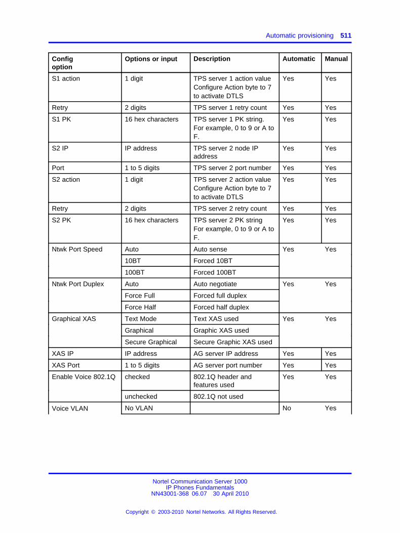
Automatic provisioning 511
Configoption
Options or input Description Automatic Manual
S1 action 1 digit TPS server 1 action valueConfigure Action byte to 7to activate DTLS
Yes Yes
Retry 2 digits TPS server 1 retry count Yes Yes
S1 PK 16 hex characters TPS server 1 PK string.For example, 0 to 9 or A toF.
Yes Yes
S2 IP IP address TPS server 2 node IPaddress
Yes Yes
Port 1 to 5 digits TPS server 2 port number Yes Yes
S2 action 1 digit TPS server 2 action valueConfigure Action byte to 7to activate DTLS
Yes Yes
Retry 2 digits TPS server 2 retry count Yes Yes
S2 PK 16 hex characters TPS server 2 PK stringFor example, 0 to 9 or A toF.
Yes Yes
Ntwk Port Speed Auto Auto sense Yes Yes
10BT Forced 10BT
100BT Forced 100BT
Ntwk Port Duplex Auto Auto negotiate Yes Yes
Force Full Forced full duplex
Force Half Forced half duplex
Text Mode Text XAS used Yes Yes
Graphical Graphic XAS used
Graphical XAS
Secure Graphical Secure Graphic XAS used
XAS IP IP address AG server IP address Yes Yes
XAS Port 1 to 5 digits AG server port number Yes Yes
Enable Voice 802.1Q checked 802.1Q header andfeatures used
Yes Yes
unchecked 802.1Q not used
Voice VLAN No VLAN No Yes
Nortel Communication Server 1000IP Phones Fundamentals
NN43001-368 06.07 30 April 2010
Copyright © 2003-2010 Nortel Networks. All Rights Reserved.
.
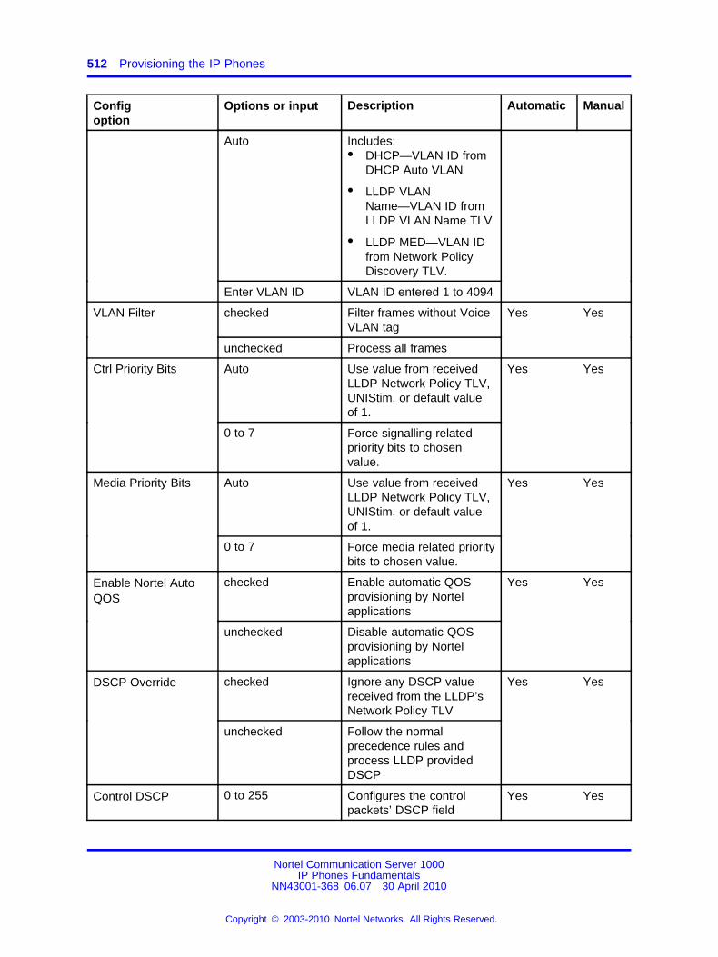
512 Provisioning the IP Phones
Configoption
Options or input Description Automatic Manual
Auto Includes:• DHCP—VLAN ID from
DHCP Auto VLAN
• LLDP VLANName—VLAN ID fromLLDP VLAN Name TLV
• LLDP MED—VLAN IDfrom Network PolicyDiscovery TLV.
Enter VLAN ID VLAN ID entered 1 to 4094
VLAN Filter checked Filter frames without VoiceVLAN tag
Yes Yes
unchecked Process all frames
Ctrl Priority Bits Auto Use value from receivedLLDP Network Policy TLV,UNIStim, or default valueof 1.
Yes Yes
0 to 7 Force signalling relatedpriority bits to chosenvalue.
Media Priority Bits Auto Use value from receivedLLDP Network Policy TLV,UNIStim, or default valueof 1.
Yes Yes
0 to 7 Force media related prioritybits to chosen value.
checked Enable automatic QOSprovisioning by Nortelapplications
Yes YesEnable Nortel AutoQOS
unchecked Disable automatic QOSprovisioning by Nortelapplications
checked Ignore any DSCP valuereceived from the LLDP’sNetwork Policy TLV
Yes YesDSCP Override
unchecked Follow the normalprecedence rules andprocess LLDP providedDSCP
Control DSCP 0 to 255 Configures the controlpackets’ DSCP field
Yes Yes
Nortel Communication Server 1000IP Phones Fundamentals
NN43001-368 06.07 30 April 2010
Copyright © 2003-2010 Nortel Networks. All Rights Reserved.
.
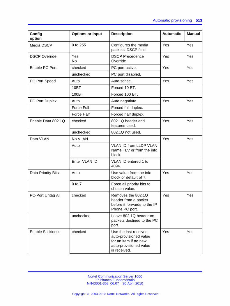
Automatic provisioning 513
Configoption
Options or input Description Automatic Manual
Media DSCP 0 to 255 Configures the mediapackets’ DSCP field
Yes Yes
DSCP Override YesNo
DSCP PrecedenceOverride
Yes Yes
Enable PC Port checked PC port active. Yes Yes
unchecked PC port disabled.
PC Port Speed Auto Auto sense. Yes Yes
10BT Forced 10 BT.
100BT Forced 100 BT.
PC Port Duplex Auto Auto negotiate. Yes Yes
Force Full Forced full duplex.
Force Half Forced half duplex.
Enable Data 802.1Q checked 802.1Q header andfeatures used.
Yes Yes
unchecked 802.1Q not used.
Data VLAN No VLAN Yes Yes
Auto VLAN ID from LLDP VLANName TLV or from the infoblock.
Enter VLAN ID VLAN ID entered 1 to4094.
Data Priority Bits Auto Use value from the infoblock or default of 7.
Yes Yes
0 to 7 Force all priority bits tochosen value.
PC-Port Untag All checked Removes the 802.1Qheader from a packetbefore it forwards to the IPPhone PC port.
Yes Yes
unchecked Leave 802.1Q header onpackets destined to the PCport.
Enable Stickiness checked Use the last receivedauto-provisioned valuefor an item if no newauto-provisioned valueis received.
Yes Yes
Nortel Communication Server 1000IP Phones Fundamentals
NN43001-368 06.07 30 April 2010
Copyright © 2003-2010 Nortel Networks. All Rights Reserved.
.

514 Provisioning the IP Phones
Configoption
Options or input Description Automatic Manual
unchecked Item reverts back todefault value if no newauto-provisioned value isreceived.
Cached IP checked Last IP Phone IP addressinfo received is used ifDHCP server not reached.
Yes Yes
unchecked Must receive responseto assign IP Phone IPaddress.
Ignore GARP checked IP Phone ignoresGratuitous ARP requests.See “Gratuitous AddressResolution Protocol” (page453) for more information.
Yes Yes
unchecked IP Phone responds toGratuitous ARP requests.
Enable SRTP PSK checked When non-SRTP USK callis set up, IP Phone tries toestablish SRTP PSK callwith far end.
Yes Yes
unchecked IP Phone does not trySRTP PSK.
SRTP PSK PayloadID
96 (default), 115,120
Payload Type ID used forthe exchange of SRTPPSK excryption parameters
Yes Yes
DSCP Override Auto DSCP PrecedenceOverride
Yes Yes
Provision up to 40 characterURL
URL for provisioningserver. For HTTP server,URL must include "http://".
Yes Yes
Provision Zone ID 1 to 5 characters IP Phone provisioningzone.
Yes Yes
Licensing Server 1 Primary License server IP
Port 31210 default License server port number
License Server 2 Secondary License serverIP
License Notification 24 hours Notification display timeframe
Enable Bluetooth® Yes Enables Bluetooth® on theIP Phone.
Yes Yes
Nortel Communication Server 1000IP Phones Fundamentals
NN43001-368 06.07 30 April 2010
Copyright © 2003-2010 Nortel Networks. All Rights Reserved.
.
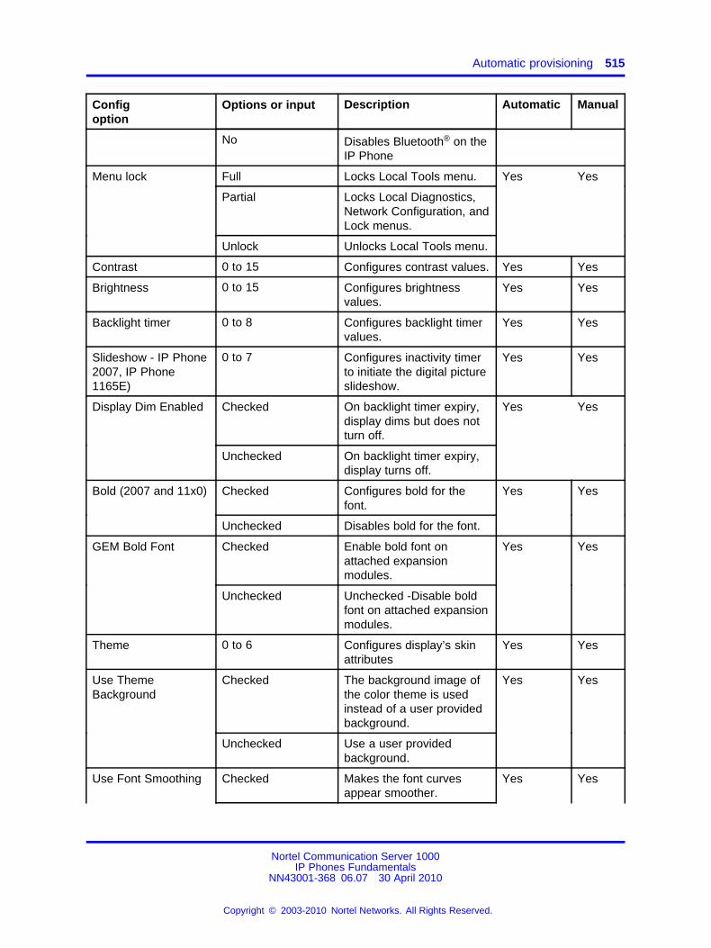
Automatic provisioning 515
Configoption
Options or input Description Automatic Manual
No Disables Bluetooth® on theIP Phone
Menu lock Full Locks Local Tools menu. Yes Yes
Partial Locks Local Diagnostics,Network Configuration, andLock menus.
Unlock Unlocks Local Tools menu.
Contrast 0 to 15 Configures contrast values. Yes Yes
Brightness 0 to 15 Configures brightnessvalues.
Yes Yes
Backlight timer 0 to 8 Configures backlight timervalues.
Yes Yes
Slideshow - IP Phone2007, IP Phone1165E)
0 to 7 Configures inactivity timerto initiate the digital pictureslideshow.
Yes Yes
Display Dim Enabled Checked On backlight timer expiry,display dims but does notturn off.
Yes Yes
Unchecked On backlight timer expiry,display turns off.
Bold (2007 and 11x0) Checked Configures bold for thefont.
Yes Yes
Unchecked Disables bold for the font.
GEM Bold Font Checked Enable bold font onattached expansionmodules.
Yes Yes
Unchecked Unchecked -Disable boldfont on attached expansionmodules.
Theme 0 to 6 Configures display’s skinattributes
Yes Yes
Use ThemeBackground
Checked The background image ofthe color theme is usedinstead of a user providedbackground.
Yes Yes
Unchecked Use a user providedbackground.
Use Font Smoothing Checked Makes the font curvesappear smoother.
Yes Yes
Nortel Communication Server 1000IP Phones Fundamentals
NN43001-368 06.07 30 April 2010
Copyright © 2003-2010 Nortel Networks. All Rights Reserved.
.
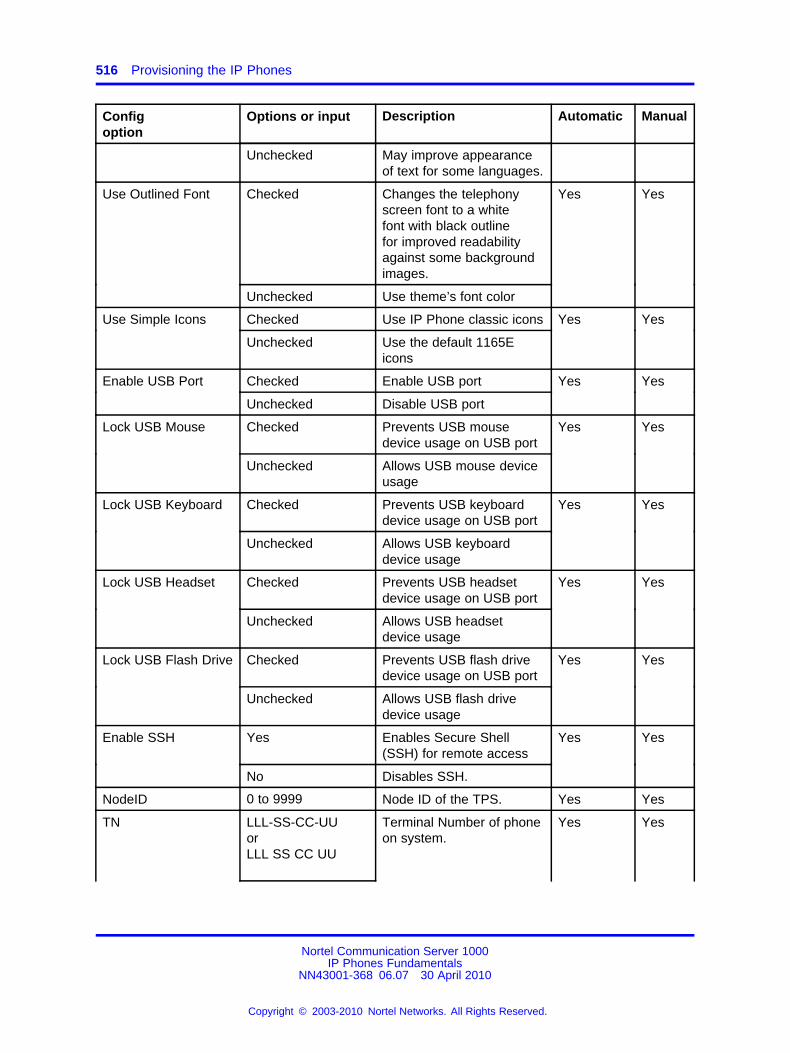
516 Provisioning the IP Phones
Configoption
Options or input Description Automatic Manual
Unchecked May improve appearanceof text for some languages.
Use Outlined Font Checked Changes the telephonyscreen font to a whitefont with black outlinefor improved readabilityagainst some backgroundimages.
Yes Yes
Unchecked Use theme’s font color
Use Simple Icons Checked Use IP Phone classic icons Yes Yes
Unchecked Use the default 1165Eicons
Enable USB Port Checked Enable USB port Yes Yes
Unchecked Disable USB port
Lock USB Mouse Checked Prevents USB mousedevice usage on USB port
Yes Yes
Unchecked Allows USB mouse deviceusage
Lock USB Keyboard Checked Prevents USB keyboarddevice usage on USB port
Yes Yes
Unchecked Allows USB keyboarddevice usage
Lock USB Headset Checked Prevents USB headsetdevice usage on USB port
Yes Yes
Unchecked Allows USB headsetdevice usage
Lock USB Flash Drive Checked Prevents USB flash drivedevice usage on USB port
Yes Yes
Unchecked Allows USB flash drivedevice usage
Enable SSH Yes Enables Secure Shell(SSH) for remote access
Yes Yes
No Disables SSH.
NodeID 0 to 9999 Node ID of the TPS. Yes Yes
TN LLL-SS-CC-UUorLLL SS CC UU
Terminal Number of phoneon system.
Yes Yes
Nortel Communication Server 1000IP Phones Fundamentals
NN43001-368 06.07 30 April 2010
Copyright © 2003-2010 Nortel Networks. All Rights Reserved.
.
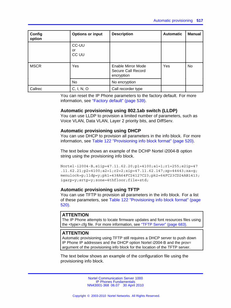
Automatic provisioning 517
Configoption
Options or input Description Automatic Manual
CC-UUorCC UU
Yes Enable Mirror ModeSecure Call Recordencryption
MSCR
No No encryption
Yes No
Callrec C, I, N, O Call recorder type
You can reset the IP Phone parameters to the factory default. For moreinformation, see “Factory default” (page 539).
Automatic provisioning using 802.1ab switch (LLDP)You can use LLDP to provision a limited number of parameters, such asVoice VLAN, Data VLAN, Layer 2 priority bits, and DiffServ.
Automatic provisioning using DHCPYou can use DHCP to provision all parameters in the info block. For moreinformation, see Table 122 "Provisioning info block format" (page 520).
The text below shows an example of the DCHP Nortel i2004-B optionstring using the provisioning info block.
Nortel-i2004-B,s1ip=47.11.62.20;p1=4100;a1=1;r1=255;s2ip=47.11.62.21;p2=4100;a2=1;r2=2;xip=47.11.62.147;xp=44443;xa=g;menulock=p;lldp=y;pk1=438A64FC24127C23;pk2=64FC23CD24AB1413;igarp=y;srtp=y;zone=4thfloor;file=ztd;
Automatic provisioning using TFTPYou can use TFTP to provision all parameters in the info block. For a listof these parameters, see Table 122 "Provisioning info block format" (page520).
ATTENTIONThe IP Phone attempts to locate firmware updates and font resources files usingthe <type>.cfg file. For more information, see “TFTP Server” (page 683).
ATTENTIONAutomatic provisioning using TFTP still requires a DHCP server to push downIP Phone IP addresses and the DHCP option Nortel i2004-B and the prov=argument of the provisioning info block for the location of the TFTP server.
The text below shows an example of the configuration file using theprovisioning info block.
Nortel Communication Server 1000IP Phones Fundamentals
NN43001-368 06.07 30 April 2010
Copyright © 2003-2010 Nortel Networks. All Rights Reserved.
.

518 Provisioning the IP Phones
s1ip=47.11.62.20;p1=4100;a1=1;r1=2;s2ip=47.11.62.21;p2=4100;a2=1;r2=2;xip=47.11.62.147;xp=5000;xa=g;unid=Main-tower;menulock=p;vq=y;vlanf=y;pc=y;pcs=a;pcd=a;dq=y;dv=60;dp=5;pcuntag=y;lldp=y;pk1=438A64FC24127C23;pk2=64FC23CD24AB1413;stickiness=y;cachedip=n;igarp=n;srtp=n;eap=peap;eapid1=DEV1024;eappwd=D3c6v5;cdiff=13;mdiff=12;prov=47.11.232.115;dns=47.11.20.20;dns2=47.11.20.21;ct=20;br=18;blt=1;dim=y;bt=y;zone=NE1F;file=ztd;hd=w;ar=y;arl=ma;ll=mi;ssh=y;sshid=1234;sshpwd=1234;
/* Primary server IP address *//* Primary server port number *//* Primary server action code *//* Primary server retry count *//* Secondary server IP address *//* Secondary server port number *//* Secondary server action code *//* Secondary server retry count *//* Secondary server retry count *//* XAS server port number *//* XAS server action code *//* Unique network identification *//* Menu lock mode *//* Enable 802.1Q for voice *//* Enable VLAN filter *//* Enable PC port *//* PC port speed *//* PC port duplex *//* Enable 802.1Q for PC port *//* VLAN ID data VLAN *//* 802.1Q p bit for PC port or data *//* PC port untag all *//* PC port untag all *//* S1 PK *//* S1 PK *//* Enable stickiness *//* Enable cached IP *//* Ignore GARP *//* Enable PSK SRTP *//* Enable 802.1x (EAP) *//* 802.1x (EAP) device ID *//* 802.1x (EAP) password *//* DiffServ code point for control *//* DiffServ code point for media *//* Provisioning server IP address *//* Primary DNS server IP address *//* Secondary DNS server IP address *//* Contrast value *//* Brightness value *//* Backlight timer *//* Enable dim *//* Enable Bluetooth® *//* Zone id *//* Exist in system specific *//* Headset type *//* Enable auto recovery *//* Auto recovery level *//* Log level *//* Enable SSH *//* Configure SSH ID /*/* Configure SSH password /*
Nortel Communication Server 1000IP Phones Fundamentals
NN43001-368 06.07 30 April 2010
Copyright © 2003-2010 Nortel Networks. All Rights Reserved.
.
Automatic provisioning 519
sst=2;bold=y;th=0;utb=n;fs=y;of=y;si=n;usb=y;usbm=y;usbk=y;usbh=y;usbms=y;
/* Enable slideshow *//* Enable bold font *//* Set theme selection *//* Don’t use theme background *//* Enable font smoothing *//* Enable outlined font *//* Don’t use simple icons *//* Enable USB port *//* Enable USB mouse device *//* Enable USB keyboard device *//* Enable USB headset device *//* Enable USB flash drive device */
Automatic provisioning using HTTPYou can use HTTP to provision all parameters in the info block. The URLmust contain "http://" string.
If the phone receives DHCP Option 66 (TFTP server name) and the stringis prefixed with "http://" the IP Phone connects to an HTTP server andretrieves the files using HTTP protocol instead of TFTP protocol.
Provisioning filesThe IP Phones can receive provisioning files from the TFTP or the HTTPserver. The IP Phone supports only a single provisioning server to providethe .prv files.
The provisioning server (TFTP or HTTP server) contains the followingprovisioning files:
• SYSTEM provisioning file–provides provisioning information to all IPPhones that support the automatic provisioning feature. (for example:system.prv)
• ZONE provisioning file– provides provisioning information to IPPhones that belong to a unique defined zone or group. (for example:headqrtr.prv)
• TYPE provisioning file–provides provisioning information to particularIP Phone types. (for example: 1140E.prv)
• DEVICE provisioning file– provides provisioning information to aspecific single device based on the device MAC address. (for example:001365FEF4D4.prv)
The IP Phones can receive the Info Block in one or more of theprovisioning files. The provisioning file contains the provisioning Info Blockonly. The IP Phone continues to use configuration files (TYPE.cfg) forobtaining firmware and font file updates.
Nortel Communication Server 1000IP Phones Fundamentals
NN43001-368 06.07 30 April 2010
Copyright © 2003-2010 Nortel Networks. All Rights Reserved.
.
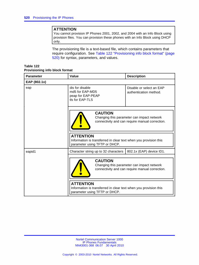
520 Provisioning the IP Phones
ATTENTIONYou cannot provision IP Phones 2001, 2002, and 2004 with an Info Block usingprovision files. You can provision these phones with an Info Block using DHCPonly.
The provisioning file is a text-based file, which contains parameters thatrequire configuration. See Table 122 "Provisioning info block format" (page520) for syntax, parameters, and values.
Table 122Provisioning info block format
Parameter Value Description
EAP (802.1x)
dis for disablemd5 for EAP-MD5peap for EAP-PEAPtls for EAP-TLS
Disable or select an EAPauthentication method.
eap
CAUTIONChanging this parameter can impact networkconnectivity and can require manual correction.
ATTENTIONInformation is transferred in clear text when you provision thisparameter using TFTP or DHCP.
Character string up to 32 characters 802.1x (EAP) device ID1.eapid1
CAUTIONChanging this parameter can impact networkconnectivity and can require manual correction.
ATTENTIONInformation is transferred in clear text when you provision thisparameter using TFTP or DHCP.
Nortel Communication Server 1000IP Phones Fundamentals
NN43001-368 06.07 30 April 2010
Copyright © 2003-2010 Nortel Networks. All Rights Reserved.
.
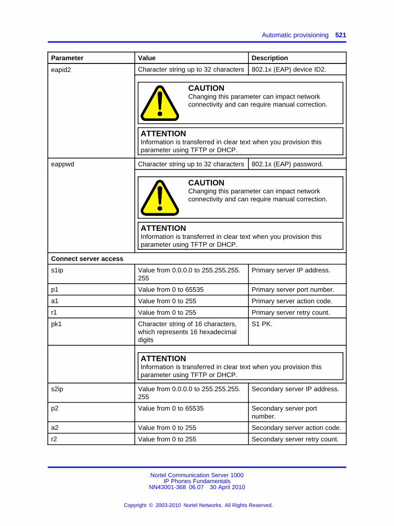
Automatic provisioning 521
Parameter Value Description
Character string up to 32 characters 802.1x (EAP) device ID2.eapid2
CAUTIONChanging this parameter can impact networkconnectivity and can require manual correction.
ATTENTIONInformation is transferred in clear text when you provision thisparameter using TFTP or DHCP.
Character string up to 32 characters 802.1x (EAP) password.eappwd
CAUTIONChanging this parameter can impact networkconnectivity and can require manual correction.
ATTENTIONInformation is transferred in clear text when you provision thisparameter using TFTP or DHCP.
Connect server access
s1ip Value from 0.0.0.0 to 255.255.255.255
Primary server IP address.
p1 Value from 0 to 65535 Primary server port number.
a1 Value from 0 to 255 Primary server action code.
r1 Value from 0 to 255 Primary server retry count.
pk1 Character string of 16 characters,which represents 16 hexadecimaldigits
S1 PK.
ATTENTIONInformation is transferred in clear text when you provision thisparameter using TFTP or DHCP.
s2ip Value from 0.0.0.0 to 255.255.255.255
Secondary server IP address.
p2 Value from 0 to 65535 Secondary server portnumber.
a2 Value from 0 to 255 Secondary server action code.
r2 Value from 0 to 255 Secondary server retry count.
Nortel Communication Server 1000IP Phones Fundamentals
NN43001-368 06.07 30 April 2010
Copyright © 2003-2010 Nortel Networks. All Rights Reserved.
.

522 Provisioning the IP Phones
Parameter Value Description
Character string of 16 characters,which represents 16 hexadecimaldigits
S2 PK.pk2
ATTENTIONInformation is transferred in clear text when you provision thisparameter using TFTP or DHCP.
Other networking
ca Character string with a maximum of80 characters
The URL of the CertificateAuthority (CA) server
cahost Character string with a maximum of32 characters
The Certificate Authority (CA)host name assigned to the IPPhone.
cadomain Character string with a maximum of50 characters
The Certificate Authority (CA)domain name to which the IPPhone is a member of.
dns Character string with a maximum of50 characters
Primary DNS server URL
dns2 Character string with a maximum of50 characters
Secondary DNS server URL
y for yesn for no
Enable 802.1ab LLDP.lldp
CAUTIONChanging this parameter can impact networkconnectivity and can require manual correction.
prov Character string with a maximum of50 characters
Provisioning server URL.For an HTTP server, you mustinclude "http://" in the URL.
stickiness y for yesn for no
Enable stickiness.
cachedip y for yesn for no
Enable cached IP.
dhcp y for yesn for no
Enable Dynamic HostConfiguration Protocol(DHCP).
Nortel Communication Server 1000IP Phones Fundamentals
NN43001-368 06.07 30 April 2010
Copyright © 2003-2010 Nortel Networks. All Rights Reserved.
.
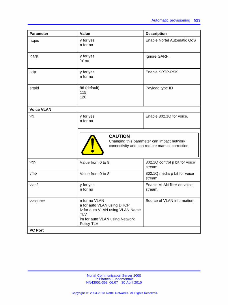
Automatic provisioning 523
Parameter Value Description
ntqos y for yesn for no
Enable Nortel Automatic QoS
igarp y for yes’n’ no
Ignore GARP.
srtp y for yesn for no
Enable SRTP-PSK.
srtpid 96 (default)115120
Payload type ID
Voice VLAN
y for yesn for no
Enable 802.1Q for voice.vq
CAUTIONChanging this parameter can impact networkconnectivity and can require manual correction.
vcp Value from 0 to 8 802.1Q control p bit for voicestream.
vmp Value from 0 to 8 802.1Q media p bit for voicestream
vlanf y for yesn for no
Enable VLAN filter on voicestream.
vvsource n for no VLANa for auto VLAN using DHCPlv for auto VLAN using VLAN NameTLVlm for auto VLAN using NetworkPolicy TLV
Source of VLAN information.
PC Port
Nortel Communication Server 1000IP Phones Fundamentals
NN43001-368 06.07 30 April 2010
Copyright © 2003-2010 Nortel Networks. All Rights Reserved.
.
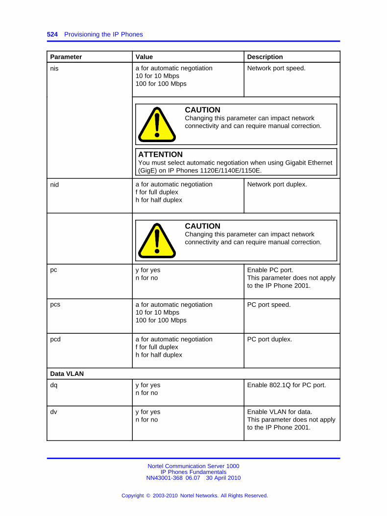
524 Provisioning the IP Phones
Parameter Value Description
a for automatic negotiation10 for 10 Mbps100 for 100 Mbps
Network port speed.nis
CAUTIONChanging this parameter can impact networkconnectivity and can require manual correction.
ATTENTIONYou must select automatic negotiation when using Gigabit Ethernet(GigE) on IP Phones 1120E/1140E/1150E.
nid a for automatic negotiationf for full duplexh for half duplex
Network port duplex.
CAUTIONChanging this parameter can impact networkconnectivity and can require manual correction.
pc y for yesn for no
Enable PC port.This parameter does not applyto the IP Phone 2001.
pcs a for automatic negotiation10 for 10 Mbps100 for 100 Mbps
PC port speed.
pcd a for automatic negotiationf for full duplexh for half duplex
PC port duplex.
Data VLAN
dq y for yesn for no
Enable 802.1Q for PC port.
dv y for yesn for no
Enable VLAN for data.This parameter does not applyto the IP Phone 2001.
Nortel Communication Server 1000IP Phones Fundamentals
NN43001-368 06.07 30 April 2010
Copyright © 2003-2010 Nortel Networks. All Rights Reserved.
.
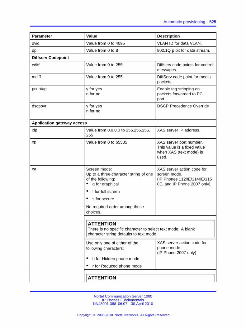
Automatic provisioning 525
Parameter Value Description
dvid Value from 0 to 4095 VLAN ID for data VLAN.
dp Value from 0 to 8 802.1Q p bit for data stream.
Diffserv Codepoint
cdiff Value from 0 to 255 Diffserv code points for controlmessages.
mdiff Value from 0 to 255 DiffServ code point for mediapackets.
pcuntag y for yesn for no
Enable tag stripping onpackets forwarded to PCport.
dscpovr y for yesn for no
DSCP Precedence Override
Application gateway access
xip Value from 0.0.0.0 to 255.255.255.255
XAS server IP address.
xp Value from 0 to 65535 XAS server port number.This value is a fixed valuewhen XAS (text mode) isused.
Screen mode:Up to a three-character string of oneof the following:• g for graphical
• f for full screen
• s for secure
No required order among thesechoices.
XAS server action code forscreen mode.(IP Phones 1120E/1140E/1150E, and IP Phone 2007 only).
ATTENTIONThere is no specific character to select text mode. A blankcharacter string defaults to text mode.
Use only one of either of thefollowing characters:
• h for Hidden phone mode
• r for Reduced phone mode
XAS server action code forphone mode.(IP Phone 2007 only)
xa
ATTENTION
Nortel Communication Server 1000IP Phones Fundamentals
NN43001-368 06.07 30 April 2010
Copyright © 2003-2010 Nortel Networks. All Rights Reserved.
.
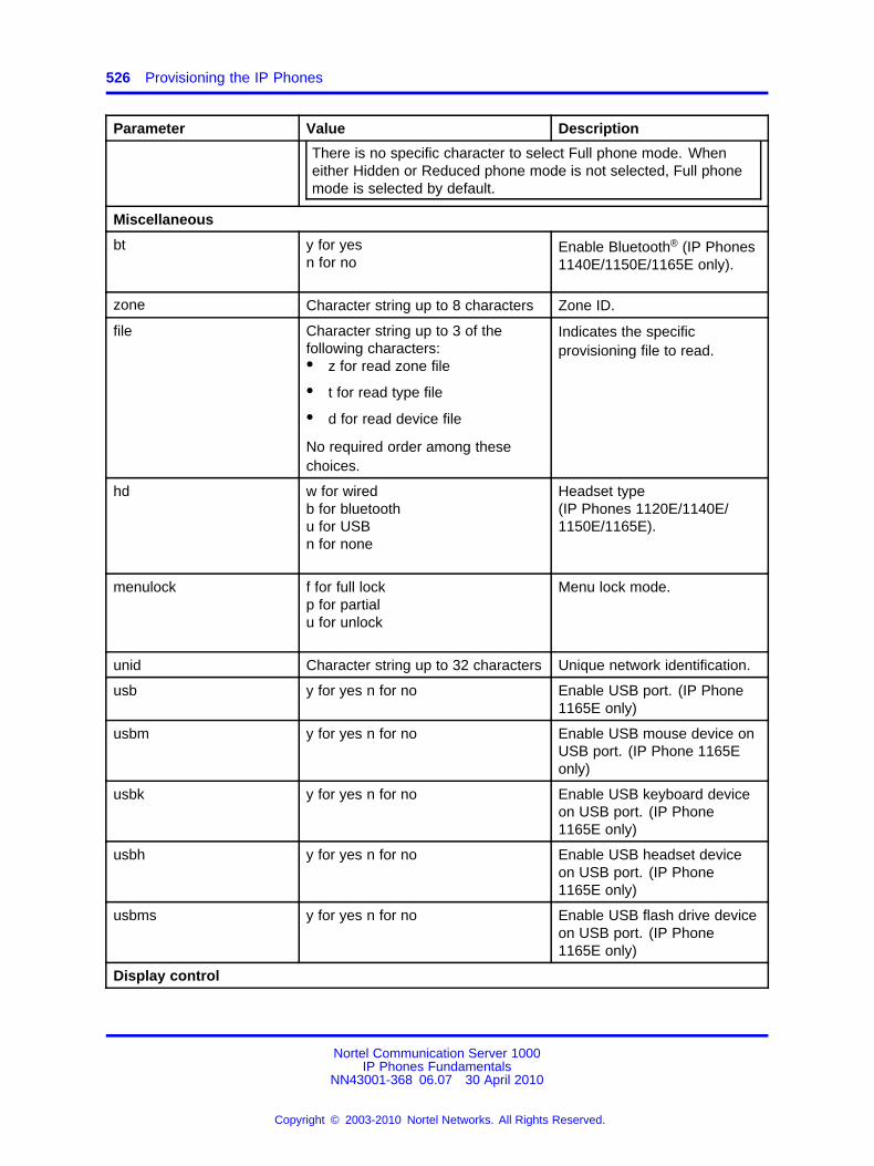
526 Provisioning the IP Phones
Parameter Value Description
There is no specific character to select Full phone mode. Wheneither Hidden or Reduced phone mode is not selected, Full phonemode is selected by default.
Miscellaneous
bt y for yesn for no
Enable Bluetooth® (IP Phones1140E/1150E/1165E only).
zone Character string up to 8 characters Zone ID.
file Character string up to 3 of thefollowing characters:• z for read zone file
• t for read type file
• d for read device file
No required order among thesechoices.
Indicates the specificprovisioning file to read.
hd w for wiredb for bluetoothu for USBn for none
Headset type(IP Phones 1120E/1140E/1150E/1165E).
menulock f for full lockp for partialu for unlock
Menu lock mode.
unid Character string up to 32 characters Unique network identification.
usb y for yes n for no Enable USB port. (IP Phone1165E only)
usbm y for yes n for no Enable USB mouse device onUSB port. (IP Phone 1165Eonly)
usbk y for yes n for no Enable USB keyboard deviceon USB port. (IP Phone1165E only)
usbh y for yes n for no Enable USB headset deviceon USB port. (IP Phone1165E only)
usbms y for yes n for no Enable USB flash drive deviceon USB port. (IP Phone1165E only)
Display control
Nortel Communication Server 1000IP Phones Fundamentals
NN43001-368 06.07 30 April 2010
Copyright © 2003-2010 Nortel Networks. All Rights Reserved.
.
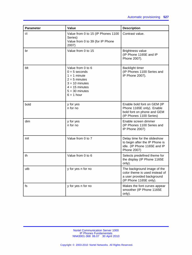
Automatic provisioning 527
Parameter Value Description
ct Value from 0 to 15 (IP Phones 1100Series)Value from 0 to 39 (for IP Phone2007)
Contrast value.
br Value from 0 to 15 Brightness value(IP Phone 1165E and IPPhone 2007).
blt Value from 0 to 60 = 5 seconds1 = 1 minute2 = 5 minutes3 = 10 minutes4 = 15 minutes5 = 30 minutes6 = 1 hour
Backlight timer(IP Phones 1100 Series andIP Phone 2007).
bold y for yesn for no
Enable bold font on GEM (IPPhone 1165E only). Enablebold font on phone and GEM(IP Phones 1100 Series)
dim y for yesn for no
Enable screen dimmer(IP Phones 1100 Series andIP Phone 2007)
sst Value from 0 to 7 Delay time for the slideshowto begin after the IP Phone isidle. (IP Phone 1165E and IPPhone 2007)
th Value from 0 to 6 Selects predefined theme forthe display (IP Phone 1165Eonly).
utb y for yes n for no The background image of thecolor theme is used instead ofa user provided background(IP Phone 1165E only).
fs y for yes n for no Makes the font curves appearsmoother (IP Phone 1165Eonly).
Nortel Communication Server 1000IP Phones Fundamentals
NN43001-368 06.07 30 April 2010
Copyright © 2003-2010 Nortel Networks. All Rights Reserved.
.
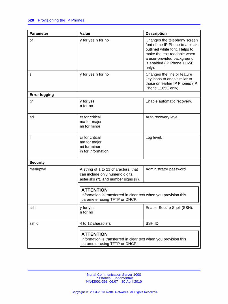
528 Provisioning the IP Phones
Parameter Value Description
of y for yes n for no Changes the telephony screenfont of the IP Phone to a blackoutlined white font. Helps tomake the text readable whena user-provided backgroundis enabled (IP Phone 1165Eonly).
si y for yes n for no Changes the line or featurekey icons to ones similar tothose on earlier IP Phones (IPPhone 1165E only).
Error logging
ar y for yesn for no
Enable automatic recovery.
arl cr for criticalma for majormi for minor
Auto recovery level.
ll cr for criticalma for majormi for minorin for information
Log level.
Security
A string of 1 to 21 characters, thatcan include only numeric digits,asterisks (*), and number signs (#).
Administrator password.menupwd
ATTENTIONInformation is transferred in clear text when you provision thisparameter using TFTP or DHCP.
ssh y for yesn for no
Enable Secure Shell (SSH).
4 to 12 characters SSH ID.sshid
ATTENTIONInformation is transferred in clear text when you provision thisparameter using TFTP or DHCP.
Nortel Communication Server 1000IP Phones Fundamentals
NN43001-368 06.07 30 April 2010
Copyright © 2003-2010 Nortel Networks. All Rights Reserved.
.
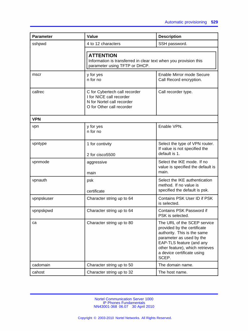
Automatic provisioning 529
Parameter Value Description
4 to 12 characters SSH password.sshpwd
ATTENTIONInformation is transferred in clear text when you provision thisparameter using TFTP or DHCP.
mscr y for yesn for no
Enable Mirror mode SecureCall Record encryption.
callrec C for Cybertech call recorderI for NICE call recorderN for Nortel call recorderO for Other call recorder
Call recorder type.
VPN
vpn y for yesn for no
Enable VPN.
vpntype 1 for contivity
2 for cisco5500
Select the type of VPN router.If value is not specified thedefault is 1.
vpnmode aggressive
main
Select the IKE mode. If novalue is specified the default ismain.
vpnauth psk
certificate
Select the IKE authenticationmethod. If no value isspecified the default is psk.
vpnpskuser Character string up to 64 Contains PSK User ID if PSKis selected.
vpnpskpwd Character string up to 64 Contains PSK Password ifPSK is selected.
ca Character string up to 80 The URL of the SCEP serviceprovided by the certificateauthority. This is the sameparameter as used by theEAP-TLS feature (and anyother feature), which retrievesa device certificate usingSCEP.
cadomain Character string up to 50 The domain name.
cahost Character string up to 32 The host name.
Nortel Communication Server 1000IP Phones Fundamentals
NN43001-368 06.07 30 April 2010
Copyright © 2003-2010 Nortel Networks. All Rights Reserved.
.
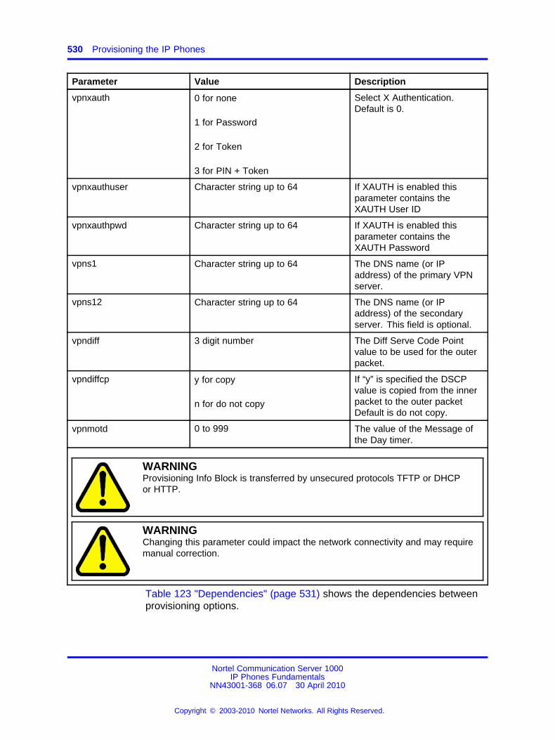
530 Provisioning the IP Phones
Parameter Value Description
vpnxauth 0 for none
1 for Password
2 for Token
3 for PIN + Token
Select X Authentication.Default is 0.
vpnxauthuser Character string up to 64 If XAUTH is enabled thisparameter contains theXAUTH User ID
vpnxauthpwd Character string up to 64 If XAUTH is enabled thisparameter contains theXAUTH Password
vpns1 Character string up to 64 The DNS name (or IPaddress) of the primary VPNserver.
vpns12 Character string up to 64 The DNS name (or IPaddress) of the secondaryserver. This field is optional.
vpndiff 3 digit number The Diff Serve Code Pointvalue to be used for the outerpacket.
vpndiffcp y for copy
n for do not copy
If “y” is specified the DSCPvalue is copied from the innerpacket to the outer packetDefault is do not copy.
vpnmotd 0 to 999 The value of the Message ofthe Day timer.
WARNINGProvisioning Info Block is transferred by unsecured protocols TFTP or DHCPor HTTP.
WARNINGChanging this parameter could impact the network connectivity and may requiremanual correction.
Table 123 "Dependencies" (page 531) shows the dependencies betweenprovisioning options.
Nortel Communication Server 1000IP Phones Fundamentals
NN43001-368 06.07 30 April 2010
Copyright © 2003-2010 Nortel Networks. All Rights Reserved.
.
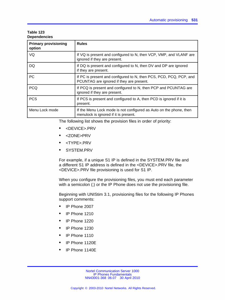
Automatic provisioning 531
Table 123Dependencies
Primary provisioningoption
Rules
VQ If VQ is present and configured to N, then VCP, VMP, and VLANF areignored if they are present.
DQ If DQ is present and configured to N, then DV and DP are ignoredif they are present.
PC If PC is present and configured to N, then PCS, PCD, PCQ, PCP, andPCUNTAG are ignored if they are present.
PCQ If PCQ is present and configured to N, then PCP and PCUNTAG areignored if they are present.
PCS If PCS is present and configured to A, then PCD is ignored if it ispresent.
Menu Lock mode If the Menu Lock mode is not configured as Auto on the phone, thenmenulock is ignored if it is present.
The following list shows the provision files in order of priority:
• <DEVICE>.PRV
• <ZONE>PRV
• <TYPE>.PRV
• SYSTEM.PRV
For example, if a unique S1 IP is defined in the SYSTEM.PRV file anda different S1 IP address is defined in the <DEVICE>.PRV file, the<DEVICE>.PRV file provisioning is used for S1 IP.
When you configure the provisioning files, you must end each parameterwith a semicolon (;) or the IP Phone does not use the provisioning file.
Beginning with UNIStim 3.1, provisioning files for the following IP Phonessupport comments:
• IP Phone 2007
• IP Phone 1210
• IP Phone 1220
• IP Phone 1230
• IP Phone 1110
• IP Phone 1120E
• IP Phone 1140E
Nortel Communication Server 1000IP Phones Fundamentals
NN43001-368 06.07 30 April 2010
Copyright © 2003-2010 Nortel Networks. All Rights Reserved.
.
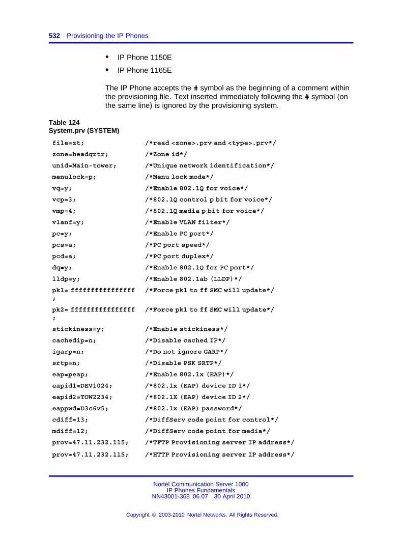
532 Provisioning the IP Phones
• IP Phone 1150E
• IP Phone 1165E
The IP Phone accepts the # symbol as the beginning of a comment withinthe provisioning file. Text inserted immediately following the # symbol (onthe same line) is ignored by the provisioning system.
Table 124System.prv (SYSTEM)
file=zt; /*read <zone>.prv and <type>.prv*/
zone=headqrtr; /*Zone id*/
unid=Main-tower; /*Unique network identification*/
menulock=p; /*Menu lock mode*/
vq=y; /*Enable 802.1Q for voice*/
vcp=3; /*802.1Q control p bit for voice*/
vmp=4; /*802.1Q media p bit for voice*/
vlanf=y; /*Enable VLAN filter*/
pc=y; /*Enable PC port*/
pcs=a; /*PC port speed*/
pcd=a; /*PC port duplex*/
dq=y; /*Enable 802.1Q for PC port*/
lldp=y; /*Enable 802.1ab (LLDP)*/
pk1= ffffffffffffffff;
/*Force pk1 to ff SMC will update*/
pk2= ffffffffffffffff;
/*Force pk1 to ff SMC will update*/
stickiness=y; /*Enable stickiness*/
cachedip=n; /*Disable cached IP*/
igarp=n; /*Do not ignore GARP*/
srtp=n; /*Disable PSK SRTP*/
eap=peap; /*Enable 802.1x (EAP)*/
eapid1=DEV1024; /*802.1x (EAP) device ID 1*/
eapid2=TOW2234; /*802.1X (EAP) device ID 2*/
eappwd=D3c6v5; /*802.1x (EAP) password*/
cdiff=13; /*DiffServ code point for control*/
mdiff=12; /*DiffServ code point for media*/
prov=47.11.232.115;
prov=47.11.232.115;
/*TFTP Provisioning server IP address*/
/*HTTP Provisioning server IP address*/
Nortel Communication Server 1000IP Phones Fundamentals
NN43001-368 06.07 30 April 2010
Copyright © 2003-2010 Nortel Networks. All Rights Reserved.
.
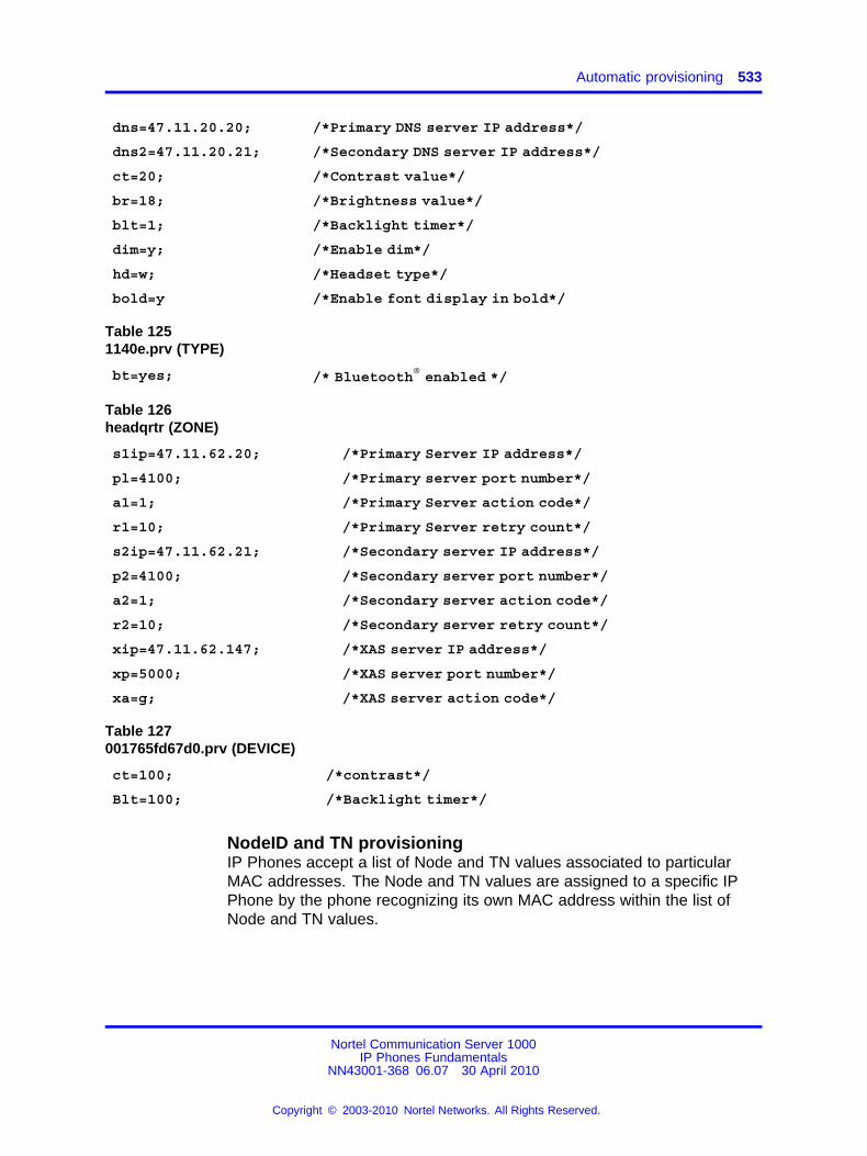
Automatic provisioning 533
dns=47.11.20.20; /*Primary DNS server IP address*/
dns2=47.11.20.21; /*Secondary DNS server IP address*/
ct=20; /*Contrast value*/
br=18; /*Brightness value*/
blt=1; /*Backlight timer*/
dim=y; /*Enable dim*/
hd=w; /*Headset type*/
bold=y /*Enable font display in bold*/
Table 1251140e.prv (TYPE)
bt=yes; /* Bluetooth® enabled */
Table 126headqrtr (ZONE)
s1ip=47.11.62.20; /*Primary Server IP address*/
pl=4100; /*Primary server port number*/
a1=1; /*Primary Server action code*/
r1=10; /*Primary Server retry count*/
s2ip=47.11.62.21; /*Secondary server IP address*/
p2=4100; /*Secondary server port number*/
a2=1; /*Secondary server action code*/
r2=10; /*Secondary server retry count*/
xip=47.11.62.147; /*XAS server IP address*/
xp=5000; /*XAS server port number*/
xa=g; /*XAS server action code*/
Table 127001765fd67d0.prv (DEVICE)
ct=100; /*contrast*/
Blt=100; /*Backlight timer*/
NodeID and TN provisioningIP Phones accept a list of Node and TN values associated to particularMAC addresses. The Node and TN values are assigned to a specific IPPhone by the phone recognizing its own MAC address within the list ofNode and TN values.
Nortel Communication Server 1000IP Phones Fundamentals
NN43001-368 06.07 30 April 2010
Copyright © 2003-2010 Nortel Networks. All Rights Reserved.
.
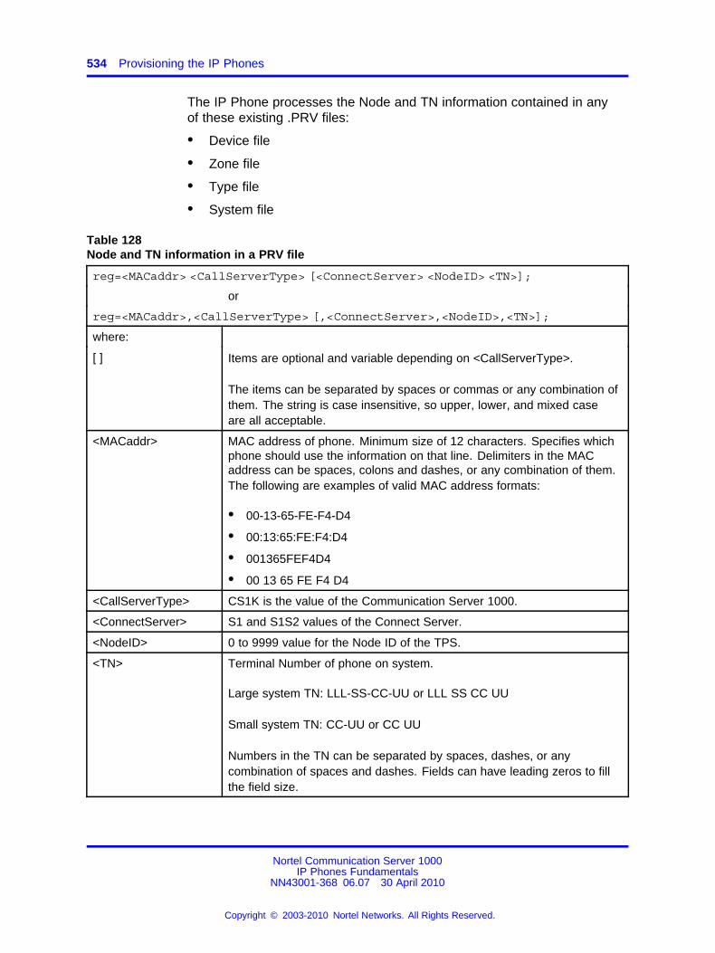
534 Provisioning the IP Phones
The IP Phone processes the Node and TN information contained in anyof these existing .PRV files:
• Device file
• Zone file
• Type file
• System file
Table 128Node and TN information in a PRV file
reg=<MACaddr> <CallServerType> [<ConnectServer> <NodeID> <TN>];
or
reg=<MACaddr>,<CallServerType> [,<ConnectServer>,<NodeID>,<TN>];
where:
[ ] Items are optional and variable depending on <CallServerType>.
The items can be separated by spaces or commas or any combination ofthem. The string is case insensitive, so upper, lower, and mixed caseare all acceptable.
<MACaddr> MAC address of phone. Minimum size of 12 characters. Specifies whichphone should use the information on that line. Delimiters in the MACaddress can be spaces, colons and dashes, or any combination of them.The following are examples of valid MAC address formats:
• 00-13-65-FE-F4-D4
• 00:13:65:FE:F4:D4
• 001365FEF4D4
• 00 13 65 FE F4 D4
<CallServerType> CS1K is the value of the Communication Server 1000.
<ConnectServer> S1 and S1S2 values of the Connect Server.
<NodeID> 0 to 9999 value for the Node ID of the TPS.
<TN> Terminal Number of phone on system.
Large system TN: LLL-SS-CC-UU or LLL SS CC UU
Small system TN: CC-UU or CC UU
Numbers in the TN can be separated by spaces, dashes, or anycombination of spaces and dashes. Fields can have leading zeros to fillthe field size.
Nortel Communication Server 1000IP Phones Fundamentals
NN43001-368 06.07 30 April 2010
Copyright © 2003-2010 Nortel Networks. All Rights Reserved.
.
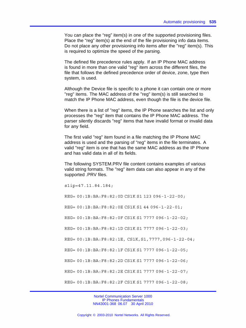
Automatic provisioning 535
You can place the “reg” item(s) in one of the supported provisioning files.Place the “reg” item(s) at the end of the file provisioning info data items.Do not place any other provisioning info items after the "reg" item(s). Thisis required to optimize the speed of the parsing.
The defined file precedence rules apply. If an IP Phone MAC addressis found in more than one valid "reg" item across the different files, thefile that follows the defined precedence order of device, zone, type thensystem, is used.
Although the Device file is specific to a phone it can contain one or more"reg" items. The MAC address of the "reg" item(s) is still searched tomatch the IP Phone MAC address, even though the file is the device file.
When there is a list of "reg" items, the IP Phone searches the list and onlyprocesses the "reg" item that contains the IP Phone MAC address. Theparser silently discards "reg" items that have invalid format or invalid datafor any field.
The first valid "reg" item found in a file matching the IP Phone MACaddress is used and the parsing of "reg" items in the file terminates. Avalid "reg" item is one that has the same MAC address as the IP Phoneand has valid data in all of its fields.
The following SYSTEM.PRV file content contains examples of variousvalid string formats. The "reg" item data can also appear in any of thesupported .PRV files.
s1ip=47.11.84.184;
REG= 00:1B:BA:F8:82:0D CS1K S1 123 096-1-22-00;
REG= 00:1B:BA:F8:82:0E CS1K S1 44 096-1-22-01;
REG= 00:1B:BA:F8:82:0F CS1K S1 7777 096-1-22-02;
REG= 00:1B:BA:F8:82:1D CS1K S1 7777 096-1-22-03;
REG= 00:1B:BA:F8:82:1E, CS1K,S1,7777,096-1-22-04;
REG= 00:1B:BA:F8:82:1F CS1K S1 7777 096-1-22-05;
REG= 00:1B:BA:F8:82:2D CS1K S1 7777 096-1-22-06;
REG= 00:1B:BA:F8:82:2E CS1K S1 7777 096-1-22-07;
REG= 00:1B:BA:F8:82:2F CS1K S1 7777 096-1-22-08;
Nortel Communication Server 1000IP Phones Fundamentals
NN43001-368 06.07 30 April 2010
Copyright © 2003-2010 Nortel Networks. All Rights Reserved.
.
536 Provisioning the IP Phones
REG= 00:1B:BA:F8:82:3D CS1K S1 7777 096-1-22-09;
reg= 00 1B BA F8 82 3E CS1K S1 7777 096-1-22-10;
reg= 001BbaF8823f Cs1k s1 8972 61 0;
reg= 00-1b-Ba-f8-82-4d cs1k S1 3434 96 00 01 11;
Automatic provisioning using UNIStimYou can use UNIStim to automatically provision a limited number ofparameters, such as Layer 2 priority bits (Ctrl and Media priority bits)and Differentiated Service Code Point (DiffServ). For information aboutconfiguring these parameters, see Signaling Server IP Line ApplicationsFundamentals (NN43001-125).
With UNIStim 3.1 and later, you can use Info Block to automaticallyprovision the following parameters on supported IP Phones:
• nis - network port speed
• nid - network port duplex mode
• dhcp - Dynamic Host Configuration Protocol (DHCP)
• ca - Certificate Authority (CA) server
• cahost - CA host name
• cadomain - CA domain name
For more information about these parameters, see Table 122 "Provisioninginfo block format" (page 520).
CAUTIONProvisioning the network port speed or network port duplexmode incorrectly, can cause loss of network connectivity. If thisoccurs, you can only restore network connectivity by manuallyprovisioning the IP Phone.
CAUTIONDisabling DHCP incorrectly, can cause loss of networkconnectivity. If this occurs, you can only restore networkconnectivity by manually provisioning the IP Phone.
Provisioning Info BlockYou can obtain configuration parameters in the IP Phone that are definedas AUTO from the Auto Provisioning page from an 802.1ab switch (LLDP),DHCP, TFTP, UNIStim, or HTTP.
Nortel Communication Server 1000IP Phones Fundamentals
NN43001-368 06.07 30 April 2010
Copyright © 2003-2010 Nortel Networks. All Rights Reserved.
.
Operation 537
You can obtain the configuration options in the following priority, fromlowest to highest:
• Manual provisioning
• Automatic provisioning using 802.1ab switch (LLDP)
• Automatic provisioning using TFTP
— Current device-specific Provisioning Info Block carried by theprovisioning server
— Current zone-specific Provisioning Info Block sent by theprovisioning server
— Current type-specific Provisioning Info Block sent by theprovisioning server
— Current system-specific Provisioning Info Block sent by theprovisioning server
• Automatic provisioning using DHCP
— Current system-specific Provisioning Info Block carried byNortel-i2004-B DHCP options
— Current existing Nortel DHCP options (existing Nortel-i2004-A andVLAN-A options)
• Automatic provisioning using HTTP
• LPR (Last auto received value)
• Factory default
For more information configuration options priorities, see “Precedence ruleand stickiness control” (page 537).
The TFTP provisioning server or the DHCP server, or the HTTP servercan provide the automatic Provisioning Info Block. The servers share thesame syntax defining the Provisioning Info Block. The TFTP provisioningserver provides the Provisioning Info Block in a set of .PRV files, wherethe DHCP Server provides the Provisioning Info Block with a new VendorSpecific String Nortel-i2004-B.
OperationThis section describes the automatic provisioning feature operation.
Precedence rule and stickiness controlThe IP Phone 2007, IP Phones 1100 Series, and IP Phones 1200 Seriescan obtain provisioning information from many sources at various times. Aprecedence rule can resolve the possible conflict when different values
Nortel Communication Server 1000IP Phones Fundamentals
NN43001-368 06.07 30 April 2010
Copyright © 2003-2010 Nortel Networks. All Rights Reserved.
.
538 Provisioning the IP Phones
are specified in various sources for one parameter. The IP Phone 2001,IP Phone 2002, and IP Phone 2004 do not support the precedence rule,therefore the phones use the last value received.
Provisioning information from a provisioning source with high prioritycan overwrite the provisioning information from a provisioning sourcewith low priority. The manual provisioning has highest priority. The otherprovisioning sources are auto-provisioning sources.
Automatic provisioning defines provisioning control for each parameter.You can either manually or automatically provision each parameter. Eachprovisioning parameter provides an attribute that specifies if the parameterwas previously provisioned manually or automatically.
The default value of the stickiness attribute is AUTO. If the provisioningparameter is AUTO, the IP Phone can receive the value from automaticprovisioning sources based on the precedence rule. If you manuallychange the parameter, the attribute value is MANUAL. If the attribute isMANUAL, the provisioning information from automatic provisioning sourcesis ignored, except for the standard DHCP parameters. To manuallyreconfigure the attribute for an individual parameter or attributes for allparameters to AUTO, use the Set to Factory Default function.
If you enable DHCP, then the IP address, the subnet mask, the defaultgateway, which the IP Phone obtains from the DHCP server, overwritesthe manually configured value. The value for EAP device ID and passwordcan also overwrite the manually configured value.
If you configure stickiness and the current provisioning source does notprovide the provisioning information for the particular parameter, the lastreceived provisioning value is used.
DHCP precedence overrule capability enables the user to obtain theDSCP values from the Call Server or from the provisioning info blockand to ignore any DSCP values provided by the LLDP Network PolicyTLV. If this feature is enabled the phone ignores any DSCP valuereceived from the Network Policy TLV. The precedence order for sourceselection of provisioning DSCP, from highest priority to lowest prioritybecomes: manual entry, Info Block through the provisioning file, InfoBlock through DHCP, Call Server (for example, Telephony Manager andElement Manager, or both). If this feature is not enabled then the defaultprecedence order for provisioning DSCP is used. This feature can beconfigured manually or automatically provisioned.
Nortel Communication Server 1000IP Phones Fundamentals
NN43001-368 06.07 30 April 2010
Copyright © 2003-2010 Nortel Networks. All Rights Reserved.
.
Operation 539
IP Phone resetThe IP Phone compares the provisioning information in the provisioningfiles with the existing provisioning information. The IP Phone applies thenew provisioning information and then
• resets silently
• resets immediately during boot phase, DHCP phase, and provisioningphase
• resets in a few seconds during TPS connecting phase
If the IP Phone is idle, information appears on the display. If the IPPhone is in an active call, the phone resets after the call ends.
Factory defaultYou can reset the following IP Phone parameters to the factory default
• IP Phone 2007
• IP Phone 1210
• IP Phone 1220
• IP Phone 1230
• IP Phone 1110
• IP Phone 1120E
• IP Phone 1140E
• IP Phone 1150E
• IP Phone 1165E
Use [*][*][7][3][6][3][9] IP Phone MAC address [#][#] to reset the IP Phoneparameters to the factory default.
Table 129 "Factory default values" (page 539) shows the factory defaultvalues for the IP Phone parameters.
Table 129Factory default values
Parameter Factory default value
Enable 802.1x (EAP) Disabled
802.1x Device ID None
802.1x Password None
Enable 802.1ab (LLDP) Yes
DHCP mode On
Nortel Communication Server 1000IP Phones Fundamentals
NN43001-368 06.07 30 April 2010
Copyright © 2003-2010 Nortel Networks. All Rights Reserved.
.
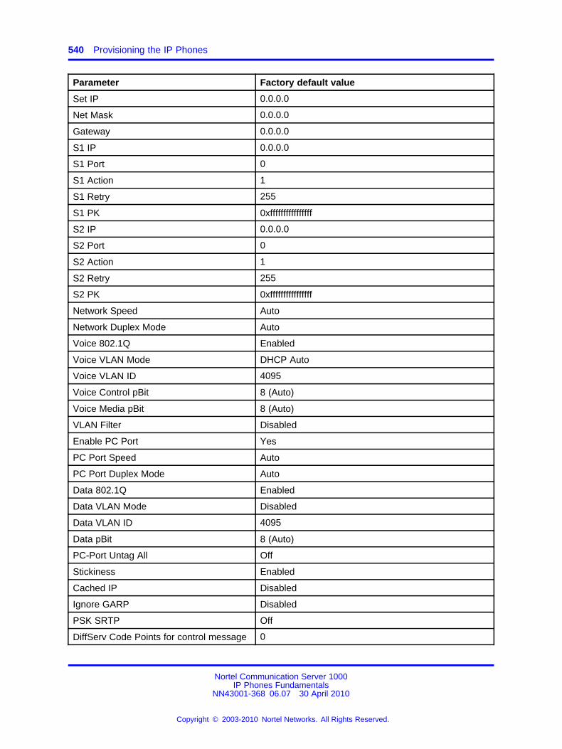
540 Provisioning the IP Phones
Parameter Factory default value
Set IP 0.0.0.0
Net Mask 0.0.0.0
Gateway 0.0.0.0
S1 IP 0.0.0.0
S1 Port 0
S1 Action 1
S1 Retry 255
S1 PK 0xffffffffffffffff
S2 IP 0.0.0.0
S2 Port 0
S2 Action 1
S2 Retry 255
S2 PK 0xffffffffffffffff
Network Speed Auto
Network Duplex Mode Auto
Voice 802.1Q Enabled
Voice VLAN Mode DHCP Auto
Voice VLAN ID 4095
Voice Control pBit 8 (Auto)
Voice Media pBit 8 (Auto)
VLAN Filter Disabled
Enable PC Port Yes
PC Port Speed Auto
PC Port Duplex Mode Auto
Data 802.1Q Enabled
Data VLAN Mode Disabled
Data VLAN ID 4095
Data pBit 8 (Auto)
PC-Port Untag All Off
Stickiness Enabled
Cached IP Disabled
Ignore GARP Disabled
PSK SRTP Off
DiffServ Code Points for control message 0
Nortel Communication Server 1000IP Phones Fundamentals
NN43001-368 06.07 30 April 2010
Copyright © 2003-2010 Nortel Networks. All Rights Reserved.
.
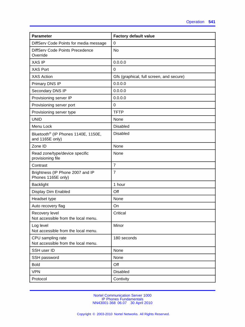
Operation 541
Parameter Factory default value
DiffServ Code Points for media message 0
DiffServ Code Points PrecedenceOverride
No
XAS IP 0.0.0.0
XAS Port 0
XAS Action Gfs (graphical, full screen, and secure)
Primary DNS IP 0.0.0.0
Secondary DNS IP 0.0.0.0
Provisioning server IP 0.0.0.0
Provisioning server port 0
Provisioning server type TFTP
UNID None
Menu Lock Disabled
Bluetooth® (IP Phones 1140E, 1150E,and 1165E only)
Disabled
Zone ID None
Read zone/type/device specificprovisioning file
None
Contrast 7
Brightness (IP Phone 2007 and IPPhones 1165E only)
7
Backlight 1 hour
Display Dim Enabled Off
Headset type None
Auto recovery flag On
Recovery levelNot accessible from the local menu.
Critical
Log levelNot accessible from the local menu.
Minor
CPU sampling rateNot accessible from the local menu.
180 seconds
SSH user ID None
SSH password None
Bold Off
VPN Disabled
Protocol Contivity
Nortel Communication Server 1000IP Phones Fundamentals
NN43001-368 06.07 30 April 2010
Copyright © 2003-2010 Nortel Networks. All Rights Reserved.
.
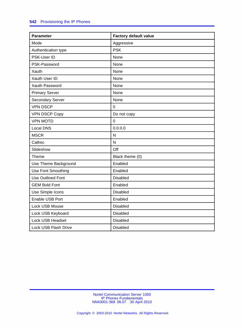
542 Provisioning the IP Phones
Parameter Factory default value
Mode Aggressive
Authentication type PSK
PSK-User ID None
PSK-Password None
Xauth None
Xauth User ID None
Xauth Password None
Primary Server None
Secondary Server None
VPN DSCP 0
VPN DSCP Copy Do not copy
VPN MOTD 0
Local DNS 0.0.0.0
MSCR N
Callrec N
Slideshow Off
Theme Black theme (0)
Use Theme Background Enabled
Use Font Smoothing Enabled
Use Outlined Font Disabled
GEM Bold Font Enabled
Use Simple Icons Disabled
Enable USB Port Enabled
Lock USB Mouse Disabled
Lock USB Keyboard Disabled
Lock USB Headset Disabled
Lock USB Flash Drive Disabled
Nortel Communication Server 1000IP Phones Fundamentals
NN43001-368 06.07 30 April 2010
Copyright © 2003-2010 Nortel Networks. All Rights Reserved.
.
543.
AppendixManual provisioning of IP Phones 1110and 1200 Series
ContentsThis section contains the following topics:
• “Introduction” (page 543)
• “Provisioning parameters” (page 543)
IntroductionThis section applies to the following IP Phones
• IP Phone 1110
• IP Phone 1210
• IP Phone 1220
• IP Phone 1230
Provisioning parametersUse the Network Configuration menu item to configure IP Phoneparameters. You can access the Network Configuration menu fortext-based phone in one of the following ways:
• Press the 4 soft keys at the bottom of the display area in sequencefrom left to right when the IP Phone boots and the text Nortel appearsin the display.
• Double-press the Services key. To make a menu selection, you canpress the number associated with the menu item (for example, press2 3 for Network Configuration) or you can use the navigation keys toscroll through the list of menu items.
Nortel Communication Server 1000IP Phones Fundamentals
NN43001-368 06.07 30 April 2010
Copyright © 2003-2010 Nortel Networks. All Rights Reserved.
.
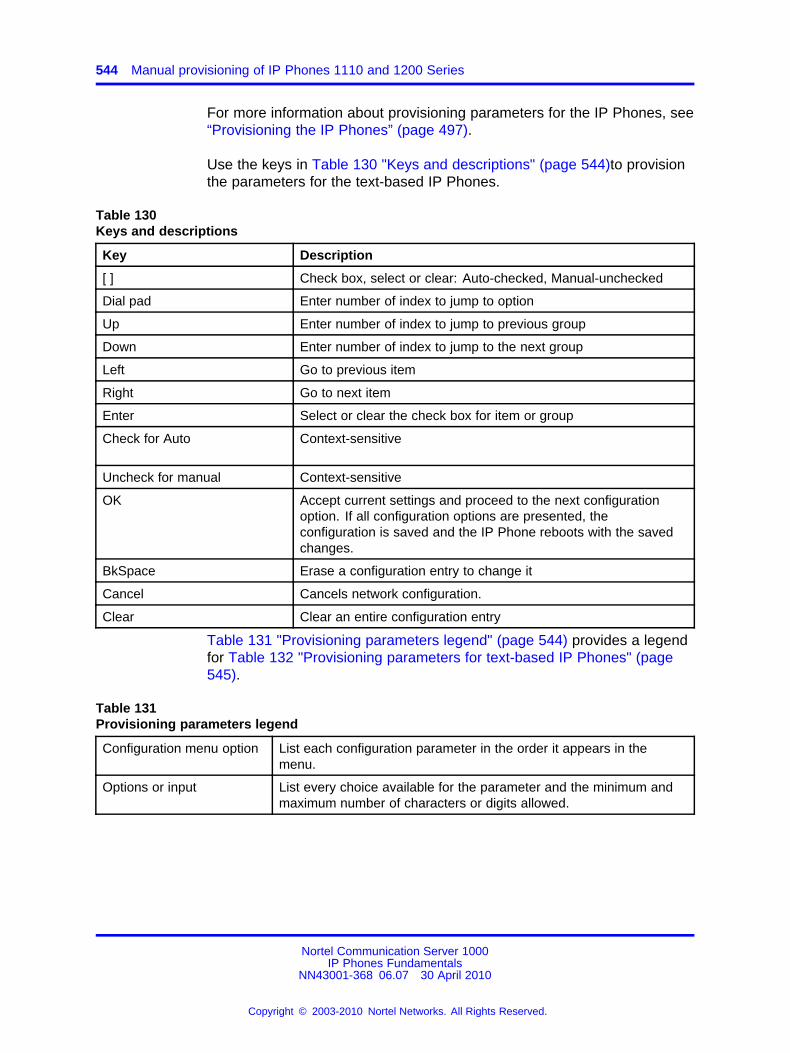
544 Manual provisioning of IP Phones 1110 and 1200 Series
For more information about provisioning parameters for the IP Phones, see“Provisioning the IP Phones” (page 497).
Use the keys in Table 130 "Keys and descriptions" (page 544)to provisionthe parameters for the text-based IP Phones.
Table 130Keys and descriptions
Key Description
[ ] Check box, select or clear: Auto-checked, Manual-unchecked
Dial pad Enter number of index to jump to option
Up Enter number of index to jump to previous group
Down Enter number of index to jump to the next group
Left Go to previous item
Right Go to next item
Enter Select or clear the check box for item or group
Check for Auto Context-sensitive
Uncheck for manual Context-sensitive
OK Accept current settings and proceed to the next configurationoption. If all configuration options are presented, theconfiguration is saved and the IP Phone reboots with the savedchanges.
BkSpace Erase a configuration entry to change it
Cancel Cancels network configuration.
Clear Clear an entire configuration entry
Table 131 "Provisioning parameters legend" (page 544) provides a legendfor Table 132 "Provisioning parameters for text-based IP Phones" (page545).
Table 131Provisioning parameters legend
Configuration menu option List each configuration parameter in the order it appears in themenu.
Options or input List every choice available for the parameter and the minimum andmaximum number of characters or digits allowed.
Nortel Communication Server 1000IP Phones Fundamentals
NN43001-368 06.07 30 April 2010
Copyright © 2003-2010 Nortel Networks. All Rights Reserved.
.
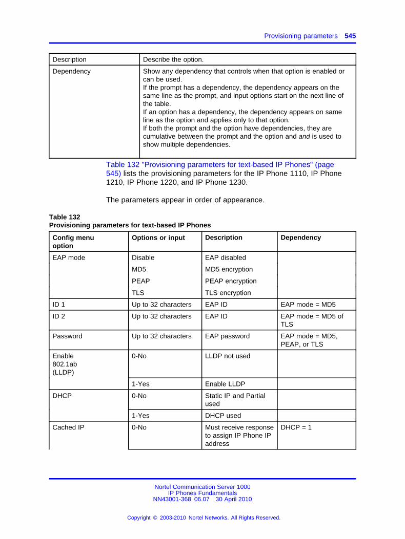
Provisioning parameters 545
Description Describe the option.
Dependency Show any dependency that controls when that option is enabled orcan be used.If the prompt has a dependency, the dependency appears on thesame line as the prompt, and input options start on the next line ofthe table.If an option has a dependency, the dependency appears on sameline as the option and applies only to that option.If both the prompt and the option have dependencies, they arecumulative between the prompt and the option and and is used toshow multiple dependencies.
Table 132 "Provisioning parameters for text-based IP Phones" (page545) lists the provisioning parameters for the IP Phone 1110, IP Phone1210, IP Phone 1220, and IP Phone 1230.
The parameters appear in order of appearance.
Table 132Provisioning parameters for text-based IP Phones
Config menuoption
Options or input Description Dependency
EAP mode Disable EAP disabled
MD5 MD5 encryption
PEAP PEAP encryption
TLS TLS encryption
ID 1 Up to 32 characters EAP ID EAP mode = MD5
ID 2 Up to 32 characters EAP ID EAP mode = MD5 ofTLS
Password Up to 32 characters EAP password EAP mode = MD5,PEAP, or TLS
Enable802.1ab(LLDP)
0-No LLDP not used
1-Yes Enable LLDP
DHCP 0-No Static IP and Partialused
1-Yes DHCP used
Cached IP 0-No Must receive responseto assign IP Phone IPaddress
DHCP = 1
Nortel Communication Server 1000IP Phones Fundamentals
NN43001-368 06.07 30 April 2010
Copyright © 2003-2010 Nortel Networks. All Rights Reserved.
.
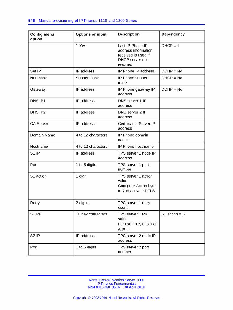
546 Manual provisioning of IP Phones 1110 and 1200 Series
Config menuoption
Options or input Description Dependency
1-Yes Last IP Phone IPaddress informationreceived is used ifDHCP server notreached
DHCP = 1
Set IP IP address IP Phone IP address DCHP = No
Net mask Subnet mask IP Phone subnetmask
DHCP = No
Gateway IP address IP Phone gateway IPaddress
DCHP = No
DNS IP1 IP address DNS server 1 IPaddress
DNS IP2 IP address DNS server 2 IPaddress
CA Server IP address Certificates Server IPaddress
Domain Name 4 to 12 characters IP Phone domainname
Hostname 4 to 12 characters IP Phone host name
S1 IP IP address TPS server 1 node IPaddress
Port 1 to 5 digits TPS server 1 portnumber
S1 action 1 digit TPS server 1 actionvalueConfigure Action byteto 7 to activate DTLS
Retry 2 digits TPS server 1 retrycount
S1 PK 16 hex characters TPS server 1 PKstringFor example, 0 to 9 orA to F.
S1 action = 6
S2 IP IP address TPS server 2 node IPaddress
Port 1 to 5 digits TPS server 2 portnumber
Nortel Communication Server 1000IP Phones Fundamentals
NN43001-368 06.07 30 April 2010
Copyright © 2003-2010 Nortel Networks. All Rights Reserved.
.
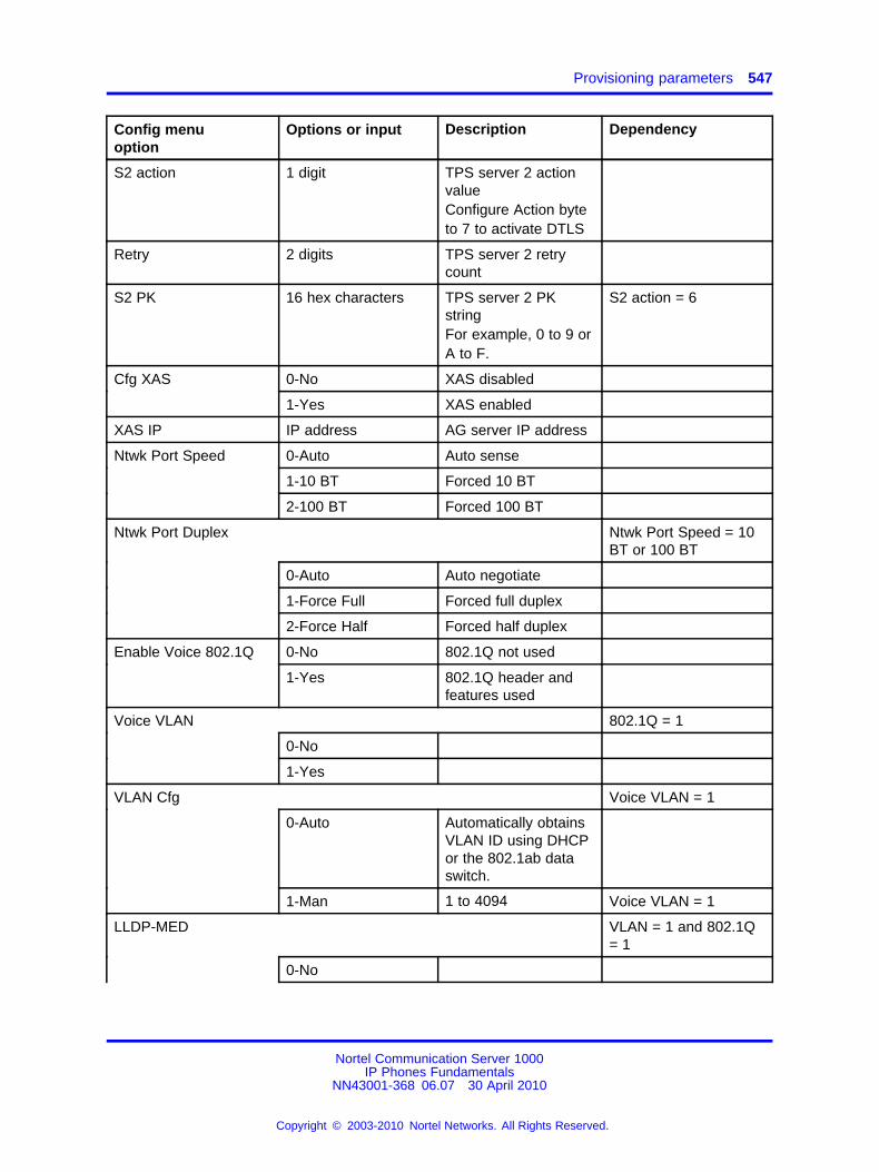
Provisioning parameters 547
Config menuoption
Options or input Description Dependency
S2 action 1 digit TPS server 2 actionvalueConfigure Action byteto 7 to activate DTLS
Retry 2 digits TPS server 2 retrycount
S2 PK 16 hex characters TPS server 2 PKstringFor example, 0 to 9 orA to F.
S2 action = 6
Cfg XAS 0-No XAS disabled
1-Yes XAS enabled
XAS IP IP address AG server IP address
Ntwk Port Speed 0-Auto Auto sense
1-10 BT Forced 10 BT
2-100 BT Forced 100 BT
Ntwk Port Duplex Ntwk Port Speed = 10BT or 100 BT
0-Auto Auto negotiate
1-Force Full Forced full duplex
2-Force Half Forced half duplex
Enable Voice 802.1Q 0-No 802.1Q not used
1-Yes 802.1Q header andfeatures used
Voice VLAN 802.1Q = 1
0-No
1-Yes
VLAN Cfg Voice VLAN = 1
0-Auto Automatically obtainsVLAN ID using DHCPor the 802.1ab dataswitch.
1-Man 1 to 4094 Voice VLAN = 1
LLDP-MED VLAN = 1 and 802.1Q= 1
0-No
Nortel Communication Server 1000IP Phones Fundamentals
NN43001-368 06.07 30 April 2010
Copyright © 2003-2010 Nortel Networks. All Rights Reserved.
.
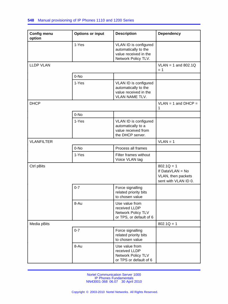
548 Manual provisioning of IP Phones 1110 and 1200 Series
Config menuoption
Options or input Description Dependency
1-Yes VLAN ID is configuredautomatically to thevalue received in theNetwork Policy TLV.
LLDP VLAN VLAN = 1 and 802.1Q= 1
0-No
1-Yes VLAN ID is configuredautomatically to thevalue received in theVLAN NAME TLV.
DHCP VLAN = 1 and DHCP =1
0-No
1-Yes VLAN ID is configuredautomatically to avalue received fromthe DHCP server.
VLANFILTER VLAN = 1
0-No Process all frames
1-Yes Filter frames withoutVoice VLAN tag
Ctrl pBits 802.1Q = 1If DataVLAN = NoVLAN, then packetssent with VLAN ID 0.
0-7 Force signallingrelated priority bitsto chosen value
8-Au Use value fromreceived LLDPNetwork Policy TLVor TPS, or default of 6
Media pBits 802.1Q = 1
0-7 Force signallingrelated priority bitsto chosen value
8-Au Use value fromreceived LLDPNetwork Policy TLVor TPS or default of 6
Nortel Communication Server 1000IP Phones Fundamentals
NN43001-368 06.07 30 April 2010
Copyright © 2003-2010 Nortel Networks. All Rights Reserved.
.
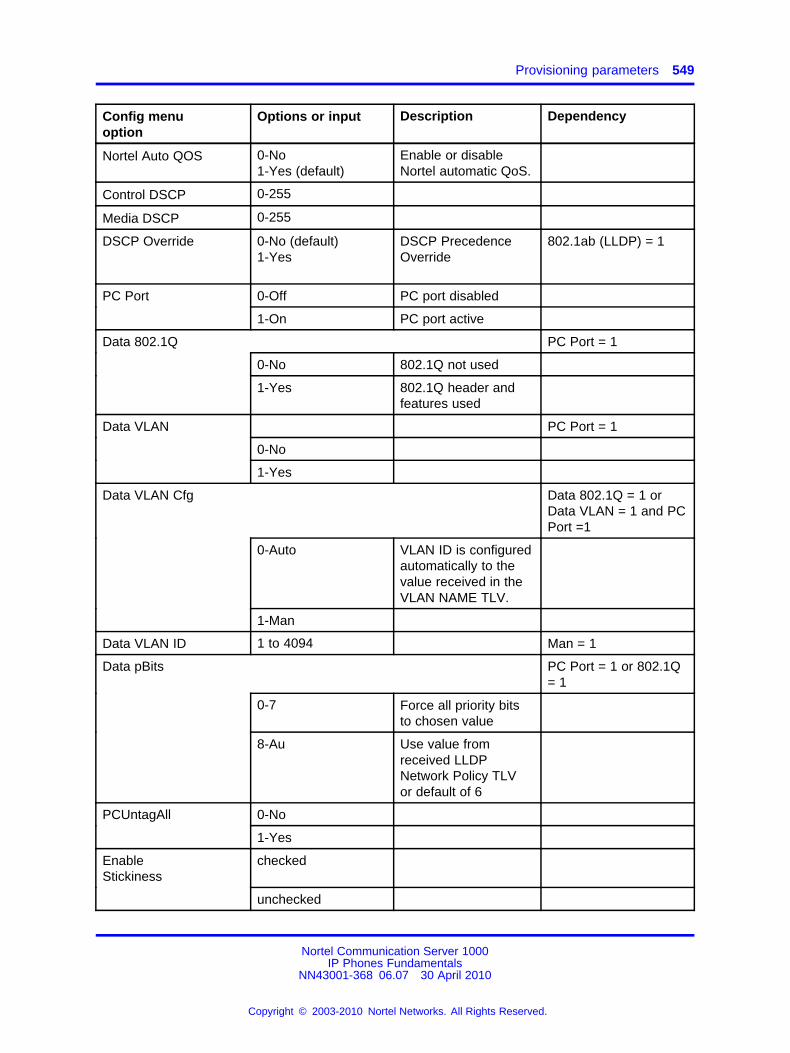
Provisioning parameters 549
Config menuoption
Options or input Description Dependency
Nortel Auto QOS 0-No1-Yes (default)
Enable or disableNortel automatic QoS.
Control DSCP 0-255
Media DSCP 0-255
DSCP Override 0-No (default)1-Yes
DSCP PrecedenceOverride
802.1ab (LLDP) = 1
PC Port 0-Off PC port disabled
1-On PC port active
Data 802.1Q PC Port = 1
0-No 802.1Q not used
1-Yes 802.1Q header andfeatures used
Data VLAN PC Port = 1
0-No
1-Yes
Data VLAN Cfg Data 802.1Q = 1 orData VLAN = 1 and PCPort =1
0-Auto VLAN ID is configuredautomatically to thevalue received in theVLAN NAME TLV.
1-Man
Data VLAN ID 1 to 4094 Man = 1
Data pBits PC Port = 1 or 802.1Q= 1
0-7 Force all priority bitsto chosen value
8-Au Use value fromreceived LLDPNetwork Policy TLVor default of 6
PCUntagAll 0-No
1-Yes
EnableStickiness
checked
unchecked
Nortel Communication Server 1000IP Phones Fundamentals
NN43001-368 06.07 30 April 2010
Copyright © 2003-2010 Nortel Networks. All Rights Reserved.
.

550 Manual provisioning of IP Phones 1110 and 1200 Series
Config menuoption
Options or input Description Dependency
PSK SRTP 0-No IP Phone does not trySRTP PSK
1-Yes When non-SRTPUSK call is set up,IP Phone tries toestablish SRTP PSKcall with far end
Pay ID 0-96 (default)1-1152-120
Payload type ID.
GARP Ignore 0-No
Provision up to 40- characterURL
URL for provisioningserver
Provision Zone ID 1 to 5 characters IP Phone provisioningzone
License Server 1 or 2 Licensing Primary andSecondary server IPaddress
Port 31210 (default) License server port
License Notification Every 24 hours (1:00AM default)
Notification time frame
Menu lock Full lockPartial lockUnlock
Menu lock mode
Contrast 0 to 15 Contrast value
Backlight timer 0 to 8 Backlight timer values:0 = 5 seconds1 = 1 minute2 = 5 minutes3 = 10 minutes4 = 15 minutes5 = 30 minutes6 = 1 hour7 = 2 hours8 = Always on
Enable SSH Yes Enable SSH
No Disable SSH
SSH ID 4 to 12 characters SSH user ID SSH enabled
SSH PWD 4 to 12 characters SSH user password SSH enabled
Nortel Communication Server 1000IP Phones Fundamentals
NN43001-368 06.07 30 April 2010
Copyright © 2003-2010 Nortel Networks. All Rights Reserved.
.

Provisioning parameters 551
Config menuoption
Options or input Description Dependency
Yes Enable Mirror SecureCall Recordingencryption
MSCR
No No encryption
Callrec C, I, N, O Call Recorder type
Nortel Communication Server 1000IP Phones Fundamentals
NN43001-368 06.07 30 April 2010
Copyright © 2003-2010 Nortel Networks. All Rights Reserved.
.

552 Manual provisioning of IP Phones 1110 and 1200 Series
Nortel Communication Server 1000IP Phones Fundamentals
NN43001-368 06.07 30 April 2010
Copyright © 2003-2010 Nortel Networks. All Rights Reserved.
.
553.
AppendixManual provisioning of IP Phones 2007and 1100 Series
ContentsThis section contains the following topics:
• “Introduction” (page 553)
• “Provision parameters” (page 553)
IntroductionThis section applies to the following graphic-based IP Phones
• IP Phone 2007
• IP Phone 1120E
• IP Phone 1140E
• IP Phone 1150E
• IP Phone 1165E
The IP Phone 1110 is a text-based IP Phone. For more information aboutmanual provisioning of the IP Phone 1110, see “Manual provisioning of IPPhones 1110 and 1200 Series” (page 543).
Provision parametersUse the Network Configuration menu item to configure IP Phoneparameters.
For the IP Phone 2007, press the Tools icon and select NetworkConfiguration menu item.
Nortel Communication Server 1000IP Phones Fundamentals
NN43001-368 06.07 30 April 2010
Copyright © 2003-2010 Nortel Networks. All Rights Reserved.
.
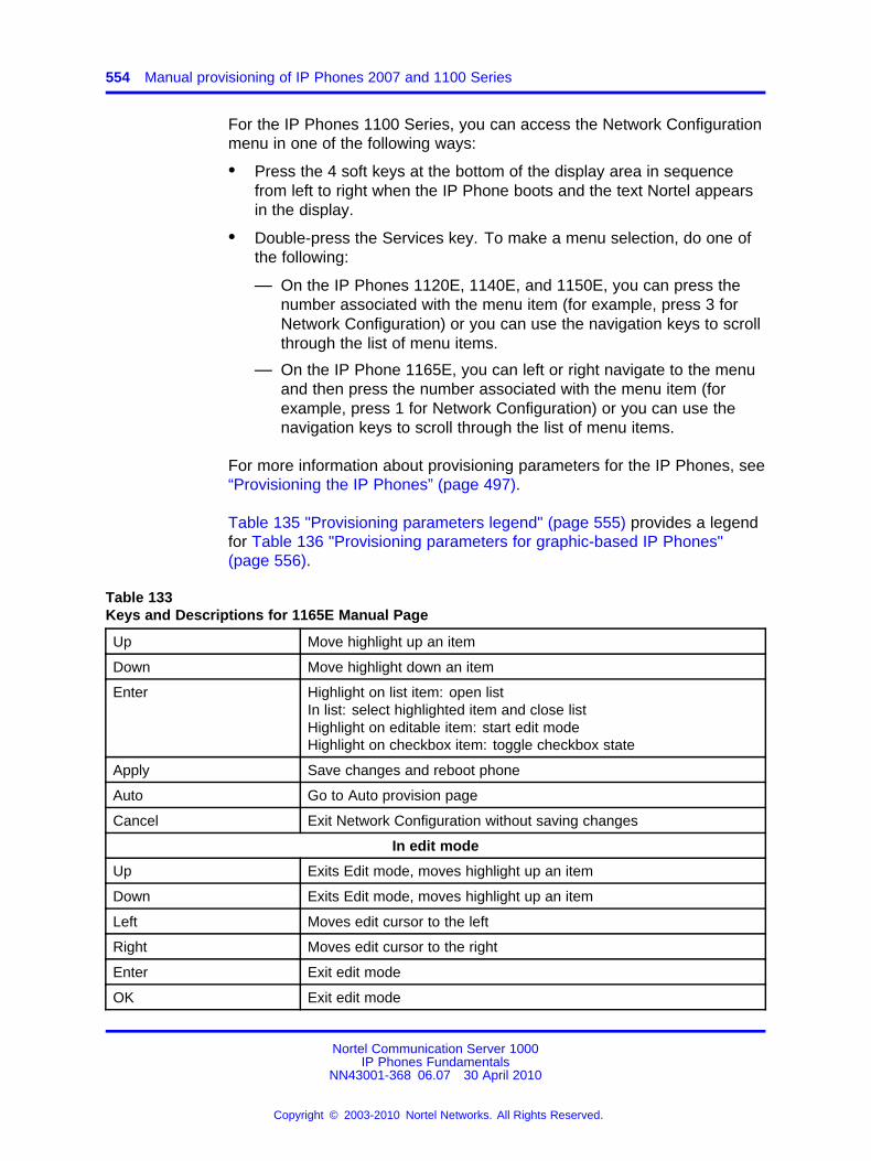
554 Manual provisioning of IP Phones 2007 and 1100 Series
For the IP Phones 1100 Series, you can access the Network Configurationmenu in one of the following ways:
• Press the 4 soft keys at the bottom of the display area in sequencefrom left to right when the IP Phone boots and the text Nortel appearsin the display.
• Double-press the Services key. To make a menu selection, do one ofthe following:
— On the IP Phones 1120E, 1140E, and 1150E, you can press thenumber associated with the menu item (for example, press 3 forNetwork Configuration) or you can use the navigation keys to scrollthrough the list of menu items.
— On the IP Phone 1165E, you can left or right navigate to the menuand then press the number associated with the menu item (forexample, press 1 for Network Configuration) or you can use thenavigation keys to scroll through the list of menu items.
For more information about provisioning parameters for the IP Phones, see“Provisioning the IP Phones” (page 497).
Table 135 "Provisioning parameters legend" (page 555) provides a legendfor Table 136 "Provisioning parameters for graphic-based IP Phones"(page 556).
Table 133Keys and Descriptions for 1165E Manual Page
Up Move highlight up an item
Down Move highlight down an item
Enter Highlight on list item: open listIn list: select highlighted item and close listHighlight on editable item: start edit modeHighlight on checkbox item: toggle checkbox state
Apply Save changes and reboot phone
Auto Go to Auto provision page
Cancel Exit Network Configuration without saving changes
In edit mode
Up Exits Edit mode, moves highlight up an item
Down Exits Edit mode, moves highlight up an item
Left Moves edit cursor to the left
Right Moves edit cursor to the right
Enter Exit edit mode
OK Exit edit mode
Nortel Communication Server 1000IP Phones Fundamentals
NN43001-368 06.07 30 April 2010
Copyright © 2003-2010 Nortel Networks. All Rights Reserved.
.
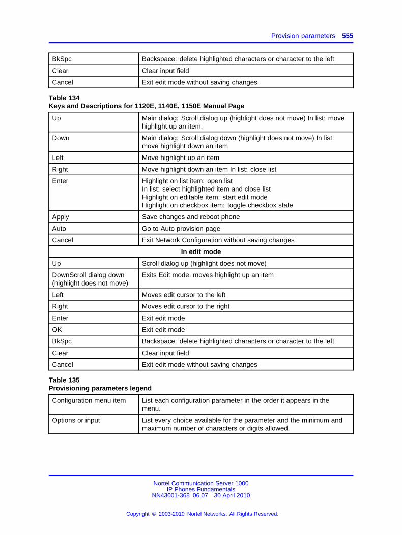
Provision parameters 555
BkSpc Backspace: delete highlighted characters or character to the left
Clear Clear input field
Cancel Exit edit mode without saving changes
Table 134Keys and Descriptions for 1120E, 1140E, 1150E Manual Page
Up Main dialog: Scroll dialog up (highlight does not move) In list: movehighlight up an item.
Down Main dialog: Scroll dialog down (highlight does not move) In list:move highlight down an item
Left Move highlight up an item
Right Move highlight down an item In list: close list
Enter Highlight on list item: open listIn list: select highlighted item and close listHighlight on editable item: start edit modeHighlight on checkbox item: toggle checkbox state
Apply Save changes and reboot phone
Auto Go to Auto provision page
Cancel Exit Network Configuration without saving changes
In edit mode
Up Scroll dialog up (highlight does not move)
DownScroll dialog down(highlight does not move)
Exits Edit mode, moves highlight up an item
Left Moves edit cursor to the left
Right Moves edit cursor to the right
Enter Exit edit mode
OK Exit edit mode
BkSpc Backspace: delete highlighted characters or character to the left
Clear Clear input field
Cancel Exit edit mode without saving changes
Table 135Provisioning parameters legend
Configuration menu item List each configuration parameter in the order it appears in themenu.
Options or input List every choice available for the parameter and the minimum andmaximum number of characters or digits allowed.
Nortel Communication Server 1000IP Phones Fundamentals
NN43001-368 06.07 30 April 2010
Copyright © 2003-2010 Nortel Networks. All Rights Reserved.
.
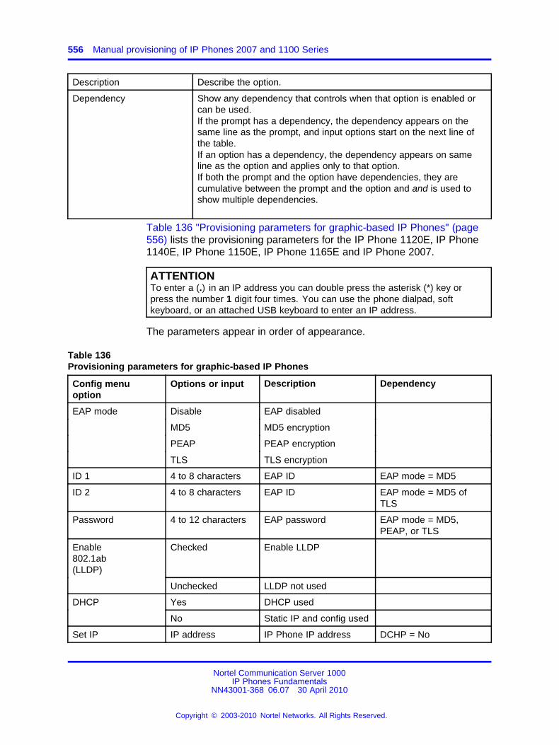
556 Manual provisioning of IP Phones 2007 and 1100 Series
Description Describe the option.
Dependency Show any dependency that controls when that option is enabled orcan be used.If the prompt has a dependency, the dependency appears on thesame line as the prompt, and input options start on the next line ofthe table.If an option has a dependency, the dependency appears on sameline as the option and applies only to that option.If both the prompt and the option have dependencies, they arecumulative between the prompt and the option and and is used toshow multiple dependencies.
Table 136 "Provisioning parameters for graphic-based IP Phones" (page556) lists the provisioning parameters for the IP Phone 1120E, IP Phone1140E, IP Phone 1150E, IP Phone 1165E and IP Phone 2007.
ATTENTIONTo enter a (.) in an IP address you can double press the asterisk (*) key orpress the number 1 digit four times. You can use the phone dialpad, softkeyboard, or an attached USB keyboard to enter an IP address.
The parameters appear in order of appearance.
Table 136Provisioning parameters for graphic-based IP Phones
Config menuoption
Options or input Description Dependency
EAP mode Disable EAP disabled
MD5 MD5 encryption
PEAP PEAP encryption
TLS TLS encryption
ID 1 4 to 8 characters EAP ID EAP mode = MD5
ID 2 4 to 8 characters EAP ID EAP mode = MD5 ofTLS
Password 4 to 12 characters EAP password EAP mode = MD5,PEAP, or TLS
Enable802.1ab(LLDP)
Checked Enable LLDP
Unchecked LLDP not used
DHCP Yes DHCP used
No Static IP and config used
Set IP IP address IP Phone IP address DCHP = No
Nortel Communication Server 1000IP Phones Fundamentals
NN43001-368 06.07 30 April 2010
Copyright © 2003-2010 Nortel Networks. All Rights Reserved.
.
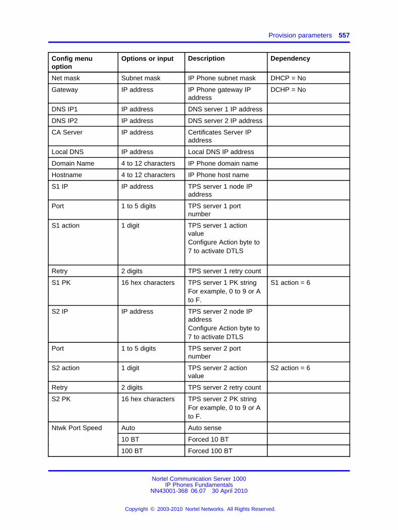
Provision parameters 557
Config menuoption
Options or input Description Dependency
Net mask Subnet mask IP Phone subnet mask DHCP = No
Gateway IP address IP Phone gateway IPaddress
DCHP = No
DNS IP1 IP address DNS server 1 IP address
DNS IP2 IP address DNS server 2 IP address
CA Server IP address Certificates Server IPaddress
Local DNS IP address Local DNS IP address
Domain Name 4 to 12 characters IP Phone domain name
Hostname 4 to 12 characters IP Phone host name
S1 IP IP address TPS server 1 node IPaddress
Port 1 to 5 digits TPS server 1 portnumber
S1 action 1 digit TPS server 1 actionvalueConfigure Action byte to7 to activate DTLS
Retry 2 digits TPS server 1 retry count
S1 PK 16 hex characters TPS server 1 PK stringFor example, 0 to 9 or Ato F.
S1 action = 6
S2 IP IP address TPS server 2 node IPaddressConfigure Action byte to7 to activate DTLS
Port 1 to 5 digits TPS server 2 portnumber
S2 action 1 digit TPS server 2 actionvalue
S2 action = 6
Retry 2 digits TPS server 2 retry count
S2 PK 16 hex characters TPS server 2 PK stringFor example, 0 to 9 or Ato F.
Ntwk Port Speed Auto Auto sense
10 BT Forced 10 BT
100 BT Forced 100 BT
Nortel Communication Server 1000IP Phones Fundamentals
NN43001-368 06.07 30 April 2010
Copyright © 2003-2010 Nortel Networks. All Rights Reserved.
.
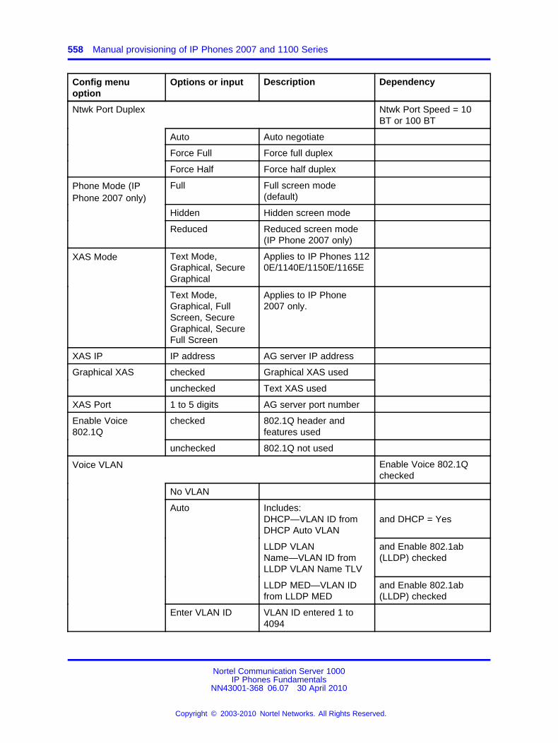
558 Manual provisioning of IP Phones 2007 and 1100 Series
Config menuoption
Options or input Description Dependency
Ntwk Port Duplex Ntwk Port Speed = 10BT or 100 BT
Auto Auto negotiate
Force Full Force full duplex
Force Half Force half duplex
Full Full screen mode(default)
Hidden Hidden screen mode
Phone Mode (IPPhone 2007 only)
Reduced Reduced screen mode(IP Phone 2007 only)
Text Mode,Graphical, SecureGraphical
Applies to IP Phones 1120E/1140E/1150E/1165E
XAS Mode
Text Mode,Graphical, FullScreen, SecureGraphical, SecureFull Screen
Applies to IP Phone2007 only.
XAS IP IP address AG server IP address
Graphical XAS checked Graphical XAS used
unchecked Text XAS used
XAS Port 1 to 5 digits AG server port number
Enable Voice802.1Q
checked 802.1Q header andfeatures used
unchecked 802.1Q not used
Voice VLAN Enable Voice 802.1Qchecked
No VLAN
Includes:DHCP—VLAN ID fromDHCP Auto VLAN
and DHCP = Yes
LLDP VLANName—VLAN ID fromLLDP VLAN Name TLV
and Enable 802.1ab(LLDP) checked
Auto
LLDP MED—VLAN IDfrom LLDP MED
and Enable 802.1ab(LLDP) checked
Enter VLAN ID VLAN ID entered 1 to4094
Nortel Communication Server 1000IP Phones Fundamentals
NN43001-368 06.07 30 April 2010
Copyright © 2003-2010 Nortel Networks. All Rights Reserved.
.
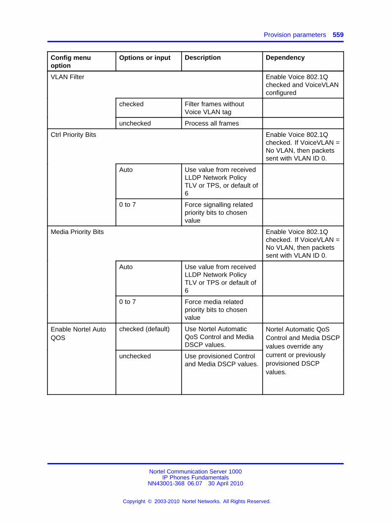
Provision parameters 559
Config menuoption
Options or input Description Dependency
VLAN Filter Enable Voice 802.1Qchecked and VoiceVLANconfigured
checked Filter frames withoutVoice VLAN tag
unchecked Process all frames
Ctrl Priority Bits Enable Voice 802.1Qchecked. If VoiceVLAN =No VLAN, then packetssent with VLAN ID 0.
Auto Use value from receivedLLDP Network PolicyTLV or TPS, or default of6
0 to 7 Force signalling relatedpriority bits to chosenvalue
Media Priority Bits Enable Voice 802.1Qchecked. If VoiceVLAN =No VLAN, then packetssent with VLAN ID 0.
Auto Use value from receivedLLDP Network PolicyTLV or TPS or default of6
0 to 7 Force media relatedpriority bits to chosenvalue
checked (default) Use Nortel AutomaticQoS Control and MediaDSCP values.
Enable Nortel AutoQOS
unchecked Use provisioned Controland Media DSCP values.
Nortel Automatic QoSControl and Media DSCPvalues override anycurrent or previouslyprovisioned DSCPvalues.
Nortel Communication Server 1000IP Phones Fundamentals
NN43001-368 06.07 30 April 2010
Copyright © 2003-2010 Nortel Networks. All Rights Reserved.
.
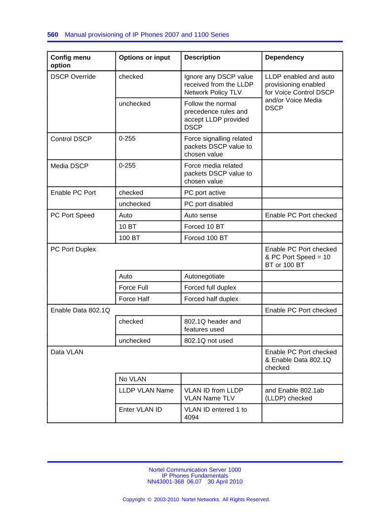
560 Manual provisioning of IP Phones 2007 and 1100 Series
Config menuoption
Options or input Description Dependency
checked Ignore any DSCP valuereceived from the LLDPNetwork Policy TLV
DSCP Override
unchecked Follow the normalprecedence rules andaccept LLDP providedDSCP
LLDP enabled and autoprovisioning enabledfor Voice Control DSCPand/or Voice MediaDSCP
Control DSCP 0-255 Force signalling relatedpackets DSCP value tochosen value
Media DSCP 0-255 Force media relatedpackets DSCP value tochosen value
Enable PC Port checked PC port active
unchecked PC port disabled
PC Port Speed Auto Auto sense Enable PC Port checked
10 BT Forced 10 BT
100 BT Forced 100 BT
PC Port Duplex Enable PC Port checked& PC Port Speed = 10BT or 100 BT
Auto Autonegotiate
Force Full Forced full duplex
Force Half Forced half duplex
Enable Data 802.1Q Enable PC Port checked
checked 802.1Q header andfeatures used
unchecked 802.1Q not used
Data VLAN Enable PC Port checked& Enable Data 802.1Qchecked
No VLAN
LLDP VLAN Name VLAN ID from LLDPVLAN Name TLV
and Enable 802.1ab(LLDP) checked
Enter VLAN ID VLAN ID entered 1 to4094
Nortel Communication Server 1000IP Phones Fundamentals
NN43001-368 06.07 30 April 2010
Copyright © 2003-2010 Nortel Networks. All Rights Reserved.
.
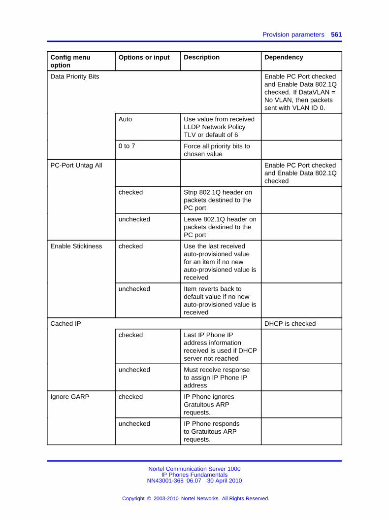
Provision parameters 561
Config menuoption
Options or input Description Dependency
Data Priority Bits Enable PC Port checkedand Enable Data 802.1Qchecked. If DataVLAN =No VLAN, then packetssent with VLAN ID 0.
Auto Use value from receivedLLDP Network PolicyTLV or default of 6
0 to 7 Force all priority bits tochosen value
PC-Port Untag All Enable PC Port checkedand Enable Data 802.1Qchecked
checked Strip 802.1Q header onpackets destined to thePC port
unchecked Leave 802.1Q header onpackets destined to thePC port
Enable Stickiness checked Use the last receivedauto-provisioned valuefor an item if no newauto-provisioned value isreceived
unchecked Item reverts back todefault value if no newauto-provisioned value isreceived
Cached IP DHCP is checked
checked Last IP Phone IPaddress informationreceived is used if DHCPserver not reached
unchecked Must receive responseto assign IP Phone IPaddress
Ignore GARP checked IP Phone ignoresGratuitous ARPrequests.
unchecked IP Phone respondsto Gratuitous ARPrequests.
Nortel Communication Server 1000IP Phones Fundamentals
NN43001-368 06.07 30 April 2010
Copyright © 2003-2010 Nortel Networks. All Rights Reserved.
.
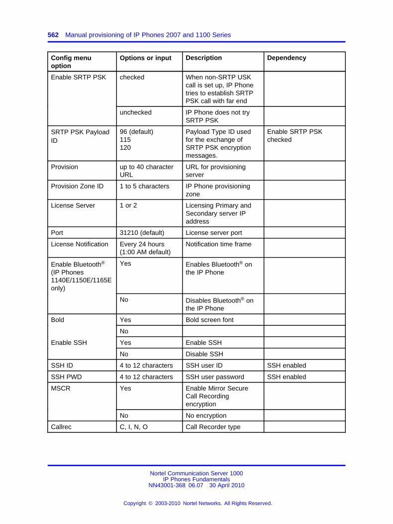
562 Manual provisioning of IP Phones 2007 and 1100 Series
Config menuoption
Options or input Description Dependency
Enable SRTP PSK checked When non-SRTP USKcall is set up, IP Phonetries to establish SRTPPSK call with far end
unchecked IP Phone does not trySRTP PSK
SRTP PSK PayloadID
96 (default)115120
Payload Type ID usedfor the exchange ofSRTP PSK encryptionmessages.
Enable SRTP PSKchecked
Provision up to 40 characterURL
URL for provisioningserver
Provision Zone ID 1 to 5 characters IP Phone provisioningzone
License Server 1 or 2 Licensing Primary andSecondary server IPaddress
Port 31210 (default) License server port
License Notification Every 24 hours(1:00 AM default)
Notification time frame
Enable Bluetooth®
(IP Phones1140E/1150E/1165Eonly)
Yes Enables Bluetooth® onthe IP Phone
No Disables Bluetooth® onthe IP Phone
Bold Yes Bold screen font
No
Enable SSH Yes Enable SSH
No Disable SSH
SSH ID 4 to 12 characters SSH user ID SSH enabled
SSH PWD 4 to 12 characters SSH user password SSH enabled
Yes Enable Mirror SecureCall Recordingencryption
MSCR
No No encryption
Callrec C, I, N, O Call Recorder type
Nortel Communication Server 1000IP Phones Fundamentals
NN43001-368 06.07 30 April 2010
Copyright © 2003-2010 Nortel Networks. All Rights Reserved.
.
563.
AppendixManual provisioning of IP Phones 2000Series
ContentsThis section contains the following topics:
• “Introduction” (page 563)
• “Provision parameters” (page 563)
IntroductionThis section applies to the following IP Phones
• IP Phone 2001
• IP Phone 2002
• IP Phone 2004
• IP Audio Conference Phone 2033
The IP Phone 2007 is a graphic-based IP Phone. For more informationabout manual provisioning of the IP Phone 2007, see “Manual provisioningof IP Phones 2007 and 1100 Series” (page 553).
Provision parametersUse the Network Configuration menu item to configure IP Phoneparameters. You can access the Network Configuration menu fortext-based phone in one of the following ways:
• Press the 4 soft keys at the bottom of the display area in sequencefrom left to right when the IP Phone boots and the text Nortel appearsin the display.
• Double-press the Services key. To make a menu selection, you canpress the number associated with the menu item (for example, press
Nortel Communication Server 1000IP Phones Fundamentals
NN43001-368 06.07 30 April 2010
Copyright © 2003-2010 Nortel Networks. All Rights Reserved.
.
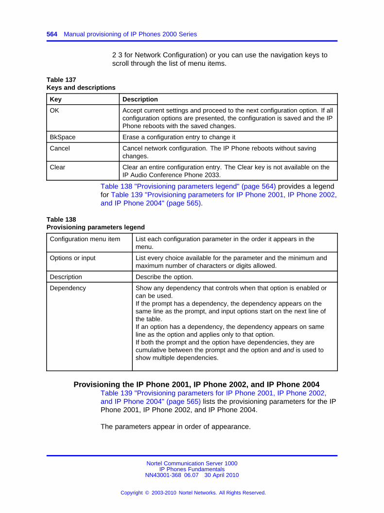
564 Manual provisioning of IP Phones 2000 Series
2 3 for Network Configuration) or you can use the navigation keys toscroll through the list of menu items.
Table 137Keys and descriptions
Key Description
OK Accept current settings and proceed to the next configuration option. If allconfiguration options are presented, the configuration is saved and the IPPhone reboots with the saved changes.
BkSpace Erase a configuration entry to change it
Cancel Cancel network configuration. The IP Phone reboots without savingchanges.
Clear Clear an entire configuration entry. The Clear key is not available on theIP Audio Conference Phone 2033.
Table 138 "Provisioning parameters legend" (page 564) provides a legendfor Table 139 "Provisioning parameters for IP Phone 2001, IP Phone 2002,and IP Phone 2004" (page 565).
Table 138Provisioning parameters legend
Configuration menu item List each configuration parameter in the order it appears in themenu.
Options or input List every choice available for the parameter and the minimum andmaximum number of characters or digits allowed.
Description Describe the option.
Dependency Show any dependency that controls when that option is enabled orcan be used.If the prompt has a dependency, the dependency appears on thesame line as the prompt, and input options start on the next line ofthe table.If an option has a dependency, the dependency appears on sameline as the option and applies only to that option.If both the prompt and the option have dependencies, they arecumulative between the prompt and the option and and is used toshow multiple dependencies.
Provisioning the IP Phone 2001, IP Phone 2002, and IP Phone 2004Table 139 "Provisioning parameters for IP Phone 2001, IP Phone 2002,and IP Phone 2004" (page 565) lists the provisioning parameters for the IPPhone 2001, IP Phone 2002, and IP Phone 2004.
The parameters appear in order of appearance.
Nortel Communication Server 1000IP Phones Fundamentals
NN43001-368 06.07 30 April 2010
Copyright © 2003-2010 Nortel Networks. All Rights Reserved.
.
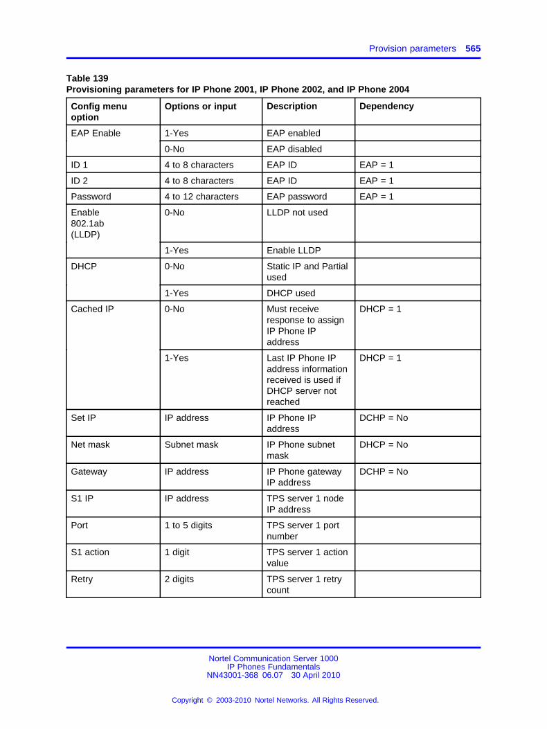
Provision parameters 565
Table 139Provisioning parameters for IP Phone 2001, IP Phone 2002, and IP Phone 2004
Config menuoption
Options or input Description Dependency
EAP Enable 1-Yes EAP enabled
0-No EAP disabled
ID 1 4 to 8 characters EAP ID EAP = 1
ID 2 4 to 8 characters EAP ID EAP = 1
Password 4 to 12 characters EAP password EAP = 1
Enable802.1ab(LLDP)
0-No LLDP not used
1-Yes Enable LLDP
DHCP 0-No Static IP and Partialused
1-Yes DHCP used
Cached IP 0-No Must receiveresponse to assignIP Phone IPaddress
DHCP = 1
1-Yes Last IP Phone IPaddress informationreceived is used ifDHCP server notreached
DHCP = 1
Set IP IP address IP Phone IPaddress
DCHP = No
Net mask Subnet mask IP Phone subnetmask
DHCP = No
Gateway IP address IP Phone gatewayIP address
DCHP = No
S1 IP IP address TPS server 1 nodeIP address
Port 1 to 5 digits TPS server 1 portnumber
S1 action 1 digit TPS server 1 actionvalue
Retry 2 digits TPS server 1 retrycount
Nortel Communication Server 1000IP Phones Fundamentals
NN43001-368 06.07 30 April 2010
Copyright © 2003-2010 Nortel Networks. All Rights Reserved.
.
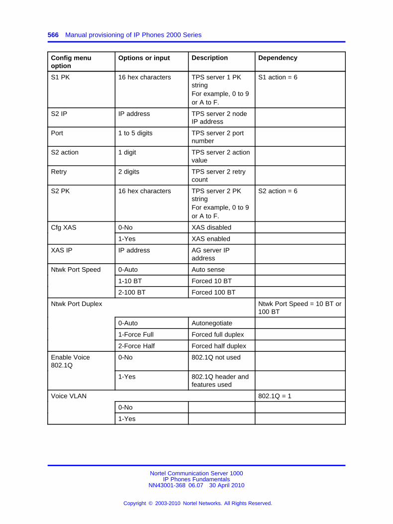
566 Manual provisioning of IP Phones 2000 Series
Config menuoption
Options or input Description Dependency
S1 PK 16 hex characters TPS server 1 PKstringFor example, 0 to 9or A to F.
S1 action = 6
S2 IP IP address TPS server 2 nodeIP address
Port 1 to 5 digits TPS server 2 portnumber
S2 action 1 digit TPS server 2 actionvalue
Retry 2 digits TPS server 2 retrycount
S2 PK 16 hex characters TPS server 2 PKstringFor example, 0 to 9or A to F.
S2 action = 6
Cfg XAS 0-No XAS disabled
1-Yes XAS enabled
XAS IP IP address AG server IPaddress
Ntwk Port Speed 0-Auto Auto sense
1-10 BT Forced 10 BT
2-100 BT Forced 100 BT
Ntwk Port Duplex Ntwk Port Speed = 10 BT or100 BT
0-Auto Autonegotiate
1-Force Full Forced full duplex
2-Force Half Forced half duplex
Enable Voice802.1Q
0-No 802.1Q not used
1-Yes 802.1Q header andfeatures used
Voice VLAN 802.1Q = 1
0-No
1-Yes
Nortel Communication Server 1000IP Phones Fundamentals
NN43001-368 06.07 30 April 2010
Copyright © 2003-2010 Nortel Networks. All Rights Reserved.
.
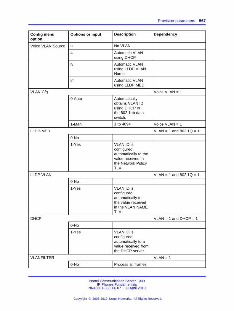
Provision parameters 567
Config menuoption
Options or input Description Dependency
n No VLAN
a Automatic VLANusing DHCP
lv Automatic VLANusing LLDP VLANName
Voice VLAN Source
lm Automatic VLANusing LLDP MED
VLAN Cfg Voice VLAN = 1
0-Auto Automaticallyobtains VLAN IDusing DHCP orthe 802.1ab dataswitch.
1-Man 1 to 4094 Voice VLAN = 1
LLDP-MED VLAN = 1 and 802.1Q = 1
0-No
1-Yes VLAN ID isconfiguredautomatically to thevalue received inthe Network PolicyTLV.
LLDP VLAN VLAN = 1 and 802.1Q = 1
0-No
1-Yes VLAN ID isconfiguredautomatically tothe value receivedin the VLAN NAMETLV.
DHCP VLAN = 1 and DHCP = 1
0-No
1-Yes VLAN ID isconfiguredautomatically to avalue received fromthe DHCP server.
VLANFILTER VLAN = 1
0-No Process all frames
Nortel Communication Server 1000IP Phones Fundamentals
NN43001-368 06.07 30 April 2010
Copyright © 2003-2010 Nortel Networks. All Rights Reserved.
.
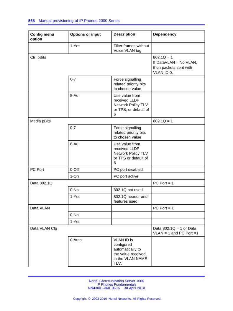
568 Manual provisioning of IP Phones 2000 Series
Config menuoption
Options or input Description Dependency
1-Yes Filter frames withoutVoice VLAN tag
Ctrl pBits 802.1Q = 1If DataVLAN = No VLAN,then packets sent withVLAN ID 0.
0-7 Force signallingrelated priority bitsto chosen value
8-Au Use value fromreceived LLDPNetwork Policy TLVor TPS, or default of6
Media pBits 802.1Q = 1
0-7 Force signallingrelated priority bitsto chosen value
8-Au Use value fromreceived LLDPNetwork Policy TLVor TPS or default of6
PC Port 0-Off PC port disabled
1-On PC port active
Data 802.1Q PC Port = 1
0-No 802.1Q not used
1-Yes 802.1Q header andfeatures used
Data VLAN PC Port = 1
0-No
1-Yes
Data VLAN Cfg Data 802.1Q = 1 or DataVLAN = 1 and PC Port =1
0-Auto VLAN ID isconfiguredautomatically tothe value receivedin the VLAN NAMETLV.
Nortel Communication Server 1000IP Phones Fundamentals
NN43001-368 06.07 30 April 2010
Copyright © 2003-2010 Nortel Networks. All Rights Reserved.
.
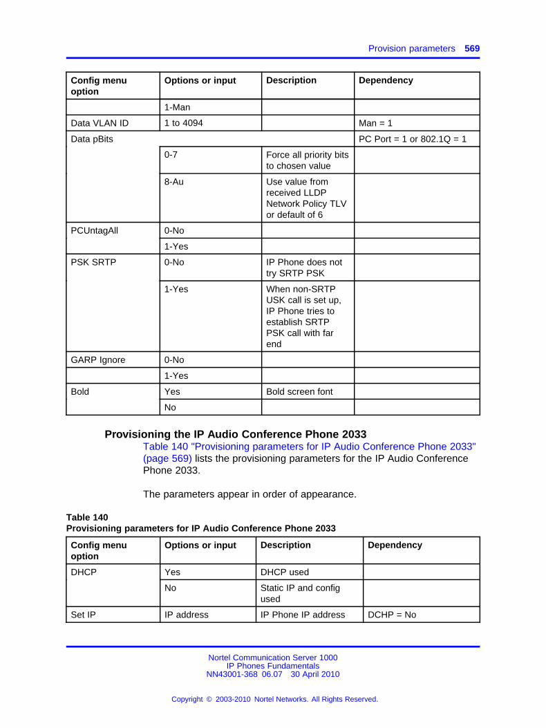
Provision parameters 569
Config menuoption
Options or input Description Dependency
1-Man
Data VLAN ID 1 to 4094 Man = 1
Data pBits PC Port = 1 or 802.1Q = 1
0-7 Force all priority bitsto chosen value
8-Au Use value fromreceived LLDPNetwork Policy TLVor default of 6
PCUntagAll 0-No
1-Yes
PSK SRTP 0-No IP Phone does nottry SRTP PSK
1-Yes When non-SRTPUSK call is set up,IP Phone tries toestablish SRTPPSK call with farend
GARP Ignore 0-No
1-Yes
Bold Yes Bold screen font
No
Provisioning the IP Audio Conference Phone 2033Table 140 "Provisioning parameters for IP Audio Conference Phone 2033"(page 569) lists the provisioning parameters for the IP Audio ConferencePhone 2033.
The parameters appear in order of appearance.
Table 140Provisioning parameters for IP Audio Conference Phone 2033
Config menuoption
Options or input Description Dependency
DHCP Yes DHCP used
No Static IP and configused
Set IP IP address IP Phone IP address DCHP = No
Nortel Communication Server 1000IP Phones Fundamentals
NN43001-368 06.07 30 April 2010
Copyright © 2003-2010 Nortel Networks. All Rights Reserved.
.
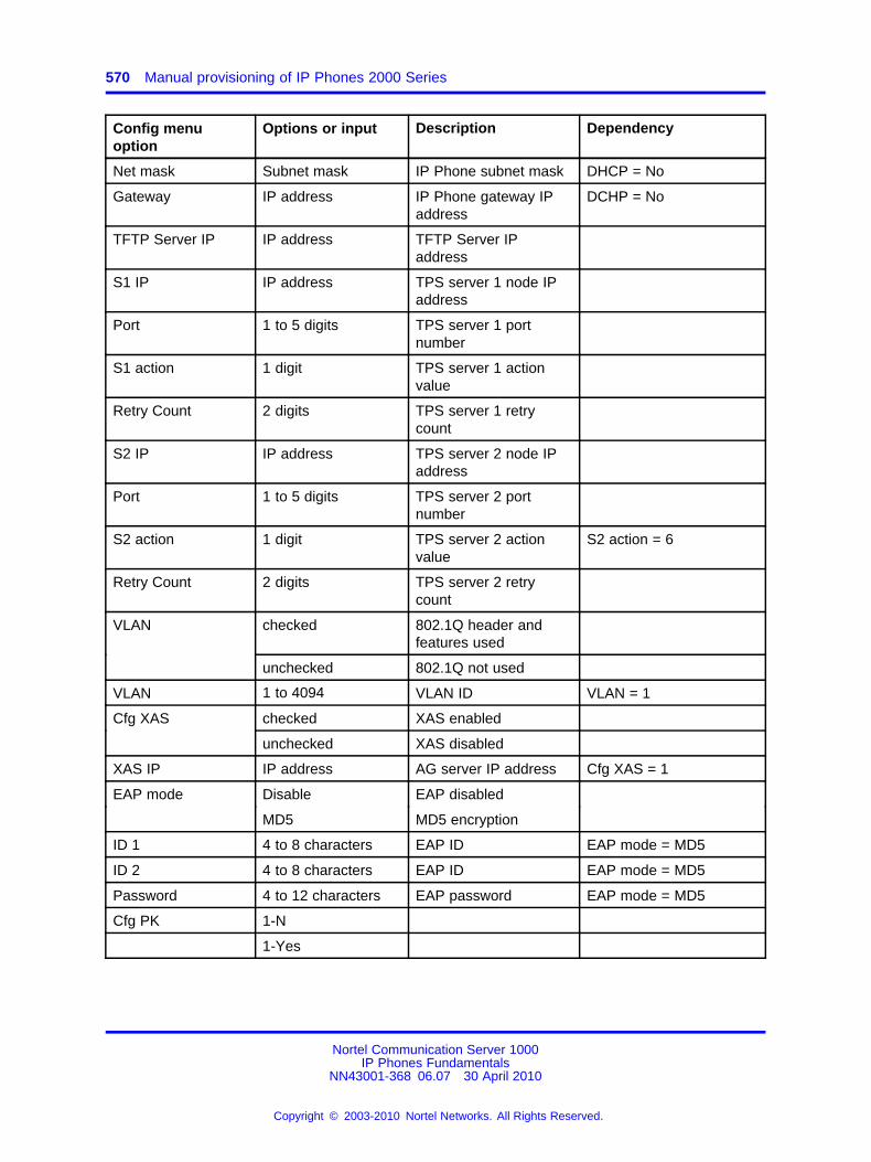
570 Manual provisioning of IP Phones 2000 Series
Config menuoption
Options or input Description Dependency
Net mask Subnet mask IP Phone subnet mask DHCP = No
Gateway IP address IP Phone gateway IPaddress
DCHP = No
TFTP Server IP IP address TFTP Server IPaddress
S1 IP IP address TPS server 1 node IPaddress
Port 1 to 5 digits TPS server 1 portnumber
S1 action 1 digit TPS server 1 actionvalue
Retry Count 2 digits TPS server 1 retrycount
S2 IP IP address TPS server 2 node IPaddress
Port 1 to 5 digits TPS server 2 portnumber
S2 action 1 digit TPS server 2 actionvalue
S2 action = 6
Retry Count 2 digits TPS server 2 retrycount
VLAN checked 802.1Q header andfeatures used
unchecked 802.1Q not used
VLAN 1 to 4094 VLAN ID VLAN = 1
Cfg XAS checked XAS enabled
unchecked XAS disabled
XAS IP IP address AG server IP address Cfg XAS = 1
EAP mode Disable EAP disabled
MD5 MD5 encryption
ID 1 4 to 8 characters EAP ID EAP mode = MD5
ID 2 4 to 8 characters EAP ID EAP mode = MD5
Password 4 to 12 characters EAP password EAP mode = MD5
Cfg PK 1-N
1-Yes
Nortel Communication Server 1000IP Phones Fundamentals
NN43001-368 06.07 30 April 2010
Copyright © 2003-2010 Nortel Networks. All Rights Reserved.
.
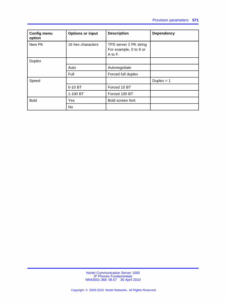
Provision parameters 571
Config menuoption
Options or input Description Dependency
New PK 16 hex characters TPS server 2 PK stringFor example, 0 to 9 orA to F.
Duplex
Auto Autonegotiate
Full Forced full duplex
Speed Duplex = 1
0-10 BT Forced 10 BT
1-100 BT Forced 100 BT
Bold Yes Bold screen font
No
Nortel Communication Server 1000IP Phones Fundamentals
NN43001-368 06.07 30 April 2010
Copyright © 2003-2010 Nortel Networks. All Rights Reserved.
.

572 Manual provisioning of IP Phones 2000 Series
Nortel Communication Server 1000IP Phones Fundamentals
NN43001-368 06.07 30 April 2010
Copyright © 2003-2010 Nortel Networks. All Rights Reserved.
.
573.
AppendixHeadset support
IntroductionThis section contains the following topics:
• “Supported wired and wireless headsets” (page 573)
• “Bluetooth® wireless technology” (page 573)
• “Configure the headsets” (page 575)
• “USB audio support” (page 576)
Supported wired and wireless headsetsFor a complete list of wired and wireless headsets that Nortel hasconfirmed provide acceptable audio quality with Nortel IP Phones, see theProduct Information Centre (PIC) at www.nortel.com.
Bluetooth® wireless technologyBluetooth® wireless technology is supported on the IP Phones1140E/1150E/1165E.
On the IP Phone 1150E, only the Agent port supports Bluetooth® wirelesstechnology.
The IP Phone contains both hardware and software support for Bluetooth®
wireless technology enabled headsets.
Enabling Bluetooth® wireless technologyThe following methods are available to enable Bluetooth® wirelesstechnology on the IP Phone
• Manual configuration— is used to set the Bluetooth® wirelesstechnology mode on the IP Phone on a phone-by-phone basis.
Use Procedure 121 “Configure the Bluetooth® wireless technologyadministration setting (IP Phone 1140E, 1150E)” (page 574) to
Nortel Communication Server 1000IP Phones Fundamentals
NN43001-368 06.07 30 April 2010
Copyright © 2003-2010 Nortel Networks. All Rights Reserved.
.
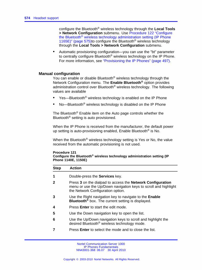
574 Headset support
configure the Bluetooth® wireless technology through the Local Tools> Network Configuration submenu. Use Procedure 122 “Configurethe Bluetooth® wireless technology administration setting (IP Phone1165E)” (page 575)to configure the Bluetooth® wireless technologythrough the Local Tools > Network Configuration submenu.
• Automatic provisioning configuration—you can use the "bt" parameterto centrally configure Bluetooth® wireless technology on the IP Phone.For more information, see “Provisioning the IP Phones” (page 497).
Manual configurationYou can enable or disable Bluetooth® wireless technology through theNetwork Configuration menu. The Enable Bluetooth® option providesadministration control over Bluetooth® wireless technology. The followingvalues are available
• Yes—Bluetooth® wireless technology is enabled on the IP Phone
• No—Bluetooth® wireless technology is disabled on the IP Phone
The Bluetooth® Enable item on the Auto page controls whether theBluetooth® setting is auto provisioned.
When the IP Phone is received from the manufacturer, the default powerup setting is auto-provisioning enabled, Enable Bluetooth® is No.
When the Bluetooth® wireless technology setting is Yes or No, the valuereceived from the automatic provisioning is not used.
Procedure 121Configure the Bluetooth® wireless technology administration setting (IPPhone 1140E, 1150E)
Step Action
1 Double-press the Services key.
2 Press 3 on the dialpad to access the Network Configurationmenu or use the Up/Down navigation keys to scroll and highlightthe Network Configuration option.
3 Use the Right navigation key to navigate to the EnableBluetooth® box. The current setting is displayed.
4 Press Enter to start the edit mode.
5 Use the Down navigation key to open the list.
6 Use the Up/Down navigation keys to scroll and highlight thedesired Bluetooth® wireless technology mode.
7 Press Enter to select the mode and to close the list.
Nortel Communication Server 1000IP Phones Fundamentals
NN43001-368 06.07 30 April 2010
Copyright © 2003-2010 Nortel Networks. All Rights Reserved.
.
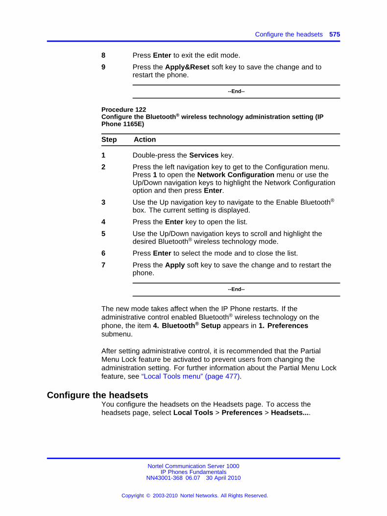
Configure the headsets 575
8 Press Enter to exit the edit mode.
9 Press the Apply&Reset soft key to save the change and torestart the phone.
--End--
Procedure 122Configure the Bluetooth® wireless technology administration setting (IPPhone 1165E)
Step Action
1 Double-press the Services key.
2 Press the left navigation key to get to the Configuration menu.Press 1 to open the Network Configuration menu or use theUp/Down navigation keys to highlight the Network Configurationoption and then press Enter.
3 Use the Up navigation key to navigate to the Enable Bluetooth®
box. The current setting is displayed.
4 Press the Enter key to open the list.
5 Use the Up/Down navigation keys to scroll and highlight thedesired Bluetooth® wireless technology mode.
6 Press Enter to select the mode and to close the list.
7 Press the Apply soft key to save the change and to restart thephone.
--End--
The new mode takes affect when the IP Phone restarts. If theadministrative control enabled Bluetooth® wireless technology on thephone, the item 4. Bluetooth® Setup appears in 1. Preferencessubmenu.
After setting administrative control, it is recommended that the PartialMenu Lock feature be activated to prevent users from changing theadministration setting. For further information about the Partial Menu Lockfeature, see “Local Tools menu” (page 477).
Configure the headsetsYou configure the headsets on the Headsets page. To access theheadsets page, select Local Tools > Preferences > Headsets....
Nortel Communication Server 1000IP Phones Fundamentals
NN43001-368 06.07 30 April 2010
Copyright © 2003-2010 Nortel Networks. All Rights Reserved.
.
576 Headset support
The Headsets page provides the following options:
• Active Headset Device
• Enable HID Commands
• Headset Type
• Backlight
Active Headset DeviceThe Active Headset Device option provides a list of headset devices.
Enable HID CommandsThe Enable HID Commands option controls the following headsetoperational modes:
• GenericMode1 - checkbox checked
• GenericMode2 - checkbox unchecked
GenericMode1GenericMode1 provides full HID support for Plantronics CS50-USB,GN-Netcom 9330, MHA, and ATA and only standard HID support for otherheadsets.
GenericMode2GenericMode2 provides audio only support for all devices including thesupported headsets.
Headset TypeThe Headset Type option provides a list of headsets in which the MHAsupports. The MHA supports 11 headsets. Nortel Mobile Kit is the defaultselection.
Headset Type and Backlight enable only when an MHA is attached. For allother headsets, these items appear dimmed.
USB audio supportWith Universal Serial Bus (USB) audio support, you can connect the following devices to the USB port on IP Phones 1120E/1140E/1150E/1165E:
• Nortel enhanced USB headset adapter
• Nortel mobile USB headset adapter
• Algo 4900 USB Analog Terminal Adapter (ATA)
• GN Netcom wireless headsets
• Plantronics wireless headsets
Nortel Communication Server 1000IP Phones Fundamentals
NN43001-368 06.07 30 April 2010
Copyright © 2003-2010 Nortel Networks. All Rights Reserved.
.
USB audio support 577
Nortel USB adaptersIP Phone USB audio support for the Nortel enhanced USB headsetadapter and the Nortel mobile USB headset adapter includes complianceto the Nortel Human Interface Device (HID).
With HID compliance the Nortel IP Phone can recognize and support callcontrolling features from the Nortel Enhanced USB Headset Adapter andthe Nortel Mobile USB Headset Adapter, including the Answer (off-hook),Release (on-hook), Mute, and Volume buttons. The Minimize/Maximizeand Smart Functions buttons (on the Enhanced adapter only) are notsupported.
The Nortel Enhanced USB Headset Adapter and the Nortel Mobile USBHeadset Adapter also support the following features:
• Red Message Waiting light - illuminates when you have voice mailmessages waiting and flashes when a call is ringing on the IP Phone.
• Backlight - if enabled, illuminates when the adapter is connected to theNortel IP Phone.
You control backlight activation or deactivation using the Back Lightcheck box in the IP Phone Preferences menu.
USB Analog Terminal AdapterThe Algo 4900 USB Analog Terminal Adapter (ATA), enablesyou to use an analog wired or cordless telephone, a TTY/TDDterminal, a fax machine, or another analog device with IP Phones1120E/1140E/1150E/1165E.
ATTENTIONNortel IP Phones do not support analog modems.
The Algo 4900 USB ATA also supports the following features:
• call originating and call terminating
• caller ID - when the Nortel IP Phone is connected to a NortelCommunication Server 1000
For more information about the Algo 4900 USB ATA, seehttp://www.algosolutions.com/products/usbATA/.
The Algo 4900 USB ATA must have firmware version v1.00.32v or greaterto connect to the Nortel IP Phone. You can use a Windows based configuration tool to upgrade the ATA firmware version. For more information, seehttp://www.algosolutions.com/products/usbATA/fw-download.html.
Nortel Communication Server 1000IP Phones Fundamentals
NN43001-368 06.07 30 April 2010
Copyright © 2003-2010 Nortel Networks. All Rights Reserved.
.
578 Headset support
Wireless USB headsetsFor a complete list of wired and wireless headsets that provide acceptableaudio quality with Nortel IP Phones, see the Product Information Centre(PIC) at www.nortel.com.
USB audio limitations and restrictionsThe following sections describe USB audio limitations and restrictions thatapply with the Nortel IP Phone.
IP Phone USB audio limitations
• IP Phone USB Audio does not support stereo audio. If you use astereo headset, the audio is merged to mono (identical audio istransmitted to both the left and right ear pieces). All audio received bythe headset microphone is mono.
• When you use USB audio on an IP Phone 1120E or an IP Phone1140E connected to a BCM system, you can hear a continuous cycleof error tones from the headset if you inadvertently hit a call controlkey. You can clear the error condition by hanging up the call.
USB headset power restrictionsUSB headsets can draw power from the IP Phone USB port to operate.The USB port on the IP Phone provides a maximum of 100mA, which canpower the Nortel USB adapters.
ATTENTIONConnecting USB headsets that draw more than 100mA to the IP Phone cancause the USB port on the IP Phone to shut down. The IP Phone 1165E cansupport 500 mA if it is AC powered, 100 mA on PoE power.
For information about ATA USB power restrictions, see “ATA USB powerlimitations” (page 579).
USB audio firmware limitations
• Firmware version V2.0.32 or later is required for Nortel USB Adapters.
• Firmware version v1.00.32 or later is required for the Algo4900 USB ATA. You can use the Windows based Algo 4900USB ATA configuration tool to verify the firmware versionand to upgrade the firmware. For more information, seehttp://www.algosolutions.com/products/usbATA/fw-download.html.
Nortel Communication Server 1000IP Phones Fundamentals
NN43001-368 06.07 30 April 2010
Copyright © 2003-2010 Nortel Networks. All Rights Reserved.
.
USB audio support 579
ATA USB power limitations
• The Algo 4900 USB ATA can only accept power from a USB sourceand is classified as a high power USB device (exceeds the 100mA limitof the IP Phone USB port).
• For IP Phones 1120E/1140E/1150E, you must connect the Algo 4900USB ATA to an externally powered USB hub, which is then connectedto the IP Phone USB port. If you connect the Algo 4900 USB ATAdirectly to the IP Phone USB port, the IP Phone shuts down serviceto the USB port
• For IP Phone 1165E, if the IP Phone is local AC powered, you canconnect the ATA directly to the phone. However, if the IP Phoneis POE powered, you must connect the Algo 4900 USB ATA to anexternally powered USB hub which is then connected to the IP PhoneUSB port.
Nortel Communication Server 1000IP Phones Fundamentals
NN43001-368 06.07 30 April 2010
Copyright © 2003-2010 Nortel Networks. All Rights Reserved.
.

580 Headset support
Nortel Communication Server 1000IP Phones Fundamentals
NN43001-368 06.07 30 April 2010
Copyright © 2003-2010 Nortel Networks. All Rights Reserved.
.
581.
AppendixDatagram Transport Layer Security
OverviewCommunication Server 1000 Release 6.0 or later is required to operatethis feature.
The following IP Phones support the Datagram Transport Layer Security(DTLS) feature.
• IP Phone 2007
• IP Phones 1100 Series (IP Phones 1110/1120E/1140E/1150E)
• IP Phones 1200 Series (IP Phones 1210/1220/1230)
Action byte 7 triggers a DTLS session. Parameters can be configuredusing a DHCP, auto provisioning, or manual provisioning. For moreinformation, see “Provisioning the IP Phones” (page 497).
The port number is assigned specially for DTLS. CS1K default port numberis 4101. See Table 141 "CS 1000 Release 6.0 and later port assignments"(page 581).
Table 141CS 1000 Release 6.0 and later port assignments
Ports
Unsecured 4100, 7300, 5100, 5105
Secured 4101, 7301, 5101, 5106
Operating modesCS 1000 Release 6.0 or later can be configured in 3 modes, as shown inTable 142 "Security modes" (page 582).
Nortel Communication Server 1000IP Phones Fundamentals
NN43001-368 06.07 30 April 2010
Copyright © 2003-2010 Nortel Networks. All Rights Reserved.
.
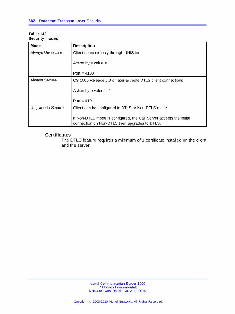
582 Datagram Transport Layer Security
Table 142Security modes
Mode Description
Always Un-secure Client connects only through UNIStim
Action byte value = 1
Port = 4100
Always Secure CS 1000 Release 6.0 or later accepts DTLS client connections
Action byte value = 7
Port = 4101
Upgrade to Secure Client can be configured in DTLS or Non-DTLS mode.
If Non-DTLS mode is configured, the Call Server accepts the initialconnection on Non-DTLS then upgrades to DTLS.
CertificatesThe DTLS feature requires a minimum of 1 certificate installed on the clientand the server.
Nortel Communication Server 1000IP Phones Fundamentals
NN43001-368 06.07 30 April 2010
Copyright © 2003-2010 Nortel Networks. All Rights Reserved.
.
583.
AppendixVirtual Private Network
DescriptionThe Virtual Private Network (VPN) feature provides VPN client capabilityto the following IP Phones:
• IP Phone 1120E
• IP Phone 1140E
• IP Phone 1150E
The following table shows supported VPN routers.
Table 143VPN routers
Router Model Release
Nortel VPN Router 1750, 2700, 5000 Release 3.2
Nortel VPN Gateway 3050, 3070 Release 7
The VPN feature enables the phone to establish an encrypted VPN tunnelfrom the phone to a VPN server, such as Nortel Contivity. When the tunnelis established, the following IP Phone related traffic traverses the tunnel.
• UNIStim Signaling
• Media
• Duplicate media
• XAS
• TFTP Provisioning
• HTTP Provisioning
• SSH debugging
Note: Contivity server must also allow that traffic through the VPNTunnel. For a list of port numbers used for each of these protocols,see “Port numbers” (page 705).
Nortel Communication Server 1000IP Phones Fundamentals
NN43001-368 06.07 30 April 2010
Copyright © 2003-2010 Nortel Networks. All Rights Reserved.
.
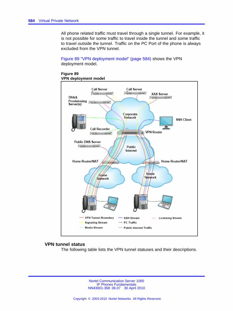
584 Virtual Private Network
All phone related traffic must travel through a single tunnel. For example, itis not possible for some traffic to travel inside the tunnel and some trafficto travel outside the tunnel. Traffic on the PC Port of the phone is alwaysexcluded from the VPN tunnel.
Figure 89 "VPN deployment model" (page 584) shows the VPNdeployment model.
Figure 89VPN deployment model
VPN tunnel statusThe following table lists the VPN tunnel statuses and their descriptions.
Nortel Communication Server 1000IP Phones Fundamentals
NN43001-368 06.07 30 April 2010
Copyright © 2003-2010 Nortel Networks. All Rights Reserved.
.
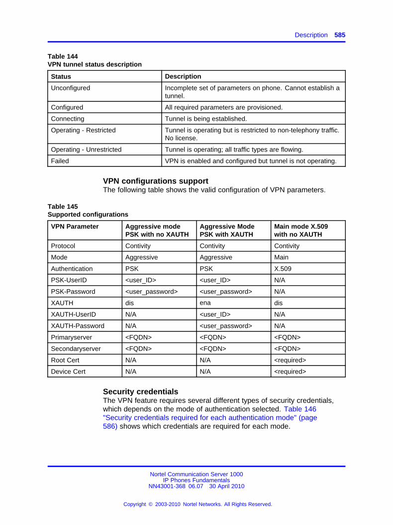
Description 585
Table 144VPN tunnel status description
Status Description
Unconfigured Incomplete set of parameters on phone. Cannot establish atunnel.
Configured All required parameters are provisioned.
Connecting Tunnel is being established.
Operating - Restricted Tunnel is operating but is restricted to non-telephony traffic.No license.
Operating - Unrestricted Tunnel is operating; all traffic types are flowing.
Failed VPN is enabled and configured but tunnel is not operating.
VPN configurations supportThe following table shows the valid configuration of VPN parameters.
Table 145Supported configurations
VPN Parameter Aggressive modePSK with no XAUTH
Aggressive ModePSK with XAUTH
Main mode X.509with no XAUTH
Protocol Contivity Contivity Contivity
Mode Aggressive Aggressive Main
Authentication PSK PSK X.509
PSK-UserID <user_ID> <user_ID> N/A
PSK-Password <user_password> <user_password> N/A
XAUTH dis ena dis
XAUTH-UserID N/A <user_ID> N/A
XAUTH-Password N/A <user_password> N/A
Primaryserver <FQDN> <FQDN> <FQDN>
Secondaryserver <FQDN> <FQDN> <FQDN>
Root Cert N/A N/A <required>
Device Cert N/A N/A <required>
Security credentialsThe VPN feature requires several different types of security credentials,which depends on the mode of authentication selected. Table 146"Security credentials required for each authentication mode" (page586) shows which credentials are required for each mode.
Nortel Communication Server 1000IP Phones Fundamentals
NN43001-368 06.07 30 April 2010
Copyright © 2003-2010 Nortel Networks. All Rights Reserved.
.
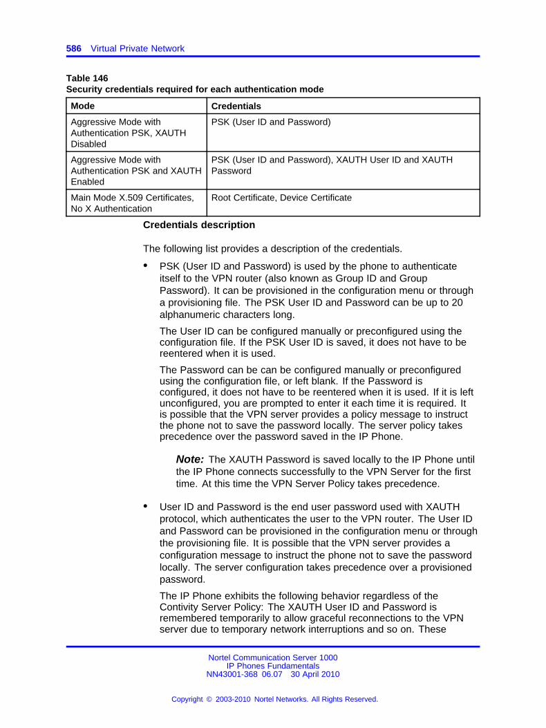
586 Virtual Private Network
Table 146Security credentials required for each authentication mode
Mode Credentials
Aggressive Mode withAuthentication PSK, XAUTHDisabled
PSK (User ID and Password)
Aggressive Mode withAuthentication PSK and XAUTHEnabled
PSK (User ID and Password), XAUTH User ID and XAUTHPassword
Main Mode X.509 Certificates,No X Authentication
Root Certificate, Device Certificate
Credentials description
The following list provides a description of the credentials.
• PSK (User ID and Password) is used by the phone to authenticateitself to the VPN router (also known as Group ID and GroupPassword). It can be provisioned in the configuration menu or througha provisioning file. The PSK User ID and Password can be up to 20alphanumeric characters long.
The User ID can be configured manually or preconfigured using theconfiguration file. If the PSK User ID is saved, it does not have to bereentered when it is used.
The Password can be can be configured manually or preconfiguredusing the configuration file, or left blank. If the Password isconfigured, it does not have to be reentered when it is used. If it is leftunconfigured, you are prompted to enter it each time it is required. Itis possible that the VPN server provides a policy message to instructthe phone not to save the password locally. The server policy takesprecedence over the password saved in the IP Phone.
Note: The XAUTH Password is saved locally to the IP Phone untilthe IP Phone connects successfully to the VPN Server for the firsttime. At this time the VPN Server Policy takes precedence.
• User ID and Password is the end user password used with XAUTHprotocol, which authenticates the user to the VPN router. The User IDand Password can be provisioned in the configuration menu or throughthe provisioning file. It is possible that the VPN server provides aconfiguration message to instruct the phone not to save the passwordlocally. The server configuration takes precedence over a provisionedpassword.
The IP Phone exhibits the following behavior regardless of theContivity Server Policy: The XAUTH User ID and Password isremembered temporarily to allow graceful reconnections to the VPNserver due to temporary network interruptions and so on. These
Nortel Communication Server 1000IP Phones Fundamentals
NN43001-368 06.07 30 April 2010
Copyright © 2003-2010 Nortel Networks. All Rights Reserved.
.
Description 587
reconnections to the VPN server do not prompt the end user to enterthe credentials. However, if the IP Phone powers down and powersup, then the user is prompted for credentials when the Contivity ServerPolicy dictates the password is not allowed to be saved locally.
Note: X.509 certificate credentials are always handled by the VPNrouter. The user is not prompted to enter a user ID or password.
• Root certificate is the customers root certificate and is installed as partof the configuration file or as part of the SCEP process.
• Device certificate is assigned specifically to the phone. It is installedusing the SCEP process when the phone is configured prior to theinstallation process. If the phone is configured using the Peer-to-Peerconfiguration process the device certificate is installed directly from theassociated PC.
VPN Security bannerThe VPN Security Banner displays on the phone display area to presentsecurity information provided by the VPN gateway. This banner ispresented only if the VPN Gateway is configured to provide one to thephone.
The Banner displays when the phone establishes a VPN tunnel to the VPNGateway for the first time, after which the banner is accepted without anyuser intervention. If the VPN primary gateway "VPN Server 1" parameter ischanged, the new security banner is displayed.
You must accept the Security Banner to establish a tunnel to allow datatraffic to flow over the tunnel. If you select Cancel you are prompted toaccept the security Banner again.
LicensingThe VPN feature requires a license to operate. When the phone is firstpowered on or when the tunnel is established, the VPN feature queriesthe license client to determine if the phone has sufficient licensing tokens.If the license request is denied, telephony services are restricted. Localmenus, such as Diagnostics, Provisioning, and Configuration menus canstill be activated. The VPN Tunnel will still activate which allows you obtainvalid license file, and provisioning information. For more information aboutlicensing, see “Licensing” (page 597).
LanguagesThe VPN prompts that are local to the phone are localized.
Nortel Communication Server 1000IP Phones Fundamentals
NN43001-368 06.07 30 April 2010
Copyright © 2003-2010 Nortel Networks. All Rights Reserved.
.
588 Virtual Private Network
Some Languages are supported only after the font file is downloaded orthe phone has connected to the Call Server. For more information aboutlanguages supported on the IP Phones, see “Languages” (page 405).
Address assignmentVPN mode requires an outer and inner IP address. The outer address(physical address) is used to encapsulate the tunnel and can be acquiredthrough a local DHCP server or can be manually configured from theNetwork Configuration menu.
The inner address (virtual address) is in the IP Phone address withinthe virtual private network and is always assigned by the IKE Configmode messages. You cannot provision these parameters using DHCP ormanually configured through the Network Configuration menu or through aprovisioning file. For more information about provisioning the IP Phones,see “Provisioning the IP Phones” (page 497).
Listening ModeUse the VPN wizard tool, a wizard-style interface, to go through the phoneconfiguration process with no prior knowledge of phone configurationneeded. To use the Peer-to-Peer Configuration Mode, the phone mustbe placed in Listening mode during boot up. If Listening Mode is notactivated, the provisioning application running on the PC cannot discoverthe phone. When the phone boots and the text "Nortel" appears on thephone, press Mute + 5 + 6 + Mute.
When Listening Mode is first invoked on the phone, the status is"Listening…; a 15-minute timer starts. If the timer reaches 0 before thepeer-to-peer configuration completes, the phone exits "Listening Mode".If the provisioning application running on the PC reaches the phone withthe discovery message before the timer runs out, the phone changes thestatus to "Connected…. When the VPN Wizard Tool successfully detectsthe phone, the phone changes the status to "Success…. If at any timeyou press Exit the phone changes the status to "Exiting…for 3 secondsafter which the phone exits Listening Mode and resumes the normal bootsequence. If the timeout is reached before provisioning information isreceived from the provisioning application the phone changes the statusfor 3 seconds to "Timeout…" then exits Listening Mode.
ATTENTION802.1Q is disabled when you enter the Mute + 5 + 6 + Mute key sequence. Youmust reboot the phone to reenable 802.1Q.
When the phone successfully receives provisioning information fromthe provisioning application the phone receives a provisioning URL andProvisioning Zone ID from the PC. These parameters are applied onthe phone and are set to "Auto" so they can be modified using autoprovisioning. The phone uses these parameters immediately after
Nortel Communication Server 1000IP Phones Fundamentals
NN43001-368 06.07 30 April 2010
Copyright © 2003-2010 Nortel Networks. All Rights Reserved.
.
Description 589
Listening Mode to contact the PC to request the provisioning files. Theprovisioning files stored on the PC are read and the contained parametersare applied on the phone. The Provision URL and Zone ID remain as thatspecified by the provisioning application unless a new value is specified inthe provisioning file that the phone reads. For example, if a phone mustbe configured to use VPN to connect to the local network, the .prv filesused to configure the phone must specify the valid provisioning server andprovisioning zone ID on the corporate network, which is accessed usingVPN.
For more information about Listening Mode, see the IP Phone 1120E,1140E, 1150E User Guides.
Limitations
• RFC 3456, DHCP over IPSec is not supported. This means that FullDHCP mode is not supported; therefore any provisioning informationmust be configured manually or configured using the peer-to-peerprovisioning feature. It is not possible to configure the name andaddress of the provisioning server using DHCP.
• The Mode Config exchange does not include a mechanism forproviding the URL of a provisioning server. In non VPN mode theURL can be provided by DHCP Option 66. Therefore, the provisioningserver URL must be configured manually or configured using thepeer-to-peer provisioning feature.
• IP Compression in Phase 2 is not supported.
• This feature is not included as part of BootC. Therefore if applicationarea of Flash memory is corrupted the phone cannot recoverautomatically when the VPN feature is enabled.
• The Cached IP Address feature for the inner IP Address is notsupported when the VPN feature is enabled.
• Redundant and load sharing servers must use the same securitycredentials and methods as the primary server, for example, there isno mechanism to provision separate credentials for different servers.
• The Provisioning PC must allow a TFTP server to run. In WindowsVista this means the user must have administrator privileges.
• If the UserIDs and Passwords are saved in nonvolatile memory andare accepted by the VPN Router the user is not prompted to enter theirUserID and Password. In this situation, the only way a UserID andPassword can be modified is through the manual configuration menu.
• If a security credential becomes invalid or obsolete while the VPNtunnel is active the tunnel is not affected until the next time thecredential is required. For example, if a certificate expires or a UserID
Nortel Communication Server 1000IP Phones Fundamentals
NN43001-368 06.07 30 April 2010
Copyright © 2003-2010 Nortel Networks. All Rights Reserved.
.

590 Virtual Private Network
is deleted the while the tunnel is operating, the tunnel continues tooperate until the next rekey operation occurs.
Nortel Communication Server 1000IP Phones Fundamentals
NN43001-368 06.07 30 April 2010
Copyright © 2003-2010 Nortel Networks. All Rights Reserved.
.
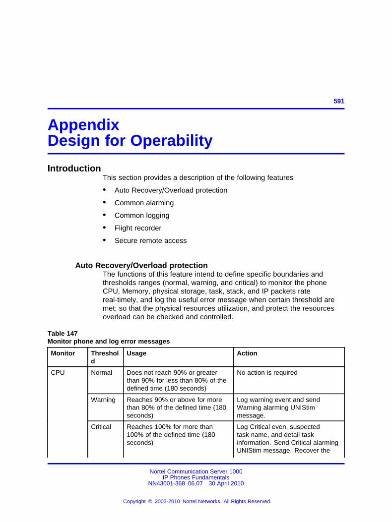
591.
AppendixDesign for Operability
IntroductionThis section provides a description of the following features
• Auto Recovery/Overload protection
• Common alarming
• Common logging
• Flight recorder
• Secure remote access
Auto Recovery/Overload protectionThe functions of this feature intend to define specific boundaries andthresholds ranges (normal, warning, and critical) to monitor the phoneCPU, Memory, physical storage, task, stack, and IP packets ratereal-timely, and log the useful error message when certain threshold aremet; so that the physical resources utilization, and protect the resourcesoverload can be checked and controlled.
Table 147Monitor phone and log error messages
Monitor Threshold
Usage Action
Normal Does not reach 90% or greaterthan 90% for less than 80% of thedefined time (180 seconds)
No action is required
Warning Reaches 90% or above for morethan 80% of the defined time (180seconds)
Log warning event and sendWarning alarming UNIStimmessage.
CPU
Critical Reaches 100% for more than100% of the defined time (180seconds)
Log Critical even, suspectedtask name, and detail taskinformation. Send Critical alarmingUNIStim message. Recover the
Nortel Communication Server 1000IP Phones Fundamentals
NN43001-368 06.07 30 April 2010
Copyright © 2003-2010 Nortel Networks. All Rights Reserved.
.
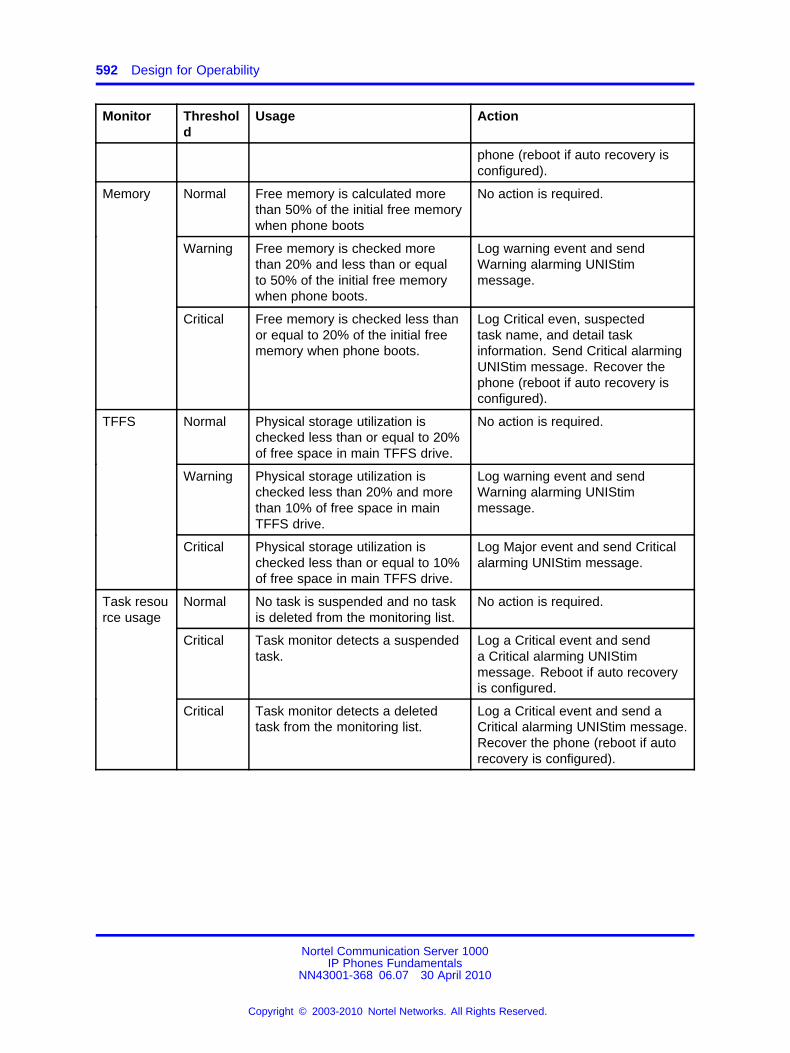
592 Design for Operability
Monitor Threshold
Usage Action
phone (reboot if auto recovery isconfigured).
Normal Free memory is calculated morethan 50% of the initial free memorywhen phone boots
No action is required.
Warning Free memory is checked morethan 20% and less than or equalto 50% of the initial free memorywhen phone boots.
Log warning event and sendWarning alarming UNIStimmessage.
Memory
Critical Free memory is checked less thanor equal to 20% of the initial freememory when phone boots.
Log Critical even, suspectedtask name, and detail taskinformation. Send Critical alarmingUNIStim message. Recover thephone (reboot if auto recovery isconfigured).
Normal Physical storage utilization ischecked less than or equal to 20%of free space in main TFFS drive.
No action is required.
Warning Physical storage utilization ischecked less than 20% and morethan 10% of free space in mainTFFS drive.
Log warning event and sendWarning alarming UNIStimmessage.
TFFS
Critical Physical storage utilization ischecked less than or equal to 10%of free space in main TFFS drive.
Log Major event and send Criticalalarming UNIStim message.
Normal No task is suspended and no taskis deleted from the monitoring list.
No action is required.
Critical Task monitor detects a suspendedtask.
Log a Critical event and senda Critical alarming UNIStimmessage. Reboot if auto recoveryis configured.
Task resource usage
Critical Task monitor detects a deletedtask from the monitoring list.
Log a Critical event and send aCritical alarming UNIStim message.Recover the phone (reboot if autorecovery is configured).
Nortel Communication Server 1000IP Phones Fundamentals
NN43001-368 06.07 30 April 2010
Copyright © 2003-2010 Nortel Networks. All Rights Reserved.
.
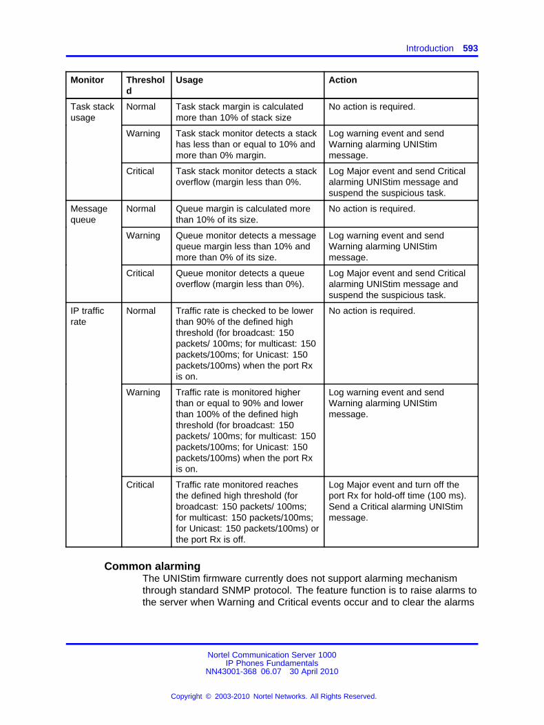
Introduction 593
Monitor Threshold
Usage Action
Normal Task stack margin is calculatedmore than 10% of stack size
No action is required.
Warning Task stack monitor detects a stackhas less than or equal to 10% andmore than 0% margin.
Log warning event and sendWarning alarming UNIStimmessage.
Task stackusage
Critical Task stack monitor detects a stackoverflow (margin less than 0%.
Log Major event and send Criticalalarming UNIStim message andsuspend the suspicious task.
Normal Queue margin is calculated morethan 10% of its size.
No action is required.
Warning Queue monitor detects a messagequeue margin less than 10% andmore than 0% of its size.
Log warning event and sendWarning alarming UNIStimmessage.
Messagequeue
Critical Queue monitor detects a queueoverflow (margin less than 0%).
Log Major event and send Criticalalarming UNIStim message andsuspend the suspicious task.
Normal Traffic rate is checked to be lowerthan 90% of the defined highthreshold (for broadcast: 150packets/ 100ms; for multicast: 150packets/100ms; for Unicast: 150packets/100ms) when the port Rxis on.
No action is required.
Warning Traffic rate is monitored higherthan or equal to 90% and lowerthan 100% of the defined highthreshold (for broadcast: 150packets/ 100ms; for multicast: 150packets/100ms; for Unicast: 150packets/100ms) when the port Rxis on.
Log warning event and sendWarning alarming UNIStimmessage.
IP trafficrate
Critical Traffic rate monitored reachesthe defined high threshold (forbroadcast: 150 packets/ 100ms;for multicast: 150 packets/100ms;for Unicast: 150 packets/100ms) orthe port Rx is off.
Log Major event and turn off theport Rx for hold-off time (100 ms).Send a Critical alarming UNIStimmessage.
Common alarmingThe UNIStim firmware currently does not support alarming mechanismthrough standard SNMP protocol. The feature function is to raise alarms tothe server when Warning and Critical events occur and to clear the alarms
Nortel Communication Server 1000IP Phones Fundamentals
NN43001-368 06.07 30 April 2010
Copyright © 2003-2010 Nortel Networks. All Rights Reserved.
.
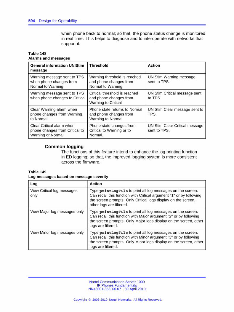
594 Design for Operability
when phone back to normal; so that, the phone status change is monitoredin real time. This helps to diagnose and to interoperate with networks thatsupport it.
Table 148Alarms and messages
General information UNIStimmessage
Threshold Action
Warning message sent to TPSwhen phone changes fromNormal to Warning
Warning threshold is reachedand phone changes fromNormal to Warning
UNIStim Warning messagesent to TPS.
Warning message sent to TPSwhen phone changes to Critical
Critical threshold is reachedand phone changes fromWarning to Critical
UNIStim Critical message sentto TPS.
Clear Warning alarm whenphone changes from Warningto Normal
Phone state returns to Normaland phone changes fromWarning to Normal
UNIStim Clear message sent toTPS.
Clear Critical alarm whenphone changes from Critical toWarning or Normal
Phone state changes fromCritical to Warning or toNormal.
UNIStim Clear Critical messagesent to TPS.
Common loggingThe functions of this feature intend to enhance the log printing functionin ED logging; so that, the improved logging system is more consistentacross the firmware.
Table 149Log messages based on message severity
Log Action
View Critical log messagesonly
Type printLogFile to print all log messages on the screen.Can recall this function with Critical argument "1" or by followingthe screen prompts. Only Critical logs display on the screen,other logs are filtered.
View Major log messages only Type printLogFile to print all log messages on the screen.Can recall this function with Major argument "2" or by followingthe screen prompts. Only Major logs display on the screen, otherlogs are filtered.
View Minor log messages only Type printLogFile to print all log messages on the screen.Can recall this function with Minor argument "3" or by followingthe screen prompts. Only Minor logs display on the screen, otherlogs are filtered.
Nortel Communication Server 1000IP Phones Fundamentals
NN43001-368 06.07 30 April 2010
Copyright © 2003-2010 Nortel Networks. All Rights Reserved.
.
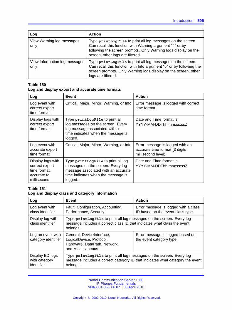
Introduction 595
Log Action
View Warning log messagesonly
Type printLogFile to print all log messages on the screen.Can recall this function with Warning argument "4" or byfollowing the screen prompts. Only Warning logs display on thescreen, other logs are filtered.
View Information log messagesonly
Type printLogFile to print all log messages on the screen.Can recall this function with Info argument "5" or by following thescreen prompts. Only Warning logs display on the screen, otherlogs are filtered.
Table 150Log and display export and accurate time formats
Log Event Action
Log event withcorrect exporttime format
Critical, Major, Minor, Warning, or Info Error message is logged with correcttime format.
Display logs withcorrect exporttime format
Type printLogFile to print alllog messages on the screen. Everylog message associated with atime indicates when the message islogged.
Date and Time format is:YYYY-MM-DDThh:mm:ss:ssZ
Log event withaccurate exporttime format
Critical, Major, Minor, Warning, or Info Error message is logged with anaccurate time format (3 digitsmillisecond level).
Display logs withcorrect exporttime format,accurate tomillisecond
Type printLogFile to print all logmessages on the screen. Every logmessage associated with an accuratetime indicates when the message islogged.
Date and Time format is:YYYY-MM-DDThh:mm:ss:ssZ
Table 151Log and display class and category information
Log Event Action
Log event withclass identifier
Fault, Configuration, Accounting,Performance, Security
Error message is logged with a classID based on the event class type.
Display log withclass identifier
Type printLogFile to print all log messages on the screen. Every logmessage includes a correct class ID that indicates what class the eventbelongs.
Log an event withcategory identifier
General, DeviceInterface,LogicalDevice, Protocol,Hardware, DataPath, Network,and Miscellaneous
Error message is logged based onthe event category type.
Display ED logswith categoryidentifier
Type printLogFile to print all log messages on the screen. Every logmessage includes a correct category ID that indicates what category the eventbelongs.
Nortel Communication Server 1000IP Phones Fundamentals
NN43001-368 06.07 30 April 2010
Copyright © 2003-2010 Nortel Networks. All Rights Reserved.
.
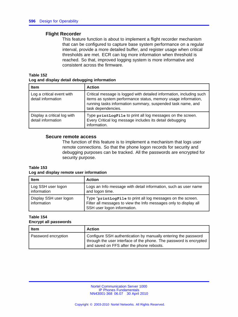
596 Design for Operability
Flight RecorderThis feature function is about to implement a flight recorder mechanismthat can be configured to capture base system performance on a regularinterval, provide a more detailed buffer, and register usage when criticalthresholds are met. ECR can log more information when threshold isreached. So that, improved logging system is more informative andconsistent across the firmware.
Table 152Log and display detail debugging information
Item Action
Log a critical event withdetail information
Critical message is logged with detailed information, including suchitems as system performance status, memory usage information,running tasks information summary, suspended task name, andtask dependencies.
Display a critical log withdetail information
Type printLogFile to print all log messages on the screen.Every Critical log message includes its detail debugginginformation.
Secure remote accessThe function of this feature is to implement a mechanism that logs userremote connections. So that the phone logon records for security anddebugging purposes can be tracked. All the passwords are encrypted forsecurity purpose.
Table 153Log and display remote user information
Item Action
Log SSH user logoninformation
Logs an Info message with detail information, such as user nameand logon time.
Display SSH user logoninformation
Type "printLogFile to print all log messages on the screen.Filter all messages to view the Info messages only to display allSSH user logon information.
Table 154Encrypt all passwords
Item Action
Password encryption Configure SSH authentication by manually entering the passwordthrough the user interface of the phone. The password is encryptedand saved on FFS after the phone reboots.
Nortel Communication Server 1000IP Phones Fundamentals
NN43001-368 06.07 30 April 2010
Copyright © 2003-2010 Nortel Networks. All Rights Reserved.
.
597.
AppendixLicensing
UNIStim 4.0 software provides a licensing framework, which delivers atoken-based licensing model.
Licensing is supported on the IP Phones 1100 Series.
The licensing framework consists of the following components:
• License server—for server-based solutions, the licensing authority ortoken resides on the network.
• License client—resides on the phone and makes requests to thelicense server for tokens.
• Nortel’s Keycode Retrieval System (KRS)—a key or license generator.
You can view licensing information in the Local Diagnostics menu. Formore information, see “IP Phone diagnostic utilities” (page 601)
Node locked licensingYou must download a valid license file to the phone in order to requesttokens from the licensing component. Features that integrate with licensingmust have a license file downloaded on the phone before tokens can berequested.
First, you must register your IP Phone if you have not registered yourphone before then you can generate license file and download it to thephone.
Procedure 123Generating a license file
Step Action
1 Go to http://bcmkeys01.ca.nortel.com/cgi-bin/bkeygen/ipcEntryShow.php.
Nortel Communication Server 1000IP Phones Fundamentals
NN43001-368 06.07 30 April 2010
Copyright © 2003-2010 Nortel Networks. All Rights Reserved.
.
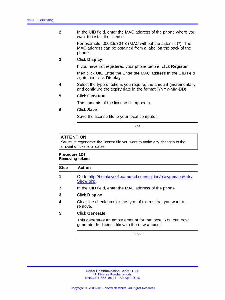
598 Licensing
2 In the UID field, enter the MAC address of the phone where youwant to install the license.
For example, 000f1fd304f8 (MAC without the asterisk (*). TheMAC address can be obtained from a label on the back of thephone.
3 Click Display.
If you have not registered your phone before, click Register
then click OK. Enter the Enter the MAC address in the UID fieldagain and click Display.
4 Select the type of tokens you require, the amount (incremental),and configure the expiry date in the format (YYYY-MM-DD).
5 Click Generate.
The contents of the license file appears.
6 Click Save.
Save the license file to your local computer.
--End--
ATTENTIONYou must regenerate the license file you want to make any changes to theamount of tokens or dates.
Procedure 124Removing tokens
Step Action
1 Go to http://bcmkeys01.ca.nortel.com/cgi-bin/bkeygen/ipcEntryShow.php.
2 In the UID field, enter the MAC address of the phone.
3 Click Display.
4 Clear the check box for the type of tokens that you want toremove.
5 Click Generate.
This generates an empty amount for that type. You can nowgenerate the license file with the new amount.
--End--
Nortel Communication Server 1000IP Phones Fundamentals
NN43001-368 06.07 30 April 2010
Copyright © 2003-2010 Nortel Networks. All Rights Reserved.
.
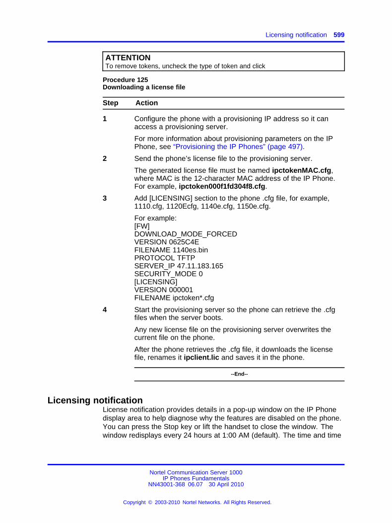
Licensing notification 599
ATTENTIONTo remove tokens, uncheck the type of token and click
Procedure 125Downloading a license file
Step Action
1 Configure the phone with a provisioning IP address so it canaccess a provisioning server.
For more information about provisioning parameters on the IPPhone, see “Provisioning the IP Phones” (page 497).
2 Send the phone’s license file to the provisioning server.
The generated license file must be named ipctokenMAC.cfg,where MAC is the 12-character MAC address of the IP Phone.For example, ipctoken000f1fd304f8.cfg.
3 Add [LICENSING] section to the phone .cfg file, for example,1110.cfg, 1120Ecfg, 1140e.cfg, 1150e.cfg.
For example:[FW]DOWNLOAD_MODE_FORCEDVERSION 0625C4EFILENAME 1140es.binPROTOCOL TFTPSERVER_IP 47.11.183.165SECURITY_MODE 0[LICENSING]VERSION 000001FILENAME ipctoken*.cfg
4 Start the provisioning server so the phone can retrieve the .cfgfiles when the server boots.
Any new license file on the provisioning server overwrites thecurrent file on the phone.
After the phone retrieves the .cfg file, it downloads the licensefile, renames it ipclient.lic and saves it in the phone.
--End--
Licensing notificationLicense notification provides details in a pop-up window on the IP Phonedisplay area to help diagnose why the features are disabled on the phone.You can press the Stop key or lift the handset to close the window. Thewindow redisplays every 24 hours at 1:00 AM (default). The time and time
Nortel Communication Server 1000IP Phones Fundamentals
NN43001-368 06.07 30 April 2010
Copyright © 2003-2010 Nortel Networks. All Rights Reserved.
.

600 Licensing
frame can be configured when you provision the phone. For informationabout configuring license notification, see “Provisioning the IP Phones”(page 497)
Nortel Communication Server 1000IP Phones Fundamentals
NN43001-368 06.07 30 April 2010
Copyright © 2003-2010 Nortel Networks. All Rights Reserved.
.
601.
AppendixIP Phone diagnostic utilities
ContentsThis section contains the following topics:
• “Introduction” (page 601)
• “Text-based diagnostic utilities” (page 601)
• “Graphic-based diagnostics utilities” (page 632)
IntroductionTwo methods of accessing IP Phone diagnostic utilities are text-based andgraphic-based. The IP Phone 2001, IP Phone 2002, IP Phone 2004, IPAudio Conference Phone 2033, IP Phone 1110, IP Phone 1210, IP Phone1220, and IP Phone 1230 use a text-based method to access diagnosticutilities. For information about diagnostic utilities for the IP Phone 2001,IP Phone 2002, IP Phone 2004, IP Audio Conference Phone 2033, IPPhone 1210, IP Phone 1220, and IP Phone 1230, see “Network diagnosticutilities” (page 602).
The IP Phone 2007, IP Phones 1120E/1140E/1150E/1165E use agraphic-based method to access Local Diagnostics through the LocalTools menu. For information about Local Diagnostics for the IP Phone2007, see “Diagnostics for the IP Phone 2007” (page 632). For informationabout Local Diagnostics for the IP Phones 1120E/1140E/1150E, see“Diagnostics for the IP Phones 1120E/1140E/1150E” (page 638).For information about Local Diagnostics for the IP Phone 1165E, see“Diagnostics for the IP Phone 1165E” (page 649) .
Text-based diagnostic utilitiesNetwork diagnostic utilities are accessible on IP Phone 2001, IP Phone2002, IP Phone 2004, IP Audio Conference Phone 2033, IP Phone 1110,IP Phone 1210, IP Phone 1220, and IP Phone 1230 to isolate voice qualityand network performance problems.
Nortel Communication Server 1000IP Phones Fundamentals
NN43001-368 06.07 30 April 2010
Copyright © 2003-2010 Nortel Networks. All Rights Reserved.
.
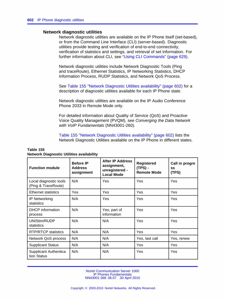
602 IP Phone diagnostic utilities
Network diagnostic utilitiesNetwork diagnostic utilities are available on the IP Phone itself (set-based),or from the Command Line Interface (CLI) (server-based). Diagnosticutilities provide testing and verification of end-to-end connectivity,verification of statistics and settings, and retrieval of set information. Forfurther information about CLI, see “Using CLI Commands” (page 629).
Network diagnostic utilities include Network Diagnostic Tools (Pingand traceRoute), Ethernet Statistics, IP Networking Statistics, DHCPInformation Process, RUDP Statistics, and Network QoS Process.
See Table 155 "Network Diagnostic Utilities availability" (page 602) for adescription of diagnostic utilities available for each IP Phone state.
Network diagnostic utilities are available on the IP Audio ConferencePhone 2033 in Remote Mode only.
For detailed information about Quality of Service (QoS) and ProactiveVoice Quality Management (PVQM), see Converging the Data Networkwith VoIP Fundamentals (NN43001-260).
Table 155 "Network Diagnostic Utilities availability" (page 602) lists theNetwork Diagnostic Utilities available on the IP Phone in different states.
Table 155Network Diagnostic Utilities availability
Function moduleBefore IPAddressassignment
After IP Addressassignment,unregistered -Local Mode
Registered(TPS) -Remote Mode
Call in progress(TPS)
Local diagnostic tools(Ping & TraceRoute)
N/A Yes Yes Yes
Ethernet statistics Yes Yes Yes Yes
IP Networkingstatistics
N/A Yes Yes Yes
DHCP informationprocess
N/A Yes, part ofinformation
Yes Yes
UNIStim/RUDPstatistics
N/A N/A Yes Yes
RTP/RTCP statistics N/A N/A Yes Yes
Network QoS process N/A N/A Yes, last call Yes, renew
Supplicant Status N/A N/A Yes Yes
Supplicant Authentication Status
N/A N/A Yes Yes
Nortel Communication Server 1000IP Phones Fundamentals
NN43001-368 06.07 30 April 2010
Copyright © 2003-2010 Nortel Networks. All Rights Reserved.
.
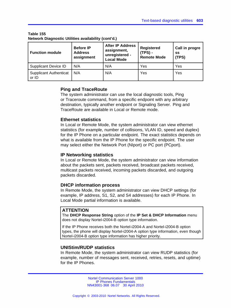
Text-based diagnostic utilities 603
Table 155Network Diagnostic Utilities availability (cont’d.)
Function moduleBefore IPAddressassignment
After IP Addressassignment,unregistered -Local Mode
Registered(TPS) -Remote Mode
Call in progress(TPS)
Supplicant Device ID N/A N/A Yes Yes
Supplicant Authenticator ID
N/A N/A Yes Yes
Ping and TraceRouteThe system administrator can use the local diagnostic tools, Pingor Traceroute command, from a specific endpoint with any arbitrarydestination, typically another endpoint or Signaling Server. Ping andTraceRoute are available in Local or Remote mode.
Ethernet statisticsIn Local or Remote Mode, the system administrator can view ethernetstatistics (for example, number of collisions, VLAN ID, speed and duplex)for the IP Phone on a particular endpoint. The exact statistics depends onwhat is available from the IP Phone for the specific endpoint. The usermay select either the Network Port (NIport) or PC port (PCport).
IP Networking statisticsIn Local or Remote Mode, the system administrator can view informationabout the packets sent, packets received, broadcast packets received,multicast packets received, incoming packets discarded, and outgoingpackets discarded.
DHCP information processIn Remote Mode, the system administrator can view DHCP settings (forexample, IP address, S1, S2, and S4 addresses) for each IP Phone. InLocal Mode partial information is available.
ATTENTIONThe DHCP Response String option of the IP Set & DHCP Information menudoes not display Nortel-i2004-B option type information.
If the IP Phone receives both the Nortel-i2004-A and Nortel-i2004-B optiontypes, the phone will display Nortel-i2004-A option type information, even thoughNortel-i2004-B option type information has higher priority.
UNIStim/RUDP statisticsIn Remote Mode, the system administrator can view RUDP statistics (forexample, number of messages sent, received, retries, resets, and uptime)for the IP Phones.
Nortel Communication Server 1000IP Phones Fundamentals
NN43001-368 06.07 30 April 2010
Copyright © 2003-2010 Nortel Networks. All Rights Reserved.
.
604 IP Phone diagnostic utilities
RTP/RTCP statisticsIn Remote Mode, the system administrator can view RTP/RTCP QoSmetrics (for example, packet loss and jitter) while a call is in progress.
Network QoS ProcessIn Remote Mode, the system administrator can view QoS statistics (forexample, packets sent, packets received, packet loss, jitter average andjitter maximum, and round trip delay).
Supplicant StatusThe system administrator uses this option to determine whether 802.1x isenabled or disabled 802.1x.
Authentication StateThe system administrator uses this option to determine whether the IPPhone is currently authenticated with the 802.1x system. The followingare valid state values
• LogOff
• Disconnected
• Connected
• Acquired
• Authorizing
• Held
• Authorized
• Dbl Authd
DeviceIDThe system administrator uses this option to check the user nameconfigured for the device that is sent to the switch for authentication. Thisshould match the corresponding entry in the RADIUS Server.
Authenticator IDThe system administrator uses this option to check the MAC address ofthe Authenticator (switch).
Accessing Network Diagnostic utilities from the IP PhoneLocal diagnostics are available from the IP Phone for either Local orRemote mode.
Diagnostics prompts are presented in English.
Nortel Communication Server 1000IP Phones Fundamentals
NN43001-368 06.07 30 April 2010
Copyright © 2003-2010 Nortel Networks. All Rights Reserved.
.
Text-based diagnostic utilities 605
Local ModeWhen the IP Phone is not registered with the signaling server, theNetwork Diagnostic Tools menu is available from the IP Phone in LocalMode (see Table 155 "Network Diagnostic Utilities availability" (page 602)).This menu is controlled by the firmware on the IP phone.
Use Procedure 126 “Accessing the Network Diagnostic Tools menu inLocal mode” (page 605) to access the Network Diagnostic Tools in Localmode.
Procedure 126Accessing the Network Diagnostic Tools menu in Local mode
Step Action
1 Double-press the Services key. The Local Main Menu, NetworkDiagnostic Tools, appears.
2 Press Cancel to quit, or use the Navigation keys to scrollthrough the menu and select one of the following
• Ping
• TraceRoute
• Ethernet Statistics
• IP Network Statistics
• IP Set & DHCP Information
--End--
Procedure 127Executing Ping
Step Action
1 Select Ping from the Network Diagnostic Tools submenu.
2 Press the IP soft key and enter the IP address to Ping.
Tip: Use the dialpad to enter the IP address. The * key is usedfor dots and the # key produces a space.
3 Press the Ping soft key. The results of the Ping appear on thedisplay.
4 Use the Navigation keys to browse the data. See Figure 90"PING data display page" (page 617).
Tip: Press the Ping soft key again to stop the pinging.
5 Press one of the following soft keys
Nortel Communication Server 1000IP Phones Fundamentals
NN43001-368 06.07 30 April 2010
Copyright © 2003-2010 Nortel Networks. All Rights Reserved.
.
606 IP Phone diagnostic utilities
• Reset — to clear the data
• Exit — to return to the Network Diagnostic Tools menu.
--End--
Procedure 128Executing TraceRoute
Step Action
1 Select TraceRoute from the Network Diagnostic Toolssubmenu.
2 Press the IP soft key and enter the IP address to trace.
3 Press the Tracert soft key. The results of the TraceRouteappear on the display.
4 Use the Navigation keys to browse the data. See Figure 91"TraceRoute data display screen" (page 617).
Tip: Press the Tracert soft key again to stop the route tracing.
5 Press one of the following soft keys
• Reset — to clear the data
• Exit — to return to the Network Diagnostic Tools menu
--End--
Procedure 129Accessing Ethernet Statistics
Step Action
1 Select Ethernet Statistics from the Network Diagnostic Toolsmenu. The Ethernet statistics appear on the display.
2 Use the Navigation keys to browse the data. See Figure 92"Ethernet Statistics data display page" (page 618).
3 Press one of the following soft keys
• Reset— to clear the data and reset the statistic counter
• Exit — to return to the Network Diagnostic Tools menu
--End--
Nortel Communication Server 1000IP Phones Fundamentals
NN43001-368 06.07 30 April 2010
Copyright © 2003-2010 Nortel Networks. All Rights Reserved.
.
Text-based diagnostic utilities 607
Procedure 130Accessing IP Network Statistics
Step Action
1 Select IP Network Statistics from the Network DiagnosticTools menu. The IP Network Statistics appear on the display.
2 Use the Navigation keys to browse the data. See Figure 93 "IPNetworking Statistics data display screen" (page 619).
3 Press one of the following soft keys
• Reset — to clear the data and reset the statistic counter
• Exit — to return to the Network Diagnostic Tools menu
--End--
Procedure 131Accessing IP Set and DHCP Information
Step Action
1 Select IP Set & DHCP Information from the NetworkDiagnostic Tools menu. The IP Set and DHCP informationappears on the display.
2 Use the Navigation keys to browse the data. See Figure 94"DHCP information data display page" (page 620).
In Local Mode, Exit is the only soft-key available in thissubmenu.
--End--
Remote ModeWhen the IP Phone is registered to the signaling server, diagnostics areavailable through the Telephone Options menu in Remote Mode. Thismenu is controlled by the TPS.
Diagnostics are available on the IP Audio Conference Phone 2033 inRemote Mode only.
When the user selects Diagnostics from the Telephone Options menu,if an IP Phone Installer Password is enabled in the Signaling Server, theDiagnostics menu is locked and the message "Access denied" displayson the IP Phone display.
Nortel Communication Server 1000IP Phones Fundamentals
NN43001-368 06.07 30 April 2010
Copyright © 2003-2010 Nortel Networks. All Rights Reserved.
.
608 IP Phone diagnostic utilities
Use Procedure 132 “Accessing the Diagnostics submenu in RemoteMode” (page 608) to access the Diagnostics submenu in Remote Mode:
Procedure 132Accessing the Diagnostics submenu in Remote Mode
Step Action
1 Press the Services key.
2 Select Telephone Options.
3 Select Diagnostics.
4 Do one of the following:
• Press the Cancel soft key to quit the Diagnostics submenuand return to the Telephone Options menu.
• Use the Navigation keys to scroll through the Diagnosticssubmenu.
• Press Select to select one of the diagnostics.
The following items are available on the Diagnostics submenu
• Diag Tools (Diagnostic Tools: Ping and TraceRoute)
• EtherStats (Ethernet Statistics)
• IP Stats (IP Statistics)
• RUDP Stats (RUDP Statistics)
• QoS Stats (Quality of Service Statistics)
--End--
Procedure 133Accessing Diagnostic Tools in Remote mode
Step Action
1 Select Diagnostic Tools from the Diagnostics submenu.
2 Do one of the following
• Press the Cancel soft key to return to the Diagnosticssubmenu.
• Use the Navigation keys to scroll to the Diagnostic Toolsselection.
3 Press the Select soft key to choose one of the following
Nortel Communication Server 1000IP Phones Fundamentals
NN43001-368 06.07 30 April 2010
Copyright © 2003-2010 Nortel Networks. All Rights Reserved.
.
Text-based diagnostic utilities 609
• Ping (see Figure 97 "Ping data display page" (page 623))
• TraceRoute (see Figure 98 "Tracert data display screen"(page 623))
--End--
Ping
The following items are available on the Ping submenu in Remote mode
• IP Addr
• Nr of Pings
• Ping!
• Last ping
Procedure 134Entering an IP address
Step Action
1 Scroll through the Ping submenu to the IP Addr menu item. AnIP address appears if previously entered. Example 47.249.48.20.
2 Press the Select soft key.
3 Use the Navigation keys to scroll to the destination IP address.
• If the destination IP address is in the list, press the Selectsoft key to select the IP address. Press the Select soft keyagain to return to the Ping submenu.
• If the destination IP address is not in the list, continuescrolling through the available IP address list until the IPaddress 0.0.0.0 appears. Press the Select soft key.Tip: To edit the IP address, use the dialpad and the Deletesoft key and the Cancel soft key. Use the * key for dots.
4 Press the Select soft key to save the new IP address or pressthe Cancel soft key to return to the Ping submenu.
--End--
Nortel Communication Server 1000IP Phones Fundamentals
NN43001-368 06.07 30 April 2010
Copyright © 2003-2010 Nortel Networks. All Rights Reserved.
.
610 IP Phone diagnostic utilities
Procedure 135Changing the number of Pings
Step Action
1 From the Ping submenu, use the Navigation keys to scroll tothe Nr of Pings submenu item.
2 Press the Select soft key.
Tip: Use the Delete and Clear soft keys to enter the number ofpings.
3 Do one of the following
• Press the Select soft key to accept the change and return tothe Ping submenu.
• Press the Cancel soft key to return to the Ping submenu.
--End--
Procedure 136Pinging an IP address
Step Action
1 From the Ping submenu, use the Navigation keys to scroll tothe Ping! submenu item.
2 Press the Select soft key. Pinging starts.
Tip: Press the Stop soft key to stop pinging.
3 Press the OK soft key to return to the Ping submenu.
--End--
Procedure 137Reviewing the results of the Ping
Step Action
1 Use the Navigation keys to scroll to the Last Ping submenuitem.
2 Press the Select soft key.
3 Use the Navigation keys to scroll through the results.
4 Press the Cancel soft key to return to the Ping submenu.
--End--
Nortel Communication Server 1000IP Phones Fundamentals
NN43001-368 06.07 30 April 2010
Copyright © 2003-2010 Nortel Networks. All Rights Reserved.
.
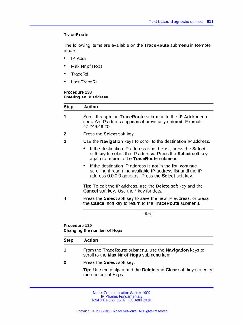
Text-based diagnostic utilities 611
TraceRoute
The following items are available on the TraceRoute submenu in Remotemode
• IP Addr
• Max Nr of Hops
• TraceRt!
• Last TraceRt
Procedure 138Entering an IP address
Step Action
1 Scroll through the TraceRoute submenu to the IP Addr menuitem. An IP address appears if previously entered. Example47.249.48.20.
2 Press the Select soft key.
3 Use the Navigation keys to scroll to the destination IP address.
• If the destination IP address is in the list, press the Selectsoft key to select the IP address. Press the Select soft keyagain to return to the TraceRoute submenu.
• If the destination IP address is not in the list, continuescrolling through the available IP address list until the IPaddress 0.0.0.0 appears. Press the Select soft key.
Tip: To edit the IP address, use the Delete soft key and theCancel soft key. Use the * key for dots.
4 Press the Select soft key to save the new IP address, or pressthe Cancel soft key to return to the TraceRoute submenu.
--End--
Procedure 139Changing the number of Hops
Step Action
1 From the TraceRoute submenu, use the Navigation keys toscroll to the Max Nr of Hops submenu item.
2 Press the Select soft key.
Tip: Use the dialpad and the Delete and Clear soft keys to enterthe number of Hops.
Nortel Communication Server 1000IP Phones Fundamentals
NN43001-368 06.07 30 April 2010
Copyright © 2003-2010 Nortel Networks. All Rights Reserved.
.
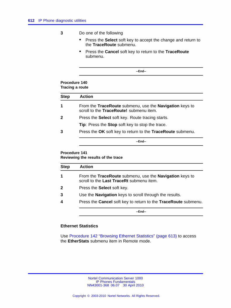
612 IP Phone diagnostic utilities
3 Do one of the following
• Press the Select soft key to accept the change and return tothe TraceRoute submenu.
• Press the Cancel soft key to return to the TraceRoutesubmenu.
--End--
Procedure 140Tracing a route
Step Action
1 From the TraceRoute submenu, use the Navigation keys toscroll to the TraceRoute! submenu item.
2 Press the Select soft key. Route tracing starts.
Tip: Press the Stop soft key to stop the trace.
3 Press the OK soft key to return to the TraceRoute submenu.
--End--
Procedure 141Reviewing the results of the trace
Step Action
1 From the TraceRoute submenu, use the Navigation keys toscroll to the Last TraceRt submenu item.
2 Press the Select soft key.
3 Use the Navigation keys to scroll through the results.
4 Press the Cancel soft key to return to the TraceRoute submenu.
--End--
Ethernet Statistics
Use Procedure 142 “Browsing Ethernet Statistics” (page 613) to accessthe EtherStats submenu item in Remote mode.
Nortel Communication Server 1000IP Phones Fundamentals
NN43001-368 06.07 30 April 2010
Copyright © 2003-2010 Nortel Networks. All Rights Reserved.
.
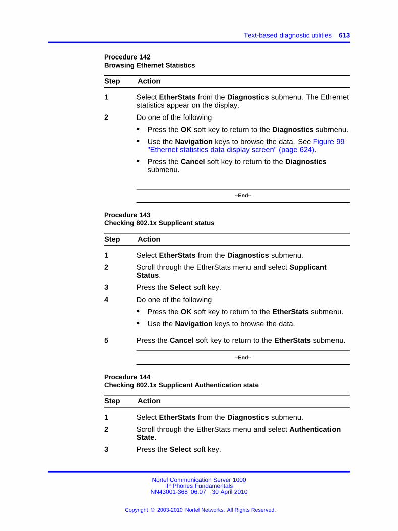
Text-based diagnostic utilities 613
Procedure 142Browsing Ethernet Statistics
Step Action
1 Select EtherStats from the Diagnostics submenu. The Ethernetstatistics appear on the display.
2 Do one of the following
• Press the OK soft key to return to the Diagnostics submenu.
• Use the Navigation keys to browse the data. See Figure 99"Ethernet statistics data display screen" (page 624).
• Press the Cancel soft key to return to the Diagnosticssubmenu.
--End--
Procedure 143Checking 802.1x Supplicant status
Step Action
1 Select EtherStats from the Diagnostics submenu.
2 Scroll through the EtherStats menu and select SupplicantStatus.
3 Press the Select soft key.
4 Do one of the following
• Press the OK soft key to return to the EtherStats submenu.
• Use the Navigation keys to browse the data.
5 Press the Cancel soft key to return to the EtherStats submenu.
--End--
Procedure 144Checking 802.1x Supplicant Authentication state
Step Action
1 Select EtherStats from the Diagnostics submenu.
2 Scroll through the EtherStats menu and select AuthenticationState.
3 Press the Select soft key.
Nortel Communication Server 1000IP Phones Fundamentals
NN43001-368 06.07 30 April 2010
Copyright © 2003-2010 Nortel Networks. All Rights Reserved.
.
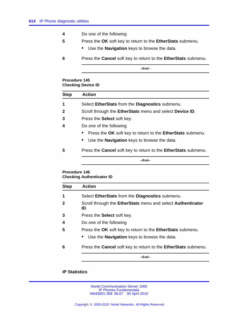
614 IP Phone diagnostic utilities
4 Do one of the following
5 Press the OK soft key to return to the EtherStats submenu.
• Use the Navigation keys to browse the data.
6 Press the Cancel soft key to return to the EtherStats submenu.
--End--
Procedure 145Checking Device ID
Step Action
1 Select EtherStats from the Diagnostics submenu.
2 Scroll through the EtherStats menu and select Device ID.
3 Press the Select soft key.
4 Do one of the following
• Press the OK soft key to return to the EtherStats submenu.
• Use the Navigation keys to browse the data.
5 Press the Cancel soft key to return to the EtherStats submenu.
--End--
Procedure 146Checking Authenticator ID
Step Action
1 Select EtherStats from the Diagnostics submenu.
2 Scroll through the EtherStats menu and select AuthenticatorID.
3 Press the Select soft key.
4 Do one of the following
5 Press the OK soft key to return to the EtherStats submenu.
• Use the Navigation keys to browse the data.
6 Press the Cancel soft key to return to the EtherStats submenu.
--End--
IP Statistics
Nortel Communication Server 1000IP Phones Fundamentals
NN43001-368 06.07 30 April 2010
Copyright © 2003-2010 Nortel Networks. All Rights Reserved.
.
Text-based diagnostic utilities 615
Use Procedure 147 “Browsing IP Statistics” (page 615) to access the IPStats submenu item in Remote mode.
Procedure 147Browsing IP Statistics
Step Action
1 Select IP Stats from the Diagnostics submenu. The IPStatistics appear on the display.
2 Do one of the following
• Press the OK soft key to return to the Diagnostics submenu.
• Use the Navigation keys to scroll through the data displayresults. See Figure 100 "IP Networking statistics data displayscreen" (page 625).
• Press the Cancel soft key to return to the Diagnosticssubmenu.
--End--
RUDP Statistics
Use Procedure 148 “Browsing RUDP Statistics” (page 615) to access theRUDP Stats submenu item in Remote mode.
Procedure 148Browsing RUDP Statistics
Step Action
1 Select RUDP Stats from the Diagnostics submenu. The RUDPstatistics appear on the display.
2 Do one of the following
• Press the OK soft key to return to the Diagnostics submenu.
• Use the Navigation keys to scroll through the data displayresults. See Figure 101 "RUDP statistics data display page"(page 625).
• Press the Cancel soft key to return to the Diagnosticssubmenu.
--End--
Nortel Communication Server 1000IP Phones Fundamentals
NN43001-368 06.07 30 April 2010
Copyright © 2003-2010 Nortel Networks. All Rights Reserved.
.
616 IP Phone diagnostic utilities
QoS Statistics
Use Procedure 149 “Browsing Quality of Service Statistics” (page 616) toaccess the QoS Stats submenu item in Remote mode.
Procedure 149Browsing Quality of Service Statistics
Step Action
1 Select QoS Stats from the Diagnostics submenu. The Qualityof Service statistics appear on the display.
2 Do one of the following
• Press the OK soft key to return to the Diagnostics submenu.
• Use the Navigation keys to scroll through the results. SeeFigure 102 "QoS statistics data display page" (page 626).
• Press the Cancel soft key to return to the Diagnosticssubmenu.
The IP Phone display returns to an idle state after 5 minutes ifthe user does not interact with menu items.
--End--
Network Diagnostic Utilities data display pagesData from the diagnostic utilities is displayed on the IP Phone display. Oneline of data at a time is displayed on IP Phone 2001, IP Phone 2002, IPAudio Conference Phone 2033, IP Phone 1210, IP Phone 1220 and 3 linesof data are displayed at a time on IP Phone 2004, and IP Phone 1230.Each line of data is up to 24 characters in length. Use the Navigationkeys to scroll through the lines of data.
Local Mode data display pagesThe following figures illustrate the Network Diagnostic Utilities data displaypages in Local Mode.
Ping
Figure 90 "PING data display page" (page 617) illustrates the datadisplayed from the Ping diagnostic tool.
Nortel Communication Server 1000IP Phones Fundamentals
NN43001-368 06.07 30 April 2010
Copyright © 2003-2010 Nortel Networks. All Rights Reserved.
.
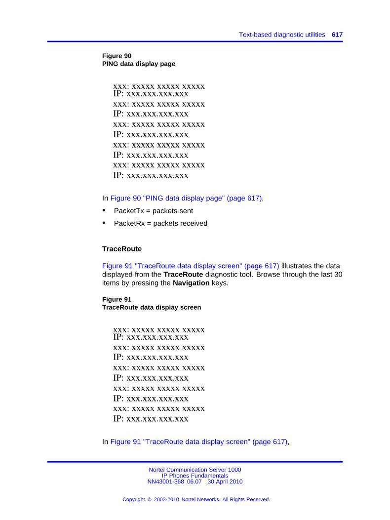
Text-based diagnostic utilities 617
Figure 90PING data display page
In Figure 90 "PING data display page" (page 617),
• PacketTx = packets sent
• PacketRx = packets received
TraceRoute
Figure 91 "TraceRoute data display screen" (page 617) illustrates the datadisplayed from the TraceRoute diagnostic tool. Browse through the last 30items by pressing the Navigation keys.
Figure 91TraceRoute data display screen
In Figure 91 "TraceRoute data display screen" (page 617),
Nortel Communication Server 1000IP Phones Fundamentals
NN43001-368 06.07 30 April 2010
Copyright © 2003-2010 Nortel Networks. All Rights Reserved.
.
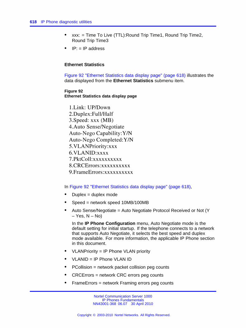
618 IP Phone diagnostic utilities
• xxx: = Time To Live (TTL):Round Trip Time1, Round Trip Time2,Round Trip Time3
• IP: = IP address
Ethernet Statistics
Figure 92 "Ethernet Statistics data display page" (page 618) illustrates thedata displayed from the Ethernet Statistics submenu item.
Figure 92Ethernet Statistics data display page
In Figure 92 "Ethernet Statistics data display page" (page 618),
• Duplex = duplex mode
• Speed = network speed 10MB/100MB
• Auto Sense/Negotiate = Auto Negotiate Protocol Received or Not (Y– Yes, N – No)
In the IP Phone Configuration menu, Auto Negotiate mode is thedefault setting for initial startup. If the telephone connects to a networkthat supports Auto Negotiate, it selects the best speed and duplexmode available. For more information, the applicable IP Phone sectionin this document.
• VLANPriority = IP Phone VLAN priority
• VLANID = IP Phone VLAN ID
• PCollision = network packet collision peg counts
• CRCErrors = network CRC errors peg counts
• FrameErrors = network Framing errors peg counts
Nortel Communication Server 1000IP Phones Fundamentals
NN43001-368 06.07 30 April 2010
Copyright © 2003-2010 Nortel Networks. All Rights Reserved.
.
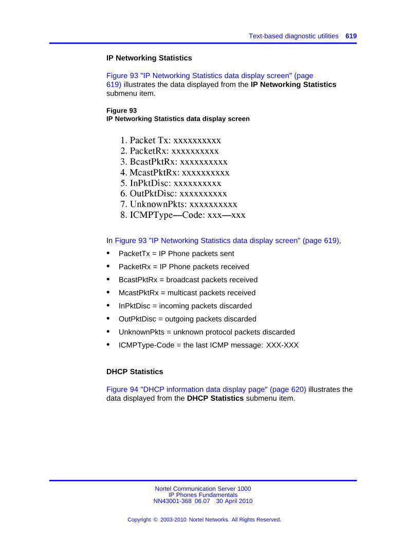
Text-based diagnostic utilities 619
IP Networking Statistics
Figure 93 "IP Networking Statistics data display screen" (page619) illustrates the data displayed from the IP Networking Statisticssubmenu item.
Figure 93IP Networking Statistics data display screen
In Figure 93 "IP Networking Statistics data display screen" (page 619),
• PacketTx = IP Phone packets sent
• PacketRx = IP Phone packets received
• BcastPktRx = broadcast packets received
• McastPktRx = multicast packets received
• InPktDisc = incoming packets discarded
• OutPktDisc = outgoing packets discarded
• UnknownPkts = unknown protocol packets discarded
• ICMPType-Code = the last ICMP message: XXX-XXX
DHCP Statistics
Figure 94 "DHCP information data display page" (page 620) illustrates thedata displayed from the DHCP Statistics submenu item.
Nortel Communication Server 1000IP Phones Fundamentals
NN43001-368 06.07 30 April 2010
Copyright © 2003-2010 Nortel Networks. All Rights Reserved.
.
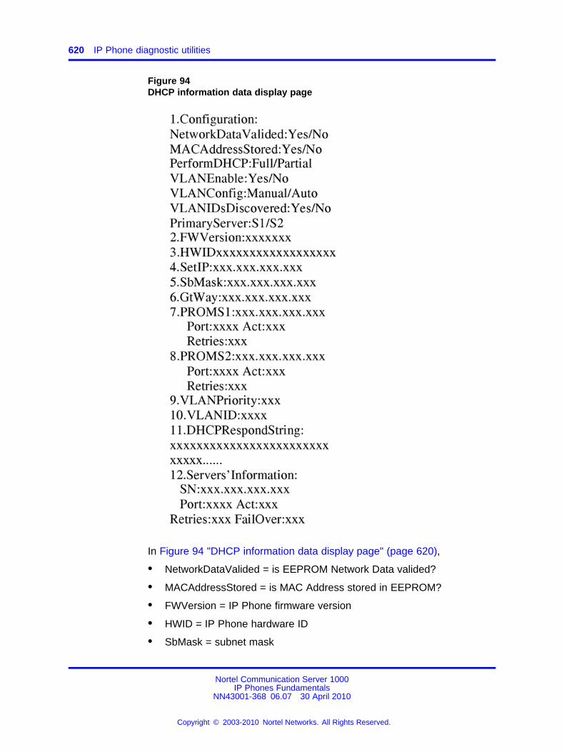
620 IP Phone diagnostic utilities
Figure 94DHCP information data display page
In Figure 94 "DHCP information data display page" (page 620),
• NetworkDataValided = is EEPROM Network Data valided?
• MACAddressStored = is MAC Address stored in EEPROM?
• FWVersion = IP Phone firmware version
• HWID = IP Phone hardware ID
• SbMask = subnet mask
Nortel Communication Server 1000IP Phones Fundamentals
NN43001-368 06.07 30 April 2010
Copyright © 2003-2010 Nortel Networks. All Rights Reserved.
.
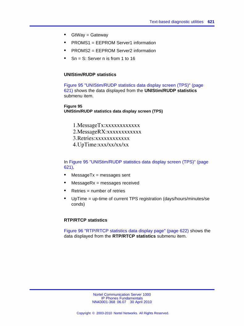
Text-based diagnostic utilities 621
• GtWay = Gateway
• PROMS1 = EEPROM Server1 information
• PROMS2 = EEPROM Server2 information
• Sn = S: Server n is from 1 to 16
UNIStim/RUDP statistics
Figure 95 "UNIStim/RUDP statistics data display screen (TPS)" (page621) shows the data displayed from the UNIStim/RUDP statisticssubmenu item.
Figure 95UNIStim/RUDP statistics data display screen (TPS)
In Figure 95 "UNIStim/RUDP statistics data display screen (TPS)" (page621),
• MessageTx = messages sent
• MessageRx = messages received
• Retries = number of retries
• UpTime = up-time of current TPS registration (days/hours/minutes/seconds)
RTP/RTCP statistics
Figure 96 "RTP/RTCP statistics data display page" (page 622) shows thedata displayed from the RTP/RTCP statistics submenu item.
Nortel Communication Server 1000IP Phones Fundamentals
NN43001-368 06.07 30 April 2010
Copyright © 2003-2010 Nortel Networks. All Rights Reserved.
.
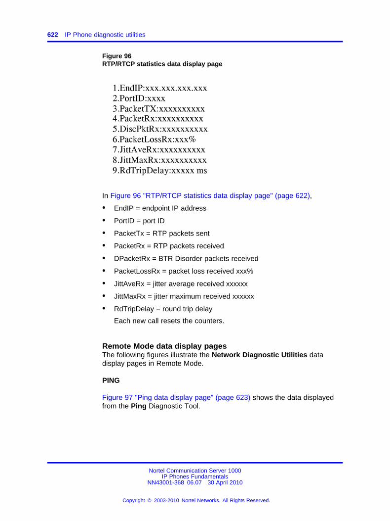
622 IP Phone diagnostic utilities
Figure 96RTP/RTCP statistics data display page
In Figure 96 "RTP/RTCP statistics data display page" (page 622),
• EndIP = endpoint IP address
• PortID = port ID
• PacketTx = RTP packets sent
• PacketRx = RTP packets received
• DPacketRx = BTR Disorder packets received
• PacketLossRx = packet loss received xxx%
• JittAveRx = jitter average received xxxxxx
• JittMaxRx = jitter maximum received xxxxxx
• RdTripDelay = round trip delay
Each new call resets the counters.
Remote Mode data display pagesThe following figures illustrate the Network Diagnostic Utilities datadisplay pages in Remote Mode.
PING
Figure 97 "Ping data display page" (page 623) shows the data displayedfrom the Ping Diagnostic Tool.
Nortel Communication Server 1000IP Phones Fundamentals
NN43001-368 06.07 30 April 2010
Copyright © 2003-2010 Nortel Networks. All Rights Reserved.
.
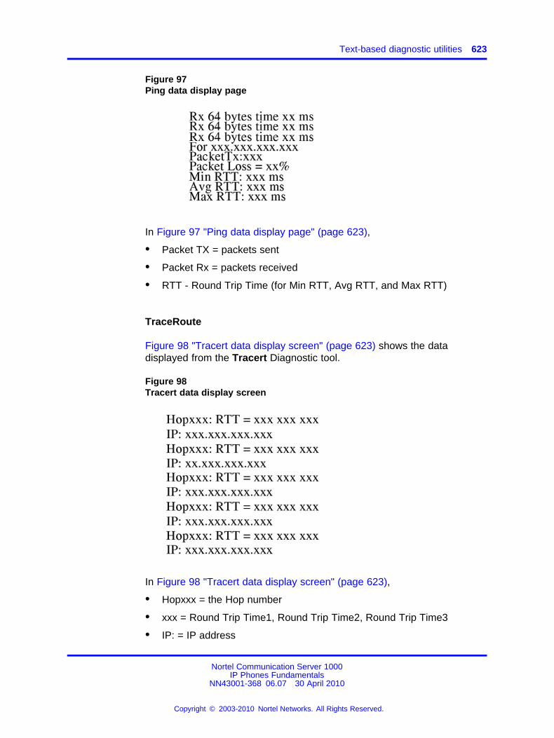
Text-based diagnostic utilities 623
Figure 97Ping data display page
In Figure 97 "Ping data display page" (page 623),
• Packet TX = packets sent
• Packet Rx = packets received
• RTT - Round Trip Time (for Min RTT, Avg RTT, and Max RTT)
TraceRoute
Figure 98 "Tracert data display screen" (page 623) shows the datadisplayed from the Tracert Diagnostic tool.
Figure 98Tracert data display screen
In Figure 98 "Tracert data display screen" (page 623),
• Hopxxx = the Hop number
• xxx = Round Trip Time1, Round Trip Time2, Round Trip Time3
• IP: = IP address
Nortel Communication Server 1000IP Phones Fundamentals
NN43001-368 06.07 30 April 2010
Copyright © 2003-2010 Nortel Networks. All Rights Reserved.
.
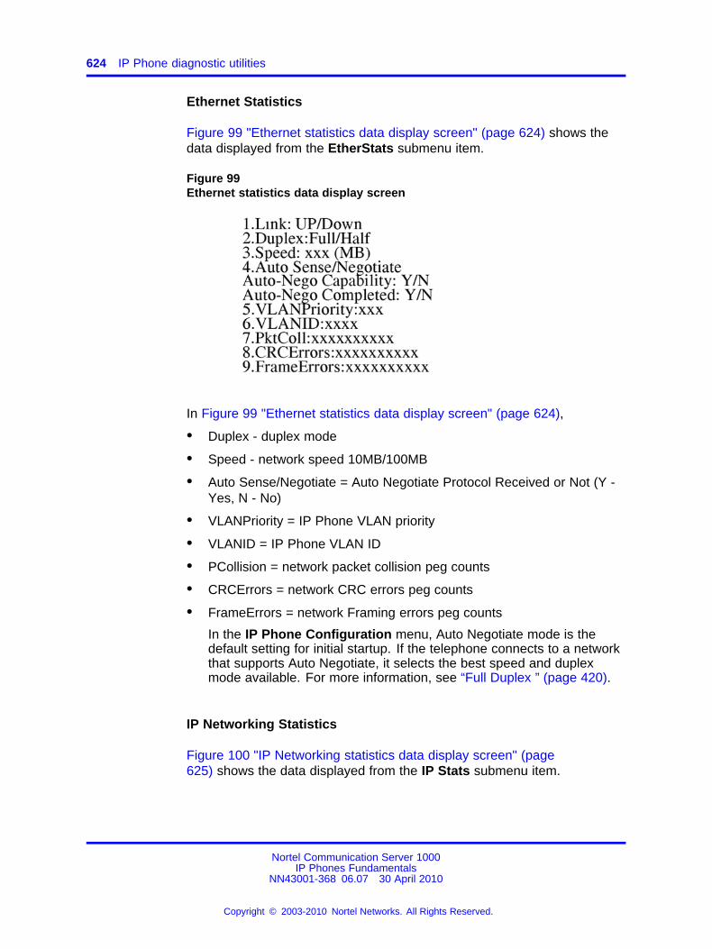
624 IP Phone diagnostic utilities
Ethernet Statistics
Figure 99 "Ethernet statistics data display screen" (page 624) shows thedata displayed from the EtherStats submenu item.
Figure 99Ethernet statistics data display screen
In Figure 99 "Ethernet statistics data display screen" (page 624),
• Duplex - duplex mode
• Speed - network speed 10MB/100MB
• Auto Sense/Negotiate = Auto Negotiate Protocol Received or Not (Y -Yes, N - No)
• VLANPriority = IP Phone VLAN priority
• VLANID = IP Phone VLAN ID
• PCollision = network packet collision peg counts
• CRCErrors = network CRC errors peg counts
• FrameErrors = network Framing errors peg counts
In the IP Phone Configuration menu, Auto Negotiate mode is thedefault setting for initial startup. If the telephone connects to a networkthat supports Auto Negotiate, it selects the best speed and duplexmode available. For more information, see “Full Duplex ” (page 420).
IP Networking Statistics
Figure 100 "IP Networking statistics data display screen" (page625) shows the data displayed from the IP Stats submenu item.
Nortel Communication Server 1000IP Phones Fundamentals
NN43001-368 06.07 30 April 2010
Copyright © 2003-2010 Nortel Networks. All Rights Reserved.
.
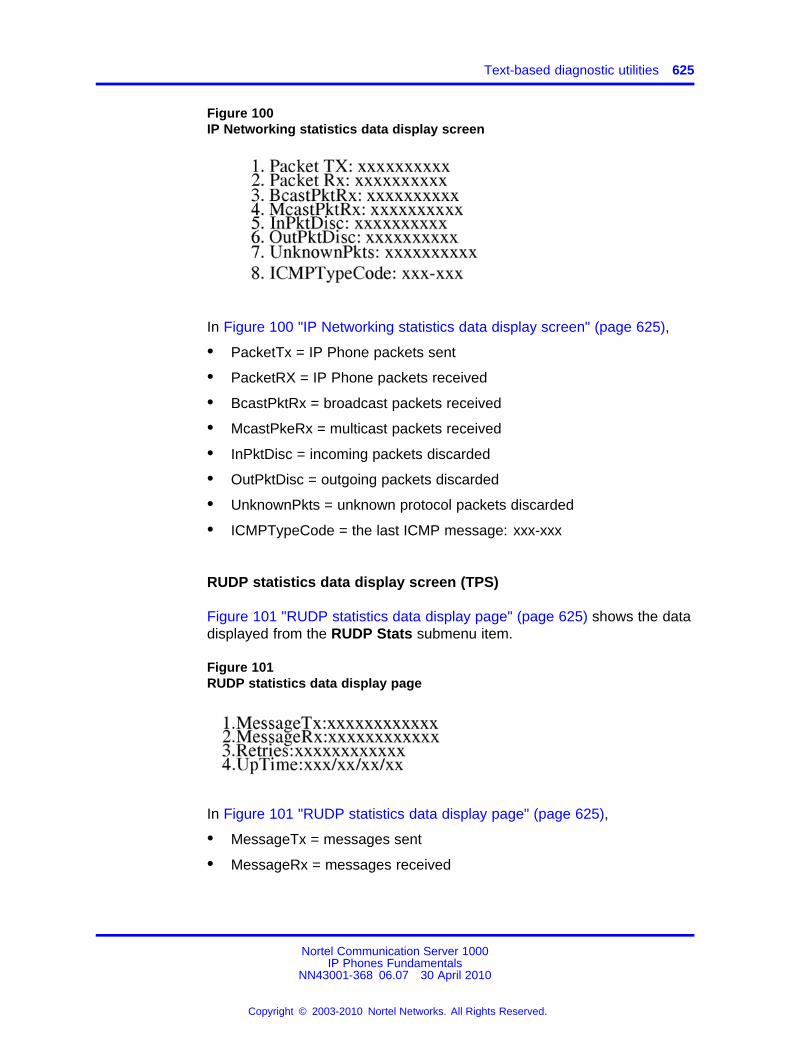
Text-based diagnostic utilities 625
Figure 100IP Networking statistics data display screen
In Figure 100 "IP Networking statistics data display screen" (page 625),
• PacketTx = IP Phone packets sent
• PacketRX = IP Phone packets received
• BcastPktRx = broadcast packets received
• McastPkeRx = multicast packets received
• InPktDisc = incoming packets discarded
• OutPktDisc = outgoing packets discarded
• UnknownPkts = unknown protocol packets discarded
• ICMPTypeCode = the last ICMP message: xxx-xxx
RUDP statistics data display screen (TPS)
Figure 101 "RUDP statistics data display page" (page 625) shows the datadisplayed from the RUDP Stats submenu item.
Figure 101RUDP statistics data display page
In Figure 101 "RUDP statistics data display page" (page 625),
• MessageTx = messages sent
• MessageRx = messages received
Nortel Communication Server 1000IP Phones Fundamentals
NN43001-368 06.07 30 April 2010
Copyright © 2003-2010 Nortel Networks. All Rights Reserved.
.
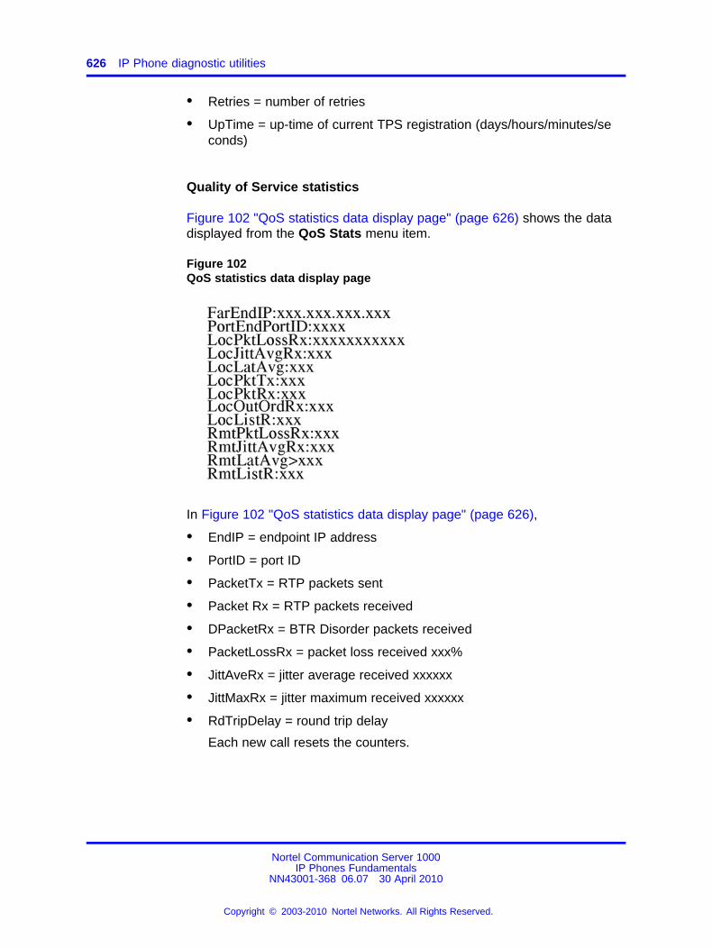
626 IP Phone diagnostic utilities
• Retries = number of retries
• UpTime = up-time of current TPS registration (days/hours/minutes/seconds)
Quality of Service statistics
Figure 102 "QoS statistics data display page" (page 626) shows the datadisplayed from the QoS Stats menu item.
Figure 102QoS statistics data display page
In Figure 102 "QoS statistics data display page" (page 626),
• EndIP = endpoint IP address
• PortID = port ID
• PacketTx = RTP packets sent
• Packet Rx = RTP packets received
• DPacketRx = BTR Disorder packets received
• PacketLossRx = packet loss received xxx%
• JittAveRx = jitter average received xxxxxx
• JittMaxRx = jitter maximum received xxxxxx
• RdTripDelay = round trip delay
Each new call resets the counters.
Nortel Communication Server 1000IP Phones Fundamentals
NN43001-368 06.07 30 April 2010
Copyright © 2003-2010 Nortel Networks. All Rights Reserved.
.
Text-based diagnostic utilities 627
Network Address Translation TraversalThis section describes the Network Address Translation (NAT) Traversalfeature as it effects IP Phones. NAT Traversal is required to permit IPPhones working behind a NAT box to connect and maintain signaling andmedia paths.
NAT Traversal is applicable to all UNIStim IP Phone clients and isone-ended. That is, it does not require the other end of a call to supportany special protocol, and it is interoperable with any other mediatermination.
In this document NAT refers to both IP port address mapping and IPaddress mapping (also known as NAPT). A NAT is used with or without aVirtual Private Network (VPN).
The NAT Traversal feature supports only IP clients behind cone NATtypes. Three types of cone NAT are: full cone, restricted cone, and portrestricted cone. NAT traversal is not compatible with symmetric NATs. Ifthe IP Phone is behind a Symmetric NAT, the LTPS unregisters the phonefrom the call server (while remaining registered on the LTPS), and displaysthe following message on the IP Phone display: Error! Symmetric NAT.
For detailed information about the NAT Traversal feature, see SignalingServer IP Line Applications Fundamentals (NN43001-125).
For information about accessing NAT information from an IP Phone, see“Set IP Information” (page 628).
ATTENTIONNortel recommends partial DHCP configuration for IP Phones residing behinda NAT router unless the NAT router supports special configuration of theDHCP server. For more information, see Signaling Server IP Line ApplicationsFundamentals (NN43001-125).
General InformationThe General Information menu displays information about the IP Phone.To access the General Information menu, press Services > TelephoneOptions > Set Information > General Information.
The General Information menu displays the following information aboutthe IP Phone
• Hardware ID
• Terminal Type
• Release Number
• Manufacturer Code
Nortel Communication Server 1000IP Phones Fundamentals
NN43001-368 06.07 30 April 2010
Copyright © 2003-2010 Nortel Networks. All Rights Reserved.
.
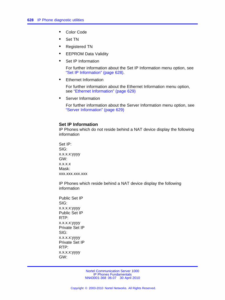
628 IP Phone diagnostic utilities
• Color Code
• Set TN
• Registered TN
• EEPROM Data Validity
• Set IP Information
For further information about the Set IP Information menu option, see“Set IP Information” (page 628).
• Ethernet Information
For further information about the Ethernet Information menu option,see “Ethernet Information” (page 629)
• Server Information
For further information about the Server Information menu option, see“Server Information” (page 629)
Set IP InformationIP Phones which do not reside behind a NAT device display the followinginformation
Set IP:SIG:x.x.x.x:yyyyGW:x.x.x.xMask:xxx.xxx.xxx.xxx
IP Phones which reside behind a NAT device display the followinginformation
Public Set IPSIG:x.x.x.x:yyyyPublic Set IPRTP:x.x.x.x:yyyyPrivate Set IPSIG:x.x.x.x:yyyyPrivate Set IPRTP:x.x.x.x:yyyyGW:
Nortel Communication Server 1000IP Phones Fundamentals
NN43001-368 06.07 30 April 2010
Copyright © 2003-2010 Nortel Networks. All Rights Reserved.
.
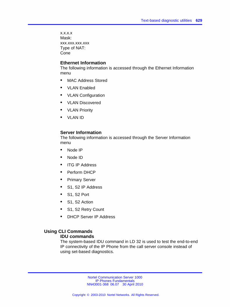
Text-based diagnostic utilities 629
x.x.x.xMask:xxx.xxx.xxx.xxxType of NAT:Cone
Ethernet InformationThe following information is accessed through the Ethernet Informationmenu
• MAC Address Stored
• VLAN Enabled
• VLAN Configuration
• VLAN Discovered
• VLAN Priority
• VLAN ID
Server InformationThe following information is accessed through the Server Informationmenu
• Node IP
• Node ID
• ITG IP Address
• Perform DHCP
• Primary Server
• S1, S2 IP Address
• S1, S2 Port
• S1, S2 Action
• S1, S2 Retry Count
• DHCP Server IP Address
Using CLI CommandsIDU commandsThe system-based IDU command in LD 32 is used to test the end-to-endIP connectivity of the IP Phone from the call server console instead ofusing set-based diagnostics.
Nortel Communication Server 1000IP Phones Fundamentals
NN43001-368 06.07 30 April 2010
Copyright © 2003-2010 Nortel Networks. All Rights Reserved.
.
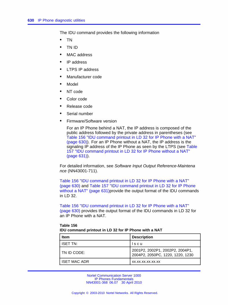
630 IP Phone diagnostic utilities
The IDU command provides the following information
• TN
• TN ID
• MAC address
• IP address
• LTPS IP address
• Manufacturer code
• Model
• NT code
• Color code
• Release code
• Serial number
• Firmware/Software version
For an IP Phone behind a NAT, the IP address is composed of thepublic address followed by the private address in parentheses (seeTable 156 "IDU command printout in LD 32 for IP Phone with a NAT"(page 630)). For an IP Phone without a NAT, the IP address is thesignaling IP address of the IP Phone as seen by the LTPS (see Table157 "IDU command printout in LD 32 for IP Phone without a NAT"(page 631)).
For detailed information, see Software Input Output Reference-Maintenance (NN43001-711).
Table 156 "IDU command printout in LD 32 for IP Phone with a NAT"(page 630) and Table 157 "IDU command printout in LD 32 for IP Phonewithout a NAT" (page 631)provide the output format of the IDU commandsin LD 32.
Table 156 "IDU command printout in LD 32 for IP Phone with a NAT"(page 630) provides the output format of the IDU commands in LD 32 foran IP Phone with a NAT.
Table 156IDU command printout in LD 32 for IP Phone with a NAT
Item Description
ISET TN: l s c u
TN ID CODE:2001P2, 2002P1, 2002P2, 2004P1,2004P2, 2050PC, 1220, 1220, 1230
ISET MAC ADR xx.xx.xx.xx.xx.xx
Nortel Communication Server 1000IP Phones Fundamentals
NN43001-368 06.07 30 April 2010
Copyright © 2003-2010 Nortel Networks. All Rights Reserved.
.
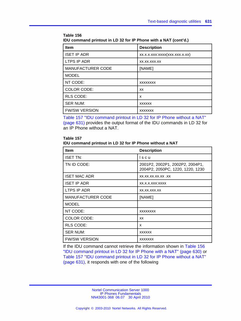
Text-based diagnostic utilities 631
Table 156IDU command printout in LD 32 for IP Phone with a NAT (cont’d.)
Item Description
ISET IP ADR xx.x.x.xxx:xxxx(xxx.xxx.x.xx)
LTPS IP ADR xx.xx.xxx.xx
MANUFACTURER CODE [NAME]
MODEL
NT CODE: xxxxxxxx
COLOR CODE: xx
RLS CODE: x
SER NUM: xxxxxx
FW/SW VERSION xxxxxxx
Table 157 "IDU command printout in LD 32 for IP Phone without a NAT"(page 631) provides the output format of the IDU commands in LD 32 foran IP Phone without a NAT.
Table 157IDU command printout in LD 32 for IP Phone without a NAT
Item Description
ISET TN: l s c u
TN ID CODE: 2001P2, 2002P1, 2002P2, 2004P1,2004P2, 2050PC, 1220, 1220, 1230
ISET MAC ADR xx.xx.xx.xx.xx .xx
ISET IP ADR xx.x.x.xxx:xxxx
LTPS IP ADR xx.xx.xxx.xx
MANUFACTURER CODE [NAME]
MODEL
NT CODE: xxxxxxxx
COLOR CODE: xx
RLS CODE: x
SER NUM: xxxxxx
FW/SW VERSION xxxxxxx
If the IDU command cannot retrieve the information shown in Table 156"IDU command printout in LD 32 for IP Phone with a NAT" (page 630) orTable 157 "IDU command printout in LD 32 for IP Phone without a NAT"(page 631), it responds with one of the following
Nortel Communication Server 1000IP Phones Fundamentals
NN43001-368 06.07 30 April 2010
Copyright © 2003-2010 Nortel Networks. All Rights Reserved.
.
632 IP Phone diagnostic utilities
• prints the IP Phone IP address and the Voice Gateway Media Cardaddress, and generates an NPR0503 message
• the IP Phone is not registered with the Call Server and generates anNPR0048 message
• the IP Phone is registered, but the Call Server is not responding, andgenerates an NPR0503 message
Graphic-based diagnostics utilitiesGraphic diagnostic utilities are available on the IP Phone 2007, IP Phones1120E/1140E/1150E /1165E.
For information about diagnostic utilities for the IP Phone 2007, see“Diagnostics for the IP Phone 2007” (page 632). For information aboutdiagnostic utilities for the IP Phone 1120E/1140E/1150E/1165E, see“Diagnostics for the IP Phones 1120E/1140E/1150E” (page 638).For information about diagnostic utilities for the IP Phone 1165E, see“Diagnostics for the IP Phone 1165E” (page 649).
Diagnostics for the IP Phone 2007To access the Diagnostics menu on the IP Phone 2007, tap the Tools iconthen tap the Diagnostics menu entry. The Diagnostics menu displays thefollowing items
• Network Diagnostic Tools
• Ethernet Statistics
• IP Network Statistics
• IP Set Information
• Advanced Diag Tools
• DHCP Information
• License Information
• Certificate Information
You can press the Return soft key in any submenu item screen to returnto the Local Diagnostics submenu. Therefore, you can gather informationand run tests without exiting and reentering the Diagnostics menu.
Use Procedure 150 “Using Network Diagnostic Tools” (page 633) toaccess Network Diagnostic Tools.
Nortel Communication Server 1000IP Phones Fundamentals
NN43001-368 06.07 30 April 2010
Copyright © 2003-2010 Nortel Networks. All Rights Reserved.
.
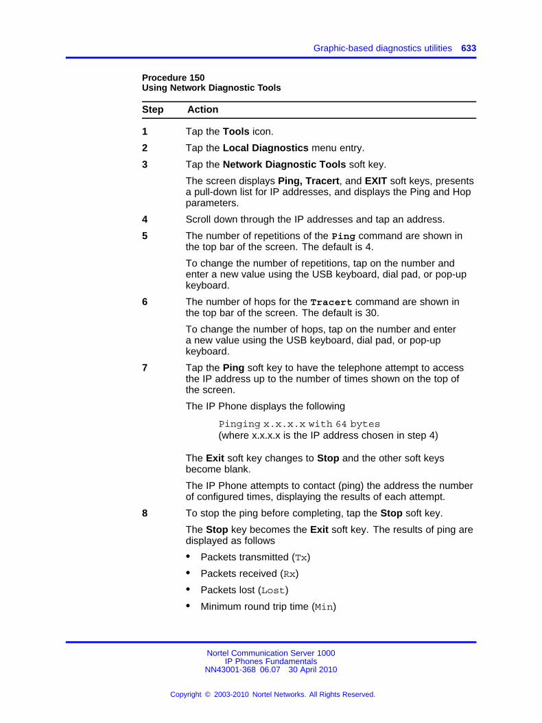
Graphic-based diagnostics utilities 633
Procedure 150Using Network Diagnostic Tools
Step Action
1 Tap the Tools icon.
2 Tap the Local Diagnostics menu entry.
3 Tap the Network Diagnostic Tools soft key.
The screen displays Ping, Tracert, and EXIT soft keys, presentsa pull-down list for IP addresses, and displays the Ping and Hopparameters.
4 Scroll down through the IP addresses and tap an address.
5 The number of repetitions of the Ping command are shown inthe top bar of the screen. The default is 4.
To change the number of repetitions, tap on the number andenter a new value using the USB keyboard, dial pad, or pop-upkeyboard.
6 The number of hops for the Tracert command are shown inthe top bar of the screen. The default is 30.
To change the number of hops, tap on the number and entera new value using the USB keyboard, dial pad, or pop-upkeyboard.
7 Tap the Ping soft key to have the telephone attempt to accessthe IP address up to the number of times shown on the top ofthe screen.
The IP Phone displays the following
Pinging x.x.x.x with 64 bytes(where x.x.x.x is the IP address chosen in step 4)
The Exit soft key changes to Stop and the other soft keysbecome blank.
The IP Phone attempts to contact (ping) the address the numberof configured times, displaying the results of each attempt.
8 To stop the ping before completing, tap the Stop soft key.
The Stop key becomes the Exit soft key. The results of ping aredisplayed as follows
• Packets transmitted (Tx)
• Packets received (Rx)
• Packets lost (Lost)
• Minimum round trip time (Min)
Nortel Communication Server 1000IP Phones Fundamentals
NN43001-368 06.07 30 April 2010
Copyright © 2003-2010 Nortel Networks. All Rights Reserved.
.
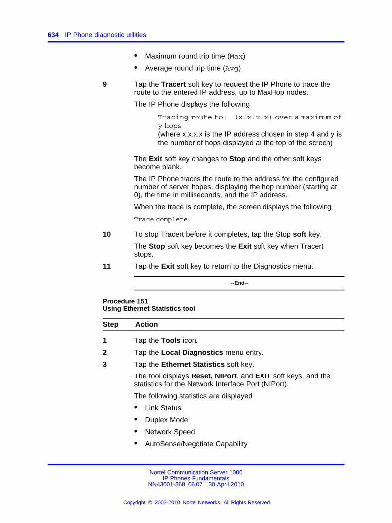
634 IP Phone diagnostic utilities
• Maximum round trip time (Max)
• Average round trip time (Avg)
9 Tap the Tracert soft key to request the IP Phone to trace theroute to the entered IP address, up to MaxHop nodes.
The IP Phone displays the following
Tracing route to: (x.x.x.x) over a maximum ofy hops(where x.x.x.x is the IP address chosen in step 4 and y isthe number of hops displayed at the top of the screen)
The Exit soft key changes to Stop and the other soft keysbecome blank.
The IP Phone traces the route to the address for the configurednumber of server hopes, displaying the hop number (starting at0), the time in milliseconds, and the IP address.
When the trace is complete, the screen displays the following
Trace complete.
10 To stop Tracert before it completes, tap the Stop soft key.
The Stop soft key becomes the Exit soft key when Tracertstops.
11 Tap the Exit soft key to return to the Diagnostics menu.
--End--
Procedure 151Using Ethernet Statistics tool
Step Action
1 Tap the Tools icon.
2 Tap the Local Diagnostics menu entry.
3 Tap the Ethernet Statistics soft key.
The tool displays Reset, NIPort, and EXIT soft keys, and thestatistics for the Network Interface Port (NIPort).
The following statistics are displayed
• Link Status
• Duplex Mode
• Network Speed
• AutoSense/Negotiate Capability
Nortel Communication Server 1000IP Phones Fundamentals
NN43001-368 06.07 30 April 2010
Copyright © 2003-2010 Nortel Networks. All Rights Reserved.
.
Graphic-based diagnostics utilities 635
• AutoSense/Negotiate Completed
• Port VLAN Priority
• Port VLAN ID
• Packet Collision
• CRC Error count
• Frame Error count
4 To reset the NIPort counters to 0, tap the Reset soft key.
5 Tap the NIPort soft key.
The NIPort soft key changes to the PCPort soft key and the tooldisplays the statistics for the Personal Computer port (PCPort).The following statistics are displayed
• Link Status
• Duplex Mode
• Network Speed
• AutoSense/Negotiate Capability
• AutoSense/Negotiate Completed
• Port VLAN Priority
• Port VLAN ID
• Packet Collision
• CRC Error count
• Frame Error count
6 To reset the PCPort statistics to 0, tap the Reset soft key.
--End--
Procedure 152Using the IP Network Statistics tool
Step Action
1 Tap the Tools icon.
2 Tap the Local Diagnostics soft key.
3 Tap the IP Network Statistics soft key.
The tool displays the Reset, NIPort, and Exit soft keys, and thestatistics for the Network Interface Port (NIPort).
Nortel Communication Server 1000IP Phones Fundamentals
NN43001-368 06.07 30 April 2010
Copyright © 2003-2010 Nortel Networks. All Rights Reserved.
.
636 IP Phone diagnostic utilities
The following statistics are displayed
• Packets sent
• Packets received
• Incoming Packets Error
• Outgoing Packets Error
• Incoming Packets discarded
• Outgoing Packets discarded
• Unknown protocols
• Last Internet Control Message Protocol (ICMP) message typeand code
4 To reset the NIPort counters to 0, tap the Reset soft key.
5 Tap the NIPort soft key.
The NIPort soft key becomes the PCPort soft key, and thestatistics for the Personal Computer Port (PCPort) are displayed.
The following statistics are displayed
• Packets sent
• Packets received
• Broadcast Packets received (Rx)
• Multicast Packets received (Rx)
• Incoming Packets discarded
• Outgoing Packets discarded
• Unknown protocols (Unknown protos
• Last Internet Control Message Protocol (ICMP) message typeand code (ICMP Type/Code)
6 To reset the PCPort counters to 0, tap the Reset soft key.
7 Tap the Exit soft key to return to the Diagnostics menu.
--End--
Procedure 153Using the IPSet Information tool
Step Action
1 Tap the Tools icon.
2 Tap the Local Diagnostics soft key.
3 Tap the IPSet Information soft key.
Nortel Communication Server 1000IP Phones Fundamentals
NN43001-368 06.07 30 April 2010
Copyright © 2003-2010 Nortel Networks. All Rights Reserved.
.
Graphic-based diagnostics utilities 637
The tool displays the Exit soft key at the bottom of the displayand the following information
• Configuration
— Network data validated, MAC address stored, DHCPsetting
— Voice VLAN status, type of configuration and discoverystatus
— Primary Server identification
— VPN Enabled & Operating
• Firmware version and Hardware Identification number
• Telephone Set IP address
• Network subnet mask
• Gateway IP address
• EPROM Server S1 and S2 IP addresses, ports, actions, andnumber of retries
• Voice VLAN priority and VLAN ID
• Server Information for S01, S02, S03, and S04, includingIP addresses, ports, actions, number of retries, and failovervalues
• Provisioning Server
• TFTP
• XAS Information
• DTLS
— Server Config
— Session Info
— Certificate DN
— Certificate Issuer
— Last Error
4 Use the scroll bar to display all the information.
5 Tap the Exit soft key to return to the Diagnostics menu.
--End--
Procedure 154Using the DHCP Information tool
Step Action
1 Tap the Tools icon.
Nortel Communication Server 1000IP Phones Fundamentals
NN43001-368 06.07 30 April 2010
Copyright © 2003-2010 Nortel Networks. All Rights Reserved.
.
638 IP Phone diagnostic utilities
2 Tap the Local Diagnostics soft key.
3 Tap the DHCP Information soft key.
--End--
The Advanced Diag Tools are available to the Nortel support organizationto configure the auto recovery function and remote access.
Procedure 155Viewing Certificates
Step Action
1 Tap the Tools icon.
2 Tap the Local Diagnostics soft key.
3 Tap the Certificate Information soft key.
The tool displays the ViewExit soft key at the bottom of thedisplay and the following information
You can tap the Return soft key to return to the Diagnosticssubmenu.
Certificate Information menu
1. Trusted Certificates
2. Device Certificates
3. Certificate Revocation List
--End--
Diagnostics for the IP Phones 1120E/1140E/1150EThis section describes the Local Diagnostics for the IP Phone 1120E, IPPhone 1140E and IP Phone 1150E . Figure 103 "Local Diagnostics menu"(page 639) shows the Local Diagnostic menu for the IP Phone 1140E.
The Local Diagnostics submenu offers the following choices
• 1. IP Set & DHCP Information
• 2. Network Diagnostic Tools
• 3. Ethernet Statistics
• 4. IP Network Statistics
• 5. USB Devices
Nortel Communication Server 1000IP Phones Fundamentals
NN43001-368 06.07 30 April 2010
Copyright © 2003-2010 Nortel Networks. All Rights Reserved.
.
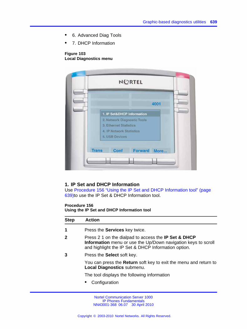
Graphic-based diagnostics utilities 639
• 6. Advanced Diag Tools
• 7. DHCP Information
Figure 103Local Diagnostics menu
1. IP Set and DHCP InformationUse Procedure 156 “Using the IP Set and DHCP Information tool” (page639)to use the IP Set & DHCP Information tool.
Procedure 156Using the IP Set and DHCP Information tool
Step Action
1 Press the Services key twice.
2 Press 2 1 on the dialpad to access the IP Set & DHCPInformation menu or use the Up/Down navigation keys to scrolland highlight the IP Set & DHCP Information option.
3 Press the Select soft key.
You can press the Return soft key to exit the menu and return toLocal Diagnostics submenu.
The tool displays the following information
• Configuration
Nortel Communication Server 1000IP Phones Fundamentals
NN43001-368 06.07 30 April 2010
Copyright © 2003-2010 Nortel Networks. All Rights Reserved.
.
640 IP Phone diagnostic utilities
— Network data validated, MAC address stored, DHCPsetting
— Voice VLAN status, type of configuration and discoverystatus
— Primary Server identification, PC Port enabled status
— VPN Enabled and Operating
• Firmware version and Hardware Identification number
• Telephone Set IP address
• Network subnet mask
• Gateway IP address
• EPROM Server S1 and S2 IP addresses, ports, actions, andnumber of retries
• Voice VLAN priority and VLAN ID
• DHCP Response String
• Server information for S01, S02, S03, and S04, includingIP addresses, ports, actions, number of retries, and failovervalues
• Provisioning Server
• TFTP Server IP address
• VPN
— VPN IP Address
— VPN Mask
— VPN Gateway IP
— VPN Server URL
• DTLS
— Server Config
— Session Info
— Certificate DN
— Certificate Issuer
— Last Error
Figure 104 "IP Set and Information screen" (page 641) shows IPSet & DHCP Information screen.
Nortel Communication Server 1000IP Phones Fundamentals
NN43001-368 06.07 30 April 2010
Copyright © 2003-2010 Nortel Networks. All Rights Reserved.
.
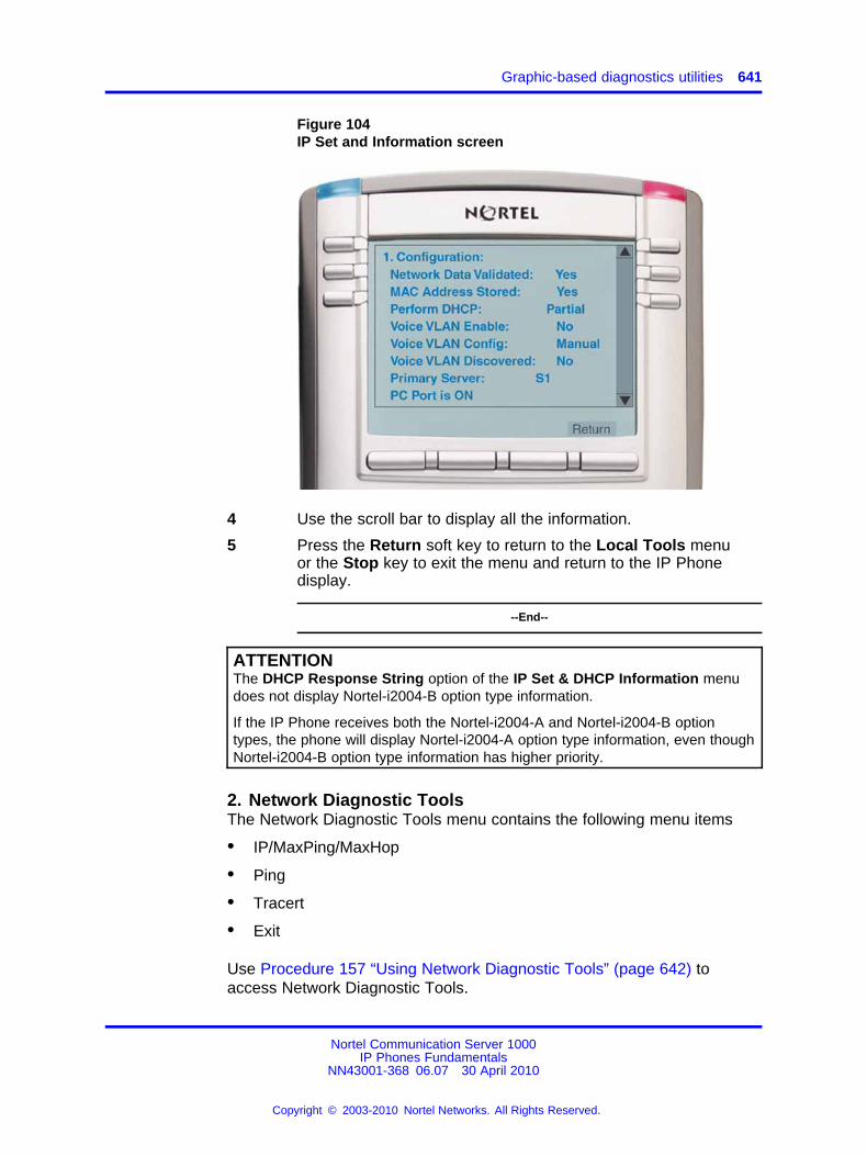
Graphic-based diagnostics utilities 641
Figure 104IP Set and Information screen
4 Use the scroll bar to display all the information.
5 Press the Return soft key to return to the Local Tools menuor the Stop key to exit the menu and return to the IP Phonedisplay.
--End--
ATTENTIONThe DHCP Response String option of the IP Set & DHCP Information menudoes not display Nortel-i2004-B option type information.
If the IP Phone receives both the Nortel-i2004-A and Nortel-i2004-B optiontypes, the phone will display Nortel-i2004-A option type information, even thoughNortel-i2004-B option type information has higher priority.
2. Network Diagnostic ToolsThe Network Diagnostic Tools menu contains the following menu items
• IP/MaxPing/MaxHop
• Ping
• Tracert
• Exit
Use Procedure 157 “Using Network Diagnostic Tools” (page 642) toaccess Network Diagnostic Tools.
Nortel Communication Server 1000IP Phones Fundamentals
NN43001-368 06.07 30 April 2010
Copyright © 2003-2010 Nortel Networks. All Rights Reserved.
.
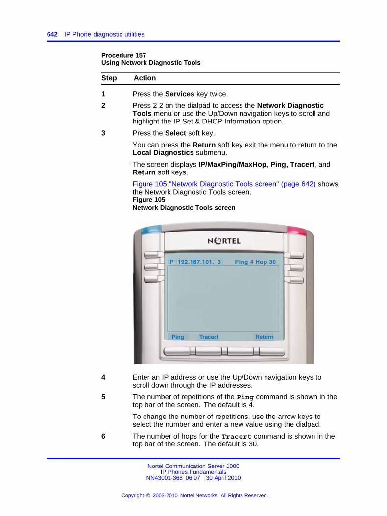
642 IP Phone diagnostic utilities
Procedure 157Using Network Diagnostic Tools
Step Action
1 Press the Services key twice.
2 Press 2 2 on the dialpad to access the Network DiagnosticTools menu or use the Up/Down navigation keys to scroll andhighlight the IP Set & DHCP Information option.
3 Press the Select soft key.
You can press the Return soft key exit the menu to return to theLocal Diagnostics submenu.
The screen displays IP/MaxPing/MaxHop, Ping, Tracert, andReturn soft keys.
Figure 105 "Network Diagnostic Tools screen" (page 642) showsthe Network Diagnostic Tools screen.Figure 105Network Diagnostic Tools screen
4 Enter an IP address or use the Up/Down navigation keys toscroll down through the IP addresses.
5 The number of repetitions of the Ping command is shown in thetop bar of the screen. The default is 4.
To change the number of repetitions, use the arrow keys toselect the number and enter a new value using the dialpad.
6 The number of hops for the Tracert command is shown in thetop bar of the screen. The default is 30.
Nortel Communication Server 1000IP Phones Fundamentals
NN43001-368 06.07 30 April 2010
Copyright © 2003-2010 Nortel Networks. All Rights Reserved.
.
Graphic-based diagnostics utilities 643
To change the number of hops, use the arrow keys to select thenumber and enter a new value using the dialpad.
7 Press the Ping soft key to have the IP Phone attempt to accessthe IP address, up to the number of times shown on the top ofthe screen.
The IP Phone displays the following
Pinging x.x.x.x with 64 bytes(where x.x.x.x is the entered IP address)
The Return soft key changes to Stop and the other soft keysbecome blank.
The IP Phone attempts to contact (ping) the address the numberof configured times, and displays the results of each attempt.
8 To stop the ping before completing, tap the Stop soft key.
The Stop soft key becomes the Return soft key. The results ofping are displayed as follows
• Packets transmitted (Tx)
• Packets received (Rx)
• Percentage of Packets Lost (Lost)
• Minimum round trip time (Min)
• Maximum round trip time (Max)
• Average round trip time (Avg)
9 Press the Tracert soft key to request the IP Phone to trace theroute to the entered IP address, up to MaxHop nodes.
The IP Phone displays the following
Tracing route to: (x.x.x.x) over a maximum of yhops(where x.x.x.x is the entered IP address and y is the number ofhops displayed at the top of the screen)
The Return soft key changes to Stop and the other soft keysbecome blank.
The IP Phone traces the route to the address for the configurednumber of server hops, displaying the hop number (starting at 0),the time in milliseconds, and the IP address.
When the trace is complete, the screen displays the following
Trace complete.
10 To stop Tracert before it completes, tap the Stop soft key.
The Stop soft key becomes the Return soft key when Tracertstops.
Nortel Communication Server 1000IP Phones Fundamentals
NN43001-368 06.07 30 April 2010
Copyright © 2003-2010 Nortel Networks. All Rights Reserved.
.
644 IP Phone diagnostic utilities
11 Press the Return soft key to return to Local Tools menu or theStop key to exit the menu and return to the IP Phone display.
--End--
3. Ethernet StatisticsUse Procedure 158 “Using Ethernet Statistics tool” (page 644) to use theEthernet Statistics menu.
Procedure 158Using Ethernet Statistics tool
Step Action
1 Press the Services key twice.
2 Press 2 3 on the dialpad to access the Ethernet Statistics menuor use the Up/Down navigation keys to scroll and highlight theEthernet Statistics option.
3 Press the Select soft key.
You can press the Return soft key exit the menu to return to theLocal Diagnostics submenu.
The screen displays Reset, NIport/PCport, and Return softkeys. The NIport/PCport soft key is used to select the Network(NI) Port or the PC (PC) Port. The soft key label indicates thecurrent display page. For example, when NIport appears on thesoft key label, the information showing on the display is for thenetwork interface port.
When NIport appears on the second soft key label, the followingstatistics are displayed
• Link Status
• Duplex Mode
• Network Speed (10 Mb, 100 Mb, or 1 G)
• AutoSense/Negotiate
— AutoSense/Negotiate Capability
— AutoSense/Negotiate Completed
• Port VLAN Priority
• Port VLAN ID
• Packet Collision
• CRC Error count
• Frame Error count
• Unicast Packets Sent
Nortel Communication Server 1000IP Phones Fundamentals
NN43001-368 06.07 30 April 2010
Copyright © 2003-2010 Nortel Networks. All Rights Reserved.
.
Graphic-based diagnostics utilities 645
• Unicast Packets Received
• Broadcast Packets Received
• Multicast Packets Received
• 802.1x Status (EAP Status)
4 To reset the NIPort counters to 0, press the Reset soft key.
5 Press the NIPort soft key.
The NIPort soft key changes to the PCPort soft key and the tooldisplays the statistics for the Personal Computer port (PCPort).The following PCPort statistics are displayed
• Link Status
• Duplex Mode
• Network Speed
• AutoSense/Negotiate Capability
• AutoSense/Negotiate Completed
• Port VLAN Priority
• Port VLAN ID
• Packet Collision
• CRC Error count
• Frame Error count
• Unicast Packets Sent
• Unicast Packets Received
• Broadcast Packets Received
• Multicast Packets Received
Figure 106 "Ethernet Statistics display screen" (page 646) showsEthernet Statistics display screen.
Nortel Communication Server 1000IP Phones Fundamentals
NN43001-368 06.07 30 April 2010
Copyright © 2003-2010 Nortel Networks. All Rights Reserved.
.
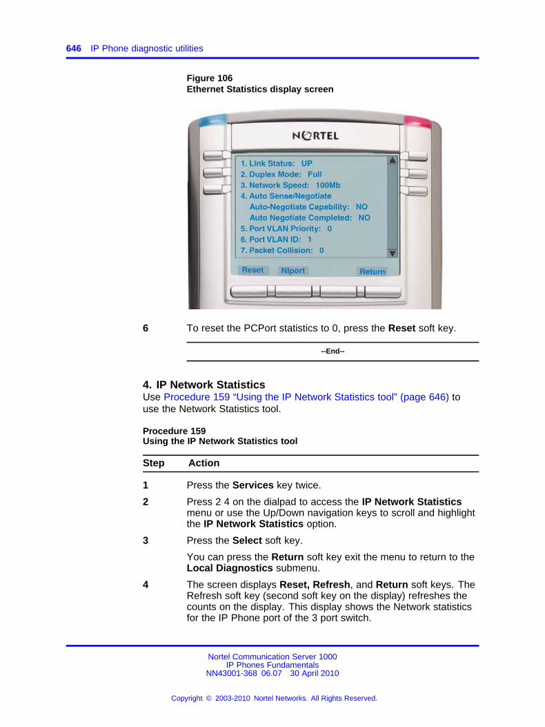
646 IP Phone diagnostic utilities
Figure 106Ethernet Statistics display screen
6 To reset the PCPort statistics to 0, press the Reset soft key.
--End--
4. IP Network StatisticsUse Procedure 159 “Using the IP Network Statistics tool” (page 646) touse the Network Statistics tool.
Procedure 159Using the IP Network Statistics tool
Step Action
1 Press the Services key twice.
2 Press 2 4 on the dialpad to access the IP Network Statisticsmenu or use the Up/Down navigation keys to scroll and highlightthe IP Network Statistics option.
3 Press the Select soft key.
You can press the Return soft key exit the menu to return to theLocal Diagnostics submenu.
4 The screen displays Reset, Refresh, and Return soft keys. TheRefresh soft key (second soft key on the display) refreshes thecounts on the display. This display shows the Network statisticsfor the IP Phone port of the 3 port switch.
Nortel Communication Server 1000IP Phones Fundamentals
NN43001-368 06.07 30 April 2010
Copyright © 2003-2010 Nortel Networks. All Rights Reserved.
.
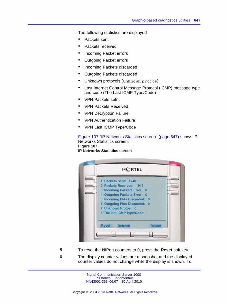
Graphic-based diagnostics utilities 647
The following statistics are displayed
• Packets sent
• Packets received
• Incoming Packet errors
• Outgoing Packet errors
• Incoming Packets discarded
• Outgoing Packets discarded
• Unknown protocols (Unknown protos)
• Last Internet Control Message Protocol (ICMP) message typeand code (The Last ICMP Type/Code)
• VPN Packets setnt
• VPN Packets Received
• VPN Decryption Failure
• VPN Authentication Failure
• VPN Last ICMP Type/Code
Figure 107 "IP Networks Statistics screen" (page 647) shows IPNetworks Statistics screen.Figure 107IP Networks Statistics screen
5 To reset the NIPort counters to 0, press the Reset soft key.
6 The display counter values are a snapshot and the displayedcounter values do not change while the display is shown. To
Nortel Communication Server 1000IP Phones Fundamentals
NN43001-368 06.07 30 April 2010
Copyright © 2003-2010 Nortel Networks. All Rights Reserved.
.
648 IP Phone diagnostic utilities
refresh them as you view the counter display, press the Refreshsoft key.
7 You can press the Return soft key exit the menu to return to theLocal Diagnostics submenu, or you can press the Stop key toclose the menu and return to the IP Phone display.
--End--
5. USB DevicesThe USB Devices tool provides information about an Universal Serial Bus(USB) devices that connect to your IP Phone. The IP Phone automaticallydetects USB devices when they are connected to the USB port in the backof the IP Phone. The IP Phone enumerates and lists any USB device,such as USB mice, USB keyboards, and USB headsets. The displayshows the descriptive text string received from the USB device.
ATTENTIONThe IP Phone USB Port available power is limited to 100mA. If USB devicesconnected to this port require more than 100mA an externally powered USBhub is required.
Procedure 160Using the USB Devices tool
Step Action
1 Press the Services key twice.
2 Press 2 5 on the dialpad to access the USB Devices menu oruse the Up/Down navigation keys to scroll and highlight the USBDevices option.
3 Press the Select soft key.
You can press the Return soft key exit the menu to return to theLocal Diagnostics submenu.
--End--
6. Advanced Diag ToolsThe Advanced Diag Tools are available to the Nortel support organizationto configure the auto recovery function and remote access.
Procedure 161Using the Advanced Diag Tools
Step Action
1 Press the Services key twice.
Nortel Communication Server 1000IP Phones Fundamentals
NN43001-368 06.07 30 April 2010
Copyright © 2003-2010 Nortel Networks. All Rights Reserved.
.
Graphic-based diagnostics utilities 649
2 Press 2 6 on the dialpad to access the Advanced Diag Toolsmenu or use the Up/Down navigation keys to scroll and highlightthe Advanced Diag Tools option.
3 Press the Select soft key.
You can press the Return soft key exit the menu to return to theLocal Diagnostics submenu.
--End--
7. DHCP InformationUse the DHCP Information menu option to display Nortel DHCP optionstrings on your phone. If DHCP is enabled the DHCP Information screendisplays the "Nortel-i2004-A", the "Nortel-i2004-B", and the "VLAN-A"option strings received by the phone from the DHCP server. If no optionstrings is present, "Not Provided" appears in the display area. The DHCPserver IP address from which the options were provided also appears inthe display area.
Procedure 162Using the DHCP Information tool
Step Action
1 Press the Services key twice.
2 Press 2 7 on the dialpad to access the DHCP Information menuor use the Up/Down navigation keys to scroll and highlight theDHCP Information option.
3 Press the Select soft key.
You can press the Return soft key exit the menu to return to theLocal Diagnostics submenu.
--End--
Diagnostics for the IP Phone 1165EThis section describes the Local Diagnostics for the IP Phone 1165E.Figure 108 "Diagnostics menu" (page 650) shows the Diagnostics menufor IP Phone 1165E.
The Local Diagnostics submenu offers the following choices:
• IP Set Information
• Network Diagnostic Tools
• Ethernet Statistics
• IP Network Statistics
Nortel Communication Server 1000IP Phones Fundamentals
NN43001-368 06.07 30 April 2010
Copyright © 2003-2010 Nortel Networks. All Rights Reserved.
.
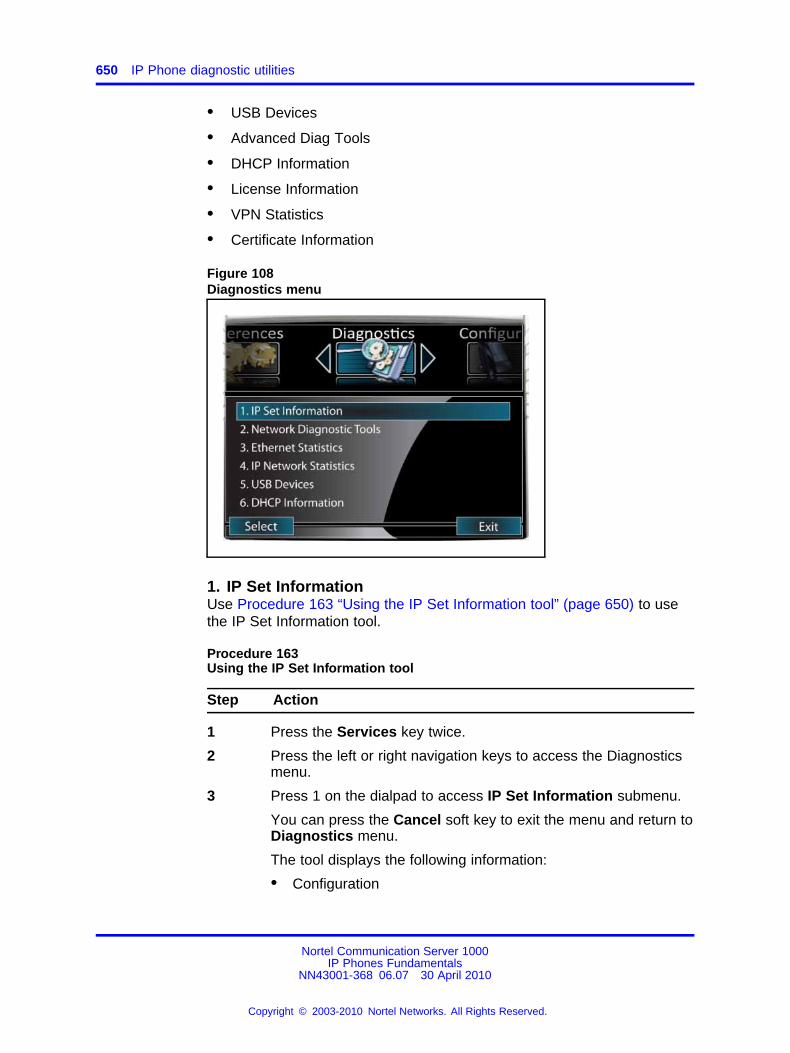
650 IP Phone diagnostic utilities
• USB Devices
• Advanced Diag Tools
• DHCP Information
• License Information
• VPN Statistics
• Certificate Information
Figure 108Diagnostics menu
1. IP Set InformationUse Procedure 163 “Using the IP Set Information tool” (page 650) to usethe IP Set Information tool.
Procedure 163Using the IP Set Information tool
Step Action
1 Press the Services key twice.
2 Press the left or right navigation keys to access the Diagnosticsmenu.
3 Press 1 on the dialpad to access IP Set Information submenu.
You can press the Cancel soft key to exit the menu and return toDiagnostics menu.
The tool displays the following information:
• Configuration
Nortel Communication Server 1000IP Phones Fundamentals
NN43001-368 06.07 30 April 2010
Copyright © 2003-2010 Nortel Networks. All Rights Reserved.
.
Graphic-based diagnostics utilities 651
— Network data validated, MAC address stored, DHCPsetting
— Voice VLAN status, type of configuration and discoverystatus
— Primary Server identification, PC Port enabled status
— VPN Enabled and Operating
• Firmware version and Hardware Identification number
• Telephone Set IP address
• Network subnet mask
• Gateway IP address
• EPROM Server S1 and S2 IP addresses, ports, actions, andnumber of retries
• Voice VLAN priority and VLAN ID
• DHCP Response String
• Server information for S01, S02, S03, and S04, includingIP addresses, ports, actions, number of retries, and failovervalues
• Provisioning Server
• TFTP Server IP address
• VPN
— VPN IP Address
— VPN Mask
— VPN Gateway IP
— VPN Server URL
• DTLS
— Server Config
— Session Info
— Certificate DN
— Certificate Issuer
— Last Error
• Application Gateway server IP address, mode and status
Figure 109 "IP Set Information" (page 652) shows IP SetInformation screen.
Nortel Communication Server 1000IP Phones Fundamentals
NN43001-368 06.07 30 April 2010
Copyright © 2003-2010 Nortel Networks. All Rights Reserved.
.
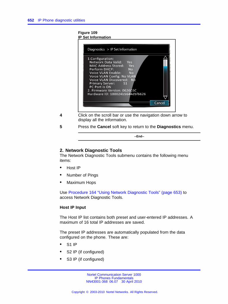
652 IP Phone diagnostic utilities
Figure 109IP Set Information
4 Click on the scroll bar or use the navigation down arrow todisplay all the information.
5 Press the Cancel soft key to return to the Diagnostics menu.
--End--
2. Network Diagnostic ToolsThe Network Diagnostic Tools submenu contains the following menuitems:
• Host IP
• Number of Pings
• Maximum Hops
Use Procedure 164 “Using Network Diagnostic Tools” (page 653) toaccess Network Diagnostic Tools.
Host IP Input
The Host IP list contains both preset and user-entered IP addresses. Amaximum of 16 total IP addresses are saved.
The preset IP addresses are automatically populated from the dataconfigured on the phone. These are:
• S1 IP
• S2 IP (if configured)
• S3 IP (if configured)
Nortel Communication Server 1000IP Phones Fundamentals
NN43001-368 06.07 30 April 2010
Copyright © 2003-2010 Nortel Networks. All Rights Reserved.
.
Graphic-based diagnostics utilities 653
• S4 IP (if configured)
• Gateway IP
• Subnet mask
You can add an IP address by navigating to an existing address andediting it. You can add minimum number of 10 IP addresses, until the listreaches the maximum of 16 IP addresses. Your IP address is saved untilthe phone reboots.
Procedure 164Using Network Diagnostic Tools
Step Action
1 Press the Services key twice.
2 Press the right navigation key to access Diagnostics menu.
3 Press 2 on the dialpad to access the Network Diagnostic Toolssubmenu.
You can press the Cancel soft key to exit the menu and return tothe Diagnostics menu.The screen displays input fields for the Host IP, Number of Pingsand Maximum Hops. It also has softkeys for Ping, Tracert, andCancel.
4 Enter a Host IP address for the Ping or Traceroute tool:
• Navigate to the Host IP field
• Press Enter to open the list
• Use the Up and Down navigation keys to navigate to an IPaddress to use or press Enter and edit an IP address
• Press Enter to select the IP address
Figure 110 "Network Diagnostic Tools" (page 654) shows theNetwork Diagnostic Tools screen.
Nortel Communication Server 1000IP Phones Fundamentals
NN43001-368 06.07 30 April 2010
Copyright © 2003-2010 Nortel Networks. All Rights Reserved.
.
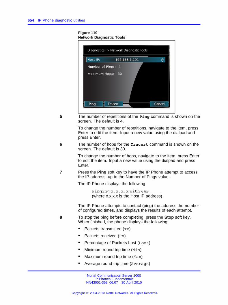
654 IP Phone diagnostic utilities
Figure 110Network Diagnostic Tools
5 The number of repetitions of the Ping command is shown on thescreen. The default is 4.
To change the number of repetitions, navigate to the item, pressEnter to edit the item. Input a new value using the dialpad andpress Enter.
6 The number of hops for the Tracert command is shown on thescreen. The default is 30.
To change the number of hops, navigate to the item, press Enterto edit the item. Input a new value using the dialpad and pressEnter.
7 Press the Ping soft key to have the IP Phone attempt to accessthe IP address, up to the Number of Pings value.
The IP Phone displays the following
Pinging x.x.x.x with 64B(where x.x.x.x is the Host IP address)
The IP Phone attempts to contact (ping) the address the numberof configured times, and displays the results of each attempt.
8 To stop the ping before completing, press the Stop soft key.When finished, the phone displays the following:
• Packets transmitted (Tx)
• Packets received (Rx)
• Percentage of Packets Lost (Lost)
• Minimum round trip time (Min)
• Maximum round trip time (Max)
• Average round trip time (Average)
Nortel Communication Server 1000IP Phones Fundamentals
NN43001-368 06.07 30 April 2010
Copyright © 2003-2010 Nortel Networks. All Rights Reserved.
.
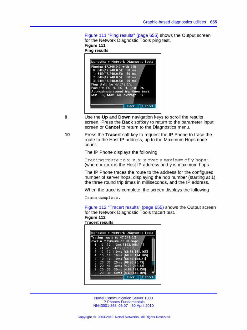
Graphic-based diagnostics utilities 655
Figure 111 "Ping results" (page 655) shows the Output screenfor the Network Diagnostic Tools ping test.Figure 111Ping results
9 Use the Up and Down navigation keys to scroll the resultsscreen. Press the Back softkey to return to the parameter inputscreen or Cancel to return to the Diagnostics menu.
10 Press the Tracert soft key to request the IP Phone to trace theroute to the Host IP address, up to the Maximum Hops nodecount.
The IP Phone displays the following
Tracing route to x.x.x.x over a maximum of y hops:(where x.x.x.x is the Host IP address and y is maximum hops
The IP Phone traces the route to the address for the configurednumber of server hops, displaying the hop number (starting at 1),the three round trip times in milliseconds, and the IP address.
When the trace is complete, the screen displays the following
Trace complete.
Figure 112 "Tracert results" (page 655) shows the Output screenfor the Network Diagnostic Tools tracert test.Figure 112Tracert results
Nortel Communication Server 1000IP Phones Fundamentals
NN43001-368 06.07 30 April 2010
Copyright © 2003-2010 Nortel Networks. All Rights Reserved.
.
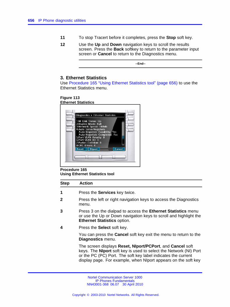
656 IP Phone diagnostic utilities
11 To stop Tracert before it completes, press the Stop soft key.
12 Use the Up and Down navigation keys to scroll the resultsscreen. Press the Back softkey to return to the parameter inputscreen or Cancel to return to the Diagnostics menu.
--End--
3. Ethernet StatisticsUse Procedure 165 “Using Ethernet Statistics tool” (page 656) to use theEthernet Statistics menu.
Figure 113Ethernet Statistics
Procedure 165Using Ethernet Statistics tool
Step Action
1 Press the Services key twice.
2 Press the left or right navigation keys to access the Diagnosticsmenu.
3 Press 3 on the dialpad to access the Ethernet Statistics menuor use the Up or Down navigation keys to scroll and highlight theEthernet Statistics option.
4 Press the Select soft key.
You can press the Cancel soft key exit the menu to return to theDiagnostics menu.
The screen displays Reset, NIport/PCPort, and Cancel softkeys. The NIport soft key is used to select the Network (NI) Portor the PC (PC) Port. The soft key label indicates the currentdisplay page. For example, when NIport appears on the soft key
Nortel Communication Server 1000IP Phones Fundamentals
NN43001-368 06.07 30 April 2010
Copyright © 2003-2010 Nortel Networks. All Rights Reserved.
.
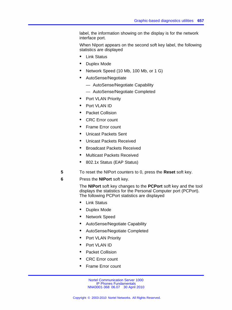
Graphic-based diagnostics utilities 657
label, the information showing on the display is for the networkinterface port.
When NIport appears on the second soft key label, the followingstatistics are displayed
• Link Status
• Duplex Mode
• Network Speed (10 Mb, 100 Mb, or 1 G)
• AutoSense/Negotiate
— AutoSense/Negotiate Capability
— AutoSense/Negotiate Completed
• Port VLAN Priority
• Port VLAN ID
• Packet Collision
• CRC Error count
• Frame Error count
• Unicast Packets Sent
• Unicast Packets Received
• Broadcast Packets Received
• Multicast Packets Received
• 802.1x Status (EAP Status)
5 To reset the NIPort counters to 0, press the Reset soft key.
6 Press the NIPort soft key.
The NIPort soft key changes to the PCPort soft key and the tooldisplays the statistics for the Personal Computer port (PCPort).The following PCPort statistics are displayed
• Link Status
• Duplex Mode
• Network Speed
• AutoSense/Negotiate Capability
• AutoSense/Negotiate Completed
• Port VLAN Priority
• Port VLAN ID
• Packet Collision
• CRC Error count
• Frame Error count
Nortel Communication Server 1000IP Phones Fundamentals
NN43001-368 06.07 30 April 2010
Copyright © 2003-2010 Nortel Networks. All Rights Reserved.
.
658 IP Phone diagnostic utilities
• Unicast Packets Sent
• Unicast Packets Received
• Broadcast Packets Received
• Multicast Packets Received
Figure 113 "Ethernet Statistics" (page 656) shows EthernetStatistics display screen.
7 To reset the PCPort statistics to 0, press the Reset soft key.
--End--
4. IP Network StatisticsUse Procedure 166 “Using the IP Network Statistics tool” (page 659) touse the IP Network Statistics tool. This display shows the Networkstatistics for the IP Phone port of the 3 port switch.
The following statistics are displayed
• Packets sent
• Packets received
• Incoming Packet errors
• Outgoing Packet errors
• Incoming Packets discarded
• Outgoing Packets discarded
• Unknown protocols (Unknown protos)
• Last Internet Control Message Protocol (ICMP) message type andcode (The Last ICMP Type/Code)
• VPN Packets sent
• VPN Packets Received
• VPN Decryption Failure
• VPN Authentication Failure
• VPN Last ICMP Type/Code
Figure 114 "IP Network Statistics" (page 659) shows IP Networks Statisticsscreen.
Nortel Communication Server 1000IP Phones Fundamentals
NN43001-368 06.07 30 April 2010
Copyright © 2003-2010 Nortel Networks. All Rights Reserved.
.
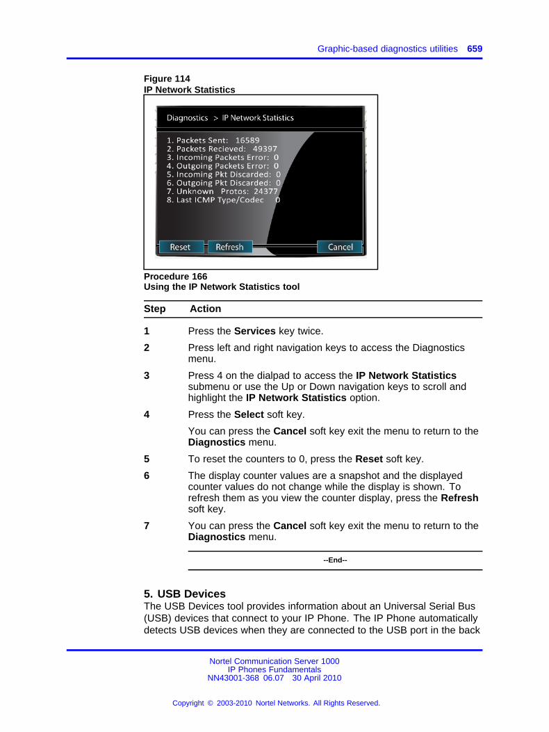
Graphic-based diagnostics utilities 659
Figure 114IP Network Statistics
Procedure 166Using the IP Network Statistics tool
Step Action
1 Press the Services key twice.
2 Press left and right navigation keys to access the Diagnosticsmenu.
3 Press 4 on the dialpad to access the IP Network Statisticssubmenu or use the Up or Down navigation keys to scroll andhighlight the IP Network Statistics option.
4 Press the Select soft key.
You can press the Cancel soft key exit the menu to return to theDiagnostics menu.
5 To reset the counters to 0, press the Reset soft key.
6 The display counter values are a snapshot and the displayedcounter values do not change while the display is shown. Torefresh them as you view the counter display, press the Refreshsoft key.
7 You can press the Cancel soft key exit the menu to return to theDiagnostics menu.
--End--
5. USB DevicesThe USB Devices tool provides information about an Universal Serial Bus(USB) devices that connect to your IP Phone. The IP Phone automaticallydetects USB devices when they are connected to the USB port in the back
Nortel Communication Server 1000IP Phones Fundamentals
NN43001-368 06.07 30 April 2010
Copyright © 2003-2010 Nortel Networks. All Rights Reserved.
.
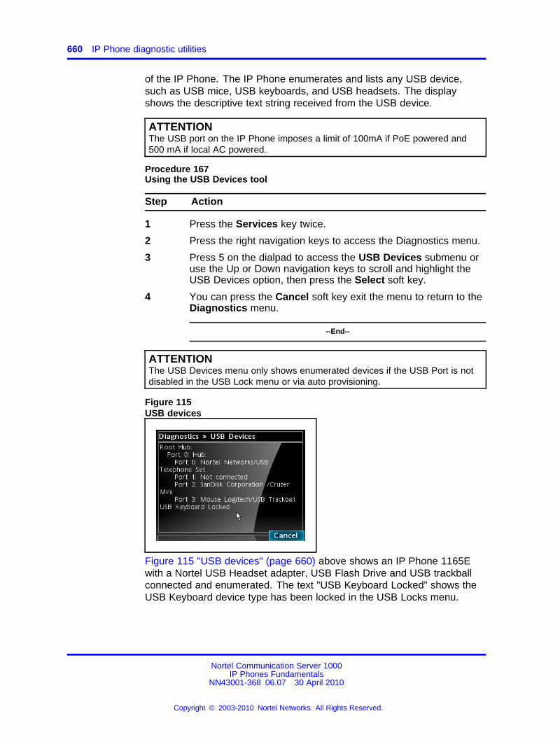
660 IP Phone diagnostic utilities
of the IP Phone. The IP Phone enumerates and lists any USB device,such as USB mice, USB keyboards, and USB headsets. The displayshows the descriptive text string received from the USB device.
ATTENTIONThe USB port on the IP Phone imposes a limit of 100mA if PoE powered and500 mA if local AC powered.
Procedure 167Using the USB Devices tool
Step Action
1 Press the Services key twice.
2 Press the right navigation keys to access the Diagnostics menu.
3 Press 5 on the dialpad to access the USB Devices submenu oruse the Up or Down navigation keys to scroll and highlight theUSB Devices option, then press the Select soft key.
4 You can press the Cancel soft key exit the menu to return to theDiagnostics menu.
--End--
ATTENTIONThe USB Devices menu only shows enumerated devices if the USB Port is notdisabled in the USB Lock menu or via auto provisioning.
Figure 115USB devices
Figure 115 "USB devices" (page 660) above shows an IP Phone 1165Ewith a Nortel USB Headset adapter, USB Flash Drive and USB trackballconnected and enumerated. The text "USB Keyboard Locked" shows theUSB Keyboard device type has been locked in the USB Locks menu.
Nortel Communication Server 1000IP Phones Fundamentals
NN43001-368 06.07 30 April 2010
Copyright © 2003-2010 Nortel Networks. All Rights Reserved.
.
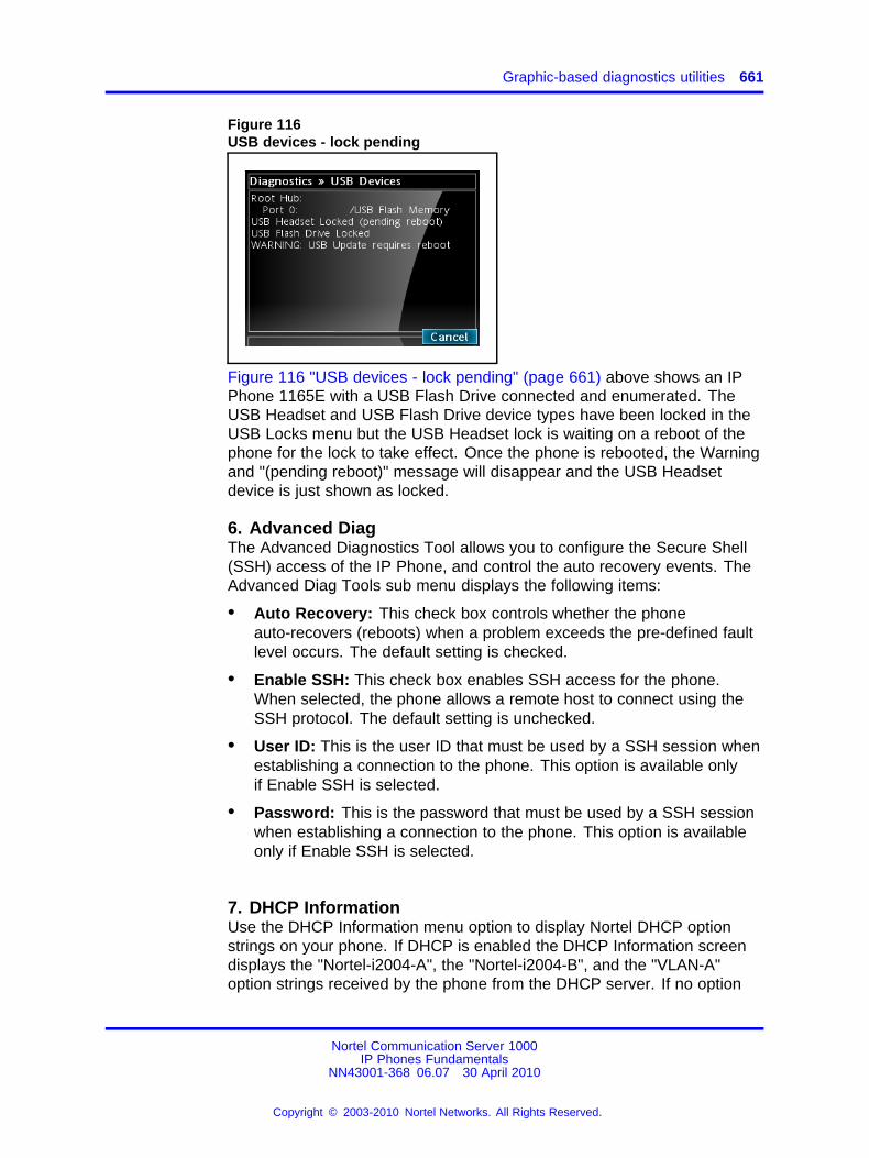
Graphic-based diagnostics utilities 661
Figure 116USB devices - lock pending
Figure 116 "USB devices - lock pending" (page 661) above shows an IPPhone 1165E with a USB Flash Drive connected and enumerated. TheUSB Headset and USB Flash Drive device types have been locked in theUSB Locks menu but the USB Headset lock is waiting on a reboot of thephone for the lock to take effect. Once the phone is rebooted, the Warningand "(pending reboot)" message will disappear and the USB Headsetdevice is just shown as locked.
6. Advanced DiagThe Advanced Diagnostics Tool allows you to configure the Secure Shell(SSH) access of the IP Phone, and control the auto recovery events. TheAdvanced Diag Tools sub menu displays the following items:
• Auto Recovery: This check box controls whether the phoneauto-recovers (reboots) when a problem exceeds the pre-defined faultlevel occurs. The default setting is checked.
• Enable SSH: This check box enables SSH access for the phone.When selected, the phone allows a remote host to connect using theSSH protocol. The default setting is unchecked.
• User ID: This is the user ID that must be used by a SSH session whenestablishing a connection to the phone. This option is available onlyif Enable SSH is selected.
• Password: This is the password that must be used by a SSH sessionwhen establishing a connection to the phone. This option is availableonly if Enable SSH is selected.
7. DHCP InformationUse the DHCP Information menu option to display Nortel DHCP optionstrings on your phone. If DHCP is enabled the DHCP Information screendisplays the "Nortel-i2004-A", the "Nortel-i2004-B", and the "VLAN-A"option strings received by the phone from the DHCP server. If no option
Nortel Communication Server 1000IP Phones Fundamentals
NN43001-368 06.07 30 April 2010
Copyright © 2003-2010 Nortel Networks. All Rights Reserved.
.
662 IP Phone diagnostic utilities
strings is present, "Not Provided" appears in the display area. The DHCPserver IP address from which the options were provided also appears inthe display area.
Procedure 168Using the DHCP Information tool
Step Action
1 Press the Services key twice.
2 Press the left or right navigation keys to access the Diagnosticsmenu.
3 Press 6 on the dialpad to access the DHCP Informationsubmenu or use the Up or Down navigation keys to scroll andhighlight the DHCP Information option.
4 Press the Select soft key.
You can press the Cancel soft key exit the menu to return to theDiagnostics menu.
--End--
8. License InformationThe License Information dialog has four items which has a minimum of5 lines and a maximum of 11 lines of information. Below is an exampleof the minimum lines form:
• License Mode Status
• Tokens Requested
• Tokens Acquired
• Licensed Features
However, the number of displayed lines increases as new licensablefeatures are added, so a scrollable dialog should be implemented fromthe start. The dialog only displays information about the license feature,therefore it can have the same form and softkeys as the IP Set and DHCPConfiguration dialog.
9. VPN StatisticsA new dialog is used to display VPN Statistics. An example forsuccessfully operating tunnel is shown below.
VPN Status Enabled & Operational Restricted
Virtual IP 10.4.5.6
Gateway vpn.example.com
Nortel Communication Server 1000IP Phones Fundamentals
NN43001-368 06.07 30 April 2010
Copyright © 2003-2010 Nortel Networks. All Rights Reserved.
.
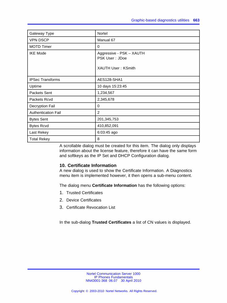
Graphic-based diagnostics utilities 663
Gateway Type Nortel
VPN DSCP Manual 67
MOTD Timer 0
IKE Mode Aggressive - PSK – XAUTHPSK User : JDoe
XAUTH User : KSmith
IPSec Transforms AES128-SHA1
Uptime 10 days 15:23:45
Packets Sent 1,234,567
Packets Rcvd 2,345,678
Decryption Fail 0
Authentication Fail 2
Bytes Sent 201,345,753
Bytes Rcvd 410,852,091
Last Rekey 6:03:45 ago
Total Rekey 8
A scrollable dialog must be created for this item. The dialog only displaysinformation about the license feature, therefore it can have the same formand softkeys as the IP Set and DHCP Configuration dialog.
10. Certificate InformationA new dialog is used to show the Certificate Information. A Diagnosticsmenu item is implemented however, it then opens a sub-menu content.
The dialog menu Certificate Information has the following options:
1. Trusted Certificates
2. Device Certificates
3. Certificate Revocation List
In the sub-dialog Trusted Certificates a list of CN values is displayed.
Nortel Communication Server 1000IP Phones Fundamentals
NN43001-368 06.07 30 April 2010
Copyright © 2003-2010 Nortel Networks. All Rights Reserved.
.
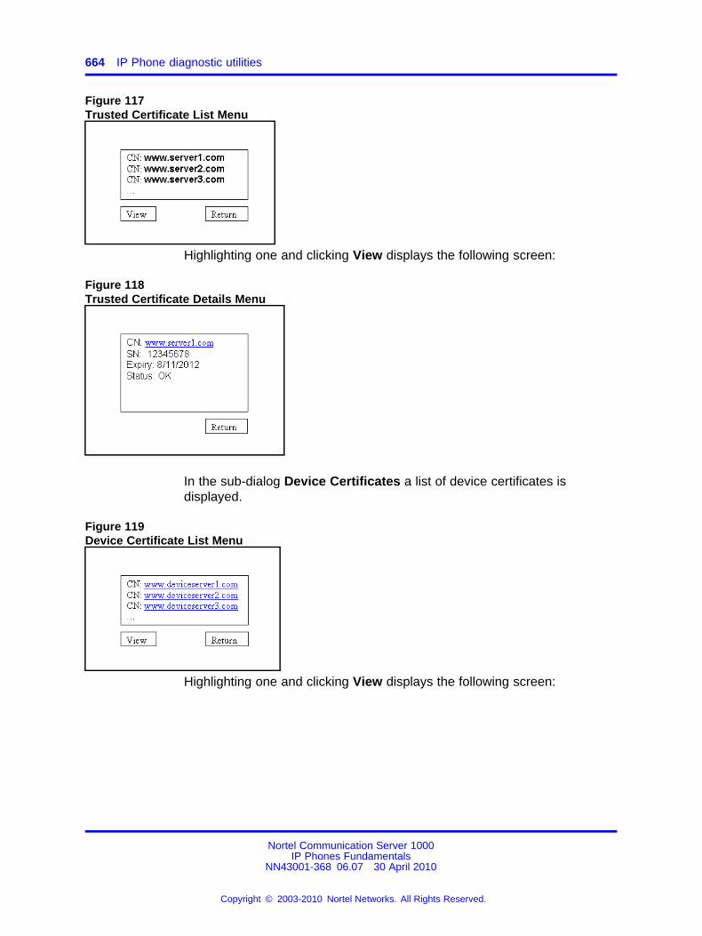
664 IP Phone diagnostic utilities
Figure 117Trusted Certificate List Menu
Highlighting one and clicking View displays the following screen:
Figure 118Trusted Certificate Details Menu
In the sub-dialog Device Certificates a list of device certificates isdisplayed.
Figure 119Device Certificate List Menu
Highlighting one and clicking View displays the following screen:
Nortel Communication Server 1000IP Phones Fundamentals
NN43001-368 06.07 30 April 2010
Copyright © 2003-2010 Nortel Networks. All Rights Reserved.
.
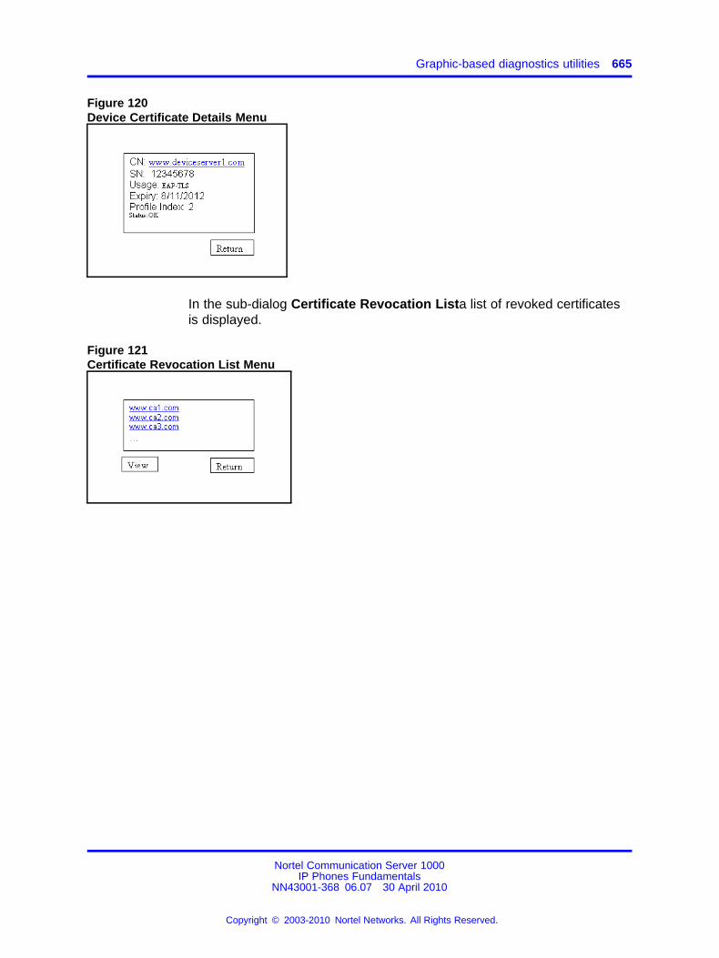
Graphic-based diagnostics utilities 665
Figure 120Device Certificate Details Menu
In the sub-dialog Certificate Revocation Lista list of revoked certificatesis displayed.
Figure 121Certificate Revocation List Menu
Nortel Communication Server 1000IP Phones Fundamentals
NN43001-368 06.07 30 April 2010
Copyright © 2003-2010 Nortel Networks. All Rights Reserved.
.

666 IP Phone diagnostic utilities
Nortel Communication Server 1000IP Phones Fundamentals
NN43001-368 06.07 30 April 2010
Copyright © 2003-2010 Nortel Networks. All Rights Reserved.
.
667.
AppendixLanguage enhancement
ContentsThis section contains the following topics:
• “Description” (page 667)
• “Expansion Module for IP Phones 1100 Series font support” (page 668)
DescriptionTo support languages with complex fonts, CS 1000 includes thefollowing language enhancements for the IP Phone 2007, IP Phones1120E/1140E/1150E/1165E.
• UNIStim font messages interpreted as UTF-8— enables the CallServer to easily display complex fonts, such as Arabic, SimplifiedChinese, Traditional Chinese, Greek, Hebrew, Japanese, and Koreanon an IP Phone.
• Support for TFTP Server—an extension of the existing configurationfile is used to download fonts as needed into the IP Phone.
• Synchronization of the display language between the Call Server andthe IP Phone—local prompts on the IP Phone and text from the CallServer are displayed in the same language.
UTF-8 character encodingUTF-8 is used as character encoding between the Call Server and the IPPhone. This must be enabled on the Call Server in order for the fonts tobe downloaded. After the Call Server has downloaded the appropriatefonts, the IP Phone can display all languages for which it has appropriatecharacter sets. Although the IP Phone supports the languages for which ithas appropriate character sets, only one language can be displayed at atime.
Nortel Communication Server 1000IP Phones Fundamentals
NN43001-368 06.07 30 April 2010
Copyright © 2003-2010 Nortel Networks. All Rights Reserved.
.
668 Language enhancement
TFTP Server supportA configuration file is used to download font files, as needed, to the IPPhone using a TFTP Server. After the font files are downloaded to the IPPhone, the configuration file creates a mapping, so the IP Phone knowshow and when to use the font.
Synchronizing the languageIf the Call Server initiates a language change, the IP Phone changes itslocal prompts to match the specified language on the Call Server. If the IPPhone user initiates a language change using the Local Tools menu, theCall Server changes its local prompts to match the specified language onthe IP Phone. If the Call Server selects a language which the IP Phonedoes not support, the local prompts default to English.
For information about downloading and configuring fonts see “TFTPServer” (page 683).
Expansion Module for IP Phones 1100 Series font supportThe Expansion Module for IP Phones 1100 Series (Expansion Module)text is rendered by the IP Phone; therefore, the selected language and fontmappings on the Expansion Module mirror the selected language and fontmappings on the IP Phone.
Nortel Communication Server 1000IP Phones Fundamentals
NN43001-368 06.07 30 April 2010
Copyright © 2003-2010 Nortel Networks. All Rights Reserved.
.
669.
AppendixDHCP server configuration
Install a Windows NT 4 or Windows 2000 serverTo set up the Windows NT 4 or Windows 2000 server, follow theinstructions provided in the installation booklet. After completion, install thelatest Service Pack and make sure the DHCP Manager is included.
WARNINGIf installing a Windows NT 4 server with Service Pack 4 orlater, follow the installation instructions included with the serverhardware.
Configure a Windows NT 4 server with DHCPConfigure a Windows NT 4 server with DHCP services using the DHCPManager provided. Use the following procedure to launch the DHCPManager.
Procedure 169Launching the DHCP Manager In Windows NT 4
Step Action
1 Click on the Windows Start button.
2 Select Programs > Administrative tools (Common) > DHCPManager. The DHCP Manager window opens.
3 Double-click Local Machines in the left pane. The CreateScope - (Local) window opens. See Figure 122 "Define newscope" (page 670).
Nortel Communication Server 1000IP Phones Fundamentals
NN43001-368 06.07 30 April 2010
Copyright © 2003-2010 Nortel Networks. All Rights Reserved.
.
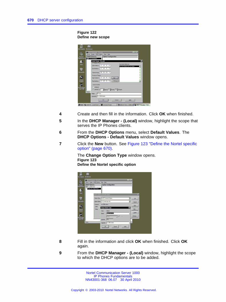
670 DHCP server configuration
Figure 122Define new scope
4 Create and then fill in the information. Click OK when finished.
5 In the DHCP Manager - (Local) window, highlight the scope thatserves the IP Phones clients.
6 From the DHCP Options menu, select Default Values. TheDHCP Options - Default Values window opens.
7 Click the New button. See Figure 123 "Define the Nortel specificoption" (page 670).
The Change Option Type window opens.Figure 123Define the Nortel specific option
8 Fill in the information and click OK when finished. Click OKagain.
9 From the DHCP Manager - (Local) window, highlight the scopeto which the DHCP options are to be added.
Nortel Communication Server 1000IP Phones Fundamentals
NN43001-368 06.07 30 April 2010
Copyright © 2003-2010 Nortel Networks. All Rights Reserved.
.
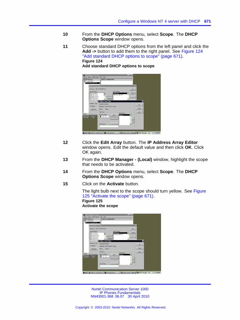
Configure a Windows NT 4 server with DHCP 671
10 From the DHCP Options menu, select Scope. The DHCPOptions Scope window opens.
11 Choose standard DHCP options from the left panel and click theAdd -> button to add them to the right panel. See Figure 124"Add standard DHCP options to scope" (page 671).Figure 124Add standard DHCP options to scope
12 Click the Edit Array button. The IP Address Array Editorwindow opens. Edit the default value and then click OK. ClickOK again.
13 From the DHCP Manager - (Local) window, highlight the scopethat needs to be activated.
14 From the DHCP Options menu, select Scope. The DHCPOptions Scope window opens.
15 Click on the Activate button.
The light bulb next to the scope should turn yellow. See Figure125 "Activate the scope" (page 671).Figure 125Activate the scope
Nortel Communication Server 1000IP Phones Fundamentals
NN43001-368 06.07 30 April 2010
Copyright © 2003-2010 Nortel Networks. All Rights Reserved.
.
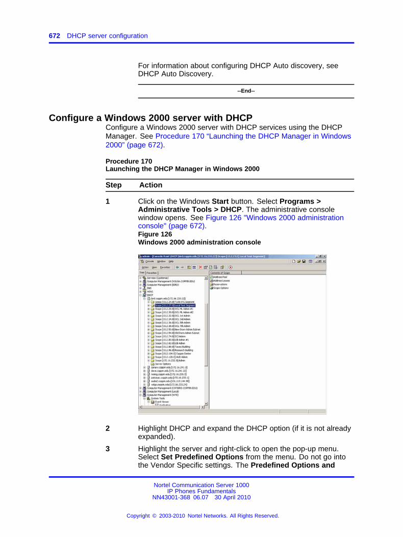
672 DHCP server configuration
For information about configuring DHCP Auto discovery, seeDHCP Auto Discovery.
--End--
Configure a Windows 2000 server with DHCPConfigure a Windows 2000 server with DHCP services using the DHCPManager. See Procedure 170 “Launching the DHCP Manager in Windows2000” (page 672).
Procedure 170Launching the DHCP Manager in Windows 2000
Step Action
1 Click on the Windows Start button. Select Programs >Administrative Tools > DHCP. The administrative consolewindow opens. See Figure 126 "Windows 2000 administrationconsole" (page 672).Figure 126Windows 2000 administration console
2 Highlight DHCP and expand the DHCP option (if it is not alreadyexpanded).
3 Highlight the server and right-click to open the pop-up menu.Select Set Predefined Options from the menu. Do not go intothe Vendor Specific settings. The Predefined Options and
Nortel Communication Server 1000IP Phones Fundamentals
NN43001-368 06.07 30 April 2010
Copyright © 2003-2010 Nortel Networks. All Rights Reserved.
.
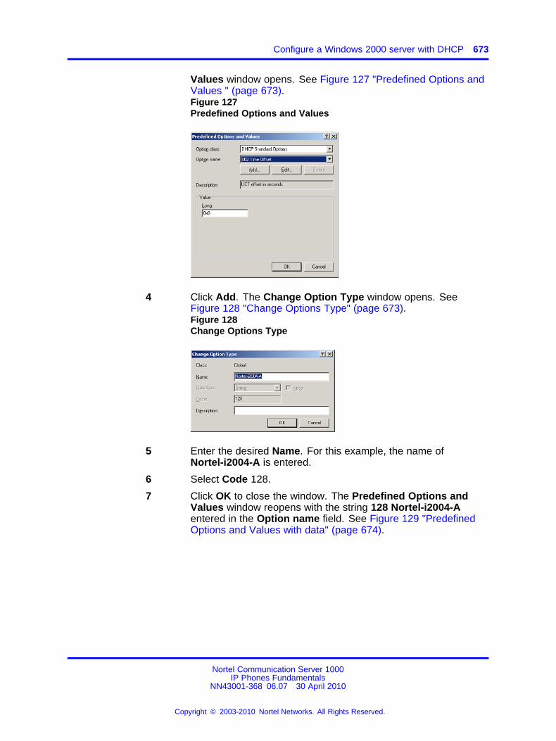
Configure a Windows 2000 server with DHCP 673
Values window opens. See Figure 127 "Predefined Options andValues " (page 673).Figure 127Predefined Options and Values
4 Click Add. The Change Option Type window opens. SeeFigure 128 "Change Options Type" (page 673).Figure 128Change Options Type
5 Enter the desired Name. For this example, the name ofNortel-i2004-A is entered.
6 Select Code 128.
7 Click OK to close the window. The Predefined Options andValues window reopens with the string 128 Nortel-i2004-Aentered in the Option name field. See Figure 129 "PredefinedOptions and Values with data" (page 674).
Nortel Communication Server 1000IP Phones Fundamentals
NN43001-368 06.07 30 April 2010
Copyright © 2003-2010 Nortel Networks. All Rights Reserved.
.
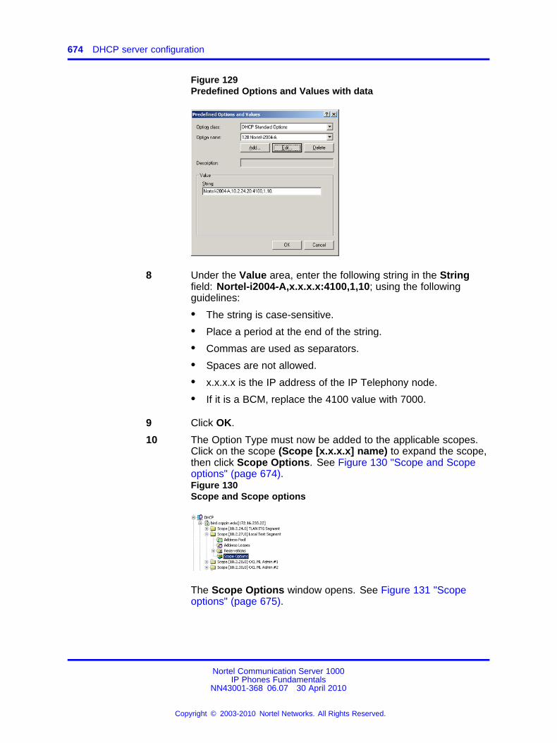
674 DHCP server configuration
Figure 129Predefined Options and Values with data
8 Under the Value area, enter the following string in the Stringfield: Nortel-i2004-A,x.x.x.x:4100,1,10; using the followingguidelines:
• The string is case-sensitive.
• Place a period at the end of the string.
• Commas are used as separators.
• Spaces are not allowed.
• x.x.x.x is the IP address of the IP Telephony node.
• If it is a BCM, replace the 4100 value with 7000.
9 Click OK.
10 The Option Type must now be added to the applicable scopes.Click on the scope (Scope [x.x.x.x] name) to expand the scope,then click Scope Options. See Figure 130 "Scope and Scopeoptions" (page 674).Figure 130Scope and Scope options
The Scope Options window opens. See Figure 131 "Scopeoptions" (page 675).
Nortel Communication Server 1000IP Phones Fundamentals
NN43001-368 06.07 30 April 2010
Copyright © 2003-2010 Nortel Networks. All Rights Reserved.
.
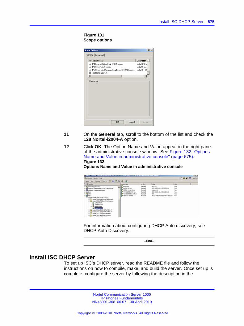
Install ISC DHCP Server 675
Figure 131Scope options
11 On the General tab, scroll to the bottom of the list and check the128 Nortel-i2004-A option.
12 Click OK. The Option Name and Value appear in the right paneof the administrative console window. See Figure 132 "OptionsName and Value in administrative console" (page 675).Figure 132Options Name and Value in administrative console
For information about configuring DHCP Auto discovery, seeDHCP Auto Discovery.
--End--
Install ISC DHCP ServerTo set up ISC’s DHCP server, read the README file and follow theinstructions on how to compile, make, and build the server. Once set up iscomplete, configure the server by following the description in the
Nortel Communication Server 1000IP Phones Fundamentals
NN43001-368 06.07 30 April 2010
Copyright © 2003-2010 Nortel Networks. All Rights Reserved.
.
676 DHCP server configuration
CAUTIONAlthough, Windows NT 4 also has the Vendor EncapsulationOption (option code 43), do not use it to encode theVoice Gateway Media Card information needed by the IPPhones. Windows NT 4 enables only 16 bytes of data to beencapsulated, which is not enough to encode all the informationneeded.
Window NT 4’s DHCP server transmits any user-defined optionassociated within a scope if the client requests it. It does nothave the ability to distinguish among different types of clients,therefore it cannot make decisions based on this information. Itis impossible to create a client-specific IP address pool/scope.
Configure ISC DHCP ServerTo configure ISC’s DHCP server, a text-based configuration process isused. Configuration is done by adding definitions and declarations inthe dhcpd.conf file located at /etc/. Various "man" files are provided onhow to configure the server, configure the lease system, use options andconditions, and run the server. Obtain the dhcpd.conf.man5 file in theserver directory and read it carefully. It provides explanations on relevanttopics, as well as the location of other man files to read for additionalinformation.
Configure ISC DHCP to work with the IP PhonesThere is a particular format for encoding the Voice Gateway Media Cardinformation. In addition to the configuration statements provided, othernetwork and subnet declarations must also be included in the configurationfile.
As indicated in the beginning of this section, read the main files and use<Example 1: Configuration files> to configure ISC’s DHCP server to workwith the IP Phones. Also, a copy of the configuration file used for thisproject is provided at the end of this section.
Use the following procedure to configure the ISC’s DHCP to work with theIP Phones.
Procedure 171Configuring ISC DHCP server
Step Action
1 Configure the server to identify a client correctly as an IP Phone2001, IP Phone 2002, IP Phone 2004, or IP Phone 2007. Thisis done using a match statement with a conditional if enclosedinside a class declaration, as follows:
class "i2004-clients"{
Nortel Communication Server 1000IP Phones Fundamentals
NN43001-368 06.07 30 April 2010
Copyright © 2003-2010 Nortel Networks. All Rights Reserved.
.
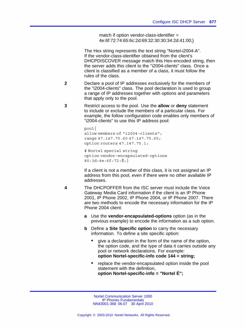
Configure ISC DHCP Server 677
match if option vendor-class-identifier =4e:6f:72:74:65:6c:2d:69:32:30:30:34:2d:41:00;}
The Hex string represents the text string "Nortel-i2004-A".If the vendor-class-identifier obtained from the client’sDHCPDISCOVER message match this Hex-encoded string, thenthe server adds this client to the "i2004-clients" class. Once aclient is classified as a member of a class, it must follow therules of the class.
2 Declare a pool of IP addresses exclusively for the members ofthe "i2004-clients" class. The pool declaration is used to groupa range of IP addresses together with options and parametersthat apply only to the pool.
3 Restrict access to the pool. Use the allow or deny statementto include or exclude the members of a particular class. Forexample, the follow configuration code enables only members of"i2004-clients" to use this IP address pool:
pool{allow members of "i2004-clients";range 47.147.75.60 47.147.75.65;option routers 47.147.75.1;
# Nortel special stringoption vendor-encapsulated-options80:3d:4e:6f:72:É;}
If a client is not a member of this class, it is not assigned an IPaddress from this pool, even if there were no other available IPaddresses.
4 The DHCPOFFER from the ISC server must include the VoiceGateway Media Card information if the client is an IP Phone2001, IP Phone 2002, IP Phone 2004, or IP Phone 2007. Thereare two methods to encode the necessary information for the IPPhone 2004 client:
a Use the vendor-encapsulated-options option (as in theprevious example) to encode the information as a sub option.
b Define a Site Specific option to carry the necessaryinformation. To define a site specific option:
• give a declaration in the form of the name of the option,the option code, and the type of data it carries outside anypool or network declarations. For example:option Nortel-specific-info code 144 = string;
• replace the vendor-encapsulated option inside the poolstatement with the definition,option Nortel-specific-info = "Nortel É";
Nortel Communication Server 1000IP Phones Fundamentals
NN43001-368 06.07 30 April 2010
Copyright © 2003-2010 Nortel Networks. All Rights Reserved.
.
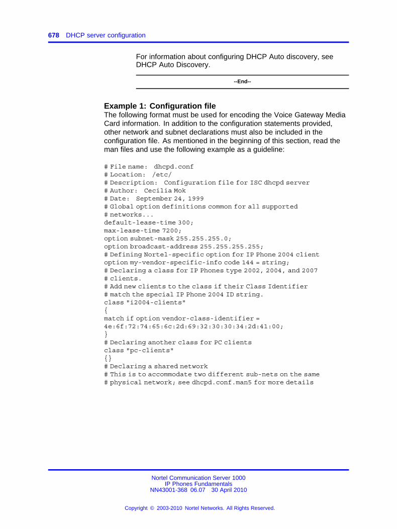
678 DHCP server configuration
For information about configuring DHCP Auto discovery, seeDHCP Auto Discovery.
--End--
Example 1: Configuration fileThe following format must be used for encoding the Voice Gateway MediaCard information. In addition to the configuration statements provided,other network and subnet declarations must also be included in theconfiguration file. As mentioned in the beginning of this section, read theman files and use the following example as a guideline:
# File name: dhcpd.conf# Location: /etc/# Description: Configuration file for ISC dhcpd server# Author: Cecilia Mok# Date: September 24, 1999# Global option definitions common for all supported# networks...default-lease-time 300;max-lease-time 7200;option subnet-mask 255.255.255.0;option broadcast-address 255.255.255.255;# Defining Nortel-specific option for IP Phone 2004 clientoption my-vendor-specific-info code 144 = string;# Declaring a class for IP Phones type 2002, 2004, and 2007# clients.# Add new clients to the class if their Class Identifier# match the special IP Phone 2004 ID string.class "i2004-clients"{match if option vendor-class-identifier =4e:6f:72:74:65:6c:2d:69:32:30:30:34:2d:41:00;}# Declaring another class for PC clientsclass "pc-clients"{}# Declaring a shared network# This is to accommodate two different sub-nets on the same# physical network; see dhcpd.conf.man5 for more details
Nortel Communication Server 1000IP Phones Fundamentals
NN43001-368 06.07 30 April 2010
Copyright © 2003-2010 Nortel Networks. All Rights Reserved.
.
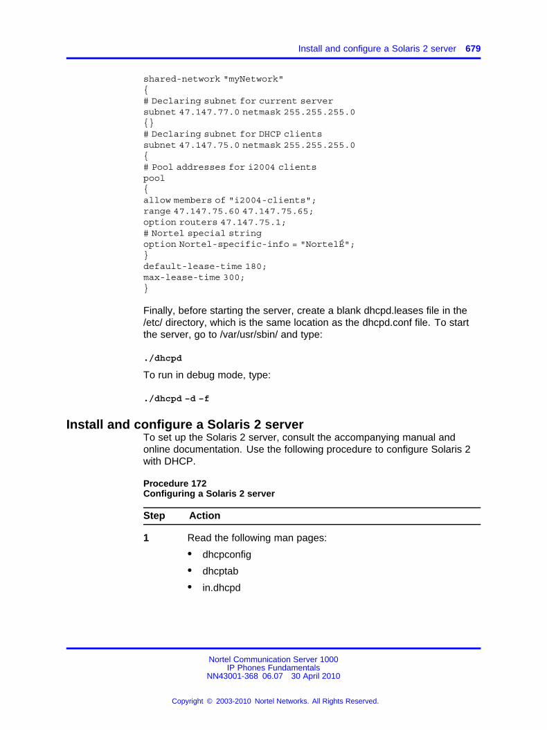
Install and configure a Solaris 2 server 679
shared-network "myNetwork"{# Declaring subnet for current serversubnet 47.147.77.0 netmask 255.255.255.0{}# Declaring subnet for DHCP clientssubnet 47.147.75.0 netmask 255.255.255.0{# Pool addresses for i2004 clientspool{allow members of "i2004-clients";range 47.147.75.60 47.147.75.65;option routers 47.147.75.1;# Nortel special stringoption Nortel-specific-info = "NortelÉ";}default-lease-time 180;max-lease-time 300;}
Finally, before starting the server, create a blank dhcpd.leases file in the/etc/ directory, which is the same location as the dhcpd.conf file. To startthe server, go to /var/usr/sbin/ and type:
./dhcpd
To run in debug mode, type:
./dhcpd –d –f
Install and configure a Solaris 2 serverTo set up the Solaris 2 server, consult the accompanying manual andonline documentation. Use the following procedure to configure Solaris 2with DHCP.
Procedure 172Configuring a Solaris 2 server
Step Action
1 Read the following man pages:
• dhcpconfig
• dhcptab
• in.dhcpd
Nortel Communication Server 1000IP Phones Fundamentals
NN43001-368 06.07 30 April 2010
Copyright © 2003-2010 Nortel Networks. All Rights Reserved.
.
680 DHCP server configuration
2 Collect information about the network such as subnet mask,router/Media Gateway and DNS server IP addresses asspecified. Make sure this information is current.
3 Log on as root and invoke the interface by typing dhcpconfigat the prompt. A list of questions is presented and theadministrator must supply answers that are then used toconfigure the DHCP server.
Solaris 2 uses a text-based interface for configuring DHCPservices.
For information about configuring DHCP Auto discovery, seeDHCP Auto Discovery.
--End--
Use the following procedure to configure Solaris 2 servers to work withIP Phones.
Procedure 173Configuring Solaris 2 to work with IP Phones
Step Action
1 Do one of the following:
• Create a symbol definition for defining a Site Specific optionby typing the following in the dhcptab configuration tablelocated at /etc/default/dhcp:NI2004 s Site,128,ASCII,1,0
• Use the dhtadm configuration table management utility bytyping the following command at the prompt:dhtadm -A -s NI2004 –d ’Site,128,ASCII,1,0’
Where:NI2004:symbol name
s:identify definition as symbolSite:site specific option128:option code
ASCII:data type1:granularity0:no maximum size of granularity, that is, infinite
2 Create a Client Identifier macro by doing one of the following:
• entering the following:Nortel-i2004-A m:NI2004="NortelÉ":
• Use the dhtadm command:dhtadm -A -m Nortel-i2004-A -d ’:NI2004="NortelÉ":’
Nortel Communication Server 1000IP Phones Fundamentals
NN43001-368 06.07 30 April 2010
Copyright © 2003-2010 Nortel Networks. All Rights Reserved.
.
Install and configure a Solaris 2 server 681
3 Invoke the DHCP services on the Solaris server by entering atthe prompt.:
in.dhcpd,
Specify –d and/or –v options for debug mode.
--End--
Table 158 "DHCP tab table" (page 681) shows examples of theinformation.
Table 158DHCP tab table
Locale m :UTCoffst=18000:
nbvws286 m
:Include=Locale:LeaseTim=150:LeaseNeg:DNSdmain=ca.nortel.com:/
DNSserv=47.108.128.216 47.211.192.8 47.80.12.69:
47.147.75.0 m :NISdmain=bvwlab:NISservs=47.147.64.91:
47.147.64.0 m
:Broadcst=47.147.79.255:Subnet=255.255.240.0:MTU=1500:/
Router=47.147.64.1:NISdmain=bvwlab:NISservs=47.147.64.91:
#
NI2004 s Site,128,ASCII,1,0
Nortel-i2004-A m:
NI2004="Nortel-i2004-A,47.147.75.31:4100,1,5;47.147.77.143:4100,1,5.":
Table 159Network table
01006038760290 00 47.147.65.198 47.147.74.36 944600968
nbvws286
0100C04F662B6F 00 47.147.65.199 47.147.74.36 944600959 nbvws286
Nortel Communication Server 1000IP Phones Fundamentals
NN43001-368 06.07 30 April 2010
Copyright © 2003-2010 Nortel Networks. All Rights Reserved.
.

682 DHCP server configuration
Nortel Communication Server 1000IP Phones Fundamentals
NN43001-368 06.07 30 April 2010
Copyright © 2003-2010 Nortel Networks. All Rights Reserved.
.
683.
AppendixTFTP Server
ContentsThis section contains the following topics:
• “Introduction” (page 683)
• “TFTP Server planning” (page 683)
• “Updating IP Phones firmware” (page 685)
• “Downloading and configuring fonts” (page 692)
IntroductionA Trivial File Transfer Protocol (TFTP) Server may be required in an IPTelephony system to distribute firmware to IP Phones. The TFTP Servercan reside on a subnet other than the Call Server and can be located oneither side of the firewall.
TFTP Server planningCAUTIONTFTP firmware download does not work when the IP AudioConference Phone 2033 is behind a NAT Server.
The TFTP Server holds the firmware for updating the IP Phones.Assuming the IP address for the TFTP Server has been configured on theIP Phone, each time the IP Phone is powered on, rebooted, or is manuallyreset, the IP Phone checks the version of firmware against the version offirmware on the TFTP Server. If the versions are different, the IP Phonedownloads the new firmware from the TFTP Server.
Nortel Communication Server 1000IP Phones Fundamentals
NN43001-368 06.07 30 April 2010
Copyright © 2003-2010 Nortel Networks. All Rights Reserved.
.
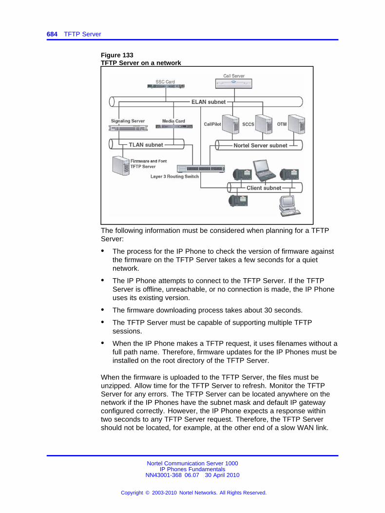
684 TFTP Server
Figure 133TFTP Server on a network
The following information must be considered when planning for a TFTPServer:
• The process for the IP Phone to check the version of firmware againstthe firmware on the TFTP Server takes a few seconds for a quietnetwork.
• The IP Phone attempts to connect to the TFTP Server. If the TFTPServer is offline, unreachable, or no connection is made, the IP Phoneuses its existing version.
• The firmware downloading process takes about 30 seconds.
• The TFTP Server must be capable of supporting multiple TFTPsessions.
• When the IP Phone makes a TFTP request, it uses filenames without afull path name. Therefore, firmware updates for the IP Phones must beinstalled on the root directory of the TFTP Server.
When the firmware is uploaded to the TFTP Server, the files must beunzipped. Allow time for the TFTP Server to refresh. Monitor the TFTPServer for any errors. The TFTP Server can be located anywhere on thenetwork if the IP Phones have the subnet mask and default IP gatewayconfigured correctly. However, the IP Phone expects a response withintwo seconds to any TFTP Server request. Therefore, the TFTP Servershould not be located, for example, at the other end of a slow WAN link.
Nortel Communication Server 1000IP Phones Fundamentals
NN43001-368 06.07 30 April 2010
Copyright © 2003-2010 Nortel Networks. All Rights Reserved.
.
Updating IP Phones firmware 685
If too many IP Phones attempt to download new software simultaneously,it can cause the downloads to slow down or return error messages. Toreduce the number of retries and error messages, manage the downloadprocess by staggering the times the IP Phones download the firmware.
Nortel has tested the following TFTP Servers. They are listed in order ofpreference:
• Nortel TFTP Server (ONMS application)
• Weird Solutions TFTP Server
• Pumpkin TFTP Server
Pre-download checklistEnsure the following requirements are met before downloading firmware:
• A LAN must be properly configured and operational.
• The Nortel Telephony system must be connected to the network andcompletely operational.
• A TFTP Server must be available on the network in order to load theappropriate firmware in the IP Phones.
Updating IP Phones firmwareThe latest IP Phone firmware files and configuration files are located onthe Nortel Web site at www.nortel.com/downloadingcontent. You mustunzip the files before you upload the files to the TFTP Server. The zipfile contains the .bin file and configuration files (.cfg) for each IP Phonetype, and a README text file (.txt) which contains instructions, to set upthe TFTP Server and to modify the configuration file correctly, so that theIP Phone downloads the firmware.
For future firmware upgrades, update the firmware file which is storedon the TFTP Server. Each time the IP Phone is powered on, it checkswith the TFTP Server to ensure it has the proper firmware version, and itdownloads the new software, if necessary.
Use Procedure 174 “Updating the IP Phones firmware” (page 686) toupdate the IP Phone firmware for IP Phone 2001, IP Phone 2002, IPPhone 2004, and IP Audio Conference Phone 2033.
For information about updating the firmware for the IP Phone 2007, IPPhones 1110/1120E/1140E/1150E/1165E, IP Phone 1210, IP Phone 1220,and IP Phone 1230, see Procedure 175 “Updating the firmware” (page688).
Nortel Communication Server 1000IP Phones Fundamentals
NN43001-368 06.07 30 April 2010
Copyright © 2003-2010 Nortel Networks. All Rights Reserved.
.
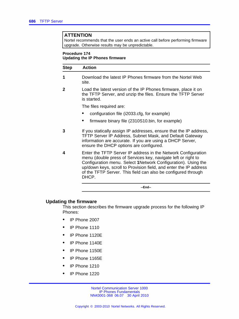
686 TFTP Server
ATTENTIONNortel recommends that the user ends an active call before performing firmwareupgrade. Otherwise results may be unpredictable.
Procedure 174Updating the IP Phones firmware
Step Action
1 Download the latest IP Phones firmware from the Nortel Website.
2 Load the latest version of the IP Phones firmware, place it onthe TFTP Server, and unzip the files. Ensure the TFTP Serveris started.
The files required are:
• configuration file (i2033.cfg, for example)
• firmware binary file (2310S10.bin, for example)
3 If you statically assign IP addresses, ensure that the IP address,TFTP Server IP Address, Subnet Mask, and Default Gatewayinformation are accurate. If you are using a DHCP Server,ensure the DHCP options are configured.
4 Enter the TFTP Server IP address in the Network Configurationmenu (double press of Services key, navigate left or right toConfiguration menu. Select 1Network Configuration). Using theup/down keys, scroll to Provision field, and enter the IP addressof the TFTP Server. This field can also be configured throughDHCP.
--End--
Updating the firmwareThis section describes the firmware upgrade process for the following IPPhones:
• IP Phone 2007
• IP Phone 1110
• IP Phone 1120E
• IP Phone 1140E
• IP Phone 1150E
• IP Phone 1165E
• IP Phone 1210
• IP Phone 1220
Nortel Communication Server 1000IP Phones Fundamentals
NN43001-368 06.07 30 April 2010
Copyright © 2003-2010 Nortel Networks. All Rights Reserved.
.
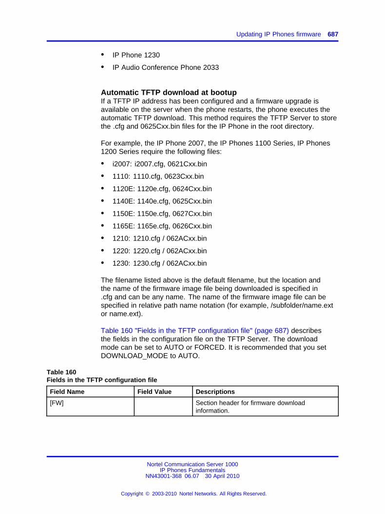
Updating IP Phones firmware 687
• IP Phone 1230
• IP Audio Conference Phone 2033
Automatic TFTP download at bootupIf a TFTP IP address has been configured and a firmware upgrade isavailable on the server when the phone restarts, the phone executes theautomatic TFTP download. This method requires the TFTP Server to storethe .cfg and 0625Cxx.bin files for the IP Phone in the root directory.
For example, the IP Phone 2007, the IP Phones 1100 Series, IP Phones1200 Series require the following files:
• i2007: i2007.cfg, 0621Cxx.bin
• 1110: 1110.cfg, 0623Cxx.bin
• 1120E: 1120e.cfg, 0624Cxx.bin
• 1140E: 1140e.cfg, 0625Cxx.bin
• 1150E: 1150e.cfg, 0627Cxx.bin
• 1165E: 1165e.cfg, 0626Cxx.bin
• 1210: 1210.cfg / 062ACxx.bin
• 1220: 1220.cfg / 062ACxx.bin
• 1230: 1230.cfg / 062ACxx.bin
The filename listed above is the default filename, but the location andthe name of the firmware image file being downloaded is specified in.cfg and can be any name. The name of the firmware image file can bespecified in relative path name notation (for example, /subfolder/name.extor name.ext).
Table 160 "Fields in the TFTP configuration file" (page 687) describesthe fields in the configuration file on the TFTP Server. The downloadmode can be set to AUTO or FORCED. It is recommended that you setDOWNLOAD_MODE to AUTO.
Table 160Fields in the TFTP configuration file
Field Name Field Value Descriptions
[FW] Section header for firmware downloadinformation.
Nortel Communication Server 1000IP Phones Fundamentals
NN43001-368 06.07 30 April 2010
Copyright © 2003-2010 Nortel Networks. All Rights Reserved.
.
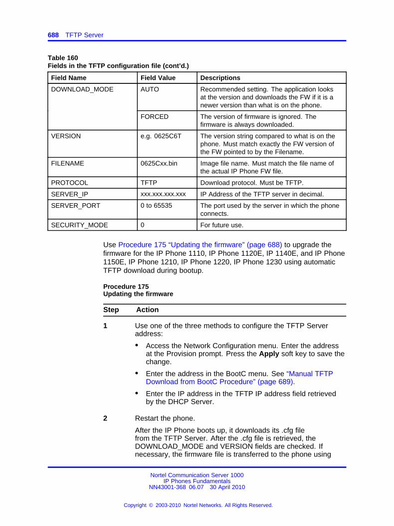
688 TFTP Server
Table 160Fields in the TFTP configuration file (cont’d.)
Field Name Field Value Descriptions
AUTO Recommended setting. The application looksat the version and downloads the FW if it is anewer version than what is on the phone.
DOWNLOAD_MODE
FORCED The version of firmware is ignored. Thefirmware is always downloaded.
VERSION e.g. 0625C6T The version string compared to what is on thephone. Must match exactly the FW version ofthe FW pointed to by the Filename.
FILENAME 0625Cxx.bin Image file name. Must match the file name ofthe actual IP Phone FW file.
PROTOCOL TFTP Download protocol. Must be TFTP.
SERVER_IP xxx.xxx.xxx.xxx IP Address of the TFTP server in decimal.
SERVER_PORT 0 to 65535 The port used by the server in which the phoneconnects.
SECURITY_MODE 0 For future use.
Use Procedure 175 “Updating the firmware” (page 688) to upgrade thefirmware for the IP Phone 1110, IP Phone 1120E, IP 1140E, and IP Phone1150E, IP Phone 1210, IP Phone 1220, IP Phone 1230 using automaticTFTP download during bootup.
Procedure 175Updating the firmware
Step Action
1 Use one of the three methods to configure the TFTP Serveraddress:
• Access the Network Configuration menu. Enter the addressat the Provision prompt. Press the Apply soft key to save thechange.
• Enter the address in the BootC menu. See “Manual TFTPDownload from BootC Procedure” (page 689).
• Enter the IP address in the TFTP IP address field retrievedby the DHCP Server.
2 Restart the phone.
After the IP Phone boots up, it downloads its .cfg filefrom the TFTP Server. After the .cfg file is retrieved, theDOWNLOAD_MODE and VERSION fields are checked. Ifnecessary, the firmware file is transferred to the phone using
Nortel Communication Server 1000IP Phones Fundamentals
NN43001-368 06.07 30 April 2010
Copyright © 2003-2010 Nortel Networks. All Rights Reserved.
.
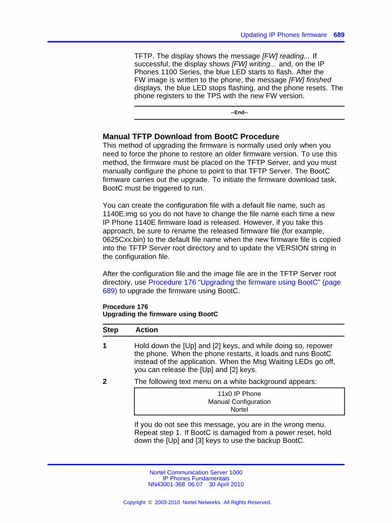
Updating IP Phones firmware 689
TFTP. The display shows the message [FW] reading... Ifsuccessful, the display shows [FW] writing... and, on the IPPhones 1100 Series, the blue LED starts to flash. After theFW image is written to the phone, the message [FW] finisheddisplays, the blue LED stops flashing, and the phone resets. Thephone registers to the TPS with the new FW version.
--End--
Manual TFTP Download from BootC ProcedureThis method of upgrading the firmware is normally used only when youneed to force the phone to restore an older firmware version. To use thismethod, the firmware must be placed on the TFTP Server, and you mustmanually configure the phone to point to that TFTP Server. The BootCfirmware carries out the upgrade. To initiate the firmware download task,BootC must be triggered to run.
You can create the configuration file with a default file name, such as1140E.img so you do not have to change the file name each time a newIP Phone 1140E firmware load is released. However, if you take thisapproach, be sure to rename the released firmware file (for example,0625Cxx.bin) to the default file name when the new firmware file is copiedinto the TFTP Server root directory and to update the VERSION string inthe configuration file.
After the configuration file and the image file are in the TFTP Server rootdirectory, use Procedure 176 “Upgrading the firmware using BootC” (page689) to upgrade the firmware using BootC.
Procedure 176Upgrading the firmware using BootC
Step Action
1 Hold down the [Up] and [2] keys, and while doing so, repowerthe phone. When the phone restarts, it loads and runs BootCinstead of the application. When the Msg Waiting LEDs go off,you can release the [Up] and [2] keys.
2 The following text menu on a white background appears:
11x0 IP PhoneManual Configuration
Nortel
If you do not see this message, you are in the wrong menu.Repeat step 1. If BootC is damaged from a power reset, holddown the [Up] and [3] keys to use the backup BootC.
Nortel Communication Server 1000IP Phones Fundamentals
NN43001-368 06.07 30 April 2010
Copyright © 2003-2010 Nortel Networks. All Rights Reserved.
.
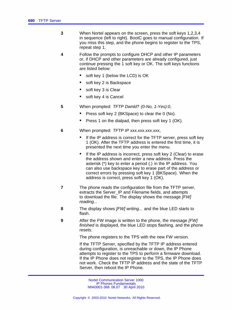
690 TFTP Server
3 When Nortel appears on the screen, press the soft keys 1,2,3,4in sequence (left to right). BootC goes to manual configuration. Ifyou miss this step, and the phone begins to register to the TPS,repeat step 1.
4 Follow the prompts to configure DHCP and other IP parametersor, if DHCP and other parameters are already configured, justcontinue pressing the 1 soft key or OK. The soft keys functionsare listed below:
• soft key 1 (below the LCD) is OK
• soft key 2 is Backspace
• soft key 3 is Clear
• soft key 4 is Cancel
5 When prompted: TFTP Dwnld? (0-No, 1-Yes):0,
• Press soft key 2 (BKSpace) to clear the 0 (No).
• Press 1 on the dialpad, then press soft key 1 (OK).
6 When prompted: TFTP IP xxx.xxx.xxx.xxx,
• If the IP address is correct for the TFTP server, press soft key1 (OK). After the TFTP address is entered the first time, it ispresented the next time you enter the menu.
• If the IP address is incorrect, press soft key 2 (Clear) to erasethe address shown and enter a new address. Press theasterisk (*) key to enter a period (.) in the IP address. Youcan also use backspace key to erase part of the address orcorrect errors by pressing soft key 1 (BKSpace). When theaddress is correct, press soft key 1 (OK).
7 The phone reads the configuration file from the TFTP server,extracts the Server_IP and Filename fields, and attemptsto download the file. The display shows the message [FW]reading...
8 The display shows [FW] writing... and the blue LED starts toflash.
9 After the FW image is written to the phone, the message [FW]finished is displayed, the blue LED stops flashing, and the phoneresets.
The phone registers to the TPS with the new FW version.
If the TFTP Server, specified by the TFTP IP address enteredduring configuration, is unreachable or down, the IP Phoneattempts to register to the TPS to perform a firmware download.If the IP Phone does not register to the TPS, the IP Phone doesnot work. Check the TFTP IP address and the state of the TFTPServer, then reboot the IP Phone.
Nortel Communication Server 1000IP Phones Fundamentals
NN43001-368 06.07 30 April 2010
Copyright © 2003-2010 Nortel Networks. All Rights Reserved.
.
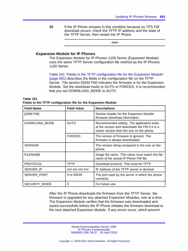
Updating IP Phones firmware 691
10 If the IP Phone remains in this condition because no TPS FWdownload occurs, check the TFTP IP address and the state ofthe TFTP Server, then restart the IP Phone.
--End--
Expansion Module for IP PhonesThe Expansion Module for IP Phones 1100 Series (Expansion Module)uses the same TFTP Server configuration file method as the IP Phones1100 Series.
Table 161 "Fields in the TFTP configuration file for the Expansion Module"(page 691) describes the fields in the configuration file on the TFTPServer. The section [GEM FW] indicates the firmware is for the ExpansionModule. Set the download mode to AUTO or FORCED. It is recommendedthat you set DOWNLOAD_MODE to AUTO.
Table 161Fields in the TFTP configuration file for the Expansion Module
Field Name Field Value Descriptions
[GEM FW] Section header for the Expansion Modulefirmware download information.
AUTO Recommended setting. The application looksat the version and downloads the FW if it is anewer version than the one on the phone.
DOWNLOAD_MODE
FORCED The version of firmware is ignored. Thefirmware is always downloaded.
VERSION The version string compared to the one on thephone.
FILENAME Image file name. This name must match the filename of the actual IP Phone FW file.
PROTOCOL TFTP Download protocol. This must be TFTP.
SERVER_IP xxx.xxx.xxx.xxx IP Address of the TFTP server in decimal.
SERVER_PORT 0 to 65535 The port used by the server in which the phoneconnects.
SECURITY_MODE 0 For future use.
After the IP Phone downloads the firmware from the TFTP Server, thefirmware is upgraded for any attached Expansion Modules, one at a time.The Expansion Module verifies that the firmware was downloaded andsaved successfully before the IP Phone initiates the firmware download tothe next attached Expansion Module. If any errors occur, which prevent
Nortel Communication Server 1000IP Phones Fundamentals
NN43001-368 06.07 30 April 2010
Copyright © 2003-2010 Nortel Networks. All Rights Reserved.
.
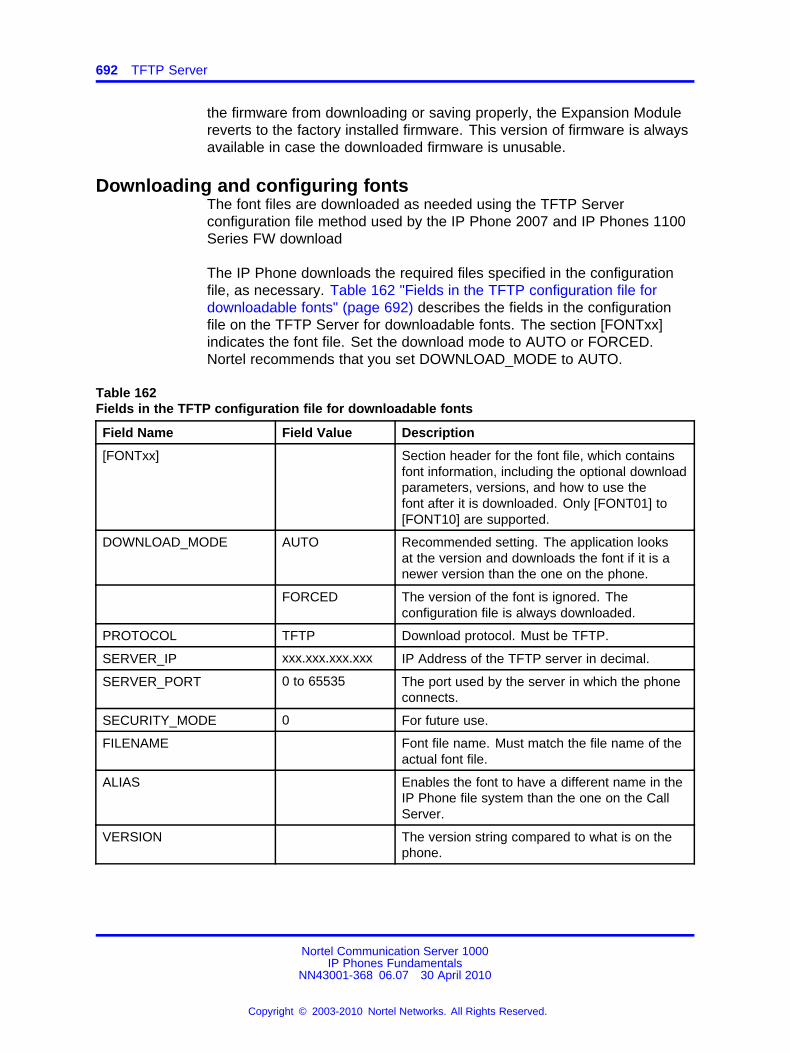
692 TFTP Server
the firmware from downloading or saving properly, the Expansion Modulereverts to the factory installed firmware. This version of firmware is alwaysavailable in case the downloaded firmware is unusable.
Downloading and configuring fontsThe font files are downloaded as needed using the TFTP Serverconfiguration file method used by the IP Phone 2007 and IP Phones 1100Series FW download
The IP Phone downloads the required files specified in the configurationfile, as necessary. Table 162 "Fields in the TFTP configuration file fordownloadable fonts" (page 692) describes the fields in the configurationfile on the TFTP Server for downloadable fonts. The section [FONTxx]indicates the font file. Set the download mode to AUTO or FORCED.Nortel recommends that you set DOWNLOAD_MODE to AUTO.
Table 162Fields in the TFTP configuration file for downloadable fonts
Field Name Field Value Description
[FONTxx] Section header for the font file, which containsfont information, including the optional downloadparameters, versions, and how to use thefont after it is downloaded. Only [FONT01] to[FONT10] are supported.
DOWNLOAD_MODE AUTO Recommended setting. The application looksat the version and downloads the font if it is anewer version than the one on the phone.
FORCED The version of the font is ignored. Theconfiguration file is always downloaded.
PROTOCOL TFTP Download protocol. Must be TFTP.
SERVER_IP xxx.xxx.xxx.xxx IP Address of the TFTP server in decimal.
SERVER_PORT 0 to 65535 The port used by the server in which the phoneconnects.
SECURITY_MODE 0 For future use.
FILENAME Font file name. Must match the file name of theactual font file.
ALIAS Enables the font to have a different name in theIP Phone file system than the one on the CallServer.
VERSION The version string compared to what is on thephone.
Nortel Communication Server 1000IP Phones Fundamentals
NN43001-368 06.07 30 April 2010
Copyright © 2003-2010 Nortel Networks. All Rights Reserved.
.
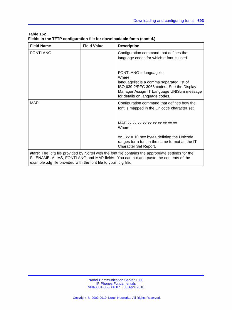
Downloading and configuring fonts 693
Table 162Fields in the TFTP configuration file for downloadable fonts (cont’d.)
Field Name Field Value Description
FONTLANG Configuration command that defines thelanguage codes for which a font is used.
FONTLANG = languagelistWhere:languagelist is a comma separated list ofISO 639-2/RFC 3066 codes. See the DisplayManager Assign IT Language UNIStim messagefor details on language codes.
MAP Configuration command that defines how thefont is mapped in the Unicode character set.
MAP xx xx xx xx xx xx xx xx xx xxWhere:
xx…xx = 10 hex bytes defining the Unicoderanges for a font in the same format as the ITCharacter Set Report.
Note: The .cfg file provided by Nortel with the font file contains the appropriate settings for theFILENAME, ALIAS, FONTLANG and MAP fields. You can cut and paste the contents of theexample .cfg file provided with the font file to your .cfg file.
Nortel Communication Server 1000IP Phones Fundamentals
NN43001-368 06.07 30 April 2010
Copyright © 2003-2010 Nortel Networks. All Rights Reserved.
.
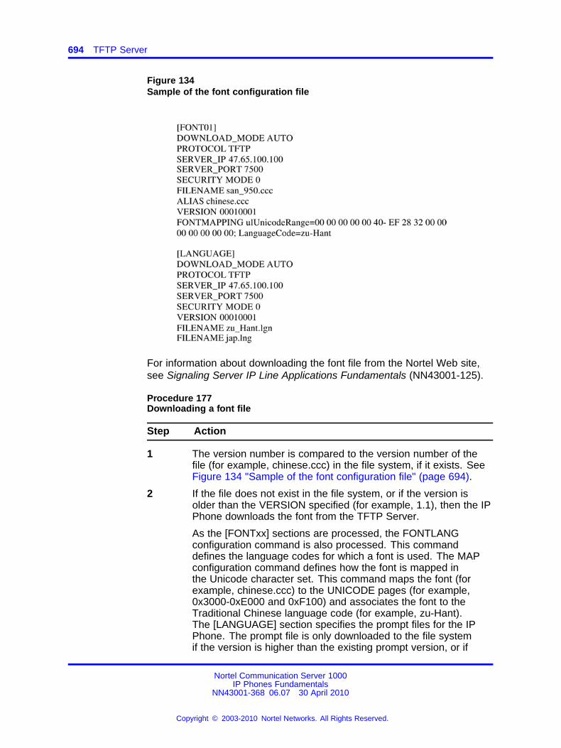
694 TFTP Server
Figure 134Sample of the font configuration file
For information about downloading the font file from the Nortel Web site,see Signaling Server IP Line Applications Fundamentals (NN43001-125).
Procedure 177Downloading a font file
Step Action
1 The version number is compared to the version number of thefile (for example, chinese.ccc) in the file system, if it exists. SeeFigure 134 "Sample of the font configuration file" (page 694).
2 If the file does not exist in the file system, or if the version isolder than the VERSION specified (for example, 1.1), then the IPPhone downloads the font from the TFTP Server.
As the [FONTxx] sections are processed, the FONTLANGconfiguration command is also processed. This commanddefines the language codes for which a font is used. The MAPconfiguration command defines how the font is mapped inthe Unicode character set. This command maps the font (forexample, chinese.ccc) to the UNICODE pages (for example,0x3000-0xE000 and 0xF100) and associates the font to theTraditional Chinese language code (for example, zu-Hant).The [LANGUAGE] section specifies the prompt files for the IPPhone. The prompt file is only downloaded to the file systemif the version is higher than the existing prompt version, or if
Nortel Communication Server 1000IP Phones Fundamentals
NN43001-368 06.07 30 April 2010
Copyright © 2003-2010 Nortel Networks. All Rights Reserved.
.

Downloading and configuring fonts 695
DOWNLOAD_MODE is set to FORCED. The IP Phone firmwareincludes the base set of prompt files so downloads are notnecessary for languages natively supported by the firmware.
3 After the required fonts are downloaded from the TFTP Server,the IP Phone resets and registers to the TPS.
--End--
Nortel Communication Server 1000IP Phones Fundamentals
NN43001-368 06.07 30 April 2010
Copyright © 2003-2010 Nortel Networks. All Rights Reserved.
.

696 TFTP Server
Nortel Communication Server 1000IP Phones Fundamentals
NN43001-368 06.07 30 April 2010
Copyright © 2003-2010 Nortel Networks. All Rights Reserved.
.
697.
Appendix802.1Q VLAN description
ContentsThis section contains the following topics:
• “Introduction” (page 697)
• “Description” (page 698)
• “IP Phone support” (page 699)
• “IP Softphone 2050 support” (page 699)
• “Three-port switch support” (page 699)
• “VLAN IDs” (page 700)
• “Enhanced Data VLAN” (page 702)
IntroductionThe 802.1Q support is available for the following IP Phones
• IP Phone 2001
• IP Phone 2002
• IP Phone 2004
• IP Phone 2007
• IP Audio Conference Phone 2033
• IP Softphone 2050 (through the PC operating system)
• IP Phone 1110
• IP Phone 1120E
• IP Phone 1140E
• IP Phone 1150E
• IP Phone 1165E
Nortel Communication Server 1000IP Phones Fundamentals
NN43001-368 06.07 30 April 2010
Copyright © 2003-2010 Nortel Networks. All Rights Reserved.
.
698 802.1Q VLAN description
• IP Phone 1210
• IP Phone 1220
• IP Phone 1230
The 802.1Q support is configured from the user display interface of theIP Phone. Configure 802.1Q VLAN support when you initially configurean IP Phone. The switch ports for Voice Gateway Media Card TLANnetwork interfaces must be configured as untagged ports so the header isremoved. While the IP Phone 2001 and the IP Audio Conference Phone2033 provide VLAN support, they do not provide a port for a PC.
The 802.1Q IEEE protocol standard allows virtual LANs (VLANs) to bedefined within a single LAN. This improves bandwidth management andlimits the impact of broadcast and multicast messages. A higher level ofsecurity between segments in a network can also be achieved.
802.1Q functionality is supported only on the IP Phone. The IP Lineapplication IP stack does not provide 802.1Q support for the VoiceGateway Media Card.
DescriptionThe p bits within the 802.1Q standard allow packet prioritization at Layer2 improving network throughput for VoIP data.
The 802.1Q standard specifies a new format of Ethernet frame. A standardEthernet frame contains
• a header consisting of a six-byte destination MAC address (followingthe header is a data area)
• a six-byte source MAC address
• a two-byte protocol identifier
The 802.1Q formatted frame is identical to a standard Ethernet frame, withthe exception of the 4-byte 802.1Q tag that is inserted between the sourceMAC address and the protocol identifier. The first 16 bits of the 802.1Qtag field is the Tag Protocol Identifier containing 8100 (hex), allowing theEthernet interface to distinguish it from standard Ethernet frames. The last16 bits of the 802.1Q tag contain the following information
• a 3-bit Priority field (the 802.1p defined bits)
• a 1-bit Canonical Field Identifier (CFI)
• a 12-bit VLAN ID field
Nortel Communication Server 1000IP Phones Fundamentals
NN43001-368 06.07 30 April 2010
Copyright © 2003-2010 Nortel Networks. All Rights Reserved.
.
Three-port switch support 699
IP Phone supportThe IP Phones support 802.1Q as follows
• 802.1Q can be enabled or disabled at boot time using manualconfiguration or control downloaded from the TPS.
• If 802.1Q is disabled, standard Ethernet frames are transmitted.
• If 802.1Q is enabled, all frames transmitted by the Ethernet driver havethe 802.1Q tag bytes inserted between the source MAC address andthe protocol type field. The tag protocol identifier field contains 8100(hex) and the CFI bit is set to 0.
• When 802.1Q is enabled, the configuration of separate voice and dataVLANs is possible. Each VLAN has its own ID and priority on the IPPhone. Voice messages have the priority bits of all frames set to 6(octal) and the VOICE VLAN ID is set to 000 (hex) by default. Datamessages have the priority bits of all frames set to 0 and the DataVLAN ID is set to 000 (hex) by default. The GUI and TPS configuredvalues override these values.
• The IP Phone Ethernet driver receives any Ethernet frame destined forit, regardless of whether 802.1Q is enabled or whether the receivedframe is an 802.1Q tagged frame.
The only exception is any 802.1Q tagged frame with the CFI = 1. Inthis case the frame is discarded.
• The IP Phone Ethernet driver strips the 802.1Q tag information fromthe frame prior to passing it on to the IP stack.
• The IP Phone Ethernet driver filters packets by the VLAN tag and MACaddress. Tagged traffic is prioritized and routed based on the prioritybits.
IP Softphone 2050 supportThe IP Softphone 2050 supports 802.1Q with Windows 2000. By default,when 802.1Q is enabled, the priority bits of all frames are set to 6 and theVLAN ID is set to 0 (a restriction of Windows 2000).
Three-port switch supportThe section refers to the following IP Phones
• IP Phone 2002
• IP Phone 2004
• IP Phone 2007
• IP Phone 1120E
• IP Phone 1140E
Nortel Communication Server 1000IP Phones Fundamentals
NN43001-368 06.07 30 April 2010
Copyright © 2003-2010 Nortel Networks. All Rights Reserved.
.
700 802.1Q VLAN description
• IP Phone 1150E
• IP Phone 1165E
• IP Phone 1220
• IP Phone 1230
The three-port switch does not interpret the 802.1Q header, but rather,allows the packets to pass through unmodified. Priority is achieved on aper port basis. The phone "port" traffic has higher priority over the Ethernetport to which the PC connects.
An IP Phone can receive Broadcast frames from a PC data VLAN. Anydata network broadcast storm packets from the network are seen by theIP Phone. Significant broadcast storms occurring on the Data VLAN canimpact IP Phone performance. See “VLAN Configuration Choices” (page702) for configuration information to filter network activity from impacting IPPhone performance.
Enhanced 802.1P and 802.1Q support improves voice quality by takingadvantage of the VLAN filtering available on the three-port switch on the IPPhones 1100 Series , IP Phones 1200 Series, IP Phone 2002, IP Phone2004, and IP Phone 2007.
The following functions are available on the three-port switch
• hardware VLAN filter
• two TX (out) queues on each port —High Priority Queue (HPQ) andLow Priority Queue (LPQ)
Therefore, traffic other than Voice VLAN can be filtered by enabling theVLAN filtering feature and taking advantage of the hardware VLAN filter.Voice traffic is always queued to the HPQ thereby ensuring a higherquality of service.
VLAN IDsThe VOICE and Data VLAN ID fields can be specified on a per interfacebasis. There is only one network interface on the IP Phone; however, theIP Phone has two internal IDs, one for voice and one for data traffic. TheIP Phone firmware can detect and route the voice and data traffic.
The VLAN ID fields are global settings. That is, all voice packetstransmitted by the IP Phone have the same VOICE VLAN ID. If DataVLAN is enabled, the IP Phone adds the Data VLAN ID to untagged traffic.However, if the traffic arriving on the PC port is already tagged, the framepasses through unchanged.
Nortel Communication Server 1000IP Phones Fundamentals
NN43001-368 06.07 30 April 2010
Copyright © 2003-2010 Nortel Networks. All Rights Reserved.
.
VLAN IDs 701
Each VLAN ID is specified as follows
• The default VLAN ID is 000 (hex).
• The VOICE and Data VLAN IDs can be specified in the manualconfiguration user interface.
• Or, in the case of the VOICE VLAN ID, the VOICE VLAN ID can alsobe configured by the DHCP parameter when using the AutomaticVLAN discovery using DHCP approach.
Automatic VOICE VLAN ID configurationAs part of the 802.1Q feature, there are two options to automaticallydiscover the voice VLAN ID: using DHCP and 802.1ab LLDP. This processreduces the configuration steps since entering data manually (the VOICEVLAN ID) is not required.
When the Automatic VOICE VLAN Discovery using DHCP approach isused, and the IP Phone has been configured as such, the following stepsare automatically taken to obtain the VOICE VLAN ID
1. The IP Phones perform an initial DHCP Discovery Request in thedefault VLAN.
2. The DHCP server returns a DHCP Ack me ssage with an IP address inthe data VLAN and one or more voice VLAN IDs in the vendor-specificfield.
3. The IP Phone reads and saves the VOICE VLAN IDs.
4. The IP Phone rejects the DHCP offer (accepts it but immediately givesup the lease).
5. The IP Phone reboots and sends a DHCP Discovery Request with thefirst VLAN ID from the saved list. This is repeated for each VLAN ID inthe list until a response is received.
This works because the Layer 2 switch discards every DHCP DiscoveryRequest it receives from the IP Phone if the VLAN ID does not match theVLAN IDs configured on the port. When the IP Phone sends a DHCPDiscovery Request with the port configured VLAN ID, the packet passesinto the network and the DHCP server Ack message is passed back.
When a DHCP Ack message is received, the IP Phone accepts the offerand saves the IP address and Node IP address.
For information on how to implement Automatic VOICE VLAN ID, see“DHCP Auto Discovery” (page 451) .
Nortel Communication Server 1000IP Phones Fundamentals
NN43001-368 06.07 30 April 2010
Copyright © 2003-2010 Nortel Networks. All Rights Reserved.
.
702 802.1Q VLAN description
To use the LLDP MED network policy TLV to provision the Voice VLAN,see “802.1ab Link Layer Discovery Protocol” (page 427).
VLAN Configuration ChoicesEnhanced VLAN has two main functions
• Enhance the current Voice VLAN by implementing the hardware VLANfilter on the IP Phone port (SMP).
• Use TX High Priority Queue (HPQ) and 802.1P VLAN priority toenhance the traffic control on the IP Phone and PC network interface.
ATTENTIONVLAN filtering on the telephony port is disabled by default. If tagging is enabledon the telephony port, you can enable VLAN filtering on the telephony port.When VLAN filtering is enabled, packets destined for the IP Phone port arefiltered based on the MAC address and the VLAN tag.
If VLAN filtering is not enabled on the telephony port, packets destined for the IPPhone port are filtered only on the MAC address. Filtering based on the VLANtag does not occur. This makes the telephony port susceptible to broadcaststorms and a Denial of Service (DOS) attack.
Enhanced Data VLANEnhancements for Data (PC Port) VLAN for the IP Phone include thefollowing
• Data (PC Port) VLAN packet handling
— PC Port (Ingress direction)
— PC Port (Egress direction)
• Data (PC Port) VLAN Tag Stripping
Data (PC Port) VLAN packet handlingPackets processed to and from the PC port operate as follows:
PC Port (Ingress direction)
• Data VLAN disabled—all traffic received on the PC port is switchedbased on MAC address. The packets are not modified in any way.
• Data VLAN enabled—all untagged packets received on the PC porthave the 802.1Q header appended and the VLAN ID is set to the valuethat was manually configured in the Data VLAN field. Any packetarriving on the PC port that is already tagged is dropped.
PC Port (Egress direction)
Nortel Communication Server 1000IP Phones Fundamentals
NN43001-368 06.07 30 April 2010
Copyright © 2003-2010 Nortel Networks. All Rights Reserved.
.
Enhanced Data VLAN 703
• Data VLAN disabled—all traffic received on the PC port has the802.1Q header appended and the VLAN ID is set to the value whichwas manually configured in the Data VLAN field. Any packet arrivingon the PC port which is already tagged is dropped.
• Data VLAN enabled—all traffic is forwarded to the PC port based on areview of the MAC address and the 802.1Q value that was manuallyconfigured in the Data VLAN field. Traffic is forwarded out the PC portonly if the packets contain the Data VLAN tag. Untagged traffic andtraffic without the Data VLAN tag is dropped.
Data (PC Port) VLAN Tag StrippingData VLAN Tag Stripping can be configured in the Network Configurationmenu. To enable Data VLAN Tag Stripping, select the PC-Port UntagAll check box, Data VLAN Tag Stripping can be enabled or disabledindependent of enabling VLAN support on the PC Port.
If the Data VLAN Tag Stripping is disabled, the packet is sent to the PCPort unmodified. If the Data VLAN Tag Stripping is enabled, the 802.1Qheader if one exists, is removed from the packet before the packet isforwarded to the PC port.
During manual configuration, if Data VLAN is enabled by configuring aVLAN ID, the PC-Port Untag All check box is selected and is enabled bydefault. By default, the egress tag is stripped. To manually override thissetting and disable egress stripping, clear the PC-Port Untag All checkbox.
If Data VLAN is not enabled during manual configuration, the PC-PortUntag All check box is not selected. By default, the ingress tag is notstripped. To manually override this setting and enable ingress stripping,select the PC-Port Untag All check box.
Nortel Communication Server 1000IP Phones Fundamentals
NN43001-368 06.07 30 April 2010
Copyright © 2003-2010 Nortel Networks. All Rights Reserved.
.

704 802.1Q VLAN description
Nortel Communication Server 1000IP Phones Fundamentals
NN43001-368 06.07 30 April 2010
Copyright © 2003-2010 Nortel Networks. All Rights Reserved.
.
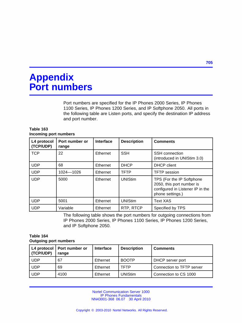
705.
AppendixPort numbers
Port numbers are specified for the IP Phones 2000 Series, IP Phones1100 Series, IP Phones 1200 Series, and IP Softphone 2050. All ports inthe following table are Listen ports, and specify the destination IP addressand port number.
Table 163Incoming port numbers
L4 protocol(TCP/UDP)
Port number orrange
Interface Description Comments
TCP 22 Ethernet SSH SSH connection(introduced in UNIStim 3.0)
UDP 68 Ethernet DHCP DHCP client
UDP 1024––1026 Ethernet TFTP TFTP session
UDP 5000 Ethernet UNIStim TPS (For the IP Softphone2050, this port number isconfigured in Listener IP in thephone settings.)
UDP 5001 Ethernet UNIStim Text XAS
UDP Variable Ethernet RTP, RTCP Specified by TPS
The following table shows the port numbers for outgoing connections fromIP Phones 2000 Series, IP Phones 1100 Series, IP Phones 1200 Series,and IP Softphone 2050.
Table 164Outgoing port numbers
L4 protocol(TCP/UDP)
Port number orrange
Interface Description Comments
UDP 67 Ethernet BOOTP DHCP server port
UDP 69 Ethernet TFTP Connection to TFTP server
UDP 4100 Ethernet UNIStim Connection to CS 1000
Nortel Communication Server 1000IP Phones Fundamentals
NN43001-368 06.07 30 April 2010
Copyright © 2003-2010 Nortel Networks. All Rights Reserved.
.
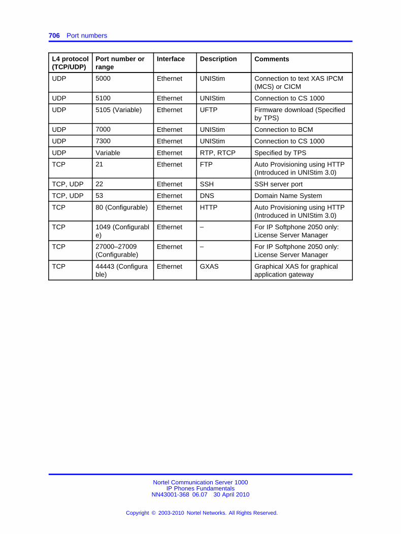
706 Port numbers
L4 protocol(TCP/UDP)
Port number orrange
Interface Description Comments
UDP 5000 Ethernet UNIStim Connection to text XAS IPCM(MCS) or CICM
UDP 5100 Ethernet UNIStim Connection to CS 1000
UDP 5105 (Variable) Ethernet UFTP Firmware download (Specifiedby TPS)
UDP 7000 Ethernet UNIStim Connection to BCM
UDP 7300 Ethernet UNIStim Connection to CS 1000
UDP Variable Ethernet RTP, RTCP Specified by TPS
TCP 21 Ethernet FTP Auto Provisioning using HTTP(Introduced in UNIStim 3.0)
TCP, UDP 22 Ethernet SSH SSH server port
TCP, UDP 53 Ethernet DNS Domain Name System
TCP 80 (Configurable) Ethernet HTTP Auto Provisioning using HTTP(Introduced in UNIStim 3.0)
TCP 1049 (Configurable)
Ethernet – For IP Softphone 2050 only:License Server Manager
TCP 27000–27009(Configurable)
Ethernet – For IP Softphone 2050 only:License Server Manager
TCP 44443 (Configurable)
Ethernet GXAS Graphical XAS for graphicalapplication gateway
Nortel Communication Server 1000IP Phones Fundamentals
NN43001-368 06.07 30 April 2010
Copyright © 2003-2010 Nortel Networks. All Rights Reserved.
.
707.
AppendixBluetooth® and Wireless Fidelityinterference
Bluetooth® is a wireless communication technology that is especiallyappropriate for cable replacement, but is not a personal mobilitytechnology. The IP Phones 1140E/1150E/1165E are Class 2 Bluetooth®
wireless technology devices. This means the Bluetooth® wirelesstechnology devices work up to 10 meters. However, audio performance ina Bluetooth® wireless technology headset suffers if you walk away fromthe phone. After 10 meters, the link drops.
Both Bluetooth® wireless technology and Wireless Fidelity (WiFi) wirelessprotocols operate in the 2.40 Industrial, Scientific and Medical (ISM)Radio Frequency (RF) band. Bluetooth® wireless technology and WiFiwireless communications can interfere with each other. Interferencecan occur between Bluetooth® wireless technology and WiFi wirelesscommunications, which results in lowered data throughput. Bluetooth®
wireless technology utilizes a frequency hopping mechanism so thatit does not stick in a fixed channel like WiFi does and the master andslave devices keep hopping synchronously during whole connectingtime. However, occasionally Bluetooth® wireless technology devices canhop into a channel, which other WiFi devices occupy and can encountercorrupted packet at that hop. The Bluetooth® wireless technology headset(audio-oriented) devices are more susceptible to radio interference thanother data-oriented devices because Synchronous Connection-OrientedLink (SCO) data do not re-transmit in the Bluetooth® wireless technologyprotocol. When an audio packet is corrupted or lost, you can hearcrackling and popping noise due to the missing data. This is evident whenyou listen to dial tones or other continuous audio tones. During regularspeech, this effect is less perceptible.
Nortel Communication Server 1000IP Phones Fundamentals
NN43001-368 06.07 30 April 2010
Copyright © 2003-2010 Nortel Networks. All Rights Reserved.
.
708 Bluetooth® and Wireless Fidelity interference
The Bluetooth® wireless technology and WiFi interference is a normalpart of network operation. If Bluetooth® wireless technology and WiFimust coexist, the following mitigation techniques can produce a moresatisfactory user experience when WiFi and Bluetooth® wirelesstechnology operate simultaneously.
• The IP Phones 1140E/1150E/1165E can transmit at up to 0 decibels(dBm). The IP Phone Bluetooth® wireless technology receivers canhandle an interference that is on channel at 11 decibels (dB) less thanthe desired signal. That is, the required signal-to-noise level is 11 dB.
For example, assume no loss exists in the antenna design, at 1meter away the power drops to -40 dBm. If the environment showsactivity throughout the band at -51dBm, performance of the Bluetooth®
wireless technology headset is optimal only within 1 meter of theIP Phone 1140E due to the required Signal-to-Noise ratio of 11 dB.However, this calculation is based on an ideal scenario.
• Due to FCC regulations, Bluetooth® wireless technology is requiredto hop amongst at least 40 of the 80 available channels in the 2.4GHz band. Hence, Bluetooth® wireless technology performance isoptimized if approximately half of the 2.4 GHz band possess low levelsof WiFi activity. Low levels of WiFi activity is determined by the desiredperformance versus distance of the Bluetooth® wireless technologyheadsets.
Clients operate on the channels along with wireless access point (WAP).Therefore, the interference zone can be up to twice the WAP range. Theinterference levels subside on a per-channel basis only when a userdevice is not nearby.
Nortel Communication Server 1000IP Phones Fundamentals
NN43001-368 06.07 30 April 2010
Copyright © 2003-2010 Nortel Networks. All Rights Reserved.
.
709.
AppendixPower requirements and environmentalspecifications
ContentsThis section contains the following topics:
• “IP Phone power requirements” (page 709)
• “Environmental specifications” (page 711)
IP Phone power requirementsIP Phone 2001, IP Phone 2002, and IP Phone 2004 have integratedhardware to support power over Ethernet for 802.3af standard power.Nortel recommends Power over Ethernet deployment since it allows forpower backup in case of power failures.
IP Phones 2001/2002/2004/2007, IP Phones 1110/1120E/1140E/1150E/1165E, and IP Phones 1210/1220/1230 also support connection toAC local power local power using a global power supply (model numberNTYS17xxE6). If local power using the global power supply is required,the global power supply must be ordered separately. If the network LANinfrastructure supports Power over Ethernet, a global power supply is notrequired.
Nortel does not recommend nor support dual powering to the IP Phones.Applying both AC power and Power over Ethernet to an IP Phone is nota supported configuration.
Table 165 "Power requirements for IP Phones using Power over EthernetClassification 2" (page 710) shows the power requirements for the IPAudio Conference Phone 2033 using Power over Ethernet Classification 0.
In the following tables, heavy load is defined as all LEDs on and 1 kHztone on the speaker and Normal load is defined as the phone powered up.
Nortel Communication Server 1000IP Phones Fundamentals
NN43001-368 06.07 30 April 2010
Copyright © 2003-2010 Nortel Networks. All Rights Reserved.
.
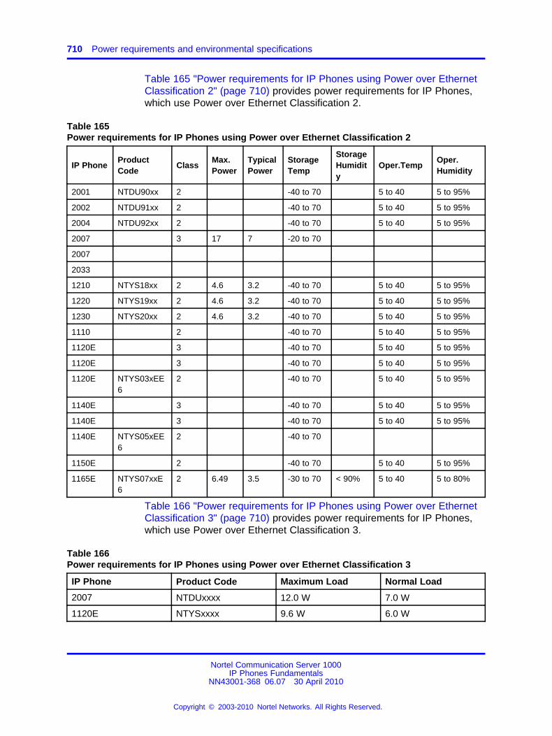
710 Power requirements and environmental specifications
Table 165 "Power requirements for IP Phones using Power over EthernetClassification 2" (page 710) provides power requirements for IP Phones,which use Power over Ethernet Classification 2.
Table 165Power requirements for IP Phones using Power over Ethernet Classification 2
IP PhoneProductCode
ClassMax.Power
TypicalPower
StorageTemp
StorageHumidity
Oper.TempOper.Humidity
2001 NTDU90xx 2 -40 to 70 5 to 40 5 to 95%
2002 NTDU91xx 2 -40 to 70 5 to 40 5 to 95%
2004 NTDU92xx 2 -40 to 70 5 to 40 5 to 95%
2007 3 17 7 -20 to 70
2007
2033
1210 NTYS18xx 2 4.6 3.2 -40 to 70 5 to 40 5 to 95%
1220 NTYS19xx 2 4.6 3.2 -40 to 70 5 to 40 5 to 95%
1230 NTYS20xx 2 4.6 3.2 -40 to 70 5 to 40 5 to 95%
1110 2 -40 to 70 5 to 40 5 to 95%
1120E 3 -40 to 70 5 to 40 5 to 95%
1120E 3 -40 to 70 5 to 40 5 to 95%
1120E NTYS03xEE6
2 -40 to 70 5 to 40 5 to 95%
1140E 3 -40 to 70 5 to 40 5 to 95%
1140E 3 -40 to 70 5 to 40 5 to 95%
1140E NTYS05xEE6
2 -40 to 70
1150E 2 -40 to 70 5 to 40 5 to 95%
1165E NTYS07xxE6
2 6.49 3.5 -30 to 70 < 90% 5 to 40 5 to 80%
Table 166 "Power requirements for IP Phones using Power over EthernetClassification 3" (page 710) provides power requirements for IP Phones,which use Power over Ethernet Classification 3.
Table 166Power requirements for IP Phones using Power over Ethernet Classification 3
IP Phone Product Code Maximum Load Normal Load
2007 NTDUxxxx 12.0 W 7.0 W
1120E NTYSxxxx 9.6 W 6.0 W
Nortel Communication Server 1000IP Phones Fundamentals
NN43001-368 06.07 30 April 2010
Copyright © 2003-2010 Nortel Networks. All Rights Reserved.
.
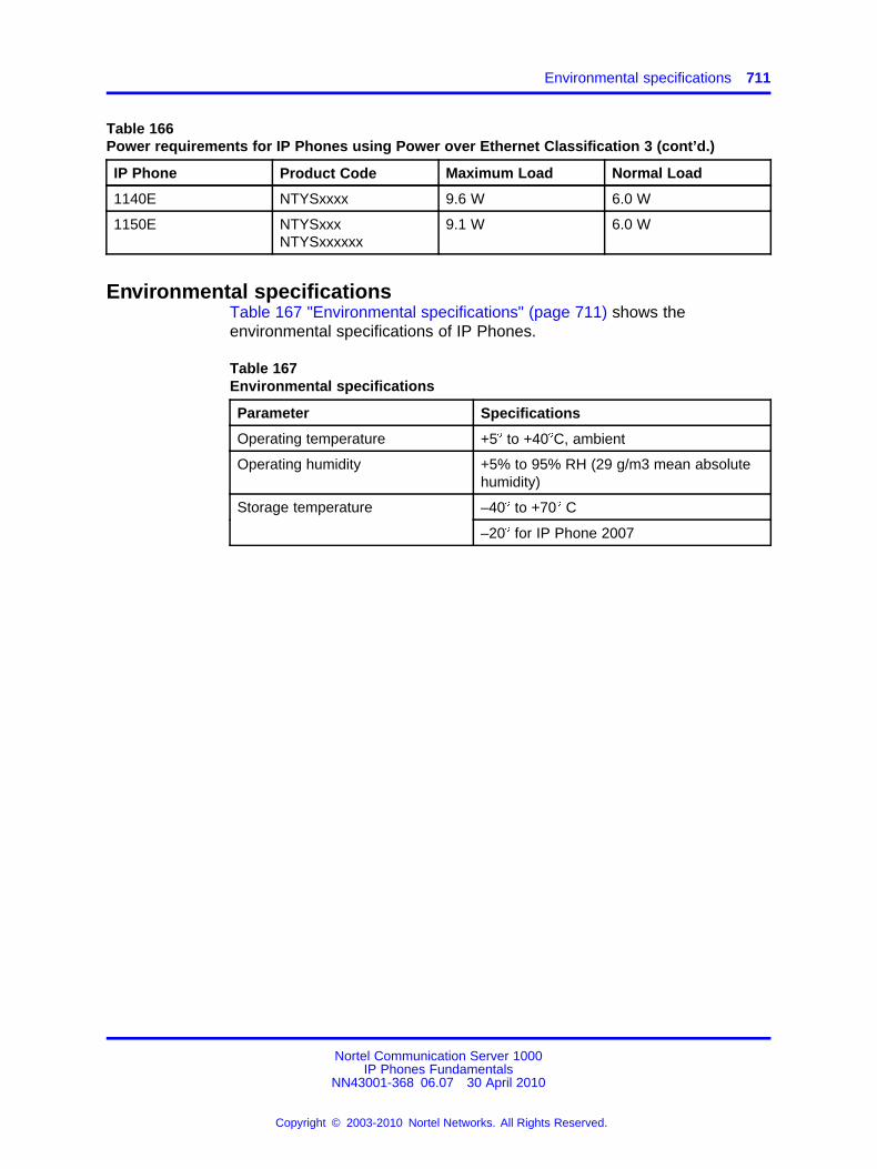
Environmental specifications 711
Table 166Power requirements for IP Phones using Power over Ethernet Classification 3 (cont’d.)
IP Phone Product Code Maximum Load Normal Load
1140E NTYSxxxx 9.6 W 6.0 W
1150E NTYSxxxNTYSxxxxxx
9.1 W 6.0 W
Environmental specificationsTable 167 "Environmental specifications" (page 711) shows theenvironmental specifications of IP Phones.
Table 167Environmental specifications
Parameter Specifications
Operating temperature +5� to +40�C, ambient
Operating humidity +5% to 95% RH (29 g/m3 mean absolutehumidity)
–40� to +70� CStorage temperature
–20� for IP Phone 2007
Nortel Communication Server 1000IP Phones Fundamentals
NN43001-368 06.07 30 April 2010
Copyright © 2003-2010 Nortel Networks. All Rights Reserved.
.

712 Power requirements and environmental specifications
Nortel Communication Server 1000IP Phones Fundamentals
NN43001-368 06.07 30 April 2010
Copyright © 2003-2010 Nortel Networks. All Rights Reserved.
.
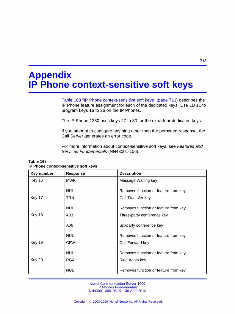
713.
AppendixIP Phone context-sensitive soft keys
Table 168 "IP Phone context-sensitive soft keys" (page 713) describes theIP Phone feature assignment for each of the dedicated keys. Use LD 11 toprogram keys 16 to 26 on the IP Phones.
The IP Phone 1230 uses keys 27 to 30 for the extra four dedicated keys.
If you attempt to configure anything other than the permitted response, theCall Server generates an error code.
For more information about context-sensitive soft keys, see Features andServices Fundamentals (NN43001-106).
Table 168IP Phone context-sensitive soft keys
Key number Response Description
Key 16 MWK
NUL
Message Waiting key
Removes function or feature from key
Key 17 TRN
NUL
Call Tran sfer key
Removes function or feature from key
Key 18 A03
A06
NUL
Three-party conference key
Six-party conference key
Removes function or feature from key
Key 19 CFW
NUL
Call Forward key
Removes function or feature from key
Key 20 RGA
NUL
Ring Again key
Removes function or feature from key
Nortel Communication Server 1000IP Phones Fundamentals
NN43001-368 06.07 30 April 2010
Copyright © 2003-2010 Nortel Networks. All Rights Reserved.
.
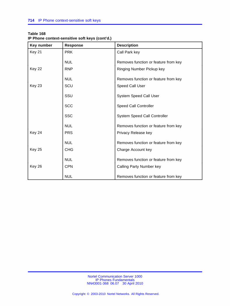
714 IP Phone context-sensitive soft keys
Table 168IP Phone context-sensitive soft keys (cont’d.)
Key number Response Description
Key 21 PRK
NUL
Call Park key
Removes function or feature from key
Key 22 RNP
NUL
Ringing Number Pickup key
Removes function or feature from key
Key 23 SCU
SSU
SCC
SSC
NUL
Speed Call User
System Speed Call User
Speed Call Controller
System Speed Call Controller
Removes function or feature from key
Key 24 PRS
NUL
Privacy Release key
Removes function or feature from key
Key 25 CHG
NUL
Charge Account key
Removes function or feature from key
Key 26 CPN
NUL
Calling Party Number key
Removes function or feature from key
Nortel Communication Server 1000IP Phones Fundamentals
NN43001-368 06.07 30 April 2010
Copyright © 2003-2010 Nortel Networks. All Rights Reserved.
.
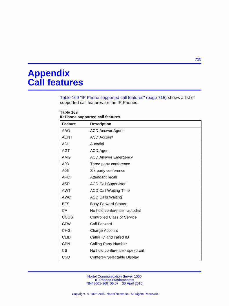
715.
AppendixCall features
Table 169 "IP Phone supported call features" (page 715) shows a list ofsupported call features for the IP Phones.
Table 169IP Phone supported call features
Feature Description
AAG ACD Answer Agent
ACNT ACD Account
ADL Autodial
AGT ACD Agent
AMG ACD Answer Emergency
A03 Three party conference
A06 Six party conference
ARC Attendant recall
ASP ACD Call Supervisor
AWT ACD Call Waiting Time
AWC ACD Calls Waiting
BFS Busy Forward Status
CA No hold conference - autodial
CCOS Controlled Class of Service
CFW Call Forward
CHG Charge Account
CLID Caller ID and called ID
CPN Calling Party Number
CS No hold conference - speed call
CSD Conferee Selectable Display
Nortel Communication Server 1000IP Phones Fundamentals
NN43001-368 06.07 30 April 2010
Copyright © 2003-2010 Nortel Networks. All Rights Reserved.
.
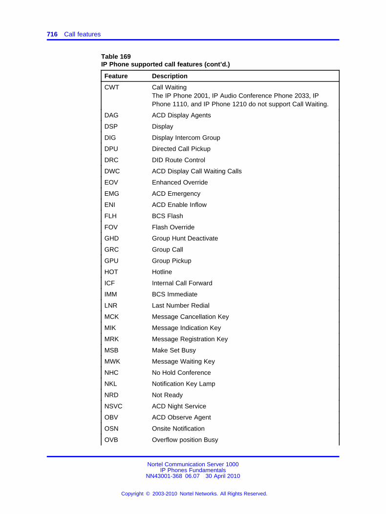
716 Call features
Table 169IP Phone supported call features (cont’d.)
Feature Description
CWT Call WaitingThe IP Phone 2001, IP Audio Conference Phone 2033, IPPhone 1110, and IP Phone 1210 do not support Call Waiting.
DAG ACD Display Agents
DSP Display
DIG Display Intercom Group
DPU Directed Call Pickup
DRC DID Route Control
DWC ACD Display Call Waiting Calls
EOV Enhanced Override
EMG ACD Emergency
ENI ACD Enable Inflow
FLH BCS Flash
FOV Flash Override
GHD Group Hunt Deactivate
GRC Group Call
GPU Group Pickup
HOT Hotline
ICF Internal Call Forward
IMM BCS Immediate
LNR Last Number Redial
MCK Message Cancellation Key
MIK Message Indication Key
MRK Message Registration Key
MSB Make Set Busy
MWK Message Waiting Key
NHC No Hold Conference
NKL Notification Key Lamp
NRD Not Ready
NSVC ACD Night Service
OBV ACD Observe Agent
OSN Onsite Notification
OVB Overflow position Busy
Nortel Communication Server 1000IP Phones Fundamentals
NN43001-368 06.07 30 April 2010
Copyright © 2003-2010 Nortel Networks. All Rights Reserved.
.
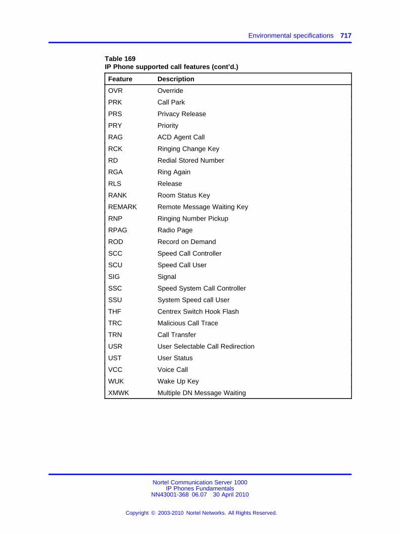
Environmental specifications 717
Table 169IP Phone supported call features (cont’d.)
Feature Description
OVR Override
PRK Call Park
PRS Privacy Release
PRY Priority
RAG ACD Agent Call
RCK Ringing Change Key
RD Redial Stored Number
RGA Ring Again
RLS Release
RANK Room Status Key
REMARK Remote Message Waiting Key
RNP Ringing Number Pickup
RPAG Radio Page
ROD Record on Demand
SCC Speed Call Controller
SCU Speed Call User
SIG Signal
SSC Speed System Call Controller
SSU System Speed call User
THF Centrex Switch Hook Flash
TRC Malicious Call Trace
TRN Call Transfer
USR User Selectable Call Redirection
UST User Status
VCC Voice Call
WUK Wake Up Key
XMWK Multiple DN Message Waiting
Nortel Communication Server 1000IP Phones Fundamentals
NN43001-368 06.07 30 April 2010
Copyright © 2003-2010 Nortel Networks. All Rights Reserved.
.

718 Call features
Nortel Communication Server 1000IP Phones Fundamentals
NN43001-368 06.07 30 April 2010
Copyright © 2003-2010 Nortel Networks. All Rights Reserved.
.
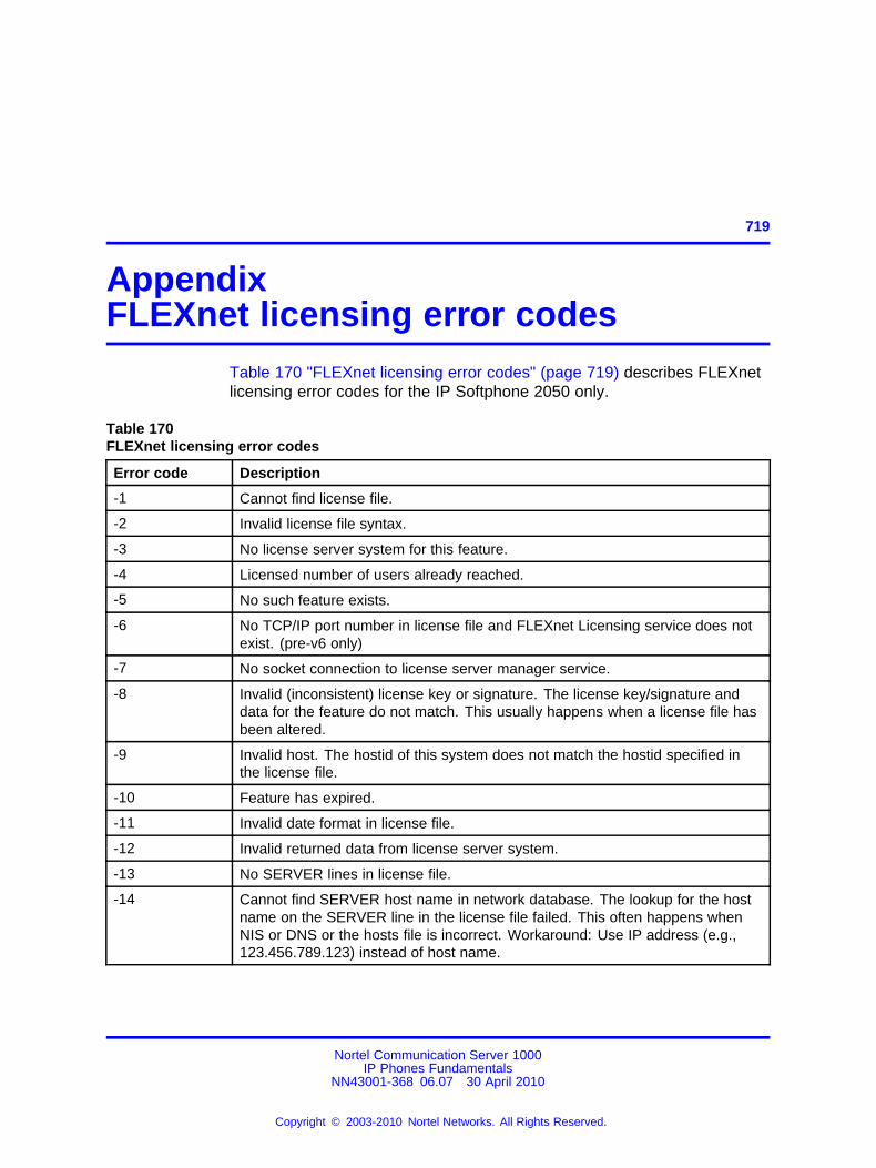
719.
AppendixFLEXnet licensing error codes
Table 170 "FLEXnet licensing error codes" (page 719) describes FLEXnetlicensing error codes for the IP Softphone 2050 only.
Table 170FLEXnet licensing error codes
Error code Description
-1 Cannot find license file.
-2 Invalid license file syntax.
-3 No license server system for this feature.
-4 Licensed number of users already reached.
-5 No such feature exists.
-6 No TCP/IP port number in license file and FLEXnet Licensing service does notexist. (pre-v6 only)
-7 No socket connection to license server manager service.
-8 Invalid (inconsistent) license key or signature. The license key/signature anddata for the feature do not match. This usually happens when a license file hasbeen altered.
-9 Invalid host. The hostid of this system does not match the hostid specified inthe license file.
-10 Feature has expired.
-11 Invalid date format in license file.
-12 Invalid returned data from license server system.
-13 No SERVER lines in license file.
-14 Cannot find SERVER host name in network database. The lookup for the hostname on the SERVER line in the license file failed. This often happens whenNIS or DNS or the hosts file is incorrect. Workaround: Use IP address (e.g.,123.456.789.123) instead of host name.
Nortel Communication Server 1000IP Phones Fundamentals
NN43001-368 06.07 30 April 2010
Copyright © 2003-2010 Nortel Networks. All Rights Reserved.
.
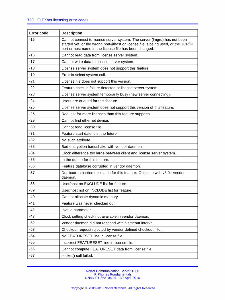
720 FLEXnet licensing error codes
Error code Description
-15 Cannot connect to license server system. The server (lmgrd) has not beenstarted yet, or the wrong port@host or license file is being used, or the TCP/IPport or host name in the license file has been changed.
-16 Cannot read data from license server system.
-17 Cannot write data to license server system.
-18 License server system does not support this feature.
-19 Error in select system call.
-21 License file does not support this version.
-22 Feature checkin failure detected at license server system.
-23 License server system temporarily busy (new server connecting).
-24 Users are queued for this feature.
-25 License server system does not support this version of this feature.
-26 Request for more licenses than this feature supports.
-29 Cannot find ethernet device.
-30 Cannot read license file.
-31 Feature start date is in the future.
-32 No such attribute.
-33 Bad encryption handshake with vendor daemon.
-34 Clock difference too large between client and license server system.
-35 In the queue for this feature.
-36 Feature database corrupted in vendor daemon.
-37 Duplicate selection mismatch for this feature. Obsolete with v8.0+ vendordaemon.
-38 User/host on EXCLUDE list for feature.
-39 User/host not on INCLUDE list for feature.
-40 Cannot allocate dynamic memory.
-41 Feature was never checked out.
-42 Invalid parameter.
-47 Clock setting check not available in vendor daemon.
-52 Vendor daemon did not respond within timeout interval.
-53 Checkout request rejected by vendor-defined checkout filter.
-54 No FEATURESET line in license file.
-55 Incorrect FEATURESET line in license file.
-56 Cannot compute FEATURESET data from license file.
-57 socket() call failed.
Nortel Communication Server 1000IP Phones Fundamentals
NN43001-368 06.07 30 April 2010
Copyright © 2003-2010 Nortel Networks. All Rights Reserved.
.
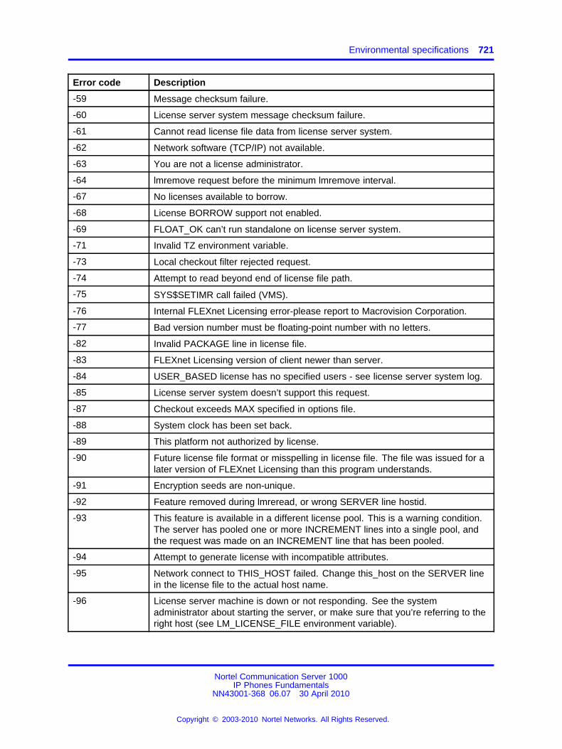
Environmental specifications 721
Error code Description
-59 Message checksum failure.
-60 License server system message checksum failure.
-61 Cannot read license file data from license server system.
-62 Network software (TCP/IP) not available.
-63 You are not a license administrator.
-64 lmremove request before the minimum lmremove interval.
-67 No licenses available to borrow.
-68 License BORROW support not enabled.
-69 FLOAT_OK can’t run standalone on license server system.
-71 Invalid TZ environment variable.
-73 Local checkout filter rejected request.
-74 Attempt to read beyond end of license file path.
-75 SYS$SETIMR call failed (VMS).
-76 Internal FLEXnet Licensing error-please report to Macrovision Corporation.
-77 Bad version number must be floating-point number with no letters.
-82 Invalid PACKAGE line in license file.
-83 FLEXnet Licensing version of client newer than server.
-84 USER_BASED license has no specified users - see license server system log.
-85 License server system doesn’t support this request.
-87 Checkout exceeds MAX specified in options file.
-88 System clock has been set back.
-89 This platform not authorized by license.
-90 Future license file format or misspelling in license file. The file was issued for alater version of FLEXnet Licensing than this program understands.
-91 Encryption seeds are non-unique.
-92 Feature removed during lmreread, or wrong SERVER line hostid.
-93 This feature is available in a different license pool. This is a warning condition.The server has pooled one or more INCREMENT lines into a single pool, andthe request was made on an INCREMENT line that has been pooled.
-94 Attempt to generate license with incompatible attributes.
-95 Network connect to THIS_HOST failed. Change this_host on the SERVER linein the license file to the actual host name.
-96 License server machine is down or not responding. See the systemadministrator about starting the server, or make sure that you’re referring to theright host (see LM_LICENSE_FILE environment variable).
Nortel Communication Server 1000IP Phones Fundamentals
NN43001-368 06.07 30 April 2010
Copyright © 2003-2010 Nortel Networks. All Rights Reserved.
.
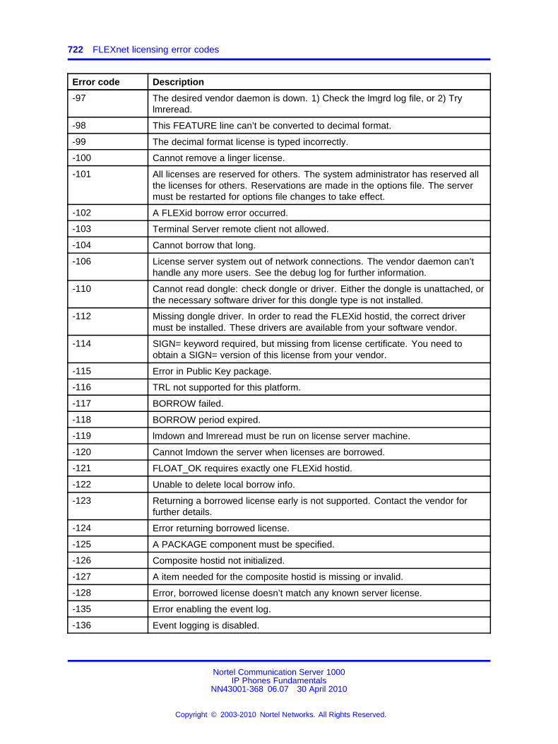
722 FLEXnet licensing error codes
Error code Description
-97 The desired vendor daemon is down. 1) Check the lmgrd log file, or 2) Trylmreread.
-98 This FEATURE line can’t be converted to decimal format.
-99 The decimal format license is typed incorrectly.
-100 Cannot remove a linger license.
-101 All licenses are reserved for others. The system administrator has reserved allthe licenses for others. Reservations are made in the options file. The servermust be restarted for options file changes to take effect.
-102 A FLEXid borrow error occurred.
-103 Terminal Server remote client not allowed.
-104 Cannot borrow that long.
-106 License server system out of network connections. The vendor daemon can’thandle any more users. See the debug log for further information.
-110 Cannot read dongle: check dongle or driver. Either the dongle is unattached, orthe necessary software driver for this dongle type is not installed.
-112 Missing dongle driver. In order to read the FLEXid hostid, the correct drivermust be installed. These drivers are available from your software vendor.
-114 SIGN= keyword required, but missing from license certificate. You need toobtain a SIGN= version of this license from your vendor.
-115 Error in Public Key package.
-116 TRL not supported for this platform.
-117 BORROW failed.
-118 BORROW period expired.
-119 lmdown and lmreread must be run on license server machine.
-120 Cannot lmdown the server when licenses are borrowed.
-121 FLOAT_OK requires exactly one FLEXid hostid.
-122 Unable to delete local borrow info.
-123 Returning a borrowed license early is not supported. Contact the vendor forfurther details.
-124 Error returning borrowed license.
-125 A PACKAGE component must be specified.
-126 Composite hostid not initialized.
-127 A item needed for the composite hostid is missing or invalid.
-128 Error, borrowed license doesn’t match any known server license.
-135 Error enabling the event log.
-136 Event logging is disabled.
Nortel Communication Server 1000IP Phones Fundamentals
NN43001-368 06.07 30 April 2010
Copyright © 2003-2010 Nortel Networks. All Rights Reserved.
.
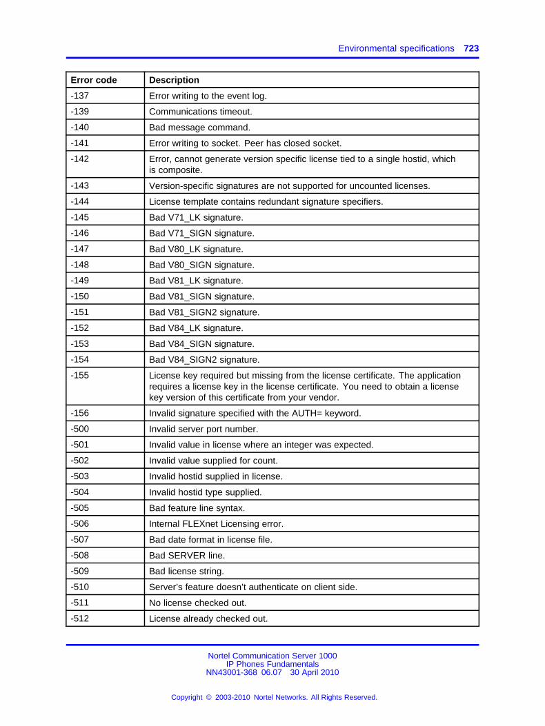
Environmental specifications 723
Error code Description
-137 Error writing to the event log.
-139 Communications timeout.
-140 Bad message command.
-141 Error writing to socket. Peer has closed socket.
-142 Error, cannot generate version specific license tied to a single hostid, whichis composite.
-143 Version-specific signatures are not supported for uncounted licenses.
-144 License template contains redundant signature specifiers.
-145 Bad V71_LK signature.
-146 Bad V71_SIGN signature.
-147 Bad V80_LK signature.
-148 Bad V80_SIGN signature.
-149 Bad V81_LK signature.
-150 Bad V81_SIGN signature.
-151 Bad V81_SIGN2 signature.
-152 Bad V84_LK signature.
-153 Bad V84_SIGN signature.
-154 Bad V84_SIGN2 signature.
-155 License key required but missing from the license certificate. The applicationrequires a license key in the license certificate. You need to obtain a licensekey version of this certificate from your vendor.
-156 Invalid signature specified with the AUTH= keyword.
-500 Invalid server port number.
-501 Invalid value in license where an integer was expected.
-502 Invalid value supplied for count.
-503 Invalid hostid supplied in license.
-504 Invalid hostid type supplied.
-505 Bad feature line syntax.
-506 Internal FLEXnet Licensing error.
-507 Bad date format in license file.
-508 Bad SERVER line.
-509 Bad license string.
-510 Server’s feature doesn’t authenticate on client side.
-511 No license checked out.
-512 License already checked out.
Nortel Communication Server 1000IP Phones Fundamentals
NN43001-368 06.07 30 April 2010
Copyright © 2003-2010 Nortel Networks. All Rights Reserved.
.
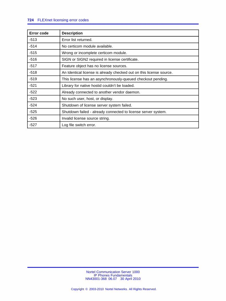
724 FLEXnet licensing error codes
Error code Description
-513 Error list returned.
-514 No certicom module available.
-515 Wrong or incomplete certicom module.
-516 SIGN or SIGN2 required in license certificate.
-517 Feature object has no license sources.
-518 An Identical license is already checked out on this license source.
-519 This license has an asynchronously-queued checkout pending.
-521 Library for native hostid couldn’t be loaded.
-522 Already connected to another vendor daemon.
-523 No such user, host, or display.
-524 Shutdown of license server system failed.
-525 Shutdown failed - already connected to license server system.
-526 Invalid license source string.
-527 Log file switch error.
Nortel Communication Server 1000IP Phones Fundamentals
NN43001-368 06.07 30 April 2010
Copyright © 2003-2010 Nortel Networks. All Rights Reserved.
.
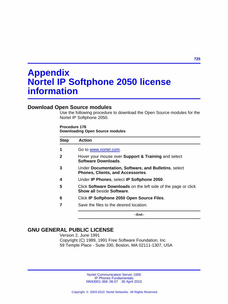
725.
AppendixNortel IP Softphone 2050 licenseinformation
Download Open Source modulesUse the following procedure to download the Open Source modules for theNortel IP Softphone 2050.
Procedure 178Downloading Open Source modules
Step Action
1 Go to www.nortel.com.
2 Hover your mouse over Support & Training and selectSoftware Downloads.
3 Under Documentation, Software, and Bulletins, selectPhones, Clients, and Accessories.
4 Under IP Phones, select IP Softphone 2050.
5 Click Software Downloads on the left side of the page or clickShow all beside Software.
6 Click IP Softphone 2050 Open Source Files.
7 Save the files to the desired location.
--End--
GNU GENERAL PUBLIC LICENSEVersion 2, June 1991Copyright (C) 1989, 1991 Free Software Foundation, Inc.59 Temple Place - Suite 330, Boston, MA 02111-1307, USA
Nortel Communication Server 1000IP Phones Fundamentals
NN43001-368 06.07 30 April 2010
Copyright © 2003-2010 Nortel Networks. All Rights Reserved.
.
726 Nortel IP Softphone 2050 license information
Everyone is permitted to copy and distribute verbatim copies of this licensedocument, but changing it is not allowed.
PreambleThe licenses for most software are designed to take away your freedomto share and change it. By contrast, the GNU General Public License isintended to guarantee your freedom to share and change free software—tomake sure the software is free for all its users. This General PublicLicense applies to most of the Free Software Foundation’s software andto any other program whose authors commit to using it. (Some other FreeSoftware Foundation software is covered by the GNU Library GeneralPublic License instead.) You can apply it to your programs, too.
When we speak of free software, we are referring to freedom, not price.Our General Public Licenses are designed to make sure that you have thefreedom to distribute copies of free software (and charge for this service ifyou wish), that you receive source code or can get it if you want it, that youcan change the software or use pieces of it in new free programs; and thatyou know you can do these things.
To protect your rights, we need to make restrictions that forbid anyoneto deny you these rights or to ask you to surrender the rights. Theserestrictions translate to certain responsibilities for you if you distributecopies of the software, or if you modify it.
For example, if you distribute copies of such a program, whether gratisor for a fee, you must give the recipients all the rights that you have. Youmust make sure that they, too, receive or can get the source code. Andyou must show them these terms so they know their rights.
We protect your rights with two steps: (1) copyright the software, and (2)offer you this license which gives you legal permission to copy, distributeand/or modify the software.
Also, for each author’s protection and ours, we want to make certain thateveryone understands that there is no warranty for this free software. Ifthe software is modified by someone else and passed on, we want itsrecipients to know that what they have is not the original, so that anyproblems introduced by others will not reflect on the original authors’reputations.
Finally, any free program is threatened constantly by software patents.We wish to avoid the danger that redistributors of a free programwill individually obtain patent licenses, in effect making the programproprietary. To prevent this, we have made it clear that any patent must belicensed for everyone’s free use or not licensed at all.
Nortel Communication Server 1000IP Phones Fundamentals
NN43001-368 06.07 30 April 2010
Copyright © 2003-2010 Nortel Networks. All Rights Reserved.
.
GNU GENERAL PUBLIC LICENSE 727
The precise terms and conditions for copying, distribution and modificationfollow.
TERMS AND CONDITIONS FOR COPYING, DISTRIBUTION ANDMODIFICATION
0. This License applies to any program or other work which contains anotice placed by the copyright holder saying it may be distributed underthe terms of this General Public License. The "Program", below, refers toany such program or work, and a "work based on the Program" meanseither the Program or any derivative work under copyright law: that is tosay, a work containing the Program or a portion of it, either verbatim orwith modifications and/or translated into another language. (Hereinafter,translation is included without limitation in the term "modification".) Eachlicensee is addressed as "you".
Activities other than copying, distribution and modification are not coveredby this License; they are outside its scope. The act of running the Programis not restricted, and the output from the Program is covered only if itscontents constitute a work based on the Program (independent of havingbeen made by running the Program). Whether that is true depends onwhat the Program does.
1. You may copy and distribute verbatim copies of the Program’s sourcecode as you receive it, in any medium, provided that you conspicuouslyand appropriately publish on each copy an appropriate copyright noticeand disclaimer of warranty; keep intact all the notices that refer to thisLicense and to the absence of any warranty; and give any other recipientsof the Program a copy of this License along with the Program.
You may charge a fee for the physical act of transferring a copy, and youmay at your option offer warranty protection in exchange for a fee.
2. You may modify your copy or copies of the Program or any portion of it,thus forming a work based on the Program, and copy and distribute suchmodifications or work under the terms of Section 1 above, provided thatyou also meet all of these conditions:
a. You must cause the modified files to carry prominent notices stating thatyou changed the files and the date of any change.
b. You must cause any work that you distribute or publish, that in whole orin part contains or is derived from the Program or any part thereof, to belicensed as a whole at no charge to all third parties under the terms of thisLicense.
Nortel Communication Server 1000IP Phones Fundamentals
NN43001-368 06.07 30 April 2010
Copyright © 2003-2010 Nortel Networks. All Rights Reserved.
.
728 Nortel IP Softphone 2050 license information
c. If the modified program normally reads commands interactively whenrun, you must cause it, when started running for such interactive use inthe most ordinary way, to print or display an announcement including anappropriate copyright notice and a notice that there is no warranty (or else,saying that you provide a warranty) and that users may redistribute theprogram under these conditions, and telling the user how to view a copyof this License. (Exception: if the Program itself is interactive but does notnormally print such an announcement, your work based on the Program isnot required to print an announcement.)
These requirements apply to the modified work as a whole. If identifiablesections of that work are not derived from the Program, and can bereasonably considered independent and separate works in themselves,then this License, and its terms, do not apply to those sections when youdistribute them as separate works. But when you distribute the samesections as part of a whole which is a work based on the Program, thedistribution of the whole must be on the terms of this License, whosepermissions for other licensees extend to the entire whole, and thus toeach and every part regardless of who wrote it.
Thus, it is not the intent of this section to claim rights or contest your rightsto work written entirely by you; rather, the intent is to exercise the rightto control the distribution of derivative or collective works based on theProgram.
In addition, mere aggregation of another work not based on the Programwith the Program (or with a work based on the Program) on a volume of astorage or distribution medium does not bring the other work under thescope of this License.
3. You may copy and distribute the Program (or a work based on it, underSection 2) in object code or executable form under the terms of Sections 1and 2 above provided that you also do one of the following:
a. Accompany it with the complete corresponding machine-readablesource code, which must be distributed under the terms of Sections 1 and2 above on a medium customarily used for software interchange; or,
b. Accompany it with a written offer, valid for at least three years, togive any third party, for a charge no more than your cost of physicallyperforming source distribution, a complete machine-readable copy of thecorresponding source code, to be distributed under the terms of Sections 1and 2 above on a medium customarily used for software interchange; or,
Nortel Communication Server 1000IP Phones Fundamentals
NN43001-368 06.07 30 April 2010
Copyright © 2003-2010 Nortel Networks. All Rights Reserved.
.
GNU GENERAL PUBLIC LICENSE 729
c. Accompany it with the information you received as to the offer todistribute corresponding source code. (This alternative is allowed only fornoncommercial distribution and only if you received the program in objectcode or executable form with such an offer, in accord with Subsection babove.)
The source code for a work means the preferred form of the work formaking modifications to it. For an executable work, complete source codemeans all the source code for all modules it contains, plus any associatedinterface definition files, plus the scripts used to control compilation andinstallation of the executable. However, as a special exception, the sourcecode distributed need not include anything that is normally distributed (ineither source or binary form) with the major components (compiler, kernel,and so on) of the operating system on which the executable runs, unlessthat component itself accompanies the executable.
If distribution of executable or object code is made by offering access tocopy from a designated place, then offering equivalent access to copythe source code from the same place counts as distribution of the sourcecode, even though third parties are not compelled to copy the source alongwith the object code.
4. You may not copy, modify, sublicense, or distribute the Program exceptas expressly provided under this License. Any attempt otherwise to copy,modify, sublicense or distribute the Program is void, and will automaticallyterminate your rights under this License. However, parties who havereceived copies, or rights, from you under this License will not have theirlicenses terminated so long as such parties remain in full compliance.
5. You are not required to accept this License, since you have not signedit. However, nothing else grants you permission to modify or distributethe Program or its derivative works. These actions are prohibited by lawif you do not accept this License. Therefore, by modifying or distributingthe Program (or any work based on the Program), you indicate youracceptance of this License to do so, and all its terms and conditions forcopying, distributing or modifying the Program or works based on it.
6. Each time you redistribute the Program (or any work based on theProgram), the recipient automatically receives a license from the originallicensor to copy, distribute or modify the Program subject to these termsand conditions. You may not impose any further restrictions on therecipients’ exercise of the rights granted herein. You are not responsiblefor enforcing compliance by third parties to this License.
7. If, as a consequence of a court judgment or allegation of patentinfringement or for any other reason (not limited to patent issues),conditions are imposed on you (whether by court order, agreement or
Nortel Communication Server 1000IP Phones Fundamentals
NN43001-368 06.07 30 April 2010
Copyright © 2003-2010 Nortel Networks. All Rights Reserved.
.
730 Nortel IP Softphone 2050 license information
otherwise) that contradict the conditions of this License, they do notexcuse you from the conditions of this License. If you cannot distribute soas to satisfy simultaneously your obligations under this License and anyother pertinent obligations, then as a consequence you may not distributethe Program at all. For example, if a patent license would not permitroyalty-free redistribution of the Program by all those who receive copiesdirectly or indirectly through you, then the only way you could satisfy bothit and this License would be to refrain entirely from distribution of theProgram.
If any portion of this section is held invalid or unenforceable under anyparticular circumstance, the balance of the section is intended to apply andthe section as a whole is intended to apply in other circumstances.
It is not the purpose of this section to induce you to infringe any patentsor other property right claims or to contest validity of any such claims;this section has the sole purpose of protecting the integrity of the freesoftware distribution system, which is implemented by public licensepractices. Many people have made generous contributions to the widerange of software distributed through that system in reliance on consistentapplication of that system; it is up to the author/donor to decide if he or sheis willing to distribute software through any other system and a licenseecannot impose that choice.
This section is intended to make thoroughly clear what is believed to be aconsequence of the rest of this License.
8. If the distribution and/or use of the Program is restricted in certaincountries either by patents or by copyrighted interfaces, the originalcopyright holder who places the Program under this License may add anexplicit geographical distribution limitation excluding those countries, sothat distribution is permitted only in or among countries not thus excluded.In such case, this License incorporates the limitation as if written in thebody of this License.
9. The Free Software Foundation may publish revised and/or new versionsof the General Public License from time to time. Such new versions will besimilar in spirit to the present version, but may differ in detail to addressnew problems or concerns.
Each version is given a distinguishing version number. If the Programspecifies a version number of this License which applies to it and "anylater version", you have the option of following the terms and conditionseither of that version or of any later version published by the Free SoftwareFoundation. If the Program does not specify a version number of thisLicense, you may choose any version ever published by the Free SoftwareFoundation.
Nortel Communication Server 1000IP Phones Fundamentals
NN43001-368 06.07 30 April 2010
Copyright © 2003-2010 Nortel Networks. All Rights Reserved.
.
GNU GENERAL PUBLIC LICENSE 731
10. If you wish to incorporate parts of the Program into other freeprograms whose distribution conditions are different, write to the author toask for permission. For software which is copyrighted by the Free SoftwareFoundation, write to the Free Software Foundation; we sometimes makeexceptions for this. Our decision will be guided by the two goals ofpreserving the free status of all derivatives of our free software and ofpromoting the sharing and reuse of software generally.
NO WARRANTY11. BECAUSE THE PROGRAM IS LICENSED FREE OF CHARGE,THERE IS NO WARRANTY FOR THE PROGRAM, TO THE EXTENTPERMITTED BY APPLICABLE LAW. EXCEPT WHEN OTHERWISESTATED IN WRITING THE COPYRIGHT HOLDERS AND/OR OTHERPARTIES PROVIDE THE PROGRAM "AS IS" WITHOUT WARRANTY OFANY KIND, EITHER EXPRESSED OR IMPLIED, INCLUDING, BUT NOTLIMITED TO, THE IMPLIED WARRANTIES OF MERCHANTABILITY ANDFITNESS FOR A PARTICULAR PURPOSE. THE ENTIRE RISK AS TOTHE QUALITY AND PERFORMANCE OF THE PROGRAM IS WITH YOU.SHOULD THE PROGRAM PROVE DEFECTIVE, YOU ASSUME THECOST OF ALL NECESSARY SERVICING, REPAIR OR CORRECTION.
12. IN NO EVENT UNLESS REQUIRED BY APPLICABLE LAW ORAGREED TO IN WRITING WILL ANY COPYRIGHT HOLDER, ORANY OTHER PARTY WHO MAY MODIFY AND/OR REDISTRIBUTETHE PROGRAM AS PERMITTED ABOVE, BE LIABLE TO YOU FORDAMAGES, INCLUDING ANY GENERAL, SPECIAL, INCIDENTALOR CONSEQUENTIAL DAMAGES ARISING OUT OF THE USE ORINABILITY TO USE THE PROGRAM (INCLUDING BUT NOT LIMITEDTO LOSS OF DATA OR DATA BEING RENDERED INACCURATE ORLOSSES SUSTAINED BY YOU OR THIRD PARTIES OR A FAILURE OFTHE PROGRAM TO OPERATE WITH ANY OTHER PROGRAMS), EVENIF SUCH HOLDER OR OTHER PARTY HAS BEEN ADVISED OF THEPOSSIBILITY OF SUCH DAMAGES.
END OF TERMS AND CONDITIONSHow to Apply These Terms to Your New ProgramsIf you develop a new program, and you want it to be of the greatestpossible use to the public, the best way to achieve this is to make it freesoftware which everyone can redistribute and change under these terms.
To do so, attach the following notices to the program. It is safest toattach them to the start of each source file to most effectively convey theexclusion of warranty; and each file should have at least the "copyright"line and a pointer to where the full notice is found; and one line to give theprogram’s name and an idea of what it does.
Copyright (C) yyyy name of author
Nortel Communication Server 1000IP Phones Fundamentals
NN43001-368 06.07 30 April 2010
Copyright © 2003-2010 Nortel Networks. All Rights Reserved.
.
732 Nortel IP Softphone 2050 license information
This program is free software; you can redistribute it and/or modify it underthe terms of the GNU General Public License as published by the FreeSoftware Foundation; either version 2 of the License, or (at your option)any later version.
This program is distributed in the hope that it will be useful, butWITHOUT ANY WARRANTY; without even the implied warranty ofMERCHANTABILITY or FITNESS FOR A PARTICULAR PURPOSE. Seethe GNU General Public License for more details.
You should have received a copy of the GNU General Public Licensealong with this program; if not, write to the Free Software Foundation, Inc.,59 Temple Place - Suite 330, Boston, MA 02111-1307, USA.
Also add information on how to contact you by electronic and paper mail.
If the program is interactive, make it output a short notice like this when itstarts in an interactive mode:
Gnomovision version 69, Copyright (C) year name of author
Gnomovision comes with ABSOLUTELY NO WARRANTY; for details type‘show w’. This is free software, and you are welcome to redistribute itunder certain conditions; type ‘show c’ for details.
The hypothetical commands ‘show w’ and ‘show c’ should show theappropriate parts of the General Public License. Of course, the commandsyou use may be called something other than ‘show w’ and ‘show c’; theycould even be mouse-clicks or menu items--whatever suits your program.
You should also get your employer (if you work as a programmer) oryour school, if any, to sign a "copyright disclaimer" for the program, ifnecessary. Here is a sample; alter the names:
Yoyodyne, Inc., hereby disclaims all copyright interest in the program‘Gnomovision’ (which makes passes at compilers) written by JamesHacker.
signature of Ty Coon, 1 April 1989Ty Coon, President of Vice
This General Public License does not permit incorporating your programinto proprietary programs. If your program is a subroutine library, you mayconsider it more useful to permit linking proprietary applications with thelibrary. If this is what you want to do, use the GNU Library General PublicLicense instead of this License.
Nortel Communication Server 1000IP Phones Fundamentals
NN43001-368 06.07 30 April 2010
Copyright © 2003-2010 Nortel Networks. All Rights Reserved.
.

GNU GENERAL PUBLIC LICENSE 733
MADThis product contains module MAD, which is distributed in accordance withthe terms of the GNU General Public License version 2, provided below.
This product is licensed as described in “GNU GENERAL PUBLICLICENSE” above.
Nortel Communication Server 1000IP Phones Fundamentals
NN43001-368 06.07 30 April 2010
Copyright © 2003-2010 Nortel Networks. All Rights Reserved.
.

734 Nortel IP Softphone 2050 license information
Nortel Communication Server 1000IP Phones Fundamentals
NN43001-368 06.07 30 April 2010
Copyright © 2003-2010 Nortel Networks. All Rights Reserved.
.
735.
Index
3-port switchand 802.1Q header 700
802.11bwireless ethernet networking 269
802.1Q 697Ethernet frame 698p bits 698
802.1Q support 698802.3af 709
AAccessory Expansion Module (AEM) 82Ack message 701Active Call Failover 395ActiveSync 270
deactivate 270uses PPP 270
Application menulanguage selection 197
audio buffers 266audio clarity 266audio delay 266audio quality 266audio streams 266Auto-Create button 264Auto-discovery
VLAN ID 701
Bbuild number 264
CCall forward key
IP Softphone 2050 224Call Handling screen 259Call park key
IP Phone 2004 714IP Softphone 2050 225
Call transfer keyIP Phone 2004 713IP Softphone 2050 224
Caller ID display order 405Callers List 393Charge account key
IP Softphone 2050 225Checking Ethernet Statistics for IP
Phone 1120E/1140E/1150E 424Checking Ethernet Statistics for IP
Phone 1165E 425Checking Ethernet statistics for IP
Phone 2007 423Checking Ethernet Statistics for IP
Phones 2000 Series and IPPhones 1200 Series 421
Codecsand jitter buffer 204
communication server 263–264Conference key
IP Softphone 2050 224connection history 262Connections settings 262contact a server 262Controls 78Corporate Directory 392
Dd Call forward key
IP Phone 2004 713Desk-mount bracket 82DHCP
Ack message 701Discovery request 701VLAN ID discovery 701
Nortel Communication Server 1000IP Phones Fundamentals
NN43001-368 06.07 30 April 2010
Copyright © 2003-2010 Nortel Networks. All Rights Reserved.
.
736
diagnostic utilities 601Diagnostic utilities
Authentication State 604Authenticator ID 604Command Line Interface (CLI) 602data display pages 616DeviceID 604DHCP information process 603Ethernet statistics 603IDU command printout in LD 32 for
IP Phone with a NAT 630IDU command printout in LD 32 for
IP Phone without a NAT 631IP Networking statistics 603Network Address Translation (NAT)
Traversal 627Network QoS Process 604Ping and TraceRoute 603RTP/RTCP statistics 604Supplicant Status 604UNIStim/RUDP statistics 603Using CLI Commands 629
Diagnostic UtilitiesNetwork diagnostic utilities
availability 602Display label 78Driver software
headset adapter 229Dynamic Host Configuration Protocol 429
EEarly Packet Resync 267Emergency Services for Virtual Office 395Enabling Full Duplex mode for IP
Phone 1120E/1140E/1150E 423Enabling Full Duplex mode for IP
Phone 1165E 424Enabling Full Duplex mode for IP
Phone 2007 422Enabling Full Duplex mode for IP
Phones 2000 Series and IPPhones 1200 Series 420
Enhanced UNIStim Firmwaredownload 396
Ethernet 264hardware addresses 264
Ethernet frame 698Expansion Module for IP Phones 1100
SeriesDescription 377
extranet client 264
FFeature keys
IP Softphone 2050 224Features
Active Call Failover 395Caller ID display order 405Callers List 393Corporate Directory 392Emergency Services for Virtual
Office 395Enhanced UNIStim Firmware
download 396IP Call Recording 393Live Dialpad 404Media security 397Normal Mode Indication 404Password Administration 393Personal Directory 392Record on Demand 418Redial List 392Virtual Office 395
Firmware Version 264flexible interface 261
HHardware ID
box. 264Hardware ID screen 263Headset adapter
driver software 229Highwater mark 267
Iinstallation
MVC 2050 260integrated switch 709IP Audio Conference Phone 2033
Changing TN 102Reinstalling 101Replacing 102
IP Call Recording 393IP Line IP stack 698IP Phone
diagnostic utilities 601IP Phone 1110 275IP Phone 1110 display characteristics 280IP Phone 1210 125
Nortel Communication Server 1000IP Phones Fundamentals
NN43001-368 06.07 30 April 2010
Copyright © 2003-2010 Nortel Networks. All Rights Reserved.
.
737
Changing TN 138Introduction 125keys and functions 127Removing 139Replacing 139
IP Phone 1220 141IP Phone 1230 159IP Phone 2001
Changing TN 42Introduction 31keys and functions 33Removing 43, 103Replacing 43
IP Phone 2002 82IP Phone 2004 82IP Phone controls 78IP Phone KEM 77, 82IP Phone Key Expansion Module (KEM) 77IP Phones
environmental specifications 711IP Phones 1200 Series LCD Expansion
Module (12-key self-labeling) 177IP Softphone 2050
software version 226TN 226
Jjitter buffer 267Jitter buffer
setting 204
KKey expansion module
configuration 79connection 83Description 77display 78features 78initialization 83installation 82key number assignments 79operating parameters 84package components 79
Key expansion module (KEM) 77
LLanguage
IP Softphone 2050 Applicationmenu 197
Late Packet Resync 267Line/feature keys 78Listener IP screen 268Live Dialpad 404
MMAC address 263–264Media security 397Message waiting key 713
IP Softphone 2050 224MVC 2050
software 250
Nnetwork interface cards 268Normal Mode Indication 404Nortel Contivity Extranet Switch 264
Pp bits 698packets 267Party conference key
IP Phone 2004 713Password Administration 393pauses in transmission and reception
gaps 270PDA
battery life 259battery life, call duration 260battery types 260extended-life battery 260processor speed adverse affects 259
Personal Digital AssistantPDA 250
Personal Directory 392Personal settings 262Power over Ethernet (PoE) 709Power requirements
IP Phone 2001, IP Phone 2002, andIP Phone 2004, power overEthernet 710
Privacy release keyIP Softphone 2050 225
Profilescreate, delete, modify, change,
export, import 265
Nortel Communication Server 1000IP Phones Fundamentals
NN43001-368 06.07 30 April 2010
Copyright © 2003-2010 Nortel Networks. All Rights Reserved.
.
738
Rrandom hardware IDs 264Record on Demand 418Redial List 392Registration
error messages 632registry key 262removing
MVC 2050 261Reserved keys
IP Phone Softphone 2050 225Ring again key
IP Phone 2004 713IP Softphone 2050 225
Ringing number pickup keyIP Phone 2004 714IP Softphone 2050 225
roaming/handover 270
SSettings screen
Server tab 262Setup
MVC 2050 261Sounds
audible notification connection,disconnection 265
Server connected 266Server unreachable 266Server unresponsive 266
specific address 268specific port
IP port 5000 268Specifications 709Speed dial
IP Phone 2004 714IP Softphone 2050 225
Start upIP Softphone 2050 236
Structural baseplate 82System settings 262
TTN
IP Softphone 2050 226Transfer key
IP Phone 2004 713Trivial File Transfer Protocol 683
Vversion number 264Virtual Office 395VLAN
802.1Q 697VLAN ID
discover using DHCP 701voice frames 267
arriving 267
Wwireless network 270
Nortel Communication Server 1000IP Phones Fundamentals
NN43001-368 06.07 30 April 2010
Copyright © 2003-2010 Nortel Networks. All Rights Reserved.
.

Nortel Communication Server 1000
IP Phones FundamentalsRelease: UNIStim 4.x for Rls 5.x and 6.0Publication: NN43001-368Document revision: 06.07Document release date: 30 April 2010
Copyright © 2003-2010 Nortel Networks. All Rights Reserved.
While the information in this document is believed to be accurate and reliable, except as otherwise expressly agreed to in writingNORTEL PROVIDES THIS DOCUMENT "AS IS" WITHOUT WARRANTY OR CONDITION OF ANY KIND, EITHER EXPRESSOR IMPLIED. The information and/or products described in this document are subject to change without notice.
Nortel, Nortel Networks, the Nortel logo, and the Globemark are trademarks of Nortel Networks.
The Bluetooth® word mark and logos are owned by the Bluetooth® SIG, Inc. and any use of such marks by Nortel Networks isunder license.
All other trademarks are the property of their respective owners.
To provide feedback or to report a problem in this document, go to www.nortel.com/documentfeedback.
www.nortel.com