internet of things (iot) in 5g mobile technologies
TRANSCRIPT

Modeling and Optimization in Science and Technologies 8
Constandinos X. MavromoustakisGeorge MastorakisJordi Mongay Batalla Editors
Internet of Things (IoT) in 5G Mobile Technologies

Modeling and Optimization in Scienceand Technologies
Volume 8
Series editors
Srikanta Patnaik, SOA University, Bhubaneswar, Indiae-mail: [email protected]
Ishwar K. Sethi, Oakland University, Rochester, USAe-mail: [email protected]
Xiaolong Li, Indiana State University, Terre Haute, USAe-mail: [email protected]
Editorial Board
Li Cheng, The Hong Kong Polytechnic University, Hong KongJeng-Haur Horng, National Formosa University, Yulin, TaiwanPedro U. Lima, Institute for Systems and Robotics, Lisbon, PortugalMun-Kew Leong, Institute of Systems Science, National University of SingaporeMuhammad Nur, Diponegoro University, Semarang, IndonesiaLuca Oneto, University of Genoa, ItalyKay Chen Tan, National University of Singapore, SingaporeSarma Yadavalli, University of Pretoria, South AfricaYeon-Mo Yang, Kumoh National Institute of Technology, Gumi, South KoreaLiangchi Zhang, The University of New South Wales, AustraliaBaojiang Zhong, Soochow University, Suzhou, ChinaAhmed Zobaa, Brunel University, Uxbridge, Middlesex, UK

About this Series
The book series Modeling and Optimization in Science and Technologies (MOST)publishes basic principles as well as novel theories and methods in the fast-evolvingfield of modeling and optimization. Topics of interest include, but are not limited to:methods for analysis, design and control of complex systems, networks andmachines; methods for analysis, visualization and management of large data sets;use of supercomputers for modeling complex systems; digital signal processing;molecular modeling; and tools and software solutions for different scientific andtechnological purposes. Special emphasis is given to publications discussing noveltheories and practical solutions that, by overcoming the limitations of traditionalmethods, may successfully address modern scientific challenges, thus promotingscientific and technological progress. The series publishes monographs, contributedvolumes and conference proceedings, as well as advanced textbooks. The maintargets of the series are graduate students, researchers and professionals working atthe forefront of their fields.
More information about this series at http://www.springer.com/series/10577

Constandinos X. MavromoustakisGeorge Mastorakis ⋅ Jordi Mongay BatallaEditors
Internet of Things (IoT)in 5G Mobile Technologies
123

EditorsConstandinos X. MavromoustakisUniversity of NicosiaNicosiaCyprus
George MastorakisTechnological Educational Institute of CreteCreteGreece
Jordi Mongay BatallaNational Institute of TelecommunicationsWarsawPoland
ISSN 2196-7326 ISSN 2196-7334 (electronic)Modeling and Optimization in Science and TechnologiesISBN 978-3-319-30911-8 ISBN 978-3-319-30913-2 (eBook)DOI 10.1007/978-3-319-30913-2
Library of Congress Control Number: 2016934431
© Springer International Publishing Switzerland 2016This work is subject to copyright. All rights are reserved by the Publisher, whether the whole or partof the material is concerned, specifically the rights of translation, reprinting, reuse of illustrations,recitation, broadcasting, reproduction on microfilms or in any other physical way, and transmissionor information storage and retrieval, electronic adaptation, computer software, or by similar or dissimilarmethodology now known or hereafter developed.The use of general descriptive names, registered names, trademarks, service marks, etc. in thispublication does not imply, even in the absence of a specific statement, that such names are exempt fromthe relevant protective laws and regulations and therefore free for general use.The publisher, the authors and the editors are safe to assume that the advice and information in thisbook are believed to be true and accurate at the date of publication. Neither the publisher nor theauthors or the editors give a warranty, express or implied, with respect to the material contained herein orfor any errors or omissions that may have been made.
Printed on acid-free paper
This Springer imprint is published by Springer NatureThe registered company is Springer International Publishing AG Switzerland

To my mother Aristi, for her always uncon-ditional caring, showing me that anything ispossible with faith, hard work, positive visionand determination
Constandinos X. Mavromoustakis
To my son Nikos, who makes my lifewonderful
George Mastorakis
To Marta, my love and my inspiration
Jordi Mongay Batalla

Contents
Part I IoT Resource Management in Application Domains
Towards the Usage of CCN for IoT Networks. . . . . . . . . . . . . . . . . . . 3Bertrand Mathieu, Cedric Westphal and Patrick Truong
On the Track of 5G Radio Access Network for IoT WirelessSpectrum Sharing in Device Positioning Applications . . . . . . . . . . . . . 25Jordi Mongay Batalla, Constandinos X. Mavromoustakis,George Mastorakis and Konrad Sienkiewicz
Millimetre Wave Communication for 5G IoT Applications . . . . . . . . . 37Turker Yilmaz, Gokce Gokkoca and Ozgur B. Akan
Challenges Implementing Internet of Things (IoT) Using CognitiveRadio Capabilities in 5G Mobile Networks . . . . . . . . . . . . . . . . . . . . . 55Konstantinos Katzis and Hamed Ahmadi
Role Coordination in Large-Scale and Highly-DenseInternet-of-Things . . . . . . . . . . . . . . . . . . . . . . . . . . . . . . . . . . . . . . . 77André Riker, Marilia Curado and Edmundo Monteiro
Energy Harvesting and Sustainable M2M Communicationin 5G Mobile Technologies . . . . . . . . . . . . . . . . . . . . . . . . . . . . . . . . . 99Deepak Mishra and Swades De
Part II Applications of IoT in 5G Access Technologies
Green 5G Femtocells for Supporting Indoor Generated IoTTraffic . . . . . . . . . . . . . . . . . . . . . . . . . . . . . . . . . . . . . . . . . . . . . . . 129Elias Yaacoub
On the Research and Development of Social Internetof Things . . . . . . . . . . . . . . . . . . . . . . . . . . . . . . . . . . . . . . . . . . . . . 153B.K. Tripathy, Deboleena Dutta and Chido Tazivazvino
vii

Microgrid State Estimation Using the IoT with 5G Technology . . . . . . 175Md Masud Rana, Li Li and Steven Su
Building IoT Ecosystems from Mobile Clouds at Network Edge . . . . . 197Marat Zhanikeev
Part III Architecture of IoT and Related Technologies
Middleware Platform for Mobile Crowd-Sensing ApplicationsUsing HTML5 APIs and Web Technologies . . . . . . . . . . . . . . . . . . . . 231Ioannis Vakintis and Spyros Panagiotakis
Identification and Access to Objects and Services in theIoT Environment . . . . . . . . . . . . . . . . . . . . . . . . . . . . . . . . . . . . . . . . 275Mariusz Gajewski and Piotr Krawiec
A Generic and Scalable IoT Data Fusion Infrastructure . . . . . . . . . . . 299Vangelis Nomikos, Ioannis Priggouris, George Bismpikis,Stathes Hadjiefthymiades and Odysseas Sekkas
ONSIDE-SELF: A Selfish Node Detection and IncentiveMechanism for Opportunistic Dissemination . . . . . . . . . . . . . . . . . . . . 317Radu-Ioan Ciobanu, Radu-Corneliu Marin, Ciprian Dobreand Valentin Cristea
Middleware Technology for IoT Systems: Challenges andPerspectives Toward 5G . . . . . . . . . . . . . . . . . . . . . . . . . . . . . . . . . . 333Leonardo Albernaz Amaral, Everton de Matos,Ramão Tiago Tiburski, Fabiano Hessel, Willian Tessaro Lunardiand Sabrina Marczak
Part IV Security Considerations in IoT Smart Ambient Systems
Security in Smart Grids and Smart Spaces for Smooth IoTDeployment in 5G . . . . . . . . . . . . . . . . . . . . . . . . . . . . . . . . . . . . . . . 371Vasos Hadjioannou, Constandinos X. Mavromoustakis,George Mastorakis, Jordi Mongay Batalla, Ioannis Kopanakis,Emmanouil Perakakis and Spiros Panagiotakis
Security Challenges in 5G-Based IoT Middleware Systems . . . . . . . . . 399Ramão Tiago Tiburski, Leonardo Albernaz Amaral and Fabiano Hessel
Signal Processing Techniques for Energy Efficiency, Security,and Reliability in the IoT Domain . . . . . . . . . . . . . . . . . . . . . . . . . . . 419Alexandros Fragkiadakis, Elias Tragos, Antonis Makrogiannakis,Stefanos Papadakis, Pavlos Charalampidis and Manolis Surligas
viii Contents

IoT Enablers and Their Security and Privacy Issues . . . . . . . . . . . . . . 449Sukirna Roy and B.S. Manoj
Part V IoT Systems for 5G Environments
Data and Traffic Models in 5G Network. . . . . . . . . . . . . . . . . . . . . . . 485Rossitza Goleva, Rumen Stainov, Desislava Wagenknecht-Dimitrova,Seferin Mirtchev, Dimitar Atamian, Constandinos X. Mavromoustakis,George Mastorakis, Ciprian Dobre, Alexander Savovand Plamen Draganov
Contents ix


Towards the Usage of CCN for IoTNetworks
Bertrand Mathieu, Cedric Westphal and Patrick Truong
1 Introduction
The Internet is now widely used by a billion people for a plethora of services:information retrieval, video streaming, file sharing, online shopping, banking, socialnetworking, etc. But as the Internet continues its evolution, it will be able to connectnot only people with each other or with a service, but will also enable objects toconnect to each other to get and share information, or to take an action. This istypically denoted as the Internet of Things (IoT) and is believed to provide the basisof the next Internet and “Web 3.0.” As the number of devices which could bepotentially connected to the Internet scales up, as the amount of traffic generated bythese devices explodes, it is necessary to reconsider the underlying protocols whichwill support the Internet of Things.
In this chapter, we consider the potential of the emerging Internet of Things(IoT), and how to support it with the content-centric networking (CCN) paradigm.This chapter outlines a list of major IoT use-cases (this list is by no meansexhaustive, others can be envisioned) in Sect. 2. These use-cases are Smart Cities,Smart Home, Vehicular sensors, Health monitoring and Sports & Leisure scenarios.Section 3 presents an overview of the CCN protocol. We then discuss in Sect. 4 themain technical challenges of these use-cases, then describe how CCN would be agood fit for such IoT environments. Finally, in Sect. 5, one specific use-case isdeveloped, as part of the Smart City domain, which leverages the CCN abstractionsin the IoT environment. This use-case focuses on the retrieval of physical objects
B. Mathieu (✉) ⋅ C. Westphal ⋅ P. TruongOrange, Paris, Francee-mail: [email protected]
© Springer International Publishing Switzerland 2016C.X. Mavromoustakis et al. (eds.), Internet of Things (IoT) in 5G Mobile Technologies,Modeling and Optimization in Science and Technologies 8,DOI 10.1007/978-3-319-30913-2_1
3

supported by the network operator: tagged object can be found thanks to sensorsdeployed in networking equipment, home boxes, smart phones or other users’device combined with some native CCN tools.
2 The Internet-of-Things (IoT) World
The Internet is now widely used for plenty of services: information retrieval, videostreaming, file sharing, online shopping, banking, social networking, etc. It isknown as the “Web 2.0”. But Internet continues its evolution, and will enableobjects to connect to each other to get some information, to take some action or toshare information. This new world of connected devices is called the Internet ofThings (IoT) and will form the new Internet, named “Web 3.0”. IoT is a verygeneric term, designating connected objects, and can encompass many objects,many services, many situations, etc. The objective of this section is to list the mainIoT application domains [1–3], grouped for this chapter in five generic groups,following a typology very similar to the one defined in [4]: Smart City, SmartHome, Vehicular, Healthcare and Sports&Leisure.
2.1 Smart City
The concept of Smart City is one of the most mentioned and agreed to by manypeople in the IoT world. There are various domains, such as the car and trafficmonitoring and management, the city environment (street light, waste; pollution;etc.), or the end-users themselves and their mobile appliances. In this IoT use-case,we can cite:
• Vehicle traffic monitoring where sensors on the roads can allow to detect trafficjam, polluted roads or damaged roadways and dynamically propose reroutingfor end-users having a GPS-like equipment and able to receive suchinformation.
• Street light which can be equipped with sensors for detecting cars or humanmovement and which can then dynamically be turned on when there is someactivity in the zone and turned off otherwise. It can help to save energy (andmoney) for the city, whilst ensuring security by avoiding to create dark zonesaround people.
• We also can have some sensors for detecting abnormal pollution in some places,or water level or fire. In this case, the early detection of abnormal environmentalsituations could be used to alert people, living in the concerned area (eventuallyasking to close their houses or leave the place), etc.
• We can also imagine to have sensors for the trash bins, for public toilets or fordetecting dirty places and then inform the appropriate service to take the right
4 B. Mathieu et al.

actions (clean the toilet, empty the bins, etc.). With such sensors, the teams areinformed to do the job only when it is necessary. It can help to save money byoptimizing the workflow.
• For end-users having intelligent mobile appliances, we can have sensors in theshops or locations which can detect the end-user and offer her a special offer ifshe is a good customer of this shop for instance or propose her a reduced price tothe movie theater if the movie which is going to be projected is in her domain ofinterest, etc.
• City and urban planning can be based upon actual collected sensor data abouthow the city is used; the evolution of the city is based upon actual usagemeasured by quantifying the inhabitant’s mobility, and infrastructure needs.Sensors become a data gathering tool.
• Structure monitoring: are the roadways smooth, is the bridge safe? Sensor builtinto the infrastructure can alert of potential issues and automate themaintenance.
• Support for autonomous or self-driving vehicles: this is happening to someextent with some forms of public transportations on dedicated right of way (railtracks for instance), but IoT enables laying sensors on common roads forassistance with autonomous vehicles for public transportation, delivery, car-pooling and shared transportation, etc.
• Integration of services within a city using multiple data sources: aggregation ofdata, data mining and processing and analysis of real time conditions. Forinstance, a data base of stolen items (say, bikes in a city environment) joinedwith a ownership sensor tag on the bike plus a sensing capacity on the roadwaycould be combined into a bike recovery service.
• Etc.
As the city gets larger, many more services can be imagined, linking things andpeople together.
2.2 Smart Home
The Smart Home domain is sometimes included in the Smart City domain. How-ever, we prefer to isolate it because the region is much more limited and the servicesmore user-oriented.
The typical Smart Home architecture divides the communication network intomultiple components: a home network, with distributed sensors throughout thehome; a gateway which collects the information from the sensor; a cloud hostedplatform that receives the (potentially processed) information from the gateway tostore and analyze; and the mobile devices of the home occupants, who can connectto the gateway or the cloud server to receive information and notification about thehome while away. This architecture allows an incremental deployment of newtechnologies and protocols for the network embedded within the home, as it is
Towards the Usage of CCN for IoT Networks 5

separated by the gateway from the wider, global Internet. Therefore, the gatewaycan act as a translator between a new protocol, say CCN, and the existing infras-tructure. Of course, other architectures are possible that do not necessarily involvedsuch a structure.
The Smart Home domain includes all home equipment that can be connectedtogether and/or to the Internet. There have been many research activities on thisuse-case for several years and various networking aspects have been investigated,such as the dynamic interconnection of equipment via uPnP or DLNA protocolsand gateways connecting them to Internet servers.
Amongst the various services, which can be part of the Smart Home use-case,we can identify:
• Connected Home Appliances, such as fridges which can order new foodproducts or beverages when it detects that a low threshold has been reached(fewer than three yogurt cups still available in the fridge, etc.); pantry which cansuggest recipes based upon available ingredient in the kitchen; oroven/micro-wave oven which can automatically calculate the necessary timeand temperature to cook a given meal, according to the type of equipment andthe meal, etc.
• Home video monitoring: The home can be equipped with small cameras locatedin several locations in the house, which can stream the video to the Internet for aremote monitoring, and can send alarms when detection of some movement inthe monitored area or abnormal behavior, smoke, carbon monoxide, etc.
• Remote Automation, where devices can be remotely controlled to make someactions: e.g. to close the shutters, to turn on/off the light, the TV or PC forrecording TV shows, to start the cooking of prepared meal, etc.
• Energy management to set the temperature and light in a room as a function ofthe number of people in the room, the time of day, the external conditions, thecost of the utility.
• Remote metering: where the gas or electricity meter can be read, or can beupgraded in case of software update for specific actions, etc.
This list is not exhaustive but aims at providing a good overview of what SmartHome can be. It shows that in the next years, many home appliances can beconnected and be automated and IoT protocols in this case will be used to connectthem to the Internet.
2.3 Vehicles/Automotive Applications
Cars have been equipped with sensors for a long time, starting with a tachymeter, ortire pressure sensors. New ones are added all the time, such as sensors for raindetection, night detection, open doors, etc. There will be much more in the comingyears. For instance, it is envisioned to have some cameras which can monitordriver’s attention and generate an alert if the driver is too exhausted, or to have
6 B. Mathieu et al.

some cameras to have automated cars, flowing lines of the roads, etc. Short rangeradio communication in between cars is being mandated and will be mandatoryshortly in the US and in other countries; sensors can already monitor the distance inbetween cars and verify that a car stays in the middle of its lane.
IoT can provide support for vehicular-to-vehicular communications and forvehicular-to-infrastructure communications, in which case the infrastructure needsto support this (and would be included in the Smart City use cases).
In addition to the basic V2V or V2I applications, more integrated services couldbe built on top of this use case. For instance, sensors can detect an accident,automatically call the emergency services (hospital or police) and transmit theonboard cameras (now ubiquitous on modern cars) and the medical records of thevehicle passengers to the emergency response team, and combine this with otherdata sets (say, which emergency room is available nearby).
Most use cases here require to configure a network in a short period of time, dueto the speed of the objects. The speed of a vehicle to the infrastructure is of theorder of a hundred miles per hour, meaning that a car will cross the typical wifirange of 100 ft in roughly one second. This connection time is halved for twoincoming vehicles. This means that the scanning, connecting, downloading, pro-cessing time need to happen within this time span, and much faster to react tounexpected conditions and avoid accidents. New protocols that speed up the con-nection layer become critical.
The domain is continuously evolving and sensors will be widely deployed in thefuture cars.
2.4 Healthcare/Telemedicine/Wearable Applications
Healthcare is a domain investigated by many people, especially with the explodingcost of managing healthcare for the Baby Boom generation. Their health need to bemonitored and sensors should be able to detect abnormal values very soon and alertresponsible people (doctor, hospital, family). We will then have several sensorsdeployed in clothes, watches, wearable accessories, even jewels in order to con-tinuously monitor the blood pressure, heartbeat, blood glucose level, blood oxygenlevel, standing position, etc.
We can also imagine sensor which can remind people to take their medication, oreven to suggest to increase or reduce their prescribed quantities according to thecurrent value of some monitored metrics (e.g., glucose levels for diabetes, bloodpressure, etc.). Sensors could also be configured to automatically refillprescriptions.
Finally, for ill people and injured people, IoT could also allow those people tostay living at home (instead of being at the hospital), but under the monitoring ofmany IoT sensors, which could monitor various aspects of the person’s body,control some actions and remotely inform doctors if needed.
Towards the Usage of CCN for IoT Networks 7

2.5 Sports & Leisure
IoT can be also envisioned for many different use-cases of the users’ live. Forinstance, we can have sensors detecting missing water for plants or sensorsdetecting abnormal behavior. We also now have sensors for people doing sport (e.g.heart rate measurement, GPS device, etc.).
In short, it concerns all of those small-size smart pieces of equipment whichbring new information for local use. We will not detail them much since they arevery specific, most of the times with a local use. Many applications here still need tobe created, but many gaming or dating applications could be enhanced through theuse of sensors.
3 Introduction to CCN (Content-Centric Networking)
Regarding Future Internet Architecture, great effort has been dedicated to designnew architectures and protocols focusing on “what information is available” insteadof “where information is located.” To achieve this, some architectures route databased on content naming. Among the different proposals for Information CentricNetworking architectures, Content-Centric Networking (CCN) [6] has receivedmuch of the attention and provides the most advanced architecture thanks to aworking implementation in the CCNx framework, enabling better validation oftheoretical results by providing a concrete implementation for testing.
CCN is a new networking paradigm. The routing is based upon the informationitself, so as to find sources which can deliver the requested content without havingan a priori location for the content. The communication is then largely differentfrom the IP model, where a communication path between two end-hosts is estab-lished first before the actual exchange of information. In CCN, there is no con-nection, and any node (source or caches) having the content can provide it; thedecision is just based on the content names.
This approach can present a great opportunity for the Internet of Things(IoT) networks, where the main goal is to collect information provided by some IoTobjects (say, sensors for temperature, pollution, heart rate, metering, etc.). In IoT,the end-user wants to know what the value of some parameter is, and having anetwork which follows similar principles can then offer ease to gather thisinformation.
In CCN, information objects are hierarchically named so that they can beaggregated into prefixes. The main motivation for hierarchical naming is that for-warding content by name can be performed by using concepts similar to IP for-warding based on longest prefix matching lookups. Names are hierarchicallyorganized in a lexicographic ordered tree data structure. Leaves correspond tocontent of interest, and all the descendants of a node in the tree share a commonprefix of the string associated with that node and form a collection of content
8 B. Mathieu et al.

objects whose name begins with this prefix. While using this name tree, CCN cansupport dynamically-managed content by authorizing users to make requests basedon a name prefix.
With the hierarchical naming scheme, the trust establishment between contentpublishers and content consumers in CCN can also be hierarchically structured byusing the SDSI/SPKI model and authorization at one level of the namespace can begranted by a key certified at a higher level [7].
CCN communications are based on two packet types: Interest and Data.A consumer asks for content by broadcasting over the network an Interest for thatcontent. Any host hearing this Interest forwards it to its neighbours unless it locallyholds the queried content and can immediately serve the consumer with a Datamessage. The latter case means that the name in the Interest is a prefix of thecontent name in the Data packet. As Interest and Data packets are identified by thefull or relative name of queried content, any CCN node involved in the commu-nication can cache data or use the Interest to update its Forwarding InformationBase (FIB).
CCN forwarding is actually similar to the IP forwarding plane for fast lookup ofcontent names in the Interest packets. Figure 1 describes the functional parts of aCCN node: the FIB to find the appropriate interface(s) to which arriving Interestpackets should be forwarded to reach the providers of queried content, a ContentStore that is the buffer memory for content caching (typically using a LRU policy tokeep new content), and a Pending Interest Table (PIT) to keep track of the inbound
Fig. 1 Forwarding engine of a CCN node
Towards the Usage of CCN for IoT Networks 9

interfaces of received Interest packets so that a Data packet sent back as a responseto an Interest registered in the table will be delivered to the right interface(s).
When an Interest packet arrives on an inbound interface, the CCN node works asfollows:
• If there exists a data object in the Content Store matching the Interest (meaningthat the content name in the Interest is a prefix of the data object name), theCCN node creates a Data packet to serve the Interest and transmits it on theinbound interface of the Interest.
• Otherwise, if an exact entry for the Interest is present in the PIT, the inboundinterface of the Interest is added to the list of Requesting interfaces maintainedin the PIT entry, and the Interest is discarded. These Requesting interfaces pointout the interfaces on which the same Interest has already been received. Whenthe related Data packet is returned as a response to the Interest, it will then beforwarded to all the Requesting interfaces.
• Otherwise, the CCN node refers to the FIB to look up the content name of theincoming Interest by using longest prefix matching. If a matching entry exists inthe FIB, the Interest needs to be forwarded to the content provider. If theresulting list is not empty, the Interest is forwarded to the remaining interfaces,and a new entry for the Interest is created in the PIT with the inbound interface.
• Otherwise, the Interest is discarded (no data matching in the CCN forwardingengine).
Unlike Interest messages, received Data packets are not routed with the FIB andonly use the PIT to find their path to the data consumers. In other words, the Interestmessages leave behind in the PIT tables of the successive node a bread crumb trailthat the Data messages then follow back to the requester of the content. The CCNnode looks up a longest prefix matching of the content name of the Data packet:
• If the cache Content Store has a matching entry, Data is then considered asduplicated, so it is discarded.
• A matching entry in the FIB means that there are no matching entries in the PIT,so the Data packet is unsolicited; it is then discarded.
• If the PIT has one or several matching entries (meaning that Interest for the Datahas been previously received), the incoming Data packet is then cached in theContent Store and forwarded to all the Requesting interfaces of the PITmatching entries except the incoming interface.
4 Technical Challenges for IoT and CCN Advantages
IoT has started to be deployed in multiple places, inside some networking equip-ment but it is still just the beginning. The research about IoT and CCN is startingand few papers are now available, mainly as an initial step (first rough ideas orarchitectures). Typically, we can cite [10, 11], which are short papers. Srivastava
10 B. Mathieu et al.

et al. [10] proposes to use the CCN protocol for the setup and maintenance of thesmart home. Utilizing the name-based networking approach eases those functionsand offers better synchronization of device data, more robust security and reducedenergy consumption. Fotiou and Polyzos [11] proposes to have a global architecturefor IoT systems realized through an integrating architecture relying on informationand its identifiers/names. [12–14] are more advanced papers. Ngoc-Thanh andYounghan, [12] proposes applying the ICN approach to WSAN (Wireless sensorand Actor Networks). It focuses on coordination and routing policy for an efficientresource consumption and interoperability among distributed entities. Song et al.[13] argues that there are a large amount of weak network devices (NDs) withconstrained resources in IoT and they propose to use CCN as an internetworkingscheme for weak NDs based on task mapping. In this scheme, weak NDs withconstrained resources can offer better tasks (in terms of storing, publishing, andretrieving). Amadeo et al. [14] suggests to develop a high-level NDN architecturefor the IoT domain and specify its main components, with a clear identification of amanagement and control plane. It accounts for the configuration and managementof services and devices, for the types of IoT data exchange (e.g., on-demandsensing/action triggering, periodic monitoring, event-triggered alarms) and theirdemands (e.g., in terms of security, reliability, timeliness, local relevance). Finally,the current most advanced paper is [8], which describes the porting of a CCNsolution into the RIOT Operating system. The research community is also focusingefforts on this topic in the IRTF ICNRG group [5, 9].
For having a smart connected world, many challenges still remain to beaddressed. This section introduces some of them, with a description of how theCCN technology can help. We group the challenges in clusters of more globalfeatures and requirements.
4.1 Configuration and Scalability
The key issue with IoT is the sheer scale of the deployment: 50 billions of IoT itemsare expected to be deployed by 2020 and this will stretch many of the networkfunction: configuration, the amount of traffic being generated, management of somany devices, failure handling and reliability of the network. Further, as thefunctions and services often cut across multiple devices and platforms, orchestrationof services at scale will be a tremendous challenge.
For configuration, there is little network action in CCN, outside of providingname-based content mapping. (It is a challenge however to provide name-basedrouting configuration, but this can be achieved using hierarchical names for scal-ability). As the ICN does not configure the network layer and is independent of hostidentities, it is relatively convenient to integrate multiple devices into a networkwhich can communicate seamlessly. The only configuration that is needed is at thelayer 2, so that two connected devices can exchange ‘interests’ and ‘data’ messages.Heterogeneous configuration is then a key benefit of CCN for this as the IoT use
Towards the Usage of CCN for IoT Networks 11

case spans multiple domains and devices: home boxes, network infrastructure,handheld devices, privately own Wi-Fi networks and operator managed WANs.
For the scalability, the CCN architecture supports scaling the configuration byvarying the time-out for the interest, providing support for scoped search, forpotentially aggregating the data. There is then little network configuration costsonce a sensor has published its ability to respond to the interests.
4.2 Efficiency
While it is expected that sensors will bring benefits, they should be efficient in termsof networking and energy consumption. Indeed, running an additional infrastructurecomposed of billions of devices will require a significant amount of resource, bothin capital expenditures and operational expenditures. One of the challenge is tomake the overhead of the IoT such that the overall outcome is positive and inparticular, such that the system is overall resource efficient.
Energy efficiency is a very important subcategory of the previous item: thetechnical challenge is to make the infrastructure much wider, yet at the same time,much more efficient overall in its use of energy. Duty cycles for instance are a wayto reduce the energy expenditure of a temperature sensor, but there is a trade-off inthe responsiveness to changes in conditions and to the duty cycle. This is but oneexample, and there is a significant challenge in optimizing for the desired outcome.The infrastructure must provide delay tolerant functionality while at the same timeproviding some level of service in order to properly support the function. Forinstance, a sensor will have a duty cycle, and can only be contacted to retrieve itsreading when it is on. On the other hand, how often it should be on depends onoptimizing for resource efficiency with some application responsivity constraints.
Deploying only the IP stack on constrained devices is already a challenge interms of memory. CCN approaches that work on top of IP might be impossible dueto the additive requirements of both the CCN stack and the IP stack. Consequently,ICN implementations should work directly on top of the link layer. For heteroge-neous deployment, border gateways can bridge between IP and CCN.
As ICN is built on top of a store-and-forward architecture, it is trivial to deliverdelay tolerant services on top of ICN. This is important since objects can be movingin an area outside of the range of the network, and be able report the informationonce it gets back into range.
Furthermore, ICN route requests to the nearest copy of the content (in an idealsetting). Therefore, data exchange tends to stay local, therefore reducing the amountof traffic in the network. This is important for IoT as most of the functions in manyof the use cases are local. For instance, in a Smart Home setting, the data repository,some of the processing servers, the sensors, etc. will all be in the same environment,or connected via a gateway which can compress and filter the data that goes overthe wide area network.
12 B. Mathieu et al.

4.3 Quality of Service
Most of the IoT use-cases require real-time data transmission. For some of them, itis even critical (health sensor for instance or vehicular applications). Then thenetwork operations for the IoT should be provisioned in such a way that data can betransmitted in real-time from the device towards the destination (which could be aserver, a gateway or another device). The network infrastructure should provide lowdelay (which might be a problem for some congestioned networks, such as 3G).There is a networking challenge in term of network design and architecture, as wellas adequate protocols to address.
Similarly, the reliability of data transfer is also of big importance for some IoTuse-cases. It is then mandatory to have a reliable network, in terms of data transferbut also in terms of the security aspects. Indeed, data should not be intercepted andaltered by a malicious equipment/user. Security is then also a strong requirementtogether with the network support to provide a reliable IoT system.
CCN enables the use of multiple interfaces concurrently as the communication isnot tied up to a specific socket. This allows providing some level of redundancy inthe data. In the worst case, if disjoint paths exist to the data, the data may betransmitted in multiple copies.
CCN natively includes security features, related to data encryption, owners’signature, etc. Indeed, we can have cryptographic material shared in between a largenumber of devices, which requires to have ways to authenticate the participants, toensure that they are authorized and to distribute keys among sets of participants intoa common function. CCN then naturally helps in ensuring the secured transmissionof data. The drawback of it is the overhead it can induce for the energy andnetworking use.
Since Local Communications is natively supported by CCN, the quality ofservice can be improved via delivery of information from closer sources, but itshould be adapted to the use-case requirements (available bandwidth, energyconsumption, always on sensors or sleeping mode, etc.). Specific pieces of contentmay require different treatment from the network. CCN enables to deploycontent-based policies and therefore can provide some level of quality of service ona per content basis. For instance, storage in the network, or some resource allocationmechanism can be made content-dependent.
4.4 Functionalities on Heterogeneous Devices
IoT devices may have very different capabilities, depending on the use-case. Andfor some, devices could have very strong requirements in terms or storage, pro-cessing or network capabilities. For instance, the memory is shared by all processesrunning on the device, including the operating system, the full network stack, theapplication(s). The cache size for content on constrained devices is then extremely
Towards the Usage of CCN for IoT Networks 13

small compared to cache sizes expected on types of devices initially targeted byCCN. As readings of sensor values are ephemeral information by nature one mightargue to disable caching altogether. However, caching is beneficial in the IoT.Indeed, multiple consumers can request the same content and each of them mayreact independently upon temperature evolution. Similarly, caching ephemeralcontent within the network may significantly increase content availability becausenodes can then sleep as often as possible to save energy, and lossy multi-hopwireless paths towards content producers are shortened. Delay Tolerant Networks(DTN) can be supported with the use of caching.
We can also have very small devices, or devices which should “live” for a longtime (long live battery), or very cheap devices in order to have the use-casesdeployable, etc. One of the key issues of IoT is to not only generate data, but tomake this accumulated data useful. It therefore needs to be collected in a place andstored there for post-processing.
All of those requirements are then specific to the use-cases, but should be takeninto consideration to evaluate the viability of the service to be offered. CCN sup-ports the use of distributed caches and data repository throughout the infrastructure,making the storage of data easy to provide (however, some thought must be givenfor persistent/resilient storage).
For some use-case, it might be necessary to have knowledge of the context (carsgoing in the same direction, health sensors and location if case of accident, etc.),which means that the value of the information itself might not be sufficient. Thesystem should then be able to identify the relationships between some sensors andperform the appropriate analysis in order to take the right action (if needed). Thiscontext might be taken into consideration via the sensors themselves or via theirdeployment/configuration or via the service platform that collects the information.
With CCN, there can be a lot of information in the meta-data about what contentis being requested, what frequency, where it is, etc.
4.5 Architecture
There will be billions of IoT devices. Many experts say that the naming of deviceswill be critical, and mainly lead to the move to IPv6. However, using the IPv6protocol for IoT could lead to networking and energy issues. The naming of devicesis then a key issue in IoT systems. Furthermore, some people argue that the mostinteresting value in IoT systems is the information itself (e.g., value of temperatureor water level or blood pressure) and not the device which provides it. The CCNarchitecture designed with content delivery in mind, is then seen as a possiblenetworking candidate, for this naming issue but also other features it offers (e.g.mobility, security, etc.). Some early sensor network designs (such as DirectedDiffusion [7], for instance) utilized the same semantics (and the same messagenames) as CCN for instance. The IoT solution should define an appropriate namingscheme and ensure scalability of the naming and the system.
14 B. Mathieu et al.

One current research issue is to know if IoT will be based on the sensor on whichto connect to get the information or if it is the information which will be the centralkey of the system. In the latter case, we care about the value of the monitoredinformation and not about the sensor which can provide this information. Forinstance, several sensors can be deployed in a city, along a river, and the people justwant to know if the water level is above a given threshold to alert the citizens, andnot the IP address of the sensor that detected it. For a technical point of view, it canbe different (e.g.; IP vs. CCN based networks for instance).
When designing a solution, one should take into account the reliability andthe availability of the system. Typically, we might wonder if only one sensor willbe deployed to monitor/meter and provide the information or if several can bedeployed forming a redundant system (or collaborative system). In this case,we need to think about the naming and the retrieval of information.
In the same direction, we can imagine to have one sensor collecting and pro-viding only one information, but also one sensor collect and providing severalinformation, depending on how it is designed. It has an impact since less sensorsmight be necessary to provide more information, but they would be more complex,and thus maybe more expensive. For the networking issues, it means that a singlesensor might be requested to obtain different information and thus the naming of thedevice and the naming of the information should be well specified. It also meansthat this sensor might be connected to different server and with the issues fornetworking the sensor and the server.
There is not a single valid architecture for IoT systems, since IoT covers a verylarge scope, but the architecture (and the technologies related) should be defined insuch a way to be applicable to most of them.
4.6 Mobility
The IoT includes many use-cases: we can have fixed sensors (light, metering, etc.)but we can also imagine mobile sensors (e.g., part of human devices or cars ordrones). In this case, the network should take into consideration the mobility ofsuch sensors in an efficient way. It should be fast, reliable and energy-efficient.
We can also have sensors communicating together or toward moving receivers.The mobility of the receivers should then also be taken into account to ensure thatdata are efficiently transmitted to the receivers. This mobility aspect is critical to thenetwork part and is a critical requirement of the underlying technology.
The semantics of ICN natively support mobility. Indeed, with CCN, the interestpackets leave a trail pointed back to the location of the requester and the data packetis transmitting using this trace (following the reverse path). If the user moves or thesensor moves, via this connectionless protocol, CCN supports mobility.
Towards the Usage of CCN for IoT Networks 15

4.7 Migration/Interconnection
As IoT will require a new infrastructure to coexist with a legacy infrastructure,integration and migration issues come into play. A key technical challenge is toallow the new infrastructure to support new functions and services while at thesame time being able to communicate with the existing Internet and leverage thecurrent functionality. It is impossible to replace a new infrastructure of this scale inone swoop, therefore the architecture design must include the transition phasewhere both legacy and proposed architecture coexist.
Another tough question is related to the interconnection of IoT Systems. WillIoT systems be deployed independently and run in an autonomous way, eachhaving its own sensors, its own network infrastructure and its own collectingarchitecture and platform? Or can some be aggregated for providing informationabout different things at the same time, using the same infrastructure? Will theservice platform be specific and isolated platform for each IoT service or will it be ageneric one? Will we have only one networking infrastructure that can allow to savemoney and improve the management of the IoT systems, but with the requireddeployment/configuration steps? Several architectures can be designed according tothe objectives and the agreement between actors.
CCN researchers are investigating a migration path to evolve from the currentarchitecture to a full fledged CCN architecture. First CCN can be implemented as anoverlay on top of IP, as CCN enables such configuration. Gateways or othersnetworking intermediates could help as well. But IoT could also be viewed as anopportunity to deploy new network architectures as a significant share of theinfrastructure would be deployed in a self-contained manner at the edge of theexisting network. For new IoT networks, CCN could then be a very good candidate.This part still has to be fully designed and also depends on the use-case and thedeployment requirements.
5 Use-Case: Retrieval of Physical Objects in Smart Cities
In this section, we present as an illustration a use-case we have defined, whichhighlights the benefits of a CCN-based infrastructure for IoT networks. Thisuse-case is related to Smart City and can be entitled as “Retrieval of PhysicalObjects in Smart Cities”.
This use-case aims at being able to detect and trace tagged items, which havebeen declared as lost or stolen by their owners. We hope to demonstrate the easewith which CCN allows to implement and deploy this use-case.
16 B. Mathieu et al.

5.1 Scenario of the Use-Case
We consider the following scenario: first, a tag is a passive (or almost passive)device. It may broadcast a unique identifier (tag ID) at periodic interval, using a lowpower transmitter (blue tooth or low power wifi or even RFID). We assume this tagis attached to, or part of, an object such as a smartphone, a laptop, a musicalinstrument, a bicycle, etc. The tag ID is a globally unique identifier, which isassigned once and is static. Therefore, the tag it carries can uniquely identify theobject.
This tag can be inserted during the manufacturing process when the object isbuilt. The tag ID is known by the object’s owner, who registers it with the discoveryservice.
When an object is lost or stolen, the owner notifies the service by declaring thetag ID of the lost or stolen objet to the service platform (e.g.; Web site of theservice).
The platform then sends a message to the CCN-based IoT network with the tagID of the object, via the IoT gateway. This interest will be propagated into the CCNnetwork all the way to the final nodes, the sensors placed in the infrastructure andthe mobile devices.
This interest will stay in the PIT of the CCN nodes until it is satisfied. Theservice platform regularly re-emits the interest of the searched tag IDs (lost objects)to announce the objects are still to be detected.
The sensors are equipped with a tag detection mechanism (the counterpart of thetag deployed in the objects). We can imagine a RFID-like mechanism but the rangeis short, or a Bluetooth protocol or another wireless protocol enabling the detectionof IDs at the wider range.
When a stolen object is passing in the detection range of a sensor, this node willdetect the ID, compare it to the list of missing IDs it has received via the CCNinterest messages, and if the ID matches a missing object, the sensor will send backan information message to the service platform, including together with its locationthe tag ID and the time of observation. This data packet will follow the trail ofinterests all the way back to the service platform. This will allow the service tolocate the lost object.
If the object is moving, then another sensor will detect it and can also send theinformation towards the service platform (for this, the service platform shouldre-send an interest for the ID, so that other sensors can reply back to it). If the newinterest arrives after the data from the next sensor, then the data from the nextsensor is retrieved from the cache to be sent immediately to the service platform.This allows to trace the mobility of the stolen object.
When the object has been detected, the service platform can notify the author-ities or the owner about the location of the stolen/lost object, so that it can beretrieved by its original owner.
Towards the Usage of CCN for IoT Networks 17

Once the object has been retrieved by its rightful owner, the Tag ID is removedfrom the list in the service platform and the service platform will no longer generateInterest messages for it.
Figure 2 depicts this use-case.
5.2 Networking Architecture
Concerning the networking deployment architecture, three main options arepossible:
• A full CCN-based network, including the IoT network, the aggregation networkand core network toward the service platform.
• An IP-based IoT network, with an IP/CCN gateway to reach the service plat-form using CCN.
• A CCN-based IoT network with CCN/IP border gateway to reach the serviceplatform using the IP connectivity.
All possibilities are introduced in the research works, each one having its ownadvantages and drawbacks.
In this study, we focus on the last one (see Fig. 3), which is the most realistic forus. Indeed, the IP core network is largely installed, used and it is difficult for anetwork operator to decide the deployment of a new core technology. It might bedone incrementally, using for example, virtualization techniques, but this wouldrequire more work than the alternatives.
Concerning the network architecture, the basic idea is to have objects connectedto the IoT networks (e.g. smart city environment), and having Internet connectivity(to reach platforms servers) via a gateway.
The gateway will be in charge of receiving IP-based requests from the serversand converting them into CCN interest messages sent into the IoT networks (andthe reply back as well). We can imagine to have several services requesting sameinformation. The CCN-based infrastructure allows to cache contents on the nodes
Fig. 2 Synoptic of the use-case of the retrieval of missing objects
18 B. Mathieu et al.

on the path. Therefore, the gateway, can temporally cache contents for a limitedtime, for replying to incoming requests.
5.3 CCN-Based IoT Sensors
For the system to be operational, sensors should include a CCN stack so as tounderstand the interest messages and to eventually reply to them if the tag ID hasbeen detected in the proximity of the sensor.
In order to detect the tag ID, a Bluetooth LE V4.0 interface is required on thosesensors, since we decided to use the Bluetooth wireless signal between the objectsand the sensors.
In our implementation, we use a Raspberry Pi model B as the hardware for thesensor. We installed on the Pi the Raspbian operating system, designed for suchsmall devices. We compiled and installed CCNx to be run on this Raspbian OS, forthe CCN-based infrastructure. Finally, we plugged a CSR USB Bluetooth V4 donglefor the wireless communication.
A script scans for bluetooth IDs at regular interval, and keeps a log of theencountered IDs at the Raspberry Pis. For the tag, we use the Bluetooth interface ofa cell phone or laptop, which is easy to turn on or off. If the Paspberry Pis see thedesired tag ID, a response to the interest CCN message is generated and propagatedback to the server.
Figure 4 presents this CCN-based IoT sensor.This implementation is done for demonstration purposes. But for large-scale
commercial use, we assume that the network operator has already deployed a set ofnetwork elements for other services and that it could use them, just adding thedetection module. It could be a corresponding radio added to different elements ofthe network infrastructure, such as a low power Bluetooth radio attached to base
Fig. 3 Global networking architecture
Towards the Usage of CCN for IoT Networks 19

stations, microcell base stations and home user’s box. As such, the cost to deploythe service is incremental: it does not require a specific dedicated infrastructure.Furthermore, an operator could deploy the sensing application also onto the devicesof its customers. A cell phone carried can detect the tag ID as well.
5.4 IP/CCN Gateway
As seen in a previous section, we promote the use of gateway for convertingIP HTTP messages into (resp. from) CCN messages. The gateway is designed inorder to manage incoming HTTP requests (and reply to them) and to initiate CCNinterest messages and get back the data.
For this, the gateway should have a HTTP server. We advocate the use of a lightserver. We have developed our own light web server, just for our specific purposes.
The gateway should also manage the CCN stack, and the memory space for thecontent store might be limited, since it can be used for directly replying to requestcoming from different servers but in a short time. If the information has beenrequested a long time ago, the value could have changed since. Otherwise, thecontent store can be used.
We could also imagine a secure access to the gateway. We do not focus on thisfeature in this chapter, but just mention it, since it can be taken into considerationfor further work.
The following Fig. 5 describes the internal functional architecture of such agateway.
Fig. 4 Internal architectureof a CCN-based IoT sensor
20 B. Mathieu et al.

5.5 Protocols
For the protocol itself, we can think of a REST-like protocol. For instance, theservice platform can send a HTTP POST message with the Tag IDs of the missingobjects to the gateway.
The gateway will then convert the POST request into CCN interest message withthe searched tag ID. This interest is transmitted into the CCN-based IoT networkand the sensor detecting the object with such a tag ID can reply back to the gatewayusing the reverse path, with the Data message containing the tag ID and the locationof the sensor.
Upon reception of this Data message, the gateway will send a HTTP POSTmessage to the service platform containing this information.
5.6 Call Flow
Figure 6 gives an example of a possible call flow for a centralized service platformaiming at looking for a missing object in two different cities. The service platformcontacts the cities’ gateway using the IP HTTP protocol. The gateway converts therequest into interest messages, sent in the CCN-based IoT network. Sensorsdetecting the tag ID of the object, reply with the Data message. Finally, the gatewaysends back the location information of the detected object to the service platformwith a HTTP message.
Fig. 5 Internal architectureof the IP/CCN gateway
Towards the Usage of CCN for IoT Networks 21

5.7 Graphical User Interface
We have developed a web portal using the framework node.js as a HTTP server andHTML 5 for the GUI.
The web portal allows users to create an account to the service, then to registertheir valuable objects (we use a mongoDB database for storing users’ information).
We assign a location to each sensor of our testbed to replicate a realisticdeployment in a city at the large scale. When a user loses her item, she can connectto the portal to make a search by simply entering the item name. The portal willthen display on a map the location of the lost item (this is actually the location ofthe sensor that has detected the close proximity of the object).
Because the user have already registered her item before losing it, we alsoimagine that as soon as a sensor detects the item, a notification by email, SMS or analert in a mobile application, will be immediately sent to the user.
Figure 7 shows the GUI of our demonstrator.
Fig. 6 Call Flow for detecting the location of missing objects
22 B. Mathieu et al.

6 Conclusion
In this chapter, we have presented how CCN could be advantageously used for IoTnetworks, with the many interesting features CCN presents and which related IoTchallenge they could solve. The list of challenges is still large, depends on theuse-cases and not all should be addressed for a specific use-case. But this list showsthat CCN can present an interesting opportunity for IoT networks in general. Theresearch community is starting to investigate this IoT use-case for CCN and somepapers are now published. Several networking architectures can be envisioned,from a complete CCN-based network infrastructure to a combined IP/CCN solu-tion. In this chapter, we have presented our view, which is to have a CCN-basedIoT network, connected to the IP network via a IP/CCN gateway, to reach theservice platform. The design of this infrastructure is presented in the document.
We have presented a use-case for CCN in Smart Cities, which leverages theoperator’s infrastructure to provide value-added services for the network operator.This use case involves detecting and retrieving objects and spans the Internet ofThings and cyber-physical systems. In our use-case, the application semanticsmatch almost exactly the CCN abstractions and APIs. The point of the demo is toimplement this function on top of CCN. It is of course possible to implement it overIP, but we wish to demonstrate the ease with which CCN enables us to deploy thisfunction. Basically, CCN enables to send an interest with the tag ID that we aretrying to locate, have this interest be distributed throughout the network, and tohave a response to the interest (namely, a sighting of the target tag) be deliveredback to the origin server. These are native semantics of CCN, and therefore come atno cost for the tag location application developer.
Fig. 7 GUI of the service portal
Towards the Usage of CCN for IoT Networks 23

To conclude, we advocate that CCN easily, cleanly and natively supports somefeatures which could be very helpful for IoT networks and that it is a significantadvantage over using IP networks in such a system.
References
1. IOT World Forum: http://www.iotwf.com/2. IOT-a project: http://www.iot-a.eu/public3. An Internet of Things: http://postscapes.com/internet-of-things-examples/4. 4G Americas’ Recommendations on 5G Requirements and Solutions, Oct 20145. IETF The Internet of Things—Use Cases and Requirements;draft-walewski-iot-use-case-00.
txt: http://tools.ietf.org/html/draft-walewski-iot-use-case-006. Jacobson, V., Smetters, D.K., Thornton, J.D., Plass, M.F., Briggs, N.H., Braynard, R.L.:
Networking Named Content. In: Proceedings of the 5th International Conference on EmergingNetworking Experiments and Technologies. CoNEXT ’09. Rome
7. Smetters, D.K., Jacobson, V.: Securing Network Content, PARC. Technical report, Oct 2009.http://www.parc.com/content/attachments/securing-network-content-tr.pdf
8. Baccelli, E., Mehlis, C., Hahm, O., Schmidt, T.C., Wählisch, M.:. Information CentricNetworking in the IoT: Experiments with NDN in the Wild. Technical report. arXiv:1406.6608
9. Zhang,Y., Raychadhuri, D., Grieco, L., Baccelli, E., Burke, J., Ravindran, R. (ed.),Wang, G.: ICNbased Architecture for IoT—Requirements and Challenges, draft-zhang-iot-icn-challenges-0, 6Nov 2014
10. Srivastava, V., Kim, D., Ko, Y.B.: A Smart Home Solution over CCN11. Fotiou, N., Polyzos, G.C.: Realizing the Internet of Things using information-centric
networking. In: 2014 10th International Conference on Heterogeneous Networking forQuality, Reliability, Security and Robustness (QShine), (pp. 193–194), Aug 2014
12. Ngoc-Thanh, D., Younghan, K.: Potential of information-centric wireless sensor and actornetworking. In: 2013 International Conference on Computing, Management andTelecommunications (ComManTel), pp.163–168, 21–24 Jan 2013
13. Song, Y., Ma, H., Liu, L.: Content-centric internetworking for resource-constrained devices inthe Internet of Things. In: 2013 IEEE International Conference on Communications (ICC),pp.1742–1747, 9–13 June 2013
14. Amadeo, M., Campolo, C., Iera, A., Molinaro, A.: Named data networking for IoT: anarchitectural perspective. In: 2014 European Conference on Networks and Communications(EuCNC), pp.1–5, 23–26 June 2014
24 B. Mathieu et al.

On the Track of 5G Radio Access Networkfor IoT Wireless Spectrum Sharingin Device Positioning Applications
Jordi Mongay Batalla, Constandinos X. Mavromoustakis,George Mastorakis and Konrad Sienkiewicz
Abstract This chapter discusses equipment positioning, which has a large range ofpotential applications from per-user advertisement, through elderly-care until copsecurity. We propose a general system based on passive measurements that, incontrast to currently available solutions using one specific technology (e.g., Wi-Fi),runs in multi-technology environment. This means that it is possible to positionradio equipment using any of the radio technologies: Wi-Fi, Bluethooth, RFID andother technologies based on IEEE 802.15.4 operating in the 2.4 GHz band. Thanksto that, our platform will significantly increase the number of monitored users.Service of abovementioned technologies will be implemented by means of acommon hardware platform, using time multiplex in the radio space. Such asolution eliminates interference between antennas from different technologies andprovides higher positioning accuracy at the same time. A second important featureis the openness and programmability of the platform, which distinguishes oursolution from similar solutions on the market and is one of its competitiveadvantages.
J. Mongay Batalla (✉) ⋅ K. SienkiewiczNational Institute of Telecommunications, Warsaw University of Technology,Warsaw, Polande-mail: [email protected]
C.X. MavromoustakisUniversity of Nicosia, Nicosia, Cypruse-mail: [email protected]
G. MastorakisDepartment of Business Administration, Technological Educational Institute of Crete,72100 Agios Nikolaos, Crete, Lakonia, Greecee-mail: [email protected]
© Springer International Publishing Switzerland 2016C.X. Mavromoustakis et al. (eds.), Internet of Things (IoT) in 5G Mobile Technologies,Modeling and Optimization in Science and Technologies 8,DOI 10.1007/978-3-319-30913-2_2
25

1 Introduction
The application discussed in this chapter is confined to human behavior analysis. Itis based in collecting data from users in order to arrange statistical data enablingoptimization of marketing activities and thereby increase revenue and improveoperations efficiency. In addition to marketing, users’ data collection is useful forseveral other applications such as security or elderly-care. Users’ data collectionrequires monitoring systems characterized by limited (or lack of) user activity,round-the-clock operation and tools for analyzing collected data according to thecustomer expectations. The customer (beneficiary) of the system will be itsadministrator, or companies interested in having information of the behavior ofpotential users. It is assumed that the users, i.e., the owners of devices (e.g.,smartphone), are not constrained to install any new software in their own devices.
The users’ data collection in marketing may innovate/improve operations such asto control the frequency of visits to a shopping center, to differentiate users withregard to visiting purpose or purchase, to identify users from the population on thebasis of technical data, to monitor staff and comparison with revenues, to makeheating maps (human activity) into shopping centers, and many other potentialfunctionalities.
From the technological point of view, the system could be based on users’hardware or be fitted with a special device that communicates with the users’devices. In this chapter we propose an implementation of a system that aims tomonitor the current location of user devices located in buildings (e.g., shoppingmall) without the explicit awareness from the users. This means, in turn, that thepositioning process will be carried out mainly based on infrastructure held byadministrator and there is no possibility to install a dedicated software on localizeddevices. These assumptions mean that the proposed solution should be based onmeasurements of the power of Received Signal Strength (RSS) radio signal underdifferent technologies, most frequently used by the users. At the same time themeasurement of RSS is performed during normal operation of monitored devices(e.g., during update of the list of active access Wi-Fi access points) and does not useadditional features requiring support from the application layer. The use of locationtechnologies which requiring support (interaction) from the localized device isinefficient in the most scenarios, since such an approach causes a significantreduction in the number of monitored devices (only belong to users who haveconsciously made the appropriate configuration).
At the control plane (MAC and routing layers), the proposed platform groupstogether the considered technologies into an open and programmable platform,which is easily adaptable to concrete requirements from the administrators of theequipment positioning system. Therefore, the full support of each radio technologywill be implemented on the basis of the software without the need for dedicatedhardware resources. In this way, it will be possible to use the protocol defined bythe IEEE 802.15.4 standard instead of a closed expensive ZigBee solutions, whichleads to reduction of the costs of the products. The undoubted benefit of using a
26 J. Mongay Batalla et al.

single hardware platform and software level technology support (eliminatingexpensive hardware acceleration) is much lower cost of transmission and reception.In result, much more antennas can be deployed in a given area, which significantlyimproves the accuracy of positioning.
2 Requirements for Users’ Data Collection System
The first requirement of the system is that it should allow for monitoring/locatingthe greatest number of people moving in the monitored areas, therefore it isdesirable to use for this purpose radio solutions implemented in different tech-nologies that can be developed into the devices owned by the users. In particular,these technologies include: Wi-Fi, Bluethooth, RFID, other systems based on IEEE802.15.4. It should be noted that although there are solutions for locating objectsinside the rooms, which use more than one technology, there are no solutions whichprovide support for all of the above technologies. Current solutions usually use nomore than two technologies for locating the users’ devices: one of which is usuallyWi-Fi technology, and the second one, depending on the approach, may be one ofthe following: Inertial Measurement Unit (IMU) [1] bluethooth [2], ultrasound [3].
Parallel monitoring of devices implementing several technologies may, on theone hand, significantly increase the number of monitored devices (users) and, on theother hand, it increases the complexity and cost of the system. Furthermore, due tothe fact that most of the abovementioned technologies operate in the same fre-quency range—2.4 GHz, interference between the systems results in reducedpositioning accuracy.
In order to avoid cross-technology interferences, we propose to use common partof the radio (antenna system) for all of these technologies. This is possible by thefact that the abovementioned technologies operate in the same frequency band, andmoreover the system will be used only for the purpose of location of users (no otherdata will be sent that require high bandwidth). Common radio access is achieved byseparating the functions, which are responsible for the transmission on the radiochannel and the control functions (including higher layers). As a result, the controlfunctions (including MAC and network layers) may be fully programmable onsoftware-based platform, as well as it is possible to use virtualization technologiestaking profit of its benefits (e.g., modularity).
Figure 1 shows the architecture of the proposed system where the technologycontroller will be developed on virtualization software platform.
The proposed solution involves that the radio part will alternately serve each oneof the abovementioned technologies (time division will be applied). In accordancewith [4], the coexistence of multiple wireless device depends on three factors:frequency, location in space and time. The individual radio networks will be able tofunction if it differs in at least one of the above factors. In our case, since we use thesame antennas (which means the same frequency and position), the coexistence ofmultiple technologies can be implemented only with time division. The two main
On the Track of 5G Radio Access Network … 27

advantages of this solution is the lack of interference between devices from differenttechnologies (because at the particular time, antenna set performs the functions ofonly one technology) and significantly lower cost of implementation compared withparallel installations for each of the technologies tackled. From the point of view ofthe developing system, the most important advantage of the proposed solution is thepossibility of providing more accurate measurements of the objects. This is due totwo factors: firstly, greater accuracy is the result of a lack of distortions resultingfrom the coexistence of radio technologies in the community, which are operatingin the same frequency band. Secondly, a much lower cost of radio network com-ponents allows for deployment of much more antennas in the area, which signifi-cantly increases the accuracy of positioning.
It is worth to pay attention to the legitimacy of the use of RFID technology. Forthe majority of applications, this technology is used to identify objects based onRFID Tag for short distances (up to tens of centimeters). Obviously, these solu-tions, due to the small range and the different range of frequencies used are notsuitable from the point of view of our proposed localization system. Nonetheless,advanced RFID systems operating in the unlicensed frequency band and usingActive Tags (with their own power supply) achieve several meters range, which issuitable for the purpose of the system in some fields as, e.g., employees monitoring.
3 Big Data Platform and Computational Algorithms
One of the cheapest systems to monitor the current location of user devices locatedin buildings may be achieved by utilizing networks in 802.11 standard (Wi-Fi). Themain advantage of Wi-Fi networks is that in many locations the Wi-Fi networkalready exists as part of the communications infrastructure. In this case we mayavoid costly and time-consuming process of infrastructure development. AlthoughWi-Fi does not include a positioning function at the preparation stage, its radiosignals can be used to assess the location based on the RSS if localized business isseen from at least three access points. Such a positioning system can be relativelyeasily implemented to any devices that support Wi-Fi.
Bas
eban
d S
igna
lM
ultip
lexe
r
IEEE 802.15.4
Wi-Fi
Bluethooth
RFIDBaseband Chip Signal
Object
Technology controler
Rad
io t
echn
olog
ym
odul
es
Antena 2,4GHz
Modulator/demodulator
Control
Big data platform
Fig. 1 General diagram of the proposed system architecture
28 J. Mongay Batalla et al.

Basically, there are two types of indoor positioning systems based on themeasurement of the signal strength of Wi-Fi devices. The first is the proximity type(proximity detection), which uses measurement of the RSS to identify the exactlocation and radio signal propagation models [5–7]. It is extremely difficult todevelop an accurate propagation model for each of Wi-Fi access points (AP) in theroom in the real environment. Therefore, the most attempts to measure this methodare burdened with relatively high positioning accuracy error [7, 8]. The secondcommon type of location based on the measured RSS is the location using theFingerprinting method [8–13]. It is based largely on the use of empirical data.Under this method, the location is usually carried out in two stages: a calibrationstage and the positioning stage. In the calibration phase, the mobile device is usedto measure the RSS value (in dBm) in a number of APs located in the selectedcalibration points. Each of n measurements becomes the point of radio maps inwhich individual locations are defined by geographical coordinates and the specificRSS values for each AP. As a reference value of RSS, the average of severalmeasurements is usually used. During positioning, the mobile device measures thevalue of RSS in an unknown location and uses an algorithm to estimate locationusing previously created radio maps. Because the rooms have unique signalpropagation characteristics, it can be assumed that each location can be determinedby a unique combination of RSS value. This approach provides a fairly accuratepositioning, even in very complex environments, where modeling of signal prop-agation is very complicated.
Importantly, the fingerprinting techniques usually do not require a preciseknowledge of the location of access points. Consequently, in practice fingerprintingmethod is the most commonly method used for determining the position of objectsin buildings.
Bearing in mind the accuracy of the fingerprinting method, a key element is thecorrelation between the RSS measurement and individual points of radio maps. Inpractice, it comes down to determine the distance between the two abovementionedissues, which in terms of statistical maps, shows the contributions of individualcomponents and uses the correlation between them. In this context, it is essential tochoose an appropriate measure of distance, since it is closely related to positioningaccuracy [14]. In [15], the authors evaluated the different measurements of distancein terms of their application to fingerprinting type positioning using Wi-Fi net-works. Among these measures were distances of: Euclidean, Manhattan,Chi-Squared, Bray-Curtis and Mahalanobis. The tests carried out showed that thehighest accuracy can be achieved using Mahalanobis distance. The confirmation ofthis thesis is the use of Mahalanobis distances by several other solutions (e.g.,[16–19]). In the mentioned solutions, a number of enhancements designed toincrease accuracy were proposed. These enhancements basically take into accountthe volatility of RSS value in the algorithms for the same location, which is verycommon in real environment. For example, a number of positioning solutions usethe fingerprinting method in order to improve the accuracy of the measurementcalled Inertial Measurement Unit (IMU) [1]. The advantage of the use of thismodule is a compensation of measurement inaccuracy associated with the
On the Track of 5G Radio Access Network … 29

movement of the user during the measurement procedure. Measurement dataindicating strength of RSS signal are linked to the IMU module data and sent to anapplication which calculates the final location based on specific algorithms. Itshould be noted that in this approach the final measurement data is obtained fromthe positioning device, which excludes the possibility of applying this method inlocalization systems based on passive measurements.
In case of Bluetooth technology, construction of locating platform can be basedon various measuring metrics which provide input data for further use of destinationalgorithms. There are 4 major metrics: RSS, LQ (Link Quality), TPL (TransmissionPower Level) and IRR (Inquiry Response Rate).
Similarly to the WI-FI case, RSS used in the fingerprinting method describedabove is the most popular measurement. Bluetooth technology in LQ connectionstatus defines the status of the link and maps it into a value from 0 to 255 (255represents a perfect link status). Tests have shown that LQ parameter depends onthe distance between the transmitter and Bluetooth receiver, which enables the useof a method based on the above parameter in determining the location. It should benoted that the LQ parameter is possible to measure when localized device has anactive connection with the master device, which represents a significant reduction inthe application.
It is also possible to measure the power of Transmission Power Level(TPL) transmission signal in Bluetooth. This parameter is possible to determineonly in the connected state, as in the case of LQ. However, preliminary tests [20]have shown weak dependence of this parameter on the distance, which virtuallyeliminates any location method based on TPL. The last parameter used to locate inBluetooth technology is IRR (Inquiry Response Rate), which indicates the numberof responses received in the time interval to inquiries generated by the master in theprocess of collating connection. This parameter is mainly used in fingerprintingmethod. However, tests showed low accuracy of location measurement based onthis parameter.
Of course, beyond the methods of determining the location based on the mea-surement of the power of radio signal, one can find in the literature a number ofalternative solutions based on active measurements. These methods may include,among others: Time of Arrival (ToA) [21], which consists of measuring the radiowave propagation time between transmitter for which location is determined andreceivers installed in Wi-Fi hotspots. The time measurements obtained from manyaccess points are further processed by an algorithm for distance approximation ofthe localized device. The main disadvantage of this method is the location accuracy,which is limited to 3 m due to the time measurement accuracy. Furthermore, itshould be emphasized that the method requires a precise time synchronization ofthe transmitting and receiving device, and, because of this, this method requiresactive measurements.
Despite the use of advanced algorithms, in practice there are a number ofrestrictions that significantly affect the accuracy of positioning. Studies in [19]showed that the RSS value, and thus the positioning accuracy, significantly dependson the orientation (rotation) of the measuring device. This is due to the radio signal
30 J. Mongay Batalla et al.

irregularities, which causes that the measured power depends on the direction oforientation of the antenna, components of the reflected radio signal and the prox-imity of the user’s body, which due to the high water content in the human bodyabsorbs a part of radio signals [19, 22, 23]. The abovementioned correlations meanthat the measurements of positioning phase in practical applications almost alwaystake place in an environment different from the measurements of calibration phase.It should also be noted that usually apparatus with totally different characteristicsare used in calibration and positioning phases. Finally, in a number of practicalapplications, there are varying propagation conditions (e.g., client standing next toanother person or a pallet with goods can substantially suppress the signal from thespecific AP), and there may be interference with other systems operating in thesame frequency band. This all results in mistakes in specifying location in enclosespaces. Therefore, we emphasize the importance of using multi-technologymulti-antenna environment for limiting positioning error. In our system,multi-technology multi-antenna system combined with fingerprinting method givesa chance to get sufficiently accurate results. For developing optimal positioningalgorithms we propose to take advantage of best practices, including [17–19, 22,24, 25].
4 Wireless Access
We propose a radio access that separates physical layer from MAC and networklayers, similarly as it occurs in Radio Access Networks in 5G networks. The maindifference is that our platform requires different modulation for different wirelesstechnologies.
To reach this objective, the antenna should develop multi-modulator thatcyclically sends frames of each one of the technologies. Thus, the antenna deploystechnology multiplex in time. The transmission and the reception from the users’devices should be synchronized. This means that when a given technology sendsbeacons and waits responses in one or more channels, the other technologies aredisabled (in the radio access).
802.15.4 standard modulates the signal with offset quadrature phase-shift keying(O-QPSK). Also Bluetooth technology bases on 802.15.4 for the physical layerimplementation,
Wi-Fi technology modulates the signal by means of Differential Binary PSK(DBPSK) for 1 megabit per second data rate signal, and Differential Quadra-ture PSK (DQPSK) for 2 mbps data rate signal. However, other extensions of802.11 standard make use of other modulations and coding mechanisms (e.g.,802.11b added Complementary Code Keying for 5.5 and 11 Mbps rates).
For higher rates (standard 802.11 g), Wi-Fi deployed orthogonal frequencydivision multiplexing (OFDM), where the available radio band is divided into anumber of sub-channels and the final chip sequence is divided and encodedbetween the radio sub-channels. The transmitter encodes the bit streams on the 64
On the Track of 5G Radio Access Network … 31

subcarriers using Binary Phase Shift Keying (BPSK), Quadrature Phase ShiftKeying (QPSK), or one of two levels of Quadrature Amplitude Modulation (16, or64-QAM). Since the modulation as well as the frequency range (2.4, 5 or 60 GHz)are different for different Wi-Fi standards, the Controller should implement differentWi-Fi nodes for different standards in the case when devices using different stan-dards are thought to be used in the scanned place.
At last, active RFID uses dual sideband modulation.The antenna should implement all these modulators and receive information
about which modulator must transmit the bit stream received from the controller.Each node of the Technology Controller (see Fig. 1) maps the frame into a streamof bits that will be directly modulated by the antenna. As an example, the 802.15.4technology creates the so-called baseband chip sequence, which is the result of theconversion from symbol to chip as shown in Table 1 (source: Standard IEEE Std802.15.4™‐2011). Each four bits of the raw data stream are converted in 32 chips,so the baseband chip sequence is eight times longer than the 802.15.4 frame createdby the controller. Therefore, the link between the controller and the antenna shouldensure high capacity (at least 1 Gbps). Moreover, problems with synchronizationmay appear for high bitrates and long bit streams. Thus, simple coax cable betweencontroller and antenna cannot be enough if the number of users located in theantenna scanning area is high.
The nodes into the Controller send information about the necessary modulationfor each bitstream in parallel to the baseband chip sequence by using the controllink between antenna and controller. The antenna is not aware about higher layersfunctionalities (e.g., MAC) which remains under the control of the technologynodes into the controller.
Table 1 Symbol-to-chip mapping for the 2450 MHz band (source IEEE Std 802.15.4™‐2011)
Data symbol Chip values (c0 c1 … c30 c31)
0 1 1 0 1 1 0 0 1 1 1 0 0 0 0 1 1 0 1 0 1 0 0 1 0 0 0 1 0 1 1 1 01 1 1 1 0 1 1 0 1 1 0 0 1 1 1 0 0 0 0 1 1 0 1 0 1 0 0 1 0 0 0 1 02 0 0 1 0 1 1 1 0 1 1 0 1 1 0 0 1 1 1 0 0 0 0 1 1 0 1 0 1 0 0 1 03 0 0 1 0 0 0 1 0 1 1 1 0 1 1 0 1 1 0 0 1 1 1 0 0 0 0 1 1 0 1 0 14 0 1 0 1 0 0 1 0 0 0 1 0 1 1 1 0 1 1 0 1 1 0 0 1 1 1 0 0 0 0 1 15 0 0 1 1 0 1 0 1 0 0 1 0 0 0 1 0 1 1 1 0 1 1 0 1 1 0 0 1 1 1 0 06 1 1 0 0 0 0 1 1 0 1 0 1 0 0 1 0 0 0 1 0 1 1 1 0 1 1 0 1 1 0 0 17 1 0 0 1 1 1 0 0 0 0 1 1 0 1 0 1 0 0 1 0 0 0 1 0 1 1 1 0 1 1 0 18 1 0 0 0 1 1 0 0 1 0 0 1 0 1 1 0 0 0 0 0 0 1 1 1 0 1 1 1 1 0 1 19 1 0 1 1 1 0 0 0 1 1 0 0 1 0 0 1 0 1 1 0 0 0 0 0 0 1 1 1 0 1 1 110 0 1 1 1 1 0 1 1 1 0 0 0 1 1 0 0 1 0 0 1 0 1 1 0 0 0 0 0 0 1 1 111 0 1 1 1 0 1 1 1 1 0 1 1 1 0 0 0 1 1 0 0 1 0 0 1 0 1 1 0 0 0 0 012 0 0 0 0 0 1 1 1 0 1 1 1 1 0 1 1 1 0 0 0 1 1 0 0 1 0 0 1 0 1 1 013 0 1 1 0 0 0 0 0 0 1 1 1 0 1 1 1 1 0 1 1 1 0 0 0 1 1 0 0 1 0 0 114 1 0 0 1 0 1 1 0 0 0 0 0 0 1 1 1 0 1 1 1 1 0 1 1 1 0 0 0 1 1 0 0
32 J. Mongay Batalla et al.

In the opposite direction (i.e., for the communication between users’ devices andcontroller), the antenna should be able to specify the demodulation used forobtaining the bit stream and pass this information to the controller (once again byusing the control link). This information is used at the host of the controller in orderto address the bit stream to the corresponding node.
The antenna performs operations in a cyclical way, so when it sends beaconsfrom one technology, the antenna waits until receiving the responses form thedevices. After finishing sending and receiving operations, the antenna changes toanother technology and asks for a new bit stream from another technology node. Allthe communication for synchronizing antenna and controller should be sent by thecontrol link.
5 Summary and Conclusions
This chapter provides a discussion about indoor positioning systems. We proposeda system directed to make the monitoring system simpler and, concretely, we facedup the possibility of bringing the 5G Radio Access Network approach to positionmonitoring devices. 5G Radio Access Network separates radio from control plane,which simplifies the hardware development. In a similar way, we presented asystem for separating radio from control in monitoring antennas, which allows for acost-efficient antenna deployment and, thanks to that, increases the measurementaccuracy by increasing the number of antennas in given indoor location.
We analyzed the different algorithms used in indoor location systems (presentedin the literature) and gave some guidelines about the best algorithms that could bedeveloped in multi-antenna environments.
At last, we presented details of radio access for four different radio technologies:Wi-Fi, RFID, Bluetooth and other technologies using 802.15.4. We analyzed therequirements for assuring radio and control separation and introduced someimplementation guidelines.
Acknowledgments This work was undertaken under the Pollux IDSECOM project supported bythe National Research Fund Luxembourg (FNR) and the National Centre for Research andDevelopment (NCBiR) in Poland.
References
1. Laoudias, C., Larkou, G., Zeinalipour-Yazti, D., Panayiotou, C.G. (University of Cyprus), Li,C.-L., Tsai, Y.-K. (Cywee Corporation Ltd): Accurate Multi-Sensor Localization on AndroidDevices
2. Dentamaro, V., Colucci, D., Ambrosini, P.: Nextome: Indoor Positioning and NavigationSystem. http://www.nextome.org/index.php
On the Track of 5G Radio Access Network … 33

3. Jiangy, Z., Xiy, W., Li, X.-Y., Zhaoy, J., Hany, J.: HiLoc: A TDoA-fingerprint hybrid indoorlocalization system. Technical report, Microsoft Indoor Localization Competition. 5G WhitePaper (2014). https://www.ngmn.org/, Accessed 02 Jun 2015
4. LaSorte, N., Rajab, S., Refai, H.: Experimental assessment of wireless coexistence for802.15.4 in the presence of 802.11 g/n. In: IEEEEMC’12, pp. 473–479 (2012)
5. Thomas, F., Ros, L.: Revisiting trilateration for robot localization. IEEE Trans. Rob. 21(1),93–101 (2005)
6. Klepal, W.M., Pesch, D.: Influence of predicted and measured fingerprint on the accuracy ofRSSI-based indoor location systems. In: Proceedings of 4th Workshop on Positioning,Navigation, and Communication 2007 (WPNC’07), pp. 145–151 (2007)
7. Yim, J., Jeong, S., Gwon, K., Joo, J.: Improvement of Kalman filters for WLAN based indoortracking. Expert Syst. Appl. 37(1), 426–433 (2010)
8. Yim, J.: Introducing a decision tree-based indoor positioning technique. Expert Syst. Appl. 34(2), 1296–1302 (2008)
9. Jekabsons, G., Zuravlyov, V.: Refining Wi-Fi based indoor positioning. In: Proceedings of 4thInternational Scientific Conference Applied Information and Communication Technologies(AICT), Jelgava, Latvia, pp. 87–95 (2010)
10. Brunato, M., Battiti, R.: Statistical learning theory for location fingerprinting in wirelessLANs. Comput. Netw. ISDN Syst. 47(6), 825–845 (2005). Elsevier
11. Ferris, B., Haehnel, D., Fox, D.: Gaussian processes for signal strength-based locationestimation. In: Proceedings of Robotics: Science and Systems (2006)
12. Hossain, A.K.M.M., Van, H.N., Jin, Y., Soh, W.S.: Indoor localization using multiple wirelesstechnologies. In: Proceedings of IEEE International Conference on Mobile Adhoc and SensorSystems (MASS’07), pp. 1–8 (2007)
13. Honkavirta, V., Perala, T., Ali-Loytty, S., Piche, R.: A comparative survey of WLAN locationfingerprinting methods. In: Proceedings of the 6th Workshop on Positioning, Navigation, andCommunication 2009 (WPNC’09), pp. 243–251 (2009)
14. Bahl, P., Padmanabhan, Y.: Radar: an in-building rf-based user location and tracking system.In: INFO COM 2000. Nineteenth Annual Joint Coriference of the IEEE Computer andCommunications Societies, vol. 2, pp. 775–784 (2000)
15. del Corte-Valiente, A., Gomez-Pulido, J.M., Gutierrez-Blanco, O.: Efficient techniques andalgorithms for improving indoor localization precision on WLAN networks applications. Int.J. Commun. Netw. Syst. Sci. 7, 645–651 (2009)
16. Duvallet, F., Tews, A.: Wi-Fi position estimation in industrial environments using gaussianprocesses. In: IEEE/RSJ International Conference on Intelligent Robots and Systems 2008,pp. 2216–2221 (2008)
17. Ferris, B., Hahnel, D., Fox, D.: Gaussian processes for signal strength-based locationestimation. In: Sukhatme, G.S., Schaal, S., Burgard, W., Fox, D. (eds.) Robotics: Science andSystems, Sukhatme. The MIT Press, Cambridge (2006)
18. Kaemarungsi, K., Krishnamurthy, P.: Modeling of indoor positioning systems based onlocation fingerprinting. In: Twenty-Third Annual Joint Conference of the IEEE Computer andCommunications Societies, vol. 2, pp. 1012–1022 (2004)
19. Seco, F., Jimenez, A., Prieto, C., Roa, J., Koutsou, K.: A survey of mathematical methods forindoor localization. In: IEEE International Symposium on Intelligent Signal Processing,pp. 9–14 (2009)
20. Hossain, A.K.M.M., Soh, W.-S.: A comprehensive study of bluetooth signal parameters forlocalization. In: IEEE 18th International Symposium on Personal, Indoor and Mobile RadioCommunications, PIMRC 2007, pp. 1–5 (2007)
21. Dobbins, R., Garcia, S., Shaw, B.: Software Defined Radio Localization Using 802.11-styleCommunications. A Major Qualifying Project Report Submitted to the Faculty ofWORCESTER POLYTECHNIC INSTITUTE
22. Vaupel, T., Seitz, J., Kiefer, F., Haimerl, S., Thielecke, J.: Wi-fi positioning: systemconsiderations and device calibration. In: 2010 International Conference on Indoor Positioningand Indoor Navigation (IPIN) (2010)
34 J. Mongay Batalla et al.

23. Scheerens, D.: Practical Indoor Localization using Bluetooth24. Microsoft indoor localization competition. http://research.microsoft.com/en-us/events/
ipsn2014indoorlocalizatinocompetition25. Reimann, R., Bestmann, A., Ernst, M.: Locating technology for AAL applications with
direction finding and distance measurement by narrow bandwidth phase analysis. In: Chessa,S., Knauth, S. (eds.) Evaluating AAL Systems Through Competitive Benchmarking.Communications in Computer and Information Science, vol. 362, pp. 52–62. Springer,Berlin (2013)
On the Track of 5G Radio Access Network … 35

Millimetre Wave Communication for 5G IoTApplications
Turker Yilmaz, Gokce Gokkoca and Ozgur B. Akan
Abstract Mobile communications industry is going through an era of very rapid
advancement as multiple major innovations are about to take place. Fifth generation
(5G) of mobile communication systems is developed to become an all-encompassing
solution to fundamentally every broadband wireless communication need of the
next decade. Since both the communication and electronic technologies are matured
enough, machine-to-machine communication is also about to take off, placing a com-
pletely new set of demands on the wireless networks. As the spectrum is already lim-
ited in the conventional sub 6 GHz bands, in order to generate efficient applications
for the Internet of Things (IoT) within the 5G systems, utilization of new frequency
bands are needed. Comprising, both licensed and unlicensed, ample bandwidth, mil-
limetre wave (mm-wave) band is the primary candidate for adoption. In line with
these, in this chapter mm-wave band is analyzed for use in 5G IoT implementations.
Subsequent to introduction, a brief description of mm-wave band channel character-
istics is provided. Then, enabling physical layer techniques of modulation, error con-
trol coding and multiple input multiple output are reviewed from the 5G mm-wave
point of view. Following conclusions, the chapter ends with open research issues and
future research directions.
1 Introduction
On our way to a connected world with smart devices, the ever increasing mobile
data usage signals high data traffic amount for the near future. According to a recent
white paper by Cisco Systems, global mobile data traffic increased 69 % in 2014 and
T. Yilmaz (✉) ⋅ G. Gokkoca ⋅ O.B. Akan
Next-generation and Wireless Communications Laboratory (NWCL),
Department of Electrical and Electronics Engineering, Koç University, Istanbul, Turkey
e-mail: [email protected]
G. Gokkoca
e-mail: [email protected]
O.B. Akan
e-mail: [email protected]
© Springer International Publishing Switzerland 2016
C.X. Mavromoustakis et al. (eds.), Internet of Things (IoT) in 5G Mobile Technologies,Modeling and Optimization in Science and Technologies 8,
DOI 10.1007/978-3-319-30913-2_3
37

38 T. Yilmaz et al.
is expected to rise at a compound annual growth rate of 57 % from 2014 to 2019 [6].
Hence, for fifth generation (5G) mobile communication systems, peak data rates on
the order of 10 gigabits per second (Gb/s) are envisioned [57, 58].
Furthermore, wireless communications are also currently on the verge of the next
major evolution, the Internet of Things (IoT). IoT essentially introduces different
number and types of devices, such as RFID tags, mobile phones and all kinds of sen-
sors, to wireless networks, all of which are uniquely identified and capable of object-
to-object communication. These equipments are able to communicate and cooperate
with each other to achieve a given task without the need for human-to-computer
interaction. As a result, the network and data traffic become things oriented, leaving
the traffic generated by human interaction at a small percentage of the total [10].
Millimetre wave (mm-wave) band, covering 30 to 300 gigahertz (GHz) which cor-
responds to wavelengths between 1 and 10 mm, offers large available bandwidths
providing a way to achieve the required high data traffic and rates [53]. However,
the characteristics of electromagnetic (EM) waves in this band introduce a number
of challenges. If these are to be categorized under generic subjects such as latency,
robustness or interference, it would mislead the mm-wave studies towards classical
communication problems. However, with 5G not only the vision of communication
but also the definition of the problems gain a new dimension due to the higher fre-
quencies, which are proposed to be used, have significantly different channel proper-
ties. These challenges do not have major effects on the conventional 2.4 and 5 GHz
wireless local area network (WLAN) channels. However, it is not the case for the 60
GHz industrial, scientific and medical (ISM) band, whose initial wireless personal
area network and WLAN standards are already completed via the Institute of Elec-
trical and Electronics Engineers (IEEE) 802.15.3c [2] and 802.11ad [3] standards,
respectively, or the forthcoming low terahertz (THz) band communication bands
such as 300 GHz [54].
For instance, free-space loss [27] faced in the mm-wave range is seen as one of
the challenges that questions the practicality of mm-wave communication. This is,
together with the effects of atmospheric absorption, why the mm-wave communica-
tion focuses on short distance communications. Hence, there is more emphasis on
line-of-sight (LoS) path. Moreover, multipath propagation analysis differs from the
previous generations and considers these challenges [36, 40], which are addressed
in [14, 41, 49] introducing key mm-wave technologies, such as mm-wave multiple
input multiple output (MIMO), beam forming, advanced antenna techniques includ-
ing phased array antennas and femtocell structures.
Channel properties of both the lower [56] and higher [55] parts of the mm-wave
spectrum are already extensively covered and available in the literature. Therefore,
only an outline of the main properties of the mm-wave band is presented in the first
section. Moving forward, when logical communication requests reach the physical
layer (PHY), which is the first layer in the seven layer Open Systems Interconnection
model, services describing the electrical, optical, mechanical, and functional inter-
faces to the physical medium are provided. Being responsible for transmission of
the message over a physical link connecting network nodes, PHY design is directly
affected by the nature of transmission medium and frequency. Operating in such high
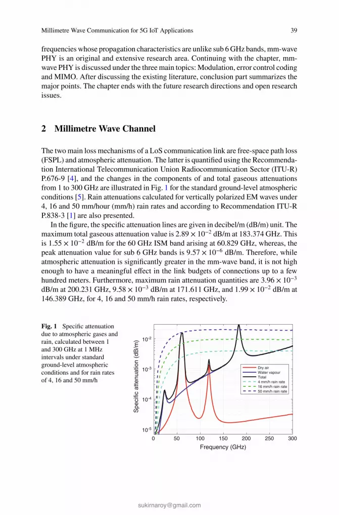
Millimetre Wave Communication for 5G IoT Applications 39
frequencies whose propagation characteristics are unlike sub 6 GHz bands, mm-wave
PHY is an original and extensive research area. Continuing with the chapter, mm-
wave PHY is discussed under the three main topics: Modulation, error control coding
and MIMO. After discussing the existing literature, conclusion part summarizes the
major points. The chapter ends with the future research directions and open research
issues.
2 Millimetre Wave Channel
The two main loss mechanisms of a LoS communication link are free-space path loss
(FSPL) and atmospheric attenuation. The latter is quantified using the Recommenda-
tion International Telecommunication Union Radiocommunication Sector (ITU-R)
P.676-9 [4], and the changes in the components of and total gaseous attenuations
from 1 to 300 GHz are illustrated in Fig. 1 for the standard ground-level atmospheric
conditions [5]. Rain attenuations calculated for vertically polarized EM waves under
4, 16 and 50 mm/hour (mm/h) rain rates and according to Recommendation ITU-R
P.838-3 [1] are also presented.
In the figure, the specific attenuation lines are given in decibel/m (dB/m) unit. The
maximum total gaseous attenuation value is 2.89 × 10⁻² dB/m at 183.374 GHz. This
is 1.55 × 10⁻² dB/m for the 60 GHz ISM band arising at 60.829 GHz, whereas, the
peak attenuation value for sub 6 GHz bands is 9.57 × 10⁻⁶ dB/m. Therefore, while
atmospheric attenuation is significantly greater in the mm-wave band, it is not high
enough to have a meaningful effect in the link budgets of connections up to a few
hundred meters. Furthermore, maximum rain attenuation quantities are 3.96 × 10⁻³dB/m at 200.231 GHz, 9.58 × 10⁻³ dB/m at 171.611 GHz, and 1.99 × 10⁻² dB/m at
146.389 GHz, for 4, 16 and 50 mm/h rain rates, respectively.
Fig. 1 Specific attenuation
due to atmospheric gases and
rain, calculated between 1
and 300 GHz at 1 MHz
intervals under standard
ground-level atmospheric
conditions and for rain rates
of 4, 16 and 50 mm/h
Frequency (GHz)
0 50 100 150 200 250 300
Spe
cific
atte
nuat
ion
(dB
/m)
10-5
10-4
10-3
10-2
Dry airWater vapourTotal4 mm/h rain rate16 mm/h rain rate50 mm/h rain rate

40 T. Yilmaz et al.
Fig. 2 FSPL, calculated
between 1 and 1000 m at 1 m
intervals and for carrier
frequencies of 5, 30, 60 and
300 GHz
Distance (m)100 101 102 103
Fre
e-sp
ace
path
loss
(dB
)
50
60
70
80
90
100
110
120
130
140
5 GHz30 GHz60 GHz300 GHz
FSPL is computed using Friis’ equation [21]. In Fig. 2, FSPL plots of exemplary
carrier frequencies of 5, 30, 60 and 300 GHz are presented for transmission distances
between 1 m and 1 km. As stated by the equation, a tenfold increase in the frequency
causes a 20 dB rise in FSPL for the same node separation. This rise becomes 27.96
and 21.58 dB when the operation frequency is increased to 60 GHz from 2.4 and 5
GHz, respectively. Hence, mm-wave communication leads to a substantial amount
of additional FSPL, which has to be countered in order to maintain consistent links.
Effects of non-line-of-sight (NLoS) propagation mechanisms are also different in
the mm-wave band, compared to the legacy bands. While absorption coefficients of
a number of materials are reported to increase with frequency [37], refractive indices
essentially stay the same regardless of the changes in the frequency [28]. However,
because the sizes of mm-wave wavelengths are comparable to the roughness of ordi-
nary surfaces, power of reflected and scattered rays are reduced [25]. Diffraction is
also demonstrated to be practically nonexistent in 60 and 300 GHz [24]. Overall,
effective use of PHY techniques are necessary to overcome the decreased received
power due to the weakened NLoS propagation.
3 Millimetre Wave Modulation
When high data rates are needed, orthogonal frequency division multiplexing
(OFDM) is usually the first modulation scheme to be considered, owing to being
well-known and already used for the LTE (Long Term Evolution). OFDM provides
a way to lessen the multipath effects, achieve high data rates, and allows multiple
users on a single channel. However, OFDM also suffers from shortcomings, about
which many methods have been proposed. For instance, in [44] cognitive radio is
considered together with OFDM. Performance evaluation of LTE access network

Millimetre Wave Communication for 5G IoT Applications 41
is discussed in [39] where single carrier frequency division multiple access (SC-
FDMA) is used for uplink (UL) to overcome OFDM being asynchronous to the net-
work. Moreover, with LTE-Advanced (LTE-A), OFDM is used together with MIMO
techniques to further increase the data rates [7]. Hence, it can be argued that OFDM
is also a strong candidate for the 5G systems. Though, it is not the only one. In
this section, OFDM, filter bank multicarrier (FBMC), universal-filtered multicarrier
(UFMC) and SC methods are examined. First three methods belong to multicar-
rier (MC) systems, where many subcarriers are used as parallel narrowband carriers
instead of a single wideband carrier to deliver the message.
3.1 OFDM
OFDM is extensively studied due to its use in LTE systems and it is an important 5G
technology candidate as a result of its resistance to multipath distortion and ease of
implementation with fast Fourier transform (FFT) and inverse FFT (IFFT) blocks.
Moreover, orthogonality of subcarriers reduces the effects of intercell interference
and its ability to adapt to phase and frequency distortions allow OFDM to work
with MIMO antenna techniques. Nevertheless, there are two disadvantages that need
to be tackled. Firstly, high peak-to-average power ratio (PAPR) causes problems in
the amplifiers by decreasing efficiency due to linearity concerns. Also, designing
an amplifier that will avoid the distortion caused by the peaks occurring is a costly
process [11, 42]. Secondly, since there are multiple subcarriers allocated next to each
other, OFDM is sensitive to carrier offset and drift [51]. Cyclic prefix (CP) is used
to avoid from this situation. Though, while introducing CP offers advantages such
as creating a guard interval, it decreases spectral efficiency.
3.2 FBMC
FBMC, just like OFDM, belongs to MC systems and provides a solution to spec-
tral efficiency problem. The main difference is, side lobes which create interference
and error propagation are filtered out at FBMC. This way, a bandlimited signal that
increases spectral efficiency without CP is obtained. Although FBMC increases com-
plexity, it also provides better subcarrier separation. Moreover, its ability to achieve
network synchronization is crucial for 5G systems. As a result, while still using con-
venient FFT and IFFT blocks, like OFDM, UL and downlink (DL) synchronization
problems are now eliminated [22, 52].
One other key aspect of FBMC is its compatibility to massive MIMO. FBMC-
based massive MIMO systems enable self equalization, which introduces a number
of benefits considering the reduced number of subcarriers, such as decreased latency
and complexity, higher bandwidth efficiency and lower PAPR. Moreover, pilot

42 T. Yilmaz et al.
contamination problem of massive MIMO is solved by the blind channel tracking
property of FBMC [18].
3.3 UFMC
UFMC is another subclass of MC systems. It separates from FBMC in that, while
FBMC uses filtering on each of the subcarriers, UFMC applies filtering to some
subset of those [50]. Hence, UFMC offers better spectral efficiency and robustness
compared to OFDM [8, 51]. Also, since filter length decreases, UFMC possesses
lower latency advantage over FBMC [8, 43].
3.4 SC
MC systems, especially OFDM, have been enjoying a huge popularity due to their
many advantages and ease of implementation. On the other hand, in addition to
employing just one wideband carrier, SC has another major distinction. In MC sys-
tems, equalization and decision take place in the frequency domain, whereas in SC
systems decision takes place in time domain using an IFFT block subsequent to
equalization, and this increases complexity [17]. Though, with the recent advance-
ments in electronics, high performance and low complexity equalizers operating in
the frequency domain became available, raising the interest in SC techniques even
further [12].
SC frequency domain equalization (SC-FDE) and SC-FDMA can be considered
as the linearly precoded OFDM scheme and its multiple access counterpart. The most
important advantage of SC over MC is its low PAPR values. For this reason, in [39],
SC-FDMA is used for UL communication to achieve reduced cost for the power
amplifier and transmit power efficiency by making use of the low PAPR. Finally,
SC is also able to cope with spectral nulls and provide robustness against frequency
offset [33].
3.5 Evaluation
Authors’ direct comparison of some of the important properties of the aforemen-
tioned mm-wave modulation methods are given in Table 1. Additional assessments
are also available in the literature [11, 13, 18, 19, 26, 42, 51].
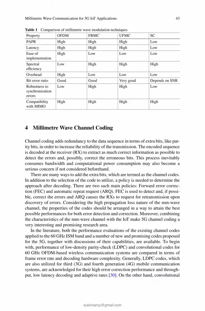
Millimetre Wave Communication for 5G IoT Applications 43
Table 1 Comparison of millimetre wave modulation techniques
Property OFDM FBMC UFMC SC
PAPR High High High Low
Latency High High High Low
Ease of
implementation
High Low Low Low
Spectral
efficiency
Low High High High
Overhead High Low Low Low
Bit error ratio Good Good Very good Depends on SNR
Robustness to
synchronization
errors
Low High High Low
Compatibility
with MIMO
High High High High
4 Millimetre Wave Channel Coding
Channel coding adds redundancy to the data sequence in terms of extra bits, like par-
ity bits, in order to increase the reliability of the transmission. The encoded sequence
is decoded at the receiver (RX) to extract as much correct information as possible to
detect the errors and, possibly, correct the erroneous bits. This process inevitably
consumes bandwidth and computational power consumption may also become a
serious concern if not considered beforehand.
There are many ways to add the extra bits, which are termed as the channel codes.
In addition to the selection of the code to utilize, a policy is needed to determine the
approach after decoding. There are two such main policies: Forward error correc-
tion (FEC) and automatic repeat request (ARQ). FEC is used to detect and, if possi-
ble, correct the errors and ARQ causes the RXs to request for retransmission upon
discovery of errors. Considering the high propagation loss nature of the mm-wave
channel, the properties of the codes should be arranged in a way to attain the best
possible performances for both error detection and correction. Moreover, combining
the characteristics of the mm-wave channel with the IoT make 5G channel coding a
very interesting and promising research area.
In the literature, both the performance evaluations of the existing channel codes
applied to the 60 GHz ISM band and a number of new and promising codes proposed
for the 5G, together with discussions of their capabilities, are available. To begin
with, performance of low-density parity-check (LDPC) and convolutional codes for
60 GHz OFDM-based wireless communication systems are compared in terms of
frame error rate and decoding hardware complexity. Generally, LDPC codes, which
are also utilized for third (3G) and fourth generation (4G) mobile communication
systems, are acknowledged for their high error correction performance and through-
put, low latency decoding and adaptive rates [30]. On the other hand, convolutional

44 T. Yilmaz et al.
codes offer reliable data transfer and high throughput is achieved through paralleliza-
tion. Simulations showed that in both LoS and NLoS cases, LDPC provides higher
coding gains than convolutional coding, which indicates that LDPC is a viable option
also for the mm-wave band.
Recently propositioned channel codes include convolutional (spatially coupled)
LDPC code, which can be interpreted as an enhanced version of the regular LDPC.
Compared to block LDPC codes, convolutional error codes have similar performance
in terms of bit error ratio. However, they offer lower decoding complexity and high
capacity for a wide range of rates [16]. Another category is the non-binary LDPC
codes. These provide better performance at shorter block lengths and higher spec-
tral efficiency, in return for increased computational complexity. Alternatively, polar
codes not only achieve higher channel capacity but also demonstrate advantages
when it comes to multi-terminal scenarios, like relaying and MIMO, which are cru-
cial to the success of real world 5G deployments.
For the coding scheme, one of the proposals is type II hybrid ARQ (HARQ). In
this scheme, message bits are either sent together with error detecting parity bits or
only FEC parity bits are transmitted. Hence, FEC bits are transmitted only if retrans-
mission is requested upon erroneous reception of the message. Moreover, consec-
utively received messages can be used to correct errors. Therefore, if the channel
is good, type II HARQ can function as standard ARQ and achieve higher capac-
ity. Additionally, when the channel is in a poor state, better throughput is achieved
using FEC. These properties enable 5G channel codes to use different rates, i.e.
adaptability, and rate compatibility.
4.1 Requirements for 5G
Iteratively decodable codes, such as turbo and LDPC codes are mainly used by 3G
mobile communication systems. This type of codes have many advantages, like low
encoding and decoding complexities and high error correction performance. With
the 4G, the employed codes were essentially kept the same as LDPC, turbo and
convolutional codes. Though, one 4G policy addition has been the introduction of
HARQ [48, 59]. HARQ observes the channel condition and uses FEC or ARQ
accordingly. Hence, HARQ allows to obtain the benefits of FEC over ARQ in poorer
channel states. As 5G deployments begin, the channel is expected to be less stable
and frequently exposed to interactions from highly mobile agents. Moreover, high
signal degradation of the mm-wave channel would also cause additional problems.
In view of these effects, the channel coding algorithms for 5G need to consider the
following [38]:
∙ Robust and adaptive coding schemes,
∙ Low latency,
∙ Low complexity encoder and decoders,

Millimetre Wave Communication for 5G IoT Applications 45
∙ Flexibility in code block size and rates,
∙ Multi-terminal coding and decoding, and,
∙ Transmission and computational power efficiencies.
5 Millimetre Wave MIMO
MIMO antenna system is one of the most important enabling technologies of 5G.
The main idea behind MIMO is employing multiple transmit and receive antennas
which communicate on the same channel. Each RX antenna then collects both the
direct and indirect components arriving from the multiple antennas at the transmit-
ter (TX) side. Moreover, combining the advanced antenna methods, such as phased
array antennas, together with the higher frequencies proposed for communications,
antenna dimensions have reduced. In addition to this, due to higher path losses, fre-
quency reuse potential in the mm-wave band is also very much improved compared
to the legacy bands, which enables densification of the base stations (BSs), where
each BS contains a large number of antennas. These antennas are used to serve mul-
tiple co-channel users, which is labelled as massive MIMO [45].
MIMO is mainly divided into two categories: Single user (SU) and multi-user
(MU) MIMO. In SU-MIMO, there are one TX and RX communicating with each
other, and an exemplary 4 × 4 SU-MIMO antenna configuration is illustrated in
Fig. 3. Alternatively, for the MU-MIMO, there may be multiple RXs communicat-
ing with the same TX. An MU-MIMO example depicting two RXs is also presented
in Fig. 4. MU-MIMO presents some important properties, which can be listed as
increased data rate, enhanced reliability, improved energy efficiency and reduced
interference [29]. These benefits were decisive for the inclusion of MU-MIMO into
LTE-A standard [46]. However, in order to be adopted by the IoT applications of the
beyond 4G (B4G) systems, further improvements are necessary.
As the carrier frequency is increased to the mm-wave range, 5G operation band-
width gets larger too. Also, since the wavelength is reduced, antennas with smaller
aperture areas are now able to provide the same amount of directivity as before,
which allows decreased antenna sizes. Therefore, dense deployments of high
Fig. 3 SU-MIMO structure
TX RX

46 T. Yilmaz et al.
Fig. 4 MU-MIMO structure
TX
RXa
RXb
capacity small cells can utilize the new ample bandwidths very efficiently. More-
over, as the number of antenna array elements increase, they become able to focus
energy into smaller areas too. This is the general way MIMO increases throughput
and lowers radiation power, leading to energy efficiency for 5G systems [29]. Mas-
sive MIMO also fits this process very well. It scales up the standard MIMO to a few
hundred antenna array elements and allows simultaneous transmission to multiple
terminals in the same time-frequency resource using spatial multiplexing and beam
forming techniques.
5.1 Spatial Multiplexing
There are many ways to send data from TX to RX. To increase the quality of trans-
mission in terms of high robustness, high capacity and low latency, one method is
making use of multiplexing techniques on the data stream. However, there usually is
a trade-off between these parameters and thus, cannot be realized all at once. There-
fore, the correct multiplexing technique should be selected among the options such
as time, frequency, space or code, in consideration of the requirements of the appli-
cation.
For 5G communications, increased channel capacity is the primary system target
due to the expected peak data rates. This necessitates the use of space division mul-
tiplexing, or spatial multiplexing. In spatial multiplexing, data stream is divided to
be transmitted over multiple independent channels in space using different TX and
RX antenna pairs. An illustration of the technique is also presented in Fig. 5.
Spatial multiplexing is considered to be suitable with both the MIMO and 5G
due to the rich scattering environment, large signal attenuation at higher frequen-
cies and channel-unawareness due to high mobility within the indoor channels. For
instance, if there were a channel-aware structure, then introducing only diversity
without multiplexing would increase the system’s robustness since the signal-to-
noise ratio (SNR) values at the RX side would rise. In that case, a linear increase
in the number of antennas would lead to a logarithmic grow in the capacity due
to Shannon’s channel capacity theorem. However, this level of capacity expansion is
not enough to meet the expectations from 5G. The mm-wave channels considered for

Millimetre Wave Communication for 5G IoT Applications 47
TX RX
TX1
TX2
TXn
RX1
RX2
RXn
1001...00 1001...00
10
01
00
.
.
.
.
.
.
Fig. 5 Outline of spatial multiplexing method
5G networks may encounter channel estimation problems more frequently than the
previous generations. Because the number of receiving antennas exceed the number
of transmitting ones in spatial multiplexing, a linear increase in the channel capacity
occurs [9, 47]. Therefore, spatial multiplexing assists massive MIMO in terms of
capacity expansion.
There are a number of difficulties which might restrain the performance of spa-
tial multiplexing massive MIMO. First of all, if some of the data streams experience
weak channel gains, the total multiplexing gain becomes limited by the spatial cor-
relation. Secondly, spatial multiplexing increases the amount of sources, which may
lead to interference problem in cellular systems [9]. Finally, to achieve a required
level of SNR, diversity is employed together with spatial multiplexing, which leads
to beam forming discussion.
5.2 Beam Forming
Beam forming institutes diversity to the MIMO structures using phased array sys-
tems. When the same information is radiated over multiple TX antennas, some
modification in amplitude or phase is necessary due to the effective radiation pat-
tern. In phased array systems, by altering the relative phases, signals transmitted in
unfavourable directions are suppressed, whereas the rest are emphasized. In addition
to increasing the signal power, beam forming helps with the interference problem
too, if the channel state information (CSI) is available. The latter is also one of the
challenges of beam forming in 5G systems [15].
There is a trade-off between robustness and capacity in MIMO systems. Indepen-
dently, diversity is not capable of attaining the required channel capacity values and
spatial multiplexing is not capable of reaching the necessary SNR quantities for 5G
systems. Therefore, beam forming and spatial multiplexing should be used in MIMO
together to meet the demands of B4G applications.

48 T. Yilmaz et al.
5.3 Evaluation
Using spatial multiplexing and beam forming, massive MIMO offers a number
of opportunities for 5G. The main advantages, besides reduced latency, increased
robustness and simplified medium access layer [29], can be listed as follows:
∙ Tenfold network capacity increase: The capacity increase is obtainable by effi-
cient use of spatial multiplexing, as explained in Subsect. 5.1 [9, 29].
∙ Radiated energy efficiency rise: Massive MIMO uses very large number of
antennas which are small in size. This allows highly directional energy radiation
into very focused regions, which decreases the energy lost into space, and thus
realizing higher energy efficiency [29]. In [34], UL power savings are analyzed
while keeping track of spectral efficiency. It is concluded that massive MIMO is
able to increase the spectral efficiency while simultaneously achieving energy effi-
ciency with linear processing.
∙ Availability of inexpensive, low-power components: The major increase in the
number of antennas required for massive MIMO structures compared to the con-
ventional antenna arrays allows the use of cheaper devices in the designs. To begin
with, high-power amplifiers can now be replaced by many low-cost amplifiers that
output lower power. Moreover, massive MIMO architecture make some costly
components redundant, like coaxial cables. In essence, the performance of reg-
ular antenna arrays depend greatly on all elements of the system, making highly
performing devices expensive. Massive MIMO, on the other hand, relies on the
sheer number of its antennas to overcome propagation problems rather than indi-
vidual components, allowing the system to be constructed at much lower costs
[29].
As for challenges, one important performance limiting problem for massive
MIMO systems is pilot contamination. Channel estimation at the BSs are performed
in the time division duplex mode by making use of the reciprocity between UL and
DL pilots. At this point, the frequency reuse opportunity of mm-wave band, which
is considered for the 5G networks, becomes complicated. Reusing the same band of
frequencies results in the use of same pilot sequences. Hence, without any interac-
tion, a BS would receive other terminals’ CSI that share the same pilot waveform.
This will lead to inter-cellular interference, which is termed as pilot contamination
[31].
The effects of pilot contamination on communication links’ performances are ana-
lyzed for different scenarios in the literature [31, 35]. It is shown that attainable data
rates are limited due to it. Several solution methods, such as optimization of allo-
cation of pilot waveforms, clever channel estimation algorithms and new precoding
techniques, are also proposed in order to utilize massive MIMO as planned [23, 29,
32].
Another difficulty is the undetermined channel response to the large arrays.
Because large and small scale fading effects can be different from the few antenna
case, realistic channel measurements need to be carried out [29].

Millimetre Wave Communication for 5G IoT Applications 49
6 Conclusions
In this chapter, the use of mm-wave band for 5G IoT applications is examined. In
general, path losses of different propagation mechanisms are increased in the mm-
wave band. While OFDM is extensively and reliably used in current communication
systems, modulation techniques with better spectral efficiency are needed to meet
the data rate and network capacity requirements of B4G systems. Mm-wave channel
coding is an active research are that does not currently exhibit a commonly favored
solution for 5G. Theory of MIMO systems is thoroughly researched; though, real
world massive MIMO implementations are distant. To sum up, utilization of mm-
wave band is necessary for efficient IoT applications within 5G mobile networks, and
correspondingly, the research efforts in the area continues to steadily intensify.
7 Future Research Directions
PHY open research issues can be summarized as follows:
1. Modulation schemes need to be evaluated simultaneously with other 5G tech-
nologies, taking into account compatibility within the communication system.
2. Massive MIMO has several problems to be solved before being deployed in actual
networks, such as:
a. Pilot contamination,
b. Reciprocity calibration,
c. Fast, distributed and coherent signal processing,
d. Hardware impairments, and,
e. Low-cost hardware manufacturing.
3. Proposed channel coding techniques for 5G need to be experimented and ana-
lyzed in a realistic test scenarios.
A further research topic for mm-wave 5G is Tactile Internet. Tactile Internet
makes use of the expected decrease in latency within a reliable and secure com-
munication link, aiming round trip delay of 1 ms [20]. When the latency is below
this level, human perception cannot notice the delays in the audio and visual inter-
actions. Thus, real time wireless control of objects becomes an achievable goal. In
addition to the reliable obtainment of latency at levels this low, design of electronic
circuitries that can process information at the increased amount and rates is another
difficulty. However, when utilized properly, there are various areas Tactile Internet
will be very beneficial to, including health care, traffic and smart grid applications,
to name a few.
Acknowledgments This work was supported in part by the Scientific and Technological Research
Council of Turkey (TUBITAK) under grant #113E962.

50 T. Yilmaz et al.
References
1. Recommendation ITU-R P.838-3: Specific attenuation model for rain for use in prediction
methods. ITU-R Recommendations, P Series Fasicle, ITU, Geneva, Switzerland (2005)
2. IEEE Standard for Information technology-Telecommunications and information exchange
between systems-Local and metropolitan area networks-Specific requirements. Part 15.3:
Wireless Medium Access Control (MAC) and Physical Layer (PHY) Specifications for High
Rate Wireless Personal Area Networks (WPANs) Amendment 2: Millimeter-wave-based Alter-
native Physical Layer Extension. IEEE Std 802.15.3c-2009 (Amendment to IEEE Std 802.15.3-
2003), pp. c1–187 (2009). doi:10.1109/IEEESTD.2009.5284444
3. IEEE Standard for Information technology-Telecommunications and information exchange
between systems-Local and metropolitan area networks-Specific requirements-Part 11: Wire-
less LAN Medium Access Control (MAC) and Physical Layer (PHY) Specifications Amend-
ment 3: Enhancements for Very High Throughput in the 60 GHz Band. IEEE Std 802.11ad-
2012 (Amendment to IEEE Std 802.11-2012, as amended by IEEE Std 802.11ae-2012 and
IEEE Std 802.11aa-2012), pp. 1–628 (2012). doi:10.1109/IEEESTD.2012.6392842
4. Recommendation ITU-R P.676-9: Attenuation by atmospheric gases. ITU-R Recommenda-
tions, P Series Fasicle, ITU, Geneva, Switzerland (2012)
5. Recommendation ITU-R P.835-5: Reference standard atmospheres. ITU-R Recommendations,
P Series Fasicle, ITU, Geneva, Switzerland (2012)
6. Cisco Visual Networking Index: Global mobile data traffic forecast update, 2014–2019. Report,
Cisco Systems, Inc. (2015)
7. Akyildiz, I.F., Gutierrez-Estevez, D.M., Reyes, E.C.: The evolution to 4G cellular systems:
LTE-advanced. Phys. Commun. 3(4), 217–244 (2010). doi:10.1016/j.phycom.2010.08.001
8. Andrews, J.G., Buzzi, S., Wan, C., Hanly, S.V., Lozano, A., Soong, A.C.K., Zhang, J.C.: What
will 5G be? IEEE J. Sel. Areas Commun. 32(6), 1065–1082 (2014). doi:10.1109/JSAC.2014.
2328098
9. Andrews, J.G., Wan, C., Heath, R.W.: Overcoming interference in spatial multiplexing MIMO
cellular networks. IEEE Wirel. Commun. 14(6), 95–104 (2007). doi:10.1109/MWC.2007.
4407232
10. Atzori, L., Iera, A., Morabito, G.: The Internet of Things: a survey. Comput. Netw. 54(15),
2787–2805 (2010). doi:10.1016/j.comnet.2010.05.010
11. Banelli, P., Buzzi, S., Colavolpe, G., Modenini, A., Rusek, F., Ugolini, A.: Modulation formats
and waveforms for 5G networks: who will be the heir of OFDM? An overview of alternative
modulation schemes for improved spectral efficiency. IEEE Signal Process. Mag. 31(6), 80–93
(2014). doi:10.1109/MSP.2014.2337391
12. Benvenuto, N., Dinis, R., Falconer, D., Tomasin, S.: Single carrier modulation with nonlinear
frequency domain equalization: an idea whose time has come—again. Proc. IEEE 98(1), 69–96
(2010). doi:10.1109/JPROC.2009.2031562
13. Benvenuto, N., Tomasin, S.: On the comparison between OFDM and single carrier modulation
with a DFE using a frequency-domain feedforward filter. IEEE Trans. Commun. 50(6), 947–
955 (2002). doi:10.1109/TCOMM.2002.1010614
14. Chandrasekhar, V., Andrews, J.G., Gatherer, A.: Femtocell networks: a survey. IEEE Commun.
Mag. 46(9), 59–67 (2008). doi:10.1109/MCOM.2008.4623708
15. Chin, W.H., Zhong, F., Haines, R.: Emerging technologies and research challenges for 5G
wireless networks. IEEE Wirel. Commun. 21(2), 106–112 (2014). doi:10.1109/MWC.2014.
6812298
16. Costello Jr., D.J., Pusane, A.E., Bates, S., Zigangirov, K.S.: A comparison between LDPC block
and convolutional codes. In: Proceedings of Information Theory and Applications Workshop
17. Czylwik, A.: Comparison between adaptive OFDM and single carrier modulation with fre-
quency domain equalization. In: IEEE 47th Vehicular Technology Conference, vol. 2, pp. 865–
869 (1997). doi:10.1109/VETEC.1997.600452

Millimetre Wave Communication for 5G IoT Applications 51
18. Farhang, A., Marchetti, N., Figueiredo, F., Miranda, J.P.: Massive MIMO and waveform design
for 5th generation wireless communication systems. In: 1st International Conference on 5G for
Ubiquitous Connectivity (5GU), pp. 70–75 (2014). doi:10.4108/icst.5gu.2014.258195
19. Farhang-Boroujeny, B.: OFDM versus filter bank multicarrier. IEEE Signal Process. Mag.
28(3), 92–112 (2011). doi:10.1109/MSP.2011.940267
20. Fettweis, G.P.: The tactile Internet: applications and challenges. IEEE Veh. Technol. Mag. 9(1),
64–70 (2014). doi:10.1109/MVT.2013.2295069
21. Friis, H.T.: A note on a simple transmission formula. Proc. IRE 34(5), 254–256 (1946)
22. Fusco, T., Petrella, A., Tanda, M.: Sensitivity of multi-user filter-bank multicarrier systems
to synchronization errors. In: 3rd International Symposium on Communications, Control and
Signal Processing, SCCSP 2008, pp. 393–398 (2008). doi:10.1109/ISCCSP.2008.4537257
23. Haifan, Y., Gesbert, D., Filippou, M., Yingzhuang, L.: A coordinated approach to channel
estimation in large-scale multiple-antenna systems. IEEE J. Sel. Areas Commun. 31(2), 264–
273 (2013). doi:10.1109/JSAC.2013.130214
24. Jacob, M., Priebe, S., Dickhoff, R., Kleine-Ostmann, T., Schrader, T., Kurner, T.: Diffraction
in mm and sub-mm wave indoor propagation channels. IEEE Trans. Microw. Theory Tech.
60(3), 833–844 (2012). doi:10.1109/TMTT.2011.2178859
25. Jansen, C., Priebe, S., Moller, C., Jacob, M., Dierke, H., Koch, M., Kurner, T.: Diffuse scatter-
ing from rough surfaces in THz communication channels. IEEE Trans. Terahertz Sci. Technol.
1(2), 462–472 (2011). doi:10.1109/TTHZ.2011.2153610
26. Jianfei, L., Du, Y., Liu, Y.: Comparison of spectral efficiency for OFDM and SC-FDE under
IEEE 802.16 scenario. In: Proceedings of 11th IEEE Symposium on Computers and Commu-
nications, ISCC ’06, pp. 467–471 (2006). doi:10.1109/ISCC.2006.52
27. Karjalainen, J., Nekovee, M., Benn, H., Kim, W., Park, J., Sungsoo, H.: Challenges and oppor-
tunities of mm-wave communication in 5G networks. In: 9th International Conference on Cog-
nitive Radio Oriented Wireless Networks and Communications (CROWNCOM), pp. 372–376
(2014)
28. Lamb, J.W.: Miscellaneous data on materials for millimetre and submillimetre optics. Int. J.
Infrared Millimeter Waves 17(12), 1997–2034 (1996). doi:10.1007/BF02069487
29. Larsson, E., Edfors, O., Tufvesson, F., Marzetta, T.: Massive MIMO for next generation
wireless systems. IEEE Commun. Mag. 52(2), 186–195 (2014). doi:10.1109/MCOM.2014.
6736761
30. Marinkovic, M., Piz, M., Chang-Soon, C., Panic, G., Ehrig, M., Grass, E.: Performance evalua-
tion of channel coding for Gbps 60-GHz OFDM-based wireless communications. In: IEEE 21st
International Symposium on Personal Indoor and Mobile Radio Communications (PIMRC),
pp. 994–998 (2010). doi:10.1109/PIMRC.2010.5671892
31. Marzetta, T.L.: Noncooperative cellular wireless with unlimited numbers of base station
antennas. IEEE Trans. Wireless Commun. 9(11), 3590–3600 (2010). doi:10.1109/TWC.2010.
092810.091092
32. Muller, R.R., Cottatellucci, L., Vehkapera, M.: Blind pilot decontamination. IEEE J. Sel. Top.
Sign. Proces. 8(5), 773–786 (2014). doi:10.1109/JSTSP.2014.2310053
33. Myung, H.G., Junsung, L., Goodman, D.: Peak-to-average power ratio of single carrier fdma
signals with pulse shaping. In: IEEE 17th International Symposium on Personal, Indoor and
Mobile Radio Communications, pp. 1–5 (2006). doi:10.1109/PIMRC.2006.254407
34. Ngo, H.Q., Larsson, E.G., Marzetta, T.L.: Energy and spectral efficiency of very large multi-
user MIMO systems. IEEE Trans. Commun. 61(4), 1436–1449 (2013). doi:10.1109/TCOMM.
2013.020413.110848
35. Ngo, H.Q., Marzetta, T.L., Larsson, E.G.: Analysis of the pilot contamination effect in very
large multicell multiuser MIMO systems for physical channel models. In: IEEE International
Conference on Acoustics, Speech and Signal Processing (ICASSP), pp. 3464–3467 (2011).
doi:10.1109/ICASSP.2011.5947131
36. Ortiz, S.: The wireless industry begins to embrace femtocells. Computer 41(7), 14–17 (2008).
doi:10.1109/MC.2008.238

52 T. Yilmaz et al.
37. Piesiewicz, R., Jansen, C., Wietzke, S., Mittleman, D., Koch, M., Kurner, T.: Properties of
building and plastic materials in the THz range. Int. J. Infrared Millimeter Waves 28(5), 363–
371 (2007). doi:10.1007/s10762-007-9217-9
38. Popovski, P., Stefanovic, C., Yomo, H., Pratas, N., Schaich, F., Santos, A., Braun, V., Gozalvez-
Serrano, D., Strom, E., Svensson, T., Sun, W., Weitkemper, P., Benjebbour, A., Saito, Y.,
Kishiyama, Y., He, N., Lin, H., Siaud, I., Siohan, P., Schellmann, M., Zhao, Z., Schubert, M.,
Lahetkangas, E., Vihriala, J., Pajukoski, K., Ascheid, G., Heinen, S., Ashok, A., Ishaque, A.,
Luecken, V., Dekorsy, A., Bockelmann, C., Quint, F., Rajatheva, N., Pirinen, P., Baghdadi, A.,
Guilloud, F.: Requirement analysis and design approaches for 5G air interface. Report (2013).
https://www.metis2020.com/wp-content/uploads/deliverables/METIS_D2.1_v1.pdf
39. Priyanto, B.E., Codina, H., Rene, S., Sorensen, T.B., Mogensen, P.: Initial performance evalu-
ation of DFT-spread OFDM based SC-FDMA for UTRA LTE uplink. In: IEEE 65th Vehicu-
lar Technology Conference, VTC2007-Spring, pp. 3175–3179 (2007). doi:10.1109/VETECS.
2007.650
40. Rappaport, T.S., Gutierrez, F., Ben-Dor, E., Murdock, J.N., Yijun, Q., Tamir, J.I.: Broadband
millimeter-wave propagation measurements and models using adaptive-beam antennas for out-
door urban cellular communications. IEEE Trans. Antennas Propag. 61(4), 1850–1859 (2013).
doi:10.1109/TAP.2012.2235056
41. Rappaport, T.S., Heath, R.W., Daniels, R.C., Murdock, J.N.: Millimeter wave wireless com-
munications. Prentice Hall (2014)
42. Schaich, F., Wild, T.: Waveform contenders for 5G—OFDM vs. FBMC vs. UFMC. In: 6th
International Symposium on Communications, Control and Signal Processing (ISCCSP), pp.
457–460 (2014). doi:10.1109/ISCCSP.2014.6877912
43. Schaich, F., Wild, T., Yejian, C.: Waveform contenders for 5G—suitability for short packet and
low latency transmissions. In: IEEE 79th Vehicular Technology Conference (VTC Spring), pp.
1–5 (2014). doi:10.1109/VTCSpring.2014.7023145
44. Songlin, S., Yanhong, J., Yamao, Y.: Overlay cognitive radio OFDM system for 4G cellu-
lar networks. IEEE Trans. Wireless Commun. 20(2), 68–73 (2013). doi:10.1109/MWC.2013.
6507396
45. Swindlehurst, A.L., Ayanoglu, E., Heydari, P., Capolino, F.: Millimeter-wave massive MIMO:
the next wireless revolution? IEEE Commun. Mag. 52(9), 56–62 (2014). doi:10.1109/MCOM.
2014.6894453
46. Talwar, S., Choudhury, D., Dimou, K., Aryafar, E., Bangerter, B., Stewart, K.: Enabling tech-
nologies and architectures for 5G wireless. In: IEEE MTT-S International Microwave Sympo-
sium (IMS), pp. 1–4 (2014). doi:10.1109/MWSYM.2014.6848639
47. Telatar, E.: Capacity of multi-antenna gaussian channels. European Trans. Telecommun. 10(6),
585–595 (1999). doi:10.1002/ett.4460100604
48. Tirouvengadam, B., Radhakrishnan, R., Nayak, A.: CAAHR: Content aware adaptive HARQ
retransmission scheme for 4G/LTE network. In: Fourth International Conference on Ubiquitous
and Future Networks (ICUFN), pp. 456–461 (2012). doi:10.1109/ICUFN.2012.6261749
49. Torkildson, E., Madhow, U., Rodwell, M.: Indoor millimeter wave MIMO: feasibility and
performance. IEEE Trans. Wireless Commun. 10(12), 4150–4160 (2011). doi:10.1109/TWC.
2011.092911.101843
50. Vakilian, V., Wild, T., Schaich, F., ten Brink, S., Frigon, J.F.: Universal-filtered multi-carrier
technique for wireless systems beyond LTE. In: IEEE Globecom Workshops (GC Wkshps),
pp. 223–228 (2013). doi:10.1109/GLOCOMW.2013.6824990
51. Wunder, G., Jung, P., Kasparick, M., Wild, T., Schaich, F., Yejian, C., Brink, S., Gaspar, I.,
Michailow, N., Festag, A., Mendes, L., Cassiau, N., Ktenas, D., Dryjanski, M., Pietrzyk, S.,
Eged, B., Vago, P., Wiedmann, F.: 5GNOW: non-orthogonal, asynchronous waveforms for
future mobile applications. IEEE Commun. Mag. 52(2), 97–105 (2014). doi:10.1109/MCOM.
2014.6736749
52. Wunder, G., Kasparick, M., ten Brink, S., Schaich, F., Wild, T., Gaspar, I., Ohlmer, E., Krone,
S., Michailow, N., Navarro, A., Fettweis, G., Ktenas, D., Berg, V., Dryjanski, M., Pietrzyk, S.,
Eged, B.: 5GNOW: challenging the LTE design paradigms of orthogonality and synchronicity.

Millimetre Wave Communication for 5G IoT Applications 53
In: IEEE 77th Vehicular Technology Conference (VTC Spring), pp. 1–5 (2013). doi:10.1109/
VTCSpring.2013.6691814
53. Yilmaz, T., Akan, O.B.: On the use of the millimeter wave and low terahertz bands for Internet
of Things. In: IEEE 2nd World Forum on Internet of Things (WF-IoT), pp. 177–180 (2015).
doi: 10.1109/WF-IoT.2015.7389048
54. Yilmaz, T., Akan, O.B.: Utilizing terahertz band for local and personal area wireless commu-
nication systems. In: IEEE 19th International Workshop on Computer Aided Modeling and
Design of Communication Links and Networks (CAMAD), pp. 330–334 (2014). doi:10.1109/
CAMAD.2014.7033260
55. Yilmaz, T., Akan, O.B.: On the use of low terahertz band for 5G indoor mobile networks.
Comput. Electr. Eng. 48, 164–173 (2015). doi:10.1016/j.compeleceng.2015.06.012
56. Yilmaz, T., Akan, O.B.: Millimetre Wave Communications for 5G Wireless Networks, book
section 15, CRC Press (2016), to appear
57. Yilmaz, T., Akan, O.B.: State-of-the-art and research challenges for consumer wireless com-
munications at 60 GHz. IEEE Trans. Consum. Electron. 62(3), (2016), to appear
58. Yilmaz, T., Fadel, E., Akan, O.B.: Employing 60 GHz ISM band for 5G wireless communi-
cations. In: IEEE International Black Sea Conference on Communications and Networking
(BlackSeaCom), pp. 77–82 (2014). doi:10.1109/BlackSeaCom.2014.6849009
59. Zukang, S., Papasakellariou, A., Montojo, J., Gerstenberger, D., Fangli, X.: Overview of 3GPP
LTE-advanced carrier aggregation for 4G wireless communications. IEEE Commun. Mag.
50(2), 122–130 (2012). doi:10.1109/MCOM.2012.6146491

Challenges Implementing Internetof Things (IoT) Using Cognitive RadioCapabilities in 5G Mobile Networks
Konstantinos Katzis and Hamed Ahmadi
Abstract This chapter aims at identifying the main design and operation con-straints, that smart environments are expected to experience within a 5Gwireless/mobile network and how these constraints can be addressed using cognitiveradio networks. This chapter first provides a general description of 5Gwireless/mobile networks and stresses their role in the future wireless communica-tions with emphasis given on smart environments. Then, the smart environments arepresented based on their architecture characteristic and the applications associatedwith their operation. In addition, an overview of various current standards related toIoT applications is presented followed by the concept of cognitive radio networksand the available experimental platforms stressing the benefits of employing thistechnology in the future 5G wireless/mobile networks. Finally, the research chal-lenges associated with integrating 5G wireless/mobile networks and IoT are outlined.
1 Introduction
Future communications envisage a plethora of wireless, connected, sometimes‘smart’ devices that will communicate in real time with each other. This is referredto as the ‘Internet of Things’. Such devices will not only be used for humaninteraction alone, but it is expected that there will be a significant demand formachine type communications. The number of such devices is expected to rise inthe order of tens of billions by 2020 [1], suggesting that there will be a constantlyincreasing demand for reliable, wireless connections. These connections are
K. Katzis (✉)Department of Computer Science and Engineering, European University Cyprus,6 Diogenes Street, Engomi, Nicosia 2404, Cypruse-mail: [email protected]
H. AhmadiSchool of Electrical and Electronic Engineering, University College Dublin,Belfield, Dublin 4, Ireland
© Springer International Publishing Switzerland 2016C.X. Mavromoustakis et al. (eds.), Internet of Things (IoT) in 5G Mobile Technologies,Modeling and Optimization in Science and Technologies 8,DOI 10.1007/978-3-319-30913-2_4
55

expected to achieve latencies low enough that the radio interface will not be thebottleneck.
Discussion around 5G indicates that there are two schools of thought regardingits operational characteristics and requirements [2]. The first view presents aservice-led view, which sees 5G as a superset of 2G, 3G, 4G, Wi-Fi and otherwireless standards, integrating greater coverage and always-on reliability. Thesecond view foresees greater data speeds and significant reduction in end-to-endlatency. However, these views support contradictory requirements, which furtherimplicate the process of defining 5G requirements. In any case, people have highexpectations regarding the services that 5G will offer and they expect no less thatthe services they’ve received so far ranging from simple voice in 1G to high dataspeeds in 4G (illustrated in Fig. 1).
Various scenarios have been coined by numerous researchers in academia andindustry in an effort to accurately represent the requirements of such a large-scale,complex system. Visualizing the future smart environment that is discerned bypolymorphic characteristics, future wireless networks might not necessarily requirea ‘gigabit experience’ across their coverage but users might operate at lowerdata-rates depending on the application in reference. Nevertheless, both userdata-rates and network capacity consist the main driver for technological evolutionand both academia and industry are working towards the development of highcapacity and high data-rate wireless networks. Further to the higher capacities andspeeds that future wireless networks are called to support, they will also be requiredto provide better performance, cell densification and access to new, broader carriersin new spectrum.
Part of the capacity growth can be addressed with the existing 3G/4G systems,but by 2020, it is expected that limits will be reached and 5G technologies will beneeded. Nokia [3] and Ericsson [4] introduced a number of new services and usecases that will drive the technology such as mobile broadband, mobile media,connected and self-driving cars, heavy machinery controlled over distances, IoTand finally massive machine type communications (very large number ofmeters/sensors embedded in the field). These use-cases define the operationparameters that 5G wireless networks will be required to fulfill. As illustrated inFig. 2, these parameters are: throughput, capacity, number of devices, cost, latency
Fig. 1 5G is expected tofeature voice, data, always onconnectivity—everything that1G to 4G offered so far butbetter
56 K. Katzis and H. Ahmadi

and reliability. Like any other wireless network, performance is subject to spatialand temporal variations.
Depending on the application, optimization is required focusing on multipleparameters or just a single parameter with one key performance indicator (KPI). 5Gnetworks are requested to support such diversity in performance optimization in aflexible and reliable way. More specifically, 5G is expected to fulfill the followingkey performance indicators (KPI’s) [5]:
• Provide 1000 times higher wireless area capacity• Enhance service capabilities• Save up to 90 % of energy per service provided• Reduce the average service creation time cycle from 90 h to 90 min• Create a secure, reliable and dependable Internet with a “zero perceived”
downtime for services provision• Facilitate highly dense deployments of wireless communication links to connect
over 7 trillion wireless devices serving over 7 billion people.• Enabling advanced user-controlled privacy.
To satisfy the KPI listed above, a new architecture along with new communi-cation technologies, and new hardware will be required. The requirements that thisarchitecture is requested to fulfill are listed below [2]:
• 1–10 Gbps connections to end points in the field• 1 ms end-to-end round trip delay (latency)• 1000x bandwidth per unit area• 10–100x number of connected devices• (Perception of) 99.999 % availability
Fig. 2 5G Main operationparameters
Challenges Implementing Internet of Things (IoT) … 57

• (Perception of) 100 % coverage• 90 % reduction in network energy usage• Up to 10 years of battery life for low power, machine-type devices
Technically it is difficult for a single platform to address all 8 requirementssimultaneously. This is not a major problem for the future of 5G. As discussed in[2], it is not necessary to address all 8 requirements since no use-case, service orapplication has been identified that requires all eight performance attributes acrossan entire network. Furthermore, 6 out of the 8 requirements are notgeneration-defining attributes. They are mostly considered as economic and busi-ness case decisions. More specifically, availability and coverage as well as band-width per unit area and number of connected devices are expected to be met bynetworks that include 5G as an incremental technology, but also require continuedsupport of pre-existing generations of network technology. In addition, reduction inenergy usage related to the network operation and improving battery life, consist animportant economic and ecological target for future wireless technologies. Again,the level of improvement for the reduction of power consumption will dependmostly on the operators and at what level they will make use of the 5G technologiesreplacing some of the existing network equipment.
For smart environments, all 8 requirements are important and must be consid-ered, but each requirement will receive a different level of priority.
2 Smart Environments in 5G Wireless Networks
Some say that 5G will arrive by 2020 and will be able to handle 1000 times moremobile data than today’s cellular systems. It is also expected that 5G will becomethe backbone for Internet of Things (IoT) linking up myriads of fixed and mobiledevices, thus forming an ecosystem of smart devices. This section defines whatsmart environments are and what are the architectures currently available/underconsideration.
2.1 Defining Smart Environments
These smart devices are expected to form the future smart environments [6] whichwill be characterized by three main components [7]: the first one involves smartobjects interacting with the environment they live in, the second componentcomprises of the interconnection of smart objects with the network and thirdly theprocedure of life-logging in this interconnected smart environment.
Smart environments such as smart homes, smart offices, smart schools, smartcars and so on, aim to provide computing and communication services in a con-venient, seamless, and enjoyable way. To achieve this, users are expected to be able
58 K. Katzis and H. Ahmadi

to remotely access and control such devices and obtain useful information abouttheir current state, through various services resulting from the integrated coopera-tion of possibly heterogeneous communication-enabled smart devices [8]. Thisdigital eco-system has been formed in the last couple of decades and it is consistedof computers, smartphones, sensors, cars, appliances, buildings, etc. These deviceswill gradually become “smarter” with advanced communicating and cognitivecapabilities enabling them in detecting the nature of the environment they are livingin. Data transfer patterns for such devices are expected to fundamentally differ fromexisting ‘human-to-human’ (H2H) internet. M2M communications will featurelow-bandwidth, upload-biased traffic. Many M2M critical applications are expectedto deliver and process information in real time, whereas power limited nodes willhave to be extremely low-power or self-powered (e.g. solar powered) devices [9].
Research and academic institutions are working towards the composition of suchdevices that will have the ability to form a sophisticated, ad hoc and cooperativecomputational and communications structure operating on technological andhuman-centered perspectives. The concepts and technologies that IoT is based on,have been available for some time now in one form or another. Concepts, some ofwhich are currently available, are machine-to-machine (M2M) communications,Radio Frequency Identification (RFID), Location based services (LBS),Lab-on-chip (LOC) sensors, augmented reality (AR), robotics and vehicle telem-atics [1]. All these technologies are expected to form an ecosystem of smartenvironments, which will feature some sort of communication intelligence runningdata over a mix of wired and wireless networks with and without IP. To understandthe smart environment system architecture and the network requirements behind it,it is important first to picture how smart objects and devices interact with thenetwork infrastructure in order to be constantly operational.
As illustrated in Fig. 3, the smart environment ecosystem is expected to provideconnectivity to a wide range of devices through a large number of existing tech-nologies. From 3G, 4G to Wi-Fi and Wi-Max, and from ZigBee to RFID, the
Fig. 3 Smart environment ecosystem operating on current network infrastructure
Challenges Implementing Internet of Things (IoT) … 59

current infrastructure is called to become a single unified platform that the smartenvironment ecosystem is expected to evolve.
Multi-service environments pose a series of research and technical challenges forfuture wireless networks. Some of these challenges are: how users can discoverservices when moving in new environments and how these service interfaces can bedescribed to allow seamless operation for users moving from one environment tothe other. Another one is how smart objects, part of the smart environment and withlimited capabilities, are able to connect to a wireless or wired network with andwithout IP [7]. Are there enough resources to support seamless, speedy, uninter-rupted operation of users in multi-service smart environments? Is the current pool ofwireless technologies adequate to support this vision or is it necessary that theseservices must be supported from the 5G mobile networks? According to ZhiguoDing [6], what currently stands in the way of the IoT are disconnected systems,which require a unified framework for seamless connection. 5G is a good oppor-tunity to provide this unified framework in order to prevent fragmented and vul-nerable networks.
2.2 Smart Environment Architectures and Applications
Smart home is one of the most popular smart environments. Smart homesaccommodate a variety of smart applications which include, smart energymetering/consumption, smart multimedia and smart home healthcare. Each of theseapplications requires different services from the network. For example, smartmultimedia system needs high downstream data rate while smart energy applicationthat reports the energy consumption to the provider transmits a small upstreamamount of data. To satisfy these requirements different network architectures havebeen proposed in the literature for smart homes.
Studying the network architecture of smart homes is important because theyhave the biggest market among the smart environments and the network architec-ture of smart homes can also be used for other smart environments that have similarfeatures like smart offices and smart schools. Therefore, we review some of theproposed network architectures for smart homes.
A cognitive gateway centric architecture is proposed in [10] for a smart homenetwork. In this architecture there are multiple subnets, which are managed andconnected to the outside world through the proposed cognitive gateway. The mainsubnets that are considered in this architecture are body areas, personal areas andlocal areas. The differences of these subnets are their range, power limitations,required rate and their technology. The authors of [11] envision a cloud-basedarchitecture for the IoT-based smart environments. This architecture encompasses awide range of devices from low-cost/low-power to compute-rich/high-performanceones. Other bases of the architecture in [11] are ultra-scalable connectivity andcloud-based mass device management which support a mix of legacy and newservices and devices. This architecture considers gateways/aggregation points that
60 K. Katzis and H. Ahmadi

bring the installed short-range sensors online and provide interworking withdifferent wireless technologies. In other words, the aggregation points are per-forming the same task as the cognitive gateway does in [10].
A Long Term Evolution-A (LTE-A) oriented architecture for infrastructurebased smart environments is proposed in [3]. The authors propose making use ofuser and/or operator deployed femtocells (Home evolved NodeB, H-eNB) to pro-vide coverage for machine type communication (MTC) devices and absorb theirtraffic. This looks like a more general version of the proposed architecture in [10].Additionally in [12] the authors have foreseen a mid-level gateway known asH-eNB gateway which directs the traffic of all H-eNBs to the serving gateway,while the macro-eNB that is directly connected to the serving gateway. The pro-posed architecture in [12] enable the interconnection with non-3GPP access pointsby connecting the trusted non-3GPP Access Points (APs) to H-eNB gateway. TheAPs exchange data through the non-3GPP interface with the served MTC devices,while they appear like H-eNBs to the H-eNB gateway. This reduces the latency ofcommunications between the APs, and increases the scalability. Figure 4 shows theproposed architecture in [12].
Smart grids belong to a class of smart environments that the considered archi-tectures for smart homes cannot be easily applied to them. Unlike smart homes,smart grids cover a large geographical area. The authors of [13] envision anarchitecture that consists of Neighborhood Area Network (NAN), Building area
Fig. 4 A candidate architecture for smart home environment
Challenges Implementing Internet of Things (IoT) … 61

network (BAN), and Home Area Network (HAN). In this architecture HANconnections are wireless over the unlicensed bands using zigbee or Bluetooth.Every building connected to the smart power grid has its own BAN that consists ofa number of apartments (HANs). HANs are connected to the BAN gateway by wireor wirelessly. For the wireless connection LTE is considered as the main candidate.A number of BANs create a NAN. The BANs in this architecture are connected tothe NAN gateway wirelessly using LTE.
3 Smart Environment Resources
Many of the devices in smart environments are powered by batteries and regardlessof how accessible these devices are, changing their batteries is costly. This oper-ation will cost more if the number of the devices is huge and they are in remoteplaces, for example highways equipped with lot of smart sensors. Therefore, theenergy efficiency of machines and the communication protocols significantly affectsthe operational costs of the network for the smart environments.
Smart environments depending on their applications use different spectrumbands. End-user deployed smart environments (mainly smart homes) normallyconsist of short-range devices that transmit on the industrial, scientific and medical(ISM) band. However, for time sensitive applications like smart health care at hometechnologies that guarantee a maximum delay are considered (for instance LTE).These technologies/standards use licensed frequency bands. Smart grids, smartcities and other wide range smart environments require longer distance coverage.Some portion of this is covered by wired connected access points while for someother parts long distance wireless connection is a must. Cellular communicationusing the licensed spectrum is one of the main candidates while cognitive com-munication on TV white space is another promising solution. Cognitive radiotechnology can use the underutilized spectrum of TV bands for opportunistic radiotransmission. Although this technology does not require paying for the expensivespectrum license, it requires avoiding the interference with the licensed users [14].
Computational power is a resource that significantly affects the power andspectrum requirements of a smart environment. Cheaper devices normally havelower computation power, which means that they have to transmit raw data to thenodes that can process the data to information. Although this is not necessarily anegative point, the designers of smart environments must carefully select theirequipment. A fiber-connected smart home can easily benefit from various cloudservices while a smart sensor-and-controller unit in a remote location should be ableto balance the energy that it spends on processing the collected data and trans-mitting them.
62 K. Katzis and H. Ahmadi

4 Cognitive Radio Networks and Platforms
One of the main forces pushing towards the deployment of cognitive radio(CR) devices and networks is what appears to be spectrum shortage. Current radiotechnologies employ portions of the radio spectrum through long-term licenses andit is impossible for new users to make use of them. Although the radio spectrumseems to be highly occupied with hundreds of bands allocated to various compa-nies, organisations etc., spectrum scarcity largely depends not on how many fre-quencies are available but on the technologies that can be deployed and how thesefrequencies can be utilised.
Currently there is a high demand for high-speed broadband technologies. Thesetechnologies require a substantial radio spectrum for their operation. Furthermore,operating frequencies must be able to support a mobile, heavily loaded, urbanpropagation environment such as we find in 3G and 4G technologies. Alternatively,there are technologies such as IEEE802.11 (Wi-Fi) and IEEE802.16 (WiMax),which pose as examples of modern broadband wireless networks. Both of themoperate in the ISM bands. These bands are internationally reserved for purposesother than telecommunications, which can sometimes cause electromagneticinterference with communication systems that are using them. Nevertheless, usingadvanced mitigation interference techniques, it has been possible to make the mostof these frequency bands and enjoy fast wireless broadband connectivity. Sincethese frequencies have been free to use (unlicensed), Wi-Fi has grown to become acheap yet fast and reliable alternative to wired networks allowing connectivity tothe internet or even locally for devices such as laptops, smartphones, TVs, DVDplayers, cameras etc.
It is therefore clear that the technological market is currently driving the researchand development of communications towards an ever more wireless, high speed,high capacity types of network that will be able to support smart environmentsfeaturing polymorphic characteristics depending on the application/use-case. Thebad news for the wireless community is that the spectrum map is highly congestedand it is almost impossible to increase the bandwidth of the existing wirelessstandards. The good news is that recent studies showed that the spectrum map isalso underutilized [15]. The underutilization of the electromagnetic spectrum lead tothe use of the term “spectrum holes” which is defined in [16] as:
“A spectrum hole is a band of frequencies assigned to a primary user, but, at aparticular time and specific geographic location, the band is not being utilized bythat user.” Spectrum holes are also presented in [17] as potential opportunities fornon-interfering use of spectrum and can be considered as multidimensional regionswithin frequency, time, and space. This is provided that the CR systems are able tosense these holes within a given range of frequencies. Spectrum holes are classifiedinto three categories. The black spaces, the grey space and the white spaces [18].Black spaces represent the spectra that are occupied by high power local interferersfor some of the time. Furthermore, grey spaces refer to partially occupied spectra bylow power interferers. Finally, white spaces are free of interferers except from any
Challenges Implementing Internet of Things (IoT) … 63

ambient noise in the area such as thermal noise, transient reflections, impulse noiseand broadband thermal noise [18].
Detecting spectrum holes can be tricky and requires capable hardware andsoftware to carry out this task. Some of the main issues regarding spectrum holedetection are listed in [18] as the environmental factors, exclusive zones and pre-diction algorithms. Environmental factors such as path-loss can reduce significantlythe received signal power whereas shadowing can cause fluctuations about the pathloss by a multiplication factor. In [17], authors propose quantile models foruncertain probability distributions (e.g. for shadowing) while secondary radiopositions have been considered unconstrained. From the results, assumingmulti-user settings, the degree of shadowing correlation has proven highly uncer-tain. Authors suggest that it might be easier to achieve a firm consensus regardingthe correlation of shadowing across different frequencies for a single radio than it isto achieve a consensus regarding the shadowing correlation across users. “WeightedProbability of Area Recovered” (WPAR) is the proposed metric that employs adiscounting-function to weigh the probability of recovering area at a given distanceaway from a single primary transmitter.
Some issues that are addressed in [17] disclose areas of spectrum hole detectionthat must be addressed in the future. These are the cooperative sensing strategies,the tradeoffs between the time-overheads and space-overheads. In addition, how thesignal to noise ratio (SNR) walls must be understood in the context of the proposedWPAR algorithm.
The possibility of employing new technologies for exploiting the spectrum holesin order to fulfill the requirements of future wireless mobile communications hasbeen enticing and it formed the basis for developing future cognitive radionetworks.
4.1 Cognitive Radio Definition
There are numerous definitions of Cognitive Radio (CR) and since this area is stillunder development, more definitions are expected to emerge. CR has been definedby Mitola [19] and later by Haykin [18] as an intelligent wireless communicationsystem that is aware of its surrounding environment and uses the methodology ofunderstanding by building to learn from the environment and adapt its internalstates based on new statistical variations. Another definition [15] states that a CRuses intelligent signal processing (ISP) at the physical layer of a wireless systemand this is achieved by combining ISP with software defined radio (SDR). The CRmakes use of its flexible radio and intelligence in order to adapt to fast changingenvironments, allows new operating requirements set by the user and followsrequirements dictated by regulations that safeguard the requirements of other radiousers sharing the spectrum environment.
These characteristics, enable CR devices to determine which portions of thespectrum are available, detect the presence or absence (spectrum holes) of licensed
64 K. Katzis and H. Ahmadi

(primary) or unlicensed CR (secondary) users. CR users are capable operating in alicensed band (spectrum sensing) by choosing the best available channel andcoordinate access to this channel with other users. Secondary CR users are requiredto vacate the channel when a licensed user is detected. Cognitive radios can offernumerous advantages compared to the legacy wireless and mobile networks. Theycan provide more efficient spectrum usage, ensure connectivity while constantlymonitoring their surroundings for spectrum availability, they are able to dynami-cally tune to spectrum, based on the location and the time of day, they have reducedpower consumption etc. A radio can be as intelligent and flexible as the currenttechnology permits. CR is expected to evolve through time until we reach the fullcognitive radio that Mitola described in [19].
The cognitive radio operation is known as a cognitive cycle and it is presented asa series of processes that are executed by the cognitive engine in order to fulfill a setof requirements. Mitola [19] first proposed the CR cycle. Simon Haykin alsopresented his version of a CR cycle in [18]. Figure 5, illustrates a simple version ofthe cognitive cycle that runs continuously on the cognitive engine to observespectral opportunities, examine these opportunities, decide what to do, and act toexplore the best opportunities [20].
First step in the cycle is sensing. The CR must feature advanced awarenesscapability with respect to the transmitted waveform, RF spectrum. This will beachieved by measuring the electromagnetic activities due to the various radiotransmissions over a range of spectrum bands and to capture useful informationrelated to these bands. In order to save energy, a CR must make real-time decisionsabout which bands to sense, how often, and for how long. Second step is thespectrum analysis, which identifies potential spectral opportunities in the sur-rounding radio environment, also known as spectrum holes. Third step is to decodethe operating parameters based on the analysis completed in the previous step anddecide the set of transmission parameters to be adapted in the fourth step. More
Fig. 5 Cognitive radio functional cycle
Challenges Implementing Internet of Things (IoT) … 65

specifically, a cognitive radio utilizes the information gathered regarding thespectrum bands identified as available spectral opportunities to define the radiotransceiver parameters for the upcoming transmission(s) over such frequency bands.The set of transceiver parameters to be decided are subject to the limitations of theunderlying transceiver architecture. Operating parameters might involve the com-munication network, geography, locally available services, power availability, userneeds, language and security policy.
A good performing CR is expected to:
1. Have low false alarm probability: Maximize secondary (CR) users2. Low missed detection probability: Minimize primary (legacy) users experienced
interference3. Responsive in taking decisions in a limited amount of time (before interfering
levels change again)4. Form a Cognitive Radio Network (CRN) that can support an efficient secondary
user network structure centralized or decentralized (distributed).5. Have good integration with the upper layers.
Moving from a fully regulated spectrum to a loose and perhaps fully unregu-lated, requires to first convince the local regulatory bodies, that existing licensedsystems will not be disturbed by CR devices. After all, this is a one-way streettowards finding capacity for all these wireless devices and applications. Secondly itis necessary to present the benefits to the licensed service providers when they sharetheir frequency bands. FCC in USA, led by its chair Michael Powell has beenworking to update the way spectrum is managed. This effort is based on three mainstrands [21]:
1. Spectrum reallocation: reallocation of bandwidth from government and otherlong-standing users to new services such as mobile communications, broadbandinternet access and video distribution.
2. Spectrum Leases: Permitting existing licensees to use their spectrum for new orhybrid services or by leasing their spectrum to third parties.
3. Spectrum Sharing: This is the allocation of an unprecedented amount of spec-trum that could be used for unlicensed or shared services.
Recently, there have been examples where regulators decided to change the waythey manage various radio spectrum bands and allow new innovative wirelesstechnology to deliver high-speed broadband communications. For example, FCChas recently announced it will adopt new rules and policies to make 150 MHz ofspectrum available between 3550 and 3700 MHz for mobile broadband and othercommercial use, which was previously locked up by the U.S. Department ofDefense (DoD) [22]. It is expected that consumers, businesses, and governmentusers will benefit from these changes in the spectrum allocation as the new rulesproposed, will support protect incumbent radar systems from interference but mostimportantly it will make additional spectrum available for flexible wirelessbroadband use, leading to improved broadband access and performance for con-sumers. Furthermore, Ofcom (UK) announced that it will allow a new wireless
66 K. Katzis and H. Ahmadi

technology access to the unused parts of the radio spectrum in the 470–790 MHzfrequency band. Ofcom refers to the TV band and more specifically to the TVWhite Spaces (TVWS). It is expected, that new technology, known as white spacesdevices, will share this band with the existing uses, Digital Terrestrial Television(DTT), including local TV, and Programme Making and Special Events (PMSE),including in particular wireless microphone users [14]. Related IEEE standards thatare currently under development and look into developing cutting edge technolo-gies to take advantage of this spectrum are IEEE 1900 coordinated by IEEEDySPAN-SC (formerly known as Standards Committee 41) [23] as well asIEEE802.11af [24], IEEE802.22 [25] etc.
4.2 CR Platforms and Testbeds
Cognitive Radios (CRs) and Cognitive Radio Networks (CRNs) can be used as themain platform for implementing a 5G wireless/mobile network. CRNs can supportthe polymorphic requirements of the future wireless/mobile applications and theycan support IoT implementation.
Current research and development activities in the area of CRs, have beenpushing towards the development of different versions of CR engines running ondifferent types of platforms. In all cases the aim is to verify whether CRs disturb theprimary (legacy) users or not as well as to prove its potential in terms of the overallsystem performance. The various types of CR platforms available ensure that thereis enough competition to drive the research and development community intodeveloping the best possible platform. Current CR platforms still have a long wayto go to achieve a fully cognitive radio. This is because of the hardware limitationsposed by the current technology as well as the spectrum sharing restrictions posedby the local spectrum regulator. Nevertheless, CRs have come a long way thanks tothe reconfigurable platforms that are currently available in the market. The plat-forms have been based on digital radio and computer software. In fact, software CRplatforms can be defined as the evolution of Software Defined Radios (SDRs).SDRs have been around for more than 20 years. They were first introduced in theanalogue modem industry where manufacturers implemented the modulating andde-modulating algorithm in software rather than in hardware, thus enabling users toupgrade/change the communication standards using the existing hardware. SDRsnowadays have become faster, more flexible and in general better in utilizing theradio spectrum and allowing real-time reconfigurability. They have also improvedcompatibility and coexistence with different wireless standards. This has beenachieved by implementing the CR functionality on a software-based platform,which performs the modulation and demodulation of the radio signals. Currentlythere is a considerable number of available software and hardware CR platformsmainly used for experimental purposes. Some of the main software platforms are:GNU Radio, IRIS, ASGARD. Combining these with the appropriate hardware RF
Challenges Implementing Internet of Things (IoT) … 67

front such as USRP2, BEE2, VESNA or WARP it is possible to create what isknown as a CR testbed [26].
CR testbeds such as XG Program, CREW, VT-CORNET, VESNA, IRIS andFP7-SAMURAI have been designed and deployed in the last few years to evaluateand improve the overall performance for cognitive radio networks. Cognitive radioresearch community requires that these testbeds are equipped with appropriatecapabilities to allow examining complex interaction between physical and networklayers. In order to achieve this, cognitive radio testbeds must employ [27]:
1. Real-time baseband processing for spectrum sensing.2. Agile transmission with high computational throughput and low latency.3. Integration of physical and network layers on embedded processors.4. Sufficiently wide bandwidth radio front end with spatial processing capabilities.5. Central processing of information exchange between multiple radios for con-
trolled physical and network layer development and analysis.6. Ability to perform controlled experiments in different propagation environments
such as indoors or outdoors.
The testbeds listed above have surfaced several potential issues concerning thedesign and implementation of the cognitive radio networks [26]. In order to achieve anoptimal configuration, it is necessary to maximize the multiple objective fitnessfunction [28, 29] that quantifies the advantages of choosing a given system (andnetwork) configuration with respect to others. Such fitness function shows howwell agiven system configuration performs towards achieving its optimum operation [26].
Cognitive Radio Testbeds provide the means for evaluating CR systems and inextend future 5G networks and implementation of IoT/M2M/etc. Designing andimplementing a testbed for 5G networks can be challenging. It requires well definedrequirement analysis of the IoT/M2M/etc. application is intended for looking atavailability, high throughput, reliability, energy efficiency, etc. Testbeds are basedon software and hardware CR platforms that can play an important role towards theestablishment of cognitive radios delivering 5G networks. They can demonstratethe operation of future 5G networks delivering IoT/M2M/etc. and its impact onlegacy systems or other CRNs, but most of all they are contributing towards raisingthe confidence of regulators to proceed with the legal framework and allowpotential use of the spectrum by CR enabled systems.
5 Current Standards and Application Scenarios
After introducing smart environments, their communications system architectureand their required resources, in this section we discuss the communication standardsfor these applications. Different communication standards are used based on thetypes of devices in the smart environment and their resources and limitations.
68 K. Katzis and H. Ahmadi

5.1 Indoor Smart Environments
In this type of smart environment, the devices are operating on ISM band andtherefore spectrum price is not a challenge. However, congestion and efficiency willbecome an important issue. Since energy is an important issue for many of machinetype communication devices standards, ZigBee and Bluetooth have taken that intoaccount, while standards like Wi-Fi where more successful for the devices thatneeded higher transmission rate with lower energy limitations.
Bluetooth over IEEE 802.15.1 standard is designed for short-range transmissionbetween cheap devices to replace cables [30]. This includes computer peripheralslike mice, keyboards, and headsets. Bluetooth range is about 10 m and operates inthe 2.4 GHz band. Bluetooth networks are master-slave, where slaves communicateonly with their masters in a peer-to-peer fashion. A master device and one or moreslave Bluetooth devices create a piconet and a collection of operational overlappingpiconets form a scatternet that enables the information to flow beyond the coveragearea of a piconet.
ZigBee over IEEE 802.15.4 supports low rate short-range communications fordevices that are simple and low cost. ZigBee provides self-organized multi-hop andreliable mesh networking with long battery lifetime [30]. A ZigBee network hasfull-function and reduced-function devices. While full-function devices (FFD) cantalk to other FFDs and reduced-function devices (RFD), RFDs can also commu-nicate with FFDs. RFDs are normally ZigBee devices that are performing verysimple operations. ZigBee considers a star network where an FFD can become itscoordinator.
Wi-Fi over IEEE802.11 is one of the most popular communication standards. Itenables broadband internet connectivity when the users are connected to an accesspoint. Operating on 2.4 and 5 GHz bands, Wi-Fi supports both peer-to-peer and startopologies while its coverage area can extend to 100 m. As expected, its high datarate and larger coverage area comes with a price which is higher energyconsumption.
All these standards have different applications in smart environments. WhileWi-Fi is mainly used for the applications like wireless surveillance cameras thatrequire high data rate and are connected to power supplies, ZigBee and Bluetoothare more popular for power-limited applications. The low power consumption ofZigBee devices and the number of devices that each smart environment canaccommodate made it a promising technology for low-range smart applications likesmart homes, smart offices and smart production lines [31]. Table 1 summarizessome of the main characteristics of these protocols.
Challenges Implementing Internet of Things (IoT) … 69

5.2 Outdoor/Long-Range Smart Environments
Cellular system is one of the main long distance communication technologies.However, its higher costs and energy requirements limited its applications inMachineto Machine (M2M) communications. 3GPP Long Term Evolution (LTE) standardrelease 12 introduced a new low complexity device category (“Cat-0”). This defines aset of reduced requirements enabling these devices to achieve lower complexity andcost [32]. However, the energy consumption and supporting the massive number ofM2M are the challenges yet to be addressed by LTE-M.
Global System for Mobile communications (GSM) is attracting the attentionof M2M community [33]. GSM is deployed almost all over the world, supportsmobility and it has low energy consumption. These interesting economical andtechnical features make it a promising technology for M2M and smart environ-ments. However, GSM and its extension for packet-switched data transmission, theGeneral Packet Radio Service (GPRS), are designed for phone calls, web browsingand streaming applications, which are different from low-rate M2M applications.
IEEE 802.11af is the standard defined for spectrum sharing among unlicensedwhite space devices and licensed services in TV white space [34]. This standardwhich is also known as Super Wi-Fi or WhiteFi protects the licensed users byapplying a geolocation database mechanism. IEEE 802.11af envisions a geoloca-tion database that stores the frequencies and operating parameters of white spacedevices by their geographic location to fulfill the regulatory requirements. For smartenvironment applications, although IEEE 802.11af has lower coverage rangecompared to cellular solutions, its lower costs due to the spectrum price made it apromising candidate.
All the aforementioned standards and technologies have their specific strengthand shortcomings for smart environment applications. However, scalability is still achallenge, which is not fully addressed.
Weightless is a new cognitive wireless standard for machine-to-machine (M2M)networking [26]. The network structure consists of master nodes (base-stations)connected to a high number of slave devices. The use of white spaces results inextended coverage, while the wireless protocol has been designed to be easilyimplemented in low-power and low-cost devices. Devices using this standard arenot yet in the market. However, the consortium of companies that developed thisstandard claims that this solution addresses the scalability problem too.
Table 1 Bluetooth, Zigbee and Wi-Fi parameters comparison
Standard Bluetooth ZigBee Wi-Fi
Frequency band 2.4 GHz 868/915 MHz, 2.4 GHz 2.4, 5 GHzNominal range (m) 10 10–100 100Max signal rate 1 Mbps 250 Kbps 54 MbpsMax number of cell nodes 8 65,000 2007
70 K. Katzis and H. Ahmadi

5.3 IoT and Cognitive Radio Applications
Objects that have communication capabilities found in IoT/M2M/etc. or theirdevices are expected to have the capability to observe, think, and understand thephysical and social environments they are asked to operate. They will be thereforeequipped with Cognitive Radio characteristics. Cognitive Internet of Things (CIoT)represents a new paradigm where current IoT devices are equipped with five fun-damental cognitive tasks: perception-action cycle, massive data analytics, semanticderivation and knowledge discovery, intelligent decision-making, and on-demandservice provisioning [35]. Authors in [35] define CIoT as “a new network para-digm, where (physical/virtual) things or objects are interconnected and behave asagents, with minimum human intervention, the things interact with each otherfollowing a context-aware perception-action cycle, use the methodology ofunderstanding-by-building to learn from both the physical environment and socialnetworks, store the learned semantic and/or knowledge in kinds of databases, andadapt themselves to changes or uncertainties via resource-efficient decision makingmechanisms”. In [36], a cognitive management framework is presented, where IoTsupports sustainable smart city development, through autonomic selection of themost relevant objects for the given application. The cognitive managementframework focuses on how to hide heterogeneity of connected objects, how toensure resilience of a dynamic service provisioning, how to instruct systems toassess proximity between IoT applications and “useful” objects and how to usecognitive technologies to provide intelligence while minimizing user’s intervention.In [37], Cognitive Internet of Things (CIoT) is viewed as an integration of thecurrent IoT with cognitive and cooperative mechanisms aiming at enhancing theoverall performance and achieve intelligence.
Several IoT applications have emerged and many more are still to come due tothe synergies formed between consumers, businesses, industry and the Internet [30].These synergies will further enable the connection of intelligent things into ourlives. These things are expected to produce and transmit useful data by sensing andmonitoring the environment we live in, thus helping creating new services. Theseservices would not be possible without this level of connectivity and analyticalintelligence. The use of future IoT platforms is directly related to continuousevolving technologies such as cloud, things, and mobile. Further to these tech-nologies, 5G and CRNs consist a decisive factor for the evolution of the futureCIoT platforms and their applications.
Figure 6 illustrates how the device layer, that is consisted of sensing, embeddedprocessing and the connectivity sections is managed by the software layer, whichalters the physical parameters of the CIoT platform. The CIoT platform can be usedas the basis for the implementation of a number of novel applications such as SmartEnergy, Smart Parking, Smart Homes, Smart Grids, Smart Lighting, Smart Cars,Smart Tags, Smart Health, Air quality Control, Search and Rescue, Smart FireMonitoring, etc.
Challenges Implementing Internet of Things (IoT) … 71

In all applications listed above, CIoT can ensure that the reconfigurable type ofnetworks formed, along with the ability to intelligently sense their environment tomake any appropriate decisions, can prove beneficial for both Quality of Experience(QoE) and energy conservation. Sensor nodes will hierarchically manage theircommunication to reach the end user through coordinated and optimized dataaggregation.
A CR type of wireless network is expected to be employing a loose type ofchannel assignment algorithm that enables IoT or any other type of wireless nodesto freely choose the best possible channel for their communication. After all, CRnetworks philosophy is to embrace the freedom of frequency allocation. Never-theless, taking advantage of this kind of freedom does not suggest anarchy for theradio spectrum usage. Not at all; as each CR node, is expected to follow a list ofrules. Avoiding any of these rules can end up in denying services to the node inreference.
Simply put, the primary purpose of managing radio spectrum is to develop anadaptive strategy for the efficient and effective use and reuse of radio spectrum bythe large number of IoT nodes. This will lead to highly reliable communicationswhenever and wherever needed. Inspired on existing wireless communicationsystems, whether these are cellular or not, the channel assignment algorithm for CRnetworks must be able to cope with the increased signaling of a large number ofCIoT nodes building on the spectrum holes detected by the radio-scene analyzerand the output of transmit-power controller. Then, select the modulation strategythat adapts to the time-varying conditions of the radio environment and therequirements of the application of the IoT sensors/devices in reference. The radioscene analyzer proposed in [18] involves the estimation of interference temperature
Fig. 6 5G and CR pushing towards rapid development of a CIoT platform carrying smartenvironments and associated applications
72 K. Katzis and H. Ahmadi

and detection of spectrum holes. Information gathered based on these twotechniques are sent back to the transmitter through the feedback channel. It alsoinvolves the deployment of an adaptive beamforming mechanism that saves powerby not radiating in all directions thus minimizing interference due to the action ofother transmitter.
6 Research Challenges in Resource Management for IoTin 5G Mobile Networks
Building a platform that will support billions of things/devices expected to connectto the Internet involves sorting out some serious resource management issues.These issues become even more obvious when the platform is designed to operatewirelessly. A great number of these things/devices are expected to be connectedwirelessly since communications through wires can be messy and highly incon-venient when used in various places such as houses, buildings, factories, ships, carsetc. In the next few years, we expect that IoT success will largely depend on theevolution of wireless/mobile/cellular networks. 5G is expected to address many ofthese issues and become the first platform to support millions, billions ofwireless/mobile things/devices. So, as users, whom their houses are fully controlledthrough the Internet, and cars are remotely monitored to check on their kids whetherthey are speeding, a very important thing to address is security. Security isimportant but there must always be some reasoning behind the levels of security asthis dictates the complexity of the thing/device itself. Small sensors that measureyour fish tank temperature might not require such a high level of security, not ashigh as you would expect on a home healthcare related device. High security alsoimplies high complexity and this needs to be addressed wisely. Beside security,another critical issue for guaranteeing the success of IoT, is to make sure that thereare enough resources available to support its operation. Considering 5G as thefuture platform for IoT, resources at great extend refer to radio resources. As thenumber of these things/devices increases, it is expected that the levels of interfer-ence will also increase. The same is expected to happen with the network traffic dueto the increased signaling. Furthermore, distributed types of networks will berequired to be self-organized to ensure optimum operation, while provided theyemploy CR capabilities, they will be able to sense their environment and criticallydecide which part of the spectrum and which modulation to use to establish theirwireless connection.
In [38] authors state that there are several research challenges (fromsystem/device design and testing to network management) to fulfill the require-ments of 5G systems. Among these are measurements and test challenges for 5Gsystems in view of higher frequencies and multiple channel bandwidths togetherwith much larger antenna arrays and the use of different transmission modes. Also,they outline the research challenges such as improved energy efficiency by
Challenges Implementing Internet of Things (IoT) … 73

energy-aware communication and energy harvesting, simultaneous transmission-reception, densification of existing cellular networks, cloud radio access networks(C-RAN), and virtualization of wireless resources. More specifically, they presentinterference management in heterogeneous networks as a major issue due to thedense deployment of heterogeneous nodes along with the coverage and trafficload imbalance due to varying transmit powers of different BSs in 5G networks.Furthermore, full-duplex communication addresses issues related to cross-layerresource management, power allocation/control, synchronization and time adjust-ment to establish full-duplex transmission, dynamic mode selection and designing aMAC protocol to support the polymorphic requirements. For the cloud radio accessnetwork (C-RAN): to deploy C-RANs, there are many research challenges, such asoptimally utilizing the processing resource, efficiently using the fronthaul linkswhich connect base band processing units (BBUs) with remote radio heads (RRHs),and centralized control of the propagation signal. To achieve wireless networkvirtualization, efficient resource utilization is required along with inter-slice isola-tion, and customizable intra-slice resource allocation. Along with wireless networkvirtualization, there are issues related to resource discovery, isolation, pricing-basedallocation, and mobility management. Regarding energy-aware communication andenergy-harvesting, one of the main challenges in 5G networks is to improve theenergy efficiency aiming at prolonging the battery life of battery-powered wirelessdevices. To achieve this, harvesting energy from energy sources is an attractiveconcept, which could significantly improve the performance of battery-powereddevices in IoT.
7 Conclusions
Future 5G cellular networks are expected to support IoT along with many otherservices. To achieve this, 5G must combine different enabling technologies. Thebiggest challenge here is to integrate all these enabling technologies and provideseamless connectivity with the highest possible QoE. This chapter has presented themain design and operation constraints, that smart environments are expected toexperience within a 5G wireless/mobile network and how these constraints can beaddressed using cognitive radio networks. The chapter stressed the role of future 5Gwireless/mobile networks on smart environments. It has presented the smart envi-ronments based on their architecture characteristic and the applications along withcommunication standards associated with their operation. The concept of cognitiveradio networks and the available experimental platforms stressing the benefits ofemploying this technology in the future 5G wireless/mobile networks has also beenpresented. Finally, the research challenges associated with integrating 5Gwireless/mobile networks and IoT have been outlined.
74 K. Katzis and H. Ahmadi

References
1. Evans, D.: The internet of things—how the next evolution of the internet is changingeverything, White Paper, CISCO. https://www.cisco.com/web/about/ac79/docs/innov/IoT_IBSG_0411FINAL.pdf (2011). Accessed 10 Mar 2015
2. GSMA Intelligence: ANALYSIS Understanding 5G: perspectives on future technologicaladvancements in mobile. https://gsmaintelligence.com/research/?file=141208-5g.pdf&download. Accessed 13 Mar 2015
3. Nokia Networks: FutureWorks 5G use cases and requirements, White paper—5G Use Casesand Requirements. http://networks.nokia.com/sites/default/files/document/5g_requirements_white_paper.pdf. Accessed 13 Mar 2015
4. Erik Ekudden: Head of Technology Strategies, Ericsson, talks about 5G use cases. 5G UseCases. http://www.ericsson.com/news/150708-5g-user-cases_244069645_c?query=5g.Accessed 23 July 2015
5. Advanced 5G Network Infrastructure for the Future Internet Public Private Partnership inHorizon 2020, “Creating a Smart Ubiquitous Network for the Future Internet”. https://5g-ppp.eu/wp-content/uploads/2014/02/Advanced-5G-Network-Infrastructure-PPP-in-H2020_Final_November-2013.pdf. Accessed 13 Mar 2015
6. Hellemans, A.: Why IoT Needs 5G, 20 May 2015. http://spectrum.ieee.org/tech-talk/computing/networks/5g-taking-stock. Accessed 13 June 2015
7. Petroulakis, N.E., Askoxylakis, I.G., Tryfonas, T.: Life-logging in smart environments:challenges and security threats. In: 2012 IEEE International Conference on Communications(ICC), pp. 5680, 5684, 10–15 June 2012. doi:10.1109/ICC.2012.6364934
8. Arabnia, H., Fang, W.-C., Lee, C., Zhang, Y.: Context-aware middleware and intelligentagents for smart environments. IEEE Intell. Syst. 25(2), 10, 11 (Mar–Apr 2010). doi:10.1109/MIS.2010.47
9. McLellan R., M2M and the Internet of Things: A guide, ZDNET Special Feature: TappingM2M: The Internet of Things. http://www.zdnet.com/article/m2m-and-the-internet-of-things-a-guide/. Accessed 27 July 2015
10. Zhang, Y., Yu, R., Xie, S., Yao, W., Xiao, Y., Guizani, M.: Home M2M networks:architectures, standards, and QoS improvement. IEEE Commun. Mag. 49(4), 44–52 (2011)
11. Wu, G., Talwar, S., Johnsson, K., Himayat, N., Johnson, K.D.: M2M: From mobile toembedded internet. IEEE Commun. Mag. 49(4), 36–43 (2011)
12. Condoluci, M., Dohler, M., Araniti, G., Molinaro, A., Zheng, K.: Toward 5G densenets:architectural advances for effective machine-type communications over femtocells. IEEECommun. Mag. 53(1), 134–141 (2015)
13. Fadlullah, Z.M., Fouda, M.M., Kato, N., Takeuchi, A., Iwasaki, N., Nozaki, Y.: Towardintelligent machine-to-machine communications in smart grid. IEEE Commun. Mag. 49(4),60–65 (2011)
14. Ofcom, Implementing TV White Spaces. http://stakeholders.ofcom.org.uk/consultations/white-space-coexistence/statement. Accessed 27 July 2015
15. Shukla, A., Alptekin, A., Bradford, J., Burbidge, E., Chandler, D., Kennet, M., Levine, P.,Weiss, S.: Cognitive Radio Technology: A Study for Ofcom—Summary Report. Ofcom,London (2007)
16. Kolodzy, P., et al.: Next generation communications: kickoff meeting. In: Proceedings ofDARPA, 17 Oct 2001
17. Tandra, R., Mishra, M., Sahai, A.: What is a spectrum hole and what does it take to recognizeone?. Proc. IEEE 824–848 (2009)
18. Haykin, S.: Cognitive radio: brain-empowered wireless communications. IEEE J. Sel. AreasCommun. 23(2), 201, 220 (2005). doi:10.1109/JSAC.2004.839380
19. Mitola, J., III; Maguire, G.Q. Jr.: Cognitive radio: making software radios more personal.IEEE Personal Commun. 6(4), 13–18 (1999)
Challenges Implementing Internet of Things (IoT) … 75

20. Khattab, A., et al.: Cognitive radio networks: from theory to practice, analog circuits andsignal processing. Springer Science Business Media, New York (2013). doi:10.1007/978-1-4614-4033-82
21. Staple, G., Werbach, K.: The end of spectrum scarcity: new technologies and regulatoryreform will bring a bandwidth bonanza. IEEE Spectr. Mag. (2004)
22. FCC, 3.5 GHz Band/Citizens Broadband Radio Service. https://www.fcc.gov/rulemaking/12-148. Accessed 27 July 2015
23. IEEE DySPAN Standards Committee (DySPAN-SC)24. IEEE 802.11af. https://standards.ieee.org/news/2014/ieee802.11af_amendment.html. Acces-
sed 27 July 201525. IEEE1800.22. http://www.ieee802.org/22/. Accessed 27 July 201526. Katzis, K., Perotti, A., De Nardis, L.: Testbeds and implementation issues. In: Di Benedetto,
M.-G., Bader, F. (eds.) Cognitive Communication and Cooperative HetNet Coexistence.ISBN: 978-3-319-01401-2 (Print) 978-3-319-01402-9 (Online), 17 Jan 2014
27. Cabric D., Taubenheim D., Cafaro G., Farrel R.: Cognitive radio platforms and testbeds. In:Wyglinski, A.M., Nekovee, M., Hou, T. (eds.) Cognitive Radio Communications andNetworks Principles and Practice. Elsevier Inc., Burlington, pp. 539–558 (2010)
28. Newman, T.R., Barker, B.A., Wyglinski, A.M., Agah, A., Evans, J.B., Minden, G.J.:Cognitive engine implementation for wireless multicarrier transceivers. Wiley J. Wirel.Commun. Mobile Comput. 7(9), 1129–1142 (2007)
29. Newman T.R., Evans J.B., Wyglinski A.M., Reconfiguration, adaptation, and optimization. In:Wyglinski, A.M., Nekovee, M., Hou, T. (eds.) Cognitive Radio Communications andNetworks-Principles and Practice. Elsevier Inc., Burlington, pp. 177–198 (2010)
30. Vermesan, O., Friess P.: Internet of Things—From Research and Innovation to MarketDeployment. River Publisher (2014). http://www.internet-of-things-research.eu/pdf/IoT-From%20Research%20and%20Innovation%20to%20Market%20Deployment_IERC_Cluster_eBook_978-87-93102-95-8_P.pdf. Accessed 28 July 2015
31. Gill, K., et al.: A Zigbee-based home automation system. IEEE Trans. Consum. Electron. 55(2), 422–430 (2009)
32. Nokia LTE M2M white paper. http://networks.nokia.com/file/34496/nokia-lte-m2m. Accessed28 July 2015
33. Pauls, F., et al.: Evaluation of efficient modes of operation of GSM/GPRS modules for M2Mcommunications. In: 2013 IEEE 78th Vehicular Technology Conference (VTC Fall). IEEE(2013)
34. Flores, A.B., Guerra, R.E., Knightly, E.W., Ecclesine, P., Pandey, S.: IEEE 802.11 af: astandard for TV white space spectrum sharing. Commun. Mag. IEEE, 51(10), 92–100 (2013)
35. Wu, Q., Ding, G., Xu, Y., Feng, S., Du, Z., Wang, J., Long, K.: Cognitive internet of things: anew paradigm beyond connection. IEEE Internet Things J. 1(2), 129, 143 (2014) doi:10.1109/JIOT.2014.2311513
36. Vlacheas, P., Giaffreda, R., Stavroulaki, V., et al.: Enabling smart cities through a cognitivemanagement framework for the internet of things. IEEE Commun. Mag. 51(6), 102–111(2013)
37. Zhang, M., Zhao, H., Zheng, R., et al.: Cognitive internet of things: concepts and applicationexample. Int. J. Comput. Sci. Issues 9(3), 151–158 (2012)
38. Hossain, E., Hasan, M.: 5G cellular: key enabling technologies and research challenges. IEEEInstrum. Meas. Mag. 18(3), 11–21 (2015). doi:10.1109/MIM.2015.7108393
76 K. Katzis and H. Ahmadi

Role Coordination in Large-Scaleand Highly-Dense Internet-of-Things
André Riker, Marilia Curado and Edmundo Monteiro
Abstract Large-Scale Highly-Dense Networks have been deployed in different
application domains of Internet-of-Things for accurate event-detection and moni-
toring. Due to the high density and large scale, the nodes in these networks must
perform some essential communication roles, namely sensing, relaying, data-fusion,
and data-control (aggregation and replication). Since the energy consumption and
the communication reliability is one of the major challenges in Large-Scale Highly-
Dense Networks, the communication roles should be coordinated in order to effi-
ciently use the energy resources and to meet a satisfactory level of communication
reliability. In this chapter, we propose an on-demand and fully distributed framework
for role coordination that is designed to detect events with different levels of critical-
ity, adapting the data-aggregation and data-replication according to the urgency level
of the detected event. Besides the criticality level, the proposed role coordination
also takes into account the network information such as energy resources, memory,
and link quality. This chapter also presents the related works and shows a qualitative
comparison between the proposed framework and the most comprehensive related
role coordination frameworks.
Keywords Role coordination ⋅ Internet-of-Things ⋅ Large-scale ⋅ Highly-dense
1 Introduction
Wireless networks are becoming extremely dense and are being used to connect all
sorts of devices [1]. Thus, it is envisaged that Large-Scale Highly-Dense Networks
(LSHDN) will emerge to support Internet-of-Things (IoT) and Machine-to-Machine
A. Riker (✉) ⋅ M. Curado ⋅ E. Monteiro
Centre for Informatics and Systems of the University of Coimbra, Coimbra, Portugal
e-mail: [email protected]
M. Curado
e-mail: [email protected]
E. Monteiro
e-mail: [email protected]
© Springer International Publishing Switzerland 2016
C.X. Mavromoustakis et al. (eds.), Internet of Things (IoT) in 5G Mobile Technologies,
Modeling and Optimization in Science and Technologies 8,
DOI 10.1007/978-3-319-30913-2_5
77

78 A. Riker et al.
(M2M) communication, and a large number of low power devices will sense and
actuate on heterogeneous targets over the network. Due to the intense dynamics of
these networks in terms of event occurrence and the different roles that a node can
play, the network should rely on efficient network coordination functions to avoid
the rapid exhaustion of the nodes resources and to maintain a satisfactory level of
communication reliability.
In Large-Scale Highly-Dense Network, the devices perform the following com-
munication roles: (i) sensing, (ii) relaying, (iii) data-fusion, and (iv) data-control
(including data-aggregation and data-replication). The sensing role is related to
the process of acquiring data of a target, while the relaying role has the function
of expanding the wireless coverage via multi-hop communication. Additionally,
the data-fusion role allows the nodes to detect the occurrence of events, and the
data-control functionalities (i.e. Data-Aggregation and Data-Replication) control the
amount of data-redundancy present on the network traffic.
In most of the current solutions [2, 3] the sink node (i.e. a device that has more
hardware and energy resources) concentrates the coordination of the roles, and the
network only executes data-aggregation, relaying and data-fusion roles. In LSHDN,
if a central entity, such as the sink node, performs locally the coordination of the
roles, it will be necessary to deploy a large number of sink nodes in order to main-
tain a satisfactory performance level of performance. Otherwise, the sink nodes will
experience overload, which can cause for instance unreliable communication, false
alarms, low load-balancing capability, and short network lifetime.
The lack of fully distributed coordination is a problem that the current approaches
have(e.g. [4–6]). Existing solutions designed to coordinate the set of roles over the
network are not fully distributed, since they are partial distributed approaches that
rely on cluster-heads or coordinator nodes. It means that most of the existing solu-
tions might spend, in LSHDN, a great amount of network resources communicating
control messages. Besides, these solutions do not consider important aspects, such
as the criticality level of the event and other data-control roles like data-replication.
Another major problem of the current approaches is the inflexibility in terms of com-
munication objectives, since only in rare cases and under limited possibilities the
current works enable orthogonal objectives, such as low energy consumption and
high communication reliability.
In line with this, this book chapter aims to present a framework designed for role
coordination in LSHDN IoT scenarios. This book chapter will also describe the main
requirements of a role coordination solution together with the analysis of the main
state-of-art solutions, and the open research issues. The remainder of this chapter
is structured as follows. Section 2 shows the related work. Section 3 describes the
proposed framework solution. Section 4 presents a discussion, while the conclusion
is presented in Sect. 5.

Role Coordination in Large-Scale and Highly-Dense . . . 79
2 Related Work
This section shows the main works that address aspects related to the role of sensing,
relaying, data-control, and data-fusion. Sections 2.1, 2.2, and 2.3 describe solutions
that focus on specific aspects of sensing and relay, data-control, and data-fusion,
respectively. Section 2.4 shows the current frameworks that solve comprehensive
aspects of role assignment and coordination. At the end of this section there is a
summary that discusses the presented solutions.
2.1 Sensing and Relaying
A particular node with the Sensing role performs two main tasks: (i) it monitors a
phenomenon, target, or event by means of an electronic circuit, and (ii) it commu-
nicates the sensed data using a network interface. In solutions that only consider
the Sensing role, it is usually assumed that every node is able to establish a direct
connection with the data-collector (e.g. base-station, sink, gateway, or data-fusion
center). However, Draves et al. [7] show that the direct connection between the sens-
ing nodes and the data-collector forces the communication between distant nodes
with poor link quality.
Hence, the Relaying role emerges to complement the sensing role. The node with
Relaying role receives the sensed data produced by the Sensing nodes, and forwards
it towards the data-collector. In applications that use both Sensing and Relaying roles,
the nodes that perform sensing are known as sources nodes, while the relay nodes
are called cooperative nodes.
In these solutions, a common assumption is that all nodes can act the sensingand/or relaying roles. This is a common assumption because great part of the current
IoT applications relies on short-range wireless technologies, which currently enable
the sensing and relaying roles. Due to the widespread use of Sensing and Relaying,
these roles are two of the most essential roles in wireless IoT scenarios.
The approaches that assign relaying roles over the network can be divided into
Reactive and Proactive. The Reactive Relaying Assignment Role (RRAR) solutions
forward the sensed data from the source to the data-collector without specifying in
each communication hop which is the next node to receive the broadcasted mes-
sages containing the sensed data. Due to the sharing property of the wireless chan-
nel, in each communication hop, any neighbor node can overhear the broadcasted
messages. Instead of defining before the transmission which node should receive the
data, RRAR solutions deal with the subsequent problem of deleting multiple copies
of the same message received on neighbor nodes.
Blestas et al. [8] propose a RRAR approach that uses Channel State Information
(CSI) to select a single relay node between the source and destination. This proposal
relies on MAC signaling messages, such as Request-to-Send (RTS) and Clear-to-
Send (CTS), to measure CSI. This solution introduces the use of timers as means

80 A. Riker et al.
of dynamically selecting the relay nodes from a set of relay candidates. Each relay
candidate has a timer set dynamically with a value that is inversely proportional to
the worse CSI among all the possible wireless connections between the candidate
node and the source or destination node. In this scheme, the relay candidate which
has the best CSI is the first node to expire its timer. The timer expiration triggers a
message announcement, which allows the neighbors to know the identity of the best
relay candidate.
The work proposed by Chou et al. [9] changes some concepts of Bletsas et al. [8]
by using thresholds instead of timers. The relay selection is made as soon as a relay
candidate has CSI values above a certain threshold level. The relay candidate nodes
are tested one by one till a suitable one is determined.
Another relay assignment approach is the Proactive Relaying Assignment Role
(PRAR). These solutions determine, based on various information, before the data
transmission, the node or set of nodes that must play the relaying role.
A simple manner to perform Proactive Relay Assignment Role is to choose as
relay node the closest neighbor. Jakllari et al. [10] apply this technique, but in
LSHDN it is probable that multiple nodes have almost the same distance, which
would damage the efficiency of this solution. An improvement of Jakllari et al. [10]
solution is proposed by Chen et al. [11]. The proposed solution is a routing PRAR
approach that measures the distance (in terms of hops) between the source nodes and
the sink. Based on this distance, the solution determines a set of cooperative nodes
around each source node. During the establishment phase, the source node broad-
casts a single PROB message. Every node that receives a PROB message becomes a
relay candidate. Taking advantage from the communication model used in this work,
the solution increases the number of relays when the hop distance increases.
In general, both Proactive and Reactive Relaying Assignment Role solutions vary
the input information that assists their internal decisions, as well as the layer where
the solution is implemented. The most common protocol layers where these solu-
tions are typically implemented and the main input information used are described
as follows:
∙ Physical Layer Solutions: The solutions proposed in the physical layer commonly
use as input the Channel State Information, the measurements revealing the diver-
sity of the space, frequency, and time. In general, these solutions aim to improve
the efficiency of the communication by using channel coding and power control.
∙ MAC Layer Solutions: The mechanisms proposed as part of the Medium Access
Control (MAC) layer usually obtain information about the interference level and
aim to find the best next relay node using criteria such as communication collisions
and energy consumption.
∙ Routing Layer Solutions: The solutions proposed in the routing layer solve end-
to-end aspects of the communication instead of only trying to improve point-to-
point or point-to-multipoint aspects. These solutions use link quality information,
which can estimate parameters such as delay, energy consumption, and bandwidth.
These solutions aim to improve the load-balancing capability (avoiding path bot-
tleneck), the overall network lifetime, and the communication reliability.

Role Coordination in Large-Scale and Highly-Dense . . . 81
The main advantage of the RRAR approach is that only the nodes that receive cor-
rectly the data participate as relay nodes, which increase the reliability and through-
put without requiring control messages to select the relays. However, the main draw-
back is related to energy expenditure caused by the extra time in which the node has
to keep the radio turned on in order to overhear the neighbor transmissions.
One of the main advantages of the PRAR approaches is that they save energy,
since the number of nodes receiving data is previously controlled by the mechanism.
The downside of these approaches is the vulnerability in case the selected relays are
not able to correctly receive the data. In these cases, there are no other nodes to
forward the data, which causes a reduction in the throughput and reliability.
2.2 Data-Control (Aggregation and Replication)
Data-Aggregation (DA) is a well-known mechanism in wireless communication,
especially in energy-constrained networks. DA consists in applying aggregation
functions to summarize the network traffic that flows over the paths. By reducing the
amount of network traffic, the nodes reduce the energy-consuming activities (e.g.
transmission, reception, collision, and overhearing). However, Data-Aggregation
brings a communication side effect, since it decreases the level of Data-Accuracy
and increases the communication vulnerability in data loss occurrence. Ssome events
require high communication reliability and high Data-Accuracy. Thus, in events
with high criticality level, instead of reducing the network traffic, the network must
replicate the messages in order to increase the reliability and assure improved Data-
Accuracy.
Regarding Data-Aggregation, Tan et al. [12] propose the Power Efficient Data
gathering and Aggregation Protocol—Power Aware (PEDAP-PA). PEDAP-PA is an
approach that computes a weighted graph, in which the weight is associated with
the energy cost involved in the communication of two nodes. This means that a link
with a higher residual energy will have a smaller weight. To find the best DA routes,
PEDAP-PA computes the Minimum Spanning Tree (MST) over the weighted graph.
PEDAP-PA shows better performance than LEACH [13] and PEGASIS [14]. How-
ever, PEDAP-PA has two main drawbacks, (i) the algorithm to estimate a link cost
does not consider the residual energy of the receiver node, and (ii) the weights are
computed every 100 communication rounds regardless the network dynamics.
To solve these PEDAP-PA problems, Energy Efficient Spanning tRee (EESR)
[15] proposes a dynamic weight scheme, which considers the residual energy of the
receiver node, and it recomputes the weights in dynamic periods. Other improvement
is presented by Lin et al. [16], which is an aggregation solution that takes into account
heterogeneous transmission power level. Similarly to PEDAP-PA and EERS, the Lin
et al. [16] proposal considers that each wireless link has an energy cost. This solution
improves the tree produced by PEDAP-DA by providing a different weight scheme
and iteratively removing edges from nodes that are spending more energy and adding
new edges to nodes spending less energy.

82 A. Riker et al.
Tan et al. [17] propose Power Efficient Data gathering and Aggregation Protocol—
Power Aware improvement called Localized Power-Efficient Data Aggregation
Protocol (L-PEDAP). This work introduces a distributed solution to compute
PEDAP-PA. To achieve that, L-PEDAP pre-computes some structures over the net-
work, namely Local Minimum Spanning Tree (LMST) and Relative Neighborhood
Graph (RNG). These structures are used because they are a superset of Minimum
Spanning Tree. Thus, if each node selects one parent from LMST or RNG, a Mini-
mum Spanning Tree is found. The paper compares the following three alternatives
to select parents: (i) select as parent the node that is responsible for delivering down-
ward traffic (i.e. traffic flowing from the root to the leaves); (ii) select the parent that
minimizes the number of hops to the root; (iii) select the parent that minimizes the
energy consumed over the path to the sink. Among all these possibilities, the paper
shows that the best alternative is to use LMST as base structure and select the parent
that minimizes the energy consumption.
Unlike EESR, PEDAP-PA, and L-PEDAP, Luo et al. [18] propose two data-
aggregation approaches based on Shortest Path Tree (SPT), one centralized and the
other distributed. Both solutions are designed to find the SPT that minimizes the
energy consumption of the nodes with lowest residual energy, which is achieved
minimizing the number of children of these nodes. This is due to the fact that the
energy consumption of a parent node depends solely on the number of children it
has. To find the best SPT, Luo et al. [18] use the information that reveals the resid-
ual energy remaining in the receiver. The link distance between the sender and the
receiver is not taken into account, since all the nodes are deployed in coordinates
that equalize the distance between adjacent nodes.
Regarding Data-Replication, it is important to differentiate between caching and
the meaning of data-replication. Caching is a well-known approach that has been
adapted for the ad-hoc communication. In general, caching has been applied to
increase the efficiency of the query-based applications, which is not the case of event-
based applications. Caching-based solutions replicate and store data in strategic
points of the network. Hence, the actual communication of the copied data (cache)
depends on the arrival of related queries. Instead of query-based applications, our
focus is on event-based applications. Thus, the aim of the data-replication role, in the
context of this work, is to produce multiple copies of the same message and commu-
nicate these copies through different paths in order to increase the communication
reliability (i.e. delivery data ratio in the destination).
Data-Replication is an approach widely used in delay and disruption-tolerant net-
works. In these networks, connectivity is not guaranteed, so the data-replication can
increase the reliability of message delivery. One of the most famous data-replication
solution is proposed by Spyropoulos et al. [19] and it is named Spray-and-Wait
(SnW). In SnW, a particular data-producer node can replicate its data up to a max-
imum number of replicas. When the data-producer node meets a good neighbor
node, it sends a replica to that neighbor. After distributing all data replicas, the
data-producer waits for the destination confirmation informing that the data has been
received. In case this confirmation does not arrive, the data-producer node waits for
the moment when it meets the destination and delivers itself the data.

Role Coordination in Large-Scale and Highly-Dense . . . 83
One of the SnW drawbacks is that it sets the maximum number of replicas as a
constant value. To solve this problem, Takahashi et al. [20] propose a solution that
controls the maximum number of replicas according to the distance between the
source node and the nearest destination. According to this solution, the nodes that
are close to one of the destinations create more replicas than the ones farther away.
Another solution that aims to dynamically calculate the number of replicas is pro-
posed by Nishiyama et al. [21] named Ring Distribution Routing (RDR). Instead of
using only the distance between the source and the destination, RDR also considers
the node density in the destination disk-shaped area.
Thompson et al. [22] show that Data-Replication approaches can congest or inef-
ficiently consume the network resources. Differently from SnW and RDR, this pro-
posed data-replication solution [22] does not determine the maximum number of
replicas in the source node. Instead, each particular node determines how many
messages it can replicate at each new neighbor encounter. The number of replicas
depends on the level of buffer congestion on the neighbor node. Each node can cal-
culate the buffer congestion level knowing the number of received, forwarded, and
dropped messages. The main idea of this proposal is to reduce the number of replicas
when the buffer of the network nodes is congested, and to increase the number of
replicas if the buffers have available resources.
2.3 Data-Fusion for Event-Detection
The field of network data-fusion for event-detection is vast. It is an inter-disciplinary
subject that involves information and decision theory, signal processing, and wireless
communication. Despite the importance of all these related areas, the main focus of
this section is to introduce the main event-detection approaches, keeping in mind the
following questions:
∙ Where are the data-fusion functionalities located? Is this choice suitable for event-
detection in Large-Scale Highly-Dense Networks?
∙ What information does the network communicate to enable data-fusion for event-
detection?
Regarding the first question, two major approaches arise, distributed and central-
ized. Many works use the distributed term due to the fact that the system collects
data from multiple sensors, even if the decision of the whole network is centralized
in a single node. In this work, we use the partly distributed term to mean that there
are some nodes over the network responsible to decide about the occurrence of an
event, and fully distributed means that each node gathers information from neighbors
and decides about the occurrence of an event. Besides, the term centralized means
that a single entity is responsible to decide about the occurrence of every event on
the whole network.

84 A. Riker et al.
Real scenarios impose some obstacles for event-detection in Large-Scale Highly-
Dense Networks, for instance: finite resources of sensors, time constraints, and the
error introduced in the collected data. The distributed approaches are preferable to
tackle these challenges, since they can balance the resource consumption, and bring
the decision-making process closer to the event occurrence location. Although the
centralized approach is obviously not suitable for LSHDN, it is by far the most used
approach due to the easier implementation. Quek et al. [23] study both distributed
and centralized data-fusion architectures in dense networks, quantifying the effect of
several factors such as node density, delivery ration, and energy consumption.
Regarding the second question, many of the distributed solutions use fusion-
centers over the network to execute the main event-detection functionalities. In this
partly distributed approach, the fusion-center receives the sensed data and executes
some sort of statistical inference. The result of the statistical inference determines
the absence or presence of a given event.
Instead of communicating the sensed data to the fusion-center, Luo et al. [24]
propose a partly distributed solution in which a node produces an individual deci-
sion (1-bit long), and sends this decision to the fusion-center. However, this solution
generates inaccurate decisions, especially in the presence of channel errors. Chaud-
hariet et al. [25] show that if the nodes send to the fusion center the log-likelihood
ratio instead of 1-bit decision, the accuracy is increased. Sheltami et al. [26] high-
light both log-likelihood and 1-bit decision solutions, and propose an approach that
allows the node to alternate the execution of both (i.e. log-likelihood ratio and 1-bit
decision) approaches, depending on its location and path length.
Some of the fully distributed data-fusion solutions, for instance [27], assume net-
work cooperation, where the nodes exchange information, seeking a common objec-
tive, which is to detect events. In this context, the nodes continuously produce data
and periodically perform an individual decision regarding the occurrence of events.
When an event is identified, the detecting nodes start a cooperation interval for infor-
mation exchange aiming for decision agreement. During this agreement period the
nodes exchange their individual decision and reach a local decision agreement. Simi-
larly, the approach proposed by Visotsky et al. [28] exploits node cooperation, defin-
ing a cooperation time, in which the nodes share their particular decisions in order
to reach a common decision.
2.4 Role Coordination Frameworks
In the literature, there are comprehensive works that address the coordination of
some roles, assigning dynamically which nodes should perform sensing, relaying,
and data-aggregation.
One of the most relevant role coordination solutions is named Information-
Fusion-based Role Assignment (InFRA) [4]. This work proposes a distributed reac-
tive role assignment approach integrated with a routing protocol. It does not address
the data-fusion role, since it assumes the existence of data-fusion algorithms able

Role Coordination in Large-Scale and Highly-Dense . . . 85
to detect events in the sensor field. When an event is detected, InFRA is able to
coordinate the assignment of sensing, relaying, and data-aggregation roles over the
network.
InFRA is a reactive cluster-based solution, which means that when no event is
occurring, there is no formed cluster in the network. When an event occurs, all the
nodes that detected the event become cluster-members and announce the event via
a message broadcast. The cluster-members also listen to the announcements, gath-
ering information from the neighbor nodes. Based on the information provided by
the neighbors, the cluster-members elect a coordinator (i.e. cluster-head). Then, the
coordinator assigns the necessary relay nodes that should participate in the commu-
nication establishment with the data-collector.
InFRA only considers sensing, relaying, and data-aggregation. It does not con-
sider other data-control algorithms such as data replication, since it assumes a per-
fect channel model and, in case of node failure, InFRA chooses the second best relay
node. Another drawback of InFRA is that the paths are selected in order to minimize
the energy consumption. The path selection that minimizes the energy consump-
tion leads to shorter network lifetime because the nodes in these paths will rapidly
deplete their energy resources. Hence, instead of minimizing the energy consump-
tion, the solution should seek to prolong the network lifetime, balancing the traffic
load according to the network residual energy.
Different from InFRA, in Data Routing for In-Network Aggregation (DRINA) [5],
before the occurrence of the first event, every node finds the lowest number of hops to
reach the data-collector. Like InFRA, when the first event occurs, the nodes acting
the sensing role elect the cluster-head, which is the node responsible for selecting
the relay nodes. DRINA and InFRA do not differentiate the criticality levels of the
events, so it is not possible to apply different data-control strategies.
Aiming to improve lnFRA and DRINA, the solution, called dYnamic and scal-
ablE tree Aware of Spatial correlaTion (YEAST) [6] assigns dynamically the sens-
ing, relaying, and aggregation roles. YEAST takes into account the level of spa-
tial correlation of the network and the level of data accuracy to be met, which is
informed by the application. Taking into account this information, YEAST defines
which nodes should play the sensing, relay, and data-aggregation roles. To achieve
this, YEAST divides the network into non-overlapping cells, where each cell con-
tains a set of nodes. Inside each cell, only one node performs the sensing role at a
time. YEAST balances the energy consumption by changing periodically the node
performing the sensing role on each cell. However, YEAST does not take the deci-
sion based on the data gathered from the event, since it adapts the assignment of the
roles based only on the application requirement (i.e. level of data accuracy) and the
spatial correlation of the network. Besides, this solution is not able to use different
data-control algorithms, such as data-aggregation and replication.

86 A. Riker et al.
2.5 Related Work Summary
Table 1 summarizes the related works, highlighting their main features and disadvan-
tages. Among the works that address exclusively sensing and relaying roles, Blestas
et al. [8] and Chou et al. [9] do not evaluate the overhead impact of their solution in
terms of energy consumption. Besides, Jakllari et al. [10] and Chen et al. [11] assume
scenarios with low node density and with low dynamics (i.e. no mobility and link
failure), respectively.
Regarding the Data-aggregation role, the solutions proposed by Luo et al. [18],
Lin et al. [16], Hussain et al. [15] are centralized, making these solutions not suitable
for Large-Scale Highly-Dense Networks. On the other hand, the distributed work
proposed by Tan et al. [17] has flaws such as the lack of measurements of the over-
head or using network topologies where the nodes are equally deployed. In general,
other problem that these works have is the low dynamics scenarios (e.g. no link
failure, and no mobility) to which these works are designed. These scenarios are
unrealistic for most Large-Scale Highly-Dense Networks applications.
The Data-Replication role can be problematic for energy constrained LSHDN.
The reason for this is that in dense topologies more nodes will sense the same event.
So, if several nodes replicate their messages, the network can be overflowed. To the
best of our knowledge, none of the works avoid this overflow via mechanisms that
detect the replication of messages carrying the same information. Another problem
is related to the energy consumption. Although Takahashi et al. [20], Nishiyama
et al. [21], and Thompson et al. [22] propose data-replication approaches designed
for energy-constrained networks, these works do not evaluate how the replication
impacts the energy consumption. In addition, most of the data-replication works
assume a perfect wireless channel, which artificially increases the delivery data ratio
since the message is only dropped due to Time-To-Live expiration or due to buffer
overflow.
The partly distributed Data-Fusion works, such as Luo et al. [24], Chaudhariet
et al. [25], and Sheltami et al. [26], based on Fusion-center for event-detection are
less complex than the fully distributed approaches (e.g. Visotsky et al. [28]). Fusion-
center-based solution can use the well-known hierarchy of the Data-Aggregation
approaches (e.g. tree or cluster) to locate the fusion-center functionalities. However,
in Large-Scale Highly-Dense Networks scenarios, the fully distributed approach is
preferable, due to its capability to exploit the high-density level, allowing a particular
node to cooperate and combine several neighbor decisions.
Concerning the coordination frameworks, the main problem is related to the fact
that these networks were designed for a single objective. Primarily, these works aim
to reduce the energy consumption or to increase the network lifetime. Thus, they
address data-aggregation, but do not consider data-replication. This restriction in
terms of objective makes these solutions to not consider events with different crit-
icality levels. The positive side of InFRA [4], DRINA [5], and YEAST [6] is the
fact that they are reactive-based approaches. This is an advantage because in event-
based applications, there are no guarantees regarding the occurrence periodicity.

Role Coordination in Large-Scale and Highly-Dense . . . 87
Table 1 Related work summary
Roles Approach Main features Main disadvantage
Sensing and relaying Blestas et al. [8] Reactive timer-based Spends energy on
overhearing
Chou et al. [9] Reactive
threshold-based
Resource expenditure
on signaling
Jakllari et al. [10] Proactive
distance-based
Low performance in
dense scenarios
Chen et al. [11] Proactive
distance-based
Low performance in
dynamic scenarios
Data-control
(Aggregation) Tan et al. [12] Periodic tree refresh
MST-based
Centralized solution
Lin et al. [16] Dynamic tree refresh
SPT-based
Centralized solution
Hussain et al. [15] Dynamic tree refresh
MST-based
Centralized solution
Tan et al. [17] Periodic tree refresh
LMST-based
Does not measuare
overhead cost
Luo et al. [18] – SPT-based Designed for equally
deployed networks
Data-control
(Replication) SnW [19] Distance-based Constant number of
replicas
Takahashi et al. [20] Distance-based Does not measure
energy consumption
Nishiyama et al. [21] Distance and
Density-based
Perfect wireless
channel
Thompson et al. [22] Congestion-based Does not measure
energy consumption
Data-fusion for
event-detection Luo et al. [24] Fusion-center-based
1-bit decision
Low accuracy in link
failure
Chaudhariet et al. [25] Fusion-center-based
log-likelihood
High energy
consumption
Sheltami et al. [26] Fusion-center-based
hybrid decision
Requires full network
connectivity
Cattivelli et al. [29] Fully distributed Constant channel
quality
Coordination Nakamura et al. [4] Reactive-based Always minimizes the
energy consumption
Villas et al. [5] Reactive-based with
auxiliary data
collection
Same criticality level
for every event
Villas et al. [6] Reactive-based with
auxiliary data
collection
Roles are addressed
partly

88 A. Riker et al.
Besides, acting on demand, these approaches can be adapted to tackle the challenges
of dynamic scenarios, such as link and node failure, as well as mobility.
3 Framework for Role Coordination in Large-Scaleand Highly-Dense IoT Scenarios
This section presents a framework for role coordination in Large-Scale and Highly-
Dense networks. Section 3.1 shows a set of design guidelines, which is used to define
the architecture of the proposed solution. Section 3.2 presents the overview of the
proposed solution, showing the components in details. Then, the rest of this section
shows the tasks executed by the proposed framework.
3.1 Applications, Requirements and Objectives
Some of the typical event-based applications in Large-Scale and Highly-Dense IoT
scenarios are related to urban applications where a node is connected to a large num-
ber of nodes, and each node might be able to detect more than one type of event. For
instance, in a urban Large-Scale and Highly-Dense IoT scenario, the nodes operate
together and might exchange data related to fire detection, vehicle accident alarm,
and emergency and rescue operations.
These Large-Scale and Highly-Dense IoT scenarios are very heterogeneous in
terms of requirements. However, it is possible to identify a set of requirements that
typically is present in event-based LSHD scenarios. These requirements are pre-
sented as follows:
∙ Diversity of Hardware Capabilities: The Large-Scale and Highly-Dense scenar-
ios of Internet-of-Things rely on nodes with different hardware capabilities. For
instance, some nodes might be powered by energy-harvesting technology which
allows the nodes to have abundant energy resources, while other nodes might not
have a replenishable battery and so should use a very restricted energy reserve.
∙ Diversity of Event: Besides the hardware diversity, the Large-Scale and Highly-
Dense IoT scenarios also involve diversity in terms of events. It means the possi-
bility of simultaneous occurrence of events with different criticality levels.
∙ Decentralization: The large-scale of these scenarios demands distributed solu-
tions able to balance the traffic and the processing functionalities over the network.
In this context, instead of using cluster-heads or coordinator nodes to execute the
role coordination, the coordination role should be done in a fully distributed man-
ner, where each node can decide or infer which role it should play.
∙ On demand: The energy constraint requires the capability of triggering the core
functionalities when an event is detected. Although some proactive functionalities

Role Coordination in Large-Scale and Highly-Dense . . . 89
are suitable for decreasing the detection delay, a full proactive solution introduces
prohibitive costs.
∙ Adaptive: The communication in Large-Scale and Highly-Dense IoT scenarios
has to deal with dynamic scenarios, such as mobility and link failures. The assump-
tion of perfect wireless channel and stationary networks is unrealistic for these
scenarios.
The proposed framework is focused on two orthogonal objectives: increase the
network lifetime and achieve high communication reliability (i.e. delivery data ratio).
Having in mind these guidelines, the general objective of the proposed framework
can be stated as: coordinate the sensing, relaying, data-control (aggregation andreplication), and data-fusion roles in order to efficiently use the energy resourcesand achieve a delivery data ratio suitable for the criticality level of the detectedevents.
3.2 Architecture Overview
As depicted in Fig. 1, the proposed framework performs role coordination of sens-
ing, relaying, data-fusion, and data-control in two phases. The first phase involves
the sensing and detection, while the second phase is related to the data communica-
Fig. 1 Overview of the framework

90 A. Riker et al.
Fig. 2 Phases and tasks of the framework
tion between the nodes and the data-collector. The first phase only involves sensing
and data-fusion roles. If the nodes agree that an event is occurring, then the sec-
ond phase takes place. During the second phase, the nodes communicate data to the
data-collector, and as can be observed, the nodes running the data-control role can
replicate alarm or monitoring messages.
Figure 2 shows the tasks performed in each phase. In task 1 (first phase), the
nodes sense the environment and collect auxiliary data. While the environment is
sensed, the nodes perform individual data-fusion. In task 2 (first phase), if an event
is detected, it announces 1-bit message. If other nodes detect the same event, there
will be a period of message exchange between the nodes. This period is used to reach
on a decision agreement and to define the criticality level of the event.
In Task 3 (second phase), the nodes define a data-control strategy according to the
criticality level and other information. In task 4 (second phase), the communication
between the nodes and the data-collector is a classical case of many-to-one or cov-
ercast communication. For this communication, the involved nodes select the relay
nodes and compute a spanning tree. However, different from the classical tree or
cluster-based solutions, in this framework the data-processing functions executed on
the network traffic vary according to the data-control strategy, which is determined
on task 3.
Role Coordination in Large-Scale and Highly-Dense . . . 91
After showing an overview about the phases and tasks of the framework, the
remaining of this section gives a detailed description of each task.
3.3 Task 1: Sensing, Individual Detection,and Collection of Auxiliary Data
As aforementioned, the sensing role involves sampling data of an event or phenom-
enon using an electronic component. The data generated from the sensing role goes
to a primary process of data-fusion decision, called individual decision, which is the
first decision regarding the presence of events.
In parallel with sensing, the nodes also collect auxiliary data. The purpose of
auxiliary data is to assist the reactive actions of the framework when an event is
detected. This data is necessary to reduce the time interval to establish the commu-
nication between the detecting nodes and the data-collector.
Similarly to the IPv6 Routing Protocol for Low-Power and Lossy Networks (RPL)
[30], the auxiliary data that a particular node collects from its neighbors is performed
periodically. For this, each node broadcasts periodically to its neighbors a message
containing its rank and residual energy. The rank is a number that reveals the cost of
an particular node to reach the root. The node’s rank is computed based on its parent
rank and the cost to reach the parent. For instance, supposing the rank computation
is based on the hop count. Then, a node’s rank can be equal to the parent’s rank
plus 1. In this case, the root’s rank has a default rank (e.g. 1), since it does not have
any parent. Besides the rank, it is also important to know the residual energy of the
neighbor nodes and the link quality. This information is useful to assist tasks 3 and 4.
3.4 Task 2: Agreement on Detectionand Event Criticality Level
Due to the temporal-spatio correlation of Large-Scale and Highly-Dense IoT scenar-
ios, there is a high probability that multiple nodes detect the same event. Thus, once
a node has detected an event individually, it is necessary to know if other nodes have
detected the same event, and reach on an agreement regarding the occurrence and
the criticality level of the event.
As Algorithm 1 shows, when a node performs a positive individual decision, this
node also determines, individually, the criticality level of the event. To determine
the criticality level, the node uses a pre-defined table that contains default values of
criticality levels for a set of covered events. Then, the node, adjusts the criticality
level based on the default value, determining how far the sensed data is from the
default value to avoid failures.

92 A. Riker et al.
Algorithm 1 Phase 1: Event detection and criticality level agreement
Initialize:1: newCriticLevel ← 0;2: Start3: while (isDecisionInterval()==true) do4: sensing[ ] ← aquisition.data();5: dataType ← aquisition.type();6: newCriticLevel ← individualDecision(sensing[ ], dataType);7: end while8: while (isAgreementInterval()==true) do9: auxiliaryData ←listenNeighbors();
10: nghCriticLevel ← auxiliaryData.getCriticLevel();11: broadcastData(newCriticLevel, itsOwnAuxData);12: if (newCriticLevel > 0) then13: criticLevelAgreement(newCriticLevel, nghCriticLevel);14: end if15: end while16: End17: function INDVIDUALDECISION(sensing[ ], dataType)
18: eventDetected ← occurrenceTest(sensing[ ], dataType)19: if (eventDetected == True) then20: defaultCriticLevel ← defaultCriticalityLevel(dataType)21: newCriticLevel ← computeCriticalityLevel(sensing[ ]);22: newCriticLevel ←adjust(newCriticLevel, defaultCriticLevel)23: end if24: return (newCriticLevel)25: end function
After the event detection and criticality level have been individually determined,
the nodes exchange messages during the agreement period. At the end of the agree-
ment period, each node has its own data and the neighbors information regarding the
event occurrence and its criticality level. Using statistical inference, the nodes can
agree or disagree on the occurrence of a particular event. In case of positive agree-
ment (i.e. an event is occurring), the criticality level of the neighbor nodes is used to
determine a common criticality level, for instance using a simple average function.
3.5 Task 3: Data-Control Strategies Decision
Data-aggregation and data-replication are the two data-control strategies that the
nodes can perform on the network traffic. In this task, the detecting node decides
which strategy it should use. To decide the data-control strategy, the node uses the
agreed criticality level (Task 2). This decision ensures that the aggregation and repli-
cation role are coordinated in a fully distributed manner, which means that these roles
do not rely on a local or central entity (e.g. cluster-head or coordinator node).

Role Coordination in Large-Scale and Highly-Dense . . . 93
The main idea is to replicate data when the criticality level of the event is high,
and data-aggregation, otherwise. These data-control strategies regulate the amount
of data that will be communicated over the network. Data-replication increases the
amount of data while data-aggregation decreases it.
This task is focused on which data-strategy should be applied, it does not aim to
tune the data-aggregation or data-replication strategy, since it is more appropriate to
compute the level of aggregation or the number of replicas knowing the neighbor-
hood information (e.g. link quality, memory, and amount of energy).
3.6 Task 4: Tree and Relay Selection
As soon as the node has decided the data-control strategy, task 4 is triggered, to
perform the tree and relay selection. To select the tree and relay nodes, the detecting
nodes use the auxiliary information collected in task 1, including the neighbors’ rank
and available memory, residual energy, and link quality. The rank allows the node to
define the candidate parent nodes, since any node that has lower rank than the node
itself is considered as a candidate parent. The other auxiliary information is used to
define which is the best candidate parent.
This task is coupled with the procedures that tune the data-control strategy. Each
detecting node must select a single or multiple parents, depending on which data-
control strategy was defined on task 3. Thus, the Tree and Relay selection has two
cases of execution (see Algorithm 2), which are presented as follows:
∙ If the defined data-control strategy is replication, the node find a number of repli-
cas and selects the set of parent nodes that will receive the message replicas.
∙ In case of data-aggregation, the node computes the aggregation level and selects
a single parent node to send the aggregated data.
Algorithm 2 Phase 2: Data-control decision and tree selection
Initialize:1: Start2: criticLevel ← getCriticLevel();3: dataControl ← decideStrategy(criticLevel);4: if (isAggregation(dataControl)) then5: aggLevel ← computeAggL(auxiliaryData);6: selectSingleParent(auxiliaryData);7: end if8: else if(isReplication(dataControl)) then9: numReplicas ← computeNumReplicas(auxiliaryData);
10: selectMultipleParents(numReplicas, auxiliaryData);11: end else if12: End

94 A. Riker et al.
Following this procedure of parent selection, some of the detecting nodes in the
border of the detecting group will end up selecting a non-detecting node as parent
(i.e. relay node). In its turn, the relay node continues the process of selecting the best
parent candidate as relay node until the message reaches the data-collector.
4 Discussion
This section describes a use case scenario, illustrating the execution of the proposed
framework, and also presents a qualitative comparison between the main related
works.
4.1 Illustration
To illustrate the operation of the proposed solution, a urban scenario is considered.
In this scenario, a Large-Scale Highly-Dense Network is used to detect and monitor
events related to emergency situations (e.g. fire, vehicle accident, and civil disaster)
and also detect vehicle traffic jams, and weather information (e.g. rain and snow
occurrence). The types of sensors used by the network to detect these events are:
smoke, temperature, humidity, location, and vibration. Hence, the network nodes are
equipped with the appropriated hardware, and execute continuously Tasks 1 and 2.
Fire, vehicle accident, and civil disaster are events with high criticality level.
On the other hand, events related to car congestion and weather information have
a smaller criticality level. In a scale ranging from 0 to 1 (zero to one), where zero
means no event occurrence, the emergency events have the default value of critical-
ity of 0.9, while the traffic jam events are 0.3 and the weather information events are
0.1. These levels of criticality (default value) are pre-loaded in the nodes. So, when
a set of nodes detects an event, they are able to compute their own criticality level
and retrieve the default value. Then, the node exchanges information to decide about
the event occurrence and its criticality level. If the nodes have detected an event and
agreed on a criticality level, the solution goes to the Phase 2.
In Phase 2, supposing the detection of a vehicle accident event having a criticality
level of 0.9, the network executes data-replication as data-control strategy. During
the Tree and Relay selection, the number of replicas will depend on the number of
parent candidates, level of energy, link quality, and memory. In the case of vehicle
traffic jam or rain event, the network executes the data-aggregation strategy. The Tree
and Relay selection will vary the Level of aggregation according level of energy and
link quality.

Role Coordination in Large-Scale and Highly-Dense . . . 95
Table 2 Qualitative comparison
Requirements InFRA Nakamura
et al. [4]
DRINA Villas
et al. [5]
YEAST Villas
et al. [6]
Proposed
framework
Diversity of
hardware
capabilities
No No No Yes
Diversity of event No No No Yes
Decentralization Partly Partly Partly Yes
On demand Yes Yes Yes Yes
Dynamic
adaptive No Yes No Yes
4.2 Qualitative Comparison
Table 2 presents a qualitative comparison between the main related works and the
proposed framework. Regarding Diversity of Hardware Capabilities, none of the
related works consider, for instance, nodes with different energy resources (e.g.
rechargeable and non-rechargeable batteries). The proposed framework considers
the energy resource during the data-control decision. For instance, in occurrence of
highly critic events, the proposed solution replicates the messages, and the number
of replicas takes into account the energy availability.
Besides, despite DRINA and YEAST exploit the simultaneous occurrence of
events, none of these works address the aspects related to the event diversity. Differ-
ently from these works, the proposed framework is designed for events with different
levels of criticality, adapting the communication strategy according to the degree of
urgency that a particular event has.
Regarding decentralization, which is a very important requirement for large scale
scenarios, the related works depend on local nodes, which are elected as node coor-
dinators. Thus, these related works can be classified as partly distributed. In com-
parison to these works, the proposed framework is designed to be fully distributed,
which means that the coordination of the roles does not depend on a local or central
entity. Instead, the nodes perform individual role decisions and adjust these decisions
using neighborhood information.
In addition, about the on demand requirement, InFRA is the only solution con-
sidered to be fully on demand, since this solution is designed to execute all actions
after an event has been detected. On contrary of InFRA, the other solutions, includ-
ing the proposed framework, collect auxiliary information before an event occurs.
The pre-collection of information has energy costs, but it allows these solutions to
decrease their response time when an event occurs.

96 A. Riker et al.
Finally, only DRINA and the proposed framework are Dynamic Adaptive solu-
tions able to run in dynamic scenarios (e.g. failures and mobility). DRINA consid-
ers the possibility of node failures and communication interruptions, and adjusts
its operation in case any of these situations happen. Being more comprehensive
than DRINA, the presented framework is designed to be adaptive, using data-
replication mechanisms to increase the delivery ratio of the communication. The
data-replication is able to deal with link and node failure, and even in cases of net-
work partition caused by node’s mobility.
5 Conclusion
Coordination of sensing, relaying, data-fusion, and data-control (aggregation and
replication) is a very important challenge in Large-Scale Highly-Dense Networks.
In this work we address this challenge, presenting an on-demand and fully distrib-
uted role coordination framework designed to efficiently use energy resources and
to adaptively provide a suitable level of data delivery ratio.
The proposed framework expands the related works by being a fully distributed
approach, and considering devices with different hardware capabilities (replenish-
able energy reserves, non-chargeable batteries, and memory buffer sizes), and events
with different levels of urgency. Besides, the proposed framework is designed to run
in dynamic scenarios having link and node failure, and mobility.
As next step, we aim to program the proposed framework in a simulation environ-
ment, which involves the implementation of: (i) the state-of-art models for energy
consumption, mobility and interference; (ii) the related works; and (iii) the algo-
rithms of this framework.
Acknowledgments This work was partially supported by MITP-TB/C S/0026/2013 SusCity: Urban
data driven models for creative and resourceful urban transitions; and through the Ciencia sem Fron-
teiras (Brazil) Program/2013.
References
1. Asadi, A., Sciancalepore, V., Mancuso, V.: On the efficient utilization of radio resources in
extremely dense wireless networks. IEEE Commun. Mag. 53(1), 126–132 (2015)
2. Lu, R., Li, X., Liang, X., Shen, X., Lin, X.: Grs: the green, reliability, and security of emerging
machine to machine communications. IEEE Commun. Mag. 49(4), 28–35 (2011)
3. Xu, X., Luo, J., Zhang, Q.: Delay tolerant event collection in sensor networks with mobile sink.
In: INFOCOM, 2010 Proceedings IEEE, pp. 1–9. IEEE (2010)
4. Nakamura, E.F., Ramos, H.S., Villas, L.A., de Oliveira, H.A., de Aquino, A.L., Loureiro, A.A.:
A reactive role assignment for data routing in event-based wireless sensor networks. Comput.
Netw. 53(12), 1980–1996 (2009)

Role Coordination in Large-Scale and Highly-Dense . . . 97
5. Villas, L.A., Boukerche, A., Ramos, H.S., de Oliveira, H.A., de Araujo, R.B., Loureiro, A.A.F.:
Drina: a lightweight and reliable routing approach for in-network aggregation in wireless sen-
sor networks. IEEE Trans. Comput. 62(4), 676–689 (2013)
6. Villas, L.A., Boukerche, A., De Oliveira, H.A., De Araujo, R.B., Loureiro, A.A.: A spatial
correlation aware algorithm to perform efficient data collection in wireless sensor networks.
Ad Hoc Netw. 12, 69–85 (2014)
7. Draves, R., Padhye, J., Zill, B.: Comparison of routing metrics for static multi-hop wireless
networks. ACM SIGCOMM Comput. Commun. Rev. 34(4), 133–144 (2004)
8. Bletsas, A., Khisti, A., Reed, D.P., Lippman, A.: A simple cooperative diversity method based
on network path selection. IEEE J. Sel. Areas Commun. 24(3), 659–672 (2006)
9. Chou, C.T., Yang, J., Wang, D.: Cooperative mac protocol with automatic relay selection in
distributed wireless networks. In: Fifth Annual IEEE International Conference on Pervasive
Computing and Communications Workshops, PerCom Workshops’ 07, pp. 526–531. IEEE
(2007)
10. Jakllari, G., Krishnamurthy, S.V., Faloutsos, M., Krishnamurthy, P.V., Ercetin, O.: A cross-
layer framework for exploiting virtual miso links in mobile ad hoc networks. IEEE Trans.
Mob. Comput. 6(6), 579–594 (2007)
11. Chen, M., Kwon, T., Mao, S., Yuan, Y.: Reliable and energy-efficient routing protocol in dense
wireless sensor networks. Int. J. Sens. Netw. 4(1), 104–117 (2008)
12. Tan, H.Ö., Körpeolu, I.: Power efficient data gathering and aggregation in wireless sensor
networks. ACM Sigmod Rec. 32(4), 66–71 (2003)
13. Heinzelman, W.B., Chandrakasan, A.P., Balakrishnan, H.: An application-specific protocol
architecture for wireless microsensor networks. IEEE Trans. Wireless Commun. 1(4), 660–
670 (2002)
14. Lindsey, S., Raghavendra, C.: Pegasis: Power-efficient gathering in sensor information systems.
In: Proceedings of IEEE Aerospace Conference 2002, vol. 3, pp. 3–1125. IEEE (2002)
15. Hussain, S., Islam, O.: An energy efficient spanning tree based multi-hop routing in wireless
sensor networks. In: IEEE Wireless Communications and Networking Conference, WCNC
2007, pp. 4383–4388. IEEE (2007)
16. Lin, H.C., Li, F.J., Wang, K.Y.: Constructing maximum-lifetime data gathering trees in sensor
networks with data aggregation. In: 2010 IEEE International Conference on Communications
(ICC), pp. 1–6. IEEE (2010)
17. Tan, H.O., Korpeoglu, I., Stojmenovic, I.: Computing localized power-efficient data aggrega-
tion trees for sensor networks. IEEE Trans. Parallel Distrib. Syst. 22(3), 489–500 (2011)
18. Luo, D., Zhu, X., Wu, X., Chen, G.: Maximizing lifetime for the shortest path aggregation tree
in wireless sensor networks. In: 2011 Proceedings of IEEE INFOCOM, pp. 1566–1574. IEEE
(2011)
19. Spyropoulos, T., Psounis, K., Raghavendra, C.S.: Spray and wait: an efficient routing scheme
for intermittently connected mobile networks. In: Proceedings of the 2005 ACM SIGCOMM
workshop on Delay-tolerant networking, pp. 252–259. ACM (2005)
20. Takahashi, A., Nishiyama, H., Kato, N., Nakahira, K., Sugiyama, T.: Replication control for
ensuring reliability of convergecast message delivery in infrastructure-aided dtns. IEEE Trans.
Veh. Technol. 63(7), 3223–3231 (2014)
21. Nishiyama, H., Takahashi, A., Kato, N., Nakahira, K., Sugiyama, T.: Dynamic replication and
forwarding control based on node surroundings in cooperative delay-tolerant networks. IEEE
Trans. Parallel Distrib. Syst. (2014)
22. Thompson, N., Nelson, S.C., Bakht, M., Abdelzaher, T., Kravets, R.: Retiring replicants: con-
gestion control for intermittently-connected networks. In: 2010 Proceedings IEEE INFOCOM,
pp. 1–9. IEEE (2010)
23. Quek, T.Q., Dardari, D., Win, M.Z.: Energy efficiency of dense wireless sensor networks: to
cooperate or not to cooperate. IEEE J. Sel. Areas Commun. 25(2), 459–470 (2007)
24. Luo, X., Dong, M., Huang, Y.: On distributed fault-tolerant detection in wireless sensor net-
works. IEEE Trans. Comput. 55(1), 58–70 (2006)

98 A. Riker et al.
25. Chaudhari, S., Lunden, J., Koivunen, V., Poor, H.V.: Cooperative sensing with imperfect
reporting channels: hard decisions or soft decisions? IEEE Trans. Signal Process. 60(1), 18–28
(2012)
26. Sheltami, T.R.: An enhanced distributed scheme for wsns. Mob. Inf. Syst. 2015 (2015)
27. Viswanathan, R., Varshney, P.K.: Distributed detection with multiple sensors i. fundamentals.
Proc. IEEE 85(1), 54–63 (1997)
28. Visotsky, E., Kuffner, S., Peterson, R.: On collaborative detection of tv transmissions in support
of dynamic spectrum sharing. In: 2005 First IEEE International Symposium on New Frontiers
in Dynamic Spectrum Access Networks, 2005. DySPAN 2005, pp. 338–345. IEEE (2005)
29. Cattivelli, F.S., Sayed, A.H.: Distributed detection over adaptive networks using diffusion adap-
tation. IEEE Trans. Signal Process. 59(5), 1917–1932 (2011)
30. Winter, T., Thubert, P., Brandt, A., Hui, J., Kelsey, R., Levis, P., Pister, K., Struik, R., Vasseur,
J., Alexander, R.: RPL: IPv6 Routing protocol for low-power and lossy networks. RFC 6550
(Proposed Standard) (Mar 2012)

Energy Harvesting and Sustainable M2MCommunication in 5G Mobile Technologies
Deepak Mishra and Swades De
Abstract With the fast growth of heterogeneous low-cost and high-end mobile
devices, there is a need for green designs for ubiquitous development of Internet
of things (IoT) due to both health and environment concerns. Unlike other energy
harvesting techniques, radio frequency (RF) energy harvesting offers controlled and
predictable energy replenishment, which can aid meeting the quality of service
requirements of machine-to-machine (M2M) communications. This chapter eval-
uates the major challenges on the feasibility of RF-powered sustainable M2M com-
munications in 5G mobile technologies and state-of-the-art research toward their
practical implementation. Strategies for improving the RF energy transfer efficiency
to realize the perpetual operation of IoT are also discussed.
1 Introduction
Machine-to-machine (M2M) communications with limited or no human interven-
tion is becoming increasingly popular. Applications of M2M communications and
Internet of things (IoT) include health-care, automation for smart grids, transport
systems, agricultural systems, industrial production, home networking, environ-
mental monitoring. An important characteristics of 5G networks is the creation
of dynamic networking constructs consisting of interconnected wireless devices—
forming device-to-device (D2D) or more generally M2M communication networks,
such as, several home appliances, sensors, or portable device creating IoT. All these
dynamic network constructs will coexist with the evolved access infrastructure.
Additionally, traffic generated from various M2M and IoT applications will have
to be properly assigned to access points without causing congestion issues. Also,
since all the devices in IoT cannot be connected to the power grid, energy-harvesting
D. Mishra ⋅ S. De (✉)
Indian Institute of Technology Delhi, New Delhi, India
e-mail: [email protected]
D. Mishra
e-mail: [email protected]
© Springer International Publishing Switzerland 2016
C.X. Mavromoustakis et al. (eds.), Internet of Things (IoT) in 5G Mobile Technologies,Modeling and Optimization in Science and Technologies 8,
DOI 10.1007/978-3-319-30913-2_6
99

100 D. Mishra and S. De
plays a fundamental role in realizing ‘energy neutral’ or ‘perpetual’ operation of the
battery-constrained wireless devices. Energy harvesting [1] and on-demand energy
replenishment [2] of drained batteries are two prominent techniques that can lead to
perpetual operation of IoT.
2 Perpetual Operation of IoT
With increasing IoT penetration, efficient spectrum usage will become critically
important. Further, with the growth of low-cost and high-end 5G mobile technolo-
gies, the capability of generating broadband content, such as video/multimedia, and
receiving them have become a true reality. Although the mobile users have a wide
choice over advanced mobile devices, one of the main impediments of multimedia
content reception is their battery life. This battery life limitation of high-end mobile
devices represent one of the highest contributors to the user dissatisfaction. We focus
on the recent developments in the field of energy harvesting, particularly radio fre-
quency (RF) energy harvesting (RFH), that has the potential to realize perpetual
operation of IoT.
2.1 Ambient Energy Harvesting Solution for Low PowerDevices
In recent times there has been a lot of focus on novel techniques to provide on-line
energy replenishment of depleted batteries of the wireless devices. Energy harvest-
ing from the ambient sources such as solar [3], wind [4], vibration [5], ambient RF
[6], and strain from human activities [7] are a few prominent ways to recharge a bat-
tery. In [8], an alternate ambient energy harvesting solution was proposed. It was
shown that in a dense network scenario, some nodes can scavenge the in-network
RF energy available due to the ongoing data communications in the neighborhood.
Ambient energy harvesting solutions can lead to green designs for low power sus-
tainable network operation. With RFH, battery constrained wireless devices in D2D
communications, under-laid or overlaid with cellular networks, can harvest and use
RF energy for their local direct communications [9]. This enables the mobile or static
D2D users to access the same spectrum band for cellular communication dynami-
cally with minimum interference to the licensed or primary users, as well as oppor-
tunistically harvest energy from the ongoing nearby communications. This results in
high spectral as well as energy efficiency, especially in highly dense networks.
However, due to low intensity of the available ambient energy, ambient energy
harvesting might not be suited for high power and quality-of-service (QoS)-
constrained applications. Also, spatio-temporal dependence of these ambient energy
sources on the environmental conditions, makes them unreliable for the perpetual

Energy Harvesting and Sustainable M2M Communication in 5G Mobile Technologies 101
Wind turbine
Solar energy
Wind flow
Base station/Hybrid access point
Optimal schedule
Data transfer
Energy transfer
iDEM
iDEM
Service station
Wireless device
iDEM: Integrated data and energy mule
M2M communication
Solar harvesting
RF harvesting
Wind harvesting
Joint data and RFET
Fig. 1 Hybrid energy harvesting solution for sustainable M2M communications
network operation. Hybrid energy harvesting, as demonstrated in Fig. 1, can over-
come this limitation by integrating the benefits of multiple energy harvesting tech-
nologies. Though this incurs an additional cost of employing multiple energy har-
vesting circuits at each wireless device. Dedicated RF energy transfer providing an
attractive alternative solution for networks with stringent energy and QoS require-
ments is discussed next.
2.2 Dedicated RF Energy Transfer to Meet High PowerRequirements
Deployment of numerous unmanned wireless mobile devices in IoT and M2M
communication systems introduce new challenges. Also, when these devices have
strict QoS and energy requirements, an on-demand energy replenishment solution is
required to enable renewable energy cycle of the on-board batteries. In this context,
RFH from a dedicated RF energy source has emerged as an effective solution [10].
Here, the “last meter” technologies, such as, IEEE 802.15, ZigBee, WiFi, and other
unlicensed RF communications can be potentially used for energy replenishment of
battery constrained wireless devices via dedicated RF energy transfer (RFET).
RFET can provide proactive energy replenishment of next generation wireless
networks. Unlike other energy harvesting techniques that depend on the environ-
ment, RFH can be predictable or on-demand, and as such it is better suited for

102 D. Mishra and S. De
supporting QoS-based applications. Mobile RF energy transmitters in vehicular
networks can provide energy replenishment to the wireless devices belonging to
pedestrians and passengers. Mobile RF sources also help in improving the quality of
monitoring by extending the lifetime of the wireless sensors in IoT. RFET also aids
by eliminating the wired connection for power supply to the sensors and actuators
installed on the moving components.
2.3 Analytical Characterization of Wireless RF ChargingProcess
As, discussed in previous section, RFET plays a pivotal role in several sustainable
applications. Here, we discuss a recently proposed analytical model to quantify the
efficacy of RFET process.
2.3.1 RF Charging Time
Characterization of RF charging process is required to determine the end-to-end
energy efficiency of the RFET process. As the incident RF waves provide constant
power (instead of constant voltage or current) to the storage element, a new theo-
retical framework for analyzing the charging behavior was proposed in [12]. Com-
mercial RF harvester from Powercast, P1110 energy harvesting evaluation board
(EVB) [11], whose functional block diagram is shown in Fig. 2a is used for RFH.
P1110 EVB can harvest energy from the incoming RF waves in the frequency range
of 902–928MHz. The operating range for the input RF power is from −5 dBm to
+20 dBm. The RF-to-DC converted energy is stored in an on-board super-capacitor
that can be later used for powering a wireless device. RF charging process that pro-
vides constant power to the energy storage element is different from the conventional
constant-voltage and constant-current charging methods. The output voltage on the
VOUT pin increases with charging time. There is an internal voltage monitor circuit
to protect the system, and as soon as the output voltage reaches a desired maximum
RF to DCConverter
VoltageMonitor
GND
LIALK
VOUT
VSET
DOUT DSET
2 4 7 9 5
1106
83RFIN
(a) (b)
Fig. 2 RF charging module and equivalent series RC circuit model [12]. a P1110 functional block
[11]. b Equivalent series RC circuit

Energy Harvesting and Sustainable M2M Communication in 5G Mobile Technologies 103
threshold, the charging circuit is disconnected from the energy storage device. This
maximum threshold voltage from the P1110 harvester IC can be adjusted between
0 and 4.2 V, as required per the requirement. The simple equivalent series RC cir-
cuit model is shown in Fig. 2b, where P is the DC power available after RF-to-DC
conversion or rectification, V(t) is the voltage on VOUT pin, I(t) is the source current
with R as the equivalent series resistance of the super-capacitor C.
The RF charging time equation, providing the time TC required to store
Q coulombs of charge in an initially uncharged capacitor with capacity C Farads,
is given by [12]:
T = 12RC
[ 2CVC
A − CVC+ ln
(A + CVC
A − CVC
)](1)
where,A =√Q2 + 4C2RP andQ = CVC. RF charging voltage and current equations
as a function of time t, derived in [12], are given by (2) and (3), respectively.
VC(t) =2√RP
(1 − 1
Z
)√
1 −(1 − 1
Z
)2. (2)
I(t) = dQdt
=−Q(t)
C+
√[(Q(t)C
)2+ 4RP
]
2R. (3)
Here Z = 12
[1 +W0
(e1+
2tRC
)], where with the knowledge that e1+
2tRC
> 0, W0 (x) is
the Lambert function [13] (principal branch).
2.3.2 Experimental Validation
Experimental validation for the RF charging equations discussed above was also
provided in [12]. The experimental set up (in Fig. 3a) consists of an RF source and
RFH end node, which are separated by 45 cm. Digital oscilloscope and multimeter
are used for measuring the voltage and current flowing in the 50 mF super-capacitor
used for storing the harvested DC power. Figure 3b shows a closely-matched analyt-
ical (given by (2)) and experimental results for voltage across the super-capacitor.
2.3.3 Charging Time Distribution
RF charging time TC is defined as the time required to charge a super-capacitor from
a residual value V𝛿
to a maximum operating voltage Vf , (say 3 volts), corresponding

104 D. Mishra and S. De
0 50 100 150 200 250 3000
0.5
1
1.5
2
2.5
3
3.5
Time (s)
Vol
tage
(V
)
ExperimentalAnalytical
(a) (b)
Fig. 3 Experimental validation of RF charging equations [12]. a Experimental setup. b RF charg-
ing voltage variation
to the maximum energy that can be stored in the super-capacitor. Mathematically,
TC = T(Vf)− T
(V𝛿
), with T(⋅) is given by (1). V
𝛿
is a random variable with lower
bound Vi (say 2 volts), corresponding to the minimum energy required in the super-
capacitor for the intended sensor node operation. The relationship between the cumu-
lative distribution function (CDF) of TC and V𝛿
, i.e. FTC and FV𝛿
, as derived in [12]
is given by:
FTC (t) = 𝐏𝐫(TC ≤ t
)= 𝐏𝐫
⎡⎢⎢⎢⎢⎣V𝛿
>
2√RP
(1 − 1
Z′
)√
1 −(1 − 1
Z′
)2
⎤⎥⎥⎥⎥⎦= 1 − FV
𝛿
(𝜐). (4)
where the initial residual voltage, 𝜐 =2√RP
(1− 1
Z′
)√
1−(1− 1
Z′
)2with Z′ =
1+W0
⎛⎜⎜⎝e1+
2(T(Vf )−t)RC
⎞⎟⎟⎠2
. From
(4), probability density function (PDF) of TC is:
fTC (t) =dFTC
dt= −fV
𝛿
(𝜐)d𝜐dt
= fV𝛿
(𝜐)
{1C
√P
RZ′′
}(5)
where fV𝛿
(𝜐) is the PDF of the residual voltage 𝜐 and Z′′ = W0
(e1+
2(T(Vf )−t)RC
).
The RF charging equations and charging time distribution discussed are useful in
evaluating the performance and efficacy of RF harvesting assisted sustainable IoT
operation.

Energy Harvesting and Sustainable M2M Communication in 5G Mobile Technologies 105
3 Strategies for Improving RF Energy Transfer Efficiency
We now motivate the problem of realizing RF harvesting assisted sustainable IoT
operation by first discussing the shortcomings of the conventional direct or single-
hop RFET. After that we discuss strategies for improving the efficiency of RFET.
3.1 Limitations of Conventional RF Energy TransferTechnology
RFH from a dedicated source shows several promising directions and has an advan-
tage over non-radiative wireless energy transfer technologies [14] in terms of relaxed
coupling/alignment and distance requirements. However, conventional single hop
RFET suffers from various losses due to the path loss, energy dissipation, shadow-
ing, and fading. The problem is exacerbated by very low energy reception sensitivity
(−10 dBm as compared to the sensitivity of −60 dBm for wireless information trans-
fer), fast decreasing RF-to-DC conversion efficiency at low receive powers and upper
limit on the maximum transmit power due to human health hazards caused by high
power RF radiation [2]. These limitations are summarized in Fig. 4.
So, to practically realize the implementation of perpetual IoT, there is a need
for novel schemes to significantly improve the efficiency of RFET. Next section is
dedicated to the smart RF energy harvesting schemes [2] for achieving this goal.
3.2 Multi-path Energy Routing
While directional RFET from a dedicated RF source positioned in the close proxim-
ity alleviates the earlier mentioned problems faced by ambient RFH to some extent
due to relatively higher power density, novel techniques are required to further boost
the energy transfer efficiency of the RF source. Also, as shown in Fig. 4, a lot of
energy in RFET gets wasted owing to the dispersion as a result of wide angled radi-
ation pattern of the RF source. The effect of this loss is further compounded due
3. Propogation losses
RF source End node
1. Maximum permissible
2. Wide angled radiation
power limits
pattern
4. Low RF energy
5. Low RF-DC
reception
conversion efficiency
sensitivity
Fig. 4 Drawbacks of conventional single-hop RF energy transfer

106 D. Mishra and S. De
Fig. 5 Block diagram of multi-path energy routing [2]
to very low RF-to-DC rectification efficiency for low received RF power [15]. An
efficient way to reduce this energy loss is to deploy dummy nodes or use the neighbor-
ing nodes as energy routers. Thus, these energy routers provide alternate RF energy
paths to the target node, apart from the direct energy path from the RF source. Multi-
path energy routing (MPER) provides an efficient RFH communication by overcom-
ing these hardware based shortcomings. The conceptual block diagram of MPER
shown in Fig. 5 illustrates that MPER is composed of three multi-hop energy trans-
fer (MHET) paths other than the direct single-hop path.
The energy saving and RFET range extension in MHET is achieved by first col-
lecting the otherwise dispersed and dissipated RF energy transmitted by the RF
source with the help of energy routers, and then directing it to the desired end node
via alternate paths, with reduced path loss, other than the direct single hop path.
Higher received power also results in improved RF-to-DC conversion efficiency.
3.2.1 Three-Tier Architecture in Multi-hop RF Energy Transfer
The basic MHET system model comprises of a three-tier architecture as shown in
Fig. 6. These three tiers, namely (i) RF source, (ii) Energy relay, and (iii) End node,
are explained below in detail.
∙ RF source: A commercial RF energy source, such as, HAMEG RF synthesizer
HM8135, which transmits at a power level, say +13 dBm at 915 MHz frequency.
∙ Energy relay: Relay or intermediate node is placed in between the source and
the end node. It is composed of the P1110 EVB that harvests RF energy from the
RF source through a 6.1 dBi antenna and stores the harvested DC power in a 50
mF super-capacitor. It also comprises of a modified MICA2 mote, powered by the
harvested energy stored in the super-capacitor, to transmit RF energy to the target
node in the form of data packets with the aid of a 6.1 dBi antenna. The maxi-
mum transmit power level of the MICA2 mote is +3 dBm during discontinuous

Energy Harvesting and Sustainable M2M Communication in 5G Mobile Technologies 107
Powercast+6dBipatchantenna
Hameg RFsynthesizer
PowercastP1110EVB
Powercast+1dBidipoleantenna
50 mF supercapacitor
Powercast P1110 EVBPowercast+6dBipatchantenna
Powercast+6dBipatchantenna
Mica2mote
50 mF supercapacitor
RF source End nodeEnergy relay
Fig. 6 Three-tier architecture for MHET and MPER
transmission or ON cycle as compared to the source’s continuous transmission at
+13 dBm. More details related to mote programming are provided in [16].
∙ End node: This is the farthest node for which readings are recorded in both the
multi-hop or multi-path transmission case with relay node(s) and the source as
transmitters, and single-hop RFET case where only the source transmits the RF
energy. The end node consists of an RF-to-DC transducer (P1110 EVB) for har-
vesting energy from the RF source and the relay node through a 1 dBi dipole
antenna. The converted DC energy is stored in a super-capacitor (of capacitance
50 mF or higher).
We use this three-tier nodal architecture in the experimental implementation of
MPER in both sparsely and densely distributed wireless sensor networks (WSNs).
3.2.2 MPER in Sparsely Deployed WSNs
In a sparse deployment, the direct line of sight (LoS) single-hop energy path to the
end node is not affected by the blocking caused due to the physical presence of the
energy relays’ presence. However, the relay/intermediate node receives energy sig-
nal with lower strength due to larger distance from the RF source. The conceptual
block diagram of MPER in sparse case, along with the experimental setup is shown
in Fig. 7. It presents a 3-path energy transfer where two intermediate nodes are sym-
metrically placed on the either sides of the LoS path for improving the overall end-to
end RFET gain.
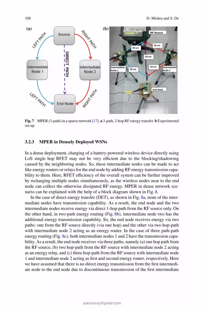
108 D. Mishra and S. De
Fig. 7 MPER (3-path) in a sparse network [17]. a 3-path, 2-hop RF energy transfer. b Experimental
set-up
3.2.3 MPER in Densely Deployed WSNs
In a dense deployment, charging of a battery-powered wireless device directly using
LoS single hop RFET may not be very efficient due to the blocking/shadowing
caused by the neighboring nodes. So, these intermediate nodes can be made to act
like energy routers or relays for the end node by adding RF energy transmission capa-
bility to them. Here, RFET efficiency of the overall system can be further improved
by recharging multiple nodes simultaneously, as the wireless nodes near to the end
node can collect the otherwise dissipated RF energy. MPER in dense network sce-
nario can be explained with the help of a block diagram shown in Fig. 8.
In the case of direct energy transfer (DET), as shown in Fig. 8a, none of the inter-
mediate nodes have transmission capability. As a result, the end node and the two
intermediate nodes receive energy via direct 1-hop path from the RF source only. On
the other hand, in two-path energy routing (Fig. 8b), intermediate node two has the
additional energy transmission capability. So, the end node receives energy via two
paths: one from the RF source directly (via one hop) and the other via two hop-path
with intermediate node 2 acting as an energy router. In the case of three path-path
energy routing (Fig. 8c), both intermediate nodes 1 and 2 have the transmission capa-
bility. As a result, the end node receives via three paths, namely (a) one hop path from
the RF source, (b) two hop-path from the RF source with intermediate node 2 acting
as an energy relay, and (c) three hop-path from the RF source with intermediate node
1 and intermediate node 2 acting as first and second energy router, respectively. Here
we have assumed that there is no direct energy transmission from the first intermedi-
ate node to the end node due to discontinuous transmission of the first intermediate

Energy Harvesting and Sustainable M2M Communication in 5G Mobile Technologies 109
Fig. 8 Illustration of MPER in dense deployment scenario. a Direct (1-hop) energy transfer (DET).
b Two path (1-hop and 2-hop) energy routing. c Three path (1-hop, 2-hop, and 3-hop) energy routing
node, that too at low transmit power which also suffers from blockage by the second
intermediate node’s position.
The experimental set-up for MPER in dense case is shown in Fig. 9a. Here, the
intermediate relay nodes have been positioned systematically to support the 3-hop
RF energy transfer, i.e., the first intermediate node is in a better position than the
second intermediate node, and both intermediate nodes are in a better position than
Fig. 9 MPER (3-path) in a dense network [17]. a Experimental set-up. b Snapshot of the oscillo-
scope reading

110 D. Mishra and S. De
the end node. Therefore, the second intermediate node receives energy from the RF
source in a two hop fashion with first intermediate node as the energy relay and
then second intermediate node itself acts as a 3-hop energy relay along with the
first intermediate node to the end node. Thus, we have created a scenario that best
suits the 3-hop energy transfer, i.e., the first node has been kept at a position such
that it can help in getting more discharging and charging (or ON-OFF) cycles of the
super-capacitor at the second intermediate node in the case of 3-hop RFET than in
the 2-hop case when the first intermediate node was OFF or was a simple energy
receiver with no energy transmission capability. Figure 9b shows a snapshot of the
digital oscilloscope reading that shows the super-capacitor voltage plots for the inter-
mediate nodes 1, 2, and the end node on channels 1, 2, and 3, respectively. It can be
observed from the snapshot that the number of charging-discharging cycles for the
first intermediate node are much higher than the second.
3.2.4 Experimental Results: Faster RF Charging Time
For the sparse case, both 2-path scenarios (left + direct path, right + direct path) as
well as 3-path scenario (direct + left + right path) are shown in Table 1. Compared
to DET, the RF charging time saved while charging the end node’s capacitor up to
3 V is about 18 % and 28 %, respectively, in the 2-path and 3-path energy routing
cases [17].
The MPER time gain results for the dense case as plotted in Table 2. Results show
that both 2-path (1-hop and 2-hop path) and 3-path (1-hop, 2-hop, and 3-hop path)
MPER provide time gains of around 12 % and 18 %, respectively, over DET for charg-
ing the end node up to 3 V [17]. The energy gain in both sparse and dense scenarios
is the same as the time gain, because energy and time are proportional for a constant
power source.
Table 1 Time gain in sparse deployment
Voltage level (V) Average left-direct
gain (%)
Average right-direct
gain (%)
Average 3-path gain
(%)
1 5.17 4.32 10.95
2 8.29 7.96 14.83
3 19.72 18.13 28.84
Table 2 Time gain in dense deployment
Voltage level (V) Average 2-path gain (%) Average 3-path gain (%)
1 6.45 12.23
2 6.86 13.50
3 12.13 17.43

Energy Harvesting and Sustainable M2M Communication in 5G Mobile Technologies 111
3.3 Optimal Energy Relay Placement in Two Hop RFET
Energy gains in MPER and MHET are strongly influenced by the relay placement.
So, here we discuss the optimal relay placement (ORP) for maximizing the efficiency
of two hop RFET.
3.3.1 Analytical Model for Energy Relay Node Operation
The end node receives power from the RF source continuously. However, as dis-
cussed above the transmission from the relay node (or intermediate node) is discon-
tinuous, because energy relay node does not have a dedicated external power supply.
The relay node is operated by the RF energy harvested from the RF radiation of the
RF source that is primarily directed to the end node. So basically, the relay nodes
forward the scavenged energy from the dispersed radiation of the RF source. Thus,
there is a continuous cycle of no transmission (OFF) state and energy transmis-sion (ON or active) state in the relay node, as shown in Fig. 10a. During OFF state,
the communication module of the relay node goes into sleep mode to allow itself
recharge its drained storage element so that it can again re-transmit during the ONstate. And during the ON state, the relay node transmits energy to the target node
using its stored energy, until the remaining energy reduces to a minimum threshold.
It may be noted that the relay node consumes a higher (different) amount of cur-
rent during discharging or ON state as compared to the charging or OFF state. So,
ON OFF
3. Transmission2. Processor active1. Battery discharging
2. Processor sleep1. Battery charging
3. No transmission
(b)
(c)
(a)
Fig. 10 Analytical model for relay node [15]. a ON-OFF state model. b Equivalent RC parallel
circuit. c Energy relay duty cycle

112 D. Mishra and S. De
the transmitter module of the energy relay node can be modeled as a resistive load
of different resistance values [18] in the ON and OFF states, which is driven by the
RF energy harvested and stored in the super-capacitor. So, the equivalent parallel
RC circuit model for the relay node is shown in Fig. 10b. The charging or OFF state
is represented by a high resistance value Rch because of low current consumption
during sleep or no-transmission state. On the other hand, discharging and ON state
is represented by a low resistance value Rdch to allow more current flowing through
the load, which comes both from capacitor (discharging or ON state) and constant
power source. The resistance Rch and Rdch values are obtained experimentally by
measuring the consumption of the energy transmission unit of the relay node during
the charging or OFF state and discharging or ON state, respectively.
It should be noted that, the relay node has two separate antennas for RF energy
reception and transmission. So, it can continuously harvest energy from the RF
source and transmit energy discontinuously in terms of bursts of “dummy” pack-
ets during the ON state. Hence, the duty cycle of relay node’s transmission with TON
and TOFF
as the ON and OFF state duration, respectively, is:
Dc(xr, yr) =T
ON(xr, yr)
TON
(xr, yr) + TOFF
(xr, yr). (6)
TON
(xr, yr) = 12RdchC log
(PDCrr
RdchC2−(CVi)2
PDCrr
RdchC2−(CVf )2)
and TOFF
(xr, yr) = 12RchC ×
log(
PDCrr
RchC2−(CVi)2
PDCrr
RchC2−(CVf )2)
.Vi corresponds to the minimum energyEmin =12CV2
i , required
at the relay for its working and Vf corresponds to the fully charged super-capacitor
C, signifying that the relay is ready for transmission. PDCrr
is the DC power available
after rectification at the relay. Duty cycle of the relay transmitter is plotted in Fig. 10c
for RF source to end node distance of 50 cm [15].
3.3.2 Optimal Relay Placement on a 2-D Euclidean Plane
The physical presence of the relay node between RF source and end node may
cause blocking to the DET. This requires characterization of the blocking losses. The
blocking region characteristics [2] are shown in Fig. 11a for different relay positions
between the RF source and the end node, which are placed 50 cm apart. It is clear
that, the intermediate node can cause significant blocking loss. Interestingly, there
lies an intermediate region between the blocking and non-blocking region, which
can provide energy gain due to reflection. To maximize the energy gains from the
relay node transmission solely, one needs to operate in the no blocking region.
As discussed above, in order to ensure that DET is unaffected by the presence
of relay node , it is positioned away from the LoS path between RF source
and end/target node . The non-blocking position of , y0 distance away from the
LoS path for DET depends on many parameters such as, the transmit power of the

Energy Harvesting and Sustainable M2M Communication in 5G Mobile Technologies 113
5 10 15 20 25 300
5
10
15
20
25
30
35
40
45
Mean Power received at end node at 50cm with 6 dBi antenna (dBm)
Distance of relay node from RF source x0 (cm)
LO
S p
ath
y 0 (
cm)
−20
−15
−10
−5
0No blocking region
Reflection gain
Blocking loss
Relay node
Target nodeRF source
x
y 2 D space for relay node placement
(0,0) (x0,0)
(xr + xd,yr)
(x0,y0)
(x0,yu(0))
(0,y0)
(0,yu(0))
(xr,yr)
LOS pathS T
R
Dis
tanc
e of
rel
ay n
ode
from
(a) (b)
Fig. 11 Optimization model for relay placement in two-hop RFET. a Blocking characterization [2].
b Three node network topology [15]
RF source, radiation pattern of the RF source and target node antennas, distance
x0 between RF source and target node, distance xd between the relay transmitter
and receiver, and physical properties of the relay node, e.g., reflection coefficient,
antenna cross-section area. y0 can be determined experimentally through trial runs.
However, we restrict our discussion to determine the position of relay node to
maximize the two-hop RFET efficiency without affecting the DET. The network
topology considered is shown in Fig. 11b.
3.3.3 Results and Discussion
The detailed discussion on the impact of the ORP problem in two-hop RFET (2HET)
has been provided in [15]. The ORP problem deals with circuits analysis (discussed
in Sect. 3.3.1), antenna propagation (Fig. 12a) and RF-to-DC conversion characteris-
tics (Fig. 12b). The polynomial-fit functions as plotted in Figs. 12a and 12b are used
for characterizing the MHET energy gains provided by ORP. Also, since the ORP
problem is nonconvex, a modified 𝛼-based branch and bound (𝛼BB) method [19]
based global optimization algorithm is employed to solve the problem up to some
predefined acceptable tolerance 𝜖. The convergence of the global optimization algo-
rithm proposed in [15] is shown in Fig. 12c for a case with source to end node dis-
tance of x0 = 100 cm. The results show a fast convergence with fast decaying gap
between the upper and lower bounds on the mean received power P2HET at the tar-
get node due to two-hop RFET. Negative of P2HET is plotted because the proposed
algorithm is a minimization algorithm, that finds the ORP which can provide the
minimum −P2HET , or in other words, maximum P2HET .
The received mean power P2HET at end node for the topology shown in Fig. 11b
with x0 = 100 cm and y0 = 25 cm is shown in Fig. 13a. The plot shows that the
mean received power at the target node is a nonconcave function of the relay
position xr, yr. Also, the received power at the target node undergoes construc-
tive and destructive interference depending upon the path difference between the
RF energy waves received from the RF source and the relay node. These regions

114 D. Mishra and S. De
0.2 0.4
0.6 0.8
130
210
60
240
90
270
120
300
150
330
180 0
Dipole (1 dBi) Patch (6 dBi) Poly. fit
−10 0 10 200
20
40
60
80
Input power (dBm)
Effi
cien
cy (
%)
Actual
Poly. fit
5 10 15 20−1
−0.8
−0.6
−0.4
Iterations
(−)
P2H
ET (
mW
)
Upper boundLower bound
(b)(a)
(c)
Fig. 12 Numerical results for the ORP problem [15]. a Normalized radiation pattern. b RF-to-DC
characteristics. c Convergence results
20 40 60 800
20
40
60
xr (cm)
y r−y o (
cm)(a)
(b)
Fig. 13 Received power characteristics for ORP on 2-D Euclidean plane [15]. a Received mean
power. b Constructive/destructive interference regions
for relay position xr, yr providing constructive interference, denoted by CI
where
the mean received power P2HET at target node is more than equal to the DET, i.e.
CI={(
xr, yr) |P2HET
(xr, yr
)≥ PDET
}; and destructive interference denoted by D
Iwhere the mean received power at target node is less than that in case of DET only,
i.e. DI={(
xr, yr) |P2HET
(xr, yr
)< PDET
}, are plotted in Fig. 13b. This reiterates
the importance of ORP in 2-hop RFET, because an arbitrarily positioned relay in
2HET can cause destructive interference at the target node, resulting in even poorer
performance than DET.

Energy Harvesting and Sustainable M2M Communication in 5G Mobile Technologies 115
3.4 Beamforming Techniques
3.4.1 Energy Beamforming
Multi-antenna transmission techniques achieve spatial multiplexing like the case of
multiple-input multiple-output (MIMO) systems, by employing energy beamform-
ing, as shown in Fig. 14. Energy beamforming improves the RFH efficiency in long-
distance RFET by exploiting large antenna array gain. However the performance
of energy beamforming techniques is strongly influenced by the quality of channel
state information (CSI) feedback. In [20], it was shown that an accurate CSI feedback
based energy beamforming can provide higher RFET efficiency. This increase in effi-
ciency is achieved at the cost of significant time overhead incurred at the receiver,
leading to lesser time for RFH. So, there exists a tradeoff.
3.4.2 Distributed Beamforming
Distributed beamforming enables a cluster of distributed energy sources to coopera-
tively form a virtual antenna array by transmitting RF energy simultaneously in the
same direction to an intended energy receiver for better diversity gains [21]. Coopera-
tive beamforming can provide RFET efficiency enhancement by adjusting the carrier
phase of each energy transmitter and compensating for the path difference between
the energy waves arriving at the target node, thus causing constructive interference.
Distributedbeamforming
Relay node
RF source
Cooperative relaying
Continuous one-hop transmission
Base Station
EnergyFlow
Sensor node
Disontinuous 2-hoptransmission
Energy beamformingusing antenna array
Sensornode
DataTransfer
Sensor node
Sensor node
Sensor node
Transmission range D+d
Relay node
BS 1
BS 2
2 hop energy transfer
RF energy transfer range extension using two hopenergy transfer with distributed beamforming
Single hop energy transfer
Transmission range D
Sensor node Base station (BS)
Distributedbeamforming
Fig. 14 Beamforming techniques for the enhancement of RFH efficiency [2]
116 D. Mishra and S. De
This results in increased directivity that can provide a maximum of N2times power
reception of RF power for N cooperative RF energy transmitters [22]. Cooperative
distributed beamforming can also provide energy transfer range extension in two
hop RFET as shown in Fig. 14. However, all these energy gains are achieved at the
overhead cost required for the phase, frequency, and time synchronization for high
frequency carrier signals. The challenges arise in the implementation, e.g., time syn-
chronization among energy sources and coordination of distributed carriers in phase
and frequency so that RF signals can be combined constructively at the receiver.
3.4.3 Cooperative Energy Relaying
Cooperative RF energy relaying is useful for small inter-nodal distances. Here,
the end node can simultaneously receive energy from the RF source and the relay
node(s). It is conceptually similar to the coherent MPER. Cooperative energy relaying
provides increased RFET efficiency and energy savings by employing distributed
beamforming of continuous transmission from the RF source and discontinuous
transmission of relay nodes, as shown in Fig. 14. The main challenge here is to
find the optimal relay placement or make relay selection to jointly maximize the
energy transfer and information transfer gains. However, as it was shown [23], relay
selection has to leverage between the efficiency of RFET and wireless information
transfer.
3.4.4 Optimal Relay Placement Study
The proposed optimization model in [15] was further extended by incorporating dis-
tributed beamforming to enhance the RFET efficiency at the cost of added synchro-
nization requirement at the RF source and relay node. With the knowledge of RF
source position, relay node can be placed on the feasible Euclidean x-y plane shown
in Fig. 11b, in such a way that their respective local oscillators can be synchronized
by introducing a controlled phase shift for compensating the path differences. This
results in constructive interference at the target node, irrespective of the relative dis-
tance of the RF source and the relay node form the target node, i.e. DI = ∅ in this
case. Using this distributed beamforming of the RF source and the relay node for
getting in-phase energy waves at the target node, the relay node is simply moved
along the x-axis at y0 distance from LoS path for a given x-axis position, in place of
moving along the y-axis. This reduces the ORP problem discussed in Sect. 3.3.2 to
a single-dimensional (or one variable) nonconvex problem.
The mean received power at the target node along with the branching operation
of the algorithm proposed in [15] is shown in Fig. 15a. Here NCF refers to the near
convex function approximation for the actual P2HET in a given branched subspace
xr for relay placement. This NCF is minimized to provide the upper bound on the
achievable P2HET in a given search subspace [15]. Also, Fig. 15b shows that the ORP
with distributed beamforming with Powercast P1110 energy harvester and antenna

Energy Harvesting and Sustainable M2M Communication in 5G Mobile Technologies 117
0 20 40 60 80−0.49
−0.48
−0.47
−0.46
−0.45
−0.44
−0.43
xr (cm)
(−)
P2H
ET
DB
(m
W)
ActualNCFNCF 1 LeftNCF 1 RightNCF 2 LeftNCF 2 RightOptimal solution
0 20 40 60 800
0.05
0.1
0.15
0.2
0.25
xr (cm)
P2H
ET
DB
(m
W)
Pt2
eff
Pr2
cont
(a) (b)
(c)
Fig. 15 ORP problem results for distributed beamforming [15]. a Received mean power.
b Pseudoconcavity of ORP problem. c Tradeoff in 2-hop RFET
turns out to be pseudoconcave function of the relay position (xr, y0). The function
f (x1) in Fig. 15b represents P2HET (xr) as a function of relay position(xr, y0
). This
problem also involves investigation of a nontrivial tradeoff between the energy scav-
enged at the relay versus the effective energy delivered by the relay to the end node
(see Fig. 15c). Here, Peff
t2is the effective transmit power from the relay node con-
sidering the duty cycle Dc and the discontinuous transmission, whereas Pcont
r2is the
received power at the target node if the relay node is assumed to have continuous
transmission with transmit power Pt2 .
Figure 16a provides performance comparison of 2HET with ORP and 2HET with
arbitrarily-placed relay (e.g., left (xr =x04− xd
2, yr = y0), center (xr =
x02− xd
2, yr =
y0), or right (xr =3x04− xd
2, yr = y0) [15]). The trends in RFET efficiency improve-
ment with ORP is not monotonic. It is a function of the distance x0 between RF
source and the end node. The plots here show that the maximum RFET efficiency
gains with different x0 values occur at different ORP distance xr. Distributed beam-
forming offers simplicity in relay placement as well as more RFET efficiency gain at
the overhead cost of phase synchronization requirement at the RF source and relay
node.
The results in Figs. 16b and 16c show that, the energy saving at the RF source due
to faster charging and thus quicker switching off of the RF source [15, 16] increases

118 D. Mishra and S. De
Case A Case B Case C0
5
10
15
20
25
Impr
ovem
ent (
%)
0 20 40 60 800
1
2
3
4
5
6
x (cm)
Ene
rgy
save
d (k
J)Case A Case B Case C
0
2
4
6
8
10
Ene
rgy
save
d (k
J)
Left Left with beamforming Center Center with beamforming Right Right with beamforming
Case ACase BCase C
0.14 %
13 J
(a) (b)
(c)
Fig. 16 Performance comparison of ORP without and with distributed beamforming. a 2HET
efficiency improvement with ORP over arbitrary relay positions (e.g., left, center, right). b Energy
saving by ORP in 2HET compared to arbitrary positioning. c Comparison of energy saving in 2HET
with distributed beamforming with DET. Here, (x0, y0) for Case A, Case B, and Case C are respec-
tively (100, 25) cm, (75, 34) cm, and (50, 38) cm [15]
with increased x0. A relative look at the Figs. 16b and 16c further reveal that the
improvement in the energy saving provided by ORP with respect to arbitrarily posi-
tioned relay in 2HET can be even higher than the gain with respect to direct single
hop RFET or DET. For example, with x0 = 100 cm the ORP with distributed beam-
forming can provide an energy saving of 9 kJ with respect to the relay placement at
the center (non-shadowing or y0 distance away from LoS path), whereas the maxi-
mum energy saving as compared to DET is about 5 kJ. This is because, an arbitrarily
positioned relay in 2HET can cause destructive interference of the RF waves received
from the source and the relay at the destination, thus resulting in even poorer RFET
performance in 2HET as compared to the DET.
3.5 Network Level Strategies
In [24], RFH was considered as a media access control (MAC) problem for maximiz-
ing the RF harvesting rate while keeping the interference to the nearby data commu-
nication minimum. The proposed RF-MAC protocol tackled several challenges like,
time allocated for RFET, priority between wireless information and energy transfer,
choice of frequency for data and energy transmission, and simultaneous RF charg-
ing of a node by multiple energy transmitters. But there is need for novel MAC

Energy Harvesting and Sustainable M2M Communication in 5G Mobile Technologies 119
and routing protocols for cognitive M2M communication in heterogeneous networks
with energy harvesting capability. In this regard, the most important challenge is
to have a protocol architecture (MAC + routing) for joint optimization of RFET
efficiency and wireless information transfer reliability, while taking into account
various system parameters and practical hardware constraints. Some of the critical
parameters of interest are RF charging time characterization, relay node positioning
for efficient MPER, cooperation among the participating nodes for joint energy and
data transfer, interference minimization, and collaborative RF energy transmission
of multiple transmitters.
3.6 A Case Study: Networking Consequence of Smart RFHarvesting Communications
With the improvement in RFH efficiency achieved by the strategies discussed in this
section and the RF charging time characterization presented in Sect. 2.3, an opti-
mal schedule for mobile RF source will provide the order in which wireless devices
should be served to have an uninterrupted perpetual IoT or sensor network opera-
tion (see Fig. 17a). We have considered a pollution monitoring network, consisting
of differential sensor nodes with different number of sensors per board. The average
energy consumption per sensing cycle in a pollution sensing node increases from
50–60 J to 140–150 J as the number of sensors per node is increased from 1 to 4 [2].
We consider the usage of an integrated data and energy MULE (iDEM) [10] for wire-
less RF charging of the nodes along with the wireless data collection. The network
size depends on the average charging time, which in turn depends on the residual
node energy on the iDEM visit and the average energy consumption per node. In
order to serve maximum number of nodes, the iDEM should spend minimum time
Mobile dediacated RF source
Optimal schedule
3 hop RF energy transfer
3 Path Energy Routing
Direct path
First 2-hop path
Second 2-hop path
Relay node
Data transfer Mobile dediacated RF source
Application
Relay node
Relay node
Relay node
node
Applicationnode
Applicationnode
Applicationnode
Applicationnode
50−60J 80−90J 110−120J 140−150J0
10
20
30
40
50
60
70
Average energy consumption per sensing cycle
Per
cent
age
impr
ovem
ent
Charging time reductionNetwork size extension
(b)
(a)
Fig. 17 RFH communication network with mobile joint RF source and data collector(s) [2]. a Joint
data collections and RF charging via dedicated mobile RF source. b Impact of improved RFH
efficiency

120 D. Mishra and S. De
in traveling, so that the length of the overall tour is minimized. So, the IDEM should
follow the shortest Hamiltonian cycle, which can be found using meta-heuristics like
genetic algorithm. The extension in the sustainable network size achieved by quicker
charging of the rechargeable sensor nodes via advanced RFH circuits [18] and smart
RFH communication techniques, due to 50 % more harvested DC power as compared
to the conventional RF harvesting networks with single iDEM. The corresponding
results are plotted in Fig. 17b.
4 Wireless Powered Communication Networks
4.1 State-of-the-Art Research
One very important characteristic associated with RFH is that the wireless signals
can also be used as a means for the delivery of both information and power. This
has introduced a new generation of wireless networks called wireless powered com-
munication networks (WPCNs), in which the uplink information transfer from the
wireless devices is powered by the downlink RF energy transfer (RFET) from the
base station.
Another closely related concept on the usage of the RF radiation for energy har-
vesting has lead to simultaneous wireless information and power transfer (SWIPT)
[25] to the energy-constrained receiver. SWIPT is different from conventional energy
harvesting techniques, where energy is harvested from RF signals meant for wire-
less information transfer [26]. So, both energy and information transfer occurs in the
downlink. SWIPT has been discussed in the pioneering works in [27, 28], assuming
that the receiver is capable of decoding information and harvesting energy from the
same RF signal. However, it was argued in [26] that this approach is not practically
feasible. The study in [26] introduced two mechanisms for practical implementation
of SWIPT: (a) power splitting (PS) and (b) time switching (TS). These three different
paradigms of wireless RFET are shown in Fig. 18.
RFH sustainable IoT or RF-powered M2M communications form a slightly dif-
ferent scenario. Here the energy is harvested by the machines or mobile devices
Informationtransfer
Energy transferHAP: Hybrid Access PointAN: Applicationnode
HAP
ANANAN AN
HAP
AN AN
HAP(a) (b) (c)
Fig. 18 Wireless RF energy transfer scenarios. a RFET. b SWIPT. c WPCN

Energy Harvesting and Sustainable M2M Communication in 5G Mobile Technologies 121
from both the downlink and uplink RF radiations meant for information exchange
between the primary users or the neighboring wireless devices. So, the M2M com-
munications are powered either by a dedicated hybrid access point (HAP) or by the
energy harvested from the data communication taking place in the neighborhood.
4.2 RF-Powered M2M Communications
As discussed earlier, extending the concepts of information communication and
energy transfer in Fig. 18, RFH can lead to perpetual operation of WPCNs and
SWIPT networks. However the existing literature considers the sustainability of
conventional networks with homogeneous devices. In this section, we outline the
sustainability of M2M communications in a heterogeneous environment for both
infrastructure-based and infrastructure-less networks. Specifically, we consider the
following three categories of sustainable M2M communications:
∙ Infrastructure-based cellular networks or network-Assisted M2M communica-tions: Here the M2M communications, or more specifically D2D communications
are powered by the ambient RF radiation available in the environment due to infor-
mation transfer between the base station and the licensed mobile users. In this
scenario, care has to be taken to avoid the interference caused by the D2D com-
munications to the existing licensed users in the network.
∙ Infrastructure-less ad-hoc networks with stationary RF power stations (PS): Here
we consider the optimal deployment of stationary power beacons [29] or RF power
stations for wireless charging of the mobile devices by RF radiation and thereby
providing practically infinite battery lives to the mobiles and eliminating the need
for the power cords. In this case, there is a need for novel strategies to mitigate the
interference caused in the energy transmission by the stationary power stations to
the underlying communication network.
∙ Infrastructure-less ad-hoc networks with mobile RF source: In this case, rather
than having the stationary power station we propose the usage of mobile dedicated
RF source for replenishing the drained energy of theses devices in order to have
sustainable M2M communications (see Fig. 17a). In this case there is a need for
novel routing and scheduling algorithms for optimal path or route to be followed
by the mobile RF source to minimize the latency and provide a larger network
size support. This mobile RF source can also act an iDEM, thereby providing
joint wireless energy and information transfer.
5 Future Research Directions and Opportunities
Here we present some future research directions in the field of RFH M2M commu-
nications, along with the associated opportunities and the underlying challenges.

122 D. Mishra and S. De
5.1 Joint Information and Energy Transfer
The machines or mobile devices communicating among themselves also require to
exchange information with HAP which can be the source of energy for these devices.
So, there is a possibility of joint energy harvesting and information transfer. In-spite
of several virtues of cooperative relaying, namely, cooperative diversity, efficient
energy and reliable data transfer, due to the huge discrepancy in the receiver’s data
and energy sensitivities, utilizing these assets for SWIPT is of significant interest.
Furthermore a key challenge is to balance time resources for channel estimation
and energy transfer in such systems because longer CSI estimation time can sig-
nificantly affect both information and energy transfer efficiency. Distributed beam-
forming can overcome the form factor constraints of MIMO systems or conventional
energy beamforming by forming a virtual antenna array system. Thus, providing
benefits like increased spectral efficiency, improved directivity, and enhanced spa-
tial diversity. However, there are underlying synchronization bottlenecks, that need
to be tackled. Such an wireless powered sustainable M2M communication network
opens up a new design paradigm, where many designs of physical, MAC, and net-
work layers in conventional wireless networks are being revisited. Also sustainable
M2M communication network poses further challenges of interoperability of mobile
users over heterogeneous networks.
5.2 Relay Assisted M2M Communication
Relay assisted transmission could efficiently enhance the performance of M2M com-
munication when the M2M channel quality is poor due to large distances between
the wireless devices. Relays originally deployed for information transfer can be used
for RFET to the nearby mobile devices by employing SWIPT. These relays acting as
energy resources need to be optimally deployed for efficient energy transfer with neg-
ligible interference to the underlying licensed users. Moreover, mobile energy+ datarelays (see Fig. 17a) with controlled mobility can deal with mobile wireless devices
and sparsely distributed network scenarios. Selection of a relay node among var-
ious relays strongly affects the performance of cooperative relaying that can pro-
vide improved energy transfer efficiency, as well as better data transfer reliability.
In [30] a stochastic-scale geometry approach has been adopted to study the impact of
cooperative density and relay selection to analyze the fundamental trade-off between
information transfer efficiency in terms of outage probability performance and RFH
efficiency in SWIPT applications.

Energy Harvesting and Sustainable M2M Communication in 5G Mobile Technologies 123
5.3 Software Defined Radio Aided M2M Communication
The increasing demand of voice and multimedia on the move can be met by utiliz-
ing the intelligence and cognizance of the radio. The flexibility and adaptability of
software defined radio (SDR) with machine learning can address the needs of imple-
menting the green sustainable M2M communication network. The SDR technique
can also be used along with the optimal energy beamforming and power allocation
schemes for preventing the source information being intercepted by the energy har-
vesting eavesdropper in secure energy harvesting M2M communication networks.
SDR technique also helps in tackling the inter-operate-ability issue of heterogeneous
M2M communication networks. Distributed beamforming and cooperative energy
relaying aspects in multi-hop M2M communication networks can further improve
RFET efficiency by using the adaptability and reconfigurability of SDR.
6 Conclusion
In this chapter we discussed the challenges and opportunities that lie on the way
towards achieving the goal of sustainable RFH M2M communication. We discussed
the state-of-art research in the field of RF-powered communication networks along
with the recent developments to maximize the efficiency of RFET. During the course
of the chapter we also presented novel RF-powered M2M communication system
models. Finally, we observed that, to fully realize the advantages of perpetually oper-
ating IoT in 5G mobile technologies, cognizance of the radio, adaptability of SDR
and efficacy smart cooperative RFH communications have to be jointly utilized.
Acknowledgments This work has been supported by the Department of Science and Technology
(DST) under Grant SB/S3/EECE/0248/2014.
References
1. Paradiso, J., Starner, T.: Energy scavenging for mobile and wireless electronics. IEEE Pervasive
Comput. 4(1), 18–27 (2005)
2. Mishra, D., De, S., Jana, S., Basagni, S., Chowdhury, K., Heinzelman, W.: Smart RF energy
harvesting communications: challenges and opportunities. IEEE Commun. Mag. 53(4), 70–78
(2015)
3. Raghunathan, V., Kansal, A., Hsu, J., Friedman, J., Srivastava, M.B.: Design considerations
for solar energy harvesting wireless embedded systems. In: Proceedings of IEEE ICNP, Los
Angeles, CA, USA (2005)
4. Weimer, M., Paing, T., Zane, R.: Remote area wind energy harvesting for low-power
autonomous sensors. In: Proceedings of IEEE Power Electronics Specialists Conference, Jeju,
Korea (2006)
5. Roundy, S., Wright, P.K., Rabaey, J.: A study of low level vibrations as a power source for
wireless sensor nodes. Elsevier Comput. Commun. 26(11), 1131–1144 (2003)

124 D. Mishra and S. De
6. Hagerty, J.A., Helmbrecht, F.B., McCalpin, W.H., Zane, R., Popovic, Z.B.: Recycling ambient
microwave energy with broad-band rectenna arrays. IEEE Trans. Microw. Theor. Techn. 52(3),
1014–1024 (2004)
7. Gonzalez, J., Rubio, A., Moll, F.: Human powered piezoelectric batteries to supply power to
wearable electronic devices. Int. J. Soc. Mater. Eng. Res. 10(1), 34–40 (2002)
8. De, S., Kawatra, A., Chatterjee, S.: On the feasibility of network rf energy operated field sen-
sors. In: Proceedings of IEEE ICC, Cape Town, pp. 1–5 (2010)
9. Sakr, A., Hossain, E.: Cognitive and energy harvesting-based d2d communication in cellular
networks: stochastic geometry modeling and analysis. IEEE Trans. Commun. 63(5), 1867–
1880 (2015)
10. De, S., Singhal, R.: Toward uninterrupted operation of wireless sensor networks. IEEE Com-
put. Mag. 45(9), 24–30 (2012)
11. Powercast P1110 powerharvester receiver datasheet. http://www.powercastco.com/PDF/
P1110-datasheet.pdf
12. Mishra, D., De, S., Chowdhury, K.: Charging time characterization for wireless RF energy
transfer. IEEE Trans. Circ. Syst. II Exp. Briefs 62(4), 362–366 (2015)
13. Weisstein, E.W.: Lambert W-Function, From MathWorld—A Wolfram Web Resource. http://
mathworld.wolfram.com/LambertW-Function.html
14. Shinohara, N.: Power without wires. IEEE Microw. Mag. 12(7), S64–S73 (2011)
15. Mishra, D., De, S.: Optimal relay placement in two-hop RF energy transfer. IEEE Trans. Com-
mun. 63(5), 1635–1647 (2015)
16. Kaushik, K., Mishra, D., De, S., Basagni, S., Heinzelman, W., Chowdhury, K., Jana, S.: Exper-
imental demonstration of multi-hop RF energy transfer. In: Proceedings of IEEE PIMRC, Lon-
don, UK, pp. 538–542 (2013)
17. Mishra, D., Kaushik, K., De, S., Basagni, S., Chowdhury, K., Jana, S., Heinzelman, W.: Imple-
mentation of multi-path energy routing. In: Proceedings of IEEE PIMRC, Washington D.C.,
USA (2014)
18. Nintanavongsa, P., Muncuk, U., Lewis, D., Chowdhury, K.: IEEE design optimization and
implementation for RF energy harvesting circuits. J. Emerg. Sel. Top. Circ. Syst. 2(1), 24–33
(2012)
19. Adjiman, C.S., Dallwig, S., Floudas, C.A., Neumaier, A.: A global optimization method, 𝛼-BB,
for general twice-differentiable constrained NLPs-I. Theor. Adv. Comput. Chem. Eng. 22(9),
1137–1158 (1998)
20. Chen, X., Wang, X., Chen, X.: Energy-efficient optimization for wireless information and
power transfer in large-scale mimo systems employing energy beamforming. IEEE Wirel.
Commun. Lett. 2(6), 667–670 (2013)
21. Quitin, F., Rahman, M.M.U., Mudumbai, R., Madhow, U.: A scalable architecture for distrib-
uted transmit beamforming with commodity radios: design and proof of concept. IEEE Trans.
Wirel. Commun. 12(3), 1418–1428 (2013)
22. Jenn, D.: Transmission equation for multiple cooperative transmitters and collective beam-
forming. IEEE Antennas Wirel. Propag. Lett. 7, 606–608 (2008)
23. Michalopoulos, D., Suraweera, H., Schober, R.: Relay selection for simultaneous information
transmission and wireless energy transfer: a tradeoff perspective. IEEE J. Sel. Areas Commun.
33, 1578–1594 (2015)
24. Naderi, M., Nintanavongsa, P., Chowdhury, K.: RF-MAC: a medium access control protocol
for re-chargeable sensor networks powered by wireless energy harvesting. IEEE Trans. Wirel.
Commun. 13(7), 3926–3937 (2014)
25. Huang, K., Larsson, E.: Simultaneous information and power transfer for broadband wireless
systems. IEEE Trans. Signal Process. 61(23), 5972–5986 (2013)
26. Zhang, R., Ho, C.K.: MIMO broadcasting for simultaneous wireless information and power
transfer. IEEE Trans. Wirel. Commun. 12(5), 1989–2001 (2013)
27. Varshney, L.: Transporting information and energy simultaneously. In: Proceedings of IEEE
International Symposium on Information Theory (ISIT), Toronto, Canada, pp. 1612–1616
(2008)

Energy Harvesting and Sustainable M2M Communication in 5G Mobile Technologies 125
28. Grover, P., Sahai, A.: Shannon meets Tesla: wireless information and power transfer. In: Pro-
ceedings of IEEE International Symposium on Information Theory (ISIT), Austin, TX, pp.
2363–2367 (2010)
29. Huang, K., Lau, V.: Enabling wireless power transfer in cellular networks: architecture, mod-
eling and deployment. IEEE Trans. Wirel. Commun. 13(2), 902–912 (2014)
30. Krikidis, I.: Simultaneous information and energy transfer in large-scale networks with/without
relaying. IEEE Trans. Commun. 62(3), 900–912 (2014)


Green 5G Femtocells for Supporting IndoorGenerated IoT Traffic
Elias Yaacoub
Abstract Supporting the traffic emanating from the internet of things (IoT) is a
major challenge for 5G systems. A significant portion of this traffic will be
generated indoors. Therefore, in this chapter, femtocell networks designed for sup-
porting IoT traffic are studied. A deployment scenario of femtocell networks with
centralized control is investigated. It consists of an integrated wired/wireless system,
where the femtocell access points (FAPs) are controlled by a single entity. This per-
mits performing joint radio resource management in a centralized and controlled way
in order to enhance the quality of service performance for all users in the network. It
also allows an energy efficient operation of the network by switching off redundant
femtocells whenever possible. Two algorithms are proposed and analyzed. The first
one is a utility maximizing radio resource management algorithm, whereas the sec-
ond one is a FAP switch off algorithm, implemented at the central controller. The
joint wired/wireless resource management approach is compared to the distributed
resource management case, where each femtocell acts as an independent wireless
network unaware of the channel and interference conditions with the other cells.
The proposed algorithm was shown to lead to significant gains. Furthermore, con-
siderable energy savings were obtained with the green algorithm.
1 Introduction
One of the major challenges for 5G cellular systems is the capability to support the
machine-to-machine (M2M) traffic with the Internet of Things (IoT) becoming a
reality. In fact, IoT is expected to include billions of connected devices using M2M
communications [1]. These devices will have a variety of requirements and differ-
ent types of behavior in the network. For example, certain devices will access the
network frequently and periodically to transmit short amounts of data, such as smart
E. Yaacoub (✉)
Strategic Decisions Group (SDG) and Arab Open University (AOU),
Beirut, Lebanon
e-mail: [email protected]
© Springer International Publishing Switzerland 2016
C.X. Mavromoustakis et al. (eds.), Internet of Things (IoT) in 5G Mobile Technologies,Modeling and Optimization in Science and Technologies 8,
DOI 10.1007/978-3-319-30913-2_7
129

130 E. Yaacoub
meters used for advanced metering infrastructure (AMI) in the smart grid [2, 3].
Other devices can store data measurements and transmit in bulk, unless there is an
alerting situation, such as sensor networks for environment monitoring [4]. In fact,
wireless sensor networks (WSNs) will constitute an integral part of the IoT paradigm,
spanning different application areas including environment, smart grid, vehicular
communication, and agriculture, among others [5]. Solutions to meet the increasing
demand include the deployment of heterogeneous networks involving macrocells
and small cells (picocells, femtocells, etc.), distributed antenna systems (DAS), or
relay stations (RSs).
A significant portion of IoT traffic will be generated indoors. This includes data
from smart meters (for electricity, water, etc.), from monitoring sensors (e.g., for
temperature, pollution levels inside an apartment or building, among other mea-
surements), and for home automation systems. IoT traffic can also emanate from
m-Health applications, with sensors relaying their monitoring data of elderly people
or indoor patients to the appropriate medical personnel and health centers [6]. Fem-
tocell Access Points (FAPs) can be used to handle this indoor traffic and reduce the
load on macrocell base stations (BSs). They generally consist of small, low power,
plug and play devices providing indoor wireless coverage to meet the quality of ser-
vice (QoS) requirements for indoor data users [7]. FAPs are installed inside the home
or office of a given subscriber. They are connected to the mobile operator’s core
network via wired links, e.g. digital subscriber line (DSL) [8]. However, they are
not under the direct control of the mobile operator since they are not connected to
neighboring macrocell BSs (MBSs) through the standardized interfaces, e.g., the X2
interface for the long term evolution (LTE) cellular system.
This chapter investigates the case of 5G IoT in indoor scenarios, where the deploy-
ment of FAPs is used to transmit the IoT traffic. Radio resource management (RRM)
algorithms are proposed for optimizing the resource allocation process and meet-
ing the quality of service (QoS) requirements of the IoT applications. Furthermore,
techniques for the green operation of femtocell networks are proposed, with the
objective of maintaining QoS while ensuring an energy efficient operation of the
network.
The chapter is organized as follows. Femtocell networks are overviewed in Sect. 2.
The system model is presented in Sect. 3. The utility metrics leading to different QoS
and performance targets are described in Sect. 4. The joint RRM algorithm imple-
mented at the central controller is presented in Sect. 5, and the FAP on/off switching
algorithm is presented in Sect. 6. Simulation results are presented and analyzed in
Sect. 7. Finally, conclusions are drawn in Sect. 8.
2 Overview of Femtocell Networks
The proliferation of small cells, notably femtocells, is expected to increase in the
coming years [9]. Since most of the wireless traffic is initiated indoors, FAPs are
designed to handle this traffic and reduce the load on MBSs by providing indoor

Green 5G Femtocells for Supporting Indoor Generated IoT Traffic 131
wireless coverage to meet QoS requirements for indoor data users [7]. Since FAPs
are not under the direct control of the mobile operator and do not use the LTE X2
interface to connect to other BSs, they pose several challenges to network operation
and management.
A major challenge is that the overall interference levels in the network depend
on the density of small cells and their operation, which affects the configuration of
macrocell sites [10]. In [11], this problem was addressed by proposing macrocell-
femtocell cooperation, where a femtocell user may act as a relay for macrocell users,
and in return each cooperative macrocell user grants the femtocell user a fraction
of its superframe. In [12], it was assumed that both macrocells and small cells are
controlled by the same operator, and it was shown that in this case the operator can
control the system loads by tuning the pricing and the bandwidth allocation policy
between macrocells and small cells.
On the other hand, other works investigated radio resource management (RRM)
in femtocell networks by avoiding interference to/from macrocells. Most of these
works focused on using cognitive radio (CR) channel sensing techniques to deter-
mine channel availability. In [13], the femtocell uses cognitive radio to sense the
spectrum and detect macrocell transmissions to avoid interference. It then performs
radio resource management on the free channels. However, there is a time dedicated
for sensing the channel that cannot overlap with transmission/RRM time. A chan-
nel sensing approach for improving the capacity of femtocell users in macro-femto
overlay networks is proposed in [14]. It is based on spatial radio resource reuse based
on the channel sensing outcomes. In [15], enhanced spectrum sensing algorithms are
proposed for femtocell networks in order to ensure better detection accuracy of chan-
nels occupied by macrocell traffic.
In this chapter, LTE femtocell networks are investigated. FAPs are not assumed
to be controlled by the mobile operator. However, in certain scenarios, FAPs at a
given location can be controlled by a single entity. This can happen, for example, in
a university campus, hotel, housing complex, or office building. In such scenarios, in
addition to the wireless connection between FAPs and mobile terminals, FAPs can be
connected via a wired high-speed network to a central controller within the building
or campus. This can allow more efficient RRM decisions leading to significant QoS
enhancements for mobile users. Furthermore, it can allow energy efficient operation
of the network, by switching off unnecessary FAPs whenever possible, and serving
their active femto user equipment (FUEs) from other neighboring FAPs that still
can satisfy their QoS requirements. Due to centralized control, users do not have to
worry about opening the access to their FAPs for FUEs within the premises, since the
controller will guarantee the QoS. This scenario is studied in this chapter, where two
algorithms are presented: A utility maximizing RRM algorithm to perform resource
allocation over the FAPs controlled by the same entity, and an algorithm for the
green operation of LTE femtocell networks via on/off switching. Significant gains
are shown to be achieved under this integrated wired/wireless scenario compared to
the case where each FAP acts independently.

132 E. Yaacoub
3 System Model
Figure 1 shows multiple IoT devices that can be found indoors. They include smart
meters (for utilities: electricity, water, gas), sensors (for monitoring temperature,
humidity, environment parameters, or the performance of electrical appliances for
example), and body area networks (BANs) formed by sensors used to monitor a
human being’s vital parameters for m-Health applications. The sensors of a BAN
can send this information via short range communications to the person’s mobile
phone. These IoT devices can communicate with the network through various tech-
nologies such as Bluetooth, Zigbee, or WiFi. In the case of BAN, the sensors actually
use these technologies to communicate with the patient’s smart phone, which in turn
communicates with the access point. With the deployment of 5G and the expected
proliferation of IoT devices, these indoor devices can communicate with an indoor
FAP using the cellular technology. With LTE-Advanced (LTE-A), this can take place
using device-to-device (D2D) communications for example. Similarly, other devices
such as laptops and mobile phones can still use the FAP normally, as shown in Fig. 1.
This allows these devices to benefit from advanced 5G features guaranteeing QoS
levels, and provides an integrated wireless network indoors without incurring any
additional costs, since the indoor communications between IoT devices and the 5G
FAP can be free of charge, similarly to Bluetooth or WiFi communications. This
comes at no loss for cellular operators too, since FAPs are user installed devices and
they relief the MBSs from this indoor generated traffic.
In this chapter, we consider a worst case scenario of a single device connected
to a FAP, and located at the opposite extremity from that FAP inside the house or
apartment. We also assume that the data rate requested by this device is equal to
or larger than the aggregate data rates of several IoT devices and other devices. For
example, real-time smart meter readings require a data rate of around 64 kbps [3],
whereas the data rates considered in the simulations of this chapter are orders of
magnitude larger (on the order of several Mbps). This allows simplifying the simu-
lations without losing the insights from the approach, since a worst case scenario is
adopted.
The system model of the worst case scenario with a single device per apartment,
denoted as the femto user equipment (FUE) is shown in Fig. 2. As an example, a
building having three apartments per floor is considered. One FAP is available in
each apartment, primarily to serve the FUEs available in that apartment. The FAPs
are connected to FUEs over the air interface, but they are connected via a wired
network (dashed lines in Fig. 2) to a central controller located within the building
(for example, in a room hosting telecom/networking equipment in the basement).
Interference is caused by the transmissions of a FAP to the FUEs served by the
other FAPs in other apartments. In the downlink (DL) direction from the FAPs to
the FUEs, interference is caused by the transmissions of a FAP to the FUEs served
by the other FAPs in other apartments, as shown by the dashed lines in Fig. 3, repre-
senting the interference on the FUE in the second apartment in the third floor from
the FAPs in neighboring apartments. In the uplink (UL) direction from the FUEs to

Green 5G Femtocells for Supporting Indoor Generated IoT Traffic 133
Fig. 1 Connections between a FAP and different IoT devices
the FAPs, interference is caused by the transmissions of an FUE to the FAPs in other
apartments, as shown by the dotted lines in Fig. 3, representing the interference on
the second FAP in the third floor from the FUEs in neighboring apartments. Central-
ized RRM in an integrated wired/wireless scenario, as shown in Fig. 2, can be used
to mitigate the impact of interference and enhance QoS performance. In addition,
centralized control allows to switch certain FAPs off, or put them in sleep mode,
when they are not serving any FUEs, or when the FUEs they serve can be handed
over to other neighboring FAPs within the same building, without affecting their
QoS. An algorithm to implement this green switching approach is one of the main
contributions of this chapter, and is presented in Sect. 6.
In the absence of the central controller and wired connections between FAPs,
each FAP would act independently, without being aware of the network conditions
within the coverage areas of other FAPs. Thus, each FAP would selfishly serve its
own FUEs, regardless of the interference caused to other FUEs, or the redundant
energy consumption.

134 E. Yaacoub
Fig. 2 System model
Fig. 3 Intercell interference in the uplink and downlink

Green 5G Femtocells for Supporting Indoor Generated IoT Traffic 135
The building of Fig. 2 is assumed to be within the coverage area of an MBS,
positioned at a distance dBS from the building. The interference from the MBS to the
FAPs is taken into account in the analysis: it is assumed in this chapter that the MBS
is fully loaded, i.e. all its resource blocks (RBs) are occupied, which causes macro
interference to all the FAPs in the building. No coordination is assumed between the
mobile operator of the MBS and the central controller of the building FAPs.
Energy efficient FAP switching in conjunction with intelligent RRM is consid-
ered in this chapter within the framework of LTE. The downlink direction (DL)
from the FAPs to the FUEs is studied, although the presented approach can be easily
adapted to the uplink (UL) direction from the FUEs to the FAPs. In LTE, orthog-
onal frequency division multiple access (OFDMA) is the access scheme used for
DL communications. The spectrum is divided into RBs, with each RB consisting of
12 adjacent subcarriers. The assignment of an RB takes place every 1 ms, which is
the duration of one transmission time interval (TTI), or, equivalently, the duration
of two 0.5 ms slots [16, 17]. LTE allows bandwidth scalability, where a bandwidth
of 1.4, 3, 5, 10, 15, and 20 MHz corresponds to 6, 15, 25, 50, 75, and 100 RBs,
respectively [17]. In this chapter, scenarios where the MBS and the FAPs are using
the same bandwidth are assumed (i.e. a frequency reuse of one where bandwidth
chunks in different cells are not orthogonal).
3.1 Channel Model
The pathloss between FUE kl (connected to FAP l) and FAP j is given by [18]:
PLkl,j,dB = 38.46 + 20 log10 dkl,j + 0.3dkl,j+ 18.3n((n+2)∕(n+1)−0.46) + qLiw
(1)
where dkl,j is the indoor distance between FUE kl and FAP j, n is the number of floors
separating FUE kl and FAP j, q is the number of walls between apartments, and Liwis a per wall penetration loss. In (1), the first term 38.46 + 20 log10 dkl,j is the distance
dependent free space path loss, the term 0.3dkl,j models indoor distance dependent
attenuation, the term 18.3n((n+2)∕(n+1)−0.46) indicates losses due to propagation across
floors, and qLiw corresponds to losses across apartment walls in the same floor. In
this chapter, Liw = 5 dB is used as recommended in [18]. The pathloss between FUE
kl and its serving FAP l is a special case of (1), with j = l, n = 0, and q = 0.
The FAPs in this chapter are assumed to be numbered from j = 1 to j = L, and
the outdoor MBS is represented by j = 0. The pathloss between FUE kl connected
to FAP l and the MBS j = 0 is given by [18]:
PLkl,j,dB = 15.3 + 37.6 log10 dout,kl,j + 0.3din,kl,j + qLiw + Low (2)

136 E. Yaacoub
where dout,kl,j is the distance traveled outdoor between the MBS and the build-
ing external wall, din,kl,j is the indoor traveled distance between the building wall
and FUE kl, and Low is an outdoor-indoor penetration loss (loss incurred by the
outdoor signal to penetrate the building). It is set to Low = 20 dB [18]. In this
chapter, the MBS is considered to be located at a distance dBS from the building.
Thus, the indoor distance can be considered negligible compared to the outdoor
distance. Furthermore, the MBS is assumed to be facing the building of Fig. 3,
such that q = 0 can be used. Thus, the outdoor-indoor propagation model of (2)
becomes:
PLkl,j,dB = 15.3 + 37.6 log10 dkl,j + Low (3)
Taking into account fading fluctuations in addition to pathloss, the channel gain
between FUE kl and FAP/MBS j can be expressed as:
Hkl,i,j,dB = −PLkl,j,dB + 𝜉kl,j + 10 log10 Fkl,i,j (4)
where the first factor captures propagation loss, according to (1) or (2)–(3). The
second factor, 𝜉kl,j, captures log-normal shadowing with zero-mean and a standard
deviation 𝜎
𝜉
(set to 𝜎
𝜉
= 8 dB in this chapter), whereas the last factor, Fkl,i,j, corre-
sponds to Rayleigh fading power between FUE kl and FAP or BS j over RB i, with
a Rayleigh parameter b such that E{|b|2} = 1. It should be noted that fast Rayleigh
fading is assumed to be approximately constant over the subcarriers of a given RB,
and independent identically distributed (iid) over RBs.
3.2 Calculation of the Data Rates
Letting Isub,kl and IRB,kl be the sets of subcarriers and RBs, respectively, allocated
to FUE kl in femtocell l, NRB the total number of RBs, L the number of FAPs, Kl the
number of FUEs connected to FAP l, Pi,l the power transmitted over subcarrier i by
FAP l, Pl,max the maximum transmission power of FAP l, and Rkl the achievable data
rate of FUE kl in femtocell l, then the OFDMA throughput of FUE kl in femtocell lis given by:
Rkl (𝐏𝐥,Isub,kl ) =∑
i∈Isub,kl
Bsub ⋅ log2(1 + 𝛽𝛾kl,i,l) (5)
where Bsub is the subcarrier bandwidth expressed as Bsub =B
Nsub, with B the total
usable bandwidth, and Nsub the total number of subcarriers. In (5), 𝛽 refers to the
signal to noise ratio (SNR) gap. It indicates the difference between the SNR needed
to achieve a certain data transmission rate for a practical M-QAM (quadrature ampli-
tude modulation) system and the theoretical limit (Shannon capacity) [19]. It is given
by 𝛽 = −1.5ln(5Pb)
, where Pb denotes the target bit error rate (BER), set to Pb = 10−6 in
this chapter.

Green 5G Femtocells for Supporting Indoor Generated IoT Traffic 137
In addition, in (5), 𝐏𝐥 represents a vector of the transmitted power on each sub-
carrier by FAP/MBS l, Pi,l. In this chapter, the transmit power is considered to be
equally allocated over the subcarriers. Hence, for all i, we have Pi,l =Pl,max
Nsub.
The signal to interference plus noise ratio (SINR) of FUE kl over subcarrier i in
cell l in the DL, 𝛾kl,i,l, is expressed as:
𝛾kl,i,l =Pi,lHkl,i,l
Ii,kl + 𝜎
2i,kl
(6)
where 𝜎
2i,kl
is the noise power over subcarrier i in the receiver of FUE kl, and Ii,kl is
the interference on subcarrier i measured at the receiver of FUE kl. The expression
of the interference is given by:
Ii,kl =L∑
j≠l,j=0
⎛⎜⎜⎝Kj∑kj=1
𝛼kj,i,j
⎞⎟⎟⎠⋅ Pi,jHkl,i,j (7)
In (7), Kj is the number of FUEs served by FAP j, and 𝛼kj,i,j is a binary variable
representing the exclusivity of subcarrier allocation: 𝛼kj,i,j = 1 if subcarrier i is allo-
cated to FUE kj in cell j, i.e., i ∈ Isub,kj , and 𝛼kj,i,j = 0 otherwise. In fact, in each
cell, an LTE RB, along with the subcarriers constituting that RB, can be allocated
to a single FUE at a given TTI. Consequently, the following is verified in each
cell j:Kj∑kj=1
𝛼kj,i,j ≤ 1 (8)
The term corresponding to j = 0 in (7) represents the interference from the MBS,
whereas the terms corresponding to j = 1 to j = L represent the interference from
the other FAPs in the building.
4 Network Utility Maximization
In this section, the problem formulation for maximizing the network utility is pre-
sented. In addition, different utility metrics leading to different QoS objectives are
presented and discussed.

138 E. Yaacoub
4.1 Problem Formulation
With U(l)and Ukl denoting the utility of FAP l and FUE kl, respectively, such that
U(l) =∑Kl
kl=1Ukl , then the objective is to maximize the total utility in the network of
Fig. 2,∑L
l=1 U(l)
:
max𝛼kl ,i,l,Pi,l
Utot =L∑l=1
U(l)(9)
Subject to:
Nsub∑i=1
Pi,l ≤ Pl,max; ∀l = 1,… ,L (10)
Kl∑kl=1
𝛼kl,i,l ≤ 1; ∀i = 1,… ,Nsub; ∀l = 1,… ,L (11)
The constraint in (10) indicates that the transmit power cannot exceed the maximum
FAP transmit power, whereas the constraint in (11) corresponds to the exclusivity
of subcarrier allocation in each femtocell, since in each LTE cell, a subcarrier can
be allocated at most to a unique user at a given scheduling instant. Different utility
functions depending on the FUEs’ data rates are described next.
4.2 Utility Selection
The utility metrics investigated include Max C/I, proportional fair (PF), and Max-
Min utilities. The impact of their implementation on the sum-rate, geometric mean,
maximum and minimum data rates in the network is studied in Sect. 7.1 using the
Algorithm of Sect. 5.
4.2.1 Max C/I Utility
Letting the utility equal to the data rate Uk = Rk, the formulation in (9) becomes a
greedy maximization of the sum-rate in the network. This approach is known in the
literature as Max C/I. However, in this case, FUEs with favorable channel and inter-
ference conditions will be allocated most of the resources and will achieve very high
data rates, whereas FUEs suffering from higher propagation losses and/or interfer-
ence levels will be deprived from RBs and will have very low data rates.
4.2.2 Max-Min Utility
Due to the unfairness of Max C/I resource allocation, the need for more fair util-
ity metrics arises. Max-Min utilities are a family of utility functions attempting to

Green 5G Femtocells for Supporting Indoor Generated IoT Traffic 139
maximize the minimum data rate in the network, e.g., [20, 21]. A vector 𝐑 of FUE
data rates is Max-Min fair if and only if, for each k, an increase in Rk leads to a
decrease in Rj for some j with Rj < Rk [20]. By increasing the priority of FUEs hav-
ing lower rates, Max-Min utilities lead to more fairness in the network. It was shown
that Max-Min fairness can be achieved by utilities of the form [21]:
Uk(Rk) = −R−ak
a, a > 0 (12)
where the parameter a determines the degree of fairness. Max-Min fairness is
attained when a → ∞ [21]. We use a = 10 in this chapter. However, enhancing the
worst case performance could come at the expense of FUEs with good channel con-
ditions (and who could achieve high data rates) that will be unfavored by the RRM
algorithms in order to increase the rates of worst case FUEs. A tradeoff between
Max C/I and Max-Min RRM can be achieved through proportional fair (PF) utili-
ties, described next.
4.2.3 Proportional Fair Utility
A tradeoff between the maximization of the sum rate and the maximization of the
minimum rate could be the maximization of the geometric mean data rate. The geo-
metric mean data rate for K FUEs is given by:
R(gm) =
( K∏k=1
Rk
)1∕K
(13)
The metric (13) is fair, since an FUE with a data rate close to zero will make the
whole product in R(gm)go to zero. Hence, any RRM algorithm maximizing R(gm)
would avoid having any FUE with very low data rate. In addition, the metric (13)
will reasonably favor FUEs with good wireless channels (capable of achieving high
data rate), since a high data rate will contribute in increasing the product in (13).
To be able to write the geometric mean in a sum-utility form as in (9), it can be
noted that maximizing the geometric mean in (13) is equivalent to maximizing the
product, which is equivalent to maximizing the sum of logarithms:
maxK∏k=1
Rk ⟺ max ln( K∏
k=1Rk
)
= maxK∑k=1
ln(Rk)
(14)
Consequently, the algorithmic implementation of (14) can be handled by the algo-
rithm of Sect. 5, by using, in that algorithm, Uk = ln(Rk) as the utility of FUE k,

140 E. Yaacoub
where ln represents the natural logarithm. Maximizing the sum of logarithms in (14)
is equivalent to maximizing the product and is easier to implement numerically.
Hence, letting U = ln(R) provides proportional fairness [21, 22].
4.2.4 QoS-Based Utility
The Max C/I, proportional fair (PF), and Max-Min utilities reflect the network per-
formance, but do not indicate if a specific FUE has achieved a desired QoS level or
not. For the green network operation, maximizing sum-rate or the minimum rate
by itself could prevent switching off certain FAPs. Instead, the objective in this
case would be to maximize the number of FUEs achieving their QoS requirements.
Resources allocated to increase the data rates beyond these requirements would be
redundant. Therefore, in this section, we propose a utility that reflects the number of
FUEs achieving a target data rate Rth, or how close they are to achieve it.
The utility function used for this purpose is expressed as follows:
Ukl = 1Rkl≥Rth+ 1Rkl<Rth
Rkl
Rth(15)
In (15), the notation 1(Condition) is used such that 1(Condition) = 1 if condition is verified,
and 1(Condition) = 0 if the condition is not verified. This utility aims to maximize the
number of FUEs who exceed their target data rate threshold Rth (first term in (15)),
or, if this is not achievable, reach a data rate as close as possible to Rth (second term
in (15), which corresponds to the fraction of Rth achieved by the FUE). This utility
is used with the Algorithm of Sect. 6 in order to obtain the results of Sect. 7.2.
5 Centralized RRM Algorithm
To perform the maximization of (9), we use the utility maximization algorithm,
Algorithm 1, described in this section. This algorithm was first presented by the
author in [23]. In this chapter, the energy efficiency aspects are added and investi-
gated through Algorithm 2 presented in Sect. 6, and the two algorithms are compared
in the results section. Algorithm 1 can be applied with a wide range of utility func-
tions, thus being able to achieve various objectives, with each objective represented
by a certain utility function. Hence, it can be used for max C/I, PF, and Max-Min
RRM, with the utilities derived in Sect. 4.2.
Lines 1–8 in Algorithm 1 are used for initialization. The loop in lines 10–21 deter-
mines the network utility enhancement that can be achieved by each (FUE, RB) allo-
cation. The allocation leading to maximum enhancement (Line 22) is performed if it
leads to an increase in network utility (Lines 23–30). After each allocation, the inter-
ference levels in the network vary. Hence, interference and data rates are updated and

Green 5G Femtocells for Supporting Indoor Generated IoT Traffic 141
Algorithm 1 Utility Maximization Algorithm
1: for all FAP l and FUE kl do2: for all RB j do3: 𝛼
oldkl ,j
= 04: Uold
kl(𝛼old) = 0
5: end for6: end for
7: Uoldtot =
L∑l=1
Kl∑kl=1
Uoldkl(𝛼old)
8: IImprovement = 19: while IImprovement = 1 do
10: for all FAP l and FUE kl do11: for all RB j do12: 𝛼
new = 𝛼
old
13: 𝛼
newkl ,j
= 114: for all FAP m and FUE km do15: Calculate the interference and achievable data rates in the network
16: Calculate Unewkm
(𝛼new)17: end for
18: Unewtot =
L∑l=1
Kl∑kl=1
Unewkl
(𝛼new)
19: 𝛿kl ,j = Unewtot − Uold
tot20: end for21: end for22: Find (k∗, l∗, j∗) = argmaxk,l,j 𝛿kl ,j23: if 𝛿k∗l∗ ,j
∗ > 0 then24: 𝛼
oldk∗l∗ ,j
∗ = 125: for all FAP m and FUE km do26: Calculate the interference and achievable data rates in the network
27: Calculate Uoldkm(𝛼old)
28: end for
29: Uoldtot =
L∑l=1
Kl∑kl=1
Uoldkl(𝛼old)
30: IImprovement = 131: else32: IImprovement = 033: end if34: end while
the novel utilities are computed. The process is repeated until no additional improve-
ment can be obtained (Lines 9–34), with IImprovement being an indicator variable track-
ing if an improvement in network utility has been achieved (IImprovement = 1) or not
(IImprovement = 0).
Algorithm 1 is implemented by the central controller in the scenario described
in Sect. 3. In this chapter, one FUE is considered to be active per femtocell, without
loss of generality. In the case where each FAP performs RRM in a distributed way

142 E. Yaacoub
(without wired connections to a central controller), then the maximization of the
three utility types in each femtocell is achieved by allocating all the RBs of a given
FAP to the active FUE. In fact, in this case, there would be no information about the
channel gains and interference levels in the other femtocells. Thus, it makes sense
for each FAP to try to maximize the QoS of its served FUE by allocating all avail-
able resources to that FUE. For a given FAP l, this corresponds, simultaneously, to
maximizing the sum rate, maximizing the logarithm of the rate, and maximizing the
minimum rate (In fact, with one FUE kl present, Rkl is the only rate and thus would
correspond to the sum rate, the minimum rate, and the geometric mean data rate in
cell l). This uncoordinated allocation will lead to an increase in interference levels,
and to an overall degradation of performance in the network, as shown by the results
of Sect. 7.
It should be noted that Algorithm 1 allocates the resources of a given FAP exclu-
sively to the FUE served by that FAP, i.e., it supports closed access operation,
although it optimizes the performance by providing centralized control over the
RRM process. In a green networking scenario, certain FAPs can be switched-off and
their FUEs served by other FAPs in order to save energy. Hence, an algorithm with
open-access operation, allowing FAP switch off while meeting the QoS requirements
of FUEs is required. Such an algorithm is presented in Sect. 6.
6 Green FAP Switching Algorithm
To perform centralized energy efficient operation of the femtocell network, the pro-
posed Algorithm 2, described in this section, is used. Algorithm 2 is implemented by
the central controller in the scenario described in Sect. 3. In this chapter, one FUE is
considered to be active per femtocell, without loss of generality, since Algorithm 2
is applicable with any number of FUEs per femtocell. An FUE is considered to be
successfully served if it achieves a data rate above a defined threshold Rth.
In the algorithm, 𝛿l is a tracking parameter used to track if an attempt has been
made to switch off FAP l. It is set to 𝛿l = 1 if an attempt was made and to 𝛿l = 0otherwise. 𝜉l is a parameter indicating if FAP l is switched on or off. It is set to
𝜉l = 1 if the FAP is active and to 𝜉l = 0 if it is switched off. In this chapter, we set
MaxRounds = L and MaxAttempts = NRB.
The algorithm finds the FAP that has the lowest load, with the load defined in
this chapter as the number of allocated RBs in the FAP (Line 5). It then makes an
attempt to switch off this FAP by moving its served FUEs to neighboring active
FAPs (Loop at Lines 9–32). The algorithm finds for each FUE, the best serving
FAP other than the current FAP l, in terms of best average SINR (Line 11). If the
FUE can be successfully handed over to the target FAP (and it can achieve its target
rate after resource allocation at Lines 14–20), it is handed over and the handover
parameter HO_OK is set to 1 (Lines 21–25). If at least one FUE cannot be handed
over, HO_OK is set to 0 and FAP l remains on after freeing any reserved RBs in
the target FAP (Lines 27–30). When all FUEs are handed over successfully, FAP l

Green 5G Femtocells for Supporting Indoor Generated IoT Traffic 143
Algorithm 2 RRM algorithm implemented at a given FAP l1: for Nrounds = 1 to MaxRounds do2: for l = 1 to L do3: 𝛿l = 04: end for5: Find l = argminj;𝜉j=1,𝛿j=0
∑Kj
kj=1∑NRB
i=1 𝛼kj ,i,j
6: kl = 07: 𝛿l = 18: HO_OK = 1
9: while kl < Kl AND HO_OK = 1 do10: kl = kl + 111: Find j∗ = argmaxj;𝜉j=1
∑NRBi=1 𝛾kl ,i,j
12: NAttempts = 013: Rkl = 014: while (Rkl < Rth) AND (
∑NRBi=1 𝛼kl ,i,j∗ < NRB) AND (NAttempts < MaxAttempts) do
15: NAttempts = NAttempts + 116: Find i∗ = argmaxi;𝛼kl ,i,j∗ =0 𝛾kl ,i,j∗17: Allocate RB i∗ to FUE kl: 𝛼kl ,i∗ ,j∗ = 118: Calculate the rate of FUE kl over RB i∗: Rkl ,i∗19: Set Rkl = Rkl + Rkl ,i∗20: end while21: if Rkl ≥ Rth then22: for all RB i such that 𝛼kl ,i,l = 1 do23: 𝛼kl ,i,l = 024: end for25: HO_OK = 1
26: else27: for all RB i such that 𝛼kl ,i,j∗ = 1 do28: 𝛼kl ,i,j∗ = 029: end for30: HO_OK = 0
31: end if32: end while33: if HO_OK = 1 AND
∑Klkl=1
∑NRBi=1 𝛼kl ,i,l = 0 then
34: 𝜉l = 035: end if36: end for
can be switched off (Lines 33–35). Otherwise, if at least one FUE was not served
successfully, FAP l remains active.
7 Results and Discussion
This section presents the Matlab simulation results obtained by implementing the
proposed approach under the system model of Sect. 3. We consider a building as
shown in Fig. 2. Three apartments per floor are assumed, with one active FUE per

144 E. Yaacoub
apartment using the FAP to access the network (assuming one FAP per apartment).
The maximum FAP transmit power is set to 1 Watt, whereas the transmit power of
the macro BS is set to 10 W.
7.1 Results of Centralized RRM with All the FAPs Active
This section presents the results of implementing Algorithm 1 described in Sect. 5
when all the FAPs are active. Scenarios with one floor only (three apartments on
ground floor), two floors (six apartments), and three floors (nine apartments) are
investigated, with the results shown in Figs. 4, 5 and 6, respectively.
The figures show that max C/I scheduling leads to the highest sum-rate in the
network. However, this comes at the expense of fairness, as it can be seen from the
geometric mean results of max C/I. In fact, the bottom subfigures of Figs. 4, 5 and 6
show that max C/I enhances the maximum rate in the network, by allocating most
of the resources to the FUE having the best channel and interference conditions,
while depriving other FUEs from sufficient resources, thus leading to unfairness,
as shown by the minimum rate plots. On the other hand, PF scheduling maximizes
the geometric mean for all the investigated scenarios. Clearly, the minimum rates
achieved with PF indicate that a PF utility is significantly more fair than max C/I.
The results of Max-Min scheduling also show a fair performance. In fact, Max-Min
resource allocation leads to maximizing the minimum rate in the network for almost
all the studied scenarios, except in the case of one and two floors with six RBs, where
6 RBs 15 RBs 25 RBs0
20
40
60
80
100
120
Sum
−R
ate
(Mbp
s)
6 RBs 15 RBs 25 RBs0
10
20
30
40
Geo
m. M
ean
Dat
a R
ate
(Mbp
s)
6 RBs 15 RBs 25 RBs0
20
40
60
80
Max
. Rat
e (M
bps)
6 RBs 15 RBs 25 RBs0
5
10
15
20
25
30
Min
. Rat
e (M
bps)
Max C/IPFMax−MinDist.
Fig. 4 Results in the case of one floor (three femtocells)

Green 5G Femtocells for Supporting Indoor Generated IoT Traffic 145
6 RBs 15 RBs 25 RBs0
50
100
150S
um−
Rat
e (M
bps)
6 RBs 15 RBs 25 RBs0
5
10
15
20
25
Geo
m. M
ean
Dat
a R
ate
(Mbp
s)
6 RBs 15 RBs 25 RBs0
20
40
60
80
Max
. Rat
e (M
bps)
6 RBs 15 RBs 25 RBs0
5
10
15
20
Min
. Rat
e (M
bps)
Max C/IPFMax−MinDist.
Fig. 5 Results in the case of two floors (six femtocells)
6 RBs 15 RBs 25 RBs0
50
100
150
200
Sum
−R
ate
(Mbp
s)
6 RBs 15 RBs 25 RBs0
5
10
15
20
Geo
m. M
ean
Dat
a R
ate
(Mbp
s)
6 RBs 15 RBs 25 RBs0
20
40
60
80
Max
. Rat
e (M
bps)
6 RBs 15 RBs 25 RBs0
5
10
15
Min
. Rat
e (M
bps)
Max C/IPFMax−MinDist.
Fig. 6 Results in the case of three floors (nine femtocells)
it is slightly outperformed by PF. This is due to the approximation performed by
taking, in (12), a = 10 instead of a = ∞. When the number of resources increases to
15 and 25 RBs, the algorithm has additional flexibility to implement RRM with Max-
Min such that the minimum rate is maximized compared to the other methods. It can

146 E. Yaacoub
also be noted that Max-Min scheduling leads to a geometric mean performance that
is reasonably close to that of PF scheduling, indicating that it also enhances overall
fairness in the network. Figures 4, 5 and 6 also show that, as expected, the data rates
increase for all the studied metrics when the number of RBs increases.
Comparing the joint wired/wireless case to the distributed scenario where each
FAP performs RRM independently without centralized control, it can be seen that the
distributed scenario is outperformed by the integrated wired/wireless approach for
all the investigated metrics: Max C/I leads to a higher sum-rate, PF leads to a higher
geometric mean, and Max-Min leads to a higher minimum rate. This is due to the
fact that with distributed RRM, a FAP is not aware of the interference conditions
to/from other FAPs and FUEs. This leads to a severe performance degradation, as
can be seen in Figs. 4, 5 and 6, although all the RBs of a given FAP are allocated to
the FUE served by that FAP.
7.2 Results of the Green Network Operation with FAPOn/Off Switching
This section presents the simulation results, considering the scenario of Fig. 2, with
different values for Rth and the available LTE bandwidth. The following methods are
compared:
∙ The centralized scheduling algorithm presented in Sect. 5. It assumes each FAP
serves only its corresponding FUEs without taking energy efficiency into account.
But the resource allocation is performed by the central controller, which allows to
avoid interference.
∙ The “selfish” approach, where each FBS allocates all its RBs to the FUE it is
serving, regardless of the allocations in other cells. This scenario assumes neither
centralized control, nor any form of coordination between FAPs. Thus, it would
be logical for each FAP to allocate all resources to its served FUEs, given that no
other coordination or interference information is available.
∙ The approach proposed in Algorithm 2, where, starting from an initial allocation
without energy efficiency obtained by implementing Algorithm 1, the proposed
Algorithm 2 implements centralized FAP switching off after offloading FUEs to
active FAPs that can maintain their QoS.
In this section, we use a capped capacity formula in order to limit the possibility
of FUEs to achieve their target rate:
Rkl (𝐏𝐥,Isub,kl ) =
max( ∑
i∈Isub,kl
Bsub ⋅ log2(1 + 𝛽𝛾kl,i,l),Rmax
)(16)

Green 5G Femtocells for Supporting Indoor Generated IoT Traffic 147
Compared to (5), the expression in (16) is a capped Shannon formula; i.e., the data
rate is not allowed to exceed the maximum limit Rmax that can be reached using
practical modulation and coding schemes (MCS) in LTE. This limit is determined
as follows:
Rmax =rn ⋅ N
(kl)RB ⋅ NRB
SC ⋅ NSCSymb ⋅ N
TTISlot
TTTI, (17)
where rn is the rate in bits/symbol corresponding to the MCS used over the subcar-
riers of the RBs allocated to the FUE. Rmax is obtained with rn = 6 corresponding to
uncoded 64-QAM, the highest MCS used in LTE. In addition, N(kl)RB is the number of
RBs allocated to kl, NRBSC is the number of subcarriers per RB (equal to 12 in LTE),
NSCSymb is the number of symbols per subcarrier during one time slot (set to six or
seven in LTE, depending whether an extended cyclic prefix is used or not), NTTISlot is
the number of time slots per TTI (two 0.5ms time slots per TTI in LTE), and TTTI is
the duration of one TTI (1ms in LTE) [16].
We use the utility (15) with both Algorithms 1 and 2. The average data rate results
are shown in Table 1. However, the average rate results alone can be misleading. In
fact, when an FUE A has a very high data rate while another FUE B has a very
poor data rate, the average might still be high, but the poor performance of FUE B
is masked by the high rate of FUE A. Using the geometric mean results provides a
better indication of fairness. The geometric mean data rate results are presented in
Table 2. In addition, Table 3 shows the fraction of FUEs in outage, i.e. the number of
FUEs that did not achieve Rth divided by the total number of FUEs. Table 4 shows the
fraction of FAPs that are active in order to serve the FUEs. Naturally, the centralized
and selfish cases have all their values equal to 1, since 100% of the FAPs are active.
Table 5 shows the value of the utility function (15).
Tables 1, 2, 3, 4 and 5 show that the centralized scheduling approach and the cen-
tralized green approach significantly outperform the selfish method, especially in
terms of fairness and outage. The results of Table 4 indicate that the proposed green
method of Algorithm 2 is achieving significant energy savings, as it is using only
one or two FAPs to serve the nine FUEs (indeed, the value 0.11 corresponds to the
ratio 1∕9). This is an interesting result, since it indicates that FUEs in neighboring
apartments can be successfully served by a single FAP, which saves around 90 % of
FAP energy consumption.
Comparing the results of Algorithm 1 to Algorithm 2, Tables 1, 2 and 5 show that
they have a comparable performance, with one being slightly better than the other,
or vice versa. However, interestingly, Table 3 shows that Algorithm 2 always leads to
better outage performance. This is explained by the fact, that, although fully central-
ized and using all FAPs, Algorithm 1 operates under the constraint that a FAP serves
only the FUEs in its apartment. Hence, although centralized control allows miti-
gating interference and a joint selection of suitable RBs in all FAPs, this approach
disregards certain scenarios where fading is constructive with other FAPs, leading
occasionally to better channels when an FUE is served by the FAP of another apart-
ment. With the proposed green method, this constraint is relaxed since the purpose

148 E. Yaacoub
Table 1 Average data rates (Mbps)
Centralized Green centralized Selfish
NRB = 15Rth = 2 Mbps
2.74 3.01 5.25
NRB = 15Rth = 5 Mbps
6.01 6.06 5.25
NRB = 15Rth = 7 Mbps
7.64 7.18 5.25
NRB = 15Rth = 10 Mbps
9.44 8.94 5.25
NRB = 25Rth = 5 Mbps
6.09 6.14 8.54
NRB = 25Rth = 7 Mbps
7.82 7.87 8.54
NRB = 25Rth = 10 Mbps
10.94 10.91 8.54
NRB = 50Rth = 10 Mbps
11.00 11.04 15.90
Table 2 Geometric mean data rates (Mbps)
Centralized Green centralized Selfish
NRB = 15Rth = 2 Mbps
2.15 2.94 2.83
NRB = 15Rth = 5 Mbps
5.83 6.00 2.83
NRB = 15Rth = 7 Mbps
7.46 6.57 2.83
NRB = 15Rth = 10 Mbps
8.84 6.01 2.83
NRB = 25Rth = 5 Mbps
5.92 6.07 4.66
NRB = 25Rth = 7 Mbps
7.70 7.83 4.66
NRB = 25Rth = 10 Mbps
10.84 10.78 4.66
NRB = 50Rth = 10 Mbps
10.91 11.01 8.56
is to offload FUEs in order to switch FAPs off. Furthermore, switching off certain
FAPs for energy efficiency has the desirable side effect of reducing the interference
in the network, due to shutting down some (or in the simulated scenario, most) of
the transmitters. Indeed, Algorithm 2 starts from an initial implementation of Algo-
rithm 1, followed by an enhancement operation consisting of FAP switch off in order
to reduce the energy consumption in the network.

Green 5G Femtocells for Supporting Indoor Generated IoT Traffic 149
Table 3 Fraction of FUEs in outage
Centralized Green centralized Selfish
NRB = 15Rth = 2 Mbps
0.16 0.0 0.36
NRB = 15Rth = 5 Mbps
0.11 0.0 0.62
NRB = 15Rth = 7 Mbps
0.15 0.13 0.73
NRB = 15Rth = 10 Mbps
0.55 0.44 0.83
NRB = 25Rth = 5 Mbps
0.11 0 0.46
NRB = 25Rth = 7 Mbps
0.11 0 0.57
NRB = 25Rth = 10 Mbps
0.10 0.01 0.68
NRB = 50Rth = 10 Mbps
0.11 0 0.49
Table 4 Fraction of active FAPs
Centralized Green centralized Selfish
NRB = 15Rth = 2 Mbps
1 0.11 1
NRB = 15Rth = 5 Mbps
1 0.11 1
NRB = 15Rth = 7 Mbps
1 0.12 1
NRB = 15Rth = 10 Mbps
1 0.21 1
NRB = 25Rth = 5 Mbps
1 0.11 1
NRB = 25Rth = 7 Mbps
1 0.11 1
NRB = 25Rth = 10 Mbps
1 0.11 1
NRB = 50Rth = 10 Mbps
1 0.11 1

150 E. Yaacoub
Table 5 Normalized utility
Centralized Green centralized Selfish
NRB = 15Rth = 2 Mbps
0.90 1.0 0.79
NRB = 15Rth = 5 Mbps
0.97 1.0 0.62
NRB = 15Rth = 7 Mbps
0.97 0.92 0.53
NRB = 15Rth = 10 Mbps
0.90 0.76 0.44
NRB = 25Rth = 5 Mbps
0.98 1 0.72
NRB = 25Rth = 7 Mbps
0.98 1 0.65
NRB = 25Rth = 10 Mbps
0.98 0.99 0.56
NRB = 50Rth = 10 Mbps
0.99 1 0.70
8 Conclusions
In this chapter, femtocell networks designed for supporting IoT traffic were studied.
Radio resource management and green operation in LTE and beyond (5G) femtocell
networks with centralized control was investigated. The studied scenario consisted
of an integrated wired/wireless system, where the femtocell access points are con-
trolled by a single entity. This permits performing joint radio resource management
in a centralized and controlled way in order to enhance the quality of service perfor-
mance for all users in the networks. It also allows an energy efficient operation of the
network by switching off redundant femtocells whenever possible. Two algorithms
were proposed and analyzed. The first one is a utility maximizing radio resource
management algorithm. It was used to maximize different utility functions leading
to different target objectives in terms of network sum-rate, fairness, and enhancing
the worst-case performance in the network. The second algorithm is FAP switch off
algorithm, implemented at the central controller. The joint wired/wireless resource
management approach was compared to the distributed resource management case,
where each femtocell acts as an independent wireless network unaware of the chan-
nel and interference conditions with the other cells. The integrated wired/wireless
approach led to significant gains compared to the wireless only case, and the perfor-
mance tradeoffs between the various utility functions were analyzed and assessed.
The results of the green algorithm showed significant energy savings while satisfying
QoS requirements.

Green 5G Femtocells for Supporting Indoor Generated IoT Traffic 151
References
1. Chen, Y.-K.: Challenges and opportunities of internet of things. In: Proceedings of the Asia
and South Pacific Design Automation Conference (ASP-DAC), Sydney, Australia, pp. 383–
388, January–February 2012
2. Yaacoub, E., Abu-Dayya, A.: Automatic meter reading in the smart grid using contention based
random access over the free cellular spectrum. Comput. Netw. (Elsevier) 59, 171–183 (2014).
February
3. Yaacoub, E., Kadri, A.: LTE radio resource management for real-time smart meter reading in
the smart grid. In: IEEE ICC 2015—Workshop on Green Communications and Networks with
Energy Harvesting, Smart Grids, and Renewable Energies, London, UK, June 2015
4. Lloret, J., Canovas, A., Sendra, S., Parra, L.: A smart communication architecture for ambient
assisted living. IEEE Commun. Mag. 53(1), 26–33 (2015). January
5. Mainetti, L., Patrono, L., Vilei, A.: Evolution of wireless sensor networks towards the internet
of things: a survey. In: Proceedings of the International Conference on Software, Telecommu-
nications and Computer Networks (SoftCOM), Split, Croatia, pp. 1–6, September 2011
6. Bisio, I., Lavagetto, F., Marchese, M., Sciarrone, A.: Smartphone-centric ambient assisted
living platform for patients suffering from co-morbidities monitoring. IEEE Commun. Mag.
53(1), 34–41 (2015). January
7. Chandrasekkhar, V., Andrews, J.G., Gatherer, A.: Femtocell networks: a survey. IEEE Com-
mun. Mag. 46(9), 59–67 (2008)
8. Knisely, D., Yoshizawa, T., Favichia, F.: Standardization of femtocells in 3GPP. IEEE Com-
mun. Mag. 47(9), 68–75 (2009)
9. Andrews, J.G., Claussen, H., Dohler, M., Rangan, S., Reed, M.C.: Femtocells: past, present,
and future. IEEE J. Sel. Areas Commun. 30(3), 497–508 (2012)
10. Chandrasekhar, V., Kountouris, M., Andrews, J.G.: Coverage in multi-antenna two-tier net-
works. IEEE Trans. Wirel. Commun. 8(10), 5314–5327 (2009)
11. Pantisano, F., Bennis, M., Saad, W., Debbah, M.: Spectrum leasing as an incentive towards
uplink macrocell and femtocell cooperation. IEEE J. Sel. Areas Commun. 30(3), 617–630
(2012)
12. Gussen, C., Belmega, V., Debbah, M.: Pricing and bandwidth allocation problems in wireless
multi-tier networks. In: Proceedings of Asilomar Conference on Signals Systems and Comput-
ers, pp. 1633–1637 (2011)
13. Lien, S.-Y., Tseng, C.-C., Chen, K.-C., Su, C.-W.: Cognitive radio resource management for
QoS guarantees in autonomous femtocell networks. In: Proceedings of the IEEE International
Conference on Communications, (ICC 2010), pp. 1–6 (2010)
14. Hong, S., Oh, C.-Y., Lee, T.-J.: Resource allocation method using channel sensing and resource
reuse for cognitive femtocells. Int. J. Inf. Electron. Eng. 3(3), 309–312 (2013)
15. Abdelmonem, M.A., Nafie, M., Ismail, M.H., El-Soudani, M.S.: Optimized spectrum sensing
algorithms for cognitive LTE femtocells. EURASIP J. Wirel. Commun. Netw. 2012(6), 19
(2012). (Open Access)
16. 3rd Generation Partnership Project (3GPP), 3GPP TS 36.211 3GPP TSG RAN Evolved Uni-
versal Terrestrial Radio Access (E-UTRA) Physical Channels and Modulation, version 12.2.0,
Release 12 (2014)
17. 3rd Generation Partnership Project (3GPP), 3GPP TS 36.213 3GPP TSG RAN Evolved Uni-
versal Terrestrial Radio Access (E-UTRA) Physical layer procedures, version 12.2.0, Release
12 (2014)
18. Qualcomm Inc.: 3GPP TSG-RAN WG1 #72 R1–130598, Agenda item: 7.3.7, Channel Models
for D2D Deployments, St. Julian’s, Malta (2013)
19. Qiu, X., Chawla, K.: On the performance of adaptive modulation in cellular systems. IEEE
Trans. Commun. 47(6), 884–895 (1999)
20. Le Boudec, J.-Y.: Rate adaptation, congestion control and fairness: a tutorial. Technical report,
Ecole Polytechnique Federale de Lausanne (EPFL), Lausanne, Switzerland (2008)

152 E. Yaacoub
21. Song, G., Li, Y.: Cross-layer optimization for ofdm wireless networks-part I: theoretical frame-
work. Ieee Trans. Wirel. Commun. 4(2), 614–624 (2005)
22. Yaacoub, E., Dawy, Z.: Resource Allocation in Uplink OFDMA Wireless Systems: Optimal
Solutions and Practical Implementations. Wiley/IEEE Press, New York (2012). ISBN: 978-1-
1180-7450-3
23. Yaacoub, E.: Radio resource management in integrated wired/wireless LTE femtocell net-
works. In: Proceedings of the 12th International Conference on Wired and Wireless Internet
Communications, Paris, France, May 2014

On the Research and Developmentof Social Internet of Things
B.K. Tripathy, Deboleena Dutta and Chido Tazivazvino
Abstract The Internet of Things (IoT) has been a new trend in the IT business andthe assembling group for quite a while. Yet, in this way, the battle with IoT is that itis attempting to locate an extraordinary advertising message about how it willspecifically enhance human lives. It has been stated that the ones who are tied in asocial network can give significantly give more exact responses to complicatedissues than an individual alone. This rule has been seriously considered in differentwebsites. Lately, with the help of IoT frameworks, it was made possible to connectbillions of objects in a very short term. The Social Internet of Things (SIoT) ischaracterized as an IoT where things are fit for building social associations withdifferent items, independently regarding people. In this chapter we propose todiscuss on the origin, development and current status of SIoT and propose somescope for future studies.
1 Introduction
In the year 1832, an electromagnetic broadcast was made by Baron Schilling inRussia; in 1833 Carl Friedrich Gauss and Wilhelm Weber created their own code toconvey over a separation of 1200 m inside Gottingen, Germany. In 1950, AlanTuring had stated in his article ‘Computing Machinery and Intelligence’, “…It canalso be maintained that it is best to provide the machine with the best sense organsthat money can buy, and then teach it to understand and speak English. This
B.K. Tripathy (✉) ⋅ D. Dutta ⋅ C. TazivazvinoSchool of Computing Science and Engineering, VIT University, Vellore 632014, TamilNadu, Indiae-mail: [email protected]
D. Duttae-mail: [email protected]
C. Tazivazvinoe-mail: [email protected]
© Springer International Publishing Switzerland 2016C.X. Mavromoustakis et al. (eds.), Internet of Things (IoT) in 5G Mobile Technologies,Modeling and Optimization in Science and Technologies 8,DOI 10.1007/978-3-319-30913-2_8
153

process could follow the normal teaching of a child”. In the year 1969, Arpanet wasinvented and in 1974 TCP/IP. In the year 1989 World Wide Web was proposed byTim Berners Lee and he created the first web page in 1991. In 1990 John Romkeyhad invented a toaster which worked using the TCP/IP. The idea of the Internet ofThings first got to be well known in 1999, when MIT Aston Kevin coined the termas “Internet of Things” [1, 2].
When we consider communication, we have always tried and developed theinteraction between human to human by sending and receiving data (or informa-tion) using different modes and mediums. In the present world, this communicationhas been in the form of Internet or World Wide Web (abbreviated as ‘www’), whichif looked closely is again between human and/to human. To break this humanand/to human communication, not in a distant future, we can connect human toobjects, objects to human and objects to objects; every objects can be connected toeach other and more. These networks of devices (or objects) which can connectdirectly with each other to capture and share vital data can be defined as ‘Internet ofthings (IoT)’. Typically, Internet of Things use the secure service layer (SSL) thatconnects to a central command and control server in the cloud [3].
The Internet of Things promises to be a source of great benefits to our lives but itdefinitely will be a source of difficulty for designers of telecommunication networksand applications unless appropriate new communication paradigms are identified.The IoT has been a new trend in the IT business and the assembling group for quitea while. Yet, in this way, the battle with IoT is that it is attempting to locate anextraordinary advertising message about how it will specifically enhance humanlives. The IoT vision can be completely accomplished just if items have the capacityto coordinate in an open way. We strongly believe that what will definitely meet theneeds of users, designers, and developers is a social approach to the Internet ofThings. It has been stated that the ones who are tied in a social network can givesignificantly give more exact responses to complicated issues than an individualalone. This rule has been seriously considered in different websites. Lately, with thehelp of IoT frameworks, it was made possible to connect billions of objects in avery short term.
The Social Internet of Things (SIoT) is characterized as an IoT where things arefit for building social associations with different items, independently regardingpeople. Thusly, an informal organization of articles is made. The objectives beingpursued by the SIoT paradigm are clear: to keep separate the two levels of peopleand things; to allow objects to have their own social networks; to allow humans toimpose rules to protect their privacy and only access the result of autonomousinter-object interactions occurring on the objects’ social network.
In our vision smart objects (even though extremely intelligent) will not make adifference, but social objects will make it [4].
154 B.K. Tripathy et al.

2 From IoT to SIoT
Now, that we have an idea about the IoT, till now the objects could see and listen toeach other, by Socializing the Internet of Things, these objects can talk. Soon wecan see business cards with tags which when scanned by a smartphone can directthe person to the website or a YouTube video or a voice navigating to the contact’saddress with the help of GPS. Much more can be done using the SIoT. Due theupcoming companies and the ideas, there are many individuals, companies ororganizations but more than that there are applications. With the help of theseapplications and interacting objects we can know a new world which would beunexpectedly interesting; eventually much closer than expected [5] (Fig. 1).
SIoT is a network based idea which work on ‘relationships’ such as friends [6].The objects in a distributed network of SIoT are the nodes which store the infor-mation and the data. Each node is a friend to another node or object. To maintainthe friendship, the communication is developed with each friend maintains theinformation and manages the same. Although, every object do not promote them-selves as a friend, it requires trust, scalability and interoperability to decide whichobject is to be promoted as a friend and that is how a system’s compatibility andcomplexities are calculated to maintain a healthy and efficient performance. Theserequire tools, functions for searching the shortest path and computational theory totransfer data providing security at the same time. Using these ideas, SIoT has beendeveloped where the sensors are made smart to detect the objects around andcommunicate with each other automatically; thus establish a ‘friendship’.
Previously, communication was very difficult between people, who stayed faraway from each other. It required days and weeks to communicate when birds orhuman messengers used to travel and deliver the information from one person toanother. Later, this communication was simplified with the invention of vehicles,telegram, telegraph and telephone; communication was made quickly both far andnear. With the invention of computer, communication now was through cables.This invention was later combined with telephone lines to form a network using a
Smart objects
Actingsensorobjects
Social objects
Fig. 1 From smart to socializing objects [4]
On the Research and Development of Social Internet of Things 155

modem and thus the internet evolved as a great revolution turning the globe into anetwork connecting people from one place to another, far and near [7].
Radio Frequency Identification (RFID) is a wireless device. It uses the elec-tromagnetic fields to automatically identify and detect tags to transfer data. Thesetags are generally attached to the objects and contain the information stored elec-tronically. Mostly used to track the devices, for example track and get the status ofthe vehicles in toll gates. RFID is considered a pre-requisite for Internet of Things.The concept of Internet of Things, incepted at the Auto-ID (for Automatic Iden-tification) Center of MIT where Sanjay Sharma, David Brock and Aston Kevin usedthe RFID tags t turn it into a network by connecting the objects to the Internet tocreate a wireless sensor network. Later, Kevin Aston, executive director of Auto-IDcentre, MIT, coined the term “Internet of Things” in the RFID journal [1, 2, 7].
RFID frameworks comprises of a receiving wire and a device, which read theradio recurrence and exchange the data to a transponder, device which can beprocessed and a tag, which has the RF hardware and data to be transmitted con-tained in an integrated circuit. RFID frameworks can be utilized pretty muchanyplace; tags can be used in rockets to garments from food to pet- anyplace whereunique ID system is required. RFID works like bar code that can interact with aframework to track each item that you put in your shopping basket. Let us imagine,one day we go to the supermarket, collect all the items in the display in our basketas per our requirement and then leave the market immediately without standing inthe queue for payment. Don’t have to wait for anyone to take each item from ourbasket, scan the bar code and generate the bill. Rather, these RFID will correspondwith an electronic sensor, that can be attached to the basket picked up from thesupermarket for collecting items or it can be attached to the door of the supermarketthat will scan and identify each item in the basket right away. This sensor will sendthe details to the retailer and to the buyers. The billing detail amount can be sentdirectly the registered bank of the customer for payment. Thus the amount can bededucted. No lines, no scanning of each item, no time wasted in waiting. The RFIDtag can convey data and information for any day to day life from simple to complextasks, as basic as the details of the owner of a pet, his address to phone number,details of the instruction to wash a car to the clothes in a machine or hand wash [8].
This might sound silly, but in an event that we have for long time been itching tohave the capacity to check from any place on the planet, precisely what number ofeggs is there in the fridge at our home, GE created an application based deviceknown as the ‘Egg Minder’. This device has a sensor just at the bottom of each cupwhere eggs are stored. The sensor transmits the information regarding the eggs,wirelessly to one’s smart phone, feeding the details in the app installed in the phone(Figs. 2 and 3).
Architects nowadays use giant glasses covering the office buildings. Theseglasses tend to get heated up during the sunny afternoons, thus affecting the airconditioning inside the building. To cope up with this, “smart glasses” whichcombine the concept of Photo chromic and electro chromic technologies to build upa glass which transforms from clear glass to hazy or shady or tinted in secondsdepending on the exposure of the sun-rays outside. These are examples based on
156 B.K. Tripathy et al.

the concept of Internet of Things, by which we can say that in near future everyobject will have some knowledge and may have some level of mindfulness and selfawareness [11, 9]. Soon there will be more objects connected in a network thanhumans. Every gadget we use daily would be have sensor soon and would worklike a computer that has a microchip of its own.
Social networking is a network of people or organization which when puttogether as a set of actors forming a social structure among them. There would be a‘dyadic ties’ i.e. interaction between these actors for the purpose of communicationfocusing mostly on social entity relationships [12] (Fig. 4).
The Internet of Things guarantees to be a wellspring of awesome advantages toour lives however it doubtlessly will be a wellspring of trouble for creators of
Fig. 2 Egg minder [9]
Internet
RFID Sensors
Internet of Things (IoT)
Sensor Networks
Intelligent tags
Internet ofknowledge
Fig. 3 Internet of things [10]
On the Research and Development of Social Internet of Things 157

telecom systems and applications unless suitable new correspondence ideal modelsare recognized. It can cooperate only among the objects which are of the samegroup. We absolutely accept that what will certainly address the issues of clients,planners, and engineers in a social way to deal with the Internet of Things. Thetargets being sought after by the Social Internet of Things (SIoT) ideal model areclear:
• To keep separate the two levels of individuals and things; to permit articles tohave their own particular informal organizations.
• To permit people to force guidelines to ensure their protection and just get to theconsequence of self-governing between article associations happening on theobjects’ interpersonal organization.
SIoT is a ‘‘new time of miracle for science’’. Social Communication sites, forexample, Twitter, Instagram, Face book, LinkedIn etc., have pulled in the con-sideration of a huge number of researchers from a few regions [13]. As of late thethought that the merging of the ‘‘Internet of Things’’ and the ‘‘Social Networks’’universes is conceivable, is picking up energy. This is because of the developingmindfulness that a ‘‘Social Internet of Things’’ (SIoT) ideal model would conveynumerous attractive repercussions, soaking the normal existence of people. Addi-tionally, plans have been suggested that utilization social connections to build largeramounts of trust, enhancing the productivity and adequacy of security arrangements[13]. Thus by Social Internet of Things we can say that every object is sociallyrelated creating a network which has smart objects connected socially.
Since the effect of the Internet age, more than 1 billion individuals have pos-sessed the capacity to be joined with the World Wide Web, making obviously
Fig. 4 Social internet ofthings [4]
158 B.K. Tripathy et al.

unimaginable open doors for correspondence and joint effort. Due to today’s fastmoving life yet be connected to the world, electronic media and social networkingplay a vital role, people have started utilizing the Internet more than expected. Thisis all around the result of an overall population wide standard change in the usesand conceivable aftereffects of the Internet itself. The concept of social networkinghas been around since very long, people have always been social animals, workingas groups, interacting with each other to get tasks done, helping others etc. Thisconcept has been used over the internet and now it is bringing a major change in thedefinition of Internet which is now an important mode of connecting people. Socialnetworking sites, like Face book, Twitter, Instagram, LinkedIn etc., in today’sworld is used to share thoughts, pictures, videos, information among themselves.This thought and idea is further utilized as a part of the late pattern and redesigningthe concept of ‘Internet of Things’ to be called as ‘Social Internet of Things’. Let ussee an example, in the novels we generally find at the back cover, the informationabout the contents of the book. What if someday we cross a bookstore and pick up abook, turn to the back cover, scan the barcode using our smart phone and getdirected to the YouTube video where author himself explains about the contents ofthe book. This social connection of human to things is a concept now being referredas SIoT [14].
The Internet of Things (IoT) connects a mixed bag of things around us that havethe capacity to associate with every other and collaborate with their neighbours tointeract with each other to complete a given task. The recently converged, ‘SocialInternet of Things’ is an IoT where things are equipped for securing social asso-ciations with different articles, self-sufficiently as for people. Benefits of SIoT are asfollows:
• Due to the SIoT structure, it can guarantee the framework navigability, so thatthe disclosure of things and organizations is performed reasonably
• Flexibility and scalability is guaranteed just like the humans, a level ofdependability can be made for utilizing the level of collaboration among thingsthat are companions or ‘friends’. SIoT is based on the idea of friendship i.e.objects can search the required service by contacting the friends and friends offriends.
• The structures which have been designed for social networking can be used toaddress the challenges and issues which are related to IoT.
The main characteristics of SIoT are (Fig. 5)
• Scalability• Fuzziness• Heterogeneity• Interoperability
The Architecture:See (Figs. 6 and 7).
On the Research and Development of Social Internet of Things 159

Fig. 5 General framework of SIoT
Fig. 6 Client side architecture
160 B.K. Tripathy et al.

3 Advantages of SIoT
We present below some of the advantages of SIoT.
3.1 Navigability
A navigable network is one in which there exists a path to all or most existing nodesin the network [6]. Each node will have information of all the nodes in the setup andusing distributed computation the nodes can exchange information. The idea is thatall the nodes in the SIoT will have a short and direct path to each other. Thisimproves the efficiency of sending and receiving data in the SIoT.
Currently the devices capable of being connected in IoT are increasing everyday, hence the connection and access time for the things has increased. SIoTprovides a way to reduce the access time of these devices through the use of socialnetwork. The nodes will be connected as friends and hence use that friendship tofind the optimal navigable path [15]. Each node will have information of thesurrounding nodes and utilizes that to select friends and navigate the global system.According to [6], a node will be allowed up to Nmax connections or friends andwhen it has the friends it can make use of the following heuristics to further makenavigability possible:
Fig. 7 Server side architecture
On the Research and Development of Social Internet of Things 161

• A node refuses any new request of friendships so that the connections are static.• A node sorts its friends based on the degree they have so as to capitalize on the
number of friends it will have from that connection.• A node accepts new friendships and discards the old ones in order to minimize
the number of nodes it can reach through its friends, i.e. to minimize the averagedegree of its friends; the node sorts its friends by their degree and the node withthe highest value is discarded.
• A node accepts new friendships and discards the old ones in order to maximizeits own local cluster coefficient; the node sorts its friends by the number of theircommon friends and the node with the lowest value is discarded.
• A node accepts new friendships and discards the old ones in order to minimizeits own local cluster coefficient; the node sorts its friends by the number of theircommon friends and the node with the highest value is discarded.
The above mentioned heuristics are used by nodes to achieve navigability henceimproving the search services and discovery of the nodes in SIoT. SIoT will pro-vide a connection that is of low cost and independent of any private entity own-ership. Systems will be deployed faster in this new system. [13] It provides amechanism for things to communicate with each other, across regions, countriesand through heterogeneous devices. It combines the physical world with the virtualtechnologically world into one seamless functioning system. The use of diversetechnologies and small systems to make a huge intelligent system will changeservices and operations making them more efficient.
3.2 Flexibility
SIoT has adopted the social network behavior and structure which enable friends todiscover each other and even connect through friends of friends. Nodes connectedin SIoT will reduce the search time by adopting the friends’ structure. Each nodewill have information about its friend or neighboring node and also its friend’sfriends. This eliminates the centralized traditional systems where every communi-cation should generate from one designated point in a system and have a dedicatedpath to every other node. The SIoT becomes very flexible and has an addedadvantage over the existing systems.
It also has the ability of being resized as the need arises, it is by nature adistributed system hence adding or removing nodes will not affect the overallsystem performance. There is no limit as to the number of nodes that can beconnected in a SIoT, it has a great advantage over normal centralized systems. Ineach connection nodes identify their friends and use those connections to scale thesystem as per need.
162 B.K. Tripathy et al.

3.3 Trustworthiness
In SIoT each model will use its experiences and opinion of a friend to decide theservice provider based on the level of trust shared. This increases the security of theSIoT because nodes will only communicate with their trusted friends. This willmake isolation of malicious nodes possible and trustworthiness can be achievedthrough various models suggested by [16].
4 SIoT Challenges
Some challenges in SIoT are as follows:
4.1 Heterogeneous Devices
Several devices are connected in SIoT which include sensors, actuators, RFID tagsor labels, mobile phones, computers and other embedded devices. In this text wewill discuss more on the RFID because it’s the major component of most or allSIOT applications and users.
The Radio Frequency Identification tags can be passive or battery assisted. Aspart of the system they pose the following challenges to SIOT:
• (Uniform coding) Many RFID tags are used in the SIoT and most of them willbe from different vendors and having different formats. This is a huge challengewhich at times affects the efficiency of the system. There is need to have auniform encoding for all tags used and deployed in SIoT environment. Currentlythe two standards used for encoding are Universal Identification (UI) supportedby Japan and Electronic Product Code (EPC) supported by Europe.
• (Conflict collision) Many RFIDs are deployed and are supposed to communi-cate together, this leads to the interference of signals and frequency, henceaffecting the quality of data exchanged. Collision can occur in the form of tagcollision which occurs there are a lot of labels to read from within a specificreader’s radar causing it to fail reading the data correctly or reader collisionoccurs when the working scope of the reader overlaps and data becomesredundant weighing the network down.
• (RFID privacy protection) The RFID has no privacy protection and this makesthe data vulnerable to malicious attacks during transmission. There is need for alightweight privacy solution for the device to be protected. There are twoaspects to consider in privacy protection that is data privacy and location pri-vacy. Data privacy requires that there be a security solution for the data stored inthe tag and location privacy involves protecting the exact location of the tagwhich can be accessed through the data stored in the tag.
On the Research and Development of Social Internet of Things 163

• (Trust management) The RFID should have a mechanism that verifies whethera node is who it says it is. Trust management should start from the bottom of theSIoT and should be ensured in the tags that are used in the system [17, 18].
The devices in SIoT use different operating systems, protocols, languages andshould communicate in real time. Interoperability can be achieved when there is amiddleware in place, to enable communication across heterogeneous devices [19].
Each device must have the following in a SIoT environment:
• Identification in the network—there is needed to identify every node in thenetwork using identification techniques available.
• A protocol for communication between devices.• An open interface—devices should be able to communicate irrespective of the
standards, operating systems and protocols used [19].
Given the above conditions SIoT faces the challenges of assigning addresses tothe devices if they are in a dynamical setup, there has to be a mechanism to namethe devices bearing in mind the fact that devices will not be static in the system. Forexample, when a smart phone wants to send data to other things and is currently inan area where there is no internet connectivity or other smart objects around.
Currently as to the best of our knowledge there is no universal communicationprotocol for things to use. This can affect the effectiveness of the SIoT if objects arenot interoperable. Each device must be open to interact with the other devices. Thiscan be achieved through the use of middleware, the main challenge would be whichmiddleware should be adopted and will it be adopted by all things bearing in mindthat each player in the SIoT will have its own brand and software. For example anydevice(thing) bearing the Microsoft brand will be inclined to use the DCOMmiddleware s compared to CORBA middleware and any java based thing will useJava Remote Method Invocation not Remote Procedure Call (SOAP or XML) [20].
4.2 Data Handling and Management
Communication in SIoT is viewed from two perspectives, data filtering and datastorage. Each device will have its own format and also storage capacity which willdiffer. Most of the times any communication done in a SIoT will be in real time, forexample sending traffic details to a smart car during traffic peak hours, monitoringthe body reading of a patient, green house temperature readings etc. all thesedevices will be sending data per continuously, depending on the signal propagationmethod used there is bound to be various irrelevant data (noise) in the network. Forthe system to be efficient each component must have a mechanism in place thatfilters the data based on relevancy. After filtering the data should be in compatibleformat for all the devices to understand especially the receiver of that data. Thisprocess at times is required to be done in real time depending on the nature of theSIoT.
164 B.K. Tripathy et al.
The data sent in the system needs to be stored and managed properly, the storageabilities of devices has increased vastly and this enables data to be stored at ease butseparately through the use of distributed databases. However at some point even theconventional servers will not be able to store the data accumulated by these devices,there is need for big data storage and analytical skills to be adopted in SIoT forstoring all the data [21]. Implementation of some of these aspects is a big hurdle inthe success of SIoT and is still an open research challenge.
4.3 Energy Consumption Management
SIoT is composed of various devices which at times may be small and portable andbattery powered. The major challenge with the energy consumption of the devicesis they need to be charged up frequently and some batteries of devices deployed inthe field may require changing after a few months or years depending upon thetechnology used. According to [21], all stages in the design of SIoT technologieshave to be oriented to low-energy consumption.
Energy management affects the availability of the things which in turn affects theeffectiveness of SIoT. The devices should be available at any time without fail foraccurate performance. There is need to harness alternative energy methods for thedevices deployed which last over years. [21]
One of the new technologies aimed at maintaining energy in the SIoT envi-ronments as mentioned by [7], is the Bluetooth 4.0, or BLE, which implements anentirely new protocol stack along with new profiles and applications. Its coreobjective is to run for a very long time on a coin-cell battery. It also enables devicesto connect to the internet, where traditionally they have not been able to, in anefficient way through its client/server architecture. BLE is designed to be easy todevelop for at a cheap price.
4.4 Security, Trust, and Privacy
Trust is a binary relationship between two entities, with one entity having confi-dence, belief and expectations that the other entity will act or intend to act bene-ficially. This is a trustor and trustee relationship, the trustor is the believing entityand the latter is the trustee [22, 23]. In SIoT trust has to be ensured amongst all theinvolved parties. Privacy refers to the user’s anonymity and how safe they are in aparticular location [24].
Security refers to techniques for ensuring that data stored in computing devicescannot be read or compromised by any individuals without authorization [23]. InSIoT devices information is transferred across the network with a high possibility ofbeing accessed by unauthorized users. Security should enforce mechanism that
On the Research and Development of Social Internet of Things 165

ensures that data will not be accessed by unauthorized users. The security aspect ofthe devices can be measured in the way a system ensures the following [25]:
• Confidentiality: Anything shared between entities should remain a secret andshould not be accessed by unauthorised nodes; this aspect should protect thedata from man in the middle attacks, and ensure the data is not understood byany intermediary. There are two aspects to consider in confidentiality accordingto [26], decision on storage and updating of security keys. In decision storagethe nodes should decide on their own what data is to be stored locally and whatis to be stored on servers or external locations. This gives the nodes moreautonomy in decision making and helps them maintain confidentiality. Updatingof security keys depends on the type of security used; there are two types ofcryptography widely known namely symmetric key and asymmetric keys. Thenodes should be able to decide which type to use based on factors like resourceoptimization and efficiency. The security keys should have solutions for unti-mely security breaches and a plan of what will be done when the security fails.
• Integrity: Data sent across the network has not been altered, to ensure integritythere is need to use digital signatures and hashing techniques when the nodessend their data. In the event that data has been altered, the nodes should be ableto have a data log of when the data was altered during transmission and decidehow to store these logs, locally or remotely. Integrity is also viewed in terms ofthe software running on the nodes; only authorized software should run on thenodes.
• Privacy: This refers to user anonymity and how safe they are in a particularlocation [24]. According to [26], the privacy policies should complementidentification models for individual nodes and should give some amount ofcontrol to the user, if not all. The following goals are stated for privacy [26]:
– Non-likability refers to the protection of the user’s profile when they haveseveral devices connected in a SIoT environment, there should be no con-nection to the user based on their devices.
– Location privacy means the user’s location should not be disclosed toanyone.
– Content privacy means that no unauthorized user should have access to thecontent shared by a user in the system.
• Availability: The system should be available at all times to the users withoutinterruption. The nodes should have access to all the components of the system.To ensure availability the system should be fault tolerant and scalable. Faulttolerance makes a system bounce back from attacks and scalability allows thesystem to grow in size without affecting performance of the system.
• Access control: The rightful user of the system has access to the data.• Non-repudiation: Concrete proof that communication between entities occur-
red. Even when nodes are friends there is still the risk of denying communi-cation after communicating.
166 B.K. Tripathy et al.

• Authorization: The data is used by the authorized intended nodes.
To ensure security, trust and privacy the SIoT can utilize encryption algorithms,digital signatures and hashing techniques.
Therefore, summarizing the security aspect [25]:
Confidentiality refers to anything shared between entities should remain asecret. Access control refers to the rightful user of the system has access to thedata.Non-repudiation refers to concrete proof that communication between entitiesoccurred. Integrity ensures that data sent across the network has not beenaltered.Authorization means the data should be used by the authorized intended user.Privacy has the following aspects non-linkability, location privacy, contentprivacy and anonymity [26]. Non-linkability refers to the protection of the user’sprofile when they have several devices connected in a SIoT environment, thereshould be no connection to the user based on their devices. Location privacymeans the user’s location should not be disclosed to anyone. Content privacymeans that no unauthorized user should have access to the content shared by auser in the system. Availability requires the system should be fault tolerant andscalable. To ensure security, trust and privacy the SIoT can utilize encryptionalgorithms, digital signatures and hashing techniques.
4.5 Resilience to Faults
According to Delic, system resilience refers to the capabilities to resist perturbancesand crises, to recover from emergencies and near- catastrophes and the ability toadapt to a constantly changing environment [27]. Resilience to faults refers to theability of the systems devices to bounce back after experiencing a technical fault.Any system is expected to have a mechanism for fault tolerance in the event that afault occurs in one of the nodes. The devices in SIoT should be connected in a waythat if one of them fails it can be removed or changed without affecting the wholesystem.
5 Some Recent Developments
Several developments have been made in putting SIoT in the proper perspectivefrom different angles. In this section we present some of these taking theirsummaries.
On the Research and Development of Social Internet of Things 167

5.1 Human Behavior
In [8] the potential of SIoT from the point of view of defining human behaviour wasconsidered.
This work analyses the interactions and potential from the perspective of humandynamics, the potential of the Big Data and Smart Cities to increase our quantitativeand qualitative understanding regarding the human behaviours.
The goal with the Internet of Things in the social area is to describe in real-timethe human behaviours and activities. These goals are starting to be feasible throughthe quantity of data provided by the personal devices such as smart phone and thesmart environments such as Smart cities that makes more intelligent the actions andthe evolution of the ecosystem. Here, the ecosystem is analyzed defined by thetriangle formed by Big Data, Smart cities and personal/Wearable computing todetermine human behaviours and human dynamics.
A smart object, also known as an embedded device, thing or sensor is a physicalelement with the capability to be identifiable and optionally it can be also able tocommunicate sense and interact with the environment and other smart objects. Theyare considered smart since they can act intelligently under certain conditionsthrough an autonomous behaviour.
Until now the IoT has been focused on supporting the interactions betweenmachines, in order to send data to each other, carry out some actions under certainconditions and make feasible that heterogeneous objects interact among themselves.
Now the challenge is to define and understand the interactions between smartobjects and humans. The origin of the Internet has been human-human typeinteractions, since the content was defined by humans to be consumed by otherhumans. Now with IoT the content being defined by objects, the interactions andinfluence over our lives is an open issue and this needs to be understood how theIoT will play a key role in our Smart Cities and Smart environments.
The IoT is defining an ecosystem, where it is not only a network to transfer data,else IoT also is interconnected with Big Data and Cloud computing to provideintelligence, in order to be able to understand the behaviours and even defineactions according to the information captured by the smart objects that are ablearound the emerging smarter cities.
The potential of the Big Data and Smart cities for the human dynamics can befollowed in three steps:
1. Define the new role of the citizens such as be prosumers2. Understanding the human behaviours from the collected data3. Influence into their behaviours through the continuous feedback.
Prosumer is a concept obtained by combining the words producer and consumertogether. Prosumers are proactive consumers, who present a higher interest to stayconnected, informed and participate, i.e. produce opinions, experiences, feelingsand information. Since the creation of value is co-created with consumers, the valueis no longer a single value creation from the enterprise, else that the prosumers
168 B.K. Tripathy et al.

participate in the process of creating value through interaction with other customersand the enterprise.
Internet users create content online without interest. It can be found severalcourses, tips and video tutorials in the network of non-profit users. It can only alsobe found that the power of collaboration between multiple users for creating evengreater resources. As an example Wikipedia provides the best example to date ofthe potential of collaborative intelligence and voluntary participation. Therefore,Big Data for prosumers and their behaviour peruses to analyses how is the activityfrom individual users to create a solution such as Wikipedia, in terms of partici-pating, providing expertise for the company.
The understanding of behaviours is being carried out through the humandynamics for limited data source, such as logs from email servers and web brow-sers. The source and quantity of the data is changing drastically with the appearanceof the social networks. But this continues increasing through the smart cities, wherethe data about the behaviour of the citizens and prosumers is also available from thereal-life.
The challenge to encourage and motivate behaviour changes has been addressedby psychology for issues such as smoking cessation, increase exercise levels, drugsadherence and reduce energy consumption. Contextualized data can make the cit-izen; thereby influencing them to improve their behaviours.
5.2 Network Navigability
In [6] the concept of network navigability in the SIoT was considered along with itsproblems and some solutions. We summarize this attempt as follows.
A new paradigm known as Social Internet of Things has been introduced andproposes the integration of social networking concepts into the internet of things.The underneath idea is that every object can look for the desired service using itsfriendships, in a distributed manner.
However, in the resulting network, every object will still have to manage a largenumber of friends, slowing down the search of the services.
The intention is to address this issue by analyzing possible strategies to drive theobjects to select the appropriate links for the benefit of overall network navigability.
A SIoT network is based on the idea that every object can look for the desiredservice by using its relationships, querying its friends, the friends of its friends and soon in a distributed manner, in order to guarantee an efficient and scalable discovery ofobjects and services following the same principles that characterize the social networksbetween humans. The assumption that a SIoT network will be navigable is based onthe principle of the sociologist Stanley Milgram about the small-world phenomenon.This paradigm refers to the existence of short chains of acquaintances among indi-vidual in societies [28]. According to this paradigm, each object has to store andmanage the information related to the friendships, implement the search functions, andeventually employ additional tools such as the trustworthiness relationship module to
On the Research and Development of Social Internet of Things 169

evaluate the reliability of each friend [16]. Clearly, the number of relationships affectsthe memory consumption, the use of computational power and battery, and the effi-cacy of the service search operations. It results that the selection of the friendships iskey for a successful deployment of the SIoT.
Five heuristics which are based on local network properties and that are expectedto have an impact on the overall network structures. Then experiments were per-formed in terms of giant components, average degree of connections, local clus-tering and average path length.
The idea of using social networking elements in the IoT to allow objects toautonomously establish social relationships is gaining popularity in the last years.The driving motivation is that a social-oriented approach is expected to boost thediscovery, selection and composition of services and information provided bydistributed objects and networks that have access to the physical world [29–32].Five different forms of socialization among objects are foreseen. These are,
1. Parental object relationship (POR)2. Co-Location Object Relationship (CLOR)3. Co-Work Object Relationship (CWOR)4. Ownership Object relationship (OOR)5. Social Object relationship (SOR)
5.3 Key Aspects of Network Navigability
In the past years, the problem of network navigability has been widely studied. Asdefined by Kleinberg [33], a network is navigable if it “contains short paths amongall (or most) pairs of nodes”. Several independent works, such as [34, 35], formallydescribe the condition for navigability: all, or the most of, the nodes must beconnected, i.e. a giant component must exist in the network, and the effectivediameter must be low.
When each node has full knowledge of the global network connectivity, findingshort communication paths is merely a matter of distributed computation. However,this solution is not practical since there should be a centralized entity, which wouldhave to handle the requests from all the objects, or the nodes themselves have tocommunicate and exchange information among each other; either way a hugeamount of traffic would be generated.
In the SIoT, node similarity will depend on the particular service requested andon the types of relationships involved. The problem of global network navigabilityis then shifted to the problem of local network navigability, where neighboringnodes engage in negotiation to create, keep or discard their relations in order tocreate network hubs and clusters. The driving idea is to select a narrow set of linksin order for a node to manage more efficiently its friendships. We first demonstratehow a SIoT network has the characteristics of navigability and then we apply
170 B.K. Tripathy et al.

several heuristics for link selection and analyze the behavior of the network in termsof giant component, average degree, local cluster coefficient and average pathlength.
6 Scope for Future Work
As SIoT is a very recent topic and is yet to come out of its infancy, there is a lot ofscope for research. However, we would like to point out a few of them in thisSection.
8.6.1 Focus on the service discovery in network navigability and analyze theperformance differences in finding the right object and service8.6.2 Further analysis of application of small-world phenomenon in the contextof SIoT8.6.3 How to empower users in order to enable them to provide data with newgadgets such as glasses, watches and bracelets. These gadgets will extend thepotential from the current smart phones8.6.4 How to analyze the huge amounts of data in order to understand anddiscover the new models that describe the human dynamics8.6.5 To define the proper and non-invasive mechanism, such as avatars,messages and metaphor mechanisms to offer feedback
The above are only a few from a pool of problems. Several such problems can betraced from the references provided below.
7 Conclusions
In this chapter, we started with the origin, history, development, challenges andcurrent status of SIoT. Due to absence of knowledge and awareness we sometimesignore ourselves and the environment in which we stay, by the way harming both.A few of the times this havoc is created and the environment is polluted knowinglybeing pretty aware of the after effects and also about the reasons behind suchpollution and harm. Even it is hardly cared. It is said, that computers have thecapability to persuade a human to bring about changes both in him and the otherhuman beings. IoT and SIoT can take it as a challenge to influence people byproviding awareness with surveys and data as a feedback from the others. Thus, canimprove and influence human and their ignorance.
IoT with the help of social media can be a platform for changes and thus canmake many unexpected or unimagined complex tasks simple with the help ofconnecting objects to objects intelligently and socially. This can create a new era oftechnology; a new revolution, if the right path is followed. Thus, smart cities can bebuilt using smart and social environment. A data once produced can be guided to
On the Research and Development of Social Internet of Things 171

form new applications connecting social objects by transforming and transferringdata to form data over data. Therefore, with the help of IoT and SIoT, new chal-lenges are being developed as to how to empower the human and their brains.
References
1. Postscrapes: Tracking the Internet of Things, a brief history of Internet of Things. http://postscapes.com/internet-of-things-history. Accessed 21 Jan 2015
2. Ashton, K.: That ‘Internet of Things’ Things, In the real world, things matter more than ideas,RFID J. http://www.rfidjournal.com/articles/view?4986 (2009). Accessed 29 Jan 2015
3. International Telecommunications Union: ITU Internet Reports 2005: The Internet of Things,Nov 2005. www.itu.int/internetofthings/ (2005). Accessed 21 Jan 2015
4. Social media on your wrist: Hicon is a bracelet that makes social networking wearable. http://iotevent.eu/application-2/social-media-wrist-hicon-bracelet-makes-social-networking-wearable-video/. Accessed 12 May 2015
5. darrel-j-butlin: Internet of Things made social. http://hexology.co/internet-of-things-made-social/ (2014). Accessed 7 Feb 2015
6. Nitti, M., Atzori, L., Cvijikj, I.P.: Friendship selection in the Social Internet of Things:challenges and possible strategies (2014)
7. Subramaniam, M., Ganesh, B.: Origin and applications of internet of things, cover story. CSICommun. 38(1) (2014). ISSN: 0970-647X
8. Jara, A.J., Bocchi, Y., Genoud, D.: Social Internet of things: the potential of the Internet ofThings for defining human behaviour. In: International Conference on Intelligent Networkingand Collaborative Systems, pp. 581–585 (2014)
9. Mims, C.: http://qz.com/100510/ge-just-invented-the-first-internet-of-things-device-youll-actually-want-to-own/ (2013)
10. Halfacree, G.: The Internet of Things gets some government cash. http://www.bit-tech.net/news/bits/2012/01/13/internet-of-things-government-cash/1 (2012). Accessed 30 Jan 2015
11. Mollman, S.: http://qz.com/409523/smart-glass-and-the-internet-of-things-will-make-your-office-less-stuffy/. Accessed 5 July 2015
12. http://en.wikipedia.org/wiki/Social_network. Accessed 5 July 201513. Atzori, L., Iera, A., Morabito, G., Nitti, M.: The social internet of things (SIoT)–when social
networks meet the internet of things: concept, architecture and network characterization.Comput. Netw. 56(16), 3594–3608 (2012)
14. Ruiz, S.G.: Social Things: When the Internet of Things Becomes Social. http://sugoru.com/2013/04/13/social-things-when-the-internet-of-things-becomes-social/ (2013). Accessed 4 July2015
15. Chen, S., Xu, H., Liu, D., Hu, B., Wang, H.: A vision of IoT: applications, challenges, andopportunities with china perspective. IEEE Internet Things J. 1(4), 349–359 (2014)
16. Nitti, M., Girau, R., Atzori, L.: Trustworthiness management in the social internet of things.IEEE Trans. Knowl. Data Eng. 26(5), 1253–1266 (2014)
17. Gubbi, J., Buyya, R., Marusic, S., Palaniswami, M.: Internet of Things (IoT): a vision,architectural elements, and future directions. Future Gener. Comput. Syst. 29(7), 1645–1660(2013)
18. Xiu, D., Liu, Z.: A formal definition for trust in distributed systems. In: Information Security,pp. 482–489. Springer, Heidelberg (2005)
19. Efremov, S., Pilipenko, N., Voskov, L.: An integrated approach to common problems in theinternet of things. Procedia Eng. 100, 1215–1223 (2015)
20. Stephen, P., Kopack, M.: Teach Yourself Web Services in 24 Hours, 1st edn, pp. 64–66.SAMS publishing, Indianapolis, Indiana, USA (2003)
172 B.K. Tripathy et al.

21. Ortiz, A.M., Hussein, D., Park, S., Han, S.N., Crespi, N.: The cluster between internet ofthings and social networks: review and research challenges. IEEE Internet Things J. 1(3),206–215 (2014)
22. Chen, Y.K.: Challenges and opportunities of internet of things. In: IEEE 17th Asia and SouthPacific, Design Automation Conference (ASP-DAC), pp.383–388 (2012)
23. Beal, V.: Security Definition. http://www.webopedia.com/TERM/S/security.html. Accessed 4June 2015
24. http://www.computerhope.com/jargon/p/privacy.html. Accessed 4 June 201525. Gunasekaran, A. (ed.).: Knowledge and Information Technology Management: Human and
Social Perspectives. IGI Global (2002)26. Ashraf, Q.M., Habaebi, M.H.: Autonomic schemes for threat mitigation in Internet of Things.
J. Netw. Comput. Appl. 49, 112–127 (2015)27. Delic: Resilience to failure in: Resilience of IoT Systems. http://www.w3.org/2014/02/wot/
papers/delic.pdf (2014). Accessed 4 June 201528. Travers, J., Milgram, S., Travers, J., Milgram, S.: An experimental study of the small world
problem. Sociometry 32, 425–443 (1969)29. Mendes, P.: Social-driven internet of connected objects. In: Proceedings of the Interconnecting
Smart Objects with the Internet Workshop, Mar 201130. Evangelos, A.K., Nikolaos, D.T., Anthony, C.B.: Integrating RFIDs and smart objects into a
unified internet of things architecture. Adv. Internet Things (2011)31. Atzori, L., Iera, A., Morabito, G.: SIoT: giving a social structure to the internet of things. IEEE
Commun. Lett. 15(11), 1193–1195 (2011)32. Nitti, M., Girau, R., Atzori, L., Iera, A., Morabito, G.: A subjective model for trustworthiness
evaluation in the social internet of things. In: 2012 IEEE 23rd International Symposium onPersonal Indoor and Mobile Radio Communications (PIMRC), pp. 18–23. IEEE, Sept 2012
33. Boguna, M., Krioukov, D., Claffy, K.C.: Navigability of complex networks. Nat. Phys. 5(1),74–80 (2009)
34. Amaral, L.A., Ottino, J.M.: Complex networks. Eur. Phys. J. B-Condens. Matter ComplexSyst. 38(2), 147–162 (2004)
35. http://www.thinkgeek.com/product/162b/36. Jing, Q., Vasilakos, A.V., Wan, J., Lu, J., Qiu, D.: Security of the internet of things:
Perspectives and challenges. Wirel Networks. 20(8), 2481–2501 (2014)
On the Research and Development of Social Internet of Things 173

Microgrid State Estimation Using the IoTwith 5G Technology
Md Masud Rana, Li Li and Steven Su
Abstract The internet of things (IoT) has been a prevalent research topic in recent
years in both academia and industry. The main idea of this framework is the integra-
tion of physical objects into a global information network. The vision of the IoT is to
integrate and connect anything at any time and any place. For this reason, it is being
applied in various areas such as power system monitoring, environment monitoring,
network control system, smart health care, military, smart cities management and
industry revolution. To achieve the goals, the fifth generation (5G) technology will
be the potential infrastructure that will assist the visions of the IoT. Starting with
the visions and requirements of the IoT with 5G networks, this chapter proposes a
distributed approach for microgrid state estimation. After modelling the microgrid,
it is linearized around the operating point, so that the proposed distributed state esti-
mation using the IoT with 5G networks can be applied. Moreover, we propose a
wireless sensor network based communication network to sense, transmit and esti-
mate the microgrid states. At the end, the simulation results show that the proposed
method is able to estimate the system state properly using the IoT with 5G networks.
1 Introduction
The smart grid is a two-way flow of electricity and information, creating automated
controlled and widely distributed energy delivery network [1, 2]. By exploiting the
two-way communication, it becomes possible to upgrade the current power system to
be a more intelligent infrastructure [3]. Consequently, the smart control centre feels
the requirement of a robust and scalable technique for state estimation that allows
continuous and accurate wide-area real-time monitoring of power system operation
and customer utilization of smart grids [1, 4, 5]. Even if these signals are measured
somehow, it is difficult to ensure their transmission to a central location at a high
M.M. Rana (✉) ⋅ L. Li ⋅ S. Su
Faculty of Engineering and Information Technology,
University of Technology Sydney, Broadway, NSW 2007, Australia
e-mail: [email protected]; [email protected]
© Springer International Publishing Switzerland 2016
C.X. Mavromoustakis et al. (eds.), Internet of Things (IoT) in 5G Mobile Technologies,Modeling and Optimization in Science and Technologies 8,
DOI 10.1007/978-3-319-30913-2_9
175

176 M.M. Rana et al.
precision. To this end, the goals and ideas of such intelligent energy management
systems are parallel to those of the internet of things (IoT), which can exploit rea-
sonable security and privacy of distributed energy resources (DERs) information,
seamless interoperability and far-reaching connectivity [6, 7]. To achieve the goals,
fifth generation (5G) technology will be the potential infrastructure that can assist
the visions of the IoT.
1.1 Related Research
The penetration of DERs has been dramatically increased all over the world due to the
eco-friendly renewable energy resources, reduce energy losses, size and clean green
energy technology [8, 9]. As a result, the distribution power network introduces great
benefits to power system operators and electricity customers [8, 10]. Unfortunately,
such DER integration into the grid complicates the distribution system operation and
needs fully distributed energy management systems [11]. Consequently, the utility
company requires timely and reliable DERs state information to properly monitor,
estimate, control and dispatch the power [8, 12]. However, most of the existing state
estimation techniques are centralised in the literature [13, 14]. This means, a huge
amount of state information is collected and processed at the central state estima-
tion unit. This not only causes communication and computational burdens but also
creates a possibility for central point failure [13, 15]. For this reason, the distributed
estimation approaches are an striking alternate as they may need less communication
bandwidth and allow parallel processing [16].
In order to estimate the system states, various distributed state estimation algo-
rithms and tools have been proposed in the literature. For example, a hierarchical
two-level static state estimation is proposed in [17]. Afterwards, the two-level state
estimation for multiarea power systems is studied in [18–20]. Next, a survey of mul-
tiarea state estimation is given in [21]. Different types of multilevel computation and
communication architecture are described for large-scale interconnected power sys-
tems. Particularly, a distributed state estimation method for multiarea power systems
is presented in [22]. Next, a fully distributed modified coordinated state estimation
(MCSE) algorithm is proposed for interconnected power systems [15]. This static
MCSE method estimates the entire system state information and communicates their
estimates with pre-specified neighbouring areas.
Interestingly, the distributed Kalman filter (DKF) has received great attentions
in the smart grid research community. In [23], a distributed hierarchical structure
is provided in which local KFs are computed independently by each sensor node
and then combined by a fusion center. In [13], the distributed extended information
filter and unscented information filter are considered for condition monitoring of
power transmission and distribution systems. After that, a decentralized unscented
KF (UKF) algorithm for real-time power system state estimation is proposed in [24].
Next, the DKF with a weighted averaging method is proposed in [25], which requires
the global information of the state covariance matrix.

Microgrid State Estimation Using the IoT with 5G Technology 177
From the perspective of communication technologies, a cognitive radio network is
used to transfer the system state information to the control center [26]. The intelligent
cognitive radio infrastructure assigns the necessary spectrum to the primary and sec-
ondary users [27, 28]. Since the sensor power is limited, the energy-aware scheme for
efficient spectrum utilization is required [29]. However, the communication network
causes delay, so the state information reaches the destination with packet dropouts.
Therefore, a joint energy and delay-aware scheme is needed for sensing the system
states [30]. In order to mitigate the channel impairment, a recursive systematic con-
volutional code is usually used to add redundancy to the system states [31, 32]. Gen-
erally speaking, the local state estimators are interconnected with each other, so there
is cross-covariance between them. Considering this factor in an aggregator filter, it
can play an important role in improving the estimation performance. To achieve a
better performance, a diffusion KF based covariance intersection is investigated in
the literature [33–35]. Finally, a diffusion least mean square based distributed static
state estimation is proposed in [36, 37]. In the aforementioned methods, it is assumed
that communication is perfect and it is not considered to apply the estimation method
for DERs state estimation in the context of smart grids.
1.2 Contributions
Based on the aforementioned motivations, this paper proposes a distributed micro-
grid state estimation using the IoT with 5G communication networks. First of all,
the visions and requirements of the IoT with 5G network are presented. Secondly, the
modelling of a microgrid is presented. The microgrid model is linearized around the
operating point, so that the proposed distributed state estimation using the IoT with
5G networks can be applied. Thirdly, we propose a wireless sensor network (WSN)
based communication network to sense, transmit and estimate the microgrid states.
Furthermore, in order to properly monitor the intermittent energy source from any
place, this technical note proposes a novel distributed state estimation method. Sim-
ulation studies are performed to investigate the effectiveness of the proposed algo-
rithm. Simulation results demonstrated that the proposed approach can be applied to
obtain the state estimation with an acceptable precision in the context of smart grid
communications.
The rest of this chapter is organized as follows. The basic description of the IoT
and its vision is described in Sect. 2. The evolution path of communication systems
and 5G enabling technology are described in Sect. 3 and in Sect. 4 respectively. A
microgrid incorporating a DER is presented in Sect. 5. The network architecture for
sensing the DER states is described in Sect. 6. In addition, the proposed dynamic
state estimation scheme is described in Sect. 7, followed by the simulation results
and discussions in Sect. 8. Finally, the chapter is wrapped-up with conclusions in
Sect. 9.

178 M.M. Rana et al.
Notation: Bold face lower and upper case letters are used to represent vectors and
matrices, respectively; superscripts x∗ and xT denote the conjugate and transpose of
x, respectively and I is the identity matrix.
2 Architecture and Vision of the IoT
The IoT is a vision that encompasses and surmounts several technologies at the con-
fluence of power systems, information technology, medicines, nanotechnology and
biotechnology [38, 39]. In fact, the application scenarios of the IoT in diverse areas
is illustrated in Fig. 1. The IoT has been considered as the latest revolution in the
digital technology after the invention of computers and the internet [38, 40]. From
the aspect of electricity network, it brings major benefits to the smart grid infrastruc-
ture design. Technically, it represents a world-wide network of heterogeneous things
such as smart devices, smart objects, smart sensors, smart actuators, radio frequency
identification (RFID) tags and readers, global positioning systems (GPS) and embed-
ded computers [40]. Such things can be deployed and exploited in different physical
environments to support diversified cyber physical applications such as information
collection, information processing, identification, control and actuation [40, 41]. For
clarify of understanding, Fig. 2 shows the information flow between the cyber and
physical space using the IoT infrastructure. It can be seen that the information pro-
duced in the physical space is transmitted to the cyber space for interpretation, which
Fig. 1 The application scenarios of the IoT [38]

Microgrid State Estimation Using the IoT with 5G Technology 179
Fig. 2 Information flow between the cyber and physical space using the IoT with 5G networks
[40]
in turn affects the physical environment such as plug in hybrid electric vehicle and
smart grid communications [40].
Generally speaking, built upon ubiquitous sensors and integrated with high infor-
mation technology, control and decision support technologies, smart grid is seen as a
modernisation of both transmission and distribution power grids with the features of
self-awareness, self-organization and self-recovery [1, 2]. However, the faults detec-
tion and monitoring of the smart grid is one of the most difficult problems for utility
companies. In fact, the IoT with advanced sensing and communication technologies
can effectively identify and monitor the power grid [1, 6]. As a result, it improves the
reliability and stability of power systems. To demonstrate, Fig. 3 depicts the concep-
tual view and services using the IoT infrastructure [40]. It is interesting to see that
the IoT can integrate concepts, entities, distributed energy source (DER), modes and
time from the real, the digital and the virtual worlds [40]. Eventually, the next gener-
ation of communication infrastructure will totally depend upon the IoT technology
implementation.

180 M.M. Rana et al.
Fig. 3 A conceptual view of the IoT [40]
3 Evolution Path of Communication Standards
The communication systems are frequently classified as different generations depend-
ing on the services offered. To begin with, the first generation (1G) comprises the
analog communication techniques, and it was mainly built on frequency modula-
tion (FM) and frequency division multiple accesses (FDMA). Next, digital com-
munication techniques are appeared in the second generation (2G) and the main
access schemes are time division multiple access (TDMA) and code division mul-
tiple access (CDMA) [42, 43]. The two most commonly accepted 2G systems are
global system for mobile (GSM) and interim standard-95 (IS-95). These systems
mostly offer speech communication and data communication limited to low data
rate. Fortunately, the concept of the third generation (3G) started operations in Octo-
ber, 2002 in Japan. The 3G partnership project (3GPP) members started a feasibil-
ity study on the enhancement of the universal terrestrial radio access in December
2004, to improve the mobile phone standard to cope with future requirements [44].
This project was called long term evolution (LTE). 3GPP LTE uses single carrier-
frequency division multiple access (SC-FDMA) for uplink transmission and orthog-
onal frequency-division multiple access (OFDMA) for downlink transmission [4,
45]. In short, Fig. 4 summarizes the evolution path of communications systems.
It can be seen that the LTE and 5G technology are based on the IP architecture,
which means fewer network elements and the ability to easily include a larger num-
ber of smart grid devices [44]. In fact, with LTE and smart grids implementation,
utilities should be able to offer better customer services such as high speed data, pro-
vide flexible access to the network and load forecasting, which is clearly changing

Microgrid State Estimation Using the IoT with 5G Technology 181
Fig. 4 Standards evolution for communications systems [44]
the broadband landscape [46, 47]. The proliferation of smart devices such as smart
phones, tablets and renewable energy sources have dramatically increased the need
for higher capacity, effective communication infrastructure and reduced latency in
wireless networks [48]. To achieve these goals, 5G communication network is one
of the potential platform that will assist the visions of the IoT. As a matter of fact,
the 5G enabling technology is illustrated in the next section.
4 A Potential 5G Architecture, Visions, Challengesand Design Principles
A huge amount of measurement, control and management information is generated
during the normal operation of today’s 3G and 4G networks. Roughly speaking, this
amount is expected to dramatically grow even more for the future 5G cellular net-
work. Likely, with the rapid development of the IoT infrastructure, it is expected
that trillions of wireless physical nodes in the IoT with diversified applications and
services may come to daily life using 5G communication systems [49]. There are
yet no official specifications of 5G networks, but rather a general consensus on the
vision that the 5G technology should be able to achieve: more user connectivity and
machine-centric communications where access to information and sharing of data
is available anywhere and anytime to anyone device [50]. From this perspective, the
main possible requirements of 5G communication networks are illustrated in Fig. 5.
It can be seen that the 5G technology can integrate heterogonous things, objects,
DERs and smart meters through different networks such as the internet, relay and
base station. This network can be generally used to send information between the
sender and destination devices or systems that are far away.

182 M.M. Rana et al.
Fig. 5 A potential 5G heterogeneous architecture and performance requirements [50]
Fig. 6 A road map toward the 5G network and beyond [51]
Normally, the 5G technology comprises all types of advanced features such as
ubiquitous computing, smart aggregator and all IP platforms which makes this tech-
nology the most powerful and in massive demand in the future [50, 51]. In order to
address these requirements, research on both the physical side and network side is
needed. To illustrate, Fig. 6 shows a road map towards the 5G network and beyond
[51]. It can be seen that most of the efforts are currently on the research and technol-
ogy phase trial. Following that it needs standardization and commercial production
approximately in 2020.
To achieve the vision of the IoT through the 5G network, the IoT infrastructure is
to collect data from the physical entities and take necessary actions based on observa-
tions [51]. As a matter of fact, monitoring the dynamic physical system and mobility

Microgrid State Estimation Using the IoT with 5G Technology 183
management is a key requirement for the IoT solutions in future generation 5G
networks. For instance, the communication network of smart cities are being empow-
ered with the internet connectivity such as traffic lights, smart building, smart ban-
ners and parking lots [51]. Therefore, the IoT infrastructure will need an efficient 5G
communication network, so that it can interact with physical objects through efficient
computation and communication.
Recently, the global warming and energy crisis have become the hottest problems
in the globe [10, 52]. One of the main reasons behind this is the increasing green-
house gas emissions from burning fossil fuels [14]. In order to mitigate such issues,
the renewable energy source is one of strong potential solutions. Therefore, the need
for the microgrid with DERs is expected to become more important in the future
smart grid. The distributed generation can continue to generate power even when
the power from a utility is absent [53]. Interestingly, in smart grids the 5G commu-
nication network plays a vital role to support control operations, deliver system state
information to the destinations and interact between substations and control centres
[54, 55]. In order to realise smart grid features, one of the prerequisites is the observ-
ability of system state information such as power flows, voltage, currents, phase and
frequency across the grid [56]. Therefore, reliable state estimation is a key technique
to fulfil this requirement and hence, it is an enabler for the automation of power grids.
5 Microgrid
A microgrid is a cluster of micro energy sources, storage systems and loads which
presents itself to the smart grid as a single entity that can respond to central or dis-
tributed control signals. From this perspective, the renewable DERs such as micro-
turbines, wind turbines, diesel generators and solar cells, are important components
in smart grids [57]. Unfortunately, the inherent intermittency and variability of such
DERs complicates microgrid operations [31]. Thus, it requires wide-area real-time
state estimation and stability control for these intermittent energy sources. In this
section, a typical distributed microgrid structure is described. The micro source is
connected to the main grid through the transmission line as shown in Fig. 7. The
mathematical model of the micro-turbine is illustrated in the next subsection.
Fig. 7 Single-line diagram of the microgrid

184 M.M. Rana et al.
5.1 Mathematical Dynamic Model of the DER
The considered DER mainly is composed of wind turbine, distribution line, asyn-
chronous generator and load [58]. Specifically, the wind turbines are connected to
the asynchronous generator through a coaxial shaft. The stator of this DER is con-
nected to the utility grid. The mathematical model of the DER is given by [58, 59]:
u′d = (Xs − X′s)iqsT ′o−
u′dT ′o+ S u′q, (1)
u′q = (X′s − Xs)
idsT ′o−
u′qT ′o− S u′d, (2)
��g =Tm2H
−Te2H
, (3)
uds = −Rsids + X′siqs + u′d, (4)
uqs = −Rsiqs − X′sids + u′q, (5)
where u′d and u′q are the d-axis and q-axis transient voltages, Xs is the steady state
reactance of the stator, X′s is the transient reactance, ids and iqs are the d-axis and q-
axis stator currents, T ′0 is the transient time constant, 𝜔g is the rotor rotational speed,
Tm and Te are the mechanical and electrical torque, H is the inertia constant, uds and
uqs are the d-axis and q-axis of the stator voltages, Rs is the resistance of the stator
and S is the slip speed defined by:
S = (𝜔s − 𝜔g)∕𝜔s. (6)
Here 𝜔s is the synchronous rotating reference frame.
The DER system described by (1)–(3) can be linearised around the operating
point and expressed as a small signal state-space dynamic model in the following
form [59]:
x(t) = Ax(t) + Bu(t) + C𝛥v(t) + n(t), (7)
where x = [𝛥u′d 𝛥u′q 𝛥𝜔g]T is the state deviation, u = 𝛥Tm is the input deviation, 𝛥v
is the PCC voltage deviation, n(t) is the zero mean process noise whose covariance
matrix is Qn, A =[ f3 f5− f6
2H− f8
2H
], B =
[ 012H
], C =
[ f4− f7
2H
]and the terms of f3,⋯ , f8
can be found in the appendix [59]. Generally, the microgrid is capable of operating
either at islanded mode or grid-connected mode. In this work, the grid-connected
node is considered, so the PCC voltage will be constant i.e., 𝛥v(t) = 0. Therefore,
the system dynamic model can be expressed as:
x(t) = Ax(t) + Bu(t) + n(t). (8)

Microgrid State Estimation Using the IoT with 5G Technology 185
In order to apply the discrete version of the Kalman filter (KF) algorithm for DER
state estimation, the discretisation of the state-space model is described in the next
subsection.
5.2 Discretisation of the DER State-Space Model
By applying the Euler formula, Eq. (8) can be transformed into the following dis-
crete form:
x(k + 1) = Adx(k) + Bdu(k) + nd(k), (9)
whereAd = exp(A𝛥t) ≈ I + A𝛥t,Bd = ∫𝛥t0 exp(A𝜉)Bd𝜉 ≈ B𝛥t,nd(k) = 𝛥tn(k)with
the covariance matrix Qnd, 𝛥t is the step size parameter, exp(.) is the exponen-
tial function, I is the identity matrix, and Ad and Bd are the discrete entities from
the continuous version of A and B, respectively [4]. In order to monitor the DER
state the proposed communication network architecture for sensing the DER states
is described in the next section.
6 Proposed 5G Communication Systems
The smart grid has been recognized as one of the vital applications of the 5G commu-
nication network, which makes the power sector to have a bidirectional communica-
tion between consumers and utility. To achieve the goal, the utility company deploys
a lot of sensors in the electricity network for monitoring system states. Mathemat-
ically, the observations from the DER states information are obtained by a set of
sensors as follows:
y(k) = Cx(k) + w(k), (10)
where y(k) is the observation information, C is the observation matrix, which maps
the true state-space to the observed space and w(k) is the zero mean observation
noise whose covariance matrix is Qwd. The observation information by the WSN
(one tools of 5G networks) is transmitted to the nearby relay node. After that, the
uniform quantizer of this node maps each observation signal to a sequence of bits.
The bit sequence b(k) is passed through the binary phase shift keying (BPSK), and
the modulated signal s(k) is obtained. The modulated signal goes through the internet
with some noise [31]. To illustrate, Fig. 8 shows the proposed 5G communication
systems in the context of smart grids. At the end, the received signal is given by:
r(k) = s(k) + e(k), (11)

186 M.M. Rana et al.
Fig. 8 An illustration of the proposed 5G communication systems
where e(k) is the additive white Gaussian noise. Followed by demodulation and
dequantization, the received signal is then used for state estimation of this dynamic
system.
7 Proposed Distributed State Estimation Using the IoTwith 5G Networks
The KF estimation technique works in two steps: time prediction step and measure-
ment update step. In the prediction stage, the KF estimates the current state variables
along with uncertainties [60]. In the correction phase, the predicted estimation is fur-
ther updated based on the measurement to get the desired state estimation. In other
words, KF is required to save the DER state values and covariances at the last time
in each estimation step. The predicted state estimate for each local KF is given by:
x−(k) = Adx(k − 1) + Bdu(k − 1), (12)
where x(k − 1) is the estimate states of the last step. The predicted estimate covari-
ance matrix is given by:
P−(k) = AdP(k − 1)ATd +Qnd(k − 1), (13)
where P(k − 1) is the estimate covariance matrix of the last step. The measurement
residual d(k) is given by:
d(k) = yrd(k) − Cx−(k), (14)
where yrd(k) is the dequantized and demodulated output bit sequences that can be
seen in Fig. 8. The Kalman gain is given by:

Microgrid State Estimation Using the IoT with 5G Technology 187
K(k) = P−(k)CT [CP−(k)CT +Qwd(k)]−1. (15)
The updated state estimation is given by:
x(k) = x−(k) +K(k)d(k). (16)
The updated estimate covariance matrix P(k) for each local KF is given by:
P(k) = P−(k) −K(k)CP−(k). (17)
At each relay node, a local KF based state estimation runs. The outputs of the local
state estimation are treated as measurements which are fed into the master fusion
station. At the end, the global state estimation can be obtained in terms of the local
state estimations and the corresponding weighting factors. In order to simplify our
discussion, here, it is assumed there are three local KFs and an aggregator filter for
estimating the global DER states. It is also assumed that the covariance matrices are
not transmitted to the global station. For clarity of understanding, Fig. 9 demonstrates
the structure of the proposed distributed state estimation using smart grid commu-
nications. For this case, the proposed distributed state estimation is described by the
following equation:
xg(k) = w1x1(k) + w2x2(k) + w3x3(k), (18)
where wi (i ∈ 1, 2, 3) is the weighting factor with the sum of one and xi(k) is the
i-th local estimation. From the Eq. (18), it can be seen that if a certain local KF state
estimators fails for any reason, the global estimator computes the DER states by
using rest of the local estimated states. For testing the performance of the proposed
Fig. 9 Structure of the proposed distributed estimation using the 5G communication systems

188 M.M. Rana et al.
distributed microgrid state estimation approach, the simulation results are presented
in the next section.
8 Simulation Results and Discussions
This section examines the performance of the proposed distributed state estimation
approach using the 5G communication networks in the context of smart grids. It is
assumed an autonomous microgrid model incorporating DERs, which are sensed
by a set of sensors. It is also assumed that the complete state of microgrid could
not be measured directly, and the measurement of each sensor is different. For state
estimation, the steady state operating point is obtained from the power flow calcu-
lations. The simulation parameters are summarized in Table 1. Note that Rtl and Xtlare the transmission line resistance and reactance, respectively. In this simulation,
it is assumed that the discretisation step size parameter 𝛥t is 0.01, and the SNR
varies from 1 to 12 dB. In practice, the communication channel is usually conta-
minated with noises which may lead to receiving the DER information in errors.
Table 1 The parameters for
the simulation using MatlabParameters Values Parameters Values
Rtl 0.2066 Ohm Xtl 0.011 Ohm
Rated voltage 380 V Frequency 50 Hz
H 0.5 T ′o 0.2688
𝛥t 0.01 Quantization 16 bits
Qnd 0.0005*I Qwd 0.05*I
Fig. 10 𝛥u′d comparison
between the true and
estimated state at SNR
= 6 dB
0 10 20 30 40 500
0.2
0.4
0.6
0.8
1
1.2
1.4
Time step k
Δud, v
olt
Estimation stateTrue state

Microgrid State Estimation Using the IoT with 5G Technology 189
Therefore, the signal-to-noise ratio (SNR) affects the DER state estimation perfor-
mance significantly.
Considering the above factors, the simulation results are presented in Figs. 10,
11, 12, 13, 14, 15. From the results, it is observed that upto the 6 dB SNR there is
a notable dip fluctuations due to the channel noise. After that the signal strength is
much more than noise, so the channel noise has less effect on the state estimation
performance. The simulation results also show that the proposed approach is able
to estimate the system state properly. This accurate estimation is obtained using the
proposed distributed state estimation method. It is also noticed that the propped esti-
mation requires approximately 0.25 s (step size × time slot) to obtain a reasonable
Fig. 11 𝛥u′q comparison
between the true and
estimated state at SNR
= 6 dB
0 10 20 30 40 500
0.5
1
1.5
2
Time step k
Δuq, v
olt
Estimation stateTrue state
Fig. 12 𝜔g comparison
between the true and
estimated state at SNR
= 6 dB
0 10 20 30 40 500
0.5
1
1.5
2
2.5
3
Time step k
Δω, r
ad/s
Estimation stateTrue state

190 M.M. Rana et al.
Fig. 13 𝛥u′d comparison
between the true and
estimated state at SNR
= 12 dB
0 10 20 30 40 50−0.2
0
0.2
0.4
0.6
0.8
1
1.2
Time step k
Δud, v
olt
Estimation stateTrue state
Fig. 14 𝛥u′q comparison
between the true and
estimated state at SNR
= 12 dB
0 10 20 30 40 500
0.5
1
1.5
2
Time step k
Δuq, v
olt
Estimation stateTrue state
estimation which is similar to the true state. From these plots it can be seen that the
fluctuation is about 5 %. This small fluctuations come from the random noise such as
process, observation and channel noises. It can also be seen from Fig. 12 that there
is a consistent difference between the true state and estimated state. The reason is
the state value (the deviation from the reference value) is generally small and sub-
stantially affected by noises.

Microgrid State Estimation Using the IoT with 5G Technology 191
Fig. 15 𝜔g comparison
between the true and
estimated state at SNR
= 12 dB
0 10 20 30 40 500
0.5
1
1.5
2
2.5
3
Time step k
Δω, r
ad/s Estimation state
True state
9 Conclusions
The proliferation of smart devices such as smart phones, tablets and renewable
energy sources has dramatically increased the need for higher capacity, effective
communication infrastructure, distributed control center and reduced latency in
wireless networks. In light of this practice, 5G communication network is one of the
potential platforms that will assist the visions of the IoT. This chapter has explored
the problem of distributed microgrid state estimation using the 5G communication
network in the context of smart grids. To simulate such an environment, it is assumed
that the complete state information is available. However, the local state estimations
of the microgrid could be obtained at the local smart stations using the proposed
state estimation method. At the end, the simulation results reveal that the proposed
method is able to estimate the system state properly.
Appendix
The terms used in (7) are given by [59]:
f1 =1
X′s2 + XtlX′
sLRtl
[0 X′
s + XtlLRtl
−X′s X2LXtl
]. (19)
f2 =sec𝛿20
X′s2 + XtlX′
sLRtl
[0X′s
]. (20)

192 M.M. Rana et al.
f3 =⎡⎢⎢⎣−
Xs+XtlLRtlT ′0(X′
s+XtlLRtl )1 − 𝜔go +
(Xs−X′s)XtlLXtl
T ′0X
′s(X′
s+XtlLRtl )
𝜔go − 1 − Xs
T ′0X
′s
⎤⎥⎥⎦. (21)
f4 =(X′
s − Xs)sec𝛿20T ′0(X′
s + XtlLRtl)
[01
]. (22)
f5 =[−u′qou′do
]. (23)
f6 = − [u′do u′qo]f1 − [itlds0 itlqso]f3. (24)
f7 = − [u′do u′qo]f2 − [itldso itlqs0]f4. (25)
f8 = − [itldso itlqso]f5. (26)
LRtl= 1 +
Rtl
Xtltan𝛿20. (27)
LXtl=
Rtl
Xtl− tan𝛿20. (28)
References
1. Kayastha, N., Niyato, D., Hossain, E., Han, Z.: Smart grid sensor data collection, communica-
tion, and networking: a tutorial. Wirel. Commun. Mob. Comput. (2012)
2. Ma, R., Chen, H.H., Huang, Y.R., Meng, W.: Smart grid communication: its challenges and
opportunities. IEEE Trans. Smart Grid 4(1), 36–46 (2013)
3. Lo, C.H., Ansari, N.: Decentralized controls and communications for autonomous distribution
networks in smart grid. IEEE Trans. Smart Grid 4(1), 66–77 (2013)
4. Rana, M.M., Li, L.: An overview of distributed microgrid state estimation and control for smart
grids. Sensors 15(2), 4302–4325 (2015)
5. Rana, M., Li, L., et al.: Distributed generation monitoring of smart grid using accuracy depen-
dent kalman filter with communication systems. In: Proceedings of the International Confer-
ence on Information Technology-New Generations, pp. 496–500. IEEE (2015)
6. Guo, J., Zhang, H., Sun, Y., Bie, R.: Square-root unscented Kalman filtering-based localization
and tracking in the internet of things. Pers. Ubiquit. Comput. 18(4), 987–996 (2014)

Microgrid State Estimation Using the IoT with 5G Technology 193
7. Rana, M., Li, L., et al.: Kalman filter based microgrid state estimation using the internet of
things communication network. In: Proceedings of the International Conference on Informa-
tion Technology-New Generations, pp. 501–505. IEEE (2015)
8. Nguyen, K.-L., Won, D.-J., Ahn, S.-J., Chung, I.-Y.: Power sharing method for a grid connected
microgrid with multiple distributed generators. J. Electr. Eng. Technol. 7(4), 459–467 (2012)
9. Zhang, X., Pei, W., Deng, W., Du, Y., Qi, Z., Dong, Z.: Emerging smart grid technology for
mitigating global warming. Int. J. Energy Res. (2015)
10. Mao, R., Li, H.: Nobody but you: sensor selection for voltage regulation in smart grid (2011).
arXiv preprint arXiv:1103.5441
11. Huang, J., Gupta, V., Huang, Y.-F.: Electric grid state estimators for distribution systems with
microgrids. In: Proceedings of the 46th Annual Conference on Information Sciences and Sys-
tems, pp. 1–6. IEEE (2012)
12. Rana, M., Li, L., et al.: Controlling the distributed energy resources using smart grid commu-
nications. In: Proceedings of the International Conference on Information Technology-New
Generations, pp. 490–495. IEEE (2015)
13. Rigatos, G., Siano, P., Zervos, N.: A distributed state estimation approach to condition moni-
toring of nonlinear electric power systems. Asian J. Control 15(3), 849–860 (2013)
14. Lo, C.-H., Ansari, N.: Decentralized controls and communications for autonomous distribution
networks in smart grid. IEEE Trans. Smart Grid 4(1), 66–77 (2013)
15. Xie, L., Choi, D.-H., Kar, S., Poor, H.V.: Fully distributed state estimation for wide-area mon-
itoring systems. IEEE Trans. Smart Grid 3(3), 1154–1169 (2012)
16. Zonouz, S., Sanders, W.H.: A Kalman based coordination for hierarchical state estimation:
agorithm and analysis. In: Proceedings of the 41st Annual Hawaii International Conference on
System Sciences, pp. 187–187. IEEE (2008)
17. Van Cutsem, T., Horward, L., Ribbens-Pavella, M.: A two-level static state estimator for elec-
tric power systems. IEEE Trans. Power Appar. Syst. 8, 3722–3732 (1981)
18. Yang, T., Sun, H., Bose, A.: Transition to a two-level linear state estimator-part I: architecture.
IEEE Trans. Power Syst. 26(1), 46–53 (2011)
19. Yang, T., Sun, H., Bose, A.: Transition to a two-level linear state estimator-part II: algorithm.
IEEE Trans. Power Syst. 26(1), 54–62 (2011)
20. Gómez-Expósito, A., De La Villa Jaén, A.: Two-level state estimation with local measurement
pre-processing. IEEE Trans. Power Syst. 24(2), 676–684 (2009)
21. Gómez-Expósito, A., Abur, A., De La Villa Jaén, A., Gómez-Quiles, C.: A multilevel state
estimation paradigm for smart grids. Proc. IEEE 99(6), 952–976 (2011)
22. Korres, G.N.: A distributed multiarea state estimation. IEEE Trans. Power Syst. 26(1), 73–84
(2011)
23. Hashemipour, H.R., Roy, S., Laub, A.J.: Decentralized structures for parallel Kalman filtering.
IEEE Trans. Autom. Control 33(1), 88–94 (1988)
24. Singh, A.K., Pal, B.C.: Decentralized dynamic state estimation in power systems using
unscented transformation. IEEE Trans. Power Syst. 29(2), 794–804 (2014)
25. Alriksson, P., Rantzer, A.: Distributed Kalman filtering using weighted averaging. In: Pro-
ceedings of the International Symposium on Mathematical Theory of Networks and Systems,
pp. 2445–2450 (2006)
26. Ma, X., Djouadi, S.M., Li, H.: State estimation over a semi-markov model based cognitive
radio system. IEEE Trans. Wirel. Commun. 11(7), 2391–2401 (2012)
27. Rana, M.M.: An adaptive channel estimation technique for OFDM based cognitive radio sys-
tems. In: Proceedings of the International Conference Computer and Information Technology,
pp. 315–320. IEEE (2011)
28. Rana, M.M.: Power control algorithm for cognitive radio systems. In: Proceedings of the Inter-
national Conference on Computer and Information Technology, pp. 6–11. IEEE (2011)
29. Mavromoustakis, C.X., Bourdena, A., Mastorakis, G., Pallis, E., Kormentzas, G.: An energy-
aware scheme for efficient spectrum utilization in a 5G mobile cognitive radio network archi-
tecture. Telecommun. Syst. 59(1), 63–75 (2014)

194 M.M. Rana et al.
30. Mavromoustakis, C.X., Mastorakis, G., Bourdena, A., Pallis, E., Kormentzas, G., Dimitriou,
C.D.: Joint energy and delay-aware scheme for 5G mobile cognitive radio networks. In: Pro-
ceddings of the Global Communications Conference, pp. 2624–2630. IEEE (2014)
31. Rana, M.M., Li, L.: Microgrid state estimation and control for smart grid and the internet of
things communication network. Electron. Lett. 51(2), 149–151 (2015)
32. Rana, M., Li, L., Su, S.: Distributed state estimation using RSC coded smart grid communica-
tions. IEEE Access 3(1), 1–10 (2015)
33. Julier, S.J., Uhlmann, J.K: General decentralized data fusion with covariance intersection (CI)
(2001)
34. Hlinka, O., Sluciak, O., Hlawatsch, F., Rupp, M.: Distributed data fusion using iterative covari-
ance intersection. In: Proceedings of the International Conference on Acoustics, Speech and
Signal Processing, pp. 1861–1865. IEEE (2014)
35. Vista IV, F.P., Lee, D.-J., Chong, K.T.: Design of an EKF-CI based sensor fusion for robust
heading estimation of marine vehicle. Int. J. Precis. Eng. Manuf. 16(2), 403–407 (2015)
36. Lopes, C.G., Sayed, A.H.: Diffusion least-mean squares over adaptive networks: formulation
and performance analysis. IEEE Trans. Signal Process. 56(7), 3122–3136 (2008)
37. Xu, S., de Lamare, R.C., Poor, H.V.: Dynamic topology adaptation for distributed estimation
in smart grids. In: Proceedings of the International Workshop on Computational Advances in
Multi-Sensor Adaptive Processing, pp. 420–423. IEEE (2013)
38. Yun, M., Yuxin, B.: Research on the architecture and key technology of internet of things (IoT)
applied on smart grid. In: Proceedings of the International Conference on Advances in Energy
Engineering, pp. 69–72. IEEE (2010)
39. Chi, Q., Yan, H., Zhang, C., Pang, Z., Da Xu, L.: A reconfigurable smart sensor interface for
industrial WSN in IoT environment. IEEE Trans. Ind. Inf. 10(2), 1417–1425 (2014)
40. Bojanova, I., Hurlburt, G., Voas, J.: Imagineering an internet of anything. Comput. 6, 72–77
(2014)
41. Huang, J., Meng, Y., Gong, X., Liu, Y., Duan, Q.: A novel deployment scheme for green internet
of things. Internet Things J. 1(2), 196–205 (2014)
42. Qiao, J., Shen, X., Mark, J., Shen, Q., He, Y., Lei, L.: Enabling device-to-device communica-
tions in millimeter-wave 5G cellular networks. IEEE Commun. Mag. 53(1), 209–215 (2015)
43. Skubic, B., Bottari, G., Rostami, A., Cavaliere, F., Öhlén, P.: Rethinking optical transport to
pave the way for 5G and the networked society. J. Lightwave Technol. 33(5), 1084–1091 (2015)
44. Rana, M.M., Kim, J.: Fundamentals of Channel Estimations for Mobile Communications-
Existing and New Techniques of a LTE SC-FDMA System. LAMBERT Academic Publishing,
Germany (2012)
45. Rana, M.M., Kim, J., Cho, W.-K.: LMS based channel estimation of LTE uplink using variable
step size and phase information. Radioengineering 19(4), 678–688 (2010)
46. Du, J., Qian, M.: Research and application on LTE technology in smart grids. In: Proceedings
of the Communications and Networking in China, pp. 76–80. IEEE (2012)
47. Jain, S., Kumar, N., Paventhan, A., Chinnaiyan, V.K., Arnachalam, V., Pradish, M.: Survey on
smart grid technologies-smart metering, IoT and EMS. In: Proceedings of the IEEE Students
Conference on Electrical, Electronics and Computer Science, pp. 1–6. IEEE (2014)
48. Bera, S., Misra, S., Rodrigues, J.J.: Cloud computing applications for smart grid: a survey.
IEEE Trans. Parallel Distrib. Syst. 26(5), 1477–1494 (2015)
49. Chih-Lin, I., Han, S., Chen, Y., Li, G.: Trillions of nodes for 5G!?. In: Proceedings of the
International Conference on Communications in China, pp. 246–250. IEEE (2014)
50. Talwar, S., Choudhury, D., Dimou, K., Aryafar, E., Bangerter, B., Stewart, K.: Enabling tech-
nologies and architectures for 5G wireless. In: Microwave Symposium, pp. 1–4. IEEE (2014)
51. Soldani, D., Manzalini, A.: Horizon 2020 and beyond: on the 5G operating system for a true
digital society. IEEE Veh. Technol. Mag. 10(1), 32–42 (2015)
52. Ding, Z., Lee, W.-J., Wang, J.: Stochastic resource planning strategy to improve the efficiency
of microgrid operation. In: Industry Applications Society Annual Meeting, pp. 1–8. IEEE
(2014)

Microgrid State Estimation Using the IoT with 5G Technology 195
53. Li, F., Qiao, W., Sun, H., Wan, H., Wang, J., Xia, Y., Xu, Z., Zhang, P.: Smart transmission
grid: vision and framework. IEEE Trans. Smart Grid 1(2), 168–177 (2010)
54. Soma, L.W., Depuru, S.S.R., Devabhaktuni, V.: Smart meters for power grid: challenges,
issues, advantages and status. Renew. Sustain. Energy Rev. 15(6), 2736–2742 (2011)
55. Yan, Y., Qian, Y., Sharif, H., Tipper, D.: A survey on smart grid communication infrastructures:
motivations, requirements and challenges. IEEE Commun. Surv. Tutor. 15(1), 5–20 (2013)
56. Caro, E., Conejo, A.J., Manguez, R.: Decentralized state estimation and bad measurement
identification: an efficient Lagrangian relaxation approach. IEEE Trans. Power Syst. 33(4),
1331–1336 (1998)
57. Yu, L., Jiang, T., Cao, Y., Qi, Q.: Carbon-aware energy cost minimization for distributed inter-
net data centers in smart microgrids. IEEE Internet Things J. 1(3), 255–264 (2014)
58. Akhmatov, V.: Induction Generators for Wind Power. Multi-Science Publishing Company Ltd,
Denmark (2007)
59. Wang, Y., Lu, Z., Min, Y., Wang, Z.: Small signal analysis of microgrid with multiple micro
sources based on reduced order model in islanding operation. In: Power and Energy Society
General Meeting, pp. 1–9. IEEE (2011)
60. Simon, D.: Optimal State Estimation: Kalman, H Infinity, and Nonlinear Approaches. Wiley,
New Jersey (2006)

Building IoT Ecosystems from MobileClouds at Network Edge
Marat Zhanikeev
Abstract While it is difficult to find a consistent definition of Internet of Things
(IoT) in research literature, the intersection of most research says that IoT is about
a wide array of devices at network edge, that people and devices should be able
to interact seamlessly, and that devices and people should be able to interact with
each other across the global network. This chapter points that local interaction of
people and devices is covered by the topic of mobile clouds and therefore can ben-
efit from the concept of GroupConnect and the related virtualization of local wire-
less resource. The wide array of devices is covered in this chapter by a new cloud
platform referred to as Local Hardware Awareness Platform (LHAP)—where the
main feature of the platform is in the name. LHAP allows for devices to advertise
and make their physical function useful to nearby applications. Finally, this chapter
discusses the concept of cloudification in which LHAP is implemented as a cloud
platform that can host traditional Virtual Machines (VMs) or container-based apps.
End-to-end connectivity is discussed as part of the cloudification process where it
may not be necessary to assign IP addresses to all devices at network edge, instead
relying on delegated networking via smartphones and WiFi Access Points.
1 Overview of Io* Technologies
Offering a solid definition for the concept of Internet of Things (IoT) is a diffi-
cult task and is recognized to be so by existing research [1]. It does not help that,
as this section discusses further on, there are several other concepts like Internet
of Everything (IoE) and Cloud of Things (CoT) which are also actively discussed
without establishing a solid difference with another closely related concept. Peo-ple and devices in various combinations—people using devices, people interacting
M. Zhanikeev (✉)
Department of Artificial Intelligence, Computer Science
and Systems Engineering, Kyushu Institute of Technology,
Kawazu 680–4, Iizuka, Fukuoka Prefecture 820–8502, Japan
e-mail: [email protected]
© Springer International Publishing Switzerland 2016
C.X. Mavromoustakis et al. (eds.), Internet of Things (IoT) in 5G Mobile Technologies,
Modeling and Optimization in Science and Technologies 8,
DOI 10.1007/978-3-319-30913-2_10
197

198 M. Zhanikeev
with devices, devices interacting with other devices, etc.—is another major thread
of interaction.
Finally, IoT platforms are actively discussed in all the above contexts. For exam-
ple, with a clear understanding that IPv4 has run out and cannot support the huge fleet
of IoT devices, there is a discussion of whether IoT platforms should use IP or rather
resort to another communication protocol altogether [2]. For example, arguably the
first IoT platform—the Auto-ID [1]—is a non-IP framework, albeit limited to a small
scale physical deployments. This chapter shows that there is ongoing research on the
various smart spaces which fill roughly the same scope at Auto-ID and regard them-
selves as the mainstream of IoT research. Note that the rough consensus today is that
IoT technologies should be global in scale [1] while projects on smart buildings and
smart grid [3] are often limited in geographical and networking scope.
This section makes another attempt to assign a minimal yet proper shape to an
IoT technology. After short overviews of IoT, Internet of Vehicles (IoV) and IoE
technologies, this section introduces the concept of cloudification and the related
platforms which are expected to answer many of the currently recognized issues
in IoT research. Since cloudified IoT—even considering the Cloud of Things (CoT)
discussion—is a rare topic in current literature, some of the terminology is solidified
in this chapter for the first time.
2 IoT: Internet of Things
Repeating an earlier statement, coming up with a proper definition for IoT presents a
major difficulty [1]. Out of a dense mesh of concepts, the following three are isolated
in this chapter as those defining the core of IoT:
∙ devices should be networked at global scale, meaning that a device or a person at
one part of the world should be able to communicate with a device or a person at
another;
∙ almost repeating the first item, there should be no different between people and
devices from the viewpoint of an IoT platform;
∙ both IP and non-IP networking should be possible without affecting global con-
nectivity.
The overall scope including the above three core concepts is described well in [1],
which offers several good definitions and taxonomies for IoT and IoT technologies.
For example, one viewpoint in [1] is pervasiveness versus scale. It is a meaningful
classification and is used in this chapter several times to discuss how the offered
technologies can support the same level of functionality at both small and large scale
without limiting the nature of physical functionality (pervasiveness).

Building IoT Ecosystems from Mobile Clouds at Network Edge 199
Several chapters in [1] are dedicated to:
∙ various kinds of smart spaces;
∙ human participation and human-centric design, ultimately including wearable
computing;
∙ web APIs to all IoT devices part of the process referred to in this chapter as Device
Function Virtualization (DFV);
∙ automation and autonomy as part of the original spirit of the Auto-ID technology,
RFID, NFC, and other current technologies following in the footsteps;
∙ software agents and syncing between local and global services;
∙ billing solutions and the related larger notion of an IoT-based resource economy.
While the above list of topics comes from chapters in springer.iot.arch.2011, they
are listed here as a statement of intent for this chapter. The concepts and technologies
discussed in this chapter offer tangible contributes in all the above items.
Another way to look at IoT is to remain small in scale as is done in the research
on the various smart spaces [3]. Buildings, separate locations and networks in smart
grid, etc. are examples of such spaces. Various specific platforms likes BACnet, Lon-
Works, ZigBee, and others, are discussed in [3], which can therefore serve as a good
reference and source of technologies to compare with the platform discussed in this
chapter. Due to space limitation, a detailed review of platforms is not offered but a
comparison is provided for all the generic features of an IoT platform, where each
feature and its function is compared with the cloud-based platform discussed here.
All in all, the ultimate target of the research covered by [3] is to interconnect as much
hardware as possible even at the expense of having to confine networking to the size
of each specific smart space.
Yet another viewpoint in IoT focuses specifically on internetworking and covers
device-to-device (D2D) and machine-to-machine (M2M) communication patterns
[2]. This literature is a good source of references on the various standards developed
for IoT as a whole (ITU-T standards) as well as on specific technologies like smartmetering, wireless protocols including the mobile version of IPv6 (often referred
to as MIPv6), and others. Note that this research is the farthest among the above
from implementation—these are mostly standards adoption of which in practice
may require several more years. By contrast, the two above branches of IoT research
already have valid implementations, as does the cloud-based branch of IoT imple-
mentation introduced at the end of this section.
3 IoV: Internet of Vehicles
Internet of Vehicles (IoV) is a good example of and IoT technology which does not
depend on IPv6 and therefore can reach implementation stage without having to
wait for all the various standards to become actively enforced. The reason for this
is simple—there are not as many cars in the world as the various other devices. For

200 M. Zhanikeev
example, the entire Kyushu area in Japan has about 800 k sedan-type cars it its offi-
cial fleet. This specific size is discussed further in this chapter as a practical environ-
ment for analysis. Since only a subset of that fleet is connected to the network—the
connection technology is discussed further below—the practical fleet size is much
smaller. This chapter will work with between 10 and 100 k fleets distributed across
a fairly large geographical area.
IoV is actively discussed in research today in various settings: Vehicle-to-Vehicle
(V2V), cars as sensors, and others [4]. In general, one can detect a rapid evolution of
vehicles from Vehicular NETworks (VANETs) to Vehicular Clouds (VCs), where the
VC technology is expected to replace VANETs completely in near future [5]. Once
the environment is cloudified, Vehicular-to-Cloud (V2C) technologies can exist side-
by-side with the various *aaS services in traditional clouds [6].
The evolution from VANETs to VCs is happening in the following stages. In the
VANET environments, one had to depend on roadside infrastructure to provide the
otherwise fully isolated VANETs with connections (sinks) to the global network.
This area is still actively discussed in research in form of such topics as opportunisticand cognitive networking [7]. Cognitive methods make is possible for VANETs or
individual vehicles to quickly sense and connect to roadside infrastructure, while
opportunistic methods are expected to increase the efficiency and throughput of such
connections. It is common for the related research to cover both topics as part of the
same method of technology.
A major evolutionary step has happened with the advent of the connected carstechnology, using which cars are expected to get access to 3G/LTE connections [8].
Current implementations are lightweight and expect the driver to provider LTE/3G
connections via his/her own smartphone, which means that vehicles are connected
to the Internet as long as the driver is physically present nearby. However, even
with such an intermittent connectivity, V2C has become easier because each vehi-
cle can now communicate with the Internet directly without depending on roadside
infrastructure.VANET-like networking is still possible via the group activity (V2V),
which, in fact, is an example of a cloud service in [8].
IoV is a specific case of IoT. In fact, vehicles can serve as sensors (V2C mode),
or as receivers of information support (C2V mode), supporting both directions of
information flow. The biggest difference is in the number of items where IoV is a
much smaller world than is considered normal scale for an IoT technology. However,
as this chapter shows further on, this is a limitation in practical utility rather than
limit in scope. In fact, one can argue that the intrinsic mobility of vehicles makes
contributes to an increased scope when compared with traditional IoT devices.
Another major difference is in the part of the battery efficiency. It is a trivial fact
that IoVs can ignore battery efficiency, while it is considered a major problem in
traditional IoT research. In fact, the mobile clouds technology which is linked to
IoT further in this chapter treats battery efficiency as an optimization problem [9].
Several other resources—storage, connection time, etc. are also greatly relaxed in
IoVs compared to IoT methods and technologies.

Building IoT Ecosystems from Mobile Clouds at Network Edge 201
4 IoE: Internet of Everything
Strictly speaking, there is no academically discernable difference between IoE and
IoT. IoE is often referred to as the next step in IoT evolution. However, most of the
times such statements should be interpreted as: “IoE will perform the same functions
as IoT but better”. At present time, discussion on IoE and IoT is discernable only in
the companies that use one of the other term rather in the content or function of such
discussions.
This chapter does need to go further that this simple statement of fact. The space
cannot accommodate a full taxonomy of IoT functionality and its comparison to what
is covered by IoE. However, the concept of cloudification presented in the next sub-
section fulfills the main promise of IoE in that the proposed platform can be classified
as IoT but makes a better job of many of its specific functions.
5 Cloudification of Io* Technologies
This chapter is a merger of several seemingly unrelated topics. Some of them are
directly linked to IoT for the first time in this chapter. First and foremost, it is the
research topic of mobile clouds [10] which follows the same line of argumentation
as is presented in this chapter. This chapter shows that cloudified IoT devices closely
resemble mobile clouds. In fact, the cloudification approach can already be found
in existing literature under the acronym of Cloud of Things (CoT) [10]. On the side
of mobile clouds, several platforms like MAUI, XaaS, etc. already exist and can be
easily adopted to support IoT devices, once the latter are cloudified.
The D2D and M2M technologies discussed in IoT today can be mapped onto
mobile clouds as the various forms of local connectivity. This chapter refers to local
connectivity as GroupConnect—a generic optimization framework which allows for
any mode of interworking between local and remote resources.
Mobile clouds often discuss the offload technology. Offload can happen in both
directions: computation can be offloaded from the core cloud to devices at network
edge [11, 12], or in the opposite direction from edge devices to cloud core [13].
Since the network distance between local and remote is the same in both directions,
the two problems are similar and can be easily aggregated under the GroupConnect
concept presented further in this chapter. For example, flexibility of the proposed
formulation is sufficient to accommodate the green clouds technology under which
excess computing capacity at cloud core can migrate to network edge in order to
same power at Data Centers (DCs) [14].
Cloudified devices at network edge are referred to as fog clouds [15]. Fog a case of
federated cloud but with a strict condition that devices are located at network edge—
the traditional scope of an IoT technology. The new cloud platform that can facilitate
a wide range of fog clouds and the physical functionality supported by them [15] is
revisited further as one of the core element of this chapter.

202 M. Zhanikeev
Although discussed only briefly in this chapter, resource economy in clouds [16]
is related to cloudified IoT as well because it translates well to billing and accounting
already discussed as part of the IoT technologies. In the cloudified form, billing and
accounting refer to micropayments for micro-use of cloudified resources at network
edge. For the concept of resource micropayment and its role in financial interactions
in federated and fog clouds, refer to [16].
Figure 1 shows the core premise of this chapter—the cloudification of any devices
all the way to the network edge. The figure plots the scale of cloudification to the
timeline. Note that smaller items (smaller size) does not necessarily stand for smaller
scale, as fog clouds can potentially be larger than traditional DC-based infrastructure.
However, for simplicity, the figure refers to the size (or, alternatively, distance from
network core) of cloudified items.
Today, we are roughly at IoV stage of cloudification, where VANETs are in tran-
sition to VC [8] using the connected cars technology. In this respect, IoV progress is
either on level or even exceeds that of mobile clouds. However, note that neither VCs
nor mobile clouds are based on cloud platforms today. This aspect of cloudification
is discussed in depth in this chapter.
In near future, we can expect that cloudification will advance further and will
embrace desktops and notebooks and finally WiFi Access Points (APs). Both can
be expected to become full-fledged cloud platforms resembling the one discussed
further in this chapter. One the APs are cloudified, the reach of cloud services grows
drastically because all the devices connected to an AP can be included into end-to-
end (e2e) networking without having to cloudify the devices themselves. This applies
to both home networks as public WiFi APs. Note that at this point, cloudification has
managed to grow and enhance its reach without resorting to IPv6 technology.
Fig. 1 The core concept of cloudification advancing left-to-right from traditional to IoT hardware
environments
Building IoT Ecosystems from Mobile Clouds at Network Edge 203
In a more distant future, one can expect smartphones to become cloudified, which
will provide an equal boost in reach. The curve of cloudification is expected to be
steeper at this point because of the increased rate of including devices at network
edge into the cloud. As shown in Fig. 1, once APs and smartphones are cloudified,
other edge devices can either be cloudified themselves, or network by delegation,
using smartphones (or APs) as relays.
Although not shown in Fig. 1, groups of devices at network edge is the main target
of research on mobile clouds [13]. The most common approach is to divide network-
ing into local versus remote parts [17]. However, a better definition is when the entire
communication resource of a group is pooled and virtualized—this idea was first
introduced in [18] and further developed in [19] under the name of GroupConnect.The technology depends on parallel use of multiple wireless modes of connectiv-
ity [20]. In overall, the topic of mobile clouds as a practical side with several existing
platforms like MAUI [21] or even platforms which focus social collaboration [22].
In way of a formal Definition of Cloudification, a cloudification technology either
makes a device easily accessible by cloud services or converts the devices into a
cloud platform. In the latter case, VMs or container-based apps can migrate to the
device and perform actions in local environment directly. The connection with soft-ware agents discussed in the traditional IoT research here is obvious.
The following are the main assumptions for a cloudification technology.
Assumption 1: Clouds are better Connectors for the dispersed resources at net-
work edge. While some research in IoT assumes that devices would be able to com-
municate directly—for example, using IPv6 addresses and related protocols, but the
communication pattern which uses cloud core for orchestration is much more viable.
Assumption 2: Cloud Platforms can be Multi-Purpose and therefore suitable for
IoT, IoV and IoE uses. Specifically, the platform discussed in this chapter has a
unique design that fulfills the assumption.
Assumption 3: Only Cloudified IoT People and Devices Are the Same. Partly,
Fig. 1 already shows that this distinction is blurred in the process of cloudification.
However, via the new platform, GroupConnect and various other technologies dis-
cussed in this chapter, it will be made clear that the convergence between people
and devices is possible in practice. With disappearance of this distinction, the true
automation of IoT devices in a global network can become possible.
The current state of clouds is as follows. Currently, hybrid clouds are actively dis-
cussed [23] as a mid-way federation between small and large cloud facilities and a
special case of infrastructure outsourcing [24]. Another current technology depends
on Service Provider (SP) to maintain a population of cloud resources across the oth-
erwise de-coupled cloud providers—see the example of a cloud-based video stream-
ing service in [25] (streaming being a specific case of the Content Delivery Network
(CDN) technology). In fact, given that true federations do not exist today, SP is put in
charge of optimizing performance of its own populations [26]. This chapter presents
the next step in this process in form of a new cloud platform that makes true feder-
ated and fog clouds possible in practice [15]. Details on the platform are provided
further in this chapter.

204 M. Zhanikeev
6 Parallel Connectivity and Mobile Clouds
Traditional IoT research largely ignores local networking [1–3]. In fact, local net-
working is often ignored even by the mobile cloud research [13] in spite of the fact
that it recognizes local wireless spaces and can benefit from optimizing its use. An
example of such optimization is shown in [18] and more fundamentally in [19], and
has already been applied to several IoT-like technologies like VCs [8]. This latter
example is considered as one of the practical IoT situations.
This section is a collection of several related subjects, namely Mobile Clouds,
4G+ wireless technology and its original features, and the GroupConnect concept
applicable to both. GroupConnect is presented as a virtualization technology which
is support to accommodate various specific technologies, each with its own opti-
mization targets. Several practical examples in this section showcase the advantage
of using GroupConnect in IoT settings.
6.1 Mobile Clouds
An excellent survey on mobile clouds can be found in [13]. The survey contains
all the important topics including the various cost models, local positioning, wire-less performance (throughput, interactivity), and battery performance. This section
focuses mainly on the features in this list.
Repeating an earlier definition, mobile clouds mostly focus on the local versusremote aspect [17]. This can be rephrased as a case of an offload technology in both
device-to-cloud [21] and cloud-to-device directions. Since mobile clouds normally
operate on groups of devices, local always refers to a group of devices within a direct
communication distance from each other.
Battery efficiency is a major problem in mobile clouds [9]. Majority of existing
research includes it as part of the optimization—see the example of such an opti-
mization in the MAUI platform [21]. The optimization is straightforward—a device
attempts to conserve its battery by either communicating as little as possible with
the cloud or by offloading some of its tasks to the cloud. This means that the offload
exists partially as a need for battery efficiency.
In terms of wireless performance, measurement studies show that 3G/LTE con-
nections are about 10x worse than local/direct WiFi [18]. As a link to battery effi-
ciency, 3G/LTE connections consume several times more (no actual measurements)
power than local connectivity [17]. These facts are also often found at part of the
overall optimization problem in mobile clouds.
Since we are talking about local grouping of devices, local positioning is a closely
related topic. Today, there is literature on local positioning using wireless commu-
nications [27, 28] or even sound [29]. A good overview on local positioning can be
found in [30]. Now, while these technologies are useful in practice, they are fairly
complex and require a non-negligible overhead. On the other hand, in absence of a

Building IoT Ecosystems from Mobile Clouds at Network Edge 205
reliable positioning method, existing literature shows that grouping by random selec-tion works fine for some practical situations [19]. It is likely that positioning remains
inaccessible for IoT devices while being gradually implemented in WiFi APs and
other high-end consumer devices.
Although it sound unintuitive, cloudification of mobile clouds has been proposed
fairly recently [17], where the argument is that cloudification not only at application
but at the level of actual cloud platforms is suitable for mobile clouds. This argu-
ment is revisited several times in this chapter each time proving that this is a valid
assumption.
Mobile clouds are somewhat restricted in part of the formulation. They are nor-
mally formulated as local-to-remote sync formulation and are normally assumed to
have only one sink—the sink defined as a node that serves as a border between local
and remote networking. However, further in this section it is shown that GroupCon-
nect offers a more generic formulation in which mobile clouds can be considered as a
subset of practical applications. However, given that mobile clouds are more readily
recognized in literature, it is fair to retain the term mobile clouds to describe both
the strictly mobile cloud formulation as well as the more generic GroupConnect.
6.2 4G+ Technologies
Mobile clouds are rarely linked to 4G+ technologies regardless of the fact that sev-
eral major features are shared. Good surveys of 4G+ technologies can be found
in [31, 32].
4G+ is mostly about the LTE-A [33] suite of technologies, -A standing for
Advanced. It is truly a suite of technologies because with CoMP, MIMO, SON and
others defined for use in dense local wireless networks. The problem of interference
is considered to be a major issue in such networks [31], opening new venues for
cognitive and opportunistic networking as part of 4G+ [34].
Figure 2 offers a taxonomy of connectivity modes under 4G+. The following ter-
minology is used. Microcells (MCs) is a generic term describing eNBs, femtocells,
picocells and others [32], while BS stands for traditional Base Stations. Connectivity
between parties is written in the A2B pattern denoting communication between A
and B. Note that MCs are new in 4G+ technologies and form a new layer of short-
range local connectivity between users and BSs. LTE/3G networks widespread today
have no MCs and instead require end users to communicate directly with BSs.
Figure 2 shows the following modes of communication. D2MC is the new form
of connection in 4G+ under which a device finds and communicates via a local MC.
D2BS is the legacy connectivity resorted to when a device cannot find an MC or
when the available MCs are congested. The two interesting functions are Device-to-
Device (D2D)—or the same M2M for machines—and Peer-to-Peer (P2P). D2D and
M2M as functionally the same—D2D is expected to be used for smartphones while
M2M should be accessible to any generic device. Note that these features are the
same in IoT research.

206 M. Zhanikeev
Fig. 2 Visual taxonomy of the various modes of connectivity under 4G+ networking
Here, it is important to understand the underlying nature of D2D/M2M connec-
tions. While P2P assumes that the two devices are in direct communication with
each other, D2D/M2M assume that the devices communicate via the MCs or the
4G+ infrastructure. While it is not found in current literature, support for the true
P2P would fully enable mobile clouds based on 4G+ suite of technologies. Given
the CoMP and SON research, some steps are being made in this direction.
Cognitive and opportunistic components are a major part of 4G+ and specifically
the 5G technologies discussed in literature. Since both MCs and BSs play indepenent
roles in establishing and maintaining wireless end-to-end paths, energy efficiency
and for terminals and spectrum efficiency for the entire system are important factors.
Discussions in [35, 36] provide good background on energy/spectrum efficiency in
the larger context of cognitive wireless networking.
6.3 Multi- and GroupConnect
Figure 3 shows the 4 possible modes of connectivity. It is important to understand the
2 × 2 taxonomy in order to be able to assess the value of the GroupConnect presented
further in this section. A similar taxonomy can be found in [20] while Fig. 3 offers a
simpler 2 × 2 grid created on crossings between two simple features. The rest of this
Fig. 3 The four possible modes of local connectivity

Building IoT Ecosystems from Mobile Clouds at Network Edge 207
subsection considers each cell in details, leading up to the GroupConnect technology
and its unique features.
Single Connectivity, Single Connection is just an ordinary/traditional connection.
The definition does not forbid multiple modes of connectivity but requires that only
one of them can be used at any given point of time. The good example of WiFi versus
3G in smartphone today—the phone will always default to one (WiFi) when both are
present and active.
Single Connectivity, Multiple Connections is an emulation of MultiConnect in the
actual absence of multiple connectivities. It is not feasible in wireless networks but is
actively used in wired networking. For example, MultiPath TCP (MPTCP) technol-
ogy is a good example [37]. Using MPTCP in wireless networks is not recommended
because it would lead poorer overall performance—for example, it is likely that the
traffic aggregate from multiple streams would be lower than that delivered over a
simple traditional connection.
Multiple Connectivity, Single Connection is a meaningless pattern because it leads
to wasted potential. For example, the case of WiFi/3G default above is such a case—
while the smartphone has two active modes of connectivity, using only one waste
the potential offered by the other one. The potential is put to practical use in the next
cells, where one can balance between two or more modes of connectivity in parallel.
Multiple Connectivity, Multiple Connections is the description of a GroupCon-
nect or a mobile cloud device [18]. Taking multiple available modes of connectiv-
ity as basis [20], the device can now support multiple parallel connections, each
allocated to a distinct mode of connectivity. Figure 3 shows a practical case where
3G/LTE (one of them) remote connectivity is used in parallel with WiFi Direct. This
set of technologies is available on most modern smartphones. The word group in the
name of the technology may be confusing but in fact it refers to the fact that local
connectivity only makes sense when it happens between two or more devices in a
local wireless space.
A full description of the GroupConnect technology can be found in [18] while
the next section explains the technology behind the virtualization of the wireless
resources made available via GroupConnect.
6.4 Wireless Connectivity Virtualization
The basic formulation as well as the generic optimization framework can be found
in [18] and even more in [19]. This section offers a short overview of the concept.
Figure 4 formulates the virtualization concept by transforming the physical struc-
ture on the left into the virtual structure on the right while the contents remains the
same in both cases. The only assumption here is that each devices a group has at least
two modes of connectivity—local and remote. This makes it possible to construct
a virtual devices by assuming that local connections are used to provide coherenceamong devices in the group while remote connections are pooled together into a
single virtual connection with the Internet.

208 M. Zhanikeev
Fig. 4 Virtualization of the entire wireless resource available to a smartphone
The above coherence feature has been measured in practice [18], where it has been
shown that WiFi Direct can provide 35 Mbps+ throughputs while 3G/LTE connec-
tions on average show rates below 1 Mbps. The coherence here is simply the numeric
fact that the pooled remote connections will never overwhelm local connections in
terms of throughput as long as group size is kept within reason (about 10 devices).
Now, what is the Virtual Wireless User in practice? In smartphones, this role
can be played by the same smartphone application installed in all the smartphones
and intelligent enough to enforce the necessary communication logic (selecting the
master node, syncing, etc.). However, further on this chapter will also consider the
case of total cloudification, where and end device is converted into a cloud platform
and VMs or container apps get direct access to local resources (Sect. 5).
6.5 Practical Advantages of Mobile Clouds
Figure 5 puts GroupConnect into perspective. The ladder of technologies has been
constructed using the measurements in [18]—where we know that 3G/LTE speeds
are slow, as well as the various other common knowledge about wireless spaces and
cloud services. The first/slowest technology in the ladder is the 3G/LTE set. CDNs
and the various cloud APIs are faster (about and above 2 Mbps) but put a cap on
rates above a given threshold in order to avoid congestion. In fact, quotas on various
resources commonly applied in clouds today are a form of rate restriction. Note that
even if a single 3G/LTE connection would be faster than CDN, then CDN would
serve as a solid throughput ceiling.
The only way to truly exceed the solid physical limitations is to use GroupCon-
nect, which, via multiple 3G/LTE connections would be able to boost throughput
beyond the cap placed by CDNs and clouds. While some quotas would still apply,
most quotas and rate shaping today applies to individual connections.

Building IoT Ecosystems from Mobile Clouds at Network Edge 209
Fig. 5 A ladder of connection rates and the rule of GroupConnect in boosting one’s wireless con-
nections
7 A Cloud-Based IoT Stack
Having formulated the main assumptions about IoT and the related cloudification, as
well as the technical means of achieving cloudification as network edge via mobile
clouds and GroupConnect, it is now possible to discuss the case of total cloudifica-tion in which all the devices at network edge become cloud platforms. This process
is presented in two steps in this section. First, the concept of Device Function Vir-
tualization (DFV) is discussed, leading to the final form in which a device actually
becomes a cloud platform and can host VMs or container-based apps.
7.1 Device Virtualization
This section shows that D2D/M2M can be implemented in two separate ways, specif-
ically using two distinct wireless stacks in devices. The choice of a stack defines how
a given device can be incorporates into a global IoT cloud.
Figure 6 shows a common device (smartphone in the center) and the two stacks
which can be used to communicate to other devices as part of D2D and M2M tech-
nologies. There are several important distinctions between the two.
Conventional Stack (left) is the most common method applied today. It is based
on WiFi (or 3G/LTE for remote) and can be used to communicate to a wide array
of personal devices among which are wireless HDDs, Chromecast or Apple TV, and
others. To be able to communicate to others, the device needs both MAC and IP
addresses—this point relates to a part of IoT research that focuses on IPv6 and its
mobile version. On this base, the device can build the standard client-server commu-
nication paradigm assigning any of the two roles to itself, depending on situation.

210 M. Zhanikeev
Fig. 6 Internals of a standard hardware environment of a wireless device—perfectly describes a
common smartphone
In Server Mode, the device would need to implement both a WiFi AP and a Web
Server, and would use the Web Server to receive requests from other devices, replies
to which would be sent back as piggyback payload on ACK packets. In Client Mode,
the device itself is a client and therefore needs to connect to a remote WiFi AP as well
as communicate to its Web Server in order to communicate with the other device.
Chomecast, Wireless HDDs and other such devices normally function in the ServerMode while the user device (smartphone) functions as a client. Note that this model
is also valid for 3G/LTE connections, in fact, literally the same communication stack
is used in the device.
P2P WiFi Stack (right) is largely ignored by IoT and mobile cloud research today
in spite of its potential. It uses any P2P WiFi function available to a device—NFC,
Bluetooth, and WiFi Direct are the common options while WiFi Direct is has been
shown by measurement studies to offer the highest throughput [18]. The main feature
of this stack is the absence of the IP address—pairing and communication between
devices is performed based on the MAC address and the arbitrary names assigned to
devices. Another major features is that communication is not based on client-servermodel. Instead, both devices are literally peers, implement the same exact stacks,
and communicate by unicasting messages to specific devices. P2P WiFi stack is in
fact simpler to use in practice because it requires no additional software apart from
the native APIs provided by operating systems in devices.
Figure 7 shows the four possible modes of connectivity made possible by the two
above stacks. The preferred model is at the bottom and represents both the cases of
partial of total cloudification.
AP Design is the traditional design when a device implements in own AP used to
communicate to clients. It should be noted that the main disadvantage of this design
is the complete inability to use MultiConnect. Since the traditional stack is shared by
WiFi and 3G/LTE connections, switching to an AP advertised by the server device,
the client device loses its Internet connection. This problem is often experienced

Building IoT Ecosystems from Mobile Clouds at Network Edge 211
Fig. 7 Four modes—including the cloudified IoT device at the bottom—of e2e connectivity
between the device and the cloud
when using a common wireless HDD. Because of this major flaw, it is unlikely that
this design can be recommended for IoT spaces.
Proxy Design is when the device connects first to a public WiFi AP but also
implements its own AP for its clients. Such devices are found among wireless HDDs
which attempt to overcome the connectivity problems of the AP Design. Note that
the Internet connection here is not often used by the device itself, instead offering
Internet connectivity to end users (smartphones). The benefit of this design is the
uninterrupted Internet connectivity. However, the fact both local and remote con-
nections go through the device is a major disadvantage because a congestion inside
the device will affect both—as is shown in the figure. Public APs can also be con-
gested in multi-user spaces in which case the Internet connection will suffer partial
impairment while connection to the device may remain fully functional.
WLAN Design is another solution the interrupted connectivity in the AP Design.
Here, the device itself connects the same local AP (normally at home) to which the
user is connected—the two end up sharing the same AP. This makes it possible for
users to communicate to the device via the AP. The disadvantage here is the same
as above—congested APs can affect both user-device and user-Internet connections.
Note that this design is more common today, with such devices as Chromecast and
Apple TV following this basic pattern of use. Also note that while it is recommended
for home use, this design can also work with public APs like that in public spaces or
hotels rooms. However, congestion here is much more likely to disrupt the commu-
nication between users (smartphones) and the device (Chromecast).

212 M. Zhanikeev
Finally, the Cloudified IoT Device design offers a distinct solution to all the above
problems. First, the two stacks are put into action, where the user uses P2P WiFi
Stack to communicate to the device and the traditional WiFi/3G/LTE stack to com-
municate to the Internet. This case creates an environment similar to IoVs discussed
above with the major exception that the smartphone does not need to implement a
WiFi AP, instead relying on P2P exchanges with the device. Connected cars today
assume that the car connects to the Internet using the AP advertised by driver’s smart-
phone.
The two levels of cloudification here are as follows. The Cloudified Design can be
implemented simply using a smartphone app which would communicate with two
sides separate and implement all the necessary processing logic in between. This can
be referred to as partial or lightweight cloudification. However, if user’s smartphone
is fully converted into a cloud platform—as was discussed in the cloudification time-
line above—then VMs can visit a device directly and implement not only a fixed
logic in form of an application but also a dynamic logic in form of an temporary
application that migrates to the device from cloud core to accomplish a specific job.
This latter case is very close to what is discussed in IoT research under the name of
software agents.
7.2 Device Cloudification
Let us discuss the reasons for converting a device into a cloud platform. First, it
should be recognized that most cloud services today are centralized. For example,
Amazon S3 storage service is popular among cloud applications, which is why a
given application can keep using Amazon S3 both when running in Amazon cloud
and outside—the outside being DCs of other cloud providers. The need for other
cloud providers is subtle but mostly has to do with having to provide proper geo-
graphical distribution for a given cloud service. At present time, Amazon has only
one DC in Japan while there are several smaller providers which have DCs all around
Japan. There are cases when a given cloud service runs on both Amazon DCs and
DCs from other cloud providers, while sharing storage facilities.
However, cloud apps spanning multiple clouds are rare today. Instead, it is com-
mon to application developers to resort to vertical integration—this is where storage
service is provided by the same cloud which is used to host VMs. For example, the
popular today Heroku is 100 % based on Amazon S3 and EC2 services. There are
yet not practical examples of active federated or fog clouds, which would be perfect
examples of horizontal integration.
The 1st step in overcoming the above problems has been already undertaken by
Akamai, which invested into building 20 k+ cloudlets around the world [12]. It is,
in fact, the largest cloudified platform today and is well beyond the comparison with
Amazon and Google whose location count is in dozens. However, Akamai network
is not strictly a cloud because it cannot be used by VM-based SPs. Instead, Akamai
itself poses as an SP and isolates its internal logic from its clients.

Building IoT Ecosystems from Mobile Clouds at Network Edge 213
The 2nd step overcomes this very problem by allowing for a limited local func-
tionality on the part of individual VMs. For example, a technology that uses a light-
weight VM plus local MiniCache is discussed in [11]. The MiniCache technology
itself is discussed in [12]. While this offers some limited local hardware awareness
to a VM, this awareness is limited to the lifespan of that very VM. With increas-
ing VM populations maintained by cloud services, the lifespan of individual VMs is
becoming increasingly shorter.
The 3rd step is to fix the main problem of the 2nd by allow to discover and use
hardware environment local to a given VM. As far as functionality goes, given the IoT
objectives, the physical functionality should be limited as little as possible. The con-
cept of Local Hardware Awareness [la:] describes such a technology. Through LHA,
VMs can break the blackbox practice in existing clouds and discover local hardware
resources at their current location. LHA Platform (LHAP for short) is therefore a
platform that implements LHA for its VMs.
Figure 8 offers a comparison between the traditional platform (leftmost) and 2nd
and 3rd steps above. The rest of this section discusses each platform in details.
Traditional Platform requires no explanation. Since it enforced complete black-
boxing for its VMs as part of the basic concept of virtualization in clouds, VMs have
no practical means that discover and use local resource, instead, relying on public
APIs for data and other functions. More often than not, such traffic is outbound rel-
ative to Physical Machines (PMs) and often even the DCs hosting the VM at a given
time. For simplicity, as a common grounds for all the three platforms, let us assume
that the PM implements a Xen hypervisor. Also, let us broaden the scope of applica-
tion by assuming that apps can run both directly in VMs as well as in containers—
where Heroku and Docker are the two popular container-based platforms today.
Fig. 8 Comparison of traditional versus MiniCache versus LHAP design

214 M. Zhanikeev
MiniOS-based Platform is used by MiniCache (storage) [12] or ClickVM (used in
SDN: Software Defined Networking) [11] technologies. MiniOS is a special kind of
VM which has more privileges that a normal VM. This means that such VMs would
normally be created and maintained locally on the fly rather than freely migrate
across clouds. Using the broader set of privileges, the new VM can access some
hardware local to its PM, where MiniCache specifically seeks access to local HDD
and SSD. The rather limited set of physical functions as well as the fact that reach
is limited to the host PM, both means that such technology is not useful for global
cloud services which need to migrate often and retain global connectivity.
Finally the LHAP approach is to enhance the Xen platform itself. The platform
is implemented in 2 layers, where API Layer together with VM Tools helps VMs
with the process of discovery and use of local resources, while Control Layer opti-
mizes and controls multi-party access to these resources. More details on the LHAP
platform can be found in [15]. Note that LHAP is not limited to the same PM and
implements 3 modes: local network, another VM in the same PM (in-box network),
or traditional (remote) access to resources.
In terms of feasibility LHAP at current level of technology, it should be pointed
that a working prototype of the platform already exists [15]. Android-based LHAP
is work-in-progress destined for cloudified smartphones. Further minimization for
cloudification of any IoT device is future work. More details on the various types
and uses for LHAP boxes is offered in the next section.
7.3 Cloud Boxes: from DCs to Edge Devices
This subsection discussed 3 separate usecases for a LHAP box, in order of increasing
applicability to IoT spaces.
Figure 9 is a DC-based usecase for LHAP. As such, it is most suitable for federated
clouds where it can help build true federations for the first time. Given the nature of
the platform, true federations are possible simply because each participant cloud
can now advertise its own local hardware functionality using the LHA concept. The
Fig. 9 LHAP in a DC environment—suitable for federated clouds and cloud hybrids

Building IoT Ecosystems from Mobile Clouds at Network Edge 215
figure shows storage, sensors, and Hadoop as the examples, but there are no practical
limits on the kind of resource as long as it can be discovered and advertised inside
LHAP using a generic APIs. APIs on the current prototype are sufficiently generic to
cover a very wide array of physical functionality. This LHAP can be useful to large-
scale cloud-based video streaming or any general distribution of content [25] even
using variable-bitrate and substream method [38], which might become necessary if
participant clouds vary in physical capacity.
Figure 10 shows a LHAP box for home or classroom use. Since it is assumed that
the entire cloud fits into a single box, the box would implement hardware functions
based on VMs inside the same PM. The access to the box is possible over a WiFi
AP to which the box is a client, or a fixed line to which the box is connected via a
simple hub. Another use for such a box would be when installing an e2e active probeat home subject of using it as part of a global active probing effort [39].
Finally, Fig. 11 shows the ideal IoT device which is a perfect isolated box con-
nected wirelessly to the outside world. The four wireless modes of connectivity avail-
able to such a box are as follows. The first two (from the bottom)—WiFi Client and
WiFi AP are self-explanatory and fit into the traditional wireless stack discussed
above. The other two come from recent literature. Beacons can be used to adver-
tise small pieces of information but also as streaming engines if implemented using
beacon stuffing [40]. Finally, P2P WiFi—specifically, the WiFi Direct available on
modern smartphones—is the option that provides that highest throughput between
the box and client devices. This LHAP box is perfect for the next generation of such
devices like Wireless HDD, Chromecast, and Apple TV. It can also be used for the
various social applications like crowdsourcing [41].
Fig. 10 LHAP as a standalone clouds—suitable for testing or educational clouds
Fig. 11 Ideal implementation of LHAP as an IoT device

216 M. Zhanikeev
Summarizing, from this point on, the two forms of cloudification—partial/light
and total will refer to app-based global reachability provided by the device versus
the LHAP-based cloudification, respectively. Both cases considered separately when
discusses the practical examples in the next section.
8 Example IoT Clouds
This section discusses in details three types of IoT clouds. All share the main fea-
tures discussed in this chapter such as mobile cloud approach, compatibility with IoTassumptions, and basic cloudification concepts. All are considered at both levels of
cloudification—partial/light and total, as was defined in the previous section.
8.1 Cloud-Based Video Streaming
The cloud service presented in this subsection is continuation of earlier work in
[25, 38]. This time, the service is implemented using the LHAP where earlier work
assumed an SP-managed fleet on top of existing clouds. The old method, therefore,
represents the partial cloudification approach, while this section uses LHAP and
MiniCache [12] and leads to total cloudification.
Let us first consider the major features of the video streaming or, generically, a
Content Delivery Network (CDN) in question. Similarity to P2P has been already
shown in [25]. The role played by trackers in P2P streaming is played by SP in clouds.
SP creates and manages its population of sources (servers). Here, the problem in tra-
ditional clouds is that while it is relatively easy to maintain populations of VMs, it
takes effort to create and maintain properly distributed populations of caches. Earlier
in this chapter is has been shown how this problem can be solved using either the
existing MiniCache technology or, in a fuller version, using the full LHAP environ-
ment and the various kinds of local caches it can support.
The other major feature in P2P and, by extension, the cloud-based streaming is
the variable-chunk version of the substream method [38]. Conventional P2P stream-
ing has long accepted that reality that streaming can be made reliable only if each
peer aggregates the stream from multiple parallel substreams, each received from
a distinct other peer. The variable-chunk version of the method goes further and
shows that reliability can be further improved if streams are variable in size and
can adapt to the differences in e2e networking across peers. The same basic method
should be applied to federated and even more to fog clouds as, just like in P2P net-
works, participant clouds are expected to vary wildly in local hardware capabilities,
network performance, etc. Detailed on the variable method and its implementation
using modern variable-rate video formats can be found in [38].

Building IoT Ecosystems from Mobile Clouds at Network Edge 217
Fig. 12 Design of a global CDN that maintains a large VM/container as well as cache populations
Figure 12 shows the basic design of such a service if implemented in a LHAP
environment. CDN Manager maintains the main storage (S3 on Amazon, for exam-
ple) just as is done in conventional systems. CDN Manager also creates and main-
tains a population of VMs/containers spread around the federated/fog cloud. LHAP
here allows each participant cloud to create and offer locally Cache 1 and Cache 2.
Note that the two caches are very different in nature. While Cache 1 is the same as
MiniCache in that it is VM-based and is limited to a given PM, Cache 2 is local to
the entire participant cloud and can be shared by all VMs/containers running in that
cloud.
Figure 13 presents a simple calculation of the benefits offered by such a system.
The following setup is used. The Main Storage contains 100 Gbytes worth of files
each 10 Mbytes in size (uniform) which makes 10 k unique files. A hotspot distrib-
ution [42] is used to model access frequency for individual files with the minimum
set to 1 (accessed only once) and maximum value left unbound due to the nature
of the distribution. Hotspots are set to amount to about 10 % of all the files and are
randomly assigned to id numbers of files.
Figure 13 is divided into the plot which studies the performance of a MiniCache-
like method by assuming only the presence of a VM-based Cache 1 while the bottom
plot studies a fuller system which has both kinds of caches.
In the top plot, horizontal scale shows relative volume (fraction) of total content
which can be stored in each local cache, while the vertical scale shows the number of
file transfers to/from an imaginary local cloud. The plot shows that there is a rapidly
growing benefit from using local cache up until about 10 % of the total volume—this
correlates with the settings of the hotspot distribution. Past that point the benefit still
grows but at a slower pace. This plot is very simple in nature and is shown here as a
subject of comparison with a more complex dynamic below.
In the bottom plot of Fig. 13 dynamics are slightly more complex. Here, not only
Cache 1 but also Cache 2 gets filled gradually as newly encountered files are down-
loaded. The slightly increased complexity is in the logic where each VM checks with
Cache 2 prior to downloading a newly encountered file. In other words, each newly
encountered file by any VM ends up in Cache 2 and is never downloaded. The plot
shows the ratios of volume for the two caches on the horizontal scale and ratio of

218 M. Zhanikeev
Fig. 13 Performance of a LHAP based system that uses only Cache 1 (top) and Cache 2 (bottom)
inner/outer file transfers on the vertical scale. Note that the inner file transfers include
those that carry the files from Cache 2 to each VM.
The results in the bottom plot are as follows. The curve starts saturating at 0.1/0.2
(horizontal) and fully saturates at 0.2/0.4 and beyond. This means that Cache 2 with
volume above 0.4 contributes to no further benefit in performance.
This example can be summarized as follows. The presented technology is perfect
for distributing resources across federated and fog clouds. The benefits are on all
sides involved in interactions: large clouds benefit by having their traffic towards
network edge reduced, CDNs benefit by getting access to a fully distributed network
of resources and being able to provide higher quality of service to end users. Smaller
crowds benefit by sharing the revenue gathered on locally provided resources.

Building IoT Ecosystems from Mobile Clouds at Network Edge 219
8.2 Vehicular Clouds as DC Extentions
This example focuses on VCs but in untraditional settings. As was discussed before,
in traditional VCs vehicles connect to the Internet with the ultimate objective of
connecting a cloud service [5]. In this example, VCs are used as extensions to DC
infrastructure. The logic of a builder for such a resource is as follows. The Kyushu
area in Japan has one DC in the center of Fukuoka city. However, cloud provider
desires to improve its geographical coverage and, in absence of other DCs and high
cost of building them from scratch, employs fleets of vehicles as extensions to its
own DC infrastructure. In a way, the vehicles function as cloudlets in the previous
example—specifically the large network built by Akamai.
Figure 14 shows geographical coverage and density distribution of the area around
Fukuoka city. The visualization comes from the actual dataset generated using the
maps2graphs crowdsourcing project [43]. This specific dataset contains the actual
locations of 200+ Family Mart convenient stores. Note that there is an area of
research which proves that density centers follow the distribution of density in pop-
ulation [44]. As far as population goes, one can be for people, but this specific exam-
ple considers density distribution of vehicles. The dataset also contains actual routes
for all pairwise combinations of nodes. Note that generation of such a dataset via a
crowdsourcing effort itself is a valid IoT subject which, however, is left outside of
the scope of this chapter [1].
Figure 14 shows a filled node in the center which marks the middle of Fukuoka
city. Node size is the inverse of density—larger nodes stand for sparsely populated
areas and vice versa. The density itself is relative and is calculated based on the
number of nodes surrounding each node in question. Fukuoka is a coastal city and
Fig. 14 A maps2graphs dataset representing distribution of the fleet across the geographical area

220 M. Zhanikeev
the upper-left part of the visualization is occupied by the ocean. The map is in GPS
coordinates but the actual map is not shown to retain clarity.
The density can be used by the cloud to decide where to allocate resources—
storage, servers running on VMs, etc., as was done in [8]. In fact, the same basic
method is used in this example as well. As far as the actual numbers go, Fukuoka
prefecture has 800 k registered sedan-type cars, but the fleet size is set at 10 k assum-
ing the only a small subset of the registered fleet agrees to host cloud services.
Several more assumptions are necessary to convert the example into a meaning-
ful IoT technology. The most important assumption is on grouping. Singular vehi-
cles are not useful to cloud services because of the unreliable e2e throughput on
3G/LTE connections, assuming the connected cars technology is applied (see sta-
tistics in [18]. However, when vehicles are grouped, the pooled remote connections
can sustain syncs between groups and the cloud. In CDNs, the ability to sync is key.
Here, the previous example of a distributed cloud storage applies as well can be help
improve the efficiency of traffic exchagne between vehicular groups and the cloud.
The same assumption is made about hotspots, in fact the same distribution is
used in the previous example [42]. However, this time two cases are defined: 5 %
for the case of few hotspots and 20 % for the case of many hotspots. The meaning
of the hotspots is, however, very different. In this example, they represent parking
spaces. Few hotspots stand for few but large spaces, while many hotspots describe
environments with a higher number of average-size parking lots.
The final distribution is built in the following two steps. In the first step, the fleet is
distributed across nodes using the actual density in the maps2graphs dataset above—
this gives us the number of individual vehicles allocated at each node. In the second
step, this number is further split across parking lots at the location, using a given
hotspot distribution. For simplicity, it is assumed that each location has 1 k loca-
tions, 5 or 20 % of which are hotspots. Vehicles are distributed across parking lots
accordingly.
The only remaining fixed parameter in the simulation is the 4-vehicles base unit.
If a parking lot has less than 4 vehicles, it is ignored by the cloud and does not appear
in results. Otherwise, the resulting count is a multiple of 4. Note that, according to
real measurements, 4-vehicle units can provide aggregate throughput in 1–4 Mbps
range [18].
Figure 15 shows the resulting coverage. The figure is actually a map of the cov-
erage, where the angle of rotation (zero is on right side) is on the horizontal and
distance from city center (in log) is on the vertical scale. Both values are quantized
in 20◦ and 0.3 steps, respectively, showing the sum for all values falling into each
quantile. The upper plot is the for case of few hotspots, and the lower plot is for the
case of many hotspots.
Here is how the performance of such a cloud in terms of coverage can be evalu-
ated. Both plots show good coverage. However, the lower plot is missing some of the
cells if compared with the upper plot—this is the case when not enough vehicles are
found at a given park located near a given location. A cloud provider would find this
information useful in the following way. It would first perform studies which would
be able to reverse-engineer hotspot distributions describing locations. One hotspots
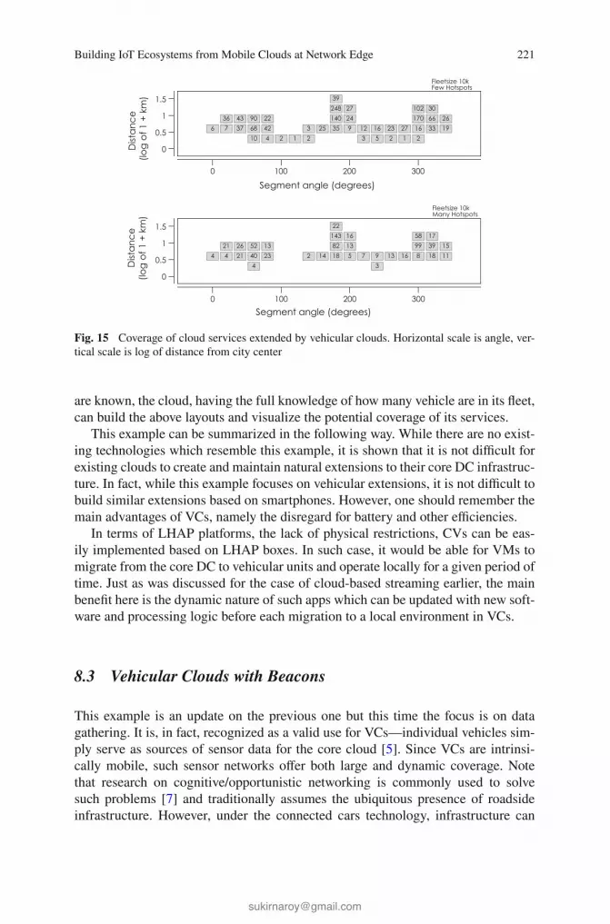
Building IoT Ecosystems from Mobile Clouds at Network Edge 221
Fig. 15 Coverage of cloud services extended by vehicular clouds. Horizontal scale is angle, ver-
tical scale is log of distance from city center
are known, the cloud, having the full knowledge of how many vehicle are in its fleet,
can build the above layouts and visualize the potential coverage of its services.
This example can be summarized in the following way. While there are no exist-
ing technologies which resemble this example, it is shown that it is not difficult for
existing clouds to create and maintain natural extensions to their core DC infrastruc-
ture. In fact, while this example focuses on vehicular extensions, it is not difficult to
build similar extensions based on smartphones. However, one should remember the
main advantages of VCs, namely the disregard for battery and other efficiencies.
In terms of LHAP platforms, the lack of physical restrictions, CVs can be eas-
ily implemented based on LHAP boxes. In such case, it would be able for VMs to
migrate from the core DC to vehicular units and operate locally for a given period of
time. Just as was discussed for the case of cloud-based streaming earlier, the main
benefit here is the dynamic nature of such apps which can be updated with new soft-
ware and processing logic before each migration to a local environment in VCs.
8.3 Vehicular Clouds with Beacons
This example is an update on the previous one but this time the focus is on data
gathering. It is, in fact, recognized as a valid use for VCs—individual vehicles sim-
ply serve as sources of sensor data for the core cloud [5]. Since VCs are intrinsi-
cally mobile, such sensor networks offer both large and dynamic coverage. Note
that research on cognitive/opportunistic networking is commonly used to solve
such problems [7] and traditionally assumes the ubiquitous presence of roadside
infrastructure. However, under the connected cars technology, infrastructure can

222 M. Zhanikeev
either be greatly reduced in size or removed altogether, instead relying on the fact
that individual vehicles are constantly connected to the Internet.
This example focuses on smart grids. Specifically, let us assume that a large geo-
graphical area has many small to mid-size power plants of various technologies
(solar, wind, etc.). The objective is to collect all the information from the many power
plants and aggregate it into a single bulk of data Big Data, by definition. The new ele-
ment in this example is the technology of wireless Beacons and the related concept
of beacon stuffing [40].
Figure 16 shows both the traditional and new technologies. In the traditional case,
it is assumed that all nodes in the network (power plants) are connected to the Internet
and submit their own information to the cloud. However, this is not a very feasible
technology in practice because such infrastructure would require large costs, spent
on connection, data maintenance, etc.
The new technology (left) therefore attempts to reduce the cost drastically by
assuming that power plants are not connected to the Internet and information is
instead delivered by vehicles in a cognitive/opportunistic manner. The role of bea-
cons is as follows. Each power plant is assumed to install very cheap beacons which
broadcast current status of a power plant at the roadside. Vehicles capture the broad-
cast information as they pass by and deliver it to the nearest node of the main road-
side infrastructure. To accomplish this, vehicles also have to implement beacons and
broadcast the aggregates of captured information as they travel.
The benefits of the new technology are as follows. Beacons provide a better cogni-
tive environment, while GPS-based location context may be very imprecise at times.
Besides, the capture process with beacons is also very natural—vehicles simply pick
up information as they go. The connected cars technology can still be used when noti-
fying cars on where the power plants are—that is, at the opposite side of the tech-
nology, which explores the business value of the collected Big Data. A bit unusual
Fig. 16 Traditional (left) versus beacon-powered (right) vehicular clouds

Building IoT Ecosystems from Mobile Clouds at Network Edge 223
application of the new technology can be found as part of the EV battery replacement
infrastructure as is discussed in [45].
Since Beacons are at the hard of this example, it is important to study their prac-
tical utility. Assuming that unit tuple containing information on one power plant can
be encoded as 10 bytes, and also assuming that one Beacon frame is 250 bytes long,
one frame can carry information on 25 power plants. This is important because it is
useful when each vehicle-roadside sync can fit into one frame.
As was mentioned before, this example is an extension of the previous one. The
same map is used and the fleet is also assumed to have 10 k vehicles. The size of the
fleet is not key in this case since it only takes one vehicle to sync data from a given
sub-location. Roadside infra in this example is allocated also based on the density—
in total up to 100 roadside nodes are allocated for 200+ physical nodes, in decreasing
order of density.
Figure 17 shows the performance for this example. Each thicker curve is for 10,
20, 40, and 50 % of nodes having roadside infra. The key point of the study is to find
out the coverage for 1-frame sync. This is important because vehicles can move very
quickly through these nodes while multi-frame syncs may not complete in one pass
and may require cars to slow down or stop. Also, the technology which uses multiple
frames is known as beacon stuffing has to be used which requires a minor hack [40].
The results are as follows. With 10 % of infrastructure, only 20 nodes can stay
within 1-frame sync range while the largest bulk requires 30 frames—such syncs
would definitely require the vehicle to stop to complete the sync. With 20 % of
infrastructure, 35 nodes can stay within 1-frame sync. Performance saturates at 40 %
of infrastructure, where about 50 nodes (out of at most 100) stay within 1-frame
syncs. At saturation, the largest syncs are at most 5–8 frames which can be handled
at slow speed and would probably not require the vehicle to stop.
This example can be summarized as follows. This is probably not a LHAP case
given that Beacons would be hard to implement as LHAP boxes—in the cloudifi-
cation timeline such devices come at the very end of the list. However, the devices
Fig. 17 Performance of a
beacon-powered vehicular
networks in smart grids

224 M. Zhanikeev
can still be considered cloudified since its networking with the cloud is delegated via
the vehicles and, ultimately, the greatly reduced roadside infrastructure. This exam-
ple can be reformulated as a network of nodes where vehicles serve as data packets
in a network connecting the multiple power plants in the smart grid. As such, such
networks can be considered as Delay Tolerant Networks (DTNs) [46].
9 Summary and Future Directions
This chapter presented a new viewpoint at the IoT technology which assumed that all
the devices and platforms are either partially or completely cloudified. The cloudifi-
cation idea is not entirely new in this chapter and has already been discussed as the
Cloud of Things (CoT) technology. However, this chapter is the first known attempt
to show that even small IoT devices at network edge can be implemented as the actual
cloud platforms.
The chapter make several interesting connections. If devices are considered in
groups, then, assuming the devices are cloudified, such IoT environments start to
closely resemble mobile clouds. This chapter has a detailed discussion of mobile
clouds in general and the technology called GroupConnect which offers even more
generic formulation than traditional mobile clouds. This discussion contributes the
concept of local versus remote communication to groups of IoT devices.
As far as the process of cloudification itself, this chapter discussed a new cloud
platform which implements Local Hardware Awareness (LHA) as its core function.
Using LHA—LHA platform is referred to as LHAP—groups of IoT devices can offer
cloud services the ability to discover and use local resources.
Several examples in this chapter put all these components to practical use. It is
also helpful that the same basic set of components is applied to drastically differ-
ent technologies. Specifically, this chapter discussed cloud-based streaming, exten-
sion of DC infrastructure using vehicular clouds and smart grids based on vehicular
clouds and roadside beacons.
The cloudification concept presented in this paper is far to completion. Closely
related subjects are Virtual Network Embedding (VNE) [47] and client-side appli-
cations [48]. The former technology can help built efficient network topologies con-
necting the distributed resources at network edge—a common example is build-
ing optimal many-to-many topologies for distributed groups. The latter can support
smarter logic for applications running in devices at network edge. Both these tech-
nologies naturally fit into the LHAP technology as well as the overall concepts of
cloudification and mobile clouds, and can be considered the immediately next step
for the research presented in this chapter.

Building IoT Ecosystems from Mobile Clouds at Network Edge 225
References
1. Uckelmann, D., Harrison, M., Michahelles, F.: Architecting the Internet of Things. Springer
(2011)
2. Minoli, D.: Building the Internet of Things wtih IPv6 and MIPv6: The Evolving World of M2M
Communications. Wiley (2013)
3. Hersent, O., Boswarthick, D., Elloumi, O.: The Internet of Things: Applications to the Smart
Grid and Building Automation. Wiley (2012)
4. Gerla, M., Lee, E.,Pau, G., Lee U.: Internet of vehicles: from intelligent grid to autonomous
cars and vehicular clouds. IEEE World Forum on Internet of Things (WF-IoT), pp. 241–246,
Mar 2014
5. Yu, R., Zhang, Y., Gjessing, S., Xia, W., YangToward, K.: Cloud-based vehicular networks
with efficient resource management. IEEE Netw. 27(5), 48–55 (2013)
6. Whaiduzzaman, M., Sookhak, M., Gani, A., Buyya, R.: A Survey on Vehicular Cloud Com-
puting. J. Netw. Comput. Appl. 40, 325–344 (2014)
7. Akyildiz, I., lee, W., Vuran, S.: Mohanty A survey on spectrum management in cognitive radio
networks. IEEE Commun. Mag. 40(4), 40–48 (2008)
8. Zhanikeev, M.: Reliable Vehicle Groups as a Cloud Storage Service. IEICE Technical Report
on Intelligent Transportation Systems (ITS), Jan 2015
9. Amft, O.: P. LukowiczFrom backpacks to smartphones: past, present, and future of wearable
computers. IEEE Pervasive Comput. 8, 8–13 (2009)
10. Zhou, H.: The Internet of Things in the Cloud: A Middleware Prospective. CRC Press (2013)
11. Manco, F., Martins, J., Huici, F.: Towards the super fluid cloudACM SIGCOMM. Comput.
Commun. Rev. 44(4), 355–356 (2014)
12. Kuenzer, S., Martins, J., Ahmed, M., Huici, F.:Towards minimalistic, virtualized content
caches with minicache. 13th Workshop on Hot Topics in Middleboxes and Network Function
Virtualization (HotMiddlebox), pp. 13–18 (2013)
13. Fernando, N., Loke, Rahayu, W.: Mobile cloud computing: a survey. Elsevier J. Futur. Gener.
Comput. Syst., vol. 29, pp. 84–106 (2013)
14. Zhanikeev, M.: Optimizing virtual machine migration for energy-efficient clouds. IEICE Trans.
Commun. E97-B(2), 450–458, Feb 2014
15. ZhanikeevA, M.: Cloud visitation platform to facilitate cloud federation and fog computing.
IEEE Comput. 48(5), 80–83 (2015)
16. Zhanikeev, M.: Coins in Cloud Drives Can Use OAuth for Micropayments and Resource Meter-
ing Alike. In: 9th International Conference on Future Internet Technologies (CFI), June 2014
17. Satyanarayanan, M., Bahl, P., Caceres, R.: The case for VM-based cloudlets in mobile com-
puting. Pervasive Comput. 8, 14–23 (2009)
18. Zhanikeev, M.: Wireless User: A Practical design for parallel multiconnect using wifi direct in
group communication. In: 10th International Conference on Mobile and Ubiquitous Systems:
Computing, Networking and Services (MobiQuitous) (2013)
19. Zhanikeev, M.: Opportunistic multiconnect with P2P wiFi and cellular providers. Advances in
Mobile Computing and Communications: 4G and Beyond, CRC (in print) (2015)
20. Schmidt, P., Merz, R., Feldmann, A.: A first look at multi-access connectivity for mobile net-
working. ACM Workshop on Capacity Sharing (CSWS), pp. 9–14, Dec 2012
21. Cuervo, E., Balasubramanian, A., Cho, D., Wolman, A., Saroiu, S., Chandra, R., Bahl, P.: Maui:
making smartphones last longer with code offload. In: 8th ACM International Conference on
Mobile Systems, Applications, and Services (MobiSys). pp. 49–62, June 2010
22. Huerta-Canepa, G., Lee, D.: A virtual cloud computing provider for mobile devices. In: 1st
ACM Workshop on Mobile Cloud Computing and Services: Social Networks and Beyond,
(MCS), vol. 6, pp. 1–5, June 2010
23. Keahay, K., Armstrong, P., Bresnahan, J., LaBissoniere, D., Riteau, P.: Infrastructure outsourc-
ing in multi-cloud environment. In: Workshop on Cloud Services, Federation, and the 8th Open
Cirrus Summit, San Jose, CA, pp. 33–38, Sept 2012

226 M. Zhanikeev
24. Keahay, K., Armstrong, P., Bresnahan, J., LaBissoniere, D., Riteau, P.: Infrastructure outsourc-
ing in multi-cloud environment. In: Workshop on Cloud Services, Federation, and the 8th Open
Cirrus Summit. San Jose, CA, USA, Sept 2012
25. Zhanikeev, M.: Multi-Source Stream Aggregation in the Cloud. Chapter 10 in the Book on
Advanced Content Delivery and Streaming in the Cloud. Wiley (2013)
26. Zhanikeev, M.: Cloud Probing. IEICE Technical Report on Information Communication Man-
agement (ICM), vol. 114, no. 389, pp. 33–36, Jan 2015
27. Banerjee, N., Agarwal, S., Bahl, P., Chandra, R., Wolman, A., Corner, M.: Virtual compass:
relative positioning to sense mobile social interactions. In: 8th International Conference on
Pervasive Computing, pp. 1–21, May 2010
28. Krumm, J., Hinckley, K.: The nearme wireless proximity server. Ubiquitous Comput. (Ubi-
comp), 283–300, Sept 2004
29. Peng, C., Shen, G., Zhang, Y., Li, Y., Tan, K.: Beepbeep: a high accuracy acoustic ranging
system using cots mobile devices. In: 5th ACM International Conference on Embedded Net-
worked Sensor Systems (SenSys), pp. 1–14, Nov 2007
30. Liu, H., Darabi, H., Banarjee, P., Liu, J.: Survey of wireless indoor positioning techniques and
systems. IEEE Trans. Syst. Man Cybern. 37(6), pp. 1067–1080, Nov 2007
31. Rumney, M.: LTE and the Evolution to 4G Wireless, Design and Measurement Challenges.
Wiley (2013)
32. Zhang, X., Zhou, X.: LTE-Advanced Air Interface Technology. CRC Press (2013)
33. Transition to 4G: 3GPP Broadband Evolution to IMT-AdvancedRysavy Research Report
(2010)
34. Glisic, S.: Advanced Wireless Networks: Cognitive, Cooperative and Opportunistic 4G Tech-
nology. Wiley (2009)
35. Mavromoustakis, C., Mastorakis, G., Bourdena, A., Pallis, E., Kormentzas, G., Dimitriou, C.:
Joint energy and delay-aware scheme for 5G mobile cognitive radio networks. In: IEEE Global
Communications Conference (GLOBECOM), pp. 2624–2630, Dec 2014
36. Mavromoustakis, C., Bourdena, A., Mastorakis, G., Pallis, E., Kormentzas, G. An energy-
aware scheme for efficient spectrum utilization in a 5G mobile cognitive radio network archi-
tecture. Telecommun. Syst. 59(1), 63–75 (2014)
37. Chen, Y., Lim, Gobbens, R., Nahum, E., Khalili, R., Towsley, D.: A measurement-based study
of multipath TCP performance over wireless networks. ACM SIGCOMM Internet Measure-
ment Conference (IMC), Aug 2013
38. Zhanikeev, M.: How variable bitrate video formats can help P2P streaming boost its reliability
and scale. Springer J. Electron. Commer. Res. 15(1), 22–47, Feb 2015
39. Zhanikeev, M: End-to-End network performance estimation using signal complexity. In: Inter-
national Symposium on Intelligent Signal Processing and Communication Systems (ISPACS),
pp. 73–78, Nov 2013
40. Chandra, R., Radhye, J., Ravindranath, L., Wolman, A.: Beacon-Stuffing: Wi-Fi without Asso-
ciations. 8th IEEE Workshop on Mobile Computing Systems and Applications (HotMobile),
pp. 53–57, Mar 2007
41. Chatzimilioudis, G., Konstantinidis, A., Laoudias, C., Zeinalipour-Yazti, D.: Crowdsourcing
with smartphones. IEEE J. Int.t Comput. 16(5), 36–44, Sept 2012
42. Zhanikeev, M., Tanaka, Y, Popularity-Based Modeling of flash events in synthetic packet
traces. IEICE Technical Report on Communication Quality, vol. 112, No. 288, pp. 1–6, Nov
2012
43. Zhanikeev, M.: Maps2Graphs: A Socially Scalable Method for Generating High-Quality GIS
Datasets Based on Google Maps APII. EICE Technical Report on Intelligent Transport Sys-
tems Technology (ITS), vol. 113, no. 337, pp. 73–76, Nov 2013
44. Gusein-ZadeAlternative, S.: Explanations of the dependence of the density of centers on the
density of population. J. Reg. Sci. 33(4), 547–558 (1993)
45. ZhanikeevOn, M.: How smart cities can improve social utility of their citizens’ commutes. J.
Inf. Process. 22(2), 253–262 (2014)

Building IoT Ecosystems from Mobile Clouds at Network Edge 227
46. Vasilakos, A., Zhang, Y., Spyropoulos T.: Delay Tolerant Networks: Protocols and Applica-
tionsCRC Press (2011)
47. Zhanikeev, M.: A new VNE method for more responsive networking in many-to-many groups
In: 7th International Conference on Ubiquitous and Future Networks (ICUFN), Sapporo, Japan,
July 2015
48. Zhanikeev, M.: A new practical design for browsable over-the-network indexing. In: Interna-
tional Conference on Information Science, Electronics and Electrical Engineering (ISEEE),
pp. 1686–1690, April 2014


Middleware Platform for MobileCrowd-Sensing Applications UsingHTML5 APIs and Web Technologies
Ioannis Vakintis and Spyros Panagiotakis
Abstract This chapter presents a web-based cross-platform architecture based onHTML5 APIs and other state-on-the-art web technologies. In fact, our architectureis a crowd sensing application which exploits the ubiquitous capabilities of modernmobile devices, along with their built-in sensing capabilities, in order to motivatethe users to collect, share and use different kind of sensor data. The platformconsists of two application specific components: the first, the client part, runs in theuser device to collect sensor data and transmit them; the second, the server part,runs in the cloud and is responsible for analyzing and visualizing the data from alldevices in a human friendly format, e.g. a map. The application is multi-sensor as itcan collect data from almost all sensors of mobile devices. Besides the use of theplatform as a participatory and opportunistic sensing architecture, our endmost aimis to be used with other Internet of Things equipment for the introduction to thethird generation of Web characterized as ubiquitous web.
1 Introduction
Mobile sensing has changed many forms over the years. In the decades of 80 and90s, mobile computing technologies leaded the development of a variety of sensorequipment to monitor phenomena of interest such as atmospheric pollution orpotholes on roads. In the next years, wireless networking technologies overcame alot of obstacles and sensors via embedded communication modules started toconnect not only to each other but also with backend servers [1]. Nowadays,ubiquitous or pervasive sensing [2, 3] enabled by web and mobile technologies for
I. Vakintis ⋅ S. Panagiotakis (✉)Department of Informatics Engineering, Technological EducationalInstitute of Crete, 71004 Heraklion, Crete, Greecee-mail: [email protected]
I. Vakintise-mail: [email protected]
© Springer International Publishing Switzerland 2016C.X. Mavromoustakis et al. (eds.), Internet of Things (IoT) in 5G Mobile Technologies,Modeling and Optimization in Science and Technologies 8,DOI 10.1007/978-3-319-30913-2_11
231

a wide range of activities in our society. Transportation and Civil InfrastructureMonitoring [4, 5], Environmental Monitoring [6–12], Health Care and Fitness [13],urban sensing [14] and traffic monitoring, social networks [15] are some areaswhich benefit from ubiquitous sensing. Smart devices have played a major role tothis trend. Smartphones, tablets, music players, sensor embedded gaming systemsand in-vehicle sensing devices (e.g. GPS navigators) are flooding the market andfeed with sensor data the Internet. They are equipped with various sensors (e.g.,accelerometer, ambient light, camera, microphone, gyroscope, proximity and meteosensors) and so they transform a near-ubiquitous smart device into a global mobilesensing device [16, 17].
In the upcoming years more sensors will be embedded in the smartphones. Thenew version of Samsung Galaxy includes two more sensors, heart rate sensor andfinger scanner [18]. It is the first time in history of smartphones that a smartphoneincludes a heart rate sensor providing the capability to the users to monitor theirphysical condition. Mobile users can measure their heart rate before and after aworkout to check out their health and workout status. The second sensor thatSamsung galaxy S5 features is a finger scanner, which improves the usability andthe security of smartphones. Some example applications for Finger Scanner includebiometric screen locking, individual file locking with “Private mode” and securemobile payments.
As it is obvious, the sensing capabilities of smartphones can recognize individualor community phenomena. The category of individual phenomena includes severalactions of a specific device’s owner, which usually are divided into 3 categories(a) movement patterns such as walking and running, (b) modes of transportationsuch as biking, driving or taking a bus and (c) activities such as listening to musicand making coffee. Most of the time, the user can have access to his personal datawhich are presented graphically as analytics. On the other hand, community phe-nomena are related to the actions of a set of people and are not limited to a specificuser. Community phenomena include real-time traffic patterns, air [19], water ornoise pollution and pothole patrol. The way in which users are involved in theprocess of collecting sensor data distinguishes sensing of community phenomena toparticipatory and opportunistic. In Sect. 2 we will present a deep analysis for bothcategories.
With respect to the sensing of community phenomena, a new sensing archi-tecture has spurred the attention of the scientific community, recently [20]. Mobilecrowdsensing or MCS, is a new business model that allows to a huge number ofmobile users to exchange information not only between them but also for a set ofactions that may affect the community. In general, the term “Crowdsensing” refersto the collection and sharing of sensor data with the scope to measure a communityphenomenon. It is a very attractive solution for companies and organizations tocollect significant data without spending enormous amounts of money. A veryimportant advantage of crowdsensing is that unlike an infrastructure-based sensingsolution, crowdsensing can potentially be cheaper as it does not require thedeployment of an expensive fixed infrastructure.
232 I. Vakintis and S. Panagiotakis

The creation of such sensing architectures has blossomed recently capitalizingthe capabilities of modern mobile and web technologies. Modern mobile operatingsystems fully exploit the features of sensing devices offering multiple capabilities tothe mobile and web developers. The developers can build applications for handhelddevices with three deferent ways: as (1) native, (2) web or (3) hybrid apps. Nativeapplications are built separately for each operating system and they are pre-installedon the mobile phones during manufacturing or can be downloaded from distributedapplication stores such as Google play or App store. Android and iOS are the twomost well-known mobile operating systems of the world having the 96.1 % of theworld market share in the 3rd quarter of 2014 [21]. Web applications are deliveredusing a server-side or client-side processing to provide an “application-like”experience within a Web browser. The last category, hybrid applications, concernsthe marriage of web technology and native execution. Hybrid apps are built withweb technologies and mobile web implementations and run inside a native con-tainer on a mobile device.
Beyond mobile technologies, the web is gaining momentum in the use ofsensing devices. The way that we interact with the web is changing throughout theyears. In the upcoming years web will enter its 3rd phase called ubiquitous orintelligent web. From that point of view, webpages are not just pages with colors,text and logos but they are similar to desktop applications and are turning to webapplications [22]. The radical improvement of content usability helps the webapplications to present content more dynamically. Also, a web application canretrieve data from multiple sources and in real time. In many cases, the traditionalHTTP communication between a web server and a browser is replaced by a singlepersistent TCP connection, which is called WebSocket [23–25]. The advantage ofthe WebSocket protocol is that it provides full-duplex bi-directional communicationthat can be used by both client and server applications. Besides robust communi-cation protocols such as Websockets, ‘the intelligent Web’ will have much moretechnology trends to extend. Semantic Web technologies, machine learning andreasoning, autonomous agents and distributed databases will turn the Web to anopen, connected and intelligent ecosystem.
The deployment of future mobile internet, is also propelled by the standard-ization efforts for the 5th generation of wireless systems [26, 27] known as 5G,which is estimated that around 2020 will be released in the public for everyday use.5G wireless technology will support dense deployment of high-speed low-latencyservices (small cells), better utilization of the current frequency bands, the release ofnew wave bands in the spectrum between 6 GHz and 100 GHz, novel techniquesfor antennas and protocols and integration of existing heterogeneous networks [28,29]. Figure 1 illustrates the evolution of 4G–5G networks. The 5G networks areexpected to fill the puzzle of the inexorable evolution of smart devices and cloudcomputing [30–33], since the new standard is designed to be versatile and scalablefor the Internet of Things devices. The improvement of key networking featuressuch as capacity, coverage, and energy efficiency will definitely benefit high rateapplications such as the mobile crowd-sensing and crowd-sourcing ones.
Middleware Platform for Mobile Crowd-Sensing Applications … 233

In this chapter, we present a web-based cross-platform architecture forcrowd-sensing, which is interfaced with the real world through the sensors ofvarious mobile devices [34, 35] and is totally based on HTML5 APIs in order tocollect, group and graphically present the retrieved data following statistical pro-cessing. To the best of our knowledge, this is the first crowd-sensing platform thatexclusively uses HTML5 APIs for the collection of sensor data. The platformconsists of two application-specific components: the first, the client part, runs in theuser device to collect sensor data and transmit them; the second, the server part,runs in the cloud and is responsible for analyzing and visualizing the data from alldevices in a human friendly format, e.g. a map [36]. The application is multi-sensoras it can collect data from almost all sensors of mobile devices and is totally basedon HTML5 features. Besides the use of the platform as a participatory andopportunistic sensing application [34], our endmost aim is to be used with otherInternet of Things equipment for the introduction to the third generation of Webcharacterized as ubiquitous web [37].
In more detail, the client, which is implemented in the form of a web page, actsas the source of data and is located in the front end of our web platform. The enduser via the client grants access to the sensors through the respective HTML5 APIs.The end user only needs to activate the client application to start the automaticprocedure of sending sensor data to the cloud. Sensor APIs obtain the raw infor-mation and forward it to the next stage for analyzing. The data analysis is dividedinto two parts, local analysis (at the client) and aggregate analysis (at the server)[38]. When local analysis finishes, useful data are sent to the server and stored in a
Fig. 1 Transition from 4G to 5G wireless networks
234 I. Vakintis and S. Panagiotakis

cloud database. At this point, the data will pass to the second stage of analysis. Thisstage provides a map visualization and statistical analysis of data collected by allclients. Statistical data are presented in the form of various charts. Both interactivemap and analytics can be accessed by anyone via a visitors’ web page open to thepublic. Apart from statistical processing and representation of sensor data andinteractive map visualization, the visitor page offers many capabilities to its visitorsincluding a collection API and dynamic map visualization.
The specific scenario that we have implemented concerns the measurement ofambient noise and light. The user gives access to three sensors of his mobile device,namely the microphone (Get user media API [39]), the light sensor (Light sensorAPI) and Location (Geolocation API). Microphone records the ambient sound andthrough an algorithm converts values to decibels. These values are periodically sentto the server through a Websocket connection while the user is active. The servercollects the decibel values along with the location of users to export the statistics.Light sensor acts with the same procedure as microphone with the only differencethat light data doesn’t need further local analysis. Light sensor API exposes data aslux values rather than Get user media which exposes raw data information.
The remaining chapter is organized as follows: Sect. 2 details in various aspectsof crowd-sensing applications. Section 3 introduces to the web technologies that arerelevant to our implementation. Section 4 presents the design of our architectureand Sect. 5 focuses on critical implementation details demonstrating in parallel theprovided functionality. Section 6 presents how privacy is assured in our system andSect. 7 introduces to the gamification approach we followed in order to motivateusers to remain online for more. Finally, Sect. 8 concludes the chapter.
2 Crowdsensing Architectures
Crowdsensing is a new way of sensing the real world which encourages people toparticipate and generate sensor data from their mobile devices. Sensor data isaggregated and fused in the cloud for further analysis and customer service delivery[40]. As mobile devices we consider mobile phones, wearable devices and smartvehicles. The embedded mobile sensors can acquire local knowledge e.g., location,noise level, traffic conditions, and in the future more specialized information such aspollution. A typical functionality of MCS application is first to collect raw sensingdata from mobile devices and then to process it to a mechanism for local analytics[20]. Second, privacy preservation, the data is sent to the backend and aggregateanalytics will further process it for different applications.
Crowdsensing is low-cost compared to a platform with static sensors and itsrange is far larger than the typical WSN systems. Moving users create an enormousrange which can expand to the most improbable places. The main research chal-lenges for crowdsensing applications are privacy and incentive mechanisms. Thenature of the data that is transferred between the applications is very sensitive henceprivacy is considered to be a critical factor for the success of such applications.
Middleware Platform for Mobile Crowd-Sensing Applications … 235

Another important issue for crowdsensing is the motivation of the user. The pur-pose is to keep the user for a long time inside the application in order to collectamounts of sensor data.
With respect to the involvement of the user in the crowdsensing process,crowdsensing applications are distinguished into participatory and opportunistic. Inparticipatory crowdsensing, the users send sensor data to the server, doing an activeeffect. On the other hand, in opportunistic crowdsensing the sensor data are sendingautomatically, with little or any involvement of the user. Taking into account thetype of the measured phenomenon, three categories of crowdsensing applicationscan be distinguished: (1) Environmental, (2) Infrastructure and (3) Social. Envi-ronmental crowdsensing is used to measure natural phenomena, such as noisepollution, level of water and air pollution. Infrastructure crowdsensing is used tomeasure public infrastructures, such as road conditions or traffic congestion.Finally, social crowdsensing is used to measure social behavior of individuals, suchas the shops visited by a citizen or the holiday travel destinations.
The information that is sensed from the users’ devices is normally transmitted toa back-end server for further analysis. The combination of information from mul-tiple mobile or desktop devices can reveal significant trends of an environment likepredicting air and noise quality. Also, they can help to improve city managementissues like the traffic sector, civil complaints or neighborhood problems. All thesedevelopments are under the category of Community sensing, People sensing,Participatory sensing, Opportunistic sensing, Crowdsensing, Crowdsourcing andSocial sensing. These buzz words all describe the space of sensing architecturesfrom various application perspectives. The purpose of these buzz words is to buildplatforms or applications that gather sensor data from volunteers belonging to thehuge number of people with mobile devices, actively or passively. Nevertheless, asensing platform can be characterized with more than one of the above namesbecause it may contain characteristics from several sensing architectures. Figure 2illustrates the classification of crowdsensing applications.
Fig. 2 Classification of Crowdsensing systems
236 I. Vakintis and S. Panagiotakis

3 Related Technologies
Apart from the evolution of mobiles, Web, also, currently lives its evolutionaryphase with HTML5. Thus, several Web applications have been mobilized and manyWeb sites are now responsive. HTML5 is the definite “software glue” which fillsthe gap between mobiles and Web and becomes the key to any future development.All these mobile features can be used combinatorial to the advanced features ofHTML5 for enabling valuable distributed participatory and opportunistic sensingapplications. As we reviewed in the second section the crowdsensing applicationscan be extended to many fields of daily life, namely: transportation and civilinfrastructure monitoring, environmental monitoring, health and fitness, urbansensing and traffic monitoring.
In this section, we will shortly introduce to various web and mobile technologies,which are capable to deal with data for IoT applications [41, 42]. At first we discussthe HTML5 APIs that deal with sensor and hardware integration and then we ana-lyze new elements that HTML presents in its fifth revision. Later in the chapter wecomment about other web technologies, which help us to construct the architectureof our platform. Also, we discuss about concepts, protocols, libraries and APIs, suchas Meteor, Nodejs, Mongodb, Google geocoding APIv3, Web Audio API, Websockets, Geolocation API, Sencha ExtJS 4 (Visualization charts) and much more.
3.1 HTML5
3.1.1 Overview
HTML5 [43–46] is a programming language used for describing the layout andpresenting the contents of Web pages. HTML5 is cooperation between the WebHypertext Application Technology Working Group (WHATWG) and the WorldWide Web Consortium (W3C). In the early years, HTML had limited potentialitiesand was designed just for describing static web content. But with the course of time,the language has been dramatically evolved, offering real challenges to developers.Its latest version, HTML5 has completely changed the status in the IT firmamentwith the breaking through technologies it introduces. For example video files do notrequire any more external plugins like flash in order to be played back in a browser,as HTML5 with its <video> tag embeds such functionalities, as play, stop/pause,move back/forward, directly into the body of the language. Essentially, HTML5 isnot anymore a simple language for describing web pages, but a combination ofHTML, CSS and many Javascipt APIs, which makes it a powerful platform withrich capabilities. In the following, the attention will be paid on these Javascipt APIs,available with the 5th edition of HTML that can enable the provision of pervasive,ubiquitous and adaptive web applications to end users. Because with these APIsweb sites and web applications are offered an insight to the personal context and
Middleware Platform for Mobile Crowd-Sensing Applications … 237
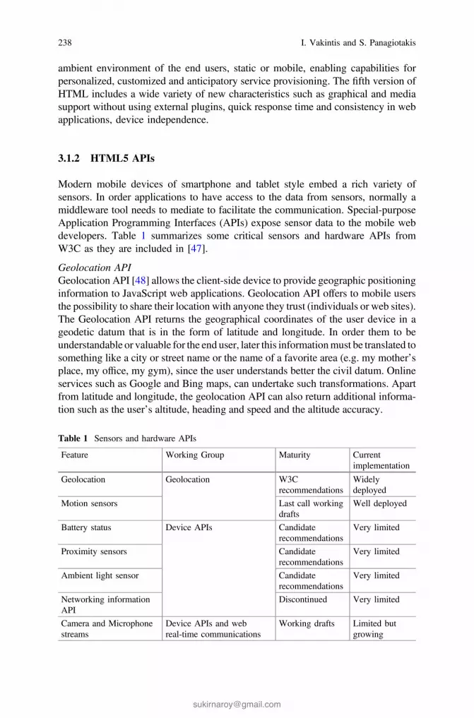
ambient environment of the end users, static or mobile, enabling capabilities forpersonalized, customized and anticipatory service provisioning. The fifth version ofHTML includes a wide variety of new characteristics such as graphical and mediasupport without using external plugins, quick response time and consistency in webapplications, device independence.
3.1.2 HTML5 APIs
Modern mobile devices of smartphone and tablet style embed a rich variety ofsensors. In order applications to have access to the data from sensors, normally amiddleware tool needs to mediate to facilitate the communication. Special-purposeApplication Programming Interfaces (APIs) expose sensor data to the mobile webdevelopers. Table 1 summarizes some critical sensors and hardware APIs fromW3C as they are included in [47].
Geolocation APIGeolocation API [48] allows the client-side device to provide geographic positioninginformation to JavaScript web applications. Geolocation API offers to mobile usersthe possibility to share their location with anyone they trust (individuals or web sites).The Geolocation API returns the geographical coordinates of the user device in ageodetic datum that is in the form of latitude and longitude. In order them to beunderstandable or valuable for the end user, later this informationmust be translated tosomething like a city or street name or the name of a favorite area (e.g. my mother’splace, my office, my gym), since the user understands better the civil datum. Onlineservices such as Google and Bing maps, can undertake such transformations. Apartfrom latitude and longitude, the geolocation API can also return additional informa-tion such as the user’s altitude, heading and speed and the altitude accuracy.
Table 1 Sensors and hardware APIs
Feature Working Group Maturity Currentimplementation
Geolocation Geolocation W3Crecommendations
Widelydeployed
Motion sensors Last call workingdrafts
Well deployed
Battery status Device APIs Candidaterecommendations
Very limited
Proximity sensors Candidaterecommendations
Very limited
Ambient light sensor Candidaterecommendations
Very limited
Networking informationAPI
Discontinued Very limited
Camera and Microphonestreams
Device APIs and webreal-time communications
Working drafts Limited butgrowing
238 I. Vakintis and S. Panagiotakis

Ambient Light Sensor APIThe Ambient Light Sensor API [49] senses the environment of the device to pro-vide web applications with the measured luminosity in lux units. The values rangefrom 0 to 10,000 lux. Obviously an embedded Light Sensor is required.
Media Capture and Streams APIThe Media Capture and Streams API (or GetUserMedia API) [50] offers to webapplications access to multimedia streams, such as video and audio, from localdevices (webcam or microphone) through a browser. It then capitalizes on theHTML5 <video> and <audio> elements to play them back. In terms of user pri-vacy, the Media Capture and Streams API behave similar to the Geolocation API.Whenever an application attempts to access the local media devices the browser asksthe user for his permission. The revolutionary with this API is that access to the localmedia devices takes place without any need for plugins installation.
Network Information APIThe Network Information API [51] measures the available bandwidth and offers tothe developers the ability to accordingly adapt web media elements such as: images,videos, audios and fonts, for better user experience with multimedia content.Despite its obvious usefulness, work on this API has been discontinued by W3C.
WebSocketsThe WebSocket protocol [52, 53], provides a bidirectional communication channelusing a single TCP connection. It has been designed for implementation in bothbrowsers and web-servers and its API has being standardized by the W3C. Web-Socket connections are established over the regular TCP port 80, which ensures thatthe system can run behind firewalls.
Web Audio APIInteractive applications, games, advanced music synthesis applications and visu-alizations need a strong API without the limitations of <audio> tag. This API is theWeb Audio API [54, 55] which is a high-level versatile JavaScript API for con-trolling, processing and synthesizing audio. It provides multiple functionalities suchas adding multiple audio sources, adding effect [56] and visualizes audio. The WebAudio API is an HTML5 API which has direct access to the audio hardware and hasbuilt around the concept of an audio context. An Audio context is a routed graphwhich contains directed audio nodes from a source (audio file or microphone) to thedestination (speakers). Figure 3 Shows a simple Audio context where the sourceand destination node are connected without any distribution between them.
Fig. 3 Audio context
Middleware Platform for Mobile Crowd-Sensing Applications … 239

3.2 Google Services
3.2.1 Google Maps and Google Maps API v3
Google Maps [57] is a web mapping service and technology for desktop and mobiledevices that provided by Google. The capabilities of the specific platform aresatellite imagery, street maps and street view perspectives. Google update thedatabase on a regular basis with images for street maps but it is not in real time.Google Maps can easily be integrated into a third-party website via the GoogleMaps API [58]. The API provides the developer with many tools like conclude amarker in a map, add multiple maps or add virtual radius. Also, Google Map APIcan intergrade with others Google services such as Google Geocoding API.
3.2.2 Google Geocoding API v3
Geocoding or forward geocoding is the procedure of translating addresses (e.g.Delaporta, Heraklion 71409, Greece) into geographic coordinates (latitude35.3191579 and longitude 25.1483078) [59, 60]. The opposite procedure oftranslating geographic coordinates into an address (in a human readable-way) iscalled reverse geocoding [61]. Figure 4 shows google geocoding API in action.Google geocoding API v3 is included in google maps web services and implementboth geocoding and reverse geocoding process. The user can have access to GoogleGeocoding API via an HTTP request. An API key is necessary to request theservice.
Fig. 4 Geocoding services translate an address into geographic coordinates and display a markerin a map
240 I. Vakintis and S. Panagiotakis

Although Google geocoding API is a free web service; it is subject to twolimitations from a single IP address. The first limitation is referred to the maximumnumber of requests per day (2500 geocode requests per 24 h). The second limitationis referred to the maximum number of requests per second (5 geocode requests persecond).
3.2.3 Geo-fence
A geo-fence [62] is a virtual boundary around a real-world geographical area whichdefines a point of interest. Geo-fence could be generated dynamically by giving thecapability to the end user to select a point of interest or static by predefined a set ofboundaries, like a field boundaries. With the dynamically capability the user canmark the desired region and see the recovered information. It is usually used inlocation-aware applications sending notifications to the users about a zoneviolation.
3.3 Meteor Platform
Our platform has been set up on meteor web platform [63]. Meteor is a real-timeJavaScript web application framework which is written on top of Node.js andconcludes various packages like MongoDB and jQuery. Meteor consider as thefuture of the web because it combine a full stack isomorphic system using the samelanguage (JavaScript) in both frontend and backend [64]. Also the same APIs canbe used for mobile applications along with Cordova. This means that you write yourcode once and run everywhere. It customizes them to communicate seamlessly withone another via Distributed Data Protocol and a built-in publish-subscribe pattern[65]. The Distributed Data Protocol is a websocket-based protocol, allowing to theuser to deliver live updates as data changes. Meteor is designed to work most withone database, MongoDB. MongoDB is a JSON-style, document-based NoSQLdatabase built for flexibility and scalability. The client side act with the same way asthe server side, having access to the database from Mongoose. Meteors customizedthese packages into smart packages and offer to the developer great capabilitiessuch as: automatically real-time, database access from the client (mongoose),latency compensation, doesn’t need to write Ajax and there is not any DOMmanipulation. Meteor allows us to easily create apps without having to worry aboutthe backend plumbing needed to set this all up. The web application runs both onthe client (browser’s JavaScript engine) and on the server (node.js). The result of allthis is a platform that manages to be very powerful and very simple by abstractingaway many of the usual hassles and difficulties of web app development. Figure 5shows the Meteor environment and separates the components between server andclient. In the next sub-chapter we will analyze every component separately.
Middleware Platform for Mobile Crowd-Sensing Applications … 241
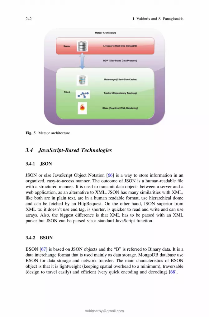
3.4 JavaScript-Based Technologies
3.4.1 JSON
JSON or else JavaScript Object Notation [66] is a way to store information in anorganized, easy-to-access manner. The outcome of JSON is a human-readable filewith a structured manner. It is used to transmit data objects between a server and aweb application, as an alternative to XML. JSON has many similarities with XML,like both are in plain text, are in a human readable format, use hierarchical domeand can be fetched by an HttpRequest. On the other hand, JSON superior fromXML to: it doesn’t use end tag, is shorter, is quicker to read and write and can usearrays. Also, the biggest difference is that XML has to be parsed with an XMLparser but JSON can be parsed via a standard JavaScript function.
3.4.2 BSON
BSON [67] is based on JSON objects and the “B” is referred to Binary data. It is adata interchange format that is used mainly as data storage. MongoDB database useBSON for data storage and network transfer. The main characteristics of BSONobject is that it is lightweight (keeping spatial overhead to a minimum), traversable(design to travel easily) and efficient (very quick encoding and decoding) [68].
Fig. 5 Meteor architecture
242 I. Vakintis and S. Panagiotakis

3.4.3 GeoJSON
GeoJSON [69] is an open standard format for encoding a variety of geographic datastructures and is based to JavaScript Object Notation. It include points (thereforeaddresses and locations), line strings (therefore streets, highways and bound-aries), polygons (countries, provinces, tracts of land), and multi-part collections ofthese types. The GeoJSON format differs from other GIS standards [70] in that itwas written and is maintained not by a formal standards organization, but by anInternet working group of developers. Below is an example of a GeoJSON datastructure.
3.4.4 Ext JS Framework
Ext JS [71, 72] is a JavaScript application framework suitable for interactive webapplications. Ajax, DHTML and DOM scripting are some of the techniques thatExt JS use to present graphics in web pages. Ext JS Charts are used to present datavisually, usually showing the relationship between different parts of the data. Ext JSexcels for master/detail form-heavy applications and no other HTML applicationframework is going to come close to Ext JS from a feature perspective.
3.5 X3D and X3Dom
The World Wide Web Consortium (W3C) and the Web Hypertext ApplicationTechnology Working Group (WHATWG) cooperated to include into the emergedHTML5 specification an updated way for the presentation of 3D content in webbrowsers. HTML5 [73, 74] through its canvas element enabled the presentation ofX3D graphics from web pages without requirement for any plugin. That is, all webbrowsers compatible with WebGL can render interactive 3D graphics. Definitely,the advent of HTML5 associated with other web technologies, such as X3Dom [75,76], can convert web browsers to 3D friendly multi-platforms with lots of capa-bilities. X3Dom is a proposed syntax model that translates X3D files to WebGL
Middleware Platform for Mobile Crowd-Sensing Applications … 243

graphics. X3Dom is considered to be the state of the art technology for the visu-alization of X3D graphics on the canvas of a web page.
4 Platform Architecture
In this chapter, we will discuss about the architecture of our crowdsensing platform.Based to the bibliography it is the first platform that use HTML5 APIs to deliverreal-time sensor data to the users. Our platform is a modern, real time web appli-cation system for gathering sensor data (e.g. noise intensity, luminous intensity andconnection type information) and display them in real-time. Apart from displayingthe client data, it analyzes them in the server side and offer them back to thecommunity. Visitor will be able to see the sensor data from a separate page. Thecollected sensor data will be shown in a fully-interactive world map and in niceinformative, responsive charts. Also, it offers the data to the community via webservices API. The sensor data could then be used for further purposes such as formaking surveys, scientific researching or doing experiments. We will start bynaming its components and then will explain every component separately. We willalso cover the interconnection between components of the architecture. Figure 6shows the architecture of the platform, which is based on the multi-tier paradigm[77]. In software engineering, multi-tier or n-tier architecture is a client-serverarchitecture in which, the presentation, the application processing and the datamanagement are logically separated processes. The most usual “multi-tier archi-tecture” is the three-tier architecture. The tiers can be called layers and it is not needto be in physically different machines.
Fig. 6 Middleware platform architecture
244 I. Vakintis and S. Panagiotakis

4.1 Components
Our platform consists of 3 major components: The client component, which isresponsible for gathering the sensor data, the server component, which contains theservice logic of the platform, and the 3rd party component, which offers a variety ofservices to end users. Finally, there is the database component which is responsiblefor storing the sensor data.
4.1.1 Client Component
The client component is responsible for the implementation of the HTML5 APIs forthe communication with the device sensors, the storing of sensor data to thedatabase and their transfer to the server. The implementation of the client com-ponent is based on the Meteor framework, which acts as an application serverbetween the other components. In particular, it undertakes to transfer the infor-mation quickly and safely to the server via a distributed data protocol. Probably, themost critical job for Meteor is the synchronization of the data in both client andserver side. The client component is the main source of sensor data in our archi-tecture. The other source is provided by the noisetube API and is implemented atserver side. The main source of data is noise data provided by the microphonedevice of clients by using the Web Audio API and exploiting getUserMedia() witha gain node analyzer. Figure 7 shows the procedure of capturing the noise data.Also, the application can collect luminosity data by the Ambient light sensor API.The user can gather simultaneously data from both sensors, or switch between noiseand light sensor from a button switcher. There is a switcher checkbox whichenables or disables each of the APIs. Both sensor data are combined with locationinformation by Geolocation API. Except from the sensor data, the client side cancollect connection type information, such as under 2G, 3G or Wi-Fi connection, viathe Network information API. Ambient light sensor API and Network informationAPI are in experimental or draft stage currently and browser support is very limited.Both APIs are supported only by mobile Firefox for Android and iOS.
Fig. 7 Noise data capture
Middleware Platform for Mobile Crowd-Sensing Applications … 245

4.1.2 Server Component
The server component is responsible to store the semantic information from theclient side and to distribute it to various collections for visualization purposes. Themain server jobs are: Reverse geocoding, time aggregation and NoiseTube datarequest. With reverse geocoding the server updates user data by translating coor-dinates to country, locality and place information using Google services. Timeaggregation job is to manipulate and insert sensor data into collections in order toachieve a spatiotemporal visualization in the third party’s page. Finally, there is theNoiseTube data request job with which the server fetches data from theNoiseTube API to create more crowd-full visualization charts.
4.1.3 3rd Party Component
The 3rd party component, similar to the client component, is built upon the Meteorframework. Meteor is a full stack real-time framework that uses MongoDB as itsmain database and DDP (websocket) as the communication channel between itscomponents. We use Meteor because its nature is to be real-time by default. Also,MongoDB is a next-generation document-oriented database, which is storing datain a JSON-like format, making the integration of data in certain types of applica-tions easier and faster. MongoDB provides scalability and flexibility to the devel-oper. It is perfect for IoT applications, which need very large databases, and also inreal-time analytics that need lightweight data.
The 3rd party component provides a way to visualize the data collected by theclient devices of our framework in real-time. It provides two ways for visualization:(1) Google maps and (2) analytics’ charts. By real-time we mean that the data aremanipulated by the server at regular intervals so the generated charts visualize thelast samples with statistical ways. Also, analytics’ charts are divided in two cate-gories: (1) time charts aggregated by country and locality information and (2) av-erages aggregated by country data. Finally, averages’ graphs are divided in twocategories: (1) 2d graphics provided by the Ext JS framework and (2) 3d graphicsprovided by the X3dom framework. Also, the 3rd party component provides someothers capabilities to the end user which are: dynamic maps, historical maps and anAPI to retrieve information from the database.
5 Demostration and Implementation Scenarios
In this chapter, we will highlight some critical implementation details of the plat-form. We will present the key features of every component separately. The pre-sentation is divided into 3 parts: Client side, 3rd party side and server side. Clientand 3rd party side are included in the presentation part of the platform. On the other
246 I. Vakintis and S. Panagiotakis

hand server side is included in the logic part of the platform. Also, in the server sidepart is analyzed some aspect of the database logic.
5.1 The Client Component
5.1.1 Data Measurement and Data Conversion Module
Noise data are the main source of the sensor data and the most of our services arereferred to them. When the user presses the main button at the client interface,automatically activates the media capture API or else getUserMedia(). Instantly theuser gains access to the microphone of the device. Before gaining access to themicrophone, browser will through an infobar to call getUserMedia(), which givesusers the option to accept or deny access to their microphone.
The second source of sensor data is the ambient light sensor API. In Clientapplication, we are using the method addEventListener for adding the event “de-vicelight”. The devicelight event will be fired when fresh data is available from alight sensor. Then it gets the data and save them in the collection.
Geolocation API is coming next. When the user enables the data gatheringbutton simultaneously enables the geolocation API. Geolocation API will throughan InfoBar just like the getUserMedia(). Then the user will have the option toaccept or deny the access to his location information. Upon “accept”, the clientstarts to retrieve the coordinates of the user.
Also, client application can detect the connection type of the user (e.g. Wi-Fi,cellular, Bluetooth) using the Network information API. The Network informationAPI is an experimental technology because its specification has not been stabilizedyet. It consists of the NetworkInformation() method and a single property to theNavigator interface: Navigator.connection. The connection object contains theproperty type, which returns the user agent’s connection type.
5.1.2 Data Insertion Module
We execute a function every 1000 ms to send the data in the server/database. Wename this procedure as data insertion job. Data insertion job calls the server method“pushSensorData” and sends the data from client to the database. The data arestored in the database as JSON documents. A server method calculates the currenthour and inserts it in the sensor document. Next panel shows the structure of thedocument. It contains coordinates, noise\light level values (embedded subdocu-ment), user ID and timestamp (hour). Every minute the server job updates the datacollection with country and locality values by coordinates.
Middleware Platform for Mobile Crowd-Sensing Applications … 247

5.1.3 Distance Calculator
We have embedded in the client a real-time noise measure map for visualizingsensor data and a distance calculator. With the latter, the user can select from avariety of choices (e.g., whole world, 10,000, 2500, 500, 100, 25, 5, 1 km) and findlive users in proximity to him. Using the Geolocation API [48] we can calculate thedistance between the specific live user and other live users within the specifiedradius and return to the user the results on his live map. The formula takes thecoordinates of the starting point of the user and compares them periodically towardshis current position. To get the starting coordinates we call getCurrentPosition() andthen the API asynchronously follows the user’s current location and saves it forlater use. This call executes only once when the user grants the application withaccess to geolocation API and then follows the moves of the user. Finally, theformula [78, 79] calculates the distance between the current user and the other liveusers. We use the haversine formula to calculate the distance between users [80].Haversine formula calculates the great-circle distance between two points—that is,the shortest distance over the earth’s surface—giving an ‘as-the-crow-flies’ distancebetween the points (ignoring any hills they fly over, of course!).
5.1.4 Geofence Functionality
As we described in the previous sub-chapter, geo-fence is a virtual boundary arounda real-world geographical area which defines a point of interest. It can be generateddynamically from the end user or statically by predefining a set of boundaries. Theuser can “draw” a point of interest and see the corresponding information from themarkers. The selection of the point is made in two steps: (1) at first there is a selection
248 I. Vakintis and S. Panagiotakis

from the database of the items which are located inside the area of the circle. (2) Thenit checks if each item is in the distance range from the center of the circle. Later thereis a real time reverse geocoding procedure that translates the coordinates of thecenter into the corresponding location. The geofence calculate all the markers thatare located inside the rectangle area and shows the average noise value of them in adynamic panel. Figure 8 shows an example of geofence into a google map.
5.1.5 Real-time Live Users
The user interface of the client application is an interactive Google Map which isessentially a real-time application. It shows all the live users that use the client
Fig. 8 Noise data capture
Fig. 9 Client application screenshot
Middleware Platform for Mobile Crowd-Sensing Applications … 249
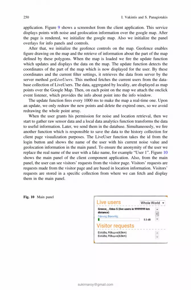
application. Figure 9 shows a screenshot from the client application. This servicedisplays points with noise and geolocation information over the google map. Afterthe page is rendered, we initialize the google map. Also we initialize the paneloverlays for info panels and controls.
After that, we initialize the geofence controls on the map. Geofence enablesfigure drawing on the map and the retrieve of information about the part of the mapdefined by these polygons. When the map is loaded we fire the update functionwhich updates and displays the data on the map. The update function detects thecoordinates of the part of the map which is now displayed for the user. By thesecoordinates and the current filter settings, it retrieves the data from server by theserver method getLiveUsers. This method fetches the current users from the data-base collection of LiveUsers. The data, aggregated by locality, are displayed as mappoints over the Google Map. Then, on each point on the map we attach the onclickevent listener, which provides the info about point into the info window.
The update function fires every 1000 ms to make the map a real-time one. Uponan update, we only redraw the new points and delete the expired ones, so we avoidredrawing the whole point array.
When the user grants his permission for noise and location retrieval, then westart to gather raw sensor data and a local data analytics function transforms the datato useful information. Later, we send them in the database. Simultaneously, we fireanother function which is responsible to save the data to the history collection forclient page visualization purposes. The LiveUser function takes the id from thelogin button and shows the name of the user with his current noise value andgeolocation information in the main panel. To ensure the anonymity of the user wereplace the real name of the user with a fake name, for example “User 1”. Figure 10shows the main panel of the client component application. Also, from the mainpanel, the user can see visitors’ requests from the visitor page. Visitors’ requests arerequests made from the visitor page and are based in location information. Visitors’requests are stored in a specific collection from where we can fetch and displaythem in the main panel.
Fig. 10 Main panel
250 I. Vakintis and S. Panagiotakis

5.2 The Server Component
5.2.1 Reverse Geocoding Job
Reverse geocoding is one of the main jobs in the server logic. In the beginning ofthe process it selects one record from the Sensor collection which has no geolo-cation data. This is any record with geographical coordinates but without theirtranslation to an address from the real world (i.e. it has no country field). If there areno records without data we just restart this function in 1000 ms. If there is datawithout country and locality information, we are executing the server method“geocode” which is part of geocoding package [81]. The geocoding package is aready package which is integrated into the server side of the meteor application. TheGeocode method searches by country name to find null fields. Then pass thecoordinates in the geocode method as arguments and wait the response from theprocedure. After retrieving the geocode data we update the record in the Sensorcollection with the following data:
{country: res.country,locality: res.locality,place: res.place //where res – result of geocoding from
google reverse geocoding service}
When the record is updated we start the function again in 1 ms. Apart from theserver geocoding job there is another similar job which is executed at client side andwe name it as “on demand” geocoding job. When the user wishes to search bylocation name or information in geofence functionality we fire this job.
5.2.2 NoiseTube Request Job
The need for a big volume of data, especially for noise data, for visualization andtesting of our platform, leads us to look for another source of data. A project withlarge amount of noise data has been built from the France laboratory of SonyComputer [82] in corporation with VUB BrusSense group [83] and is calledNoiseTube [84]. NoiseTube is a research project which started in 2008 and its mainscope is to measure noise pollution levels in many cities. It contains a NoiseTubemobile app which turns the mobile devices into noise sensors enabling citizens tomeasure their daily exposure to sound. Every user can create a collective map ofnoise pollution by sharing his geolocalized measurements. The noise is measured in
Middleware Platform for Mobile Crowd-Sensing Applications … 251

dB (A) and the mobile application can be used by iOS, Android and Java ME-basedmobile devices. Figure 11 shows a screenshot from the official webpage of theproject.
The NoiseTube research project contains a data collective API and an API whichgives access to its database. When the user creates the account then he is given anAPI key to authorize his identity and allow him to send and retrieve data from thedatabase. The data collective API lets you create “a track” that when its processingis finished it is published and shared through the website. The second API is thedata commons API that lets you retrieve raw collected data from the server. Theuser can make a query giving his API key along with some other criteria such aslocation, dbmax and dbmin.
The NoiseTube data request job is actually a parser which requests NoiseTubedata from the Noise Tube server and stores them in the sensor collection. Thisservice requests the noise data from the NoiseTube server, converts them to havethe same structure as records in our data base and puts them in the sensor collection.We make an http request with the following structure:
Fig. 11 NoiseTube official webpage
252 I. Vakintis and S. Panagiotakis

When we initialize the system, it gets the current date and makes request toNoiseTube server to get the last 1 hour data. After that we check if data exists andput it in a queue. The last part is to convert the data from NoiseTube format to thesensor collection format and put it into database. The format of NoiseTube data arethe following:
We change the format of the above document to the following format:
When the entire record has become as it is required, we call the pushSensorDatafunction to store the object in the Sensor collection. The function pushSensorDatafills the last field “hour” with the current time in Unix timestamp format.
Middleware Platform for Mobile Crowd-Sensing Applications … 253

5.2.3 History Record Jobs
History record jobs contain the following jobs: Hourly job, daily job, monthly joband yearly job for both country and locality data. IoT and crowdsensing applica-tions gather a huge amount of sensor information. Multiple clients are feeding themanaging system with a big volume of data which in many cases will be difficult toanalyze and manage. Some of the capabilities of our platform are the historical map,the access data API and the 2d-3d visualization averages of countries. By real-timewe mean that the data are manipulated by the server at regular intervals so chartsillustrate the last samples with statistical ways.
Instead of storing the sensor data to one collection and making a heavy query,we create a more effective job. Time jobs are used to aggregate data according tothe needs of the charts. We group records with same localities and timestamps andcreate new collections with averages of the initial data. This kind of job helps us tosave time in the visitor page when it needs to visualize the data. We have made 4server jobs to aggregate raw sensor data based on time. The idea is to take rawsensor data and aggregate them to create country and locality hourly data.Respectively, we will take the hourly sensor data and aggregate them with the sameway to create day’s sensor data. The same procedure is followed for monthly andyearly data. The server contains 4 jobs for country data and 4 for locality data.There are not any differences between country time and locality time jobs.
5.2.4 Clean and Record Generator Jobs
At frequent intervals we fire a clean job to keep the database in good condition andnot overcome the quota offered by the host provider. We calculate the current hourand remove the last two hour data from the sensor collection. The calculation ofcurrent time is made with use of the date function. We transform conventionaltimestamp into unix timestamp in seconds and then we divide by 1000/3600 to gaina 6 digit number with hour timestamp. This way we can keep the database compact.Each object in database takes about 250 bytes of disk space, so 1 GB will containabout 400 localities with hourly data for one year.
Here it is worth mentioning that unix timestamp is a way of storing instants intime, defined as the number of seconds that have elapsed since midnight ofThursday, 1 January 1970, UTC. It has a form of a ten digit number that canrepresent multiple time zones at once.
Another server job is the record generator job. Due to the small amount of datafrom client applications and NoiseTube API, we have created a signal generator.The duty of this job is to generate incidentally noise sensor data at frequentlyintervals. When such a sensor document is ready, it pushes it into the sensorcollection with client application and NoiseTube data for the reverse geocoding job.First, we have the user field, which takes the name “gen” due to the generator. Latand long fields take specific coordinates from an array with a big amount ofcountries. Hour field takes the current hour in hourly format. Finally, it is the sensor
254 I. Vakintis and S. Panagiotakis

field for noise data which takes a random value produced by a random generatorwith upper limit the 60 db and lower limit the 10 db.
5.2.5 Time Aggregation Job
One of the most important jobs for the server is to create new aggregated sensordata from raw data in order to provide quicker services in the 3rd party component.There are 4 jobs for this part: hourly data job, daily data job, monthly data job andyearly data job. Figure 12 shows a diagram with the sequence of jobs. Practicallythere is not any connection between the jobs since they are independent to eachother.
5.2.6 Hourly Job
The first job is to convert the data from sensor collection into hourly sensor data.The hourly data job calculates the current hour and gets the sensor data of the lasthour based on the unix timestamp. When it has taken all the records with thespecific hour then it groups them by country field and by user field. The result is anarray of countries, each of which contains an array of users and each user has itsaverage value of noise data. Next, we do a sum aggregation to the array so everycountry is associated with its sum and number of records. We create an array ofvalues indexed by country in order to have a faster access to the collection. Thefinal step is to insert the aggregated data into the CountryHour collection. For eachcountry we do:
1. If there’s no data in the CountryHour collection for that country and hour, weinsert the average data for that country into the CountryHour collection.
2. If data exists, we are updating the record averaging the existing data with thecurrent average data for the country.
The Hourly job updates the hourly statistics per minute. Table 2 compares thedocument of sensor collection with the result of the hourly job. We follow the sameprocedure for locality data but instead of aggregating with the country field, weaggregate with the locality field.
Fig. 12 Time aggregation sequence job
Middleware Platform for Mobile Crowd-Sensing Applications … 255

5.2.7 Daily—Monthly—Yearly Job
The CountryHour collection is the source of data for the daily job. The latter,instead of taking input from the raw sensor collection, takes as such the result of thehourly job. At first, we calculate the current day in timestamps and then we gothrough the last two days documents. For every day we find the correspondinghourly data records and then we follow the same procedure as with the Hourly job.That is, we take all the hourly records within the specific period and then group therecords by country field and by user field.
The result is an array grouped by countries. Each country contains an array withhours. Next, we do a sum aggregation to the array so every country is associated witha sum value and its number of records. We also create an array of values indexed bycountry in order to have a fasted access to the collection. The final step is to insert theaggregated data into the CountryDay collection. For each country we do:
1. If there’s no data in the CountryDay collection for that country and hour, weinsert the average data for that country into the CountryDay collection.
2. If data exists, we are updating the record averaging the existing data with thecurrent average data for the country.
The Daily job updates the daily statistics per minute. We follow the sameprocedure with Monthly and Yearly jobs. We don’t use anywhere the yearly datafor visualization purposes. The only use is to get the country list in the chart pagedue to the fact that it is the most lightweight collection with the fewer documents.
Table 2 Result of hourly job
Sensor collection document Country hour collection document
256 I. Vakintis and S. Panagiotakis

5.3 The 3rd Party Component
5.3.1 Access Data API
This API allows users to have access to raw sensor data from our server byspecifying some parameters [85] and use them at will. The can send a query fromtheir browser directly to the database. Below is an example of such a query:
http://domain.extension:3300/api?geo=0.805974,-100.2278493,88.4755191,172.1061351&type=noise&max=10&maxlevel=50&minlevel=48
Right after the domain name and port of this service, the end user needs tospecify some parameters that elaborate his query. Table 3 includes the keyparameters and their description.
The document that is returned to the user contains 5 fields: Hour, Sensors,Country, Locality and Place. We notice that we return to the requesting user onlythe database fields with value to him, excluding fields such as “mongoDB id” or“id” of the user.
In order to proceed with such a data request, we need to retrieve data from ourdatabase. So, we send a parameterized find request. We define the fields that will bereturned with the natural operator in a descent order. Natural order refers to thelogical ordering of documents internally within the database.
The last step is to flush all the data to the user in a JSON format. Below is a boxwhich contains a return object from the access data API.
Figure 13 shows the Access Data API documentation from the User Interface ofour visitor page.
Table 3 Description of API keys
Key Description
Max The maximum number of returned items (<=500)Type Type of the sensor data. Can be noise/light/bothGeo Coordinates. format: minLat, minLng, maxLat, maxLngMaxlevel The maximum noise levelMinlevel The minimum noise level
Middleware Platform for Mobile Crowd-Sensing Applications … 257

5.3.2 Dynamic Map and Data Uploading Module
This service offers the capability to any visitor user to upload custom sensor data toour server, which are then displayed as a heatmap. Figure 14 shows a sample ofsuch noise data that are appeared as heat points in a google map. Also, the dynamicmap service can store such data in the sensor collection of our data base, so it can bealso used for other purposes.
After the page is rendered, we initialize the google map. Also we initialize thepanel overlays for legend panel and controls. The next step is to draw the legend.The map legend displays the gradient of colors for heatmap in 0…100 range. Inupload section we have the simple upload form by using the HTML5 “File API”.Every time the user selects a file, it uploads it to the browser app, which converts itinto binary format.
Then we fire the Update function, which is responsible for two jobs. First, it goesthrough the data array and puts all the data into the heatmap to visualize them. TheUpdate function takes the Json file and parses it to use the noise values as weights in
Fig. 13 API documentation
Fig. 14 Heatmap screenshot
258 I. Vakintis and S. Panagiotakis

the heatmap. We use the “lat” and “lng” fields to feed the location property of theheatmap and, also, the “weight” field to feed the corresponding weight property.
The second job is to put the received data into the sensor collection of ourdatabase by calling the server method pushSensorData. Due to the fact that the userdocument includes time values in seconds, we need to transform these values intohour timestamps for compatibility with the other database records.
5.3.3 Real-Time Map
The main functionality of the visitors’ web page is to illustrate the sensor dataderived from the live users of our framework into a reactive google map. The datafor the real-time map are derived from 3 sources of data: Client components,NoiseTube API and Signal generator. This service displays the last gathered valuesover the google map as points with noise and geolocation information. Figure 15shows a screenshot from the real-time map of the visitors’ page.
When the page is rendered, we initialize the google map. Along with the googlemap, we initialize the panel overlays for info panels and controls. The next task isthe initialization of the geofence controls on the map. Geofence enables drawingpolygons on the map and retrieving information about the part of the map fenced bythese polygons.
When the map is loaded we fire the update function, which updates and displaysthe data on the map. The Update function detects the coordinates of the part of themap which is now displayed for the user. By these coordinates and current filtersettings it retrieves the specific data by the server method getLiveUsers. This dataare aggregated by locality and get displayed as map points. Each point has its coloraccording to its noise level.
Fig. 15 Reactive real-time map
Middleware Platform for Mobile Crowd-Sensing Applications … 259

Also we put the data from the database into the point variable. The updatefunction fires every 1000 ms to make the map real-time. On every update, we onlydraw new points and delete the expired ones, so we don’t redraw the whole pointarray.
5.3.4 Ticketing Functionality
Real-time map has a unique functionality that allows visitors to communicate withlive users and send them noise request tickets. In particular, visitors have the capa-bility to request noise data for a specific location. The visitor can either use his ownlocation by geolocation API, or specify it by text search. If the user uses thegeolocation API, then the geocoding service transforms his coordinates into thecorresponding locality or place. When the user uses the text search, the geocodingprocess, again, checks the location text. Figure 15 illustrates this functionality of theVisitor page. Then, the request ticket goes to the request panel of the client pagerunning on the live users’ devices. Only live users within the specified locationreceive such requests. We build a document with 3 fields: lat, lng (for the coordinates)and place and we insert it into the UserRequest collection. Later a confirmation alertbox is displayed in the browser. If the data are not valid the alert box displays amessage “unknown data”. In the client page, clients can see the list of the tickets validfor them. Also, once a new one is added in the database, clients receive a notificationmessage with a sound alert. Figure 10 depicts this functionality at client side.
5.3.5 Historical Map
This service displays a heatmap over the google map with historical noise valuedata. Figure 16 shows a screenshot from the historical map.
Fig. 16 Historical map
260 I. Vakintis and S. Panagiotakis

When the page is rendered, we set the default session variables and initialize thegoogle map. After that, we initialize the panel overlays for info panels and controls.When the map is loaded we fire the update function which updates and displays thedata for the map overlay. Also we setup the heatmap controls which provide thecapability for data filtering.
The update function detects the coordinates of the map which is now displayedfor the user. By these coordinates and current filter settings it retrieves the data bythe server method getHistoryData. Then the data, aggregated by locality and con-verted into a Google Heatmap Layer data format, goes into the heatmap and getdisplayed as an overlay.
Every time the user activates the map filter, we fire the update function using thesettings set by the user. After specified the zoom level on the map, we display insight view the points from the database with info about geolocation and noise levelas we presented in the live map section.
5.3.6 Charts by Time
This service displays spatial- temporal analytics charts. The charts display daily,monthly and yearly data for all the countries that participate in the project. Fig-ures 17 and 18 show screenshots of the charts page.
The logic behind this service is just to convert data from the collection records tochart data format. The charts have 3 types of displayed information: hourly chart foran exact date, daily chart for a selected month of the year, monthly chart for aselected year. Each type can have 2 states: country average values and localityvalues for the selected country.
When the template is rendered we fire the chart initialization function. First weinitialize the ext.js data storage. The user interface has options to select country,range type and period. Those options will retrieve data from the generateDatafunction. The generateData function will call the following server methods:
Fig. 17 Spatial—temporal analytics charts
Middleware Platform for Mobile Crowd-Sensing Applications … 261

getCountryDayData, getCountryMonthData, getCountryYearData. Each of thesemethods has option to select data from the database only for the localities of theselected country. Also, every method retrieves data from different collection andhas different date type according to its scope.
We take as example the function getCountryDayData. It takes the date from theuser, and makes the query to database “{$gte:curr_hour-1,$lte:curr_hour + 24}”.The query means that it will take the data for all hours from 00:00 of selected day to00:00 of the next day. Then it will return an array of hourly data to the client.
When it gets the hourly data then it calls the Ext.js constructor and specifies thedata storage.
Later in the data generation function we specify Y and X axes. The name field inthe given data reflects to the column size. Next comes the rendering function whichadds to the column title the noise level. After any change we redraw the chart withthe new parameters.
5.3.7 Averages 2D ∼ Ext JS by Country
This service displays average data for each country on a column chart. Each columnis painted by color according to its noise level. Figure 19 shows a screenshot fromthe averages page.
This service uses the Ext.js visualization framework. First we generate ext.js datastorage. Next, the generateData function calls the server method getCoun-tryAvgData which returns aggregated data from the database. The getCoun-tryAvgData groups documents per country and calculates the average noise percountry from the countryHour collection. It returns an array with the name of all thecountries and the corresponding average values of noise. When we obtain thecountry array with the average values then we set the chart settings in the chartconstructor and specify the data storage “store:store1”. Next, we specify the ele-ment to put the chart in HTML. Axes x-y take as parameter the elements of country
Fig. 18 Spatial—temporal analytics charts
262 I. Vakintis and S. Panagiotakis

name and average noise in order to create the column size. Finally, we fire therendering function to colorize the column by the noise level.
5.3.8 Averages 3D ∼ X3Dom by Country
For demonstration purposes, this service displays the same average data like theExt.js framework but in 3D format using the X3dom framework. Figure 20 shows ascreenshot from the country noise averages by x3dom. We create a 3d bar plot witha d3.js approach [86] using x3dom for 3d visualization. After loading the page wefire the getCountryAvgData server method. When we get the response we run thegetChart3D function which provides the drawing of the X3dom scene for the givendata. It takes two parameters: the dom element, in which we append the x3domscene, and the response from the getCountryAvgData function. Then we draw the Xand Y axis using the maximum noise value and the number of countries. Later we
Fig. 20 Country noise averages with 3D visualization
Fig. 19 Country noise averages with 2D visualization
Middleware Platform for Mobile Crowd-Sensing Applications … 263

draw the column chart using the 3D boxes as columns with text on it and withY-length by noise value. After drawing DOM, we request the X3dom js file whichmakes the 3D scene by given markup. The X3dom file contains two functions tocreate the x3d scene. The first is the initializeAxis, which creates axis lines in thescene, and the second is the drawaxis, which creates the columns on axis and thelegend upon them. The colors of the 3d bars, change according to the averagevalues for the countries. We change the diffuseColor attribute of the 3d bars withthe colorByNoise function.
Due to the fact that X3Dom is just a plaintext, we use the D3js library to create itdynamically from a JavaScript function. D3 is a JavaScript library that createsdocuments and visualizations which are entirely driven by the data behind them.We are using D3js along with X3dom in order to create hardware-accelerated 3dvisualizations directly in the browser.
6 Privacy
6.1 Introduction
Mobile crowdsensing applications collect detailed information from sensors andtheir owners during task management procedures. Most of the time, this kind ofinformation is considered as sensitive and it is endangered if intercepted by a thirdparty malicious program. Figure 21 illustrates the generic data exchanges that takeplace in such applications. In this section we outline several task managementapproaches and assess the security issue [87]. Also, we discuss how various privacytechniques are utilized in existing sensing applications to address these threats. We
Fig. 21 Generic task flow in Mobile Crowdsensing applications
264 I. Vakintis and S. Panagiotakis

will focus on the security challenges for opportunistic people-centric sensing andwe will outline general solutions to this end, because of the nature of our HTML5crowdsensing platform.
The issues of security and privacy have changed in comparison with the olderstatic systems. In the past the focus was mainly on security solutions forresource-constrained devices [88, 89], secure routing techniques for static sensornetworks [90–92] and secure data collection and aggregation in static and fixed treetopologies [93, 94] or for providing anonymity in location-based applications [95].The transfer to more dynamic platforms due to the domination of mobile devicesand anonymous tasking systems has raised other issues that need to be solved. Thedevelopers of crowdsensing platforms have to succeed in protecting the data ofusers and simultaneously assure the platform can perform all of its tasks. There arethree main approaches to solve security issues and protect the users’ privacy incrowdsensing platforms. These approaches are: anonymization, encryption, anddata perturbation.
6.2 Anonymization
Anonymization is a technique which removes the user identity from collectedsensor data during the task distribution. In some cases the removal of identifyinginformation cannot ensure the anonymity of the user. Applications which containthe agent location will face such problems. It is very usual for an individual to visitthe same place many times. This will result in the identification of theuser/individual. Below we will review two anonymization techniques.
1. Pseudonyms: This is a technique that hides the real identity of the user andreplaces it with a pseudonym [96].
2. Connection Anonymization: In this technique we are using IP addressesmasking to prevent network-based tracing attacks [96–98].
6.3 Encryption
Encryption ensures that only an authorized party will have access to the submittedsensor data of the users. Unauthorized third parties will not be able to obtaininformation even if they ask about it. On the other hand, large volumes of dataconsume significant computer resources. Recently, a new technique is used forencryption of location-based services [99] and it is called PIR-based method.PIR-based method guarantees cryptographic privacy by allowing data retrieval froma database without revealing any information to the database server about theretrieved item. In crowdsensing applications there are several issues with this
Middleware Platform for Mobile Crowd-Sensing Applications … 265

approach because it will suffer from overlapping task selection and bias sincesharing entities would not learn which tasks are retrieved.
6.4 Data Perturbation
In the data perturbation technique, we add noise to sensor data when the data issubmitted by individuals. This will result to non-recognition of the data by a thirdperson. The micro-aggregation is a form of data perturbation in which we replace aselected field with an aggregate or a more general value for example a ZIP code canbe replaced by the name of a state. This example was a typical case ofmicro-aggregation. Micro-aggregation can be operationally defined in terms of twosteps, namely partition and aggregation. Partition refers to partitioning a data setinto several parts (groups, clusters). The aggregation refers to the replacement ofeach record in a part with the average record. Such a data perturbation technique isSpatio-Temporal Cloaking: Some applications do not require the exact location, sowe can use a perturbed or cloaked location. This technique hides the location of theuser into a cloaked region using dummy locations in order to succeed in locationprivacy [99].
7 Motivation—User Incentives
7.1 Introduction
Questions about human motivation have been discussed and analyzed in manyfields such as philosophy and economics. It is a crucial issue to find the perfectincentives for the participants to join to an application and share their personal data.So what is the perfect incentive for a participant? The promise of financial ormonetary gain is an important incentive method for most participants in marketsand traditional organizations. Interest and entertainment are important motivators inmany situations, even when there is no prospect of monetary gain. Finally, social orethical reasons, such as socializing with other people or recognition can be goodmotivational boosts for a participant.
7.2 Gamification
The motivation of using a crowdsensing application is a crucial issue for the successof the application and can determine the quantity and quality of sensor data.
266 I. Vakintis and S. Panagiotakis

Developers always search for an interesting and motivating point to convince theusers to use the application. There is a recent trending technique which is called“Gamification” and it is very popular for motivating user behavior. Gamification[100] is the notion of using various types of game techniques in order to drivedesired behaviors. Turning an application into a game and of course by definingsome basic principles can inspire a user to visit again and again. With gamificationyou can incentivize any action you value and can engage an audience eitherenthusiastic or passive to participate.
7.3 Gamification in Crowdsensing
Gamification has several applications in the field of crowdsensing. The Crowd-sensing developers are using gamification techniques in web and mobile applica-tions as a means to engage the users to use the applications. There are several waysto succeed gathering sensor data using gamification. One way is during the use ofthe games to create a mechanism which will gather data in background without anyinterruption from the user. Another way is to create a gamification process andthrough it to collect the sensor data.
The author of [101] had created two gamification applications to overpass theboredom of the user when they are using a passive application or doing repetitivetasks. He presents an approach for gathering noise pollution data by using mobileapplications. The first application is the NoiseBattle in which the player takes therole of the Achiever. The main scope is to conquer areas and winning points bysending noises to the enemies. Noise Battle has in great status the competitionfactor in order to make the achievements more pleasurable. The second applicationis the NoiseQuest where the player takes the role of the explorer. The scope of theapplication is to walk around the town and take measurements. It is more importantto take measurements from different places than the total score achieved from theobservations. Competition isn’t as serious as in NoiseBattle.
7.4 Noise Pollution Puzzles
In our platform we use gamification techniques to motivate the user to extend thetime of using the crowdsensing application. We embedded a HTML5 game puzzlein the user profile of the client application. The client has a list with 10 differentpuzzles to solve. Puzzles have a scalable level of difficulty from 1 to 10. The playerneeds to solve the first puzzle to move on to the second and it continues accord-ingly. Figure 22 shows the first puzzle that needs to be solved to pass the initialstage.
Middleware Platform for Mobile Crowd-Sensing Applications … 267

When the player solves a puzzle he gets the appropriate points. The points areadded in the player’s profile which keeps the total player’s score. The user cancompare his score with this of other users in the leaderboard. The leaderboardshows the 10 top players with the best score. We are using a HTML5 Gameframework from [102]. It is loaded in the client component as an iframe. In addi-tion, we have included some JavaScript scripts for calculating scores and storing thehighest scores and stages in the users’ collection. Figure 23 shows the personalprofile of each user. The User Profile contains various user information, such asnoise level exposure and location. Also, it contains the available stages of thepuzzle game and which of them have been unlocked by the user.
Fig. 23 Player leaderboard
Fig. 22 Noise pollution puzzle
268 I. Vakintis and S. Panagiotakis

8 Conclusion and Future Work
In this chapter we created awebmiddleware platformwhich is interfaced with the realworld through various mobile sensors. HTML5 gives the capability to the developersto interact with mobile and desktop sensors with a web manner. HTML5 sensor APIsoffer access to the device hardware with only some lines of JavaScript code. Hence,the fundamental functionality of the platform is to gather; process and visualize theinitial information that acquires from the device sensors. The scope of the platform isto group and graphically present the retrieved data following statistical processing.The uniquely of the platform is that it solely uses HTML5 APIs to deliver real-timesensors data to the end users. Google maps and rich-interactive charts are some of thevisualization ways that apply. The platform has more advanced capabilities such as acollecting and accessing API which integrates with the database. All these webservices are offered to the end users via a 3rd party component.
The sensor data are a very important source of information. An appropriateanalysis can offer a better understanding of the environment that surrounds us.Hence, a real-time analysis based on the events from sensors can be a serious helpfor urban community. Of course, raw sensor data are just numbers. It needs toprocess, analyze and store the information in some form with human value forfuture use. A graph or an aggregation can offer multi-information.
Our middleware platform is an intergraded solution for Internet of Thingsequipment offering services from its components for gathering sensor data alongwith statistical and visualization services. It contains 3 separated application layers:Presentation layer (split in two parts: Client and 3rd party page), logic layer anddatabase layer. Each part has its own logic which is built in a separate environmentfollowing the generic principles of multi-tier software engineering architectures.The components communicate and share data between them with state-of-the-artbidirectional communication protocols such as websockets. The platform alsocontains an application server, namely the Meteor, which acts as a synchronizationlayer that keeps client and server databases up to date. Although the client part ofplatform has been built for users equipped with mobile devices, it can be easilyextended to also include devices of any size equipped with ambient and GPSsensors. The only software requirement from such IoT devices is to support HTTPfor the transmission of sensor data to our server.
This platform has a variety of future applications and uses. Using statisticallanguages like “R”, it can help for performing advanced statistical analysis of themeasurements and then using them to export conclusions for future changes insociety or the environment. A visualization service like google maps can help tocreate a world map for storing gathered sensor data and presenting statistics.A similar project that records your voice and then adds it to the map has been builtin [103]. By using “R” it can create a specific dialect for every place of the world.Also, “R” can be used as analysis tool for more accurate mapping information. Forexample in [104] it describes the usage of “R” along with Shiny to help farmers andmanagers to achieve better yields from their crops.
Middleware Platform for Mobile Crowd-Sensing Applications … 269

Improvements in the application can be made in many areas. We can add to theclient component a personal account that will keep the personal statistics for everyuser. There it can store time and location statistics with the personal exposure tonoise and analogically to the statistics it will reward with budges and other pricesthe user. Another improvement that we can make is to insert additional informationto the GUI of the client like comments and reviews which will help him to take aneasier decision.
Also, the client component can be built with one of the highly promisingHTML5 hybrid frameworks like Ionic [105], mobile angular UI [106], Intel XDK[107], Titanium [108] or Phonegap [109]. HTML5 mobile development is evolvingday by day and there are always new options emerging. Finally, in the field ofusability engineering we can make our web applications responsive to desktop ormobile devices. An optimal viewing experience like easy reading and navigationwith a minimum of resizing and scrolling is a desired step.
References
1. Campbell, A.T., et al.: People-centric urban sensing.In: Proceedings of the 2nd AnnualInternational Workshop on Wireless Internet. ACM (2006)
2. Essa, I.A.: Ubiquitous sensing for smart and aware environments. IEEE Pers. Commun. 7(5),47–49 (2000)
3. Saha, D., Mukherjee, A.: Pervasive computing: a paradigm for the 21st century. Computer 36(3), 25–31 (2003)
4. Thiagarajan, A., et al.: VTrack: accurate, energy-aware road traffic delay estimation usingmobile phones. In: Proceedings of the 7th ACM Conference on Embedded NetworkedSensor Systems. ACM, (2009)
5. UC Berkeley/Nokia/NAVTEQ: Mobile Millennium, http://traffic.berkeley.edu/, as visited on10 March 2015
6. Maisonneuve, N., Stevens, M., Ochab, Bartek: Participatory noise pollution monitoring usingmobile phones. Inf. Polity 15(1), 51–71 (2010)
7. D’Hondt, E., Stevens, M.: Participatory noise mapping. In: Demo Proceedings of the 9thInternational Conference on Pervasive (2011)
8. D’Hondt, E., Stevens, M., Jacobs, A.: Participatory noise mapping works! An evaluation ofparticipatory sensing as an alternative to standard techniques for environmental monitoring.Pervasive Mob. Comput. 9(5), 681–694 (2013)
9. Maisonneuve, N., et al.: NoiseTube: Measuring and mapping noise pollution with mobilephones. Information Technologies in Environmental Engineering, pp. 215–228. Springer,Berlin (2009)
10. Maisonneuve, N., et al.: Citizen noise pollution monitoring. In: Proceedings of the 10thAnnual International Conference on Digital Government Research: Social Networks: MakingConnections between Citizens, Data and Government. Digital Government Society of NorthAmerica (2009)
11. Drosatos, G., et al.: A privacy-preserving cloud computing system for creating participatorynoise maps. In: Computer Software and Applications Conference (COMPSAC), 2012 IEEE36th Annual. IEEE (2012)
12. Mun, M., et al.: PEIR, the personal environmental impact report, as a platform forparticipatory sensing systems research. In: Proceedings of the 7th international conference onMobile systems, Applications, and Services. ACM (2009)
270 I. Vakintis and S. Panagiotakis

13. Consolvo, S., et al.: Activity sensing in the wild: a field trial of ubifit garden. In: Proceedingsof the SIGCHI Conference on Human Factors in Computing Systems. ACM (2008)
14. Krause, A., Horvitz, E., Kansal, A., Zhao, F.: Toward community sensing. In: Proceedings ofthe 7th International Conference on Information Processing in Sensor Networks,pp. 481–492, 22–24 April 2008
15. Miluzzo, E., et al.: Sensing meets mobile social networks: the design, implementation andevaluation of the cenceme application. In: Proceedings of the 6th ACM conference onEmbedded Network Sensor Systems. ACM (2008)
16. Campbell, A.T., et al.: The rise of people-centric sensing. IEEE Internet Comput. 12(4),12–21 (2008)
17. Pintus, A., et al.: Connecting smart things through web services orchestrations. Springer,Berlin (2010)
18. Gsmarena, Samsung galaxy S5 specs, http://www.gsmarena.com/samsung_galaxy_s5-6033.php, as visited on 10 March 2015
19. Dutta, P., et al.: Common sense: participatory urban sensing using a network of handheld airquality monitors. In: Proceedings of the 7th ACM Conference on Embedded NetworkedSensor Systems. ACM (2009)
20. Ganti, R.K., Ye, F., Lei, H.: Mobile crowdsensing: current state and future challenges. IEEECommun. Mag. 49(11), 32–39 (2011)
21. IDC: http://www.idc.com/, as visited on 10 March 201522. Lewis, D.: What is web 2.0? Crossroads 13(1), 3 (2006)23. Robbins, J.N.: HTML5 Pocket Reference. O’Reilly Media, Inc. (2013)24. Lengstorf, J., Leggetter, P.: Real Time Web Apps. Apress, United States of America (2013)25. Freeman, A.: The Definitive Guide to HTML5. Apress (2011)26. Wikipedia: 5G networks, https://en.wikipedia.org/wiki/5G27. Bangerter, B., et al.: Networks and devices for the 5G era. IEEE Commun. Mag. 52(2),
90–96 (2014)28. 5G networks features: http://www.unwiredinsight.com/2014/5g-mobile-network-features29. Chin, W.H., Fan, Z., Haines, R.: Emerging technologies and research challenges for 5G
wireless networks. IEEE Wirel. Commun. 21(2), 106–112 (2014)30. Mavromoustakis, C.X., Pallis, E., Mastorakis, G.: Resource management in mobile
computing environments, vol. 3. Springer, Berlin (2014)31. Papanikolaou, K., Mavromoustakis, C.X., Mastorakis, G., Bourdena, A., Dobre, C.: Energy
consumption optimization using social interaction in the mobile cloud. In Mobile Networksand Management, pp. 431–445. Springer International Publishing (2015)
32. Ciobanu, N.V., Comaneci, D.G., Dobre, C., Mavromoustakis, C.X., Mastorakis, G.:OpenMobs: mobile broadband internet connection sharing. In Mobile Networks andManagement, pp. 244–258. Springer International Publishing (2015)
33. Mavromoustakis, C.X., Perakakis, E., Mastorakis, G., Bourdena, A., Zaharis, Z.D., Stratakis,D., Xenos, T.D.: A Social-Oriented Mobile Cloud Scheme for Optimal Energy Conservation.Resource Management of Mobile Cloud Computing Networks and Environments, p. 97(2015)
34. Panagiotakis, S., et al.: Towards ubiquitous and adaptive web-based MultimediaCommunications via the Cloud. Resource Management of Mobile Cloud ComputingNetworks and Environments, p. 307 (2015)
35. Guinard, D., Trifa, V., Wilde, E.: A resource oriented architecture for the web ofthings. IEEE Internet Things (IOT) (2010)
36. Lee, U., et al.: Mobeyes: smart mobs for urban monitoring with a vehicular sensor network.IEEE Wirel. Commun. 13(5), 52–57 (2006)
37. http://www.labnol.org/internet/web-3-concepts-explained/8908/, as visited on 10 March2015
38. Alamri, A., et al.: A survey on sensor-cloud: architecture, applications, and approaches. Int.J. Distrib. Sens. Netw. (2013)
Middleware Platform for Mobile Crowd-Sensing Applications … 271

39. HTML5rocks: Getusermedia, http://www.html5rocks.com/en/tutorials/getusermedia/intro/,as visited on 10 March 2015
40. Dimov D.: Crowdsensing: state of the art and privacy aspects, http://resources.infosecinstitute.com/crowdsensing-state-art-privacy-aspects/
41. Gubbi, J., et al.: Internet of Things (IoT): a vision, architectural elements, and futuredirections. Futur. Gener. Comput. Syst. 29(7), 1645–1660 (2013)
42. WikiPedia: Internet Of Things, http://en.wikipedia.org/wiki/Internet_of_Things, as visited on10 March 2015
43. Sabari website: http://www.sabarimarketing.com/blog/html5-the-fifth-revision-of-the-hypertext-markup language-html, as visited on 10 March 2015
44. W3C: HTML5, http://www.w3.org/2014/10/html5-rec.html.en, as visited on 10 March 201545. W3C: HTML5 recommendation, http://www.w3.org/html/wg/drafts/html/master/, as visited
on 10 March 201546. WikiPedia: HTML5, http://en.wikipedia.org/wiki/HTML5, as visited on 10 March 201547. W3C: Standards for Web Applications on Mobile, http://www.w3.org/2014/04/mobile-web-
app-state/, as visited on 10 March 201548. W3C: Geolocation API, http://www.w3.org/TR/geolocation-API/, as visited on 10 March
201549. W3C: Ambient light, http://www.w3.org/TR/ambient-light/, as visited on 10 March 201550. W3C: Media capture and streams, http://www.w3.org/TR/mediacapture-streams/, as visited
on 10 March 201551. W3C: Network information API, http://www.w3.org/TR/netinfo-api/, as visited on 10 March
201552. Websocket official webpage, https://www.websocket.org/, as visited on March 10, 201553. HTML5rocks: websockets, http://www.html5rocks.com/en/tutorials/websockets/basics/, as
visited on 10 March 201554. The Web Audio API- W3C: https://dvcs.w3.org/hg/audio/raw-file/tip/webaudio/
specification.html, as visited on 10 March 201555. HTML5rocks, Getting Started with Web Audio API, http://www.html5rocks.com/en/
tutorials/webaudio/intro/, as visited on March 10, 201556. Visualizing raw data: http://scottizu.wordpress.com/2014/06/24/visualizing-raw-data-
samples-from-a-microphone/, as visited on 10 March 201557. Google maps official webpage: https://www.google.gr/maps/, as visited on 10 March 201558. Google maps website: https://developers.google.com/maps/, as visited on 10 March 201559. WikiPedia: Geocoding process, http://en.wikipedia.org/wiki/Geocoding/, as visited on 10
March 201560. The Google Geocoding API: https://developers.google.com/maps/documentation/geocoding/,
as visited on 10 March 201561. Google Maps JavaScript API: https://developers.google.com/maps/documentation/javascript/
examples/geocoding-reverse, as visited on 10 March 201562. WikiPedia: Geo-fence, http://en.wikipedia.org/wiki/Geo-fence, as visited on 10 March 201563. WikiPedia: Meteor framework, http://en.wikipedia.org/wiki/Meteor_(web_framework), as
visited on 10 March 201564. Meteor official website: https://www.meteor.com/, as visited on March 10, 201565. Discovermeteor: https://www.discovermeteor.com/blog/understanding-meteor-publications-
and-subscriptions/, as visited on 10 March 201566. WikiPedia: JSON, http://en.wikipedia.org/wiki/JSON, as visited on 10 March 201567. WikiPedia: BSON, http://en.wikipedia.org/wiki/BSON, as visited on 10 March 201568. BSON official webpage: http://bsonspec.org/, as visited on 10 March 201569. WikiPedia: GeoJSON, http://en.wikipedia.org/wiki/GeoJSON, as visited on 10 March 201570. GeoJSON official webpage: http://geojson.org/, as visited on 10 March 201571. WikiPedia: Ext_JS framework, http://en.wikipedia.org/wiki/Ext_JS, as visited on 10 March
2015
272 I. Vakintis and S. Panagiotakis

72. Ext JS, documentation, http://docs.sencha.com/extjs/4.2.1/#!/guide/charting, as visited on 10March 2015
73. W3C: HTML5, http://www.w3.org/html/wg/drafts/html/master/, as visited on 10 March 201574. http://www.web3d.org/wiki/index.php/X3D_and_HTML5, as visited on March 16, 201575. Spyros, P.: Browser platform assessment for X3Dom graphics’ rendering capabilities. IJCIT
(2014)76. Behr, J., et al.: X3DOM: a DOM-based HTML5/X3D integration model. In: Proceedings of
the 14th International Conference on 3D Web Technology, pp. 127–135. ACM (2009)77. WikiPedia: Multitier architecture, http://en.wikipedia.org/wiki/Multitier_architecture, as
visited on 10 March 201578. Geolocation tutorial: HTML5rocks, http://www.html5rocks.com/en/tutorials/geolocation/
trip_meter/, as visited on 10 March 201579. Movable type scripts, http://www.movable-type.co.uk/scripts/latlong.html, as visited on 10
March 201580. WikiPedia: Haversine formula, http://en.wikipedia.org/wiki/Haversine_formula, as visited on
10 March 201581. Atmospherejs, Meteorjs packages, https://atmospherejs.com/aldeed/geocoder82. Sony lamporatory in Paris official website, http://www.csl.sony.fr/83. Brussense, research team, http://www.brussense.be/84. Noisetube project official website, http://www.noisetube.net/85. Amundsen, M.: Building Hypermedia APIs with HTML5 and Node. O’Reilly Media, Inc.
(2011)86. Blog, D3 and X3Dom example, http://bl.ocks.org/camio/5087116, as visited on 10 March
201587. Pournajaf, L., et al.: A survey on privacy in mobile crowd sensing task management.
Technical Report TR-2014-002, Department of Mathe-matics and Computer Science, EmoryUniversity (2014)
88. Perrig, A., et al.: SPINS: Security protocols for sensor networks. Wirel. Netw. 8(5), 521–534(2002)
89. Zhu, S., Setia, S., Jajodia, S.: LEAP +: Efficient security mechanisms for large-scaledistributed sensor networks. ACM Trans. Sens. Netw. (TOSN) 2(4), 500–528 (2006)
90. Karlof, C., Wagner, D.: Secure routing in wireless sensor networks: Attacks andcountermeasures. Ad Hoc Netw. 1(2), 293–315 (2003)
91. Yin, C., et al.: Secure routing for large-scale wireless sensor networks. In: ICCT 2003.International Conference on Communication Technology Proceedings, vol. 2. IEEE (2003)
92. Deng, J., Han, R., Mishra, S.: A performance evaluation of intrusion-tolerant routing inwireless sensor networks. Information Processing in Sensor Networks. Springer, Berlin(2003)
93. Chan, H., Perrig, A., Song., D.: Secure hierarchical in-network aggregation in sensornetworks. In: Proceedings of the 13th ACM conference on Computer and communicationssecurity. ACM (2006)
94. Chana, H., et al.: SI A: Secure information aggregation in sensor networks. Security ofAd-hoc and Sensor Networks, p. 69 (2007)
95. Tang, K.P., et al.: Putting people in their place: an anonymous and privacy-sensitiveapproach to collecting sensed data in location-based applications. In: Proceedings of theSIGCHI conference on Human Factors in computing systems. ACM (2006)
96. Shin, M., et al.: AnonySense: A system for anonymous opportunistic sensing. PervasiveMob. Comput. 7(1), 16–30 (2011)
97. Christin, D., et al.: A survey on privacy in mobile participatory sensing applications. J. Syst.Softw. 84(11), 1928–1946 (2011)
98. Dingledine, R., Mathewson, N., Syverson, P.: Tor: The second-generation onion router.Naval Research Lab, Washington DC (2004)
99. Ghinita, G.: Privacy for location-based services. Synth. Lect. Inf. Secur. Priv. Trust 4(1),1–85 (2013)
Middleware Platform for Mobile Crowd-Sensing Applications … 273

100. WikiPedia: Gamification, http://en.wikipedia.org/wiki/Gamification, as visited on 10 March2015
101. Martí, I.G., et al.: Mobile application for noise pollution monitoring through gamificationtechniques. Entertainment Computing-ICEC 2012, pp. 562–571. Springer, Berlin (2012)
102. Github example, https://codeload.github.com/edse/puzzle/zip/master103. R Video tutorial for Spatial Statistics, http://r-video-tutorial.blogspot.gr/2013/07/interfacing-
r-and-google-maps.html, as visited on 10 March 2015104. Jahanshiri, E., Shariff, A.R.M.: Developing web-based data analysis tools for precision
farming using R and Shiny. IOP Conference Series: Earth and Environmental Science. vol.20. No. 1. IOP Publishing (2014)
105. Ionic: framework for HTML5 application, http://ionicframework.com/, as visited on 10March 2015
106. Angular framework, http://mobileangularui.com/, as visited on 10 March 2015107. Indel XDK framework, https://software.intel.com/en-us/html5/tools, as visited on 10 March
2015108. Appcelerator mobile application platform, http://www.appcelerator.com/titanium/, as visited
on 10 March 2015109. Phonegap official page, http://phonegap.com/, as visited on 10 March 2015
274 I. Vakintis and S. Panagiotakis

Identification and Access to Objectsand Services in the IoT Environment
Mariusz Gajewski and Piotr Krawiec
Abstract Object and service identification is recognized as one of the mainchallenges on the way to developing global Internet of Things (IoT). In this chapterwe present the current State of the Art and research trends in the area of identifi-cation and access methods for IoT objects. We describe existing IoT identificationtechnologies, which already have practical applications, such as IPv6 addressing,EPC, ucode and HIP. We also provide an overview of solutions investigated byresearch projects, where two main research trends can be distinguished. The firstone are advanced methods for objects discovery based on semantic web, and thesecond one aims to improve efficiency of IoT systems by introducing additionalidentifier layer. In summary, we foresee that future 5G IoT will be based on IPv6 ingeneral, due to immensity of devices and services existed in the current Internet,with islands of non-IP solutions dedicated for specific purposes.
1 Introduction
Internet of Things (IoT) is considered as a significant milestone of the ongoingdigital revolution, which leads to further transformation of the today’s world intofull “information society”, where information about the whole surrounding envi-ronment will be available always and everywhere, for the growth of people’s lifeand business. Connecting within the one, global network, all the devices andobjects around us, may have an enormous impact on many parts of human life, fromintelligent transportation systems, sophisticated, remote medical care, to automaticcontrol of home appliances.
M. GajewskiNational Institute of Telecommunications, Warsaw, Polande-mail: [email protected]
P. Krawiec (✉)Warsaw University of Technology, Warsaw, Polande-mail: [email protected]
© Springer International Publishing Switzerland 2016C.X. Mavromoustakis et al. (eds.), Internet of Things (IoT) in 5G Mobile Technologies,Modeling and Optimization in Science and Technologies 8,DOI 10.1007/978-3-319-30913-2_12
275

The vision of IoT assumes that the primary communication model is anexchange of information between objects (things) directly, without human inter-action (a machine-to-machine, or M2M, communication). With a wide range ofcharacteristics and demands, the reach set of IoT objects which includes bothlow-cost/short-range/low-power sensors as well as broadband devices (for example,security cameras), cannot be efficiently handled by current mobile networks. Fol-lowing common observations done among studies [1, 2], it can be concluded thattwo features of IoT system pose a particular challenge for involved mobilenetworks:
• Massive access—many usage scenarios for IoT are related with high concen-tration of objects in a small area. Examples of this might include dense sensornetworks occurring in smart home or smart factory solutions, as well as wear-able devices. The latter are in strong uptrend and include not only accessories assmart watches or smart glasses, but also low power and water resistant sensorsintegrated into clothing. Significant number of M2M devices located in closeproximity can be challenging in terms of radio access network (RAN) conges-tion and overload.
• Fast access—some currently developed IoT applications are very demanding interms of latency and reliability. An example is the autonomous (driverless) car.Another are applications requiring so-called tactile interaction, which refers tosystems where humans remotely control real and virtual objects [3]. This way ofinteraction typically requires a tactile control signal and audio and/or visualfeedback. A good example of that service is the use of software running in thecloud, when the user should not perceive difference, in terms of response time,between local and remote operations. The main challenge in tactile interaction isthe real-response time that is expected to be in range of several milliseconds.
Although the latest, i.e. the fourth, generation of mobile system (4G) offers significantimprovements in many wireless network characteristics, as transfer rates, systemcapacity and Quality of Experience (QoE) perceived by users, we have to keep inmind that it was designed primarily for conventional services, with network latency ofabout 50 ms (what is enough for human communication scenarios). Consequently, itis commonly accepted that this novel 4G technology is still insufficient to meetmassive access and fast access requirements of the IoT. These requirements should befulfilled by next, the fifth, generation of mobile system (5G, which is also called asIMT-2020 by ITU [4]). The new generation of mobile infrastructure will involvedifferent wireless technologies, with coordinated and shared spectrum usage, toconsume the explosion of wireless data triggered by IoT [5]. Another critical keyperformance indicator for 5G is a significant drop in latency. Transfer delays intro-duced by 5G network should not exceed 1 ms [6]. In this way, 5G will become aperfect opportunity to wide development of IoT, and correspondingly, IoT is con-sidered as the ideal application for 5G. The vision of 5G presented in [7] brings outthe crucial role of IoT in 5G system. The authors claim that, thanks to IoT, the finalservice client for 5G will be mostly an industry sector (transportation, energyproduction/distribution and so on), not the consumer.
276 M. Gajewski and P. Krawiec

The first step towards realizing IoT ideas within future 5G, as well as existingnetworks, is the ability to assign adequate identifiers to IoT objects and servicesoffered by them. In terms of usability IoT naming should meet the followingrequirements: (i) assigned identifiers need to be persistent (within one or morecontexts) against dynamic features, such as mobility or migration, that are commonin IoT systems; (ii) identifiers need also to be secure and adequate to applicationrequirements. In this context, a key issue is an efficient identification and accessingan object which is able to perform certain tasks (e.g., read measurement data or doproper control tasks). Sometimes smart object cannot be accessed directly, forexample when it refers to place/localization, which are labeled by passive RFID(Radio-Frequency Identification) or QR (Quick Response) tags. In this case IoTapplications require accessibility to object’s digital representation. In many casesnaming of digitalized objects is supplemented by an additional description to ensuretheir uniqueness.
On the other hand uniqueness of identifiers has often substantial impact onincreasing response times. Where required, the network locator (i.e. address)structure should give the opportunity to perform rapid interpretation and, in con-sequence, time-efficient data delivery. In this context, efficiency of solution can beimproved by disconnection of two types of information characterizing the object:(i) naming scheme (identification), and (ii) localization scheme (networkaddressing).
A consequence of this separation is also a need for developing differentapproaches to solve the problem of IoT objects discovery. During the discoveryprocess additional attributes of the object are becoming essential, as e.g. set ofservices offered by the object, object’s location or measurement accuracy (in case ofsensors). The discovery process should, in effect, give an answer where (in terms ofthe network location), and which objects (in terms of assigned identifiers) meet thesearch criteria. At present, IoT systems perform this task in different ways, becausetheir architecture and engaged resources are strictly tailored to prearranged usagescenario. The range of possible solutions starts with a simple translation of tagassigned to the object (e.g., in the form of an RFID tag, a barcode, or described laterEPC or ucode identifiers) over DNS-based methods (in particular DNS-SD [8] andmDNS [9] in local networks) to browsing over semantic annotations. In particular,the last method is exploited by advanced search engines. It is based on descriptionsassigned to each object (annotations) which might be additionally enriched by URIs(Uniform Resource Identifier) to other descriptions. In effect, such linkeddescriptions form a network of semantic relationships (so called Semantic Web).Although this method requires a rigid consistency in creation of descriptions, itoffers the highest effectiveness in searching of IoT objects according to assumedcriteria. However, IoT solutions using these technologies are in early developmentstage and available implementations do not refer yet to a wide range of applications.
In this chapter we will present the current State of the Art and research trends inthe area of IoT object/service identification and access. Specifically, we willdescribe existing IoT identification technologies, which already have practicalapplications. Next, we will provide an overview of solutions investigated by
Identification and Access to Objects and Services … 277

research projects, which includes both evolutionary schemes as well as revolu-tionary approaches, what requires radical reconstruction of the network infras-tructure. The chapter ends with discussion of the future development trends andforecast for IoT identification technologies within the scope of 5G mobile networks.
2 Current Technologies for IoT Naming
In this section we present systems which are based on legacy standards and arededicated and deployed to specific applications, such as energy distribution,products distribution or intelligent transport. However, these solutions are notcompatible, hence current situation can be described as existing of many discon-nected systems, i.e. Intranets of Things, instead of one, global Internet of Things.Four representative solutions are described below.
2.1 IPv6 Addressing
IP protocol is the core of today’s Internet. An IP address is used not only to identifythe device attached to the network, but also to locate it. In order to facilitate theprocess of recognizing as well as to discovery the resources available in the net-work, the URI scheme is used which, based on the names, is a more natural way ofidentifying objects for a human than the IP address. The necessary translationbetween the name of the resource (i.e. URI identifier) and its IP address is donethrough Domain Name System (DNS).
The adaptation of the existing solution to the needs of IoT undoubtedly has a lotof advantages thanks to its native ability to cooperate with the existing Internetinfrastructure. The development of IoT based on currently used IP, URI and DNStechnologies, can be conducted on the basis of already acquired knowledge andexperience, with the use of the existing, commonly used tools and techniques.
The new version of the IP protocol, known as IPv6, introduces 128 bits longaddresses, where the first 64 bits constitute the network prefix, whereas the fol-lowing 64 bits are used to identify the interface. Therefore, available address spaceis big enough to implement IoT scenarios. Moreover, the auto-configurationmechanisms provided by IPv6 protocol make it possible for the objects to acquirethe addresses in a relatively autonomous way, considerably simplifying the pro-cedures of setup and configuring the IoT system.
The concept of creating the Internet of Things based on existing IP, URI andDNS technologies is intensively promoted by IETF (Internet Engineering TaskForce) standardization body. As early as in 2007 IETF published the first version of6LoWPAN protocol specification [10, 11], which enables the direct cooperationbetween IEEE 802.15.4 devices with constrained resources (such as sensors) andIPv6 networks. The protocol introduces mechanisms for encapsulation and IP
278 M. Gajewski and P. Krawiec

header compression, what make it possible for IEEE 802.15.4 wireless devices toperform routing and forwarding processes based directly on IPv6 packets. Addi-tionally, the RFC6775 specification [12] defines the mechanisms for IPv6auto-configuration, which are adapted to limited resources of IEEE 802.15.4wireless nodes. Since the MAC layer of the IEEE 1901.2 standard for Power LineCommunication (PLC) systems is compatible with IEEE 802.15.4 MAC layer,6LoWPAN was also applied to intelligent management systems for the productionand distribution of electricity, called Smart Grids [13]. Nowadays, the researchworks have been conducted into cooperation with IPv6 protocol the devices usingother standards for data transmission, such as Near Field Communication(NFC) [14], Bluetooth Smart [15] or DECT Ultra Low Energy [16].
Taking into account different characteristics, in comparison to classic IP net-works, of wireless networks connecting resource constrained IoT objects, the newIP routing distance-vector protocol has been proposed, which is called RPL (IPv6Routing Protocol for Low-Power and Lossy Networks) [17]. RPL is characterizedby a good efficiency in the networking environment of low capacity as well as highbit-error rates, requiring at the same time the small overhead of control traffic.
In order to enable publishing information about IoT objects and servicesavailable in IP domain, as well as to discovery them, the mDNS [9] and DNS-SD[8] mechanisms were proposed. mDNS (multicast DNS) enables to acquire DNSrecords in the local network in which there is no dedicated DNS server (thiscorresponds to the typical IoT scenario, which assumes setup of the local domainentirely from the IoT objects, without the need to introduce additional devices). Inturn, DNS-SD defines the way of acquiring information about objects and servicesat global level, with the use of standard packets and formats of the DNS records,through exploitation of Distributed Hash Table (DHT) infrastructure.
Handling the standard HTTP protocol in the devices of the Internet of Things,which are constrained by power and memory capacity, might be ineffective or evenimpossible due to a large overhead of HTTP headers as well as the use of TCPprotocol in the transport layer (the need of establishing TCP session only tosend/receive a single HTTP query is problematic, if we take into account highlylimited bandwidth of wireless sensor networks and the capacity of the IoT objectsbatteries). In order to prevent that, IETF has proposed Constrained ApplicationProtocol (CoAP) [18] dedicated to resource-constrained objects. It implementswidely used GET, PUT, POST and DELETE methods of the HTTP, as well asresponse codes in accordance with the HTTP specification. At the same time, CoAPis characterized by a small headers size (it is a binary protocol), asynchronousmessage exchange mode as well as the exploitation of stateless UDP protocol in thetransport layer. Apart from CoAP protocol itself, the RFC7252 [18] also specifiesthe proxy mechanism for message translation between CoAP and HTTP. Imple-menting CoAP enables that access to IoT objects and their services can be realizedin the form of web services, fully in accordance with the REST architecture [19].There are already available the extensions to web browsers, such as Copper [20]dedicated to Mozilla Firefox, which exploit CoAP to provide access to IoT objectsand services directly from the web browser.
Identification and Access to Objects and Services … 279

2.2 EPC
One of the most popular product coding system nowadays is the Electronic ProductCode (EPC) promoted by EPCglobal initiative established by GS1 [21]—theorganization responsible for the development of industry-driven standards. EPC isdesigned as a universal identifier that provides a unique identity for every physicalobject existing in the world. The main EPCglobal’s goal is ensuring global uniqueidentification of individual items using EPCs encoded in inexpensive tags (mainlyRFID). These efforts resulted in development of the EPCglobal FrameworkArchitecture [22] which standardizes data formats, data exchange rules, and alsosome software and hardware aspects involved in EPC support. The architecturestandardized and promoted by EPCglobal meets expectations of many commercialentities, which are interested in labeling of products, tracking them, and their quickidentification.
The basic assumption of the EPC code was that it must be sufficiently large toenumerate all objects, and to accommodate all current and future naming methods.In contrast to barcodes, the EPC was developed for unique identification of everylabeled item. For this purpose, the EPC is divided into hierarchically organizedsections. The identifier pattern has evolved since its design phase, however itsbinary 96 bites long form is still in use, because it is easy to encode directly into a96-bits RFID tag. It starts with 8-bits header for meta-data that points to the EPCtype. Moreover, it contains three subsections, which store information on: the EPCmanager (i.e. the manufacturer), the EPC object class (i.e. the product type) and aserial number.
In computer systems, the EPC takes the form of an Internet URI. An identifiermay occur in an electronic record or file, in a database, in an electronic message, orany other data context. The URI form of EPC identifier is intended for use whenreferring to a specific physical object in communications within business applica-tions. Currently, it is also a basic form which represents the identifier regardless ofwhether the EPC was originally read from an RFID tag or other kind of data carrier.This form is called the “Pure Identity EPC URI” and its generalized structure isshown below:
urn:epc:id:scheme:component1.component2.
where the scheme is approved naming scheme, and further label components(component1.component2) are parts of the identifier assigned to the object.
To distinguish the different naming schemes, GS1 delivers keys defined in theGS1 General Specifications [23] that can identify different categories of objects(e.g., GTIN—Global Trade Item Number scheme, which is used to assign a uniqueidentity to an class of a trade items), unique objects (e.g., GLN—Global LocationNumber used to assign a unique identity to a physical location, such as a specificbuilding or a specific unit of shelving within a warehouse), or a hybrid (e.g., GRAI—Global Returnable Asset Identifier, which is used to assign a unique identity to aspecific returnable asset, such as a reusable shipping container or a pallet). Above
280 M. Gajewski and P. Krawiec

naming schemes may identify either categories or unique objects depending on theabsence or presence of a serial number. The GTIN is the only naming scheme, thatrequires a separate serial number to uniquely identify an object, but that serialnumber is not considered as a part of the identification key. Thus, only the Seri-alized GTIN (SGTIN) points to the specific item or product. The generalized formof the SGTIN identifier is as follows:
urn:epc:id:sgtin:CompanyPrefix.ItemRefAndIndicator.SerialNumber
where CompanyPrefix is an identifier assigned by GS1, ItemRefAndIndi-cator indicates the type of product, and the serialNumber identifies a specificproduct item.
An important feature of the EPCglobal Framework Architecture is the ability toexchange information based on EPC codes via the network (the EPCglobal Net-work). In this way, stakeholders can exchange information associated with theobjects identified with EPC codes. The framework defines a set of services calledEPCIS (EPC Information Services), which enable stakeholders to exchange datarelated to the operation on the supply chain. Data are exposed through a stan-dardized API (Application Programming Interface), which is also used to exchangeinformation about events involving EPC labeled items. A prerequisite for that is theability to track objects through the company’s IT systems and the implementationof a repository for storing and sharing collected information.
Searching for specific EPC labeled objects via Internet is supported by ObjectName Service (ONS), which returns, on a request, a list of network accessibleservice endpoints that maintain actual information about the EPC. ONS can beconsidered as a subset of the DNS system, because it adopts a similar structure andfield values in its queries. In this way, ONS can be easily integrated with DNS, andexisting infrastructure for DNS can be used, without the need for making significantmodifications, for discovery objects identified by EPC codes. However, at thismoment ONS cannot be treated as a global service, because is authoritative only forlimited number of entities. Typical example is that ONS is used to discover anEPCIS service that contains information about a product, which was provided byproduct’s manufacturer.
2.3 Ucode
The Ubiquitous Code system [24] is another solution exploiting naming schemebased on unique identifiers assigned to objects. This concept encompasses thedistributed architecture for retrieving information and services from objects andplaces in the real world, that are identified by unique identifiers called ucodes. Theymay describe different objects in IoT world including also real and virtual entities,places and relationships between them. Identifiers assigned to objects are stored inthe tags, called ucode tags. Many automatic recognition technologies may be
Identification and Access to Objects and Services … 281

engaged to automatically identify the objects with assigned ucode tag—tags areimplemented by RFID, smart cards, barcodes, or 2D codes. The ucode tags can alsobe exploited as containers including other code systems. By utilizing this metacodefunction, the ucode can embed existing identifiers as barcodes or the numberingsystems for various industrial products.
The naming space offered by the ucode system is divided into subspaces calleddomains. Each domain consists of two levels: upper level named Top LevelDomain (TLD), and the lower Second Level Domain (SLD). TLD is used foridentifying authorities responsible for allocating of lower ucode spaces for SLDentities. And the SLD identifies organizations (or individuals) which exploits ucodespace allocated by the TLD authority. The Identification Code (IC), as an identi-fication number assigned by SLD entity to given object, completes the entire ucodestructure. The naming scheme and size of the particular ucode parts are illustrated inFig. 1.
As seen above, ucode does not include any semantic information describing theobjects or location. This information is stored on a remote database accessible viaInternet. To acquire information about an object, a communicator reads the object’sucode from the ucode tag, and next it sends a query to the ucode resolution server toobtain information associated with obtained ucode. The ucode resolution servermaintains information about the association of the ucode and location of itsdescription. Finally, the communicator connects to the information server andretrieves desired data and services.
Development work on ucode system has taken place mostly within the T-EngineForum [25] and the Ubiquitous ID Center [26]. The latest Ubiquitous ID Architecture2.0 introduces meta information processing technology called ucR (ucode Relation)into the ucode resolution process. This metadata describes relationships betweenobjects and places as relationships between ucodes assigned to them. It provides anadditional information which helps in better description of dependencies betweenphysical objects. Hereby, to access particular relationships information, it is necessaryto use a relational database which stores information binding different ucodes.
Fig. 1 The basic (128 bits) ucode structure
282 M. Gajewski and P. Krawiec

2.4 HIP
The Host Identity Protocol [27] is implemented between the network and thetransport layer according to the OSI model. Protocol specification introduces a HostIdentity (HI) namespace as an additional space apart from IP address space. The HInamespace is based on public keys (typically self-generated). For HIP enabledhosts, all occurrences of IP addresses in applications are eliminated and replacedwith cryptographic host identifiers.
Each HIP-enabled host may be assigned one or more host identifiers (HIs). Eachof them is represented by a Host Identity Tag (HIT) which is a 128-bit crypto-graphic hash based on the public key. The HIT is similar to a SSH fingerprint, butunlike SSH, it can be used by all applications. HIP also supports IPv4-compatiblenames called Local Scope Identifiers (LSIs). HITs in HIP are statistically uniqueand inherently secure because they are derived from public keys and, therefore, aredifficult to forge.
To establish the HIP connection there are two lookups required. At the begin-ning the initiator sends a DNS query looking up the HI/HIT of the responder. DNSserver replies with HI instead of IP address (fully qualified domain name, FQDN, isset to HI). In the next step another lookup is made in the HI layer by the HIPdaemon. Within this stage Host Identities are translated into IP addresses for net-work layer delivery.
The complementary solutions for HIP is the Locator Identifier Separation Pro-tocol (LISP) [28] which focuses on improving scalability of the routing system,whereas HIP assures secure end-to-end communication and enables multihomingand mobility.
Enhancing smart devices functionality with the HIP protocol ensures objectsmobility and provides additional tools for identification. Both are very useful fea-tures in large scale IoT deployments—especially in context of 5G networks.Adopting HIP protocol to capabilities of constrained IoT devices should alsoprovide a strong mechanism for securing the IoT network. However, implemen-tation may be challenging due to required low overhead of the protocol (radiointerface) and limited computational resources.
3 Solutions Proposed by Research Projects
In the area of identification and access to IoT objects, we can distinguish tworesearch trends. The first one is semantic web, in other words, advanced methodsfor objects discovery, and the second one aims to increase efficiency of IoT systemsby introducing additional identifier layer.
In many IoT applications IP address assigned to the object is insufficient as anidentifier. IoT devices may expose their services using identifiers based on domainaddresses—mainly URIs. Some IoT applications require also additional information
Identification and Access to Objects and Services … 283

describing detailed object’s features like its location, neighborhood and so on. Thisimplies that address information have to be extended to be aware of location,functionality or limitations of particular objects, mainly for discovering purposes.This approach requires tools supporting mappings between identifiers and supple-mentary address information on the fly (e.g. by dedicated IoT middleware).
Some relevant Web technologies including HTTP for accessing RESTful ser-vices, are also used for naming objects. Simultaneously, they act as a basis forlinked data and enriched descriptions. Results worked out in several projects (asFP7 projects OpenIoT, IoT@Work and iCORE) prove that semantic technologiesare sufficient to meet those needs. Especially, projects focused on solving problemsin certain areas (industry, medical equipment, etc.) provided the answer, how toform a device symbolic name that maps its semantic description.
Considering differentiated requirements of IoT applications, it is reasonable tointroduce an additional layer which encompasses both identification as well asnetwork mechanisms—the so called ID (IDentifier) layer. The objective of thislayer is to expose IoT objects and their services in unified way, regardless of theirnetwork localization.
Generally, approaches for ID layer proposed so far can be divided into twogroups, according to the way the separation between network locators and identi-fiers is assured. The first group assumes realization of IoT objects identificationinside of the application layer and uses distributed database solution for registrationand resolution of identifiers, as in EPC or ucode system presented in the previoussection. In the second approach, a new layer is introduced to network to improveforwarding efficiency since forwarding decisions take into account object’s iden-tifier. Such approach was investigated in the following projects presented later inthis section: (1) Veil-VIRO, which uses a structured virtual id space for objectaddress resolution, routing and forwarding; (2) MobilityFirst, which introducesa global identifier assigned to the object independently of its network address andlocation; and (3) in IDSECOM, which proposed the solution for ID layer whichbases on Named Data Networking paradigm.
3.1 OpenIoT
The main goal of the OpenIoT project [29] is to develop an open source infras-tructure for applications, which realizes the idea of the cloud-computing and the IoTconvergence. It aims to provide processing capabilities for data streamed fromvariety of Global Sensor Networks (GSNs). One of the major challenges forensuring the interworking between GSNs was to unify the semantics of differentIoT deployments in the cloud. The project proposed the use of the W3C SemanticSensor Networks (SSN) [30] ontology as a standard-based common model forsemantic unification of diverse IoT systems and data streams.
284 M. Gajewski and P. Krawiec

The core part of OpenIoT infrastructure is a middleware framework exploited byservice providers to deploy and monitor IoT applications in the cloud. It alsoenables service integrators and end-users access and management of InternetConnected Objects (ICOs). The middleware comprises the Extended Global SensorNetwork (X-GSN) and the Linked Sensor Middleware (LSM). The X-GSN collects,filters and combines data streams from virtual sensors and physical devices con-nected to the platform. It plays the hub role between the OpenIoT platform and thesmart devices. In parallel, the LSM is a part of Cloud Data Storage where sensordata are processed and stored. The LSM uses virtual sensors layer, created byX-GSN, as input data source. Within the LSM, data coming from virtual sensorsreceive a Linked Data representation, i.e. a Resource Description Framework(RDF) annotation according to the supported ontologies.
The OpenIoT project assumes that each registered ICO from the IoT world hasassigned its own unique identifier which maps to a unique URI. This identifier isautomatically assigned by the LSM during the registration process. In turn, eachURI points to structures describing ICOs properties. These structures are describedfollowing OpenIoT ontology based on the W3C SSN, which is common for all theregistered objects. The registration allows to transform the incoming sensor datainto a common format for all existing objects.
This approach supports discovery of sensors and ICOs data and resources on thebasis of the SPARQL language [31]. Created structures can be also linked to otherURIs (i.e. semantically annotated resources) on the basis of the Linked DataParadigm [32].
The OpenIoT project delivers middleware platform for ICOs, which allows forintegration of data coming from various devices. Some of these devices exposecommunication interfaces based on IP stack but many of them are also hiddenbehind gateways supporting protocol translation or even expose only digital rep-resentation of these objects. The OpenIoT outcome proves that unification of accessto various objects is possible by means of middleware layer. Registered objectsneed to be semantically annotated as well as transformed to comply with theLinked Data principles. By using middleware it is possible to connect many IoTislands into one functional system. Furthermore, semantic technology used inOpenIoT offers the ability to serve dynamic sensor/ICO selection and orchestrationfunctionalities.
3.2 IoT@Work
The IoT@Work project focuses on industrial applications of IoT [33]. In this field itpoints out the need of proper system configuration within a highly complex envi-ronment and demanding communication network. Research efforts resulted indevelopment of an overlay system called Event Notification Service (ENS). Thisservice is responsible for gathering and management of events generated by
Identification and Access to Objects and Services … 285

different objects in production industry environment. For that purpose ENS makesuse of namespaces that have a hierarchical structure in which nodes could identifyphysical objects (e.g. PLC controllers) or objects aggregations (e.g. productionlines). ENS introduces also additional naming schemes which reflect the relation-ships between the elements involved in the manufacturing process—tools, pro-duction cells, control devices, etc.
Namespaces used by ENS have a hierarchical tree-like structures to ensuresubscribers flexibility in identifying subsets of events they are interested in. Such anapproach requires that the tree structure reflects functional aspects specific forparticular production entity. In this structure leaf nodes, which are tied to physicalobjects, are named in the same way in different namespaces. In turn, intermediatenodes as well as the namespace hierarchy can be different among namespaces.Typical set of attributes describing a node can encompass:
• Name—the identifier of the node;• Description—the short text description of the entity represented by the node;• EntityURI—an URI that points to a semantically enriched description of the
entity represented by the node;• An URI that points to meta-data useful for subscribing applications to manage
and process the published events.
Within above attributes, Name is an identifier of the node while others are used toimprove the handling of the event. It is worth noting that nodes of differentnamespaces are typically uncorrelated and according to different hierarchy therecould exist leaf nodes named in the same way. This feature does not affect thecorrectness of naming nor overall performance. The ENS deployment proposed inthe project is based on the RabbitMQ [34] implementation of the AdvancedMessage Queuing Protocol specification (AMQP) [35]. AMQP is an example of aMessage Oriented Middleware (MOM) protocol that transfers application layermessages and is independent from the underlying technology. The proposed inIoT@Work solution is an alternative construction of middleware which is able toconnect IoT islands consisting of various entities. As in other IoT projects,deployed middleware enables interworking between objects equipped with standardnetwork interfaces as well as hidden behind gateways.
The pure hierarchized naming structure proposed by IoT@Work is flexible indefining terms, which are later used by event information subscribers. However, itmay be inefficient if subscribers are forced to exploit long names because of fullyexpanded tree structure. Moreover, it does not support the mobility of leaf nodes ina direct way, what is a significant disadvantage in case of 5G systems.
3.3 iCORE
The iCORE [36] project focuses on enriching the IoT with the use of cognitivetechnologies to become more responsive and adaptable to user needs. A cognitive
286 M. Gajewski and P. Krawiec

system has the ability to dynamically select its behavior configuration, throughself-management/awareness functionality, taking into account information andknowledge (obtained through machine learning) on the context of operation (e.g.internal status and status of environment), as well as policies (designated objectives,constraints, rules, etc.).
Solution proposed within the iCORE is based on concept of Virtual Objects(VO). It is the one-to-one virtualization of real world things which allows serviceaccess. The VO is semantically and functionally enriched and this enrichmentencompasses both semantic annotations, related reasoning mechanisms, and newfunctions of cognitive nature. In this way, it allows introducing intelligence andother properties to a virtualized entity or aggregation of them.
Virtual Objects bind devices used for performing observations/actuations (sen-sors, controllers, etc.) with observed phenomena (e.g., temperature in the particularroom) and software required for exposing this functionality to IT systems (as APIs).Besides names assigned to particular VOs’ representing physical components, eachof them is also distinguished on basis of URIs. Their URI addresses have also othercomponents included in VO, i.e. description of offered functions, measured quan-tities etc. This gives the possibility to establish links between objects as well.
Since the project objective is to transparently map virtualized objects and theirfunctionalities to expected applications logical functions, the main effort is done toperform cognitive reasoning on the best resources that should be allocated forspecific application. Each application should define their requirements which helpchoosing desired functions and consequently choose the proper sensors. The servicelevel is responsible for analyzing current situation and iCORE platform, on thebasis of reasoning process, engages suitable functionality offered by sensors.Finally, the platform approximates the requested logical functions with thoseactually available and supported by objects connected to the platform.
In IoT applications multiple services offered by individual service providers (orindividual objects) need to be merged with minimal human intervention. Addi-tionally, the iCORE project’s main objective is to maximize the fulfillment ofapplication requirements (in terms of function and virtual objects allocated to theapplication) and, at the same time, to minimize the number of functions and objectsallocated by the system as a whole. It exploits specific cognitive reasoning on usingbest resources to allocate for specific application. Whenever a service request isreceived from a user application, the service layer analyzes it and splits it intosmaller tasks. The service layer also decides how these subtasks are assembled toreach the assumed goal.
3.4 VIRO
Virtual Id Routing (VIRO) [37] describes novel routing paradigm which assumesdecoupling routing/forwarding mechanisms from network addresses assigned to the
Identification and Access to Objects and Services … 287

end-nodes. It introduces an additional communication layer with its own namespaceaimed at unifying the typical L2/L3 routing/forwarding functionalities. VIROintroduces a topology-aware, structured virtual identifier (vid) which createsnamespace independent from L2/L3 addressing. However, this namespace may bemapped onto both L2 identifiers as well as higher layer addresses and names(IPv4/IPv6 addresses or domain names). This approach requires that addressesconstituting new namespace are assigned on basis of network connection topology.It leads to the namespace based on structured spaces, e.g. hypercubes, virtual trees,etc., in such manner that physical proximity among VIRO switches are approxi-mately preserved. The example presented in [37] assumes that the namespace isconstructed as virtual binary tree, where only leafs correspond to physical(switching/routing) devices (other intermediate nodes are virtual).
The name space is created at the network bootstrapping phase. When a newrouting node is attached to the network, its vid is created on basis of the addressused in the subtree (and neighbors). When a host attaches to the network, it isassigned an extended vid consisting of the L-bit vid of the border node plus arandomly assigned l-bit local identifier (see Fig. 2). Hereby, vid identifiers assignedto hosts attached to the same border node share an L-bit prefix and they are at0 logical distance from each other.
Taking advantage of the topology-aware namespace, VIRO uses aKademlia-style Distributed Hash Tables [38] as routing tables at each node.Routing tables are based on logical distance between vid assigned to nodes. VIROuses also publish-&-query mechanism at each node to spread relevant routinginformation required to update routing tables at neighbor nodes. IP-based DHTsrouting and look-up procedures have been adopted in VIRO to operate on vidnamespace.
Although the VIRO concept is not derived directly from IoT world, someapplications may take advantage of using mechanisms for identification of networktopology (e.g., measurements performed by mobile equipment). Besides thecapability of self-organization, this feature is also desired due to increasing com-plexity in 5G network management and coordination among multiple network tiers.It is related to densification of existing cellular networks with the massive additionof small cells and a provision for M2M communication-enabled multi-tier hetero-geneous networks.
Fig. 2 The basic vid structure for the host [37]
288 M. Gajewski and P. Krawiec

3.5 MobilityFirst
MobilityFirst project [39, 40] proposes Global Unique Identifier (GUID), which isassigned to objects regardless of their network addresses and actual localization.GUID identifier is a string of alphanumeric characters, created as concatenation oftwo structures: (i) a public key of object’s owner, and (ii) a hash signature com-puted for given object. GUID identifier has constant length equals to 128 bits, whatensures efficient hardware realization of GUID-based message forwarding.
MobilityFirst nodes perform hybrid, two-layer routing process taking intoaccount a GUID identifier and/or network address of an object. GUID layer islocated above the network layer and has flat structure. Mapping function between(permanent) object’s GUID identifier and the current network address assigned tothe object, is provided by, logically centralized, Global Name Resolution Service(GNRS). Network nodes of MobilityFirst platform can transfer data based solely onGUID identifiers, or they can use GNRS service to determine network addresslinked at the time to the GUID of message’s destination object. Next, resolvednetwork address is used in forwarding process.
Discovery of IoT objects and their services in MobilityFirst platform is realizedby external Name Certification Service (NCS). NCS is used to assign to givenGUID a semantic description of the object, and then publish it. An owner registersits objects to the NCS, and as a result each object obtains a GUID identifierassigned by the NCS. Afterward, objects’ GUID identifiers, jointly with validnetwork addresses of the objects, are passed down to GNRS layer. Wherever anobject change its location, what results in the change of its network address, GNRSservice updates stored information about mapping between object’s GUID andactual network address.
3.6 IDSECOM
Similar approach as presented by MobilityFirst, which exploits identifier-basedcommunication service, was proposed by IDSECOM project [41]. The mainIDSECOM concept assumes that identifiers of IoT objects, as well as servicesoffered by them, are directly used for addressing purposes at the network level [42].Routing of messages between network nodes is realized based solely onobject/service identifiers. For this purposes, a new ID layer was introduced inIDSECOM communication model, which is responsible for both: unique namingscheme and also network addressing towards the need of data forwarding.
IDSECOM namespace, as it is in IoT@Work project, is hierarchical and forms atree structure (an acyclic graph). In contrast to MobilityFirst which utilizes binary,fixed length identifiers, IDSECOM proposes identifiers which are created ashuman-friendly ASCII strings and are assigned to each object and to each serviceoffered by this object. At the same time, the IDSECOM naming scheme
Identification and Access to Objects and Services … 289

accommodates relations between locations of objects/services and network nodes.That means the IDSECOM system is characterized by a built-in semantic availableat network level, which is resulting in increased efficiency of discovery process aswell as simplify access to needed IoT objects and services.
In IDSECOM system, object’s address is formed as a concatenation of constantlength segments (8 ASCII characters) separated by a dot. An example of suchaddress is:
build001.floor001.room0123.temp_001
which indicates temperature sensor number 1, located at room number 123 on thefirst floor of building 1. Moreover, there is a set of special characters, which allowssearching and accessing objects using regular expression. For instance, the asterisk“*” indicates zero or more of the preceding characters, and can be used for creatingmulticast/anycast addresses.
One of the main IDSECOM objective is fast and efficient data forwardingprocess. Therefore, forwarding mechanisms of network nodes were implemented asLinux kernel modules (the source code is available on project’s webpage [41]).Additionally, data transfer efficiency was increased by using caching of forwardedmessages in network nodes. IDSECOM introduces the same caching mechanism asin Named Data Networking (NDN) architecture [43]. It involves storing by networknode a copy of each message which is forwarded through that node and carriesobject’s response (a Data message). Then each consecutive Request message,which is addressed to given object, can be handled in a shorter time using datacached in the nearest network node, instead of transferring Data message directlyfrom the object. Due to dynamic character of IoT environment, Data messages maybe valid only for a limited time. The validity time determines how long givenmessage can be cached, and it is carried, as a parameter, in Data message header. Itis worth noting, that caching of messages in network nodes not only decreases timeneeded to access to data produced by sensors, but also improves energy efficiency.This is of particular importance in the situation, when sensors have capability toperiodically enter into sleep mode to save power.
The restriction agreed in a conscious way during the design phase of IDSECOMsystem, was limited address space and, as a consequence, limited scalability ofproposed solution. However, this is compensated by high efficiency of messagesforwarding, intuitive usage of identifiers, and also a close link between used namingscheme and sensor network structure. IDSECOM solution is dedicated for rathersmall IoT scenarios, such as smart buildings or smart factories.
4 Research and Future Development Trends and Forecast
At this moment, it is hard to indicate particular method for identification of IoTobjects, which will dominate in the future Internet of Things deployed in the 5Gframework. Systems which use RFID technology and EPC tags have gained
290 M. Gajewski and P. Krawiec

nowadays high popularity in supply chain management processes, and also they arewidely used in the field of health care [44]. However, the problem that is oftenindicated is the way of implementing ONS service, which assumes the attendanceone, centralized unit on the highest level. As a result, the service is characterized byhigh vulnerability to attacks such as Distributed Denial of Service (DDoS) [45]. Itcan also impose the degradation of address resolution service in case of a significantload of the system. In turn, the ucode approach seems to be attractive, because itgives the opportunity to define unique identifiers for a broad set of different objects(real and abstract). Additionally, it provides tools for creation and management therelationships between them. Nevertheless, the ucode system has been applied so farin Japan only, where it was elaborated (the authority responsible for allocation ofucode spaces at the highest level is Japanese organization T-Engine Forum, whichcan raise concerns of a political nature and, as a consequence, block the widerdeployment of the system).
HIP protocol is too complex for constrained-resources devices, because HIPIdentifiers (HIT) rely on cryptographic procedures, i.e. a digest of an RSA publickey. Especially, the HIP Base EXchange (BEX) handshake relies on public-keycryptography using certificates that generates an excessive burden for constraineddevices. Thus, more lightweight security mechanisms should be used to providedesired security level. One proposition was presented in [46], where the authorsadapt Multimedia KEYing (AMIKEY) [47] mechanism to provide keys forsecuring the two-side communication between devices in an IoT network.
The concept of building Internet of Things on the basis of existing architecture,i.e. with the use of IPv6 protocol, URI scheme and DNS system, seems to be themost advanced nowadays. Intensive standardization works conducted by IETFcover a lot of aspects connected with adjusting the solutions of today’s Internet tofunctioning in the IoT domain, such as handling of IPv6 protocol in theresource-constrained devices (6LoWPAN) or providing the mechanisms for dis-covery and name resolving in wireless sensor networks environment (DNS-SD andmDNS). There have been developed implementations of IP stack based on6LoWPAN (so called embedded IP), which code takes 17 kilobytes only (in case ofa node which is involved in routing process; the code for an end node does notexceed 11 KB) and which needs only 8 KB of RAM to operate (end node—2 KB)[48]. The devices communicating through IPv6 protocol have been built, which arenot bigger than a 25-millimeter coin, while they are equipped with accelerometer,temperature and light sensors, 802.15.4 wireless transmission module as well as thebattery providing operating time counted in years [48]. On the market there are lightbulbs having their own IPv6 address (e.g. products offered by GreenWave [49]).
This direction for development of the Internet of Things has a wide group ofsupporters. One of the main argument is its total, unhindered integration with thecurrent Internet. The possibility to use the existing knowledge (skilled engineers,deployment best practices), tools and infrastructure will make the costs significantlylower in comparison to the costs of creating a completely new solution from
Identification and Access to Objects and Services … 291

scratch. Proposed CoAP protocol enables the realization of network services inaccordance with the REST architecture, the most popular technique of building webapplications. It enables to create IoT applications on the basis of well-known,commonly used technologies (JavaScript, Java EE, Python etc.), and also it givesthe opportunity to easily modify already deployed web services and applications,allowing them to enrich their usability thanks to get access to IoT objects and theirservices.
In order to promote the idea of IPv6-based IoT, as well as coordinate the actionsaiming at developing so called good practices in this domain, in 2008 IPSO Alli-ance [50] was appointed, which at this moment has over 40 member companies.There are also works conducted aiming at integrating other platforms with IPv6.The ZigBee Alliance association, which specifies IoT systems based on their owncommunication stack, incompatible with IP protocol, has developed the solutionenabling interworking of the devices compliant with ZigBee standard with IPv6network [51]. Since the 96 bits RFID tags, used by EPCglobal, cannot be inserteddirectly into the 64-bit interface field of IPv6 address, dedicated methods of con-veying information about EPC identifiers through IPv6 networks have been pro-posed [52].
A substantial direction of conducted research is assuming that transport serviceis realized by IPv6 protocol, and focusing on improving the identification andobject discovery service through the modification of the DNS system or intro-duction of an entirely new service. The issue of semantic web has gained a sig-nificant attention, the example of which are approaches investigated within projectspresented in Sect. 3 (OpenIoT, IoT@Work and iCORE). It plays an important rolewhen physical IoT resources can be represented by their virtual representationswhich are described in a similar manner. Next, semantic web technologies can beexploited in order to enable dynamic and intelligent discovery of such objectsacross different IoT systems. However, their use is associated with performance andscalability issues due to large number of various IoT entities. It is worth noting thatto add and to represent clear, precise and machine-understandable annotation of anobject, is not a trivial task. Therefore, extremely large systems based on semantictechnologies would suffer mainly from quality of search results. Moreover,searching numerous databases related to the reasoning process influences also theoverall performance. From this point of view, semantically supported IoT systemsused within future 5G networks will probably disrupt benefits achieved thanks tothe radio technology, since lower transmission delays in RAN networks will beoverwhelmed by time required for solving complex computational problems in datacenters.
The presented above concept of IPv6-based IoT, also has a lot of opponents whopoint out considerable disadvantages of such solution [53]. To start with, IPv6protocol does not provide a native support for mobility, whereas mobility is anintrinsic characteristic of 5G network. Object and/or user relocation, dynamicallychanging the states of connection, or even temporary lack of connection, which are
292 M. Gajewski and P. Krawiec

typical for wireless sensor networks, cannot be effectively served in the IPv6environment. Proposed solutions for mobility handling in IPv6 networks, have beencriticized in the literature due to their low effectiveness resulting from introduceddelays as well as data overhead. Another significant drawback is the lack of built-insecurity mechanisms on network level: both sender and receiver taking part in thecommunication process are not able to prove their authenticity solely on the basis ofthe IPv6 addresses which identifies them. Furthermore, despite introducing solu-tions such as 6LoWPAN, IPv6 is still characterized by a significant header over-head and complexity of autonomic configuration processes. In the face ofcontinuous miniaturization of IoT devices (concept of the Internet of Nano-Thingsis already in use), for some IoT objects it can be even impossible to go through withthe procedure of IPv6 address acquisition.
For that reasons, in parallel to works presented above, the research is doneaiming at creating a new architecture, deprived of the drawbacks of the systembased on the IP protocol. One of the approaches is to separate the object identifierfrom its network address, as a result of which full support for handling objectsmobility is gained. The example of such solution is MobilityFirst project. Itassumes that data transfer takes place mainly based on GUID identifier, which isusually translated into the actual network address of the object by the last networknode of the transmission path. In this way, it is possible to carry on messageexchange process between two objects without disturbances even if one of themchanges its localization (i.e. network address) during ongoing communicationsession.
Another promising concept of creating the Internet of Things is the approachbased on taking advantage of NDN architecture, which has been used, amongothers, in IDSECOM project. NDN assumes data transfer based on names and wasoriginally created to improve the process of searching and downloading content.However, on account of its characteristics, such as name-based routing, in-networkdata caching, native support for mobility as well as an easy realization of multi- andanycast connections, it has been recently considered as a solution which enablesdevelopment of IoT systems. In papers [54, 55] the authors compared a conven-tional IoT network deployment, established on the basis of 6LoWPAN, to theimplementation based on NDN concept. The obtained results demonstrated theadvantages of the latter when compared to overhead introduced by control plane,delays in access to services, as well as energy consumption. Nevertheless, intro-ducing a global Internet based on NDN approach requires conducting furtherresearch, concerning among others, adaptation of naming scheme to requirementsof resource-constrained devices. Another issues are related with scalabilityaspect [56].
One can note that there is a certain trade-off between identification schemesbased on existing solutions and new, revolutionary approaches as MobilityFirst orIDSECOM. The first ones exploits the existing base, which is usually well known,matured and widely tested. Evolutionary schemes can be easily incorporated intoexisting and emerging networks. On the other hand, the revolutionary solutions canbe designed to better support new challenges of IoT and to overcome discovered
Identification and Access to Objects and Services … 293

limitations of existing systems. However, such solutions generally involves pro-found redevelopment of the network infrastructure, which significantly increasesthe implementation costs.
5 Summary and Conclusions
This chapter provides an survey of identification and access methods for IoTobjects, with the purpose to shed light on the most recent advances in this area. Wehave presented solutions which are compliant with existing standards and arecurrently used in selected scenarios (e.g. logistics systems), as well as approachesinvestigated within different research projects, where the potential deployment maytake several years.
Designing of one, universal identification method which considers requirementsfrom all IoT scenarios, is scalable, provides authorized access to services ofobtaining identifiers and objects discovery, and is suitable for future 5G system, is avery complex task. Consequently, in our opinion the most likely way is develop-ment of the solution which assumes existing of several different mechanisms forobjects identification, tied to specific use cases. These mechanisms should allowclose cooperation between them, and also ensure a unified manner for representingobjects and their services on the semantic plane.
We think, that future 5G IoT will be based on IPv6 in general, due to immensityof devices and services existed in current Internet. Although at this moment we arenot sure how exactly will proceed the development of 5G system, we can take that itwill maintain backward compatibility with previous generations, at least at thenetwork level. IPv6 IoT, in contrary to revolutionary approaches, preserves inter-operability with IP-based 3G and 4G wireless systems.
In complement, there will be different “Intranets of things” based on other stan-dards or vendor solutions, dedicated for specific purposes and/or ultra-constraineddevices (e.g. EPC in supply chain management, or ucode). The interoperabilitybetween that two worlds will be provided thanks to gateways and (cloud-based)translation services. Some of that non-IP islands may be constructed based on rev-olutionary approaches, such as building management system which will exploitNDN-based (i.e. IDSECOM) solution.
In case of objects’ discovery process, semantic technologies are considered asone of the most significant method aiming at integrating various IoT systems interms of the semantic interoperability. Despite the high complexity that charac-terizes such solutions nowadays, we believe that evolution of semantics algorithmsas well as data centers performance, decrease the time needed for obtaininginformation about objects.
Acknowledgments This work was undertaken under the Pollux IDSECOM project supported bythe National Research Fund Luxembourg (FNR) and the National Centre for Research andDevelopment (NCBiR) in Poland.
294 M. Gajewski and P. Krawiec

References
1. NGMN 5G White Paper: https://www.ngmn.org/ (2015). Accessed 02 June 20152. Chin, W.H., Fan, Z., Haines, R.J.: Emerging technologies and research challenges for 5G
wireless networks. IEEE Wireless Commun. 21(2): 106–112 (2014)3. Fettweis, G.P.: The tactile internet: applications and challenges. Veh. Technol. Mag. IEEE
9(1), 64–70 (2014)4. ITU-R Study Group 5 Terrestrial Services, Working Party 5D (WP 5D)—IMT Systems.
Webpage: http://www.itu.int/en/ITU-R/study-groups/rsg5/rwp5d (2015). Accessed 15 June2015
5. Hrasnica, H. (ed.): Joint technical position papers and technology roadmap towards andbeyond Horizon 2020—Updated Version 2, FP7 Networked Society Project (NetSoc).Deliverable D1, 4 July 2014
6. Wang, H., Pan, Z., Chih, L.I.: Perspectives on high frequency small cell with ultra densedeployment. In: Proceedings of 2014 IEEE/CIC International Conference on Communicationsin China (ICCC), Shanghai, China, pp. 502–506, 13–15 Oct 2014
7. Chih-Lin, I., Uusitalo, M.A., Moessner, K.: The 5G Huddle (From the Guest Editors). IEEEVeh. Technol. Mag. 10(1), 28–31 (2015)
8. Cheshire, S., Krochmal, M.: DNS-Based service discovery. In: Internet Engineering TaskForce (IETF), RFC 6763 (2013)
9. Cheshire, S., Krochmal, M.: Multicast DNS. In: Internet Engineering Task Force (IETF), RFC6762 (2013)
10. Montenegro, G., Kushalnagar, N., Hui, J., Culler, D.: Transmission of IPv6 packets over IEEE802.15.4 networks. In: Internet Engineering Task Force (IETF), RFC 4944, Sept 2007
11. Hui, J., (ed.), Thubert, P.: Compression format for IPv6 datagrams over IEEE 802.15.4-Basednet-works. In: Internet Engineering Task Force (IETF), RFC 6282, Sept (2011)
12. Shelby, Z., (ed.), Chakrabarti, S., Nordmark, E., Bormann, C.: Neighbor discoveryoptimization for IPv6 over Low-Power wireless personal area networks (6LoWPANs). In:Internet Engineering Task Force (IETF), RFC 6775, Nov 2012
13. Vasseur, J.-P., et. al.: A Standardized and Flexible IPv6 Architecture for Field Area Networks.Smart Grid Last Mile Infrastructure. White Paper. http://www.cisco.com/web/strategy/docs/energy/ip_arch_sg_wp.pdf (2015). Accessed 05 May 2015
14. Hong, Y-G., et al.: Transmission of IPv6 packets over near field communication. In: IETFInternet-Draft draft-ietf-6lo-nfc-00, Mar 2015
15. Nieminen, J., et al.: IPv6 over BLUETOOTH(R) low energy. In: IETF Internet-Draft,draft-ietf-6lo-btle-13, May 2015
16. Mariager, P., Petersen, J. (ed.), Shelby, Z., Van de Logt, M., Barthel, D.: Transmission of IPv6Packets over DECT ultra low energy. In: IETF Internet-Draft draft-ietf-6lo-dect-ule-01, Jan2015
17. Winter, T., Thubert P. (eds.): RPL: IPv6 routing protocol for Low-Power and lossy networks.In: Internet Engineering Task Force (IETF), RFC 6550, Mar 2012
18. Shelby, Z., Hartke, K., Bormann, C.: The constrained application protocol (CoAP). In: InternetEngineering Task Force (IETF), RFC 7252, June 2014
19. Shelby, Z.: Constrained RESTful environments (CoRE) Link Format. In: Internet EngineeringTask Force (IETF), RFC 6690, Aug 2012
20. Kovatsch, M.: CoAP for the web of things: from tiny resource-constrained devices to the webbrowser. In: 4th International Workshop on the Web of Things (WoT 2013), Sept 8–12, 2013,Zurich, Switzer-land
21. EPCglobal initative. Webpage: http://www.gs1.org/epcglobal (2015). Accessed 03 May 201522. Traub, K.: The GS1 EPCglobal Architecture Framework, Version 1.6, April 200923. GS1 General Specifications—Version 15, Issue 2, January 2015, Published by GS1, www.
gs1.org
Identification and Access to Objects and Services … 295

24. Koshizuka, N., Sakamura, K.: Ubiquitous ID: standards for ubiquitous computing and theinternet of things. IEEE Pervasive Comput. 9(4) (2010)
25. T-Engine Project. Webpage: http://www.t-engine.org/ (2015). Accessed 04 May 201526. Ubiquitous ID Center. Webpage: http://www.uidcenter.org (2015). Accessed 04 May 201527. Moskowitz, R., Nikander, P., Jokela, P., Henderson, T.: Host identity protocol. In: Internet
Engineering Task Force (IETF), RFC 5201, April 200828. Farinacci, D., Fuller, V., Meyer, D., Lewis, D.: The Locator/ID Separation Protocol (LISP). In:
Internet Engineering Task Force (IETF), RFC 6830, Jan 201329. OpenIoT. Project description and deliverables: http://www.openiot.eu/30. Compton, M., et al.: The SSN ontology of the W3C semantic sensor network incubator
group. Elsevier J. Web Semant. (2012)31. SPARQL 1.1 Overview. W3C Recommendation 21 March 2013. Retrieved June 9, 2015,
from http://www.w3.org/TR/sparql11-overview/32. Bizer, C.H., Heath, T., Berners-Lee, T.: Linked data—the story so far. Int. J. Semant. Web Inf.
Syst. 5(3): 1–22 (2009). doi:10.4018/jswis.2009081901. ISSN: 1552-628333. IoT@Work: Project description and deliverables. https://www.iot-at-work.eu/34. RabbitMQ protocol. Webpage: http://www.rabbitmq.com (2015). Accessed 04 June 201535. AMQP—Advanced Message Queuing Protocol, Standard ISO/IEC 1946436. iCORE. Project description and deliverables. http://www.iot-icore.eu/37. Jain, S., Chen, Y., Zhang, Z.: VIRO: a scalable, robust and namespace independent virtual id
routing for future networks. In: Proceedings of the INFOCOM (2011)38. Maymounkov, P., Mazieres, D.: Kademlia: a peer-to-peer information system based on the xor
metric. In: Proceedings of IPTPS02 (2002)39. Jun, L., Yanyong, Z., Nagaraja, K., Raychaudhuri, D.: Supporting efficient machine-to-
machine communications in the future mobile internet. In: Proceeding of the IEEE WirelessCommunications and Networking Conference Workshops WCNCW 2012, pp. 181–185.Paris, France, April 2012
40. Jun, L., Shvartzshnaider, Y., Francisco, J., Martin, RP., Raychaudhuri, D.: EnablingInternet-of-Things services in the Mobility First Future Internet Architecture. In:Proceedings of the IEEE International Symposium on a World of Wireless, Mobile andMultimedia Networks WoWMoM 2012, San Francisco, USA, June 2012
41. IDSECOM: ID-based SEcure COMmunications system for unified access in IoT. Projectwebpage. https://idsecom.itl.waw.pl/
42. Batalla, J.M., Gajewski, M., Latoszek, W., Krawiec, P.: Implementation and performancetesting of ID layer nodes for hierarchized IoT network. In: 7th Asian Conference on IntelligentInformation and Database Systems (ACIIDS). Bali, Indonesia, 23–25 March 2015. LectureNotes in Computer Science, vol 9012, pp 463–472 (2015)
43. Zhanget, L., et al.: Named Data Networking (NDN) Project, PARC, Technical Report noNDN-0001, Oct 2010
44. Boeck, H., Bendavid, Y.: Health-care managers pave their own path to RFID adoption.RFID J. http://www.rfidjournal.com/articles/view?12840 (2015)
45. Ye Tian, et al.: RNS: a public resource name service platform for the internet of things. In:Proceedings of IEEE International Conference on Green Computing and Communications(GreenCom) 2012, pp. 234–239. France, Nov 2012
46. Vidal-Meca, F., et al.: HIP security architecture for the ip-based internet of things In:Proceedings of the 2013 27th International Conference on Advanced Information Networkingand Applications Workshops, WAINA ‘13, pp. 1331–1336 (2013)
47. J. Arkko et al.: MIKEY: Multimedia Internet KEYing. In: Internet Engineering Task Force(IETF), RFC 3830, Aug 2004
48. Mulligan, G.: IPv6 for IoT and M2M applications, 2013 North American IPv6 Summit, 18–19April 2013. http://www.rmv6tf.org/wp-content/uploads/2013/04/3-NA-IPv6-Summit-2013-Geoff-Mulligan.pdf (20013). Accessed 10 May 2015
49. The IPv6-Addressable Light Bulb Goes On Sale. Greentechmedia: http://www.greentechmedia.com/articles/read/the-ipv6-addressable-light-bulb-goes-on-sale (2015). Accessed 10 May 2015
296 M. Gajewski and P. Krawiec

50. IPSO Alliance. Webpage: www.ipso-alliance.org (2015). Accessed 10 May 201551. Recommendation ZigBee IP and 920IP. ZigBee Alliance52. Atzori, L., et al.: The internet of things: a sur-vey. Comput. Netw. 54(15), 2787–2805 (2010)53. Amadeo, M., Campolo, C., Iera, A., Molinaro, A.: Named DataNetworking for IoT: an
Architectural Perspective. In: IFIP EuCNC, Bologna, Italy (2014), DOI: 10.1109/EuCNC.2014.6882665
54. Ravindran, R., et al.: Information-Centric networking based homenet. In: IFIP/IEEE ManFIWorkshop (2013)
55. Baccelli, E., et al.: Information centric networking in the loT: experiments with NDN in thewild. ACM ICN (2014)
56. Yuan, H., Song, T., Crowley, P.: Scalable NDN forwarding: concepts, issues and principles.In: Proceedings of the 21th international conference on computer communications andnetworks (ICCCN). Munich, Germany, Aug 2012
Identification and Access to Objects and Services … 297

A Generic and Scalable IoT Data FusionInfrastructure
Vangelis Nomikos, Ioannis Priggouris, George Bismpikis,Stathes Hadjiefthymiades and Odysseas Sekkas
Abstract Applications in the IoT domain are in need of information coming frommany different sources. To mitigate the processing overhead for increased volumesof raw data (seen at the application layer) on vast pervasive networks (a significantpillar of 5G networks), we introduce a customizable middleware platform. Suchplatform allows the treatment of incoming data flows through complex, yet fullyspecifiable/controllable data processing workflows. The derivation of new infor-mation through this high level processing task is termed data fusion, hence, thepresented architecture is named “Fusion Box”. The middleware platform is cus-tomizable through a Domain Specific Language that allows the domain (and not theIT) expert to easily specify the needed processing and automatically transform suchspecification to executable workflows. The coupling between the Domain SpecificLanguage and the Fusion Box is based on the concept of contextors, a versatileprocessing unit that can be instantiated and managed in many different ways asneeds dictate.
Keywords Internet of Things ⋅ Data processing ⋅ IoT middleware ⋅ Softwareabstractions ⋅ Domain specific language ⋅ Ubiquitous computing
V. Nomikos (✉) ⋅ I. Priggouris ⋅ G. Bismpikis ⋅ S. HadjiefthymiadesDepartment of Informatics and Telecommunications, Pervasive ComputingResearch Group, National and Kapodistrian University of Athens, Athens, Greecee-mail: [email protected]
I. Priggourise-mail: [email protected]
G. Bismpikise-mail: [email protected]
S. Hadjiefthymiadese-mail: [email protected]
O. SekkasResearch Department, Mobics, Athens, Greecee-mail: [email protected]
© Springer International Publishing Switzerland 2016C.X. Mavromoustakis et al. (eds.), Internet of Things (IoT) in 5G Mobile Technologies,Modeling and Optimization in Science and Technologies 8,DOI 10.1007/978-3-319-30913-2_13
299

1 Introduction
The vision of an Internet of Things (IoT) has attracted the interest of researchers andpractitioners aiming to deliver innovative applications that improve aspects of ourdaily lives. Although, over the past decade, advances in hardware development,sensing capabilities and IoT software architectures have triggered important tech-nical and commercial successes, challenges and opportunities persist as we movetowards generic and scalable approaches for composing and interoperating existingIoT functionality [1, 5, 9].
By 2020, industry analysts estimate that 25 billion devices will be connected tomobile networks worldwide.1 To cope with the explosion of connected devices thatwill be part of the IoT, a new level of wireless internet connectivity will be required.5G is the name being given to the next generation of wireless networks and it isenvisioned to make things go smoothly [15]. We are still in an early stage of the 5Grevolution but the key objectives that will unlock the potential of IoT have been set.The higher transmission data rates will enable mobile devices to send more bits ofinformation to other devices, gateways, or cloud-based infrastructures. Also, thelatency (network response times) of 5G is expected to be just a single millisecond(i.e., 50 times faster than 4G) and the increased reliability factor is somethingparticularly important for industrial and mission critical IoT applications (e.g., firedetection).
Our work focuses on prototyping a generic and scalable architecture that willenable processing and consolidating data from heterogeneous sources. The FusionBox (FB), as we call our prototype, facilitates the integration and interpretation ofdifferent types of data sources, through the definition and execution of multiplealgorithmic flows triggered by these sources. The main concept behind this is toderive new indices and metrics based on a combination of data flows. The use ofmultiple types of data sources increases the accuracy with which a quantity orphenomenon can be observed, interpreted and used for event matching/recognition,while redundancy can provide an improved estimate of a physical measurement.The most fundamental mechanism of the FB involves (i) the detection ofpre-defined events, (ii) the decision or inference regarding the characteristics of anobserved entity and (iii) an interpretation of the observed entity in the context of itssurroundings and relationships to other entities. The FB context detection capabilityis among the key characteristics of IoT middleware [2, 13].
Our intentions in building the FB are multi-fold. Specifically, we aimed to:
• shift the complexity and computational load from the application to a versatilemiddleware platform,
• perform complex operations efficiently even under increased workload,• allow the integration of heterogeneous information sources, a key aspect in IoT,
1OpenStreetMap (2015). Retrieved June 1st from http://www.openstreetmap.org.
300 V. Nomikos et al.

• enable the customization of the middleware processing according to the specificrequirements of a wide spectrum of application scenarios, and,
• enable the universal modeling of data processing workflows and their effortlessspecification by application domain experts.
To cope with the listed needs we have introduced a workflow processing enginebuilt around basic blocks termed contextors that handle autonomous algorithmicsteps, structured in a way that satisfies high scalability requirements and comesalong a Domain Specific Language.
The FB architecture is far more versatile than existing IoT platforms [4, 8, 16] asit allows full customization and support of the application domain requirements.Existing IoT platforms impose a certain (static) processing in the collected data ontheir route from the data collection layer to the application or focus on differentaspects of IoT (e.g., network support). Even the Complex Event Processing(CEP) middleware that exists nowadays has quite limiting semantics that are largelydependent upon event occurrence [7, 17].
2 Basic Principles: Contextors and Algorithms
The architecture of the Fusion Box draws its principles from the theory of contextors[6] and leverages the Open Geospatial Consortium (OGC) Sensor ObservationService (SOS) standard for the interoperable integration of data sources [11]; animportant catalyst of IoT solution proliferation. In its initial conception, as describedin [6], the contextor is introduced as an abstract functional unit, which defines someinbound data flows and a single outbound flow, generated by the contextor’sfunctional core. This core is what, actually, differentiates one contextor fromanother, defining its behavior; that is what its outbound flow will be based on thereceived input. In addition each contextor defines an inbound and an outboundcontrol flow; the former is used for controlling its operation and the latter for pro-ducing control directives towards other contextors. These control flows allow for thecreation of complex structures composed from a taxonomy of a limited number ofelementary contextors (i.e., Elementary, History, Threshold, Translator, Fusionor,Abstractor).
Our conception of a contextor is that of an abstract software entity which, like inprincipal theory, features one or more inputs, has a single output and defines afunctional core consisting of a software implemented algorithm used for trans-forming the inbound flows to a specific outbound flow. The term flow is inten-tionally used here since our contextor has been designed to handle time-aligned dataflows and produce outputs which are both context sensitive and time specific. Theconceptual design of the FB contextor is depicted in Fig. 1.
The basic deviation from the principal contextor is that contextors inside the FBdo not define any discrete control flows. This modification was based on theassumption that control commands can be considered as special data flows and as
A Generic and Scalable IoT Data Fusion Infrastructure 301

such they can be integrated with the data flows, without discount in the level ofachieved control functionality. For example, an on/off control functionality in ourconsideration is nothing more than a 0/1 data flow, stemming out from a contextor’soutbound flow towards another contextor’s inbound flow. Moreover, the FB con-textor does not use the taxonomy of contextors defined in [6]. We took a moregeneric approach by defining an abstract contextor, which encapsulates a singlealgorithm or operator.
3 The Fusion Box Architecture
The core principle of the Fusion Box design is the provisioning of the necessarymiddleware services in order to handle the full lifecycle of a contextor. In thisperspective, the FB acts as a sandbox for deploying and running complex dataprocessing workflows (DPWs) composed of multiple contextors. It provides ser-vices both on the microscopic level of the contextor as well as on the macroscopiclevel of the data processing workflow, thus allowing a contextor to:
• Retrieve data from different data sources• Execute a dynamically selected algorithm from a predefined set in order to
produce a specific output• Disseminate the produced output
Moreover, the FB provides the necessary infrastructure services to enable:
• The exchange of information between different contextors through an enterprisemessaging framework
• The dynamic deployment and provisioning of DPWs consisting of multiplecontextors
• The dispatching of the output produced by DPWs either within the same FB oroutside the FB
Taking a bird’s eye view of the FB architecture (Fig. 2), we see its southboundinterface towards data sources. Heterogeneous sources are one of the most importantcharacteristics of the IoT. These sources can be any IoT device or anything else
Fig. 1 Conceptual design of the FB contextor
302 V. Nomikos et al.

capable to provide a data flow. We opted to use an SOS compliant interface in thisboundary in order to achieve interoperability between sources and provide an openand layered architecture [13].
However, SOS proved highly extensible and capable to accommodate data flowscoming from other sources as well. It has also inherent support for relaying andstoring the position and the timestamp of a data element which is a highly desirablefeature. Surely, many real world data sources do not currently support SOS, whichmeans that additional work needs to be done in order to transform raw data flows toSOS compliant flows for our system. However, its adoption is highly advantageousas it conceals the complexities of different underlying communication protocols anddata formats, allowing for a seamless interoperable integration of external datasources. The current SOS implementation is based on 52o North’s referenceimplementation and uses PostgreSQL database with spatial extensions enabled [18].
In order to achieve its role as a data processing workflowmiddleware sandbox, theFB features a modular approach. From an implementation perspective, the FBmodules are software entities that have been developed using enterprise softwaredevelopment abstractions and technologies (e.g., JBoss Application Server, JavaEE).
Fig. 2 The high level architecture of the FB
A Generic and Scalable IoT Data Fusion Infrastructure 303

3.1 The Network Module
The Network Module (NM) handles information flows from external data sourcesthat have been selected as inputs by a specific data processing workflow. In thisperspective it provides the appropriate services for enabling a DPW to query andselect the appropriate sources that will feed with data its contextors. This selectionis performed upon the deployment of a new DPW application and results to theestablishment of a DPW specific data source context, composed by the set ofselected data sources (Fig. 3). This context is kept alive, inside the network module,throughout the lifetime of the workflow acting as a peer entity to the DPW thatmonitors the activity of the selected sources and dispatches their incoming data tothe DPW application. The module provides a rich interface towards the DPWapplication allowing selection of sources based on multiple criteria from theselection of specific sources based on their identifiers to spatial queries (e.g., an areaof interest) or queries based on specific characteristics of the source (e.g., the datatype of the flow). Such selection criteria are defined inside the DPW script wherespecific directives of a domain specific language (i.e., DPWDL) are used for thispurpose.
Fig. 3 Network module: the concept of the DPW data source context
304 V. Nomikos et al.

3.2 The Configuration Module
The Configurator Module (CM) of the FB is a component that receives the DPWscript, parses and validates the provided information which is described through theDPWDL and creates the binary/executable entity of the corresponding DPW appli-cation. A DPW application comes in the form of a java Enterprise ARchive (EAR),which is automatically generated by combining the DPWDL directives, with a tem-plate DPW application archive and injected into the data processing core engine(Fig. 4). The ConfigurationModule provides a very simpleAPIwhich allows for threemain operations:
• Deployment of a new DPW application• Undeployment of an existing DPW application• Retrieval of DPW application metadata
Retrieval of application meta-information is also possible through HTTP, withthe information returned in JSON like format.
3.3 The Data Processing Engine
The Data Processing Engine (DPE) comprises the application layer of the FBarchitecture, which provides the appropriate runtime environment for all DPWapplications. As already mentioned, a DPW application consists of several contextorsinterconnected such as one’s output serves as input for another, so that all together toform a directed acyclic graph (DAG). The structural elements of this graph areinstances of the FB contextor, where a specific algorithm is encapsulated and runswithin each instance. A list of the algorithms/operators that have been implementedand are currently available for use by the FB contextor is displayed in Table 1. Surely,this pool of algorithms is not static; new algorithms conforming to the directives that
Fig. 4 Creation and deployment of a new DPW application
A Generic and Scalable IoT Data Fusion Infrastructure 305

the FB contextor architecture dictates can be easily implemented and added to thispool, thus, enriching the set of available algorithms.
From an operational perspective, the execution of each contextor is completelyevent based, triggered by the reception of a new data element in any of its data-inchannels. This data element comes either from the data out channel of anothercontextor or from the DPW data source context that has been configured, inside thenetwork module. All data dispatching inside the core is handled by the FB enter-prise service middleware which has been implemented on top of the HornetQMessage-oriented Middleware (MoM).
Another important aspect of a DPW application running inside the FB is the wayit dispatches data outside its infrastructure. Here the FB adopts a rather abstractapproach. There is no particular built in support for relaying data to external entities.What FB does instead is to integrate the data dispatch functionality inside the DPWapplication per se. This is achieved through a specialization of the FB contextor,which we call “Output Contextor”. In its conception, the output contextor is com-pletely alike the FB contextor featuring a similar structure. The only exception is thatthe single algorithmic part in its core has been replaced by a pipeline of two func-tional entities (Fig. 5) namely: (a) the formatter and (b) the adapter.
The latter handles the actual dispatching of data to external entities using aspecific transmission protocol, while the former formats this data prior its relayoutside the FB. Again, there is a pool of specific formatters and adapters that hasbeen implemented and is available for immediate use in DPW applications. Asapplies in the case of the algorithms also, this list can be easily enriched by newimplementations. Currently, we opted to support all major internet-related delivery
Table 1 Pool of algorithms and operators that is currently available in the DPE
Algorithm/Operator Description
Arithmetic aggregationoperators
e.g., minimum, maximum, average, median
Belief aggregationoperators
e.g., probabilistic, Lukasiewicz
Linear and symmetricopinion pool
Combines the probabilities of different sources to produce a socialprobability
Dempster-Shafer ruleof combination
Part of the Dempster-Shafer theory. Combines evidence from two ormore sources to form inferences
Voting algorithms e.g., threshold voting algorithms [12]Missing valuesubstitution algorithms
e.g., current mean value, polynomial extrapolation
Cumulative sumdetection algorithm
Detects a change on a distribution of a time series xt ∈R w.r.t. a targetvalue
Shewhart control chart A variable xt is detected to deviate at time k from its normalitydenoted by two control limits: the Upper Control Limit (UCL) andLower Control Limit (LCL) [3]
Crisp valueBayesian network
A probabilistic graphical model that represents a set of randomvariables (with crisp values) and their conditional dependencies [14]
306 V. Nomikos et al.

methods (e.g., http, email) along with some more sophisticated such as java mes-sage service (jms) and short message service (sms). Information elements can bedelivered both in SOS format, mainly for the case of application-to-applicationcommunication, as well as more user-friendly formats such as plain text or domainspecific formats such as the Common Alerting Protocol (CAP) [10]. Tables 2 and 3below provide a comprehensive list of available FB implementations for bothformatters and adapters.
3.4 The Fusion Box Expert User Interface
The Fusion Box Expert (Graphical) User Interface is an easy to handle managementtool targeting the FB user. The tool is web based and provides functionalities for:
• Monitoring of the input data sources• Deploying/undeploying of DPW scripts• Monitoring of deployed DPW applications
Fig. 5 Conceptual design of the output contextor
Table 2 List of output formatters supported by the FB
Formatter Description
CAP Formats the application output to produce a Common Alerting Protocol compliantmessage (a.k.a., an alert)
SOS Formats the application output to produce a Sensor Observation Servicecompliant message
Table 3 List of output adapters supported by the FB
Adapter Description
CAP Dispatches CAP formatted messages. The need for this specific adapter stems fromthe fact that the CAP protocol needs to maintain some kind of session informationfor the CAP alerts that are dispatched
Email Dispatches formatted message of any type to specific email recipientsHTTP Relays the formatted output message through HTTP to a specific URLMQ Dispatches the formatted message to a specific JMS endpoint
A Generic and Scalable IoT Data Fusion Infrastructure 307

The definition of a DPW script dictates the need to know the metadata (e.g., typeof data, location) of the available data sources. Only if this information is provided,the domain expert is able to successfully select the input data streams and composethe data processing workflow. Currently, this functionality is provided by the mapview which depicts the already integrated data sources in the SOS part of the FB.For that purpose, a base map (e.g., OpenStreetMap2) with clickable descriptiveicons representing the available sources is used and enables the domain expert tospatially identify the necessary data sources.
However, in order to demonstrate a more dynamic view of the underlying datasources, a monitoring mechanism for the last reported measurements is also pro-vided. The information is visualized in a tabular format and is related to:
• the unique identifier of the data source that reported the value,• the timestamp that the measurement has been taken place,• the phenomenon that this measurement is related with and• the reported value
In a case where a lot of data streams appear on the table, a searching mechanismalong with a sorting functionality assists the user to obtain the needed information.Figure 6 illustrates snapshots of a real world deployment of the FB Expert GUI.
For the definition and management of DPW scripts, the Expert GUI provides allnecessary functionalities which enable the domain expert to load DPW scripts andinitiate their deployment to the FB Configuration Module. The Expert GUI providesthree options for deploying DPW applications:
Fig. 6 Functionalities of the Fusion Box Expert GUI: a map view and b last reportedmeasurements
2OpenStreetMap (2015). Retrieved June 1st from http://www.openstreetmap.org.
308 V. Nomikos et al.

• Upload them from the local file system• Upload pre-defined/built-in DPW scripts• Write them from scratch in the provided text editor
The GUI provides also a monitoring view for the DPW applications alreadydeployed. This view displays a list of all deployed DPW applications, along withtheir current status (i.e., deployed, started, stopped) as well as means for unde-ploying these applications. Figure 7 depicts a snapshot for the aforementionedcapabilities of the FBox Expert GUI.
4 The Data Processing Workflow Description Language
A data processing workflow comprises from a directed acyclic graph of contextors,with defined external inputs and outputs. Each input is a data flow coming from thenetwork module, while each output is another data flow dispatched in specificformat using a specific protocol adapter. For the purpose of defining data processingworkflows, inside the FB, an XML-based language has been devised. The DataProcessing Workflow Description Language (DPWDL) provides structures thatallow defining:
• The input data flows• The set of contextors along with their configuration parameters• The connections between the defined contextors• The format of the desired output, along with the transmission protocol/adapter
which will be used for the dissemination of data produced
Domain experts can use this language to create scripts, which can be subse-quently injected in the FB. Each DPW application is represented by a uniqueidentifier accompanied by a short description as well.
From a structural perspective, a DPW script is divided into three distinctmandatory sections. The first section is defined through the “streamers” tag. In this
Fig. 7 Deployment, monitoring and undeployment functionalities of the FBox Expert GUI
A Generic and Scalable IoT Data Fusion Infrastructure 309

section, the input data sources are specified. The selection of the input streams canbe based on spatial criteria and/or through direct definition of specific character-istics of the data sources or their unique identifiers. The streamers section consti-tutes the bottom layer of every FB application. They, actually, define whichinformation sources are relevant to our application.
The second section is represented by the “contextors” tag where all the contextorsthat participate in the data processing workflow are declared. For the proper defi-nition of a contextor, the algorithm’s name (i.e., algorithm tag), the parameter(s)(i.e., iparam tag) and the input(s) (i.e., src id tag) must be provided. If a contextorencapsulates a single-input single-output algorithm and there are more than oneinputs, the configurator module of the FB will instantiate so many instances of thiscontextor as the cardinality of input channels and a different input data flow will beassigned to each one. This section is correlated to the middle layer of a FB appli-cation. It is where all processing takes place. The application developer simplydefines contextors to use, parameterizes their underlying algorithms and defines howthey are interconnected, aiming to process, shape and channel the appropriateinformation towards the top layer. Algorithms to use are selected from the existingpool presented in Table 1 but the extensibility of the system allows him to build anew one, inject it to the existing pool specifying a unique name for it, and then use it.
The last section is defined through the “output” tag and contains all the infor-mation pertaining to the formatting and dispatching of the FB output result to everyinterested entity. Hence, for every output block, a formatter and an adapter must bedefined as a pair through the corresponding DPWDL tags. The configuration of theselected formatter and adapter is realized through the generic “iparam” tag. Thissection of the script builds the top layer of the application which handles thedissemination of the produced information towards external entities/systems, otherFB applications, or other FB instances.
Table 4 presents the mapping between the main logical concepts of a DPW scriptand their counterparts in DPWDL terms.
4.1 An Example DPW Script: Detection of a Fire Event
In order to make clearer how the language is used, we present a specific scenario,which was developed to assess the functionality of the system during the field-trialsof the IDIRA project. The scenario implements a fire event detection case; it isfairly simple but quite representative of how DPW applications can be built andexecuted inside the FB, using the DPWDL.
Let us consider the case where an FB user is interested in the detection/monitoring of an event such as forest fires, a quite common threat in the wider areaof Mediterranean basin countries due to their climate and geographic morphology.We assume that in the monitored region a variety of sensors sources has alreadybeen deployed such as water level, pluviometer, humidity, temperature, visionsensors and a number of weather stations that can monitor multiple phenomena.
310 V. Nomikos et al.

Although this sensory infrastructure is already integrated into the FB through theSOS, the simple interpretation of these data is not enough to provide the necessaryinformation for the detection of the hazardous event of interest. The collection andthe combination of data that stem from heterogeneous sources though, could pro-vide a more comprehensible figure to the domain expert. For example, measure-ments from water level and pluviometer sensors are inappropriate for producingestimates related to the fire incident while weather stations, temperature, humidityand vision sensors that reside near the area of interest are of paramount importance.Data sources that are far from the observed area do not provide any added value tothe data processing process and as consequence they are ignored during the defi-nition of the necessary DPW script.
Having the aforementioned in mind, the expert concludes to an information flowwhere the incoming data are combined in a phenomenon based approach. There isno need for a priori knowledge on the available sensor identifiers in the region, justthe spatial determination of the area. On the one hand, all the temperature streamsare monitored for anomalies in their distributions by applying change detection
Table 4 Structural blocks of a DPW script
Logical concepts DPWDL structural blocks
Output formattingand dispatching
<output><out id="...">
<formatter type="..."><iparam name="...">...</iparam>
</formatter><adapter type="...">
<iparam name="...">...</iparam></adapter> <sources>
<src id="..."/><src id="..."/>
</sources></out>
</output>
Data processingworkflow ofcontextors
<contextors><contextor id="...">
<algorithm name="..."><iparam name="...">...</iparam>
</algorithm><sources>
<src selector="..."/><src selector="..."/>
</sources> </contextor>
</contextors>
Selection ofdata sources
<streamers><streamSelector id="...">
<select type="spatial">...</select><select type="phenomenon">...</select>
</streamSelector></streamers>
A Generic and Scalable IoT Data Fusion Infrastructure 311

algorithms in order to trace possible increase in the received values while thehumidity streams must be observed for respective decreases. From each category,the percentage of sensors that deviates from the expected phenomenon value is keptas intermediate information. These percentages are forwarded to the next level ofthe workflow where the heterogeneous and also independent values are combinedby applying the appropriate weight for their reliability based on the experience ofthe domain expert on the factors that imply a forest fire break out. On the otherhand, the received values from the vision sensors are also accounted as a differentcategory/group since these are preprocessed estimations regarding the possibility ofa fire incident in their current field of view. The average of the reported values istaken into account and is combined with the resulted value from the association ofthe temperature and humidity outcomes. The weights in this occasion are equallydistributed. The output of the final level from this fusion procedure provides a beliefof the occurrence probability for the fire phenomenon. Should the probability isgreater than 60 % the domain expert will be notified through an email alert in hispersonal account for the incident’s detection. Figure 8 depicts the graphical rep-resentation of the analyzed information flow.
Fig. 8 Graphical representation of the example DPW script. The original script is available athttp://satia.di.uoa.gr/iot45g/Example_DPW_Script.xml
312 V. Nomikos et al.

5 The Fusion Box Ecosystem
The generic and versatile architecture of Fusion Box along with the high degree ofexpressiveness of the Data Processing Workflows Language allow its operationbased on a variety of patterns of use. At the most common operation scenario a singleinstance of the FB is running on a single machine and the external data sources areintegrated through the appropriate interface. Multiple DPW scripts are injected intothe FB and new applications are instantiated over raw data in order to produce higherlevel information elements. These elements can next be formatted in a set of sup-ported formats and transmitted to external entities (e.g., a decision support system)using a set of common communication protocols. In a more advanced operationpattern (Fig. 9) a single instance of the FB hosts a set of different DPW applicationsand enables the inter-application communication leveraging the interoperable way tointegrate data into the FB. The output of an application is encoded in SOS format andbecomes input for other DPW applications running on the same FB instance.
In order to handle a large number of data flows and derive more complexinformation elements a federated multi-layer FB architecture can be used (Fig. 10).Different FB instances hosts blocs of DPW applications and they are distributed ondifferent dedicated machines or on cloud-based infrastructures. Hence, the potentialof creating such a multi-layer architecture allows for increased performance andscalability by distributing workload among FB instances participating in thefederation.
Such versatility is largely connected to the 5G ecosystem. The various patternsof FB usage can be realized by means of machine-to-machine communications
Fig. 9 a Single instance of FB, b Single instance of FB with inter-application communication
A Generic and Scalable IoT Data Fusion Infrastructure 313

which in the 5G landscape can support a vast number of devices and associatedstreams. The FB capability to filter and fuse volumes of data contributes to the scalevision of 5G.
6 Conclusions and Platform Extensions
Fusion Box is more than just a platform for developing IoT applications based onthe interpretation of raw data. It is a generic and scalable architecture based onwell-defined modeling and programming approaches. The DPWDL simplifies thecreation of new DPW applications allowing for the realization of a dynamic andscalable model which enables algorithmic workflows to be defined and run overraw data, in order to produce higher level information elements. These elements cannext be used either by external entities or become input for other DPW applications,running on the same FB instance or external FB instances (i.e., in a federated FBarchitecture), in the perspective of producing even higher level information ele-ments and at the same time enhancing the scalability of the system. The possiblepatterns of FB use are well harmonized with the needs set forth by the 5G tech-nology. The FB greatly facilitates the operation of pervasive networks but alsocapitalizes on the M2 M communication infrastructure that 5G offers.
Our plans for further enhancing the basic FB architecture presented aboveinclude the enrichment of the algorithmic pool that is currently available. Hence, the
Fig. 10 Multiple instances of the FB in a federated multi-layer architecture
314 V. Nomikos et al.

FB will be able to cope with a much wider spectrum of data processing workflowsand deliver more advanced IoT solutions. Additionally, we aim to address therequirement of setting up and running data processing workflows in a fully dynamicmanner. For this need we are developing a meta-contextor framework which willreceive external stimuli and dynamically organize and instantiate contextors as theapplication scenario dictates.
Acknowledgments This work has been partially supported by European Commission within the7th Framework Programme through project IDIRA (Interoperability of Data and procedures inlarge-scale multinational Disaster Response Actions), contract FP7-SEC-2010-1. An application ofthe presented platform in the fire detection domain (environmental risk) has been pursued in thecontext of Research Funding Programme Thales through project SWeFS (Sensor Web FireShield), contract THALES-180, funded by the Greek Ministry of Education (Operational Program“Education and Lifelong Learning”).
References
1. Atzori, L., Iera, A., Morabito, G.: The Internet of Things: a survey. Comput. Netw. 54(15),2787–2805 (2010)
2. Bandyopadhyay, S., Sengupta, M., Maiti, S., Dutta, S.: Role of middleware for Internet ofThings: a study. Int. J. Comput. Sci. Eng. Surv. 2(3), 94–105 (2011)
3. Basseville, M., Nikiforov, I.V.: Detection of Abrupt Changes: Theory and Application, vol.104. Prentice Hall, Englewood Cliffs (1993)
4. Blackstock, M., Kaviani, N., Lea, R., Friday, A.: MAGICBroker 2: an open and extensibleplatform for the Internet of Things. In: Internet of Things (IOT), pp. 1–8. IEEE (2010)
5. Gubbi, J., Buyya, R., Marusic, S., Palaniswami, M.: Internet of Things (IoT): a vision,architectural elements, and future directions. Future Gener. Comput. Syst. 29(7), 1645–1660(2013)
6. Coutaz, J., Rey, G.: Foundations for a theory of contextors. In: Computer-Aided Design ofUser Interfaces III, pp. 13–33. Springer (2002)
7. Liang, D., Wang, D., Sheng, H.: Design of RFID middleware based on complex eventprocessing. In: Cybernetics and Intelligent Systems, pp. 1–6. IEEE (2006)
8. Kovatsch, M., Lanter, M., Duquennoy, S.: Actinium: a RESTful runtime container forscriptable Internet of Things applications. In: Proceedings of the 3rd International Conferenceon the Internet of Things, pp. 135–142. IEEE (2012)
9. Miorandi, D., Sicari, S., De Pellegrini, F., Chlamtac, I.: Internet of things: vision, applicationsand research challenges. Ad Hoc Netw. 10(7), 1497–1516 (2012)
10. OASIS: Common Alerting Protocol (CAP) Version 1.2. http://docs.oasis-open.org/emergency/cap/v1.2/CAP-v1.2-os.html (2014). Accessed 10 June 2014
11. OGC: Open Geospatial Consortium, Sensor Observation Service (SOS). http://www.opengeospatial.org/standards/sos (2014). Accessed 15 May 2014
12. Parhami, B.: Voting Algorithms. IEEE Trans. Reliab. 43(4), 617–629 (1994)13. Perera, C., Zaslavsky, A., Christen, P., Georgakopoulos, D.: Context aware computing for the
Internet of Things: a survey. Commun. Surv. Tut. IEEE 16(1), 414–454 (2014)14. Phoha, S., La Porta, T.F., Griffin, C. (eds.): Sensor Network Operations. John Wiley & Sons
(2006)15. Rodriguez, J.: Fundamentals of 5G Mobile Networks. John Wiley & Sons (2015)16. Wang, F., Zhou, J., Zhao, K.: A data processing middleware based on SOA for the Internet of
Things. J. Sens. (2015)
A Generic and Scalable IoT Data Fusion Infrastructure 315

17. Wu, E., Diao, Y., Rizvi, S.: High-performance complex event processing over streams. In:Proceedings of the 2006 ACM SIGMOD International Conference on Management of Data,pp. 407–418. ACM (2006)
18. 52o North: Reference implementation of Sensor Observation Service (SOS). http://52north.org/downloads/sensor-web/sos (2014). Accessed 22 June 2014
316 V. Nomikos et al.

ONSIDE-SELF: A Selfish Node Detectionand Incentive Mechanism for OpportunisticDissemination
Radu-Ioan Ciobanu, Radu-Corneliu Marin, Ciprian Dobreand Valentin Cristea
Abstract The advent of IoT (the Internet of Things) has led to the necessity of fast
and secure communication between devices, ranging from small sensors to top-of-
the-line smartphones or laptops. One proposal for IoT communication is through
5G, which is estimated to be rolled out by 2020. However, the infrastructure for 5G
communication might not always be present, or it should be avoided because of con-
gestion. Moreover, employing it in smaller IoT networks can prove too expensive
in some cases, while some small devices such as sensors might not even have 5G
capabilities (or having them would greatly increase their price). For these reasons,
opportunistic communication is an alternative for IoTs where mobile broadband con-
nections cannot be used. Opportunistic networks are formed of mobile devices (such
as smartphones and tablets belonging to social users) that communicate using close-
range protocols such as Bluetooth or WiFi Direct. These networks are based on the
store-carry-and-forward paradigm, where contacts between nodes are used oppor-
tunistically to transport data from a source to a destination, even though the two
nodes might never be in direct communication range. Data dissemination assumes
that nodes do not send directed messages (i.e., from a source to a pre-set destination),
instead using channels to perform communication. Nodes are able to subscribe to
channels, which are represented by interests (e.g., a node interested in “IT” will need
to receive all messages marked with that tag). The main requirement of opportunistic
networks is that the participating nodes should be altruistic, since communication is
performed with the help of other nodes. However, this might not always be the case,
R.-I. Ciobanu ⋅ R.-C. Marin ⋅ C. Dobre(✉) ⋅ V. Cristea
University Politehnica of Bucharest, Splaiul Independentei 313,
Bucharest, Romania
e-mail: [email protected]
R.-I. Ciobanu
e-mail: [email protected]
R.-C. Marin
e-mail: [email protected]
V. Cristea
e-mail: [email protected]
© Springer International Publishing Switzerland 2016
C.X. Mavromoustakis et al. (eds.), Internet of Things (IoT) in 5G Mobile Technologies,Modeling and Optimization in Science and Technologies 8,
DOI 10.1007/978-3-319-30913-2_14
317

318 R.-I. Ciobanu et al.
since selfish nodes might decide that they do not want to help others. Such nodes
should be detected and not allowed to participate in the dissemination process. This
way, their messages will not be delivered, so they will be forced to become altruistic
if they want a good networking experience. In this chapter, we propose a method
for detecting and punishing selfish nodes in opportunistic networks dissemination,
using gossiping mechanisms over the dynamic social network. Nodes learn about the
behavior of other nodes and, when a contact occurs, share this information with an
encountered device. We apply this method to an existing social and interest-based
dissemination algorithm (ONSIDE) and show that it correctly detects and punishes
selfish nodes, thus increasing the network’s behavior in terms of message delivery
and congestion.
1 Introduction
Opportunistic networks (ONs) represent a means of implementing the communica-
tion layer of the Internet of Things (IoT), when other alternatives (such as 5G) are not
possible. For example, using 5G might prove too expensive, since all the nodes in the
IoT should be capable of communicating through it. Furthermore, in an IoT network
with a large number of devices, the 5G communication channel might get congested,
leading to high latencies and poor quality of service. For this reason, alternatives are
needed, and one such alternative is represented by opportunistic networks, which
are decentralized networks formed mostly of mobile devices such as smartphones or
tablets, where no direct routes exist between nodes, and disconnections are the norm.
They are based on a paradigm entitled store-carry-and-forward, which assumes that
nodes generate data, store it, carry it around the network, and then forward it when
the destination is met, or when an encountered node is deemed to be able to deliver
the data closer to the destination than the current carrier. ONs are thus based on the
altruism of nodes, since there may be situations where a source node might never
be in contact with the intended destination of the data it generates. This is especially
true when dealing with dissemination, since nodes generate content marked with
certain tags, and expect it to be delivered to all interested nodes. Because there are
no brokers or other central entities like in regular publish/subscribe-based dissemi-
nation, ONs have to rely on the fact that the participating nodes are altruistic.
However, this may not always be the case. There are situations where nodes have
no interest in helping others. Because the nodes in an opportunistic network gener-
ally belong to humans, their movement is based on the social relationships between
their owners. This leads to cases where nodes may be altruistic towards nodes in
their own community, and selfish towards non-connected nodes. Moreover, there
are situations where, because of reduced storage/computing capabilities or low bat-
tery, they might not even be able to relay data for others. Thus, selfish nodes in ONs
must be detected and punished, but a difference should be made between nodes that
can’t relay data, and nodes that don’t want to relay data. For this reason, we pro-
posed SENSE [4], a social collaboration-based selfish node detection and incentive

ONSIDE-SELF: A Selfish Node Detection and Incentive Mechanism . . . 319
mechanism for opportunistic networks, which is able to improve the overall behav-
ior of routing in an ON (in terms of hit rate, delivery latency, congestion) when
selfish nodes are present. Moreover, through incentives, SENSE is able to modify
the behavior of selfish nodes and convince them to collaborate.
However, SENSE was built for routing in ONs, where nodes send directed unicast
messages. When dealing with data dissemination, the situation is different, because
nodes that generate data are not aware of the recipients. They simply publish mes-
sages marked with certain tags (or interests, since we are dealing with nodes belong-
ing to social human users). In these situations, nodes don’t group together based only
on social connections, but also based on common interests. Therefore, in this chapter
we propose an improved version of SENSE that functions for dissemination in ONs.
We apply it on a social-aware and interest-based data dissemination algorithm called
ONSIDE [5] (which has been shown to perform better than other existing ON dis-
semination methods), resulting in an algorithm we call ONSIDE-SELF (ONSIDE
with SENSE-based selfish node detection mechanisms). We present it here, and test
it on real-life mobility traces, showing that it is able to improve the behavior of an ON
where selfish nodes are present, in terms of message delivery rate and congestion.
The rest of this chapter is structured as follows. Section 2 highlights the most
important existing selfishness detection methods and trust mechanisms in oppor-
tunistic networks. Section 3 presents ONSIDE, a social and interest-based data dis-
semination mechanism for ONs which will be used to assess the performance of
our proposed solution. Section 4 shows SENSE, a method for detecting and pun-
ishing selfish nodes in opportunistic routing, which is the basis for the algorithm
proposed in this chapter. Then, Sect. 5 presents our proposal for ONSIDE-SELF, a
solution for selfish node detection and incentivising in opportunistic data dissemina-
tion. Finally, Sect. 6 highlights the performance of ONSIDE-SELF in an ON, while
Sect. 7 presents our conclusions.
2 Related Work
Several selfish node detection and incentive mechanisms for mobile networks have
been proposed over the years. For example, the mechanism described in [8] uses a
collaborative watchdog approach to detect selfish nodes in Delay-Tolerant Networks
(DTNs) and Mobile Ad Hoc Networks (MANETs) and spread this information to
others. A node’s perception of another node in the network can have three states:
unknown (no information available), selfish or altruistic. Thus, if a node A has no
information about a node B and receives a “selfish” or “altruistic” message from a
node C, then A sets its perception of B according to the received information. When
A already has a perception about B and the opposite information is received (e.g.,
A thinks B is altruistic, but C states that it is selfish), the perception is reset to the
no-data state. The main drawback of this method is that nodes can easily be fooled
if the malicious entities in the network act in cooperation.

320 R.-I. Ciobanu et al.
Instead of marking nodes as either selfish or altruistic, we propose an approach
that uses values between 0 and 1 for a node’s altruism since it is more realistic. Our
approach is somewhat similar to [10], where gossiping is used by nodes to spread
their interpretation of the monitoring level, for a faster detection of selfish nodes.
In [7], the authors propose an ontology-based trust model, where nodes’ behavior
is analyzed based on direct and indirect reputation. A node A’s direct trust in another
node B is thus given based on A’s own experiences with B, in terms of information
retrieval and connection service. Based on the collected data, A performs an average
(simple or exponential) over the last experiences with B. On the other hand, A’s trust
in B is also computed using indirect information obtained from other nodes in the
network, where other nodes’ opinions about B are weighted using A’s opinion of said
nodes. Through an ontology, a node A is able to assign one of five trust values to its
information, and only nodes with a similar or higher trust value (from A’s standpoint)
are able to receive the requested data.
In [16], nodes’ trust is social-based, since it is argued that they belong to an
opportunistic network composed of people’s devices (such as smartphones). Thus,
socially-connected nodes have an intrinsic trust in each other, since they are likely to
interact more often in good conditions. The authors propose two major techniques
of establishing trust: Relay-to-Relay and Source-to-Relay. When using the former
method, a node that is carrying a message computes an encountered peer’s altruism
based on the relationship between the two nodes, while the latter method assumes
that candidate forwarders are analyzed based on their relationship with the message’s
source. For each of the two trust methods, three ways of computing a node’s trust are
proposed: common interests, common friends and social graph distance. ONSIDE-
SELF is based on a similar idea, where a node’s selfishness regarding a message is
estimated based on its history of forwarding similar messages.
A social-based trust solution is also proposed in [19, 20], where the social net-
work (with its pre-established friends), its structure and its dynamics are used to
create a subset of trusted nodes in the network. Moreover, nodes that are frequently
co-located, as well as nodes with common tastes, are employed as the basis of the
trust algorithm. Two complementary approaches are employed for social trust estab-
lishment: explicit and implicit. The former is obtained directly from the social net-
works, where values of 1 are assigned to a node’s direct friends, and decreasing
values for one-hop friends, two-hop friends, etc. The implicit trust is obtained based
on node similarity (namely the degree to which two nodes’ familiars coincide) and
familiarity (accumulated contact time). It is shown that the explicit social trust helps
identify legitimate users, whereas the implicit social trust is more useful for getting
valuable opinions from nodes with similar interests.
RADON [11] is a reputation-assisted data forwarding solution for ONs that is
based on the notion of positive feedback messages (PFMs). These are special con-
firmation messages that help the reputation mechanism monitor the behavior of a
forwarder. They contain the IDs of the nodes exchanging data, as well as the number
of total encounters between the two nodes and the signature of the PFM creator, and
are generated by a node upon receiving a message and disseminated epidemically
in the network. They are used by nodes in the network to assess the reputation of

ONSIDE-SELF: A Selfish Node Detection and Incentive Mechanism . . . 321
other nodes, since counters are updated for each forwarder depending on whether
the PFM arrived or not in time (or if it arrived with the expected content). The main
problem of this solution is the risk of congesting the network with the PFMs, espe-
cially if their TTLs are high. On the other hand, low TTLs may lead to PFMs not
reaching the intended destinations, and thus wrong opinions being formed regarding
the nodes in the network.
Incentive methods for selfish nodes in ONs have also been proposed, and one
such example is IRONMAN [1], which uses pre-existing social network information
to detect and punish selfish nodes, incentivising them to participate in the network.
Each node stores a perceived altruism value for other nodes, initialized based on the
social network layout. When a node A meets a node B, it checks its encounter history
to see if B has ever created a message for A that has been relayed to another node C.
If this is the case, and A has encountered C after B had given it the message but Adidn’t receive the message, then C is considered selfish, and A’s perceived altruism
of C is decreased. Whenever a node A receives a message from a node B which is not
the source, A’s perceived altruism of B is increased. IRONMAN nodes stop relaying
data for peers that are considered selfish. Thus, selfish nodes might end up not being
able to send their messages, unless they become altruistic.
Another method specifically designed for disseminating data in opportunistic net-
works using an incentive-driven publish/subscribe scheme is ConDis [24], which
uses TFT (Tit-for-Tat) as the incentive method for dealing with selfish nodes. TFT
requires that nodes exchange equal amounts of data. This way, if selfish nodes want
their messages to reach the intended destinations, they need to become altruistic.
ONSIDE-SELF uses a similar mechanism, where selfish nodes are not helped by
other peers unless they start relaying data for others.
A very thorough survey of security and trust management in ONs is presented
in [22]. Among a multitude of security and privacy-related issues, the authors also
tackle the problem of managing trust in opportunistic networks, in terms of having
confidence that a node that is relayed a message will successfully deliver it towards
the intended destination. The authors present existing trust solutions for mobile net-
works, and split them into several categories, depending on the type of trust estab-
lishment: reputation-based trust [12], social trust [16, 20], environmental trust [19]
and data-centric trust.
3 Data Dissemination in Opportunistic Networks(ONSIDE)
As previously stated, in this chapter we attempt to improve an existing data dissem-
ination method for ONs with selfishness detection and incentive mechanisms. The
chosen algorithm is ONSIDE, which we proposed in [5]. ONSIDE (OpportuNis-
tic Socially-aware and Interest-based DissEmination) is a dissemination strategy
that leverages information about a node’s social connections, interests and contact
history, in order to decrease network overhead and congestion, while not affecting the

322 R.-I. Ciobanu et al.
network’s hit rate and delivery latency. This is done by carefully selecting the nodes
that act as forwarders, instead of simply flooding every node. ONSIDE is based on
two assumptions. Firstly, it takes advantage of the fact that nodes that have common
interests (i.e., that are subscribed to the same channels) tend to meet each other more
often than nodes that do not. This happens because humans generally form communi-
ties based on similar tastes and preferences (as shown in previous works [6, 14, 15]),
since people sharing common interests are more likely to bond together. Because of
this, we believe that data dissemination in opportunistic networks can be improved in
terms of bandwidth usage and congestion by leveraging interest information when
performing dissemination decisions. The second assumption made by ONSIDE is
that online social network connections (such as Facebook friendships, Google+ cir-
cles or LinkedIn endorsements) are respected in an ON node’s encounters. We have
shown in [3] that a node encounters other socially-connected nodes with a high prob-
ability. Not only is this true, but there is also a high chance that a node encounters a
second-degree neighbor.
When two ONSIDE nodes meet, each node analyzes the other’s messages and
decides which of them should be downloaded. This analysis is performed by calling
a function for every message in the encountered node’s data memory, which returns
a boolean value that specifies whether the analyzed message is of interest to the
current node. In this case, a downloaded message is not necessarily one that the
current node is interested in, but also that other nodes that are tightly connected to
the current node (either through frequent contacts, a strong social connection, or
common topics) are interested in. This way, congestion is avoided by not flooding
the entire network with all the messages, and the network’s hit rate is increased by
leveraging altruistic nodes for a quicker dissemination.
The function used by a node A to analyze a message M from a node B and to
decide whether it should be downloaded is:
exchange(A,B,M) = (common_interests(A,B) ≥ 1)∧ (interested(A,M.topic)
∨ (interested_friends(A,M.topic) ≥ thrf )∨ (interests_encountered(A,M.topic) ≥ thri))
(1)
In the formula above, common_interests returns the number of topics that both
A and B are interested in, so data transfers are only performed between nodes with
at least one common interest. The second component of the exchange function is
interested, which returns true if node A is subscribed to the channel that generated
message M (i.e., if it is interested in M’s topic). By using this function, a node will
not only download a message for itself and then drop it after use, but will also store
it for others, since it is highly likely to encounter other nodes that have similar inter-
ests to its own. The interested_friends function returns the number of online social
network friends of node A that are subscribed to the channel that generated M. This
component has the role of further reducing the amount of messages exchanged in
the network, by only requesting a message if a node’s social network friends are also

ONSIDE-SELF: A Selfish Node Detection and Incentive Mechanism . . . 323
interested in it. This not only reduces the congestion, but also has the role of speed-
ing up the message’s delivery. thrf is a threshold that can be varied according to
the ON’s and social network’s densities. Finally, interests_encountered is computed
based on node A’s history of encounters. It returns the percentage of encounters with
nodes that were interested in messages similar to M. This function is based on the
assumption that a node’s behavior in an ON is predictable (as shown in [2]), so that if
it encountered many nodes subscribed to a certain channel, it is likely to encounter
others in the future as well. thri is a threshold between 0 and 1 that can be varied
depending on the number of channels in the network.
A detailed analysis of ONSIDE can be found in [5], but it should be noted that
results show a decrease in an ON’s congestion and overhead when using ONSIDE
as opposed to other data dissemination techniques for opportunistic networks (such
as ML-SOR [18]).
4 Selfishness in Opportunistic Routing (SENSE)
Data dissemination and routing algorithms in ONs assume that nodes are altruistic
and thus willing to help transport each other’s data, for the overall benefit of the net-
work. This assumption is at the basis of opportunistic networks, where no central
entity that governs communication exists. Moreover, since there is a high degree of
mobility in ONs and there are no established routes between nodes, the communi-
cation is performed opportunistically: whenever a node encounters a peer and sees
an opportunity for its data to be brought closer to the intended recipients, it forwards
the data to the encountered node. Therefore, it can easily be seen that the presence
of selfish nodes in ONs might drastically affect the overall performance of such net-
works, because nodes would send their data to encountered peers and assume that
it will reach the intended destinations, but the encountered nodes might be selfish
and drop that data. Since ON nodes can’t be notified when their data has reached the
destination, information might be lost because of selfish nodes.
Thus, we proposed a method for detecting and punishing selfish nodes in oppor-
tunistic networks, called SENSE [4]. It bases its analysis on the current context, such
as social knowledge or information about the device’s battery. We used social infor-
mation because nodes tend to interact more and be more altruistic towards members
of their own community. In terms of altruism modeling, we used the community-
biased model [23], which assumes that people in a community have greater incen-
tives to carry messages for other members of the same community. Thus, altruism
is modeled using an intra- and an inter-community altruism level (both between 0
and 1), with the first value being higher.
When two nodes A and B running SENSE meet, each of them starts by computing
an altruism value for the other node and, based on that value, decides if it will forward
data for the other node. If the two nodes decide that they are altruistic towards one
another, they exchange lists of past forwards O and past receives I. When a node
receives one of these lists, it updates its own list with the newly received information.

324 R.-I. Ciobanu et al.
This way, a node can have a more informed view of the behavior of various nodes in
the network, through gossiping.
Based on the lists of past encounters, each node computes a perceived altruism
value for the other node with regard to the messages stored in its own data memory.
If this value is within certain limits, the communication continues and the desired
algorithm is applied. If not, then the encountered node is considered selfish and is
notified that its messages won’t be relayed. This functions as an incentive mecha-
nism, because if a node wants its messages to be routed by other nodes, it shouldn’t
be selfish towards them. Therefore, every time a node is notified that it is selfish in
regard to a certain message, it increases its altruism value. If there is a social con-
nection between the node considered selfish and the source of the message, then the
inter-community altruism is increased. If the two nodes aren’t socially connected,
the intra-community altruism value grows.
The formula for computing perceived altruism values for a node N and a message
M based on the lists of past forwards (O) and receives (I) is:
altruism(N,M) =N.id=o.d,N.id=i.s∑o∈O,i∈I,o.m=i.m
type(M.id, o.m) × thr(o.b) (2)
In the formula presented above, a past encounter x has a field x.m which specifies
the ID of the message that was sent or received, x.s is the source of the transfer,
x.d is the destination and x.b is the battery level of the source. type is a function
that returns 1 if the types of the two messages received as parameters are the same
(in terms of communities, priorities, etc.), and 0 otherwise, while thr returns 1 if
the value received as parameter is higher than a preset threshold, and 0 if it is not.
Basically, the altruism computation function counts how many messages of the same
type as M have been forwarded with the help of node N, when N’s battery was at an
acceptable level.
A detailed analysis of the effects of SENSE on opportunistic routing can be found
in [4]. There, we show that SENSE performs much better than existing solutions
(such as IRONMAN [1]) in terms of message delivery, latency and congestion, when
selfish nodes are present in the network. Moreover, we present a battery-aware sce-
nario which shows that SENSE can distinguish between nodes that won’t disseminate
data for others because they are selfish, and nodes that are low on battery and can’t
help with dissemination. We also show that SENSE’s selfish node detection accuracy
can be as high as 70 %.
5 ONSIDE-SELF
We are now interested in adding the selfish node detection and incentive mech-
anisms used by SENSE to data dissemination (and, in particular, to ONSIDE).
As previously stated, nodes may be selfish for many reasons, such as low battery,

ONSIDE-SELF: A Selfish Node Detection and Incentive Mechanism . . . 325
insufficient memory, lack of incentives, etc. Generally, in an interest-based dissemi-
nation environment, nodes have no reason for acting as relays for messages that are
not of interest to them or to the members of their interest community. However, for
the overall effectiveness of the network, nodes from separate interest communities
should help each other, because even if they don’t meet very often, they might be
able to deliver messages to other interested nodes that aren’t encountered by the data
publishers.
When describing SENSE [4], we stated that we used the community-biased altru-
ism model to compute an altruism level for each node in the network. This model
assumes that each node has two altruism values: one for nodes in its own social com-
munity (intra-community altruism), and one for nodes outside its community (inter-
community altruism). The intra-community value is higher than the inter-community
one, since nodes have a greater interest in helping members of their own commu-
nity. When dealing with data dissemination in an interest-based environment, the
situation changes. Nodes are no longer split into communities based on their social
relationships, but according to common interests. Therefore, instead of having differ-
ent altruism values according to types of nodes, we propose having altruism values
for a message’s type. Since a message generated by a publisher in an interest-based
environment is tagged with a topic, we propose that each node should have an altru-
ism value between 0 and 1 for messages tagged with a topic that the node is inter-
ested in, and another one for messages tagged with a topic that is of no interest to
the computing node. This way, a node is more likely to help deliver messages that
it is interested in, since this also means that it will be of interest to the encountered
nodes. We propose calling these two values the common-interest altruism and the
no-interest altruism, with the former being naturally higher.
By using these two altruism values, a node is able to decide whether it will accept
to forward a message that it receives from an encountered node. Thus, when a node
A meets a node B, it runs a data dissemination algorithm (such as Epidemic [21]
or ONSIDE) to decide what messages should be relayed to B, so that it can move
them forward. Then, for each message it receives, B decides what the altruism level
towards its tagged interest is, and thus whether it will accept it or not. IfB decides that
it has no interest in carrying a certain message, it drops it. Thus, having such selfish
nodes in the network clearly affects its overall efficiency, both in terms of hit rate, as
well as latency. Moreover, the delivery cost may suffer significantly, since messages
are being sent, but they end up being dropped by the uninterested node. For this
reason, we propose improving ONSIDE with selfish node detection and incentive
mechanisms.
The ONSIDE-SELF selfishness detection mechanism is similar to SENSE [4].
Namely, each node stores a history of message exchanges, split into past forwards
(O) and past receives (I). These two lists are updated through gossiping at every
encounter with another node, and are used to decide whether a potential relayer is
suitable for receiving the data (i.e., whether the encountered node is selfish towards
a certain type of message or not). The decision is made by comparing the percentage
of messages of the same type with the target message (i.e., that have the same tag)
that have been successfully relayed by the encountered node, with a pre-established

326 R.-I. Ciobanu et al.
altruism threshold. If the computed value exceeds the threshold, then that node is not
considered selfish, so the message will be relayed to it. If it is selfish, then the mes-
sage is not sent, and the node is notified that it is considered selfish. Nodes marked as
selfish will stop receiving help from the other nodes in the network, as a punishment,
until they stop being selfish. This is the incentive mechanism used for ONSIDE,
which assumes that selfish nodes wish to become unselfish in order to convince other
nodes to forward their messages. Nodes stop being selfish by increasing the altruism
levels until they are not considered selfish any more. The common-interest altruism
level is increased if a node is considered selfish towards a message that is tagged
with one of its interests, while the no-interest altruism is increased otherwise.
The formula for deciding if a node N is selfish towards a message M based on the
lists of past forwards (O) and receives (I) is:
altruism(N,M) =∑N.id=o.d,N.id=i.s
o∈O,i∈I,o.m=i.m type(M.id, o.m) × time(o, i) × thr(o.b)∑N.id=o.do∈O type(M.id, o.m) × thr(o.b)
(3)
The formula above counts the number of message sent by any node to N which
were successfully delivered by N to an interested node or to another carrier, and
divides it by the total number of messages sent to N. Each node N has an ID (N.id),
while a past encounter x has a field x.m which specifies the message that was sent
or received, x.s is the source of the transfer, x.d is the destination, and x.b is the
battery level of the source. Similar to SENSE, type is a function that returns 1 if the
two messages received as parameters have the same tag (and 0 otherwise), time is
1 if the timestamp of the first parameter is lower than the timestamp of the second
parameter (in this case, if the message was received by another node from N after Nhas received the message), and thr returns 1 if the battery value received is higher
than a threshold. thr is used to remove the risk of considering a node selfish when
it couldn’t deliver a message due to its low battery, for example. In Sect. 6, we will
present the results of running ONSIDE-SELF on several real-life traces, and compare
its output to the one obtained by basic ONSIDE where selfish nodes are present in
the network.
6 Experimental Results
6.1 Experimental Setup
For our analysis, we used three real-life mobility traces, collected in different types
of environments: Infocom 2006 [9], Sigcomm 2009 [17] and UPB 2012 [13]. Table 1
presents additional information about each trace. We ran these traces in MobEmu [3],
an opportunistic network emulator that is able to replay a trace and apply a desired
algorithm when two nodes meet.

ONSIDE-SELF: A Selfish Node Detection and Incentive Mechanism . . . 327
Table 1 Information about the mobility traces used
Trace Nodes Duration Type Topics Topics per node
Infocom 2006 98 4 days Conference 27 14.53
Sigcomm 2009 76 4 days Conference 154 15.61
UPB 2012 66 64 days Academic 5 3.51
There are two metrics that we use for analyzing the obtained results. Firstly, the
hit rate is defined as the ratio between the number of messages that have successfully
arrived at nodes subscribed to the corresponding channels, and the total number of
messages generated, multiplied by the number of subscribers to the channel. The
second metric is the delivery cost, defined as the ratio between the total number
of messages exchanged, and the number of generated messages multiplied by the
number of corresponding channel subscribers.
Data is generated through channels that nodes are able to subscribe to. When a
node is subscribed to a channel, it is interested in any data generated by that chan-
nel that it hasn’t received yet. Because all three traces used for testing have interest
information available, we consider that a channel is represented by a topic. Nodes
can only generate data on the channels corresponding to their interests. Each node
that has at least one interest generates 30 messages per day. A node that is interested
in multiple topics is able to randomly choose which tag will be used for a message out
of its interests. Therefore, there are 27 channels for Infocom 2006, 154 for Sigcomm
2009 and 5 for UPB 2012.
In order to highlight the benefits of ONSIDE-SELF, we compare it to basic
ONSIDE, to Limited Epidemic, and to a dissemination-modified version of
ML-SOR [18] (as described in [5]). Limited Epidemic is a modified version of the
Epidemic algorithm [21] which doesn’t assume that a node’s data memory is unlim-
ited. Instead, if the memory fills and a new message must be stored, the oldest one is
replaced. In order to analyze how the various algorithms we test with fare in differ-
ent conditions, we also vary a node’s data memory size. Thus, a node is able to store
either 20, 100, 500 or 4500 messages at once in its memory. The sizes of I and O are
set to 100 each. The two ONSIDE thresholds (thrf and thri) are the ones presented
in [5].
6.2 Results
In this section, we present the results of running ONSIDE with selfish nodes detec-
tion and incentive mechanisms. We begin by showing the effects of adding selfish-
ness to nodes in the Sigcomm 2009 trace, as seen in Fig. 1. We ran all our tests
with each node’s two altruism levels (common-interest and no-interest) distributed
normally in the network with a mean of 0.4 for no-interest altruism and 0.6 for

328 R.-I. Ciobanu et al.
0.5
0.6
0.7
0.8
0.9
1
20 100 500 4500
Hit
rate
Data memory size (number of messages)
Limited EpidemicLimited Epidemic (s)
ML-SORML-SOR (s)
ONSIDEONSIDE (s)
ONSIDE-S (s)
0
70
140
210
280
350
20 100 500 4500
Del
iver
y co
st
Data memory size (number of messages)
Limited EpidemicLimited Epidemic (s)
ML-SORML-SOR (s)
ONSIDEONSIDE (s)
ONSIDE-S (s)
(a) (b)
Fig. 1 Results for the Sigcomm 2009 trace (“s” means there are selfish nodes present). a Hit rate.
b Delivery cost
common-interest altruism. When there are selfish nodes in the network, the net-
work’s average hit rate drops considerably, especially for higher data memory sizes.
Thus, the hit rate when nodes are selfish drops by 8.10 % for Limited Epidemic,
12.54 % for ML-SOR and 7.92 % for ONSIDE, for a data memory of 4500. The
delivery cost is affected even more, increasing by 32 for Limited Epidemic, 14 for
ML-SOR and 2 for ONSIDE, when selfish nodes are present. This shows that, when
nodes are not altruistic towards each other, the overall effectiveness of the network
is affected, and thus even the selfish nodes suffer the consequences. This is where
adding selfish node detection mechanisms can lead to improvements.
We ran the ONSIDE-SELF algorithm while varying the altruism threshold from
0.1 to 0.9, in increments of 0.1. The results in Fig. 1 are for the threshold that yielded
the best results, which in this case was 0.7. Figure 1a shows that ONSIDE-SELF
is able to increase the hit rate of ONSIDE in certain situations (for data memory
sizes of 100 and 500), even if the network is affected by selfish nodes. It does this
by not sending messages to selfish nodes, keeping them for forwarding to more suit-
able sources instead. Moreover, the incentive mechanism convinces the selfish nodes
to become more altruistic if they want to have their messages delivered. Figure 1b
shows that ONSIDE-SELF is also able to decrease the delivery cost of the network,
thus also decreasing the ON congestion. This happens because fewer messages are
being sent in the network, since nodes that are considered selfish are ignored and no
data is sent to them (data which, if the selfishness detection mechanism were correct,
would end up being dropped anyway). Furthermore, ONSIDE-SELF’s delivery cost
is still much lower than the one obtained by Limited Epidemic and ML-SOR.
Figure 2, which presents the results for UPB 2012, shows that the situation for
this trace is different. Firstly, it can be seen that the hit rate is not affected very
much, even though selfish nodes are present in the network. This happens because

ONSIDE-SELF: A Selfish Node Detection and Incentive Mechanism . . . 329
0
0.06
0.12
0.18
0.24
0.3
20 100 500 4500
Hit
rate
Data memory size (number of messages)
Limited EpidemicLimited Epidemic (s)
ML-SORML-SOR (s)
ONSIDEONSIDE (s)
ONSIDE-S (s)
0
2.6
5.2
7.8
10.4
13
20 100 500 4500
Del
iver
y co
st
Data memory size (number of messages)
Limited EpidemicLimited Epidemic (s)
ML-SORML-SOR (s)
ONSIDEONSIDE (s)
ONSIDE-S (s)
(a) (b)
Fig. 2 Results for the UPB 2012 trace (“s” means there are selfish nodes present). a Hit rate.
b Delivery cost
this particular trace doesn’t have many nodes, but they encounter each other many
times, since the trace duration is high, and all nodes are students or teachers at the
same faculty. Thus, a node might be selfish on one encounter towards another node,
and altruistic on the next encounter, depending on the altruism level. Moreover, there
are very few defined interests in this trace (only five), so there is a very high chance
that two nodes that meet have at least one common interest, so the common-interest
altruism level (which is higher than the no-interest altruism) is used most of the time.
The delivery cost of the three algorithms when nodes are selfish is lower than for the
non-selfish situation, because some of the messages are dropped by the selfish nodes,
so they don’t get the chance to be relayed onwards, thus decreasing the number of data
transfers. It can be seen in Fig. 2 that ONSIDE-SELF (with an empirically-chosen
altruism threshold of 0.3) doesn’t bring any improvements to hit rate for UPB 2012,
but it does manage to decrease the delivery cost, when compared to ONSIDE. Thus,
the network becomes less congested.
Finally, Fig. 3 shows the results for the Infocom 2006 trace. In terms of com-
parison with the results obtained when there are no selfish nodes in the network,
the situation is similar to UPB 2012: the hit rate is not affected very much, and the
delivery cost is decreased. However, ONSIDE-SELF (with an altruism threshold of
0.5) is able to increase the hit rate obtained by ONSIDE, while also decreasing the
delivery cost by as much as 6.5 for a data memory of 4500 messages.
The results presented above show that, although ONSIDE-SELF might be able to
successfully detect selfish nodes, there are situations where it can’t do much about the
hit rate or the delivery cost. This happens because selfishness in data dissemination
is a somewhat different problem than selfishness in routing, mainly because, when
we are talking about data dissemination and publish/subscribe, there isn’t a single
destination for a message. Instead, many nodes are interested in a message, so the

330 R.-I. Ciobanu et al.
0.8
0.84
0.88
0.92
0.96
1
20 100 500 4500
Hit
rate
Data memory size (number of messages)
Limited EpidemicLimited Epidemic (s)
ML-SORML-SOR (s)
ONSIDEONSIDE (s)
ONSIDE-S (s)
0
400
800
1200
1600
2000
20 100 500 4500
Del
iver
y co
st
Data memory size (number of messages)
Limited EpidemicLimited Epidemic (s)
ML-SORML-SOR (s)
ONSIDEONSIDE (s)
ONSIDE-S (s)
(a) (b)
Fig. 3 Results for the Infocom 2006 trace (“s” means there are selfish nodes present). a Hit rate.
b Delivery cost
message spreads much easier through the network. Although a node might be selfish,
it still has to download the data it is interested in, which might be of interest to many
other nodes, so it invariably delivers it to them eventually. Moreover, since more
nodes are interested in a message, there are more paths a message can take to reach
an interested subscriber.
In order to verify the success of selfish nodes detection, we measured the interest-
biased detection accuracy, which represents the percentage of nodes that end up with
an altruism (common-interest or no-interest) value of 1 due to the incentive mecha-
nisms. Having an altruism of 1 means that these nodes have been recognized by most
nodes in the network as being selfish, and have thus been avoided until their altruism
value increased. The results are shown in Fig. 4, and it can be seen that, for the Sig-
comm 2009 and Infocom 2006 traces, the detection accuracy values are around 60 %,
0
0.5
1
Sigcomm 2009 UPB 2012 Infocom 2006
Inte
rest
-bia
sed
selfi
shne
ss d
etec
tion
accu
racy
Trace
No-interestCommon-interest
Fig. 4 Interest-biased selfishness detection accuracy results

ONSIDE-SELF: A Selfish Node Detection and Incentive Mechanism . . . 331
so more than half of the nodes in the ON that are selfish are recognized as such, and
convinced by the incentive mechanism to be more altruistic. However, both the no-
interest and the common-interest detection accuracy values for UPB 2012 are very
low. The cause of this is that, as stated before, there are very few interests in this
trace, so generally nodes, although they are selfish, have an interest in delivering a
message, since it is most likely of interest to them as well.
7 Conclusions
In this chapter, we have addressed the issue of selfish nodes in opportunistic net-
works, which represent a way of implementing the communication layer in the Inter-
net of Things, without the costs of employing 5G technologies. We have presented
ONSIDE-SELF, a modified version of the SENSE selfish node detection and incen-
tive mechanism for opportunistic networks, applied to the ONSIDE dissemination
algorithm. By testing with real-life opportunistic mobility traces, we have shown
that ONSIDE-SELF is able to detect a high percentage of selfish nodes, while at the
same time incentivising them to become altruistic. We have shown this to lead to an
overall improvement in the hit rate and the congestion of the network.
Acknowledgments The presented work is co-funded by project MobiWay, PN-II-PT-PCCA-2013-
4-0321.
References
1. Bigwood, G., Henderson, T.: IRONMAN: using social networks to add incentives and reputa-
tion to opportunistic networks. In: SocialCom/PASSAT, pp. 65–72. IEEE (2011)
2. Ciobanu, R.I., Dobre, C.: Predicting encounters in opportunistic networks. In: Proceedings of
the 1st ACM Workshop on High Performance Mobile Opportunistic Systems, HP-MOSys’12,
pp. 9–14. ACM, New York, NY, USA (2012). doi:10.1145/2386980.2386983, http://doi.acm.
org/10.1145/2386980.2386983
3. Ciobanu, R.I., Dobre, C., Cristea, V.: Social aspects to support opportunistic networks in
an academic environment. In: Proceedings of the 11th International Conference on Ad-hoc,
Mobile, and Wireless Networks, ADHOC-NOW’12, pp. 69–82. Springer, Berlin (2012).
doi:10.1007/978-3-642-31638-8_6
4. Ciobanu, R.I., Dobre, C., Dascalu, M., Trausan-Matu, S., Cristea, V.: SENSE: A collaborative
selfish node detection and incentive mechanism for opportunistic networks. J. Netw. Comput.
Appl. 41(0), 240–249 (2014). doi:10.1016/j.jnca.2014.01.009
5. Ciobanu, R.I., Marin, R.C., Dobre, C., Cristea, V.: Interest-awareness in data dissemination for
opportunistic networks. Ad Hoc Netw. (2014). doi:10.1016/j.adhoc.2014.07.004
6. Costa, P., Mascolo, C., Musolesi, M., Picco, G.P.: Socially-aware routing for publish-subscribe
in delay-tolerant mobile ad hoc networks. IEEE J. Sel. Areas Commun. 26(5), 748–760 (2008).
doi:10.1109/JSAC.2008.080602
7. Goncalves, M.R.P., dos Santos Moreira, E., Martimiano, L.A.F.: Trust management in oppor-
tunistic networks. In: 2010 Ninth International Conference on Networks (ICN), pp. 209–214
(2010). doi:10.1109/ICN.2010.41

332 R.-I. Ciobanu et al.
8. Hernández-Orallo, E., Serrat Olmos, M.D., Cano, J.C., Calafate, C.T., Manzoni, P.: Evaluation
of collaborative selfish node detection in MANETs and DTNs. In: Proceedings of the 15th
ACM International Conference on Modeling, Analysis and Simulation of Wireless and Mobile
Systems, MSWiM’12, pp. 159–166. ACM, New York, NY, USA (2012). doi:10.1145/2387238.
2387266
9. Hui, P., Crowcroft, J.: Bubble Rap: forwarding in small world DTNs in ever decreasing circles.
Technical Report UCAM-CL-TR-684, University of Cambridge Computer Laboratory (2007)
10. Lavinia, A., Dobre, C., Pop, F., Cristea, V.: A failure detection system for large scale distributed
systems. In: 2010 International Conference on Complex, Intelligent and Software Intensive
Systems (CISIS), pp. 482–489 (2010). doi:10.1109/CISIS.2010.29
11. Li, N., Das, S.K.: RADON: Reputation-assisted data forwarding in opportunistic networks.
In: Proceedings of the Second International Workshop on Mobile Opportunistic Networking,
MobiOpp’10, pp. 8–14. ACM, New York, NY, USA (2010). doi:10.1145/1755743.1755746,
http://doi.acm.org/10.1145/1755743.1755746
12. Li, N., Das, S.K.: A trust-based framework for data forwarding in opportunistic networks. Ad
Hoc Netw. 11(4), 1497–1509 (2013). doi:10.1016/j.adhoc.2011.01.018, http://dx.doi.org/10.
1016/j.adhoc.2011.01.018
13. Marin, R.C., Dobre, C., Xhafa, F.: Exploring predictability in mobile interaction. In: 2012
Third International Conference on Emerging Intelligent Data and Web Technologies (EIDWT),
pp. 133–139. IEEE (2012). doi:10.1109/EIDWT.2012.29
14. Mei, A., Morabito, G., Santi, P., Stefa, J.: Social-aware stateless forwarding in pocket switched
networks. In: 2011 Proceedings IEEE INFOCOM, pp. 251–255 (2011). doi:10.1109/INFCOM.
2011.5935076
15. Moghadam, A., Schulzrinne, H.: Interest-aware content distribution protocol for mobile
disruption-tolerant networks. In: 2009 IEEE International Symposium on a World of Wire-
less, Mobile and Multimedia Networks Workshops, WoWMoM 2009, pp. 1–7 (2009). doi:10.
1109/WOWMOM.2009.5282479
16. Mtibaa, A., Harras, K.A.: Social-based trust in mobile opportunistic networks. In: 2011
Proceedings of 20th International Conference on Computer Communications and Networks
(ICCCN), pp. 1–6 (2011). doi:10.1109/ICCCN.2011.6006047
17. Pietiläinen, A.K., Oliver, E., LeBrun, J., Varghese, G., Diot, C.: MobiClique: middleware
for mobile social networking. In: Proceedings of the 2nd ACM Workshop on Online Social
Networks, WOSN’09, pp. 49–54. ACM, New York, NY, USA (2009). doi:10.1145/1592665.
1592678
18. Socievole, A., Yoneki, E., De Rango, F., Crowcroft, J.: Opportunistic message routing using
multi-layer social networks. In: Proceedings of the 2nd ACM Workshop on High Performance
Mobile Opportunistic Systems, HP-MOSys’13, pp. 39–46. ACM, New York, NY, USA (2013).
doi:10.1145/2507908.2507923
19. Trifunovic, S., Legendre, F.: Trust in opportunistic networks (2009)
20. Trifunovic, S., Legendre, F., Anastasiades, C.: Social trust in opportunistic networks. In: 2010
INFOCOM IEEE Conference on Computer Communications Workshops, pp. 1–6 (2010).
doi:10.1109/INFCOMW.2010.5466696
21. Vahdat, A., Becker, D.: Epidemic routing for partially connected ad hoc networks (2000)
22. Wu, Y., Zhao, Y., Riguidel, M., Wang, G., Yi, P.: Security and trust management in oppor-
tunistic networks: a survey. Secur. Commun. Netw. 8(9), 1812–1827 (2015). doi:10.1002/sec.
1116, http://dx.doi.org/10.1002/sec.1116
23. Xu, K., Hui, P., Li, V.O., Crowcroft, J., Latora, V., Lio, P.: Impact of altruism on opportunis-
tic communications. In: Proceedings of the First International Conference on Ubiquitous and
Future Networks, ICUFN’09, pp. 153–158. IEEE Press, Piscataway, NJ, USA (2009)
24. Zhou, H., Wu, J., Zhao, H., Tang, S., Chen, C., Chen, J.: Incentive-driven and freshness-aware
content dissemination in selfish opportunistic mobile networks. In: 2013 IEEE 10th Inter-
national Conference on Mobile Ad-Hoc and Sensor Systems (MASS), pp. 333–341 (2013).
doi:10.1109/MASS.2013.54

Middleware Technology for IoT Systems:Challenges and Perspectives Toward 5G
Leonardo Albernaz Amaral, Everton de Matos, Ramão Tiago Tiburski,Fabiano Hessel, Willian Tessaro Lunardi and Sabrina Marczak
Abstract Middleware for IoT is the software technology that has been used as
the basis for the development, management, and integration of both heterogeneous
devices and applications in IoT environments. Despite the intended definition of a
horizontal architecture approach (i.e., a common system approach to manage differ-
ent application domains or verticals) for IoT middleware has been one of the main
requirements by global IoT projects during the last years, the imminent arrival of
5G technology is revealing that current middleware approaches possibly will face
some challenges due to new application requirements imposed by 5G (e.g., big data
bandwidth and infinity, reliable, and efficient capability of networking, joining mas-
sive user experiences on mobile communications with multimedia sharing). In this
way, this chapter not only presents concepts and architectural layers of IoT Middle-
ware, but also helps in the identification of future challenges and further perspectives
regarding the IoT Middleware ability to provide pervasive systems services able to
cope with 5G-based application requirements in IoT environments. The intention of
this chapter is to identify what will be the next step of IoT Middleware technology
and also the R&D technological impact of this step toward the real maturity of 5G.
L.A. Amaral (✉) ⋅ E. de Matos ⋅ R.T. Tiburski ⋅ F. Hessel ⋅ W.T. Lunardi ⋅ S. Marczak
PUCRS, Porto Alegre, Brazil
e-mail: [email protected]
E. de Matos
e-mail: [email protected]
R.T. Tiburski
e-mail: [email protected]
F. Hessel
e-mail: [email protected]
W.T. Lunardi
e-mail: [email protected]
S. Marczak
e-mail: [email protected]
© Springer International Publishing Switzerland 2016
C.X. Mavromoustakis et al. (eds.), Internet of Things (IoT) in 5G Mobile Technologies,Modeling and Optimization in Science and Technologies 8,
DOI 10.1007/978-3-319-30913-2_15
333

334 L.A. Amaral et al.
1 Introduction
During the last decades the development of ubiquitous and pervasive applications
has been influenced by innumerous technological improvements, and middleware
technology, which is an important building block idealized by the distributed sys-
tem community toward the fulfillment of many application requirements, is one of
these cutting edge technologies that are influencing the way modern systems and
applications are developed today.
Middleware is considered as an enabling technology that facilitates the develop-
ment of distributed applications. In this sense, middleware has evolved from hiding
network details from applications, into more sophisticated systems to handle many
important requirements providing support for distribution, heterogeneity, mobility,
interoperability, and data management, just to name a few [8]. The natural evolu-
tion of middleware technology has been influenced by innumerous developments
and standardization efforts, and the Internet of Things (IoT) is an important field of
the contemporary computing that dictates the increasing evolution of middleware in
terms of both worldwide scientific research and industrial development.
Internet of Things has been stating a vision of a computing paradigm that goes
beyond to plug physical devices into the Internet in order to link physical and
virtual objects globally. In other words, IoT must be able to cause new experi-
ences to users, providing smart and ubiquitous services to users according to their
behaviors and needs. Thus, the main enabling factor of the IoT is the ubiquitous
integration of several Information and Communication Technologies (ICT) in an
environment (ecosystem) where pervasive things can automatically communicate to
computer systems, people, and each other providing smart services for the benefit of
humankind [14].
IoT ecosystem is a computational environment based on a layered systems archi-
tecture style that uses this view to abstract the integration of objects (i.e., physical
devices) and to provide services solutions to applications. In IoT ecosystems, high-
level system layers (as the application layer) are composed of IoT applications and
middleware system, which is an entity interposed between the physical infrastruc-
ture of devices and the applications [4]. Consequently, one of the main functions of
IoT middleware is to provide to applications a concise set of services according to
physical devices functionalities.
Although there are IoT middleware systems designed to be applied in specific
areas of applications (e.g., a vertical architecture approach), most of IoT middleware
were designed to cover different domains and lack for a generic and more horizontal
system architecture able to cope with the interoperation of these different areas. In
this sense, the SOA (Service-Oriented Architecture) standard has been used as a
viable design choice to help mitigate this gap [63]. The adoption of SOA principles
allows the decomposition of complex systems into a set of modular applications,
which consist of a system of simpler and well-defined components that offer their
own functionality as standard services.

Middleware Technology for IoT Systems: Challenges and Perspectives Toward 5G 335
Despite the definition of a horizontal architecture approach for IoT middleware
has been one of the main requirements by global IoT projects for the last years, the
imminent arrival of 5G technology in coming years is revealing that current mid-
dleware approaches possibly will face some challenges due to the new application
requirements imposed by 5G. It makes sense if we consider that 5G is aiming to
provide big data bandwidth and infinity, reliable, and efficient capability of network-
ing, being able to join user experiences on mobile communications with multimedia
sharing. In this way, integrate existing and advanced IoT technologies and at the
same time try to innovate in terms of new techniques for 5G communication and
services provision, probably will introduce challenges in the future IoT middleware
perspective.
Current analyses from R&D institutes predict that, by 2020, 50 billion of IoT
devices will be connected to mobile networks worldwide, and consequently, will
produce a large number of mobile data traffic [25]. This explosion in data traffic can
be characterized by the proliferation of high-end mobile devices in people’s lives,
mainly the Internet-oriented smart phones and tablets which have been considered
a kind of data-hungry mobile devices. Another important factor associated with the
mobile data traffic growth is the increasing demand from users for advanced mul-
timedia applications such as Ultra-High Definition (UHD) and 3D video, as well
as augmented reality and immersive experience. Furthermore, social networking
and mobile cloud computing applications (MCC) have become important elements
for mobile users introducing new consumption trends and a considerable amount of
mobile data traffic around the world [25].
Apart from users gadget devices, there are also the IoT devices that started gen-
erating large volume of data traffic mainly in the industry field. IoT devices can
incorporate sensors to measure pressure, temperature, or human stress, and can also
include actuators to turn on/off physical devices, or even make real-time adjustments
in environment resources. In IoT environments, buildings, bridges, and roads can
be monitored continuously for structural health. Industry, corporations, and govern-
ments can use air-pollution monitoring data to regulate emissions and apply correc-
tive actions. Moreover, patient vital signs data can be logged and monitored in order
to provide a better understanding of cause and effect of certain health conditions.
In order to reveal all the potential of the IoT paradigm, the desired 5G technology
must address not only network response times (latency), but also another important
requirements related to system capacity (1000x more data traffic, and 10–100x more
connected devices), energy consumption (10 years of battery for IoT devices), user
data rates (over 10 Gb/s), ultra-low cost devices, and ultra reliability in terms of net-
work coverage [9]. Besides, the development of the 5G has been pushing the cellular
system to a broadband ubiquitous network with extreme networking capacity and
diverse quality of service support. Indeed, it is envisaged that the next-generation
cellular system (the evolution from 4G to 5G) will be the first instance of a truly
converged wired and wireless network, providing fiber-like experience for mobile
users. Moreover, this ubiquitous, ultra-broadband, and ultra-low latency wireless
infrastructure will connect the society and drive the future economy toward the 5G-
based IoT ultra-connected world.

336 L.A. Amaral et al.
The main contribution of this chapter is to present a future perspective regarding
the IoT middleware technology and its potential adaptation approaches to support
the coming 5G communication paradigm. This chapter also aims to contribute to the
broadly definition of the IoT architecture helping in the identification of basic archi-
tectural layers, as well as in the mapping of the IoT middleware requirements (e.g.,
Cloud-based Big Data Management, Heterogeneity of IPV6-based Devices, Interop-
erability of Data, Context-based Smart Services Provision, Pervasive and Cognitive
Communication Patterns, and Security and Privacy issues) that would be needed to
reach the future 5G-based IoT applications requirements demands.
Another contribution of this chapter is to present our current IoT middleware plat-
form that has been extended to reach the evolution of the IoT, and consequently, the
advent of the 5G paradigm. COMPaaS (Cooperative Middleware Platform as a Ser-
vice) was designed to help users in the development of IoT applications. COMPaaS
extends the specifications of the EPCglobal regarding RFID middleware interfaces
for high-level services provision. Moreover, it provides lightweight system archi-
tecture based on the ETSI specifications for M2M (Machine-to-Machine) services
platform, as well as web-based application services for physical devices integration
(CoAP project). The main functions of COMPaaS range from data management to
devices integration, and address the provision of high-level and cooperative services
to IoT applications.
The next sections of this chapter are organized as follows. In Sect. 2 we present the
concepts regarding middleware technology for IoT systems. In Sect. 3 we present the
challenges introduced by the 5G technology in IoT middleware systems. Section 4
approaches the IoT middleware perspectives toward the imminent arrival of the 5G.
Section 5 presents the related work. And Sect. 6 summarizes the chapter.
2 Middleware Technology for IoT Systems
2.1 IoT Ecosystem Overview
Internet of Things is an emerging computing paradigm that combines aspects and
technologies coming from different areas of human knowledge in order to provide
a computing environment able to autonomously cope with users needs and require-
ments. Ubiquitous and pervasive computing, sensing and communication technolo-
gies, operating systems, mobile computing, big data management, and embedded
systems are examples of research fields that have been merged together to form the
IoT ecosystem wherein representations of real and digital worlds meet each other in
order to keep a ubiquitous environment in constant interaction [11].
In IoT ecosystems, computing interactions are driven by smart objects, which
are system entities considered the main building blocks of the IoT environment. By
putting intelligence into everyday objects (i.e., dedicated embedded systems into
everyday physical devices), these devices are turned into smart objects able not only

Middleware Technology for IoT Systems: Challenges and Perspectives Toward 5G 337
to collect information from the environment and interact/control the things of the
physical world, but also to be interconnected to each other through the Internet to
autonomously exchange pervasive data and information. The expected huge number
of interconnected devices and the significant amount of available data, open new
opportunities to create smart services that will bring tangible benefits to the society,
environment, economy, and individual citizens [11].
IoT considers the pervasive presence of a variety of smart objects interacting and
cooperating in the physical environment through available ubiquitous services. Thus,
the goal of the IoT is to enable things to be interconnected at anytime, anyplace, with
anything and anyone, ideally using any path/network and any source.
To make the idea of the IoT more clear, let us consider the “city ecosystem” as
an example of how the city of the future (i.e., the Smart City) will look like in the
coming years [11]. Indeed, a smart city is a kind of city that should be able to oper-
ate simultaneously on two representation levels, physical and virtual, respectively.
These abstractions should imply in the provision of intelligent solutions that ensure
efficiency at multiple levels, aiming basically to: (i) a more aware and optimized
usage of the resources of the city, (ii) a minimization of environmental impact (e.g.,
by reducing CO2 emissions), and (iii) an increase in the life quality of citizens in
terms of safety, health, and wellness. This smart capability is desired due to the fact
that, today, half of the global population is concentrated in the cities, and hence, is
increasingly consuming the city’s resources (e.g., light, water) everyday. Besides,
quality, sustainability, and security are crucial requirements and unavoidable issues
for the city.
A smart city should provide autonomous management of its public services (e.g.,
transport, energy, lighting, waste management, health, and entertainment) through
the widespread adoption of Information and Communication Technologies (ICT).
Such technologies are the basis for the provision of a logical/virtual infrastructure
that should be able to control and coordinate the physical infrastructure of the city in
order to adapt the city services to the actual citizen needs, while reducing waste and
making the city more sustainable [12]. In this way, IoT is essential in this transition
process since it has helped conventional cities to be turned into smart cities where
traditional and more emerging sectors such as mobility, buildings, energy, living,
and governance will also benefit from this transition. For example, smart mobility
services can be created to provide effective tools to the citizens to accurately plan
their journeys with public/private transportation.
Figure 1 provides a schematic representation of a smart city ecosystem. In this
perspective, the city will be equipped with physical devices or things (i.e., net-
work of sensors, cameras, speakers, smart meters, and thermostats) that will col-
lect information of the environment. The gathered information, the so-called “Big
Data” (the name refers to its large volume and its heterogeneity in terms of con-
tent and data representation), will not only be used for the improvement of just a
single city service/application, but it will also be shared among different services
into the smart city ecosystem [41]. In this sense, a common platform for the oper-
ational management of city elements—a sort of City Operating System [11], will
be responsible for managing, storing, analyzing, processing, and forwarding the city

338 L.A. Amaral et al.
Fig. 1 Schematic representation of a Smart City ecosystem [24]
data anywhere and anytime, to anyone and anything, helping the city to improve
and adapting the city services to users needs. This management layer, no longer ver-
tical but horizontal, will ensure interoperability, coordination, and optimization of
individual services/applications through the analysis of heterogeneous information
flows. Citizens/authorities will access the services offered by the platform through
their applications, will consume them and will actively participate by creating addi-
tional content (i.e., new data or applications) that will be provided as further input
to the City Operating System.
From the above description of the future Smart City, it is clear that, for the IoT
vision to successfully emerge, a number of different technical challenges need to
be faced and solved. These challenges range from hardware devices, systems and
platform architectures, communication technology, devices and data discovery, data
processing and network management, security and privacy, just to mention a few.
Furthermore, there is also a significant lack of a “standard middleware system plat-
form” able to cope with the horizontal abstraction of the common management layer
described above. This middleware layer should not only take care of the elements and
services of the city, but also be aware of most technical challenges identified above.
2.2 Horizontal Architecture Approach for IoT Systems
A systemic implementation of IoT ecosystems is usually based on a layered archi-
tecture style [7], which can range from data acquisition layer (i.e., Perception layer)
at the bottom, to application layer at the top (see Fig. 2). In this kind of architecture,
layers from the bottom usually contribute to devices integration and data capturing,
while layers from the top are responsible for data distribution and utilization by IoT
applications.

Middleware Technology for IoT Systems: Challenges and Perspectives Toward 5G 339
Fig. 2 IoT systems architecture overiew
The common architectural approach largely used by current IoT systems is a ver-
tical strategy where each application is built on its proprietary ICT infrastructure
and dedicated physical devices. In this approach, similar applications do not share
any feature of the IoT infrastructure (e.g., managing services and network), result-
ing in unnecessary redundancy and increase of costs (i.e., financial and computa-
tional costs). As explained in the smart city example, this totally vertical approach
should be overtaken by a more flexible and horizontal approach, where a common
operational platform is able to manage the network and the application services,
and abstracts across a diverse range of data sources to enable applications to work
properly.
As shown by Fig. 2, through a horizontal IoT middleware approach, applications
no longer work in isolation, and share infrastructure, environment, and network
elements by means of a common service platform (i.e., the IoT middleware plat-
form) that orchestrates on behalf of them. Figure 2 also shows the three different
layers (or interaction phases) in which the cyber-physical world interactions should
take place. Specifically, they are: (i) perception layer, (ii) transportation layer, and
(iii) application layer (i.e., process, management and utilization phases). Each layer
is characterized by different interacting technologies and protocols and has different
purposes and functions as discussed below:

340 L.A. Amaral et al.
∙ Perception layer: it refers to procedures for sensing the physical environment,
collecting real-time data, and reconstructing a general perception of it in the vir-
tual world (i.e., in the system logical domain). Technologies such as RFID and
sensors provide identification of physical objects and sensing of physical parame-
ters. While technologies such as IEEE 802.15.4 and Bluetooth are responsible for
data collecting.
∙ Transportation layer: it includes mechanisms to deliver the collected data to
applications and to different external servers. Methods are therefore required for
accessing the network through gateways and heterogeneous technologies (e.g.,
wired, wireless, satellite), as well as for addressing and/or routing.
∙ Applications layer: it deals with processing and analyzing information flows,
forwarding data to applications and services, and providing feedbacks to control
applications. In addition, it is responsible for critical functions such as device dis-
covery, device management, data filtering, data aggregation, semantic analysis,
and information utilization/distribution. Indeed, these functions are essential for
IoT ecosystems, and as such, must be handled by an IoT middleware platform.
The first step toward the Internet of Things is the collection of information about
the physical environment (e.g., temperature, humidity, brightness) or about objects
(e.g., identity, state, energy level). Data acquisition is encompassed by using dif-
ferent sensing technologies attached to sensors, cameras, GPS terminals, while data
collection is generally accomplished by short range communications, which could be
open source standard solutions (e.g., Bluetooth, ZigBee, Dash7, Wireless M-BUS)
as well as proprietary solutions (e.g., Z-Wave, ANT).
Once data is gathered through sensing technologies, it needs to be transmitted
across the network in order applications can be able to consume the data. Heteroge-
neous communication technologies form the backbone to access the network.
When data arrives in the application layer, information flows are processed and
then forwarded to applications. The IoT middleware layer covers a fundamental role
for managing the above operations. It is crucial for hiding the heterogeneity of hard-
ware, software, data formats, technologies and communication protocols that charac-
terize an IoT ecosystem [15]. Besides, it is responsible for abstracting all the features
of objects, network, and services, and for offering a loose coupling of components.
Additional features of this layer are service discovery and service composition.
2.3 SOA-based IoT Middleware
In IoT ecosystems, computation, storage, data management, and communication
services are intended to be high ubiquitous and distributed. Furthermore, the enti-
ties of the environment (people, things/objects, platforms, and surrounding spaces)
are intended to create to IoT applications a highly decentralized common pool of
resources, which must be interconnected by a dynamic network of networks.

Middleware Technology for IoT Systems: Challenges and Perspectives Toward 5G 341
The smart integration of both intended services and entities represents the real
ecosystem of the IoT. In this context, middleware for IoT is considered an important
building block for the provision of IoT services, which are extremely desired to be
highly pervasive and distributed. Indeed, middleware is an IoT platform intended
to be a service of services to IoT ecosystems (i.e., a common services platform as
described in the Sect. 2.2).
The notion of service-based IoT systems has been realized according to the
principles of SOA and ROA (Resource-Oriented Architecture) architecture styles,
which increasingly coexist in the IoT ecosystem since ROA allows the deployment
of lightweight SOA-based communication mechanisms embedded into resource-
constrained IoT devices [45]. SOA-based techniques provide to IoT applications a
uniform and structured abstraction of services for communication with IoT devices.
On the other hand, ROA-based approaches realize the necessary requirements to
make the devices (things) addressable, searchable, controllable, and accessible to
IoT applications through the Web.
According to Fig. 3 (which is an extension of Fig. 2), IoT middleware is a software
layer or a set of sub-layers interposed between technological (perception and trans-
portation layers) and application layers. The middleware’s ability to hide the details
of different technologies is fundamental to exempt the programmer from issues that
are not directly pertinent to her/his focus, which is the development of specific appli-
cations enabled by IoT infrastructures [4]. In this way, IoT middleware has received
much attention in the last years due to its major role of simplify the development of
application and the integration of devices.
Many of the system architectures proposed for IoT middleware comply with the
SOA approach. A SOA structure for IoT middleware is illustrated in Fig. 3. Accord-
ing to this structure, the applications layer allows end users to request information
services and to interact with the middleware.
Fig. 3 SOA-based IoT middleware architecture

342 L.A. Amaral et al.
The devices layer can be composed of any IoT device which can connect to the
middleware to provide services based on its features/resources. The devices abstrac-
tion layer can be embedded into both devices and middleware. Each service in the
services provision layer is composed of one or more services from the devices. The
devices function is abstracted into services by the devices abstraction layer and pro-
vided by the middleware through the services provision layer.
The applications should use an API from the services provision layer to consume
the provided services. All the processing activity is generated in the management
core layer also called middleware core. The security layer must ensure security in all
exchanged and stored data, since the middleware architecture enables some vulner-
ability points that can be explored by security threats.
3 Challenges Introduced by 5G in IoT Middleware
3.1 Technological Requirements of 5G Systems
5G is a promising technology that has been considered the next step for a long-
term worldwide evolution of mobile communication. 5G is intended to be the major
component of the networked or IoT/M2M-oriented society, and will help to real-
ize the IoT vision toward unlimited access to information and sharing of pervasive
data (anywhere and anytime) for anyone (human-centric approach) and anything
(device/things-oriented approach) [27]. The aim of 5G is not only about mobile
connectivity for people, but also mobile and ubiquitous connectivity for any kind
of computing device and application that may benefit from being connected to the
Internet (IoT) and also to the Web (WoT—Web of Things).
In order to enable massive connectivity for a very wide range of heterogeneous
IoT applications and devices, the capabilities of 5G mobile networks must extend
far beyond those of previous generations of mobile communication (e.g., 3G and
4G). Next topics present the main requirements and capabilities that are considered
technological challenges for 5G mobile communication [16]. These features are also
summarized in Table 1.
A. Massive System Capacity
Massive system capacity is related to higher data traffic demands and higher num-
ber of IoT devices and applications that will be connected to the Internet in the 5G
Era. Data traffic demands for mobile communication in IoT systems are predicted
to increase dramatically in the coming years [26]. To support such demand, 5G net-
work technologies must be able to deliver data with much lower cost per bit compared
with the current and available networks. Furthermore, in order to be able to operate
with the same or preferably even lower overall energy consumption compared with
today mobile technologies, 5G must enable radically lower energy consumption per
delivered bit.

Middleware Technology for IoT Systems: Challenges and Perspectives Toward 5G 343
Table 1 A summary of the 5G technological requirements
Massive system capacity
• Related to higher data traffic demands and higher number of IoT devices and applications
• To deliver data with much lower cost per bit and lower energy consumption per delivered bit
• Very little traffic for each device in order to limit the impact of the overall traffic volume of the
network
Higher ubiquitous data rates for real-life conditions situations
• 10 Gbps in specific scenarios
• 100 Mbps in urban and sub-urban environments
• (At least) 10 Mbps in everywhere
Very low latency for next-generation networks
• 1 ms or less to end-to-end latency-critical applications
Ultra-high reliability and availability for mobile connectivity
• Reliability and availability requirements should be guaranteed for mission critical applications
and with no deviation
Very low cost and energy consumption for mobile devices
• Devices with very low cost and with a battery life of several years without recharging
Virtualized network technology support
• Software-based implementations and virtualized technologies for cost and deployment
flexibility factor in 5G networks
• Multiple virtual core networks tailored to particular applications requirements
Powerful nodes at the edge of the network
• To offload the traffic from the core of the network
• To manage data flows efficiently by dynamic adjusting the network resources for each
application flow
• To process the raw information coming from the multitude of sensors/IoT devices
Another aspect of 5G-system capacity is the capability to support a much larger
number of IoT devices and applications compared with today. The new use cases
envisioned for 5G-based IoT applications include, for example, the deployment of
billions of wirelessly connected sensors, actuators, and other mobile devices, but
allowing that each device will be associated with very little traffic, implying that,
even jointly, they will have a limited impact on the overall traffic volume of the
network.
B. Higher Ubiquitous Data Rates for Real-life Conditions Situations
Every generation of mobile communication technology has been associated with
higher data rates compared with the previous one. In the past, much focus has been
taken on the peak data rate that can be supported by a wireless-access technology
under ideal conditions. However, a more interesting requirement regarding capability
is the data rate that can actually be provided under real-life conditions in different
IoT scenarios. In this way, the intended data rates requirements for 5G must be:

344 L.A. Amaral et al.
∙ 10 Gbps in specific scenarios such as indoor and dense outdoor environments;
∙ 100 Mbps should be generally achievable in urban and sub-urban environments;
∙ (At least) 10 Mbps should be achievable essentially everywhere, including sparsely
populated rural areas in both developed and developing countries.
C. Very Low Latency for Next-generation Networks
Lower latency network has been a key target for both 4G and the evolution of 3G,
driven mainly by the continuous quest for higher achievable data rates. As envisioned
IoT applications (e.g., traffic safety and control of critical infrastructure and industry
processes) may require much lower latency compared with what is possible with the
mobile communication systems of today, the 5G research community is targeting
higher data rates, which itself, will drive a need for very lower latency. To support
such latency-critical applications, 5G should allow for an end-to-end application, a
latency of 1ms or less.
D. Ultra-high Reliability and Availability for Mobile Connectivity
In addition to very low latency, 5G should also enable mobile connectivity with ultra-
high reliability and availability. For critical services, such as Healthcare monitoring
systems and Traffic Safety, connectivity with certain guarantees, such as specific
maximum latency, should not only be “typically available”. Rather, ensuring connec-
tivity with specific requirements should be always available (i.e., with “availability”)
and essentially with no deviation (i.e., with “reliability”).
E. Very Low Cost and Energy Consumption for Mobile Devices
The possibility for low cost and low energy consumption for mobile devices has been
a key requirement since the early days of mobile communication. However, in order
to enable the vision of billions of wirelessly connected devices, a further step has to
be taken in terms of hardware cost and energy consumption. It should be possible
for such IoT/5G devices to be available at very low cost and with a battery life of
several years without recharging.
F. Virtualized Network Technology Support
Cost and deployment flexibility will also be important factors in 5G networks, requir-
ing a shift toward software-based implementations and virtualization technologies.
In particular, 5G systems will be able to create multiple virtual core networks tailored
to the specialized requirements of particular applications. For example, the system
could create a virtual core network to support M2M, a separate virtual core network
to support the Internet content, and another virtual core network to support operator-
differentiated media services, all of which can be configured by dynamically utilizing
the network resources from the same or different networks.

Middleware Technology for IoT Systems: Challenges and Perspectives Toward 5G 345
G. Powerful Nodes at the Edge of the Network
Flexible and powerful nodes at the edge of the network to offload the traffic from the
core, to manage data flows efficiently by dynamically adjusting network resources for
each application flow, and to process the raw information coming from the multitude
of sensors/IoT devices, is another important requirement. Thus, more content will be
cached at the edge of the network to reduce core network traffic during busy hours
and reduce latency when content is being retrieved. Pre-caching of user generated
content and Internet content based on estimated popularity, social trends, and user
presence and preferences will allow network operators to better utilize their network
pipelines based on context information.
3.2 5G-based IoT Services and Applications Requirements
IoT has an immense potentiality for developing new intelligent applications in nearly
every field. This perspective is possible, mainly, due to its double ability to perform
situated sensing (e.g., collect information about natural phenomena, medical para-
meters, or user habits), and to offer tailored services. Regardless of the application
field, such IoT applications aim to enhance the quality of people in everyday life, and
will have a profound impact on the economy and society.
Although the rapid increase of worldwide mobile data traffic is mainly driven by
the video sharing related content, it is expected that many innovative and uncon-
ventional IoT services and applications will materialize in the near future due to the
maturity of the 5G technology. Otherwise, at least those applications that are infeasi-
ble due to technological limitations can benefit with 5G in the future. In this way, we
identified a set of application fields and requirements that can be considered strong
consumer candidates for the 5G technologies in the coming years which is summa-
rized in Table 2.
“User’s Immersive and Pervasive Experience” is one of these application fields.
The immersive experience enriched by context information, ultra high definition
(UHD) video, augmented reality, as well as the concept of anything as a service
(XaaS) and user personalization, will be the main driver for the massive adoption of
the 5G technology components, which will evolve beyond the current Client-Server
service models. In order to facilitate the requirements of the immersive-like applica-
tions, the future 5G technologies will have to be capable of providing fiber-like peak
access data rates, i.e., access data rates in the magnitude of Gbps.
Another application field is “Ubiquitous Connectivity of Smart Objects”. IoT and
M2M networking and communication concepts are foreseen to accommodate mas-
sive number of machine type devices and smart connected objects that will usher
the automation process in nearly all fields of the modern society, enabling advanced
applications like smart grids, smart cities, intelligent transportation systems, etc.
The role of 5G will be to employ novel access protocols and techniques that will be
capable of achieving 100-fold increase in the number of simultaneously connected

346 L.A. Amaral et al.
Table 2 Main requirements of IoT applications and services
User’s immersive and pervasive experience
• Main driver for the massive adoption of 5G-based IoT applications
• Enriched context information, UHD videos, augmented reality, and anything as a service
(XaaS)
• Fiber-like peak access data rates (magnitude of Gbps)
Ubiquitous connectivity of smart objects and applications
• Novel access protocols and techniques to accommodate massive number of machine type
devices and smart connected objects and applications
• 100-fold increase in the number of simultaneously connected devices
• Reduced energy consumption-per-bit usage by a factor of a thousand
Everything on cloud
• Desktop-like services experiences to users on mobile devices based on cloud computing
• Very-high data rates, massive multiple access, and minuscule end-do-end delays
Uninterrupted and reliable operation of critical applications
• Very-high availability and reliability of mobile network technology for mission critical
applications
Massive applications with very large number of IoT devices
• Alternative connectivity through capillary networks with short range RAT’s (Radio Access
Technologies), e.g., Wi-Fi, Bluetooth or 802.15.4/6LowPAN
devices compared to legacy wireless systems (e.g., LTE), and to reduce the energy
consumption-per-bit usage by a factor of a thousand [21].
Another example of application is “Everything on Cloud”, in which cloud ser-
vices and cloud computing technologies will facilitate the opportunity for end users
to experience desktop-like services (i.e., services that require high computational
power and storage) while utilizing mobile devices. This concept opens the possibil-
ities for novel applications that will substantially increase the volume of the mobile
traffic due to the frequent and massive exchange of data between the cloud and mobile
devices and will necessitate all of the previously mentioned communication techni-
cal requirements (i.e., very high data rates, massive multiple access and minuscule
end-to-end delays).
In terms of “Machine-Type-Communication (MTC) Applications”, mobile tele-
phony, mobile broadband, and media delivery are applications that, fundamentally,
provide information for humans. In contrast, many of the new IoT/M2M applica-
tions and use cases that drive the requirements and capabilities of 5G, are about end-
to-end communications between human-to-devices and also devices-to-devices. In
order to distinguish this kind of application from the more human-centric wireless
communication use cases, these new applications are often labeled Machine-Type
Communication (MTC).
Although spanning a wide range of different applications, MTC applications can
be divided into two main categories, “massive” and “critical MTC”, depending on
their characteristics and requirements.

Middleware Technology for IoT Systems: Challenges and Perspectives Toward 5G 347
Massive MTC corresponds to IoT/M2M applications that typically involve a very
large number of devices, such as different types of sensors, actuators, and similar
devices. These devices typically should be of very low cost and with very low energy
consumption, enabling very long battery life. At the same time, the amount of data
generated by each device is normally very small, and very low latency is not a critical
requirement.
Instead of providing direct mobile-network connectivity for all massive MTC
devices, connectivity may alternatively be provided by means of capillary networks.
In a capillary network, local connectivity is provided by means of some short range
RATs (Radio Access Technology), for example Wi-Fi, Bluetooth or 802.15.4/6Low-
PAN. Wireless connectivity beyond the local area is then provided by the mobile
network via a gateway node.
Critical MTC corresponds to applications such as traffic safety/control, control
of critical infrastructure, and wireless connectivity for industrial processes. Such
applications require very high reliability and availability of the wireless connectivity.
Furthermore, they may often be associated with requirements for very low latency.
On the other hand, low device cost and energy consumption is not as critical as for
massive MTC applications.
In mission-critical applications, such as smart grids, telemedicine, industrial con-
trol, public safety, and vehicle communications, the communication requirements
will be very strict aiming to ensure uninterrupted and reliable operation. Full sup-
port for mission-critical applications will require that 5G should be able to provide
ultra-reliable connectivity with guaranteed availability and reliability of service, as
well as end-to-end delays that will range in the magnitude of several milliseconds.
There is a lot to gain from being able to provide as many different applications as
possible, including mobile broadband, media delivery, and a wide range of different
MTC applications by means of the same basic wireless access technology and within
the same spectrum. This avoids spectrum fragmentation and allows operators to offer
support for new MTC services for which the business potential is inherently uncer-
tain without having to deploy a separate network and reassign spectrum specifically
for these applications.
3.3 5G-based Challenges for IoT Middleware
In Sect. 2 we emphasized the importance of have a “standard platform for middle-
ware system” able to cope with the desired “horizontal abstraction approach” (i.e., a
common service/application management layer), which is an important requirement
that has been lacking in current IoT ecosystems architectures around the world in
the last years. Although this horizontal approach aims to provide a better interop-
eration, coordination, and optimization of services and applications from different
domains (e.g., through the analysis of heterogeneous information flows), this desired
middleware layer should not only merely take care of data management and inter-
operability issues. Conversely, it should provide a reliable and smart support for

348 L.A. Amaral et al.
advanced challenges that go beyond classic IoT middleware requirements (such as
interoperability, scalability, data management, security, etc.), and that should imply
in rethinking some middleware functionality, mainly if we consider that, in the near
future, IoT applications will be increasingly more pervasive and centered on users
life experiences thanks to a ubiquitous coexistence of IoT and 5G.
Irrespective of the various requirements of 5G and even the newest trends
regarding mobile broadband technological transitions, what is really important for
the perspective of future IoT middleware technology is the real impact 5G mobile
technology will imply in the functionality scope of the future IoT applications. In
terms of future and advanced IoT applications, what we will have in the near future
has been considered an increasingly trend for: (1) 5G-based IoT applications cen-
tered on mobile broadband networks, and (2) intrinsic user-centric and context-aware
experience applications, where assistance services and personalized content will be
pervasively delivered in the IoT environment through mobile cloud services.
According to the applications requirements identified in Table 2 and also the 5G
requirements from Table 1, it is feasible to say that, in fact, the 5G technology will
impact in the technological scope of advanced IoT applications, which consequently
will also impact in the design of the next generation of IoT middleware systems.
Most of the estimated technological impact in the middleware design will be
sourced by features like: (1) potential data processing in cloud (since advanced 5G
mobile/broadband networks will be able to transmit such data in a reliable and fast
manner); (2) high scalability and interoperability; (3) support for managing virtu-
alized networks; (4) support for managing next-generation networks and transport
technologies; and also (5) support for flexible and powerful nodes at the edge of the
network.
Based on these potential impacts, next topics present important challenges regard-
ing the future of IoT middleware technology in the Era of 5G.
A. Cloud-based Big Data Management
Big data is characterised by the relation between volume, variety, velocity and verac-
ity. In other words, big data comes in large amounts (volume), is a mixture of
structured and unstructured information (variety), arrives at (often real-time) speed
(velocity) and can be of uncertain provenance (veracity). Such information is unsuit-
able for processing using only traditional SQL-queried relational database manage-
ment systems (RDBMSs), which justifies why many alternative tools (e.g., Apache’s
open-source Hadoop distributed data processing system, and NoSQL databases) and
a range of business intelligence platforms has evolved to service this market.
Beyond big data management requirement, the large increase of devices and appli-
cations imposed by the fusion of IoT and 5G will generate a lot of data, which will
hinder the devices ability to pre-processing their own data. In this sense, process
the data on cloud becomes essential to allow the proper data management of high
scalable systems (i.e., systems that handle diverse data and in high volumes).

Middleware Technology for IoT Systems: Challenges and Perspectives Toward 5G 349
B. Interoperability and Scalability
IoT represents an enormous interoperability challenge for middleware approaches
since heterogeneous devices and applications are expected to collaborate each other
in terms of communication and information exchange in order to provide solutions
for applications. Systems interoperability means that any system with different tech-
nologies can work together and communicate with each other seamlessly [29].
Since IoT is expected to support a large number of devices, scalability seems to
be one of the major challenges faced by middleware approaches. This is the result of
having thousands of devices that will interact in different places. A reliable IoT mid-
dleware is required to effectively manage scalability issues so that the basic functions
will operate efficiently in small-scale and large-scale environments [14].
An ideal middleware for 5G-based IoT environments should provide abstractions
at various levels, such as, heterogeneous input and output hardware devices, hard-
ware and software interfaces, data streams, physicality and the development process.
This challenge increases the research effort to design an IoT middleware that should
cover a large number of different types of devices, and even new types of devices
that may be discovered in the future. To cope with this heterogeneity requirement,
middleware should use an abstraction layer for each device to translate the proto-
col supported by the device to a common protocol [14]. Another important require-
ment for this architecture is to support scaling from a small deployment to a very
large number of devices. Elastic scalability and the ability to deploy in a cloud are
essential.
C. Context-based Smart Services Provision
Context is considered any information that can be used to characterize the situation
of an entity. Entity is a person, place, or computing device (also called thing) that is
relevant to the interaction between a user and an application, including the user and
the application themselves. A system is context-aware if it uses context to provide
relevant information and/or services to the user, where relevancy depends on the
user’s task [2, 62]. In this way, an IoT middleware requires a context-aware mech-
anism to be aware of the environment situation in order to help users in the most
useful way.
In order to provide a high quality of experience (QoE), 5G systems will need to be
context-aware, utilizing context information in a real-time manner based on network,
devices, applications, users and their environment. This context awareness will allow
improvements in the efficiency of existing services, and help provide more user-
centric and personalized services, which can be called smart services. For example,
networks will need to be more aware of application requirements, QoE metrics, and
specific ways to adapt the application flows to meet the QoE needs of the user. New
interfaces will be necessary between application layers and network layers to effi-
ciently adapt both the application source and networking resources to deliver the best
QoE for the most users [9]. The context-based adaptations discussed above should
take into account:

350 L.A. Amaral et al.
∙ Device-level context, including battery state, CPU load, and device characteristics;
∙ Application context, such as video, web browsing, gaming, or interactive cloud-
based applications; QoE metrics; and video-specific parameters such as on-demand
versus real-time streaming, bit rate and resolution;
∙ User context, such as user-specific preferences on quality, user activity, user loca-
tion, and user level of distraction;
∙ Environment context, which includes motion, lighting conditions, and proximate
devices;
∙ Network context, such as congestion/load, airlink and backhaul quality, available
timely throughputs, and alternative network/spectrum availability.
In the 5G Era, new ways to abstract and efficiently generate context information
are needed, as well as new ways to share context information between the application,
network, and devices.
D. Device Discovery and Management
Device discovery and management features play an essential role for successful 5G-
based IoT deployments. Devices and services should be dynamically discovered and
used by the others in a seamless and transparent way. Only powerful and expres-
sive device and service discovery protocols (together with description protocols)
would allow a 5G-based IoT system to be fully dynamic (topology-wise). In other
words, this will require standardized interfaces on discovery capabilities as well as
the appropriate semantic annotation to ensure that information becomes interopera-
ble.
Semantic technologies can assist in managing, querying, and combining devices
and observation data. Moreover, it allows users to operate at abstraction levels above
the technical details of format and integration. Machine-interpretable semantics
allow autonomous or semi-autonomous agents to assist in collecting, processing, rea-
soning about, and acting on devices and their observations. Shared semantic defini-
tions help not only with data integration from multiple sources, but can also assist in
integrating new data into historical, temporal and spatial contexts [2]. Taking mobil-
ity into account, localization technologies will play an important role especially for
finding things, but also for deriving knowledge (e.g., geo-location based discovery).
E. Security and Privacy
Security is one of the most important aspects for 5G-based IoT middleware since
communication of real-life objects represents a huge challenge due to many security
threats [4]. In SOA-based approaches, for example, the functions related to security
and privacy can either be built on a single layer or distributed among all other layers.
However, the protection of all layers is extremely recommended in order to have an
entire protected architecture.
Regarding privacy and security for 5G, the imminent arrival of this new technol-
ogy will allow new services and applications that will also impact on how things will
be integrated, opening some important issues for this area. New ways to intercon-
nect different types of cognitive networks and devices will require an IoT middleware

Middleware Technology for IoT Systems: Challenges and Perspectives Toward 5G 351
to make this integration, as well as a security standard. New services in the cloud
should also impact on security mechanisms. With a network infrastructure better and
faster, there will be greater interaction between things, especially with the distribu-
tion of processing for virtual entities (cloud), also generating a high impact in terms
of data security, and enabling the development of new applications (ubiquitous and
pervasive) that will increasingly make life easier for people [62].
The main challenge is to predict what 5G will introduce in terms of security
requirements for IoT middleware. It is essential that as 5G standards are being refined
and ratified, and the technology is being developed, it’s mandatory that these activ-
ities should be done with security in mind. Security must be an integral component
of design right from the outset, and then at each subsequent stage of the process.
We need provide secure policies, protocols, and standards to efficiently handle and
organize all the mass information generated by IoT. Thus, we can obtain a security
solution for the entire 5G-based IoT middleware architecture.
4 Perspectives and a Middleware Approach Toward 5G
According to [62], novel middleware architecture approaches toward 5G will not
suffer major changes compared to what we have today in terms of SOA-based IoT
middleware systems, and hence, the core of the architecture shown in Fig. 3 probably
will be maintained. However, as mentioned in Sect. 3, IoT middleware systems will
have to support the requirements imposed by 5G which will result in specific changes
to allow the applications requirements demanded by 5G.
Figure 4 illustrates a possible system architecture for 5G-based IoT Middleware
with two application examples: (a) a “Healthcare Monitoring application” oriented to
mission-critical services in a hospital (i.e., a group of medical devices and sensors for
patients monitoring that continuously route data through redundant networks to guar-
antee delivery of priority data), and (b) a non-critical example focused on “Social
Networks” as WhatsApp Messenger (i.e., a set of smart phones interacting through
the Internet with the middleware which acts as a topic-based pub/sub server notifying
users with appropriated data). An alternative example for Social Networking could
be the Participatory Sensing in Smart Cities, where group of people can collabo-
rate through their smart phones by providing public information regarding specific
topics of the city, such as transportation, civil infrastructure monitoring, security, or
urban sensing. Both examples exercise the architecture of the middleware against the
middleware challenges presented in Sect. 3.3.
Many other applications for e-Health could be deployed in scenarios like Home-
care and Emergency Medical Services (EMS). Homecare is usually related to moni-
toring systems for the elderly or post trauma patients. An application example is the
automated movement monitoring systems that allows the identification of falls and
notification of medical personnel without any user intervention. The combination of
voice and video allows for verification and a more appropriate response in the case
of alarms.

352 L.A. Amaral et al.
Fig. 4 IoT middleware as a common platform for city OS
In case of disaster relief operations or EMS, an ambulance-to-hospital based e-
Health system is a good example of how 5G-based IoT technology can help save
lives. In this case, by providing real-time patient information to the hospital via
wireless communications, this e-Health system enables remote diagnoses and pri-
mary care, and reducing rescue response time. In both cited cases we can use IoT
middleware systems to abstract the devices or medical equipments integration from
a house or an ambulance, and also to allow the interaction with hospital systems.
In EMS, for example, the IoT Middleware can locate the ambulance and provide the
shortest path routing, so patients can be carried to the hospital as quickly as possible.
In this sense, it is also important to have an effective middleware system to ensure
that the response time between send and interpret data is fast enough to guarantee
that all decisions of a doctor are based on the current health condition of the patient.
Regarding the core architecture illustrated in Fig. 4, one of the necessary changes
is related to the “potential processing in cloud”, since 5G network will be able to
transmit data in a reliable and fast manner. In this perspective, the middleware would
be involved in the provision of reliable and elastic services to interact with the

Middleware Technology for IoT Systems: Challenges and Perspectives Toward 5G 353
physical devices, allowing to abstract both the integration and interoperability of
data, which potentially can be embedded in the cloud, but performing the same tasks
as it does outside the cloud.
In 5G environments, the communication between objects will be faster than today.
IoT middleware systems will have also to be widely more scalable than they are today
in order to ensure more connections from devices and applications allowing them
to communicate. To cope with this, a more interoperable middleware system will
be necessary to interact with other middleware systems, and also to understand the
different data types. “Interoperability and scalability” are two essential requirements
that will ensure the IoT consolidation through the 5G evolution.
As the number of devices will increase drastically, IoT middleware systems will
need to host “context-aware lookup services” that enable discovery and management
of thousands of devices. The use of these services will ensure the context provision
for applications beyond the proper management of devices. In addition, a require-
ment that will be present to ensure the provision of lookup services is “context-
awareness”. Context is extremely important to allow the composition of services with
relevant and appropriate information to the user at anytime and anyplace. Moreover,
context will be used to give sense to the devices connected to the network in order
to be used in the best possible way.
Finally, all middleware perspectives aimed to 5G will need a “security architec-
ture” that should be lightweight in order to provide security in all the middleware
layers, as well as to contemplate all security requirements necessary to ensure sys-
tem protection against various threats that will arise, especially in communication
networks.
Next we present a real example of IoT middleware platform that has been extended
to reach the evolution of the IoT, and consequently, the advent of the 5G paradigm.
4.1 COMPaaS Middleware
COMPaaS (Cooperative Middleware Platform as a Service) is an IoT middleware
system [3] that has been tailored to support the 5G technology integration. Basically,
the goals of the COMPaaS can be summarized as follow:
∙ Abstraction of the integration and interoperation between applications and phys-
ical devices through the provision of hierarchical system services according to
device profiles (i.e., a set of functional characteristics describing each physical
device).
∙ Abstraction of the collection and management of data provided by physical devices
through the provision of application-level services.
∙ Provision of high-level services to facilitate the development and integration of
IoT applications.
∙ Provision of a software architecture based on IoT/M2M and WoT (Web of Things)
standards.

354 L.A. Amaral et al.
Fig. 5 COMPaaS
architecture
COMPaaS architecture is based on SOA approach [4] and is composed of two
main systems according to Fig. 5: “Middleware” and “Logical Device”. Logical
Device is the system responsible for hiding all the complexity of physical devices
and abstracts the functionality of these devices to the upper layer. Both systems are
explained in the next topics.
∙ Middleware: Middleware is the system responsible for abstracting the interaction
between applications and devices and also for hiding all the complexity involved
in these activities. It provides an API to be used by applications in order to use
the services of the COMPaaS. The main functions of the middleware range from
data management to device integration and address the provision of high-level
services to applications. Figure 6 presents the organization of the modules of the
middleware. All services are part of the middleware API available to applications,
except the communication service, which is used for both applications and logical
devices. The rest of the modules (Resource Manager, Resource Handler, and Event
Handler) allows the integration with logical device(s).
∙ Logical Device: This is the middleware abstraction for the physical devices that
are relevant to the applications and that must be accessible to provide some ben-
efit. Logical Devices are described through system profiles. Each system profile
Fig. 6 Modules of the COMPaaS

Middleware Technology for IoT Systems: Challenges and Perspectives Toward 5G 355
contains attributes to characterize the physical device, such as: name, manufac-
turer, function, model, data type, URI, etc. These attributes are used by appli-
cations to find the desired devices. Besides the profile, logical device also con-
tains two more system elements: communication module and service module. The
communication module is not only responsible for the publication of the resource
(the registration of the resource in the middleware), but also for the provision of
the features for data communication and for notification of the operational sta-
tus of the resource to the middleware. On the other hand, the service module is
responsible to expose the interfaces and features of the resource to the middleware.
The imminent coexistence of IoT and 5G will demand for more advanced middle-
ware systems that can cope with the challenges mentioned in Sect. 3.3. In the next
items we describe how COMPaaS middleware has evolved to address a 5G-based
IoT middleware perspective.
4.1.1 Interoperability and Scalability
The Middleware layer in COMPaaS must provide standard abstractions for both the
device registration and interoperability, as well as for the provision of high-level ser-
vices to applications, making the IoT programming as platform independent as pos-
sible using simple, web-based and high-level primitives instead of the node-centric
programming.
In terms of design standardization, the architecture of the COMPaaS extends the
patterns defined by the EPCglobal regarding the specifications of RFID Middleware
systems, and provides services that abstract specific software/hardware components.
There is a service layer responsible to handle the desires (requests) of the applica-
tions. It receives requests from the applications and triggers the related actions in the
middleware. Middleware system also acts as service consumer consuming services
from one or more Logical Devices (i.e., abstraction for physical devices).
The Middleware layer provides its on services to the application through Web
Services SOAP. SOAP is used as the communication pattern between applications
and middleware because it is a standard and fits well in scenarios with medium-
performance in terms of real-time communication requirements. Furthermore, SOAP
is neutral in terms of transport protocol. It runs over any transport protocol (HTTP,
TCP, UDP) and also allows independence of any client-programming model (loosely-
coupled distributed communication pattern) what is an important requirement for the
interoperability required by the middleware project.
On the other hand, each Logical Device provides its own services to the mid-
dleware through a standard RESTful API (HTTP protocol for subscription). These
services abstract the main methods of each device and allow middleware to send
commands to the devices. Each Logical Device must be implemented in order to
define its profile and to encapsulate the low-level API of the device (device driver).
Thus, the native API of the device can be mapped into the RESTful API. We use
REST in these components because it is a well-defined technology with a lightweight
approach to be used in resource-constrained environments.

356 L.A. Amaral et al.
The use of well-defined standards and technologies provides an abstract architec-
ture, both for communication and data. This approach makes the middleware archi-
tecture very scalable, enabling its use with thousands of applications requests and
connected devices.
4.1.2 Device Discovery and Management
In COMPaaS, the device discovery and management challenge is addressed by a
system known as COBASEN. COBASEN (COntext BAsed Search ENgine) [53] is
a software system composed of a Context Module and a Search Engine to address
the research challenge regarding the discovery and management of IoT devices when
large number of devices with overlapping and sometimes redundant functionality
are available in IoT middleware systems. The search engine operates based on the
semantic characteristics of the devices, which is provided by the context module.
COBASEN is complied with any SOA-based middleware solution that supports the
Subscribe/Notify communication pattern, as well as data requesting mode using
XML and Web Services.
Assuming that COMPaaS is intended for end users as developers, the goals of
COBASEN system are twofold: (1) to allow users to search, select, and interact with
devices that best suit the application requirements; and (2) to make the IoT middle-
ware patterns transparent to users (i.e., users do not have to understand the middle-
ware standards to define and subscribe specification reports).
COBASEN framework is composed of two main components: Context Module
and Search Engine. The Context Module is responsible for gather the device con-
text from the middleware and to send this context to the Search Engine. The Search
Engine is responsible for indexing the obtained device context and answer queries
using the index. The Search Engine also provides a graphical interface that allows
users to select one or more devices (aggregation), as well to generate all data (spec-
ification) needed to use of this aggregation. Finally, the Search Engine sends the
specification to the middleware layer and gives a feedback to the user.
4.1.3 Data Management
COMPaaS uses the XML standard to abstract data from devices and requests from
applications. The middleware layer understands the generic data object encapsu-
lated by the Logical Device layer and processes it according to the requirements
subscribed in the middleware by the application. The data collected from devices
pass through a rule-based processing in order to contextualize the data (i.e., it uses
a CEP-based internal engine to process the heterogeneous flows of data). The appli-
cation can also require for a specific processing, such as the maximum, minimum,
and average values of the data or perform other customized functions, as data fil-
tering and aggregation, or event pattern identification. In addition, all the devices
information and generated data are stored in a database in the middleware layer.

Middleware Technology for IoT Systems: Challenges and Perspectives Toward 5G 357
4.1.4 Context-Based Smart Services Provision
To address the context-aware challenge, COMPaaS offers a system module (or con-
text module) able to provide contextualized information services [54]. These services
interacts with the infrastructure of devices provided by the middleware. Moreover,
several middleware can be connected to this context module, and each one can be
responsible for dealing with a specific domain (e.g., healthcare, agriculture, indus-
trial control, etc.).
The context module aims to provide to users/applications a set of services of con-
textualized information, both on-line (through real-time contextualized data) and off-
line (through historical contextualized data). The services must be used independent
of the knowledge of the environment. In other words, a user can request the services
been unaware of exactly which devices will be used in the process.
An API allows users to interact with the system. Users are able to use methods of
the API to send their requests to the system (i.e., an XML file containing information
regarding their requests). In addition to the API, the context module provides an
architecture composed of three main layers: Communication Layer, Storage Layer
and Processing Layer.
The process of receive and interpret the user’s request is made in the Communi-
cation layer. It is also responsible for context distribution process sending results to
users. The Storage layer is responsible for storing information of sub-modules inher-
ent within the context module. This information could be of context, devices con-
nected in the middleware, or events related to these devices that occur in real-time.
The Processing layer is very important in the context generation since it is responsi-
ble for the context reasoning process. In this layer the knowledge is obtained through
reasoning methods.
4.1.5 Security and Privacy
The security services provide by middleware systems should preferably be based on
established standards in order to provide a secure interoperability between systems
entities (i.e., devices, middleware and applications). In this way, the correct choice
of the security standards protocols to be used in 5G-based IoT middleware systems
is a step forward towards the protection of these architectures. The accomplishment
of the security architecture for IoT middleware means to guarantee both confiden-
tiality, integrity, authenticity, and access control for all entities and data exchanged
and stored in the system.
The security architecture in COMPaaS middleware is composed of three secu-
rity services: Applications and Devices Authentication (ADA), Authorization and
Access Control (AAC), and Data Confidentiality and Integrity (DCI). The imple-
mentation of these services in a SOA-based IoT middleware toward 5G, like COM-
PaaS, can ensure the protection of the system against some important attacks from
IoT and 5G scenarios like: eavesdropping, man-in-the-middle, masquerading,

358 L.A. Amaral et al.
message modification, etc. Next we present a brief definition for each service in order
to explain how they could provide security for 5G-based IoT middleware systems.
The ADA service is responsible for enabling the authentication of applications
and devices in the middleware through mutual authentication mechanisms. The main
part of the authentication service is contained in the middleware core. However,
some methods used for authentication by applications and devices are contained into
API and logical device, respectively.
The AAC service is responsible for allowing the access of information for an
authenticated application or device. It prohibits the unauthorized access of any object
or information present in the middleware, since they are confidential and must be
accessed only by authorized entities. This service is based on an access control model
known as RBAC (Role-based Access Control) and is present into the middleware
core. It is directly related to the authentication service (ADA), since it only performs
functions based on a previous authentication.
The DCI service involves all layers of the architecture. Part of this service is based
on a data encoding and decoding mechanism, which is responsible for encrypting and
decrypting data in all layers. This service is also responsible for protecting the stored
data in the middleware. The other part of this service is related to data integrity
mechanisms and is responsible for allowing integrity checking of the transmitted
data in the network (between application/devices and middleware) through the use
of MACs (Message Authentication Codes). Moreover, the integrity service is also
used to protect the stored data.
The fact of the API is used by applications and the devices abstraction layer is
embedded into the devices allow protection for the entire architecture. This feature
is mandatory in the middleware architecture since the middleware layers are distrib-
uted between applications and devices which enables the use of confidentiality and
integrity service to ensure data authenticity during the entire data life cycle.
Another important issue that involves IoT and 5G is the large amount of data
that flows in these systems. So, it is mandatory to be careful with the way in which
the involved protocols can be deployed since some IoT devices may not have suffi-
cient resources to perform complex security mechanisms. An important challenge
followed by COMPaaS is the use of lightweight security solutions [48, 60] such as
authentication, access control, confidentiality and integrity in resources-constrained
environments like the physical infrastructure of devices of the IoT/M2M.
5 Related Work
As described in Sect. 2, IoT is the result of many different technologies. Thus, is evi-
dent that an extraordinary effort is required to combine all these different “forces” as
well as to address all the correspondent challenges. The same is true for Middleware
technology since it is also a combination of different forces and technologies, and
hence, benefits from the evolution of all individual efforts toward a better IoT system
architecture.

Middleware Technology for IoT Systems: Challenges and Perspectives Toward 5G 359
In this section we focus on important research areas regarding the IoT ecosystem
in order to discuss the main issues and to present the major milestones achieved so far.
Although these works are not specifically focused on technical improvements driven
to 5G, they can help in the identification of what exist and how these approaches can
improve the IoT middleware perspectives.
5.1 Internet of Things Projects
In terms of IoT projects, we can classify the relevant works in two groups. The first
group focuses on the development of IoT architectures that ensure interoperability
between vertical application solutions and different technologies. This is an essential
requirement for IoT middleware toward 5G. The focus on business services and on
the development of SOA-based architectures and dynamic environments to semanti-
cally integrate services into 5G-based IoT ecosystem are important issues addressed
by EBBITS [32] and IoT.est [36].
Some projects focuses on cloud computing architecture to meet the challenges
of flexibility, extensibility and economic viability of the IoT (e.g., NEB-ULA [58],
BETaaS [40]). Theoretical models of the IoT architecture and the definition of an
initial set of key building blocks are key objectives of IoT-A [31]—an important
project that has been working for the standardization of many IoT building blocks.
This standardization can assist in the IoT consolidation and hence the 5G evolution,
since it can ensure well-defined services for security, context interoperability, etc.
Furthermore, the main goal of iCORE [34] is to develop an open network architecture
based on object’s virtualization that encompasses the technological heterogeneity,
while BUTLER [35] aim at developing open architectures providing secure location
and context-aware services, transparent inference of user’s behaviors and needs, and
actions on their behalf to improve their quality-of-life.
The IoT6 project [37] is an example of researching the potentiality of IPv6, and
related standards, within a high-scalable SOA-based architecture in order to integrate
smart and heterogeneous things and components.
The second group of IoT projects deals with the design of innovative communi-
cation protocols for IoT. These protocols can be extremely important towards 5G,
since this emerging technology depends on new efficient communication protocols
to ensure consistency broadcasts on the network. For example, SNAIL [57] proposes
a network platform fully compatible with the IETF standards, enabling smart objects
to communicate seamlessly one another, while EPCSN [56] aims at developing wire-
less sensor networks like EPC systems. The ICSI project [39] focuses on Intelligent
Transport Systems (ITSs) and proposes intelligent solutions for communication pro-
tocols, advanced sensing, and distribution of context-data to enable advanced traffic
and travel management strategies.
Another important challenges for 5G communications networks are related to
cross-layer communication. For example, CALIPSO [38] focuses on energy effi-
ciency and network lifetime increase by proposing solutions spread at the network,

360 L.A. Amaral et al.
routing and application levels. Conversely, GAMBAS [33] focuses on a single net-
work layer, that is, on open source and adaptive middleware systems for enabling
utilization of behavior-driven services.
5.2 Interoperability and Scalability
The IoT represents a huge interoperability challenge for middleware approaches
since heterogeneous devices are expected to collaborate together in communication
and information exchange. This challenge increases the research effort to design a
middleware that can cover a large number of different types of devices, and even new
types of devices that may be discovered in the future [14].
Interoperability will be one of the main characteristics in the era of 5G and IoT
middleware is the system able to expose multiple APIs and services to perform the
interoperation of functionalities. SOA-based architecture [22, 63] and Ubiquitous
Service-Discovery Service [13] are some of the common approaches adapted by the
available IoT middleware systems for interoperation. Some IoT middleware use sen-
sorML (Sensor Model Language) [59] to connect the diverse things with the Internet,
which provides standard models and XML schema for interoperating with things.
This defines multiple models for various functionalities of the sensors, like actua-
tion, aggregation, detection.
Since the IoT is expected to support a large number of devices, scalability is
another challenge for 5G-based IoT middleware approaches [14]. This is the result of
having thousands of devices that will interact, but fortunately, almost in one place.
A reliable IoT middleware is required to effectively manage scalability issues so that
the basic functions will operate efficiently in small-scale and large-scale environ-
ments [55]. In [42], scalability is one of the proposed approach drawbacks, while in
[1], scalability support is an advantage.
5.3 Addressing and Naming
Finding efficient mechanisms to retrieve all content produced by the various objects
is another important topic in 5G-based IoT. Indeed, it is fundamental that users,
regardless of their position, may access and use the data generated by objects. Essen-
tially, these issues are similar to those solved in the legacy Internet architecture, by
the classic Dynamic Name Service (DNS). Within the RFID context, this role is
played by the Object Name Service (ONS) [23, 24], which implements a simple
lookup service that resolves the EPC number in the EPCIS server address of the
manufacturer of the searched tag. Solutions for different technologies, such sensors
and other devices, are missing. When the search and selection of objects is improved,
the time taken for this decreases, making it more dynamic, which is essential to 5G.
In this way, the speed capabilities provided by 5G can be used in the most useful way.

Middleware Technology for IoT Systems: Challenges and Perspectives Toward 5G 361
In terms of existing systems, Linked Sensor Middleware (LSM) [19, 50] provides
limited functionality such as selecting devices based on location and device types.
Nevertheless, all the searching capability uses SPARQL query language, which is
not intuitive. GSN [44] is another IoT middleware similar to LSM that provides a
middleware to address the challenges of device data integration and distributed query
processing. In short, GSN lists all devices available in a combo-box, which is used
by the user to select the desired device. Xively [52] (formely known as COSM) is
another approach that connects and collects data from devices to provide real-time
control and data storage. Xively also offers only keyword search.
5.4 Data Management
The large amount of data is an important problem in 5G-based IoT middleware. Effi-
cient indexing methods need to be developed in order to find a specific data item
easily. Suitable representation schemes are also needed to capture the heterogeneity
of objects and metadata, and to enable their self-description. In addition, interoper-
ability among different data is also important. Approaches introducing an abstrac-
tion level may solve them. Ontologies and semantics look to be promising [43]. The
research attention should be also devoted to finding suitable languages for accessing
data. However, data in IoT will be mainly semi-structured, hence alternative solu-
tions should be considered. The XML Query (XQuery) language [10] seems a suit-
able choice allowing to query structured data as well as less structured data.
Related to data management in existing IoT middleware systems, in [6, 61]
the Storage Manager module realizes the persistent storage and administration of
information. It can integrate any kind of storage into the middleware, address those
storages as virtual devices and stores the data as string. In [64] agents acquire knowl-
edge by utilizing available data mining algorithms and dynamically reconfigure the
data management architecture on the basis of this knowledge. In [28], a SOA-based
scheme has been proposed for managing heterogeneous data from different devices
through Web Services. Features implemented by devices are encapsulated into ser-
vices, and a common interface for invoking services is defined. The works in [20,
51] address the data storage, that is another important issue related to 5G-based IoT
systems. IoT data storage can be local, distributed, or centralized. A set of researchers
focuses on centralized solutions as they assume this approach more suitable for
an environment with huge data, intensive queries, and data shared among different
applications [65].
5.5 Context of Things
Context is responsible for characterizing the situation of an entity where an entity
can be person, place, or object relevant to the interaction between a user and an

362 L.A. Amaral et al.
application, including the user and applications themselves [2]. IoT middleware must
be context aware for working into 5G smart environments.
Hydra [5] is an IoT middleware that comprises a Context Aware Framework
(CAF). This framework consists of two main components: Data Acquisition Com-
ponent (DAqC) and the Context Manager (CM). DAqC is responsible for connect-
ing and retrieving data from sensors. CM is responsible for context management,
context awareness, and context interpretation. A rule engine called Drools [47] has
been employed as the core context reasoning mechanism. The UbiRoad IoT middle-
ware described in [64] performs context detection by collecting information from
the sensor devices and extracts required context data by utilizing available data min-
ing algorithms. Hydra and UbiRoad have methods related to device abstraction in
context acquisition, thus providing interoperability, that is an important requirement
for 5G middleware.
Octopus [30] is an open-source and dynamically extensible system that supports
data management and fusion for IoT applications. Octopus develops middleware
abstractions and programming models for the IoT. It enables non-specialized devel-
opers to deploy sensors and applications without detailed knowledge of the underly-
ing technologies and network. Another example is COSMOS [17], a middleware that
enables the processing of context information in ubiquitous environments. COSMOS
consists of three layers: context collector, context processing, and context adapta-
tion. Therefore, COSMOS has a differential if we think in the 5G era, it follows a
distributed architecture to process the context events which increases the middleware
scalability.
5.6 Security and Privacy
Security and privacy are responsible for authentication, authorization, access con-
trol, confidentiality and integrity, which are essentials requirements in order to pro-
vide protection for 5G-based IoT environments. Security can be implemented in two
ways: (i) secure high-level entity communication which enables higher layer to com-
municate among entities in a secure and abstract way; and (ii) secure topology man-
agement which deals with the authentication of new entities, permissions to access
the network and protection of routing information exchanged in the network.
Security is considered an important requirement for 5G-based IoT middleware
systems. The security issues have driven the design and the development of the
VIRTUS Middleware [18], an IoT middleware relying on the open eXtensible Mes-
saging and Presence Protocol (XMPP) to provide secure event-driven communica-
tions within an IoT scenario. Leveraging the standard security features provided by
XMPP, the middleware offers a reliable and secure communication channel for dis-
tributed applications protected with both authentication (through TLS protocol) and
encryption (SASL protocol) mechanisms. Middleware in [64] depicts the semantic
ontology-based approach to build a universal trust management system. In this work,
trust descriptions are interpretable and processable by autonomous trust manage-

Middleware Technology for IoT Systems: Challenges and Perspectives Toward 5G 363
ment procedures and modules. Besides, trust data should be given explicit meaning
via semantic annotation. SOCRADES [63] focuses its security approaches in access
control and authentication for applications and devices. In this work devices and
back-end services may only be accessed by clients that have a certain authorization
privileges and provide correct credentials for authentication. COSMOS middleware
[49] dedicates its security approaches in authentication for applications and devices,
access control and data confidentiality. It has a module named security manager that
controls the access for sensor networks in the middleware. This module provides the
protection of the system. In [46], a framework is proposed for enhancing security,
privacy and trust in embedded system infrastructures. The authors suggest the use
of lightweight symmetric encryption (for data) and asymmetric encryption proto-
cols (for key exchange) in Trivial File Transfer Protocol (TFTP). Integrity service
and access control [1] are other techniques deployed for IoT.
6 Summary
Middleware systems have been considered as enabling technologies that have had
a strong evolution in the last decades due to many development standards efforts,
and the Internet of Things (IoT) is an important field of the modern society that
dictates this evolution. The basic idea of the IoT is to establish a pervasive and ubiq-
uitous environment (i.e., an IoT ecosystem) with a variety of things or objects (e.g.,
RFID tags, sensors and actuators, smart phones, and washing machines) that can
autonomously cooperate to reach common goals providing smart services for the
benefit of humankind.
The computational environment of the IoT is based on a layered architecture
which is used to abstract the integration of system objects and to provide services
solutions to applications. In this environment, high-level system layers, as the appli-
cations layer, are composed of IoT applications and middleware system which basi-
cally aims to simplify the development of IoT applications.
The imminent arrival of the 5G technology in the coming years is revealing
that current IoT middleware approaches possibly will face some issues due to new
requirements imposed by 5G. Basically, the 5G paradigm aims to offer new advance-
ments and improvements to the state of the art regarding mobile broadband commu-
nication technologies. In this way, it is expected that 5G should be able to address
not only network response times (latency), but also another important requirements
related to system capacity (1000x more data traffic, and 10-100x more connected
devices), energy consumption (10 years of battery for IoT devices), user data rates
(over 10 Gb/s), ultra-low cost devices, and ultra reliability in terms of network cov-
erage.
5G will definitely apply and benefit not only the IoT, but also the pervasive
and social computing, cognitive networks, and cloud computing. However, integrate
existing IoT advanced technologies and at the same time try to innovate in terms of

364 L.A. Amaral et al.
new techniques for 5G communication and services provision will introduce tremen-
dous challenges in the IoT middleware area.
The main contribution of this chapter is to present a future perspective regarding
the IoT middleware technology in terms of adaptation approaches to support the
coming 5G communication paradigm.
We emphasized the importance of having a standard middleware system plat-
form able to cope with the desired horizontal abstraction approach (i.e., a common
service/application management layer) which is an important requirement that has
been lacking in current IoT ecosystems architectures around the world in the last
years. Although this horizontal approach aims to provide a better interoperation,
coordination, and optimization of services and applications from different domains
(e.g., through the analysis of heterogeneous information flows), this desired mid-
dleware layer should not only merely take care of data management and interop-
erability issues. Conversely, it should also provide a reliable and smart support for
advanced challenges that go beyond classic IoT middleware requirements (such as
interoperability, scalability, data management, security, etc.), and that should imply
in rethinking some middleware functionalities, mainly if we consider that, in the near
future, IoT applications will be increasingly more pervasive and centered on users
life experiences thanks to a ubiquitous coexistence of IoT and 5G.
In the future, most of the estimated technological impact in the middleware
design will be sourced by features like: (1) potential data processing in cloud (since
advanced 5G mobile/broadband networks will be able to transmit such data in a
reliable and fast manner); (2) high scalability and interoperability; (3) support for
managing virtualized networks; (4) support for managing next-generation networks
and transport technologies; and also (5) support for flexible and powerful nodes at
the edge of the network. Indeed, the IoT middleware technology has to evolve in
order to reach the natural evolution of next-generation 5G-based IoT applications.
However, the perspective in terms of a future middleware system architecture will
not suffer major significant changes compared to what we have today.
This chapter contributes to the broadly definition of the IoT architecture helping
in the identification of basic architectural layers as well as in the mapping of the IoT
middleware requirements that would be needed to reach the future 5G technology
demand.
Another contribution of this chapter is to present our IoT middleware platform that
has been extended to reach the evolution of the IoT, and consequently, the advent
of the 5G paradigm. COMPaaS (Cooperative Middleware Platform as a Service)
is the name of the platform which was designed to help users in the development
of IoT applications. COMPaaS extends the specifications of the EPCglobal regard-
ing RFID middleware interfaces for high-level services provision. Moreover, it pro-
vides a lightweight system architecture based on the ETSI specifications for M2M
(Machine-to-Machine) services platform, as well as web-based application services
for physical devices integration (CoAP project). The main functions of COMPaaS
range from data management to device integration and address the provision of high-
level and cooperative services to IoT applications.

Middleware Technology for IoT Systems: Challenges and Perspectives Toward 5G 365
Acknowledgments Our thanks to CAPES/CNPq for the funding within the scope of the project
numbers 058792/2010, 382169/2014-0 and 381657/2014-0.
References
1. Aberer, K., Hauswirth, M.: Middleware support for the Internet of Things (2006)
2. Abowd, G.D., Dey, A.K., Brown, P.J., Davies, N., Smith, M., Steggles, P.: Towards a better
understanding of context and context-awareness. In: Proceedings of the 1st International Sym-
posium on Handheld and Ubiquitous Computing, pp. 304–307. Springer (1999). http://dl.acm.
org/citation.cfm?id=647985.743843
3. Amaral, L., Tiburski, R., Matos, E., Hessel, F.: Cooperative middleware platform as a service
for Internet of Things applications. In: Proceedings of the 30th Annual ACM Symposium on
Applied Computing (to be published), SAC ’15. ACM, New York, NY, USA (2015). doi: 10.
1145/2480362.2480685. http://dx.doi.org/10.1145/2695664.2695799
4. Atzori, L., Iera, A., Morabito, G.: The internet of things: a survey. Comput. Netw. 54(15),
2787–2805 (2010). doi:10.1016/j.comnet.2010.05.010
5. Badii, A., Crouch, M., Lallah, C.: A context-awareness framework for intelligent networked
embedded systems. In: 2010 Third International Conference on Advances in Human-Oriented
and Personalized Mechanisms, Technologies and Services (CENTRIC), pp. 105–110. IEEE
(2010)
6. Badii, A., Khan, J., Crouch, M., Zickau, S.: Hydra: networked embedded system middleware
for heterogeneous physical devices in a distributed architecture. In: Final External Developers
Workshops Teaching Materials (2010)
7. Bandyopadhyay, D., Sen, J.: Internet of things: applications and challenges in technology and
standardization. Wirel. Pers. Commun. 58(1), 49–69 (2011). doi:10.1007/s11277-011-0288-
5. http://dx.doi.org/10.1007/s11277-011-0288-5
8. Bandyopadhyay, S., Sengupta, M., Maiti, S., Dutta, S.: Role of middleware for internet of
things: a study. Int. J. Comput. Sci. Eng. Surv. (IJCSES) 2(3), 94–105 (2011)
9. Bangerter, B., Talwar, S., Arefi, R., Stewart, K.: Networks and devices for the 5G era. Commun.
Mag. IEEE 52(2), 90–96 (2014). doi:10.1109/MCOM.2014.6736748
10. Boag, S., Chamberlin, D., Fernández, M.F., Florescu, D., Robie, J., Siméon, J., Stefanescu, M.:
Xquery 1.0: An xml query language (2002)
11. Borgia, E.: The internet of things vision: key features, applications and open issues. Comput.
Commun. 54, 1–31 (2014)
12. Calabrese, F., Conti, M., Dahlem, D., Di Lorenzo, G., Phithakkitnukoon, S.: Special issue on
pervasive urban applications (2013)
13. Caporuscio, M., Raverdy, P.G., Issarny, V.: ubiSOAP: a service-oriented middleware for ubiq-
uitous networking. IEEE Trans. Serv. Comput. 5(1), 86–98 (2012). doi:10.1109/TSC.2010.
60
14. Chaqfeh, M., Mohamed, N.: Challenges in middleware solutions for the internet of things. In:
2012 International Conference on Collaboration Technologies and Systems (CTS), pp. 21–26
(2012). doi:10.1109/CTS.2012.6261022
15. Chen, M., Leung, V.C.M., Hjelsvold, R., Huang, X.: Smart and interactive ubiquitous multime-
dia services. Comput. Commun. 35(15), 1769–1771 (2012). doi:10.1016/j.comcom.2012.07.
012. http://www.sciencedirect.com/science/article/pii/S0140366412002538. Smart and Inter-
active Ubiquitous Multimedia Services
16. Chin, W.H., Fan, Z., Haines, R.: Emerging technologies and research challenges for 5G wireless
networks. Wirel. Commun. IEEE 21(2), 106–112 (2014)
17. Conan, D., Rouvoy, R., Seinturier, L.: Scalable processing of context information with cosmos.
In: Distributed Applications and Interoperable Systems, pp. 210–224. Springer (2007)

366 L.A. Amaral et al.
18. Conzon, D., Bolognesi, T., Brizzi, P., Lotito, A., Tomasi, R., Spirito, M.: The VIRTUS middle-
ware: an XMPP based architecture for secure iot communications. In: 2012 21st International
Conference on Computer Communications and Networks (ICCCN), pp. 1–6 (2012). doi:10.
1109/ICCCN.2012.6289309
19. Digital Enterprise Research Institute: Linked sensor middleware (lsm). http://lsm.deri.ie/
(2015). Accessed 20 June 2015
20. Ding, Z., Yang, Q., Wu, H.: Massive heterogeneous sensor data management in the Internet
of Things. In: Internet of Things (iThings/CPSCom), 2011 International Conference on and
4th International Conference on Cyber, Physical and Social Computing, pp. 100–108. IEEE
(2011)
21. Docomo: 5G radio access: Requirements, concept and technologies. White Paper (2014)
22. Eisenhauer, M., Rosengren, P., Antolin, P.: A development platform for integrating wireless
devices and sensors into ambient intelligence systems. In: 6th Annual IEEE Communications
Society Conference on Sensor, Mesh and Ad Hoc Communications and Networks Workshops,
2009. SECON Workshops’ 09. pp. 1–3. IEEE (2009)
23. EPCglobal Inc.: EPCglobal Object Name Service (ONS) 1.0.1. (2008)
24. EPCglobal Inc.: EPCglobal Object Name Service (ONS) 2.0.1. (2013)
25. Ericsson: More than 50 billion connected devices. White Paper (2011)
26. Ericsson: Ericsson mobility report: On the pulse of the networked society. White Paper (2014)
27. Ericsson: 5G radio access. White Paper (2015)
28. Fan, T., Chen, Y.: A scheme of data management in the Internet of Things. In: 2010 2nd IEEE
International Conference on Network Infrastructure and Digital Content, pp. 110–114. IEEE
(2010)
29. Felita, C., Suryanegara, M.: 5G key technologies: Identifying innovation opportunity. In: 2013
International Conference on QiR (Quality in Research), pp. 235–238. IEEE (2013)
30. Firner, B., Moore, R.S., Howard, R., Martin, R.P., Zhang, Y.: Poster: Smart buildings, sensor
networks, and the internet of things. In: Proceedings of the 9th ACM Conference on Embedded
Networked Sensor Systems, pp. 337–338. ACM (2011)
31. FP7-ICT 257521: IoT-A—Internet of Things Architecture (2010)
32. FP7-ICT 257852: ebbits Enabling the Business-Based Internet of Things and Services (2010)
33. FP7-ICT 287661: GAMBAS Generic Adaptive Middleware for BehaviorDriven Autonomous
Systems (2012)
34. FP7-ICT 287708: iCORE Internet Connected Objects for Reconfigurable Ecosystem (2010)
35. FP7-ICT 287901: BUTLER uBiquitous, secUre internet-of-things with Location and contExt-
awaReness (2011)
36. FP7-ICT 288385: IoT.est Internet of Things Environment for Service Creation and Testing
(2011)
37. FP7-ICT 288445: IoT6 Universal Integration of the Internet of Things through an IPv6-based
Service Oriented Architecture Enabling Heterogeneous Components Interoperability (2011)
38. FP7-ICT 288879: CALIPSO Connect All IP-based Smart Objects IoT6 (2011)
39. FP7-ICT 317671: ICSI Intelligent Cooperative Sensing for Improved Traffic Efficiency (2012)
40. FP7-ICT 317674: BETaaS Building the Environment for the Things as a Service (2012)
41. Gama, K., Touseau, L., Donsez, D.: Combining heterogeneous service technologies
for building an Internet of Things middleware. Comput. Commun. 35(4), 405–417
(2012). doi:10.1016/j.comcom.2011.11.003. http://www.sciencedirect.com/science/article/
pii/S0140366411003586
42. Gómez-Goiri, A., López-de Ipiña, D.: A Triple Space-Based Semantic Distributed Middleware
for Internet of Things. Springer (2010)
43. Group, W.O.W., et al.: {OWL} 2 web ontology language document overview (2009)
44. GSN Team: Global Sensor Network. http://sourceforge.net/apps/trac/gsn/ (2015). Accessed 23
June 2015
45. Guinard, D., Trifa, V., Wilde, E.: A resource oriented architecture for the web of things. Int.
Things (IOT) 2010, 1–8 (2010). doi:10.1109/IOT.2010.5678452

Middleware Technology for IoT Systems: Challenges and Perspectives Toward 5G 367
46. Isa, M.A.M., Mohamed, N.N., Hashim, H., Adnan, S.F.S., Manan, J., Mahmod, R.: A light-
weight and secure TFTP protocol for smart environment. In: 2012 IEEE Symposium on Com-
puter Applications and Industrial Electronics (ISCAIE), pp. 302–306. IEEE (2012)
47. jboss.org: Drools—the business logic integration platformn. http://www.jboss.org/drools
(2015). Accessed 15 May 2015
48. Jing, Q., Vasilakos, A., Wan, J., Lu, J., Qiu, D.: Security of the Internet of Things: perspectives
and challenges. Wirel. Netw. 20(8), 2481–2501 (2014). doi:10.1007/s11276-014-0761-7
49. Kim, M., Lee, J.W., Lee, Y.J., Ryou, J.C.: Cosmos: a middleware for integrated data processing
over heterogeneous sensor networks. ETRI J. 30(5), 696–706 (2008). doi:10.1007/s11277-
011-0288-5
50. Le-Phuoc, D., Quoc, H.N.M., Parreira, J.X., Hauswirth, M.: The linked sensor middleware-
connecting the real world and the semantic web. In: Proceedings of the Semantic Web Chal-
lenge (2011)
51. Li, T., Liu, Y., Tian, Y., Shen, S., Mao, W.: A storage solution for massive iot data based
on nosql. In: 2012 IEEE International Conference on Green Computing and Communications
(GreenCom), pp. 50–57. IEEE (2012)
52. LogMeIn: Xively. http://xively.com/ (2015). Accessed 24 June 2015
53. Lunardi, W., Matos, E., Tiburski, R., Amaral, L., Marczak, S., Hessel, F.: Context-based search
engine for industrial IoT: Discovery, search, selection, and usage of devices. In: Emerging
Technology and Factory Automation (ETFA), 2015 IEEE (to be published). IEEE (2015)
54. Matos, E., Amaral, L., Tiburski, R., Lunardi, W., Hessel, F.: Context-aware system for infor-
mation services provision in the Internet of Things. In: IEEE Conference on Emerging Tech-
nologies & Factory Automation, 2015. ETFA 2015, pp. 1–4. IEEE (2015)
55. Mattern, F., Floerkemeier, C.: From the internet of computers to the Internet of Things. In:
From active data management to event-based systems and more, pp. 242–259. Springer (2010)
56. NRF of Korea: EPCSN Electronic Product Code Sensor Networks (2010)
57. NRF of Korea 2010–0018859: SNAIL Sensor Networks for an All-IP worLd (2010)
58. Nsf, FIA CNS-1040672: NEBULA a trustworthy, secure and evolvable Future Internet Archi-
tecture (2010)
59. OGC: Sensor Model Language. http://www.opengeospatial.org/standards/sensorml (2015).
Accessed 25 June 2015
60. Raza, S., Shafagh, H., Hewage, K., Hummen, R., Voigt, T.: Lithe: lightweight secure coap
for the Internet of Things. Sens. J. IEEE 13(10), 3711–3720 (2013). doi:10.1109/JSEN.2013.
2277656
61. Reiners, R., Zimmermann, A., Jentsch, M., Zhang, Y.: Automizing home environments and
supervising patients at home with the hydra middleware: application scenarios using the hydra
middleware for embedded systems. In: Proceedings of the first international workshop on
Context-aware software technology and applications, pp. 9–12. ACM (2009)
62. Rodriguez, J.: Fundamentals of 5G Mobile Networks. Wiley (2015)
63. Spiess, P., Karnouskos, S., Guinard, D., Savio, D., Baecker, O., Souza, L., Trifa, V.: Soa-based
integration of the Internet of Things in enterprise services. In: IEEE International Conference
on Web Services, 2009. ICWS 2009, pp. 968–975 (2009). doi:10.1109/ICWS.2009.98
64. Terziyan, V., Kaykova, O., Zhovtobryukh, D.: Ubiroad: Semantic middleware for context-
aware smart road environments. In: 2010 Fifth International Conference on Internet and Web
Applications and Services (ICIW), pp. 295–302 (2010). doi:10.1109/ICIW.2010.50
65. Zhonglin, H., Yuhua, H.: Preliminary study on data management technologies of internet of
things. In: 2011 International Conference on Intelligence Science and Information Engineering
(ISIE), pp. 137–140. IEEE (2011)


Security in Smart Grids and Smart Spacesfor Smooth IoT Deployment in 5G
Vasos Hadjioannou, Constandinos X. Mavromoustakis,George Mastorakis, Jordi Mongay Batalla, Ioannis Kopanakis,Emmanouil Perakakis and Spiros Panagiotakis
Abstract The emergence of the 5th generation wireless standard for telecommu-nications (5G) will enable the Internet of Things (IoT), a huge network of inter-connected devices that can be utilized in almost every aspect of our daily lives,either that is in healthcare, transportation, environmental monitoring, and so on. Asgood as it sounds though, individuals with malicious intent will always be around totry and compromise what has been built for their own personal gain. Therefore,nothing can be accomplished unless the system and communication betweendevices is secured, and we are positive that the privacy and well being of users, andsociety in general, is ensured. This chapter will present the notion of smart spaces
V. Hadjioannou (✉) ⋅ C.X. MavromoustakisDepartment of Computer Science, University of Nicosia,46 Makedonitissa Avenue, 1700 Nicosia, Cypruse-mail: [email protected]
C.X. Mavromoustakise-mail: [email protected]
G. MastorakisDepartment of Business Administration, Technological Institute of Crete,Heraclion, Crete, Greecee-mail: [email protected]
J.M. BatallaNational Institute of Telecommunications,Str.1, 04-894 Szachowa, Warsaw, Polande-mail: [email protected]
I. Kopanakis ⋅ E. PerakakisDepartment of Business Administration,Technological Educational Institute of Crete Agios, 72100 Nikolaos, Crete, Greecee-mail: [email protected]
E. Perakakise-mail: [email protected]
S. PanagiotakisDepartment of Informatics Engineering,Technological Educational Institute of Crete Agios, 72100 Nikolaos, Crete, Greecee-mail: [email protected]
© Springer International Publishing Switzerland 2016C.X. Mavromoustakis et al. (eds.), Internet of Things (IoT) in 5G Mobile Technologies,Modeling and Optimization in Science and Technologies 8,DOI 10.1007/978-3-319-30913-2_16
371

and smart grids along with their architecture and way of operation. It will also stressthe necessity for securing the various processes and services of such technologies,in order to predict, identify, prevent and counter any potential attacks on the systemas well as protecting and preserving the privacy of the users. Furthermore, thechapter will include the security requirements a system needs to fulfill, along withany security threats that might compromise the system and various measures thatneed to be taken to achieve a secure environment.
1 5G and the Internet of Things
With the 5th generation of wireless systems (5G) being on its way, new opportu-nities keep presenting themselves in the area of networks and telecommunications,which will bring revolutionary changes in the ICT (Information and Communica-tion Technology) field. It will provide significantly greater data-transfer speeds,almost no latency, but most importantly, it will deliver the means for devices tocommunicate directly with one another and be able to establish a connection andexchange information, without the need of any intermediaries.
This MP2P (Mobile Peer-To-Peer) nature of 5G will enable the emergence of theIoT (Internet of Things), an evolution of the current Internet in which all sorts ofobjects will be able to participate in it and act as data gathering, and transmitting,agents. All these smart devices, that will comprise the IoT, will have the capabilitiesof sensing and gathering information from the physical world, send, receive andprocess any kind of outgoing and incoming data, both automatically and reliably.Due to its omnipresent nature, IoT can be utilized in a plethora of fields, such as:
• Healthcare: Automatic identification and information retrieval about patients(blood pressure, previously administered drugs, etc.), using sensors and RFID(Radio-Frequency Identification) tags.
• Transportation: Equipping cars, trains, roads, etc., with sensors in order toachieve constant communication between various vehicles, as well as roadsideinfrastructure, to ensure safer travels, optimal route determination, avoidingtraffic congestion, along with some value added services.
• Environmental monitoring: Using sensors to gather data such as temperature,humidity, soil/water/air quality, etc., for monitoring the state of our environment(nature and animals included) and predict any possible natural disasters(earthquakes, tornadoes, volcanic eruptions etc.).
• Smart houses: An automated house will be able to monitor resource con-sumption (electricity, gas, water) and help prevent any unnecessary consump-tion. Additionally, appliances will have the capability of being remotelycontrolled, as well as remember various preferences of the user.
• Smart cities: Monitoring the consumption of resources in a city in order tominimize expenditure and maximize efficiency. Also, various services the city
372 V. Hadjioannou et al.

provides will be automized, and citizens will be able to obtain any informationat any time they require it. A smart city will include the aforementioned IoTareas.
Unfortunately, before being able to enjoy the services these new technologieshave to offer, their secure operation needs to be guaranteed. They need to be able todetect, identify, prevent and counter any kind of security attacks or violations thatcould lead to the modification or theft of information, either that is sensitive or not,as well as the invasion of privacy for both individuals or groups. This chapter willexpress the notion of smart spaces and smart grids, which will be used in the IoT,along with any potential security attacks that might occur. Furthermore, it willpresent the consequences of such attacks and provide measures that can, and need,to be taken in order for smart spaces and smart grids to stay protected frommalicious attacks and unauthorized access.
2 Smart Spaces
A smart space is defined as any environment, such as home, office, campus etc.,where smart devices are able to communicate and interact with each other using awireless medium. They are also able gather information about their surroundings,and automatically adapt to the needs of the users in order to deliver a set of serviceswhich are secure, efficient and reliable. A smart space utilizes context-awarecomputing since the smart devices comprising it are able to sense and collectdifferent kinds of data, depending on their environment, remember preferences andact accordingly. These devices can be various everyday items, such as mobilephones, shoes, glasses, mirrors, etc., that will be equipped with processing (notnecessarily all of them), storage and communicating capabilities and will be ableconvert primary data to knowledge in real time.
The purpose of a smart space is not only for convenience, entertainment andluxury, but also for conserving time, money and resources for governments,organizations and individuals. It can also be very effective when it comes tomonitoring the environment in which we live in, as well as prove to be a valuableasset for saving lives, if successfully deployed in healthcare.
The architecture of a smart space cannot really be defined in general, since itdepends on the actual environment and the purpose of its configuration. A smartspace though will usually consist of the various aforementioned devices, aninfrastructure responsible for their communication (a set of routers perhaps, if thedevices are not in the range of each other), and a system which will serve as the coreof the environment and will be responsible for the coordination of the whole setup.
Security in Smart Grids and Smart Spaces … 373

3 Smart Grids
A smart grid can be considered as the evolution of the conventional electrical grid,whose purpose is to distribute electricity to consumers, from various suppliers, in asecure and reliable manner using interconnected distribution networks. It is capableof gathering information about its surroundings, and anything that participates inthe network with the help of collector devices, and act upon the gathered data inorder to provide its electricity-delivering services in a more efficient and productiveway. It was designed to optimize the operation of the already existing electricalgrid, in terms of resource and expense conservation, maintenance, respond to therising demand of electricity, and in general to upgrade and modernize the alreadyexisting infrastructure to become more dependable and effective, while minimizingfailures at the same time.
The smart grid, unlike its ancestor, is able to constantly manage electricityconsumption, as well as monitor the behavior of consumers using smart meters.They are the improved, and more advanced, versions of the electricity meter that isnowadays deployed on any kind of building that runs on electricity, in order tomeasure the power consumption of the facility. Each smart meter is equipped withprocessing, storing and communication capabilities and they are able to provide andtransmit a detailed status report about the electricity amount that was used up on theestablishment it is attached on. Additional features of such device can be utilized bythe end user in order to save both money and energy, by allowing the smart meter tocontrol the actions of any smart appliance automatically, (for example switchingdown the heating when nobody is home) thus reducing the power spent, andtherefore conserving resources [1–3].
In order to comprehend how a smart grid works, it is crucial to understand itsmulti-step architecture, comprised of the production, transmission, distribution andmonitoring phases, as seen in Fig. 1.
The first step consists of the generation of electricity, which is accomplished bypower plants that take advantage of any kind of natural resource and convert it intoenergy (wind, sun, water, coal etc.). After that, the generated electricity is trans-mitted to a Distribution Substation (DS), and from there, it is delivered to thefacilities that require it. The DS is also responsible for communicating and pro-viding information to a Control Center (CS), which is in charge of scheduling thepower generation and distribution efficiently, in order to optimize the operation ofthe whole process. The DS though, is not the only actor in the architecture thatprovides information to the CS. All the facilities that consume electricity alsocommunicate with it in order to deliver reports created by their smart meters, so thatthe CS will have a complete picture of the electricity needs and be able to scheduleaccordingly [4, 5].
374 V. Hadjioannou et al.

4 Security and Privacy
In environments such as the ones existing in smart spaces and smart grids, whereevery device wirelessly communicates with one another, it is of critical importancethat the operation of the system, as well as the transmission of data is secured; thatis, no entity should be capable of gaining unauthorized access to datasets or, ingeneral, compromise the system’s functionality. Therefore, the integrity of theservices provided by smart spaces/grids must be guaranteed, before they can bewidely deployed, otherwise, in the case of malicious cyber attacks, there can besevere financial and social consequences, as well as endangerment of human lives.
Another issue in such environments is the preservation of privacy for individ-uals, as well as for groups or organizations. Since all sorts of data will be wirelesslytransferred from device to device, it is possible to gather sensitive information aboutthe personal life, or habits of the victim, and use it against him. For example, theinformation that can be gathered from a smart meter about the owner’s electricityconsumption, could help the attacker deduce the lifestyle of the victim, since pat-terns in energy consumption could show how many people live inside a particularresidence, what kind of appliances exist and are currently used, as well as reveal thetimes when they are away from home.
5 Services that Need to Be Secure
When it comes to smart spaces and smart grids, several phases, processes andactivities are executed simultaneously, in order to efficiently deliver the requiredand expected services to the user. These services though need to be protected, and
Fig. 1 Architecture of a smart grid
Security in Smart Grids and Smart Spaces … 375

in order to accomplish that, it is crucial that every step along the way is secure aswell, since a single security hole in the life-cycle of an operation is what it takes forthe entire system to be compromised. In this section, several of such processes andservices, that need protection, are presented and explained, for both smart spacesand smart grids.
5.1 Data Collection
The collection of data is an important process in both smart spaces and smart gridsand it is of crucial importance that it is secure, so no tampering with the raw datacan occur. Data regarding smart spaces can vary, from information gatheredregarding the environment, to information regarding the health of an individual.Due to the ubiquitous nature of smart spaces, the compromisation of the integrity ofthe gathered data can have devastating results for organizations, individuals andgovernments. Incorrect measurements could put lives in danger’s way (in the caseof natural disaster prediction, or drug administration in hospitals), as well as be thecause of wasting resources and money (for example, wrong resource scheduling insmart cities).
The same applies in smart grids, where information regarding the amount ofelectricity spent on a facility, needs to be gathered by the control center that is incharge of a smart grid. Such information can be found and retrieved from smartmeters, and it is important for the proper scheduling of the produced energy, as wellas for making appropriate adjustments for the distribution of power at the distri-bution substations. The reports generated by the smart meters, are also used forissuing the bills each user needs to pay, according to their individual consumption.If data collection cannot be achieved in a secure manner, it could lead to improperscheduling and measuring of electricity, which in turn can be the cause for anunbalanced power distribution (some buildings that need higher amounts of energythan others, like hospitals, could be left in the dark) and/or wrongly issued electricbills [6].
5.2 Control Messages
Another important activity that is in need of protection is the transmission of controlmessages, from the entity that is in charge of managing the various devices in thenetwork, or from any other device responsible for the proper operation of its“subordinate” devices. While the human factor will still play a role in smart spaces,most of the communications and message exchanges will be performed in anautomatic M2M (Machine-to-Machine) manner. For example, as already men-tioned, an automated house will control the various devices located inside a resi-dence, according to the preferences of the user, in order to provide services that
376 V. Hadjioannou et al.

require the least human interaction. If these devices believe that a control messagecomes from a credible entity, then they will execute it no matter what the outcomeis. Therefore, in order to prevent an attacker from manipulating any devices at will,the transmission of control messages needs to be secure at all costs.
Moreover, in smart grids, such messages will be transmitted from the controlcenter to the various devices in the network, as well as from smart meters to othernearby smart devices. When a new component is added to the distribution network(like inverter, smart meter, etc.), the control center will be able to control their wayof operation, using such messages, in order to achieve coordination and efficiencyin the network. Furthermore, the smart meter will be able to automatically controlthe actions of various smart devices in its proximity (if access is given of course),according to the preferences of the user, for reducing the power consumption andconserving energy (controlling heating, lighting, etc.). It is safe to say that if thecontrol messages cannot be transferred securely from source to destination, and canbe tampered with, the results would be more than just “inconvenient”, since anydevice that receives a modified message could act in an unpredictable manner. Ofcourse, the modification of messages is not the only way for compromising such aservice, since it is also possible for an attacker to force the dropping of messagesfrom the network, causing them never to reach their destination [6].
5.3 Equipment Monitoring
Failure of the equipment and devices comprising the network of a smart space, aswell as the distribution network is used in smart grids, is unavoidable and can becaused, sooner or later, by numerous reasons that don’t have anything to do withmalicious intent. It is therefore necessary to constantly monitor the status of theused equipment, by measuring parameters such as voltage, current, phase, etc., inorder to quickly fix any problematic parts and keep up with proper maintenance. Inthis case, what needs to be secured is the control center, and in general, the systemthat is in charge of the operation of a smart environment, since they will beresponsible for the monitoring of equipment, in order to be able to reliably detectand identify the source of a physical problem [6].
5.4 Notification Transmission
It is necessary that there exists a secure manner of communication between thesystem and the users, so they can be provided with any kind of information. Suchnotifications could be either in the form of status reports, announcements, remin-ders, informative messages about the current, or future, behavior of the system, andin general, keeping the users posted about events and their responsibilities.
Security in Smart Grids and Smart Spaces … 377

In smart grids, information such as pricing policies, monthly consumptionreports, electricity bills, and so on, need to be provided. Needless to say, if thetransmission of any kind of data is not safe, it could lead to a plethora of problems,both for the consumers and providers, since nothing can be gained from misin-formation [6].
6 Security Requirements
In order for any system to be considered secure, it needs to fulfill the appropriaterequirements and provide some predetermined security services. This applies to anyinformation system, including the ones used in smart grids and smart spaces, so thatthey will be able to operate without having to worry about any potential threats orattacks. The security aspect though does not apply only to the system itself, since inorder to truly provide protection, the communication channels, as well as thedevices, owned by the users, need to be safe as well. The services that need to beprovided are confidentiality, integrity and availability, also known as the CIA triadof information security, as well as authentication, nonrepudiation and accesscontrol.
6.1 Confidentiality
The confidentiality service is concerned with protecting the data, that is to betransmitted, from passive attacks (more on passive and active attacks in the nextsection), as well as network traffic analysis. It is necessary for preventing unau-thorized individuals from gathering any sort of data, either that is information aboutthe communicating parties, or the messages and traffic that are being exchanged [7].
Attacks against confidentiality could be related with invasion of privacy sincethe goal of the attacker is to gather information about the user that consumes theoffered services, or the organization that provides them. Information such asresource consumption (electricity, gas, water, etc.), or the user’s account numbercan be collected in the case of smart spaces/grids, which can lead to finding outsensitive information about users and their habits. Therefore, it is crucial for anyorganization’s information system to provide confidentiality, so that its customers,as well as the organization itself, can keep private data the way it’s supposed to be;private [8].
378 V. Hadjioannou et al.

6.2 Integrity
For a system to provide integrity, it means it is able to guarantee that the dataobtained on the receiving end of a data transfer is the same as it was originally sent,with no modifications. Furthermore, having integrity means that a transmittedmessage is successfully delivered without duplication or replays, and its contentswere not erased or altered in any way. The integrity of transmitted messages isthreatened by active cyber attacks, and a secure system must be able to detect,discern, and report such violations [7].
Attacks concerning the integrity of transmitted messages in smart spaces/gridsusually target information about the user (billing reports, amount of resourceconsumption, customer account balance, etc.), or the network operations (com-munication between entities, status of running devices, control messages, etc.). Inother words, the objective of such attacks is the modification of data that is wire-lessly sent back and forth [8, 9].
6.3 Availability
The availability service indicates the ability of a system to be accessible, andprovide its services whenever they are demanded, according to its specification. Notunlike the other services, availability depends greatly on the physical aspect of asystem, and can be influenced by possible technical failures [7].
Devices in smart grids and smart spaces will communicate with each other usingIP-based protocols, and TCP/IP is vulnerable to DoS (Denial of Service) attacks,whose goal is to cause unavailability of services and resources. For example, anattacker can compromise delay-sensitive messages by generating meaninglesstraffic and overflowing the communication channel. Therefore, it is safe to say thatas long as a device, or a network node, communicates using its IP address, it can bea potential victim of a DoS attack, and that is why the availability service needs tobe guaranteed to achieve security [8, 9].
As mentioned before, these three services are grouped together and called theCIA triad, as they represent the most important services that any properly securedsystem must provide, in order for it to be secured (Fig. 2).
Fig. 2 CIA Triad ininformation security
Security in Smart Grids and Smart Spaces … 379

Information systems though, can, and are recommended to, provide additionalservices for ensuring the protection of themselves and their users, and not just relyon the basic security the CIA triad provides.
6.4 Authentication
When two communicating devices exchange information, they need to be able toprovide assurance to each other about their identity, in order to prevent any entityfrom impersonating another one. Furthermore, at the time of the connectionestablishment, the system must be able to verify that the communication channel issecure so that no unauthorized third party will be able to access it and interrupt themessage transmission, or reception, in any way. In other words, authentication is aservice that is responsible for assuring the authenticity of the communicating par-ties, as well as the connection itself, in order to make sure that data, or messages,can be successfully and securely delivered to their destination without having toworry about any third party interference [7, 9].
6.5 Nonrepudiation
When a message transfer takes place, and nonrepudiation is provided, then neitherthe sender, nor the receiver, can deny sending or receiving the message. After atransmission, both parties are able to prove the actions of each other, and have themverified at any given time by a third party, thus, none of the two can deny theauthenticity of the message’s origin [7, 9].
6.6 Access Control
This service deals with restricting entities, which do not have the appropriateclearance, from accessing a system and consuming the services it provides. In otherwords, it describes the ability of a system to prevent any unauthorized use ofresources [7, 9].
7 Security Attacks
There are two types of attacks that can be used to compromise the integrity ofinformation systems; the passive and active attacks. In this section, passive andactive attacks are described in general, and some specific examples of assaults that
380 V. Hadjioannou et al.

fall under these two categories are provided, along with the way they can affect theoperation of a smart grid or a smart space.
7.1 Passive Attacks
Attacks whose purpose is to retrieve and gather information from transmissions,without modifying, adding or deleting anything from the transferred data. Passiveattacks are in the form of eavesdropping, and therefore difficult to detect, but can beeasily encountered by encrypting the data before sending it, and decrypting it at thereceivers end. Without knowing the appropriate key, the attacker will not be able toread the data, even if he manages to obtain it.
7.1.1 Release of Message Contents
A passive attack, in which the attacker violates the confidentiality service providedby a system, by acquiring information not designated for him, while it is trans-mitted. This attack can be quickly launched, and since the attacker does not attemptto alter, or in any way interfere with the operation of the system, it is difficult todetect. Release of message contents is an attack that cannot be easily prevented, dueto the detection difficulties, but it can be countered using encryption (more onencryption and other ways to counter attacks in the next section).
The wireless communication that is used in smart spaces and smart grids makessuch an attack even more feasible due to the openness of the utilized medium. Thewireless signal is broadcasted over open space and therefore it is easier to capture.In such environments, an attacker could obtain information about the victim’shabits and resource consumption, which falls under privacy violation, as well asobtain messages containing sensitive information, which could be disastrous fororganizations or governments [6, 10].
7.1.2 Traffic Analysis
Traffic analysis is also a passive attack, in which the attacker attempts to gatherinformation about his target by obtaining transferred messages and observingpatterns in their transmission (such as frequency a message has been sent orreceived). Given the nature of this attack, information can still be deduced, even ifthe message is encrypted, since the contents of the messages are irrelevant when itcomes to pattern recognition. Using such an attack, the attacker can determine thelocation and identity of the communicating parties, as well as the frequency andlength of the messages. The attacker can also determine who the sender and who thereceiver is, given a message transaction, by observing the locations in which amessage has been at, at different times (if a message is noticed to be at locations L1
Security in Smart Grids and Smart Spaces … 381

and L2, at times T1 and T2 respectively, and T1 < T2, then it is safe to say that itwas sent from L1 to L2). Similarly to the aforementioned passive attack, trafficanalysis is also difficult to detect.
Even if traffic analysis seems more “innocent” than release of message contents,it is still a cyber attack that can threaten confidentiality and the privacy of thevictims. In smart spaces, where devices constantly communicate with each other,producing this way a dense traffic flow, an attacker will have ample messages at hisdisposal for recognizing patterns during their transmission. For example, in the caseof automated houses, or smart buildings in general, the frequency of transmissionsat different times of the day could provide information about the number of peoplethat are currently inside the building.
Additionally, in the case of WSNs (Wireless Sensor Network), traffic analysiscan be used for figuring out the location of a base station, as well as the topology ofthe sensor network. Given the attacker has sufficient knowledge about the usedrouting protocols, traffic analysis could pose a serious threat to the privacy of thebase stations [11, 12] (Fig. 3).
7.2 Active Attacks
An active attack refers to an intentional disruption of the operation of an infor-mation system by a malicious individual. Such attacks usually target the potentialweak points of a system in order to alter, add or erase stored or transmittedinformation, restrict access to users, and in general, interrupt the fluent operation ofthe system.
7.2.1 Denial of Service
DoS falls into the category of active attacks and its purpose is to deteriorate anetwork’s availability by disrupting the transmission of information. The attackercan achieve this either by incapacitating the communication channel, or
Fig. 3 The two types of passive attacks
382 V. Hadjioannou et al.

overflowing it with messages, so that packets being transferred will be significantlydelayed or dropped (as depicted in Fig. 4, where the attacker sends traffic to thetarget server, through the Internet, by using a number of already compromisedcomputers). Additionally, the target of a DoS attack could be a specific individual,rather than a group of people using the network, and in this case, such an attackcould be accomplished by simply suppressing any sent/received messages of thetarget.
As aforementioned, since smart spaces/grids use IP-based protocols, they arevulnerable to a DoS attack, and due to the time-sensitive nature of the transmittedpackets, especially in smart grids, it is easier to disrupt the network communicationsby overwhelming the channel with meaningless messages. For example, an attackercould flood the control center of a smart grid by constantly sending gibberish-filledpackets, forcing it this way to spend a large amount of time, and resources, for theverification of these messages, thus rendering it unable to respond to the legitimatetraffic in a timely manner [8, 9, 13].
7.2.2 Jamming
A jamming attack is a type of DoS attack which also compromises the availabilityservice by filling the wireless channel with noise signals, either constantly or atspecific times. It is able to interrupt the proper communication between two nodesby disrupting the connection establishment, since the one who tries to initiate theconnection will deduce that the wireless channel is busy and, therefore, give upafter a predetermined number of tries. Furthermore, a jamming attack can also belaunched at the time of transmission, leading to the distortion of data due to theexisting noise in the medium, which will eventually cause packet drops.
A jammer can be set up to constantly generate and emit noise signals, and bydoing so, completely blocking the wireless channel. In this case though, the jammer
Fig. 4 Typical DoS (Denial of Service) attack
Security in Smart Grids and Smart Spaces … 383

operates inefficiently, since continuously broadcasted radio signals consume largeamounts of energy. It is also easy to detect whether such an attack is taking placedue to the constant unavailability of the wireless channel. This case is calledproactive jamming.
Another way of launching a jamming attack is to use the so-called reactivejamming. In the case of reactive jamming, the jammer emits noise signals onlywhen it senses other signals in the medium. It is continuously listening to thewireless channel, and releases jamming signals when information is being trans-ferred, making the reactive jamming more difficult to detect, and more efficient thanproactive jamming.
Jamming attacks can affect smart spaces and smart grids in a similar manner asDoS attacks. They can compromise the communication channels, making nodes inthe network unable to exchange data. As seen before, when a DoS attack takesplace, a control center will be overly occupied with dealing with fake messages,making it impossible for it to respond to the delay-sensitive messages in a timelymanner. On the other hand, in the case of jamming, either the messages will not besent at all (if the target of the attack is the connection establishment), or they will besent in time but never reach their destination (if the noise generated by the jammercauses the packets to be dropped) [6, 10, 14].
7.2.3 False Data Injection (FDI)
FDI is also categorized as an active attack, since it has to do with manipulating thedata of a system, and it can be used to compromise its integrity. In this case, theattacker’s goal is to insert fake data into an information system, or alter the alreadyexisting datasets. Smart spaces are especially vulnerable to such attacks, since alarge part of them is comprised of smart devices. These devices are all connected tothe Internet and, therefore, each of them can be considered as a potential accesspoint to the local network in the eyes of an attacker.
Additionally, the smart meter could be used to launch an FDI attack by con-sumers who wish to alter the energy consumption measured by the meter, in orderto receive reduced prices on their energy bills. A much more serious case of an FDIattack, concerning the compromisation of smart meters in smart grids, is whenmalicious individuals or groups attempt to influence the energy demand and supply,by injecting false data to the control center from a large number of smart meters.Since the data gathered from smart meters is used for calculating the energy needsof consumers, along with other parameters concerning the energy distribution, aswell as the general operation of the smart grid, being able to tamper with thesemeasurements could lead to devastating results [15, 16].
384 V. Hadjioannou et al.

7.2.4 Masquerade
This attack occurs when an entity impersonates and pretends to be another entity inthe network. Basically, the attacker manages to gain unauthorized access to asystem or a network, through authentic access identification, and take advantage ofthe privileges the victim has. A masquerade attack can be launched using stolencredentials, or by exploiting weak points regarding the authentication process of asystem. It can be also initiated by utilizing replay attacks, in which the attackerretransmits previously captured messages in order to reproduce the results of atransmission.
In networks that rely on M2M communications, such as the ones used in smartspaces/grids, an attacker that launches a masquerade attack will be able to imper-sonate a specific device in the network, and send messages to another device. Forexample, a compromised node in a Smart Grid network could send fake ARP(Address Resolution Protocol) packets, which are used for converting IP addressesto MAC addresses, in order to influence and control the operation of IEDs (Intel-ligent Electronic Device), used for protection and monitoring purposes in a powersystem [17, 18].
8 Security Measures and Ongoing Research
8.1 Securing Smart Spaces and Smart Grids
In order for an information system to be able to provide protection, it is firstnecessary to understand that security is something that is considered and built-infrom the very first phases of the system’s lifecycle, and not something that isimplemented afterwards. Such a system needs to be able to provide the afore-mentioned security services, as well as detect, identify, counter and prevent anypotential security attacks, while at the same time maintaining its scalability, inter-operability and flexibility [19–21].
For launching an attack against a smart space or a smart grid, it is necessary forthe attacker to initially compromise and gain access to a node in the networkwithout being detected. It is therefore crucial that a strong authentication protocol isdesigned, in order for the different devices comprising the network, to be able tocommunicate in a secure manner, both efficiently and rapidly. Of course, for suc-cessfully designing and implementing such protocols, several aspects andrequirements of the messages that are going to be transmitted will need to be takeninto consideration (such as messages with timing constrictions), along with thecapabilities of the provided infrastructure (e.g. restrictions in power consumption)[6, 22–26].
Additionally, it is necessary for smart spaces/grids to have intrusion detectioncapabilities, that is, to be able to identify potential unauthorized access at any given
Security in Smart Grids and Smart Spaces … 385

time, as well as to monitor and control any incoming and outgoing traffic, byutilizing efficiently designed firewalls and gateways, countering this way possibleDoS attacks. In the case of smart grids, we know that there is a two-way com-munication between the control center and the devices (such as smart meters) of thenetwork. Therefore, since the traffic transmitted will be either from, or to, thecontrol center and these devices, it makes the utilization of an efficient firewall morefeasible (as depicted in Fig. 5) [8].
As mentioned in the previous section, to protect against the passive attack ofreleasing the contents of a transmitted message by an unauthorized third party, it isnecessary to encrypt the messages at the source before sending them, and to decryptthem at the destination. Encryption is the process in which a plain-text, which canbe read by anyone, is converted into an unreadable cipher-text, using an encryptionalgorithm and a key. There two existing types of encryption, the symmetric andasymmetric encryptions. The symmetric one involves a common key which isshared by the sender and receiver, and it is used for both encrypting and decryptingthe contents of a transmitted message. On the other hand, asymmetric encryption(also known as public-key encryption) involves two keys; one for encrypting themessage (public key which is publicly distributed to other entities in the network)and one for decrypting it (private key, which is known only by the receiver).Asymmetric encryption is the safest, and most advanced of the two ways ofencryption, and that is why it is the one that needs to be used for providing theconfidentiality, as well as the authentication, service in the environment of a smartspace/grid [27, 28–31] (Fig. 6).
It is also important that Smart Spaces/Grids are equipped with anti-jammingtechniques to enable proper, noise-free, wireless communications. Spread spectrumis such a technique, which allows two entities to communicate with each other,using the wireless medium, in a jamming-protected manner, by deliberatelyspreading the frequency of the signal. This way, the signal ends up having a muchlarger bandwidth than what it would normally have, resulting in the significantreduction, or total avoidance, of a jammer’s influence. The different forms of spreadspectrum are:
• Frequency-Hopping Spread Spectrum (FHSS): A spread spectrum method inwhich the transmitted signals are constantly switching carriers among a plethoraof frequencies, using a sequence that is known to both communicating entities[10]
• Direct-Sequence Spread Spectrum (DSSS): The transmitted signal is modulatedwith a bit sequence of a lager bandwidth, which divides the transferred data
Fig. 5 Firewall utilization in a smart grid
386 V. Hadjioannou et al.

according to the spreading ratio of the sequence, resulting in a signal whosebandwidth becomes as much as the sequence’s bandwidth [32, 33]
• Time-Hopping Spread Spectrum (THSS): The transmission time of a RF(Radio-Frequency) pulsed carrier is randomly changed, by altering its periodand duty cycle in a pseudorandom manner [34, 22–24, 35–38]
Of course, hybrid versions of these techniques can be used to provide moreefficient anti-jamming measures, such as the combination of FHSS and THSS,which gives a Time-Division Multiple Access (TDMA) spread spectrum. Fur-thermore, the Wireless standard IEEE 802.11 uses FHSS or DSSS, therefore, anydevice in a smart space/grid that utilize this standard for its communications, theywill either use FHSS or DSSS for countering jamming attacks.
Securing 5G, along with smart spaces/grids, is still an area under research andthat is why there is no concrete manner of providing it. There are though a plethoraof experiments and ideas out there, proposed by researchers around the globe, thatfocus on the safe operation of these systems. The next part of this section presentssome of the work already performed in this field, which were presented in the formof research papers.
Fig. 6 The two types of encryption
Security in Smart Grids and Smart Spaces … 387

8.2 Ongoing Research
8.2.1 Flocking-Based Model Against DoS Attacks
Authors propose a model in [39, 25, 26, 40], that operates using a flocking-basedbehavior, which enables transmitted packets to dynamically adjust their route fromsource to destination, in order to avoid areas affected by DoS attacks. In this model,packets that have the same source-destination pairs are grouped together into aflock, and each packet that is transmitted at a give time is able to interact with itsimmediate flockmate (packet in the same flock), whose current location is exactlyone hop ahead from it. A packet selects the node to travel next, based on a priorityparameter. This is accomplished by checking the status of its neighboring flock-mates and investigating whether there exists a flockmate that has successfullyarrived at its destination (highest priority), a flockmate that hasn’t yet reached(second priority), or a flockmate that was dropped (lowest priority); thus, enablingpackets to be successfully transferred in case of faults in the network or DoSattacks.
8.2.2 Warning System Against Malicious Events
Once again on the subject of DoS attacks, Fadlullah et al. present a warning systemin [41], which is able to anticipate DoS attacks (or other similar unwanted events),enabling this way a smart grid’s control center to take preventive measures, or atleast minimize the impact of the abnormality. While the proposed system wasdesigned for issuing alerts for a variety of problems, the paper focuses on a singleissue for the sake of experimentation; the injection of fake authentication packets insmart meters, which forces them to spend their already limited resources forauthenticating the packets. The prediction of such malicious activities was achievedby using a Gaussian process regression; in which random variables would representabnormal events in the network (Gaussian process regression can be considered as aBayesian modeling method that uses probabilistic parameters). This way, anyobserved abnormal activity, concerning a smart meter, is immediately reported tothe control center, which relays instructions to the smart meter at hand. The controlcenter also contacts nearby smart meters and control centers, and transmits emer-gency notifications advising caution and to expect similar abnormalities. Simula-tions showed that the proposed model can successfully provide alerts regardingimminent DoS attacks.
8.2.3 Jamming Attack Detection Based on Estimation (JADE)
The authors of [42] introduce a new metric, the message invalidation ratio, which isused for measuring the performance of time-sensitive message transmissions. By
388 V. Hadjioannou et al.

performing various experiments, they measured the message invalidation ratio ofdifferent smart grid applications, suffering from jamming attacks, and by usingthese experimental results, they designed a Jamming Attack Detection based onEstimation (JADE) scheme, which was able to detect jamming attacks that targettime-critical wireless networks. JADE uses offline profiling (instead of the con-ventional online profiling) for obtaining information about the different nodes in thenetwork (such as background traffic), which is necessary for recognizing changes inthe network, thus leading to the detection of jamming attacks.
8.2.4 Smart Tracking Firewall
Wang et al. propose a smart tracking firewall in [6], which is able to filter incomingmalicious traffic, block security attacks, and at the same time locate the nodesresponsible for an attack. This is accomplished by deploying an intrusion detectionagent, as well as an intrusion response agent on each node. Additionally, everynode maintains two lists; a blacklist, which is comprised of malicious nodes markedby the intrusion detection agent, and a greylist, which includes nodes that exist inthe blacklists of their neighboring nodes. When a malicious node is detected, allcommunications to, and from, it are blocked, and a prealarm message is sent to theneighbors of the legitimate node, informing them of the incident. When such amessage arrives, the malicious node is immediately placed on the neighbor’sgreylist, unless they receive a prealarm message from multiple sources, then it isplaced on the blacklist. Finally, when a greylist node moves into communicationrange, it is immediately place in the blacklist, isolating this way the compromisednodes that are used for launching attacks.
8.2.5 Cryptographic Keys in the Internet of Things
The work performed by Premnath et al. in [43], demonstrates that the reduction inthe size of cryptographic keys is feasible in an IoT environment, enabling this waydevices with less storage and computational capabilities to conserve energy whenencrypting or decrypting messages. The authors take into consideration the avail-able resources of an attacker (time and money), along with the fact that IoTinformation can be outdated in a short amount of time, and make estimations aboutthe required size of a cryptographic key based on Moore’s law, which states thatcomputational power is doubled every 1.5 years. Additionally, they consider Morethan Moore, where computational capabilities increase beyond Moore’s predic-tions, as well as Less than Moore, which states that the technological growth ratebecomes less than what Moore predicted. The authors conclude in having a key of1024 bits, instead of a typical 3248 bit key, allows an IoT node to use only 3.1 % ofits capabilities, thus reducing power consumption. Furthermore, they estimate thatany privacy related information can stay protected for 10 days, when a key of thatsize is used, from an attacker with a budget of $50,000.
Security in Smart Grids and Smart Spaces … 389

8.2.6 Real-Time Detection of False Data Injection Scheme
The paper written by Huang et al. in [44], proposes a real-time detection scheme,based on the CUSUM (cumulative sum) technique, which can be used to quicklyrecognize false data injection attacks in smart grids. It minimizes the detection delayby abiding to the boundaries of its predefined constraints (accuracy and misseddetection rate). In contrast with other schemes, this one is able to take into con-sideration low complexity unknown parameters, and by using power flow dataobserved by the control center, it generates measurement samples which are used toenhance the reliability of the scheme.
8.2.7 Minimizing Message Delay Under Jamming Conditions
The authors in [45] tackle an open issue in wireless communications regardingtime-sensitive messages, and how to reduce their transmission delay, when spreadspectrum is used to fend off jamming attacks. They state that a transmitted message,with timing constrictions, becomes invalid if the suffered delay is greater than acertain threshold. Therefore, the goal of this paper was to investigate which jam-ming attacks produce the greater message invalidation probabilities (probability inwhich the message delay exceeds the predefined threshold), and try to minimize theconsequences of the worst-case scenario. Through theoretical analysis, the authorsproved that reactive jamming provides the worst delay measurements, and in orderto counter that, they used camouflage traffic (transmitting redundant traffic throughthe network). According to their experimental results, camouflage traffic helped inreducing the delay suffered by transmitted messages, in the case of reactive jam-ming, but it didn’t make much difference when it came to non-reactive jamming.
8.2.8 Privacy in Smart Grids Using Aggregated Key Encryption
Marmol et al. present a smart metering architecture in [46], which enables thecontrol center of a smart grid to successfully receive the electricity measurements ofgroups in a protected way. In this scheme, each smart meter encrypts its ownmeasurements using a key, and transmits the encrypted data to the control center.The control center though does not have the key used for the encryption, andtherefore cannot decrypt individual measurements. What it does have though, is anaggregated key, which is able to decrypt the collected measurements of an entiregroup. This aggregated key is generated by an aggregator (any smart meter in thenetwork), which receives all the keys from the other smart meters, and uses them tocreate an aggregated key, using homomorphic encryption, which is then sent to thecontrol center (the transmission of the key can be performed using a key exchangealgorithm, like Diffie-Hellman).
In every round the smart meters change their encryption key, and the aggregator,which is basically the gathering point of the various keys, is periodically changed
390 V. Hadjioannou et al.

among the group. Moreover, it doesn’t matter if an attacker manages to obtain thekeys from the aggregator since he would still need to get the measurements from thecontrol center as well, and since the measurements are also aggregated, he wouldneed to try all the potential combinations to get the data in a separated manner.
8.2.9 False Data Injection Detection in Smart Grids
An investigation was performed by the authors of [47], regarding whether theChi-Square (χ2) detector and the cosine similarity matching methods can be used inorder to detect false data injection attacks in a smart grid. For detecting the attacks,the authors used inconsistencies between estimated values of electricity consump-tion, which were calculated using Kalman Filter, and the actual gathered data. In thecase where there is a substantial deviation between the two (compared to a pre-defined threshold), an alarm would be triggered informing of the attack.
During experimentation, using MATPOWER (a MATLAB-based power systemsimulation package), the Chi-square detector proved to be incapable of detectingfalse data injection attacks, since they can be designed in a way to avoid suchstatistical detectors. On the other hand, the cosine similarity matching methodshowed promising results, as it managed to detect the attacks in each simulationscenario.
8.2.10 Intrusion Detection in NANs
Beigi-Mohammadi et al. propose an intrusion detection system in [48], which isable to detect wormhole attacks in a NAN, and notify of their existence. Theydesigned a hybrid model which includes characteristics of both signature-based andanomaly-based detection systems. The system is able to detect anomalies in a smartgrid by searching for signatures of attacks; that is, by comparing the expectedbehavior of the network’s communications with the actual ones.
The mechanism used in the model is based on hop-count estimation [49]between collectors and smart meters. Additionally the process of detecting intru-sions in the network is performed by collector nodes, which have increased com-putational capabilities compared to smart meters, as well as their hardware designmakes it more difficult for someone to compromise them.
Experimental results, performed using the OPNET modeler, showed that thesystem is able to detect intrusions in rural, suburb, and urban environments, bymeasuring FP (False-Positive), FN (False-Negative), and DR (Detection-Rate)parameters. Moreover, the results showed that the FP rate was at its highest in thecase of urban environments, due to the increased number of nodes, whilst in ruralenvironments, FN had the highest values due to the lower number of nodes.
Security in Smart Grids and Smart Spaces … 391

8.3 Current Issues and Challenges
Despite all the research and work gone into securing smart spaces and smart grids,plenty of challenges and open issues still remain before they can be fully deployed.One such issue can be considered the recovering of the state of a compromisedsystem after an attack is launched against it. For example, in the case of false datainjection attacks, there are a plethora of propositions (some of the presented in theprevious sections) in how to detect when a malicious node trying to inject data intothe system. In case the utilized detection scheme though, is not able to detect suchan attack in time (or at all), the results could be disastrous, since it can be extremelydifficult to restore the system without any consequences (such as losing data).
Another challenge that still must be dealt with is the secure transmission of databetween network entities. Of course, there are ample propositions describing pro-tocols and schemes to accomplish this, but keep in mind that the messages trans-mitted between nodes can be attacked in a plethora of ways (interruptingtransmission using DoS and jamming attacks, release of message contents, trafficanalysis). Therefore, the scheme that is to be used needs to be able to fend off all ofthese attacks, in order for the system to guarantee availability and privacy preser-vation, and not just most of them.
Additionally, while message encryption can guarantee protection against thepassive attack of releasing of message contents, we must consider that not alldevices existing in a smart space environment are able to support theencryption/decryption process. There are devices with limited, or none at all,processing capabilities that are unable to encrypt or decrypt messages.
Kantarci et al. also describe such open issues and challenges in [50] regardingsmart grid forensics (smart grid forensic studies involve the investigation ofphysical and cyber attacks launched against a smart grid), which are summarized inthe form of a table in their paper, as seen in Fig. 7.
Fig. 7 Challenges and open issues in smart grid forensics [50]
392 V. Hadjioannou et al.

8.4 Scheme Proposition for Data Retrieval After an FDIAttack
The final section of this chapter includes a scheme proposed by the authors, whichis responsible for restoring datasets, which were possibly altered or injected throughan FDI attack, to their original state. It is also able to detect possible unauthorizeddata modifications that were not picked up by an FDI detection method.
The proposed scheme requires the periodic back-up of the system’s datasets aswell as an FDI detection method in order for it to work. The first step for thescheme’s utilization includes the comparison of multiple datasets, taken at differenttime intervals, in order to observe the expected deviation between them. Addi-tionally every time a new back-up takes place, we compare the latest version of thedataset with the previously backed up one, and check whether the difference isexpected according to the observed patterns. If that is not the case, it could possiblemean that an undetected FDI attack managed to go through the FDI scheme andmodified the data unnoticed (meaning that even if an attack bypasses somehow theFDI detector, it is still observed at the time of the back-up).
In order to restore any altered data, we first need to measure the maximum time(T) it takes for an FDI attack to be observed by the detector. Then, whenever anattack is detected, we compare the latest dataset (D1) with a dataset created at anearlier time (D2). The time difference between the creation of D1 and D2 needs to beat least T. This way, if the difference between D1 and D2 is expected, then the attackwas detected before it could alter the datasets. On the other hand, if the deviationexceeds the expected results, that means the attack was successful in injecting datainto the system’s datasets. If this is the case, we can replace the altered values of D1,with the appropriate ones from D2, or investigate the subject further before doing so(the pseudocode of the proposed scheme can be seen below).
There are of course some downsides to this scheme, such as the need of constantback-ups, possible false alarms in the case where datasets deviate more thanexpected, as well as potential replacement of data with outdated values. Further-more, if an FDI attack overcomes the detection scheme, it could alter or inject justenough amounts of data so that it goes undetected.
Pseudocode of proposed scheme:
1. T = maximum time for detecting an FDI attack2. Periodically back-up the system’s datasets3. Observe deviations between datasets at different time
intervals4. If new back-up
Compare latest dataset with previously backed-up oneIf deviation is not expected
Trigger FDI attack alarm
Security in Smart Grids and Smart Spaces … 393

5. If alarm is triggered
D1 = latest datasetD2 = backed-up dataset whose creation time > TIf data in D1 is not expected when compared to D2
Replace false data of D1 with values from D2
Of course, as mentioned earlier, this scheme is still simply a proposition. It willbe taken into consideration for future research and experiments in order to deter-mine whether it can be actually utilized for efficiently restoring altered datasets incase of successful false data injection attacks.
References
1. McDaniel, P. Smith,, S.W.: Security challenges in the smart grid. IEEE Comput. Reliab. Soc.(2009)
2. Steven, J., Peterson, G., Frincke, D.A.: Smart-grid security issues. IEEE Comput. Reliab. Soc.(2010)
3. Norton, D.E.: Terms of protection. IEEE Power Energy Mag. (2012)4. Bou-Harb, E., Fachkha, C., Poutzandi, M., et al.: Communication security for smart grid
distribution networks. IEEE Commun. Mag. (2013)5. Zhou, L., Rodrigues, J.J.P.C., Oliviera, L.M.: QoE-driven power scheduling in smart grid:
architecture, strategy and methodology. IEEE Commun. Mag. (2012)6. Wang, X., Yi, P.: Security framework for wireless communications in smart distribution grid.
IEEE Trans. Smart Grid 2(4) (2011)7. Stallings, W.: Cryptography and Network Security: Principles and Practice, 5th edn. Prentice
Hall Press, pp. 19–22 (2010)8. Lu, Z., Lu, X., Wang, W., et al.: Review and evaluation of security threat on the
communication networks in the smart grid. In: Military Communications Conference—Unclassified Program—Cyber Security Network Management (2010)
9. Yan, Y., Qian, Y., Sharif, H., et al.: A survey on cyber security for smart grid communications.IEEE Commun. Surv. Tutorials 4(4) (2012)
10. Lee, E.-K., Gerla, M., Oh, S.Y.: Physical layer security in wireless smart grid. IEEE Commun.Mag. (2012)
11. Pandey, M., Verma, S.: Residual energy based anti-traffic analysis privacy preservation inWSN. I. J. Comput. Netw. Inf. Secur. (2012)
12. Mahmoud, M.E., Shen. X.S.: A novel traffic-analysis back tracing attack for locating sourcenodes in wireless sensor networks. In: IEEE Communication and Information SystemsSecurity Symposium (2012)
13. Li, X., Lille, I., Liang, X., et al.: Securing smart grid: cyber attacks, counter-measures andchallenges. IEEE Commun. Mag. (2012)
14. Harjula, I., Pinola, J., Prokkola, J.: Performance of IEEE 802.11 Based WLAN devices undervarious jamming signals. In: Military Communications Conference—Track 5—Communications Network Systems (2011)
15. Chen, P.-Y., Yang, S., McCann, J.A., et al.: Detection of false data injection attacks insmart-grid systems. IEEE Commun. Mag. (2015)
16. Chen, P.-Y., Cheng, S.-M., Chen, K.-C.: Smart attacks in smart grid communication networks.IEEE Commun. Mag. (2012)
394 V. Hadjioannou et al.

17. Wang, W., Lu, Z.: Cyber security in the smart grid: survey and challenges. Elsevier B.V.(2013)
18. Gupta, S., Verma, H.K., Sangal, A.L.: Analysis and removal of vulnerabilities inmasquerading attack in wireless sensor networks. Int. J. Comput. Technol. Electron. Eng.(IJCTEE) 2(3) (2012)
19. Mavromoustakis, C.X., Bourdena, A., Mastorakis, G., Pallis, E., Kormentzas, G., Dimitriou,C.D.: An energy-aware scheme for efficient spectrum utilization in a 5G mobile cognitiveradio network architecture, accepted for publication in the Special Issue on Energy Efficient5G Wireless Technologies, Springer Telecommunication Systems Journal (Accepted Sept2014)/[Impact Factor 1.763], to appear 2015
20. Bourdena, A., Mavromoustakis, C.X., Kormantzas, G., Pallis, E., Mastorakis, G., BaniYassein, M.: A resource intensive traffic-aware scheme using energy-efficient routing incognitive radio networks. Future Gener. Comput. Syst. J. Elsevier 39, 16–28 (2014) [ImpactFactor: 1.864/2013; 5-Year Impact Factor: 2.033/2013]
21. Mavromoustakis, C.X., Mastorakis, G., Bourdena, A., Pallis, E.: Energy efficient resourcesharing using a traffic-oriented routing scheme for cognitive radio networks. IET Netw. J. 3(1),54–63 (2014) (IEEE DL) [awarded the 2015 Premium Award for Best Paper in IET NetworksJournal]
22. Dias, J.J.A.F.F., Rodrigues, J.J.P.C., Kumar, N., Mavromoustakis, C.X.: A hybrid system tostimulate selfish nodes to cooperate in vehicular delay-tolerant networks. In: Proceedings ofIEEE International Conference on Communications 2015 (IEEE ICC 2015), CommunicationsQoS, Reliability and Modeling, London, UK, 08–12 June 2015, pp. 5910–5915
23. Batalla, J.M., Kantor, M., Mavromoustakis, C.X., Skourletopoulos, G., Mastorakis, G.: Anovel methodology for efficient throughput evaluation in virtualized routers. In: Proceedingsof IEEE International Conference on Communications 2015 (IEEE ICC 2015), London, UK,08–12 June 2015, pp. 6899–6905
24. Charalambous, M.C., Mavromoustakis, C.X., Yassein, M.B.: A resource intensivetraffic-aware scheme for cluster-based energy conservation in wireless devices. In:Proceedings IEEE 14th International Conference on High Performance Computing andCommunications (HPCC-2012) of the Third International Workshop on Wireless Networksand Multimedia (WNM-2012), to be held in conjunction, 25–27 June 2012, Liverpool, UK,pp. 879–884 [acceptance rate = 17.1 %], Best paper award candidacy
25. Mavromoustakis, C.X., Dimitriou, C.D.: Using social interactions for opportunistic resourcesharing using mobility-enabled contact-oriented replication. In: Proceedings of the 2012International Conference on Collaboration Technologies and Systems (CTS 2012), inCooperation with ACM, IEEE, Internet of Things, Machine to Machine and Smart ServicesApplications (IoT 2012), 21–25 May 2012, The Westin Westminster Hotel, Denver, Colorado,USA, pp. 195–202
26. Mavromoustakis, C.X.: Optimizing the end-to-end opportunistic resource sharing using socialmobility. In: Proceedings of the First International Conference on Intelligent Systems andApplications, INTELLI 2012, 29 Apr–4 May. Chamonix/Mont Blanc, France, pp. 41–46
27. Katz, J., Lindell, Y.: Introduction to Modern Cryptography. CRC Press, Taylor & FrancisGroup, pp. 285–337 (2015)
28. Kryftis, Y., Mastorakis, G., Mavromoustakis, C.X., Batalla, J.M., Pallis, E., Kormentzas, G.:Efficient entertainment services provision over a novel network architecture, accepted/toappear to the IEEE Wireless Communication Magazine, July 2015 [Impact Factor 6.524,2014]
29. Kryftis, Y., Mastorakis, G., Mavromoustakis, C.X., Batalla, J.M., Rodrigues, J.J.P.C., Dobre,C.: Resource usage prediction models for optimal multimedia content provision. IEEESystems Journal, accepted-to appear (notified Oct 2015)
30. Bourdena, A., Mavromoustakis, C.X., Mastorakis, G., Rodrigues, J.J.P.C., Dobre, C.: Usingsocio-spatial context in mobile cloud process offloading for energy conservation in wirelessdevices, TCCSI-2015–05-0199. IEEE Transactions on Cloud Computing, preliminaryacceptance notification/pending full acceptance-minor revisions
Security in Smart Grids and Smart Spaces … 395

31. Dias, J., Rodrigues, J., Xia, F., Mavromoustakis, C.: A cooperative watchdog system to detectmisbehavior nodes in vehicular delay-tolerant networks, accepted for publication in the IEEETransactions on Industrial Electronics, February 2015 [Impact Factor 6.58, 2014],pp. 7929–7937, vol. 62, no. 1, January 2016
32. Jo, Y., Wu, D.: Blind Synchronization, Estimation of Data Symbol, Spread Sequence andGenerator Polynomial in Direct Sequence Spread Spectrum Systems. Supported in part by agrant from Cyber Technology Research Foundation (2008)
33. Papanikolaou, K., Mavromoustakis, C.X.: Resource and scheduling management in cloudcomputing application paradigm. In: Zaigham Mahmood (ed.) Cloud Computing: Methodsand Practical Approaches. Springer International Publishing, pp. 107–132 (2013)
34. Quintana, C., Rabadan, J., Rufo, J., Delgado, F., et al.: Time-hopping spread-spectrum systemfor wireless optical communications. IEEE Trans. Consum. Electron. 55(3) (2009)
35. Mavromoustakis, C.X., Dimitriou, C.D., Mastorakis, G.: On the real-time evaluation oftwo-level BTD scheme for energy conservation in the presence of delay sensitivetransmissions and intermittent connectivity in wireless devices. Int. J. Adv. Netw. Serv. 6(3&4), 148–162 (2013)
36. Skourletopoulos, G., Mavromoustakis, C.X., Mastorakis, G., Rodrigues, J.J.P.C.,Chatzimisios, P., Batalla, J.M.: A fluctuation-based modelling approach to quantification ofthe technical debt on mobile cloud-based service level. In: IEEE GLOBECOM 2015, FourthInternational Workshop on Cloud Computing Systems, Networks, and Applications(CCSNA), 6–10 Dec 2015
37. Kryftis, Y., Mavromoustakis, C.X., Mastorakis, G., Batalla, J.M., Chatzimisios, P.: Epidemicmodels using resource prediction mechanism for optimal provision of multimedia services. In:IEEE 20th International Workshop on Computer Aided Modeling and Design ofCommunication Links and Networks (CAMAD)—IEEE CAMAD 2015, 7–9 Sept 2015.University of Surrey, Guildford, UK/General Track, pp. 91–96
38. Posnakides, D., Mavromoustakis, C.X., Skourletopoulos, G., Mastorakis, G., Pallis, E.,Batalla, J.M.: Performance analysis of a rate-adaptive bandwidth allocation scheme in 5Gmobile networks. In: Proceedings of the 2nd IEEE International Workshop on A 5G WirelessOdyssey:2020 in conjunction with the ISCC 2015—The Twentieth IEEE Symposium onComputers and Communications (ISCC 2015), 6–9 July 2015
39. Wei, J., Kundur, D.: A flocking-based model for DoS-resilient communication routing insmart grid. In: Symposium on Selected Areas in Communications, Globecom (2012)
40. Mavromoustakis, C.X.: Exploiting movement synchronization to increase end-to-end filesharing efficiency for delay sensitive streams in vehicular P2P devices. In: Proceedings of theSeventh International Conference on Wireless and Mobile Communications ICWMC 2011,19–24 June 2011, Luxembourg, pp. 53–58
41. Fadlullah, Z.Md., Fouda, M.M., Kato, N., et al.: An early warning system against maliciousactivities for smart grid communications. IEEE Netw. (2011)
42. Lu, Z., Wang, W., Wang, C.: Modeling, evaluation and detection of jamming attacks intime-critical wireless applications. IEEE Trans. Mobile Comput. 13(8) (2014)
43. Premnath, S.N., Haas, Z.J.: Security and privacy in the internet-of-things undertime-and-budget-limited adversary model. IEEE Wirel. Commun. Lett. (the article has beenaccepted for publication in a future issue of this journal) (2014)
44. Huang, Y., Tang, J., Cheng, Y., et al.: Real-time detection of false data injection in smart gridnetworks: an adaptive CUSUM method and analysis. IEEE Syst. J. (the article has beenaccepted for publication in a future issue of this journal) (2014)
45. Lu, Z., Wang, W., Wang, C.: Hiding traffic with camouflage: minimizing message delay in thesmart grid under jamming. In: 31st Annual IEEE International Conference on ComputerCommunications: Mini-Conference (2012)
46. Marmol, F.G., Sorge, C., Ugus, O., et al.: Do not snoop my habits: preserving privacy in thesmart grid. IEEE Commun. Mag. (2012)
47. Rawat, D.B., Bajracharya, C.: Detection of false data injection attacks in smart gridcommunication systems. IEEE Signal Process. Lett. 22(10) (2015)
396 V. Hadjioannou et al.

48. Beigi-Mohammadi, N., Misic, J., Khazaei, H., et al.: An intrusion detection system for smartgrid neighborhood area network. In: IEEE ICC 2014—Selected Areas in CommunicationsSymposium (2014)
49. Batalla, J.M., Mastorakis, G., Mavromoustakis, C.X.: On cohabitating networkingtechnologies with common wireless access for home automation systems purposes, toappear in the Special Issue on Enabling Wireless Communication and NetworkingTechnologies for the Internet of Things, IEEE Wireless Communication Magazine 2016[Impact Factor 6.524, 2014]
50. Erol-Kantarci, M., Mouftah, H.T.: Smart grid forensic science: applications, challenges, andopen issues. IEEE Commun. Mag. (2013)
Security in Smart Grids and Smart Spaces … 397

Security Challenges in 5G-Based IoTMiddleware Systems
Ramão Tiago Tiburski, Leonardo Albernaz Amaral and Fabiano Hessel
Abstract The emergence of 5G technology in the coming years will probably result
in many new challenges in several computing areas. 5G is expected to be deployed
around 2020 and has been considered an important building block for the consoli-
dation of the Internet of Things (IoT). IoT is a contemporary computing paradigm
that has been recognized for allowing the connection of the physical and virtual
worlds. However, its growth in several application domains requires a well-defined
infrastructure of systems that provides services for devices abstraction and data man-
agement, and also supports the development of applications. IoT middleware has
been recognized as the system that can provide this necessary infrastructure of ser-
vices and has become increasingly important for IoT over the last years. IoT middle-
ware systems have security as one of their main challenges, and, with the arrival of
the 5G, these systems will be target of new security threats. In this chapter we present
the main threats and security requirements envisaged to be introduced by 5G in IoT
middleware systems. In addition, we also analyze the current security approaches of
IoT middleware systems, and present some challenges related to security aiming the
5G-based IoT middleware technologies.
1 Introduction
The massive growth in the number of smartphones, tablets, wearables, and other data
consuming devices, coupled with enhanced and pervasive applications are expected
to demand more than the current 4G technology is able to provide. The increase in
data rates is expected to continue in the coming years and around 2020 the mobile
R.T. Tiburski (✉) ⋅ L.A. Amaral ⋅ F. Hessel
PUCRS, Porto Alegre, Brazil
e-mail: [email protected]
L.A. Amaral
e-mail: [email protected]
F. Hessel
e-mail: [email protected]
© Springer International Publishing Switzerland 2016
C.X. Mavromoustakis et al. (eds.), Internet of Things (IoT) in 5G Mobile Technologies,
Modeling and Optimization in Science and Technologies 8,
DOI 10.1007/978-3-319-30913-2_17
399

400 R.T. Tiburski et al.
networks might need to deliver as much as 1000 times the capacity relative to current
commercial mobile systems [41]. In parallel, there is a strong drive from every indus-
try sector including utility companies, car and manufacturing industries, as well as
health and education sectors to exploit the benefits of 5G connectivity. Such evo-
lution, combined with the proliferation of smart devices, will make the Internet of
Things a reality [23].
IoT is a computing paradigm that is rapidly gaining space in scenarios of modern
communication technologies, and basically aims to interconnect our everyday life
objects (or things) using the Internet as the communication medium. This paradigm
provides communication and information processing capabilities to enable things to
sense, integrate, and present data, reacting to all aspects of the mobile and physical
world [3]. In IoT, high-level system layers as the application layer are composed of
IoT applications and middleware system, which is an important entity that basically
enables the interoperability between heterogeneous devices and applications.
IoT middleware systems have evolved from hiding network details to applications
into more sophisticated systems to handle many important requirements, providing
support for heterogeneity and interoperability of devices, security, data management,
etc. [3]. Although security is one of the main requirements of IoT middleware sys-
tems [26], the current security approaches will probably be no longer enough to
support the security requirements expected to be introduced by the imminent arrival
of the 5G technologies in the coming years. The 5G paradigm aims to offer a big data
bandwidth and infinite, reliable, and efficient capability of networking, joining user
experiences on mobile communications and multimedia sharing. 5G will definitely
apply and benefit not only the Internet of Things, but also the pervasive and social
computing, cognitive networks, and cloud computing [23].
5G will allow new services and applications that will also impact on how things
will be integrated, opening some important issues for both privacy and security [42].
New ways to interconnect different types of cognitive networks will require a middle-
ware to make this integration, as well as a secure architecture. New services in cloud
should also impact on security mechanisms. With a network infrastructure better and
faster, there will be greater interaction between things, especially with the distribu-
tion of processing for virtual entities, also generating a high impact in terms of data
security and privacy, and enabling the development of new applications (ubiquitous
and pervasive) that will increasingly make life easier for people.
The security issues are very important in order to provide an interoperable and
secure architecture for the integration and communication between heterogeneous
devices and applications in 5G environments. In this chapter we present new threats,
requirements and challenges regarding security for 5G-based IoT middleware sys-
tems. We point to potential future trends regarding security and also a brief vision of
what will be important in order to protect these systems. In addition, we also present
the current state-of-the-art research about security approaches in well-defined and
consolidated IoT middleware systems.
Next section presents the concepts regarding both 5G technology and the Internet
of Things. Section 3 presents IoT middleware architecture together with the potential
threats and security requirements for these systems toward 5G. Section 4 presents

Security Challenges in 5G-Based IoT Middleware Systems 401
the current state-of-the-art research about the existing work related to security in
IoT middleware systems. Section 5 presents challenges regarding security for these
systems. We conclude this chapter with a summary in Sect. 6.
2 5G and the Internet of Things
In order to support possibly billions of IoT devices around the world, a wireless net-
work infrastructure is required to be not only highly scalable in terms of its capacity,
but also optimally handle with different service needs of various IoT verticals [22].
Mobile Internet and the IoT are the two main drivers of future mobile networks, and
will span a broad prospect for 5G. 5G technology is being described as the first net-
work designed to be scalable, versatile, and energy smart for the hyper-connected
Internet of Things world [10]. According to [25], 5G will cope with many aspects of
life in the future, such as home, work, and transportation, and will be characterized
by high traffic volume density, high connection density, or high mobility, composing
the main features of IoT ecosystems.
2.1 5G Technology
The fifth generation (5G) mobile and wireless communication technologies are
emerging into research fields. Based on the Internet Protocol architecture of 4G com-
munication systems, unprecedented numbers of smart and heterogeneous wireless
devices will be accessing future 5G mobile and wireless communication systems
with a continuing growth of Internet traffic. Therefore, compared with 4G commu-
nication systems, significantly higher wireless transmission rates are expected in 5G
communication systems [18].
5G will help realize the vision of essentially unlimited access to information and
sharing of data anywhere and anytime for anyone and anything [15]. In this sense,
5G will provide ubiquitous connectivity for any kind of device and application that
may benefit from being connected. Moreover, mobile broadband will continue to
be important and will drive the need for higher system capacity and higher data
rates [14]. Accordingly, 5G will also provide wireless broadband connectivity for a
wide range of new applications and use cases, as well as for very-high-speed media
delivery.
5G is expected to be deployed around 2020. Apart from the expected 10 Gbps
peak data rate, the major challenge for 5G is the massive number of connected
machines (i.e., smart devices or things) and the 1000x growth in mobile traffic [33].
5G will bring new unique service capabilities for consumers but also for new indus-
trial stakeholders.
The 5G technology will integrate networking, computing and storage resources
into one programmable and unified infrastructure. This unification will allow an opti-

402 R.T. Tiburski et al.
mized and more dynamic usage of all distributed resources, and the convergence of
fixed, mobile and broadcast services [41]. In addition, 5G will support multi-tenancy
service architecture models, enabling network operators and other players to collab-
orate, leveraging more scalable and efficient applications based on the characteristic
of current cloud computing technologies [42].
5G will be a key enabler for the IoT by providing that massive number of objects
can be connected to the Internet. In IoT environments, sensors and actuators will
be spread everywhere [15]. In this sense, since these things require very low energy
consumption to save battery lifetime, the network will have to effectively support this
low-power requirement. Besides, objects, users, and their personal network, whether
body worn or in a household, will be producer and consumer of data [42]. Therefore,
future devices and other smart objects will create local networks using a multitude
of different access methods. 5G will allow all these objects to connect independently
of a specific available network infrastructure.
Along with the IoT consolidation, 5G networks must accommodate many more
applications and devices while delivering more data to each application at any instant
in time. Researchers envision not only a 5G network with unprecedented data rates
and mobile access, but also an opportunity to redefine the network to accommodate
a wealth of new and diverse connected devices [24]. The large number of connected
devices will lead to a wide variety of mobile IoT applications that are predicted to
grow at a much faster pace.
Finally, we can also expect a further growth of mobile cloud-based applications,
which have unique characteristics in terms of latency and bandwidth [39]. In fact, the
most complex applications are often offloaded to a cloud server, so as to reduce
the processing and energy burden of mobile devices. While this effectively makes
the smartphone or tablet leaner, it stresses the importance of a reliable, low latency,
high bandwidth connection to the Internet.
2.2 Internet of Things
The Internet of Things is considered as the next big step in the evolution of the Inter-
net. IoT can be defined as a global infrastructure for the information society, enabling
advanced services by interconnecting (physical and virtual) things based on existing
and evolving interoperable information and communication technologies [6].
The IoT principle is the pervasive presence of a variety of things or objects that
are able to interact with each other and cooperate with their neighbors to reach com-
mon goals through unique addressing schemes and reliable communication medium
over the Internet [3, 20]. Therefore, as we are moving toward the maturity of the IoT,
the number of IoT devices deployed around the world is growing at a rapid pace. In
this way, there are current market statistics and predictions that demonstrate a rapid
growth in computing device deployments related to IoT environments. By 2020, it
is estimated that there will be 50 to 100 billion IoT devices connected to the Inter-
net [37].

Security Challenges in 5G-Based IoT Middleware Systems 403
Fig. 1 IoT architecture
IoT has been adding new dimensions to the world of information and communi-
cation technology through the mobile networking and information processing capa-
bility embedded into a wide array of gadgets and everyday computing devices. Thus,
IoT has been enabling new forms of communication between people and things, and
between things themselves [6].
IoT ecosystem is based on a layered architecture style and uses this view to
abstract and automate the integration of objects, and to provide smart services solu-
tions to applications. Figure 1 shows a generic layered architecture for IoT that consist
of three layers [26]:
∙ Perception layer: This is the hardware layer that consists of embedded systems,
RFID tags, sensor networks and all of the other sensors in different forms.
This hardware layer can perform several functions, such as collecting informa-
tion from a system or an environment, processing information and supporting
communication.
∙ Transportation layer: This layer provides network ubiquitous access for the ele-
ments of the perception layer [44]. This layer is a combination of a variety of het-
erogeneous networks and can be divided into three layers: access network, core
network and edge area. Access network provides ubiquitous accessing of the net-
work. Core network is mainly responsible for the data transmission. And edge area
network facilitates the use of networks resources.
∙ Application layer: This layer can be divided in two parts: IoT application and appli-
cation support layer. IoT application refers to the domains that applications can be
developed such as logistics, retail, healthcare, etc. On the other hand, applica-
tion support layer assists services and realizes intelligent computation and logical
resources allocation. Application support layer can be organized in different ways
according to different services. Usually it includes middleware, M2M, cloud com-
puting platform and service support platform. Middleware, for example, has some
critical functionalities, such as aggregating and filtering the received data from the
hardware devices, performing information discovery and provide protection from
devices to applications.

404 R.T. Tiburski et al.
The recent advances in 5G networks will enable the realization of the IoT and
pervasive computing visions since they allow connecting the physical objects of the
world to the information technology infrastructure [23]. This will facilitate the devel-
opment of a huge number of applications that can significantly improve our lives in
various environments currently equipped with “things” with primitive intelligence.
By allowing these things or objects to communicate and share information, several
applications can be deployed in transportation, healthcare, home, office, and social
domains. However, enabling the move of the Internet from interconnected computers
to interconnected things requires considerable efforts [8]. Therefore, it is feasible to
design a middleware system that can simplify the development of applications and
services. However, these systems should be developed in a secure way in order to
protect the architecture against potential threats.
3 Security in 5G-Based IoT Middleware
IoT middleware is a software layer or a set of sub-layers interposed between techno-
logical (perception and transportation layers) and application layers (see Fig. 1). The
middleware’s ability to hide the details of different technologies is fundamental to
exempt the programmer from issues that are not directly pertinent to his/her focus,
which is the development of specific applications enabled by IoT systems infrastruc-
ture [3]. In this way, IoT middleware has received much attention in the last years
due to its major role of simplify the development of application and the integration
of devices.
Before defining threats and security requirements for this kind of system, is
mandatory to understand how is the architecture of a 5G-based middleware system.
Many of the system architectures proposed comply with the SOA (Service-Oriented
Architecture) approach. The adoption of SOA principles allows the decomposition
of complex systems into applications consisting of a system of simpler and well-
defined components. In SOA architecture, each system offers its functionality as
standard services. Moreover, the SOA architecture supports open and standardized
communication through all layers of web services [3]. We present an SOA-based IoT
middleware architecture in Fig. 2 and describe it as follows:
∙ Applications: This layer allows end users to request information services and inter-
act with the middleware using an API.
∙ API: Applications need to implement the methods proposed by this layer in order
to use middleware services.
∙ Service Provision: This is the highest level middleware layer in which services
are available to be used by applications. In this layer there is no notion of devices
and the only visible assets are services. Each available service has a respective
infrastructure of devices connected to the middleware, so the devices function is
abstracted into a service and provided in this layer.

Security Challenges in 5G-Based IoT Middleware Systems 405
Fig. 2 SOA-based architecture for IoT middleware
∙ Management Core: This is the main layer of the middleware. It is composed of
functions that allow the management of each device of the environment. The basic
set of functions encompasses: dynamic discovery of device, status monitoring,
service configuration, data management and context management. This layer can
provide a catalogue of services to the upper layer. The upper layer can then com-
pose complex services by joining services provided at this layer.
∙ Devices Abstraction: This is the lowest layer of the middleware and facilitates
the management of the devices through a common language and procedures. It is
composed of two parts: the first is the service interface which is responsible for
managing all incoming and outgoing messages involving communication with the
devices. The second sub-layer is responsible for translating the service methods
into a set of device-specific commands to communicate with the devices. These
sub-layers must be embedded into the device to allow its interaction with the upper
layers.
∙ Devices: This layer is composed of any IoT device. These devices can connect to
the middleware and provide data to the upper layers.
∙ Security: The support of security is considered an important feature of an IoT
middleware system. The middleware must be able to provide functions related
to security for all exchanged and stored data. These functions can be either built
on a single layer or distributed among all layers. Moreover, it must not affect the
performance of the system or introduce overheads.
According to [33], the SOA-based middleware architecture toward 5G will not
suffer major changes in terms of features when compared to approaches oriented to
4G-based IoT architectures. The devices abstraction layer keeps the same, as well as
the services available to applications. The biggest change will be related to the poten-
tial processing in cloud, since the network will be able to transmit such data in a reli-
able and fast manner. In this way, the devices layer will be responsible for abstracting

406 R.T. Tiburski et al.
Fig. 3 Security taxonomy for 5G-based IoT middleware
the devices and send the data to the middleware, which potentially can be embedded
in the cloud in order to perform the same tasks it does in current approaches (i.e., to
provide services to applications).
3.1 New Threats and Requirements
After defining a middleware architecture to be used in 5G communications, it is
essential to map the possible new threats and security requirements in this architec-
ture, since security support is definitely crucial for the functions of a 5G-based IoT
middleware solution.
We present in Fig. 3 a security taxonomy for SOA-based IoT middleware which
identifies the most attractive targets for future attackers in the upcoming 5G commu-
nications systems and also the security requirements for these systems. According
to the taxonomy, the attacks can occur in entities, data and communication chan-
nels [31, 33]. Entities attacks are related to unauthorized access in applications,
middleware or devices. With the expected growing of the devices combined with
the increased data transmission capabilities of 5G networks, the wide adoption of
open operating systems and the fact that the devices will support a large variety of
connectivity options, are factors that render these entities a prime target for attacks.
Devices and mobiles technologies will suffer with DoS (Denial-of-Service) attacks
via messages, malware, etc. An invaded device can compromise an entire network
where it is inserted. Potential attacks in entities are masquerading, authentication
attacks, physical attacks and DoS attacks.

Security Challenges in 5G-Based IoT Middleware Systems 407
Since IoT is becoming omnipresent, privacy issue has become a real concern. It is
extremely important to disclose users data only to authorized parties. In this sense,
data attacks can happen in two ways: when data are changed or spied during the
transmission between entities, and/or when the stored data are illegally modified in
the data repository. Potential attacks in data are message modification, eavesdrop-
ping and man-in-the-middle. These attacks happen on the communication channel,
however they have data as main goal.
The fact that 5G mobile systems will support many different access networks
leads them to inherit all the security issues of the underlying access networks that
they will support [33]. 5G mobile systems will be vulnerable to communication
channel attacks that are common over the Internet. They happen in the commu-
nication between system entities. An IoT middleware basically have two commu-
nication channels, one with applications and another with devices. Both channels
can be explored by attacks. According to [33], external networks can be the target
of DDoS (Distributed Denial-of-Service) attacks in 5G communications systems,
where mobile botnets generate a high volume of traffic and transmit it to the tar-
get over the core network. Other potential attack is the message insertion, an attack
that occurs in LTE (Long Term Evolution) networks when an attacker injects control
protocol data units into the system to achieve DoS attack against a device. Another
potential attacks in communication channels are eavesdropping, man-in-the-middle,
message modification, message replay and traffic analysis.
We describe in the next items the potential attacks identified previously for 5G-
based IoT middleware systems [19, 33]. These attacks can be divided between active
and passive. Active attacks are those carried out by transmitting or replaying traffic,
while passive ones are only based on listening traffic. Active attacks are:
∙ Man-in-the-Middle: Attacker intercepts the path of communications between two
legitimate parties, thereby obtaining authentication credentials and data.
∙ Message Modification: Attacker actively alters a legitimate message by deleting,
adding to, changing, or reordering it.
∙ Masquerading: Attacker impersonates an authorized user and gains certain unau-
thorized privileges.
∙ Authentication Attacks: Intruders use these attacks to steal legitimate user identi-
ties and credentials. Dictionary attacks and brute force attacks are two common
attacks in this category.
∙ DoS Attacks: Attacks attempt to inhibit or prevent legitimate use of the communi-
cation services.
∙ Physical Attack: Attacker has physical access to the device and can steal credential
information like static keys.
Passive attacks are:
∙ Message Replay: Attacker passively spoofs transmission frames and retransmits
them, acting as if the attacker is a legitimate user. This attack is also considered
an active attack.
∙ Eavesdropping: Attacker passively monitors the network communications for cap-
turing communicating data and authentication credentials.

408 R.T. Tiburski et al.
∙ Traffic Analysis: Attacker passively monitors transmissions to identify communi-
cation patterns and participants.
Although these attacks already exist, all of them will also be present in the 5G
communications systems.
In order to protect the whole 5G-based IoT middleware architecture from these
attacks, some security countermeasures must be developed and deployed in the mid-
dleware architecture. Next topics describe a set of security requirements that should
be used to ensure protection of the whole architecture [26, 33, 34]:
∙ Authentication: It is necessary to establish an authentic connection between two
entities in order to exchange data and keys in a reliable manner. In IoT context,
mutual authentication is required because IoT data are used in different decision
making and actuating processes. Therefore, both entities needs to be assured that
the service is accessed by authentic parties, and service is offered by an authen-
tic source. Furthermore, strict authentication mechanisms need to be deployed in
order to prevent impersonation. Enforcing any authentication mechanism requires
to register user identities. Moreover, the resource limitation of IoT objects poses
stringent constraints to enable any authentication technique.
∙ Authorization: It refers to the means of expressing the access polices that explicitly
assign certain permissions to subjects based on previously authentication. The
IoT environment needs to provide fine-grained, reusable, dynamic, easy to use
policies defining and updating mechanism. Thereby, it is imperative to externalize
the policy definition and enforcement mechanism of IoT services. Authorization
is a mandatory requirement for applications and devices since they have different
privileges for accessing specific resources and services in an IoT middleware.
∙ Access Control: This is an enforcement mechanism that allows only authorized
users access to the resources. The enforcement is usually based on access control
decisions. Since IoT is becoming omnipresent, privacy issue has become a real
concern. It is extremely important to disclose users data only to authorized parties.
∙ Communication Channel Protection: The role of this requirement is to protect the
communication channels between applications/devices and middleware. The goal
is to protect the data exchanged by entities against attacks during the transmission
through the use of security protocols that must ensure the communication channel
protection independent of the security requirements used by them.
∙ Confidentiality: This requirement can be achieved through cryptography mecha-
nisms. Different existing symmetric and asymmetric cryptography schemes can
be leveraged to ensure confidentiality. The selection of a particular cryptogra-
phy algorithm is highly device capability dependent since IoT devices are in a
resource-constrained environment. Confidentiality should be used to preserve the
exchanged data in the whole architecture of the middleware. It can also ensures
that the data inside an entity is protected from unauthorized access.
∙ Integrity: This requirement ensures that an exchanged message has not been
changed during the transmission by an unauthorized part through data validation
and verification. IoT entities exchange critical data with other entities, which put
forward stringent demand that sensed, stored and transmitted data must not be

Security Challenges in 5G-Based IoT Middleware Systems 409
Table 1 Relationship between attacks and requirements
Potential Attacks AUTa
AACb
CCPc
CONd
INTe
AVAf
Man-in-the-Middle ✓ ✓ ✓Message Modification ✓ ✓Masquerading ✓ ✓ ✓Authentication Attacks ✓ ✓DoS Attacks ✓Physical Attack ✓ ✓Message Replay ✓ ✓Eavesdropping ✓ ✓Traffic Analysis ✓ ✓aAuthentication,
bAuthorization and Access control,
cCommunication channel protection,
dConfidentiality,
eIntegrity,
fAvailability
tampered either maliciously or accidentally. Integrity protection of device data is
crucial for designing reliable and dependable IoT applications. This is ensured
with message authentication codes (MAC) using one way hash functions. The
selection of MAC technique again depends on device capabilities. Integrity can
also be used to protect data stored in entities.
∙ Availability: It is extremely important that IoT services be available from anywhere
at any time in order to provide information continuously. There is no single secu-
rity protocol that can satisfy this property. However, different pragmatic measures
can be taken to ensure the availability.
The relationship between potential attacks and security requirements is presented
in Table 1. The attacks dedicated to entities that aim to have access to unautho-
rized privileges or to steal legal users identities and credentials must be prevented
through authentication and access control mechanisms, which are strongly related.
The middleware is responsible for controlling the security policies of these mecha-
nisms that should also protect the system from illegal access coming from applica-
tions or devices. In this sense, we have to identify ways to ensure that entities services
will be always available in order to provide information continuously.
The attacks related to data can occur when data are exchanged between entities
or when they are stored in entities. Attackers can obtain access to authentication cre-
dentials, data or keys in order to change or spy these information. Data manipulation
can be prevented with integrity checking, since this approach allows to verify if data
has been modified during transmission, and data leakage can be prevented with con-
fidentiality mechanisms. The stored data in entities also must be protected through
data encoding and integrity checking mechanisms.
Regarding the attacks on communication channels, attackers can intercept com-
munications between two legitimate parties in order to get access to important data
or to insert malicious messages in the network. The violation of the communication
between both applications/devices and middleware should be prevented with channel
protection protocols. The relationship between attacks and requirements presented
in Table 1 is intended to highlight the possible countermeasures that can be used to

410 R.T. Tiburski et al.
mitigate the mentioned security vulnerabilities. Moreover, it is possible to improve
the system security by adding more security levels for each possible attack (e.g.,
using authentication and authorization control to prevent attacks on the stored data).
4 Related Work
This section presents an overview of the current state-of-the-art research about secu-
rity for 5G-based IoT middleware systems. We make an analysis of the security
approaches in these systems that could be used on 5G mobile network architec-
tures according to the work in [35], which presents upcoming features of 5G net-
works technology, applications, hardware and software for 5G technologies and
network architecture for 5G wireless technologies. Our intention is to identify secu-
rity approaches and standards that can be used in these 5G networks and also poten-
tial challenges not addressed by the analyzed security architectures.
The security issues have driven the VIRTUS Middleware [12], an IoT middle-
ware relying on the open eXtensible Messaging and Presence Protocol (XMPP), to
provide a reliable and secure communication channel for distributed applications in
5G networks, which is protected with both authentication (through TLS protocol)
and encryption (SASL protocol) mechanisms.
OneM2M [32] proposes a global service layer platform for M2M communica-
tions. It aims at unifying the Global M2M Community, by enabling the interoper-
ability of different M2M systems, across multiple networks and topologies on top of
IP. The presented middleware is able to support secure end-to-end data transmissions
among the M2M devices and the emerging 5G applications. Such a goal is obtained
by means of authentication, encryption, connectivity setup, buffering, synchroniza-
tion, aggregation and device management. Several recent works tried to address the
presented issues [11, 30, 38].
SOCRADES [36] focuses its security approaches in access control and authen-
tication for new 5G applications and devices. In this work devices and back-end
services may only be accessed by clients that have a certain authorization privileges
and provide correct credentials for authentication.
COSMOS middleware [27] dedicates its security approaches in authentication for
upcoming 5G applications and devices, access control and data confidentiality. It has
a module named security manager that controls the access for sensor networks in the
middleware. This module provides the protection of the system.
SIRENA middleware [7] concentrates its security approaches in communica-
tion channel protection and authentication for 5G applications and devices. It uses
the DPWS (Devices Profile for Web Services) technology in its framework, which
defines a minimal set of implementation requirements to enable secure Web Ser-
vice messaging on resource-constrained devices. DPWS uses TLS/SSL to establish a
connection between applications and devices. Moreover, it uses the x.509.v3 certifi-
cate as a cryptographic credential to allow authentication.

Security Challenges in 5G-Based IoT Middleware Systems 411
Table 2 Security mechanisms implemented in IoT middleware systems
IoT middleware AUTa
AACb
CCPc
CONd
INTe
AVAf
VIRTUS ✓ ✓ ✓ONEM2M ✓ ✓ ✓ ✓ ✓ ✓SOCRADES ✓ ✓COSMOS ✓ ✓ ✓SIRENA ✓ ✓HYDRA ✓ ✓ ✓ ✓aAuthentication,
bAuthorization and Access control,
cCommunication channel protection,
dConfidentiality,
eIntegrity,
fAvailability
The HYDRA project [5, 40] develops an SOA-based middleware for Networked
Embedded Systems. HYDRA contemplates distributed security issues and social
trust among the middleware components. It supports security on different abstrac-
tion levels and uses the middleware layer for building secure 5G channel by authenti-
cation, access control, communication and data protection. HYDRA uses an Access
Control Policy Framework, which is an implementation of the XACML (eXtensible
Access Control Mark-up Language) processing model to ensure protection against
unauthorized access [4].
As we can see in Table 2, all IoT middleware address authentication in their secu-
rity approaches. On the other hand, authorization and access control, confidentiality
and communication channel protection have a lower coverage, while integrity and
availability are cited only in one work. A thorough comparison of the security mech-
anisms used in these systems was hindered since some of these work did not present
information about the technologies used in their implementations.
By the analyze of these IoT middleware systems we identified some relevant
challenges related to security in constrained environments. In addition, most of the
analyzed work do not propose solutions that span all the middleware security require-
ments. However, as can be seen in oneM2M middleware, all these requirements
are important in order to accomplish a 5G security architecture for IoT middleware
systems.
The use of well-defined and established standards is essential to provide security
in 5G-based IoT middleware, however, there are still some important challenges to
be addressed. The definition of a standard security architecture for SOA-based IoT
middleware through the use of the security requirements is one of these challenges.
In this sense, the work in [16] proposes a security architecture for an IoT transparent
middleware. Its protection measures are based on existing technologies for security,
such as AES, TLS and oAuth. In this way, the privacy, authenticity, integrity and
confidentiality of exchanged data are integrated to provide security for smart objects,
services and users.
The development of efficient approaches for both security and interoperability in
5G mobile networks are extremely important. In this sense, the authors in [28, 29]
propose an energy-efficient delay-aware cooperative scheme, exploited for efficient
resource management and maximum energy conservation in a 5G mobile cognitive

412 R.T. Tiburski et al.
radio network architecture. This kind of research is important in order to provide
efficient solutions to resources consumption in resources-constrained environments
like the IoT. Other important challenges for security in 5G-based IoT middleware are
discussed in the next section.
5 Security Challenges Toward 5G
Security is an intrinsic requirement of 5G networks. As the number of 5G devices
and applications are growing, the need for security is vital in retrieving information
between entities. According to [33], it is expected that the security issues will be
raised in 5G due to a number of factors including: (1) the IP-based open architecture
of the 5G system, (2) the diversity of the underlying access network technologies of
the 5G system, (3) the plethora of interconnected communicating devices, which will
also be highly mobile and dynamic, (4) the heterogeneity of device types, and (5) the
cloud use for data processing and information exchange. In addition, the use of ser-
vices will also become a more common practice, enabling interoperability between
entities and communication from everywhere. Consequently, the integration of mul-
tiple existing advanced technologies with innovative techniques will lead to tremen-
dous security challenges in future 5G-based IoT systems.
5G will bring new requirements that must be considered in order to ensure the
protection of the systems [23]. In this sense, the main challenge is to predict what new
security challenges 5G will introduce for IoT middleware systems in the next years.
Once 5G will allow the consolidation of the IoT, some future directions are already
taking shape. The following sections present the main security challenges for 5G-
based IoT middleware related to the requirements and evolution of 5G technology [8,
9, 13].
5.1 User Privacy and Data Protection
User privacy will be an important issue in 5G-based IoT systems since they are
known to deal with large numbers of users and data, so, ensure that each user will
have access only to his/her data is essential. Privacy in data collection, as well as data
sharing and management, and data security matters remain open research issues to be
fulfilled [2]. 5G will increase data transfer speeds, which implies in higher threats of
malicious file transfers. With high transfer rates, data exfiltration or large malicious
file transfers could more easily escape notice [1].
As much as the information in 5G-based IoT systems may be personal data, there
is a requirement to support anonymity and restrictive handling of personal informa-
tion. According to [43], there are a number of areas where advances are required:
∙ Cryptographic techniques that enable protected data to be stored, processed and
shared, without the information content being accessible to other parties.

Security Challenges in 5G-Based IoT Middleware Systems 413
∙ Techniques to support Privacy by Design concepts, including data minimisation,
identification, authentication and anonymity.
∙ Fine-grain and self-configuring access control mechanism emulating the real
world.
In addition, there are a number of privacy implications arising from the ubiq-
uity and pervasiveness of 5G-based IoT devices where further research is required,
including:
∙ Preserving location privacy, where location can be inferred from things associated
with people.
∙ Prevention of personal information inference, that individuals would wish to keep
private, through the observation of IoT-related exchanges.
∙ Keeping information as local as possible using decentralised computing and key
management.
∙ Use of soft identities, where the real identity of the user can be used to generate
various soft identities for specific applications.
∙ Each soft identity can be designed for a specific context or application without
revealing unnecessary information, which can lead to privacy breaches.
5.2 Big Data Security and Lightweight Approaches
IoT systems generate massive heterogeneous data every minute. In addition, data
traffic demands for mobile communication in IoT systems are predicted to increase
dramatically in the coming years [14, 21]. Therefore, it is mandatory to find an effi-
cient way to deal with these massive data generated by IoT systems. To support such
demand, 5G network technologies must be able to deliver data with much lower cost
per bit compared with the current and available networks. Related to security, we
need to provide secure protocols to efficiently handle and organize all these mass
information so that we can finally obtain a more comprehensive security solution for
the entire application-related 5G-based IoT system. According to [26], the hetero-
geneity of IoT data makes it quite different from the Internet. However, it is possible
to use the Internet solutions for big data in 5G-based IoT systems.
As the IoT systems are characterized by large amount of data, devices and applica-
tions, provide lightweight security solutions for IoT middleware systems is another
challenge. In this sense, it is also mandatory to be careful with the way in which
the involved protocols can be deployed, since some IoT devices may not have suffi-
cient resources to perform specific security mechanisms [26, 43]. Provide solutions
such as key management, authentication, access control, confidentiality and integrity
are considered a big challenge mainly when applied in resources-constrained envi-
ronments like the physical infrastructure of devices of the IoT. In this way, we

414 R.T. Tiburski et al.
need to develop lightweight and symmetric solutions to support resource-constrained
devices and also lightweight key management systems to enable the establishment of
trust relationships and distribution of encryption materials using minimum commu-
nication and processing resources, consistent with the resource-constrained nature
of many IoT devices [43].
5.3 Devices and Applications Protection
Ensure protection for many devices and applications is another challenge. A key
aspect of 5G-based IoT systems is the capability to support a much larger number of
devices and applications compared with today. The new use cases envisioned for 5G-
based IoT applications include, for example, the deployment of billions of wirelessly
connected sensors, actuators and other mobile devices [15]. Adding connectivity for
billions of new devices and applications will open new security issues. For example,
in a 5G environment, ransomware victims could be locked out of their house and car,
as well as from many other connected devices.
Multiplying the number of connected devices and applications means more oppor-
tunity for attacks such as DoS. Users in 5G-based systems need to perform more
frequent mutual authentications than in 4G to prevent impersonation and man-in-
the-middle attacks. Therefore, faster, efficient, and robust handover authentication
and privacy protection schemes need to be developed for complex 5G heterogeneous
networks [43]. However, applying cryptographic schemes for encryption and authen-
tication codes to packets is not sufficient for resource-constrained IoT. For complete
end-to-end security, the verification of individual identity on both ends, protocols for
dynamically negotiating session keys (such as TLS and IPsec), and algorithms (for
example AES and Hash algorithms) must be securely implemented [1].
5.4 Communication Channels Protection
Protect communication channels between devices, middleware and applications is
also a challenge. In IoT with end-to-end security, both ends can typically rely on
the fact that their communication is not visible to anyone else, and no one else can
modify data in transit. Correct and complete end-to-end security is required, with-
out which, many applications would not be possible [1]. 5G will revolutionize the
ways of transmitting messages through new requirements as lower latency in data
transmission. In this sense, it is probable that some communication security proto-
cols used today will be changed in order to continue protecting the communication
channels between entities in 5G-based IoT systems.
Security Challenges in 5G-Based IoT Middleware Systems 415
5.5 Standard Security Architecture
Based on the challenges addressed in the previous subsections we have another chal-
lenge that is the definition of a security architecture to be used by 5G-based IoT
middleware systems in diverse environments. However, the transportation layer, the
perception layer, as well as the application layer have distinct security requirements
and communication patterns [43]. Securing only the application layer leaves the net-
work open to attacks, while security focused only at the network layer might intro-
duce possible applications and devices security threats. Hence, the limited resources
of things may require sharing of keying material and common security mechanisms
between layers. Such cross layer concepts should be considered for an IoT-driven
redesign of Internet security protocols [17].
A security architecture that provides a full stack of security services composed
of authentication, authorization, integrity, communication channel protection, confi-
dentiality and availability should be defined [26]. A security architecture is intended
to ensure protection for an entire system since none of the security requirements
mentioned in this chapter are able to ensure, by themselves, an adequate protection
for a whole 5G-based system. Some security protocols have already been standard-
ized and adapting them to be used according to 5G requirements will be beneficial
for the security architecture definition.
It is essential that as 5G standards are refined and ratified, and the technology
is developed, that this is done with security in mind. Security must be an integral
component of design right from the outset, and then at each subsequent stage of the
process. Security policies, protocols and standards must be defined as the technology
evolves.
6 Summary
The use of mobile communication networks has increased significantly in the past
decades. The proliferation of smart devices and the resulting exponential growth in
data traffic has increased the need for higher capacity wireless networks. In addition,
with the emergence of Internet of Things, billions of devices will be connected and
managed by wireless networks. The attention is now shifting toward the next set of
innovations in architecture and technologies that will address capacity and service
demands envisioned for the next years. These innovations are expected to form the
so called fifth generation of communications systems.
5G will be largely responsible for making the IoT a reality. In this sense, it is
important to know that IoT middleware will be the systems able to allow interoper-
ability between devices and applications in order to enable the services provision and
the use of devices resources. On the other hand, the information exchange between
entities can only happen if contemplate a security architecture that protects the entire
system. Security is an essential requirement in both IoT and 5G. Therefore, it is very

416 R.T. Tiburski et al.
important understand how the 5G evolution will impact in security of the IoT mid-
dleware systems.
As can be seen during this chapter, both traditional and new threats will be present
in 5G-based systems. In addition, IoT middleware systems will continue to suffer
attacks on data, entities and communication channels. In order to protect them, the
use of basic security requirements is required, such as authentication, authoriza-
tion, access control, communication channel protection, confidentiality, integrity and
availability, which will continue meeting the 5G-based systems. On the other hand,
new approaches are needed in order to provide security with these requirements.
The new requirements imposed by 5G will drive to new security challenges. They
will aim to the use of lightweight security mechanisms, user privacy, and data pro-
tection as a main focus, beyond the security standards protocols adaptation in order
to achieve a standard security architecture that can be used by 5G-based IoT mid-
dleware systems. Finally, security is and will remain a future research field. The
5G deployment, along with the IoT consolidation, will need the mitigation of many
security challenges to enable a successful deployment of these technologies.
Acknowledgments Our thanks to CAPES/CNPq for the funding within the scope of the project
numbers 058792/2010 and 382169/2014-0.
References
1. Abomhara, M., Koien, G.: Security and privacy in the internet of things: current status and
open issues. In: 2014 International Conference on Privacy and Security in Mobile Systems
(PRISMS), pp. 1–8 (2014). doi:10.1109/PRISMS.2014.6970594
2. Agrawal, R., Srikant, R.: Privacy-preserving data mining. In: ACM Sigmod Record, vol. 29,
pp. 439–450. ACM (2000)
3. Atzori, L., Iera, A., Morabito, G.: The internet of things: a survey. Comput. Netw. 54(15),
2787–2805 (2010). doi:10.1016/j.comnet.2010.05.010
4. Badii, A., Crouch, M., Lallah, C.: A context-awareness framework for intelligent networked
embedded systems. In: Third International Conference on Advances in Human-Oriented and
Personalized Mechanisms, Technologies and Services (CENTRIC), pp. 105–110. IEEE (2010)
5. Badii, A., Khan, J., Crouch, M., Zickau, S.: Hydra: Networked embedded system middleware
for heterogeneous physical devices in a distributed architecture. In: Final External Developers
Workshops Teaching Materials (2010)
6. Bandyopadhyay, D., Sen, J.: Internet of things: applications and challenges in technology and
standardization. Wirel. Pers. Commun. 58(1), 49–69 (2011). doi:10.1007/s11277-011-0288-5
7. Bohn, H., Bobek, A., Golatowski, F.: SIRENA—service infrastructure for real-time embedded
networked devices: a service-oriented framework for different domains. In: International Con-
ference on Networking, International Conference on Systems and International Conference on
Mobile Communications and Learning Technologies, 2006, pp. 43–43 (2006). doi:10.1109/
ICNICONSMCL.2006.196
8. Chaqfeh, M., Mohamed, N.: Challenges in middleware solutions for the internet of things. In:
2012 International Conference on Collaboration Technologies and Systems (CTS), pp. 21–26
(2012). doi:10.1109/CTS.2012.6261022
9. Chen, S., Zhao, J.: The requirements, challenges, and technologies for 5G of terrestrial mobile
telecommunication. IEEE Commun. Mag. 52(5), 36–43 (2014). doi:10.1109/MCOM.2014.
6815891
Security Challenges in 5G-Based IoT Middleware Systems 417
10. Chvez-Santiago, R., Szydeko, M., Kliks, A., Foukalas, F., Haddad, Y., Nolan, K., Kelly, M.,
Masonta, M., Balasingham, I.: 5G: The convergence of wireless communications. Wireless
Personal Communications, pp. 1–26 (2015). doi:10.1007/s11277-015-2467-2. http://dx.doi.
org/10.1007/s11277-015-2467-2
11. Colistra, G., Pilloni, V., Atzori, L.: The problem of task allocation in the internet of things
and the consensus-based approach. Comput. Netw. 73, 98–111 (2014). doi:10.1016/j.comnet.
2014.07.011. http://www.sciencedirect.com/science/article/pii/S1389128614002655
12. Conzon, D., Bolognesi, T., Brizzi, P., Lotito, A., Tomasi, R., Spirito, M.: The virtus middle-
ware: an XMPP based architecture for secure IoT communications. In: 21st International Con-
ference on Computer Communications and Networks (ICCCN), 2012, pp. 1–6 (2012). doi:10.
1109/ICCCN.2012.6289309
13. Dahlman, E., Mildh, G., Parkvall, S., Peisa, J., Sachs, J., Selen, Y., Skold, J.: 5G wireless
access: requirements and realization. IEEE Commun. Mag. 52(12), 42–47 (2014). doi:10.1109/
MCOM.2014.6979985
14. Ericsson: Ericsson mobility report: on the pulse of the networked society. White Paper (2014)
15. Ericsson: 5G radio access. White Paper (2015)
16. Ferreira, H., Sousa, R., Gomes, F., Canedo, E.: Proposal of a secure, deployable and transparent
middleware for Internet of Things. In: 9th Iberian Conference on Information Systems and
Technologies (CISTI), 2014, pp. 1–4 (2014). doi:10.1109/CISTI.2014.6877069
17. Garcia-Morchon, O., Kumar, S., Struik, R., Keoh, S., Hummen, R.: Security considerations in
the ip-based internet of things (2013)
18. Gavrilovska, L., Rakovic, V., Atanasovski, V.: Visions towards 5G: technical requirements
and potential enablers. Wirel. Pers. Commun. 1–27 (2015). doi:10.1007/s11277-015-2632-7.
http://dx.doi.org/10.1007/s11277-015-2632-7
19. Giannattasio, G., Erfanian, J., Wills, P., Nguyen, H.Q., Croda, T., Rauscher, K., Fernando, X.,
Pavlidou, N., Wong, K.D., et al.: A Guide to the Wireless Engineering Body of Knowledge
(WEBOK). Wiley, Hoboken (2009)
20. Giusto, D., Iera, A., Morabito, G.: The Internet of Things. Springer, New York (2010)
21. Group 4G Americas: 4G americas recommendations on 5G requirements and solutions. White
Paper (2014)
22. Group 4G Americas: 5G spectrum recommendations. Technical report, 4G Americas (2015)
23. Hasan, S.F.: 5G communication technology. In: Hasan, S.F. (ed.) Emerging Trends in Com-
munication Networks, pp. 59–69. Springer (2014)
24. Huawei: 5G: A technology vision. Technical report, Huawei (2015). http://www.huawei.com/
5gwhitepaper/
25. IMT: 5G vison and requirements. Technical report, International Mobile Telecommunications
(2014)
26. Jing, Q., Vasilakos, A., Wan, J., Lu, J., Qiu, D.: Security of the internet of things: perspectives
and challenges. Wirel. Netw. 20(8), 2481–2501 (2014). doi:10.1007/s11276-014-0761-7
27. Kim, M., Lee, J.W., Lee, Y.J., Ryou, J.C.: Cosmos: a middleware for integrated data processing
over heterogeneous sensor networks. ETRI J. 30(5), 696–706 (2008). doi:10.1007/s11277-
011-0288-5
28. Mavromoustakis, C.X., Bourdena, A., Mastorakis, G., Pallis, E., Kormentzas, G.: An energy-
aware scheme for efficient spectrum utilization in a 5G mobile cognitive radio network archi-
tecture. Telecommun. Syst. 59(1), 63–75 (2014)
29. Mavromoustakis, C.X., Mastorakis, G., Bourdena, A., Pallis, E., Kormentzas, G., Dimitriou,
C.D.: Joint energy and delay-aware scheme for 5G mobile cognitive radio networks. In: 2014
IEEE Global Communications Conference (GLOBECOM), pp. 2624–2630. IEEE (2014)
30. oneM2M: oneM2M security solutions. Technical report (2014)
31. oneM2M: oneM2M technical report v1.0.0. Technical report (2014)
32. oneM2M: Standards for M2M and the Internet of Things (2015). http://www.onem2m.org
33. Rodriguez, J.: Fundamentals of 5G Mobile Networks. Wiley, Hoboken (2015)
34. Sicari, S., Rizzardi, A., Grieco, L., Coen-Porisini, A.: Security, privacy and trust in internet
of things: the road ahead. Comput. Netw. 76, 146–164 (2015). doi:10.1016/j.comnet.2014.11.
008. http://www.sciencedirect.com/science/article/pii/S1389128614003971

418 R.T. Tiburski et al.
35. Singh, S., Singh, P.: Key concepts and network architecture for 5G mobile technology. Int. J.
Sci. Res. Eng. Technol. (IJSRET) 1(5), 165–170 (2012)
36. Spiess, P., Karnouskos, S., Guinard, D., Savio, D., Baecker, O., Souza, L., Trifa, V.: SOA-based
integration of the internet of things in enterprise services. In: IEEE International Conference
on Web Services, 2009. ICWS 2009, pp. 968–975 (2009). doi:10.1109/ICWS.2009.98
37. Sundmaeker, H., Guillemin, P., Friess, P., Woelfflé, S.: Vision and challenges for realising the
internet of things (2010)
38. Swetina, J., Lu, G., Jacobs, P., Ennesser, F., Song, J.: Toward a standardized common M2M
service layer platform: introduction to oneM2M. IEEE Wirel. Commun. 21(3), 20–26 (2014).
doi:10.1109/MWC.2014.6845045
39. Talwar, S., Choudhury, D., Dimou, K., Aryafar, E., Bangerter, B., Stewart, K.: Enabling tech-
nologies and architectures for 5G wireless. In: Microwave Symposium (IMS), 2014 IEEE
MTT-S International, pp. 1–4 (2014). doi:10.1109/MWSYM.2014.6848639
40. Team, H.P.: Hydra project (2016). http://www.hydramiddleware.eu/
41. The 5G Infrastructure Public Private Partnership (5G-PPP): Advanced 5G network infrastruc-
ture for the future internet. Technical report, European Commission (2014). https://5g-ppp.eu/
wp-content/uploads/2014/02/Advanced-5G-Network-Infrastructure-PPP-in-H2020_Final_
November-2013.pdf
42. The 5G Infrastructure Public Private Partnership (5G-PPP): 5G vision. Technical report,
European Commission (2015). https://5g-ppp.eu/wp-content/uploads/2015/02/5G-Vision-
Brochure-v1.pdf
43. Vermesan, O., Friess, P.: Internet of Things: Converging Technologies for Smart Environments
and Integrated Ecosystems. River Publishers (2013)
44. Zhang, L., Wang, Z.: Integration of RFID into wireless sensor networks: architectures, oppor-
tunities and challenging problems. In: Fifth International Conference on Grid and Cooperative
Computing Workshops, 2006. GCCW’06, pp. 463–469 (2006). doi:10.1109/GCCW.2006.58

Signal Processing Techniques for EnergyEfficiency, Security, and Reliability in the IoTDomain
Alexandros Fragkiadakis, Elias Tragos, Antonis Makrogiannakis,Stefanos Papadakis, Pavlos Charalampidis and Manolis Surligas
Abstract The next generation of communication networks, known as 5G technolo-
gies, is envisioned to address several major technical challenges like increased data
rates, efficient spectral use, higher capacity, etc. One of the core pillars of the 5G
technologies is the Internet of Things (IoT) use-case. This employs hundreds or
even thousands of smart objects serving numerous applications (e.g. environmental
monitoring, smart homes, smart traffic management, etc.). Typical IoT applications
become feasible through the use of large-scale Wireless Sensor Networks deployed
using a number of miniature devices called as sensors or motes. In this chapter,
we demonstrate how two popular signal processing techniques, namely Compres-
sive Sensing and Matrix Completion can be used to make feasible energy efficiency,
lightweight encryption, and packet loss mitigation. Furthermore, we present an IoT
platform based on a Software Defined Radio that provides multiple channel support
for both IEEE 802.11 and IEEE 802.15.4 standards.
A. Fragkiadakis (✉) ⋅ E. Tragos ⋅ A. Makrogiannakis ⋅ S. Papadakis ⋅P. Charalampidis ⋅ M. Surligas
Institute of Computer Science, FORTH, Heraklion, Crete, Greece
e-mail: [email protected]
E. Tragos
e-mail: [email protected]
A. Makrogiannakis
e-mail: [email protected]
S. Papadakis
e-mail: [email protected]
P. Charalampidis
e-mail: [email protected]
M. Surligas
e-mail: [email protected]
© Springer International Publishing Switzerland 2016
C.X. Mavromoustakis et al. (eds.), Internet of Things (IoT) in 5G Mobile Technologies,Modeling and Optimization in Science and Technologies 8,
DOI 10.1007/978-3-319-30913-2_18
419

420 A. Fragkiadakis et al.
1 Introduction
A very promising technology that belongs to the next generation of communication
networks, known as 5G technologies, is envisioned to address several technical chal-
lenges including increased data rates, efficient spectral use, higher capacity, etc. A
major pillar of the 5G architectures is the IoT use case, where hundreds or even thou-
sands of smart objects collect information, serving numerous applications (e-health,
smart traffic management, smart homes, etc.).
The interconnection of the smart objects for serving IoT applications becomes fea-
sible using Wireless Sensor Networks (WSNs), where the smart objects are usually
referred as sensors or motes. These devices are often severe resource constrained,
in terms of memory, processing, and storage. For this reason, and in order to fulfill
5G performance expectations, efficient algorithms are of paramount importance for
addressing a number of issues like energy efficiency, security, privacy, QoS, robust-
ness, etc.
In this chapter, we describe the use of two advanced signal processing techniques,
namely as Compressive Sensing (CS), and Matrix Completion (MC). More specifi-
cally, we apply CS in a WSN in order to encrypt/compress data in the sensors, and
later on to decrypt/decompress them in a sink (server node). CS has the major advan-
tage that it enables data encryption and compression in a single step. Another advan-
tage is that data compression is a lightweight process as it mainly involves data multi-
plication with a matrix, known as measurement matrix in CS terminology. We show
how the secret keys required by CS can be derived from channel measurements using
the Received-Signal-Strength-Indicator (RSSI). The performance evaluation shows
that a malicious node that is at a distance greater than half of the wavelength of the
communication frequency used, experiences a very low performance in terms of the
reconstruction error.
WSNs, the building blocks of IoT, often experience severe packet loss mainly due
to several protocol inefficiencies and hardware limitations. We address this issue
by using the MC principles, successfully recovering the missing information. The
evaluation results show that even for fairly high packet loss, MC can recover most of
the missing information.
In general, CS performance, in terms of the reconstruction error, heavily depends
on data sparsity that is a measure of data compressibility. Building on the fact that
the sparsity of the sensed data changes due to their time-varying nature, we propose a
(compression) rate-adaptive mechanism for maintaining a maximum level of recon-
struction error at the receiver. We use a Change Point Method (CPM) for detecting
sparsity changes at the receiver, as well as a set of additional cross validation CS
measurements to estimate new sparsity values. Next, the optimal measurement rate
is chosen by searching a lookup-table that is built in a one-time offline analysis by
computing the phase transition curve, and this is fed back to the device through a
feedback channel. We evaluate the performance of our scheme by performing simu-
lations both on synthetic, and real experimental data.

Signal Processing Techniques … 421
The IoT ecosystem includes a large number of different telecommunication stan-
dards and technologies. Nowadays, the vast majority of the wireless devices are
based on two major standards, the IEEE 802.11 family [1, 2] and IEEE 802.15.4 [3].
Although these two standards share the same unlicensed frequency bands, they target
different type of devices or applications. Until now, if an application requires the sup-
port of multiple standards, the only solution is to incorporate discrete radio modules,
one for each different standard. Moreover, IoT deployments create quite dense wire-
less networks, and in order to avoid interference, wireless devices may be clustered
in different frequency bands. However, existing radio modules can tune only to one
center frequency at a time; therefore, applications that require to retrieve data from
different channels, should also be equipped with additional radio modules. In the last
section, we demonstrate the use of the Software-Defined-Radio (SDR) technology
in order to both minimise the number of radio components (i.e. transceivers, anten-
nas) needed to support a heterogeneous environment, and to be able to adapt into
any future standard or modification. We present a prototype system, implemented
entirely on software running on General Purpose Processors (GPPs) that is able han-
dle simultaneously, with a single SDR hardware device, the two popular standards,
IEEE 802.11 and IEEE 802.15.4.
2 Compressive Sensing
According to the Nyquist theorem, the minimum rate a signal can be sampled with-
out introducing any errors, should be twice the highest frequency of that signal. A
relatively new theory called as Compressed Sensing, or Compressive Sensing [4],
shows that if several criteria are met, error-free reconstruction can be performed
when sampling with a lower frequency than the Nyquist one.
Assume that 𝐱 ∈ ℝNrefers to information collected, for example, by a sensor. CS
transforms 𝐱 ∈ ℝNto 𝐲 ∈ ℝM
using the following formula:
𝐲 = 𝚽𝐱 = 𝚽𝚿𝐛 = 𝚯𝐛, (1)
where 𝚯 = 𝚽𝚿.
Matrix 𝚽 ∈ ℝM×Nis called as the measurement matrix, while matrix 𝚿 ∈ ℝN×N
is referred as the sparsifying basis. As shown in (1), 𝐲 is produced by a linear pro-
jection of 𝐱 into 𝚽. As M ≪ N, 𝐲 is the compressed version of 𝐱.
The key principles in the development of CS theory are sparsity and coherence.
Sparsity refers to the number of the non-negative elements of data 𝐱 to a suitable
sparsifying basis. If 𝐱 is sparse, for example, in the frequency domain, then it can
be written as 𝐱 = 𝚿𝐛, where 𝚿 contains the N × N coefficients of the FFT trans-
formation, and matrix 𝐛 contains the magnitudes of the representation of 𝐱 into the
frequency domain. If data 𝐱 is K-sparse in FFT, then matrix 𝐛 has K non-zero ele-
ments (‖b‖0 = K). CS theory proves that if a signal 𝐱 is K-sparse in some domain,

422 A. Fragkiadakis et al.
it can be reconstructed exactly with overwhelming probability from M randomised
linear projections of 𝐱 into 𝚽, if M satisfies the following inequality:
M ≥ C × K × log(NK), (2)
where C ∈ ℝ+, K the sparsity of the signal, and N its length.
Another important characteristic that affects CS performance, except the signal’s
sparsity, is the so-called coherence between the measurement matrix (𝚽) and the
sparsifying basis (𝚿). Coherence measures the largest correlation between any two
elements of 𝚽 and 𝚿 [4], mathematically described as:
𝜇(𝚽,𝚿) =√N × max
1≤k,j≤N|𝜙T
k𝜓j| (3)
In practice, this means that the rows of 𝚽 cannot sparsely represent the columns of
𝚿 (and vice versa). In general, the lower the coherence, the higher the performance
of CS, in terms of the reconstruction error.
Decompression is the reverse operation, where an estimate �� is derived from 𝐲.
In CS terminology this process is usually referred as reconstruction. One would
assume that, by taking into account (1), the reconstructed data could be derived as
�� = [𝚽]−1𝐲. Nevertheless, as M ≪ N, matrix 𝚽 has no inverse, so the compression
model shown in (1) consists of an under-determined system with more unknowns
than equations. A variety of reconstruction algorithms based on linear programming,
convex relaxation, and greedy strategies have been proposed to solve (1). Greedy
strategies like the Orthogonal Matching Pursuit (OMP) [5] are computationally effi-
cient. In general, the original vector 𝐛 and consequently the sparse signal 𝐱, are esti-
mated by solving the following 𝓁0-norm constrained optimization problem:
𝐛 = argmin ‖𝐛‖0 s.t. 𝐲 = 𝚯𝐛, (4)
where the ‖𝐛‖0 norm counts the number of non-zero components of 𝐛. Unfortu-
nately, the problem described in (4) is both numerically unstable and NP-complete,
so the 𝓁0 norm can be replaced by the 𝓁1 norm and problem (4) can be rephrased as
the following 𝓁1 norm convex relaxation problem:
𝐛 = argmin ‖𝐛‖1 s.t. 𝐲 = 𝚯𝐛 (5)
Techniques like the OMP use (5) for the CS reconstruction.
Another important characteristic that is useful for the robustness of CS is the
restricted isometry property (RIP). As stated in [4], for each integer S = 1, 2,… the
isometry constant 𝛿S is defined such that:
(1 − 𝛿S)‖x‖22 ≤ ‖𝚽x‖22 ≤ (1 + 𝛿S)‖x‖22 (6)

Signal Processing Techniques … 423
holds for all K-sparse vectors 𝐱. If this property is true, then matrix 𝚽 preserves the
Euclidean length of K-sparse signals, meaning that these signals cannot belong in
the null space of 𝚽; otherwise, the reconstruction would be impossible.
3 Matrix Completion
The matrix completion theory allows to fully recover a matrix from incomplete
measurements. Suppose that 𝐌 ∈ ℝn×kis an unknown matrix that has to be recov-
ered. The only available information from this matrix is a set of entries 𝐌 ∈ ℝi×j,
(i, j) ∈ Ω, whereΩ is the full set of entries n × k. In general, the available information
about this matrix can be defined as follows:
[PΩ(X)]ij ={
Xij, if (i, j) ∈ Ω0, otherwise
(7)
If 𝐌 ∈ ℝn×kis a low rank matrix, then it can be recovered by solving [6]:
minimize rank(X)subject toPΩ(X) = PΩ(M) (8)
However this is a NP-hard problem, so (8) is relaxed to the following convex opti-
misation problem:
minimize ∥ X ∥∗subject toPΩ(X) = PΩ(M), (9)
where ∥ X ∥∗ denotes the Frobenius norm of X. Practically, as shown in [7], one
can recover M from s ≥ Cd6∕5rlog(d) random measurements, where C is a positive
constant, d = max(n, k), and r the rank of the matrix.
4 Secret Key Generation from Channel Measurements
In Sect. 2 we referred to CS as a technique that enables lossy data compression using
a rate far lower that the Nyquist one. Another attractive characteristic of CS is that
allows, along with compression, data encryption. Observe in (1) that 𝐲, the com-
pressed version of 𝐱, is derived from a random linear projection using matrix 𝚽.
This operation is very similar to an encryption one, where block ciphers are used.
For example, the following formula shows how the Hill Cipher [8] that is a block
cipher performs encryption:
𝐲′ = 𝚽′𝐱′(mod m), (10)

424 A. Fragkiadakis et al.
where 𝐱′ is the plaintext, and 𝐲′ the corresponding ciphertext. In this case, 𝚽′ ∈ℝN×N
is the encryption matrix, and both 𝐱′ and 𝐲′ have the same length (∈ ℝN).
Consequently, decryption takes place by using 𝐱′ = [𝚽′]−1𝐲′(mod m), where [𝚽′]−1is the inverse of matrix 𝚽′
. By comparing (1) and (10), observe that CS performs
encryption similarly to a block cipher, using matrix 𝚽 as the encryption key. A major
difference, however, is that CS performs compression simultaneously with encryp-
tion, as M ≪ N. Another difference is that decryption for the block cipher is per-
formed by solving an equation using the inverse of the encryption matrix, where for
CS no inverse exists (because M ≪ N); therefore, an under-determined system has
to be solved (as shown in (5)).
Several works (e.g. [9, 10]) have highlighted that although CS does not achieve
perfect secrecy, as this is defined by Shannon [11], it however, provides computa-
tional secrecy against resource-bounded attackers. In order to design a crypto-system
based on CS, the selection of the encryption matrix 𝚽 is of high importance. Sev-
eral works have shown that when the elements of this matrix belong to a Gaussian
distribution, CS performance is maximised.
In this section, however, we do not focus on the type of matrix 𝚽; rather, we are
interested in the on-the-fly creation of such matrices in a WSN using channel mea-
surements, and more specifically, the Received-Signal-Strength-Indicator (RSSI),
highly available in all commodity hardware. We consider a scenario with a WSN
topology with two legitimate sensors (Alice and Bob), and one malicious (Eve), as
shown in Fig. 1 [12]. This scenario includes three phases: (i) in Phase#1 Alice and
Bob exchange a number of probing packets where the RSSI values are recorded by
both of them, (ii) in Phase#2 Alice, based on her RSSI values, creates an encryption
matrix 𝚽𝐀; similarly, Bob creates his own matrix 𝚽𝐁, (iii) in Phase#3 Alice encrypts
her data using 𝚽𝐀 and Bob decrypts them using 𝚽𝐁.
The on-the-fly creation of encryption keys using channel measurements in a WSN
has several advantages:
∙ There is no need to pre-store keys in the sensors, so keys are protected by attackers
Fig. 1 Key extraction from
the wireless channel with the
presence of an eavesdropper
AliceBob
Eve
Wireless medium
d1
d2 d3

Signal Processing Techniques … 425
∙ There is no need to establish a key distribution scheme, thus making the encryption
process more robust against unauthorised sensors
∙ Key refreshment can be automated in a frequent fashion
In the next sections we describe how the encryption keys are generated using the
RSSI.
4.1 Key Generation
The secret key for the CS encryption/decryption operations is generated using the
following techniques:
∙ RSSI sampling. As shown in [13], the wireless channel can be regarded as a
time and space varying filter that has the same filter response between two wire-
less nodes. In the network topology we consider (Fig. 1), the multipath properties
between Alice and Bob are identical on both directions of the communication link
(known as channel reciprocity). These properties change with a rate that depends
on the network’s coherence time, defined as the minimum time the channel prop-
erties are invariant.
As shown in [14], the wireless signal rapidly decorrelates over a distance of
roughly half a wavelength, therefore, if d2, d3 >𝜆
2(Fig. 1), where 𝜆 is carrier fre-
quency’s wavelength, Eve will extract a completely different key. Regarding the
RSSI collection, Bob periodically transmits a single packet to Alice. As soon as
Alice receives this packet, it records the RSSI reported by her wireless interface.
Upon the correct reception of the same packet, an ACK (at the MAC layer) is sent
back to Bob that enables him to record the RSSI for this phase.
∙ Quantisation. Before the secret key generation we quantise the collected RSSI
values for guarding against a sophisticated attacker that tries to guess the RSSI val-
ues of Bob and Alice in case he knows their physical locations (as the RSSI heavily
depends on those locations). We filter out of the collected RSSI its mean value and
split these values into several blocks of length Bl, performing per-block quantisa-
tion, using a quantisation function Q(.). Supposing RSSIBlis the vector that con-
tains the RSSI values, function Q(.) first computes p = maxRSSIBl− minRSSIBl
.
Then, given n ∈ ℝ+the number of bits used for quantisation, we split the recorded
RSSIBlinto
2n
pequally-sized regions, and for each region we assign a n-bit binary
word. For example, if RSSIBl= {20, 22, 23, 24} and n = 2 bits, then Q(.) gives
{(00), (01), (10), (11)}. The total number of bits after the quantisation process
equals Bl × n. Moreover, we employ the Gray code [15] to ensure that small RSSI
discrepancies cause no more than a single bit error. This is important as the pos-
sible key mismatch between Alice and Bob has to be minimized.
∙ Key uniformity. The performance of CS, in terms of the reconstruction error,
heavily depends on the type of the measurement matrix used. The performance is
maximised when Gaussian (or uniform) distributions are used for the generation

426 A. Fragkiadakis et al.
1 2 3 4 5 6 7 8 9 10 11 12 13 14 15 16 17 18 19 200
5
10
15
20
25
30
35
40
45
50
55
60
Block id
BMR(%)
Alice−Bob Alice−Eve
Fig. 2 Bit mismatch rate between the keys of Alice-Bob and Alice-Eve
of this matrix (the secret key in our case). For this reason, after the RSSI quan-
tisation takes place, we hash each block using Uquark [16], a lightweight hash
algorithm which takes as input a 64-byte block and produces a 17-byte hashed
output. This algorithm has a very low number of collisions; hence, high probabil-
ity of achieving uniformity.
∙ Information reconciliation. As the RSSI is highly volatile, the encryption keys
generated by Alice and Bob, KeyA and KeyB respectively, is expected to differ.
The more they differ, the lower the performance of the CS encryption/decryption
scheme. Figure 2 shows the bit-mismatch-rate (BMR) between KeyA and KeyB,
and KeyA and KeyE, for the different blocks. BMR gives the number of bits that
are found to be different when comparing two keys at the bit level. BMR can sig-
nificantly vary between the blocks because measurements are taken in a dynamic
environment where multipath fading causes significant RSSI fluctuations.
The challenge here is to make Alice and Bob to agree on a common key, based on
the block id that gives the lowest BMR. This procedure is known as informationreconciliation. We achieve this by using a cryptographic primitive called as securesketch (SeS) [17]. This technique works as follows: for each RSSI block, and after
the quantisation and key uniformity steps, one of the legitimate sensors, e.g. Alice,
creates a SeS and sends it to Bob. Now Bob, based on Alice’s SeS and his own
SeS, for the same block id, can compute the BMR for that block id. This procedure
is repeated until they agree on the optimum block id that can be transmitted on air
even in clear text.
4.2 Performance Evaluation
For the evaluation of the described algorithm, we consider the network topology
shown in Fig. 1, where Alice encrypts data, and Bob decrypts them, based on the

Signal Processing Techniques … 427
0 0.01 0.02 0.03 0.04 0.05 0.06 0.07 0.08 0.09 0.10.10
0.1
0.2
0.3
0.4
0.5
0.6
0.7
0.8
0.9
11
e
CDF
1−bit
2−bit
3−bit
4−bit
Fig. 3 Reconstruction error at Bob or Alice for different quantisation levels
keys keyA and keyB, respectively. Furthermore, we assume that Eve is fully aware
of the key encryption algorithm, she does not interfere with Alice and Bob, and she
does not masquerade as one of them.
Alice performs CS with an compression ratio of 50 %, encrypting data provided
by a real WSN [18]. We compute the reconstruction error of the collected measure-
ments, defined as e = ||𝐱−��||2||𝐱||2 , where 𝐱 and �� are the original and reconstructed tem-
perature measurements, respectively. During the evaluation, Alice encrypts data with
keyA, while Bob and Eve decrypt them with keyB, and keyE, respectively. For decryp-
tion we use the OMP algorithm [5]. The length of the equally-sized RSSI blocks is set
to 25000. As RSSI sampling is performed every 1 ms, this results to a key generation
every 25 s that is an adequate time for key refreshment.
Figure 3 shows the cumulative density function (CDF) of the reconstruction error
when information is decrypted by Bob, for an increasing number of quantisation
bits. Observe that as the number of bits increases, the error also increases. This is
because BMR increases for the keys of Alice and Bob when the bit length of the keys
increases (Fig. 4). However, the error even for the 4-bit quantisation is less than 0.05
for the 80 % of the encrypted information (temperature measurements are split into
blocks and encrypted separately). For a 3-bit quantisation, the error is less than 0.05
for more than the 90 % of the encrypted blocks.
When Eve decrypts information using keyE, the reconstruction error is extremely
high as shown in Fig. 5 (note that this figure has a different x-axis scale). Even for
the 1-bit quantisation, Eve experiences an error of more than 0.6, meaning that the
decrypted data differ by more than 60 % with the original data, thus making Eve
unable to steal potential sensitive information.

428 A. Fragkiadakis et al.
0 10 20 30 40 50 60 70 80 90 1000
0.1
0.2
0.3
0.4
0.5
0.6
0.7
0.8
0.9
11
BMR (%)
CDF
1−bit
2−bit
3−bit
4−bit
Fig. 4 Bit mismatch rate for different quantisation levels
0.6 0.7 0.8 0.9 1 1.1 1.2 1.3 1.4 1.5 1.60
0.1
0.2
0.3
0.4
0.5
0.6
0.7
0.8
0.9
11
e
CDF
1−bit
2−bit
3−bit
4−bit
Fig. 5 Reconstruction error at Eve for different quantisation levels
5 Packet Loss Mitigation
Several protocol and hardware inefficiencies, and bandwidth limitations can lead to
an excessive packet loss in a WSN. Furthermore, harmful interference [19] can lead
to packet congestion that can further cause packet loss within the network. In this
section, we describe how we minimise the required number of transmitted packets by
using CS for compression/encryption, and how we recover the missing information
(due to packet loss) using the primitives of MC.

Signal Processing Techniques … 429
Fig. 6 Ambient temperature
measured by a single sensor
0 5 10 15 20 25 30 35 402
4
6
8
10
12
14
Ambient temperature (°C)
Time (hours)
5.1 Compressive Sensing for the Intra-temporal Correlation
Usually, the data collected by a WSN are characterised by long time periods where
they do not significantly change. Figure 6 shows the ambient temperature measured
by a sensor (data collected every 30 s) of a WSN described in [18]. Although the
temperature may change during the day, there are, however, time periods where it
does not significantly change. This reveals the intra-temporal correlation of the data
sensed at each individual sensor.
5.2 Matrix Completion for the Inter-spatial Correlation
As referred in Sect. 3, MC can be used to recover the missing information of a matrix
using its non-missing data, if the rank of this matrix is sufficiently low. Consider the
network topology shown in Fig. 7, consisting of 32 Z1 sensors that run the Contiki
operating system [20], controlled by Cooja [21], Contiki’s simulator/emulator. In
this scenario, all sensors periodically report their measurements to the sink, which
is assumed to be a non resource-constrained device.
Each transmitted packet carries a packet id (assigned by its originating sensor)
that is incremented for every new packet. The sink creates a table accumulating the
measurements sent by the sensors (Table 1). The table cells that contain the symbol
(?) denote the information carried by the packets that were lost in the WSN.
Actually, the non-missing entries of Table 1 contain compressed values that are
derived by using the CS primitives. More specifically, each sensor splits its sensed
data into equally-sized blocks of length N. Then, for each block, using CS with a
compression ratio equal to 100 × N−MN
, it produces a compressed signal 𝐲 of length
M (using (1)) that is smaller than its uncompressed version 𝐱. Signal 𝐲 is transmitted
to the sink using a total number of M packets. In this paper, we use a Gaussian
distribution for matrix 𝚽, and FFT as the basis for matrix 𝚿.

430 A. Fragkiadakis et al.
Sink
Fig. 7 Simulated wireless sensor network testbed
Table 1 Missing information at the sink
Packet id Sensor id
S1 S2 ... Sk1 10.22 ? ... 11.22
2 10.33 9.12 ... 11.45
3 1.23 ? ... 11.56
4 ? 9.54 ... ?5 ? 9.12 ... 11.12
... ... ... ... ...
At this point we present the performance evaluation results using the network
topology shown in Fig. 7. Ambient temperature measurements, provided by [18] are
pre-stored in the sensors. For the CS compression, we use three compression ratios:
25, 50, and 75 %. The sensors compress the data and transmit them to a sink using
a protocol built over UDP. Furthermore, we vary the transmitted packet rate so as
to create the average packet loss in WSN that varies from 10 to 80 %, with a step
of 10 %, and repeat each experiment for 50 times. Data recovery (decompression) is
performed using (4), while the missing values are recovered using (9), through the
Singular Value Thresholding (SVT) algorithm [22].
Figure 8 shows the MC recovery error (MCerr) for different compression ratios
and average packet loss. MCerr is defined as MCerr =||M−X||2||M||2 , where X is the recov-
ered matrix, and M the matrix if there were no packet loss. The vertical lines on this

Signal Processing Techniques … 431
10% 20% 30% 40% 50% 60% 70% 80%0
0.05
0.1
0.15
0.2
0.25
0.3
0.35
Packet loss
MC recovery error
10% 20% 30% 40% 50% 60% 70% 80%0
0.05
0.1
0.15
0.2
0.25
0.3
0.35
Packet loss
MC recovery error
10% 20% 30% 40% 50% 60% 70% 80%0
0.05
0.1
0.15
0.2
0.25
0.3
0.35
Packet loss
MC recovery error
(a)
(b)
(c)
Fig. 8 MC recovery error for different compression ratios and packet loss. a Compression ratio:
25 %. b Compression ratio: 50 %. c Compression ratio: 75 %
figure show the 95 % confidence interval. Observe that as the packet loss increases,
MCerr increases as less information is available for a successful recover. Further-
more, as the CS compression ratio increases, MCerr increases for the same average

432 A. Fragkiadakis et al.
packet loss. This happens because a higher compression ratio results in a smaller
matrix at the sink. The size of the matrix directly affects its rank that it further affects
MC performance. The smaller the matrix, the less the correlated information, hence
the higher its rank.
6 Adaptive Compressive Sensing
The goal of energy minimization in IoT has attracted a lot of interest in the research
community. The devices consume energy basically for performing the following
tasks: (i) environmental sensing and data gathering, (ii) data processing and storing,
and (iii) communication with other devices. Of the above, the most energy consum-
ing task has been proven to be the communication task, since the radio interface
requires a large amount of energy, both for transmission and reception. Thus, com-
pressive sensing has been widely used in WSNs, achieving both data compression
and encryption simultaneously.
In order to enhance CS performance, in terms of the reconstruction accuracy,
adaptation of CS framework to signals of dynamic, time-varying nature has been
discussed in the literature under different perspectives, namely (i) adaptive encod-
ing/compression, (ii) adaptive decoding/decompression and (iii) adaptive rate selec-
tion. Adaptive-rate decoders with stopping criteria based on consistency and cross
validation metrics are proposed in [23] and [24], respectively. The problem of energy
efficient CS signal acquisition in WSNs is studied in [25] where a sampling rate indi-
cator feedback is sent by the fusion center to the sensor so that a trade-off between
reconstruction accuracy and energy consumption is satisfied. The work we present
here differs in: (i) we use structurally random matrices instead of random sampling
for signal encoding, exploiting in such way the weak encryption property of CS, and
(ii) we do not send additional cross-validation measurements for each data block
but only when a sparsity-change is detected, reducing the total transmission cost at
the encoder. The authors in [26] exploit the linear spatial correlation between sen-
sor data to adaptively decompress the CS gathered measured signals. Adaptation of
the compressive measurement rate based on the heterogeneity of the resource con-
sumption in the nodes of a WSN is studied in [27]. Fragkiadakis et al. [28] used an
overcomplete sparsifying basis to recover sensed data for IoT applications. In this
work, however, we are based on the sparsity of the sampled data in order to adjust
the measurement rate, taking into account the time-varying nature of the signals.
6.1 Change Point Method Based on KS Statistic
Change point methods (CPMs) are statistical tests that are adopted to detect abrupt
changes in i.i.d. sequences of observations. In general, CPMs fall into two categories,
namely parametric and non-parametric. In parametric CPMs the observations’ sta-

Signal Processing Techniques … 433
tionary distribution has to be known in advance. On the contrary, non-parametric
CPMs can detect changes even when this distribution is unknown. In the following,
we present a non-parametric CPM based on Kolmogorov-Smirnov (KS) statistic that
is able to detect arbitrary changes in an unknown scalar distribution. We call this
method in brief as KS-CPM.
Assume initially a fixed-length sequence S ={r1,… , rt
}. Then, we can test for
a change point immediately after rk with k ∈ (0, t) by partitioning S into two con-
tiguous non-overlapping sequences S1 ={r1,… , rk
}and S2 =
{rk+1,… , rt
}, and
comparing the empirical distribution functions of the two subsequences, defined as:
FS1 (r) =1k
k∑i=1
I(ri ≤ r) (11)
FS2 (r) =1
t − k
t∑i=k+1
I(ri ≤ r), (12)
where I(ri ≤ r) is the indicator function defined as:
I(ri ≤ r) ={
1, ri ≤ r0, otherwise
(13)
We declare a change if Dk,t > hk,t, where Dk,t is the KS statistic define as Dk,t =supr
| FS1 (r) − FS2 (r)|, and hk,t an appropriate threshold that depends on the desired
average run length (ARL0) value, namely the average number of observations
between two false-positive detections, estimated by numerical simulations.
The test is repeated for any k ∈ (1, t) and, as far as a change is declared, the change
point location 𝜏 is defined as:
𝜏 = argmaxk
Dk,t (14)
7 Rate-Adaptive CS Under a CPM Framework
In this section, we present a novel adaptive CS scheme for energy efficient data com-
pression and transmission in IoT applications. The proposed adaptive CS scheme is
depicted in Fig. 9. In the sequel, the main parts of our scheme are presented.

434 A. Fragkiadakis et al.
Fig. 9 Block diagram of the proposed adaptive scheme
7.1 CS Compression and Decompression
After a sensor collects a data block 𝐱 ∈ ℝN, we obtain the corresponding CS mea-
surements 𝐲 ∈ ℝMcur by projecting 𝐱 on the measurement matrix 𝚽. The number
of measurements Mcur is chosen based on the current compression rate CRcur =1 −Mcur∕N as it was determined by the receiver after the last sparsity-change detec-
tion. It is noted that during the initialization of the algorithm the device sends a
compressed block at full rate (CR = 0) so that the receiver can make an accurate
reconstruction and compute reliably the initial sparsity. Then, an appropriate com-
pression rate based on the computed sparsity is selected for the next block.
The received CS measurements are reconstructed at the receiver by using the
OMP algorithm [5]:
𝐛 = argmin𝐛
‖𝐲 −𝚽𝚿𝐛‖22, s.t. ‖𝐛‖0 ≤ Kcur (15)
where Kcur stands for the current sparsity level, as it was computed during the last
sparsity estimation step. The final estimate of the block is given by �� = 𝚿𝐛.
To quantitatively assess the extend to which the reconstructed signal �� can be
sparsely represented using Kcur elements of 𝚿 we propose to use the 𝓁2 norm of the
residual error of OMP defined as
r = ‖𝐲 −𝚽𝚿��‖2. (16)

Signal Processing Techniques … 435
7.2 Measurement Matrix Design
In most CS systems the design of the measurement matrix 𝚽 involves drawing each
entry independently from a specific distribution (e.g. Gaussian, Bernoulli). Some
other matrices like the Toeplitz matrices [29] are suitable for resource-constrained
devices. Recently, a class of matrices, the so called structurally random matrices(SRMs), have been introduced [30] implementing the compression process in a struc-
tured three-step highly sparse process with nearly optimal performance, in terms of
the required number of measurements for accurate decompression.
Given a specific measurement matrix construction technique we can compute
a phase diagram, namely a numerical representation of successful reconstruction
probability over the space (K∕N,M∕N) ∈ [0, 1]2, as in [31]. We discretise this space
and perform multiple compression/decompression experiments at each grid point.
The phase diagram is finally approximated by the percentage of trials that result in
successful reconstruction, declared when e ≤ the, with the an appropriately selected
threshold. Afterwards, a logistic regression is fitted on the probability of correct
reconstruction for each value of K/N for creating a phase transition curve for a spe-
cific success probability. In Fig. 10, the phase diagram for an SRM, constructed with
a local pre-randomizer and Fast Walsh-Hadamard Transform (FWHT) of block size
16, is depicted along with the 90% success phase transition curve.
We note that we construct the phase transition curve in an one-time, offline analy-
sis. On computing the sparsity level, the receiver uses the phase transition curve as a
lookup table to find the optimal measurement rate, or equivalently compression rate
that feeds back to the device.
0.1 0.2 0.3 0.4 0.5 0.6 0.7 0.8 0.9 1
0.1
0.2
0.3
0.4
0.5
0.6
0.7
0.8
0.9
1
K/N (sparsity level)
M/N
(m
easu
rem
ent r
ate)
0
0.1
0.2
0.3
0.4
0.5
0.6
0.7
0.8
0.9
1
90%
Fig. 10 Phase diagram for SRM

436 A. Fragkiadakis et al.
7.3 Sparsity Change Detection and Estimation
After the reconstruction of the compressed block 𝐲 = 𝚽𝐱 at the receiver, based on
the current sparsity level Kcur, the new residual is fed as input to the KS-CPM algo-
rithm that declares or not a change in the sparsity level. If a sparsity-change alarm is
raised, the receiver requires a mechanism for estimating the new sparsity level, thus
an accurate decompression of the current block in terms of reconstruction error e.
Since we cannot calculate e explicitly, following the framework of [32], we pro-
pose that the receiver acquires an extra set of CS cross validation measurements
𝐲cv = 𝚽cv𝐱 from the device, where 𝚽cv is a matrix whose entries are drawn from
an i.i.d. Bernoulli distribution with zero mean and variance 1∕r. Then, for a given
accuracy 𝜖 and confidence level 𝜌, we need Mcv ≥ C𝜖2 log 12𝜌
cross-validation mea-
surements for an estimate �� in order to bound e as follows:
1 − 3𝜖(1 + 𝜖)(1 − 𝜖)2
‖𝐲cv −𝚽cv��‖2‖𝐲cv‖2 ≤ e ≤ 1(1 − 𝜖)2
‖𝐲cv −𝚽cv��‖2‖𝐲cv‖2 , (17)
with probability exceeding 1 − 𝜌.
Subsequently, the device (sender) transmits additional CS measurements to the
receiver until the required error bound is satisfied. In order to avoid excessive compu-
tational burden due to a lot of reconstructions, the receiver performs decompression
after every m additional measurements. In the current work, we fix m = 5. Finally,
the sparsity of the accurately reconstructed signal is calculated, and the appropriate
number of measurements based on the phase transition curve technique described in
Sect. 7.2 is updated.
7.4 Evaluation
In this section, we evaluate the proposed adaptive scheme in terms of the reconstruc-
tion error e. First, we show that the performance on a synthetically generated dataset
of signals with varying sparsity in the Discrete Cosine Transform (DCT) domain.
Then, we examine the behavior of the scheme on real data provided from an indoor
sensor network deployment that monitors environmental variables (ambient temper-
ature, ambient light illuminance). In both cases, the data are compressed by using an
SRM, constructed through a local pre-randomizer and FWHT of block size 16.
Synthetic data: We generate blocks of N = 128 samples with sparsity levels vary-
ing in {5, 10, and 15%}, and non-zero DCT coefficients independently drawn from
a normal distribution (0, 1). Each sparsity level is chosen uniformly at random,
while the interval (in number of blocks) between two successive sparsity changes
is also uniformly at random chosen in [50, 200]. We change the sensitivity of the
KS-CPM by varying the values of ARL0 in {100, 200, 500, 1000}, and repeat each
experiment 50 times. We compare our scheme with a baseline non-adaptive strategy,

Signal Processing Techniques … 437
0 0.02 0.04 0.06 0.08 0.1 0.12 0.14 0.16 0.18 0.20
0.1
0.2
0.3
0.4
0.5
0.6
0.7
0.8
0.9
1
e
CD
F
Non−adaptive (ARL0=100)
Non−adaptive (ARL0=200)
Non−adaptive (ARL0=500)
Non−adaptive (ARL0=1000)
Adaptive ARL0=100
Adaptive ARL0=200
Adaptive ARL0=500
Adaptive ARL0=1000
Fig. 11 CDF of the reconstruction error for synthetic data. a Ambient light b Ambient temperature
where all blocks are compressed using the mean compression rate of the correspond-
ing adaptive scheme.
In Fig. 11 the cumulative density function (CDF) of e is depicted for all differ-
ent values of ARL0, and for the two different approaches. The solid curves corre-
spond to the proposed adaptive scheme, while the dashed lines correspond to the
non-adaptive strategy. It is clear that the adaptive scheme substantially outperforms
the non-adaptive one across all values of ARL0. It is further observed that the more
sensitive the KS-CPM algorithm is, the less erratic the signal decompression is. This
happens because of the decreased delay in the sparsity-change detection phase of the
CPM that enables a fast adaptation of the compression rate. As a result, almost 95%of the blocks have a mean reconstruction error of 0.01 for ARL0 = 100.
Real experimental data: We further apply our scheme to real data from the Intel
Berkeley Lab dataset.1
In particular, we use ambient light and ambient tempera-
ture data captured once every 31 s, from a subset of 20 sensors. We use 104 sam-
ples of each type (light and temperature) from each sensor that add up to a total
of 2 × 10⁵ samples per type. As previously, we vary the sensitivity of KS-CPM in
{100, 200, 500, 1000}, and repeat each experiment 50 times, choosing a different
measurement matrix 𝚽 each time.
The cumulative density function of e for the ambient light and temperature data
is depicted in Fig. 12a, b, respectively, for the different values of ARL0 and both
schemes. As before, our adaptive approach in general outperforms the corresponding
non-adaptive one. The difference is more profound in the case of light data compared
to that of the temperature data, due to the increased variability in sparsity of the first.
This is also the reason for the higher reconstruction error in the ambient light data.
1http://db.csail.mit.edu/labdata/labdata.html.

438 A. Fragkiadakis et al.
0 0.02 0.04 0.06 0.08 0.1 0.12 0.14 0.16 0.18 0.20
0.1
0.2
0.3
0.4
0.5
0.6
0.7
0.8
0.9
1
e
CD
F
Non−adaptive (ARL0=100)
Non−adaptive (ARL0=200)
Non−adaptive (ARL0=500)
Non−adaptive (ARL0=1000)
Adaptive ARL0=100
Adaptive ARL0=200
Adaptive ARL0=500
Adaptive ARL0=1000
0 0.02 0.04 0.06 0.08 0.1 0.12 0.14 0.16 0.18 0.20
0.1
0.2
0.3
0.4
0.5
0.6
0.7
0.8
0.9
1
e
CD
F
Non−adaptive (ARL0=100)
Non−adaptive (ARL0=200)
Non−adaptive (ARL0=500)
Non−adaptive (ARL0=1000)
Adaptive ARL0=100
Adaptive ARL0=200
Adaptive ARL0=500
Adaptive ARL0=1000
(a) (b)
Fig. 12 Reconstruction error for the Intel Berkeley data
Additionally, we observe that for the light data, and in contrast to the synthetic
dataset, the lower the CPM sensitivity, the higher the decompression accuracy. This
can be explained by the increased variability of the sparsity in the light data. If the
CPM algorithm is highly sensitive, a sparsity change is declared even for an abrupt
and instantaneous variation in sparsity that can compromise the compression rate
for several subsequent blocks. On the other hand, for a higher value of ARL0, the
decreased sensitivity of the CPM prevents an unnecessary change in compression
rate that will degrade performance. Thus, by using the adaptive scheme with ARL0 =1000, almost 80% of the blocks has a reconstruction error lower than 0.02.
Similar observations can be also made for the case of temperature data, where,
however, the adaptive scheme offers a small performance improvement. In particular,
we can see that by using the adaptive scheme with ARL0 = 1000, over 90% of the
blocks has a reconstruction error lower than 0.01.
8 A Software Defined Radio Architecture for IoTApplications
The IoT ecosystem includes a large number of different telecommunication standards
and technologies. Nowadays, the vast majority of the wireless devices are based on
two major standards, the IEEE 802.11 family and IEEE 802.15.4. Although these
two standards share the same unlicensed frequency bands, they target different type
of devices or applications. Until now, if an application requires the support of multi-
ple standards, the only solution is to incorporate discrete radio modules, one for each
different standard. Moreover, IoT deployments create quite dense wireless networks,
and in order to avoid interference, wireless devices may be clustered in different
frequency bands. However, existing radio modules can tune only to one center fre-

Signal Processing Techniques … 439
quency at a time; therefore, applications that require to retrieve data from different
channels, should also be equipped with additional radio modules.
In this section, we demonstrate the use of the SDR technology in order to both
minimise the number of radio components (i.e. transceivers, antennas) needed to
support a heterogeneous environment, and to be able to adapt into any future standard
or modification. We present a prototype system, implemented entirely on software
running on GPPs that is able to handle simultaneously, with a single SDR hardware
device, two popular standards, the IEEE 802.11a/g and IEEE 802.15.4. Going even
further, the prototype is able to receive and transmit data concurrently, not only at
a specific frequency channel, but also at a set of adjacent/neighboring channels as
well.
8.1 Physical Layer Implementation
Using the GNU Radio [33] framework, we implemented the entire physical layer
(PHY) of both IEEE 802.11a/g and IEEE 802.15.4 standards. The IEEE 802.11a/g
software PHY implementation, supports all mandatory data rates, from 6 to 54 Mb/s
occupying 20 MHz of bandwidth, plus two additional operation modes, half and
quarter-clocked of 10 and 5 MHz bandwidth, respectively.
The main implementation challenge of this standard was the strict timing con-
straints. Moreover, the 20 MHz bandwidth of the normal operation mode dictates
that some of the processing blocks should be able to operate at a sampling rate of
20 Mega Samples Per Second (MSPS). Achieving real-time processing at this high
rate of samples in commodity GPPs can be quite challenging for some processing
blocks, like filters or equalizers. In order to satisfy these requirements, several soft-
ware optimisation techniques and technologies are introduced. The PHY software
implementation intensively utilizes lookup-tables (LUT) in many of the processing
blocks. The LUTs used have relatively small memory footprint, so they are easily fit
in the cache of modern CPUs, increasing the efficiency of this technique. Further-
more, notable performance gains are achieved with the use of Single Instruction,
Multiple Data (SIMD) instructions. The direct advantage of these instructions is the
increased processing throughput, due to the fact that they can perform processing to
multiple data with a single instruction call. At the same time, these instructions con-
tribute towards the lower latency goal. Conditional branches can be eliminated by
the proper use of SIMD instructions, which is quite essential for a signal processing
application like IEEE 802.11a/g that incorporates several stages of decision mak-
ing. A good example of such processing block is the Viterbi decoder [34], which is
known to be a heavy computational process. Despite the use of LUTs, the implemen-
tation of the Viterbi decoder utilizes the SIMD instructions in order to both increase
the processing throughput, and eliminate the relatively large number of conditional
branches. Table 2 summarises the optimisation techniques used in some of the core
processing blocks of the PHY implementation.

440 A. Fragkiadakis et al.
Table 2 Optimisation techniques for several processing blocks
Processing block Optimisation technique
Convolutional encoder LUT
Scrambler LUT + SIMD
Interleaver LUT
Viterbi LUT + SIMD
Equalizer SIMD
Phase-tracking SIMD
CFO-Correction SIMD
Constellation mapping LUT
Constellation demapping LUT + Integer arithmetic
As far the IEEE 802.15.4 software PHY implementation is concerned, it is
less computational intensive, so a public available implementation based on GNU
Radio [35] is used in the prototype. However, this implementation lacks the Car-
rier Sense Multiple Access (CSMA) mechanism, so this additional functionality
was developed in order the software implementation to be able to coexist with other
devices.
8.2 MAC Layer Integration
A significant part of the functionality of each standard is implemented in the corre-
sponding Media Access Control (MAC) layer. Some of the MAC layer functionalities
include fair medium access, acknowledgments (ACKs) and re-transmissions, Station
(STA) management (association, authentication), and security.
For some years now, the vendors follow a different approach on the production
of wireless adapters. While the PHY is implemented on hardware, the same is not
true for the MAC layer. In this approach, a significant part of the MAC layer is
implemented on software, and executed in the host computer, an approach known as
SoftMAC. The advantages of the SoftMAC architecture are significant. Firstly, the
hardware is simpler and consequently cheaper. Furthermore, a SoftMAC architecture
enables the design of a unified way of configuration and management of the wire-
less devices, providing the ability to the operating system to handle them robustly
and efficiently. On the other hand, each telecommunication standard includes a set
of time critical operations that may be very difficult for the SoftMAC to satisfy their
timing constraints. For this reason, such time critical operations, like CSMA and
ACK are still implemented on hardware.

Signal Processing Techniques … 441
In Linux, the corresponding SoftMAC implementation for IEEE 802.11a/g stan-
dard is the mac80211 [36] kernel module. This module provides an API that can
be used by the wireless hardware driver in order to properly configure the wireless
card, for data transmission and reception. To deal with the user defined configura-
tion settings, a helper module called cfg80211 is used. The architecture is depicted in
Fig. 13a. Our prototype utilizes the mac80211 module, and enhances the PHY soft-
ware implementation with a fully standard compliant MAC layer. Two are the great
advantages of this integration. Firstly, by reusing the existing MAC layer implemen-
tation, there is no need for a custom MAC layer implementation. Taking into consid-
eration the complexity of the IEEE 802.11a/g MAC layer, this could be a very time
consuming process. The second advantage, is that the operating system is unaware
of the fact that the PHY actually runs on software, hence it identifies the wireless
interface as a normal one, with all the capabilities of parameterisations enabled. As
a direct consequence, all network applications, and tools, can be used with zero mod-
ifications.
In addition, latest versions of the Linux kernel are shipped together with a Soft-
MAC implementation for IEEE 802.15.4 based devices, the 6lowpan [37] kernel
module. Using this module arbitrary number of 6LoWPAN compliant wireless inter-
faces are created, with the same advantages discussed before. The architecture of the
6LoWPAN SoftMAC is also presented in Fig. 13a.
PHY and SoftMAC Interconnection
The SDR PHY implementation of each standard operates on the user-space, whereas
as described in the previous sections, each SoftMAC implementation is a kernel
module, thus it executes in kernel-space. For this reason, we developed the Super
Software Define Radio (SSDR) driver, a special kernel module that bonds the user-
space PHY implementation and the corresponding SoftMAC together.
The SSDR driver creates and registers a user defined number of virtual IEEE
802.11a/g and/or 6LoWPAN devices. It also provides the necessary mechanisms
that allow the data exchange between the user-space PHY implementations and the
corresponding SoftMAC. The proposed architecture is illustrated in Fig. 13b.
Nevertheless, as discussed previously, timing critical operations are omitted from
SoftMAC implementations, leaving the responsibility to the hardware to handle
them. In the SDR paradigm, there two ways to implement their functionality. One
possible solution would be to implement them in the FPGA that SDR hardware
devices incorporate. Despite the low latency of this solution, compatibility and flexi-
bility due to the constraints of the hardware is an issue. On the other hand, a software
implementation has the necessary flexibility and adaptability, but lacks in terms of
performance due to the increased latency. In the prototype described in the following
section, the software approach of the time critical operations is considered.

442 A. Fragkiadakis et al.
(a)
(b)
Fig. 13 a Conventional SoftMAC devices b Proposed approach for SDRs

Signal Processing Techniques … 443
8.3 An IoT Prototype Application
Multiple Channel Support
The SDR paradigm enables the support of multi-channel and multi-standard imple-
mentations by a single SDR hardware device. The reception and decoding of signals
from multiple channels is a quite straightforward procedure, requiring only a set of
pass-band filters. As multiple channels transmission is concerned, for stream ori-
ented protocols like DVB-T, the procedure is also straightforward. The time domain
signals from each channel are summed together into a single stream. The resulting
time domain signal is directly transmitted through the SDR hardware. On the other
hand, multi-channel transmission of bursty protocols like IEEE 802.11a/g and IEEE
802.15.4 is quite difficult. Bursty protocols initiate transmissions of arbitrary frame
sizes at arbitrary time instants. Trying to create the superposition of the multiple
bursty channels in software, requires complex synchronization primitives making it
practically infeasible at least for commodity non-realtime operating systems.
On the other hand, all the components in the FPGA of the SDR hardware operates
on a constant clock. Taking advantage of the predictable way of execution in the
FPGA, we create the superposition of all available channels on the FPGA. Each
different channel writes arbitrarily its samples at a corresponding queue of the SDR
hardware. At every clock period, the FPGA checks the available samples of each
queue, sum them together on a single stream and propagate the resulting samples
to the (Digital to Analog Converter) DAC. The architecture, which is not complex
and requires minimum amount of FPGA resources is illustrated in Fig. 14. However,
there is always the possibility of arithmetic overflow during the summation of all
channels. To keep the complexity of the FPGA extra work as simple as possible, this
problem is properly handled by the software running on the host.
Prototype Description
The prototype is based on off-the-shelf components, a typical PC utilizing an over
2.6 GHz Intel i7 class CPU, and a x4 PCIe SDR card called Per Vices Noctar. The
Fig. 14 Multiple flows architecture for multiple bursty channel/protocol support

444 A. Fragkiadakis et al.
Pow
er (
dBr)
Frequency (MHz)
IEEE 802.11 (5 MHz)IEEE 802.15.4
Fig. 15 Spectrum of one 802.15.4 channel and three adjacent 802.11 5 MHz channels
SDR device is capable of receiving and transmitting at wide frequency spans, up to
125 MHz. The number of channels and their bandwidth can be altered accordingly,
depending on the capabilities of the SDR hardware, and the available processing
power of the host computer.
The prototype can be used for several applications, but one of the most interest-
ing ones uses just 20 MHz at the 2.4 GHz ISM band, to multiplex two standards and
four channels. The 20 MHz of the manipulated spectrum is divided into four adjacent
channels of 5 MHz, and each channel of the spectrum is processed independently.
At each channel, both PHY implementations of IEEE 802.11a/g and IEEE 802.15.4
are assigned. The 5 MHz channel span is sufficient for the IEEE 802.15.4 standard
requirements, whereas for the IEEE 802.11, the 5 MHz operation mode is incorpo-
rated. An example of the 20 MHz bandwidth occupation by the two standards and the
four channels is illustrated in Fig. 15. In the presence of a wireless transmission, the
appropriate PHY software decodes the frame, and propagates it to the corresponding
MAC layer. Using this technique, the prototype application can handle two different
standards at four different channels, simultaneously. Practically, this could be use-
ful in network applications where spectrum sensing is employed for the detection of
possible vacant spectrum bands [38].
Due to the fact that each PHY is accompanied with a virtual network interface,
efficient routing between interfaces can be applied using existing routing tools and
protocols, without any additional networking devices. Furthermore, the prototype
can transparently act as a gateway and provide routing from IPv6 addresses that are
widely used at the IEEE 802.15.4 devices, to IPv4 addresses, and vice versa. Con-
sequently, IEEE 802.11 devices can seamlessly communicate with IEEE 802.15.4
based devices. In addition, by exploiting the ability of the system to decode multiple
standards at multiple channels concurrently, any cognitive radio technique can be

Signal Processing Techniques … 445
applied directly in either the PHY or MAC layers, and interoperability between the
two standards has already been implemented.
9 Conclusions
IoT architectures are expected to heavily utilise WSNs in the context of the 5G net-
works, serving millions of users and providing anywhere and anytime high available
bandwidth, going beyond the limitations of the current technologies. WSNs usu-
ally consist of miniature devices that are severely resource constrained. This along
with the inefficiencies of the current communication protocols, can lead to extensive
packet loss within the networks. Furthermore, the resource constrained nature of the
devices does not make feasible the implementation of strong security algorithms,
something that could jeopardise security and privacy in those networks.
In this chapter, we showed how CS can be used to encrypt and compress data in a
lightweight fashion. We also presented a technique that allows the on-the-fly creation
of the CS encryption keys from channel measurements. The evaluation results show
that the legitimate nodes have a low reconstruction error, whereas an eavesdropper
that is fully aware of this technique experiences a very high error.
Next, we presented an adaptive CS scheme, where a receiver can estimate the
reconstruction error, and if this exceeds a pre-defined threshold, it informs the sender
to adjust the compression rate, thus achieving a good balance between the energy
efficiency of the network, and the reconstruction error.
Using MC jointly with CS, we demonstrated how packet loss mitigation can be
achieved within the network. The evaluation results presented, show that packet loss
mitigation with a small reconstruction error is highly feasible.
In the last part of this chapter, we presented an IoT platform based on SDR that
fully implements the PHY and MAC layers of both the IEEE 802.11, and IEEE
802.15.4 standards.
Acknowledgments This work has received funding from the European Union’s Seventh Frame-
work Programme (FP7/2007-2013) under the grant agreements no 609094 and 612361.
References
1. IEEE 802.11 Working Group and others, IEEE Standard for Information technology-
Telecommunications and information exchange between systems-Local and metropolitan area
networks-Specific requirements Part 11: Wireless LAN Medium Access Control (MAC) and
Physical Layer (PHY) Specifications, IEEE Std 802.11-2007 (Revision of IEEE Std 802.11-
1999), p. C1 (2009)
2. Siris, V., Stamatakis, G., Tragos, E.: A simple end-to-end throughput model for 802.11 multi-
radio multi-rate wireless mesh networks. IEEE Commun. Lett. 635–637 (2011)
3. Chaari, L., Kamoun, L.: Performance analysis of ieee 802.15.4/zigbee standard under real time
constraints. Int. J. Comput. Netw. Commun. 3, 235–251 (2011)

446 A. Fragkiadakis et al.
4. Candes, E., Wakin, M.: An introduction to compressive sampling. IEEE Signal Process. Mag.
25(2), 21–30 (2008)
5. Tropp, J., Gilbert, A.: Signal recovery from random measurements via orthogonal matching
pursuit. IEEE Trans. Inf. Theory 53, 4655–4666 (2007)
6. Candes, E., Plan, Y.: Matrix completion with noise. Proc. IEEE 98(6), 925–936 (2010)
7. Candes, E., Recht, B.: Exact matrix completion via convex optimization. Commun. ACM
55(6), 111–119 (2008)
8. Eisenberg, M.: Hill ciphers and modular linear algebra. University of Massachusetts,
Mimeographed notes (1998)
9. Rachlin, Y., Baron, D.: The secrecy of compressed sensing measurements. In: Proceedings of
Allerton Conference on Communication, Control, and Computing, pp. 813–817 (2008)
10. Orsdemir, A., Altun, H., Sharma, G., Bocko, M.: On the security and robustness of encryption
via compressed sensing. In: Proceedings of MILCOM, pp. 1–7 (2008)
11. Shannon, C.: Communication theory of secrecy systems. Bell Syst. Tech. J 28, 656–715 (1949)
12. Fragkiadakis, A., Tragos, E., Traganitis, A.: Lightweight and secure encryption using channel
measurements. In: Proceedings of Vitae, pp. 1–5 (2014)
13. Premnath, S., Jana, S., Croft, J., Gowda, P., Clark, M., Kasera, S., Patwari, N., Krishnamurthy,
S.: Secret key extraction from wireless signal strength in real environments. IEEE Trans. Mob.
Comput. 12(5), 917–930 (2013)
14. Jakes, W.: Microwave Mobile Communications. Wiley (1974)
15. Ye, C., Reznik, A., Shah, Y.: Extracting secrecy from jointly gaussian random variables. In:
Proceedings of ISIT, pp. 2593–2597 (2006)
16. Aumassony, J., Henzenz, L., Plasencia, W.M.M.: Quark: a lightweight hash. J. Cryptol. 26(2),
313–339 (2013)
17. Dodis, Y., Ostrovsky, R., Reyzin, L., Smith, A.: Fuzzy extractors: how to generate strong keys
from biometrics and other noisy data. SIAM J. Comput. 38(1), 97–139 (2008)
18. Sensorscope: Sensor networks for environmental monitoring. http://lcav.epfl.ch/sensorscope-
en
19. Tragos, E., Fragkiadakis, A., Askoxylakis, I., Siris, V.: The impact of interference on the per-
formance of a multi-path metropolitan wireless mesh network. In: Proceedings of ISCC, pp.
199–204 (2011)
20. The open source os for the internet of things. http://www.contiki-os.org
21. Osterlind, F., Dunkels, A., Eriksson, J., Finne, N., Voigt, T.: Cross-level sensor network simu-
lation with cooja. In: Proceedings of 31st IEEE Conference on Local Computer Networks, pp.
641–648 (2006)
22. Cai, J., Candes, E., Shen, Z.: A singular value thresholding algorithm for matrix completion.
SIAM J. Optim. 20, 1956–1982 (2010)
23. Malioutov, D.M., Sanghavi, S.R., Willsky, A.S.: Sequential compressed sensing. IEEE J. Sel.
Top. Sign. Proces. 4(2), 435–444 (2010)
24. Boufounos, P., Duarte, M.F., Baraniuk, R.G.: Sparse signal reconstruction from noisy compres-
sive measurements using cross validation. In: IEEE/SP 14th Workshop on Statistical Signal
Processing SSP’07, pp. 299–303. IEEE (2007)
25. Chen, W., Wassell, I.: Energy efficient signal acquisition via compressive sensing in wireless
sensor networks. In: Proceedings of ISWPC (2011)
26. Wang, J., Tang, S., Yin, B., Li, X.: Data gathering in wireless sensor networks through intelli-
gent compressive sensing. In: Proceedings of Infocom, pp. 603–611 (2012)
27. Shen, Y., Hu, W., Rana, R., Chou, C.: Non-uniform compressive sensing in wireless sensor
networks: feasibility and application. In: Proceedings of ISSNIP, pp. 271–276 (2011)
28. Fragkiadakis, A., Charalampidis, P., Papadakis, S., Tragos, E.: Experiences with deploying
compressive sensing and matrix completion techniques in iot devices. In: Proceedings of
CAMAD, pp. 213–217 (2014)
29. Fragkiadakis, A., Nikitaki, S., Tsakalides, P.: Physical-layer intrusion detection for wireless
networks using compressed sensing. In: Proceedings of WiMob, pp. 845–852 (2012)

Signal Processing Techniques … 447
30. Do, T., Gan, L., Nguyen, N., Tran, T.: Fast and efficient compressive sensing using structurally
random matrices. IEEE Trans. Signal Process. 60(1), 139–154 (2012)
31. Donoho, D., Tanner, J.: Precise undersampling theorems. Proceedings of the IEEE 98(6), 913–
924 (2010)
32. Ward, R.: Compressed sensing with cross validation. IEEE Trans. Inf. Theory 55(12), 5773–
5782 (2009)
33. GNU Radio. http://gnuradio.org
34. Yeo, E., Augsburger, S., Davis, W., Nikolic, B.: A 500-mb/s soft-output viterbi decoder. IEEE
J. Solid-State Circuits 38, 1234–1241 (2003)
35. Schmid, T.: GNU Radio 802.15.4 En- and Decoding (2006)
36. Linux wireless. http://wireless.kernel.org
37. 6LoWPAN Linux implementation. https://www.kernel.org/doc/Documentation/networking/
ieee802154.txt
38. Tragos, E., Angelakis, V.: Cognitive radio inspired m2m communications. In: Proceedings of
WPMC, pp. 1–5 (2013)

IoT Enablers and Their Securityand Privacy Issues
Sukirna Roy and B.S. Manoj
Abstract Internet of Things (IoT) is one of the most important future evolutions of
the Internet where computing as well as non-computing elements will be Internet-
enabled. It is expected that over 50 billion such things will be Internet-enabled in
the next half a decade. The technologies that enable such a large and complex future
Internet will be a collection of communication approaches commonly referred to as
enablers of IoT. A detailed survey of the potential enablers of IoT has been done
in this chapter and an estimation of their current state of development along with
their security and privacy issues presented. The key enablers of IoT considered are:
(i) Electronic Product Code Global (EPCGlobal), (ii) Wireless Highway Addressable
Remote Transducer (WirelessHART), (iii) ZigBee, (iv) Near Field Communication
(NFC), (v) IPv6 over Low power Wireless Personal Area Network (6LoWPAN), and
(vi) Developers’ Alliance for Standards Harmonization (Dash7). Finally, a detailed
qualitative comparison of the technological merits and demerits of the enablers of
IoT has been done.
1 Introduction
The Internet of Things (IoT), a term first introduced by Kevin Ashton in 1999 [1], is
a comprehensive network encompassing almost every single object which is of any
interest to us. The requirements and implications of such a network would introduce
a paradigm shift into our perception of the world and that of the internet. Realizing
IoT would require current technology barriers to be breached and its implications
would pose new challenges for the society. The technological breakthroughs required
S. Roy (✉)
Master Control Facility, Indian Space Research Organization,
Hassan 573201, India
e-mail: [email protected]
B.S. Manoj
Department of Avionics, Indian Institute of Space Science and Technology,
Trivandrum 695547, India
e-mail: [email protected]
© Springer International Publishing Switzerland 2016
C.X. Mavromoustakis et al. (eds.), Internet of Things (IoT) in 5G Mobile Technologies,Modeling and Optimization in Science and Technologies 8,
DOI 10.1007/978-3-319-30913-2_19
449

450 S. Roy and B.S. Manoj
would include power efficient computing capabilities, secure wireless communica-
tion, extended battery life, ubiquity across varied applications and implementation
scenarios, ease of production, integration into the current networks and industry
adoption.
The implications of IoT, though, can pose challenges in an entirely different
dimension. People are required to accept IoT in their regular lives for it to be real-
ized. IoT, as it has been envisioned of now, can provide an unprecedented level of
access into the lives of the end users and information about them. For instance, IoT
may reveal apparently innocuous information such as the brand of the toothpaste a
person uses or the grocery store one frequents, to more sensitive information such
as personal contact details, spending patterns and financial transaction details.
Considering the sensitivity and personal nature of such information, a framework
to handle, secure and regulate access to the information has to be in place right from
the initial stages of development of IoT [2]. The framework needs to ensure proper
collection, security, handling, storage, access, retrieval and deletion of the data. The
technologies and frameworks which may be used to realize IoT have to address the
functional as well as the privacy and security requirements. These technologies and
frameworks eventually enable IoT and are referred to as enablers of IoT.
The rest of the paper has been organized into the following sections. In Sect. 2,
enabler of IoT has been defined and its characteristics classified and listed. In the fol-
lowing sections from Sects. 3 to 8, potential identified enablers have been detailed.
In Sect. 9, an effort has been made to compare and analyse the advantages and
drawbacks of the identified enablers of IoT. In Sect. 10, the current work has been
concluded along with mentions of certain technologies which, though currently
unsuitable as an enabler of IoT, may have innovative implementations and can poten-
tially be improvised upon.
2 IoT Enabler
Any communication framework or implementation which is capable of realizing IoT
completely or partially can be considered an IoT enabler. The complete realization
of IoT refers to the general implementation of IoT catering to a wide range of deploy-
ment or application scenarios whereas the partial realization refers to the realization
of IoT in a highly specialized deployment where only a specific subset of capabilities
are required to meet a certain IoT application scenario. The functional requirements
of an IoT enabler need to be addressed by the technological framework. Along with
it, the end user privacy and security concerns also need to be addressed by the data
security and legal frameworks.

IoT Enablers and Their Security and Privacy Issues 451
2.1 Technological Framework
An IoT technological framework has to deal with implementation issues and scenar-
ios. Current and future technological implementations should be capable of address-
ing the following requirements for effectively deploying IoT:
∙ Architecture: The architecture must be robust and simple enough to support a wide
range of applications and be resilient to attacks.
∙ Technology: The technology for a certain implementation must satisfy certain real
world requirements such as availability of the medium for transmission of data,
maximum range of communication, minimum achievable bandwidth, power con-
sumption and computational power requirements. It must also be able to interact
and integrate with the world wide web directly or over an adapter or gateway.
∙ Applications and industry adoption: Applicability for a certain scenario and the
level of acceptance and adoption in the industry are ultimately required to realize
the complete potential of the technology.
∙ Vulnerabilities and security features: Virtually all implementations are expected
to be wireless with the data and the network subjected to constant threats. As such,
the vulnerabilities in an implementation need to be realized, their level of security
detailed and suitability analysed for a specific implementation scenario.
2.2 Data Security Framework
Privacy and security of personal information can be considered as a right for every
human being [3] and has also been linked with the freedom of an individual [4]. The
future as well as current capabilities of IoT may turn out to be a significant security
and privacy concern if a robust framework is not designed for protecting the privacy
and information of the end users.
Privacy is defined as concealment of personal information as well as complete
control over it’s usage, distribution and storage [2]. The users may not be aware of
the attribution of a unique identity to the objects they might be using and there may
not be any visual or sensory sign, either. As such, their activities may be logged
without their explicit consent and exploited for profit or ulterior motives. The entity
collecting the information may be a government body, private organization, a group
or an individual who may exploit it. Since, business processes may also be imple-
menting the technologies; a high degree of reliability is required. These requirements
imply that the technological measures must be backed by a strong and robust legal
framework as well as operational guidelines to protect the end users.
For providing authentication capabilities along with access control and protec-
tion of data [5], a data security framework has to be in place. The quintessential
characteristics of the framework are:

452 S. Roy and B.S. Manoj
∙ Data Access Control: Authorized entities are only entitled to read and write infor-
mation.
∙ System Access Control: Only authorized and authentic entities are entitled to con-
figure and modify the system.
∙ Data Authentication Capabilities: It must be capable of authenticating retrieved
information [3].
∙ Transparency: The system must be transparent and the end users should be able to
understand and comprehend the framework so that they can trust the framework
with their personal data.
∙ Technological Feasibility: The complexity of the data security framework must be
technologically addressable and should be practically implementable.
∙ End User Privacy: It must be technologically infeasible to collect personal infor-
mation and usage statistics of end users without their explicit consent.
With the current global technological and political scenario, it is extremely important
for data security framework to generate confidence among end users so that they can
accept IoT in their regular lives.
2.3 Legal Framework
The architecture of IoT raises a number of legal issues. The primary ones are [3]:
∙ The requirement of a centralized governing body: Is there a need for a central gov-
erning body to impose legislations or would current market regulations be suffi-
cient for handling the requirements of IoT?
∙ The requirements of new laws: If legislations are required, would the current ones
be sufficient or should new ones be drafted and imposed?
∙ The time frame of implementation: If new legislations need to be drafted and
imposed, what should be the requisite time period for it?
The establishment and implementation of an appropriate legal framework calls for a
systematic approach [6] in relation to the legislative process. Therefore, usage sce-
narios must be comprehensively and systematically developed, qualitatively classi-
fied, with the facts sufficiently known and then legal provisions drafted. The fact
remains that actual IoT scenarios can vary widely and it may be practically impos-
sible to design a homogeneous legal framework [3]. As such, analysis of potential
legal scenarios can be done taking into consideration [3]:
∙ Interpretation of law: IoT would be globally implemented and varying laws across
international borders could complicate matters further. Hence, interpretation of
the legal frameworks for a particular region need to be taken into account when
analysing a potential legal scenario.
∙ Timeline scalability: IoT enabled objects may have a lifetime that can start at their
tagging to the end of their life cycles, which probably ends with them being dis-
posed off or recycled [7]. The capability of the technical framework for supporting

IoT Enablers and Their Security and Privacy Issues 453
the product and the validity of information collected, during a part of or through-
out the product’s life time, may need to be taken into consideration.
∙ Ubiquity: IoT objects may encompass multiple entities and scenarios and as such,
the uniqueness of a scenario and the particular implementation, need to be taken
into account.
∙ Technological implementation: The technological aspect, including the complex-
ity and the limitations of a particular implementation, need to be taken into con-
sideration as well.
Inevitably, designing the legal framework would require involving the technological
community with the regulation drafting body and the framework needs to designed
at an international level addressing all fundamental issues and requirements.
In IoT, the data belong to the end users and service providers are responsible for
providing the services. The government and the scientific research community will
be responsible for ensuring transparency, uniformity and fair play in implementation
of IoT. The government will also be responsible for designing and implementing the
laws governing IoT. The scientific research community will be responsible for draft-
ing the standards and designing the data security framework as well as contribute to
the design of the legal framework. Therefore, IoT can only be realised as a collabo-
rative effort of multiple communities and the end users [3].
Though, there is yet to be an enabler which has been tailored for IoT, certain
implementations, which are either currently being used in the industry or are being
actively developed, can be used to realize IoT. The identified candidate technologies
are EPCglobal, Zigbee, WirelessHART, NFC, 6LoWPAN [8] and Dash7. In the fol-
lowing sections, they have been detailed and analysed.
3 EPCglobal
EPCglobal, formed in 2003, is a joint venture between GS1 (formerly EAN Inter-
national) [9] and GS1 US (formerly Uniform Code Council, Inc.) [10]. It has been
primarily set up to achieve worldwide adoption and standardization of Electronic
Product Code (EPC) [11] over Radio Frequency Identification (RFID) tags and is
being backed by players of several key industrial sectors which include apparel, gro-
cery, health care and food services [10]. EPCglobal provides a holistic ecosystem,
wherein, the technology is complemented by the support services resulting in a con-
trolled and managed environment.
3.1 Architecture
The EPCglobal network assigns a unique Electronic Product Code in a RFID tag
to an object, which can be read by using a RFID tag reader. It is capable of pro-
viding near real time tracking capability over a supply chain and throughout the

454 S. Roy and B.S. Manoj
Fig. 1 EPCglobal ecosystem
product’s life cycle [12]. Figure 1 shows a simplified view of the EPCglobal ecosys-
tem. EPCglobal currently uses passive RFID tags which are read by a tag reader
which communicates with the EPCglobal framework via a middleware. It uses a
standard framework consisting of three core services for tracking, sharing informa-
tion and securing the network [12]. The core services are:
∙ EPC Object Naming Service (EPCONS): The Object Naming Service (ONS) can
be used to locate the product manufacturer’s EPC Information Service (EPCIS)
using the unique EPC of the object as the argument. The ONS can be considered
as a lookup service, similar to the Domain Name System (DNS), which replies
with the address of the manufacturer’s EPCIS as assigned by the EPC Manager.
The root ONS is operated by VeriSign [13].
∙ EPC Information Service (EPCIS): The Information Service (IS) regulates the
storage and retrieval of the product information on a particular EPC. It is respon-
sible for product tracking, authentication, diversion detection and further services
which may involve one or more industry partners. It provides a capture and query
interface for sharing information, increasing visibility, accuracy and automation.
∙ EPC Discovery Service (EPCDS): The Discovery Service (DS) serves as a search
engine to look up all the relevant Information Services for an EPC. It might happen
that information about a product may be spread across several locations as well
as several EPCIS servers, not just the one initially assigned by the EPC Manager.
EPCDS helps in locating all such instances and provides consolidated information.

IoT Enablers and Their Security and Privacy Issues 455
EPCglobal implements a 96 bit namespace, which can be considered enough for
current requirements. The current version uses 44 bits for EPC Manager (uniquely
identifies the manager) and Object Class (identifies the exact type of product) and
38 bits for the Serial Number [13].
3.2 Specifications
∙ Technology: Current Generation-2 Class 1 tags are passive, multiple read mul-
tiple write systems, with 256 bit memory, out of which 96 bits are reserved for
namespace [14]. It utilizes the power from the tag reader’s electromagnetic field
to transmit information, effectively, functioning as transponders [13].
∙ Operational frequency: It operates in the UHF spectrum in 860–868 MHz in
Europe, 902–928 MHz in North America and 860–960 MHz world tags to oper-
ate globally. All the above stated tags use Frequency Hopping Spread Spectrum
(FHSS) [15].
∙ Range and bandwidth: Maximum range is 10 m and the maximum data transfer
rate can be upto 128 kbps [16]. However, achieving this rate and range is dependent
on the terrain characteristics.
∙ Power consumption and expected life: Passive tags do not require a battery or
active power source. Instead, they utilize the energy from the electric field gener-
ated by the reader to power themselves.
3.3 Industry Adoption
EPCglobal is one of the most widely deployed solution of its kind in the industry
with over 100 member organizations in over 150 countries [17]. Currently available
standards [18] are not sufficient for individual item level tagging, though. It currently
focuses on higher level tagging such as crate level and is being used in supply chain
management, shipping, tracking and production management.
3.4 Security Features and Vulnerabilities
In EPCglobal, vulnerabilities exist both at the front-end and at the back-end. Infor-
mation is exchanged between the tag and the reader in the front-end and between
the reader and the back end services, namely, EPCONS, EPCDS and EPCIS at the
back-end. The basic security features provided at the front-end are [19]:

456 S. Roy and B.S. Manoj
∙ Kill command: Tags can permanently be rendered inoperable by the KILL com-
mand. The command is protected by a 32 bit password, which provides a basic
level of security.
∙ Disguised EPC Number: The EPC number of the tags are disguised to protect its
identity and data.
The front-end is vulnerable to the following attacks [20]:
∙ Skimming: Data can be accessed from the tag without acknowledgement form
the tag owner. For example, a tag on a product can be read and the associated
ownership information collected without the owner’s explicit consent.
∙ Eavesdropping: A listening device may intercept the information that is being
transmitted between the tag and the reader without explicit consent of the owner
culminating in an eavesdropping attack.
∙ Spoofing: A rogue device can interact with the reader mimicking an actual tag and
manage to get sensitive information from the reader.
∙ Cloning: Duplicating the tag data to another tag creating a perfect copy which may
be used instead of the original tag to get access into the network.
∙ Malicious Code Insertion: EPCGlobal tags are equipped with the capability to be
reprogrammed and it may be exploited by reprogramming the tag for a different
and possibly nefarious purpose. This risk has been theoretically demonstrated.
However, a proper system design can be used to circumvent it.
∙ Denial of Service: Tags may be used to provide multiple simultaneous responses
to a reader, effectively overloading it, culminating in a form of denial of service
attack.
∙ Killing: EPCGlobal tags support electronic destruction of the data by executing
an explicit kill command. The tag can also be destructed physically, for instance,
by burning it.
∙ Jamming: Disrupting the reader’s ability by creating radio interference in the same
frequency spectrum as that of the system, thereby, effectively rendering the entire
communication system useless.
∙ Shielding: Using mechanical means, such as a Faraday’s Cage, to disrupt commu-
nication. It may be used to isolate RFID tags effectively making them invisible to
the reader.
The back-end, where information is exchanged between the tag reader and the
back end servers, presents a scenario which is not very different form the Internet.
Back-end security measures are standard security measures which are implemented
to secure data and servers on the Internet using:
∙ Communication is secured by encryption using standard technologies such as
Secure Socket Layer (SSL)/Transport Layer Security (TLS) [21].
∙ EPC Subscriber Authentication Service (EPC-SAS) provides certificate profile
for authentication of entities including subscribers, services and physical devices
incorporated into the EPCglobal network, serving as a foundation for further
implementation of security functions [22].

IoT Enablers and Their Security and Privacy Issues 457
∙ Bindings such as Simple Object Access Protocol (SOAP) over Hyper Text Transfer
Protocol (HTTP) with TLS and Extended Markup Language (XML) over Appli-
cation Statement 2 (AS2). These bindings are not standardized by EPCglobal [21].
The back-end vulnerabilities are:
∙ EPCONS Vulnerabilities: ONS is analogous to DNS of the current Internet and is
susceptible to all the attacks that DNS is susceptible to including file corruption,
unauthorized updates, cache poisoning, spoofing, packet interception and all other
client-server or server-server threats [23].
∙ EPCIS Vulnerabilities: EPCIS serves as a database server and a web server. As
such, it is susceptible to all forms of attack a web server and database system is
susceptible to, including, SQL injection, unauthorized intrusion and viruses [12].
∙ EPCDS Vulnerabilities: EPCDS serves as a search engine for the EPCglobal net-
work and is susceptible to internal as well external attacks, including privilege
escalation attacks and access to confidential information along with attacks simi-
lar to the ones EPCIS is subjected to [12].
3.5 Guidelines/Framework for Managing Data
EPCglobal has well defined guidelines for handling consumer data. Every subscriber
of EPCglobal is required to comply with these guidelines. The guidelines being [24]:
∙ Consumer Notice: Consumers must clearly be aware of the presence of RFID tags.
∙ Consumer Choice: Consumers must be informed of the choices that are available
to them to discard, remove or disable EPC tags from the products.
∙ Consumer Education: Consumers must have the opportunity to easily obtain accu-
rate information about EPC and its applications, as well as information about
advances in the technology.
∙ Record Use, Retention and Security: Companies will publish, in compliance with
all applicable laws, information on their policies regarding the retention, use and
protection of any personally identifiable information associated with EPC use.
3.6 Proposed Upgrades
EPCglobal has agreements with seven AutoID labs across the world responsible for
developing the technology [9]. As of this writing, current implementations under
development are [25]:
∙ EPC Class 2: EPC Class 2 tags have all Class 1 features along with an extended
Tag ID (TID), extended user memory, authenticated access control and additional
features which are to be defined.

458 S. Roy and B.S. Manoj
∙ EPC Class 3: EPC Class 3 tags are battery-assisted semi-passive tags. The speci-
fications are yet to be defined but features include a power source for its operation
and sensors with optional data logging capabilities. It will use a passive radio to
communicate with a reader.
∙ EPC Class 4: EPC Class 4 tags will be active tags which would include a power
source and would be able to initiate communication with a reader or another tag.
Class 4 tags would have an EPC identifier, an extended Tag ID, authenticated
access control, a power source, a transmitter, optional user memory and optional
sensors with or without data logging capabilities.
3.7 Advantages and Drawbacks
EPCglobal has the most evolved ecosystem to support consumer requirements and
has been widely adopted in the industry. The advantages include a robust support
framework and well defined security and privacy guidelines. The technology is being
further developed by the AutoID labs [26] to support wider range of applications.
The drawbacks of the current Generation 2 Class 1 tag implementations are that it
cannot support item level tagging, has weak data and password protection and lacks
tag as well as reader authentication mechanisms [27].
4 WirelessHART
WirelessHART, where “HART” is an acronym for Highway Addressable Remote
Transducer, is a bi-directional communication protocol which provides data access
between intelligent field instruments and host systems [28]. It has been an open tech-
nology since 1990 (IEC 61158). It was primarily designed for industrial automation
and control systems with the wireless capability being added with the HART7 pro-
tocol in 2007 (IEC 62591 Ed. 1.0). It is capable of establishing a wireless mesh net-
work based on standard internet protocols, such as IPv6 over Low Power Personal
Area Network (6LoWPAN), Internet Protocol version 6 (IPv6), Protocol for Carry-
ing Authentication for Network Access (PANA), Routing Protocol for Low-Power
and Lossy Networks (RPL), Transport and Control Protocol (TCP), TLS and User
Datagram Protocol (UDP).
4.1 Architecture
Figure 2 shows a WirelessHART network along with its components. A Wire-
lessHART network generally operates in the 2.4 GHz Industrial, Scientific and Med-
ical (ISM) band and primarily consists of [29]:

IoT Enablers and Their Security and Privacy Issues 459
Fig. 2 A WirelessHART network
∙ Field Devices: These devices are responsible for collecting data. Field devices
include sensors such as optical sensors, thermal sensors or similar devices which
are responsible for collecting data directly.
∙ Routers: These devices which are intended to improve wireless connectivity but
are not a necessary requirement. They serve the purpose of passing information
from a node or router to another router or the gateway.
∙ Adapters: These devices connect legacy HART devices with the WirelessHART
network. Initially, HART devices were meant to be wired providing analogue feed-
back in the 4–20 mA range. HART7 (IEC 62591Ed. 1.0) was introduced in 2007
providing wireless capabilities and legacy devices could be incorporated into the
wireless network using an adapter which provides them with the required addi-
tional capabilities [30].
∙ Handheld Devices: These devices are portable and are used for installation, con-
figuration, monitoring and maintenance of other WirelessHART devices and net-
work.
∙ Gateways: Gateways connect the WirelessHART network with the host system.
Integrated gateway devices consist of [31]:
– An access point: It is a radio providing connectivity with the network,
– A host interface: It serves as a bridge between the wireless and the wired net-
works.
– A security manager: It is responsible for generation, storage and management
of the encryption keys and authorization requirements.
– A virtual gateway: It is responsible for distributing the information to all other
elements, caching data as well as providing access to the network manager.
– A network manager: It controls the entire network by forming, extending, mon-
itoring and maintaining the network, distributing join and network keys, as well

460 S. Roy and B.S. Manoj
as communication slots and channels. One network manager is required per net-
work and a second one may be installed for providing redundancy.
WirelessHART forms a mesh or star topology providing redundant paths around
obstacles and interference [32]. It implements two different routing algorithms;
graph routing, where pre-determined paths are used to route a message from a source
to destination and source routing, where ad-hoc routes are created without providing
any path diversity. Source routing is not intended for regular data transmission and
graph routing is the preferred routing algorithm [33].
4.2 Specifications
∙ Technology: WirelessHART primarily utilizes active radio and conforms to the
IEEE 802.15.4-2006 specification [34].
∙ Operational Frequency: It operates in the 2.4–2.483 GHz ISM band and imple-
ments Frequency Hopping Spread Spectrum (FHSS), uniquely assigned time slots
using Time Division Multiple Access (TDMA) and path diversity to avoid inter-
ference [34].
∙ Range and bandwidth: Maximum range is approximately 200 m and the maximum
possible data transfer rate is 250 kbps. However, both range and data rate depend
on the terrain and environmental factors such as electromagnetic interference [35].
∙ Power Consumption and expected life: The protocol has been designed for
extremely low power consumption and nodes can remain functional for years. In a
certain user case scenario study, the expected battery life has been stated as about
3.25 years [36], while designs with over 10 years of battery life are available [37].
4.3 Industry Adoption
WirelessHART has been widely adopted in industry and has been awarded a 3 Sigma
rating (99.7300204 % uptime) [38]. The HART foundation, responsible for designing
and maintaining the implementation, is over 20 years old, with over 230 members.
30 million HART devices have been installed worldwide with over 250 global sup-
pliers, giving WirelessHART real world credibility [39]. WirelessHART has been
employed in widely varying scenarios including equipment and process monitoring,
environmental monitoring, energy management and regulatory compliance, asset
management, predictive maintenance and advanced diagnostics.

IoT Enablers and Their Security and Privacy Issues 461
4.4 Security Features and Vulnerabilities
Security features incorporated into WirelessHART include [40]:
∙ Data Protection: Data protection is provided using 128 bit Advanced Encryp-
tion Standard (AES) with Counter with CBC-MAC (CCM*) encryption at net-
work/transport layer from the source to the destination. Three types of network
keys are provided; namely, session key, network key and join key. Session keys are
used to encrypt end-to-end sessions, network key is used to encrypt the common
network traffic and a separate join key is used to authenticate a new node joining
the network. An encrypted message integrity check field ensures data authenticity,
protection of routing information and verification of the origin of the data packet.
∙ Network Protection: To protect the network, WirelessHART depends on authen-
tication and authorization capabilities of the gateway. Detection of an attack is
through a device’s capability of reporting anomalous behaviour, message integrity
check failures, failed access attempts, authentication failures and similar unantic-
ipated behaviour.
∙ Security Manager: The security manager is responsible for generating, storing and
managing the network, session, and join keys. The network manager requires all
the keys to co-ordinate the network. The network devices must be provided with
the join key to join the network. One security manager is associated with each
WirelessHART network but a single instance may serve more than one network.
In addition to all the front end vulnerabilities that EPCglobal is susceptible to,
WirelessHART is also susceptible to the following attacks:
∙ Interference: Interference due to unintentional disruption of signal and the fact
that the 2.4 GHz frequency band is used by multiple technologies including WiFi,
Bluetooth and Zigbee makes the channel more prone to interference.
∙ Sybil attack: The lack of a central authority for verifying nodes makes the network
vulnerable to sybil attack [41], where an attacker can own multiple identities by
introducing a node or software into the network.
∙ De-synchronization: The attacker may disrupt communication by introducing false
timing information in the network resulting in the devices wasting their resources
in synchronizing time [42].
∙ Wormhole: In a wormhole attack [43], the network traffic is redirected by creating
a tunnel between legitimate nodes by connecting them through a stronger wireless
or wired link.
∙ Selective Forwarding Attack: In a selective forwarding attack, a compromised
node selectively drops packets to or from a particular address. In case it drops
all received packets, it creates a black hole but doing so makes it detectable while
selectively dropping packets and forwarding other packets makes the attack diffi-
cult to detect [40].

462 S. Roy and B.S. Manoj
4.5 Guidelines/Framework for Managing Data
Since WirelessHART does not provide back end infrastructure, it is up to the con-
sumer to decide and implement privacy and security policies. As such, the policies
vary with implementation cases and it is upto the the end users to manage and secure
the data.
4.6 Proposed Upgrades
The current version of WirelessHART was approved in 2010 by the International
Electrotechnical Commission and it is the first wireless international standard,
IEC62591. No current upgrades are proposed as of this writing. The HART founda-
tion, though, is committed for continuing its development in future [44].
4.7 Advantages and Drawbacks
WirelessHART is inherently secure as it is impossible to completely turn off the
network security features. The system has been proven to be reliable, resilient and it
has also been awarded 3-sigma rating. It is power efficient and works over a mesh or
star topology.
The drawbacks of the framework include lack of public key encryption, interfer-
ence in the 2.4 GHz spectrum due to other devices and lack of ability of the nodes to
directly connect to other networks without a gateway. The technology has primarily
been designed for industrial applications and may not be suitable in its current form
for ubiquitous implementation.
5 Zigbee
ZigBee is a specification for a high level protocol stack using small, low-power and
low-cost radios. Zigbee was first standardized in 2003 and the current version was
introduced in 2007. Zigbee is capable of providing short range wireless networking
which is scalable, self-organizing and secure, with up to two years of battery life
for nodes. The ZigBee protocol stack is maintained by the ZigBee Alliance. For
non-commercial purposes, the ZigBee specification is available for free to general
public [45].

IoT Enablers and Their Security and Privacy Issues 463
Fig. 3 ZigBee network
5.1 Architecture
Figure 3 shows a ZigBee network along with its components. A ZigBee network
consists of:
∙ ZigBee Coordinator: ZigBee Coordinator initiates the network tree and serves as
the bridge between multiple networks, if required. There is exactly one coordina-
tor in a network. The ZigBee LightLink specification, though, allows operation
without a ZigBee Coordinator [46]. The coordinator stores information about the
network including security keys.
∙ ZigBee Router: ZigBee Router may run an application and function as a router as
well for routing data packets in the network.
∙ ZigBee End Device: ZigBee End Device can communicate with a parent node or
router but cannot relay information in the network. This allows the node to sleep,
extending its battery life.
ZigBee supports star, mesh and cluster tree (a special case of mesh topology) topolo-
gies and implements Ad-hoc On Demand Distance Vector (AODV) routing for rout-
ing data [29].
5.2 Specifications
∙ Technology: ZigBee devices employ active radio interface based on the IEEE
802.15.4 specification, same as WirelessHART.
∙ Operational Frequency: It operates on three frequency bands; 2.4 GHz, 915 MHz,
and 868 MHz.

464 S. Roy and B.S. Manoj
∙ Range and bandwidth: The maximum range may vary between 10 and 100 m
depending on the frequency band and environment and the maximum data transfer
rates are 250 kbps at 2.4 GHz, 40 kbps at 915 MHz, and 20 kbps at 868 MHz [47].
∙ Power Consumption and expected life: Zigbee devices have extremely low power
consumption and can remain functional for several years depending upon usage
conditions. A Zigbee network employs timed beacons which effectively limit the
maximum life of a device.
5.3 Industry Adoption
ZigBee has been adopted in the industry for a wide range of applications in commer-
cial, residential, energy, consumer and industrial sectors. It has developed global
standards for energy management and efficiency, home and building automation,
health care, fitness, telecommunication and consumer electronics. The areas of appli-
cation include demand response systems, lighting controls, heating control, medical
sensing and monitoring and sensing applications.
5.4 Security Features and Vulnerabilities
ZigBee supports authentication, integrity and encryption at network and applica-
tion layer. It implements 128 bit AES with CCM* encryption and uses sequential
numbering for protection against replay attacks. Zigbee networks have three keys,
a master key, for joining the network, a link key, for end to end encryption, and a
network key, for common shared encryption. The keys are hard coded or acquired
from a trust center and may be updated periodically over a physical interface or over
the air.
While ZigBee is susceptible to almost all forms of wireless of attacks that Wire-
lessHART is susceptible to, the ones specific to ZigBee devices are [48]:
∙ Physical Attacks: An attacker can gain physical access to a ZigBee device and
compromise it to obtain the encryption key. ZigBee radios which use hard coded
keys are unlikely to change it. This may compromise the security of the entire
network.
∙ Key Attacks: ZigBee radios use either pre-shared key or over the air (OTA) key
delivery. OTA is preferred for its ease of updating. A device mimicking a ZigBee
node can intercept the transmissions and then it could be decrypted to access the
data as well as the key.
∙ Replay and Injection Attacks: The minimal session checking in ZigBee networks
can lead to key-based attacks blended with packet replay and injection attacks
leading the ZigBee devices to perform unauthorized actions.

IoT Enablers and Their Security and Privacy Issues 465
5.5 Guidelines/Framework for Managing Data
ZigBee does not provide a back-end infrastructure, it is up to the consumer to decide
and implement their privacy and security policies. As such, the policies vary with
implementations and there exist no well-defined guidelines for handling the data.
5.6 Proposed Upgrades
∙ ZigBee RF4CE: The ZigBee RF4CE was conceived in 2009 by the Zigbee alliance
and Radio Frequency for Consumer Electronics Consortium (RF4CE) and the
most recent profile was delivered in 2012. The specifications build upon the IEEE
802.15.4, defining a remote controlled network with wireless connectivity for con-
sumer electronic devices [49].
∙ Zigbee Smart Energy: It defines an IP based protocol and application profile for
wired and wireless networks [50].
5.7 Advantages and Drawbacks
Zigbee has a reasonably good data throughput in applications with low duty cycle,
implements a mesh network and is reliable and robust.
The network, though, is susceptible to interference from other devices using the
same frequency spectrum. Unlike WirelessHART, ZigBee does not implement chan-
nel hopping to avoid interference, and lacks public key encryption.
6 Near Field Communication
Near Field Communication (NFC) is a set of standards enabling radio communica-
tion between devices within close proximity, about 5 cm, of each other. The standards
are based on ISO 18000-3 [51]. It has been developed and is being maintained by
the NFC Forums, founded by Sony, Nokia and Philips Semiconductors in 2004.
NFC involves an initiator and a target; the initiator actively generates a radio fre-
quency (RF) field that may be used to power a passive target. NFC peer-to-peer
communication is possible, provided both devices are powered. NFC Forum is, in
general, responsible for liaising with companies and directing the development of
NFC on a global scale [52].

466 S. Roy and B.S. Manoj
6.1 Architecture
NFC ecosystem is primarily defined by the type of tags, mode of operation and the
signalling technology used. Two major specifications exist for NFC, ISO/IEC 14443
and ISO/IEC 18000-3. The first defines standards for storing data. The latter specifies
the RFID communication standards used by NFC devices.
Tags are primarily classified according to their memory capacity and type. There
are four types of tags as of this writing [53]:
∙ Type 1: Type 1 tags are re-writable or read only tags and comply with ISO 14443
A standard. Read only mode does not let the information to be altered once it has
been written and the tags are equipped with data collision protection, to avoid
interference. They have 96 bytes of memory which may be increased if required
and have a data transfer rate of 106 kbps. Type 1 tags are preferred for most static
applications as they are cheap and have enough memory for small amounts of
information, such as a website address.
∙ Type 2: Type 2 tags are re-writable or read-only tags and comply with the ISO
14443 A standards as well. They have 48 bytes of memory, but can be expanded
to be as large as a Type 1 tag and are capable of data collision protection as well.
Data transfer rates are same for tag Types 1 and 2.
∙ Type 3: Type 3 tags have been designed for Felicity Card (FeliCa), have larger
memory and higher data transfer rates at 212 kbps as compared to Type 1 and
Type 2 tags, feature data collision protection and cost more than Type 1 and Type
2 tags.
∙ Type 4: Type 4 tags can use either NFC-A or NFC-B signalling technology with
respective data transfer rates of 106 and 424 kbps and have data collision protec-
tion. These tags are set as either re-writable or read-only when manufactured and
this setting cannot be changed later, unlike other NFC tags which can be altered.
These tags have a maximum of 32 KBytes of memory.
Signalling technology refers to the encoding and modulation used by the devices. As
of this writing, three signalling technologies are in use [54]:
∙ NFC-A: NFC-A corresponds with RFID Type A communication which imple-
ments Miller encoding with amplitude modulation at 100 % with maximum data
transfer rate of 106 kbps.
∙ NFC-B: NFC-B corresponds with RFID Type B communication which imple-
ments Manchester encoding with amplitude modulation of 10 % with a maximum
data transfer rate of 424 kbps.
∙ NFC-F: NFC-F refers to FeliCa, a technology similar to NFC. NFC-F is faster than
NFC-A and is the preferred implementation of NFC in Japan with a maximum data
transfer rate of 212 kbps.

IoT Enablers and Their Security and Privacy Issues 467
The modes of operation of NFC are [55]:
∙ Reader/Writer Mode: In this mode of operation, an active NFC device interacts
with another NFC device or tag. The reader/writer mode on the RF interface is
compliant with the ISO 14443 and FeliCa schemes.
∙ Peer-to-Peer Mode: In this mode of operation, two NFC devices can exchange
data, for instance, to share configuration parameters or information. Peer-to-Peer
mode is based on the ISO/IEC 18092 standard.
∙ Card Emulation Mode: In this mode of operation, the NFC device emulates and
appears to an external reader as a contactless smart card without changing the
existing infrastructure. This sort of implementation may be used for contactless
payments and ticketing operations.
6.2 Specifications
∙ Technology: NFC devices can be active as well as passive. The devices create a
high frequency electro-magnetic field between the loosely coupled coils in both the
interrogating device and the NFC tag. Once this field is established, a connection
is formed and information can be passed between them.
∙ Operational Frequency: NFC devices share the basic technology with proximity
RFID tags, operating at 13.56 MHz [51].
∙ Range and bandwidth: NFC devices need to be in close proximity with each other,
which should be less than 5 cm. The NFC standard supports varying data rates to
ensure interoperability between existing infrastructure components. The current
data transfer rates are 106, 212, and 424 kbps [56].
∙ Power Consumption and battery Life: NFC tags are either passive or integrated
into devices with a dedicated power source, such as a cell phone or card reader,
instead of being independent devices. As such, the expected life of an independent
NFC device has not been explicitly studied.
6.3 Industry Adoption
Figure 4 shows some possible NFC communication scenarios. NFC has widely been
adopted in industry with applications in access control, consumer electronics, health-
care, information collection and exchange, payments and transport. Mobile service
operators, such as Orange [57] and Vodafone [58], are either in the process of rolling
out its services for banks, retailers, transport and other service providers in multiple
countries across Europe [59]. S PASS cards in Bangladesh [60], Visa Contactless
from Visa International [61] and multiple other applications of NFC are in use, as of
this writing.

468 S. Roy and B.S. Manoj
Fig. 4 Possible NFC use case scenarios
FeliCa, a contactless NFC compatible RFID smart card system from Sony, is
widely used in Japan, primarily for electronic fund transfer [62].
6.4 Security Features and Vulnerabilities
NFC provides a 128 bit AES encrypted channel for communication. Most of the
generic wireless attacks such as eavesdropping and interception are practically ruled
out due to the extremely short range of communication. NFC devices can possibly
detect data corruption and avoid it [63]. Securing the device with a secondary secu-
rity measure such as a password makes the implementation safer.
Even with the limited possibility, NFC may be susceptible to the following
issues [63]:
∙ Eavesdropping in case the communication is un-encrypted.
∙ Data corruption and manipulation.
∙ Physical theft of the device, resulting in direct access to the tag in case the device
has not been secured by secondary means, such as a password.

IoT Enablers and Their Security and Privacy Issues 469
6.5 Guidelines/Framework for Managing Data
NFC is meant for peer to peer communication between two devices and the tags are
not meant for storing any significant volume of data. No guideline or framework
has been defined to manage user data and as such, it’s data management policies are
implementation dependent.
6.6 Proposed Upgrades
NFC implementations have been widely applied in various devices, such as, Android-
Beam for Android 4.0 and above [64], S-Beam for Samsung Galaxy SIII [65], Sony
SmartTags and a collaborative effort between Samsung and Visa to develop mobile
payment systems.
The NFC Research Lab in Hagenberg, part of the Research Centre at the Univer-
sity of Applied Sciences, Upper Austria, is dedicated towards development of Near
Field Communication, it’s applications and services, that enable people to interact
with everyday objects and situations through their mobile devices [66].
6.7 Advantages and Drawbacks
NFC is already available and is currently being used for a wide range of applications
including identification cards, mobile payments, smart posters, as an adhoc technol-
ogy to assist in device and connection configuration along with initiatives such as
ISIS [67], Store Logistics and Payment with NFC (StoLPan) [68]. It is inherently
secure due to its short range and encrypted data transfer capability.
From the perspective of IoT though, the short range may prove to be a drawback
and the data transfer rate may not be sufficient for demanding application scenarios.
7 6LoWPAN
6LoWPAN, an acronym for IPv6 over Low Power Wireless Personal Area Network,
is an open standard providing an adapter layer for IPv6 in between the Network layer
and Data Link/Physical Layer, such as, over IEEE 802.15.4 [69] or Low Energy
Bluetooth (BT-LE) [70]. It is meant to provide inter-operatability between embedded
and regular devices using standard protocols so that all devices can directly connect
to the Internet and each other, providing an essential foundation for IoT.

470 S. Roy and B.S. Manoj
Fig. 5 6LoWPAN protocol stack
7.1 Architecture
Figure 5 shows the 6LoWPAN implementation protocol stack. 6LoWPAN is an
adapter layer just below the network layer and is designed for devices with con-
straints such as limited available memory, low computational capability, limited
power source and available bandwidth. 6LoWPAN implementations are designed
with the following features [71]:
∙ IP connectivity: It supports automatic network configuration with statelessness,
wide address space and inter-connectivity with other devices including the Inter-
net.
∙ Topology: It supports multiple topologies including mesh and star topologies.
∙ Routing: Routing protocol has extremely low overhead, with low computational
complexity and must be delay tolerant.
∙ Limited packet size: Data transmission frame is designed to be in a single frame
to avoid incurring overhead of fragmentation and reassembly.
∙ Limited configuration and management: Devices using 6LoWPAN can be
deployed in large numbers and they should require minimum initial configuration.
∙ Service discovery: 6LoWPAN requires only simple service discovery network
protocols to discover, control and maintain services provided by the devices. Sev-
eral nodes may be linked together as a single entity to provide a service.
∙ Security: 6LoWPAN devices must be secured against wireless and physical
attacks. It provides data confidentiality, authentication, integrity and assurance
of freshness of data packets. The network needs to ensure its availability and be
resilient against attacks while maintaining energy efficiency.

IoT Enablers and Their Security and Privacy Issues 471
7.2 Specifications
∙ Technology: 6LoWPAN is primarily being designed for IEEE 801.15.4 [71].
As of now, it has also been proposed for implementation over Bluetooth-Low
Energy (BT-LE) [72], Digitally Enhanced Cordless Telecommunication Ultra
Low Energy (DECT ULE) [73] and over G.9959 (lowanz) [74]. It has been
designed for active radio devices with a dedicated power source. Porting it to pas-
sive devices involves a separate set of challenges than the ones being currently
addressed. Routing for 6LoWPAN is also being worked out by the Routing Over
Low Power and Lossy Networks (ROLL) Working Group as Routing Protocol
for Low Power and Lossy Networks (RPL) [75] and further enabling technologies
such as Constrained Application Protocol (CoAP) [76], as an alternative for Hyper
Text Transfer Protocol (HTTP), are being developed [77].
∙ Operational frequency: Operational frequency would be the same as the underly-
ing data link/physical layer, 2.4 GHz in case of IEEE 802.15.4 and BT-LE.
∙ Range and bandwidth: Range and data transfer rate depends upon the data
link/physical layer, available power and hardware design.
∙ Power consumption and battery life: Power consumption is one of the primary
concerns in the design of 6LoWPAN devices and it is optimized to increase battery
life by reducing transmission and processing overheads.
7.3 Industry Adoption
6LoWPAN is being designed for ubiquitous implementation is real world scenar-
ios such as automation, healthcare, monitoring, communication and e-commerce.
6LoWPAN implementations are designed for low power computing requirements
with ability to connect a remote node to the internet straight away, if needed.
As of now, 6LoWPAN has multiple implementations which are either under
development or available [78], such as Blip [79] and uIPv6 [80]. It is supported on
multiple hardware platforms which including Telosb [81], Sensinode [82], Wasp-
mote [83], MicaZ and FireFly Sensor Networking Platform running Nano-RK [84]
as the operating system. However, it is yet to see significant real world adoption as
the platforms as well as implementations are not very mature and parts of them are
still under development.
7.4 Security Features and Vulnerabilities
6LoWPAN may be subjected to all known attacks on a wireless network and is fur-
ther vulnerable due to its limited power, range and computational capabilities. The
security features which are being incorporated into 6LoWPAN are as follows [71]:

472 S. Roy and B.S. Manoj
∙ Data link/physical layer security: The data link layer has its own security and
encryption independent of the rest of the protocol stack. For instance, IEEE
802.15.4 employs 128 bit AES CCM* encryption and message authentication.
∙ IPSec: IPSec provides an end to end security solution. However, in order to be
implemented, it needs to be modified as per 6LoWPAN constraints.
∙ Key management: Key management is essential for effective security of a network.
The devices may have an initial pre-programmed key which can later be updated.
Current implementations of public key encryption, though, may not be a feasible
solution due to their resource intensive nature.
∙ Safe bootstrapping: An effective method of authenticating and connecting a node
to an existing network is essential to eliminate threats initially. An effective boot
strapping procedure needs to be incorporated into a 6LoWPAN network.
∙ Multi-level security: Security features are incorporated at multiple levels of the
OSI model strengthening the entire network.
6LoWPAN needs to counteract eavesdropping, denial of service (DoS) attack,
jamming, partial failure of the network and generic attacks on wireless networks.
Intrusion, sink-hole, replay attacks and attacks on routing mechanisms may disrupt
and significantly degrade the performance of the network. Physically capturing a net-
work device and extracting data including, but not limited to, network and encryption
keys, from it, is another threat that needs to be addressed [85].
7.5 Guidelines/Framework for Managing Data
6LoWPAN, being a standard for communication instead of a framework or imple-
mentation, does not define guidelines for handling, processing or retrieval of data.
7.6 Proposed Upgrades
The standard has been finalized in [69] and updated in [86] and [87] but is still being
expanded as can be seen in [72–74]. The available implementations of the standard
such as [79] and [80] are being constantly updated and optimized for better compli-
ance and performance.
7.7 Advantages and Drawbacks
6LoWPAN as a standard has been designed to satisfy the requirements of a net-
work of low powered and resource constrained devices, with the ability to provide
direct Internet connectivity and ubiquity along with being secure. Multiple imple-

IoT Enablers and Their Security and Privacy Issues 473
mentations of 6LoWPAN have been or are being developed but, as a platform, is
still under development and it’s performance and features are yet to be completely
analysed.
8 Dash7
Dash7, a loose acronym for Developers’ Alliance for Standards Harmonization of
ISO 18000-7, is an open source wireless networking implementation for ISO 18000-
7 [88]. Initially, it was primarily being designed for United States Department of
Defence (DoD) and allied agencies [89]. Dash7 operates at 433 MHz spectrum mak-
ing it inherently better at wider area coverage and global applicability when com-
pared to similar technologies operating at higher frequency bands such as IEEE
802.15.4 (ZigBee, WirelessHART, Bluetooth and Wi-Fi). It is being currently devel-
oped and supported by the Dash7 Alliance.
8.1 Architecture
Dash7 has been designed with the following characteristics [88]:
∙ Bursty: Data transfer is abrupt and is not intended to include content such as video,
audio, or other isochronous (i.e. streaming) forms of data.
∙ Light-data: Packet sizes are limited to 256 bytes. Transmission of multiple, con-
secutive packets may occur but is avoided, if possible.
∙ Asynchronous: Dash7 primarily communicates by command-response which, by
design, does not require periodic hand-shaking or synchronization between
devices.
∙ Transitive: A Dash7 network is inherently mobile. Dash7 has been primarily
designed to upload data instead of download and as such, nodes need not be man-
aged extensively by fixed infrastructure (i.e. base stations).
Dash7 is built on a query model, where routes or connections need not be cached
or maintained. It is effectively limited to two hops and requires a certain degree of
standardization in the protocol stack.
8.2 Specifications
∙ Technology: Dash7 is based on ISO 18000-7 standards and is implementable as
both, active and passive RFID systems. It can be implemented over IPv6 and can
co-exist with NFC on the same implementation [90].

474 S. Roy and B.S. Manoj
∙ Operational frequency: Dash7 devices operate in the 433 MHz spectrum which
makes them almost globally usable without any major changes [90].
∙ Range and bandwidth: The lower frequency channel offers a range of up to 1 km
with data transfer rate of 28 kbps [88].
∙ Power Consumption and Battery Life: The power consumption is extremely low
on account of lower frequency transmission and symmetric implementation [88].
8.3 Industry Adoption
United States DoD has mandated Dash7 for its requirements. Currently, the Dash7
alliance is being backed by over fifty organizations including UDEA, Confidex and
Savi Technologies [91]. Dash7 can be implemented for security and sensing, track-
ing mobile objects, in aircraft (due to extremely low electromagnetic interference),
real-time tracking and can penetrate water as well, making it suitable for use in agri-
cultural and medical industry.
8.4 Security Features and Vulnerabilities
Dash7 can be subjected to all forms of generic wireless network attacks. Any vulner-
ability specific to Dash7 network is yet to be found. Dash7 is capable of employing
public and private key cryptography along with 128 bit AES encryption at MAC
level making it one of the most secure technologies available.
8.5 Guidelines/Framework for Managing Data
Dash7 does not explicitly provide any guidelines, support framework or services for
handling and managing data.
8.6 Proposed Upgrades
A revised version of Dash7, Dash7 Mode2 is under development. It aims to achieve [92]:
∙ Reduced device size with smaller hardware implementations and batteries.
∙ Sensor and alarm integration into the system along with passive RF capabilities.
∙ Amorphous networks with unstructured mobile readers along with fixed and
mobile tags.
∙ Eliminate frequent and redundant polling.

IoT Enablers and Their Security and Privacy Issues 475
∙ Over-the-air standardized configuration, commission, and upload/download.
∙ Support for location services.
∙ Longer range, for outdoor networks.
8.7 Advantages and Drawbacks
Dash7 has been projected to be power efficient and capable of long range commu-
nication as compared to similar available technologies. It can co-exist with NFC
implementations, as they have similar hardware design and support public key cryp-
tography.
Dash7, though, has a relatively low throughput and is yet to be actually imple-
mented in real world scenarios, as of this writing.
9 Comparative Analysis
The IoT enablers presented in the above sections are extremely diverse in their func-
tional capabilities, feature sets and application scenarios. In this section, the techno-
logical capabilities and feature sets of the above stated enablers have been compared.
Table 1 compares the technical specifications and characteristics of the enablers of
IoT and Table 2 compares the features and drawbacks.
The comparison highlights the strengths and weaknesses of the above stated
enablers and it may be concluded that they are at least partially capable of enabling
IoT. It is cautioned against objectively judging the technologies based on the pre-
sented comparison because such a judgement can not be justified due to the het-
erogeneity and diversity of the stated enablers. The analysis done so far highlights
certain key strengths and weaknesses of the available IoT enablers. The strengths
are:
∙ Certain implementations have wide coverage and can easily work for short to
medium range applications.
∙ The implementations have battery life of over a year, with the current set of sup-
ported features and standards.
The major weaknesses evident are:
∙ Low data transfer rate.
∙ Lack of strong security standards and public key cryptography.
∙ Non availability of capable portable power sources to support more powerful hard-
ware.
∙ Non availability of implementations of standard applications such as, public key
cryptography, light enough to run on the available hardware platforms.

476 S. Roy and B.S. Manoj
Table 1 Specification analysis of IoT enablers
Enabler Technology/
Frequency
range/Bandwidth
Development
status
Security Guidelines/
Framework
for
handling
data
Encryption
EPCglobal Passive/900
MHz/10 m/106
kbps/Peer to peer
Gen2 Class1
tags avail-
able,Class 2,
3 and active
Class 4 tags
under
development
Front end:
Weak
Back end:
Strong
Guidelines
defined
Front end: No
Back end: Yes
Wireless
HART
Active/2.4
GHz/250 m/250
kbps/star and
mesh/technologies
Available Reasonably
strong
User
defined
128 bit AES
ZigBee Active/2.4
GHz/100 m/250
kbps/star and
mesh topologies
Available Weak User
defined
128 bit AES
NFC,
FeliCa
Active and
passive, 13.56
MHz/5 cm/100
kbps/Peer to peer
Available Inherently
strong
Not
applicable
128 bit AES
6LoWPAN IEEE 802.15.4 or
BT-LE or DECT
ULE or
D.9959/routing
using RPL
Partially
developed,
available
Strong
require-
ments
Not
applicable
Implementation
dependent
Dash7 Active/433 MHz/1
km/28 kbps/Two
hop
Developed,
Mode 2
under
development
Strong Not
applicable
128 bit AES
Public key
encryption
available
Except 6LoWAPN, the rest of the technologies have been designed for specific sce-
narios and use case implementations. WirelessHART was primarily designed for
industrial control, monitoring and automation, ZigBee was conceived as a replace-
ment for WiFi and Bluetooth for low powered devices, NFC for short range, contact-
less data transfer and Dash7 was initially designed for the United States Department
of Defence.
Consideration was given to the EPCGlobal design as a potential ubiquitous
enabler of IoT [93], however, it is not yet capable of item level tagging. 6LoWPAN
holds promise as a ubiquitous solution for deploying IoT, however, it’s implementa-
tions are still under development.

IoT Enablers and Their Security and Privacy Issues 477
Table 2 Advantages and disadvantages of IoT enablers
EPCglobal WirelessHART Zigbee NFC 6LoWPAN Dash7
Advantages Support
framework
and
industry
adoption
Secure,
interference
avoidance,
supports mesh
topology,
industry
adoption
Power
efficient,
supports
mesh
topol-
ogy
Secure,
can
co-exist
with
Dash7
Designed
for low
power
mobile
devices,
can
connect
directly to
the Internet
Power
efficient,
long range,
universally
usable,
public-key
encryption
can co-exist
with NFC
Drawbacks Weak
front-end
security,
infrastruc-
ture
incapable
of item
level
tagging
Application
specific imple-
mentation, low
bandwidth and
range
Low
band-
width
and
range,
prone to
interfer-
ence
Extremely
low range,
low data
transfer
rates
Still under
develop-
ment,
perfor-
mance
depends on
MAC/PHY
protocol
Current
version
supports
two hop
network
lacks
industry
adoption,
low
throughput
None of the current implementations completely satisfy all requirements of IoT,
however, given the varied application scenarios and wide implementation chal-
lenges, it is virtually impossible to design a single solution satisfying all the require-
ments of IoT. Therefore, it is very likely that current IoT enablers will form the
foundation of a highly heterogeneous IoT ecosystem.
10 Conclusion
Realizing IoT poses challenges, which requires innovations stretching the current
technological boundaries. It is highly unlikely to develop a single solution to address
all concerns for IoT. As such, IoT would eventually be realized as a heterogeneous
network incorporating multiple solution. There are multiple other implementations
outside the purview of this survey which provide alternative approaches to realis-
ing IoT. One such approach is Machine to Machine communication (M2M). M2M
communication intends to provide a middleware making the applications platform
agnostic while providing a standard application layer interface for the applications.
The European Telecommunication Standards Institute (ETSI) has constituted a M2M
Technical Committee to oversee the standardization of M2M systems [94]. There are
some sensor platforms which have implemented certain innovative features which
can, perhaps, be incorporated into current solutions to make them better at handling
the requirements of IoT. Two such platforms are:

478 S. Roy and B.S. Manoj
∙ EnOcean: EnOcean is a wireless energy harvesting technology which harvests
energy from its surroundings to power the device with or without a traditional
power source, enabling them to communicate wirelessly. It has been standardised
as ISO/IEC 14543-3-10. The technology is capable of harvesting energy from its
environment through temperature difference, surrounding luminescence, motion
or vibration [95]. The technology provides an interesting alternative to mainstream
power sources such as batteries and direct power.
∙ MyriaNed: MyriaNed is a wireless sensor network platform which implements
an epidemic model of communication, known as gossiping [96]. In this model of
communication, a node broadcasts a packet to all the other nodes in its vicinity
which then rebroadcast the packet to other nodes in their vicinity. Eventually, the
packet would reach all the nodes on the network and as such, all the nodes would
be aware of the state of the network and other nodes [97]. This behavior is referred
to as the shared state. The advantages of gossiping lies in the path redundancy it
provides and lack of routing overhead.
The above technologies show unconventional approaches to solving problems that
current implementations are facing. In future, hybrid solutions featuring one or more
unique technologies, borrowing the best from each of them, would eventually be
possible.
The enablers of IoT are responsible for realizing IoT and with the increase in low
power mobile computing devices and related applications, IoT is gradually being
realized. The impact of IoT in the lives of end users is going to be tremendous and
as such, it is of paramount importance for the required support frameworks to evolve
along with, as well. In the end, it would be the end users who would eventually adopt
the technology into their daily lives, realizing the true potential of IoT.
References
1. Ashton, K.: That ‘Internet of Things’ Thing. http://www.rfidjournal.com/articles/view?4986.
Accessed June 2009
2. Gurses, S.F., Berendt, B., Santen, T.: Multilateral security requirements analysis for preserv-
ing privacy in ubiquitous environments. In: Berendt, B., Menasalvas, E. (eds.) Proceedings of
Workshop on Ubiquitous Knowledge Discovery for Users (UKDU’06), pp. 51–64, Sept 2006
3. Weber, R.H.: Internet of things—new security and privacy challenges. Elsevier Comput. Law
Secur. Rev. 26(1), 23–30 (2010)
4. Hosein, G.: Privacy as freedom. In: Jrgensen, R.F. (ed.) Human Rights in the Global Infor-
mation Society, pp. 121–147. Cambridge/Massachusetts (2006)
5. Grummt, E., Muller, M.: Fine-grained access control for EPC information services. In: Flo-
erkemeier, C., Langheinrich, M., Fleisch, E., Mattern, F., Sarma, S.E. (eds.) Proceedings of
First International Conference, IOT 2008, pp. 35–49, Mar 2008
6. Kleve, P., De Mulder, R.V.: Privacy protection and the right to information. In: Mercado, S.K.
(ed.) Search of a New Symbiosis in the Information Age, Cyberlaw, Security and Privacy, pp.
201–212 (2007). http://ssrn.com/abstract=1138287
7. Garcia-Morchon, O., Keoh, S., Kumar, S., Hummen, R., Struik, R.: Security Considerations
in the IP-based Internet of Things, draft-garcia-core-security-04 (work in progress), Mar 2012

IoT Enablers and Their Security and Privacy Issues 479
8. Atzori, L., Iera, A., Morabito, G.: The internet of things: a survey. Comput. Netw. 54(15),
2787–2805 (2010)
9. GS1. http://www.gs1.org
10. GS1 US. http://www.gs1us.org
11. EPCglobal. http://www.gs1.org/epcglobal
12. Li, T., He, W.: RFID product authentication in EPCglobal network. In: Turcu, C.
(ed.) Development and Implementation of RFID Technology, Jan 2009. InTech. http://
www.intechopen.com/books/development_and_implementation_of_rfid_technology/rfid_
product_authentication_in_epcglobal_network
13. Fabian, B., Günther, O.: Distributed ONS and its impact on privacy. In: Proceedings of IEEE
International Conference on Communications (ICC’07), pp. 1223–1228, June 2007
14. GS1 EPC Tag Data Standard 1.7, Specification, GS1, May 2013
15. Regulatory status for using RFID in the EPC Gen 2 band (860 to 960 MHz) of the UHF
spectrum, Report, May 2013. http://www.gs1.org/docs/epcglobal/UHF_Regulations.pdf
16. EPC (TM) Radio-Frequency Identification Protocols Class-1 Generation-2 UHF RFID Pro-
tocol for Communications at 860 MHz–960 MHz, Version 1.2.0, Specification, May 2013.
http://www.gs1.org/gsmp/kc/epcglobal/uhfc1g2/uhfc1g2_1_2_0-standard-20080511.pdf
17. GS1 Timeline. http://www.gs1.org/about/media_centre/timeline
18. Traub, K., Armenio, F., Barthel, H., Dietrich, P., Duker, J., Floerkemeier, C., Garrett, J., Har-
rison, M., Hogan, B., Mitsugi, J., Preishuber-Pflurgl, J., Ryaboy, O., Sarma, S., Suen, K.K.,
Williams, J.: The GS1 EPCglobal Architecture Framework Version 1.5, Specification, GS1,
Mar 2013
19. RFID Security issues—Generation2 Security. http://www.thingmagic.com/rfid-security-
issues/16-rfid-security-issues/141-rfid-security-issues
20. Information technology—Radio frequency identification for item management—
Implementation guidelines—Part 4: RFID guideline on tag data security. ISO/IEC
PDTR 24729–4:2008, Specification. https://www.iso.org/obp/ui/#iso:std:iso-iec:tr:24729:-
4:ed-1:v1:en
21. Song, J., Kim, T., Lee, S., Kim, H.: Security enhanced RFID middleware system. In: World
Academy of Science, Engineering and Technology, Oct 2005
22. EPCglobal Certificate Profile Specification, Version 2.0, Specification, EPCglobal, June
2010. http://www.gs1.org/gsmp/kc/epcglobal/cert/cert_2_0-standard-20100610.pdf
23. Fabian, B., Gnther, O., Spiekermann, S.: Security analysis of the object name service. In: Pro-
ceedings of 1st IEEE Workshop on Security, Privacy and Trust in Pervasive and Ubiquitous
Computing (SecPerU 2005), in Conjunction with IEEE ICPS 2005 (2005)
24. EPCglobal Guidelines on EPC for Consumer Products, EPCglobal, June 2013. http://www.
gs1.org/epcglobal/public_policy/guidelines
25. RFID Gen 2—What is it?—Smart RFID!, SkyRFID Inc. http://www.skyrfid.com/RFID_
Gen_2_What_is_it.php
26. AutoID Labs. http://www.autoidlabs.org
27. Huang, C.: An overview of RFID technology, application, and security/privacy threats and
solutions. In: Kaps, J. (ed.) Scholarly Paper. Spring (2009)
28. HART Communication Foundation. http://www.hartcomm.org
29. Lennvall, T., Svensson, S., Hekland, F.: A comparison of WirelessHART and ZigBee for
industrial applications. In: IEEE International Workshop on Factory Communication Sys-
tems, 2008 (WFCS 2008), pp. 85–88, May 2008
30. Johnston, G., Cobb, J., Rotvold, E., Rampe, A., Holmes, T.: WirelessHART Adaptor. Revision
1.0, HART Communication Foundation, Mar 2009. http://pt.hartcomm.org/protocol/training/
resources/wiHART_resources/WirelessHART_adaptor_LIT118.pdf
31. Lohmann, G.: WirelessHART device types? Gateways. Revision 1.0, HART Communi-
cation Foundation, June 2010. http://jp.hartcomm.org/protocol/training/resources/wiHART_
resources/WiHARTDevices_Gateways_LIT119.pdf
32. Lohmann, G.: Wireless Introduction. Revision 1.0, HART Communication Foun-
dation, Mar 2010. http://pt.hartcomm.org/protocol/training/resources/wiHART_resources/
Wireless_Introduction_LIT-131.pdf

480 S. Roy and B.S. Manoj
33. Song, J., Han, S., Mok, A.K., Chen, D., Lucas, M., Nixon, M., Prat, W.: WirelessHART:
applying wireless technology in real-time industrial process control. In: IEEE Real-Time and
Embedded Technology and Applications Symposium, 2008 (RTAS’08), Apr 2008
34. Johnston, G., Cobb, J., Rotvold, E., Singhal, R.: Co-Existence of WirelessHART with
other Wireless Technologies. Revision 1.0, HART Communication Foundation, Mar
2010. http://pt.hartcomm.org/protocol/training/resources/wiHART_resources/CoExistence_
WirelessHART_LIT122.pdf
35. Carlson, D., Shamsi, M., Schnaare, T., Daugherty, D., Potter, J., Nixon, M.: IEC 62591 Wire-
lessHART System Engineering Guide. Revision 1.0, HART Communication Foundation,
May 2013
36. Krohn, A., Hilz, T., Suss, G.: WirelessHART in practice: saving power with proper network
and field device configuration. Whitepaper, Softing Industrial Automation GmbH. http://
www.fortronic.it/user/file/A%26VElettronica/WirelessHART.pdf
37. WirelessHART & Internet Protocol Wireless Sensor Networks Achieve Industry’s Lowest
Power Consumption at Less Than 50µA per Node. Linear Technol. http://cds.linear.com/
docs/en/press-release/LTC5800.pdf
38. Network Management Specification, HCF SPEC-085, Revision 1.1, HART Communication
Foundation, May 2008
39. WirelessHART, HCF_LIT-90, Revision 2.0, HART Communication Foundation (2009).
http://www2.emersonprocess.com/siteadmincenter/PM%20Central%20Web%
20Documents/HART%20Wireless%20Brochure%20v10%20Final.pdf
40. Cobb, J., Rotvold, E., Potter, J.: WirelessHART Security Overview. Revision 1.0, HART
Communication Foundation, Mar 2010. http://pt.hartcomm.org/protocol/training/resources/
wiHART_resources/Security_Overview_LIT114.pdf
41. Douceur, J.R.: The sybil attack. In: 1st International workshop on Peer-To-Peer Systems
(IPTPS), Mar 2002
42. Raza, S., Slabbert, A., Voigt, T., Landernas, K.: Security considerations for the Wire-
lessHART protocol. In: IEEE Conference on Emerging Technologies and Factory Automation
2009 (ETFA 2009), Sept 2009
43. Buttyan, L., Hubaux, J.P.: Security and Cooperation in Wireless Network. Cambridge
University Press (2007)
44. Helson, R.: Understanding The Power of HART Communication. HART Communi-
cation Foundation, Mar 2003. http://www.hartcomm.org/protocol/training/resources/tech_
resources/Understnading_ThePower_of_HART.pdf
45. Zigbee Standards. http://www.zigbee.org/Standards/Downloads.aspx
46. ZigBee Light Link Standard, Version 1.0, Specification, ZigBee Alliance, Apr 2012
47. Ergen, S.C.: ZigBee/IEEE 802.15.4 Summary, Sept 2004. http://staff.ustc.edu.cn/ustcsse/
papers/SR10.ZigBee.pdf
48. Bowers, B.: ZigBee Wireless Security: A New Age Penetration Tester’s Toolkit. http://www.
ciscopress.com/articles/article.asp?p=1823368&seqNum=4
49. Understanding ZigBee, ZigBee Alliance, Feb 2013. https://docs.zigbee.org/zigbee-docs/dcn/
09-5231.PDF
50. Smart Energy Profile Specification, Version 1.1 Revision 16, ZigBee Alliance, Mar 2011.
http://www.zigbee.org/Standards/ZigBeeSmartEnergy/PublicApplicationProfile.aspx
51. Information technology—Radio frequency identification for item management—Part 3: Para-
meters for air interface communications at 13,56 MHz. ISO/IEC 18000–3:2010, Specifi-
cation. http://www.iso.org/iso/iso_catalogue/catalogue_tc/catalogue_detail.htm?csnumber=
53424
52. The NFC Forum. http://www.nfc-forum.org/aboutus/
53. NFC Forum Type Tags, White Paper Version 1.0, NXP Semiconductors, Apr 2009. http://
www.nfc-forum.org/resources/white_papers/NXP_BV_Type_Tags_White_Paper-Apr_09.
54. NFC Signaling Technologies. http://www.nearfieldcommunication.org/nfc-signaling.html

IoT Enablers and Their Security and Privacy Issues 481
55. What are the operating modes of NFC devices? http://www.nfc-forum.org/resources/faqs#
operating
56. What are the data transmission rates? http://www.nfc-forum.org/resources/faqs#data
57. Clark, S.: Orange to roll out NFC services across Europe in 2011. http://www.nfcworld.com/
2010/12/16/35498/orange-to-roll-out-nfc-services-across-europe-in-2011/
58. Dyer, K.: Vodafone and Orange to launch NFC payments in Spain. http://www.nfcworld.com/
2013/09/04/325710/vodafone-orange-launch-nfc-payments-spain/
59. Quick Tap. http://shop.orange.co.uk/mobile-phones/contactless/overview
60. FeliCa E. http://www.sony.net/Products/felica/business/data/FeliCa_E.pdf
61. VISA Contactless. http://www.visa.co.uk/en/products/contactless.aspx
62. IC card transit tickets/interoperable services throughout Japan. http://www.sony.net/Products/
felica/casestudy/index.html
63. Haselsteiner, E., Breitfu, K.: Security in near field communication (NFC). In: Workshop on
RFID Security (RFIDSec, 2006) (2006)
64. Android Beam. http://en.wikipedia.org/wiki/Android_Beam
65. Near Field Communication: A Simple Exchange of Information. http://www.samsung.com/
us/article/near-field-communication-a-simple-exchange-of-information
66. Near Field Communication Research Lab Hagenberg. http://www.nfc-research.at/
67. ISIS. https://www.paywithisis.com
68. STOLPAN. http://www.stolpan.com
69. Montenegro, G., Kushalnagar, N., Hui, J., Culler, D.: Transmission of IPv6 Packets over IEEE
802.15.4 Networks. RFC 4944 (Sept 2007)
70. Bormann, C.: 6LoWPAN Roadmap and Implementation Guide, draft-bormann-6lowpan-
roadmap-04 (work in progress), Apr 2013
71. Kushalnagar, N., Montenegro, G., Schumacher, C.: IPv6 over Low-Power Wireless Personal
Area Networks (6LoWPANs): Overview, Assumptions, Problem Statement, and Goals. RFC
4919 (Aug 2007)
72. Nieminen, J., Savolainen, T., Isomaki, M., Patil, B., Shelby, Z., Gomez, C.: Transmission of
IPv6 Packets over BLUETOOTH Low Energy. draft-ietf-6lowpan-btle-12 (work in progress),
Feb 2013
73. Maraiger, P., Petersen, J., Shelby, Z.: Transmission of IPv6 Packets over DECT Ultra Low
Energy, draft-mariager-6lowpan-v6over-dect-ule-03 (work in progress), July 2013
74. Brandt, A., Buron, J.: Transmission of IPv6 packets over ITU-T G.9959 Networks, draft-
brandt-6man-lowpanz-02 (work in progress), June 2013
75. Winter, T., Thubert, P., Brandt, A., Hui, J., Kelsey, R., Levis, P., Pister, K., Struik, R., Vasseur,
J.P., Alexander, R.: RPL: IPv6 Routing Protocol for Low-Power and Lossy Networks. RFC
6550 (Mar 2012)
76. Kovatsch, M., Bergmann, O., Dijk, E., He, X., Bormann, C.: CoAP Implementation Guidance.
draft-kovatsch-lwig-coap-01 (work in progress), July 2013
77. Shelby, Z., Hartke, K., Bormann, C.: Constrained Application Protocol (CoAP). draft-ietf-
core-coap-18 (work in progress), June 2013
78. Mazzer, Y., Tourancheau, B.: Comparisons of 6LoWPAN implementations on wireless sensor
networks. In: Third International Conference on Sensor Technologies and Applications, 2009
(SENSORCOMM’09), June 2009
79. Blip 2.0. http://tinyos.stanford.edu/tinyos-wiki/index.php/BLIP_2.0
80. Cisco, Atmel and the Swedish Institute of Computer Science (SICS) Collaborate to Support
a Future Where Any Device Can Be Connected to the Internet. http://newsroom.cisco.com/
dlls/2008/prod_101408e.html
81. Wireless Sensor Networks. http://www.advanticsys.com/shop/wireless-sensor-networks-c-7.
html
82. Sensinode. http://www.sensinode.com/
83. IBM and Libelium Launch Internet of Things Starter Kit. http://www.
machinetomachinemagazine.com/2013/10/21/ibm-and-libelium-launch-internet-of-things-
starter-kit/

482 S. Roy and B.S. Manoj
84. Nano-RK 6LoWPAN. http://www.nanork.org/projects/nanork/wiki/6LoWPAN?version=17
85. Park, S., Kim, K., Haddad, W., Chakrabarti, S., Laganier, J.: IPv6 over Low Power WPAN
Security Analysis. draft-daniel-6lowpan-security-analysis-05 (work in progress), Mar 2011
86. Hui, J., Thubert, P.: Compression Format for IPv6 Datagrams over IEEE 802.15.4-Based
Networks. RFC6282, Sept 2011
87. Shelby, Z., Chakrabarti, S., Nordmark, E., Bormann, C.: Neighbor Discovery Optimization
for IPv6 over Low-Power Wireless Personal Area Networks (6LoWPANs). RFC6775, Nov
2012
88. Norair, J.P.: Introduction to Dash7 Technologies First Edition. Whitepaper, Mar 2009. https://
dash7.memberclicks.net/assets/PDF/dash7%20wp%20ed1.pdf
89. Bacheldor, B.: U.S. Defense Department Picks Four for RFID III, Jan 2009. http://www.
rfidjournal.com/articles/view?4539
90. Norair, J.P.: Extending the Near Field Communication Market Opportunity with
DASH7 Wireless Sensor Networking Technology. Whitepaper, Apr 2010. https://dash7.
memberclicks.net/assets/PDF/dash7%20nfc%20whitepaper%20041210.pdf
91. Our members. http://www.dash7.org/our-members
92. Mode 2 Revision to ISO 18000–7, Dash7 Alliance, July 2010. http://www.slideshare.net/
peburns/dash7-mode-2-summary
93. About EPCglobal. http://www.gs1hk.org/en/products_and_services/eztrack/epcglobal/about_
epcglobal.html
94. Machine to Machine Communications. http://www.etsi.org/technologies-clusters/
technologies/m2m
95. EnOcean Technology? Energy Harvesting Wireless, Whitepaper, EnOcean GmbH, July 2011.
http://www.enocean.com/en/white-papers
96. Anemaet, P.: Distributed G-MAC: A flexible MAC protocol for Servicing Gossip Algorithms.
M.Sc. thesis, Technical University Delft, The Netherlands (2008)
97. MyriaNed. http://www.devlab.nl/myrianed


Data and Traffic Models in 5G Network
Rossitza Goleva, Rumen Stainov, Desislava Wagenknecht-Dimitrova,SeferinMirtchev, Dimitar Atamian, Constandinos X.Mavromoustakis,George Mastorakis, Ciprian Dobre, Alexander Savovand Plamen Draganov
Abstract This chapter presents data and traffic analyses in 5G networks. We setupexperiments with Zigbee sensors and measure different traffic patterns by changingthe environmental conditions and number of channels. Due to the differences inread, write operations, message fragmentations and backoff of the Carrier SenseMultiple Access/Collision Avoidance algorithm we demonstrated that the trafficflows are changing dynamically. This leads to different behaviour of the networkdomain and requires special attention to network design. Statistical analyses areperformed using Easyfit tool. It allows to find best fitting probability densityfunction of traffic flows, approximation toward selected distributions as Pareto andGamma and random number generation with selected distribution. Our chapter
R. Goleva (✉) ⋅ S. Mirtchev ⋅ D. AtamianTechnical University of Sofia, Kl. Ohridski Blvd. 8, 1756 Sofia, Bulgariae-mail: [email protected]
S. Mirtcheve-mail: [email protected]
D. Atamiane-mail: [email protected]
R. StainovApplied Computer Science Department, University of Applied Science,Leipziger Straße 123, 36039 Fulda, Germanye-mail: [email protected]
D. Wagenknecht-DimitrovaETH Zurich, Zürich, Switzerlande-mail: [email protected]
C.X. MavromoustakisDepartment of Computer Science, University of Nicosia, 46 Makedonitissas Avenue,1700 Nicosia, Cypruse-mail: [email protected]
G. MastorakisTechnological Educational Institute of Crete, 71500 Estavromenos,Heraklion, Crete, Greecee-mail: [email protected]
© Springer International Publishing Switzerland 2016C.X. Mavromoustakis et al. (eds.), Internet of Things (IoT) in 5G Mobile Technologies,Modeling and Optimization in Science and Technologies 8,DOI 10.1007/978-3-319-30913-2_20
485

concludes with future plan for distribution parameters mapping to different trafficpatterns, network topologies, different protocols and experimental environment.
Keywords Sensor measurements ⋅ Best-fitting pdf ⋅ 5G traffic
1 Introduction
The aim of this chapter is to present generic approach to modelling of traffic flowpatterns in 5G sensor networks. The transparency of data in place and time com-bined with node mobility, distributed data processing and network virtualizationcause traffic patterns to change dynamically and often unexpectedly. Depending onthe type of communication (peer-to-peer, client/server, machine-to-machine, sensorand personal area networks, delay tolerant applications) and the layer of observation(application, virtual platform, Internet Protocol (IP) or physical machine) trafficsources produce distinct traffic patterns, which are further complicated by trafficshaping and engineering applied by overlay networks [16], network services [9] andsoftware defined network functionality [8].
The diversity in flow behaviour needs appropriate and customized modelling tosupport the development of network management schemes able to cope withmodern traffic patterns. Topology adaptations, mapping of sources to network paths(scheduling), traffic engineering and policing, reliability and failover algorithms fallunder management. Main part of the challenge ahead of traffic models is the varietyand dynamic nature of modern application and services [7]. While some maygenerate rather static, predictable patterns, e.g., replicated storage backups orsoftware updates, others generate high variable and difficult to predict patterns, e.g.,opportunistic content dissemination [5], distributed media services [9], sensor data,machine-to-machine data flows. For example, a large network of Zigbee sensor,although generating only few bytes of payload, can produce high intensity traffic inreal-time. Worse is the case of surveillance and security or social analytics, whichmake a perfect example of big data applications, causing distinctly differenttraffic patterns in and across data centers. Newly emerging device-to-device
C. DobreFaculty of Automatic Control and Computers, University Politehnica of Bucharest,313, Splaiul Independentei, 060042 Bucharest, Romaniae-mail: [email protected]
A. Savov ⋅ P. DraganovComicon Ltd., Mladost 4, Roman Avramov Blvd., Bitov Kombinat,et.2, 1715 Sofia, Bulgariae-mail: [email protected]
P. Draganove-mail: [email protected]
486 R. Goleva et al.
communications (in mobile networks) and peer-port application lead to more fuzzydata models [8]. Additional aspects which influence the construction of trafficmodels and on which we will reflect are engineering approaches such as redun-dancy, power-efficient operation and distributed processing. Redundancy benefitsservice availability but also causes traffic to be load balanced over several availablepaths and when applied at the packet level breaks the flow traffic pattern at thesource. Power consumption dictates certain transmission policies, especially inenergy-constraint devices and with green technology requirements [4]. Distributedprocessing often results in big amounts of data transferred across the network.Understanding and simulation of the complexity of the traffic sources, including thestatistical parameters and probability density functions (pdf) of the inter-arrival andservicing processes in 5G, is essential for further network planning and design [16].
This chapter consists of state of the art part that explains details on trafficmeasurements, Zigbee sensor networks and their traffic specific features. Afterdetailed description of the experiments in the next section, main results are shownand commented. Finally, we expose views of open-research issues for offeringanalytical traffic models that fit to the traffic flows and will allows optimization inthe 5G traffic.
2 State of the Art
Zigbee technology and especially applications in body/personal area networks andsmart environments became popular recent years. Connection to the cloud andcloud-based data gathering and analyses allows high level of data processing andbetter data interpretation [8]. Usually the traffic generated by these networks isconsidered small or even negligible. When the number of sources is significant, thenetworks are dynamically created and destroyed, traffic sources are moving andchange their behaviour it is difficult to predict the load to the processing equipmentand plan the resources properly. Details on similar software defined networks andthe interfaces and attributes could be found in [15]. In our papers [10, 11] wedemonstrate Zigbee technology and its applicability to the body/personal envi-ronments. We setup experiments there to measure round trip delays and loss in thenetwork. In this chapter, we enrich the analyses toward delay distributions andstatistical parameters.
An interesting approach using priorities at application/session layer is presentedin [1, 2]. The authors demonstrated the complexity of the traffic models when thetraffic is prioritized and is transmitted via congested network elements. Possiblesolution for network node configuration taking into account the nature of the trafficcould be found in [3]. Specific applications [6] and the influence on the networkconfiguration could be diverse and irregular by nature. More abstract and completeapproach to network design is presented in [13]. Machine-to-machine vehiclenetwork is shown in [19]. In [20] authors demonstrated an approach for assistedliving networks. A very specific almost complete underwater network is presented
Data and Traffic Models in 5G Network 487

in [14]. A decision for energy harvesting and big data analyses in sensor networkcould be seen in [18].
Delay and priority analyses could be found in [21]. Reliable solution throughdifferent access scenarios is presented in [22].
3 Experiment Setup
In order to analyze the behaviour of the sensors as traffic sources we setup anexperiment in the laboratory shown on Fig. 1. The channel is duplex. Under thesame serial radio channel, at least three pairs of sensors are transmitting simulta-neously interfering all the time. In different measurements (Table 1) the conditionsare changing. The operations are reads and writes with different length of theinformation sent. During part of the experiments, there are additional radio trans-missions that emulate a radio noise and/or an 802.11 radio signal with two levels ofintensity.
The protocol is Modbus RTU. Sensors are connected to the controller for datagathering and acquisition. For more complexity, the number of transmitting sensorscould be increased. Such case is not presented in this chapter. Session 1 betweensensors 1 and 4 is used for delay and loss measurements. Session 2 between sensors2 and 5 as well as session 3 between sensors 3 and 6 are used for changing theconditions in the radio channel. In Table 1 there are 21 experiments presented. InSect. 4, we show only part of the results concerning the best fitting probabilitydensity function of packet round trip delays. The collected data for delay isexported and evaluated by Easyfit statistical tool. The fitting is also performed
Sensor 1
Sensor 2
Sensor 3
Sensor 4
Sensor 5
Sensor 6Sensor 6
Fig. 1 Many sensorstransmitting simultaneouslyover the same radio channels
488 R. Goleva et al.

Table 1 List of measurements in Zigbee network
No Description
1 No interference, sessions 1 and 2 active, read operation with 2 and 40 bytes at 200 and500 ms intervals, Burr distribution as the best fitting pdf in accordance toKolmogorov-Smirnov and Anderson-Darling approximations
2 No interference, sessions 1 and 2 active, read operation with 120 and 40 bytes at 200 and500 ms intervals, Burr (4P) distribution as the best fitting pdf in accordance toKolmogorov-Smirnov and Anderson-Darling approximations
3 No interference, sessions 1 and 2 active, read operation with 240 and 40 bytes at 200 and500 ms intervals, Cauchy distribution as the best fitting pdf in accordance toKolmogorov-Smirnov, Anderson-Darling and Chi-Squared approximations
4 No interference, sessions 1, 2 and 3 active, read operation with 240, 40 and 240 bytes at200, 500 and 1,000 ms intervals, Cauchy distribution as the best fitting pdf in accordanceto Kolmogorov-Smirnov, Anderson-Darling and Chi-Squared approximations
5 No interference, sessions 1, 2 and 3 active, read operation with 240, 40 and 2 bytes at200, 500 and 10 ms intervals, Cauchy distribution as the best fitting pdf in accordance toKolmogorov-Smirnov and Anderson-Darling approximations
6 No interference, sessions 1, 2 and 3 active, read operation with 240, 40 and 240 bytes at200, 500 and 10 ms intervals, Cauchy distribution as the best fitting pdf in accordance toKolmogorov-Smirnov, Anderson-Darling and Chi-Squared approximations
7 RF radio interference, sessions 1 and 2 active, read operation with 240 and 40 bytes at200 and 500 ms intervals, Cauchy distribution as the best fitting pdf in accordance toKolmogorov-Smirnov, Anderson-Darling and Chi-Squared approximations
8 Doubled RF radio interference, sessions 1 and 2 active, read operation with 240 and 40bytes at 200 and 500 ms intervals, Cauchy distribution as the best fitting pdf inaccordance to Kolmogorov-Smirnov, Anderson-Darling and Chi-Squaredapproximations
9 802.11 radio interference, sessions 1 and 2 active, read operation with 240 and 40 bytesat 200 and 500 ms intervals, Cauchy distribution as the best fitting pdf in accordance toKolmogorov-Smirnov, Anderson-Darling and Chi-Squared approximations
10 Doubled 802.11 radio interference, sessions 1 and 2 active, read operation with 240 and40 bytes at 200 and 500 ms intervals, Cauchy distribution as the best fitting pdf inaccordance to Kolmogorov-Smirnov, Anderson-Darling and Chi-Squaredapproximations
11 Doubled RF and 802.11 radio interference, sessions 1, 2 and 3 active, read operationwith 240, 40 and 240 bytes at 200, 500 and 10 ms intervals, Cauchy distribution as thebest fitting pdf in accordance to Kolmogorov-Smirnov, Anderson-Darling andChi-Squared approximations
12 Doubled RF and 802.11 radio interference, sessions 1, 2 and 3 active, read operationwith 240, 40 and 240 bytes at 10, 500 and 10 ms intervals, Cauchy distribution as thebest fitting pdf in accordance to Kolmogorov-Smirnov, Anderson-Darling andChi-Squared approximations
13 Doubled RF and 802.11 radio interference, sessions 1, 2 and 3 active, read operationwith 240, 40 and 240 bytes at 1000, 500 and 10 ms intervals, Cauchy distribution as thebest fitting pdf in accordance to Kolmogorov-Smirnov, Anderson-Darling andChi-Squared approximations
(continued)
Data and Traffic Models in 5G Network 489

towards well known from our previous experiments Pareto and Gamma distribu-tions for better comparison. Sensors collide when tried to transmit at once. Theprotocol for collusion avoidance applies backoff timer. Depending on the number ofcollisions, the losses and delays also change rapidly.
4 Results
Part of the results concerning best fitting probability density functions are alreadyshown on Table 1. In order to save space we demonstrated only part of the datagraphically and numerically in Tables 2 and 3 as well as next graphs. Table 2demonstrates the best fitting pdf parameters and fitting parameters to the Gamma
Table 1 (continued)
No Description
14 No radio interference, sessions 1 and 2 active, write operation with 2 and 40 bytes at 200and 500 ms intervals, Gen. Pareto distribution as the best fitting pdf in accordance toKolmogorov-Smirnov and Burr distribution in accordance to the Anderson-Darlingapproximation
15 No radio interference, sessions 1 and 2 active, write operation with 120 and 40 bytes at200 and 500 ms intervals, Burr distribution as the best fitting pdf in accordance toKolmogorov-Smirnov and Log-Logistic (3P) distribution in accordance to theAnderson-Darling approximation
16 No radio interference, sessions 1 and 2 active, write operation with 240 and 40 bytes at200 and 500 ms intervals, Log-Logistic (3P) distribution as the best fitting pdf inaccordance to Kolmogorov-Smirnov and Frechet (3P) distribution in accordance to theAnderson-Darling approximation
17 Doubled RF and 802.11 radio interference, sessions 1, 2 and 3 active, write operationwith 240, 40 and 240 bytes at 200, 500 and 10 ms intervals, Beta distribution as the bestfitting pdf in accordance to Kolmogorov-Smirnov and Anderson-Darling approximations
18 Doubled RF and 802.11 radio interference, sessions 1, 2 and 3 active, write operationwith 240, 40 and 240 bytes at 10, 500 and 10 ms intervals, Phased Bi-Weibulldistribution as the best fitting pdf in accordance to Kolmogorov-Smirnov andAnderson-Darling approximations
19 Doubled RF and 802.11 radio interference, sessions 1, 2 and 3 active, write operationwith 240, 40 and 240 bytes at 1000, 500 and 10 ms intervals, Pearson 5 (3P) distributionas the best fitting pdf in accordance to Kolmogorov-Smirnov and Anderson-Darlingapproximations
20 Doubled RF and 802.11 radio interference, sessions 1, 2 and 3 active, read operationwith 240, 240 and 240 bytes at 1000, 10 and 10 ms intervals, Cauchy distribution as thebest fitting pdf in accordance to Kolmogorov-Smirnov, Anderson-Darling andChi-Squared approximations
21 Doubled RF and 802.11 radio interference, sessions 1, 2 and 3 active, write operationwith 240, 240 and 240 bytes at 1000, 10 and 10 ms intervals, Beta distribution as thebest fitting pdf in accordance to Kolmogorov-Smirnov and Anderson-Darlingapproximations
490 R. Goleva et al.

Table 2 Fitting distribution parameters
Experiment Fitting pdf Approximation Parameters
1: Low traffic Best fitting:Burr
Kolmogorov-Smirnovand Anderson-Darling
k = 0.1229; α = 141.6777;β = 143.55
Gen. Pareto Kolmogorov-Smirnov k = −0.01455; σ = 9.74865;μ = 142.564
Gen. Gamma(4P)
Kolmogorov-Smirnov,Anderson-Darling andChi-Squared
k = 0.4714; α = 13.7316;β = 0.052; γ = 137.216
2: Medium traffic Best fitting:Burr (4P)
Kolmogorov-Smirnov,Anderson-Darling
k = 0.422; α = 17.661; β = 52.644;γ = 300.24
Gen. Gamma(4P)
Kolmogorov-Smirnov,Anderson-Darling andChi-Squared
k = 1.61; α = 13.96; β = 10.8313;γ = 303.51
Gen. Pareto Kolmogorov-Smirnov,Anderson-Darling
k = 0.5558; α = 7.002;μ = 349.1967
3: High traffic Best fitting:Cauchy
Kolmogorov-Smirnov,Anderson-Darling andChi-Squared
σ = 5.133; μ = 484.046
Gen. Pareto Kolmogorov-Smirnov,Anderson-Darling
k = 0.658; σ = 10.221;μ = 470.6347
Gamma (3P) Kolmogorov-Smirnov,Anderson-Darling andChi-Squared
α = 5.915; β = 32.458; γ = 308.528
4: Highinterference andhigh traffic
Best fitting:Cauchy
Kolmogorov-Smirnov,Anderson-Darling andChi-Squared
σ = 21.95; μ = 535.91
Gen. Gamma(4P)
Kolmogorov-Smirnov,Anderson-Darling andChi-Squared
k = 0.381; α = 26.393;β = 0.09564; γ = 50.675
Gen. Pareto Kolmogorov-Smirnov,Anderson-Darling
k = 0.59675; σ = 88.86;μ = 425.808
14: Writes, lowtraffic
Best fitting:Gen. Pareto
Kolmogorov-Smirnov,Anderson-Darling
k = −0.10785; σ = 10.696;μ = 162.399
Gen. Gamma(4P)
Kolmogorov-Smirnov,Anderson-Darling andChi-Squared
k = 0.6; α = 9.424; β = 0.345;γ = 156.75
16: Writes, hightraffic
Best fitting:Log-Logistic(3P)
Kolmogorov-Smirnov,Anderson-Darling andChi-Squared
α = 1.592; β = 8.7069; γ = 510.936
Gen. Pareto Kolmogorov-Smirnov,Anderson-Darling andChi-Squared
k = 0.915; σ = 13.72; μ = 509.53
Gen. Gamma(4P)
Kolmogorov-Smirnov,Anderson-Darling
k = 1.62; α = 0.108; β = 1562.184;γ = 511.0
(continued)
Data and Traffic Models in 5G Network 491

and Pareto distributions. The data allows random number generation and compar-ison to the well known distributions [12]. Tables 3 and 4 present general data of themeasured traffic flows. The values for variance on Table 3 are very high due to theirregularity of the sources. Table 4 contains data percentiles.
The main conclusion from the experiments is that the traffic in sensor networks isvarying rapidly depending on the protocol, topology, interference, amount,mobility, etc. Keeping this in mind and knowing that in the Internet of Thingsenvironment billions of traffic sources will transmit simultaneously and will needprocessing the design of the platforms could be done in the way to meet thesechallenging requirements. On Fig. 2 best fitting pdf is shown from the 1,000independent measurements during experiment 1. On the figure bars represent themeasured data as well as continuous line represents the approximated densityfunction. When the traffic increases, the pdf is not always changing (Fig. 3). Themain differences in comparison to the Fig. 2 are due to the collisions and backoff.
Modbus RTU limits the maximal interval between bytes from any single mes-sage. Zigbee protocol limits the number of bytes in a single message in the radiointerface. Due to this Modbus RTU messages are often fragmented over the radiointerface adding additional delay for fragmentation and end-to-end transmission.
Further increase of the traffic, collisions and interference results in best fittingdistribution change to Cauchy (Fig. 4). The main differences between reads andwrites (Figs. 4, 5, 6, 7 and 8) are due to the difference in sensor sensitivity and thepower needed to perform the operations.
On Figs. 6, 7 and 8 experiments with writes demonstrate different best fittingdistributions depending on the traffic from Generalized Pareto, Log.-Logistics andPhased Bi-Weibull. Special attention should be paid to the last one. Due to the bigmessages, fragmentation and collisions the delays for part of the messagesare increasing rapidly and they form the second right peak on the graph (Fig. 8).
Table 2 (continued)
Experiment Fitting pdf Approximation Parameters
18: Writes, hightraffic, highinterference
Best fitting:PhasedBi-Weibull
Kolmogorov-Smirnov,Anderson-Darling
α1 = 0.87184; β1 = 367.225;γ1 = 474; α2 = 0.4053;β2 = 1,660.4535; γ2 = 99
Gen. Gamma(4P)
Kolmogorov-Smirnov,Anderson-Darling andChi-Squared
k = 0.524; α = 1.106; β = 1,045.74;γ = 474.0
Pareto Kolmogorov-Smirnov,Anderson-Darling andChi-Squared
α = 0.8856; β = 474
492 R. Goleva et al.

Tab
le3
Descriptiv
estatistics,samplesize
1,00
0experiments,RTTrang
e,mean,
variance
inms
Exp
erim
ent
Samplesize
Range
Mean
Variance
Std.
deviation
Coef.of
variation
Std.
error
Skew
ness
ExcessKurtosis
1,read
1,00
023
815
2.17
134.8
11.61
0.08
0.37
8.3
141.01
2,read
1,00
04,96
436
4.96
25,592
.96
159.98
0.44
5.06
29.415
895.37
3,read
1,00
05,59
050
0.52
66,836
.825
8.53
0.52
8.17
517
.92
340.08
4,read
1,00
05,85
764
6.2
507,59
8.4
712.46
1.1
22.53
6.03
437
.30
14,write
1,00
082
172.05
84.285
9.18
0.05
340.29
2.2
8.54
716
,write
1,00
05,48
067
0.95
563
8,64
279
9.15
1.19
125
.27
5.38
528
.026
18,write
1,00
05,52
82,51
5.88
5,24
7,48
12,29
0.7
0.91
72.44
0.4
−1.7
Data and Traffic Models in 5G Network 493

Such multimodal functions had been investigated previously also in [17]. As ageneral rule in case of the lack of fragmentation, a high interference in the channeldoes not change round trip time variations due to the CSMA/CA during readoperations. The only visible effect is reduced peak that means that the round triptimes are spread around the mean value due to the backoff.
Table 4 Percentile
Experiment Min 5 % 10 % 25 %(Q1)
50 %(Median)
75 %(Q3)
90 % 95 % Max
1 138 143 144 146 149 156 164 168 3762 314 347 349 353 357 364 369 375 5,2783 312 475 476 478 485 489 497 503.95 5,9024 72 356 386 518 536 560 605.9 666.95 5,92914 157 163 164 166 169 176 184 187 23916 511 513 514 516 519 526 536 548.95 5,99118 474 547 554 566 626 5,364 5,678.5 5,777.95 6,002
Fig. 2 Experiment 1, standard traffic, no backoff because the channel is idle
494 R. Goleva et al.

Fig. 3 Experiment 2, increased traffic, backoff because the channel is not always idle
Fig. 4 Bigger traffic in experiment 3 and bigger probability for backoff
Data and Traffic Models in 5G Network 495

Fig. 5 Experiment 12, very high interference, very high traffic
Fig. 6 Experiment 14, write operation with 2 bytes payload
496 R. Goleva et al.

5 Conclusion and Future Work Plan
In this chapter, we show traffic measurements and analyses in sensor networksaiming to obtain necessary information for network design. We investigated roundtrip delay of read, write operations, and found them different from traffic point ofview. Round trip delay depends mostly on transmission channel characteristics andend-devices. Backoff timer influences the data significantly as well as message
Fig. 7 Experiment 16, write operation with 240 bytes payload
Fig. 8 Experiment 18, write operation with high traffic and high interference
Data and Traffic Models in 5G Network 497

fragmentations. With high traffic, write operation round trip time variance tends tobecome similar to read operation round trip time variance with higher mean value.Due to the high traffic and interference, the distribution could become multimodal.
Our future research continues with mesh network measurements and analyses aswell as traffic relaying phenomenon investigation. We continue our experimentswith different types of sensors. We aim also to map inter-arrival times to Gammadistribution and find mapping between gamma parameters and transmission nature.
Acknowledgments Our thanks to ICT COST Action IC1303: Algorithms, Architectures andPlatforms for Enhanced Living Environments (AAPELE), ICT COST Action IC1406:High-Performance Modelling and Simulation for Big Data Applications (cHiPSet), project NoИФ-02-9/15.12.2012, Gateway Prototype Modelling and Development for Wired and WirelessCommunication Networks for Industrial and Building Automation and project on irrigation con-troller development.
References
1. Balabanov, G., Mirtchev, S.: A priority traffic models in wideband mobile networks. In:Proceedings of XLIII International Scientific Conference on Information, Communication andEnergy Systems and Technologies—ICEST 2008, June 2008, vol. 1, pp. 470–473. Nis, Serbia(2008)
2. Balabanov, G., Mirtchev, M.: Dynamic queue management of partial shared buffer with mixedpriority for QoS guarantee in LTE uplink. In: ELEKTROTECHNICA & ELEKTRONICA (E+E). 49, 1–2 2014, Union of Electronics, Electrical Engineering and Telecommunications(CEEC), pp. 7–13 (2014)
3. Batalla, J.M., Kantor, M., Mavromoustakis, C.X., et al.: A novel methodology for efficientthroughput evaluation in virtualized routers. In: 2015 IEEE International Conference onCommunications (ICC), 8–12 June 2015, pp. 6899–6905 (2015). doi:10.1109/ICC.2015.7249425
4. Bernardo, V., Curado, M., Braun, T.: An IEEE 802.11 energy efficient mechanism forcontinuous media applications. In: Sustainable Computing: Informatics and Systems, SpecialIssue on Selected papers from EE-LSDS 2013 Conference, 2014/6/, vol. 4, issue. 2,pp. 106–117 (2014). http://dx.doi.org/10.1016/j.suscom.2014.04.001
5. Ciobanu, R.I., Marin, R.C., Dobre, C., et al.: Opportunistic dissemination using context-baseddata aggregation over interest spaces. In: 2015 IEEE International Conference onCommunications (ICC), 8–12 June 2015, pp. 1219–1225 (2015). doi:10.1109/ICC.2015.7248489
6. Cippitelli, E., Gasparrini, S., Gambi, E., et al.: Time synchronization and data fusion forRGB-depth cameras and inertial sensors in AAL applications. In: 2015 IEEE InternationalConference on Communication Workshop (ICCW), 8–12 June 2015 (2015). doi:10.1109/ICCW.2015.7247189, pp. 265–270
7. Dias, J.A., Rodrigues, J.J., Kumar, N., et al.: A hybrid system to stimulate selfish nodes tocooperate in vehicular delay-tolerant networks. In: 2015 IEEE International Conference onCommunications (ICC), 8–12 June 2015, pp. 5910–5915. doi:10.1109/ICC.2015.7249264
8. Garcia, N.M., Rodrigues, J.J.P.: Ambient Assisted Living. CRC Press, Boca Raton, FL, USA(2015)
9. Garcia, N.M., Garcia, N.C., Sousa, P., et al.: TICE.Healthy: A perspective on medicalinformation integration. In: 2014 IEEE-EMBS International Conference on Biomedical andHealth Informatics (BHI), 1–4 June 2014, pp. 464–467 (2014). doi:10.1109/BHI.2014.6864403
498 R. Goleva et al.

10. Goleva, R., Stainov, R., Savov, A., et al.: Reliable platform for enhanced living environment.In: Agüero, R., Zinner, T., Goleva, R., et al. (eds.) Mobile Networks and Management,First COST Action IC1303 AAPELE Workshop Element 2014, in Conjunction withMONAMI 2014 Conference, Wurzburg, 24 Sept 2014. Lecture Notes of the Institute forComputer Sciences, Social Informatics and Telecommunications Engineering, vol. 141,pp. 315–328. Springer, New York (2015). ISBN: 978-3-319-16291-1. http://dx.doi.org/10.1007/978-3-319-16292-8_23
11. Goleva, R., Stainov, R., Savov, A., et al.: Automated ambient open platform for enhancedliving environment. In: Loshkovska, S., Koceski, S. (eds.) ICT Innovations 2015, Advances inIntelligent Systems and Computing, ELEMENT 2015, vol. 399, pp. 255–264. Springer(2015). http://dx.doi.org/10.1007/978-3-319-25733-4_26
12. Goleva, R., Atamian, D., Mirtchev, S., et al.: Traffic analyses and measurements: technologicaldependability. In: Mastorakis, G., Mavromoustakis, C., Pallis, E. (eds.) Resource Managementof Mobile Cloud Computing Networks and Environments, Hershey, PA. Information ScienceReference, pp. 122–173 (2015). doi:10.4018/978-1-4666-8225-2.ch006
13. Grguric, A., Huljenic, D., Mosmondor, M.: AAL ontology: from design to validation. In: 2015IEEE International Conference on Communication Workshop (ICCW), 8–12 June 2015,pp. 234–239 (2015). doi:10.1109/ICCW.2015.7247184
14. Han, G., Jiang, J., Sun, N., et al.: Secure communication for underwater acoustic sensornetworks. IEEE Commun. Mag. 53(8), 54–60 (2015). doi:10.1109/MCOM.2015.7180508
15. Jarschel, M., Zinner, T., Hossfeld, T., et al.: Interfaces, attributes, and use cases: a compass forSDN. IEEE Commun. Mag. 52(6), 210–217 (2014)
16. Kryftis, Y., Mavromoustakis, C.X., Mastorakis, G., et al.: Resource usage predictionalgorithms for optimal selection of multimedia content delivery methods. In: 2015 IEEEInternational Conference on Communications (ICC), 8–12 June 2015, pp. 5903–5909 (2015).doi:10.1109/ICC.2015.7249263
17. Mirtchev, S., Goleva, R.: Discrete time single server queueing model whit a multimodalpacket size distribution. In: Atanasova, T. (ed) Proceedings of a Conjoint Seminar “Modellingand Control of Information Processes”, Sofia, Bulgaria, pp. 83–101. CTP, Sofia (2009). ISBN:978-954-9332-55-1
18. Wu, D., He, J., Wang, H., et al.: A hierarchical packet forwarding mechanism for energyharvesting wireless sensor networks. IEEE Commun. Mag. 53(8), 92–98 (2015). doi:10.1109/MCOM.2015.7180514
19. Yang, Q., Wang, H.: Toward trustworthy vehicular social networks. IEEE Commun. Mag.53(8), 42–47 (2015). doi:10.1109/MCOM.2015.7180506
20. Yu, C., Chen, C.Y., Chao, H.C.: Verifiable, privacy-assured, and accurate signal collection forcloud-assisted wireless sensor networks. IEEE Commun. Mag. 53(8), 48–53 (2015). doi:10.1109/MCOM.2015.7180507
21. Zhang, F., Lau, V.K.N.: Delay-sensitive dynamic resource control for energy harvestingwireless systems with finite energy storage. IEEE Commun. Mag. 53(8), 106–113 (2015).doi:10.1109/MCOM.2015.7180516
22. Zhou, M.T., Oodo, M., Hoang, V.D., et al.: Greater reliability in disrupted metropolitan areanetworks: use cases, standards, and practices. IEEE Commun. Mag. 53(8), 198–207 (2015).doi:10.1109/MCOM.2015.7180528
Data and Traffic Models in 5G Network 499