internet-based interactive hdtv
TRANSCRIPT
Digital Object Identifier (DOI) 10.1007/s00530-003-0121-4Multimedia Systems (2003) Multimedia Systems
© Springer-Verlag 2003
Internet-based interactive HDTV
Bin Yu, Klara Nahrstedt
Department of Computer Science, University of Illinois at Urbana-Champaign, 1401 West Green Street, Urbana, IL 61801, USA(e-mail: binyu,[email protected])
Received: ♣ / Accepted: ♣
Abstract. Traditional interactive TV systems depend on ex-pensive hardware, proprietary formats, and a closed-loop end-to-end approach, which greatly limits scalability and extensi-bility of TV services. In this paper, we present the HDControlinteractive Internet TV architecture that achieves an open ser-vice model and combines high-quality video with flexible usercontrol using two key software real-time algorithms: visual in-formation embedding (VIE) algorithm and resynchronizationalgorithm. Experimental results in our HDTV testbed haveconfirmed the feasibility and efficiency of our proposed algo-rithms.
1. Introduction
Recent years have seen many advances in several fields thathave generated new results in multimedia information distri-bution technology. MPEG2 standard [3] has become the mostwidely accepted standard for video transmission and storagein various video applications, such as the standard-definitionTV and high-definition digital TV (HDTV) [5] broadcast, In-ternet video-on-demand, interactive TV, and video conferenc-ing. On the other hand, broadband networking technologiessuch as cable modem [8] and xDSL [6] are bringing to ourhomes and office buildings Internet connections with up to20 Mbps or higher bandwidth at acceptable prices. More ad-vanced technologies of even higher resource availability, suchas Fast Ethernet [13] and Gigabit Ethernet [2], are provid-ing capacity to afford multiple high-quality video streams si-multaneously. At the same time, high-end personal computersare becoming more powerful with processors of speeds over3 GHz, large memory, and capacious storage devices. Finally,tremendous amounts of information resources have appearedon Internet servers (e.g., yahoo.com), which are becoming themost popular model of information sharing.
With all these exciting technologies, we can expect muchbetter video distribution services offering higher visual qual-ity, richer information content, greater interactivity, more flex-ibility, and finer customization. Aiming at the same goal,two originally separate approaches, PC plus Internet and TVcable network plus set-top box , are rapidly converging to
provide a common set of services including pay-per-view,multichannel view via picture-in-picture (PiP), Web brows-ing, stock/weather/sports/news updating, e-mail accessing,and others. The first approach, PC plus Internet, provides easyinteractivity, flexibility, and customization of various multime-dia services (Fig. 1a). But this approach does not provide high-quality HDTV display and processing due to limited screensize and lack of efficient software solutions that are capable ofcomposing high-bitrate MPEG2 video streams online.1 On theother hand, the second approach, TV cable network plus set-top box, provides high-quality video delivery through specialhardware at the TV devices or set-top box (Fig. 1b). How-ever, this does not support easy interactivity, flexibility, andcustomization of the displayed content since all the video pro-cessing is done in a closed world – from the TV station to theset-top box – using predefined operation modules and propri-etary formats.
Therefore, we need a third approach that combines thegood features of the previous solutions in a new architecture.In this paper, we present one solution that allows for high-quality content delivery, easy interactivity, flexibility, and ser-vice customization (Fig. 1c). Our solution uses TV devices forhigh-quality display, but all the content will come from the In-ternet. To allow this to happen, we need to put PCs on the pathbetween the TV and Internet sources due to the format and pro-tocol mismatch. The PCs function as smart and open set-topboxes that allow for interactivity between the user and Internet,customization and flexibility of services, and content deliveryof a video stream to the TV devices in an appropriate format.To enable such an architecture, it is crucial to have an open,flexible, and scalable software solution to compose multipleMPEG2 video streams online. The key vision is that all theservices mentioned above, such as Web/e-mail browsing andnews updates, can be implemented through a visual informa-tion embedding (VIE) process. VIE refers to an operation thatembeds any visual information (video, image, or text) into theoriginal video stream. Example applications include contentembedding, such as picture-in-picture (PiP), logo/ticker inser-tion and captioning, and control interface presentation, suchas displaying menus and buttons on the TV screen to invite
1 The TV networks have agreed to deliver all digital video contentin MPEG2 format.

2 B. Yu, K. Nahrstedt: Internet-based interactive HDTV
User
PC
InternetSources
-- Poor Display
+ Multiple Streams+ Interactive Contents+ Customization
STB
TVDisplay
User
TV Station
Cable Network
+ High Quality Display
-- Single Channel-- Proprietary Format
PC
InternetSources
+ Multiple Streams+ Interactive Contents+ Customization
TVDisplay
User
+ High Quality Display
(c)(b)(a) Fig. 1. Three models for interactive TV
TVContent
ContentMultiplexer
Live Control Unit
ContentDemultiplexer
DecodingUnit
User InputOperator
Input Device
ContentServers
OperatorDisplayDevice
CommunicationNetwork
User SideTV Studio Side
ContentOverlay
TVDevice
AddedContent
request
control
Internet
Email Server
Video ServerImage Server
StoredPrograms
InternetAccessLive Feed
SatelliteCable
Fig. 2. Traditional interactiveTV architecture
the user’s interaction. VIE allows us to edit video streams byembedding data information retrieved from the Web and con-trol information from user commands onto the backgroundMPEG2 video stream.2
Our solution has many challenges and benefits (Fig. 1c).One challenge is that PCs are far from fast enough to naivelydecode and then encode each frame to embed new content.Another challenge results from the loss of synchronizationdue to video editing operations. The benefits of our solutionare also manifold: it gives users more flexibility and controlover how the service is customized to their needs, it provides anopen and standard platform for third-party service providers tooffer content and functions, and it gives software programmersmore control over the presentation of multimedia information.
In the next section, we will present our HDControl interac-tive Internet TV architecture by comparing it with traditionalinteractive TV approaches. In Sects. 3 and 4, the two key algo-rithms that enable real-time video manipulation are discussed.Section 5 presents experimental results, and Sect. 6 concludesthe paper.
2 In contrast to the windowing mechanisms used for PCs, TVdecoding devices only accept a single MPEG2 standard formattedstream, which is why we need to make sure the output from the PCis formatted in this way.
2. Interactive TV
To better illustrate the advantages of our architecture, we firstdescribe traditional interactive TV and then present our newsolution.
2.1. Traditional interactive TV architecture
Figure 2 is a simplified diagram of a traditional interactiveTV solution that provides live data insertion and distribution(see [11] for a more detailed description). Basically the pri-mary TV content in MPEG2 format is multiplexed with theadded content and sent from the TV studio through the com-munications network (such as cable lines or satellite signals)to user devices, where it is demultiplexed, decoded, and dis-played on the TV device. User input controls how the addedcontent should be overlaid on top of the decoded TV content,and it may also trigger some requests that are routed back tothe studio’s live control unit. In the studio, user requests aredisplayed to the operator with the operator display devices, andthe operator will specify what kind of new content is needed(e.g., stored video programs, live content feed, or data obtainedfrom the Internet) and how it should be multiplexed with thecurrent TV content.
Though this model has proven to be practical and efficient,its closed-loop end-to-end approach inevitably leads to severaldeficiencies:

B. Yu, K. Nahrstedt: Internet-based interactive HDTV 3
1. Scalability. When the user subscribes to more services andrequests more content to be inserted, all the data have tobe sent back to the studio first and all the processing hasto be done inside the studio. This is not scalable because itincreases processing and scheduling complexity at the livecontrol unit and creates traffic concentration at the Internetaccess.
2. Compatibility. Because the TV program is sent througha closed channel in proprietary format, different ven-dors’TV programs are not compatible. Third-party serviceproviders cannot fit into this picture other than by provid-ing data to the content server in the TV studio.Also, if userswant to switch to a new TV service provider, they have tobuy a new set of client devices, which is inconvenient andexpensive.
3. Customizability. Since the content multiplexing and em-bedding are performed in a predefined, nonstandard end-to-end manner, it is hard for users to arbitrarily customizethe content insertion and information overlay. For exam-ple, the viewer cannot access e-mail while watching TV,and the position and size of the embedded window is alsolimited to predefined settings.
2.2. HDControl interactive Internet TV architecture
Figure 3 illustrates our new architecture for interactive Inter-net TV. Because it supports high-definition television (HDTV)streams yet allows users greater control over how the TVstream is presented, we give it the name HDControl. TheActive Service model [4] is adopted in which video editingservents are deployed across the Internet to provide data for-warding and video editing services such as VIE and bitratecontrol. The primary data flow is the following: the TV con-tent encoded in standard MPEG2 format is forwarded throughthe high-bandwidth Internet connection to the user computerand then decoded and displayed on the TV set. On top of this,the commands from user interaction and information from thehome network are handled by a VIE processing module at theuser’s computer. External content can be provided by any dataserver on the Internet and added to the primary TV data streamat the VIE servents along the path.
Because the Active Service model has been widely used,we will only briefly describe how our VIE service fits into it.Initially, no service is subscribed to, and the TV content will gothrough the IP network directly to the user’s computer. Whenthe user specifies a new piece of information to be added,the user interaction module will contact a bootstrap server toidentify the nearest VIE service cluster along the streamingpath and initiate a new VIE servent in that cluster. This newservent will then set up a connection with the data server thatprovides the content requested by the user. At this point, theTV stream will be rerouted through this new servent, and thedata server will begin to send the content to the servent, whoembeds it into the TV stream. Whenever another new contentis requested, either an existing VIE servent is reused to set upthe connection with that data server or a new servent is createdalong the path.
In summary, the special features that distinguish our ar-chitecture from the traditional one are:
Standard video format: MPEG2 transport format is usedacross all processing and communication until finally the pro-gram is decoded and displayed on the TV device, and bothHDTV and standard-definition TV (SDTV) are supported. Ourarchitecture allows the TV station’s data server, the interme-diate service / content providers, and the user devices to beimplemented independently and cooperate without any com-patibility problems. Also, the bitrate of the stream becomesmuch more controllable because the inserted information isembedded directly instead of being carried additionally alongthe stream.
Distributed data server: As shown in Fig. 3, the data serversare now distributed across the whole Internet instead of beingconfined within the TV studio. Each server can specialize in aparticular kind of information, such as video, audio, image, e-mail, Web pages, stock values, weather reports, etc. Users canrequest different types of information, and the control units ofeach data server will respond to these requests and send thespecified content to the nearest VIE gateway on the path of theprimary stream. In addition, at the user’s home the informationsources from the electronic devices in the home network canalso be formatted into visual content and embedded onto theTV stream when necessary.
Distributed data processing: The embedding of different in-formation from different data servers happens in a distributedfashion along the path of the stream to avoid central failureand reduces complexity at each VIE gateway. When severaldata servers are close to each other, their contents can be firstmerged on their way to the stream path by intermediate VIEgateways as well, as illustrated by the Weather Server and theDatabase Server in Fig. 3.
Flexibility and customizability: Because all kinds ofdata / control information are directly embedded into the TVcontent using software modules, our TV service providesmuch greater flexibility for user control and customization.For example, users can use any input devices that communi-cate with a user PC, and the type of the information embeddedcan be flexibly specified and changed at no cost. For instance,when a user wants to view her e-mail in a separate TV windowwhile watching a football game, she can specify the size andposition of the e-mail window or even the font of the charac-ters.
The key result that enables our architecture is the abil-ity to do (1) real-time software VIE on MPEG2 streams and(2) resynchronization after video editing operations. We willdiscuss our algorithms in detail in the next two sections.
3. Visual information embedding
A naive solution is that each VIE servent first decodes thestream into raw pixels, then overwrites the embedded contenton top of the background pixels, and finally reencodes the rawdata back to MPEG2 standard format. Obviously this would bevery expensive and slow with the current capabilities of hard-ware even for standard-resolution digital TV (as opposed toHDTV). Therefore, we have developed a suite of two key algo-rithms that embed visual information directly into the MPEG2compressed stream in real time (see below) and adapted the

4 B. Yu, K. Nahrstedt: Internet-based interactive HDTV
TVStation
Internet
Stock Server
Email Server Weather Server
Database Server
VIE Servent
TV set
YUVsignal
VIEProcessing
Module
User
InteractionModule
Content
PreparationModule
MPEG2MPEG2
Decoding Device
HomeNetwork
Telephone
D V D
...
Refrigerator
Digital
Camera
DVD/VCR
Player
Storage
Device
Command
MouseKeyboardHand-held
Device
...
...
...
VIERequest
Live Control Unit
OperatorInputDevice
ContentServers
OperatorDisplayDevice
UserRequest
Contentto be
Added
A Typical Data Server
Bootstrap
Server
Re-Synchronization
VIE Servent
Fig. 3. HDControl interactive Internet TV architecture
Original MPEG-compressed Frame
MC DomainData
RD Domain
Data
MotionCompensation
Resulting MPEG-compressed Frame
Header Parsing & Inverse VLC
Foreground MBReplacement
AdditionalVisual
Information
CompositeMC Domain
Data
Fixing Wrongeference
Header Packing& VLC Fig. 4. Visual information embed-
ding process
I
P1MB1
MB2P2
MB0FG
FG
FG
BG
BG
BG
MB3
MB4
Fig. 5. Wrong reference problem
timestamps accordingly to ensure proper clock recovery at thereceiver’s decoding device (Sect. 4).
3.1. VIE and wrong reference problem
The VIE process aims to embed visual information into anMPEG2 stream directly at the compressed domain, and Fig. 4shows the primary operations in the VIE process. To achieveVIE, we take the original MPEG compressed frame, parse itthrough the macroblock headers, and perform inverse variablelength coding (VLC) to reach the so-called motion compensa-tion (MC) domain, which contains macroblock headers withinformation such as motion vectors and prediction errors inquantized DCT format. Then, motion compensation is doneto get the reconstructedDCT (RD) domain data, which contain
the DCT-formatted values for each image block. At this pointwe replace those macroblocks in the foreground area (the em-bedded window) with macroblocks of the visual informationto be embedded, and the resulting data are encoded back to anMPEG2 frame.
However, the embedding leads to a wrong reference prob-lem because some of the changed macroblocks are used asprediction references for future macroblocks. More specifi-cally, let us consider the chain of I → P1 → P2 framesin Fig. 5. The foreground area is the smaller rectangle (FG),and the background frame area is the large rectangle (BG).The small squares represent macroblocks (MB). Let us as-sume that MB2 in frame P2 uses the data of MB1 in frameP1 as a reference for prediction. Due to VIE, the data in MB1are changed by the content of the embedded objects. If MB2uses these new data for its prediction and adds the originalprediction error, the final result is obviously wrong. To makematters worse, this wrongly decoded macroblock may thenbe used as a reference itself for other macroblocks in laterframes, causing the error to propagate all the way down themotion prediction link until the next I frame appears. To fixMB2’s MC data, we need to know MB2’s RD domain dataand therefore MB1’s. Also note that MB1 itself may rely onthe data from another macroblock (MB0 in Fig. 5) for pre-diction reference. Therefore, to know MB1’s value, MB0 will

B. Yu, K. Nahrstedt: Internet-based interactive HDTV 5
also need to be decoded to the RD domain. In the worst case,for a GOP pattern of IBBPBBPBBPBBPBB, the data of onemacroblock in the first I frame may be referenced four timesto derive the content of macroblocks in all four of the follow-ing P frames and many other macroblocks in B frames. Fora maximum search distance of 16 macroblocks used by theencoder to search the optimal prediction block, this means theprediction link may stride 4×16 = 64 macroblocks across thebackground area. Therefore, potentially all the macroblocksin the I and P frames need to be decoded to the RD domain incase future macroblocks need it. In the following discussion,we will call macroblocks like MB0 or MB1 d-MBs since theirdata are needed to be decoded to the RD domain for futurereference by other macroblocks. Similarly, we will call mac-roblocks like MB2 c-MBs as their reference blocks are wrongand so their MC data have been changed.
3.2. Previous work on information embedding
Many MPEG compressed domain algorithms have been de-veloped for manipulating video frames, among which [7,12,10] provide a good starting point for our work.
In [7], Chang and Messerschmitt thoroughly defined howto do motion compensation and motion reestimation in theDCT compressed domain and proposed the inference principlethat achieves great computation savings (10% to 30% speedupaccording to [7]) in calculating new MC domain data. How-ever, their video manipulation is still a costly process over-all, and the motion compensation feature for getting the RDdomain data for reference becomes the bottleneck. Thoughspeedup compared to the spatial domain approach has beenachieved, real-time processing is still not readily feasible. Forexample, for HDTV stream with a resolution of 1920× 1088,the decoding step alone is not feasible for real-time processingon general-purpose single-processor PCs.
Based on [7], Meng and Chang [12] proposed a fastersolution to the problem of visible watermark embedding. Thesituation is different in that the watermark block is simplyadded to the original background data:
Eij = Eij + Wij , (1)
Eij = Eij − Wreference + Wij . (2)
For intracoded macroblocks, Eq. 1 is used to add the water-mark value Wij to the image value Eij for the ij-th block.For intercoded macroblocks, Eq. 2 is used because we need tofirst subtract the watermark added to the reference macroblockWreference from the original prediction error Eij . This way,the motion compensation work for reference macroblocks iseliminated since we only need to know how they have changedand can adjust the prediction errors based on the changes cal-culated using only the watermark embedded.
Subsequent to this, Nang et al. [10] pointed out that [12]’sapproach may not work: if the embedded watermark or cap-tions are too strong (luminance values are too large), Eq. 1will make Eij overflow the [16,235] bound for a pixel’s lumi-nance value. In this case, the result will be cut off, but then thechanges made to the prediction error would also depend onthe original reference macroblock’s data. Therefore, to truly
FG
BG
c-MB
d-MB
d-MB d-MB
d-MB
d-MBd-MBd-MB
Fig. 6. Typical inverse motion prediction link discovered by back-tracking
prevent overflow, the maximum luminance value of the refer-ence macroblock is needed again and the savings of [12] areno longer available. The authors of [10] avoided this prob-lem heuristically by using the average luminance of the back-ground block to estimate the caption threshold, which is theDC coefficient in the DCT domain and can be easily acquired.The potential problem is that, when the maximum pixel valuediffers significantly from the average, overflow will still occur,but the authors claim that the resulting image is of acceptablequality.
In summary, for general-purpose video/image/text embed-ding, we must have the original macroblock value of both thereference macroblocks and the dependent macroblocks in theRD domain via motion compensation and so cannot avoid itas in [10,12]. Therefore, we have to face the computation-intensive motion compensation operation and find a new so-lution to minimize the amount of computation involved inmotion compensation.
3.3. Solution for efficient motion compensation
Our key observation is that previous solutions are doing muchmore work than the minimum decoding necessary for ren-dering correct results. Originally, the RD domain data servedtwo goals: (1) getting the correct values of the d-MBs and c-MBs and (2) calculating new MC domain data through motionestimation. Since Chang et al. [7] simplified the motion rees-timation part by only examining the edge macroblocks fromthe background frame surrounding the foreground area, thesecond goal can be satisfied as long as we always decode theedge macroblocks, which we call the gold edge. For the firstgoal, in cases where there are only a few c-MBs, the corre-sponding number of d-MBs will also be small, and the totalnumber of macroblocks needed for reconstruction is muchless than the total number of macroblocks in I and P frames.Our experimental results have also confirmed that only thosemacroblocks surrounding the foreground window are affectedby the VIE process and most other macroblocks are not usedat all. The only reason that Chang et al.’s solution [7] makesthe efforts to completely reconstruct all reference frames isthat the future motion prediction pattern is not known in ad-vance. For example, in Fig. 5, when we decode frame P1, wedo not know that only a few d-MBs like MB1 will be used asreference for future macroblocks like MB2 in frame P2.
The insight behind our approach is that, for most dis-tributed interactive video applications, various delays ex-ist, such as queueing delay inside the network, buffer-ing / synchronization delay at the receiver side, and delays due

6 B. Yu, K. Nahrstedt: Internet-based interactive HDTV
to jitter control and traffic policing. Therefore, for the VIEservice case, we expect users to accept the service even ifit will introduce a slightly larger delay, or a larger responsetime for interactive applications, as long as the extra contentis embedded in an impromptu manner.
Under this assumption, we can simulate predicting thefuture by buffering the past. That is, we decode each frameto the MC domain and buffer the motion vectors and quan-tized DCT coefficients. After we have gone through the wholeGOP, all the c-MBs can be identified by testing whether a mac-roblock’s motion vectors are pointing to somewhere inside theforeground area. Similarly, d-MBs can be identified if somefuture d-MBs or c-MBs are using it as a prediction reference.Formally, we can define a backtracking process as follows:3
From the last B frame to the first I frame in a GOP, for eachmacroblock MB current in the frame, if it uses referencemacroblock(s) MB reference in the foreground area, thenwe mark MB current as a c-MB and MB reference asd-MBs.Also, for every d-MB, all the macroblocks it refers towill also be marked as d-MBs. In addition, all macroblockson the gold edge are by default marked as d-MBs.
This way, all the active prediction links that are relevantto the motion compensation will be found out. Typically theselinks take the format of c-MB → d-MBs → ... dMBs, such asthe link MB2 → MB1 → MB0 in Fig. 5. Figure 6 showswhat a typical inverse prediction link looks like. Note that ateach step the number of macroblocks may double or quadru-ple since the prediction does not follow regular 16 × 16 mac-roblock boundaries. Once the c-MBs and d-MBs are markedout, we can resume the decoding and embedding process fromthe I frame of this GOP again. At this time we have the MCdomain data, and we can continue the VIE process in this way:we perform motion compensation only for those c-MBs andd-MBs that are marked to get their RD domain data, and weperform motion estimation only for c-MBs to get their newmotion modes and prediction errors. For other macroblocks,we do nothing, and their MC domain data will be directlyreused in a later reencoding phase. We also want to point outthat the work done in backtracking is always needed withinthe motion compensation process for any solutions so that itdoes not incur any extra cost. Rather, instead of backtrackingmotion vectors and performing motion compensation for eachsingle frame, we defer the backtracking to the end of a wholeGOP of frames and use the knowledge acquired to cleverlydo motion compensation. Great savings can be expected sinceonly c-MBs and d-MBs need motion compensation, which istypically much less than the total number of macroblocks in Iand P frames. This VIE solution is especially useful for timelydelivery service for multiple multimedia streams from differ-ent sources to a single TV receiver. In addition, the idea ofidentifying the minimum set of macroblocks for motion com-pensation through backtracking can also be applied to manyother video manipulation operations such as video clippingand video tiling.
3 For a detailed algorithm, please refer to [14].
FG
BG
Ball movingdirection
P_MB_1
P_MB_2
B_MB
Fig. 7. Bidirectional prediction
3.4. Optimizations
Since the VIE process is quite complicated and involves manyoperations, there are a lot of places where we can make trade-offs and optimize toward a certain QoS metric. The followingare three examples:
Bidirection to unidirection prediction: For a c-MB that isbidirectionally predicted, an interesting phenomenon is that itis very likely that only one of its prediction links will pointto the foreground area while the others will not. The corre-sponding physical meaning can be explained this way. Let usassume a jumping ball in a video moving directly toward theforeground area, as in Fig. 7, which shows the position of threemacroblocks that describe this scenario in three neighboringP-B-P frames. When encoding a macroblock for the B frame,the encoder may choose to predict it bidirectionally and usethe average of the two macroblocks (P MB 1 and P MB 2) inthe two P frames. Since P MB 2 is located inside the fore-ground area, B MB will be marked as c-MB and the two Pframe macroblocks will be marked as d-MBs. Since B MB isnot very different from the two P macroblocks, we can exploitthis phenomenon to reduce processing time by discarding thebroken prediction. That is, we change the macroblock in the Bframe to be unidirectionally predicted using only the one mac-roblock that is not in the foreground area. The same predictionerror can be used since all three macroblocks are basically ofthe same content, and then the only operation we will needto do will be to change the motion compensation mode frombidirectional to unidirectional and delete one motion vector.In this example, we will only need to change the B MB to beunidirectionally predicted from P MB 1, and all three of thesemacroblocks will not be marked as c-MB or d-MB at all. Al-though the resulting picture will have a slightly lower visualquality, the experimental results show that it is not obvious tothe naked eye and the saving in processing power justifies thiscost.
Sensitive area: Sometimes the foreground window only occu-pies a small portion of the background frame, and thus manymacroblocks from the background stream may never be af-fected by the VIE operation. Therefore, we can define a sen-sitive area for each frame for the back tracking process. A d-sensitive area specifies the area that may contain d-MBs, anda c-sensitive area specifies the area that may contain c-MBs.The benefit of defining sensitive areas comes from saving thedecoding work needed for macroblocks outside the sensitivearea. If a whole slice of macroblocks is insensitive, we cancopy it from the input stream directly to the output stream

B. Yu, K. Nahrstedt: Internet-based interactive HDTV 7
Cut off
: S
Region 0 =
FG + Edge
Region 1
Region 2
Region 3
...
...
Fig. 8. Sensitive regions: candidate macroblocks for backtracking
Table 1. Sensitive regions for each frames
Frame I B B P B B P B B P B B P B B
c – 1 1 – 1 1 1 1 1 1 1 1 1 1 1d 5 – – 4 – – 3 – – 2 – – 0 – –Final 5 1 1 4 1 1 3 1 1 2 1 1 1 1 1
without even decoding it to the MC domain. In case part of aslice still lies inside the sensitive region, we will still need todecode these slices to the MC domain, but macroblocks out-side the sensitive area do not need to be checked for c-MBs ord-MBs in the backtracking process.
For convenience, we define S to be the maximum searchdistance (in units of macroblocks) used by the encoder duringmotion estimation (a typical value is 16 macroblocks) and de-fine Region i (i ≥ 0) as follows: Region 0 is the foregroundwindow plus the “gold edge” – the one circle of macroblocksin the background frame surrounding the foreground window.Region i is acquired by enlarging Region (i-1) in all four di-rections by S macroblocks. If the enlarged region exceeds theframe boundary, then the surplus part will be cut off. Thisis shown in Fig. 8. For every intercoded frame, the c-MBswill only be referring to macroblocks inside Region 0 (thebidirectional case can be eliminated by transforming it to uni-directional prediction), and so the c-sensitive area for everyframe is Region 1. The d-sensitive area changes as the back-tracking process progresses – the further back we go, the widerthe area of macroblocks that may be touched by the predic-tion link. For the last P frame, the d-MBs are located insidethe foreground area plus the gold edge (as needed for motionreestimation), which is Region 0. Therefore, the final sensitivearea for the last P frame is the superset of its c- and d-sensitiveareas, which is Region 1. All these macroblocks may needmacroblocks in the penultimate P frame for reference, andthus those reference macroblocks (candidate d-MBs) are atmost S distance away from the gold edge. Therefore, the d-sensitive area for the penultimate P frame is S macroblockslarger than Region 1, which is shown as Region 2 in Fig. 8.Based on a similar deduction, we get the final sensitive areafor every frame as shown in Table 1. The numbers representregion indices (– means not applicable), and the final sensi-tive area of each frame is the super set of that frame’s c- andd-sensitive areas.
We will see that when the foreground window is locatedon the boundary of the background frame, which is the normal
case, many slices and macroblocks will be in the insensitivearea and require little decoding / encoding operation.
Shortening the delay: The longer delay and / or response timecaused by the buffering of a GOP of frames is the major cost ofour approach. Since Delay = GOP size/frame rate, for avideo clip at 30 fps, a GOP of 15 frames means 0.5-s delay. Asstated above, this delay is used to wait for knowledge aboutfuture reference patterns so that we do not do unnecessary mo-tion compensation. However, we can reduce the delay in twoways. First, we can select a shorter GOP size at the encodingtime or insert a transcoding proxy to shorten the GOP size. Fora GOP size of six frames with 30 fps, the delay will be only200 ms. If the frame rate is higher, the delay will also be shorter.Of course, a shorter GOP or a higher frame rate means a largerbandwidth requirement for the same video quality or a reducedvideo quality under the same bandwidth.Therefore, the changeof GOP size is rather an engineering choice that balances be-tween video quality, bandwidth requirement, and processingdelay. Second, since the last P frames have a relatively smallsensitive area, we can start the backtracking process earlier,if necessary, by assuming all the macroblocks in that sensi-tive area are d-MBs. For example, after we have decoded thepenultimate P frame, if we assume all macroblocks in its d-sensitive area are d-MBs, then we can start the backtrackingfrom this point immediately instead of waiting for the remain-ing four B frames and one P frame to come. This 5/15 = 33%speedup comes at the price of having more d-MBs and thusmore motion compensation decoding. The earlier we start thebacktracking, the more d-MBs we decode without using them.If we push this to the extreme, then all the macroblocks in theI frame are assumed to be d-MBs, and we are back to the samesituation as in [7]: no delay and hence no saving in decoding.This provides another way of balancing the delay and process-ing time. The more processing power we have, the less delaywe may achieve.
4. Resynchronization
As mentioned in the introduction, another major challenge toour HDControl architecture is the synchronization problemcaused by video editing operations such as VIE and low pass-ing (discarding AC coefficients above a threshold). In this sec-tion, we will present some background information on MPEG2transport stream’s synchronization mechanism and then de-scribe in detail the synchronization problem and our solutions.
4.1. Synchronization points in MPEG2 transport stream
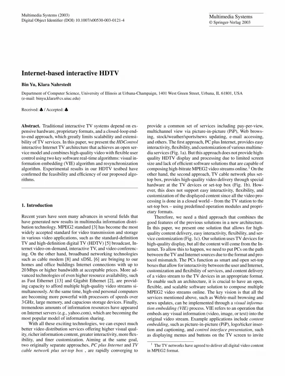
Figure 9 shows how MPEG2 transport streams manage tomaintain synchronization between the sender, which encodesthe stream, and the receiver, which decodes it.As the video andaudio data units are packetized, their target decoding times-tamp (DTS) and presentation timestamp (PTS) are determinedbased on the current sender clock and inserted into the packetheaders. For video streams, the access unit is a frame, andboth the DTS and PTS are given only for the first bit of eachframe after its picture header. These timestamps are later usedby the decoder to control the timing at which it starts to do
8 B. Yu, K. Nahrstedt: Internet-based interactive HDTV
Fig. 9. Synchronization be-tween the encoder and de-coder
PCR Packet Video Packet Non-Video Packet NULL Packet
... ...
Demultiplexing
Video Editing OperationCopyAdjustmentif needed
Multiplexing
... ...
... ...
Simple Padding
Time Invariant Bitrate Scaling with SF = 3/4
PCR TimestampsNon-Video
DataVideoFrame 1
VideoFrame 2
VideoFrame 3
...
...
...
...
Fig. 10. Demultiplexing, video editing, andmultiplexing at intermediate video editingservents
decoding and presentation. After that, as all of these pack-ets are multiplexed together, the final stream is timestampedwith synchronization points, called program clock reference(PCR), that are acquired by periodically sampling the encoderclock. This resulting transport layer stream is then sent over thenetwork to the receiver or stored in storage devices for the de-coder to read in the future. As long as the delay that the wholestream experiences remains constant from the receiver’s pointof view, the receiver should be able to reconstruct the sender’sclock that was used when the stream was encoded. The ac-curacy and stability of this recovered clock is very importantsince the decoder will try to match the PTS and DTS againstthis clock to guide its decoding and displaying activities.
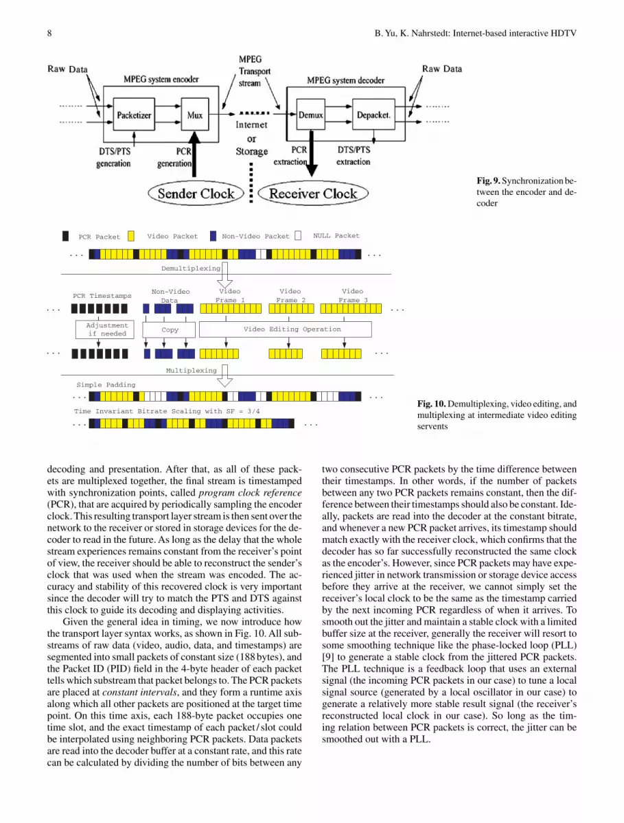
Given the general idea in timing, we now introduce howthe transport layer syntax works, as shown in Fig. 10. All sub-streams of raw data (video, audio, data, and timestamps) aresegmented into small packets of constant size (188 bytes), andthe Packet ID (PID) field in the 4-byte header of each packettells which substream that packet belongs to. The PCR packetsare placed at constant intervals, and they form a runtime axisalong which all other packets are positioned at the target timepoint. On this time axis, each 188-byte packet occupies onetime slot, and the exact timestamp of each packet / slot couldbe interpolated using neighboring PCR packets. Data packetsare read into the decoder buffer at a constant rate, and this ratecan be calculated by dividing the number of bits between any
two consecutive PCR packets by the time difference betweentheir timestamps. In other words, if the number of packetsbetween any two PCR packets remains constant, then the dif-ference between their timestamps should also be constant. Ide-ally, packets are read into the decoder at the constant bitrate,and whenever a new PCR packet arrives, its timestamp shouldmatch exactly with the receiver clock, which confirms that thedecoder has so far successfully reconstructed the same clockas the encoder’s. However, since PCR packets may have expe-rienced jitter in network transmission or storage device accessbefore they arrive at the receiver, we cannot simply set thereceiver’s local clock to be the same as the timestamp carriedby the next incoming PCR regardless of when it arrives. Tosmooth out the jitter and maintain a stable clock with a limitedbuffer size at the receiver, generally the receiver will resort tosome smoothing technique like the phase-locked loop (PLL)[9] to generate a stable clock from the jittered PCR packets.The PLL technique is a feedback loop that uses an externalsignal (the incoming PCR packets in our case) to tune a localsignal source (generated by a local oscillator in our case) togenerate a relatively more stable result signal (the receiver’sreconstructed local clock in our case). So long as the tim-ing relation between PCR packets is correct, the jitter can besmoothed out with a PLL.

B. Yu, K. Nahrstedt: Internet-based interactive HDTV 9
4.2. Resynchronization problem at video editing servents
As shown in Fig. 10, when the incoming stream arrives, thevideo editing servents demultiplex it into PCR timestamps,nonvideo data, and video frames, exercise video editing oper-ations on the video frames, and then multiplex the resultingframes with other data to form the output stream. The chal-lenge comes from the fact that the frame size will be changedby the editing operations. For example, after a VIE operationthe frame size may be larger if the embedding content is oflower compression ratio; after a low passing operation, somehigh-frequency AC coefficients will be discarded, and so theframe size will decrease. This change in frame size meansthe number of 188-byte packets used to carry data for eachframe will also be changed, and if we naively pack the result-ing packets together, the constant spacing of PCR packets willbe violated. Also, the relative position of each video / audioframe on the timeline will be changed, which will also affectthe decoding process. Therefore, the key problem is how tocorrectly and efficiently do the multiplexing after the videoediting operations at the intermediate video editing servent sothat the synchronization between the original encoder and de-coder is maintained. We call this problem the resynchroniza-tion problem. Formally, the resynchronization problem maybe described as follows:
Given the incoming MPEG2 transport stream, each packetis represented by a tuple (sequence no, frame number,type), where sequence no ≥ 0 is the packet sequencenumber, frame number ≥ 0 is the sequence numberof the video frame this packet belongs to, and type ∈[PCR,NONV IDEO, V IDEO,NULL]. As a result ofthe video editing operation, the number of packets withtype = VIDEO may increase or decrease, so the originalsequence no will not be correct. The goal is to assign a newsequence number to each packet (original nonvideo packetsand new packets from output of video editing operations), sothat the resulting stream’s PCR packets are spaced with con-stant distance and non-PCR packets are placed at the righttime point between the PCR packets.
4.3. Our solutions
To solve the resynchronization problem, an immediate solu-tion would be to do the same kind of clock reconstruction asthe decoder does at the video editing servents and then regen-erate new PCR packets to reflect the changes caused by theediting operations. The smoothing mechanisms like PLL canhelp, but they are implemented in hardware circuits containinga voltage-controlled oscillator that generates high-frequencysignals to be tuned with the incoming PCR timestamps. This ishard, if not impossible, to do in software on computers withoutreal-time support in hardware. Hence this hardware solutionis not a viable solution as our goal is to find a pure softwaresolution that would enable us to distribute video editing ser-vents across a network to any point along the streaming path.Another goal for us is to achieve a cheap and efficient solu-tion that could be easily implemented and carried out by anycomputer with modest CPU and memory resources available.
The key idea behind our solution comes from the obser-vation that the DTS and PTS are only associated with the
beginning packet of each frame. Consequently, as long as wemanage to fix that point to the correct position on the timeaxis, the decoder should work fine even if the remaining bitsof that frame following the starting point are stretched shorteror longer.
4.3.1. Simple padding
Following the discussion above, we have designed a simplesolution that works for bitrate-reducing video editing opera-tions, as shown in Fig. 10. We do not change the timestamp andthe position of any PCR packet along the time axis within thestream, and we also preserve the position of the frame headerand the beginning bit of every frame. What is changed here isthe size of each frame in terms of the number of bits, and wejust pack the resulting bits of a frame closely following thepicture header. Since each frame takes fewer packets to carry,yet the frame headers are still positioned at their original timepoints, we can imagine that there would be some white spaceleft between the last bit of one frame and the first bit of theheader of the next frame. Actually, the capacity of this space isthe same as the reduction in the number of bits used to encodethis frame as a result of the video editing operations, and wecan simply pad this space with empty (NULL) packets.
This solution is very simple to understand and implement,and it preserves synchronization since we only need to packthe filtered bits of each frame continuously after the pictureheader and then insert NULL packets until the header of thenext frame. No new timestamps need to be generated in realtime, and the bitrate remains stable at the original rate. How-ever, the solution inevitably has two drawbacks. First, it canonly handle bitrate-reducing operations. We only try to fix theheader of each frame to its original position on the time axis,which means the changed frames should not occupy morebits larger than the distance between the current frame headerand the next. This property does not always hold since somevideo editing operations like VIE and watermarking may in-crease the frame size. Second, the saved bits are padded withNULL packets to maintain the original constant bitrate andthe starting point of each frame, and this runs against the ini-tial goal of bitrate-reduction operations like low pass filteringand color/frame dropping. The resulting stream contains thesame number of packets as the original one. The only differ-ence is that the number of bits representing each frame hasbeen shrunk, yet this saving is spent immediately by paddingNULL packets at the end of each frame. Though we can com-press these extra NULL packets with a special protocol be-tween the encoder and decoder, that would no longer conformwith the standard MPEG2 transport syntax and would com-promise interoperability.
4.3.2. Time-invariant bitrate scaling
To ultimately solve the synchronization problem, a more gen-eral algorithm has been designed. The key insight behind thisalgorithm is that we can change the bitrate to another constantvalue while preserving the PCR timestamps by changing thenumber of packets between any PCR pair to another constantvalue. The ratio between the original PCR packet distance

10 B. Yu, K. Nahrstedt: Internet-based interactive HDTV
and the resulting PCR packet distance is called the scalingfactor (SF). This way, we can scale the PCR packets’ distanceand achieve a fixed new bitrate, as if the time axis is scaledlooser or tighter to carry more or less packets. Yet we do notneed to regenerate new PCR timestamps that rely on hardwarereal-time support. All nonvideo stream packets can be simplymapped to the new position on the scaled output time axis thatcorresponds to the same time point as on the original inputtime axis. If no exact mapping is available because the pack-ets are aligned at units of 188 bytes, we could simply use thenearest time point on the new time axis without introducingany serious problems. For video stream, the same kind of pic-ture header fixing and frame data packing are conducted asin the first solution but in a scaled way. In the example givenin Fig. 10, where SF is 3/4, there is one PCR packet everysix packets instead of eight packets as in the original stream,and no NULL packet is needed. Note that simple padding isthe special case where SF is 1.0. Formally, the time-invariantbitrate scaling algorithm goes as follows:
For each packet p do {let q be p’s previous packet;if (p.type is not Video ) {
p.sequence_no = floor(p.sequence_no * SF);if (p.sequence_no < q.sequence_no)
p.sequence_no = q.sequence_no + 1;} else {
let F_after be the frame after editing that pbelongs to;let F_before be the same frame before editing;if (p is the first packet of F_after) {
let q be the starting packet of F_beforep.sequence_no = q.sequence_no * SF;if (p.sequence_no < q.sequence_no)
p.sequence_no = q.sequence_no + 1;} else {
let s be p’s previous packet in F_afterp.sequence_no = s.sequence_no+1;if (p is the last packet in F_after ) {
let t be F_before’s last packetfor (i=p.sequence_no+1;i<=t.sequence_no*SF;i++)
insert a NULL packet with sequence_no i} } } }
This algorithm is also very simple to implement. For eachnonvideo packet, its distance (in number of packets) from thelast PCR packet is multiplied by a scaling factor SF , and theresult is used to set the distance between this packet and thelast PCR packet in the output stream. For video frames, theheader containing DTS and PTS is scaled and positioned inthe same way, and the remaining bits are closely appended tothe header in the result stream.
Now the only problem is how to determine SF for a spe-cific video editing operation. If we shrink the time scale toomuch and for some frames the editing does not achieve a sig-nificant bitrate reduction, then we will not have enough spaceto squeeze in this frame, which will push the beginning bitof the next frame behind schedule. On the other hand, if weshrink the time axis too little or expand (SF > 1) it too much,then more space will be padded using NULL packets to pre-serve important time points, leading to a waste of bandwidth.There exists one optimal scale factor SFopt that can balancethese two strengths if it fulfills the conditions that (1) everyresulting packet can be assigned a valid sequence no and (2)the number of NULL packets used for padding is kept to aminimum.
However, this optimal scale factor is hard to estimate in ad-vance since different operations with various parameters have
Fig. 11. An example screen shot for PiP
quite varying effects on different video clips in terms of bitratechanging. Therefore, in our current implementation, we haveadopted a two-stage approach. First, we measure offline themaximal ratio (R) in number of packets of a stream beforeand after the video editing operation for typical video streamsand operation parameters. Second, when the streaming hasstarted, we monitor online the actual ratio (AR) of changeof the number of packets (excluding NULL packets) betweeneach pair of PCR packets before and after the video editingoperation. The scaling factor is calculated using the followingformula: SFnew = α ∗ R + (1 − α)∗ (average AR over thelast N pairs of PCR packets). Note that α controls how offlineexperience determines current SFnew values, and N is thewindow size of how many previous PCR pairs will affect thecurrent SFnew value. For the decoder to reconstruct a stableclock, SF should not be changed frequently, so we only up-date SF with SFnew when their difference is larger than anempirical threshold.
5. Experimental results
5.1. HDTV testbed
Because of the limitation in full deployment of our proposedarchitecture in the wide area Internet, we have built a testbedfor HDTV streaming and editing within our department localarea network (LAN). Live high-definition digital TV streamfrom the satellite or the HD storage device is fed into the serverPC, which then encodes the HD video into MPEG2 transportstream and multicasts this stream over the high-speed LAN.Players on the user PCs join this multicast group to receive theHD stream and feed this stream into the HDFocus decodingboard [1]. The decoded analog signal is then sent to the wide-screen TV for high-quality display. Video editing gateways(servents) receive this stream in the same way as a normalplayer and perform various video editing operations on thisstream in real time, such as low pass filtering, frame / colordropping, and VIE. There can be multiple editing operationsdone to the same stream in a chain, and the resulting streamsat all stages are available to users through different multicastgroups.

B. Yu, K. Nahrstedt: Internet-based interactive HDTV 11
Table 2. Comparison of number of macroblocks that need motioncompensation
Football Stars Trees
Previous approach 1360000 1360000 1360000Our approach 139455 55509 56613
5.2. VIE results
We analyze the performance of the proposed VIE approachwith respect to aspects:
Real-time processing: The VIE service gateway runs on ageneral-purpose PC with a single Pentium IV 1.4-GHz pro-cessor and 512 MB memory. The program is written in VisualC++ and runs on Windows 2000 platform. As expected, wecan perform many VIE functions in real time, introducing anextra delay of approximately 0.5 s.After initialization, the pro-cessor utilization levels off at 70% when no other applicationsare running on the gateway machine at the same time. For thisexperiment, we have chosen the background stream to be aHD quality (1920 × 1088, 30 fps) stream “Trees1.mpg”, andthe foreground stream to be a standard resolution MPEG video“football sd.mpg” (480 × 256, 30 fps ). Figure 11 presents ascreen shot of the resulting stream. Note that the foregroundwindow can be located anywhere in the frame as long as itfollows the 16 × 16 macroblock boundaries.
Computational complexity reduction:As has been analyzedabove and was also pointed out by Chang [7], a very expensivecomputation done using Chang’s approach is the decodingof reference macroblocks from MC domain to RD domain,and our approach consists precisely in solving this problembased on the observation that normally a large portion of thesemacroblocks is not used at all.
To demonstrate this, we only need to compare the num-ber of macroblocks that are decoded to the RD domain bythe two approaches. In the approach in [7], all the mac-roblocks in all I and P frames should be counted; thus forthe “football in trees” example in Fig. 11, the total numberof macroblocks decoded to RD domain for 500 frames is1920×1088
16×16 × 515 × 500 = 1360000. On the other hand, for our
approach the total count depends upon the nature of the back-ground stream since we only work on affected macroblocks.For three different background streams, the total number ofmacroblocks reconstructed through motion compensation isgiven in Table 2.
From Table 2 we know that with our approach the most ex-pensive motion compensation operation only needs to be donefor less than10%of the previous approach, and for backgroundstreams such as stars and trees this percentage is even smaller.To further explain the saving, we have plotted out the distribu-tion of d-MBs over the whole background area. Specifically,for each MB position over the 1920
16 × 192016 = 120 × 68MB
coordinates, we counted how many times that MB is markedas a d-MB for 300 consecutive frames, and the embeddedwindow’s coordinate is [6, 4, 36, 20] (the same as illustratedin Fig. 11). As shown in Fig. 12, only MBs near the windowedge are likely to be actually decoded by the VIE process.
Fig. 12. Distribution of d-MBs
Fig. 13. pSNR of background image for 3 video clips
Resulting video quality: We will perform the image qual-ity pSNR analysis, as done in other studies such as [7]. Thequality degradation primarily comes from DCT quantization,simplified motion estimation, and some of the optimizationswe discussed. For the visual quality test, because the fore-ground video is not changed to opaque overlaying, we onlycalculate the pSNR (peak signal-to-noise, Eq. 3) values for thebackground streams:
pSNR(X,Y )
= 20log10
255√
1MN
∑Mi=1
∑Nj=1(Xij − Yij)2
. (3)
Specifically, we use a standard MPEG2 decoder to decode boththe original background streams and the resulting streams afterembedding the overlay stream to pixel domain and use theirdifference (excluding the foreground area) as the noise value.From the result shown in Fig. 13 we can see that the I framesare not affected at all, and other frames’ pSNR value changesfor different video clips: the more motions exist in the videostream, the more noise results from the VIE process.
We have also performed a thorough subjective test. Over100 viewers have seen the resulting stream of our real-timeVIE, and no perceptible quality degradation was observed.

12 B. Yu, K. Nahrstedt: Internet-based interactive HDTV
Fig. 14. Effect of time-invariant bitrate scaling
5.3. Resynchronization results
Figure 14 shows the effect of the time-invariant bitrate scal-ing approach for low pass operations with an AC coefficientthreshold of 5. Each point on the x-axis represents a PCRpacket, and the y-axis shows in three colors how many videopackets, NULL packets, or packets for other data streams arepresent in between this PCR packet and its previous PCRpacket. We can see that the distribution of the three areas iskept almost constant for the original frame except for moreNULL packets at the end of a frame. For simple padding, thenumber of video packets varies across different PCR inter-vals and a lot of extra space is padded with NULL packets, asshown in the upper right panel of the figure. On the other hand,if we do time-invariant bitrate scaling with a scaling factor of80%, then the padding occurs mostly at the end of frames andthe stream contains mostly useful data.
Despite the resynchronization process, our scaling ap-proach may still introduce a skewed starting time for someframes. The reason is that after the video editing operation,each frame shrinks to a size mostly less than 80% of its origi-nal size. If we mask out all other packets, we can see that in thevideo stream frames are packed closely one after another. Ifone frame takes more space than its share, then the next framemay be pushed behind its time point, but this skew will becompensated shortly by another frame with a stronger shrink-ing effect. As we said before, this kind of small jitter aroundthe exact time point on the scaled time axis is acceptable, andit is the change in the bitrate at which the decoder reads inthe data that fundamentally enables our algorithm to solve theproblem.
Another experiment shows how to determine the scalingfactor SF for a particular kind of video editing operation.Three kinds of operations are tested: low pass filtering (LP)with threshold of 10 and 5 andVIE for picture-in-picture (PiP).The original stream is a HD stream “stars1.mpg” with bitrate
Table 3. Proving for the scaling factor
LP (10) LP (5) PiP
Original BR (Mbps) 18.0 18.0 18.0Average resulting BR (Mbps) 15.45 13.71 19.04Average relative change 0.86 0.76 1.06Suggested SF 0.90 0.80 1.10
18 Mbps in MPEG2 transport layer format. The embeddedframe used for picture-in-picture is a scaled-down version ofanother HD stream “football1.mpg”. Since the content of thisstream is more condensed than the background stream (i.e.,more DCT coefficients are used to describe each block), it isexpected that the bitrate will increase after this VIE operation.The final statistics are shown in Table 3. Experimental resultshave shown that with the suggested scaling factor based onreal-world statistics, our time-invariant bitrate scaling algo-rithm could successfully solve the synchronization problem.
6. Conclusion and future work
Interactive Internet TV that features open standard and servicemodel, high-quality video, dynamic software real-time edit-ing, and great user customization is a very promising area, andin this paper we have presented the HDControl architectureand the corresponding service model. We have also presentedtwo key algorithms that are essential to any real-time systemsthat work on MPEG2 format content. The experimental re-sults on our local testbed have validated the efficiency andfeasibility of our approach.

B. Yu, K. Nahrstedt: Internet-based interactive HDTV 13
References
1. HDFocus: High Definition MPEG Decoding Board.http://www.visualcircuits.com/prod serv/HD.cfm
2. Gigabit Ethernet (2001) The IEEE international symposium oncircuits and systems (ISCAS 2001), tutorial guide, location, daymonth 2001, pp 9.4.1–9.4.16
3. ISO/IEC 13818 13818 (1994) Generic coding of moving picturesand associated audio information. ISO
4. Amir E, McCanne S, Katz RH (1998) An active service frame-work and its application to real-time multimedia transcoding. In:Proceedings of SIGCOMM 1998, Vancouver, British Columbia,August 1998, pp 178–189
5. Bezzan C (1990) High definition TV: its history and perspective.Proceedings of the SBT/IEEE international telecommunicationssymposium (ITS ’90), Rio de Janeiro, September 1990
6. Bhagavath VK (1999) Emerging high-speed xDSL access ser-vices: architectures, issues, insights, and implications IEEECommun Mag 37(11):106–114
7. Chang SF, Messerschmitt DG (1995) Manipulation and com-positing of MC-DCT compressed video. IEEE J Select AreasCommun 13(1):1–11
8. Dutta-Roy A (2001) An overview of cable modem technologyand market perspectives. IEEE Commun Mag 39(6):81–88
9. Holborow CE (1994) Simulation of phase-locked loopfor processing jittered PCRs. ISO/IEC JTC1/SC29/WG11,MPEG94/071, March 1994
10. Nang SHJ, Kwon O (2000) Caption processing for MPEG videoin MC-DCT compressed domain. In: Proceedings of the 8thACM Multimedia, Los Angeles, October 2000
11. Zhang LJ, Chung JY, Liu LK, Lipscomb JS, Zhou Q (2002) Anintegrated live interactive content insertion system for digital TVcommerce. In: Proceedings of the international symposium onmultimedia software engineering, Newport Beach, CA, Decem-ber 2002
12. Meng J, Chang SF (1998) Embedding visible watermark in com-pressed video stream. In: Proceedings of the 1998 internationalconference on image processing (ICIP’98), Chicago, October1998
13. Spragins J (1996) Fast Ethernet: dawn of a new network. IEEENetw 10(2):4
14. Yu B, Nahrstedt K (2002) A compressed-domain visual infor-mation embedding algorithm for MPEG2 HDTV streams. In:Proceedings of the international conference on multimedia andexpo, Newport Beach, CA December, 2002