plasma tv - hdtv solutions.com
TRANSCRIPT
PLASMA TVOWNER’S MANUAL
Please read this manual carefully and completely beforeoperating your TV. Retain this manual for future reference.Record model number and serial number of the TV in thespaces provided below. See the label attached on the back cover and relate thisinformation to your dealer if you require service.
Model Number : Serial Number :
MODELS: RU-42PZ61/71RU-50PZ61RU-60PZ61
LG Electronics U.S.A., Inc.
2 Plasma TV
Warning
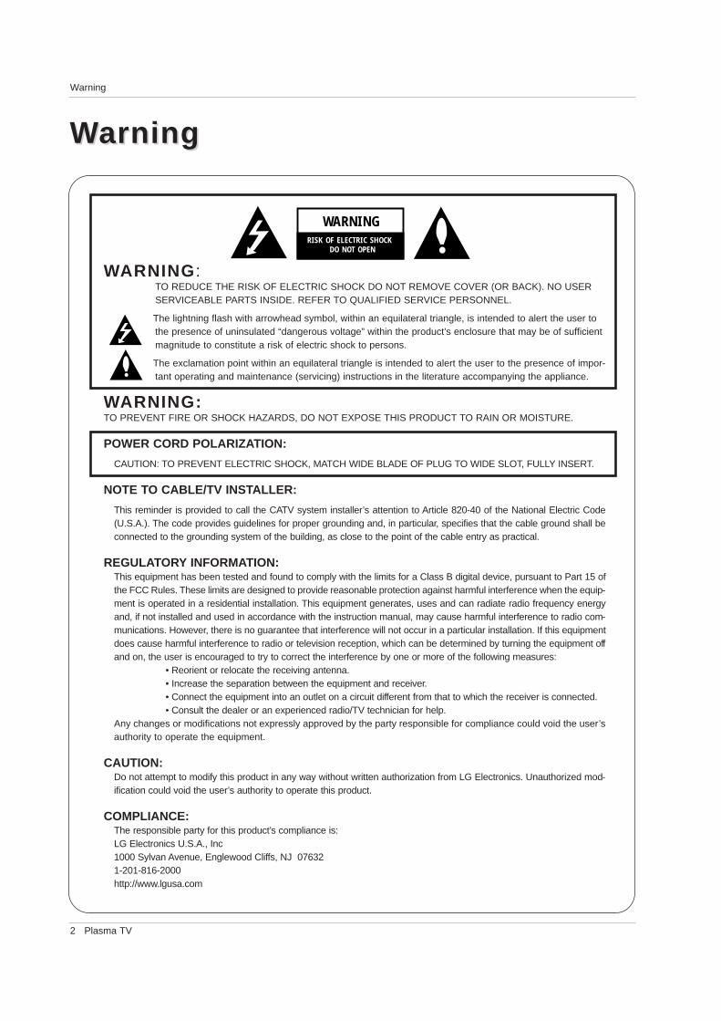
WARNING:TO REDUCE THE RISK OF ELECTRIC SHOCK DO NOT REMOVE COVER (OR BACK). NO USERSERVICEABLE PARTS INSIDE. REFER TO QUALIFIED SERVICE PERSONNEL.
The lightning flash with arrowhead symbol, within an equilateral triangle, is intended to alert the user tothe presence of uninsulated “dangerous voltage” within the product’s enclosure that may be of sufficientmagnitude to constitute a risk of electric shock to persons.
The exclamation point within an equilateral triangle is intended to alert the user to the presence of impor-tant operating and maintenance (servicing) instructions in the literature accompanying the appliance.
WARNING:TO PREVENT FIRE OR SHOCK HAZARDS, DO NOT EXPOSE THIS PRODUCT TO RAIN OR MOISTURE.
POWER CORD POLARIZATION:
CAUTION: TO PREVENT ELECTRIC SHOCK, MATCH WIDE BLADE OF PLUG TO WIDE SLOT, FULLY INSERT.
NOTE TO CABLE/TV INSTALLER:
This reminder is provided to call the CATV system installer’s attention to Article 820-40 of the National Electric Code(U.S.A.). The code provides guidelines for proper grounding and, in particular, specifies that the cable ground shall beconnected to the grounding system of the building, as close to the point of the cable entry as practical.
REGULATORY INFORMATION:This equipment has been tested and found to comply with the limits for a Class B digital device, pursuant to Part 15 ofthe FCC Rules. These limits are designed to provide reasonable protection against harmful interference when the equip-ment is operated in a residential installation. This equipment generates, uses and can radiate radio frequency energyand, if not installed and used in accordance with the instruction manual, may cause harmful interference to radio com-munications. However, there is no guarantee that interference will not occur in a particular installation. If this equipmentdoes cause harmful interference to radio or television reception, which can be determined by turning the equipment offand on, the user is encouraged to try to correct the interference by one or more of the following measures:
• Reorient or relocate the receiving antenna.• Increase the separation between the equipment and receiver.• Connect the equipment into an outlet on a circuit different from that to which the receiver is connected.• Consult the dealer or an experienced radio/TV technician for help.
Any changes or modifications not expressly approved by the party responsible for compliance could void the user’sauthority to operate the equipment.
CAUTION:Do not attempt to modify this product in any way without written authorization from LG Electronics. Unauthorized mod-ification could void the user’s authority to operate this product.
COMPLIANCE:The responsible party for this product’s compliance is:LG Electronics U.S.A., Inc1000 Sylvan Avenue, Englewood Cliffs, NJ 076321-201-816-2000http://www.lgusa.com
WARNINGRISK OF ELECTRIC SHOCK DO NOT OPEN
WWarningarning
Owner’s Manual 3
Safety Instructions
Important safeguards for you and your new product
Your product has been manufactured and tested with your safety in mind. However, improper use can result in electricalshock or fire hazards. To avoid defeating the safeguards that have been built into your new product, please read and observethe following safety points when installing and using your new product, and save them for future reference.
Observing the simple precautions discussed in this manual can help you get many years of enjoyment and safe operationthat are built into your new product.
This product complies with all applicable U.S. Federal safety requirements, and those of the Canadian Standards Association.
1. Read InstructionsAll the safety and operating instructions should be readbefore the product is operated.
2. Follow InstructionsAll operating and use instructions should be followed.
3. Retain InstructionsThe safety and operating instructions should be retained forfuture reference.
4. Heed WarningsAll warnings on the product and in the operating instructionsshould be adhered to.
5. CleaningUnplug this product from the wall outlet before cleaning. Donot use liquid cleaners or aerosol cleaners. Use a dampcloth for cleaning.
6. Water and MoistureDo not use this product near water, for example, near a bathtub, wash bowl, kitchen sink, or laundry tub, in a wet base-ment, or near a swimming pool.
7. Accessories, Carts, and StandsDo not place this product on a slippery or tilted surface, or onan unstable cart, stand, tripod, bracket, or table. The productmay slide or fall, causing serious injury to a child or adult,and serious damage to the product. Use only with a cart,stand, tripod, bracket, or table recommended by the manu-facturer, or sold with the product. Any mounting of the prod-uct should follow the manufacturer’s instructions, and shoulduse a mounting accessory recommended by the manufac-turer.
8. Transporting ProductA product and cart combination should be moved with care.Quick stops, excessive force, and uneven surfaces maycause the product and cart combination to overturn.
9. AttachmentsDo not use attachments not recommended by the productmanufacturer as they may cause hazards.
10. VentilationSlots and openings in the cabinet are provided for ventilationand to ensure reliable operation of the product and to protectit from overheating, and these openings must not be blockedor covered. The openings should never be blocked by plac-ing the product on a bed, sofa, rug, or other similar surface.This product should not be placed in a built-in installationsuch as a bookcase or rack unless proper ventilation is pro-vided or the manufacturer’s instructions have been adheredto.
11. Power SourcesThis product should be operated only from the type of powersource indicated on the marking label. If you are not sure ofthe type of power supply to your home, consult your productdealer or local power company. For products intended tooperate from battery power, or other sources, refer to theoperating instructions.
12. Power-Cord PolarizationThis product is equipped with a three-wire grounding typeplug, a plug having a third (grounding) pin. This plug will onlyfit into the grounding-type power outlet. This is a safety fea-ture. If you are unable to insert the plug into the outlet, con-tact your electrician to replace your obsolete outlet. Do notdefeat the safety purpose of the grounding-type plug.
13. Power-Cord ProtectionPower-supply cords should be routed so that they are notlikely to be walked on or pinched by items placed upon oragainst them, paying particular attention to cords at plugs,convenience receptacles, and the point where they exit fromthe product.
PORTABLE CART WARNING
Safety InstructionsSafety Instructions
4 Plasma TV
Safety Instructions
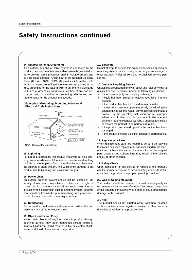
Antenna Lead in Wire
Antenna Discharge Unit(NEC Section 810-20)
Grounding Conductor(NEC Section 810-21)
Ground Clamps
Power Service GroundingElectrode System (NECArt 250, Part H)
Ground Clamp
Electric ServiceEquipment
Example of Grounding According to NationalElectrical Code Instructions
NEC - National Electrical Code
14. Outdoor Antenna GroundingIf an outside antenna or cable system is connected to theproduct, be sure the antenna or cable system is grounded soas to provide some protection against voltage surges andbuilt-up static charges. Article 810 of the National ElectricalCode (U.S.A.), ANSI/ NFPA 70 provides information withregard to proper grounding of the mast and supporting struc-ture, grounding of the lead-in wire to an antenna dischargeunit, size of grounding conductors, location of antenna-dis-charge unit, connection to grounding electrodes, andrequirements for the grounding electrode.
15. Lightning For added protection for this product (receiver) during a light-ning storm, or when it is left unattended and unused for longperiods of time, unplug it from the wall outlet and disconnectthe antenna or cable system. This will prevent damage to theproduct due to lightning and power-line surges.
16. Power LinesAn outside antenna system should not be located in thevicinity of overhead power lines or other electric light orpower circuits, or where it can fall into such power lines orcircuits. When installing an outside antenna system, extremecare should be taken to keep from touching such power linesor circuits as contact with them might be fatal.
17. OverloadingDo not overload wall outlets and extension cords as this canresult in a risk of fire or electric shock.
18. Object and Liquid EntryNever push objects of any kind into this product throughopenings as they may touch dangerous voltage points orshort-out parts that could result in a fire or electric shock.Never spill liquid of any kind on the product.
19. ServicingDo not attempt to service this product yourself as opening orremoving covers may expose you to dangerous voltage orother hazards. Refer all servicing to qualified service per-sonnel.
20. Damage Requiring ServiceUnplug this product from the wall outlet and refer servicing toqualified service personnel under the following conditions:a. If the power-supply cord or plug is damaged.b. If liquid has been spilled, or objects have fallen into the
product.c. If the product has been exposed to rain or water.d. If the product does not operate normally by following the
operating instructions. Adjust only those controls that arecovered by the operating instructions as an improperadjustment of other controls may result in damage andwill often require extensive work by a qualified technicianto restore the product to its normal operation.
e. If the product has been dropped or the cabinet has beendamaged.
f. If the product exhibits a distinct change in performance.
21. Replacement PartsWhen replacement parts are required, be sure the servicetechnician has used replacement parts specified by the man-ufacturer or have the same characteristics as the originalpart. Unauthorized substitutions may result in fire, electricshock, or other hazards.
22. Safety CheckUpon completion of any service or repairs to this product,ask the service technician to perform safety checks to deter-mine that the product is in proper operating condition.
23. Wall or Ceiling MountingThe product should be mounted to a wall or ceiling only asrecommended by the manufacturer. The product may slideor fall, causing serious injury to a child or adult, and seriousdamage to the product.
24. HeatThe product should be situated away from heat sourcessuch as radiators, heat registers, stoves, or other products(including amplifiers) that produce heat.
Safety Instructions continuedSafety Instructions continued
Owner’s Manual 5
Introduction
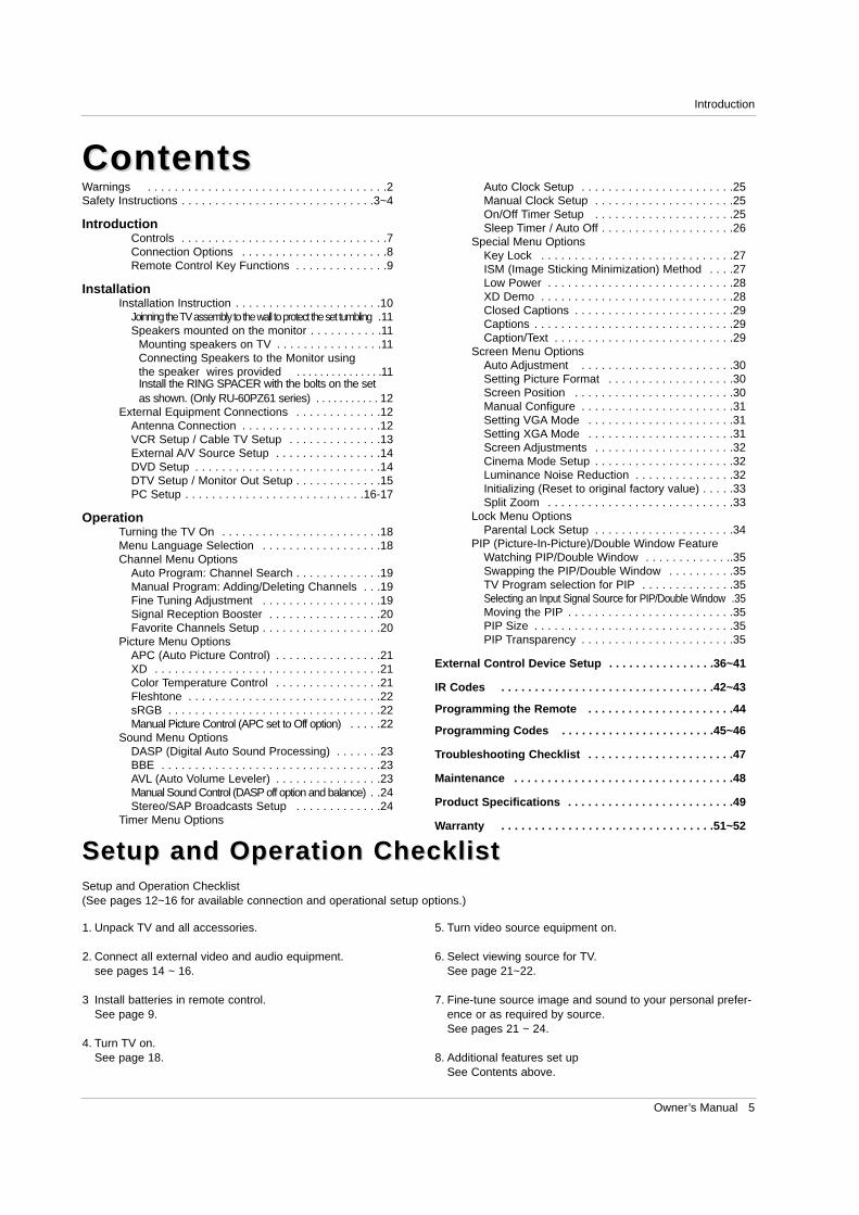
ContentsContentsWarnings . . . . . . . . . . . . . . . . . . . . . . . . . . . . . . . . . . . .2Safety Instructions . . . . . . . . . . . . . . . . . . . . . . . . . . . . .3~4
IntroductionControls . . . . . . . . . . . . . . . . . . . . . . . . . . . . . . .7Connection Options . . . . . . . . . . . . . . . . . . . . . .8Remote Control Key Functions . . . . . . . . . . . . . .9
InstallationInstallation Instruction . . . . . . . . . . . . . . . . . . . . . .10
Joinning the TV assembly to the wall to protect the set tumbling .11Speakers mounted on the monitor . . . . . . . . . . .11
Mounting speakers on TV . . . . . . . . . . . . . . . .11Connecting Speakers to the Monitor usingthe speaker wires provided . . . . . . . . . . . . . . .11Install the RING SPACER with the bolts on the set as shown. (Only RU-60PZ61 series) . . . . . . . . . . . 12
External Equipment Connections . . . . . . . . . . . . .12Antenna Connection . . . . . . . . . . . . . . . . . . . . .12VCR Setup / Cable TV Setup . . . . . . . . . . . . . .13External A/V Source Setup . . . . . . . . . . . . . . . .14DVD Setup . . . . . . . . . . . . . . . . . . . . . . . . . . . .14DTV Setup / Monitor Out Setup . . . . . . . . . . . . .15PC Setup . . . . . . . . . . . . . . . . . . . . . . . . . . .16-17
OperationTurning the TV On . . . . . . . . . . . . . . . . . . . . . . . .18Menu Language Selection . . . . . . . . . . . . . . . . . .18Channel Menu Options
Auto Program: Channel Search . . . . . . . . . . . . .19Manual Program: Adding/Deleting Channels . . .19Fine Tuning Adjustment . . . . . . . . . . . . . . . . . .19Signal Reception Booster . . . . . . . . . . . . . . . . .20Favorite Channels Setup . . . . . . . . . . . . . . . . . .20
Picture Menu OptionsAPC (Auto Picture Control) . . . . . . . . . . . . . . . .21XD . . . . . . . . . . . . . . . . . . . . . . . . . . . . . . . . . .21Color Temperature Control . . . . . . . . . . . . . . . .21Fleshtone . . . . . . . . . . . . . . . . . . . . . . . . . . . . .22sRGB . . . . . . . . . . . . . . . . . . . . . . . . . . . . . . . .22Manual Picture Control (APC set to Off option) . . . . .22
Sound Menu OptionsDASP (Digital Auto Sound Processing) . . . . . . .23BBE . . . . . . . . . . . . . . . . . . . . . . . . . . . . . . . . .23AVL (Auto Volume Leveler) . . . . . . . . . . . . . . . .23Manual Sound Control (DASP off option and balance) . .24Stereo/SAP Broadcasts Setup . . . . . . . . . . . . .24
Timer Menu Options
Auto Clock Setup . . . . . . . . . . . . . . . . . . . . . . .25Manual Clock Setup . . . . . . . . . . . . . . . . . . . . .25On/Off Timer Setup . . . . . . . . . . . . . . . . . . . . .25Sleep Timer / Auto Off . . . . . . . . . . . . . . . . . . . .26
Special Menu OptionsKey Lock . . . . . . . . . . . . . . . . . . . . . . . . . . . . .27ISM (Image Sticking Minimization) Method . . . .27Low Power . . . . . . . . . . . . . . . . . . . . . . . . . . . .28XD Demo . . . . . . . . . . . . . . . . . . . . . . . . . . . . .28Closed Captions . . . . . . . . . . . . . . . . . . . . . . . .29Captions . . . . . . . . . . . . . . . . . . . . . . . . . . . . . .29Caption/Text . . . . . . . . . . . . . . . . . . . . . . . . . . .29
Screen Menu Options Auto Adjustment . . . . . . . . . . . . . . . . . . . . . . .30Setting Picture Format . . . . . . . . . . . . . . . . . . .30Screen Position . . . . . . . . . . . . . . . . . . . . . . . .30Manual Configure . . . . . . . . . . . . . . . . . . . . . . .31Setting VGA Mode . . . . . . . . . . . . . . . . . . . . . .31Setting XGA Mode . . . . . . . . . . . . . . . . . . . . . .31Screen Adjustments . . . . . . . . . . . . . . . . . . . . .32Cinema Mode Setup . . . . . . . . . . . . . . . . . . . . .32Luminance Noise Reduction . . . . . . . . . . . . . . .32Initializing (Reset to original factory value) . . . . .33Split Zoom . . . . . . . . . . . . . . . . . . . . . . . . . . . .33
Lock Menu OptionsParental Lock Setup . . . . . . . . . . . . . . . . . . . . .34
PIP (Picture-In-Picture)/Double Window FeatureWatching PIP/Double Window . . . . . . . . . . . . ..35Swapping the PIP/Double Window . . . . . . . . . .35TV Program selection for PIP . . . . . . . . . . . . . .35Selecting an Input Signal Source for PIP/Double Window .35Moving the PIP . . . . . . . . . . . . . . . . . . . . . . . . .35PIP Size . . . . . . . . . . . . . . . . . . . . . . . . . . . . . .35PIP Transparency . . . . . . . . . . . . . . . . . . . . . . .35
External Control Device Setup . . . . . . . . . . . . . . . .36~41
IR Codes . . . . . . . . . . . . . . . . . . . . . . . . . . . . . . . .42~43
Programming the Remote . . . . . . . . . . . . . . . . . . . . . .44
Programming Codes . . . . . . . . . . . . . . . . . . . . . . .45~46
Troubleshooting Checklist . . . . . . . . . . . . . . . . . . . . . .47
Maintenance . . . . . . . . . . . . . . . . . . . . . . . . . . . . . . . . .48
Product Specifications . . . . . . . . . . . . . . . . . . . . . . . . .49
Warranty . . . . . . . . . . . . . . . . . . . . . . . . . . . . . . . .51~52
Setup and Operation ChecklistSetup and Operation ChecklistSetup and Operation Checklist(See pages 12~16 for available connection and operational setup options.)
1. Unpack TV and all accessories.
2. Connect all external video and audio equipment.see pages 14 ~ 16.
3 Install batteries in remote control.See page 9.
4. Turn TV on.See page 18.
5. Turn video source equipment on.
6. Select viewing source for TV.See page 21~22.
7. Fine-tune source image and sound to your personal prefer-ence or as required by source. See pages 21 ~ 24.
8. Additional features set upSee Contents above.
6 Plasma TV
Introduction
IntroductionIntroduction
What is a Plasma Display Panel (PDP)?A plasma display panel is the latest display technology. It is currently the best way to achieve flat panel displays with excellentimage quality and large screen sizes, that are easily viewable. The PDP can be thought of as a descendant of the neon lamp andit can be also be viewed as a series of fluorescent lamps.
How does it work?PDP is an array of cells, known as pixels, which are comprised of 3 sub pixels, corresponding to the colors red, green, and blue.Gas in a plasma state is used to react with phosphors in each sub-pixel to produce colored light (red, green, or blue). These phos-phors are the same types used in Cathode Ray Tube (CRT) devices such as televisions and common computer monitors.
You get the rich, dynamic colors that you expect. Each sub-pixel is individually controlled by advanced electronics to produce over16 million different colors. All of this means that you get perfect images that are easily viewable in a display that is less than 5inches thick.
160° - Wide angle range of visionYour flat panel plasma screen offers an exceptionally broad viewing angle -- over 160 degrees. This means that the display isclear and visible to viewers anywhere in the room who can see the screen.
Wide ScreenThe screen of the Plasma Display is so wide that your viewing experience is as if you are in a theater.
MultimediaConnect your plasma display to a PC and you can use it for conferencing, games, and Internet browsing. The Picture-in-Picturefeature allows you to view your PC and video images simultaneously.
VersatileThe light weight and thin size makes it easy to install your plasma display in a variety of locations where conventional TVs will notfit.
The PDP Manufacturing Process: a few minute colored dots may be present on the PDP screenThe PDP (Plasma Display Panel), which is the display device of this product is composed of 0.9 to 2.2 million cells. A few celldefects will normally occur in the PDP manufacturing process. Several tiny, minute colored dots visible on the screen should beacceptable. This also occurs in other PDP manufacturers' products. The tiny dots appearing does not mean that this PDP is defec-tive. Thus a few cell defects are not sufficient cause for the PDP to be exchanged or returned. Our production technology mini-mizes these cell defects during the manufacture and operation of this product.
In the same way that a fan is used in a PC computer to keep the CPU (Central Processing Unit) cool, the PDP is equipped withcooling fans to cool the Monitor and improve its reliability. Therefore, a certain level of noise could occur while the fans are operat-ing and cooling the PDP.The fan noise doesn't have any negative effect on the PDP's efficiency or reliability. The noise from these fans is normal during theoperation of this product. We hope you understand that a certain level of noise from the cooling fans is acceptable and is not suffi-cient cause for the PDP to be exchanged or returned.
S-VIDEO VIDEO AUDIOL/MONO R TV/VIDEO MENU VOL CHON/OFF
FRONT A/V INPUT R
TruSurround XTruSurround XT
ON/OFFS-VIDEO VIDEO AUDIOL/MONO R
ON/OFFS-VIDEO VIDEO AUDIOL/MONO R
FRONT A/V INPUT
FRONT A/V INPUT
TV/VIDEO MENU VOL CHR
TruSurround XTruSurround XT
TV/VIDEO MENU VOL CHR
TruSurround XTruSurround XT
Owner’s Manual 7
Introduction
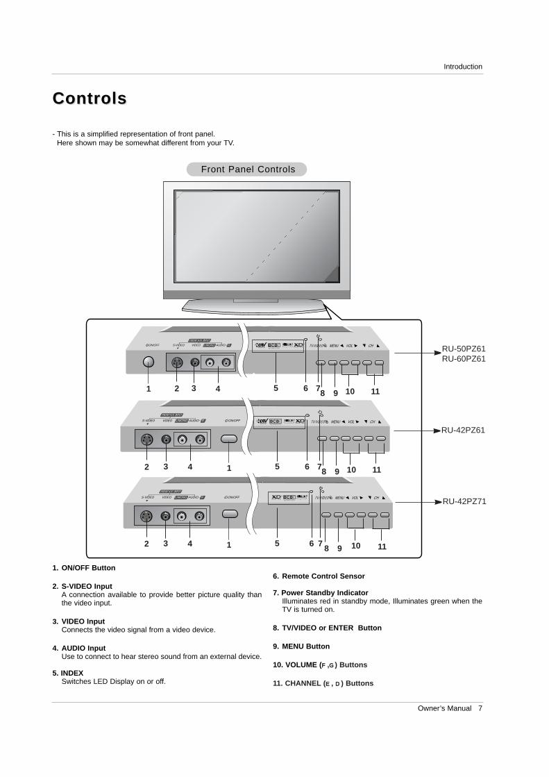
ControlsControls
- This is a simplified representation of front panel. Here shown may be somewhat different from your TV.
Front Panel ControlsFront Panel Controls
1. ON/OFF Button
2. S-VIDEO InputA connection available to provide better picture quality thanthe video input.
3. VIDEO InputConnects the video signal from a video device.
4. AUDIO InputUse to connect to hear stereo sound from an external device.
5. INDEXSwitches LED Display on or off.
6. Remote Control Sensor
7. Power Standby IndicatorIlluminates red in standby mode, Illuminates green when theTV is turned on.
8. TV/VIDEO or ENTER Button
9. MENU Button
10. VOLUME (F,G) Buttons
11. CHANNEL (E, D) Buttons
51 2 3 4 6 8 9 10 117
512 3 4 6 8 9 10 117
512 3 4 6 8 9 10 117
RU-50PZ61RU-60PZ61
RU-42PZ61
RU-42PZ71
8 Plasma TV
Introduction
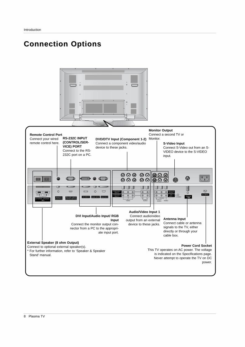
Connection OptionsConnection Options
RGB INPUTAntenna
AUDIO INPUTDVI INPUTREMOTECONTROL
AC INPUTR
EXTERNAL SPEAKER
R L
RS-232C INPUT(CONTROL/SERVICE)
S-VIDEO
AUDIOVIDEO
COMPONENTINPUT 2
COMPONENTINPUT 1
MONITOROUTPUT
A/VINPUT 1
(R) (L)
AUDIO VIDEO
(L/MONO)(R)
DVI Input/Audio Input/ RGBInput
Connect the monitor output con-nector from a PC to the appropri-
ate input port.
Remote Control PortConnect your wiredremote control here.
External Speaker (8 ohm Output)Connect to optional external speaker(s).* For further information, refer to ‘Speaker & Speaker
Stand’ manual.
RS-232C INPUT(CONTROL/SER-VICE) PORTConnect to the RS-232C port on a PC.
DVD/DTV Input (Component 1-2)Connect a component video/audiodevice to these jacks.
Audio/Video Input 1Connect audio/video
output from an externaldevice to these jacks.
Monitor OutputConnect a second TV orMonitor.
S-Video InputConnect S-Video out from an S-VIDEO device to the S-VIDEOinput.
Antenna InputConnect cable or antennasignals to the TV, eitherdirectly or through yourcable box.
Power Cord SocketThis TV operates on AC power. The voltage
is indicated on the Specifications page.Never attempt to operate the TV on DC
power.
Owner’s Manual 9
Introduction
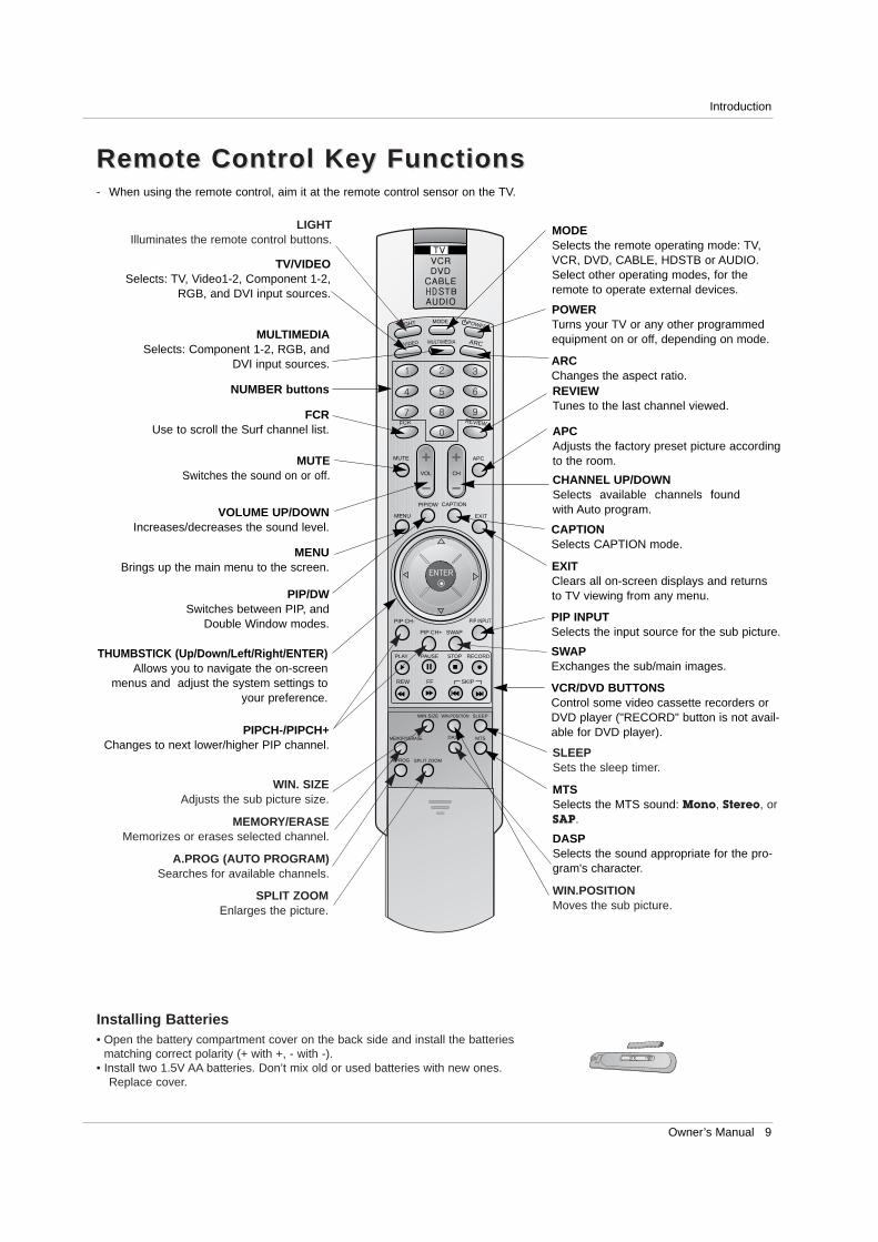
- When using the remote control, aim it at the remote control sensor on the TV.
TV/VIDEO MULTIMEDIA
MODE
ARC
APC
VOL CH
MENU
PIP/DW CAPTION
EXIT
PIP CH-
PIP CH+ SWAP
PIP INPUT
PLAY PAUSE STOP RECORD
WIN.SIZE WIN.POSITION SLEEP
A.PROG
ENTER
MTSMEMORY/ERASE
SPLIT ZOOM
REW FF SKIP
REVIEW
LIGHT POWER
FCR
MUTE
DASP
HD
TV/VIDEOSelects: TV, Video1-2, Component 1-2,
RGB, and DVI input sources.
MULTIMEDIASelects: Component 1-2, RGB, and
DVI input sources. ARCChanges the aspect ratio.
NUMBER buttons
FCRUse to scroll the Surf channel list. APC
Adjusts the factory preset picture accordingto the room.
VCR/DVD BUTTONSControl some video cassette recorders orDVD player ("RECORD" button is not avail-able for DVD player).
CAPTIONSelects CAPTION mode.
MODESelects the remote operating mode: TV,VCR, DVD, CABLE, HDSTB or AUDIO.Select other operating modes, for theremote to operate external devices.
POWERTurns your TV or any other programmedequipment on or off, depending on mode.
MUTESwitches the sound on or off.
DASPSelects the sound appropriate for the pro-gram's character.
EXITClears all on-screen displays and returnsto TV viewing from any menu.
REVIEWTunes to the last channel viewed.
THUMBSTICK (Up/Down/Left/Right/ENTER)Allows you to navigate the on-screen
menus and adjust the system settings toyour preference.
CHANNEL UP/DOWNSelects available channels foundwith Auto program.
PIP INPUTSelects the input source for the sub picture.
SWAPExchanges the sub/main images.
VOLUME UP/DOWNIncreases/decreases the sound level.
PIP/DWSwitches between PIP, and
Double Window modes.
PIPCH-/PIPCH+Changes to next lower/higher PIP channel.
MENUBrings up the main menu to the screen.
MTSSelects the MTS sound: Mono, Stereo, orSAP.
WIN.POSITIONMoves the sub picture.
SLEEPSets the sleep timer.
MEMORY/ERASEMemorizes or erases selected channel.
A.PROG (AUTO PROGRAM)Searches for available channels.
SPLIT ZOOMEnlarges the picture.
Installing Batteries• Open the battery compartment cover on the back side and install the batteries
matching correct polarity (+ with +, - with -).• Install two 1.5V AA batteries. Don’t mix old or used batteries with new ones.
Replace cover.
Remote Control Key FunctionsRemote Control Key Functions
WIN. SIZEAdjusts the sub picture size.
LIGHTIlluminates the remote control buttons.
10 Plasma TV
Installation
InstallationInstallation
Installation InstructionsInstallation InstructionsGROUNDING
Ensure that you connect the grounding / earth wire to prevent possibleelectric shock. If grounding methods are not possible, have a qualifiedelectrician install a separate circuit breaker. Do not try to ground theunit by connecting it to telephone wires, lightening rods, or gas pipes.
PowerSupply
Short-circuitBreaker
Owner’s Manual
1.5V1.5V
BatteriesPower Cord
TV/VIDEOMULTIMEDIA
MODE
ARC
APC
VOL
CHMENU PIP/DWCAPTION
EXIT
PIP CH-
PIP CH+SWAP
PIP INPUT
PLAY
PAUSESTOP
RECORD
WIN.SIZEWIN.POSITION
SLEEP
A.PROG
ENTER
MTS
MEMORY/ERASE
SPLIT ZOOM
REW
FF
SKIP
REVIEW
LIGHT
POW
ER
FCR
MUTE
DASP
HD
Remote Control
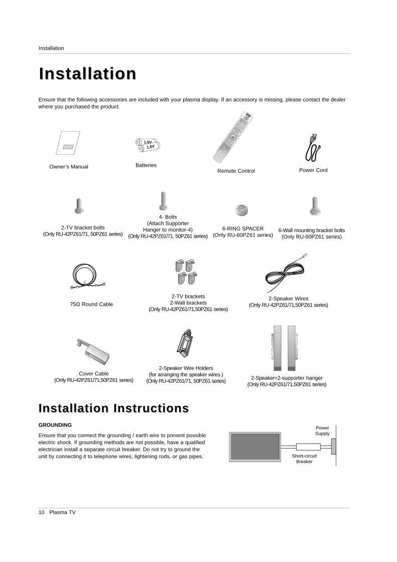
Ensure that the following accessories are included with your plasma display. If an accessory is missing, please contact the dealerwhere you purchased the product.
75Ω Round Cable
2-TV brackets2-Wall brackets
(Only RU-42PZ61/71,50PZ61 series)
2-TV bracket bolts(Only RU-42PZ61/71, 50PZ61 series)
Cover Cable(Only RU-42PZ61/71,50PZ61 series)
2-Speaker Wires(Only RU-42PZ61/71,50PZ61 series)
4- Bolts (Attach Supporter
Hanger to monitor-4)(Only RU-42PZ61/71, 50PZ61 series)
2-Speaker Wire Holders (for arranging the speaker wires.)
(Only RU-42PZ61/71, 50PZ61 series) 2-Speaker+2-supporter hanger(Only RU-42PZ61/71,50PZ61 series)
6-RING SPACER(Only RU-60PZ61 series)
6-Wall mounting bracket bolts(Only RU-60PZ61 series)
Owner’s Manual 11
Installation
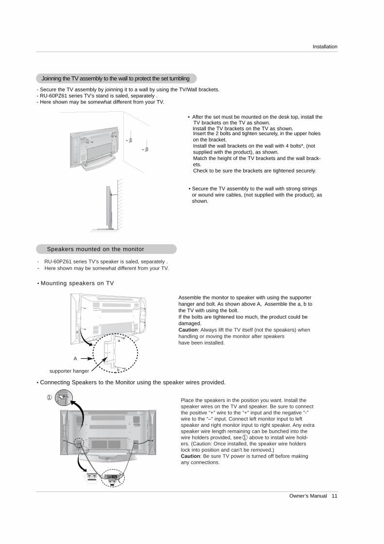
- Secure the TV assembly by joinning it to a wall by using the TV/Wall brackets.- RU-60PZ61 series TV’s stand is saled, separately .- Here shown may be somewhat different from your TV.
Joinning the TV assembly to the wall to protect the set tumbling
• After the set must be mounted on the desk top, install theTV brackets on the TV as shown.Install the TV brackets on the TV as shown.Insert the 2 bolts and tighten securely, in the upper holeson the bracket. Install the wall brackets on the wall with 4 bolts*, (notsupplied with the product), as shown.Match the height of the TV brackets and the wall brack-ets. Check to be sure the brackets are tightened securely.
• Secure the TV assembly to the wall with strong stringsor wound wire cables, (not supplied with the product), asshown.
Speakers mounted on the monitorSpeakers mounted on the monitor
Assemble the monitor to speaker with using the supporterhanger and bolt. As shown above A, Assemble the a, b tothe TV with using the bolt.If the bolts are tightened too much, the product could bedamaged.Caution: Always lift the TV itself (not the speakers) whenhandling or moving the monitor after speakershave been installed.
Place the speakers in the position you want. Install thespeaker wires on the TV and speaker. Be sure to connectthe positive “+” wire to the “+” input and the negative “-”wire to the “–” input. Connect left monitor input to leftspeaker and right monitor input to right speaker. Any extraspeaker wire length remaining can be bunched into thewire holders provided, see 1 above to install wire hold-ers. (Caution: Once installed, the speaker wire holderslock into position and can’t be removed.)Caution: Be sure TV power is turned off before makingany connections.
- RU-60PZ61 series TV’s speaker is saled, separately .- Here shown may be somewhat different from your TV.
• Mounting speakers on Mounting speakers on TVTV
• Connecting Speakers to the Monitor using the speaker wires provided.Connecting Speakers to the Monitor using the speaker wires provided.
A
supporter hanger
a
b
1
12 Plasma TV
Installation
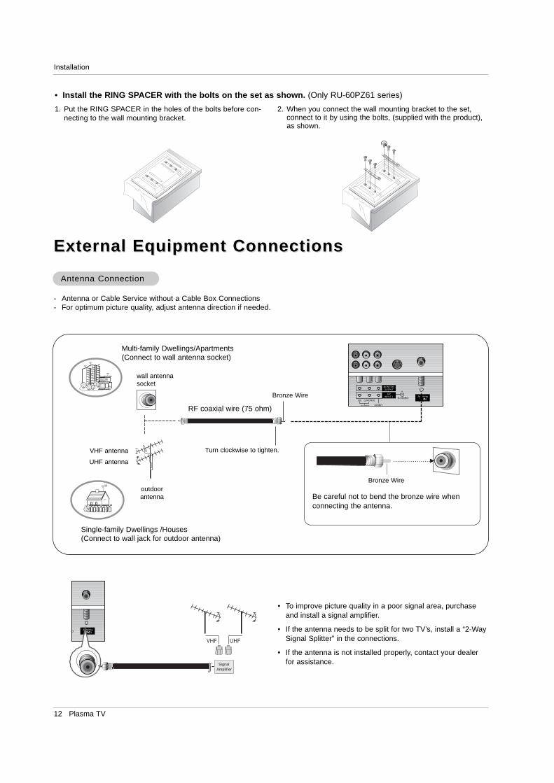
- Antenna or Cable Service without a Cable Box Connections- For optimum picture quality, adjust antenna direction if needed.
External Equipment ConnectionsExternal Equipment Connections
Antenna ConnectionAntenna Connection
• To improve picture quality in a poor signal area, purchaseand install a signal amplifier.
• If the antenna needs to be split for two TV’s, install a “2-WaySignal Splitter” in the connections.
• If the antenna is not installed properly, contact your dealerfor assistance.
AntennaO
SignalAmplifier
AntennaS-VIDEO
MONITOROUTPUT
A/VINPUT 1
AUDIO VIDEO
(L/MONO)(R)
Multi-family Dwellings/Apartments(Connect to wall antenna socket)
Single-family Dwellings /Houses(Connect to wall jack for outdoor antenna)
outdoorantenna
wall antennasocket
VHF antenna
UHF antenna
RF coaxial wire (75 ohm)
Bronze Wire
Turn clockwise to tighten.
Bronze Wire
Be careful not to bend the bronze wire whenconnecting the antenna.
1. Put the RING SPACER in the holes of the bolts before con-necting to the wall mounting bracket.
2. When you connect the wall mounting bracket to the set,connect to it by using the bolts, (supplied with the product),as shown.
• Install the RING SPACER with the bolts on the set as shown. (Only RU-60PZ61 series)
Owner’s Manual 13
Installation
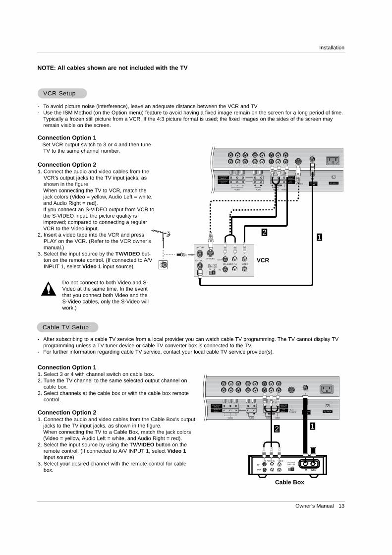
NOTE: All cables shown are not included with the TV
- To avoid picture noise (interference), leave an adequate distance between the VCR and TV- Use the ISM Method (on the Option menu) feature to avoid having a fixed image remain on the screen for a long period of time.
Typically a frozen still picture from a VCR. If the 4:3 picture format is used; the fixed images on the sides of the screen mayremain visible on the screen.
Connection Option 1Set VCR output switch to 3 or 4 and then tuneTV to the same channel number.
Connection Option 21. Connect the audio and video cables from the
VCR's output jacks to the TV input jacks, asshown in the figure. When connecting the TV to VCR, match thejack colors (Video = yellow, Audio Left = white,and Audio Right = red).If you connect an S-VIDEO output from VCR tothe S-VIDEO input, the picture quality isimproved; compared to connecting a regularVCR to the Video input.
2. Insert a video tape into the VCR and pressPLAY on the VCR. (Refer to the VCR owner’smanual.)
3. Select the input source by the TV/VIDEO but-ton on the remote control. (If connected to A/VINPUT 1, select Video 1 input source)
Do not connect to both Video and S-Video at the same time. In the eventthat you connect both Video and theS-Video cables, only the S-Video willwork.)
VCR SetupVCR Setup
AntennaS-VIDEO AC INPUT
AUDIOVIDEO
COMPONENTINPUT 2
COMPONENTINPUT 1
MONITOROUTPUT
A/VINPUT 1
R L
AUDIO VIDEO
R L/MONO
S-VIDEO OUT
IN
(R) AUDIO (L) VIDEO
3 4
OUTPUTSWITCH
ANT OUT
ANT IN
- After subscribing to a cable TV service from a local provider you can watch cable TV programming. The TV cannot display TVprogramming unless a TV tuner device or cable TV converter box is connected to the TV.
- For further information regarding cable TV service, contact your local cable TV service provider(s).
Connection Option 11. Select 3 or 4 with channel switch on cable box.2. Tune the TV channel to the same selected output channel on
cable box.3. Select channels at the cable box or with the cable box remote
control.
Connection Option 21. Connect the audio and video cables from the Cable Box's output
jacks to the TV input jacks, as shown in the figure. When connecting the TV to a Cable Box, match the jack colors(Video = yellow, Audio Left = white, and Audio Right = red).
2. Select the input source by using the TV/VIDEO button on theremote control. (If connected to A/V INPUT 1, select Video 1input source)
3. Select your desired channel with the remote control for cablebox.
Cable Cable TV SetupTV Setup
AntennaS-VIDEO AC INPUT
AUDIOVIDEO
COMPONENTINPUT 2
COMPONENTINPUT 1
MONITOROUTPUT
A/VINPUT 1
R L
AUDIO VIDEO
R L/MONO
TV
VCR RF Cable
(R) AUDIO (L) VIDEO
3 4
OUTPUTSWITCH
VCR
Cable Box
12
12
14 Plasma TV
Installation
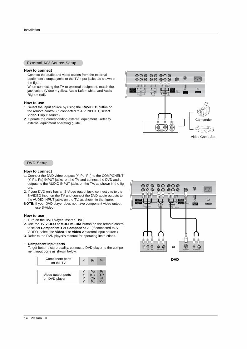
• Component Input portsTo get better picture quality, connect a DVD player to the compo-nent input ports as shown below.
How to connectConnect the audio and video cables from the externalequipment's output jacks to the TV input jacks, as shown inthe figure. When connecting the TV to external equipment, match thejack colors (Video = yellow, Audio Left = white, and AudioRight = red).
How to use1. Select the input source by using the TV/VIDEO button on
the remote control. (If connected to A/V INPUT 1, selectVideo 1 input source).
2. Operate the corresponding external equipment. Refer toexternal equipment operating guide.
Component ports on the TV
Y PB PR
Video output ports on DVD player
YYYY
PbB-YCbPB
PrR-YCrPR
How to connect1. Connect the DVD video outputs (Y, PB, PR) to the COMPONENT
(Y, PB, PR) INPUT jacks on the TV and connect the DVD audiooutputs to the AUDIO INPUT jacks on the TV, as shown in the fig-ure.
2. If your DVD only has an S-Video output jack, connect this to theS-VIDEO input on the TV and connect the DVD audio outputs tothe AUDIO INPUT jacks on the TV, as shown in the figure.
NOTE: If your DVD player does not have component video output,use S-Video.
How to use1. Turn on the DVD player, insert a DVD.2. Use the TV/VIDEO or MULTIMEDIA button on the remote control
to select Component 1 or Component 2. (If connected to S-VIDEO, select the Video 1 or Video 2 external input source.)
3. Refer to the DVD player's manual for operating instructions.
External External A/V Source SetupA/V Source Setup
DVD SetupDVD Setup
AntennaS-VIDEO AC INPUT
AUDIOVIDEO
COMPONENTINPUT 2
COMPONENTINPUT 1
MONITOROUTPUT
A/VINPUT 1
R L
AUDIO VIDEO
R L/MONO
R LAUDIO VIDEO
AntennaS-VIDEO AC INPUT
AUDIOVIDEO
COMPONENTINPUT 2
COMPONENTINPUT 1
MONITOROUTPUT
A/VINPUT 1
R L
AUDIO VIDEO
R L/MONO
B R (R) AUDIO (L) (R) AUDIO (L)S-VIDEO
DVD
or
Camcorder
Video Game Set
Owner’s Manual 15
Installation
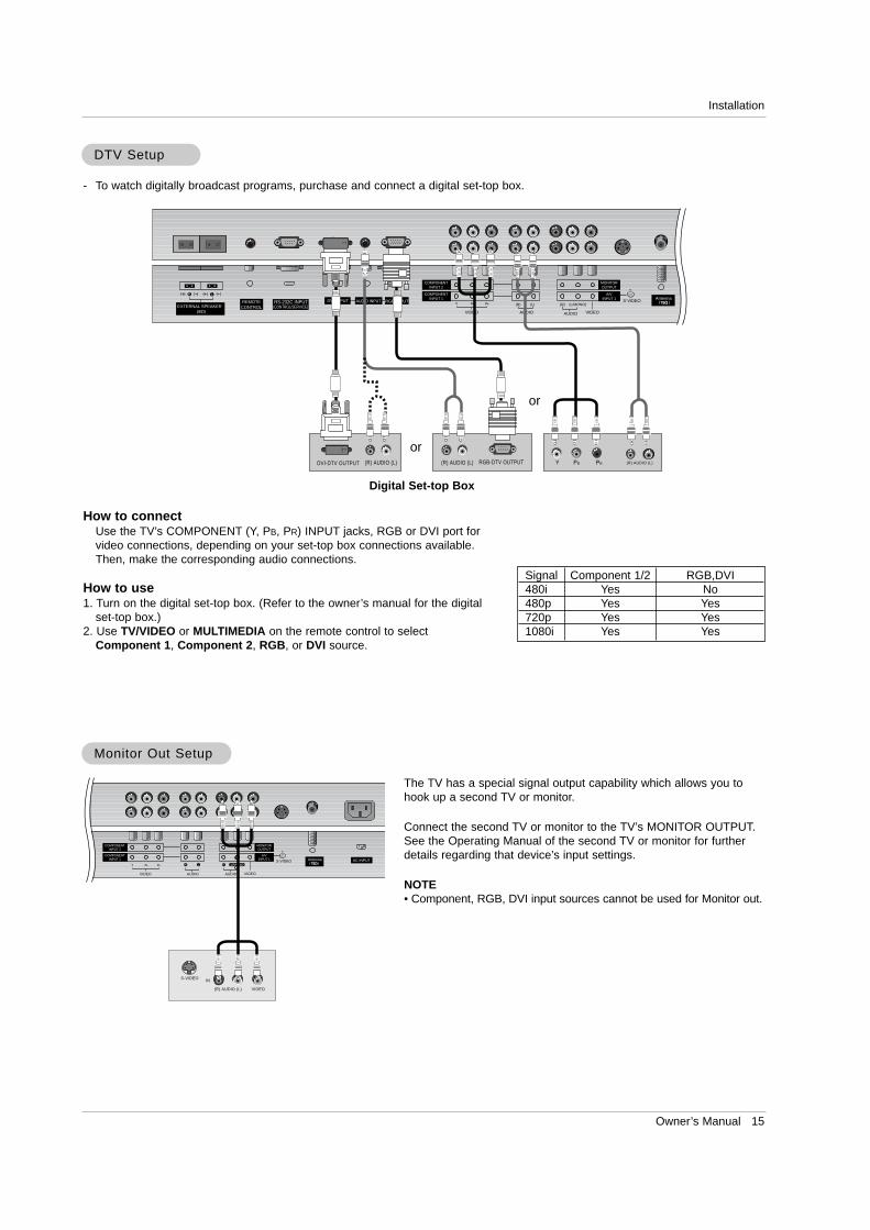
How to connectUse the TV’s COMPONENT (Y, PB, PR) INPUT jacks, RGB or DVI port forvideo connections, depending on your set-top box connections available.Then, make the corresponding audio connections.
How to use1. Turn on the digital set-top box. (Refer to the owner’s manual for the digital
set-top box.) 2. Use TV/VIDEO or MULTIMEDIA on the remote control to select
Component 1, Component 2, RGB, or DVI source.
- To watch digitally broadcast programs, purchase and connect a digital set-top box.
DTV SetupDTV Setup
RGB INPUTAntenna
AUDIO INPUTDVI INPUTREMOTECONTROL
R
EXTERNAL SPEAKER
R L
RS-232C INPUT(CONTROL/SERVICE)
S-VIDEO
AUDIOVIDEO
COMPONENTINPUT 2
COMPONENTINPUT 1
MONITOROUTPUT
A/VINPUT 1
(R) (L)
AUDIO VIDEO
(L/MONO)(R)
B R (R) AUDIO (L)(R) AUDIO (L) RGB-DTV OUTPUT(R) AUDIO (L)DVI-DTV OUTPUT
Digital Set-top Box
or
or
Signal480i480p720p1080i
Component 1/2YesYesYesYes
RGB,DVINoYesYesYes
The TV has a special signal output capability which allows you tohook up a second TV or monitor.
Connect the second TV or monitor to the TV’s MONITOR OUTPUT.See the Operating Manual of the second TV or monitor for furtherdetails regarding that device’s input settings.
NOTE• Component, RGB, DVI input sources cannot be used for Monitor out.
AntennaS-VIDEO AC INPUT
AUDIOVIDEO
COMPONENTINPUT 2
COMPONENTINPUT 1
MONITOROUTPUT
A/VINPUT 1
R L
AUDIO VIDEO
R L/MONO
S-VIDEO IN
(R) AUDIO (L) VIDEO
Monitor Out SetupMonitor Out Setup
16 Plasma TV
Operation
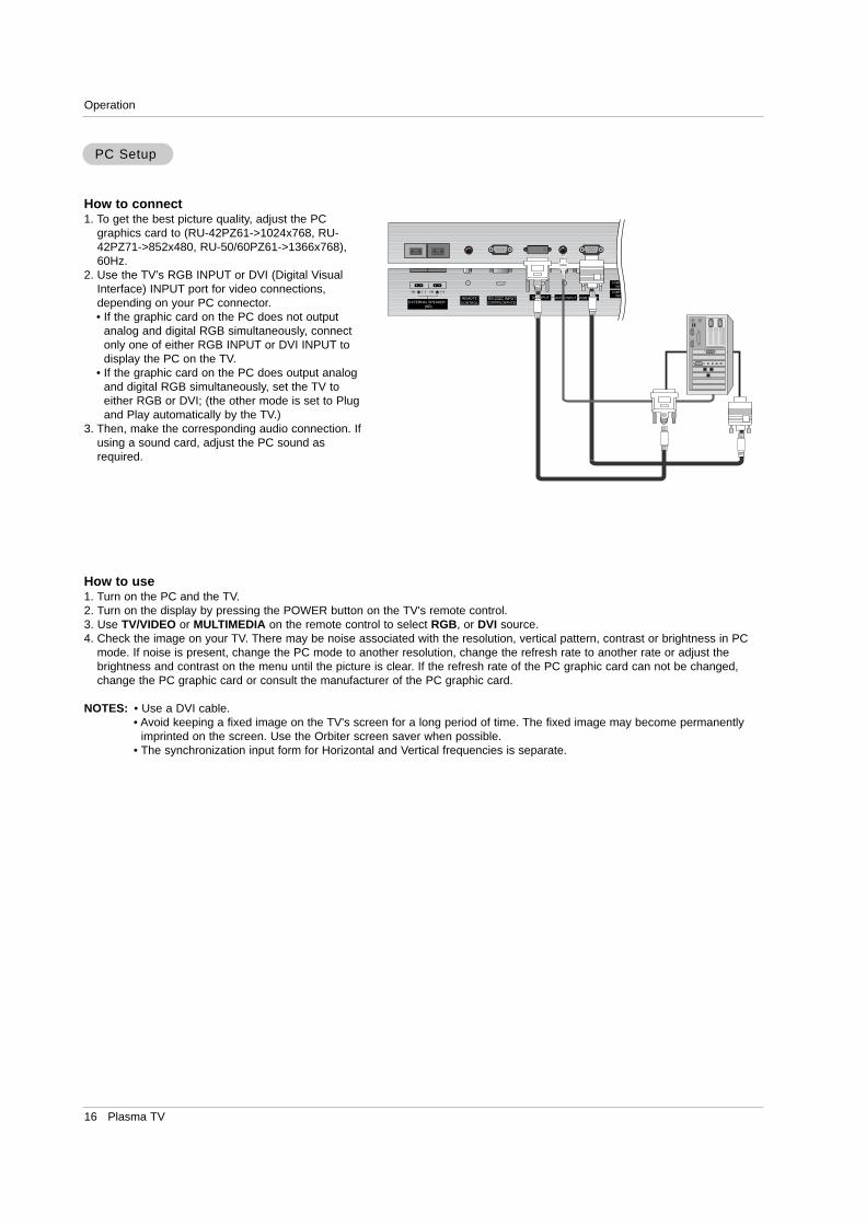
How to connect1. To get the best picture quality, adjust the PC
graphics card to (RU-42PZ61->1024x768, RU-42PZ71->852x480, RU-50/60PZ61->1366x768),60Hz.
2. Use the TV’s RGB INPUT or DVI (Digital VisualInterface) INPUT port for video connections,depending on your PC connector. • If the graphic card on the PC does not output
analog and digital RGB simultaneously, connectonly one of either RGB INPUT or DVI INPUT todisplay the PC on the TV.
• If the graphic card on the PC does output analogand digital RGB simultaneously, set the TV toeither RGB or DVI; (the other mode is set to Plugand Play automatically by the TV.)
3. Then, make the corresponding audio connection. Ifusing a sound card, adjust the PC sound asrequired.
How to use1. Turn on the PC and the TV.2. Turn on the display by pressing the POWER button on the TV's remote control.3. Use TV/VIDEO or MULTIMEDIA on the remote control to select RGB, or DVI source.4. Check the image on your TV. There may be noise associated with the resolution, vertical pattern, contrast or brightness in PC
mode. If noise is present, change the PC mode to another resolution, change the refresh rate to another rate or adjust thebrightness and contrast on the menu until the picture is clear. If the refresh rate of the PC graphic card can not be changed,change the PC graphic card or consult the manufacturer of the PC graphic card.
NOTES: • Use a DVI cable.• Avoid keeping a fixed image on the TV's screen for a long period of time. The fixed image may become permanently
imprinted on the screen. Use the Orbiter screen saver when possible.• The synchronization input form for Horizontal and Vertical frequencies is separate.
PC SetupPC Setup
RGB INPUTAUDIO INPUTDVI INPUTREMOTECONTROL
R
EXTERNAL SPEAKER
R L
RS-232C INPUT(CONTROL/SERVICE)
AUDIOVIDEO
COMPONENTINPUT 2
COMPONENTINPUT 1
MONIOUT
A/INPU
(R) (L)
AUDIO VIDEO
(L/MONO)(R)
Owner’s Manual 17
Operation
48.363
56.476
60.023
68.677
47.700
59.625
47.700
59.625
54.348
63.995
67.500
77.487
68.681
47,693
60.0911
68.504
60.023
63.981
Resolution
640x350
720x400
640x480
848x480
HorizontalFrequency(KHz)
VerticalFrequency(Hz)
852x480
31.468
37.861
31.469
37.927
31.469
35.000
37.861
37.500
43.269
31.500
37.799
39.375
31.500
37.799
39.375
70.09
85.08
70.08
85.03
59.94
66.66
72.80
75.00
85.00
60.00
70.00
75.00
60.00
70.00
75.00
800x600
832x624
1024x768
1152x864(RGB)
1152x870(RGB)
1280x1024(RGB)
60.00
70.06
75.02
85.00
60.00
75.02
60.00
75.02
60.05
70.01
75.00
85.00
75.06
59.922
74.926
84.887
60.02
60.02
1280x960(RGB)
RGB / DVI Mode
35.156
37.879
48.077
46.875
53.674
49.725
56.25
60.31
72.18
75.00
85.06
74.55
1360x768(XGA)
1366x768(XGA)
1280x768(XGA)
48.363
56.476
60.023
68.677
47.700
59.625
68.500
47.700
59.625
69.500
54.348
63.995
67.500
77.487
68.681
47,693
60.0911
68.504
60.023
63.981
Resolution
640x350
720x400
640x480
848x480
HorizontalFrequency(KHz)
VerticalFrequency(Hz)
852x480
31.468
37.861
31.469
37.927
31.469
35.000
37.861
37.500
43.269
31.500
37.799
39.375
31.500
37.799
39.375
70.09
85.08
70.08
85.03
59.94
66.66
72.80
75.00
85.00
60.00
70.00
75.00
60.00
70.00
75.00
800x600
832x624
1024x768
1152x864(RGB)
1152x870(RGB)
1280x1024(RGB)
60.00
70.06
75.02
85.00
60.00
75.02
85.00
60.00
75.02
85.00
60.05
70.01
75.00
85.00
75.06
59.922
74.926
84.887
60.02
60.02
1280x960(RGB)
RGB / DVI Mode
35.156
37.879
48.077
46.875
53.674
49.725
56.25(RGB)
60.31
72.18
75.00
85.06
74.55
1360x768
1366x768
RU-42PZ61/71
RU-50/60PZ61
Displayable Monitor Specifications
1280x768
18 Plasma TV
Operation
OperationOperation
- The menus can be shown on the screen in the selected language. First select your language.
1. Press the MENU button and then use D / E button to select the SPECIAL menu.
2. Press the G button and then use D / E button to select Language.
3. Press the G button and then use D / E button to select your desired language.From this point on, the on-screen menus will be shown in the language of yourchoice.
4. Press the ENTER button to save.
Menu Language SelectionMenu Language Selection
TTurning the TV Onurning the TV On
Turning on the TV just after installation
Turning on the TV (power cord is still connected)
1. Connect power cord correctly.
2. Press the ON/OFF button on the TV. At this moment, the TV is switched to standby mode. Pressthe TV/VIDEO, CH (D / E) button on the TV or press the POWER, TV/VIDEO, MULTIMEDIA,Number (0 ~ 9) button on the remote control and then the TV will turn on.
• Press the ON/OFF button on the TV to turn the TV on.
1. If the TV was turned off with the ON/OFF button on the TV
2. If the TV was turned off with the remote control and then the ON/OFF button on the TV
• Press the ON/OFF button on the TV and then press the TV/VIDEO, CH (D / E) button on the TV orpress the POWER, TV/VIDEO, MULTIMEDIA, Number (0 ~ 9) button on the remote control to turnthe TV on.
NOTE• If you intend to be away on vacation, disconnect the power plug from the wall power outlet.
* In this manual, the OSD (On Screen Display) may be different from your TV’s because it is just anexample to help you with the TV operation.
Owner’s Manual 19
Operation
- You can add or delete channels from the channel scan manually.
1. Use the D / E or NUMBER buttons to select the channel number you want to add or delete.
2. Press the MEMORY/ERASE button.
3. Use the MEMORY/ERASE button to select Memory or Erase.
4. Press the ENTER button.
• You can also do Manual program with the CHANNEL menu.
Manual Program: Manual Program: Adding/Deleting ChannelsAdding/Deleting Channels
1. Press the A.PROG button and then press the G button.AUTO PROGRAM starts the channel search.If you want to stop auto programming, press the ENTER button. Only the chan-nels found up to at that time are memorized.• You can also select the Auto program option and do a channel search in
the CHANNEL menu.
Auto Program: Channel SearchAuto Program: Channel Search
Auto Program should be used to memorize all the active channels in your area before you are able to use the TV.There are two ways of storing channels in the TV's memory. You can use either.One is called AUTO PROGRAM and the other is called MANUAL PROGRAM.In AUTO PROGRAM mode, the TV will memorize the channels in ascending numerical order. If there are additional channels youwant to add or delete, you can manually add or delete those channels with Manual Program.
- Redo Auto Program if the Plasma Display is ever moved to another location.- Auto Program will search for channels only through the ANT IN jack.- If channels numbers for broadcast over-the air TV and cable TV are duplicated
where different channels have the same number, press the same number but-tons again to toggle between:
(For example, press 17 to go to the channel, press 17 again to go to the dupli-cated channel.)
Broadcast TV Channels Cable TV Channels
Channel Menu OptionsChannel Menu Options
- Use this function to correct the picture's instability and condition if it ispoor.
Notes• To remove fine tuning from a channel, reprogram the finely-tuned channel with
Auto program or Manual Program.• If a finely-tuned channel is memorized, the color of the channel number changes
to yellow.
1. Press the MENU button and then use D / E button to select the CHANNEL menu.
2. Press the G button and then use D / E button to select Manual program.
3. Press the G button and then use D / E button to select Fine.
4. Use the F / G button to adjust the picture to your preference.
5. Press the ENTER button to save.
Fine Fine TTuning uning AdjustmentAdjustment
CHANNEL
PICTURE
SOUND
TIMER
SPECIAL
SCREEN
PIP/DW
LOCK Prev.Menu
To startAuto program G
Manual program
Favorite channel
CHANNEL
PICTURE
SOUND
TIMER
SPECIAL
SCREEN
PIP/DW
LOCK Prev.Menu
TV 2
Memory On
Fine 0
Booster Off
Auto program
Manual program G
Favorite channel
20 Plasma TV
Operation
- Favorite Channels is a convenient feature that lets you quickly scan up to 8 channels of your choice withouthaving to wait for the TV to scan through all the in-between channels.
1. Press the MENU button and then use D / E button to select the CHANNEL menu.
2. Press the G button and then use D / E button to select Favorite channel.
3. Press the G button and then use D / E button to select the first favorite channelposition.
4. Use the F / G button to set the desired channel number for first favorite channel.
5. Repeat steps 3 to 4 to memorize other favorite channels.
6. Press the ENTER button to save.
• To tune to a favorite channel, press the FCR (Favorite Channel Review) but-ton repeatedly. The eight favorite channels appear on the screen in numericalorder.
Favorite Channels SetupFavorite Channels Setup
- If TV signal reception is poor because you are in a fringe area, set Booster to On.If the picture condition is good, set Booster to Off.
- Adjustments for one channel don’t affect the adjustment for other channels. Set booster to on or off for each channel separately.
1. Press the MENU button and then use D / E button to select the CHANNEL menu.
2. Press the G button and then use D / E button to select Manual program.
3. Press the G button and then use D / E button to select Booster.
4. Use F / G button to select On or Off.5. Press the ENTER button to save.
Signal Reception BoosterSignal Reception Booster
CHANNEL
PICTURE
SOUND
TIMER
SPECIAL
SCREEN
PIP/DW
LOCK Prev.Menu
- - - - - - - -
- - - - - - - -
- - - - - - - -
- - - - - - - -
- - - - - - - -
- - - - - - - -
- - - - - - - -
- - - - - - - -
Auto program
Manual program
Favorite channel G
CHANNEL
PICTURE
SOUND
TIMER
SPECIAL
SCREEN
PIP/DW
LOCK Prev.Menu
TV 2
Memory On
Fine 0
Booster Off
Auto program
Manual program G
Favorite channel
Channel Menu Options continuedChannel Menu Options continued
Owner’s Manual 21
Operation
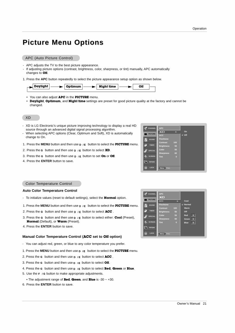
- XD is LG Electronic’s unique picture improving technology to display a real HDsource through an advanced digital signal processing algorithm.
- When selecting APC options (Clear, Optimum and Soft), XD is automaticallychange to On.
1. Press the MENU button and then use D / E button to select the PICTURE menu.
2. Press the G button and then use D / E button to select XD.
3. Press the G button and then use D / E button to set On or Off.4. Press the ENTER button to save.
XDXD
1. Press the APC button repeatedly to select the picture appearance setup option as shown below.
APC (Auto Picture Control)APC (Auto Picture Control)
• You can also adjust APC in the PICTURE menu. • Daylight, Optimum, and Night time settings are preset for good picture quality at the factory and cannot be
changed.
Daylight Optimum Night time Off
- APC adjusts the TV to the best picture appearance. - If adjusting picture options (contrast, brightness, color, sharpness, or tint) manually, APC automatically
changes to Off.
Auto Color Temperature Control
- To initialize values (reset to default settings), select the Normal option.
1. Press the MENU button and then use D / E button to select the PICTURE menu.
2. Press the G button and then use D / E button to select ACC .
3. Press the G button and then use D / E button to select either: Cool (Preset),Normal (Default), or Warm (Preset).
4. Press the ENTER button to save.
Color Color TTemperature Controlemperature Control
Manual Color Temperature Control (ACC set to Off option)
- You can adjust red, green, or blue to any color temperature you prefer.
1. Press the MENU button and then use D / E button to select the PICTURE menu.
2. Press the G button and then use D / E button to select ACC .
3. Press the G button and then use D / E button to select Off.
4. Press the G button and then use D / E button to select Red, Green or Blue.
5. Use the F / G button to make appropriate adjustments.
• The adjustment range of Red, Green, and Blue is -30 ~ +30.
6. Press the ENTER button to save.
Picture Menu OptionsPicture Menu Options
CHANNEL
PICTURE
SOUND
TIMER
SPECIAL
SCREEN
PIP/DW
LOCK Prev.Menu
Cool
Normal
Warm
Off
Red 0
Green 0
Blue 0
APC
ACC G
Fleshtone
Contrast 100
Brightness 55
Color 55
Sharpness 60
Tint 0
CHANNEL
PICTURE
SOUND
TIMER
SPECIAL
SCREEN
PIP/DW
LOCK Prev.Menu
On
Off
APC
G
ACC
Fleshtone
Contrast 100
Brightness 55
Color 55
Sharpness 60
Tint 0
22 Plasma TV
Operation
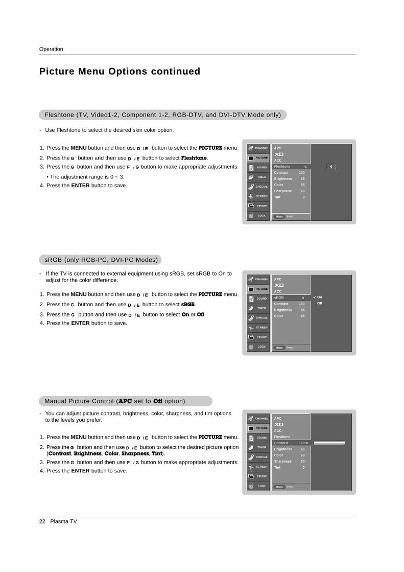
- You can adjust picture contrast, brightness, color, sharpness, and tint optionsto the levels you prefer.
1. Press the MENU button and then use D / E button to select the PICTURE menu.
2. Press the G button and then use D / E button to select the desired picture option(Contrast, Brightness, Color, Sharpness, Tint).
3. Press the G button and then use F / G button to make appropriate adjustments.
4. Press the ENTER button to save.
Manual Picture Control (Manual Picture Control (APC set to set to Off option)option)
- If the TV is connected to external equipment using sRGB, set sRGB to On toadjust for the color difference.
1. Press the MENU button and then use D / E button to select the PICTURE menu.
2. Press the G button and then use D / E button to select sRGB.
3. Press the G button and then use D / E button to select On or Off.4. Press the ENTER button to save.
sRGB (only RGB-PC, DVI-PC Modes)sRGB (only RGB-PC, DVI-PC Modes)
- Use Fleshtone to select the desired skin color option.
1. Press the MENU button and then use D / E button to select the PICTURE menu.
2. Press the G button and then use D / E button to select Fleshtone.
3. Press the G button and then use F / G button to make appropriate adjustments.
• The adjustment range is 0 ~ 3.
4. Press the ENTER button to save.
Fleshtone (TVFleshtone (TV, V, Video1-2, Component 1-2, RGB-DTVideo1-2, Component 1-2, RGB-DTV, and DVI-DTV Mode only), and DVI-DTV Mode only)
CHANNEL
PICTURE
SOUND
TIMER
SPECIAL
SCREEN
PIP/DW
LOCK Prev.Menu
0
APC
ACC
Fleshtone G
Contrast 100
Brightness 55
Color 55
Sharpness 60
Tint 0
CHANNEL
PICTURE
SOUND
TIMER
SPECIAL
SCREEN
PIP/DW
LOCK Prev.Menu
APC
ACC
Fleshtone
Contrast 100 G
Brightness 60
Color 50
Sharpness 50
Tint 0
CHANNEL
PICTURE
SOUND
TIMER
SPECIAL
SCREEN
PIP/DW
LOCK Prev.Menu
On
Off
APC
ACC
sRGB G
Contrast 100
Brightness 55
Color 55
Picture Menu Options continuedPicture Menu Options continued

Owner’s Manual 23
Operation
1. Press the DASP button repeatedly to select the appropriate sound setup as shown below.
DASPDASP (Digital (Digital Auto Sound Processing)Auto Sound Processing)
• You can also adjust DASP in the SOUND menu.• SRS TSXT, Flat, Music, Movie, and Sports are preset for good sound quality at the factory and cannot be changed.• is a trademark of SRS Labs, Inc.
• TruSurround XT technology is incorporated under license from SRS Labs, Inc.
Flat Music Movie Sports OffSRS TSXT
- This function lets you enjoy the best sound without any special adjustment because the TV has the appropriatesound options based on the program content.
- If you adjust sound options (Treble and Bass) manually, DASP automatically changes to Off.
- AVL maintains an equal sound level; even if you change channels.
1. Press the MENU button and then use D / E button to select the SOUND menu.
2. Press the G button and then use D / E button to select AVL.
3. Press the G button and then use D / E button to select On or Off.4. Press the ENTER button to save.
AAVLVL (Auto V(Auto Volume Leveler)olume Leveler)
Sound Menu OptionsSound Menu Options
CHANNEL
PICTURE
SOUND
TIMER
SPECIAL
SCREEN
PIP/DW
LOCK Prev.Menu
On
Off
DASP
BBE
AVL G
Balance 0
Treble 50
Bass 50
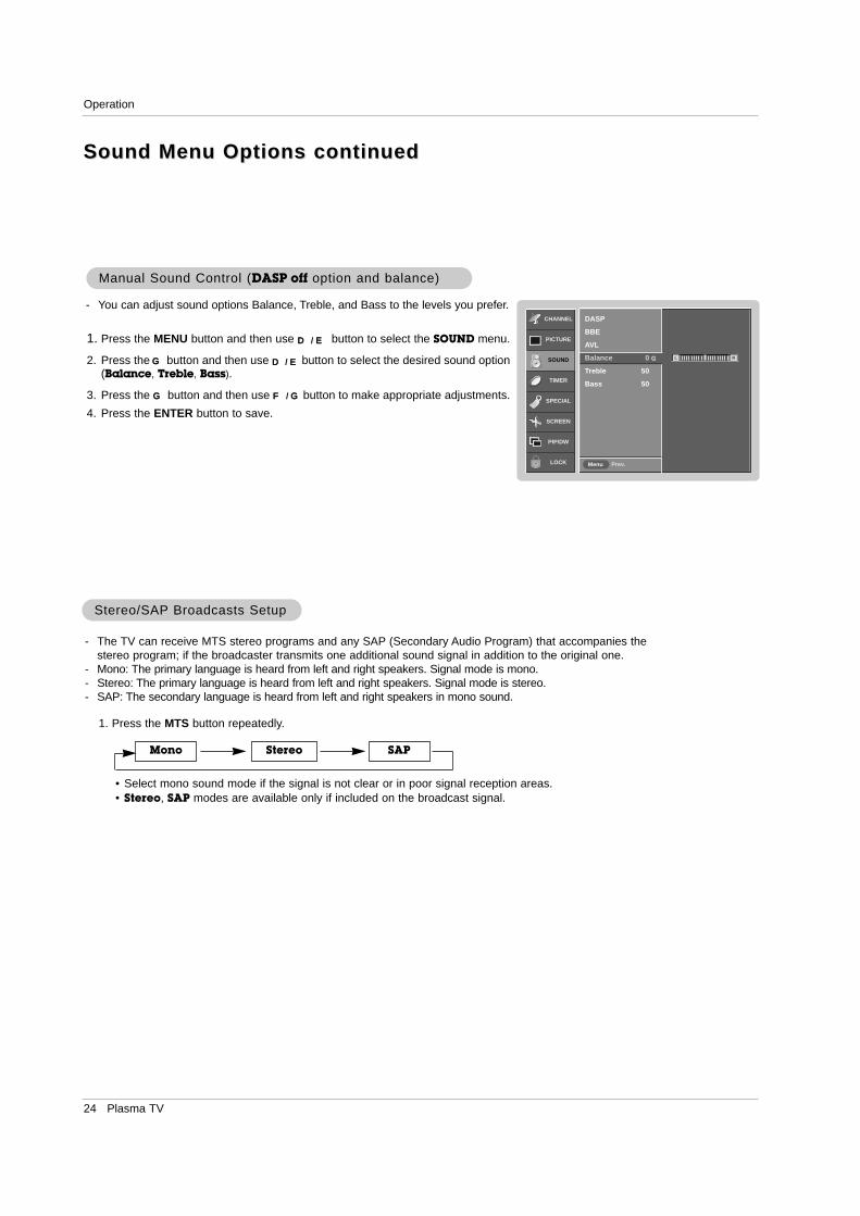
1. Press the MENU button and then use D / E button to select the SOUND menu.
2. Press the G button and then use D / E button to select BBE.
3. Press the G button and then use D / E button to select On or Off.4. Press the ENTER button to save.
BBEBBE
- BBE High Definition Sound restores clarity and presence for better speechintelligibility and music realism.
• Manufactured under license from BBE Sound, Inc.
• Treble, Bass or BBE aren’t suitable for SRS TSXT mode.
CHANNEL
PICTURE
SOUND
TIMER
SPECIAL
SCREEN
PIP/DW
LOCK Prev.Menu
On
Off
DASP
BBE G
AVL
Balance 0
Treble 50
Bass 50
24 Plasma TV
Operation
1. Press the MTS button repeatedly.
Stereo/SAPStereo/SAP Broadcasts SetupBroadcasts Setup
• Select mono sound mode if the signal is not clear or in poor signal reception areas.• Stereo, SAP modes are available only if included on the broadcast signal.
Mono Stereo SAP
- The TV can receive MTS stereo programs and any SAP (Secondary Audio Program) that accompanies thestereo program; if the broadcaster transmits one additional sound signal in addition to the original one.
- Mono: The primary language is heard from left and right speakers. Signal mode is mono.- Stereo: The primary language is heard from left and right speakers. Signal mode is stereo.- SAP: The secondary language is heard from left and right speakers in mono sound.
1. Press the MENU button and then use D / E button to select the SOUND menu.
2. Press the G button and then use D / E button to select the desired sound option(Balance, Treble, Bass).
3. Press the G button and then use F / G button to make appropriate adjustments.
4. Press the ENTER button to save.
Manual Sound Control (Manual Sound Control (DASP off option and balance)option and balance)
- You can adjust sound options Balance, Treble, and Bass to the levels you prefer.CHANNEL
PICTURE
SOUND
TIMER
SPECIAL
SCREEN
PIP/DW
LOCK Prev.Menu
DASP
BBE
AVL
Balance 0 G
Treble 50
Bass 50
L R
Sound Menu Options continuedSound Menu Options continued

Owner’s Manual 25
Operation
TTimer Menu Optionsimer Menu Options
CHANNEL
PICTURE
SOUND
TIMER
SPECIAL
SCREEN
PIP/DW
LOCK Prev.Menu
Auto
Manual
Time zone
Auto
PBS Channel
TV 2
Daylight Saving
Auto
Clock G
Off timer
On timer
Auto off
CHANNEL
PICTURE
SOUND
TIMER
SPECIAL
SCREEN
PIP/DW
LOCK Prev.Menu
Auto
Manual
- - : - - AM
Clock G
Off timer
On timer
Auto off
CHANNEL
PICTURE
SOUND
TIMER
SPECIAL
SCREEN
PIP/DW
LOCK Prev.Menu
On
Off
6 : 30 AM
Volume 17
Ch. TV 2
Clock
Off timer
On timer G
Auto off
- Timer function operates only if current time has been set.- Off-Timer function overrides On-Timer function if they are set both set to the same time.- The TV must be in standby mode for the On-Timer to work.- If you do not press any button within 2 hours after the TV turns on with the On Timer function, the TV will automatically revert to
standby mode.
On/OfOn/Off f TTimer Setupimer Setup
1. Press the MENU button and then use D / E button to select the TIMER menu.
2. Press the G button and then use D / E button to select Off timer or On timer.
3. Press the G button and then use D / E button to select On.• To cancel On/Off timer function, select Off.
4. Press the G button and then use D / E button to set the hour.
5. Press the G button and then use D / E button to set the minutes.
6. For only On timer functionPress the G button and then use D / E button to set the sound level at turn-on.Press the G button and then use D / E button to select the channel at turn-on.
7. Press the ENTER button to save.
Auto Clock SetupAuto Clock Setup
- Set the time automatically through the PBS broadcast signal. - ThePBS channel signal includes information for the current time.- Set the clock manually, if the current time is set incorrectly programed by the auto clock function.
1. Press the MENU button and then use D / E button to select the TIMER menu.
2. Press the G button and then use D / E button to select Clock.
3. Press the G button and then use D / E button to select Auto.
4. Press the G button and then use D / E button to select the time zone for yourviewing area. Your choices are: Auto, E.S.T. (Eastern Standard Time), C.S.T.(Central Standard Time), M.S.T. (Mountain Standard Time), P.S.T. (PacificStandard Time), Alaska, and Hawaii.
5. Press the G button and then use D / E button to set PBS Channel.
6. Press the G button and then use D / E button to set Daylight Saving TimeAuto, On or Off, depending on whether or not your viewing area observesDaylight Saving Time.
7. Press the ENTER button to save.
Manual Clock SetupManual Clock Setup
- If current time setting is wrong, reset the clock manually.
1. Press the MENU button and then use D / E button to select the TIMER menu.
2. Press the G button and then use D / E button to select Clock.
3. Press the G button and then use D / E button to selectt Manual.
4. Press the G button and then use D / E button to set the hour.
5. Press the G button and then use D / E button to set the minutes.
6. Press the ENTER button to save.
26 Plasma TV
Operation
CHANNEL
PICTURE
SOUND
TIMER
SPECIAL
SCREEN
PIP/DW
LOCK Prev.Menu
On
Off
Clock
Off timer
On timer
Auto off G
Auto OfAuto Offf
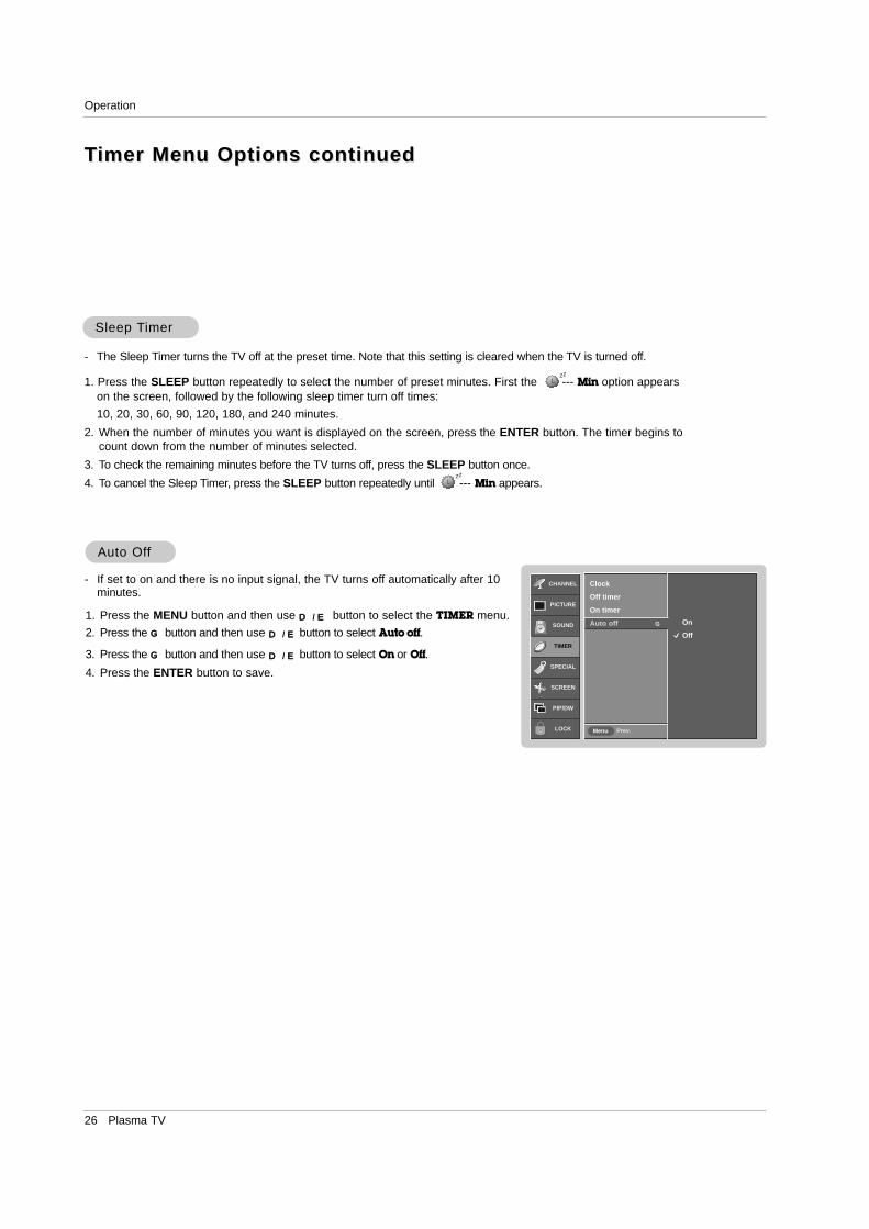
- If set to on and there is no input signal, the TV turns off automatically after 10minutes.
1. Press the MENU button and then use D / E button to select the TIMER menu.
2. Press the G button and then use D / E button to select Auto off.
3. Press the G button and then use D / E button to select On or Off.4. Press the ENTER button to save.
Sleep Sleep TTimerimer
- The Sleep Timer turns the TV off at the preset time. Note that this setting is cleared when the TV is turned off.
1. Press the SLEEP button repeatedly to select the number of preset minutes. First the --- Min option appearson the screen, followed by the following sleep timer turn off times:
10, 20, 30, 60, 90, 120, 180, and 240 minutes.
2. When the number of minutes you want is displayed on the screen, press the ENTER button. The timer begins tocount down from the number of minutes selected.
3. To check the remaining minutes before the TV turns off, press the SLEEP button once.
4. To cancel the Sleep Timer, press the SLEEP button repeatedly until --- Min appears.
zz
zz
TTimer Menu Options continuedimer Menu Options continued
Owner’s Manual 27
Operation
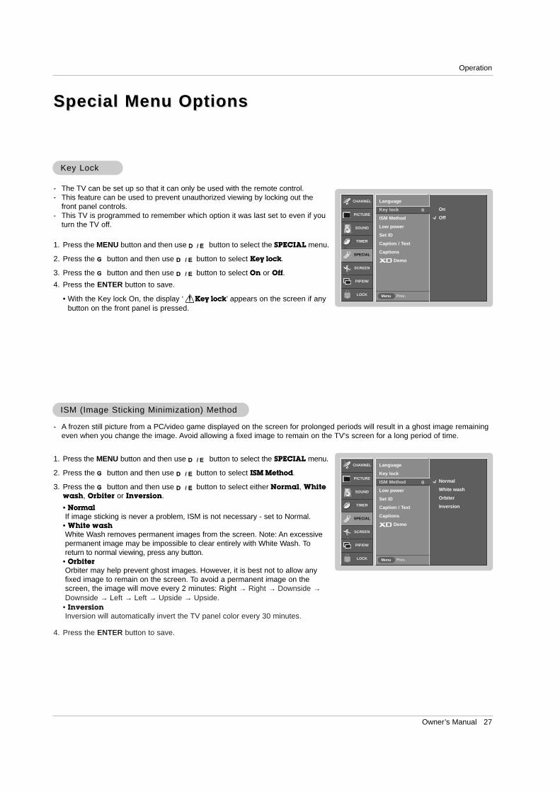
Key LockKey Lock
- The TV can be set up so that it can only be used with the remote control. - This feature can be used to prevent unauthorized viewing by locking out the
front panel controls.- This TV is programmed to remember which option it was last set to even if you
turn the TV off.
Special Menu OptionsSpecial Menu Options
1. Press the MENU button and then use D / E button to select the SPECIAL menu.
2. Press the G button and then use D / E button to select Key lock.
3. Press the G button and then use D / E button to select On or Off.4. Press the ENTER button to save.
• With the Key lock On, the display ‘ Key lock’ appears on the screen if anybutton on the front panel is pressed.
W
ISM (Image Sticking Minimization) MethodISM (Image Sticking Minimization) Method
- A frozen still picture from a PC/video game displayed on the screen for prolonged periods will result in a ghost image remainingeven when you change the image. Avoid allowing a fixed image to remain on the TV's screen for a long period of time.
1. Press the MENU button and then use D / E button to select the SPECIAL menu.
2. Press the G button and then use D / E button to select ISM Method.
3. Press the G button and then use D / E button to select either Normal, Whitewash, Orbiter or Inversion.
• NormalIf image sticking is never a problem, ISM is not necessary - set to Normal.
• White washWhite Wash removes permanent images from the screen. Note: An excessivepermanent image may be impossible to clear entirely with White Wash. Toreturn to normal viewing, press any button.
• OrbiterOrbiter may help prevent ghost images. However, it is best not to allow anyfixed image to remain on the screen. To avoid a permanent image on thescreen, the image will move every 2 minutes: Right → Right → Downside →Downside → Left → Left → Upside → Upside.
• InversionInversion will automatically invert the TV panel color every 30 minutes.
4. Press the ENTER button to save.
CHANNEL
PICTURE
SOUND
TIMER
SPECIAL
SCREEN
PIP/DW
LOCK Prev.Menu
On
Off
Language
Key lock G
ISM Method
Low power
Set ID
Caption / Text
Captions
Demo
CHANNEL
PICTURE
SOUND
TIMER
SPECIAL
SCREEN
PIP/DW
LOCK Prev.Menu
Normal
White wash
Orbiter
Inversion
Language
Key lock
ISM Method G
Low power
Set ID
Caption / Text
Captions
Demo

28 Plasma TV
Low PowerLow Power
- Low power reduces the plasma display power consumption.
1. Press the MENU button and then use D / E button to select the SPECIAL menu.
2. Press the G button and then use D / E button to select Low power.
3. Press the G button and then use D / E button to select On or Off.
• When you select On, the screen darkens.
4. Press the ENTER button to save.
CHANNEL
PICTURE
SOUND
TIMER
SPECIAL
SCREEN
PIP/DW
LOCK Prev.Menu
On
Off
Language
Key lock
ISM Method
Low power G
Set ID
Caption / Text
Captions
Demo
Special Menu Options continuedSpecial Menu Options continued
XD DemoXD Demo
1. Press the MENU button and then use D / E button to select the SPECIAL menu.
2. Press the G button and then use D / E button to select Demo.
3. Press the G button to begin XD Demo.
4. Press the EXIT button to stop XD Demo.
- Use it to see the difference between XD Demo on and XD Demo off.
CHANNEL
PICTURE
SOUND
TIME
SPECIAL
SCREEN
PIP/DW Prev.MENU
Language
Key lock
ISM Method
Low power
Set ID
Caption / Text
Captions
Demo G To start
Owner’s Manual 29
Operation
Closed CaptionsClosed Captions
2. An old, bad, or illegally recorded tape is being played.3. Strong, random signals from a car or airplane interfere with
the TV signal.4. The signal from the antenna is weak.5. The program wasn’t captioned when it was produced, trans-
mitted, or taped.
Closed captioning is a process which converts the audio portionof a television program into written words which then appear assubtitles on the television screen. Closed captions allow viewersto read the dialogue and narration of television programs.
Using Closed CaptionsCaptions are the subtitles of the dialogue and narration of tele-vision programs. For prerecorded programs, program dialoguecan be arranged into captions in advance. Its possible to captiona live program by using a process called real-time captioning,which creates captions instantly. Real-time captioning is nor-mally done by professional reporters using a machine shorthand
system and computer for trans-lation into English.Captioning is an effective sys-tem for the hearing-impaired,and it can also aid in teachinglanguage skills.
• The picture at left shows atypical caption.
Caption Tips• Not all TV broadcasts include closed caption signals.• Sometimes TV stations broadcast four different caption sig-
nals on the same channel. By selecting CC 1 to CC 2, youcan choose which signal you view. CC 1 is usually the signalwith the captions, while Another mode might show demon-stration or programming information.
• Your TV might not receive caption signals normally in the fol-lowing situations.
• IGNITION:Picture may flutter, drift, suffer from blackspots, or horizontal streaking. Usuallycaused by interference from automobileignition systems, neon lamps, electricaldrills, and other electrical appliances.
• GHOSTS:Ghosts are caused when the TV signalsplits and follows two paths. One is thedirect path and the other is reflected offtall buildings, hills or other objects.Changing the direction or position of theantenna may improve reception.
• SNOW:If your receiver is located at the weak,fringe area of a TV signal, your picturemay be marred by small dots. It may benecessary to install a special antenna toimprove the picture.
FOLLOW ME
1. Poor reception conditions are encountered:
CHANNEL
PICTURE
SOUND
TIMER
SPECIAL
SCREEN
PIP/DW
LOCK Prev.Menu
CC1
CC2
CC3
CC4
Text1
Text2
Text3
Text4
Language
Key lock
ISM Method
Low power
Set ID
Caption / Text G
Captions
Demo
Caption/TCaption/Textext
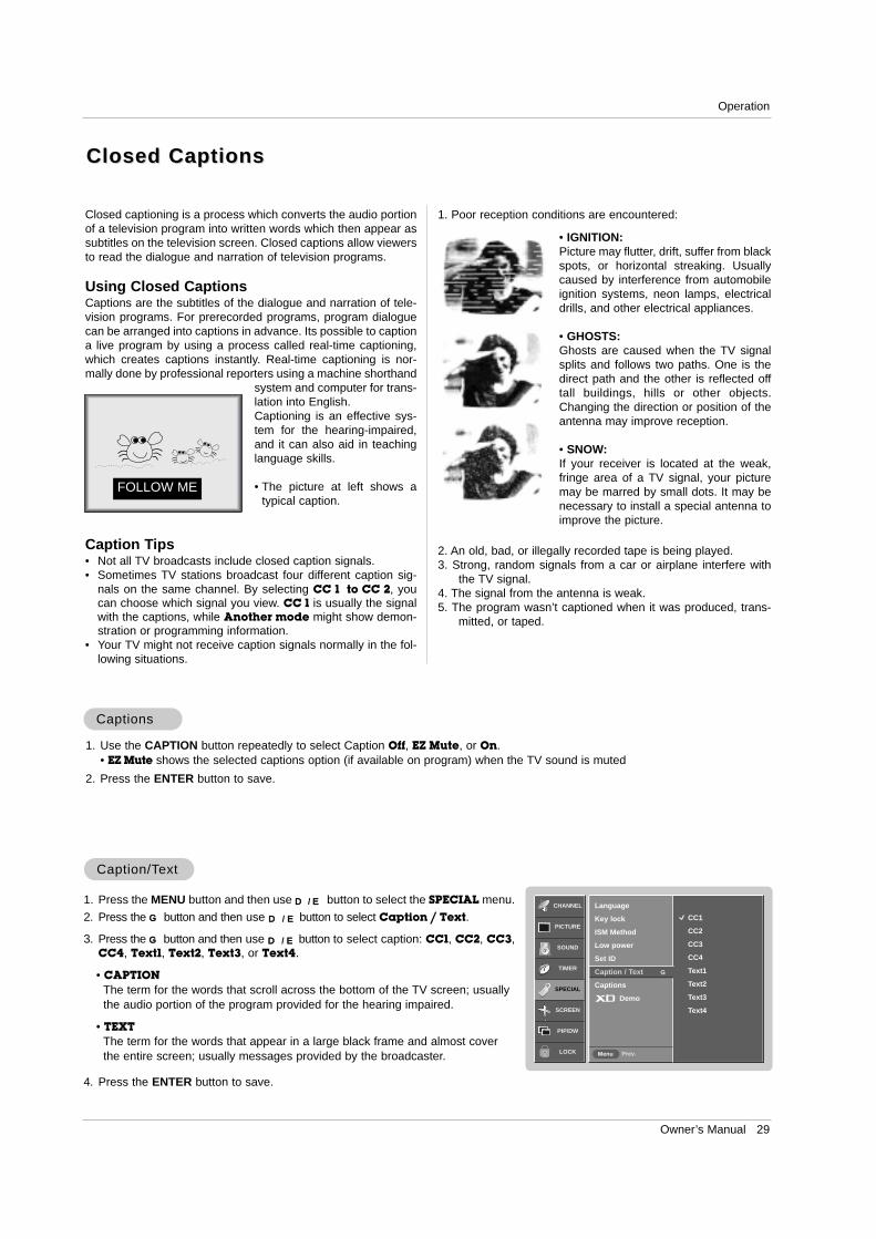
1. Press the MENU button and then use D / E button to select the SPECIAL menu.
2. Press the G button and then use D / E button to select Caption / Text.
3. Press the G button and then use D / E button to select caption: CC1, CC2, CC3,CC4, Text1, Text2, Text3, or Text4.
• CAPTIONThe term for the words that scroll across the bottom of the TV screen; usuallythe audio portion of the program provided for the hearing impaired.
• TEXTThe term for the words that appear in a large black frame and almost coverthe entire screen; usually messages provided by the broadcaster.
4. Press the ENTER button to save.
CaptionsCaptions
1. Use the CAPTION button repeatedly to select Caption Off, EZ Mute, or On. • EZ Mute shows the selected captions option (if available on program) when the TV sound is muted
2. Press the ENTER button to save.
30 Plasma TV
Operation
Screen Menu OptionsScreen Menu Options
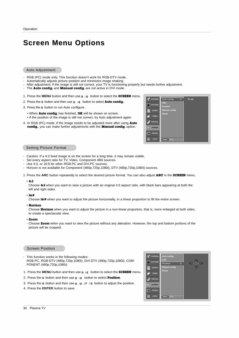
Auto Auto AdjustmentAdjustment
- RGB (PC) mode only; This function doesn’t work for RGB-DTV mode.- Automatically adjusts picture position and minimizes image shaking.- After adjustment, if the image is still not correct, your TV is functioning properly but needs further adjustment.- The Auto config. and Manual config. are not active in DVI mode.
1. Press the MENU button and then use D / E button to select the SCREEN menu.
2. Press the G button and then use D / E button to select Auto config..
3. Press the G button to run Auto configure.
• When Auto config. has finished, OK will be shown on screen.• If the position of the image is still not correct, try Auto adjustment again.
4. In RGB (PC) mode, if the image needs to be adjusted more after using Autoconfig., you can make further adjustments with the Manual config. option.
Setting Picture FormatSetting Picture Format
- Caution: If a 4:3 fixed image is on the screen for a long time, it may remain visible.- Set every aspect ratio for TV, Video, Component 480i sources. - Use 4:3, or 16:9 for other RGB-PC and DVI-PC sources.- Horizon is not available for Component (480p,720p,1080i), DTV (480p,720p,1080i) sources.
1. Press the ARC button repeatedly to select the desired picture format. You can also adjust ARC in the SCREEN menu.
• 4:3Choose 4:3 when you want to view a picture with an original 4:3 aspect ratio, with black bars appearing at both theleft and right sides.
• 16:9Choose 16:9 when you want to adjust the picture horizontally, in a linear proportion to fill the entire screen.
• HorizonChoose Horizon when you want to adjust the picture in a non-linear proportion, that is, more enlarged at both sides,to create a spectacular view.
• Zoom- Choose Zoom when you want to view the picture without any alteration. However, the top and bottom portions of the
picture will be cropped.
1. Press the MENU button and then use D / E button to select the SCREEN menu.
2. Press the G button and then use D / E button to select Position.
3. Press the G button and then use D / E / F / G button to adjust the position.
4. Press the ENTER button to save.
Screen PositionScreen Position
- This function works in the following modes:RGB-PC, RGB-DTV (480p,720p,1080i), DVI-DTV (480p,720p,1080i), COM-PONENT (480p,720p,1080i).
CHANNEL
PICTURE
SOUND
TIMER
SPECIAL
SCREEN
PIP/DW
LOCK Prev.Menu
To setAuto config. G
ARC
Position
Manual config
Reset
CHANNEL
PICTURE
SOUND
TIMER
SPECIAL
SCREEN
PIP/DW
LOCK Prev.Menu
Auto config.
ARC
Position G
Manual config
Reset
DF G
E
Owner’s Manual 31
Operation
CHANNEL
PICTURE
SOUND
TIMER
SPECIAL
SCREEN
PIP/DW
LOCK Prev.Menu
Auto config.
ARC
Position
Manual config G
Reset
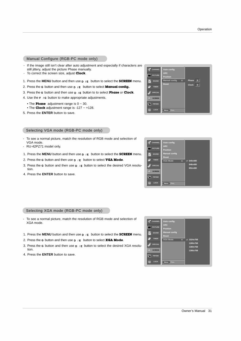
Manual Configure (RGB-PC mode only)Manual Configure (RGB-PC mode only)
- If the image still isn’t clear after auto adjustment and especially if characters arestill jittery, adjust the picture Phase manually.
- To correct the screen size, adjust Clock.
1. Press the MENU button and then use D / E button to select the SCREEN menu.
2. Press the G button and then use D / E button to select Manual config..
3. Press the G button and then use D / E button to to select Phase or Clock.
4. Use the F / G button to make appropriate adjustments.
• The Phase adjustment range is 0 ~ 30.• The Clock adjustment range is -127 ~ +128.
5. Press the ENTER button to save.
Phase 0
Clock 0
CHANNEL
PICTURE
SOUND
TIMER
SPECIAL
SCREEN
PIP/DW
LOCK Prev.Menu
Auto config.
ARC
Position
Manual config
Reset
VGA Mode G 640x480
848x480
852x480
Selecting VGASelecting VGA mode (RGB-PC mode only)mode (RGB-PC mode only)
- To see a normal picture, match the resolution of RGB mode and selection ofVGA mode.
- RU-42PZ71 model only.
1. Press the MENU button and then use D / E button to select the SCREEN menu.
2. Press the G button and then use D / E button to select VGA Mode.
3. Press the G button and then use D / E button to select the desired VGA resolu-tion.
4. Press the ENTER button to save.
CHANNEL
PICTURE
SOUND
TIMER
SPECIAL
SCREEN
PIP/DW
LOCK Prev.Menu
Auto config.
ARC
Position
Manual config
Reset
XGA Mode G 1024x768
1280x768
1360x768
1366x768
Selecting XGASelecting XGA mode (RGB-PC mode only)mode (RGB-PC mode only)
- To see a normal picture, match the resolution of RGB mode and selection ofXGA mode.
1. Press the MENU button and then use D / E button to select the SCREEN menu.
2. Press the G button and then use D / E button to select XGA Mode.
3. Press the G button and then use D / E button to select the desired XGA resolu-tion.
4. Press the ENTER button to save.
32 Plasma TV
CHANNEL
PICTURE
SOUND
TIMER
SPECIAL
SCREEN
PIP/DW
LOCK Prev.Menu
On
Off
Screen adj.
ARC
Cinema
YNR G
Reset
- Use YNR to reduce the picture noise that may appear on the screen.
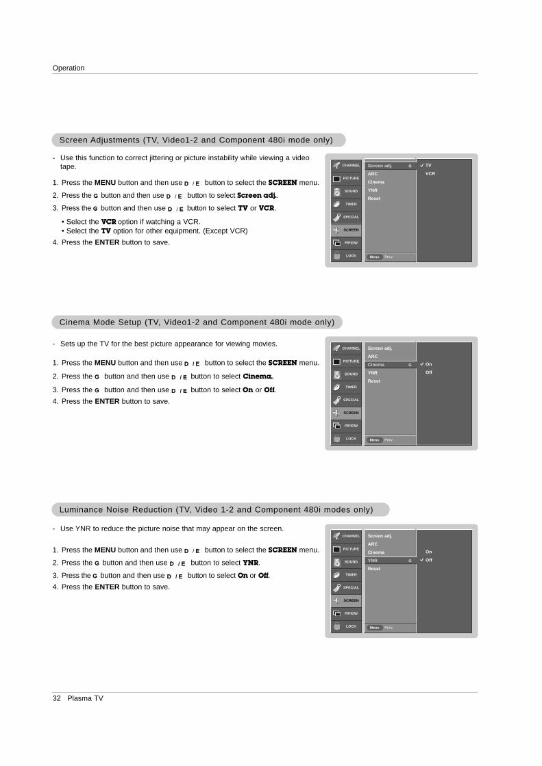
Luminance Noise Reduction (TVLuminance Noise Reduction (TV, V, Video 1-2 and Component 480i modes only)ideo 1-2 and Component 480i modes only)
1. Press the MENU button and then use D / E button to select the SCREEN menu.
2. Press the G button and then use D / E button to select YNR.
3. Press the G button and then use D / E button to select On or Off.4. Press the ENTER button to save.
CHANNEL
PICTURE
SOUND
TIMER
SPECIAL
SCREEN
PIP/DW
LOCK Prev.Menu
TV
VCR
Screen adj. G
ARC
Cinema
YNR
Reset
CHANNEL
PICTURE
SOUND
TIMER
SPECIAL
SCREEN
PIP/DW
LOCK Prev.Menu
On
Off
Screen adj.
ARC
Cinema G
YNR
Reset
Screen Screen Adjustments (TVAdjustments (TV, V, Video1-2 and Component 480i mode only)ideo1-2 and Component 480i mode only)
- Use this function to correct jittering or picture instability while viewing a videotape.
1. Press the MENU button and then use D / E button to select the SCREEN menu.
2. Press the G button and then use D / E button to select Screen adj..
3. Press the G button and then use D / E button to select TV or VCR.
• Select the VCR option if watching a VCR. • Select the TV option for other equipment. (Except VCR)
4. Press the ENTER button to save.
- Sets up the TV for the best picture appearance for viewing movies.
1. Press the MENU button and then use D / E button to select the SCREEN menu.
2. Press the G button and then use D / E button to select Cinema..
3. Press the G button and then use D / E button to select On or Off.4. Press the ENTER button to save.
Cinema Mode Setup (TVCinema Mode Setup (TV, V, Video1-2 and Component 480i mode only)ideo1-2 and Component 480i mode only)
Operation

Owner’s Manual 33
Operation
CHANNEL
PICTURE
SOUND
TIMER
SPECIAL
SCREEN
PIP/DW
LOCK Prev.Menu
To set
Screen adj.
ARC
Cinema
YNR
Reset G
1. Press the MENU button and then use D / E button to select the SCREEN menu.
2. Press the G button and then use D / E button to select Reset.
3. Press the G button.
• You can initialize Position, Split zoom, PIP Transparency, PIP position, PIP sizeand sub picture size for double window.
Initializing (Reset to original factory value)Initializing (Reset to original factory value)
- Use the Reset option to initialize the adjusted settings.
Split ZoomSplit Zoom
- Enlarges the picture in correct proportions.- Split Zoom can be used for all input sources.- In 2-Split Zoom mode, you can only move the image up or down.- If an image is enlarged, a section can be viewed without using Split Zoom.
1. Press the SPLIT ZOOM button repeatedly to select either 2, 4, or 9 Split Zoom.
2. Press the number button corresponding to the section you wish to enlarge. You can move within the enlarged pic-
ture using the D / E / F / G button. To return to normal viewing, press the SPLIT ZOOM button again.
Example of choosing 5. Section 5 is enlarged to fillthe screen.
Screen Menu Options continuedScreen Menu Options continued
1
4
2-Split zoom
1
4
2
5
4-Split zoom
1 2 3
4 5 6
7 8 9
9-Split zoom
1 2 3
4 5 6
7 8 9
9-Split zoom
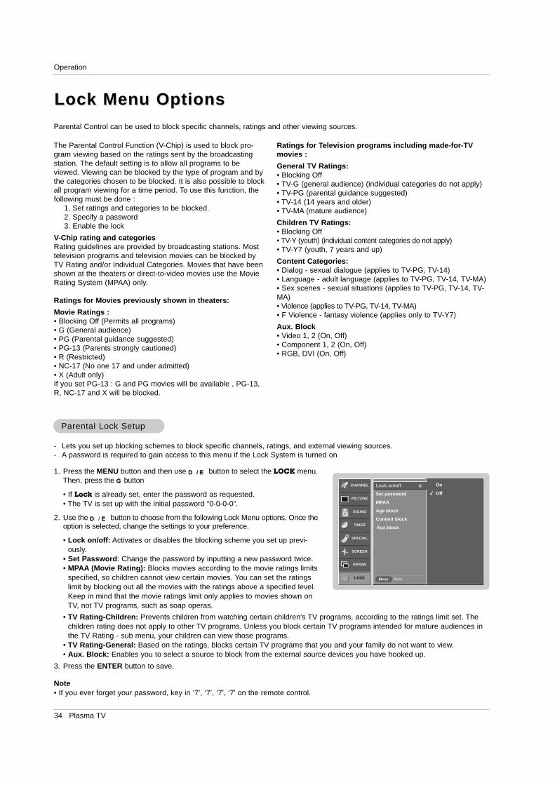
34 Plasma TV
Operation
Lock Menu OptionsLock Menu OptionsParental Control can be used to block specific channels, ratings and other viewing sources.
The Parental Control Function (V-Chip) is used to block pro-gram viewing based on the ratings sent by the broadcastingstation. The default setting is to allow all programs to beviewed. Viewing can be blocked by the type of program and bythe categories chosen to be blocked. It is also possible to blockall program viewing for a time period. To use this function, thefollowing must be done :
1. Set ratings and categories to be blocked.2. Specify a password3. Enable the lock
V-Chip rating and categoriesRating guidelines are provided by broadcasting stations. Mosttelevision programs and television movies can be blocked byTV Rating and/or Individual Categories. Movies that have beenshown at the theaters or direct-to-video movies use the MovieRating System (MPAA) only.
Ratings for Movies previously shown in theaters:
Movie Ratings :• Blocking Off (Permits all programs)• G (General audience)• PG (Parental guidance suggested)• PG-13 (Parents strongly cautioned)• R (Restricted)• NC-17 (No one 17 and under admitted)• X (Adult only)If you set PG-13 : G and PG movies will be available , PG-13,R, NC-17 and X will be blocked.
Ratings for Television programs including made-for-TVmovies :
General TV Ratings:• Blocking Off• TV-G (general audience) (individual categories do not apply)• TV-PG (parental guidance suggested)• TV-14 (14 years and older)• TV-MA (mature audience)
Children TV Ratings:• Blocking Off• TV-Y (youth) (individual content categories do not apply)• TV-Y7 (youth, 7 years and up)
Content Categories:• Dialog - sexual dialogue (applies to TV-PG, TV-14)• Language - adult language (applies to TV-PG, TV-14, TV-MA)• Sex scenes - sexual situations (applies to TV-PG, TV-14, TV-MA)• Violence (applies to TV-PG, TV-14, TV-MA)• F Violence - fantasy violence (applies only to TV-Y7)
Aux. Block• Video 1, 2 (On, Off)• Component 1, 2 (On, Off)• RGB, DVI (On, Off)
Parental Lock SetupParental Lock Setup
1. Press the MENU button and then use D / E button to select the LOCK menu.Then, press the G button
• If Lock is already set, enter the password as requested.• The TV is set up with the initial password “0-0-0-0”.
2. Use the D / E button to choose from the following Lock Menu options. Once theoption is selected, change the settings to your preference.
• Lock on/off: Activates or disables the blocking scheme you set up previ-ously.
• Set Password: Change the password by inputting a new password twice. • MPAA (Movie Rating): Blocks movies according to the movie ratings limits
specified, so children cannot view certain movies. You can set the ratingslimit by blocking out all the movies with the ratings above a specified level.Keep in mind that the movie ratings limit only applies to movies shown onTV, not TV programs, such as soap operas.
- Lets you set up blocking schemes to block specific channels, ratings, and external viewing sources.- A password is required to gain access to this menu if the Lock System is turned on
CHANNEL
PICTURE
SOUND
TIMER
SPECIAL
SCREEN
PIP/DW
LOCK Prev.Menu
On
Off
Lock on/off G
Set password
MPAA
Age block
Content block
Aux.block
• TV Rating-Children: Prevents children from watching certain children's TV programs, according to the ratings limit set. Thechildren rating does not apply to other TV programs. Unless you block certain TV programs intended for mature audiences inthe TV Rating - sub menu, your children can view those programs.
• TV Rating-General: Based on the ratings, blocks certain TV programs that you and your family do not want to view.• Aux. Block: Enables you to select a source to block from the external source devices you have hooked up.
3. Press the ENTER button to save.
Note• If you ever forget your password, key in ‘7’, ‘7’, ‘7’, ‘7’ on the remote control.
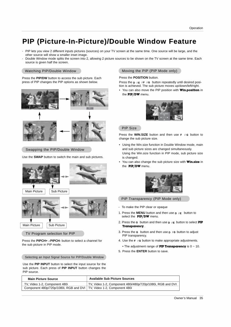
Owner’s Manual 35
Operation
- PIP lets you view 2 different inputs pictures (sources) on your TV screen at the same time. One source will be large, and theother source will show a smaller inset image.
- Double Window mode splits the screen into 2, allowing 2 picture sources to be shown on the TV screen at the same time. Eachsource is given half the screen.
PIPPIP (Picture-In-Picture)/Double W(Picture-In-Picture)/Double Window Featureindow Feature
WWatching PIP/Double Watching PIP/Double Windowindow Moving the PIPMoving the PIP (PIP(PIP Mode only)Mode only)
Press the POSITION button.
Press the D / E / F / G button repeatedly until desired posi-tion is achieved. The sub picture moves up/down/left/right.• You can also move the PIP position with Win.position in
the PIP/DW menu.
Win.position
DW 1
DW 2
Press the PIP/DW button to access the sub picture. Eachpress of PIP changes the PIP options as shown below.
PIP
Off
TV Program selection for PIPTV Program selection for PIP
Press the PIPCH+ / PIPCH- button to select a channel forthe sub picture in PIP mode.
Swapping the PIPSwapping the PIP//Double WDouble Windowindow
Use the SWAP button to switch the main and sub pictures.
Selecting an Input Signal Source for PIPSelecting an Input Signal Source for PIP/Double W/Double Windowindow
Use the PIP INPUT button to select the input source for thesub picture. Each press of PIP INPUT button changes thePIP source.
Main Picture Sub Picture
Main Picture Sub Picture
PIPPIP SizeSize
Press the WIN.SIZE button and then use F / G button tochange the sub picture size.
• Using the Win.size function in Double Window mode, mainand sub picture sizes are changed simultaneously.Using the Win.size function in PIP mode, sub picture sizeis changed.
• You can also change the sub picture size with Win.size inthe PIP/DW menu.
Win.size
F G
PIPPIP TTransparency (PIPransparency (PIP Mode only)Mode only)
- To make the PIP clear or opaque
1. Press the MENU button and then use D / E button toselect the PIP/DW menu.
2. Press the G button and then use D / E button to select PIPTransparency .
3. Press the G button and then use D / G button to adjustPIP transparency.
4. Use the F / G button to make appropriate adjustments.
• The adjustment range of PIP Transparency is 0 ~ 10.
5. Press the ENTER button to save.
Main Picture Source Available Sub Picture Sources
TV, Video 1-2, Component 480iComponent 480p/720p/1080i, RGB and DVI
TV, Video 1-2, Component 480i/480p/720p/1080i, RGB and DVITV, Video 1-2, Component 480i
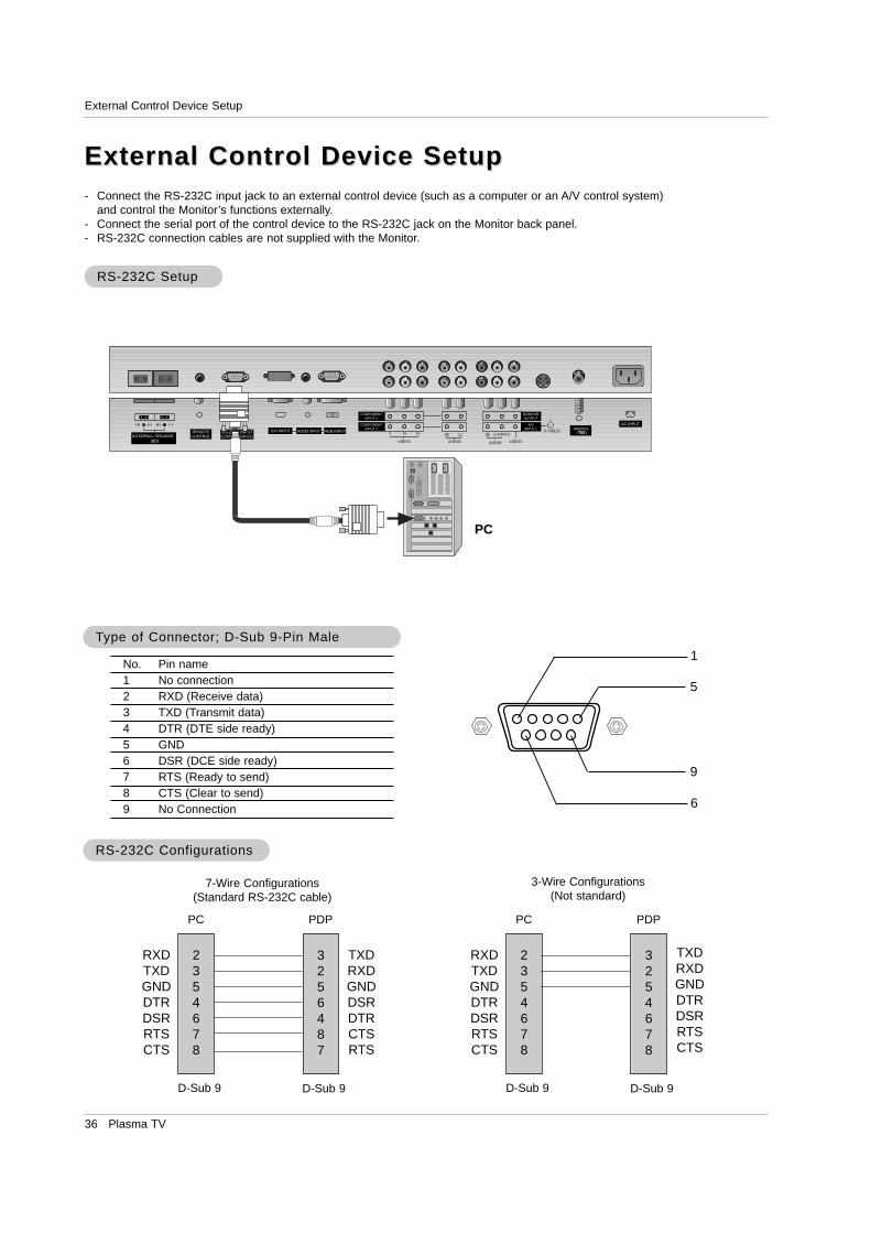
36 Plasma TV
External Control Device Setup
No. Pin name1 No connection2 RXD (Receive data)3 TXD (Transmit data)4 DTR (DTE side ready)5 GND6 DSR (DCE side ready)7 RTS (Ready to send)8 CTS (Clear to send)9 No Connection
1
5
6
9
2354678
RXDTXDGNDDTRDSRRTSCTS
TXDRXDGNDDSRDTRCTSRTS
PC
7-Wire Configurations(Standard RS-232C cable)
D-Sub 9
3256487
PDP
D-Sub 9
2354678
RXDTXDGNDDTRDSRRTSCTS
TXDRXDGNDDTRDSRRTSCTS
PC
3-Wire Configurations(Not standard)
D-Sub 9
3254678
PDP
D-Sub 9
- Connect the RS-232C input jack to an external control device (such as a computer or an A/V control system)and control the Monitor’s functions externally.
- Connect the serial port of the control device to the RS-232C jack on the Monitor back panel.- RS-232C connection cables are not supplied with the Monitor.
TType of Connector; D-Sub 9-Pin Maleype of Connector; D-Sub 9-Pin Male
RS-232C ConfigurationsRS-232C Configurations
External Control Device SetupExternal Control Device Setup
RS-232C SetupRS-232C Setup
RGB INPUTAntenna
AUDIO INPUTDVI INPUTREMOTECONTROL
AC INPUTR
EXTERNAL SPEAKER
R L
RS-232C INPUT(CONTROL/SERVICE)
S-VIDEO
AUDIOVIDEO
COMPONENTINPUT 2
COMPONENTINPUT 1
MONITOROUTPUT
A/VINPUT 1
(R) (L)
AUDIO VIDEO
(L/MONO)(R)
PC
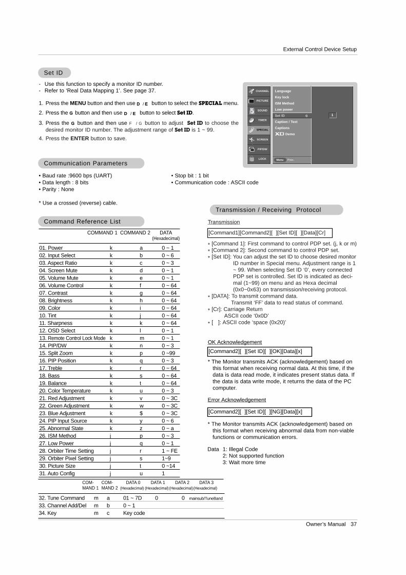
Owner’s Manual 37
External Control Device Setup
Set IDSet ID
- Use this function to specify a monitor ID number. - Refer to ‘Real Data Mapping 1’. See page 37.
• Baud rate :9600 bps (UART)• Data length : 8 bits• Parity : None
* Use a crossed (reverse) cable.
• Stop bit : 1 bit• Communication code : ASCII code
Communication ParametersCommunication Parameters
1. Press the MENU button and then use D / E button to select the SPECIAL menu.
2. Press the G button and then use D / E button to select Set ID.
3. Press the G button and then use F / G button to adjust Set ID to choose thedesired monitor ID number. The adjustment range of Set ID is 1 ~ 99.
4. Press the ENTER button to save.
Transmission
* [Command 1]: First command to control PDP set. (j, k or m)* [Command 2]: Second command to control PDP set.* [Set ID]: You can adjust the set ID to choose desired monitor
ID number in Special menu. Adjustment range is 1~ 99. When selecting Set ID ‘0’, every connectedPDP set is controlled. Set ID is indicated as deci-mal (1~99) on menu and as Hexa decimal(0x0~0x63) on transmission/receiving protocol.
* [DATA]: To transmit command data.Transmit ‘FF’ data to read status of command.
* [Cr]: Carriage ReturnASCII code ‘0x0D’
* [ ]: ASCII code ‘space (0x20)’
[Command1][Command2][ ][Set ID][ ][Data][Cr]
TTransmission / Receiving Protocolransmission / Receiving Protocol
OK Acknowledgement
* The Monitor transmits ACK (acknowledgement) based onthis format when receiving normal data. At this time, if thedata is data read mode, it indicates present status data. Ifthe data is data write mode, it returns the data of the PCcomputer.
[Command2][ ][Set ID][ ][OK][Data][x]
Error Acknowledgement
* The Monitor transmits ACK (acknowledgement) based onthis format when receiving abnormal data from non-viablefunctions or communication errors.
[Command2][ ][Set ID][ ][NG][Data][x]
Data 1: Illegal Code2: Not supported function3: Wait more time
01. Power k a 0 ~ 102. Input Select k b 0 ~ 603. Aspect Ratio k c 0 ~ 304. Screen Mute k d 0 ~ 105. Volume Mute k e 0 ~ 106. Volume Control k f 0 ~ 6407. Contrast k g 0 ~ 6408. Brightness k h 0 ~ 6409. Color k i 0 ~ 6410. Tint k j 0 ~ 6411. Sharpness k k 0 ~ 6412. OSD Select k l 0 ~ 113. Remote Control Lock Mode k m 0 ~ 114. PIP/DW k n 0 ~ 315. Split Zoom k p 0 ~9916. PIP Position k q 0 ~ 317. Treble k r 0 ~ 6418. Bass k s 0 ~ 6419. Balance k t 0 ~ 6420. Color Temperature k u 0 ~ 321. Red Adjustment k v 0 ~ 3C22. Green Adjustment k w 0 ~ 3C23. Blue Adjustment k $ 0 ~ 3C24. PIP Input Source k y 0 ~ 625. Abnormal State k z 0 ~ a26. ISM Method j p 0 ~ 327. Low Power j q 0 ~ 128. Orbiter Time Setting j r 1 ~ FE29. Orbiter Pixel Setting j s 1~930. Picture Size j t 0 ~1431. Auto Config j u 1
COMMAND 1 COMMAND 2 DATA(Hexadecimal)
Command Reference ListCommand Reference List
CHANNEL
PICTURE
SOUND
TIMER
SPECIAL
SCREEN
PIP/DW
LOCK Prev.Menu
Language
Key lock
ISM Method
Low power
Set ID G
Caption / Text
Captions
Demo
1
32. Tune Command m a 01 ~ 7D 0 0 mainsub/TuneBand
33. Channel Add/Del m b 0 ~ 134. Key m c Key code
COM-MAND 2
COM-MAND 1
DATA 0(Hexadecimal)
DATA 1(Hexadecimal)
DATA 2(Hexadecimal)
DATA 3(Hexadecimal)
38 Plasma TV
External Control Device Setup
02. Input Select (Command2:b) (Main Picture Input)
G To select input source for the TV. You can also select an input source using the TV/VIDEObutton on the TV's remote control.
Transmission
Data 0 : TV1 : Video 12 : Video 23 : Component 1
4 : Component 25 : RGB6 : DVI
[k][b][ ][Set ID][ ][Data][Cr]
Acknowledgement
[b][ ][Set ID][ ][OK][Data][x]
01. Power (Command2:a)
G To control Power On/Off of the TV.
Transmission
Data 0 : Power Off 1 : Power On
[k][a][ ][Set ID][ ][Data][Cr]
Acknowledgement
[a][ ][Set ID][ ][OK][Data][x]
* In a like manner, if other functions transmit ‘FF’ databased on this format, Acknowledgement data feedbackpresents status about each function.
* Real data mapping 1
0 : Step 0
A : Step 10 (SET ID 10)
F : Step 15 (SET ID 15)10 : Step 16 (SET ID 16)
63 : Step 99 (SET ID 99)64 : Step 100
05. Volume Mute (Command2:e)
G To control volume mute on/off.You can also adjust mute using the MUTE button onremote control.
Transmission
Data 0 : Volume mute on (Volume off)1 : Volume mute off (Volume on)
[k][e][ ][Set ID][ ][Data][Cr]
Acknowledgement
[e][ ][Set ID][ ][OK][Data][x]
03. Aspect Ratio (Command2:c) (Main picture format)
G To adjust the screen format.You can also adjust the screen format using the ARC(Aspect Ratio Control) button on remote control or in theScreen menu.
Transmission
Data 0 : Normal screen (4:3)1 : Wide screen (16:9) 2 : Horizon 3 : Zoom
[k][c][ ][Set ID][ ][Data][Cr]
Acknowledgement
[c][ ][Set ID][ ][OK][Data][x]
04. Screen Mute (Command2:d)
G To select screen mute on/off.
Transmission
Data 0 : Screen mute off (Picture on)1 : Screen mute on (Picture off)
[k][d][ ][Set ID][ ][Data][Cr]
Acknowledgement
[d][ ][Set ID][ ][OK][Data][x]
06. Volume Control (Command2:f)
G To adjust volume.You can also adjust volume with the volume buttonson remote control.
Transmission
Data Min : 0 ~ Max : 64
• Refer to ‘Real data mapping 1’ as shown below.
[k][f][ ][Set ID][ ][Data][Cr]
Acknowledgement
[f][ ][Set ID][ ][OK][Data][x]
07. Contrast (Command2:g)G To adjust screen contrast.
You can also adjust contrast in the Picture menu.
Transmission
Data Min : 0 ~ Max : 64
• Refer to ‘Real data mapping 1’ as shown below.
[k][g][ ][Set ID][ ][Data][Cr]
Acknowledgement
[g][ ][Set ID][ ][OK][Data][x]
08. Brightness (Command2:h)
G To adjust screen brightness.You can also adjust brightness in the Picture menu.
Transmission
Data Min : 0 ~ Max : 64
• Refer to ‘Real data mapping 1’ as shown below.
[k][h][ ][Set ID][ ][Data][Cr]
Acknowledgement
[h][ ][Set ID][ ][OK][Data][x]
Owner’s Manual 39
External Control Device Setup
17. Treble (Command2:r)
G To adjust treble.You can also adjust treble in the Sound menu.
Transmission
Data Min: 0 ~ Max: 64
• Refer to ‘Real data mapping 1’. See page 38.
[k][r][ ][Set ID][ ][Data][Cr]
Acknowledgement
[r][ ][Set ID][ ][OK][Data][x]
09. Color (Command2:i)G To adjust the screen color.
You can also adjust color in the Picture menu.
Transmission
Data Min : 0 ~ Max : 64
• Refer to ‘Real data mapping 1’. See page 38.
[k][i][ ][Set ID][ ][Data][Cr]
Acknowledgement
[i][ ][Set ID][ ][OK][Data][x]
10. Tint (Command2:j)
G To adjust the screen tint.You can also adjust tint in the Picture menu.
Transmission
Data Red : 0 ~ Green : 64
• Refer to ‘Real data mapping 1’. See page 38.
[k][ j ][ ][Set ID][ ][Data][Cr]
Acknowledgement
[ j ][ ][Set ID][ ][OK][Data][x]
13. Remote Control Lock Mode (Command2:m)
G To lock the remote control and the front panel controls onthe monitor.
Transmission
[k][m][ ][Set ID][ ][Data][Cr]
Acknowledgement
Data 0: Lock off 1: Lock on
• If you’re not using the remote control and front panel controlson the monitor, use this mode. When main power is on/off,remote control lock is released.
[m][ ][Set ID][ ][OK][Data][x]
14. PIP / DW (Command2:n)G To control the PIP (Picture In picture)/DW (Double Window).
You can also control the PIP/DW using the PIP/DW buttonon the remote control or in the PIP/DW menu.
Transmission
Data 0: PIP/DW off1: PIP
2: DW13: DW2
[k][n][ ][Set ID][ ][Data][Cr]
Acknowledgement
[n][ ][Set ID][ ][OK][Data][x]
G To adjust the screen sharpness.You can also adjust sharpness in the Picture menu.
Transmission
11. Sharpness (Command2:k)
Data Min: 0 ~ Max: 64
• Refer to ‘Real data mapping 1’. See page 38.
[k][k][ ][Set ID][ ][Data][Cr]
Acknowledgement
[k][ ][Set ID][ ][OK][Data][x]
12. OSD Select (Command2:l)
G To select OSD (On Screen Display) on/off.
Transmission
[k][l][ ][Set ID][ ][Data][Cr]
Acknowledgement
Data 0: OSD off 1: OSD on
[l][ ][Set ID][ ][OK][Data][x]
15. Split Zoom (Command2:p)
G To operate split zoom function and select the splitzoom section number.
Transmission
Data Min: 0 ~ Max:99
• Refer to ‘Real data mapping 2’.
[k][p][ ][Set ID][ ][Data][Cr]
Acknowledgement
[p][ ][Set ID][ ][OK][Data][x]
* Real data mapping 2
0 : Reset split zoom21: Selection 1 of 2 split zoom24: Selection 4 of 2 split zoom41: Selection 1 of 4 split zoom42: Selection 2 of 4 split zoom44: Selection 4 of 4 split zoom45: Selection 5 of 4 split zoom91: Selection 1 of 9 split zoom
99: Selection 9 of 9 split zoom
16. PIP Position (Command2:q)
G To select sub picture position for PIP. You can also adjust the sub picture position usingWIN.POSITION on the remote control or in the PIP/DW menu.
Transmission
Data 0: Right down on screen1: Left down on screen2: Left up on screen3: Right up on screen
[k][q][ ][Set ID][ ][Data][Cr]
Acknowledgement
[q][ ][Set ID][ ][OK][Data][x]
40 Plasma TV
External Control Device Setup
21. Red Adjustment (Command2:v)
G To adjust red in color temperature.
Transmission
Data Min: 0 ~ Max: 3C
• Refer to ‘Real data mapping 3’ as shown right.
[k][v][ ][Set ID][ ][Data][Cr]
Acknowledgement
[v][ ][Set ID][ ][OK][Data][x]
22. Green Adjustment (Command2:w)
G To adjust green in color temperature.
Transmission
Data Min: 0 ~ Max: 3C
• Refer to ‘Real data mapping 3’ as shown right.
[k][w][ ][Set ID][ ][Data][Cr]
Acknowledgement
[w][ ][Set ID][ ][OK][Data][x]
23. Blue Adjustment (Command2:$)
G To adjust blue in color temperature.
Transmission
Data Min: 0 ~ Max: 3C
• Refer to ‘Real data mapping 3’ as shown below.
[k][$][ ][Set ID][ ][Data][Cr]
Acknowledgement
[$][ ][Set ID][ ][OK][Data][x]
20. Color Temperature (Command2:u)G To adjust color temperature.
You can also adjust ACC in the Picture menu.
Transmission
Data 0: Cool 1: Normal 2: Warm 3: Off
[k][u][ ][Set ID][ ][Data][Cr]
Acknowledgement
[u][ ][Set ID][ ][OK][Data][x]
19. Balance (Command2:t)G To adjust balance.
You can also adjust balance in the Sound menu.
Transmission
Data Min: 0 ~ Max: 64
• Refer to ‘Real data mapping 1’. See page 38.
[k][t][ ][Set ID][ ][Data][Cr]
Acknowledgement
[t][ ][Set ID][ ][OK][Data][x]
18. Bass (Command2:s)G To adjust bass.
You can also adjust bass in the Sound menu.
Transmission
Data Min: 0 ~ Max: 64
• Refer to ‘Real data mapping 1’. See page 38.
[k][s][ ][Set ID][ ][Data][Cr]
Acknowledgement
[s][ ][Set ID][ ][OK][Data][x]
24. PIP Input Select (Command2:y)
G To select input source for sub picture in PIP mode.
Transmission
Data 0 : TV1 : Video 12 : Video 23 : Component 1
4 : Component 25 : RGB6 : DVI
[k][y][ ][Set ID][ ][Data][Cr]
Acknowledgement
[y][ ][Set ID][ ][OK][Data][x]
25. Abnormal State (Command2:z)
G To recognize an abnormal state.
Transmission
Data 0: Normal (Power on and signal exist)1: No signal (Power on).2: Turn the monitor off with remote control.3: Turn the monitor off with Sleep Time function.4: Turn the monitor off with RS-232C function.5: 5V down.6: AC down.7: Turn the monitor off with Fan Alarm function.8: Turn the monitor off with Off Time function.9: Turn the monitor off with Auto Off function.a: Turn the monitor off with On Time function.
(If you do not press any button within 2 hours after the TV turns on with the On Timer function, the TV willautomatically revert to standby mode.)
Data FF:Read
[k][z][ ][Set ID][ ][FF][Cr]
Acknowledgement
[z][ ][Set ID][ ][OK][Data][x]
* Real data mapping 3
0 : -301 : -292 : -28
1E : 0
3A : +283B : +293C : +30
Owner’s Manual 41
External Control Device Setup
26. ISM Method (Command2:p)
G To avoid having a fixed image remain on screen.
Transmission
Data 0: Normal1: White wash
2: Orbiter3: Inversion
[ j ][p][ ][Set ID][ ][Data][Cr]
Acknowledgement
[p][ ][Set ID][ ][OK][Data][x]
27. Low Power (Command2:q)
G To control the low power function on/off.
Transmission
Data 0: Low power off1: Low power on
[ j ][q][ ][Set ID][ ][Data][Cr]
Acknowledgement
[q][ ][Set ID][ ][OK][Data][x]
28. Orbiter Time Setting (Command2:r)
G To adjust orbiter operation time term.
Transmission
Data Min: 1 ~ Max: FE
[ j ][r][ ][Set ID][ ][Data][Cr]
Acknowledgement
[r][ ][Set ID][ ][OK][Data][x]
29. Orbiter Pixel Setting (Command2:s)
G To adjust pixel number in orbiter function.
Transmission
Data Min: 1 ~ Max: 9
[ j ][s][ ][Set ID][ ][Data][Cr]
Acknowledgement
[s][ ][Set ID][ ][OK][Data][x]
30. Picture Size Setting for Double Windowmode (Command2:t)
G To adjust main window size in Double Window mode.
Transmission
Data Min: 0 ~ Max: 1E (or 20)
• Refer to ‘Real data mapping1’. See page 38.
[ j ][t][ ][Set ID][ ][Data][Cr]
Acknowledgement
[t][ ][Set ID][ ][OK][Data][x]
31. Auto Configure (Command2:u)
G To adjust picture position and minimize image shakingautomatically. It works only in RGB (PC) mode.
Transmission
Data 1: To set
[ j ][u][ ][Set ID][ ][Data][Cr]
Acknowledgement
[u][ ][Set ID][ ][OK][Data][x]
32. Tune command (Command: m a)
G Tune channel to following physical number
Transmission
Data 0: Air: 02 ~ 45, Cable: 01, 0E ~ 7D1: 02: 03: High → Main Channel: 0, Sub Channel: 1
Low → Air: 0, CATV: 1
[m][a][ ][Set ID][ ][Data0][ ][Data1][ ][Data2][ ][Data3][Cr]
Acknowledgement
[a][ ][Set ID][ ][OK][Data0][ ][Data1][ ][Data2][ ][Data3][x]
33. Channel Add/Del (Command: m b)
G To add and delete the channels
Transmission
Data 0: Channel Memory1: Channel Erase
[m][b][ ][Set ID][ ][Data][Cr]
[b][ ][Set ID][ ][OK][Data][x]
Acknowledgement
34. Key (Command: m c)
G To send IR remote key code
Transmission
Data Key code: Refer to page 43.
[m][c][ ][Set ID][ ][Data][ ][Cr]
[c][ ][Set ID][ ][OK][Data][x]
Acknowledgement
42 Plasma TV
IR Codes
G Connect your wired remote control to the Remote Control port on the Monitor.
G Output waveform
Single pulse, modulated with 37.917KHz signal at 455KHz
G Configuration of frame
G Repeat code
G Lead code
• 1st frame
Low custom code
Leadcode
High custom code
Data code Data code
TC
Tf
T1
C0
Carrier frequency
FCAR = 1/TC = fOSC/12Duty ratio = T1/TC = 1/3
• Repeat frame
C1 C2 C3 C4 C5 C6 C7 C0 C1 C2 C3 C4 C5 C6 C7 D0 D1 D2 D3 D4 D5 D6 D7 D0 D1 D2 D3 D4 D5 D6 D7
Repeat code
9 ms 4.5 ms
0.55 ms
9 ms
2.25 ms
G Bit description
G Frame interval : Tf
The waveform is transmitted as long as a key is depressed.
• Bit “0”
Tf Tf
Tf=108ms @455KHz
0.56 ms 0.56 ms
1.12 ms
• Bit “1”
2.24 ms
How to ConnectHow to Connect
Remote Control IR CodeRemote Control IR Code
IR CodesIR Codes
Owner’s Manual 43
IR Codes
Code (Hexa) Function Note
0001020308C4C509101112131415161718190B98D65AD0BFD4C6D50E43444D52606163646271727B797677AF1E1A54550A3999
R/C ButtonR/C ButtonR/C ButtonR/C ButtonR/C Button (Power On/Off)Discrete IR Code (Only Power On)Discrete IR Code (Only Power Off)R/C ButtonR/C ButtonR/C ButtonR/C ButtonR/C ButtonR/C ButtonR/C ButtonR/C ButtonR/C ButtonR/C ButtonR/C ButtonR/C ButtonR/C ButtonDiscrete IR Code (Input TV Selection)Discrete IR Code (Input VIDEO1 Selection)Discrete IR Code (Input VIDEO2 Selection)Discrete IR Code (Input COMPONENT1 Selection)Discrete IR Code (Input COMPONENT2 Selection)Discrete IR Code (Input DVI Selection)Discrete IR Code (Input RGB Selection)R/C ButtonR/C ButtonR/C ButtonR/C ButtonR/C ButtonR/C ButtonR/C ButtonR/C ButtonR/C ButtonR/C ButtonR/C ButtonR/C ButtonR/C ButtonR/C ButtonDiscrete IR Code (Only 4:3 mode)Discrete IR Code (Only 16:9 mode)Discrete IR Code (Only Zoom mode)R/C ButtonR/C ButtonR/C ButtonR/C ButtonR/C ButtonR/C ButtonDiscrete IR Code
CH (D)CH (E)VOL (G)VOL (F)POWER POWER ONPOWER OFFMUTENumber Key 0Number Key 1Number Key 2Number Key 3Number Key 4Number Key 5Number Key 6Number Key 7Number Key 8Number Key 9TV/VIDEOMULTIMEDIA
TVVIDEO1VIDEO2COMPONENT1COMPONENT2DVIRGB
SLEEPMENUENTERAPCDASPPIP/DWPIP INPUTSWAPWIN.SIZEPOSITIONPIP CH+PIP CH-SPLIT ZOOMARCARC (4:3)ARC (16:9)ARC (Zoom)FCRREVIEWAUTO PROGRAMMEMORY/ERASEMTSCAPTIONAUTO CONFIG
44 Plasma TV
Programming the Remote
G The remote control is a multi-brand or universal remote control. It can be programmed to operate most remote-controllabledevices of other manufacturers.Note that the remote control may not control all models of other brands.
Programming a code into a remote modeProgramming a code into a remote mode
Programming the RemoteProgramming the Remote
1. Test your remote control.To find out whether your remote control can operate the component without programming, turn on the component such as a VCRand press the corresponding MODE button (VCR) on the remote control, while pointing at the component. Test the POWER andCH +/- buttons to see if the component responds properly. If not, the remote requires programming to operate the device.
2. Turn on the component to be programmed, then press the corresponding MODE button on the remote control.
3. Press the PIP CH- and MUTE buttons simultaneously, the remote control is ready to be programmed for the code.
4. There are two ways to find the right code for the component.A. If you press the CH +/- buttons repeatedly, the codes will change one at-a-time. Press the POWER button after each code
change. If the right code is found, the device will turn off.B. Enter a code number using the number buttons on the remote. Programming code numbers for the corresponding component
can be found on the following pages. Again, if the code is correct, the device will turn off.
5. Press the MENU button to store the code.
6. Test the remote control functions to see if the component responds properly. If not, repeat from step 2.
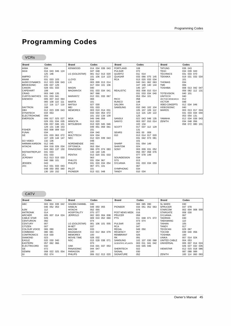
Owner’s Manual 45
Programming Codes
Programming CodesProgramming Codes
VCRsVCRs
CACATVTV
AIWA 034AKAI 016 043 046 124
125 146AMPRO 072ANAM 031 033 103AUDIO DYNAMICS 012 023 039 043BROKSONIC 035 037 129CANON 028 031 033CAPEHART 108CRAIG 003 040 135CURTIS MATHES 031 033 041DAEWOO 005 007 010 064
065 108 110 111112 116 117 119
DAYTRON 108DBX 012 023 039 043DYNATECH 034 053ELECTROHOME 059EMERSON 006 017 025 027
029 031 034 035036 037 046 101129 131 138 153
FISHER 003 008 009 010FUNAI 034GE 031 033 063 072
107 109 144 147GO VIDEO 132 136HARMAN KARDON 012 045HITACHI 004 018 026 034
043 063 137 150INSTANTREPLAY 031 033JCL 031 033JCPENNY 012 013 015 033
040 066 101JENSEN 043JVC 012 031 033 043
048 050 055 060130 150 152
KENWOOD 014 034 039 043047 048
LG (GOLDSTAR) 001 012 013 020101 106 114 123
LLOYD 034LXI 003 009 013 014
017 034 101 106MAGIN 040MAGNAVOX 031 033 034 041
067 068MARANTZ 012 031 033 067
069MARTA 101MATSUI 027 030MEI 031 033MEMOREX 003 010 014 031
033 034 053 072101 102 134 139
MGA 045 046 059MINOLTA 013 020MITSUBISHI 013 020 045 046
049 051 059 061151
MTC 034 040MULTITECH 024 034NEC 012 023 039 043
048NORDMENDE 043OPTONICA 053 054PANASONIC 066 070 074 083
133 140 145PENTAX 013 020 031 033
063PHILCO 031 034 067PHILIPS 031 033 034 054
067 071 101PILOT 101PIONEER 013 021 048
PORTLAND 108PULSAR 072QUARTZ 011 014QUASAR 033 066 075 145RCA 013 020 033 034
040 041 062 063107 109 140 144145 147
REALISTIC 003 008 010 014031 033 034 040053 054 101
RICO 058RUNCO 148SALORA 014SAMSUNG 032 040 102 104
105 107 109 112113 115 120 122125
SANSUI 022 043 048 135SANYO 003 007 010 014
102 134SCOTT 017 037 112 129
131SEARS 003 00 009010 013 014 017 020
031 042 073 081101
SHARP 031 054 149SHINTOM 024SONY 003 009 031 052
056 057 058 076077 078 149
SOUNDESIGN 034STS 013SYLVANIA 031 033 034 059
067SYMPHONIC 034TANDY 010 034
TATUNG 039 043TEAC 034 039 043TECHNICS 031 033 070TEKNIKA 019 031 033 034
101THOMAS 034TMK 006TOSHIBA 008 013 042 047
059 082 112 131TOTEVISION 040 101UNITECH 040VECTOR RESEARCH 012VICTOR 048VIDEO CONCEPTS 012 034 046VIDEOSONIC 040WARDS 003 013 017 024
031 033 034 040053 054 131
YAMAHA 012 034 039 043ZENITH 034 048 056
058 072 080 101
Brand Codes Brand Codes Brand Codes Brand Codes
Brand Codes Brand Codes Brand Codes Brand Codes
ABC 003 004 039 042046 052 053
AJIN 112ANTRONIK 014ARCHER 005 007 014 024CABLE STAR 026CENTURION 092CENTURY 007CITIZEN 007COLOUR VOICE 065 090COMBANO 080 081COMTRONICS 019 030DIAMOND 023EAGLE 020 030 040EASTERN 057 062 066ELECTRICORD 032GE 072GEMINI 008 022 025 054GI 052 074
GOLDEN CHANNEL 030HAMLIN 049 050 055HITACHI 052 055HOSPITALITY 070 077JERROLD 002 003 004 008
009 010 052 069074
LG (GOLDSTAR) 001 106 101 005 M-NET 037MACOM 033MAGNAVOX 010 012 064 079MEMOREX 100MOVIE TIME 028 032NSC 015 028 038 071
073OAK 016 031 037 053PANASONIC 044 047PARAGON 100PHILIPS 006 012 013 020
065 085 090PIONEER 034 051 052 063
076POST NEWS WEEK 016PRUCER 059PTS 011 048 071 072
073 074PULSAR 100RCA 047REGAL 049 050REGENCY 057REMBRANT 025RK 091SAMSUNG 102 107 030 068SCIENTIFIC ATLANTA 003 011 041 042
043 045 046SHERITECH 022SIGNAL 030SIGNATURE 052
SL MARX 030SPRUCER 047 078STARCOM 002 004 008 009STARGATE 008 030SYLVANIA 067TADIRAN 030TAEKWANG 110TAIHAN 105TANDY 017TEXSCAN 029 067TOCOM 039 040 056TOSHIBA 100UNIKA 007 014 024UNITED CABLE 004 053UNIVERSAL 005 007 014 024
026 027 032 035VIEWSTAR 012 015 018 086
087 088 089ZENITH 100 114 060 093
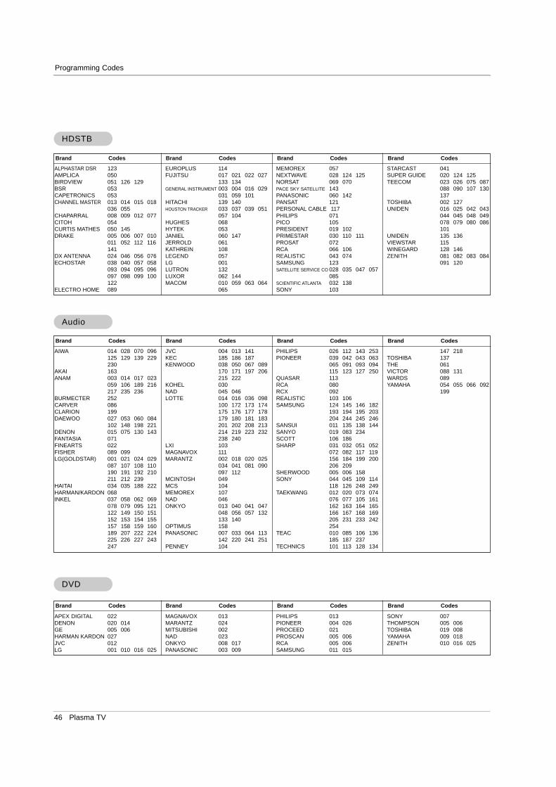
46 Plasma TV
Programming Codes
AudioAudio
APEX DIGITAL 022DENON 020 014GE 005 006HARMAN KARDON 027JVC 012LG 001 010 016 025
MAGNAVOX 013MARANTZ 024MITSUBISHI 002NAD 023ONKYO 008 017PANASONIC 003 009
PHILIPS 013PIONEER 004 026PROCEED 021PROSCAN 005 006RCA 005 006SAMSUNG 011 015
SONY 007THOMPSON 005 006TOSHIBA 019 008YAMAHA 009 018ZENITH 010 016 025
DVDDVD
ALPHASTAR DSR 123AMPLICA 050BIRDVIEW 051 126 129BSR 053CAPETRONICS 053CHANNEL MASTER 013 014 015 018
036 055CHAPARRAL 008 009 012 077CITOH 054CURTIS MATHES 050 145DRAKE 005 006 007 010
011 052 112 116141
DX ANTENNA 024 046 056 076ECHOSTAR 038 040 057 058
093 094 095 096097 098 099 100122
ELECTRO HOME 089
EUROPLUS 114FUJITSU 017 021 022 027
133 134GENERAL INSTRUMENT 003 004 016 029
031 059 101HITACHI 139 140HOUSTON TRACKER 033 037 039 051
057 104HUGHES 068HYTEK 053JANIEL 060 147JERROLD 061KATHREIN 108LEGEND 057LG 001LUTRON 132LUXOR 062 144MACOM 010 059 063 064
065
MEMOREX 057NEXTWAVE 028 124 125NORSAT 069 070PACE SKY SATELLITE 143PANASONIC 060 142PANSAT 121PERSONAL CABLE 117PHILIPS 071PICO 105PRESIDENT 019 102PRIMESTAR 030 110 111PROSAT 072RCA 066 106REALISTIC 043 074SAMSUNG 123SATELLITE SERVICE CO 028 035 047 057
085SCIENTIFIC ATLANTA 032 138SONY 103
STARCAST 041SUPER GUIDE 020 124 125TEECOM 023 026 075 087
088 090 107 130137
TOSHIBA 002 127UNIDEN 016 025 042 043
044 045 048 049078 079 080 086101
UNIDEN 135 136VIEWSTAR 115WINEGARD 128 146ZENITH 081 082 083 084
091 120
HDSTBHDSTB
Brand Codes Brand Codes Brand Codes Brand Codes
Brand Codes Brand Codes Brand Codes Brand Codes
AIWA 014 028 070 096125 129 139 229230
AKAI 163ANAM 003 014 017 023
059 106 189 216217 235 236
BURMECTER 252CARVER 086CLARION 199DAEWOO 027 053 060 084
102 148 198 221DENON 015 075 130 143FANTASIA 071FINEARTS 022FISHER 089 099LG(GOLDSTAR) 001 021 024 029
087 107 108 110190 191 192 210211 212 239
HAITAI 034 035 188 222HARMAN/KARDON 068INKEL 037 058 062 069
078 079 095 121122 149 150 151152 153 154 155 157 158 159 160189 207 222 224 225 226 227 243 247
JVC 004 013 141KEC 185 186 187KENWOOD 038 050 067 089
170 171 197 206215 222
KOHEL 030NAD 045 046LOTTE 014 016 036 098
100 172 173 174 175 176 177 178179 180 181 183201 202 208 213214 219 223 232 238 240
LXI 103MAGNAVOX 111MARANTZ 002 018 020 025
034 041 081 090097 112
MCINTOSH 049MCS 104MEMOREX 107NAD 046 ONKYO 013 040 041 047
048 056 057 132133 140
OPTIMUS 158PANASONIC 007 033 064 113
142 220 241 251PENNEY 104
PHILIPS 026 112 143 253PIONEER 039 042 043 063
065 091 093 094115 123 127 250
QUASAR 113RCA 080RCX 092REALISTIC 103 106 SAMSUNG 124 145 146 182
193 194 195 203204 244 245 246
SANSUI 011 135 138 144SANYO 019 083 234SCOTT 106 186SHARP 031 032 051 052
072 082 117 119156 184 199 200 206 209
SHERWOOD 005 006 158SONY 044 045 109 114
118 126 248 249 TAEKWANG 012 020 073 074
076 077 105 161162 163 164 165166 167 168 169205 231 233 242254
TEAC 010 085 106 136185 187 237
TECHNICS 101 113 128 134
147 218 TOSHIBA 137THE 061VICTOR 088 131WARDS 089YAMAHA 054 055 066 092
199
Brand Codes Brand Codes Brand Codes Brand Codes
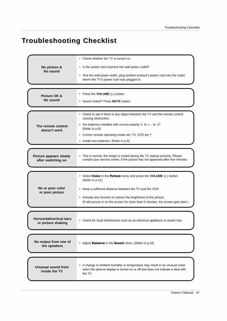
Owner’s Manual 47
Troubleshooting Checklist
No output from one ofthe speakers
• Adjust Balance in the Sound menu. (Refer to p.24)
Unusual sound frominside the TV
• A change in ambient humidity or temperature may result in an unusual noisewhen the plasma display is turned on or off and does not indicate a fault withthe TV.
No picture &No sound
• Check whether the TV is turned on.
• Is the power cord inserted into wall power outlet?
• Test the wall power outlet, plug another product’s power cord into the outletwhere the TV’s power cord was plugged in.
No or poor coloror poor picture
• Select Color in the Picture menu and press the VOLUME (G) button. (Refer to p.21)
• Keep a sufficient distance between the TV and the VCR.
• Activate any function to restore the brightness of the picture.
(If still picture is on the screen for more than 5 minutes, the screen gets dark.)
The remote control doesn’t work
• Check to see if there is any object between the TV and the remote controlcausing obstruction.
• Are batteries installed with correct polarity (+ to +, - to -)? (Refer to p.9)
• Correct remote operating mode set: TV, VCR etc.?
• Install new batteries. (Refer to p.9)
Picture OK &No sound
• Press the VOLUME (G) button.
• Sound muted? Press MUTE button.
Picture appears slowlyafter switching on
• This is normal, the image is muted during the TV startup process. Pleasecontact your service center, if the picture has not appeared after five minutes.
Horizontal/vertical barsor picture shaking
• Check for local interference such as an electrical appliance or power tool.
TTroubleshooting Checklistroubleshooting Checklist
48 Plasma TV
Maintenance
1. Here’s a great way to keep the dust off your screen for a while. Wet a soft cloth in a mixture of lukewarm water anda little fabric softener or dish washing detergent. Wring the cloth until it’s almost dry, and then use it to wipe thescreen.
2. Make sure the excess water is off the screen, and then let it air-dry before you turn on your TV.
To remove dirt or dust, wipe the cabinet with a soft, dry, lint-free cloth.Please be sure not to use a wet cloth.
If you expect to leave your TV dormant for a long time (such as a vacation), it’s a good idea to unplugthe power cord to protect against possible damage from lightning or power surges.
- Early malfunctions can be prevented. Careful and regular cleaning can extend the amount of time you will have yournew TV. Be sure to turn the power off and unplug the power cord before you begin any cleaning.
Cleaning the ScreenCleaning the Screen
Cleaning the CabinetCleaning the Cabinet
Extended Extended AbsenceAbsence
MaintenanceMaintenance
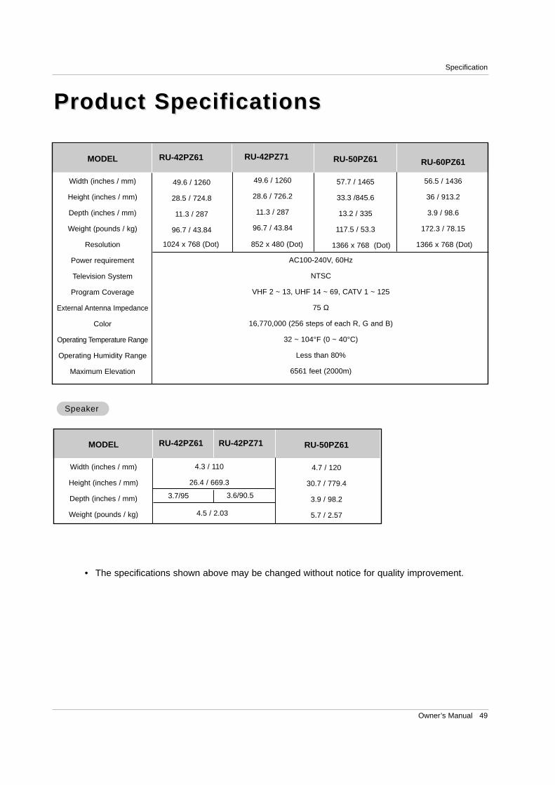
Owner’s Manual 49
Specification
Product SpecificationsProduct Specifications
• The specifications shown above may be changed without notice for quality improvement.
MODEL RU-50PZ61
57.7 / 1465
33.3 /845.6
13.2 / 335
117.5 / 53.3
1366 x 768 (Dot)
AC100-240V, 60Hz
NTSC
VHF 2 ~ 13, UHF 14 ~ 69, CATV 1 ~ 125
75 Ω
16,770,000 (256 steps of each R, G and B)
32 ~ 104°F (0 ~ 40°C)
Less than 80%
6561 feet (2000m)
Width (inches / mm)
Height (inches / mm)
Depth (inches / mm)
Weight (pounds / kg)
Resolution
Power requirement
Television System
Program Coverage
External Antenna Impedance
Color
Operating Temperature Range
Operating Humidity Range
Maximum Elevation
49.6 / 1260
28.5 / 724.8
11.3 / 287
96.7 / 43.84
RU-60PZ61
56.5 / 1436
36 / 913.2
3.9 / 98.6
172.3 / 78.15
1366 x 768 (Dot) 1024 x 768 (Dot) 852 x 480 (Dot)
RU-42PZ61 RU-42PZ71
MODEL RU-50PZ61
4.7 / 120
30.7 / 779.4
3.9 / 98.2
5.7 / 2.57
Width (inches / mm)
Height (inches / mm)
Depth (inches / mm)
Weight (pounds / kg)
4.3 / 110
26.4 / 669.3
SpeakerSpeaker
RU-42PZ61 RU-42PZ71
3.7/95
4.5 / 2.03
3.6/90.5
49.6 / 1260
28.6 / 726.2
11.3 / 287
96.7 / 43.84

50 Plasma TV
NotesNotes
Your LG Plasma TV will be repaired or replaced in accordance with the terms of this warranty, at LGE’s option, if itproves to be defective in material or workmanship under normal use, during the warranty period (“Warranty Period”)listed below, effective from the date (“Date of Purchase”) of original consumer purchase of the product. This war-ranty is good only to the original purchaser of the product and effective only when used in the United States, includ-ing Alaska, Hawaii, and U.S. Territories.
LG ELECTRONICS, INC. PLASMA TV — U.S. LIMITED WARRANTY
CONCERNING PIXEL FUNCTIONALITY: Your Plasma TV contains about one million individual pixels. Plasma TVtypically contain a small number of pixels that do not function normally. Your display has been inspected and is incompliance with manufacturer’s specifications, indicating that any pixel defects do not effect the operation or useof your display.
THIS WARRANTY IS IN LIEU OF ANY OTHER WARRANTY, EXPRESS OR IMPLIED, INCLUDING WITHOUTLIMITATION, ANY WARRANTY OF MERCHANTABILITY OR FITNESS FOR A PARTICULAR PURPOSE. TO THEEXTENT ANY IMPLIED WARRANTY IS REQUIRED BY LAW, IT IS LIMITED IN DURATION TO THE EXPRESSWARRANTY PERIOD ABOVE. NEITHER THE MANUFACTURER NOR ITS U.S. DISTRIBUTOR SHALL BELIABLE FOR ANY INCIDENTAL, CONSEQUENTIAL, INDIRECT, SPECIAL, OR PUNITIVE DAMAGES OF ANYNATURE, INCLUDING WITHOUT LIMITATION, LOST PROFITS, LOST OR CORRUPTED PROGRAMMING ORDATA, OR ANY OTHER DAMAGE WHETHER BASED IN CONTRACT, TORT, OR OTHERWISE. Some states donot allow the exclusion or limitation of incidental or consequential damages or limitations on how long an impliedwarranty lasts, so the above exclusion or limitation may not apply to you. This warranty gives you specific legalrights and you may also have other rights that vary from state to state.
WARRANTY PERIOD:
LABOR and PARTS: 2 YEARS from the Date of Purchase.Your unit will be repaired or replaced with a new, substitutemodel or factory reconditioned unit, at LGE’s option. Ifrepaired, parts used in the repair may be new or remanufac-tured. Replacement Units and Repair Parts are warranted for theremaining portion of the original unit’s warranty period.
EFFECTIVE DATE OF WARRANTY: Your warranty periodbegins on the date of sale to the original consumer/end user.KEEP THE DEALER’S DATED BILL OF SALE OR PROOF OFDELIVERY as evidence of the purchase date. You will berequired to submit a legible copy of your bill of sale or proofof delivery when requesting warranty service.
HOW SERVICE IS HANDLED:
In-Home Service: Please retain dealer’sdated bill of sale or delivery ticket as evidenceof the Date of Purchase for proof of warranty,and submit a copy of the bill of sale to the ser-vice person at the time warranty service is pro-vided.
Please call 1-201-816-2000 to locate yournearest LGE Authorized Service Center.
Visit our website at: http://www.lgservice.com
IMPORTANT: Please fill out and mail in your Product Registration Card or go to www.lgservice.com to register yourproduct online. This information will allow us to reach you promptly should we discover a safety or reliability prob-lem that could affect you.

P/N : 3828VA0470Q
TO CONTACT THE LGE CUSTOMER SERVICE CENTER BY MAIL: LGE Customer Interactive Center P.O. Box 240007 201 James Record Road Huntsville, Alabama 35824 http://www.lgservice.com
FOR SERVICE: Before you call for warranty service, check your operating guide – you may avoid a service call. For warranty service information, please contact the LGE Customer Interactive Center telephone number.
When calling for service, please have your product model number, serial number and the date of pur-chase or the date of original installation available.
If a replacement unit is required, under some circumstances you may be asked to provide a reserve deposit tothe LGE Service Center against a credit card number as surety for advanced shipment. Your credit card will notbe charged if you return the defective unit within 10 working days.
If a replacement unit is received, please use the carton and packaging from that unit in returning the defectiveunit to the LG®Brand Service Center.
Parts and service in accordance with the LGE warranty are LGE’s responsibility and will be provided withoutcharge. Other service requirements will be at the owner’s expense. If you have problems in obtaining satisfactorywarranty service, write or call the LGE Customer Interactive Center. Service may be provided by independentlyowned and operated service organizations.
To assure proper credit and avoid unnecessary charges, you must obtain an LGE Return Authorization beforereturning any product to the LGE Service Center. Contact the Customer Interactive Center for details.
CUSTOMER INTERACTIVE CENTER NUMBERS:
To obtain customer assistance, productinformation or Dealer or Service locations
Call 1-201-816-2000 24 hours a day, 365 days per year
THIS LIMITED WARRANTY DOES NOT APPLY TO:
The cost of repair or replacement under these excluded circumstances shall be borne by the consumer.
damage caused in shipping or transit service required as a result of improper installation,
including incorrect or insufficient AC supply (pleaseconsult the owner’s manual for power supplyrequirements)
installation or repair of antenna systems, cable con-verters, cable company supplied equipment, orother components in a video system
set-up or adjustment on consumer controls, ordamage caused by improper adjustments
damage caused by other system components any panel that has been modified or incorporated
into any other product replacement of batteries on the remote control. damage (including cosmetic damage), failure, loss
or personal injury due to misuse, abuse, negli-
gence, improper maintenance or storage, or to actsof nature or other causes beyond our control.(Causes beyond our control include but are not lim-ited to lightning strike, power surges, power out-ages and water damage.)
image burn-in repair or replacement of warranted parts by other
than LGE authorized service centers. units purchased or serviced outside of the coverage
area. product where the original factory serial numbers
have been removed, defaced or changed in anyway.
product sold and labeled as “as is, where is” or sim-ilar disclaimer.