international collaboration activities in different geologic
TRANSCRIPT

International Collaboration Activities in Different Geologic Disposal Environments
Fuel Cycle Research & Development
Prepared for U.S. Department of Energy
Used Fuel DispositionJens Birkholzer
Lawrence Berkeley National LaboratorySeptember, 2015
With Contributions from Liange Zheng (LBNL), Paul Reimus and Hari Viswanathan (LANL),
and Carlos Jove-Colon (SnL)
FCRD-UFD-2015-000079

DISCLAIMERThis document was prepared as an account of work sponsored by the United States Government. While this document is believed to contain correct information, neither the United States Government nor any agency thereof, nor the Regents of the University of California, nor any of their employees, makes any warranty, express or implied, or assumes any legal responsibility for the accuracy, completeness, or usefulness of any information, apparatus, product, or process disclosed, or represents that its use would not infringe privately owned rights. Reference herein to any specific commercial product, process, or service by its trade name, trademark, manufacturer, or otherwise, does not necessarily constitute or imply its endorsement, recommendation, or favoring by the United States Government or any agency thereof, or the Regents of the University of California. The views and opinions of authors expressed herein do not necessarily state or reflect those of the United States Government or any agency thereof or the Regents of the University of California.

International Collaboration Activities in Different Geologic Disposal EnvironmentsSeptember 2015 iii
APPENDIX E
FCT DOCUMENT COVER SHEET 1
Revision 2 12/20/2012
Name/Title ofDeliverable/Milestone/Revision No.
Work Package Title and Number Work Package WBS Number Responsible Work Package Manager
International Collaboration Activities in Different Geologic DisposalEnvironments____________________________________________International Collaborations Integration & Coordination - LBNL FT-15LB081101__________________________________________1.02.08.11_______________________________________________Jens Birkholzer (signature on file)___________________________
(Name/Signature)
Date Submitted 09/25/2015
QRL-1Lab/Participant
Quality Rigor Level for QRL-3 QRL-2 QA Program (noDeliverable/Milestone2 Nuclear Data additional FCT QA
requirements)
This deliverable was prepared in accordance with Lawrence Berkeley National Laboratory(Participant/National Laboratory Name)
QA program which meets the requirements of DOE Order 414.1 NQA-1-2000 □ Other
This Deliverable was subjected to:
1^1 Technical Review
Technical Review (TR)
Review Documentation Provided I I Signed TR Report or,I I Signed TR Concurrence Sheet or, 1^1 Signature of TR Reviewer(s) below
Name and Signature of Reviewers
Boris Faybishenko (signature on file)
I I Peer Review
Peer Review (PR)
Review Documentation Provided I I Signed PR Report or,I I Signed PR Concurrence Sheet or,I I Signature of PR Reviewer(s) below
NOTE 1: Appendix E should be filled out and submitted with the deliverable. Or, if the PICS:NE system permits, completely enter all applicable information in the PICS:NE Deliverable Form. The requirement is to ensure that all applicable information is entered either in the PICS:NE system or by using the FCT Document Cover Sheet.
NOTE 2: In some cases there may be a milestone where an item is being fabricated, maintenance is being performed on a facility, or a document is being issued through a formal document control process where it specifically calls out a formal review of the document. In these cases, documentation (e.g., inspection report, maintenance request, work planning package documentation or the documented review of the issued document through the document control process) of the completion of the activity along with the Document Cover Sheet is sufficient to demonstrate achieving the milestone. If QRL 1, 2, or 3 is not assigned, then the Lab/Participant QA Program (no additional FCT QA requirements) box must be checked, and the work is understood to be performed, and any deliverable developed, in conformance with the respective National Laboratory/Participant, DOE- or NNSA-approved QA Program.

ivInternational Collaboration Activities in Different Geologic Disposal Environments
September 2015
This page is intentionally blank.

International Collaboration Activities in Different Geologic Disposal EnvironmentsSeptember 2015 v
EXECUTIVE SUMMARY
Background and Main Objective
This report describes the current status of international collaboration regarding geologic disposal research in the Used Fuel Disposition (UFD) Campaign. Since 2012, in an effort coordinated by Lawrence Berkeley National Laboratory, UFD has advanced active collaboration with several international geologic disposal programs in Europe and Asia. Such collaboration allows the UFD Campaign to benefit from a deep knowledge base with regards to alternative repository environments developed over decades, and to utilize international investments in research facilities (such as underground research laboratories), saving millions of R&D dollars that have been and are being provided by other countries. To date, UFD’s International Disposal R&D Program has established formal collaboration agreements with five international initiatives and several international partners, and national lab scientists associated with UFD have conducted specific collaborative R&D activities that align well with its R&D priorities. Guiding principles for selection of collaboration options and activities are as follows:
• Focus on activities that complement ongoing disposal R&D within UFD (e.g., the science and engineering tools developed in UFD are tested in comparison with international experiments).
• Select collaborative R&D activities based on technical merit, relevance to safety case, and cost/benefit, and strive for balance in terms of host rock focus and repository design.
• Emphasize collaboration that provides access to and/or allows participation in field experiments conducted in operating underground research laboratories not currently available in the U.S. (i.e., clay, crystalline).
• Focus on collaboration opportunities for active R&D participation (i.e., U.S. researchers work closely together with international scientists on specific R&D projects relevant to both sides).
Key Issues Tackled in Current and Planned Portfolio
The current work conducted within international activities centers on the following key research questions:
• Near-Field Perturbation: How important is the near-field damage to a host rock (such as clay and salt) due to initial mechanical and thermal perturbation, and how effective is healing and sealing of the damage zone in the long term? How reliable are existing constitutive models for the deformation of elastoplastic and plastic geomaterials as affected by temperature and water- content changes?
• Engineered Barrier Integrity: What is the long-term stability and retention capability of backfills and seals? Can bentonite mixtures be developed that allow for gas-pressure release while maintaining sealing properties for water? Can bentonite be eroded when in contact with water from flowing fractures? How relevant are interactions between engineered and natural barrier materials, such as metal-bentonite-cement interactions?
• Radionuclide Transport: Can the radionuclide transport in fractured rock be predicted with confidence? What is the potential for enhanced transport with colloids? How can the diffusive transport processes in nanopore materials such as compacted clays and bentonites best be described? What is the effect of high temperature on the swelling and sorption characteristics of clays (i.e., considering the heat load from dual-purpose canisters)?
• Demonstration of Integrated System Behavior: Can the behavior of an entire repository system, including all engineered and natural barriers and their interaction, be measured and demonstrated? Are the planned construction/emplacement methods feasible?

viInternational Collaboration Activities in Different Geologic Disposal Environments
September 2015
International Cooperative Initiatives
Since 2012, UFD has joined five multinational cooperation initiatives as a formal partner, and has established a balanced portfolio of selected R&D projects collaborating with international peers. These projects cover a range of relevant R&D fields like near-field perturbation, engineered barrier integrity, radionuclide (RN) transport, and integrated system behavior.
DECOVALEX Project
The DECOVALEX Project is an international research collaboration and model comparison activity for coupled processes simulations in geologic repository systems (currently 10 project partners). The project develops modeling test cases that involve experimental data sets from international underground research facilities. Typically, these experimental test cases are proposed by one of the project partners, and are then collectively studied and modeled by all DECOVALEX participants. Currently, the project involves test cases from four international underground research laboratories (URLs) in France (Tournemire), Japan (Horonobe), Switzerland (Mont Terri), and the Czech Republic (Bedrichov Tunnel). These URLs, and the activities conducted there, constitute multi-million dollar investments now available to UFD researchers. DOE joined the DECOVALEX Project in January 2012 as a formal partner. Modeling cases with UFD involvement include, for example, an engineered-barrier heater test and the use of environmental tracers for estimating fracture properties. The current DECOVALEX Project phase will end in December 2015; planning of tasks for a new project phase is ongoing.
Mont Terri Project
The Mont Terri Project is an international research partnership for the characterization and performance assessment of a clay/shale formation (currently 15 partners). The partnership essentially provides open access to an existing underground research laboratory (URL) in Switzerland, the Mont Terri URL. Partner organizations can conduct experiments in the URL, can participate in experiments conducted by others, and have access to all project results from past and ongoing efforts. In the current phase, the Mont Terri Project comprises about 40 separate experiments that are relevant to all relevant phases in the lifetime of a repository. The annual budget for the in situ work amounts to several million U.S. dollars, complemented by the interpretation, analyses, and modeling work conducted by the partners. DOE joined the Mont Terri Project as a formal partner in July 2012. UFD researchers have engaged in several projects ranging from large-scale heater tests to damage zone and diffusion experiments.
Colloid Formation and Migration (CFM) Project
The CFM Project is an international research project for the investigation of colloid formation, bentonite erosion, colloid migration, and colloid-associated radionuclide transport. This collaborative project (currently nine partners) is one of several experimental R&D projects associated with the Grimsel Test Site (GTS) in the Swiss Alps, a URL situated in sparsely fractured crystalline host rock and one of few facilities underground that permits radionuclide studies. The CFM project conducts radionuclide migration experiments in a fracture shear zone complemented by laboratory and modeling studies. DOE joined the CFM Project in August 2012 but recently decided to cancel its participation. UFD researchers have interpreted field measurements conducted as GTS using semi-analytical and numerical methods, and have supported the field interpretation with laboratory experiments on colloidal transport and sorption.
FEBEX Dismantling Project
The Full-scale Engineered Barriers Experiment (FEBEX) experiment at GTS consists of an in situ full- scale heater test conducted in a crystalline host rock with bentonite backfill (currently 10 partners). Heating started in 1997, and since then a constant temperature of 100°C has been maintained, while the

International Collaboration Activities in Different Geologic Disposal EnvironmentsSeptember 2015 vii
bentonite buffer has been slowly hydrating in a natural way. The heating phase of the experiment, which ended in Spring 2015 after 18 years of operation, was followed by a new project, the FEBEX Dismantling Project (FEBEX-DP), aimed at dismantling the test site and conducting post-mortem analysis of engineered and natural barrier components. FEBEX-DP, kicked off with a planning phase in June 2014, provides a unique opportunity for better understanding the performance of barrier components that underwent continuous heating and natural resaturation for a significant period of time. DOE joined the FEBEX-DP Project as one of the initial partners. UFD researchers have been participating in the planning and predictive modeling of the experiment, and will soon conduct sample analysis and interpretation of long-term engineered barrier behavior.
SKB (Swedish Nuclear Fuel and Waste Management) Task Forces
The SKB Task Forces are a forum for international collaboration in the area of conceptual and numerical modeling of performance-relevant processes in natural and engineered systems (currently 12 partners). One task force focuses on flow and radionuclide migration processes in naturally fractured crystalline rock (GWFTS Task Force); another task force tackles remaining challenges in predicting the coupled behavior of the engineered barrier system (EBS Task Force). The task force topics center on experimental work conducted at the Aspo Hard Rock Laboratory (HRL) situated in crystalline rock. DOE joined both task forces in January 2014. UFD researchers are actively engaged in the interpretation and modeling of a bentonite-rock interaction experiment currently under way at the Aspo Hard Rock Laboratory (HRL). Planning of additional involvement is underway.
Bilateral Collaborations
UFD has also explored bilateral collaboration opportunities for active collaboration, and has selected additional R&D activities with potential for substantial technical advances. The status of selected opportunities and activities is listed below.
• The Korea Atomic Energy Research Institute (KAERI) Underground Research Tunnel (KURT) is a generic underground research laboratory hosted by a shallow tunnel in a granite host rock, located in a mountainous area near Daejeon, Republic of Korea. In collaboration with the Korean Atomic Energy Institute, UFD researchers are developing improved techniques for in situ borehole characterization and are also testing methods for measuring streaming potential (SP) to characterize groundwater flow in a fractured formation. The approach will soon be tested in the field in KURT following an ongoing expansion of the underground facility. This work is being performed under the Joint Fuel Cycle Studies agreement with the Republic of Korea.
• UFD and the German Federal Ministry of Education and Research (BMWi) are collaborating on model benchmarking and data exchange for salt repositories at the Waste Isolation Pilot Plant (WIPP) in New Mexico and at Gorleben in Germany. The U.S.-German collaboration currently focuses on modeling the temperature influence on the deformation behavior of rock salt. This is of particular importance for the design, operation, and evaluation of the long-term safety of underground repositories for disposal of high-level radioactive waste in rock salt.
• A recent Memorandum of Understanding (MoU) between the National Radioactive Waste Management Agency of France (ANDRA) and DOE may be a starting point for collaborative work in clay/shale disposal at the LSMHM Underground Laboratory near Bure, co-located with the French disposal site Cigeo in Meuse/Haute-Marne in the east of France. (LSMHM stands for Laboratoire de recherche Souterrain de Meuse/Haute-Marne, meaning an underground laboratory in the Meuse/Haute-Marne region in France.) Currently, UFD scientists are not engaged in collaborative disposal R&D at Bure.

viiiInternational Collaboration Activities in Different Geologic Disposal Environments
September 2015
• Other currently untapped opportunities exist with disposal programs in Japan, Belgium, and Finland. The Horonobe (sedimentary) and Mizunami (crystalline) URLs in Japan are accessible for UFD participation under the JNEAP (Joint U.S .-Japan Nuclear Energy Action Plan) agreement. Belgium and Finland have strong R&D programs in geologic disposal and a long history of work in an underground research laboratory HADES (High Activity Disposal Experimental Site) URL in Belgium, Onkalo URL in Finland), and both countries are open to collaboration with UFD scientists.
• DOE is a member in Nuclear Energy Agency (NEA) collaborative initiatives, such as the NEA Thermochemical Database Project and the NEA Salt Club. Participation in NEA’s Clay Club is also being considered. The focus of these collaboration initiatives is less on active collaboration than on the exchange of information and shared approaches.
Status and Outlook
UFD has initiated a balanced portfolio of international R&D activities in disposal science, addressing relevant R&D challenges in fields like near-field perturbation, engineered barrier integrity, RN transport, and integrated system behavior. These now form a considerable portion of UFD disposal research, in particular in the Crystalline and Argillite work packages, and significant advances have been made over the past few years. The joint R&D with international researchers and the access to relevant data/experiments from a variety of URLs and host rocks has helped UFD researchers significantly improve their understanding of the current technical basis for disposal in a range of potential host rock environments. Comparison with experimental data has contributed to testing and validating predictive computational models for evaluation of disposal system performance in a variety of generic disposal system concepts. Comparison of model results with other international modeling groups, using their own simulation tools and conceptual understanding, have enhanced our confidence in the robustness of predictive models used for performance assessment. The possibility of linking model differences to particular choices in conceptual model setup provides guidance into “best” modeling choices and understanding the effect of conceptual model variability. Promising opportunities exist for further expansion of the international program.

International Collaboration Activities in Different Geologic Disposal EnvironmentsSeptember 2015 ix
CONTENTS
EXECUTIVE SUMMARY......................................................................................................................... V
1. INTRODUCTION..................................................................................................................................1
2. INTERNATIONAL OPPORTUNITIES AND STRATEGIC CONSIDERATIONS...........................2
3. MULTINATIONAL COOPERATIVE INITIATIVES......................................................................... 63.1 DECOVALEX Project.............................................................................................................. 6
3.1.1 Introduction to the DECOVALEX Proj ect.................................................................. 63.1.2 Modeling Tasks for DECOVALEX-2015................................................................... 9
3.1.2.1 Task A: SEALEX Experiment at the Tournemire URL, France................. 113.1.2.2 Task B1: HE-E Heater Test at Mont Terri URL, Switzerland.................... 143.1.2.3 Task B2: EBS Experiment at Horonobe URL, Japan.................................. 173.1.2.4 Task C1: THMC Processes in Single Fractures..........................................203.1.2.5 Task C2: Bedrichov Tunnel Experiment, Czech Republic..........................22
3.1.3 Proposed Modeling Tasks for DECOVALEX-2019................................................. 253.1.3.1 ENGINEER - Modeling Advective Gas Flow in Low PermeabilitySealing Materials...................................................................................................... 253.1.3.2 INBEB: HM and THM Interactions in Bentonite Barriers.........................273.1.3.3 GREET: Groundwater Recovery around a Gallery in Crystalline Rock....303.1.3.4 Modeling the Induced Slip of a Fault in Argillaceous Rock......................313.1.3.5 Upscaling of Heater Test Modeling Results from Half-scale to Full-scale. 33
3.1.4 DECOVALEX Summary.......................................................................................... 343.2 Mont Terri Project................................................................................................................... 35
3.2.1 Introduction to the Mont Terri Project....................................................................... 353.2.2 FE Heater Test........................................................................................................... 403.2.3 HG-A Experiment...................................................................................................... 433.2.4 DR-A Diffusion, Retention and Perturbation Experiment......................................... 453.2.5 FS Fault Slip Experiment........................................................................................... 463.2.6 Mont Terri Summary................................................................................................. 50
3.3 Grimsel Test Site Projects....................................................................................................... 513.3.1 Colloid Formation and Migration Project.................................................................. 52
3.3.1.1 Introduction to the CFM Project................................................................. 523.3.1.2 Colloid-Facilitated Radionuclide Tracer Test.............................................563.3.1.3 LIT - Radionuclide-Doped Bentonite Plug Transport Experiment............573.3.1.4 Colloid Formation and Migration Summary............................................... 63
3.3.2 FEBEX Dismantling Project...................................................................................... 643.3.2.1 Introduction to FEBEX Dismantling Project.............................................. 643.3.2.2 FEBEX-DP Objectives................................................................................ 663.3.2.3 FEBEX-DP Activities and Timeline........................................................... 673.3.2.4 FEBEX-DP Summary................................................................................. 69
3.3.3 Other Experiments at Grimsel Test Site, Switzerland............................................... 703.3.3.1 Ongoing Experiments.................................................................................. 703.3.3.2 High-Temperature Heater Test.................................................................... 71
3.4 SKB Task Forces..................................................................................................................... 733.4.1 Introduction to SKB Task Forces.............................................................................. 733.4.2 GWFTS Task Force................................................................................................... 74
3.4.2.1 Task 8: Bentonite Rock Interaction Experiment (BRIE)............................ 74

xInternational Collaboration Activities in Different Geologic Disposal Environments
September 2015
3.4.2.2 Task 9: Modeling Two Diffusion and Sorption Experiments in Crystalline Rock....................................................................................................... 76
3.4.3 EBS-THM Task Force............................................................................................... 813.4.3.1 Homogenization Task.................................................................................. 813.4.3.2 Prototype Repository.................................................................................. 833.4.3.3 Potential Future EbS-THM Tasks and Outlook.......................................... 85
3.4.4 EBS-C Task Force..................................................................................................... 853.4.4.1 Current Modeling Benchmarks ................................................................... 853.4.4.2 Potential Future EBS-C Tasks and Outlook................................................ 89
3.4.5 SKB Task Force Summary........................................................................................ 903.5 NEA’s Cooperative Initiatives................................................................................................91
3.5.1 NEA’s Clay Club....................................................................................................... 913.5.2 NEA’s Salt Club........................................................................................................ 923.5.3 NEA’s Thermochemical Database Project................................................................ 93
4. BILATERAL COLLABORATION OPPORTUNITIES ................................................................... 944.1 Experiments at KURT URL, Republic of Korea .................................................................... 944.2 Salt Research Collaboration with German Researchers.......................................................... 974.3 Collaboration Opportunities at ANDRA’s LSMHM URL, France........................................ 994.4 Collaboration Opportunities with JAEA’s URLs in Japan....................................................1004.5 Collaboration Opportunities at HADES URL, Belgium........................................................101
4.5.1 PRACLAY Test........................................................................................................1024.5.2 Radionuclide Migration Experiments.......................................................................103
4.6 Collaboration Opportunities at Onkalo URL, Finland...........................................................104
5. SELECTION OF INTERNATIONAL COLLABORATION TASKS............................................ 106
6. STATUS OF INTERNATIONAL COLLABORATION ACTIVITIES WITH FOCUS ONURL EXPERIMENTS.....................................................................................................................1156.1 Near-Field Perturbation and EBS Integrity............................................................................115
6.1.1 THM Modeling of Heater Experiments....................................................................1156.1.1.1 Status of Participation in DECOVALEX Task B1................................... 1166.1.1.2 Status of Participation in DECOVALEX Task B2................................... 1236.1.1.3 THM Modeling of FE Heater Test at Mont Terri..................................... 1286.1.1.4 Summary of Heater Test Modeling in Argillite Rocks.............................130
6.1.2 UFD Participation in FEBEX-DP Experiment.........................................................1316.1.2.1 Status of FEBEX-DP Activities................................................................ 1316.1.2.2 Future Plans for FEBEX-DP Activities.................................................... 134
6.1.3 DFN Modeling of the HG-A Experiment at Mont Terri.......................................... 1356.1.4 DFN Modeling of BRIE Experiment at Aspo Hard Rock Laboratory.................... 1386.1.5 Thermal-Hydrologic-Mechanical-Chemical (THMC) Processes in Single
Fractures...................................................................................................................1416.1.6 Salt Geomechanics Modeling and Benchmarking....................................................142
6.2 Fluid Flow and Radionuclide Transport.................................................................................1446.2.1 Using Environmental Tracers to Estimate Fracture-Network Properties:
Application to the Bedrichov Tunnel Experiment...................................................1446.2.2 Diffusion-Reaction Modeling of the DR-A Experiment at Mont Terri................... 1466.2.3 Interpretative Analysis of Colloid Migration and Radionuclide Transport for
CFM Field Experiments...........................................................................................148

International Collaboration Activities in Different Geologic Disposal EnvironmentsSeptember 2015 xi
6.2.4 Laboratory Analysis of Colloid-Facilitated Transport of Cesium byBentonite Colloids Related to CFM.........................................................................149
6.2.5 Plutonium Adsorption and Desorption Laboratory Experiments Related toCFM.........................................................................................................................152
6.3 Characterization and Monitoring Techniques........................................................................1536.3.1 R&D Cooperation with KAERI at the KURT URL............................................... 153
6.3.1.1 R&D Cooperation with KAERI Regarding Streaming Potential.............. 1536.3.1.2 R&D Cooperation with KAERI Regarding Deep Borehole Disposal......155
6.3.2 Collaboration with COSC Project in Sweden on Deep Borehole Disposal............155 7 8 9 10
7. BRIEF STATUS OF OTHER INTERNATIONAL COLLABORATION ACTIVITIES................ 1597.1 Collaborative Salt Repository Research with Germany.........................................................1597.2 Thermodynamic Database Evaluations..................................................................................160
8. SUMMARY.......................................................................................................................................162
9. ACKNOWLEDGMENTS..................................................................................................................163
10. REFERENCES...................................................................................................................................163

xiiInternational Collaboration Activities in Different Geologic Disposal Environments
September 2015
FIGURESFigure 3-1. SEALEX Experiment at the Tournemire URL: Schematic setup of mini-tunnel with
seal core and instrumentation (from Barnichon and Millard, 2012).......................................... 11
Figure 3-2. SEALEX Experiment at the Tournemire URL: Layout of mini-tunnels, accesstunnels, and main gallery (from Millard and Barnichon, 2014)................................................ 12
Figure 3-3. SEALEX Experiment at the Tournemire URL: View of mini-tunnel from galleryafter seal emplacement (from Barnichon, 2011)....................................................................... 12
Figure 3-4. SEALEX Experiment at the Tournemire URL: Planned experiments and schedule(from Barnichon, 2011)..............................................................................................................13
Figure 3-5. Geologic cross section of the Tournemire URL (from Barnichon, 2011)............................... 13
Figure 3-6. Schematic setup of HE-E Heater Test at Mont Terri URL (from Garitte et al., 2011)........... 15
Figure 3-7. HE-E Heater Test at Mont Terri URL: Photo of micro-tunnel before bufferemplacement (from Gaus et al., 2012)........................................................................................15
Figure 3-8. HE-E Heater Test at Mont Terri URL: Typical sensor placement (from Gaus et al.,2014)............................................................................................................................................16
Figure 3-9. HE-E Heater Test at Mont Terri URL: Measured temperature inside compactedbentonite blocks near heater surface (from Gaus et al., 2014)................................................... 16
Figure 3-10. Design of Horonobe URL (from Sugita and Nakama, 2012)................................................ 18
Figure 3-11. Design of EBS Experiment at Horonobe URL (from Sugita and Nakama, 2012)................ 18
Figure 3-12. EBS Experiment: design of monitoring boreholes for sensor installation (fromDECOVALEX web site, www.decovalex.org).......................................................................... 19
Figure 3-13. THMC behavior effects in a single fracture exposed to different externaltemperatures and varying stress conditions (from Yasuhara et al., 2006).................................21
Figure 3-14. Fracture surface topography for the novaculite experiment (dimensions in mm)(from DECOVALEX web site, www.decovalex.org)................................................................ 22
Figure 3-15. Bohemian granitic massif in Czech Republic and water inflow evidence in theBedrichov Tunnel (from Hokr and Slovak, 2011)...................................................................... 23
Figure 3-16. Profile of the tunnel with basic hydrogeological features and some measurementpoints (from DECOVALEX web site, www.decovalex.org).....................................................24
Figure 3-17. Example of numerical model of flow at the site, with combined 3D and 2D domains(from Hokr et al., 2014).............................................................................................................. 24
Figure 3-18. Processes for movement of gas in low-permeability bentonite (from Harrington etal., 2015)..................................................................................................................................... 26
Figure 3-19. LASGIT Experiment at Aspo HRL (from Harrington et al., 2015)..................................... 26
Figure 3-20. Typical design and measurements from constant volume flow test conducted at BGS(from Harrington et al., 2015)..................................................................................................... 27
Figure 3-21. EB experiment design (from Mayor and Gens, 2015)......................................................... 28
Figure 3-22. Photo showing the assembly of the EB experiment with mockup canister sitting onbentonite blocks and hydration pipes (from Mayor and Gens, 2015)........................................29

International Collaboration Activities in Different Geologic Disposal EnvironmentsSeptember 2015 xiii
Figure 3-23. Example results from dismantling project: distribution of bentonite density in fourdifferent cross sections (from Mayor and Gens, 2015)............................................................. 29
Figure 3-24. Schematic showing GREET tunnel design in a cross-section (from Sugita, 2015).............30
Figure 3-25. Flowing and non-flowing fracture in test tunnel section (from Sugita, 2015)..................... 30
Figure 3-26. Proposed experimental sequence for GREET experiment (from Sugita, 2015)................... 31
Figure 3-27. Basic design of fault slip experiment and measured deformation along and normalto fault plane (from Graupner, 2015)......................................................................................... 32
Figure 3-28. Basic design of Alveole HA Test conducted at Bure (from Armand, 2015)........................33
Figure 3-29. 3D schematic of the Mont Terri URL with side galleries and drifts. Pink area showsaccess gallery drilled for Mine-by Test and FE Heater Test (from Bossart, 2012)...................35
Figure 3-30. List of main Mont Terri URL experiments conducted during Phase 20 (July 2014 through June 2015), displayed with respect to relevancy during different repository stages (from Bossart, 2015)........................................................................................................ 37
Figure 3-31. Plan view of the Mont Terri URL with 42 experiments conducted during Phase 19 (July 2013 through June 2014). Gallery FE indicates the area of the FE Heater test, which is currently the largest subsurface heater experiment worldwide (Bossart, 2014b)........38
Figure 3-32. Plan view of the Mont Terri URL with potential extension in mostly south-westward direction (from Bossart, 2015)...................................................................................40
Figure 3-33. FE Heater Test at Mont Terri URL: experiment setup and borehole layout (fromZheng et al., 2015)...................................................................................................................... 41
Figure 3-34. FE Heater Test at Mont Terri URL: Side view of experiment setup and heater layout(from Garitte, 2010).................................................................................................................... 42
Figure 3-35. View from the FE gallery into the heater tunnel during final installation (fromBossart, 2014a)........................................................................................................................... 42
Figure 3-36. Images from the construction and installation of heaters, bentonite buffer and plugs(from NAGRA daily reports by Herwig Muller, NAGRA)....................................................... 43
Figure 3-37. Schematic setup of HG-A Experiment at Mont Terri URL (from Marschall et al.,2012)........................................................................................................................................... 44
Figure 3-38. HG-A Experiment at Mont Terri URL: Installation of packer system (fromMarschall et al., 2012)................................................................................................................ 44
Figure 3-39. Schematic of the Diffusion Experiment at Mont Terri URL, showing main featuresof the down-hole and surface equipment (from Wersin et al., 2004; 2008)...............................45
Figure 3-40. Geologic setting showing Mont Terri URL and location of main fault (fromGuglielmi et al., 2015)................................................................................................................ 47
Figure 3-41. General design of fault slip monitoring system for testing of Mont Terri main fault, showing the layout of test borehole and HPPP probe packer system. Image on the right shows HPPP probe before moving deeper into the borehole (from Guglielmi et al.,2015)........................................................................................................................................... 47
Figure 3-42. Detailed fault geometry at Mont Terri (from Guglielmi et al., 2015)...................................48
Figure 3-43. Close-up image of main fault with structural features (from Guglielmi et al., 2015)...........49
Figure 3-44. 3D view of layout of the Grimsel Test Site in Switzerland (from NAGRA, 2010)..............51

xivInternational Collaboration Activities in Different Geologic Disposal Environments
September 2015
Figure 3-45. Schematic illustration of the CFM field test bed at Grimsel Test Site (from Reimus,2012)........................................................................................................................................... 53
Figure 3-46. CFM field test bed at Grimsel Test Site: Tunnel packer system used to isolate the shear zone (from http://www.grimsel.com/gts-phase-vi/cfm-section/cfm-site- preparation). Small disks with tubing issuing from them (inside yellow packer) are “surface packers” that seal the tunnel wall and collect water from inflow points. Tunnel diameter is 3.5 meters..................................................................................................................53
Figure 3-47. CFM field test bed at Grimsel Test Site: Borehole layout and test locations for alltracer tests 2001-2012 (from Reimus, 2012)............................................................................. 54
Figure 3-48. Plan view of the borehole configuration for the LIT (left) and photo showing theboreholes at the access tunnel wall (right).................................................................................. 55
Figure 3-49. Colloid-Facilitated Radionuclide Tracer Test at Grimsel Test Site: Normalizedbreakthrough curves of all tracers in CFM Tracer Test 12-02 (from Reimus, 2012)................57
Figure 3-50. LIT packer system with PEEK mandrel shown in yellow (left), configuration of 16 bentonite rings between packers (middle), and photo of compacted bentonite ring (right). The four central bentonite rings were traced with a synthetic Zn-labeled montmorillonite (10% of mass) and had 4 holes drilled in each of them for insertion of glass vials containing radionuclide-doped bentonite...................................................................59
Figure 3-51. Schematic showing the LIT packer string and a photo of one of the radionuclide- doped bentonite vials after insertion into a hole in one of the four central bentonite rings............................................................................................................................................ 59
Figure 3-52. Pressures recorded during the first 25 days after bentonite emplacement. Note there are two redundant total pressure transducers in the upper and lower packer surfaces and one pore pressure transducer in each packer surface. CFM 11.003 is one of the nearfield monitoring boreholes.......................................................................................................... 60
Figure 3-53. Onsite chemistry monitoring data during the first year of after bentoniteemplacement. Red lines correspond to the CFM 11.002 near-field monitoring borehole and black lines correspond to the Pinkel surface packer at the access tunnel wall (EC,Eh and pH)...................................................................................................................................61
Figure 3-54. Amino-G acid signal at the Pinkel surface packer (magenta) and a scaled down plotof the Amino-G acid signal in the near-field monitoring borehole (red)...................................62
Figure 3-55. Schematic cross section of the FEBEX Test at Grimsel Test Site (from NAGRA,2014)........................................................................................................................................... 64
Figure 3-56. Bentonite blocks during installation of the experiment in 1996 (left) and after the first dismantling in 2002 (right). In 2002, all initial emplacement gaps between blocks were closed (from NAGRA, 2014)............................................................................................. 65
Figure 3-57. Moisture content and sampling locations derived from 2002 dismantling campaign.Moisture distribution in the bentonite shows an axial symmetry independent of thegeologic variability in the adjacent host rock (from NAGRA, 2014)........................................ 65
Figure 3-58. Primary goals of FEBEX-DP Project (from NAGRA, 2014)............................................... 66
Figure 3-59. Sampling cross-sections (numbers in circles are cross-section numbers) for FEBEX-DP Project (from NAGRA, 2014).............................................................................................. 68
Figure 3-60. An overcore that preserves the interface between shotcrete and bentonite............................ 68

International Collaboration Activities in Different Geologic Disposal EnvironmentsSeptember 2015 xv
Figure 3-61. The front of dismantling section 62 with the core samples taken for microbiologicalstudies, the blue bar prevents the partially detached bentonite from collapsing........................69
Figure 3-62. GAST Experiment at Grimsel Test Site: Schematic picture of repository seal design with 8-10 m long sand/bentonite plug in between two gravel packs and a concrete plug for reinforcement (from http://www.grimsel.com/gts-phase-vi/gast/gast-introduction)...........71
Figure 3-63. Conceptual design of a potential high-temperature heater test to be conducted atGrimsel Test Site, in the well-characterized FEBEX drift (Vomvoris et al., 2015)..................72
Figure 3-64. Layout of Aspo HRL and location of main experiments (from Birkholzer, 2012)..............73
Figure 3-65. Schematic presentation of the stages of the BRIE Experiment at Aspo HRL (fromBockgard et al., 2012)................................................................................................................ 75
Figure 3-66. BRIE Experiment at Aspo HRL: The test niche and five boreholes (distance 1.5 m)used for initial characterization and selection of BRIE site (from SKB, 2011b)....................... 76
Figure 3-67. Schematic layout of LTDE-SD at Aspo HRL (from SKB, 2011a)...................................... 77
Figure 3-68. Illustration of the sampling of the overcored rock volume in LTDE-SD (from SKB,2011a)......................................................................................................................................... 78
Figure 3-69. Results from the in-situ in-diffusion experiment LTDE-SD through a natural fracture surface. Modeled Na-22 and Cl-36 penetration profiles (solid curves) are compared to the measured profiles (diamonds). Na-22 activities in the rock matrix were obtained on intact of crushed rock slices and Cl-36 activities were obtained by leaching of intact or crushed slices............................................................................................................79
Figure 3-70. The REPRO Niche at the 401 m level at ONKALO, and the nine boreholes drilled from the niche. Borehole PP323 is utilized for WPDE-1&2, and boreholes PP324,PP326, and PP327 for TDE.........................................................................................................80
Figure 3-71. Top: Schematic view of device geometry used in the large-scale bufferhomogenization experiments. Bottom: Photo of the device showing the lid, inlets, and sensors along with bentonite block (from Borgesson et al., 2015)............................................82
Figure 3-72. Schematic layout of Prototype Repository at Aspo HRL (from SKB, 2011a, 2011b).......... 83
Figure 3-73. Prototype Repository at Aspo HRL: Photo of excavated deposition hole............................. 84
Figure 3-74. Experimental setup for Benchmark 1 involving salt diffusion experiment inmontmorillonite (Birgersson, 2011; Birgersson et al., 2009)..................................................... 86
Figure 3-75. Sample configuration for Benchmark 2 experiments (Birgersson, 2011)............................87
Figure 3-76. Experimental setup for Benchmark 3 to investigate ion exchange and effect onswelling pressure (Birgersson 2011; Birgersson et al., 2009)................................................... 87
Figure 3-77. Schematic diagram of percolation experiment setup for compacted bentonite(Birgersson, 2011)...................................................................................................................... 88
Figure 3-78. Schematic diagram showing diffusion cell used in Benchmark 5 (Birgersson, 2011;Hofmanova and Cervinka, 2014)................................................................................................ 88
Figure 4-1. Current layout of the KURT URL in Daejeon, Korea (from KAERI, 2011)..........................95
Figure 4-2. Preliminary layout for tunnel extension of KURT (from Wang et al., 2014).........................95
Figure 4-3. Location of in situ tests and experiments with related boreholes at KURT (fromWang et al., 2014)....................................................................................................................... 96

xviInternational Collaboration Activities in Different Geologic Disposal Environments
September 2015
Figure 4-4. Specification of DB-2 borehole and its location near KURT site (from Wang et al.,2014) .........................................................................................................................................96
Figure 4-5. View of one of the underground tunnels at Gorleben site at the 840 m level (fromBMWi, 2008).............................................................................................................................. 98
Figure 4-6. Schematic view of the two drift tests used in the TSDE experiment (800 m level ofthe Asse salt mine) (from Ruqvist et al., 2015).......................................................................... 98
Figure 4-7. Layout of the LSMHM URL at Bure, France (from Lebon, 2011)........................................99
Figure 4-8. LSMHM URL at Bure, France (from http://www.andra.fr/download/andra-international-en/document/355VA-B.pdf)................................................................................ 100
Figure 4-9. Layout of the Mizunami Underground Research Laboratory in Japan, and photo oftunnel shaft construction (from http://www.jaea.go.jp/04/tono/miu_e/).................................. 101
Figure 4-10. Layout of the HADES URL in Mol, Belgium (from Li, 2011)........................................... 102
Figure 4-11. Layout of the PRACLAY in situ experiment at HADES URL (from Li, 2011)...................102
Figure 4-12. PRACLAY in situ experiment at HADES URL: Configuration of boreholes forpressure, stress, displacement, and water chemistry measurements (from Li, 2011)............... 103
Figure 4-13. PRACLAY in situ experiment at HADES URL: Photo on left shows hydraulic seal from the outside, with an access hole to the right, which soon will be closed. Photo on right was taken from access hole into the heater gallery section, which is currently being backfilled......................................................................................................................... 103
Figure 4-14. Schematic of CP1 Diffusion Experiment at HADES URL (from Maes et al., 2011).......... 104
Figure 4-15. Layout of the Onkalo URL in Finland (from Aikas, 2011)................................................. 105
Figure 6-1. Layout of the heater borehole of the HE-D Heater Test at Mont Terri URL (fromGaritte and Gens, 2012).............................................................................................................117
Figure 6-2. Comparison of simulated and measured temperature and pressure at two monitoring points (B15 and B16) and strain at another location close to the heater (from Rutqvist et al., 2013)....................................................................................................................................118
Figure 6-3. Comparison of measurements and model results of for the temperature evolution overtime at sensors HEDB03 (a) and HEDB14 (b) (from Graupner et al., 2013)..........................119
Figure 6-4. Schematic of experimental setups of column experiment in sequential steps: (1)Heating at temperature of 100 °C from 0 to 1566 hours, (2) heating with new insulationlayer from 1566 to 3527 hours, (3) heating at 140 °C from 3527 to 5015 hours, (4)heating with hydration valve open after 5015 hours (from Zheng et al., 2014)......................120
Figure 6-5. Simulated and measured relative humidity (RH) and temperature (T) as a function oftime after heater was turned on (from Zheng et al., 2014)......................................................120
Figure 6-6. TOUGH-FLAC 3-D model of the Mont Terri HE-E experiment (from Zheng et al.,2015) .......................................................................................................................................121
Figure 6-7. Comparison of predicted (dashed lines) and measured (solid lines) evolutions of (a) relative humidity and (b) temperature, in a cross section of the HE-E experiment (from Zheng et al., 2015).....................................................................................................................122
Figure 6-8. Comparison of predicted (dashed lines) and measured (solid lines) evolutions of pore pressure in Opalinus Clay at a point located 3.54 m from the tunnel wall (from Zheng et al., 2015)................................................................................................................................123

International Collaboration Activities in Different Geologic Disposal EnvironmentsSeptember 2015 xvii
Figure 6-9. Definition of 1D benchmark test for Task B2 (from Rutqvist et al., 2013)......................... 124
Figure 6-10. Task B2 Benchmark test: Comparison of simulated temperature as a function ofdistance from the center, for two time steps at 10 days and 730 days (from Zheng et al.,2014) .......................................................................................................................................124
Figure 6-11. Task B2 Benchmark Test: Comparison of the simulated stress change at X=1.13m(from Zheng et al., 2014)...........................................................................................................125
Figure 6-12. TOUGH-FLAC 3D numerical grid of the Horonobe EBS experiment (from Zhenget al., 2015)................................................................................................................................125
Figure 6-13. EBS Experiment: TOUGH-FLAC simulation results of temperature in the bufferand rock (from Zheng et al., 2015)........................................................................................... 126
Figure 6-14. Comparison of simulated temperature profiles at 10 and 365 days among theDECOVALEX modeling teams (from Zheng et al., 2015)..................................................... 127
Figure 6-15. Comparison of simulated saturation profiles at 10 and 365 days obtained by theDECOVALEX modeling teams (from Zheng et al., 2015)...................................................... 127
Figure 6-16. TOUGH-FLAC 3D numerical grid of the FE experiment (from Zheng et al., 2014)........129
Figure 6-17. Model prediction of (a) temperature and (b) liquid saturation for full power of1500 W at each heater (from Zheng et al., 2014).................................................................... 130
Figure 6-18. Model prediction of temperature for staged power in first emplaced heater. The results in (a) and (b) are the same but using a different range on the time axis to highlight the early time behavior. Solid lines refer to evolution at the heater that is turned on, whereas dashed lines refer to evolution at heaters that are turned off (from Zheng et al., 2015)..................................................................................................................... 130
Figure 6-19. Temperature measured by sensors located at radial distance of 1.05 m in sections E2 and F2 of FEBEX Test and model results from the base TH model (from Zheng et al.,2015) .......................................................................................................................................132
Figure 6-20. Concentration profile of chloride measured during dismantling of Heater 1 2002 (at 1930 days) and model results from the base model, for 1930 days and 6698 days (representative of Heater 2 dismantling in 2015) (from Zheng et al., 2015)...........................133
Figure 6-21. Fracture patterns of the specimens with various orientations of fabric forming the angle of B with the loading axis. Note that the positive angle indicates counterclockwise rotation from the vertical orientation (from Zheng et al., 2014).............................136
Figure 6-22. a) Excavation damage viewing from the HG-A Niche towards back end (fromMarschall et al., 2006); and b) Conceptual diagram of the damage zone (from Lanyonet al., 2009)................................................................................................................................137
Figure 6-23. a) Discretization of the computational domain for the HG-A test simulation; b)nonuniform fracture pattern around the tunnel; and c) deformed shape of the borehole(from Zheng et al., 2014)...........................................................................................................137
Figure 6-24. Example showing the creation of a hybrid tetrahedral/DFN mesh. Such hybridmeshes were required to model the rewetting of bentonite in the BRIE (from Dittrich etal., 2014).................................................................................................................................... 139
Figure 6-25. Computational mesh for the three-dimensional model of the BRIE experiment. The DFN and boreholes are shown in A. The arrow indicates the position of one of the

xviiiInternational Collaboration Activities in Different Geologic Disposal Environments
September 2015
boreholes. A detail from the computational mesh showing the merged DFN andtetrahedral mesh is shown in B (from Dittrich et al., 2014).....................................................139
Figure 6-26. Details from two simulations of rewetting of the BRIE experiment boreholes.Results from one realization of the DFN are shown in each of the two columns. The top row is at 3 months, the middle row is at 6 months, and the bottom row is after one year of rewetting (from Dittrich et al., 2014)...................................................................................140
Figure 6-27. Spontaneous initiation of aperture channeling. As the fracture aperture reduces due to pressure dissolution, the preferred wave length of dissolution fingering decreases. Once the preferred wave length falls within the experimental observation range, a spontaneous initiation of preferential channeling can be observed. This may be responsible for the observed spontaneous switch from a net permeability reduction to a net permeability increase with no changes in a limestone fracture experiment (fromWang et al., 2015).................................................................................................................... 141
Figure 6-28. TSDE test: views of the initial mesh used in the geomechanics sub-problem. Themain dimensions of the model are also shown (from Rutqvist et al., 2015)............................ 143
Figure 6-29. TSDE test: backfill porosity in the heated area and in the non-heated area. Points represent measurements, solid lines correspond to TOUGH-FLAC and dashed lines correspond to FLAC-TOUGH (from Rutqvist et al., 2015).....................................................143
Figure 6-30. Measured and modeled stable isotope composition for the Bedrichov collectioncanal using the exponential age distribution (from Wang et al., 2014)...................................144
Figure 6-31. Transport sequence of tracer migration from a selected PFLOTRAN simulation run.Note that tracer concentration is contoured in log scale. Fracture plane on left side of domain, tunnel on right (front) of domain (from Wang et al., 2014)......................................145
Figure 6-32. Transient recharge, modeled fracture discharge and observed discharge (Wang etal., 2015).................................................................................................................................. 145
Figure 6-33. Transient 518O in precipitation (red line), modeled 518O in the fracture outflow(green lime) and observed 518O (blue dots) in fracture outflow (from Wang et al., 2015).....146
Figure 6-34. Evolution of concentration in the borehole with comparison of data (symbols)versus simulation results (solid lines) for the DR-A test through Day 412. The pale bluedashed line represents simulation results for anion diffusion where the EDL thicknessand porosity is not affected by ionic strength (from Zheng et al., 2014)................................. 148
Figure 6-35. Simulated and experimental breakthrough curves for the conservative dye tracers and colloids in CFM Runs 10-01, 10-03 and 12-02. Three colloid breakthrough curves are shown for Run 12-02 because three analytical methods were used to quantify thecolloid concentrations (from Dittrich et al., 2014)...................................................................150
Figure 6-36. Results of batch adsorption experiment of 137Cs onto fracture-fill material from GTS. The one-site and two-site model curves were generated using the best-fitting parameters for the column experiments and do not represent fits to the batch data (from Viswanathan et al., 2015)......................................................................................................... 151
Figure 6-37. Results of batch experiment of first desorption step of 137Cs from fracture-fillmaterial from GTS. The one-site and two-site model curves were generated using the best-fitting parameters for the column experiments and do not represent fits to the batch data (from Viswanathan et al., 2015)....................................................................................... 151

International Collaboration Activities in Different Geologic Disposal EnvironmentsSeptember 2015 xix
Figure 6-38. Normalized breakthrough curves of 137Cs in column experiments with and without colloids in the injection pulse. Lines are model matches to the data assuming only a single type of sorption site on both the colloids and the FFM. Note that the injection pulses ended when the model curves show sudden drops in concentration. 3HHO and colloid breakthrough curves are not shown, but the colloids essentially mirrored the 3HHO curves and showed no evidence of any filtration (from Viswanathan et al.,2015)..........................................................................................................................................152
Figure 6-39. Design of sandbox (from Wang et al., 2015)..................................................................... 154
Figure 6-40. Full setup of a sandbox experiment (from Wang et al., 2015)...........................................155
Figure 6-41. Schematic depiction of FFEC logging method for detection of hydraulicallyconductive inflow zones into the borehole............................................................................... 156
Figure 6-42. Fluid Electric Conductivity measured in the preliminary FFEC logging. Left: absolute values from P0 (no pumping) and P1 and P2 (two times after pumping started). Right: changes between P1 and P0, and P2 and P0....................................................157
Figure 6-43. Core sample obtained for one of the five hydraulically conductive inflow zones witha distinct fracture zone intersecting the borehole.......................................................................158
TABLESTable 2-1. Summary of SNF and HLW Management Programs in Other Countries.................................. 3
Table 3-1. Participation of International Programs in Cooperative Initiatives Related to URLs:Status September 2015................................................................................................................. 8
Table 3-2. Modeling Test Cases for DECOVALEX-2015 (from Jing and Hudson, 2011)...................... 10
Table 5-1. Summary and Ranking of International Programs in Cooperative Initiatives Related to URLs: Status as of September 2014. The FEPs ranking is based on Tables 7 and 8 in Nutt (2011). Table entries are sorted by URLs........................................................................ 109
Table 5-2. Current and Future Work Package Activities with International Collaboration andFocus on URL Experiments (sorted by URL)......................................................................... 114

xxInternational Collaboration Activities in Different Geologic Disposal Environments
September 2015
ANDRA
ACRONYMS/INSTITUTIONSNational Radioactive Waste Management Agency, France
ANL Argonne National Laboratory, USA
BBM Barcelona Basic Model
BGR Federal Institute for Geosciences & Natural Resources, Germany
BMT Benchmark Test
BMWi Ministry for Economy and Labor, Germany
BRIE Bentonite Rock Interaction Experiment, Aspo HRL, Sweden
CAS Chinese Academy of Sciences, China
CEC Cation exchange capacity
CFM Colloid Formation and Migration Project, Grimsel Test Site, Switzerland
CIEMAT Centro Investigaciones Energeticas Medioambientales y Tecnologicas, Madrid, Spain
CRIEPI Central Research Institute of Electric Power Industry, Japan
CRR Colloid and Radionuclide Retardation Project, Grimsel Test Site, Switzerland
CS-A Well Leakage Simulation and Remediation Experiment, Mont Terri, Switzerland
DECOVALEX Development of Coupled Models and their Validation Against Experiments
DFN Discrete Fracture Network
DOE Department of Energy, USA
DOPAS Demonstration of Plugs and Seals Experiment, Morsleben, Germany
DR-A Diffusion, Retention, and Perturbation Experiment, Mont Terri, Switzerland
EBS Engineered Barrier System
EDL Electrical Double Layer
EDRAM International Association for Environmentally Safe Disposal of Radioactive Waste
EDZ Excavation Damage Zone (or Excavation Disturbed Zone)
ENRESA National Radioactive Waste Corporation, Spain
ENSI Swiss Federal Nuclear Safety Inspectorate, Switzerland
FE Full-scale Emplacement Experiment, Mont Terri, Switzerland
FEBEX Full-scale High Level Waste Engineered Barriers Experiment, Grimsel Test Site, Switzerland

International Collaboration Activities in Different Geologic Disposal EnvironmentsSeptember 2015 xxi
FEBEX-DP FEBEX Dismantling Project
FEPs Features, Events, and Processes
FFM Fracture-fill material
FORGE Fate of Repository Gases Experiment, Grimsel Test Site, Switzerland
FS Faults Slip Hydro-Mechanical Characterization Experiment, Mont Terri, Switzerland
FSC Forum on Stakeholder Confidence
GAST Gas-Permeable Seal Test, Grimsel Test Site, Switzerland
GRS Gesellschaft fur Anlagen- und Reaktorsicherheit mbH, Germany
GTS Grimsel Test Site, Switzerland
GWFTS Groundwater Flow and Transport Task Force, Sweden
HADES High Activity Disposal Experimental Site, Mol, Belgium
HG-A Gas Path through Host Rock and Seals Experiment, Mont Terri, Switzerland
HE-E In Situ Heater Experiment in Micro-tunnel, Mont Terri, Switzerland
HLW High-Level Waste
HM Hydro-mechanical
HMC Hydro-mechanical-chemical
HPPP High-Pulse Poroelasticity Protocol
HRL Hard Rock Laboratory
IAEA International Atomic Energy Agency
IC Imperial College of London, UK
IGSC Integration Group for the Safety Case
IRSN Institut de Radioprotection et de Surete Nucleaire, France
JAEA Japan Atomic Energy Agency, Japan
JFCS U.S.-Korea Joint Fuel Cycle Studies
JNEAP U.S.-Japan Nuclear Energy Action Plan
KAERI Korea Atomic Energy Research Institute, Republic of Korea
KIT Karlsruhe Institute of Technology, Karlsruhe, Germany
KTH Royal Institute of Technology, Stockholm, Sweden
KURT KAERI Underground Research Tunnel, Republic of Korea

xxiiInternational Collaboration Activities in Different Geologic Disposal Environments
September 2015
LANL Los Alamos National Laboratory, USA
LBNL Lawrence Berkeley National Laboratory, USA
LLNL Lawrence Livermore National Laboratory, USA
LCS Long-Term Cement Studies, Grimsel Test Site, Switzerland
LIT Long-term in-situ test, Grimsel Test Site, Switzerland
LSMHM Laboratoire de recherche Souterrain de Meuse/Haute -Marne
LTD Long-Term Diffusion, Grimsel Test Site, Switzerland
LTDE-SD Long-Term Diffusion Sorption Experiment, Aspo HRL, Sweden
MD Molecular dynamics
MoU Memorandum of Understanding
MWCF Major Water Conducting Feature
NAGRA National Cooperative for the Disposal of Radioactive Waste, Switzerland
NBS Natural Barrier System
NE DOE Office of Nuclear Energy, USA
NEA Nuclear Energy Agency
NRC Nuclear Regulatory Commission, USA
NWMO Nuclear Waste Management Organization, Canada
OBAYASHI Construction, Engineering and Management Company, Japan
ONDRAF/NIRAS National Agency for Radioactive Waste and Enriched Fissile Material, Belgium
PA Performance Assessment
PEBS Long-term Performance of the Engineered Barrier System, European Union Project
POSIVA Nuclear Waste Management Organization, Finland
PSI Paul Scherrer Institute, Switzerland
PUNT U.S.-China Peaceful Uses of Nuclear Technology
RWM Radioactive Waste Management Limited, UK
R&D Research and Development
SURAO Radioactive Waste Repository Authority, Czech Republic
RBSN Rigid-Body-Spring Network
RELAP REactive Transport LAPlace Transform

International Collaboration Activities in Different Geologic Disposal EnvironmentsSeptember 2015 xxiii
REPRO Rock Matrix Retention Properties, Onkalo URL, Finland
RH Relative Humidity
ROK Republic of Korea
SA Safety Assessment
SCK/CEN Belgian Nuclear Research Centre, Belgium
SIERRA Sandia Integrated Environment for Robust Research Algorithms
SKB Swedish Nuclear Fuel and Waste Management, Sweden
SNF Spent Nuclear Fuel
SNL Sandia National Laboratories, USA
SNU Seoul National University, Republic of Korea
SPHM Single Part Hooke’s Model
SSM Swedish Nuclear Waste Regulator
swisstopo Federal Office of Topography, Switzerland
TC Test Case
TDB Thermochemical Database
TDE Through Diffusion Experiment
THC Thermo-hydro-chemical
THM Thermo-hydro-mechanical
THMC Thermo-hydro-mechanical-chemical
TPHM Two-Part Hooke’s Model
TSDE Thermal Simulation for Drift Emplacement Experiment, Asse II Mine, Germany
TUC Clausthal University of Technology, Germany
UFD Used Fuel Disposition Campaign, USA
UFZ Umweltforschungszentrum Leipzig-Halle, Germany
UPC Polytechnic University of Catalonia, Barcelona, Spain
URL Underground Research Laboratory
WPDE Water Phase Diffusion Experiment
WIPP Waste Isolation Pilot Plant, New Mexico, USA

xxivInternational Collaboration Activities in Different Geologic Disposal Environments
September 2015
This page is intentionally blank.

International Collaboration Activities in Different Geologic Disposal EnvironmentsSeptember 2015 1
1. INTRODUCTION
After decades of focusing geologic disposal R&D on open tunnel emplacement in unsaturated fractured tuff, the United States’ interest has shifted to alternative host rocks (e.g., clay, crystalline, salt), hydrogeologic conditions (i.e., saturated, reducing), and repository designs (e.g., bentonite backfill and seals). These alternatives are similar to those that have been investigated by international geologic disposal programs in Europe and Asia. Close collaboration with these programs allows U.S. researchers (1) to benefit from a deep knowledge base with regards to alternative repository solutions developed over decades, and (2) to utilize international investments in research facilities (such as underground research laboratories), saving millions of R&D dollars that have been and are being provided by other countries. In 2012, the U.S. Department of Energy (DOE) embarked on a comprehensive effort to identify international collaboration opportunities in disposal research, to interact with international organizations and advance promising collaborations, and to plan/develop specific R&D activities in cooperation with international partners. To date, DOE has established formal collaboration agreements with five international initiatives and several international partners, and has conducted some specific collaborative R&D activities that align well with its R&D priorities. Several promising opportunities exist for further expansion of the program with relatively modest additional investment.
This report describes the current status of international collaboration regarding geologic disposal research in the Used Fuel Disposition (UFD) Campaign. The focus of the report is on opportunities that provide access to field data (and respective interpretation and modeling), and/or allow participation in ongoing and planned field experiments. The report is an update to earlier reports summarizing UFD’s international activities (Status of UFD Campaign International Activities in Disposal Research, FCRD-UFD-2012- 000295, September 2012 [Birkholzer, 2012], and International Collaboration Activities in Different Geologic Disposal Environments, FCRD-UFD-2014-000065, September 2014 [Birkholzer, 2014]).

2International Collaboration Activities in Different Geologic Disposal Environments
September 2015
2. INTERNATIONAL OPPORTUNITIES AND STRATEGIC CONSIDERATIONS
Recognizing the benefits of international collaboration toward the common goal of safely and efficiently managing the back end of the nuclear fuel cycle, DOE’s Office of Nuclear Energy (NE) and its Office of Used Fuel Disposition Research and Development have developed a strategic plan to advance cooperation with international partners (UFD, 2012). International geologic disposal programs are at different maturation states, ranging from essentially “no progress” in some countries to selected sites and pending license applications in others. Table 2-1 summarizes the status of spent nuclear fuel (SNF) and high-level waste (HLW) management programs in several countries. The opportunity exists to collaborate at different levels, ranging from providing expertise to those countries “behind” the U.S. to sharing information and expertise with those countries that have mature programs (Used Fuel Disposition Campaign International Activities Implementation Plan, FCRD-USED-2011-000016 REV 0, November 2010 [Nutt, 2010]). Working with other countries optimizes limited resources by integrating knowledge developed by researchers across the globe (UFD, 2012).
UFD’s strategic plan lays out two interdependent areas of international collaboration (UFD, 2012). The first area is cooperation with the international nuclear community through participation in international organizations, working groups, committees, and expert panels. Such participation typically involves conference and workshop visits, information exchanges, reviews, and training and education. Examples include multinational activities, such as under IAEA (e.g., review activities, conference participation, and education), OECD/NEA (e.g., participation in annual meetings, Integration Group for the Safety Case membership, NEA Thermochemical Database, NEA’s Clay Club, NEA’s Salt Club), and EDRAM (International Association for Environmentally Safe Disposal of Radioactive Waste). DOE also actively supports bilateral agreements such as PUNT (U.S.-China Peaceful Uses of Nuclear Technology), JNEAP (U.S.-Japan Nuclear Energy Action Plan), and the U.S.-Germany Memorandum of Understanding for Cooperation in the Field of Geologic Disposal of Radioactive Wastes. UFD will continue participation in and/or support of ongoing international collaborations in this first area, will assess their benefits, and will identify the need for expanding or extending their scope. New activities and agreements may be developed with an eye toward the objectives and R&D needs of the United States (UFD, 2012).
The second area of international collaboration laid out in the strategic plan involves active R&D participation of U.S. researchers within international projects or programs (UFD, 2012). By active R&D, it is meant here that U.S. researchers work closely together with international scientists on specific R&D projects relevant to both sides. With respect to geologic disposal of radioactive waste, such active collaboration provides direct access to information, data, and expertise on various disposal options and geologic environments that have been collected internationally over the past decades. Many international programs have been operating underground research laboratories (URLs) in clay/shale, granite, and salt environments, in which relevant field experiments have been and are being conducted. Depending on the type of collaboration, U.S. researchers can participate in planning, conducting, and interpreting experiments in these URLs, and thereby get early access to field studies without having in situ underground research facilities in the United States.

International Collaboration Activities in Different Geologic Disposal EnvironmentsSeptember 2015____________________________________________________________ 3
Table 2-1. Summary of SNF and HLW Management Programs in Other Countries
CountryMaterial to be
DisposedCentralized
StorageGeologic Environments URL Site-Selection
Anticipated Start of Repository Operations
Finland SNFGranite, Gneiss, Grandiorite,
MigmatiteONKALO (Granite) Site at Olkiluoto Selected 2020
Sweden SNFCLAB -
OskarshamnGranite Aspo (Granite) Site at Osthammar Selected 2023
France HLW and ILW Argillite and Granite Bure (Argillite) Site near Bure Selected 2025
Belgium HLW Clay/Shale Mol (clay) Not Initiated ~2040
China HLW GranitePreliminary Investigations Underway
Beishan in Gobi Desert~2050
Switzerland HLWWulenlingen(ZWILAG)
Clay and GraniteMont Terri (Clay) Grimsel (Clay)
Initiated No sooner than 2040
Japan HLW Granite and SedimentaryMizunami (Granite)
Hornonobe (Sedimentary)
Initiated No Decision Made
Canada SNF Granite and SedimentaryPinawa (Granite) -
being decommissionedInitiated No Decision Made
United Kingdom HLW and ILW Undecided Initiated No Decision Made
GermanyHLW, SNF, heat generating ILW
Gorleben and Ahaus
Salt Gorleben (Salt) On Hold No Decision Made
Republic of Korea SNF Envisioned GraniteKorea Underground Research Tunnel (Granite, Shallow)
Not Initiated No Decision Made
Spain No Decision MadeSiting Process
InitiatedGranite, Clay, Salt Not Initiated No Decision Made
Source: Nuclear Waste Technical Review Board, 2009. Survey of National Programs for Managing High-Level Radioactive Waste and Spent Nuclear Fuel

4International Collaboration Activities in Different Geologic Disposal Environments
September 2015
UFD considers this second area, active international R&D, to be very beneficial to the program, helping to efficiently achieve the program’s key disposal research goals, such as short- and medium-term research objectives as described in Update of the Used Fuel Disposition Campaign Implementation Plan (FCRD- UFD-2014-000047, September 2014 [Bragg-Sitton et al., 2014]). For example, the Campaign Implementation Plan calls for 5-year objectives of achieving a “comprehensive understanding of the current technical basis for disposal of used nuclear fuel and high-level nuclear waste in a range of potential disposal environments to identify long-term R&D needs” and developing “advanced, predictive computational models, with experimental validation, for evaluation of disposal system performance in a variety of generic disposal system concepts and environments.” These research goals and objectives were formulated under the assumption of specific target dates for geologic repository development set out in the 2013 DOE Strategy for the Management and Disposal of Used Nuclear Fuel and High-Level Radioactive Waste (http://energy.gov/downloads/strategy-management-and-disposal-used-nuclear-fuel- and-high-level-radioactive-waste). With the caveat that full execution of the DOE strategy requires enactment of revised legislative authority dates, the target dates identified are, respectively, Year 2026 to have a repository sited, Year 2042 to have it characterized, designed, and licensed, and finally, Year 2048 for a repository constructed and operations commenced.
In 2012, UFD decided that advancing and utilizing such active international collaboration in disposal research should be a campaign priority. Coordinated by LBNL, a focused effort was made to collect information on international opportunities that complement ongoing disposal R&D within the UFD, help identify those activities that provide the greatest potential for substantive technical advances, interact with international organizations and programs to help advance specific collaborations, and initiate specific R&D activities in cooperation with international partners. Active collaboration can be achieved under different working models. One option stems from informal peer-to-peer interaction with international R&D organizations. Many U.S. scientists involved in UFD research activities have close relationships with their international counterparts, resulting from workshops and symposia meetings, or from active R&D collaboration outside of UFD. Continued UFD support for participation of U.S. researchers in relevant international workshops, meetings, conferences and symposia will help to foster discussion and expand such relationships.
Other working models for active international collaboration require that DOE becomes a formal member in multinational initiatives. Dr. Jens Birkholzer from LBNL, UFD’s coordinator for international collaboration in disposal research, identified and examined several such multinational opportunities and made recommendations to DOE/UFD leadership as to which initiatives would be most beneficial. Since 2012, DOE has joined five international cooperation initiatives as a formal partner, the DECOVALEX Project, the Mont Terri Project, the Colloid Formation and Migration Project, the FEBEX Dismantling Project, and the SKB Task Forces. All of these provide access to field data from URLs and/or allow participation in ongoing and planned URL field experiments. Section 3 of this report gives a comprehensive overview of these initiatives and describes the various opportunities arising from DOE’s membership. Outside of the above initiatives, UFD scientists can also collaborate with individual international disposal programs, which may or may not require formal bilateral agreements. Section 4 such presents international disposal programs that are open to bilateral collaboration with U.S. researchers.
The benefit of international collaboration needs to be evaluated, and periodically reevaluated, in the context of the open R&D issues that can be addressed through collaborative scientific activities. Open R&D issues with respect to NBS behavior are summarized in UFD reports (e.g., Natural System Evaluation and Tool Development - FY10 Progress Report, August 2010 [Wang, 2010]); specific R&D issues related to clay/shale host rock are discussed, for example, in Tsang et al. (2011). EBS-related R&D items have also been considered in previous progress reports (e.g., Jove-Colon et al., 2010). All R&D

International Collaboration Activities in Different Geologic Disposal EnvironmentsSeptember 2015 5
gaps identified in these reports have been evaluated in consideration of their importance to the safety case in a recently conducted roadmap exercise (Used Fuel Disposition Campaign Disposal Research and Development Roadmap, FCRD-USED-2011-000065 Rev 0, March 2011; Tables 7 and 8; [Nutt, 2011]). The ranking of features, events, and processes (FEPs) in this roadmap report founded the basis for identifying the most relevant and promising international opportunities. Section 5 describes the planning exercise conducted by UFD in FY11 and FY12, which led to the initial selection of a set of R&D activities that align with current goals, priorities, and funded plans of UFD. In FY15, UFD reassessed its international research portfolio, as research priorities and boundary conditions changed and as new opportunities for collaboration developed. Results from this reassessment are also described in Section 5.
The current status of R&D activities conducted in FY14 and FY15 is described in the remainder of the report. Section 6 is dedicated to R&D work with primary focus on participation in, and analysis of, URL experiments. Example R&D results are presented, albeit without providing exhaustive explanations. Ongoing international collaboration activities unrelated to URLs are briefly mentioned in Section 7.

6International Collaboration Activities in Different Geologic Disposal Environments
September 2015
3. MULTINATIONAL COOPERATIVE INITIATIVES
This section gives a comprehensive overview of the five international cooperation initiatives that DOE has joined as a formal partner. These are the DECOVALEX Project, the Mont Terri Project, the Colloid Formation and Migration Project (CFM), the FEBEX Dismantling Project, and the SKB Task Forces. (Note that just recently, in July 2015, a decision was made by DOE to not renew its partnership in the Colloid Formation and Migration Project, due to cost/benefit considerations). Table 3-1 lists the international waste disposal organizations currently participating in those five initiatives, sorted by country. The table demonstrates the high level of cooperation between nuclear nations. As mentioned before, the focus of DOE’s international collaboration strategy is on initiatives that foster active research with other international disposal programs, provide access to field data (and respective interpretation/modeling), and/or may allow participation in ongoing and planned field experiments in URLs (Sections 3.1 to 3.4). Section 3.5 at the end briefly touches on other international collaboration initiatives organized by the Nuclear Energy Agency (NEA) where the focus is less on active collaboration and more on the exchange of information and shared approaches.
3.1 DECOVALEX Project
3.1.1 Introduction to the DECOVALEX Project
The DECOVALEX Project is a multinational research collaboration for advancing the understanding and mathematical modeling of coupled thermo-hydro-mechanical (THM) and thermo-hydro-chemical (THC) processes in geologic and engineered systems associated with geologic disposal of radioactive waste. DECOVALEX is an acronym for “Development of Coupled Models and their Validation against Experiments.” Starting in 1992, the project has made important progress and played a key role in the development and validation of advanced numerical models. Through this project, in-depth knowledge has been gained of the complex THM and THC behavior of different host rock formations and buffer/backfill materials, and significant advances have been made in numerical simulation methods for their quantitative analysis. The knowledge accumulated from this project, in the form of a large number of research reports and international journal and conference papers in the open literature, has been applied effectively in the implementation and review of national radioactive-waste-management programs in the participating countries. The project has been conducted by research teams from a large number of radioactive-waste- management organizations and regulatory authorities, from countries such as Canada, China, Finland, France, Japan, Germany, Spain, Sweden, UK, Republic of Korea, Czech Republic, and the USA. A good overview of the project is provided on the DECOVALEX Project web site (www.decovalex.org) and also given in Tsang et al. (2009).
The DECOVALEX Project has been conducted in separate 3-4 year project phases. Each phase features a small number (typically three to six) of modeling tasks of importance to radioactive waste disposal. Modeling tasks can either be Test Cases (TC) or Benchmark Tests (BMT). TCs are laboratory and field experiments that have been conducted by one of the project partners and are then collectively studied and modeled by DECOVALEX participants. BMTs involve less complex modeling problems, often targeted at comparing specific solution methods or developing new constitutive relationships. Numerical modeling of TCs and BMTs, followed by comparative assessment of model results between international modeling teams, can assist both to interpret the test results and to test the models used. While code verification and benchmarking efforts have been undertaken elsewhere to test simulation codes, the model comparison conducted within the DECOVALEX framework is different, because (a) the modeling tasks are often actual laboratory and field experiments, and (b) DECOVALEX engages model comparison in a broad and comprehensive sense, including the modelers’ choice of interpretation of experimental data, boundary conditions, rock and fluid properties, etc., in addition to their choice of simulators. Over the years, a

International Collaboration Activities in Different Geologic Disposal EnvironmentsSeptember 2015 7
number of large-scale, multiyear field experiments have been studied within the project (e.g., the Kamaishi THM Experiment in Japan, the FEBEX heater test at Grimsel Test Site in Switzerland, and the Yucca Mountain Drift-Scale Heater Test). Thus, the project provides access to valuable technical data and expertise obtained by DECOVALEX partner organizations; this is particularly useful in disposal programs that are starting their research on certain disposal or repository environments and have no URLs. DECOVALEX has a modeling focus, but with a tight connection to experimental data.
To participate in a given DECOVALEX phase, interested parties—such as waste management organizations or regulatory authorities—need to formally join the project and pay an annual fee that covers the cost of administrative and technical matters. In addition to this fee, participating (funding) organizations provide funding to their own research teams to work on some or all of the problems defined in the project phase. Representatives from the funding organizations form a Steering Committee that collectively directs all project activities.
DOE had been a DECOVALEX funding organization for several past project phases, but decided to drop out in 2007 with the increasing focus on the license application for Yucca Mountain. When the radioactive waste disposal program shifted to other disposal options and geologic environments, a renewed DOE engagement with DECOVALEX was suggested in 2011 (Birkholzer, 2011) as a logical step for advancing collaborative research with international scientists. In 2011, DOE evaluated the benefits of joining the upcoming DECOVALEX phase for the years 2012 through 2015, referred to as DECOVALEX-2015. UFD leadership realized that a renewed DECOVALEX participation would provide UFD researchers access to relevant field data from international programs and would allow them to work collaboratively with international scientists on analyzing and modeling these data. More specifically, the modeling test cases and experimental data sets proposed for DECOVALEX-2015 were highly relevant to UFD’s R&D objectives. A decision was made in early 2012 that DOE would formally join the DECOVALEX-2015 project as a funding organization. In April 2012, the kick-off workshop for DECOVALEX-2015 was hosted by DOE and held at Lawrence Berkeley National Laboratory in Berkeley, California. UFD researchers are now involved in two of the three main modeling tasks in DECOVALEX-2015, as described below. Planning of a new DECOVALEX phase with new modeling tasks (referred to as DECOVALEX-2019) is currently under way; relevant potential tasks for this next DECOVALEX phase are briefly described in Section 3.1.3.

8International Collaboration Activities in Different Geologic Disposal Environments____________________________________________________________ September 2015
Table 3-1. Participation of International Programs in Cooperative Initiatives Related to URLs: Status September 2015
Belgium SCK/CEN x
Canada NWMO x x
China CAS x
Czech Republic SURAO x x x
France ANDRA x x
IRSN x x
Finland POSIVA x x x
Germany BGR x x x x
GRS x
BMWi/KIT x x x
Great Britain RWM x x x x
Japan JAEA x x x x
CRIEPI x x x
Obayashi x x
Republic of Korea KAERI x x x x
Spain ENRESA x x
CIEMAT x
Sweden SKB x x x
Switzerland NAGRA x x x x
ENSI x x
swisstopo x
United States DOE x x (x) x x
NRC x
Chevron x

International Collaboration Activities in Different Geologic Disposal EnvironmentsSeptember 2014 9
3.1.2 Modeling Tasks for DECOVALEX-2015
Three main modeling tasks were defined for DECOVALEX-2015, all of which involve using data from experiments conducted in URLs (Table 3-2):
• Task A:SEALEX Experiment: A long-term test of the hydraulic (sealing) performance of a swelling bentonite core (5 m long) in a mini tunnel (60 cm diameter) at the Tournemire URL in France
• Task B:B1) HE-E Heater Test: Studies of bentonite/rock interaction to evaluate sealing and clay barrier performance, in a micro-tunnel at the Mont Terri URLB2) EBS Experiment: Studies of the THMC behavior of the EBS under heating conditions in both the early resaturation and post-closure stages of the repository, in a vertical emplacement hole at the Horonobe URL
• Task C:C1) THMC Modeling of Rock Fractures: Modeling of laboratory experiments on THMC impacts on fracture flowC2) Bedrichov Tunnel Experiment: Interpretation of inflow patterns and tracer transport behavior in fractured granite
Of these modeling tasks, Tasks A, B1, and B2 are mostly relevant to the Argillite work package of UFD; both target the behavior of clay-based backfill and sealing materials in interaction with clay host rock, at ambient (Task A) and heated conditions (Task B1 and B2). Tasks C1 and C2, the THMC Modeling Study and the Bedrichov Tunnel Experiment, are mostly relevant to the Crystalline work package of UFD. Details on Tasks A, B1, B2, C1, and C2 are given below.
The current funding organizations for DECOVALEX-2015 are:
BGR/UFZ Federal Inst. for Geosciences & Natural Resources (BGR) and Umweltforschungszentrum Leipzig-Halle (UFZ)
Germany
CAS Chinese Academy of Sciences ChinaDOE Department of Energy United StatesENSI Swiss Federal Nuclear Safety Inspectorate SwitzerlandIRSN Inst. for Radiological Protection & Nuclear Safety FranceJAEA Japan Atomic Energy Agency JapanKAERI Korean Atomic Energy Research Institute: KoreaNRC Nuclear Regulatory Commission United StatesRWM Radioactive Waste Management Limited Great BritainSURAO Radioactive Waste Repository Authority Czech Republic
These organizations are participating in the three modeling tasks as follows:
• Task A: IRSN, RWM, NRC, SURAO• Task B: BGR/UFZ, CAS, DOE, ENSI, JAEA, KAERI, NRC• Task C: CAS, DOE, RWM, NRC, SURAO
Since each modeling task is being investigated by four or more modeling groups, in-depth collaboration and model comparison between several international research teams is ensured.

10Status of UFD Campaign International Activities in Disposal Research_________________________________________________ September 2012
Table 3-2. Modeling Test Cases for DECOVALEX-2015 (from Jing and Hudson, 2011)
Task A Task B Task CTask No. Task B1 Task B2 Task C1 Task C2Task Title SEALEX Experiment HE-E Heater Test EBS Experiment THMC Fracture Bedrichov TunnelProponent IRSN NAGRA JAEA RWM SURAO
Main topicEBS & EBS-rock interaction
EBS & EBS-rock interaction
EBS & EBS-rock interaction
NBS, Fundamental study on flow & transport
NBS, Flow & transport in fractured crystalline rocks
Relevance torepositorydevelopment
Excavation, sealing & post-closure Sealing & post-closure Excavation, sealing &
post-closureSite characterization through to safety assessment
Site characterization and safety assessment
Processes HMC THM THMC THMC HMC
Test time 2011-2015+ 2011-2015 and beyond 2014-2015+Data obtained, published data & literature support
Basic characterization completed, tracer tests planned
Host rock Clay Clay Sedimentary rock Granite and other hard rocks Granite
Test site Tournemire, France Mont Terri, Switzerland Horonobe, Japan Laboratory tests Czech Republic
Relevance to other rock types
Argillaceous but applies to all types of host rocks using EBS
Argillaceous but applies to all types of host rocks using EBS
Sedimentary but applies to all types of host rocks using EBS
Applies to all types of host rocks
Specific to crystalline but principles can be applied to other rocks
BMT or TC TC TC TC BMT BMT/TC
Impact on PA/SAImportant for EBS, PA & total system SA
Important for EBS PA & total system SA
Important for EBS PA & total system SA
Important for scientific basis of radioactive waste disposal
Important for site characterization and total system SA
Group leader IRSN NAGRA JAEA NDA SURAO

International Collaboration Activities in Different Geologic Disposal EnvironmentsSeptember 2015 11
3.1.2.1 Task A: SEALEX Experiment at the Tournemire URL, France
The SEALEX experiment aims at investigating the long-term HM behavior and hydraulic performance of swelling clay-based seals (Figure 3-1). A suite of experiments is conducted in several 60 cm diameter mini-tunnels (5 m long) (Figures 3-2 and 3-3), which are exposed to nominal conditions, different technological choices for seal mixtures (e.g., bentonite-sand mixtures) and emplacement, and altered situations (e.g., forced resaturation or not, loss of mechanical confinement or not) (Figure 3-4). Forced resaturation can lead to heterogeneous saturation and porosity/permeability fields within the bentonite- sand core, and hence the possibility of clay-core erosion due to flow channeling. The experiments test these hydraulic parameters and their spatial distribution via state-of-the-art measurement technology (e.g., wireless sensors installed within the core to limit preferential flow along cables). Hydraulic tests (pulse tests and constant load tests) are conducted to determine the overall hydraulic properties (permeability, leaks) of the seals, for different representative conditions.
The SEALEX experimental site is located in the Tournemire URL in the south of France. The URL is characterized by a subhorizontal indurated argillaceous claystone layer 250 m thick. A railway tunnel, constructed in 1881 through the argillaceous formation, is 2 km long, 6 m high, and 4.7 m wide, and was excavated using a pneumatic tool. In 1996 and 2003, additional research tunnels were excavated off the main railway tunnel. Thus, this facility allows study of near-field rock behavior in indurated clay with different time periods of exposure to the atmosphere, namely 130, 15, and 8 years, respectively (Rejeb and Cabrera, 2006) (Figure 3-5).
The main objective of the SEALEX in situ tests is to evaluate the long-term hydraulic performance of swelling seal cores. Relevant scientific issues considered are:
• Investigation of hydraulic and mechanical processes such as evolution of excavation damage zone (EDZ), hydraulic performance of seals, and processes at bentonite-rock interfaces
• Investigation of the hydraulic performance of the seal-rock interface, including forced saturation effects, seal core swelling, sealing performance of the bentonite-rock interfaces
• Investigation of the generation of gas
Figure 3-1. SEALEX Experiment at the Tournemire URL: Schematic setup of mini-tunnel with seal core and instrumentation (from Barnichon and Millard, 2012)

12International Collaboration Activities in Different Geologic Disposal Environments
September 2015
Figure 3-2. SEALEX Experiment at the Toumemire URL: Layout of mini-tunnels, access tunnels, and main gallery (from Millard and Barnichon, 2014)
Figure 3-3. SEALEX Experiment at the Tournemire URL: View of mini-tunnel from gallery after seal emplacement (from Barnichon, 2011)

International Collaboration Activities in Different Geologic Disposal EnvironmentsSeptember 2015 13
ReferenceTests
PerformanceTests
Intra-core geometryCore conditioning
Composition (MX80/sand)Core view
Alteredconditio ns
Base caseRT-1
PT-N1
Monolithic disks Precompacted
(70/30)No
- PT-A1Monolithic disks Precompacted
(70/30)
Confinementloss
Variations/ Base case
- PT-N2Disks + internal joints (4/4)
Precompacted(70/30)
No
RT-2
PT-N3
Pellets/powderIn situ compacted
(100/0)No
- PT-N4Monolithic disks Precompacted
(20/80)No
Emplacementdate
12/2010
06/2011
06/2012
12/2011
12/2012
06/2013
12/2013
Bathonian (limestones. doloston^
Figure 3-4. SEALEX Experiment at the Toumemire URL: Planned experiments and schedule (from Barnichon, 2011)
Fourmats
Cemon Fault Cernon Riv.
SOUTH NORTH
C3JS#Sou zon Riv.Bajocian (limestones, dolostones)
Aalenian (limestones ■ aquifer
5002001 Drills
Toarcian I argillites, marls199* ,lnd 2008 Drifts watertight formation40C
Hettangian
Domerian (marts100
Carixian (limestones - aquifer^ 'Stnemurien (Limestones, dotostonesi
1000 1500 2000
Figure 3-5. Geologic cross section of the Tournemire URL (from Barnichon, 2011)
The SEALEX test program is divided into reference tests and performance tests. The reference tests are performed mainly for quantifying the coupled hydro-mechanical fields inside the seal cores, characterized by stress, swelling pressure, pore pressure, and relative humidity, measured by high quality intracore wireless instrumentation. The performance tests consider mainly hydraulic tests (pulse tests and constant pressure tests) to determine the overall permeability fields and leaking of the seal cores, under alternative

14International Collaboration Activities in Different Geologic Disposal Environments
September 2015
testing and core representation conditions. A progressive parametric testing approach has been designed to perform the reference and performance tests with alternative bentonite core characteristics, instrument designs, and installation conditions of the cores. For Task A of the DECOVALEX-2015 project, the participating research teams perform numerical simulations of the saturation phase of the SEALEX experiments and investigate the coupled hydro-mechanical behavior of the seal/rock interfaces and intracore (rock) regions.
The modeling plan for Task A starts with simpler models for the investigation of seal hydration behavior from laboratory experiments, followed by modeling of a 1/10 scale generic mock-up reproduction of the SEALEX experiment without rock-mass interaction, followed by an in situ experiment testing the behavior of the rock-mass surrounding the test site, and finally the most complex modeling step targeted at fully understanding the HM behavior of a selected in situ performance test. To this end, four successive modeling steps are being conducted:
• Step 0: Modeling of bentonite-sand mixture hydro-mechanical behavior and parameter identification from various laboratory tests
• Step 1: Hydro-mechanical modeling of a 1/10 scale mock-up of the SEALEX experiment• Step 2: Modeling of hydraulic behavior of the rock surrounding an experiment• Step 3: Hydro-mechanical modeling of an in situ performance test
UFD researchers are currently not involved in Task A.
3.1.2.2 Task B1: HE-E Heater Test at Mont Terri URL, Switzerland
The HE-E Heater Test at the Mont Terri URL focuses on the THM behavior of bentonite barriers in the early nonisothermal resaturation stage and the THM interaction with Opalinus Clay (see Section 3.2 for more information on the Mont Terri URL). Comparison between model results and in situ measurements allow for model validation. The main scientific issues considered are the thermal evolution, buffer resaturation (including in situ determination of the thermal conductivity of bentonite and its dependency on saturation), pore-water pressure in the near field, the evolution of swelling pressures in the buffer, and water exchange between the EBS and the surrounding clay rock.
Because the HE-E Heater Test is conducted in a micro-tunnel at 1:2 scale (Figures 3-6 and 3-7), it is considered a process and model validation, not a demonstration experiment. The heater test is conducted to assess the performance of two types of bentonite buffer materials, one consisting of bentonite pellets, the other made of a bentonite-sand mixture. A dense instrumentation network that had already been in place in the host rock surrounding the micro-tunnel (from a previous experiment testing the impact of ventilation on the clay host rock) was amended (up to 40 piezometers in total); various sensors were also placed into the buffer material (Figure 3-8). Heating started in the summer of 2011 and has been continuously operating since. The heater-buffer interface is heated to a maximum of 140°C; the temperature at the buffer-rock interface is about 60-70°C (Figure 3-9).

International Collaboration Activities in Different Geologic Disposal EnvironmentsSeptember 2015 15
Front of tunnel
cable channel
Sand bentonite mixture(2nd section)Bentonite pellets
Host rock(1 st section)Plug 3 Humidity and temperature Plu9 2 Back of
sensors tunnel
Plug 1
Figure 3-6. Schematic setup of HE-E Heater Test at Mont Terri URL (from Garitte et al., 2011)
Figure 3-7. HE-E Heater Test at Mont Terri URL: Photo of micro-tunnel before buffer emplacement (from Gaus et al., 2012)

16International Collaboration Activities in Different Geologic Disposal Environments
September 2015
Figure 3-8. HE-E Heater Test at Mont Terri URL: Typical sensor placement (from Cans et a!.. 2014)
150
135—T-G1-5BI
—T-G1-7BI
T-Gl-5Bt
T-G1-7BI120
u 105 100 uc
84 UC
26-6-11 12-1-12 30-7-12 15-2-13 3-9-13 22-3-14Time
Figure 3-9. HE-E Heater Test at Mont Terri URL: Measured temperature inside compacted bentonite blocks near heater surface (from Gaus et al.. 2014)

International Collaboration Activities in Different Geologic Disposal EnvironmentsSeptember 2015 17
The organizers of Task B1 designed a modeling plan with increasingly complex modeling steps as listed below. Instead of starting directly with the HE-E experiment. modeling teams initially focused on two preparatory modeling steps that looked separately at the THM response in clay host rock and bentonite respectively. Once this was achieved. modeling teams were asked to move to the HE-E experiment to test the THM behavior of bentonite barriers and the THM interaction with Opalinus Clay. The modeling plan for Task B1 includes the following steps:
• Step 1a: Opalinus Clay study including HE-D experiment. literature study. process understanding. and parameter determination.
• Step 1b: Buffer material study including column cells. literature study. process understanding. and parameter determination.
• Step 2: HE-E predictive modeling using as-built characteristics and true power load.• Step 3: 3D HE-E interpretative modeling when monitoring data were made available.
UFD researchers from LBNL are participating as DOE’s modeling team in this task (see Section 6.1.1.1).
3.1.2.3 Task B2: EBS Experiment at Horonobe URL, Japan
The EBS Experiment at Horonobe URL investigates the THMC behavior of the EBS under heating conditions in both the early resaturation and post-closure stage of the repository and its interaction with the host rock. The scientific issues include thermal evolution. buffer (bentonite) resaturation processes. backfill effects. pore-water pressure evolution in the near-field. swelling pressure evolution of the bentonite. water input from rock to EBS (involving characterization of rock saturation surrounding the EBS). and possible chemical issues. with model development and validation. and confidence building as one of the major objectives. The schedule of the experimental work in Task B2. with a heater start in January 2015. made it possible to adopt a blind prediction and validation approach. conducting a first set of simulations before obtaining data from the EBS experiment.
The EBS Experiment is carried out at a depth of 350 m in sedimentary rock in the Horonobe URL (Figure 3-10). Figure 3-11 shows the experimental layout with a vertical heater emplacement installed in a test pit at the bottom of an experimental drift. The experimental drift has been backfilled after the installation of the heater and bentonite buffer into the test pit. Backfill and buffer materials are based on the Japanese Kunigel V1 bentonite. Over one hundred sensors have been placed in the buffer. backfill. and surrounding rock mass to monitor the coupled THMC processes. including temperature. pH. lithostatic and pore pressure. water content. resistivity. displacement. and strain (Figure 3-12). The exact sensor layout was decided upon based on model predictions by the DECOVALEX teams.

18International Collaboration Activities in Different Geologic Disposal Environments
September 2015
Ventilation shaft
depending on the results of
Access shaft Access shaft(West) (East)
Connection driftat 140 m in depth
Connection driftat 250 m in depth
Experimental driftat 350 m in depth
This layout might be changed Experimental driftat 500 m in depthfuture investigations
Figure 3-10. Design of Horonobe URL (from Sugita and Nakama. 2012)
Figure 3-11. Design of EBS Experiment at Horonobe URL (from Sugita and Nakama. 2012)

International Collaboration Activities in Different Geologic Disposal EnvironmentsSeptember 2015 19
Figure 3-12. EBS Experiment: design of monitoring boreholes for sensor installation (from DECOVALEX web site. www.decovalex.org)
The modeling steps related to Task B2. the Horonobe EBS experiment. are defined as follows:
• Step 1: 1D benchmark test designed for validation of the numerical models• Step 2: Prediction analysis and proposal of the sensor layout• Step 3: Calibration analysis once experimental data become available
The 1D benchmark test (Step 1) was designed to take into account the host rock properties and boundary conditions given by the JAEA. This modeling exercise was conducted so that modeling teams could familiarize themselves with the problem and to obtain the data for the development and validation of computer codes and models before going into the more complex full-scale case. In Step 2. modeling teams were asked to construct a model of the real experiment and to conduct a first set of predictive THM simulations. As mentioned. these results were used to guide the installation of sensors. which began in the spring of 2014. Recently. after several months of heating. JAEA provided an initial set of monitoring data to the research teams. The research teams are currently calibrating their models against the first months of field data. and in the future may carry out coupled numerical analysis for long-term predictions (1001.000 years) using the data from the EBS experiment. UFD researchers from LBNL are participating as DOE’s modeling team in this task (see Section 6.1.1.2).

20International Collaboration Activities in Different Geologic Disposal Environments
September 2015
3.1.2.4 Task C1: THMC Processes in Single Fractures
Many of the proposed sites for nuclear waste repositories are naturally fractured. and the macroscopic permeability is controlled by the transmissivity of the individual fractures. These may be altered by the dissolution and precipitation of minerals. a process strongly influenced by temperature. and by the stresses acting within the asperities the fractures. This process constitutes a truly thermo-hydromechanical-chemical (THMC) coupled system.
Task C1 uses data from single-fracture-flow laboratory experiments to model such THMC processes. in particular looking at the linkage of thermal stresses mediating chemical effects. and conversely of chemical potentials mediating mechanical behavior (e.g.. pressure solution). and how any of these processes affect flow behavior. This task requires fully coupled THMC model capabilities. which only recently have become available and still require thorough validation. Early laboratory experiments available to target such THMC behavior have been conducted on single rock fractures in novaculite (a form of microcrystalline or cryptocrystalline quartz) (Figure 3-13) (Polak et al.. 2003; Yasuhara et al.. 2004; Yasuhara et al.. 2006). These experiments involved reactive flow-through compression and shear tests conducted on single natural-fracture specimens under different temperature. stress. and chemical conditions. The experiments were constrained by concurrent monitoring of stress/strain. influent and effluent flows/chemical reactants. and by intermittent nondestructive imaging by x-ray computer tomography. More recently. similar experiments have been conducted on granite (Yasuhara et al.. 2011). The data sets from these experiments can be used for validation of THMC models with direct chemical- mechanical coupling between chemical reaction and strain.
Task C1 aims at modeling. in a fully coupled manner. the THMC processes in rock fractures based on the two sets of experiments described by Yasuhara et al. (2006) and Yasuhara et al. (2011). which exhibit coupled THMC responses in single artificial fractures in novaculite (quartzite) and granite. respectively. The ultimate objective is to investigate. develop. and test robust process models for the representation of coupled THMC processes in fractured rock. by using the experimental data and the results of the modeling work above. The modeling plan developed for Task C1 includes seven distinct steps. The focus was initially on the novaculite experiment where the simpler geochemistry and more comprehensive fracture topography data make for a more natural starting point (Figure 3-14). Teams then moved on to conduct more complex geochemical experiments in granite.
• Step 0: Novaculite: Basic benchmarking and initial models of the early part of the experiment.• Step 1: Novaculite: More complete models covering only the isothermal part of the experiment• Step 2: Novaculite: Complete models for the whole experiment• Step 3: Granite: Basic benchmarking and initial models of the early part of the experiment• Step 4: Granite: Models covering only the isothermal part of the experiment• Step 5: Granite: Non-isothermal models• Step 6: Application (Optional). Blind long-term comparison of the granite models using a
synthetic mock-up of a fracture close to a heat generating waste disposal canister.
UFD researchers from Sandia National Laboratories are participating as DOE’s modeling team in this task (see Section 6.1.5).

International Collaboration Activities in Different Geologic Disposal EnvironmentsSeptember 2015 21
Figure 3-13. THMC behavior effects in a single fracture exposed to different external temperatures and varying stress conditions (from Yasuhara et al., 2006)

22International Collaboration Activities in Different Geologic Disposal Environments
September 2015
Figure 3-14. Fracture surface topography for the novaculite experiment (dimensions in mm) (from DECOVALEX web site, www.decovalex.org)
3.1.2.5 Task C2: Bedrichov Tunnel Experiment, Czech Republic
The Bedrichov tunnel is an existing tunnel, 2,600 m in length, located in the Northern Czech Republic. The tunnel hosts a water pipe, but was recently made available for geologic studies. SURAO (the Radioactive Waste Management Authority of the Czech Republic) and associated university researchers use the tunnel as a preliminary underground laboratory to study the suitability of the Bohemian granitic massif as a host rock for a radioactive waste repository (Figures 3-15 and 3-16). The site was already selected as a test case for flow models in the previous DECOVALEX phase, and since then, data collection and interpretation have progressed gradually.
The new modeling test case for DECOVALEX-2015 aims at better understanding and predicting flow patterns and tracer transport behavior within the fractured rock, between the ground surface (about 120 m above the tunnel axis) and the tunnel, including the zone around the tunnel where mechanical damage has occurred. The main issue is inhomogeneity of water inflow along the tunnel axis, i.e., the heterogeneous distribution of water inflow as a result of conduits of different size and scale (faults, fractures), and relation of water quantity and flow velocity (or residence time). Measured data include tunnel-water inflow patterns and rates, precipitation and infiltration at the ground surface), water temperature, and water chemistry, the latter including chemical composition of major elements, pH, and several natural

International Collaboration Activities in Different Geologic Disposal EnvironmentsSeptember 2015 23
isotopes as tracers. Discrete representations of the fracture network surrounding the tunnel have been obtained based on fracture mapping in the tunnel and electrical resistivity profiles (Figure 3-17). A comprehensive database has been established, containing data on site geology, fracture mapping (inside the tunnel), resistivity profiles, water inflow, water chemistry, and fracture displacements. The dataset also includes stable isotopes of water, tritium, tritiogenic 3He and noble gases, and dissolved chlorofluorocarbons measured in fracture discharge.
The goal of Task C2 is to model groundwater flow and transport of environmental tracers in the fractured system surrounding the Bedrichov Tunnel, and utilize these data to constrain fracture-network parameters. The following modeling steps have been laid out by the task organizers:
• Step 1: Steady-state modeling of flow with average inflow (calibration of hydraulic conductivity and comparison of models between the teams)
• Step 2: Lumped-parameter model interpretation of natural tracers and coarse estimation of residence time
• Step 3: Transient hydraulic model interpretation to understand response of inflow to changing infiltration, for more precise calibration of conductivity, and to evaluate interaction between the shallow and the deep zones
• Step 4: Tracer transport in 3D for calibration of hydraulic parameters and porosity/apertures, with hypothetical pulse tracer (optionally) and actual natural tracer measurements
• Optional Step: 1D models of reaction of infiltrated water with rock minerals, fitting the tunnel inflow ion composition
• Step 5: Evaluation of residence time and other parameter determining uncertainty - comparing models with new data measured during the project
UFD researchers from Sandia National Laboratories are participating as DOE’s modeling team in this task (see Section 6.2.1).
Figure 3-15. Bohemian granitic massif in Czech Republic and water inflow evidence in the Bedrichov Tunnel (from Hokr and Slovak, 2011)

24International Collaboration Activities in Different Geologic Disposal Environments
September 2015
Profile probe
WSW + Lysimeter : ENE
V8V5 V2 V3 ft it# + +
V4 Tunnel chainage [m] 1 700 (not to scale)100 200 800 1400 2200 2500
Under reservoirLarge inflow
Shal low part Large (va riable) inflow
Deep part Small inflow
Shallow part Large inflow
Surface excavationBored part of the tunnel Blasted part of the tunnel
Figure 3-16. Profile of the tunnel with basic hydrogeological features and some measurement points (from DECOVALEX web site, www.decovalex.org)
Figure 3-17. Example of numerical model of flow at the site, with combined 3D and 2D domains (from Hokr et al., 2014)

International Collaboration Activities in Different Geologic Disposal EnvironmentsSeptember 2015 25
3.1.3 Proposed Modeling Tasks for DECOVALEX-2019
As mentioned before, a new DECOVALEX Project phase is planned starting in April 2016 until December 2019, referred to as DECOVALEX-2019. Current and potential new funding organizations have been developing and presenting task proposals for this new phase, as summarized below. The current list of possible tasks include seven proposals, of which three to five will be selected for inclusion in DECOVALEX-2019, based on the level of interest from funding organizations. The final task selection will be done in October 2015 at the last DECOVALEX-2015 workshop held near the Horonobe URL in Japan.
The seven modeling tasks currently proposed for DECOVALEX-2019 are listed below, most of which involve data from experiments conducted in URLs:
• ENGINEER: Modeling Advective Gas Flow in Low Permeability Sealing Materials (proposed by RWM, Great Britain)
• INBEB: HM and THM Interactions in Bentonite Barriers (proposed by ENRESA, Spain)• GREET: Modeling of Coupled Behavior During Groundwater Recovery around a Gallery in
Crystalline Rock (proposed by JAEA, Japan)• Modeling the Induced Slip of a Fault in Argillaceous Rock (proposed by ENSI, Switzerland)• Upscaling of Heater Test Modeling Results from Half-scale to Full-scale: from the HE-E Heater
Test to the FE Heater Test (proposed by NAGRA, Switzerland)• Fluid Inclusion and Movement in the Tight Rock (proposed by BGR, Germany)• Reliability, Feasibility, and Significance of Measurements of Conductivity and Transmissivity of
the Rock Mass for the Understanding of the Evolution of a Repository of Spent Nuclear Fuel (proposed by SSM, Sweden)
Based on preliminary level of interest by Funding Organizations, the first five proposed tasks in above list are most likely to be selected for DECOVALEX-2019. More information on these five tasks is provided in the following Sections 3.1.3.1 through 3.1.3.5.
3.1.3.1 ENGINEER - Modeling Advective Gas Flow in Low Permeability SealingMaterials
This task addresses the fate of repository gases that are generated over long time periods from corrosion of metallic materials under anoxic conditions and related formation of hydrogen. Radioactive decay of the waste and the radiolysis of water are additional source terms for gas production. If the gas production rate exceeds the rate of diffusion of gas molecules in the pores of the bentonite backfill or clay host rock, a discrete gas phase will form. Gas would continue to accumulate until its pressure becomes sufficiently large for it to enter the engineered barrier or host rock, possibly creating advective pathways in the bentonite (Figure 3-18). Accumulation and migration will impact near-field hydrogeological processes, potentially coupling to other issues from contaminant transport to fracture/fault reactivation. Understanding and modeling the flow of gas through the seals (which act as chokes in the system) is paramount. There is now a general consensus that in the case of plastic clay-rich clays and in particular bentonite, classic concepts of porous medium two-phase flow are inappropriate and continuum approaches to modeling gas flow may be questionable depending on the scale of the processes and resolution of the numerical model. The “memory” of dilatant pathways within clay may also impair barrier performance, in particular, acting as preferential flow paths for the movement of radionuclides. There is now a consensus that development of new and novel numerical representations, including discrete fracture representations, is required for the quantitative treatment of gas migration in clay-based repository systems, which would be the goal of this DECOVALEX task.

26International Collaboration Activities in Different Geologic Disposal Environments
September 2015
Dilatancy Fracture
Diffusion
Envelope of damage zone
Advection and diffusion Visco-capillary flow of gas and Dilatancy controlled ga: Gas transport in tensileof dissolved gas water phase (two-phase flow ) flow ( pathway dilation ) fractures ( hydro-/gasfrac )
Figure 3-18. Processes for movement of gas in low-permeability bentonite (from Harrington et al., 2015)
The proposed modeling task will focus on LASGIT, a large-scale gas migration experiment at Aspo HRL in Sweden, and will also utilize a series of well-instrumented small-scale laboratory experiments that were conducted by the British Geological Survey (BGS). LASGIT, which has been in operation for several years, was specifically designed to address specific issues relating to gas migration and its longterm effect on the hydro-mechanical performance of the buffer clay, the question of heterogeneity and tortuosity of flow paths and the possible generation of new flow paths, and the complex coupling between gas, stress, and pore-water pressure at different scales (Figure 3-19). The main organization conducting the experiment is SKB (Sweden), together with BGS.
- Section 14
- Section 4
— Section 1
Figure 3-19. LASGIT Experiment at Aspo HRL (from Harrington et al., 2015)

International Collaboration Activities in Different Geologic Disposal EnvironmentsSeptember 2015 27
Before modeling the large-scale LASGIT experiment, task participants would be asked to test new model representations in comparison to laboratory experiments that were conducted under varying conditions and dimensionalities, ranging from 1D gas flow under isotropically stressed samples to spherical gas flow from a central injection point under constant volume conditions (Figure 3-20). In addition to gas flux measurements, the laboratory testing allowed simultaneous measurements of stress and porewater pressure for better understanding of hydromechanical couplings. Application to LASGIT data would be a final full-scale verification test for new model concepts.
Figure 3-20. Typical design and measurements from constant volume flow test conducted at BGS (from Harrington et al., 2015)
The proposed task would be of high relevance to UFD. The overall objective is to understand the processes and mechanisms governing the advective movement of gas in compact bentonite and natural clay-based materials and its impact on performance assessment. While LASGIT is a test conducted in a crystalline environment, the model simulations are relevant to different host rock types: The knowledge gained through understanding the processes and mechanisms governing gas flow is of direct relevance to many repository concepts that use compacted bentonite in deposition holes, boreholes or gallery seals.
3.1.3.2 INBEB: HM and THM interactions in Bentonite Barriers
The objective of the INBEB task is the interpretation and modeling of the performance of an initially inhomogeneous bentonite barrier using two full-scale long-term experiments, namely the isothermal Engineered Barrier experiment (EB) which ran for over ten years at the Mont Terri URL and the non- isothermal FEBEX experiment which ran for over 18 years at the Grimsel Test Site. The evolution from an installed unsaturated engineered system to a fully functioning barrier will be assessed with HM and THM models in comparison to experimental data. This will require an increased understanding of material behavior and properties, an enhanced understanding of the fundamental processes that lead to barrier homogenization, and improved capabilities for numerical modeling.
In both full-scale experiments, the bentonite component and surrounding host rocks were instrumented at high spatial resolution. In addition, both tests (EB and FEBEX) have been dismantled after 10 years and 18 years of operation respectively; therefore there is the unique opportunity to observe the final state of

28International Collaboration Activities in Different Geologic Disposal Environments
September 2015
the bentonite barrier after saturation and homogenization. Also, complementary small-scale laboratory tests on the same bentonite material will be made available to DECOVALEX modeling teams.
Note that more information on the non-isothermal FEBEX experiment is provided in Section 3.3.2. Here we briefly provide specifics on the isothermal EB (or Engineered Barrier) experiment. The test was conducted at the Mont Terri URL to demonstrate an advanced concept for the construction of a clay- based buffer for emplacement in horizontal drifts. The concept was based on the combined use of a lower bed made of compacted bentonite blocks and an upper backfill made with a granular bentonite material (GBM) that can be blown in from some distance (see Figures 3-21, 3-22, and 3-23). After emplacement of mockup canister and bentonite backfill in 2001, the experiment started with artificial water supply to enable faster hydration of the bentonite and to achieve full saturation at the end of the experiment. Sensors were emplaced to measure canister displacements, relative humidity in the buffer, pore pressures in the rock and total stress in the interfaces between canister/buffer and rock/buffer. Observations from the monitoring system are available for the full duration of the test up to practically full saturation, after about 10 years of hydration. Dismantling of the hydrated bentonite, which started in October 2012 and concluded in January 2013, provides a large amount of high quality data concerning the final state of the buffer (especially water content, density and degree of saturation, hydraulic conductivity). In addition, there is information on EDZ behavior before and after dismantling.
CDCN
L
rOpalinus Clay
Bentonite blocks
Granular backfill (GBM)
Concrete slab
Hydration pipes
Hydration mats
3,0 H (Dimensions in meters)
Figure 3-21. EB experiment design (from Mayor and Gens, 2015)

International Collaboration Activities in Different Geologic Disposal EnvironmentsSeptember 2015 29
Figure 3-22. Photo showing the assembly of the EB experiment with mockup canister sitting on bentonite blocks and hydration pipes (from Mayor and Gens, 2015)
Figure 3-23. Example results from dismantling project: distribution of bentonite density in four different cross sections (from Mayor and Gens, 2015)

30International Collaboration Activities in Different Geologic Disposal Environments
September 2015
3.1.3.3 GREET: Groundwater Recovery around a Gallery in Crystalline Rock
GREET is a full-scale experiment being conducted in the Japanese Mizunami URL (crystalline rock). The objective of the test is to evaluate the processes and implications of natural resaturation of the repository near-field environment after construction and before repository closure. To test these processes, GREET is essentially a drift closure and water-filling experiment, measuring, for example, the mechanisms of groundwater recovery, alkalization of groundwater, microbial redox change, and hydraulic conductivity reduction in fractures by filling with cementing materials. The goals are as follows: (1) to understand the water recovery processes and mechanisms of the geological environment during facility closure, (2) to verify coupled hydrological-mechanical-chemical and -biological simulation methods for modeling these processes, and (3) to develop monitoring techniques for the facility closure phase and appropriate closure methods taking recovery processes into account. Figures 3-24, 3-25, and 3-26 show, respectively, the test design with an inclined tunnel leading to a sealed-off drift section, an example of the hydrogeologic data available for the near-field fractured rock mass, and an illustration of the test sequence with filling and drainage cycles.
Monitoring BoreholeVR Gallery- iflain
Floor LevelClosure test drift
MeasuremeniEquipments
:a. Sm L 46.5m x WS.Om xInclined Drift
L 57m xW 4.5m xH3^5rn
Monitoring Bore hoi
Figure 3-24. Schematic showing GREET tunnel design in a cross-section (from Sugita, 2015)
-------- Fracture
--------Water conducting fracture
Figure 3-25. Flowing and non-flowing fracture in test tunnel section (from Sugita, 2015)

Intemational Collaboration Activities in Different Geologic Disposal EnvironmentsSeptember 2015_________________________________________________________ 31
Construction of borehole niche Groundwater filling
Observe the initial condition of rock/water around backfilling materials
—n------------------------------L
Monitoring of water pressure response and water chemistry
- Q JiDrill the (pilot) hydrochemical monitoring
boreholeConstruction of plug Drain
----------------------------
....
Estimate the hydrochemical baseline Confirm the plug techniquesMonitoring of water pressure response and water chemistry
-----.—J~»F -A—
Excavation of closure test drift-----------------------Groundwater filling Open the plug
' i—-r
Estimate the hydrochemical disturbance during drift excavation
Monitoring of water pressure response and water chemistry Confirm the plug techniques
—-Drill the monitoring boreholes
oDrain and reduce the water pressure
^ ‘
Sampling and analysis of rock/water around backfilling material
^___ =■
>r5TrEstimate the hydrochemical baseline after drift excavation
______________________________________ Or-
Monitoring of water pressure response and water chemistry
-------------------------------- ----------------------------------- n
Estimate the change of rock/water around backfilling materials
----------------------------- 2---------------------------------------------
Figure 3-26. Proposed experimental sequence for GREET experiment (from Sugito. 2015)
3.1.3.4 Modeling the induced Slip of a Fault in Argillaceous Rock
This modeling task evaluates the conditions for slip activation and stability of faults in clay formations and in particular addresses the complex coupling between fault slip, pore pressure, permeability creation, and fluid migration. This subject is of great importance to many subsurface applications where injection of fluids leads to pore pressure increase and reduction of effective normal stresses on funks, which m him can cause fault reactivation. Regarding radioactive waste emplacement, increases in pore pressure could be caused by release of heat from the high-level waste or by the generation of gds due to stoxd eoi'rosmn. The possibility of an increased permeability caused by fault slip and generation of potential pathways in the host rock or in an upper sealing formation could be a major risk for the long-term safety of a repository.
The central element of the proposed task is a novel experimental setup that allows controlled fault slip testing in realistic underground settings at field scale. As shown in Figure' w2?, a tornliok intersextmg a fault Is equipped with a borehole probe (High-Pulse Poroelasticity Protocd probe' or Hppp probe) insisting of a straddle packer system that can be stepwise pressurized via flrnd injeetlon. ^glwrnsduPon devices measure at unprecedented resolution both axial and radial micro-scale deformations at the borehole wall while monitoring downhole fluid pressure and fl°\\ mte as the fauk is slipping. The testing approach has so far been applied in two tunnel-based underground research facilities in France, in the Laboratoire Souterrain a Bas Bruit (http://lsbb.oca.eu) which is a F'wndi natmnd totibty situated in porous-fractured carbonates in South of France, in the Toumemire URL Gvwwarsn.ff) wltwlt is an |RSN (France) facility located in a shaley claystone, and recently in the Mont Terri URL in an argillaceous clavstone in Switzerland (Section 3.2.5).

32International Collaboration Activities in Different Geologic Disposal Environments
September 2015
The modeling task would be organized in a stepwise approach. Task 1 would include preparatory tasks like the simulation of lab experiments on slip properties, the modeling of fluid flow with permeability changes based on stress-dependent permeability relationship and modeling of Mohr-Coulomb reactivation criteria with plastic effects. Task 2 would focus on the recent fault slip experiment at Mont Terri. The modeling of pulse tests and leak-off tests are to be used to identify the initial properties. The fault slip activation experiment would then be used to model pressure induced movements and the stress dependent permeability evolution. Task 3 would allow the application of the model developed and calibrated for Mont Terri to comparable tests at other sites like the Tournemire URL.
Figure 3-27. Basic design of fault slip experiment and measured deformation along and normal to fault plane (from Graupner, 2015)

International Collaboration Activities in Different Geologic Disposal EnvironmentsSeptember 2015 33
3.1.3.5 Upscaling of Heater Test Modeling Results from Half-scale to Full-scale
This potential modeling task would attempt to understand the complexities involved in upscaling the THM behavior in argillaceous rocks. The basis for this exercise is a modeling comparison of two ongoing heater experiments at Mont Terri, the half-scale HE-E experiment (see Section 3.1.2.2) as well as the full- scale FE Heater Test, which is further described in Section 3.2.2 below. In continuation of the current DECOVALEX Task B1, the proposed task would examine the long-term evolution of the HE Heater Test until its planned end date of 2017. Task participants would then develop predictive models for the FE Heater Test, and would later conduct interpretative modeling analysis when measurements become available. There is furthermore a possibility ofbringing into this task another heater experiment representative of the French repository design, a full-size reproduction of a typical high-level waste cell envisioned in the French program. The so-called Alveole HA Experiment Meuse/Haute-Marne URL at Bure started its main heating phase in April 2013, and has been at a maximum temperature of about 90 oC since then (Figure 3-28). Planning for this task proposal is still ongoing.
en wod- moki > kwt 0 77$ mm
Initial phase: easily retrieviable package stage
Heating dummy packages empty insert
■
Delayed phase: closure plugging
EDZ -■
w—*—
Closed fractures
Figure 3-28. Basic design of Alveole HA Test conducted at Bure (from Armand, 2015)

34International Collaboration Activities in Different Geologic Disposal Environments
September 2015
3.1.4 DECOVALEX Summary
Benefits of Participation:
• Access to four to six sets of experimental data from different URLs and different host rock environments
• Opportunities for modeling and analysis of existing data in collaboration with other modeling groups (typically less direct interaction with the project teams that run or interpret the experiments)
• Opportunity to suggest modeling test cases of interest to DOE.
Status of Participation:
DOE has formally joined the DECOVALEX project for the current phase, DECOVALEX-2015. A small annual membership fee is paid that covers the cost of administrative and technical matters. DECOVALEX-2015 started in spring 2012 with a kick-off workshop held in Berkeley, and will run for four years until the end of 2015. Researchers affiliated with UFD are currently participating in two DECOVALEX tasks, namely Tasks B and C (see Sections 6.1.1 and 6.2.1).
Outlook:
UFD scientists will finalize Task B and Task C participation in December 2015, when the ongoing DECOVALEX phase officially ends. DECOVALEX leadership has started planning for a new DECOVALEX phase referred to as DECOVALEX-2019. Preliminary ideas for new modeling tasks have been developed, as discussed in Section 3.1.3, many of which with high relevance for UFD. Dr. Jens Birkholzer of LBNL will be the new chairman of the DECOVALEX project with the start of the new phase.
Contact Information:
DOE Contact:Mark Tynan, DOE-NE
UFD Contact:Jens Birkholzer, LBNL
DECOVALEX Contact:John Hudson, Chairman of DECOVALEX-2015, Imperial College, Great Britain Jens Birkholzer, Vice Chairman of DECOVALEX-2015, and Incoming Chairman for DECOVALEX-2019, LBNL, USA Lanru Jing, DECOVALEX Secretariat, KTH, Sweden

International Collaboration Activities in Different Geologic Disposal EnvironmentsSeptember 2015 35
3.2 Mont Terri Project
3.2.1 Introduction to the Mont Terri Project
The Mont Terri Project is an international research project for the hydrogeological, geochemical, and geotechnical characterization of a clay/shale formation suitable for geologic disposal of radioactive waste (Zuidema, 2007; Bossart and Thury, 2007). The project, which was officially initiated in 1996, has been conducted in a clay-rock underground rock laboratory, which lies north of the town of St-Ursanne in northwestern Switzerland and is located at a depth of ~300 m below the surface in argillaceous claystone (Opalinus Clay). The rock laboratory is located in and beside the security gallery (initially the reconnaissance gallery) of the Mont Terri motorway tunnel, which was opened to traffic at the end of 1998. The rock laboratory consists mainly of eight small niches along the security gallery, excavated in 1996, Gallery 98 with 5 lateral niches, excavated in 1997/98, a gallery for the EZ-A experiment, excavated in 2003, Gallery 04 with 4 lateral niches, excavated in 2004, and lastly, Gallery 08 with side galleries for the Mine-by Test and FE Heater Test, excavated in 2008 (Figure 3-29).
Figure 3-29. 3D schematic of the Mont Terri URL with side galleries and drifts. Pink area shows access gallery drilled for Mine-by Test and FE Heater Test (from Bossart, 2012)
The Mont Terri Project essentially operates as a collaborative program providing open access to an existing URL. The research program consists of a series of individual experiments and is divided into annual project phases, running from July 1 in one year to June 30 the next year. The Swiss Federal Office of Topography, swisstopo, helps with the operation and maintenance of the rock laboratory, and provides the operational management and experimental support. The research-partner organizations fund the experiments and their evaluations. Partner organizations can select and conduct experiments and participate in experiments conducted by others, and they have access to all project results from past and ongoing efforts, which are available in reports and publications and a project-owned web-based database. Planning, steering, and financing is the responsibility of all partners participating in the experiment.

36International Collaboration Activities in Different Geologic Disposal Environments
September 2015
(Larger field experiments are therefore often conducted by more than one organization.) Over the years, the organizations involved in the Mont Terri Project have provided substantial financial investments. Additional support has been contributed by the European Community and by the Swiss Federal Office for Science and Education. It is not surprising, therefore, that the Mont Terri Project has been very successful, and a wide range of experimental studies on clay/shale behavior (including backfill/buffer behavior) have been and are being conducted.
DOE leadership started to realize in 2011 that membership in the Mont Terri Project could be highly beneficial to UFD’s R&D mission, and decided in early 2012 to formally apply for membership. On January 27, 2012, a letter was sent to the Mont Terri Project Director confirming DOE’s intent to become a partner. Shortly thereafter, all existing Mont Terri Project partners unanimously accepted DOE as a new partner organization, and DOE’s partnership started officially with Phase 18 of the project, which ran from July 1, 2012 through June 30, 2013. DOE is now one of 15 Mont Terri Project partners from eight countries, namely from Switzerland (swisstopo, ENSI, NAGRA), Belgium (SCK/CEN), France (ANDRA, IRSN), Germany (BGR, GRS), Japan (OBAYASHI, JAEA, CRIEPI), Spain (ENRESA), Canada (NWMO), and the U.S. (Chevron, DOE). DOE participation in the project provides unlimited access to an operating underground rock laboratory in a claystone environment, with several past and ongoing experiments that are highly relevant to UFD’s R&D objectives. Membership has provided UFD researchers with relevant field data and project results from all past Mont Terri phases. More importantly, UFD researchers have started working collaboratively with international scientists on selected ongoing and future experimental studies, which include all design, characterization, modeling, and interpretation aspects related to field experiments. DOE also has an opportunity to propose and eventually conduct its own experiments at the Mont Terri URL, which could be an option for project future phases. This type of international collaboration goes beyond the mostly modeling focus of DECOVALEX, and may be the most fruitful approach to active international R&D.
Figures 3-30 and 3-31 show an overview of experiments currently conducted at the Mont Terri URL. The timeline in Figure 3-30 places these experiments in the context of relevance to different phases in the lifetime of a repository: (1) Experiments related to initial conditions and repository construction, (2) Experiments related to buffer emplacement and monitoring, (3) Experiments related to the transient postclosure phase of a repository, (4) Experiments related to the equilibrated post-closure phase of a repository, and (5) Experiments related to radionuclide transport. In terms of the experimental objective, one may distinguish three categories: (a) Experiments to provide a better understanding of performancerelevant processes during the lifetime of a generic clay repository (e.g., EDZ, thermal effects, gas generation and transport, RN transport), (b) Experiments to better characterize the site-specific conditions at Mont Terri (e.g., host rock properties, in situ stresses, in situ geochemistry), and (c) Experiments testing and improving characterization and monitoring technologies.

International Collaboration Activities in Different Geologic Disposal EnvironmentsSeptember 2015____________________________________________________________ 37
Figure 3-30. List of main Mont Terri URL experiments conducted during Phase 20 (July 2014 through June 2015), displayed with respect to relevancy during different repository stages (from Bossart, 2015)

38International Collaboration Activities in Different Geologic Disposal Environments____________________________________________________________ September 2015
Density tomography |«wwt muonsIMDI
[EDZgas distribution Ibyurtxwi Isotope EG
6 rumen nitrate clay interaction BN?
tePotabirand stun PS[Niche EZ-A Niche EZ-BjRMGtwgat
jNsar wll swing integrity f<w C02 qeotoqica- itouge ,'CS)
[transport (HG-D)
Niche SBLong-term deformation meuuiemtnl IDM-01Inveitigat bo uf wrl iWS- larehol* sealing (SB-W Gallery 04 j
IlioncomsinnflCl |iin situ heater exponmcnt or key |lHM processes and pare meteii(Ht-£||
Invest igatio n of spat al
mnablity (VAiLong leimand multi sale remit tying| with passive geophysical methods [MO a:|
xmg term C eto rmaho n measurement IDM-Al| Hydrogen transferor•jling iSB-A
eparatbn of technology fo ng-lwm irvowtoiinij lMO)
cA'rosior of iron i bontome HC AJ
NicheTT _Niche 3Niche DR-A1 CfaybyM:
MotorwayTunnel heOPA IDS DB A;,
Security Galleryffp|| Ip^kryy- nmulaliind remediationiCS-Ar
Reserve Niche PP Niche BF Niche ISN -h--.H(.:NNiche OP
[ fautssl pnydr;-m?;rvsrol rharacte’isationli-^i i Mir he Cuc po-waerequebrium irC 1
iHohresouticn seismic monitor iro iW Bl| NichoGallery 98 Niche HE
Niche Dl
Niche EBNiche I—
situ heater end
Niche UR
| [Gallery 08
mm uluatmi oiHm puix-mt",Qunotc pore pressure 1-1 -menstifcrc-rli (UP A □palittsClay [HM Ana y lit of properties of Op* firms
Niche MBLong terrnond nxJln Kale nnonitDrna
Dffui on, retention witfi oassnre ocophvscal methods (VO-A)I Sedlmentology ot Opalinus Clay 1SO11| & ptrtuf actions tUR-A)
Niche FE-A
iFt-mf-CJ I ]
HeiytTE-D IVPhase 19 experimentsfng meeting purl at I up *aipemuHsi,mpiil npenme-nt irK
the vicinrty cf the Ft Gallery [TE-ti50 in with in-situ works
Figure 3-31. Plan view of the Mont Terri URL with 42 experiments conducted during Phase 19 (July 2013 through June 2014). Gallery FE indicates the area of the FE Heater test, which is currently the largest subsurface heater experiment worldwide (Bossart, 2014b)

International Collaboration Activities in Different Geologic Disposal EnvironmentsSeptember 2015 39
Many experiments shown in Figure 3-30 (Status January 2015, Phase 20) are long-running tests that have carried on into the ongoing Phase 20 of the Mont Terri Project, and that will continue into future project phases. While a few additional experiments have recently been initiated at Mont Terri that are relevant to other subsurface applications such as geologic carbon sequestration (i.e., CS-A Experiment: Well-leakage simulation & remediation experiment), the majority of activities continue to be related to geologic disposal of radioactive waste. Since 2012, DOE has engaged in several such experiments: the FE Heater Test, the Mine-by Test, the HG-A Experiment, and the DR-A Diffusion, Retention, and Perturbation Experiment. Some detail on these experiments is given in sub-sections below, and summaries of UFD research activities related to these experiments are provided in Section 6. In addition, there is the HE-E Heater Test at Mont Terri, used as Task B1 of the current DECOVALEX-2015 phase and previously introduced in Section 3.1.4. Almost all experiments include substantial laboratory and modeling tasks, in addition to the actual field components of the project.
It is worth describing how the collaborative Mont Terri project operates and how the process of planning and initiating new experiments works. Once a year, at the Technical Meeting held in late winter, partner organizations may propose in brief presentations any new work that they would like to undertake in the upcoming Mont Terri project phase(s) (as mentioned before, project phases always run from July 1 of one year through June 30th of the following year). The proposing partners will present the technical scope and merit of the proposed work and will give a rough estimate of the cost. Then, they will invite other partner organizations to consider joining the new task. In some cases, that could mean a direct financial contribution to the cost of the experiment; in other cases, they may invite partners to conduct monitoring or modeling analysis complementing their proposal. They will then write a short project description prior to the next Mont Terri Steering Committee Meeting (which is typically held a few months after the Technical Meeting) where ongoing and new experiments are selected. The experimental program for the next project phase is then finalized, including the financial contributions of each partner, in a second Steering Committee Meeting held just before the start of the new phase. This process is repeated every year.
For DOE, there is thus a clear path forward at Mont Terri, if, in the future, UFD had an interest in proposing its own experiments. Partners can be found if the proposed work aligns well with the interest of other Mont Terri organizations. It is important to note in this context that the existing infrastructure at Mont Terri makes developing and conducting experiments very easy, even if the proposing partner is located far away from the URL. Swisstopo can handle a lot of the organizational details, if needed, and there is a long list of experienced contractors that are available to conduct the actual experimental work. Furthermore, swisstopo and its partners have started to engage in a planning exercise regarding potential extension of the underground research laboratory in the 2018-2020 timeframe, to provide additional working space for future large-scale experiments relating geologic disposal, but also to CO2 sequestration and geothermal applications. As shown in Figure 3.32, a feasible extension of the URL could be achieved via a tunnel loop excavated in a south-westward direction. However, several variants are being discussed and no decision has been made yet.

40International Collaboration Activities in Different Geologic Disposal Environments
September 2015
Figure 3-32. Plan view of the Mont Terri URL with potential extension in mostly south-westward direction (from Bossart, 2015)
3.2.2 FE Heater Test
The Full-Scale Emplacement Experiment (FE Heater Test) is one of the largest and longest-duration subsurface heater tests ever conducted. This heater experiment has been designed by NAGRA as an ultimate test for the performance of geologic disposal in Opalinus Clay, with focus on both EBS components and host-rock behavior. Mont Terri partners collaborating with NAGRA in this experiment are AnDRA, BGR, GRS, NWMO, and, as of July 2012, also DOE (see Section 5.2.1). As shown in Figures 3-33 through 3-35, the FE Heater Test is conducted in a side niche and gallery at Mont Terri, excavated along the claystone bedding plane for this purpose, with 50 m length and about 2.8 m diameter. Heating from emplaced waste is simulated by three heat-producing canisters of 1500 W maximum power. A sophisticated monitoring program was planned and implemented, including dense pre-instrumentation of the site for in situ characterization, dense instrumentation of bentonite buffer and host rock, and extensive geophysical monitoring. A THM modeling program is conducted in parallel with the testing and monitoring activities.
After years of preparation and construction, all the heaters, the bentonite buffer, and instrumentation have been now been installed, the tunnel has been plugged, and the final heater started operating on February 15, 2015 (Figure 3-36). During the preparation phase, predictive THM models of the anticipated FE Heater Test behavior had been developed by some project partners (among them UFD scientists from LBNL, see Section 6.1.1.3), for the support of design and for instrumentation planning, as well as for later comparison of “blind predictions” with measured THM effects. In the final design, a staged heating

International Collaboration Activities in Different Geologic Disposal EnvironmentsSeptember 2015 41
approach was employed in which the three heaters were turned on in stages. This ensured that the models for predicting the maximum temperature in the buffer were validated against early temperature data before running all three heaters at the same time.
NAGRA's HLW emplacement concept
in ‘reality1: Canister for FE: HeaterMotorway tunnel
Bentonite pellets Bentonite blocks
Gallery 98 :urity Gallery
15-20 years of heating
Granular bentonite emplacementGallery 04
(Figure from Tobias VogtNAGRA)
Figure 3-33. FE Heater Test at Mont Terri URL: experiment setup and borehole layout (from Zheng et al., 2015)
The experiment will provide data useful for the validation of THM coupling effects regarding the processes in the host rock, while correctly accounting for (and examining) the expected conditions in the emplacement tunnel (temperature, saturation, and swelling pressure). Due to the 1:1 scale of the experiment, it will be possible to achieve realistic temperature, saturation, and stress gradients. It will also be possible to test backfilling technology with granular bentonite, as well as lining technology with shotcrete, anchors, and steel ribs. Processes examined in the test cover many aspects of repository evolution, such as EDZ creation and desaturation of the EDZ during tunnel excavation and operation (including ventilation for about one year), reconsolidation of the EDZ, resaturation, thermal stresses, and thermal pore-pressure increase after backfilling and heating (heating and monitoring period > 10 years).

42International Collaboration Activities in Different Geologic Disposal Environments
September 2015
Figure 3-34. FE Heater Test at Mont Terri URL: Side view of experiment setup and heater layout (from Garitte, 2010)
Figure 3-35. View from the FE gallery into the heater tunnel during final installation (from Bossart, 2014a)

International Collaboration Activities in Different Geologic Disposal EnvironmentsSeptember 2015 43
Figure 3-36. Images from the construction and installation of heaters, bentonite buffer and plugs (from NAGRA daily reports by Herwig Muller, NAGRA)
3.2.3 HG-A Experiment
The HG-A Experiment focuses on investigations of gas paths through the near-field host rock and specifically along seal sections. The objectives are to assess the potential for gas escape from a sealed disposal tunnel, to investigate the role of the EDZ as an important gas path, to understand the importance of sealing processes along the EDZ, and to determine the rock permeability along the tunnel, through measurements and predictions of fluid and gas flow. Partner organizations currently involved in the HG- A experiment are ANDRA, BGR, NAGRA, and NWMO. UFD scientists from Lawrence Berkeley National Laboratory have been using EDZ characteristics from the HG-A Experiment to test a new THM simulator for coupled fluid flow and discrete geomechanics including fracture propagation (see Section 6.1.3).
The HG-A experiment is conducted in a horizontal micro-tunnel that represents a sealed disposal tunnel section at a scale of 1:2.5 (Figures 3-37 and 3-38). Initial characterization of the stress conditions and EDZ extent in the near-field of the open micro-tunnel indicated localized damage and exfoliations along the wall, clearly affected by the anisotropic strength characteristics of the rock. The tunnel was then backfilled, sealed, and artificially resaturated. Starting in 2006, several long-term hydraulic and gas- injection tests have been performed to determine "macro-permeability" before, during, and after the gas- injection phase. Gas injection was conducted by pressurization of the deep micro-tunnel section with nitrogen gas and monitoring of pressure build-up in the sealed disposal tunnel section. Hydraulic testing of the sealed tunnel subsequent to the gas-injection phase was conducted to determine possible alteration

44International Collaboration Activities in Different Geologic Disposal Environments
September 2015
of the barrier function of the Opalinus Clay. Results obtained so far confirm that the EDZ serves as a preferential flow path along a seal section, and that it carries the gas efficiently, but in a localized manner, at moderate gas pressures. Further experiments are planned for current and future project phases, for example a new gas-injection test with increased injection rate followed by a seal test.
Figure 3-37. Schematic setup of HG-A Experiment at Mont Terri URL (from Marschall et al., 2012)
Figure 3-38. HG-A Experiment at Mont Terri URL: Installation of packer system (from Marschall et al., 2012)

International Collaboration Activities in Different Geologic Disposal EnvironmentsSeptember 2015 45
3.2.4 DR-A Diffusion, Retention and Perturbation Experiment
The DR-A Experiment was conducted at Mont Terri to characterize the diffusive transport behavior in a low-permeability Opalinus Clay host rock, which is the dominant mode for radionuclide transport. As shown in Figure 3-39 for an earlier diffusion test with similar setup, the experimental design consisted of a single borehole drilled in the Opalinus Clay, which contained a constant ionic strength cocktail of anions, cations, and nonreactive tracers such as tritium (HTO). Measurements of water-chemistry changes in the borehole then allowed for an evaluation of several processes affecting effective diffusion behavior, such as anion exclusion and sorption of cations. One novel aspect of the DR-A Experiment was that the solutions were perturbed to be in disequilibrium with the host rock: mineral reactions were therefore induced in the rock, and tracer response to different solution chemistries and altered clay mineralogies could be examined. Perturbations of the pore-water chemistry in the DR-A Experiment were introduced by a stepwise change in the ionic strength of the circulating solution. A higher ionic strength is likely to affect sorption, but can also affect the transport of weakly sorbing anions that are partly excluded from the electrical double layer (EDL). Ionic strength furthermore has a direct effect on the volume of “EDL porosity” through its control on the thickness of the diffuse layer. In the first stage of the experiment through Day 189, the borehole cocktail was a 0.384 M ionic strength solution dominated by sodium. At Day 189, a higher ionic strength solution (1.135 M) was circulated in the borehole without diluting the tracers (HTO, iodine, and bromine) in the cocktail. The higher ionic strength was made up of both Na+ (0.50M) and K+ (0.56M) and Cl- (1.13M) and was allowed to diffuse out of the borehole through Day 412. The aim behind inducing disturbances is to test the predictive capabilities of reactive transport models currently being used by disposal programs. Partner organizations involved in the DR-A experiment were NAGRA and NWMO, and at later stages also DOE (see Section 6.2.2).
re-circulation line
tracer injecfeoft vial
Packer control i circulation pump
data acquisition lor y-d electionflow meter
Nitrogen
steel liner ----diam, 350 mm
electnc cooler
PVC liner
packer
tube PFA
:..i '**}:! . p. 'HM
I lellonl
Figure 3-39. Schematic of the Diffusion Experiment at Mont Terri URL, showing main features of the down-hole and surface equipment (from Wersin et al., 2004; 2008)

46International Collaboration Activities in Different Geologic Disposal Environments
September 2015
3.2.5 FS Fault Slip Experiment
One of the more recent experiments at the Mont Terri URL is the Fault Slip (or FS) Test, which aims at understanding (i) the conditions for slip activation and stability of clay faults, and (ii) the evolution of the coupling between fault slip, pore pressure and fluids migration. Results obtained by the experiment are crucial in defining mechanisms of natural and induced earthquakes, their precursors and risk assessment, but also the loss of integrity of natural low permeability barriers. Recent studies suggest that slow slip on faults may be a dominant deformation mechanism of shales during hydraulic stimulation or other large subsurface injection activities (Zoback et al., 2012). The same mechanism may be of importance in many other contexts where a stress perturbation is high enough to reactivate the faults, for example drilling a network of underground galleries for radioactive waste emplacement could activate slip on pre-existing faults and eventually enhance the formation permeability. Of similar concern to radioactive waste emplacement may be fault slip caused by pore pressure increase from the release of heat from the high-level waste or from the generation of gas due to steel corrosion. Hence, the possibility of an increased permeability caused by fault slip and generation of potential pathways in the host rock or in an upper sealing formation could be a major risk for the long-term safety of a repository.
The conditions for slip activation on clay faults are generally poorly understood, the clay content being suspected to constrain the slip stability and the type of seismicity that can be triggered. Field observations indicate that active faults can be hydraulically conductive even in low permeability clay dominated formations. Laboratory experiments on clay-rich samples generally conclude that for a given mean effective stress, shearing tends to reduce permeability (Zhang and Cox, 2000). However, significant increases (a factor of 10-100) have been measured on silt/clay mixes sheared or failed under highly over consolidated conditions (Bolton et al., 1999), and similar increases have been observed in intermediate-scale experiments in two tunnel-based underground research facilities in France.
The key idea of the FS experiment is to conduct localized pressurizations in a packed-off section of a borehole drilled through the Mont Terri main fault zone (Figures 3-30 and 3-31). Water is injected between inflatable packers at increasing flow rates in order to progressively decrease the effective stress until fault destabilization occurs, while monitoring injection flow rate, pore pressure, fault slip and normal displacement evolution from the stable to the unstable fault states. Monitoring is performed with a new device called the High-Pulse Poroelasticity Protocol (HPPP) probe (Guglielmi et al., 2013a and b), which is capable of measuring slip velocities and slip deformation at unprecedented spatial resolution. The HPPP probe allows simultaneous high-frequency monitoring of full 3D- deformations of the borehole wall, fluid pressures, and injection flow rates within a 1.5 m long injection chamber set between two inflatable packers (Figure 3-40). Accuracy of measurements is of 10-6 in deformations, 10-3 Pa in pressure, and 0.1 L/min in flow rate. Figure 3-41 shows that if the probe is set across a fault, it can continuously capture the fault movements through an anchoring system that is controlled from the surface. The probe, which uses fiber-optic sensors (fiber Bragg gratings) with reflection of light at specific wavelengths, requires no down-hole electrical supply. Thus, the operation is simple and passive, with response times << 0.5 10-3 s. Probe sensors are immune to electromagnetic interference and can withstand harsh environments. The probe is calibrated in the laboratory prior to borehole installation. With the current probe, hydromechanical tests can be conducted up to 70 MPa differential pressures and 60°C temperatures. The probe (diameter of the HPPP probe is 0.1 m) can be lowered to depths of about 300 m or more from gallery (underground drift) walls or in characterization wells.

International Collaboration Activities in Different Geologic Disposal EnvironmentsSeptember 2015 47
Figure 3-40. Geologic setting showing Mont Terri URL and location of main fault (from Guglielmi et al., 2015)
Gallery 08
hafy facies
N33; 170 ICtilWy N1S2
shaly fadessandy fat I* '
plannedtesting sections'
(September 201S)
tat47.20m (doni
injectionborehole (BFS-1
Figure 3-41. General design of fault slip monitoring system for testing of Mont Terri main fault, showing the layout of test borehole and HPPP probe packer system. Image on the right shows HPPP probe before moving deeper into the borehole (from Guglielmi et al., 2015)

48International Collaboration Activities in Different Geologic Disposal Environments
September 2015
The HPPP testing approach has so far been applied in two tunnel-based underground research facilities in France, in the Laboratoire Souterrain a Bas Bruit (http://lsbb.oca.eu) which is a French national facility situated in porous-fractured carbonates in South of France, and in the Tournemire URL (www.irsn.fr) which is an IRSN (France) facility located in a shaley claystone, and recently in the Mont Terri URL in an argillaceous claystone in Switzerland. At Mont Terri, two experimental test sequences using the HPPP probe in the main fault zone are conducted in 2015, one in May and one in September. Prior to active testing, the detailed three-dimensional geology of the main fault was characterized and the regional state of stress was determined. The aim of the analysis was to estimate how the fault zone structural heterogeneity controls the fault slip activation and what may be the effects on pore pressures. Indeed, these faults display a high structural heterogeneity characterized by solitary slickensides, mm- thin gouges associated with scaly clay having contrasted hydraulic and mechanical properties that can generate complex shear stresses concentrations and hydromechanical couplings (Figures 3-42 and 3-43). Note that results from these tests may be utilized in a proposed task for the new DECOVALEX phase starting in 2016 (see Section 3.1.3.4).
bedding trace
^ fault plane with
shear sense
tectonic brecciacrenulation cleavage
EDZ extensionalfracture (mode I)
tM/7o azimuth/dip of fault planescaly clay
gouge (discontinuous/inferred) 5cm
BPS-10
Figure 3-42. Detailed fault geometry at Mont Terri (from Guglielmi et al., 2015)

International Collaboration Activities in Different Geologic Disposal EnvironmentsSeptember 2015 49
Slickensides, Scaly Cla Gou Veins in Main Faulte
Slickenside■ ' ; V'4m
fmm§I/V/van Seal cla
m ■n- wxX
'm*■
5 cm
Figure 3-43. Close-up image of main fault with structural features (from Guglielmi et al., 2015)

50International Collaboration Activities in Different Geologic Disposal Environments
September 2015
3.2.6 Mont Terri Summary
Benefits of Participation:
• Access to experimental data from one URL in clay/shale host rock, with many past, ongoing and future experiments addressing various FEPs
• Opportunity to participate directly in international research groups that conduct, analyze, and model experiments (more direct involvement than DECOVALEX)
• Opportunity for participating in and steering ongoing or planned experiments as well asconducting own experiments
Status of Participation:
Effective July 1, 2012, DOE formally joined the Mont Terri Project as a partner organization. A substantial part of DOE’s partnership fee is provided as an in-kind contribution provided by DOE researchers (i.e., by having UFD researchers conduct work related to ongoing Mont Terri experiments). Specifically, the in-kind contribution of DOE is participation of LBNL researchers in the design and prediction modeling of the FE Heater Test. In addition to the FE Heater Test, UFD researchers have participated, or are participating, in the Mine-by Test, the HE-E Heater Test, the HG-A Experiment, and the DR-A Diffusion Experiment (Section 6).
Outlook:
Ongoing participation of UFD researchers in the Mont Terri Project has been very beneficial. UFD researchers will continue to stay involved in relevant experiments, in particular in the long-term FE Heater Test, and they will keep abreast of new opportunities in the URL as they evolve. Eventually, DOE/UFD may propose its own experiments to be conducted at the site (e.g., a heater test to evaluate strongly elevated temperature in EBS and host rock for understanding direct disposal options for dualpurpose canisters).
Contact. Information:
DOE Contact:Prasad Nair, DOE-NE (R&D)
UFD Contact:Jens Birkholzer, LBNL
Mont Terri Project Contact:Paul Bossart, Director, swisstopo, SwitzerlandChristophe Nussbaum, Project Manager, swisstopo, Switzerland
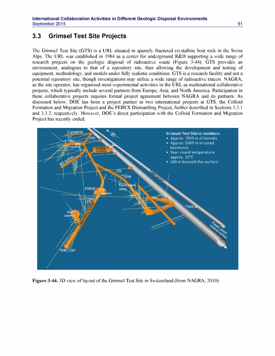
International Collaboration Activities in Different Geologic Disposal EnvironmentsSeptember 2015 51
3.3 Grimsel Test Site Projects
The Grimsel Test Site (GTS) is a URL situated in sparsely fractured crystalline host rock in the Swiss Alps. The URL was established in 1984 as a center for underground R&D supporting a wide range of research projects on the geologic disposal of radioactive waste (Figure 3-44). GTS provides an environment, analogous to that of a repository site, thus allowing the development and testing of equipment, methodology, and models under fully realistic conditions. GTS is a research facility and not a potential repository site, though investigations may utilize a wide range of radioactive tracers. NAGRA, as the site operator, has organized most experimental activities in the URL as multinational collaborative projects, which typically include several partners from Europe, Asia, and North America. Participation in these collaborative projects requires formal project agreement between NAGRA and its partners. As discussed below, DOE has been a project partner in two international projects at GTS, the Colloid Formation and Migration Project and the FEBEX Dismantling Project, further described in Sections 3.3.1 and 3.3.2, respectively. However, DOE’s direct participation with the Colloid Formation and Migration Project has recently ended.
Grimsel Test Site in numbers• Approx. 1000 m of tunnels• Approx. 5000 m of cored
boreholes• Year-round temperature
approx. 13°C• 400 m beneath the surface
Figure 3-44. 3D view of layout of the Grimsel Test Site in Switzerland (from NAGRA, 2010)

52International Collaboration Activities in Different Geologic Disposal Environments
September 2015
3.3.1 Colloid Formation and Migration Project
3.3.1.1 introduction to the CFM Project
The Colloid Formation and Migration (CFM) Project is an international research project for the investigation of colloid formation/bentonite erosion, colloid migration, and colloid-associated radionuclide transport, relevant to both NBS and EBS areas of UFD. Colloid-related R&D at GTS comprises in situ migration experiments conducted between boreholes in a fracture shear zone; these are complemented by laboratory and modeling studies. The main R&D objectives are as follows:
• To examine colloid generation rates and mechanisms at the EBS-host rock boundary under in situ conditions
• To study the long-term geochemical behavior (mobility, mineralization, colloid formation, etc.) of radionuclides at the EBS-host rock interface
• To evaluate the long-distance migration behavior of radionuclides and colloids in waterconducting features in a repository-relevant flow system (i.e., with a very low flow rate/water flux)
• To examine reversibility of radionuclide uptake onto colloids• To gain experience in long-term monitoring of radionuclide/colloid propagation near a repository.
The CFM project was preceded by the Colloid and Radionuclide Retardation (CRR) project, conducted at the Grimsel Test Site from 1997 to 2003. Twenty-seven field tracer tests were conducted during the CRR, including seven that involved short-lived radionuclides, one involving a suite of long-lived radionuclides with isotopes of U, Np, Am, and Pu, and one involving a suite of radionuclides (including Cs, Sr, Tc, U, Np, Am, and Pu isotopes) injected with bentonite colloids. Colloid-facilitated radionuclide transport was quantified by comparing the breakthrough curves of the radionuclides in the latter two tests (with and without the colloids). Similar tests with and without colloids were also conducted using nonradioactive homologues of actinides (e.g., stable isotopes of Th, Hf, and Tb). All of the CRR tests were conducted as weak-dipole tests between boreholes completed in a fracture shear zone, with the tests involving radionuclides being conducted between boreholes separated by 2.2 m. Tracer residence times in all tests were no more than a few hours.
The CFM project was initiated soon after the Grimsel Test Site transitioned to Phase VI testing in 2004. While similar in many respects to the CRR project, the CFM project aimed to improve or expand upon CRR in two key areas: (1) increase tracer residence times in the fracture shear zone to allow interrogation of processes that may not be observed over the very short time scales of the CRR tests (e.g., colloid filtration, radionuclide desorption from colloids), and (2) directly evaluate the performance of bentonite backfill with respect to swelling, erosion, and colloid generation, by emplacing a bentonite plug into a borehole completed in the fracture shear zone. To accomplish these objectives, a “tunnel packer” system was installed to seal off the entire access tunnel (Figures 3-45 and 3-46) where it was intersected by the shear zone. With this packer system, the flow rate from the shear zone into the tunnel could be throttled back from a natural rate of ~700 mL/min to any desired value, and the water from the shear zone could be collected in a controlled manner. Boreholes penetrating the shear zone could then be used as injection boreholes for tracer tests or for emplacement of the bentonite plug, with the tunnel packer effectively serving as an extraction location.

International Collaboration Activities in Different Geologic Disposal EnvironmentsSeptember 2015 53
Packer System - Monitoring
Steel liner Yellow Submarine"Surface packers control
RfinlurM-ment ribs,outflow from shear zone
Hydraulic Doughnut packer
Resin layer; hydraulically sealsshear zone and adjoining matrix
Retrieval, monitoring and analysis
2 litre vial containingradionuclide input solution
Packer System - Injection/emplacement
Figure 3-45. Schematic illustration of the CFM field test bed at Grimsel Test Site (from Reimus, 2012)
Figure 3-46. CFM field test bed at Grimsel Test Site: Tunnel packer system used to isolate the shear zone (from http://www.grimsel.com/gts-phase-vi/cfm-section/cfm-site-preparation). Small disks with tubing issuing from them (inside yellow packer) are “surface packers” that seal the tunnel wall and collect water from inflow points. Tunnel diameter is 3.5 meters.

54International Collaboration Activities in Different Geologic Disposal Environments
September 2015
Seven conservative (nonsorbing) tracer tests were conducted in late 2006 through 2007 at various shear zone flow rates using different boreholes as injection holes to test the tunnel packer system and to evaluate tracer residence times that could be achieved. Tracer transport pathways in these tests and in all the CRR tests are depicted in Figure 3-47, which shows the locations of several boreholes relative to the main tunnel within the shear zone. Borehole CFM 06.002, drilled in 2006 for the CFM project, was established as the primary injection borehole to be used in subsequent tracer testing involving colloids, homologues, and radionuclides. Tests were conducted with injections of tracer solutions into borehole CFM 06.002 while extracting water from the Pinkel surface packer located at the tunnel wall ~6.2 m from the injection interval. In 2008, a tracer test was conducted in which a bentonite colloid solution with homologues presorbed onto the colloids was injected into CFM 06.002 (referred to as Test 08-01, where the first number indicates the year and the second number indicates the sequential test for that year). This test was followed immediately with a conservative tracer test in the same configuration. Based on lessons learned from these tests, a series of five more tests was conducted in 2009 and 2010. Three of these included only conservative tracers, and two included bentonite colloids and homologues in addition to conservative tracers (Test 10-01 and 10-03). More recently, the CFM Project conducted a new test (12-02), described in Section 3.3.1.2 below, involving the injection of a radionuclide-colloid cocktail including the actinides Pu(IV) and Am(III) into injection interval CFM 06.002. This experiment evaluated the transport of bentonite colloids with radionuclides from the source to the extraction point at the tunnel wall.
CRR non-radionuclide tracer testCFM 06.001
r100CR1R radionuclide tracer test
• CFM non-radionuclide tracer test
■6 All CFM tests since 2007CFM 06.002
3.5 m
6.2 m
Tunnel / \\
^591
BOMI 2-2 m BOMI 86.005M eS2BOMI 87.007
123.251BOCR 9!
5.3 miCR 00.003BOMI 86.004 BOMI 87.008 [26.20
3.9 mBOEX2
BOMI 87.009
Figure 3-47. CFM field test bed at Grimsel Test Site: Borehole layout and test locations for all tracer tests 2001-2012 (from Reimus, 2012)
The CFM project entered a new phase of testing in May 2014 with the emplacement of a radionuclide- doped bentonite plug into the same injection interval CFM 06.002 intersecting the flowing shear zone at the GTS. This experiment is being called the Long-term In-situ Test, or LIT. In 2011, three smaller diameter boreholes, CFM 11.001, 11.002, and 11.003, were drilled through the shear zone in roughly a triangular pattern around CFM 06.002 to serve as near-field monitoring boreholes during the LIT. A plan

International Collaboration Activities in Different Geologic Disposal EnvironmentsSeptember 2015 55
view of the borehole configuration around 06.002 is shown in Fig. 3-48. In addition to providing nearfield access for monitoring and sampling during the LIT, these boreholes will be used for injection of epoxy to provide stability for post-experiment overcoring of 06.002 through the shear zone over a diameter that encompasses the three smaller boreholes (shown as dashed lines in Fig. 3-48). This overcoring will allow a careful post-mortem of the LIT to determine the disposition of both bentonite and radionuclides in the shear zone at the end of the experiment. More detail on the LIT experiment is given in Section 3.3.1.3 below.
86mm borehole \Bentonite
CFM 11.001Overcorediameter
56mmCFM 06.002f monitoring
mterva si (low volume)
.Mil.. ,
h
CFM 11.003 i
OCFM 11.002Sampling
0.02m /minSZ outflowto tunnel6m
Figure 3-48. Plan view of the borehole configuration for the LIT (left) and photo showing the boreholesat the access tunnel wall (right)
In addition to the field activities conducted at the Grimsel Test Site, the CFM project includes many complementary activities aimed at helping achieve the R&D objectives listed at the beginning of this section. These activities include:
• Bentonite swelling and erosion experiments in various laboratory configurations, including artificial fractures, to better understand the processes of swelling and erosion that will occur in the bentonite-plug field experiment
• Laboratory sorption and desorption experiments of radionuclides and homologues onto both bentonite colloids and Grimsel fracture fill material
• Sorption/desorption experiments involving the competitive sorption and desorption of radionuclides/homologues in the presence of both colloids and fracture-fill material
• Colloid-facilitated radionuclide transport experiments in both crushed rock columns and in fractures in the laboratory.
• Laboratory experiments to improve detection and quantification methods for colloid analyses in field experiments, including possibly labeling the bentonite with a marker element
• Development of a bentonite swelling/erosion model• Interpretive modeling of the laboratory experiments and the field tracer tests

56International Collaboration Activities in Different Geologic Disposal Environments
September 2015
Realizing the benefit of becoming a formal partner, DOE in early 2012 formally applied for partnership in the CFM Project and was accepted as a new partner in August 2012. Other current CFM project partners are from Germany (BGR, BMWi/KIT), Japan (JAEA, CRIEPI), Great Britain (NDA), Sweden (SKB), Republic of Korea (KAERI), Finland (POSIVA), and Switzerland (NAGRA). Partnership gave DOE and affiliated National Laboratories exclusive access to all experimental data generated by CFM. More importantly, it allowed for UFD researchers to work collaboratively with international scientists in ongoing experimental and modeling studies, and it involves them in the planning of new experimental studies to be conducted in the future. Like the Mont Terri Project, this type of international collaboration goes beyond the mostly modeling focus of DECOVALEX. In contrast to both the DECOVALEX project and the Mont Terri project, which comprise a range of experiments covering a wide spectrum of relevant R&D issues, the CFM has a relatively narrow focus, i.e., colloid-facilitated radionuclide migration. In part because of this narrow focus and the comparably high membership fee relative to other international initiatives, DOE recently decided to not renew its participation in the CFM Project beyond 2015. However, UFD researchers from LANL and LLNL have actively collaborated with their international partners in FY15 and before. LANL performed interpretative analysis of CFM field measurements (Section 6.2.3), and both LANL and LLNL conducted complementary laboratory investigations of colloid-facilitated transport (Section 6.2.4 and 6.2.5).
3.3.1.2 Colloid-Facilitated Radionuclide Tracer Test
In February 2012, a colloid-facilitated radionuclide tracer test referred to as Test 12-02 (second test in 2012) was conducted in a fracture shear zone at Grimsel. The colloids were derived from FEBEX bentonite, which is mined in Spain and is being considered as a potential waste-package backfill material for a Spanish nuclear waste repository. The radionuclides were pre-sorbed onto the colloids to varying degrees, dictated by their sorption to the colloids (probably ~100% sorbed for Pu and Am, ~50% sorbed for U and Np, somewhere in between for fission products Cs and Sr). The tracer cocktail was injected into injection interval CFM 06.002i2 at a target flow rate of ~0.35 mL/min, while water was being continuously extracted at a rate of 25 mL/min from the Pinkel surface packer at the tunnel wall ~6.1 m from the injection interval. The test was initiated by introducing the tracer cocktail into a flow loop that circulated through the injection interval at a relatively high rate to keep the interval well mixed while maintaining a near-constant net injection flow rate into the shear zone. The volume of the vessel containing the tracer cocktail was 2.25 L, and the volume of the injection flow loop was 1.0 L, so the entire injection circuit volume was 3.25 L after the tracer vessel was plumbed into the system. This arrangement resulted in an exponentially decaying source term in the shear zone as the tracers were slowly bled out of the injection circuit. Two previous colloid-facilitated transport tests were conducted in this configuration, but they involved nonradioactive homologues, not radionuclides. Figure 3-49 shows measurements from the tracer test, depicting the normalized concentrations of tracers (concentrations divided by injection volume) in the water extracted from the Pinkel surface packer as a function of time.

International Collaboration Activities in Different Geologic Disposal EnvironmentsSeptember 2015 57
--------- AGA
• Colloids (MOB2)
• Pu
A Am
a Na
X Ba
• Cs
Figure 3-49. Colloid-Facilitated Radionuclide Tracer Test at Grimsel Test Site: Normalized breakthroughcurves of all tracers in CFM Tracer Test 12-02 (from Reimus, 2012)
3.3.1.3 LIT - Radionuclide-Doped Bentonite Plug Transport Experiment
This section describes the ongoing LIT experiment at CFM which involves a bentonite plug (FEBEX backfill material) doped with a suite of radionuclides that in May 2014 was emplaced into the CFM06.002 injection interval used in previous tracer tests. As mentioned above, new small boreholes were drilled and instrumented around CFM 06.002 for sampling at very low rates to provide an early indication of swelling and radionuclide release. Here we describe the LIT design/configuration as well as the emplacement and monitoring activities that have been conducted to date (from May 2014 through about June 2015). This summary is intended to document the current status of the LIT so that future involvement in the CFM project can be considered from an informed point of view. Much of this information comes from a current draft NAGRA report on the status of the LIT after one year that is not currently citable but was provided by NAGRA as a courtesy to a project partner.
The emplacement of the radionuclide-doped bentonite plug for the LIT was a significant challenge. There were several design considerations and test constraints, including the following:
• the need to confine the emplaced bentonite between straddle packers in the borehole at the depth of the shear zone and to fill as much of the empty space between the packers as possible with bentonite,
• the need for minimally reactive materials in the straddle packer assembly so that the radionuclides would not interact with these materials in the borehole,
• the need to dope the bentonite with radionuclides in a way that would allow the straddle packer assembly to be inserted into the emplacement hole without smearing contamination onto the borehole walls.

58International Collaboration Activities in Different Geologic Disposal Environments
September 2015
The resulting emplacement system is shown in Figures 3-50 and 3-51. Its features included:• A set of 16 bentonite rings compressed to a target dry density of 1.65 g/cm3 and designed to fit
snugly over a straddle packer mandrel made of nonreactive PEEK® material (shown in previous studies to be one of the most nonreactive materials to the radionuclides) (Figure 3-50),
• 16 small glass vials filled with radionuclide-doped bentonite that were inserted into holes drilled into the central 4 of bentonite rings (the glass provided containment of the radionuclides during insertion of the system into the borehole, with the expectation that the vials would break open when the bentonite wetted and exerted swelling pressure on them) (Figure 3-51),
• pressure transducers in both the upper and the lower packer assemblies to measure both total axial pressure exerted on the packers (redundant transducers in each packer) and pore pressure in the bentonite (measured with a transducer behind a fine-mesh screen that prevented the bentonite from exerting pressure directly on the transducer).
The bentonite in the four central rings into which holes were drilled consisted of 90% regular FEBEX bentonite (used in all previous CFM experiments; obtained from a mine in Spain) and 10% synthetic bentonite labeled with Zn, and the bentonite inserted into the vials was a Ni-labeled synthetic bentonite. The Zn and Ni were to be subsequently used to distinguish colloids from the bentonite source term from natural colloids in groundwater samples. The radionuclides and a dye tracer (Amino-G Acid, or AGA) were added to a solution that was used to create a concentrated bentonite slurry that was packed into each of the vials (leaving a small amount of void space in the vials). The bentonite rings had to be broken to fit them around the mandrel of the packer system, but they were pieced back together with negligible loss of bentonite and held together with plastic tape until just before they were inserted into the borehole, after which the borehole walls prevented them from falling away from the mandrel.
The bentonite packer system emplacement was accomplished without incident on May 12, 2014, with a last-minute adjustment that involved removing all the vial caps before placing the vials open-end-first into the holes drilled into the bentonite rings. This adjustment ensured that the radionuclides would have a release pathway out of the vials even if the swelling pressure was not sufficient to cause them to break (laboratory tests had shown that breakage did not always occur when the bentonite swelled). The vials were also pre-scored to facilitate their breakage.
In parallel with the emplacement, low-flow sampling of one of the three near-field monitoring boreholes was established in the shear zone. This sampling was conducted at a steady rate of 0.02 ml/min in the monitoring borehole (CFM 11.002) that was shown in previous tracer tests to be the best connected of the three small boreholes to the emplacement hole. The other two monitoring boreholes were shut in and are simply being used for pressure monitoring, although they also have sampling systems that can be activated later if desired. Each of the monitoring boreholes is equipped with a PEEK ‘dummy’ that occupies the majority of the dead space between the packers, leaving only a ~1-mm annular space to reduce dead volume for sampling.
Prior to and after the bentonite emplacement, a steady outflow rate of 25 ml/min was maintained in the Pinkel surface packer installed in the mega-packer system at the access tunnel wall approximately 6 m from the bentonite emplacement. This flow rate had been shown in previous tracer tests to be sufficient to induce a shear zone flow that captured most of the water passing through the shear zone near the emplacement borehole, thus maximizing the probability that radionuclides and colloids released from the bentonite source term would be collected at the tunnel wall. Samples collected in both the near-field monitoring borehole sampling system and at the Pinkel surface packer were analyzed onsite for fluorescence to detect the appearance of the dye tracer included in the radionuclide cocktail and turbidity to detect the appearance of bentonite colloids. Additionally, parameters such as pH, Eh/ORP and specific conductance can be routinely monitored on site. The radionuclide concentrations and additional colloid

International Collaboration Activities in Different Geologic Disposal EnvironmentsSeptember 2015 59
parameters (e.g., more quantitative determinations of concentrations as well as size distributions) are being measured in analyses conducted at offsite laboratories. Additionally, a laser-induced breakdown system has been used intermittently onsite to obtain colloid concentration and size distribution data.
Figure 3-50. LIT packer system with PEEK mandrel shown in yellow (left), configuration of 16 bentonite rings between packers (middle), and photo of compacted bentonite ring (right). The four central bentonite rings were traced with a synthetic Zn-labeled montmorillonite (10% of mass) and had 4 holes drilled in each of them for insertion of glass vials containing radionuclide-doped bentonite.
Figure 3-51. Schematic showing the LIT packer string and a photo of one of the radionuclide-doped bentonite vials after insertion into a hole in one of the four central bentonite rings

60International Collaboration Activities in Different Geologic Disposal Environments
September 2015
Preliminary test results since May 2014 show that the bentonite rings emplaced between the packers in CFM 06.002i2 wetted and swelled rapidly. Figure 3-52 shows the early pressure history measured by the transducers in both CFM 06.002 and in one of the nearby monitoring boreholes that was not being actively sampled, CFM 11.003. The pressures exerted on the transducers exposed to the swelling bentonite rose very rapidly to different pressures in the top and bottom packers, although both pressures were significantly elevated above the shear zone porewater pressure (indicated by the CFM 11.003 pressure). The pore pressures measured behind the mesh screens that prevented bentonite contact with the transducers rose somewhat less rapidly to the ambient water pressure in the shear zone, indicating relatively quick saturation within the interval and pressure equilibration with the shear zone. These results suggest rapid swelling of the bentonite near the shear zone inflow point(s) and rapid transmittal of the swelling pressure to the ends of the packed-off interval, followed by later arrival of the water itself at the ends of the interval, resulting in a delayed rise in pore pressure. The different total pressures exerted at the different ends of interval indicate some apparent heterogeneity in the swelling of the bentonite.
Upper packer; surface ■
o w Q.
Lower packer surface
CFM 06.002-i2down
10 15Elapsed (days)
Figure 3-52. Pressures recorded during the first 25 days after bentonite emplacement. Note there are two redundant total pressure transducers in the upper and lower packer surfaces and one pore pressure transducer in each packer surface. CFM 11.003 is one of the near-field monitoring boreholes.
Figure 3-53 shows the onsite chemistry monitoring data in the near-field monitoring borehole (red), and also the specific conductance, Eh and pH in the water extracted from the surface packer at the tunnel wall

International Collaboration Activities in Different Geologic Disposal EnvironmentsSeptember 2015 61
(black) during the first year after bentonite emplacement. The data appear somewhat choppy with occasional discontinuities (particularly SC, Eh and pH) because of power interruptions and periodic calibrations of the monitoring instrumentation. The specific conductance quickly rose from ambient values, suggesting some dissolution of accessory minerals in the bentonite (which is not pure montmorillonite), but it then leveled off and decreased throughout the remainder of the one-year period. pH initially drifted downward in the near-field monitoring borehole but then reversed, mirroring the specific conductance trend. Eh showed an initial decrease in the near-field borehole, consistent with the consumption and flushing of the oxygen/air that was introduced to the system during the emplacement, but it never reached the low values recorded at the tunnel wall.
recalibration of flu ro meter
UUubjjf^rh^mrrrrTTr rmr
200Elapsed days
L1BD reconnectgeochemistry
; cabinet __^-T> KWO Power. J - - . V . I , , . . failure, ,
Figure 3-53. Onsite chemistry monitoring data during the first year of after bentonite emplacement. Red lines correspond to the CFM 11.002 near-field monitoring borehole and black lines correspond to the Pinkel surface packer at the access tunnel wall (EC, Eh and pH).
The fluorescence (AGA concentration) and turbidity data of Figure 3-53 indicate the arrival of both conservative dye tracer and colloids (turbidity) in CFM 11.002 after about 100 days. The AGA fluorescence results suggest that at least one of the vials started contributing dye tracer to the shear zone flow system at this time, and the turbidity results suggest that some of the emplaced bentonite began eroding to form mobile colloids at this time. It should be noted that an acoustic monitoring system was deployed within the packer system to monitor for glass vial breakage, but the system failed to detect any definitive breakage signals. Of course, given that the vials were inserted uncapped, breakage would not strictly be necessary to release the dye tracer into the bentonite.
Figure 3-54 shows the apparent breakthrough of Amino-G Acid at the Pinkel surface packer at the tunnel wall. The signal is somewhat noisy because the concentrations are barely above detection limits. Also shown in Figure 3-54 is a scaled-down version of the tracer response in the near-field monitoring borehole, and it is apparent that the breakthrough at the tunnel wall was essentially coincident with the breakthrough in CFM 11.002. This result is not surprising, as the mean shear zone residence times in all previous tracer tests conducted between the CFM 06.002 emplacement hole and the tunnel wall were on

62International Collaboration Activities in Different Geologic Disposal Environments
September 2015
the order of a day, so over the time scale of the LIT, the breakthroughs at the two location would be expected to be essentially coincident. Radionuclide and colloid concentrations in samples are in the process of being analyzed at the time this chapter was written, and there are no results to report yet (other than the onsite turbidity measurements for colloids in CFM 11.002).
Figure 3-54. Amino-G acid signal at the Pinkel surface packer (magenta) and a scaled down plot of the Amino-G acid signal in the near-field monitoring borehole (red)
Overall, the LIT is progressing very well with successful monitoring of swelling of the emplaced bentonite water saturation of the emplacement interval during the early portions of the test. Although the swelling pressures are quite different at the two ends of the emplacement interval, the pressures are consistent with expected dry densities in the interval (within 10% of theoretical/calculated) assuming the emplaced bentonite swelled to fill the available space in the interval. Chemistry monitoring in a near-field monitoring borehole indicates some early chemical transients likely associated with accessory mineral dissolution in the emplaced bentonite, followed by the appearance of the conservative dye tracer and (less prominently) colloids about 100 days after bentonite emplacement. The conservative dye tracer has also been detected at very low levels in the water drawn from the surface packer at the tunnel wall (starting at about 100 days after emplacement and roughly mirroring the breakthrough in the near-field borehole).
The LIT will progress for at least another year, at which time the project partners will decide whether to continue the test in its current configuration for an additional period of time or to stop the test and proceed with the planned overcoring of the emplacement borehole and near-field monitoring boreholes to determine the disposition of the swelled bentonite and radionuclides in the shear zone. The information obtained from both the shut-in/monitoring phase of the test (i.e., the current phase) and the overcoring phase of the test should be useful for the development and validation of models for swelling and erosion of clays, and for models of radionuclide release and transport from a bentonite buffer/backfill.

International Collaboration Activities in Different Geologic Disposal EnvironmentsSeptember 2015 63
3.3.1.4 Colloid Formation and Migration Summary
Benefits of Participation:
• Access to experimental data from a suite of past, ongoing, and future experiments on colloid- facilitated migration at Grimsel, more narrow focus than other initiatives (Note that CFM membership does not provide access to other experiments at Grimsel)
• Opportunity to participate directly in international research groups that conduct, analyze, and model migration experiments (more direct involvement than DECOVALEX)
• Opportunity for participating in and steering ongoing or planned experiments as well asconducting own experiments
Status of Participation:
DOE formally joined the CFM Project in August 2012. UFD researchers have been involved in the interpretation and analysis of several colloid-facilitated tracer tests (Section 6.2.3) and have recently conducted batch and column transport experiments to refine a colloid-facilitated transport model and to provide insight into potential colloid-facilitated transport of Cs isotopes in a crystalline rock repository (Sections 6.2.4 and 6.2.5).
Outlook:
The interpretation of the colloid-facilitated tracer tests by UFD researchers has led to important findings with regards to relevance and predictability of colloid migration and colloid-associated RN transport. The ongoing LIT is providing valuable insights on additional aspects of colloid transport related to bentonite erosion, an important subject for UFD. However, UFD recently decided against continued participation in the CFM project, in part due to resource constraints but also because the scientific focus of the CFM Project is narrower than other initiatives discussed in this section.
Contact Information:
DOE Contact:Prasad Nair, DOE-NE
UFD Contact:Jens Birkholzer (LBNL)Paul Reimus (LANL)
CFM Contact:Ingo Blechschmidt, Head of Grimsel Test Site, NAGRA, Switzerland

64International Collaboration Activities in Different Geologic Disposal Environments
September 2015
3.3.2 FEBEX Dismantling Project
3.3.2.1 introduction to FEBEX Dismantling Project
The FEBEX heater test is a full-scale Engineered Barrier System (EBS) test that has been operating under natural resaturation conditions for almost two decades (Figures 3-55). The overall objective was to evaluate the long-term performance of the EBS and, to a lesser degree, the near-field crystalline rock, with emphasis on the thermal evolution and resaturation of bentonite backfill surrounding a heated waste package. With heating started in 1997, the FEBEX experiment is the longest running full-scale heater experiment in the world, providing a unique data set for the transient behavior of a heated repository. A fixed temperature of 100°C has been maintained at the heater/bentonite contact during this time, while the bentonite buffer has been slowly hydrating with the water naturally coming from the rock. A total of 632 sensors of diverse types were installed in the clay barrier, the rock mass, the heaters, and the service zone to measure the following variables: temperature, humidity, total pressure, displacement, and pore pressure.
Partial dismantling of the in situ test was carried out during 2002, after five years of heating. The first one of the two heaters was removed and the materials recovered (bentonite, metals, instruments, etc.) have been analyzed to investigate the different types of processes undergone, while the second heater continued (Figures 3-56 and 3-57). The samples recovered from this first heater experiment provided valuable information on the long-term condition of heated EBS materials (Lanyon et al., 2013). In FY15, about 12 years after the first partial dismantling, NAGRA launched the FEBEX Dismantling Project (FEBEX-DP), which removed the second heater and recovered relevant EBS and host rock materials. This provides a unique opportunity for analyzing samples from an engineered barrier and its components that underwent continuous heating and natural resaturation for 18 years. DOE has joined the FEBEX-DP Project as one of the initial partners, together with NAGRA, SKB, POSIVA, ENRESA, CIEMAT, KAERI, OBAYASHI, ANDRA, and possibly RWM and SURAO. In FY15, UFD researchers from LANL, LBNL, and SNL participated in the test design and sampling plan development and conducted preliminary model predictions (Section 6.1.2).
HEATER #1 HEATER #2
CONCRETEPLUG
LINER CABLECHANNEL
SECTIONSLICE
D1 L El FI Ml N G H I102 9694 06+05 79 73 67 63 59oi to so so «o o soon o to o «— t—. ft ti inOn *— <T> on on tr. on cr>mm* I I —L # A h.. m T1 mm. -TI
M2F2 E2 D246 42 + 41 32+ 31 24
si S §^ ~ ^X VALUE
I l Lamprophyre !■. ■ j Concretet'’’i Granite i i Bentonite
0 1
Figure 3-55. Schematic cross section of the FEBEX Test at Grimsel Test Site (from NAGRA, 2014)

International Collaboration Activities in Different Geologic Disposal EnvironmentsSeptember 2015 65
Figure 3-56. Bentonite blocks during installation of the experiment in 1996 (left) and after the first dismantling in 2002 (right). In 2002, all initial emplacement gaps between blocks were closed (from NAGRA, 2014).
Moisturecontent
SECTION 1 SI ice 110
BSlC*&rom instruments
Figure 3-57. Moisture content and sampling locations derived from 2002 dismantling campaign. Moisture distribution in the bentonite shows an axial symmetry independent of the geologic variability in the adjacent host rock (from NAGRA, 2014).

66International Collaboration Activities in Different Geologic Disposal Environments
September 2015
3.3.22 FEBEX-DP Objectives
The FEBEX-DP project is conducted to provide data and to improve understanding of the long-term THMC performance of the EBS components and their interactions with the host rock. This will increase confidence in the models required for predicting the long-term evolution of the engineered barriers and how these are affected by their natural environment. The FEBEX-DP Project thus focuses on the following primary goals (Gaus and Kober, 2014; NAGRA, 2014) (Figure 3-58):
• Characterization of the key physical properties (density, water content) of the bentonite and their distribution
• Characterization of corrosion processes on instruments and coupons under evolving redox conditions and saturation states
• Characterization of mineralogical interactions at material interfaces and potential impacts on porosity
• Integration of monitoring results and modeling
1 Bentonite characterisation* Density, water content and spatial distribution* Chemical changes
Characterisation of corrosion and microbial processes* On instruments/sensors and coupons* Bacterial growth* All under evolving redox-conditions
/
X.
Mineralogical interactions at material interfaces• Conrete- bentonite, heater/liner - bentonite, rock - bentonite* Impact on pore water composition
Integration of the monitoring results and modelling* TH M/THMC modelling• Pre-and postdismantling
Figure 3-58. Primary goals of FEBEX-DP Project (from NAGRA, 2014)

International Collaboration Activities in Different Geologic Disposal EnvironmentsSeptember 2015 67
These primary goals are realized by pursuing the following secondary objectives regarding the main elements of the experiment:
• Buffer and interfaces:- Obtain 3D insight into the water content and density distributions of the bentonite through
extensive sampling.- Obtain insight into THM parameters and their evolution in time through comparison with the
values of the first dismantling- Characterize pore water changes, modifications in the absorbed cations in the clays and
potentially mineralogical alteration.- Microbiological characterization- Characterize interfaces with the liner, the heater, the embedded corrosion coupons and
instrumentation and identify potential chemical interactions affecting the bentonite• Instrumentation and metal coupons:
- Recalibrate and correct the monitoring results if required, analyze their mechanical performance
- Analyze corrosion products• Plug and interfaces
- Investigate the performance of the shotcrete at macro and micro level as well as the potential chemical changes occurring along the interfaces
• Granite host rock (service area and heated zone)- Investigate the rock properties of both zones, in particular the performance of the granite and
the interfaces granite/bentonite.• Heater and liner
- Analyze potential corrosion, changes of position of the heater and deformations of the liner
3.32.3 FEBEX-DP Activities and Timeline
The FEBEX-DP project officially started with a kick-off meeting held June 10, 2014, in Thun, Switzerland. The project will continue until the end of 2016, when a final synthesis report is expected on the project findings. The FEBEX-DP project includes the following activities (Gaus and Kober, 2014):
Pre-dismantling modeling:
Pre-test modeling was conducted by a few international modeling groups to evaluate the predictive capability of THM and THC models regarding the long-term behavior of the EBS components. The THM models were developed by the Technical University of Catalonia to analyze the potential impact of switching off the heaters on the stress, pore pressure and relative water content in the EBS and granite. Preliminary THC models have been developed by LBNL to provide a scope of the geochemical changes after the dismantling of Heater 2 (see Section 6.1.2).
Field work related to the dismantling:
A final dismantling plan was developed in January 2015. Figure 3-59 shows the configuration of the dismantling sections during the dismantling of Heater 2. In February 2015, drilling was conducted through the concrete plug and parts of the bentonite to get access to the heater test area, and in about two weeks of dismantling, the dismantling crew retrieved several overcores with intact shotcrete/bentonite interface (Figure 3-60). Then the concrete plug was demolished staring from April 8, 2015 until April 16, 2015. On April 24, 2015, the heater was switched off, after 6630 days of operation. The sampling on the first bentonite section (Section 36) started on May 11, 2015. Sampling of all other sections was finished

68International Collaboration Activities in Different Geologic Disposal Environments
September 2015
on August 6, 2015. Figure 3-61 shows an example of several core samples drilled out of one dismantling section, in this case section 62. The samples are currently being distributed to partners of FEBEX-DP for THMC and biological characterization and further experimental study.
s is s imi r * swsi * ^ * ssbs §5 S3 * ssfff Ss s esc S3 s s sseS
Tracers (SSS. CP)
rHM and THG
Water Content and Dry DensityRock/Concrete or Concrete
Sensors
Microbial
Corrosion
Figure 3-59. Sampling cross-sections (numbers in circles are cross-section numbers) for FEBEX-DP Project (from NAGRA, 2014)
Figure 3-60. An overcore that preserves the interface between shotcrete and bentonite

International Collaboration Activities in Different Geologic Disposal EnvironmentsSeptember 2015 69
Figure 3-61. The front of dismantling section 62 with the core samples taken for microbiological studies,the blue bar prevents the partially detached bentonite from collapsing.
Data synthesis and post-dismantling modeling:
Starting in early FY16, results from laboratory analysis of various types of samples will be tested and compared against the predicted behavior of the EBS components, using coupled THM and THC models. UFD researchers have participated in the pre-dismantling modeling (see Section 6.1.2.1). Postdismantling modeling, analytical work on samples and further laboratory experiments on FEBEX bentonite will be conducted by UFD in FY16 (see Section 6.1.2.2).
3.3.24 FEBEX-DP Summary
Benefits of Participation:
• Access to experimental samples and laboratory investigations from a long-term heater experiment with focus on engineered barrier components, more narrow focus than other initiatives (Note that FEBEX-DP membership does not provide access to other experiments at Grimsel)
• Opportunity to participate directly in international research groups that analyze samples and conduct modeling work on coupled THM and THC behavior (more direct involvement than DECOVALEX)
• Opportunity for designing sampling plans as well as conducting own laboratory experiments

70International Collaboration Activities in Different Geologic Disposal Environments
September 2015
Status of Participation:
DOE joined the FEBEX-DP Project as one of the initial partners. UFD researchers have participated in the test design and sampling plan development, and will continue working on the post-dismantling modeling and experimental studies (Section 6.1.2). In FY15, the dismantling operation of the FEBEX test bed was successfully finalized and has provided valuable core samples for further analysis, testing and modeling.
Outlook:
In FY15, LBNL researchers finished a preliminary THC model (Zheng et al., 2015) for pre-dismantling analyses. DOE/UFD is expected to receive samples at the beginning of FY16. Until the end of project in calendar year 2016, DOE/UFD researcher will develop coupled THMC model for post-dismantling interpretation and will conduct further laboratory experiments with FEBEX bentonite samples to study the pore structure of bentonite and chemical alteration under high temperatures.
Contact Information:
DOE Contact:Prasad Nair, DOE-NE
UFD Contact:Jens Birkholzer (LBNL)Carlos Jove-Colon (SNL)Liange Zheng (LBNL)
CFM Contact:Irina Gaus and Florian Kober, NAGRA, Switzerland
3.3.3 Other Experiments at Grimsel Test Site, Switzerland
3.3.3.1 Ongoing Experiments
Besides the CFM and the FEBEX-DP Project, other collaboratively conducted experiment at the Grimsel Test Site (GTS) may also be of interest to DOE/UFD. Worth considering is perhaps the Gas-Permeable Seal Test (GAST) (Focus: EBS), which looks at bentonite-sand mixtures for increased gas transport capacity (to mitigate pressure buildup from gas generation) within the backfilled underground structures, without compromising the radionuclide retention capacity of the engineered barrier system (Figure 3-62). Other options include the Long-Term Cement Studies (LCS) project (Focus: EBS), which has the overall aim to increase understanding of the cement-leachate interaction effects in the repository near field and geosphere, the (2) the Long-Term Diffusion (LTD) project (Focus: NBS), which has the overall aim to provide quantitative information on matrix diffusion of radionuclides in fractured rock under in situ conditions over long time scales, and (3) the experiments on gas production and migration conducted within the European Union project FORGE (Fate of Repository Gases). The possibility of participation, and the conditions of being involved in these latter three projects, requires further clarification.

International Collaboration Activities in Different Geologic Disposal EnvironmentsSeptember 2015 71
Figure 3-62. GAST Experiment at Grimsel Test Site: Schematic picture of repository seal design with 810 m long sand/bentonite plug in between two gravel packs and a concrete plug for reinforcement (from http://www.grimsel.com/gts-phase-vi/gast/gast-introduction)
3.3.3.2 High-Temperature Heater Test
On a final note, several international disposal programs have recently initiated investigating if clay-based barriers can withstand temperatures higher than the 100 °C threshold for bentonite performance usually assumed in advanced repository designs. For example, the UFD campaign is investigating the feasibility of direct geological disposal of large spent nuclear fuel canisters currently in dry storage (Hardin et al., 2014), which would benefit from much higher emplacement temperatures. The performance of bentonite barriers in the <100 °C temperature range is underpinned by a broad knowledge base built on laboratory and large-scale in-situ experiments. Bentonite parameter characterization above 100°C is sparser (especially for pelletized materials), although up to about 150 °C no significant changes in safety-relevant properties are indicated. At temperatures above 150 °C, it is possible that a potentially detrimental temperature-driven physico-chemical response of materials (cementation, illitization) may occur, the characteristics of which are highly dependent on, and coupled with, the complex moisture transport processes induced by strong thermal gradients. The impact of such complex processes on the performance of a repository cannot be realistically reproduced and properly (non-conservatively) assessed at the smaller laboratory scale. Such an assessment needs to be conducted by large in-situ experiments in underground research laboratories (URLs), where the most relevant features of future emplacement conditions can be adequately reproduced.
Potential options for a targeted high-temperature experiment (150 °C to 200 °C) in a fractured rock environment are currently being considered (Vomvoris et al., 2015). NAGRA has recently suggested that one possibility would be to use the well-characterized FEBEX drift at the Grimsel Test Site once the FEBEX-DP dismantling is finalized (Figure 3-63). Design characteristics for such an experiment still need to be developed, for example type of bentonite, target temperature, duration and additional processes to be investigated. The benefit of such a large-scale test, accompanied by a systematic laboratory program and modeling effort, is that the temperature effects can be evaluated under realistic conditions of strong thermal, hydraulic and density gradients, which cannot be reproduced in the laboratory. This will lead to improved mechanistic models for the prediction of temperature-induced processes, including chemical

72International Collaboration Activities in Different Geologic Disposal Environments
September 2015
alteration and mechanical changes, which can then be used for performance assessment (PA) analysis of high-temperature scenarios. The key question is whether higher repository temperatures would trigger mechanisms that compromise the various barrier functions assigned to the engineered components and host rock. If the barrier function is (partially) compromised, PA analysis can evaluate whether reduced performance of a sub-barrier (or parts thereof) would still give adequate performance. Discussions are ongoing within the international community regarding the feasibility and specifications of a “hot” FEBEX test.
Figure 3-63. Conceptual design of a potential high-temperature heater test to be conducted at Grimsel Test Site, in the well-characterized FEBEX drift (Vomvoris et al., 2015)

International Collaboration Activities in Different Geologic Disposal EnvironmentsSeptember 2015 73
3.4 SKB Task Forces
3.4.1 Introduction to SKB Task Forces
SKB, the Swedish Nuclear Fuel and Waste Management Company, has been organizing task forces as a forum for international organizations to interact in the area of conceptual and numerical modeling of performance-relevant processes in natural and engineered systems. There are two task forces: the Groundwater Flow and Transport (GWFTS) Task Force initiated in 1992, and the Engineered Barrier Systems (EBS) Task Force initiated in 2004. The GWFTS Task Force is led by Bjorn Gylling of SKB. The EBS Task Force has two parts, one for THM processes (led by Antonio Gens from UPC in Spain), the other for THC processes (led by Urs Maeder of University of Bern). Different modeling tasks are being addressed collaboratively, often involving experiments carried out at SKB’s Aspo Hard Rock Laboratory (HRL) situated in crystalline rock near Oskarshamn in Sweden. The Aspo HRL consists of a main tunnel that descends in two spiral turns to a depth of 460 m, where various tests have been and are being performed in several side galleries and niches (Figure 3-64).
Figure 3-64. Layout of Aspo HRL and location of main experiments (from Birkholzer, 2012)
Like the other collaborative initiatives introduced earlier in this report, participation in SKB in the Task Forces requires a formal membership agreement. Each participating organization is represented by a delegate; the modeling work is performed by modeling groups associated with these organizations (not

74International Collaboration Activities in Different Geologic Disposal Environments
September 2015
unlike the DECOVALEX framework). The task forces meet regularly about once to twice a year. Task force members interact closely with the principal investigators responsible for carrying out experiments at Aspo HRL. Much emphasis is put on building of confidence in the approaches and methods in use for modeling of groundwater flow and migration, as well as coupled THM and THC process, in order to demonstrate their use for performance and safety assessments.
In the past years, DOE/UFD’s liaison for international collaboration frequently interacted with SKB representatives to evaluate the condition and benefits of joining one or both task forces. UFD representatives participated in the GWFTS Task Force meeting in April 24-25, 2012, in Oskarshamn in Sweden and also participated in a joint meeting of the GWFTS and EBS Task Forces held in Lund, Sweden, November 27-29, 2012. DOE eventually joined both task forces in January 2014 and hosted a joint task force meeting in Berkeley in December 2014. Other participating organizations in the GWFTS and/or EBS Task Forces are SKB, POSIVA, KAERI, CRIEPI, JAEA, NAGRA, BMWi/KIT, RWM, NWMO, and SURAO.
In the past, UFD researchers have been actively engaged in the GWFTS task force and have conducted simulation work supporting the interpretation of the BRIE experiment (see Section 6.1.4). Currently, DOE/UFD is going through a planning and selection process regarding future work with SKB as both task forces are in a transition stage with several long-running modeling tasks winding down and new task proposals being developed and discussed.
3.4.2 GWFTS Task Force
The main objective of the GWFTS Task Force is to develop and apply appropriate methods for investigating flow and transport in fractured crystalline rock, in particular to obtain better understanding of the retention of radionuclides transport in crystalline rock, and to improve the credibility of simulation models. The task force also provides a platform for interaction in the area of conceptual and numerical modeling of groundwater flow and solute transport in fractured rock.
The main modeling task currently conducted in the GWFTS task force is Task 8: Modeling of the Bentonite Rock Interaction Experiment (BRIE) at Aspo HRL. The BRIE experiment is a joint task shared between the GWFTS and the EBS Task Forces. The main objective of the BRIE experiment is to enhance the understanding of the hydraulic interaction between the fractured crystalline rock at Aspo HRL and the unsaturated bentonite used as backfill. The experiment is subdivided into two parts: the first part involving the selection and characterization of a test site and two central boreholes, the second part handling the installation, monitoring, and later overcoring of the bentonite-rock interface. Modeling groups seek (a) to gain a better understanding of water exchange at the bentonite-rock interface, and (b) to obtain better predictions of bentonite wetting in a fractured rock mass. Task 8 has been ongoing for several years now and is expected to wind down in 2016 or 2017. A new task is currently under consideration in the GWFTS Task Force, which would involve modeling of diffusion/sorption experiments such as the Long Term Diffusion Experiment at Aspo HRL or the REPRO (Rock Matrix Retention Properties) Experiment at Onkalo URL in Finland. More details on Tasks 8 and 9 are given below.
3.4.2.1 Task 8: Bentonite Rock interaction Experiment (BRIE)
The main objective of the ongoing BRIE experiment is to enhance the understanding of the hydraulic interaction between the fractured crystalline rock at Aspo HRL and the initially unsaturated bentonite used as backfill (SKB, 2011b). The setup is aligned with the Swedish concept of emplacing canisters into vertical deposition holes that are subsequently backfilled (Figures 3-65 and 3-66). The experiment is

International Collaboration Activities in Different Geologic Disposal EnvironmentsSeptember 2015 75
subdivided into two main parts: the first part describing the selection and characterization of a test site and two central boreholes, the second part handling the installation and extraction of the bentonite buffer. Initial characterization resulted in a deterministic description of the fracture network at a small scale (10 m). This includes all identified fractures and the water-bearing part of the fractures. BRIE has its focus on the common boundary between the bentonite clay and the water-bearing fractures in the near-field host rock, and as mentioned above, is a modeling task jointly undertaken by the Task Force on Groundwater Flow and Transport and the Task Force on Engineered Barrier Systems. UFD researchers from Los Alamos National Laboratories have been participating in the modeling analysis of the BRIE experiment (see Section 6.1.4).
a) Selection of siteb) Site characterization
:) Drilling and characterization of central borehole
d) Draw-down and stabilization e) Deposition of bentonite buffer
f) Recovery and saturation g) Recovered and saturated
Figure 3-65. Schematic presentation of the stages of the BRIE Experiment at Aspo HRL (from Bockgard et al., 2012)

76International Collaboration Activities in Different Geologic Disposal Environments
September 2015
Figure 3-66. BRIE Experiment at Aspo HRL: The test niche and five boreholes (distance 1.5 m) used for initial characterization and selection of BRIE site (from SKB, 2011b)
3.4.2.2 Task 9: Modeling Two Diffusion and Sorption Experiments in Crystalline Rock
This proposed task focuses on the modeling of coupled matrix diffusion and sorption in heterogeneous crystalline rock matrix at depth. This is done in the context of inverse and predictive modeling of tracer concentrations measured in two in-situ experiments performed within LTDE-SD at the Aspo HRL in Sweden as well as within the REPRO project at Onkalo URL in Finland (see Section 4.6), focusing on sorption and diffusion. The ultimate aim is to develop models that in a more realistic way represent retardation in the natural rock matrix at depth. Researchers from DOE/UFD are likely to participate in Task 9 starting FY16.
LTDE-SD, the Long-Term Diffusion Sorption Experiment was completed in 2010. The experiment was designed to examine diffusion and sorption processes in both matrix rock and a typical conductive fracture identified in a pilot borehole. A telescoped large-diameter borehole was drilled subparallel to the pilot borehole, in such a way that it intercepts the identified fracture some 10 m from the tunnel wall, and with an approximate separation of 0.3 m between the circumferences of the two boreholes (Figure 3-67). A cocktail of nonsorbing and sorbing tracers was circulated between the boreholes in packed-off sections for a period of 6 4 months, after which the borehole was overcored and the extracted rock analyzed for tracer penetration and fixation. The specific objectives of LTDE-SD were to:
• Obtain data on sorption properties and processes of individual radionuclides, and their effect on natural fracture surfaces and internal surfaces in the rock matrix.
• Investigate the magnitude and extent of diffusion into matrix rock from a natural fracture in situ under natural rock stress conditions and hydraulic pressure and groundwater chemical conditions.
• Compare laboratory-derived diffusion constants and sorption coefficients for the investigated rock fracture system with the sorption behavior observed in situ under natural conditions, and to evaluate whether laboratory-scale sorption results are representative also for larger scales.

International Collaboration Activities in Different Geologic Disposal EnvironmentsSeptember 2015 77
The illustration in the lower right of Figure 3-67 shows the location of LTDE-SD in the Aspo HRL tunnel system. In the center of the figure, the local tunnel section is depicted together with the different boreholes drilled from the site. These boreholes include the LTDE-SD borehole and the closely located pilot borehole. These two boreholes intersect a water-conducting natural fracture at a distance of 11 m from the tunnel wall, which is the experiment’s target fracture. The LTDE-SD borehole was drilled with different diameters, roughly described as follows. Up to the fracture plane the borehole has a large diameter and beyond the fracture plane a small diameter was used. This is simplistically illustrated in the lower left of Figure 3-67. The borehole is indicated by the solid black line and the intersected fracture is indicated by the curved blue line. Orange areas indicate packed-off volumes, whereas blue areas indicate volumes of the tracer cocktail. The red arrows symbolize in-diffusion of tracers from the large-diameter borehole through the fracture surface and into the underlying altered rock matrix. They also symbolize diffusion into the unaltered rock matrix from the small-diameter borehole. The dashed black line indicates the rock volume that was overcored at the end of the tracer test.
The tracers injected were Na-22, S-35, Cl-36, Co-57, Ni-63, Se-75, Sr-85, Nb-95, Zr-95, Tc-99, Pd-102, Cd-109, Ag-110, Sn-113, Ba-133, Cs-137, Gd-153, Hf-175, Ra-226, Pa-233, U-236, and Np-237. Tracer concentrations as well as other environmental parameters were monitored during the 200 days the tracer test progressed. After that the surrounding rock volume was overcored, and from the overcored volume a number of smaller drill cores were excavated, as illustrated on the left in Figure 3-68. Here the natural fracture surface is located on the right-hand side of the overcored rock volume. A large number of the core samples of Figure 3-68 were cut into subsamples as indicated to the right in Figure 3-68, enabling the obtaining of tracer penetration profiles. Tracer concentrations (or activities) in the rock were obtained by a number of analysis methods, including autoradiography on intact samples; direct activity measurements on intact and crush samples; and leaching or dissolution of intact and crush samples, followed by water phase measurements.
experiment container
Electronic container
LTDE-SD large-diameter borehole
LTDE-SD sma -diameterboreho e
Pilot borehole
LTDE-SD target fractureNaba 3C6/A
LTDE-SD site
Figure 3-67. Schematic layout of LTDE-SD at Aspo HRL (from SKB, 2011a)

78International Collaboration Activities in Different Geologic Disposal Environments
September 2015
A1.4 A1.5 Al.fi
Figure 3-68. Illustration of the sampling of the overcored rock volume in LTDE-SD (from SKB, 2011a)

International Collaboration Activities in Different Geologic Disposal EnvironmentsSeptember 2015 79
Results from the overcoring rock volume in LTDE-SD provide concentration profiles in the rock matrix that are not fully understood to date. Figure 3-69 shows experimental concentration profiles of two tracers compared to predictive model results, with obvious discrepancies in the curve shapes. These may be a result of heterogeneities in the rock matrix or may be related to inappropriate model assumptions related to Fickian diffusion or equilibrium sorption. One aim of Task 9 will be to increase realism in the diffusion-sorption predictions of the LTDE-SD.
CI-36, fracture coated A-coreNa-22, fracture coated A-core1E+03 1E+02
♦ Measured cone ♦ Measured cone.
1 Prediction1E+02 Prediction1E+01 ik
1E+01
1E+00 -
1E+00
1E-011E-01
IE-02IE-020 0E+00 5.0E-02 1 0E-01
Penetration depth (m) Penetration depth (m)
Figure 3-69. Results from the in-situ in-diffusion experiment LTDE-SD through a natural fracture surface. Modeled Na-22 and Cl-36 penetration profiles (solid curves) are compared to the measured profiles (diamonds). Na-22 activities in the rock matrix were obtained on intact of crushed rock slices and Cl-36 activities were obtained by leaching of intact or crushed slices.
The REPRO experiments are the other important element of Task 9. REPCO involves a number of boreholes that have been drilled into the non-fractured rock matrix from a working niche at the Onkalo underground rock characterization facility, at about 400 m depth (see Figure 3-70). Borehole ONK-PP323 is utilized for the Water Phase Diffusion (WPDE) series of experiments, which are advection-diffusion- sorption tests. They are carried out between ~ 18-20 m from the tunnel wall. A 1.9 m long section has been packed off, and in this section a dummy has been placed. Its diameter is 54 mm whereas the borehole diameter is 56 mm, leaving a 1 mm gap between the borehole wall and the dummy. This gap is regarded as an artificial fracture of relatively well-defined geometry. A very low steady state water flow has been applied in this gap, directed towards the tunnel. This is achieved by injecting the water at the far end of the packed-off section, as shown to the upper right in Figure 3-70. In this water flow the tracers HTO, Na-22, Cl-36, and I-125 were injected in WPDE-1, and HTO, Na-22, Cl-36, Sr-85 and Ba-133 in WPDE-2. Injection was made as a few hours long pulse at the far end of the experimental section. As the pulse travels with the water flow, its tracers diffuse into the rock matrix. As the pulse passes, the concentration gradients are reversed and the tracers diffuse out of the rock matrix and into the flowing water. To date, two experiments have been performed at different flow rates; WPDE-1 (20 pL/min) and WPDE-2 (10 pL/min). The tracer concentrations were measured in water flowing out of the experimental section, both by on-line Na(Tl)I-scintillation detection and by analyzing water samples in the laboratory. Breakthrough curves have been obtained over half a year and about one and a half a year for WPDE-1

80International Collaboration Activities in Different Geologic Disposal Environments
September 2015
and WPDE-2, respectively. Currently there are no plans for overcoring of the rock volume surrounding the experimental section.
Another REPRO experiment, referred to as Through Diffusion Experiment (TDE), will be carried out between three parallel boreholes situated perpendicular to each other, in 1 m long packed-off sections, at a distance of about 11 to 12 m from the tunnel wall. Borehole ONK-PP326 will be used as the injection hole and boreholes ONK-PP324 and ONK-PP327 as observation holes (see Figure 3-70, upper left corner). The distances between the boreholes are between 10 and 15 cm. Advective flow between the boreholes is foreseen to be insignificant, as the experiment takes placed in a rock volume that lacks in water-bearing fractures. The tracers HTO, Na-22, Cl-36, Ba-133, and probably Cs-134 are planned to be injected. The decreasing and (expected) increasing tracer concentrations in the injection hole and observations holes, respectively, will be analyzed. This is done on extracted samples in the laboratory, by liquid scintillation counting and High Resolution x-ray spectroscopy (gamma measurements). Furthermore, on-line measurements will be performed in the injection hole and observation holes by a High Performance Germanium detector and a Na(Tl)I-scintillation detector, respectively. Tracer concentrations in the injection hole will be measured at a higher frequency at the first part of the experiment, while focus will be shifted towards analyzing breakthrough concentrations in the observation holes as the experiment progresses. Breakthroughs of non-sorbing tracers are foreseen within the timeframe of conducting Task 9, although unexpectedly low pore diffusivities may prevent this from happening. The tracers were chosen to make overcoring and analysis of tracer penetration profiles possible, although this option is presently not included in the REPRO planning. As the REPRO project is ongoing, it offers the possibility of both inverse and predictive modeling. The in-situ part of REPRO aims to tackle the topics of diffusion, sorption, anion exclusion, and rock matrix anisotropy. The laboratory part has, in addition, focused on small-scale rock characterization. This provides a wealth of input data that can be incorporated in the modeling.
PP323
TDE WPDE - PP323PP318Flow inlet
■Flow outlet32-
321fkra
327
PP320
TDE boreholes PP321, PP322,
PP324, PP326, PP327
Figure 3-70. The REPRO Niche at the 401 m level at ONKALO, and the nine boreholes drilled from the niche. Borehole PP323 is utilized for WPDE-1&2, and boreholes PP324, PP326, and PP327 for TDE.

International Collaboration Activities in Different Geologic Disposal EnvironmentsSeptember 2015 81
3.4.3 EBS-THM Task Force
As mentioned above, the EBS Task Force essentially has two distinct focus areas, one on THM processes referred to as EBS-THM (led by Antonio Gens from UPC in Spain), the other on chemical processes referred to as EBS-C (led by Urs Maeder of University of Bern). The main objective of the EBS-THM Task Force is the development and application of general and effective tools for the advanced coupled THMC analysis of buffer and backfill materials, and their interactions with a saturated fractured host rock environment. Specific goals are as follows: (1) to verify the capability to model THM processes in unsaturated as well as saturated bentonite buffer and backfill materials, (2) to validate and further develop material models and computer codes by numerical THM modeling of laboratory and field tests and compare modeling results with measured results, and (3) to evaluate the influence of parameter variations, parameter uncertainties and model imperfections. There are three ongoing modeling tasks in the EBS- THM task force, all of which have been running for several years and are expected to wind down in 2016 or 2017: the Homogenization Task, the Prototype Repository, and the BRIE experiment which is shared with the GWFTS Task Force (see Section 3.4.2.1). The Homogenization Task and the Prototype Repository Task are briefly described below, followed by a review of possible future tasks in the EBS- THM Task Force.
3.4.3.1 Homogenization Task
SKB has been undertaking an experimental program with a series of laboratory experiments to better understand and quantify homogenization of bentonite backfill. Gaps and cracks may exist due to initial bentonite emplacement or due to long-term hydraulic and chemical erosion of bentonite (the latter refers the possibility of low-ionic strength waters affecting bentonite). Such heterogeneities can impact the bulk transport properties of the backfill and thus the isolation performance of the EBS. Therefore, these experiments are important to evaluate the fate of buffer/backfill upon hydration and the capacity for effective self-sealing and water saturation in the presence of these heterogeneities.
The Homogenization Task is a modeling task supporting the experimental program. Modeling teams developed predictive models for bentonite homogenization, which were then being tested in comparison to results from the experimental series. Figure 3-71 shows a typical experimental setup for a laboratory experiment as part of the Homogenization Task. This experiment was designed to investigate the swelling and potential self-sealing of an irregular cavity that was deliberately cut into a bentonite block in two diametrical positions as shown in the figure. Because these experiments involved the study of saturated bentonite, water for hydration was provided along the radial surfaces and in the cavities. Nine transducers for measuring swelling pressure and two for measuring suction were installed as shown in Figure 3-71. Experimental results showed that complete homogenization of the bentonite block incorporating the two cavities occurred after about 4 months, a result that then needs to be explained by the simulation models. UFD researchers are not currently active in this task.

82International Collaboration Activities in Different Geologic Disposal Environments
September 2015
D(steel ring) = 304 mm D(inside filter) = 300 mm)
Measurementofforcespiston D= 20 mm Number: 7+2
120 mm 120 mmplasticcircularfilter
Block D = 300 mm H = 100 mm D = 100 mm
H = 100 mm 35 mm 100 mm
Measurement of suction Number: 2
15 mm
50 mm
70 mmCavity
Figure 3-71. Top: Schematic view of device geometry used in the large-scale buffer homogenization experiments. Bottom: Photo of the device showing the lid, inlets, and sensors along with bentonite block (from Borgesson et al., 2015)

International Collaboration Activities in Different Geologic Disposal EnvironmentsSeptember 2015 83
34.3.2 Prototype Repository
In 2000, SKB started the planning and installation of a so-called Prototype Repository as a full-scale demonstration of the integrated function of the repository, and a reference for testing predictive models concerning individual components as well as the complete repository system. The test area is located in the innermost section of the TBM tunnel at Aspo HRL. The layout involves a total of six deposition holes, four in an inner and two in an outer section—see Figure 3-72. Canisters with dimension and weight according to the current plans for the final repository, and with heaters to simulate the thermal energy output from the spent nuclear fuel, have been positioned in the holes and surrounded by bentonite buffer. The deposition holes were placed with a center distance of 6 m. This distance was evaluated considering the thermal diffusivity of the rock mass and the maximum acceptable temperature of the buffer. The deposition tunnel was backfilled with a mixture of bentonite and crushed rock (30/70). A massive concrete plug, designed to withstand full water and swelling pressures, separates the test area from the open tunnel system, and a second plug separates the two sections. This layout provides two more or less independent test sections. The monitoring system is comprised of a dense network of sensors for temperature, total pressure, pore-water pressure, relative humidity and resistivity, as well as some rock mechanical measurements. The heaters of the inner section were turned on in 2001; those in the outer section in 2004. This was followed by several years of monitoring, offering a very valuable data set of early-stage, full-scale repository evolution.
Figure 3-72. Schematic layout of Prototype Repository at Aspo HRL (from SKB, 2011a, 2011b)
In 2011, SKB excavated the outer section of the Prototype Repository while extensive samplings were performed. Approximately 1,000 samples of the backfill and about 3,000 samples of the buffer were taken to determine water content and density. The two canisters were lifted up and transported to SKB’s

84International Collaboration Activities in Different Geologic Disposal Environments
September 2015
Canister Laboratory in Oskarshamn for additional investigations. The main objectives of dismantling the outer section were to (1) investigate the density and water saturation of the buffer and backfill, (2) investigate the interface between buffer - backfill and between backfill - rock surfaces, after 7 years of wetting, (3) measure and examine the canisters (positions, mechanical stress, corrosion), (4) investigate the bedrock after dismantling, (5) study biological and chemical activities in the buffer and backfill, and (6) study possible changes of the buffer material caused by temperature and saturation processes. The observations made in one of the excavated deposition holes (Figure 3-73) are the focus of the prototype Repository modeling task of the EBS Task Force, the objective being to verify the THM processes occurring during heating and resaturation, and validation against the post-mortem analysis. The task involves modeling of one of the two outer deposition holes. UFD researchers are not currently participating in this task.
Figure 3-73. Prototype Repository at Aspo HRL: Photo of excavated deposition hole

International Collaboration Activities in Different Geologic Disposal EnvironmentsSeptember 2015 85
3.4.3.3 Potential Future EBS-THM Tasks and Outlook
The EBS-THM Task Force is considering initiation of new tasks and has been soliciting input from its task force participants. Several ideas have been brought up in recent meetings in Berkeley (December 2014) and Barcelona (May 2015), some of which may be of relevance to DOE/UFD:
• Task on homogenization in unsaturated barriers (as a continuation of the Homogenization task described in Section 3.4.3.1)
• Task on modeling of water transport in pellet filled laboratory chambers, which would aim to develop new material models for the time-dependent water uptake simulations of pelletized buffer materials
• Task on modeling the FEBEX-DP Experiment (see details in Section 3.3.2)• Task on gas transport in bentonite utilizing new gas injection laboratory experiments conducted
by the University of Bern
The above R&D activities have common goals for potential collaboration with the DOE UFD. However, no decisions on future task selection have been made to date. DOE/UFD will be represented at future task force meetings and will help finalize the future task list of the EBS-THM Task Force.
3.4.4 EBS-C Task Force
The EBS-C section of the EBS Task Force, led by Urs Maeder from the University of Bern, aims at advancing the fundamental understanding of physico-chemical processes in clay or bentonite materials relevant to various aspects of safety assessment. While ultimately a tight integration between EBS-THM and EBS-C is desired, the two EBS sections are currently working on different modeling tasks, and EBS Task Force meetings are jointly held but in separate sessions for THM and C. Also, in contrast to the EBS-THM section, which usually has a tight connection between models and experiments, the “chemical” task force has been mainly working on conceptual model development and modeling benchmark studies of varying complexity. The main goals of the EBS-C section are:
• To develop and test alternate porosity concepts that explain fundamental properties like ion and water transport and swelling pressure in bentonite buffers and other nanoporous materials,
• To assemble experimental data sets (literature and/or own experiments) that allow testing of alternate concepts and assess so their relative merits
• To gain insight at the molecular scale of physico-chemical processes within smectite interlayers (e.g., via MD simulations)
• To further develop numerical tools that allow for a general implementation of these chemical aspects into a THM framework (integration with EBS-THM). There is presently no THM code available that integrates a full chemical module including an electrostatic treatment of pore water, and likewise there is no general reactive transport code that handles an electrostatic treatment of pore water and is linked to HM processes.
3.4.4.1 Current Modeling Benchmarks
In terms of model comparison, the EBS-C group has been working on benchmark data sets of various complexity based on experiments. While these benchmarks are generally highly idealized and quite simple in terms of geometry, they tackle chemical questions of high complexity. The following provides a brief description of the benchmark data sets used in the EBS-C Task Force.

86International Collaboration Activities in Different Geologic Disposal Environments
September 2015
Benchmark 1: Salt Diffusion in Montmorillonite
This benchmark experiment evaluates diffusion of salts (Na/Ca) through montmorillonite clay. To effectively prevent ion exchange, the cation type of the source saline solution is equal to the charge- compensating cation in the montmorillonite structure. Figure 3-74 shows the experimental setup used in this experiment (Birgersson, 2011). The experimental device is fitted with a pressure transducer to measure swelling pressure. Various source solution compositions were considered:
• 1 M, 0.4 M and 0.1 M NaCl in the Na-montmorillonite case.• 0.4 M, 0.1 M, and 0.25 M CaCl2 in the Ca-montmorillonite case.
The target solution was maintained diluted during the experiment. Electrochemical measurements were used to measure electrolyte concentrations in the target solution. The key measurements in this experiment are the swelling pressure (axial stress) and salt concentration in the target solution. Also, measurements of water/solid mass ratio were performed upon tests by weight difference between dry and wet samples. Experimental data for this experimental are available through the SKB EBS TF website. The experiments are discussed in Birgersson et al. (2009).
steel filters
smiice solution
Force transducer
1target solution
montmorillonitesample
Figure 3-74. Experimental setup for Benchmark 1 involving salt diffusion experiment in montmorillonite (Birgersson, 2011; Birgersson et al., 2009)
Benchmark 2: Gypsum Dissolution in Na- and Ca-Montmorillonite
This benchmark experiment is similar to Benchmark 1 since the experimental setup is the same but the clay sample is different. This experiment evaluates through-diffusion and gypsum dissolution in a mixed sample of montmorillonite clay and gypsum in a configuration depicted in Figure 3-75. Gypsum powder is sandwiched between water-saturated montmorillonite clay samples. Water saturation was attained by monitoring the stabilization of swelling pressure in the cell. Experiments and data collection were conducted in the same fashion as in Benchmark 1. Through-diffusion and gypsum dissolution experiments were performed by controlled solution concentrations in the source and target solution reservoirs. This allows for control of chemical gradients induced by solution concentration in the reservoirs. The experiments were conducted in configurations of Na-montmorillonite - Gypsum - Na- montmorillonite and Ca-montmorillonite - Gypsum - Ca-montmorillonite. These experiments are important in evaluating the potential effects of secondary minerals in bentonite. Such effects have been identified in bentonite hydrothermal experiments conducted by UFD (Cheshire et al., 2014), where degradation of secondary phases could yields marked effects on the altered mineral assemblage and solution chemistry.

International Collaboration Activities in Different Geologic Disposal EnvironmentsSeptember 2015 87
Figure 3-75. Sample configuration for Benchmark 2 experiments (Birgersson, 2011)
Benchmark 3: Ca/Na Ion Exchange in Montmorillonite
This benchmark consists of ion exchange experiments on compacted Na-Ca montmorillonite having different densities and test solutions (Birgersson, 2011). The purpose of these tests is to evaluation ion exchange equilibria along with diffusion of Na and Ca in saturated montmorillonite clay. It also investigates the effects of solution chemistry on swelling pressure. The experimental cell shown in Figure 3-76 is similar to Benchmarks 1 and 2 except that input solutions are recirculated through the semi- permeable membrane filters (Birgersson 2011). Swelling pressure was monitored constantly to confirm the attainment of an equilibrium state. Chemical analyses of different equilibrium states were used in the evaluation of cation exchange capacity (CEC).
100 niL circulating solution
Forcetransducer
Clay sample
Filters + semi-permeable membranes
Figure 3-76. Experimental setup for Benchmark 3 to investigate ion exchange and effect on swelling pressure (Birgersson 2011; Birgersson et al., 2009)
Benchmark 4: Multi-Component Advective-Diffusive Transport Experiment in MX-80 Bentonite
Benchmark 4 investigates a percolation experiment (Figure 3-77) where an input solution of synthetic groundwater is injected through a sample of bentonite MX-80 (Birgersson, 2011). The pressure difference (i.e., hydraulic gradient) in the sample is maintained constant throughout the experiment while keeping constant flow. This allows for periodic sampling of outlet solutions with time. The setup also allows for monitoring of hydraulic and electrical conductivity. Experimental data consisting of solution concentrations of synthetic groundwater constituents (Na+, K+, Mg++, Ca++, Sr++, Cl-, Br-, SO4--, NO3-, and deuterium) are available the SKB EBS TF website. Alt-Epping et al. (2015) provided reactive transport

88International Collaboration Activities in Different Geologic Disposal Environments
September 2015
simulations for four computer codes using this benchmark. These authors also examine the effects of electrostatic effects on diffusion using the appropriate implementation in the simulation code. Such benchmarking exercise is not only important for code inter-comparisons but also to evaluate the significance of capturing pore-scale versus continuum effects (upscaling). This allows for analyzing the adequacy or predictive capability of reactive-transport model implementations and their use in the PA of a repository.
Figure 3-77. Schematic diagram of percolation experiment setup for compacted bentonite (Birgersson, 2011)
Benchmark 5: Diffusion of Selected Anions through Compacted Bentonite
This benchmark describes the diffusion of the anions Cl-, I-, and SeO4-- in compacted Czech bentonite (Birgersson, 2011; Hofmanova and Cervinka, 2014). Radionuclides of these anionic species (36Cl-, 129I", and 79SeO4"") were used in the diffusion experiments. The aim of this study is to evaluate anionic retardation due to electrostatic effects in saturated bentonite at constant ionic strength of 0.1 M. The experimental setup is made up of a diffusion cell (Figure 3-78) containing compacted bentonite between two solution reservoirs (source and target). The bentonite sample is lined at each fluid contacting face with stainless steel filters. Samples were saturated under vacuum conditions.
strainer bentonite sample stainless steel filter
Figure 3-78. Schematic diagram showing diffusion cell used in Benchmark 5 (Birgersson, 2011; Hofmanova and Cervinka, 2014)

International Collaboration Activities in Different Geologic Disposal EnvironmentsSeptember 2015 89
3.4.4.2 Potential Future EBS-C Tasks and Outlook
The ongoing Benchmarks (1 - 5) provide a platform for collaboration tasks that are aligned with UFD experimental and modeling activities, for example:
• Molecular dynamics (MD) and first principles modeling of clay interlayer chemistry: MD modeling has been identified as a potential future activity in the EBS-C Task Force. This work could target sorption dynamics at clay edge sites and diffusion effects using the expertise from the UFD R&D on MD modeling on clay. Another potential activity is the application of density functional theory simulations to evaluate the dynamics of clay dehydroxylation on montmorillonite. Dehydroxylation phenomena at interlayers can potentially exert key chemo- mechanical effects on the interlayer chemistry.
• Diffusion in compacted clay (model/experiment): Experimental and modeling activities on diffusion through clay conducted at LBNL and LLNL can benefit from similar work in the EBS- C Task Force (Benchmarks 1 - 5). This collaboration should be centered on the leveraging of existing data to examine the effects of electrostatics on reactive diffusion in porous clay.
• The effect of soluble or unstable phases in the buffer/backfill clay matrix: Current UFDC experimental activities on clay interactions have revealed the effects of minor phases on the high temperature degradation of barrier clay material (Cheshire et al., 2014). Benchmark 2 has provided a data set on the effect of gypsum dissolution embedded with clay.
In addition, the EBS-C Task Force is presently considering new ideas about future activities and priorities. Below is a list of some of the topics discussed in recent EBS workshops.
• Experiments discriminating among concepts: Recent work has described “up-hill diffusion” of Na across a clay membrane and against a distinct salinity gradient between external reservoirs. Clearly, such behavior cannot be modeled without electrostatic effects that dictate ion equilibrium within the clay. A more difficult issue is to distinguish among the relative merits of the homogeneous mixture model and dual porosity models that treat electrostatic effects in the porosity representing the interlayer volume. There is largely agreement within the Task Force that a proper treatment of ion equilibrium within the interlayer volume (via Donnan approximation to the Poisson-Boltzmann distribution, for example) should be a central element in a conceptual model and its implementation.
• Interlayer chemistry: Accepting that chemistry in swelling clays largely happens within the interlayer space leads to some currently unresolved issues. For example, what type of water is contacting a canister in contact with bentonite? Is it the “free pore water” that exists in dualporosity models, or is it interlayer water containing much higher concentrations of cations, including protons?
• HM-C coupling: There are relatively few experiments that include a complete description of the pore water chemical aspects and hydromechanical constraints. It is thought that such experiments are needed as test cases for implementing a coupling between chemistry and hydromechanics. Benchmarks 1-4 are also characterized with respect to swelling pressure or total pressure constraints, and could be used in this context. A new initiative by POSIVA (with Uni Bern) aims at providing a comprehensive HMC data set based on new squeezing experiments under drained conditions, as basis for future modeling.
Similar to the EBS-THM task force, there are no final decision yet as to which new task ideas might be carried forward in the EBS-C task force. DOE/UFD will be represented at future task force meetings and will help finalize the future task list of the EBS-C Task Force.

90International Collaboration Activities in Different Geologic Disposal Environments
September 2015
3.4.5 SKB Task Force Summary
Benefits of Participation:
• Access to several sets of experimental data from one URL in crystalline rock• Opportunity to perform modeling and analysis of existing data in collaboration with other modeling
groups (typically less direct interaction with the project teams that run or interpret the experiments)
Status of Participation:
DOE joined both task forces in January 2014. UFD researchers have actively engaged in the interpretation and modeling of a bentonite-rock experiment (Section 6.1.5).
Outlook:
With DOE’s membership in the task forces recently formalized, UFD’s collaboration portfolio with SKB is still in development. In addition to BRIE, there are other valuable tasks, a selection of which will be conducted in FY16.
Contact Information:
DOE Contact:Prasad Nair, DOE-NE
UFD Contact:Jens Birkholzer, LBNLHari Viswanathan, LANL (GWFTS Task Force)Carlos Jove-Colon, SNL, and Liange Zheng, LBNL (EBS Task Force)
SKB Contact:Anders Sjoland, Executive Secretary, Technical-Scientific Council, SKB, Sweden Bjorn Gylling, Secretary of GWFTS Task Force, SKB, Sweden Antonio Gens, EBS Task Force for THM, from UPC, Spain Urs Maeder, EBS Task Force for THC, University of Bern, Switzerland

International Collaboration Activities in Different Geologic Disposal EnvironmentsSeptember 2015 91
3.5 NEA’s Cooperative Initiatives
The previous sections describe initiatives that foster active research with other international disposal programs, provide access to field data, and/or may allow participation in field experiments in URLs (Sections 3.1 to 3.4). Here we briefly touch on NEA’s international collaboration initiatives where the focus is less on active collaboration than on the exchange of information and shared approaches.
3.5.1 NEA’s Clay ClubIn 1991, the Nuclear Energy Agency (NEA) established a “Working Group on the Characterization, the Understanding and the Performance of Argillaceous Rocks as Repository Host Formations,” known more commonly as the “Clay Club” (http://www.oecd-nea.org/rwm/clayclub/). Since 2000, the Clay Club has operated under the umbrella of NEA’s Integration Group for the Safety Case (IGSC), an international forum on confidence-building in repository technical safety cases and on the underlying methodological and scientific bases for the purpose of decision-making in repository development. The Clay Club promotes the exchange of information and shared approaches and methods to develop and document an understanding of clay media as a host rock for a repository. The Clay Club generally establishes the program of work at its own initiative, based on experience and progress in repository programs of its member countries. The work program and products are presented at each IGSC plenary meeting. The Clay Club may also carry out specific tasks at the request of IGSC dealing with, for instance, the analysis of performance of clays for safety assessment purposes. The Clay Club chooses among a variety of mechanisms for its work program, including, for example: to install task-oriented expert groups; to organize workshops; to hire dedicated consultants and specialists; to collaborate in conferences; or a combination of these. A high priority is placed on making the results of Clay Club projects publicly available, using printed and/or electronic publications. The Clay Club working group is composed of senior technical experts with experience in assembling or reviewing the understanding of argillaceous media as host rocks for deep geologic disposal projects. Members represent waste-management agencies, regulatory authorities, academic institutions, and research and development institutions.
The work program and modus operandi of the Clay Club emphasize the pooling of resources, the sharing and synthesis of understanding and experiences, and the communication of findings to various audiences. Clay Club projects are established most often at the initiative of the members; work may also be undertaken on specific topics at the request of the IGSC. The topics of work reflect issues of common interest, considering the experience, progress and challenges of national program. Decisions on projects are made on a consensus basis, taking into account the importance and urgency of the issue, the breadth of interest (i.e., the number of national program for whom the issue is considered a key issue), and the necessary resources and schedules to accomplish the work proposed. Communication within the group takes place through plenary meetings, which occur on at least an annual basis.
In general, the Clay Club addresses recommendations, trends, and information gaps concerning the characterization, evolution, modeling, and performance of argillaceous media, for example regarding:
• Understanding (and development of associated conceptual models) of argillaceous rocks through site characterization and expert evaluation, including both field and laboratory work on key issues
• Quality (characterization, understanding and conceptualization capability) and limitations of the information that is available
• Performance assessment and supporting models, including model abstraction and simplification as well as the traceability of related data and information
• Links and potential knowledge transfer between the understanding of clay as a host material and its use in engineered barrier systems of geologic repositories

92International Collaboration Activities in Different Geologic Disposal Environments
September 2015
• Relevant progress in R&D on clay materials in other fields or industries, such as petroleum exploration and CO2 sequestration
Examples of topics that have been (or are being) addressed are:
• Catalogue of characteristics of the various argillaceous media;• Relevant FEPs• Use of natural tracers to support long-term dominance of diffusion;• Role and influence of faults and fractures at repository depths• The quality and limitations of the information that is available• Potential for self- sealing of fractures in clay rocks• Imaging and observations of clays at the microscopic level (current)• Anomalous heads in clay media (current)• Micro-mechanical models (current)
Membership in the Clay Club requires no formal agreement, but rather a simple expression of interest, acceptance by current Clay Club members, and a voluntary annual financial contribution. Each member organization sends a representative to the annual meetings and provides a report on ongoing activities. Clay Club members are expected to: promote Clay Club activities in their own organization; provide relevant data and bibliographic material to support Clay Club initiatives; and, as appropriate and on an ad hoc basis, make human or financial resources available to the Clay Club initiatives. In contrast to other international initiatives (such as the Mont Terri Project, DECOVALEX, or SKB’s Task Forces), the Clay Club is not about active R&D collaboration, but rather about having a regular forum for in-depth discussion and information exchange. Current members are institutions from Belgium, Canada, France, Germany, Hungary, Japan, Netherlands, Spain, Switzerland, and United Kingdom. DOE has been contemplating membership in the past, but so far has not ultimately decided on participation.
3.5.2 NEA’s Salt Club
The Salt Club brings together nations currently considering rock salt as a candidate medium for deep geologic disposal of HLW and long-lived radioactive waste (http://www.oecd-nea.org/rwm/saltclub/). The club’s mission is to develop and exchange scientific information on rock salt as a host rock formation for deep geologic repositories. By promoting information and knowledge exchange, the Salt Club also intends to stimulate interest in other nations with appreciable rock salt deposits to consider rock salt as a viable repository medium. In addition to the technical aspects, the working group also aims at transferring obtained knowledge to programs at different phases of development, fostering education and training of future subject-matter experts in the field of rock salt, and cooperating with other NEA working groups (e.g., the Forum on Stakeholder Confidence, FSC) to engender public acceptance and building stakeholder confidence. The Salt Club working group is composed of senior technical experts with experience in assembling or reviewing the understanding of salt formations as host rock for deep geologic disposal projects. Members represent waste management agencies, regulatory authorities, academic institutions, and research and development institutions. Salt Club members have a level of seniority in their organizations such that they are able to mobilize resources to contribute to Salt Club initiatives. DOE is a current member of the Salt Club; other members are Sandia National Laboratories (SNL), Los Alamos National Laboratory (LANL), and institutions from Germany, the Netherlands, and Poland.
The club started in 2011 as a NEA working group, comprised of scientists and experts in developing disposal in geologic rock salt formations. The official kick-off meeting for the Salt Club took place on April 20, 2012, at the OECD NEA headquarters in Paris to discuss initial work activities, schedules and other project details. Recently, the 4th Nuclear Energy Agency (NEA) Salt Club Meeting was held February 25, 2015 in Paris, France. The Salt Club has the following areas of interest:

International Collaboration Activities in Different Geologic Disposal EnvironmentsSeptember 2015 93
• Geomechanical issues (coupled processes, excavation damaged zone (EDZ) behavior, rock mechanic issues, backfilling, sealing and plugging of rooms, drifts, shafts)
• Brine and gas migration• Actinide and brine chemistry• Microbial activities in rock salt• Geochemical issues (radionuclide chemistry, modeling, natural analogs)• Technical/technological and engineering issues (construction, operation, closure)• Performance of geotechnical barriers• Contributions to the Safety Case (e.g. FEP catalog, scenarios, performance assessment issues,
uncertainties, use of natural analogs)
Similar to the Clay Club, the Salt Club is not about active R&D collaboration, but rather about providing a regular forum for in-depth discussion and information exchange.
3.5.3 NEA’s Thermochemical Database Project
The purpose of the international Thermochemical Database Project (TDB) is to make available a comprehensive, internally consistent, quality-assured and internationally recognized chemical thermodynamic database of selected chemical elements, in order to meet the specialized modeling requirements for safety assessments of radioactive waste disposal systems. The unique feature of the TDB project is that the data are evaluated and selected by teams of leading experts drawn from universities and research institutes around the world, through a critical review of the existing primary experimental sources. Detailed TDB reports document the process leading to the selected values. Participating countries are as follows: Belgium, Canada, Czech Republic, Finland, France, Germany, Japan, Spain, Sweden, Switzerland, United Kingdom, and the United States. A history of NEA TDB activities was recently published and summarizes the accomplishment of the project since its inception in 1984 (Ragoussi and Brassinnes, 2015).
The project has operated in five phases over almost two decades. During the first part of the project, a high priority was assigned to the critical evaluation of the data of inorganic compounds and complexes of the actinides uranium, americium, neptunium, and plutonium, as well as the inorganic compounds and complexes of technetium. The second phase provided for further needs of the radioactive-waste- management programs by updating the existing database and applying the TDB methodology to new elements present in radioactive waste (as fission or activation products): nickel, selenium and zirconium, and also simple organic complexes. The third phase started in 2003, with three new reviews on thorium, tin, and iron (part 1), and with the constitution of an expert team for the preparation of guidelines for the evaluation of thermodynamic data for solid solutions. The fourth phase (2008-2013), included three reviews concerning molybdenum, iron (part 2) and ancillary data, and the initiation of two state-of-the-art reports on cement minerals and high-ionic-strength solutions. The program for the current fifth phase (2014-2018) of the Thermochemical Database (TDB) Project comprises the following activities:
• Completion of the reviews from the fourth phase• Preparation of an update of the phase II actinide volumes, including technetium• Preparation of a state-of-the-art report on the thermodynamic properties of cement minerals• Preparation of a state-of-the-art report on thermodynamic considerations for actinides in high-
ionic-strength solutions
DOE has been participating in the TDB Project for a while, and is currently represented by scientists from LLNL.

94International Collaboration Activities in Different Geologic Disposal Environments
September 2015
4. BILATERAL COLLABORATION OPPORTUNITIES
Access to data from international field experiments and participation of UFD researchers in collaborative field studies can also be facilitated via direct informal or semi-formal agreements between national laboratories and international partners. Several UFD scientists have close relationships with their international counterparts, resulting from workshops and symposia meetings, or from collaboration outside of UFD’s scope. International disposal programs benefited from collaboration with UFD scientists and are generally quite open to including them in their ongoing research teams. This may require preparation of MoUs or other types of bilateral agreements. The U.S. DOE has several such bilateral agreements in place, among those the Joint Fuel Cycle Studies (JFCS) agreement with the Republic of Korea, with the German Federal Ministry of Education and Research (BMWi), with Japan under the JNEAP (Joint U.S.-Japan Nuclear Energy Action Plan) agreement, and with France as a result of a recent MoU with ANDRA. The subsections below give a short description of selected bilateral collaboration opportunities providing access to valuable data and major field experiments. The first two opportunities with the Republic of Korea and Germany have already resulted in close collaborative research work between UFD scientists and their international counterparts; the others describe opportunities for future collaboration. This list will be amended and updated as new opportunities arise.
4.1 Experiments at KURT URL, Republic of Korea
KURT is a generic underground research laboratory hosted by a shallow tunnel in a granite host rock, located in a mountainous area near Daejeon, Republic of Korea. KURT stands for KAERI Underground Research Tunnel, with KAERI being the Korea Atomic Energy Research Institute. Using KURT, KAERI intends to obtain information on the geologic environment and the behavior and performance of engineered barriers under repository conditions. KURT has a total length of 255 m with a 180 m long access tunnel and two research modules with a total length of 75 m. The maximum depth of the tunnel is 90 m from the peak of a mountain. The horseshoe shape tunnel is 6 m wide and 6 m high (Figure 4-1). The tunnel construction at KURT started in March 2005 and was completed in November 2006. An expansion of the tunnel has recently been completed as shown in Figure 4-2, which allows for additional several hundred meters of tunnel length for further site characterization and in situ testing. The host rock is granite, which is one of the potential host rock types for an HLW disposal repository in Korea. The utilization of radioactive material in KURT is not allowed.
Compared to other URLs, including those discussed in Section 3, KURT is a relatively new facility. The first 5-year research phase started in 2006 after successful completion of the facility. Past or current research works has included (1) geologic characterization and long-term monitoring, (2) development and testing of site investigation techniques, (3) solute and colloid migration experiments, (4) EDZ characterization, (5) borehole heater tests, and (6) investigation of correlation between streaming potential and groundwater flow (Figure 4-3). A second 5-year research phase, which started in 2012, comprises additional site characterization work related to the tunnel expansion and in situ long-term performance tests on a 1/3 scale engineered barrier system at KURT. The focus of the site characterization work is a major water-conducting feature (MWCF), which was initially identified from surface boreholes and which will soon be accessed from the new expansion tunnels. The hydrogeological, geochemical, and transport properties of the MWCF will be characterized, before, during, and after excavation.
The KURT site offers one unique feature with regards to in situ borehole characterization and deep borehole disposal R&D. The site hosts an existing deep (1 km) borehole drilled into granitic bedrock, which provides a unique opportunity for developing and testing techniques for in situ borehole characterization in fractured crystalline rocks. The DB-2 borehole was drilled from the surface to a depth
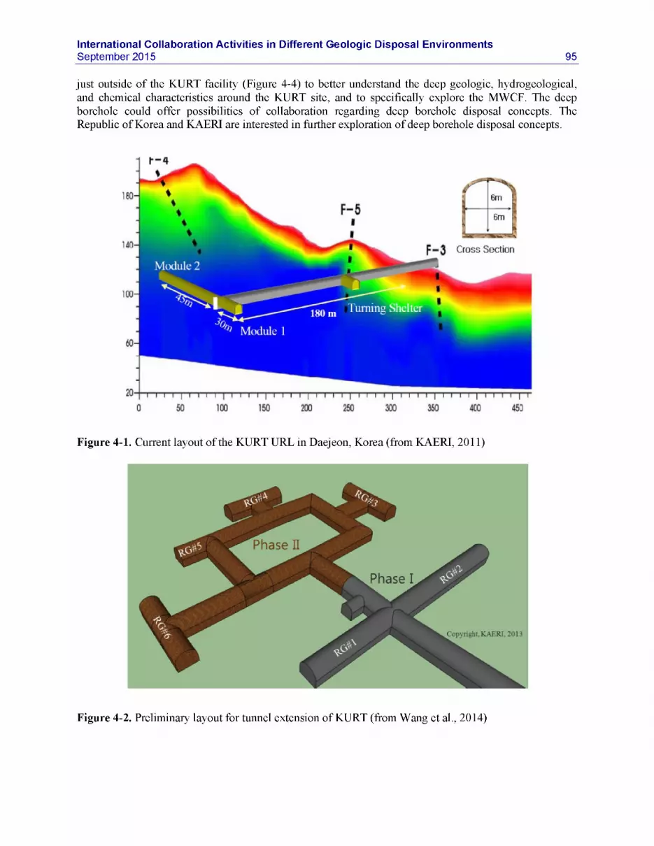
International Collaboration Activities in Different Geologic Disposal EnvironmentsSeptember 2015 95
just outside of the KURT facility (Figure 4-4) to better understand the deep geologic, hydrogeological, and chemical characteristics around the KURT site, and to specifically explore the MWCF. The deep borehole could offer possibilities of collaboration regarding deep borehole disposal concepts. The Republic of Korea and KAERI are interested in further exploration of deep borehole disposal concepts.
Figure 4-1. Current layout of the KURT URL in Daejeon, Korea (from KAERI, 2011)
Figure 4-2. Preliminary layout for tunnel extension of KURT (from Wang et al., 2014)

96International Collaboration Activities in Different Geologic Disposal Environments
September 2015
f.dz test
Fracturezone Groundwater
MigrationHeater test
EDZ test & AE
Figure 4-3. Location of in situ tests and experiments with related boreholes at KURT (from Wang et al., 2014)
Figure 4-4. Specification of DB-2 borehole and its location near KURT site (from Wang et al., 2014)

International Collaboration Activities in Different Geologic Disposal EnvironmentsSeptember 2015 97
In general, KAERI is open to international collaboration and is looking for new ideas and experimental designs for future tests. A few years ago, a formal commitment to collaboration on the management of nuclear fuel was established between the United States and the Republic of Korea (ROK). The agreement, called the Joint Fuel Cycle Studies (JFCS), between the U.S. Department of Energy, the ROK Ministry of Education, Science & Technology, and the ROK Ministry of Knowledge Economy, focuses mainly on three areas of fuel-cycle technologies (electrochemical recycling, safeguards, and fuel cycle alternatives), but has also some research elements related to geologic disposal. Researchers at SNL and KAERI have developed a multi-year plan for joint field testing and modeling to support the study of high-level nuclear waste disposal in crystalline geologic media, which includes sharing of KURT site characterization data. There are two specific collaborative tasks, as follows: (1) streaming potential (SP) testing regarding correlation with groundwater flow, and (2) technique development for in situ borehole characterization. For Task 1, KAERI and SNL have completed the experimental design and conducted a first set of laboratory tests. In situ testing is planned at KURT once the extension is completed. For Task 2, KAERI and SNL have finalized a new contract for collaborative work on the development of in-situ hydrological and geochemical measurements in boreholes. This task is a joint effort between the UFD deep borehole disposal work package and the crystalline disposal R&D work package. More detail on these collaborative tasks is given in Section 6.3.1.
4.2 Salt Research Collaboration with German Researchers
DOE/UFD scientists and their German colleagues in academia and other research laboratories collaborate closely on various R&D issues related to disposal of radionuclide waste in salt. A MoU was signed a few years ago between DOE and the German Federal Ministry of Economics and Technology (BMWi) to cooperate in the field of geologic disposal of radioactive wastes (MoU date: November 2011). Four U.S. -German Salt workshops have been held so far to advance collaboration, starting with a preparatory workshop on May 25-27, 2010, in Jackson Mississippi, followed by Peine, Germany, (November 9-10, 2011), Albuquerque, New Mexico (October 8-11, 2012), Berlin, Germany (September 16-17, 2013) (Hansen et al., 2013), and Santa Fe, New Mexico (September 8-10, 2014) (Hansen et al., 2015). The overriding premise for U.S./German collaborations is to advance the scientific basis for salt repositories. Today, scientists from both countries have started cooperative work in several areas, including coupled- salt-mechanics modeling (Section 6.1.6), safety case aspects, plugging and sealing of a salt repository, and repository design (see Section 7.1).
Germany has a long history of salt R&D. The country started in 1979 to conduct exploration work at the Gorleben salt dome to evaluate its suitability for waste disposal (Figure 4-5). However, a moratorium on further exploration at the Gorleben site was imposed in 2000, mainly due to political reasons. While the moratorium has now been lifted, R&D activities at Gorleben have not yet resumed, and it is questionable whether and when further underground testing at this URL might be conducted. Another mine, the Asse II mine, was also used as a research facility in the past, between 1965 and 1995, where some major experiments such as the long-term TSDE (Thermal Simulation for Drift Emplacement) experiment were carried out. As shown in Figure 4-6, the TSDE experiment comprised of two parallel drifts, each of which housing three electrical heaters to simulate emplacement of heat-producing waste. A significant amount of data was collected over several years in 20 monitoring cross sections: temperature, stress changes, displacement, convergence, and porosity of crushed salt, among others. Data from the TDSE experiment are currently used by UFD scientists to validate the large-scale applicability of coupled THM models (Rutqvist et al., 2015). Note that between 1967 and 1978, low-level and intermediate-level radioactive wastes were placed in storage in other parts of the Asse II mine. Research was eventually stopped; between 1995 and 2004, all underground tunnels and cavities were filled with salt. Today, the Asse II mine is the subject of major controversy because of security concerns regarding water inflow and salt stability.

98International Collaboration Activities in Different Geologic Disposal Environments
September 2015
Figure 4-5. View of one of the underground tunnels at Gorleben site at the 840 m level (from BMWi, 2008)
Figure 4-6. Schematic view of the two drift tests used in the TSDE experiment (800 m level of the Asse salt mine) (from Ruqvist et al., 2015)

International Collaboration Activities in Different Geologic Disposal EnvironmentsSeptember 2015 99
4.3 Collaboration Opportunities at ANDRA’s LSMHM URL, France
The major underground disposal research facility in France is ANDRA’s LSMHM URL sited near Bure in the Meuse and Haute-Marne districts in the east of France, co-located with the proposed French disposal site Cigeo. R&D at Bure aims at studying the feasibility of reversible geologic disposal of high- level and long-lived intermediate-level radioactive waste in the Callovo-Oxfordian clay formation. This facility was licensed in August 1999, and its construction (access shafts, basic drift network with underground ventilation) was finalized in 2006. As shown in Figure 4-7, the URL consists of two shafts sunk down to a depth of about 500 m. A network of about 900 m of tunnels and drifts is used for various scientific experiments, engineering technological demonstrations, and the testing of industrial solutions for construction and operation (Figure 4-8). A recent MoU between ANDRA and DOE can be a starting point for collaborative work in clay/shale disposal at the Bure URL, though currently there are no ongoing joint R&D projects between U.S. and French scientists related to the Bure URL. Note that ANDRA has tentatively proposed to utilize its Alveole Heater Test as one possible test case for the new DECOVALEX-2019 phase starting in 2016 (see Section 3.1.3.5).
Figure 4-7. Layout of the LSMHM URL at Bure, France (from Lebon, 2011)

100International Collaboration Activities in Different Geologic Disposal Environments
September 2015
Figure 4-8. LSMHM URL at Bure, France (from http://www.andra.fr/download/andra-international- en/document/355VA-B.pdf)
4.4 Collaboration Opportunities with JAEA’s URLs in Japan
Opportunities for active collaborative R&D with Japan exist not only at the Horonobe URL in sedimentary rock (see Section 3.1.2.3), but also at this nation’s second URL at the Mizunami Underground Research Laboratory, which resides in crystalline rock (Figure 4-9). Japan and the United States entertain close collaboration on issues related to nuclear energy under the JNEAP (Joint U.S.- Japan Nuclear Energy Action Plan) agreement. JNEAP has a Waste Management Working Group that meets in regular intervals to discuss joint R&D on, among other topics, waste disposal issues. Japanese research institutions are also a frequent partner in many of the cooperative initiatives that DOE has joined in recent years (see Section 3, Table 3.1), and both nations collaborate on the DECOVALEX task featuring JAEA’s Horonobe EBS experiment. There are currently no joint activities related to experimental work at the Mizunami URL. However, JAEA has tentatively proposed to utilize its GREET experiment at Mizunami URL as one possible test case for the new DECOVALEX-2019 phase starting in 2016 (see Section 3.1.3.3).

International Collaboration Activities in Different Geologic Disposal EnvironmentsSeptember 2015 101
Figure 4-9. Layout of the Mizunami Underground Research Laboratory in Japan, and photo of tunnel shaft construction (from http://www.jaea.go.jp/04/tono/miu_e/)
4.5 Collaboration Opportunities at HADES URL, Belgium
Belgium is another country with a strong R&D program in geologic disposal and a long history of experimental work in an underground research laboratory. The HADES (High Activity Disposal Experimental Site) URL is located in a secured area belonging to one of Belgium’s nuclear power plants, which also hosts other nuclear research facilities. HADES is essentially a several-hundred-meter-long tunnel in the soft Boom Clay rock formation, accessible by two shafts located at each end (Figure 4-10). The tunnels were drilled in stages, starting with a first section in 1982, followed by additions in 1987 and 2001. Each of these sections was secured with different types of ground support, reflecting increased knowledge about the structural behavior of the host rock. Most interesting to DOE’s program is probably the PRACLAY heater experiment, and to a lesser degree long-term clay diffusion experiments, both of which are discussed in more detail below. The Belgium organizations involved in conducting and interpreting these experiments have long-standing relationships with DOE/UFD scientists; they are open to participation with UFD research groups and have already invited researchers to provide THM modeling expertise to the PRACLAY project team. However, there are currently no joint activities related to the HADES URL.

102International Collaboration Activities in Different Geologic Disposal Environments
September 2015
Test Drift 1987
Cun netting gulleiy 2001-2002
First shaft 1980-1982
URL1982-1983
Second shaft 1997-1999
Experimental shaft & gallery 1983-1984
PRACLAY gallery . 2006-2007
Figure 4-10. Layout of the HADES URL in Mol, Belgium (from Li, 2011)
4.5.1 PRACLAY Test
The PRACLAY Heater Test is a full-scale validation and confirmation experiment conducted at the HADES URL, excavated at 223 m depth in Boom Clay, a tertiary clay formation in Mol, Belgium. The heater test, which started its heating phase in January 2015, involves a 30 m gallery section heated for 10 years with many monitoring sensors (Figures 4-11, 4-12, and 4-13), for the purpose of investigating the thermo-hydro-mechanical (THM) behavior of near-field plastic clay under the most “mechanically critical” conditions that may occur around a repository (Van Marcke and Bastiaens, 2010). For plastic clay under the influence of temperature change, these are undrained conditions, which then generate a higher pore-pressure increase and a higher possibility of near-field damage. For this objective, a hydraulic seal has been installed at the intersection between the planned heated and unheated sections of the gallery. This installation makes up the Seal Test, which was initiated in 2010, and allows for testing the functionality of the hydraulic seal under heated repository conditions.
Steel reinforcement Steel structure Bentonite Backfill material Heating source n 2
Heating source n 1
Access gallery
Gallery & Crossing test Seal test
Figure 4-11. Layout of the PRACLAY in situ experiment at HADES URL (from Li, 2011)

International Collaboration Activities in Different Geologic Disposal EnvironmentsSeptember 2015 103
Figure 4-12. PRACLAY in situ experiment at HADES URL: Configuration of boreholes for pressure, stress, displacement, and water chemistry measurements (from Li, 2011)
Figure 4-13. PRACLAY in situ experiment at HADES URL: Photo on left shows hydraulic seal from the outside, with an access hole to the right, which soon will be closed. Photo on right was taken from access hole into the heater gallery section, which is currently being backfilled.
4.5.2 Radionuclide Migration Experiments
The Belgium waste management program has been conducting a suite of long-term radionuclide migration in situ experiments in dense clays at their HADES URL near Mol. Two of these experiments, named CP1 (Figure 4-14) and Tribicarb-3D, have been ongoing for 23 and 16 years, respectively, and offer valuable data on the slow diffusion-controlled migration of radionuclides in clay rock. Because of their duration, they offer unique test cases for model and process validation. Recently, two other ongoing large-scale migration experiments were initiated at HADES. The TRANCOM test involves colloid

104International Collaboration Activities in Different Geologic Disposal Environments
September 2015
transport with C-14 labeled humic substances. The RESEAL shaft seal experiment investigates transport of iodine-125 through the disturbed zone and the interface between Boom Clay and bentonite.
Figure 4-14. Schematic of CP1 Diffusion Experiment at HADES URL (from Maes et al., 2011)
4.6 Collaboration Opportunities at Onkalo URL, Finland
The Onkalo URL in Finland is located at a site chosen to potentially co-host a repository. Thus, it is not only an underground research laboratory, but also an underground characterization facility. It is constructed in crystalline bedrock to the anticipated repository depth of 430-440 m. Construction began in 2004 and is ongoing, but actual underground tests were already started in 2007. Figure 4-15 shows the layout of the URL, with an access tunnel and three shafts. The access tunnel takes the form of a spiral on an approximately 1 in 10 incline downward, and reaches the technical facilities level at about 437 m. The three shafts consist of one personnel shaft and two ventilation shafts. Details may be found in Posiva (2011) and Aalto et al. (2009). There are currently no joint activities between DOE and the Finnish waste management program related to the Onkalo URL. However, the REPRO diffusion experiment at Onkalo is being considered as a new Task 9 in the SKB GWFTS Task Force (see Section 3.4.2.2).

International Collaboration Activities in Different Geologic Disposal EnvironmentsSeptember 2015
Figure 4-15. Layout of the Onkalo URL in Finland (from Aikas, 2011)
105

106International Collaboration Activities in Different Geologic Disposal Environments
September 2015
5. SELECTION OF INTERNATIONAL COLLABORATION TASKS
As discussed in Sections 3, DOE joined several multinational and multipartner initiatives that promote active international collaboration with specific focus on URL field experiments and related data: the DECOVALEX project, the Mont Terri Project, the Colloid Formation and Migration Project (until July 2015), the FEBEX-DP Project, and the SKB Task Forces. UFD researchers are in a position that allows participation in planning, conducting, and interpreting the many past and ongoing field experiments associated with these initiatives, and they do so in close collaborative partnership with international scientists. DOE also reached out to—and explored options of collaboration with—individual international disposal programs, such as the Republic of Korea’s KAERI, Germany’s BMWi, France’s ANDRA, Japan’s JAEA, Belgium’s SCK/CEN, and Finland’s POSIVA (Section 4).
With many collaboration opportunities available to UFD, the campaign in FY12 started a planning exercise to identify the most relevant and promising ones, and to select and develop a set of activities that align with current goals, priorities, and funding plans of the UFD. In a general sense, the benefits of international collaboration are obvious: UFD can gain substantial value from the knowledge, data, and modeling capabilities that international partners have developed over decades of research. However, the benefit of international collaboration needs to be evaluated in the context of the open R&D issues that can be addressed through collaborative scientific activities. Open R&D issues with respect to NBS behavior are summarized in previous progress reports (e.g., Natural System Evaluation and Tool Development - FY10 Progress Report, August 2010 [Wang, 2010]); specific R&D issues related to clay/shale host rock are discussed, for example, in Tsang et al. (2011). EBS-related R&D items have also been considered in previous progress reports (e.g., Jove-Colon et al., 2010). All R&D gaps identified in these reports have been evaluated in consideration of their importance to the safety case in a roadmap exercise (Used Fuel Disposition Campaign Disposal Research and Development Roadmap, FCRD-USED-2011-000065 Rev 0, March 2011; Tables 7 and 8; [Nutt, 2011]).
A summary table was developed in 2012 to provide a basis for planning and selection of international activities. Table 5-1 below is an updated version of this summary table (status September 2014); it lists the most relevant ongoing or planned field experiments conducted in international URLs, provides information on how UFD participation can be achieved, which research areas would be the main benefactor (generally either the Engineered barrier System, EBS, or Natural Barrier System, EBS), the key FEPs addressed (including a link to roadmap and FEPs importance ranking; using the Used Fuel Disposition Campaign Disposal Research and Development Roadmap, FCRD-USED-2011-000065 Rev 0, March 2011 [Nutt, 2011]), and finally information on the experimental schedules.
Three workshops were held in FY11 and FY12 to inform the DOE leadership and UFD scientists about existing or future international opportunities, and align UFD work-package activities with international initiatives. The first workshop was a session held in conjunction with the UFD Working Group Meeting in Las Vegas, July 12-14, 2011, at this point mostly for informative purposes. The second workshop, held in Las Vegas on April 11, 2012, was a full-day meeting to review the current and planned work scope within UFD work packages for possible leveraging with the international programs, and to develop an initial set of R&D activities that align with goals, priorities, and funded plans of the UFD program. A third workshop was a session held in conjunction with the UFD Working Group Meeting in Las Vegas, May 15-17, 2012, to inform UFD researchers about the outcome of the full-day planning workshop.
Today, three years after its initiation, the international disposal program within UFD has established a balanced portfolio of selected collaborative R&D activities in disposal science, addressing relevant R&D challenges and open research questions as follows:

International Collaboration Activities in Different Geologic Disposal EnvironmentsSeptember 2015 107
• Near-Field Perturbation: How important is the near-field damage to a host rock (such as clay and salt) due to initial mechanical and thermal perturbation, and how effective is healing and sealing of the damage zone in the long term? How reliable are existing constitutive models describing the deformation of elastoplastic and plastic geomaterials as affected by temperature and water content changes?
• Engineered Barrier Integrity: What is the long-term stability and retention capability of backfills and seals? In a clay host rock, can bentonite mixtures be developed that allow for gas pressure release while maintaining sealing properties for water? In fractured granite, can bentonite be eroded when in contact with water from flowing fractures? How relevant are interactions between engineered and natural barrier materials, such as metal-bentonite-cement interactions?
• Radionuclide Transport: Can the radionuclide transport in fractured granites be predicted with confidence? What is the potential for enhanced transport with colloids? How can the diffusive transport processes in nanopore materials such as compacted clays and bentonites best be described? What is the effect of high temperature on the swelling and sorption characteristics of clays?
• Demonstration of Integrated System Behavior: Can the behavior of an entire repository system, including all engineered and natural barriers and their interaction, be demonstrated, and is the planned construction/emplacement method feasible?
Table 5-2 summarizes the FY15 portfolio of recent, ongoing or planned UFD activities related to relevant experiments in international URLs. As described in the following sections, this collaborative research portfolio has led to significant advances over the past years. The joint R&D with international researchers and the access to relevant data/experiments from a variety of URLs and host rocks have helped UFD researchers to significantly improve their understanding of the current technical basis for disposal in a range of potential host-rock environments and has contributed to testing and validating predictive computational models for evaluation of disposal-system performance in a variety of generic disposal- system concepts.
Over the years, as research priorities change, and as new opportunities for collaboration develop, UFD’s international research portfolio has evolved and will continue to evolve. In FY15, UFD made a targeted effort to re-evaluate its international collaboration activities, in a process similar to the initial planning phase in 2012. Two planning sessions were held in conjunction with the UFD Working Group Meeting in Las Vegas, June 9-11, 2015, to review existing and emerging opportunities for international collaboration and evaluate their technical merit and cost/benefit ratio, to align these opportunities with the current and planned work scope within UFD work packages for possible leveraging, and to develop a revised portfolio of international R&D activities that align with goals, priorities, and funded plans of the UFD program. As a result of this process, UFD decided in FY15 to end its participation in the CFM Project because of its relatively narrow focus and relatively high participatory cost.
Another discussion point is whether DOE/UFD can and should move from a mostly participatory role in ongoing URL experiments conducted by other nations, to a more active role in developing its own experimental program specifically tailored to the DOE/UFD needs. Some collaborative initiatives like the Mont Terri Project definitely provide the opportunity to involve partners, such as DOE, to conduct their own experimental work. As mentioned earlier in this document, other international partners can be found if the proposed work aligns well with the interests of other Mont Terri organizations. It is important to note in this context that the existing infrastructure at Mont Terri makes developing and conducting experiments very easy, even if the proposing partner is located far away from the URL. Swisstopo can handle a lot of the organizational details if needed, and there is a long list of experienced contractors that are available to conduct the actual experimental work. There are currently no immediate plans for DOE to move into a more active role conducting its own experiments at URLs of opportunity. However, because of DOE’s interest in the feasibility of direct geological disposal of large spent nuclear fuel canisters

108International Collaboration Activities in Different Geologic Disposal Environments
September 2015
currently in dry storage (Hardin et al., 2014), the important question arises whether clay-based barriers can withstand temperatures higher than the 100 °C threshold for bentonite performance usually assumed in advanced repository designs. In the future, there could be a need for a targeted high-temperature heater experiment developed or co-developed by DOE, which could be done in, for example, at Mont Terri or the Grimsel Test Site (see Section 3.3.3.2).

International Collaboration Activities in Different Geologic Disposal EnvironmentsSeptember 2014____________________________________________________________ 109
Table 5-1. Summary and Ranking of International Programs in Cooperative Initiatives Related to URLs: Status as of September 2014. The FEPs ranking is based on Tables 7 and 8 in Nutt (2011). Table entries are sorted by URLs.
URL
Relevant Ongoing or Planned Experiments(Selected)
CooperationMode Main Focus FEPs Ranking based on Tables 7 and 8 in Nutt (2011) Test Period
Mont Terri, FE: Full-scale heater Via Mont Terri Both EBS and NBS Geosphere FEPS (for shale): Heating started inSwitzerland (Opalinus Clay)
test demonstration experiment
ProjectNBS: Many aspects of nearfield shale repository evolution, such as EDZ creation, desaturation and resaturation, thermal effects, pore-pressure increase after backfilling and heating
EBS: Performance of EBS backfilling and lining technology
2.2.01: Excavation Disturbed Zone (EDZ) >> High (Shale)2.2.07: Mechanical Processes >> Medium (Shale)2.2.08: Hydrologic Processes >> Medium (Shale)2.2.11: Thermal Processes >> Medium (Shale)
Engineered System FEPS: Buffer/Backfill materials2.1.04.01: Buffer/Backfill >> High2.1.07.02, .03., .04., .09: Mechanical Processes >> Medium2.1.08.03, .07, .08: Hydrological Processes >> Medium2.1.11.04: Thermal Processes >> Medium
Engineered System FEPS: Seal/liner materials2.1.05.01: Seals >> Medium2.1.07.02, .08., .09: Mechanical Processes >> Medium2.1.08.04, .05, .07, .08, .09: Hydrological Processes >> Low
early 2015
Mont Terri, HE-E: Half-scale Via Mostly EBS Geosphere (for shale): Heating phase: JuneSwitzerland heater test in VE test
section
(VE = Ventilation Experiment)
DECOVALEXProject EBS: Non-isothermal
resaturation behavior in bentonite backfill
NBS: Interaction of nearfield shale rock with EBS components
2.2.01: Excavation Disturbed Zone (EDZ) >> High (Shale)2.2.07: Mechanical Processes >> Medium (Shale)2.2.08: Hydrologic Processes >> Medium (Shale)2.2.11: Thermal Processes >> Medium (Shale)2.2.09: Chemical Processes - Transport >> Medium-High
Engineered System FEPS: Buffer/Backfill materials2.1.04.01: Buffer/Backfill >> High2.1.07.02, .03., .04., .09: Mechanical Processes >> Medium2.1.08.03, .07, .08: Hydrological Processes >> Medium2.1.11.04: Thermal Processes >> Medium
2011 through 2018
Mont Terri, MB: Mine-by Test Via Mont Terri NBS Geosphere FEPS (for shale): 2008 - 2009Switzerland for full-scale HM
validationProject Excavation-generated
response in the argillaceous clay host rock near a mined tunnel, including changes in the near-field hydrologic properties
2.2.01: Excavation Disturbed Zone (EDZ) >> High (Shale)2.2.07: Mechanical Processes >> Medium (Shale)2.2.08: Hydrologic Processes >> Medium (Shale)

110Status of UFD Campaign International Activities in Disposal Research_________________________________________________ September 2012
Relevant OngoingCooperationModeURL or Planned
Experiments(Selected)
Main Focus FEPs Ranking based on Tables 7 and 8 in Nutt (2011) Test Period
Mont Terri, HG-A: Gas path host Via Mont Terri Mostly NBS Geosphere FEPS (for shale): Ongoing since 2006Switzerland rock and seals Project Investigation of EDZ as 2.2.01: Excavation Disturbed Zone (EDZ) >> High (Shale) in various stages
preferential flow path for 2.2.08: Hydrologic Processes >> Medium (Shale) with hydraulic andgases generated from corrosion
2.2.12: Gas sources and effects >> Low gas injection tests
Mont Terri, DR-A: Diffusion, Via Mont Terri NBS Geosphere FEPS (for shale) 2011 - 2013Switzerland retention and Project Long-term diffusion behavior 2.2.05: Flow and Transport Pathways >> Medium (Shale)
perturbations of sorbing and non-sorbing 2.2.08: Hydrologic Processes >> Medium (Shale)radionuclides in clay 2.2.09: Chemical Processes - Transport >> Medium (Shale)
Grimsel Test Site, CFM: RN tracer test Via CFM Project NBS Geosphere FEPS (for crystalline rock) Several tests in 2009Switzerland Transport behavior of a 2.2.05: Flow and Transport Pathways >> Medium (Crystalline) through 2012
tracer/radionuclide “cocktail” 2.2.08: Hydrologic Processes >> Low (Crystalline)in a shear zone. Test includes 2.2.09: Chemical Processes - Transport >> Medium (Crystalline)conservative tracers, weakly sorbing solutes, strongly sorbing solutes and bentonite colloids
Grimsel Test Site, CFM: RN-Doped Via CFM Project NBS: Geosphere FEPS (for crystalline rock) Started in May 2014Switzerland Plug Experiment Similar to above test, but this 2.2.05: Flow and Transport Pathways >> Medium (Crystalline)
time involving at 2.2.08: Hydrologic Processes >> Low (Crystalline)radionuclide-doped bentonite plug which erodes and
2.2.09: Chemical Processes - Transport >> Medium (Crystalline)
induces colloid-facilitated Engineered System FEPS: Buffer/backfill materialstransport 2.1.04.01: Buffer/Backfill >> High
2.1.09.51-59, .61: Chemical Processes -Transport >> Low toMedium
Grimsel Test Site, FEBEX-DP: Full- Via FEBEX-DP Mostly EBS Engineered System FEPS: Buffer/Backfill materials Heater test ongoingSwitzerland scale heater test Project Long-term performance of 2.1.04.01: Buffer/Backfill >> High since 1997;
dismantling project the bentonite backfill and, to 2.1.07.02, .03., .04., .09: Mechanical Processes >> Medium dismantlinga lesser degree, the near-field 2.1.08.03, .07, .08: Hydrological Processes >> Medium conducted incrystalline rock, with emphasis on the thermal
2.1.11.04: Thermal Processes >> Medium Summer 2015
evolution and resaturation of Geosphere FEPS (for crystalline rock)bentonite backfill 2.2.01: Excavation Disturbed Zone (EDZ) >> Medium (Crystalline)surrounding a heated waste 2.2.07: Mechanical Processes >> Low (Crystalline)package 2.2.08: Hydrologic Processes >> Low (Crystalline)
2.2.11: Thermal Processes >> Low (Crystalline)

International Collaboration Activities in Different Geologic Disposal EnvironmentsSeptember 2014____________________________________________________________ 111
URL
Relevant Ongoing or Planned Experiments(Selected)
CooperationMode Main Focus FEPs Ranking based on Tables 7 and 8 in Nutt (2011) Test Period
Grimsel Test Site, Switzerland
GAST: Gas permeable seal experiment
Possibly viaMoU with NAGRA
EBSDemonstrate the performance of repository seals and to improve the understanding of water and gas transport through these sealing systems. The experiment involves specially designed backfill and sealing materials such as high porosity mortars or sand/bentonite (S/B) mixtures.
Engineered System FEPS: Buffer/Backfill materials2.1.04.01: Buffer/Backfill >> High2.1.08.03, .07, .08: Hydrological Processes >> Medium2.1.12.01, .02, .03: Gas sources and effects >> Medium
2010 - 2015
Aspo Hard Rock Laboratory, Sweden
BRIE: Bentonite rock interaction experiment
Via SKB TaskForces
Both NBS and EBSUnderstand the exchange of water and potential bentonite erosion at the interface between backfill and flowing fractures
Engineered System FEPS: Buffer/Backfill materials2.1.04.01: Buffer/Backfill >> High2.1.08.03, .07, .08: Hydrological Processes >> Medium
Geosphere FEPS (for crystalline rock)2.2.05: Flow and Transport Pathways >> Medium (Crystalline)2.2.08: Hydrologic Processes >>Low (Crystalline)
Ongoing since 2012
Aspo Hard Rock Laboratory, Sweden
LTDE-SD: Longterm sorption diffusion experiment
Via SKB TaskForces
NBSDiffusion and sorption in a conducting fracture and adjacent matrix (sorbing and non-sorbing tracers)
Geosphere FEPS (for crystalline rock)2.2.05: Flow and Transport Pathways >> Medium (Crystalline)2.2.08: Hydrologic Processes >>Low (Crystalline)2.2.09: Chemical Processes - Transport >> Medium (Crystalline)
Completed in 2010 with 6 months test duration
Aspo Hard Rock Laboratory, Sweden
PrototypeRepository: full-scale prototype tunnels with six deposition holes
Via SKB Task Forces
Mostly EBS, also NBS Demonstration of the integrated function of the repository and a full-scale reference for test of predictive models concerning individual components as well as the complete repository system. Includes heaters and backfill.
Geosphere FEPS (for shale):2.2.01: Excavation Disturbed Zone (EDZ) >> High (Shale)2.2.07: Mechanical Processes >> Medium (Shale)2.2.08: Hydrologic Processes >> Medium (Shale)2.2.11: Thermal Processes >> Medium (Shale)
Engineered System FEPS: Buffer/Backfill materials2.1.04.01: Buffer/Backfill >> High2.1.07.02, .03., .04., .09: Mechanical Processes >> Medium2.1.08.03, .07, .08: Hydrological Processes >> Medium2.1.11.04: Thermal Processes >> Medium
Since 2001. Outer test section opened and retrieved in2011.

112Status of UFD Campaign International Activities in Disposal Research_________________________________________________ September 2012
Relevant OngoingCooperationModeURL or Planned
Experiments(Selected)
Main Focus FEPs Ranking based on Tables 7 and 8 in Nutt (2011) Test Period
Tournemire, France SEALEX: Long-time Via Mostly EBS Engineered System FEPS: Seal/liner materials 2011 - 2015sealing experiment DECOVALEX Long-term isothermal HM© 2.1.05.01: Buffer/Backfill >> Mediumfor different behavior and hydraulic 2.1.07.02, .08., .09: Mechanical Processes >> Mediummaterials performance of swelling 2.1.08.04, .05, .07, .08, .09: Hydrological Processes >> Medium
clay-based seals (Flow through seals)2.1.09.01, .03, .09, .13: Chemical Processes - Chemistry >> Medium
Bedrichov Tunnel, Flow patterns and Via NBS Geosphere (for crystalline rock): HydrogeologicCzech tracer transport in DECOVALEX Flow patterns and tracer 2.2.02: Host Rock Properties >> High (Crystalline) characterization andRepublic fractured granite transport behavior within 2.2.05: Flow and Transport Pathways >> Medium (crystalline) monitoring ongoing
fractured crystalline rock 2.2.08: Hydrologic Processes >> Medium (Crystalline)Horonobe URL, EBS experiment: Via Mostly EBS Geosphere (for shale): Start of heatingJapan Vertical heater and DECOVALEX 2.2.01: Excavation Disturbed Zone (EDZ) >> High (Shale) phase in late 2014
buffer test (planned) EBS: Non-isothermal 2.2.07: Mechanical Processes >> Medium (Shale)resaturation behavior in 2.2.08: Hydrologic Processes >> Medium (Shale)bentonite backfill 2.2.11: Thermal Processes >> Medium (Shale)
NBS: Interaction of near- Engineered System FEPS: Buffer/Backfill materialsfield shale rock with EBS 2.1.04.01: Buffer/Backfill >> Highcomponents 2.1.07.02, .03., .04., .09: Mechanical Processes >> Medium
2.1.08.03, .07, .08: Hydrological Processes >> Medium2.1.11.04: Thermal Processes >> Medium
KURT URL, Korea Streaming potential Via MoU with NBS: Geosphere (for crystalline rock): In situ testing will be(SP) testing and KAERI Flow patterns in fractured 2.2.02: Host Rock Properties >> High (Crystalline) conducted once thecorrelation with crystalline rock 2.2.05: Flow and Transport Pathways >> Medium (crystalline) KURT extension isgroundwater flow 2.2.08: Hydrologic Processes >> Medium (Crystalline) complete
KURT URL, Korea Development of Via MoU with NBS: Geosphere FEPS (for borehole): Ongoingtechniques for in situ KAERI Relevance to deep borehole 2.2.01: Excavation Disturbed Zone (EDZ) >> High (Borehole)borehole disposal 2.2.07: Mechanical Processes >> Low (Borehole)characterization and 2.2.08: Hydrologic Processes >> Medium (Borehole)monitoring 2.2.11: Thermal Processes >> Medium (Borehole)
2.2.09: Chemical Processes - Chemistry >> Medium-High (Borehole)2.2.09: Chemical Processes - Transport >> Medium-High (Borehole) 2.2.02: Host Rock (properties) >> High (Borehole)2.2.05. Flow and Transport Pathways >> Medium (Borehole)

International Collaboration Activities in Different Geologic Disposal EnvironmentsSeptember 2014____________________________________________________________ 113
URL
Relevant Ongoing or Planned Experiments(Selected)
CooperationMode Main Focus FEPs Ranking based on Tables 7 and 8 in Nutt (2011) Test Period
HADES URL,Belgium
PRACLAY: Full- scale seal and heater experiment
Possibly via bilateral collaboration with SCK/CEN
Mostly NBSMany aspects of near-field boom clay repository evolution, such as EDZ creation, desaturation and resaturation, thermal effects, pore-pressure increase after backfilling and heating
Geosphere FEPS (for shale):2.2.01: Excavation Disturbed Zone (EDZ) >> High (Shale)2.2.07: Mechanical Processes >> Medium (Shale)2.2.08: Hydrologic Processes >> Medium (Shale)2.2.11: Thermal Processes >> Medium (Shale)
Heating startedJanuary 2015
HADES URL,Belgium
RN Migration: Long- running RN diffusion tests
Possibly via bilateral collaboration with SCK/CEN
NBSDiffusion-controlled migration of radionuclides in clay rocks
Geosphere FEPS (for shale)2.2.05: Flow and Transport Pathways >> Medium (Shale)2.2.09: Chemical Processes - Transport >> Medium (Shale)
Ongoing since more than two decades

114Status of UFD Campaign International Activities in Disposal Research_________________________________________________ September 2012
Table 5-2. Current and Future Work Package Activities with International Collaboration and Focus on URL Experiments (sorted by URL)
Mont Terri,Switzerland (Opalinus Clay)
• FE: Full-scale heater test demonstration experiment• HE-E: Half-scale heater test in VE test section• HG-A: Gas path host rock and seals• DR-A: Diffusion, retention and perturbations• EB: Engineered Barrier Experiment
FS: Fault Slip Experiment
• Mont Terri Project• DECOVALEX-2015• Mont Terri Project• Mont Terri Project• DECOVALEX-2019• DECOVALEX-2019
• LBNL• LBNL• LBNL (Complete)• LBNL (Complete)• Maybe• Maybe
Grimsel Test Site,Switzerland(Granite)
• CFM: RN tracer test and RN-doped plug experiment• FEBEX-DP: full-scale heater test dismantling
• CFM• FEBEX-DP
• LANL, LLNL (Complete)• SNL, LANL, LBNL
Aspo Hard Rock Laboratory, Sweden (Granite)
• BRIE: Bentonite rock interaction experiment• LTDE-SD and REPRO (Diffusion-Advection-Sorption)• LASGIT
• SKB Task Forces• SKB Task Forces• DECOVALEX-2019
• LANL (Complete)• Likely, LANL• Maybe
Mizunami, Japan (Granite)
• GREET: Groundwater Recovery Experiment • DECOVALEX-2019 • Maybe
Bedrichov Tunnel,Czech Republic (Granite)
• Flow patterns and tracer transport in fractured granite • DECOVALEX-2015 • Ongoing, SNL
Horonobe URL, Japan (Sedimentary rock)
• EBS experiment: Vertical heater and buffer test (planned) • DECOVALEX-2015 • Ongoing, LBNL
KURT URL, Korea (Crystalline rock)
• Streaming potential (SP) testing regarding correlation with groundwater flow
• Technique development for in situ borehole characterization
• MoU KAERI
• MoU KAERI
• Ongoing, SNL
• Ongoing, SNL
LSMHM URL, France (COX Clay)
• Alveole Heater Test • DECOVALEX-2019 (Tentative)
• Maybe

International Collaboration Activities in Different Geologic Disposal EnvironmentsSeptember 2015 115
6. STATUS OF INTERNATIONAL COLLABORATION ACTIVITIES WITH FOCUS ON URL EXPERIMENTS
Here we give a brief description of ongoing international collaboration activities involving UFD scientists. The section is dedicated to R&D work with primary focus on participation in, and analysis of, URL experiments, as described in Table 5-2. We start with research work addressing issues related to near-field perturbation and engineered barrier integrity (Section 6.1), followed by R&D understanding fluid flow and radionuclide transport processes in the host rock (Section 6.2), and end with collaborative research to develop new characterization and monitoring methods (Section 6.3). Example R&D results will be presented, albeit without providing exhaustive explanations; we intend to merely illustrate technical achievements made in various areas. All necessary detail can be found in the references given throughout the text. International collaboration activities unrelated to URLs are briefly described in Section 7.
6.1 Near-Field Perturbation and EBS Integrity
6.1.1 THM Modeling of Heater Experiments
On behalf of DOE, LBNL has been participating in the DECOVALEX-2015 Project since 2012 as one of the international modeling teams working on Task B1, the HE-E Heater Test at Mont Terri (Section 3.1.4) and Task B2, the Horonobe Engineered Barrier Experiment (Section 3.1.5). LBNL has also been contributing to the design and scoping simulations for the FE Heater Test at Mont Terri. As described in Section 4 of the milestone report entitled “Investigation of Coupled Processes and Impact of High Temperature Limits in Argillite Rock,” FCRD-UFD-2015-000362, (Zheng et al., 2015), the TOUGH- FLAC simulator developed at LBNL is the primary analysis tool, because this simulator has the required capabilities to model a large variety of problems associated with nuclear waste disposal for various engineering and natural systems. TOUGH-FLAC can simulate coupled THM processes under multiphase flow conditions through a sequential coupling of the TOUGH2 multiphase flow simulator with the FLAC3D geomechanical code (Rutqvist et al., 2002; Rutqvist, 2011). As part of the UFD R&D program, TOUGH-FLAC has been modified for applications related to bentonite-backfilled repositories in clay host formations (Rutqvist et al., 2014a). Major improvements include implementation of the Barcelona Basic Model (BBM) for the rigorous THM modeling of behavior of swelling soils and applied to modeling of bentonite backfill behavior (Alonso et al., 1990). The BBM model can describe many typical features of unsaturated-soil mechanical behavior, including wetting-induced swelling or collapse strains, depending on the magnitude of applied stress, as well as the increase in shear strength and apparent preconsolidation stress with suction (Gens et al., 2006).
Recently, the BBM has been extended to a dual-structure model, referred to as the Barcelona Expansive Model (BExM). In a dual-structure model, the material consists of two structural levels: a microstructure in which the interactions occur at the particle level, and a macrostructure that accounts for the overall fabric arrangement of the material comprising aggregates and macropores (Gens et al., 2006, Sanchez et al., 2005). A dual-structure model has important features for modeling the mechanical behavior of a bentonite buffer, such as irreversible strain during suction cycles. However, most importantly, a dualstructure model provides the necessary link between chemistry and mechanics, enabling us to develop a coupled THMC model for the analysis of long-term EBS behavior. This approach enables mechanistic modeling of processes important for long-term buffer stability, including effects of pore-water salinity on swelling (loss of swelling), conversion of smectite to nonexpansive mineral forms (loss of swelling), and swelling pressure versus exchangeable cations (Rutqvist et al. 2014b).

116International Collaboration Activities in Different Geologic Disposal Environments
September 2015
6.1.1.1 Status of Participation in DECOVALEX Task B1
Eight international modeling teams are participating in Task B1 of DECOVALEX-2015. Instead of starting directly with the interpretation and simulation of the rather complex HE-E heater experiment, Task B1 included several modeling steps of increasing complexity: (1) the study of THM processes in the host rock, using data from an earlier borehole heater test (HE-D experiment); (2) the study of THM processes in the buffer materials, using data from laboratory experiments (CIEMAT Column Experiments), and (3) the study of the ongoing HE-E experiment considering the host rock as well as the buffer material, initially as a predictive exercise, then as an interpretative effort with comparison to monitoring data (Garitte and Gens, 2012). Regarding the HE-E experiment, the main objective is to test model capabilities addressing the evolution of EBS components and the near-field Opalinus Clay in the early post-closure perturbation period, with emphasis on thermal evolution, resaturation, and evolution of swelling pressure in bentonite backfill.
The first step of modeling the HE-D experiment started in 2012 and was completed in November 2013. LBNL’s modeling of the HE-D experiment and comparison of the TOUGH-FLAC modeling results to those of other DECOVALEX modeling teams were reported in the FY2013 milestone report entitled “THM and Reactive Transport Model Development and Evaluation: International Activities,” FCRD- UFD-2013-000372 (Rutqvist et al., 2013). Simulating the THM behavior in this test allowed initial model comparison and validation without the complicating THM interaction with engineered barrier components. The second step, a study of bentonite properties through modeling of laboratory experiments, were completed in FY14 and described in the FY14 milestone report entitled “Investigation of Coupled Processes and Impact of High Temperature Limits in Argillite Rock,” FCRD-UFD-2014- 000493 (Zheng et al., 2014). The predictive and finally interpretive modeling of the HE-E experiment (the final step of Task B1) is ongoing; details on the current modeling status and model comparison results are given in Zheng et al., 2015). Below, we provide brief descriptions of the LBNL modeling studies conducted for the HE-D heater test, the CIEMAT column experiments, and for the HE-E experiment.
The HE-D experiment was conducted at the Mont Terri URL between March 2004 and June 2005 by heating of Opalinus Clay from two heaters placed in a horizontal borehole (Wileveau, 2005; Gens et al., 2007). About 30 temperature sensors, 10 water pressure sensors, and 3 extensometers were placed around this heating borehole (Figure 6-1). Approximately one month after installation, the heaters were switched on with a total power of 650 W (325 W per heater). The heaters were then maintained under constant power for 90 days. Afterwards, the power was increased threefold, to 1950 W (975 W per heater), and maintained at that level for a further 248 days. At the end of this second heating stage, the heaters were switched off and the clay was allowed to cool down. Temperature, pore pressure, and deformation were measured throughout.

International Collaboration Activities in Different Geologic Disposal EnvironmentsSeptember 2015 117
HED0OOH2T2
7 485m
HFATFR 1
HCD0OOH1T4
Instrumental layout - Borehole BHE-DO
HE-D Niche
~-cA A' B B
► C' ► D
D-D' F-F
AND A
Figure 6-1. Layout of the heater borehole of the HE-D Heater Test at Mont Terri URL (from Garitte and Gens, 2012)
LBNL modeled the HE-D experiment using the TOUGH-FLAC simulator. Anisotropic material models were employed to account for the effect of sedimentation planes found in the Opalinus Clay. Figure 6-2 shows typical simulation results at two temperature monitoring points near the heaters, and one strain gage at another location in the perturbed rock mass. The simulation shows a correlation between temperature and fluid pressure as a result of thermal pressurization, which is caused by the differences in the coefficient of thermal expansion between the fluid and the solid rock. Temperature is in good agreement with measured data when an anisotropic thermal conductivity is used. Simulated pressure and strain are also in reasonable agreement with the measurements. The radial strain indicates mainly compression during heating as rock is expanded from the heated borehole.

118International Collaboration Activities in Different Geologic Disposal Environments
September 2015
HDB16TEM1 HDB15TEM150 55
45 50
40 45ModelMeasurement
Model
35 40
35
30IH 2520
2015
100 200 300 400Time (d)
HDB15TEM1
500 600100 200 300 400
Time (d)500 600
HDB16TEM1 HDB04DP90.1
-------Model° Field data0.05
-0.05
-1-0.15 -------Model
-------Field data-1-0.2-------Model
-------Field data 100 200 300 400 500Time (d)-0.25
100 200 300 400 100 200 300 400 500Time (d) Time (d)
Figure 6-2. Comparison of simulated and measured temperature and pressure at two monitoring points (B15 and B16) and strain at another location close to the heater (from Rutqvist et al., 2013)
Figure 6-3 gives a comparison of simulation results obtained by the eight teams involved in modeling the HE-D experiment of DECOVALEX-2015 with the measured data by two temperature sensors located, respectively, at a distance of 1.11 m away from the center of the heater parallel to bedding (HEDB03), and at a distance of 0.775 m away from the center of the heater perpendicular to bedding (HEDB14). Despite the different distances to the heater, both sensors show a similar course of temperature evolution over time, which illustrates the effect of anisotropic heat conduction in the Opalinus Clay. Overall, the figure demonstrates good agreement between the results of the different groups. Furthermore, the temperature observations are well enveloped by the modeling results of the eight teams. The largest disagreement is observed at sensor HEDB14, where the simulated temperature is strongly overestimated by one of the international modeling teams. This particular simulation was conducted with an axisymmetric model in which thermal anisotropy cannot be considered. The comparative evaluation shown in Figure 6-3 is a good example of the value that DECOVALEX-type model comparison studies can provide to system understanding and model validation. The fact that several individual research groups with their own simulation tools and conceptual understanding arrive at similar model predictions enhances confidence in the robustness of THM models. And the possibility of linking model differences to particular choices in conceptual model setup provides guidance into “best” modeling choices and understanding the effect of conceptual model variability.
The CIEMAT column experiments tested the thermal hydration behavior in two buffer materials, granular bentonite (or bentonite pellets) and a sand/bentonite mixture (Figure 6-4). The design of the column experiments mimicked the HE-E conditions, with the height of the column equal to the thickness of the buffer filled between the canister and the host rock. A heater was placed at the bottom and a cooler at the top of each column, so that the column was heated while the top remained at an ambient temperature of ~21.5°C. Sensors were installed at distances of 10 cm, 22 cm, and 40 cm from the heater to measure temperature and relative humidity. The experiment was conducted in several stages with changing boundary/heating conditions, as illustrated in Figure 6-4. The simulation objective was to predict the

International Collaboration Activities in Different Geologic Disposal EnvironmentsSeptember 2015 119
transient fluid-flow and heat-transfer processes that occur in the experiment, and to calibrate the evolution of flow and thermal properties of the two hydrating buffer materials against the experimental measurements.
CNSCKAERI
100 200 300Time in days after heating(b)
CNSC
100 200 300Time in days after heating(a)
Figure 6-3. Comparison of measurements and model results of for the temperature evolution over time at sensors HEDB03 (a) and HEDB14 (b) (from Graupner et al., 2013)
Figure 6-5 shows selected simulation results after model calibration by the LBNL team. After heating is initiated, the temperature at the 10 cm location increases rapidly to ~30°C. Further step-wise increases occur when the insulation is changed and later as the heater temperature is raised to 140°C. The simulated relative humidity at 10 cm also increases rapidly after heating starts, due to the increase in temperature and the vapor flowing up from the bottom. There are complex couplings at play. When temperature increases at the 10 cm location, the relative humidity becomes larger as the capillary pressure drops, even if the water saturation remains unchanged. However, heating also causes the vapor pressure to increase near the heater, which drives vapor flowing up and contributes to the increased relative humidity at the 10 cm location during the early stage of heating. Over time, the relative humidity decreases at the 10 cm location. This is because further heating causes the drying at the 10 cm location with the vapor flowing further up. This upflow of vapor is evidenced by the continuous increase in relative humidity at the 22 cm and 40 cm locations, which in part is also caused by as a result of liquid water flowing downward from the top of the cell via gravity and capillary forces. Overall, the simulated temperatures and relative humidity values at three locations are in a good agreement with the measured ones.
The simulations for the CIEMAT column experiments demonstrate the complexity of the coupled processes involved in the temperature and hydration behavior of heated bentonite. Results also indicate the importance of adequately understanding experimental boundary conditions, such as the water intake of the experimental column or the substantial heat loss from the equipment that has to be considered in order to characterize the thermal properties of the buffer material. Modeling teams learned that one can obtain a unique solution for back-calculating the thermal and hydraulic properties of the buffer material by evaluating the transient temperature and moisture responses in addition to steady-state profiles. By accounting for the enhanced permeability of gas and the temperature dependency of the capillary pressure, the models can reasonably reproduce the evolution of relative humidity along the column in the experiments.

120International Collaboration Activities in Different Geologic Disposal Environments
September 2015
Porous disc; 8mm Porous disc: 8mm
48,39 cm 4B.39cm
BT-IV: 2Smm
21.5 *C21.5 C 11.5 "C21.5 CX
Foam: 5mm Wool: 30mm
ft-Hon L5rtim Teflon: 15mm
Jp to 5cm
I |«—|
100 "C 140 X140 X
Figure 6-4. Schematic of experimental setups of column experiment in sequential steps: (1) Heating at temperature of 100 °C from 0 to 1566 hours, (2) heating with new insulation layer from 1566 to 3527 hours, (3) heating at 140 °C from 3527 to 5015 hours, (4) heating with hydration valve open after 5015 hours (from Zheng et al., 2014)
60q Data_40 cm __ Sim_40 cm A Data_22 cm
Sim_22 cm O Data_10 cm
Sim_10 cm
55
50
45
40
I- 35
30
25
20
15,1000 2000
Time (h)3000
100
90
80
70
40 q Data_40 cm Sim_40 cm
A Data_22 cm Sim_22 cm
O Data_10 cm — Sim_10 cm
30
20
10,1000 2000
Time (h)3000
Figure 6-5. Simulated and measured relative humidity (RH) and temperature (T) as a function of time after heater was turned on (from Zheng et al., 2014)
As described in Section 3.1.2.2, the Mont Terri HE-E Experiment focuses on the THM behavior of bentonite barriers in the early nonisothermal resaturation stage and their THM interaction with Opalinus Clay. The objective is to better understand the evolution of a disposal system for high level waste in the early post-closure period, with emphasis on the thermal evolution, buffer resaturation (in situ determination of the thermal conductivity of bentonite and its dependency on saturation), pore-water

International Collaboration Activities in Different Geologic Disposal EnvironmentsSeptember 2015 121
pressure in the near field, and the evolution of swelling pressures in the buffer (Gaus et al., 2014). Similar to other modeling teams involved in this DECOVALEX task, LBNL first conducted a predictive analysis of the HE-E experiment, before the field data were available to the DECOVALEX-2015 participants, followed by a comparison of the initial model predictions with experimental results. A final interpretive modeling of the field experimental data and comparison with other modeling teams is ongoing and will be completed during the rest of calendar year 2015.
Figure 6-6 shows LBNL’s 3-D model grid for the HE-E experiment and its location within the Mont Terri URL. It is a half symmetric model with a vertical symmetry plane along the tunnel axis. In the model, the relevant materials are represented, including the different types of bentonite materials. The most important thermal and hydraulic properties were derived from literature data and from material properties estimated by modeling of various THM laboratory experiments on bentonite.
Mont Terri URL Model of HE-E Experiment
Bentonite Pellets
OpalinusClayHeaters
Bentonite Blocks
Sand/Bentonite
Figure 6-6. TOUGH-FLAC 3-D model of the Mont Terri HE-E experiment (from Zheng et al., 2015)
A comparison of the predicted and observed evolutions of relative humidity and temperature is shown in Figure 6-7. The figure shows that the general humidity behavior of the bentonite at the rock wall and drying of the inner parts of the bentonite buffer is captured well in the modeling. Model results for relative humidity, which is related to saturation, show very good agreement with measurements for the blue and red curves (i.e. close the rock wall and close to the heater). However, the model overestimates

122International Collaboration Activities in Different Geologic Disposal Environments
September 2015
relative humidity in the mid part of the bentonite buffer (green curve). A parameter study was performed as to identify possible reasons for this discrepancy in the wetting of the bentonite buffer. The included variation of buffer absolute permeability (no significant effect), diffusion coefficient (did not help) and buffer relative permeability (tried to reduce relative permeability, but this did not help). A possible reason that will be investigated next is the high suction part of the water retention curve with the van-Genuchten water retention model may cause important deviations from the experimental data at low saturation. Nevertheless, the overall evolution of relative humidity was reasonably predicted by the modeling.
Figure 6-8 shows the evolution of fluid pressure within Opalinus Clay at a monitoring point located 3.54 m from the tunnel wall. This increase in fluid pressure is a result of so-called thermal pressurization, caused by thermal expansion of the pore fluid that cannot escape in the relatively low-permeability host rock. The magnitude and duration of this excess pressure pulse depends on parameters such as rock permeability, and compressibility of water and rock. Using the Opalinus Clay properties determined from the modeling of the HE-D experiments, it appears that the model can predict this pressure increase fairly well.
I 0.5
i 11 i i i i , I i. i ..I i i Itoo 200 300 400 500 600 700 800 600 1000
TIME (days) TIME (days)
Figure 6-7. Comparison of predicted (dashed lines) and measured (solid lines) evolutions of (a) relative humidity and (b) temperature, in a cross section of the HE-E experiment (from Zheng et al., 2015)

International Collaboration Activities in Different Geologic Disposal EnvironmentsSeptember 2015 123
1E+06
Model
0.800000
200000
I I I I I I I I I I I I I,,,,-100 0 100 200 300 400 500 600 700 800 900 1000
TIME (days)
Figure 6-8. Comparison of predicted (dashed lines) and measured (solid lines) evolutions of pore pressure in Opalinus Clay at a point located 3.54 m from the tunnel wall (from Zheng et al., 2015)
6112 Status of Participation in DECOVALEX Task B2
Task B2 focuses on coupled THMC modeling of a recently initiated full-scale EBS experiment conducted by the Japan Atomic Energy Agency (JAEA) at the Horonobe URL in Japan (Section 3.1.2.3). As a first modeling step, participating teams were asked to simulate a simplified 1D benchmark test with exact properties and boundary conditions given by the JAEA. This step allowed teams to get familiar with the problem setup and to conduct an initial model comparison for a simpler test problem before simulating the complex full-scale EBS experiment. The benchmark is a one-dimensional representation of the heater, buffer, and rock extending from the center of the overpack (heat source) out to 25 m. As shown in Figure 6-9, this includes 0.41 m of overpack, 0.72 m of bentonite buffer, and 23.87 m of rock. Figures 6-10 and 6-11 show selected simulation results, demonstrating good agreement between the five modeling teams participating in Task B2. As discussed below, teams have now moved to the next modeling steps, which are to conduct initial “blind” model predictions for the full-scale Horonobe EBS experiment followed by a calibration analysis using the first few months of monitoring data. Results are reported in Rutqvist et al. (2013), Zheng et al. (2014), and Zheng et al. (2015).

124International Collaboration Activities in Different Geologic Disposal Environments
September 2015
Backfill
OverpackInitial condition 15°C Boundary conditions
Fixed temperature [15°C]Hv/Hrai ilir nrPQei irp FflMP;
(Heater)Rock
unit thickness | Buffer Rock riAeu lempeidiure uj
Hydraulic pressure [OMPal25 m0.41 m 1.13 m
O'tz100_g
Buffer
Output line
1030 60 100 200 365 500 730 day
Figure 6-9. Definition of 1D benchmark test for Task B2 (from Rutqvist et al., 2013)
O<D3+JCO<DQ.£<DI-
100
90
80
70
60
50
40
30
20
10
TX JAEA(10days)
\ 'XBGR(i0days)CAS(10days)KAERI(10days)DOE(10days)JAEA(730days)BGR(730days)CAS(730days)KAERI(730days)DOE(730days)
l \\
\
K '—
1 1
5 1Distance from the center (m)
0
Figure 6-10. Task B2 Benchmark test: Comparison of simulated temperature as a function of distance from the center, for two time steps at 10 days and 730 days (from Zheng et al., 2014)

International Collaboration Activities in Different Geologic Disposal EnvironmentsSeptember 2015 125
0.6
0.5
0.4'S0.-0.3U)U)
CD
0.2
0.1
0.0
-♦-JAEA(X=1.13m)BGR(X=1.13m)CAS(X=1.13m)KAERI(X=1.13m)DOE(X=1.13m)
0 200 400 600 800Elapsed time (day)
Figure 6-11. Task B2 Benchmark Test: Comparison of the simulated stress change at X=1.13m (from Zheng et al., 2014)
To conduct the predictive simulations for the Horonobe EBS experiment, the LBNL team developed a half symmetric 3D model, which includes half of the tunnel and half of the deposition hole (Figure 6-12), and explicitly represents all relevant materials, including mudstone rock, buffer, backfill, a sand layer at the rock/buffer interface, concrete lining, and plug. Preliminary simulations of the expected THM response were conducted for a heating period of about 2 years. Selected results of temperature evolution are shown in Figures 6-13 for points located in the buffer and near-field rock. When keeping the heater temperature constant at 100°C, the simulation shows that the temperature at the buffer-rock interface (P3, P4 in Figure 6-13) increases to about 60°C after 2 years.
Figure 6-12. TOUGH-FLAC 3D numerical grid of the Horonobe EBS experiment (from Zheng et al., 2015)

126International Collaboration Activities in Different Geologic Disposal Environments
September 2015
Backfill
IP3-P5
Monitoring points in backfill andnear field
Calculated temperature m 3DTOUGH-FLAC model
100 r-
Bentomte n. 60Buffer
w 50
m P7, P8. P9
• Q^pic pores
200 400 >0(TIME (days)unit mm
Cross section(test pit)
Figure 6-13. EBS Experiment: TOUGH-FLAC simulation results of temperature in the buffer and rock (from Zheng et al., 2015)
In addition to LBNL’s prediction, four other international modeling teams are participating in Task B2, namely BGR from Germany, CAS from China, KAERI from Korea, and JAEA. The predictive results of the model predictions provided by all the DECOVALEX-2015 modeling teams have been compared. Figure 6-14 and 6-15 show examples of comparison of blind predictions, related to the evolution of temperature and liquid saturation in the bentonite buffer. The results are quite consistent and in good agreement between the modeling teams, though some outliers can be observed. The next step is to complete the calibration analysis using measured data to be provided by the JAEA.

International Collaboration Activities in Different Geologic Disposal EnvironmentsSeptember 2015 127
Figure 6-14. Comparison of simulated temperature profiles at 10 and 365 days among the DECOVALEX modeling teams (from Zheng et al., 2015)
JAEA MOdays JAEA(365days)
BGR(1 Odays) - -BGR(365days)
-^CAS(365days)CAS 10days)
KAERI 365daysKAERI(lOdays)
-LBNL 365days)LBNL todays)
Distance from the center m Distance from the center (m
Figure 6-15. Comparison of simulated saturation profiles at 10 and 365 days obtained by the DECOVALEX modeling teams (from Zheng et al., 2015)

128International Collaboration Activities in Different Geologic Disposal Environments
September 2015
6.1.1.3 THM Modeling of FE Heater Test at Mont Terri
Enabled by DOE’s formal partnership in the Mont Terri Project, LBNL is one of seven international modeling teams conducting THM simulations for the design of the FE Heater Test and for the evaluation of monitoring data. As mentioned in Section 3.2.2, this experiment has started its heating phase in February 2015 and is now the largest and longest-duration heater tests worldwide, with focus on both the EBS components and the host-rock behavior. Over more than a decade, the experiment will provide data useful for the validation of THM coupling effects regarding the processes in the host rock, while correctly accounting for (and examining) the conditions in the emplacement tunnel (temperature, saturation, and swelling pressure). Due to the 1:1 scale of the experiment, it is possible to achieve realistic temperature, saturation, and stress gradients in the emplacement tunnel and the host rock, which is extremely useful for THM model validation.
During the past three years, modeling teams have conducted design predictions for the FE Heater Test, developing conceptual models and selecting material properties from the review of available literature (papers and reports) on lab experiments and previous Mont Terri in situ tests. Several sets of scoping simulations were conducted to probe the relevance of coupled processes, evaluate their significance and parameter range, compare conceptual models, test sensitivity to input parameters, and summarize lessons learned before the onset of the experiment (parameter ranges, importance, expected response). This initial step was complemented with a restricted benchmark test for code comparison, in which properties and model geometry were defined by NAGRA. Modeling teams are now moving into a new modeling phase with evaluation, interpretation, and validation using measured data from the FE Heater Test.
In collaboration with NAGRA and other teams, LBNL has developed a sophisticated 3D TOUGH-FLAC model for the THM design predictions. This work is described in the FY14 milestone report entitled “Investigation of Coupled Processes and Impact of High Temperature Limits in Argillite Rock,” FCRD- UFD-2014-000493 (Zheng et al., 2014). The host rock is modeled with anisotropic properties considering bedding planes in the Opalinus Clay. An inclined TOUGH-FLAC mesh was created to accurately represent anisotropic thermal and hydrological behavior. Anisotropic mechanical material behavior is simulated using the FLAC3D ubiquitous joint model, with initial properties derived from excavation design analysis conducted by another FE Heater Test modeling team (Nater, 2012). In the ubiquitous joint model, weak planes are assumed along the bedding planes of the Opalinus Clay; in other words, the shear strength properties are different in the direction of bedding versus the direction across bedding. Bentonite behavior is accounted for with the Barcelona Basic Model (BBM). Figure 6-16 presents the 3D TOUGH- FLAC numerical grid of the FE experiment. This model grid includes all vital material components for the modeling of the FE experiment, including layered Opalinus Clay host rock, excavation-disturbed zone, tunnel, three heaters, bentonite buffer, concrete liner, and concrete plug. As in the real test, the predictive simulations start with an open tunnel at atmospheric pressure for one year, creating a pressure drop and hydraulic gradient around the tunnel. Thereafter, the model assumes instantaneous emplacement of the heater and buffer, and the heating period is simulated.

International Collaboration Activities in Different Geologic Disposal EnvironmentsSeptember 2015 129
Access tunnel
Shot crete
entonite
Heater
Bentoniteblocks
pellets
Figure 6-16. TOUGH-FLAC 3D numerical grid of the FE experiment (from Zheng et al., 2014)
Figure 6-17 shows LBNL’s initial prediction of temperature and saturation evolution, assuming the full 1500 W power in each heater operating over a 20-year period. In this case, the peak temperature at the buffer is as high as 160°C, i.e., considerably higher than the targeted 125°C to 135°C. In the experiment, the temperature should not exceed 150°C, because this could be damaging for some of the monitoring sensors. The high peak temperature at the canister surface is caused by the combined effects of low thermal conductivity of the buffer and the rock, as well as the high vapor diffusion coefficient that keeps the buffer dry around the heater. Modeling teams then explored alternative heating schemes, including staged heating, to better accommodate the targeted temperature constraints.
Figure 6-18 gives recent simulation results designing a staged heating schedule using only one of the three heaters, i.e., the one placed farthest into the tunnel, during the first few months of the experiment, The staged heating schedule was eventually adopted by the project leads to enable an early model calibration of the in situ thermal properties that can then be used to make a more reliable prediction of the peak temperature once the full thermal power is applied. This is done to ensure that the temperature will not be so high as to damage the monitoring system.

International Collaboration Activities in Different Geologic Disposal Environments130 September 2015
0.8
0.6
0.4
0.2
i I i i I i i i i I i i i I10 15
TIME (Years)
20 25 30
(b)
200
150
100
50
10 15
TIME (Years)20 25 30
(a)
Figure 6-17. Model prediction of (a) temperature and (b) liquid saturation for full power of 1500 W at each heater (from Zheng et al., 2014)
150
100
50
0
150
100
50
0 200 400 600 800 1000TIME (days) TIME (days)
(a) (b)
Figure 6-18. Model prediction of temperature for staged power in first emplaced heater. The results in (a) and (b) are the same but using a different range on the time axis to highlight the early time behavior. Solid lines refer to evolution at the heater that is turned on, whereas dashed lines refer to evolution at heaters that are turned off (from Zheng et al., 2015).
6.1.1.4 Summary of Heater Test Modeling in Argillite Rocks
Over the past few years, UFD researchers have greatly benefited from participating in international activities for developing expertise and testing advanced models for coupled THM processes. As described below, LBNL scientists are now utilizing data and results from laboratory and field studies that have been

International Collaboration Activities in Different Geologic Disposal EnvironmentsSeptember 2015 131
and are being conducted with millions of R&D investments provided by international partners. UFD simulators are being verified and validated against these experimental studies, providing a robust modeling and experimental basis for the prediction of the complex long-term THM and THMC evolution of a multi-barrier waste repository system involving backfilled emplacement tunnels and argillite host formations. Specific FY2015 accomplishments of UFD scientists include:
• Validation of TOUGH-FLAC and characterization of THM properties was achieved through modeling of CIEMAT laboratory column experiments and interpretative simulation of the Mont Terri HE-E experiment.
• Benchmarking associated with the DECOV ALEX-2015 Horonobe EBS Experiment demonstrated good agreement of UFD models with results of other international modeling teams, providing code-to-code verification of TOUGH-FLAC.
• Full-scale 3D models were developed for the Horonobe EBS Experiment and the Mont Terri FE Heater Test and initial model predictions of temperature and saturation evolutions were conducted for later comparison with measurements.
• Ongoing collaborative work in this area utilizes the full-scale 3D models of the in situ heater experiments—in particular the long-running Mont Terri FE experiment—for further comparison of simulation results with measurements and with the results of other international modeling teams.
6.1.2 UFD Participation in FEBEX-DP Experiment
6.1.2.1 Status of FEBEX-DP Activities
As described in Section 3.3.2, the FEBEX-DP project provides a unique opportunity to evaluating the long-term behavior of an engineered barrier that underwent continuous heating with natural resaturation for about 18 years. In FY15, LBNL scientists have been participating in the pre-dismantling modeling, with particular focus on the chemical alteration of the bentonite and how this alteration is affected by THM processes such as hydration, thermal osmosis, and swelling; this activity will continue in FY16 with post-dismantling modeling and interpretative analyses once dismantling results have become available. In FY16, UFD scientists from LBNL, LANL, and SNL will also participate in the sample analysis campaign of bentonite and its interfaces with other EBS components (i.e., metals, cement).
The ultimate goal of LBNL’s modeling effort is to develop a coupled THMC model of the FEBEX-DP behavior tested against observation data. Specifically the following questions are to be answered with THMC modeling:
• What causes the hydration of bentonite to be slower than typically predicted by a Darcy flow model: Non-Darcian flow behavior, thermal osmosis that counteracts flow toward the heater, decrease of intrinsic permeability of the buffer due to changes in microstructure, or a combination of all these processes?
• What is the spatial density variation of the bentonite as a result of long-term hydration and swelling?
• What is the chemical evolution in the bentonite, especially the changes of more soluble minerals (gypsum, calcite and pyrite) and aqueous concentration, evolution of pH and Eh and alteration of smectite or other clay minerals?

132International Collaboration Activities in Different Geologic Disposal Environments
September 2015
As described in Zheng et al. (2015), LBNL’s THMC simulations are conducted with TOUGHREACT- FLAC3D, which sequentially couples the multiphase fluid flow and reactive transport simulator, TOUGHREACT (Xu et al., 2011), with the finite-difference geomechanical code FLAC3D (Itasca, 2009). The coupling of TOUGHREACT and FLAC was initially developed in Zheng et al. (2012) to provide the necessary numerical framework for modeling fully coupled THMC processes. It was equipped with a linear elastic swelling model (Zheng et al., 2012; Rutqvist et al., 2013) to account for swelling as a result of changes in saturation and pore-water composition and the abundance of swelling clay (Liu et al., 2013; Zheng et al., 2014). A recent addition to the code is the capability of simulating Non-Darcian flow.
Model development for FEBEX-DP is being conducted in a sequence, starting with the development of a TH model, followed by development of separate THC and THM models, and eventually establishment of a fully coupled THMC model. In FY15, a preliminary THC model has been developed to provide scoping simulations of chemical changes and test the relevance of Non-Darcian flow behavior on the hydration of bentonite. THC model results were compared with TH data measured in the bentonite surrounding Heater 2, and with chemical data obtained from the 2002 dismantling of Heater 1 (chemical data for Heater 2 will become available in FY16). Example plots for temperature data and chloride concentrations in comparison with simulation results are given in Figures 6-19 and 6-20, respectively (Zheng et al., 2015).
OJ3%01Q.OlE|2
60
50
40
30
20
10
R = ~1.05 m
— r ~~ 3-
ra WPSF2-C 51 °
WPSF2-Co WPSF2-0□ WPSE2-0
865
----- baseTH model
2000 4000Time (day)
6000 80000
0
Figure 6-19. Temperature measured by sensors located at radial distance of 1.05 m in sections E2 and F2 of FEBEX Test and model results from the base TH model (from Zheng et al., 2015)
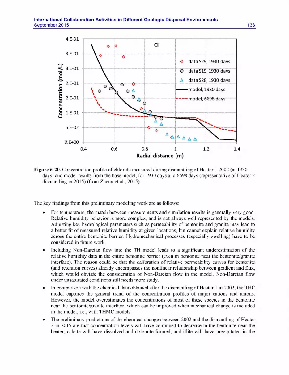
International Collaboration Activities in Different Geologic Disposal EnvironmentsSeptember 2015 133
4.E-01Cl'
3.E-01O dataS29, 1930 days
3.E-01 O dataS19, 1930 days
, 1930 daysA dataS282.E-01model, 1930 days
2.E-01 ~ ~ ~ model, 6698 days
1.E-01
5.E-02
0.E+000.4 0.6 0.8 1
Radial distance (m)1.2 1.4
Figure 6-20. Concentration profile of chloride measured during dismantling of Heater 1 2002 (at 1930 days) and model results from the base model, for 1930 days and 6698 days (representative of Heater 2 dismantling in 2015) (from Zheng et al., 2015)
The key findings from this preliminary modeling work are as follows:
• For temperature, the match between measurements and simulation results is generally very good. Relative humidity behavior is more complex, and is not always well represented by the models. Adjusting key hydrological parameters such as permeability of bentonite and granite may lead to a better fit of measured relative humidity at given locations, but cannot explain relative humidity across the entire bentonite barrier. Hydromechanical processes (especially swelling) have to be considered in future work.
• Including Non-Darcian flow into the TH model leads to a significant underestimation of the relative humidity data in the entire bentonite barrier (even in bentonite near the bentonite/granite interface). The reason could be that the calibration of relative permeability curves for bentonite (and retention curves) already encompasses the nonlinear relationship between gradient and flux, which would obviate the consideration of Non-Darcian flow in the model. Non-Darcian flow under unsaturated conditions still needs more study.
• In comparison with the chemical data obtained after the dismantling of Heater 1 in 2002, the THC model captures the general trend of the concentration profiles of major cations and anions. However, the model overestimates the concentrations of most of these species in the bentonite near the bentonite/granite interface, which can be improved when mechanical change is included in the model, i.e., with THMC models.
• The preliminary predictions of the chemical changes between 2002 and the dismantling of Heater 2 in 2015 are that concentration levels will have continued to decrease in the bentonite near the heater; calcite will have dissolved and dolomite formed; and illite will have precipitated in the

134International Collaboration Activities in Different Geologic Disposal Environments
September 2015
bentonite near the bentonite/granite interface accompanied by the dissolution of smectite at the same place. In FY16, these preliminary predictions will be tested against dismantling analyses.
6122 Future Plans forFEBEX-DPActivities
In FY16, the development of a THMC model for the FEBEX-DP test will continue. The following modeling tasks are planned:
• Mechanical processes will be added to the current THC model. Once the coupled THMC model is developed, mechanical-hydrological coupling relationships will be calibrated again measured stress, dry density, water content and relative humidity data.
• The chemical model will be further refined. Once the concentration profile for chloride can be matched by the THMC model, predictions will be made for other chemical species and mineral phases.
• Once the corrosion of the steel liner is analyzed, chemical changes of steel will be included in the chemical model to evaluate the interaction of steel and bentonite.
Ultimately, after the THMC models for FEBEX in situ test are fully validated with data, they will be used to explore long-term THMC changes under high-temperature conditions.
In FY16, UFD scientists will also participate in the sampling and analysis campaign of bentonite interfaces with other EBS components (i.e., metals, cement). LANL scientists will perform initial forensic analysis of selected samples (focusing on bentonite-metal, bentonite, and bentonite-cement segments) to understand the alterations that took place during the 18-year experiment. Following the forensic analyses, a series of hydrothermal experiments will be conducted to expand the thermal knowledge of this particular bentonite system and compare the results to ongoing LANL experiments conducted on other bentonite systems. Results from these hydrothermal experiments will elucidate bentonite alterations during long-term heating under controlled conditions beyond what was observed in the FEBEX project.
LBNL and SNL plan to collaborate on the study of micro-cracks in FEBEX-DP samples. Micro-cracks could have formed during heating and drying, but then might have healed during hydration. Such a study will not only facilitate better understanding of potential flow paths in bentonite, but will also shed light on the self-healing of excavation disturbed zone (EDZ) in the argillite host rocks, because of the similarity in the controlling processes. LBNL will use the synchrotron light source at LBNL to examine the microcracks at a resolution of ~750 nm. These microCT images will provide a dynamic of the evolving microcracks. In a second step, the microCT results will be used by SNL to select target locations for FIB/SEM analysis and serial sectioning to image micro-cracks at a smaller scale but higher resolution. Together, these tests will yield a multiscale characterization of micro-crack behavior.

International Collaboration Activities in Different Geologic Disposal EnvironmentsSeptember 2015 135
6.1.3 DFN Modeling of the HG-A Experiment at Mont Terri
To more accurately characterize and model excavation-damage-zone evolution and its impact on flow and transport, LBNL has developed a new modeling approach for studying hydro-mechanical coupled processes, including fracture development, within geologic formations. This is accomplished through the novel linking of two codes: TOUGH for subsurface multiphase flow based on the finite volume method, and RBSN (Rigid-Body-Spring-Network) for discrete (lattice) representation of material elasticity and dynamic fracture development/propagation. The RBSN formulation is based on the concept of the Rigid- Body-Spring model, first introduced by Kawai (1978), in which the material constitution is represented as a collection of rigid bodies connected by spring sets. TOUGH is used to simulate relevant scalar quantities (e.g., temperature, pressure, and degree of saturation) associated with fluid flow and heat transport, whereas RBSN accounts for mechanical quantities (e.g., displacement, strain, and stress) of interest. The TOUGH-RBSN simulator predicts fracture evolution, as well as mass transport through fractured porous rock, under dynamically changing thermal-hydrologic and -mechanical conditions. The modeling approach is facilitated by a Voronoi-based discretization technique common to both codes, capable of representing discrete fracture networks embedded in a porous matrix. Further details on this method and UFD-related applications are provided in Section 3 of the Report on Investigation of Coupled Processes and Impact of High Temperature Limits in Argillite Rock, FCRD-UFD-2014-000493, August 2014 [Zheng et al., 2014]). More recent developments of the TOUGH-RBSN simulator, including a new dynamic simulation framework for RBSN that can be easily parallelized, are described in Zheng et al. (2015).
In FY13 and FY14, LBNL tested its new capabilities using data from the ongoing HG-A experiment at Mont Terri (Section 3.2.3). This experiment examines gas paths through the near-field host rock affected by the evolution of the damage zone. Several hydraulic and gas injection tests have been conducted, and a detailed discrete fracture mapping study was performed. The test is therefore a valuable testbed for discrete fracture and THM modeling capabilities. However, application to the HG-A experiment required a modification to the standard RBSN approach to account for anisotropic elastic properties of the RBSN spring sets. In the standard RBSN, the spring sets are oriented randomly as defined by the Voronoi element structure. In the new scheme, by comparison, all the spring sets are aligned with the principal bedding direction. The spring coefficients are defined in global fabric coordinates, where two orthogonal axes are normal and parallel to bedding, respectively. The anisotropic modeling scheme was validated through comparison with uniaxial compression tests for transversely isotropic rock specimens from Mont Terri. Cylindrical core samples were subjected to unconfined uniaxial compression, in which the loading direction formed an angle relative to the bedding plane. TOUGH-RBSN simulations were conducted for seven cases of fabric orientation relative to core sample axis with f = 0°, 15°, 30°, 45°, 60°, 75°, 90°. Selected damage patterns are shown in Figure 6-21.
An initial set of TOUGH-RBSN simulations for the HG-A experiment focused on the excavation damage observed in the micro-tunnel (Figure 6-18). The partial damage and exfoliations observed along the tunnel have been mainly attributed to the anisotropic strength characteristics of the rock. The relative weakness of the rock orthogonal to the bedding and the weakness near faults intercepting the tunnel, as depicted in Figure 6-18, result in the nonuniform damage around the excavation wall. Simulated damage patterns are shown in Figure 6-19. Damage zones are more prominent at the tunneling wall tangential to the bedding planes, similarly to the failure characteristics seen in Figure 6-18. For identification of failure modes, individual fracture segments are drawn in different colors: blue and red segments represent tensile and shear failure modes, respectively. Tensile fracturing is concentrated at the borehole boundary, due to the lack of constraints against the pore pressure acting towards the center of the tunnel. This failure feature can be supported by observation of the deformation around the borehole. Figure 6-19c depicts the deformed shape of the tunnel, in which the deformation is exaggerated for better visibility. Voronoi cells

136International Collaboration Activities in Different Geologic Disposal Environments
September 2015
adjacent to the borehole come off the body, which indicates tensile failure. For FY15, LBNL had planned to conduct a second set of HG-A simulations modeling the hydraulic and gas injection tests conducted at the site, in particular those that may have caused additional damage in the EDZ; however, these plans were abandoned because of budget constraints. Currently discussed is the possibility of using TOUGH- RBSN for damage modeling related to long-term gas generation from canister corrosion in low-permeable backfill, a possible modeling task in the next DECOVALEX Project phase (Section 3.1.3.1).
Figure 6-21. Fracture patterns of the specimens with various orientations of fabric forming the angle of B with the loading axis. Note that the positive angle indicates counter-clockwise rotation from the vertical orientation (from Zheng et al., 2014)

International Collaboration Activities in Different Geologic Disposal EnvironmentsSeptember 2015 137
tectonic fault planes subparallel to bed»ng
— bedding plane
(a) failure mainly controlled by strength anisotropy (bedding > or other planes ol weakness (tectonic faults, weakly cemented srfty intercalations)
b failure mainly controlled by stress anisotropy
a) b)
Figure 6-22. a) Excavation damage viewing from the HG-A Niche towards back end (from Marschall et al., 2006); and b) Conceptual diagram of the damage zone (from Lanyon et al., 2009)
Figure 6-23. a) Discretization of the computational domain for the HG-A test simulation; b) nonuniform fracture pattern around the tunnel; and c) deformed shape of the borehole (from Zheng et al., 2014)

138International Collaboration Activities in Different Geologic Disposal Environments
September 2015
6.1.4 DFN Modeling of BRIE Experiment at Aspo Hard Rock Laboratory
Researchers at LANL have been developing novel discrete fracture network (DFN) approaches for modeling flow and transport in the near- and far-field domains of sparsely fractured crystalline formations (e.g., Section 2 in Milestone Report “Crystalline and Crystalline International Disposal Activities FCRD-UFD-2014-000495 [Dittrich et al., 2014], and Section 1 in Milestone Report “Crystalline and Crystalline International Disposal ActivitiesFCRD-UFD-2015-000602 [Viswanathan et al., 2015]). In FY14, LANL started applying these capabilities (referred to as DFNWORKS) to the ongoing BRIE Experiment at Aspo Hard Rock Laboratory (see Section 3.4.2.1), where the water-bearing fractures have been mapped and their interaction with the bentonite backfill in a vertical deposition hole is being measured (Section 3.4.2). The main objectives of the work are to test and refine the DFN modeling capability using the BRIE site as a well-characterized demonstration site. While the development of DFN capabilities continued in FY15, there was no additional work on BRIE conducted this fiscal year. Therefore, we briefly summarize below the FY14 activities at LANL, and point out that there are plans for continued development of the DFN computational suite, including further application of the suite to model/interpret data sets related to SKB GWFTS Task Force activities, such as the proposed Task 9 (LTDE-SD at the Aspo HRL in Sweden, REPRO project at Onkalo in Finland) (see Section 3.4.2.2).
The scope of the BRIE modeling task is to simulate wetting of the bentonite in the emplacement boreholes (see Section 3.4.2.1). This requires that flow in the fracture network near the boreholes also be modeled. The DFN grids are locally two-dimensional whereas the emplaced bentonite requires a conventional three-dimensional space-filling grid. As a preliminary step in the BRIE modeling, LANL’s DFN modeling capability needed to be extended to allow for hybrid DFN/volume grids. The procedure used to create hybrid DFN/volume meshes is illustrated for a simple example in Figure 6-24. In this example, the interior of a cylinder is to be meshed and merged with a DFN grid in the nearby rock volume. A DFN is first generated using the procedures described previously (Painter et al., 2012; Hyman et al., 2014). The generated DFN ignores the volume to be meshed. However, before the DFN is meshed, interfaces between fractures and the cylinder to be meshed are identified. A two-dimensional mesh is then created on each fracture in a way that conforms to the fracture intersections and to the fracture-volume interfaces (Figure 6-24A). In the second step, nodes on the fractures within the volume to be meshed are removed (Figure 6-24B). A tetrahedral mesh that conforms to the fracture intersection is then created within the cylinder. In the final step, the tetrahedral mesh and the DFN mesh are merged and duplicate nodes removed (Figure 6-24C). The LaGriT software (Los Alamos Grid Toolbox, 2011) was used to execute the meshing calculations.
Using the hybrid procedure explained above, the LANL team developed a BRIE model for a 40 m * 40 m x 40 m cube to simulate flow in the fractured granite surrounding two BRIE boreholes as well as flow in the bentonite-filled boreholes themselves. One typical meshed realization of the BRIE DFN with three deterministic fractures and two BRIE boreholes is shown in Figure 6-25. For this preliminary simulation, the lower cutoff for fracture length was increased to 1.0 m to reduce the size of the network, with appropriate adjustments to the fracture density. The network contains approximately 3500 stochastically generated fractures. Initial results for rewetting of the BRIE experiment boreholes for two realizations of the DFN are shown in Figure 6-26 at 3 months, 6 months, and 12 months. Little difference is noted between the two realizations. Both realizations show a steep gradient in liquid saturation in the bentonite near where it intersects with fractures. Away from that intersection, the bentonite is rewetting relatively uniformly. This dependence of saturation on distance from the fracture intersection is attributed to the shape of the capillary pressure versus saturation curve, which provides for strong suction at lower saturation values (Section 3 in Dittrich et al., 2014). The two realizations of the DFN with boreholes in place is an important demonstration of an advanced modeling capability combining volume and DFN meshes, and incorporating complex geometries.

International Collaboration Activities in Different Geologic Disposal EnvironmentsSeptember 2015 139
BA
Figure 6-24. Example showing the creation of a hybrid tetrahedral/DFN mesh. Such hybrid meshes were required to model the rewetting of bentonite in the BRIE (from Dittrich et al., 2014).
Figure 6-25. Computational mesh for the three-dimensional model of the BRIE experiment. The DFN and boreholes are shown in A. The arrow indicates the position of one of the boreholes. A detail from the computational mesh showing the merged DFN and tetrahedral mesh is shown in B (from Dittrich et al., 2014).

140International Collaboration Activities in Different Geologic Disposal Environments
September 2015
Figure 6-26. Details from two simulations of rewetting of the BRIE experiment boreholes. Results from one realization of the DFN are shown in each of the two columns. The top row is at 3 months, the middle row is at 6 months, and the bottom row is after one year of rewetting (from Dittrich et al., 2014).

International Collaboration Activities in Different Geologic Disposal EnvironmentsSeptember 2015 141
6.1.5 Thermal-Hydrologic-Mechanical-Chemical (THMC) Processes in Single Fractures
Since 2014, SNL scientists have participated as DOE’s modeling team in the interpretation and modeling of DECOVALEX Task C1, which uses data from single-fracture-flow laboratory experiments to model complex coupled THMC processes, in particular looking at the linkage of thermal stresses mediating chemical effects, and conversely of chemical potentials mediating mechanical behavior (e.g., pressure solution) (see Section 3.1.2.5). A mechanistic understanding of THMC-induced fracture opening and closure in geologic media is of significant importance to radioactive waste isolation (e.g., radioactive waste disposal and carbon sequestration and storage). It has been observed that, under certain circumstances, a fracture can undergo either opening or closure or switch from one regime to another. Fracture evolution involves a complex set of coupled physical and chemical processes, including stress- mediated mineral dissolution and precipitation, fluid flow and transport, mechanical deformation, etc. In FY15, SNL researchers formulated a dynamic model for subsurface fracture opening and closure (Wang et al., 2015). It is assumed that a fracture plane can be represented with isolated contacting asperities and connected aperture channels that run through between the asperities. It is further assumed that the crosssection of an individual aperture channel can be described as a truncated ellipse defined by the intersection of two identical ellipses. The model explicitly accounts for the stress concentration around individual aperture channels and the stress-activated mineral dissolution and precipitation. A preliminary model analysis demonstrated the importance of the stress-activated dissolution mechanism in the evolution of fracture aperture in a stressed geologic medium. The model provides a reasonable explanation for some key features of fracture opening and closure observed in laboratory experiments, including a spontaneous switch from a net permeability reduction to a net permeability increase with no changes in experimental conditions (Figure 6-27).
Reducing aperture (b)/ increasing confining stress (CToo)
Wave length
Figure 6-27. Spontaneous initiation of aperture channeling. As the fracture aperture reduces due topressure dissolution, the preferred wave length of dissolution fingering decreases. Once the preferred wave length falls within the experimental observation range, a spontaneous initiation of preferential channeling can be observed. This may be responsible for the observed spontaneous switch from a net permeability reduction to a net permeability increase with no changes in a limestone fracture experiment (from Wang et al., 2015).

142International Collaboration Activities in Different Geologic Disposal Environments
September 2015
6.1.6 Salt Geomechanics Modeling and Benchmarking
A joint benchmarking study on HM and TM processes in salt between German groups and SNL has been officially extended to include two additional benchmarking problems based on in situ full-scale tests conducted in the early 1980s at WIPP. Modeling exercises compare an isothermal mining development test (WIPP Room D) to a heated “overtest” for simulated defense high-level waste (WIPP Room B). Calculations are isothermal, thermal-mechanical uncoupled, and thermal-mechanical coupled. Sandia uses a state-of-the-art Sandia Integrated Environment for Robust Research Algorithms (SIERRA) solid and thermal mechanics computer codes (Arguello, 2014), while the German partners use their respective codes and models as described by Hampel et al. (2012; 2013). All calculations use highly advanced constitutive laws that mathematically describe deformational processes inherent to those found in nuclear waste repository environment. The first goal of the project is to check the ability of numerical modeling tools to correctly describe relevant deformation phenomena in rock salt under various influences. International collaboration on model benchmarking is complemented immensely by additional testing of WIPP salt cores by German research laboratories. In concert with benchmarking of WIPP in situ experiments, German research groups are parameterizing their respective model variables through a series of special laboratory tests on WIPP salt. Thus their codes and models, which have been thoroughly calibrated against in situ experiments conducted in domal salt formations, will be appropriately parameterized for generic salt repository analysis with the inclusion of parameters representative of bedded salt (Hansen et al., 2015).
In a parallel US-German effort, researchers from LBNL have been collaborating with a research group led by Professor Lux in Germany at the Clausthal University of Technology (TUC) on modeling coupled THM processes in salt. LBNL incorporated into the TOUGH-FLAC simulator an advanced geomechanical constitutive model for rock salt developed by the TUC group (the Lux/Wolters model), a model that can handle creep, damage, sealing, and healing of the salt as a function of stress, temperature, and pore pressure. In FY15, using the TOUGH-FLAC simulator, LBNL and TUC have started working on THM benchmarking studies involving the TSDE (Thermal Simulation for Drift Emplacement) test conducted in the Asse Mine in the 1990s, Germany (see Section 4.2). A 3D (86,000 elements) TOUGH- FLAC model was developed and applied to simulate the TDSE behavior and compare simulation results with the observations (Figures 6-28 and 6-29). This is the first time this experiment has been modeled in a complete THM analysis (all previous analyses of TSDE have been limited thermal-mechanical processes, ignoring multiphase flow hydraulic processes). The modeling of the TSDE also provides the opportunity to calibrate stationary creep parameters at very low deviatoric stress and extremely slow loading that are not available from current laboratory tests. Good agreement was achieved between modeled and experimental data, involving drift closure and compaction of the EBS (crushed salt), thus providing validation of both host rock and crushed salt constitutive models and their implementation into the TOUGH-FLAC simulator. More details are provided in Milestone Report “Modeling Coupled THMC Processes and Brine Migration in Salt at High Temperatures,” FCRD-UFD-2014-000341 (Rutqvist et al., 2015).

International Collaboration Activities in Different Geologic Disposal EnvironmentsSeptember 2015 143
Figure 6-28. TSDE test: views of the initial mesh used in the geomechanics sub-problem. The main dimensions of the model are also shown (from Rutqvist et al., 2015).
Figure 6-29. TSDE test: backfill porosity in the heated area and in the non-heated area. Points represent measurements, solid lines correspond to TOUGH-FLAC and dashed lines correspond to FLAC- TOUGH (from Rutqvist et al., 2015).

144International Collaboration Activities in Different Geologic Disposal Environments
September 2015
6.2 Fluid Flow and Radionuclide Transport
6.2.1 Using Environmental Tracers to Estimate Fracture-Network Properties: Application to the Bedrichov Tunnel Experiment
SNL scientists have also participated as DOE’s modeling team in the interpretation and modeling of DECOVALEX Task C2, which is the Bedrichov Tunnel Experiment in the Czech Republic (see Section 3.1.2.5). The task utilizes a dataset of environmental tracers and discharge in the Bedrichov Tunnel. The expectation is that environmental tracers can provide valuable information for constraining parameters controlling flow and transport and making better predictions of contaminant transport in fracture network systems. The high-resolution groundwater discharge data measured in the Bedrichov Tunnel—along with measurements of stable isotopes of water, tritium, tritiogenic 3He and other noble gases, as well as dissolved chlorofluorocarbons—provide a unique data set against which to test and calibrate numerical models of groundwater flow and solute transport in fractured media. The goal of Task C2 is to model groundwater flow and transport of environmental tracers in the fracture systems surrounding the Bedrichov Tunnel and utilize this data to constrain fracture-network parameters.
In previous work, consistent with the modeling steps defined for Task C2, SNL scientists initially developed a lumped parameter model for stable isotope, tritium and CFC-12 transport at the Bedrichov Tunnel site and compared model results to measured data (Wang et al., 2014). The lumped parameter model consistently predicts heavier isotopic values observed at the site, indicating preferential recharge of winter precipitation (Figure 6-30). PFLOTRAN, a multiphase, multicomponent reactive flow and transport simulator, was then used to simulate multiple environmental tracer concentrations in heterogeneous 2D and 3D domains (Figure 6-31). Fracture-zone permeability was calculated by matching the steady tunnel discharge to the appropriate values given in the description of Task C2. The modeling results demonstrate the usefulness of both the lumped parameter model and the PFLOTRAN code for evaluating flow and transport behavior in fractured crystalline rocks.
Figure 6-30. Measured and modeled stable isotope composition for the Bedrichov collection canal using the exponential age distribution (from Wang et al., 2014)

International Collaboration Activities in Different Geologic Disposal EnvironmentsSeptember 2015 145
Figure 6-31. Transport sequence of tracer migration from a selected PFLOTRAN simulation run. Note that tracer concentration is contoured in log scale. Fracture plane on left side of domain, tunnel on right (front) of domain (from Wang et al., 2014) .
In FY15, SNL continued its interpretative modeling work for the Bedrichov site, utilizing several different conceptual models for isotopic transport at the site, including models that allow for a vertical fracture zone in addition to a background matrix permeability (Wang et al., 2015). In the latest set of simulations, the constant recharge used earlier models was changed to a transient recharge set as 20% of monthly average observed precipitation at the site. The steady state hydraulic field was used as the initial condition, and then the transient recharge was applied across the top of the domain. A transient defined concentration taken as monthly average isotopic concentration was then applied across the recharge zone. The estimated recharge, the calculated discharge, and the observed discharge are plotted below in Figure 6-32. Overall there is a reasonable order of magnitude match to the observed discharge. An annual transport sequence of S18O, which highlights the seasonal changes in isotopic composition and its transport through the system, is shown in Figure 6-33.
5e+06
Variable Flow
3.5e+u7 150000RechargeDischarge 140000Observed3e+07
130000
1200002.5e+07
1100002e+Q 7 100000
900001.56+07
80000
le+07 70000
60000
50000
40000
Time (yr)
Figure 6-32. Transient recharge, modeled fracture discharge and observed discharge (Wang et al., 2015)

146International Collaboration Activities in Different Geologic Disposal Environments
September 2015
Stable Isotopes
cr00 rechargecr00 discharge
Observed *
lime (yr)
Figure 6-33. Transient 518O in precipitation (red line), modeled 518O in the fracture outflow (green lime) and observed 518O (blue dots) in fracture outflow (from Wang et al., 2015)
In FY15, the different modeling teams participating in DECOVALEX Task C2 conducted a thorough evaluation and comparison of their respective simulation models. For the most part the teams were able to match each other results, and overall all models reproduced the gross characteristics of hydraulic and tracer transport observed in the field. Understanding the discrepancies between models has proved to be a great learning experience for all teams and improved the understanding of the underlying mechanics of each code, and each codes strengths and limitations (Wang et al., 2015).
6.2.2 Diffusion-Reaction Modeling of the DR-A Experiment at Mont Terri
UFD researchers have also utilized international collaboration to test modeling approaches for radionuclide diffusion processes in compacted clay-based materials. In such materials (e.g., clay-rich rocks or compacted bentonite), the negatively charged clay particles are balanced by a cation-enriched electrical double layer (EDL). Radionuclide diffusion is affected by these electrochemical effects. While anions are likely to be excluded from this layer at high degrees of compaction, their concentration is decreased in the double layer even at lower degrees of compaction, and the tortuosity of the compacted clay with respect to chloride changes as well. Both of these contribute to slower diffusive transport rates of ions through compacted clay-rich materials (Bourg et al., 2003; Bourg et al., 2006; Leroy et al., 2006; Gonsalves et al., 2007), an effect that becomes increasingly important as the compaction increases. For realistic performance predictions of radionuclide transport in the EBS and near-field rock, it is important to develop rigorous and yet practically useful approaches to modeling such diffusive processes.

International Collaboration Activities in Different Geologic Disposal EnvironmentsSeptember 2015 147
LBNL has been pursuing two separate but related approaches to modeling ion diffusion through compacted clays. The first makes use of a Donnan equilibrium approach, in which a mean electrostatic potential is defined for the electrical double layer that balances the fixed negative charge of the clays. The volume of the EDL required for mass-balanced-based transport calculations is the product of the surface area of the clays and the width of the EDL, normally calculated as some multiple of the Debye length. The second approach involves the use of the Nernst-Planck and Poisson-Boltzmann equation (termed the Poisson-Nernst-Planck or PNP equation), which resolves the electrical potential as a function of distance from the charged clay surfaces. Both approaches predict that the electrical potential in the space between two clay layers does not decay to zero when the clay layers or interlamellae are closely spaced, and thus the water within the space does not have the same properties as “bulk water.” A recent improvement of both methods now allows dynamic calculation of the width and the composition of the electrical double layer (or micro) porosity as a function of ionic strength (and other geochemical properties). Further details on this method and applications are provided in Section 6 of the Milestone Report “Investigation of Coupled Processes and Impact of High Temperature Limits in Argillite Rock,” FCRD-UFD-2014-000493 (Zheng et al., 2014).
In FY13 and FY14, LBNL has been one of the international research teams involved in the DR-A Diffusion, Retention and Perturbation Experiment of the Mont Terri Project. As mentioned in Section 3.2.4, one of the geochemical perturbations investigated in this experiment was a dynamic change in ionic strength, which provides an extremely valuable set of validation data to test LBNL’s new diffusive transport modeling capabilities with dynamic calculation of the EDL. We recall that the DR-A test consisted of a single borehole drilled in the Opalinus Clay that contained an ionic strength cocktail and anions, cations, and nonreactive tracers like tritium (HTO), operated in two stages: In the first stage through Day 189, the borehole cocktail was a 0.384 M ionic strength solution dominated by sodium. At Day 189, a higher ionic strength solution (1.135M) was circulated in the borehole without diluting the tracers (HTO, iodine, and bromine) in the cocktail. The higher ionic strength solution was allowed to diffuse out of the borehole through Day 412.
The diffusion simulations for the DR-A test conducted by LBNL assume a fixed total porosity for the Opalinus Clay, but with dynamic partitioning between the “bulk” and “EDL” porosities governed by the Debye length (which in turn is determined by the ionic strength, and thus variable over the course of the 412 day experiment). Selected results from the simulations, including the increase in ionic strength in the borehole-reservoir system at Day 189, are shown in Figure 6-34 in comparison to the measured data. One expects that the increase in ionic strength will lead to a decrease in the thickness of the EDL, and thus an increase in bulk versus EDL porosity. An increase in bulk porosity, in turn, is expected to allow for more effective diffusion of anions, and thus an increase in rate of loss from the borehole. Indeed, the anion (iodide and bromide) concentrations in the borehole show an increase in the rate of loss from the borehole starting about Day 189, the time when the ionic strength was increased. The simulation results also show an increase in the rate of loss from the borehole (solid blue for iodide), albeit slightly less pronounced, which is likely the result of the use of the same diffusion coefficients for the iodide and bromide in the EDL and bulk porosity. One expects that diffusion rates of anions in the EDL are smaller because of the greater tortuosity for the negatively ions versus the bulk fluid. The comparison between simulations and test results provides evidence that the electric double layer influences anion diffusion rates in the Opalinus Clay, that these rates are also affected by ionic strength, and that the new modeling approaches developed by LBNL can account for all relevant influences and effects on ion diffusion.

148International Collaboration Activities in Different Geologic Disposal Environments
September 2015
Figure 6-34. Evolution of concentration in the borehole with comparison of data (symbols) versus simulation results (solid lines) for the DR-A test through Day 412. The pale blue dashed line represents simulation results for anion diffusion where the EDL thickness and porosity is not affected by ionic strength (from Zheng et al., 2014).
6.2.3 Interpretative Analysis of Colloid Migration and Radionuclide Transport for CFM Field Experiments
In FY13 and FY14, LANL scientists conducted quantitative interpretation of radionuclide transport and colloid breakthrough from four colloid-facilitated transport tests performed as part of the CFM Project between 2008 and 2012 at the Grimsel Test Site in Switzerland (Section 3.3.1). These tests provide valuable data on how colloids released as a result of swelling and erosion of a bentonite plug will transport radionuclides through a preferred flow path such as a shear zone. Initial model interpretations conducted in FY13 (Section 2 in Wang et al., 2013) to analyze the tri- and tetravalent homologue and actinide breakthrough curves in these tests were refined in FY14, with emphasis on evaluating alternative descriptions of the desorption process of the solutes from the bentonite colloids and determining which description best explains the test observations. This activity, conducted in FY13 and FY14, is described in detail in Section 6 of Milestone Report “Crystalline and Crystalline International Disposal Activities, ” FCRD-UFD-2014-000495 (Dittrich et al., 2014). A brief summary of the field data analysis is given below.
The interpretation of breakthrough curves in the CFM tracer tests was conducted using a semi-analytical model referred to as RELAP (REactive transport LAPlace transform) (Reimus et al., 2003) as well as a more sophisticated 2D numerical model (Reimus, 2012). RELAP uses a Fourier transform inversion method to solve the Laplace-domain transport equations in either a single- or a dual-porosity system. The model can account for diffusion between fractures and matrix, as well as linear, first-order reactions in both fractures and matrix. The very rapid execution of the model makes it ideal for the numerous simulations needed for transport parameter estimation. For each test, RELAP was first applied to fit the conservative tracer extraction breakthrough curves by adjusting the mean residence time and Peclet number in the shear zone (Peclet number is transport distance divided by longitudinal dispersivity) as well as the fractional tracer mass participation in each test. In addition to providing estimates of shear-zone

International Collaboration Activities in Different Geologic Disposal EnvironmentsSeptember 2015 149
transport parameters for the conservative tracers, RELAP was also used to estimate colloid transport parameters (filtration and resuspension rate constants). These estimates were obtained by assuming that the mean residence time, Peclet number, and fractional mass participation estimated for the conservative tracers also applied to the colloids, and then the filtration-rate parameters were adjusted to fit the colloid data. The resulting best-fitting parameters from RELAP were used as initial parameter estimates in a 2-D numerical model that could account for processes that RELAP does not explicitly account for. The most important of these processes were the variable injection flow rates observed in one of the field experiments and the simultaneous transport of colloids and reactive solutes in all the tests (RELAP does not account for interacting species).
It was found that once appropriate mean residence times, Peclet numbers and fractional mass participations were determined for the conservative tracer breakthrough curves in each test, and filtration parameters were determined for the colloids, the model fits to the colloid-facilitated solute breakthrough curves were sensitive mainly to the desorption-rate constants of the solutes from the colloids. The best fits to the field data were obtained when (1) the rate constants for solute adsorption to the shear-zone surfaces were large enough that the solutes rapidly adsorbed to these surfaces after they desorbed from the colloids and (2) the rate constants for solute desorption from the shear-zone surfaces were small enough that the solutes effectively did not desorb from these surfaces for the remainder of the tests. Under these conditions, the shear zone surfaces act as a fast and irreversible sink once desorption from colloids occurs. Because the tri- and tetravalent solute desorption process from colloids appeared to be so important, LANL researchers implemented into their models alternative descriptions of the solute associations with the colloids and tested these against the measured breakthrough curves from the CFM experiments. Figure 6-35 shows sample results for the model fit to the breakthrough curves for the conservative dye tracers and colloids. Overall, the simulated and measured breakthrough curves show excellent agreement, indicating the relevant processes driving colloid-facilitated transport are reasonably accounted for in the RELAP analysis, at least at the scale of the CFM test facility. As discussed in Dittrich et al. (2014), upscaling to repository scale presents further challenges.
6.2.4 Laboratory Analysis of Colloid-Facilitated Transport of Cesium by Bentonite Colloids Related to CFM
In FY15, LANL complemented the field-based colloid simulations with laboratory experiments of colloid-facilitated transport. The objective was to quantify the potential for colloid-facilitated transport of one strongly-adsorbing radionuclide, cesium (as 137Cs), through a weathered fractured granodiorite system (Viswanathan et al., 2015). Cs was adsorbed to bentonite clay colloids before injection through columns packed with geologic media to provide estimates of desorption rate constants (from colloids) and other parameters that are important for performance assessment calculations. Bentonite colloids were processed from a brick of compressed bentonite from the Corijo de Archidona deposit (Almeria, Spain). This material is also called FEBEX bentonite because it was used in the FEBEX Heater Test (Section 3.3.2). Fractured and weathered granodiorite samples from the shear zone at GTS were selected as a model crystalline rock repository system because the system has been thoroughly studied, and field experiments involving radionuclides have already been conducted at this site. Working on this system provides a unique opportunity to compare lab experimental results with field-scale observations. LANL then conducted a series of batch adsorption and desorption experiments, as well as three flow-through experiments in small columns to evaluate the colloid-facilitated transport of Cs in the shear zone at the GTS. The batch adsorption and desorption experiments were conducted to evaluate the interaction of Cs with crushed fracture-fill material (FFM) from the shear zone. The experiments were performed in duplicate in polycarbonate centrifuge tubes, and a control experiment without the FFM was also conducted to allow corrections for any interaction of the Cs with the centrifuge tube walls. Column

150International Collaboration Activities in Different Geologic Disposal Environments
September 2015
transport experiments were conducted by eluting Cs and bentonite suspensions through columns packed with FFM in the 150-355 gm size range.
1.E-03
• 1.E-04
1.E-05
Run 10-01
—Uranine
Colloids - LIBD
Uranine Model
Colloid Model
50
Time, hrs500
1.E-03
so'5
1.E-04
1.E-0510 100 1000
Time, hrs1.E-02
1.E-03
^~1.E-04
01U1.E-05
1.E-06
Figure 6-35. Simulated and experimental breakthrough curves for the conservative dye tracers andcolloids in CFM Runs 10-01, 10-03 and 12-02. Three colloid breakthrough curves are shown for Run 12-02 because three analytical methods were used to quantify the colloid concentrations (from Dittrich et al., 2014).
Interpretative analysis was conducted as follows: The batch experiments were interpreted by simply calculating 137Cs partition coefficients near the end of the experiments for either adsorption or desorption. The column modeling procedure involved first using the 3HHO breakthrough curves to obtain estimates of the mean residence time and dispersivity in the columns, and then these parameters were assumed to apply to the transport of colloids and Cs through the columns. Rapid and reversible adsorption of the Cs onto the colloids was assumed based on observations that the Cs partitioning to the colloids occurred as
5 50 500Time, hrs

International Collaboration Activities in Different Geologic Disposal EnvironmentsSeptember 2015 151
rapidly as could be measured when 137Cs-spiked suspensions were prepared. The ratios of adsorption rate constants to desorption rate constants for the Cs on both the colloids and the FFM were constrained by the partitioning observed in the batch experiments, but the rate constants themselves were allowed to vary to match the observed breakthrough curves. Figures 6-36 through 6-38 shows example results of adsorption, desorption, and flow-through experiments.
900
800
▲ Control700
600 ♦ Cs-1
500■ Cs-2
400
2-site Model300
200 1-site Model
100
00
Time (hr)
Figure 6-36. Results of batch adsorption experiment of 137Cs onto fracture-fill material from GTS. The one-site and two-site model curves were generated using the best-fitting parameters for the column experiments and do not represent fits to the batch data (from Viswanathan et al., 2015).
120
100▲ Control
80 ♦ Cs_1
■ Cs 2
2-site Model40
1-site Model20
Time (hr)
Figure 6-37. Results of batch experiment of first desorption step of 137Cs from fracture-fill material from GTS. The one-site and two-site model curves were generated using the best-fitting parameters for the column experiments and do not represent fits to the batch data (from Viswanathan et al., 2015).

152International Collaboration Activities in Different Geologic Disposal Environments
September 2015
♦ Cs w/o colloids
□ Total Cs w/colloids
X Dissolved Cs w/colloids0.8
Cs no Colloids Model
Cs w/ Colloids Model0.6
Dissolved Cs w/colloids Model
0.4
0.2
100 200 300 400 500 600
Cumulative Volume (mL)700 800
Figure 6-38. Normalized breakthrough curves of 137Cs in column experiments with and without colloids in the injection pulse. Lines are model matches to the data assuming only a single type of sorption site on both the colloids and the FFM. Note that the injection pulses ended when the model curves show sudden drops in concentration. 3HHO and colloid breakthrough curves are not shown, but the colloids essentially mirrored the 3HHO curves and showed no evidence of any filtration (from Viswanathan et al., 2015).
Above results demonstrate how a combination of batch sorption/desorption experiments and column transport experiments could be used to effectively parameterize a model describing the colloid-facilitated transport of Cs in the Grimsel granodiorite/fracture-fill system. Cs partition coefficient estimates onto both the colloids and the stationary media obtained from the batch experiments were used as initial estimates of partition coefficients in the column experiments, and then the column experiment results were used to obtain refined estimates of the number of different sorption sites and the adsorption and desorption rate constants of the sites. The desorption portion of the column breakthrough curves highlighted the importance of accounting for adsorption-desorption hysteresis (or a very nonlinear adsorption isotherm) of the Cs on the fracture-fill material in the model, and this portion of the breakthrough curves also dictated that there be at least two different types of sorption sites on the fracture-fill material. In the end, the two-site model parameters estimated from the column experiments provided excellent matches to the batch adsorption/desorption data, which provided a measure of assurance in the validity of the model. For future work, the model developed in this study will be applied to do a forward prediction of the Cs breakthrough curve in the 2012 colloid-facilitated transport experiment at the GTS.
6.2.5 Plutonium Adsorption and Desorption Laboratory Experiments Related to CFM
In FY15, in support of the international collaboration with the CFM Project, researchers at LLNL continued their laboratory experiments and interpretation work on plutonium adsorption and desorption to

International Collaboration Activities in Different Geologic Disposal EnvironmentsSeptember 2015 153
bentonite. Due to its swelling properties, plasticity, ion exchange, sorption and sealing capability, bentonite is a suitable candidate for backfill material in nuclear waste repository scenarios. However, as discussed in the Sections 6.2.3 and 6.2.4, one of the concerns with the use of bentonite is that it can form colloidal particles, which may enhance the migration of radionuclide species (Geckeis et al., 2004; Kersting et al., 1999). As a result, radionuclide (including Pu) adsorption to mineral colloids has been the subject of considerable research. In contrast, desorption reactions have been far less well studied. The aim of LLNL’s FY15 activities has been two-fold: (1) to provide information on Pu adsorption/desorption to FEBEX bentonite, a backfill material used at the Grimsel Test Site, and (2) to determine if the linearity observed for Pu(V) sorption to a pure clay mineral is replicated for Pu(IV) sorption to a multicomponent clay rock. To this extent, the sorption behavior of Pu(IV) to FEBEX bentonite was examined in laboratory experiments across a wide range of initial concentrations (10-7 - 10-16 M) over a 120 d period. In addition, LLNL performed long-term (10 month) adsorption experiments with Pu(V) to better constrain the slow apparent rates of reduction on bentonite. The experimental setup and results are described in Milestone Report “Progress Report on FY15 Crystalline Experiments,” M4FT-15LL0807052 (Zavarin et al., 2015). LLNL’s experiments demonstrate the control that the montmorillonite in bentonite exerts on the adsorption behavior of Pu, provide long-term adsorption data useful for the interpretation of colloid transport experiments at the Grimsel test site, and validate the extrapolation of Pu(IV) experiments performed at concentrations of 10-10 M Pu to concentrations typically found in the environment at timescales relevant for groundwater transport.
6.3 Characterization and Monitoring Techniques
6.3.1 R&D Cooperation with KAERI at the KURT URL
As part of ongoing bilateral collaboration between DOE and the Republic of Korea (Section 4.1), researchers at SNL have developed a multi-year plan for joint field testing and modeling to support the study of high-level nuclear waste disposal in crystalline geologic media. The work for FY15 focused on two tasks: (1) streaming potential (SP) testing to better understand groundwater flow and transport, and (2) technique development for in situ borehole characterization.
6.3.1.1 R&D Cooperation with KAERI Regarding Streaming Potential
The SP method is a geophysical technique that is sensitive to the movement of groundwater in real time. The method is based on the fact that the streaming of water through pores and fractures in the ground can produce a natural electrical potential (called streaming potential) along the flow path. Therefore, unlike other geophysical methods, there is a direct relation between SP signal and groundwater flow. The objective of the collaborative R&D between SNL and KAERI is to evaluate whether the SP method can also be used to estimate solute transport characteristics of an aquifer. In FY15, the joint research team conducted tracer tests under steady-state groundwater flow condition with recording SP signals (Wang et al., 2015). An acrylic tank was filled with medium to coarse-grained sand and infiltrated with water (Figures 3-39 and 3-40). The team then tried to detect the changes in SP signals due to injection and transport of tracer.

154International Collaboration Activities in Different Geologic Disposal Environments
September 2015
/ JJown ,f/fetrearr
Tracerinject
Upstreaoverflew
Downstream
overflow
1 meter lengthhand made
screened wellcovered bv 200
H size mesh tofiltrate water
from sand
5W-1 SW-2 SW-3 SW-4/ SW 51 pstream Down streamoverflow overflow
L pstream
0OSHstream
:>0 cm l>0 cm >0 cm
Figure 6-39. Design of sandbox (from Wang et al.. 2015)

International Collaboration Activities in Different Geologic Disposal EnvironmentsSeptember 2015 155
E ectrodeConnectinginto theElectrode
sandwithmu timeter
Keithly MultimeterM2700
Figure 6-40. Full setup of a sandbox experiment (from Wang et al., 2015)
Tracer tests were performed in the sandbox with the help of peristaltic pump, and tracer samples were collected from the same interval of five screened wells in the sandbox. During the tracer test, SP signals resulting from the distribution of 20 nonpolarizable electrodes were measured at the top of the tank by a multichannel meter. The results showed that there were changes in the observed SP after injection of the tracer, which indicated that the SP was likely to be related to the solute transport. However, further testing is needed to confirm these preliminary results.
6.3.1.2 R&D Cooperation with KAERI Regarding Deep Borehole Disposal
As mentioned above, KAERI and SNL are collaborating on a second task: technique development and demonstration for in situ borehole measurements. This task is a jointed effort between the UFD deep borehole disposal work package and the crystalline disposal R&D work package. In FY15, SNL finalized a new contract with KAERI on a collaborative work the development of in-situ hydrological and geochemical measurements in boreholes. The goal of this collaborative work it to initiate an actual field test at the KURT site for the development of in-situ measurement techniques in boreholes (Wang et al., 2015).
6.3.2 Collaboration with COSC Project in Sweden on Deep Borehole Disposal
COSC stands for "Collisional Orogeny in the Scandinavian Caledonides" and is a scientific deep drilling project with the primary objective of resolving some key issues in orogenesis, but also with geophysical, hydrological, geothermal, microbiologic, and geochemical measurement goals. The project is centered on the drilling of two deep boreholes (each to depth of 2.5 km) into crystalline rock in Sweden. One of the

156International Collaboration Activities in Different Geologic Disposal Environments
September 2015
holes (COSC-1) was drilled last year and another will be drilled in 2017. Core was collected from the first borehole COSC-1 with over 99% core recovery. In FY15, LBNL scientists started collaborating with the COSC project as part of the UFD campaign’s deep borehole activity. This is to take advantage of the data and experiences in drilling and testing in the first 2.5-Km COSC-1 borehole that was completed on 26 August 2014. In the drilling of COSC-1, the Swedish scientists kept a good record of (1) drilling experience with more than 99% core recovery; (2) pre-drilling and post-drilling seismic and other geophysical surveys, (3) borehole geophysical logs, (4) core handling procedure and immediate on-site measurement on recovered cores, (5) systematic XRF measurement on all cores at 10 cm intervals for key chemical compositions, and (6) downhole SGR logging to determine U, Th and K content all along the borehole.
COSC provides a leveraged opportunity for DOE to test deep borehole characterization techniques that could be used for the planned UFD deep borehole, such as the hydrologic logging using a method called the flowing fluid electrical conductivity (FFEC) log that was developed at LBNL (Figure 6-41). The FFEC logs can be used to identify locations of hydraulically active zones at decimeter (10-cm) resolution in the borehole. In the summer of 2014 during the drilling period, COSC already conducted preliminary FFEC logging, successfully identifying five hydraulically conductive zones along the borehole depth from 300m to 2500m and providing estimates of their transmissivities (Figure 6-42). The experience with the FFEC logging conducted in Sweden can be very important when conducting similar field monitoring in deep borehole demonstration project currently planned in the US.
Z^Z>
V?>Qo f
◄—92 ^2ZZ/ZZ /ZZZZ/ zzzzz --------
-*—91 C1
UjInitial Replacing Borehole Water
FEC Logging (several times) while
Pumping at Q
A(FEC)
Figure 6-41. Schematic depiction of FFEC logging method for detection of hydraulically conductive inflow zones into the borehole

International Collaboration Activities in Different Geologic Disposal EnvironmentsSeptember 2015 157
In FY15, under the COSC collaboration, LBNL studied and analyzed existing data from the COSC-1 borehole as a case study, with the goal to develop a better understanding of what information can be obtained from core and borehole measurements and what is the deep subsurface environment in granitic rocks in the context of nuclear waste disposal. LBNL and COSC scientists are now in the process of conducting a longer-term repeat FFEC logging campaign at COSC-1 to improve on the preliminary measurements. Because of operational limitations during the drilling period, the preliminary logs data are limited and their analysis involved some uncertainties. The improved FFEC log data will be analyzed at LBNL. The field activities are integrated with a laboratory measurements program at LBNL. LBNL has obtained water samples and core samples around both flowing and non-flowing fractures for laboratory testing at LBNL. These are full-round (diameter of 3 or 4 inch), vertically-oriented cores up to 8 inches long (Figure 6-43). The laboratory measurements program has three parts: (i) chemical analysis of water samples from the eight identified flow zones at COSC-1 borehole; (ii) analyses of rock matrix and fracture minerals of core samples by optical mineralogy in thin sections to determine how fracture mineralogy differs from the bulk rock and what are the differences in diagenetic alteration between hydraulically active fractures and fractures without measurable hydraulic conductivity, and (iii) measurement of fracture permeability of cores from the eight flow zones as a function of controlled stress. These laboratory permeability measurements will be compared with in-situ determinations from the detailed FFEC logging. Further, an integrated study will be made of these results, together with other data from the COSC project (temperature, dipmeter, sonic, acoustic televiewer, rock resistivity, spectral gamma ray, and magnetic susceptibility logs, etc.) which will be made available to us, to understand and evaluate the hydraulic structure, permeability variation, and geochemical distribution in the deep subsurface environment in granitic rock, in the context of their suitability for nuclear waste disposal.
Rel Fluid Conductivity (uS/cm)-10 90 190 290 390
400
600
800
£ 1000Q.01Q
1200
1400
1600
-----EC (P1-P0)
---- EC (P2-P0)
Figure 6-42. Fluid Electric Conductivity measured in the preliminary FFEC logging. Left: absolute values from P0 (no pumping) and P1 and P2 (two times after pumping started). Right: changes between P1 and P0, and P2 and P0.

158International Collaboration Activities in Different Geologic Disposal Environments
September 2015
2500 0
Ditt Lund 3 Diff Lund 4 Di« Lund 6 Dill ICDP
Zone 1: ca. 338 micorrcctrd) (corrected) (corrected) i corroded | (corrected)
400-15 w -115 300-15 100-15
f
+ z + -341.11
Figure 6-43. Core sample obtained for one of the five hydraulically conductive inflow zones with a distinct fracture zone intersecting the borehole

International Collaboration Activities in Different Geologic Disposal EnvironmentsSeptember 2015 159
7. BRIEF STATUS OF OTHER INTERNATIONAL COLLABORATION ACTIVITIES
This section provides brief descriptions of ongoing international collaboration activities that are not directly associated with access to field data or participation in URL field experiments. As with the remainder of this report, the focus here is on active collaboration in specific R&D projects, not on conferences, meetings, or other types of information exchange.
7.1 Collaborative Salt Repository Research with Germany
There are ongoing collaborative efforts between scientists from the U.S. and Germany regarding salt as a host rock for radioactive waste. These collaborative efforts focus on fundamental topics such as thermomechanical behavior of salt, plugging and sealing, the safety case, and performance assessment, and are aimed at advancing the basis for disposal of heat-generating nuclear waste in salt formations. In addition, the topic of operational safety was introduced as a new collaborative topic in FY15. Two salt conferences were held to further these collaborations: the 5th US/German Salt Workshop (Hansen et al., 2015), held September 8-10, 2014 in Santa Fe, New Mexico; and the 4th Nuclear Energy Agency (NEA) Salt Club Meeting, held February 25, 2015 in Paris, France. Details of the collaborations in each of these areas are summarized below (mainly based on Milestone Report “Status of UFD Campaign International Activities in Disposal Research at SNL,” FCRD-UFD-2015-000713, McMahon, 2015).
Design and Operational SafetyThe serious operational events at WIPP in 2014 provided sharp focus and tangible reality to the topic of operational safety. Workshop participants gained deeper appreciation for the seriousness of operational safety and the complexity involved with recovery from off-normal events. Design of a salt repository for high-level waste and spent nuclear fuel takes into account retrievability and safety requirements. Examples provided at the 5th US/German Workshop included:• In 2010, the Bundesministerium fur Umwelt (German Federal Ministry for the Environment, Nature
Conservation and Nuclear Safety) issued the new Safety Requirements Governing the Final Disposal of Heat-Generating Radioactive Waste. The safety requirements focus on retrievability and make it a strict licensing requirement. According to the safety requirements, retrievability is considered as the planned technical option.
• A very recent and important development is the increasing relevance of probabilistic approaches in the regulation of geologic repositories. The shift from deterministic to probabilistic approaches is clearly exemplified in the US DOE nuclear facility safety analysis (WIPP Documented Safety Analysis) and the Yucca Mountain License Application. For the Yucca Mountain Project probabilistic requirements have even been formalized in the U.S. safety regulation (10 CFR Part 63). It can be seen that operational safety analysis is changing, at the same time that safety experience is accumulating at existing facilities. Especially for new systems and technologies, probabilistic approaches provide important supplements for safety demonstration. Nevertheless, since probabilistic approaches for large-scale systems are yet under development it is of vital importance to facilitate an international exchange in order to avoid diverging methodologies, respectively to build up confidence in probabilistic approaches.
Geomechanical IssuesOngoing collaborations between US and German salt researchers include testing on all scales, advanced thermal-mechanical modeling and benchmarking, and seal system performance, to name a few. Specific collaborations in FY15 included:

160International Collaboration Activities in Different Geologic Disposal Environments
September 2015
• Investigations of the mechanical response and evolution of the salt underground initiated by excavation, including ongoing geomechanics matters pertaining to room closure.
• Code benchmarking of salt constitutive modeling and implementation using large modern computational frameworks.
• Continued collaboration in laboratory and field testing and geomechanical modeling. This work has ensured validated and verified computational capabilities for both bedded and domal salt are being developed and parameterized.
• Lessons learned from the Gorleben site (Vorlaufige Sicherheitsanalyse Gorleben or VSG)• Plugging and sealing studies
Underground Research Laboratory Developments (URL)In collaboration, US and German researchers have reviewed and evaluated thermally driven processes in salt disposal and identified key technical areas in which to prioritize resources. The goal for disposal research in salt is to provide sufficient technical information to license a repository successfully. The necessity or utility of a salt underground laboratory is to be evaluated in the context of an overall research agenda that supports a license application. In both advanced programs and also in the less advanced ones URLs are considered to be indispensable especially to perform experiments and demonstration activities under repository like conditions. Specific activities in FY15 included:• Discussion of the need for a salt URL (including bedded and/or domal salt)• Identification of a generic research strategy and proposed testing activities for a salt URL.• Discussion of the use of a URL or other mined salt formation for experimental activities that could
capture the early evolution of a salt excavation (e.g., examine the initial, undisturbed conditions, the evolutionary changes imparted by excavation, and the boundary conditions extant when field activities are undertaken).
Safety Case for Heat-Generating Waste Disposal in SaltSpecific collaborations in FY15 included:• Subject matter experts from the US and Germany are in the process of compiling a comprehensive
Features, Events, and Processes (FEPs) catalogue for disposal of heat-generating waste in salt (Freeze et al. 2014).
• SNL has developed a generic safety case for disposal of heat-generating waste in bedded salt. Collaborators discussed elements of the safety case including handling uncertainties and the qualitative contribution of analogues. This progress along with Germany’s preliminary safety analysis for the Gorleben site (Vorlaufige Sicherheitsanalyse Gorleben or VSG) provide a strong technical basis for a safety case for salt disposal of heat-generating nuclear waste.
• SNL has developed a salt knowledge archive.• Far-field hydrogeologic modeling, with applicable porous and fractured media flow.• Exploring public outreach initiatives implemented successfully in other countries to help frame a
societal strategy.
7.2 Thermodynamic Database Evaluations
Thermodynamic data are essential for understanding, evaluating, and modeling geochemical processes, such as speciation solubility, reaction paths, or reactive transport. The data are required to evaluate both equilibrium states and the kinetic approach to such states. However, thermodynamic databases are often limited and do not span the range of conditions that may exist under the various generic repository scenarios (salt, deep borehole, etc.). For example, previously developed thermodynamic data overstate the stabilities of smectites and illites. While this is adequate for both tuff and salt host rock, the databases

International Collaboration Activities in Different Geologic Disposal EnvironmentsSeptember 2015 161
have some deficiencies with respect to other repository designs, such as those in clay/shale, or those that include a clay/bentonite buffer. Data that continue to come out of the NEA thermochemical database review program were not incorporated into the previous DOE thermodynamic databases. Furthermore, NEA data are also limited and do not account for pressure extrapolations applicable to deep borehole repositories. Ion exchange data and surface complexation processes are also lacking in most current thermodynamic databases.
Scientists at LLNL have collaborated with the international research community to improve thermodynamic databases and models that evaluate the stability of EBS materials and their interactions with fluids at various physico-chemical conditions relevant to subsurface repository environments. The development and implementation of equilibrium thermodynamic models are intended to describe chemical and physical processes such as solubility, sorption, and diffusion. As part of this work, LLNL scientists have continued participating in the NEA Thermochemical Database (TDB) Project (see Section 3.5.3). Furthermore, LLNL has revised previously developed thermodynamic databases and expanded them to cover the needs of the repository types currently under consideration by UFD (i.e., clay, granite, deep borehole). In another collaborative effort, LLNL scientists have worked with colleagues from the Helmholtz Zentrum Dresden-Rossendorf in Germany to develop improved thermodynamic data for high- ionic-strength conditions and surface-complexation models. Progress made on these tasks is documented in the Milestone Report “Thermodynamic and Sorption Data FY15 Progress Report,” M4FT- 15LL0806062 (Zavarin et al., 2015).

162International Collaboration Activities in Different Geologic Disposal Environments
September 2015
8. SUMMARY
Active collaboration with international programs, initiatives, or projects is very beneficial to UFD’s disposal research program, providing access to the decades of experience that some international programs have gained in various disposal options and geologic environments. The first part of this report discusses opportunities for active international collaboration, with focus on those opportunities that involve field experiments in international URLs. Section 3 contains a summary of currently existing international opportunities resulting from DOE’s formal “membership” in international collaborative initiatives, such as the DECOVALEX Project, the Mont Terri Project, the Colloid Formations and Migration Project, the FEBEX-DP Project, and the SKB Task Forces. Benefits of DOE participation include (1) access to experimental data from many past, ongoing, and future in situ tests conducted in several URLs in different host rocks, (2) active research participation in international groups that conduct, analyze, and model experiments, and (3) the opportunity to conduct own experiments in international URLs. Additional cooperation possibilities are discussed in Section 4; these comprise bilateral collaborations options with international disposal programs.
With many collaboration opportunities available to UFD, the campaign in FY12 started a planning exercise to identify the most relevant and promising opportunities, and to select and initiate several cooperative R&D activities that align with its goals and priorities. The following criteria were applied: (1) Focus on activities that complement ongoing disposal R&D within UFD, (2) Select collaborative R&D activities based on technical merit, relevance to safety case, and cost/benefit, and strive for balance in terms of host rock focus and repository design, (3) Emphasize collaboration that provides access to and/or allows participation in field experiments conducted in operating underground research laboratories not currently available in the U.S. (i.e., clay, crystalline), (4) Focus on collaboration opportunities for active R&D participation.
Since 2012, UFD scientists have participated in various collaborative projects to address high-priority R&D challenges related to near-field perturbation, engineered barrier integrity, flow and radionuclide transport, integrated system behavior, and method development for characterization and monitoring. The second part of this report provides an overview of this collaborative R&D portfolio and explains how UFD scientists benefit from collaboration with international peers. Section 5 describes the planning process that led to the selection of specific activities. Section 6 then gives a detailed description of projects that make use of international field experiments, and Section 7 briefly mentions other active cooperation projects. Overall, this report attests to the fact that DOE/UFD has in a very short time frame developed a balanced portfolio of international research collaborations that have already led to substantial technical advances (i.e., several science and engineering tools developed in UFD were tested in comparison with data from international experiments). UFD scientists have utilized data and results from laboratory and field studies that have been and are being conducted with millions of R&D investments provided by international partners. UFD’s advanced simulation models are being verified and validated against these experimental studies, providing a robust modeling and experimental basis for the prediction of the complex processes defining the performance of a multibarrier waste repository system. Comparison of UFD model results with other international modeling groups, using their own simulation tools and conceptual understanding, enhanced confidence in the robustness of predictive models used for performance assessment. And the possibility of linking model differences to particular choices in conceptual model setup provides guidance into “best” modeling choices and understanding the effect of conceptual model variability. Promising opportunities exist for further expansion of the international program.
In FY15, UFD re-evaluated its international research portfolio, in a process similar to the initial planning phase in 2012. As research priorities change and new opportunities for collaboration develop, one

International Collaboration Activities in Different Geologic Disposal EnvironmentsSeptember 2015 163
objective was to reassess the relevance of ongoing activities in light of new possibilities for cooperation. As a result, UFD decided in FY15 to end its participation in the CFM Project because of its relatively narrow focus and relatively high participatory cost. In contrast, all other international collaborative projects described in Section 4 are considered extremely valuable and will continue in future years. The joint R&D with international researchers and the access to relevant data/experiments from a variety of URLs and host rocks have helped UFD researchers to significantly improve their understanding of the current technical basis for disposal in a range of potential host-rock environments and has contributed to testing and validating predictive computational models for evaluation of disposal-system performance in a variety of generic disposal-system concepts.
In the future, UFD will also evaluate whether its international collaboration focus should move from a mostly participatory role in ongoing in situ experiments conducted by other nations, to a more active role in developing its own experimental program in international URLs. Some collaborative initiatives like the Mont Terri Project provide their partner organizations with the opportunity of conducting their own experimental work and inviting other partners to join. This option would allow the U.S. disposal program to perform in situ field work in representative host rocks (clay, crystalline), even though there are currently no operating underground research laboratories in the U.S.
9. ACKNOWLEDGMENTS
Funding for this work was provided by the Used Fuel Disposition Campaign, Office of Nuclear Energy, of the U.S. Department of Energy under Contract Number DE-AC02-05CH11231 with Lawrence Berkeley National Laboratory. The authors are grateful to the various international collaboration partners for many fruitful interactions and collaborations. The joint R&D with international researchers and the access to relevant data/experiments from a variety of URLs and host rocks have helped UFD researchers to significantly improve their understanding of the current technical basis for disposal in a range of potential host-rock environments and has contributed to testing and validating predictive computational models for evaluation of disposal-system performance in a variety of generic disposal-system concepts.
10. REFERENCES
Aalto, P., I. Aaltonen, H. Ahokas, J. Andersson, M. Hakala, P. Hella, J.A. Hudson, E. Johansson,K. Kemppainen, L. Koskinen, M. Laaksoharju, M. Lahti, S. Lindgren, A. Mustonen, K. Pedersen,P. Pitkanen, A. Poteri, M. Snellman, and M. Yla-Mella (2009), Programme for Repository Host Rock Characterization in ONKALO (ReRoc), Posiva Oy Working Report 2009-31.
Aikas, T. (2011), Towards Implementation, Presentation given at the HADES Workshop, “30 Years of Underground Research Laboratory,” May 23-25, 2011, Antwerp, Belgium.
Alonso, E.E., A. Gens, and A. Josa (1990), A Constitutive Model for Partially Saturated Soils, Geotechnique, 40(3), 405-430.
Alt-Epping, P., C. Tournassat, P. Rasouli, C.I. Steefel, K.U. Mayer, A. Jenni, U. Mader, S.S. Sengor, andR. Fernandez, (2015), Benchmark reactive transport simulations of a column experiment in compacted bentonite with multispecies diffusion and explicit treatment of electrostatic effects: Computational Geosciences, v. 19, no. 3, p. 535-550.

164International Collaboration Activities in Different Geologic Disposal Environments
September 2015
Arguello, J.G. (2014), Results from the US-German Benchmark Initiative for FY14. SAND2014-18272R. Sandia National Laboratories, Albuquerque, NM.
Armand, G. (2015), Possible input from Andra in DECOVALEX 2019, Presentation given at 7th DECOVALEX 2015 Workshop, April 2015, Brno, Czech Republic.
Barnichon, J.D. (2011), IRSNproposal - the SEALEXIn Situ Tests, Presentation given at 7th DECOVALEX 2011 Workshop, April 2011, Helsinki, Finland.
Barnichon, J.D., and A. Millard (2012), Task A: the SEALEX In Situ Experiments, Presentation given at 1st DECOVALEX 2015 Workshop, April 2012, Berkeley, CA.
Birgersson, M. (2011), EBS-TFC: Experimental overview of benchmarks 1 - 4, Clay Technology AB, SKB EBS Task Force Internal Document: Sweden, SKB (Swedish Nuclear Fuel and Waste Management Company), p. 13.
Birgersson, M., L. Borgesson, M. Hedstrom, O. Karnland, and U. Nilsson (2009), Bentonite erosion - Final report (TR-09-34), Clay Technology AB: Sweden, SKB (Swedish Nuclear Fuel and Waste Management Company), p. 164.
Birkholzer, J.T. (2011), Disposal R&D in the Used Fuel Disposition Campaign: A Discussion ofOpportunities for Active International Collaboration, Prepared for U.S. Department of Energy Used Fuel Disposition Campaign, FCRD-USED-2011-000225, Lawrence Berkeley National Laboratory.
Birkholzer, J.T. (2012), Status of UFD Campaign International Activities in Disposal Research, Prepared for U.S. Department of Energy Used Fuel Disposition Campaign, FCRD-UFD-2012-000295, Lawrence Berkeley National Laboratory.
Birkholzer, J.T. (2014), International Collaboration Activities in Different Geologic Disposal Environments, Prepared for U.S. Department of Energy Used Fuel Disposition Campaign, FCRD- UFD-2014-000065, Lawrence Berkeley National Laboratory.
Bockgard, N., P. Vidstrand, M. Akesson (2012), Task 8, Modeling the interaction between engineered and natural barriers - An assessment of a fractured bedrock description in the wetting process of bentonite at deposition tunnel scale, Task Description for GWFTS Task Force, SKB, Internal Report.
Bolton, A.J., M.B. Clennell, and A.J. Maltman (1999), Nonlinear stress dependence of permeability: A mechanism for episodic fluid flow in accretionary wedges, Geology, 27(3), 323-334.
Borgesson, L., A. Dueck, and R. Goudarzi (2015), EBS TF Assignment For Phase 2 Homogenisation Task 2, Self-Healing Test (DRAFT): Sweden, SKB (Swedish Nuclear Fuel and Waste Management Company), p. 10.
Bossart, P., and M. Thury (2007), Research in the Mont Terri Rock laboratory: Quo vadis? Physics and Chemistry of the Earth, Parts A/B/C, 32(1-7), 19-31.
Bossart, P. (2012), Welcome to Technical Meeting 8-9 February 2012, Presentation given at the Mont Terri Technical Meeting TM-30, February 8-9, 2012, Saint Ursanne, Switzerland.
Bossart, P. (2014a), Enclosure - Steering Meeting SM-64, Presentation given at the Mont Terri Steering Meeting SM-64, March 27, 2014, Tournemire URL, France.
Bossart, P. (2014b), Enclosure - Steering Meeting SM-65, Presentation given at the Mont Terri Steering Meeting SM-65, May 15, 2014, Horonobe URL, Japan.
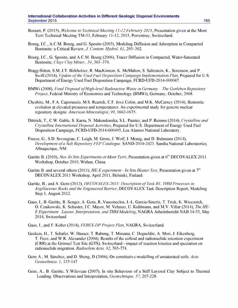
International Collaboration Activities in Different Geologic Disposal EnvironmentsSeptember 2015 165
Bossart, P. (2015), Welcome to Technical Meeting 11-12 February 2015, Presentation given at the Mont Terri Technical Meeting TM-33, February 11-12, 2015, Porrentruy, Switzerland.
Bourg, I.C., A.C.M. Bourg, and G. Sposito (2003), Modeling Diffusion and Adsorption in Compacted Bentonite: a Critical Review, J. Contam. Hydrol. 61, 293-302.
Bourg, I.C., G. Sposito, and A.C.M. Bourg (2006), Tracer Diffusion in Compacted, Water-Saturated Bentonite, Clays Clay Miner., 54, 363-374.
Bragg-Sitton, S.M, J.T. Birkholzer, R. MacKinnon, K. McMahon, S. Saltzstein, K., Sorenson, and P.Swift (2014), Update of the Used Fuel Disposition Campaign Implementation Plan, Prepared for U.S. Department of Energy Used Fuel Disposition Campaign, FCRD-UFD-2014-000047.
BMWi (2008), Final Disposal of High-level Radioactive Waste in Germany - The Gorleben Repository Project, Federal Ministry of Economics and Technology (BMWi), Germany, October, 2008.
Cheshire, M., F.A. Caporuscio, M.S. Rearick, C.F. Jove Colon, and M.K. McCarney (2014), Bentonite evolution at elevated pressures and temperatures: An experimental study for generic nuclear repository designs: American Mineralogist, 99, 1662-1675.
Dittrich, T., C.W. Gable, S. Karra, N. Makendonska, S.L. Painter, and P. Reimus (2014), Crystalline and Crystalline International Disposal Activities, Prepared for U.S. Department of Energy Used Fuel Disposition Campaign, FCRD-UFD-2014-000495, Los Alamos National Laboratory.
Freeze, G., S.D. Sevougian, C. Leigh, M. Gross, J. Wolf, J. Monig, and D. Buhmann (2014),Development of a Salt Repository FEP Catalogue. SAND-2014-2423. Sandia National Laboratories, Albuquerque, NM.
Garitte B. (2010), New In Situ Experiments at Mont Terri, Presentation given at 6th DECOVALEX 2011 Workshop, October 2010, Wuhan, China.
Garitte B. and several others (2011), HE-E experiment - In Situ Heater Test, Presentation given at 7th DECOVALEX 2011 Workshop, April 2011, Helsinki, Finland.
Garitte, B., and A. Gens (2012), DECOVALEX-2015: Description of Task B1, THM Processes inArgillaceous Rocks and the Engineered Barrier, DECOVALEX Task Description Report, Modeling Step 1, August 2012.
Gaus, I., B. Garitte, R. Senger, A. Gens, R.,Vasconcelos, J.-L. Garcia-Sineriz, T. Trick, K. Wieczorek,O. Czaikowski, K. Schuster, J.C. Mayor, M. Velasco, U. Kuhlmann, and M.V. Villar (2014), The HE- E Experiment- Layout, Interpretation, and THM Modeling, NAGRA Arbeitsbericht NAB 14-53, May 2014, Switzerland.
Gaus, I., and F. Kober (2014), FEBEX-DP Project Plan, NAGRA, Switzerland.
Geckeis, H., T. Schafer, W. Hauser, T. Rabung, T. Missana, C. Degueldre, A. Mori, J. Eikenberg,T. Fierz, and W.R. Alexander (2004), Results of the colloid and radionuclide retention experiment (CRR) at the Grimsel Test Site (GTS), Switzerland - impact of reaction kinetics and speciation on radionuclide migration. Radiochim Acta, 92, 765-774.
Gens A., M. Sanchez, and D. Sheng, D (2006), On constitutive modelling of unsaturated soils. Acta Geotechnica. 1, 137-147
Gens, A., B. Garitte, Y.Wileveau (2007), In situ Behaviour of a Stiff Layered Clay Subject to Thermal Loading: Observations and Interpretation, Geotechnique, 57, 207-228.

166International Collaboration Activities in Different Geologic Disposal Environments
September 2015
Gonsalves, J., P. Rousseau-Gueutin, and A. Revil (2007), Introducing Inter-acting Diffuse layers in TLM Calculations: A Reappraisal of the Influence on the Swelling Pressure and the Osmotic Efficiency of Compacted Bentonites, Journal of Colloid Interface Science 316, 92-99.
Graupner, B. (2015), Proposal of a Possible Task based on the FS Experiment Mont Terri, Presentation given at 7th DECOVALEX 2015 Workshop, April 2015, Brno, Czech Republic.
Graupner, B.J., C. Lee, C. Manepally, P. Pan, J. Rutqvist, W.Wang, and B. Garitte (2013), The Mont Terri HE-D Experiment as a Benchmark for the Simulation of Coupled THM Processes. Extended abstract for the European Association of Geoscientists & Engineers (EAGE) International Workshop Geomechanics & Energy, Lausanne, Switzerland, 26-28 November, 2013
Guglielmi Y., F. Cappa, H. Lan$on, J.B. Janowczyk, J. Rutqvist, C.F. Tsang, and J. Wang (2013a), Estimation of permeability, elastic and friction properties of fractured rock masses from in situ hydromechanical testing: the High- frequency Pulse Poroelasticity Protocole (HPPP) testing method. Submitted contribution to the ISRM Commission on Testing Methods, Int J Rock Mech Min Sci and Geomech Abstr special issue.
Guglielmi Y., P. Henry, F. Cappa, and B. Derode (2013b), Relationships between slow slip, seismicity and fluid leakage during a pressurized fault zone rupture in situ experiment: Importance for reservoir/caprock stimulation monitoring and efficiency assessment. ARMA Symposium Paper N°13- 517, ARMA San Francisco 23-26 June 2013.
Guglielmi Y., P. Henry, C. Nussbaum, P. Dick, C. Gout, and F. Amann (2015), Underground Research Laboratories for conducting fault activation experiments in shales. ARMA Symposium Paper N°15- 480, ARMA San Francisco June 2015.
Hampel, A., J.G. Arguello, F. Hansen, R.M. Gunther, K. Salzer, K., W. Minkley, K.-H. Lux, K. Herchen, U. Dusterloh, A. Pudewills, S. Yildirim, K. Staudtmeister, R. Rokahr, D. Zapf, A. Gahrken, C.Missal, and J.Stahlmann. (2013), Benchmark Calculations of the Thermo-Mechanical Behavior of Rock Salt - Results from a US-German Joint Project. 47th US Rock Mechanics Symposium, San Francisco, California.
Hampel, A., K. Salzer, R.-M. Gunther, w. Minkley, A. Pudewills, B. Leuger, D. Zapf, K. Staudtmeister,R. Rokahr, K. Herchen, R. Wolters, and K.-H. Lux (2012), Joint Projects on the Comparison of Constitutive Models for the Mechanical Behavior of Rock Salt - II. Overview of the Models and Results of 3-D Benchmark Calculations. In P. Berest, M. Ghoreychi, F. Hadj-Hassen & M. Tijani (eds.), Mechanical Behavior of Salt VII, Proc. 7th Conference, Paris. London: Taylor & Francis Group (Balkema).
Hansen, F., W. Steininger, and E. Biurrun (2013), Proceedings of the 4th US/German Workshop on Salt Repository Research, Design and Operation. FCRD-UFD-2014-000335, SAND2013-10592P. U.S. Department of Energy, Office of Nuclear Energy, Used Fuel Disposition Campaign, Washington,D.C.
Hansen, F., C.W. Leigh, W. Steininger, W. Bollingerfehr, and T. von Berlepsch (2015), Proceedings of the 5th US/German Workshop on Salt Repository Research, Design and Operation. FCRD-UFRD- 2015-00514, SAND2015-0500R. U.S. Department of Energy, Office of Nuclear Energy, Used Fuel Disposition Campaign, Washington, D.C.

International Collaboration Activities in Different Geologic Disposal EnvironmentsSeptember 2015 167
Hardin, E., C. Bryan, A. Ilgen, E. Kalinina, S. Teich-Goldrick, K. Banerjee, J. Clarity, R. Howard,R. Jubin, J. Scaglione, F. Perry, L. Zheng, J. Rutqvist, J.T. Birkholzer, H. Greenberg, J. Carter, and T. Severynse (2014), Investigation of Dual-Purpose Canister Direct Disposal Feasibility, Prepared for U.S. Department of Energy Used Fuel Disposition Campaign, FCRD-UFD-2014-000069 REV 1, Sandia Laboratories.
Harrington, J., R. Cuss, C. Graham, and S. Norris (2015), Advective Gas Flow in Bentonite, Presentation given at 7th DECOVALEX 2015 Workshop, April 2015, Brno, Czech Republic.
Hokr, M. and J. Slovak (2011), Bedrichov Tunnel Test Case Proposal for DECOVALEX 2015, Presentation given at 7th DECOVALEX 2011 Workshop, April 2011, Helsinki, Finland.
Hokr, M., A. Balvin, I. Skarydova, and P. Ralek (2014), Tunnel inflow in granite - fitting the field observations with hybrid model of discrete fractures and continuum, in (Sharp and Troeger, eds) Groundwater in Fractured Rocks, 13 pages, to appear 2014
Hofmanova, E., and R. Cervinka, 2014, Benchmark 5 - Diffusion of selected anions through compacted bentonite, SKB EBS Task Force Internal Documentation, p. 7.
Hunt, C.W. and M.H. Worthington (2000), Borehole electrokinetic responses in fracture dominated hydraulically conductive zones. Geophysical Research Letters, 27(9), 1315-1318.
Hyman, J., C.W. Gable, S.L. Painter, and N. Makedonska (2014), Conforming Delaunay Triangulation of Stochastically Generated Three Dimensional Discrete Fracture Networks: A Feature Rejection Algorithm for Meshing Strategy. SIAM Journal on Scientific Computing, 36(4), A1871-A1894.
Itasca (2009) FLAC3D V4.0, Fast Lagrangian Analysis of Continua in 3 Dimensions, User’s Guide,Itasca Consulting Group, Minneapolis, Minnesota.
Jing, L. and J.A. Hudson (2011), Technical Descriptions of the Three Tasks Proposed for the Next Phase of the DECOVALEX Project (2012-2015), Internal DECOVALEX Report, December 15, 2011.
Jove-Colon, C.F., F.A. Caporuscio, S.S. Levy, H. Xu, J.A. Blink, W.G. Halsey, T. Buscheck, M. Sutton, M.A. Serrano de Caro, T.J. Wolery, H.-H. Liu, J.T. Birkholzer, C.I. Steefel, J. Rutqvist, C.-F. Tsang, and E. Sonnenthal (2010), Disposal Systems Evaluations and Tool Development - Engineered Barrier System (EBS) Evaluation, Prepared for U.S. Department of Energy Used Fuel Disposition Campaign, Used Fuel Disposition Campaign.
KAERI (2011), KURT - KAERI Underground Research Tunnel, Brochure, Korea Atomic Energy Research Institute, Division of Radioactive Waste Technology Development.
Kawai, T. (1978), New Discrete Models and their Application to Seismic Response Analysis of Structures. Nuclear Engineering and Design, 48, 207-229.
Kersting, A.B., D.W. Efurd, D.L. Finnegan, D.J. Rokop, D.K. Smith, and Thompson, J.L. (1999), Migration of plutonium in ground water at the Nevada Test Site. Nature, 397, 56-59.
Lanyon, W. et al. (2013), Review of the FEBEX in situ experiment and the mock-up after 15 years of operation and monitoring. NAGRA NAB 13-096.
Lanyon, G.W., P. Marschall, T. Trick, R. de La Vaissiere, H. Shao, and H. Leung, (2009),Hydromechanical Evolution and Self-Sealing of Damage Zones around a Microtunnel in a Claystone Formation of the Swiss Jura Mountains. American Rock Mechanics Association, ARMA 09-333.

168International Collaboration Activities in Different Geologic Disposal Environments
September 2015
Lebon, P. (2011) Large-scale Experiment at Bure, Presentation given at the HADES Workshop, “30 Years of Underground Research Laboratory,” May 23-25, 2011, Antwerp, Belgium.
Leroy, P., A. Revil, and D. Coelho (2006), Diffusion of Ionic Species in Bentonite, J. Colloid Interface Sci. 296 (1), 248-255.
Li, X. (2011), Design and Status of the PRACLAY Seal and Heater Test, Presentation given at theHADES Workshop, “30 Years of Underground Research Laboratory,” May 23-25, 2011, Antwerp, Belgium.
McMahon, K. (2015), Report on the Status of the UFD Campaign International Activities in Disposal Research at SNL, Prepared for U.S. Department of Energy Used Fuel Disposition Campaign, FCRD- UFD-2015-000713, Sandia National Laboratories.
Maes, N., E. Weetjens, M. Aertsen, J. Govaerts, and L. Van Ravestyn (2011), Added Value and Lessons Learned from In Situ Experiments - Radionuclide Migration, Presentation given at the HADES Workshop, “30 Years of Underground Research Laboratory,” May 23-25, 2011, Antwerp, Belgium.
Marschall, P. and several others (2012), Gaspath Through Host Rock and Along Seal Sections (HG-A), Presentation given at the Mont Terri Technical Meeting TM-30, February 8 and 9, 2012, Saint Ursanne, Switzerland.
Marschall, P., M. Distinguin, H. Shao, P. Bossart, C. Enachescu, and T. Trick (2006), Creation and Evolution of Damage Zones Around a Microtunnel in a Claystone Formation of the Swiss Jura Mountains. Society of Petroleum Engineers, SPE-98537-PP.
Mayor, J.C. and A. Gens (2015), HM and THM Interactions in Bentonite Engineered Barriers, Presentation given at 7th DECOVALEX 2015 Workshop, April 2015, Brno, Czech Republic.
Millard, A. and J.D. Barnichon (2014), Task A - Step 2: Modelling of the SEALEX WT-1 test,Presentation given at 5th DECOVALEX 2015 Workshop, April 2014, Avignon, France.
NAGRA (2010), Grimsel Test Site - Research on Safe Geologic Disposal of Radioactive Waste, Brochure in Recognition of 25 Years of Research at Grimsel Test Site, NAGRA, July 2010.
NAGRA (2014), FEBEX-DP Kick-Off Meeting, Presentation given at the kick-off meeting for the FEBEX-DP project, Thun, Switzerland, June 2014.
Nater, P. (2012), Mont Terri /FE-Experiment Geomechanische Modellierung des Vortriebs. NAGRA Report, AN 12-184.
Nuclear Waste Technical Review Board (2009), Survey of National Programs for Managing High-Level Radioactive Waste and Spent Nuclear Fuel, report to Congress and the Secretary of Energy.
Nutt, M. (2010), Used Fuel Disposition Campaign International Activities Implementation Plan, Prepared for U.S. Department of Energy Used Fuel Disposition Campaign, FCRD-USED-2011-000016 REV 0, Argonne National Laboratory.
Nutt, M. (2011), Used Fuel Disposition Campaign Disposal Research and Development Roadmap,Prepared for U.S. Department of Energy Used Fuel Disposition Campaign, FCRD-USED-2011- 000065 REV0, Argonne National Laboratory.
Painter, S., C. Gable, N. Makedonska, J. Hyman, T.-L. Hsieh, Q. Bui, H.-H. Liu, and J.T. Birkholzer, (2012), Fluid Flow Model Development for Representative Geologic Media. Los Alamos National Laboratory. LAUR-12-26878. FCRD-UFD-2013-000058.

International Collaboration Activities in Different Geologic Disposal EnvironmentsSeptember 2015 169
Polak, A., D. Elsworth, H. Yasuhara, A.S. Grader and P.M. Halleck (2003), Permeability Reduction of a Natural Fracture Under Net Dissolution by Hydrothermal Fluids, Geophys. Res. Lett., 30(20), 2020.
Posiva (2011), Olkiluoto Site Description 2011, Posiva Oy, Report POSIVA 2011.
Ragoussi, M. E. and S. Brassinnes (2015), The NEA Thermochemical Database Project: 30 years of accomplishments. Radiochimica Acta, 2392.
Reimus, P.W., G. Pohll, T. Mihevc, J. Chapman, L. Papelis, B. Lyles, S. Kosinski, R. Niswonger, and P. Sanders (2003), Testing and Parameterizing a Conceptual Model for Radionuclide Transport in a Fractured Granite Using Multiple Tracers in a Forced-Gradient Test, Water Resour. Res., 39(12),1350, doi:10.1029/2002WR001597.
Reimus, P. (2012), Preliminary Interpretation of a Radionuclide and Colloid Tracer Test in aGranodiorite Shear Zone at the Grimsel Test Site, Switzerland, Prepared for U.S. Department of Energy Used Fuel Disposition Campaign.
Rejeb A. and J. Cabrera (2006) Time-dependent evolution of the excavation damaged zone in the argillaceous Tournemire Site (France), Proceedings “GeoProc 2006,” Invited lecture in the 2nd International Conference on Coupled THMC Processes in Geosystems and Engineering, May 22-25 2006, Nanjing, China, pp. 65-74.
Rutqvist, J., Y.-S. Wu, C.-F. Tsang, G. Bodvarsson, G. (2002), A Modeling Approach for Analysis of Coupled Multiphase Fluid Flow, Heat Transfer, and Deformation in Fractured Porous Rock, Int. J. of Rock Mechanics & Mining Sciences, 39, 429-442.
Rutqvist, J. (2011), Status of the TOUGH-FLAC simulator and recent applications related to coupled fluid flow and crustal deformations. Computers & Geosciences, 37, 739-750.
Rutqvist, J., C. Steefel, F. Chen, J. Houseworth, V. Vilarrasa, H.-H. Liu, and J.T. Birkholzer (2013), THM and Reactive Transport Model Development and Evaluation: International Activities, Prepared for U.S. Department of Energy Used Fuel Disposition Campaign, FCRD-UFD-2013-000372, Lawrence Berkeley National Laboratory.
Rutqvist, J., L. Zheng, F. Chen, H.-H. Liu, and J.T. Birkholzer (2014a), Modeling of Coupled ThermoHydro-Mechanical Processes with Links to Geochemistry Associated with Bentonite-Backfilled Repository Tunnels in Clay Formations. Rock Mechanics and Rock Engineering, 47, 167-186.
Rutqvist J., J. Davis, L. Zheng, V. Vilarrasa, J. Houseworth, and J.T. Birkholzer (2014b), Investigation of Coupled THMC Processes and Reactive Transport: FY14 Progress. Prepared for U.S. Department of Energy, Used Fuel Disposition, FCRD-UFD-2014-000497, Lawrence Berkeley National Laboratory, LBNL-6720E (2014).
Rutqvist, J., L. Blanco-Martin, S. Molins, D. Trebotich, and J.T. Birkholzer (2015), Modeling Coupled THM Processes and Brine Migration in Salt at High Temperatures, Prepared for U.S. Department of Energy Used Fuel Disposition Campaign, FCRD-UFD-2015-000366, Lawrence Berkeley National Laboratory, LBNL-191216.
Sanchez, M., A. Gens, L. do N. Guimaraes, and S. Olivella (2005), A double structure generalized plasticity model for expansive materials. Int. J. Numer. Anal. Meth. Geomech., 29, 751-787.
SKB (2011a), Aspo Hard Rock Laboratory Annual Report 2010, SKB Technical Report TR-11-10, February 2011.

170International Collaboration Activities in Different Geologic Disposal Environments
September 2015
SKB (2011b), Aspo Hard Rock Laboratory Planning Report for 2011, SKB International Progress Report IPR-10-19, February 2011.
Sugita, Y. and S. Nakama (2012), Task B: EBSHoronobe Experiment, Presentation given at 1st DECOVALEX 2015 Workshop, April 2012, Berkeley, CA.
Sugita, Y. (2015), Groundwater REcovery Experiment in Tunnel (GREET) in the MIUProject, Presentation given at 7th DECOVALEX 2015 Workshop, April 2015, Brno, Czech Republic.
Tsang, C.-F., O. Stephansson, L. Jing, and F. Kautsky (2009), DECOVALEX Project: from 1992 to 2007, Environmental Geology, 57, 1221-1237, 2009.
Tsang, C.-F., J.D. Barnichon, J.T. Birkholzer, X.L. Li, H.-H. Liu, X. Sillen, and T. Vietor (2011), A Review of Coupled Thermo-Hydro-Mechanical Processes in the Near-field of a High-Level Radioactive Waste Repository in a Clay Formation, International Journal of Rock Mechanics and Mining Sciences, 49, 31-44.
UFD (2012), Office of Used Nuclear Fuel Disposition International Program - Strategic Plan, April 2012, U.S. Department of Energy.
Van Marcke, P. and W. Bastiaens (2010) Construction of the PRACLAY Experimental Gallery at the Hades URF, Clay in Natural and Engineered Barriers for Radioactive Waste Confinement, 4th International Meeting, March, 2010, Nantes, France.
Viswanathan, H., C. Chu, T. Dittrich, J. Hyman, S. Karra, N. Makendonska, and P. Reimus (2015),Crystalline and Crystalline International Disposal Activities, Prepared for U.S. Department of Energy Used Fuel Disposition Campaign, FCRD-UFD-2015-000602, Los Alamos National Laboratory.
Vomvoris, S., J.T. Birkholzer, L. Zheng, I. Gays, and I. Blechschmidt (2015), THMC behavior of clay- based barriers under high temperature - from laboratory to URL scale, Proceedings, International High-Level Radioactive Waste Management Conference, Charleston, NC, USA, April 12-16, 2015.
Wang, Y. (editor) (2010), Natural System Evaluation and Tool Development - FY10 Progress Report, Prepared for U.S. Department of Energy Used Fuel Disposition Campaign, August 2010, Sandia National Laboratories.
Wang, Y., P. Gardner, K.L. Kuhlman, G.-Y. Kim, and S.-H. Ji (2014), International Collaborations on Fluid Flow in Fractured Crystalline Rocks: FY14 Progress Report, Prepared for U.S. Department of Energy Used Fuel Disposition Campaign, FCRD-UFD-2014-000499, Sandia National Laboratories.
Wang, Y., P. Gardner, K.L. Kuhlman, M.L. Kabir, M.L, and S.-H. Ji (2015), International Collaborations on Fluid Flow in Fractured Crystalline Rocks: FY15 Progress Report, Prepared for U.S. Department of Energy Used Fuel Disposition Campaign, FCRD-UFD-2015-000711, Sandia National Laboratories.
Wersin, P., L.R. Van Loon, J.M. Soler, A. Yllera, J. Eikenberg, Th. Gimmi, P. Hernan, and J.-Y. Boisson (2004), Long-term Diffusion Experiment at Mont Terri: First Results from Field and Laboratory Data, Applied Clay Science, 26, 123-135.
Wersin, P., J.M. Soler, L.R. Van Loon, J. Eikenberg, B. Baeyens, D. Grolimund, Th. Gimmi andS. Dewonck (2008), Diffusion of HTO, Br", I", Cs+, 85Sr2+ and 60Co2+ in a Clay Formation: Results and Modeling from an In Situ Experiment in Opalinus Clay, Applied Geochemistry, 23, 678-691.
Wileveau, Y. (2005) THM Behavior of Host Rock (HE-D Experiment): Progress Report September 2003 - October 2004, Mont Terri Technical Report TR2005-03.

International Collaboration Activities in Different Geologic Disposal EnvironmentsSeptember 2015 171
Xu, T., N. Spycher, E. Sonnenthal, G. Zhang, L. Zheng, and K. Pruess (2011) TOUGHREACT Version 2.0: A simulator for subsurface reactive transport under non-isothermal multiphase flow conditions. Computers & Geosciences 37(6): 763-774.
Yasuhara, H., D. Elsworth, and A. Polak (2004) The Evolution of Permeability in a Natural Fracture: Significant Role of Pressure Solution, J. Geophys. Res., 109(B3).
Yasuhara, H., A. Polak, Y. Mitani, A. Grader, P. Halleck, and D. Elsworth (2006), Evolution of Fracture Permeability Through Fluid-Rock Reaction Under Hydrothermal Conditions, Earth Planet. Sci. Lett. 244: 186-200.
Yasuhara, H., N. Kinoshita, H. Ohfuji, D.S. Lee, S. Nakashima, and K. Kishida (2011), TemporalAlteration of Fracture Permeability in Granite Under Hydrothermal Conditions and its Interpretation by Coupled Chemo-MechanicalModel, Appl. Geochem. 26, 2074-2088.
Zavarin, M., T. Wolery, and M. Sutton, (2015), Thermodynamic and Sorption Data Progress Report, Prepared for U.S. Department of Energy Used Fuel Disposition Campaign, M4FT-15LL0806062, Lawrence Livermore National Laboratory.
Zavarin, M., P. Zhao, C. Joseph, J.D. Begg, Z. Dai and A.B. Kersting (2015), Progress Report on FY15 Crystalline Experiments, Prepared for U.S. Department of Energy Used Fuel Disposition Campaign, M4FT-15LL0807052, Lawrence Livermore National Laboratory.
Zhang, S.Q., and S.F. Cox (2000), Enhancement of fluid permeability during shear deformation of a synthetic mud. Journal of Structural Geology, 22(10), 1385-1393.
Zheng, L., L. Li, J. Rutqvist H.-H. Liu, and J.T. Birkholzer, (2012), Modeling Radionuclide Transport in Clays. Lawrence Berkeley National Laboratory. FCRD-UFD-2012-000128
Zheng L., J. Rutqvist, C. Steefel, K. Kim, F. Chen, V. Vilarrasa, S. Nakagawa, J. Houseworth, and J.T. Birkholzer (2014), Investigation of Coupled Processes and Impact of High Temperature Limits in Argillite Rock, Prepared for U.S. Department of Energy, Used Fuel Disposition, FCRD-UFD-2014- 000493, Lawrence Berkeley National Laboratory.
Zheng, L., J. Rutqvist, K. Kim, and J. Houseworth (2015), Investigation of Coupled Processes and Impact of High Temperature Limits in Argillite Rock, Prepared for U.S. Department of Energy Used Fuel Disposition Campaign, FCRD-UFD-2015-000362, Lawrence Berkeley National Laboratory.
Zoback M., A. Kohli, I. Das, and M. McClure (2012), The importance of Slow Slip on Faults During Hydraulic Fracturing Stimulation of Shale Gas Reservoirs. Society of Petroleum Engineer, SPE155476, The Americas Unconventional Resources Conference, Pittsburgh, Pennsylvania, USA, 5-7 June 2012.
Zuidema, P. (2007), Advancements in Deep Geological Disposal of Radioactive Waste through International Cooperation: The Role of Underground Laboratories - Mont Terri Project,Proceedings of the 10 Year Anniversary Workshop, pp 69-71, Rep. Swiss Geol. Surv. 2.