abstracts of the annual meeting of planetary geologic
TRANSCRIPT
Abstracts of the Annual Meeting of Planetary Geologic Mappers, Honolulu, HI 2015 Edited by: James A. Skinner, Jr. U. S. Geological Survey, Flagstaff, AZ David Williams Arizona State University, Tempe, AZ NOTE: Abstracts in this volume can be cited using the following format: Graupner, M. and Hansen, V.L., 2015, Structural and Geologic Mapping of Tellus Region, Venus, in Skinner, J.A., Jr. and Williams, D. A., eds., Abstracts of the Annual Meeting of Planetary Geologic Mappers, Honolulu, HI, June 22-24, 2015.
1
Planetary Mappers’ Meeting University of Hawaii
June 22-24, 2015 Day 1: Monday, June 22, 2015 8:30 Refreshments (30 min) 9:00 David Williams, Rhett Butler (HIGP Director), and Peter Mouginis-Mark: Welcome and
Logistics (15 min) 9:15 Corey Fortezzo (for Jim Skinner): Overview of the NASA Planetary Mapping Program
(30 min) 9:45 Trent Hare: GIS Update (20 min) 10:05 Alexandra Huff: Digitization of the 1:5M Mariner 9 geologic maps of Mars (10 min) 10:15 Break (20 min) Oral Presentations: Mars Mapping, Part 1 (20 min each) 10:35 Corey Fortezzo: Local mapping in Hadriacus Cavi, Mars 10:55 Bob Anderson: Completion of the Terra Sirenum project 11:15 Dan Berman: Geologic mapping of the source region of Shalbatana Vallis 11:35 Devon Burr: Characterizing the history of a diverse inverted landscape: Aeolis Dorsa 11:55 Fred Calef: Geologic mapping of the MSL landing ellipse 12:15 Ken Coles: Format and scope of a new atlas of Mars 12:35 - 1:45: Lunch Break (1 hr 10 min) Oral Presentations: Mars Mapping, Part 2 (20 min each) 1:45 David Crown: Geologic mapping investigations of the S Tharsis region 2:05 James Dohm: Geological and hydrological histories of Argyre Province 2:25 Peter Fawdon: Understanding the evolution of Syrtis Major volcanic complex 2:45 Corey Fortezzo: Geologic mapping of central Valles Marineris 3:05 John Grant/Sharon Wilson: Southwestern Margaritifer Terra quadrangles
2
3:25 Keenan Golder: Constraining the magma behavior that led to the Cerberus channel flood lavas
3:45 Break and Poster Session, Part 1 (75 minutes)
Buczkowski-Caloris, Hansen-Aphrodite, Lopez-Niobe, Tovar-Aphrodite, Ogawa-Kaguya, Cameron-Ganymede, Yingst-Planck, Anderson-Terra Sirenum, Burr-Aeolis Dorsa, Calef-MSL, Coles-Mars, Crown-Tharsis, Fawdon-Syrtis, Grant-Wilson-Margaritifer (4), Huff-Mariner 9, Hynek-Mercury-Mars (3), Mest-Hellas, Okubo-Candor, Ramsdale-Mars, Thomson/Lang-Mahuea, Garry-Tharsis Montes, Skinner-Hadriacus, Lang-Venus.
5:05 Adjourn 6:15-8:30: Social Event at Pete Mouginis-Mark’s home Day 2: Tuesday, June 23, 2015 8:30 Refreshments (30 minutes) Oral Presentations: The Rest of the Solar System (20 min each) 9:00 Scott Mest: Geologic mapping of volcanic and sedimentary materials around upper Dao
and Niger Valles 9:20 Debra Buczkowski: Caloris basin, Mercury 9:40 David Tovar: Detailed structural mapping of W. Aphrodite Terra, Venus 10:00 Aileen Yingst: Planck quadrangle, the Moon 10:20 Break (20 min) 10:40 Justin Hagerty: Compositional and morphological mapping of the Copernicus
quadrangle, the Moon: Year 3 status 11:00 Dave Williams: Geologic Mapping plans for Ceres during Dawn Mission 11:20 Wesley Patterson: Progress on the 1:2M global geologic map of Enceladus 11:40 Dave Williams: Geologic Mapping of Titan 12:00-1:15: Lunch Break (1 hr 20 min) Oral Presentations: Mars Mapping, Part 3 (20 min each) 1:35 Peter Mouginis-Mark: Hrad Vallis and the flows from Galaxias Fossae
3
1:55 Jason Ramsdale: Mapping Mars’ northern plains: Overview of grid mapping method 2:15 Alexis Rodriguez: Geologic mapping reveals that tsunami waves extensively resurfaced
the coasts of early Martian oceans 2:35 Brad Thomson: Western Aeolis Mons, 1:60K 2:55 Cathy Weitz: Geologic mapping to constrain the sources and timing of fluvial activity in
western Ladon Basin 3:15 Break (15 min) 3:30 Sharon Wilson: Geologic mapping in southern Margaritifer Terra: Constraining the
timing and origin of fluvial activity 3:50 Brent Garry: Geologic mapping of the Tharsis Montes 4:10-5:30 David Williams: GEMS Issues and Group Discussion 5:30 Adjourn Day 3: Wednesday, June 24, 2015 8:30 Refreshments GIS Day (Trent Hare, Presiding) 9:00 am - ~11:30: GIS/Data Demos * ArcMap Pro (brief introduction to new interface) + why we are not supporting it yet. * WMS/ArcGIS Online Demo + useful live layers and how to add * QGIS Demo (better planetary support, crater tool, surface tool). + why we still can't support for geologic mapping * PILOT / POW demo + Processing GIS-ready images using Astro's clusters. + New simple stereo-tool finder * Map-a-Planet 2 demo + Find and process basemap data (~70 available layers) * CTX mosaic tool builder (ArcMap) + Once Mosaic is built how to manipulate layers * Attribute Domains (ArcMap: renaming new generic features, adding new) + Geodatabase organization

4
11:30 – 12:30 Optional viewing of new “digital wall” for viewing planetary data 11:30-1:30 Lunch 1:00 pm - ??: Mapper Q&A Session * Answer specific questions from mappers Note: Mappers should bring projects for detailed help 3:00-5:00: Adjourn
CONTENTS (sorted by body, then alphabetically by author) Mercury A Geologic Map of the Caloris Basin, Mercury.
D. L. Buczkowski, B. W. Denevi, C. M. Ernst, C. I. Fasset and P. K. Byrne……...………1 Unlocking Mercury’s Geological History with Rembrandt Basin: Year 1.
B. M. Hynek, S. J. Robbins, M. K. Osterloo, K. Mueller, J. Gemerpline………………….3 Venus 1:10M Geologic Map of Aphrodite Terra Region, Venus (I-2476).
V. L. Hansen, I. López, and K. G. Thaisen………………………………………………..5 An Initial Look at the Mahuea Tholus (V-49) Quadrangle, Venus.
N. P. Lang and B. J. Thomson…………………………………………………………….7 Progress Report on the Geologic Mapping of the 1:10M Niobe Map Area, Venus.
I. López and V. L. Hansen…………………………………………..……………………..9 Detailed structural map of a highly fractured zone in an equatorial region at Western Aphrodite Terra, Venus (15S-20S / 110E-124E)
D. Tovar, V. L. Hansen, and J. B. Swenson……...………………………………………11 Moon Compositional and Morphologic Mapping of the Copernicus Quadrangle, the Moon: Year 3 Status.
J. J. Hagerty, J. A Skinner Jr., L. R. Gaddis, J. R. Laura, C. M. Fortezzo and A. E. Huff……………………………………………………………13
Update on Geologic Mapping of the Lunar South Pole Quadrangle (LQ-30).
S. C. Mest, D. C. Berman, N. E. Petro, and R. A. Yingst………………..……………….15 A Web-GIS "Gekko" (which means moonlight in Japanese): a viewer of the data from the Spectral Profiler Onboard Kaguya.
Y. Ogawa, Y. Hayashi, N. Hirata, J. Terazono, H. Demura, T. Matsunaga, S. Yamamoto, Y. Yokota, M. Ohtake, H. Ootake…………...…………….17
Geologic Mapping of the Planck Quadrangle of the Moon.
R. A. Yingst, F. C. Chuang, D. C. Berman, and S. C. Mest………………..…………….18
Mars Completion of the Terra Sirenum Map Project: A Window into Pre-Tharsis and Tharsis Phases of Mars Evolution.
R. C. Anderson, J. M. Dohm, S. Robbins, and J. Schroeder……….…………………….20 Geologic Mapping of the Source Region of Shalbatana Vallis, Mars.
D. C. Berman, J. A. P. Rodriguez, C. M. Weitz, and D. A. Crown………...…………….22 Characterizing the History of a Diverse Inverted Landscape: Mapping of the Aeolis Dorsa Region, Mars.
D. M. Burr and R. E. Jacobsen………………….……………………………………….24 Geologic Mapping of the Mars Science Laboratory Landing Ellipse: Final Preparation for Submission.
F. J. Calef III, W. E. Dietrich, L. Edgar, J. Farmer, A. Fraeman, J. Grotzinger, M. C. Palucis, T. Parker, M. Rice, S. Rowland, K. M. Stack, D. Sumner, J. Williams, and the MSL Science Team……...……………….26
Format and Scope of a New Atlas of Mars.
K. S. Coles and K. L. Tanaka………………………………………….…………………27 Geologic Mapping Investigations of the Southern Tharsis Region of Mars.
D. A. Crown, D. C. Berman, F. C. Chuang, M. S. Ramsey, and L. L. Tornabene…….…28 Geologic History of the Argyre Province, Mars.
J.M. Dohm, T.M. Hare, S.J. Robbins, J.P. Williams, R.J. Soare, M.R. El Maarry, S.J. Conway, J.S. Kargel, D.L. Buczkowski, M. E. Banks, Hirdy Miyamoto, R.C. Anderson, B. Hynek, S. Maruyama..………………30
Evolving Magmas, Explosive Eruptions and Hydrothermal Deposits at Nili Patea Caldera, Syrtis Major, Mars.
P. Fawdon, J. R. Skok, M.R. Balme, C. Vye-Brown, D.A. Rothery, and C.J. Jordan……......…………………………………………………………………33
Understanding the Evolution of the Syrtis Major Volcanic Complex (Mars).
P. Fawdon, M.R. Balme, C. Vye-Brown, D.A. Rothery, and C.J. Jordan……….……….35 Geologic Mapping of Central Valles Marineris, Mars.
C. M. Fortezzo, T. Platz, and P. S. Kumar…………………………………...………….37 Geologic Mapping of the Tharsis Montes (Arsia, Pavonis, and Ascraeus), Mars.
W. B. Garry, D. A. Williams, J. E. Bleacher, and A. M. Dapremont…………………….39 Constraining the Magma Behavior That Led to the Cerberus Channel Flood Lavas, Mars.
K. B. Golder and D. M. Burr……………….................…………………………………41
Discontinuous Drainage Systems in the Channeled Plains North-East of Hellas Basin.
H.I. Hargitai and V. Gulick…………………………………………………….………..43 Digitization of the 1:5,000,000-Scale Mariner 9-Based Geological Maps of Mars.
A. E. Huff, J. A. Skinner, Jr., and T. M. Hare……………………………………………45 Geologic Mapping of the Coprates Chasma (MTM -15057), Mars: Year 1.
B. M. Hynek, M. Chojnacki, S. R. Black, and J. R. Martin………………………………47
Geologic Map of the Meridiani Region of Mars. B. M. Hynek and G. Di Achille………………………………………………………......49
Geologic Mapping of Volcanic and Sedimentary Materials Around Upper Dao and Niger Valles, Northeast Hellas, Mars.
S. C. Mest, D. A. Crown, J. Michalski, F. C. Chuang, K. P. Blount, and L. F. Bleamaster………………………………………………………51
. Hrad Vallis and the Flows from Galaxias Fossae.
P. J. Mouginis-Mark, C. W. Hamilton, and L. Wilson………………………………..….53 High-Resolution Geologic Mapping in East Candor Chasma: 2015 Status Report.
C. H. Okubo and L. A. Edgar………………………………………………...…………..55 Mapping Mars’ Northern Plains: Origins, Evolution and Response to Climate Change – A New Overview of Recent Ice Indicative Landforms.
J.D. Ramsdale, M.R. Balme, S.J. Conway, C. Gallagher, A. Kereszturi, F. Costard, S. van Gasselt, E. Hauber, A.E. Johnsson, C. Orgel, T. Platz, A. Séjourné, J.A. Skinner, Z. Swirad, D. Reiss, and A. Losiak…………………….……57
Mapping Mars’ Northern Plains: Origins, Evolution and Response to Climate Change - An Overview of the Grid Mapping Method.
J.D. Ramsdale, M.R. Balme, S.J. Conway, F. Costard, C. Gallagher, S. van Gasselt, E. Hauber, A. E. Johnsson, A. Kereszturi, T. Platz, A. Séjourné, J. A. Skinner, Jr., D. Reiss, Z. Swirad, C. Orgel, and A. Losiak…………………………………………………………………………….59
Geologic Mapping Reveals That Tsunami Waves Extensively Resurfaced the Coasts of Early Martian Oceans.
J.A.P. Rodriguez, K.L. Tanaka, A.G. Fairén, G. Komatsu, V. Gulick, V.R. Baker, T. Platz, R. Linares, M. Zarroca, Y. Jianguo and N. Glines………………………………………………………………..61
Geologic Mapping of Basin Sequences in Hadriacus Cavi, Mars: Method, Results, and Next Steps.
J. A. Skinner, Jr., C. M. Fortezzo, and L. A. Edgar……………………......…………….63 Unconformable Deposits on Aeolis Mons, Gale Crater.
B. J. Thomson, L. S. Crumpler, D. L. Buczkowski, and K. D. Seelos……………………65 Geologic Mapping to Constrain the Sources and Timing of Fluvial Activity in Western Ladon Basin, Mars.
C. M. Weitz, S. A. Wilson, R. P. Irwin III, and J. A. Grant………………………………67 Geologic Mapping in Southern Margaritifer Terra on Mars: Constraining the Timing and Origin of Fluvial Activity.
S. A. Wilson, J. A. Grant, D. L. Buczkowski, and C. M. Weitz………………….……….69 Ganymede Strike-Slip Mapping on Ganymede.
M. E. Cameron, L. Burkhard, B. R. Smith-Konter, R. T. Pappalardo, and G. C. Collins……………….......……………………………………………………71
Enceladus Progress on a 1:2M Global Geologic Map of Enceladus.
G. W. Patterson, M. T. Bland, T. L. Becker, K. L. Edmundson, G. C. Collins, and R. T. Pappalardo………………………………….........…………….72
Titan The Geologic Mapping of Titan.
D. A. Williams, M. J. Malaska, R. M. C. Lopes, and S. P. Birch……………..………….74 Ceres Geologic Mapping Plans for Ceres from NASA’s Dawn Mission.
D.A. Williams, D.L. Buczkowski, S.C. Mest, and J.E.C. Scully……………....………….76
A GEOLOGIC MAP OF THE CALORIS BASIN, MERCURY. D. L. Buczkowski1 , B. W. Denevi1, C. M. Ernst1, C. I. Fasset2 and P. K. Byrne3, 1JHU/APL, Laurel, MD 20723, [email protected]; 2Mt. Holyoke College, S. Hadley, MA; 3LPI, Houston, TX.
Introduction: The 1,550 km-diameter Caloris ba-sin, the largest impact structure on Mercury, is a highly complex geologic landform. The basin is floored by light-toned plains [1] that have been determined to be volcanic in nature, and multiple landforms, including volcanic vents and even a possible small shield volca-no [e.g. 2,3], have been identified. The basin floor also shows a degree of tectonic diversity that is far greater and more complex than anywhere else on the planet [4]. Also, the nature of the annulus of dark-toned mate-rial that surrounds the basin remains unclear [3]. While the hummocks are thought to be ejecta blocks, the smooth, dark, ridged plains interfingering them have been interpreted to be younger than the light-toned plains within the Caloris basin. This would imply a second, plains emplacement event, possibly involving lower albedo volcanic material, which resurfaced the original ejecta deposit. A geologic map of the Caloris basin will serve to synthesize the results of these pre-vious studies into a contextual framework for quickly viewing the thematic research that has been performed on this interesting region.
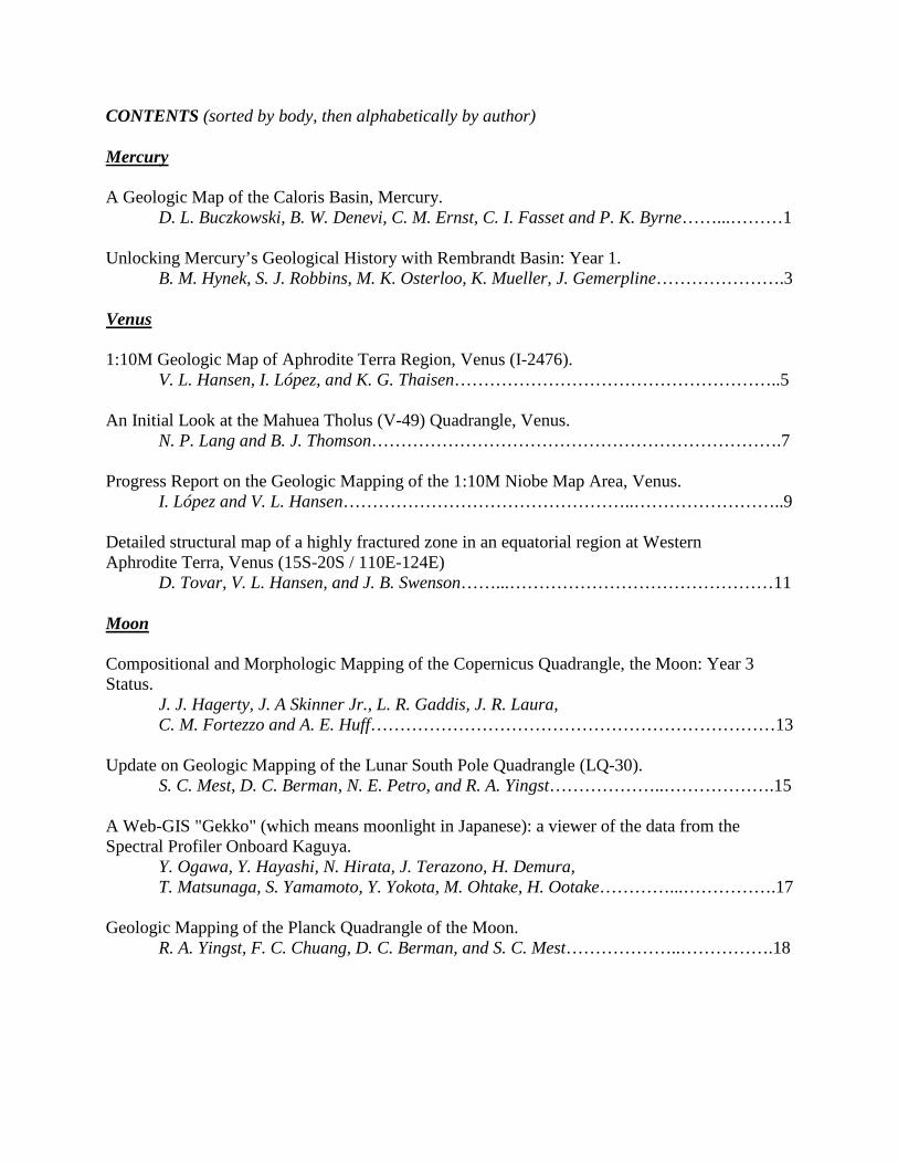
Caloris basin map: In the mapping scheme de-signed for Mercury, the Caloris basin crosses four quadrangles: H-3 Shakespeare (21º-66°N, 90º-180°W), H-4 Raditladi (21º-66°N, 180º-270°W), H-8 Tolstoj(21ºS -21°N, 144º-216°W) and H-9 Eminescu (21ºS-21°N, 216°-288º W). In this mapping effort, we aredeveloping a Caloris basin map that ranges from 0º-60°N, 160º-240°W (Fig. 1), covering both the entirebasin and its surrounding dark annulus. This areal ex-tent best summarizes the thematic research of the Calo-ris basin region. Such region specific maps are com-mon on Mars (e.g. the northern plains [5], the Chrysebasin [6], etc.) and can truly focus understanding of aregion of interest. We will combining existing high-resolution maps, crater counts, and stratigraphic anal-yses into a single ArcGIS product to be submitted tothe USGS for publication as a finished USGS map.
Geologic Units: Two Mercury quadrangle maps based on Mariner 10 data cover the eastern third of the Caloris basin (Fig. 2): H-8 Tolstoj [7] and H-3 Shake-speare [8]. Several terrain units associated with the Caloris basin were identified by [9]. Later, a rock-stratigraphic group consisting of several formations was developed during the 1:5M mapping of the H-8 Tolstoj [7] and H-3 Shakespeare [8] quadrangles and then formalized [10]. The formations of the Caloris group correspond with the morphological units recog-nized previously [9] (Fig. 2).
The most prominent annular feature surrounding the Caloris basin structure is comprised of smooth-surfaced massifs 1-2 km high and 100-150 km wide. Originally referred to as “mountain terrain” [9], the unit was officially named the Caloris Montes For-mation (cm) [7,8,10]. The component blocks were interpreted as uplifted bedrock [9].
The depressions between the massifs of the Calo-ris Montes are mantled by a undulating to smooth unit called the Nevro Formation (cn) [7,8,10]. McCauley et al. [10] interpreted these “intermontane plains” [9] as fallback material from the Caloris impact itself, but much of the formation may be impact melt ejected from the excavation cavity of the basin [11].
An extensive plains unit, similar in appearance to the ps material outside of Caloris, covers the floor of the basin. However, the Caloris floor material shows more intense tectonic deformation than the exterior smooth plains, including abundant wrinkle ridges and graben with discrete basin-radial, -concentric, and -oblique orientations [4]. In the Tolstoj and Shake-speare quadrangles the Caloris Floor Plains Material (cfp) and the Smooth Plains Material (ps) are mapped as distinct units [7,8]. Unable to discern an unequivo-cal formation mechanism for the cfp material, the quadrangle maps suggest that it is either volcanic in origin or a thick impact-melt sheet.
There are two geologic units considered to be fa-cies of Caloris ejecta: the Odin formation and the Van Eyck formation [7-10]. The Van Eyck Formation (cvl) includes a lineated terrain extending radially 1000 km from the outer edge of the Caloris Montes and clusters of secondary craters identified by [7]. The long, hilly ridges and grooves comprising the Van Eyck are sub-radial to the basin proper and are interpreted as ejecta from Caloris secondaries.
The other Caloris ejecta unit is formally named the Odin Formation (co) [7,8,10]. Hummocky plains [9], consisting of low hills ranging from 0.3-1 km across and up to a few hundred meters high, encircle the basin in a broad annulus that extends up to many hundreds of kilometers from the Caloris Montes. In some places the Odin hills are concentric to the rim of the Caloris ba-sin, and the spacing between hills can vary greatly. The outer boundary of the Odin Formation is gradational with the younger Smooth Plains Material (ps) exterior to the Caloris basin, which is similarly surrounded by the older, pre-Caloris Intercrater Plains Material (pi).
Fassett et al. [12] concluded that while the Odin Formation knobs are Caloris ejecta blocks, they may have been mostly embayed and buried by younger vol-
1

canic deposits. Conversely, Denevi et al. [3] found conflicting evidence for the origin of the circum-Caloris plains, and determined that the crater size–frequency distributions in these regions may not be meaningful discriminators of age. They suggested that the higher density of craters on the Caloris rim and ejecta deposits may be the result of non-uniform self-secondary cratering, such as has sometimes been ob-served on the Moon [13-16]. A second possibility is that a difference in target material properties between ejecta deposits and impact melt could also have result-ed in a higher density of craters on the Caloris rim, leading to a false interpretation of greater age. This, too, has been observed in lunar craters [16-19]. Meanwhile, Buczkowski et al. [20] found that the Odin Formation showed two distinct sub-units: a dark sub-unit that has a higher concentration of knobs and a (relatively) bright sub-unit that has fewer and fresher craters. They suggested that the bright sub-unit repre-sents a volcanic flow younger than and interfingering the knobs and darker flows that represent the Caloris ejecta. By integrating all current data sets, analyses, and maps into a single map product, the persisting question of the nature of the Odin formation can be addressed definitively.
Acknowledgements: This work is supported by the Planetary Geology and Geophysics program, grant number NNX14AP50G.
References: [1] Murchie S. et al. (2008) Science, 185, 73-76. [2] Goudge T. A. et al. (2012) LPS XLIII, Abstract #1325. [3] Denevi B. W. et al. (2013) JGR, 118, doi:10.1002/jgre.20075. [4] Byrne P. K. et al. (2014) Nature Geosci., 7, 301–307. [5] Tanaka K. L. et al. (2005) U.S. Geol. Survey Map I-2888. [6] Rotto S. and Tanaka K. L. (1995) U.S. Geol. Survey Map I-2441. [7] Schaber G. G. and McCauley J. F. (1980) U.S. Geol. Survey, Map I-1199. [8] Guest J. E. and Greeley R. (1983) U.S. Geol. Survey, Map I-1408. [9] Trask N. J. and Guest J. E. (1975) JGR., 80, 2462-2477. [10] McCauley J. F. et al. (1981) Icarus, 47, 184-202. [11] Spudis P. D. and Guest J. E. (1988) in Mercury, Univ. of Ariz. Press, 118-164. [12] Fassett C. I. et al. (2009) EPSL, 285, 297-308. [13] Shoemaker E. M. et al. (1968) in Surveyor 7 Mission Report. Part 2. NASA Tech. Rep., 32-700, 75–134. [14] Plescia J. B. et al. (2010), LPS XLI, Abstract #2038. [15] Plescia J. B. and Robinson M. S. (2011), LPS XLII, Abstract #1839. [16] Hiesinger H. et al. (2012) JGR, 117, doi: 10.1029/2011JE00393. [17] Schultz P. H. et al. (1977) LPS VIII, 3539–3564. [18] Dundas C. M. et al. (2010) GRL, 37, doi: 10.1029/ 2010GL042869. [19] van der Bogert, C. H. et al. (2010) LPS XLI, Abstract #2165. [20] Buczkowski D. L. and Seelos K. D. (2012) LPS XLIII, Abstract #1844.
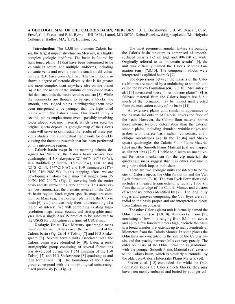
(left) Figure 1. Geologic map of the Caloris basin, Mercury, in progress.
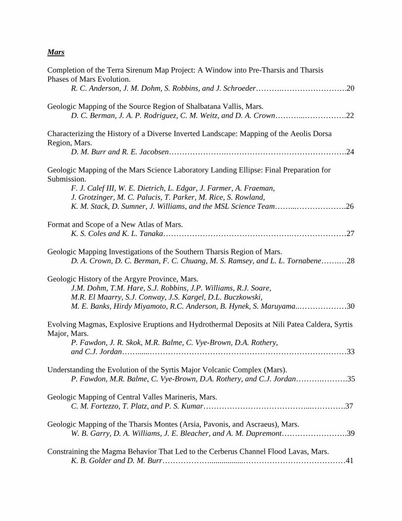
(above) Figure 2. MESSENGER mosa-ic of the Caloris basin overlain by portions of the H-8 Tolstoj [7] and H-3 Shakespeare [8] quadrangles. Odin Formation is light blue; Smooth Plains are pink.
2
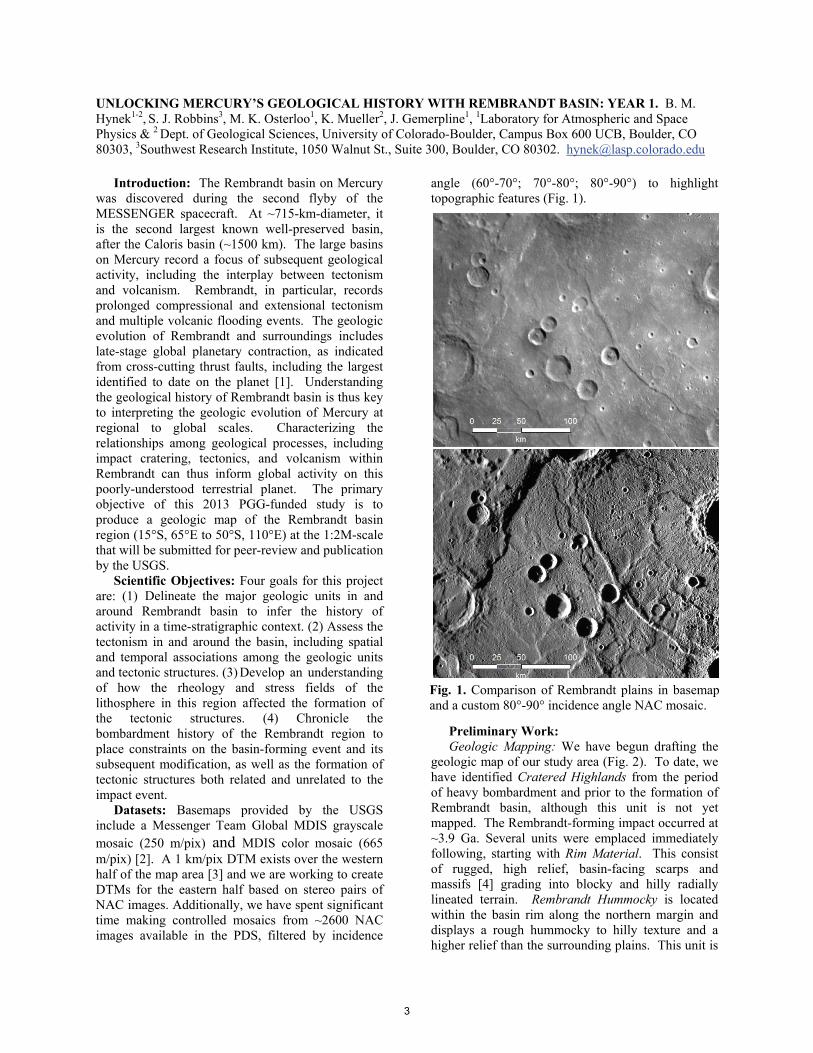
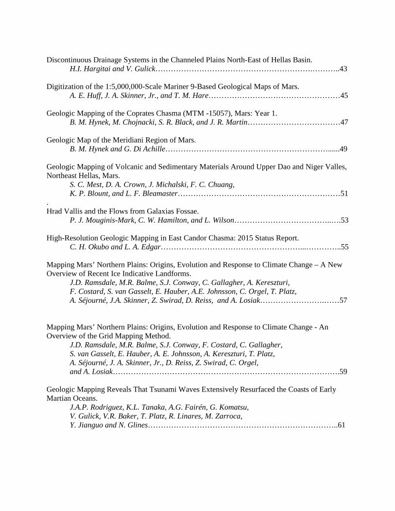
Fig. 1. Comparison of Rembrandt plains in basemap and a custom 80°-90° incidence angle NAC mosaic.
UNLOCKING MERCURY’S GEOLOGICAL HISTORY WITH REMBRANDT BASIN: YEAR 1. B. M. Hynek1-2, S. J. Robbins3, M. K. Osterloo1, K. Mueller2, J. Gemerpline1, 1Laboratory for Atmospheric and Space Physics & 2 Dept. of Geological Sciences, University of Colorado-Boulder, Campus Box 600 UCB, Boulder, CO 80303, 3Southwest Research Institute, 1050 Walnut St., Suite 300, Boulder, CO 80302. [email protected]
Introduction: The Rembrandt basin on Mercury was discovered during the second flyby of the MESSENGER spacecraft. At ~715-km-diameter, it is the second largest known well-preserved basin, after the Caloris basin (~1500 km). The large basins on Mercury record a focus of subsequent geological activity, including the interplay between tectonism and volcanism. Rembrandt, in particular, records prolonged compressional and extensional tectonism and multiple volcanic flooding events. The geologic evolution of Rembrandt and surroundings includes late-stage global planetary contraction, as indicated from cross-cutting thrust faults, including the largest identified to date on the planet [1]. Understanding the geological history of Rembrandt basin is thus key to interpreting the geologic evolution of Mercury at regional to global scales. Characterizing the relationships among geological processes, including impact cratering, tectonics, and volcanism within Rembrandt can thus inform global activity on this poorly-understood terrestrial planet. The primary objective of this 2013 PGG-funded study is to produce a geologic map of the Rembrandt basin region (15°S, 65°E to 50°S, 110°E) at the 1:2M-scale that will be submitted for peer-review and publication by the USGS.
Scientific Objectives: Four goals for this project are: (1) Delineate the major geologic units in and around Rembrandt basin to infer the history of activity in a time-stratigraphic context. (2) Assess the tectonism in and around the basin, including spatial and temporal associations among the geologic units and tectonic structures. (3) Develop an understanding of how the rheology and stress fields of the lithosphere in this region affected the formation of the tectonic structures. (4) Chronicle the bombardment history of the Rembrandt region to place constraints on the basin-forming event and its subsequent modification, as well as the formation of tectonic structures both related and unrelated to the impact event.
Datasets: Basemaps provided by the USGS include a Messenger Team Global MDIS grayscale mosaic (250 m/pix) and MDIS color mosaic (665 m/pix) [2]. A 1 km/pix DTM exists over the western half of the map area [3] and we are working to create DTMs for the eastern half based on stereo pairs of NAC images. Additionally, we have spent significant time making controlled mosaics from ~2600 NAC images available in the PDS, filtered by incidence
angle (60°-70°; 70°-80°; 80°-90°) to highlight topographic features (Fig. 1).
Preliminary Work: Geologic Mapping: We have begun drafting the
geologic map of our study area (Fig. 2). To date, we have identified Cratered Highlands from the period of heavy bombardment and prior to the formation of Rembrandt basin, although this unit is not yet mapped. The Rembrandt-forming impact occurred at ~3.9 Ga. Several units were emplaced immediately following, starting with Rim Material. This consist of rugged, high relief, basin-facing scarps and massifs [4] grading into blocky and hilly radially lineated terrain. Rembrandt Hummocky is located within the basin rim along the northern margin and displays a rough hummocky to hilly texture and a higher relief than the surrounding plains. This unit is
3
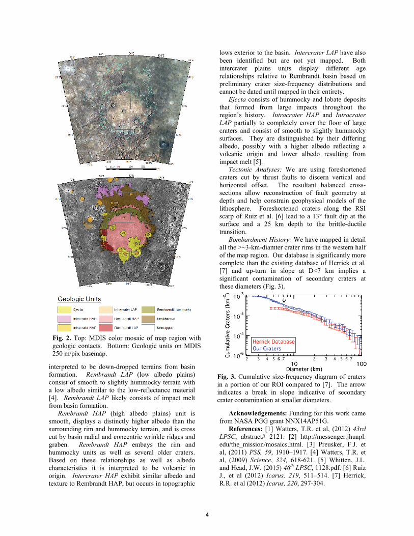
Fig. 2. Top: MDIS color mosaic of map region with geologic contacts. Bottom: Geologic units on MDIS 250 m/pix basemap.
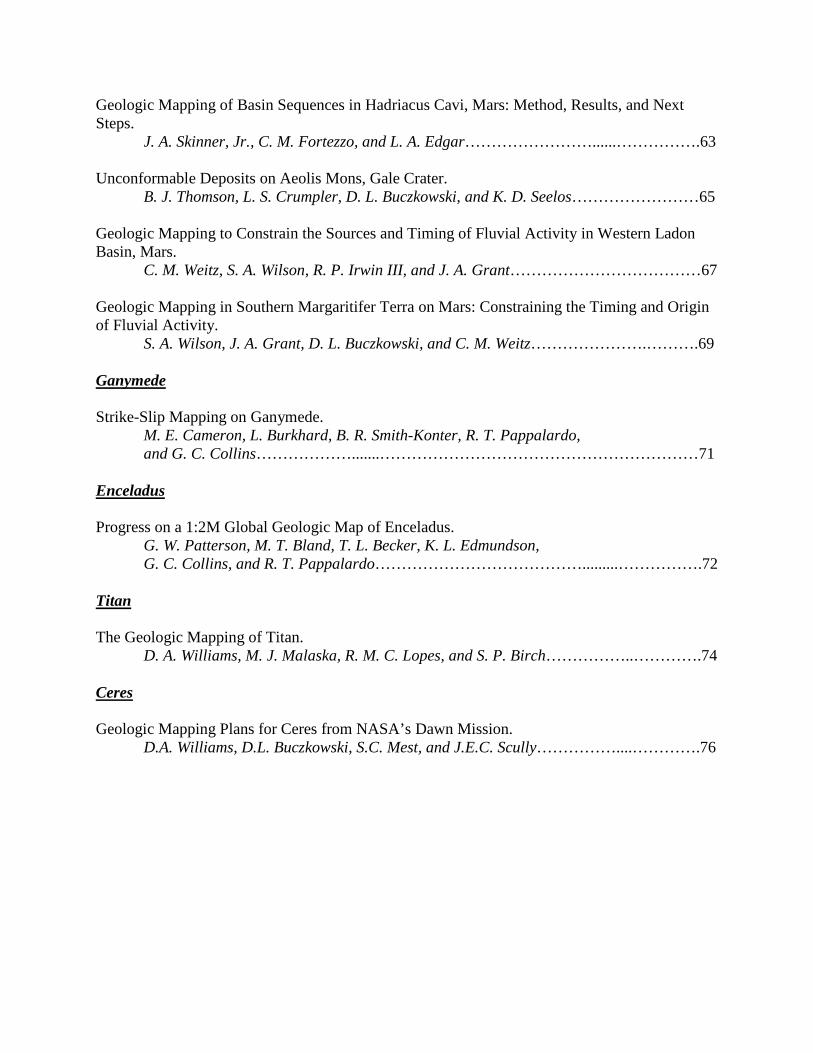
Fig. 3. Cumulative size-frequency diagram of craters in a portion of our ROI compared to [7]. The arrow indicates a break in slope indicative of secondary crater contamination at smaller diameters.
interpreted to be down-dropped terrains from basin formation. Rembrandt LAP (low albedo plains) consist of smooth to slightly hummocky terrain with a low albedo similar to the low-reflectance material [4]. Rembrandt LAP likely consists of impact melt from basin formation.
Rembrandt HAP (high albedo plains) unit is smooth, displays a distinctly higher albedo than the surrounding rim and hummocky terrain, and is cross cut by basin radial and concentric wrinkle ridges and graben. Rembrandt HAP embays the rim and hummocky units as well as several older craters. Based on these relationships as well as albedo characteristics it is interpreted to be volcanic in origin. Intercrater HAP exhibit similar albedo and texture to Rembrandt HAP, but occurs in topographic
lows exterior to the basin. Intercrater LAP have also been identified but are not yet mapped. Both intercrater plains units display different age relationships relative to Rembrandt basin based on preliminary crater size-frequency distributions and cannot be dated until mapped in their entirety.
Ejecta consists of hummocky and lobate deposits that formed from large impacts throughout the region’s history. Intracrater HAP and Intracrater LAP partially to completely cover the floor of large craters and consist of smooth to slightly hummocky surfaces. They are distinguished by their differing albedo, possibly with a higher albedo reflecting a volcanic origin and lower albedo resulting from impact melt [5].
Tectonic Analyses: We are using foreshortened craters cut by thrust faults to discern vertical and horizontal offset. The resultant balanced cross-sections allow reconstruction of fault geometry at depth and help constrain geophysical models of the lithosphere. Foreshortened craters along the RSI scarp of Ruiz et al. [6] lead to a 13° fault dip at the surface and a 25 km depth to the brittle-ductile transition.
Bombardment History: We have mapped in detail all the >~3-km-diamter crater rims in the western half of the map region. Our database is significantly more complete than the existing database of Herrick et al. [7] and up-turn in slope at D<7 km implies a significant contamination of secondary craters at these diameters (Fig. 3).
Acknowledgements: Funding for this work came from NASA PGG grant NNX14AP51G.
References: [1] Watters, T.R. et al, (2012) 43rd LPSC, abstract# 2121. [2] http://messenger.jhuapl. edu/the_mission/mosaics.html. [3] Preusker, F.J. et al, (2011) PSS, 59, 1910–1917. [4] Watters, T.R. et al, (2009) Science, 324, 618-621. [5] Whitten, J.L. and Head, J.W. (2015) 46th LPSC, 1128.pdf. [6] Ruiz J., et al (2012) Icarus, 219, 511–514. [7] Herrick, R.R. et al (2012) Icarus, 220, 297-304.
4
1:10M GEOLOGIC MAP OF APHRODITE TERRA REGION, VENUS (I-2476). V.L. Hansen1, I. López2, K.G. Thaisen1, 1University of Minnesota Duluth, Duluth, MN 55812 ([email protected]), 2Área de Geología. Universidad Rey Juan Carlos. 28933. Mostoles. Madrid ([email protected]).
Introduction: The newly constructed 1:10M geo-
logic map of Aphrodite Terra Region (I-2476, 0º-57ºS/60º-180ºE) captures a rich evolutionary history of Venus. The region contains an assemblage of: local basement terrains (crustal plateaus, lowland tessera inliers and other local basal units); a suite of geological elements—tectonic and magmatic—associated with the formation of the Artemis superstructure [1]; vol-canic material (shield terrain, mons/volcano- and co-rona-related materials, fracture-fed flows, undivided flows); and regionally extensive ‘lineament/fracture zones’, locally spatially associated with linear trends of coronae and chasmata.
Data and methods. Geologic mapping was car-ried out using: (1) NASA Magellan full-resolution SAR data (left- and right-look; normal and inverted modes) [2]; (2) NASA Magellan altimetry; and (3) synthetic stereo images constructed using NIH-Image macros developed by D.A. Young. Data visualization and geologic mapping was conducted using Adobe Illustratortm with linked data layers, MAPublishertm to scale and georeference raster datasets, and ArcGIStm and ArcGlobetm for compilation, projection and analy-sis. Geologic mapping began with delineation of secondary structures, with attention to structural char-acter, orientation, patterns and temporal relations; ma-terial units are defined based on the patterns of secon-dary structures and the nature of radar characteristics [3]. Map relations determined using full-resolution data were translated to the 1:10M map scale.
Overview of the Aphrodite Map Area (AMA). The AMA is broadly divisible into four major geologic domains, which spatially overlap: (1) crustal plateaus (Ovda & western Ovda, and Thetis Regiones) and low-land inliers of ribbon tessera terrain; (2) Artemis, in-cluding Artemis Chasma and the interior region, and a huge radial dyke swarm and concentric wrinkle ridge suite, 12,000- and 13,000-km diameter, respectively [1]; (3) ‘fracture zones’—focused zones of deforma-tion marked by a combination of fractures (broadly defined), coroane, and chasmata [4,5]; and (4) south-eastern AMA, which lacks ribbon-tesera terrain and corona/chasmata/fracture zones; this region is cut by Artemis-radial fractures, and host both shield terrain and extensive tracts of thin Artemis-fed flows, which host Artemis-concentric wrinkle ridges. The AMA records a spatially and temporally varied geohistory.
Domain Descriptions.
Domain 1: Ribbon tessera terrain [6], and other ba-sal regions mark some of the oldest recognizable crustal exposures across AMA. These are best pre-served in elevated crustal plateaus, although exposures occur across the map area as basal windows that record an early story of crustal evolution [7]; southeastern AMA generally lacks ribbon-tessera terrain, although other basal units occur locally, units which could be temporally correlative to ribbon-tessera formation.
Domain 2: The two suites of Artemis-centric struc-tures—radial fractures and concentric wrinkle ridges— are developed across AMA, and extend into Niobe Planitia Region (I-2467) to the north [1,8-9]. These structures, and their relations with regional units are best preserved in domain 4, which was not affected by younger events. In some places Artemis-radial frac-tures are well developed, in other regions, Artemis-concentric wrinkle ridges dominate. Regardless it is clear that these suites are genetically related to one another and to the Artemis superstructure [1]. Detailed and regional map relations both indicate that fractures began to form before wrinkle ridges, and that the frac-tures likely served as conduits for Artemis-fed flows distributing flows to local surfaces across regions far removed from Artemis’ interior/chasma. Areas buried by these flows, as well as regions covered by a thin cover of shield terrain [10,11] were later deformed by the suite of Artemis-concentric wrinkle ridges. Locally Artemis-radial fractures are buried, and in some cases reactivated as inversion structures [11]; Artemis-radial fractures locally occur as buried lineaments. Artemis-fed flows lack indications of flow morphology, likely due to simple leaking to the surface where the mag-matic head intersected the local surface.
A broad topographic trough (~6,500-km diameter), concentric to Artemis chasma, host wrinkle ridges within the trough low; radial fractures are locally pre-served in a concentric region on either side of the trough. Collectively relations indicate that the trough and outer high formed during Artemis superstructure evolution with Artemis-fed ‘flows’ collecting in the broad trough relative to the higher-standing trough boundaries—that is to say, the trough (and covered fractures) mark where the downward warped surface intersected with the magmatic head, resulting in magma emerging to the surface.
Domain 3: Fracture zones—comprised of penetra-tively deformed zones marked by a linement consisting of fractures, dikes, pitchains, stoped troughs, hybrid
5
structures [3] and coronae/chasmata—dominantly post-date the formation of the Artemis-centric suites of fractures and wrinkle ridges. AMA hosts three types of coronae, with hybrids between these end members: (A) coronae marked by concentric structures; (B) radial fracture coronae; (C) coronae with obvious corona- sourced flows. Radial and concentric fractures repre-sent dikes/fractures and/or magmatic stoping struc-tures; in general, magma locally remained at depth, but emerged to the surface in the case of coronae with sur-face flows. Coronae type may be related to local litho-spheric thickness, and the ability to support volcanic edifices and surface flows [13].
The fracture/corona/chasmata zones defined re-gions of variable deformation along linear to fan-shape areas with the shape and orientation of the fracture zones broadly paralleling the trend of the internal structural fabric within each zone. The most prominent zone, the Diana-Dali Chasmata/Corona chain, trends ENE in the east extending to Atla Regio (outside AMA), and WNW north of Artemis Chasma. Here the fracture zone splays cutting south of Thetis and Ovda Regiones, and to the NW dissecting ribbon-tessera both within Ovda, and between Thetis and Ovda Re-giones. Directly north and west of Artemis this zone is characterized by extreme penentrative development of linear toughs and pit chains, which collectively likely represent magmatic stoping. This zone of intense frac-ture/pitchian/stoping trough development trends WNW along the southern edge of Thetis and Ovda Regiones, The zone is similar in character to the Diana-Dali zone, though generally lacking in coronae. The ‘fracture zones takes on a different character where it dissects ribbon-tessera terrain and crustal plateaus. A possible N-trending zone may also form part of the general fracture zone, although this portion lies mostly in Niobe characterized by coronae [9]. West of the Artemis trough, fracture zones take on a fan-like char-acter; one spoke, marked by penetratively developed linaments, trends SW (7 o’clock relative to Artemis) and lacks coronae; coronae and lineaments define a broad zone faning outward to the WSW.
The Diana-Dali arm, which sits along a ~3000 km wide topographic linear that trends to Atla Regio, is characterized by extremely penetrative deformation across an ~2000-km wide band; it hosts AMA’s largest coronae; chasmata mark deep troughs, and bounding scarps are steep and sharply defined. All of the coronae display radial and concentric fractures; they display variable development of surface flows. Coronae far-thest from Artemis Chasma and closest to Atla Regio display more surface flows; fractured crust, and a no-table lack of surface flows, characterize coronae closer to Artemis. Coronae developed on the fracture zone
periphery display more prominent flows. The relatively high elevation across this belt is consistent with thin lithosphere [14], consistent in turn with formation of coronae with subsurface magmatism [13]; the relative size of the coronae is likely due to the broad width of thin lithosphere.
The broad fan-shape region west of Artemis Chasma hosts both coronae and fracture zones; overall deformation here is more distributed, or less penetra-tively developed than in the other ‘fracture zones’. This region is also more topographically subdue, consitent with thicker lithosphere [14]. Coronae repre-sent all 3-suites of corona types noted above. Corona-adial fractures and -concentric fractures are best devel-oped along trends parallel to the local orientation of Artemis-radial fractures, whereas concentric folds are best developed parallel to the local orientation of Artemis-concentric wrinkle ridges. These relations are consistent with the interpretation that these coronae mark a regional suite that evolved broadly synchro-nously across this domain, and in association with, but at the tail-end of, the evolution of the (perhaps long-lived) Artemis superstructure. Most coronae within this region display corona-sourced surface flows. This ob-servation is consistent with a thicker lithosphere across this region [13], compared to that of the Diana-Dali zone, or the mostly coronae-free fracture zone south of Ovda and Theteis Regiones.
Domain 4: Southeastern AMA preserves an area with limited basal-terrains (just enough to provide use-ful boundaries), and is free of zone structures. There-fore this area preserves an excellent record of the spa-tial and temporal development of the Artemis-centric structural suites, and Artemis fed flows. The basal units provide windows in time, locally providing a rich, though fragmented record of surface evolution prior to the formation of the Artemis superstructure. Artemis-radial fractures display incredible continuity, extending for 2000-3000 km; the structures are locally buried, yet reappear along trend, either as exposed fractures, or as veiled locally buried structures. Where fractures are best developed wrinkle ridges do not form, and where wrinkle ridges are best developed, fractures are clearly buried.
References: [1] Hansen V.L. & Olive A. (2010) Geol. 38, 467-470. [2] Ford J.P. et al. (1993) JPL Publ. 93-24. [3] Hansen V.L. & López I. (2014) GSA Abstr. Progs., 46-6, 50-5. [4] Hansen V.L. & Willis J.J. (1998) Icarus 132, 312-343. [5] Hansen V.L. & López I, (2010) Geol. 38, 311-314. [6] López I. & Hansen V.L. (2015) LPSC 46, 2050.pdf. [7] Tovar D. et al. (2015) LPSC, 46, 2555.pdf. [8] López I. & Hansen V.L. (2015) this volume. [9] Aubele J. (1996) LPSC 27, 49-50. [10] Hansen V.L. (2005) GSAB 117, 808-820. [11] Deshon H.R. et al. (2000) JGR 105, 6983-6995. [12] McGovern et al. (2014) Geol. Soc. London Spec. Publ. 401, 19 p. [13] Rosenblatt P. & Pinet P.C. (1994) GRL 21, 465-468.
6
AN INITIAL LOOK AT THE MAHUEA THOLUS (V-49) QUADRANGLE, VENUS. N.P. Lang1, B.J.
Thomson2;
1Department of Geology, Mercyhurst University, Erie, PA 16546 ([email protected]),
2Center for
Remote Sensing, Boston University, Boston, MA 02215 ([email protected]).
Introduction: The Mahuea Tholus quadrangle
(V-49; Figure 1) is a 25 degree latitude by 30 degree
longitude quadrangle in Venus’ southern hemisphere.
The quadrangle covers an area of >7×10⁶
km2 and is
named after a prominent tholus (volcano) that occurs
in the center of the map. Moving clockwise from due
north, the Mahuea Tholus quadrangle is bounded by
the Diana Chasma, Thetis Regio, Artemis Chasma,
Henie, Barrymore, Isabella, and Stanton quadrangles;
with the exception of Stanton, all of these
quadrangles have either been published or are
currently being mapped as part of the VMap
program; Mahuea Tholus is one of two remaining
quadrangles yet to be mapped in this swath of Venus. Here we describe our very initial results of
geologically mapping this quadrangle at the 1:5M
scale. These results are based on reconnaissance
mapping of V-49 and will form the basis for how to
proceed with more detailed mapping (e.g., 1:200k
scale) of the quadrangle.
Volcanism: The map area is characterized
predominantly by lowlands (Zhibek and Nsomeka
planitiae). The lowlands here have an overall north-
northeast trend that is ~1000 kilometers wide and
~2000 km long and appear to have served as a
depocenter for numerous extensive volcanic flows
that have been sourced from the northern and
southern rims of the basin as well as from localized
sources from within the basin itself [e.g., 1]. Several
of the flows appear to have been transported to the
basin via at least seven simple channel [2] systems
that occur within the quadrangle; the occurrence of
these seven identified channels appears to be among
the highest density of channels in one region of
Venus [3]. Volcanic sources within the basin include
>103 small shield edifices and domes [4] as well as
Mahuea Tholus: a 0.5-1.1 kilometer tall and nearly
100 km diameter volcano characterized by relatively
thick (~10s of meters), overlapping, high-backscatter
lava flows that emanate from a central edifice. These
high backscatter flow materials preserve distinct flow
structures including lobate and digitate flow fronts,
constructional levees, and flow ridges. Surrounding
Mahuea Tholus is an intermediate backscatter
material that locally contains lobate fronts; because
this material surrounds Mahuea Tholus, it is
interpreted as sourced from the volcano, though the
nature of emplacement (i.e., lava flow vs. air fall) is
unconstrained [1]. [1] suggested that the volcano's
flows may be highly siliceous due to the volcano
being positioned in a planar region, the seemingly
high viscosity of the volcano's flows, and the flows'
unusual relief.
The southern edge of the lowlands gently rises
into Dsonkwa Regio, an apparent volcanic center that
extends south into the V-58 quadrangle (Henie)
where it is hosts two coronae and >>103 small shield
edifices [e.g., 4] that comprise Mena Colles, a shield
field [5] that stretches between V-49 and V-58; these
coronae and shields are the sources of volcanic
material flowing north into Zhibek and Nsomeka
planitiae. At least some of the flow material from
Dsonkwa Regio has traveled into the central basin via
the four channels (valles) that meander across the
southern extent of the map area. Two of these
channels (Khalanasy and Umaga valles) appear to
have transported material directly north whereas the
other two (Lusaber and Austrina valles) transported
material in an easterly or westerly direction.
Tectonism: The northwestern rim of the basin is
noted by the presence of the Diana-Dali Chasmata
system, which cuts across the northwest corner of the
map as it extends from near Artemis Corona in V-48
to the west [6] to Atla Regio to the northeast (V-26).
This rift system is ~500 km wide here and has an
overall north-northeast trend that parallels the basin,
but has two southeast trending arms that extend a few
hundred kilometers into the quadrangle. Four double-
rimmed coronae [7] have formed within the segment
of the rift system in V-49 and have sourced extensive
lava flows south into Zhibek Planitia; several flows
have also been sourced directly from fractures in the
rift itself as well as from numerous small shield
edifices that have also formed along segments of the
rift – these shield edifices appear to have mostly
formed on (mechanically strong?) crustal blocks that
the rift zone has wraps around.
Besides the rift zone, other tectonic structures in
the map area include a northeast-trending suite of
wrinkle ridges. These ridges also parallel the basin
and have wavelengths ranging between 20 to 30
kilometers [8] and are part of a broad circum-
Aphrodite Terra wrinkle ridge system described by
7
[9]. These ridges deform most of the materials
emplaced within the basin including the moderate
backscatter materials surrounding Mahuea Tholus,
but they are, in turn, buried by the relatively thick,
high backscatter flow materials of the volcano [1,8].
Two groupings of tessera terrain also outcrop in
the map area. Urd Terrsera outcrops as a couple
northerly-trending kipuka along the eastern edge of
the topographic basin where they approximately
mark the boundary between Zhibek and Nsomeka
planitiae. Nortia Tesserae outcrops as a larger
grouping of smaller kipuka along the northern edge
of Donskwa Regio.
Impact craters: Thirteen identified and named
impact craters also dot this map area and range from
‘young’ craters [10] with low-backscatter
surrounding crater haloes and high backcatter crater
floors [11] to ‘older’ craters [10] with no surrounding
halo and basins filled with a low backscatter material
[11].
Discussion: The Mahuea Tholus quadrangle is
seemingly a microcosm of the landforms and
processes that characterize much of Venus and
subsequent mapping here will emphasize the timing
and sources of volcanism and tectonism.
References: [1] Moore, H.J., J.J. Plaut, P.M. Schenk, and
J.W. Head (1992), An unusual volcano on Venus; J.
Geophys. Res., 97, E8, 13,479-13,493. [2] Baker, V. R., G.
Komatsu, V. C. Gulick, and T. J. Parker (1997), Channels
and valleys, in Venus II, edited by S. W. Bougher, D. M.
Hunten, and R.J. Phillips, pp. 757– 793, Univ. of Ariz.
Press, Tucson. [3] Komatsu, G., V. R. Baker, V. C. Gulick,
and T. J. Parker (1993), Venusian channels and valleys:
Distribution and volcanological implications; Icarus, 102, 1
–25. [4] Guest, J. E., M. H. Bulmer, J. Aubele, K. Beratan,
R. Greeley, J. W. Head, G. Michaels, C. Weitz, and C.
Wiles (1992), Small volcanic edifices and volcanism in the
plains of Venus, J. Geophys. Res., 97, 15949. [5] Crumpler,
L. S., J. C. Aubele, D. A. Senske, S. T. Keddie, K. P.
Magee, and J. W. Head (1997), Volcanoes and centers of
volcanism on Venus, in Venus II, edited by S. W. Bougher,
D. M. Hunten, and R. J. Phillips, pp. 697– 756, Univ. of
Ariz. Press, Tucson. [6] Bannister, R.A., & V. L. Hansen
(2010) Geologic map of the Artemis quadrangle (V-48),
Venus; U.S. Geological Survey SIM 3099. [7] Stofan, E. R.,
Hamilton, V. E., Janes, D. M. and Smrekar, S. E. (1997),
Coronae on Venus: morphology and origin. In: Bouger, S.
W., Hunten, D. M. and Phillips, R. J. (eds) Venus II.
University of Arizona Press, Tucson, 931–968. [8] Pierce,
N.P., and Lang, N.P. (2012), Preliminary geological
overview of the Mahuea Tholus quadrangle (V-49), Venus;
Lunar and Planetary Science Conference Abstract #1682.
[9] Bilotti, F., and J. Suppe (1999), The global distribution
of wrinkle ridges on Venus, Icarus, 139(1), 137-157. [10]
Basilevsky, A.T., J.W. Head, and I.V. Setyaeva (2003),
Venus: Estimation of age of impact craters on the basis of
degree of preservation of associated radar-dark deposits;
Geophs. Res. Lett., 30, 8, 1950,
doi:10.1029/2003GL017504. [11] Izenberg, N.R.,
Arvidson, R.E., and Phillips, R.J. (1994), Impact
degradation on Venusian plains: Geophysical Research
Letters, v. 21, p. 289–292.
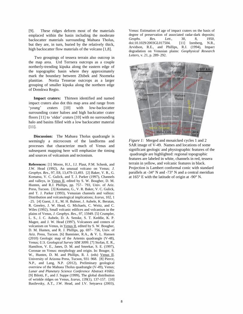
Figure 1: Merged and mosaicked cycles 1 and 2
SAR image of V-49. Names and locations of some
significant geologic and physiographic features of the
quadrangle are highlighted: regional topographic
features are labeled in white, channels in red, tessera
terrain in yellow, and volcanic features in black.
Projection is Lambert conformal conic with standard
parallels at -34° N and -73° N and a central meridian
at 165° E with the latitude of origin at -90° N.
8
PROGRESS REPORT ON THE GEOLOGIC MAPPING OF THE 1:10M NIOBE MAP AREA, VENUS. I. López1 and V. L. Hansen2, 1Área de Geología. Universidad Rey Juan Carlos. 28933. Mostoles. Madrid ([email protected]), 2University of Minnesota Duluth, Duluth, MN 55812([email protected]).
Introduction: We are constructing the 1:10M geo-
logic map of Niobe Planitia (0º-57ºN/60º-180ºE, I-2467) to establish the geologic history of this region, and test existing hypotheses for the geodynamic evolu-tion of Venus. The Niobe Map Area (NMA) contains a rich assemblage of basement (crustal plateaus and low-land tessera inliers), deformation belts, and plains ma-terials (shield plains, volcano- and corona-related ma-terials and large expanses of apparently undivided plain materials).
We present the result of the structural mapping of the NMA and describe the regional-scale patterns, lo-cal modifications of these regional patterns, and the effect of large tectonomagmatic structures on these regional fractures suites. We limit the discussion to lowland structures; tessera terrain structure are not discussed herein. Recognition of lowland structures and their interaction with volcanic materials is funda-mental for the delineation of lowland material units and the establishment of a geologic history at regional scale [1]. We also present the initial observations re-garding the delination of map units.
Data and methods: Geologic analysis was carried out using: (1) NASA’s Magellan full-resolution SAR data (left- and right-looking and in both normal and inverted modes) [2]; (2) Magellan altimetry; and (3) synthetic stereo images constructed after using NIH-Image macros developed by Duncan Young.
Data visualization and geologic mapping was con-ducted using Adobe Illustratortm for mapping with linked NASA Magellan SAR and altimetry data, MA-Publishertm to scale and place georeferenced raster datasets, and ArcGIStm and ArcGlobetm for compi-lation, analysis and final map production. Geologic mapping has been conducted using full-resolution data to constrain the nature of the structures and the cross-cutting relationship between structures and material units, and later translated to the 1:10M mapping scale.
Lowland Structures in the NMA: Structures in the volcanic plains of the NMA are divided into two groups: (a) regional structures distributed across huge expanses of the NMA; and (b) local structures that are both spatially and genetically related to individual tec-tonomagmatic features.
Regional contractional deformation suites Folds. Broad folds deform local basal units of the
volcanic plains. These folds occur in areas of concen-trated deformation in two areas: NNW-trending folds within Lemkechen and Unelanuhi Dorsa in basal mate-
rials in Akhtamar Planitia, western NMA; NNE- trend-ing folds in basal materials of eastern NMA (Llorona, Vellamo and Atalanta planitiae).
Wrinkle ridges. We recognize four different suites of wrinkle ridges: (a) regional suites; (b) local inver-sion structures; (c) local suites concentric to individual coronae; (d) wrinkle ridge trends that parallel adjacent tectonomagmatic features and deformation belts. The circum-Artemis trend (a) marks a suite of wrinkle ridges that extend beyond the map area, and define a region >13,000 km in diameter around Artemis Chasma in the Aphrodite Map Area [I-2476; 3]. Some wrinkle ridges of this regional trend display trends parallel to large tectonomagmatic centers and deforma-tion belts (d); in eastern NMA wrinkle ridges parallel local deformation belts (e.g. deformation belts in Atalanta Planitia and Vellamo Plaintia), nearly orthogonal to the main circum-Artemis regional trend. This relationship indicates that the deformation belts likely predated formation of the Artemis-suite of wrinkle ridges. In western NMA folds in the basal plain materials nearly parallel wrinkle ridge trends, thus temporal relations are undefined.
In central NMA local N-trending wrinkle ridges show clear evidence of being inversion structures; that is, wrinkle ridges occur along strike with individual fractures locally buried by lava flow material [4]. These relationships indicate that N-trending fractures formed first, followed by local burial, and finally shortening resulting in the formation of inversion structures.
In Leda Planitia wrinkle ridges define a reticulate pattern similar to that present in the basement materials and in the volcanic materials that postdate these base-ment materials, but the existence of reactivation has not yet clearly established.
Regional extensional deformation suites Regional fractures. We identify different fracture
suites of regional extent based on trend, spacing and temporal relations with volcanic materials.
Suite A. NNW-trending fractures mark the oldest fracture suite in central NMA, and in Leda Planitia this fracture trend also deforms lower plain materials, due to reactivation of buried structures. This trend parallels ribbon structure trends in underlying tessera terrain in central NMA. Locally it is clear that the NNW-fracture suite results from reactivation of local basement struc-tures, which were covered by thin flows or discontinu-ous materials from small shields; the trend of the shal-
9
lowly buried structures is apparent in high resolution SAR. Consistency in trend and fracture spacing of this fracture suite across a great expanse of the central NMA indicates that basement structures/heterogeneity played a strong role in fracture trend.
Suite B. A NNE-trending fracture suite occurs in Leda Planitia, where the suite is best developed, and locally within central NMA. Within Leda Planitia frac-tures parallel underlying ribbon structure trends of Dekla Tessera (which parallel ribbon tessera fold trends to the south in northern Tellus Regio). Within Leda Planitia fractures appear to be reactivation struc-tures, similar to suite-A fractures. In central NMA, however, fractures are more widely spaced, and there is no evidence of underlying structural trends that might serve as loci for reactivation. Within Leda Plani-tia wrinkle ridges define a reticulate pattern that likely occurs due to two near-orthogonal fracture suites re-lated to underlying tessera terrain fabric trends of Dekla Tesserae and Tellus Regio. The consistent spac-ing of both suites suggest a control by underlying structures or the presence of a regional rheological discontinuity beneath the relatively thin cover unit.
Artemis-radial suite. A suite of regional fractures that fans across the NMA describes a huge suite of fractures radial to Artemis Chasma [3]. These fractures trend NE in the eastern NMA and trend NW in western NMA. Within central NMA these fractures trend N, and are the youngest recognized regional fractures at this location. Coronae decorate this fracture suite, and they are likely temporally related; structural elements of the corona annuli both cut and are cut by fractures of this suite, consistent with a genetic relationship. Portions of the Artemis-radial suite are locally reacti-vated to inversion wrinkle ridges within in several ar-eas of the NMA.
Map relations indicate that Artemis-radial fractures predate formation of Kunhild and Ereshkigal Coronae in Akhtamar Planitia, which are interpreted as an ex-tinct hot-spot [5]; thus these coronae likely post-date formation of the coronae in central NMA.
Local deformation suites. Radial fractures. Radial fracture suites occur re-
lated to large tectonomagmatic centers. These suites can extend great distances from their foci, and there-fore might be useful as local temporal markers for unit delineation (i.e., Holde Corona in Atalanta Planitia and Kurukulla Mons in Till-Hanun Planitia).
In western NMA (i.e., Akhtamar Planitia) radial fracture suites connect large, otherwise isolated, tec-tonomagmatic centres (Hatshepsut Patera-H’uraru Co-rona, Uli-Ata Mons, Kaltash Corona, Kunhild Corona, Ereshkigal Corona), forming an extensive intercon-
nected suite that is difficult to differentiate from the regional fracture suites described herein.
Concentric fractures. Concentric fracture suites that occur as annuli of individual coronae in the central NMA appear temporally related to the N-trending por-tion of the Artemis-radial fracture suite. Typically these coronae lack obvious flows; the lack of flows may be a function of homogeneization through weath-ering, or indicate that coronae did not transfer magma to the surface. Coronae located in Aphrodite Terra (e.g., Kaltash and Rosmerta Coronae) display a annuli of concentric fractures and extensive flows that embay and postdate the crustal plateaus, and clearly emerged from radial corona-related fractures.
Concentric ridges. Concentric ridges form the an-nuli of some coronae (e.g., Ituana and Bil Coronae in eastern NMA). These coronae source large traceable flows that bury extensive portions of the NMA. Similar concentric ridges in Irnini Mons are interpreted as re-sult of tectonic inversion or warping of regional stress around a hole in a plate (i.e., empty magmatic reser-voir) [6]. Futher mapping of flows and materials is necessary to favor one of the working models.
Delineation of units: Regional mapping based on units compiled from published 1:5M maps and new mapping for areas without published cartography sug-gest a mixed style in local resurfacing with both point source volcanism (i.e., shield plains) and corona- and volcano-related units. Resurfacing through point source volcanism, shield terrain and basal materials that combine abundant shields and local larger vol-canic structures (i.e. coronae and volcanoes), dominate the central and western parts of the NMA. Local co-rona- and volcano-related flows postdate these materi-als in localized areas where coronae and volcanoes cluster and resurfaced large areas (e.g., the Kunhild-Ereshkigal hot-spot; [5]). Temporal relations between these corona clusters will be studied using the Artemis-radial suite as a temporal reference.
Large flows associated with coronae located along the equator also resurface large areas and disrupt older basement materials. In the eastern part of the NMA shield terrain is not so important and point sourced volcanism is more areally restricted to shields fields and associated flows that together with corona-related flows are the major resurfacing agents in the southeast of the study area (i.e Rusalka Planitia).
References: [1] Ford J.P. et al. (1993) JPL Publ. 93-24. [2] Hansen V.L. (2000) EPSL 527-542. [3] Hansen V.L. & A. Olive (2010) Geol., 38, 467-470. [4] Deshon H.R. et al. (2000) JGR 105, 6983-6995. [5] Herrick, R.R. & McGovern, P.J. (2000) Geoph. Res. Lett. 27, 839–842. [6] Buczkowski D.L. (2002) J. Struc. Geol. 28, 2156-2168.
10
Detailed structural map of a highly fractured zone in an equatorial region at Western Aphrodite Terra, Venus (15S-20S / 110E-124E)
D. Tovar1 , V.L. Hansen1 & J.B. Swenson1 . 1 Department of Earth and Environmental Sciences, University of Minnesota-Duluth, 1114 Kirby Drive, Duluth, MN 55812, USA ([email protected]; [email protected]; [email protected])
Introduction: Venus is considered Earth’s twin planet given its similar size, density, composition, and distance from the Sun. Given these conditions, we can argue that both planets were formed at the same time and same way; therefore the internal structure and heat budget must be similar too. Plate tectonic processes play a key role in dissipating heat on Earth. Venus, however, lacks plate tectonics, raising the fundamental question: how does Venus dissipate heat? Venus’ hypsometry is well represented by unimodal distribution meanwhile Earth has a bimodal hypsometry that corresponds to continental and oceanic crust. The oceanic peak has been compared with 80 % of Venus’ hypsometry although considerable differences related to spatial distribution favoring the presence of large-scale hot spots [1]. Venus’ extensive fracture zones might be conceptually correlative to Earth’s divergent boundaries, and likely mark regions of significant heat transfer. Extensive fracture zones are particularly well developed in an equatorial position in southern Aphrodite Terra. The fractures likely represent a subsurface magmatic plumbing system [2]. We are generating a detailed structural analysis of a targeted portion of an Aphrodite fracture zone in order to understand the architectural evolution through space and time and, ultimately, to derive a thermal model in order to gain insight into possible mechanisms of heat transfer on Venus. The map area (15S-20S/110E-124E), characterized by extreme density of faults, pit chains, troughs encompasses over 700,000 km2. The map area has excellent coverage by Magellan SAR data (right-look, left-look and stereo), which we employ in mapping.
Map Area: The fracture zone (FZ) includes two
zones characterized by E- and NNW-trending lineaments, respectively; a coronae-like feature with radial and concentric lineaments marks the intersection of the fracture trends (Fig. 1). The SW part of the map area encompasses the FZ boundary. Topographically the FZ sits high compared to its surroundings. We delineated lineaments, lineament trends and structural domains using radar Magellan SAR and altimetry data. We focus here on tectonic
lineaments, which characterize the FZ. These lineaments defined four broad suites based on patterns and/or orientation. We map lineaments in function of width; wider lineaments, which are easy to map, clearly represent pit chains and well-developed troughs; narrower lineaments clearly mark fractures and pit chains as well, although detailed element interpretation is limited by data resolution. All of the lineaments are long narrow structures with extreme aspect ratios; lineament length scales are hundreds of kilometers. Wide lineaments are more widely spaced, facilitating mapping, whereas narrow lineaments are so closely spaced, i.e. at or near data resolution, as to define a penetrative fabric across the map area. Narrow lineaments, trends, rather than individual lineaments are shown on the maps (Fig.1) Lineaments of all widths define similar regional patterns. The northern part of the FZ is defined by intersecting suites of penetratively developed fractures that define scallop-like packages with ~30° of curvature over ~500 km; the eastern FZ is dominated by the corona-like structure with mainly presence of radial and concentric fractures. Wide lineaments also mark short connected pit chains and troughs in the corona-interior. Cross-cutting relations indicate that the lineaments formed time transgressively and preserve a record of FZ evolution. Structural domains A-D, defined based on lineament density, represent structural facies and not material units. Domains A-D were defined as function of fracture density and, together with cross-cutting relations, provide a record of progressive evolution (through space and time) of the FZ architecture and, by extrapolation, the magmatic plumbing system. Domain D evidences the lowest density of fractures and occurs outside and along the boundary of the FZ. Domain D lies at the lowest elevation in the map area, and slopes away from the FZ. Domain D preserves lava flow structures and canali, which clearly indicate that local tectonic lineaments served as magma conduits; pit chains leak, cut, and are buried by flows; flow is consistent with contemporary regional slope. Domain C occurs within the FZ and along the inside of the FZ; lineaments are widely spaced, yet clearly cut across domain boundaries. Domain A,
11
with the highest fracture density, typically includes interesting suites of fractures. Domain B is transitional between A and C. Topographically, domains A-C cross topography; that is, there is no a simple relationship between topography and domain boundaries, as with domain D. Lineament suites extend beneath cover in regions of domains C and B within the FZ. Low lineament density in domain D and in the regions of domain C along the FZ boundary result from fewer numbers of lineaments formed during the evolution of the FZ, rather than burial of earlier formed lineaments.
References: [1] Rosenblatt, P. et al. (1994) GRL.,
21, 465-468. [2] Le Corvec, N. et al. (2013) JGR SE, 118, 968-984.
12
COMPOSITIONAL AND MORPHOLOGIC MAPPING OF THE COPERNICUS QUADRANGLE, THE MOON: YEAR 3 STATUS. J. J. Hagerty, J. A Skinner Jr., L. R. Gaddis, J. R. Laura, C. M. Fortezzo and A. E. Huff, USGS Astrogeology Science Center, 2255 N. Gemini Drive, Flagstaff, AZ 86001 ([email protected]).
Introduction: The recent flood of lunar data has
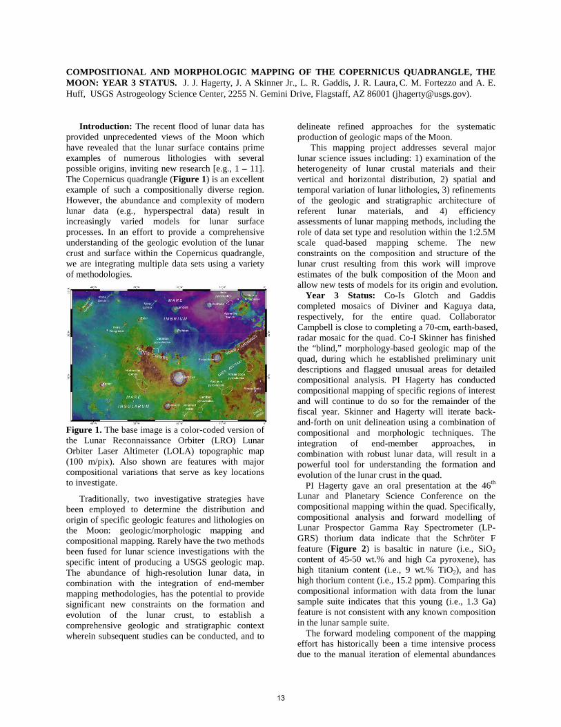
provided unprecedented views of the Moon which have revealed that the lunar surface contains prime examples of numerous lithologies with several possible origins, inviting new research [e.g., 1 – 11]. The Copernicus quadrangle (Figure 1) is an excellent example of such a compositionally diverse region. However, the abundance and complexity of modern lunar data (e.g., hyperspectral data) result in increasingly varied models for lunar surface processes. In an effort to provide a comprehensive understanding of the geologic evolution of the lunar crust and surface within the Copernicus quadrangle, we are integrating multiple data sets using a variety of methodologies.
Figure 1. The base image is a color-coded version of the Lunar Reconnaissance Orbiter (LRO) Lunar Orbiter Laser Altimeter (LOLA) topographic map (100 m/pix). Also shown are features with major compositional variations that serve as key locations to investigate.
Traditionally, two investigative strategies have been employed to determine the distribution and origin of specific geologic features and lithologies on the Moon: geologic/morphologic mapping and compositional mapping. Rarely have the two methods been fused for lunar science investigations with the specific intent of producing a USGS geologic map. The abundance of high-resolution lunar data, in combination with the integration of end-member mapping methodologies, has the potential to provide significant new constraints on the formation and evolution of the lunar crust, to establish a comprehensive geologic and stratigraphic context wherein subsequent studies can be conducted, and to
delineate refined approaches for the systematic production of geologic maps of the Moon.
This mapping project addresses several major lunar science issues including: 1) examination of the heterogeneity of lunar crustal materials and their vertical and horizontal distribution, 2) spatial and temporal variation of lunar lithologies, 3) refinements of the geologic and stratigraphic architecture of referent lunar materials, and 4) efficiency assessments of lunar mapping methods, including the role of data set type and resolution within the 1:2.5M scale quad-based mapping scheme. The new constraints on the composition and structure of the lunar crust resulting from this work will improve estimates of the bulk composition of the Moon and allow new tests of models for its origin and evolution.
Year 3 Status: Co-Is Glotch and Gaddis completed mosaics of Diviner and Kaguya data, respectively, for the entire quad. Collaborator Campbell is close to completing a 70-cm, earth-based, radar mosaic for the quad. Co-I Skinner has finished the “blind,” morphology-based geologic map of the quad, during which he established preliminary unit descriptions and flagged unusual areas for detailed compositional analysis. PI Hagerty has conducted compositional mapping of specific regions of interest and will continue to do so for the remainder of the fiscal year. Skinner and Hagerty will iterate back-and-forth on unit delineation using a combination of compositional and morphologic techniques. The integration of end-member approaches, in combination with robust lunar data, will result in a powerful tool for understanding the formation and evolution of the lunar crust in the quad.
PI Hagerty gave an oral presentation at the 46th Lunar and Planetary Science Conference on the compositional mapping within the quad. Specifically, compositional analysis and forward modelling of Lunar Prospector Gamma Ray Spectrometer (LP-GRS) thorium data indicate that the Schröter F feature (Figure 2) is basaltic in nature (i.e., SiO2 content of 45-50 wt.% and high Ca pyroxene), has high titanium content (i.e., 9 wt.% TiO2), and has high thorium content (i.e., 15.2 ppm). Comparing this compositional information with data from the lunar sample suite indicates that this young (i.e., 1.3 Ga) feature is not consistent with any known composition in the lunar sample suite.
The forward modeling component of the mapping effort has historically been a time intensive process due to the manual iteration of elemental abundances
13

within the models. As part of the forward modeling efforts discussed above, Co-I Laura was tasked with converting the current IDL-based modeling code to a more modern and more accessible platform. Using a combination of approaches, Co-I Laura was able to create an ArcGIS thorium modeling tool that makes it possible for users to obtain robust estimates of LP-GRS derived thorium abundances for features as small as 1 km in diameter on the lunar surface. This modeling tool is still in the testing phase, but will eventually be made available to the mapping community for use in compositional mapping of other portions of the lunar surface.
Figure 2. LP-GRS thorium map overlain on top of LROC-WAC mosaic. White to yellow pixels represent elevated thorium abundances and blue to black pixels represent low thorium abundances.
The project team has been augmented by the inclusion of a Planetary Geology and Geophysics Undergraduate Research Program (PGGURP) student from Northern Arizona University (Alex Huff). This student conducted a detailed, systematic survey of pyroclastic deposits and impact craters within the quad (Fig. 3 & Table 1) and submitted the results of her work to the Lunar and Planetary Science Conference where she gave a poster presentation. As part of her work, Huff mapped the distribution of lunar pyroclastic deposits, possible source vents, and penetrating craters within the quad to determine the areal extent, foci, and volume of pyroclastic materials, as a precursor for the compositional investigations.
Future Work: For the remainder of the fiscal year, additional compositional mapping will be conducted by Hagerty and Gaddis. The results of the compositional mapping will be combined with the morphologic mapping of Skinner, Fortezzo, and Huff. Additional testing of the ArcGIS thorium modeling tool will be completed in an effort to make the tool available to mapping community.
Acknowledgements: This work is supported by NASA through the Planetary Geology and Geophysics program via grant NNH12AU82I.
References: [1] Cahill et al. (2009) J. Geophys. Res., 114, E09001; [2] Chevrel et al. (2009) Icarus, 199, 9; [3] Glotch et al. (2010) Science, 329, 1510; [4] Hagerty et al. (2006) J. Geophys. Res., 111, E06002; [5] Hagerty et al. (2009) J. Geophys. Res., 114, E04002; [6] Lawrence et al. (2007) Geophys. Res. Lett., 34, doi: 10.1029/2006GL028530; [7] Matsunaga et al. (2008) Geophys. Res. Lett., 35, L23201; [8] Spudis, P. and Taylor, G.J. (2009) Lunar. Planet. Sci. Conf., 40, abstract #1039; [9] Woehler et al. (2011) Planet. Space Sci., 59, 92; [10] Yamamoto et al. (2010) Nat. Geosci., 384, doi:10.1038/NGEO897; [11] Hagerty et al. (2013) Geol. Soc. Am. Abstracts with Programs, Vol. 45, No. 7, 405.
Figure 3. Pyroclastic units and measured craters in northern Rimae Bode (cen. 12 °N, -4 °E). Western, smoother, mare deposits with large wrinkle ridges grade into rough, knobby highlands to the east. Both mare and highlands deposits are overlain by a dark mantle (tan) and an intermediate mantle (orange). Craters shown in color where penetrating, and shown in black where non-penetrating. See Table 1 for the range and mean values of excavation.
Table 1. Crater diameters, number, and range and mean values for excavating depths.
Diameter (m) N Range (m) 𝐱� (𝐦) <50 39 3.13 – 4.19 3.8
50 – 75 139 4.20 – 6.29 5.3 75 – 100 80 7.39 – 8.38 7.2
>100 55 8.46 – 50.3 12.96
14
UPDATE ON GEOLOGIC MAPPING OF THE LUNAR SOUTH POLE QUADRANGLE (LQ-30). S.C. Mest1, D.C. Berman1, N.E. Petro2, and R.A. Yingst1, 1Planetary Science Institute, 1700 E. Ft. Lowell, Suite 106, Tucson, AZ 85719-2395; 2Planetary Geodynamics Laboratory, NASA GSFC, Greenbelt, MD. ([email protected])
Introduction: We are using recently acquired image, spectral, and topographic data to map the geology of the lunar South Pole quadrangle (LQ-30, 60°-90°S, 0°-±180°) at 1:2.5M scale [1-7]. The overall objective of this research is to constrain the geologic evolution of LQ-30 with specific emphasis on evaluation of a) the regional effects of impact basin formation, and b) the spatial distribution of ejecta, in particular resulting from formation of the South Pole-Aitken (SPA) basin and other large basins. Key scientific objectives for this map area include: 1) Determining the geologic history of LQ-30 and examining the spatial and temporal variability of geologic processes. 2) Evaluating the distribution of volcanic materials. And 3) constraining the distribution of impact-generated materials, and determining the timing and effects of major basin-forming impacts on crustal structure and stratigraphy.
Methodology: We are utilizing ArcGIS (v. 10.3) to compile and integrate image, topographic and spectral datasets to produce a geologic map of LQ-30. We are using the Lunar Reconnaissance Orbiter (LRO) Wide Angle Camera (WAC) mosaic (~100 m/pixel) as our primary basemap to characterize geologic units from surface textures and albedo, identify contacts and structures, and map impact craters (D>1 km). We are using additional datasets to complement the base, which include mosaics (Lunar Orbiter, Clementine UVVIS and NIR), images (LROC NAC, Clementine UVVIS and HIRES, and Lunar Orbiter), Clementine color ratio data, Moon Mineralogy Mapper (M3) multispectral data, and LOLA topography.
Regional Geology: LQ-30 exhibits ~16 km of topographic relief. The nearside consists predominantly of cratered highlands, is more heavily cratered and displays higher elevations than the farside. This difference is due to the overwhelming presence of SPA, which encompasses nearly all of the far side map area (Figure 1).
SPA is the largest (D=2600 km, ~18 km deep) and oldest (pre-Nectarian) impact basin confidently identified on the Moon [8-10]. Models suggest that SPA formed by an oblique impact that excavated material from the upper crust [11,12] to the lower crust or upper mantle [13,14]. Numerous multispectral datasets show enrichment in mafic materials [15-19] and LP-GRS data show enhancements in both Fe and Th [20-23] within the basin relative to the surrounding highlands. The materials exposed within SPA, such as in central peaks or in crater walls, are used to estimate the composition of the lower crust/upper mantle.
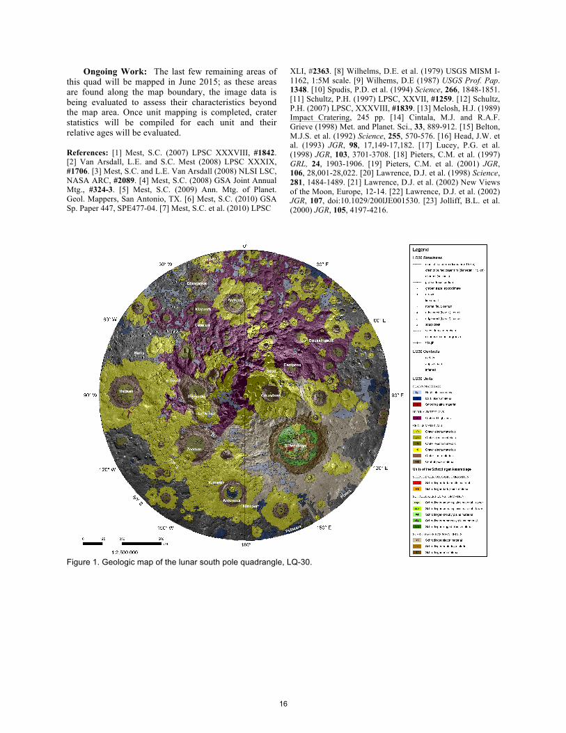
Mapping Progress: We are currently focusing our mapping efforts on the rugged terrains within and outside of SPA, and intercrater regions that exhibit relatively flat surfaces. Unit delineations are illustrated in Figure 1. Cratered Highlands: The cratered highlands unit (unit ch) covers a large portion of the map area on the nearside. This rugged terrain consists of a complex sequence of overlapping impact craters for which materials of individual craters (e.g., rim and ejecta materials) are difficult to distinguish. Compositionally, this unit is part of the feldspathic highlands, characterized by its lack of iron and thorium relative to nearby mare or the floor of SPA [23]. Plains Materials: Numerous deposits of plains materials are mapped throughout the quadrangle. These include bright plains (unit bp), dark plains (unit dp), and smooth plains (unit sp).
Bright plains are found in low-lying areas among the cratered highland unit, on the floors of ancient buried craters, within the ejecta blankets of Schrödinger and other impacts, and within the unmapped terrains along the map edge. These plains are generally flat and featureless, and exhibit a higher albedo than other plains units in the map area. Their edges tend to be lobate and embay adjacent units indicating they superpose the units with which they are in contact. These deposits could consist of volcanic materials, cryptomare, or impact melt, but no evidence for source vents or flow features are observed, or they could represent ejecta blankets that were emplaced within low areas.
Dark plains deposits are found throughout the map area on the floors of impact craters, such as Antoniadi, and form the deposits of Mare Australe, whereas others are found within low-lying areas of more rugged terrains. These deposits exhibit moderate to low albedos with relatively smooth surfaces, are higher in iron than most other materials in the map area, and most are found in association with fractures on the floors of the craters in which they reside, or dome-shaped or conical features. This combination of evidence suggests a volcanic origin for these deposits.
Smooth plains deposits are areally small and only five exposures are found in the map area. Deposits are found on the floors, rims, and/or ejecta blankets of the impact craters Hausen, Clavius, and Deluc G. In all cases, the deposits are low in albedo and exhibit a surface morphology indicating flow of the material downslope. Their association with impact craters suggests these materials are likely composed of impact melt.
15
Ongoing Work: The last few remaining areas of this quad will be mapped in June 2015; as these areas are found along the map boundary, the image data is being evaluated to assess their characteristics beyond the map area. Once unit mapping is completed, crater statistics will be compiled for each unit and their relative ages will be evaluated.
References: [1] Mest, S.C. (2007) LPSC XXXVIII, #1842. [2] Van Arsdall, L.E. and S.C. Mest (2008) LPSC XXXIX, #1706. [3] Mest, S.C. and L.E. Van Arsdall (2008) NLSI LSC, NASA ARC, #2089. [4] Mest, S.C. (2008) GSA Joint Annual Mtg., #324-3. [5] Mest, S.C. (2009) Ann. Mtg. of Planet. Geol. Mappers, San Antonio, TX. [6] Mest, S.C. (2010) GSA Sp. Paper 447, SPE477-04. [7] Mest, S.C. et al. (2010) LPSC
XLI, #2363. [8] Wilhelms, D.E. et al. (1979) USGS MISM I-1162, 1:5M scale. [9] Wilhems, D.E (1987) USGS Prof. Pap. 1348. [10] Spudis, P.D. et al. (1994) Science, 266, 1848-1851. [11] Schultz, P.H. (1997) LPSC, XXVII, #1259. [12] Schultz, P.H. (2007) LPSC, XXXVIII, #1839. [13] Melosh, H.J. (1989) Impact Cratering, 245 pp. [14] Cintala, M.J. and R.A.F. Grieve (1998) Met. and Planet. Sci., 33, 889-912. [15] Belton, M.J.S. et al. (1992) Science, 255, 570-576. [16] Head, J.W. et al. (1993) JGR, 98, 17,149-17,182. [17] Lucey, P.G. et al. (1998) JGR, 103, 3701-3708. [18] Pieters, C.M. et al. (1997) GRL, 24, 1903-1906. [19] Pieters, C.M. et al. (2001) JGR, 106, 28,001-28,022. [20] Lawrence, D.J. et al. (1998) Science, 281, 1484-1489. [21] Lawrence, D.J. et al. (2002) New Views of the Moon, Europe, 12-14. [22] Lawrence, D.J. et al. (2002) JGR, 107, doi:10.1029/200lJE001530. [23] Jolliff, B.L. et al. (2000) JGR, 105, 4197-4216.
Figure 1. Geologic map of the lunar south pole quadrangle, LQ-30.
16
A Web-GIS "Gekko" (which means moonlight in Japanese): a viewer of the data from the Spectral Profiler onboard Kaguya. Y. Ogawa1, Y. Hayashi2, N. Hirata1, J. Terazono1, H. Demura1, T. Matsunaga3, S. Yamamoto3, Y. Yokota, M. Ohtake4, H. Ootake4, 1The University of Aizu, Aizu-Wakamatsu, Japan, 2Space Development Atelier, 3National Institute for Environmental Studies, Tsukuba, Japan, 4Institute of Space and Astronautical Science, Japan Aerospace Exploration Agency, Sagamihara, Japan. (Ikki Machi, Tsuruga, Aizu Wakamatsu City, 965-8580, Japan, yoshiko@u-aizu.ac.jp)
Introduction: The Kaguya satellite, a Japanese
lunar orbiter, observed the whole Moon during 2007-2009. The Spectral Profiler (SP) onboard Kaguya is a visible and near ‐ infrared (VIS-NIR) spectrometer covering wavelengths of 0.5-2.6um and observed the continuous reflectance spectra of the Moon [1]. The lunar minerals characteristically have their substantial absorption bands in VIS-NIR wavelengths. By using and analyzing the SP data, we can constrain the characteristic quality of the observed absorption bands in the observed spectra and then identify the surface minerals on the Moon [e.g. 2]. The SP observation spots (footprints) distribute on the lunar surface globally. The total number of the footprints amounts to about 70 million. Each single SP spectrum consists of 296 reflectance components. This study introduces a Web-GIS “GEKKO” which is positioned as a preliminary step for comprehensive understanding of the mineral distribution on the Moon by using the Kaguya/SP data. The GEKKO system handles all the observed SP data extensively, simply and conveniently. “GEKKO” is a Japanese term meaning moonlight.
Data: We installed the complete data set of SP Level 2C (SP L2C) data product in the GEKKO system. SP L2C data is currently the highest level in the processing phase. SP L2C data includes the latest version of the calibrated SP spectral data [3], ancillary data and the simultaneously observed images. The simultaneously observed images are from Multi-band Imager (MI) and Terrain Camera both on board the Kaguya satellite. The default base map of the GEKKO system is the MI mosaic image [4] but more than10 kinds of optional base maps of the Moon are supported such as the shaded relief map based on the Clementine/UVVIS image [5], the topography map from LRO/LOLA, and the image mosaic from LRO/LROC-WAC which are referred to the Planetary WMS service [6].
Equipped functions: The client selects any area on the preferred base map of the Moon controlling zooming-in or -out. Then the footprints of SP observation in that area are marked on the lunar base map image. The clients select a particular SP footprint and then the SP spectrum observed exactly at the corresponding spot is plotted with the graph. At
the same time, the text table is shown too, which describes the ancillary data at the time of the observation. The client can register the plotted spectral graph with the observation footprints to compare with each other. In addition, the GEKKO supports some optional functions such as running-average and stacking procedure, continuum-removal function commonly used for the general spectral analysis, The system also prepares a function peculiar for the lunar VIS-NIR spectral analysis, which makes the SP reflectance at the Apollo 16 site in accordance with that of Lunar sample No. 62231[7] assuring the direct comparison of SP data with other mission data. The GEKKO provides download function, too. Every step of the procedure is very simple and completed just with mouse-control. The system configuration and technical details are described in [8].
Service Plan: We started the service and operation of GEKKO in August 2014 first for the Japanese lunar science community. We ask the clients to accept the general agreements and keep a single account for one client. We now plan to extend the service to international use and would like to cultivate the potential clients.
References: [1] Matsunaga, T. et al. Geophys. Res. Lett., 35,
doi:10.1029/2008GL035868, 2008. [2] Ogawa, Y. et al., Geophys. Res. Lett., 38, doi:10.1029/2011GL048 569, 2011. [3] Yamamoto, S. et al., IEEE Trans. Geo sci. Remote Sens., 52, 6882-6898, doi:10.1109/TGRS. 2014. 2304581, 2014. [4] Ohtake, M. et al., 461, 236 –240, doi:10.1038/nature08317, 2009. [5] USGS, Pla netary GIS Web Server. http://webgis.wr.usgs.gov/pi gwad/down/moon_airbrushed_shadedrelief_warp.htm (accessed on April 30, 2015). [6] USGS, Astrogeo logy WMS Map Layers. http://astroweb maps.wr. us gs.gov/webmapatlas/Layers/maps.html (accessed on April 30, 2015). [7] Tompkins, S. and Pieters, C. M., Meteorit. Planet. Sci., 34, 25–41, 1999. [8] Hayashi, Y. et al., Journal of Space Science Informatics Japan, 4, 91-103, 2015.
17
GEOLOGIC MAPPING OF THE PLANCK QUADRANGLE OF THE MOON. R. A. Yingst1, F. C. Chuang1, D. C. Berman1, and S. C. Mest1, 1Planetary Science Institute (1700 E. Fort Lowell, Suite 106, Tucson, AZ 85719; [email protected]).
Introduction: A new systematic lunar geologic mapping effort has endeavored to build on the success of earlier mapping programs by fully integrating the many new datasets using Geographic Information Systems (GIS) software and bringing to bear the most current understanding of lunar geologic history [1,2]. This new mapping effort began with the division of the Moon into 30 quadrangles and the preliminary mapping of the Copernicus Quadrangle (Lunar Quadrangle 11 [3,4]). As part of this effort, we present a 1:2,500,000-scale map of the Planck Quadrangle (Lunar Quadrangle 29). Using traditional and current (digital) photogeologic mapping techniques, we have identified and mapped 19 geologic units and 14 linear feature types, which collectively document major episodes of unit emplacement and modification. Superposition, cross-cutting relations, and analysis of impact crater size-frequency distributions yielded relative and modeled absolute ages of map units.
Physiographic Setting: Planck Quadrangle covers the area from -60° to -30° latitude and 120° to 180° longitude; to the south, it borders the South Pole Quadrangle (LQ30 [Mest et al., 2008]). The quad encompasses the western portion of South Pole-Aitken (SPA) basin and a portion of the adjacent farside highlands. The northwest rim of SPA cuts across the quadrangle from the southwest to the northwest-northcenter [5]. The basin floor is dominated by multiple, overlapping impact structures from sizes below resolution to over 600 km across, with ages ranging from pre-Nectarian to Copernican. The southern portion of the quadrangle is dominated by the impact structures Poincaré and Planck, while the eastern part of the quad contains the impact structures Leibnitz and Von Kármán. In the north-center lies Jules Verne, while slightly east of this is Ingenii, which is filled by Mare Ingenii.
Data and Mapping Methods: Our basemap utilized the ~ 100 m/pixel global mosaic of Lunar Reconnaissance Orbiter Camera (LROC) Wide Angle Camera (WAC) images. This dataset provides a 3x improvement in resolution over Lunar Orbiter images along with global nadir coverage. Additionally, we used LRO Lunar Orbiter Laser Altimeter (LOLA) [6,7] and LRO WAC DTMs [8] to characterize the topographic expression of the surface and understand processes in vertical cross-section. Gridded LOLA and WAC DEMs provide complete coverage of the lunar surface at a resolution of 100 m/pixel, and represent the most refined spatial and vertical (~1 m/pixel) resolutions acquired for the Moon.
Morphological features were mapped using the LROC WAC basemap. Clementine multispectral data was utilized to extract compositional information. Coverage includes ultraviolet/visible (5 bands between 415 and 1000 nm) and near-infrared (6 bands between 1100 and 2780 nm) data. We examined the 750/950 nm, 750/415 nm, and 415/750 nm band ratios. The 750/950 nm ratio (green channel) indicates FeO content; the deeper the absorption feature, the greater the FeO content. The other band ratios measure the red-to-blue “continuum slope;" the younger the soil, the flatter the slope. LOLA data yields topographic information at 100 m/pixel. LRO Narrow Angle Camera (NAC) images provide non-global, high resolution (0.5 m/pixel at 50 km altitude) panchromatic images of the lunar surface. NAC images were used when identification of small features and textures on scales of tens of meters was required to confirm unit characteristics and to refine contact locations.
Map Development: Geologic units were defined primarily on the basis of morphology, albedo, surface texture and topography. The combination of morphology and topography provided sufficient information to define most units and determine most unit boundaries. For example, smooth plains material (ps) is identified by low, flat topography and smoother morphology on the scale of 2-5 km, while highland terrain (th) is distinguished by slightly higher topography and more hummocky morphology. Clementine multispectral data (e.g., color ratio data and iron abundance estimates) were utilized to refine unit boundaries where the morphologic characteristics were unclear or the interpretation of the unit type was ambiguous. Specifically, the spectral signature of crater ejecta is an indicator of the subsurface composition, regardless of how mature or mixed the surface “soil” is [refs]. Thus, where unit boundaries are obscured by subsequent geologic activity (typically through emplacement of impact ejecta, or through vertical or lateral mixing of the regolith [refs]), ejecta from craters that post-date the activity may be used as a proxy for the unmodified composition of the unit. Boundaries between spectrally different units can sometimes be discerned even when the morphology does not yield a clear interpretation.
Units are delineated by relative age as borne out by stratigraphic overlap and embayment relations, and their chronostratigraphic ages were determined by densities of impact crater populations. Units were assigned ages according to five periods previously
18
utilized by [5,9,10]: from oldest to youngest, the pre-Nectarian, Nectarian, Imbrian, Eratosthenian, and Copernican. We group units by geographic setting and lithologic divisions for unit names and labels.
For age-dating, impact craters larger than 2 km in diameter (1 km for mare units) were mapped following the methods described by [11,12] among others. There was no attempt to distinguish secondary from primary craters, except in cases of obvious clusters or chains, as the production functions contain both; issues with secondary crater contamination, such as those discussed by [13] are not relevant for craters > 1 km in diameter.
Geologic Units: Units classed by geographic setting include terra, plains, and basin groups, some subdivided by age and primary morphologic character. Terra units include ancient highlands (pNth), rugged terra representing the SPA floor (pNtr), and groove-and-mound terrain around Ingenii basin (knobby terra, Itk). Smooth plains (pNps) are iron-enriched plains materials with a morphology that might be indicative of impact melt. Basin units include those associated with the impact structures Poincaré, Planck, Ingenii, Leibnitz and Von Kármán.
Lithologic units include volcanic (mare) and impact (crater) categories. Volcanic products are primarily discrete, non-contiguous deposits occurring exclusively within, or breaching the rims of, craters or basins (areas of low crustal thickness). The composition of many of these is basaltic, similar to the nearside maria, but low in Fe and Ti (possibly due to vertical or lateral mixing of non-mare soils beneath these thin, areally small deposits). Other volcanic features or constructs include domes, wrinkle ridges, sinuous rilles and dark, Fe-rich plains (pNpd). Patches of smooth material enriched in FeO but buried or mixed into the regolith as a result of impact activity (referred to as cryptomare [14]) are mapped as mantled mare (Nmm, Imm). Other important basin or impact materials include the high-albedo swirl-like markings of the Reiner Gamma class in Mare Ingenii.
Geologic History: The geologic record in the pre-Nectarian period was dominated here by large impacts, including those that formed the Poincaré (~4.07 Ga), Planck (~4.06 Ga), Jules Verne (~4.01 Ga) and Von Kármán (~3.97 Ga) basins. The oldest terra units in Planck Quadrangle are the rugged and highlands terra (~4.07-4.06 Ga). The smooth plains unit (pNps) and iron-rich dark plains unit (pNpd) are also dated as pre-Nectarian, essentially contemporaneous with each other at ~4.00 and ~3.98 Ga respectively.
Key events during the Nectarian include the formation of the Ingenii (~3.91 Ga) and Leibnitz (~3.88 Ga) basins, and the emplacement of mare within a crater at -51°N, 128°E and inside Planck.
Crater statistics for all these areas are within, or nearly within, each other’s error bars, suggesting that these events happened within at most a few tens of millions of years of each other. Ingenii ejecta would likely have covered nearly the entire quadrangle [15], mantling any older mare deposits, if they existed.
Most volcanic deposits are late Imbrian. The larger ponds all cluster within ~3.74-3.71, except for the pond in Pauli crater (~3.61 Ga), and one NE of Poincaré, in a highly degraded crater (~3.79 Ga). One possible interpretation based on the fact that the chronological separation of most mare ponds is 20 My or less, is to consider nearly all mare deposits contemporaneous. However, the ponds in and around Poincaré were previously mapped as lower Imbrian by [10], consistent with an older age for the deposits in this area. Also, the two largest ponds in this area both pre-date all mare deposits except for the oldest, likely less affected by Ingenii ejecta. Taken together, an older relative age for these deposits is preferred.
The knobby terra unit (Itk) is dated at the beginning of the early Imbrian (~3.83 Ga), consistent with the interpretation that it is associated with terrain disruption at the antipode of the Imbrium basin. The surficial swirls (s) are also dated as early Imbrian (~3.78 +/- 0.02 Ga). This age is not consistent with an origin by young cometary impact or meteoroid scour, but allows hypotheses that associate the formation of this unit through shielding or sorting of particles by a magnetic field associated with the Imbrium antipode.
References: [1] Gaddis, L. (2002), Abs. Annual Mtg. Planetary Mappers, USGS Open-File Report 02-412. [2] Gaddis, L. et al. (2004) Abs. Annual Mtg. Planetary Mappers, USGS Open-File report 2004-1289. [3] Gaddis, L. et al. (2006) Lunar Planet Sci. Conf., 37th, Abs. #2135. [4] Skinner, J. et al. (2006) Abs. Annual Mtg. Planetary Mappers, USGS Open-File Report 2006-1263. [5] Stuart-Alexander, D. (1978) U.S. Geol. Surv. Map, I-1047. [6] Smith, D. et al. (2010) Space Sci. Rev., 150, 209–241. [7] Zuber, M. et al. (2010) Space Sci. Rev., 150, 63–80. [8] Scholten, F. et al. (2012), J. Geophys. Res., 117, E00H17. [9] Wilhelms, D. and F. El-Baz (1977) U.S. Geol. Surv. Map, I-948. [10] Wilhelms et al. (1979) U.S. Geol. Surv. Map, I-1162. [11] Hartmann, W. and G. Neukum (2001) Composition and Origin of Cometary Materials, 165-194. [12] Michael, G. and G. Neukum (2010) Earth and Planet. Sci. Lett., 294, 223-229. [13] McEwen, A.S. and E.B. Bierhaus (2006) Annual Rev. Earth Planet. Sci., 34, 535-567. [14] Hawke, B.R. et al. (1990) LPI-LAPST Wksp on Mare Volcanism and Basalt Petrogenesis, p. 5-6. [15] Whitten, J. and J. Head (2015) Icarus, 247, 150-171.
19
Completion of the Terra Sirenum Map Project: A Window into Pre-Tharsis and Tharsis Phases of Mars Evolution Robert. C. Andersona, James M. Dohmb, S. Robbinsc, and J. Schroedera, aJet Propulsion Laboratory, California Institute of Technology, Pasadena, CA 91109, bThe Museum, The University of Tokyo, Hongo 7-3-1, Bunkyo-ku, Tokyo 113-0033, Japan, cLaboratory for Atmospheric and Space Physics, University of Colorado, Boulder, Colorado USA.
Introduction: The Terra Sirenum region, which is located to the southwest of Tharsis, records not only the development of the Tharsis magmatic complex, at least since the Middle Noachian [1-3] up to present-day, but just as importantly, contains some of the oldest stratigraphic units of the western hemisphere region of Mars. Detailed examination of the structures and units within this region provided an excellent window into identifying the tectonic processes that influenced the ancient (pre-Tharsis) phase of the geologic evolution of Mars. Here, we present an overview from our mapping effort detailing both the status of our mapping project as well as the region’s earliest geologic history.
Mapping Status: We have completed a detailed 1:5,000,000-scale geologic map of the Terra Sirenum region (referred to hereafter as the Memnonia-Sirenum region), which includes mapping stratigraphic units and identifying tectonic, erosional, depositional, and impact structures (Fig. 1). We followed the procedure for mapping surface units defined by [4] and [5]. Stratigraphic units were differentiated based on both stratigraphic (crosscutting, overlap, and embayment) and contact relations and morphologic characteristics. High-resolution MOC, NA, CTX, HiRise, and HRSC data were utilized to compile the geologic map information.
Crater statistics have been completed for our map units of the Terra Sirenum region using a new global impact crater database [6-7]. In addition, all impact craters with diameters ≥ 3 km were manually examined to identify only those superposed on the most recent resurfaced terrains (those impact craters that display pristine rims and ejecta blankets and well-defined, bowl-shaped basins with little to no infill that have no visible evidence of volcanic, fluvial, and tectonic resurfacing). The superposed impact craters were verified through ConTeXt camera images where there was coverage [8].
Hypothesized Geologic History of the Memnonia-Sirenum Region: Dynamic geologic
activity identified within this region includes the formation of large (hundreds to over a thousand kilometers long) north trending, structurally controlled basins and ranges; the basin and ranges are similar to those of the Basin & Range, southwest United States [9, 10]. In the case of the Earth, both magmatic upwelling and plate tectonism are hypothesized to have contributed to the Basin & Range.
The basins and ranges of the Memnonia-Sirenum region are interpreted to have formed pre-Tharsis and/or early Tharsis magmatic upwelling [9, 10]; pre-Tharsis activity would have occurred during an early phase of Martian evolution when the dynamo and associated magnetosphere were still in operation, based on stratigraphy, cross-cutting relations, crater statistics, and paleomagnetic data. Subsequently, the basins have acted as a long-term catchment of water and rock materials, evidenced through the geomorphology and CRISM-based geochemistry. Evidence of this includes Mangala Valles sourcing from a Tharsis-centered fault of Memnonia Fossae and the identification of phyllosilicates and chloride salt deposits. Highly degraded massifs with well-developed valley networks have been identified and interpreted to be ancient volcanic constructs formed during the early development of the rift systems.
The formation of Tharsis contributed significantly to the geologic history of the Memnonia-Sirenum map region, including the emplacement of lava flows prominent in the region’s northeast and east-central parts. To the east and northeast of the map region, the evolution of Tharsis included the formation of igneous plateaus, volcanoes, lava flow fields, and fault, rift, and ridge systems, dating back to the Middle Noachian.
Ensuing growth of Tharsis and related inundations in the northern plains contributed to the present-day, Basin & Range-like topography, including a subsequent stage of basin formation and subsidence. The latest stage of basin formation, for example, is pronounced through the central basin, with subsidence linked to the formation of Mangala Valles at the basin’s northern end and
20
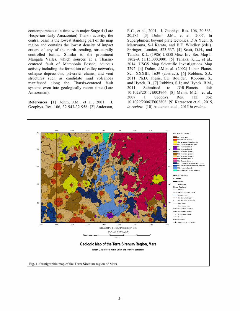
contemporaneous in time with major Stage 4 (Late Hesperian-Early Amazonian) Tharsis activity; the central basin is the lowest standing part of the map region and contains the lowest density of impact craters of any of the north-trending, structurally controlled basins. Similar to the prominent Mangala Valles, which sources at a Tharsis-centered fault of Memnonia Fossae, aqueous activity including the formation of valley networks, collapse depressions, pit-crater chains, and vent structures such as candidate mud volcanoes manifested along the Tharsis-centered fault systems even into geologically recent time (Late Amazonian). References. [1] Dohm, J.M., et al., 2001. J. Geophys. Res. 106, 32 943-32 958. [2] Anderson,
R.C., et al., 2001. J. Geophys. Res. 106, 20,563-20,585. [3] Dohm, J.M., et al., 2007. In Superplumes: beyond plate tectonics. D.A Yuen, S. Maruyama, S-I Karato, and B.F. Windley (eds.). Springer, London, 523-537. [4] Scott, D.H., and Tanaka, K.L. (1986) USGS Misc. Inv. Ser. Map I-1802-A (1:15,000,000). [5] Tanaka, K.L., et al., 2014. USGS Map Scientific Investigations Map 3292. [4] Dohm, J.M.et al. (2002) Lunar Planet. Sci. XXXIII, 1639 (abstract). [6] Robbins, S.J., 2011. Ph.D. Thesis, CU, Boulder. Robbins, S., and Hynek, B., [7] Robbins, S.J.; and Hynek, B.M., 2011. Submitted to JGR-Planets. doi: 10.1029/2011JE003966. [8] Malin, M.C., et al., 2007. J. Geophys. Res. 112, doi: 10.1029/2006JE002808. [9] Karasözen et al., 2015, in review. [10] Anderson et al., 2015 in review.
Fig. 1 Stratigraphic map of the Terra Sirenum region of Mars.
21
GEOLOGIC MAPPING OF THE SOURCE REGION OF SHALBATANA VALLIS, MARS. Daniel C. Berman, J. Alexis P. Rodriguez, Cathy M. Weitz, and David A. Crown, Planetary Science Institute, 1700 E. Ft. Lowell Rd., Suite 106, Tucson, AZ 85719; [email protected].
Research Objectives. The primary objective of
this study is to develop a greater understanding of the geologic history of the portion of Xanthe Terra surrounding Orson Welles Crater, including the source region for Shalbatana Vallis, with a focus on the role of water. This region to the south of Chryse Planitia and west of Hydraotes Chaos includes diverse landforms indicative of water release and surface flow that occur in terrains of different ages. We seek to develop an understanding of: 1) The history of impact, deformation, collapse, and outflow; 2) The types and timing of surface flow features that have modified this region; 3) Deposition and/or alteration associated with light-toned layered deposits; and 4) How these features fit together in time and relate to the history of water in the region.
A key scientific objective of the investigation includes constraining the sequence of geologic events in the region, including the impact that formed Orson Welles Crater, deformation, collapse, formation of the chaotic terrains and the Shalbatana and Ravi Valles systems, additional surface flow, and infilling and modification in order to understand any causal relationships and to test theories for the formation of these landforms.
Geologic Mapping: This research will help us test competing hypothesis for the formation of Shalbatana Vallis, unique among the circum-Chryse outflow channels in its narrow width and long segments with angled joints. We will test whether the collapse of the Shalbatana source region was caused by water release from confined aquifers [1], or by the interaction between intrusive magmatism and permafrost [2]. We are accomplishing these objectives through the following set of tasks: a) Production of a USGS-published 1:500,000-scale geologic map of Mars Transverse Mercator (MTM) quadrangles 00042 and 00047 to identify and constrain the relative timing of stratigraphic units and provide geologic context; these quadrangles include Orson Welles crater, the source region for Shalbatana Vallis, and regional highlands, as well as Aromatum Chaos and Ravi Vallis; crater count analyses will be conducted to constrain the ages of geologic units and characterize episodes of resurfacing; b) Production of a digital-only detailed 1:100,000-scale geomorphic map of specific features in MTM quadrangles 00042 and 00047, including infilled impact craters, mass wasting features, small-scale channels, putative
shorelines and deltas, collapsed and deformed terrains, and light-toned layered deposits; c) Specific morphologic and morphometric analyses of selected features identified in the geomorphic map will also be conducted to further assist in the reconstruction of the region’s geologic history and increase our understanding of the role of water in shaping this region. We will focus on the following set of features: putative lacustrine landforms; chaotic, deformed, and collapsed terrains and light-toned, layered deposits. These analyses will extend beyond the map area when necessary, including the southern extent of the depression between Orson Welles crater and Ganges Chasma; d) Synthesis and interpretation of the role of water in the regional geologic history. Results will be archived as a digital ArcGIS product and will be made available to the planetary science community through journal publications and as a USGS map product, along with supplementary data products.
Mapping Progress. The focus to date has been on assembly of the datasets necessary for geologic mapping (including production of base materials and the GIS map file by the USGS and processing and import of CTX and HiRISE imagery). Preliminary mapping has been focused on drawing contact lines for crater ejecta blankets, channel floors, and the boundaries of chaotic terrain; linear features including crater rims, scarps, and fluvial features; and small-scale features such as light-toned deposits for the geomorphologic map. See Fig. 1 for current mapping progress.
Data Processing and Ingestion: Upon receipt of the GIS project containing basemaps from the USGS, all current CTX and HiRISE images covering the map region were downloaded. CTX images were processed in ISIS. All images were then imported into the map project. CTX coverage of the map region is now ~97%. The primary map base is the controlled daytime THEMIS IR mosaic. Mapping is being done at 1:125,000, four times the map publication scale of 1:500,000.
Plains: Rotto and Tanaka (1995) mapped this region with two Noachian plains units (Npl1 and Npl2). Initial observations suggest one plains unit. The plains contain wrinkle ridges throughout, primarily oriented in the north-south direction. The plains are also covered by secondary craters radiating from Orson Welles crater, as well as several large
22

craters containing chaotic terrains. All clearly delineated ejecta blankets have been mapped, and crater rims for craters ~5 km in diameter and greater have been mapped as features.
Orson Welles Crater and Shalbatana Vallis: The two map quadrangles are dominated by the presence of Orson Welles crater, which serves as the source for Shalbatana Vallis. The walls of Orson Welles and Shalbatana have been previously mapped as a distinct unconsolidated unit [3], but we have not yet determined whether or not to map them as such, or as a continuation of the crater materials unit, mapped by the crater ejecta. The extent of the continuous ejecta of Orson Welles is unclear and has been difficult to map. Large landslides emanating from the crater wall onto the floor are being mapped as geologic units. The floor of Orson Welles consists of a combination of smooth units and chaotic terrain. To the south of Orson Welles, there is also deformed and collapsed terrain. Preliminary contacts have been drawn for wall units and smooth and chaotic floor units. The Orson Welles crater rim and the scarp of Shalbatana Vallis have been mapped as linear features. The chaotic terrain will be mapped in detail as part of the geomorphic map.
Nanedi Vallis: Nanedi Vallis is a narrow channel that flows to the north with a source in the western edge of the map region. Its floor deposits are being mapped as a geologic unit and preliminary contacts have been drawn.
Aromatum Chaos and Ravi Vallis: Aromatum Chaos lies east of Orson Welles crater and trends east into Ravi Vallis. Initial contacts have been drawn, delineating smooth and chaotic geologic units. The floor of Ravi Vallis is characterized by grooved terrain.
Chaotic terrains: Deformed, subsided, and chaotic terrains will be mapped in detail as part of the geomorphic map. Chaotic terrains will be characterized as polygonal or knobby.
Light-toned deposits: Light-toned, sometimes layered deposits are being mapped at high-resolution for the geomorphic map. Co-I Weitz has conducted CRISM analyses over one area of light-toned deposits on the floor of Orson Welles crater and found evidence for hydrated minerals.
Geologic sequence. Our mapping has revealed important stratigraphic relationships. For example, Fig. 2 shows secondary impact craters extending from Orson Welles crater as well as from another impact crater to the SW (yellow arrows). These secondaries are infilled with low thermal inertia surficial materials (most likely aeolian drift), indicating that they likely served as traps for recent
sediment. Counts of flat-floored craters filled to their rims indicate that they likely formed during a stage of elevated sedimentation during the Late Noachian [4]. The secondaries appear to modify some flat-floored craters (red arrow), indicating that these craters must be either Noachian or early Hesperian in age. However, they are absent from flat-floor craters that show collapsed surfaces (orange arrow), indicating that collapse post-dated the Late Hesperian age of secondary emplacement.
In all, we observe the following sequence of events: (i) Formation of flat floor craters; (ii) Formation of the Orson Welles crater; (iii) Collapse of some flat floor craters; (iv) Aeolian mantling of secondary craters. Formation of Shalbatana Vallis occurred sometime after (ii). We will investigate the sequence and types of likely processes after a more complete history emerges.
[1] Cabrol N.A. et al. (1997) Icarus, 125, 455–464. [2] Rodriguez J.A.P. et al. (2003) GRL, 30, 1304. [3] Rotto S. and Tanaka K.L. (1995) USGS Invest. Ser. Map, I2441-A. [4] Rodriguez J.A.P. et al. (2009) LPSC 40, abstract 2347.
Figure 1. Geologic contacts and linear features drawn over 128 pixel/deg gridded MOLA data (color, red is high, blue is low) and 100 meter/pixel daytime THEMIS IR mosaic.
Figure 2. Nighttime THEMIS IR mosaic showing stratigraphic relationships.
23
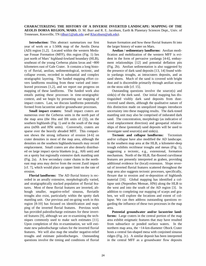
CHARACTERIZING THE HISTORY OF A DIVERSE INVERTED LANDSCAPE: MAPPING OF THE
AEOLIS DORSA REGION, MARS. D. M. Burr and R. E. Jacobsen, Earth & Planetary Sciences Dept., Univ. of
Tennessee, Knoxville, TN ([email protected] and [email protected]).
Introduction: This abstract summarizes our first
year of work on a 1:500k map of the Aeolis Dorsa
(AD) region [1,2]. Located within the western Medu-
sae Fossae Formation (MFF), this region (Fig. 1) lies
just north of Mars’ highland-lowland boundary (HLB),
southeast of the young Cerberus plains lavas and ~800
kilometers east of Gale Crater. It contains a long histo-
ry of fluvial, aeolian, sedimentological, tectonic, and
collapse events, recorded in substantial and complex
stratigraphic layering. The funded mapping effort co-
vers landforms resulting from these varied and inter-
leaved processes [1,2], and we report our progress on
mapping of these landforms. The funded work also
entails putting these processes in time-stratigraphic
context, and we begin by presenting our mapping of
impact craters. Last, we discuss landforms potentially
formed from lacustrine and/or groundwater processes.
Small impact craters: Small impact craters are
numerous over the Cerberus units in the north part of
the map area (the Htu and lHt units of [3]), on the
southern highlands (Fig. 1) and in the south of the map
area (mNh and HNt units). Conversely, craters are
sparse over the heavily abraded MFF. This compari-
son shows the strong influence of erosion [4-6] on
crater densities in most of the map area, although the
densities on the southern highlands/massifs may record
emplacement. Small craters are also densely distribut-
ed on large impact ejecta blankets (e.g., AHi unit) and
on a spotty but regionally extensive dark mantling unit
(Fig. 2a). A few secondary crater chains in the north-
east map area may derive from the recent Zunil impact
[cf. 7], which would place an upper limit on the rate of
erosion.
Fluvial landforms: The AD fluvial history is rec-
orded in an areally extensive, morphologically varied,
and stratigraphically stacked population of fluvial fea-
tures. Most of these fluvial features are inverted, alt-
hough smaller, negative-relief sinuous, fluviatile
troughs also exist, particularly within the spotty dark
mantling unit. Our previous and on-going work in this
region [8-10] has focused on identification and map-
ping of the inverted fluvial features. Previous work
has provided paleodischarge estimates for these invert-
ed features [9], although we are re-examining the tech-
niques commonly used to make such estimates [11].
Upon completion of this re-examination, we will esti-
mate new paleodischarge values for the inverted fluvial
features. We will also map the smaller negative-relief
troughs and estimate paleodischarges. Outstanding
questions involve the timing and conditions of fluvial
feature formation and how these fluvial features fit into
the larger history of water on Mars.
Aeolian / sedimentary landforms: Aeolian modi-
fication and mobilization of the western MFF is evi-
dent in the form of pervasive yardangs [4-6], embay-
ment relationships [12] and potential deflation pits
(Fig. 2b). Aeolian sedimentation is also suggested by
the presence of dark sand deposits [13, 14] found with-
in yardangs troughs, as intracraters deposits, and as
sand sheets. Much of the sand is covered with bright
dust and is discernible primarily through aeolian scour
on the stoss side [cf. 15].
Outstanding questions involve the source(s) and
sink(s) of the dark sand. Our initial mapping has dis-
tinguished visibly dark sand deposits from dust-
covered sand sheets, although the qualitative nature of
this distinction made on unequlized images introduces
uncertainty into these mapping results. The dark-toned
mantling unit may also be comprised of indurated dark
sand. The concentration, morphology (as indicative of
wind emplacement direction) and geospatial relation-
ships of these (potential) sand deposits will be used to
investigate sand source(s) and sink(s).
Tectonic and collapse landforms: Tectonism
and/or collapse have also modified the AD landscape.
In the southern map area at the HLB, a kilometer-deep
trough exhibits rectilinear troughs and mesas (Fig. 1),
suggesting a tectonic, e.g., extensional, formation
mechanism. North of the HLB, flat-floored curvilinear
features are presently interpreted as graben, providing
additional evidence for (local) extension. Slope rever-
sal of inverted fluvial features scattered throughout the
map area also suggests tectonic processes, specifically,
flexure due to erosion and re-deposition of highlands
material [16]. Global mapping has identified a col-
lapse unit (Nepenthes Mensae, HNt) along the HLB to
the west and into the south of the AD region [3]. In
addition to completing our mapping of scarps and gra-
ben, we will explore the locations and extent of col-
lapse. We can then address outstanding questions re-
garding the influence of these two processes in the map
area.
Potential groundwater and/or lacustrine land-
forms: Large craters in the central portion of the map
area exhibit enigmatic features that may have resulted
from subsurface or ponded surface waters. In the
northern map area, the ~14-km-diameter Obock Crater
hosts a central fan-shaped mesa with conjoined sinuous
ridges (Fig. 2c). A similar deposit has been interpreted
in the central MFF as a groundwater flow deposits
24
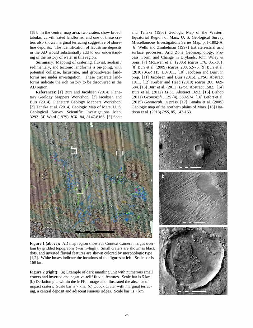
[18]. In the central map area, two craters show broad,
tabular, curvilineated landforms, and one of these cra-
ters also shows marginal terracing suggestive of shore-
line depoists. The identification of lacustrine deposits
in the AD would substantially add to our understand-
ing of the history of water in this region.
Summary: Mapping of cratering, fluvial, aeolian /
sedimentary, and tectonic landforms is on-going, with
potential collapse, lacustrine, and groundwater land-
forms are under investigation. These disparate land-
forms indicate the rich history to be discovered in the
AD region.
References: [1] Burr and Jacobsen (2014) Plane-
tary Geology Mappers Workshop. [2] Jacobsen and
Burr (2014), Planetary Geology Mappers Workshop.
[3] Tanaka et al. (2014) Geologic Map of Mars, U. S.
Geological Survey Scientific Investigations Map,
3292. [4] Ward (1979) JGR, 84, 8147-8166. [5] Scott
and Tanaka (1986) Geologic Map of the Western
Equatorial Region of Mars: U. S. Geological Survey
Miscellaneous Investigations Series Map, p. I-1802-A.
[6] Wells and Zimbelman (1997) Extraterrestrial arid
surface processes, Arid Zone Geomorphology: Pro-
cess, Form, and Change in Drylands, John Wiley &
Sons. [7] McEwen et al. (2005) Icarus 176, 351-381.
[8] Burr et al. (2009) Icarus, 200, 52-76. [9] Burr et al.
(2010) JGR 115, E07011. [10] Jacobsen and Burr, in
prep. [11] Jacobsen and Burr (2015), LPSC Abstract
1011. [12] Kerber and Head (2010) Icarus 206, 669-
684. [13] Burr et al. (2011) LPSC Abstract 1582. [14]
Burr et al. (2012) LPSC Abstract 1692. [15] Bishop
(2011) Geomorph., 125 (4), 569-574. [16] Lefort et al.
(2015) Geomorph. in press. [17] Tanaka et al. (2005)
Geologic map of the northern plains of Mars. [18] Har-
rison et al. (2013) PSS, 85, 142-163.
Figure 1 (above): AD map region shown as Context Camera images over-
lain by gridded topography (warm=high). Small craters are shown as black
dots, and inverted fluvial features are shown colored by morphologic type
[1,2]. White boxes indicate the locations of the figures at left. Scale bar is
160 km.
Figure 2 (right): (a) Example of dark mantling unit with numerous small
craters and inverted and negative-relif fluvial features. Scale bar is 5 km.
(b) Deflation pits within the MFF. Image also illustrated the absence of
impact craters. Scale bar is 7 km. (c) Obock Crater with marginal terrac-
ing, a central deposit and adjacent sinuous ridges. Scale bar is 7 km.
25
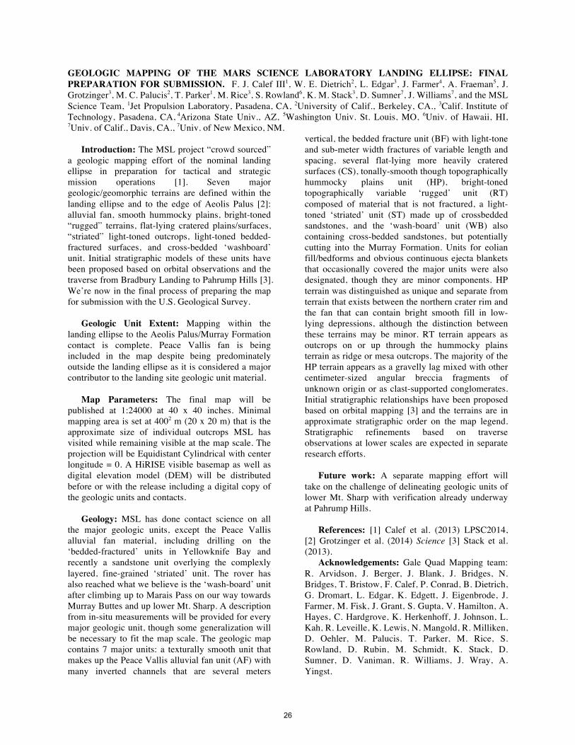
GEOLOGIC MAPPING OF THE MARS SCIENCE LABORATORY LANDING ELLIPSE: FINAL PREPARATION FOR SUBMISSION. F. J. Calef III1, W. E. Dietrich2, L. Edgar3, J. Farmer4, A. Fraeman5, J. Grotzinger3, M. C. Palucis2, T. Parker1, M. Rice3, S. Rowland6, K. M. Stack3, D. Sumner7, J. Williams7, and the MSL Science Team, 1Jet Propulsion Laboratory, Pasadena, CA, 2University of Calif., Berkeley, CA., 3Calif. Institute of Technology, Pasadena, CA, 4Arizona State Univ., AZ, 5Washington Univ. St. Louis, MO, 6Univ. of Hawaii, HI, 7Univ. of Calif., Davis, CA., 7Univ. of New Mexico, NM.
Introduction: The MSL project “crowd sourced”
a geologic mapping effort of the nominal landing ellipse in preparation for tactical and strategic mission operations [1]. Seven major geologic/geomorphic terrains are defined within the landing ellipse and to the edge of Aeolis Palus [2]: alluvial fan, smooth hummocky plains, bright-toned “rugged” terrains, flat-lying cratered plains/surfaces, “striated” light-toned outcrops, light-toned bedded-fractured surfaces, and cross-bedded ‘washboard’ unit. Initial stratigraphic models of these units have been proposed based on orbital observations and the traverse from Bradbury Landing to Pahrump Hills [3]. We’re now in the final process of preparing the map for submission with the U.S. Geological Survey.
Geologic Unit Extent: Mapping within the
landing ellipse to the Aeolis Palus/Murray Formation contact is complete. Peace Vallis fan is being included in the map despite being predominately outside the landing ellipse as it is considered a major contributor to the landing site geologic unit material.
Map Parameters: The final map will be
published at 1:24000 at 40 x 40 inches. Minimal mapping area is set at 4002 m (20 x 20 m) that is the approximate size of individual outcrops MSL has visited while remaining visible at the map scale. The projection will be Equidistant Cylindrical with center longitude = 0. A HiRISE visible basemap as well as digital elevation model (DEM) will be distributed before or with the release including a digital copy of the geologic units and contacts.
Geology: MSL has done contact science on all
the major geologic units, except the Peace Vallis alluvial fan material, including drilling on the ‘bedded-fractured’ units in Yellowknife Bay and recently a sandstone unit overlying the complexly layered, fine-grained ‘striated’ unit. The rover has also reached what we believe is the ‘wash-board’ unit after climbing up to Marais Pass on our way towards Murray Buttes and up lower Mt. Sharp. A description from in-situ measurements will be provided for every major geologic unit, though some generalization will be necessary to fit the map scale. The geologic map contains 7 major units: a texturally smooth unit that makes up the Peace Vallis alluvial fan unit (AF) with many inverted channels that are several meters
vertical, the bedded fracture unit (BF) with light-tone and sub-meter width fractures of variable length and spacing, several flat-lying more heavily cratered surfaces (CS), tonally-smooth though topographically hummocky plains unit (HP), bright-toned topographically variable ‘rugged’ unit (RT) composed of material that is not fractured, a light-toned ‘striated’ unit (ST) made up of crossbedded sandstones, and the ‘wash-board’ unit (WB) also containing cross-bedded sandstones, but potentially cutting into the Murray Formation. Units for eolian fill/bedforms and obvious continuous ejecta blankets that occasionally covered the major units were also designated, though they are minor components. HP terrain was distinguished as unique and separate from terrain that exists between the northern crater rim and the fan that can contain bright smooth fill in low-lying depressions, although the distinction between these terrains may be minor. RT terrain appears as outcrops on or up through the hummocky plains terrain as ridge or mesa outcrops. The majority of the HP terrain appears as a gravelly lag mixed with other centimeter-sized angular breccia fragments of unknown origin or as clast-supported conglomerates. Initial stratigraphic relationships have been proposed based on orbital mapping [3] and the terrains are in approximate stratigraphic order on the map legend. Stratigraphic refinements based on traverse observations at lower scales are expected in separate research efforts.
Future work: A separate mapping effort will
take on the challenge of delineating geologic units of lower Mt. Sharp with verification already underway at Pahrump Hills.
References: [1] Calef et al. (2013) LPSC2014,
[2] Grotzinger et al. (2014) Science [3] Stack et al. (2013).
Acknowledgements: Gale Quad Mapping team: R. Arvidson, J. Berger, J. Blank, J. Bridges, N. Bridges, T. Bristow, F. Calef, P. Conrad, B. Dietrich, G. Dromart, L. Edgar, K. Edgett, J. Eigenbrode, J. Farmer, M. Fisk, J. Grant, S. Gupta, V. Hamilton, A. Hayes, C. Hardgrove, K. Herkenhoff, J. Johnson, L. Kah, R. Leveille, K. Lewis, N. Mangold, R. Milliken, D. Oehler, M. Palucis, T. Parker, M. Rice, S. Rowland, D. Rubin, M. Schmidt, K. Stack, D. Sumner, D. Vaniman, R. Williams, J. Wray, A. Yingst.
26
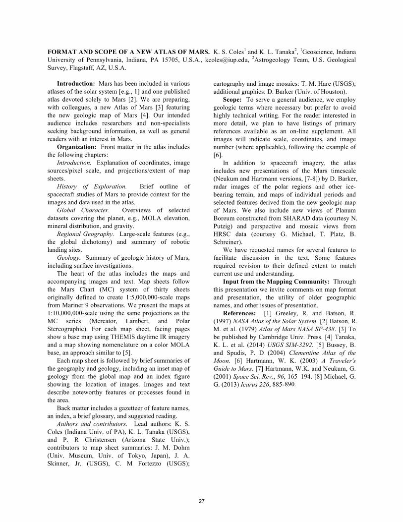
FORMAT AND SCOPE OF A NEW ATLAS OF MARS. K. S. Coles1 and K. L. Tanaka2, 1Geoscience, Indiana University of Pennsylvania, Indiana, PA 15705, U.S.A., [email protected], 2Astrogeology Team, U.S. Geological Survey, Flagstaff, AZ, U.S.A.
Introduction: Mars has been included in various
atlases of the solar system [e.g., 1] and one published atlas devoted solely to Mars [2]. We are preparing, with colleagues, a new Atlas of Mars [3] featuring the new geologic map of Mars [4]. Our intended audience includes researchers and non-specialists seeking background information, as well as general readers with an interest in Mars.
Organization: Front matter in the atlas includes the following chapters:
Introduction. Explanation of coordinates, image sources/pixel scale, and projections/extent of map sheets.
History of Exploration. Brief outline of spacecraft studies of Mars to provide context for the images and data used in the atlas.
Global Character. Overviews of selected datasets covering the planet, e.g., MOLA elevation, mineral distribution, and gravity.
Regional Geography. Large-scale features (e.g., the global dichotomy) and summary of robotic landing sites.
Geology. Summary of geologic history of Mars, including surface investigations.
The heart of the atlas includes the maps and accompanying images and text. Map sheets follow the Mars Chart (MC) system of thirty sheets originally defined to create 1:5,000,000-scale maps from Mariner 9 observations. We present the maps at 1:10,000,000-scale using the same projections as the MC series (Mercator, Lambert, and Polar Stereographic). For each map sheet, facing pages show a base map using THEMIS daytime IR imagery and a map showing nomenclature on a color MOLA base, an approach similar to [5].
Each map sheet is followed by brief summaries of the geography and geology, including an inset map of geology from the global map and an index figure showing the location of images. Images and text describe noteworthy features or processes found in the area.
Back matter includes a gazetteer of feature names, an index, a brief glossary, and suggested reading.
Authors and contributors. Lead authors: K. S. Coles (Indiana Univ. of PA), K. L. Tanaka (USGS), and P. R Christensen (Arizona State Univ.); contributors to map sheet summaries: J. M. Dohm (Univ. Museum, Univ. of Tokyo, Japan), J. A. Skinner, Jr. (USGS), C. M Fortezzo (USGS);
cartography and image mosaics: T. M. Hare (USGS); additional graphics: D. Barker (Univ. of Houston).
Scope: To serve a general audience, we employ geologic terms where necessary but prefer to avoid highly technical writing. For the reader interested in more detail, we plan to have listings of primary references available as an on-line supplement. All images will indicate scale, coordinates, and image number (where applicable), following the example of [6].
In addition to spacecraft imagery, the atlas includes new presentations of the Mars timescale (Neukum and Hartmann versions, [7-8]) by D. Barker, radar images of the polar regions and other ice-bearing terrain, and maps of individual periods and selected features derived from the new geologic map of Mars. We also include new views of Planum Boreum constructed from SHARAD data (courtesy N. Putzig) and perspective and mosaic views from HRSC data (courtesy G. Michael, T. Platz, B. Schreiner).
We have requested names for several features to facilitate discussion in the text. Some features required revision to their defined extent to match current use and understanding.
Input from the Mapping Community: Through this presentation we invite comments on map format and presentation, the utility of older geographic names, and other issues of presentation.
References: [1] Greeley, R. and Batson, R. (1997) NASA Atlas of the Solar System. [2] Batson, R. M. et al. (1979) Atlas of Mars NASA SP-438. [3] To be published by Cambridge Univ. Press. [4] Tanaka, K. L. et al. (2014) USGS SIM-3292. [5] Bussey, B. and Spudis, P. D (2004) Clementine Atlas of the Moon. [6] Hartmann, W. K. (2003) A Traveler's Guide to Mars. [7] Hartmann, W.K. and Neukum, G. (2001) Space Sci. Rev., 96, 165–194. [8] Michael, G. G. (2013) Icarus 226, 885-890.
27
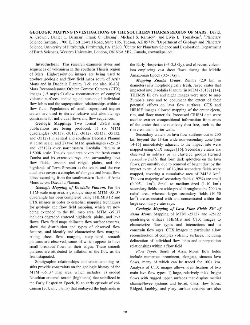
GEOLOGIC MAPPING INVESTIGATIONS OF THE SOUTHERN THARSIS REGION OF MARS. David. A. Crown1, Daniel C. Berman1, Frank C. Chuang1, Michael S. Ramsey2, and Livio L. Tornabene3, 1Planetary Science Institute, 1700 E. Fort Lowell Road, Suite 106, Tucson, AZ 85719, 2Department of Geology and Planetary Science, University of Pittsburgh, Pittsburgh, PA 15260, 3Centre for Planetary Science and Exploration, Department of Earth Sciences, Western University, London, ON N6A 5B7, Canada, [email protected].
Introduction: This research examines styles and
sequences of volcanism in the southern Tharsis region of Mars. High-resolution images are being used to produce geologic and flow field maps south of Arsia Mons and in Daedalia Planum [1-9; see also 10-13]. Mars Reconnaissance Orbiter Context Camera (CTX) images (~5 m/pixel) allow reconstruction of complex volcanic surfaces, including delineation of individual flow lobes and the superposition relationships within a flow field. Populations of small, superposed impact craters are used to derive relative and absolute age constraints for individual flows and flow sequences.
Geologic Mapping: Two formal USGS map publications are being produced: 1) six MTM quadrangles (-30137, -30132, -30127, -35137, -35132, and -35127) in central and southern Daedalia Planum at 1:1M scale, and 2) two MTM quadrangles (-25127 and -25122) over northeastern Daedalia Planum at 1:500K scale. The six quad area covers the fresh crater Zumba and its extensive rays, the surrounding lava flow fields, smooth and ridged plains, and the highlands of Terra Sirenum to the south, and the two quad area covers a complex of elongate and broad flow lobes extending from the southwestern flanks of Arsia Mons across Daedalia Planum.
Geologic Mapping of Daedalia Planum. For the 1:1M-scale map area, a geologic map of MTM -35137 quadrangle has been completed using THEMIS IR and CTX images in order to establish mapping techniques for geologic and flow field mapping, which are now being extended to the full map area. MTM -35137 includes degraded cratered highlands, plains, and lava flows. Flow field maps delineate flow surface textures, show the distribution and types of observed flow features, and identify and characterize flow margins. Along sheet flow margins, steep-sided, smooth plateaus are observed, some of which appear to have small breakout flows at their edges. These smooth plateaus are attributed to inflation of the flow as the front stagnated.
Stratigraphic relationships and crater counting re-sults provide constraints on the geologic history of the MTM -35137 map area, which includes: a) eroded Noachian cratered terrain (highlands) that stabilized in the Early Hesperian Epoch, b) an early episode of vol-canism (volcanic plains) that embayed the highlands in
the Early Hesperian (~3-3.5 Gy), and c) recent volcan-ism emplacing vast sheet flows during the Middle Amazonian Epoch (0.5-1 Gy).
Mapping Zumba Crater. Zumba (2.9 km in diameter) is a morphologically fresh, rayed crater that impacted into Daedalia Planum (in MTM -30132) [14]. THEMIS IR day and night images were used to map Zumba’s rays and to document the extent of their potential effects on lava flow surfaces. CTX and HiRISE images allowed mapping of the crater ejecta, rim, and floor materials. Processed CRISM data were used to extract compositional information from areas of the crater that are relatively dust-free, such as the rim crest and interior walls.
Secondary craters on lava flow surfaces out to 200 km beyond the 15-km wide non-secondary zone [see 14-15] immediately adjacent to the impact site were mapped using CTX images [16]. Secondary craters are observed in solitary or in clustered groups (termed secondary fields) that form dark splotches on the lava flows, presumably due to removal of bright dust by the impact event. A total of 13,064 secondary fields were mapped, covering a cumulative area of 2442.8 km2. The vast majority of secondary fields (~92%) are small (0.005-1 km2). Small to medium-sized (1-10 km2) secondary fields are widespread throughout the 200 km radial area, whereas larger secondary fields (10-50 km2) are associated with and concentrated within the large secondary crater rays.
Geologic Mapping of Lava Flow Fields SW of Arsia Mons. Mapping of MTM -25127 and -25122 quadrangles utilizes THEMIS and CTX images to characterize flow types and interactions and to constrain flow ages. CTX images in particular allow reconstruction of complex volcanic surfaces, including delineation of individual flow lobes and superposition relationships within a flow field.
Flow Types. South of Arsia Mons, flow fields include numerous prominent, elongate, sinuous lava flows, many of which can be traced for 100+ km. Analysis of CTX images allows identification of two main lava flow types: 1) large, relatively thick, bright flows with rugged upper surfaces that display medial channel/levee systems and broad, distal flow lobes. Ridged, knobby, and platy surface textures are also
28
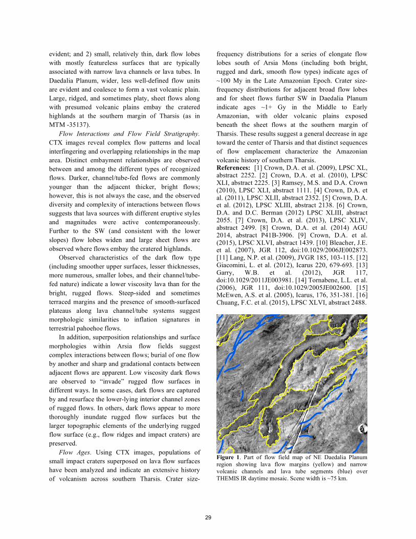
evident; and 2) small, relatively thin, dark flow lobes with mostly featureless surfaces that are typically associated with narrow lava channels or lava tubes. In Daedalia Planum, wider, less well-defined flow units are evident and coalesce to form a vast volcanic plain. Large, ridged, and sometimes platy, sheet flows along with presumed volcanic plains embay the cratered highlands at the southern margin of Tharsis (as in MTM -35137).
Flow Interactions and Flow Field Stratigraphy. CTX images reveal complex flow patterns and local interfingering and overlapping relationships in the map area. Distinct embayment relationships are observed between and among the different types of recognized flows. Darker, channel/tube-fed flows are commonly younger than the adjacent thicker, bright flows; however, this is not always the case, and the observed diversity and complexity of interactions between flows suggests that lava sources with different eruptive styles and magnitudes were active contemporaneously. Further to the SW (and consistent with the lower slopes) flow lobes widen and large sheet flows are observed where flows embay the cratered highlands.
Observed characteristics of the dark flow type (including smoother upper surfaces, lesser thicknesses, more numerous, smaller lobes, and their channel/tube-fed nature) indicate a lower viscosity lava than for the bright, rugged flows. Steep-sided and sometimes terraced margins and the presence of smooth-surfaced plateaus along lava channel/tube systems suggest morphologic similarities to inflation signatures in terrestrial pahoehoe flows.
In addition, superposition relationships and surface morphologies within Arsia flow fields suggest complex interactions between flows; burial of one flow by another and sharp and gradational contacts between adjacent flows are apparent. Low viscosity dark flows are observed to “invade” rugged flow surfaces in different ways. In some cases, dark flows are captured by and resurface the lower-lying interior channel zones of rugged flows. In others, dark flows appear to more thoroughly inundate rugged flow surfaces but the larger topographic elements of the underlying rugged flow surface (e.g., flow ridges and impact craters) are preserved.
Flow Ages. Using CTX images, populations of small impact craters superposed on lava flow surfaces have been analyzed and indicate an extensive history of volcanism across southern Tharsis. Crater size-
frequency distributions for a series of elongate flow lobes south of Arsia Mons (including both bright, rugged and dark, smooth flow types) indicate ages of ~100 My in the Late Amazonian Epoch. Crater size-frequency distributions for adjacent broad flow lobes and for sheet flows further SW in Daedalia Planum indicate ages ~1+ Gy in the Middle to Early Amazonian, with older volcanic plains exposed beneath the sheet flows at the southern margin of Tharsis. These results suggest a general decrease in age toward the center of Tharsis and that distinct sequences of flow emplacement characterize the Amazonian volcanic history of southern Tharsis. References: [1] Crown, D.A. et al. (2009), LPSC XL, abstract 2252. [2] Crown, D.A. et al. (2010), LPSC XLI, abstract 2225. [3] Ramsey, M.S. and D.A. Crown (2010), LPSC XLI, abstract 1111. [4] Crown, D.A. et al. (2011), LPSC XLII, abstract 2352. [5] Crown, D.A. et al. (2012), LPSC XLIII, abstract 2138. [6] Crown, D.A. and D.C. Berman (2012) LPSC XLIII, abstract 2055. [7] Crown, D.A. et al. (2013), LPSC XLIV, abstract 2499. [8] Crown, D.A. et al. (2014) AGU 2014, abstract P41B-3906. [9] Crown, D.A. et al. (2015), LPSC XLVI, abstract 1439. [10] Bleacher, J.E. et al. (2007), JGR 112, doi:10.1029/2006JE002873. [11] Lang, N.P. et al. (2009), JVGR 185, 103-115. [12] Giacomini, L. et al. (2012), Icarus 220, 679-693. [13] Garry, W.B. et al. (2012), JGR 117, doi:10.1029/2011JE003981. [14] Tornabene, L.L. et al. (2006), JGR 111, doi:10.1029/2005JE002600. [15] McEwen, A.S. et al. (2005), Icarus, 176, 351-381. [16] Chuang, F.C. et al. (2015), LPSC XLVI, abstract 2488.
Figure 1. Part of flow field map of NE Daedalia Planum region showing lava flow margins (yellow) and narrow volcanic channels and lava tube segments (blue) over THEMIS IR daytime mosaic. Scene width is ~75 km.
2
3
29
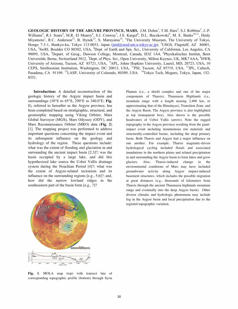
GEOLOGIC HISTORY OF THE ARGYRE PROVINCE, MARS. J.M. Dohm1, T.M. Hare2, S.J. Robbins3, J.-P. Williams4, R.J. Soare5, M.R. El Maarry6, S.J. Conway7, J.S. Kargel8, D.L. Buczkowski9, M. E. Banks10,11, Hirdy Miyamoto1, R.C. Anderson12, B. Hynek13, S. Maruyama14, 1The University Museum, The University of Tokyo, Hongo 7-3-1, Bunkyo-ku, Tokyo 113-0033, Japan ([email protected]), 2USGS, Flagstaff, AZ 86001, USA, 3SwRI, Boulder CO 80302, USA, 4Dept. of Earth and Spa. Sci., University of California, Los Angeles, CA 90095, USA, 5Depart. of Geog., Dawson College, Montreal, Canada, H3Z 1A4, 6Physikalisches Institut, Bern Universität, Berne, Switzerland 3012, 7Dept. of Phys. Sci., Open University, Milton Keynes, UK, MK7 6AA, 8HWR, University of Arizona, Tucson, AZ 85721, USA, 9APL, Johns Hopkins University, Laurel, MD, 20723, USA, 10 CEPS, Smithsonian Institution, Washington, DC 20013, USA, 11PSI, Tucson, AZ 85719, USA, 12JPL, Caltech, Pasadena, CA 91109. 13LASP, University of Colorado, 80309, USA. 14Tokyo Tech, Meguro, Tokyo, Japan, 152-8551.
Introduction: A detailed reconstruction of the
geologic history of the Argyre impact basin and surroundings (30°S to 65°S, 290°E to 340.0°E; Fig. 1), referred to hereafter as the Argyre province, has been completed based on stratigraphic, structural, and geomorphic mapping using Viking Orbiter, Mars Global Surveyor (MGS), Mars Odyssey (ODY), and Mars Reconnaissance Orbiter (MRO) data (Fig. 2) [1]. The mapping project was performed to address important questions concerning the impact event and its subsequent influence on the geology and hydrology of the region. These questions include: what was the extent of flooding and glaciation in and surrounding the ancient impact basin [2,3]?; was the basin occupied by a large lake, and did this hypothesized lake source the Uzboi Vallis drainage system during the Noachian Period [4]?; what was the extent of Argyre-related tectonism and its influence on the surrounding regions [e.g., 5,6]?; and, how did the narrow lowland ridges in the southeastern part of the basin form [e.g., 7]?
Fig. 1. MOLA map (top) with transect line of corresponding topographic profile (bottom) through Syria
Planum (i.e., a shield complex and one of the major components of Tharsis), Thaumasia Highlands (i.e., mountain range with a length nearing 2,400 km, or approximating that of the Himalayas), Transition Zone, and the Argyre Basin. The Argyre province is also highlighted at top (transparent box). Also shown is the possible headwaters of Uzboi Vallis (arrow). Note the rugged topography in the Argyre province resulting from the giant-impact event including mountainous rim materials and structurally-controlled basins, including the deep primary basin. Both Tharsis and Argyre had a major influence on one another. For example, Tharsis magmatic-driven hydrological cycling included floods and associated inundations in the northern plains and related precipitation in and surrounding the Argyre basin to form lakes and grow glaciers. Also, Tharsis-induced change in the environmental conditions of Mars may have included groundwater activity along Argyre impact-induced basement structures, which includes the possible migration at great distances (e.g., thousands of kilometers from Tharsis through the ancient Thaumasia highlands mountain range and eventually into the deep Argyre basin). Other diverse climatic and hydrologic phenomena may include fog in the Argyre basin and local precipitation due to the regional topographic variation.
30
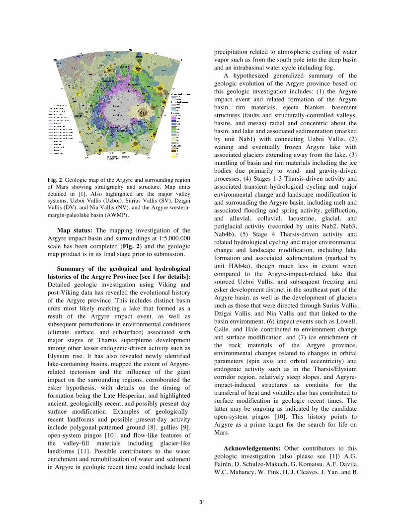
Fig. 2. Geologic map of the Argyre and surrounding region of Mars showing stratigraphy and structure. Map units detailed in [1]. Also highlighted are the major valley systems, Uzboi Vallis (Uzboi), Surius Vallis (SV), Dzigai Vallis (DV), and Nia Vallis (NV), and the Argyre western-margin-paleolake basin (AWMP).
Map status: The mapping investigation of the Argyre impact basin and surroundings at 1:5,000,000 scale has been completed (Fig. 2) and the geologic map product is in its final stage prior to submission.
Summary of the geological and hydrological histories of the Argyre Province [see 1 for details]: Detailed geologic investigation using Viking and post-Viking data has revealed the evolutional history of the Argyre province. This includes distinct basin units most likely marking a lake that formed as a result of the Argyre impact event, as well as subsequent perturbations in environmental conditions (climate, surface, and subsurface) associated with major stages of Tharsis superplume development among other lesser endogenic-driven activity such as Elysium rise. It has also revealed newly identified lake-containing basins, mapped the extent of Argyre-related tectonism and the influence of the giant impact on the surrounding regions, corroborated the esker hypothesis, with details on the timing of formation being the Late Hesperian, and highlighted ancient, geologically-recent, and possibly present-day surface modification. Examples of geologically-recent landforms and possible present-day activity include polygonal-patterned ground [8], gullies [9], open-system pingos [10], and flow-like features of the valley-fill materials including glacier-like landforms [11]. Possible contributors to the water enrichment and remobilization of water and sediment in Argyre in geologic recent time could include local
precipitation related to atmospheric cycling of water vapor such as from the south pole into the deep basin and an intrabasinal water cycle including fog.
A hypothesized generalized summary of the geologic evolution of the Argyre province based on this geologic investigation includes: (1) the Argyre impact event and related formation of the Argyre basin, rim materials, ejecta blanket, basement structures (faults and structurally-controlled valleys, basins, and mesas) radial and concentric about the basin, and lake and associated sedimentation (marked by unit Nab1) with connecting Uzboi Vallis, (2) waning and eventually frozen Argyre lake with associated glaciers extending away from the lake, (3) mantling of basin and rim materials including the ice bodies due primarily to wind- and gravity-driven processes, (4) Stages 1-3 Tharsis-driven activity and associated transient hydrological cycling and major environmental change and landscape modification in and surrounding the Argyre basin, including melt and associated flooding and spring activity, gelifluction, and alluvial, colluvial, lacustrine, glacial, and periglacial activity (recorded by units Nab2, Nab3, Nab4b), (5) Stage 4 Tharsis-driven activity and related hydrological cycling and major environmental change and landscape modification, including lake formation and associated sedimentation (marked by unit HAb4a), though much less in extent when compared to the Argyre-impact-related lake that sourced Uzboi Vallis, and subsequent freezing and esker development distinct in the southeast part of the Argyre basin, as well as the development of glaciers such as those that were directed through Surius Vallis, Dzigai Vallis, and Nia Vallis and that linked to the basin environment, (6) impact events such as Lowell, Galle, and Hale contributed to environment change and surface modification, and (7) ice enrichment of the rock materials of the Argyre province, environmental changes related to changes in orbital parameters (spin axis and orbital eccentricity) and endogenic activity such as in the Tharsis/Elysium corridor region, relatively steep slopes, and Agryre-impact-induced structures as conduits for the transferal of heat and volatiles also has contributed to surface modification in geologic recent times. The latter may be ongoing as indicated by the candidate open-system pingos [10]. This history points to Argyre as a prime target for the search for life on Mars.
Acknowledgements: Other contributors to this
geologic investigation (also please see [1]) A.G. Fairén, D. Schulze-Makuch, G. Komatsu, A.F. Davila, W.C. Mahaney, W. Fink, H. J. Cleaves, J. Yan, and B.
31
Hynek. PI J.M. Dohm was supported by the National Aeronautics and Space Administration (NASA) Planetary Geology & Geophysics Program. Professors Dohm and Miyamoto express their gratitude to the Tokyo Dome Corporation for their support of the TeNQ exhibit and the branch of Space Exploration Education & Discovery, the University Museum, the University of Tokyo.
References: [1] Dohm J.M. et al. (2015) Icarus, 253, 66-98. [2] Kargel J.S. and Strom R.G. (1992) Geology, 20, 3-7. [3] Kargel J.S. (2004) Praxis-Springer, 557 pages. [4] Parker T.J. and Gorsline D.S. (1993) Am. Geophys. Union Spring Meeting, 1pp. [5] Scott D.H. et al (986-87) USGS Map I-1802-A-C. [6] Dohm J.M. et al. (2001) USGS Map I-2650. [7] Banks M.E. et al. (2008) JGR, 113, E12015, doi:10.1029/2007JE002994. [8] Soare R.J. et al. (2014) Icarus, 233, 214-228. [9] Conway S.J. and Soare, R.J. (2013) LPSC 44th, abstract #2488. [10] Soare R.J. et al. (2014). Earth and Planet. Lett., 398, 25-36. [11] El Maarry, M.R., et al. (2013) Icarus, 226, 905-922.
32
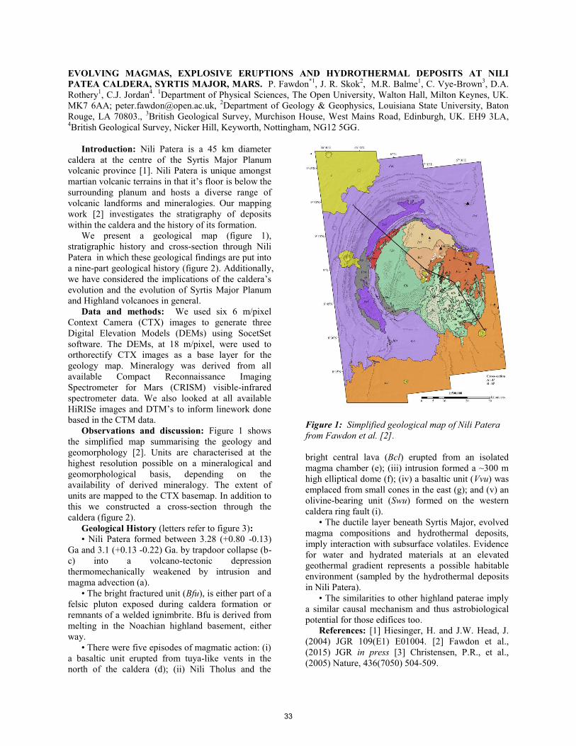
EVOLVING MAGMAS, EXPLOSIVE ERUPTIONS AND HYDROTHERMAL DEPOSITS AT NILI
PATEA CALDERA, SYRTIS MAJOR, MARS. P. Fawdon*1
, J. R. Skok2, M.R. Balme
1, C. Vye-Brown
3, D.A.
Rothery1, C.J. Jordan
4.
1Department of Physical Sciences, The Open University, Walton Hall, Milton Keynes, UK.
MK7 6AA; [email protected], 2Department of Geology & Geophysics, Louisiana State University, Baton
Rouge, LA 70803., 3British Geological Survey, Murchison House, West Mains Road, Edinburgh, UK. EH9 3LA,
4British Geological Survey, Nicker Hill, Keyworth, Nottingham, NG12 5GG.
Introduction: Nili Patera is a 45 km diameter
caldera at the centre of the Syrtis Major Planum
volcanic province [1]. Nili Patera is unique amongst
martian volcanic terrains in that it’s floor is below the
surrounding planum and hosts a diverse range of
volcanic landforms and mineralogies. Our mapping
work [2] investigates the stratigraphy of deposits
within the caldera and the history of its formation.
We present a geological map (figure 1),
stratigraphic history and cross-section through Nili
Patera in which these geological findings are put into
a nine-part geological history (figure 2). Additionally,
we have considered the implications of the caldera’s
evolution and the evolution of Syrtis Major Planum
and Highland volcanoes in general.
Data and methods: We used six 6 m/pixel
Context Camera (CTX) images to generate three
Digital Elevation Models (DEMs) using SocetSet
software. The DEMs, at 18 m/pixel, were used to
orthorectify CTX images as a base layer for the
geology map. Mineralogy was derived from all
available Compact Reconnaissance Imaging
Spectrometer for Mars (CRISM) visible-infrared
spectrometer data. We also looked at all available
HiRISe images and DTM’s to inform linework done
based in the CTM data.
Observations and discussion: Figure 1 shows
the simplified map summarising the geology and
geomorphology [2]. Units are characterised at the
highest resolution possible on a mineralogical and
geomorphological basis, depending on the
availability of derived mineralogy. The extent of
units are mapped to the CTX basemap. In addition to
this we constructed a cross-section through the
caldera (figure 2).
Geological History (letters refer to figure 3):
• Nili Patera formed between 3.28 (+0.80 -0.13)
Ga and 3.1 (+0.13 -0.22) Ga. by trapdoor collapse (b-
c) into a volcano-tectonic depression
thermomechanically weakened by intrusion and
magma advection (a).
• The bright fractured unit (Bfu), is either part of a
felsic pluton exposed during caldera formation or
remnants of a welded ignimbrite. Bfu is derived from
melting in the Noachian highland basement, either
way.
• There were five episodes of magmatic action: (i)
a basaltic unit erupted from tuya-like vents in the
north of the caldera (d); (ii) Nili Tholus and the
bright central lava (Bcl) erupted from an isolated
magma chamber (e); (iii) intrusion formed a ~300 m
high elliptical dome (f); (iv) a basaltic unit (Vvu) was
emplaced from small cones in the east (g); and (v) an
olivine-bearing unit (Swu) formed on the western
caldera ring fault (i).
• The ductile layer beneath Syrtis Major, evolved
magma compositions and hydrothermal deposits,
imply interaction with subsurface volatiles. Evidence
for water and hydrated materials at an elevated
geothermal gradient represents a possible habitable
environment (sampled by the hydrothermal deposits
in Nili Patera).
• The similarities to other highland paterae imply
a similar causal mechanism and thus astrobiological
potential for those edifices too.
References: [1] Hiesinger, H. and J.W. Head, J.
(2004) JGR 109(E1) E01004. [2] Fawdon et al.,
(2015) JGR in press [3] Christensen, P.R., et al.,
(2005) Nature, 436(7050) 504-509.
Figure 1: Simplified geological map of Nili Patera
from Fawdon et al. [2].
33
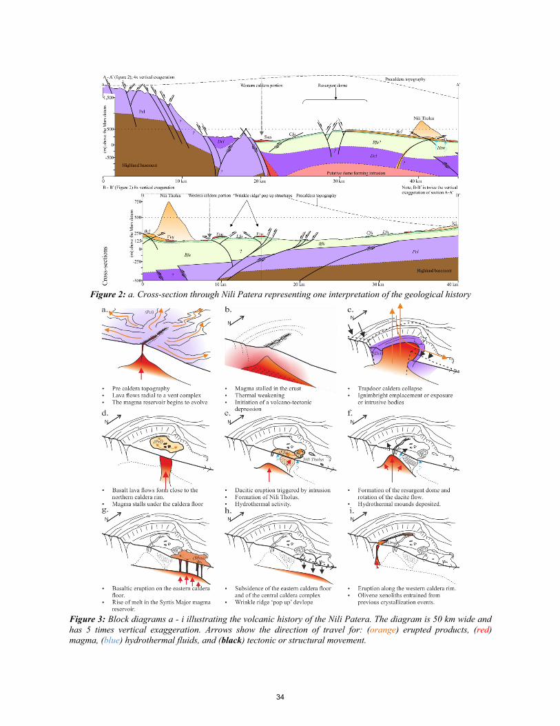
Figure 2: a. Cross-section through Nili Patera representing one interpretation of the geological history
Figure 3: Block diagrams a - i illustrating the volcanic history of the Nili Patera. The diagram is 50 km wide and
has 5 times vertical exaggeration. Arrows show the direction of travel for: (orange) erupted products, (red)
magma, (blue) hydrothermal fluids, and (black) tectonic or structural movement.
34
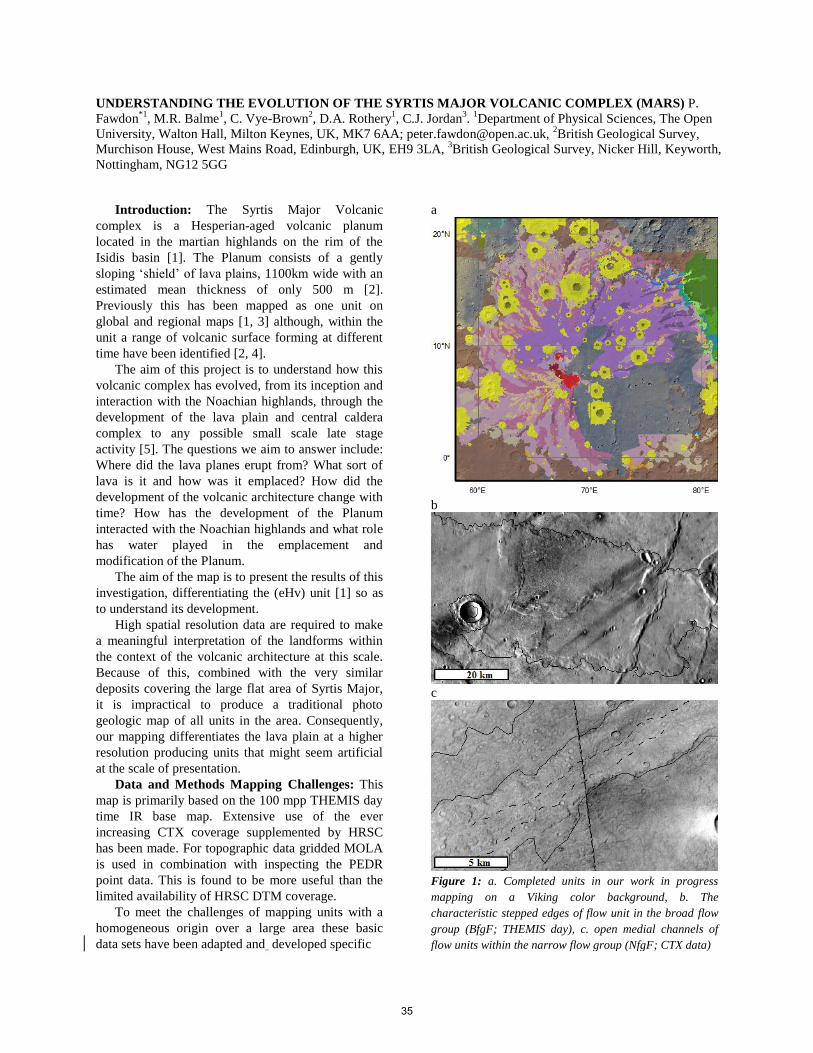
UNDERSTANDING THE EVOLUTION OF THE SYRTIS MAJOR VOLCANIC COMPLEX (MARS) P.
Fawdon*1
, M.R. Balme1, C. Vye-Brown
2, D.A. Rothery
1, C.J. Jordan
3.
1Department of Physical Sciences, The Open
University, Walton Hall, Milton Keynes, UK, MK7 6AA; [email protected], 2British Geological Survey,
Murchison House, West Mains Road, Edinburgh, UK, EH9 3LA, 3British Geological Survey, Nicker Hill, Keyworth,
Nottingham, NG12 5GG
Introduction: The Syrtis Major Volcanic
complex is a Hesperian-aged volcanic planum
located in the martian highlands on the rim of the
Isidis basin [1]. The Planum consists of a gently
sloping ‘shield’ of lava plains, 1100km wide with an
estimated mean thickness of only 500 m [2].
Previously this has been mapped as one unit on
global and regional maps [1, 3] although, within the
unit a range of volcanic surface forming at different
time have been identified [2, 4].
The aim of this project is to understand how this
volcanic complex has evolved, from its inception and
interaction with the Noachian highlands, through the
development of the lava plain and central caldera
complex to any possible small scale late stage
activity [5]. The questions we aim to answer include:
Where did the lava planes erupt from? What sort of
lava is it and how was it emplaced? How did the
development of the volcanic architecture change with
time? How has the development of the Planum
interacted with the Noachian highlands and what role
has water played in the emplacement and
modification of the Planum.
The aim of the map is to present the results of this
investigation, differentiating the (eHv) unit [1] so as
to understand its development.
High spatial resolution data are required to make
a meaningful interpretation of the landforms within
the context of the volcanic architecture at this scale.
Because of this, combined with the very similar
deposits covering the large flat area of Syrtis Major,
it is impractical to produce a traditional photo
geologic map of all units in the area. Consequently,
our mapping differentiates the lava plain at a higher
resolution producing units that might seem artificial
at the scale of presentation.
Data and Methods Mapping Challenges: This
map is primarily based on the 100 mpp THEMIS day
time IR base map. Extensive use of the ever
increasing CTX coverage supplemented by HRSC
has been made. For topographic data gridded MOLA
is used in combination with inspecting the PEDR
point data. This is found to be more useful than the
limited availability of HRSC DTM coverage.
To meet the challenges of mapping units with a
homogeneous origin over a large area these basic
data sets have been adapted and developed specific
a
b
c
Figure 1: a. Completed units in our work in progress
mapping on a Viking color background, b. The
characteristic stepped edges of flow unit in the broad flow
group (BfgF; THEMIS day), c. open medial channels of
flow units within the narrow flow group (NfgF; CTX data)
35
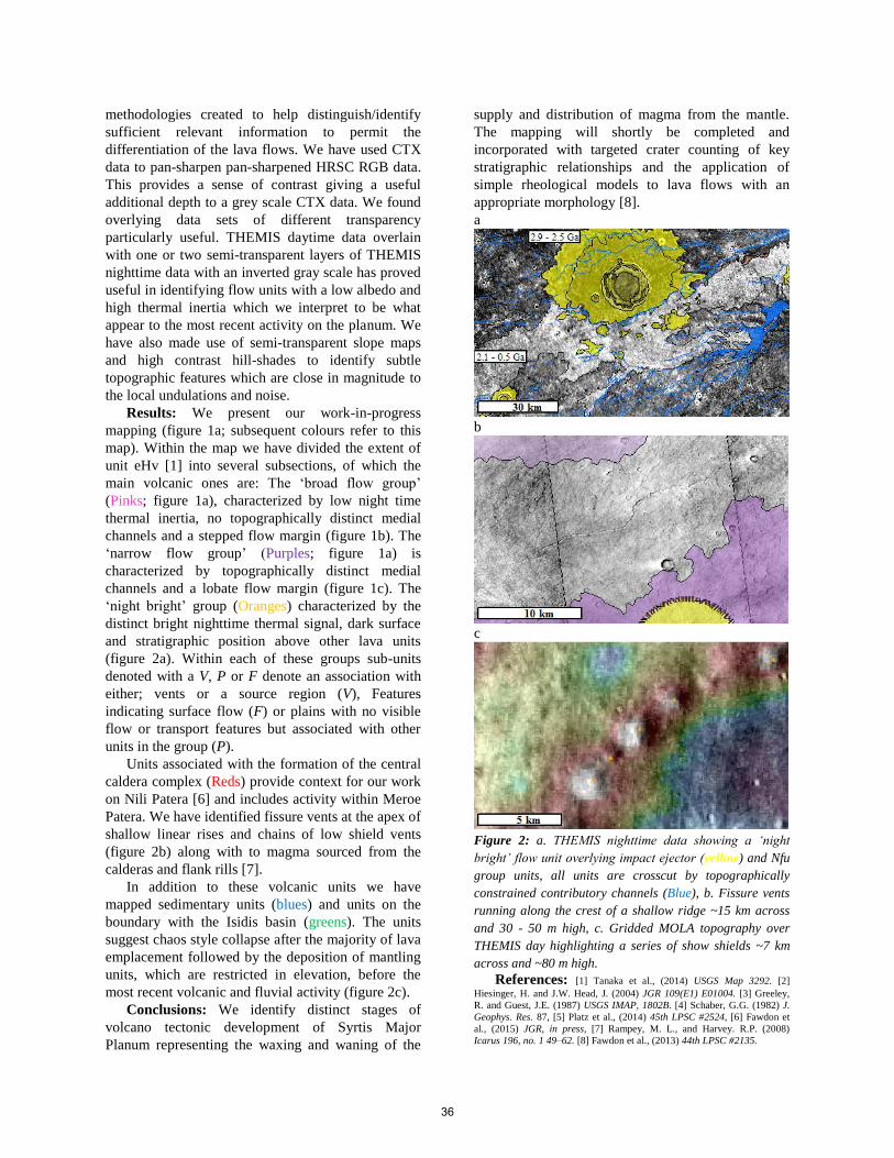
methodologies created to help distinguish/identify
sufficient relevant information to permit the
differentiation of the lava flows. We have used CTX
data to pan-sharpen pan-sharpened HRSC RGB data.
This provides a sense of contrast giving a useful
additional depth to a grey scale CTX data. We found
overlying data sets of different transparency
particularly useful. THEMIS daytime data overlain
with one or two semi-transparent layers of THEMIS
nighttime data with an inverted gray scale has proved
useful in identifying flow units with a low albedo and
high thermal inertia which we interpret to be what
appear to the most recent activity on the planum. We
have also made use of semi-transparent slope maps
and high contrast hill-shades to identify subtle
topographic features which are close in magnitude to
the local undulations and noise.
Results: We present our work-in-progress
mapping (figure 1a; subsequent colours refer to this
map). Within the map we have divided the extent of
unit eHv [1] into several subsections, of which the
main volcanic ones are: The ‘broad flow group’
(Pinks; figure 1a), characterized by low night time
thermal inertia, no topographically distinct medial
channels and a stepped flow margin (figure 1b). The
‘narrow flow group’ (Purples; figure 1a) is
characterized by topographically distinct medial
channels and a lobate flow margin (figure 1c). The
‘night bright’ group (Oranges) characterized by the
distinct bright nighttime thermal signal, dark surface
and stratigraphic position above other lava units
(figure 2a). Within each of these groups sub-units
denoted with a V, P or F denote an association with
either; vents or a source region (V), Features
indicating surface flow (F) or plains with no visible
flow or transport features but associated with other
units in the group (P).
Units associated with the formation of the central
caldera complex (Reds) provide context for our work
on Nili Patera [6] and includes activity within Meroe
Patera. We have identified fissure vents at the apex of
shallow linear rises and chains of low shield vents
(figure 2b) along with to magma sourced from the
calderas and flank rills [7].
In addition to these volcanic units we have
mapped sedimentary units (blues) and units on the
boundary with the Isidis basin (greens). The units
suggest chaos style collapse after the majority of lava
emplacement followed by the deposition of mantling
units, which are restricted in elevation, before the
most recent volcanic and fluvial activity (figure 2c).
Conclusions: We identify distinct stages of
volcano tectonic development of Syrtis Major
Planum representing the waxing and waning of the
supply and distribution of magma from the mantle.
The mapping will shortly be completed and
incorporated with targeted crater counting of key
stratigraphic relationships and the application of
simple rheological models to lava flows with an
appropriate morphology [8].
a
b
c
Figure 2: a. THEMIS nighttime data showing a ‘night
bright’ flow unit overlying impact ejector (yellow) and Nfu
group units, all units are crosscut by topographically
constrained contributory channels (Blue), b. Fissure vents
running along the crest of a shallow ridge ~15 km across
and 30 - 50 m high, c. Gridded MOLA topography over
THEMIS day highlighting a series of show shields ~7 km
across and ~80 m high.
References: [1] Tanaka et al., (2014) USGS Map 3292. [2]
Hiesinger, H. and J.W. Head, J. (2004) JGR 109(E1) E01004. [3] Greeley,
R. and Guest, J.E. (1987) USGS IMAP, 1802B. [4] Schaber, G.G. (1982) J.
Geophys. Res. 87, [5] Platz et al., (2014) 45th LPSC #2524, [6] Fawdon et
al., (2015) JGR, in press, [7] Rampey, M. L., and Harvey. R.P. (2008)
Icarus 196, no. 1 49–62. [8] Fawdon et al., (2013) 44th LPSC #2135.
36
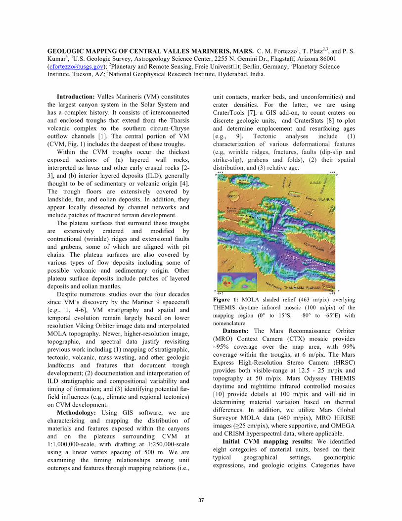
GEOLOGIC MAPPING OF CENTRAL VALLES MARINERIS, MARS. C. M. Fortezzo1, T. Platz2,3, and P. S. Kumar4, 1U.S. Geologic Survey, Astrogeology Science Center, 2255 N. Gemini Dr., Flagstaff, Arizona 86001 ([email protected]); 2Planetary and Remote Sensing, Freie Universt�t, Berlin, Germany; 3Planetary Science Institute, Tucson, AZ; 4National Geophysical Research Institute, Hyderabad, India.
Introduction: Valles Marineris (VM) constitutes
the largest canyon system in the Solar System and has a complex history. It consists of interconnected and enclosed troughs that extend from the Tharsis volcanic complex to the southern circum-Chryse outflow channels [1]. The central portion of VM (CVM, Fig. 1) includes the deepest of these troughs.
Within the CVM troughs occur the thickest exposed sections of (a) layered wall rocks, interpreted as lavas and other early crustal rocks [2-3], and (b) interior layered deposits (ILD), generally thought to be of sedimentary or volcanic origin [4]. The trough floors are extensively covered by landslide, fan, and eolian deposits. In addition, they appear locally dissected by channel networks and include patches of fractured terrain development.
The plateau surfaces that surround these troughs are extensively cratered and modified by contractional (wrinkle) ridges and extensional faults and grabens, some of which are aligned with pit chains. The plateau surfaces are also covered by various types of flow deposits including some of possible volcanic and sedimentary origin. Other plateau surface deposits include patches of layered deposits and eolian mantles.
Despite numerous studies over the four decades since VM’s discovery by the Mariner 9 spacecraft [e.g., 1, 4-6], VM stratigraphy and spatial and temporal evolution remain largely based on lower resolution Viking Orbiter image data and interpolated MOLA topography. Newer, higher-resolution image, topographic, and spectral data justify revisiting previous work including (1) mapping of stratigraphic, tectonic, volcanic, mass-wasting, and other geologic landforms and features that document trough development; (2) documentation and interpretation of ILD stratigraphic and compositional variability and timing of formation; and (3) identifying potential far-field influences (e.g., climate and regional tectonics) on CVM development.
Methodology: Using GIS software, we are characterizing and mapping the distribution of materials and features exposed within the canyons and on the plateaus surrounding CVM at 1:1,000,000-scale, with drafting at 1:250,000-scale using a linear vertex spacing of 500 m. We are examining the timing relationships among unit outcrops and features through mapping relations (i.e.,
unit contacts, marker beds, and unconformities) and crater densities. For the latter, we are using CraterTools [7], a GIS add-on, to count craters on discrete geologic units, and CraterStats [8] to plot and determine emplacement and resurfacing ages [e.g., 9]. Tectonic analyses include (1) characterization of various deformational features (e.g, wrinkle ridges, fractures, faults (dip-slip and strike-slip), grabens and folds), (2) their spatial distribution, and (3) relative age.
Figure 1: MOLA shaded relief (463 m/pix) overlying THEMIS daytime infrared mosaic (100 m/pix) of the mapping region (0° to 15°S, -80° to -65°E) with nomenclature.
Datasets: The Mars Reconnaissance Orbiter (MRO) Context Camera (CTX) mosaic provides ~95% coverage over the map area, with 99% coverage within the troughs, at 6 m/pix. The Mars Express High-Resolution Stereo Camera (HRSC) provides both visible-range at 12.5 - 25 m/pix and topography at 50 m/pix. Mars Odyssey THEMIS daytime and nighttime infrared controlled mosaics [10] provide details at 100 m/pix and will aid in determining material variation based on thermal differences. In addition, we utilize Mars Global Surveyor MOLA data (460 m/pix), MRO HiRISE images (≥25 cm/pix), where supportive, and OMEGA and CRISM hyperspectral data, where applicable.
Initial CVM mapping results: We identified eight categories of material units, based on their typical geographical settings, geomorphic expressions, and geologic origins. Categories have
37
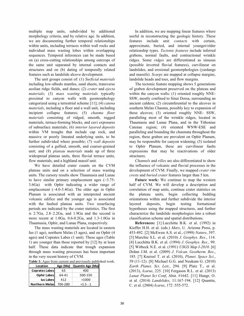
multiple map units, subdivided by additional morphology criteria, and by relative age. In addition, we are documenting further temporal relationships within units, including terraces within wall rocks and individual mass wasting lobes within overlapping sequences. Temporal inferences can be made based on (a) cross-cutting relationships among outcrops of the same unit separated by internal contacts and structures and on (b) dating of temporally related features such as landslide alcove development.
The unit groups consist of: (1) Surficial materials including low-albedo mantles, sand sheets, transverse aeolian ridge fields, and dunes; (2) crater and ejecta materials; (3) mass wasting materials typically proximal to canyon walls with geomorphology categorized using a terrestrial scheme [11]; (4) catena materials, including a floor and a wall unit, including incipient collapse features; (5) chasma floor materials consisting of ridged, smooth, rugged materials, terrace-forming blocks, and cavi exposures of subsurface materials; (6) interior layered deposits within VM troughs that include cap rock, and massive or poorly lineated underlying units, to be further subdivided where possible; (7) wall deposits consisting of a gullied, smooth, and coarser-grained unit; and (8) plateau materials made up of three widespread plateau units, three fluvial terrace units, flow materials, and a highland massif unit.
We have detailed crater counts on the CVM plateau units and on a selection of mass wasting units. The cursory results show Thaumasia and Lunae to have similar primary emplacement ages (~3.75-3.6Ga) with Ophir indicating a wider range of emplacement (~4.0-3.4Ga). The older age in Ophir Planum is associated with an interpreted ancient volcanic edifice and the younger age is associated with the faulted plateau units. Two resurfacing periods are indicated by the crater statistics. The first is 2.7Ga, 2.8–2.2Ga, and 1.9Ga and the second is more recent at 1.0Ga, 0.6-0.2Ga, and 1.3-1.0Ga in Thaumasia, Ophir, and Lunae Plana, respectively.
The mass wasting materials are located in eastern Ius (1 age), northern Melas (3 ages), and on Ophir (4 ages) and Coprates Labes (1 unit). These ages (Table 1) are younger than those reported by [12] by at least half. These data indicate that trough expansion through mass wasting processes has been important in the very recent history of CVM. Table 1: Ages from current and previously published work.
In addition, we are mapping linear features where useful in reconstructing the geologic history. These features include unit contacts with certain, approximate, buried, and internal younger/older relationship types. Tectonic features include inferred grabens, normal faults, and contractional wrinkle ridges. Some ridges are differentiated as sinuous (possible inverted fluvial features), curvilinear on landslides, and erosional geomorphologies (yardangs and massifs). Scarps are mapped at collapse margins, landslide heads and toes, and flow margins.
The tectonic feature mapping shows 5 generations of graben development preserved on the plateau and within the canyon walls: (1) oriented roughly NNE-SSW, mostly confined to Sinai Dorsa, surrounding an ancient caldera; (2) circumferential to the alcoves in southern Melas Chasma, possibly key to expansion of these alcoves; (3) oriented roughly NNE- SSW, paralleling most of the wrinkle ridges, located in Thaumasia and Lunae Plana, and in the Tithoniae Catenae region; (4) oriented WNW-ESE and paralleling and bounding the chasmata throughout the region, these graben are prevalent on Ophir Planum, may be responsible for canyon widening; (5) isolated to Ophir Planum, these are curvilinear faults expressions that may be reactivations of older structures.
Channels and rilles are also differentiated to show the influence of volcanic and fluvial processes in the development of CVM. Finally, we mapped crater rim crests and buried crater features larger than 5 km.
Future work: We continue to map the western half of CVM. We will develop a description and correlation of map units, continue crater statistics on the plateau units, begin collecting bedding orientations within and further subdivide the interior layered deposits, begin testing formational hypotheses using the mapped structures, and further characterize the landslide morphologies into a robust classification scheme and spatial distributions.
References: [1] Lucchitta B.K. et al. (1992) in Kieffer H.H. et al. (eds.) Mars, U. Arizona Press, p. 453-492. [2] McEwen A.S. et al., (1999) Nature, 397. [3] Murchie S.L. et al. (2010) J. Geophys. Res., 114. [4] Lucchitta B.K. et al. (1994) J. Geophys. Res., 99. [5] Witbeck N.E. et al. (1991) USGS Map I-2010. [6] Dohm J.M. et al. (2009) J. Volcan. Geotherm. Res., 185. [7] Kneissl T. et al. (2010), Planet. Space Sci., 59 (11-12). [8] Michael G.G. and Neukum G. (2010) Earth Planet. Sci. Lett., 294. [9] Platz T., et al. (2013), Icarus, 225. [10] Fergason R.L. et al. (2013) Lunar Planet Sci Conf, Abst. #1642. [11] Hungr, O. et al. (2014) Landslides, 11:167-194. [12] Quantin, C. et al. (2004) Icarus, 172 :555-572.
Location Age (Ma) Quantin Age (Ma)Coprates Labes 63 400
Ophir Labes 64-‐41 500-‐150Ius Labes 412 >1000
Northern Melas 700-‐280 >1.5 -‐ 1
38

GEOLOGIC MAPPING OF THE THARSIS MONTES (ARSIA, PAVONIS, AND ASCRAEUS), MARS. W.Brent Garry1, David A. Williams2, Jacob E. Bleacher1, and Angela M. Dapremont1 1Planetary Geodynamics La-boratory, Code 698, NASA Goddard Space Flight Center, Greenbelt, MD 20771, 2School of Earth and Space Explo-ration, Arizona State University, PO Box 871404, Tempe, AZ 85287, [email protected]
Introduction: The Tharsis Montes (Arsia, Pavonis,
Ascraeus) volcanoes on Mars are some the largest vol-canoes on Mars and in our Solar System. The three volcanoes are aligned northeast to southwest and have similar volcanic structure including 1) summit caldera, 2) main shield, 3) rift apron, 4) lava plains, and 5) a fan-shaped deposit. While their general forms are simi-lar, high resolution images and topography reveal a unique eruption history for each volcano.
Our team is funded by NASA’s Mars Data Analy-sis Program (MDAP) to complete a set of 1:1,000,000 geologic maps of Arsia, Pavonis, and Ascraeus based on the mapping style defined by [1,2]. Figure 1 shows the area around each volcano that we are funded to map, including additional sections that cover the rift aprons and small vent fields, plus the mapping area for Olympus Mons. Detailed mapping of a limited area of these volcanoes revealed a diverse distribution of vol-canic landforms within the calderas, on the flanks, rift aprons, and surrounding plains [1].
Figure 1. MOLA shaded relief map with the bounda-ries (solid lines) for each map and extensions (dashed lines) to cover rift aprons and small vent fields.
Data and Methods: We are mapping the three volcanoes in ArcMap 10.2 at 1:1,000,000 scale to pro-duce three geologic maps for the USGS. A THEMIS daytime IR mosaic serves as the primary basemap,
supplemented by CTX mosaics for Pavonis and Arsia, HiRISE images, and MOLA data. Our primary objec-tive is to show the areal extent, distribution, and strati-graphic relations of the different lava flow morpholo-gies across each volcano to better understand their evo-lution and geologic history. To address our science questions we have conducted our mapping at ~1:100,000 on the THEMIS and CTX basemaps. This scale enables us to distinguish between different mor-phologic features like sinuous rilles, and leveed chan-nels, low shields, and surface textures (hummocky, mottled, smooth), plus we are able to determine flow margins, flow directions, and stratigraphic relation-ships between different eruption sequences.
Mapping Progress: Each map is in a different stage of the geologic mapping process. The Ascraeus Mons map is the most recently funded project (Fig. 2). The maps of Arsia and Pavonis Montes will be ready to submit for publication in 2015 (Figs. 3, 4).
For the Tharsis Montes, our objective this year has to map the contacts between different volcanic prov-inces on each volcano (e.g., main shield, rift aprons, and lava plains). We have mapped the surficial fan deposits on Pavonis and Arsia Mons using sketch maps from [4-6] as guides for mapping similar units (e.g., smooth, ridged, knobby).
Figure 2. Geologic map of Ascraeus Mons. Discussion: Our current progress has provided several insights into the eruption processes and evolution of these volcanoes.
Geologic Units: The current mapping units have evolved from the original proposed mapping units to correspond with units used for the recent geologic map
39

of Olympus Mons [9]. Detailed imagery from CTX has allowed us to diversify the units based on various eruption styles. The units are distinguished primarily by morphology and are grouped for each edifice (main shield, rift apron, fan deposit, lava plains).
Figure 3. Geologic map of Pavonis Mons. General Formation Sequence: Mapping reveals a simi-lar sequence of events for the evolution of the three Tharsis Montes volcanoes [1,2,8]: 1) main shield forms, 2) eruptions from the NE/SW rifts emplace long lava flows that surround the main flank, 3) eruptions wane and build up the rift aprons and shield fields, 4) glaciers deposit surficial fan deposit material [9], and 5) localized recent eruptions along the main flanks, in the calderas, and within the fan-shaped deposits. Fur-ther mapping will reveal the relative geologic timing of eruptive units on the main shields and provide a more complete analysis of the spatial distribution of tube-fed versus channel-fed flows for each volcano and how they compare with Olympus Mons as originally dis-cussed by [1].
Figure 5. Geologic sketch map of the main volcanoes in the Tharsis region [10]. References: [1] Bleacher J. E. et al. (2007) JGR, 112, E04003, doi:10.1029/2006JE002826. [2] Bleacher J. E. et al. (2007) JGR, 112, E09005, doi:10.1029/2006 JE002873. [3] William D. A. et al. (2012) LPSC 43, Abstract 1528. [4] Richardson P.W. et al., (2009) LPSC 40, Abstract 1527. [5] Shean D.E. et al. (2007) JGR,112, E03004, doi:10.1029/2006JE00 2761. [6] Shean D.E. et al. (2005) JGR, 110, E05001, doi:10.1029/ 2004JE002360. [7] Head J.W. and Marchant D. R. (2003) Geology, 31, 641-644. [8] Crumpler L.S. and Aubele J.C. (1978) Icarus, 34, 496-511. [9] Bleacher J.E. et al., (2013) LPSC 44, Abstract 2074. [10] C.A. Hodges, H.J. Moore (1994) Atlas of volcanic landforms on Mars. USGS. Acknowledgements: These maps are funded by two separate NASA Mars Data Analysis Program grants: NNX10AO15G (Arsia and Pavonis), and NNX14AM30G (Ascraeus) award-ed to D.A. Williams (Arizona State University).
Figure 4. Geologic map of Arsia Mons.
40
CONSTRAINING THE MAGMA BEHAVIOR THAT LED TO THE CERBERUS CHANNEL FLOOD
LAVAS, MARS. K. B. Golder1 and D. M. Burr
1,
1University of Tennessee Knoxville, Department of Earth and
Planetary Sciences, 1412 Circle Drive, Knoxville, TN, 37996 ([email protected]).
Introduction: Young regional volcanism on Mars
is exemplified in the Cerberus plains [e.g., 1], with
distinct lava flows found within three circum-Cerberus
aqueous flood channels, Athabasca, Grjotá, and Marte
Valles [e.g., 2-9]. Each channel and embaying lava
flow emanate from separate points along the Cerberus
Fossae [Fig.1; 2-6], a regional fissure network modeled
as having developed in response to loading stresses
during the Olympus/Tharsis volcano-tectonic province
formation [10]. This fissure network also exhibits an
apparent radial relationship to Elysium Mons [e.g., 11].
Age estimates derived from crater counts of the in-
channel lava surfaces (Table 1) indicate the eruptions
were discrete events. These results could be interpret-
ed several ways to explain the magma behavior: the
lavas were sourced from the Olympus/Tharsis volcanic
province through typical dike propagation; magma
retreated towards the Elysium volcanic province over
time; or volcanism was related to a regional magma
source that was not tied to either Elysium or Tharsis (or
was tied to both of them).
The lavas within each of the channels appear to
have been emplaced as single flow units [9,12]. Due to
their lack of dust cover and crystalline lithology, they
retain sharp unit contacts and show well-preserved
craters [8-9]. These attributes suggest that crater
counts on the lava surfaces would give reliable em-
placement ages. With a Context Camera (CTX) [13]
basemap, we can clarify the extent of the lava flows
through mapping, to then delineate regions for new
crater counts. Refining the ages of emplacement will
allow us to determine the most feasible explanation of
the magma behavior.
Hypotheses: Based on previous age estimates, we
hypothesize that the lava emplacement within the three
channels occurred in sequence, from east (oldest) to
west (youngest). Such a finding would indicate that the
lava flows developed as a consequence of loading as-
sociated with Olympus/Tharsis having led to the fissure
development and subsequent eruptions, or the flows
developed during the westward retreat of the magma
source(s) toward Elysium and their subsequent erup-
tion through fissure growth. Two alternative hypothe-
ses to explain these eruptions are: (1) the lava em-
placement within the three channels occurred in se-
quence, from west (oldest) to east (youngest), which
would suggest the lava flows developed during the
eastward dike propagation from Elysium, or during
magma retreat towards Olympus/Tharsis, and (2) lava
emplacement occurred with no discernible directional
trend across the three channel systems within the same
moment of geologic time, which would imply the lavas
were sourced from the same regional magma chamber
(or multiple chambers).
Data: Morphological characteristics, such as
streamlined islands [e.g., 2], lobate margins, and platy-
ridged textures [7], have been used to delineate lava
margins [9,12,14 ]. This work was accomplished using
Thermal Emission Imaging System (THEMIS) 100
m/pixel infrared day- and nighttime mosaics [15]; High
Resolution Stereo Camera (HRSC) ~15 m/pixel images
[16], CTX 6 m/pixel images; and High Resolution Im-
aging Science Experiment (HiRISE) ~0.25 m/pixel
images [17]. Topographic data will be used to identify
stratigraphic relationships, which will be derived from
Mars Orbiter Laser Altimeter (MOLA) 463 m/pixel
gridded topography and 168 m-dia. Precision Experi-
ment Data Records (PEDRs) data points [18]. CTX
digital elevation models (DEMs) will be used to sup-
plement the MOLA DEM along the margins of distinct
lava flows.
Methodology: Morphological Mapping: Mapping
was performed in the ArcGIS environment and built
upon previous global [e.g., 19] and regional [e.g., 20]
geologic maps, and maps of the extent of individual
flow fields [9,12]. Mapping used a CTX basemap sup-
plemented by THEMIS, HRSC, and HiRISE images
where gaps exist in CTX data coverage. Current pro-
gress and updates [14] to unit identification, contact
mapping, and channel delineation are presented in Fig-
ure 1. Unit contacts and mapping along the periphery
of the region remain to be finalized, along with a final
determination of crater count locations. Stratigraphy of
the lava flows within the channels and their relation-
ship to bordering terrain will be determined based on
indications of superposition, embayment, onlapping,
cross-cutting and local topographic relationships.
PEDR data points and CTX DEMs will be used to
characterize the topography across each flow.
Crater Counts: Estimation of planetary surface ag-
es relies on crater-size frequency distributions, a statis-
tical approach in which craters of various diameters
within a given area are counted. Those features which
contain higher densities of impact craters are inferred
to be older than surfaces with a lower density of craters
[e.g., 21-22]. In this study, targets for crater counting
will be distributed within the channels (Fig. 1), and will
use an ~1000 km2 or greater area coverage, a minimum
area recommended to provide a statistically representa-
tive sampling of crater sizes [23].
Secondary craters, which originate as ejecta from
primary impacts, may skew crater counting results
41
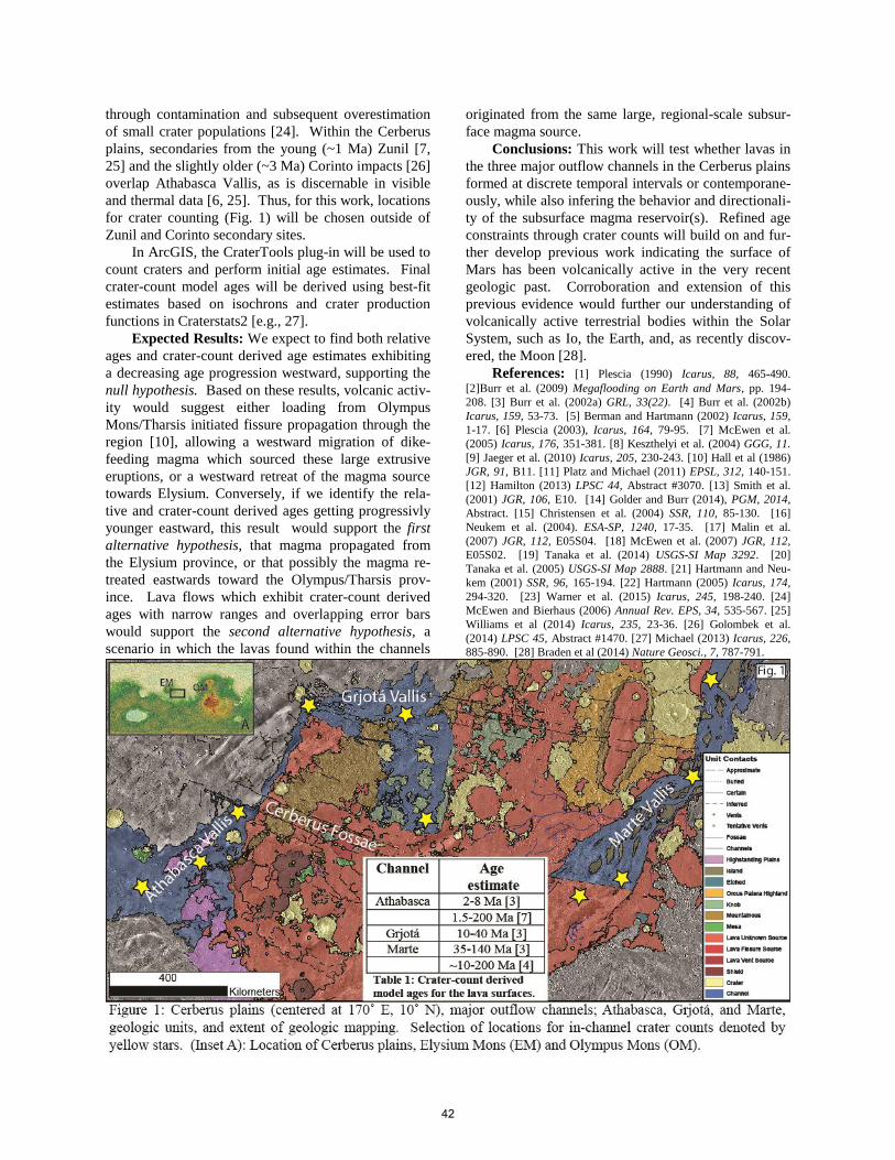
through contamination and subsequent overestimation
of small crater populations [24]. Within the Cerberus
plains, secondaries from the young (~1 Ma) Zunil [7,
25] and the slightly older (~3 Ma) Corinto impacts [26]
overlap Athabasca Vallis, as is discernable in visible
and thermal data [6, 25]. Thus, for this work, locations
for crater counting (Fig. 1) will be chosen outside of
Zunil and Corinto secondary sites.
In ArcGIS, the CraterTools plug-in will be used to
count craters and perform initial age estimates. Final
crater-count model ages will be derived using best-fit
estimates based on isochrons and crater production
functions in Craterstats2 [e.g., 27].
Expected Results: We expect to find both relative
ages and crater-count derived age estimates exhibiting
a decreasing age progression westward, supporting the
null hypothesis. Based on these results, volcanic activ-
ity would suggest either loading from Olympus
Mons/Tharsis initiated fissure propagation through the
region [10], allowing a westward migration of dike-
feeding magma which sourced these large extrusive
eruptions, or a westward retreat of the magma source
towards Elysium. Conversely, if we identify the rela-
tive and crater-count derived ages getting progressivly
younger eastward, this result would support the first
alternative hypothesis, that magma propagated from
the Elysium province, or that possibly the magma re-
treated eastwards toward the Olympus/Tharsis prov-
ince. Lava flows which exhibit crater-count derived
ages with narrow ranges and overlapping error bars
would support the second alternative hypothesis, a
scenario in which the lavas found within the channels
originated from the same large, regional-scale subsur-
face magma source.
Conclusions: This work will test whether lavas in
the three major outflow channels in the Cerberus plains
formed at discrete temporal intervals or contemporane-
ously, while also infering the behavior and directionali-
ty of the subsurface magma reservoir(s). Refined age
constraints through crater counts will build on and fur-
ther develop previous work indicating the surface of
Mars has been volcanically active in the very recent
geologic past. Corroboration and extension of this
previous evidence would further our understanding of
volcanically active terrestrial bodies within the Solar
System, such as Io, the Earth, and, as recently discov-
ered, the Moon [28].
References: [1] Plescia (1990) Icarus, 88, 465-490.
[2]Burr et al. (2009) Megaflooding on Earth and Mars, pp. 194-
208. [3] Burr et al. (2002a) GRL, 33(22). [4] Burr et al. (2002b)
Icarus, 159, 53-73. [5] Berman and Hartmann (2002) Icarus, 159,
1-17. [6] Plescia (2003), Icarus, 164, 79-95. [7] McEwen et al.
(2005) Icarus, 176, 351-381. [8] Keszthelyi et al. (2004) GGG, 11.
[9] Jaeger et al. (2010) Icarus, 205, 230-243. [10] Hall et al (1986)
JGR, 91, B11. [11] Platz and Michael (2011) EPSL, 312, 140-151.
[12] Hamilton (2013) LPSC 44, Abstract #3070. [13] Smith et al.
(2001) JGR, 106, E10. [14] Golder and Burr (2014), PGM, 2014,
Abstract. [15] Christensen et al. (2004) SSR, 110, 85-130. [16]
Neukem et al. (2004). ESA-SP, 1240, 17-35. [17] Malin et al.
(2007) JGR, 112, E05S04. [18] McEwen et al. (2007) JGR, 112,
E05S02. [19] Tanaka et al. (2014) USGS-SI Map 3292. [20]
Tanaka et al. (2005) USGS-SI Map 2888. [21] Hartmann and Neu-
kem (2001) SSR, 96, 165-194. [22] Hartmann (2005) Icarus, 174,
294-320. [23] Warner et al. (2015) Icarus, 245, 198-240. [24]
McEwen and Bierhaus (2006) Annual Rev. EPS, 34, 535-567. [25]
Williams et al (2014) Icarus, 235, 23-36. [26] Golombek et al.
(2014) LPSC 45, Abstract #1470. [27] Michael (2013) Icarus, 226,
885-890. [28] Braden et al (2014) Nature Geosci., 7, 787-791.
42
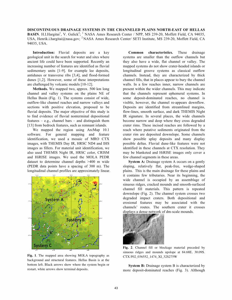
DISCONTINUOUS DRAINAGE SYSTEMS IN THE CHANNELED PLAINS NORTH-EAST OF HELLAS BASIN. H.I.Hargitai1, V. Gulick2; 1 NASA Ames Research Center / NPP, MS 239-20, Moffett Field, CA 94035, USA, [email protected]; 2 NASA Ames Research Center/ SETI Institute, MS 239-20, Moffett Field, CA 94035, USA.
Introduction: Fluvial deposits are a key
geological unit in the search for water and sites where ancient life could have been supported. Recently an increasing number of features are identified as fluvial sedimentary units [1-9]. for example lee deposits, antidunes or transverse ribs [3,4], and flood-formed dunes [1,2]. However, some of these interpretations are challenged by volcanic models [10-12].
Methods. We mapped two, approx. 500 km long channel and valley systems on the plains NE of Hellas Basin (Fig. 1). The systems consist of wide, outflow-like channel reaches and narrow valleys and sections with positive elevation, proposed to be fluvial deposits. The major objective of this study is to find evidence of fluvial nonterminal depositional features – e.g., channel bars – and distinguish them [13] from bedrock features, such as remnant islands.
We mapped the region using ArcMap 10.1 software. For general mapping and feature identification, we used a mosaic of MRO CTX images, with THEMIS Day IR, HRSC ND4 and IHS images as fillers. For material unit identification, we also used THEMIS Night IR, HRSC color, CRISM and HiRISE images. We used the MOLA PEDR dataset to determine channel depths >400 m wide (PEDR data points have a spacing of 300 m). The longitudinal channel profiles are approximately linear.
Fig. 1. The mapped area showing MOLA topography as background and structural features. Hellas Basin is at the bottom left. Black arrows show where the system begin or restart, white arrows show terminal deposits.
Common characteristics. These drainage systems are smaller than the outflow channels but they also have a wide, flat channel or valley. The mapped systems do not show crater-headed islands or longitudinal groove systems as classical outflow channels. Instead, they are characterized by thick channel fills, that in places appear to bury the channel walls. In a few reaches inner, narrow channels are present within the wider channels. This may indicate that the channels represent ephemeral systems. In some deposit-dominated reaches, no channel is visible, however, the channel re-appears downflow. Deposits are identified from streamlined margins, flow-lines, smooth surface, and dark THEMIS Night IR signature. In several places, the wide channels become narrow and deep where they cross degraded crater rims. These incised reaches are followed by a reach where putative sediments originated from the crater rim are deposited downslope. Some channels show possible splay deposits and many display possible deltas. Fluvial dune-like features were not identified in these channels at CTX resolution. They may be blanketed and HiRISE images only cover a few channel segments in these areas.
System A: Drainage system A occurs on a gently sloping, relatively flat, peak-free, wedge-shaped plains. This is the main drainage for these plains and it contains few tributaries. Near its beginning, the wide channel is occupied by an assemblage of sinuous ridges, cracked mounds and smooth-surfaced channel fill materials. This pattern is repeated downslope (Fig. 2). The channel system crosses two degraded impact craters. Both depositional and erosional features may be associated with the channels’ routes. The southern crater it crosses displays a dense network of dm-scale mounds.
Fig. 2. Channel fill or blockage material preceded by sinuous ridges and mounds upslope at 84.68E, 30.09S. CTX F02_036552_1474_XI_32S275W
System B: Drainage system B is characterized by more deposit-dominated reaches (Fig. 3). Although
43
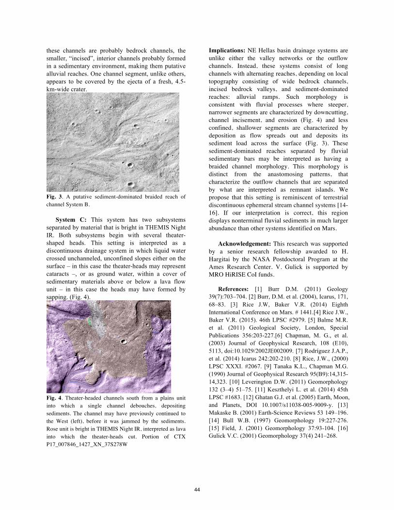
these channels are probably bedrock channels, the smaller, “incised”, interior channels probably formed in a sedimentary environment, making them putative alluvial reaches. One channel segment, unlike others, appears to be covered by the ejecta of a fresh, 4.5-km-wide crater.
Fig. 3. A putative sediment-dominated braided reach of channel System B.
System C: This system has two subsystems separated by material that is bright in THEMIS Night IR. Both subsystems begin with several theater-shaped heads. This setting is interpreted as a discontinuous drainage system in which liquid water crossed unchanneled, unconfined slopes either on the surface – in this case the theater-heads may represent cataracts –, or as ground water, within a cover of sedimentary materials above or below a lava flow unit – in this case the heads may have formed by sapping. (Fig. 4).
Fig. 4. Theater-headed channels south from a plains unit into which a single channel debouches, depositing sediments. The channel may have previously continued to the West (left), before it was jammed by the sediments. Rose unit is bright in THEMIS Night IR, interpreted as lava into which the theater-heads cut. Portion of CTX P17_007846_1427_XN_37S278W
Implications: NE Hellas basin drainage systems are unlike either the valley networks or the outflow channels. Instead, these systems consist of long channels with alternating reaches, depending on local topography consisting of wide bedrock channels, incised bedrock valleys, and sediment-dominated reaches: alluvial ramps. Such morphology is consistent with fluvial processes where steeper, narrower segments are characterized by downcutting, channel incisement, and erosion (Fig. 4) and less confined, shallower segments are characterized by deposition as flow spreads out and deposits its sediment load across the surface (Fig. 3). These sediment-dominated reaches separated by fluvial sedimentary bars may be interpreted as having a braided channel morphology. This morphology is distinct from the anastomosing patterns, that characterize the outflow channels that are separated by what are interpreted as remnant islands. We propose that this setting is reminiscent of terrestrial discontinuous ephemeral stream channel systems [14-16]. If our interpretation is correct, this region displays nonterminal fluvial sediments in much larger abundance than other systems identified on Mars.
Acknowledgement: This research was supported by a senior research fellowship awarded to H. Hargitai by the NASA Postdoctoral Program at the Ames Research Center. V. Gulick is supported by MRO HiRISE CoI funds.
References: [1] Burr D.M. (2011) Geology 39(7):703–704. [2] Burr, D.M. et al. (2004), Icarus, 171, 68–83. [3] Rice J.W, Baker V.R. (2014) Eighth International Conference on Mars. # 1441.[4] Rice J.W., Baker V.R. (2015). 46th LPSC #2979. [5] Balme M.R. et al. (2011) Geological Society, London, Special Publications 356:203-227.[6] Chapman, M. G., et al. (2003) Journal of Geophysical Research, 108 (E10), 5113, doi:10.1029/2002JE002009. [7] Rodríguez J.A.P., et al. (2014) Icarus 242:202-210. [8] Rice, J.W., (2000) LPSC XXXI. #2067. [9] Tanaka K.L., Chapman M.G. (1990) Journal of Geophysical Research 95(B9):14,315-14,323. [10] Leverington D.W. (2011) Geomorphology 132 (3–4) 51–75. [11] Keszthelyi L. et al. (2014) 45th LPSC #1683. [12] Ghatan G.J. et al. (2005) Earth, Moon, and Planets, DOI 10.1007/s11038-005-9009-y. [13] Makaske B. (2001) Earth-Science Reviews 53 149–196. [14] Bull W.B. (1997) Geomorphology 19:227-276. [15] Field, J. (2001) Geomorphology 37:93-104. [16] Gulick V.C. (2001) Geomorphology 37(4) 241–268.
44
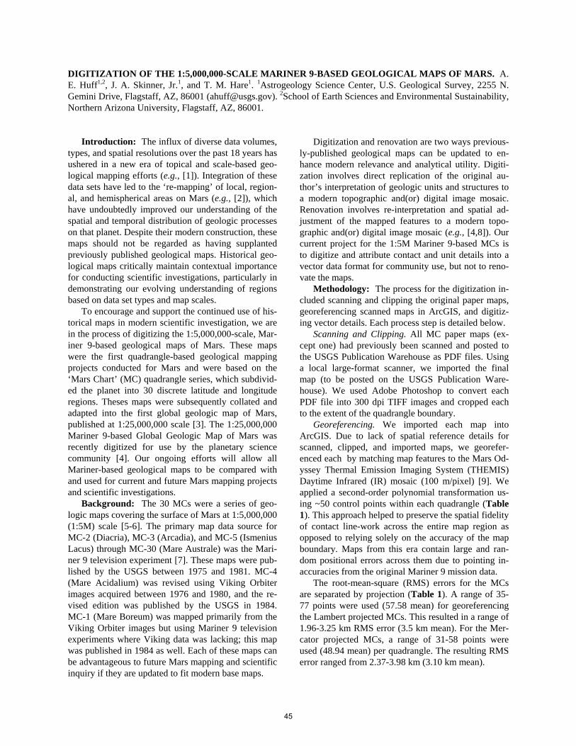
DIGITIZATION OF THE 1:5,000,000-SCALE MARINER 9-BASED GEOLOGICAL MAPS OF MARS. A. E. Huff1,2, J. A. Skinner, Jr.1, and T. M. Hare1. 1Astrogeology Science Center, U.S. Geological Survey, 2255 N. Gemini Drive, Flagstaff, AZ, 86001 ([email protected]). 2School of Earth Sciences and Environmental Sustainability, Northern Arizona University, Flagstaff, AZ, 86001.
Introduction: The influx of diverse data volumes,
types, and spatial resolutions over the past 18 years has ushered in a new era of topical and scale-based geo-logical mapping efforts (e.g., [1]). Integration of these data sets have led to the ‘re-mapping’ of local, region-al, and hemispherical areas on Mars (e.g., [2]), which have undoubtedly improved our understanding of the spatial and temporal distribution of geologic processes on that planet. Despite their modern construction, these maps should not be regarded as having supplanted previously published geological maps. Historical geo-logical maps critically maintain contextual importance for conducting scientific investigations, particularly in demonstrating our evolving understanding of regions based on data set types and map scales.
To encourage and support the continued use of his-torical maps in modern scientific investigation, we are in the process of digitizing the 1:5,000,000-scale, Mar-iner 9-based geological maps of Mars. These maps were the first quadrangle-based geological mapping projects conducted for Mars and were based on the ‘Mars Chart’ (MC) quadrangle series, which subdivid-ed the planet into 30 discrete latitude and longitude regions. Theses maps were subsequently collated and adapted into the first global geologic map of Mars, published at 1:25,000,000 scale [3]. The 1:25,000,000 Mariner 9-based Global Geologic Map of Mars was recently digitized for use by the planetary science community [4]. Our ongoing efforts will allow all Mariner-based geological maps to be compared with and used for current and future Mars mapping projects and scientific investigations.
Background: The 30 MCs were a series of geo-logic maps covering the surface of Mars at 1:5,000,000 (1:5M) scale [5-6]. The primary map data source for MC-2 (Diacria), MC-3 (Arcadia), and MC-5 (Ismenius Lacus) through MC-30 (Mare Australe) was the Mari-ner 9 television experiment [7]. These maps were pub-lished by the USGS between 1975 and 1981. MC-4 (Mare Acidalium) was revised using Viking Orbiter images acquired between 1976 and 1980, and the re-vised edition was published by the USGS in 1984. MC-1 (Mare Boreum) was mapped primarily from the Viking Orbiter images but using Mariner 9 television experiments where Viking data was lacking; this map was published in 1984 as well. Each of these maps can be advantageous to future Mars mapping and scientific inquiry if they are updated to fit modern base maps.
Digitization and renovation are two ways previous-ly-published geological maps can be updated to en-hance modern relevance and analytical utility. Digiti-zation involves direct replication of the original au-thor’s interpretation of geologic units and structures to a modern topographic and(or) digital image mosaic. Renovation involves re-interpretation and spatial ad-justment of the mapped features to a modern topo-graphic and(or) digital image mosaic (e.g., [4,8]). Our current project for the 1:5M Mariner 9-based MCs is to digitize and attribute contact and unit details into a vector data format for community use, but not to reno-vate the maps.
Methodology: The process for the digitization in-cluded scanning and clipping the original paper maps, georeferencing scanned maps in ArcGIS, and digitiz-ing vector details. Each process step is detailed below.
Scanning and Clipping. All MC paper maps (ex-cept one) had previously been scanned and posted to the USGS Publication Warehouse as PDF files. Using a local large-format scanner, we imported the final map (to be posted on the USGS Publication Ware-house). We used Adobe Photoshop to convert each PDF file into 300 dpi TIFF images and cropped each to the extent of the quadrangle boundary.
Georeferencing. We imported each map into ArcGIS. Due to lack of spatial reference details for scanned, clipped, and imported maps, we georefer-enced each by matching map features to the Mars Od-yssey Thermal Emission Imaging System (THEMIS) Daytime Infrared (IR) mosaic (100 m/pixel) [9]. We applied a second-order polynomial transformation us-ing ~50 control points within each quadrangle (Table 1). This approach helped to preserve the spatial fidelity of contact line-work across the entire map region as opposed to relying solely on the accuracy of the map boundary. Maps from this era contain large and ran-dom positional errors across them due to pointing in-accuracies from the original Mariner 9 mission data.
The root-mean-square (RMS) errors for the MCs are separated by projection (Table 1). A range of 35-77 points were used (57.58 mean) for georeferencing the Lambert projected MCs. This resulted in a range of 1.96-3.25 km RMS error (3.5 km mean). For the Mer-cator projected MCs, a range of 31-58 points were used (48.94 mean) per quadrangle. The resulting RMS error ranged from 2.37-3.98 km (3.10 km mean).
45
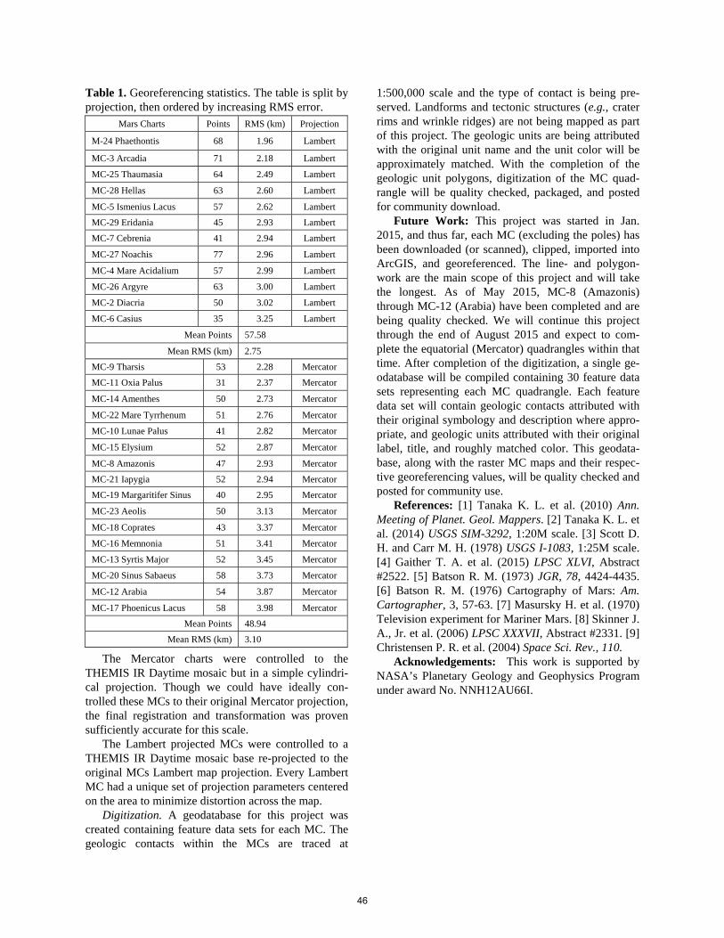
Table 1. Georeferencing statistics. The table is split by projection, then ordered by increasing RMS error.
The Mercator charts were controlled to the THEMIS IR Daytime mosaic but in a simple cylindri-cal projection. Though we could have ideally con-trolled these MCs to their original Mercator projection, the final registration and transformation was proven sufficiently accurate for this scale.
The Lambert projected MCs were controlled to a THEMIS IR Daytime mosaic base re-projected to the original MCs Lambert map projection. Every Lambert MC had a unique set of projection parameters centered on the area to minimize distortion across the map.
Digitization. A geodatabase for this project was created containing feature data sets for each MC. The geologic contacts within the MCs are traced at
1:500,000 scale and the type of contact is being pre-served. Landforms and tectonic structures (e.g., crater rims and wrinkle ridges) are not being mapped as part of this project. The geologic units are being attributed with the original unit name and the unit color will be approximately matched. With the completion of the geologic unit polygons, digitization of the MC quad-rangle will be quality checked, packaged, and posted for community download.
Future Work: This project was started in Jan. 2015, and thus far, each MC (excluding the poles) has been downloaded (or scanned), clipped, imported into ArcGIS, and georeferenced. The line- and polygon-work are the main scope of this project and will take the longest. As of May 2015, MC-8 (Amazonis) through MC-12 (Arabia) have been completed and are being quality checked. We will continue this project through the end of August 2015 and expect to com-plete the equatorial (Mercator) quadrangles within that time. After completion of the digitization, a single ge-odatabase will be compiled containing 30 feature data sets representing each MC quadrangle. Each feature data set will contain geologic contacts attributed with their original symbology and description where appro-priate, and geologic units attributed with their original label, title, and roughly matched color. This geodata-base, along with the raster MC maps and their respec-tive georeferencing values, will be quality checked and posted for community use.
References: [1] Tanaka K. L. et al. (2010) Ann. Meeting of Planet. Geol. Mappers. [2] Tanaka K. L. et al. (2014) USGS SIM-3292, 1:20M scale. [3] Scott D. H. and Carr M. H. (1978) USGS I-1083, 1:25M scale. [4] Gaither T. A. et al. (2015) LPSC XLVI, Abstract #2522. [5] Batson R. M. (1973) JGR, 78, 4424-4435. [6] Batson R. M. (1976) Cartography of Mars: Am. Cartographer, 3, 57-63. [7] Masursky H. et al. (1970) Television experiment for Mariner Mars. [8] Skinner J. A., Jr. et al. (2006) LPSC XXXVII, Abstract #2331. [9] Christensen P. R. et al. (2004) Space Sci. Rev., 110.
Acknowledgements: This work is supported by NASA’s Planetary Geology and Geophysics Program under award No. NNH12AU66I.
Mars Charts Points RMS (km) Projection
M-24 Phaethontis 68 1.96 Lambert
MC-3 Arcadia 71 2.18 Lambert
MC-25 Thaumasia 64 2.49 Lambert
MC-28 Hellas 63 2.60 Lambert
MC-5 Ismenius Lacus 57 2.62 Lambert
MC-29 Eridania 45 2.93 Lambert
MC-7 Cebrenia 41 2.94 Lambert
MC-27 Noachis 77 2.96 Lambert
MC-4 Mare Acidalium 57 2.99 Lambert
MC-26 Argyre 63 3.00 Lambert
MC-2 Diacria 50 3.02 Lambert
MC-6 Casius 35 3.25 Lambert
Mean Points 57.58
Mean RMS (km) 2.75
MC-9 Tharsis 53 2.28 Mercator
MC-11 Oxia Palus 31 2.37 Mercator
MC-14 Amenthes 50 2.73 Mercator
MC-22 Mare Tyrrhenum 51 2.76 Mercator
MC-10 Lunae Palus 41 2.82 Mercator
MC-15 Elysium 52 2.87 Mercator
MC-8 Amazonis 47 2.93 Mercator
MC-21 Iapygia 52 2.94 Mercator
MC-19 Margaritifer Sinus 40 2.95 Mercator
MC-23 Aeolis 50 3.13 Mercator
MC-18 Coprates 43 3.37 Mercator
MC-16 Memnonia 51 3.41 Mercator
MC-13 Syrtis Major 52 3.45 Mercator
MC-20 Sinus Sabaeus 58 3.73 Mercator
MC-12 Arabia 54 3.87 Mercator
MC-17 Phoenicus Lacus 58 3.98 Mercator
Mean Points 48.94
Mean RMS (km) 3.10
46
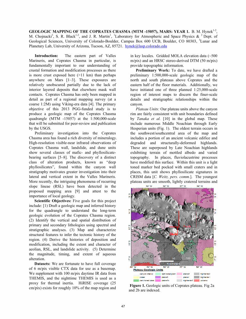
Figure 1. Geologic units of Coprates plateau. Fig 2a and 2b are indexed.
GEOLOGIC MAPPING OF THE COPRATES CHASMA (MTM -15057), MARS: YEAR 1. B. M. Hynek1-2,
M. Chojnacki3, S. R. Black1-2, and J. R. Martin1, 1Laboratory for Atmospheric and Space Physics & 2 Dept. of Geological Sciences, University of Colorado-Boulder, Campus Box 600 UCB, Boulder, CO 80303, 3Lunar and Planetary Lab, University of Arizona, Tucson, AZ, 85721. [email protected]
Introduction: The eastern part of Valles Marineris, and Coprates Chasma in particular, is fundamentally important to our understanding of crustal formation and modification processes as there is more crust exposed here (>11 km) than perhaps anywhere on Mars [1–3]. These exposures are relatively unobscured partially due to the lack of interior layered deposits that elsewhere mask wall contacts. Coprates Chasma has only been mapped in detail as part of a regional mapping survey (at a coarse 1:2M) using Viking-era data [4]. The primary objective of this 2013 PGG-funded study is to produce a geologic map of the Coprates Chasma quadrangle (MTM -15057) at the 1:500,000-scale that will be submitted for peer-review and publication by the USGS.
Preliminary investigation into the Coprates Chasma area has found a rich diversity of mineralogy. High-resolution visible-near infrared observations of Coprates Chasma wall, landslide, and dune units show several classes of mafic- and phyllosilicate-bearing surfaces [5–8]. The discovery of a distinct class of alteration products, known as “deep phyllosilicates”, found within the canyon wall stratigraphy motivates greater investigation into their lateral and vertical extent in the Valles Marineris. More recently, the intriguing phenomena of recurring slope lineae (RSL) have been detected in the proposed mapping area [9] and attest to the importance of local geology.
Scientific Objectives: Five goals for this project include: [1) Draft a geologic map and inferred history for the quadrangle to understand the long-term geologic evolution of the Coprates Chasma region. (2) Identify the vertical and spatial distribution of primary and secondary lithologies using spectral and stratigraphic analyses. (3) Map and characterize structural features to infer the tectonic history of the region. (4) Derive the histories of deposition and modification, including the extent and character of aeolian, RSL, and landslide activity. (5) Determine the magnitude, timing, and extent of aqueous alteration.
Datasets: We are fortunate to have full coverage of 6 m/pix visible CTX data for use as a basemap. We supplement with 100 m/pix daytime IR data from THEMIS, and the nighttime THEMIS is used as a proxy for thermal inertia. HiRISE coverage (25 cm/pix) exists for roughly 10% of the map region and
in key locales. Gridded MOLA elevation data (~500 m/pix) and an HRSC stereo-derived DTM (50 m/pix) provide topographic information.
Preliminary Work: To date, we have drafted a preliminary 1:500,000-scale geologic map of the north and south plateaus above Coprates and the eastern half of the floor materials. Additionally, we have initiated one of three planned 1:25,000-scale region of interest maps to discern the finer-scale details and stratigraphic relationships within the canyon.
Plateau Units: Our plateau units above the canyon rim are fairly consistent with unit boundaries defined by Tanaka et al. [10] in the global map. These include numerous Middle Noachian through Early Hesperian units (Fig. 1). The oldest terrain occurs in the southwest/southcentral area of the map and includes a portion of an ancient volcanic edifice and degraded and structurally-deformed highlands. These are superposed by Late Noachian highlands exhibiting terrain of mottled albedo and varied topography. In places, fluviolacustrine processes have modified this surface. Within this unit is a light toned marker bed pocked with small craters and in places, this unit shows phyllosilicate signatures in CRISM data [C. Weitz, pers. comm.]. The youngest plateau units are smooth, lightly cratered terrains and
47

are interpreted as Hesperian-aged lava flows. Most of the plateau units have been modified with wrinkle ridges and a few larger craters, which sometimes show multilobate ejecta.
Eastern Canyon Units: Preliminary mapping of the interior has revealed a diversity of units not resolved by previous efforts at coarser scales. The
nine units encapsulated in Fig. 2a include: (1) mid-walls, including bedrock spurs and low-albedo fans, some of which host RSL sites; (2) wall talus , largely composed of bright-tone, fine materials; (3) landslide deposits of rugged, sometimes lineated materials and varying runout distances; (4) floor mounds or blocks, possessing spurs, talus, and occasional fine-layering; (5) crater and ejecta materials; (6) crater deposits consisting of hummocky materials; (7) canyon floors with fractures, polygonal terrain or smooth materials which are often heavily cratered; (8) aeolian dune deposits of low-albedo sand forming slip faces and masking lower-lying units; (9) aeolian sand sheets of mid-toned fine materials frequently filling in local topographic lows. Additional units identified but not shown are; (10) mantling units of dark-toned, smooth, flat deposits which retain small craters; (11) layered deposits which are light in tone, patchy, and distributed on canyon floors and walls. One surficial unit of a low-albedo, smooth mantle material covers some geologic units, but does not obscure morphology. Several of these units such as the landslides and floors will be further subdivided by relative age and morphology.
A preliminary 1:25,000-scale map has been completed for a ~1,000 km2 portion of the eastern canyon (Fig. 2b). At this finer resolution, five units have been identified, in addition to the units discussed in the eastern canyon units above: (1) resistant upper wall, spur-forming unit located in the topmost portion of the canyon walls; (2) recessive upper wall, a talus-forming unit located just below the resistant upper wall; (3) fan materials, individual fan deposits which are distinguishable from the adjacent wall talus; (4) smooth floor materials, which do not appear to be mantled by sand or dust, and may underlie the surrounding, more heavily pitted floor material; and (5) layered terrain, a blocky mound-forming unit which contains patches of light-toned layers, and may be partially or entirely formed through large mass-wasting events.
Acknowledgements: Funding for this work came from NASA PGG grant NNX14AN36G.
References: [1] McEwen A.S. et al. (1999) Nature, 397, 584–586. [2] J.-P. Williams J.-P. et al. (2003) Geophys. Res. Lett., 30. [3] Beyer R.A et al. (2005) Icarus, 179, 1–23. [4] Witbeck N.E. et al. (1991) MAP I-2010, U.S. Geol. Surv., Reston, Va. [5] Murchie S.L. et al. (2009) J. Geophys. Res., 114. [6] Flahaut J. et al. (2012) Icarus, 221, 420-435. [7] Chojnacki M. et al. (2014) Icarus. 232, 187–219. [8] Chojnacki M. et al. (2014) Icarus. 230, 96–142. [9] McEwen A.S. et al. (2014) Nature Geosci. 7, 53-58. [10] Tanaka K.L. et al. (2014) Planetary and Space Science. 95, 11–24.
Figure 2. (a) Coprates canyon floor mapped at the 1: 500,000-scale and (b) sub-area 1 mapped at the 1:25,000-scale. (Indexed on Fig. 1)
a
b
48
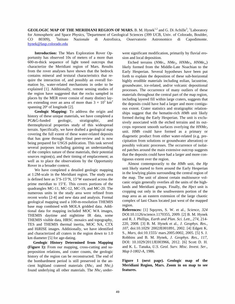
GEOLOGIC MAP OF THE MERIDIANI REGION OF MARS. B. M. Hynek1,2 and G. Di Achille3, 1Laboratory for Atmospheric and Space Physics, 2Department of Geological Sciences (399 UCB, Univ. of Colorado, Boulder, CO 80309), 3Istituto Nazionale di Astrofisica, Osservatorio Astronomico di Capodimonte. [email protected]
Introduction: The Mars Exploration Rover Op-
portunity has observed 10s of meters of a more than 600-m-thick sequence of light toned outcrops that characterize the Meridiani region of Mars. Results from the rover analyses have shown that the bedrock contains mineral and textural characteristics that re-quire the interaction of, and possibly an overall for-mation by, water-related mechanisms in order to be explained [1]. Additionally, remote sensing studies of the region have suggested that the rocks sampled in places by the MER rover consist of many distinct lay-ers extending over an area of more than 3 × 10⁵ km2 spanning 20º of longitude [2].
Geologic Mapping: To address the origin and history of these unique materials, we have completed a PG&G-funded geologic, stratigraphic, and thermophysical properties study of this widespread terrain. Specifically, we have drafted a geological map covering the full extent of these water-related deposits that has gone through final peer-review and is now being prepared for USGS publication. This task served several purposes including gaining an understanding of the complex nature of these materials, their potential sources region(s), and their timing of emplacement; as well as to place the observations by the Opportunity Rover in a broader context.
We have completed a detailed geologic mapping at 1:2M-scale in the Meridiani region. The study area is defined here as 5S-15N, 15W eastward across the prime meridian to 15E. This covers portions of the quadrangles MC-11, MC-12, MC-19, and MC-20. The numerous units in the study area were refined from recent works [2-4] and new data and analysis. Formal geological mapping used a 100-m-resolution THEMIS base map combined with MOLA gridded data. Addi-tional data for mapping included MOC WA images, THEMIS daytime and nighttime IR data, some THEMIS visible data, HRSC mosaics and topography, TES and THEMIS thermal inertia, MOC NA, CTX and HiRISE images. Additionally, we have identified and characterized all craters in the region down to 1.0 km diameter [5] for age-dating.
Geologic History Determined from Mapping (Figure 1): From our mapping, cross-cutting and su-perposition relations, and crater counts, the geologic history of the region can be reconstructed. The end of the bombardment period is still preserved in the an-cient highland cratered materials (Nhc1 and Nhc2) found underlying all other materials. The Nhc2 under-
went significant modification, primarily by fluvial ero-sion and local deposition.
Etched terrains (NMe1, NMe2, HNMe3, HNMeu,) likely formed from the Middle-Late Noachian to the Early Hesperian. Several hypotheses have been put forth to explain the deposition of these sub-horizontal highly erodible materials including eolian, lacustrine, groundwater, ice-related, and/or volcanic depositional processes. The occurrence of many outliers of these materials throughout the central part of the map region, including layered fill within large craters, suggests that the deposits could have had a larger and more contigu-ous extent. Crater statistics and stratigraphic relation-ships suggest that the hematite-rich HMh unit likely formed during the Early Hesperian. The unit is exclu-sively associated with the etched terrains and its out-crops represent smooth surfaces overlying the HNMe3
unit. HMh could have formed as a primary or diagenetic product from either water-related (e.g. pre-cipitation from solutions or groundwater alteration) or possibly volcanic processes. The occurrence of isolat-ed patches around the main extensive outcrop suggests that the deposits could have had a larger and more con-tiguous extent over the region.
Almost contemporarily to the HMh unit, the Hp unit likely started to form around the Early Hesperian in the lowlying plains surrounding the central region of the map. The unit of almost certain multisource vol-canic origin generally overlies all the units of the high-lands and Meridiani groups. Finally, the Hpct unit is cropping out only in the southwestern portion of the map area as an eastern extension of the large chaotic complex of Iani Chaos located just west of the mapped region. References: [1] Squyres, S. W. et al., Science, 324 DOI:10.1126/science.1170355, 2009. [2] B. M. Hynek and R. J. Phillips, Earth and Plan. Sci. Lett., 274, 214-220, 2008. [3] B. M. Hynek et al., J. Geophys. Res., 107, doi:10.1029/ 2002JE001891, 2002. [4] Edgett K. S., Mars, doi:10.1555/ mars.2005.0002, 2005. [5] S. J. Robbins and B. M. Hynek, J. Geophys. Res., 117, DOI: 10.1029/2011JE003966, 2012. [6] Scott D. H. and K. L. Tanaka, U.S. Geol. Surv. Misc. Invest. Ser., Map I-1802-A, 1986. Figure 1 (next page). Geologic map of the Meridiani Region, Mars. Zoom in on map to see features.
49
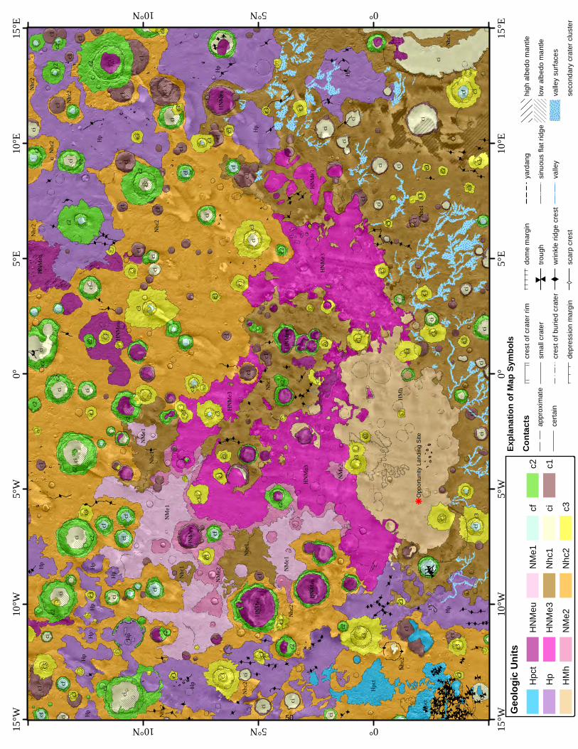
X
# #
#
#
##
#
#
#
#
XX
X
X
X
X
X
X
X
XX
X
X X X
X
X
XXX
XX
X
X
XXX
X
X
X
XXXX
XXX
#
#
#
##
#
#
###
#
#
#
## #
#
#
# #
#
## #
#
#
#
#
#
#
##
#
#
#
#
##
#
###
#
##
#
X
X
X
XX
X
XX
X
X
XXX
XX
X
X
X
XXXXX
X
X
X
X
X
X
X X
X
XX
X
X
X
X
XXX
X
X
X
X
X
X
X
XX
X
X
X
X
X
X
X
X
X
X
X
X
X
X
X
X
X
X
X
XX
XX
X
X
X
X
X
XY
XY
#
#
XX
#
#
#
#
# #
#
##
#
#
#
#
#
X
#
#
#
#
# #
#
#
#
#
XX
YY
X
#
#
#
#
#
#
X
XY
X
X
X
X
#
#
# #
#
#
# # #
#
#
#
#
#
#
#
#
#
##
#
#
k
Nhc2
Nhc1
Hp
HMh
Hp
Hp
Nhc1
Nhc2
ci
HNMe
3
Nhc2 Hp
NMe1
HNMe
3
Hp
c2
c2
NMe2
c3
c2
Hp
c2
c2
c2
c3
c2Hp
c3
Nhc1
NMe1
c3
c3
Nhc1
ci
c3
HNMe
3
ciHp
ci
Hp
c2
c2
Hpct
c2
c1
ci
Hp
HNMe
u
c3
Hpct
c2
c3
c3
c1
ci
c2
c1
c2
c3
c3
c1
Nhc2
c2
HNMe
u
c3
c1
Nhc2
ci
c3c3
ci
c1
c2
c3
c1
c3
c2
HNMe
u
Nhc2
ci
ci
c3
ci
Nhc1
c3
cic3
c1
cf
c3
ci
ci
Hp
ci
Hp
c1
c3
c1
ci
HNMe
u
cic3
c1
c3
c3
Nhc2
c3
ci
ci
ci
ci
c3NM
e1
Hp
c3
HNMe
3
Nhc2
c3
ci
Nhc2
Nhc1
c1
c3
cic3
cicf
HNMe
uc3
c1
Hp
c3
c2
c2
ci
c2
c3cf
ci
cf
c1
c3c3
cic3 c1
c1
ci
Nhc2
c2
c1
c3
cf
ci
HNMe
uc3
c3
c1
NMe2
c3
ci
cfc3
c2
ci
c3
cf
HNMe
u
c1
c3
ci
ci
ci
c3
c3
c1
c1
cf
cf
ci
c3
cf
c1
c2
cf
ci
c1
c1
ci
ci
c3
cf
c1
c1
c3
c3
c3
c3
c3
Opp
ortu
nity
Lan
ding
Site
15°E
15°E
10°E
10°E
5°E5°E
0°0°
5°W5°W
10°W
10°W
15°W
15°W 10°N
10°N
5°N
5°N
0°
0°
Geolo
gic U
nits
Hpc
t
Hp
HM
h
HN
Meu
HN
Me3
NM
e2
NM
e1
Nhc
1
Nhc
2
cf ci c3
c2 c1
Expla
natio
n of M
ap Sy
mbols
Conta
cts appr
oxim
ate
certa
in
cres
t of c
rate
r rim
smal
l cra
ter
cres
t of b
urie
d cr
ater
depr
essi
on m
argi
n
dom
e m
argi
n
#
#tro
ugh
Xw
rinkl
e rid
ge c
rest
XYsc
arp
cres
t
yard
ang
sinu
ous
flat r
idge
valle
y
high
alb
edo
man
tle
low
alb
edo
man
tle
valle
y su
rface
s
seco
ndar
y cr
ater
clu
ster
50
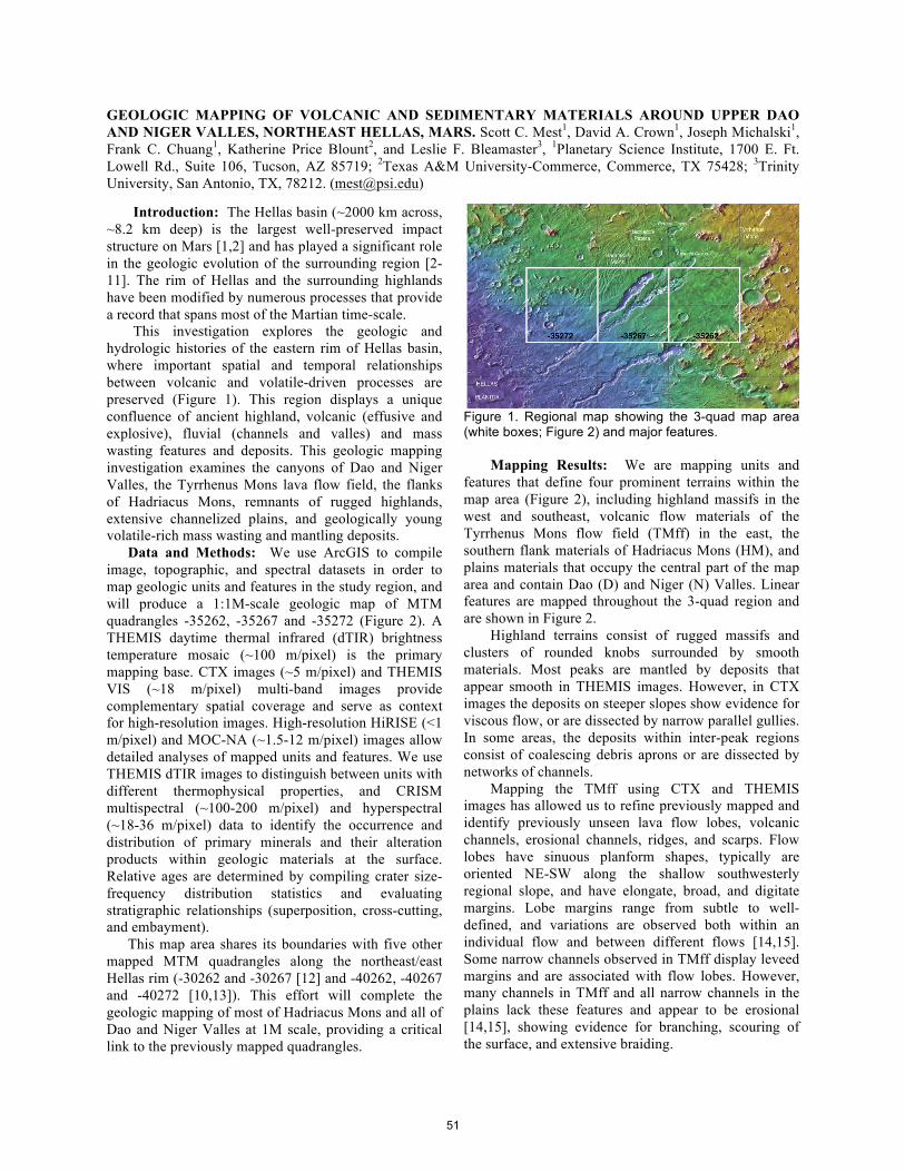
GEOLOGIC MAPPING OF VOLCANIC AND SEDIMENTARY MATERIALS AROUND UPPER DAO AND NIGER VALLES, NORTHEAST HELLAS, MARS. Scott C. Mest1, David A. Crown1, Joseph Michalski1, Frank C. Chuang1, Katherine Price Blount2, and Leslie F. Bleamaster3, 1Planetary Science Institute, 1700 E. Ft. Lowell Rd., Suite 106, Tucson, AZ 85719; 2Texas A&M University-Commerce, Commerce, TX 75428; 3Trinity University, San Antonio, TX, 78212. ([email protected])
Introduction: The Hellas basin (~2000 km across, ~8.2 km deep) is the largest well-preserved impact structure on Mars [1,2] and has played a significant role in the geologic evolution of the surrounding region [2-11]. The rim of Hellas and the surrounding highlands have been modified by numerous processes that provide a record that spans most of the Martian time-scale.
This investigation explores the geologic and hydrologic histories of the eastern rim of Hellas basin, where important spatial and temporal relationships between volcanic and volatile-driven processes are preserved (Figure 1). This region displays a unique confluence of ancient highland, volcanic (effusive and explosive), fluvial (channels and valles) and mass wasting features and deposits. This geologic mapping investigation examines the canyons of Dao and Niger Valles, the Tyrrhenus Mons lava flow field, the flanks of Hadriacus Mons, remnants of rugged highlands, extensive channelized plains, and geologically young volatile-rich mass wasting and mantling deposits.
Data and Methods: We use ArcGIS to compile image, topographic, and spectral datasets in order to map geologic units and features in the study region, and will produce a 1:1M-scale geologic map of MTM quadrangles -35262, -35267 and -35272 (Figure 2). A THEMIS daytime thermal infrared (dTIR) brightness temperature mosaic (~100 m/pixel) is the primary mapping base. CTX images (~5 m/pixel) and THEMIS VIS (~18 m/pixel) multi-band images provide complementary spatial coverage and serve as context for high-resolution images. High-resolution HiRISE (<1 m/pixel) and MOC-NA (~1.5-12 m/pixel) images allow detailed analyses of mapped units and features. We use THEMIS dTIR images to distinguish between units with different thermophysical properties, and CRISM multispectral (~100-200 m/pixel) and hyperspectral (~18-36 m/pixel) data to identify the occurrence and distribution of primary minerals and their alteration products within geologic materials at the surface. Relative ages are determined by compiling crater size-frequency distribution statistics and evaluating stratigraphic relationships (superposition, cross-cutting, and embayment).
This map area shares its boundaries with five other mapped MTM quadrangles along the northeast/east Hellas rim (-30262 and -30267 [12] and -40262, -40267 and -40272 [10,13]). This effort will complete the geologic mapping of most of Hadriacus Mons and all of Dao and Niger Valles at 1M scale, providing a critical link to the previously mapped quadrangles.
Figure 1. Regional map showing the 3-quad map area (white boxes; Figure 2) and major features.
Mapping Results: We are mapping units and features that define four prominent terrains within the map area (Figure 2), including highland massifs in the west and southeast, volcanic flow materials of the Tyrrhenus Mons flow field (TMff) in the east, the southern flank materials of Hadriacus Mons (HM), and plains materials that occupy the central part of the map area and contain Dao (D) and Niger (N) Valles. Linear features are mapped throughout the 3-quad region and are shown in Figure 2.
Highland terrains consist of rugged massifs and clusters of rounded knobs surrounded by smooth materials. Most peaks are mantled by deposits that appear smooth in THEMIS images. However, in CTX images the deposits on steeper slopes show evidence for viscous flow, or are dissected by narrow parallel gullies. In some areas, the deposits within inter-peak regions consist of coalescing debris aprons or are dissected by networks of channels.
Mapping the TMff using CTX and THEMIS images has allowed us to refine previously mapped and identify previously unseen lava flow lobes, volcanic channels, erosional channels, ridges, and scarps. Flow lobes have sinuous planform shapes, typically are oriented NE-SW along the shallow southwesterly regional slope, and have elongate, broad, and digitate margins. Lobe margins range from subtle to well-defined, and variations are observed both within an individual flow and between different flows [14,15]. Some narrow channels observed in TMff display leveed margins and are associated with flow lobes. However, many channels in TMff and all narrow channels in the plains lack these features and appear to be erosional [14,15], showing evidence for branching, scouring of the surface, and extensive braiding.
51
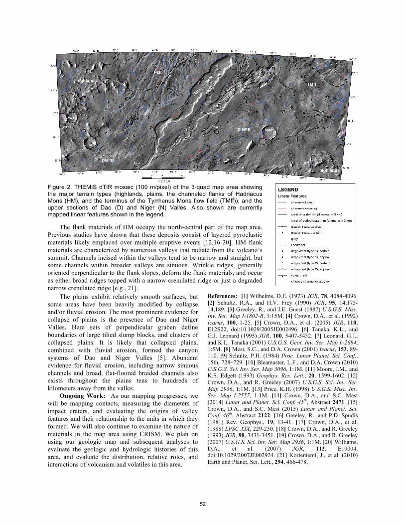
Figure 2. THEMIS dTIR mosaic (100 m/pixel) of the 3-quad map area showing the major terrain types (highlands, plains, the channeled flanks of Hadriacus Mons (HM), and the terminus of the Tyrrhenus Mons flow field (TMff)), and the upper sections of Dao (D) and Niger (N) Valles. Also shown are currently mapped linear features shown in the legend.
The flank materials of HM occupy the north-central part of the map area. Previous studies have shown that these deposits consist of layered pyroclastic materials likely emplaced over multiple eruptive events [12,16-20]. HM flank materials are characterized by numerous valleys that radiate from the volcano’s summit. Channels incised within the valleys tend to be narrow and straight, but some channels within broader valleys are sinuous. Wrinkle ridges, generally oriented perpendicular to the flank slopes, deform the flank materials, and occur as either broad ridges topped with a narrow crenulated ridge or just a degraded narrow crenulated ridge [e.g., 21].
The plains exhibit relatively smooth surfaces, but some areas have been heavily modified by collapse and/or fluvial erosion. The most prominent evidence for collapse of plains is the presence of Dao and Niger Valles. Here sets of perpendicular graben define boundaries of large tilted slump blocks, and clusters of collapsed plains. It is likely that collapsed plains, combined with fluvial erosion, formed the canyon systems of Dao and Niger Valles [5]. Abundant evidence for fluvial erosion, including narrow sinuous channels and broad, flat-floored braided channels also exists throughout the plains tens to hundreds of kilometers away from the valles.
Ongoing Work: As our mapping progresses, we will be mapping contacts, measuring the diameters of impact craters, and evaluating the origins of valley features and their relationship to the units in which they formed. We will also continue to examine the nature of materials in the map area using CRISM. We plan on using our geologic map and subsequent analyses to evaluate the geologic and hydrologic histories of this area, and evaluate the distribution, relative roles, and interactions of volcanism and volatiles in this area.
References: [1] Wilhelms, D.E. (1973) JGR, 78, 4084-4096. [2] Schultz, R.A., and H.V. Frey (1990) JGR, 95, 14,175-14,189. [3] Greeley, R., and J.E. Guest (1987) U.S.G.S. Misc. Inv. Ser. Map I-1802-B, 1:15M. [4] Crown, D.A., et al. (1992) Icarus, 100, 1-25. [5] Crown, D.A., et al. (2005) JGR, 110, E12S22, doi:10.1029/2005JE002496. [6] Tanaka, K.L., and G.J. Leonard (1995) JGR, 100, 5407-5432. [7] Leonard, G.J., and K.L. Tanaka (2001) U.S.G.S. Geol. Inv. Ser. Map I–2694, 1:5M. [8] Mest, S.C., and D.A. Crown (2001) Icarus, 153, 89-110. [9] Schultz, P.H. (1984) Proc. Lunar Planet. Sci. Conf., 15th, 728–729. [10] Bleamaster, L.F., and D.A. Crown (2010) U.S.G.S. Sci. Inv. Ser. Map 3096, 1:1M. [11] Moore, J.M., and K.S. Edgett (1993) Geophys. Res. Lett., 20, 1599-1602. [12] Crown, D.A., and R. Greeley (2007) U.S.G.S. Sci. Inv. Ser. Map 2936, 1:1M. [13] Price, K.H. (1998) U.S.G.S. Misc. Inv. Ser. Map I-2557, 1:1M. [14] Crown, D.A., and S.C. Mest [2014] Lunar and Planet. Sci. Conf. 45th, Abstract 2471. [15] Crown, D.A., and S.C. Mest (2015) Lunar and Planet. Sci. Conf. 46th, Abstract 2122. [16] Greeley, R., and P.D. Spudis (1981) Rev. Geophys., 19, 13-41. [17] Crown, D.A., et al. (1988) LPSC XIX, 229-230. [18] Crown, D.A., and R. Greeley (1993) JGR, 98, 3431-3451. [19] Crown, D.A., and R. Greeley (2007) U.S.G.S. Sci. Inv. Ser. Map 2936, 1:1M. [20] Williams, D.A., et al. (2007) JGR, 112, E10004, doi:10.1029/2007JE002924. [21] Korteniemi, J., et al. (2010) Earth and Planet. Sci. Lett., 294, 466-478.
52
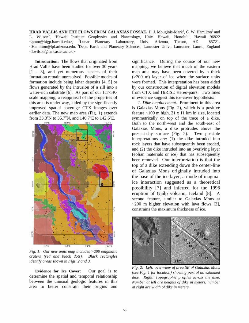
HRAD VALLIS AND THE FLOWS FROM GALAXIAS FOSSAE. P. J. Mouginis-Mark1, C. W. Hamilton2 and L. Wilson3, 1Hawaii Institute Geophysics and Planetology, Univ. Hawaii, Honolulu, Hawaii 96822 <[email protected]>, 2Lunar Planetary Laboratory, Univ. Arizona, Tucson, AZ 85721. <[email protected]. 3Dept. Earth and Planetary Sciences, Lancaster Univ., Lancaster, Lancs., England <[email protected]>
Introduction: The flows that originated from
Hrad Vallis have been studied for over 30 years [1 - 3], and yet numerous aspects of their formation remain unresolved. Possible modes of formation include being lahar deposits [4, 5] or flows generated by the intrusion of a sill into a water-rich substrate [6]. As part of our 1:175K-scale mapping, a reappraisal of the properties of this area is under way, aided by the significantly improved spatial coverage CTX images over earlier data. The new map area (Fig. 1) extends from 33.3oN to 35.7oN, and 140.7oE to 142.6oE.
Fig. 1: Our new units map includes >200 enigmatic craters (red and black dots). Black rectangles identify areas shown in Figs. 2 and 3.
Evidence for Ice Cover: Our goal is to
determine the spatial and temporal relationship between the unusual geologic features in this area to better constrain their origins and
significance. During the course of our new mapping, we believe that much of the eastern map area may have been covered by a thick (>200 m) layer of ice when the surface units were formed. This interpretation has been aided by our construction of digital elevation models from CTX and HiRISE stereo-pairs. Two lines of evidence suggest this ice-cover hypothesis:
1. Dike emplacement. Prominent in this area is Galaxias Mons (Fig. 2), which is a positive feature ~100 m high, 21 x 11 km in size, located symmetrically on top of the trace of a dike. Both to the north-west and the south-east of Galaxias Mons, a dike protrudes above the present-day surface (Fig. 2). Two possible interpretations are: (1) the dike intruded into rock layers that have subsequently been eroded, and (2) the dike intruded into an overlying layer (eolian materials or ice) that has subsequently been removed. Our interpretation is that the top of a dike extending down the center-line of Galaxias Mons originally intruded into the base of the ice layer, a mode of magma-ice interaction suggested as a theoretical possibility [7] and inferred for the 1996 eruption of Gjálp volcano, Iceland [8]. A second feature, similar to Galaxias Mons at ~200 m higher elevation with lava flows [3], constrains the maximum thickness of ice.
Fig. 2: Left: over-view of area SE of Galaxias Mons (see Fig. 1 for location) showing part of an exhumed dike. Right: Topographic profiles across the dike. Number at left are heights of dike in meters, number at right are width of dike in meters.
53
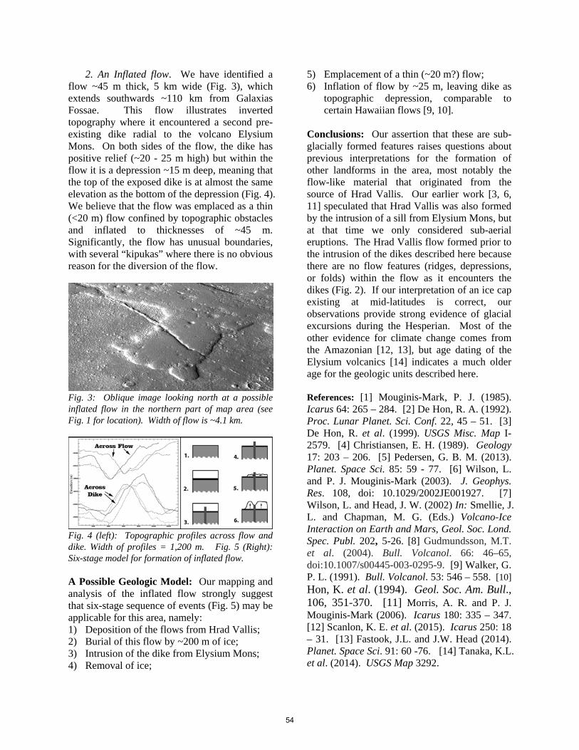
2. An Inflated flow. We have identified a flow ~45 m thick, 5 km wide (Fig. 3), which extends southwards ~110 km from Galaxias Fossae. This flow illustrates inverted topography where it encountered a second pre-existing dike radial to the volcano Elysium Mons. On both sides of the flow, the dike has positive relief (~20 - 25 m high) but within the flow it is a depression ~15 m deep, meaning that the top of the exposed dike is at almost the same elevation as the bottom of the depression (Fig. 4). We believe that the flow was emplaced as a thin (<20 m) flow confined by topographic obstacles and inflated to thicknesses of ~45 m. Significantly, the flow has unusual boundaries, with several “kipukas” where there is no obvious reason for the diversion of the flow.
Fig. 3: Oblique image looking north at a possible inflated flow in the northern part of map area (see Fig. 1 for location). Width of flow is ~4.1 km.
Fig. 4 (left): Topographic profiles across flow and dike. Width of profiles = 1,200 m. Fig. 5 (Right): Six-stage model for formation of inflated flow. A Possible Geologic Model: Our mapping and analysis of the inflated flow strongly suggest that six-stage sequence of events (Fig. 5) may be applicable for this area, namely: 1) Deposition of the flows from Hrad Vallis; 2) Burial of this flow by ~200 m of ice; 3) Intrusion of the dike from Elysium Mons; 4) Removal of ice;
5) Emplacement of a thin (~20 m?) flow; 6) Inflation of flow by ~25 m, leaving dike as
topographic depression, comparable to certain Hawaiian flows [9, 10].
Conclusions: Our assertion that these are sub-glacially formed features raises questions about previous interpretations for the formation of other landforms in the area, most notably the flow-like material that originated from the source of Hrad Vallis. Our earlier work [3, 6, 11] speculated that Hrad Vallis was also formed by the intrusion of a sill from Elysium Mons, but at that time we only considered sub-aerial eruptions. The Hrad Vallis flow formed prior to the intrusion of the dikes described here because there are no flow features (ridges, depressions, or folds) within the flow as it encounters the dikes (Fig. 2). If our interpretation of an ice cap existing at mid-latitudes is correct, our observations provide strong evidence of glacial excursions during the Hesperian. Most of the other evidence for climate change comes from the Amazonian [12, 13], but age dating of the Elysium volcanics [14] indicates a much older age for the geologic units described here.
References: [1] Mouginis-Mark, P. J. (1985). Icarus 64: 265 – 284. [2] De Hon, R. A. (1992). Proc. Lunar Planet. Sci. Conf. 22, 45 – 51. [3] De Hon, R. et al. (1999). USGS Misc. Map I-2579. [4] Christiansen, E. H. (1989). Geology 17: 203 – 206. [5] Pedersen, G. B. M. (2013). Planet. Space Sci. 85: 59 - 77. [6] Wilson, L. and P. J. Mouginis-Mark (2003). J. Geophys. Res. 108, doi: 10.1029/2002JE001927. [7] Wilson, L. and Head, J. W. (2002) In: Smellie, J. L. and Chapman, M. G. (Eds.) Volcano-Ice Interaction on Earth and Mars, Geol. Soc. Lond. Spec. Publ. 202, 5-26. [8] Gudmundsson, M.T. et al. (2004). Bull. Volcanol. 66: 46–65, doi:10.1007/s00445-003-0295-9. [9] Walker, G. P. L. (1991). Bull. Volcanol. 53: 546 – 558. [10] Hon, K. et al. (1994). Geol. Soc. Am. Bull., 106, 351-370. [11] Morris, A. R. and P. J. Mouginis-Mark (2006). Icarus 180: 335 – 347. [12] Scanlon, K. E. et al. (2015). Icarus 250: 18 – 31. [13] Fastook, J.L. and J.W. Head (2014). Planet. Space Sci. 91: 60 -76. [14] Tanaka, K.L. et al. (2014). USGS Map 3292.
54

HIGH-RESOLUTION GEOLOGIC MAPPING IN EAST CANDOR CHASMA: 2015 STATUS REPORT. C. H. Okubo1 and L. A. Edgar2, 1US Geological Survey, 1541 E. University Blvd., Tucson, AZ 85721, [email protected], 2US Geological Survey, 2255 N. Gemini Dr., Flagstaff, AZ 86001.
Introduction: This abstract summarizes planned
activities and current results from a new initiative to construct a series of three high-resolution structural and geologic maps in the east Candor Chasma region of Valles Marineris, Mars.
The goal of this work is to advance current under-standing of the coupled structural evolution of east Candor Chasma and the sedimentary deposits within it through a campaign of geologic unit and structural mapping at spatial resolutions that are at least an order of magnitude finer than has been achieved by previous studies in this part of Valles Marineris. This will be accomplished by characterizing the structure of the sedimentary deposits using digital elevation models derived from publicly released, stereo image pairs ac-quired by the High Resolution Imaging Science Exper-iment (HiRISE) camera.
Background: This work is a continuation of high-resolution mapping done in the western part of Candor Chasma (Fig. 1, blue locations). The central Candor Colles map has been published [1] and the remaining three maps are currently in revision.
Collectively, mapping in west Candor Chasma re-veals that landslides of chasma wall rock (Ceti Labes and Candor Labes) predate deposition of the stratified sedimentary deposits. Bedding morphologies and su-perposition relationships within the sedimentary depos-its indicate that they accumulated in wet playa envi-ronments. Bedforms consistent with sand dunes are present but rare, being only clearly observed the west Ceti Mensa map area. The majority of the strata are horizontally bedded, consistent with sand sheets. Prominent soft-sediment deformation in the form of
injectite megapipes [2] further attest to a wet playa depositional environment.
The sedimentary deposits also exhibit evidence of recurrent periods where sedimentation ceased and eoli-an erosion was widespread. These periods are record-ed as prominent unconformities (e.g., “supersurfaces”) that can be traced throughout the stratified sedimentary rocks in west Candor Chasma. The sediments are di-vided into geologic units based on these regional un-conformities – the units are allostratigraphic. Eleven sedimentary units are mapped in total amongst the four map areas and some units are observed in multiple maps. Many more allostratigraphic divisions are ob-served outside of the map areas, recording more than twenty-five periods of regional eolian deflation.
Landsliding occurred contemporaneously with sed-iment accumulation. The central Candor Colles and southeast and west Ceti Mensa map areas show clear evidence of landslides of sedimentary deposits that were deflated along regional unconformities prior to burial by subsequent sedimentary units.
Though insightful, the results from the relatively small areas studied in west Candor Chasma offer only a glimpse into the broader geologic history of Valles Marineris. In order to realize the full potential that high-resolution structural and geologic mapping has for unraveling the geologic history of Valles Marineris, additional high-resolution mapping must be undertaken in other areas.
East Candor Chasma is selected as the next logical focus area for high-resolution mapping. This region has received relatively little attention with respect to post-Viking era mapping despite being physiograph-
Figure 1. Locations of the maps discussed in this abstract. Background is a THEMIS daytime infrared mosaic.
55

ically comparable to west Candor Chasma and contain-ing morphologically similar stratified sedimentary de-posits. Many of the same geologic units are identified by [3] in both the eastern and western parts of Candor Chasma. Thus results from this expanded mapping effort can be used to develop an integrated geologic history of Candor Chasma as a whole.
Map Areas: Mapping in east Candor Chasma fo-cuses on three separate areas (Fig. 1, red locations), with work on the north Nia Mensa map underway this year and mapping in the other two areas planned for subsequent years. Just as with the west Candor Chasma mapping, the goal of these three maps is to character-ize the timing of chasma formation and sedimentation, as well as to investigate the depositional setting of the stratified sediments within the chasma.
North Nia Mensa. This map encompasses the con-tact between the massive Hesperian-aged sediments that comprise most of Nia Mensa and the Amazonian-aged sedimentary and mass-wasting deposits exposed within the moat between Nia Mensa and the north wall of east Candor Chasma [3]. This map also falls along a putative chasma-related normal fault zone that under-lies the north side of east Candor Chasma [4]. The area contains a stratified fan-like deposit [5] that appears to be sourced from Nia Mensa (Fig. 2). If this feature proves to be depositional in origin, it would help to constrin the depositional setting of the local sediments.
Southeast Nia Mensa. This map is located on the southeast corner of Nia Mensa. It encompasses the contact between the massively bedded, Hesperian-aged sediments of Nia Mensa and the Amazonian-aged sed-imentary and mass-wasting deposits exposed within the moat between Nia Mensa and the south wall of east Candor Chasma [3]. This map also falls along a puta-tive chasma-related normal fault zone that underlies the south side of east Candor Chasma [4]. HiRISE ob-servations reveal possible morphologic evidence of inverted fluvial channels within some stratified depos-its in this area. Fluvial channels have not yet been mapped within Candor Chasma, and if present, would provide significant new constraints on the depositional environment of these sediments.
South Juventae Mensa. This map encompasses the contact between the massively bedded, Hesperian-aged sediments that comprise most of Juventae Mensa and the Amazonian-aged sedimentary and mass-wasting deposits exposed within the moat between Juventae Mensa and the south wall of east Candor Chasma [3]. This map is located along the same putative chasma-related fault zone as the southeast Nia Mensa map and also encompasses a spur of the chasma wall rock.
Current results from the north Nia Mensa map: Two HiRISE stereo pairs (ESP_014154_1730/ ESP_014431_1730 and ESP_031916_1730/ ESP_031982_1730) were used to create one merged digital elevation model (DEM), and the individual im-ages were orthorectified using this DEM. These data, together with ancillary datasets, such as Context (CTX) images, were compiled into an ArcGIS project. This project was modeled after the final GIS project for the Candor Colles map in west Candor Chasma [1] to ensure continuity with, and leverage time savings by following the precedent set by, this earlier high resolu-tion HiRISE-based map.
Work is now focused on measuring the orientations of bedding, fractures and unconformities using the Layer Tools plug-in for ArcGIS. Initial measurements of bedding orientation reveal that the strata within the fan-like deposit dip outward (at less than ~10°), away from its morphologic apex. Thus the structure of this feature is consistent with a fan deposit. Work is on-going to further test this interpretation as a fan deposit and to assess possible depositional settings for this feature and associated sediments.
References: [1] Okubo C. H. (2014) USGS Sci. Inv. Map 3309. [2] Chan M. A. et al. (2007) AAPG Memoir 87, 233–244. [3] Witbeck N. E. et al. (1991) USGS Misc. Inv. Ser. I–2010. [4] Schultz R. A. and Lin J. (2001) JGR, 106, B8, 16549–16566. [5] Le Deit, L. et al. (2008) JGR, 113, E7, E07001.
Figure 2. The north Nia Mensa map area (colored region). Colorized elevations from the HiRISE digital elevation mod-el overlaid on a CTX mosaic.
56
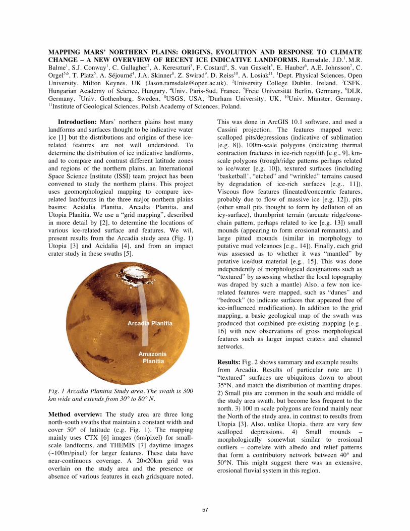
MAPPING MARS’ NORTHERN PLAINS: ORIGINS, EVOLUTION AND RESPONSE TO CLIMATE CHANGE – A NEW OVERVIEW OF RECENT ICE INDICATIVE LANDFORMS. Ramsdale, J.D.1, M.R. Balme1, S.J. Conway1, C. Gallagher2, A. Kereszturi3, F. Costard4, S. van Gasselt5, E. Hauber6, A.E. Johnsson7, C. Orgel5,6, T. Platz5, A. Séjourné4, J.A. Skinner8, Z. Swirad9, D. Reiss10, A. Losiak11. 1Dept. Physical Sciences, Open University, Milton Keynes, UK ([email protected]), 2University College Dublin, Ireland, 3CSFK, Hungarian Academy of Science, Hungary, 4Univ. Paris-Sud, France, 5Freie Universität Berlin, Germany, 6DLR, Germany, 7Univ. Gothenburg, Sweden, 8USGS, USA, 9Durham University, UK, 10Univ. Münster, Germany, 11Institute of Geological Sciences, Polish Academy of Sciences, Poland.
Introduction: Mars’ northern plains host many
landforms and surfaces thought to be indicative water ice [1] but the distributions and origins of these ice-related features are not well understood. To determine the distribution of ice indicative landforms, and to compare and contrast different latitude zones and regions of the northern plains, an International Space Science Institute (ISSI) team project has been convened to study the northern plains. This project uses geomorphological mapping to compare ice-related landforms in the three major northern plains basins: Acidalia Planitia, Arcadia Planitia, and Utopia Planitia. We use a “grid mapping”, described in more detail by [2], to determine the locations of various ice-related surface and features. We wil, present results from the Arcadia study area (Fig. 1) Utopia [3] and Acidalia [4], and from an impact crater study in these swaths [5].
Fig. 1 Arcadia Planitia Study area. The swath is 300 km wide and extends from 30° to 80° N. Method overview: The study area are three long north-south swaths that maintain a constant width and cover 50° of latitude (e.g. Fig. 1). The mapping mainly uses CTX [6] images (6m/pixel) for small-scale landforms, and THEMIS [7] daytime images (~100m/pixel) for larger features. These data have near-continuous coverage. A 20×20km grid was overlain on the study area and the presence or absence of various features in each gridsquare noted.
This was done in ArcGIS 10.1 software, and used a Cassini projection. The features mapped were: scalloped pits/depressions (indicative of sublimation [e.g. 8]), 100m-scale polygons (indicating thermal contraction fractures in ice-rich regolith [e.g., 9], km-scale polygons (trough/ridge patterns perhaps related to ice/water [e.g. 10]), textured surfaces (including ‘basketball’, “etched” and “wrinkled” terrains caused by degradation of ice-rich surfaces [e.g., 11]), Viscous flow features (lineated/concentric features, probably due to flow of massive ice [e.g. 12]), pits (other small pits thought to form by deflation of an icy-surface), thumbprint terrain (arcuate ridge/cone-chain pattern, perhaps related to ice [e.g. 13]) small mounds (appearing to form erosional remnants), and large pitted mounds (similar in morphology to putative mud volcanoes [e.g., 14]). Finally, each grid was assessed as to whether it was “mantled” by putative ice/dust material [e.g., 15]. This was done independently of morphological designations such as “textured” by assessing whether the local topography was draped by such a mantle) Also, a few non ice-related features were mapped, such as “dunes” and “bedrock” (to indicate surfaces that appeared free of ice-influenced modification). In addition to the grid mapping, a basic geological map of the swath was produced that combined pre-existing mapping [e.g., 16] with new observations of gross morphological features such as larger impact craters and channel networks. Results: Fig. 2 shows summary and example results from Arcadia. Results of particular note are 1) “textured” surfaces are ubiquitous down to about 35°N, and match the distribution of mantling drapes. 2) Small pits are common in the south and middle of the study area swath, but become less frequent to the north. 3) 100 m scale polygons are found mainly near the North of the study area, in contrast to results from Utopia [3]. Also, unlike Utopia, there are very few scalloped depressions. 4) Small mounds – morphologically somewhat similar to erosional outliers – correlate with albedo and relief patterns that form a contributory network between 40° and 50°N. This might suggest there was an extensive, erosional fluvial system in this region.
57
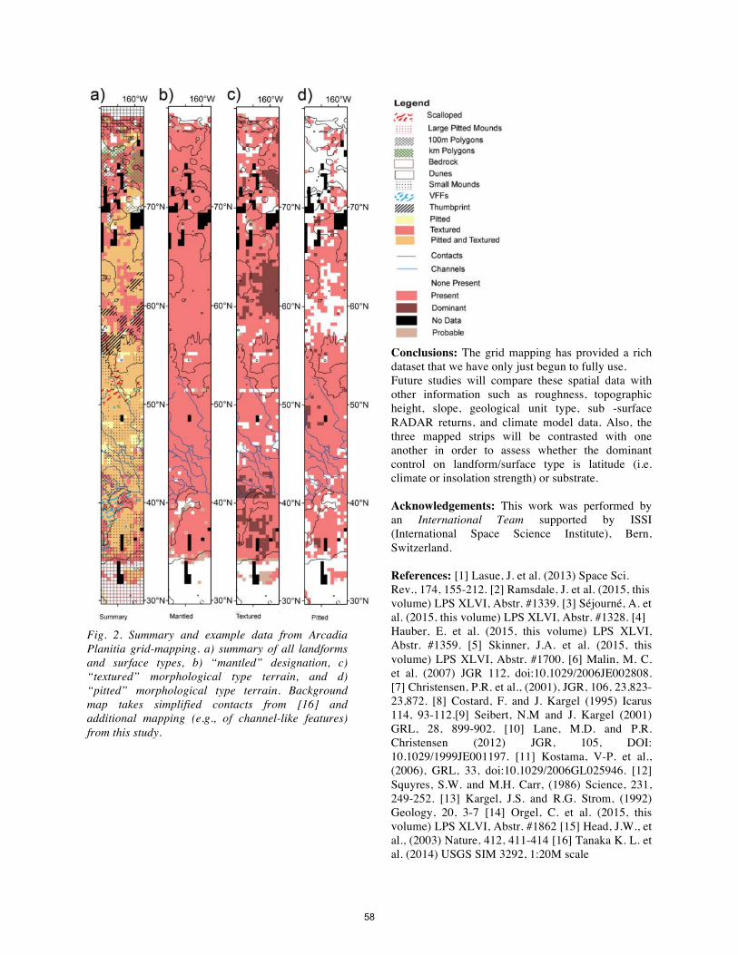
Fig. 2. Summary and example data from Arcadia Planitia grid-mapping. a) summary of all landforms and surface types, b) “mantled” designation, c) “textured” morphological type terrain, and d) “pitted” morphological type terrain. Background map takes simplified contacts from [16] and additional mapping (e.g., of channel-like features) from this study.
Conclusions: The grid mapping has provided a rich dataset that we have only just begun to fully use. Future studies will compare these spatial data with other information such as roughness, topographic height, slope, geological unit type, sub -surface RADAR returns, and climate model data. Also, the three mapped strips will be contrasted with one another in order to assess whether the dominant control on landform/surface type is latitude (i.e. climate or insolation strength) or substrate. Acknowledgements: This work was performed by an International Team supported by ISSI (International Space Science Institute), Bern, Switzerland. References: [1] Lasue, J. et al. (2013) Space Sci. Rev., 174, 155-212. [2] Ramsdale, J. et al. (2015, this volume) LPS XLVI, Abstr. #1339. [3] Séjourné, A. et al. (2015, this volume) LPS XLVI, Abstr. #1328. [4] Hauber, E. et al. (2015, this volume) LPS XLVI, Abstr. #1359. [5] Skinner, J.A. et al. (2015, this volume) LPS XLVI, Abstr. #1700. [6] Malin, M. C. et al. (2007) JGR 112, doi:10.1029/2006JE002808. [7] Christensen, P.R. et al., (2001), JGR, 106, 23,823-23,872. [8] Costard, F. and J. Kargel (1995) Icarus 114, 93-112.[9] Seibert, N.M and J. Kargel (2001) GRL, 28, 899-902. [10] Lane, M.D. and P.R. Christensen (2012) JGR, 105, DOI: 10.1029/1999JE001197. [11] Kostama, V-P. et al., (2006), GRL, 33, doi:10.1029/2006GL025946. [12] Squyres, S.W. and M.H. Carr, (1986) Science, 231, 249-252. [13] Kargel, J.S. and R.G. Strom, (1992) Geology, 20, 3-7 [14] Orgel, C. et al. (2015, this volume) LPS XLVI, Abstr. #1862 [15] Head, J.W., et al., (2003) Nature, 412, 411-414 [16] Tanaka K. L. et al. (2014) USGS SIM 3292, 1:20M scale
58
MAPPING MARS’ NORTHERN PLAINS: ORIGINS, EVOLUTION AND RESPONSE TO CLIMATE CHANGE - AN OVERVIEW OF THE GRID MAPPING METHOD. Ramsdale, J.D. 1 , Balme, M.R. 1,2, Conway, S.J., Costard, F., Gallagher, C., van Gasselt, S., Hauber, E., Johnsson, A.E., Kereszturi, A., Platz, T., Séjourné, A., Skinner, J.A., Jr., Reiss, D., Swirad, Z., Orgel, C., Losiak, A. 1Dept. Physical Sciences, Open University, Walton Hall, Milton Keynes, MK7 6AA ([email protected]). 2Planetary Science Institute, Suite 106, 1700 East Fort Lowell, Tuscon, AZ, USA.
Introduction: An International Space Science Institute (ISSI) team project has been convened to study the northern plains of Mars. Using geomorphological mapping to compare ice-related landforms in the three northern plains basins: Acidalia Planitia, Arcadia Planitia, and Utopia Planitia the main questions this project aims to answer are: 1) “What is the distribution of ice-related
landforms in the northern plains, and can it be related to distinct latitude bands or different geological or geomorphological units?”
2) “What is the relationship between the latitude dependent mantle (LDM) and (i) landforms indicative of ground ice, and (ii) other geological units in the northern plains?”
3) “What are the distributions and associations of recent landforms indicative of thaw of ice or snow?”
With increasing coverage of high-resolution images of the surface of Mars (e.g. Context Imager – CTX, ~ 6 m/pixel, covering ~ 90% of the surface as of December 2014 [1]) we are able to identify increasing numbers and varieties of small-scale landforms. Many such landforms are too small to represent on regional maps, yet determining their presence or absence across large areas can form the observational basis for developing hypotheses on the nature and history of an area. The combination of improved spatial resolution with near continuous coverage increases the time required to analyse the data. This becomes problematic when attempting regional or global-scale studies of metre-scale landforms. Here, we describe an approach for mapping small features across large areas that was formulated for the ISSI project. Results from this study are presented in [2,3,4]. Three study areas, each consisting of a long latitudinal swath, were defined in the Acidalia, Arcadia, and Utopia regions. Preliminary work established that traditional mapping, or survey techniques would not work: many of the landforms of interest (e.g., scalloped pits and 100m-scale polygonal fractures), could only be identified in CTX
images viewed at 1:10,000 or 1:20,000 scale. However, to meet the project goals, we needed to map the distribution of such landforms across very large continuous areas. Identifying and recording landforms individually would take an impossibly long time, so an alternative approach was designed, described here. Method: Rather than traditional mapping with points, lines and polygons, we used a grid “tick box” approach to determine where specific landforms are. The mapping strips were divided into a 15×150 grid of squares, each approximately 20×20 km, for each study area. In ArcGIS, we produced a polygon shapefile in which each sub-grid was represented by a single square polygon. In the attribute table of this shapefile, a new attribute for each landform/surface type was added. CTX and THEMIS daytime images were then viewed systematically for each sub-grid square and the presence or absence of each of the basic suite of landforms recorded. The landforms are shown in Fig. 1. The landforms were recorded as “present”, “dominant”, or “absent” in each sub-grid square. Where relevant, each square was also recorded as “null” (meaning “no data”) or “possible” if there was uncertainty in identification (but where the mapper felt that there was some evidence to suggest that the landform was present). The result is a series of coarse resolution “rasters” showing the distribution of the different types of landforms across the strip (Fig. 1). Projection and data: The Arcadia study area, shown here as an example of what can be achieved with this approach, is a 300 km wide strip that extends over 50° latitude, centred on 170° W. We used a Cassini projection centred on the 170° west meridian. Analysis was performed primarily using publically available CTX images, downloaded pre-processed from the Arizona State University Mars Portal and inserted into ArcGIS. MOLA (Mars Orbiter Laser Altimeter [5]) gridded data and hillshade products and THEMIS (THermal EMission Imaging System [6]) images were downloaded from the Planetary Data Systems’ Geosciences Node, Mars Orbital Data Explorer (ODE) and used as basemaps. Assessment of the method: Grid mapping (Fig. 1; Table 1) is efficient: for each sub-grid, only the presence or absence of a landform needs to be
59

ascertained, and no detailed digitising is needed. This also removes subjectivity: removing an individual’s decision as to where to draw boundaries and improving repeatability. If further resolution was needed, finer scale grids could be added. Carrying the null and zero values forward from the larger grids would mean only areas with positive values for that landform would need to be examined to increase the resolution for the whole strip.
Table 1. Pros and Cons of the grid mapping method. Conclusion: Grid mapping provides an efficient and scalable approach to collecting data on large quantities of small landforms over large areas. Acknowledgements: This work was supported by the International Space Science Institute, Switzerland. References: [1] Malin, M. C. et al. (2007) JGR 112, doi: 10.1029/2006JE002808. [2], Balme, M.R., et al. (2015) LPSC XLVI, Abstr. #1339 [3], Hauber et al., (2015) LPSC XLVI, Abstr. #1359 [4] Séjourné et al., (2015) LPSC XLVI, Abstr. #1328, [5] Smith, D. E. et al. (2001) JGR 106, doi: 10.1029/2000JE001364. [6] Christensen, P. R. et al. (2004) Space Sci. Rev. 110, 85–130. [7] Tanaka, K. L., et al., (2005) Geologic map of the northern plains of Mars.
Fig. 1 Arcadia Planitia results. a) Geological Map [7]. b) Summary of geomorphological grid mapping results. c) Grid mapping showing only the spatial density of “textured” (ice-degradation) landforms.
60

GEOLOGIC MAPPING REVEALS THAT TSUNAMI WAVES EXTENSIVELY RESURFACED THE COASTS OF EARLY MARTIAN OCEANS. J.A.P. Rodriguez1,2, K.L. Tanaka3, A.G. Fairén4,5, G. Komatsu6, V. Gulick2,7, V.R. Baker8, T. Platz1, R. Linares9, M. Zarroca9, Y. Jianguo10 and N. Glines2,7. 1Planetary Science Institute, Tucson, AZ; [email protected]; 2NASA Ames Research Center, Moffett Field, CA; 3U.S. Geological Survey, Flagstaff, AZ; 4Centro de Astrobiología, Madrid, Spain; 5University, Ithaca, NY; 6Università d’Annunzio, Pescara, Italy; 7SETI Institute, Mountain View, CA; 8University of Arizona, Tucson, AZ; 9Autonomous University of Barcelona, Barcelona, Spain; 10Wuhan University, Wuhan, China.
Abstract. Viking image-based mapping of a
widespread deposit covering most of the northern lowlands of Mars, led to the proposal by Parker et al. [1-2] that the deposit represents the vestiges of an enormous ocean. Later identified as the Vastitas Borealis Formation [3], the latest geologic map of Mars [4] identifies the deposit as the Late Hesperian lowland unit (lHl). The deposit is typically bounded by raised lobate margins [5-7]. In addition, some margins were found to have associated rille channels, which could have been produced sub-aerially by the backwash of high-energy tsunami waves [2]. Radar-sounding data indicate that the deposit is ice-rich [8]. However, until now, the lack of wave-cut shoreline features and the presence of lobate margins have remained an impediment to acceptance of the paleo-ocean hypothesis.
Here, we present new morphological observations and mapping results based on Context Camera (CTX) and High Resolution Imaging System Experiment (HiRISE) images and Mars Orbital Laser Altimeter (MOLA) digital elevation data as well as numerical analysis that indicate that unit lHl’s marginal morphologies were generated by two enormous tsunami waves. Proposed tsunami-related landforms, in part based on Earth analogs, include (1) sedimentary lobes emplaced over gently sloping plains, (2) extensive backwash, boulder-filled channel networks incised into cratered highland regions flanking the planet’s northern lowlands, and (3) thermokarst depressions produced by sublimation of margin, ice-rich materials. The proposed tsunami deposits are mapped as older and younger members of unit lHl (lHl1 and lHl2 respectively).
Identification and timing of tsunami landscape modification on Mars. Using the latest remote-sensing datasets, we have mapped and examined spatial and geologic characteristics of the unit lHl lobes in the region of circum-Chryse. Large-scale sedimentation associated with the run-up flows covered a large number of streamlined promontories (Fig. 1A), indicating that the lobes propagated extensively into vast, pre-existing circum-Chryse outwash plains. The lobes are mostly composed of water-ice-rich sediment [8] and have run-up distances reaching ~800 km over a relief of as much as ~750 m
(elevation profile in Fig. 1A); these observations are indicative of highly energetic liquid water flows. We propose here that these lobes mark the margins of successive tsunami waves that were induced by one or two impact events into a Late Hesperian ocean. The tsunami event(s) would have occurred following cirum-Chryse outflow channel floods formed the ocean, but before the ocean completely froze over.
Morphology and climatic influences. Long-distance, sub-aerial run-up water flows on Earth typically result from tsunami waves, which are known to exhibit landward-facing, lobate termini produced by the entrapment of large volumes of debris [7]. In the case of unit lHl lobes, we propose that ice crystals produced by the progressive freezing of the tsunami flows as they propagated under cryogenic environmental conditions would have increased the flows’ ductility, leading to lobe formation and preservation [9]. We also propose that, in western Arabia Terra, the tsunami reached the highland-lowland boundary, where it deposited sediments that embayed, or mantled, the cratered highland scarps (Fig. 1A). These terrains are extensively marked by north-trending channels (Fig. 1B), which were first identified in Viking data [2]. On Earth, similar channel forms perpendicular to the shoreline, though much smaller in scale respect to the Martian counterparts, are observed to develop on sand berms during tsunami retreat phases [10].
The topographic baseline of the mapped lobes and the lowermost extent of the buried streamlined promontories within the circum-Chryse outwash plains are both at -4250 m in elevation. This elevation is within the mean elevation range (-3760 ± 560 m) previously estimate for the paleo-ocean shoreline [11]. Numerical modeling indicates that the ~200-km-diameter Chicxulub impact crater on Earth produced tsunami reaching a ~300 m in height as it approached the shoreline, and which attained run-up distances of ~300 km inland and elevations ~300 m above sea-level [12]. Paleo-geographic reconstructions indicate that the impact occurred in relative proximity to land and within a shallow (~200-m-deep) sea.
For similar tsunami wave energy and coastal features, the inland distance to complete energy
61
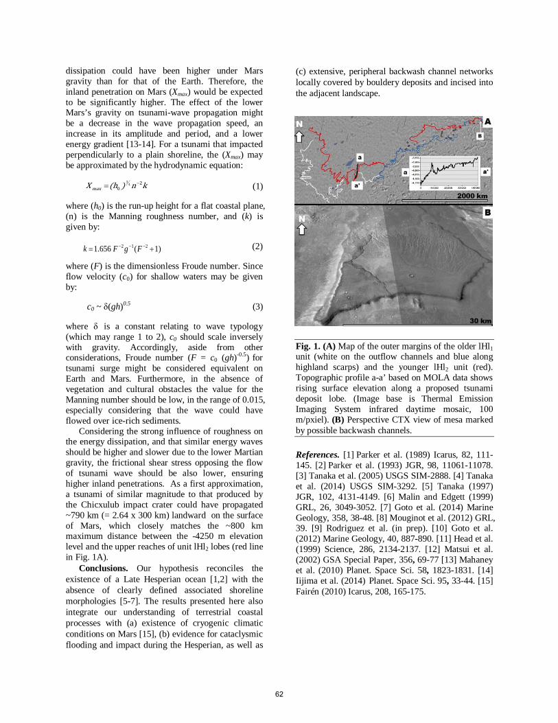
dissipation could have been higher under Mars gravity than for that of the Earth. Therefore, the inland penetration on Mars (Xmax) would be expected to be significantly higher. The effect of the lower Mars’s gravity on tsunami-wave propagation might be a decrease in the wave propagation speed, an increase in its amplitude and period, and a lower energy gradient [13-14]. For a tsunami that impacted perpendicularly to a plain shoreline, the (Xmax) may be approximated by the hydrodynamic equation:
(1)
where (h0) is the run-up height for a flat coastal plane, (n) is the Manning roughness number, and (k) is given by:
(2)
where (F) is the dimensionless Froude number. Since flow velocity (c0) for shallow waters may be given by:
c0 ~ δ(gh)0.5 (3)
where δ is a constant relating to wave typology (which may range 1 to 2), c0 should scale inversely with gravity. Accordingly, aside from other considerations, Froude number (F = c0 (gh)-0.5) for tsunami surge might be considered equivalent on Earth and Mars. Furthermore, in the absence of vegetation and cultural obstacles the value for the Manning number should be low, in the range of 0.015, especially considering that the wave could have flowed over ice-rich sediments.
Considering the strong influence of roughness on the energy dissipation, and that similar energy waves should be higher and slower due to the lower Martian gravity, the frictional shear stress opposing the flow of tsunami wave should be also lower, ensuring higher inland penetrations. As a first approximation, a tsunami of similar magnitude to that produced by the Chicxulub impact crater could have propagated ~790 km (= 2.64 x 300 km) landward on the surface of Mars, which closely matches the ~800 km maximum distance between the -4250 m elevation level and the upper reaches of unit lHl2 lobes (red line in Fig. 1A).
Conclusions. Our hypothesis reconciles the existence of a Late Hesperian ocean [1,2] with the absence of clearly defined associated shoreline morphologies [5-7]. The results presented here also integrate our understanding of terrestrial coastal processes with (a) existence of cryogenic climatic conditions on Mars [15], (b) evidence for cataclysmic flooding and impact during the Hesperian, as well as
(c) extensive, peripheral backwash channel networks locally covered by bouldery deposits and incised into the adjacent landscape.
Fig. 1. (A) Map of the outer margins of the older lHl1 unit (white on the outflow channels and blue along highland scarps) and the younger lHl2 unit (red). Topographic profile a-a’ based on MOLA data shows rising surface elevation along a proposed tsunami deposit lobe. (Image base is Thermal Emission Imaging System infrared daytime mosaic, 100 m/pxiel). (B) Perspective CTX view of mesa marked by possible backwash channels.
References. [1] Parker et al. (1989) Icarus, 82, 111-145. [2] Parker et al. (1993) JGR, 98, 11061-11078. [3] Tanaka et al. (2005) USGS SIM-2888. [4] Tanaka et al. (2014) USGS SIM-3292. [5] Tanaka (1997) JGR, 102, 4131-4149. [6] Malin and Edgett (1999) GRL, 26, 3049-3052. [7] Goto et al. (2014) Marine Geology, 358, 38-48. [8] Mouginot et al. (2012) GRL, 39. [9] Rodriguez et al. (in prep). [10] Goto et al. (2012) Marine Geology, 40, 887-890. [11] Head et al. (1999) Science, 286, 2134-2137. [12] Matsui et al. (2002) GSA Special Paper, 356, 69-77 [13] Mahaney et al. (2010) Planet. Space Sci. 58, 1823-1831. [14] Iijima et al. (2014) Planet. Space Sci. 95, 33-44. [15] Fairén (2010) Icarus, 208, 165-175.
kn)(h X max2
04
3 −=
1)(1.656 212 += −−− FgF k
62
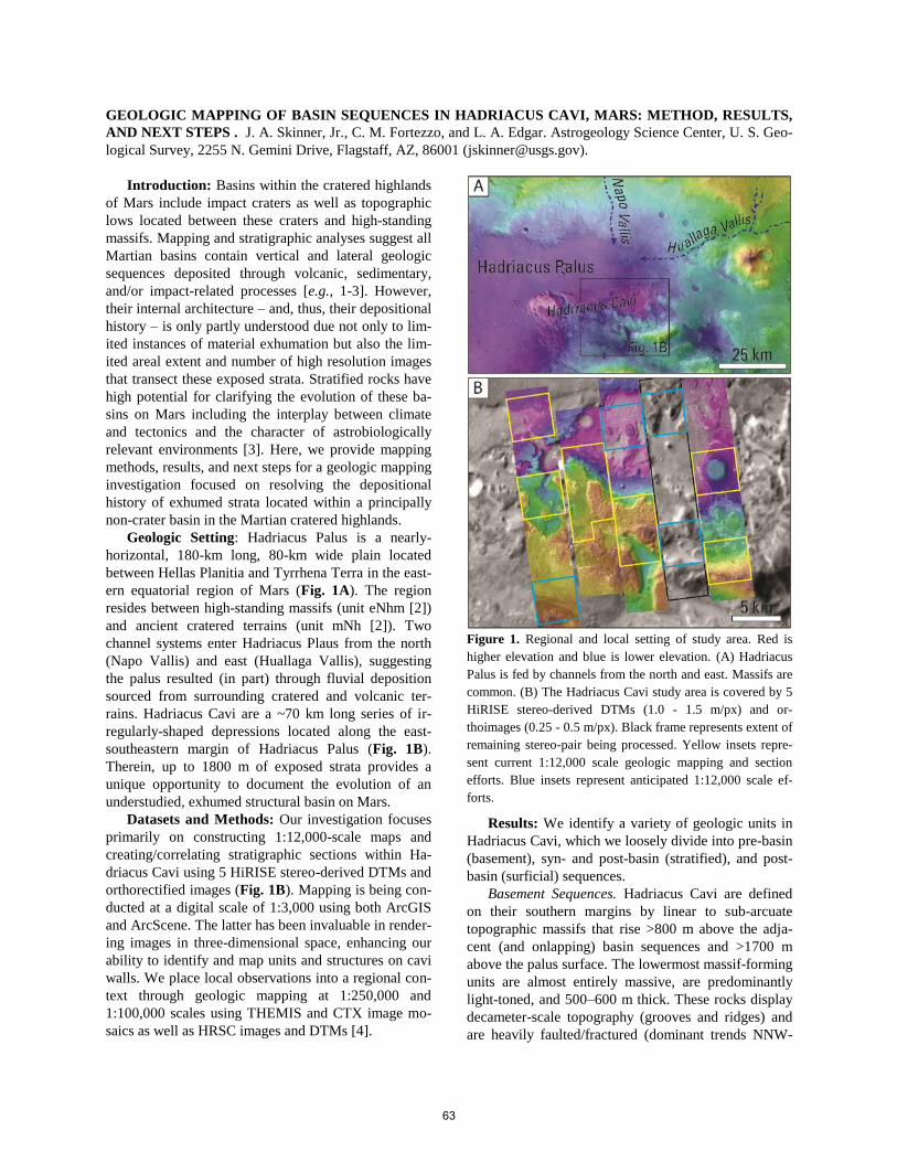
GEOLOGIC MAPPING OF BASIN SEQUENCES IN HADRIACUS CAVI, MARS: METHOD, RESULTS,
AND NEXT STEPS . J. A. Skinner, Jr., C. M. Fortezzo, and L. A. Edgar. Astrogeology Science Center, U. S. Geo-
logical Survey, 2255 N. Gemini Drive, Flagstaff, AZ, 86001 ([email protected]).
Introduction: Basins within the cratered highlands
of Mars include impact craters as well as topographic
lows located between these craters and high-standing
massifs. Mapping and stratigraphic analyses suggest all
Martian basins contain vertical and lateral geologic
sequences deposited through volcanic, sedimentary,
and/or impact-related processes [e.g., 1-3]. However,
their internal architecture – and, thus, their depositional
history – is only partly understood due not only to lim-
ited instances of material exhumation but also the lim-
ited areal extent and number of high resolution images
that transect these exposed strata. Stratified rocks have
high potential for clarifying the evolution of these ba-
sins on Mars including the interplay between climate
and tectonics and the character of astrobiologically
relevant environments [3]. Here, we provide mapping
methods, results, and next steps for a geologic mapping
investigation focused on resolving the depositional
history of exhumed strata located within a principally
non-crater basin in the Martian cratered highlands.
Geologic Setting: Hadriacus Palus is a nearly-
horizontal, 180-km long, 80-km wide plain located
between Hellas Planitia and Tyrrhena Terra in the east-
ern equatorial region of Mars (Fig. 1A). The region
resides between high-standing massifs (unit eNhm [2])
and ancient cratered terrains (unit mNh [2]). Two
channel systems enter Hadriacus Plaus from the north
(Napo Vallis) and east (Huallaga Vallis), suggesting
the palus resulted (in part) through fluvial deposition
sourced from surrounding cratered and volcanic ter-
rains. Hadriacus Cavi are a ~70 km long series of ir-
regularly-shaped depressions located along the east-
southeastern margin of Hadriacus Palus (Fig. 1B).
Therein, up to 1800 m of exposed strata provides a
unique opportunity to document the evolution of an
understudied, exhumed structural basin on Mars.
Datasets and Methods: Our investigation focuses
primarily on constructing 1:12,000-scale maps and
creating/correlating stratigraphic sections within Ha-
driacus Cavi using 5 HiRISE stereo-derived DTMs and
orthorectified images (Fig. 1B). Mapping is being con-
ducted at a digital scale of 1:3,000 using both ArcGIS
and ArcScene. The latter has been invaluable in render-
ing images in three-dimensional space, enhancing our
ability to identify and map units and structures on cavi
walls. We place local observations into a regional con-
text through geologic mapping at 1:250,000 and
1:100,000 scales using THEMIS and CTX image mo-
saics as well as HRSC images and DTMs [4].
Figure 1. Regional and local setting of study area. Red is
higher elevation and blue is lower elevation. (A) Hadriacus
Palus is fed by channels from the north and east. Massifs are
common. (B) The Hadriacus Cavi study area is covered by 5
HiRISE stereo-derived DTMs (1.0 - 1.5 m/px) and or-
thoimages (0.25 - 0.5 m/px). Black frame represents extent of
remaining stereo-pair being processed. Yellow insets repre-
sent current 1:12,000 scale geologic mapping and section
efforts. Blue insets represent anticipated 1:12,000 scale ef-
forts.
Results: We identify a variety of geologic units in
Hadriacus Cavi, which we loosely divide into pre-basin
(basement), syn- and post-basin (stratified), and post-
basin (surficial) sequences.
Basement Sequences. Hadriacus Cavi are defined
on their southern margins by linear to sub-arcuate
topographic massifs that rise >800 m above the adja-
cent (and onlapping) basin sequences and >1700 m
above the palus surface. The lowermost massif-forming
units are almost entirely massive, are predominantly
light-toned, and 500–600 m thick. These rocks display
decameter-scale topography (grooves and ridges) and
are heavily faulted/fractured (dominant trends NNW-
63
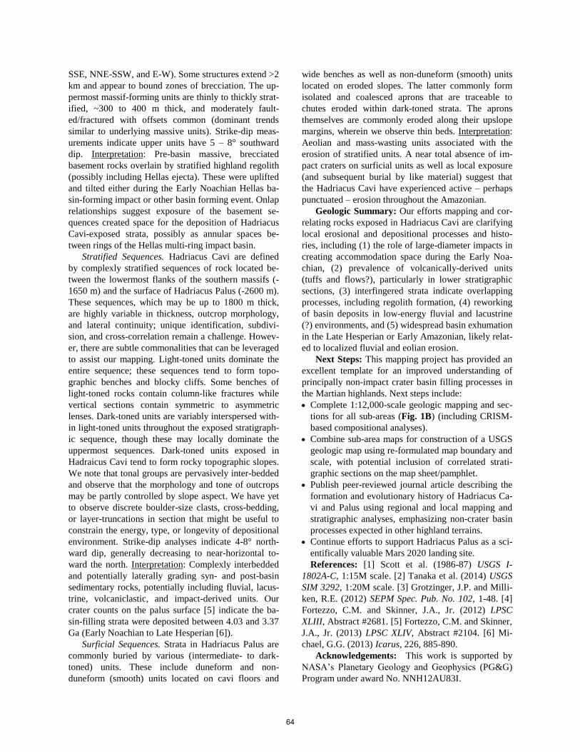
SSE, NNE-SSW, and E-W). Some structures extend >2
km and appear to bound zones of brecciation. The up-
permost massif-forming units are thinly to thickly strat-
ified, ~300 to 400 m thick, and moderately fault-
ed/fractured with offsets common (dominant trends
similar to underlying massive units). Strike-dip meas-
urements indicate upper units have 5 – 8° southward
dip. Interpretation: Pre-basin massive, brecciated
basement rocks overlain by stratified highland regolith
(possibly including Hellas ejecta). These were uplifted
and tilted either during the Early Noachian Hellas ba-
sin-forming impact or other basin forming event. Onlap
relationships suggest exposure of the basement se-
quences created space for the deposition of Hadriacus
Cavi-exposed strata, possibly as annular spaces be-
tween rings of the Hellas multi-ring impact basin.
Stratified Sequences. Hadriacus Cavi are defined
by complexly stratified sequences of rock located be-
tween the lowermost flanks of the southern massifs (-
1650 m) and the surface of Hadriacus Palus (-2600 m).
These sequences, which may be up to 1800 m thick,
are highly variable in thickness, outcrop morphology,
and lateral continuity; unique identification, subdivi-
sion, and cross-correlation remain a challenge. Howev-
er, there are subtle commonalities that can be leveraged
to assist our mapping. Light-toned units dominate the
entire sequence; these sequences tend to form topo-
graphic benches and blocky cliffs. Some benches of
light-toned rocks contain column-like fractures while
vertical sections contain symmetric to asymmetric
lenses. Dark-toned units are variably interspersed with-
in light-toned units throughout the exposed stratigraph-
ic sequence, though these may locally dominate the
uppermost sequences. Dark-toned units exposed in
Hadraicus Cavi tend to form rocky topographic slopes.
We note that tonal groups are pervasively inter-bedded
and observe that the morphology and tone of outcrops
may be partly controlled by slope aspect. We have yet
to observe discrete boulder-size clasts, cross-bedding,
or layer-truncations in section that might be useful to
constrain the energy, type, or longevity of depositional
environment. Strike-dip analyses indicate 4-8° north-
ward dip, generally decreasing to near-horizontal to-
ward the north. Interpretation: Complexly interbedded
and potentially laterally grading syn- and post-basin
sedimentary rocks, potentially including fluvial, lacus-
trine, volcaniclastic, and impact-derived units. Our
crater counts on the palus surface [5] indicate the ba-
sin-filling strata were deposited between 4.03 and 3.37
Ga (Early Noachian to Late Hesperian [6]).
Surficial Sequences. Strata in Hadriacus Palus are
commonly buried by various (intermediate- to dark-
toned) units. These include duneform and non-
duneform (smooth) units located on cavi floors and
wide benches as well as non-duneform (smooth) units
located on eroded slopes. The latter commonly form
isolated and coalesced aprons that are traceable to
chutes eroded within dark-toned strata. The aprons
themselves are commonly eroded along their upslope
margins, wherein we observe thin beds. Interpretation:
Aeolian and mass-wasting units associated with the
erosion of stratified units. A near total absence of im-
pact craters on surficial units as well as local exposure
(and subsequent burial by like material) suggest that
the Hadriacus Cavi have experienced active – perhaps
punctuated – erosion throughout the Amazonian.
Geologic Summary: Our efforts mapping and cor-
relating rocks exposed in Hadriacus Cavi are clarifying
local erosional and depositional processes and histo-
ries, including (1) the role of large-diameter impacts in
creating accommodation space during the Early Noa-
chian, (2) prevalence of volcanically-derived units
(tuffs and flows?), particularly in lower stratigraphic
sections, (3) interfingered strata indicate overlapping
processes, including regolith formation, (4) reworking
of basin deposits in low-energy fluvial and lacustrine
(?) environments, and (5) widespread basin exhumation
in the Late Hesperian or Early Amazonian, likely relat-
ed to localized fluvial and eolian erosion.
Next Steps: This mapping project has provided an
excellent template for an improved understanding of
principally non-impact crater basin filling processes in
the Martian highlands. Next steps include:
Complete 1:12,000-scale geologic mapping and sec-
tions for all sub-areas (Fig. 1B) (including CRISM-
based compositional analyses).
Combine sub-area maps for construction of a USGS
geologic map using re-formulated map boundary and
scale, with potential inclusion of correlated strati-
graphic sections on the map sheet/pamphlet.
Publish peer-reviewed journal article describing the
formation and evolutionary history of Hadriacus Ca-
vi and Palus using regional and local mapping and
stratigraphic analyses, emphasizing non-crater basin
processes expected in other highland terrains.
Continue efforts to support Hadriacus Palus as a sci-
entifically valuable Mars 2020 landing site.
References: [1] Scott et al. (1986-87) USGS I-
1802A-C, 1:15M scale. [2] Tanaka et al. (2014) USGS
SIM 3292, 1:20M scale. [3] Grotzinger, J.P. and Milli-
ken, R.E. (2012) SEPM Spec. Pub. No. 102, 1-48. [4]
Fortezzo, C.M. and Skinner, J.A., Jr. (2012) LPSC
XLIII, Abstract #2681. [5] Fortezzo, C.M. and Skinner,
J.A., Jr. (2013) LPSC XLIV, Abstract #2104. [6] Mi-
chael, G.G. (2013) Icarus, 226, 885-890.
Acknowledgements: This work is supported by
NASA’s Planetary Geology and Geophysics (PG&G)
Program under award No. NNH12AU83I.
64
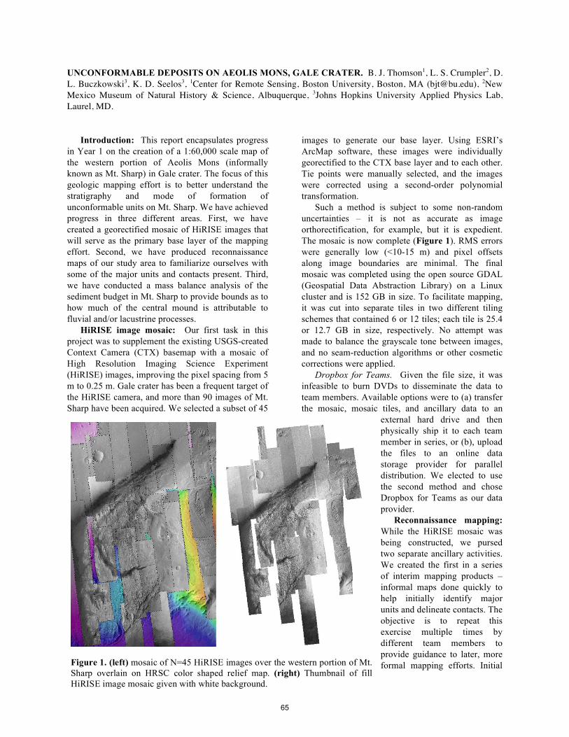
UNCONFORMABLE DEPOSITS ON AEOLIS MONS, GALE CRATER. B. J. Thomson1, L. S. Crumpler2, D. L. Buczkowski3, K. D. Seelos3, 1Center for Remote Sensing, Boston University, Boston, MA ([email protected]), 2New Mexico Museum of Natural History & Science, Albuquerque, 3Johns Hopkins University Applied Physics Lab, Laurel, MD.
Introduction: This report encapsulates progress
in Year 1 on the creation of a 1:60,000 scale map of the western portion of Aeolis Mons (informally known as Mt. Sharp) in Gale crater. The focus of this geologic mapping effort is to better understand the stratigraphy and mode of formation of unconformable units on Mt. Sharp. We have achieved progress in three different areas. First, we have created a georectified mosaic of HiRISE images that will serve as the primary base layer of the mapping effort. Second, we have produced reconnaissance maps of our study area to familiarize ourselves with some of the major units and contacts present. Third, we have conducted a mass balance analysis of the sediment budget in Mt. Sharp to provide bounds as to how much of the central mound is attributable to fluvial and/or lacustrine processes.
HiRISE image mosaic: Our first task in this project was to supplement the existing USGS-created Context Camera (CTX) basemap with a mosaic of High Resolution Imaging Science Experiment (HiRISE) images, improving the pixel spacing from 5 m to 0.25 m. Gale crater has been a frequent target of the HiRISE camera, and more than 90 images of Mt. Sharp have been acquired. We selected a subset of 45
images to generate our base layer. Using ESRI’s ArcMap software, these images were individually georectified to the CTX base layer and to each other. Tie points were manually selected, and the images were corrected using a second-order polynomial transformation.
Such a method is subject to some non-random uncertainties – it is not as accurate as image orthorectification, for example, but it is expedient. The mosaic is now complete (Figure 1). RMS errors were generally low (<10-15 m) and pixel offsets along image boundaries are minimal. The final mosaic was completed using the open source GDAL (Geospatial Data Abstraction Library) on a Linux cluster and is 152 GB in size. To facilitate mapping, it was cut into separate tiles in two different tiling schemes that contained 6 or 12 tiles; each tile is 25.4 or 12.7 GB in size, respectively. No attempt was made to balance the grayscale tone between images, and no seam-reduction algorithms or other cosmetic corrections were applied.
Dropbox for Teams. Given the file size, it was infeasible to burn DVDs to disseminate the data to team members. Available options were to (a) transfer the mosaic, mosaic tiles, and ancillary data to an
external hard drive and then physically ship it to each team member in series, or (b), upload the files to an online data storage provider for parallel distribution. We elected to use the second method and chose Dropbox for Teams as our data provider.
Reconnaissance mapping: While the HiRISE mosaic was being constructed, we pursed two separate ancillary activities. We created the first in a series of interim mapping products – informal maps done quickly to help initially identify major units and delineate contacts. The objective is to repeat this exercise multiple times by different team members to provide guidance to later, more formal mapping efforts. Initial
Figure 1. (left) mosaic of N=45 HiRISE images over the western portion of Mt. Sharp overlain on HRSC color shaped relief map. (right) Thumbnail of fill HiRISE image mosaic given with white background.
65
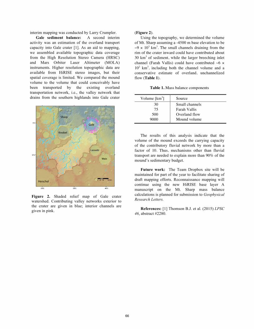
interim mapping was conducted by Larry Crumpler. Gale sediment balance: A second interim
activity was an estimation of the overland transport capacity into Gale crater [1]. As an aid to mapping, we assembled available topographic data coverage from the High Resolution Stereo Camera (HRSC) and Mars Orbiter Laser Altimeter (MOLA) instruments. Higher resolution topographic data are available from HiRISE stereo images, but their spatial coverage is limited. We compared the mound volume to the volume that could conceivably have been transported by the existing overland transportation network, i.e., the valley network that drains from the southern highlands into Gale crater
(Figure 2). Using the topography, we determined the volume
of Mt. Sharp assuming a -4500 m base elevation to be ~9 × 10³ km3. The small channels draining from the rim of the crater inward could have contributed about 30 km3 of sediment, while the larger breeching inlet channel (Farah Vallis) could have contributed ~6 × 10² km3, including both the channel volume and a conservative estimate of overland, unchannelized flow (Table 1).
Table 1. Mass balance components
Volume [km3] Source 30 Small channels 75 Farah Vallis
500 Overland flow 9000 Mound volume
The results of this analysis indicate that the volume of the mound exceeds the carrying capacity of the contributory fluvial network by more than a factor of 10. Thus, mechanisms other than fluvial transport are needed to explain more than 90% of the mound’s sedimentary budget.
Future work: The Team Dropbox site will be maintained for part of the year to facilitate sharing of draft mapping efforts. Reconnaissance mapping will continue using the new HiRISE base layer A manuscript on the Mt. Sharp mass balance calculations is planned for submission to Geophysical Research Letters.
References: [1] Thomson B.J. et al. (2015) LPSC 46, abstract #2280.
Figure 2. Shaded relief map of Gale crater watershed. Contributing valley networks exterior to the crater are given in blue; interior channels are given in pink.
66
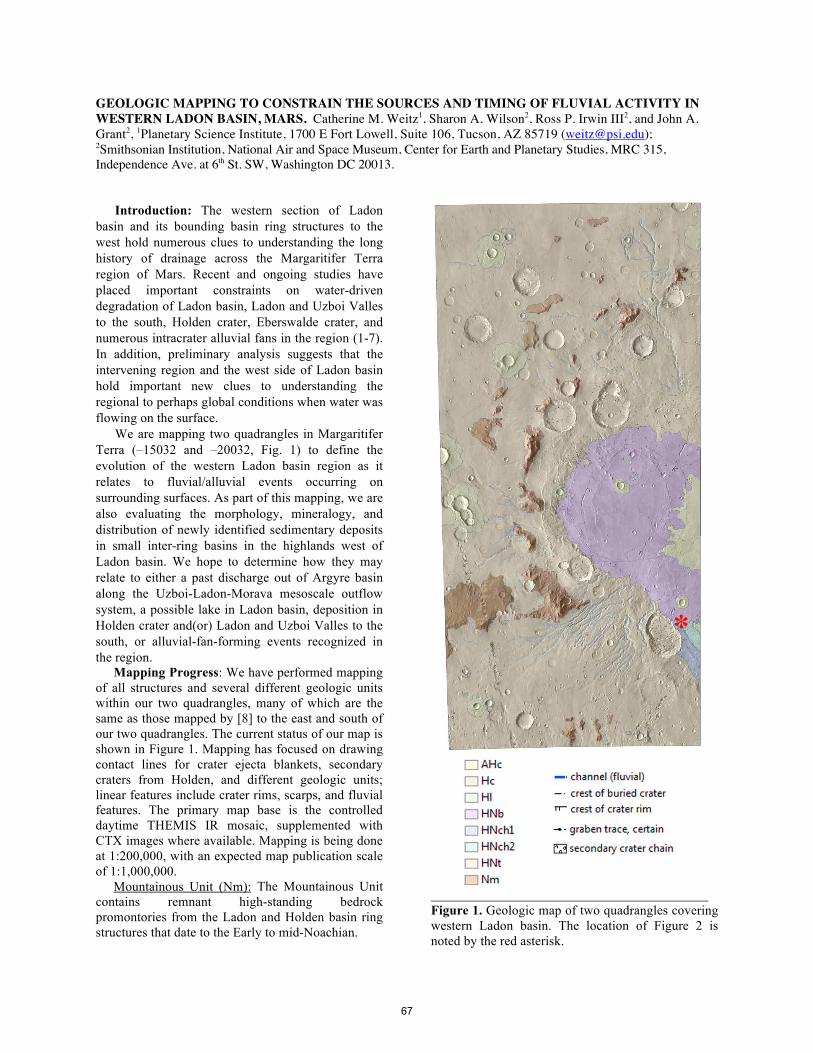
GEOLOGIC MAPPING TO CONSTRAIN THE SOURCES AND TIMING OF FLUVIAL ACTIVITY IN WESTERN LADON BASIN, MARS. Catherine M. Weitz1, Sharon A. Wilson2, Ross P. Irwin III2, and John A. Grant2, 1Planetary Science Institute, 1700 E Fort Lowell, Suite 106, Tucson, AZ 85719 ([email protected]); 2Smithsonian Institution, National Air and Space Museum, Center for Earth and Planetary Studies, MRC 315, Independence Ave. at 6th St. SW, Washington DC 20013.
Introduction: The western section of Ladon
basin and its bounding basin ring structures to the west hold numerous clues to understanding the long history of drainage across the Margaritifer Terra region of Mars. Recent and ongoing studies have placed important constraints on water-driven degradation of Ladon basin, Ladon and Uzboi Valles to the south, Holden crater, Eberswalde crater, and numerous intracrater alluvial fans in the region (1-7). In addition, preliminary analysis suggests that the intervening region and the west side of Ladon basin hold important new clues to understanding the regional to perhaps global conditions when water was flowing on the surface.
We are mapping two quadrangles in Margaritifer Terra (–15032 and –20032, Fig. 1) to define the evolution of the western Ladon basin region as it relates to fluvial/alluvial events occurring on surrounding surfaces. As part of this mapping, we are also evaluating the morphology, mineralogy, and distribution of newly identified sedimentary deposits in small inter-ring basins in the highlands west of Ladon basin. We hope to determine how they may relate to either a past discharge out of Argyre basin along the Uzboi-Ladon-Morava mesoscale outflow system, a possible lake in Ladon basin, deposition in Holden crater and(or) Ladon and Uzboi Valles to the south, or alluvial-fan-forming events recognized in the region.
Mapping Progress: We have performed mapping of all structures and several different geologic units within our two quadrangles, many of which are the same as those mapped by [8] to the east and south of our two quadrangles. The current status of our map is shown in Figure 1. Mapping has focused on drawing contact lines for crater ejecta blankets, secondary craters from Holden, and different geologic units; linear features include crater rims, scarps, and fluvial features. The primary map base is the controlled daytime THEMIS IR mosaic, supplemented with CTX images where available. Mapping is being done at 1:200,000, with an expected map publication scale of 1:1,000,000.
Mountainous Unit (Nm): The Mountainous Unit contains remnant high-standing bedrock promontories from the Ladon and Holden basin ring structures that date to the Early to mid-Noachian.
Figure 1. Geologic map of two quadrangles covering western Ladon basin. The location of Figure 2 is noted by the red asterisk.
*
67
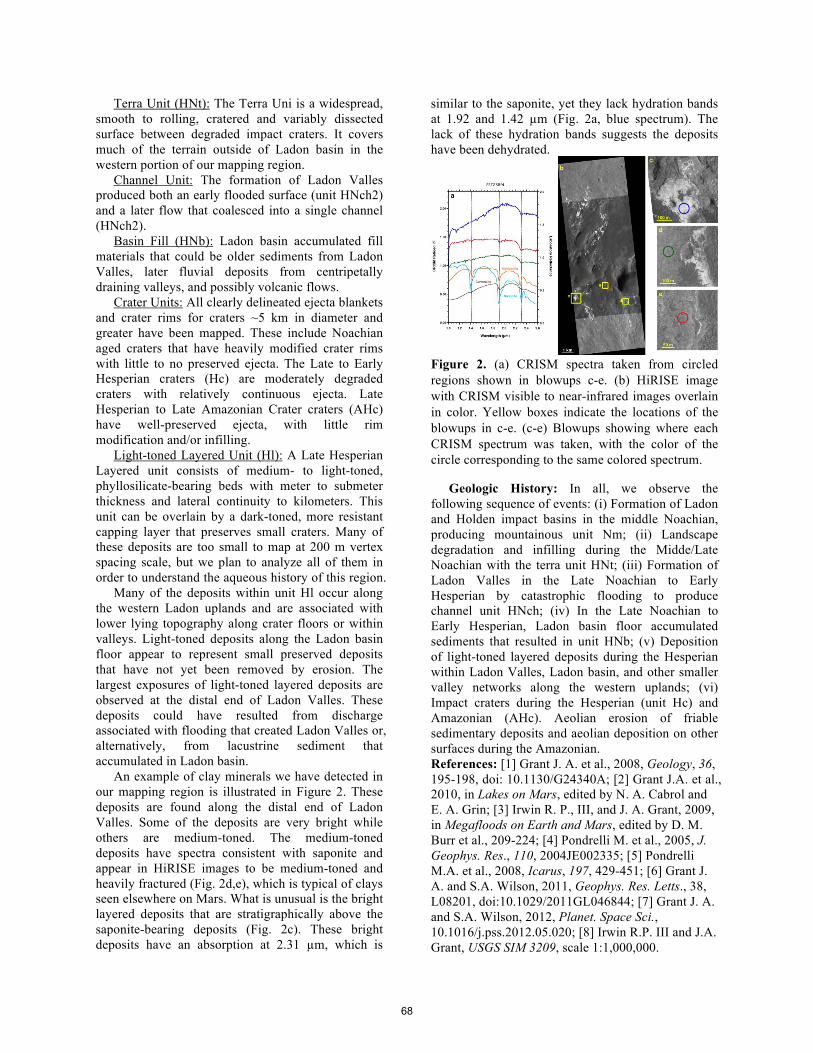
Terra Unit (HNt): The Terra Uni is a widespread, smooth to rolling, cratered and variably dissected surface between degraded impact craters. It covers much of the terrain outside of Ladon basin in the western portion of our mapping region.
Channel Unit: The formation of Ladon Valles produced both an early flooded surface (unit HNch2) and a later flow that coalesced into a single channel (HNch2).
Basin Fill (HNb): Ladon basin accumulated fill materials that could be older sediments from Ladon Valles, later fluvial deposits from centripetally draining valleys, and possibly volcanic flows.
Crater Units: All clearly delineated ejecta blankets and crater rims for craters ~5 km in diameter and greater have been mapped. These include Noachian aged craters that have heavily modified crater rims with little to no preserved ejecta. The Late to Early Hesperian craters (Hc) are moderately degraded craters with relatively continuous ejecta. Late Hesperian to Late Amazonian Crater craters (AHc) have well-preserved ejecta, with little rim modification and/or infilling.
Light-toned Layered Unit (Hl): A Late Hesperian Layered unit consists of medium- to light-toned, phyllosilicate-bearing beds with meter to submeter thickness and lateral continuity to kilometers. This unit can be overlain by a dark-toned, more resistant capping layer that preserves small craters. Many of these deposits are too small to map at 200 m vertex spacing scale, but we plan to analyze all of them in order to understand the aqueous history of this region.
Many of the deposits within unit Hl occur along the western Ladon uplands and are associated with lower lying topography along crater floors or within valleys. Light-toned deposits along the Ladon basin floor appear to represent small preserved deposits that have not yet been removed by erosion. The largest exposures of light-toned layered deposits are observed at the distal end of Ladon Valles. These deposits could have resulted from discharge associated with flooding that created Ladon Valles or, alternatively, from lacustrine sediment that accumulated in Ladon basin.
An example of clay minerals we have detected in our mapping region is illustrated in Figure 2. These deposits are found along the distal end of Ladon Valles. Some of the deposits are very bright while others are medium-toned. The medium-toned deposits have spectra consistent with saponite and appear in HiRISE images to be medium-toned and heavily fractured (Fig. 2d,e), which is typical of clays seen elsewhere on Mars. What is unusual is the bright layered deposits that are stratigraphically above the saponite-bearing deposits (Fig. 2c). These bright deposits have an absorption at 2.31 µm, which is
similar to the saponite, yet they lack hydration bands at 1.92 and 1.42 µm (Fig. 2a, blue spectrum). The lack of these hydration bands suggests the deposits have been dehydrated.
Figure 2. (a) CRISM spectra taken from circled regions shown in blowups c-e. (b) HiRISE image with CRISM visible to near-infrared images overlain in color. Yellow boxes indicate the locations of the blowups in c-e. (c-e) Blowups showing where each CRISM spectrum was taken, with the color of the circle corresponding to the same colored spectrum.
Geologic History: In all, we observe the following sequence of events: (i) Formation of Ladon and Holden impact basins in the middle Noachian, producing mountainous unit Nm; (ii) Landscape degradation and infilling during the Midde/Late Noachian with the terra unit HNt; (iii) Formation of Ladon Valles in the Late Noachian to Early Hesperian by catastrophic flooding to produce channel unit HNch; (iv) In the Late Noachian to Early Hesperian, Ladon basin floor accumulated sediments that resulted in unit HNb; (v) Deposition of light-toned layered deposits during the Hesperian within Ladon Valles, Ladon basin, and other smaller valley networks along the western uplands; (vi) Impact craters during the Hesperian (unit Hc) and Amazonian (AHc). Aeolian erosion of friable sedimentary deposits and aeolian deposition on other surfaces during the Amazonian. References: [1] Grant J. A. et al., 2008, Geology, 36, 195-198, doi: 10.1130/G24340A; [2] Grant J.A. et al., 2010, in Lakes on Mars, edited by N. A. Cabrol and E. A. Grin; [3] Irwin R. P., III, and J. A. Grant, 2009, in Megafloods on Earth and Mars, edited by D. M. Burr et al., 209-224; [4] Pondrelli M. et al., 2005, J. Geophys. Res., 110, 2004JE002335; [5] Pondrelli M.A. et al., 2008, Icarus, 197, 429-451; [6] Grant J. A. and S.A. Wilson, 2011, Geophys. Res. Letts., 38, L08201, doi:10.1029/2011GL046844; [7] Grant J. A. and S.A. Wilson, 2012, Planet. Space Sci., 10.1016/j.pss.2012.05.020; [8] Irwin R.P. III and J.A. Grant, USGS SIM 3209, scale 1:1,000,000.
68
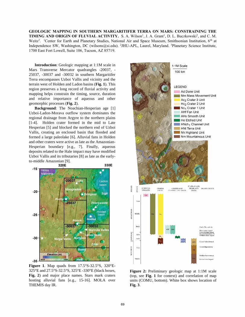
GEOLOGIC MAPPING IN SOUTHERN MARGARITIFER TERRA ON MARS: CONSTRAINING THE
TIMING AND ORIGIN OF FLUVIAL ACTIVITY. S. A. Wilson1, J. A. Grant1, D. L. Buczkowski2, and C. M.
Weitz3. 1Center for Earth and Planetary Studies, National Air and Space Museum, Smithsonian Institution, 6 th at
Independence SW, Washington, DC ([email protected]). 2JHU-APL, Laurel, Maryland. 3Planetary Science Institute,
1700 East Fort Lowell, Suite 106, Tucson, AZ 85719.
Introduction: Geologic mapping at 1:1M scale in
Mars Transverse Mercator quadrangles -20037, -
25037, -30037 and -30032 in southern Margaritifer
Terra encompasses Uzboi Vallis and vicinity and the
terrain west of Holden and Ladon basins (Fig. 1). This
region preserves a long record of fluvial activity and
mapping helps constrain the timing, source, duration
and relative importance of aqueous and other
geomorphic processes (Fig. 2).
Background: The Noachian-Hesperian age [1]
Uzboi-Ladon-Morava outflow system dominates the
regional drainage from Argyre to the northern plains
[1-4]. Holden crater formed in the mid to Late
Hesperian [5] and blocked the northern end of Uzboi
Vallis, creating an enclosed basin that flooded and
formed a large paleolake [6]. Alluvial fans in Holden
and other craters were active as late as the Amazonian-
Hesperian boundary [e.g., 7]. Finally, aqueous
deposits related to the Hale impact may have modified
Uzboi Vallis and its tributaries [8] as late as the early-
to-middle Amazonian [9].
Figure 1. Map quads from 17.5°S-32.5°S, 320°E-
325°E and 27.5°S-32.5°S, 325°E -330°E (black boxes,
Fig. 2) and major place names. Stars mark craters
hosting alluvial fans [e.g., 15-16]. MOLA over
THEMIS day IR.
Figure 2: Preliminary geologic map at 1:1M scale
(top, see Fig. 1 for context) and correlation of map
units (COMU, bottom). White box shows location of
Fig. 3.
69

Preliminary Description of Map Units (Fig. 2):
Plateau and Highland Materials. The remnant
high-standing bedrock promontories from the Ladon
and Holden basin ring structures are mapped as Early
to mid-Noachian Mountainous unit (Nm) [10]. The
Highland unit (Nh) is likely late Noachian to early
Hesperian in age and occurs primarily in -30037 and -
30032. This unit is heavily cratered, differentially
mantled, contains older valley networks, grabens, a
few wrinkle ridges, and lacks evidence of the
phyllosilicate layer observed in the Terra unit (HNt)
[11]. Unit Nh embays unit Nm and underlies all other
units. The Late Noachian to Early Hesperian Terra unit
(HNt) is characterized by widespread, smooth to
rolling, cratered and variably dissected surfaces
between degraded impact craters [12]. In -25037, unit
HNt occurs beneath the continuous Holden ejecta (unit
Hc2) and was modified by secondary craters related to
the impact. Unit HNt west of Uzboi Vallis consists of
a ~10 m-thick, laterally continuous Fe/Mg-smectite
phyllosilicate-bearing layer located a few meters
below the surface cap material and stratigraphically
above Al-phyllosilicates [13-14].
Crater and Channel-Fill Units. The Late Noachian
to Early Hesperian Channel unit (NHch) are fluvially
eroded surfaces related to the initial incision of Uzboi
Vallis [12]. The floor of Uzboi Vallis is mapped as
Early to Late Hesperian Etched unit (He),
characterized by erosionally resistant material exposed
where aeolian deflation has selectively removed light-
toned layered material [12]. A similar etched unit
exposing light-toned deposits occurs in Gringauz and
possibly on the floor of the unnamed crater near 29°S,
326.6°E. The floor of Nirgal Vallis is tentatively
mapped as NHch but will likely change upon further
investigation of its origin, age and relation to Uzboi.
The Late Hesperian to Early Amazonian Smooth
unit (AHs) is dark-toned, smooth at scales of 10s to
100s of m, typically bright in THEMIS day IR with
variable thickness. Channels and streamlined deposits
are common close to Hale crater south of the map area
[9]. Unit AHs occurs in pre-existing valleys and
topographic depressions, locally forming lobes with
distinct margins [9] (Fig. 3). Light-toned, meter-scale
boulders, aeolian bedforms and extensive cracks are
common on lobe surfaces, and layering is not evident
[8]. The deposit embays secondary craters from Hale
and thins with distance from Hale [8]. We interpret
these to be aqueous deposits related to the formation
of crater Hale. Local aeolian erosion of the distal
margins of the lobes implies a fine-grained
component, perhaps produced by weathering.
The Late Hesperian to Early Amazonian Fan unit
(AHf) are sloping or cone-shaped deposits that occur
on the interior slopes of craters [12]. Distributary
paleo-channel networks are preserved in negative or
(more commonly) positive relief. Cone-shaped
deposits derived from deeply dissected impact crater
walls coalesced into fans in craters Luba, Roddy,
Gringauz and Holden. Bright in THEMIS nighttime
IR. We interpret AHf as alluvial deposits composed
primarily of gravel and fines [e.g. 7, 15] emplaced by
fluvial sediment transport with little to no evident
contribution from debris flows. Low abundance of
boulders at HiRISE scale.
Crater Units. The Noachian Crater 1 unit (Nc1) are
heavily modified with little to no preserved ejecta.
Late to Early Hesperian Crater 2 unit (Hc2) are
moderately degraded craters with relatively
continuous ejecta (e.g., Luba). Late Hesperian to Late
Amazonian Crater 3 Unit (Ac3) are “fresh” craters with
well-preserved ejecta.
Surficial Deposits. The Noachian to Amazonian
Mass movement unit (Mm) is a single to multi-lobed
shaped deposit with distinct margins interpreted as
landslide deposits in craters Roddy and Blunck. Late
Amazonian aged Dune unit (Ad) after [12] are
concentrations of typically dark-toned bedforms
interpreted to be aeolian dunes.
Figure 3. Unit AHs was deposited on unit Nh,
occupying pre-existing depressions west of Bond (see
Fig. 2 for context). CTX mosaic P21_009261_1472,
P21_009050_1472, B22_018254_1472. North to top.
References: [1] Grant, JA 1987, NASA Memo.
89871, 1-268 [2] Grant, JA, TJ Parker 2002, JGR, doi:
10.1029/2001JE001678 [3] Parker, TJ 1985, MS
Thesis, Cal. State [4] Saunders SR 1979, USGS Map
I-1144 [5] Irwin, RP, JA Grant 2013, USGS Map I-
3209 [6] Grant, JA et al. 2011, Icarus, doi:10.1016/j.ic
arus.2010.11.024 [7] Grant, JA, SA Wilson 2011,
GRL, doi:10.1029/2011GL046844. [8] Wilson SA et
al. 2013, Ann. Planet. Geol. Mappers. [9] Jones et al.
2011, Icarus, doi:10.1016/j.icarus.2010.10.014 [10]
Shultz et al. 1982, JGR [11] Wilson SA et al., 2014,
Ann. Planet. Geol. Mappers. [12] Irwin, RP III and JA
Grant 2013, USGS Map 3209 [13] Buczkowski, DL et
al. 2010 LPSC, Abst. 1458 [14] Buczkowski, DL et al.
2013 LPSC, Abst. 2331 [15] Moore, JM, AD Moore
2005, JGR, doi:10.1029/ 2005JE002352. [16] Wilson
et al. 2013, LPSC Abst. 2710.
70
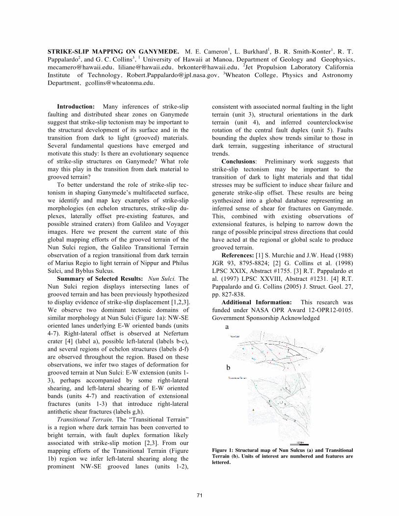
STRIKE-SLIP MAPPING ON GANYMEDE. M. E. Cameron1, L. Burkhard1, B. R. Smith-Konter1, R. T. Pappalardo2, and G. C. Collins3, 1 University of Hawaii at Manoa, Department of Geology and Geophysics, [email protected], [email protected], [email protected], 2Jet Propulsion Laboratory California Institute of Technology, [email protected], 3Wheaton College, Physics and Astronomy Department, [email protected].
Introduction: Many inferences of strike-slip
faulting and distributed shear zones on Ganymede suggest that strike-slip tectonism may be important to the structural development of its surface and in the transition from dark to light (grooved) materials. Several fundamental questions have emerged and motivate this study: Is there an evolutionary sequence of strike-slip structures on Ganymede? What role may this play in the transition from dark material to grooved terrain?
To better understand the role of strike-slip tec- tonism in shaping Ganymede’s multifaceted surface, we identify and map key examples of strike-slip morphologies (en echelon structures, strike-slip du- plexes, laterally offset pre-existing features, and possible strained craters) from Galileo and Voyager images. Here we present the current state of this global mapping efforts of the grooved terrain of the Nun Sulci region, the Galileo Transitional Terrain observation of a region transitional from dark terrain of Marius Regio to light terrain of Nippur and Philus Sulci, and Byblus Sulcus.
Summary of Selected Results: Nun Sulci. The Nun Sulci region displays intersecting lanes of grooved terrain and has been previously hypothesized to display evidence of strike-slip displacement [1,2,3]. We observe two dominant tectonic domains of similar morphology at Nun Sulci (Figure 1a): NW-SE oriented lanes underlying E-W oriented bands (units 4-7). Right-lateral offset is observed at Nefertum crater [4] (label a), possible left-lateral (labels b-c), and several regions of echelon structures (labels d-f) are observed throughout the region. Based on these observations, we infer two stages of deformation for grooved terrain at Nun Sulci: E-W extension (units 1-3), perhaps accompanied by some right-lateral shearing, and left-lateral shearing of E-W oriented bands (units 4-7) and reactivation of extensional fractures (units 1-3) that introduce right-lateral antithetic shear fractures (labels g,h).
Transitional Terrain. The “Transitional Terrain” is a region where dark terrain has been converted to bright terrain, with fault duplex formation likely associated with strike-slip motion [2,3]. From our mapping efforts of the Transitional Terrain (Figure 1b) region we infer left-lateral shearing along the prominent NW-SE grooved lanes (units 1-2),
consistent with associated normal faulting in the light terrain (unit 3), structural orientations in the dark terrain (unit 4), and inferred counterclockwise rotation of the central fault duplex (unit 5). Faults bounding the duplex show trends similar to those in dark terrain, suggesting inheritance of structural trends.
Conclusions: Preliminary work suggests that strike-slip tectonism may be important to the transition of dark to light materials and that tidal stresses may be sufficient to induce shear failure and generate strike-slip offset. These results are being synthesized into a global database representing an inferred sense of shear for fractures on Ganymede. This, combined with existing observations of extensional features, is helping to narrow down the range of possible principal stress directions that could have acted at the regional or global scale to produce grooved terrain.
References: [1] S. Murchie and J.W. Head (1988) JGR 93, 8795-8824; [2] G. Collins et al. (1998) LPSC XXIX, Abstract #1755. [3] R.T. Pappalardo et al. (1997) LPSC XXVIII, Abstract #1231. [4] R.T. Pappalardo and G. Collins (2005) J. Struct. Geol. 27, pp. 827-838.
Additional Information: This research was funded under NASA OPR Award 12-OPR12-0105. Government Sponsorship Acknowledged
Figure 1: Structural map of Nun Sulcus (a) and Transitional Terrain (b). Units of interest are numbered and features are lettered.
a
b
71
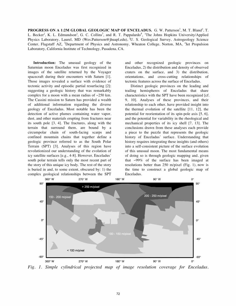
PROGRESS ON A 1:2M GLOBAL GEOLOGIC MAP OF ENCELADUS. G. W. Patterson1, M. T. Bland2, T. L. Becker2, K. L. Edmundson2, G. C. Collins3, and R. T. Pappalardo4, 1The Johns Hopkins University/Applied Physics Laboratory, Laurel, MD ([email protected]), 2U. S. Geological Survey, Astrogeology Science Center, Flagstaff AZ, 3Department of Physics and Astronomy, Wheaton College, Norton, MA, 4Jet Propulsion Laboratory, California Institute of Technology, Pasadena, CA.
Introduction: The unusual geology of the
Saturnian moon Enceladus was first recognized in images of the satellite returned by the Voyager spacecraft during their encounters with Saturn [1]. Those images revealed a surface with evidence of tectonic activity and episodic partial resurfacing [2]; suggesting a geologic history that was remarkably complex for a moon with a mean radius of ~250 km. The Cassini mission to Saturn has provided a wealth of additional information regarding the diverse geology of Enceladus. Most notable has been the detection of active plumes containing water vapor, dust, and other materials erupting from fractures near its south pole [3, 4]. The fractures, along with the terrain that surround them, are bound by a circumpolar chain of south-facing scarps and confined mountain chains that together define a geologic province referred to as the South Polar Terrain (SPT) [3]. Analyses of this region have revolutionized our understanding of the evolution of icy satellite surfaces [e.g., 4-8]. However, Enceladus’ south polar terrain tells only the most recent part of the story of this unique icy body. The rest of the story is buried in and, to some extent, obscured by: 1) the complex geological relationships between the SPT
and other recognized geologic provinces on Enceladus, 2) the distribution and density of observed craters on the surface, and 3) the distribution, orientations, and cross-cutting relationships of tectonic features across the surface of Enceladus.
Distinct geologic provinces on the leading and trailing hemispheres of Enceladus that share characteristics with the SPT have been recognized [cf. 9, 10]. Analyses of these provinces, and their relationship to each other, have provided insight into the thermal evolution of the satellite [11, 12], the potential for reorientation of its spin-pole axis [5, 6], and the potential for variability in the rheological and mechanical properties of its icy shell [7, 13]. The conclusions drawn from these analyses each provide a piece to the puzzle that represents the geologic history of Enceladus’ surface. Understanding that history requires integrating these insights (and others) into a self-consistent picture of the surface evolution of this unusual moon. The most fundamental means of doing so is through geologic mapping and, given that ~99% of the surface has been imaged at resolutions better than 250 m/pixel (Fig. 1), now is the time to construct a global geologic map of Enceladus.
Fig. 1. Simple cylindrical projected map of image resolution coverage for Enceladus.
72
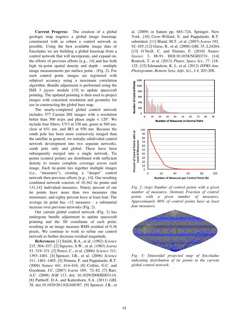
Current Progress: The creation of a global geologic map requires a global image basemap, constructed with as robust a control network as possible. Using the best available image data of Enceladus we are building a global basemap from a control network that will incorporate, and expand on, the efforts of previous efforts [e.g., 14] and has both high tie-point spatial density and depth - multiple image measurements per surface point - (Fig. 2). For each control point, images are registered with subpixel accuracy using a maximum correlation algorithm. Bundle adjustment is performed using the ISIS 3 jigsaw module [15] to update spacecraft pointing. The updated pointing is then used to project images with consistent resolution and geometry for use in constructing the global base map.
The nearly-completed global control network includes 577 Cassini ISS images with a resolution better than 500 m/px and phase angle < 120o. We include four filters: UV3 at 338 nm, green at 569 nm, clear at 651 nm, and IR3 at 930 nm. Because the south pole has been more extensively imaged than the satellite in general, we initially subdivided control network development into two separate networks, south pole only and global. These have been subsequently merged into a single network. Tie points (control points) are distributed with sufficient density to ensure complete coverage across each image. Each tie-point ties together multiple images (i.e., “measures”), creating a “deeper” control network then previous efforts [e.g., 14]. Our resulting combined network consists of 10,362 tie points and 131,142 individual measures. Ninety percent of our tie points have more than two measures (the minimum), and eighty percent have at least four. The average tie point has ∼12 measures - a substantial increase over previous networks (Fig. 2).
Our current global control network (Fig. 3) has undergone bundle adjustment to update spacecraft pointing and the 3D coordinate of each point, resulting in an image measure RMS residual of 0.36 pixels. We continue to work to refine our control network to further decrease residual magnitude.
References: [1] Smith, B.A., et al. (1982) Science 215, 504–537. [2] Squyres, S.W., et al. (1983) Icarus 53, 319–331. [3] Porco, C., et al. (2006) Science 311, 1393–1401. [4] Spencer, J.R., et al. (2006) Science 311, 1401–1405. [5] Nimmo, F. and Pappalardo, R.T. (2006) Nature 441, 614–616. [6] Collins, G.C. and Goodman, J.C. (2007) Icarus 189, 72–82. [7] Barr, A.C. (2008) JGR 113, doi: 10.1029/2008JE003114. [8] Patthoff, D.A. and Kattenhorn, S.A. (2011) GRL 38, doi:10.1029/2011GL048387. [9] Spencer, J.R., et
al. (2009) in Saturn pp. 683–724, Springer, New York. [10] Crow-Willard, E. and Pappalardo, R.T. submitted. [11] Bland, M.T., et al. (2007) Icarus 192, 92–105. [12] Giese, B., et al. (2008) GRL 35, L24204. [13] O’Neill, C. and Nimmo, F. (2010) Nature Geosci. 3, 88-91, DOI:10.1038/NGEO731. [14] Roatsch, T. et al. (2013) Planet. Space Sci., 77, 118-125. [15] Edmundson, K. L. et al. (2012) ISPRS Ann. Photogramm. Remote Sens. Info. Sci., I-4, 203-208.
Fig. 2: (top) Number of control points with a given number of measures. (bottom) Fraction of control points with a given number of measures. Approximately 80% of control points have at least four measures.
Fig. 3: Sinusoidal projected map of Enceladus indicating distribution of tie points in the current global control network.
73
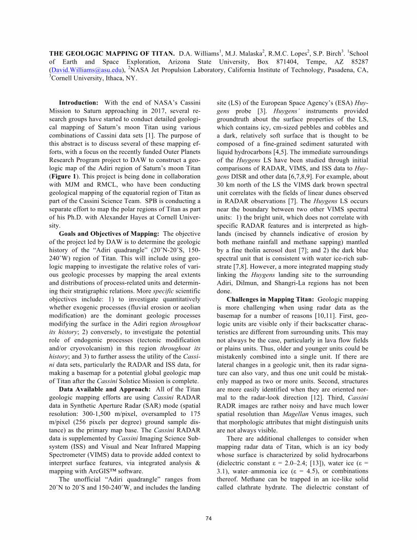
THE GEOLOGIC MAPPING OF TITAN. D.A. Williams1, M.J. Malaska2, R.M.C. Lopes2, S.P. Birch3. 1School of Earth and Space Exploration, Arizona State University, Box 871404, Tempe, AZ 85287 ([email protected]), 2NASA Jet Propulsion Laboratory, California Institute of Technology, Pasadena, CA, 3Cornell University, Ithaca, NY.
Introduction: With the end of NASA’s Cassini
Mission to Saturn approaching in 2017, several re-search groups have started to conduct detailed geologi-cal mapping of Saturn’s moon Titan using various combinations of Cassini data sets [1]. The purpose of this abstract is to discuss several of these mapping ef-forts, with a focus on the recently funded Outer Planets Research Program project to DAW to construct a geo-logic map of the Adiri region of Saturn’s moon Titan (Figure 1). This project is being done in collaboration with MJM and RMCL, who have been conducting geological mapping of the equatorial region of Titan as part of the Cassini Science Team. SPB is conducting a separate effort to map the polar regions of Titan as part of his Ph.D. with Alexander Hayes at Cornell Univer-sity.
Goals and Objectives of Mapping: The objective of the project led by DAW is to determine the geologic history of the “Adiri quadrangle” (20˚N-20˚S, 150-240˚W) region of Titan. This will include using geo-logic mapping to investigate the relative roles of vari-ous geologic processes by mapping the areal extents and distributions of process-related units and determin-ing their stratigraphic relations. More specific scientific objectives include: 1) to investigate quantitatively whether exogenic processes (fluvial erosion or aeolian modification) are the dominant geologic processes modifying the surface in the Adiri region throughout its history; 2) conversely, to investigate the potential role of endogenic processes (tectonic modification and/or cryovolcanism) in this region throughout its history; and 3) to further assess the utility of the Cassi-ni data sets, particularly the RADAR and ISS data, for making a basemap for a potential global geologic map of Titan after the Cassini Solstice Mission is complete.
Data Available and Approach: All of the Titan geologic mapping efforts are using Cassini RADAR data in Synthetic Aperture Radar (SAR) mode (spatial resolution: 300-1,500 m/pixel, oversampled to 175 m/pixel (256 pixels per degree) ground sample dis-tance) as the primary map base. The Cassini RADAR data is supplemented by Cassini Imaging Science Sub-system (ISS) and Visual and Near Infrared Mapping Spectrometer (VIMS) data to provide added context to interpret surface features, via integrated analysis & mapping with ArcGIS™ software.
The unofficial “Adiri quadrangle” ranges from 20˚N to 20˚S and 150-240˚W, and includes the landing
site (LS) of the European Space Agency’s (ESA) Huy-gens probe [3]. Huygens’ instruments provided groundtruth about the surface properties of the LS, which contains icy, cm-sized pebbles and cobbles and a dark, relatively soft surface that is thought to be composed of a fine-grained sediment saturated with liquid hydrocarbons [4,5]. The immediate surroundings of the Huygens LS have been studied through initial comparisons of RADAR, VIMS, and ISS data to Huy-gens DISR and other data [6,7,8,9]. For example, about 30 km north of the LS the VIMS dark brown spectral unit correlates with the fields of linear dunes observed in RADAR observations [7]. The Huygens LS occurs near the boundary between two other VIMS spectral units: 1) the bright unit, which does not correlate with specific RADAR features and is interpreted as high-lands (incised by channels indicative of erosion by both methane rainfall and methane sapping) mantled by a fine tholin aerosol dust [7]; and 2) the dark blue spectral unit that is consistent with water ice-rich sub-strate [7,8]. However, a more integrated mapping study linking the Huygens landing site to the surrounding Adiri, Dilmun, and Shangri-La regions has not been done.
Challenges in Mapping Titan: Geologic mapping is more challenging when using radar data as the basemap for a number of reasons [10,11]. First, geo-logic units are visible only if their backscatter charac-teristics are different from surrounding units. This may not always be the case, particularly in lava flow fields or plains units. Thus, older and younger units could be mistakenly combined into a single unit. If there are lateral changes in a geologic unit, then its radar signa-ture can also vary, and thus one unit could be mistak-enly mapped as two or more units. Second, structures are more easily identified when they are oriented nor-mal to the radar-look direction [12]. Third, Cassini RADR images are rather noisy and have much lower spatial resolution than Magellan Venus images, such that morphologic attributes that might distinguish units are not always visible.
There are additional challenges to consider when mapping radar data of Titan, which is an icy body whose surface is characterized by solid hydrocarbons (dielectric constant ε = 2.0–2.4; [13]), water ice (ε = 3.1), water–ammonia ice (ε = 4.5), or combinations thereof. Methane can be trapped in an ice-like solid called clathrate hydrate. The dielectric constant of
74
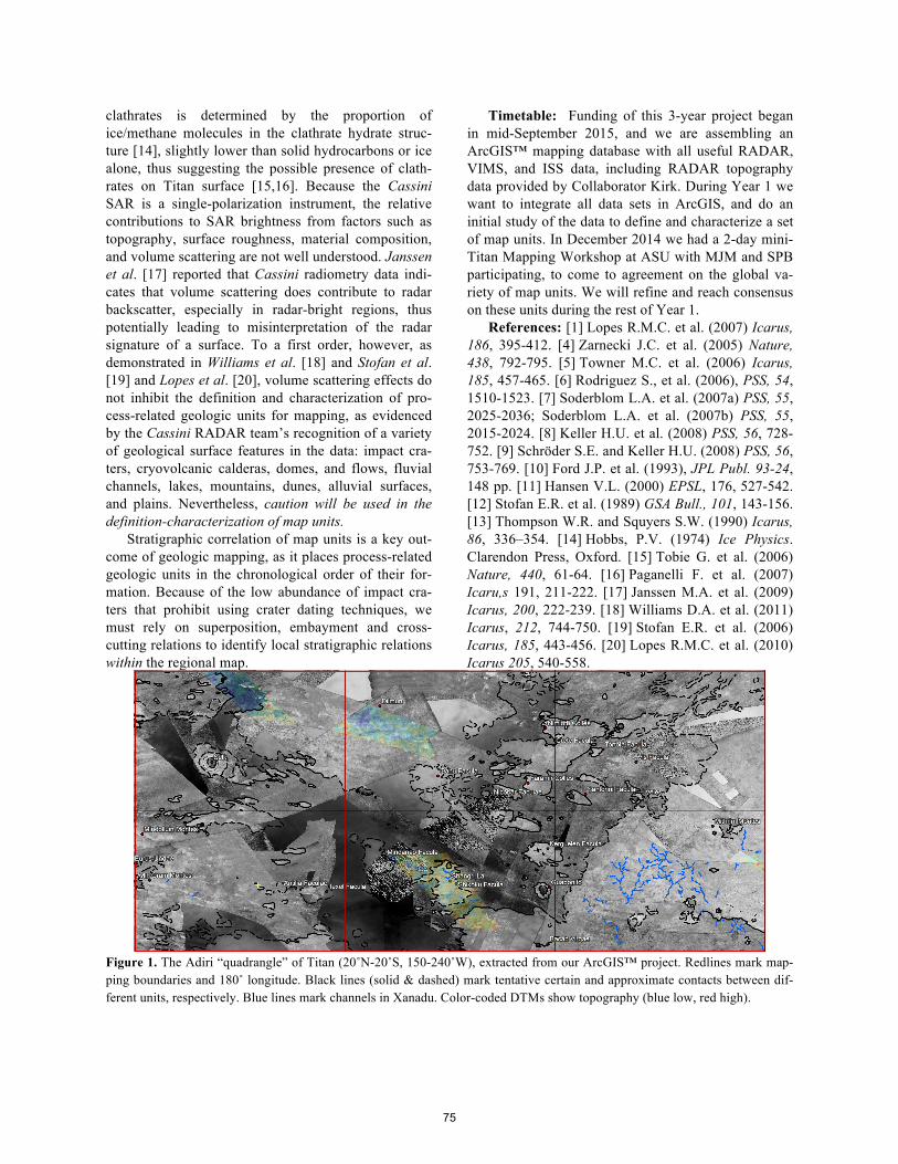
clathrates is determined by the proportion of ice/methane molecules in the clathrate hydrate struc-ture [14], slightly lower than solid hydrocarbons or ice alone, thus suggesting the possible presence of clath-rates on Titan surface [15,16]. Because the Cassini SAR is a single-polarization instrument, the relative contributions to SAR brightness from factors such as topography, surface roughness, material composition, and volume scattering are not well understood. Janssen et al. [17] reported that Cassini radiometry data indi-cates that volume scattering does contribute to radar backscatter, especially in radar-bright regions, thus potentially leading to misinterpretation of the radar signature of a surface. To a first order, however, as demonstrated in Williams et al. [18] and Stofan et al. [19] and Lopes et al. [20], volume scattering effects do not inhibit the definition and characterization of pro-cess-related geologic units for mapping, as evidenced by the Cassini RADAR team’s recognition of a variety of geological surface features in the data: impact cra-ters, cryovolcanic calderas, domes, and flows, fluvial channels, lakes, mountains, dunes, alluvial surfaces, and plains. Nevertheless, caution will be used in the definition-characterization of map units.
Stratigraphic correlation of map units is a key out-come of geologic mapping, as it places process-related geologic units in the chronological order of their for-mation. Because of the low abundance of impact cra-ters that prohibit using crater dating techniques, we must rely on superposition, embayment and cross-cutting relations to identify local stratigraphic relations within the regional map.
Timetable: Funding of this 3-year project began in mid-September 2015, and we are assembling an ArcGIS™ mapping database with all useful RADAR, VIMS, and ISS data, including RADAR topography data provided by Collaborator Kirk. During Year 1 we want to integrate all data sets in ArcGIS, and do an initial study of the data to define and characterize a set of map units. In December 2014 we had a 2-day mini-Titan Mapping Workshop at ASU with MJM and SPB participating, to come to agreement on the global va-riety of map units. We will refine and reach consensus on these units during the rest of Year 1.
References: [1] Lopes R.M.C. et al. (2007) Icarus, 186, 395-412. [4] Zarnecki J.C. et al. (2005) Nature, 438, 792-795. [5] Towner M.C. et al. (2006) Icarus, 185, 457-465. [6] Rodriguez S., et al. (2006), PSS, 54, 1510-1523. [7] Soderblom L.A. et al. (2007a) PSS, 55, 2025-2036; Soderblom L.A. et al. (2007b) PSS, 55, 2015-2024. [8] Keller H.U. et al. (2008) PSS, 56, 728-752. [9] Schröder S.E. and Keller H.U. (2008) PSS, 56, 753-769. [10] Ford J.P. et al. (1993), JPL Publ. 93-24, 148 pp. [11] Hansen V.L. (2000) EPSL, 176, 527-542. [12] Stofan E.R. et al. (1989) GSA Bull., 101, 143-156. [13] Thompson W.R. and Squyers S.W. (1990) Icarus, 86, 336–354. [14] Hobbs, P.V. (1974) Ice Physics. Clarendon Press, Oxford. [15] Tobie G. et al. (2006) Nature, 440, 61-64. [16] Paganelli F. et al. (2007) Icaru,s 191, 211-222. [17] Janssen M.A. et al. (2009) Icarus, 200, 222-239. [18] Williams D.A. et al. (2011) Icarus, 212, 744-750. [19] Stofan E.R. et al. (2006) Icarus, 185, 443-456. [20] Lopes R.M.C. et al. (2010) Icarus 205, 540-558.
Figure 1. The Adiri “quadrangle” of Titan (20˚N-20˚S, 150-240˚W), extracted from our ArcGIS™ project. Redlines mark map-ping boundaries and 180˚ longitude. Black lines (solid & dashed) mark tentative certain and approximate contacts between dif-ferent units, respectively. Blue lines mark channels in Xanadu. Color-coded DTMs show topography (blue low, red high).
75
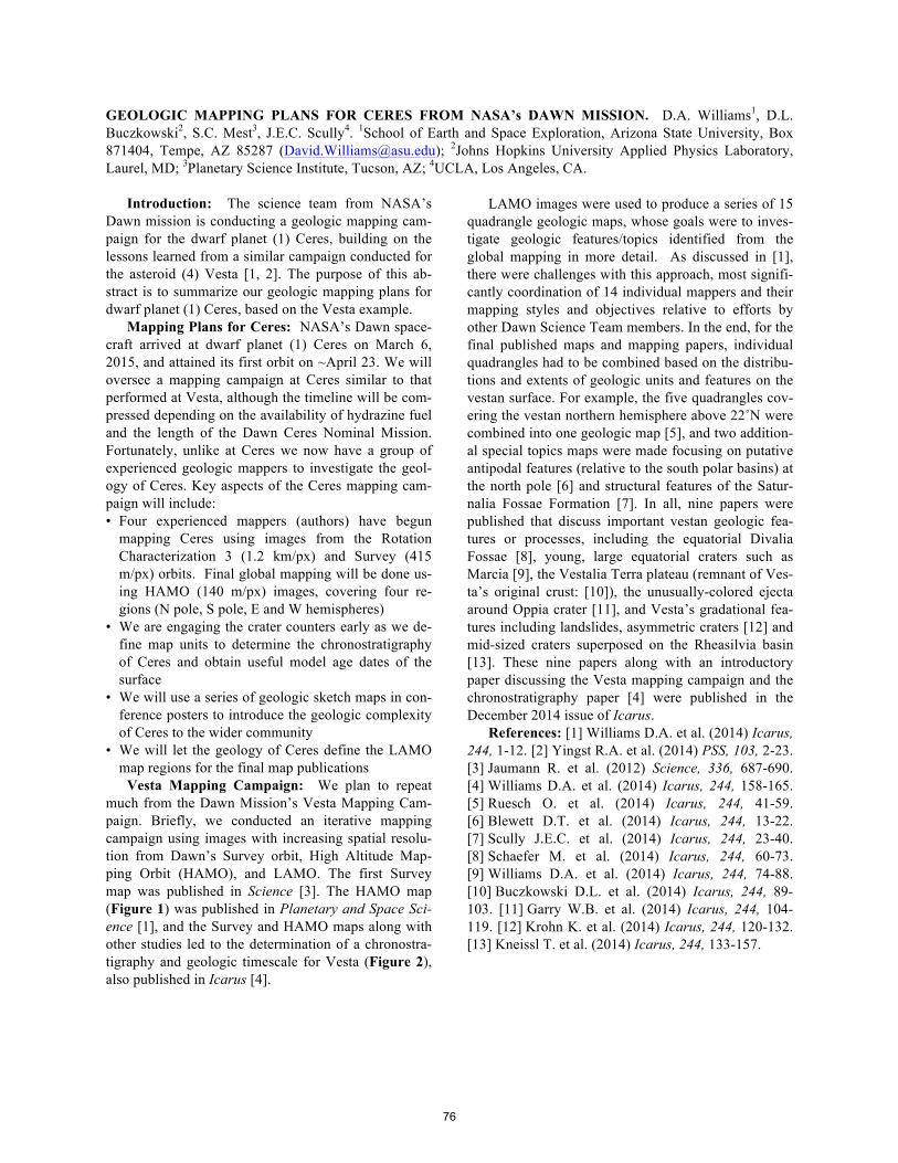
GEOLOGIC MAPPING PLANS FOR CERES FROM NASA’s DAWN MISSION. D.A. Williams1, D.L. Buczkowski2, S.C. Mest3, J.E.C. Scully4. 1School of Earth and Space Exploration, Arizona State University, Box 871404, Tempe, AZ 85287 ([email protected]); 2Johns Hopkins University Applied Physics Laboratory, Laurel, MD; 3Planetary Science Institute, Tucson, AZ; 4UCLA, Los Angeles, CA.
Introduction: The science team from NASA’s
Dawn mission is conducting a geologic mapping cam-paign for the dwarf planet (1) Ceres, building on the lessons learned from a similar campaign conducted for the asteroid (4) Vesta [1, 2]. The purpose of this ab-stract is to summarize our geologic mapping plans for dwarf planet (1) Ceres, based on the Vesta example.
Mapping Plans for Ceres: NASA’s Dawn space-craft arrived at dwarf planet (1) Ceres on March 6, 2015, and attained its first orbit on ~April 23. We will oversee a mapping campaign at Ceres similar to that performed at Vesta, although the timeline will be com-pressed depending on the availability of hydrazine fuel and the length of the Dawn Ceres Nominal Mission. Fortunately, unlike at Ceres we now have a group of experienced geologic mappers to investigate the geol-ogy of Ceres. Key aspects of the Ceres mapping cam-paign will include: • Four experienced mappers (authors) have begun
mapping Ceres using images from the Rotation Characterization 3 (1.2 km/px) and Survey (415 m/px) orbits. Final global mapping will be done us-ing HAMO (140 m/px) images, covering four re-gions (N pole, S pole, E and W hemispheres)
• We are engaging the crater counters early as we de-fine map units to determine the chronostratigraphy of Ceres and obtain useful model age dates of the surface
• We will use a series of geologic sketch maps in con-ference posters to introduce the geologic complexity of Ceres to the wider community
• We will let the geology of Ceres define the LAMO map regions for the final map publications
Vesta Mapping Campaign: We plan to repeat much from the Dawn Mission’s Vesta Mapping Cam-paign. Briefly, we conducted an iterative mapping campaign using images with increasing spatial resolu-tion from Dawn’s Survey orbit, High Altitude Map-ping Orbit (HAMO), and LAMO. The first Survey map was published in Science [3]. The HAMO map (Figure 1) was published in Planetary and Space Sci-ence [1], and the Survey and HAMO maps along with other studies led to the determination of a chronostra-tigraphy and geologic timescale for Vesta (Figure 2), also published in Icarus [4].
LAMO images were used to produce a series of 15 quadrangle geologic maps, whose goals were to inves-tigate geologic features/topics identified from the global mapping in more detail. As discussed in [1], there were challenges with this approach, most signifi-cantly coordination of 14 individual mappers and their mapping styles and objectives relative to efforts by other Dawn Science Team members. In the end, for the final published maps and mapping papers, individual quadrangles had to be combined based on the distribu-tions and extents of geologic units and features on the vestan surface. For example, the five quadrangles cov-ering the vestan northern hemisphere above 22˚N were combined into one geologic map [5], and two addition-al special topics maps were made focusing on putative antipodal features (relative to the south polar basins) at the north pole [6] and structural features of the Satur-nalia Fossae Formation [7]. In all, nine papers were published that discuss important vestan geologic fea-tures or processes, including the equatorial Divalia Fossae [8], young, large equatorial craters such as Marcia [9], the Vestalia Terra plateau (remnant of Ves-ta’s original crust: [10]), the unusually-colored ejecta around Oppia crater [11], and Vesta’s gradational fea-tures including landslides, asymmetric craters [12] and mid-sized craters superposed on the Rheasilvia basin [13]. These nine papers along with an introductory paper discussing the Vesta mapping campaign and the chronostratigraphy paper [4] were published in the December 2014 issue of Icarus.
References: [1] Williams D.A. et al. (2014) Icarus, 244, 1-12. [2] Yingst R.A. et al. (2014) PSS, 103, 2-23. [3] Jaumann R. et al. (2012) Science, 336, 687-690. [4] Williams D.A. et al. (2014) Icarus, 244, 158-165. [5] Ruesch O. et al. (2014) Icarus, 244, 41-59. [6] Blewett D.T. et al. (2014) Icarus, 244, 13-22. [7] Scully J.E.C. et al. (2014) Icarus, 244, 23-40. [8] Schaefer M. et al. (2014) Icarus, 244, 60-73. [9] Williams D.A. et al. (2014) Icarus, 244, 74-88. [10] Buczkowski D.L. et al. (2014) Icarus, 244, 89-103. [11] Garry W.B. et al. (2014) Icarus, 244, 104-119. [12] Krohn K. et al. (2014) Icarus, 244, 120-132. [13] Kneissl T. et al. (2014) Icarus, 244, 133-157.
76
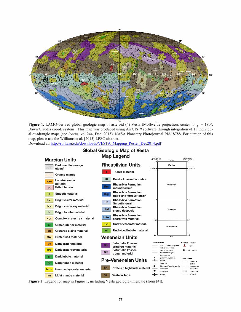
Figure 1. LAMO-derived global geologic map of asteroid (4) Vesta (Mollweide projection, center long. = 180˚, Dawn Claudia coord. system). This map was produced using ArcGIS™ software through integration of 15 individu-al quadrangle maps (see Icarus, vol 244, Dec. 2015). NASA Planetary Photojournal PIA18788. For citation of this map, please use the Williams et al. [2015] LPSC abstract. Download at: http://rpif.asu.edu/downloads/VESTA_Mapping_Poster_Dec2014.pdf
Figure 2. Legend for map in Figure 1, including Vesta geologic timescale (from [4]).
77